4140XMPT Installation Instructions FA1300C Manual
User Manual: FA1300C Installation Manual AlarmHow.net Library
Open the PDF directly: View PDF ![]() .
.
Page Count: 60
- 4140XMPT Installation Instructions
- Table of Contents
- List ofFigures
- General Information
- Zone Configuration
- Peripheral Devices
- Mounting and Powering theSystem
- System Operation
- System Communication
- Programming the System
- Programming Form
- Downloading Primer
- Testing theSystem
- Troubleshooting
- Specifications
- Summary of Connections
- Dip Switch Tables
- 4140XMPT Programming Form
- FCC Statement
- Canadian DOC Statement
- Limitations of this Alarm System
- Limited Warranty
VISTA
SERIES
PARTITIONED SECURITY SYSTEM
4140XMPT
INSTALLATION
INSTRUCTIONS
Meuv2m2 237
CONGRATULATIONS
on your purchase of the VISTA 4140XMPT!
The purpose of these Installation Instructions is to give you abrief overview of
the VISTA 4140XMPT system, and provide instructions for installing abasic
system.
As always, ADEMCO is there for YOU! Our SALES and TECHNICAL
SUPPORT sti are eager to assist you in any way they can, so don’t hesitate
to call, for any reason!
East Coast Technical Support: 1-800-645-7492 (8 a.m. -6p.m. E.S.T.)
West Coast Technical Support: 1-800-458-9469 (8 a.m.-5 p.m. P.S.T.)
PLEJWE,
Before you call Technical Support, be sure you have:
●Checked all wiring comections.
●Determined that the power supply and/or backup battery are
supplying proper voltages.
sVerified your programming information where applicable.
●Noted the proper model number of this product, and the version level
Gfknown) along with any documentation that came with the product.
●Noted your Ademco customer number and.lorcompany name.
Having this information handy will make it easier for us to serve you
quickly and effectively.
Again, CONGRATUMTIONS, and WELCOME ABOARD!
-2-
—.—. — —— -- -.——--——
1.
Il.
Ill,
Iv.
TABLE OF
GENERAL INFORMATION ..........................
lNTRODLfCTtONTO THE CONTROL.............................~
suMAARYoF41~SY51’EMmnmEs ............. 5
mmowcnm TO P~ED SYSTEMS............... 6
Suit Psr6tkmii Futures .................................... 6
~of pu6fii ........................................ 6
GlobalPmWoningFosmms6Rasw-s .................. 6
~Spsoi6cF~ ..................................... 6
ZONE CONFIGURATtONS .......................... 7
ZONE IVPE DEFINlmONS......................................... 7
SAStc9mwiREDzaES ................................... 7
Zono l ................................................................ 7
zon@ 9................................................................ 7
Zonoc 24 ............................................................ 7
2-WIWOJNG LOOP (thtf@ibSXLooP)...................... :
...........................................................
Pollinglaop Dwioss............................................. 8
WIRELESS EXPANSION ........................................... 9
=4- RF Rowiwrs .....................................
-ting m- *W*= DO* .................. .
wmti ......................................................... @
Houso l~ntifmtin .............................................. 9
Tmnsmittor ldsntifiosfb........................................ 9
Sdftsrtim D@mrrninsHouso10......................... 9
Ctrodrhg TmnsmitmrHwso IDs.............................. 9
GoNo *T@stM.... ......................................... e
=ti~tiNdiOS ....................................... :
...............................................
Wxdossbns Typos............................................ 10
Adti80tis .......................................................... lD
Wxss Dwioos................................................. 10
PERIPHERAL DEVICES . .. . .. . ... .. . ... .. . . ... .. . .11
REMOTEcONmLEs .............................................. 11
5137AD~sdls A@hs LCDCor?sds................. 11
. m Calsdn....................................11
9%$s2ss ..................................................11
surtsosMoun6ng610calsdos
..............................11
hsubl, ConsolaDIP ~......................... 11
Powot%?QAddidon,l C@lsobs..,”.... ........................ t2
FlustIMounAngWhTrkn Ring10t(51~ ............. ti
A@stingmsAlphsCorlsdsvi Angls...............l2
EXTERM4L=NDE% ........................................... *
............................................ 13
............................................ 13
UL lnsMation8 ................................................... W
-* ~........................................... 13
Sh6xJy .............................................. 13
............................................................... 13
Zonoc 2-8........................................................... u
.................................
rl%-~y~ .................. ............. :
MrslsssSmok@~ ...................................... a
PASSIVE INFRARED DETECTORS.... ..... ...... .. ........ 13
G- SREAKDETEC_ .................................... $4
P~UNECU4NE~ ....................................M
cOOJOJTORXI~ER OUTPUTS...................... .. M
............................................. M
Grwsrdsmrt. ............................................ M
Rmnots K9yswitdl (4146)...................................... ~
~ConsdssoundsroP9m40n........................l5
CONNECTORJ6 INPUTS&~LfTS ........... . .......... W
EventLoggingPhnK Como@om s
-- ~~::::::::::::::::::::*
21~Ul;~N: &POWERING .........................ll.
............................................................
Moudf9u@ts41~m Sad.. ........................ 17
~WG~2ailtlaaMlat .................................... g
........................................
PrimaryPowor..................................................... m
Su&up . ................................................... *
.................................... :
....................................
............................................
...................... :
................. 16
CON:Y:IHJS ~pERA7,0N
v. ............................. 10
sEclJmYAccEs CmEs ..................................... s
User CodDs&LO* of AuttKwy............ ............... s
hkdbpkPsnibwIw(GOTOFtmo60n)...............t9
Instsuor m...................................................... a
Master/Msnsgor Cocos...................................... 2f
Ooomtor C*s ................................................... 21
Dboss ~...: ................................................... %
~~G~lEL-TIME CLOCK-... .......................2I
..............................................
Arming Fm@aC ................................................. :
Psrtnion-m7u Commands.................................. z
vii Cspsbiutin of ●User..................................... z
vi Dwnbs&4Msssagm ..............................z
using6rsSuiit-hUser%Guids............................... a
Displaying Dosoriptorx.......................................... 2
z
A%tiwctitiitis .......................' ..........'.... 33
...........................................
%klJti~ ................................................a
...................................................... a
Other Trwbb conditions......................................33
EVENTmNG PRmEDuREs
..............................a
......................................................a
DmplsyaPrint Modes...................................... x
Closr Event @................................................... ~
V1. SYSTEM COMMUNICA~ONS .................... 25
—
V1l.
Vlll.
lx.
x.
xl.
X11.
SpwDud Rspming.............................................z
A&moo Low sposd..............................................:
SEscmmdma .............................................
4+2 ~Wtig ...................................................... 3
4+2 Expms8....................................................... s
~,i3!JllJl&$01qRsPor@ ............................... g
............................................
Tabbof CataotlDEwrrt Cdos ............................ s
. .
~m- -........................=
PROGRAMMING THE SYSTEM ................... 27
GENERALPROGRMMNG PROCEDURES................. z
Commdosbon DsfwH Progmmmin3....................... D
UssrFIWK3yZons,Dsvios&AlphsProgmmmkq....... 27
ProgrammingSbpS..............................................27
COMMUNiCA~ P~NG ...........................a
a~ ................................................. a
=Y~ ~‘brIFti ................... a
w~-~ @p- ................... .
.................................
.................................... B
.......................................... a
.................................................... a
arwh@mrmhg ............................................... a
............................................. m
.............................................. 3t
EnmrklgZonsDsso@@m..................................... 3f
mCus&rl Wds ..... .................................... 3t
cm8ting Pardbn Doson@m................................. 31
Cmdnga ~Msssqs .................................. S!
V~d~ InMsmofy............................. a
DOWNLOADING PRIMER... . .. ... . .. ... . .. . ... .. 33
nsmfoci THE SYSTEN
........................... 34
tJsinQTest Mods.................................................. a
-SysWm Test.............................................. 3t
Tming ti ~-B AmUser....................... x
uLfNSTALLATtoNREWWEMENTS.......................... a
T-ESHOOTING .............................. 35
...........................................................
HARD-WIREDZoNEs 1+ ......................................... :
................................................................... 3
WRELESS............................................................ s
CaAuncAmats ................................................ 9
SPECIFICATIONS ................................. 38
41sOWH OPERATION kWIRING . .. . . .. . . .. .. .. . 30
DtP SWITCH S-G TABLES ................. 40
PROGRAMMING FORM ............................ 43
tNDExTo PRDGmMFIELm ...................................47
-3”
LIST OF FIGURES
1. PARTITIONED SYSTEM .................................................................................................................5
2. ADDRESSABLE CONSOLE WfTH DIP SWITCH .............................................................................11
3. SURFACE MOUNTING THE CONSOLES ......................................................................................11
4. POWERING ADDITIONAL CONSOLES .........................................................................................l 2
i5. FLUSH MOUNTING THE CONSOLES ...........................................................................................l 2
6. ADJUSTING THE VIEW ANGLE/lNSERTING THE N~EPMTE ......................................................f 2
7. CONNECTOR J7 ..........................................................................................................................14
0. GROUND START MODULE ..........................................................................................................14
9. REMOTE KEYSWITCH MRING .................................................c...................................................l 5
10. REMOTE CONSOLE SOUNDING DIAGRAM ..................................................................................15
11. EVENT LOGGING PRINTER CONNECTIONS ................................................................................16
12. DIRECT WIRE DOWNLOADING CONNECTIONS ............................................................................16
13. MOUNTING THE PC BOARD .........................................................................................................17
~14. MOUNTING THE CABINET LOCK ..................................................................................................17
15. 4190WH OPERATION& WIRING DIAGRAM ...................................................................................38
16. SUMMARY OF CONNECTIONS DIAGRAM .....................................................................................39
-4-
LGENERAL INFORMATION
INTRODUCTION TO THE CONTROL
)NOTE: At hast orw 5137AD consob must b. used with this system. J
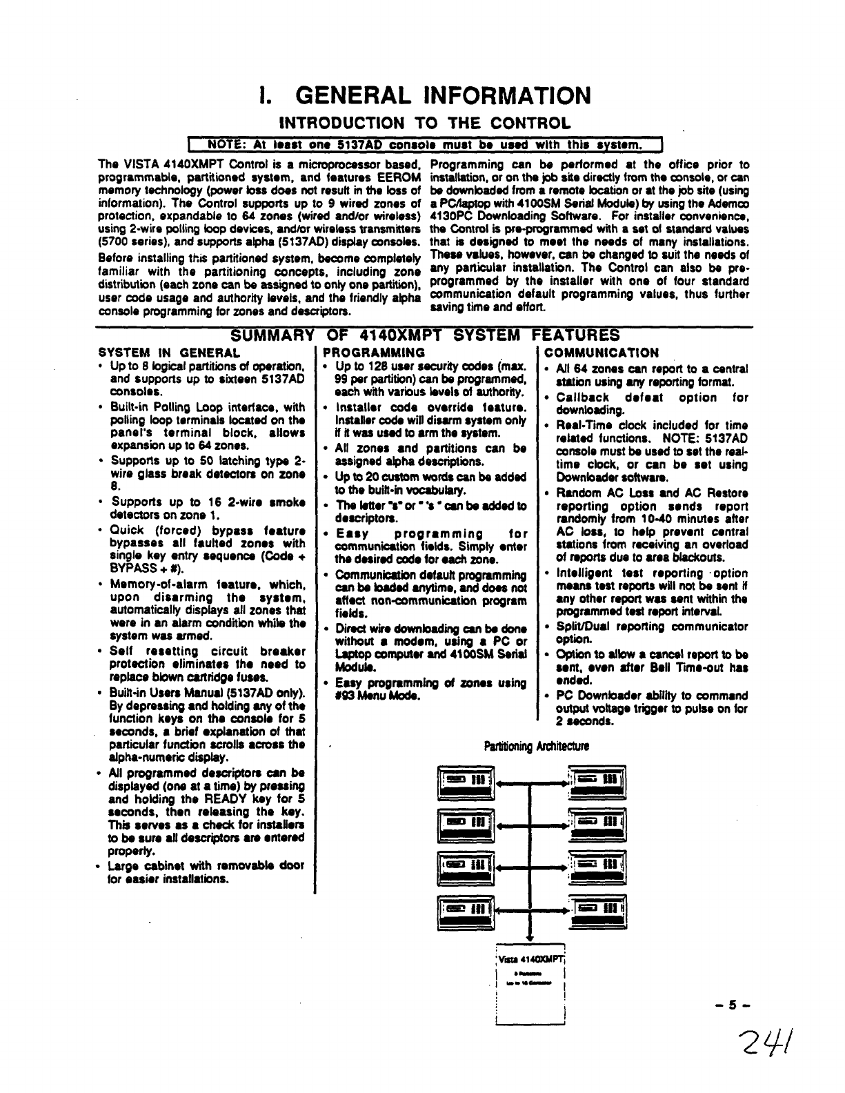
The VISTA 4140XMPT Oontrol is amicropmcasaor baaed,
programmable, partitioned syslom, and features EEROM
memory technology (power baa does not result mtha loss of
information). The Control supports up to 9wired zones of
protection, expandable to 64 zones (wired and/or wireless)
using 2-wirs polling bop devices, andlor wireless transmitters
(5700 serias), and supports alpha (5137AD) display oxwoias.
Before installing this partitioned system, become completely
familiar with the partitioning concepts, including zone
dWibution (each zons can be assigned to only one partition),
user code usage and authority levels, and the friendly alpha
console programming for zones and descriptors.
Programming can be performed at the office prior to
inatal~!on, or on the job site directly from the czmaole,or can
be downbadad from aremote locationor at the pb site (using
aPCAsptopwith41OOSMSerial Modub) by usingthe Ademco
4130PC Downloading Software. For installer oonvenienca,
the Control is Pm-programmed with asot of standsrd values
that ia designed to meet the needs of marry installations.
These values, however, can be changed to suit ths needs of
any particular installat”mn. The Control can also be pre-
programmed by the installer with one of four standard
communication default programming values, thus further
saving time and effort.
SYSTEM IN GENERAL
.
.
.
.
.
.
.
.
.
.
Up to 8bgical partitiin~of operation,
and supports up to sixteen 5137AD
consoles.
Built-in Polling Loop interface, with
polling loop terminals located on the
panel’s terminal block, allows
expans”mnup to 64 zones.
Supports up to 50 tatching type 2-
wire glass break detectors on zono
8.
Supports up to 16 2-wire smoke
detectors on zone 1.
Quick (forced) bypasa feature
bypaases all faulted zones with
singie key entry sequence (Oode +
BYPASS +#).
Memory-of -alarm feature. which,
upon disarming the system,
automatically displays all zones that
were in an alarm condnion WW the
system was armed.
Seif resatting circuit breaker
protection eliminates the need to
replace blown oartridge fuses.
Built-in Users Manual (5137AD onty).
By depressing ●nd holding any o~the
function keys on the oonsde for 5
seconds, ●brief ●xplanatbn of that
particular funotion aorolta ●crosa the
atpha-numaic d-y.
Afl programmed descriptors can be
displayed (one at atime) by pressing
and holding the READY key for 5
seconds, then releasing the key.
This sewes 8s ●check for instafiera
to be sure ●ftdescriptors are ●ntered
properly.
Large oabinet with removable door
for easier instafiations.
PROGRAMMING
.
●
✎
●
●
●
✎
✎
●
Up to 128 user sacurii oodes (max.
99 par partition)can be programmed,
each with various levels of authoriiy.
Installer code override faaturo.
Inetaliercoda will disarm system only
if itwas uaad to arm the system.
All zones and partitions can be
assigned atpha deacriptiins.
Up to 20 custom wordscan be addad
to the buitbirrvocabulary.
Thalatter%-or-’s ”oanbaaddadto
descriptors.
Easy programming for
oommunbation fields. Simply ●nter
the desired code for ●aoh zone.
Communicationdefauff programming
can babadad anytime, anddoasnot
affect non-communication program
fiefds.
Diracf wire downbading sari be done
without ●modem, using ●PC or
La@op computer and 4100SM Sariaf
Modufa.
Easy programming of zones using
#93 Menu Mcda.
COMMUNICATION
●
●
●
●
●
✎
●
✎
All 64 zones cart report to acantrai
station using any repofiing format.
Callback defeat option for
downloadhg.
Real-Time cfock included for time
related functions. NOTE: 5137AD
console must be used to set the reai-
time clock, or can be set using
Oownbader software.
Random AC Loss and AC Restore
reporting option eends report
randomty from 10-40 minutes after
AC Iosa, to hetp prevent central
stations from receiving an overload
of reports dua to ama blackouts.
Intelligent test reporting option
means teat reptma will not be sent if
arty other report was sent within the
programmed test report interval.
Sptit/Dual reporting communicator
option.
Optii to afbw ●oancal report to be
sent, ●von after Bell Time-out has
●nded.
PC Downbader abiiity to command
output vottage triiger to pulse on for
2seconds.
ParfmningArcftiirs
-5-
INTRODUCTION TO THE PARTITIONED SYSTEM
~hlo soctlon 1s Intondcd to ohm you, tho Installer, ●novarvlow of tho 4140XMPT partlt toning”
oonoepta. For spaclfk quastiotw on progrsntrnlng or using specific ●sp~cts of tho panel, plosae rofor
to the SYSTEM OPERATfON ●nd PROGRAMMING THE SYSTEM sections ‘of this manuai. +
The 4140XMPT represents the iateet in apace pmtadion mohndogy. Combining wired, wirefesaand wiling loop xonos intoone
powarfui wntrol. the 4140XMPT &●~ntroi communicator capable of suwrting atrue ~itionti environment. Apetitioned
onvironrnant is one whereby muftipio unmiatad users wish to be protected by ●saourity system yet aech user raquims the
operational freedom *have tho system behave as if it was theirs and theirs alone. Thb global definition impiks abt of things in
terms of the required fasturos of tho equ@manf you will install.Some basic foatums ●re fistedbelow
BASIC PARTfTIONING FEATURES
●
✎
●
✎
●
●
✎
✎
✎
✎
✎
✎
✎
Easy to use ●nd program as the simpieat alarm system.
irttagrityof aecurhy is not oompromiaed for arty usats of the system.
hhwant miiabiiii of the partitioned syatom is equal *astand alone aiarrn system it purchased Saparmoly.
Flexible numbar of consobs per partitiin (UP to 16 ●nyway you want to assignth.m!)
128 User Codes assigned virtualiy anyway you want them (99 msx per any partition, otherwise no restricfiirrs) Enough to
handle the largest commercial pbs.
Mzones em~yi~ wired, wireless or multiplex technobgy (install any mix for any type of amstruction chailengas!)
Appropriate sounds and massages to assigned ansoias only (Each system appears to be independent to users)
Abiiii to inhbit other mnsoias from using your paftition (Total saourffyin astrip mall environment)
=10” fundion provides ~ss to other partitions (fcieaifor executive access to factory for ●xampb)
Muftii bvois d●ut~ per partition (Allows key paopb in apartitiin to have campiate oontrol●nd iimit eystemtampering
by Othere)
Arty zone can be assigned to any particularpartitiin (Easy to instail, allows logical assignment by the daabr)
inteifigent parMionmns programming hap (Siipiifies the programming ●nd reduces errors)
Programmable 4-charac@r Partition name displayed when needed (No need to memorize numbers -name ●nd number ●re
shoivnfor you)
EXAMPLES OF PARTtTtONING
in surveying deaiers throughout the country, we have
iearnad of two giobai appiiitiona for partitioned control
panels. One is ●typical two family house (residential), the
other ●Factory/Offiie environment (commercial). Theee
broad dassifiodions can batter be understood by way of
exampias.
lWO FAMiLY HOUSE: YouWe just ●rrived at apb site to
quote ●security system. The ownor wants an alarm ●ystem
whkh ha oan use for his famify (living upstairs) AND ha afso
wants bprovide protection for the aaparata living quarters of
his mother (iiirtg downataira with aeparata ●nfranoe). The
owner obviously wants to keep oo$ts down yot provide
protadion and flexibility for hm mother iiving downstairs. You
oouidchooaatoirtstatlatradiil aiamrpanalto kaepmsts
down, but the system would be very limiting for ●ither the
mothor or tho upstairs family. To moot the fioxibWy
roquimmonts ●sdeeired, you oouid install two traditiinai
●iarm panels, but the cost might cause you to bse the
business. Now you can quote the 4140XMPT with
oonfiienod
FACTORY/OFFiCE: You arrive at ●smafi manufacturing
cmoem boiting to pmvido proteion throughout tMr offiis
as woil as ttiir factory. The very nature of the business ia
such that factory wrkara mrrre to writ at 730AM ●nd bava
at 4PM, whifa the offkes are open 830AM to 6WPM. Some
●xocutivas wan want to stay late at night or oomo Wto
wotk after 6WPM. irtetafiii two panais (one for the faotory,
one for the offiis) would oartainiy work at ●aret premium,
but think of ati the comptox.hy whan ownors triedtogain
~to the factory after hours...two aoceas oodes to
remember, aooidarttai false atarrtte. Even the reef frustration
ofrtot W~ngabie topmparfy Pr09ramth. twosyatornsto
●ifow ●asy aoceas from the faotory to offii or vice varsai
htstaffthe 4140XMPT, your programming pmbfams ●re over,
~g~~lof the buahess wiil approd$ta its fbxbffh’y
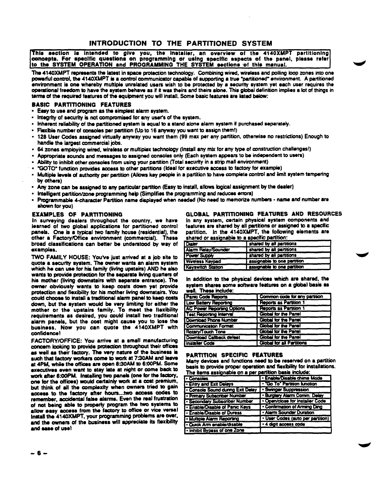
GLOBAL PARTtTiONING FEATURES AND RESOURCES
in any system, oartain physical system components ●nd
features ●re shard by ali pertitiins or assigned to aspeoifii
Dartition. in the 4140XMPT, tha foibwintt eiemertts are
.*- CMtinn l..*Muuhb *nnm9uailir
in ●ddition to the physioaf devioas whioh ●re shared, the
system shares some software features on ●global basis as
. . r
11
-.-—
mrv-i
.1 delaat 4I
I
,— .. . —. —..
PARTITION SPECIFIC FEATURES
Many davbes ●nd functions need to be reservad on apartitiin
basis to orovide cwoparmaration and flexibilityfor irtstatfations.
-6-
,,:. .
Il. ZONE CONFIGURATIONS
ZONE TYPE DEFINITIONS
The VISTA 4140XMPT System albws up to 64 zones of hard-wire, pollingbop andlor wirebss protection,distributedamong up
to 8partitions. Each zone must be assigned to azone type, which dafhes the way in which the system responds to faults in
that zone. In sdditkm, there are three keypad activated zones (PANIC keys, see note below) for each partition, apolli loop
supervisionzone, and four RF supmisory zones, tvmfor each 4280 or 4260-8 RF Receiver installed.
TYPE 1: ENTRYEXIT #1
Used for the primary entry/exit route (ox: front door, main
entrance).
TYPE 2: ENTRY/EXIT #2
Used for asecondary entry/exit route (ox: Garage door,
bading ti door, basement door), where more time mightbe
needed to get to and from the ~nsole.
TYPE 3: PERIMETER BURGLARY
Used for exterior doors and/or windows whmh require an
instant alarm when violated.
TYPE 4: INTERIOR BURGLARY (FOLLOWER)
Used for areas where an entry delay is required only If an
entry/exit delay zone is faulted first.
TYPE 5: DAY/NIGHT BURGLARY
USsd for zones WMI anain afoil-protecteddoor or window
(such as in astore), or to azone cevering ●sensitive area
such as a stock room, drug supply room, etc., Or othor
controlled access area where immediate notificafiin of an
entry is desired.
TYPE 6: 24 HOUR SILENT ALARM
This zone type is generafly assigned to ●zone mntainings
Hofd-up or Panic button that is designed to initiate ●nafarm
report to the Cantrat Station, but whti produces no visual
displays or alarm sounds (ox: banks, pwelry exwnters).
TYPE 7: 24 HOUR AUDIBLE
This type also assigned to azone containing ●Panic button,
but whch will initiate an audible alarm in sddiin to an afarm
report to the Central Station (ox bedside panic).
~PE 8: 24 HOUR AUXIUARY
This type assigned to azone containing abutton for use h
personal emergencies or to azone containing monitoring
dev”ms such ●swater sensors. temperature sensors, ●tc.
Designed to initiate●nalarm reportto the Central Station and
only provides Console ●larm sounds and alarm displays.
TYPE 9: SUPERVISED FIRE
Used for zones containing smoke detectors, heat datectors,
pull stations, MC. An open in this zone will initiate atrotJbb
eignsl. Ashort in this zone will initiate afire ●larm (pulsed
●xternal sounder and report to central station).
TYPE 10: INTERIOR BURGLARY (DELAY)
Thii type is similar to type 4, except that entry delay ~ms
whenever sensors in thii zone are violated, regardless of
whather or not an entry/exit delay zone was faulted first
NOTE FOR PANIC KEYS
Keypad panic zones share the same zone roeponsetype for
all 8partitions, but panics may be individually ●nebbd for
each partitikm.
IMPORTANT! FAULT ANNUNCIATION
Polling bop and RF faults (zones 88-91 &97) will report as
trouble cmditions only, ●nd ●ssuch, should be assigned
●ither zone type 00 if no annunciation is desired, or zono
type 05 if ●nnunciatbn as trouble mndiiion is desired. See
FAULT ANNUNCfATION notes in POLLING LOOP and
WIRELESS EXPANSfON sectionsfor more information.
BASIC 9HARD-WIRED ZONES
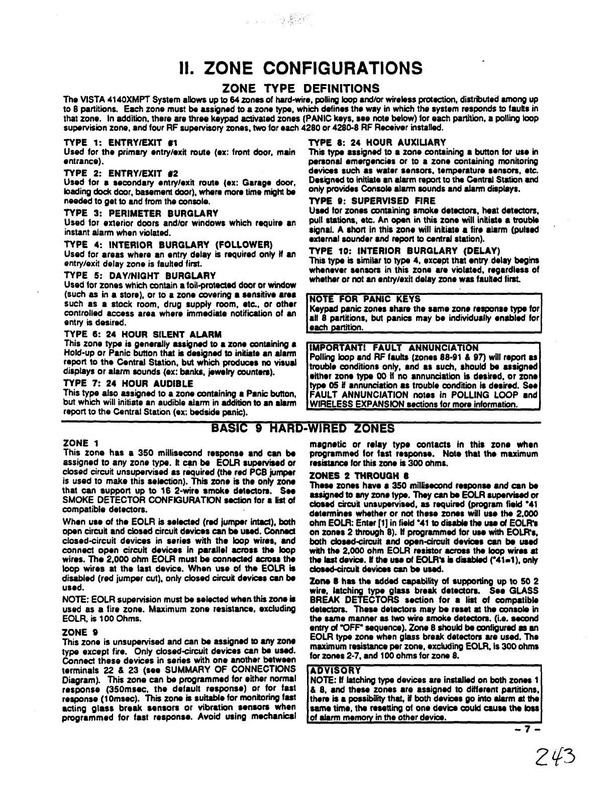
ZONE 1
This zone has a 350 rnillisacsnd response ●nd can ba
assigned to any zone type. ft ~be EOLR supervised or
cbsed circuit unsupervised as required (the red PCB jumper
is used to make this sabction). This zone is the only zone
that can support up to 16 2-wire smoke detectors. See
SMOKE DETECTOR CONFtGURATfON section for ●fistof
compatible detectors.
When use of the EOLR is sebcted (red jumper intact), both
open circuit and dosed circuit devices can be used. Connect
closed-circuit devices in series with the bop wires, and
connect open circuit devices in paraflel across the bop
wires. The 2,000 ohm EOLR must be connected across the
loop wires at the last device. When use of the EOLR is
disiled (red jumper cut), only closed circuit devices can be
NOTE: EOLR supervision must be selected whenthii zone is
used as a fire zone. Maximum zona resistance, excluding
EOLR, is 100 Ohms.
ZONE 9
This zone is unsupawised and can be assigned to any zone
type except fire. Only dosed-circuit devices can be usad.
Connect these devices in series with one another between
terminals 22 &23 (see SUMMARY OF CONNECTIONS
Diagram). This zone can be programmed for either normal
responee (350msec, the default responso) or for fast
response (1Omsec). This zone is suitabfe for monitoringfast
●cting glass break sensors or vibration sensors when
programmed for fast response. Avoid using mechanical
magnotie or rday type contacts in this zone when
programmed for fast response. Not. that tho maximum
resistancefor thb zone is 300 ohms.
ZONES 2THROUGH 8
These zones have a 350 milfis~nd roapoma and can be
assignedtoenyzonetyps. Ttteycenba EOLRauparviaedor
dosed circuii unsupervised, as required (program field “41
deterrninos whether or not these zones will use fhe 2,000
ohm EOLR Enter [1] in fiafd ●41 to d- the use of EOLR’S
on zones 2through 8). ff programmed for use with EOLR’S,
both closed-circuit and open-circuit devices can be used
with the 2,000 ohm EOLR resistor across the bop wkas ●t
the fastdevice. ffthe use of EOfR’e is diaabfed ~41-1), only
clod-oircutt devices can be used.
zOttS 8has the SddSd C8pSbiky Of SUppOdng Up tO 602
wire, latching type glass break detectors. See GLASS
BREAK DETECTORS section for ●list of compatible
detectors. These detectors may be reset at the oonaob in
the same manner se two wire smoke detectors. (i.e. asoond
entry of %)FP sequence). zone 8shouldbe oonfiiurad es m
EOLR type zone when glass break detectors are used. The
maximum resistanceper zone, excludingEOLR, is 300 ohms
for zones 2-7, and 100 ohms for zone 8.
G
NOTE: ff fatting type devices are insfafbd on both zones 1
&8, and these zones ●re ●ssigned to dtierent partitions,
there IS ●POSSIMY ths4 dboth dewcss go mto afarm at the
-7-
2$3
2-WIRE POLLING
(Zones 10
GENERAL lNFORMATtON
Tho 4140XMPT provides abuift-in 2. wire polling toop
intatiaoa whbh ●llows the number of zones to be ●tpmdad
from the basic 9zones to up to 64 zones using various
RPMs, and the 4280 RF Raoaiver. Sse babw for ●tist of
armpstfbta sensors.
Thapoftii bopprmMaa powartoaensorsand aervasasa
communbatbn path between the panel and sensors. Eaoh
sensor must be aasignod ●unqus address tO number (frmm
10-64) bafora bdmg oonnectod to the polling hop. Most
sensors have DIP switches for thb purpose. Sea the DIP
SWITCH SIVfllNG TABLE FOR POLLING LOOP DEVICES
for information on how to assign lD numbers using DIP
awhchas. Care must be taken to assign unqua tD numbers
to S* sensor ‘mordor to atbw tho panel to supervise ●nd
provide unquo oonaole status indbatiins for individual
sensors.
connect thcsa sensors ~terminate 24 &25. Sensorsan
be=’ :?adto ●singlerun,or groups of sensors may be
eon 2aaparat. wire nJnSwithout affecting the p8n0rS
abiin Jpewiso individual swtsora. Follow the wiring
tiruc’m. ,vaprovided with irtdiiual aansOra (4180WH Wing
diagram is provided at the ●nd of this manual). Be sure to
oberva sensor polaritywhen wiring. Ilta maximum albwabfs
wire run tength batwmn tho panel and tho last sensor on ●
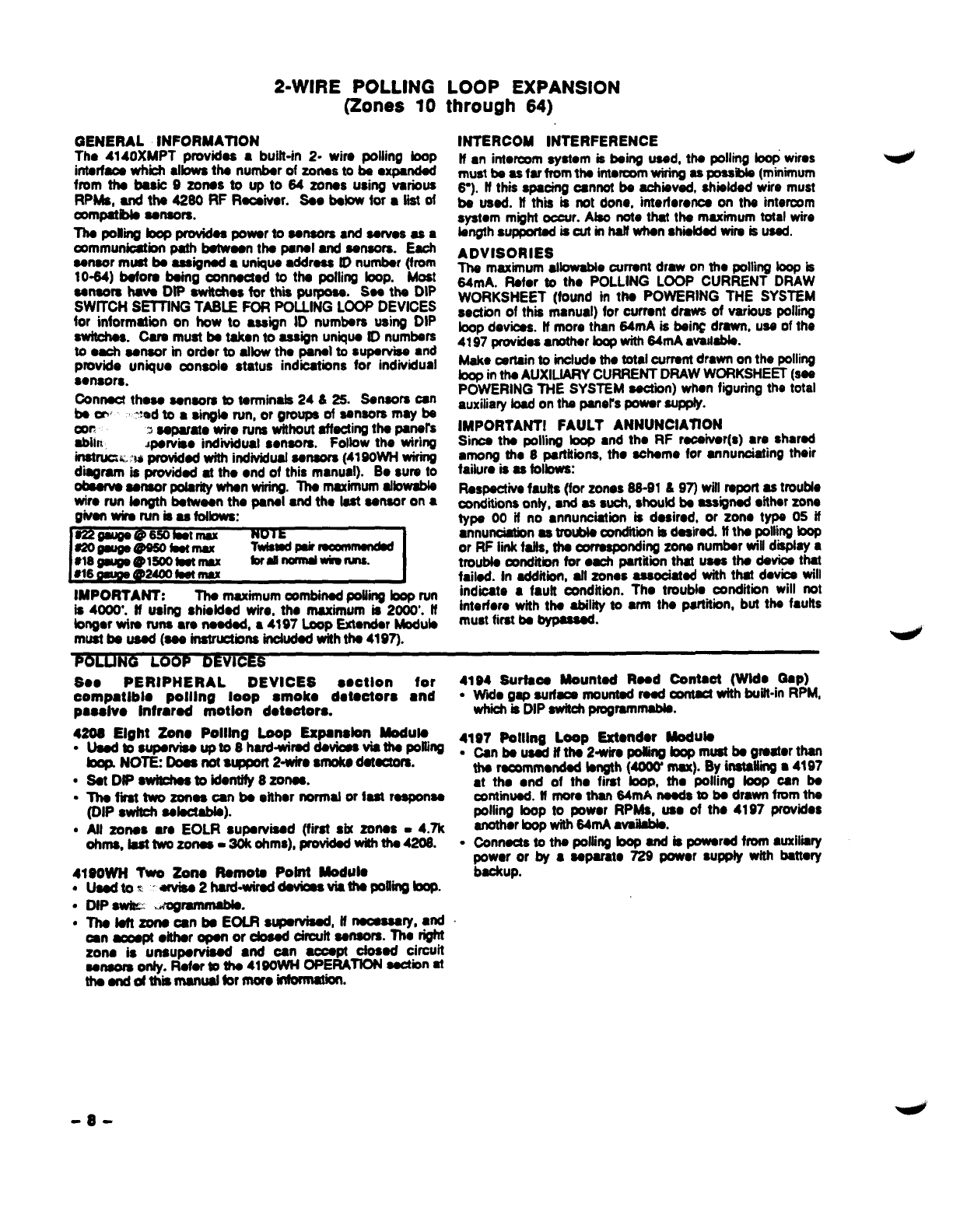
givanwiraruniaasfdbwa:
s22gau@a@650bat mall NOlt
s20gsugs@s60kaImax Twlsmdmraammsndsd
●4gmlga@mootastmsx tordnorrrdwbllms.
816 9su9s@2400hetmax
IMPORTANT: The maximum oombinad polling bop run
is 4000’. t! using shielded wire, tho maximum is 2000’. If
bngar wire runs w. neadad, a 4197 Loop Extondar Module
must be used (sea inatndorts indudod with the 4197).
LOOP EXPANSION
through 64)
INTERCOM INTERFERENCE
If an into~m aystom is being used, the pollrng Iwrp wires
must bs as far from the imsrcomwiring as poasibb (miniium
6-). tf this spacing cannot be achieved, shielded wire must
be used. If thii is not done, irtterforonca on the intermm
system might occur. Abo note that the maximum total wire
bngth supported is cut in half when shmldadwire is used.
ADVISORIES
The maximum allowable ourrant draw on tho polling bop is
64mA. Ftafor to tho POLLING LOOP CURRENT DRAW
WORKSHEET (found in the POWERING THE SYSTEM
section of this manual) for currant draws of various polling
bop devices. If more than 64mA is being drawn, use of the
4197 provides●mther toopwith 64mA avmtabb.
Mah cartsin to indurh tho total currant drawn on the polling
bop inthe AUXILfARY CURRENT DRAW WORKSHEET (sea
POWERING THE SYSTEM section) when fiiuring the total
auxiliary bad on the pOnOrSpower supply.
IMPORTANT! FAULT ANNUNCIATtON
Since the polling bop ●nd tho RF racaivar(s) ●re shared
among the 8partitions, the scheme for annunciating their
failure is 6s follows:
Respective faults (for zones 86-916 97) will report 86 trouble
oonditiins only, and as such, should be assigned either zone
type 00 if no ●nnundatbn is desired, or zone type 05 if
●nnunciationas tro- amdhion is desired. tf the polling boP
or RF tinkfaifs, the corresponding zone number will display a
trouble oondiibn for ●ach panitibrt thatuses the devioa that
failed. In addition, aft zones asaooiatad with that dsvbs will
indicate ●fautt condition. The troubia condition will not
interfere with theabilityto●rm thepartitkm, but thefaults
must first be bypauad.
POLUNG LOOP DEVICES
See PERIPHERAL DEVICES ●ectlon for 4184 Surtaoa Mounted Read Contaot (Wide Gap)
compatlblo polllng loop ●rook. detootoro ●nd ●W@e gap aurfaoa mounted raad oontacf with buift-in RPM,
psodvo Infrared motton dotootors. which kDIP switchprogrammabb.
4208 Eight Zono Polllng Loop Eapattdon Moduta 4197 Polllna LOOD ExWtdor Module
sUudtosupewise upto8hard+vkad daviasviatha PoltiIIE .
@p. NOTE Doos not st@port 2-wke ●rooks dat@tofs.
●Sat DtPawkhea toidontify 8zonea.
●The fm tvm zones can be either normal or fast response
(DIP Swttdt aalaotabb).
●Afl zones ue EOLR supmised (fkst six zones =4.7k
ohms, battwmzonas =20kohms), provWedwith tha4208. s
4190WH Two Zone Rarnota Pobtt Moduts
●Uaedtot Wiaa2hard-wirad daviouviatha pdtiibop.
●DtP Swk” ?Jmgremmabk
●Thaleft zoneoanba EOLR suparviaad, tfnaossssrY, and
oan aowpt dther ~or ctoaad oirouft sensors. The right
zone is unsupervised ●nd oan aooept dosed circuit
sensors only. Rofor @the 41wWN OPERATION sactbn at
thaanddthiirnanuat formoro~.
Can be u~ if the-2-wira po8ing bop must be greater than
the raootnmwtded bngth (40W mu). By installing ●4197
●tthe ●nd of the first loom tha @iin9 fooP -n bS
cmtinuad. If more than 84mA naads mbe drawn from the
polling bop to power RPMs, use of the 4197 provides
anothorbop with 64ntA avaifabb.
connects to the polfirtgbop and is powered fmm wxiiiiry
power or by ●separate 729 power suppfy with battery
backup.
-a-
WIRELESS EXPANSION
(Zones 1-63)
4280/4280-8 RF RECEIVER .
The system supports up to 83 wimbsa tmnamitters (5700
series), plus a 5727 wiretass keypad. To ●xpand tho syetom
using wireless, one or two 4280 RF Raceiiora (or 4280-8 if
only8wirelesszones are used)mustbe connected to the
polling loop. The 4280 receives status ●nd slarm signals
from wireless transmitters (@345MHz USA; 315MHz
Canada) within anominal range of 200 feat, and relays this
informationto the controlvia the polling hop. Two 4280s can
be used to provide ●ither agreater ●rea of coverage, or
provide redundant protection.
IMPORTANT Note that if using two RF Receivers, one of
them must be powered from auxifiiry power.
For more information regarding the 4280 instailatkm, refer to
the installation instructionsprovided with the 4280.
E: Unless stated otherwise, references 10 the 4280
Receiver represent the 4280 andlor4280-8 Receivers.
PROGRAMMING NOTE
All RF zones must be designated as such in their raspacfivo
program fields (1”18-1“25). Any zone from 1-83 can be
designated ●san RF zone. To enable ●zone as wireless,
simply ●ntar ●‘1” in the bcation for that zone, or us. the #93
ZONE PROGRAMMING method. Be oaroful when
dealgnathtg RF zonee. If you want ●zone to be ●ithor
hard-wired or on tho pelting loop, but ~rttaity ●nabb &as
RF, the system will ignore that zone. RF ●nabfa overrides
wire!
ff using a4280-8, onfy up to 8zones oan be ●nabbd as RF
zorws. ff more than 6zones ●re ●nabled, the meseaga
‘SET-UP ERROW will be diaphyad.
SUPERVISION
Each transmitter (except 5701 and 5727) is auparvised by ●
check-in $ignal that is cent to the receiver at 70-90 mhruto
intewals, ff at least one Check-in bnot received from ●
transmitter within ●programmed intervat (field 1°31), the
console will dmpiay the transmitter number ●nd WHECW will
be displayed.
Each transmitter (including 5701 and 5727) is ●lso
supervised for low battery conditbns, and wffttransmit ●bw
battwy signal to the 4280 when the battery has
approximately 30 days of life ramaining. The consofe wilf
display the tmnsmittor number and %0 BAr.
NOTE: After replacing abw or dead battery, activate the
transmitter ●nd ●nter the security c@de +OFF to dear ita
memory of the low Batter signal.
The 4280 itself is afao auperviaed three waya:
1.
2.
3.
ff the cover of the 4280 is removed, ●TROUBLE wift be
disptayed for zones 89 or 91 (if type 05 is ●ssigned in
field 1“09).
ff theconnection is broken between the 4280 and the
control panal, aTROUBLE wifl be diapfayad for zones 89
or 91 (i type 05 is assigned in fiotd 1“09). In addtin, aff
zones associated with the RF device will report atroubb
conditiin.
If, within ●progmmmad interval of time, the 4280 does not
hear trom any of its tmnsm”~ra, ●TROUBLE will appear
for zones 88 or 90 (if type 05 is assigned in fwld 1“09).
HOUSE fDENTfFfCATfON
The 4280 responds onty to transm”hterawith the same house
ID (DIP awitoh programmable from 01-31). Thb pravants
system intorfomnce from transmfttors in other newby
aystema. To mdce sure you do not cfwose aHouaa ID that is
in US* nearby, put the system in the Sniffer Mode, which b
described fater in thmsection.
TRANSMITTER lDENTIFICATfON
Each transmitter haa its own unique tD number (Zone #),
whii is DfP switch programmabb in ●ach unit. Whenever ●
tmnamisaiin takes ptaca, ●ither for an afarm, fautt, check-in
or tow battery, ths ID number is sent ●bng with the massage
to the 4280 which, in turn, relays this information to the
control panel, whii displays the condition●nd zone number
on the console. See the DfP SWITCH TABLES FOR
WfRELESS DEVICES at the end of this mmuaf, for individual
transmitter settings.
SNIFFER MODE FOR HOUSE ID (ado +[#1 +[2])
To check for house fDa being used in nearby systems, set
the DfP switches in the 4280 for ●House ID of ’00- (all
switohesup), then enter your “installerCode=+ [#]+ [2]. The
4280 will now “sniff=out any House IDs in the ●rea and
diapfay them. Keeping the 4280 in this mode for about 2
hourswill give agood indicationof the house fDa beiig used.
To ●xit the Sniffer Mode, simply key your inataUer code +
OtXWfifi:t your house ID to one not displayed in the
.
IMPORTANT: Since Sniffer Mode affectively diaabba
mint raceotirw Sniffer Moda oannot be ●merad Wlb anv
1*rtitionis’armid. .
J
CHECKfNG TRANSMflTER HOUSE IDs
(Oode ●[q ●p])
To check that ●ti transmitters have bean set for the propar
houaalD, aetfha4280 totheproparhouaa lDandontartha
Inatalbr codo +[#] +[3]. Aft tranemittere that have been
●tablad for tho parthii in whfchthe test was irdfbted wifl be
diapfayed. *aach tranamhtor checks in (up to 2hours), Its
ID number wilt disappear. Afaster way to do this is to fault
●ach transmffter, wh@ cauaaa ●tmnsmiasion to be sent to
tho 4280. When afl transmlttera have checked in, there
shouid be no tD numbara displayed.
NOTE: Repeat this procedure for ●ach partftbn that uses RF
tranamlttem.
BUILT4N “QO/NO GO- TEST MODE (Patontod)
This mode helps determine tho best bcatbn for ●ach
transmitter and is activated by putting the control panel in
the TEST mode ●nd removing tho 4280’s covor. The
racefvera aanaitii is reduced by haft. Once transmitters
●re pfaced imtheir dasired locations ●nd the●pproximate
length of who to be run to sensors is oonnocted to the
transmitter’s screw terminab, opan circuit ●ach transmitter.
flonotcunducfthi atsafwithyourhan d~atoimdthe
transmitter.
ff ●sh’tgb 4280 is used, the conaob wilt beep three times to
indii signal reception. #two 4280s are uaad, theconaob
wifibeep once if the fti 4280 received the signal,twice ffthe
second 4280 received the signaf ●nd three times if both
raceivara heard the signal (which is daaimbb for redundant
confiiumtions).
tt the oonsota doos not beep, reorient or movo the
transmitterto another boatiin. Usuafly ●few inches in ●ither
diraotionis atl that krequired.
To exft thii mode, replace the 4280’s cover, then ●mer the
instafler coda and proaa OFF. Not. that the Receiver’s
aenaftii is fully restored when the cow is rafkad.
-9-
ZV5
IMPORTANT BA17ERY NOTICE
Tho VISTA wimbss tranarnittws are designed to provkfe bng
battery life under normal operating conditions. Longevity of
batteries may be ●smuch ●s4-7 years depending on the
●vironmont, usage, ●nd the specific WKSIOSSdevice bshg
used. Extomal factors such as humidity, high or low
tampamturas, as well as large swings in temperature may all
raduco theactual battery iii. in aghran installation. The
VISTA wirobss system can identify atrue low battery
situation, thus allowing the deabr or user of the system time
to arrange ●change of battery ●nd maintain protection for
that given point within the system.
WIRELESS ZONE TYPES
Each RF zone can be programmed to respond as any zone
type such as ENTRY/EXtT, INTERIOR, PERIMETER, etc.
(sss the ZONE lWES section for ●cmrtplete axplanatbn of
each zone type). Desired aiamt responses areas Ioibws
46mrough._
46 dwougrr55”(57a
24 HourParic 46ttsaq
(sdentor●udible) 620r63’
DsynwghtBur@ary 1tr~h.,
2Ho Allrlllmru ~thnutnh4+
:OT:S
●
✎✎ ✍ ✍✍✍✍✍ ✌mr.,. -,. -I
.f40tstht ZOIWS143 can be USSd,but have the fdkwi~
fimiidons: Tmnsmittsmsatforzones46-55 Mtransmit~
●my 12 secondswtrii uw zoneis faulted.Transmitterssatfor
Zolws 56-63 winwalwmitOrra awry 3ssoo* Whii faulted.
Theso two ranges ot zone numbets could advarsstydtsct
~smhter banmylife.Transmitterssatform ID of 32 ~gh
47 willhew ●3minute fockut batwsen transmissions.Use
this test mngo of zone ID numbers for sensors protecting
~-doomwwif ltibc-emt$at mytife.
‘“ ;mnsm!tW IDs 46 though 55 havehigkt si~ priw@.
W* mnsrmtwlDs62md63usunsupsnJisadm@vrramovatot
be 5701Orf
premises-signal priorityisfowrhsnthet offire,
buthigherthanburglary.
ADVISORIES
1.
2.
3.
4.
5.
Do not place tmnsmtttors on or near metal objects. This
wifi dsoraaea rang. tir bbck tmnsmissiins.
Ptaca the 4280 in ●high, centrafiy bcatad ama for boat
raoeption. Do not ptaca racsivar on or near metal objects.
Tho 4280 roceivor must be at least 10 feat fmm tho
Control panel or any remoto censolos to ●void
intedoronce from their micaoprccassor.
When connecting adoor/window contact to ●57t 1,
5711 WM, or 5715 transmitter, avoid ●wire bngfh of 20-24
inches. Thii particular length dacraasss range. Ashoner
or bngor bngth has no effect.
UL NOTE: For UL Housohold Burglary
Installations, wired ioops connocted to these
dwicos cannot ●xceed 3foot.
tfduai 4280s or 42808s am used:
A. Both must be at iaast 10 loot from ●ach other, as wsli
as from the Controi panel and remote oonsofas.
B. One of the 4280s or 4260-8s must be powered from
Aux. power so as not to ●xcasd 64 mA poiiing foop
current rating.
C. The house iDs must be the same.
D. Using two Ftsceivers doss not incmaso the number of
transmitters the system can support (63 transmitters,
pius awirebss keypad).
6.
.
Refer to the maximum polling loop wirs runs described in
the POLLING LOOP sktio; when connecting 4280s to
the polling hop.
lMPORTA~ The maximum combined polling tip run
is 4000’. Husing shielded wire, the maximum is 2000.
FAULT ANNUNCIATION
Since the polling bop and the RF receiver(s) are shared
●mong the 8partitions, the scheme for annunciating their
failure is as folbws:
Respective fautrrl(for zones 88-91 &97) wiii report as trouble
conditions only, and as such, should be assigned either zone
type 00 if no annunciation is desired, or zone type 05 if
annunciation as trouble condition is desired. if the polling loop
or RF iink fails, the corresponding zone number will display a
troubte condiikrn for aach partition that uses the device that
faiisd. in addition, ●ii zones associated with that device wiil
indicate afault condition. The trouble condition wiil not
interfere with the abifii to arm the partition, but the faults
must first be bypassed.
WIRELESS DEViCES
S.. tho Peripheral DEViCES section for
compatible wireieas smoke detectors ●nd
passive infrared motion doteotors.
5701 Panic Transmitter
.Progmmmabta for ●ither silent or ●udbia 24 hour alarm
(can be DIP switd programmed forzones 62 or 63).
5711 Sllmline Dcor/Window Transmitter
●Can be used with any dosed arcuit sensor. NOTE: Can be
used on any zone 1-63 but, it programmed for zones 32-
47, there wili be a 3 minute iock-out between
transmissions.
5711 WM Door/Window Transmitter w/Reed Switch
●Siimiine doortwindow tmnsmitter with buitt-in reed switch
(magnet inciuded). Can be used with any closed circuit
ssnsor. NOTE: Can be used on any zone 1-63 but, if
progmmmad for zmes 32-47, there will be ●3minute bck-
out between transmissions.
571 5WH Univorsai Transmitter
.DiP switch saiectabb for fast response, open or closed
circuit sensor usage, and has ●tamper protected cover.
Use in appiiiions where open circuit heat detectors ●re
needed or wham fast rasponae devices ●re needed.
NOTE: Can be used on any zone 1-63 but, if programmed
for zones 32-47. there will be ●3minute tock.out between
transmissions.
5727 Wireiose Keypad
●Wkeiess keypad that can be used to turn the burgiary
protection on and off, and features the same buitt-in panic
functions as wired consobs for either sibnf or audible 24
hour ●larm. An LED indication iiihts each time a key is
pressed to verify transmission (LED boated in the ~]
READY key).
●The keypad is identified as zone Wr when ittransmits low
battery messages. Ths keypad panics ●re idontifbd as
%~!g~ [#l, ‘W for [#]+ [3], and W5- for ~]+ [1] if
.
S716 Door/Window Transmitter
●Can be used with anY open or closed circuit sensor (DiP
switch selectable), and features abuilt-in read switch.
NOTE Can be used on any zone 1-63 but, if progmmmed
for zones 3247, thers wilt be a 3 minute Iook+ut between
tmnsmissions.
-1o-
Ill. PERIPHERAL DEVICES
REMOTE CONSOLES
— ———
GENERAL
The 4140XMPT supplies up to 750 ti of auxitiarypower tir
rmrroteconsoles, pelting bop devices andbr other auxiliary
devices such as motion detectors or 4-wiro smoko
detectors’. The 4140XMPT supports, independent of
●uxiliary powor considerations, up to 16 5137AD
addressable romoto consoles. Up to 8cortsobs can be
powered from the ●uxitiary powor output provided that the
total current drawn from this output does not axoeed 750 mA.
You must keep this in mind wtmn adding rsmoto consolesso
you dent ovordraw current from tho parwl. This would resuft
in ●battwy which doos not charge properly or possibly ●
tripped auxiliary solid state circuii brwkor.
It the auxiliary load is determined to be greater than 750 mA,
then additional consolos can be powered from aseparate
power supply. The diagram on the next page shows how to
make connections to the s~ate power supply.
“44w smokedstscws csnnotbeusedbULUsmd@iation$.
5137AD ADDRESSABLE ALPHA LCD CONSOLE
●Equipped with aprogrammtile 2-line, 32.cftaracter (16
characters par line), backlit alphanumeric LCD for
complete zone identificat’mn in English language (if
descriptors are programmed). Keys are also backfii.
●An alarm sounder is buitt in, eliminating the need for ●
separate indoor sounder.
●DIP switch selectable tD number, which aflowe cortsob to
display unique, partitiin spscifii messages.
●90mA current drew.
PROGRAMMING THE CONSOLES
Consobs must be programmed for type, parUtbn number and
console ●oundor suppression options. Refer to the
PROGRAMMING THE SYSTEM ●sction (DEVICE
PROGRAMMING) for instructions.
WIRING CONSOLES
Consoles may be wired to asingle wire run or indtiual
consoles may be connected to separate wire rune. The
maximum wire run bngth from the panel to aconaotewhich is
homerun back to the panel must not exceed:
s22gaugs@450fset msxknum NOTE:Tlwtwlerhofas*rwm
szogsugs@700 faetmsximum ~rnllstlmoxcosdm
018gauge@I100bet maximum _~~~~~~w ~~
#169wJ90@17=fsot~ #nldOdmke
ff more than one consob is wired to ●run, then-the above
maximum bngths must be diviied by the number of czmsobs
on the run (i... the maximum bngth wwid be 225 feet if twu
consobs are wired on aS22 gauge run).
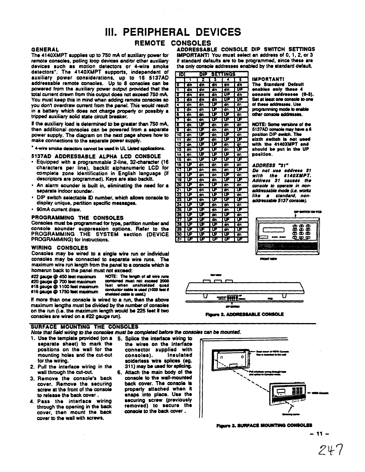
ADDRESSABLE CONSOLE DIP SWfTCH SETTtNGS
IMPORTANT! You must eelect ●n●ddress of O, 1,2, or 3
if standard defaults era to be programmed, since these ara
the only consob addresses enabbd by the standard defautL
IMPORTANTI
Tho Stsndar4 Defeult
ensbtas only these 4
oensolo ●ddrosees (0.$).
Satattosstonscuuob mons
of rhsse-ss0s. use
-tDsrlsbb
%%%%% addresses,
NoT’Esoms Wrsionsofdis
5137ADcutdsmsyhswa6
posirionDIP switi. Ths
●lxth swltoh Is not wad
with tho 4140XMPT ●nd
shouldbe put in tho UP
posltlon.
ADDRESS W“
DO not U80 wddroas 81
with the 4140XNP~.
Address 31 causes the
conwkJ mOpsrers in mn-
a@rsssaMe mods (Le. -
like 8standard, non-
ad&ossaMs 5M7cmsob).
~
Note that iii wiring to the wnsobss must be wrr@etodbefore tfre corrsoks can be mounted.
1. Use the tamplati provided (on ●5.
2.
3.
4.
separate sheet) to mark the
positions on the wall for the
mounting bobs ●nd the cut-out
for the wiring. ”
Pull the interface wiring in the
watl through the cut-out.
Removo the console’s back
cover. Remove the securing
screw at the front of tha wnsob
to release the back cam.
Pass the interface wiring
through the opening in the back
6.
Spfii the intarfacs wiring to
the wires on the interface
connector supplied with
consoles). Insulated
aotdertess wire sptbes (eg.
311)maybeusodforsPlbin9.
Attach Wmain body of tho
consote to the wstl-mounted
back cover. TIM console is
properly ●
ttached when it ““.-
snaps into place. Uso tho
securing screw (previously
removed) to secure the LB
~,<
. . . “wl!iw---
wve~, than mount the back consota tottre McK cover. II /
cover to the watl with screws. --
Pbtwea. sunPAcs MOWmJO~
11 -
2+7
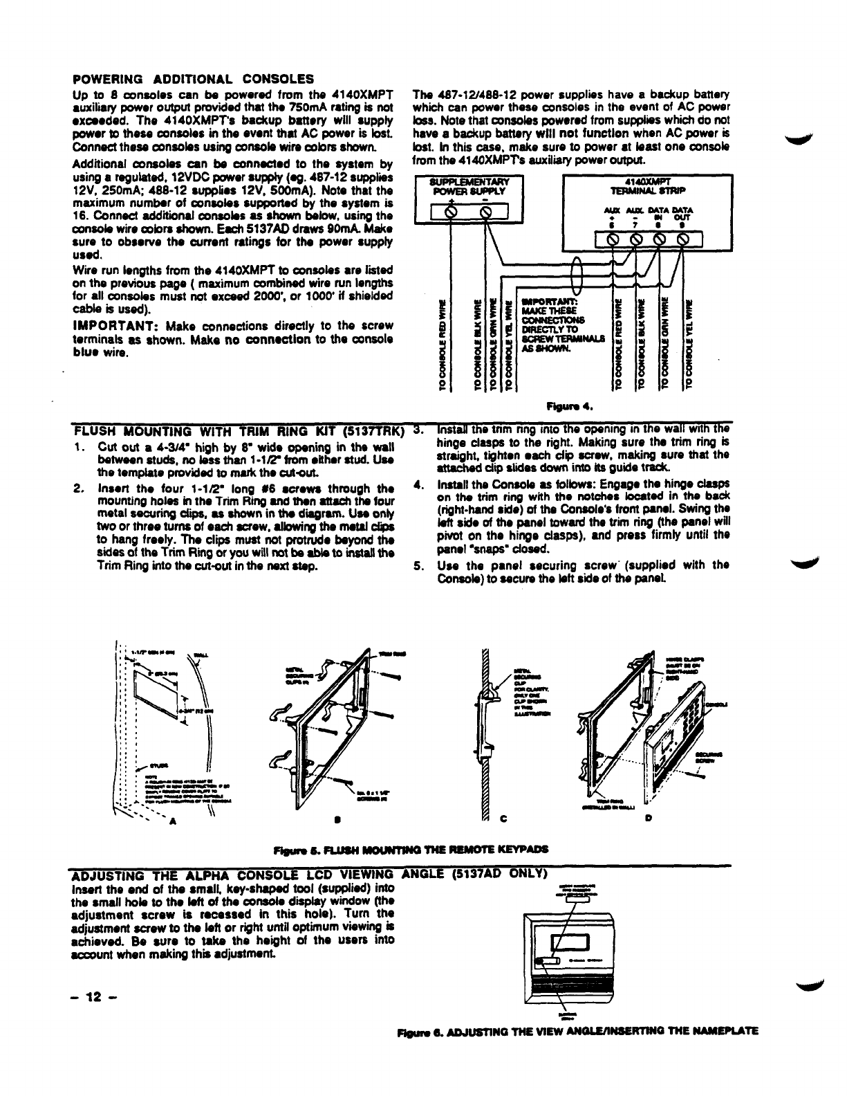
POWERING ADDITtONAL CONSOLES
Up to 8consoles can be powered from ths 4140XMPT
auxiliary powor output provided that the 750mA rating is not
●xceoded. The 4140XMPT’S bSdUlp battery Wiit SUpp~
powor to these consoles in the event that AC power is bst.
Connect these conaobs using consob wire cobm shown.
Additional consoles can be connachd to the system by
using aregulated, 12VDC power supply (eg. 487-12 suppliis
12V, 250mA; 488-12 supplies 12V, 500mA). Nets that the
maximum number of consoles supported by the system is
16.Connect additional consoles as shown below, using the
consob wire mbra shown. Each 5137AD drawa 90rrtA Make
~:d to obsorve the ourrent rstings for the power supply
.
Wire run lengths from the 4140XMPT to consotas are lied
on the previous page (maximum combined wire run lengths
for all consoles must mOXCSed2000’, or 1000’ifshielded
cable is used).
IMPORTANT: Make connections directly to the screw
terminals as shown. Make no oottnoctlon to the COnSOb
bluo wire.
Ths 467-12/488-12 power supplies have abackup battery
which can power these cmsoles in the event of AC power
toes. Note that oxwobs powered from supphss which do net
have abackup battery will not function when AC power is
bat. In this ease, make sure to power at bast one amok
from the 4140XMPT’s auxiliarypower output.
IauPPtEMENIARY1[4140XMPT
~SuwLr lERMINAlSlmP I
-4.
FLUSH MOUNTING WITH TRIM RING KtT (5137TRK) 3. install the tnm nng mto the opanmg mthe wall with the
1. Cut out a4-3/4- high by 8- wide opening in the wall
between studs, no bss than 1-lfi from dther stud. Use
the template provided to mark the cutaut.
2. Insert the four 1-1~- long #6 aorows through the 4.
mounting holes in the Trim Wrg and then attachthe four
metal securing dips, as shown in the d~ram. Use only
two or three turns of eaoh screw, allowingthe metal dips
to hang freely. ThtI clips must not protrudo beyond the
sides of the Trim Rktg or you will rnt ba abb to installthe
Trim Rhg into the cut-out in the next step. 5.
L
!!, -
. , . .— ----
4,
. , ~~-_~m ●-
,, —.——
.:!. A.Ov*-.. —
-. ..
-.. -. \\
A
hinge clasps to the right. Making sure the trim ring is
straight, tighten ●ach dip screw, making sure thm the
atmchad dlp slides down into its guide track.
Install the Oonsob as follows: Engage the hinge deeps
on the trim ring with the notches located in the back
(right-hand side) of the Oonaole’s front panel. Swing the
bft side of the panel toward the trim ring (the panel will
phmt on the hinge clasps), and press firmly until the
panel “snaps”dosed.
Use the panel securing screw” (supplied with the
Oonsob) to secure the bft side of the panel
mm k’
—-w D
ADJUSTING THE AL HA CONSO~
Insert the end of the smalk key-shaped tool (supplied) into =_—
the small hob to the bft of the console display window (the
adjustment screw is rooassod in this hole). Turn the
adjustment screw to the left or right until optimum viewing is
achieved. Be sure to take the height of the users into
account when making thm ●djustment.
EXTERNAL SOUNDERS
RELAY OUTPUT
Tho4140XMPT~ mwotbddsyou@@~bw@d
to powsr ●rtsrnsl slsrm soundors. Oonnoctionssrs mark to
tormirmb 4@ositiW output) ●nd s(nogstivo rsturn). Soo
SUMMARY OF CONNECTDNS Disgrmr.
NON-UL INSTALLATIONS
For non-UL installations, ths totsl ourront drawn from thm
output csnnot sxoood 2.8 reps. Abdtsry must bs instaflad
si~ this OUrrontis Stt@iSd by tk httwy. UP to *702
tirommk ti, ti#hmb. wbti719skons -
bUs@d,Wirsdin psrsflsl.
UL INSTALLATIONS
For UL hmtslbtbns, tho totsl currsrttdrswn fmm this output
●nd tho suxilii powsr output combinod,osnnot ●xcsd 760
mA For ●xample, if two BRK PA400 piszo ●lsrm soundsrs
widrn@lmX@4mA~,tin~ti~ti-
24 mA) is ●vailsbls for ●uxilimypoworoutputUSS.
lMPORTANfi Gohg bsyond tha ●bovs rncmionsd tim”hs
will owrfosd thopower suppfy or may possiblytrip ttw boll
output thornd tilt bmskor.
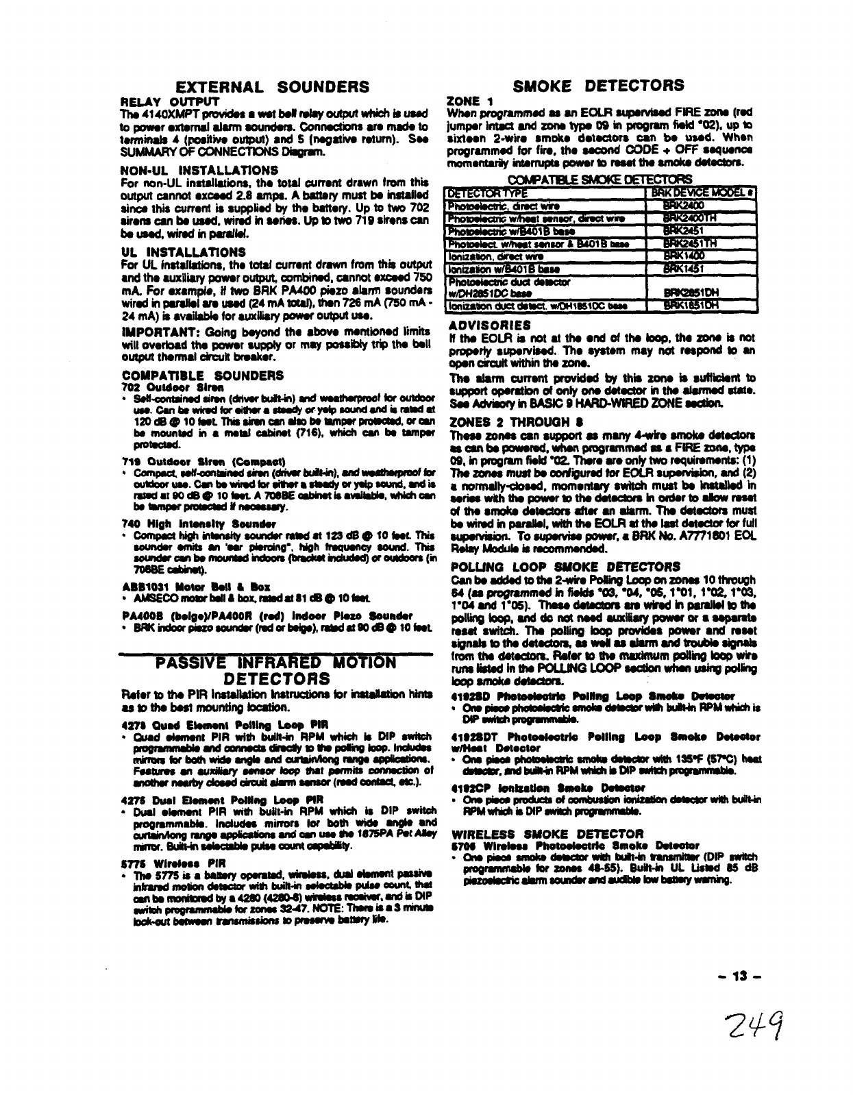
SMOKE DETECTORS
ZONE 1
Whan programm~ 8s srr EOLR supondssdPtRE zons (rat
jumporintact and20nstyp.09b Pm9m tiokf*02), upm
sixtoan 2-wiro smoko dotuaors oan b. USA When
progrsmmsd for fii, tho -00DE +OFF squsntx
momontarityintormptspoworto routdwsmokoti-.
,4TH
%=3
,1
Ma
COMPATIBLE SOUNDERS
702 outdoor Slrsn
●Sstlerwd Sirsn(drlvorblath) WldWs8thsrpmoftorOlmbor
use.C8nbewk9dtor si6rsrmWa*sound8ndkrsMti
120d6@lots@L lRissimncwI d80ttsmnPsr PrOmcsdorialr
bs mmmtsd in ●moml @not (716), which OM bs tsmpsr
protscwd.
719 outdoor slrm (Cempast)
“compsunu-Wudshsn @hmrW6t4n),sndwsshmrdbr
ouMooruao.Cm bowirsdbrsitmra zor Msawrd, wrdis
mtadat60=@ 10koLA706SE abbmtiswdkbls,uMdcm
bs~pmmasdumomsuy.
740 High Intsrwlty Soundor
“ommPscthiehwsnsitysoundsrrswat122ds @fotnL71ris
soundsrsmits=’oar piordng”,~h~ sound. This
sowrdsrrnbo nmurrrdtifbra dwthdudsd)or~(m
706SEcdinct).
ABBIW1 MOtW Ml &Box
“AMSECOrnomrbsllcboxmsdat81 *@lotsst
PMOOB (boigo)/PA400R (rod) Indoor Plus Sounder
●Bwhdoorpisso sourr&(rsd or bsies), radam*@ lo fsot
PASSIVE INFRARED MOTION
DETECTORS
Rstsr to ths PIR htsllstii Instructbns for inasWbn hints
astoths bsstmounting batiort.
4278 Ousd Etomonl Potllrlg Loop Pm
“e~t PIR wfdr built-in RPM whii bDtP switch
-~-m-mm.~
mkmmkxboth widssrlgbsnd ouminmmrmws 8c@os@mo,
F9auruansuxilisrysmsorlomprhmpsrmits Omnweon
Snothsrnsubyobuddcuitdsrrnssrwar(msdsonmas=).
427s Dual Etomart Pottha Loop PtR
●Dud ●lomont PIR wib built-in RPM whioh is DIP SWitOh
.Indudss- rnirrm Wboth wids angls ●nd
sndomuso Uw16=’A-AJSY
rrdnor.Suitt-irr mum o@diG&
Sn6 Wlrotoso PIR
●Tho5776is absttmyopsrstsd. wimbss#u-m
infmmd*tirtitim& akctsbbpubceun; thm
an bsnwnimmdbya4260 (4260.@wimisumd8f9-~~p
mvitdtpqmnmmMkrr zonnw7. ~: Wba3W
bokltbsnWsn~*m~~*”
Wmasmc bss 1BmQ661DH
Ionmmonductdsw. wluHm51mema SUKW61OH I
ADVISORIES
htiEO~ktitattkoddtk~,tia zons is not
WOW* s%wwbod. Tho sy8tom may not rsspond to srr
oooncimuit withintho20no.
&dsrm CUrrsnt providsd by this zono is SUtfidSllt to
WppOrtopsrstkmofonf yonodstauor kltttoslsrmOd ststo.
SSSkhrboryin SASf09HAR0-WIREDZONE ssdion.
ZONES 2THROUGH S
Thsss20rtas 08nsuppoft ssmsny4-wim uttofcodotsotors
mo9rtbspoworsd, wtwnprograrmnoduaFtRE20ns,tYPs
09, in progrsmfisld “02. Thsro SroOnfy*rquirsrnom (1)
Ths20nssmustbsc@@ursd forEOLRsuImisbm and(2)
8norrnalty-sod, momontary switoh must bs instsllstt in
aorisswith thopowwmtha dotochn inordormabwmsot
ofthosrnoks dstootttm aftorartsfsrm. Tho dstoctofs must
bowirsdinp8rslbl, whhtho EoLRstth9tsstdstuaorfor fufl
~. Tosupuvbs powor,●SRK hh. A7771soI EOL
Rdsy hhdub b mconrmondod.
POLLfNG LOOP SUOKE DETECTORS
Osnboaddsdtotho 2+uiroPo2ingLoaponzonw10throqh
64 (ss progrsmmsd in fblds ●O3 “04, “OS, 1%% l= 1“03,
l*04Mdl”06). Thssodouotom smwkodhpsrslbfbths
PoNn9boposnddonot ti-fisfymwap
tosotswitoh. Thopofiing bopprovidoapoww wtdrosot
signslstoths dsts@om,sswotlssslsrrrt sndtroubbsignsb
fmmthsdot~ Rofort9tho msximumpoWirrgbopwirs
runsli6tsd inths POLLWGLOOP sootbnwhat us@polfirrg
bopsmoICodstwaom.
41@2SD Phstooktdo Pang Lsop Smsks Detoswr
●Orwpismphmmbak smO1mdsmsmrwBlbuMl RPMMrMi8
w-~
41WBDT Phomuootrb Polllna Loop Smolco Dotostor
wlt+oat Domator
●aspbo@phoashW smdw dstadorw16r126+ (6PC) hnt
&mmmr.mdbuiRa RPMwhMrb DlP8amr~.
yzcP6zcmlz8u0&i yloks tpssaor
mmbusWnimlkabn~wmlbuut4rl
m@rlchiBDtP ssdlpro#mmM
WIRELESS SMOKE DETECTOR
6706 Wlrobss Photdoot *Smelts Dotootor
.O1Opiws 8nlolrads90mrwahbdt-bl ~(DtP8wkh
progq *zorws 46-66). S@+ UL Listsd 66 dB
pbmsbcmdsrnlsourdsrmtmd blskwbmaywmhg.
-13-
GLASS BREAK DETECTORS
GENERAL INFORMATION
Zono 8can support 2-wire, latching type glass break
dotectora when configured as ●nEOLR supervised zone.
The seand CODE+ OFF sequence momentarily interrupts
power to th~ zone to reset devices wired to it. Use detectors
whii am compstibfe with the ratingsbabwr
standbyVoftage:5VDC-13.8VDC
Standby Resistance: Greater than 20k ohms (equivalent
rosiatanca of all detecbra in paralfel)
A&rm ~OtanCO: LOSSthan Ilk OhlllS (SOSnote betow)
AtarmctJrrOW2mA-lomA
Roast Tree: LOOSthan 6aemntfs
The IEl 735L ●ones deteclora have been tested and found to
be compatible with these ratings. Up to 50 IEI ?35L
detectors, connected in parallal, may be used (the ,arm
current provided by this zone is sufficient to support
operation of only one detector in alarmed state). FoIfow the
manufacturer’s recommendations on proper instsllatiin.
NOTES:
Detectors which exceed Ilk ohms in alarm, but maintain a
voltage drop in afarm of bss than 3.8 voftscan afso be used.
tJse of N.O. or N.C.’contacts on the same zone may prevent
proper glass break detector operation.
See Adviiry in BASIC 9HARD-WtRED ZONE section,
PHONE LINE CONNECTIONS
GENERAL INFORMATION
incoming phone iine and handset wiring is connected to tha
main terminal block as follows (refer to SUMMARY OF
CONNECTIONS DqramY
TB1-26: Local Handset (TIP)
TB1-27: Local Handset (RING)
TB1-28: IncomingPhona Lins (TfP)
TB1-29: Inarming Phone Line (RING)
ff if is desired to mnnecf the panel to phone linesthat require
ground startcapaMliiy,then a 675 Ground Start Moduts must
be used. Thii modub is triggered by one of the outputs on
the connector labeled J7 (see CONNECTOR J7 TRIGGER
oulPuTs).
WARNING: To prevent the risk of shock, disconnect
phone lines at tetaI jack before servicingthe panel.
IMPORTANT
ffthe ~mmunicator is connected to atebphono line insiie a
PABX. be sure the PABX has aback-up power supply that
can support the PABX for 24 hours. Many PABXS ●r~ not
power backed up and connection to such aPABX wifl rosuft
in acommunicationfailure if power is lost.
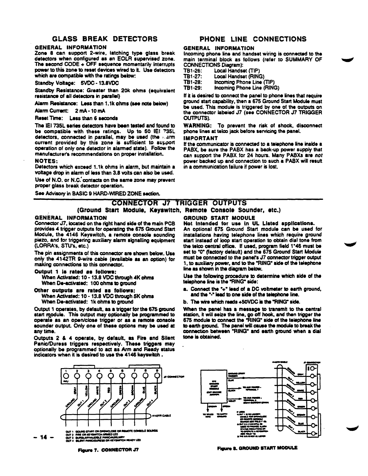
coNNECTO RJ7 TRIGGER OUTPUTS
(Ground Start Module, K.yswltch, Remote Console Sounder, etc.)
GENERAL lNFORMATtON GROUND START MODULE
connector J7, focated on the righthand side of the main PCB Not Intandod for use In UL L18tad ●pplloatfons.
provides 4trigger outputs for operating tho 675 Ground Stan An optional 675 Ground Start module can be used for
Modula, the 4146 Keyawitch, ●remote consob sounding installations having telephone Iinos wh@h require ground
piezo, and for triggering auxiiii afarm signaling equipment
(LORRA’S, STU’S, ●tc.) stacf instead of loop start operation to obtain dial tone from
the tetca centraf office. ff used, program fmkl 1*46 must be
The pin assignments of thii connector ●re shown befow. Use ●et to ‘O” (factory dafauft) and the 675 Ground Start Module
only the 4142TR 9-wire cab& (mraitable as an option) for must be connected to the panef’s J7 connector trigger output
making connections to ths connector. 1, to auxilii power, and to the ‘RING side of the telephone
Output 1Is rated ●e?ollowe: fineasSflOWOinthediagram babw.
When kthrated: 10-13.8 VDC through 4Kohms Use the following procedure to determine whii side of the
When Do-activated: 100 ohms @ground tebphone line is the %lN& aide:
Other outpute ●re rated ●sfollows: ●.connect the ‘+- taad of aDC voltmeter to ●arth ground,
When Actiiated: 10-13.8 VDC thtough SK ohms artdthe”-”tead toonesideofthe tebphonefii.
When De-activated: lk ohms bground b. Thawirawhii reeds +50VDCisths%lfW sida.
OutPM 1operates, by detautt, as ●trigger forths 676 ground When the panel has ●message to transmit to the oentral
start r@ub. Thii output may optionally be programmed to Statiom it witl seize the line. go off hook ●nd then trigger the
operate ●s●nopenlciosa trigger or as ●romota @naole 675 nrodub to connacf the %lN& side of tho tebphona fine
sounder output. Only one of thase optiona may be used at toaarthgtound. Thapanelwilt oauaethsmodufeto breakthe
●ny time. connection between “RING ●nd earth ground when ●diil
Outputs 2&4operate, by dofauft, as Fire ●nd Silent ~boM$in~o
P@c/Durass triggers respactivoly. Thoso triggers may .
optionally be programmed to act ●sArm and Ready status
indicators when it is des”ti to use the 4146 keyawii. --
t1tL
~6666b666 -m
sCUM- m-
i=—w~~ -
{~#~~i!
/////
cvl_- -
—m~~ .
w---
.-
<Im-- m_- ww~-=-_
m- -
-m-*o
mwu*c-ma
~mm_--~
m4usca~~~
ml wummmm
-14- WT2mm ~-o UD m-m ●—
m9msm
-I ~~ *--*-*-
aw4 aom~m~-~
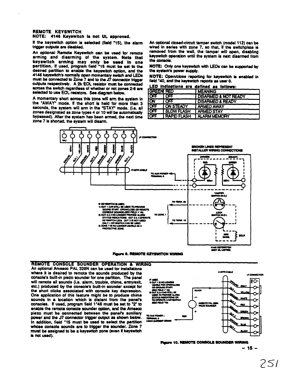
REMOTE KEYSWITCH
NOTE. 4146 Ksyswlteh la not UL ●pprovod.
If th. koyswitch option is selected (fwld “15),tho alarm
trigger outputs are dti.
An optional Rornoto Kayawitch oan be used tor remoto
●rming ●nd dissrming of tho system. Not. that
koyswltch ●rming may only ba uaod In on.
psrtltlon. tt usad, pfogfem fisld “15 must ba eat to ths
dasirad ptition to ●nabfa tha kayawitch option, and the
4146ksysw&h’snormatlyopenrnomentafyawitcffandLEOa
mustbsconnsctadwZona7and tith. J7w~tfigg.f
outputsrospsctivsly.A2k EOL resistor must be umnactd
acfos8tha awitchrsgafdla$s ofwhathafof notzcmas24$f.
aelaotadto use EOL resistors. Sss d~rarn befow.
Amomentary short across thm zona will arm tho systam in
the ‘AWAY m~e. Mthe $hoft &heM for mom than 3
seconds, the system will arm in the STAY mods. (i.., all
zones designated as zone types 4or 10 will bs automatically
bypassed). Aftar thasystem has besn afmad, tha next tirna
zone 7is shorted, the system will disarm.
An optional dosed-circuit tamper switch (modal 1t2) oan ba
wirad in swiss with zone 7, so that, it ths switchplata is
romovad from the wall, tho tamper will opan. disabling
kayswitch opemtbrr until the system is nsxt disarmed from
tha console.
NOT12 Onfy on. kqawhch with LEOS can bs supportsdby
tha system’spower suppty.
NOTE: Operucioao reporting for keyaMoh b●nab&d in
fiikf”40, arxithakaysmMh raportaasusero.
LEO Indioettons w. dofinod ‘- ‘-”-—
r~~
+=4-------?5-
‘-’L3+---+?J!
.
Ib---
:=
1-
L---- 1-
%kMO?E CONS OLE SOUNDER OPtRATiON &WIRING
An optional Arnaaoo PAL 328N an be used for instattatbna
wharo it is desirad to ramoto tho sounds produoad by the 41Uma
consob’s WWin piszo sounder for one parlitii. The panel
will remote all sounds (i.a. alarm, tfoubla, chime. entry/exit,
●tc.) produced by tha oonsois’a built-in sounder sxcapt tor
tho short clicks ●ssooiatod with ~nsob ksy doprossion.
On. application of this featuro might ba to produoa chinm
sounds in ●bcation whti is distant from the pansl’s
consoles. If used, program field 1“U must ba set to 7to
●nable tho romoto oonsola soundor @on, and the Amaeoo
piazo must ba oonnactad batwoon tho panal’s auxiliary
power and tha J7 mnector trigger output as shown babw.
in addition, field “15 must ba usad to salact the partitiin
whoso consolo sounds ara to trigger tho aourrdar. Zona 7
must be aaaignad to ba aksyswitch zona (evan it byswhch
is not Ussd).
-to. ~00NS0L2~wlaIna
-15-
2?5/
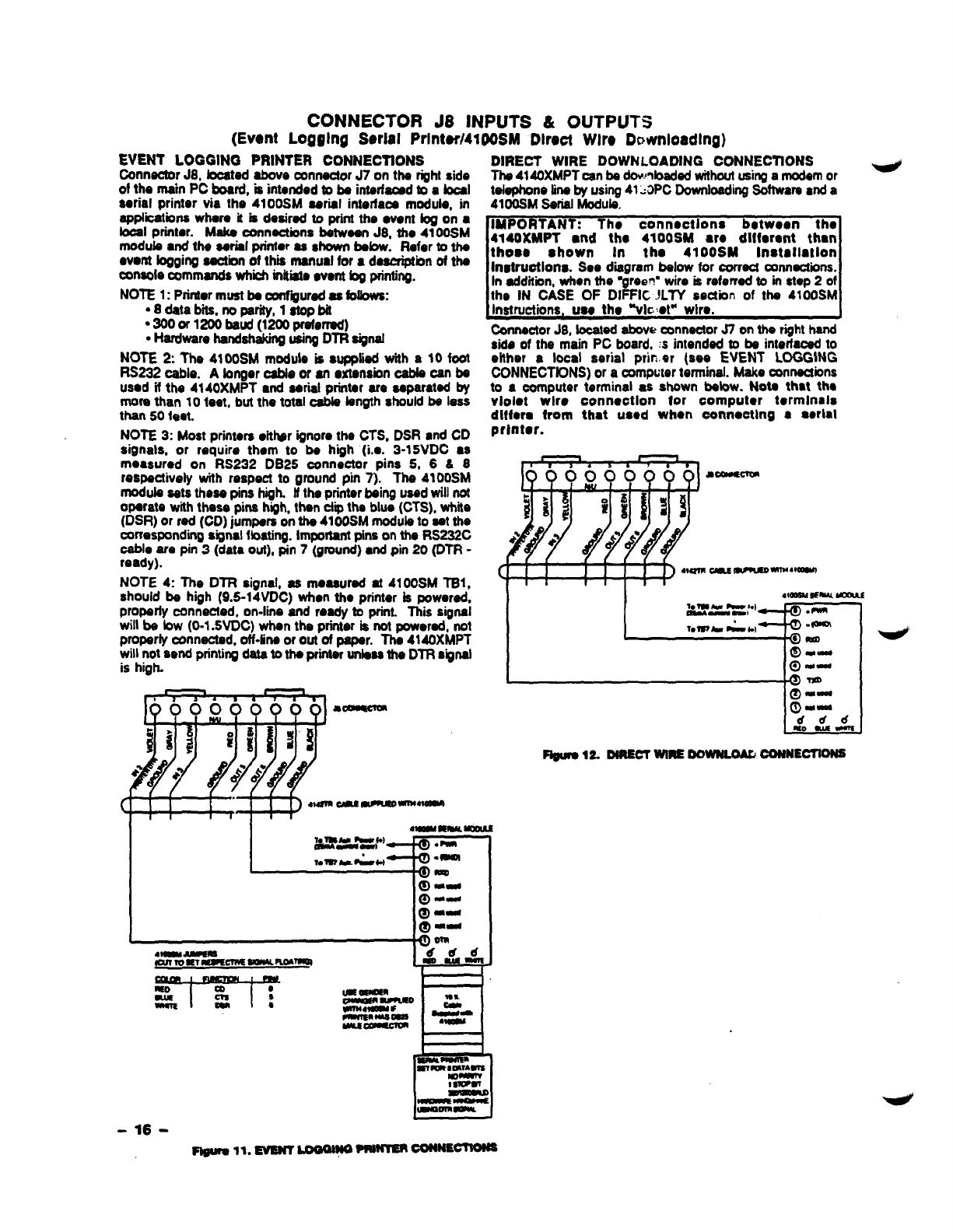
CONNECTOR J8 INPUTS &OUTPUTS
(Event Logging Serial PrIntar/41gOSM Dlr.ot Wlr. Dmvrtloadlng)
EVENT LOGGING PRINTER CONNECTIONS
Connector J8, located above connectorJ7 on the right side
of the main PC board, is intended to be interf~d to afocal
aerial printer via the 4100SM aerial interlaoa module, in
wtii~bm ~m kbdesired to print the ●wrnt bg on ●
boal prmtor. Make connections between J8, the 41OOSM
modub ●nd the aerial printer 0s shown below. Refer to the
●vent logging section of th~ manual for ●daaaiptiin of the
console commands whii inkiata event bg printing.
NOTE 1: Pnmor mustbe confffurad es fofbwa:
●8datab*. noparity, latopbit
●Sooor1200baud(1200preferred)
●Hardware handah~ usingDTR signal
NOTE 2The 4100SM module is su@ied with a 10 foot
RS232 cable. Abngor -e Or mextensionoabb can be
used if the 4140XMPT and aerial printer are separated by
more than 10 teat, but the total cable bngth should be less
than 50 feat.
NOTE 3: Most printers •it~r ignore the CTS, DSR ●nd CD
signats, or require thorn to be h“qh (i.e. 3-15VDC ●s
measured on RS232 DB25 connector pina 5, 6&8
respectively with respect to ground pin 7). The 4t 00SM
module sets these pins high, tfthe printerbeing used will not
operate with these pina hqh, then clii the blue (CTS), whiie
(DSR) or red (CD) jumpers on the 41oOSM moduleto set the
correspondingsignal fbating. Importantpins on the RS233C
cable are pin 3(data out), pin 7(ground) ●nd pin 20 (DTR -
ready).
NOTE 4: The DTR signal, as moaaured at 41ooSM TB1,
should be high (9.5-14VDC) when tho printer is powered,
proparfy connected, on-line and ready to print. Thii signal
will ba bw (O-1.5VDC) when the printer is not poworad, not
proparly camsctad, off-fineor our of paper. The 4140XMPT
will not aend printingdata to the printerunlessthe DTR signal
is high.
h-1 1 4
●s*
0000?? 7#●
a~
@fl [21 q
DIRECT WIRE DOWNLOADING CONNECTIONS
Tha 4140XMPTcan be dowdxsded withoutusingamodemor
tebphone tineby using41~2PC DownloadingSoftware●nd a
41oOSMSerial Modub.
IMPORTANT: The connsctlons botwaen the
4140XMPT wtd th. 41OOSM ●re dllferent thwr
those shown In the 41OOSM installation
Inatruotlorw. See dwgram below for correct mnnactions.
In edditiin, when the ~reen’ wire is referred to in step 2of
the IN CASE OF DIFFIC ~LTY section of the 41OOSM
Instructions, use the “WCet” wire,
tinnactor J8, located above connectorJ7 on the righthand
side of the main PC board, :s intendad to be interfacedto
either alocal sarial prk w(see EVENT LOGGING
00NNECTfDNS) or acomputerterminal. Make connections
to aoomputer terminal as shown below. Note that ths
violet wk. connection for computor terminsis
differe from that ueod when concocting ●●oriai
printer.
Figua 12.DIREm WiREDOWNLO& OWNECTtONS
IV. MOUNTING AND POWERING THE SYSTEM
MOUNTING
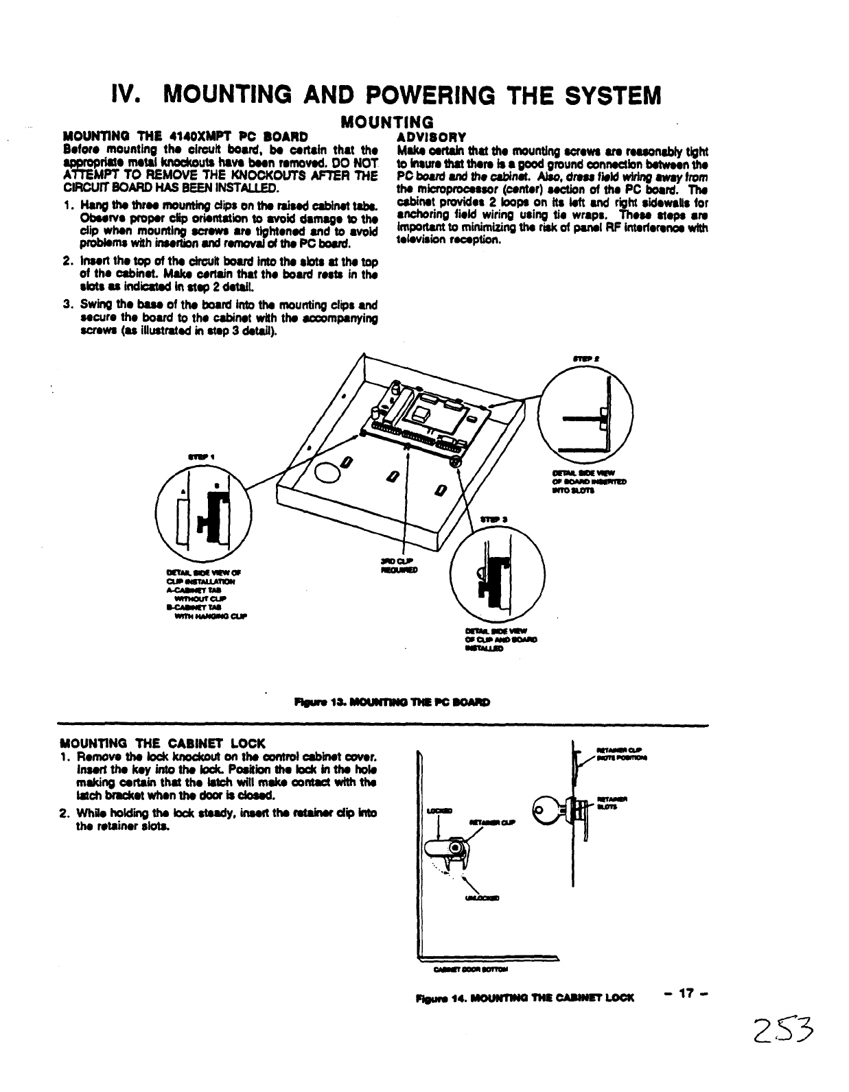
MOUNTINO TNE 4140XMPT PC BOARD
Bdor. mountine tho cirouit bored, koortsirr that tho
wdam rnotsi knookouts hsva boon romovod, 00 NOT
AMPT TO REMOVE THE KNOOKOUTS AFER TNE
CIRCUfi EOARD NM BEEN INSTALLED.
1.
2.
3.
Nurg hthroo mountingdips on ths rsisod osbinot tsbs.
Obsowo propor ofip orisntstion to avoid d8m8go to tho
dtp when mounting screws ●mtightonod and to svoid
proMsmswith insortbnand romovalofths PC bosrd.
lmfitk~dtka~wititb$b$dw~
of ths @Mnst. Maks oortain that tho board rests in ths
sbtsas Mo8tsdinstsp2dct8il.
swing tho bus of tho bosrd into ths mounting dips and
sscuro the bowd to tho cabinet wiih ths~mpsnyirrg
straws (u iliustratsd in stop 3d,tait).
ADVISORY
Make osrtain that tho mounting oorows us rsuondy tight
tohauro that thors is 8good ground oonnsctbn botwoontho
PC bud snd #o abirwt. Also, drossMd wiriq awsyhorn
ths mbroprocsssor (oontsr) sootion of ths PC board. Ths
08binM providoa 2loops on its loft snd right sidswdls for
●choring field wiring using tio wraps, Thoss stops ●
importsnt to minimizingths risk of psnsl RP intsrtorsnoswtttr
toiovision rcooption,
,r ,, -
‘1 w=%%=—’
S&JP
-um)
Fblmla. MounnNo T?tE?c BoAmD
MOUNTING TNE CABINET LOCK
1.Romovs ths lock knockout on h oontrol osbiit covor.
lnsorttho koyinfotho iocfLPositiithobck inthshols
making certain that tha Isti wili msko =ntact with ths
istchbmckotwhon thodoorisoiosod.
2. Whilohoidii tholock stsady, inssrtthofsminsf dphto
the rotsiner slots.
)%-A
rw“
Pl@w014. UwNTlrw mEamrJETLoott -17-
253

POWERING THE SYSTEM
PRIMARY POWER
Powor to the 4140XMPT oontrol panel is supplied by mmdol
No. 1361 ●Piug-in Transformer whti is rated ●t16.5VAC,
40VA Cauth must be taken when wiring this transformer to
tho panel to guard ●gainst blowing tho fuss inside the
transformer (non-rapiaceabie).
●NOTE: lfas 1361CN Transformer in Candan ineteMons.
BACK-UP POWER
in the evonf of an AC power loss, the 4140XMPT control
panel is supportod by ●back-up, rechargeabfa got cell
battery. YUASA NP4-12 (12V, 4AH) and NP7-12 (12V, 7AH)
battorios ●ra recommended. Do not use Gates
batterlos (aealad load-acid type).
The standby battery is automatkalfy tested every 24 hours,
beginning 24 hours after ●xiting programming mode. in
addition, entry into the test mode wifi ause abattery test to
be initiated.
NOTE: The above f~uros are approximate, and may vtuy
depending u~n the age, quality, and capacby of the battery
atthetimeof the ACioss.
●Uas 4AH batte~ for UL htdadms.
EARTH GROUND CONNECTIONS
in order for the tiihtning transient protective devioes in this
product to be effective, the designated earth ground
termina~ must be terminated in agood esrih ground. Tha
foiiowiig ●re ●xamples of good earth grounds ●vaiiabfe ●t
most instaiiations:
Metal Cold Water Pips: Use snonarrosive metal strap
(-r ~~mme~~) firm@=ured to the pipe to which
the ground lead is eiectricatiycamected snd secured.
AC Power Outlet Ground: Avaiiabie from 3-prong,
120VAC, power outieta only. To test the integrfty of the
ground terminal, use ●three-wire arouit tester with neon
imp indiiors, such se the UL-Listed ideal Modei 61.035,
or equivsbnt, avsiiabia at most electrical supply atoms.
POWER-UP PROCEDURE
1. Fiil out the Poiiing Loop Current Draw and Auxfiary Devios
Cument Drsw Worksheets shown below. Make sum thst
the currents drswn from these outputs do not exoeed
their respective ratings.
CAUTiON: Faiiure to observe the potiing loop current
rating wili cause poiiiig loop malfunction. Fsilure to
obsewe the auxiliary output current rating will result in ●
battery which does not charge properiy or possibly ●
tripped cirouii breaker.
2. WIrs the 1361 transformer (1361CN in Csnads) to the
panel (before anrrecting the battery) ss shown in the
suMMARYOF coNNEmONs d~ratlt. mMpluginat
thistime.
3. ~~ dlillii~gebop and auxiliary devices, suoh 86
●O
4. Piug the 1361 into sn 24 hour, uninterrupted AC outlet.
After ●few seconds, the green POWER LED on the
console(s) should iiiht and the oortsoie(s) should display
-DfsARMED READY TO ARM.=
5. Connect the battery as shown in the SUMMARY OF
CONNEC~S diagmm.
POLLING LOOP CURRENT DRAW WORKSHEET
A*m 6--A
42W &ZoIWRPM
4ao-68arle RF
.* tfthe Uslaxrent-~64mA
m1
hi
tit
. .. . .-.— -.-..—. ,—..
AUXILIARY DEVICE CURRENT DRAW WORKSHEET
675 GroundSranModUls 50m
4260or4260-6Rsoam40m
Suilr-kr PoMQ ISoP (-
A107DallLcYM)F-*imm
~rnoddemustbusad.
“0 tfueinotwo4260s or426Ms, youaIeawuwof*
hmwxiiiny powsrhsWof ushgs41@7boPe~
-.
-18-

V. SYSTEM OPERATION
SECURITY ACCESS CODES
GENERAL lNFORMATfON
The VISTA 4140XMPT System ●ltowa up to 128 (99 maximum per partition) saourity aceass rsdes to be assignsd, aach
identtfii by ●war ID number. In additiin, tha Quii Arm foatura oan also be Prograrnrnad,whbh ●nabbs the [#] k.y to h
proasad instead of ●ntoringtho security cod~ when arming tho syatom. Tho oodo must still ba ●ntorad when disarming the
syatom. Nota that OpwvCbso reportingof Ouii Arm is ●ablad it Lfsar2is ●nabbd for Op@Cbsa raporting, and that Qu’bk
Arm mporta as Uaar O.
B
USER CODES &LEVELS OF AUTHORfTY
E
Each user of ths syatsm oan L
be aasignsd various levels of o
●uthority (tslls system what 1
systsm functions that user is 2
authorized to do), and can 3
have different levels of 4
authority within each partitiin. 5
Use the “View Capabilities” 6UU===
keypad function to view the
pa~iions ●nd ●uthority levels
for which aparticular ussr is
●uthorized. In highsst to
lowest ranking, these fevels
are 83 fofbwa:
Instsllor fLevel 0}
●
9
●
.
.
.
Can ps~-m afl s~stem functions (arm, disarm, bypass,
etc.) and is the onty user that can ●ntar program nmda.
Enter program mod. and ntdw imrorammingchangaa.
Change liiaownmda. - - - -
Add, Dolets, Change MASTER, MANAGER, or
OPERATORS.
Selsof op9n/doa6 reports for ●ny uaar.
Oparats ●partition, but CANNOT DISARM ft arrnad bv ●
rmde othar tian INSTALLER’S mdo (iuding Oubk ~).
Maator (Lavsl I)
●May cretto other usora of ths aystsm babw thii level
(Maator cannot assign anybody ●Iavsi of Oor 1).
●Ohangshiaownooda.
●Add, Debts, Changa MANAGERS or OPERATORS.
cOEankfoso raoortirw of ●dded ooarator users will BE
SAME ●shis own [&nablad or di~ad as assignad by
INSTALLER).
●Oparate ●partitbn.
Manager (Levoi 2)
●
✎
✎
✎
●
●
Can-parform atl systam fundb~ (Ann, D-, Bypa6a,
ate.) programmed by Maator.
May create othor uasrs of tha aystsm bebw thii taval
(Manager cannot assign ●nybody abvel of 0,1, or 2).
MW changa his own coda.
May WDaIata, Changa OPERATORS. “
Opankfoaaraportingof addaduaaraWitiBE SAME as his
own (onabfad or disabkt uaaaignad by fNSTALLER or
MASTER).
May oparata ●partbion.
Operator (LoWS 34)
●fmvaat tavda of users.
wMay operate ●partitbn with ona of the three OPERATOR
●uthority bvsts Athrough Ctistsd in ths OPERATOR’S
CODE paragraph Iatsr in thii section.
Our@as (Lavol 6)
●Oanarrn anddmthe SYStan butaboaandasitant
duress moaaage to central atatbn (If aenrba is
concocted).
.Code is aaaignad on ●partition Wpartitibnbasis.
Ganoral Rules on Authority Lavols ●nd changoe
To kaap thii atmduro manageable, the fofbwing rubs appfy
to uaara whan making modificationswithin the syatom baaad
on ths uasr code authoritybvela:
●Auaar may not debto or chango the user code of ths
SAME or HtGHER authoritythan which ha is assignad.
.Aussr may only ADD usersto ●LOWER uthorhy Iavat.
●Auser may assign other users aooeas to othor partitions
onfy il ha hnaatt has access to those partitiina.
●Auaarcan only be DELETED or CHANGED from withinthe
partitiin ha is ●ssionad.
I
MULTfPLE PARTfTION ACCESS (GOTO Funotlon)
To maka ●partitionad ●nvironmont particutarty uaafuL tha
syatammuat afbwforcertain paopfatohava acoaaatoothar
partitions. This ia particularly true in ths Factory~bs
●nvironment whare tha president of ths oompany wanta
aoosss to any area of hm company. Tha 4140XMPT has
wfbxibilhy in supporting thii raquirsrnartt. On ●USER
baais, ●ach usar is programmed for ●baas partitbn (the orw
ha normally is aaaignad) and ona or mora partitbna which ha
oanbaauthorizad to~.
In ●ddltbn, within ●aoh partitiin, ●ach USER may ba
oroorammad to have different levels of ●uthorftv. For
;x~-mob. Usar #3. th. V.P. of Enginaarino. o&rld ba
usigned to work-within the Engi;ooring ‘baparfmont
(Partitbn 1) of ABC Manufacturing. Since ha naads tha hd[
capabilities in his area, ho is ●aaignad as ●MASTER with
Lsvaflauthority. Thiarnaana hsmay Arm, Dbrrn,Bypasa,
Add or Modii uaara in partttion 1. tt is atao ●raquiremant
that ha be abla to gain access to tha manufacturing ●raa
(parthiin 2) on an ●m3●ncy basis. You oan set thb up
aaailywtthths 4140XM bynowrqusating thathsafsoba
aaaignad to partitiin 2, with ●taval of authorhy set &war,
auoh as Levah4 (OPERATOR Lavel B) whbh albwa him to
Arm ●nd Disarm, but nothing ●laa. Ths oontrol will
●utomaticafiy assign hlm tha next availabb user numbar
within partition2and doss not raquira reprogramming of Ma
afrasdy dating 4dqit aaourky OodslThis typa of Satup can
badonstoraaoh usarofthasystam and forarryoombindon
Ofuptospartihal
EXAMPLE OF MULTIPLE PARTITION ACOESS
In the abovo ●xampfa, Uaar 3haa MASTER ●dhortty in
parutbn landoPERAToR Bauthdty inpartitii2. Hi
wm-h_n2bU_rStiti4d@Mdktti
awn. for both partitbna.Acosaa to Othar Partitbrrs. Not.
mtia-rnu-rb~~~m-inam,ti
system WSautornaticattyassign an unuaad Uaar numbar.
Aaaignii users to othar partitions is ona thing, but how
about actuafly baklgauaarandtry ingto%aa”onaoftha
otharpartkii? Tha4140XMPThasdevabpad ●shptakey
aquanos (ooda +~] +partitiin numbar O-6, partith O
raturna to tha dafauft partitbn for that conaofa) aohama for ●
uaarto go to anothor-in.
-19-
/75 5
.
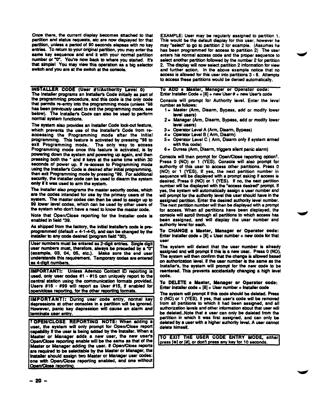
Once them, the current display baoomaa attached to that
psrfttiin and status rqueats, etc am now diaphyed for that
P@bnsu*a@=fo f@-*e@eeswithmkay
wttriaa. To ratum to your orightal parthbn, YOUmay ●nter the
same key aaquanoa ●nd ●nd if with your normal partitiin
number or T. You’re now ba& to where you started. ft’a
thataimpial Yournay viawthm operation as8bigsebctor
awkofrandyau aroatthaawftcii atthecOnsaIa.
INSTALLER 00DE (Uaar #1/Authortty fmml O)
The instafbr wrams ●ntnstafbte Code rnitiaflyas pan of
the programming prooedum, and thii -O is the only oode
that parmtte -my into the programming made (unless “98
has been pmvbusty usad to ●xit the programming mode, see
bebw). The lnst~br’a Code can also bused to perform
normal system functions.
The ayatam atso pmvidea an Instalkr Ode bohut feature,
which pr.vents the uss of the Installer’s Code from re-
●ooosaing the Programming modo ●fter the initial
programming. Thii feature is activated by pressiW “98 to
●xft Programming mod.. Tho only way to ●ccess
programming mode once this feature is aotivated, is by
~~ dthe aystom and powering up again, ●nd then
~bg-htha ”and#kaysattho sama timawithin30
seconds of power up. ff re~ea to Programming mode
using the Instafbr’s Code ki desired after initialprogmmming,
then ●xit Programming mods by pressing “99. For additional
aoourfty,the inatafler code can be used to disarm the system
ortfyti ilwasuaadto armthasyatom.
The Inatalbr also programs tho master aacurftyoudas, whii
am the oodaa intended for use by the primary users of the
ayatent. Thamastaroodas oanthanbe usadtoaagignupb
99 bwor bvol cxtdas, which can be used by other users of
tis~m-~n?hanatib~titicr~.
Note that Opan/Cbse reporting for tho Instatbr ode is
●nabled in fwld %9.
Asaftippad fromthafactory$ theinitiaf kwtalfatimde&~
~rammed (default. 4-1-4-0), ad oan be ohangad by the
kmtaffarbany cede daaimd (program fii WO).
~
~
Users #16 -#99 will ropoti as Usar ~15kHmogsbled for
IMPORTANT!: uring user oode ●ntry, normal koy
dapasms atotharomsotes inapartitiin wiftbeignomd.
However, panio key depression will oaues ●n●larm and
tarminato user ●rrtry.
tOPE@J/CLOSE REP ORTING NOTE When adding ●
user, tho syatom will only prompt far 6petibeo report
~Wtith.WfsM~n9-&t*&r.Wna
Maetor or Martagor adds ●now user, tho now user%
OpOt@bOO f@Portktg.rtabb will be the same as that of the
Master or Managar ●dding the user. MOpen/Cbaa reports
amrequirad *ba@eotabb by the kbtor or Manager, the
fndaffar should assign two MaaW or Martagor user oodas:
one wffh Opart@oaa raporting ●nabfad, and one without
EXAMPLE: User may be regularly ●ssigned to partition 1.
This would be t- default display for this user, howevar he
may ‘SOW to go to partitiin 2for example. (Assumes he
has been programmed for aooass to partition 2) The user
inters hia normal aamsa code and the proper squonce to
select ●n@wr partitiin followed by the number 2for partition
2. ~dmay will now select partitiin 2informationfor view
●nd further action. In the above ●xampte notice that no
aoeass is afbwad far thii user into partitions 3-8. Attempts
to access these partitionswould be den”bdautomatiiliy.
IeAUU amaw.r, mmagm or upwaIor coa.:
Etierltir-+[8]+-Mr#+-M~do
Console will prompt for Authority level. Enter the level
number as fotkms
1=Master (Arm, Dbarm, Bypass, ●dd or modify lower
bval users)
2- Managar (Arm, Dm, Bypass, add or modiiy bwer
level Usars)
3= OPSratorLevel A(Arm, Disarm, Bypass)
49 Opsrator LOvalB(h, Dm)
5= Operator Level C(Arm, Disarm only ff system armed
with thii ode)
6- Duress (Arm, Dunn, triggerssibnt panic alarm)
Oonsolo witl than prompt for OpartKXose repoting option$.
Press O(NO) or 1(YES). Oonsolo will also prompt for
●uthority of this user to access other partitions. Press O
(NO) or 1(YES). If YCS, tha next partition number in
sequence will be dmptayad with ●prompt askktg if ~s is
desired. Press O(NO) or 1(YES). fl no, the next pdtiin
number witlbe diied with the “access desirti prompt. tf
yes. the system will ●utomatically assign ●user number and
will prompt for the amhodly bvol thm user should have in the
assigned partition. Enter the desired authorfty level number.
The nexf partitionnumber will than be displayed with aprompt
for access. When ●ll psrtitiins have been displayed, the
umsols will aomll through ●ll partitionsto which aocass has
been ●ssigned, and will display the user number ●nd
authorhy level for ●ach.
To CHANGE ●Maator, Martagor or Operator oode:
Enter fnstalbr ~ + [8] +User number +new oode for that
user
The system tit detect that the uaor number is ●tready
assigned and wftl prom@ Mthii is ●new uaar. Pmsa O(NO).
Theeystemwillthen tiithatthe ohangoisatbwad basad
an authdzatbn bval. tfthauaar nuntber isthaaamaasthe
Installer’s, the system will prompt for the new code to be
reantomd. This prevents -idontaHy changing ah~h level
oode.
To DELETE sBMtor, Mattagor or Oparator ood.:
Entar fnatallerooda +[8] +Uaar number +fnatalkr cads
The system wifl promfx if thii -e should be deleted. Press
o(NO) or 1(YES). Nyes, that user’s code will be removed
from all partitions to which it had been assigned, ●nd ●ll
wthorixatbn bvafs and other informationabout that user will
be delatad..Note that ●user can only be defetd from the
partitiin mwhd nwas first ●ssigned, ●nd can only be
debted by ●user with ●hgher authoritylevel. Auser oannot
delete hmseff.
TO EXIT THE USER CODE ENTRY MODf& either
-2D -
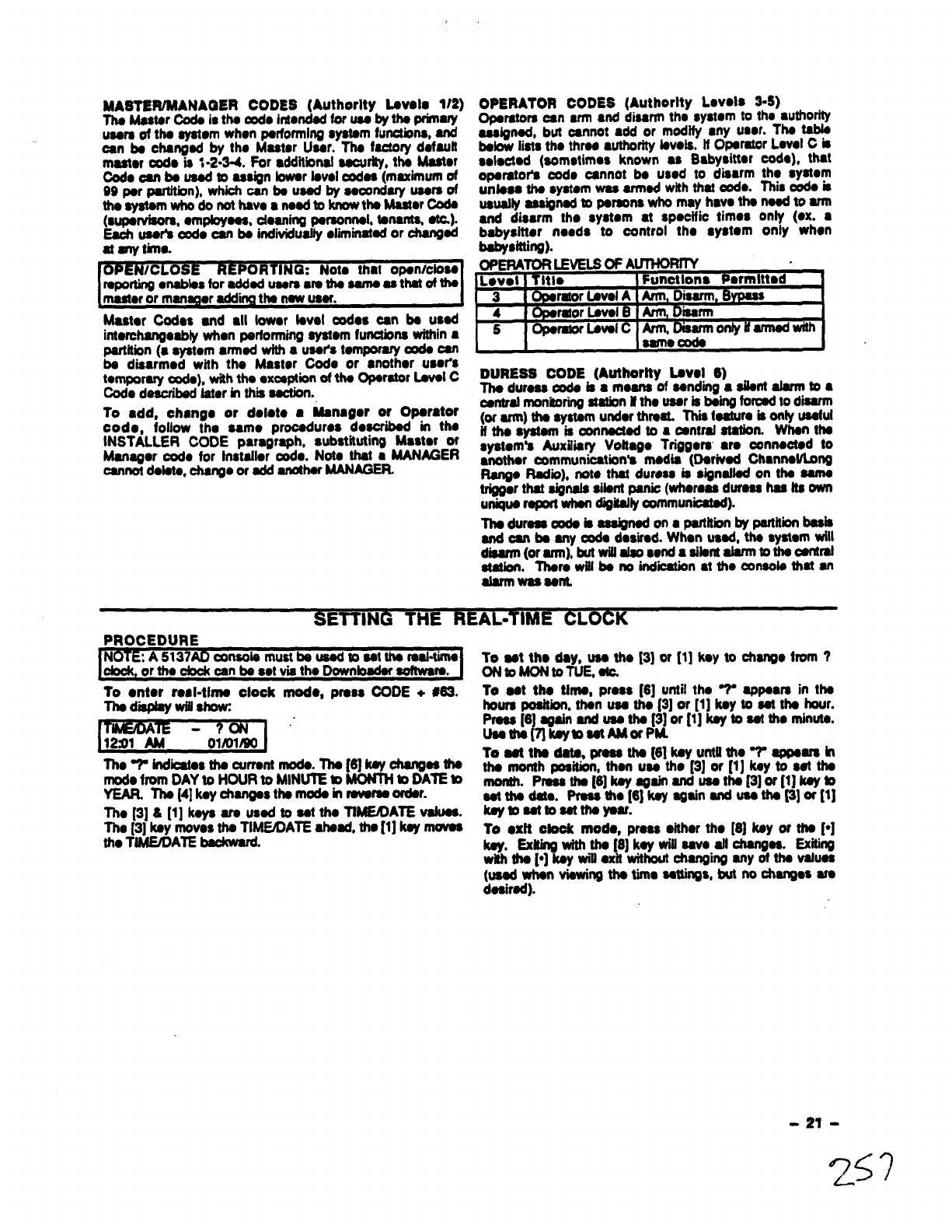
.,
MASTEWMANAQER CODES (Authority Lavolo 1/2)
Tha Mastar CXrdais ths do intwrdad for uss by ths primary
usars of tha system when psrformhtg sysfam functbns, and
can bs changsd by tho Master Usar. Ths factory dafault
mastar do is %2-3-4. Por ●dditbnaf ssourity, thsMaster
Cod. oanb usadm assign bwar faval codas (maximum of
99 par p@tiin), which can bs usad by ~ndary usars of
thasystamwho donothavoa naadtoknowtha Master_
(supervisors, ●mpbyass, doaning Poraonnal. fa~ w).
Eaoh user’a cod. oan bs indiiuafty diiinatsd or -ad
at aly tkno.
OPE NICLOSE RkP OR TING: Not. that opsn/cfoso
raporting●ablas for addsd uasra wa tha cams as thatofths
masteror manager adding ths nsw usar.
Master Ccdos ●nd ●ll fewer tavel tics can bs usad
intorchangesbly when psrformiflg sysfom functbns withh m
psrtftion (a system ●rmed wfth ausots tompomry oods oan
ba disarmed with the Master Code or wrothor user’s
tornporary ~), with ths excsptiorrof tho Operator Lovsl C
Code describsd Iator in thii asctbrr.
10 ●dd, chango or doloto ●Msna@or or Oparator
cod., follow tho samo prooaduros doscribsd in ths
INSTALLER CODE paragraph, substituting Master or
Manager cod. for Instatlor @o. Not. that ●MANAGER
cannot dobta, charrgoor add ancthor MANAGER.
OPERATOR CODES (Autttorlty Lsvols 3=S)
Opomtors can ●rm ●nd disarm ths system to tha authority
asslgnad, but cannot sdd or modify ●ny user. Tha tabfa
Mow fiis tho thrss ●uthority Isvols. HOparator Lsvol Ck
soloctsd (somotimcs known ●sBabysitter cod.), that
opamto~ cod. osnnot ba used to disarm tho system
unlsaa tha systcm -armed wkh that ccdo. This cods is
usually assigned to parsons who may havo tha rrasdto arm
and disarm ths system ●
tspecific times only (ox. ●
babystttar noods to oontrel the system only when
babysitting).
oPERAlOR LEVELS wAfJTHoRf’lY
Lovol 17 MI* %nctlons Pormlttad I
3Opsrmor Laval AAnt
4IOPS rater Lavsl BArm, DmnT
Is‘-=+
lopsmtorLavsltqAm,Disafmonly ifafmdrdh
IIIsamoaids I
DURESS CODE (Authortty Lavcl 6)
-dur--bamo~d-ndmga~titiba
csntral monitoringstation fftho usar is baii fomad to disarm
(or arm) tha systam under threat. This faatura is only usaful
if tha systam is oonnsctad to ●oontmfstation. Whsn tha
system’s Auxiliary Vottago Triggers ●moonnootad to
●nothor communication’s madis (Dorivad Ch8nnafAong
Ranoo Radio). not. that duress is signaffsd on tha cams
trigg;r that tinals silant psnb (whoro~ durass has fts own
uniqus rapcrt whan digWy communicated).
Thadumssmda hasaignsdon aparfltiiby psrthbn -
and oarr ba any ~dssirad. When usad, ths system till
d~(tim), tiWtisotia @km-@ ti~tid
atatbn. Thara wifl ba no indication ●ttfw consols that an
alarrnwassant.
SETTING THE REAL-TIME CLOCK
PROCEDURE
clock, or tho cbdr can bs sot via tho Oownbador scftwara.
10 ●ntor raal-tlma clock mod., prsss CODE +#63.
Thsd*witl show
Tho-?=frldbatos thaarrrsnt rnoda. Tha[6Jkayohangas tha
mod. from DAY to HOURto MINtJIE to MONTHto DATEto
YEAR. Ths [4] koy drangss thsmods in ravarssofdar.
Tho [3] &[1] kays am USOdto sat tho T’t=ATE vafucS.
Tho [3] ksy moves ths TIME/DATE ahsad, tha [1] kay nrwas
tho TfME/DATE backwad.
T& :t&:&Em~he [3] or [1] kay to change from ?
To act tha Urea: press [6] until tho 7appears in ths
hours poshionothen usa tha (3] or [1] kay to sat tha hour.
Pmss[6 qdnti-ti[3]or[l]~*m~tinti.
h
Usaths kaytosst AMor PkA.
Toatbti,~~[6]~uti~tio?~- in
tha month @tbn, than USCtho [3] Or [1] kSy to SCf fhc
month. P-h[6]*qti ti*tbp]w[l]w*
satths dam. Prasstho [6)ksyagain andusathsp]or [l]
kaytosafto sstthsyoar.
To ●xft ctook mod., press ●fthor tho [8] ksy or tha ~]
kay. Exfting wfth tha [8] koy wifl savs all changas. Exiiirtg
w2h tha ~] kay wii ●xit without changing any of ths vafuaa
(uSad Whan viswing tha timo sattings, but no Changes am
dasimd).
-21-
25 ‘?
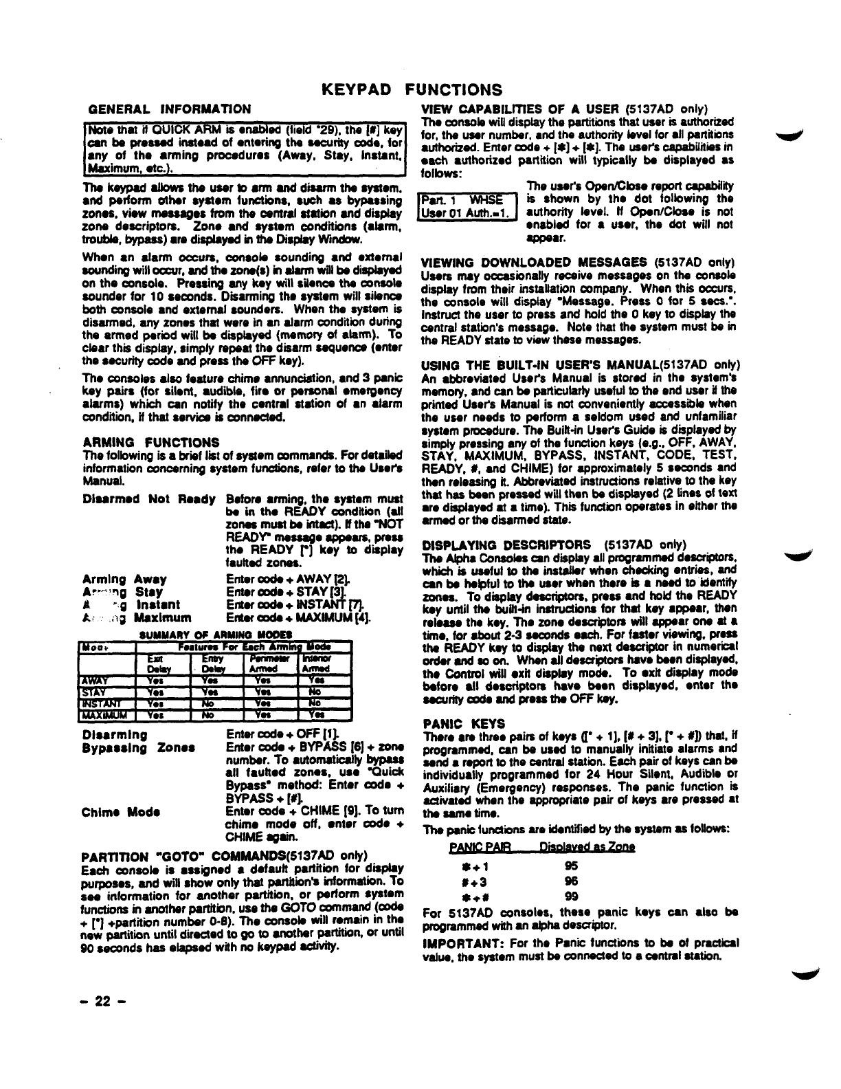
KEYPAD FUNCTIONS
GENERAL INFORMATION VIEW CAPABILfTtES OF AUSER (5137AD only)
Note that if QUICK AThe conaob wiffdisplaythepartitionsthat user is authorized
RMise nabted (field “29), the 1#]key for, the user number, ●nd the authority bvel for all partitions
oan be pmssad instead of entering the security coda, for
●ny of the ●rming prooedums (Away, Stay, Instant, authorbed. Enter arde +lx] +[r@].The user’soapabiiitkw in
Maximum, etc.). oaoh authorized partition will typioally be displayed ●s
folbws:
Thakeypad afbwathe usertoarm anddiaarrntha ayatom.
●nd perform other ayatom Iunctiona,such ●sbypassing
zonos, view messages from the oentml atatiin and disptay
zone descriptors. Zono ●nd system conditions (darer,
troubb, bypass) are diaptayed in the Dispby WI*.
When ●nafarm otawa, oonsob sounding ●nd ●xtomal
soundhg will oowr, and the zone(s) in abrm witl be diapbyed
on the corrsola. Pressing any key will sitonos the oonsota
aoundsr for 10 aeamds. Dsarming ths system will sibnce
both console and external sounders. When the system is
disarmed, any zorms that were in mdam condtbn during
the armed perbd will be dsptsyed (memory of atarm). To
ctaar this display, simpfy repeat tho disarm sequence (ontor
the SSOU~ code and press the OFF key).
Tho oortsobs afso feature chime ●nnunciation, ●nd 3panio
key pairs (for sibnt, ●udiile,fir.or personal ●mergen~
alarms) which can notify the central station of ●nalarm
conditiin, if that servios is connected.
ARMING FUNCTIONS
The folbwing is abriif list of system mrnmanda. For detaited
information concerning system functions, refer to the User%
Manual.
Dlaarmed Not Ready Before ●rming, the system must
be in the READY oondtiion (atl
zones must be intact). tfthe %JOT
READY message appears, press
the READY r] koy to display
tautted zones.
Arming Away Enter *+ AWAY ~
AW’~g Stay Enter oode +STAY [3.
At -g Instant J
Enter *+ tNST
A{ .ag Maxlrttum Etier mde +MAKfMUM~4].
SUMMARYWARMINOWOES
Disarming Enter code +OFF [1).
Bypasalng Zonos Enter coda +BYPASS [6]+ zone
number. To automaticallybypass
atl fautted zones, use ~uick
Bypass” method: Enter csde +
BYPASS +[#l.
Chimo Mode Enter cede +CHIME [9]. To turn
chime mode off, ●nter oode +
CHIME a@n.
PARTfTION “GOTO” COMMANDS(5137A0 OnfY)
Each oonaob is ●ssigned ●defauft partition for display
purposes, and will show only that parlitiin’s information. To
aee information for another partition, or perform system
functions in another patiion, use the GOTO command (ads
+~] +pa.@tiin nym~r O-6). The oonsob will remain in the
new parhtmn untrl directed to go to another partition, or until
90 seconds has etspaed with no keypad -.
me users opanmoae reponcapabmy
EzEl
is shown by the dot folbwing the
●uthority favel. ff Open/Cbse is not
●nabled for ●user, the dot will not
appear.
VIEWING DOWNLOADED MESSAGES (5137AD only)
Users may occasionally resrive messages on the mtsob
tfispfay from their installation mmpany. When this occurs,
the console will display ‘Message. Press Ofor 5sacs.-.
Instruct the user to press and hold the Okey to disphy the
central station’s message. Note that the system must be in
the READY state to view these massages.
USING THE BUILT-IN USER’S MANUAL(5137AD only)
An abbreviated User’s Manual is stored in the system’s
mmov, and -n be psrticutartyuseful to the end user if the
printad Users Manual is not conveniently acceasibb when
the user needs to perform aseldom used and unfamiliar
system procedure. Ths Buitt-in Users Guide is displayed by
simply pressing any of the function keys (e.g., OFF. AWAY.
STAY, MAXIMUM, BYPASS, INSTANT, CODE, TEST,
READY, #, ●nd CHIME) for approximately 5seconds and
then releasing it. Abbreviated instructionsrelative to the key
that has been pressed witl than be displayed (2 lines of text
●re diapfayed at atime).This function operates in either the
armed or the disarmed state.
DISPLAYING DESCRIPTORS (5137AD only)
The Atpha Conaobs an dispfay ●ll programmed descriptors,
which is useful to the instafbr when checking entries, and
can be helpful to the user when there is ●need to identify
zones. To disptay dadptom, press and hokt the READY
key until the buitt-irt instructions for that key ●ppear, then
roteasa the key. The zone descriptors will appear one at ●
time. for ●bout 2-3 seconds aach. For faafor vWIW. Pfes$
the READY key to d- the next descriptor in numeriil
order and so on. When afl descriptors have been disptaywf,
the Oontrol wilf ●xif disptay mode. To ●xh display mode
bafore ●ll desoriptora have been displayed. enter the
aaourityde andpressfhe OFFkey.
PANIC KEYS
There ●mthree pairs of keys (1. +1], [# +3]. ~ + #]) ti~t ~
programmed, an be used to manually initiito alarms ●nd
send ●mporl to the cantrat station. Each pair of keys can be
indwidually programmed for 24 Hour SWnt, Audible or
Auxitiary (Emergency) responses. The panic function is
activated when the appropriate pair of keys ●re pressed at
the same time.
The panic hmdions am identifbd by the system as follovm
*+1 95
#+3 96
*+* 99
For 5137AD oonsolos, these panic keys oan ●lso bs
programmed with an a@hadescriptor.
IMPORTANT: For the Panic functions to be of practical
vafue, the system must be connected to aoentral station.
-22-
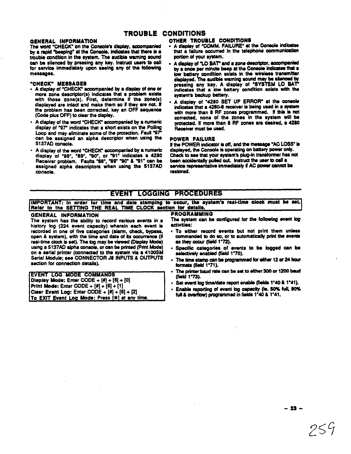
TROUBLE CONDITIONS
OENERAL INFORMATION OTHGR TROUBLB
Tha wrd “CHE* on tha Oonsolo’s diapiay, aooornpanbd
~am~~g~tk%nwb,~~.--oba
●Adlaplay of %OMM. FAiLURF at ths Oonaota hdbataa
that atalk murrad In tha talophona oornmunbatlw
tmubb rnnditbn tn tha watom, Tha ●tdlbb warnhm sound
_——
oan ba silamd by pmaihg ●ykay, Inatruoi uasi to oail .
for sorvba Immadlatoly upon saaing ●yof tho fof~ng
rnoaaagcs.
“CHECK” MESSA@ES
cAdisplay of “CHECK aommpanbd by ●display of wor
mora zono dasoriptor(s) indiiataa that ●probbm ●xiata
wtth thoso zono(s). First, dotormino tf ttm zona(s)
disdavad am intact and maks thorn SD Uthav ara not. if ●
.
.
(Odeplus OFF) to dsar the display. -
Adisplay of tha wrd ‘CHEC~ acmrnpaniadby●numario
display of 897 indicates that ashotl ●xists on tha Polling
b30D ●nd mav sdiminatosome of tha omtaction. Fautt Vr
CONDITIONS
portbn of your syatam.
Adbpiayof ’LO SArandazono_r, m~W
byaonoapar mlnh-ptitio~hd~~a
tow battwy oenditbn axbta in tha wtrsbaa tranamittar
dia@ayad.Tha audbb wamlrw sound maY ba $Iian08dby
prassing ●ny kay. Adisplay of ‘SYSTEM LO SAr
indbatos that ●bw battery conditbn axtata with tha
ayatom’9 kradtup battaryo
Adisplay of ‘4280 SET UP ERROW at tha oonsoia
hdiithat a42iB0-6raoaivar iabaiiusadhaaYs@n
with mora than 8RF zonosprogrammed. if this bmt
oorraciad, non. of tho zonos in tho syatam wlil bs
~*=imHWm&mu~ 8RF zonasara dasirad,●4260
.
can” bs ●ssigned an ●lpha doscr~r when using tho
5137AD resole. POWER FAILURE
tftha POWER indbaioriaoff,andthamaaaaga”AC1._~
Adisplay of tti WOmf“CHECK ~~bd bY ●nUfnSfiO diiad, tha C@nadois Oparatingon battaty powar only.
display of ‘S8”, ‘89=, %O-. or WI= indioatos ●4280 Chadt to ass that ysur ayatwn’s plug-in tmnafomr has not
Racaivor problem. Faults %8”, %~ %& &~1” can ba basn~ntaiiy pybdout. tnatructtha usartooafia
●ssigned alpha daacriptors when using tit. S137A0 asrvba WmSanWW immadiify if AC powar oannofba
consofa. rastorad.
~
In ordor for tima ●nd data stamping to ooour, tha ●yatom’o roai-ttrno oiook must ba sat.
Rofor to tho S~NG THE REAL TiME CLOCK aaotion for dotsiis.
GENERAL lNFORMATtON Programing
The system has tha abitii to racord various avonta in ●Ths system can ba oonfiiurad for tha foifowing .vanf bg
historv km (224 want CSDSCihd whamin cacti avont is activitk
racordd” k 06 of fiw- ca~~o$s (alarm, A, bypass, ●
opan 6system), with tha tima and dah of ks oocurronoa (if
raal-tima dock is sat). The bg may ba viswd (Dispby Mod@)
USiW a5137A0 @la mnsob, oroan ba printad (print Mods) ●
on aserial printer (connactad to tha ayatam via ●4100SM
Sarial Moduia: soo 00NNECTOR J8 iNPUTS &OUTPUTS c
saction for amnaction dataita).
~;
Diaptay Mod.: Enter OOD~~] +[8] +[0]
Print Mod.” Enter CODE +[#]+ [6]+ [1]
Ciaar Event Log: Enter CODE+ [#]+ [6]+ P]
To EXfT Event Lo Mod.: Press *at an time.
To ●ithar raoord ●vents but not print thorn unbas
wmmandad bdoso, ortoautomathffy print thaavanta
as thay amu (fiitd 1“72).
Spadfio catogorias of ●vants to ba toggad oan ba
Ssbctivoiy anabbd (kid 170).
Thotirnaatmpcan tJaprogrammadfor aMwr120r24hour
brmata (fii 1“71).
Thaprintartmud mtacanbsaatto aithar3000r 1200bmst
(fiitd 173).
sat awnt togt.hnddatoraport●nabia (fbfda 1*4O*1*41).
Enabiaraporting ofavant bgoapac&y (b.50%fui180%
full&ovarfbw) programmedinfialda1“406 1*41.
-23-
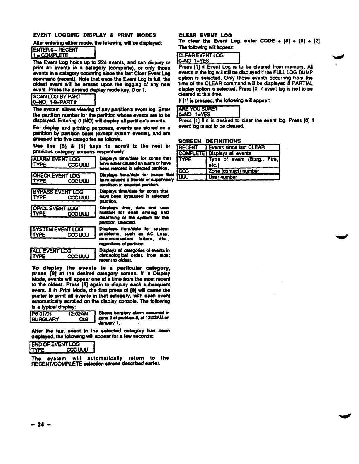
EVENT LOGGING DISPLAY &PRINT MODES
After ●ntering either mode, tho foUowingwitl be d~ed:
ENTER O. RECENT
The Event Log hotds up to 224 wonts, ●nd can display or
print ●ll wonts in ●oatogofy (oomphto), or only tho60
wonts in ●cawgory oocurring sinoa tho fast Clear Event Log
command (reoant). Note that ones the Event @is Mf, the
oldost event will be ●rasod upon the logging of ●ny new
went. Prass the dosirod display mode key, Oor 1.
~
The eystom afbws viewing of any partition’s event fog. Enter
tho part&ion number for the panition whose wonts am to bo
dmpfeyed. Entorirtg O(NO) willd-y allpartitbn’s events.
For dispfay and printing purpoeas, ovonta U. stored on ●
partition by partitii baaii (excepl aystam wants), and ars
9- into fiie ategories as Mows.
Use tho [3] &[I] keys to eoroll to tho next or
Previous cateoorv suaons resoectivetw
EVENT LOG
muw I
IE5YzEl
10 dleDlav the wmtte
Disptsystino/dstsforSonesmet
hevsaiUmrausaden
dsrrnaheva
beonrosmradrnsdsctedpsrtMrl.
CLEAR EVENT LOG
To otear tho Event Log, ●ntor CODE +[#] +[6] +[2]
mfdbwing will-kppw
~
Press [1] if Event Log is to be cfoard from momo~. Atl
wonts in tho togwill stillbe disptsyed iftho FUU LOG DUMP
option is sela&ted. Only those events oocurring from tho
timo of tho CLEARcommand will b. dmpteyod if PARTfAL
diapfay option is selected. Press [0] if ovont log is not to ba
doarod et this time.
ft [1] bproaaad, tho foftowii will appeac
I
~1
prw1-YES J
Press [1] il it is desired to dear the ovont log. Press [0) if
event fogisnotto be cloarad.
SCREEN DEFINITIONS
REOENT Events sines lest CLEAR f
Dmpkly s allevents
lYPE Typo of event (Burg., Fire,
etc. )
Disptoys timeldsm for Zonos -t ~Zono (awnect) number
hsveausada 80uUsorsuporvisnw User numbar
ODn&ioninaekctadparmolt
DisPhYsdmeMa*timf-tit
hsvsbeon bypassodinsefeow
partition.
Di8ptaya tires, dam end user
rwrnbar for cash ●rming ●nd
disarminQof rho Systemfor be
partition~.
Displays thne/data for systam
probtams, suoh ●sAC Loss,
oommuniostion failure, ●tc.,
rogardiessof pufidon.
Db@Wdamofwsnkrn
ohronobgioel ordar, from most
-t m ddost
In ●particular oetegory,
mreas ~81 ~the desired ceteaorv screen. ff in Diiofw
be, &&tts witi appear one at ~tirno fmm the most ra&ti
to the ofdest. Press [8] again bdispfay oaoh subsquent
event. ff in Print Mods, the first press of [8] will ceusa tho
printer to print aft ●vents in that category, with each ●vent
●utomaticefiy sorofted on the d~fey console. Tho foffowing
iss typical display 8howsburglsry alannoccurmdin
zono30fpudtion 8,st12.U2AMon
-1.
After the fast ●vent in the sdected category has boon
d~tayed, the foffowingwifl appear for a law seconds:
I
The system will ●utomatically return to tho
RECENTtCOMPLETE selection screen dascrbod ●arlier.
-24-

VI. SYSTEM COMMUNICATION
SPLITIDUAL REPORTING
Dual raporting(%1) sands Wropofis to both prtmwy and
ssoondmy phono numbam. Splft rsporting altowa ropma to b
divided betwsan tho phono numbers ~rding to the fiifd’s
(1*34) solactions. Spliiual roportlng can ba ●act6d by
●nablii dual repotting and ●nabling ona of the split mportlng
options in fiofd 1“34. ff optbn [1] is s6factad, di atarrns, alarm
mstoros and canoal ropom will go to both phona numbers,
whii atlothar reportswiflgo to the saoondary phone number. ff
[2] is sebctad, opantcbss and test mossagaa wifl go to both
ohono numbem. whife ●ll othor reoorts will wto tha orfmaw
R@orthgC+tbns:-
FORMAT 31 1%4
SPLIT ola2
ADEMCO LOW SPEED
AOEMCO LOW SPEED is apulsedformatwhbhrespondsto
81400 Hz handshako and kiss-off. and transmits data w~h
1900H2 pub bnos @10 pUISSSpar second (pps). Afypioal
message ~nsists of two rounds whd must bs tmffi by
the racaiver. A~mplete standard raporf consistsof ●f&har●
3or 4diiit acceunt number followed ~●ld~it alarm ooda.
Though 2rounds ●re santj only the vafid raport kdisplayed.
[n expanded reporting, two messages are sent, two rounds
par message, the first bahg tha ~unt number and ●h
me,tksmmwl~tiemodeb-tih
wasassigned. Acomplete expandad raporf consistsof ●3or
4-digit account number folbwed by ●Idigit afarm oode, then
the alarm cx%feis repeated, folbwed by tho ohannal nurnbar.
E)(. Smrdard CCCCEwhsrw &=rXk2 ~
ExPandd ycc: Z-zonalDads
SESCOA/RADIONICS
Standard ●nd ●xpandod reporting in tho
SESCOA/FtADIONICS format is virtually tho sams as
ADEMCO &w Spaad ax~pf fortha folbwing:
1.ThahandsMwandkiss*ff fmqumoyis22cONz
2. Thadsrais8an4mit9sdwi611600H2fx4aamnas.
3. Thararaof rmsmissbnis20ppc.
4+2 REPORTIN@
A4+2 report cons.bta of ●4dqit ~unt numbar and ●2-
digit alarm code, or ●vent code. 4+2 raports oan be
accomplished either in ADEMCO Low Spead (10 pps), or
SESCOA/R.ADIONICS (2o P@ format.
In 4+2 reporting 8uniquo 2digif code for ●ach zone is
reported. A4dqir acoounf number followad by ●2dwit oode
is sent, wham the first digit is the actuaf event such as in
ALARM, RESTORE, or TROUBLE, ate, and tha aaoond digit
of tho oodo reprosants tho %ona- share the worn ~ad.
(but not nacossarity ths actual zons numbar). Each cods in
itsaff is unique to ●sp6cifiizon6. ffdesired,thaadual zone
numbar can bs raportad by ●ntering the mrresponding 2digit
y~rn~t=rx. zona 1= [0] [1]: zona S3- [6] m. Araporf
.
.
12S4 S@(%W~boa~ —rRoWt2RE61m.2oN2 a.
4+2 EXPRESS
ADEMCO’S now Express format providas tho ●m.
information uthe&2 format, but with threa diffo~
1. Tho datm is transmitted in DTMF (Dual Tono Mutti-
Fmquoncy, fcnown as VouchTono”. dm. ~. of 10
characters par sscond). Thii greatfy dacreasas tha tfma if
takas aroporf to go through to c6ntraf atatbn. An average
4+2 Low Spsadraportmight takeasbngas 20asoondsto
Oomplota its raport but 4+2 Exprass takas Under3sacs.
2. Two message rounds are .Iiminatad by tho use of ●
oheoksum dwh. Instaad of tho communbator aendhtg 2
rounds per report, Bsands only 1round wtth aoheduum
digit ●tthe ●nd. Doing this ●bo halpa in deoreaaing the
tinwlttalwa foraraporttobasert
3. The hmdshaka fraquency is 1400 Hz followed by 2300
HZ6ndthakiasoff frquo*k1400*
ADEMCO HIGH SPEED REPORTfNQ
ADEMOO’a Hiih SpaadforrnattransmUadafa in DTMFatar@a
of 10 characters por saoond. Tha handshake frequanoy &
1400 Hz fofbwed by 23oO H& and the kfaaoff fraqusnq b
1400 Hz. lhs maasago cmntains13 dgtts as foftowc A4.digff
eunt numbar +●ighf channafa of zons informatbn (1-3 or
duress PIUS3-1S) +on. status channal whbh idantifii the
typa of ●vanta baii reported in tho ●ight zorw bcatbna. A
typial Hqh Speadraportwifl bekiasadoffin undar5aaconds.
O&nlWmghso ouldhav60neotth efo30w@toondnbrrx
“NOIE. Ctwvnfl wM-nthausarlDW, A-Fif OpWCbs
fv-wm~
Ths statuschannal might have orw of ths fotbwing oondhiinx
1. DlfREss&OroumssPbschsrswk6.150nty)
2.mNfNG
3. SYPAss(Forcblrlsb 1401ty)
4- CWSING
5-TRCtlJu(For~ld~)
6- ~M ~A~: ●AclQS6inctWvdl
●msAmRYirlchW0d2
•~TAWER&I~3
•~oNmhctmsnt4
7-~~~A~ ~1.uq)
g.~~
Atypbafhqh apoadrsport may bokasfoffmw
l~Sl15s7(ti#l=ti_wtiti2d3)
LIMITATIONS
l.Whanuaing Adamoohiihapssd, mmanbartharearo onfyls
charmebavaiUfa, pbsadurasa ohannaLUmorathanlS
zon6aareb6ing usad*th6ywi9 hav6toahar60hsmWs.
2.WM Ada- Hiih Spaod reporting, channels 9-15 cannot
raporttmubfasor~. usethasschannalsforzonas
thatwfflnot
raporfthesa oondhiins.
CONTACT ID REPORllNG
This is theonfy format that can identify ●ll S4 profadion
zonas by thair uniquo zona (Contaot) ID numbsm, ●nd
providos ●l-diiit avont quafifiar and 3digit, spacdbdy
defii wont ~.whii quickfy idOfltffiiStho ~ndiibn
baii mportad.
~tDraportainDTMF(DualTonsMutii-Frquancy@10
characters per aacond) and responds to ●1400 HZ fofbwad
by2300Hz h6ndshake,6nd a1400Hz tdssoff.This form6f
also US6Schadcsum instead of tww messago vorifbatbn. A
~mporf takes undar 3●aoonds.
-lDRePortiqtakaa thaforrrr@ OCOOQEEEGGZZ
wham
m- Cuaamar(sukrbar) nwnbsr.
o-EvsruQ&iarowhom:E-lw9&rllxJ&as10rs (3)
-EwrMoods(2haxadawMI
tionmsnsxtpags. “
-Fmmnrssnbsr.
z-zmwommdforusnbu~ hedwrn(ool~
orussrnunrbsr(oo1470)torop@0bsersporm.
SysmrrrS- rnsssaoss(AC@s&W* lest,sk)
oonmnZsroaSintlazzzbmaOn.
-Es-
9/ 1
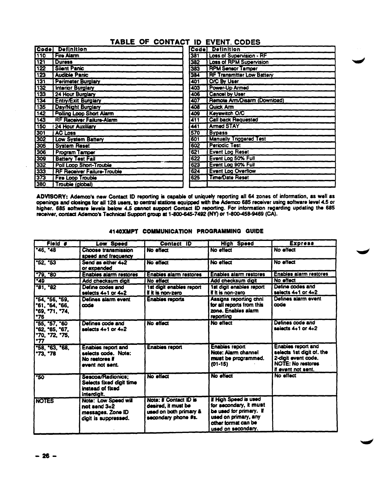
TABLE OF CONTAC
Codo IDofUrltlon
IlO IFm Alarm II
J
WBurg181y
--- –—.-— I
rtAlarrn I409 lKwsw
, . ..JmAiarrn 4f 1!call be%
441 IArmedS1
“B nuxiliary
** {
r-. u- i
-RF
vision
Ir
BfV
knr {
meqlr-3ater-
rAv I
570 Bwass
601 Manually Trigqerad Test
602 Periodic Test
621 IEvent bReset
622 IEvent Log 50% Full
623 IEvent Log 90% Full
624 iEventLw Overflow
626 Time~ate Reset I
ADVtSORY: Adamda new Contact tD reporting is capabfe of uniquety reporting all 64 zones of information, as well as
openings and cbaii ti afi 128 users,@oerrtralstationsequipped with the Memo 685 receiver using software bvel 4.5 or
higher. 685 software fevela bebw 4.5 oannot ●upporf Contaci ID reporting. For information regarding updating the 685
receiver, amted Adontoo’s Teohnii Support groq at 1—80&S6-7492 (NY) or 1-800-458-9469 (CA).
4140XMPT COMMUNICATION PROGRAMMING GUIDE
or ●xQanded
“79, ’80 Enables alarm restores
“49 Add cheokaum digit
“81, “82 Define -es and
selects 4+1 or 4t2
“64, ●56, ●59, Dofiis atarrn went
“61. ●64. “66. Ooda
[“69: “71: ●74. I
“50 SaaooatRad”smow
selects fKOd digit time
inatoad of fried
NOTES fbta: Low speed win
not send 3+2
ntaaa8ges. Zone fD
dgit is suppressed.
Contaot ID High Speed Express
No ●ffect No effect No effect
No Offact No ●ffect No offecf
Enables ●larm roatorea Enabfos alarm restores Enables alarm restores
No effeu Add checksum digit No offad
Iatdigit ●nabba raporl let digii enablae report Define odes and
wit la non-zero it It is non-zero selects 4+1 or 4+2
i%atMasramrta haions raoortino ohnl Dafws alarm event
I I
ti-~f ~arootia code
.I
Ireportrlg
iI
No effau INo ●ffact IDefines code and I
I Iaelaota4+1 or 4+2 I
Enabbs report ‘1
Enablesrepmt
I
Enablesreportand
W. Alarmchannel sebotalet d~it of.the
nwst be programmed. 24igit event ode.
(01-15) NOTE: No reatorea
.– .if event not sent.
)40 ●ffect No ●ffect No effect
disirad,ifntuafba *&o&fary, if must
usadonfJoth prirnuy& be used for primary. ~
aeamdary phone #a. used on primary, any
~fonlmucnab w.
-26-
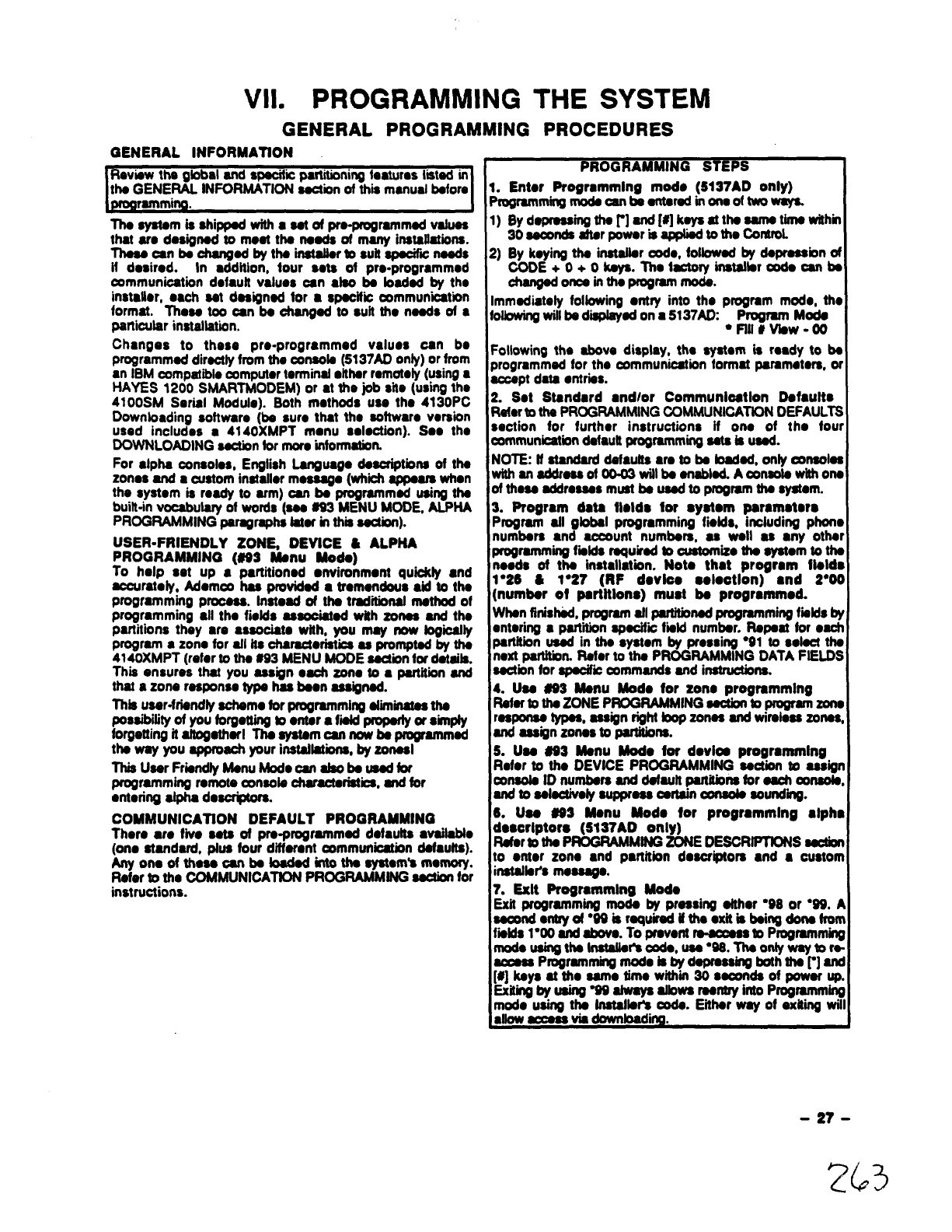
VII. PROGRAMMING THE SYSTEM
GENERAL PROGRAMMING PROCEDURES
GENERAL lNFORMATtON
Review the global and specifii partitioning Isstums Iited in
the GENERAL INFORMATION esction of thii mmmi More
~amming.
Theeyatam isshippad withasetof prs-progmmmad vatuaa
that aro designed to moat tha naods of many installations.
Thaaa an ba ohangod by ths inatafbr to suil apacifii naeds
if dosirod. In ●ddition, four sam of pro-programmed
oommunioation dofautt values can dao ba badad by ths
instalbr, ●ach sat designed tor ●specitii communbation
format. Thoea too can be ohangad to sutt tho nsads of 8
particular installation.
Chsnges to these pm-programmed values can b.
programmed directly from the console (5137AD onty) or from
an IBM compatible computorterminal ●ithar mmotdy (using ●
HAYES 1200 SMARTMODEM) or at the job sit. (using the
4100SM Sar@l M~uio). Both rnothods use tho 4130pC
Downbading softwsm (be sum that the software vsrsion
used includas s4140XMPT menu election). Soe tho
DOWNLOAOING sactbn for more information.
For ●lpha oonsolos, Engfish Language descriptions of ths
zonos and ●custom inatafler mesaago (whii appears when
the system is ready to arm) oan be progmmmsd using ths
built-in vooabuiary of words (sss 693 MENU MODE, ALPHA
PROGRAMMING paragraphs tatar hthii asctbn).
USER-FRIENDLY ZONE, DEWCE ~ALPHA
PROGRAMMING (669 Menu Mods)
To help set up ●partitioned ●nvironmonf qubkfy ●nd
accuratoiy, Adom~ has providad ●tmmandous *to ths
programming prooaas. Inatoad of tha traditional msttrod of
programming ●ll tho fietds assooiatad with zonas and the
partitions thay ●re associate with, you may now fogiity
program ●zone for aft tts charactoristii se promptad by tha
4140XMPT (mfor to tha #93 MENU MODE aactionfor dataits.
This ensures that you assign ●aoh zono to ap@tion and
that azone rasponso type has bean asaignod.
Thb user-friendly schamo for programming aliiinafaa the
possibilityof you forgetting to ●ntar ●fii pmparty or simpfy
forgetting it attogetharl The system can now ba programmed
the way you approach your insfaflatii, by zonaal
This User FriendfyManu Mode can afsobe uead for
programming remote ~nsota chamctaristba, and tor
●toring alpha desufptom.
COMMUNICATfON DEFAULT PROGRAMMING
Thor. W. fiio sate of pra.progmmmad dofautta ●vailabb
(on. standard, ptus four diffemnf oommunbatbn dafaufts).
Anyonsofthaaa oanb9toadad intotha syatom’snwnory.
Rotor to the COMMUNICATtON PROGRAMMING section for
instructions.
PROGRAMMING STEPS
1. Enter Progrsmmlng mode (5137AD only)
Programmingmodscanbaantarad inonaoftwo~
1) Byd~~tir]ti [#]k~athmttitihh
30 seconds after powsr is apptiodto tho ControL
2) By keying the inatallar oodo, folbwsd by doprsssbn of
CODE+ O+ Okays. ~ol*ryinstallsr* canba
--htiPWm*”
Immediately followhg ●ntry into the program mod., the
foltowingwitlbe d~ad on a5137Atl Program Mode
●Fflf#viaw-oo
Following the above display, the syswm is ready to bs
programm~ for tho communication format pammoters, or
accept data ●ntrias.
2. Sot Standard ●ndlor Communloatlon Dafaulto
Rak to the PROGRAMMING OOMMUNICATtON DEFAULTS
section for further instructions if on. of tho four
communicationdatautt programmingsate is used.
NOTE: tf standard dafautta ●rs to ba Mad, only oonsoba
withanaddmaeoto003willba snabbdAmwotswhhona
of these addmaaas must be uaad to program fha system.
3. Frogrsm data fblds for syatom paramatsra
Program afl gbbsl programming fiilds, including phons
numbsrs and aocount numbars, as well as ●ny other
programming fiitds mquimd boustomKo the system to the
noads of tha installation. Not. thct program flolds
1●26 &1“27 (RF dovlco soktlon) ●nd 2“00
(number of partftlons) must ba progrmnmod.
When finished,program atl parfftbned programmingfiitds by
entering ●part-tin spacitii tiitd number. Rspaat for ●ach
partition uead in the system by preesing “91 to sotsct the
next partitbn. Rafor to the PROGRAMMING DATA FtELDS
aaction for spaoifii oommands and inatmctbns.
4. Uaa #63 Menu Mode for zone programming
RafartotheZONEPROGRAMMING aactbn bprogramzone
r~~ ~, ~ign rigflf bop ZOrwaSlld wireless ZOnSSO
and assign zonas to partifbna.
S. Uaa 663 Menu Mod. for dovlos progrmnnlng
Rater to the DEVfCE PROGRAMMING aactbn to assign
mwob ID numbers and dsfauft partitionstor aach oonaota,
and to Sebctivaty SuppressCsrtainOonao& Soundii.
6. Uaa #63 Menu Mod. for programming ●lphc
doaorlptors (5137AD only)
Refers the PROGRAMMING ZONEDEBCRfFTfONSsection
to ●nter zono ●nd partition descriptors ●nd ●custom
inataflar’smeaaago.
7. Exit Programming Modo
Exii programming mode by pmesing aither ’98 or “69. A
Seoondontryof”wisraquiradif thaixitisba ingdonafron
tiitis l*o0 and above. To pmront m—acosnbProgmrnmfnf
modousingtha tnatafbr%ooda, usa”66. Thaonlywaytor*
~Pmgramming modOisbydapmaaing boththar]anc
[#] keys at tho eamo limo wtthin 30 saoonds of power up
Exitingbyuaing W9ahvaysalbws mantryinto Programming
m~~~ ~&~ cads. Eiihar way of exkii wil
m.
-27-
263
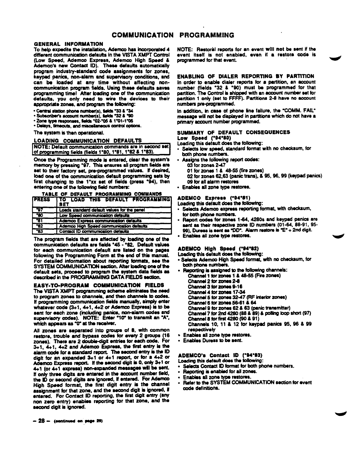
COMMUNICATION PROGRAMMING
GENERAL lNFORMATtON
To hafp ●xpsdite ths installation, Monm has fnmpomtsd 4
difbmnt communbation defsutta in tha ViSTA XMPT Control
(Low Spaod, Momoo ExPrass, Momoo High Spaad &
Adamoo’s naw ~ID). Thaaa dafdts ●utomatiasily
program industry-standard ode assignments for zonos,
keypad panics, non-alarm and Supervisory Conditions, and
can bs foadad ●
t●ny timo without dfocting non-
mmmunbatbn program fmids. lMng thasa dafauita savas
programming tirnal Attor bading ons of tha oommunioatbn
dofauits, you only rmad to wiro tho dovbas to their
appmpr@o Zonaa, and program tha fofbwi~
“Csntrsl,srationphornnumbsr(s),*m&%
.SubsonWs~nt numbsr(s),ti %2*W
“Zxletyps ~, flaW %2-W tlml-lm6
“Dshys, tirnsom, mdmkdmsou smm options.
The systarn is then oparationai.
LOADING COMMUNICATION DEFAULTS
Ones the Programming mods is ●ntorsd, clam ths syatsm’s
rnamory by pmsa~ ●97. Thii ●nsuras ●il program fwlds am
sat to their fuaory sat, pm-progmmmsd vafuaa. if dasirod,
toad ona of tha mmmurkatii dofautt programming ssts by
first changing fO tha 1“XX sat of fialds (pr.as ●94), than
omering ona of tha following fisid numbaw
TABLE OF DEFAULT PROGRAMMING CONUAND6
PRE= I~0= LOAD THIS EFAULT RAMMING
The program fiaids that ●ro dfaotad by badhtg ons of ths
commurtioation dafaufts u. fiaids “46 -“62, Default vaiuas
for ●ach communioatbn da@utt am iiatad on tho psgo$
following tho Programming Format tha ●nd of thii manual.
For detaibd information about raporting formats, saa tho
SYSTEM COMMUNICATION saotion. Aftar bading wdtha
dafautf SOtS,proooad to -M tha aystarn data fiaid$ =
daaufbed in tha PROGRAMMING DATA FIELDS aadion.
EASY=TO-PROGRAM COMMUNICATION flELDS
Tha ViSTA XMPT programming schamo oiiminatas ths nssd
to program zonas to ohannaia, and than ohannais to oodaa.
tf programming ~mmunioation fiaida manuafly, s“knpfyantor
whamvor oodo (3+1, 4tl, 4+2 or Mama Expraas) bto bs
Sam for oaoh zona (including panics, non-alarm oocfas●d
suparvbory oodas). NOTE: Entar “Ir to transmit an ‘A-,
Whiiappaars aawattharaaivar.
All zonas ●re saparatad into groups of 8, with oommon
raatom, troubia ●nd bypass oodaa for ●very 2groups (16
zonaa). Thare am 2doubiadigft antriaa for ●ach ooda. For
3+1, 4+1, 4+2 ●dAdamoo Express, Wfirsf •~ry kths
atarmoodsfora standadrsport. Thoaaoondantry iattwlD
digit for an ●xpandad 3+1 or 4+1 r.port. or ~r ●4+2 ~
Adamoo ExprassrapofL lffhasaoond digii@O, ~3+lor
4+1 (or 4+1 axpmss) non-a- ~.$ ~i b. ~
if only tins d~ita am ●ntomd in ths -unt numbar fistd,
ths ID or sacond dnita am igti, ff m~. * Ad.-
High Spaed format, tho first digit retry fs ths ohannoi
aaaignmom for that zone, and thasamd dwitisignoradif
●
ntamd. For Contaof ID rapofiinfi, th. first diih .mIY (-
non zero ●mry) onabbs reporting for that zono, and tho
aocord digit is ignored.
NOTE: Rastotii mprms for ●nwent wlli not bs sant ff ths
ovont itself is not ●nablod, won il ●mstom code is
pqrammsd for that went.
ENABUNG OF DtALER REPORllNG BY PARTtTION
in order to onabis distar mporta for ●partition, ●naccount
numbsr (fiiids ●32 &“90) must bs programmed for that
psrtifiin. Ths Controi is ahippsd with ●n~nt nurnbsrsst for
partftiin 1onfy (sat to FFFF). Partitbna 2-8 have no aouwnt
numbs ~mmmad.
In ●ddiiion, in ass of phons fin. taiiuro, the ‘COMM. FAIU
rnasaags wifi not ba diapisyad in psrtitiina whbh do not have a
pfifn~ acaum numbsr programmed.
SUMMARY OF DEFAULT CONSEQUENCES
LoW Spood (“94”80)
faading tits default doas ths following:
●Saiacts bw apaatf, standard format with no chscksum, for
both phons numbsrs.
●Assignsths fofbwing raporf codas:
03 for zonss 2-47
01 for zonss 1&46-55 (fro zonas)
02 for zones 62,63 (panic tmns), &%, 96.99 (k- PM*)
09 for ail alarm raatoma
●Enabisa ati zons typs tmtoraa.
ADEMCO Exprooa (-94”81 )
Loading thii dofautt doss ths following:
●Ssiscts Mom= ●xpmsa raportingformatt **urn*
tor both phons numbars.
●Raporloodaa forzonas 1-64, 4260s and kaypadpanicsars
asnt as thak raspsctiva zons iD numbars (01-64, 88-91, 95-
99), Durosais sant as QD”. Aiarm ratirs is %“ +2nddigif.
●Enabias aii zons typs MOMS.
ADEMCO High Spaad (’94”82)
Loadii his dafauft doaa ths Mowing:
.Salaota Adamoe High Spasd formal with no chackaum, for
bdh phona nurnbsrs.
“Rsportingis8saKPd*ti-*mk:
channstlforzonss l&46-85 (Fiwozonss)
channsi2forzatas 2-6
Channa13forzonsa 916
channai4forzonsa 1744
Channa15forzonas 3247(RFintarbrzonSS)
Channsi6forzonsa 66-61664
Channai 9for zonas 62 &63 (panictransmitter)
ckti7*tia(m689) 6p**ti@7)
Channs18fOrfirSt42if0 @&91)
Channais 10,11 &12 forkaypadpanba 95, 96&99
raspoctivefy
●EnaMaa afi ZOnStypa rSStOMS.
●Enabbs DUmSSto bs aam.
ADEMCO’S Contaot ID (*94983)
Lo.adirrgthii dafauit doos tha foiiowino:
●Saiscta Contact to format for both phons numbsrs.
●Raporting is ●nabisd for all zonas.
●Enabiss attzona typs MStOMS.
●Rafor to ths SYSTEM COMMUNICATION sactionfor went
cods dafhitbna.
-28-@ontlnwdonPeoss)
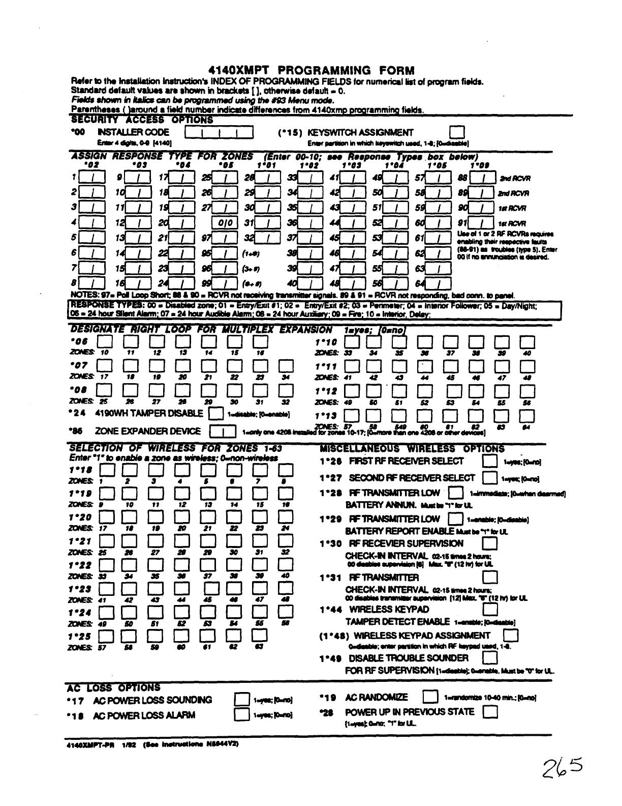
4140XMPT PROGRAMMING FORM
Rdor bths InsWMion Instmtm
“%INDEX OF PROGRAMM It@ FIELDS for numofical listol programfislds.
Sti2?d d.t2Utt V21u2g2?sshown in H.t2 [], othorwissd.tautt. 0.
FtiskwrIin Wan bSDIOBwmO$U&IW #IS~MSIXI~.
round ●fti-nuhr ind~o ~ttiorsncesfmm 4140xmp orog
“00 NsTAILER mm [-l (“1s) KEWCHASSIGNMENT c1
*4mo.s tmo] Enwmh-~bwd,14,~]
ASS!G NRESPONSE TYPE FOR ZONES (Enter 00-10: sos R..DOnSO TvD@# box bdow)
●O2 ●O8 ●O4 ●0s l~ol 1“02” f●OS“1“Od-1●OS
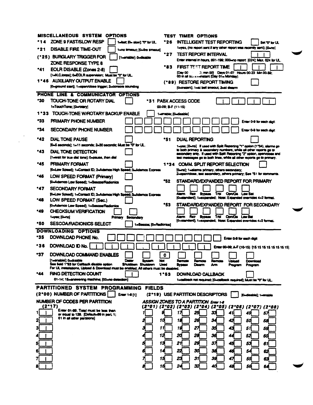
MISCELLANEOUS SYSTEM OFTIONS TEST TIMER OPTIONS
●14 ZONE9FAST~RESP ❑l~~tikW’tiU “26 IN7ELLGENT TEST REPORTING •1 *W-U
“21 DISASLEF*TIME~ ❑ldDWNO@fC&IWMIUOIU] lqO&(noRpalWnIifqoeluf9pMrl-momluy8@nwbl
(“25) BLJRGMRYIRIGGERm ❑[lmblohodiaabb ●27 TESTFEPORTMERVAL m
ZONE RESPONSETYPE8 Enmrmwvalmkm, W1-lWOObmmpm [024kb024brU
●41 EOLR DISASLE (Zones 2-8) ❑“83 ~=’TWPOIWTktE 1~1 ml ~]
[ldt.ca~ tiaR ~Mbowtila- 2“m-m~~p 00-= ~-.
oom~s..~ .
1●46 AUXILIARY
OUTPUTENASLE ❑(980) RESTOREREPORTIBUFJG
l~til ~w@c ~ooLmdl~ ❑
~:1~=~--
~
●3O lWCN-mE OR ROTH ML ❑“31 PASXACCESSOODE mmmm
loTouchT~ [~] m.oaw(11-12)
1●33 TOIJ(X+-TONEWMOTARYBACKUPENU ❑1~,~]
●33
●34
“42
●43
●45
848
’47
●46
●4@
9s0
“53 STAND~ANDED REPORTFORSECONDARY
❑onclcln
pRo82ypa98 TluqllW191.talf Ba _.
.- . .
●3S
“36
“37
●44
PARTITIONED SYSTEM PROGRAMMING FIELDS
(2”00) NUMSEROFP~ •1 211ar14 [1] (2”19) usEPARTmoN oEsoRIPToRs n~~ 1~
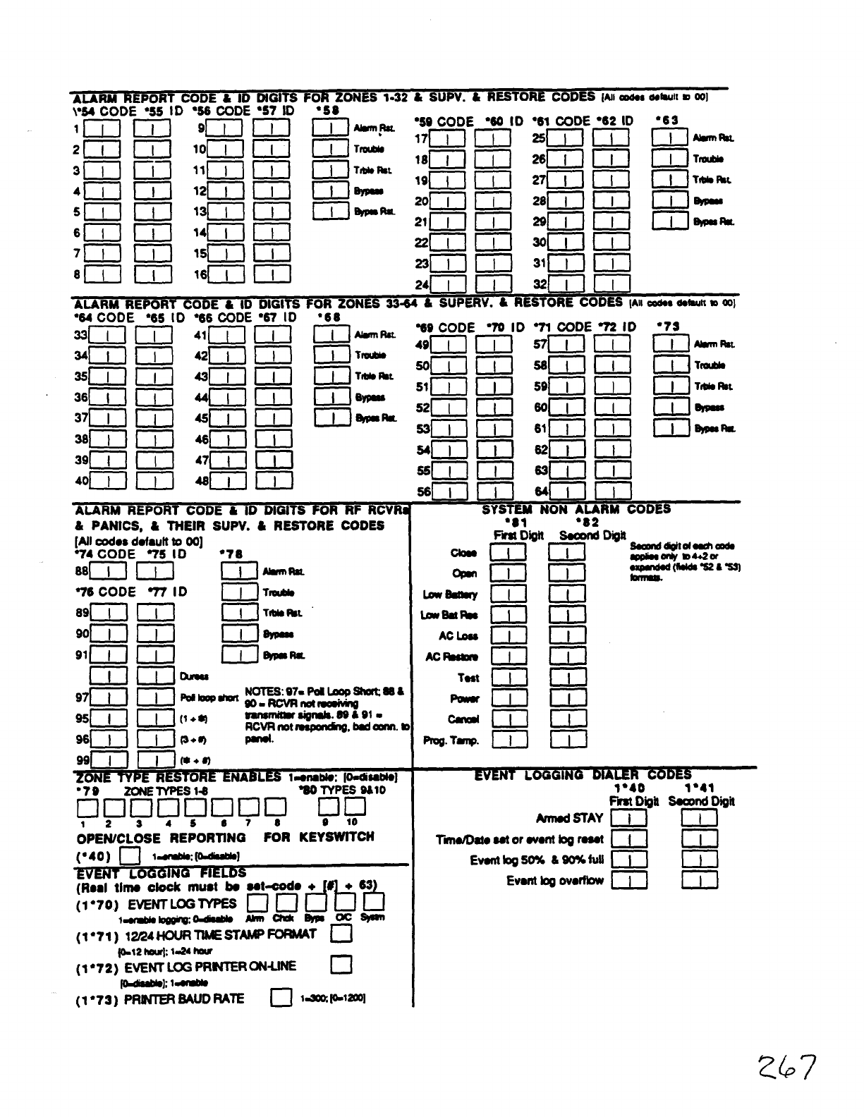
40L]lllj4611111J
~OR RF RCVRi
&PANICS, &TNEIR SUPV. ~RES70RE CODES
[All -OS default to 00]
74 CODE 75 ID ●78
88~1 ml [-l -Rm.
qIII IJ(*+8)
ZONE TYPE RESTORE EN BL= I=ofublo:p-dhabto]
●7B ZONETYPES 14
❑ncloclcl&l *Eb”’O
12345078 @10
OPEWCLOSE REPORTtNG FOR KEYSWITCH
(“40) ❑1~~1
%VENT OGGING FIELDS
(Raal tl~ ctook must hoat-do +
(1”70) EVENTLOGTYPES ❑ ❑ d%?l
ldrmblDbY221m~*mmm ms)m
(1*71) 1~4t+0LJRWST-~T n
(0-12lwr~ 1-24ha#
(1”72) EVENTLOGPR_R~UK c1
~h 1~
(1“73) PRtNlER6AlJD RAIE c1 la *1200]
Glow
Lwsdtay
bw%
ACb
AC-
Test
Prog.Tamp.
●81 ●
82
15mm-
mm
mm
GIGI
mm
mm
mm
mm
mm
mm
MSTAY
Tii20tor2vortt bgro8st
Evonttog50% &SO%tulI
Event ~OVOffbW
1“40 1“41
H-mD*R
mm
mm
mm
767
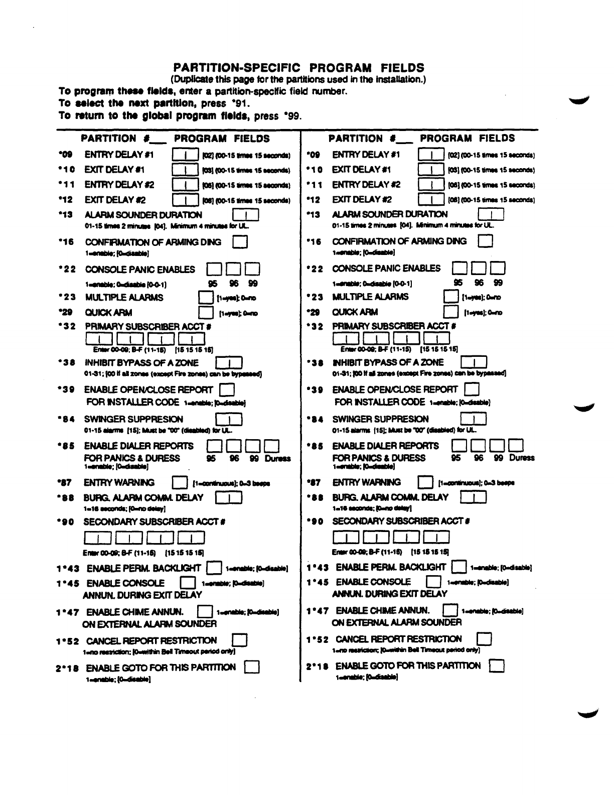
PARTITION-SPECIFIC PROGRAM FIELDS
(DufMcatO
thispaga lorthe partitions used in the installation.)
To progmm thssa fialds, enter apartitiimspsclfii field rnmdw.
To select ths nsxt pmtltlon, press ●91.
To mtum to the globsl progmm fl.ids, press 999.
PARTITION #_ PROGRAM FIELDS
m
“10
●11
●12
“33
“16
“22
“23
●29
●32
“38
●39
●84
“85
“87
●8S
“@o
EXIT DEtAY wm{ P31m@15-1$~)
ENmYDEtAY#2 GI pq(OMsiffU81500wrle9)
ExtT DEtAY 62 lill=let*-,s==@@
ALARAmsouNDERDuR4TmN ml
CONFtRMA” OFARMINGDNG ❑
1~~]
PRtMARY SUBSCRIBER ACCT #
cZlm DD
Enor-: w(1$-151 [151s15lSI
INHIBIT BYPASSOF AZONE ‘m
0141;loowa9zam@(OmBptF&ozamOO)mnbo@pmt,dJ
ENABLEOPENCLOSE REPORT n
FUR tNSTALLER CODE ~~~
swtNGER suPPREstoN m
01-lsdmm [la, wabowr( dnwod)brut..
ENTRYWARNING •1 [1
—mmhJO@mbopa
BURG. AIARM COMM. DEtAY 1~1
1.16~&moo@]
SECONDARY SUSSCR@ER ACCT#
EHiNilD
Ew~. W(11-1S) [1S1S1S1~
1*43 ENABLE PERM. BACKLBHT n$~loa-kl
1“45 ENABLECONBOLE nt~,~l
ANNUN.DURNG EWT DEIAY
1*47 ENABLECHNEANNLN. ❑la:~]
ON EXERNALAURMSOUNDER
1*S2 cANcELREPoRTFEsTRICTmJ ❑
l-~mMT~~*]
2“18 ENABLEGOTOFORTHLSP~ c1
~1
l~; [
●OS
“lo
’11
“12
“13
“16
“22
●23
●2S
●32
●SS
“3s
●B4
*S5
●S7
●SO
●9O
PARTITION #_ PROGRAM FIELDS
EXITDEtAY *1 [I]RWWs-15~)
ENTRY-Y= (T’lwoM56mumuuldB)
EXITDEtAY 62 ml @s](W15 WINS15UUlnd8]
HSouNDERmm m
ol.ls Em$2MMJW8Io4].WlhlUn4rlWMmsfnfLL.
CONFtRMATtON OF ARMtNG DING n
ldlMo; foddllOl
PRMARYSUBSCRBERAccT #
mNiHilml
Enm~HN1.lSl [15lS151~
NHtBtTBYPASSOF AZONE D
oi-sl:loolfd-@mwlFkOzonu)anbbYPundl
ENABIEOPEWLOSE REPORT ❑
FDR NSTALLER CODE t- K=IIOl
SWINGERSUPPRESDN ml
ol.ls&mna 115kMNtbow[~bruL.
ENABLE DL4LERREPORTS ❑KHJcl
FmiJy$luREss 9S 9689 DuNss
sEwNDARYwsscmERAczT#
mmmm
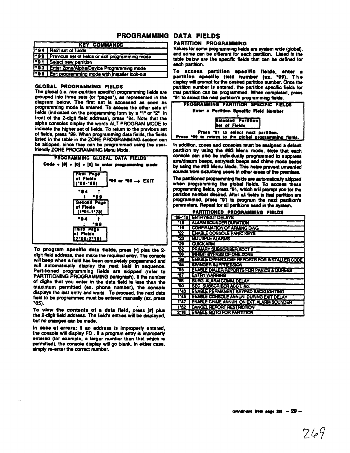
PROGRAMMING
KkY COMMANDS
’94 NextsetofIislds
●99 Pravious sat dfiatdsor ●xit Urog
ramming mods
’91 Salad naw partitiin
“03 Entar Zona/AlptrStDaVioaPmgmmming mod.
●D8 Exit programmingmock with installarIock-oul
GLOBAL PROGRAMMING FtELDS
Ths global(i... non-partitionspaoific) programmingfiilds am
groupad into thrao sata (or “pages-), as raprossntad in tho
diagram bslow. Tho first sot is aocasssd as soon ●s
programmhg mode is ●ntard. To ~tha othor ask of
fialds (indicatad on tha programming fom by ●~“ or Win
front of the 2dqit field •ddrc~), pru “94. Noto that the
alpha consoles display the wrds ALT PROGRAM MODE to
indicate tho higher sat of fmlds. To rstum bths pmvbua sat
of fialds, pmaa “99. Whan progmmming data fmlds,ths fwlds
fbtad in th. tabls in ths ZONE PROGWMING auxion an
coda +[q +[0] +[0] tsantsr ~mlng msda
“94 ●9:
m
●go
●94 t
1●99
\I
To program spacl(k data flaldq pmas [*] pfuaths2-
dgit fmld addmas, than rnalw tha mquiti •m~lti wnaofa
will hasp whorl ●fistd has ban amplatdy programmed and
will ●utomatically diapfay tho next fidd in ssqusnca.
Partitioned programming fields ●makippsd (mfor to
PARTlT1014tt4G PROGRAMMING paragraph). lf tha numbsr
of digits that you ●ntsr in tha data fwld is lass than tha
maximum parmittad (CX. phono numbsr), ths oonaola
displays tha fast onfry ●nd waita. To prooaad, tha -data
fisld to ba progmmmad must bs ●ntorad manuafly (ox. praaa
“05).
To vlsw tho oontsnts of ●data ftsld, pr.ss [#] plus
tha2digit fiofd address.Ths fiild’s●ntrisawillbs diapfaysd,
butnocharrgsacan bsmads,
In 0sss of ●rrora: tf ●n●ddrosa is impropsrty ●ntomd,
tha conaols will disptay FC. tf ●program ●ntry is impropsrty
ontorad (for oxampto, ●hrgor numbar than that whii is
parmttkd), tho mnaobs d- witl go btank. In ●ithar asa,
simply m-ardor tha oarract numbsr.
DATA FIELDS
PARTITtON PROGRAMMING
Vafusa
for aoma programmingfidds am ayatsm*(gbbal),
and aoms oan bs difforsnt for aach partition. Liatsd in ths
tabls bsbw am tho apacifii fmlda that oan bs dafii for
Oti parthbn.
To sooosa pmtltlon ●poclflc fields, ●ntor ●
parfttion spoclflo flald ttumbar (ox. %9). T h●
dmwfUprom@fortha daairadpwtition numbsr. Oncsths
partitiin numbsr kantorad, tha partitiin -i fmfds for
that oartitbn osn ba uroorammad. Whan rnmofotad, prssa
IPrss. W1 to oalsot nut pmthlon.
Prsos Wto rstum to tho olobal prsorammlno ffstds,
in sddabno xonaa and mnaolaa mustbs assignadadsfautt
partition by using ths #93 Msrtu mods. Nets that ●ach
ansola an ●bo bs indiviiuafty programmed b●uppmsa
-isarm baspa, Sntrylsxtfbsapa and dtirns mods bsspa
w**~3-w. TM*k*pmvant unwantsd
aaundafrom d-ussminothsr arsa$dttto pramiga$.
ThspaWonad programmfngfisMs am~aldpp8d
when programming ttm gbbat fiifds. To aoaas thoaa
_m~fi.kblpmsa Wl. whkhwfllprorn@ you fofth8
partittonnurrtbordaaikad. Aftsr afl fii hthat partkion am
pmgmmmad, prsas ●91 to program ttta naxf partitiin’a
pamnafsm RapaatforsllfMkbrts uasdbtthaayatam,
PARTfTfONED PROGRANMI
k. “121E~ I
Wnv
m.. *
-1 Av
(OonlhMdkwsa) -2s-
24$’
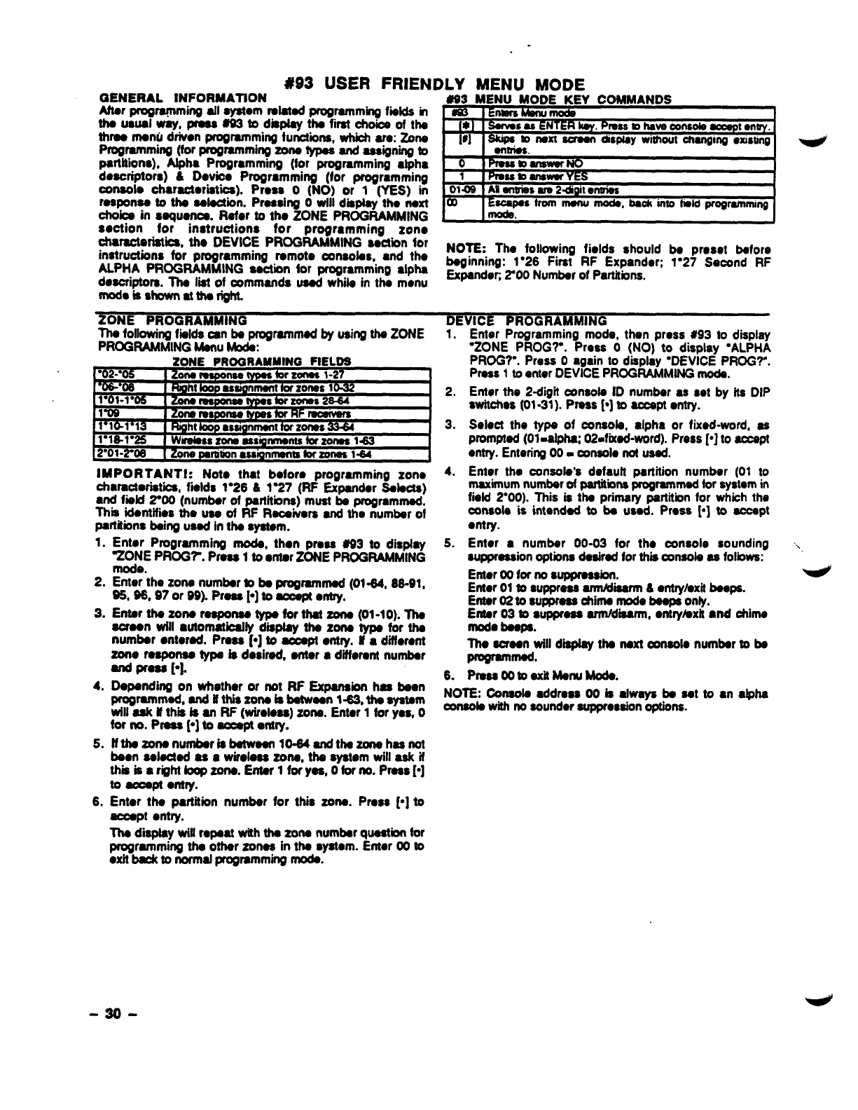
#93 USER FRIEN
GENERAL INFORMATION
Aftar prografnming afl aystom ralatad programming f~lda in
tha USLMIWay,PMSS~tO displayths firstChO& of ths
thraornonti driven programming functions, which am: Zons
Programming (for programming zona typas ad assigning to
partitions), Alpha Programming (for progmmmirrg ●tpha
doacriptors) &Dovioa Programming (for programming
console Charaotoriatioa). Pmas O(NO) or 1(YES) in
raaponaa to tha aaluakrn. Prassing Owill display tho naxt
choba in squonca. Rater to tho ZONE PROGRAMMING
section for instructions for progmmming zono
chamctariatii, tha DEVICE PROGRAMMING section for
instructions for programming ramoto ansotas, and the
ALPHA PROGRAMMING ●action for programming ●lpha
doscriotors. lha fii of commands uaad whila in tha menu
DLY MENU MODE
#93 MENU MODE KEY COMMANDS
rlmskkm!rnods
t13snmsumk@y. Press~have
oonsolsaccspt●n~.
1; @ups @nsxt scraan dmplaywithoutcharromoembnn
I I M* .- -1
I--------
0lpfo Sstoanswsrrdo
1Pmcc mmn- YES I
Scapsstrom Illanu Inoda, bsok into fieldprograrnminq
IllllLMh -1
NOTE: Tho following fields should ba preset baforo
baginning: 1“26 First RF Expander; 1●27 Second RF
Expandoc %00 Numbar of Partitions.
modoisshown attharight.
ZONE PROGRAMMING DEVICE PROGRAMMING
Tha foll~~ fislds can ~programmed by using ths ZONE 1.
IMPOR TANTt: Noto that bofom programming zono
chamotoristica, fidds 1“26 &1=7 (RF Expandsr SalsUs)
●nd fwfd 2=m (numbar of partitions) must ba programmed.
This idontifios the ttss of RF Raoakrars and the numbar of
partitions baing usad in tha system.
1.
2.
3.
4.
5.
6.
2.
3.
4.
Enter Programming ~, then prasa #93 to dispfay 5.
ZONE PROG?. Prass 1to ●ar ZONE PROGRAMMING
%%the zona numbar to ba pmgrammad (01-64, 86-91,
S5, 96,97 or 99). Press ~] to ~wrtry.
Enter tha zons raspoma typa for thatZons (01-10). Tha
aoraon will ●ufomatioaffy dmpfay ths zona typs for tha
numbar ●ntorad. Prass ~] to aooapf ●rttry. ff ●different
zone rasponaa typa is dosimd. antor ●dfloranf numbar
and prass p]. 6
-.
. ... . .—
E~or Pa-ramming mode, then press #93 to display
‘ZONE PROG?. Press O(NO) to display ‘ALPHA
PROG?”. Press Oaaain to disolav “DEVICE PROGY.
w
Prass 1to enter DEVk2E PROG~MING mods.
Enter the 2-digif console ID number as set by its DIP
switchas (01.31). Press ~] to aceapt entry.
Select the typa of consob, ●lpha or fixed-word, as
promptad (01.afpha; 02.fixad-word). Press ~] to accspt
●ntry. Entering 00- console not usad.
Enter tho consofa’s defautt partition number (01 to
mdrnum numbar of panitiins programmed for system in
field 2“00). This is tha primary partition for whioh the
consols is intendad to ba usad. Press ~] to accapt
●ntry.
Enter ●numbsr 00-03 for tho oonsole sounding .
suppression options dasirad for this oonaols as folbws:
Enter 00 for no suppmasbn.
Enter 01 to suppraaa amWbarm &●ntry/axifbaaps.
Entar 02 to suppraaa ohima mode baaps onty.
Enfar 03 to supprass arrnldiirm, ●ntrylsxit snd chims
mods baspa.
Ths soraon will display tha naxt oonaola numbar to bs
~-.
Prasa 00 baxil Manu Moda.
Dopanding on whsthor or not RF Expansion haa ba~n No= ~~ob addrcaa 00 is always b% sat to ●nalpha
programmed, and ifthiszona iabatwaan l-63, thaaystam
will ask tf thm &an RF (wiroleas) zona. Entar 1for yes, O~b withnosounder auppmssion options.
for no. Pmsa ~] to accapt ●ntry.
ffthszonanumbar is batwaan 10.64 andthazonahasnot
baon aalaotad as 8 wimlass zona, tha aystom will ask if
tikkar@~~mw. E~ltiy~, Otirm. Pws~]
to aooapt anfry.
Enter tha partition numbar for this zona. Prass p] to
mpt ●rttry.
Tha display wifl mpaat with fha zona numbar quaatbn for
programming tha ofhar zonos in tha syawm. Enter 00 to
●xif back to normal progmmmirrg mods.
-30-

ALPHA PROGRAMMING
Asslgrhg Zen. &Pm’tltlon Dosorlptors
tt using ●5137A0 ~neolo, ●user friendly Engfiih language
doscriptionlbcetion of all protection zorms, partitions
keypad panbs, polling bop short ●nd 4280 supervision
faults -n be programmed into the s~rn. Each descr”~icrn
can be composed of acombination of words (up to ●
maximum of 3) that ●re selected from ●vocabulary of
approximately 220 words stored in memory, and ●ny word
can have ●n‘s” or -‘s “ ●dded to it. tn addition, up to 20
irrstatlordefined words oan be added to those ●lrsady in
mmory. Thus, wtm an afarm or tmubb mews hazone, ●n
eppmpriato doacription for the location of that zone will be
displayed at the amsole. An irrstatbr’smessage can also be
programmed for ●ach partition which wifl be dispteyed when
the systam is %e~ (ex. lHE PETERSON%).
To program alpha descriptors,ontor Programming mode,
than proas #33 to display ‘ZONE PROG7. Pm O(NO) ~
display ‘ALPHA PROG’?. Press 1to ●ntor ALPHA
PROGRAMMING mode. There are 5sub-menu eebctiorts
that will be displayed one ●
tatime. Press 1to select the
mod. desired. Press Oto display the next morh availsbb.
The ●lpha sub menu sobctbns am:
1.
2.
3.
Entering Zone Descriptors Addl ng Custom Worda
SelectZONE DESCRIPmade.
Tho consab keys patform tho followingfurrcfbns:
[3] Scrolls both ●lphabet and actual words in escandhg
[1]
[2]
[6]
[8]
[#]
●lphabetical orcbr.
Scrolls both alphabet and actual words in
descendhg alphabetical order.
~swromows-%=~”’s”ba~-.
Toggles between stphatretand actual word Ii uead
to accept ●ntries.
Saves tho zone dadption in the system’smemory.
#plus zone number will display the doscriptbn for
that zone.
Key “01 to begin ●ntsiringtho descr@ion for zone 1, (by
“02 for zone 2, ●O3 for zono 3ate.). The following W61be
displayed: “ZN 01 A
Nota that the first latter of the afphabet appears attor the
zone number, and that the zone number is automatioafly
included with the deecripbn.
Select the first btter of the desired descrbtiin htote that
‘A” is already dispbyed). Use ~-p] to &an& through
the alphabet ●nd koy [1] to go backward. For exampb,
assume the desired description for Zons 1is BACK
DOOR. Press key ~] repeatedly (or hafd down the ksy)
until %“ appears, then press key [6]. to dispfay the first
available word beginning with B. Repeatedly press key [3)
to advance through the ●
vailable words until the word
BACK is displayed. Press key [1] to move backward
through tho word list.
To add an ‘a” or -‘a ‘, prsss the [2] key. The first
depression adds ●n‘a=, the aeoond depression adds an ■
‘s’, the fhkd depression dwfaye no character (to erase
the character), the fourth depraasbn adds an “c-, ate.
To accept ths WW press the [6] key, mto99~ ~
to atphabet fist.
4, For selection of the naxt ward (~), ~a $t.P 3* but
press key 13] until tlw desired fii letter of the next word
appears (in thm ●xampfo, W). Than press key [61b
display the f~ avaibbfe word beginning with ~. Press
key [3] repaatsdly until the desired word (DOOR)
appears. To aooeptthe wed, presstha 16] key, which
sgain toggles beck batphabet list.
5. When alldesiredwordshavebeen ●nterad, press ~[8]
to store the deacriptbn in memory.
6. To review the zone descriptions, key [#] plus zone
number (e.g., #01 ). To adii zone deacriptiins. key ~]
plus zone number (e.g.. “01)
7. TO .xit the zone desdptbn mod., fW ~.
NOTE: Alpha descriptor entry can be ●ntored focaffyat the
5137AD console or remotefyusing ●4130PC Downbder.
Up to 20 instefbrdefined words can be added to the butt-in
vooabulery. Eaoh of the 20 Wards= can actustly ooneist of
several words, but bear in mind that ●maximum of 10
charactere oanbeueedfor -wanlatring.
1. Select CUSTOM WORD mode. The keys parform the
folbwing functions
[3] Advances through a@habet in ascendingorder.
[1] Mvanees through a@mMt in dascsrrdii order,
[6] Selects desired Iattec moves the cursor 1space rigM.
[4] Mows the cursorone epaoe to the left.
[7] Inserts ●space et the cursor bcation, ●raskrg w
oharacfer at that focatiin.
[8] Saves the new word in the aystem~ memory.
~] Returnstodeacripbr ●ntry mode.
4. K~tbnum*d-~~orwd~tigtib
oreated (01-20). For ●xempts, if you are creating the fikst
ward (or word string), ●nter 01: when oraatingthe saoond
wwd, ●nter 02. and so on. Aoursorwitlnow appear at the
begiining of the second line.
5. Use tho [3] key to ●dvanoe through the ●lphabet
(numbers, symbols ●nd special characters ●re included).
Lfsetha(l]keyto movabsckthrough the@abat.
IMPORTANT: Custom words must baain with an
6.
7.
8.
94
alphabetic character. ff numbers or ~mb%-sre usd ti
the fii character.tha word wifl not be saved.
When you have reached the desired charauar, press the
[6] key to sefacf kThe cursor wifl then move to the right,
in positionfor the next character.
Repeat steps 5and 6to create the desired word (or
words).Note that the [4] key can be used to move the
cursor tothefaff ifnecesaary, end that key~canba
used to inter ●blank {or to ●raea an existing chareuar).
Eaohwardorword atringoannot axoeedlocharutars.
Preee the [6] key to save the ouetam word(s) and return
tothe*ED ??dbplay. Thecu$tomwxwd (or stringof
wards) will be ●utomatbally added to the buitt-in
vooebularyattheenddthegroup ofwurdsbegiining with
the same btfer.
Repeat stops 4through 8to crest. up to 19 ●ddiinal
customwords (or word strings).
10. Press the r] key to return to the 9ZN ?? dieptay, and
followthe zone dasafptbn entry procedureto assign the
newwordsto azonedaecriptbn.
Il. Key OOtooxltthe zonedascr@bn programmingmode.
Creatlrtg Partltlon Descriptors
1. SelectVan DESCRIPT: mode. The system witl ask for the
psrtitiin number desired. ~er the number as a eingtakey.
2. Folbw the same procedure as for CUSTOM WORDS,
●xcapt that partition deaor@om are IkrMad to four (4)
charaotors (ax. WHSE for warohousa).
-31-
2?)

Croatlno ACustom MOB-O. D18PlaY (Instahr’s M.ssao.)
Normal~, when tho system bin tha disarmed ststo, the 2.
following display Is prasant on tha Consolo.
“-DMRMED”- READY TU ARM
Psfi or afl of tho above messaga osn be trddiad to oraatc ●
ouatom Inatdlor mossago for ●aoh partition. For ●xamplo,
‘-DISARMED- on tho first iii or READY TO ARM on ttw
saoond Iins could be roplaoed hy tha indlatiin company
rum. or phono numbar for service. Not. that tharo am only
16 charactar spaoes on ●aoh of tha two Iinas. To oroato ●
ouatom display massaga, prcmad as follows:
1. SeIad DEFAULTSCREEN mode.The oonsolewifl ask for
the partitii numbar for this massage. Enter ths partitii
nurnbar number. Press (’l to ~entry.
Thafdbwing wiuappaac
““DISARMED””” 3.
READYTOARM
Acursor will ba present at ttw ●trame left of tha first Iii 4.
(over the first “star). The [6] key is used to move the
cursor to the right ●nd ths [4] key to movethe cursor to
the bft. Key 171may ba used tO WifI$efi s-s or.-
existing chu-a6tem;
Vo[
AIR
ALCOVE
ALLEY
AMBUSH
AREA
f#ThENT
ATTIC
AUDfO
AUXILMRY
BABY
BAOK
BASEMENT
BATHROOM
E%OOM
BEU
BLOWER
BOILER
BOITOM
BOX
;=!NG
sum=
CABINET
OASE
CEILING
CELLAR
:=
CLIP
CLOSED
cOtN
BULARY OF \
COATROOM
collection
coMslJsTioN
coMPlmR
CONTACT
:)
DESK
OHECTOR
DINfNG
psNsuylNATof
‘bowti
DOWNSTAIRS
DRAWER
DRIVEWAY
ELEcmo
EMERGENCY
EWWCWW
E%fOR
F~
FAtLURE
FAMILY
FATHERS
FENCE
FILE
%
IRDS STOREO
FOIL
FOYER
mm-
w
G&l&FgY
ES
G&ST
HEAT
HIGH
Wx&P
INSIDE
lf4ERJoR
@JIRUsloN
JEWELRY
LA&DRY
LEVEL
LIBRARY
X&T
LIVING
LO~lffi
L@O
LOWER
fIAAOHINE
5.
For cxamplo, to rcplsos READY TO ARM with tho
mossago SERVICE*4=01 77, proosad as folbws:
Prass ths 16] koy to movo tho cursor to ths dght, and
oonthw until tho cursor is posltkmd ovar tha fkst
bostiononthe saoondfins.
Presstho [3] koy to advanos through tfw ●lphabat to the
first desired character (i thii oaao. “S). ~SS fh~ [11W
to go backward, when necessary. When tho desired
charauor is rsachad, press [6]. Ths cursor will then move
to ths naxt position, raady for ●ntry of ths naxt character
(m thm ●xanrpie, %7. When the cursor raachas aposition
ovar an ●xistii Charactm, pressing the [3]or [1Jkey will
●dvanoa or back up from that character in the alphabst.
Prcwead in this mannar untilall characters in the message
two been onterad.
To store this new display message in memory, press the
[8] key.
Press the ~] key to return to the “ ZN ?? display. To
confirm that the new message has been stored in
memory, press 00 and then press 00 again. The new
massage shoufd be dispfayad.
Key 00 to exit the descriptorlprogrammingmode.
UMEMORY*
MAGNETIC
MAtDs
MAtN
MASTER
MAT
MEDICAL
MEINCINE
MICROWAVE
MONEY
MONITOR
MOTHERS
MoTtON
mm
NURSERY
OFF=
OIL
~RINC3
OLJTSfDE
OVERFLW
ovERHEAD
PAtNIING
PANtc
PASSIVE
PATK)
PERIMEIER
PHONE
Ptiti
POINT
POLtCE
POOL
POWER
RADto
REcREAmN
REFRtG
N
W
RtGHT
SAFE
SCREEN
SENSOR
SERVICE
SHOOK
SHOP
SIDE
:KJ.m.
SMOKE
SONIC
%%%
~f+wf?.R
STATtON
STEREO
_
STRESS
glJwJE
Supervised
~~P~;;$ON
swrroH
TAMPER
TAPE
TELOOFHONE
TELLER
TEMPERAlwE
TOOL
HSMRTER
ULTRA
UP
UPPER
UPSTAIRS
UTtLITY
VALVE
VAULT
VIJ~W&N
WALL
WAREHOUSE
WASH
WEST
%!:
M=vlss
YARD
ZONE
o
E
4TH
m
!%
9TH
“Note: lhis facfoty-pfoviddvocabulary of twrds is subjwf to change.
-32-
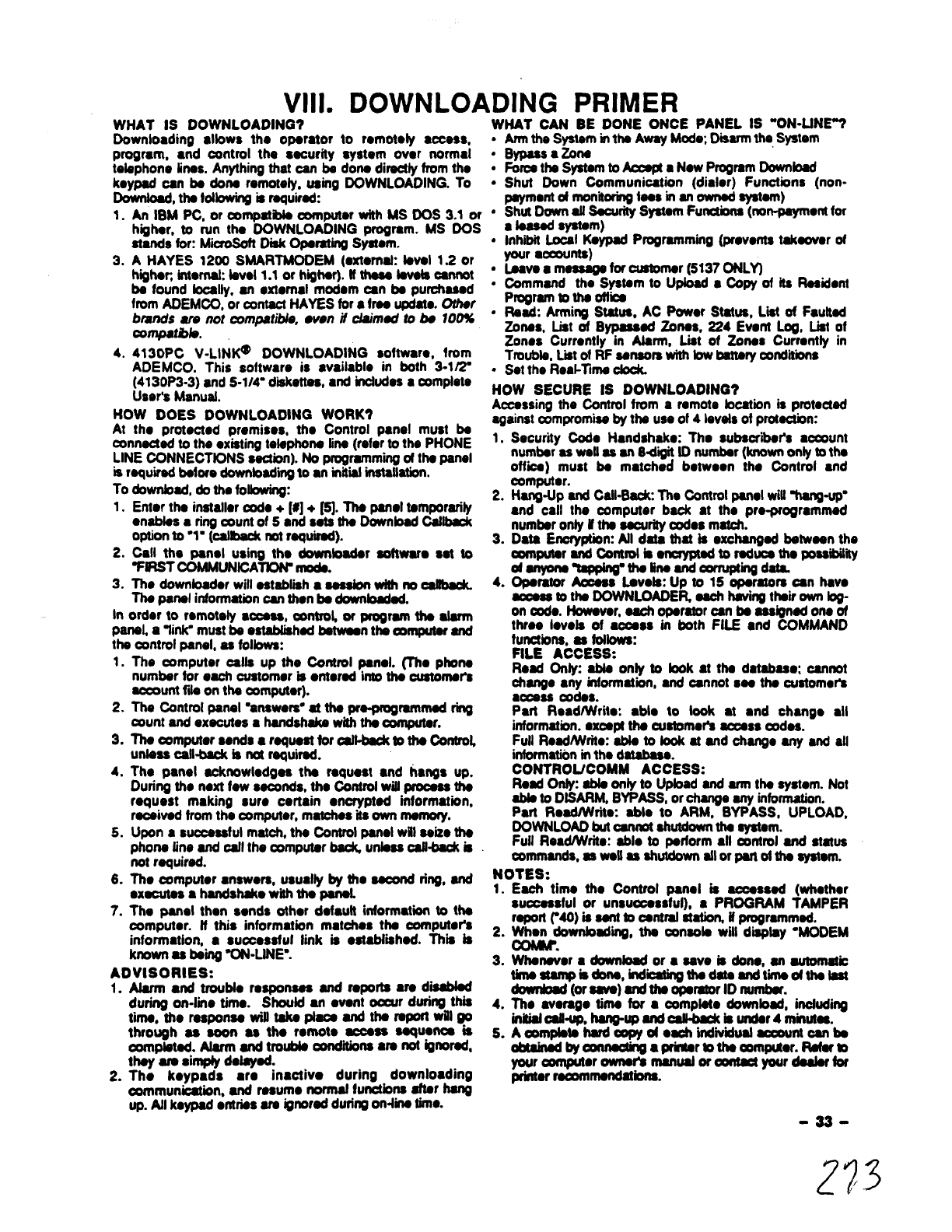
Vlll. DOWNLOADING PRIMER
WHAT IS DOWNLOADING? ——..———...- ..- —---- -.-—--
Downloading dbws tho operator to mmototy ●ccess,
progmm, ●nd control the security system over normal
tebphone lines. Anything that can be dona directly from tho
keypad can be dona remotely. using DOWNLOADING. To
hwnioad, the tdbwing is MqUiMd:
1.
3.
4.
An IBM PC, or compatible oomputor with MS UM 3.1 or
highar, to run tho DOWNLOADING program. MS DOS
stands for: Mii Disk Operating Syawm.
AHAYES 1200 SMARTMODEM (mrtomak feval 1.2 or
hqhen internak bvel 1.1 or hqhar). tt thsse bvais cannot
be found locally, an ●xtemd modem an be purchased
from ADEMCO, or contact HAYES for ●free updam. Other
brands are not compatible, ●ven it claimed to bs 100%
conrpatbb.
4130PC V-LINK@’ DOWNLOADING softwar., from
ADEMCO. This software is ●vailable in both 3-1/2-
(4130P3-3) and S-1/4- d~keftas, ●nd incfudes●complete
User’s Manual.
HOW DOES DOWNLOADING WORK?
At the protected premises, the Control panel must be
connaded to the ●xistingtelephone fine (refer to the PHONE
LINE CONNECTIONS section). No progmmm”~ of the panel
is rquirad before downbadii to ●niniiial inataiiation.
To download, do the foibwing:
1. Enter the installer ~e +[#l+ ~. ~panel temporarily
●nables ●ring aunt of 5●nd sets the Downbad cat-
option to “1- (caitback rmtrequired).
2. Call the panel using the downbader aoftwam set to
%iFtSTCOMMUNtCA~ nmda.
3. The downloader will establish ●session with no ~
The panel informationcan then be dwnti.
In order to remotely ●ccess, mntrol or program the alarm
panel, a~ir& must be eatabiiahadbetweenthe oomputM and
tha cimtrol panel, as Mows:
1. The computer calfa up the Control panel. (’l%. phone
2.
3,
4.
5.
6.
7.
number for each customer is ●terad into thecustomer’s
account fk on theoomputor).
The Control panel “answers”at the pra.progmmmad ring
count and executes ahandshake with the ~r.
The computer sends ●rqueat for oaf-to the Control
unteaa dkback is not required.
The panel acknowledges the request ●nd hangs up.
During the next few seconds. the control will process the
request making suro certain ●ncrypted hrformatbn,
received from the canpuwr, matches ils own memory.
Upon asuccessful match, the Control panel will seize the
phone tine and cdl the ~mputer baclG unless caft-backb
not required.
The computer ●nswers, usualfy ~the second ring, and
●xecutes ahandstdte with the panef.
The panel then sends other default information to the
computer. ft this information matohos the computer’s
information, ●succosaful link is ●atabtiihed. This is
known as baii “ON-LiNE”.
ADVISORIES:
1. Aiarm ●nd trouble responses and reports are dieabbd
during on-lime time. Should an ●vent occur during thii
tima, the msponaa will take place and the report will go
through as soon as the remote access sequence is
aJmpiatad. Afarm and trouble conditions 8ra not ignored,
they are simply delayed.
2. Tho keypads ●re inactivo during downloading
communication, and resume normaf functionsafterhang
UP.Atlkeypad●ntriesare ignoredduringon-tinetime.
WHAT CAN BE DONE ONCE PANEL W‘ON-LINE7
●
✎
●
✎
●
✎
✎
✎
✎
●
Armthe System inthe Away Modw Disarmthe System
Bypass●zone
Foroathe Systemto ~●New Progmm Download
Shut Down Communication (dialer) Functions (non-
payment dmonitoringfees in an owned system)
Shut Down afl Sacurhy System Functions(non-paymentfor
●teased system)
Inhti Local Keypad Programming (prevents takeover of
your •~nts)
Laave ●meaaagafor customer (5137 ONLY)
Cemmand the System to Upbad ●COPYof its Resident
Program to the ofb
Read: Arming Status, AC Power Status, L@ of Faufted
zones, List of Bypassed ~fW, 224 Ewnf Log, List of
Zones Currently in Alarm, List of zones Currentty in
Troubb, Listof RF sensors with low battery =lldii’bft$
Set the Reai-Tima cbdL
HOW SECURE IS DOWNLOADING?
Accessing the Control from aremote bcation is protected
against campromiaaby the use of 4bveisofprotection:
1. Securiiy Code Handshake: The subacr”tir’a account
number as wati as an 8d@ fD number (knownonly to the
offii) must be matched between the Control ●nd
computer.
2. Hang.lfp and Catl-Bacic The Control panel wiU%ang-up”
●nd call the computer back at the pm-programmed
numbr only if the securitycodes match.
3. Data Encryption Atl data that is exchanged between the
computer and Cantmlbmcrypwd toreducethe posaibiMy
ofanyune~ths iineandcorrupting dti
4. Operator Acoess Laveta: Up to 15 operators can have
access to the DOWNLOADER each havingthdr own bg-
on code. However, each operator can be assigned one of
three ievefa of access in both FILE ●nd COMMAND
functions, as fotbwa:
FILE ACCESS:
Read Onty: able onty to bok at the database; cannot
change ●ny information, and cannot sea the customer’s
access ~des.
Part ReadlWriie: ●ble to took ●
t●nd change ●ll
informatbn. except the aratomer’a access ~dea.
Full ReadMfte: ebb to look at and change any and all
informationin the database.
CONTROtJCOMM ACCESS:
Read O* ebb only to Upbad and arm the system. Not
ebb to DtSARM, BYPASS, or change any information.
Part ReadlWrit. able to ARM, BYPASS, UPLOAD,
DOWNLOAD but cannot shutdownthe system.
Full Read/Write: able to perform ●ll =ntrol and status
commands, os well as shutdownatlor part of the system.
NOTES:
1. Each time the Control panei is accessed (whether
successful or unsuocesaful). ●PROGRAM TAMPER
reportMO) issentto centraliiafiomifprogrammed. -
2. ~30wnbdk’ig, the console will display ‘MODEM
3. Whatier ●download or ●save is don., an automatic
tkneatampia done, indiithadata andtimeotthefast
downbad (oraave) and the operator ID number.
4. TIM avemge time for ●complete downbed, hrcf~tng
initialoafl-up, hang-up and ~is under 4minutes.
5. Amrnpiete hardoopyd oechindiiidimla caountcanbe
obtdnadbyanna&g a~rtothamrnpder. Rafarm
youroornputer owner’a manuator~your daaiarfor
prhter moommendationa.
-33-
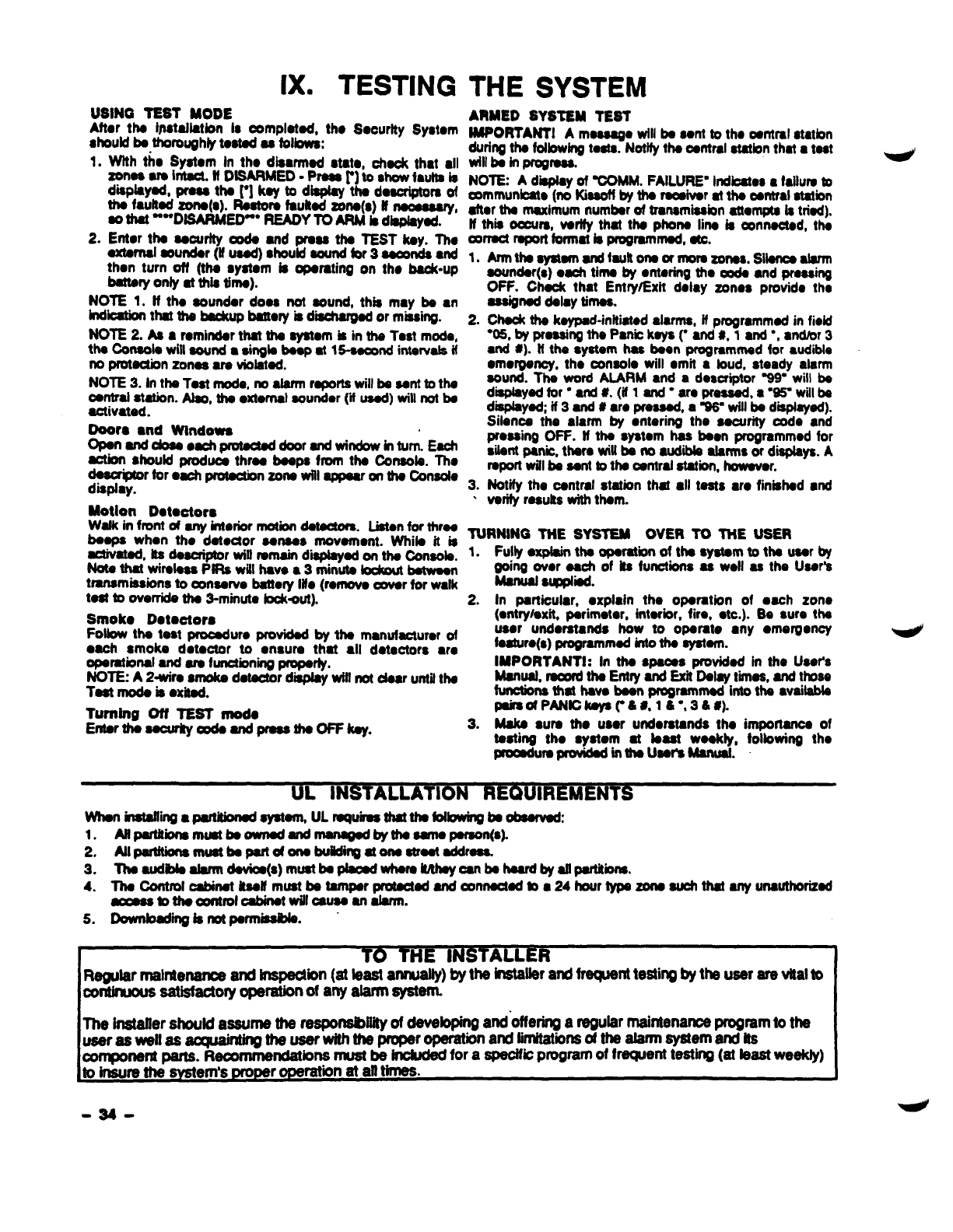
IX. TESTING THE SYSTEM
USING TEST MODE
After tha Ijtstaflatlonboomplatad, the Socurfty System
8hOUfdbs thoroughly taatad C8 fobws:
1.Wtth tho Syatom In tho dkmad stat., chaok that ●ll
~mimflDSMED-P-r]~stitaw b
displayad, praaa tha ~] kay to dbplay tha daacdptora of
thhttad Zona(o). Raatora fauttad Zona(s) ff ~,
‘“Disarmed”” READYTQ ARM& dbpiayad.
2. Erttor thaaaoudtyooda and praaa tha TEST kay. ~C
axtarnalaoundar (if uaod) should sound for 3~and
then turn off (tha syatom bopamting on tho bad(-up
battery onfy at this tirno).
NOTE 1. If tho aoundor doss not sound, this may ba ●n
indii that tha ~battery is dii or missii.
NOTE 2. Aa ●romhdar that ths ayatom is in tha Test mode,
tha Consola will Wnd 8Singla baap at 1~ intarvals if
no protection zonas ara vblatad.
NOTE 3. In tha last mode, no alarm raportawill ba aant to tha
oarrtralatatbn. Abo, tha ●xtornat aoundor (i mad) will not ba
activatad.
Doors ●nd Wtndowa
OpanandcJoaaoach pmtact@doorandwindow inturn. Each
-should produca thraa boaps from tha Conaob. Tho
=~ratimnzotit ii~onfhatinaola
.
MotIon Dotootors
Wafk in front af any intmior motbn damotom. Man for thrw
baapa when tho datactor aansa$ movamont. Whila it ia
sctivatad, its daacriptor wilf remain d-ad on tha Consob.
Nota that wiralosa PIRs wifl havo ●3minuta Iodrnut hatwaan
transmisabns to oonaarvo batbty Iilo (ronwva -r for walk
taat boverrida tha 3-minuta Ioctwut).
Smoko Dotootors
Fotbw tha taat procAuro providadby tha manuf~uror of
●ach smoke dotaotor to ●nsura that ●ll dotactors w.
oparatbrral and ara functioning proparly.
NOTE: A2-wiro amoka datactor d- wffi not obar until tha
Taat rnoda is ●xitad.
Tumfng Off TEST mod.
Enfarthaaocurky mdaandpraaatha OFFkay.
ARMED SYSTEM TEST
IMPORTANT1 Amasaago will bs sent to tho oantral otmbn
during tha folbwlng tosta. Notify thaoantralatatbn that ●tut
till ba In ~raaa,
NOTE Ad-y of -MM. FAILURE’lndioatos●fdhlm b
=mmunbato (no Kiasotfby tha raodvor at tha cmtml atatbn
afbr tha maximum numbar of tranamiasion altwnpta la triad).
ff thb oaura, varffy that tha phons Iina b~nnactad, tha
mrract raport format bprogrammed, UC.
1, Armthasyatam arxltaultona orrnorazorraa, siiancaabrrn
2.
3.
.
00Uftd.r(.) ●aohtima by ●ntoring tho ooda and prassing
OFF. Chack that Entry/Exit delay zonos provido tho
aasignad daby timas.
Chock tha kaypad-initiatad abrms, ff programmed in field
“OS,by praaaingths Panic kaya ~●nd #, 1●nd ●,●rrdbr3
and *). tf the syatam haa boon programmed for audible
●mordancy, tho oonaolo will ●mit abud, steady alarm
sound. Tha word AIARM ●nd adescriptor %9= will ba
d~dtir” ti#. (til~O=o vti, a-Wwtilk
dbplayad; if 3and #●ro proaaad, aW= wiflba diaplayad).
Sikwa the alarm by ●ntering the saourity oodo ●nd
proasing OFF. tf tha system has boon programmed for
silant panb, thars will ba no audii alarms or d~ys. A
raporl will ba aant to tha oantral station, howavor.
Notify the carttral station that ●ll tasts ●ro finbhad ●nd
varify rasutts with tham.
TURNING TNE SYSTEM OVEf! TO TNE USER
1. Fulty ●plairr tha ~ratbn of ths ●ystam to tha uaar by
going ovor each of Its functions as WOII so the Usar’a
Manual S1.pphad.
2. In Particular, ●xpldr the oparation of ●ach zone
(entry/exit, parimotor, {ntarior, fire, ●
tc.). Sa sure tha
user undoratands how to oparate ●ny ●mergoncy
fa8turo(s) programmed into tha ayatam.
lMPORTANTf: In tha spacas providadin tho Uao~s
Manuat,mwrd tha EntryandExitDatayt.hnaa,andthosa
btctbns that hava baanprogramrnodintotha ●
vailabb
pairaofPANtckayac41 #,16=,36 #).
3. Maka ●ura tho user undorstanda tho importanoa of
tasting tho ●ystom at Iaast waokty, foibwing tho
Pm=dWaprOvibdinfhautiManuat.
~UL IN IREMENT
WtroninstaNingapankhadsystam, ULroquirasthatthafofbwingtraabaarwd
1, ASpartitii mkmtbaownad andmanagad by fhaamoparaon(a}
2. AllpartWns rnuatbapartof onabueding atonastraataddraaa
3. -d--~(a)mmb~-m~-~-~d~-.
4. Tha Contmfcabinat itaalfmust batamparmtactad andcmmactdb ●24hourtypa zonoauchthat anyurrauthorizad
amaasbthaarol oabinafwifloauaaanitarrn.
S. Downbadii isnotparrniaabta.
~installttr should assume the responsibUityof dewfoping andofferingaregular maintenance program to the
Useraswella sacqbung ti~r-ti~rmbn atiti-mmdti~memamw
acerrtmncfatbrts must be incfudd for aapedfic progfarn of f~eti testing (at feast weekfy)
component parts. R
toirlsuremesYst em’s pmpe oPe
rration at alf times.
=34-
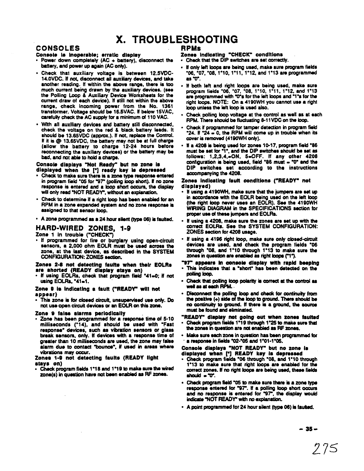
X. TROUBLESHOOTING
CONSOLES RPMs
Con80k ta lnooambk: ●rmtlo dkdav Zonos Indkating ‘CHECK” conditions
●Powor down ~rnptak~ (AC +battc~), disconnect the .
battery, ●nd powar up again (AC only). ●
●Chock that ●uxiliary voltago is betwoon 12.5VDC-
14.oVDC. if md~nnsct afl auxitii devii, and take
●nether readhg. If within tha abovs fangs, there is too .
much currant being drawn by the ●uxiliary dovicas. (see
tho Polling Loop &Auxiliiry Device Workshaats for the
current draw of ●ach dev’be). tf still not within the above
mngeo chsck incoming power from the No. 1361
transformer. Vohage should bs 16.5VAC. ff bebw 15VAC, .
carefullycheek the AC supplyfor aminimumof 110 VAC.
●With all auxifiary dev”kes ●nd battery still disoonnacfed,
check the voltage on the red &black battery leads. It “
should be 13.65VDC (approx.).tfnot,raplsosthe Control.
ff it is@ 13.65VDC, the battery may not be ●tfull charge
(allow the bafkry to charge 12-24 hours bsfore “
moonnecting the auxiliry devioas) or the batterymay bs
bad, andnotabbto hokfacharge.
Consoto dlspkyo “Not Ready” but no zone k
dkplayod what the ~] ready koy bdopro8sed
●Chaokto rnakosure thsra is ●zone tVPSrasponsa ●ntemd
check that the DIP switches are set Oormctly.
Konly left loops am bsii ussd, mako sure program fiitds
“06, ●07, “08, 1“10, 1*11, 1“12, and 1“13 am pmgrsmmad
as v.
ff both left and right toops are bshg used, make sure
program fields “06, “07, “08, 1“$0, 1“11, 1*12, and 1“13
am programmed withW% for the bft hops and ‘1”s for the
right hops. NOTE: On a4190WH you cannot use ●right
Ioopunlessthe bftbopisusedalso.
Check pelting toop voltage at the cmtroi as wall as at each
RPM. Thsm Shodd be fluotuafing8-11VDC wr the bq.
Check if programmed for tamper detection in pmgmm fwld
“24. II “24= 0, the RPM willoome up in troubb when its
mvar is removed (4190WH onty).
tt a 4208 is bsii used kr zones 10-17, program fiikt ●86
must bessttor”l”, andtha DIPwvitchesahouid beset 8s
follows: 1,2,3,4,-ON, 5-OFF. If ●ny other 4208
oontiiumtbn is bshqf used, fiikt ●86 must -Vend the
DIP switches sot ●ccording to tho instructions
-mpsnying tha 4208.
in program tiitd “05 for %7 fpotling btitt). ff no zone Zonoa Indkstlng fauft oondltlons (“READY” not
rasponso is ●ntorad and ●tikp short are, the dispfay
will only read wOT READY, withoutan ●xpbndi.
●Ched( to dotermino if ●right bop has bean ●nabbd for an
RPM in azone ●xpanded syskm and rm zone msponaa is
assigned to that sensor foop.
●Azona programmed as ●24 hour Want (type 06) is fautkd.
HARD-WIRED ZONES, 1-9
Zono 1In troubk (“CHECK”)
●ff programmed for fire or burglary using opsn-circuit
sensors, ●2,000 ohm EOLR must bs used ●oss ths
zone, at the fast devioe, as daacribad mths SYSTEM
CONFfGURATION: ZONES sactbn.
Zonos 2-S not doteotlng faufts when tholr EOLR8
●mshorted (READY dkpfay days on)
●ff using EOLRS, check that progmm fbfd “41-o ff not
usingEOLRS,“41.1.
Zone 0 k Indkstlng ●fautt (“READY” wtll not
●ppear)
●Thii zono is for dosed drouff, unsupswfssd uss onfy. Do
notuseoponcirouit do~sorsn EOLRonthiizons.
Zen. 9fake ●krms psrlodlodly
●Zone has bsen programmed for ●rsspo= timo of 5-10
milliseconds ~1 4), ●nd should be used with ‘Fast
rosporrso”devioas, such as vibratbn sorrsorsor glass
break sansors.onty. Hdevicsswith8msponsstime of
gmatorthan10 miffisscondsam used,tho zone may fats.
atarm duo to oontacf%ounoa”, tf ussd &r areas where
vibrations may oocur.
Zonos 1-9 not dotootlng faufts (READY Ilght
stays on)
●ChaCkPr09mmfia!dS1018and l“19tomaks sursthswimd
zone(s)inquestionhmmnotbeanwablsd as RF zones.
dlsplayod)
.
.
.
tt‘usirig●4W0Wt+,maka●um that the jumpsrs am sst up
in ~rdanoe with ths EOLR behg usad on the tstt bop
(the right tooprrevor uses ●nEOLR). Sss the 4190WH
WfRING DtAGRAM in ths SPECIFICATIONS section for
~Wdt-XVdEOR.
Husing ●4208, make sum the zonos are setup wtth ths
arract EOLRS. Se. tho SYSTEM CONFIGURATION:
ZONES section for 42o8 usage.
ff using ●4186 rfght toop, mako sure onty ctossd~rcuif
dsvicss am used, and chsck the program tiolds %6
through “08, and 1*1Othrough 1“13 to mako sum ths
zonsainqusstbn aresnabbdas righttoopsft’).
“87” ●ppeam In ooneofs dkptsy wfth mpld baepfng
●Thii indaos that ●“short= has bsen dstected on ths
P-W *.
“OMcatOcJkll&*pobrfty fs~atthsmlltrolas
●Disoonnssf the potlirrgtoop and chdt for continuky from
tiehh(+)bdhbtigmd.hsmub
no continuity to ground. tf them is aground, ths aouros
mustbs found and ●laminated.
“READY” dkpfay not gelng out when zonos faulted
●Ohsokprogmm fiil”19through l%5tomakssursthat
thszonss krquestbn aratienabbd as ffzonsa.
●Makosure sachzonsinqumtion has bsonprogmmmedfor
“●msponss intibtds %2-*O5 and l“ol=l”m.
Coneda dbptays “NOT READY” but no zon. k
dkpky.d wh.n r] READY k.y kd.prosssd
●-programfidd$ 906through●08. ●nd 1.IO through
1“13 to make sure that MM boos are ●nabled for the
●
.
awmctzonea.tfnorighttrxipsare-bsii uasd, thssefiekts
should -v.
-~rmtiM*W@Wsurotkmkamw
msponsa ●ntered for WT. tf ●poltii foop short ~rs
and no rasponso is ●ntersd for 37, the dwlay wouid
indii ‘NOT READV with rm●xpbdon.
Apoint pmgmmmad for 24 hour silent (typs 06) is faufted.
-3s -
275

WIRELESS
’88” or ’90” ●ppeara ttt oonsofa dbplay ●nd rapid
bsanlrta ooours
●
●
✎
●
●
●
The raoeiver ia not raoaiving ●ysignets from arty of the
trartemittdrsin tho aystom. An W“ is for the2nd rscaivcr;
●*is for theIstraoeiver. These d~bys ●m●nablad
by assigning ●zone rasponsstype in progmmfiitd V09.
cheek that the ●rtonna binatatiad proparty ●nd is not
shortod to ●ny matal objoot, mfsr to WIRELESS
ExPANsfoNaeuionfordataiia.
-thatth. tran$mittora ●mpowered up with fresh 9
voft batteries.
CharStthatthe houseIfYantabh between tmrtsmitters●nd
the racaiw.
Dotormina if ●nything bblocking tmnsmission to the
reoeivar (ox: ntetaf cabhtata or shelves, etc.)
M4280 buaad. remove ha covor. Put the system hthe
test mode, fhon sss if tha transmitters ckk-in. ff rwt,
move the reoehrorto another focationand teat *sin.
’88” or “81” ●ppswa in oortaolo display ●nd rapid
besmlno 000UrS
.
●
✎
✎
✎
Tb ~ivar is rrmraspondii to tho Canfrol panel An %~
mfsra to the second receiver and ●%1” refers to the first
raoeivor.
H@80buti,Mtiti~~S~rkonatiW
magnet is in dose proximityto the read switch.
Check that the arttrol bwired properly bthe raoehrer.
tf 4260 is used, determine that the- ourmnt dmw on tho
polfing loop is not mom than 64mA. ff the draw does
exceed 64mA instafl ●4197 loop axtondcr module, or
-r the 4280 from auxitiarypower, as doscribad.
Chec4cthat the wire run length is in agraemont with the
racortrmendadwire gauge.
Zonos, not progmntned kt tho system, ●m
Indloatlrtg “CHECK” oortdltlons
●Check programfwlds “02 throughW6, ●nd 1●O1through
l*05tomaka 8uraattunuaetfzonaaara0W.
.Cti programfmtds1“18through1%!6to makesurethat
sltnon-RFzonssareos.
Zortos Indlcstlng ‘NOT READY” oortdltlon, but
trsnsmlttor oontaot toop is intaot
●Put the system in the SNiFFER MODEforat taut 2ftoura,
to as. if another system in ths arsa is using the aamo
house ID. Uso, changs thm system’s houaa tD number.
●Make sure zonos in question ●re seiectad as RF &tfmtda
1“18-1”25.
on. or mors transmlttors ●rs htdloat)ng ‘CHECK”
oondftlons ●fter ●whlls; oonaolo bseping rspldty:
.Chsck that the transmitter havo tho oorrscthouss ID
programmed.
●check thatthotrarrsmittors have the correct transmittm ID
ssaignad.
.Chti that the tranamittsra have fresh batteries.
“07” ●ppsars In tho conaoio dlcpby snd rapid
booDina occuis
●
●
✎
✎
T& ifiioatss that tho polling bop has stfhor ●dirsctshort,
ors short to ground on tho (+) side. Miiht ●lso indicatethat
the 4280 RF Racaivor is causing the short (diseannect
4260 to Vsdfy).
Chti that polling bop polarity is oorract ●tthe control
panai, aswsflasat oach4280.
Check oorttinuity from (+) sido of ths bop to ground
(disconnect the potting loop from the control firstl) -●n
open shoufd be mad (no continuity). tf ●short to ground
●xists, fti and ●fiminatothe short.
~VOttageacrosa the polling bOp at the control panel
●sWOII as ●t●ach 4280. if used -them should be
fluctuatbn betwsan 8-11 VDC.
;READY” diapiay not going out ufhan RF zortos
.. .
.
●
●
.
.
.
Check that the house iDs match between the transmitters
and the receiver.
Check that the rsceiver is onabbd in program fields f“26
for the first receiver and 1“27 for the second receiver.
Check that the zones in qusstion ●re enabted for RF in
programfia~s 1*18 through 1“25.
Check that azone response is progmmmad for the zones
in question, in fields ’02 through“05, and 1“01 through
1“05.
Chaokthatthe racahrahantennaisproperly
installed.
Remove ●ny ssnsors from tho transmitters and shon
across the transmitter terminals. Then fault the transmitter
to sea tf the “READ~ iight goes OUt.tt il does not go OUt,
check the programming for that particular tmnsmittac if it
dOSSgo out, checkths sensors on *M ZOIIS.
Move the receiver to another toostionfor batter reoaotion.
.
Conao& diaptays “NOT READY” but no zone “is
disptayed when ~] READY koy is deproessd
●Checkprogramfiiid “OSto makesure37 hasazone tVDS
msponiaonterad U●foopshort oocurs and no raspoiiia
is ●ntered for %7, the console woutd display only oNOT
READW,with no ●xptadom
●ASient Panb artdiiion may be present. Key the security
da+oFFwsae tithamndiicbar’s.
Whlta in the “TEST” mode, some or stt of ths
trsrtarnittors sre not responding, or sro
responding irrogutarly
●
.
.
.
TheTest’- as the-racahratssensitivityby50%. This
meansthat as brrgas ●transmitter responds, its location
is satisfactory.
Move the affected transmitters to another location and ra-
test. There may be something blocking its transmission
path.
If afi transmitters ue ●ffeoted, move the recaiver to
●nether location. There may be something Mocking its
reception.
tf no raoaiver bcation oan be found that can reliabty
receive at/ transmitters, add ●second receiver in ●
different bcation in the premises to ●xtend the RF
coverageofthe ayatem.
-36-
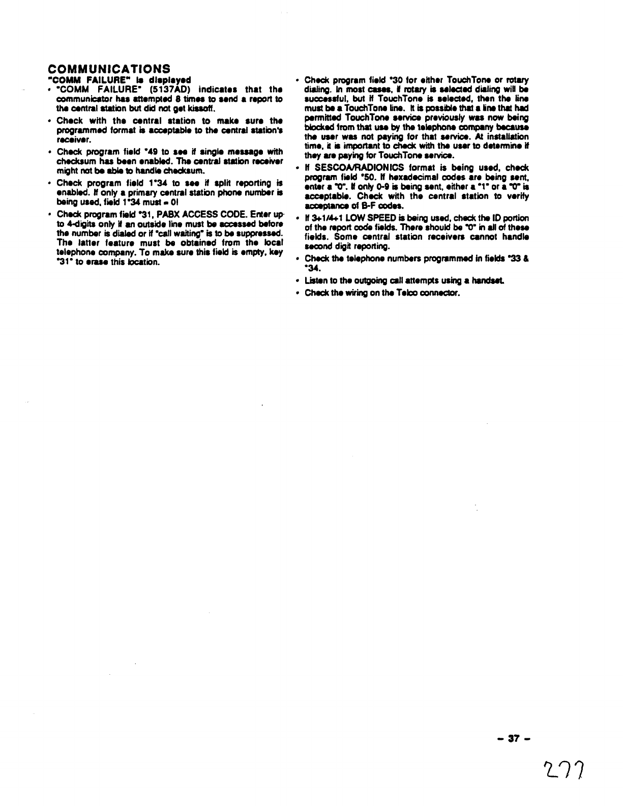
COMMUNICATIONS
‘COMM FAILURE” la dlmlawd
●
●
●
✎
✎
“COMM FAILURE” (5137AD) indicates thst tho
communicamr has attomptad 8timaa to send ●report to
the central station but did not get kissoft.
Chock with the central station to mako sum the
programmed format is ●ccaptabb to the central statbn’a
racaivor.
Check program field “49 to sea it singlo mossago with
checksum has been onabted. The central station receiver
might not be able mhendte chedtaum.
Chock program field 1●34 to see if split repofiing is
enabled. tf only ●prim~ centml station ptmna number is
being used, field 1“34 must. 01
Check program fmld “31, PASX ACCESS CODE. Entar up
to 4digha only if an outside lie must be accessed before
the number is dialed or if “callwaiting”is to ba suppressed.
The latter feature must be obtainod from the bcal
telephone curnpany. To make sum tits field is empty, koy
%1” to ●raae this bC8tiOn.
●
●
●
●
●
●
Chaokprogram fiotd “30 for oithor TouchTon. or rotary
diahng. tn most CSSSS,Erotary is selected dialing will be
successful, but if TouchTone is solocted, than the tina
must be ●TouchTone tina. tt is POSSMOthat ●tinsthat hd
permitted TouchTone swvics previously was now being
biodtad from that use by the telephone _ny because
the user wee not paying for that service. At inetsllatkm
time, it is important to check with the user to determine if
they era paying for TouchTone service.
HSESCONRADIONICS format is being used, check
program fmld “30. tt hexadecimal codos ●re being sent,
enter ●W. Uonly 0-9 is being sent, oithor ●”1●or aTis
acceptable.dC~~dw~h the central station to verify
.
If 3+1/4+1LOW SPEEDisbahg used,cha& theID portion
of the won coda folds. There should be W- in afl of these
fields. Some central station receivers cannot handle
seared digit re~rting.
Chad the telephone numbers progmmmad in fields =&
“34.
Listento the outgoing all attemps using ●handaeL
Check thewiringon the Tebo connector.
-37-

XL SPECIFICATIONS
4140XMPT CONTROL
PtrYslcal: 12-lm x14-W-H x3-D
Eloctrlcal:
VOLTAGEINPUT:
ALARMSOUNDER0Lf7P~
AUXIUARYPOWEROLfTPtJV
BACK-UPBAITERY
STANDBY:
CIRCU~ PROTECTORS:
From Ademco No. 1361 Pkrg4nTransformer (use 1361CN in Oanada) rated 16.5VAC, 40 VA.
10VDG13.8VDC, 2.8 amps max. (non-UL installations),75omA lass aux. current draw (UL
installations).
9.6VDC-13.8VDC, 750mA max. For UL installations,the accessories connected to the output
must be UL listed, and rated to operate in the above voitaga range.
12VDC, 4AH or 7AH gal d. YUASA NP4-12 (12V, 4AH) or NP7-12 (12V, 7AH) remmmendad.
Use 4AH battery for UL installatkms.
4hours min. with 750 mA aux. load using 6AH battery.
Thermal circuit breakers are used on batterYincwtto protect aoainst reverse battew
conrmctionsand on alarm sounder output 6ptbtact against wfing fauks (Shorts). “
Asolid state atcuit breaker is used on auxiiiiry power output to protect against wiring fautts
(shorts).
DIGITAL COMMUNICATOR 5137AD REMOTE CONSOLES
FORMATS SUPPORTED: Phyaicai: Width: 8.4 inches
ADEMCO HtGH SPEED Height: 4.75 inches
ADEMCO 442 EXPRESS Dsipth: 1.1 inches
ADEMCO LOW SPEED
ADEMCO 00NTACT fD Eioctrical: Voitage Input 12VDC
SESCOA CurrentDrain: 90 mA (5137AD with
RADIONiCS LOW SPEED backiiihting)
LINE SEIZE: Doubie Poie Interfaca Wiring:
RINGER EQUIVALENCE: 0.78 RED: 12VDC input(+) auxiliarypower
FCC REGISTRATION NO.: AC396U-66192-AL-E BLUE: Not Used
GREEN: Data in
YELLOW Data Out
BLACK:Ground and (-) connectionfrom suppiamental
power suppiy.
4190~ OPkRATIC)N &~[N~ DIAGRAM
The 4190WH is a2-zona (known as bft and right ioops) JUMPERS
RPM. The left ioop can be used for cloeed-circuit USAGE (LEFT ZONE ONLY)
devices, with or without EOLR supervision, and for ut forlow currsnl mods (reed tvoa Switches):use the
open-circuit devices. with EOLR suoervisbn. The ieft
loop can also be” used with fast-response (1O
millisecond) devices. if necessary. Foibw the chart for
cutting the correct jumpers and choosing the correct
resistor when using the leftloop.
The right loop is for ciosed-circuit, unsupervised use
only, and has aresponse time of 400 miiiisaconds. The
jumpers do not affect the right bop m●ny way. Do not
use arosiator on this hop. Note that the right bop can
only be used it the ieft Loopis also used, and that the
right loop numerically foliows the iaft loop’s zone
number, wh~ is set with the unit’s DiP switches (ax. it
krffioop is zone 12, right bop is zone 13).
IMPORTANT: The tamper/supenrision reeponsa of
the 4190WH is determined by the zone response type
assigned to the loft loop (even if the right bop is
aaeigned ●difbront response type). Whiie the system
is disarmed, tampartsuperviaory fauits wili ●lwa ys
reportas troublemessages.Whilethesystemis armed.
tampar/supervisory faults will repofi as troubbs if the
iett bop is assigned anon-burgiary response type (i.e.
fire, panic. aux), and will raport.as alarms if assigned a
burgiary response type.
W,WO ohm resistor,pmvidad.Must_&cutif BLUEjuntpr is
cut. 4t90WHdraws1mAhornthepollingloopinthismade.
Cut toruse wrthno EOLR (doserkurcwtonly). Doingttus
●utomstioallyputsan internalS0,000ohmresistorhseries
withbe zone,sothewhitejumpermust also be cut.
RXECUT- Hgh ctmentmode:Uss the 4,7W ohm resistor,prowdsd,
Wialmachnkd swkchesineithermopemcircunorcbssd-
ckuit oontigwation.41SOWH&aws 2mAfromUw polling
loopinthismode.
/’EiiiwF-
-O=Oilnl ‘---
-38-
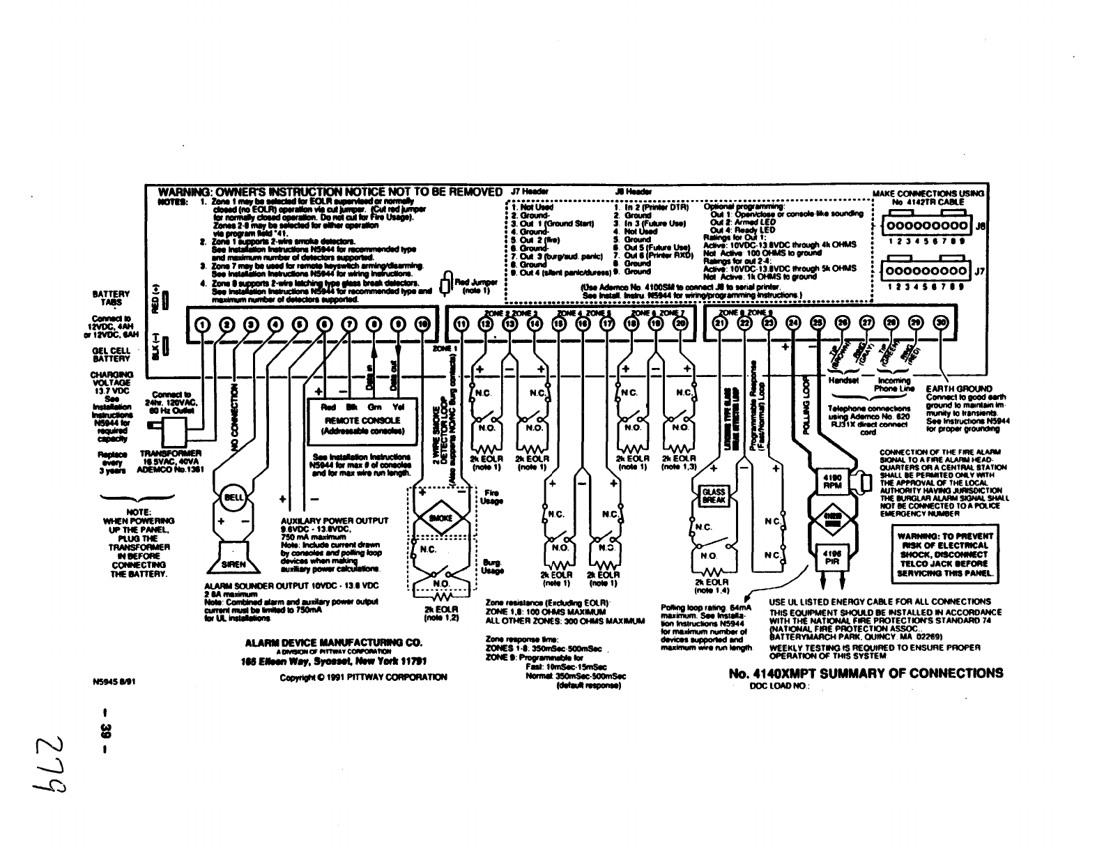
........... .---..-.---1
3maN--==rw~
........................
w
-)
277
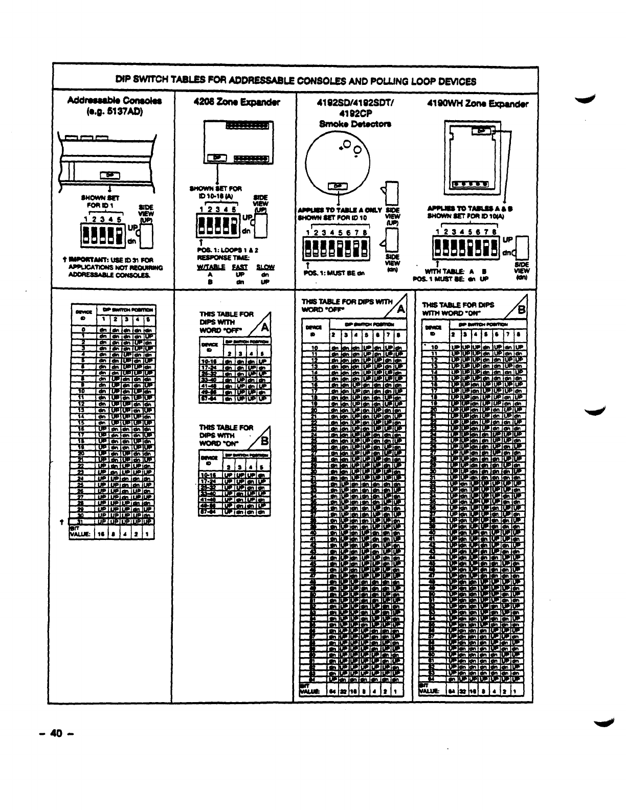
OIP SW1’OH TABUES FOR AOD~LE CONSOLES AND POLLING LOOP OEVICSS
-40-
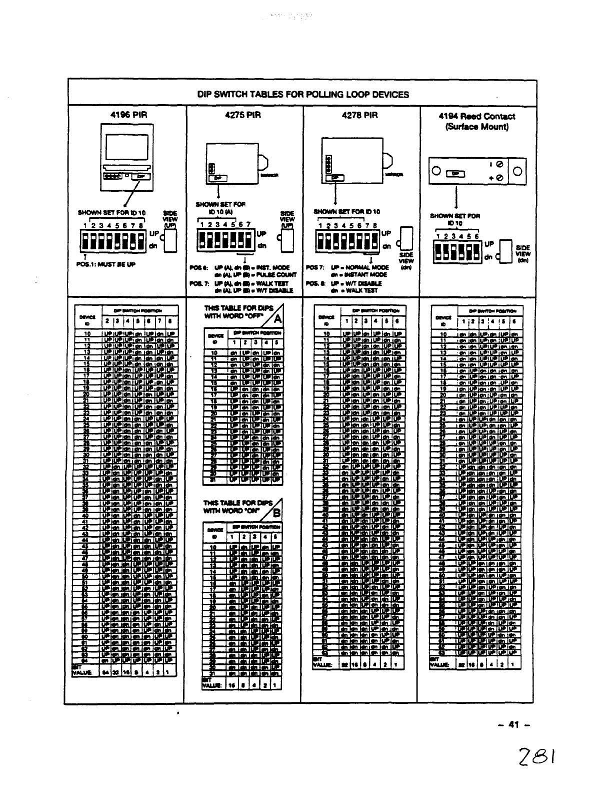
DIP SWITCH TABLES FOR POLLING LOOP DEVICES
,
-41-
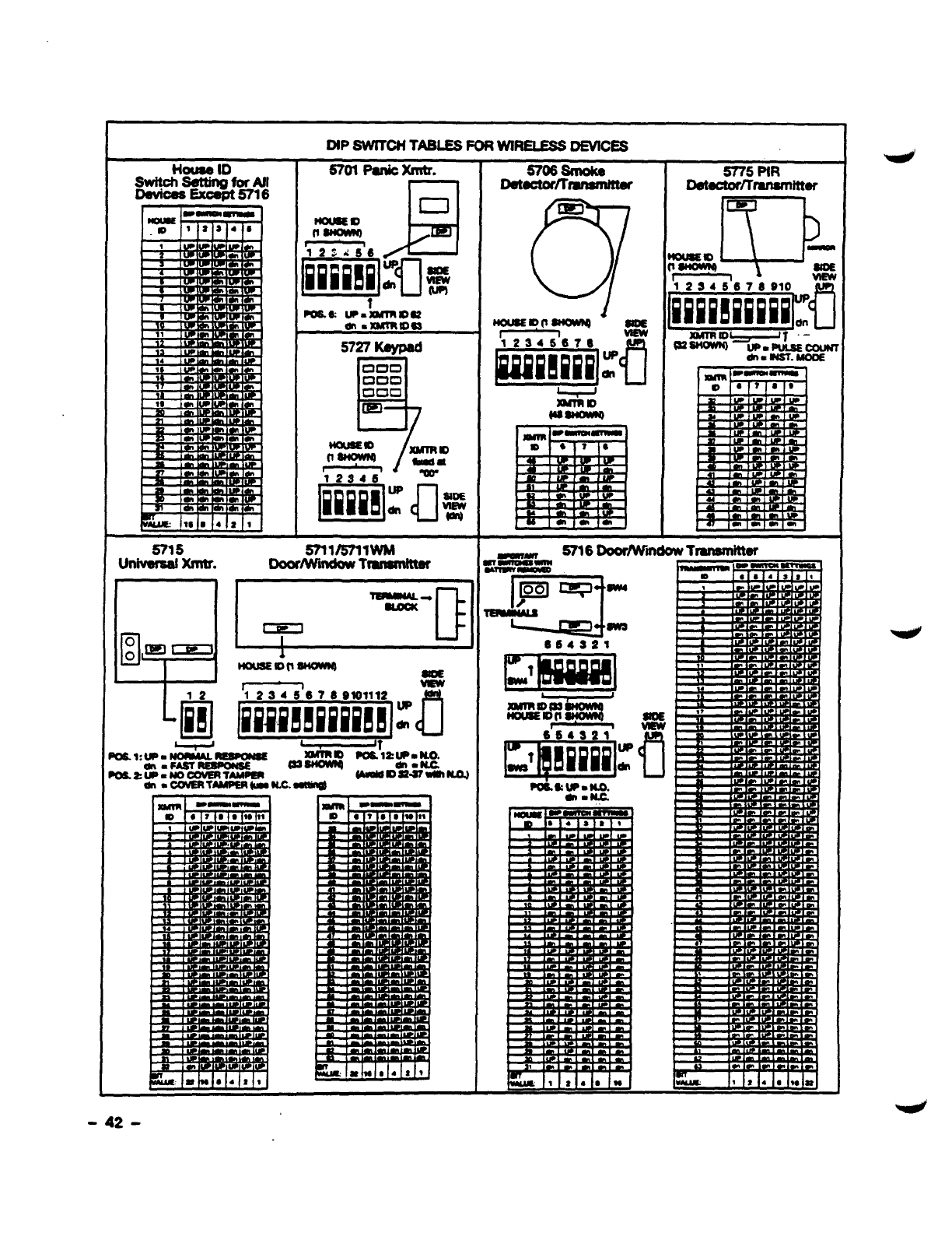
14cnmeID
swttchseltingforAll
Devices Excmt5716
DIP SW7CH TABLESFORWIRELESSDEVICES
5701 Panicxmtr.
m
mm UP.hnnlfm
en9XWROG3
5727 Keypad
D
000
mom
000
m
/
XMTnm
*-W*
G41-
UP
dn Ugl
!5715
---- s711/6711wM
Univenwl xmtr. DwidWndow Trandttw
, .
H
d
c1
o
~fmmi?a 1- U
t40usElofl~ am
r1m
6706 smoke
Detutorflmnwnmef
C!i’!l
km
SloE
m
Cl
S775 PIR
D@toctmKmflsnlttter
ICI!EJ I
l\ b
BwTransmitter
-42-
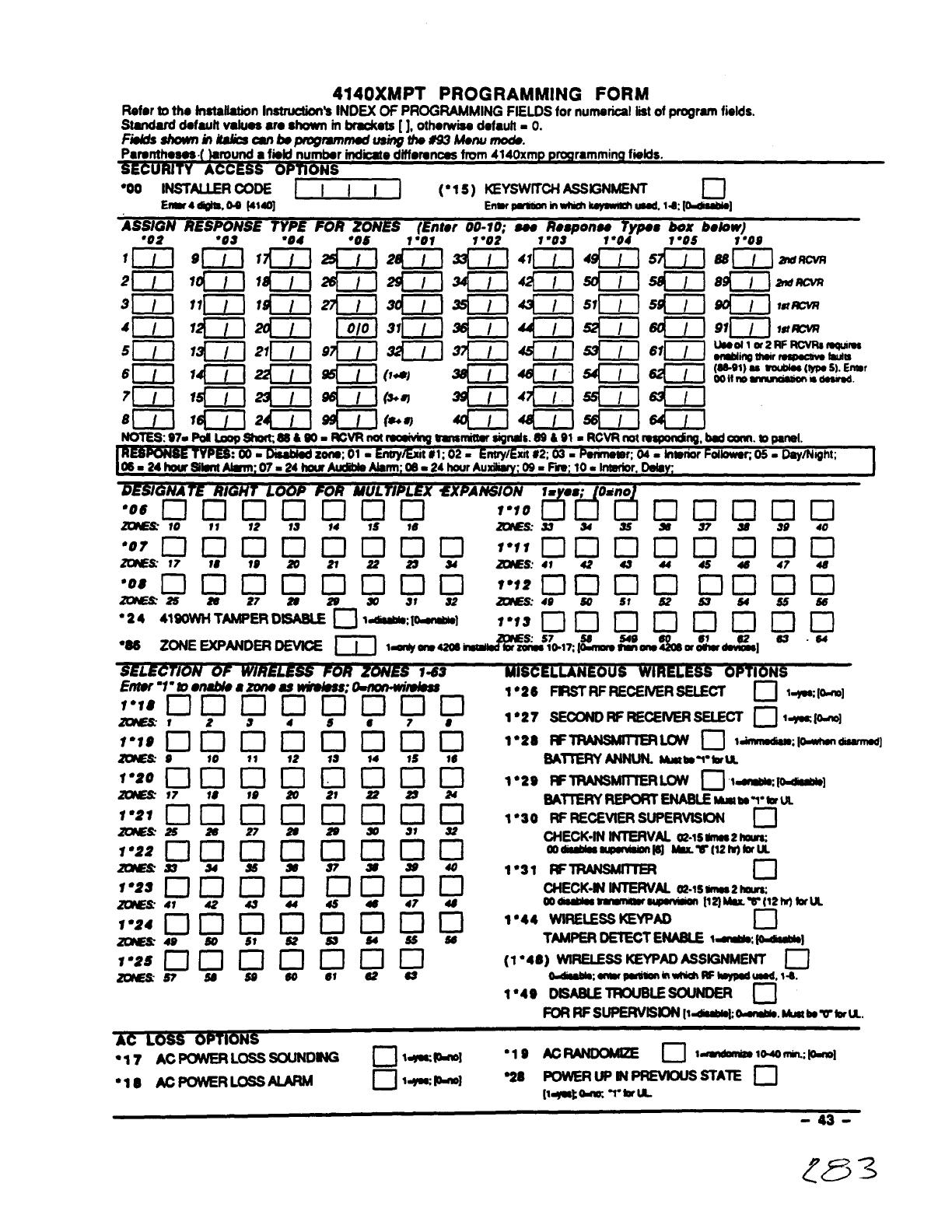
4140XMPT PROGRAMMING FORM
Roforto th6 fnstafhfion Instmctm
-‘s INDEX Of PROGRAMMING FIELDS for numenosl hstof program fields.
Standard dofauft vafuos ●rc shown mbraokats [], othorwise dofauh =O.
Fiufdsshown in2s&oMbop+ugrammsd using thu693MOnumodu.
Paronthosos (laround ●fmkf number indicatediffmwm8s from 4140xmp programminrafolds.
SECURITY OPTIO
+] (“1 5) KEYSWITCH ASSGNMENT
Enmr4di91E,0-sf41401 ❑
Errwmnt-~-.ld;[bdsabla 1
ASSIGN RESPONSE 7YPE FOR ZONES (Enter 00-10; so. Re8~onw 7YDOS box balow)
1“”09
911 / j 14fmvR
UsOollorzwwvrwmqulm
ding UWrr4maCw9huiu
(SS-91)wSoubin(IypoS).Enmr
Oowno ~nm
DESIGNA lE RIGHT LOOP FOR MULTIPLEX ●XPANSION 1= .s; O&no
“06DDDDOU0 1“10
~10 11 12 13 *4 1S 16 C!CM ❑0000
~a 24 26 s37 26 W40
AC LOSS OPTIONS
“17 AC PCXVEFtLOSS=Dffi c1 t-~] “1s AcFWDWfZE 0ldMdamx@ 1044mm.:P-1
●1S @POWER LOSSALARM ❑lWWI aPOWERUPIN PREVDUS STATE ❑
[l+ate -I”*U
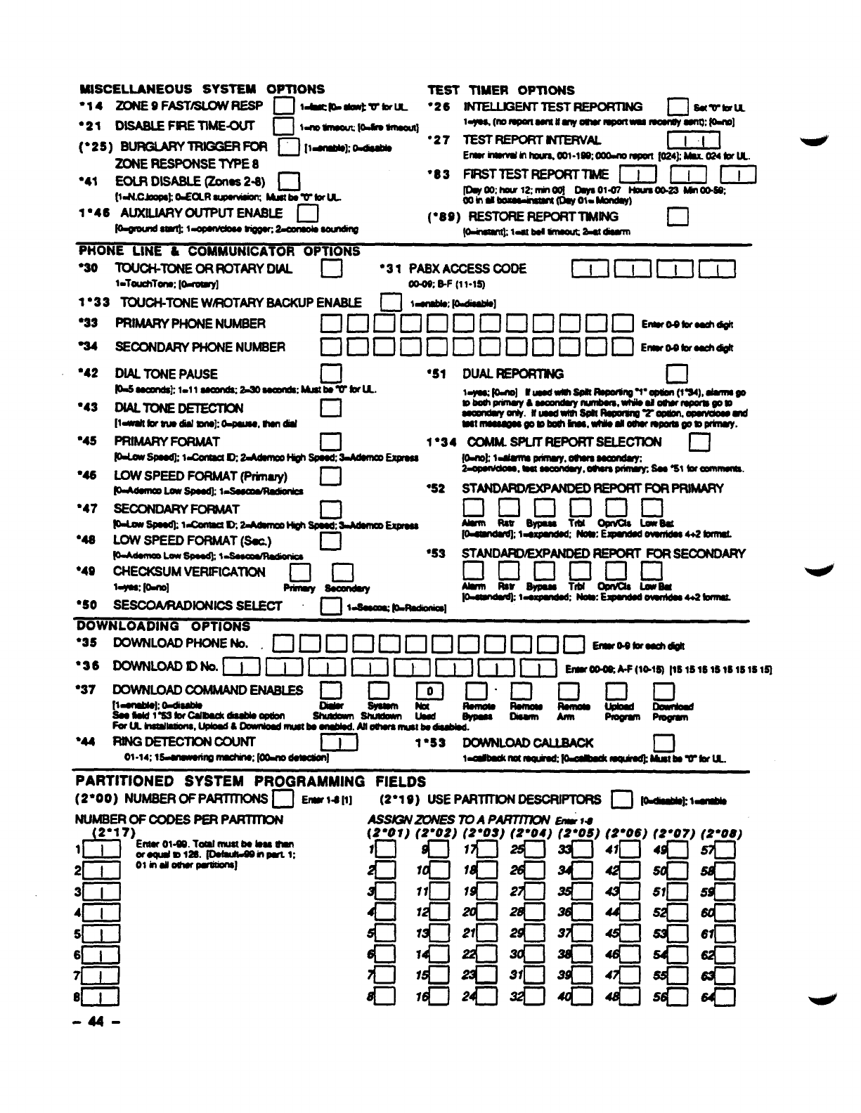
1•33 R)UCWONE WROTARY SACKUPENASLE mt~; ~1
●33
%4
“42
●43
“45
“48
“47
“48
“49
●SO
PRIMARYPHONENUMBER ❑nminDnnnoan E””’”-
SEOONDARYPHONENUMSER Dclunclnnclclnc lo’”---
DIAL TONEPAUSE n“s1
P-saOaJn@l-ll~,a30a0mn118. MbvklL
DIALToNE~ ❑
[14mltkwwodialmnoko+tauM,sundd
PRIMARYFORMAT •1 1“34
w6m0dl=0maaQ2=Mmn!0 w-~
LOWSPEEDFORMAT@nary) a-●52
~Low6Pob111.1~
SECONDARYFOFMAT
P-LatspOOdklanmc?ct~ c1
m-~
LOWSPEEDFORMAT(Sac) c1 -●5,
~Lon$vwJk*~
OHECKSUMVERIFICATION ❑0
~s lomol
=-—K-SELECT- •-~WWmmR,
DUALFEPORTM c1
●3S
●36
●37
“u
l—— ,
nm. r
I1s1s1sI1s1slq
PARTITIONED SYSTEM PROGRAMMING FIELDS
(2”00) NUMSEROFPNWITKWS n‘rlw 14 [1] (2”19) USE PAR~DESORllTORS D~kt~
NuMsERoFcQDEs PEF?PARITnoN AS~ZON/ES 7DAP~ EIIR14
(2’07)
lo
c1
c1
c1
a
a
a
d-l
-
(2”07)
4q--J
s~
Sln
K1
a
a
=0
slf-J
-44-
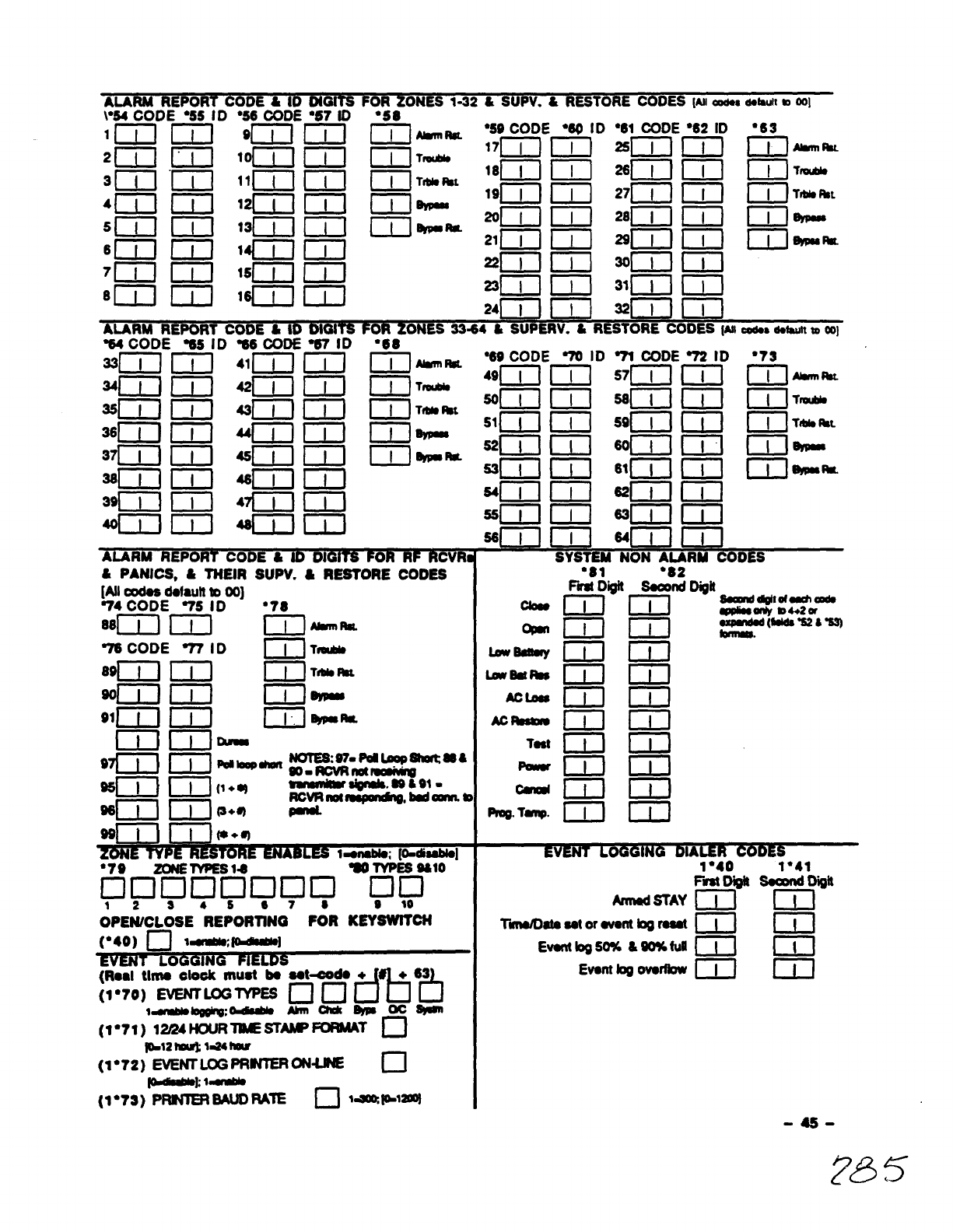
\“84 “CODE–“55 ID “56-~~n= ‘g7 ID
—— ------ .- “s8
i71 ~J ~lMri,t ●59 CODE ●69 1D●61 CODE“62 ID ●63
1— 17m r-i-l 2sl-il m~]#.llnnmL
~T*
~) TtiWL
ALARM REPORT CODE &ID 01 T’
%4 CODE %8 ID %8 CODE~G’in
=[~ ~] 41T1 I I J
A-ilm 42mri-1
“+% *.. - ●69 CODE 70 ID 71 CODE72 ID ●73
II IAmmm -——-
--— --—- --— -
I.— . .._-
~- . . 49~–1[[1 S7[I-[111 [ll&lnlW
~W[ll[llqll[lll{ ITraulds
36wl Fi iwlm i%lildbt —— —— —
S1{III[159111111W
6217 ml q“l IT m
—— ———
TIM8Mt
?A.== —63~{lll]611illllw9YPuIbm
I
I
I
-----
“81
F-D@
m
m
m
m
m
m
m
CD
m
m
III
D
m
ml
ml
El
Annd STAY
Tti8tosotorov9nt bgruat
Evontlog50% &W%fulI
Event log ovorfbw
1“40
F- Digit
m
ml
m
m
1“41
wDigil
m
m
Iil
m
-4s-
765
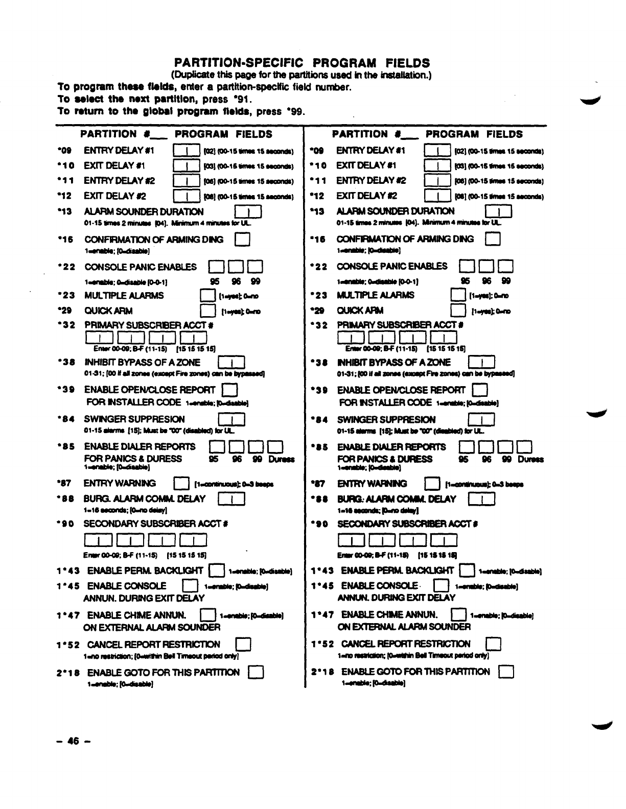
PARTITION-SPECIFIC PROGRAM FIELDS
(me tti paw fortheptitions used tnthe insWatiin.)
10 program these flelda, enter apartition-speclfk field nurrber.
To aeleot the next partltlon, press “91.
To return to the gtobal program fields, press “99.
●
O9
●lo
●11
“12
’13
“16
“22
●23
“29
“32
“38
●39
“84
’85
“87
●88
“90
—.- —.—--- -.. ——- ——.—-—-—.—-
PARTITION @_ PROGRAM FIELDS
ENTRYDEIAY #l r“ mwls-ls~,
EXIT DELAY*1 m@] (@t6- lssaOmld@
ENTRYDEIAY #2 ml Klmls-lsoomnm
EX17DEIAY 82 ~] fm,pt,9mats~,
AIARM SOUNDERDURATION m
ol-ls DlN92~ pq. ~411Uumstiu
CONFIRMATIONOF ARMINGDNG n
1~: [~ 1
l-almbk~[o+l] %s39
MULTIPLEAIARMS D[w-t-
QUIOKARM c1[Iqat bm
PRIMARYSUBSCRIBERAOOT#
mlmmlml
Enwro&oo;W(11-16) [1S16161~
INHIBITBYPASSOFAZONE m
Olsl:[oolfalzuna(QFhalna}aflbby pmaq
ENABLEOPEhlJCLOSEREPORT ❑
FOR S$JSTAUERCODE1~~
SWtNGER SUPPRES~ m
01-lsti [l* Mlakuw(d19all@bruL
ENABLEDIALERREPORIS UCIDCJ
FORPANICS&DURESS %3s83Dwaa
t~pdm9b10]
BURG.AJARMCOM$ADELAY 1~1
l-16~@l10dd9y]
SECONDARYSUBSCRBERAOCT#
DDlrHil
ErIwH, 6$ (11-15 [1S1S161~
I*43 EWmPERM.M~ ❑I=oMM~]
1“45 ENABLE OONSOLE Cl t~ ~]
ANNUN. DURINGEXITDELAY
1“47 ENABLEWIMEANNUN. ❑1~~]
oNExlERNALALAm souNDER
1“52 OANcELREPoRTREsmcmN n
l-nolB8mCmn;[odtm EWTWULnuPaiod0rW
2*18 ENABLEGOTOFORTHBPAR7mON D
ldrnbk;fOdubiO]
‘0s
“lo
811
812
’13
“16
“22
“23
“2s
“32
“38
“39
“84
●86
●87
●88
“90
PARTITION #_ PROGRAM FIELDS
ENTRYDEIAY MmIo21wls-15a0ml’dC)
EXITDEIAY m[–[–] ~]plsh 15su4nds)
AIARMsmNDmmtRATm m
ol-lsmz~ p4). MMllUn4-brtA
CON-m OF ARMING DNG n
1~ ~]
PRIMARY SUBSCR8ERAooT#
EHiHiHm
EfmrM w(11-12)[1s151s lsl
NHIBK BYPASS WAZONE m
ol-w;lootitiaolln(m%oqmb~
SWINGERsuPmsloN m
01-lsdmm[l* Mmtbw=[mbruL.
lilcilmlml
Emrm EF[ll-lQ [161s1514
1*43 ENABLEPERM.BKKIBHT •1 1~ ~]
1*45 ENABLEm~ ❑t~~I
ANNW. DURING EXKDEIAY
1“47 ENAB1.EcHIMEANNLJN. c1 1~ pdimbb]
cME%lmNALAIARMsouNDER
1“52 cmcELREPm7REsmcmN c1
ldmmmwmpmiwl!somripmiodalty]
2’18 ENABLEGOlOFORTHISPARTllWN c1
1~ p=dlnbb]
-46-
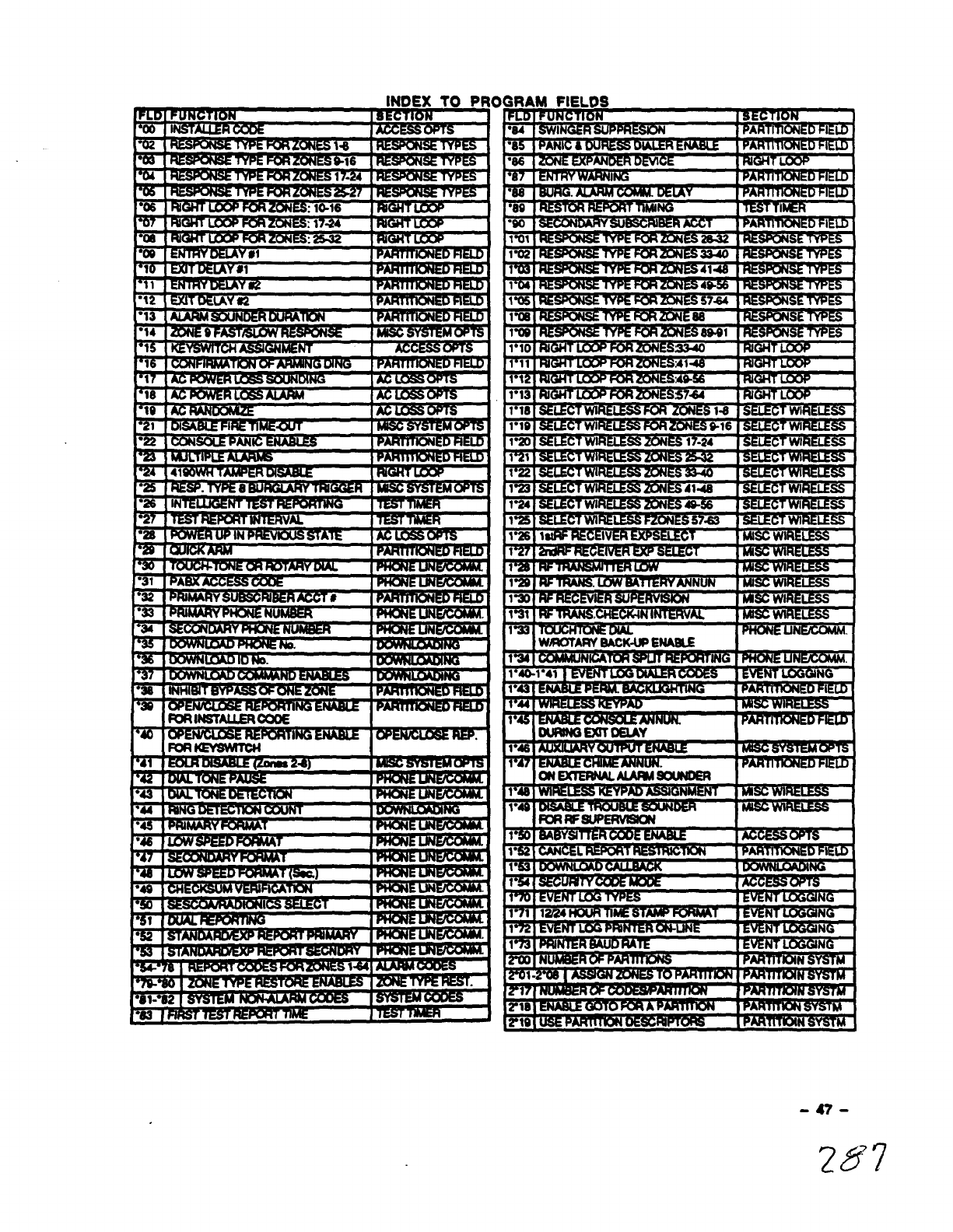
OG
●-.....—_.. —-. ..—-.-.
*U
.---.—. ..—
---- ------ .-—. —.... ... ..----— —..-
.
--. ....- -..-. .-—..--—. .
1lFoRRFsuPERwsm II
-47-
287
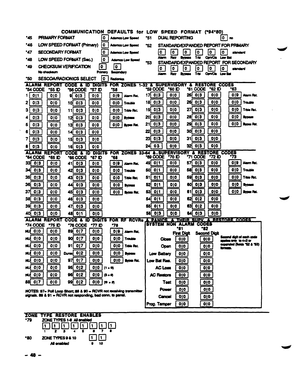
COMMUNICATION DEFAULTS for
“45 mktmv FORM4T •1
o~LW2@d
“46 LOWSPEEDFORMAT(Prhary) ~/ir&meuIJNx
“47 SEOONOARYFOWAT n
o~m2p48d
●46 ~SPEEDFORMAT(SarA) /-jg M8nwm2Pnd
●49 ONECKSUMVERIFIOATON am
M~ -~
“50 SESOOARADIONICSSELECT ~ ~
“5510
m
G1
00
ml
&l
ml
El
ml
l%
LOW SPEED FORMAT (“94”80
“51 DUALREPoRnNG b
Om
%2 STANOAROEXP
ANDEDREPORTFORPRIMAFW
mmmmma~
A&trlwrrxTfum@au
%3 sTmmRoExPANoEo REPORTFORsEmNDARY
EIEIEIEIEI El--
AJmmlR8um Tlu@nCalsUM
AMRM REPORT CODE &ID DIG1= FOR ZONES 1-32 &SUPERVISOR Y&RESTORE CODES
“54 CODE “57 ID “58
1~( mm“”
2~ m[ml T-
3ml ~] [ml Tlbbmt
4Jml EiEHml
5Im’ mm-”
61=1 m
7~j C!iiicl
am m
19pJ3J
apiiq
21F
“6010
EiiiEl
El
ml
&
“61 CODE
26[-1
●6210 “63
EEI E!El””
Em m’-
——
,>IJ
ALARM REPORT CODE ‘& ID DIGITS FOR ZONES W=64;
“64CODE “65 IO “66000E “67IO “68 “86000E 701D 71 OOOE “nlo 73
**m m““m mm-” ●iIl m=m mg,-”
-—— —— ——
~
Iml
m
E!EJ
m
Im
KILl
m
P&J
Em
ImI
ml
tml
m
m
w
m
m
EiLEl
Tmwo
web au
Uy$mm
IAfll
12iEl
m
I&l
m
Eii!Il
ITiFl
lwJ
m
m
Giir
m
m
r%
L010 Ilmutlb
G1
00 TIW*L
ml
00 6rml
FJ ~ihattu
74 CODE
m
m
rw[010 J
43iiiIl
rum]
f’J4ml
a!i
ml
I&l
IziKl
IzEl
EiEl
“77ID
m
00
ml
&l
m
lml
ml
00(1
la-
m
00 TmlAb
m
00 TIM8ML
m00 ~
m
00 ma
+*
bwsd!ory
bws@ti.
Aclsss
Ao~
Tom
‘s1
~la”
00
ml
G
m
m
Eiiin
ml
la
m
00
%2
Suar)igll
El
ml
&l
El
EiiiIl
EEl
m
E
EiEJ
9“dliii?iifirmElm
1234S87 S
●8O zoNE7YPEs9&lo Em
ABuIa8d e 10
-48-
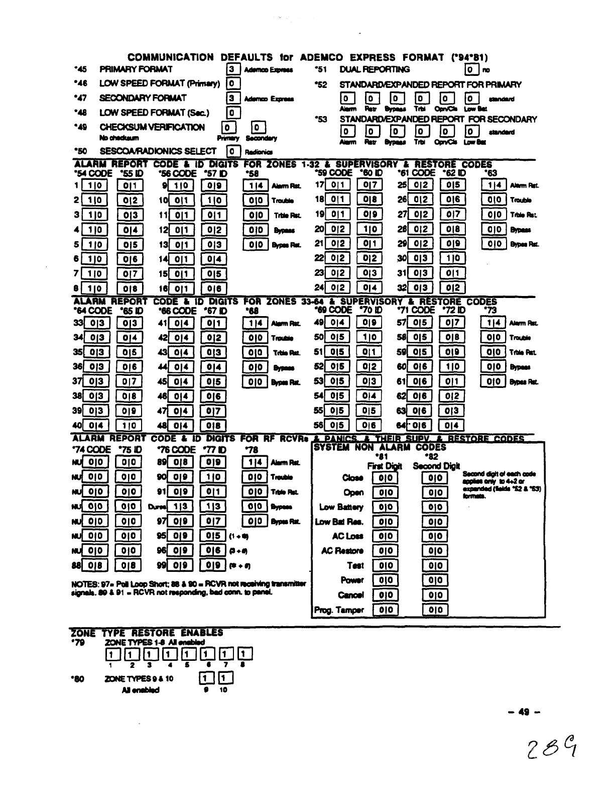
“45
“46
“47
“48
●49
●5O sEscaARADloNlcsSELECT mRdhfiu
ADEMCO EXPRESS FORMAT (*94*81)
“51 DUAL~~ful
“52 sTmDmDExPANDEDREPORTFORPRw
EIEmmlEI El-’-
sRBuXTrbIXWRa
“66
●
75 ID
m
m
EiiEl
II!EI
m
IzEl
ml
m
77s) 76
Ciiaml
mm
mm
mEiEJ
mm
NoTlE6:D7=Pdbap3haltm &m9RcvRnotmahh168wWnhmr
$ipm18.a?kel-RcvRnotm8pmdng. waunn. mPuul
LowSaltuy
&w8d Ra.
ACbu
To8t
FQwt
●81
d
F- “
010
@!Il
m
m
m
m
m
m
mU!Ll
b4m
frog. Tampw ~
%“’~y4jylJfy,y1 ,~
12s4s07 8
“60 MuETYPEs@&lo ma
A8udd #10
-49-
285
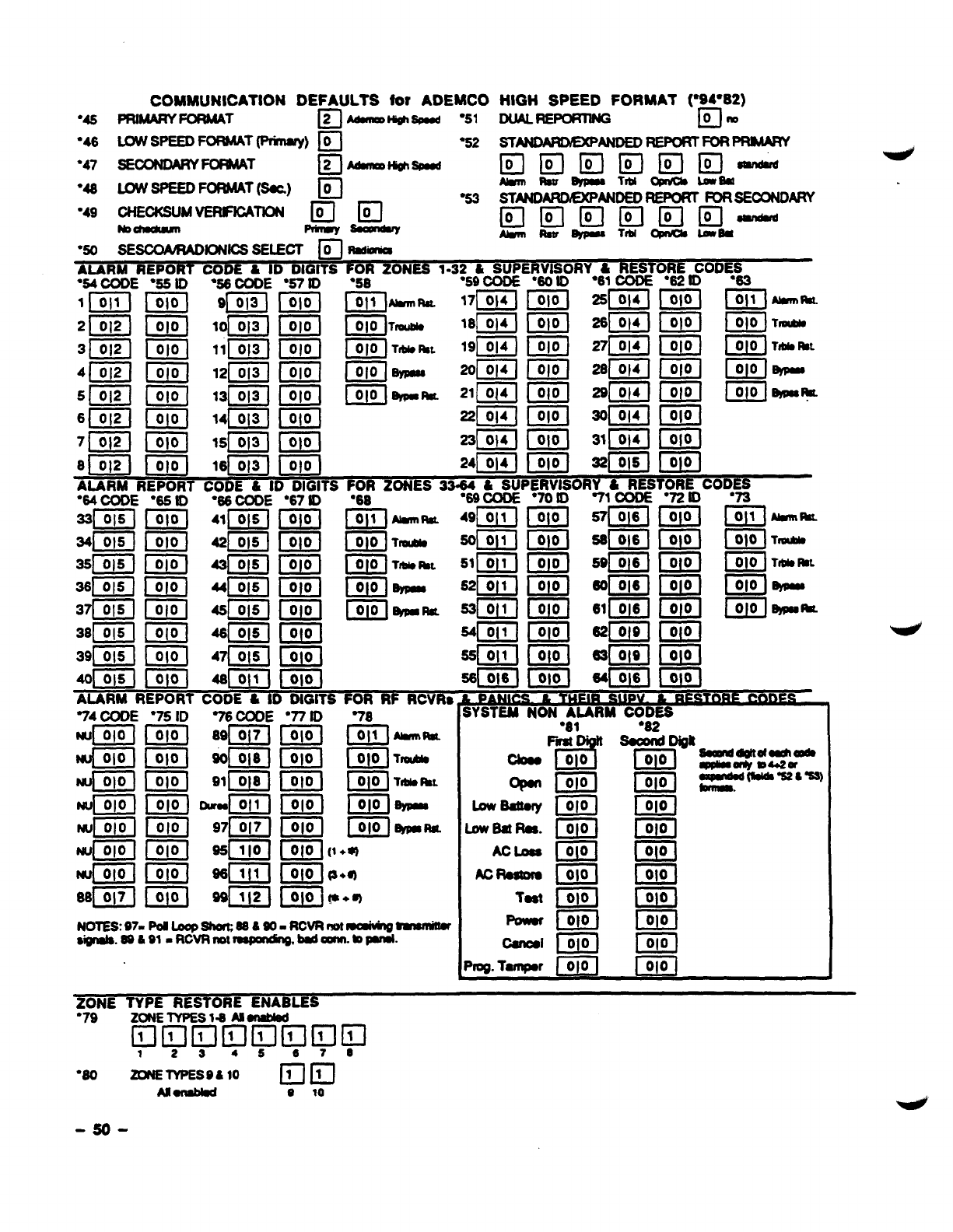
COMMUNICATION DEFAULTS ior ADEMCO
“45 PRIMARYFORM4T ~~Hi#lm “51
“46 WSPEEDFORMAT(l%nq) ❑%2
●47 SECONDARYFO%AAT c1
2~Wgh3pnd
HIGH SPEED FORMAT (“94”82)
DuALREPORw@ m“
sTANDAmQ@ANoED REPOmFoRPRhMRY
●53
“50 sEsco&RADlmlcs SELEOT F-1Rd-
ALARM REP co &D DII=O ON
~CODES
!ID ’63
——
110111 10101 9! 013 I I 010 I I 011 I*W 171014 I I o
21 0121 I0101 10I 013 I I 0101 I010 hlWbb 1610]4 I I 010 I
7-. 211 014 I1 010 I291014110101 IOIO16KIUIW
. . ---- .- - ------ .-—
Hi &“- ●iiIIEiiIl flml= m“’
Ezl 12im- “m EJ “m EEJ ~T’-’
IziiIl EiG--- -~-v-~t-r-, ---- -’j
—— —— ——
7T& k, 511011 I1 010 I59i 016 ti010 i i OtO iTtilW
IiIllm @iEmiEl
Zim2iEl @imilIl
—— ——
016110101 64LO161\OIO]
;Y%d NON AURM CODES
“77 10
12iE’1
EiEl
m
EziIl
IziEl
“81
d!!’
FM.
&
II@l
m
m
l.owB8ttory
13wB8tR66.
AOLD66
Is!d
E!iizl
m
m
13iEl
m
w
IzEl
Izicl
IzEJ
w
66[’[ -U!!AJ UiLl
-EE1 ml
-’m DiiEl
%g.
Tampw 010 m
NoTEs97= PadLoap8h0m85a80-RcvRnm19aiVh6 tM6n40w
8ign816.WJh91-RcvR Irolm6PondW,b6clounn.mPm181.
;#NE TYPE RESTORE ENABLES
ZU4ElYPESla Alordbd
❑amammmm
1234567 6
●8O zoNElvPEs@&lo Elm
A261MM6d @10
-so-
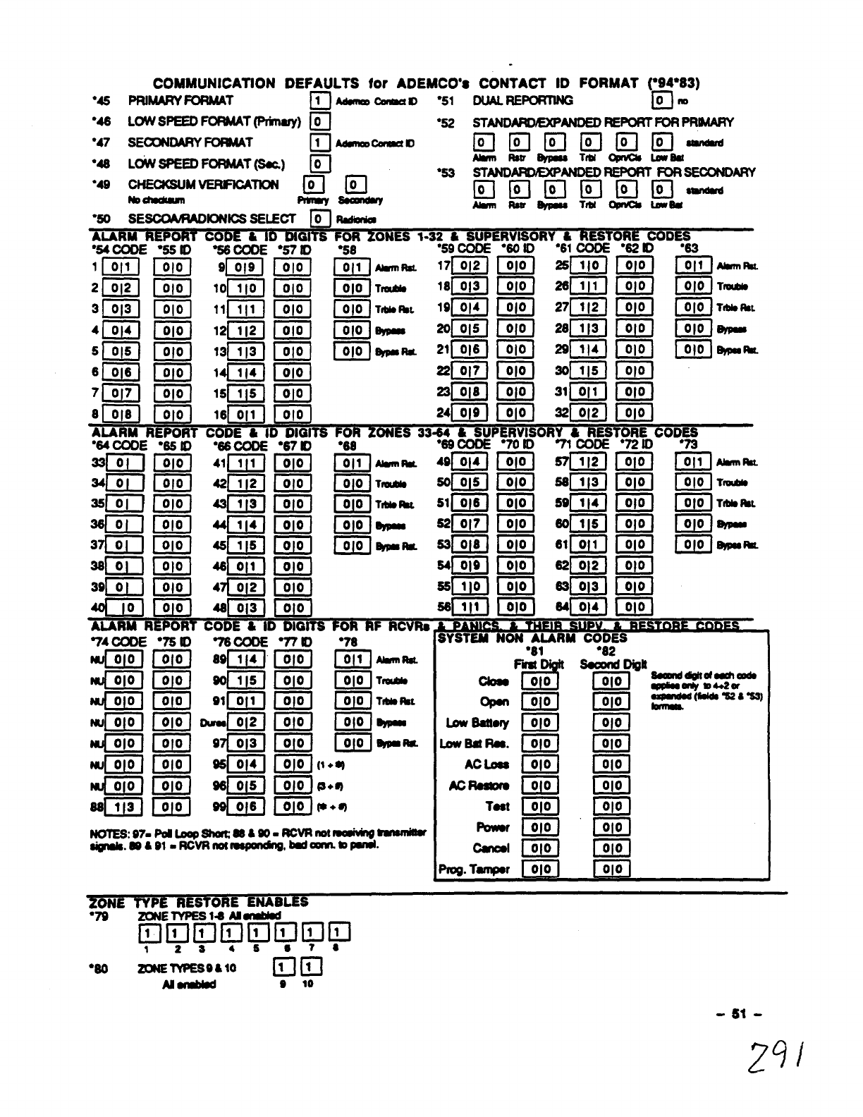
COMMUNICATION DEFAULTS for ADEMCO’S CONTACT ID FORMAT (W4*83)
●45 PRIM4RYFORMAT ❑MalUlcalwl “51 DLJALREFoRnNG III”
“46 LW SPEEDFORMAT(Prinsry) ❑●52 STANDARDEXPANDEDREm FORPRMARY
●47 SE~DARY ~T •~cmmau mmmmmm~
●46 LW SPEEDFORMAT(See) ❑A@wIRo& BYPMs Tfu@ICISlaWBm
“49 CNECKSUM VERFWm mm
●53 sTAND~ANDED REPORT msEcoNoARY
No&mdLun m~ •mmamm’~
hwIIIm~TIUWLawW
●5O SE~~lCS SELECT n~
ALARM REPORT CODE &ID DIGI= FOR ZONES 1-32 &_SUPERVISORY k@.ESIoW _~DES
21 0121 1 0101 10I 1101 10101 I010 lTmIUD 181 0[3 I I 010 i
IImEl 241
ID DIGITS FOR ZONES 3344
36101 I]olol 41[4jlo[o J[Olo]opa 621017 jlolo[ 60[1[5110101 [Ololewal
—— ——— —— ———
w
m
m
m
w
m
m
m
14111
—— ——
ORT CODE &ID D
10101 61~011110101 10IOleypnrru
——
SYSTEM
“7610
13!zl
m
13irJ
El
ml
ml
ml
El fwsl
77 ID
Eiiil
m
m
IziiEl
ml
m
ml
EiiEl
“78
m
01 AhlllRu
~’1-
(1+8)
bSsttory w
Iswsa Ra. m
ACLoss m
aR2sior2 _m
Test ,~~]
mm
am
14!Ll
Eim
ml
m
IT
Pow2r[
tir
lProg.Tamper ~[010 I
>I? PE RESTO EENABLES
This equipment has been tested to FCC requirements and has been found acoeptk for use. The FCC requires
the followingstatementfor your information.
This equipmenf generatesandusesradiofrequency energy and tf not installed and used property, that is, in strtot
aooordanoewiththe manufaoturet’sinstructions,mayoauseinterferenceto radio andtefevisiinrecetiion.It has
been type testedandfoundtooompfywith the Iimitsior aCtass Bco~ting device in aooordanoe with the
speoifiiions inSubpartJof Part15of FCC Rules,Wkh aredesignedtopnwidereasonableprotectionagainst
suti interferenceharesidentialinstaltatiin.However,thereisnoguaranteethatinterferencewillnotoocurina
particularinstaftation.tfthisequipmentdoesoauseinterferenceto rado ortelevisionreoeption,whii oanbe
determinedby turning the equipment off and on, the user is encouraged to try to oorrecfthe interterenoeby one
or more ofthe followingmSSSUreS:
●tfusingan indoorantenna,haveaqualityoutdoorantennainstalled.
sReorientthe receivingantennauntilinterferenceisreducedor etirninated.
“Movethe receiver away from the oonfmlkormunicator.
“Move the antenna feads away from any wire runs to the oontro14mmnunicator.
“Plug the controlbornmunioator into adifferent outlet so that if and the receiver are ondifferentbranchoirwits.
If necessary, the usershould oonsuttthe deaferor an experiencedradioltetevisionteohnioianforadditional
Suggestions.
The user or i~ta[ler msy find the following booklet prepared by the Federal Comrnunicafkm$commission he~ul:
“Interference Handbook”
This bookfat is availabta from the lJ.S. Government PrirtWgOffice,Washington,DC20402.
StookNo. 004-000-00450-7.
The usershallnotmakeanychsngesorrnodifiibna to the equipmentunless authorized bythe Inefaltatiin
Instruotiona
or LJseFs Manuaf. unauthorized changes or modifications 00u1d void the user’s authorfty to OpWSte
IN THE EVENT OF TELEPHONE OPERATIONAL PROBLEMS
In the “event of telephoneoperatbnal pmble~,-ditinne~- the 00ntrolpa-~l by removingthe pfug fIbWIthe
RJ31 X(CA38A in Canada) wall ja~. We r~mrnend that you demonstrate rflsconnecthtg the phones on
installation of the system. DOr@tdsoonneotthe phoneoonnectiinin&dethe ControlPanel. Doingsowfllresult
in the loss of your phone lines. If the regular phone works oorrectly after the Control Panel has been
disconnected from the phonelines,The ControlPanelhasaproblemand shoutdbe returnedfor repair. ffupon
disconnectionof the ControlPanel, there is still aproblem on the fine, notify the tefephone oompany that they
have aproblem and request prompt repair servioe. The user may not under any oiroumstanoes(in or out of ““
warranty) attemptany service or repairsto the system, ttmust be returnedto the faotoryor an authorizedaervioe
agency foraflrepairs.
-52-
CAN~AN ~mT WCO-CATIONS
(DOC) STATEMENT
IThe Canadian Department of Communicationslabelkfentitiescertifiedequipment.This certificationmeans that
the equfprnenl meets certaintelecommnhcationsnetworkprotective,operationaland safetyrequirements.The
~m doesnotgwamee the equipmentwiiloperatetotheuserssatisfaction. I
Beforeinstatingthisequipment,usersshoutdensurethat it ispermissibleto be connectedto the facilitiesof the
focal telecommunicationscompany. The equipment must also be installedusing an acceptablemethodof
connection.In somecases,the conqmy’s insidewiringassociatedwithasinglelineindividualservicemaybe
extendedby meansof certifii connectorasserWy (telephoneextensioncord).The customershoutdbe aware
thatcomptiincewiththe aboveconditionsmaynotpreventdegradationofserviceinsomesituations.
Repairsto certiW equipmentshouidbe madebyan authorizedCanadmnmaintenancefacilitydesignatedbythe
sup~~er.Anyrepairsor alterationsmadebythe userto thisequipment,or equipmentmalfunctions,maygivethe
telecommunicationscompanycauseto requestthe userto d-nnect the equipment.
Usersshoukfensurefortheirownprotectionthatthe electricalgroundconnectionsof the powerufiiii, telephone
lines and internal metalfii water pipe system, if present, are connected together. This precaution may be
particutmtyfnpxanf hrurafareas.
Caution: User shouid not attempt to make such connectiina themselves, but shoufd contact the appropriate
eiectrfc inspadon authority,or electrician,as apfnpMte.
~(LN) assignedto each terminaldevice denotesthe percentageof the total bad to be
connectedto atebphone ioopwhichis used by the device, to preventoverioadng.The terminationon abq
mayconsistof anycombinationofdevicessubjectontyto the requirementthatthetotaiof theLoadNumbersofall
thedevicesdoes notexceed 100.
LWquette du miniatr&Jredes Communicatiis du Canada ktentifie la mat~riel t@rmbgu6 Cette dtiquette certifii
que Ie mafdrieleat conformsAcertainesnormesde protection,dexpbitation et de s6curitddes r6seauxde
t6i&Xmununicat”ions.
Le minist&e n’assuretoutefoispas que kmatdrielfonctionneraAis satisfactionde
f’utitisateur.
Avant d’instaiiercs mat&iel, t’utiiisateurdoit s’assurerqu”ii est permis de ie raccorder eux installafbns de
t’entrepriaefocafede t#6comnunication. Le matdriei doit dgaiement dtre instaffd en auivant une nWtod accept6e
de raccordement. Dans ce~ins cas, ies fus int6rieumde t’entrepriaeufifis6s pour un service indiviiel aiigne
unkquepeuvent We probn@s au moyen d’un d~itit homoiogudde raccordement(cordonproiongateur
t6i4phon@e inteme).L’abonnene doitpasoubiier@ii est possibfeque is conforrnifd
aux conditbne dnorx%es
I&daaaus n’arnpkhant pas ta @gradationdservicepar certainessituations.Actueltement,tesenterprisesde
tWcomnunicatbn ne permettentpas que ron mccordafeurmat&iei aux jacksd’abonnds,aauf dana ies cas
x*wM-wmkm*msm-
Lee reparationsde matdrielhomobgud doivemdtre effectu6espas un centred’entretiencanadienaufhorisd
d6aign6par fe foumiaseur.La conymgniade Wcornmunfcationepeufdemander~I’utifiieur de d&wmcherun
apparsdl ~la suite de r@arations ou de modifications eftectu6es par Wtiii$titeur ou Acause de mauvais
fonctbnnement.
Pour as propre protectbn, f’utifiaateurdoit s’assurer qua tous ies tiis de mise his terra de is source deneI@s
6iectrique, dea iignea t61@hmiques et des canafiaafbna d’eau mdtaftiques,s’iiyen a, sentraccord6senaenbie.
Cetteprecautionestparticufiirementhrqmrtanteclansiesr6gbnamales.
AvertlaaemeftC L’utitiaateurne doltpas tamer de faire ces raccordements tuiitime: il doit avoirrecoursAun
aewiced’inspectiondes fnstaliatbnsdfectdques,ouAun4ectrbian,aebn fe caa.
~lC) aaaign6AchaquedispoaitifterminalpourMtertoute surchatgeindiiue ISpourcentagede
fachargetotaiequi peut &re mccwde4 Aun citwft t&@honique boudd ufifii par ce dqsitif. La terminaisondu
drcuff bouci6 peuf We conatftude de nln’qwte quells oo~naieon de diapostiifs, POUIVUque is aommedes
indices de charge de f’enaeti des dispositifsne ddpaaae pas 100.
1I
-s3-
,WARNING
THE LIMITATIONS OF THIS ALARM SYSTEM
Whflethbsystemis an advanceddesii aeouritysystem,itdoesnotofferguarameectpmteotionagainstburglary,
fii orotheremergency.Anafarmsystem,whetheroomnvsrcialorresidential,issubjectto wnpromise or failureto
warnfor anunlw of raasons. For exarrtpte:
sIntruders may gain aooeas through tmpmtecfed openings or have the technkal sophisticationto bypass an
atarmsensorordisoormad analarm-devbe.
cIntrusiondeteotora (e.g. passive infrared detectors), smoke detectors, and many other sensing devices will not
work without power. BatteIY operated devices wiltnot work wtthoutbatteries,with dead batteries, or ffthe batleries
arem~~p~~. ~~~titi~~AC til MWAtit&ir X~r-k@titira~
reason, however briefly.
cSiinals sent by wiretesstmsmfttars may be bbcked or reflectedby metal before they reach the alarm reoeiver.
Ennfltis@ml @h~hn~ti@ti@ ~~a-t-, _~n Wrtia-al~k
movedimothe path.
cAuser may not be able to reach apanioor emergency buttonquicktyermugh.
●While smoke detectors have played a key role mreducingresidentialfire deaths in the UnitedStates,they may
not actiie orprovideesrfywarningforavarietyofreasonsinas manyas 3S%ofatlfns, accordingto data
publiihed by the Federal Emergency Managemem Agency. Some of the reasons smoke deteotors used in
conjundionwiththisSystem may not work areas Ioltows. SMOke detectors may have been irrtproperfy instatfecf
and positioned. Smoke detectors may not sense fires that start where smke cannot reach the deteotors, auoh as
in ohimneya, in waffs,or roofs,or on fhe other side of obsed doors. Smoke deteotorsalso may not sense aii on
another level of aresidenceorbuflding.Asaaxxt fbor detector,forexampfe,maynotsenseafii fbor or
basement fire. Moreover, smoke deteotom have sensing limitations. No smoke deteotor Oan Sense every kind of
fire every time. In general, detectors may not atways warn about fries caused by oareleaaness and safety hazards
Iiie smoking fn bad, vfofanf expfosbns, eaoap&lg gas, Irrpmpar storage or fkrnmabla materfsk, overbadad
elactrioal cirwfts, chfkfren playing with matohes, or arson. Depending on the nature of the fire Sm@Orthe Iooatbn
of the smoke deteotors, the deteotor, even If it operates as antiited, may not provkte aufficknt warning to albw
all ocoupants to esoaps intimeto preventinjuryordeath.
●Passive Infrared MotionDetaotorsoanonfydeteotintrusbnwfthinthedesignedrangesas d~rnmed intheir
installationmanual.Passive Infrared Detectors do Mprovide votumatrfo area protedbn, Theydooreatemuttiple
beams of protection, and intrusbnoanonlybe deteotedinunobstructedareasooveredbythe beams. They
Cannotdetectrnotbn or intruabn that takes ~behimt wafk, oeilings, fbora, ofoaed doors, glass partftbns,
9kss doors,orwfndows.Meohanioattawrfng, maskfng,paitiiru orsprayingof anymaterialonthemirrors,
windowsor any part of the optioalsystemoan raduoatheirdeteotionability.PassivekdraradDeteUorasense
changesIntemperature:however,as the ambientte~rafure of the proteotedarea appmaohs the teqwrature
range of 90° to 150”F,the detactbnperforrnanoeoandeoraase.
●-wmiqw~m~am, bkamm~m~fi~ ~mq~m-am~
on~eo*r* @a**or~~n~. H_**mtiona *mm Wl@tim*m
fmmthe bedrooms,thentheyare leasIikefyto wakenor @aftpeopleInsidethe bedmoma.Even paraww wtm are
Xemymt~arti wa~Utitimk ~~m~~a S~, Xm~rti~r~~, ti
bypSSSi~ tMffii. FinSfty, aiarrn _devbes, however bud, MSY nOt WSrn ha~ pa@a or waken
deep sleepers.
Telephonefinesneededtotransmftalarmsignalsfmmapre~s to~ oentrafmonitoringatatbnmaybe outof
servbe or temporalityoutof servioe.TefephonaIii are alsosubjectto compromkeby aophktfeatadIntmders.
●Evenifthe systemrespondsto the emergenoyas intended,however,oooupantsmayhavehwffbient timeto
proteotthemselvesfmmthe emergencysftuation.Intheoaaeofamonftoredalarmsysfem,authwttksmaynot
respondappropriately.
●Thise@pment, likeothereieotrbaldevioes,issubjectto oonponentfailure.Eventhoughthisequlprnetiis
designedtolaat as bng as 10 years,the ekotmnk OorrponentsOoutilairat anytime.
The mostoommonoauseofan @armsystemnotfunctioningwhenan intrusionorfn oooursisbadeqmm
msfntena~. Thisalarmsystemshouldbe testedweekfytomakeauraaftsensorsareworkingcmperfy.
I~~~a_*emmy tiem~*tirtimH *-, ~m-*em Sma~e
for Insuranoe.Homeowners,propertyownersand reweraahoukfoonthweto aotprudentfyinprotecting
tharnaefvesand oontinueto insurethefrfivesandproperty.
We oontfnueto devebp newand improvedproteoffondevkes. UsersofalarmSySteIJtSowe Itto fhemsefvesand
Jheirbved onesto learnaboutthese develornnants.
w
-s4-
ADEMCO LIMITED WARRANTY
Alarm Device Manufacturing Company, aDwisiin of PittWay Corporation, and its d~lons, subsidiaries and affili-
ates (%eller), 165 Eileen Way, Syosset, New York 11791, warrants its products to be in conformance with its own
plane and spaMoations and to be free from defects in materials and workmanship under normal use and service
for18 monthsfrom the date stampcontrolonthe product or, forproducts not having an Adernco date stamp, for
12 months from date of orlghal purchase unless the installation “hstructions or ~abg sets fotth aShotter period,
inwhichcase the shorter period shall appfy. seller’s obligation shall be limited to repairing or replacing, at its op-
tion, tree of charge for materials or labor, any product whch is proved not inmrrpliancewithSellersspecifications
or provesdefectivein materialsor workmanshipunder normal use and service.seller shall have no obfiitkm un-
der this Limited Warranty or otherwise if the product is attered or improperly repaired or serviced by anyone other
than Memco factory service. For warranty sewice, return product transportation prepaid, to Ademco Factory
Service, 165 Eiieen Way, Syosaet, New York 11791.
THERE ARE NO WARRANTIES, EXPRESS OR iMPLiED, OF MERCHANTABiLiTY, OR FiTNESS FOR A
PARTiClfLAR PURPOSE OR OTHERWiSE, WHICH E~END BEYOND THE DESCRIPTION ON THE FACE
HEREOF. iN NO CASE SHAU SELLER BE LiABLE TO ANYONE FOR ANY CONSEQUENTIAL OR incidental
DAMAGES FOR BREACH OF THiS OR ANY OTHER WARRANTY, EXPRESS OR iMPLIED, OR UPON ANY
OTHER BASiS OF LiABiLilY WATSOEVER, EVEN iF THE LOSS OR DAMAGE iS CAUSED BY THE SEUER’S
OWN NEGUGENCE OR FAULT.
Baiter does not represent that the pmfucts it seiis may not be compromised or circumvented: that the products
wifi prevent any personal injj~ or property toss by burglary, robbery, fire or othemvise; or that the products wifi in ail
cases provide adequate warning or protection. Customer understands that aproperty inataifed and maintained
alarm may only reduce the risk of abu9tafy, robbery, tire or other events occurring without providhg an alarm, but
if is not insurance or aguarantee that such wifi rmt occur or that there wili be no personai injury or propady bss as a
reauft. CONSEQUENTLY, SELLER SHALL HAVE NO LiABfLiTYFOR ANY PERSONALfNJiJRY,PROPERIY
DAMAGEOR OTHER LOSSBASEDON ACiAIM THE PRODUCTFAiLEDTO GIVE WARNING.HOWEVER,iF
SEUER iS HELDLiABLE,WHETHERDiRECTLYOR indirectly, FORANYLOSSOR DAMAGEARiSiNGUN-
DER Ti-ffS LIMfTED WARRANTY OR OTHERWfSE, REGARDLESS OF CAUSE OR 0Ri(3fN, SELLER’SMAXiMUM
LiABiLITYSHALLNOT iN ANY CASEEXCEEDTHE PURCHASEPRICEOF THE PRODUCT,WfiCH SHALLBE
THE COMPLETEAND EXCLUSiVEREMEDYAGAfNSTSELLER.Ths warrantyreplacesanypreviouswarranties
and isthe onlywarrantymadeby Selleronths product.No increaseorafteratbn,writtenor verbai,ofthe obliga-
tionsof thw LimitedWarrantvisauthorized.

w
u6euv2mQ on@YmgMolalullwN~
