FA1340C, FA1340C UL Programming Form Program Manual
User Manual: FA1340C Program Manual AlarmHow.net Library
Open the PDF directly: View PDF ![]() .
.
Page Count: 16
FAl34OC
FAi34OGUL
PARTITIONED SECURITY SYSTEM
with SCHEDULING
FA1340GPR 6195 (See Instructions N5944-5)
PECIFIC section for
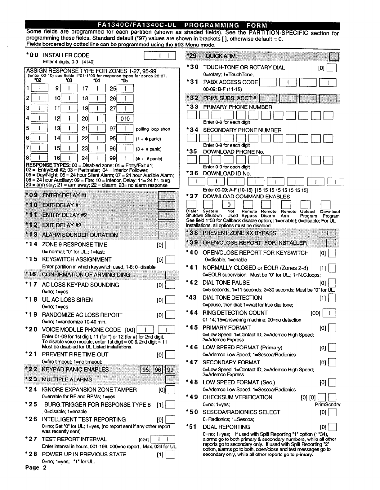
+ 0 0 INSTALLER CODE p-7-J
Enter 4 digits, O-9 [4140]
ASSIGN RESPONSE TYPE FOR ZONES l-27,95-99
(En&OO-10) see fikl$ 1’01-1’09~ response&ps for zones 29-97.
91
lop-j
1lr-q
12p-j
I 1
17r-q
18jI
191
20/-T--j
5 1 1 ) 131 1 1 211 1 1 971 1 1 polling loop short
6 [I
1411 2211 9511
(I panic) + *
7 II
151 23[/ 96/T]
(3 + #panic)
m-m-
RESPONSE TYPES: 00 = Disabled zone; 01 = Entry/Exit #l;
Is lKj.:6i ,I 121. I, ‘_““I I i(*+;pa;
02 = Entry/Exit #2.03 = Perimeter 04 - Interior Follower
05 = Da /Night; 06 = 24 hour Silent Alarm; 07 = 24 hour Audible Alarm;
08 = 24 our Auxiliary; 09 = Fire; 10 = Interior, Delay; 1 1= 24 hr. burg.
20 = arm sta ; 21= arm awa ; 22 = disarm; 23= no alarm res se
l 14
ZONE 9 RESPONSE TIME PI I
l
3 0 TOUCH-TONE OR ROTARY DIAL
PI u
O=rotary; 1 =TouchTone;
* 3
1
PABX ACCESS CODE II II m r(I
00-09; B-F (11-15)
* 3
2 PRIM.
SUSS: ACCT# m m It m
l
3 3 PRIMARY PHONE NUMBER
q uuuuuuuuuuo
Enter O-9 for each digit
l
3 4 SECONDARY PHONE NUMBER
q ouuouuuuuuu
Enter O-9 for each digit
*35 DOWNLOAD PHONE No.
q uuuuuuuuuun
Enter O-9 for each diait
l
3 6 DOWNLOAD ID No.
IIIIrnIIIIII
EnterOO-O9;A-F(lO-15) [1515151515151515]
* 3 7 DOWNLOAD COMMAND ENABLES
q umclclclucl
Dialer S stem Not
Shutdwn hutdwn
H Remote Remote Remote Upload Download
Used Bypass Disarm Arm Program Program
See field 1’53 for Callback disable option: Il=enable]; Wisable: For UL
installations, all options must be disabled: -
l 3 8
f%nilEbk ZONE h 6YP;ASS n I
*
3 9
OPEN/CL&E REPORT FOR INSTALLER
q
-
O= normal; ‘o* for UL.; 1 =fast; -
l
16 KEYSWITCH ASSIGNMENT PI 0
Enter partition in which keyswitch used, 1-8; Oaisable
*I 6 CONFIRMATiON OF ARMING DING
q
l
17 AC LOSS KEYPAD SOUNDING
WI 0
O=no; l=yes
l
18 UL AC LOSS SIREN
[OIO
O=no; l=yes
* 19 RANDOMIZE AC LOSS REPORT
PI 0
O=no; 1 =mndomize 1 O-40 min.
l
2 0 VOICE MODULE PHONE CODE [00] II/ II
Enter 01-09 for 1 st digit; 11 (for ‘) or 12 (for #) for 2nd digit.
To disable voice module, enter 1 st digit = 00 8 2nd digit = 11
Must be disabled for UL Listed installations.
l
2 1 PREVENT FIRE TIME-OUT 101 I-l
*40
l
41
*42
l
43
l
44
*45
l
46
O=fire timeout; l=no timeout;
* 2 2 KEYPAD PANIC ENABLES
*2 3 MULTIPLE ALARMS
* ‘I
195/[96qiq
q
* 2 4 IGNORE EXPANSION ZONE TAMPER
MO
O=enable for RF and RPMs; 1 =yes
l
2 5 BURG.TRIGGER FOR RESPONSE TYPE 8 [1] 0
O=disable; l=enable
l
2 6 INTELLIGENT TEST REPORTING
WI r-J
O=no; Set ‘0’ for UL; 1 =yes, (no report sent if any other report
was recently sent)
l
2 7 TEST REPORT INTERVAL
10241 -1
Enter interval in hours, 001-199; OOO=no report ; Max. 024 for UL.
l
2 8 POWER UP IN PREVIOUS STATE [llU
O=no;
1 =yes; ‘1’ for UL.
Page 2
l
47
l
48
l 49
‘50
l
51
OPEN/CLOSE REPORT FOR KEYSWITCH
Oaisable; 1 =enable
PI u
NORMALLY CLOSED or EOLR (Zones 2-8)
111 0
O=EOLR supervision; Must be “0’ for UL.; l=N.C.lcops;
DIAL TONE PAUSE
PI 0
0=5 seconds; 1 =l 1 seconds; 2-30 seconds; Must be ‘0’ for UL.
DIAL TONE DETECTION
111 I-J
O=pause, then dii; 1 =wait for true dial tone;
RING DETECTION COUNT
WI F--J
01-14; 15-answering machine; OO=no detection
PRIMARY FORMAT
PI 0
O=Low Speed; l=Contact ID; P=Ademco High Speed;
3=Ademcu Express
LOW SPEED FORMAT (Primary)
PI 0
O=Ademco Low Speed; 1 =SescoaRadionics
SECONDARY FORMAT
PI 0
O=Low Speed; l=Contact ID; 2=Ademco High Speed;
3=Ademco Express
LOW SPEED FORMAT (Sec.)
WI 0
O=Ademco Low Speed; 1 =Sescoa/FIadionics
CHECKSUM VERIFICATION
101 101
ä ä
O=m; l=yes; PrimScndry
SESCOAIRADIONICS SELECT
PI 0
O=Radionics; l=Sescoa;
DUAL REPORTING
PI 0
O=no; l=yes; If used with Spilt Reporting ‘1’ option (1’34),
alarms go to both primary & secondary numbers, while all other
reports go to secondary only. If used with Split Reporting ‘2
option, alam go to both, open/dose and test messages go to
secondary only, while all other reports go to primary.
l
5
2
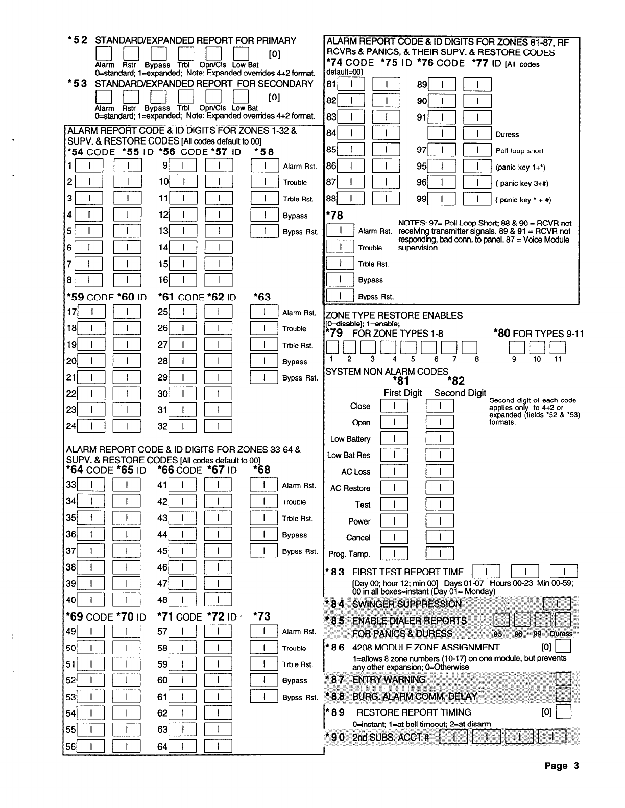
STANDARD/EXPANDED REPORT FOR PRIMARY
q uuuuu PI
Alarm Rstr Bypass TrbI OpnKls Low Bat
O=star&rd; l=expar&d; Note: mded overrides 4+2 format.
l
5 3 STANDARD/EXPANDED REPORT FOR SECONDARY
q unoun PI
Alarm Rstr Bypass Trbl Opn/Cls Low Bat
O=stmdad; 1 =expanded; Note: Expanded ovenides 4+2 format.
ALARM REPORT CODE & ID DIGITS FOR ZONES 1-32 &
SUPV. & RESTORE CODES [All codes default to 001
ARM REPORT CODE & ID DIGITS FOR ZONES 81-87, RF
XRs & PANICS, &THEIR SUPV. & RESTORE CODES
‘74
CODE
l
75 ID
l
76 CODE
l
77 ID
[All codes
lefaukOO1
1311 r7-j 91f-q r--q
141
I[ [I m Duress
$-i--l I[ 97[ I[ Poll loop short
1611)
951 II (panic key I+‘)
17r-i-j p--j 961
II ( panic key 3+#)
181 I[
991 ( ( panic key
l
+ U)
l
54
CODE *55 ID *56 CODE ‘57 1~
1lIl ccl 9rrn-r-l
4xl I
CLI I
41 III
l
i8
L-L-I
Alarm Rst.
[I Trouble
L-d
Table Rst.
I] Bypass
L-!--J
Bypss Rst.
NOTES: 97= Poll Loop Short; 68 & 90 = RCVR not
Alarm Rst. receiving transmitter signals. 89 & 91 = RCVR not
responding, bad corm. to panel. 87 = Voice Module
Trouble supervision.
Trble Rst.
a Bypass
*63
1 1 Bypss Rst.
161-i-j m
*61
CODE
l 62
ID
l
59 CODE
*60
ID
L-!--l
Alarm Rst.
I] Trouble
Trble Rst.
IOtjE.TYF]E REsTORE ENABLES
kosmej; 1 =enawe;
79 FOR ZONE TYPES l-8
*80
FOR TYPES 9-11
7cluuuuclcl q uu
12 3 45 67 6 9 IO 11
1 1 1 Bypass
I Bypss Rst.
;YSTEM NON AlA8y CODES
l 82
First Digit Second Digit
Close II] FJ
Second di it of each code
applies on
% to 4+2 or
OdIl III
ft,:ppzd fields ‘52 &
l
53)
Low Battery II /-?-I
.ow Bat Res mlli
ACLoss I] I]
AC Restore mm
Teat II /I
Power Elm
ALARM REPORT CODE & ID DIGITS FOR ZONES 33-64 &
SUPV. & RESTORE CODES [All codes default to 001
l 64
CODE
l 65
ID
*66
CODE
l 67
ID
l 68
I I
Alan Rst.
Trouble
L-L
I
Trble Rst.
I] Bypass
Bypss Rst.
Cencd l---T--[
‘rog.Tamp. m
8 3 FIRSTTEST REPORTTIME 1 I 1 1 I 1 1 I 1
[Day 00; hour 12; min 001 Days 01-07 Hours 00-23 Min 00-59;
00 in all boxes=instant (Dav Ol= Mondavl
401 r-7-J
“69
CODE
*70
ID
49p-J p---j
5oy-q l-7-J
51[1 l--i-y
8
4
SWINGER SUPPRiS&N ” 1 I
8 5 ENABLE,DtALER REPORTS
FOR PANICS ts DURESS
fl f--i n rl
95 6 99 fhress
1
l 71
CODE
l 72
ID
*73
I
Alarm Rst.
II Trouble
El Trble Rst.
II Bypass
III Bypss Rst.
8 6 4208 MODULE ZONE ASSIGNMENT
PI u
l=allows 8 zone numbers (1 O-l 7) on one module, but prevents
any other expansion; o--otherwise
8 7
ENTRY WARNING cl
88 BURG.AtARMCOMM. DELAY . I, n
-
52(1 I[
53/ r-i---[
54j-q l-q
551 p-j
8 9 RESTORE REPORT TIMING PI I I
OAstant; l=et bell timeout; 2=et disan
9 0 2nd SUBS, ACCT # [Ii f--i--l tj rTl
--
5611 ml
--
641-i-j /--i--j
Page 3
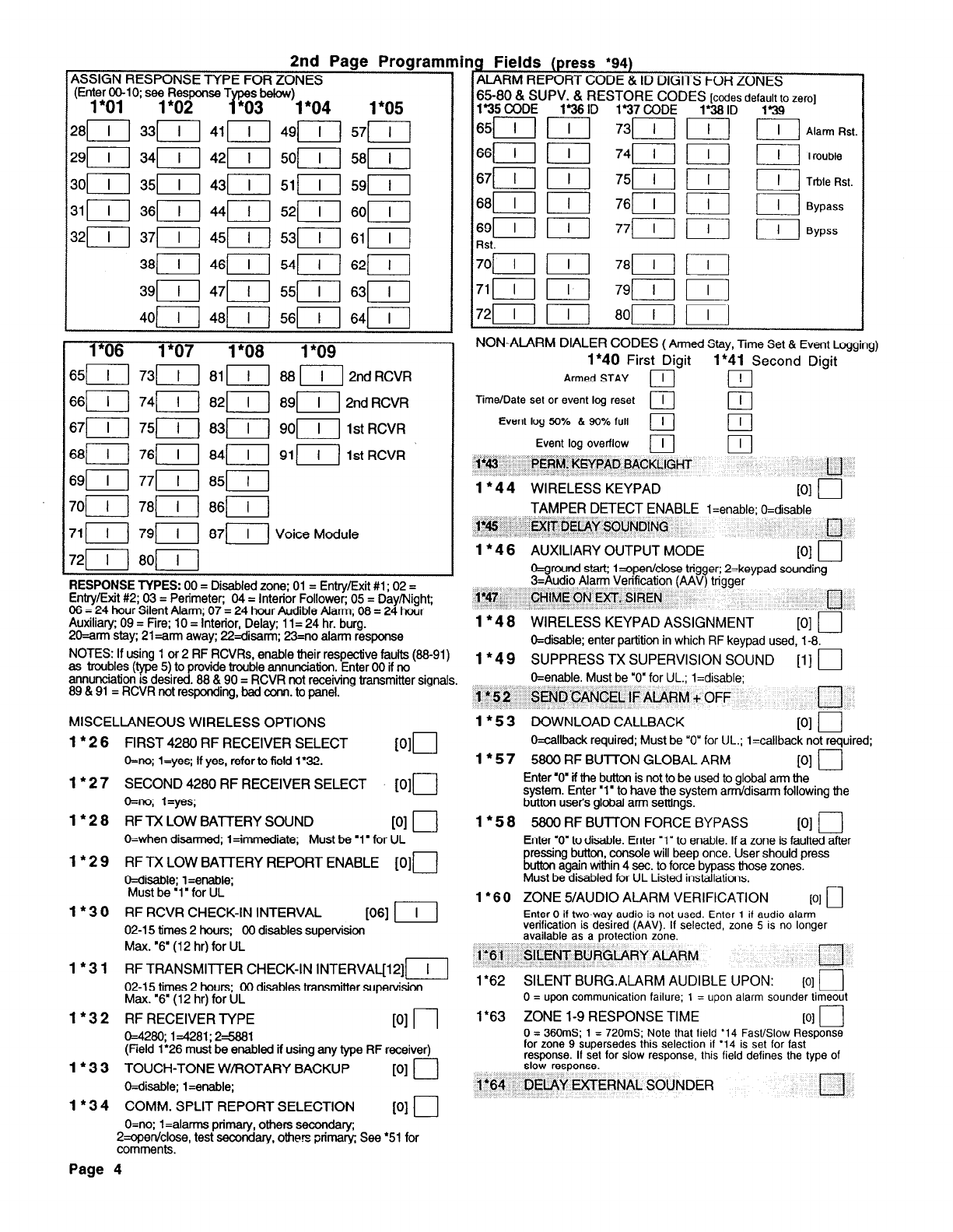
2nd Page Programming Fields (press
‘94)
ASSIGN RESPONSE TYPE F;r&yES ’
(En;e:oylO; “1 ;z2m T
1 ALARM REPORT CODE & 1~ DIGITS FOR ZONES
r@
*03 l"O4 1*05
I
T;58@DzUPv. & RESTORE CODE;&:;
defy% zero]
1’36
ID 137 CODE
1*06 1*07 1*08 1*09
6511 7311 81 I[ 88 [I[ 2nd RCVR
6611 7411 8211 89[12nd RCVR
6711 7511 831-j 9011 1st RCVR
6811 7611 841 9111 1st RCVR
SST] 771-j 85111
7011 7811 8611
71 II 7911 8711) Voice Module
7211 8011
RESPONSE TYPES:
00 = Disabled zone; 01 = Entry/Exit #1 ; 02 =
Entry/Exit #2; 03 = Perimeter; 04 = Interior Follower; 05 = Day/Night;
08 = 24 hour Silent Alarm; 07 = 24 hour Audible Alarm; 08 = 24 hour
Auxiliary; 09 = Fire; 10 = Interior, Delay; 1 1= 24 hr. burg.
2O=arm stay; 21 =arm away; 22=disann; 23=no alarm response
NOTES: If using 1 or 2 RF RCVRs, enable their respective faults (88-91)
as troubles (p 5) to provide trouble annunciation. Enter 00 if no
annunciation IS desired. 88 & 90 = RCVR not receiving transmitter signals.
89 & 91 = RCVR not responding, bad corm. to panel.
MISCELLANEOUS WIRELESS OPTIONS
1 l 26
1 l 27
1 l 28
1*29
1 l 30
1*31
1 l 32
1 l 33
1*34
FIRST 4280 RF RECEIVER SELECT
O=no; l=yes; If yes, refer to field 1’32.
SECOND 4280 RF RECEIVER SELECT
O=no; l=ye.s;
[OIO
PID
RF TX LOW BATTERY SOUND
PI I-J
O=when disarmed; l=immediate; Must be ‘1’ for UL
RF l-X LOW BATTERY REPORT ENABLE [O]o
Wisable; l=enable;
Must be ‘1’ for UL
RF RCVR CHECK-IN INTERVAL
WI
[I[
02-l 5 times 2 hours; 00 disables supervision
Max. ‘8” (12 hr) for UL
RF TRANSMI-ITER CHECK-IN INTERVAu12]r[
02-15 times 2 hours; 00 disabfes transmitter supervision
Max. “6’ (12 hr) for UL
RF RECEIVER TYPE
PI 0
0=4280;
1=4281; 25881
(Field 1’26 must be enabled if using any type RF receiver)
TOUCH-TONE W/ROTARY BACKUP
PI 0
O=disable; l=enable;
COMM. SPLIT REPORT SELECTION
v-4 r-l
65/--i-j 1 I 1 73r-i-j
661r-i-j f---q 74p-j
67/ I[ 7511
76/--i--l
77r-i-l
79r-i-j
8011
III
III
Alarm Rst.
II Trouble
III Trble Rst.
I[ Bypass
[I[ Bypss
1
NON-ALARM DIALER CODES
( Armed Stay, Time Set & Event Logging)
I*40 First Digit I*41 Second Digit
Armed STAY
Time/Date set or event tog reset PI Ei
m
Event tog 60% B 90% full
Event tog overflow
-
Iv3
PERM. KEYPAD BACKLIGHT n
1 * 4 4 WIRELESS KEYPAD
PI 0
TAMPER DETECT ENABLE
l=enabte; O=disable
1*45
EXIT DELAY SOUNDING
1
l
4
tl
6 AUXILIARY OUTPUT MODE 101 r-l
L ‘I
O=ground start; l=open/dose trig er; 2=keypad sounding
3=Audio Alarm Verification (AAV trigger
3
1*47 CHtME ON EXT. SIREN
1
l
4 8 WIRELESS KEYPAD ASSIGNMENT
PI I
O=disable; enter partition in which RF keypad used, l-8.
1
l
4 9 SUPPRESS TX SUPERVISION SOUND
111 0
O=enable. Must be “0” for UL.; l=disable;
1*52 SEND’CANCEL IF ALARM + OFF El
1 * 5 3 DOWNLOAD CALLBACK
PI 0
O=callback required; Must be ‘0” for UL.; l=callback not required;
1* 5 7 5800 RF BUlTON GLOBAL ARM
PI l--J
Enter ‘0” if the button is not to be used to global arm the
system. Enter ‘1’ to have the system arm/disarm following the
button user’s global arm settings.
1 * 5 8 5800 RF BUllON FORCE BYPASS
PI r-J
Enter ‘0’ to disable. Enter ‘1” to enable. If a zone is faulted after
Ltt
ressing button, console will beep once. User should press
on again within 4 sec. to force bypass those zones.
Must be disabled for UL Listed installations.
1
l
60
ZONE
5/AUDIO ALARM VERIFICATION PI 0
Enter 0 if two-way audio is not used. Enter 1 if audio alarm
verification is desired (AAV). If selected, zone 5 is no lonoer
available as a protectibn zone.
l”81 SILENT BURGLARY ALARM -17
-
1
l
62 SILENT BURG.ALARM AUDIBLE UPON: PI u
0 = upon communication failure; 1 = upon alarm sounder timeout
1’63 ZONE 1-9 RESPONSE TIME WI 0
0 = 360mS; 1 = 720mS; Note that field ‘14 Fast/Slow Response
for zone 9 supersedes this selection if ‘14 is set for fast
response. If set for slow response, this field defines the type of
stow response.
1’64 DELAY EXTERNAL SOUNDER cl
-
O=no: 1 =alam primary, others secondary;
2=open/close, test secondary, others primary; See
l
51 for
comments.
Page 4
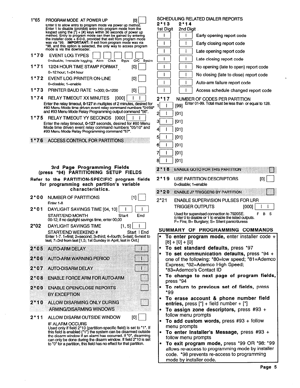
1’65 PROGRAM MODE AT POWER UP
PI u
Enter 0 to allow entry to program mode via power up method.
Enter 1 to disable (prohibit) entry into program mode from the
keypad using the I’] + [ff] keys within 30 seconds of power up
method. Entry to program mode can then be gained by entering
the installer code + 8-O-0, provided that exit from program mode
was via ‘99. IMPORTANT: If exit from program mode was via
‘98. and this ootion is selected. the onlv wav to access oroaram
mode is via the downloader.
1*70 EVENTLOGTYPES 0 d b
. I
0
q
O=disable; l=enable logging; Alrm Chck Byps O/C Systm
1
l
7 1 12/24 HOUR TIME STAMP FORMAT . .
PI 0
0=12 hour; 1=24 hour
1’ 7 2 EVENT LOG PRINTER ON-LINE 101 l-l
--l---J
Wisable; Lenable
1 * 7 3 PRINTER BAUD RATE ksoo;
0=1200
PI l---J
SCHEDULING RELATED DIALER REPORTS
2*13 2’14
1st Digit 2nd Digit
II Early opening report code
II Early closing report code
Elm Late opening report code
IIlm Late closing report code
II No opening (late to open) report code
mm No closing (late to close) report code
mm Auto-arm failure report code
mm Access schedule changed report code
I* 7 4 RELAY TIMEOUT XX MINUTES [000] -1 2
l
17 NUMBER OF CODES PER PARTITION
Enter the relay timeout, 6127 in multiples of 2 minutes, desired for
#80 Menu Mode time driven event relay command numbers ‘04/Og
1p-l w Enter 01-99. Total must be less than or equal to 128.
and #93 Menu Mode Relay Programming output command ‘56’.
1 l
7 5 RELAY TIMEOUT YY SECONDS [000] IIlj
477
WI
Enter the relay timeout, O-127 seconds, desired for #80 Menu
311
WI
Mode time driven event relay command numbers ‘05/l 0’ and
#93 Menu Mode Relay Programming command ‘57’.
41
PI
1 * 7 6 ACCESS CONTROL FOR PARTITIONS
51
1 I PI
4-7-j
WI
3rd Page Programming Fields
(press ‘94) PARTITIONING SETUP FIELDS
2 * 1‘8 ENkLE r;o;rcj kQR THIS PARTITICIN , IT
Refer to the PARTITION-SPECIFIC program fields
2
l 19
USE PARTITION DESCRIPTORS
PI 0
for programming each partition’s variable
O=disable; l=enable
characteristics.
2 * 2
0 ENABLE A7 TRIGGERS BY PARTiTION cl
2
l
0 0 NUMBER OF PARTITIONS
PI 0
Enter l-8
2*21 ENABLE SUPERVISION PULSES FOR LRR
2
l
0 1 DAYLIGHT SAVINGS TIME [04, lo] m m TRIGGER OUTPUTS [OOO] r--T-q
START/END MONTH Start End Used for supervised connection to 7920SE.
F B S
00-12; if no daylight savings time, enter 00,OO Enter 0 to disable or 1 to enable the listed outputs.
2*02
[If 51 r-c--j
F= Fire; B= Burglary; S= Silent panic/duress
DAYLIGHT SAVINGS TIME
START/END WEEKEND # Start I End
SUMMARY OF PROGRAMMING COMMANDS
_
Enter 1-7. l=first; 2=second; 3=third; 4=fourth; 5=&t; 8=next to
last; 7=3rd from last [ 1,5; 1st Sunday in April, last in Oct.]
2 * 11 ALLOW DISARM OUTSIDE WINDOW
PI r--J
IF ALARM OCCURS
Used only if field 2’10 (partition-specific field) is set to ‘1’. If
this field is enabled (‘1’) the system can be disarmed outside
the disarm window if an alarm has occurred. If ‘o’, disarming
can only be done during the disarm window. If field 2’10 is set
to ‘0’ for a partition, this field has no effect for that partition.
.
.
I-
To enter program mode,
enter installer code +
PI + PI + PI
To set standard defaults,
press ‘97
To set communication defaults,
press *94 +
one of the following:
l
8O=low speed; *81=Ademca
Express;
l
82=Ademco High Speed;
l
83=Ademco’s Contact ID
To change to next page of program fields,
press *94
To return to previous set of fields,
press
l 99
To erase account & phone number field
entries,
press [*I + field number + [‘I
To assign zone descriptors,
press #93 +
follow menu prompts
To add custom words,
press #93 + follow
menu prompts
To enter Installer’s Message,
press #93 +
follow menu prompts
To exit program mode,
press
l
99 OR *98: ‘99
allows re-access to programming mode by installer
code.
l
98 prevents re-access to programming
mode by installer code.
Page 5
.
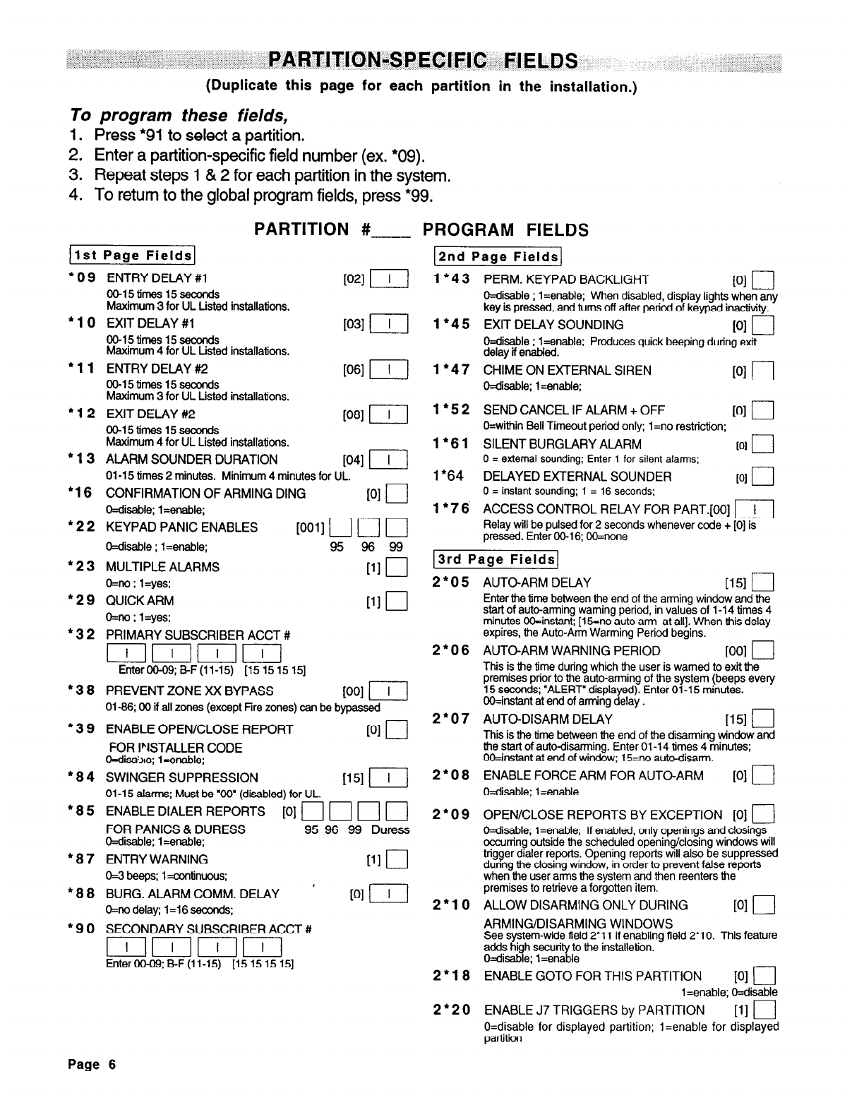
; ..,:. ;.:<, .,; ,.. ., PARTlTlON-SPECIFIC FIELDS
(Duplicate this page for each partition in the installation.)
To program these fields,
1. Press *91 to select a partition.
2. Enter a partition-specific field number (ex. *09).
3. Repeat steps 1 & 2 for each partition in the system.
4. To return to the global program fields, press *99.
1st Page Fields
PARTITION #
“09
+10
*11
l
12
+13
*16
*22
*23
l 29
*32
“38
l 39
l
84
*85
l
a7
*8a
‘90
ENTRY DELAY #l
Kw II
OO-15times15seconds
Maximum 3 for UL Listed installations.
EXIT DELAY #l
OO-15tfmes15secolxts
1031 p-1
Maximum 4 for UL Listed installations.
ENTRY DELAY #2
OO-15times15seconds
Maximum 3 for UL Listed installations.
EXIT DELAY #2
OO-15cmes 15seccnds
WI I]
Maximum 4 for UL Listed installations.
ALARM SOUNDER DURATION
1041 p-j
01-15 times 2 minutes. Minimum 4 minutes for UL.
CONFIRMATION OF ARMING DING
WI 0
C=disable; l=enable;
KEYPAD PANIC ENABLES
10011 rt r---l r-j
O=disable ; l=enable; 95 98 99
MULTIPLE ALARMS
111 u
O=no ; l=yes;
QUICK ARM
111 0
O=no ; 1 =yes;
PRIMARY SUBSCRIBER ACCT #
IrnIIrn
EnterOO-09; BF (11-15) [15 15 15 151
PREVENT ZONE XX BYPASS WI I--i--j
01-66; 00 if all zones (except Fire zones) can be bypassed
ENABLE OPEN/CLOSE REPORT
PI 0
FOR I%TALLER CODE
O=disa!>re; 1 =enable;
SWINGER SUPPRESSION
1151 p---I
01-15 alarms; Must be ‘00” (disabled) for UL.
ENABLE DIALER REPORTS [O] n II ri ri
FOR PANICS & DURESS
95 96 99 Duress
Wisable; 1 =enable;
ENTRY WARNING
PI 0
o-3 beeps; l=continuous;
’
BURG. ALARM COMM. DELAY
PI I-q
O=no delay; 1=16 seccnds;
SECONDARY SUBSCRIBER ACCT #
IIIII
EnterOO-O9;B-F(ll-15) [15151515]
PROGRAM FIELDS
1*43
1
l
45
l”47
1
l
52
1
l
61
1
l
64
1
l
76’
12nd Page Fields]
PERM. KEYPAD BACKLIGHT
PI u
O=disable ; l=enable; When disabled, display lights when any
key is pressed, and turns off after period of keypad inactivity.
EXIT DELAY SOUNDING PI 0
O=disable ; l=enable; Produces quick beeping during exit
delay if enabfed.
CHIME ON EXTERNAL SIREN
Wisable; l=enable;
PI 0
SEND CANCEL IF ALARM + OFF
WI r---J
O=within Bell Timeout period only; 1 =no restriction;
SILENT BURGLARY ALARM to1
q
0 = external sounding; Enter 1 for silent alarms.;
DELAYED EXTERNAL SOUNDER PI r-J
0 = instant sounding; 1 = 16 seconds;
ACCESS CONTROL RELAY FOR PART.[OO] rj
Relay will be pulsed for 2 seconds whenever code + [0] is
pressed. Enter 06-l 6; OO=none
3rd Page Fields
2*05
AUTO-ARM DELAY
1151 j----J
Enter the time between the end of the arming window end the
start of auto-arming warning period, in values of l-1 4 times 4
minutes OO=instant; [15=no auto arm at all]. When this delay
expires, the Auto-Arm Warming Period begins.
AUTO-ARM WARNING PERIOD
PO1 0
This is the time during which the user is warned to exit the
premises prior to the auto-arming of the system (beeps every
15 seconds; “ALERT” displayed). Enter 01-l 5 minutes.
OO=instant at end of arming delay .
AUTO-DISARM DELAY
1151 i---J
This is the time between the end of the disarming window and
the start of auto-disarming. Enter 01-l 4 times 4 minutes;
OO=instant at end of window; 15=no auto-disarm.
ENABLE FORCE ARM FOR AUTO-ARM
PI 0
W&able; l=enable
2*06
2*07
2*08
2*09
2”lO
2*18
2*20
OPEN/CLOSE REPORTS BY EXCEPTION [0] 0
O=disable; l=enable; If enabled, only openings and closings
occurring outside the scheduled opening/closing windows will
bigger dialer reports. Opening reports will also be suppressed
dunng the closing window, in order to prevent false reports
when the user arms the system and then reenters the
premises to retrieve a forgotten item.
ALLOW DISARMING ONLY DURING
PI 0
ARMING/DISARMING WINDOWS
See system-wide field 2’11 if enabling field 2’10. This feature
adds high securi Yl to the installetion.
O=disable; l=ena le
ENABLE GOT0 FOR THIS PARTITION
PI 0
1 =enable; Wisable
ENABLE J7 TRIGGERS by PARTITION
PI 0
O=disable for displayed partition; 1 =enable for displayed
partition
Page 6
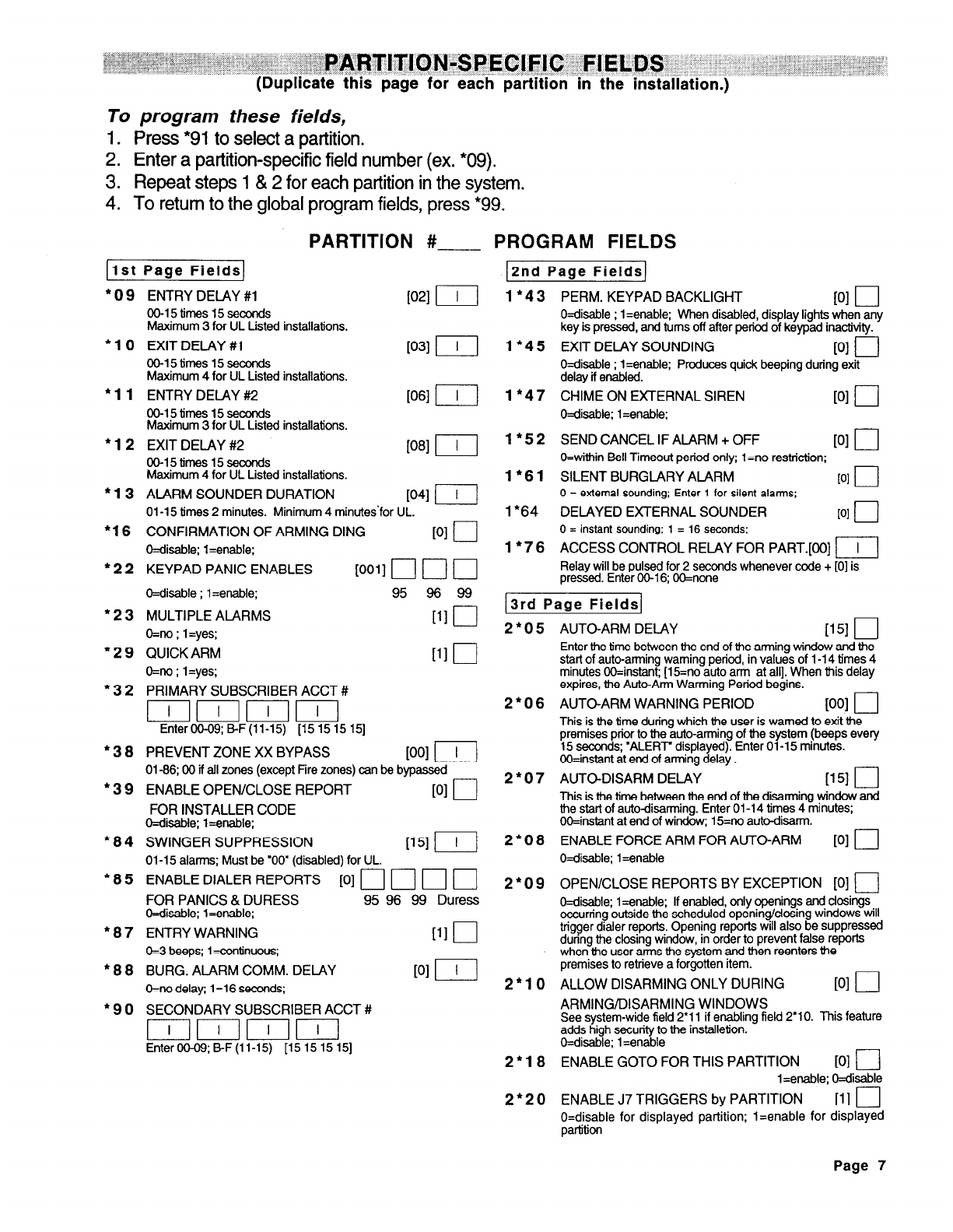
To program these fields,
1. PresS *91 to select a partition.
2. Enter a partition-specific field number (ex. *09).
3. Repeat steps 1 & 2 for each partition in the system.
4. To return to the global program fields, press *99.
l 09
‘10
l
11
l
12
l
13
l
16
*22
*23
l 29
l 32
l
3a
*39
*a4
*a5
*a7
*aa
l 90
PARTITION #
Ilst Page Fields
ENTRY DELAY #l
00-15 times 15 seccnds
Maximum 3 for UL Listed installations.
EXIT DELAY #l
WI LIl
1031 p--j
OO-15times15seconds
Maximum 4 for UL Listed installations.
ENTRY DELAY ##2
00-15 times 15 seconds
Maximum 3 for UL Listed installations.
EXIT DELAY #2
00-15times15seconds
WI II
Maximum 4 for UL Listed installations.
ALARM SOUNDER DURATION
P41 r-q
01-15 times 2 minutes. Minimum 4 minutes’for UL.
CONFIRMATION OF ARMING DING
PI cl
O=disable; l=enable:
KEYPAD PANIC ENABLES
[0011 r-7 r-7 ri
Wisable ; 1 =enable;
95
96 99
MULTIPLE ALARMS
[1lU
O=no ; l=yes;
QUICK ARM
ill 0
O=no ; l=yes;
PRIMARY SUBSCRIBER ACCT #
EnterOO-09; B-F(ll-15) [15 15 15 151
PREVENT ZONE XX BYPASS
Ku l7-j
01-66; 00 if all zones (except Fire zones) can be bypassed -
ENABLE OPEN/CLOSE REPORT
WI LJ
FOR INSTALLER CODE
O=diile; l=enable;
SWINGER SUPPRESSION
iI51 II
01-15 alarms; Must be ‘00” (disabled) for UL.
ENABLE DIALER REPORTS [O] 1-1 n n rj
FOR PANICS & DURESS 95 96 99 Duress
O=disable; l=enable;
ENTRY WARNING
111 0
O-3 beeps; 1 =confnuous;
BURG. ALARM COMM. DELAY
PI II
O=no delay; 1 =16 seconds;
SECONDARY SUBSCRIBER ACCT #
IIIII
EnterOO-09; B-F (11-15) [15 15 15 151
PROGRAM FIELDS
2nd Page Fields
1
l
43
1
l
45
1
l
47
1*52
1*61
1*64
1
l
76
PERM. KEYPAD BACKLIGHT 101 I I
- --
O=disable ; 1 =enable; When disabled, display lights when any
key is pressed, and turns off after period of kevpad inactivitv.
EXIT DELAY SOUNDING -’
101 n
O=disable ; l=enable; Produces quick beeping during exit
delay if enabled.
CHIME ON EXTERNAL SIREN
Wisable; 1 =enable;
PI 0
SEND CANCEL IF ALARM + OFF
PI 0
O=within Bell Timeout period only; 1 =no restriction;
SILENT BURGLARY ALARM IO1 0
0 = external sounding; Enter 1 for silent alarms;
DELAYED EXTERNAL SOUNDER
PI /--J
0 = instant sounding; 1 = 16 seconds;
ACCESS CONTROL RELAY FOR PART.[OO] FIj
Relay will be pulsed for 2 seconds whenever code + [0] is
pressed. Enter 00-l 6; OO=none
13rd Page Fields/
2*05
AUTO-ARM DELAY
u51 I
Enter the time between the end of the arming window and the
start of auto-arming warning period, in values of l-1 4 times 4
minutes OO=instant; [15=no auto arm at all]. When this delay
expires, the Auto-Arm Warning Period begins.
AUTO-ARM WARNING PERIOD
vw 0
This is the time during which the user is warned to exit the
premises prior to the auto-arming of the system (beeps every
15 seconds; ‘ALERT’ displayed). Enter 01-15 minutes.
OO=instant at end of am-ring delay .
AUTO-DISARM DELAY
iI51 0
This is the time between the end of the disarming window and
the start of autodisarming. Enter 01-14 times 4 minutes;
OO=instant at end of window; 15=no auto-disarm.
ENABLE FORCE ARM
FOR AUTO-ARM
PI 0
O=disable; l=enable
2*06
2*07
2*08
2*09
2*10
2*la
2*20
OPEN/CLOSE REPORTS BY EXCEPTION [0]
q
Wisable; 1 =enable; If enabled, only openings and closings
occurring outside the scheduled opening/dosing windows will
trigger dialer reports. Opening reports will also be suppressed
during the closing window, in order to prevent false reports
when the user arms the system and then reenters the
premises to retrieve a forgotten item.
ALLOW DISARMING ONLY DURING
PI 0
ARMING/DISARMING WINDOWS
See system-wide field 2’11 if enabling field 2’10. This feature
adds high security to the installetion.
O=dsable; 1 =enable
ENABLE GOT0 FOR THIS PARTITION
PI l---J
1 =enable; Wisable
ENABLE J7 TRIGGERS by PARTITION
VI r--J
O=disable for displayed partition; l=enable for displayed
partition
Page 7
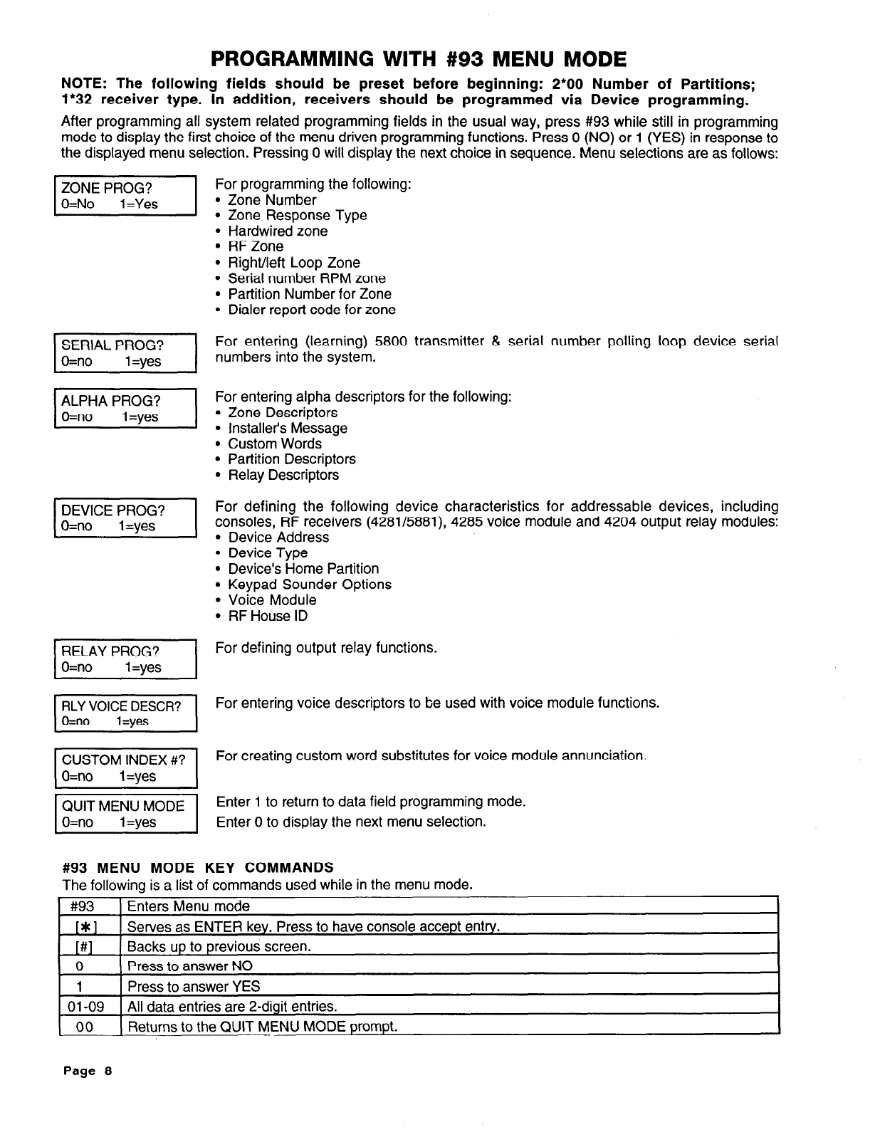
PROGRAMMING WITH #93 MENU MODE
ZONE PROG?
O=No 1 =Yes I
For programming the following:
l
Zone Number
l
Zone Response Type
l
Hardwired zone
l
RFZone
l
Right/left Loop Zone
l
Serial number RPM zone
l
Partition Number for Zone
l
Dialer report code for zone
NOTE: The following fields should be preset before beginning: 2*00 Number of Partitions;
1*32 receiver type. In addition, receivers should be programmed via Device programming.
After programming all system related programming fields in the usual way, press #93 while still in programming
mode to display the first choice of the menu driven programming functions. Press 0 (NO) or 1 (YES) in response to
the displayed menu selection. Pressing 0 will display the next choice in sequence. Menu selections are as follows:
I
DEVICE PROG?
O=no 1 =yes I
I
RLY VOICE DESCR?
O=no 1 =yes I
For entering (learning) 5800 transmitter & serial number polling loop device serial
numbers into the system.
For entering alpha descriptors for the following:
l
Zone Descriptors
l
Installer’s Message
l
Custom Words
l
Partition Descriptors
l
Relay Descriptors
For defining the following device characteristics for addressable devices, including
consoles, RF receivers (4281/5881), 4285 voice module and 4204 output relay modules:
l
Device Address
l
Device Type
l
Device’s Home Partition
l
Keypad Sounder Options
l
Voice Module
l
RF House ID
For defining output relay functions.
For entering voice descriptors to be used with voice module functions.
For creating custom word substitutes for voice module annunciation.
Enter 1 to return to data field programming mode.
Enter 0 to display the next menu selection.
#93 MENU MODE KEY COMMANDS
The following is a list of commands used while in the menu mode.
#93 Enters Menu mode
[*I Serves as ENTER key. Press to have console accept entry.
[#] Backs up to previous screen.
0 Press to answer NO
1 Press to answer YES
01-09 All data entries are 2-digit entries.
00 Returns to the QUIT MENU MODE prompt.
Page 8
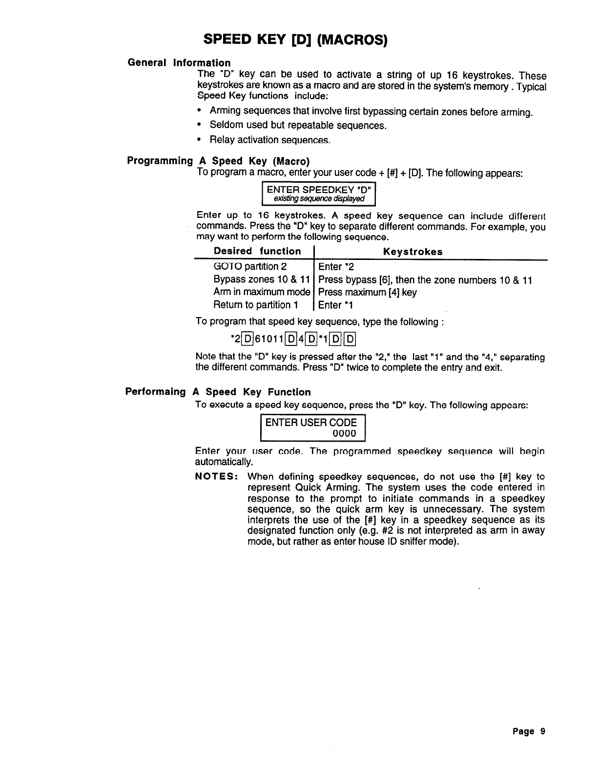
SPEED KEY [D] (MACROS)
General Information
The “D” key can be used to activate a string of up 16 keystrokes. These
keystrokes are known as
a
macro and are stored in the system’s memory . Typical
Speed Key functions include:
l
Arming sequences that involve first bypassing certain zones before arming.
l
Seldom used but repeatable sequences.
l
Relay activation sequences.
Programming A Speed Key (Macro)
To program a macro, enter your user code + [#] + [D]. The following appears:
Enter up to 16 keystrokes. A speed key sequence can include different
commands. Press the “D” key to separate different commands. For example, you
may want to perform the following sequence.
Desired function Keystrokes
GOT0 partition 2 Enter ‘2
Bypass zones 10 & 11 Press bypass [6], then the zone numbers 10 & 11
Ann in maximum mode Press maximum [4] key
Return to partition 1 Enter *l
To program that speed key sequence, type the following :
‘2m6101 lm4m*lpim
Note that the “D” key is pressed after the “2,” the last “1” and the “4,” separating
the different commands. Press “D” twice to complete the entry and exit.
Performaing A Speed Key Function
To execute a speed key sequence, press the “D” key. The following appears:
p7zEE&j
Enter your user code. The programmed speedkey sequence will begin
automatically.
NOTES:
When defining speedkey sequences, do not use the [#] key to
represent Quick Arming. The system uses the code entered in
response to the prompt to initiate commands in a speedkey
sequence, so the quick arm key is unnecessary. The system
interprets the use of the [#] key in a speedkey sequence as its
designated function only (e.g. #2 is not interpreted as arm in away
mode, but rather as enter house ID sniffer mode).
Page 9
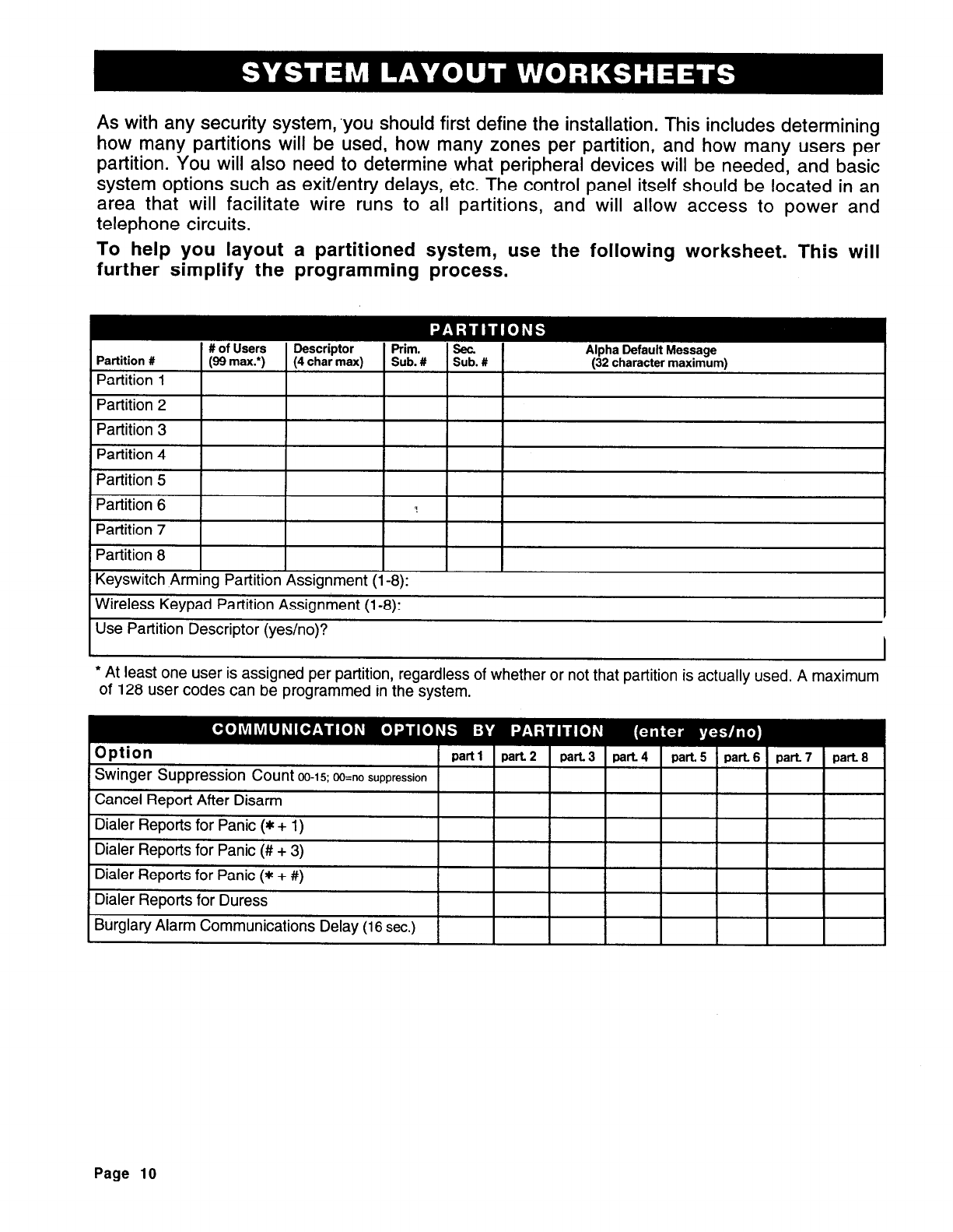
As with any security system, ‘you should first define the installation. This includes determining
how many partitions will be used, how many zones per partition, and how many users per
partition. You will also need to determine what peripheral devices will be needed, and basic
system options such as exit/entry delays, etc. The control panel itself should be located in an
area that will facilitate wire runs to all partitions, and will allow access to power and
telephone circuits.
To help you layout a partitioned system, use the following worksheet. This will
further simplify the programming process.
I I
* At least one user is assigned per partition, regardless of whether or not that partition is actually used. A maximum
of 128 user codes can be programmed in the system.
Page 10
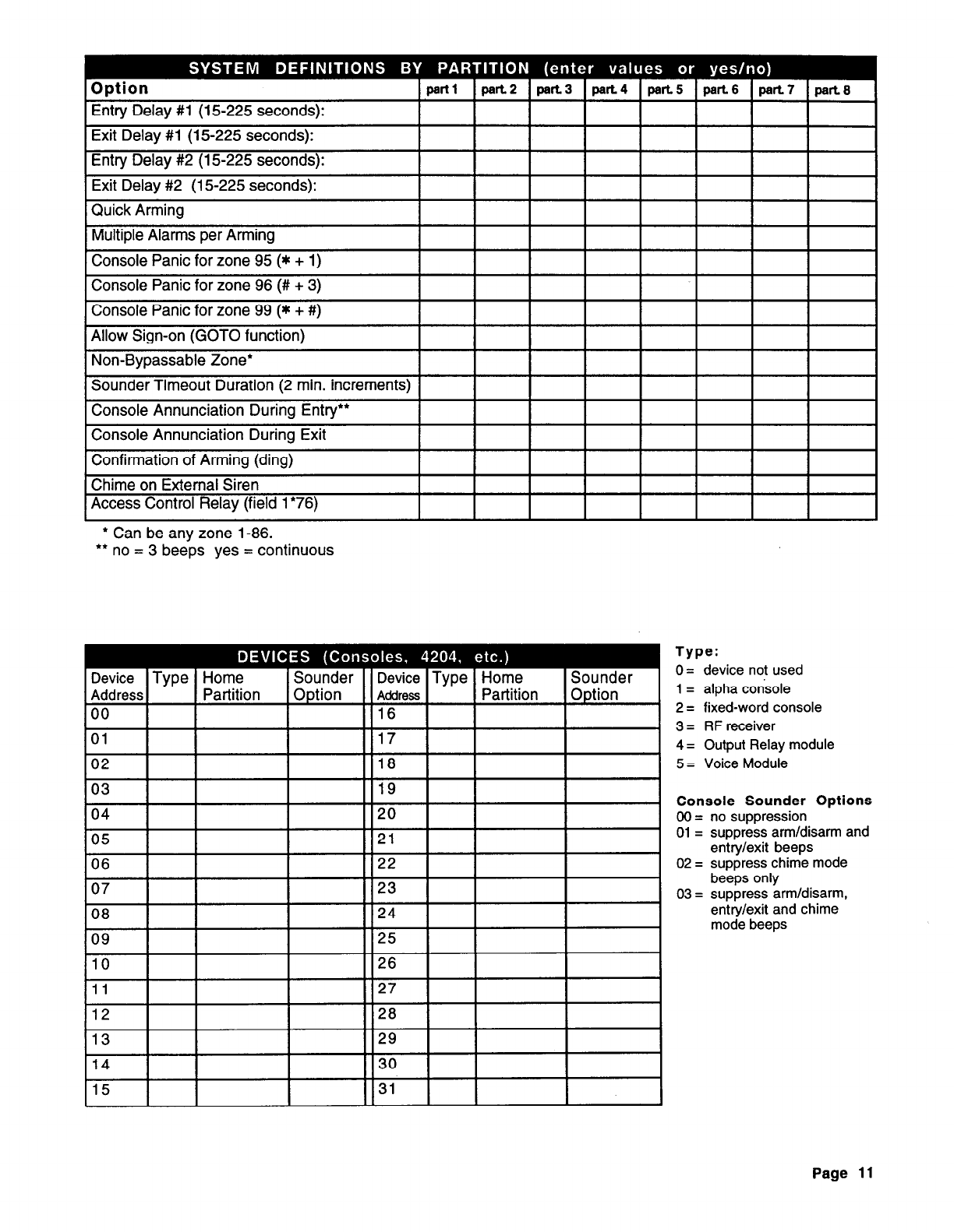
* Can be any zone l-86.
l
* no = 3 beeps yes = continuous
Type:
0= device not used
1 = alpha condole
2 = fixed-word console
3 = RF receiver
4 = Output Relay module
5 = Voice Module
Console Sounder Options
00 = no suppression
01 = suppress arm/disarm and
entry/exit beeps
02 = suppress chime mode
beeps only
03 = suppress arm/disarm,
entry/exit and chime
mode beeps
Page 11
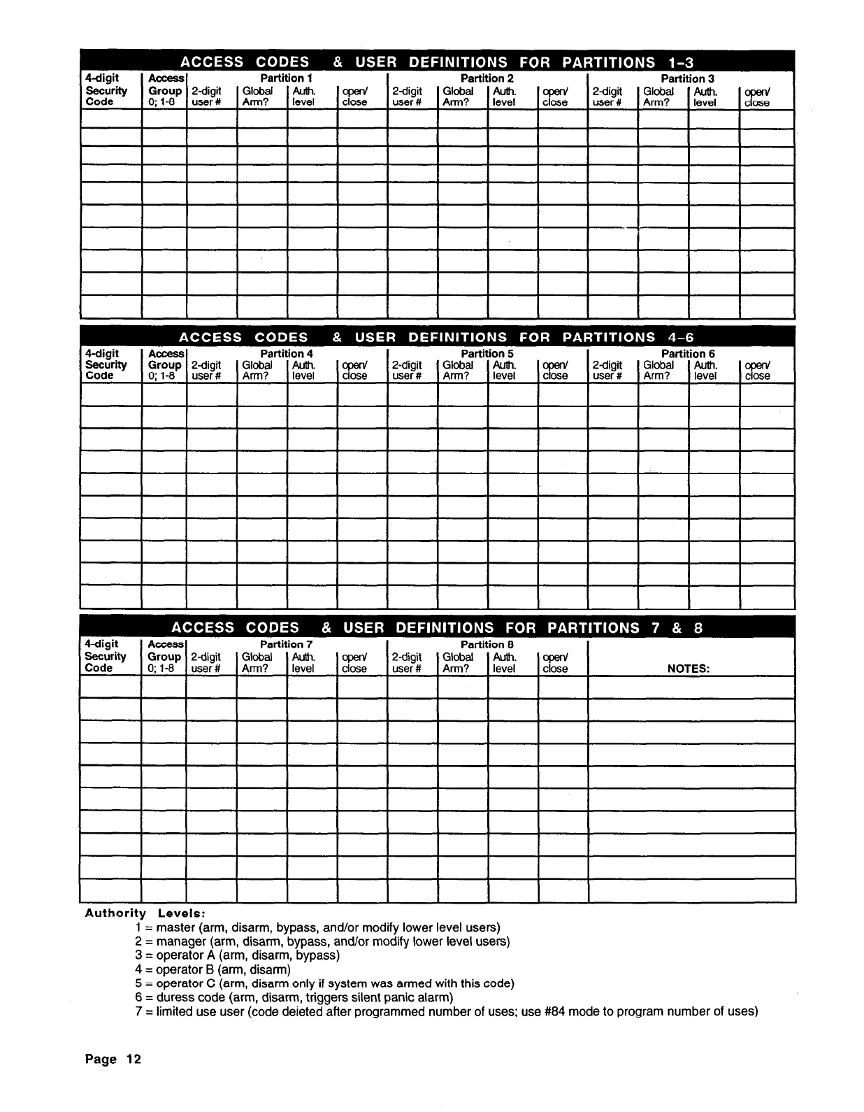
Authority Levels:
1 = master (arm, disarm, bypass, and/or modify lower level users)
2 = manager (arm, disarm, bypass, and/or modify lower level users)
3 = operator A (arm, disarm, bypass)
4 = operator B (arm, disarm)
5 = operator C (arm, disarm only if system was armed with this code)
6 = duress code (arm, disarm, triggers silent panic alarm)
7 = limited use user (code deieted after programmed number of uses; use #84 mode to program number of uses)
Page 12
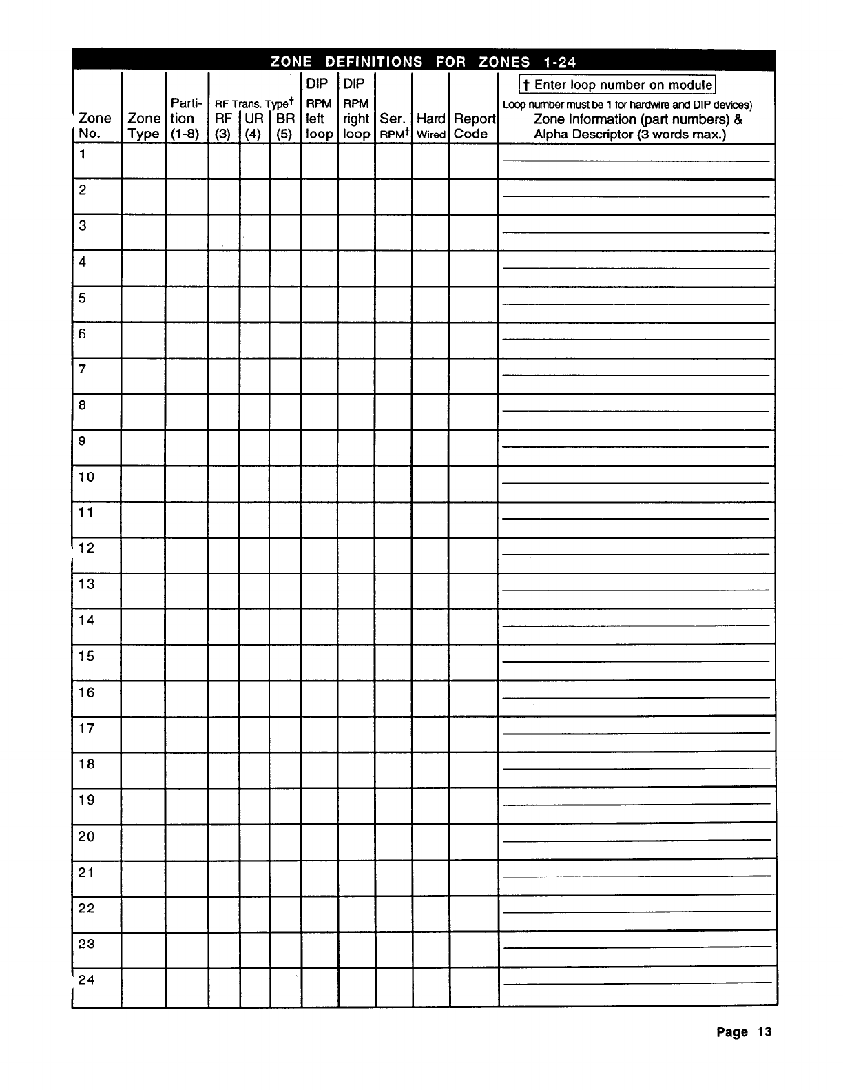
Zone
No. Zone
We
~
RF Trans. Typet
RF UR BR
+I-
(3) (4) (5)
DIP DIP
RPM
c
RPM
left
loop
c
right
loop
1 It Enter loop number on module1
Loop number must be 1 for hardwire and DIP devices)
Report Zone Information (part numbers) &
Code Alpha Descriptor (3 words max.)
23
24
I
Page 13
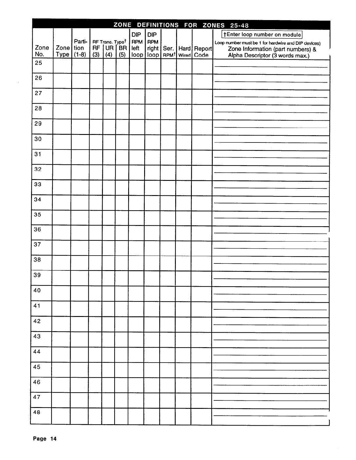
Page 14
1 tEnter loop number on module1
Loop number must be 1 for hardwire and DIP devices)
Zone Information (part numbers) & I
Alpha Descriptor (3 words max.)
I I
Zone Zone
No. No.
t-
t- 49 49
Patti-
RF Trans. Typet
--u--l+
Zone tion RF UR BR
Type (l-8) (3) (4) (5)
DIP DIP
RPM RPM
left right Ser. Hard Repor
loop loop RPMt
wired
Code
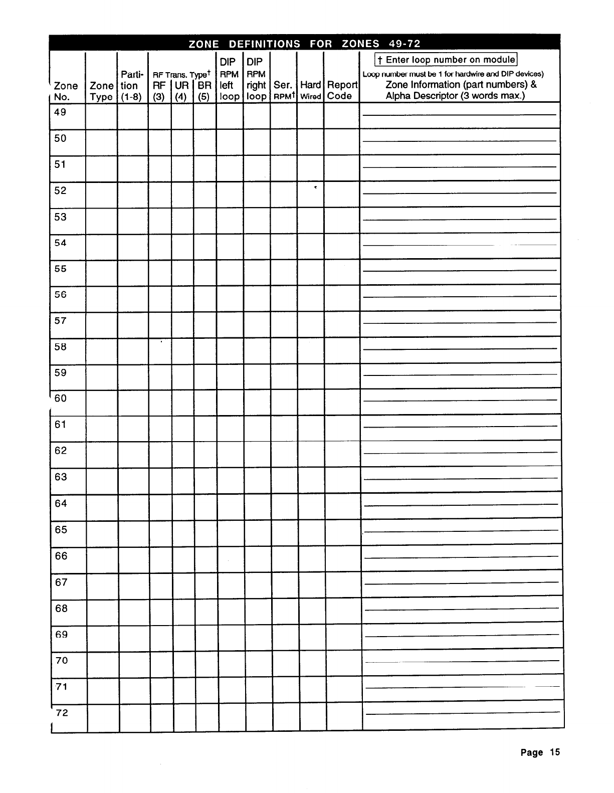
Patti-
RFTWIS. Typet
RPM RPM
Zone tion RF UR BR left right Ser. Hard Repor
Type (l-8) (3) (4) (5) loop loop
RPMt Wired
Code
DIP DIP
1 t Enter loop number on module]
Loop number must be 1 for ha&ire and DIP devices)
Zone Information (oat-l numbers) &
Alpha Descriptor (3 words max.
j
’ 72
I
Page 15
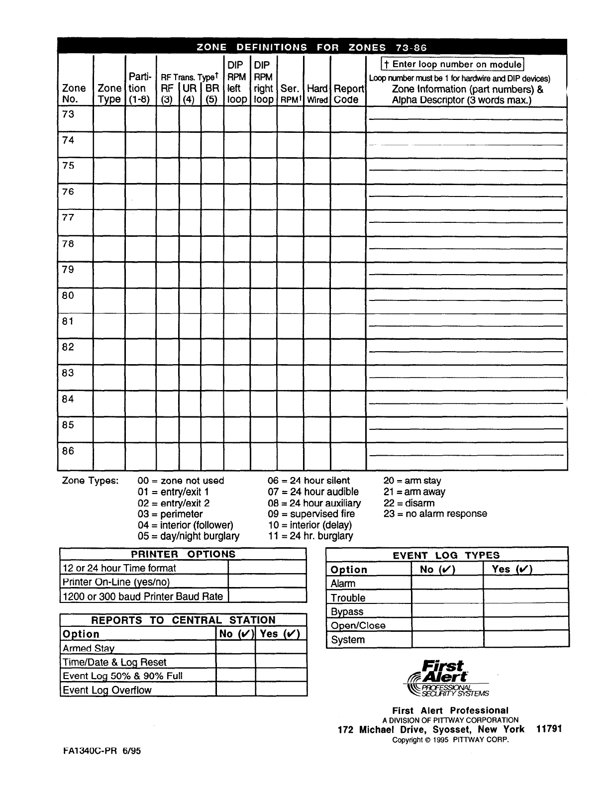
DIP DIP DIP DIP
Patti-
RFTrans. Typet
RPM RPM Patti-
RFTrans. Typet
RPM RPM
Zone Zone Zone tion Zone tion RF UR BR left right Ser. Hard Reporl RF UR BR left right Ser. Hard Reporl
No. No. Type (l-8) (3) (4) (5)
loop
loop
RPMt Wired
Code Type (l-8) (3) (4) (5)
loop
loop
RPMt Wired
Code
73 73
74 74
80
81
82
83
84
85
Zone Types: 00 = zone not used
01 = entry/exit 1
02 = entry/exit 2
03 = perimeter
04 = interior (follower)
05 = day/night burglary
PRINTER OPTIONS
12 or 24 hour Time format
Printer On-Line (yes/no)
1200 or 300 baud Printer Baud Rate
06 = 24 hour silent
07 = 24 hour audible
08 = 24 hour auxiliary
09 = supervised fire
10 = interior (delay)
11 = 24 hr. burglary
20 = arm stay
21= arm away
22 = disarm
23 = no alarm response
EVENT LOG TYPES
Option 1 No (4) 1 Yes (d)
REPORTS TO CENTRAL STATION
Option No (d) Yes (d)
Armed Stay
Time/Date & Log Reset
Event Log 50% & 90% Full
Event Log Overflow
Alarm
Trouble
Bypass
Open/Close
System
It Enter loop number on module1
Loop number must be 1 for hardwire and DIP devices)
Zone Information (part numbers) &
Alpha Descriptor (3 words max.)
c
I
First Alert Professional
A DIVISION OF PIllWAY CORPORATION
172 Michael Drive, Syosset, New York 11791
Copyright 0 1995 PITTWAY CORP.
FA1340C-PR 6195
