K5305 5v5_ii Platformupdate FA148CPSIA V6 Installation Manual
User Manual: FA148CPSIA v6 Installation Manual AlarmHow.net Library
Open the PDF directly: View PDF ![]() .
.
Page Count: 40
Installation and Set-Up Guide
ON OFF
ARMED
READY
A
B
C
D
6
4
79
#
3
5
8
0
2
1
FA260
R
ARMED
READY
FA560
6
4
79
#
3
5
8
0
2
1
R
AWAY
STAY
PAGE
K5305-5V5 11/08 Rev. A
FA168CPS / FA168CPSSIA
FA168CPS / FA168CPSSIAFA168CPS / FA168CPSSIA
FA168CPS / FA168CPSSIA
FA148CP / FA148CPSIA
FA148CP / FA148CPSIAFA148CP / FA148CPSIA
FA148CP / FA148CPSIA
S
S
e
ec
cu
u
r
r
i
it
ty
y
S
S
y
ys
st
te
em
ms
s
RECOMMENDATIONS FOR PROPER PROTECTION
The Following Recommendations for the Location of Fire and Burglary Detection
Devices Help Provide Proper Coverage for the Protected Premises.
Recommendations For Smoke And Heat Detectors
With regard to the number and placement of smoke/heat detectors, we subscribe to the recommendations
contained in the National Fire Protection Association's (NFPA) Standard #72 noted below.
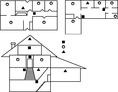
Early warning fire detection is best achieved by the installation of fire detection equipment in all rooms
and areas of the household as follows: For minimum protection a smoke detector should be installed
outside of each separate sleeping area, and on each additional floor of a multi-floor family living unit,
including basements. The installation of smoke detectors in kitchens, attics (finished or unfinished), or in
garages is not normally recommended.
For additional protection the NFPA recommends that you install heat or smoke detectors in the living
room, dining room, bedroom(s), kitchen, hallway(s), attic, furnace room, utility and storage rooms,
basements and attached garages.
In addition, we recommend the following:
• Install a smoke detector inside every bedroom where a smoker sleeps.
• Install a smoke detector inside every bedroom where someone sleeps with the door partly or
completely closed. Smoke could be blocked by the closed door. Also, an alarm in the hallway outside
may not wake up the sleeper if the door is closed.
DINING
KITCHEN BEDROOM
BEDROOM
BEDROOM
BEDROOM
LIVING ROOM BEDROOM
BDRM
DINING
LIVING ROOM
TV ROOM KITCHEN
BEDROOM BEDROOM
TO
BR
LVNG RM
BASEMENT
KTCHN
.
CLOSED
DOOR
GARAGE
Smoke Detectors for Minimum Protection
Smoke Detectors for Additional Protection
Heat-Activated Detectors
BDRM
floor_plan-001-V1
• Install a smoke detector inside bedrooms
where electrical appliances (such as
portable heaters, air conditioners or
humidifiers) are used.
• Install a smoke detector at both ends of a
h
allway if the hallway is more than 40 feet
(12 meters) long.
• Install smoke detectors in any room where
an alarm control is located, or in any room
where alarm control connections to an AC
source or phone lines are made. If
detectors are not so located, a fire within
the room could prevent the control from
reporting a fire or an intrusion.
THIS CONTROL COMPLIES WITH NFPA
REQUIREMENTS FOR TEMPORAL PULSE
SOUNDING OF FIRE NOTIFICATION
APPLIANCES.
Recommendations For Proper Intrusion Protection
For proper intrusion coverage, sensors should be located at every possible point of entry to a home or
commercial premises. This would include any skylights that may be present, and the upper windows in
a multi-level building.
In addition, we recommend that radio backup be used in a security system so that alarm signals can still
be sent to the alarm monitoring station in the event that the telephone lines are out of order (alarm
signals are normally sent over the phone lines, if connected to an alarm monitoring station).
ii
Table Of Contents
•••••••••••••••••••••••••••••••••••••
Features and Installation Highlights........................................................................................................... 1-1
Capabilities and Functions ..............................................................................................................................1-1
Compatible Devices...........................................................................................................................................1-2
Important Installation Highlights (Installer Please Read)............................................................................1-2
Mounting and Wiring the Control................................................................................................................. 2-1
Cabinet and Lock..............................................................................................................................................2-1
Mounting the PC Board Alone.........................................................................................................................2-1
Mounting Board with RF Receiver..................................................................................................................2-2
Wiring to Keypads ............................................................................................................................................2-3
Sounder (Bell) Connections..............................................................................................................................2-4
Wiring the AC Transformer.............................................................................................................................2-4
Backup Battery.................................................................................................................................................2-5
Earth Ground....................................................................................................................................................2-5
Hardwire Zones.................................................................................................................................................2-6
Smoke Detectors ...............................................................................................................................................2-6
4219/4229 Expansion Zones.............................................................................................................................2-7
Installing the RF Receiver ...............................................................................................................................2-8
Installing a 5800TM Module............................................................................................................................2-8
Installing the Transmitters..............................................................................................................................2-8
Installing a Keyswitch......................................................................................................................................2-9
Connecting Relay Modules.............................................................................................................................2-10
Powerline Carrier Devices..............................................................................................................................2-11
On-Board Triggers..........................................................................................................................................2-11
Phone Line/Phone Module Connections ........................................................................................................2-12
Long Range Radio Connections......................................................................................................................2-13
Audio Alarm Verification Connections (AAV, “listen-in”)............................................................................2-13
System Communication and Operation....................................................................................................... 3-1
Panel Communication with Central Station...................................................................................................3-1
Report Code Formats........................................................................................................................................3-1
Ademco Contact ID®........................................................................................................................................3-2
Uploading/Downloading via the Internet........................................................................................................3-4
Security Codes...................................................................................................................................................3-5
Setting the Real-Time Clock ............................................................................................................................3-7
Various System Trouble Displays....................................................................................................................3-8
Testing the System............................................................................................................................................ 4-1
About Test Procedures......................................................................................................................................4-1
System Test.......................................................................................................................................................4-1
Go/No Go Test Mode.........................................................................................................................................4-2
Dialer Communication Test and Periodic Test Reports.................................................................................4-2
Specifications & Accessories .......................................................................................................................... 5-1
Security Control................................................................................................................................................5-1
Compatible Devices...........................................................................................................................................5-1
Regulatory Agency Statements...................................................................................................................... 6-1
Limitations and Warranty............................................................................................................................... 7-3
iii
iv

SECTION 1
Features and Installation Highlights
•••••••••••••••••••••••••••••••••••••••
This manual applies to the following controls:
FA168CPS, FA168CPSSIA, FA168CPS-CN (Canada), FA148CP, FA148CPSIA, and FA148CP-CN
(Canada). Features and procedures apply to all, except where differences are noted.
SIA Installations: The FA168CPSSIA and FA148CPSIA certified SIA-compliant controls that meet SIA
specifications for False Alarm Reduction. The other controls described in this manual are not certified as SIA
compliant, but can be programmed for False Alarm Reduction. To program for False Alarm Reduction, follow the
SIA Guidelines noted in the applicable programming fields.
Capabilities and Functions
Feature/Function FA168CPS FA148CP
Partitions
• 2 partitions, can protect two independent
areas
• Common zone option allows either
partition to arm, while leaving a common
area (ex. lobby or foyer) disarmed for
access into the other partition.
FA148CP is not a partitioned system.
Zones Up to 48 protection zones plus 16 keyfob
zones (zones 49-64) for total of 64 zones:
• 8 basic hardwired zones (zones 1-8) with
optional zone-doubling feature
• Up to 40 additional wired zones (zones 9-
48) using up to 5 4219/4229 modules
• Up to 40 wireless transmitter zones (5800
series; zones 9-48)
• Up to 4 configurable zone types
Up to 32 zones plus 8 keyfob zones (zones
49-56) for total of 40 zones:
• 6 basic hardwired zones (zone 1-6)
• Up to 16 additional wired zones (zones 9-
24) using up to 2 4219/4229 modules
• Up to 26 wireless transmitter zones
(5800 series; zones 9-34)
• Up to 2 configurable zone types
Security Codes Up to 48 Security Codes, with separate
authority levels and partition access Up to 32 Security Codes, with separate
authority levels
One-button arming Dedicated keys can arm the system. Dedicated keys can arm the system.
Schedules Up to 32; can control devices and/or auto-
arm/disarm Up to 8; can control devices and/or auto-
arm/disarm
Keypad macros Up to 4; activated by wired keypads Up to 2; activated by wired keypads
Paging Up to 4 pagers; certain system conditions
can report to pagers; can use a dedicated
key on keypads to send a signal to a pager
Up to 2 pagers; certain system conditions
can report to pagers; can use a dedicated
key on keypads to send a signal to a pager
Event Logging 100 events; display via Compass Downloader
software or installer/master code at Keypad 50 events; display via Compass Downloader
software or installer/master code at Keypad
Zone descriptors Can assign for all zones (for alpha display keypads and/or 4286 Phone Module).
Bell supervision Optional, detects external sounder wiring short (when in alarm) or open (when bell is off);
causes a trouble condition, keypad display, and sends a report to the central monitoring
station, if enabled.
RF jam detection Optional, for wireless systems detects a condition that may impede proper RF reception
(i.e., jamming or other RF interference); causes keypad display, and sends a report to the
central monitoring station (if trouble reporting is enabled).
Telephone Line
Monitoring Built-in option can monitor the telephone line voltage and can cause a local display, or a
display and trouble/alarm sound
Downloading via
Phone Line or
Internet
•
Via Standard Phone Line: Use an IBM compatible computer, Compass downloading
software, and a compatible HAYES or CIA modem specified by Honeywell.
•
Via Internet: supports Upload/Download via the Internet/Intranet when used with
an appropriate communications device (ex. 7845i-GSM) and Compass downloading
software. This allows site maintenance independent of central station monitoring, and
modification to sites globally via the Internet.
UL NOTE: Uploading/Downloading via the Internet has not been evaluated by UL
1-1

Compatible Devices
• Supports up to eight Addressable Keypads: FA215KP/ FA260KP Fixed-Word Display Keypads,
FA560KP Alpha Display Keypad, FA260RF Keypad/Transceiver, FA560VKP Voice Keypad
• Supports Touch Screen Devices (AUI), in addition to up to eight keypads (described above)
• Supports 4219, 4229 addressable hardwire zone expander modules (FA168CPS = up to five for up
to 40 expansion zones; FA148CP = up to two for up to 16 expansion zones)
• Supports 5881 series receiver and 5800 series transmitters
• Output relays and/or Powerline Carrier Devices (X-10 type)
-- FA168CPS = up to 16 relays/devices plus two on-board triggers
-- FA148CP = up to eight relays/devices plus two on-board triggers)
-- Use any combination of 4204, 4229 and or Powerline Carrier Devices.
-- Output functions (up to 48)
• 4286 Phone Module (Part. 1 only); provides access to the system via on premises or off-premises
phones for arming, disarming, etc., plus control of relay outputs and Powerline Carrier devices.
• Audio Alarm Verification (using AAV module, such as ADEMCO UVS or Eagle Model 1250); can be
used in conjunction with an output trigger to permit voice dialog between an operator at the central
station and a person at the premises.
• Alarm output provides a 12VDC, 2 AMP output that can drive the compatible sounders; steady
output for burglary/panic, or temporal pulse (3 pulses – pause – 3 pulses – pause – 3 pulses. . .) for
fire. Uses current limiting circuitry for protection.
• Auxiliary Power Output: 12VDC, 600 mA maximum (uses fuse for protection).
• Backup Battery: Rechargeable (sealed lead-acid type) 12VDC, 4AH minimum.
• Long Range Radio (Communication Device): Primary telephone number messages can be reported
via ECP connection to various Long Range Radios (check compatibility and availability of specific
models)
• AC Power Supply: Plug-in 120VAC transformer, ADEMCO 1321 (1321CN in Canada) or, if using
Powerline Carrier devices, ADEMCO 1361X10 Transformer Module
NOTE: All devices and accessories used in a Canadian installation must be Listed for use in Canada.
Important Installation Highlights (Installer Please Read)
• This system uses addressable keypads and Zone Expander Modules.
• Keypads must be set for addresses 16-23 (first keypad is address 16, which is different from
previous controls) and programmed in data fields *190-*196.
• Zone Expander Modules must be set for specific addresses (07-11), based on the zone numbers used
(see table of addresses in 4219/4229 Expansion Zones section).
• 4204 Relay Modules must be set for specific addresses (12-15; see Connecting Relay Modules
section).
• This control will not power-up unless AC power is connected (will not power-up on battery alone).
However, once the system is powered up, it will operate on battery power in the event of AC loss.
• Relays have two programming menu modes: Use *79 Menu mode to map module addresses and
device (output) numbers. Use *80 Menu mode to define the output functions (see Output Device
Programming section).
• This system supports programmable function keys. Use *57 Menu mode to define the function keys
(see Function Key Programming section).
• This system provides various paging features. Refer to the Programming Overview section for a
summary on pager programming.
Installation and Setup Guide
1-2
SECTION 2
Mounting and Wiring the Control
•••••••••••••••••••••••••••••••••••••••
This section describes the procedures for mounting and wiring this control and its peripheral devices.
In the following subsections, procedures are listed in the left column, while notes and pertinent
explanations are provided in the right column.
Cabinet and Lock
1. Mount the control cabinet to a sturdy wall in a clean,
dry area, which is not readily accessible to the
general public, using fasteners or anchors (not
supplied) with the four cabinet mounting holes.
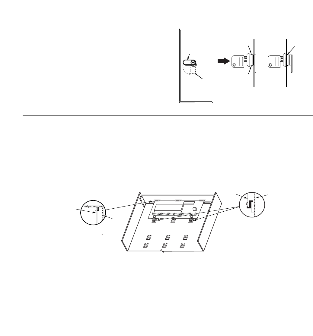
2. Remove cabinet door, then remove the lock knockout
from the door. Insert the key into the lock.
3. Position the lock in the hole, making certain that the
latch will make contact with the latch bracket when
the door is closed. When correctly positioned, push
the lock until it is held securely by its snap tabs.
Notes
• The cabinet can be closed and secured without a
lock by using 2 screws in the cover's edge.
CABINET DOOR
BOTTOM
LOCKED
UNLOCKED
cab_lock_snap-001-V0
ADEMCO
ADEMCO
PUSH
SNAP
TAB
SNAP
TAB
PUSH
ON LOCK
UNTIL IT
IS SEATED
SECURELY
STEP 2STEP 1
CHECK
POSITION
Figure 1. Installing the Cabinet Lock
Mounting the PC Board Alone
(no RF Receiver)
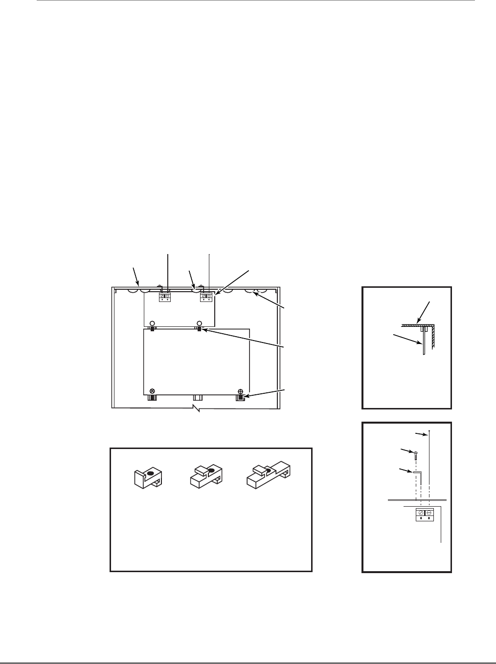
1. Hang two short mounting clips (provided) on the
raised cabinet tabs (see Detail B in Fig. 2).
2. a. Insert the top of the circuit board into the slots at
the top of the cabinet. Make sure that the board
rests on the correct row (see Detail A).
b. Swing the base of the board into the mounting
clips and secure the board to the cabinet with the
accompanying screws (see Detail B).
Notes
• Before installing the cabinet's contents, remove
the metal cabinet knockouts required for wiring
entry. Do not remove the knockouts after the
circuit board has been installed.
+
+
CIRCUIT
BOARD
DETAIL B
SIDE VIEW
OF MOUNTING
CLIPS
DETAIL A
SIDE VIEW
OF BOARD
SUPPORTING
SLOTS
CIRCUIT
BOARD
MOUNTING-001-V0
CABINET
CABINET
Figure 2. Mounting the PC Board
2-1
Mounting Board with RF Receiver
1. a. Remove the receiver board from its case, then
insert the top of the board into the slots at the top
of the cabinet, as shown in Detail A in Figure 3.
Make sure that the board rests on the correct row
of tabs.
b. Swing the base of the board into the mounting clips
and secure it to the cabinet with the accompanying
screws.
c. Insert the top of the control's board into the slot in
the clips and position two clips at the lower edge of
the board.
d. Swing this board into place and secure it with two
additional screws.
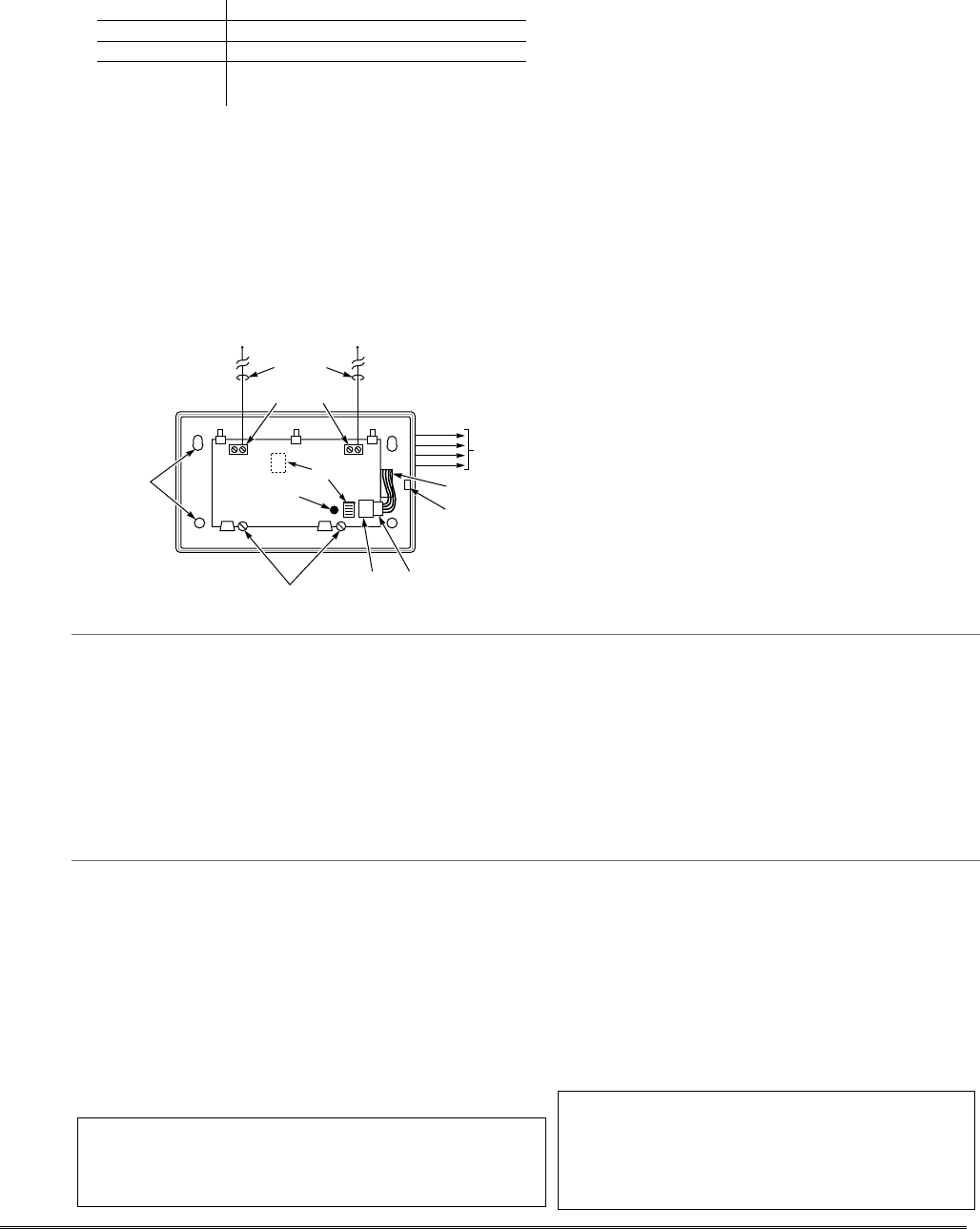
2. Insert grounding lugs (supplied with the receiver)
through the top of the cabinet into the left-hand
terminals of the antenna blocks (at the upper edge of
the receiver board) and secure them to the cabinet
top with the screws provided, as shown in Detail B.
3. Insert the receiver's antennas through the top of the
cabinet, into the blocks' right-hand terminals, and
tighten the screws.
Notes
• Do not mount the cabinet on or near metal
objects. This will decrease RF range and/or block
RF transmissions from wireless transmitters.
• Do not locate the cabinet in an area of high RF
interference (revealed by frequent or prolonged
lighting of the LED in the receiver after it is
operational (random flicker is OK)
ANTENNA
MOUNT
(2 PLACES)
ANTENNA
(2)
SCREW
(2)
BLACK
MOUNTING
CLIP
RED
MOUNTING
CLIP
WHITE
MOUNTING
CLIP
GROUNDING
LUG
(2)
NOTE
A COMBINATION OF THESE MOUNTING CLIPS HAS BEEN
INCLUDED IN YOUR INSTALLATION KIT.
USE THE APPROPRIATE CLIPS FOR MOUNTING.
IF NO RF RECEIVER IS USED, MOUNT THE PC BOARD USING
EITHER THE WHITE OR BLACK CLIPS, WHICHEVER ARE
INCLUDED IN THE CONTROL PANEL'S HARDWARE KIT.
DETAIL A
SIDE VIEW
OF BOARD -
SUPPORTING SLOTS
CIRCUIT
BOARD
CABINET
MOUNTING
CLIP
CABINET
MOUNTING
CLIP
CONTROL
CIRCUIT
BOARD
BOARD
SUPPORTING
SLOTS
RECEIVER CIRCUIT BOARD
++
AB
pc_mount-001-V1
DETAIL B
ANTENNA AND GROUNDING
LUG INSTALLATION
INSTALLATION WITH RECEIVER CIRCUIT BOARD
Figure 3. Mounting the PC Board and RF Receiver
Installation and Setup Guide
2-2
Wiring to Keypads
1. Connect keypads to the control’s keypad terminals as
shown on the Summary of Connections diagram.
Determine wire size using the Wire Run Chart below.
2. Set keypad addresses. Refer to the address setting
instructions included with the keypads and set each
keypad device address according to the chart at right.
3. Program the keypad addresses, partition
assignments and sound options in data fields *190-
*196.
NOTE: Each keypad must be assigned a unique
address, starting at address 16. Keypads
programmed with the same address will give
unpredictable results.
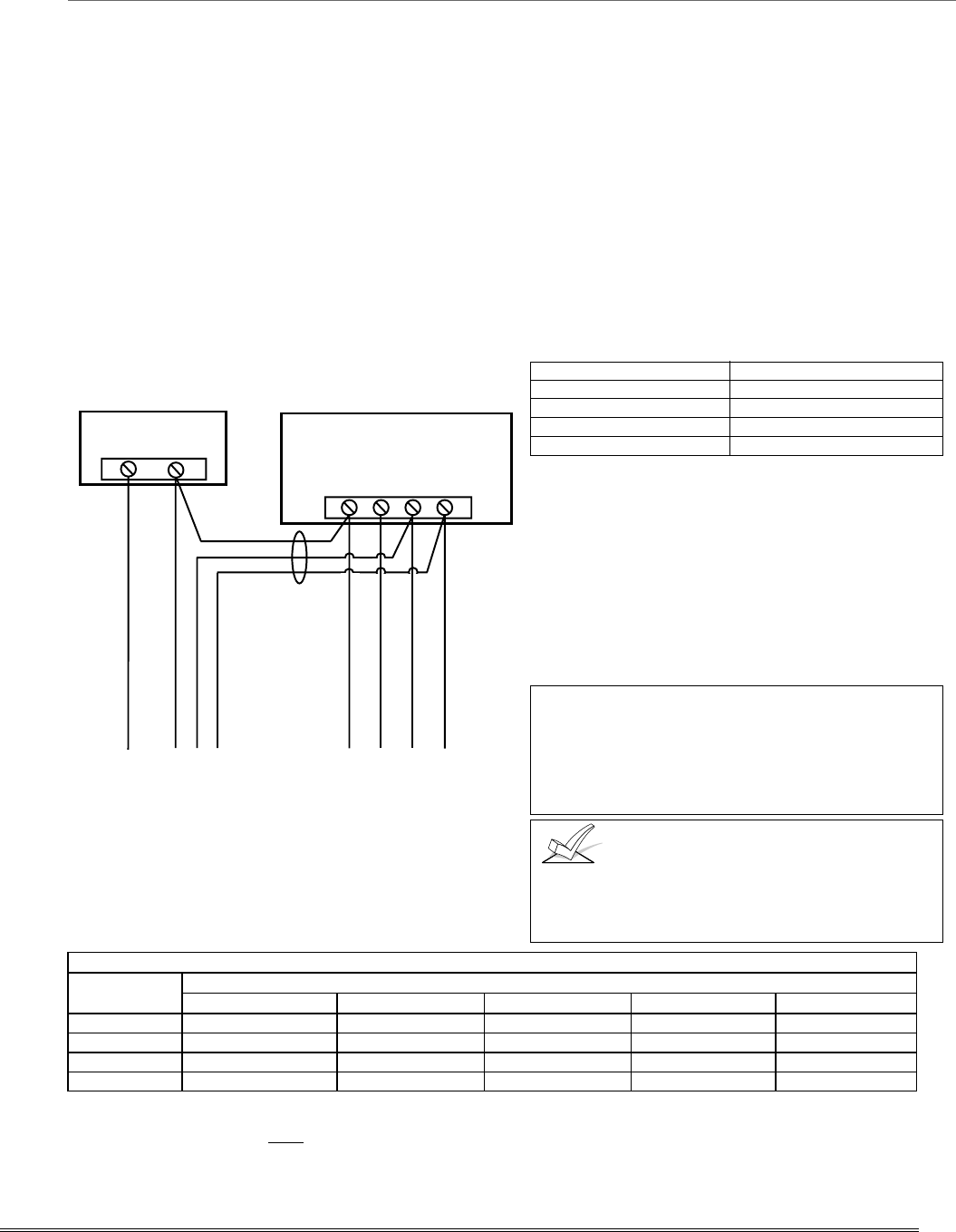
Supplementary Power (optional)
1. Connect as shown. Be sure to connect the negative (–)
terminal on the power supply unit to terminal 4
(AUX –) on the control.
+–
+
456 7
SUPPLEMENTARY
POWER SUPPLY
–
CONTROL TERMINAL STRIP
AUX. AUX. DATA
IN DATA
OUT
IMPORTANT:
MAKE THESE
CONNECTIONS
DIRECTLY TO
SCREW
TERMINALS AS
SHOWN.
TO KEYPAD RED WIRE
TO KEYPAD BLK WIRE
TO KEYPAD YEL WIRE
TO KEYPAD GRN WIRE
TO KEYPAD BLK WIRE
TO KEYPAD RED WIRE
TO KEYPAD GRN WIRE
TO KEYPAD YEL WIRE
supp_pwr_supply-V0
Figure 4. Using a Supplementary Power Supply
Notes
• Fixed-Word Display: FA215KP, FA260KP
• Alpha Display: FA560KP; Voice Keypad: FA560VKP
• Keypad/Transceiver: FA260RF
• AUI: Supports Symphony FA800KP (see note
below) or FA700KP Touch Screen keypads
• The system supports up to 8 keypads, which can be
assigned to partitions in any combination
(see program fields *190-*196).
• For single 4-wire runs, determine the current
drawn by all units, then refer to the Wiring Run
chart to determine the maximum length that can
be safely used for each wire size.
•
U
se supplementary power if the control’s aux. power
load for all devices exceeds 600mA.
Suggested power supply: AD12612
Keypad Addresses
Keypad Address Keypad Address
no. 1 16** no. 5 20
no. 2 17 no. 6 21
no. 3 18 no. 7 22
no. 4 19 no. 8 23
** The first keypad is address 16, which is always
enabled and set for partition 1 with all sounds on.
AUI NOTES:
•
••
• Use of AUI is independent from standard keypads and
does not affect the number of standard keypads the
system can support.
•
••
• AUI keypads must be set for either address 1, 2,5, or 6
depending on which unit is enabled in field *189.
•
••
• To ensure proper AUI device operation, use AUI devices
with the following rev levels: FA700KP series use version
1.0.9 or higher; FA800KP (Symphony) series use version
1.1.175 or higher.
UL Use a UL Listed, battery-backed supply for UL
installations. The battery supplies power to these
keypads in case of AC power loss.
The battery-backed power supply should have
enough power to supply the keypads with the UL
required minimum standby power time.
Keypads powered from supplies that do
not have a backup battery will not function if AC
power is lost. Make sure to power at least one keypad
in each partition from the control’s auxiliary power
output.
Wire Run Chart For Devices* Drawing Aux Power From The Control (12V+ & 12V–)
Wire TOTAL CURRENT DRAWN BY ALL DEVICES CONNECTED TO A SINGLE WIRE RUN
Size 50 mA or less 100 mA 300 mA 500 mA 600 mA
#22 900 ft (274m) 450 ft (137m) 150 ft (46m) 90 ft (27m) 75 ft (23m)
#20 1400 ft (427m) 700 ft (213m) 240 ft (73m) 140 ft (43m) 120 ft (37m)
#18 1500 ft (457m) 1100 ft (335m) 350 ft (107m) 220 ft (67m) 170 ft (52m)
#16 1500 ft (457m) 1500 ft (457m) 550 ft (168m) 350 ft (107m) 270 ft (82m)
* Includes Keypads, RF Receivers, Zone Expander/Relay Units, 4286 Phone Module, and Long Range Radio.
Maximum wire lengths for any device that is homerun to the control can also be determined from the Wiring Run Chart, based on
the current draw of that device alone.
The length of all wire runs for both partitions combined must not exceed 1500 feet (457m) when unshielded quad conductor cable is
used (750 feet if shielded cable is used). This restriction is due to the capacitive effect on the data lines when quad cable is used.
2-3
Sounder (Bell) Connections
1. Make sounder connections to alarm output terminals 3
(+) and 4 (–).
For supervised output, continue with steps 2 and 3.
2. Cut the red Bell Supervision Jumper located above
terminals 2 and 3 on the control board.
3. Connect a 2k ohm resistor across the terminals of the
last sounder.
+
+
2
EXTERNAL ALARM
SOUNDER
TERMINALS ON
CONTROL BOARD
ALARM
OUTPUT
TERMINALS
sounder-001-V0
3
4
CUT RED JUMPER ON CONTROL
BOARD TO ENABLE BELL
(SOUNDER) SUPERVISION.
2000
OHM
EOL
RESISTOR
IF BELL SUPERVISION IS ENABLED
(RED JUMPER ON CONTROL BOARD IS CUT)
CONNECT A 2000 OHM RESISTOR ACROSS
THE EXTERNAL SOUNDER AS SHOWN BY
THE DOTTED LINE.
DO NOT CONNECT THE RESISTOR AT THE
ALARM OUTPUT TERMINALS THEMSELVES!
OBSERVE
POLARITY
Figure 5. Sounder Wiring (Supervised)
Notes
This control complies with NFPA requirements for
temporal pulse sounding of fire notification appliances.
Temporal pulse sounding for a fire alarm consists of:
3 pulses – pause – 3 pulses – pause – 3 pulses–etc..
• The 12VDC sounder output activates when an
alarm occurs.
• Total current drawn from this output cannot
exceed 2 amps (going beyond 2 amps will
overload the power supply, or may cause the
electronic circuit protecting the sounder output to
trip).
• You must install a battery, since the battery
supplies this current.
UL
• Use only UL Listed sounding devices for UL
installations.
• Bell supervision is required for fire alarm installations.
• The total current drawn from the alarm output and the
auxiliary power output, combined, cannot exceed 600
mA. In addition, the sounding device must be a UL
Listed audible signal appliance rated to operate in a
10.2-13.8 VDC voltage range, and must be mounted
indoors.
Wiring the AC Transformer
1321 Transformer:
Connect the 1321 Transformer to terminals 1 and 2 on
the control board. See Wire Run Chart at right for wire
size to use. (Use 1321CN in Canada)
1361X10 Transformer
(required if using Powerline Carrier devices)
1. Splice one end of a 3-conductor cable to the wire ends
of the SA4120XM-1 Cable.
2. Connect the SA4120XM-1 cable plug to the 8-pin
connector on the control (see the Summary of
Connections diagram for location of the 8-pin
connector).
3. Connect the other end of the 3-conductor cable to the
1361X10 Transformer, as shown.
Canada: See Powerline Carrier Device section for
connections to the PSC04 X-10 Interface and trigger pins.
Notes
• Use caution when wiring the transformer to the
control to guard against blowing the transformer
fuse (the fuse is non-replaceable).
• Wiring to the AC transformer must not exceed
250 feet using 16 gauge wire. The voltage
reading between terminals 1 and 2 of the
control must not fall below 16.5VAC or an “AC
LOSS” message will be displayed.
• Do not plug the transformer into the AC outlet
while making any wiring connections to the
control. As a safety precaution, always power
down the control when making such connections.
Wiring Run Chart
Distance from control Wire Size
Up to 50 feet # 20
50–100 feet # 18
100-250 feet # 16
AC AC SYNC COM DATA
2
34 5
1
2
1
SA412OXM-1
CABLE
CONTROL
BOARD
TERMS.
1361X10 TRANSFORMER
00-trigcon-001-V2
1 345678
8-PIN TRIGGER CONNECTOR
KEY
+12 AUX.
DATA
COM
SYNC
GND (-)
OUTPUT 17 (RED)
OUTPUT 18 (GREEN)
(ORANGE)
(YELLOW)
(BLUE)
(PURPLE)
(BLACK)
Figure 6. Connections of 1361X10 Transformer to the Control Board
Installation and Setup Guide
2-4

Backup Battery
1. Place the 12-volt backup battery in the cabinet.
2. After all connections to the control are completed and
AC power has been applied, connect the red and black
flying leads on the control board to the battery. Do not
attach these leads to the battery terminals until all
connections are completed.
Battery Saver Feature: The battery will disconnect
from the system after its voltage decreases below 9VDC.
This assists the control panel in recharging the battery
when AC is restored.
Notes
IMPORTANT: The panel will not power up
initially on battery power only. You must plug the
transformer in first, and then connect the battery.
UL For UL installations and Residential fire
installations, refer to the chart below for the
correct battery size required to meet the
mandatory standby time.
CALIFORNIA STATE FIRE MARSHALL (CSFM) AND UL RESIDENTIAL FIRE
24-HOUR BATTERY BACKUP REQUIREMENTS
The California State Fire Marshal and UL have regulations which require that all residential fire alarm control
panels must be provided with a backup battery which has sufficient capacity to operate the panel and its attached
peripheral devices for 24 hours in the intended standby condition, followed by at least 4 minutes in the intended
fire alarm signaling condition. This control panel can meet these requirements without using a supplementary
power supply, provided that the panel’s auxiliary power and bell output currents are limited as indicated below.
OUTPUT LIMITATIONS TO MEET CSFM 24 HOUR BATTERY BACKUP REQUIREMENTS
AND UL RESIDENTIAL FIRE INSTALLATIONS
OUTPUT CURRENT LIMITATIONS BATTERY INFORMATION
Output Current Total Maximum Auxiliary Current
Battery Capacity
To Use (Amp/Hrs) Recommended Battery
(Yuasa Model No.)
600mA maximum total of
auxiliary power plus bell
output currents
45mA
160mA
200mA
425mA
500mA
4AH
7AH
8AH
14AH
17.2AH
NP4-12 (or ADEMCO 467)
NP7-12
NP4-12 (two) ‡
NP7-12 (two) ‡
NPG18-12
‡ NOTE: Use two batteries, connected in parallel. Obtain an Ademco Battery Harness Kit SA5140-1. (Both batteries will
fit inside the panel’s cabinet.)
Earth Ground
Metal Cold Water Pipe:
Use a non-corrosive metal strap (copper is recommended)
firmly secured to the pipe to which the ground lead is
electrically connected and secured.
AC Power Outlet Ground:
Available from 3-prong, 120VAC power outlets only. To
test the integrity of the ground terminal, use a 3-wire
circuit tester with neon lamp indicators, such as the UL
Listed Ideal Model 61-035, or equivalent, available at
most electrical supply stores.
Notes
• This product has been designed and laboratory-
tested to ensure its resistance to damage from
generally expected levels of lightning and
electrical discharge, and does not normally
require an earth ground.
• If an earth ground is desired for additional
protection in areas of severe electrical activity,
terminal 25 on the control board, or the cabinet,
may be used as the ground connection point. The
examples of good earth grounds listed at the left
are available at most installations.
AUXILIARY DEVICE CURRENT DRAW WORKSHEET
DEVICE CURRENT # UNITS TOTAL CURRENT
FA215KP Fixed-Word Keypad 35mA/55mA**
FA260KP Fixed-Word Keypad 75 mA/150mA**
FA560KP Alpha Keypad 80 mA/150mA**
FA560VKP Voice Keypad 60mA/190mA**
FA260RF Keypad/Transceiver 105mA/175mA**
FA700KP Touch Screen Keypad 180mA/280mA**
FA800KP AUI (Symphony) 150mA/400mA**
5881/5882 RF Receiver 60mA
5883 Transceiver 80mA
4219 Zone Expander 30mA
4204 Relay Unit 15/180mA‡
4229 Zone Expander/Relay Unit 30/100mA‡
FA4286 Phone Module 300mA
*
*
*
(Current available from Aux. terminals = 600 mA max.)†
T
OTAL
* If using hardwire devices
such as PIRs, refer to the
specifications for that
particular unit's current draw.
** Values are for standby/alarm;
alarm for keypads means
armed with backlighting on
and sounder on
† In UL installations, maximum
current draw from the
Auxiliary Output and the
Alarm Output combined
must not exceed 600 mA
(500 mA max from Auxiliary
Output).
‡ Figures are for relays
OFF/relays ON.
2-5
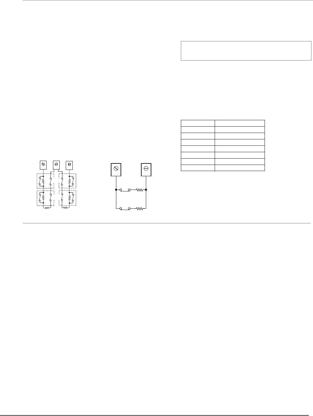
Hardwire Zones
Normally Open Zones/ Normally Open EOLR Zones
1. Connect open circuit devices in parallel across the
loop; for EOLR zones, connect the EOLR across the
loop wires at the last device.
2. Enable normally open/EOLR zones using Zone
Programming mode, “Hardwire Type” prompt.
Normally Closed Zones/Normally Closed EOLR Zones
1. Connect closed circuit devices in series in the high (+)
side of the loop; for EOLR zones, connect the EOLR in
series following the last device.
2. Enable normally closed/EOLR zones using Zone
Programming mode, “Hardwire Type” prompt.
Double-Balanced (FA168CPS only): Connect as shown
below (resistor provided for one device).
IMPORTANT: Double-balanced zones provide zone tamper
protection, and should be used as burglary zones only. Do not
use double-balanced zones as fire zones.
Zone Doubling (FA168CPS only): Connect as shown
below (resistors provided).
NOTE: Zone numbers used for zone doubling cannot be
used for anything else (ex. cannot be used for 4219 zones)
2k
2k
2k
ZONE 3
2k
2k
2k
ZONE 4
12 13 14
zone-002-V0
TAMPER
CONTACTS
TAMPER
CONTACTS
10 11
6.2k
ZONE 10
3k
ZONE 2
zone-004-V0
Double Balanced Zones Zone Doubling
Notes
• EOLR: If the EOLR is not at the end of the loop,
t
he zone is not properly supervised and the system
may not respond to an “open” on the zone.
• Zone 1 is intended for EOLR only.
UL For UL commercial burglar alarm
installations, use EOLR zones.
Zone Doubling (FA168CPS only):
This feature provides two hardwired normally
closed zones for each standard hardwired zone
connected to the control’s terminals (but does not
increase the total number of zones supported by
the control). If enabled (Zone Programming mode,
“Hardwire Type” prompt, option “3”), hardwire
zones are automatically paired as follows:
Zone Paired with zone
2 10
3 11
4 12
5 13
6 14
7 15
8 16
Do not use zone doubling for fire zones.
NOTE: A short across the EOL (i.e., at terminal)
on either zone of a zone-doubled pair or on a
double-balanced zone causes a tamper condition
(displayed as CHECK plus zone numbers).
Smoke Detectors
2-Wire Smoke Detectors
1. Connect up to sixteen (10, if “clean me” option used)
2-wire smoke detectors across zone 1 terminals 8 (+)
and 9 (-) as shown in the Summary of Connections
diagram at the back this manual. Observe proper
polarity when connecting the detectors.
2. Connect an EOL resistor across the loop wires at the
last detector.
Notes
•
••
• Fire Verification (zone type 16): The control
panel will “verify” a fire alarm by resetting the
smoke detectors after the first alarm trigger, and
then waiting up to 90 seconds for a second alarm
trigger. If the smoke detector or thermostat does
not trigger again, the control will disregard the
first trigger, and no alarm signal will occur. This
feature eliminates false alarms due to electrical
or physical transients.
SIA Installations: If using fire verification on
zones other than zone 1, UL Fire Alarm Listed
relay accessories must be used to reset power as
described in step 3.
• The zone 1 alarm current supports only one
smoke detector in the alarmed state.
•
••
• Clean Me Option: If enabled (field *174 = 1;
*56 zone programming, response time prompt =
3), certain ESL smoke detectors† send “clean me”
reports as appropriate. If used, the maximum
number of detectors is reduced to 10 (not
standard 16).
† Refer to the ESL documentation included with
the smoke detector for information regarding
compatibility with the clean-me option.
Installation and Setup Guide
2-6
Smoke Detectors (continued)
4-Wire Smoke Detectors
3. Connect 4-wire smoke detectors (up to 16, depending
on detector current draw) to any zone from 2-8 as
shown below. This control does not automatically reset
power to 4-wire smoke detector zones, so you must use
a relay (e.g., 4204, 4229), or on-board trigger to reset
power (also required for fire verification). Do this by
programming the designated relay/trigger as zone type
54 (fire zone reset); see On-Board Trigger section for
other information.
NOTE: Maximum current on trigger 17 is 100mA.
Notes
• Do not use 4-wire smoke detectors on zone 1.
Figure 7. 4-Wire Smoke Detector Connections
+
+
2000
OHMS
EOLR
HEAT
DETECTOR
RED
EOL
POWER
SUPERVISION
RELAY MODULE
A77-716B.
USE N.O.
CONTACT,
WHICH CLOSES
WHEN POWER
IS APPLIED.
VIOLET
AUX PWR
OUTPUT
TERMINALS
5
4
+
BLK
+
4_wiresmk-007-V0
TO ZONE TERM. ( )
TO ZONE TERM. ( )
RELAY
CONTACT OPENS
MOMENTARILY UPON
FIRE ALARM RESET
PROGRAM
RELAY
AS ZONE
TYPE 54
(FIRE ZONE
RESET)
4-WIRE SMOKE
OR COMBUSTION
DETECTOR
N.C.
N.O.
+
2000
OHMS
EOLR
HEAT
DETECTOR
RED
VIOLET
AUX PWR 5
+
BLK
+
4_wiresmk-008-V0
4-WIRE SMOKE
OR COMBUSTION
DETECTOR
( )
( )
+
TO ZONE TERM. ( )
TO ZONE TERM. ( )
TO OUTPUT 17
PROGRAM OUTPUT 17
FOR "OUT NORM
LOW" = YES IN 79 MENU
MODE AND AS ZONE
TYPE 54 IN
80 MENU MODE
EOL
POWER
SUPERVISION
RELAY MODULE
A77-716B.
USE N.O.
CONTACT,
WHICH CLOSES
WHEN POWER
IS APPLIED.
N.O.
4-Wire Smoke Detector Using Relay for Power Reset 4-Wire Smoke Detector Using Output 17 for Power Reset
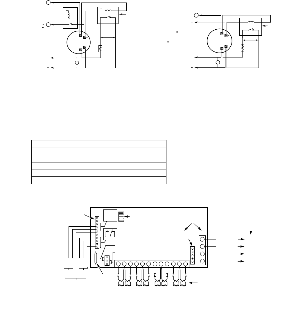
4219/4229 Expansion Zones
1. Connect each module to the control’s keypad
terminals.
2. Assign each module a unique device address (07-11)
using its DIP switches. Device addresses determine
the zone numbers being used, as shown in the
following table.
Expander Module Addresses
For Zones…Set Module to Device Address…
09-16 07 (not available if zone-doubling enabled)
17-24 08
25-32 09 (FA168CPS)
33-40 10 (FA168CPS)
41-48 11 (FA168CPS)
3. Connect sensors to the module’s loops.
4. If using relays with the 4229, connect the desired
field wiring to the unit's relay contact terminals.
Notes
• Supports expansion zones (NO or NC) using
4219/4229 Zone Expander Modules as follows:
FA168CPS: Up to 40 expansion zones using up to
five Zone Expander Modules.
FA148CP: Up to 16 expansion zones using up to
two Zone Expander Modules.
• Use 1000 ohm end-of-line resistors at the end of
loops connected to the 4219/4229 modules. (End-
of line resistors used on the control terminals are
2000 ohms.)
• Expansion zones have normal response time
(300–500 msec), except zone connected to each
module’s loop “A,” which can be set for fast
response (10–15 msec).
BRN
GRN
BLK
(–) GROUND
RED
(+) 12VDC
YEL
4
3
2
1
ZONES ABC DFGH
DIP SWITCH
FOR SETTING ADDRESS
AND ZONE "A" RESPONSE
TAMPER JUMPER POSITION
4229 IN CABINET
(NOT TAMPER)
4229 REMOTE
(TAMPER PROTECTED) TB1
4229
TB2
WHT
GRY
VIO
BLK
YEL
ORG
NO
NC
C
GND
NO
NC
C
RLY
1
RLY
2
RELAYS OFF
RELAY
CONNECTOR RELAY
2
RELAY
1
(TERM 6)
(TERM 4)
(TERM 5)
(TERM 7)
NO C NC
TERMINALS ON
CONTROL PANEL
1
2
3
4DATA OUT (>)
TO CONTROL
DATA IN (<)
FROM
CONTROL
5811
REED
(TAMPER)
SWITCH
2
E
134 6 7910 12
TERMINATE EACH
PROGRAMMED ZONE
WITH 1000 OHM (1K)
END-OF-LINE RESISTOR
(EACH ZONE'S MAX.
LOOP RESISTANCE
300 OHMS + EOL)
4-PIN CONSOLE PLUG
EITHER OR BOTH CAN BE USED
4229-002-V0
Figure 8. Wiring Connections, 4219 & 4229 (4229 shown)
2-7
Installing the RF Receiver
Use any ADEMCO 5800 Series Wireless Receivers, such
as:
RF Receiver No. of Zones
5881L/5882L up to 8
5881M/5882M up to 16
5881H/5882H, FA168CPS = up to 40 plus 16 buttons
5883, FA260RF FA148CP = up to 26 plus 8 buttons
1. Set Device Address to “00” as described in its
instructions (set all switches to the right, “off” position).
2. Mount the receiver, noting that the RF receiver can
detect signals from transmitters within a nominal
range of 200 feet.
3. Connect the receiver's wire harness to the control's
keypad terminals. Plug the connector at the other end
of the harness into the receiver. Refer to the
installation instructions provided with the receiver
for further installation procedures regarding antenna
mounting, etc.
Notes
• The receiver is supervised and a trouble report is
sent (“CHECK 100” displayed) if communication
b
etween the panel and receiver is interrupted, or if
no valid RF signals from at least one supervised
transmitter are received within 12 hours.
If the receiver is mounted remotely:
• Place the RF receiver in a high, centrally located
area for best reception.
• Do not locate the receiver or transmitters on or
near metal objects. This will decrease range
and/or block transmissions.
• Do not locate the RF receiver in an area of high
RF interference (indicated by frequent or
prolonged lighting of the LED in the receiver;
random flicker is OK).
• Do not locate RF receiver closer than 10 feet from
any keypads to avoid interference from the
microprocessors in those units.
MOUNTING
HOLES INTERFERENCE
INDICATOR
LED
CIRCUIT BOARD
DIP
SWITCH
ANTENNAS
(INSERT IN
RIGHT-HAND
TERMINALS)
YELLOW
RED
BLACK
GREEN
WIRING OPENING
KNOCKOUT AREA
FOR SURFACE WIRING
TO CONTROL'S
REMOTE KEYPAD
CONNECTION
POINTS.
5882
LOCATION
TO RELEASE CIRCUIT BOARD,
REMOVE SCREWS AND
BEND BACK TABS
NOTE
CIRCUIT BOARD IS MOUNTED IN
CONTROL'S CABINET. GROUNDING
LUGS (2) PROVIDED
MUST
BE INSERTED
IN LEFT-HAND TERMINALS OF ANTENNA
BLOCKS AND SECURED TO CABINET.
(SEE RECEIVER'S AND CONTROL'S
INSTRUCTIONS)
SOCKET PLUG
MODEL NO. IS INDICATED ON CIRCUIT BOARD
5881-003-V0
INSERT IN
RIGHT- HAND
TERMINALS
Figure 9. 5881/5882 RF Receiver (cover removed)
Installing a 5800TM Module
1. Mount the 5800TM next to the RF receiver (between
one and two feet from the receiver’s antennas) using
its accompanying mounting bracket. Do not install
within the control cabinet.
2. Connect the 5800TM to the control panel’s keypad
connection terminals as shown on the Summary of
Connections diagram and set to address 28.
Notes
• Use this module only if you are using one or more
wireless bi-directional keypads or keyfobs with a
wireless Receiver; 5800TM is not necessary if
using a Transceiver (e.g., 5883).
• The 5800TM must be set to address 28 (cut red-
W1 jumper).
• The 5800TM can be used in partition 1 only.
• For additional information regarding the
5800TM, refer to the 5800TM’s instructions.
Installing the Transmitters
1. To be sure reception of the transmitter's signal at the
proposed mounting location is adequate, perform a
Go/No Go Test, described in the Testing the System
section.
2. Install transmitters in accordance with the
instructions provided with each.
3. Set 5827, 5827BD, 5804BD wireless keypads to the
programmed House ID (field *24), using its DIP
switches (5827) or follow the instructions provided
with the device.
ULC NOTE: In accordance with ULC standards, the
RF supervision period for the FA168CPS-CN and
FA148CP-CN is three hours for Fire zones (Zone Type 9
and 16) and 12 hours for all other zone types.
Notes
• Refer to the table of compatible devices at the
back of this manual.
• Supervised transmitters† send check-in signals to
the receiver at 70-90 minute intervals. If at least
one check-in message is not received from each
transmitter within a 12-hour period, the “missing”
transmitter number(s) and “CHECK” is displayed.
† Hand-held transmitters (e.g., 5802, 5802CP, 5804,
5804BD, 5827, 5827BD) do not send check-in signals.
UL The following transmitters are not intended for use
in UL installations: 5802MN, 5802MN2, 5804, 5804BD,
5814, 5816TEMP, 5819, 5819WHS & BRS, and 5850.
The 5827BD and 5800TM can be used in UL Listed
Residential Burglar installations.
WIRELESS ZONE NUMBERS
FA168CPS: transmitter zones 9-48
button zones 49-64
FA148CP: transmitter zones 9-34
button zones 49-56
Installation and Setup Guide
2-8
Transmitter Battery Life
• See Wireless Transmitter paragraph in the Limitations of This Alarm System statement located at the end
of this manual for information on transmitter battery life.
• Some transmitters (e.g., 5802 and 5802CP) contain long-life but non-replaceable batteries, and no battery
installation is required. At the end of their life, the complete unit must be replaced (and a new serial number
enrolled by the control).
• Button-type transmitters (such as 5801, 5802, and 5802CP) should be periodically tested for battery life.
• The 5802MN and 5804 Button Transmitters have replaceable batteries.
Do not install batteries in wireless transmitters until you are ready to enroll during system programming.
After enrolling, batteries need not be removed.
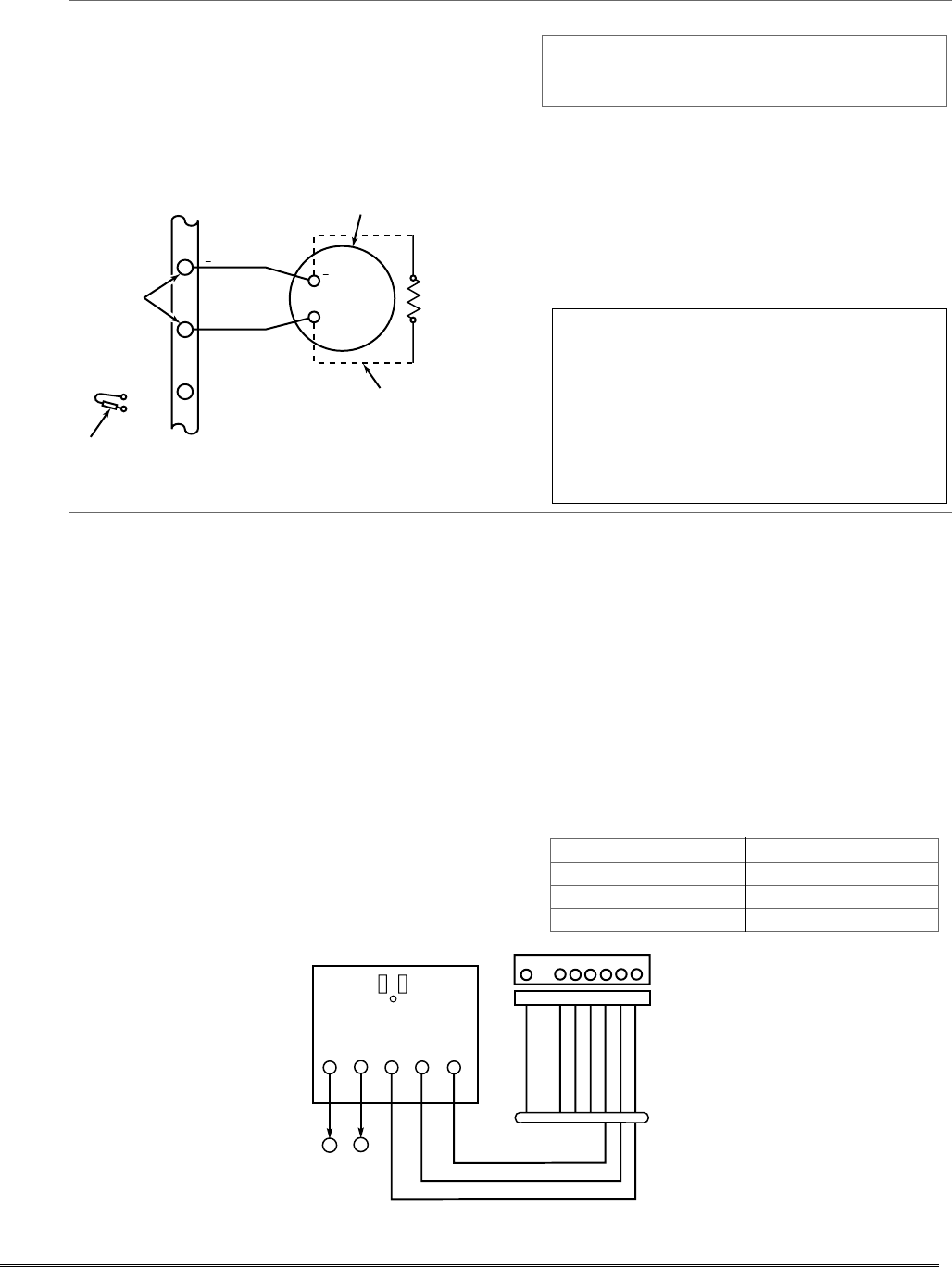
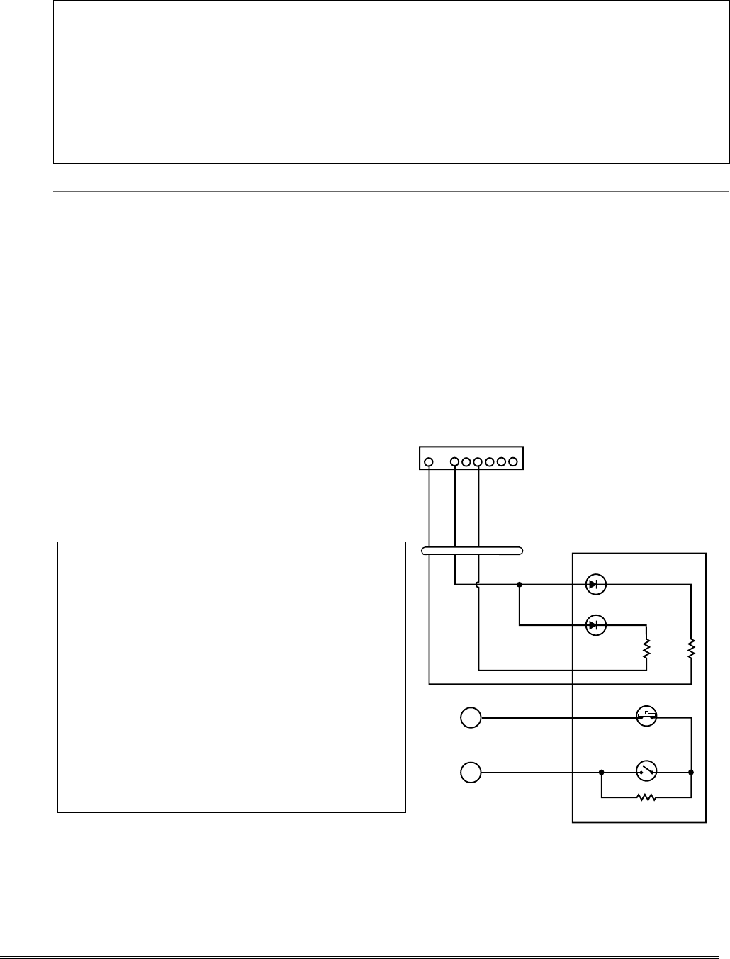
Installing a Keyswitch
1. Connect the 4146 keyswitch's normally open
momentary switch to a zone’s (2-8) terminals. Remove
the 2000 ohm EOL resistor if connected across the
selected zone.
2. Using a standard keypad cable as shown:
Connect the yellow and white keyswitch wires to
trigger connector pin 3 (+12V).
Connect the Red and Green LED wires to the
appropriate output 17/output 18 trigger connector
pins.
3. Connect a 2000 ohm EOL resistor across the
momentary switch.
4. You can wire an optional closed-circuit tamper switch
(model 112) in series with the zone. If the switchplate
is then removed from the wall, the tamper will open,
disabling keyswitch operation until the system is
next disarmed from the keypad.
If the tamper is opened when the system is armed, an
alarm will occur.
UL A UL Listed keyswitch is required for fire
installations and UL commercial and residential burglar
alarm installations.
If a keyswitch is used on:
• an installation that transmits opening and closing
signals, the keyswitch zone must be programmed to
send opening and closing signals.
• a UL commercial burglar alarm installation, the
keyswitch’s tamper switch must be connected in to the
alarm system. This tamper switch zone must also be
programmed for Zone Type 05 – Trouble by Day / Alarm
by Night.
• a fire alarm installation, the keyswitch must be located
next to an alphanumeric display keypad.
The Ademco 4146 keyswitch is UL Listed.
Notes
• Use 4146 keyswitch or any N.O. keyswitch.
• Use only one keyswitch per partition.
• When using a keyswitch, the zone it is connected
to is no longer available for use as a protective
zone.
• Use *56 Menu mode to program the keyswitch
zone and assign it zone type 77.
• Use *80 Menu mode to program the LED
functions: program outputs 17 and 18 for system
operation zone type 78 (red LED) and 79 (green
LED) as appropriate (see Output Device
Programming section).
4146 KEYSWITCH
(READY)
GREEN
LOCK
SWITCH (N. O.)
TAMPER
SWITCH (N. C.)
(ARMED)
RED
YELLOW
WHITE
EOLR
(use appropriate value)
11
10
TYPICAL ZONE
ON CONTROL
BOARD
BROWN
BLUE
BROWN
BLUE
820
ohms
820
ohms
00-trigcon-004-V1
1345678
STANDARD
KEYPAD
CABLE
8-PIN TRIGGER CONNECTOR
KEY
+12 AUX.
OUTPUT 17
OUTPUT 18
(RED)
(YELLOW)
(GREEN)
RED
BLACK
Figure 10. Keyswitch Wiring Connections
2-9
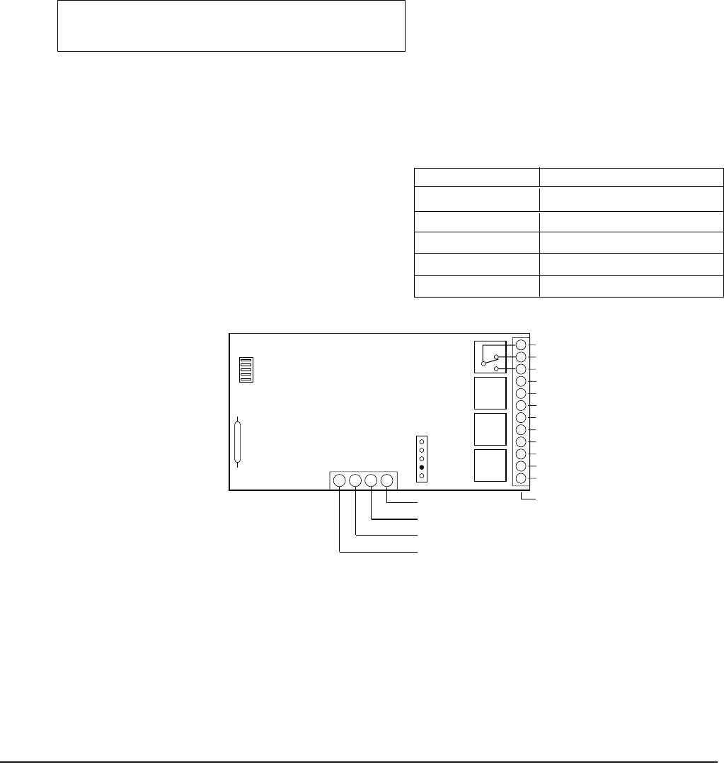
Connecting Relay Modules
1. Mount either remotely or in the control panel.
2. Connect to control’s keypad terminals using the
connector harness supplied with the module. Use
standard 4-conductor twisted cable for long wiring
runs.
3. Set each module’s device address according to the
table at right.
4. Connect the desired field wiring to the unit's relay
contact terminals.
UL For UL installation requirements, refer to the
Installation Instructions for the 4204.
Notes
• Use 4204 or 4229 modules.
• Supervision: 4204 and 4229 modules are
supervised against removal. The module’s device
address is displayed as follows if a module is
disconnected from the control’s terminals, or if
the module cover is removed and the tamper
jumper is installed:
Alpha: CHECK xx Wire Expansion
FAULT xx Wire Expansion
ALARM xx Wire Expansion
Fixed-Glass: lxx (or 91 if field *199 set for 2-digit
display)
where “xx is the module’s address.
• If communication/tamper failure occurs on a
device with zones wired to it, all zones on the
device will be displayed in their respective
partitions.
Relay Module Addresses
4204 Address 4229 Address
no. 1 12 no. 1 (zn 09-16) †† 07
no. 2 13 no. 2 (zn 17-24) 08
no. 3† 14 no. 3
† (zn 25-32) 09
no. 4† 15 no. 4† (zn 33-40) 10
no. 5† (zn 41-48) 11
† Applies to FA168CPS.
†† Not available if zone doubling used
TB2
121110
9
87654321
(–) GROUND
(+) 12V
YEL
BLK
GRN
RED
13 14 15 16
DIP SWITCH
FOR SETTING DEVICE ADDRESS
AND ENABLING/DISABLING TAMPER
COVER TAMPER (REED) SWITCH
TB1
4204
4-PIN TOUCHPAD PLUG
3
2
RELAY
1
4
TYPICAL
(SHOWN "OFF")
C
NC
NO
C
NC
NO
C
NC
4204_conn-1-V0
NC
NO
C
NC
NO
EITHER OR BOTH
CAN BE USED
DATA IN
FROM CONTROL
DATA OUT
TO CONTROL
RELAY
RELAY
RELAY
Figure 11. 4204 Connections to Control
(4229 Module is shown in the 4219/4229 Expansion Zones paragraph on page 2-7)
Installation and Setup Guide
2-10
Powerline Carrier Devices
1. Install the powerline carrier devices according to the
instructions included with each.
FA168CPS: Up to 16 devices (if no relays are used)
FA148CP: Up to 8 devices (if no relays are used)
2. Use Programming Mode to enter the device house ID
in data field*27, and enter the unit code using *79
Output Device menu Mode.
3. See connections diagram in the AC Wiring paragraph
for connecting the 1361X10 transformer to the triggers.
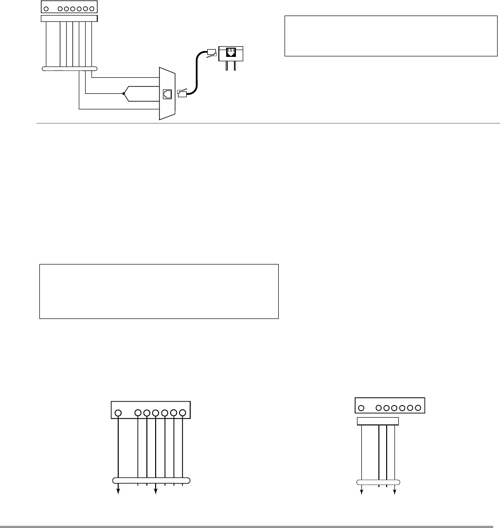
Canada: Use the PSC04 Powerline Interface as shown:
1 2 3 4
SA4120XM-1 CABLE
X-10 PSC04
POWERLINE INTERFACE
YEL
RED
GRN
BLK MODULAR PHONE CORD (not supplied)
1 - BLACK
2 - RED
3 - GREEN
4 - YELLOW
SYNC
DATA
COM
1345678
KEY
+12 AUX.
DATA
COM
SYNC
GND (-)
OUTPUT 17 (RED)
OUTPUT 18 (GREEN)
(ORANGE)
(YELLOW)
(BLUE)
(PURPLE)
(BLACK)
8-PIN TRIGGER CONNECTOR
Notes
• When using Powerline Carrier devices, you must
use a 1361X10 Transformer instead of the 1321
Transformer.
• The 1361X10 Transformer provides AC power to
the control panel, and also supplies signals from
the control panel through the premises AC
wiring to the Powerline Carrier devices (which
are plugged into AC outlets). You can then make
devices that are plugged into Powerline Carrier
devices perform various functions in response to
commands you enter at the security system
keypads.
UL Powerline Carrier devices are not UL Listed
for fire or burglary functions and are intended for
home automation.
On-Board Triggers
Connect field wiring to the desired trigger pin on the
8-pin trigger connector centrally located above the
terminal strip.
• If using 1361X10 transformer and powerline carrier
devices, use the SA4120XM-1 cable. See Wiring the
AC Transformer section for transformer
connections.
• If only using the on-board triggers, you can use a
4-wire cable (N4632-4, supplied with the control)
cable as shown below.
UL If on-board triggers are used, the wiring between the
control unit and the UL Listed device must be run in
conduit, be no more than 3 feet apart and have no
intervening barriers or walls.
Notes
• Trigger outputs are normally high, and go low
upon programmed condition.
• The outputs can be programmed for inverted
operation (normally low, go high) using *79
Menu mode.
• Program these triggers using *80/*81 Menu
modes as you would for any other relay output.
• When using these outputs, note:
pin 1 = output number 17 (trigger 1):
15 ohms to ground when closed (output
low), open when off (output high, normal
default); can be used to reset smoke detector
power (must set “output normal low = yes”
in *79 Menu mode, and set for zone type 54,
fire zone reset, in *80 Menu mode); or can
support 12V relay module† that draws less
than 100mA
pin 5 = output number 18 (trigger 2):
100 ohms to ground when closed (output
low); open when off (output high, normal
default); or can support 12V relay module
that draws less than 20mA
† e.g., Altronix AX-RBS
1345678
SA412OXM-1
CABLE
8-PIN TRIGGER CONNECTOR
KEY
TRIGCON-003-V0
+12 AUX.
DATA
COM
SYNC
GND (-)
OUTPUT 17 (RED)
OUTPUT 18 (GREEN)
(ORANGE)
(YELLOW)
(BLUE)
(PURPLE)
(BLACK)
4-WIRE
CABLE
00-trigcon-005-V2
+12 AUX.
GND (-)
OUTPUT 17
OUTPUT 18
(RED)
(YELLOW)
(BLACK)
(GREEN)
1345678
8-PIN TRIGGER CONNECTOR
KEY
Figure 12. On-Board Trigger Connector with Figure 13. On-Board Trigger Connector with
SA4120XM-1 Cable for Use With 1361X10 Transformer 4-Wire Cable for Trigger Use Only
2-11
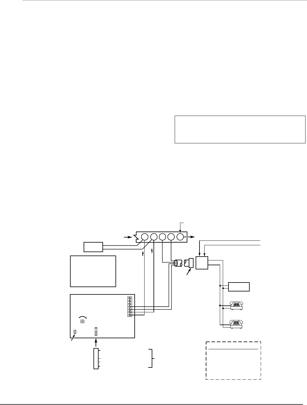
Phone Line/Phone Module Connections
1. Connect incoming phone line and handset wiring to
the main terminal block (via an RJ31X jack) as
shown in the Summary of Connections diagram at the
back of this manual. Wire colors represent the colors
of the cable to the RJ31X jack.
If using a phone module, continue with the following steps.
2. Make 12V (+) and (–) and data in and data out
connections from the phone module to the control,
using the connector cable supplied with the phone
module, then insert the keyed connector at the other
end of the connector cable into the header on the
phone module.
3. Connect Phone Module terminals as shown below.
Use an RJ31X jack with a direct-connect cord and
make all connections exactly as shown.
4. Caller ID Units: If a Caller ID unit is being used,
connect the unit directly to the “Handset” terminals
(21 & 22) on the control, as shown.
Notes
• Use 4286 Phone Modules.
Compatibility: 4286 Phone Modules must have
software version WA4286-15.1 or higher (refer to
the label on the square 4286 microprocessor chip).
• Only one phone module can be used and it can
only be connected to partition 1.
• The phone lines must be in service for the phone
module to function, even when accessing the
system from an on-premises phone.
• If you are also using an Audio Alarm Verification
(AAV) unit, refer to Audio Alarm Verification
(AAV) section for special wiring connections.
CAUTION: To reduce the risk of fire, use only No.
26 AWG or larger telecommunication line cord for
phone line connections.
UL The 4286 modules are UL Listed only for use
on residential fire and UL residential burglar alarm
installations.
Phone Module Problems
If no touch tones are produced following access to the security system from on-premises (this problem may arise
in rare cases), it may be necessary to reverse the wires connected to terminals 3 and 4 on the phone module and
the wires connected to terminals (21) & (22) on the control. The wiring diagram shows the wiring connections
that will provide proper operation in most cases.
Connection to the incoming telco line via a RJ31X jack and direct-connect cord, as shown, is essential, even if
the system is not connected to a central station. The 4286 will not function if this is not done and an error
signal (fast busy signal) will occur when trying to access the system via the phone.
The house phone lines (gray and brown wires) must be wired to the phone module terminals; not to the control
terminals. Otherwise, an error signal (fast busy signal) will occur when trying to access the system from an on-
premises phone.
ANSWERING
MACHINE
TERMINALS
ON CONTROL
TO EARTH GROUND (COLD WATER PIPE, ETC.)
UNUSED
KEYED
HEADER
4286 VIP MODULE
123456 7
YELLOW: TO DATA OUT (term. 7)
NO CONNECTION
RED: TO AUX (+) (term. 5)
BLACK: TO AUX. GROUND (–) (term.4)
GREEN: TO DATA IN (term. 6)
CONNECTOR
WITH FLYING
LEADS
TO CONTROL
PANEL
TERMINALS
USED FOR
KEYPAD
CONNECTIONS
PREMISES ANSWERING
MACHINE AND PHONES
HANDSET
INCOMING
TELCO LINE
TIP
RING
PLUG
DIRECT
CONNECT
CORD
TIP
RING
GROUND
(TIP)
(RING)
GREEN (TIP)
RED (RING)
INCOMING TELCO LINE
GREY (R)
BROWN (T)
4286 TERMINAL ASSIGNMENTS
1 - TIP
2 - RING PHONE INPUT
3 - TIP
4 - RING PHONE OUTPUT
5 - NO CONNECTION
6 -
7 - AUDIO OUT
}
}
}
{
{
IMPORTANT NOTE FOR
EXISTING INSTALLATIONS:
EXISTING WIRES
CONNECTED TO THE
"HANDSET" TERMINALS ON
CONTROL MUST BE MOVED
FROM THERE TO TERMINALS
3 AND 4 ON THE 4286.
*
*
*
NOTE: IF THE TELEPHONE HAS BUILT-IN CALLER ID,
THE CALLER ID FUNCTION MAY NOT WORK
.
CA38A
IN
CANADA
4286_cntrl-001-V1
LOUDER
VOLUME
21 22 23 24 25
CALLER ID
UNIT
RJ31X
JACK
Figure 14. 4286 Phone Module Wiring Connections
Installation and Setup Guide
2-12
Long Range Radio Connections
Connect the data in/data out terminals and voltage
input terminals of the Long Range Radio to the
control's keypad connection points.
Set the radio’s address to “03” following the
instructions provided with the radio.
Notes
• Use compatible Long Range Radios (e.g.,
7720PLUS, 7820, 7835C, or 7845C).
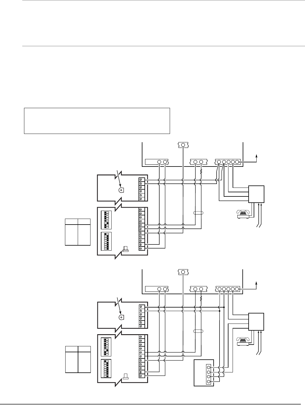
Audio Alarm Verification Connections
(AAV, “listen-in”)
Using the UVS System with UVCM Module
Refer to the connection diagrams below. One diagram
shows connections when a 4286 Phone Module is
used, the other shows connections when the 4286 is
not used.
Connections use one of the on-board triggers.
UL UL installations using the AAV feature must use the
ADEMCO UVCM module (part of the ADEMCO UVS
system).
Suggested Module: ADEMCO UVS (shown) or Eagle 1250
Notes
•
S
et field *91 for AAV and program the appropriate
output (output 17 or 18) using *80 Menu mode:
select zone type 60 and output action 1 (close for 2
seconds) or action 2 (stay closed).
• For voice session monitoring, connect an EOLR
zone to UVCM module terminals 6 & 7, and
program the zone as zone type 81 (*56 Menu
mode).
E.g., Using output 18 for the trigger, program an
output function in *80 Menu mode as: ZT = 60,
P = 0, Action = 1, Device = 18
ON ON
12345678 12345678
1234567891011 29 30 31 32 33 34
NOTE:
REFER TO UVCM MODULE
INSTRUCTIONS FOR
CONNECTIONS TO AUDIO
SPEAKERS AND MICROPHONE.
UVCM
MODULE
ZONE
TERMINALS
EARTH
GROUND
RED (R)
GREEN (T)
GREY (R)
BROWN (T)
TRIGGER
CONNECTOR
OUTPUT 18
EOL
RING
TIP
OPTIONAL
MONITORING ZONE
CONNECTION
(USE ZONE TYPE 81)
FALLING VOICE TRIG
GND
+12VDC IN
SWITCH
BANK 2
SWITCH
BANK 1
SWITCH BANK 2
SWITCH BANK 1
AUXILIARY
AUDIO LEVEL
ADJUSTMENT
TRIM POT
aav_uvcm-003-V0
CONTROL
INCOMING
PHONE LINE
TO
PREMISES
HANDSET
5
1 = ON
2 = ON
3 = OFF
4 = ON
5 = ON
6 = ON
7 = ON
8 = ON
1 = OFF
2 = OFF
3 = OFF
4 = OFF
5 = OFF
6 = OFF
7 = OFF
8 = ON
23 24 25
+12VDC
GND
4521 22
RJ31X
Figure 15. Connection of AAV Unit When Not Using a FA4286 Phone Module
1234567891011 29 30 31 32 33 34
NOTE:
REFER TO UVCM MODULE
INSTRUCTIONS FOR
CONNECTIONS TO AUDIO
SPEAKERS AND MICROPHONE.
UVCM
MODULE
CONTROL
EARTH
GROUND
RED (R)
GREEN (T)
GREY (R)
BROWN (T)
TRIGGER
CONNECTOR
OUTPUT 18
4286
RING
TIP
FALLING VOICE TRIG
GND
+12VDC IN
SWITCH
BANK 2
SWITCH
BANK 1
SWITCH BANK 2
SWITCH BANK 1
AUXILIARY
AUDIO LEVEL
ADJUSTMENT
TRIM POT
aav_uvcm-004-V1
ZONE
TERMINALS
OPTIONAL
MONITORING
ZONE
CONNECTION
(USE ZONE
TYPE 81)
23 24 25
22
21
45
INCOMING
PHONE LINE
TO
PREMISES
HANDSET
RJ31X
2
3
4
1
5
1 = ON
2 = ON
3 = OFF
4 = ON
5 = ON
6 = ON
7 = ON
8 = ON
1 = OFF
2 = OFF
3 = OFF
4 = OFF
5 = OFF
6 = OFF
7 = OFF
8 = ON
ON ON
12345678 12345678
RING
TIP
+12VDC
GND
EOL
Figure 16. Connection of AAV Unit When Using a 4286 Phone Module
2-13
Using the AVS System with AVS Module and AVST
Remote Stations
The AVS system provides audio alarm verification via the
phone line or via AlarmNet if the GSMV module is used as
the communication device.
Refer to the instructions included with the AVS system
for installation procedures. The following is a summary.
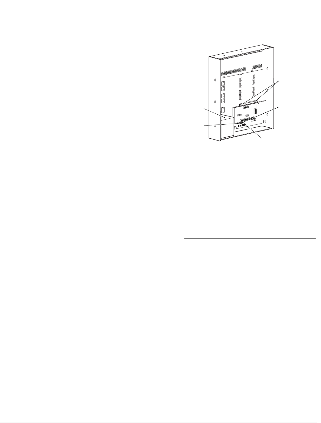
Mounting the AVS Base Unit
As shipped, the AVS Base unit board comes pre-mounted
on its mounting bracket, which is designed to mount
inside the control cabinet.
Refer to the diagram at right.
a. Position the mounting plate/PC board assembly in the
bottom of the control’s cabinet.
b. Slide the mounting plate to the right so that the
plate’s left-hand tang slides under the cabinet’s tie-
wrap loop.
c. Secure the assembly to the cabinet using the two self-
tapping screws provided.
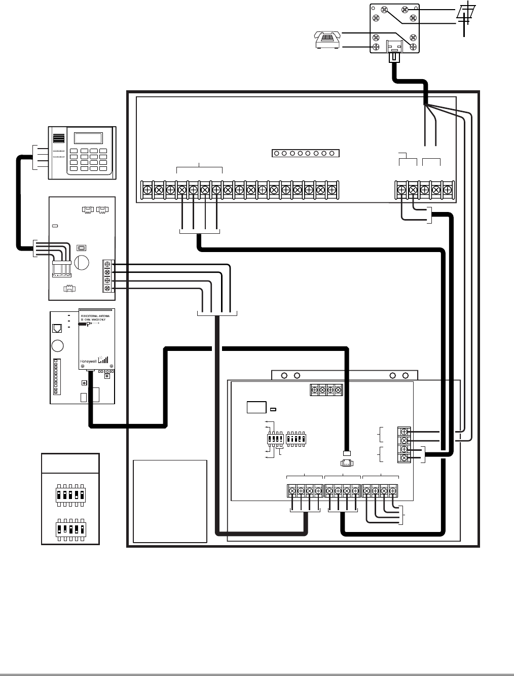
Wiring the AVS to the Control
The AVS Base unit board has several terminal blocks for
making connections to remote stations, telephone lines,
and to the control panel. The AVS base unit connects to the
control’s ECP terminals, with all other ECP devices connecting to
the AVS base unit ECP terminals. See the diagram on the
next page for specific wiring connections.
Connecting an Optional GSMV Module
a. If using a GSMV module for 2-way voice operation,
install the module according to its instructions.
NOTE: The module must be mounted within three
feet of the control.
b. Connect the audio cable from the GSMV module to the
Audio connector on the AVS board. The audio cable is
supplied with the GSMV module.
c. Complete all other GSMV wiring following the
instructions included with that module.
The following summarizes the programming steps for AVS
operation (refer to the Programming Guide for details of
the AVS Quick Command options):
a. Install the AVS module according to its instructions.
b. Use one of the control’s AVS Quick Program
commands as follows :
• installer code + [#] + 03: enable AVS operation
without panel sounds on the AVST
• installer code + [#] + 04: enable AVS operation
and enable panel sounds on the AVST speaker
c. Use data field ∗55 Dynamic Signaling Priority to
select the desired reporting paths.
Notes
AVS-003-V0
SYSTEM
BATTERY
235
1
ON
4
23
1
ON
4
TANG
BENEATH
MOUNTING
PLATE
SECURE
WITH TWO (2)
SELF-TAP SCREWS
(SUPPLIED)
SLIDE ASSEMBLY TO RIGHT UNTIL
TANG SLIPS UNDER CABINET LOOP
CABINET
TIE-WRAP
LOOP
BATTERY NOTE: When using a 7AH battery,
mount the battery vertically on the bottom left-
hand side of the cabinet, with the terminals facing
down and right (negative terminal closest to the
PC board bracket).
IMPORTANT: The AVS should be the only
ECP device connected to the control’s ECP
terminals. Connect all other ECP devices
(keypads, expander modules, etc.) to the ECP
terminals on the AVS board.
Installation and Setup Guide
2-14
FIRST ALERT PROFESSIONAL RESIDENTIAL CONTROL
BATTERY
HANDSET
(EARTH GND
(RING)
(TIP)
GRY
BRN
GRN
RED
INCOMING
PHONE LINE
(RING)
(TIP)
DIRECT
CONNECT
CORD
ECP TERMINALS
AVS-FA-001-V0
AVS BASE UNIT
KEYPAD
BLK
GRN
YEL
RED
MIC
SPEAKERS
DATA
AUDIO
GND
+VDC
YEL
GRN
BLK
RED
AAV
AVST STATION
BRN
GRY
RING
TIP
RING
TIP
(200 FT. MAX)
HANDSET
INCOMING
PHONE LINE
SUPPLIED HARNESS
AUDIO CABLE
DATA
IN DATA
OUT
PREMISES
PHONES
INCOMING
TELCO
RING
TIP
RING
TIP
KEYPAD
78
123456
TRIGGER HEADER
RJ31X
12 3
4
5
67
8
RED BLK GRN YELRED BLK GRN YELRED BLK GRN YEL
PANEL ECP
PHONE
AAV
TO ALL
OTHER ECP
DEVICES
LED
VOLUME / ID
BUTTON
LED
NORMAL MODE
PROGRAM MODE
CALLBACK MODE
PANEL TRIGGER
MODE
GND AUX
AUDIO CONNECTOR
IMPORTANT:
DO NOT CONNECT ANY OTHER
ECP DEVICES TO PANEL.
USE AVS BASE UNIT ECP
TERMINALS FOR OTHER ECP DEVICES.
NOT
USED
DIP SW
DEVICE ADDRESS
(ADDRESS 8
SHOWN)
TB 1
6
7
8
5
11
10
9
2
3
4
1
GSM
GPPS
WEB
MODE 2
MODE 1
RSSI
GSMV
(OPTIONAL)
FA168CPS = 11
BASE UNIT
DEVICE ADDRESS
FA148CP = 8
2341
ON
23 541
ON
23 541
ON
23 541
ON
Figure 18. Connections for the AVS System
2-15

Installation and Setup Guide
2-16

SECTION 3
System Communication and Operation
•••••••••••••••••••••••••••••••••••••••
Panel Communication with Central Station
This system accommodates several formats for reporting alarms and other system conditions to the
Central Station. The process of a successful transmission consists of both the method of communication
between the control panel and the Central Station receiver; and the actual way the information is sent
and displayed at the Central Station.
When the panel calls the Central Station receiver, it waits to hear a “handshake” frequency from the
receiver to confirm that the receiver is on-line and ready to receive its message. Once the panel hears
the handshake it is programmed to listen for, it sends its message. The panel then waits for a “kissoff”
frequency from the receiver acknowledging that the message was received and understood.
If the handshake frequency is not given or is not understood by the panel, the panel will not send its
message. Once the handshake frequency is received and understood by the panel, the panel sends its
message. If there is an error in the transmission (the receiver does not receive a “valid” message), the
kissoff frequency is not given by the Central Station receiver.
The panel makes a total of eight attempts to the primary telephone number and eight attempts to the
secondary telephone number (if programmed) to get a valid message through. If the panel is not
successful after its numerous attempts, the keypad displays COMM. FAILURE (on alpha keypads) or
FC (on fixed-word keypads).
Report Code Formats
The following chart indicates the types of (handshake/kissoff) frequencies that the panel supports and
the different formats that can be sent with each.
FORMAT HANDSHAKE TRANSMITS DATA KISSOFF TRANSMIT TIME
Low Speed 1400 Hz 1900Hz (10PPS) 1400 Hz Under 15 secs
3+1, 4+1, 4+2
(Standard report)
Sescoa/Rad 2300 Hz 1800Hz (20PPS) 2300 Hz Under 10 secs
3+1, 4+1, 4+2
(Standard report)
Express 1400–2300 Hz DTMF (10 cps) 1400 Hz Under 3 secs
4+2
Contact ID 1400–2300 Hz DTMF (10 cps) 1400 Hz Under 3 secs
The following table describes each format in greater detail.
FORMAT TYPE DESCRIPTION
3+1 and 4+1
Standard Formats Comprises a 3- (or 4-) digit subscriber number and a single-digit report
code (e.g., Alarm, Trouble, Restore, Open, Close, etc).
3+1 and 4+1
Expanded Formats Comprises a 3- (or 4-) digit subscriber number and a two-digit report code.
The first digit is displayed on the first line. On the second line, it is
repeated 3 (or 4) times and is followed by the second digit. This is the
“expanded” digit.
4+2 Format Comprises a 4-digit subscriber number and 2-digit report code.
ADEMCO Contact ID
Reporting Format Comprises a 4- or 10-digit subscriber number (depending on format
selected), 1-digit event qualifier (“new” or “restore”), 3-digit event code,
and 3-digit zone number, user number, or system status number (see the
following page).
3-1

The following table lists codes for reports sent in different formats:
Code for Code for
Type of 3+1/4+1 3+1/4+1 Code for
Report Standard Expanded 4+2
Alarm SSS(S) A SSS(S) A SSSS AZ
AAA(A) Z
Trouble SSS(S) T SSS(S) T SSSS Tt
TTT(T) t
Bypass SSS(S) B SSS(S) B SSSS Bb
BBB(B) b
AC Loss SSS(S) E SSS(S) E SSSS EAC
EEE(E) AC
Low Batt SSS(S) L SSS(S) L SSSS LLB
LLL(L) LB
Open SSS(S) O SSS(S) O SSSS OU
OOO(O) U
Close SSS(S) C SSS(S) C SSSS CU
CCC(C) U
Test SSS(S) G SSS(S) G SSSS Gg
GGG(G)g
Restore SSS(S) R SSS(S) R SSSS RZ
Alarm RRR(R) Z
AC Restore SSS(S) RA SSS(S) RA SSSSRA Ac
R
ARARA(RA)Ac
LoBat Res. SSS(S) RL SSS(S) RL SSSS RLLB
R
LRLRL(RL)LB
Trouble Res. SSS(S) RT SSS(S) RT SSSS RTt
R
TRTRT (RT)t
Bypass Res. SSS(S) RB SSS(S) RB SSSS RBb
R
BRBRB (RB)b
Where:
SSS or SSSS = Subscriber ID C = Close Code–1st Digit
A = Alarm Code–1st digit U = User Number (in hex)
Z = Typically Zone Number*–2nd digit Gg = Test Code (1st & 2nd digits)
Tt = Trouble Code (1st & 2nd digits) R = Restore Code (Alarm)
Bb = Bypass Code (1st & 2nd digits) RTt = Restore Code (Trbl) 1st & 2nd digits
EAC = AC Loss Code (1st & 2nd digits) RBb = Restore Code (Byps) 1st & 2nd digits
LLB = Low Battery Code (1st & 2nd digits) RAAC = Restore Code (AC) 1st & 2nd digits
O = Open Code–1st Digit RLLB = Restore Code (Bat) 1st & 2nd digits
*Zone numbers for: ✱ & #, or B = 99 1 + ✱, or A = 95 Duress = 92
3 + #, or C = 96
Ademco Contact ID®
The Ademco Contact ID® Reporting Format comprises the following:
4-digit or 10-digit (depending on format selected) subscriber number.
1-digit event qualifier (“new” or “restore”).
3-digit event code.
2-digit Partition No.
3-digit zone number, user number, or system status number (see the following page).
Installation and Setup Guide
3-2

Ademco Contact ID® Reporting takes the following format: CCCC(CCCCCC) Q EEE GG ZZZ
where:
CCCC(CCCCCC) = Customer (subscriber) ID (4 or 10 digits depending on format selected)
Q = Event qualifier, where: E = new event, and R = restore
EEE = Event code (3 hexadecimal digits)
Note:For a complete list of event codes, refer to the central office receiver
manual.
GG = Partition Number (system messages show “00”)
ZZZ = Zone/contact ID number reporting the alarm, or user number for open/close
reports. System status messages (AC Loss, Walk Test, etc.) contain zeroes in the
ZZZ location.
TABLE OF CONTACT ID EVENT CODES
(Some event codes may not apply to certain control panels)
Code Definition
110 Fire Alarm
121 Duress
122 Alarm, 24-hour Silent
123 Alarm, 24-hour Audible
131 Alarm, Perimeter
132 Alarm, Interior
134 Alarm, Entry/Exit
135 Alarm, Day/Night
137 Alarm, Tamper
143 Alarm, Expansion Module
145 ECP Module cover tamper
146 Silent Burglary
150 Alarm, 24-Hour Auxiliary/Monitor zone
162 Carbon Monoxide
301 AC Power
302 Low System Battery/Battery Test Fail
305 System Reset (Log only)
321 Bell/Siren Trouble
333 Trouble, Expansion Mod. Supervision
341 Trouble, ECP Cover Tamper
344 RF Receiver Jam
351 Telco Line Fault
353 Long Range Radio Trouble
373 Fire Loop Trouble
374 Exit Error Alarm
380 Global Trouble, Trouble Day/Night
Code Definition
381 RF Sensor Supervision Trouble
382 Supervision Auxiliary Wire Zone
383 RF Sensor Tamper
384 RF Sensor Low-battery
393 Clean Me
401 Disarmed, Armed AWAY, Armed
MAXIMUM
403 Schedule Arm/Disarm AWAY
406 Cancel by User
407 Remote Arm/Disarm (Downloading)
408 Quick Arm AWAY
409 Keyswitch Arm/Disarm AWAY
441 Disarmed/Armed STAY/INSTANT,
Quick-Arm STAY/INSTANT
442 Keyswitch Arm/Disarm STAY
459 Recent Closing
570 Bypass
601 Manually Triggered Dialer Test
602 Periodic Test
606 AAV to Follow
607 Walk Test Entered/Exited
623 Event Log 80% Full
625 Real-Time Clock was Changed (log only)
627 Program Mode Entry (log only)
628 Program Mode Exit (log only)
642 Latch Key (log only)
750 -
789 Reserved for Configurable Zone Type
report codes (check with central station
when using these codes)
3-3

Uploading/Downloading via the Internet
UL: Up/downloading via the Internet has not been evaluated by UL.
This control, when used with a compatible Internet/Intranet Communication Device, supports
upload/download programming capability via the Internet using the AlarmNet network or, depending
on the communication module used, a Private local area network (Intranet). This allows site
maintenance independent of central station monitoring, and modification to sites globally via the
Internet. Depending on the module used, Internet connection from the protected premises is either
via high speed (broadband) cable or phone service, or via the GSM/GPRS digital cellular network
(GSM modules).
Refer to the instructions provided with the communication module for information regarding its
installation, programming, and registration. The System Requirements table below lists two sets of
system requirements, depending upon whether you intend to communicate over the Internet or
whether you are communicating over a Private LAN (Intranet).
Compatible Communication Modules: The following modules support Internet
uploading/downloading, but future modules may also provide Internet upload/download support; refer
to the module’s instructions for compatibility. Compatible Modules: 7845i-ent, 7845i-GSM, 7845GSM
System Requirements
Internet Communication
At the Installation Site:
• Appropriate Internet Communication Module
• 7720P Programmer
• Broadband Internet Access (for wired modules)
• Broadband (Cable/DSL) Modem (for wired modules)
• Broadband (Cable/DSL) Router (for wired modules if
connecting more than one device to the Internet)
• IP compatible Control Panel
At the Downloading Office:
• Broadband Internet Access
• Broadband (Cable/DSL) Modem
• Broadband (Cable/DSL) Router (optional, if
connecting more than one device to the Internet)
• Computer running Compass Downloading Software
version that supports Internet upload/download for
this control.
Intranet (Private LAN) Communication, if applicable*
At the Installation Site:
• Internet/Intranet Communication Module
• 7720P Programmer
• Ethernet Network Connection
• IP compatible Control Panel
At the Downloading Office:
• 7810iR-ent IP Receiver
• Internal Router
• Computer(s) running the following software:
- Compass Downloading Software version that
supports IP upload/download for this control.
- Compass Connect Data Server Application
- Compass Connect Control Server Application
* see module’s instructions for applicability for LAN
usage (ex. 7845i-ent supports LAN)
NOTE: Compass, the Compass Connect Data Server, and the
Compass Connect Control Server applications may all be
installed on the same computer if desired. If they are installed
on one computer, the computer must have a fixed IP Address.
To set up the control panel, do the following:
1. Connect the module to the control panel’s ECP (keypad) terminals.
2. Internet Users: For wired modules, connect the module to the Internet via a cable/DSL modem and
router.
Intranet Users: Connect the module to the Intranet (LAN) via the appropriate Ethernet connection.
3. Enable the module as a Long Range Radio in the control panel (programming field *29) to enable
alarm reporting and module supervision.
4. Set the module for address 3.
5. Program the module as required using the module’s programming methods (ex. 7720P programmer).
6. Register the module with AlarmNet. The module must be registered before downloading or alarm
reporting can take place.
To perform upload/download functions:
1. Connect the computer to the Internet and start the Compass downloading software.
2. Open the control’s account, then select the Communications function and click the Connect button.
3. At the Connect screen, check that the control’s MAC address is entered and the TCP/IP checkbox is
checked.
4. Click Connect. The Internet connection to the control is made automatically via AlarmNet.
5. Once connected, use Compass downloading software to perform upload/download functions.
Installation and Setup Guide
3-4

Security Codes
The FA168CPS system supports up to 48 security codes (FA148CP supports 32 codes), which can
each be assigned one of 5 authority levels. The authority level determines the functions each code can
perform as follows:
Authority Levels (authority levels can be assigned to users 3-49 only; users 1 and 2 cannot be changed)
Level User No. Functions
Installer 01 (default=4112) perform all security functions except can disarm only if
used to arm; can enter program mode; can change System Master code;
cannot assign any other user codes
System 02 (default 1234) only one system master code per system; can perform all
Master security functions, add/delete users in either partition, change system
master code, view event log, set system clock, program keypad macro,
program scheduled events, activate output devices (triggers/relays)
Partition P1 = 03 FA168CPS. Same as Master, except add/delete users limited to
Master P2 = 33 assigned partition only, (these users can be assigned different authority
(default) levels; any user can be assigned the partition master authority level)
0-User 03-49† perform security functions (arm, disarm, etc.) only; cannot add/delete
03-33†† users, view event log, set system clock or program scheduled events
1-Arm Only see “user” arm system only
2-Guest see “user” can disarm the system only if it was used to arm the system
3-Duress see “user” performs security functions, but also silently sends a duress message to the
central station; reports as duress code user number.
4-Partition see “user” FA168CPS. See Partition Master paragraph above; used to assign
Master other user numbers as partition masters
† FA168CPS; †† FA148CP
Refer to the user guide for detailed procedures on adding/deleting security codes and changing user
attributes.
The following is a brief description of how to add user codes.
Changing the System Master code...
• Using Installer code: Installer code + [8] + 02 + new code
• Using current System Master code: System Master code + [8] + 02 + new code + new code again
Adding a User Code: Master code + [8] + 2-digit user no. + user’s code
Deleting a User Code: Master code + [8] + 2-digit user no. + [#] [0]
Assigning Attributes: Master code + [8] + 2-digit user no. + [#] [attribute no.] + value
Attributes: Values
1 = Authority Level 0-4 (see Authority Level table above)
2 = Access Group 0-8 (0 = not assigned to a group)
3 = Active Partition(s) 1, 2, 3 (common)
for this user; Enter partitions consecutively if more than one
and press [#] to end the entries.
4 = RF Zone No. Assigns user number to button type zone for
arm/disarm (keyfob must be enrolled in
system first; see Wireless Key Templates
section).
5 = Open/Close Paging 1 for yes, 0 for no
3-5

Keypad Functions
The following is a brief list of system commands. For detailed information concerning system
functions, refer to the User's Manual. For AUI users, refer to the separate AUI User’s Guide.
Voice Keypads
The FA560VKP Voice Keypad provides the following features:
• Message Center, which lets the user record and playback one message.
• Voice Status, which can announce system status by using the STATUS key.
• Voice Chime, which can alert users to the opening of doors/windows while the system is disarmed.
Refer to the User Guide for specific procedures for activating and using these features.
Keypad Commands
Function Description
Silence Burglary
Alarms Pressing any key will silence the keypad sounder for 10 seconds. Disarming the
system (security code + OFF) silences both keypad and external sounders.
Silence Fire or
Carbon Monoxide
Alarms
Press the OFF [1] key to silence the keypad sounder and, for fire alarms, the
external sounder. The detector sounding stops when the contaminated air is
cleared from the detector; see the detector’s instructions for further information.
Quick Arm If enabled (field ∗21), you can press [#] in place of the system's security code, plus
the desired arming key (Away, Stay, Instant, Maximum)
Single-Button
arming If programmed (*57 Function Key menu mode), lettered keys A-D can be used for
arming, using options 3-AWAY, 4-STAY, 5-NIGHT-STAY, or 6-Step-Arming
If used, no security code is required to arm the system.
Alarm Memory When the system is disarmed, any zones that were in an alarm condition during
the armed period will be displayed. To clear this display, simply repeat the disarm
sequence (enter the security code and press the OFF key) again.
Arming Away Enter code + AWAY [2] or simply press appropriate lettered key on the keypads
(see “Single-Button Arming” above). If the “Auto-Stay Arm” feature is enabled
(field *84) and the entry/exit door is not opened and closed within the
programmed exit delay time, the system will automatically arm in STAY mode if
armed from a wired keypad (non-RF device). If the door is opened and closed
within the exit delay period, the system arms in AWAY mode.
Arming Stay Enter code + STAY [3] or simply press appropriate key on the keypads (see
“Single-Button Arming” above). See “Arming Away” above for Auto-Stay arming
feature.
Arming Night-Stay Enter code + STAY [3] + STAY [3] or simply press appropriate key on the keypads
(see “Single-Button Arming” above).
Arming Instant Enter code + INSTANT [7].
Arming Maximum Enter code + MAXIMUM [4] or simply press appropriate lettered key on the
keypads (see “Single-Button Arming” above).
Disarming Enter code + OFF [1]. If entry delay or an alarm is active, you do not need to press
OFF.
Bypassing Zones Enter code + BYPASS [6] + zone number(s).
Forced (Quick)
Bypass To automatically bypass all faulted zones, use the “Quick Bypass” method. Enter
code + BYPASS + [#], then wait for all open zones to be displayed. Arm when
display indicates “ZONE BYPASSED” and “READY TO ARM”.
Chime Mode Enter code + CHIME [9]. To turn chime off, enter code + CHIME again.
Activate Output
Devices If relay outputs (via a 4204, or 4229), or Powerline Carrier devices are used, two
keypad entries available to the user are included. If programmed, these entries
can be used to manually activate or deactivate the device(s) for starting or
stopping some action, such as turning lights on or off, etc. These keypad entries
are:
[Security Code] + # + 7 + [2-digit Device #] activates (starts) that device.
[Security Code] + # + 8 + [2-digit Device #] deactivates (stops) that device.
Installation and Setup Guide
3-6
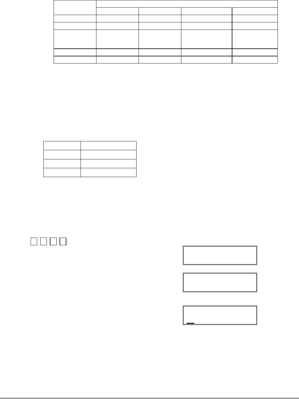
SUMMARY OF ARMING MODES
Features for Each Arming Mode
Arming Mode Exit Delay Entry Delay Perimeter Armed Interior Armed
AWAY Yes Yes Yes Yes
STAY Yes Yes Yes No
NIGHT-STAY Yes Yes Yes only those zones
listed in Night-
Stay zone list
INSTANT Yes No Yes No
MAXIMUM Yes No Yes Yes
Panic Keys
There are three Panic keys (A, B, and C) that, if programmed, can be used to manually initiate
alarms and send a report to the central station.
Each key can be programmed for 24-hour Silent, 24-hour Audible, Fire, or Personal Emergency
responses.
The programmed Panic response is activated when the appropriate key is pressed for at least 2
seconds.
The Panic keys are identified by the system as follows:
Keys Displayed as Zone
[A] (∗/1) 95
[B] (∗/#) 99
[C] (3/#) 96
IMPORTANT: For a Silent panic function (if programmed) to be of practical value, you must
program a report code for the zone and the system must be connected to a central station.
Setting the Real-Time Clock
IMPORTANT: The Real-Time Clock must be set before the end of the installation.
NOTE: All partitions must be disarmed before time/date can be set.
Set the time and date by doing the following:
1. +[#] + [6] [3]
(Master Code)
Alpha Display:
DISARMED
READY TO ARM
2. Press [∗] when the time/date is displayed.
A cursor appears under the first digit of the hour.
To move cursor ahead, press [
∗
]. To go back, press [#].
• Enter the 2-digit hour setting.
• Enter the 2-digit minute setting.
• Press [1] for PM or [2] for AM.
• Enter the last two digits of the current year.
• Enter the 2-digit month setting.
• Enter the 2-digit day setting.
3. To exit, press [∗] when cursor is at the last digit, or
wait 30 seconds.
TIME/DATE SAT
04:04PM 10/17/00
Current time display
TIME/DATE SAT
04:04P2000/10/17
Time/date editing display
3-7

Various System Trouble Displays
Alpha Display Fixed Disp. Meaning
ALARM CANCELED CA will appear if an exit or interior zone contained a fault during closing at the time
the Exit Delay ended (e.g., exit door left open), but the system was disarmed
during the Entry Delay time. The alarm sounder and keypad sound continuously,
but stop when the system is disarmed. No message will be transmitted to the
central station.
EXIT ALARM EA will appear when the Exit Delay ends if an exit or interior zone contained a fault
during closing. The alarm sounder and keypad sound continuously until the
system is disarmed (or timeout occurs). An “Exit Alarm” message is sent to the
central station. Also results if an alarm from an exit or interior zone occurs
within 2 minutes after the end of an Exit Delay.
CHECK CHECK indicates that a problem exists with the displayed zone(s) and requires attention.
ALARM 1xx 1xx indicates that communication between control and a zone expander or wireless
FAULT 1xx 1xx receiver is interrupted, where “xx” is the device address. Check the wiring and
CHECK 1xx 1xx DIP switch settings on the units.
91 If field *199 is set to “1,” all ECP module problems are displayed as “91.”
If there are wireless sensors in the system, the Check condition may also be
caused by some change in the environment that prevents the receiver from
receiving signals from a particular sensor.
SYSTEM LO BAT BAT with no zone number indicates that the system's main standby battery is weak.
LO BAT BAT with a zone number and a once-per-minute beeping at the keypad indicates that a
low-battery condition exists in the wireless sensor displayed (zone “00” indicates a
wireless keypad). If the battery is not replaced within 30 days, a “CHECK”
display may occur.
NOTE: Some wireless sensors contain a non-replaceable long-life battery which
requires replacement of the entire unit at the end of battery life (e.g., Nos. 5802,
5802CP).
TELCO FAULT 94 Telephone Line Failure, indicates that a monitored telephone line (if programmed
in field *92) has been cut or disconnected. Depending on how the system was
programmed, the keypad may also produce a trouble sound, and the external
sounder may be activated. Silence by entering installer code + OFF.
Busy-Standby dl If this remains displayed for more than 1 minute, the system is disabled.
Modem Comm CC The system is in communication with the central station for change of function or
status verification.
no display no display Power Failure
If there is no keypad display at all and the LEDs are unlit, operating power (AC
and battery) for the system has stopped and the system is inoperative.
If the message “AC LOSS” (Alpha display keypads) or “NO AC” (Fixed-Word
display keypads) is displayed, the keypad is operating on battery power only.
If the battery standby capacity is used up during a prolonged AC power outage,
the control's power will shut down to minimize deep discharge of the battery.
Comm. Failure FC A communication failure has occurred.
Open Circuit 0C The keypad is not receiving signals from the control and sees an open circuit.
Long Rng Trbl bF Backup LRR communication failure.
Bell Failure 70 Bell supervision failure.
RCVR Jam 90 RF jam detected.
KEYPAD LOW BAT 00 BAT Wireless keypad low battery
Phone Okay Cd The dialer test has been successful (CID code 601).
Dialer Off d0 The dialer is disabled.
Test in Progress dd Walk test mode is active(CID code 607).
Upload Completed dC The upload or download session was completed.
Upload Failed dF The upload or download session failed before completion.
Installation and Setup Guide
3-8

SECTION 4
Testing the System
•••••••••••••••••••••••••••••••••••••••
About Test Procedures
After the installation is complete, you should perform the following tests:
System Test: Checks that all zones have been installed properly and responds to faults.
Dialer Test: Checks that the phone connection to the central station is working properly.
Go/No Go Test: Checks that transmissions can be received from transmitters. Should be
performed before permanently mounting transmitters.
RF Sniffer Mode: Checks that RF transmitter serial numbers have been properly enrolled.
Battery Tests: Automatic battery tests are performed by the system.
System Test
NOTE: Test mode can be entered from any keypad. However, faulted zones appear only on those
keypads assigned to the partition to which the zone is assigned (i.e., partition 1 zones appear only on
part. 1 keypads, etc.). To see another partition’s faulted zones, view a keypad assigned to that partition
or use the GOTO command (code +[∗] + partition number 0-3, where 0 is the keypad’s home partition).
With the system in the disarmed state, check that all zones are intact (not faulted). Doors and
windows with contacts should be closed, PIRs should be covered (use a cloth to mask them
temporarily if necessary). If a “NOT READY” message is displayed, press [∗] to display the faulted
zone(s). Restore faulted zone(s) if necessary, so that the “READY” message is displayed.
1. Enter Installer Code + 5 [TEST] , then press “0” at the prompt to start Walk Test mode.
1=DIAL, 0=WALK (no special display on Fixed-Word keypads)
The following will be displayed on the initiating keypad and a Contact ID report is sent (code 607):
TEST IN PROGRESS (“dd” displayed on Fixed-Word Display Keypads)
2. Upon entering the system test mode, the outside sounder should sound for 1 second.
If the backup battery is discharged or missing, the sounder may not turn on and a “LOW
BATTERY” report will be transmitted with a “TEST” report.
The keypad will beep about every 30 seconds as a reminder that the system is in the Test mode.
NOTE: Wireless motion detectors (Passive Infrared units) will send signals out only if they have
been inactive for 3 minutes (conserves battery life).
3. Test all sensors using the procedure described in the User’s Guide “Testing the System” section.
4. After checking sensors, turn off the test mode by entering installer code + OFF.
NOTE: Test mode automatically ends after 4 hours. During the final 5 minutes (after 3 hours 55
minutes of Test mode), the keypad emits a double-beep every 30 seconds to alert that the end of
Test mode is nearing.
Checking Transmitter Enrollment (Sniffer Mode)
Use this mode to verify that all transmitters have been properly programmed. Make sure both
partitions are disarmed before trying to enter this mode, since this is a system-wide command.
1. From a keypad in partition 1, press [Installer code] + [#] + 3.
Note: If the communicator is in the process of sending a report to the central station, the system
will not go into the Sniffer mode. If so, wait a few minutes, and try again.
The keypads in both partitions will display all zone numbers of wireless units (in both partitions)
programmed into the system. Fault each transmitter in turn, causing each one to send a signal.
As the system receives a signal from each of the transmitters, the zone number of that
transmitter disappears from the display.
2. After all transmitters have been checked, exit the sniffer mode by keying [Installer code] + OFF.
4-1

IMPORTANT: Sniffer mode does not automatically expire. You must manually exit Sniffer mode (by
entering [Installer code] + OFF) to return to normal operation.
Notes: • All BR type units must physically be activated to clear the display.
• When one button of a transmitter (RF, UR, or BR) is activated, all zones assigned to
other buttons on that transmitter are cleared. This also applies to 5816 and 5817
transmitters, which have multiple loops (zones).
• Any transmitter that is not “enrolled” will not turn off its zone number.
Go/No Go Test Mode
The Go/No Go Test verifies adequate RF signal strength from the proposed transmitter location, and
allow you to reorient or relocate transmitters if necessary, before mounting the transmitters
permanently. This mode is similar to the Transmitter Test mode, except that the wireless receiver
gain is reduced. This will enable you to make sure that the RF signal from each transmitter is
received with sufficient signal amplitude when the system is in the normal operating mode.
1. Enter [Installer code] + [#] + 4 from the partition being tested. For multi-partition systems, repeat
this test for each partition.
2. After you have placed transmitters in their desired locations and the approximate length of wire to
be run to sensors is connected to the transmitter's screw terminals (if used), fault each transmitter.
Do not conduct this test with your hand wrapped around the transmitter, as this can cause
inaccurate results.
a. The keypad beeps three times to indicate signal reception and displays the zone number.
b. If the keypad does not beep, you should reorient or move the transmitter to another location.
Usually a few inches in either direction is all that is required.
4. If each transmitter produces the proper keypad response when it is faulted, you can then
permanently mount each of the transmitters according to the instructions provided with them.
5. Exit the Go/No Go Test mode by entering: [any user code (partition-specific)] + OFF.
Dialer Communication Test and Periodic Test Reports
1. Enter Installer Code + 5 [TEST], then press “1” at the prompt to start the Dialer Test (checks
phone line integrity only; does not confirm report transmissions).
1=DIAL, 0=WALK (no special display on Fixed-Word keypads)
The following will be displayed (accompanied by 2 beeps) if test is successful:
PHONE OKAY (“Cd” displayed on Fixed-Word Display Keypads)
A Contact ID report will also be sent (code 601)
COMM FAILURE If the dialer test is unsuccessful, this prompt is displayed.
(“FC” displayed on Fixed-Word Display Keypads)
2. Enter Installer code + OFF to clear the display and exit.
Automatic Periodic Test Report
The system can be set to automatically send test reports (enabled in field *64; Contact ID code 602) at
specified intervals. Frequency of the reports is set in Scheduling mode (event 11) or by the following
key commands: installer code + [#] + 0 + 0 = test report sent every 24 hours
installer code + [#] + 0 + 1 = test report sent once per week
installer code + [#] + 0 + 2 = test report sent every 28 days
Each mode sets schedule 32 (FA168CPS) or schedule 08 (FA148CP) to the selected repeat option; first
test report sent 12 hours after command. To ensure that test reports are sent at the times expected, set
the Real-Time Clock to the proper time before entering the test report schedule command.
Automatic Standby Battery Tests
1. An automatic test is conducted every 3 minutes to ensure that a standby battery is present and
properly connected. If a battery is not present or is not properly connected, a “LOW BATTERY”
message is displayed and, if so programmed, will be reported to the central station.
2. A battery capacity test is automatically conducted for 2 minutes every 4 hours, beginning 4 hours
after exiting the Programming mode or after powering up the system. In addition, entry into the
Test mode will also cause a battery capacity test to be initiated. If the battery cannot sustain a load,
a “Low Battery” message is displayed and, if so programmed, will be reported to the central station.
Installation and Setup Guide
4-2

SECTION 5
Specifications & Accessories
•••••••••••••••••••••••••••••••••••••••
SECURITY CONTROL
1. Physical: 12-1/2” W x 14-1/2” H x 3” D (318mm x 368mm x 76mm)
2. Electrical:
VOLTAGE INPUT: 16.5VAC from plug-in 25VA transformer, Ademco No. 1321 (in U.S.A.)
RECHARGEABLE BACKUP BATTERY: 12VDC, 4AH (sealed lead acid type). Charging
Voltage: 13.8VDC.
ALARM SOUNDER: 12V, 2.0 Amp output can drive 12V BELLS or can drive one or two 702
(series connected) self-contained 20-watt sirens. Do not connect two 702s in parallel.
AUXILIARY POWER OUTPUT: 12VDC, 600mA max.
Note: For UL installations, Alarm Sounder plus Auxiliary Power currents should not exceed
600mA total.
FUSE: Battery (3A) No. 90–12
3. Communication:
FORMAT SUPPORTED:
ADEMCO Express: 10 characters/sec, DTMF (TouchTone) Data Tones,
1400/2300Hz ACK, 1400Hz KISSOFF.
ADEMCO Low Speed: 10 pulses/sec, 1900Hz Data Tone, 1400Hz ACK/KISSOFF.
Radionics/SESCOA: 20 pulses/sec, 1800Hz Data Tone, 2300Hz ACK/KISSOFF.
Can report 0-9, B-F
Ademco Contact ID 10 characters/sec., DTMF (TouchTone) Data Tones,
1400/2300Hz ACK, 1400Hz KISSOFF.
LINE SEIZE: Double Pole
RINGER EQUIVALENCE: 0.1B
FCC REGISTRATION No.: 5GBUSA-44003-AL-E
4. Maximum Zone Resistance: Zones 1–8 = 300 ohms excluding EOLR standard zones
COMPATIBLE DEVICES
Keypads: FA215KP and FA260KP Fixed-Word Keypads, FA560KP Alpha Keypad,
FA560VKP Voice Keypad, FA700KP Touch Screen Keypad,
Symphony Advanced User Interface
Wireless Receivers: 5881L/5882L: accepts up to 8 transmitters
5881M/5882M: accepts up to 16 transmitters
5881H/5882H: accepts up to system maximum transmitters
5800TM Transmitter Module (used with Wireless 2-Way Keypads)
5883 Transceiver: accepts up to system maximum transmitters
FA260RF Keypad/Transceiver: accepts up to system maximum transmitters
Zone Expansion: 4219 WIRED EXPANSION MODULE
4229 WIRED EXPANSION/RELAY MODULE
Relay Module: 4204 RELAY MODULE
Phone Modules: 4286 PHONE MODULE
Long Range Radio 7845GSM, 7845i-GSM
(Communication Device)
5-1

2-Wire Smoke Detector:
Detector Type System Sensor Model No.
Photoelectric w/heat sensor, direct wire 2300TB
Photoelectric, direct wire 2400
Photoelectric w/heat sensor, direct wire 2400TH
Photoelectric 2451 w/B401B base
Photoelectric w/heat sensor 2451TH w/B401B base
Ionization, direct wire 1400
Ionization 1451 w/B401B base
Photoelectric duct detector 2451 w/DH400 base
Ionization duct detector 1451D w/DH400 base H
Low-profile, Photoelectric, w/135°F thermal 2100T
Low-profile, Ionization type, direct wire 1100
Transformers: 1321: 16.5VAC, 25VA Plug-In Transformer (No. 1321CN in Canada)
1361X10: 16.5VAC, 40VA Powerline Carrier device Interface AC Transformer
Sounders: Ademco AB-12M 10” Motorized Bell & Box
1011BE12M 10” Motorized Bell & Box
702 Outdoor Siren
719 2-Channel Siren
713 High Power Speaker
746 Indoor Speaker
747 Indoor Siren
747PD Two-Tone Piezo Dynamic Indoor Siren
747UL Indoor Siren
748 Dual Tone Siren
749 Speaker/Horn
744 Siren Driver
745X3 Voice Siren Driver
705-820, 5-inch Round Speaker
713 Speaker
WAVE Speaker
WAVE2 Two-Tone Siren
WAVE2PD Two-Tone Piezo Dynamic Siren
5800WAVE Wireless Siren
System Sensor PA400B (beige)/; PA400R (red) Indoor Piezo Sounder
Installation and Setup Guide
5-2

SECTION 6
Regulatory Agency Statements
•••••••••••••••••••••••••••••••••••••••
“FEDERAL COMMUNICATIONS COMMISSION (FCC) Part 15 STATEMENT”
This equipment has been tested to FCC requirements and has been found acceptable for use. The FCC requires the following statement for your information:
This equipment generates and uses radio frequency energy and if not installed and used properly, that is, in strict accordance with the manufacturer’s
instructions, may cause interference to radio and television reception. It has been type tested and found to comply with the limits for a Class B computing
device in accordance with the specifications in Part 15 of FCC Rules, which are designed to provide reasonable protection against such interference in a
residential installation. However, there is no guarantee that interference will not occur in a particular installation. If this equipment does cause interference
to radio or television reception, which can be determined by turning the equipment off and on, the user is encouraged to try to correct the interference by one
or more of the following measures:
• If using an indoor antenna, have a quality outdoor antenna installed.
• Reorient the receiving antenna until interference is reduced or eliminated.
• Move the receiver away from the control/communicator.
• Move the antenna leads away from any wire runs to the control/communicator.
• Plug the control/communicator into a different outlet so that it and the receiver are on different branch circuits.
If necessary, the user should consult the dealer or an experienced radio/television technician for additional suggestions.
The user or installer may find the following booklet prepared by the Federal Communications Commission helpful: “Interference Handbook”
This booklet is available from the U.S. Government Printing Office, Washington, DC 20402.
The user shall not make any changes or modifications to the equipment unless authorized by the Installation Instructions or User’s Manual. Unauthorized
changes or modifications could void the user’s authority to operate the equipment.
TELEPHONE/MODEM INTERFACE
FCC Part 68
This equipment complies with Part 68 of the FCC rules. On the front cover of this equipment is a label that contains the FCC registration number and
Ringer Equivalence Number (REN). You must provide this information to the telephone company when requested.
This equipment uses the following USOC jack: RJ31X
This equipment may not be used on telephone-company-provided coin service. Connection to party lines is subject to state tariffs. This equipment is
hearing-aid compatible.
Industry Canada
NOTICE: The Industry Canada Label identifies certified equipment. This certification means that the equipment meets telecommunications network
protective, operational and safety requirements as prescribed in the appropriate Terminal Equipment Technical Requirements document(s). The
Department does not guarantee the equipment will operate to the user’s satisfaction.
Before installing this equipment, users should ensure that it is permissible to be connected to the facilities of the local telecommunications company. The
equipment must also be installed using an acceptable method of connection. The customer should be aware that compliance with the above conditions may
not prevent degradation of service in some situations.
Repairs to certified equipment should be coordinated by a representative designated by the supplier. Any repairs or alterations made by the user to this
equipment, or equipment malfunctions, may give the telecommunications company to request the user to disconnect the equipment.
Users should ensure for their own protection that the electrical ground connections of the power utility, telephone lines and internal metallic water pipe
system, if present, are connected together, This precaution may be particularly important in rural areas.
Caution: Users should not attempt to make such connections themselves but should contact appropriate electric inspection authority, or electrician, as
appropriate.
Ringer Equivalence Number Notice:
The Ringer Equivalence Number (REN) assigned to each terminal device provides an indication of the maximum number of terminals allowed to be
connected to a telephone interface. The termination on an interface may consist of any combination of devices subject only to the requirement that the sum
of the Ringer Equivalence Numbers of all the devices does not exceed 5.
Industrie Canada
AVIS: l’étiquette d’Industrie Canada identifie le matériel homologué. Cette étiquette certifie que le matériel est conforme aux normes de protection,
d’exploitation et de sécurité des réseaux de télécommunications, comme le prescrivent les documents concernant les exigences techniques relatives au
matériel terminal. Le Ministère n’assure toutefois pas que le matériel fonctionnera à la satisfaction de l’utilisateur.
Avant d’installer ce matériel, l’utilisateur doit s’assurer qu’il est permis de le raccorder aux installations de l’enterprise locale de télécommunication. Le
matériel doit également être installé en suivant une méthode acceptée da raccordement. L’abonné ne doit pas oublier qu’il est possible que la conformité aux
conditions énoncées ci-dessus n’empêche pas la dégradation du service dans certaines situations.
Les réparations de matériel nomologué doivent être coordonnées par un représentant désigné par le fournisseur. L’entreprise de télécommunications peut
demander à l’utilisateur da débrancher un appareil à la suite de réparations ou de modifications effectuées par l’utilisateur ou à cause de mauvais
fonctionnement.
Pour sa propre protection, l’utilisateur doit s’assurer que tous les fils de mise à la terre de la source d’energie électrique, de lignes téléphoniques et des
canalisations d’eau métalliques, s’il y en a, sont raccordés ensemble. Cette précaution est particulièrement importante dans les régions rurales.
Avertissement : L’utilisateur ne doit pas tenter de faire ces raccordements lui-même; il doit avoir racours à un service d’inspection des installations
électriques, ou à un électricien, selon le cas.
AVIS : L’indice d’équivalence de la sonnerie (IES) assigné à chaque dispositif terminal indique le nombre maximal de terminaux qui peuvent être
raccordés à une interface. La terminaison d’une interface téléphonique peut consister en une combinaison de quelques dispositifs, à la seule condition que la
somme d’indices d’équivalence de la sonnerie de tous les dispositifs n’excède pas 5.
6-1

UL NOTICES
1. Entry Delay No. 1 and No. 2 (fields ∗35, ∗36) cannot be greater than 30 seconds for UL Residential Burglar
Alarm installations, and entry delay plus dial delay should not exceed 1 minute. For UL Commercial Burglar
Alarm installations, total entry delay may not exceed 45 seconds.
2. For UL Commercial Burglar Alarm and UL Residential Burglar Alarm installations with line security, total
exit delay time must not exceed 60 seconds.
3. The maximum number of reports per armed period (field ∗93) must be set to “0” (unlimited) for UL
installations.
4. Periodic testing (see scheduling mode) must be at least every 24 hours.
5. Alarm Sounder plus Auxiliary Power currents must not exceed 600mA total for UL installations (Aux power
500mA max.).
6. All partitions must be owned and managed by the same person(s).
7. All partitions must be part of one building at one street address.
8. If used, the audible alarm device(s) must be placed where it/they can be heard by all partitions.
9. For UL commercial burglar alarm installations the control unit must be protected from unauthorized access.
The tamper switch installed to protect the control unit enclosure door is suitable for this purpose.
10. Remote downloading without an alarm company technician on-site (unattended downloading) is not
permissible for UL installations.
11. Auto-disarming is not a UL Listed feature.
12. As SIA limits for delay of alarm reporting and sounding can exceed UL limits for commercial and residential
applications, the following UL requirements per UL681 are provided:
The maximum time that a control unit shall be programmed to delay the transmission of a signal to a remote
monitoring location, or to delay the energizing of a local alarm sounding device to permit the alarm system
user to enter and disarm the system, or to arm the system and exit shall not exceed:
a) 60 seconds for a system with standard line security or encrypted line security,
b) 120 seconds for a system without standard line security or encrypted line security, or
c) 120 seconds for a system that does not transmit an alarm signal to a remote monitoring location.
13. This control is not intended for bank safe and vault applications.
SIA Quick Reference Guide
1. ∗31 Single Alarm Sounding per Zone: If “0” selected, “alarm sounding per zone” will be the same as the
“number of reports in armed period” set in field ∗93 (1 if one report, 2 if 2 reports, unlimited for zones in
zone list 7).
2. ∗34 Exit Delay: Minimum exit delay is 45 seconds.
3. ∗35/*36 Entry Delay 1 and 2: Minimum entry delay is 30 seconds.
4. ∗37 Audible Exit Warning: Feature always enabled; field does not exist.
5. ∗39 Power Up in Previous State: Must be “1,” power up in previous state.
6. ∗40 PABX Access Code or Call Waiting Disable: If call waiting is used, call waiting disable option in field
∗91 must be set.
7. ∗50 Burglary Dial Delay: Delay must be minimum of 30 seconds.
8. ∗59 Exit Error Alarm Report Code: Always enabled.
9 ∗68 Cancel Report Code: Default is “code enabled.”
10. ∗69 Recent Closing Report Code: Always enabled.
11. ∗91 Option Selection: Exit Delay option should be enabled. If call waiting is used, Call Waiting Disable must
be set to “1” (enabled).
12. ∗93 No. reports in Armed Period: Must be set for 1 or 2 report pairs.
13. Cross zone timer programming is set in field ∗85; cross zone pairs are assigned in zone list 4 using ∗81 Zone
List mode.
14. Duress code is assigned by using the “add a user code” procedure found in the User Guide. Enable Duress
code reporting by programming zone 92 using ∗56 Zone Programming mode.
15. Fire alarm verification is a built-in system feature when a zone is programmed for zone type 16.
Installation and Setup Guide
6-2

SECTION 7
Limitations and Warranty
•••••••••••••••••••••••••••••••••••••••
WARNING
THE LIMITATIONS OF THIS ALARM SYSTEM
While this System is an advanced design security system, it does not offer guaranteed protection against burglary, fire or other
emergency. Any alarm system, whether commercial or residential, is subject to compromise or failure to warn for a variety of
reasons. For example:
• Intruders may gain access through unprotected openings or have the technical sophistication to bypass an alarm sensor or
disconnect an alarm warning device.
• Intrusion detectors (e.g., passive infrared detectors), smoke detectors, and many other sensing devices will not work without
power. Battery-operated devices will not work without batteries, with dead batteries, or if the batteries are not put in
properly. Devices powered solely by AC will not work if their AC power supply is cut off for any reason, however briefly.
• Signals sent by wireless transmitters may be blocked or reflected by metal before they reach the alarm receiver. Even if the
signal path has been recently checked during a weekly test, blockage can occur if a metal object is moved into the path.
• A user may not be able to reach a panic or emergency button quickly enough.
• While smoke detectors have played a key role in reducing residential fire deaths in the United States, they may not activate
or provide early warning for a variety of reasons in as many as 35% of all fires, according to data published by the Federal
Emergency Management Agency. Some of the reasons smoke detectors used in conjunction with this System may not work
are as follows. Smoke detectors may have been improperly installed and positioned. Smoke detectors may not sense fires
that start where smoke cannot reach the detectors, such as in chimneys, in walls, or roofs, or on the other side of closed
doors. Smoke detectors also may not sense a fire on another level of a residence or building. A second floor detector, for
example, may not sense a first floor or basement fire. Finally, smoke detectors have sensing limitations. No smoke detector
can sense every kind of fire every time. In general, detectors may not always warn about fires caused by carelessness and
safety hazards like smoking in bed, violent explosions, escaping gas, improper storage of flammable materials, overloaded
electrical circuits, children playing with matches, or arson. Depending on the nature of the fire and/or location of the smoke
detectors, the detector, even if it operates as anticipated, may not provide sufficient warning to allow all occupants to escape
in time to prevent injury or death.
• Passive Infrared Motion Detectors can only detect intrusion within the designed ranges as diagrammed in their installation
manual. Passive Infrared Detectors do not provide volumetric area protection. They do create multiple beams of protection,
and intrusion can only be detected in unobstructed areas covered by those beams. They cannot detect motion or intrusion
that takes place behind walls, ceilings, floors, closed doors, glass partitions, glass doors, or windows. Mechanical tampering,
masking, painting or spraying of any material on the mirrors, windows or any part of the optical system can reduce their
detection ability. Passive Infrared Detectors sense changes in temperature; however, as the ambient temperature of the
protected area approaches the temperature range of 90° to 105°F (32° to 40°C), the detection performance can decrease.
• Alarm warning devices such as sirens, bells or horns may not alert people or wake up sleepers if they are located on the
other side of closed or partly open doors. If warning devices are located on a different level of the residence from the
bedrooms, then they are less likely to waken or alert people inside the bedrooms. Even persons who are awake may not hear
the warning if the alarm is muffled by noise from a stereo, radio, air conditioner or other appliance, or by passing traffic.
Finally, alarm warning devices, however loud, may not warn hearing-impaired people.
• Telephone lines needed to transmit alarm signals from a premises to a central monitoring station may be out of service or
temporarily out of service. Telephone lines are also subject to compromise by sophisticated intruders.
• Even if the system responds to the emergency as intended, however, occupants may have insufficient time to protect
themselves from the emergency situation. In the case of a monitored alarm system, authorities may not respond
appropriately.
• This equipment, like other electrical devices, is subject to component failure. Even though this equipment is designed to last
as long as 10 years, the electronic components could fail at any time.
The most common cause of an alarm system not functioning when an intrusion or fire occurs is inadequate maintenance. This
alarm system should be tested weekly to make sure all sensors and transmitters are working properly. The security keypad
(and remote keypad) should be tested as well.
Wireless transmitters (used in some systems) are designed to provide long battery life under normal operating conditions.
Longevity of batteries may be as much as 4 to 7 years, depending on the environment, usage, and the specific wireless device
being used. External factors such as humidity, high or low temperatures, as well as large swings in temperature, may all
reduce the actual battery life in a given installation. This wireless system, however, can identify a true low-battery situation,
thus allowing time to arrange a change of battery to maintain protection for that given point within the system.
Installing an alarm system may make the owner eligible for a lower insurance rate, but an alarm system is not a substitute for
insurance. Homeowners, property owners and renters should continue to act prudently in protecting themselves and continue
to insure their lives and property.
We continue to develop new and improved protection devices. Users of alarm systems owe it to themselves and their loved ones
to learn about these developments.
7-3

– INDEX –
1
1321.......................................... 1-2, 2-4
1321X10........... 1-2, 2-4, 2-12, 2-13, 5-2
1361 AC Transformer..................... 2-12
1361X10......................................... 2-12
2
2-Wire Smoke Detectors.................. 2-6
3
3+1 and 4+1 Standard Formats........ 3-1
4
4204............ 1-2, 2-5, 2-7, 2-11, 3-3, 5-1
4219............ 1-1, 1-2, 2-5, 2-7, 2-11, 5-1
4229..... 1-1, 1-2, 2-5, 2-7, 2-11, 3-3, 5-1
4286............................................... 2-15
4300................................................. 2-4
4-Wire Smoke Detectors.................. 2-7
5
5800 Series Transmitters ................. 2-9
5800TM.............................. 2-8, 2-9, 5-1
5801............................................... 2-10
5802........................................ 2-10, 3-5
5802CP................................... 2-10, 3-5
5827................................................. 2-9
5827BD..................................... 2-8, 2-9
5881................................... 1-2, 2-5, 2-8
7
7720PLUS or 7820........................... 1-2
9
9-pin connector .............................. 2-10
A
AAV Connections........................... 2-15
AC Power Supply............................. 1-2
AC Transformer ............... 2-4, 2-13, 5-2
AD12612.......................................... 2-3
Alarm Output............................. 1-2, 2-4
Arming Away.................................... 3-3
Arming Instant.................................. 3-3
Arming Modes.................................. 3-4
Arming Stay ..................................... 3-3
Audio Alarm Verification.......... 1-2, 2-14
Audio Alarm Verification (AAV) ...... 2-14
Authority Levels ............................... 3-2
B
Backup Battery................................. 1-2
Battery Life..................................... 2-10
Battery Tests............................. 4-1, 4-2
Bell Supervision ............................... 2-4
Bell Supervision Jumper .................. 2-4
Bypassing Zones ............................. 3-3
C
Cabinet ............................................ 2-1
CALIFORNIA STATE FIRE MARSHALL
.................................................... 2-5
Caller ID Unit.................................. 2-14
Charging Voltage ............................. 5-1
Chime Mode..................................... 3-3
Clean Me Option .............................. 2-6
Communication.................. 3-1, 4-2, 5-1
Contact ID Reporting........................ 5-1
CSFM............................................... 2-5
D
device address.......... 2-3, 2-7, 2-11, 3-5
DIP Switches.................................... 2-9
Disarming......................................... 3-3
Double-Balanced.............................. 2-6
E
Enrolling......................................... 2-10
Entry Delay ............................... 3-4, 3-5
EOLR........................................ 2-6, 5-1
Exit Delay.................................. 3-4, 3-5
Exit Error Alarm................................... 3
Exit Error Alarm................................ 3-5
Expander Module Addresses ........... 2-7
Expansion Zones ............. 1-2, 2-7, 2-11
F
FA148CP ......................................... 1-1
FA260KP ........................... 1-2, 2-3, 2-5
FA4286 ............................................ 2-5
FA560KP ........................... 1-2, 2-3, 2-5
Fast Busy Signal............................ 2-14
FCC ................................................. 6-1
Function Key Programming.............. 1-2
Fuse................................................. 5-1
G
Go/No Go Test Mode....................... 4-2
H
Handshake....................................... 3-1
hardwired zones............................... 1-1
HAYES Modem................................ 1-1
House ID.......................................... 2-9
I
Ideal Model 61–035.......................... 2-5
Installer Code............................ 4-1, 4-2
K
keypad addresses............................ 2-3
Keyswitch................................... 2-10, 3
Kissoff.............................................. 3-1
L
Lock................................................. 2-1
Long Range Radio ....... 1-2, 2-15, 3, 5-1
Low Battery Message....................... 4-2
M
model 112 ...................................... 2-10
Modem............................................. 3-5
momentary switch.......................... 2-10
N
Normally Closed Zones.................... 2-6
Normally Open Zones ...................... 2-6
O
on-board triggers............................ 2-15
On-Board Triggers.......................... 2-13
Output Devices................................. 3-3
Output relays.................................... 1-2
P
Panic Keys....................................... 3-4
Phone Line..................................... 2-14
Phone Module1-1, 1-2, 2-3, 2-5, 2-14, 2-
15, 5-1
Power Failure................................... 3-5
power supply............... 2-3, 2-4, 2-5, 7-3
Powerline Carrier Devices 1-2, 2-12, 3-3
R
Relay Module Addresses................ 2-11
Relay Modules ........................ 1-2, 2-11
Remote Keypads.............................. 1-2
Report Code..................................... 3-1
Report Code Formats....................... 3-1
response time .................................. 2-7
RF Interference ................................ 2-8
RF jam detection.............................. 1-1
RF Receiver..... 2-1, 2-2, 2-3, 2-5, 2-8, 3
RJ31X Jack.................................... 2-14
S
SA4120XM-1 Cable.......................... 2-4
Security Codes.......................... 1-1, 3-2
Silent Burglary..................................... 3
Silent Panic...................................... 3-4
Sniffer Mode..................................... 4-1
sounder connections ........................ 2-4
Supplementary Power...................... 2-3
System Communication ................... 3-1
System Test..................................... 4-1
T
tamper switch................................. 2-10
Telco Line .................................. 2-14, 3
Telephone Line Monitoring............... 1-1
Test Mode................................. 4-1, 4-2
Transmitter Battery Life.................. 2-10
Trouble Displays ....................... 3-4, 3-5
U
UL .................................... 2-4, 2-12, 5-1
V
Verify Operation ............................... 2-6
W
Wiring Length/Gauge Chart.............. 2-3
Wiring Run Chart.............................. 2-3
Worksheet........................................ 2-5
Z
Zone Doubling.................................. 2-6
Zone Types...................................... 2-6
Installation and Setup Guide
7-4
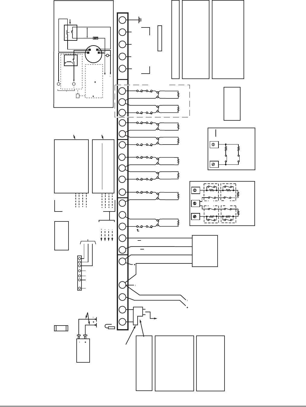
FA168CPS148CP-SOC-V6
FA168CPS / FA168CPSSIA / FA148CP / FA148CPSIA
SUMMARY OF CONNECTIONS
CLASS 2 PLUG-IN TRANSFORMER
16.5VAC, 25VA
(e.g. 1321).
(USE No. 1321CN IN CANADA)
TO 110VAC
UNSWITCHED
OUTLET (24HR)
THIS EQUIPMENT SHOULD BE INSTALLED
IN ACCORDANCE WITH THE NATIONAL
FIRE PROTECTION ASSOCIATION'S
STANDARD 72, CHAPTER 11 (NATIONAL
FIRE PROTECTION ASSOCIATION,
BATTERY-MARCH PARK, QUINCY, MA
02169).
PRINTED INFORMATION
DESCRIBING PROPER INSTALLATION,
OPERATION,TESTING, MAINTENANCE,
EVACUATION PLANNING AND REPAIR
SERVICE IS TO BE PROVIDED WITH THIS
EQUIPMENT.
24-HR BATTERY STANDBY REQUIRED FOR
FIRE INSTALLATIONS. USE 12V, 17.2AH
BATTERY FOR 600mA AUX POWER. SEE
INSTRUCTIONS.
BATTERY CAPACITY FOR EMERGENCY
BURGLARY STANDBY USE AT LEAST 4 HRS
USE UL LISTED LIMITED ENERGY
CABLE FOR ALL CONNECTIONS
USE 1361X10 TRANSFORMER
INTERFACE IN PLACE OF 1321 OR
1321CN WHEN POWER LINE CARRIER
DEVICES ARE BEING USED. (SEE
INSTRUCTIONS FOR CONNECTIONS)
FOR COMPLETE
INFORMATION,
SEE INSTRUCTIONS
K5305-5V4
ALARM OUTPUT
10.5–13.8VDC, 2A MAX.
(600mA MAX. FOR UL
USAGE, INCLUDING
AUX POWER) STEADY
FOR BURGLARY/PANIC,
TEMPORAL PULSE
SOUNDING FOR FIRE.
CAN USE 702 SIREN,
OR 12V BELL).
SEE INSTRUCTIONS.
CHARGING VOLTAGE
13.8VDC. MAXIMUM
CHARGING CURRENT
650mA.
BATTERY
12V, 4AH
BLACK
RED
SEALED LEAD-ACID TYPE.
BATTERY NORMALLY NEED NOT BE
REPLACED FOR AT LEAST 3 YRS.
TO DETERMINE TOTAL STANDBY LOAD
ON BATTERY, ADD 100mA TO TOTAL OF
AUX. POWER OUTPUT AND REMOTE
KEYPAD CURRENTS.
FLYING LEADS
FOR BATTERY
CONNECTION
CONNECTION OF THE FIRE ALARM
SIGNAL TO A FIRE ALARM
HEADQUARTERS OR A CENTRAL STATION
SHALL BE PERMITTED ONLY WITH THE
PERMISSION OF THE LOCAL AUTHORITY
HAVING JURISDICTION. THE BURGLAR
ALARM SIGNAL SHALL NOT BE
CONNECTED TO A POLICE EMERGENCY
NUMBER.
AUX. POWER
OUTPUT
10.5-13.8VDC
600mA MAX.
(500mA MAX.
FOR UL
OPTIONAL
FOR UP TO 40 ADDITIONAL ZONES
( FROM EITHER OR BOTH GROUPS)
5881* Type
RF RECEIVER
WIRELESS ZONES
4219
WIRED EXPANSION MODULE
(8 ADD'L EOLR WIRED ZONES)
-OR-
4229
WIRED EXPANSION/RELAY MODULE
(8 ADD'L EOLR WIRED ZONES PLUS 2
OUTPUT RELAYS)
-OR-
4204 RELAY MODULE
(4 OUTPUT RELAYS)
BLK
RED
GRN
YEL
123 7 21 22 23 24 25
EARTH
GROUND
SEE
INSTRUCTIONS
FOR PROPER
GROUNDING
TELEPHONE WIRING
(VIA RJ31X* JACK AND DIRECT
CONNECT CORD)
DOC LOAD NO.: 3
BLACK: KEYPAD GROUND (- ) RETURN
RED: KEYPAD PWR ( + )
GREEN: DATA IN FROM KEYPAD
YELLOW: KEYPAD DATA OUT
▲
▲
REMOTE
KEYPADS
AND OTHER
ADDRESSABLE
DEVICES
(e.g. 5800TM, 4286,
LRR, 4219, 4229,
4204, 5881)
BLK
RED
GRN
YEL
TO TERM 4
TO TERM 5
TO TERM 6
TO TERM 7
BLK
RED
GRN
YEL
AND/OR
RING
(GRAY) TIP
(GREEN) RING
(RED)
INCOMING
PHONE LINE
HANDSET
ZONE 1
ZONE 2
HI
LO
HI
LO
ZONE 3
ZONE 4
HI
LO
HI
LO
ZONE 5
ZONE 6
HI
LO
HI
LO
ZONE 7
ZONE 8
HI
LO
HI
LO
•
MAXIMUM LOOP RESISTANCE: (EACH ZONE) 300 OHMS (PLUS EOLR)
•
• RESPONSE, ZONES 1-8: 10, 350, OR 700 MSEC (PROGRAMMABLE)
8-PIN CONNECTOR
USED FOR 1361X10
TRANSFORMER
CONNECTIONS AND FOR
ON-BOARD TRIGGERS
SEE INSTRUCTIONS.
78 (USE SA4120XM-1
CABLE)
TIP
(BROWN)
}
}
CAN BE USED FOR 2-WIRE SMOKE DETECTORS
RED JUMPER
CUT FOR BELL SUPERVISION.
ALSO, CONNECT 2000 OHM RESISTOR
DIRECTLY ACROSS SOUNDER.
5881L: UP TO 8
5881M: UP TO 16
5881H: UP TO 64
INSTALLATIONS)
ALL OUTPUTS
ARE POWER
LIMITED.
NOTE:
KEYPAD (S)
CURRENT (IN
BOTH
PARTITIONS)
AND ALL
OTHER DEVICES
DRAWING
POWER FROM
TERMS 4 & 5
MUST BE
INCLUDED IN
AUX CURRENT
DRAIN
CALCULATIONS.
}
2000
OHMS
EOLR
2000
OHMS
EOLR
2000
OHMS
EOLR
2000
OHMS
EOLR
2000
OHMS
EOLR
2000
OHMS
EOLR
2000
OHMS
EOLR
2000
OHMS
EOLR
SYNC
COM
DATA
TO
TRANS.
GND
+12 AUX
654
1234 5 6
OUTPUT 18
(TRIG. 2)
OUTPUT 17
(TRIG. 1)
BATTERY FUSE
FOR REPLACEMENT,
USE SAME VALUE
(e.g. ADEMCO No. 90-12)
3A
SET
RECEIVER’S
DIP SWITCH
FOR DEVICE
ADDRESS
OF “0”.
SEE
INSTRUCTIONS.
SET UNIT’S
DIP SWITCH
FOR DEVICE
ADDRESSES
7 - 15
SEE
INSTRUCTIONS.
MAXIMUM NUMBER OF 2-WIRE SMOKE DETECTORS ON ZONE 1 IS 16;
DETECTORS MUST HAVE COMPATIBILITY IDENTIFIER AS "A".
ZONE
PAIRS
2 / 10
3 / 11
4 / 12
5 / 13
6 / 14
7 / 15
8 / 16
1312 14
6.2k
ZONE 10
3k
ZONE 2
2k
2k
2k
ZONE 3
2k
2k
2k
ZONE 4
TAMPER
CONTACTS
TAMPER
CONTACTS
FA168CPS ONLY
13
12 14
10 11
8 9 17
16
15 20
18 19
*5882 IN CANADA
TYPICAL WIRING FOR
ZONE DOUBLING
(FA168CPS ONLY)
TYPICAL WIRING FOR
DOUBLE BALANCED ZONE
(FA168CPS ONLY)
REMOTE KEYPADS
CAN USE FA215KP, FA260KP,
FA260RF, OR FA560KP
KEYPADS. LOCAL
PROGRAMMING MUST BE
DONE WITH A FA560KP,
BUT NEED NOT REMAIN IN
THE SYSTEM
(SET TO ADDRESS 16).
ALL DEVICES AND
ACCESSORIES USED IN A
CANADIAN INSTALLATION
MUST BE LISTED FOR
USE IN CANADA
POWER SHUTDOWN NOTE:
SYSTEM SHUTS DOWN
SENSOR DETECTION
PROCESSING IF CONTROL'S
VOLTAGE DROPS BELOW 9.6V.
WEEKLY TESTING IS REQUIRED TO
ENSURE PROPER OPERATION OF THIS
SYSTEM. IN ADDITION, THIS SYSTEM
MUST BE CHECKED BY A
QUALIFIED TECHNICIAN AT LEAST
ONCE EVERY THREE (3) YEARS.
10 11
4-WIRE SMOKE DETECTOR CONNECTIONS
+
+
2000
OHMS
EOLR
HEAT
DETECTOR
RED
EOL
POWER
SUPERVISION
RELAY MODULE
A77-716B.
USE N.O.
CONTACT,
WHICH CLOSES
WHEN POWER
IS APPLIED.
VIOLET
AUX PWR
OUTPUT
TERMINALS
5
4
+
BLK
TO ZONE TERM. ( )
TO ZONE TERM. ( )
RELAY
CONTACT OPENS MOMENTARILY
UPON FIRE ALARM RESET
PROGRAM RELAY
AS ZONE TYPE 54
(FIRE ZONE RESET)
+
4-WIRE SMOKE
OR COMBUSTION
DETECTOR
N.C. N.O.
TO OUTPUT 17
PROGRAM OUTPUT 17 FOR
"OUT NORM LOW" = YES IN
79 MENU MODE AND AS ZONE
TYPE 54 IN 80 MENU MODE
MAX. CURRENT = 100 mA
(UP TO 16 DETECTORS
PLUS EOL MODULE)
OR
*CA38A IN CANADA
FOR CONNECTION OF OPTIONAL FA4286 VIP MODULES
TO PHONE TERMINALS, SEE INSTRUCTIONS.
COMPLIES WITH FCC RULES, PART 68. FCC REGISTRATION
NO. 5GBUSA-44003-AL-E RINGER EQUIVALENCE: 0.1B.
AVERTISSEMENT
TO PREVENT RISK OF SHOCK,
DISCONNECT TELEPHONE LINE
AT TELCO JACK BEFORE
SERVICING THIS UNIT.
WARNING
AFIN D’EVITER TOUS CHOC
ELECTRIQUE, IL EST CONSEILLE
DE DECONNECTER LA LIGNE
TELEPHONIQUE AVANT TOUTES
INTERVENTION.
VERS UNE PRISE
110 VCA ACTIVE
EN TOUT TEMPS
(NON RELIÉE À UN
INTERRUPTEUR).
Figure 17. Summary of Connections
7-5

WARRANTY INFORMATION
For the latest warranty information, please go to:
www.honeywell.com/security/hsc/resources/wa
2 Corporate Center Drive, Suite 100
P.O. Box 9040, Melville, NY 11747
www.firstalertprofessional.com
Copyright © 2003 Honeywell International Inc.
ÊK5305-5V59Š
K5305-5V5 11/08 Rev. A
