K5305 5v2_ii FA148CP V2 Installation Manual
User Manual: FA148CP v2 Installation Manual AlarmHow.net Library
Open the PDF directly: View PDF ![]() .
.
Page Count: 96
,QVWDOODWLRQDQG6HW8S*XLGH
ON OFF
ARMED
READY
A
B
C
D
6
4
79
#
3
5
8
0
2
1
FA260
R
ARMED
READY
FA560
6
4
79
#
3
5
8
0
2
1
R
AWAY
STAY
PAGE
K5305-5V2 10/03 Rev. A
)$&36
)$&3
6
6H
HF
FX
XU
UL
LW
W\
\
6
6\
\V
VW
WH
HP
PV
V

RECOMMENDATIONS FOR PROPER PROTECTION
The Following Recommendations for the Location of Fire and Burglary Detection
Devices Help Provide Proper Coverage for the Protected Premises.
Recommendations For Smoke And Heat Detectors
With regard to the number and placement of smoke/heat detectors, we subscribe to the recommendations
contained in the National Fire Protection Association's (NFPA) Standard #72 noted below.
Early warning fire detection is best achieved by the installation of fire detection equipment in all rooms
and areas of the household as follows: For minimum protection a smoke detector should be installed
outside of each separate sleeping area, and on each additional floor of a multi-floor family living unit,
including basements. The installation of smoke detectors in kitchens, attics (finished or unfinished), or in
garages is not normally recommended.
For additional protection the NFPA recommends that you install heat or smoke detectors in the living
room, dining room, bedroom(s), kitchen, hallway(s), attic, furnace room, utility and storage rooms,
basements and attached garages.
In addition, we recommend the following:
• Install a smoke detector inside every bedroom where a smoker sleeps.
• Install a smoke detector inside every bedroom where someone sleeps with the door partly or
completely closed. Smoke could be blocked by the closed door. Also, an alarm in the hallway outside
may not wake up the sleeper if the door is closed.
DINING
KITCHEN
BEDROOM
BEDROOM
BEDROOM
BEDROOM
LIVING ROOM
✪
✪
✪✪
✪
▲
▲
BEDROOM
BDRM
BDRM
DINING
LIVING ROOM
TV ROOM KITCHEN
■■
■
✪
✪
✪
✪✪
✪
▲
✪
✪
✪
BEDROOM BEDROOM
TO
BR
■
■
■
■
■
LVNG RM
BASEMENT
KTCHN
▲
▲
.
CLOSED
DOOR
GARAGE
▲
Smoke Detectors for Minimum Protection
Smoke Detectors for Additional Protection
Heat-Activated Detectors
• Install a smoke detector inside bedrooms
where electrical appliances (such as
portable heaters, air conditioners or
humidifiers) are used.
• Install a smoke detector at both ends of a
hallway if the hallway is more than 40
feet (12 meters) long.
• Install smoke detectors in any room where
an alarm control is located, or in any room
where alarm control connections to an AC
source or phone lines are made. If
detectors are not so located, a fire within
the room could prevent the control from
reporting a fire or an intrusion.
THIS CONTROL COMPLIES WITH NFPA
REQUIREMENTS FOR TEMPORAL PULSE
SOUNDING OF FIRE NOTIFICATION
APPLIANCES.
Recommendations For Proper Intrusion Protection
For proper intrusion coverage, sensors should be located at every possible point of entry to a home or
commercial premises. This would include any skylights that may be present, and the upper windows in
a multi-level building.
In addition, we recommend that radio backup be used in a security system so that alarm signals can
still be sent to the alarm monitoring station in the event that the telephone lines are out of order (alarm
signals are normally sent over the phone lines, if connected to an alarm monitoring station).
ii

Table Of Contents
•••••••••••••••••••••••••••••••••••••
Section 1. Features and Installation Highlights......................................................................................1-1
Capabilities ..................................................................................................................................................................... 1-1
Functions ......................................................................................................................................................................... 1-1
Compatible Devices......................................................................................................................................................... 1-2
Important Installation Highlights (Installer Please Read) .......................................................................................... 1-2
Section 2. Mounting and Wiring the Control............................................................................................2-1
Cabinet and Lock ............................................................................................................................................................ 2-1
Mounting the PC Board Alone ....................................................................................................................................... 2-1
Mounting Board with RF Receiver................................................................................................................................. 2-2
Wiring to Keypads........................................................................................................................................................... 2-3
Sounder (Bell) Connections ............................................................................................................................................ 2-4
Wiring the AC Transformer............................................................................................................................................ 2-4
Backup Battery ............................................................................................................................................................... 2-5
Earth Ground .................................................................................................................................................................. 2-5
Hardwire Zones............................................................................................................................................................... 2-6
Double Balanced Zones ................................................................................................................................................. 2-6
Zone Doubling ................................................................................................................................................. 2-6
Smoke Detectors.............................................................................................................................................................. 2-6
4219/4229 Expansion Zones ........................................................................................................................................... 2-7
Installing the RF Receiver.............................................................................................................................................. 2-8
Installing a 5800TM Module .......................................................................................................................................... 2-8
Installing the Transmitters ............................................................................................................................................ 2-8
Installing a Keyswitch .................................................................................................................................................... 2-9
Connecting Relay Modules ........................................................................................................................................... 2-10
Powerline Carrier Devices ............................................................................................................................................ 2-11
On-Board Triggers ........................................................................................................................................................ 2-11
Phone Line/Phone Module Connections....................................................................................................................... 2-12
Long Range Radio Connections.................................................................................................................................... 2-13
AAV Connections .......................................................................................................................................................... 2-13
Section 3. Programming Overview .............................................................................................................3-1
About Programming........................................................................................................................................................ 3-1
Zones and Partitions....................................................................................................................................................... 3-1
Keypads ........................................................................................................................................................................... 3-2
Wireless Receiver, Transmitters, and Wireless Keys (keyfobs) ................................................................................... 3-2
Pager Programming........................................................................................................................................................ 3-2
Function Keys.................................................................................................................................................................. 3-3
Output Devices................................................................................................................................................................ 3-3
Zone Type Definitions..................................................................................................................................................... 3-3
Mechanics of Programming ............................................................................................................................................ 3-5
Section 4. Data Field Programming............................................................................................................4-1
About Data Field Programming ..................................................................................................................................... 4-1
Programming Data Fields .............................................................................................................................................. 4-1
System Setup Fields (∗20 – ∗29) .................................................................................................................................... 4-1
Zone Sounds & Timing (∗31–∗39)................................................................................................................................... 4-2
Dialer Programming (∗40 – ∗50) .................................................................................................................................... 4-3
Miscellaneous System Fields.......................................................................................................................................... 4-6
Pager Programming Fields............................................................................................................................................. 4-8
Miscellaneous System Fields........................................................................................................................................ 4-10
Configurable Zone Type Programming Fields............................................................................................................. 4-11
Keypad Programming Fields........................................................................................................................................ 4-13
iii

Section 5. Zone Programming ......................................................................................................................5-1
About Zone Programming............................................................................................................................................... 5-1
∗56 Zone Programming Procedure ................................................................................................................................. 5-1
Completing Zone Programming ..................................................................................................................................... 5-4
∗58 Expert Programming Mode Procedures .................................................................................................................. 5-4
Wireless Key Programming Templates ......................................................................................................................... 5-6
Section 6. Output Device Programming ....................................................................................................6-1
About Output Device Programming............................................................................................................................... 6-1
*79 Menu Mode: Output Device Mapping ..................................................................................................................... 6-1
*80 Menu Mode: Defining Output Functions ................................................................................................................ 6-3
Section 7. Zone Lists (∗81).............................................................................................................................7-1
About Zone Lists (*81 Menu Mode)................................................................................................................................ 7-1
Zone List Programming .................................................................................................................................................. 7-1
Section 8. Function Key Programming (∗57 Menu Mode) ..................................................................... 8-1
About Function Key Programming ................................................................................................................................ 8-1
Programming Function Keys.......................................................................................................................................... 8-1
Section 9. Alpha Descriptor Programming (*82 Menu Mode) ..............................................................9-1
About Descriptor Programming ..................................................................................................................................... 9-1
Programming Zone Descriptors (program menu mode ∗82) ......................................................................................... 9-1
Adding Custom Words (will not be annunciated by FA4285/FA4286 Phone Module) ................................................ 9-3
Section 10. Creating Schedules..................................................................................................................10-1
About Schedules............................................................................................................................................................ 10-1
Section 11. System Communication..........................................................................................................11-1
Panel Communication with Central Station ............................................................................................................... 11-1
Report Code Formats .................................................................................................................................................... 11-1
Ademco Contact ID®..................................................................................................................................................... 11-2
Section 12. System Operation.....................................................................................................................12-1
Security Codes............................................................................................................................................................... 12-1
Keypad Functions ......................................................................................................................................................... 12-2
Various System Trouble Displays ................................................................................................................................ 12-4
Section 13. Testing the System...................................................................................................................13-1
About Test Procedures.................................................................................................................................................. 13-1
System Test ................................................................................................................................................................... 13-1
Go/No Go Test Mode ..................................................................................................................................................... 13-2
Dialer Communication Test ......................................................................................................................................... 13-3
Section 14. Specifications & Accessories.................................................................................................14-1
Security Control ............................................................................................................................................................ 14-1
Compatible Devices....................................................................................................................................................... 14-1
5800 Series Transmitter Input Loop Identification .................................................................................................... 14-3
Section 15. Regulatory Agency Statements ............................................................................................15-1
Section 16. Limitations and Warranty .....................................................................................................16-1
iv

SECTION 1
Features and Installation Highlights
•••••••••••••••••••••••••••••••••••••••
This manual applies to the following controls:
FA168CPS, FA168CPS-CN(Canada), FA148CP, and FA148CP-CN (Canada).
These systems are SIA-compliant controls (in accordance with ANSI/SIA standard CP-01-2000 control
unit standard-features for false alarm reduction).
Features and procedures apply to all, except where differences are noted.
Capabilities
FA168CPS Partitions (FA148CP is not a partitioned system)
• Supports 2 partitions, which can protect two independent areas, as if each area had its own control.
• Common zone option allows either partition to arm, while leaving a common area (ex. lobby or
foyer) disarmed for access into the other partition.
Zones
FA168CPS
• Supports up to 48 protection zones plus 16 keyfob zones (zones 49-64) for total of 64 zones:
-- 8 basic hardwired zones (zones 1-8) with optional zone-doubling feature
-- Up to 40 additional wired zones (zones 9-48) using up to 5 4219/4229 modules
-- Supports up to 40 wireless transmitter zones (5800 series; zones 9-48)
-- Supports up to 4 configurable zone types
FA148CP
• Supports up to 32 zones plus 8 keyfob zones (zones 49-56) for total of 40 zones:
-- 6 basic hardwired zones (zone 1-6)
-- Up to 16 additional wired zones (zones 9-24) using up to 2 4219/4229 modules
-- Supports up to 26 wireless transmitter zones (5800 series; zones 9-34)
-- Supports 2 configurable zone types
Security Codes
FA168CPS: Up to 48 Security Codes, each with separate authority levels and partition access
FA148CP: Up to 32 Security Codes, each with separate authority levels
Downloading: Via an IBM compatible computer, Compass downloading software, and a compatible
HAYES or CIA modem specified by Ademco.
Functions
• Single-button arming feature: Can use dedicated keys to arm the system AWAY or STAY
• Schedules, to control devices and/or auto-arm/disarm the system (FA168CPS = 32; FA148CP = 8)
• Keypad macros, which can be activated by wired keypads (FA168CPS = 4; FA148CP = 2)
• Paging feature allows certain system conditions to be reported to pager phone numbers; can use a
dedicated key on keypads to send a signal to a pager (FA168CPS = 4 pagers; FA148CP = 2 pagers)
• Built-in Telephone Line Monitoring option can monitor the telephone line voltage and can cause a
local display, or a display and trouble/alarm sound.
• Event Logging records selected events in a history log; control and readout from the log is done via
Ademco Compass Downloader software or installer/master code at Keypad (FA168CPS = 100
events; FA148CP = 50 events)
• Zone descriptors for all zones (useful only when using Alpha display keypads and/or the
FA4285/FA4286 Phone Module).
• Optional bell supervision detects external sounder wiring short or open; causes a trouble condition,
keypad display, and sends a report to the central monitoring station, if enabled.
• Optional RF jam detection for wireless systems detects a condition that may impede proper RF
reception (i.e., jamming or other RF interference); causes keypad display, and sends a report to the
central monitoring station (if trouble reporting is enabled).
1-1

Compatible Devices
• Supports up to eight Addressable Keypads: FA215KP/ FA260KP Fixed-Word Display Keypads,
FA560KP Alpha Display Keypad, FA260RF Keypad/Transceiver, FA560VKP Voice Keypad
• Supports up to two AUI units, in addition to up to eight keypads (described above)
• Supports 4219, 4229 addressable hardwire zone expander modules (FA168CPS = up to five for up
to 40 expansion zones; FA148CP = up to two for up to 16 expansion zones)
• Supports 5881 series receiver and 5800 series transmitters
• Output relays and/or Powerline Carrier Devices (X-10 type)
-- FA168CPS = up to 16 relays/devices plus two on-board triggers
-- FA148CP = up to eight relays/devices plus two on-board triggers)
-- Use any combination of 4204, 4229 and or Powerline Carrier Devices.
-- Output functions (up to 48)
• Ademco FA4285/FA4286 Phone Module (Part. 1 only); provides access to the system via on
premises or off-premises phones for arming, disarming, etc., plus control of relay outputs and
Powerline Carrier devices.
• Audio Alarm Verification (using AAV module, such as ADEMCO UVS or Eagle Model 1250); can be
used in conjunction with an output trigger to permit voice dialog between an operator at the
central station and a person at the premises.
• Alarm output provides a 12VDC, 2 AMP output that can drive the compatible sounders; steady
output for burglary/panic, or temporal pulse (3 pulses – pause – 3 pulses – pause – 3 pulses. . .) for
fire. Uses current limiting circuitry for protection.
• Auxiliary Power Output: 12VDC, 600 mA maximum (uses fuse for protection).
• Backup Battery: Rechargeable (sealed lead-acid type) 12VDC, 4AH minimum.
• Long Range Radio: Primary telephone number messages can be reported via ECP connection to
various Long Range Radios (check compatibility and availability of specific models)
• AC Power Supply: Plug-in 120VAC transformer, ADEMCO 1321 (1321CN in Canada) or, if using
Powerline Carrier devices, ADEMCO 1361X10 Transformer Module
NOTE: All devices and accessories used in a Canadian installation must be Listed for use in Canada.
Important Installation Highlights (Installer Please Read)
• This system uses addressable keypads and Zone Expander Modules (see table of addresses in
Programming Overview section).
• Keypads must be set for addresses 16-23 (first keypad is address 16, which is different from
previous controls) and programmed in data fields *190-*196.
• Zone Expander Modules must be set for specific addresses (07-11), based on the zone numbers used
(see table of addresses in 4219/4229 Expansion Zones section).
• 4204 Relay Modules must be set for specific addresses (12-15; see Connecting Relay Modules
section).
• This control will not power-up unless AC power is connected (will not power-up on battery alone).
However, once the system is powered up, it will operate on battery power in the event of AC loss.
• Relays have two programming menu modes: Use *79 Menu mode to map module addresses and
device (output) numbers. Use *80 Menu mode to define the output functions (see Output Device
Programming section).
• This system supports programmable function keys. Use *57 Menu mode to define the function keys
(see Function Key Programming section).
• This system provides various paging features. Refer to the Programming Overview section for a
summary on pager programming.
Installation and Setup Guide
1-2
SECTION 2
Mounting and Wiring the Control
•••••••••••••••••••••••••••••••••••••••
This section describes the procedures for mounting and wiring this control and its peripheral devices.
In the following subsections, procedures are listed in the left column, while notes and pertinent
explanations are provided in the right column.
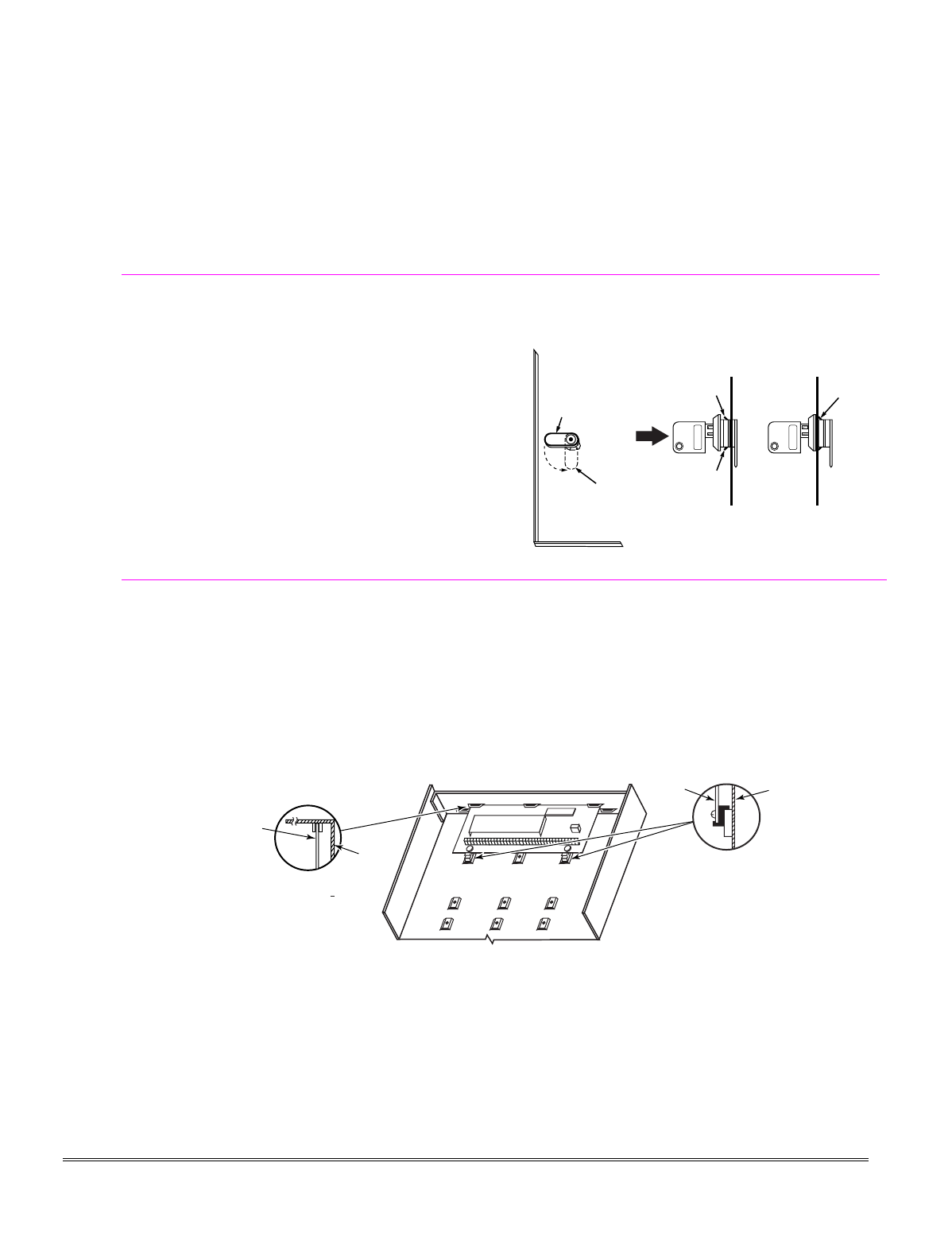
Cabinet and Lock
1. Mount the control cabinet to a sturdy wall in a clean,
dry area, which is not readily accessible to the
general public, using fasteners or anchors (not
supplied) with the four cabinet mounting holes.
2. Remove cabinet door, then remove the lock knockout
from the door. Insert the key into the lock.
3. Position the lock in the hole, making certain that the
latch will make contact with the latch bracket when
the door is closed. When correctly positioned, push
the lock until it is held securely by its snap tabs.
Notes
• The cabinet can be closed and secured without a
lock by using 2 screws in the cover's edge.
CABINET DOOR
BOTTOM
LOCKED
UNLOCKED
cab_lock_snap-001-V0
ADEMCO
ADEMCO
PUSH
SNAP
TAB
SNAP
TAB
PUSH
ON LOCK
UNTIL IT
IS SEATED
SECURELY
STEP 2STEP 1
CHECK
POSITION
Figure 1. Installing the Cabinet Lock
Mounting the PC Board Alone
(no RF Receiver)
1. Hang two short mounting clips (provided) on the
raised cabinet tabs (see Detail B in Fig. 2).
2. a. Insert the top of the circuit board into the slots
at the top of the cabinet. Make sure that the
board rests on the correct row (see Detail A).
b. Swing the base of the board into the mounting
clips and secure the board to the cabinet with the
accompanying screws (see Detail B).
Notes
• Before installing the cabinet's contents, remove
the metal cabinet knockouts required for wiring
entry. Do not remove the knockouts after the
circuit board has been installed.
+
+
CIRCUIT
BOARD
DETAIL B
SIDE VIEW
OF MOUNTING
CLIPS
DETAIL A
SIDE VIEW
OF BOARD
SUPPORTING
SLOTS
CIRCUIT
BOARD
MOUNTING-001-V0
CABINET
CABINET
Figure 2. Mounting the PC Board
2-1
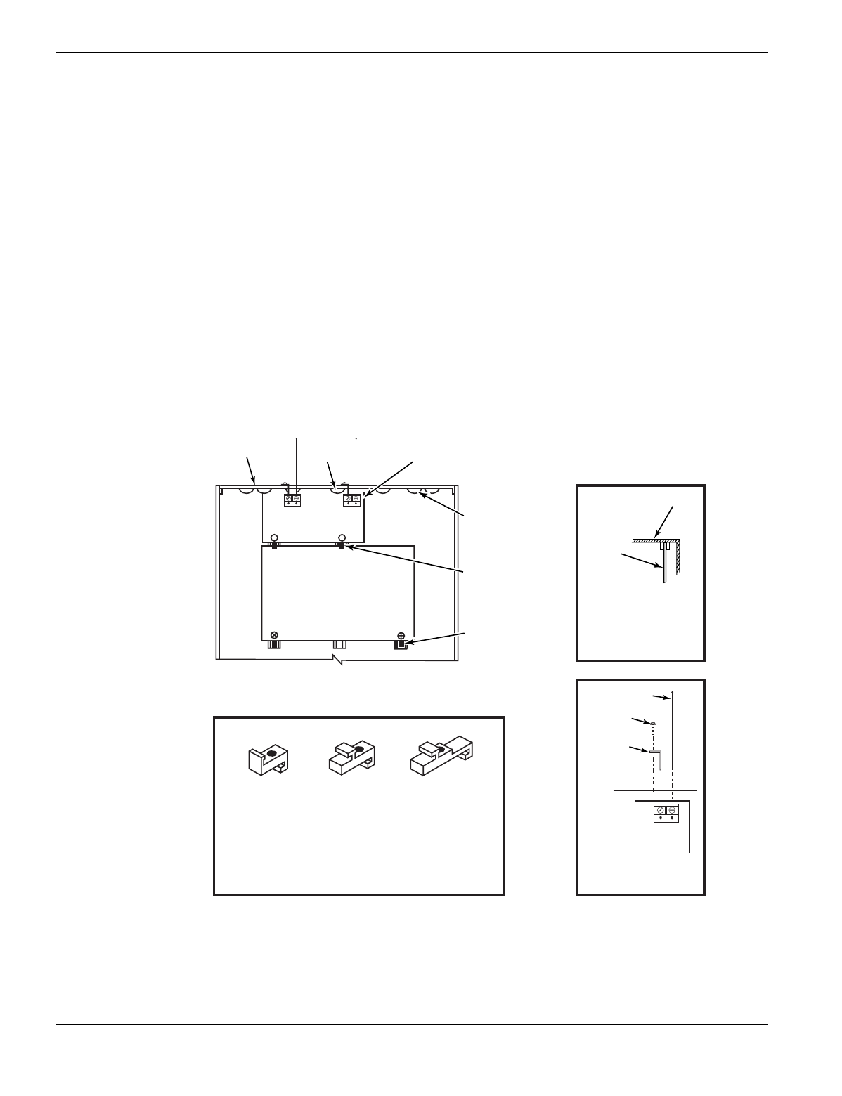
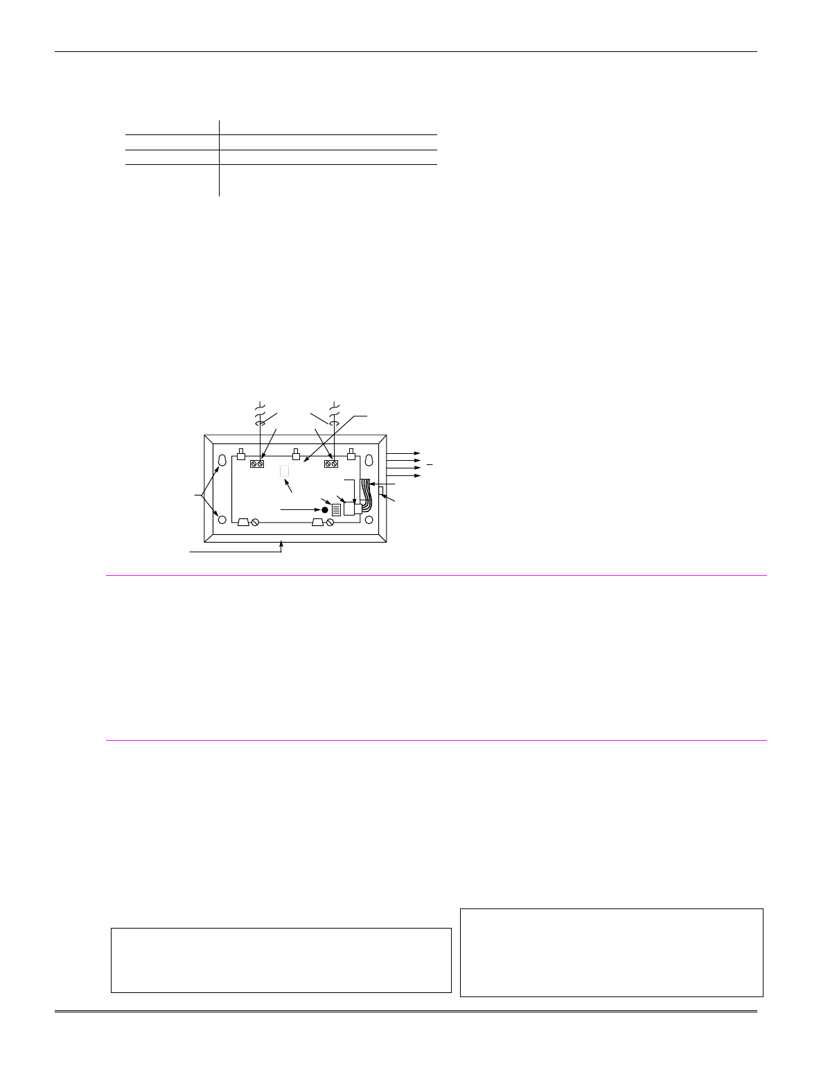
Mounting Board with RF Receiver
1. a. Remove the receiver board from its case, then
insert the top of the board into the slots at the top
of the cabinet, as shown in Detail A in Figure 3.
Make sure that the board rests on the correct row
of tabs.
b. Swing the base of the board into the mounting
clips and secure it to the cabinet with the
accompanying screws.
c. Insert the top of the control's board into the slot in
the clips and position two clips at the lower edge of
the board.
d. Swing this board into place and secure it with two
additional screws.
2. Insert grounding lugs (supplied with the receiver)
through the top of the cabinet into the left-hand
terminals of the antenna blocks (at the upper edge of
the receiver board) and secure them to the cabinet
top with the screws provided, as shown in Detail B.
3. Insert the receiver's antennas through the top of the
cabinet, into the blocks' right-hand terminals, and
tighten the screws.
Notes
• Do not mount the cabinet on or near metal
objects. This will decrease RF range and/or block
RF transmissions from wireless transmitters.
• Do not locate the cabinet in an area of high RF
interference (revealed by frequent or prolonged
lighting of the LED in the receiver after it is
operational (random flicker is OK)
ANTENNA
MOUNT
(2 PLACES)
ANTENNA
(2)
SCREW
(2)
BLACK
MOUNTING
CLIP
RED
MOUNTING
CLIP
WHITE
MOUNTING
CLIP
GROUNDING
LUG
(2)
NOTE
A COMBINATION OF THESE MOUNTING CLIPS HAS BEEN
INCLUDED IN YOUR INSTALLATION KIT.
USE THE APPROPRIATE CLIPS FOR MOUNTING.
IF NO RF RECEIVER IS USED, MOUNT THE PC BOARD USING
EITHER THE WHITE OR BLACK CLIPS, WHICHEVER ARE
INCLUDED IN THE CONTROL PANEL'S HARDWARE KIT.
DETAIL A
SIDE VIEW
OF BOARD -
SUPPORTING SLOTS
CIRCUIT
BOARD
CABINET
MOUNTING
CLIP
CABINET
MOUNTING
CLIP
CONTROL
CIRCUIT
BOARD
BOARD
SUPPORTING
SLOTS
RECEIVER CIRCUIT BOARD
++
AB
pc_mount-001-V1
DETAIL B
ANTENNA AND GROUNDING
LUG INSTALLATION
INSTALLATION WITH RECEIVER CIRCUIT BOARD
Figure 3. Mounting the PC Board and RF Receiver
Installation Instructions
2-2
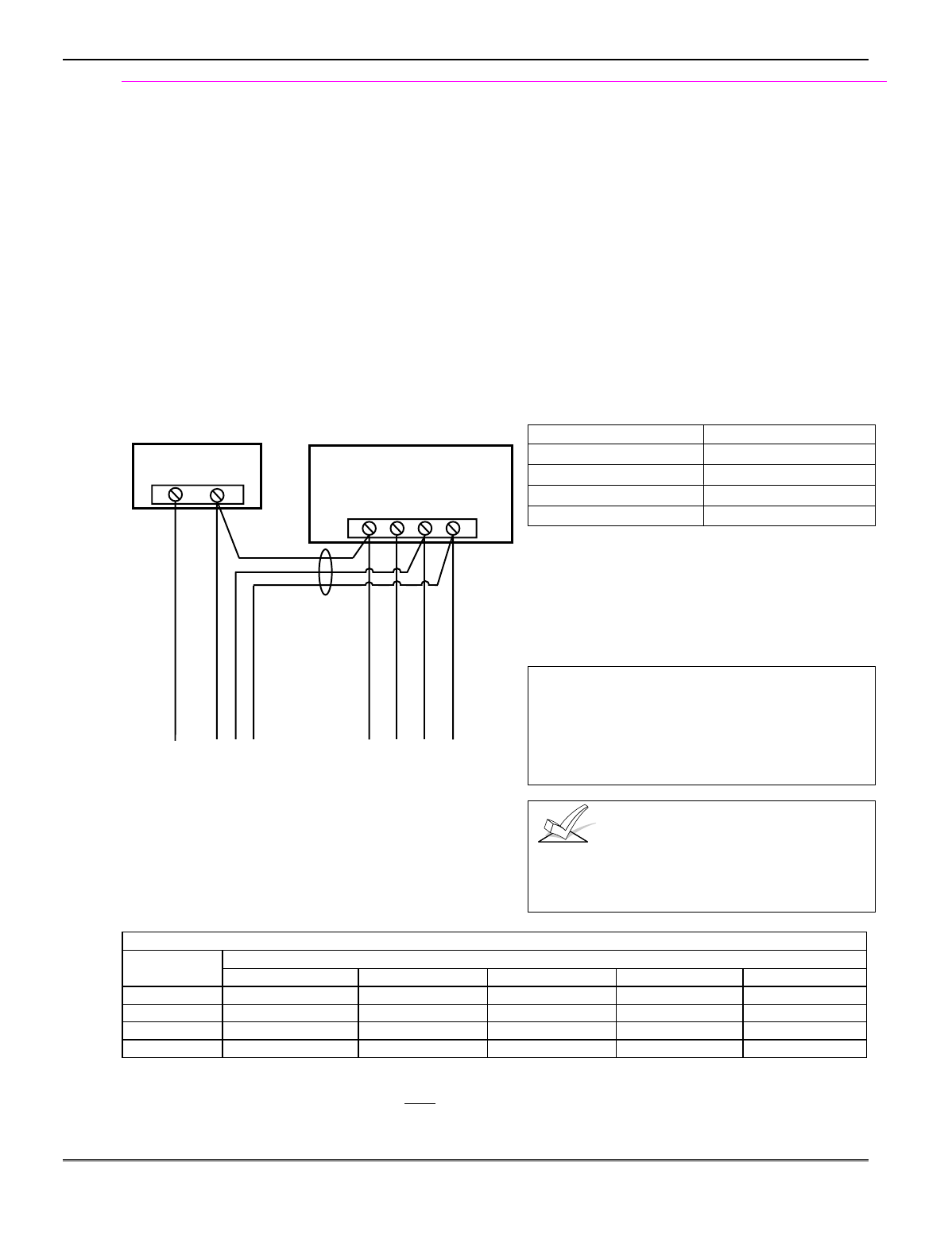
Wiring to Keypads
1. Connect keypads to the control’s keypad terminals as
shown on the Summary of Connections diagram.
Determine wire size using the Wire Run Chart below.
2. Set keypad addresses. Refer to the address setting
instructions included with the keypads and set each
keypad device address according to the chart at right.
3. Program the keypad addresses, partition
assignments and sound options in data fields *190-
*196.
NOTE: Each keypad must be assigned a unique
address, starting at address 16. Keypads
programmed with the same address will give
unpredictable results.
Supplementary Power (optional)
1. Connect as shown. Be sure to connect the negative (–)
terminal on the power supply unit to terminal 4
(AUX –) on the control.
+–
+
456 7
SUPPLEMENTARY
POWER SUPPLY
–
CONTROL TERMINAL STRIP
AUX. AUX. DATA
IN
DATA
OUT
IMPORTANT:
MAKE THESE
CONNECTIONS
DIRECTLY TO
SCREW
TERMINALS AS
SHOWN.
TO KEYPAD RED WIRE
TO KEYPAD BLK WIRE
TO KEYPAD YEL WIRE
TO KEYPAD GRN WIRE
TO KEYPAD BLK WIRE
TO KEYPAD RED WIRE
TO KEYPAD GRN WIRE
TO KEYPAD YEL WIRE
supp_pwr_supply-V0
Figure 4. Using a Supplementary Power Supply
Notes
• Fixed-Word Display: FA215KP, FA260KP
• Alpha Display: FA560KP
• Voice Keypad: FA560VKP
• Keypad/Transceiver: FA260RF
• AUI: Up to two Symphony FA800KP (see note
below) or FA700KP Touch Screen keypads
• The system supports up to 8 keypads, which can
be assigned to partitions in any combination
(see program fields *190-*196).
• For single 4-wire runs, determine the current
drawn by all units, then refer to the Wiring Run
chart to determine the maximum length that can
be safely used for each wire size.
• Use supplementary power if the control’s aux.
power load for all devices exceeds 600mA.
Suggested power supply: AD12612
Keypad Addresses
Keypad Address Keypad Address
no. 1 16** no. 5 20
no. 2 17 no. 6 21
no. 3 18 no. 7 22
no. 4 19 no. 8 23
** The first keypad is address 16, which is always
enabled and set for partition 1 with all sounds on.
AUI NOTE: Use of AUI is independent from standard
keypads and does not affect the number of standard
keypads the system can support. AUI keypads must be
set for either address 1 or address 2, depending on which
unit is enabled in field *189.
UL Use a UL Listed, battery-backed supply for
UL installations. The battery supplies power to
these keypads in case of AC power loss.
The battery-backed power supply should have
enough power to supply the keypads with the UL
required minimum standby power time.
Keypads powered from supplies that do not have a
backup battery will not function if AC power is lost.
Make sure to power at least one keypad in each
partition from the control’s auxiliary power output.
Wire Run Chart For Devices* Drawing Aux Power From The Control (12V+ & 12V–)
Wire TOTAL CURRENT DRAWN BY ALL DEVICES CONNECTED TO A SINGLE WIRE RUN
Size 50 mA or less 100 mA 300 mA 500 mA 600 mA
#22 900 ft (274m) 450 ft (137m) 150 ft (46m) 90 ft (27m) 75 ft (23m)
#20 1400 ft (427m) 700 ft (213m) 240 ft (73m) 140 ft (43m) 120 ft (37m)
#18 1500 ft (457m) 1100 ft (335m) 350 ft (107m) 220 ft (67m) 170 ft (52m)
#16 1500 ft (457m) 1500 ft (457m) 550 ft (168m) 350 ft (107m) 270 ft (82m)
* Includes Keypads, RF Receivers, Zone Expander/Relay Units, FA4285/FA4286 Phone Module, and Long Range Radio.
Maximum wire lengths for any device that is homerun to the control can also be determined from the Wiring Run Chart,
based on the current draw of that device alone.
The length of all wire runs for both partitions combined must not exceed 1500 feet (457m) when unshielded quad
conductor cable is used (750 feet if shielded cable is used). This restriction is due to the capacitive effect on the data lines
when quad cable is used.
Mounting and Wiring the Control
2-3
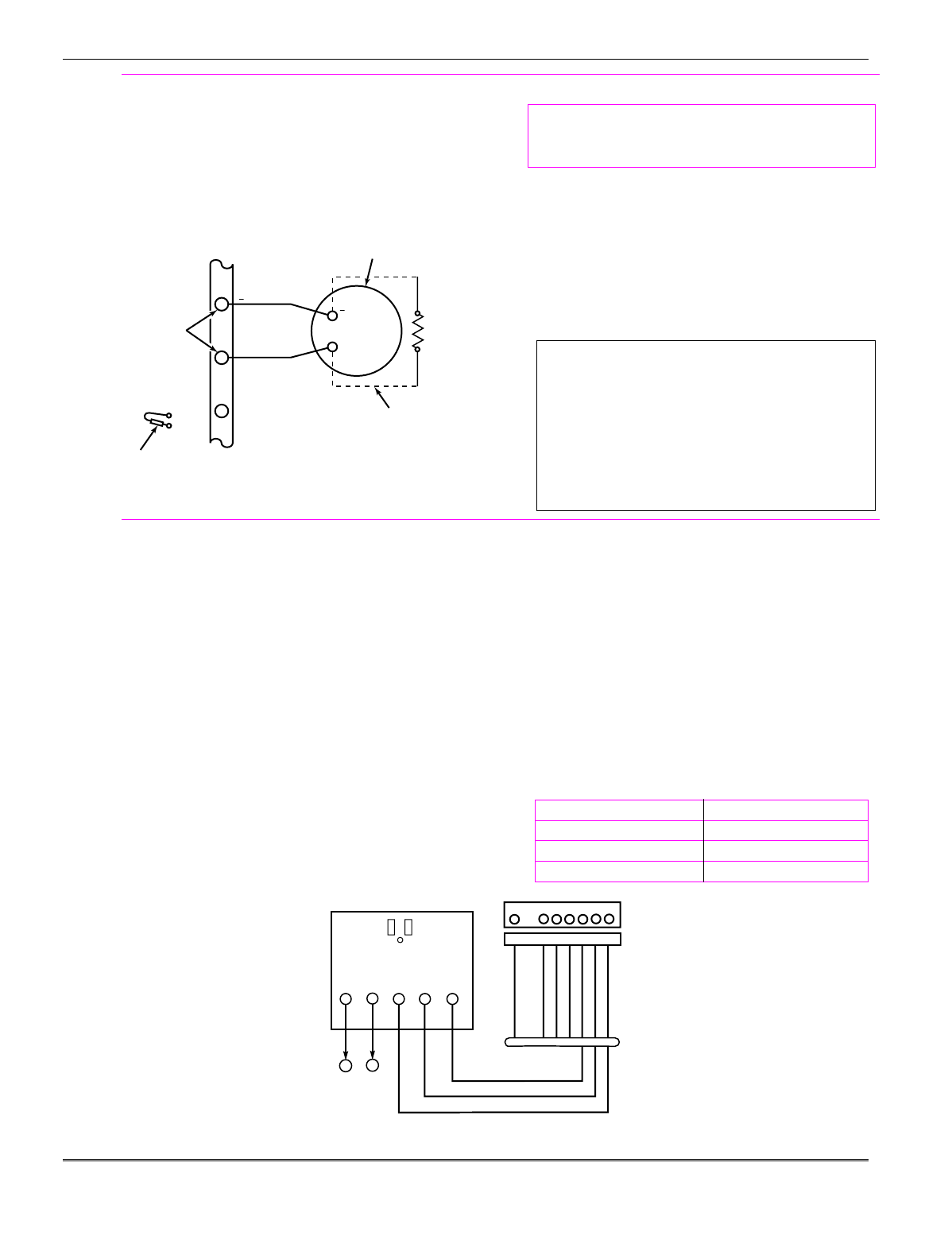
Sounder (Bell) Connections
1. Make sounder connections to alarm output terminals
3 (+) and 4 (–).
For supervised output, continue with steps 2 and 3.
2. Cut the red Bell Supervision Jumper located above
terminals 2 and 3 on the control board.
3. Connect a 2k ohm resistor across the terminals of the
last sounder.
+
+
2
EXTERNAL ALARM
SOUNDER
TERMINALS ON
CONTROL BOARD
ALARM
OUTPUT
TERMINALS
sounder-001-V0
3
4
CUT RED JUMPER ON CONTROL
BOARD TO ENABLE BELL
(SOUNDER) SUPERVISION.
2000
OHM
EOL
RESISTOR
IF BELL SUPERVISION IS ENABLED
(RED JUMPER ON CONTROL BOARD IS CUT)
CONNECT A 2000 OHM RESISTOR ACROSS
THE EXTERNAL SOUNDER AS SHOWN BY
THE DOTTED LINE.
DO NOT CONNECT THE RESISTOR AT THE
ALARM OUTPUT TERMINALS THEMSELVES!
OBSERVE
POLARITY
Figure 5. Sounder Wiring (Supervised)
Notes
This control complies with NFPA requirements for
temporal pulse sounding of fire notification appliances.
Temporal pulse sounding for a fire alarm consists of:
3 pulses – pause – 3 pulses – pause – 3 pulses–etc..
• The 12VDC sounder output activates when an
alarm occurs.
• Total current drawn from this output cannot
exceed 2 amps (going beyond 2 amps will
overload the power supply, or may cause the
electronic circuit protecting the sounder output
to trip).
• You must install a battery, since the battery
supplies this current.
UL
• Use only UL Listed sounding devices for UL
installations.
• Bell supervision is required for fire alarm installations.
• The total current drawn from the alarm output and the
auxiliary power output, combined, cannot exceed 600
mA. In addition, the sounding device must be a UL
Listed audible signal appliance rated to operate in a
10.2-13.8 VDC voltage range, and must be mounted
indoors.
Wiring the AC Transformer
1321 Transformer:
Connect the 1321 Transformer to terminals 1 and 2 on
the control board. See Wire Run Chart at right for wire
size to use. (Use 1321CN in Canada)
1361X10 Transformer
(required if using Powerline Carrier devices)
1. Splice one end of a 3-conductor cable to the wire ends
of the SA4120XM-1 Cable.
2. Connect the SA4120XM-1 cable plug to the 8-pin
connector on the control (see the Summary of
Connections diagram for location of the 8-pin
connector).
3. Connect the other end of the 3-conductor cable to the
1361X10 Transformer, as shown.
Canada: See Powerline Carrier Device section for
connections to the PSC04 X-10 Interface and trigger pins.
Notes
• Use caution when wiring the transformer to the
control to guard against blowing the transformer
fuse (the fuse is non-replaceable).
• Wiring to the AC transformer must not exceed
250 feet using 16 gauge wire. The voltage
reading between terminals 1 and 2 of the
control must not fall below 16.5VAC or an “AC
LOSS” message will be displayed.
• Do not plug the transformer into the AC outlet
while making any wiring connections to the
control. As a safety precaution, always power
down the control when making such connections.
Wiring Run Chart
Distance from control Wire Size
Up to 50 feet # 20
50–100 feet # 18
100-250 feet # 16
AC AC SYNC COM DATA
2
34 5
1
2
1
SA412OXM-1
CABLE
CONTROL
BOARD
TERMS.
1361X10 TRANSFORMER
00-trigcon-001-V2
1 345678
8-PIN TRIGGER CONNECTOR
KEY
+12 AUX.
DATA
COM
SYNC
GND (-)
OUTPUT 17 (RED)
OUTPUT 18 (GREEN)
(ORANGE)
(YELLOW)
(BLUE)
(PURPLE)
(BLACK)
Figure 6. Connections of 1361X10 Transformer to the Control Board
Installation Instructions
2-4
Backup Battery
1. Place the 12-volt backup battery in the cabinet.
2. After all connections to the control are completed and
AC power has been applied, connect the red and black
flying leads on the control board to the battery. Do not
attach these leads to the battery terminals until all
connections are completed.
Battery Saver Feature: The battery will disconnect
from the system after its voltage decreases below 9VDC.
This assists the control panel in recharging the battery
when AC is restored.
Notes
IMPORTANT: The panel will not power up
initially on battery power only. You must plug the
transformer in first, and then connect the battery.
UL For UL installations and Residential fire
installations, refer to the chart below for the
correct battery size required to meet the
mandatory standby time.
CALIFORNIA STATE FIRE MARSHALL (CSFM) AND UL RESIDENTIAL FIRE
24-HOUR BATTERY BACKUP REQUIREMENTS
The California State Fire Marshal and UL have regulations which require that all residential fire alarm control
panels must be provided with a backup battery which has sufficient capacity to operate the panel and its attached
peripheral devices for 24 hours in the intended standby condition, followed by at least 4 minutes in the intended
fire alarm signaling condition. This control panel can meet these requirements without using a supplementary
power supply, provided that the panel’s auxiliary power and bell output currents are limited as indicated below.
OUTPUT LIMITATIONS TO MEET CSFM 24 HOUR BATTERY BACKUP REQUIREMENTS
AND UL RESIDENTIAL FIRE INSTALLATIONS
OUTPUT CURRENT LIMITATIONS BATTERY INFORMATION
Output Current Total Maximum Auxiliary Current Battery Capacity
To Use (Amp/Hrs)
Recommended Battery
(Yuasa Model No.)
600mA maximum total of
auxiliary power plus bell
output currents
45mA
160mA
200mA
425mA
500mA
4AH
7AH
8AH
14AH
17.2AH
NP4-12 (or ADEMCO 467)
NP7-12
NP4-12 (two) ‡
NP7-12 (two) ‡
NPG18-12
‡ NOTE: Use two batteries, connected in parallel. Obtain an Ademco Battery Harness Kit SA5140-1. (Both batteries
will fit inside the panel’s cabinet.)
Earth Ground
Metal Cold Water Pipe:
Use a non-corrosive metal strap (copper is recommended)
firmly secured to the pipe to which the ground lead is
electrically connected and secured.
AC Power Outlet Ground:
Available from 3-prong, 120VAC power outlets only. To
test the integrity of the ground terminal, use a 3-wire
circuit tester with neon lamp indicators, such as the UL
Listed Ideal Model 61-035, or equivalent, available at
most electrical supply stores.
Notes
• This product has been designed and laboratory-
tested to ensure its resistance to damage from
generally expected levels of lightning and
electrical discharge, and does not normally
require an earth ground.
• If an earth ground is desired for additional
protection in areas of severe electrical activity,
terminal 25 on the control board, or the cabinet,
may be used as the ground connection point. The
examples of good earth grounds listed at the left
are available at most installations.
AUXILIARY DEVICE CURRENT DRAW WORKSHEET
DEVICE CURRENT # UNITS TOTAL CURRENT
FA215KP Fixed-Word Keypad 35mA
FA260KP Fixed-Word Keypad 75 mA
FA560KP Alpha Keypad 80 mA
FA560VKP Voice Keypad 60mA
FA260RF Keypad/Transceiver 105mA
5881/5882 RF Receiver 35mA
5883 Transceiver 80mA
4219 Zone Expander 35mA
4204 Relay Unit 15/180mA‡
4229 Zone Expander/Relay Unit 35/100mA‡
FA4285 Phone Module 160mA
FA4286 Phone Module 300mA
*
TOTAL =
(Current available from Aux. terminals = 600 mA max.)†
* If using hardwire devices such as PIRs, refer to the specifications for that particular unit's current draw.
† In UL installations, maximum current draw from the Auxiliary Output and the Alarm Output combined must not
exceed 600 mA (500 mA max from Auxiliary Output).
‡ Figures are for relays OFF/relays ON.
Mounting and Wiring the Control
2-5
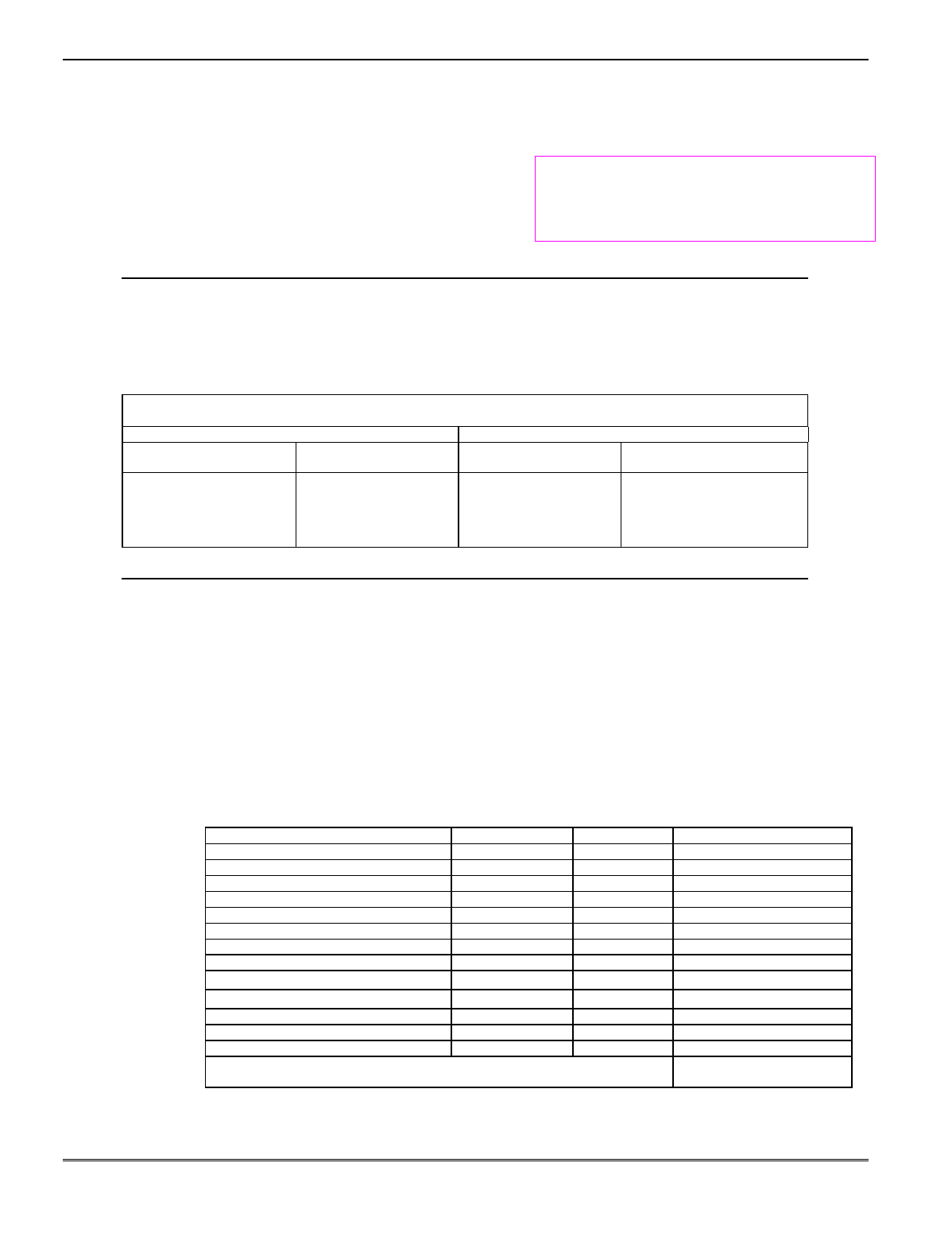
Hardwire Zones
Normally Open Zones/ Normally Open EOLR Zones
1. Connect open circuit devices in parallel across the
loop; for EOLR zones, connect the EOLR across the
loop wires at the last device.
2. Enable normally open/EOLR zones using Zone
Programming mode, “Hardwire Type” prompt.
Normally Closed Zones/Normally Closed EOLR Zones
1. Connect closed circuit devices in series in the high (+)
side of the loop; for EOLR zones, connect the EOLR in
series following the last device.
2. Enable normally closed/EOLR zones using Zone
Programming mode, “Hardwire Type” prompt.
Double-Balanced (FA168CPS only): Connect as shown
below (resistor provided for one device).
IMPORTANT: Double-balanced zones provide zone tamper
protection, and should be used as burglary zones only. Do not
use double-balanced zones as fire zones.
Zone Doubling (FA168CPS only): Connect as shown
below (resistors provided).
2k
2k
2k
ZONE 3
2k
2k
2k
ZONE 4
12 13 14
zone-002-V0
TAMPER
CONTACTS
TAMPER
CONTACTS
10 11
6.2k
ZONE 10
3k
ZONE 2
zone-004-V0
Double Balanced Zones Zone Doubling
Notes
• EOLR: If the EOLR is not at the end of the loop,
the zone is not properly supervised and the
system may not respond to an “open” on the zone.
• Zone 1 is intended for EOLR only.
UL For UL commercial burglar alarm
installations, use EOLR zones.
Zone Doubling (FA168CPS only):
This feature provides two hardwired normally
closed zones for each standard hardwired zone
connected to the control’s terminals (but does not
increase the total number of zones supported by
the control). If enabled (Zone Programming mode,
“Hardwire Type” prompt, option “3”), hardwire
zones are automatically paired as follows:
Zone Paired with zone
2 10
3 11
4 12
5 13
6 14
7 15
8 16
Do not use zone doubling for fire zones.
NOTE: A short across the EOL (i.e., at terminal)
on either zone of a zone-doubled pair or on a
double-balanced zone causes a tamper condition
(displayed as CHECK plus zone numbers).
Smoke Detectors
2-Wire Smoke Detectors
1. Connect up to sixteen (10, if “clean me” option used)
2-wire smoke detectors across zone 1 terminals 8 (+)
and 9 (-) as shown in the Summary of Connections
diagram at the back this manual. Observe proper
polarity when connecting the detectors.
2. Connect an EOL resistor across the loop wires at the
last detector.
Notes
• Fire Verification (zone type 16): The control
panel will “verify” a fire alarm by resetting the
smoke detectors after the first alarm trigger, and
then waiting 90 seconds for a second alarm
trigger. If the smoke detector or thermostat does
not trigger again, the control will disregard the
first trigger, and no alarm signal will occur. This
feature eliminates false alarms due to electrical
or physical transients.
SIA Installations: If using fire verification on
zones other than zone 1, UL Fire Alarm Listed
relay accessories must be used to reset power as
described in step 3.
• The zone 1 alarm current supports only one
smoke detector in the alarmed state.
• Clean Me Option: If enabled (field *174 = 1;
*56 zone programming, response time prompt =
3), certain ESL smoke detectors† send “clean me”
reports as appropriate. If used, the maximum
number of detectors is reduced to 10 (not
standard 16).
† Refer to the ESL documentation included with
the smoke detector for information regarding
compatibility with the clean-me option.
Installation Instructions
2-6
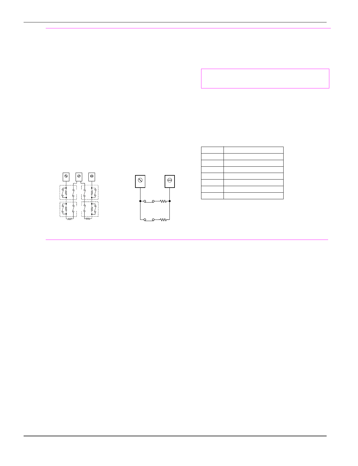
Smoke Detectors (continued)
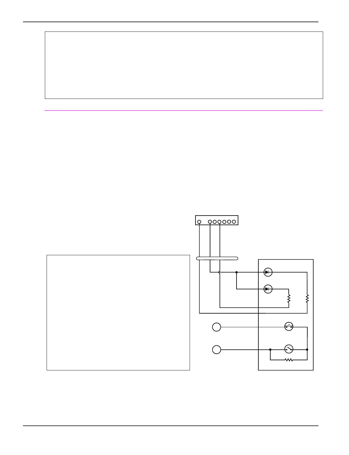
4-Wire Smoke Detectors
3. Connect 4-wire smoke detectors (up to 16, depending
on detector current draw) to any zone from 2-8 as
shown below. This control does not automatically
reset power to 4-wire smoke detector zones, so you
must use a relay (e.g., 4204, 4229), or on-board trigger
to reset power (also required for fire verification). Do
this by programming the designated relay/trigger as
zone type 54 (fire zone reset); see On-Board Trigger
section for other information.
NOTE: Maximum current on trigger 17 is 100mA.
Notes
• Do not use 4-wire smoke detectors on zone 1.
Figure 7. 4-Wire Smoke Detector Connections
+
+
2000
OHMS
EOLR
HEAT
DETECTOR
RED
EOL
POWER
SUPERVISION
RELAY MODULE
A77-716B.
USE N.O.
CONTACT,
WHICH CLOSES
WHEN POWER
IS APPLIED.
VIOLET
AUX PWR
OUTPUT
TERMINALS
5
4
+
BLK
+
4_wiresmk-007-V0
TO ZONE TERM. ( )
TO ZONE TERM. ( )
RELAY
CONTACT OPENS
MOMENTARILY UPON
FIRE ALARM RESET
PROGRAM
RELAY
AS ZONE
TYPE 54
(FIRE ZONE
RESET)
4-WIRE SMOKE
OR COMBUSTION
DETECTOR
N.C.
N.O.
+
2000
OHMS
EOLR
HEAT
DETECTOR
RED
VIOLET
AUX PWR 5
+
BLK
+
4_wiresmk-008-V0
4-WIRE SMOKE
OR COMBUSTION
DETECTOR
( )
( )
+
TO ZONE TERM. ( )
TO ZONE TERM. ( )
TO OUTPUT 17
PROGRAM OUTPUT 17
FOR "OUT NORM
LOW" = YES IN 79 MENU
MODE AND AS ZONE
TYPE 54 IN
80 MENU MODE
EOL
POWER
SUPERVISION
RELAY MODULE
A77-716B.
USE N.O.
CONTACT,
WHICH CLOSES
WHEN POWER
IS APPLIED.
N.O.
4-Wire Smoke Detector Using Relay for Power Reset 4-Wire Smoke Detector Using Output 17 for Power Reset
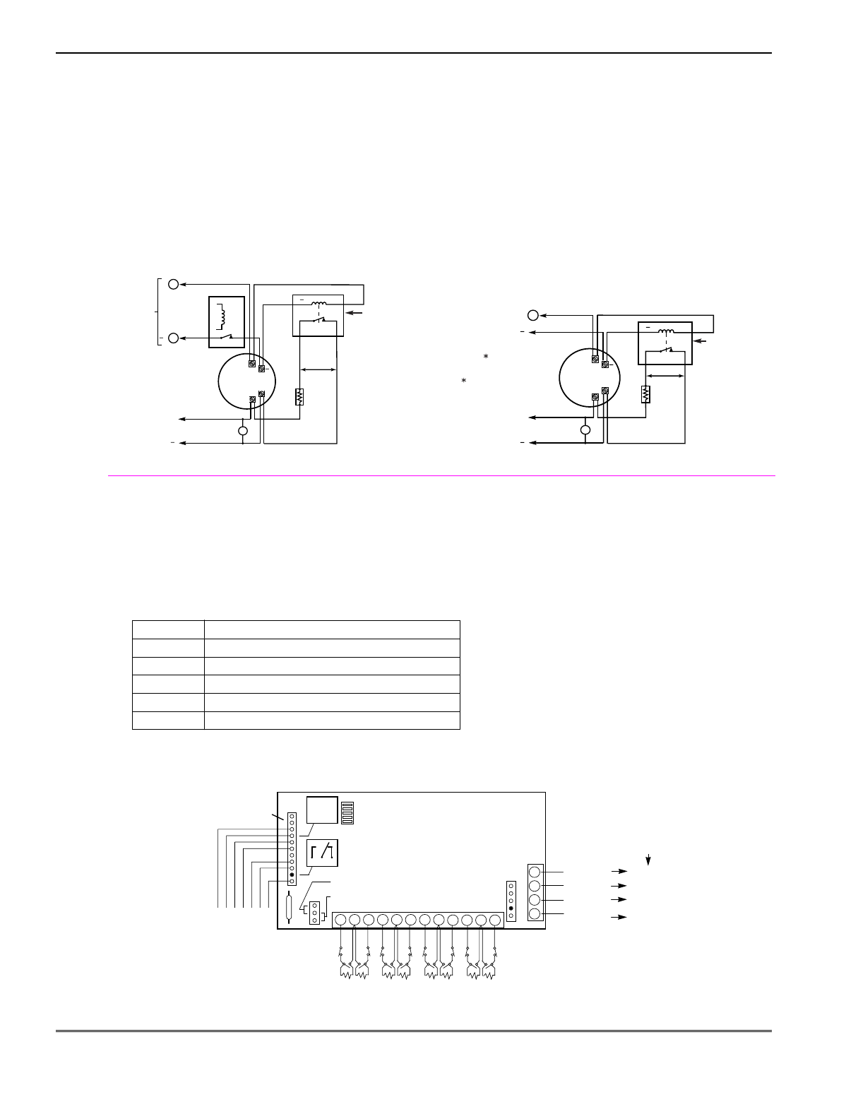
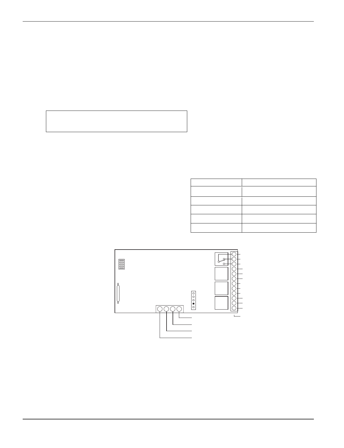
4219/4229 Expansion Zones
1. Connect each module to the control’s keypad
terminals.
2. Assign each module a unique device address (07-11)
using its DIP switches. Device addresses determine
the zone numbers being used, as shown in the
following table.
Expander Module Addresses
For Zones…Set Module to Device Address…
09-16 07 (not available if zone-doubling enabled)
17-24 08
25-32 09 (FA168CPS)
33-40 10 (FA168CPS)
41-48 11 (FA168CPS)
3. Connect sensors to the module’s loops.
4. If using relays with the 4229, connect the desired
field wiring to the unit's relay contact terminals.
Notes
• Supports expansion zones (NO or NC) using
4219/4229 Zone Expander Modules as follows:
FA168CPS: Up to 40 expansion zones using up to
five Zone Expander Modules.
FA148CP: Up to 16 expansion zones using up to
two Zone Expander Modules.
• Use 1000 ohm end-of-line resistors at the end of
loops connected to the 4219/4229 modules. (End-
of line resistors used on the control terminals are
2000 ohms.)
• Expansion zones have normal response time
(300–500 msec), except zone connected to each
module’s loop “A,” which can be set for fast
response (10–15 msec).
BRN
123456789 101112 1
2
3
4GRN
DATA OUT
TO CONTROL
BLK
(–) GROUND
RED
(+) 12V
YEL
DATA IN
FROM
CONTROL
4
3
2
1
TERMINATE EACH
PROGRAMMED ZONE
WITH 1000 OHM (1K)
END-OF-LINE RESISTOR
(EACH ZONE'S MAX.
LOOP RESISTANCE:
300 OHMS + E.O.L.)
➞
ZONES:
A B C D E F G H
1K
DIP SWITCH
FOR SETTING ADDRESS
AND ZONE “A” RESPONSE
➞
REED
(TAMPER)
SWITCH
➞
TAMPER JUMPER POSITION
4229 IN CABINET
(NOT TAMPERED)
4229 REMOTE
(TAMPER PROTECTED) TB1
4229
TB2
4-PIN CONSOLE PLUG
➞
EITHER OR BOTH CAN BE USED
➞
➞
WHT
GRY
VIO
BLK
YEL
ORG
NO
NC
C
GND
NO
NC
C
RLY
2RLY
1
RELAYS
"OFF"
RELAY
CONNECTOR
NO C NC
▲
▲
{
{
{
➞
RELAY
2
}
}
RELAY
1
TERMINALS ON
CONTROL PANEL
(TERM 6)
(TERM 4)
(TERM 5)
(TERM 7)
Figure 8. Wiring Connections, 4219 & 4229 (4229 shown)
Mounting and Wiring the Control
2-7
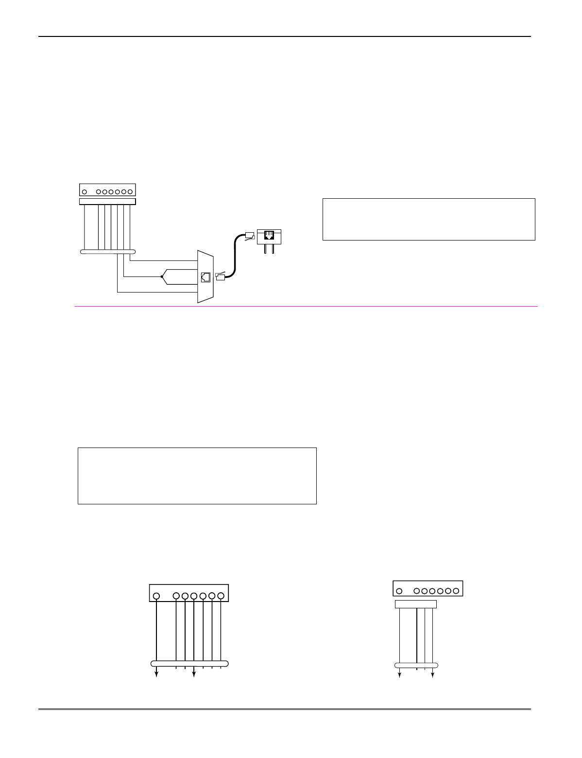
Installing the RF Receiver
Use any ADEMCO 5800 Series Wireless Receivers, such
as:
RF Receiver No. of Zones
5881L/5882L up to 8
5881M/5882M up to 16
5881H/5882H, FA168CPS = up to 40 plus 16 buttons
5883, FA260RF FA148CP = up to 26 plus 8 buttons
1. Set Device Address to “00” as described in its
instructions (set all switches to the right, “off”
position).
2. Mount the receiver, noting that the RF receiver can
detect signals from transmitters within a nominal
range of 200 feet.
3. Connect the receiver's wire harness to the control's
keypad terminals. Plug the connector at the other
end of the harness into the receiver. Refer to the
installation instructions provided with the receiver
for further installation procedures regarding antenna
mounting, etc.
Notes
• The receiver is supervised and a trouble report is
sent (“CHECK 100” displayed) if communication
between the panel and receiver is interrupted, or
if no valid RF signals from at least one supervised
transmitter are received within 12 hours.
If the receiver is mounted remotely:
• Place the RF receiver in a high, centrally located
area for best reception.
• Do not locate the receiver or transmitters on or
near metal objects. This will decrease range
and/or block transmissions.
• Do not locate the RF receiver in an area of high
RF interference (indicated by frequent or
prolonged lighting of the LED in the receiver;
random flicker is OK).
• Do not locate RF receiver closer than 10 feet
from any keypads to avoid interference from the
microprocessors in those units.
MOUNTING
HOLES INTERFERENCE
INDICATOR
LED
CIRCUIT
BOARD
DIP SWITCH
PLUG
&
SOCKET
INSERT IN
RIGHT-HAND
TERMINALS
ANTENNAS
YELLOW
RED
BLACK
GREEN
}
TO CONTROL’S
REMOTE KEYPAD
CONNECTION
POINTS.
WIRING
OPENING
KNOCKOUT
AREA FOR
SURFACE
WIRING
5882
LOCATION
}
TO RELEASE CIRCUIT BOARD,
REMOVE SCREWS (2)
AND BEND BACK TABS (2).
MODEL No. IS INDICATED
ON CIRCUIT BOARD
NOTE: CIRCUIT BOARD IS MOUNTED IN
CONTROL’S CABINET, GROUNDING LUGS (2)
PROVIDED
MUST
BE INSERTED IN LEFT-
HAND TERMINALS OF ANTENNA BLOCKS AND
SECURED TO CABINET (SEE RECEIVER’S
AND CONTROL’S INSTRUCTIONS)
Figure 9. 5881/5882 RF Receiver (cover removed)
Installing a 5800TM Module
1. Mount the 5800TM next to the RF receiver (between
one and two feet from the receiver’s antennas) using
its accompanying mounting bracket. Do not install
within the control cabinet.
2. Connect the 5800TM to the control panel’s keypad
connection terminals as shown on the Summary of
Connections diagram and set to address 28.
Notes
• Use this module only if you are using one or
more wireless bi-directional keypads or keyfobs
with a wireless Receiver; 5800TM is not
necessary if using a Transceiver (e.g., 5883).
• The 5800TM must be set to address 28 (cut red-
W1 jumper).
• The 5800TM can be used in partition 1 only.
• For additional information regarding the
5800TM, refer to the 5800TM’s instructions.
Installing the Transmitters
1. To be sure reception of the transmitter's signal at the
proposed mounting location is adequate, perform a
Go/No Go Test, described in the Testing the System
section.
2. Install transmitters in accordance with the
instructions provided with each.
3. Set 5827, 5827BD, 5804BD wireless keypads to the
programmed House ID (field *24), using its DIP
switches (5827) or follow the instructions provided
with the device.
ULC NOTE: In accordance with ULC standards, the
RF supervision period for the FA168CPS-CN and
FA148CP-CN is three hours for Fire zones (Zone Type 9
and 16) and 12 hours for all other zone types.
Notes
• Refer to the table of compatible devices at the
back of this manual.
• Supervised transmitters† send check-in signals to
the receiver at 70-90 minute intervals. If at least
one check-in message is not received from each
transmitter within a 12-hour period, the “missing”
transmitter number(s) and “CHECK” is displayed.
† Hand-held transmitters (e.g., 5802, 5802CP, 5804,
5804BD, 5827, 5827BD) do not send check-in signals.
UL The following transmitters are not intended for use
in UL installations: 5802MN, 5802MN2, 5804, 5804BD,
5814, 5816TEMP, 5819, 5819WHS & BRS, and 5850.
The 5827BD and 5800TM can be used in UL Listed
Residential Burglar installations.
WIRELESS ZONE NUMBERS
FA168CPS: transmitter zones 9-48
button zones 49-64
FA148CP: transmitter zones 9-34
button zones 49-56
Installation Instructions
2-8
Transmitter Battery Life
• See Wireless Transmitter paragraph in the Limitations of This Alarm System statement located at the end
of this manual for information on transmitter battery life.
• Some transmitters (e.g., 5802 and 5802CP) contain long-life but non-replaceable batteries, and no battery
installation is required. At the end of their life, the complete unit must be replaced (and a new serial
number enrolled by the control).
• Button-type transmitters (such as 5801, 5802, and 5802CP) should be periodically tested for battery life.
• The 5802MN and 5804 Button Transmitters have replaceable batteries.
Do not install batteries in wireless transmitters until you are ready to enroll during system programming.
After enrolling, batteries need not be removed.
Installing a Keyswitch
1. Connect the 4146 keyswitch's normally open
momentary switch to a zone’s (2-8) terminals.
Remove the 2000 ohm EOL resistor if connected
across the selected zone.
2. Using a standard keypad cable as shown:
Connect the yellow and white keyswitch wires to
trigger connector pin 3 (+12V).
Connect the Red and Green LED wires to the
appropriate output 17/output 18 trigger connector
pins.
3. Connect a 2000 ohm EOL resistor across the
momentary switch.
4. You can wire an optional closed-circuit tamper switch
(model 112) in series with the zone. If the switchplate
is then removed from the wall, the tamper will open,
disabling keyswitch operation until the system is
next disarmed from the keypad.
If the tamper is opened when the system is armed, an
alarm will occur.
UL A UL Listed keyswitch is required for fire
installations and UL commercial and residential burglar
alarm installations.
If a keyswitch is used on:
• an installation that transmits opening and closing
signals, the keyswitch zone must be programmed to
send opening and closing signals.
• a UL commercial burglar alarm installation, the
keyswitch’s tamper switch must be connected in to the
alarm system. This tamper switch zone must also be
programmed for Zone Type 05 – Trouble by Day /
Alarm by Night.
• a fire alarm installation, the keyswitch must be located
next to an alphanumeric display keypad.
The Ademco 4146 keyswitch is UL Listed.
Notes
• Use 4146 keyswitch or any N.O. keyswitch.
• Use only one keyswitch per partition.
• When using a keyswitch, the zone it is connected
to is no longer available for use as a protective
zone.
• Use *56 Menu mode to program the keyswitch
zone and assign it zone type 77.
• Use *80 Menu mode to program the LED
functions: program outputs 17 and 18 for system
operation zone type 78 (red LED) and 79 (green
LED) as appropriate (see Output Device
Programming section).
4146 KEYSWITCH
(READY)
GREEN
LOCK
SWITCH (N. O.)
TAMPER
SWITCH (N. C.)
(ARMED)
RED
YELLOW
WHITE
EOLR
(use appropriate value)
11
10
TYPICAL ZONE
ON CONTROL
BOARD
BROWN
BLUE
BROWN
BLUE
820
ohms
820
ohms
00-trigcon-004-V1
1345678
STANDARD
KEYPAD
CABLE
8-PIN TRIGGER CONNECTOR
KEY
+12 AUX.
OUTPUT 17
OUTPUT 18
(RED)
(YELLOW)
(GREEN)
RED
BLACK
Figure 10. Keyswitch Wiring Connections
Mounting and Wiring the Control
2-9
Connecting Relay Modules
1. Mount either remotely or in the control panel.
2. Connect to control’s keypad terminals using the
connector harness supplied with the module. Use
standard 4-conductor twisted cable for long wiring
runs.
3. Set each module’s device address according to the
table at right.
4. Connect the desired field wiring to the unit's relay
contact terminals.
UL For UL installation requirements, refer to the
Installation Instructions for the 4204.
Notes
• Use 4204 or 4229 modules.
• Supervision: 4204 and 4229 modules are
supervised against removal. The module’s device
address is displayed as follows if a module is
disconnected from the control’s terminals, or if
the module cover is removed and the tamper
jumper is installed:
Alpha: CHECK xx Wire Expansion
FAULT xx Wire Expansion
ALARM xx Wire Expansion
Fixed-Glass: lxx (or 91 if field *199 set for 2-digit
display)
where “xx is the module’s address.
• If communication/tamper failure occurs on a
device with zones wired to it, all zones on the
device will be displayed in their respective
partitions.
Relay Module Addresses
4204 Address 4229 Address
no. 1 12 no. 1 (zn 09-16) †† 07
no. 2 13 no. 2 (zn 17-24) 08
no. 3† 14 no. 3
† (zn 25-32) 09
no. 4† 15 no. 4† (zn 33-40) 10
no. 5† (zn 41-48) 11
† Applies to FA168CPS.
†† Not available if zone doubling used
13 14 15 16
C
NC
NO
DIP SWITCH
FOR SETTING DEVICE ADDRESS
AND ENABLING/DISABLING TAMPER
COVER TAMPER (REED) SWITCH
TB1
4204
TB2
4-PIN CONSOLE PLUG
121110987654321
C
NC
NO
C
NC
NO
C
NC
NO
RELAY
3
RELAY
2
RELAY
1
RELAY 4
TYPICAL
(SHOWN "OFF")
EITHER OR BOTH
CAN BE USED
DATA IN
FROM CONTROL
(–) GROUND
DATA OUT
TO CONTROL
(+) 12V
YEL
BLK
GRN
RED
4204
Figure 11. 4204 Connections to Control
(4229 Module is shown in the 4219/4229 Expansion Zones paragraph on page 2-7)
Installation Instructions
2-10
Powerline Carrier Devices
1. Install the powerline carrier devices according to the
instructions included with each.
FA168CPS: Up to 16 devices (if no relays are used)
FA148CP: Up to 8 devices (if no relays are used)
2. Use Programming Mode to enter the device house ID
in data field*27, and enter the unit code using *79
Output Device menu Mode.
3. See connections diagram in the AC Wiring paragraph
for connecting the 1361X10 transformer to the triggers.
Canada: Use the PSC04 Powerline Interface as shown:
1 2 3 4
SA4120XM-1 CABLE
X-10 PSC04
POWERLINE INTERFACE
YEL
RED
GRN
BLK MODULAR PHONE CORD (not supplied)
1 - BLACK
2 - RED
3 - GREEN
4 - YELLOW
SYNC
DATA
COM
1345678
KEY
+12 AUX.
DATA
COM
SYNC
GND (-)
OUTPUT 17 (RED)
OUTPUT 18 (GREEN)
(ORANGE)
(YELLOW)
(BLUE)
(PURPLE)
(BLACK)
8-PIN TRIGGER CONNECTOR
Notes
• When using Powerline Carrier devices, you must
use a 1361X10 Transformer instead of the 1321
Transformer.
• The 1361X10 Transformer provides AC power to
the control panel, and also supplies signals from
the control panel through the premises AC
wiring to the Powerline Carrier devices (which
are plugged into AC outlets). You can then make
devices that are plugged into Powerline Carrier
devices perform various functions in response to
commands you enter at the security system
keypads.
UL Powerline Carrier devices are not UL Listed
for fire or burglary functions and are intended for
home automation.
On-Board Triggers
Connect field wiring to the desired trigger pin on the
8-pin trigger connector centrally located above the
terminal strip.
• If using 1361X10 transformer and powerline
carrier devices, use the SA4120XM-1 cable. See
Wiring the AC Transformer section for transformer
connections.
• If only using the on-board triggers, you can use a
4-wire cable (N4632-4, supplied with the control)
cable as shown below.
UL If on-board triggers are used, the wiring between the
control unit and the UL Listed device must be run in
conduit, be no more than 3 feet apart and have no
intervening barriers or walls.
Notes
• Trigger outputs are normally high, and go low
upon programmed condition.
• The outputs can be programmed for inverted
operation (normally low, go high) using *79
Menu mode.
• Program these triggers using *80/*81 Menu
modes as you would for any other relay output.
• When using these outputs, note:
pin 1 = output number 17 (trigger 1):
15 ohms to ground when closed (output
low), open when off (output high, normal
default); can be used to reset smoke
detector power (must set “output normal
low = yes” in *79 Menu mode, and set for
zone type 54, fire zone reset, in *80 Menu
mode); or can support 12V relay module†
that draws less than 100mA
pin 5 = output number 18 (trigger 2):
100 ohms to ground when closed (output
low); open when off (output high, normal
default); or can support 12V relay module
that draws less than 20mA
† e.g., Altronix AX-RBS
1345678
SA412OXM-1
CABLE
8-PIN TRIGGER CONNECTOR
KEY
TRIGCON-003-V0
+12 AUX.
DATA
COM
SYNC
GND (-)
OUTPUT 17 (RED)
OUTPUT 18 (GREEN)
(ORANGE)
(YELLOW)
(BLUE)
(PURPLE)
(BLACK)
4-WIRE
CABLE
00-trigcon-005-V2
+12 AUX.
GND (-)
OUTPUT 17
OUTPUT 18
(RED)
(YELLOW)
(BLACK)
(GREEN)
1345678
8-PIN TRIGGER CONNECTOR
KEY
Figure 12. On-Board Trigger Connector with Figure 13. On-Board Trigger Connector with
SA4120XM-1 Cable for Use With 1361X10 Transformer 4-Wire Cable for Trigger Use Only
Mounting and Wiring the Control
2-11
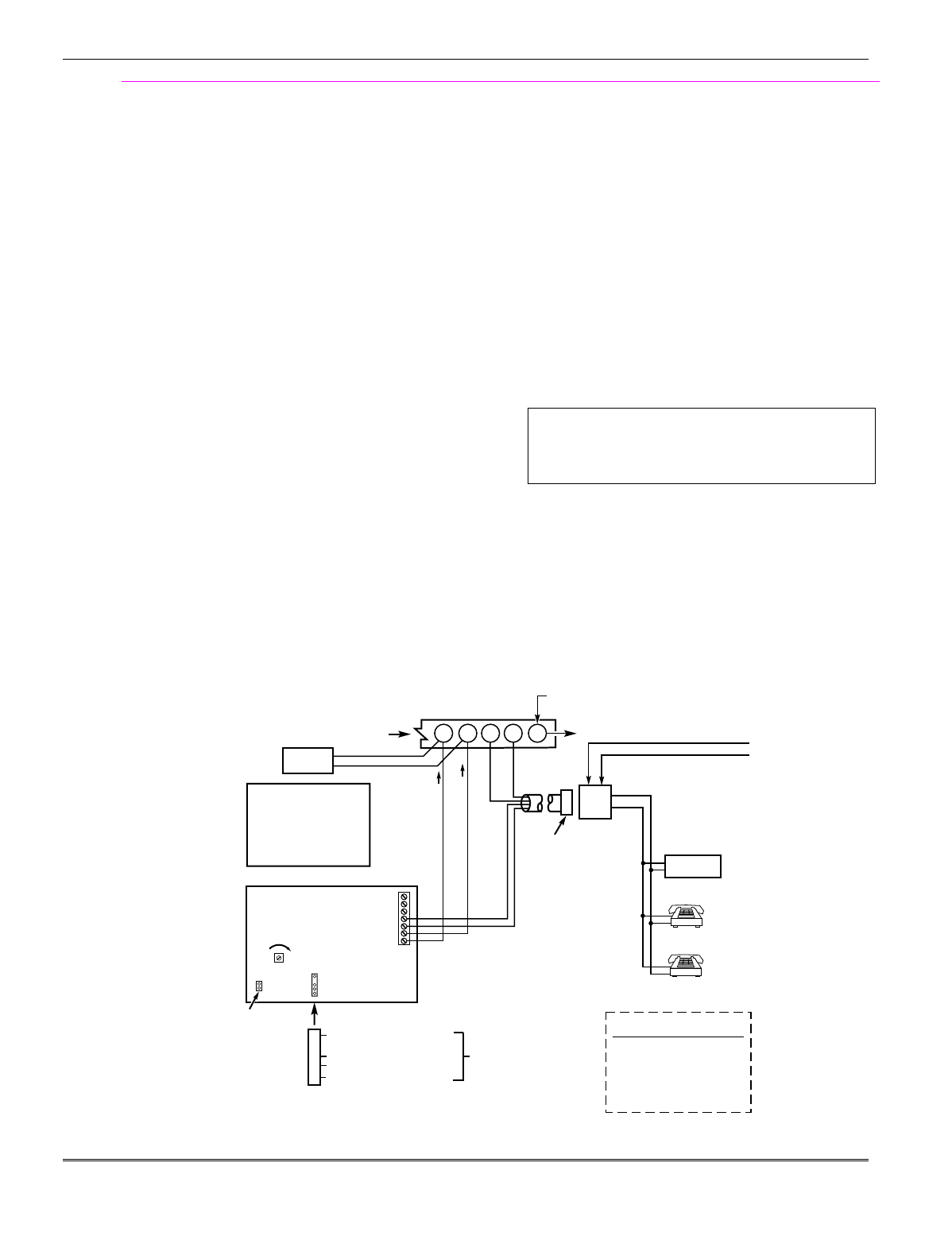
Phone Line/Phone Module Connections
1. Connect incoming phone line and handset wiring to
the main terminal block (via an RJ31X jack) as
shown in the Summary of Connections diagram at
the back of this manual. Wire colors represent the
colors of the cable to the RJ31X jack.
If using a phone module, continue with the following steps.
2. Make 12V (+) and (–) and data in and data out
connections from the phone module to the control,
using the connector cable supplied with the phone
module, then insert the keyed connector at the other
end of the connector cable into the header on the
phone module.
3. Connect Phone Module terminals as shown below.
Use an RJ31X jack with a direct-connect cord and
make all connections exactly as shown.
4. Caller ID Units: If a Caller ID unit is being used,
connect the unit directly to the “Handset” terminals
(21 & 22) on the control, as shown.
Notes
• Use FA4285 or FA4286 Phone Modules.
Compatibility: FA4286 Phone Modules must have
software version WA4286-15.1 or higher (refer to
the label on the square FA4286 microprocessor
chip).
• Only one phone module can be used and it can
only be connected to partition 1.
• The phone lines must be in service for the phone
module to function, even when accessing the
system from an on-premises phone.
• If you are also using an Audio Alarm Verification
(AAV) unit, refer to Audio Alarm Verification
(AAV) section for special wiring connections.
CAUTION: To reduce the risk of fire, use only No.
26 AWG or larger telecommunication line cord for
phone line connections.
UL The FA4285 and FA4286 modules are UL
Listed only for use on residential fire and UL
residential burglar alarm installations.
Phone Module Problems
If no touch tones are produced following access to the security system from on-premises (this problem may
arise in rare cases), it may be necessary to reverse the wires connected to terminals 3 and 4 on the phone
module and the wires connected to terminals (21) & (22) on the control. The wiring diagram shows the wiring
connections that will provide proper operation in most cases.
Connection to the incoming telco line via a RJ31X jack and direct-connect cord, as shown, is essential, even if
the system is not connected to a central station. The FA4285 or FA4286 will not function if this is not done and
an error signal (fast busy signal) will occur when trying to access the system via the phone.
The house phone lines (gray and brown wires) must be wired to the phone module terminals; not to the control
terminals. Otherwise, an error signal (fast busy signal) will occur when trying to access the system from an on-
premises phone.
ANSWERING
MACHINE
TERMINALS
ON CONTROL
TO EARTH GROUND (COLD WATER PIPE, ETC.)
UNUSED
KEYED
HEADER
FA4285/FA4286
VIP MODULE
123456 7
YELLOW: TO DATA OUT (term. 7)
NO CONNECTION
RED: TO AUX (+) (term. 5)
BLACK: TO AUX. GROUND (–) (term.4)
GREEN: TO DATA IN (term. 6)
CONNECTOR
WITH FLYING
LEADS
TO CONTROL
PANEL
TERMINALS
USED FOR
KEYPAD
CONNECTIONS
PREMISES ANSWERING
MACHINE AND PHONES
HANDSET
INCOMING
TELCO LINE
TIP
RING
PLUG
DIRECT
CONNECT
CORD
TIP
RING
GROUND
(TIP)
(RING)
GREEN (TIP)
RED (RING)
INCOMING TELCO LINE
GREY (R)
BROWN (T)
FA4285/FA4286
TERMINAL ASSIGNMENTS
1 - TIP
2 - RING PHONE INPUT
3 - TIP
4 - RING PHONE OUTPUT
5 - NO CONNECTION
6 -
7 -
AUDIO OUT
FA4286 ONLY
}
}
}
{
{
IMPORTANT NOTE FOR
EXISTING INSTALLATIONS:
EXISTING WIRES
CONNECTED TO THE
"HANDSET" TERMINALS ON
CONTROL MUST BE MOVED
FROM THERE TO TERMINALS
3 AND 4 ON THE FA4285/4286.
*
*
*
NOTE: IF THE TELEPHONE HAS BUILT-IN CALLER ID,
THE CALLER ID FUNCTION MAY NOT WORK
.
CA38A
IN
CANADA
4286_cntrl-10-001-V0
LOUDER
VOLUME
(FA4286
ONLY)
21 22 23 24 25
CALLER ID
UNIT
RJ31X
JACK
Figure 14. FA4285/FA4286 Phone Module Wiring Connections
Installation Instructions
2-12
Long Range Radio Connections
Connect the data in/data out terminals and voltage
input terminals of the Long Range Radio to the
control's keypad connection points.
Set the radio’s address to “03” following the
instructions provided with the radio.
Notes
• Use compatible Long Range Radios (e.g.,
7720PLUS, 7820, 7835C, or 7845C).
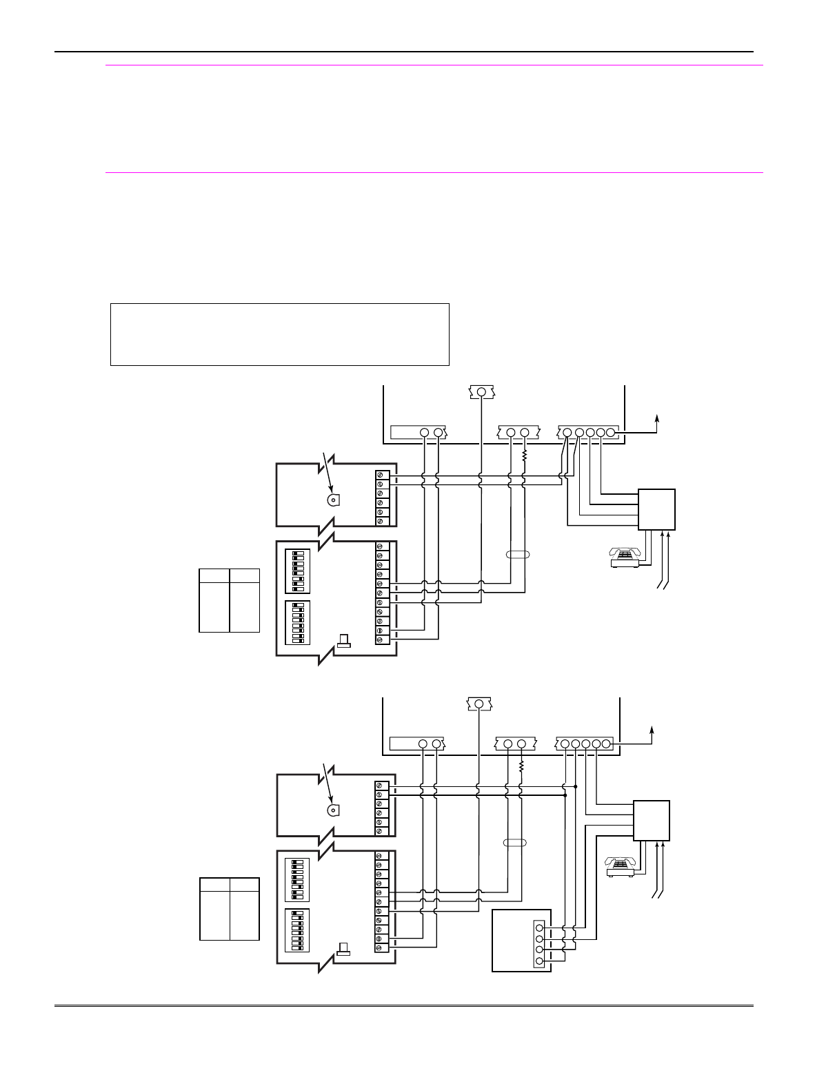
Audio Alarm Verification Connections
(AAV, “listen-in”)
Refer to the connection diagrams below. One diagram
shows connections when a FA4285/FA4286 Phone
Module is used, the other shows connections when
the FA4285/FA4286 is not used.
Connections use one of the on-board triggers.
UL UL installations using the AAV feature must use the
ADEMCO UVCM module (part of the ADEMCO UVS
system).
Suggested Module: ADEMCO UVS (shown) or Eagle 1250
Notes
• Set field *91 for AAV and program the
appropriate output (output 17 or 18) using *80
Menu mode (select zone type “60”).
• For voice session monitoring, connect an EOLR
zone to UVCM module terminals 6 & 7, and
program the zone as zone type 81 (*56 Menu
mode).
E.g., Using output 18 for the trigger, program an
output function in *80 Menu mode as: ZT = 60,
P = 0, Action = 1, Device = 18
ON ON
12345678 12345678
1234567891011 29 30 31 32 33 34
NOTE:
REFER TO UVCM MODULE
INSTRUCTIONS FOR
CONNECTIONS TO AUDIO
SPEAKERS AND MICROPHONE.
UVCM
MODULE
ZONE
TERMINALS
EARTH
GROUND
RED (R)
GREEN (T)
GREY (R)
BROWN (T)
TRIGGER
CONNECTOR
OUTPUT 18
EOL
RING
TIP
OPTIONAL
MONITORING ZONE
CONNECTION
(USE ZONE TYPE 81)
FALLING VOICE TRIG
GND
+12VDC IN
SWITCH
BANK 2
SWITCH
BANK 1
SWITCH BANK 2
SWITCH BANK 1
AUXILIARY
AUDIO LEVEL
ADJUSTMENT
TRIM POT
aav_uvcm-003-V0
CONTROL
INCOMING
PHONE LINE
TO
PREMISES
HANDSET
5
1 = ON
2 = ON
3 = OFF
4 = ON
5 = ON
6 = ON
7 = ON
8 = ON
1 = OFF
2 = OFF
3 = OFF
4 = OFF
5 = OFF
6 = OFF
7 = OFF
8 = ON
23 24 25
+12VDC
GND
4521 22
RJ31X
Figure 15. Connection of AAV Unit When Not Using a FA4285/FA4286 Phone Module
1234567891011 29 30 31 32 33 34
NOTE:
REFER TO UVCM MODULE
INSTRUCTIONS FOR
CONNECTIONS TO AUDIO
SPEAKERS AND MICROPHONE.
UVCM
MODULE
CONTROL
EARTH
GROUND
RED (R)
GREEN (T)
GREY (R)
BROWN (T)
TRIGGER
CONNECTOR
OUTPUT 18
FA4285/FA4286
RING
TIP
FALLING VOICE TRIG
GND
+12VDC IN
SWITCH
BANK 2
SWITCH
BANK 1
SWITCH BANK 2
SWITCH BANK 1
AUXILIARY
AUDIO LEVEL
ADJUSTMENT
TRIM POT
10-aav_uvcm-001-V0
ZONE
TERMINALS
OPTIONAL
MONITORING
ZONE
CONNECTION
(USE ZONE
TYPE 81)
23 24 25
22
21
45
INCOMING
PHONE LINE
TO
PREMISES
HANDSET
RJ31X
2
3
4
1
5
1 = ON
2 = ON
3 = OFF
4 = ON
5 = ON
6 = ON
7 = ON
8 = ON
1 = OFF
2 = OFF
3 = OFF
4 = OFF
5 = OFF
6 = OFF
7 = OFF
8 = ON
ON ON
12345678 12345678
RING
TIP
+12VDC
GND
EOL
Figure 16. Connection of AAV Unit When Using a FA4285 or FA4286 Phone Module
Mounting and Wiring the Control
2-13

Installation Instructions
2-14

SECTION 3
Programming Overview
•••••••••••••••••••••••••••••••••••••••
About Programming
You can program the system at any time, even at the installer's premises prior to the actual
installation. Programming can also be performed remotely from the installer’s office/home, using an
IBM personal computer, a modem, and Compass downloading software.
The following is a list of the various Programming modes used to program this system:
Programming Mode… Used to …
Data Field Programming Program basic data fields used for setting the various system options.
Most of the data fields in this system have been programmed for specific
default values. However, some fields must be programmed for each
particular installation to establish its specific alarm and reporting features.
∗56 Zone Programming Assign zone characteristics, report codes, alpha descriptors, and serial
numbers for 5800 RF transmitters.
∗57 Function Key Programming Program each of the four alphabet function keys to perform one of several
system operations.
∗58 Zone Programming Assign zone attributes similar to ∗56 mode, but provides a faster
(Expert Mode) programming procedure and is intended for those more experienced in
programming controls of this type.
∗79 Output Device Mapping Assign device addresses used by 4229 or 4204 Relay modules and map
specific relays and device outputs, and assign unit codes for Powerline
Carrier devices
∗80 Output Definitions Define up to 48 output definitions which can control the output relays
mapped using *79 Output Device Mapping mode.
∗81 Zone List Programming Create Zone Lists for relay/powerline carrier zones, chime, night-stay, cross
zones, and pager zones.
∗82 Alpha Programming Create alpha descriptors for easy zone identification.
Scheduling Mode (code + [#] +64) Create schedules to automate various system functions.
Zones and Partitions
Each protection zone needs to be programmed with various attributes using *56 Zone Programming
mode or *58 Expert Programming mode. Refer to those sections for detailed procedures.
The FA168CPS system can control two independent areas of protection (known as partitions) for use
by independent users, if desired, by simply assigning zones to one or the other partition during zone
programming. The FA168CPS, by default, automatically distributes users between the two
partitions. The master user can change the user number distributions.
Zones can also be assigned to a common partition, which is an area shared by users of both partitions
(such as a lobby in a building). This allows either partition to arm, while leaving the common
partition disarmed for access into the other partition. The following describes the functioning of the
FA168CPS common partition:
• The common zone sounds and reports alarms only when both partitions are armed. If only one
partition is armed, the system ignores faults on the common zone.
• Either partition may arm its system if the common zone is faulted, but once armed, the other
partition will not be able to arm unless the common zone is first bypassed or the fault is corrected.
• Faults on the common zone are displayed on common zone keypads, and will also appear on
another partition’s keypad when that partition is armed.
• Either partition can clear and restore the common zone after an alarm.
3-1

Keypads
Keypads are identified by predefined addresses (starting at address 16) as follows:
Address Keypad Program Field
16 keypad 1 • always enabled for partition 1, all sounds enabled. NOTE: First keypad is address 16.
17 keypad 2 • data field *190
18 keypad 3 • data field *191
19 keypad 4 • data field *192
20 keypad 5 • data field *193
21 keypad 6 • data field *194
22 keypad 7 • data field *195
23 keypad 8 • data field *196
To enable keypads:
1. Set desired address at keypad (refer to keypad’s instructions for setting the address).
2. Use data field program mode to enable keypad addresses, assign a partition, enable sound options
in fields *190-*196 as shown in the table above.
3. If desired, use data field *198 to turn on the display of the partition number.
4. Set the following keypad-related data fields as required by the installation:
*21 Quick Arm Enable; *23 Forced Bypass, *84 Auto STAY Arm
5. If using AUI, enable each unit in field *189 and set AUI 1 to address 1, AUI 2 to address 2.
Wireless Receiver, Transmitters, and Wireless Keys (keyfobs)
Receiver: Set the receiver’s address to “00” using its DIP switches, then set the following options:
*22 RF Jam Option†
*24 RF House ID Code (if using wireless keypads) for each partition
*67 Transmitter Low Battery Report Code†
*75 Transmitter Low battery restore report code†
Transmitters: Use *56 or *58 Zone Programming Menu modes to program zone information and
enroll transmitters (FA168CPS: zones 9-48, buttons 49-64; FA148CP: zones 9-34, buttons 49-56).
Wireless Keys: Use Wireless Key Programming Templates section of the *58 Zone Programming
Menu mode to program zone information and enroll each button of the wireless keys used. Once a
wireless key is enrolled, it must be assigned to a user before it becomes active. See Adding/Deleting
Security Codes section for procedure.
Pager Programming
The system can send various reports to several pagers (FA168CPS = up to 4; FA148CP = up to 2).
1. Enter the appropriate information in the following data fields:
*160, *163, *166, *169 Pager Phone Numbers (for pagers 1-4† respectively)
*161, *164, *167, *170 Pager Prefix Characters (for pagers 1-4† respectively)
*162, *165, *168, *171 Pager Reporting Options by Partition† (for pagers 1-4 respectively)
2. Enable Pager Delay, if desired, in field *172 (delays alarm reporting for ALL pagers).
3. Make sure appropriate user open/close pager reports are enabled (see Security Codes, Assigning
attributes in Section 12. System Operation). Users that perform actions in partition 1 will, if
enabled, attempt to report to all pagers enabled for open/close reporting in partition 1. Users that
perform actions in partition 2 will, if enabled, attempt to report to all pagers enabled for
open/close reporting in partition 2.
4. If using latchkey pager report, define the latchkey report schedule using Scheduling mode (master
code + [#] [6] [4] select event type “03”). System must be armed for the Latchkey report to be sent.
5. If using a function key to manually send a message to a pager, see Function Keys on the next page.
6. If reporting zone alarms and troubles to a pager, use *81 Zone List menu mode to assign the zones
associated with each pager (zone lists 9-12†).
† FA168CPS supports four pagers and partitioning; FA148CP supports two pagers and zone lists 9
and 10 only.
† These fields must be enabled for Residential
Fire, UL Residential Burglar Alarm, and UL
Commercial Bur
g
lar Alarm installations.
Installation Instructions
3-2

Function Keys
To assign functions to the function keys, use *57 Function Key menu mode.
To assign emergency key functions (function key option “00”), first program the respective emergency
zone number (95 for “A” key, 96 for “C” key, 99 for “B” key) with the desired zone type using *56 Zone
Programming mode, then use *57 Function Key menu mode to assign the desired key.
If using a function key to activate a relay action (*57 Menu mode key function 07), use *79 Menu
mode to map the output, and use *80 Menu mode to define the output’s action; select system
operation type “66.”
If using a function key for a user macro, use *57 menu mode to activate the desired key, then define
the actual macro functions using the user code + [#] + [6] [6] command.
Output Devices
To program a device for manual activation (user code + [#] [7] / [#] [8] + 2-digit device number) or for
scheduled automatic activation, simply map the device using *79 Menu mode.
To program a device to automatically activate upon a system event (or function key), use *79 Menu
mode to map the device, then use *80 Menu mode to define the automated device action.
If the device action is based on more than one zone, use *81 Zone List menu mode to assign the zones.
Zone Type Definitions
You must assign a zone type to each zone, which defines the way in which the system responds to
faults in that zone. Zone types are defined below.
Zone Type Description
Type 00
Zone Not Used
Program a zone with this zone type if the zone is not used.
Type 01
Entry/Exit Burglary #1
• Assign to zones that are used for primary entry and exit.
• Provides entry delay when zone is faulted if control is armed in the Away, Stay,
or Night-Stay modes.
• No entry delay provided when the panel is armed in the Instant/Maximum mode.
• Entry delay #1 is programmable (field *35) for each partition.
• Exit delay begins whenever the control is armed, regardless of the arming mode
selected, and is programmable (field *34).
Type 02
Entry/Exit Burglary #2
• Assign to zones that are used for entry and exit and require more time than the
primary entry/exit point.
• Provides a secondary entry delay, in same manner as entry delay #1.
• Entry delay #2 is programmable (field *36) for each partition.
• Exit delay is same as described for Type 01.
Type 03
Perimeter Burglary
• Assign to all sensors or contacts on exterior doors and windows.
• Provides an instant alarm if the zone is faulted when the panel is armed in the
Away, Stay, Night-Stay, Instant or Maximum modes.
Type 04
Interior Follower
• Assign to a zone covering an area such as a foyer, lobby, or hallway through
which one must pass upon entry (to and from the keypad).
• Provides a delayed alarm (using the programmed entry 1 time) if the entry/exit
zone is faulted first. Otherwise this zone type gives an instant alarm.
• Active when the panel is armed in the Away mode.
• Bypassed automatically when the panel is armed in the Stay or Instant modes;
if armed in Night-Stay mode, zones assigned to zone list 05 (night-stay zone list)
are not bypassed when system armed in Night-Stay mode.
Type 05
Trouble by Day/
Alarm by Night
• Assign to a zone that contains a foil-protected door or window (such as in a store),
or to a zone covering a sensitive area such as a stock room, drug supply room, etc.
• Can also be used on a sensor or contact in an area where immediate notification
of an entry is desired.
• Provides an instant alarm if faulted when armed in the Away, Stay, Night-Stay,
Instant or Maximum (night) modes.
• During the disarmed state (day), the system will provide a latched trouble
sounding from the keypad (and a central station report, if desired).
3-3

Type 06
24-hour Silent Alarm
• Usually assigned to a zone containing an emergency button.
• Sends a report to the central station but provides no keypad display or sounding.
Type 07
24-hour Audible Alarm
• Assign to a zone that has an emergency button.
• Sends a report to the central station, and provides an alarm sound at the keypad,
and an audible external alarm.
Type 08
24-hour
Auxiliary Alarm
• Assign to a zone containing an emergency button, or to a zone containing
monitoring devices such as water or temperature sensors.
• Sends a report to the central station and provides an alarm sound at the keypad.
(No bell output is provided.)
Type 09
Supervised Fire
• Provides a fire alarm on short circuit and a trouble condition on open circuit. A
fire alarm produces a pulsing bell output.
• This zone type is always active and cannot be bypassed.
Type 10
Interior w/Delay
• Provides entry delay (using the programmed entry time), if tripped when the
panel is armed in the Away mode.
• Entry Delay 1 begins whenever sensors in this zone are violated, regardless of
whether or not an entry/exit delay zone was tripped first.
• Bypassed when the panel is armed in the Stay or Instant modes; if armed in
Night-Stay mode, zones assigned to zone list 05 (night-stay zone list) are not
bypassed when system armed in Night-Stay mode.
Type 12
Monitor Zone
• Works as a dynamic monitor of a zone fault/trouble (not alarm). In the case of a
short/open, the message, "*ALARM*-24 Hr. Non-Burg. -#XXX " (where XXX is
the zone number) will be sent to the Central Station. The system keypad will
display a “check” message indicating the appropriate zone (but keypad beeping
does not occur). Upon restoral of the zone, the message, "*RESTORE*-24 Hr.
Non-Burg. -#XXX " will be sent to the Central Station.
• The “check” message will automatically disappear from the keypad dynamically,
when the zone restores; a user code + off sequence is not needed to reset the zone.
• Faults of this zone type are independent of the system, and can exist at the time
of arming without interference.
• Since this is a “trouble” zone type, do not use this zone type with relays set to
activate upon “alarm.”
Type 14
24 Hour Carbon
Monoxide Monitor
• Assigned to any zone with a carbon monoxide detector.
• The bell output will pulse when this zone type is alarmed.
• Always active and cannot be bypassed.
Type 16
Fire w/Verification
• Provides a fire alarm when zone is shorted, but only after alarm verified.
• System verifies alarm by resetting zones for 12 seconds after short is detected. A
subsequent short circuit within 90 seconds triggers fire alarm.
• Provides a trouble response when zone is open.
Type 20
Arm-Stay (BR only)
• Arms the system in Stay mode when the zone is activated.
• Pushbutton units send the user number to the central station when arming or
disarming.
• User number for button must be assigned.
Type 21
Arm-Away (BR only)
• Arms the system in Away mode when the zone is activated.
• Pushbutton units send the user number to the central station when arming or
disarming.
• User number for button must be assigned.
Type 22
Disarm (BR only)
• Disarms the system when the zone is activated.
• User number for button must be assigned.
Type 23 *
No Alarm Response
• Can be used on a zone when an output relay action is desired, but with no
accompanying alarm (e.g., lobby door access).
Installation Instructions
3-4

Type 24
Silent Burglary
• Usually assigned to all sensors or contacts on exterior doors and windows where
bells and/or sirens are NOT desired.
• Provides an instant alarm, with NO audible indication at any keypad or external
sounder, if the zone is faulted when the system is armed in the Away, Stay,
Instant, or Maximum modes.
• A report is sent to the central station.
Type 77
Keyswitch
• Assign to zone wired to a keyswitch.
• Do not use devices assigned as input type “BR” with this zone type.
Type 81
AAV Monitor Zone
• Assign to zone connected to AAV module.
• Monitors 2-way voice sessions as follows:
- When the zone is faulted, all alarm sounding and dialer reporting stops, except
for fire alarms, which immediately terminate the voice session and cause
a fire report to be sent.
- When the zone is restored (session ended), sounding resumes (if bell timeout
has not expired) and reports that were stopped are sent.
Types 90-93
Configurable
Allows for various custom responses. Options include response to entry/exit delays,
response opens/shorts, types of alarm/trouble sounding, dial delay, and unique
Contact ID report codes. Types 92 and 93 can only be programmed via downloader.
UL installations: Zone Types 90 -93 may not be used as fire or burglar alarm zones
on fire or UL burglar alarm installations.
* The system can still be armed when these zone types are in a faulted condition.
NOTE: All of the zone types described are available for the wireless portion of the system, if used.
Mechanics of Programming
To program the system from a keypad:
• You must use a 2-line Alpha display keypad.
• Both partitions must be disarmed.
Data Field Programming Procedures
Task Procedure
Entering Program Mode A) Press both [∗] and [#] at the same time within 50 seconds after power is applied
to the control,
OR
B) After power-up, enter [Installer code (4-1-1-2)] + 8 0 0 (long beep indicates one
of the partitions is armed and system cannot enter program mode).
(method “B” is disabled if you exit the program mode using ∗98)
Go to a Data Field Press [∗] + [Field Number] (for example, ∗21).
A display of “EE” or “Entry Error” means you have entered a nonexistent field.
Simply re-enter [∗] plus a valid field number.
Entering Data When the desired field number appears, simply enter the digits required. The
keypad beeps three times after the last digit is entered and automatically displays
the next data field in sequence.
If entering less than the maximum digits available (e.g., phone number field),
enter the desired digits, then press [∗] to end the entry.
Review a Data Field Press [#] + [Field Number].
That field’s data is displayed, but no changes can be made.
Deleting an Entry Press [∗] + [Field No.] + [∗] (applies only to phone number, account number, and
pager character fields).
3-5
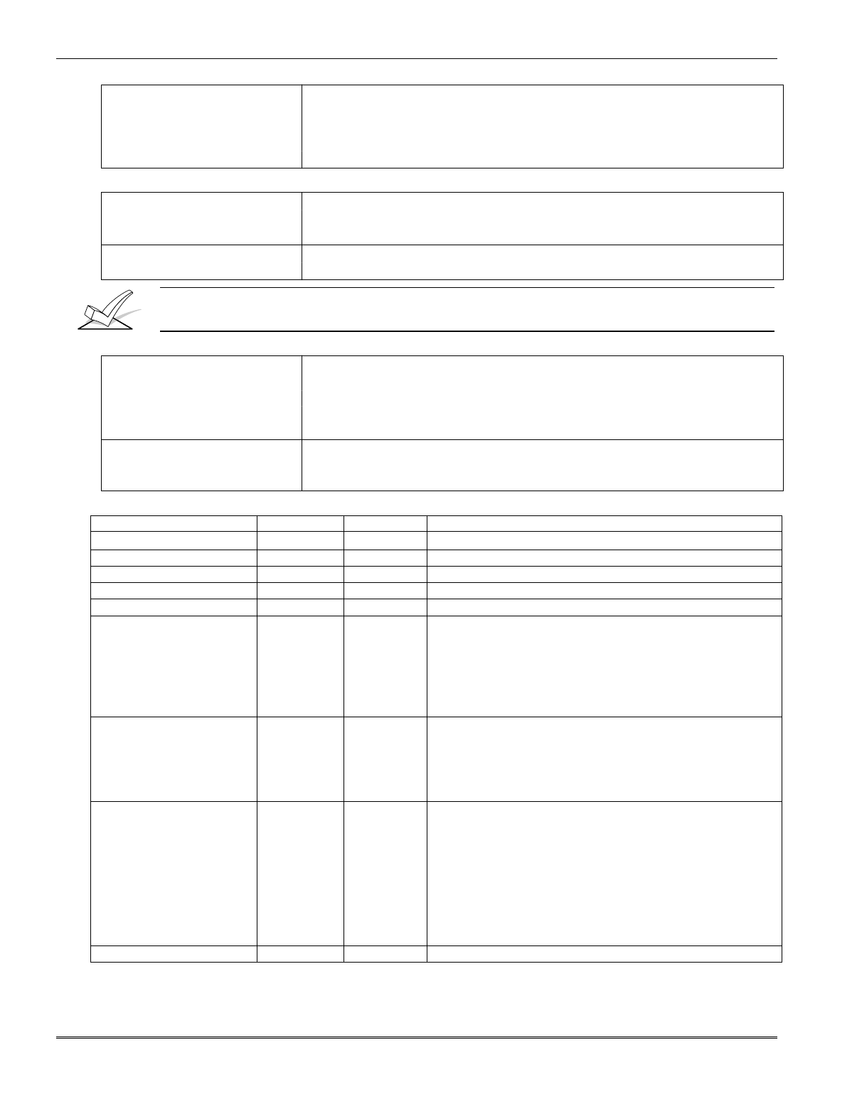
Interactive Mode Programming (∗56, *57, ∗58, ∗79, ∗80, ∗81, ∗82)
Entering Interactive Mode Press [∗] + [Interactive Mode No.] (for example, ∗56) while in Program Mode.
The Alpha display keypad will display the first of a series of prompts
requesting entries.
After making the appropriate entry, press the [∗] key to accept the entry and
continue to the next prompt.
Loading Factory Defaults/Initializing for Download
To Load Default Entries Press ∗97 while in Program Mode. This resets all data fields to the default
values shown on the Program Form. Use ∗97 only if you wish to return to the
original factory-programmed defaults.
To Initialize Download ID Press ∗96 while in Program Mode. This initializes the system for
downloading and resets all the subscriber account numbers and CSID.
Do not press ✱97 to load defaults if any programming has been done previously—data already
programmed into the system will be changed!
Exiting the Programming Mode
Prevent installer code reentry Press ∗98. Exits Programming Mode and prevents re-entry by:
Installer Code + [8] + [0] + [0]. To enter the programming mode if ∗ 98 was
used to exit, you must first power the system down. Then power up again,
and press [∗] and [#] at the same time, within 50 seconds of powering up.
See field *88 for other Program mode lockout options.
Allow installer code reentry Press ∗99. Exits Programming Mode and allows re-entry by:
Installer Code + [ 8] + [0] + [0] or by: Pressing [∗] and [#] at the same time,
within 50 seconds of power-up.
Table of Device Addresses
This Device Uses Address Reports as†† Enabled By…
RF Receiver 00 100 *56 zone programming: input device type entry
AUI 1 (FA168CPS only) 01 101 automatic if AUI enable field *189 enabled for AUI 1
AUI 2 (FA168CPS only) 02 102 automatic if AUI enable field *189 enabled for AUI 2
Long Range Radio 03 103 automatic if output to long range radio field *29 enabled
FA4286 Voice Module 04 104 automatic if phone module access code field *28 enabled
Zone Expanders (4219/4229):
module 1 (for zones 09 - 16)
module 2 (for zones 17 - 24)
module 3 (for zones 25 - 32)
module 4 zones 33 - 40
module 5 zones 41 - 48
07
08
09†
10†
11†
107
108
109
110
111
*56 zone programming: input device type, entry 2, then:
automatic if zone no. 9-16 entered as AW type or relay assigned
automatic if zone no. 17-24 entered as AW type or relay assigned
automatic if zone no. 25-32 entered as AW type or relay assigned
automatic if zone no. 33-40 entered as AW type or relay assigned
automatic if zone no. 41-48 entered as AW type or relay assigned
Relay Modules (4204):
module 1
module 2
module 3
module 4
12
13
14†
15†
112
113
114
115
*79 output device programming: device address prompt:
entered at device address prompt
entered at device address prompt
entered at device address prompt
entered at device address prompt
Keypads:
keypad 1
keypad 2
keypad 3
keypad 4
keypad 5
keypad 6
keypad 7
keypad 8
16
17
18
19
20
21
22
23
n/a
n/a
n/a
n/a
n/a
n/a
n/a
n/a
data field programming as listed below:
always enabled for partition 1, all sounds enabled.
data field *190
data field *191
data field *192
data field *193
data field *194
data field *195
data field *196
5800TM Module 28 n/a automatic
† 4219/4229 addresses 9-11 and 4204 addresses 14-15 apply to the FA168CPS.
†† Addressable devices are identified by “1” plus the device address when reporting. Enter a report code for zone 91 to enable
addressable device reporting (default = reports enabled). See field *199 for addressable device (ECP) 3-digit/2-digit
identification keypad display options.
Installation Instructions
3-6

SECTION 4
Data Field Programming
•••••••••••••••••••••••••••••••••••••••
About Data Field Programming
The following pages list this control’s data fields in numerical order. Field numbers are listed in the
left column followed by a “Title and Data Entries” column, which lists the valid entries for each field.
Experienced installers can simply follow this column when programming the data fields. The
“Explanation” column provides explanatory information and special notes where applicable.
Use the blank programming form to record the data for this installation.
Programming Data Fields
Data field programming involves making the appropriate entries for each of the data fields.
Start Data Field programming by entering the installer code + 8 + 0 + 0.
System Setup Fields (∗20 – ∗29)
FIELD TITLE and DATA ENTRIES EXPLANATION
*20 Installer Code
Enter 4 digits, 0-9
The Installer Code can perform all system functions except it cannot
disarm the system unless it is used to arm the system.
*21 Quick Arm Enable
0 = do not allow quick arm
1 = allow quick arm
If enabled, a user code is not needed to arm the system. Instead,
users can press the [#] followed by an arming key to arm the system.
However, the user code is always needed to disarm the system.
*22 RF Jam Option
0 = no RF jam detection
1 = send RF jam report
If enabled, a report is sent if the system detects an RF jamming
signal.
UL installations must be 1 if wireless devices are used.
*23 Quick (Forced) Bypass
0 = no quick bypass
1 = allow quick bypass (code + [6] + [#] )
All zones bypassed by this function will be displayed after the bypass
is initiated.
UL installations must be 0 (no forced bypass)
*24 RF House ID Code
00 = disable all wireless keypad usage
01–31 = House ID for partition 1, 2 and
common
The House ID identifies receivers and wireless keypads. If a 5827 or
5827BD Wireless Keypad or 5804BD Transmitter is being used, a
House ID code must be entered, and the keypad should be set to the
same House ID. You can assign RF house ID for each partition.
*26 Chime By Zone List 3
0 = no zone list (chimes on fault of any
entry/exit or perimeter zone when chime
mode on)
1 = use zone list (chimes on fault of
specific zones programmed in relay
zone list 3 when Chime mode on)
If enabled, you can define the specific zones intended to chime when
faulted while the system is in Chime mode. Use zone list 3 to assign
these zones (see ∗81 Zone List Programming section for details).
*27 Powerline Carrier Device (X-10)
House ID
0 = A 6 = G # + 11 = L
1 = B 7 = H # + 12 = M
2 = C 8 = I # + 13 = N
3 = D 9 = J # + 14 = O
4 = E # + 10 = K # + 15 = P
5 = F
Powerline Carrier devices require a House ID, identified in this field.
Program Powerline Carrier devices in interactive modes ∗79, *80 and
*81.
Not intended for fire or UL installations.
*28 Access Code for Phone Module
1-9 = first digit of access code
∗ or # = second digit of access code (enter #
+11 for “∗”, or # +12 for “#”)
You need to assign a 2-digit access code for the FA4285/FA4286
Phone Module, if used. Example: If desired access code is 7∗ , 7 is the
first entry, and [#] + 11 (for ∗) is the second entry.
NOTE: A “0” in either digit disables the phone module.
Must be “00” for UL Commercial Burglar Alarm installations.
4-1

FIELD TITLE and DATA ENTRIES EXPLANATION
*29 Long Range Radio Output
0 = not used
1 = using Long Range Radio output
If selected, all messages programmed to go to the primary telephone
line receiver will also be sent to the connected 7720PLUS, 7820,
7835, or 7845 Radio (sent in Contact ID format). The data line is
supervised as well as certain functions in the radio. If
communication is lost or a trouble develops, an attempt will be made
to send a message via both radio and telephone to the central station.
Program the radio for device address 3.
Zone Sounds & Timing (∗31–∗39)
FIELD TITLE and DATA ENTRIES EXPLANATION
*31 Single Alarm Sounding Per Zone
(per armed period)
0 = no limit on alarm sounding per zone
1 = limit alarm sounding to once per arming
period for a given zone
UL installations must be 0 (no limit).
*32 Fire Alarm Sounder Timeout
0 = yes; fire sounder timeout after time
programmed in field ∗33
1 = no fire sounder timeout; continue
sounding until manually turned off
This control complies with NFPA requirements for temporal pulse
sounding of fire notification appliances.
Temporal pulse sounding for a fire alarm consists of the following:
3 pulses – pause – 3 pulses – pause – 3 pulses.
UL fire alarm installations: must be 1.
*33 Alarm Sounder Timeout
0 = No timeout 3 = 12 min
1 = 4 min 4 = 16 min
2 = 8 min
This field determines whether the external sounder will shut off
after time allotted, or continue until manually turned off.
UL installations: For residential fire alarm installation, must be set
for a minimum of 4 min (option 1); for UL Commercial Burglary
installations, must be minimum of 16 min (option 4).
*34 Exit Delay
00 - 96 = 0 - 96 seconds
97 = 120 seconds
The system waits the time entered before arming entry/exit zones. If
the entry/exit door is left open after this time expires, an alarm will
occur. Common zones use same delay as partition 1.
UL installations: For UL Commercial Burglar Alarm (Grade AA) and
UL Residential Burglar Alarm installations with line security, total
exit time must not exceed 60 seconds. For UL Burglar Alarm
installations without line security (Grade A), total exit time must not
exceed 120 seconds.
SIA Installations: minimum exit delay is 45 seconds
*35 Entry Delay 1
00 - 96 = 0 - 96 seconds
97 = 120 seconds
98 = 180 seconds
99 = 240 seconds
Upon entering, the system must be disarmed before the time entered
expires, otherwise it sounds an alarm. Common zones use same
delay as partition 1.
UL installations: For UL Residential Burglary Alarm installations,
must be set for a maximum of 30 seconds; entry delay plus dial delay
should not exceed 1 min. For UL Commercial Burglar Alarm, total
entry delay may not exceed 45 seconds.
SIA Installations: minimum entry delay is 30 seconds
*36 Entry Delay 2
See *35 above for entries.
See *35 above for explanation.
*37 Audible Exit Warning
0 = no; 1 = yes
Warning sound consists of slow continuous beeps until last 10 seconds,
then it changes to fast beeps. Sound ends when exit time expires.
SIA Installations: must be enabled (enter 1)
*38 Confirmation Of Arming Ding
0 = no ding
1 = confirmation ding after arming system
2 = confirmation ding after arming from RF
button or RF keypad only
Confirmation of arming is 1/2 second external sounder “ding.”
If “1” selected, ding occurs when closing report is sent, or at the end
of Exit Delay.
If “2” selected, ding occurs upon reception of the wireless arming
command.
UL installations: must be “1” for UL Commercial Burglar Alarm
installations.
*39 Power-Up In Previous State
0 = always power-up in a disarmed state
1 = assume the system status prior to
power down
When the system powers up armed, an alarm will occur 1 minute
after arming if a zone is faulted.
Note that if the previous state was armed Away or Stay, the system
will not respond to sensor changes for 1 minute, which allows time
for sensors such as PIRs to stabilize.
UL installations: must be 1 (power-up in previous state)
Installation Instructions
4-2

Dialer Programming (∗40 – ∗50)
FIELD TITLE and DATA ENTRIES EXPLANATION
*40 PABX Access Code
Enter up to 6 digits if PABX is needed to
access an outside line. Do not fill unused
spaces.
0–9, # + 11 for ‘∗’, # + 12 for ‘#’, # + 13 for a
pause (2 seconds)
To clear entries from field, press ∗40∗. If fewer than 6 digits need to
be entered, exit by pressing [∗], which advances to the next field.
Call Waiting: If the subscriber’s phone service has “call waiting”
(and is not using PABX), enter “*70” (“# + 11”) plus “# + 13” (pause)
as the PABX entry to disable “call waiting” during control panel calls.
If the subscriber does not have “call waiting” and is not using PABX,
make no entry in this field.
*41 Primary Phone No.
Enter up to 20 digits. Do not fill unused
spaces.
0–9, # + 11 for ‘∗’, # + 12 for ‘#’, # + 13 for a
pause (2 seconds)
If you enter fewer than 20 digits, exit by pressing [∗]. To clear entries
from field, press ∗41∗.
NOTE: Backup reporting (in which 8 calls are made to the secondary
phone number if no kissoff is received after 8 attempts to the
primary number) is automatic only if there is a secondary phone
number (field ∗42).
*42 Secondary Phone No.
Enter up to 20 digits.
0–9, # + 11 for ‘✱’, # + 12 for ‘#’, # + 13 for a
pause (2 seconds)
If you enter fewer than 20 digits, exit by pressing [∗]. To clear entries
from field, press ∗42∗. See backup reporting note for field ∗41.
Don’t fill unused spaces.
*43 Part. 1 Primary Subs. Acct. No.
Enter digits 0–9; # + 11 for B, # + 12 for C, #
+ 13 for D, # + 14 for E, # + 15 for F.
To clear entries from field, press ∗43∗.
*44 Part. 1 Secondary Subs. Acct. No.
Enter digits 0–9; # + 11 for B, # + 12 for C, #
+ 13 for D, # + 14 for E, # + 15 for F.
To clear entries from field, press ∗44∗.
*45 Part. 2 Primary Subs. Acct. No.
Enter digits 0–9; # + 11 for B, # + 12 for C, #
+ 13 for D, # + 14 for E, # + 15 for F.
FA168CPS.
To clear entries from field, press ∗45∗.
*46 Part. 2 Secondary Subs. Acct. No.
Enter digits 0–9; # + 11 for B, # + 12 for C, #
+ 13 for D, # + 14 for E, # + 15 for F.
FA168CPS.
To clear entries from field, press ∗46∗.
*47 Phone System Select
If Central Station Receiver is not on WATS
line: 0 = Pulse Dial; 1 = Tone Dial
If Central Station Receiver is on WATS line:
2 = Pulse Dial; 3 = Tone Dial
Select the type of telephone service.
*48 Report Format (Primary/Secondary)
0 = 3+1, 4+1 ADEMCO L/S STANDARD
1 = 3+1, 4+1 RADIONICS STANDARD
2 = 4+2 ADEMCO L/S STANDARD
3 = 4+2 RADIONICS STANDARD
5 = ADEMCO Contact ID® 10-digit Format
6 = 4+2 ADEMCO EXPRESS
7 = ADEMCO Contact ID® 4-digit Format
8 = 3+1, 4+1 ADEMCO L/S EXPANDED
9 = 3+1, 4+1 RADIONICS EXPANDED
Select report format for primary and secondary phone numbers.
*49 Split/Dual Reporting
0 = standard/backup reporting only
(all reports only to primary unless
unsuccessful, then will attempt
secondary)
1 - 5 (see table to right)
To Primary No. To Secondary No.
1 = alarms, restore, cancel others
2 = all except open/close, test open/close, test
3 = alarms, restore, cancel all
4 = all except open/close, test all
5 = all all
*50 Burglary Dialer Delay
0 = no dial delay
1 = 15 seconds
2 = 30 seconds
3 = 45 seconds
Provides delay of “BURGLARY ALARM” report to the central
station, which allows time for the subscriber to avoid a false alarm
transmission. This delay does not apply to zone type 24 alarms
(silent burglary) or to 24-hour zone types 6, 7, and 8 (silent panic,
audible alarm, auxiliary alarm), which are always sent as soon as
they occur.
UL: must be “0”
SIA Installations: delay must be minimum of 30 seconds
*53 SESCOA/Radionics Select
0 = Radionics (0-9, B-F reporting)
1 = SESCOA (0-9 only reporting)
Select SESCOA or Radionics format.
Select 0 for all other formats.
4-3

FIELD TITLE and DATA ENTRIES EXPLANATION
*54 Dynamic Signaling Delay
0 = disabled (both signals sent)
1–15 = entry times a 15-second delay.
e.g., 1 = 15 seconds, 2 = 30 seconds, etc.
Intended for use with Long Range Radio reporting.
This field lets you select the time the panel should wait for
acknowledgment from the first reporting destination (see ∗55) before
it attempts to send a message to the second destination. Delays can
be selected from 0 to 225 seconds, in 15-second increments. This
delay is per message. If ”0” is entered in this field, the control panel
will send redundant reports to both Primary Dialer and LRR.
UL Installations:
For Fire Alarm and UL Burglar Alarm installations without Line
Security (Grade A), the maximum Dynamic Signaling Delay must
be no more than 15 seconds.
For UL Burglar Alarm installations with Line Security (Grade
AA), Dynamic Signaling Delay must be “0”. The reports will be sent
to both the dialer and the LRR.
*55 Dynamic Signaling Priority
0 = Primary dialer first;
1 = Long Range Radio (LRR) first.
UL Installations: For UL Commercial
Burglary installations that use a DACT and
LRR, the DACT must be programmed for
priority (option “0”).
Intended for use with Long Range Radio reporting.
You must also enable field ∗29, OUTPUT TO LONG RANGE RADIO.
Select the initial reporting destination for messages as follows:
Primary Dialer First selected (0):
• If acknowledged before delay expires (see ∗54), then message will
not be sent to LRR.
• If not acknowledged before delay expires, then message is sent to
both the Primary Phone No. and LRR.
Long Range Radio First selected (1):
• If acknowledged before delay expires, then message will not be
sent to the primary dialer.
• If not acknowledged before delay expires, then message is sent to
both the Primary Phone No. and LRR.
*56 Zone Programming Menu Mode
Use this menu mode to program zone information. See Zone
Programming section for procedures.
*57 Function Key Menu Mode
Use this menu mode to program keypad function keys. See Function
Key section for procedures.
*58 Expert Zone Programming Menu
Mode
This menu mode can be used to quickly program zone information,
but is recommended only for those already familiar with *56 menu
mode. See Zone Programming section for procedures.
System Status Report Codes
Zone report codes are programmed using interactive ✱56 or ✱58 Zone Programming modes, while system status
(non-alarm) codes and restore codes are entered in data fields *59 - *68, *70 - *76, *89. The actual report code digits
that you enter depend upon the particular installation, and should agree with the Central Station office receiving
the signals.
3+1 or 4+1 Standard Format: Enter a code in the first box: 1–9, A, B, C, D, E, or F. Enter #+10 for A (this
reports a 0 on some receivers), #+11 for B, #+12 for C, #+13 for D, #+14 for E, #+15 for F.
An entry of 0 in the first box disables a report. Entering 0 in the second box advance to the next field.
Expanded or 4+2 Format: Enter codes in both boxes (first and second digits) for 1–9 or A–F, as described
above. An entry of 0 in the first box disables a report. An entry of 0 in the second box eliminates the expanded
message for that report.
ADEMCO Contact ID® Reporting: Enter a digit in the first box to enable the zone to report. Use a different
digit for each zone until you have used up available digits. If the number of zones exceeds the number of
available digits, begin with digit 1 again. This is an “enabling” code only and is not the actual code sent to the
Central Station office. Entries in the second boxes are ignored. An entry of 0 in the first box disables the report.
UL installations: Program fields *59 - *76 as required by the applicable UL Standards shown in each field.
Installation Instructions
4-4

FIELD TITLE and DATA ENTRIES EXPLANATION
*59 Exit Error Report Code
0 = no report
1-F = see description above
After arming the system, entry/exit and interior zones remaining open
after exit delay expires cause an alarm sound at the keypad and
external sounder (keypad also displays “EXIT ALARM”), and entry
delay begins. Disarming before the end of the entry delay stops the
alarm sounding and no message is sent to the central station. The
keypad displays “CA” (fixed-word) or “CANCELED ALARM” (alpha
display).
If the system is not disarmed before entry delay expires, an “EXIT
ALARM” message will be sent to the central station if Exit Error
Report Code is enabled. The keypad will display “EA” (fixed-word ) or
“EXIT ALARM” (alpha display), and alarm sounding continues until
the system is disarmed (or timeout occurs).
An Exit Alarm condition will also result if a fault occurs in an exit or
interior zone within 2 minutes following the end of the exit delay,
and an “EXIT ALARM” message will be sent to the central station
1
With Contact ID format, the message will contain the zone number
and error code 374 (“ALARM–EXIT ERROR”).
*60 Trouble Report Code
0 = no report
1-F = see description above *59
This will be sent if a zone has a trouble condition.
UL: Required for UL commercial burglar alarm installations and
required for residential fire alarm installations.
*61 Bypass Report Code
0 = no report
1-F = see description above *59
This will be sent when a zone is manually bypassed.
UL: Required for UL commercial burglar alarm installations.
*62 AC Loss Report Code
0 = no report
1-F = see description above *59
Timing of this report is random with up to a 4-hour delay. If AC
restores before the report goes out, there is no “AC RESTORE”
report.
UL: Required for UL commercial burglar alarm installations and
required for residential fire alarm installations.
*63 Low Bat Report Code
0 = no report
1-F = see description above *59
Sent when a low-battery condition exists in the system’s battery.
UL: Required for UL commercial burglar alarm installations and
required for residential fire alarm installations.
*64 Test Report Code
0 = no report
1-F = see description above *59
† NOTE: Make sure the Real-Time Clock
is set to the proper time before entering
the test report schedule command to
ensure that test reports are sent when
expected. (see Setting the Real-Time
Clock section on page 12-3)
Sent periodically to test that the communicator and phone lines are
operational. Frequency of report is set in Scheduling mode
(event 11) or by the following key commands:
installer code + [#] + 0 + 0 = test report sent every 24 hrs
installer code + [#] + 0 + 1 = test report sent once per week
installer code + [#] + 0 + 2 = test report sent every 28 days
Each of these modes sets schedule 32 (FA168CPS) or 8
(FA148CP) to the selected repeat option; first test report sent
12 hours after command†.
UL: Required for UL commercial burglar alarm installations and
required for residential fire alarm installations.
*65 Open Report Code
0 = no report; 1-F = see description above *59
This is sent upon disarming of the system in the selected partitions.
UL: Required for UL commercial burglar alarm installations.
*66 Arm Away/Stay Report Code
0 = no report
1-F = see description above *59
This option allows for independent programming of Away and Stay
reports for each partition, including the common lobby.
NOTE: “OPEN” reports are not sent if the associated closing report
is not enabled.
*67 RF Trans. Low Batt. Report Code
0 = no report; 1-F = see description above *59
Sent when a wireless transmitter low-battery condition exists.
UL installations: must be enabled if wireless devices are used.
*68 Cancel Report Code
0 = no report
1-F = see description above *59
This is sent upon disarming of the system after an alarm condition
was reported.
*70 Alarm Restore Report Code
0 = no report
1-F = see description above *59
Sent when an alarm zone is restored to its non-faulted condition.
UL: Required for UL commercial burglar alarm installations and
required for residential fire alarm installations.
*71 Trouble Restore Report Code
0 = no report
1-F = see description above *59
This is sent when a trouble in a zone is restored
UL: Required for UL commercial burglar alarm installations.
4-5

FIELD TITLE and DATA ENTRIES EXPLANATION
*72 Bypass Restore Report Code
0 = no report
1-F = see description above *59
This is sent when a zone that has been bypassed is unbypassed.
UL: Required for UL commercial burglar alarm installations.
*73 AC Restore Report Code
0 = no report
1-F = see description above *59
Sent when AC power has been restored after an AC power outage.
UL: Required for UL commercial burglar alarm installations and
required for residential fire alarm installations.
*74 Low Bat Restore Report Code
0 = no report
1-F = see description above *59
Sent when a system low-battery condition is restored to normal.
UL: Required for UL commercial burglar alarm installations and
required for residential fire alarm installations.
*75 RF Xmtr Low Batt. Restore Code
0 = no report
1-F = see description above *59
Sent when a transmitter’s low battery condition is restored (i.e., new
battery installed).
UL installations: must be enabled if wireless devices are used.
Required for UL commercial burglar alarm installations and
required for residential fire alarm installations.
*76 Test Restore Report Code
0 = no report
1-F = see description above *59
This is sent when the Test mode is exited.
UL: Required for UL commercial burglar alarm installations and
required for residential fire alarm installations.
Miscellaneous System Fields
FIELD TITLE and DATA ENTRIES EXPLANATION
*77 Daylight Saving Time
Start/End Month
0 = Disabled 4 = April
1 = Jan # + 10 = Oct
2 = Feb # + 11 = Nov
3 = Mar # + 12 = Dec
Enter the start and end month for daylight savings time, if
applicable to the region.
*78 Daylight Saving Time
Start/End Weekend
0 = disabled 4 = fourth
1 = first 5 = last
2 = second 6 = next to last
3 = third 7 = third to last
Enter the start and end weekend for daylight savings time, if
applicable to the region.
*79 Output Device Mapping Menu Mode Use this menu mode to enter output devices/powerline carrier
devices into the system. See Output Device Programming
section for procedures.
*80 Output Programming Menu Mode Use this menu mode to define output functions for use with
output devices/powerline carrier devices. See Output
Programming section for procedures.
*81 Zone List Programming Menu Mode Use the menu mode to define zone lists. See Zone List
Programming section.
*82 Alpha Descriptor Programming
Menu Mode
Use this menu mode to assign alpha descriptors to zones and/or
create partition descriptors (FA168CPS).
*84 Auto-Stay Arm
0 = no
1 = partition 1 only
2 = partition 2 only
3 = both partitions
If enabled, the system will automatically change
AWAY/MAXIMUM modes to STAY/INSTANT modes
respectively if the entry/exit door is not opened and closed
within the exit delay time after a user arms in AWAY mode
from a wired keypad (non-RF device). An Opening report
followed by an Armed Stay report is sent to the Central Station.
If the door is opened and closed within the exit delay period, the
system remains in AWAY mode.
Any RF device that arms the system AWAY overrides this
feature and the system remains armed in the AWAY mode.
*85 Cross Zone Timer
0 = 15 secs 6 = 2-1/2 min #+12 = 8 min
1 = 30 secs 7 = 3 min #+13 = 10 min
2 = 45 secs 8 = 4 min #+14 = 12 min
3 = 60 secs 9 = 5 min #+15 = 15 min
4 = 90 secs #+10 = 6 min
5 = 2 min #+11 = 7 min
Sets the maximum amount of time in which two cross zones
must be tripped in an armed system to send an alarm message
to the Central Station. If only one cross zone is tripped during
this time, a trouble message (CID code 380) for that zone is sent
to the Central Station.
Assign cross zone pairs in zone list 4.
This option not for use in UL installations.
Installation Instructions
4-6
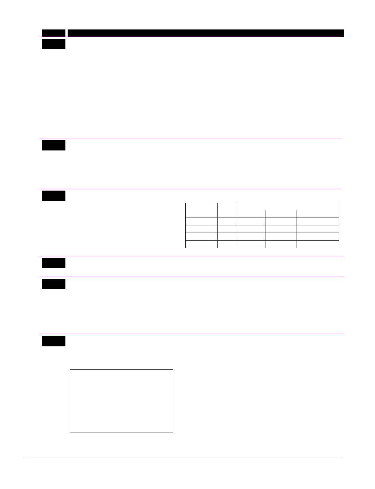
FIELD TITLE and DATA ENTRIES EXPLANATION
*86 Cancel Verify Keypad Display
0 = no
1 = yes
When enabled (1 = yes), this feature causes a “CANCELED
ALARM” display on the LCD keypad under the following
conditions:
• After the kissoff of the cancel message to the Central Station,
indicating a successful transmission.
• When an alarm is successfully canceled before the Central
Station received the Alarm message. E.g., if an alarm is
incorrectly triggered and the user presses code + OFF before
the dial delay time has expired, the message will never go out
to the CS.
• When the Cancel report is not enabled and the system is
disarmed:
a. before dialer delay expires (alarm report not sent)
message “Canceled Alarm” is displayed.
b. after dialer delay expires message “Canceled Alarm” is
not displayed.
*87 Misc. Fault Delay Time
0 = 15 secs 6 = 2-1/2 min #+12 = 8 min
1 = 30 secs 7 = 3 min #+13 = 10 min
2 = 45 secs 8 = 4 min #+14 = 12 min
3 = 60 secs 9 = 5 min #+15 = 15 min
4 = 90 secs #+10 = 6 min
5 = 2 min #+11 = 7 min
Used with zones assigned to a configurable zone type with fault
delay on (configurable zone type digit “6”), and sets a zone
response time of 15 seconds to 15 min. It can be assigned to
zones with sensors that provide a trouble indication when an oil
tank is low, or similar applications for critical condition
monitoring where a non-alarm response is desired.
UL: May only be used on non-burglar alarm and non-fire alarm
zones when used on a fire and/or UL burglar alarm installation.
*88 Program Mode Lockout Options
0 = standard *98 installer code lockout
1 = lockout [∗] + [#] reentry after *98 exit (reentry
via installer code only)
2 = not used
3 = lockout all local programming after *98 exit
(reentry via downloader only)
Select the desired options. The following table summarizes the
Program mode lockout options:
Exit *88 Reentry By:
Command Entry Installer Power-up† Downloader
*99 n/a yes yes yes
*98 0 no yes yes
*98 1 yes no yes
*98 3 no no yes
† pressing [∗] + [#] within 50 seconds of power up
*89 Event Log Full Report Code
0 = no report
1-F = see description above *59
If an Event Logging selection is made in field ∗90, a message can be
sent to the central station receiver when the log is 80% full. If the log
becomes full, new messages overwrite the oldest messages in the log.
*90 Event Log Enables
0 = no event logging
1 = log Alarm/Alarm Restore
2 = log Trouble/Trouble Restore
4 = log Bypass/Bypass Restore
8 = log Open/Close
x = log combination of events (add value of
entries)
This system has the ability to record various events in a history log
(FA168CPS = 100 events; FA148CP = 50 events). At any time, the
downloader operator can then upload the log and view or print out all
or selected categories of the log. The downloader operator can also
clear the log. Event log can also be viewed at an alpha keypad.
The display/printout at the central station will show the date, time,
event, and description of the occurrences.
Data Entry Example: To select Alarm/Alarm Restore” and
“Open/Close”, enter 9 (1+ 8); to select all events, enter #15.
*91 Option Selection
0 = none
2 = Sounder Delay
4 = using Audio Alarm Verification (AAV) unit
8 = Enable Exit delay restart/reset ††
UL If sounder delay is used, entry delay
(field *35) must be 30 sec. max.
UL installations using the AAV feature
must use the ADEMCO UVCM module
(part of the ADEMCO UVS system).
Exit Delay Restart/Reset must be
disabled.
FOR SIA INSTALLATIONS: Exit delay
should be enabled.
Multiple choice example: for both AAV and
Exit delay restart, enter # + 12 (4 + 8).
Select the desired options by adding the values of each desired option.
Sounder Delay: If enabled, delays external sounding by 15-seconds.
††“Exit Delay Restart/reset” option allows use of the [∗] key to restart
the exit delay at any time when the system is armed STAY or
INSTANT. This feature also enables automatic exit delay reset,
which resets exit delay if the entry/exit door is re-opened and closed
before exit delay time expires after arming AWAY.
IMPORTANT: AAV should not be used when Paging or Alarm
Reports are sent to a secondary number unless the monitoring zone
option is used (which pauses calls). Otherwise, the call to the
secondary number by the communicator after the alarm report will
prevent the AAV from taking control of the telephone line, and the
AAV “Listen in” session cannot take place.
4-7
FIELD TITLE and DATA ENTRIES EXPLANATION
*92 Phone Line Monitor Enable
Entry 1–Timeout:
0 = disabled
1-15 = 1 minute to 15 minutes respectively
(2 = 2 min, 3 = 3 min, etc.; # + 10 =10 min, #
+ 11 = 11 min, # + 12 = 12 min, # + 13 = 13
min, # + 14 = 14 min, # + 15 = 15 min)
Entry 2–Display/Sound:
0 = keypad display only when phone line is
faulted.
1 = keypad display plus keypad trouble
sound when line is faulted. Each
partition turns off its own trouble sound.
No automatic timeout.
2 = Same as “1” plus programmed output
device STARTS. If either partition is
armed, external sounder activates.
External sounder will be turned off by
normal bell timeout, or by security code
plus OFF from either partition (it does
not have to be the one that was armed).
Entry 1: Sets the length of time a phone line fault must remain after
detected before the second digit option is activated.
Entry 2: Selects the desired phone line fault response.
Option 2 may be used even if a relay unit or Powerline carrier device
is not connected to the control.
Programmed Output Device must either be programmed to be
STOPPED in field ∗80 or STOPPED by entry of [security code] + [#]
+ 8 + device number. Partition in ∗80 should be set to “0,” for STOP.
UL Field *92 must be enabled for fire alarm installations, UL
commercial burglar alarm installations and UL residential burglar alarm
installations.
If the control unit is used on a UL commercial burglar alarm system
which requires 2 methods of remote communication, then the control
unit’s DACT and the other method of signal transmission must monitor
each other against communication failure and line fault. The fault must
be received and annunciated within 200 seconds of its occurrence.
*93 No. of Reports In Armed Period
per Zone (Swinger Suppression)
0 = unlimited number of reports
1 = 1 report pair per zone per armed period
2 = 2 report pairs per zone per armed period
This option can be used to limit the number of alarm/alarm restore
messages per zone sent to the central station in an armed period.
A report pair is the alarm followed by the alarm restore.
UL installations must be 0 (unlimited reports).
SIA Installations: Must be set for option 1 or 2.
*94 Download Phone Number
Enter up to 20 digits as follows: 0–9, # +11
for “∗”, # + 12 for “#”, # + 13 for a pause.
Enter the phone number of the downloading computer.
Do not fill unused spaces. End field by entering ∗. To clear entries
from field, press ∗94∗.
*95 Ring Count For Downloading
0–15 = number of rings before control picks
up phone line .
† NOTE: If “15” is entered to bypass an
answering machine, and a FA4285 or FA4286
Phone Module is included in the system, you
should note the following:
When calling in from an off-premises phone,
the user should make the initial call, allow 1 or
2 rings only, then hang up, then call again. The
phone module will now seize the line, and 2
long tones sound, followed by the usual voice
prompt for the access code. If this procedure is
not followed, phone module operation will not
be possible.
Refer to the chart below and program this field accordingly.
phone answer down-
module machine loading Set field
∗95 to…
yes no no 1-14 (not 0)
yes yes no higher than number of rings set on
answer machine (e.g., if ans.
machine is 4 rings, set this field to
5). This allows access to the phone
module if the answer machine is off.
yes no yes 1-14 (not 0)
yes yes yes 15 (bypasses answer machine†)
no no no 0
no yes no 0
no no yes 1-14
no yes yes 15
*96 Command to Initialize CSID and
Subscriber Account Number
This is a command function, not a data field. Use this command, if
necessary, to reset all subscriber account numbers and the internal
CSID to the factory default values.
*97 Command to Reset System to
Factory Default Values
This is a command function, not a data field. Pressing ∗97 resets
all data fields to the factory default values (shown on the
Program Form).
IMPORTANT: Do not press ∗97 to load defaults if any
programming has been done previously—data already
programmed into the system will be changed!
*98 Command to Exit Program Mode
(with installer code lockout)
Exits Programming Mode and prevents re-entry by:
Installer Code + [8] + [0] + [0]. To enter the programming
mode if ∗ 98 was used to exit, you must first power the system
down. Then power up again, and press [∗] and [#] at the same
time, within 50 seconds of powering up.
See field *88 for other Program mode lockout options.
*99 Command to Exit Program Mode
Exits Programming Mode and allows re-entry by:
Installer Code + [ 8] + [0] + [0] or by: Pressing [∗] and [#] at
the same time, within 50 seconds of power-up.
Installation Instructions
4-8

Pager Programming Fields
FIELD TITLE and DATA ENTRIES EXPLANATION
*160 Pager 1 Phone No.
Enter up to 20 digits
If you enter fewer than 20 digits, exit by pressing [∗] and next field
number. To clear entries from this field, press ∗160∗.
*161 Pager 1 Characters
Enter up to 16 characters
Up to 16 optional characters may be sent as a prefix to the 7-digit
system status code sent to pager #1 (if used). Phone number in field
*160 must have been entered. If fewer than 16 characters, exit by
pressing [∗] and next field number. To clear entries from this field,
press ∗161∗.
For example, these optional 16 characters may be composed of the
following:
• PIN number (to identify a specific pager to the paging company)
• Subscriber account number
• ∗ (enter # + 11 to send ∗)
• # (enter # + 12 to send #)
• Pause (enter # + 13 to allow a 2-second pause)*
• Any special character(s) the end user may decide to transmit
* Some paging systems require pause(s) before the prefix.
The format for the 7-digit system status code is defined as follows:
Pager Format: XXX-YYYY where:
XXX = 3-digit event code: 911 = Alarm
811 = Trouble
101 = Opening (disarm)
102 = Closing (arm AWAY)
YYYY = 4-digit user or zone number (depending on type of event).
The first digit indicates partition (0 = system, 1 = part 1,
2 = part 2, 3 = common), followed by the 3-digit user or
zone number.
Example 1. Pager displays: 911–1004
This indicates that the system is reporting an alarm (911) caused by
a fault in zone 4 (0004) in partition 1.
Example 2. Pager displays: 102–2005
This indicates that the system is reporting a closing–system arming
(102) by User 5 (0005) in partition 2.
*162 Pager 1 Report Options
0 = No reports sent
1 = Open/close for all users enabled to page†
4 = All alarms and troubles
5 = All alarms, troubles, and open/close for
all users enabled to page
12 = Alarms and troubles for zones entered
in zone list 9
13 = Alarms and troubles for zones listed in
zone list 9 and open/close for all users
enabled to page
Enter the types of reports to be sent to pager 1 for each partition.
† Reports to pager only when arming (close)/disarming (open) from a
keypad using a security code; auto-arming/disarming, arming with
assigned button, and keyswitch arming do not send pager messages.
*163 Pager 2 Phone No.
Enter up to 20 digits
If you enter fewer than 20 digits, exit by pressing [∗] and next field
number. To clear entries from this field, press ∗163∗.
4-9

FIELD TITLE and DATA ENTRIES EXPLANATION
*164 Pager 2 Characters
Enter up to 16 characters
See field ∗161 for explanation of entries. If fewer than 16 characters,
exit by pressing [∗] and next field number. To clear entries from this
field, press ∗164∗.
*165 Pager 2 Report Options
see pager 1 reports, field *162 for entries,
except use zone list 10.
Enter the types of reports to be sent to pager 2 for each partition.
*166 Pager 3 Phone No.
Enter up to 20 digits
FA168CPS.
If you enter fewer than 20 digits, exit by pressing [∗] and next field
number. To clear entries from this field, press ∗166∗.
*167 Pager 3 Characters
Enter up to 16 characters
FA168CPS.
See field ∗161 for explanation of entries. If fewer than 16 characters,
exit by pressing [∗] and next field number. To clear entries from this
field, press ∗167∗.
*168 Pager 3 Report Options
see pager 1 reports, field *162 for entries,
except use zone list 11.
FA168CPS.
Enter the types of reports to be sent to pager 3 for each partition.
*169 Pager 4 Phone No.
Enter up to 20 digits
FA168CPS.
If you enter fewer than 20 digits, exit by pressing [∗] and next field
number. To clear entries from this field, press ∗169∗.
*170 Pager 4 Characters
Enter up to 16 characters
FA168CPS.
See field ∗161 for explanation of entries. If fewer than 16 characters,
exit by pressing [∗] and next field number. To clear entries from this
field, press ∗170∗.
*171 Pager 4 Report Options
see pager 1 reports, field *162 for entries,
except use zone list 12.
FA168CPS.
Enter the types of reports to be sent to pager 4 for each partition.
*172 Pager Delay Option for Alarms
0 = none 2 = 2 minutes
1 = 1 minute 3 = 3 minutes
This field determines the delay of alarm reports to the pager. This
gives the Central Station enough time to verify the alarm report that
it received, before the dialer attempts to dial the pager.
This delay is for ALL pagers in the system.
Miscellaneous System Fields
*174 Clean Me Option
0 = disable
1 = enable
This is a maintenance feature for ESL 2-wire smoke detectors
on Zone 1. If used, this option limits the number of smoke detectors to
a maximum of 10, rather than 16. To enable the “clean me” feature, a
time response setting of “3” (1.2 seconds) must be entered in ∗56 Zone
Programming for zone 1.
*177 Device Duration 1, 2
0 = 15 secs 6 = 2-1/2 min #+12 = 8 min
1 = 30 secs 7 = 3 min #+13 = 10 min
2 = 45 secs 8 = 4 min #+14 = 12 min
3 = 60 secs 9 = 5 min #+15 = 15 min
4 = 90 secs #+10 = 6 min
5 = 2 min #+11 = 7 min
These entries set the duration for output action options 5 (duration
1) and 6 (duration 2) programmed in ∗80 Output Function
Programming.
*181 50/60 Hz AC Operation
0 = 60 Hz
1 = 50 Hz
Select the type of AC power applied to the control.
This option is used for Real-Time Clock synchronization.
Installation Instructions
4-10
Configurable Zone Type Programming Fields
The system allows you to define custom zone types (FA168CPS supports 4 [types 90-93]; FA148CP
supports 2 [types 90, 91]), based on the options described below. All configurable zone types can be
programmed via the downloader. Configurable zone types 90 and 91 can also be programmed from a
keypad using data fields *182-*185 described below.
UL installations: Do not configure zones as fire alarm or UL burglar alarm zones.
*182 Configurable Zone Type 90
0-15 = values for each of 10 entries
(0-9, # + 10 = 10, # + 11 = 11, # + 12 = 12,
# + 13 = 13, # + 14 = 14, # + 15 = 15)
Enter the appropriate value for each entry, 1-10, based on the charts
on the next page. To calculate the value for each entry, add the
values of the selected options in each of the entry’s columns shown in
the respective chart (one option per column). For example, to
program entry 2 for “alarm response to short,” “auto restore on,” but
not a “vent zone,” enter 5 (“1” for alarm short + “4” for auto restore-
yes + “0” for vent zone-no).
*183 Zone Type 90 Report Codes
Use existing Contact ID® codes, if
appropriate, or define unique codes in CID
code range 750-789.
Enter the desired 3-digit Contact ID® report codes for alarms and
troubles occurring on zones assigned to this zone type.
Press [∗] to accept and continue.
Important Notice on Report Codes: To avoid confusion at the
central station, it is recommended that existing Contact ID® codes be
used with configurable zone types whenever possible. See list in
System Communication section and/or check with the central
station for a complete list of Contact ID® report codes. If none of the
codes are suitable, choose a code in the reserved range of 750-789
(reserved for configurable zone type report codes) and make sure to
define the code with your central station.
*184 Configurable Zone Type 91
see *182 for entries
See field *182 for explanation of entries.
*185 Zone Type 91 Report Codes
See field *183 for explanation of entries and read the Important
notice on using these codes.
Configurable Zone Type Options
Auto Restore (entry 2) Faults on zones set for this option are cleared; restore messages sent upon restoral of
faults.
Vent Zone (entry 2) Zones set for this option are ignored if faulted when arming the system, but are protected
if the zone is later restored (e.g., an open window can be ignored when arming, but if the
window is later closed, it will be protected; opening the window again causes an alarm.)
Bypass Disarmed (entry 4) Zones set for this option can be bypassed only while the system is disarmed.
Bypass Armed (entry 4) Zones set for this option can be bypassed when the system is armed or disarmed.
Dial Delay (entry 6) Alarms on zones set for this option participate in dial delay central station reporting, if
system dial delay enabled in field *50.
Fault Delay (entry 6) Faults on zones set for this option are delayed by the time set in field *87. Do not use this
option if using entry/exit delay for this zone type.
Faults Display (entry 7) Selects how faults on zones set for this zone type are displayed.
Power Reset/Verification Selects whether the system resets power (when user enters code + OFF), and
(entry 7) whether the system performs alarm verification (see description for zone type 16 in
Programming Overview section) when a fault occurs on these zones.
Use Entry Delay (entry 8) Selects whether to use the system’s entry delay times.
Use Exit Delay (entry 8) Selects whether to use the system’s exit delay time.
Interior Type (entry 8) Zones set for this option are treated same as standard zone type 4 (bypasses when armed
STAY, faults displayed).
Alarm Sounds (entry 9) Selects the type of alarms sound for zones set for this zone type.
Bell Timeout (entry 9) Alarm sounding on zones set for this option remain for the duration set in fields *32 / *33.
Fire Zone (entry 9) Zones set for this option respond in the same manner as if programmed for zone type 9.
Do not set fire zones to respond as a “fault” in entries 1-6.
Trouble Sounds (entry 10) Selects the type of trouble sounds for zones set for this zone type (periodic beeps = once
every 30 seconds; trouble beeps = rapid beeping).
Chime Enable (entry 10) Zones set for this option cause a chime when Chime mode is on.
4-11
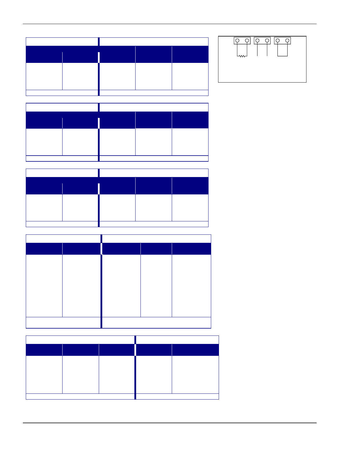
Configurable Zone Type Charts
ENTRY 1 ENTRY 2
Response when system disarmed and zone is:
Intact EOL
RF zone normal
Open
RF zone N/A
Shorted
RF zn off-normal
Auto
Restore
Vent Zone
0 = normal
1 = alarm
2 = trouble
3 = fault
0 = normal
4 = alarm
8 = trouble
12 = fault
see note 5
0 = normal
1 = alarm
2 = trouble
3 = fault
see note 6
0 = no
4 = yes
0 = no
8 = yes
Entry 1 = EOL + Open Entry 2 = Short + auto restore + vent zone
ENTRY 3 ENTRY 4
Response when armed STAY and zone is:
Intact EOL
RF zone normal
Open
RF zone N/A
Shorted
RF zn off-normal
Byp. when
disarmed
Byp. when
armed
0 = normal
1 = alarm
2 = trouble
3 = fault
0 = normal
4 = alarm
8 = trouble
12 = fault
see note 5
0 = normal
1 = alarm
2 = trouble
3 = fault
see note 6
0 = no
4 = yes
0 = no
8 = yes
Entry 3 = EOL + Open Entry 4 = Short + byp. disarmed + byp. armed
ENTRY 5 ENTRY 6
Response when armed AWAY and zone is:
Intact EOL
RF zone normal
Open
RF zone N/A
Shorted
RF zn off-normal
Dial Delay
(see field *50)
Fault Delay
(see field *87)
0 = normal
1 = alarm
2 = trouble
3 = fault
0 = normal
4 = alarm
8 = trouble
12 = fault
see note 5
0 = normal
1 = alarm
2 = trouble
3 = fault
see note 6
0 = no
4 = use delay
0 = no
8 = use delay
see note 1
Entry 5 = EOL + Open Entry 6 = Short + dial delay + fault delay
ENTRY 7 ENTRY 8
Display Faults Power Reset/
Verification
Use Entry
Delay 1/2
Use Exit
Delay
Respond as
Interior Type
0 = show alarms
when armed
& disarmed
1 = don’t show
alarms when
armed (show
alarms, trbles,
faults when
disarmed)
3 = never show
any alarms,
trbles, faults
0 = no
4 = power reset
after fault
(with code + OFF)
12 = verification
(see zone
type 16)
0 = no
1 = delay 1
2 = delay 2
0 = no
4 = use exit
delay
0 = no
8 = yes
see note 2
Entry 7 = fault display + power
reset/verification
Entry 8 = entry delay 1/entry delay 2 + exit delay +
interior zone type
ENTRY 9 ENTRY 10
Alarm Sounds Use Bell
Timeout
Respond as
Fire Zone
Trouble
Sounds
Chime when Chime
Mode On
0 = none
1 = steady
keypad
2 = steady bell
and keypad
3 = pulsing bell
and keypad
0 = no
4 = yes
see fields *32,
*33
0 = no
8 = yes
see zone type
09; see note 4
0 = none
1 = periodic
beep
2 = trouble
beeps
0 = no
4 = yes
Entry 9 = alarm sounds + bell timeout + fire zone Entry 10 = trouble sounds + chime
OPEN SHORTEDINTACT
EOL
ZONE-003-V0
Zone Conditions Represented
in Entries 1-6
Configurable Zone Type Notes
1. Do not use the “fault delay” option
with a configurable zone type if it
is set for an entry or exit delay,
otherwise unpredictable results
may occur.
2. To create an interior type zone,
select “respond as interior zone
type” (entry 8, interior type = yes),
and set zone response to “fault” in
entries 3-4 to ensure fault
displays; do not set as “normal,”
“alarm,” or “trouble.”
3. Do not set fire zones to respond as
a “fault” (entries 1-6), otherwise
faults will not display unless the
[∗] key is pressed.
4. 4219/4229 modules must use
EOLRs or unpredictable results
may occur.
5. RF Zones: The “open” options in
entries 1, 3, and 5 are not
applicable for RF zones. Use the
“intact EOL” option for normal RF
zone conditions and “shorted” for
off-normal RF zone conditions.
6. a. Zone-Doubling/Double-Balanced:
A short on either zone of a zone-
doubled pair or on a double-
balanced zone causes a tamper
condition.
b. For double-balanced zones, this
entry must be “0”.
c. For zone-doubled zones, both
zones of the doubled pair must
be assigned the same response
to a short.
Installation Instructions
4-12
Touch Screen Device (AUI) Enable
FIELD TITLE and DATA ENTRIES EXPLANATION
*189 AUI Device 1 and 2 Enable
0 = disabled
1 = partition 1
2 = partition 2
3 = common lobby
For Touch Screen style keypads
The system supports up to two touch screen style keypads (e.g.
Symphony Advanced User Interface (AUI), and FA700KP Touch
Screen Keypad).
Enter each touch screen (AUI) device’s home partition.
AUI 1 address must be set to 1.
AUI 2 address must be set to 2.
NOTE: A minimum of one standard keypad must also be installed
when touch screen devices are used. Use of touch screen devices does
not affect the number of standard keypads supported.
Keypad Programming Fields
FIELD TITLE and DATA ENTRIES EXPLANATION
*190 Keypad 2 Device Address 17
Entry 1 – Partition Assignment:
0 = keypad disabled
1 = partition 1 (FA168CPS)/enabled (FA148CP)
2 = partition 2
3 = common
Entry 2 – Sound Option:
0 = no suppression
1 = suppress arm/disarm and E/E/ beeps
2 = suppress chime beeps only
3 = suppress arm/disarm, E/E/ beeps and
chime beeps
Keypad 2
Entry 1: For FA168CPS, enter the partition in which the keypad is
located; for FA148CP, enter 1 to enable, or 0 to disable.
Entry 2: Enter the desired sound option for this keypad.
NOTE: Address 16 is reserved for keypad 1, which is automatically
set to partition 1 with all sounds enabled.
*191 Keypad 3 Device Address 18
See field *190 for entries.
Keypad 3
See field *190 for explanation.
*192 Keypad 4 Device Address 19
See field *190 for entries.
Keypad 4
See field *190 for explanation..
*193 Keypad 5 Device Address 20
See field *190 for entries.
Keypad 5
See field *190 for explanation.
*194 Keypad 6 Device Address 21
See field *190 for entries.
Keypad 6
See field *190 for explanation.
*195 Keypad 7 Device Address 22
See field *190 for entries.
Keypad 7
See field *190 for explanation.
*196 Keypad 8 Device Address 23
See field *190 for entries.
Keypad 8
See field *190 for explanation.
*197 Exit Time Display Interval
0 = no display
1-5 = seconds between display updates
If enabled, keypads display the exit time remaining after arming the
system, with display updates at the interval selected (i.e. if the exit
delay is 30 seconds and “2” is selected in this field, the keypad display
refreshes every 2 seconds, displaying 30, 28, 26, 24, etc.).
An interval greater than “1” may be necessary for some older keypads
to allow users time to enter key presses between display updates.
FIXED-WORD KEYPAD NOTE: If using 2-digit display keypads
(e.g. FA245RF), do not use exit times greater than the 96-second delay
option. Using a longer delay time may cause end-user confusion
because 2-digit display keypads cannot display times greater than
“99.” If longer exit time is required by the installation, it is
recommended that the Exit Time Display option be disabled (“0”).
*198 Display Partition Number
0 = no
1 = yes
FA168CPS.
If selected, the partition number is displayed in the upper-left corner
of the display. This is useful when using the GOTO partition function.
*199 ECP Fail Display
0 = 3-digit display (“1” + device address)
1 = 2-digit fixed-display as “91”
Select “0” if using Alpha keypads and/or 3-digit Fixed-Word Display
keypads. ECP faults will display “1” plus the device address (00-30) of
device causing the fault (e.g., faults on device 07 display as “107”).
Select “1” if using 2-digit Fixed-Word Display keypads (e.g., certain
6128 series keypads). If selected, ECP faults for all devices will display
as “91” on 2-digit displays, and “191” on 3-digit or Alpha keypads.
4-13

Installation Instructions
4-14

SECTION 5
Zone Programming
(✱56 and ✱58 Menu Modes)
••••••••••••••••••••••••••••••••••••••••••••••••••
About Zone Programming
✱56 Zone Programming is used to program zones, zone types, report codes, enroll 5800 RF Wireless
Transmitter serial numbers, and identify the type of loop input device(s). This mode can also be used
to enter alpha descriptors for programmed zones; however, we recommend entering descriptors in
menu mode ✱82 (Alpha Descriptor Programming after all zone programming has been completed).
For a faster method of zone programming, you can use the ✱58 Expert Programming Mode instead of
✱56 Zone programming. The ✱58 Expert Programming Mode is designed for those who have had
previous experience in programming control panels of this type.
NOTE: Alpha display prompts are shown in a double-line box.
✱56 Zone Programming Procedure
Zone Programming involves:
1. Entering the zone number to be programmed;
2. Making appropriate entries at the prompts;
3. Confirming the serial number of wireless transmitter zones.
Start Zone Programming mode by pressing ✱56 while in Data Programming mode. The following
prompts are displayed:
PROMPT VALID ENTRIES EXPLANATION
SET TO CONFIRM?
0 = NO 1 = YES
Set to Confirm
0 = no
1 = yes
If 1 (Yes) is entered, you will be prompted to confirm each
transmitter after entering the serial and loop numbers (at the “XMIT
TO CONFIRM” prompt later in this procedure). We recommend
that you confirm the programming of every transmitter.
Enter Zn Num.
(00 = Quit) 10
Zone Number
FA168CPS:
wired zones 01-08†, 09-48††
wireless zones 09-48
RF button zones 49-64
FA148CP:
wired zones 01-06†, 07-22††
wireless zones 09-34
RF button zones 49-56
Both Controls:
91 = addr. device report enable
92 = duress report enable
95, 96, 99 =emergency zones
00 to quit
[∗] to continue
Enter the zone number that you wish to program. Zone 10 has been
entered as an example in the display at left.
Enter a report code for zone 91 to enable addressable device
reporting.
Enter a report code for zone 92 to enable duress reporting.
95, 96, 99 are emergency (panic) key zones.
† Built-in wired zones. †† expander module wired zones, if used.
Zn ZT P RC In: L
10 00 1 10 RF: 1
OR
Zn ZT P RC In: AD
10 00 1 10 AW: 07
OR
Zn ZT P RC HW: RT
10 00 1 10 EL 1
Summary Screen
[∗] to continue
A summary display appears.
“IN: L” appears for wireless zones and indicates input type and loop.
“IN: AD” appears for hardwire expansion zones (AW) and indicates
the module’s address (AD), which is based on the zone number.
“HW: RT” appears for hardwire zones and indicates configuration
(EOL, NO, NC, zone doubling, double-balanced) and response time
selection.
5-1
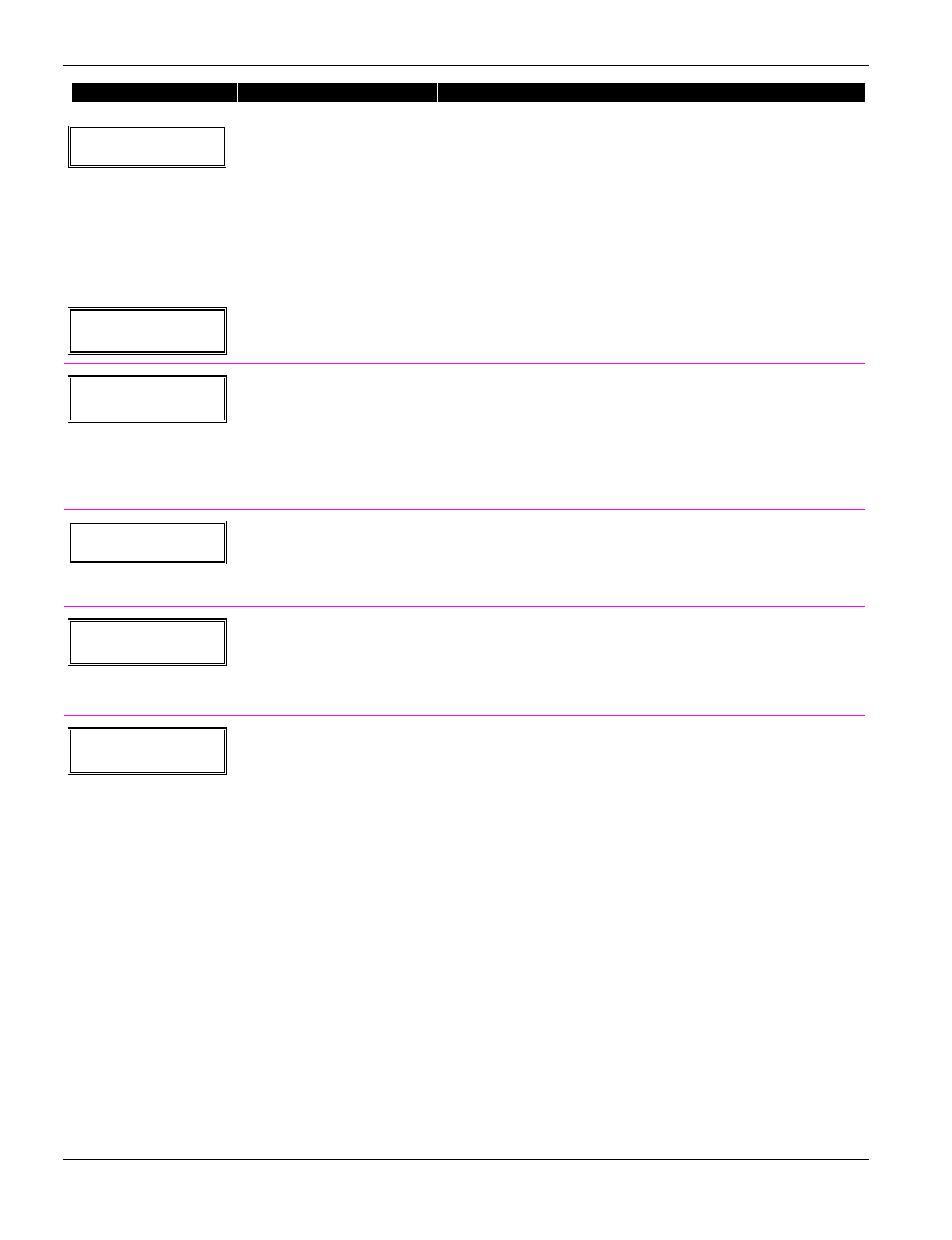
PROMPT VALID ENTRIES EXPLANATION
10 Zone Type
Perimeter 03
Zone Type (ZT)
see table at right; configurable
zone types 92 and 93
programmable only via
downloader
Each zone must be assigned to a zone type, which defines the way in
which the system responds to faults in that zone.
Enter the Zone Type code from the list below:
Note: If 00 is entered, Delete Zone ? will be displayed.
00 = Not used 07 = 24-Hr Audible 20 = Arm–STAY*
01 = Entry/exit #1 08 = 24-Hr Aux 21 = Arm–AWAY*
02 = Entry/exit #2 09 = Fire 22 = Disarm*
03 = Perimeter 10 = Interior w/Delay 23 = No Alarm Resp
04 = Interior Follower 12 = Monitor Zone 24 = Silent Burglary
05 = Trouble Day/Alarm Night 14 = Carbon Monoxide 77 = Keyswitch
06 = 24-Hr Silent 16 = Fire w/Verify 81 = AAV Monitor Zone
*5800 button-type transmitters only 90-91 = Configurable
10 Partition
1
Partition No. (P)
1-3 = partition (3 = common)
[∗] to continue
FA168CPS.
Enter the Partition number for this zone. Partition 1 is shown
entered.
10 Report Code
1st 01 2nd 00 10
Report Code (RC)
First Digit: 1-9, #+10 for 0, #+11
for B, #+12 for C,
#+13 for D, #+14 for
E, #+15 for F
00 to disable
Second Digit: same as above
[∗] to continue
Enter the report code for this zone, which consists of 2 hexadecimal
digits, each in turn consisting of 2 numerical digits. For example, for
a report code of “10,” enter 01 and 00.
For Contact ID®, entering any non-zero entry as the first digit
enables the report code for this zone. Refer to the System
Communication section for information about report codes and
formats.
02 HARDWIRE TYPE
EOL 0
Hardwire Type
0 = EOL 3 = zone doubling† (ZD)
1 = NC 4 = double-balanced†
2 = NO (DB)
[∗] to continue
This prompt appears only for zone numbers 02-08.
Zone 1 is automatically set for EOL operation.
† FA168CPS
02 Response Time
1
Response Time (RT)
0 = 10mSec
1 = 350mSec
2 = 700mSec
3 = 1.2 seconds
[∗] to continue
This prompt appears only for hard-wired zones 01-08 (zone 02 is used
as an example in display).
Option 3: used for “clean me” option on zone 1 (see field ∗174).
NOTE: If zone doubling is being used, the response time selected for
zones 02-08 automatically applies to each zone’s associated doubled
zone.
10 INPUT TYPE
RF TRANS 3
Input Device type (In)
2 = AW (Aux wired zone)
3 = RF (supervised RF
transmitter,
4 = UR (unsupervised RF
transmitter)
5 = Button type RF transmitter
(unsupervised).
[∗] to continue
This prompt is skipped for zones 2-8, or 2-16 if zone-doubling was
enabled at “Hardwire Type” prompt.
All of the RF transmitters have one or more unique factory-assigned
input (loop) ID codes. Each of the inputs requires its own
programming zone (e.g., a 5804's four inputs require four
programming zones).
RF Transmitters can be enrolled as one of the following types:
Type Description
“RF” Sends periodic check-in signals, as well as
(Supervised RF) fault, restore, and low-battery signals. The
transmitter must stay within receiver's range.
“UR” Sends all the signals that the “RF” type
(Unsupervised RF) does, but the control does not supervise the
check-in signals. The transmitter may therefore
be carried off-premises.
“BR” (Unsupervised Sends only fault signals. It will not send a
Button RF) low-battery signal until it is activated. The
transmitter may be carried off-premises.
NOTE:
• For the built-in hardwired zones, the Input Device type is
automatically displayed as HW and cannot be edited.
• To change the input type of a previously programmed wireless
device (type RF, UR, BR) to a wired zone (type AW), you must first
delete transmitter’s serial number (see To Delete A Serial Number
prompt on next page)
Installation Instructions
5-2
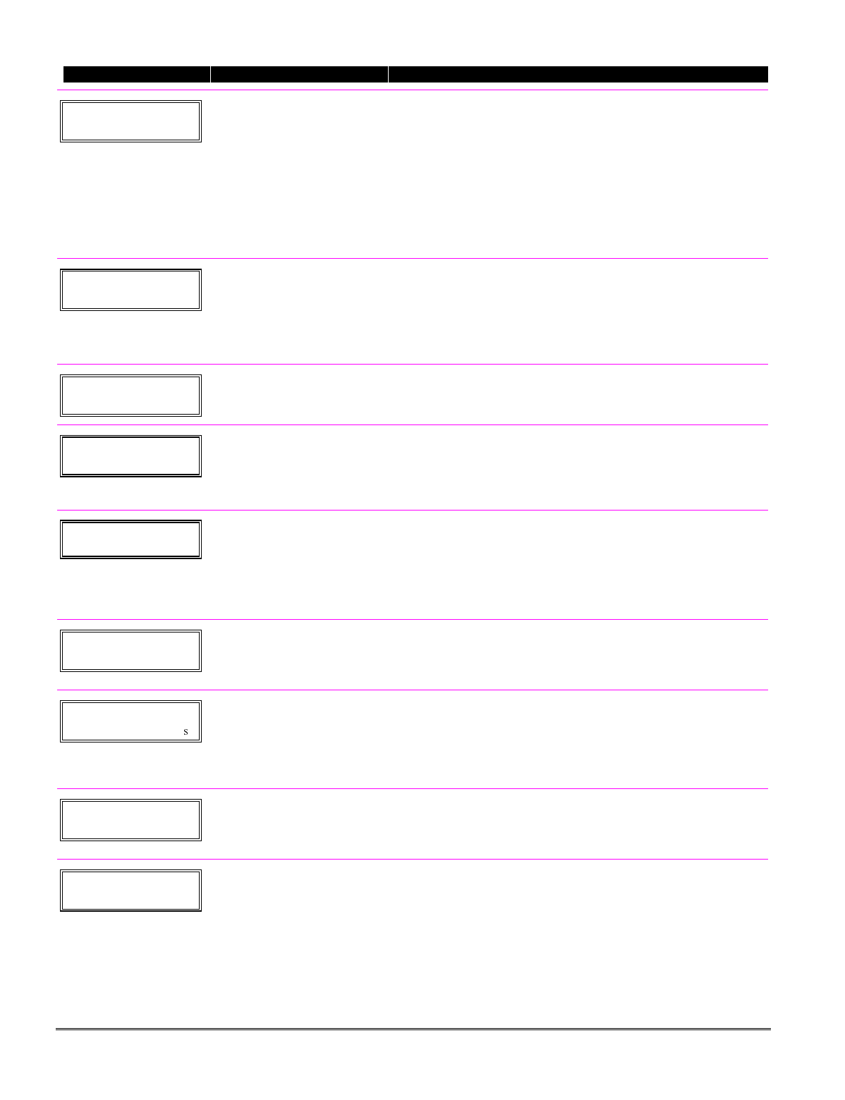
PROMPT VALID ENTRIES EXPLANATION
10 INPUT S/N: L
A022-4064 1
Serial number Entry and
Loop Number Entry
see explanation
[∗] to continue
Used only when enrolling wireless transmitters.
a. Transmit two open/close sequences. If using a button-type
transmitter, press and release the button twice, but wait about 4
seconds before pressing the button the second time.
OR
b. Manually enter the 7-digit serial number printed on the label of
the transmitter. Then press the [✱] key – the cursor will move to
the “L” position. You can edit the loop number, if necessary.
When the loop number is acceptable, press [✱].
c. Press key [C] to copy the serial number previously enrolled (used
when programming a transmitter with several input loops).
10 INPUT S/N L
A022-4064 ?
Loop Number Change
[∗] to continue
NOTE: If the [C] key is used to copy the previously enrolled serial
number, the cursor will move to the Loop column (L) with the
previous serial number displayed, and display a highlighted question
mark for the loop number.
Enter the loop number and press [✱]. The system will now check for
a duplicate serial/loop number combination.
10 INPUT S/N L
A022-4064 1
Enroll Summary
[∗] to continue
If the serial/loop number combination is not a duplicate in the
system, a display showing the serial number and loop number entry
will appear.
XMIT TO CONFIRM
PRESS ✱TO SKIP
Confirmation Option
[∗] to continue
This prompt will only appear if you answered “Yes” at the first
prompt in this section.
The system will enter a confirmation mode so that the operation of
the actual programmed input can be confirmed.
Activate the loop input or button that corresponds to this zone.
Entd A022-4063 1
Rcvd A022-4064 1
If Serial or Loop
Numbers do not match
after activating the
transmitter
[∗] to continue
If the serial number transmitted does not match the serial number
entered, a display similar to the one shown appears. If the loop
number does not match, it will also be displayed.
If so, activate the loop input or button on the transmitter once again.
If a match is not obtained (i.e., summary display does not appear),
press the [#] key twice and then enter (or transmit) the correct serial
number.
10 INPUT S/N: L
A000-0000 0
To Delete a Serial No.
enter 0 in loop number field
# = undo deletion
[∗] to continue
To delete an existing serial number, enter 0 in the loop number field.
The serial number will change to 0's.
If 0 was entered in error, simply re-enter the loop number or press
[#], and the serial number will return to the display.
Zn ZT RC In: L
10 03 10 RF: 1
Summary Screen
[∗] to continue
If the serial number transmitted matches the serial number
entered, the keypad will beep 3 times and a summary display
will appear, showing that zone's programming. Note that an
“s” indicates that a transmitter’s serial number has been
enrolled.
Press [✱] to accept the zone information and continue.
PROGRAM ALPHA?
0 = NO 1 = YES 0
Alpha Descriptors
0 = no
1 = yes
[∗] to continue
If you want to program descriptors for zones now, enter 1 (Yes) and
refer to the Alpha Descriptor Programming section for available
descriptors.
ENTER ZN NUM.
(00 = QUIT) 11
Next Zone Number
00 = quit
[∗] to continue
If 0 (No) was entered above, the system will return you to the
ENTER ZN NUM. prompt for the next zone.
When all zones have been programmed, enter 00 to quit.
5-3

Completing Zone Programming
When you have finished programming all zones, test each zone using the system’s TEST mode. Do
not use the Transmitter ID Sniffer Mode for checking wireless transmitting devices, as it
will only check for transmission of one zone on a particular transmitter, NOT the zones assigned to
each additional loop.
NOTE: Following the successful enrollment of each wireless device, note the device serial number in
the appropriate column on the ENROLLED TRANSMITTERS worksheet in the Programming Form;
then enter the other information (zone number, zone type, loop number, etc.) relevant to that device.
∗58 Expert Programming Mode Procedures
This method is designed for use by installers with previous experience in programming ADEMCO
control panels. This mode is also used to program wireless keys using pre-defined templates.
Start Expert Programming mode by pressing ✱58 while in Data Programming mode. The following
prompts are displayed:
PROMPT VALID ENTRIES EXPLANATION
SET TO CONFIRM?
0 = NO 1 = YES 0
Confirm?
0 = no
1 = yes
[∗] to continue
This display appears upon entry into this mode.
The default is 0 (No).
If 1 (Yes) is entered, you will be prompted to confirm each
transmitter after entering the serial and loop numbers (at the “XMIT
TO CONFIRM” prompt later).
Zn ZT P RC HW: RT
01 09 1 10 EL 1
Zn ZT P RC IN: L
10 00 1 10: RF –
Summary Screen
01-64 = zone number
00 = quit
[∗] to continue
OR
[D] to go to prompts for wireless
key programming templates
A summary screen will appear, showing zone 1’s currently
programmed (or default) values.
Enter the zone number being programmed, then press [∗], which
displays a summary screen for that zone. See next prompt (in this
example, zone 10 is being entered).
If programming a wireless key, press the [D] key then skip to the
Wireless Key Programming Templates section following this section.
When [D] is pressed, you can choose from a series of preset templates
for easy programming of wireless key zones.
When all zones have been programmed, press “00” at this prompt to
quit this menu mode.
Zn ZT P RC IN: L
10 00 1 10 RF 1
Zone Programming
ZT = see Zone Type chart
shown in *56 Menu Mode
“Zone Type” prompt
P = partition 1, 2, 3 (common)
RC = 1 (send CID report)
0 (no report)
IN = input type
L = loop number
[∗] to continue
A summary screen with the selected zone’s current programming
appears.
Begin programming zone information as follows:
• Enter Zone Type (ZT), Partition (P), Report Code (RC), and Input
Device Type (IN)* sequentially, but not the Loop No. (L).
• Use the [A] (Advance) and [B] (Back) keys on the keypad to move
the cursor within the screen.
• Use the [C] key to copy the previous zone’s attributes.
Press [✱] to save the programming and continue to the serial
number/loop number prompt. If needed, you can press the [#] key to
back up without saving.
* If HW (hardwired) or AW (Auxiliary) is entered for Input Device
Type, the next screen will be similar to the prompt shown, except
that HW or AW will be displayed under “IN”.
If RF, BR, or UR is entered, a prompt for Serial and Loop number
will be displayed, as follows.
Installation Instructions
5-4
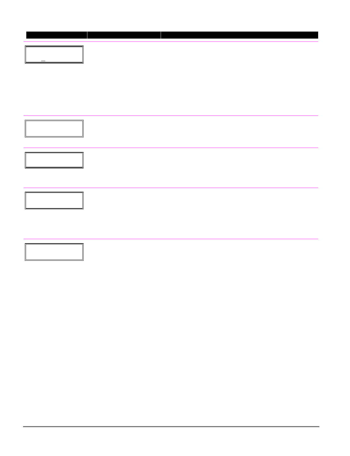
PROMPT VALID ENTRIES EXPLANATION
10 INPUT S/N: L
AXXX-XXX –
Serial number
S/N = serial number
L = loop number
[∗] to continue
Manually enter the serial number (found on the transmitter label),
by typing digits in the “X” locations, using the [A] (advance) or [B]
(back) keys as required. You can also perform two open and close
sequences; for button-type transmitters that means pressing and
releasing the button twice.
NOTE: If you want to copy the previous zone’s serial number, press
the [C] key.
Press [✱] to advance to the loop number, then enter loop number.
Press [✱] to accept the existing serial and loop number and continue
to the “Confirm” prompt below. If necessary, press [#] to back up and
re-enter or edit the serial number.
10 INPUT S/N: L
A000-0000 0
To Delete a Serial
Number
[∗] to continue
To delete an existing serial number, enter 0 in the loop number
field. The serial number will change to all 0's as shown.
If 0 was entered in error, simply re-enter the loop number, and the
serial number will return to the display.
10 XMIT TO CONFIRM
PRESS ✱ TO SKIP
Confirm
[∗] to continue
The prompt to confirm appears. This prompt will only appear if the
first prompt after entering ✱58 was answered “Yes.” To confirm,
activate the loop input or button that corresponds to this zone.
The system checks for duplicate. If a duplicate exists, a long error
beep will sound.
Press [#] to back up and re-enter the serial and/or loop number.
Entd A022-4063
Rcvd A022-4064
If Serial or Loop
Numbers do not match
after activating the
transmitter
[∗] to continue
If the serial/loop number combination transmitted does not match
the serial and loop number entered, a display similar to the one
below will appear. If the loop number does not match, it will
also be displayed. If so, activate the transmitter’s loop input or
button one or more times.
If a match is still not obtained (i.e., summary display does not
appear), press the [#] key twice and enter the correct loop input or, if
correct, press [#] again and then enter the correct serial number.
Zn ZT P RC In L
10 03 1 10 RF: 1s
Note that an “s”
indicates that a
transmitter’s serial
number has been
enrolled.
Summary Screen
[∗] to continue
If the serial number transmitted matches the serial number entered,
the keypad will beep 3 times and a summary display will appear,
showing the programmed information for that zone.
Press [✱] to begin programming the next zone. See first “Summary
Screen” prompt paragraph on previous page.
5-5
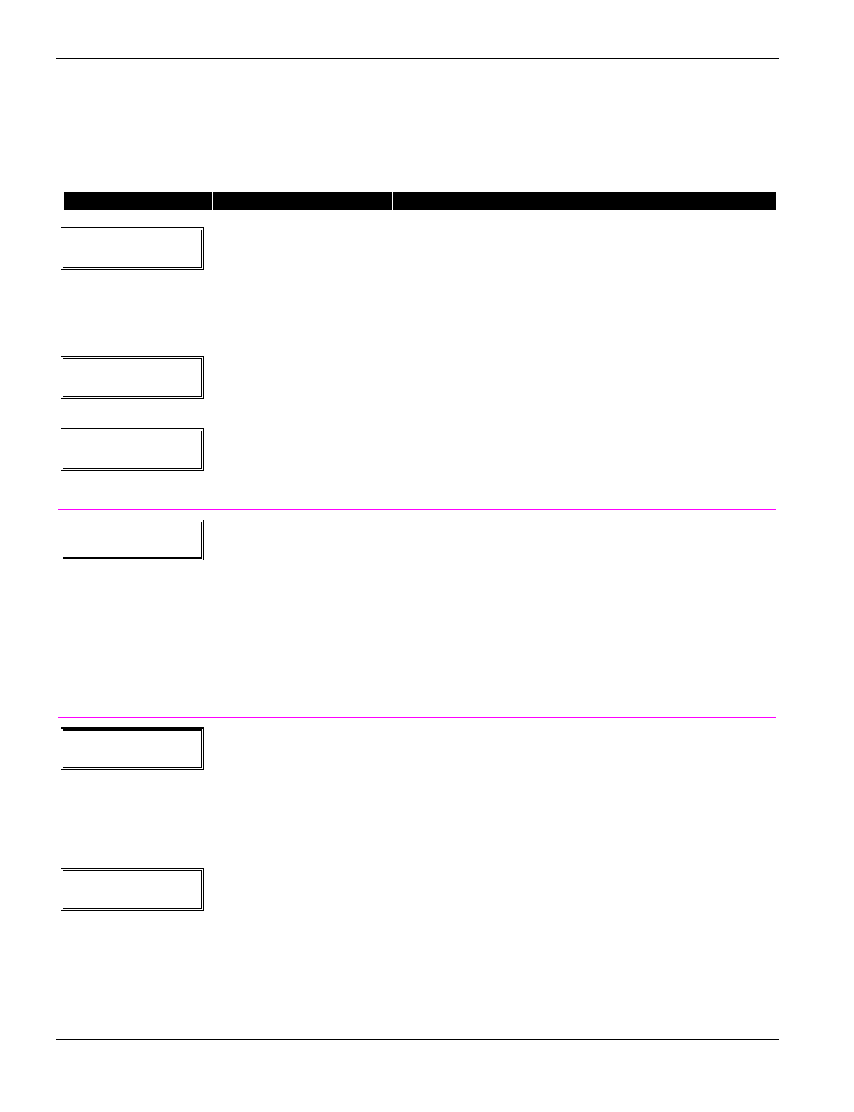
Wireless Key Programming Templates
This procedure programs the wireless keys, but a key is not active for arming/disarming until
it is assigned to a user number (see System Operation section, assigning attributes command).
If the D key was previously pressed (from *58 Menu mode) to program 5804 and/or 5804BD wireless
keys, the following screens appear.
PROMPT VALID ENTRIES EXPLANATION
TEMPLATE ?
1–6 1
Template Number
1–3 = 5804 templates
4–6 = 5804BD templates
[∗] to continue
1. Enter Template number 1–6 (from next page).
See the defaults provided for each template in the chart that
follows these procedures.
2. Select from templates. Press [✱] to display template (1 shown
selected). NOTE: If necessary, press [#] to back up and re-enter
template number.
3. If you want to return to the *58 Menu mode Summary Screen,
press [#].
L 01 02 03 04
T 23 22 21 23
Template Display
[∗] to continue
4. When [✱] is pressed, the selected template will be displayed.
Top line of display represents loop numbers, bottom line
represents zone type assigned for each loop.
5. Press [✱] to accept template.
PARTITION
1
Partition
1 = partition 1
2 = partition 2
3 = common partition
[∗] to continue
FA168CPS.
6. Enter the partition in which the key is to be active.
7. Press [∗] to continue.
ENTER START ZONE
00 = QUIT 36
Start Zone Number
[∗] to continue
8. The system will search for the highest available consecutive 4-
zone group (the four zones in the case of the 5804 and 5804BD),
and display the lowest zone number of the group.
If you want to start at a different zone, enter the zone desired,
and press [✱]. If that zone number is displayed, the system has
the required number of consecutive zones available, beginning
with the zone you entered. If not, the system will again display a
suggested zone that can be used.
If the required number of consecutive zones is not available at all,
the system will display “00”.
To quit this mode and return to *58 Menu mode, enter 00 at
this prompt.
9. Press [✱] to accept.
INPUT S/N L
AXXX-XXXX –
Serial Number
[∗] to continue
10. Manually enter the serial number printed on the label for the
wireless key or press and release the button to transmit its serial
number.
11. Press [✱] to accept the serial number. The system will check for
duplicate.
12. If necessary, press the [#] key to back up without saving, and re-
enter the serial number.
Use the [A] key to move forward within the screen, and the [B] key to
move backward.
XMIT TO CONFIRM
PRESS ✱ TO SKIP
Confirm
[∗] to continue
13. If “Yes” was entered at the SET TO CONFIRM? prompt
previously (see first prompt following entry into the ∗58 Expert
Programming Mode), the display on the left will appear. Confirm
serial and loop numbers by activating the wireless key.
IMPORTANT:
When confirmed, the key is not active for arming/disarming until it
is assigned to a user number (using the assigning attributes
command, attribute “4”). See System Operation section for
procedure.
Installation Instructions
5-6
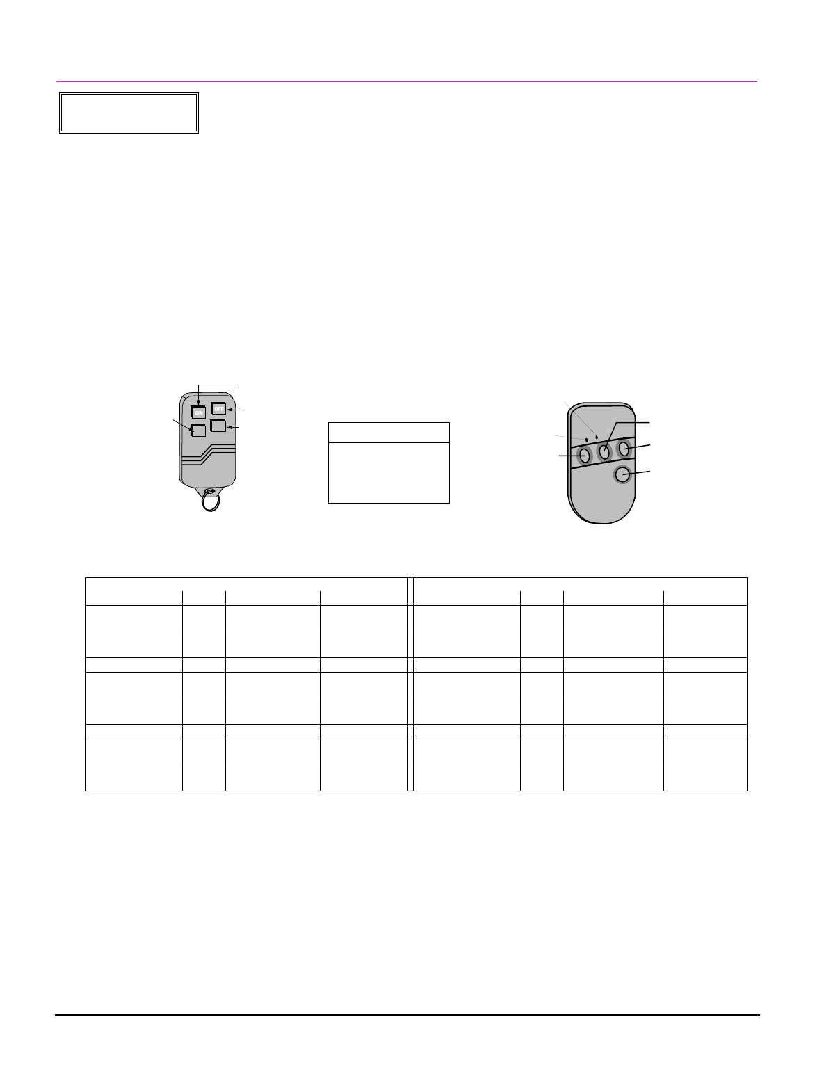
Entd A022-4063
Rcvd A022-4064
Not Confirmed
[∗] to continue
If the serial number transmitted does not match the serial number
entered, a display similar to the one shown will appear. If the loop
number does not match, it will also be displayed.
If so, activate the button on the wireless key once again. If a match is
not obtained (i.e., summary display does not appear), press the [#]
key and then enter the correct serial number.
If the serial number transmitted matches the serial number entered,
the keypad will beep 3 times and will return you to step 8 (Zone
Number prompt) to enter the starting zone for the next wireless key.
Or you can return to *58 Menu mode by pressing 00 at the Zone
Number prompt.
NOTE: Following the successful enrollment of each wireless device,
remove ONE of the serial number labels from the device and affix it
in the appropriate column on the ENROLLED TRANSMITTERS
worksheet of the Programming Form; then enter the other
information (zone number, zone type, loop number, etc.) relevant to
that device.
Wireless Key Predefined Default Templates
YOU MUST
PROGRAMME
THIS BUTTON
LOOP 3
LOOP 1
LOOP 2
LOOP 4
ENROLL AS "BR"
YOU MUST
PROGRAM
THIS
BUTTON
(
LOOP 4
)
LOOP 3
LOOP 2
LOOP 1
5804 Wireless Key Transmitter
Note:
These transmitters
are not intended for
use in UL
installations.
5804BD FRONT VIEW
•
•
•
••
••
•
•
•
•
•
•
•
•
•
•
•
•
BUTTON A
BUTTON D
BUTTON B
BUTTON C
GREEN/YELLOW
LED
RED/YELLOW
LED
LOOP 3
LOOP 2
LOOP 4
LOOP 1
GRE
GREEN/YELLOW
LED
RED/YELLOW
LED
(
YOU MUST PROGRAM
THIS BUTTON
)
ENROLL AS "BR"
5804BD 2-Way Wireless Key Transmitter
For 5804
For 5804BD
TEMPLATE 1 Loop Function Zone Type TEMPLATE 4 Loop Function Zone Type
1 No Response 23 1 No Response 23
2 Disarm 22 2 No Response 23
3 Arm Away 21 3 Arm Away 21
4 No Response 23 4 Disarm 22
TEMPLATE 2 Loop Function Zone Type TEMPLATE 5 Loop Function Zone Type
1 No Response 23 1 No Response 23
2 Disarm 22 2 Arm Stay 20
3 Arm Away 21 3 Arm Away 21
4 Arm Stay 20 4 Disarm 22
TEMPLATE 3 Loop Function Zone Type TEMPLATE 6 Loop Function Zone Type
1 24-hour audible 7 1 24-hour audible 7
2 Disarm 22 2 Arm Stay 20
3 Arm Away 21 3 Arm Away 21
4 Arm Stay 20 4 Disarm 22
5-7

Installation Instructions
5-8
SECTION 6
Output Device Programming
(*79/*80 Menu Mode)
•••••••••••••••••••••••••••••••••••••••
About Output Device Programming
Output Devices: The FA168CPS system supports up to 16 relays and/or Powerline Carrier
devices (X-10 devices) plus 2 built-in trigger outputs in any combination.
These 18 “outputs” are assigned to system-wide output numbers (01-18). Use
*79 Menu Mode to assign output numbers and map them to device addresses.
The FA148CP supports 8 relays and 2 built-in trigger outputs (total 10
outputs).
Output Functions: The system also provides installer-defined output functions, which can be
assigned to any of the physical outputs. Therefore, the action of any one of the
outputs can be based on as many of these functions as desired. This lets a single
relay or X-10 device perform many functions.
The controls support up to 48 output functions.
Use *80 Menu Mode to define output functions.
Relays and output devices are not recommended for life safety applications.
NOTE: When navigating the *79 and *80 menus: The [✱] key is used to accept an entry and advance
to the next prompt. The [#] key is used to revert back to the last question to check or change an
entry. Press [✱] to go forward again.
Output Device programming involves:
1. Use *79 Menu Mode to assign module and output numbers and map them to device addresses.
NOTE: You must map output devices using *79 Menu Mode before you can use *80 menu Mode.
2. Use *80 Menu Mode to create output definitions, which control the output devices.
*79 Menu Mode: Output Device Mapping
Use this menu to assign Relay Module device addresses and specific relay numbers, and Powerline
Carrier unit numbers. The system is based on predefined module addresses for 4204 and 4229
modules. Refer to the table shown at the “Module Address” prompt on the next page and set the
modules’ addresses (via module DIP switches) accordingly.
The following table shows how these outputs are identified.
Output Identification
This output… is identified by…
Relays: the Relay Module’s device address and the relay position on that module (i.e. the
physical relay number, 1-4, on that module).
X-10 Device a house ID (entered in data field *27) and the unit number of the device.
Built-in Outputs the output number assigned, 17 for Trigger 1 and/or 18 for Trigger 2.
6-1
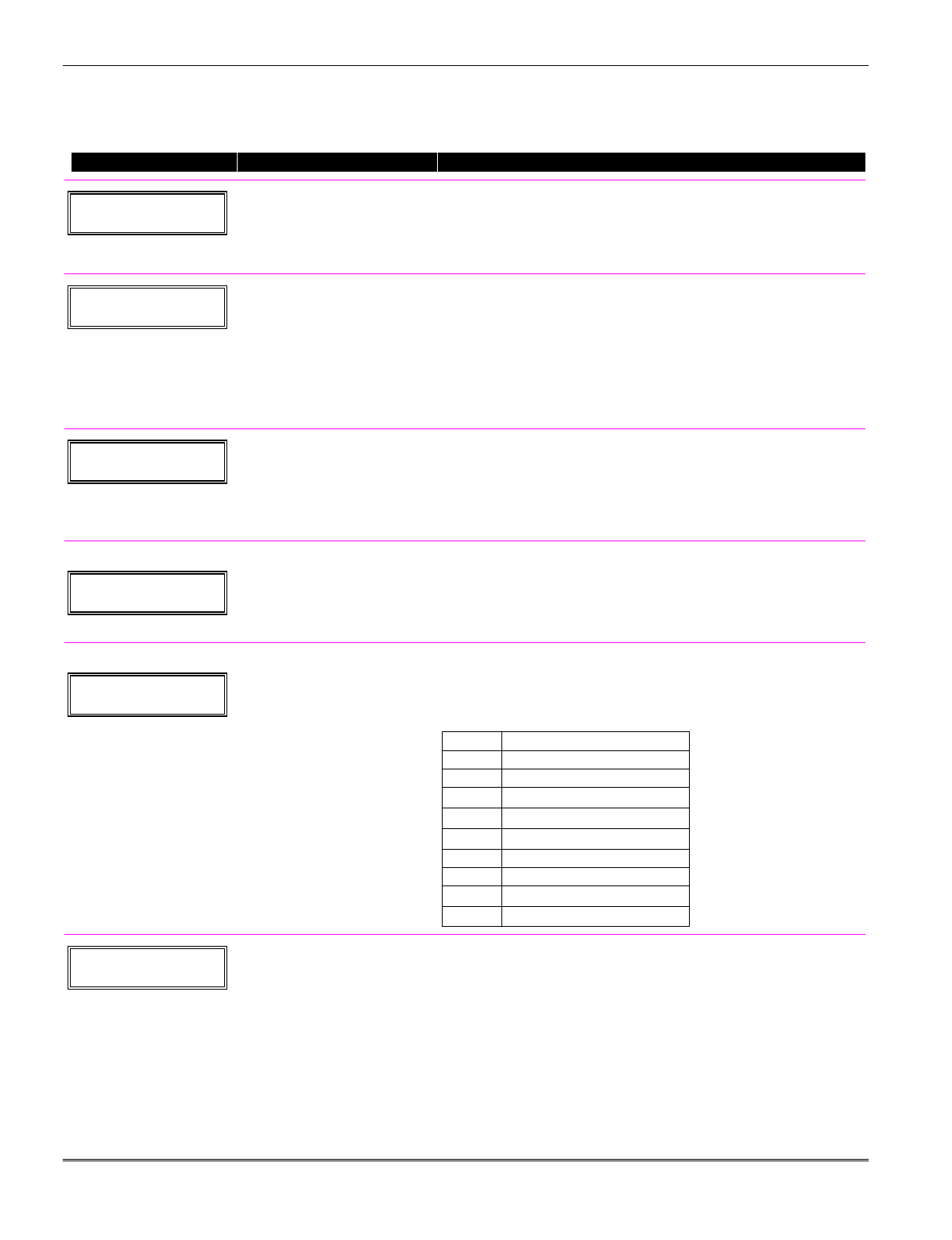
Start Output Device Mapping by pressing *79 while in Data Programming Mode. The following
prompts are displayed:
∗79 Menu Mode
PROMPT VALID ENTRIES EXPLANATION
ENTER OUTPUT NO.
00 = QUIT xx
Device Output Number
01-18 = FA168CPS relays/X-10
01-08, 17, 18 = FA148CP
relays/X-10
[∗] to continue
This is the logical (or reference) relay number as used in the system.
Relays and X-10 devices are numbered 01-16; the on-board triggers
are numbered 17 and 18 and can be programmed for inverted output.
Use the worksheet on the Programming Form (printed separately) to
organize device numbers.
17 OUT NORM LOW
0 = NO 1 = YES 0
Output Normally Low
0 = no (standard default)
1 = yes
[∗] to continue
This prompt appears only for Triggers 17 and 18.
Selecting 0 (no) sets the output level normally high.
Selecting 1 (yes) sets the output normally low.
Output Trigger 17 can be used for resetting 4-wire smoke detectors
by connecting it to the negative power terminal of the smoke
detector, selecting 1 at this prompt, and setting as zone type 54, fire
zone reset, in *80 Menu mode.
After entry, display returns to Output Number prompt. Use *80
Menu mode to program the function of the trigger.
XX OUTPUT TYPE
DELETE 0
Output Type
0 = delete
1 = relay on 4204/4229 module
2 = Powerline Carrier device
[∗] to continue
Select whether this is a relay or a Powerline Carrier (X-10) device.
If Powerline Carrier is selected, go to “A” prompt.
If relay is selected, skip to “B” prompt.
“A”
XX UNIT No.
yy
Unit Number
01-16 = predefined address
[∗] to continue
If X-10 is selected, a prompt for the unit number appears.
Enter the unit code (set at the device) and press [∗].
The system returns to the Output Number prompt.
“B”
XX MODULE ADDR
07-15 yy
Module Address
07-15 = predefined address
[∗] to continue
If relay is selected, this prompt appears.
Enter the predefined address for this module as listed below. Make
sure the module’s DIP switches are set to the selected address.
Module Addresses
Address Module † These addresses
07 1st 4229 (with zones 09-16) apply to the FA168CPS
08 2nd 4229 (with zones 17-24) only.
09† 3rd 4229 (with zones 25-32)
10† 4th 4229 (with zones 33-40)
11† 5th 4229 (with zones 41-48)
12 1st 4204
13 2nd 4204
14† 3rd 4204
15† 4th 4204
XX REL POSITION
1-4 zz
Relay Position
1-4 = relay position
[∗] to continue
This is the actual (or physical) relay number with respect to the
Relay Module upon which it is located. For 4204 modules, relay
numbers are 1-4. For 4229 modules, relay numbers are 1-2.
The system returns to the Output Number prompt for programming
the next device.
Installation Instructions
6-2

*80 Menu Mode: Defining Output Functions
Use this mode to program output function definitions (up to 48 functions) that provide automated
control of any of the output devices, based on events occurring on individual zones or zones with
certain zone types. Each output definition is identified by an output function number, and includes
the following components:
Output Definition Components
Component Description
Output Function No. A reference number that defines an output’s characteristics.
Activated By Determines whether the initiating event occurs on a zone, a zone list, or a zone type.
Event Event that triggers the output action. Can be an event occurring on a specific zone
number or a zone list, or a specific zone type.
Partition If the output is activated by zone type, this defines the partition in which the
programmed event is to cause the device action.
Output Action Defines the action of the relay/X-10 device when the defined event occurs. Can close for
2 seconds, stay closed until reset, continuously pulse (1-second close-open-close-open,
etc.), toggle the device state, or activate for a defined duration (set in data field *177).
Output No. Assigns this function to a specific output number (defined in *79 Menu Mode). This is
the output number that will perform this function upon the triggering event. Note that
each defined function is associated with only one output number. This means that if
more than one output device needs to perform this particular function, you need to
define another output function number with the same attributes, but assign the
appropriate output number. (i.e. output devices can be assigned more than one function
number, but each function number can only be assigned a single output number.
For example, if you want to pulse a strobe light upon fire alarms on zone 4 using a relay mapped to
output number 2 (as programmed in *79 Menu Mode), program the following in *80 Menu Mode:
Prompt Entry
Output Funct. # = 01 (assuming this is the first output function)
Activated By: = 3 (zone number)
Enter Zn No. = 04 (requires 2-digit zone numbers)
Output Action = 3 (continuous pulse)
Output Number = 02 (device mapped in *79 Menu Mode)
Start Output Definition mode by pressing ✱80 while in Data Programming mode. The following
prompts are displayed:
∗80 Menu Mode
PROMPT VALID ENTRIES EXPLANATION
Output Funct. #
(00 = Quit) 01
Output Function No.
01-48 = FA168CPS function no.
01-24 = FA148CP function no.
[∗] to continue
Enter the output function number to be defined (or 00 to exit).
01 A E P Trig
?00 0 0 – ZL=00
Summary Screen
[∗] to continue
This screen displays a summary of the current output programming
(for this example, Zone List has been selected-this is the default
screen).
A = Output Action; E = Triggering event; P = Partition; Trig =
Trigger type
NOTE: A question mark in the summary screen indicates that the
device number shown has not been mapped. Use *79 Menu mode to
map the device.
6-3
01 Activated By:
Zone List
Activated By
0 = delete
1 = zone list
2 = zone type
3 = zone number
[∗] to continue
Select where the initiating event for this output definition is to occur
as follows:
0 = delete (deletes the output function and any previous
programming;-see prompt below)
1 = zone list (go to “A” prompt)
2 = zone type (go to “B” prompt)
3 = zone number (go to “C” prompt)
If you enter “0,” the following prompt appears:
Delete? Press 1 to delete this
0 = NO, 1 = YES output definition.
“A”
01 Zn List
1
Zone List
01-08 = zone list
[∗] to continue
If zone list was selected, this screen appears. Otherwise skip to the
next row.
Enter the desired zone list number associated with this output
number.
NOTE: Do not use pager zone lists 09-12 in output definitions.
Press [✱] to continue.
Enter the zone list event that will activate this output.
Enter Event 0 = restore; 1 = alarm;
Alarm 1
2 = fault; 3= trouble
NOTE: For alarm, fault, and trouble, an event on ANY zone in the
list activates the output, but ALL zones in the list must be restored
before the output is restored.
Press [✱] to continue and skip to the “Output Action” prompt.
“B”
01 Enter Zn type
Perimeter 03
Zone Type
see list at right
If zone type was selected, this screen appears. Otherwise skip to the
next row.
Enter the desired zone type associated with this output number. See
below for a list of available zone types.
CHOICES FOR ZONE TYPES:
00 = Not Used 05 = Trouble Day/Alarm Night 12 = Monitor Zone
01 = Ent/Exit #1 06 = 24 Hr Silent 14 = Carbon Monoxide
02 = Ent/Exit #2 07 = 24 Hr Audible 16 = Fire w/verification
03 = Perimeter 08 = 24 Hr Aux 23 = No Alarm Response
04 = Interior Follower 09 = Fire 24 = Silent Burglary
10 = Interior w/Delay 77 = Keyswitch Zone
81 = AAV Monitor Zone
90-91 = Configurable
CHOICES FOR SYSTEM OPERATION:
20 = Arming–Stay 36 = **At Bell Timeout*** 52 = Kissoff
21 = Arming–Away 38 = Chime 54 = Fire Zone Reset
22 = Disarming 39 = Any Fire Alarm 58 = Duress
31 = End of Exit Time 40 = Bypassing 60 = AAV
32 = Start of Entry Time 41 = **AC Power Failure 66 = Function Key†
33 = Any Burglary Alarm 42 = **System Battery Low 67 = Bell Fail
43 = Comm. Failure 68 = Telco line cut
78 = Keyswitch red LED
79 = Keyswitch green LED
** Use 0 (Any) for Partition No. (P) entry.
*** Or at Disarming, whichever occurs earlier.
† Use *57 Menu Mode to assign the function key (function “07”).
Note: In normal operation mode:
Code + # + 7 + NN Key Entry starts Device NN.
Code + # + 8 + NN Key Entry stops Device NN.
Enter the partition in which this zone type will occur.
01 Partition 0 = any partition; 1 = partition 1;
Any partition 0 2 = partition 2; 3 = common
Press [✱] to continue and skip to the “Output Action” prompt.
Installation Instructions
6-4
“C”
01 Enter Zn No.
12
Zone Number
If zone number was selected, this screen appears.
Enter the desired zone number associated with this output number.
Press [✱] to continue.
Enter the zone event that will activate this output.
01 Enter Event 0 = restore; 1 = alarm/fault/trouble
Restore 0
Press [✱] to continue to the “Output Action” prompt
01 Output Action
Close for 2 sec 1
Output Action
0-6 = see list at right
Enter the desired device action as listed below. Press the [✱] key to
continue.
0 = off 4 = Change Device State
1 = Close for 2 seconds 5 = Duration 1 (see data field *177)
2 = Stay Closed 6 = Duration 2 (see data field *177)
3 = Pulse on & off (1 sec ON, 1 sec OFF)
Enter Output No.
R02 02
Output Number
01-16 = FA168CPS output no.
01-08 = FA148CP output no.
17-18 = on-board triggers
Enter the device output number (programmed in *79 Menu Mode)
you want associated with this output.
Press [✱] to continue.
02 A E P TRIG
R02 1 1 3 ZL=00
Summary Screen
A summary screen appears showing the programmed settings.
Press [✱] to continue.
6-5

Installation Instructions
6-6
SECTION 7
Zone Lists
(∗81)
•••••••••••••••••••••••••••••••••••••••
About Zone Lists (*81 Menu Mode)
Zone lists let you group individual zones for use with certain system actions. The following table
shows the available zone lists and their purposes:
List No. Used for…
1, 2 general purpose
3 chime-by-zone
4 cross zones
5 night stay zones
6, 7, 8 general purpose
9 zones that activate Pager 1
10 zones that activate Pager 2
11 zones that activate Pager 3 (FA168CPS)
12 zones that activate Pager 4 (FA168CPS)
Zone List Programming
Zone List programming involves:
1. Selecting an appropriate zone list number;
2. Adding the desired zone numbers to be included in that list.
Start Zone List Program Mode by pressing ✱81 while in Data Programming mode. The following
prompts are displayed:
*81 Menu Mode
PROMPT VALID ENTRIES EXPLANATION
Zone List No.
(00 = Quit) 01
Zone List Number
01-12 = zone list number
[∗] to continue
Enter the Zone List Number to program (or 00 to end these entries).
Press [✱] to advance.
In the following displays, zone list 01 has been selected for
programming.
01 Enter Zn Num.
(00 = Quit) 00
Zone Number
01-64† = zone numbers
followed by [∗] to
accept each zone
00 to continue
Enter each zone number to add to the zone list, followed by pressing
[✱] (example, 01✱, 02✱, 03✱). After all zones are entered, press 00 to
continue.
IMPORTANT: Do not include fire zones in zone lists that are used
to STOP device actions.
† FA168CPS = 01-64; FA148CP = 01-06, 09-34, 49-56.
01 Del Zn List?
0 = No 1 = Yes 0
Deleting Zone Lists
0 = don’t delete list
1 = delete this zone list
[∗] to continue
To delete the zone list, enter 1. All zones in the zone list will be
deleted automatically and the system returns to the Zone List No.
prompt.
To save the zone list, enter 0.
01 Delete Zone?
0 = No 1 = Yes 0
Deleting a Zone
0 = don’t delete zones
1 = go to next prompt to delete
zones
[∗] to continue
To save the entire zone list, enter 0 and the system returns to the
Zone List No. prompt.
To delete a zone or zones in a zone list enter 1 to continue.
01 Zn to Delete?
(00 = Quit) 00
Delete the Zone
01-64† = zones to be deleted
from list followed by [∗]
to accept each zone
00 to continue
Enter each zone to be deleted from the list, followed by [✱]. After all
zones to be deleted are entered, enter 00 to return to the Zone List
No. prompt so that another list can be programmed, if desired.
† FA168CPS = 01-64; FA148CP = 01-06, 09-34, 49-56.
7-1

Notes:
• Any list may include any or all of the system's zone numbers.
• A zone list can be assigned to more than one output relay.
• When creating zone list 4 for cross zoning, include only zones assigned to zone types 3, 4, or 5. Do
not include zones that have delays (entry/exit zones, interior w/delay) or 24-hour zones, as these
zone types may produce unpredictable operation and may not function as intended.
Installation Instructions
7-2
SECTION 8
Function Key Programming
(✱57 Menu Mode)
•••••••••••••••••••••••••••••••••••••••
About Function Key Programming
The system provides the ability to program each of the four keypad function keys to perform one of
12 system operations. The end user can then activate the function by simply pressing and holding
the programmed key for 2 seconds. Typical functions (listed below) include single-button arming,
turning lights on/off, or single-button paging.
Programming Function Keys
Function key programming involves:
1. Assigning the function key number and partition;
2. Selecting the desired function for that key.
Start Function Key Programming mode by pressing ✱57 while in Data Programming mode. The
following prompts are displayed:
PROMPT VALID ENTRIES EXPLANATION
Press Key to Pgm
0 = Quit 0
Function Key
Press the desired function key,
A-D.
[∗] to continue
Press the desired function key (A-D) you want to program.
NOTE: A key programmed as a function key is no longer available to be
used as an end-user macro key or panic key.
321
654
987
#0
*READY
INSTANT
MAX
OFF
CODE
AWAY
TEST
CHECK
STAY
BYPASS
A
B
C
D
keypad_keys-00-001-V0
Partition
1
Partition Number
1 = partition 1
2 = partition 2
3 = common partition
[∗] to continue
Enter the partition in which the function key is active.
Key "A" Func
Zone 95 00
Define Key Function
00-12 = see list to right
[∗] to continue
Returns to key number prompt
with the next function key letter
displayed.
† System defaults to these
function key settings.
†† Macros 11-12 apply to
FA168CPS only.
††† If night-stay zones are
listed in zone list 5.
Enter the desired function for this key, 00 to 12, from the options listed.
(00 selected for example display shown at left)
00† = For the Function key selected, the function will be as follows:
If A selected = Zone 95 (emergency key, same as [1] [∗] pair)
If B selected = Zone 99 (emergency key, same as [∗] [#] pair)
If C selected = Zone 96 (emergency key, same as [3] [#] pair)
If D selected = Single-button paging
01 = Single-button paging (sends a 999-9999 message to pager)
02 = Display time
03 = Arm AWAY (reports as User 00 if closing reports are enabled)
04 = Arm STAY (reports as User 00 if closing reports are enabled)
05 = Arm NIGHT-STAY††† (reports asUser 00 if closing reports enabled)
06 = Step Arming (arms STAY, then NIGHT-STAY†††, then AWAY)
07 = Output Device Command (for device programmed as system
operation type 66–function key in *80 Menu Mode)
08 = Communication Test (sends Contact ID code 601)
09 = Macro Key 1 (define macro by user code + [#] [6] [6] command)
10 = Macro Key 2 (define macro by user code + [#] [6] [6] command)
11 = Macro Key 3†† (define macro by user code + [#] [6] [6] command)
12 = Macro Key 4†† (define macro by user code + [#] [6] [6] command)
8-1

Installation Instructions
8-2
SECTION 9
Alpha Descriptor Programming
(*82 Menu Mode)
•••••••••••••••••••••••••••••••••••••••
About Descriptor Programming
The system lets you assign zone descriptors for protection zones, keypad panics, and RF receiver
supervision faults. Each description can be composed of a combination of words (up to 3) selected from
a vocabulary of 196 words stored in memory (see a following page). In addition, up to 10 installer-
defined words can be added to those already in memory, plus 3 additional words can be assigned as
partition descriptors. Thus, when an alarm or trouble occurs in a zone, an appropriate description for
that zone's location can be displayed at the keypad. Zone descriptors are recommended for systems
using Alpha display keypads, and are necessary if a FA4285 or FA4286 VIP Phone Module is used.
NOTE: You can enter zone descriptors when the zone is being defined in ✱56 Menu mode, but we
recommend you do it using ✱82 Menu mode.
If using a FA4285 or FA4286 VIP Phone Module, select from those words in the Alpha Vocabulary
List shown in boldface type. The phone module will not provide annunciation of the other words.
If a FA4285/FA4286 Phone Module is added to an existing system, the Alpha descriptors
presently in the system should be reprogrammed, selecting from those words shown in boldface
type in the Alpha Vocabulary List. The phone module will not provide annunciation of any other
words.
Programming Zone Descriptors (Menu Mode ∗82)
Descriptor programming involves:
1. Entering index numbers for up to three words from the vocabulary list for each descriptor;
2. Entering up to ten 10-digit custom words, if desired, which can then be used in descriptors.
When defining descriptors:
• Pressing the [6] key accepts the entered index number and moves the cursor to the next position
for a descriptor.
• Pressing the [8] key saves the entered descriptor and moves to the next descriptor.
Start Zone Descriptor Programming mode by pressing *82 while in Data Programming mode. The
following prompts are displayed:
PROMPT VALID ENTRIES EXPLANATION
Program Alpha ?
0=No, 1=Yes 00
Program Alpha
0 = no
1 = yes
[∗] to continue
The “Program Alpha ?” prompt will appear.
Press 1 to continue.
Custom Words ?
0=No, 1=Yes 00
Custom Words
0 = no
1 = yes
[∗] to continue
The “Custom Words” prompt will appear.
Press 0 to program standard alpha descriptors from the fixed
vocabulary. The system will then automatically display the descriptor
for zone 1.
Press 1 to define custom words (described later in “Adding Custom
Words” section).
✱ ZN 01 Summary Screen
[∗] to continue
Note that this is a “Summary mode,” and that no entries can be
made. Entries can be made only when the display contains a flashing
cursor, which signifies the “Entry mode.”
Press [∗] to continue.
9-1
✱ ZN 01 Flashing Cursor
[∗] to continue
To delete or change the default descriptor for zone 1, press [✱] plus
the same zone number (01). This will clear that descriptor and allow
changes to be made at the flashing cursor.
NOTE: If you do not wish to change the existing descriptor for zone
1, enter [✱] plus the next zone number for which you wish to enter
(or check) a descriptor. A summary display for that zone will appear.
You must then press [✱] plus the same zone number again to gain
access to the entry mode (flashing cursor) for that zone.
✱ ZN 01 B ACK First 3-Digit Index No.
see index for entries
[∗] to continue
Press [#] plus the 3-digit number for the first word from the Alpha
Vocabulary List. Example: The descriptor that we wish to enter for
zone 1 is BACK DOOR. From the list, BACK = 013. Therefore, you
would enter #013.
Note: If you accidentally enter the wrong word, simply press [#] plus
the correct 3-digit number for the word you want.
✱ ZN 01 BACK
Accept First Word
6 = save word and go to next
word in this descriptor
8 = save word and end
descriptor- go to next zone
Press [6] to accept the selected word and continue to the next word.
NOTE: If this is the only word you are using for the descriptor, press
[8] instead of [6] to save that word in memory.
✱ ZN 01 BACK
OOR
Second 3-Digit Index No.
see index for entries
[∗] to continue
Enter the 3-digit number for the next word. In our example, the word
is DOOR, whose number is “057.”
Enter # 0 5 7.
✱ ZN 01 BACK
DOOR
Accept Second Word
6 = save word and go to last
word in this descriptor
8 = save word and end
descriptor- go to next zone
Press [6] to accept the selected word.
NOTE: If these are the only words you are using for the descriptor,
press [8] instead of [6] to save them in memory.
The two words in our example have now been entered. Note,
however, that up to three words may be entered (provided the
number of characters will fit on the screen).
Press [8] to save all words in memory.
✱ ZN 01 BACK
DOOR
Summary Screen
[∗] to continue
The flashing cursor will disappear, indicating that the word(s) are
stored in memory for that zone, as shown in the summary display at
the left.
To enter a descriptor for the next zone, press [✱] plus the desired
zone number (e.g., ✱02). The summary display will appear. Now
repeat the previous steps to enter the descriptor for the next zone.
To exit the Alpha descriptor mode, press ✱ + 0 + 0 at the summary
display.
Installation Instructions
9-2
Adding Custom Words (will not be annunciated by FA4285/FA4286 Phone Module)
You can add up to 10 installer-defined words to the built-in vocabulary, which can then be used
when programming zone descriptors. Each of the 10 words can actually consist of a word string of
one or more words, but no more than ten characters can be used for each word or word string.
When adding custom words, the keypad keys perform the following functions:
[4] Moves cursor one space to the left.
[6] Moves cursor one space to the right.
[8] Saves the new word in the system's memory.
1. Select Custom Word mode (enter 1) when the prompt “ ” is displayed.
2. Enter the number (01–10†) of the custom word or word string to be created, corresponding to
index numbers 245 - 254 respectively (for example, if you are creating the first custom word or
word-string, enter 01, for the second, enter 02, etc.). A cursor will now appear at the beginning of
the second line.
† or 11, 12, 13 for partition 1, partition 2 and common partition descriptors respectively. See
Assigning Partition Descriptors paragraph below.
NOTE: Custom words 8, 9, and 10 are “reminder words” that can be programmed to display using
Scheduling Mode.
3. Refer to the Character List of letters, numbers, and symbols on a following page.
Press [#], followed by the two-digit entry for the first letter you would like to display
(e.g., # 6 5 for “A”).
The cursor will then move to the right, in position for the next character.
4. Repeat Step 3 to create the desired word(s). Note that the “4” key can be used to move the cursor
to the left, if necessary. Remember, no word or word-string can exceed 10 characters.
5. Press the [8] key to save the custom word(s) and return to the “” display.
Repeat Steps 2–5 for other custom words to be entered. To change a custom word, just overwrite
it. If no more are to be entered now, press [0] to return to the Descriptor entry. The custom
word(s) will be automatically added to the built-in vocabulary.
Assigning Partition/Custom Message Descriptors
FA148CP: You can create a custom message display that appears on alpha keypads instead of
“System Ready.” To assign a custom message, use word number 11 as described below.
FA168CPS: You can assign a partition descriptor (up to 16 characters) for each partition plus the
common lobby.
Use the same procedure as for adding custom words (described above), but use the following word
numbers in step 2:
11 = partition 1 ___________________________________________
12 = partition 2 ___________________________________________ (FA168CPS only)
13 = common lobby ________________________________________ (FA168CPS only)
Use the SPACE character (#32) to delete existing characters.
Once a custom word is entered in any of these word locations (11-13), the system displays the
appropriate partition’s word instead of the normal “DISARMED READY TO ARM” message.
9-3

ALPHA VOCABULARY LIST
(For Entering Zone Descriptors)
000
(Word Space)
– A –
• 001 AIR
• 002 ALARM
∗
004 ALLEY
005 AMBUSH
• 006 AREA
• 007 APARTMENT
• 009 ATTIC
∗
010 AUDIO
– B –
• 012 BABY
∗
• 013 BACK
∗
• 014 BAR
• 016 BASEMENT
∗
• 017 BATHROOM
∗
• 018 BED
• 019 BEDROOM
∗
020 BELL
• 021 BLOWER
• 022 BOILER
023 BOTTOM
025 BREAK
• 026 BUILDING
– C –
028 CABINET
• 029 CALL
030 CAMERA
031 CAR
033 CASH
034 CCTV
035 CEILING
036 CELLAR
• 037 CENTRAL
038 CIRCUIT
• 040 CLOSED
∗
• 046 COMPUTER
047 CONTACT
– D –
• 048 DAUGHTERS
049 DELAYED
• 050 DEN
∗
051 DESK
• 052 DETECTOR
∗
• 053 DINING
∗
054 DISCRIMINATOR
055 DISPLAY
• 057 DOOR
∗
• 059 DOWN
• 060 DOWNSTAIRS
061 DRAWER
• 062 DRIVEWAY
• 064 DUCT
– E –
• 065 EAST
066 ELECTRIC
067 EMERGENCY ∗
068 ENTRY
• 069 EQUIPMENT
• 071 EXIT
∗
072 EXTERIOR
– F –
• 073 FACTORY
075 FAMILY
• 076 FATHERS
• 077 FENCE
• 079 FIRE
∗
• 080 FLOOR
∗
081 FLOW
082 FOIL
• 083 FOYER
084 FREEZER
• 085 FRONT
∗
– G –
• 089 GARAGE
∗
• 090 GAS
091 GATE
• 092 GLASS
093 GUEST
094 GUN
– H –
• 095 HALL
∗
• 096 HEAT
098 HOLDUP
099 HOUSE
100 INFRARED
• 101 INSIDE
∗
102 INTERIOR
103 INTRUSION
– J –
104 JEWELRY
– K –
• 105 KITCHEN
∗
–
L –
• 106 LAUNDRY
∗
• 107 LEFT
108 LEVEL
• 109 LIBRARY
∗
• 110 LIGHT
111 LINE
• 113 LIVING
∗
• 114 LOADING
115 LOCK
116 LOOP
117 LOW
• 118 LOWER
– M –
• 119 MACHINE
121 MAIDS
122 MAIN ∗
• 123 MASTER
∗
• 125 MEDICAL
∗
126 MEDICINE
128 MONEY
129 MONITOR
• 130 MOTHERS
• 131 MOTION
∗
132 MOTOR
– N –
• 134 NORTH
135 NURSERY
– O –
• 136 OFFICE
∗
• 138 OPEN
∗
139 OPENING
• 140 OUTSIDE
142 OVERHEAD
– P –
143 PAINTING
• 144 PANIC
∗
145 PASSIVE
• 146 PATIO
∗
147 PERIMETER
• 148 PHONE
150 POINT
151 POLICE ∗
152 POOL ∗
• 153 POWER
– R –
155 RADIO
• 156 REAR
157 RECREATION
159 REFRIGERATION
160 RF
• 161 RIGHT
• 162 ROOM
∗
163 ROOF
– S –
164 SAFE
165 SCREEN
166 SENSOR
• 167 SERVICE
• 168 SHED
∗
169 SHOCK
• 170 SHOP
∗
171 SHORT
• 173 SIDE
∗
174 SKYLIGHT
175 SLIDING ∗
• 176 SMOKE
∗
• 178 SONS
• 179 SOUTH
180 SPRINKLER
• 182 STATION
184 STORE
• 185 STORAGE
∗
186 STORY
190 SUPERVISED ∗
191 SUPERVISION
192 SWIMMING
193 SWITCH
– T –
194 TAMPER
196 TELCO
197 TELEPHONE
• 199 TEMPERATURE
200 THERMOSTAT
• 201 TOOL
202 TRANSMITTER
– U –
• 205 UP
• 206 UPPER
• 207 UPSTAIRS
∗
• 208 UTILITY
∗
– V –
209 VALVE
210 VAULT
212 VOLTAGE
– W –
213 WALL
214 WAREHOUSE
• 216 WEST
• 217 WINDOW
∗
• 219 WING
220 WIRELESS
– X –
222 XMITTER
– Y –
223 YARD
– Z –
224 ZONE (No.)
• 225 ZONE
∗
• 226 0
• 227 1
• 228 1ST
∗
• 229 2
• 230 2ND
∗
• 231 3
• 232 3RD
∗
• 233 4
• 234 4TH
• 235 5
• 236 5TH
• 237 6
• 238 6TH
• 239 7
• 240 7TH
• 241 8
• 242 8TH
• 243 9
• 244 9TH
245 Custom Word #1
246 Custom Word #2
247 Custom Word #3
248 Custom Word #4
249 Custom Word #5
250 Custom Word #6
251 Custom Word #7
252 Custom Word #8
253 Custom Word #9
254 Custom Word #10
NOTE: Custom words 8,
9, 10 are “reminder
words” that can be
programmed to display
using Scheduling Mode.
Note: Bulleted (•) words in boldface type are those that are also available for use by the FA4285/FA4286 Phone Module. If using
a phone module, and words other than these are selected for Alpha descriptors, the phone module will not provide
annunciation of those words.
Italicized words followed by an asterisk indicate those words supported by the FA560VKP Voice Keypad.
––––––––––––––––––––––––––––––– CHARACTER (ASCII) CHART –––––––––––––––––––––––––––––––
(For Adding Custom Words)
32 (space)
33 !
34 “
35 #
36 $
37 %
38 &
39 '
40 (
41 )
42 *
43 +
44 ,
45 –
46 .
47 /
48 0
49 1
50 2
51 3
52 4
53 5
54 6
55 7
56 8
57 9
58 :
59 ;
60 <
61 =
62 >
63 ?
64 @
65 A
66 B
67 C
68 D
69 E
70 F
71 G
72 H
73 I
74 J
75 K
76 L
77 M
78 N
79 O
80 P
81 Q
82 R
83 S
84 T
85 U
86 V
87 W
88 X
89 Y
90 Z
9-4
SECTION 10
Creating Schedules
•••••••••••••••••••••••••••••••••••••••
About Schedules
The FA168CPS system provides up to 32 schedules (FA148CP supports 8), which can be used to control
11 types of system events at pre-defined times. Sixteen schedules are intended for use by the end-user,
and sixteen are reserved for the installer (FA148CP = 4 user schedules, 4 installer schedules). In
addition, some events are also reserved for the installer only (listed in the “Enter Event” prompt
paragraph below).
Start Scheduling mode by entering installer code + [#] + [6] [4] while in normal operating mode.
NOTE: The master code can only access schedules 01-16 (FA148CP = 01-04) and events 00-07.
The following prompts are displayed:
PROMPT VALID ENTRIES EXPLANATION
ENTER SCHED NO.
00=QUIT 00
Schedule Number
FA168CPS
01-16 = end-user schedules
17-32 = installer-only schedules
FA148CP
01-04 = end-user schedules
05-08- = installer-only schedules
[∗] to continue
Enter the desired schedule number.
ENTER EVENT
NOTE: Events 07 and
10 cause the keypad to
beep every 30 seconds
when messages are
displayed. Stop the
beeps by pressing any
key.
Enter Event
00 = clear event
01 = Relay On/Off
02 = User Access
03 = Latch Key Report to Pager
04 = Forced Stay Arming†
05 = Forced Away Arming†
06 = Auto Disarm
07 = Display “Reminder”
10 = Display custom words ††
11 = Periodic Test Report†††
[∗] to continue
Enter the desired event number for event you want to occur at a
specified time.
Events 10-11 are reserved for the installer only.
Latch key report (option 03) is sent to all pagers in the user’s
partition and is active only when the system is armed (message sent
is 777-7777). User must be enabled for paging (see User Attributes in
System Operation section).
† Forced bypass is automatically enabled regardless of setting in field
*23.
†† if selected, system displays custom words 8, 9, and 10 at defined
time. Can be used as installer’s reminder message to the end user.
††† see key commands in Testing the System section to quickly set
periodic test reporting intervals
DEVICE NUMBER
XX
Device Number
01-18 = device number
[∗] to continue
This prompt appears if event “1” (relay on/off) was selected, otherwise
it is skipped.
Enter the physical device number as programmed in ∗79 Menu Mode,
then press [*] to continue to the “Start” prompt.
Device numbers 17 and 18 designate built-in triggers 1 and 2
respectively.
GROUP NUMBER
X
Group Number
1-8 = group number
[∗] to continue
This prompt appears if event “2” (user access) was selected.
Otherwise it is skipped.
Press [*] to continue to the “Start” prompt.
PARTITION
X
Partition
0 = all partitions
1 = partition 1
2 = partition 2
3 = common
[∗] to continue
This prompt appears if events “3-7,10” were selected. Otherwise it is
skipped.
Press [*] to continue to the “Start” prompt.
10-1

START SMTWTFS
HH MMAM 0010000
Start Time
01-12 = hour
00-59 = minute
0 = AM; 1 = PM
Days = place “1” under days
[∗] to continue
Enter the event’s start time and days of the week to occur.
To select days, position the cursor under the desired days using the
[∗] key to move forward, then press “1” to select the day.
STOP SMTWTFS
HH MMAM 0010000
Stop Time
01-12 = hour
00-59 = minute
0 = AM; 1 = PM
Days = place “1” under days
[∗] to continue
Enter the event’s stop time and days of the week to occur, if
applicable.
To select days, position the cursor under the desired days using the
[∗] key to move forward, then press “1” to select the day.
This entry applies only to the following events:
1 (relay on/off)
2 (user access)
3 (latch key report)
REPEAT OPTION
0-4 X
Repeat Option
0 = do not repeat
1 = repeat schedule weekly
2 = repeat schedule biweekly
(every other week)
3 = repeat schedule every third
week
4 = repeat schedule every
fourth week
[∗] to continue
Enter the desired repeat option for this schedule.
e.g., To make a schedule that happens everyday you would select all
days with a repeat count of 1. To make a schedule that runs for one
week then stops, select everyday with a repeat count of 0.
RANDOMIZE
0=NO 1=YES X
Randomize
0 = no
1 = yes
[∗] to continue
Applies to events 01 and 11.
If selected, the scheduled start and stop times will vary within 60
minutes of the “hour” time. For example, if a schedule is set to start
at 6:15pm, it will do so the first time 6:15pm arrives, but on
subsequent days it will start anytime between 6:00 and 6:59 p.m.
NOTE: Do not use the random option if the start and stop times are
within the same “hour” setting, otherwise unpredictable results may
occur (e.g., the randomized stop time may occur before the start time).
Installation Instructions
10-2

SECTION 11
System Communication
•••••••••••••••••••••••••••••••••••••••
Panel Communication with Central Station
This system accommodates several formats for reporting alarms and other system conditions to the
Central Station. The process of a successful transmission consists of both the method of communication
between the control panel and the Central Station receiver; and the actual way the information is sent
and displayed at the Central Station.
When the panel calls the Central Station receiver, it waits to hear a “handshake” frequency from the
receiver to confirm that the receiver is on-line and ready to receive its message. Once the panel hears
the handshake it is programmed to listen for, it sends its message. The panel then waits for a “kissoff”
frequency from the receiver acknowledging that the message was received and understood.
If the handshake frequency is not given or is not understood by the panel, the panel will not send its
message. Once the handshake frequency is received and understood by the panel, the panel sends its
message. If there is an error in the transmission (the receiver does not receive a “valid” message), the
kissoff frequency is not given by the Central Station receiver.
The panel makes a total of eight attempts to the primary telephone number and eight attempts to the
secondary telephone number (if programmed) to get a valid message through. If the panel is not
successful after its numerous attempts, the keypad displays COMM. FAILURE (on alpha keypads) or
FC (on fixed-word keypads).
Report Code Formats
The following chart indicates the types of (handshake/kissoff) frequencies that the panel supports and
the different formats that can be sent with each.
FORMAT HANDSHAKE TRANSMITS DATA KISSOFF TRANSMIT TIME
Low Speed 1400 Hz 1900Hz (10PPS) 1400 Hz Under 15 secs
3+1, 4+1, 4+2
(Standard report)
Sescoa/Rad 2300 Hz 1800Hz (20PPS) 2300 Hz Under 10 secs
3+1, 4+1, 4+2
(Standard report)
Express 1400–2300 Hz DTMF (10 cps) 1400 Hz Under 3 secs
4+2
Contact ID 1400–2300 Hz DTMF (10 cps) 1400 Hz Under 3 secs
The following table describes each format in greater detail.
FORMAT TYPE DESCRIPTION
3+1 and 4+1
Standard Formats
Comprises a 3- (or 4-) digit subscriber number and a single-digit report
code (e.g., Alarm, Trouble, Restore, Open, Close, etc).
3+1 and 4+1
Expanded Formats
Comprises a 3- (or 4-) digit subscriber number and a two-digit report code.
The first digit is displayed on the first line. On the second line, it is
repeated 3 (or 4) times and is followed by the second digit. This is the
“expanded” digit.
4+2 Format Comprises a 4-digit subscriber number and 2-digit report code.
ADEMCO Contact ID
Reporting Format
Comprises a 4- or 10-digit subscriber number (depending on format
selected), 1-digit event qualifier (“new” or “restore”), 3-digit event code,
and 3-digit zone number, user number, or system status number (see the
following page).
11-1

The following table lists codes for reports sent in different formats:
Code for Code for
Type of 3+1/4+1 3+1/4+1 Code for
Report Standard Expanded 4+2
Alarm SSS(S) A SSS(S) A SSSS AZ
AAA(A) Z
Trouble SSS(S) T SSS(S) T SSSS Tt
TTT(T) t
Bypass SSS(S) B SSS(S) B SSSS Bb
BBB(B) b
AC Loss SSS(S) E SSS(S) E SSSS EAC
EEE(E) AC
Low Batt SSS(S) L SSS(S) L SSSS LLB
LLL(L) LB
Open SSS(S) O SSS(S) O SSSS OU
OOO(O) U
Close SSS(S) C SSS(S) C SSSS CU
CCC(C) U
Test SSS(S) G SSS(S) G SSSS Gg
GGG(G)g
Restore SSS(S) R SSS(S) R SSSS RZ
Alarm RRR(R) Z
AC Restore SSS(S) RA SSS(S) RA SSSSRA Ac
R
ARARA(RA)Ac
LoBat Res. SSS(S) RL SSS(S) RL SSSS RLLB
R
LRLRL(RL)LB
Trouble Res. SSS(S) RT SSS(S) RT SSSS RTt
R
TRTRT (RT)t
Bypass Res. SSS(S) RB SSS(S) RB SSSS RBb
R
BRBRB (RB)b
Where:
SSS or SSSS = Subscriber ID C = Close Code–1st Digit
A = Alarm Code–1st digit U = User Number (in hex)
Z = Typically Zone Number*–2nd digit Gg = Test Code (1st & 2nd digits)
Tt = Trouble Code (1st & 2nd digits) R = Restore Code (Alarm)
Bb = Bypass Code (1st & 2nd digits) RTt = Restore Code (Trbl) 1st & 2nd digits
EAC = AC Loss Code (1st & 2nd digits) RBb = Restore Code (Byps) 1st & 2nd digits
LLB = Low Battery Code (1st & 2nd digits) RAAC = Restore Code (AC) 1st & 2nd digits
O = Open Code–1st Digit RLLB = Restore Code (Bat) 1st & 2nd digits
*Zone numbers for: ✱ & #, or B = 99 1 + ✱, or A = 95 Duress = 92
3 + #, or C = 96
Ademco Contact ID®
The Ademco Contact ID® Reporting Format comprises the following:
4-digit or 10-digit (depending on format selected) subscriber number.
1-digit event qualifier (“new” or “restore”).
3-digit event code.
2-digit Partition No.
3-digit zone number, user number, or system status number (see the following page).
Installation Instructions
11-2

Ademco Contact ID® Reporting takes the following format: CCCC(CCCCCC) Q EEE GG ZZZ
where:
CCCC(CCCCCC) = Customer (subscriber) ID (4 or 10 digits depending on format selected)
Q = Event qualifier, where: E = new event, and R = restore
EEE = Event code (3 hexadecimal digits)
Note:For a complete list of event codes, refer to the central office receiver
manual.
GG = Partition Number (system messages show “00”)
ZZZ = Zone/contact ID number reporting the alarm, or user number for open/close
reports. System status messages (AC Loss, Walk Test, etc.) contain zeroes in the
ZZZ location.
TABLE OF CONTACT ID EVENT CODES
(Some event codes may not apply to certain control panels)
Code Definition
110 Fire Alarm
121 Duress
122 Alarm, 24-hour Silent
123 Alarm, 24-hour Audible
131 Alarm, Perimeter
132 Alarm, Interior
134 Alarm, Entry/Exit
135 Alarm, Day/Night
143 Alarm, Expansion Module
145 ECP Module cover tamper
146 Silent Burglary
150 Alarm, 24-Hour Auxiliary/Monitor zone
162 Carbon Monoxide
301 AC Power
302 Low System Battery/Battery Test Fail
305 System Reset (Log only)
309 Battery Test Failure
321 Bell/Siren Trouble
333 Trouble, Expansion Mod. Supervision
341 Trouble, ECP Cover Tamper
344 RF Receiver Jam
351 Telco Line Fault
353 Long Range Radio Trouble
373 Fire Loop Trouble
374 Exit Error Alarm
380 Global Trouble, Trouble Day/Night
Code Definition
381 RF Sensor Supervision Trouble
382 Supervision Auxiliary Wire Zone
383 RF Sensor Tamper
384 RF Sensor Low-battery
393 Clean Me
401 Disarmed, Armed AWAY, Armed
MAXIMUM
403 Schedule Arm/Disarm AWAY
406 Cancel by User
407 Remote Arm/Disarm (Downloading)
408 Quick Arm AWAY
409 Keyswitch Arm/Disarm AWAY
441 Disarmed/Armed STAY/INSTANT,
Quick-Arm STAY/INSTANT
442 Keyswitch Arm/Disarm STAY
570 Bypass
601 Manually Triggered Dialer Test
602 Periodic Test
606 AAV to Follow
607 Walk Test Entered/Exited
623 Event Log 80% Full
625 Real-Time Clock was Changed (log only)
627 Program Mode Entry (log only)
628 Program Mode Exit (log only)
642 Latch Key (log only)
750 -
789
Reserved for Configurable Zone Type
report codes (check with central station
when using these codes)
11-3

11-4

SECTION 12
System Operation
•••••••••••••••••••••••••••••••••••••••
Security Codes
The FA168CPS system supports up to 48 security codes (FA148CP supports 32 codes), which can
each be assigned one of 5 authority levels. The authority level determines the functions each code
can perform as follows:
Authority Levels (authority levels can be assigned to users 3-49 only; users 1 and 2 cannot be changed)
Level User No. Functions
Installer 01 (default=4112) perform all security functions except can disarm only if
used to arm; can enter program mode; can change System Master code;
cannot assign any other user codes
System 02 (default 1234) only one system master code per system; can perform all
Master security functions, add/delete users in either partition, change system
master code, view event log, set system clock, program keypad macro,
program scheduled events, activate output devices (triggers/relays)
Partition P1 = 03 FA168CPS. Same as Master, except add/delete users limited to
Master P2 = 33 assigned partition only, (these users can be assigned different authority
(default) levels; any user can be assigned the partition master authority level)
0-User 03-49† perform security functions (arm, disarm, etc.) only; cannot add/delete
03-33†† users, view event log, set system clock or program scheduled events
1-Arm Only see “user” arm system only
2-Guest see “user” can disarm the system only if it was used to arm the system
3-Duress see “user” performs security functions, but also silently sends a duress message to
the central station; reports as duress code user number.
4-Partition see “user” FA168CPS. See Partition Master paragraph above; used to assign
Master other user numbers as partition masters
† FA168CPS; †† FA148CP
Refer to the user guide for detailed procedures on adding/deleting security codes and changing user
attributes.
The following is a brief description of how to add user codes.
Changing the System Master code...
• Using Installer code: Installer code + [8] + 02 + new code
• Using current System Master code: System Master code + [8] + 02 + new code + new code again
Adding a User Code: Master code + [8] + 2-digit user no. + user’s code
Deleting a User Code: Master code + [8] + 2-digit user no. + [#] [0]
Assigning Attributes: Master code + [8] + 2-digit user no. + [#] [attribute no.] + value
Attributes: Values
1 = Authority Level 0-4 (see Authority Level table above)
2 = Access Group 0-8 (0 = not assigned to a group)
3 = Active Partition(s) 1, 2, 3 (common)
for this user; Enter partitions consecutively if more than one
and press [#] to end the entries.
4 = RF Zone No. Assigns user number to button type zone for
arm/disarm (keyfob must be enrolled in
system first; see Wireless Key Templates
section).
5 = Open/Close Paging 1 for yes, 0 for no
12-1

Keypad Functions
The following is a brief list of system commands. For detailed information concerning system
functions, refer to the User's Manual. For AUI users, refer to the separate AUI User’s Guide.
Voice Keypads
The FA560VKP Voice Keypad provides the following features:
• Message Center, which lets the user record and playback one message.
• Voice Status, which can announce system status by using the STATUS key.
• Voice Chime, which can alert users to the opening of doors/windows while the system is disarmed.
Refer to the User Guide for specific procedures for activating and using these features.
Keypad Commands
Function Description
Silence alarms Pressing any key will silence the keypad sounder for 10 seconds. Disarming the
system will silence both keypad and external sounders.
Quick Arm If enabled (field ∗21), you can press [#] in place of the system's security code, plus the
desired arming key (Away, Stay, Instant, Maximum)
Single-Button arming If programmed (*57 Function Key menu mode), lettered keys A-D can be used for
arming, using options 3-AWAY, 4-STAY, 5-NIGHT-STAY, or 6-Step-Arming
If used, no security code is required to arm the system.
Alarm Memory When the system is disarmed, any zones that were in an alarm condition during the
armed period will be displayed. To clear this display, simply repeat the disarm
sequence (enter the security code and press the OFF key) again.
Arming Away Enter code + AWAY [2] or simply press appropriate lettered key on the keypads (see
“Single-Button Arming” above). If the “Auto-Stay Arm” feature is enabled (field *84)
and the entry/exit door is not opened and closed within the programmed exit delay
time, the system will automatically arm in STAY mode if armed from a wired keypad
(non-RF device). If the door is opened and closed within the exit delay period, the
system arms in AWAY mode.
Arming Stay Enter code + STAY [3] or simply press appropriate key on the keypads (see “Single-
Button Arming” above). See “Arming Away” above for Auto-Stay arming feature.
Arming Night-Stay Enter code + STAY [3] + STAY [3] or simply press appropriate key on the keypads
(see “Single-Button Arming” above).
Arming Instant Enter code + INSTANT [7].
Arming Maximum Enter code + MAXIMUM [4] or simply press appropriate lettered key on the keypads
(see “Single-Button Arming” above).
Disarming Enter code + OFF [1]. If entry delay or an alarm is active, you do not need to
press OFF.
Bypassing Zones Enter code + BYPASS [6] + zone number(s).
Forced (Quick) Bypass To automatically bypass all faulted zones, use the “Quick Bypass” method. Enter code
+ BYPASS + [#], then wait for all open zones to be displayed. Arm when display
indicates “ZONE BYPASSED” and “READY TO ARM”.
Chime Mode Enter code + CHIME [9]. To turn chime off, enter code + CHIME again.
Activate Output Devices If relay outputs (via a 4204, or 4229), or Powerline Carrier devices are used, two
keypad entries available to the user are included. If programmed, these entries can be
used to manually activate or deactivate the device(s) for starting or stopping some
action, such as turning lights on or off, etc. These keypad entries are:
[Security Code] + # + 7 + [2-digit Device #] activates (starts) that device.
[Security Code] + # + 8 + [2-digit Device #] deactivates (stops) that device.
Installation Instructions
12-2
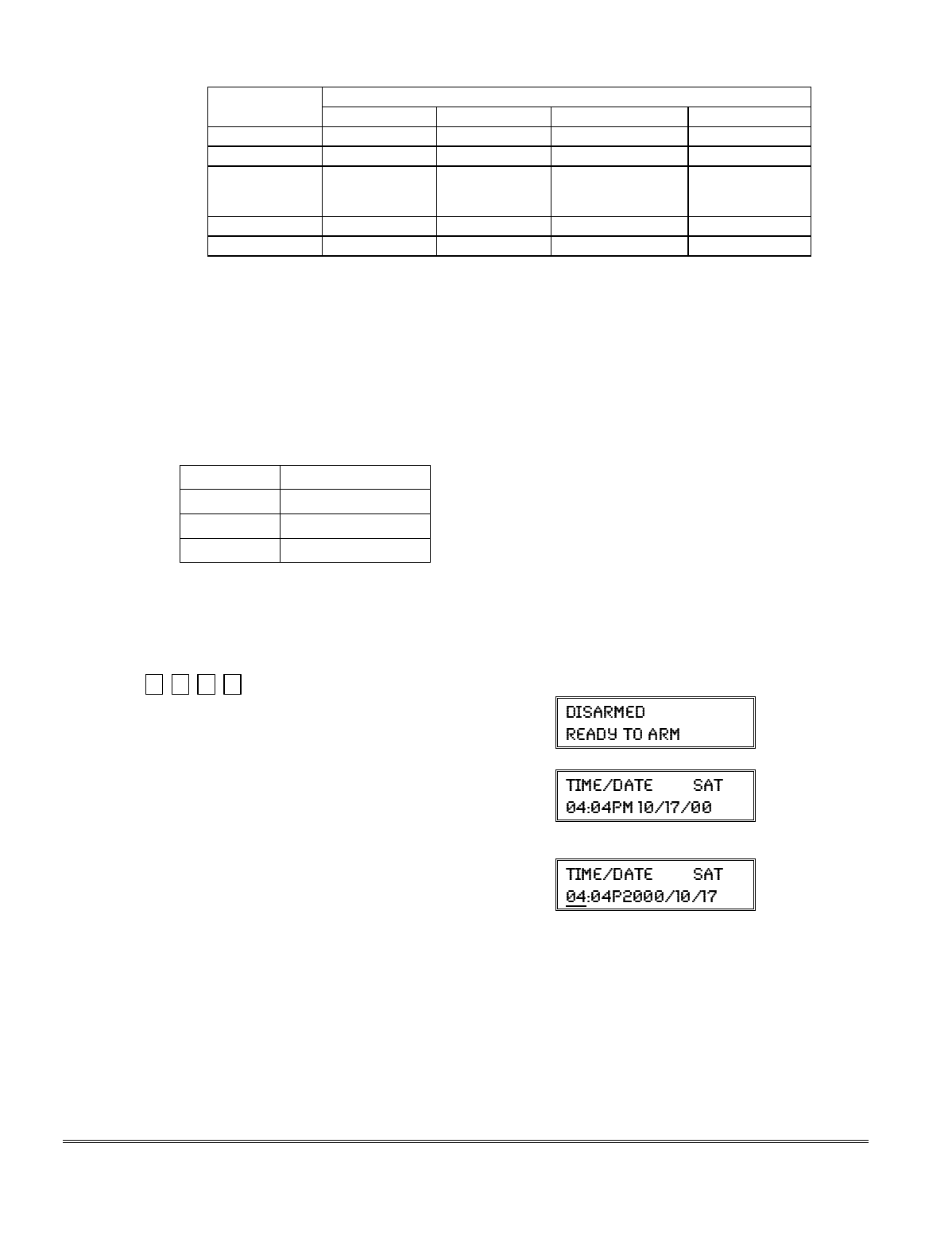
SUMMARY OF ARMING MODES
Features for Each Arming Mode
Arming Mode
Exit Delay Entry Delay Perimeter Armed Interior Armed
AWAY Yes Yes Yes Yes
STAY Yes Yes Yes No
NIGHT-STAY Yes Yes Yes only those zones
listed in Night-
Stay zone list
INSTANT Yes No Yes No
MAXIMUM Yes No Yes Yes
Panic Keys
There are three Panic keys (A, B, and C) that, if programmed, can be used to manually initiate
alarms and send a report to the central station.
Each key can be programmed for 24-hour Silent, 24-hour Audible, Fire, or Personal Emergency
responses.
The programmed Panic response is activated when the appropriate key is pressed for at least 2
seconds.
The Panic keys are identified by the system as follows:
Keys Displayed as Zone
[A] (∗/1) 95
[B] (∗/#) 99
[C] (3/#) 96
IMPORTANT: For a Silent panic function (if programmed) to be of practical value, you must
program a report code for the zone and the system must be connected to a central station.
Setting the Real-Time Clock
Set the time and date by doing the following:
1.
+[#] + [6] [3]
(Security Code)
Alpha Display:
2. Press [∗] when the time/date is displayed.
A cursor appears under the first digit of the hour.
To move cursor ahead, press [
∗
]. To go back, press [#].
• Enter the 2-digit hour setting.
• Enter the 2-digit minute setting.
• Press [1] for PM or [2] for AM.
• Enter the last two digits of the current year.
• Enter the 2-digit month setting.
• Enter the 2-digit day setting.
3. To exit, press [∗] when cursor is at the last digit, or
wait 10 seconds.
Current time display
Time/date editing display
12-3

Various System Trouble Displays
Alpha Display Fixed Disp. Meaning
CANCELED ALARM CA will appear if an exit or interior zone contained a fault during closing at the time
the Exit Delay ended (e.g., exit door left open), but the system was disarmed
during the Entry Delay time. The alarm sounder and keypad sound continuously,
but stop when the system is disarmed. No message will be transmitted to the
central station.
EXIT ALARM EA will appear when the Exit Delay ends if an exit or interior zone contained a fault
during closing. The alarm sounder and keypad sound continuously until the
system is disarmed (or timeout occurs). An “Exit Alarm” message is sent to the
central station. Also results if an alarm from an exit or interior zone occurs
within 2 minutes after the end of an Exit Delay.
CHECK CHECK indicates that a problem exists with the displayed zone(s) and requires attention.
ALARM 1xx 1xx indicates that communication between control and a zone expander or wireless
FAULT 1xx 1xx receiver is interrupted, where “xx” is the device address. Check the wiring and
CHECK 1xx 1xx DIP switch settings on the units.
91 If field *199 is set to “1,” all ECP module problems are displayed as “91.”
If there are wireless sensors in the system, the Check condition may also be
caused by some change in the environment that prevents the receiver from
receiving signals from a particular sensor.
SYSTEM LO BAT BAT with no zone number indicates that the system's main standby battery is weak.
LO BAT BAT with a zone number and a once-per-minute beeping at the keypad indicates that a
low-battery condition exists in the wireless sensor displayed (zone “00” indicates a
wireless keypad). If the battery is not replaced within 30 days, a “CHECK”
display may occur.
NOTE: Some wireless sensors contain a non-replaceable long-life battery which
requires replacement of the entire unit at the end of battery life (e.g., Nos. 5802,
5802CP).
TELCO FAULT 94 Telephone Line Failure, indicates that a monitored telephone line (if programmed
in field *92) has been cut or disconnected. Depending on how the system was
programmed, the keypad may also produce a trouble sound, and the external
sounder may be activated. Silence by entering installer code + OFF.
Busy-Standby dl If this remains displayed for more than 1 minute, the system is disabled.
Modem Comm CC The system is in communication with the central station for change of function or
status verification.
no display no display Power Failure
If there is no keypad display at all and the LEDs are unlit, operating power (AC
and battery) for the system has stopped and the system is inoperative.
If the message “AC LOSS” (Alpha display keypads) or “NO AC” (Fixed-Word
display keypads) is displayed, the keypad is operating on battery power only.
If the battery standby capacity is used up during a prolonged AC power outage,
the control's power will shut down to minimize deep discharge of the battery.
Comm. Failure FC A communication failure has occurred.
Open Circuit OC The keypad is not receiving signals from the control and sees an open circuit.
Long Rng Trbl bF Backup LRR communication failure.
Bell Failure 70 Bell supervision failure.
RCVR Jam 90 RF jam detected.
KEYPAD LOW BAT 00 BAT Wireless keypad low battery
Phone Okay Cd The dialer test has been successful (CID code 601).
Dialer Off dO The dialer is disabled.
Test in Progress dd Walk test mode is active(CID code 607).
Upload Completed dC The upload or download session was completed.
Upload Failed dF The upload or download session failed before completion.
Installation Instructions
12-4

SECTION 13
Testing the System
•••••••••••••••••••••••••••••••••••••••
About Test Procedures
After the installation is complete, you should perform the following tests:
System Test: Checks that all zones have been installed properly and the system properly
responds to faults.
Dialer Test: Checks that the phone connection to the central station is working properly.
Go/No Go Test: Checks that transmissions can be received from transmitters. Should be
performed before permanently mounting transmitters.
RF Sniffer Mode: Checks that RF transmitter serial numbers have been properly entered into the
system.
Battery Tests: Automatic battery tests are performed by the system. See Automatic Battery Test
paragraph for details.
System Test
With the system in the disarmed state, check that all zones are intact (not faulted). Doors and
windows with contacts should be closed, PIRs should be covered (use a cloth to mask them
temporarily if necessary). If a “NOT READY” message is displayed, press [∗] to display the faulted
zone(s). Restore faulted zone(s) if necessary, so that the “READY” message is displayed.
1. Enter Installer Code + 5 [TEST] , then press “0” at the prompt to start Walk Test mode.
1=DIAL, 0=WALK (no special display on Fixed-Word keypads)
The following will be displayed:
TEST IN PROGRESS (“dd” displayed on Fixed-Word Display Keypads)
A Contact ID report will also be sent (code 607)
2. Upon entering the system test mode, the outside sounder should sound for 1 second.
If the backup battery is discharged or missing, the sounder may not turn on and a “LOW
BATTERY” report will be transmitted with a “TEST” report.
The keypad will beep about every 40 seconds as a reminder that the system is in the Test mode.
NOTE: Wireless motion detectors (Passive Infrared units) will send signals out only if they have
been inactive for 3 minutes (conserves battery life).
3. Test all sensors using the procedure described in the User’s Guide “Testing the System” section.
4. After checking sensors, turn off the test mode by entering installer code + OFF.
NOTE: Test mode automatically ends after 4 hours. During the final 5 minutes (after 3 hours 55
minutes of Test mode), the keypad emits a double-beep every 30 seconds to alert that the end of
Test mode is nearing.
13-1

Checking Transmitter Enrollment (Sniffer Mode)
Use this mode to verify that all transmitters have been properly programmed. Make sure both
partitions are disarmed before trying to enter this mode, since this is a system-wide command.
1. Press [Installer code] + [#] + 3.
Note: If the communicator is in the process of sending a report to the central station, the
system will not go into the Sniffer mode. If so, wait a few minutes, and try again.
The keypads in both partitions will display all zone numbers of wireless units (in both partitions)
programmed into the system. Fault each transmitter in turn, causing each one to send a signal.
As the system receives a signal from each of the transmitters, the zone number of that
transmitter disappears from the display.
2. After all transmitters have been checked, exit the sniffer mode by keying [Installer code] + OFF.
IMPORTANT: Sniffer mode does not automatically expire. You must manually exit Sniffer
mode (by entering [Installer code] + OFF) to return to normal operation.
Notes:
• All BR type units must physically be activated to clear the display.
• When
one button of a transmitter (RF, UR, or BR) is activated, all zones assigned to other
buttons on that transmitter are cleared. This also applies to 5816 and 5817 transmitters, which
have multiple loops (zones).
• Any transmitter that is not “enrolled” will not turn off its zone number.
Go/No Go Test Mode
The Go/No Go Test verifies adequate RF signal strength from the proposed transmitter location, and
allow you to reorient or relocate transmitters if necessary, before mounting the transmitters
permanently. This mode is similar to the Transmitter Test mode, except that the wireless receiver
gain is reduced. This will enable you to make sure that the RF signal from each transmitter is
received with sufficient signal amplitude when the system is in the normal operating mode.
1. Enter [Installer code] + [#] + 4 from the partition being tested. For multi-partition systems, repeat
this test for each partition.
2. After you have placed transmitters in their desired locations and the approximate length of wire
to be run to sensors is connected to the transmitter's screw terminals (if used), fault each
transmitter. Do not conduct this test with your hand wrapped around the transmitter, as this will
cause inaccurate results.
a. The keypad will beep three times to indicate signal reception and display the appropriate zone
number.
b. If the keypad does not beep, you should reorient or move the transmitter to another location.
Usually a few inches in either direction is all that is required.
4. If each transmitter produces the proper keypad response when it is faulted, you can then
permanently mount each of the transmitters according to the instructions provided with them.
5. Exit the Go/No Go Test mode by entering: [any user code (partition-specific)] + OFF.
Installation Instructions
13-2

Dialer Communication Test and Periodic Test Reports
1. Enter Installer Code + 5 [TEST], then press “1” at the prompt to start the Dialer Test.
1=DIAL, 0=WALK (no special display on Fixed-Word keypads)
The following will be displayed (accompanied by 2 beeps) if test is successful:
PHONE OKAY (“Cd” displayed on Fixed-Word Display Keypads)
A Contact ID report will also be sent (code 601)
If the dialer test is unsuccessful, the following is displayed:
COMM FAILURE (“FC” displayed on Fixed-Word Display Keypads)
2. Enter Installer code + OFF to clear the display and exit.
Automatic Periodic Test Report
The system can be set to automatically send test reports (enabled in field *64; Contact ID code 602) at
specified intervals.
Frequency of the reports is set in Scheduling mode (event 11) or by the following key commands:
installer code + [#] + 0 + 0 = test report sent every 24 hours
installer code + [#] + 0 + 1 = test report sent once per week
installer code + [#] + 0 + 2 = test report sent every 28 days
Each mode sets schedule 32 (FA168CPS) or schedule 08 (FA148CP) to the selected repeat option; first
test report sent 12 hours after command.
To ensure that test reports are sent at the times expected, set the Real-Time Clock to the proper time
before entering the test report schedule command.
Automatic Standby Battery Tests
1. An automatic test is conducted every 3 minutes to ensure that a standby battery is present and
properly connected. If a battery is not present or is not properly connected, a “LOW BATTERY”
message is displayed and, if so programmed, will be reported to the central station.
2. A battery capacity test is automatically conducted for 2 minutes every 4 hours, beginning 4 hours
after exiting the Programming mode or after powering up the system. In addition, entry into the
Test mode will also cause a battery capacity test to be initiated. If the battery cannot sustain a
load, a “Low Battery” message is displayed and, if so programmed, will be reported to the central
station.
13-3

Installation Instructions
13-4

SECTION 14
Specifications & Accessories
•••••••••••••••••••••••••••••••••••••••
SECURITY CONTROL
1. Physical: 12-1/2” W x 14-1/2” H x 3” D (318mm x 368mm x 76mm)
2. Electrical:
VOLTAGE INPUT: 16.5VAC from plug-in 25VA transformer, Ademco No. 1321 (in U.S.A.)
RECHARGEABLE BACKUP BATTERY: 12VDC, 4AH (sealed lead acid type). Charging
Voltage: 13.8VDC.
ALARM SOUNDER: 12V, 2.0 Amp output can drive 12V BELLS or can drive one or two
702 (series connected) self-contained 20-watt sirens. Do not connect
two 702s in parallel.
AUXILIARY POWER OUTPUT: 12VDC, 600mA max.
Note: For UL installations, Alarm Sounder plus Auxiliary Power currents should not
exceed 600mA total.
FUSE: Battery (3A) No. 90–12
3. Communication:
FORMAT SUPPORTED:
ADEMCO Express: 10 characters/sec, DTMF (TouchTone) Data Tones,
1400/2300Hz ACK, 1400Hz KISSOFF.
ADEMCO Low Speed: 10 pulses/sec, 1900Hz Data Tone, 1400Hz ACK/KISSOFF.
Ademco Contact ID 10 characters/sec., DTMF (TouchTone) Data Tones,
1400/2300Hz ACK, 1400Hz KISSOFF.
LINE SEIZE: Double Pole
RINGER EQUIVALENCE: 0.1B
FCC REGISTRATION No.: 5GBUSA-44003-AL-E
4. Maximum Zone Resistance: Zones 1–8 = 300 ohms excluding EOLR standard zones
COMPATIBLE DEVICES
Keypads: FA215KP and FA260KP Fixed-Word Keypads, FA560KP Alpha Keypad,
FA560VKP Voice Keypad, FA700KP Touch Screen Keypad,
Symphony Advanced User Interface
Wireless Receivers: 5881L/5882L: accepts up to 8 transmitters
5881M/5882M: accepts up to 16 transmitters
5881H/5882H: accepts up to system maximum transmitters
5800TM Transmitter Module (used with Wireless 2-Way Keypads)
5883 Transceiver: accepts up to system maximum transmitters
FA260RF Keypad/Transceiver: accepts up to system maximum transmitters
Zone Expansion: 4219 WIRED EXPANSION MODULE
4229 WIRED EXPANSION/RELAY MODULE
Relay Module: 4204 RELAY MODULE
Phone Modules: FA4285 PHONE MODULE
FA4286VIP PHONE MODULE
Long Range Radio 7835C/7845C
14-1

2-Wire Smoke Detector:
Detector Type
System Sensor
Model No.
Photoelectric w/heat sensor, direct wire 2300TB
Photoelectric, direct wire 2400
Photoelectric w/heat sensor, direct wire 2400TH
Photoelectric 2451 w/B401B base
Photoelectric w/heat sensor 2451TH w/B401B base
Ionization, direct wire 1400
Ionization 1451 w/B401B base
Photoelectric duct detector 2451 w/DH400 base
Ionization duct detector 1451D w/DH400 base H
Low-profile, Photoelectric, w/135°F thermal 2100T
Low-profile, Ionization type, direct wire 1100
Transformers: 1321: 16.5VAC, 25VA Plug-In Transformer (No. 1321CN in Canada)
1361X10: 16.5VAC, 40VA Powerline Carrier device Interface AC Transformer
Sounders: Ademco AB-12M 10” Motorized Bell & Box
Ademco 1011BE12M 10” Motorized Bell & Box
Ademco 702 Outdoor Siren
Ademco 719 2-Channel Siren
Ademco 747 Indoor Siren
Ademco 747UL Indoor Siren
Ademco 744 Siren Driver
Ademco 745X3 Voice Siren Driver
Ademco 705-820, 5-inch Round Speaker
Ademco 713 Speaker
System Sensor PA400B (beige)/; PA400R (red) Indoor Piezo Sounder
Installation Instructions
14-2
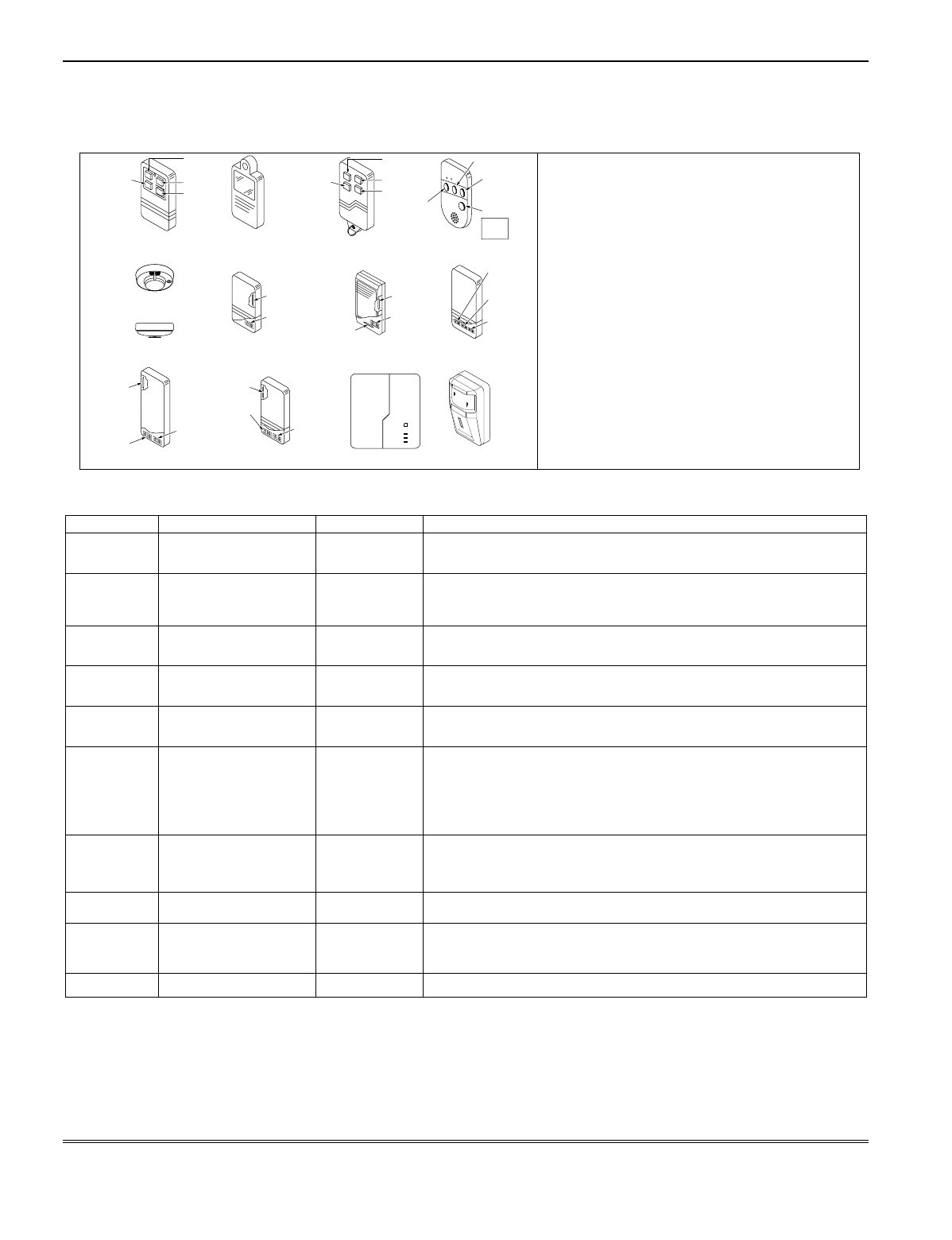
5800 Series Transmitter Input Loop Identification
All of the transmitters illustrated below have one or more unique factory assigned input (loop) ID codes. Each of the input
loops requires its own programming zone
(e.g., a 5804's four inputs require four programming zones).
5802MN
ENROLL AS
"UR" OR "RF"
LOOP
1
V20P-006-V0
5817
ENROLL AS
"RF"
5890
ENROLL AS
"RF" OR "RM"
LOOP 1
5808
ENROLL AS
"RF"
LOOP 1
5809
ENROLL AS
"RF"
5850 (GBD)
ENROLL AS
"RF"
(Green)
(Red)
(Yellow)
5804BD
ENROLL AS
"BR"
LOOP 4
YOU MUST
ENROLL
THIS BUTTON
SET
HOUSE
CODE
LOOP 3 LOOP 1
LOOP 2
5804
ENROLL AS "BR"
ON
5816MN
ENROLL AS
"RF"
LOOP 2
(REED)
5816
ENROLL AS
"RF"
LOOP 1
(TERMINALS)
LOOP 2
(REED)
LOOP 3
(TERMINALS)
5819S (WHS & BRS)
ENROLL AS
"RF"
LOOP 1
(INTERNAL
SHOCK
SENSOR
LOOP 2
(REED)
5819
ENROLL AS
"RF"
LOOP 2
(REED)
LOOP 3
(TERMINALS)
LOOP 1
(TERMINALS)
5801
ENROLL AS
"UR" OR "RF"
LOOP 3
LOOP 1
LOOP 2
LOOP 4
YOU MUST
ENROLL
THIS
BUTTON
LOOP 1
LOOP 2
LOOP 4
YOU MUST
ENROLL
THIS
BUTTON
LOOP 3
LOOP
1
MOTION
LOOP 2
(AUX.
CENTER)
LOOP 1
(PRIMARY)
LOOP 3
(AUX.
RIGHT)
LOOP 1
(TERMINALS)
ALTERNATE
POSITION
FOR LOOP 2
OFF
NOTE: For information on any transmitter not
shown, refer to the instructions accompanying
that transmitter for details regarding loop
numbers, etc.
UL NOTE: The following transmitters are
not intended for use in UL
installations:
5802MN, 5802MN2, 5804,
5804BD, 5814, 5816TEMP,
5819, 5819WHS & BRS, and
5850.
Compatible 5800 Series Transmitters Table
Model Product Input Type Description
5801 Wireless Panic
Transmitter
UR or RF • Four pushbuttons, each with a unique input (loop) code.
• Programmable responses (e.g., Panic, Arm, Disarm, etc.)
5802 Pendant (Personal
Emergency Transmitter)
BR Only • Has single pushbutton.
• Usually programmed for response type of 24-Hr audible or 24-Hr
Silent (other zone responses are possible).
5802CP Belt Clip (Personal
Emergency)
BR Only Same as 5802.
5802MN Miniature (Personal
Emergency Trans.)
UR or RF Same as 5802.
5804 Wireless Key
Transmitter
BR Only • Has four pushbuttons, each with a unique input (loop) code.
• Programmable responses (e.g., Arm, Disarm, etc.)
5804BD Bi-Directional
Wireless Key
BR • House ID must be set.
• Requires 5800TM Transmitter Module.
• Can indicate system status via its 2 LEDs and built-in sounder.
• Has four pushbuttons, each with a unique input (loop) code.
• Operates the system similarly to wired keypads.
5806
5807
5808
Wireless
Photoelectric Smoke
Detectors
RF One-piece smoke detectors with a built-in transmitter.
5809 Heat Detector RF One-piece rate-of-rise heat detector with a built-in transmitter.
5816
5816MN
Door/Window
Transmitters
RF Has two unique input (loop) codes: one for a wired closed circuit
contact loop; the other for its built-in reed switch (used with a
magnet).
5816TEMP Low-Temp. Sensor RF Transmits a fault condition when temperature drops below 45°F.
14-3

Compatible 5800 Series Transmitters Table (continued)
Model Product Input Type Description
5817 Multi-Point Universal
Transmitter
RF Has three unique input (loop) codes: one for a “Primary” contact
loop with programmable options; the others for two “auxiliary”
closed circuit contact loops.
5818 Recessed
Transmitter
RF • Reed switch magnetic contact sensor; easily hidden in the frame
and edge of a door or window.
• Has a single unique input (loop) code.
5819 Shock Processor
Transmitter
RF • Connects to externally mounted inertia-type shock detector (not
supplied).
• Has built-in tampered cover switch.
• Has 3 unique input (loop) codes:
Loop 1:
Terminals for a wired, N.C. sensor loop.
Loop 2:
For a closed circuit contact loop using the built-in reed
switch in conjunction with a magnet.
Loop 3:
Terminals for a wired, closed circuit contact loop.
5819WHS
5819BRS
Shock Processor
Transmitter
RF • Has built-in shock sensor.
• Has built-in tampered cover switch.
• Has 3 unique input (loop) codes:
Loop 1:
Built-in shock sensor loop wired to TB1 (normally closed).
Loop 2:
For a closed circuit contact loop using the built-in reed
switch in conjunction with a magnet.
Loop 3:
Externally wired, closed circuit loop connected to TB2.
5827 Wireless Keypad Uses House
ID only
• Can be used to turn the burglary protection on and off.
• Features the same built-in panic functions as wired keypads.
• The keypad is identified as zone “00” on wired keypads when it
transmits with a low battery.
5827BD Wireless Two-Way
Keypad
Uses House
ID only
• Requires 5800TM Transmitter Module.
• Operates the system similarly to wired keypads, including panics.
• Can indicate system status via its 3 LEDs and sounder.
• Includes 3 panic keys.
5849 Glassbreak Detector RF • House ID must also be set.
• Requires both sound and shock of breaking glass to cause
alarm to be transmitted.
5890 PR Detector RF Dual-element passive infrared detector/transmitter with built-in
selectable pulse count.
Note:
There is a 3-minute lockout between fault transmissions to
conserve battery life.
5899 Magnets Package of 4 magnets for use with 5816 and 5817 transmitters.
Installation Instructions
14-4

– NOTES –
14-5

– NOTES –
Installation Instructions
14-6

– NOTES –
14-7

– NOTES –
Installation Instructions
14-8

– NOTES –
14-9

– NOTES –
Installation Instructions
14-10

– NOTES –
14-11

– NOTES –
Installation Instructions
14-12

SECTION 15
Regulatory Agency Statements
•••••••••••••••••••••••••••••••••••••••
RADIO FREQUENCY EMISSIONS
Federal Communications Commission (FCC) Part 15
This device complies with part 15 of the FCC rules. Operation is subject to the following two conditions: (1) This device may not cause harmful interference,
and (2) this device must accept any interference received, including interference that may cause undesired operation.
Industry Canada
This Class B digital apparatus complies with Canadian ICES-003.
Cet Appareil numérique de la classe B est conforme à la norme NMB-003 du Canada.
TELEPHONE/MODEM INTERFACE
FCC Part 68
This equipment complies with Part 68 of the FCC rules. On the front cover of this equipment is a label that contains the FCC registration number and
Ringer Equivalence Number (REN). You must provide this information to the telephone company when requested.
This equipment uses the following USOC jack: RJ31X
This equipment may not be used on telephone-company-provided coin service. Connection to party lines is subject to state tariffs. This equipment is
hearing-aid compatible.
Industry Canada
NOTICE: The Industry Canada Label identifies certified equipment. This certification means that the equipment meets telecommunications network
protective, operational and safety requirements as prescribed in the appropriate Terminal Equipment Technical Requirements document(s). The
Department does not guarantee the equipment will operate to the user’s satisfaction.
Before installing this equipment, users should ensure that it is permissible to be connected to the facilities of the local telecommunications company. The
equipment must also be installed using an acceptable method of connection. The customer should be aware that compliance with the above conditions may
not prevent degradation of service in some situations.
Repairs to certified equipment should be coordinated by a representative designated by the supplier. Any repairs or alterations made by the user to this
equipment, or equipment malfunctions, may give the telecommunications company to request the user to disconnect the equipment.
Users should ensure for their own protection that the electrical ground connections of the power utility, telephone lines and internal metallic water pipe
system, if present, are connected together, This precaution may be particularly important in rural areas.
Caution: Users should not attempt to make such connections themselves but should contact appropriate electric inspection authority, or electrician, as
appropriate.
Ringer Equivalence Number Notice:
The Ringer Equivalence Number (REN) assigned to each terminal device provides an indication of the maximum number of terminals allowed to be
connected to a telephone interface. The termination on an interface may consist of any combination of devices subject only to the requirement that the sum
of the Ringer Equivalence Numbers of all the devices does not exceed 5.
Industrie Canada
AVIS: l’étiquette d’Industrie Canada identifie le matériel homologué. Cette étiquette certifie que le matériel est conforme aux normes de protection,
d’exploitation et de sécurité des réseaux de télécommunications, comme le prescrivent les documents concernant les exigences techniques relatives au
matériel terminal. Le Ministère n’assure toutefois pas que le matériel fonctionnera à la satisfaction de l’utilisateur.
Avant d’installer ce matériel, l’utilisateur doit s’assurer qu’il est permis de le raccorder aux installations de l’enterprise locale de télécommunication. Le
matériel doit également être installé en suivant une méthode acceptée da raccordement. L’abonné ne doit pas oublier qu’il est possible que la conformité aux
conditions énoncées ci-dessus n’empêche pas la dégradation du service dans certaines situations.
Les réparations de matériel nomologué doivent être coordonnées par un représentant désigné par le fournisseur. L’entreprise de télécommunications peut
demander à l’utilisateur da débrancher un appareil à la suite de réparations ou de modifications effectuées par l’utilisateur ou à cause de mauvais
fonctionnement.
Pour sa propre protection, l’utilisateur doit s’assurer que tous les fils de mise à la terre de la source d’energie électrique, de lignes téléphoniques et des
canalisations d’eau métalliques, s’il y en a, sont raccordés ensemble. Cette précaution est particulièrement importante dans les régions rurales.
Avertissement : L’utilisateur ne doit pas tenter de faire ces raccordements lui-même; il doit avoir racours à un service d’inspection des installations
électriques, ou à un électricien, selon le cas.
AVIS : L’indice d’équivalence de la sonnerie (IES) assigné à chaque dispositif terminal indique le nombre maximal de terminaux qui peuvent être
raccordés à une interface. La terminaison d’une interface téléphonique peut consister en une combinaison de quelques dispositifs, à la seule condition que la
somme d’indices d’équivalence de la sonnerie de tous les dispositifs n’excède pas 5.
15-1

UL NOTICES
1. Entry Delay No. 1 and No. 2 (fields ✱35, ✱36) cannot be greater than 30 seconds
for UL Residential Burglar Alarm installations, and entry delay plus dial delay
should not exceed 1 minute. For UL Commercial Burglar Alarm installations,
total entry delay may not exceed 45 seconds.
2. For UL Commercial Burglar Alarm (Grade AA) and UL Residential Burglar
Alarm installations with line security, total exit delay time must not exceed 60
seconds. For UL Burglar Alarm installations without line security (Grade A),
total exit delay time must not exceed 120 seconds.
3. The maximum number of reports per armed period (field ✱93) must be set to “0”
(unlimited) for UL installations.
4. Periodic testing (see scheduling mode) must be at least every 24 hours.
5. Alarm Sounder plus Auxiliary Power currents must not exceed 600mA total for
UL installations (Aux power 500mA max.).
6. All partitions must be owned and managed by the same person(s).
7. All partitions must be part of one building at one street address.
8. If used, the audible alarm device(s) must be placed where it/they can be heard
by all partitions.
9. For UL commercial burglar alarm installations the control unit must be
protected from unauthorized access. The tamper switch installed to protect the
control unit enclosure door is suitable for this purpose.
10. Remote downloading without an alarm company technician on-site (unattended
downloading) is not permissible for UL installations.
11. Auto-disarming is not a UL Listed feature.
Installation Instructions
15-2

SECTION 16
Limitations and Warranty
•••••••••••••••••••••••••••••••••••••••
WARNING
THE LIMITATIONS OF THIS ALARM SYSTEM
While this System is an advanced design security system, it does not offer guaranteed protection against
burglary, fire or other emergency. Any alarm system, whether commercial or residential, is subject to
compromise or failure to warn for a variety of reasons. For example:
• Intruders may gain access through unprotected openings or have the technical sophistication to bypass an
alarm sensor or disconnect an alarm warning device.
• Intrusion detectors (e.g., passive infrared detectors), smoke detectors, and many other sensing devices will
not work without power. Battery-operated devices will not work without batteries, with dead batteries, or if
the batteries are not put in properly. Devices powered solely by AC will not work if their AC power supply is
cut off for any reason, however briefly.
• Signals sent by wireless transmitters may be blocked or reflected by metal before they reach the alarm
receiver. Even if the signal path has been recently checked during a weekly test, blockage can occur if a
metal object is moved into the path.
• A user may not be able to reach a panic or emergency button quickly enough.
• While smoke detectors have played a key role in reducing residential fire deaths in the United States, they
may not activate or provide early warning for a variety of reasons in as many as 35% of all fires, according to
data published by the Federal Emergency Management Agency. Some of the reasons smoke detectors used
in conjunction with this System may not work are as follows. Smoke detectors may have been improperly
installed and positioned. Smoke detectors may not sense fires that start where smoke cannot reach the
detectors, such as in chimneys, in walls, or roofs, or on the other side of closed doors. Smoke detectors also
may not sense a fire on another level of a residence or building. A second floor detector, for example, may not
sense a first floor or basement fire. Finally, smoke detectors have sensing limitations. No smoke detector can
sense every kind of fire every time. In general, detectors may not always warn about fires caused by
carelessness and safety hazards like smoking in bed, violent explosions, escaping gas, improper storage of
flammable materials, overloaded electrical circuits, children playing with matches, or arson. Depending on
the nature of the fire and/or location of the smoke detectors, the detector, even if it operates as anticipated,
may not provide sufficient warning to allow all occupants to escape in time to prevent injury or death.
• Passive Infrared Motion Detectors can only detect intrusion within the designed ranges as diagrammed in
their installation manual. Passive Infrared Detectors do not provide volumetric area protection. They do
create multiple beams of protection, and intrusion can only be detected in unobstructed areas covered by
those beams. They cannot detect motion or intrusion that takes place behind walls, ceilings, floors, closed
doors, glass partitions, glass doors, or windows. Mechanical tampering, masking, painting or spraying of any
material on the mirrors, windows or any part of the optical system can reduce their detection ability. Passive
Infrared Detectors sense changes in temperature; however, as the ambient temperature of the protected
area approaches the temperature range of 90° to 105°F (32° to 40°C), the detection performance can
decrease.
• Alarm warning devices such as sirens, bells or horns may not alert people or wake up sleepers if they are
located on the other side of closed or partly open doors. If warning devices are located on a different level of
the residence from the bedrooms, then they are less likely to waken or alert people inside the bedrooms.
Even persons who are awake may not hear the warning if the alarm is muffled by noise from a stereo, radio,
air conditioner or other appliance, or by passing traffic. Finally, alarm warning devices, however loud, may
not warn hearing-impaired people.
• Telephone lines needed to transmit alarm signals from a premises to a central monitoring station may be
out of service or temporarily out of service. Telephone lines are also subject to compromise by sophisticated
intruders.
• Even if the system responds to the emergency as intended, however, occupants may have insufficient time to
protect themselves from the emergency situation. In the case of a monitored alarm system, authorities may
not respond appropriately.
• This equipment, like other electrical devices, is subject to component failure. Even though this equipment is
designed to last as long as 10 years, the electronic components could fail at any time.
(Continued)
16-1

WARNING
THE LIMITATIONS OF THIS ALARM SYSTEM
(Continued)
The most common cause of an alarm system not functioning when an intrusion or fire occurs is inadequate
maintenance. This alarm system should be tested weekly to make sure all sensors and transmitters are
working properly. The security keypad (and remote keypad) should be tested as well.
Wireless transmitters (used in some systems) are designed to provide long battery life under normal operating
conditions. Longevity of batteries may be as much as 4 to 7 years, depending on the environment, usage, and
the specific wireless device being used. External factors such as humidity, high or low temperatures, as well as
large swings in temperature, may all reduce the actual battery life in a given installation. This wireless system,
however, can identify a true low-battery situation, thus allowing time to arrange a change of battery to
maintain protection for that given point within the system.
Installing an alarm system may make the owner eligible for a lower insurance rate, but an alarm system is not
a substitute for insurance. Homeowners, property owners and renters should continue to act prudently in
protecting themselves and continue to insure their lives and property.
We continue to develop new and improved protection devices. Users of alarm systems owe it to themselves and
their loved ones to learn about these developments.
Installation Instructions
16-2

– INDEX –
1
1321 AC Transformer...............1-2, 2-4
1361X10 ................1-2, 2-4, 2-11, 14-2
15-Second Dialer Delay (Burglary) ..4-3
2
24-Hour Audible Alarm....................3-4
24-Hour Auxiliary Alarm ..................3-4
24-Hour Silent Alarm.......................3-4
2-Wire Smoke Detectors .................2-6
3
3+1 and 4+1 Standard Formats.....11-1
4
4204 1-2, 2-5, 2-6, 2-10, 3-1, 3-6, 6-1, 6-
2, 12-2, 14-1
4219 1-1, 1-2, 2-5, 2-7, 2-10, 3-6, 14-1
4229 1-1, 1-2, 2-5, 2-6, 2-7, 2-10, 3-1,
3-6, 6-1, 6-2, 12-2, 14-1
FA4285 Phone Module 1-2, 2-13, 9-3, 9-
1
FA4286 Phone Module 1-2, 2-13, 9-3, 9-
1
4-Wire Smoke Detectors .................2-7
5
5800 Series Transmitters .....14-3, 14-4
5800TM........ 2-8, 3-6, 14-1, 14-4, 14-5
5801.......................................2-9, 14-4
5802..............................2-9, 12-3, 14-4
5802CP.........................2-9, 12-3, 14-4
5804 wireless key ...........................5-6
5804BD wireless key................2-8, 5-6
5827................................2-8, 4-1, 14-5
5827BD.........2-8, 4-1, 14-1, 14-3, 14-5
5881..................................1-2, 2-5, 2-8
A
AAV Connections..........................2-13
AC Power Supply............................1-2
AC Transformer ....... iii, 2-4, 2-11, 14-2
AD12612.........................................2-3
Alarm Output.....................1-2, 2-4, 2-5
Alarm Sounder Timeout ..................4-2
Alpha Descriptor ........5-1, 5-3, 9-1, 9-2
Alpha Programming ........................3-1
Alpha Vocabulary List .....................9-4
Arm Away/Stay Report Code ..........4-5
Arming Away..........................3-4, 12-2
Arming Instant...............................12-2
Arming Modes...............................12-2
Arming Stay ...........................3-4, 12-2
Audio Alarm Verification..1-2, 2-12, 4-7
Authority Levels ............................12-1
Auto-STAY Arming..........................4-6
Auxiliary Output...............................2-5
B
Backup Battery................................1-2
Battery Life......................................2-9
Battery Tests........................13-1, 13-3
Bell Supervision ..............................2-4
Bell Supervision Jumper..................2-4
Bypassing Zones ..........................12-2
C
Cabinet .......................................... 2-1
California State Fire Marshall ..........2-5
Caller ID Unit.................................2-12
Cancel Report Code........................4-5
Character List..................................9-3
Charging Voltage ..........................14-1
Chime By Zone ...............................4-1
Chime Mode.........................4-11, 12-2
Clean Me Option .............................2-6
common zone .................................3-1
Communication ....8-1, 11-1, 13-3, 14-1
Configurable Zone Type Options...4-11
Configurable Zone Type Programming
Fields....................................... 4-11
Confirmation Of Arming Ding...........4-2
Contact ID Reporting............11-3, 14-1
Custom Message ............................9-3
Custom Words ........................ 9-1, 9-3
D
Data Field Programming Procedures3-5
Defining Output Functions.............. 6-3
Descriptor Programming ................ 9-1
Device Address 2-3, 2-7, 2-10, 3-1, 3-6,
4-2, 4-12, 6-1, 12-3
DIP Switches...................................2-8
Disarming........................3-4, 6-4, 12-2
Double-Balanced.............................2-6
E
Earth Ground ..................................2-5
Enrolling...................................2-9, 5-1
entering serial number.....................5-5
Entry Delay 3-4, 4-2, 4-4, 4-10, 12-2, 12-
3, 15-2
Entry/Exit Burglary ..........................3-3
EOLR.....................................2-6, 14-1
Event Logging ..........................1-1, 4-6
Exit Delay4-2, 4-4, 4-7, 4-10, 12-2, 12-3
Exit Error Alarm.............................12-3
Exit Error Report Code....................4-4
Exit Warning....................................4-2
Expander Module Addresses ..........2-7
Expansion Zones ........... 1-2, 2-7, 2-10
Expert Programming Mode 5-1, 5-4, 5-6
F
Factory Defaults..............................3-6
Fast Busy Signal ...........................2-12
Fault Delay Time.............................4-6
Fire Alarm Sounder Timeout ...........4-2
Forced Bypass Function..................4-1
Function Key Programming 1-2, 3-1, 8-1
Function Keys ...................3-2, 3-3, 8-1
G
Go/No Go Test Mode ....................13-2
H
Handshake....................................11-1
hardwired zones..............1-1, 5-2, 12-3
HAYES Modem...............................1-1
House ID................2-8, 4-1, 14-4, 14-5
I
IBM Personal Computer..................3-1
Ideal Model 61–035.........................2-5
Input Device Type .........5-4, 14-4, 14-5
Installer Code.........3-6, 4-1, 13-1, 13-3
Interior Follower ................3-3, 5-2, 6-4
Interior w/Delay .................3-4, 5-2, 6-4
K
Keypad Addresses ...................2-3, 3-2
Keypad Functions .........................12-2
Keypad Programming Fields ........ 4-12
Keyswitch..................... 2-9, 3-5, 5-2, 3
Kissoff....................................6-4, 11-1
L
Lock ............................................... 2-1
Long Range Radio . 1-2, 2-13, 3-6, 4-2,
4-4, 14-1
Low Battery Message....................13-3
M
Macros............................................1-1
Master Security Code....................12-1
model 112 .......................................2-9
Modem...................................3-1, 12-4
Module Addresses ..........................6-2
Momentary Switch...........................2-9
N
No Alarm Response .................3-4, 6-4
Normally Closed Zones...................2-6
Normally Open Zones .....................2-6
O
On-Board Triggers................2-11, 2-13
Output Device Mapping.... 3-1, 6-1, 6-2
Output Devices .............. 3-3, 6-1, 12-2
Output Functions.............................6-1
Output relays...................................1-2
Output To Long Range Radio..........4-2
16-3

P
PABX Access Code ........................4-3
Pager 1 Phone No...........................4-8
Pager Format..................................4-8
Pager Programming................ 3-2, 4-8
Pager Programming Fields............. 4-8
Pager Report Options .....................4-8
Panic Keys....................................12-3
Partitions................................. 1-1, 3-1
Perimeter Burglary ..........................3-3
Phone Line................................... 2-12
Phone Module 1-1, 1-2, 2-3, 2-5, 2-12,
2-13, 4-1, 4-7, 9-1, 9-3, 9-4, 14-1
Phone Module Access Code...........4-1
Power Failure.........................6-4, 12-4
Power Supply...........2-3, 2-4, 2-5, 16-1
Power Up In Previous State ............4-2
Powerline Carrier Devices . 1-2, 2-11, 4-
1, 12-2
Primary Phone No...........................4-4
Primary Phone No...........................4-3
Q
Quick Arm Enable...........................3-2
R
Relay Module Addresses ..............2-10
Relay Modules ............... 1-2, 2-10, 3-6
Report Code 3-2, 4-4, 4-5, 4-6, 4-10, 5-
2, 5-4, 11-1
Report Code Formats....................11-1
Reports In Armed Period.................4-7
response time ...................2-7, 4-6, 5-1
RF House ID Code...................3-2, 4-1
RF Interference ...............................2-8
RF jam detection......................1-1, 4-1
RF Jam Option................................3-2
RF Receiver iii, 2-1, 2-2, 2-3, 2-5, 2-8, 3-
6
Ring Detection Count For Downloading
...................................................4-7
RJ31X Jack...................................2-12
S
SA4120XM-1 Trigger Cable ............2-4
Schedules .................................... 10-1
Secondary Phone No. .....................4-3
Security Codes...................... 1-1, 12-1
Silent Burglary...............3-5, 5-2, 6-4, 3
Silent Panic...................................12-3
Single Alarm Sounding Per Zone ....4-2
Smoke Detectors ......................... 14-4
Sniffer Mode..................5-4, 13-1, 13-2
Sounder Connections......................2-4
Supervised Fire...............................3-4
Supplementary Power.....................2-3
Swinger Suppression ......................4-7
System Communicationiv, 4-10, 5-2, 11-
1
System Operationiv, 4-1, 5-6, 6-4, 10-1,
12-1
System Status Report Codes ......... 4-4
System Test................................. 13-1
T
tamper switch.........................2-9, 15-2
Telco Line .................................2-12, 3
Telephone Line Monitoring..............1-1
Test Mode............................13-1, 13-2
Test Restore Report Code ..............4-5
Transmitter Battery Life...................2-9
Transmitter Input Types ..................5-2
Trouble by Day/...............................3-3
Trouble Displays .......................... 12-3
V
Vocabulary List ...............................9-4
W
Wireless Key Templates..................5-6
Wiring Length/Gauge Chart.............2-3
Wiring Run Chart.............................2-3
Word String.....................................9-3
Worksheet.......................................2-5
Z
Zone Doubling.................................2-6
Zone Lists ............................... 3-1, 7-1
Zone Not Used................................3-3
Zone Programming..........................5-1
Zone Programming Procedure ....... 5-1
Zone Type Definitions .....................3-3
Zone Types ........ 2-6, 3-3, 3-5, 5-2, 6-4
Installation Instructions
16-4
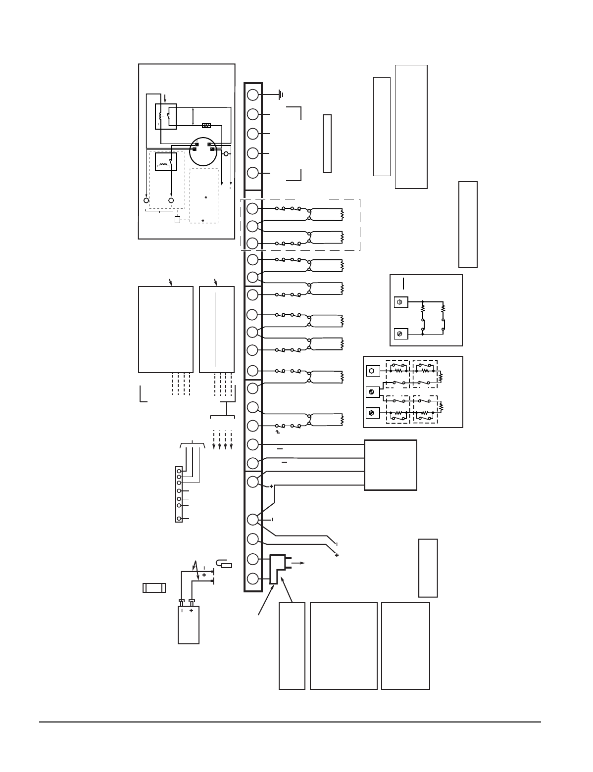
CLASS 2 PLUG-IN TRANSFORMER
16.5VAC, 25VA
(e.g. 1321).
(USE No. 1321CN IN CANADA)
TO 110VAC
UNSWITCHED
OUTLET (24HR)
THIS EQUIPMENT SHOULD BE INSTALLED
IN ACCORDANCE WITH THE NATIONAL
FIRE PROTECTION ASSOCIATION'S
STANDARD 72, CHAPTER 2 (NATIONAL
FIRE PROTECTION ASSOCIATION,
BATTERY-MARCH PARK, QUINCY,MA
02269).
PRINTED INFORMATION
DESCRIBING PROPER INSTALLATION,
OPERATION,TESTING, MAINTENANCE,
EVACUATION PLANNING AND REPAIR
SERVICE IS TO BE PROVIDED WITH THIS
EQUIPMENT.
24-HR BATTERY STANDBY REQUIRED FOR
FIRE INSTALLATIONS. USE 12V, 17.2AH
BATTERY FOR 600mA AUX POWER. SEE
INSTRUCTIONS.
BATTERY CAPACITY FOR EMERGENCY
BURGLARY STANDBY USE AT LEAST 4 HRS
USE UL LISTED LIMITED ENERGY
CABLE FOR ALL CONNECTIONS
USE 4300 / 1321X10 TRANSFORMER
INTERFACE IN PLACE OF 1321 OR
1321CN WHEN POWER LINE CARRIER
DEVICES ARE BEING USED. (SEE
INSTRUCTIONS FOR CONNECTIONS)
FOR COMPLETE
INFORMATION, SEE
INSTRUCTIONS K5305-5V1
ALARM OUTPUT
10.5–13.8VDC, 2A MAX.
(600mA MAX. FOR UL
USAGE, INCLUDING
AUX POWER) STEADY
FOR BURGLARY/PANIC,
TEMPORAL PULSE
SOUNDING FOR FIRE.
CAN USE 702 SIREN,
OR 12V BELL).
SEE INSTRUCTIONS.
CHARGING VOLTAGE
13.8VDC. MAXIMUM
CHARGING CURRENT
650mA.
BATTERY
12V, 4AH
BLACK
RED
SEALED LEAD-ACID TYPE.
BATTERY NORMALLY NEED NOT BE
REPLACED FOR AT LEAST 3 YRS.
TO DETERMINE TOTAL STANDBY LOAD
ON BATTERY, ADD 100mA TO TOTAL OF
AUX. POWER OUTPUT AND REMOTE
KEYPAD CURRENTS.
FLYING LEADS
FOR BATTERY
CONNECTION
CONNECTION OF THE FIRE ALARM
SIGNAL TO A FIRE ALARM
HEADQUARTERS OR A CENTRAL STATION
SHALL BE PERMITTED ONLY WITH THE
PERMISSION OF THE LOCAL AUTHORITY
HAVING JURISDICTION. THE BURGLAR
ALARM SIGNAL SHALL NOT BE
CONNECTED TO A POLICE EMERGENCY
NUMBER.
AUX. POWER
OUTPUT
10.5-13.8VDC
600mA MAX.
(500mA MAX.
FOR UL
OPTIONAL
FOR UP TO 40 ADDITIONAL ZONES
( FROM EITHER OR BOTH GROUPS)
5881* Type
RF RECEIVER
WIRELESS ZONES
4219
WIRED EXPANSION MODULE
(8 ADD'L EOLR WIRED ZONES)
-OR-
4229
WIRED EXPANSION/RELAY MODULE
(8 ADD'L EOLR WIRED ZONES PLUS 2
OUTPUT RELAYS)
-OR-
4204 RELAY MODULE
(4 OUTPUT RELAYS)
BLK
RED
GRN
YEL
12 3 7 21 22 23 24 25
EARTH
GROUND
SEE
INSTRUCTIONS
FOR PROPER
GROUNDING
TELEPHONE WIRING
(VIA RJ31X* JACK AND DIRECT
CONNECT CORD)
*CA38A IN CANADA
DOC LOAD NO.: 3
BLACK: KEYPAD GROUND (
-
) RETURN
RED: KEYPAD PWR (
+
)
GREEN: DATA IN FROM KEYPAD
YELLOW: KEYPAD DATA OUT
▲
▲
REMOTE
KEYPADS
AND OTHER
ADDRESSABLE
DEVICES
(e.g. 5800TM,
4285/4286, LRR,
4219, 4229,
4204, 5881)
WARNING:
TO PREVENT RISK OF SHOCK,
DISCONNECT TELEPHONE LINE AT TELCO
JACK BEFORE SERVICING THIS UNIT.
BLK
RED
GRN
YEL
TO TERM 4
TO TERM 5
TO TERM 6
TO TERM 7
BLK
RED
GRN
YEL
AND/OR
RING
(GRAY)
TIP
(GREEN)
RING
(RED)
INCOMING
PHONE LINE
HANDSET
ZONE 1
ZONE 2
HI
LO
HI
LO
ZONE 3
ZONE 4
HI
LO
HI
LO
ZONE 5
ZONE 6
HI
LO
HI
LO
ZONE 7
ZONE 8
HI
LO
HI
LO
•
MAXIMUM LOOP RESISTANCE: (EACH ZONE) 300 OHMS (PLUS EOLR)
•
• RESPONSE, ZONES 1-8: 10, 350, OR 700 MSEC (PROGRAMMABLE)
8-PIN CONNECTOR
USED FOR 4300/1321X10
TRANSFORMER
CONNECTIONS AND FOR
ON-BOARD TRIGGERS
SEE INSTRUCTIONS.
78 (USE SA4120XM-1
CABLE)
TIP
(BROWN)
}
}
THIS DEVICE COMPLIES WITH PART 15 OF FCC RULES.
OPERATION IS SUBJECT TO THE FOLLOWING TWO
CONDITIONS: (1) THIS DEVICE MAY NOT CAUSE HARMFUL
INTERFERENCE, AND (2) THIS DEVICE MUST ACCEPT ANY
INTERFERENCE RECEIVED, INCLUDING INTERFERENCE
THAT MAY CAUSE UNDESIRED OPERATION.
COMPLIES WITH FCC RULES, PART 68.
FCC REGISTRATION NO. 5GBUSA-44003-AL-E
RINGER EQUIVALENCE: 0.1B.
WEEKLY TESTING IS REQUIRED TO ENSURE PROPER OPERATION OF THIS
SYSTEM. IN ADDITION, THIS SYSTEM MUST BE CHECKED BY A QUALIFIED
TECHNICIAN AT LEAST ONCE EVERY THREE (3) YEARS.
CAN BE USED FOR 2-WIRE SMOKE DETECTORS
RED JUMPER
CUT FOR BELL SUPERVISION.
ALSO, CONNECT 2000 OHM
RESISTOR DIRECTLY ACROSS
SOUNDER.
FOR CONNECTION OF OPTIONAL FA4285 OR FA4286 VIP
MODULES TO PHONE TERMINALS, SEE INSTRUCTIONS.
5881L: UP TO 8
5881M: UP TO 16
5881H: UP TO 64
INSTALLATIONS)
ALL OUTPUTS
ARE POWER
LIMITED.
NOTE:
KEYPAD (S)
CURRENT (IN
BOTH
PARTITIONS)
AND ALL
OTHER DEVICES
DRAWING
POWER FROM
TERMS 4 & 5
MUST BE
INCLUDED IN
AUX CURRENT
DRAIN
CALCULATIONS.
}
2000
OHMS
EOLR
2000
OHMS
EOLR
2000
OHMS
EOLR
2000
OHMS
EOLR
2000
OHMS
EOLR
2000
OHMS
EOLR
2000
OHMS
EOLR
2000
OHMS
EOLR
SYNC
COM
DATA
TO
TRANS.
GND
+12 AUX
654
1234 5 6
OUTPUT 18
(TRIG. 2)
OUTPUT 17
(TRIG. 1)
ALL DEVICES AND ACCESSORIES
USED IN A CANADIAN INSTALLATION
MUST BE LISTED FOR USE IN CANADA
BATTERY FUSE
FOR REPLACEMENT,
USE SAME VALUE
(e.g. ADEMCO No. 90-12)
3A
SET
RECEIVER’S
DIP SWITCH
FOR DEVICE
ADDRESS
OF “0”.
SEE
INSTRUCTIONS.
SET UNIT’S
DIP SWITCH
FOR DEVICE
ADDRESSES
7 - 15
SEE
INSTRUCTIONS.
MAXIMUM NUMBER OF 2-WIRE SMOKE DETECTORS ON ZONE 1 IS 16;
DETECTORS MUST HAVE COMPATIBILITY IDENTIFIER AS "A".
ZONE
PAIRS
2 / 10
3 / 11
4 / 12
5 / 13
6 / 14
7 / 15
8 / 16
FA168CPS / FA148CP
SUMMARY OF CONNECTIONS
1312 14
10 11
6.2k
ZONE 10
3k
ZONE 2
2k
2k
2k
ZONE 3
2k
2k
2k
ZONE 4
TAMPER
CONTACTS
TAMPER
CONTACTS
FA168CPS ONLY
13
12 14
10 11
8 9 17
16
15 20
18 19
*5882 IN CANADA
TYPICAL WIRING FOR
ZONE DOUBLING
(FA168CPS ONLY)
TYPICAL WIRING FOR
DOUBLE BALANCED ZONE
(FA168CPS ONLY)
REMOTE KEYPADS
CAN USE FA215KP, FA260KP,
FA260RF, OR FA560KP
KEYPADS. LOCAL
PROGRAMMING MUST BE
DONE WITH A FA560KP,
BUT NEED NOT REMAIN IN
THE SYSTEM
(SET TO ADDRESS 16).
POWER SHUTDOWN NOTE:
SYSTEM SHUTS DOWN SENSOR
DETECTION PROCESSING IF
CONTROL'S VOLTAGE DROPS
BELOW 9.6V.
4-WIRE SMOKE DETECTOR CONNECTIONS
+
+
2000
OHMS
EOLR
HEAT
DETECTOR
RED
EOL
POWER
SUPERVISION
RELAY MODULE
A77-716B.
USE N.O.
CONTACT,
WHICH CLOSES
WHEN POWER
IS APPLIED.
VIOLET
AUX PWR
OUTPUT
TERMINALS
5
4
+
BLK
TO ZONE TERM. ( )
TO ZONE TERM. ( )
RELAY
CONTACT OPENS MOMENTARILY
UPON FIRE ALARM RESET
PROGRAM RELAY
AS ZONE TYPE 54
(FIRE ZONE RESET)
+
4-WIRE SMOKE
OR COMBUSTION
DETECTOR
N.C. N.O.
TO OUTPUT 17
PROGRAM OUTPUT 17 FOR
"OUT NORM LOW" = YES IN
79 MENU MODE AND AS ZONE
TYPE 54 IN 80 MENU MODE
MAX. CURRENT = 100 mA
(UP TO 16 DETECTORS
PLUS EOL MODULE)
OR
FA168CPS148CP-SOC-V0
Figure 17. Summary of Connections
16-5

LIMITED WARRANTY
Honeywell International Inc., acting through its First Alert Professional business ("Seller"), 165
Eileen Way, Syosset, New York 11791, warrants its First Alert products to be in conformance with its
own plans and specifications and to be free from defects in materials and workmanship under normal
use and service for 36 months from the date stamp control on the product or, for products not having
a date stamp, for 30 months from date of original purchase unless the installation instructions or
catalog sets forth a shorter period, in which case the shorter period shall apply. Seller's obligation
shall be limited to repairing or replacing, at its option, free of charge for materials or labor, any prod-
uct which is proved not in compliance with Seller's specifications or proves defective in materials or
workmanship under normal use and service. Seller shall have no obligation under this Limited
Warranty or otherwise if the product is altered or improperly repaired or serviced by anyone other
than First Alert Professional factory service. For warranty service, return product transportation
prepaid, to:
First Alert Professional Factory Service, 165 Eileen Way, Syosset, New York 11791.
THERE ARE NO WARRANTIES, EXPRESS OR IMPLIED, OF MERCHANTABILITY, OR FITNESS
FOR A PARTICULAR PURPOSE OR OTHERWISE, WHICH EXTEND BEYOND THE
DESCRIPTION ON THE FACE HEREOF. IN NO CASE SHALL SELLER BE LIABLE TO ANYONE
FOR ANY CONSEQUENTIAL OR INCIDENTAL DAMAGES FOR BREACH OF THIS OR ANY
OTHER WARRANTY, EXPRESS OR IMPLIED, OR UPON ANY OTHER BASIS OF LIABILITY
WHATSOEVER, EVEN IF THE LOSS OR DAMAGE IS CAUSED BY THE SELLER'S OWN
NEGLIGENCE OR FAULT.
Seller does not represent that the products it sells may not be compromised or circumvented; that the
products will prevent any personal injury or property loss by burglary, robbery, fire or otherwise; or
that the products will in all cases provide adequate warning or protection. Customer understands
that a properly installed and maintained alarm may only reduce the risk of a burglary, robbery, fire
or other events occurring without providing an alarm, but it is not insurance or a guarantee that
such will not occur or that there will be no personal injury or property loss as a result.
CONSEQUENTLY, SELLER SHALL HAVE NO LIABILITY FOR ANY PERSONAL INJURY,
PROPERTY DAMAGE OR OTHER LOSS BASED ON A CLAIM THE PRODUCT FAILED TO GIVE
WARNING. HOWEVER, IF SELLER IS HELD LIABLE, WHETHER DIRECTLY OR INDIRECTLY,
FOR ANY LOSS OR DAMAGE ARISING UNDER THIS LIMITED WARRANTY OR OTHERWISE,
REGARDLESS OF CAUSE OR ORIGIN, SELLER'S MAXIMUM LIABILITY SHALL NOT IN ANY
CASE EXCEED THE PURCHASE PRICE OF THE PRODUCT, WHICH SHALL BE THE
COMPLETE AND EXCLUSIVE REMEDY AGAINST SELLER. This warranty replaces any previous
warranties and is the only warranty made by Seller on this product. No increase or alteration,
written or verbal, of the obligations of this Limited Warranty is authorized
149 Eileen Way, Syosset, NY 11791
www.firstalertpro.com
Copyright © 2003 Honeywell International Inc.
¬.9«l
K5305-5V2 10/03 Rev. A
