FELCOM 250 FB 500 IME 56660J
User Manual: FELCOM 250
Open the PDF directly: View PDF ![]() .
.
Page Count: 65

www.furuno.com
A
ll brand and product names are trademarks, registered trademarks or service marks of their respective holders.
Installation Manual
INMARSAT FLEETBROADBAND
FELCOM 250/FELCOM 500
SAFETY INSTRUCTIONS ............................................................................................... i
SYSTEM CONFIGURATION .......................................................................................... ii
EQUIPMENT LISTS....................................................................................................... iii
1. HOW TO INSTALL THE UNIT................................................................................. 1
1.1 Antenna Unit.................................................................................................................1
1.2 Communication Unit ...................................................................................................12
1.3 IP Handset..................................................................................................................13
1.4 Incoming Indicator (option).........................................................................................14
1.5 Facsimile FAX-2820 (Option) .....................................................................................16
1.6 Telephone FC755D1 (Option) ....................................................................................17
2. CONNECTIONS..................................................................................................... 20
2.1 Standard Connection..................................................................................................20
2.2 Antenna Cable............................................................................................................21
2.3 Communication Unit ...................................................................................................24
2.4 Notice for network connection ....................................................................................27
2.5 Desktop Installation of Communication Unit to comply with IPX2 (dripping) standard28
2.6 LAN Cable Fabrication ...............................................................................................30
3. SETTING AFTER INSTALLATION ....................................................................... 31
3.1 Preparation for Setting................................................................................................31
3.2 GPS Setting................................................................................................................34
3.3 Analog Port Setting.....................................................................................................35
3.4 Incoming Indicator Setting..........................................................................................36
3.5 Serial Port Setting.......................................................................................................37
3.6 Satellite Setting...........................................................................................................37
3.7 OTA Setting................................................................................................................38
3.8 Handset Setting..........................................................................................................38
3.9 User Registration (for data connection)......................................................................42
JIS CABLE GUIDE ................................................................................................... AP-1
PACKING LISTS ........................................................................................................ A-1
OUTLINE DRAWINGS ............................................................................................... D-1
INTERCONNECTION DIAGRAM ................................................................................S-1

The paper used in this manual
is elemental chlorine free.
・FURUNO Authorized Distributor/Dealer
9-52 Ashihara-cho,
Nishinomiya, 662-8580, JAPAN
A : AUG 2009
.
Printed in Japan
All rights reserved.
J : JUN . 08, 2011
Pub. No. IME-56660-J
*00017097918**00017097918*
(DAMI ) FELCOM500/250
*
00017097918
*
*
00017097918
*
* 0 0 0 1 7 0 9 7 9 1 8 *
i
SAFETY INSTRUCTIONS
Do not open the equipment unless
totally familiar with electrical circuits
and service manual.
Only qualified personnel should work
inside the equipment.
Do not approach the radome closer
than 1.4 m (FELCOM 500) or 0.7 m
(FELCOM 250) when it is transmitting.
The radome emits radio waves which
can be harmful to the human body,
particularly the eyes.
Turn off the power at the mains
switchboard before beginning the
installation. Post a sign near the
switch to indicate it should not be
turned on while the equipment is
being installed.
Fire, electrical shock or serious injury
can result if thepower is left on or is
applied while the eqiuipment is being
installed.
Ground the equipment to prevent
electrical shock and mutual
interference.
Standard
compass
Steering
compass
0.75m 0.40 m
0.30 m
0.45 m
0.40 m
0.70 m
0.80 m
1.30 m
0.40 m
0.50 m
0.30 m
0.45 m
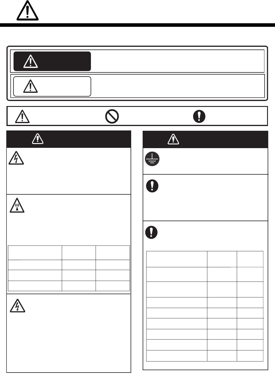
WARNING
Indicates a condition that can cause death or serious injury if
not avoided.
CAUTION
Indicates a condition that can cause minor or moderate injury if
not avoided.
Mandatory Action
Prohibitive Action
Read these safety instructions before you operate the equipment.
Warning, Caution
WARNING WARNING
FELCOM500
distance
100W/m -
0.5 m
1.4 m
RF power dendity
on antenna aperture
2
25W/m 2
10W/m2
Confirm that the power supply voltage
is compatible with the voltage rating
of the equipment.
Connection to the wrong power supply
can cause fire or damage the equipment.
Keep the following compass safe
distances to prevent interference to
a magnetic compass.
FELCOM 500
Antenna Unit
Communication Unit
IP Handset
Facsimile
Telephone
Incoming Indicator
AC-DC Power Supply 0.60 m
0.90 m
Unit
-
0.4 m
0.7 m
FELCOM250
distance
0.70m 0.40 m
FELCOM 250
Antenna Unit
ii
SYSTEM CONFIGURATION
Antenna unit
FB-1500 (FELCOM 500)
FB-1250 (FELCOM 250)
Communication unit
FB-2000
IP Handset
FB-8000
Incoming indicator
FB-3000
Network Equipment
G3 facsimile
Analog telephone
Analog telephone
Analog telephone
Navigation equipment
External alarm
PC or Router
AC-DC
Power supply
PR-240
12-24 VDC
100-115/
200-230 VAC
LAN(4)
TEL(4)
RS-232C
NMEA
Antenna unit
Communication unit,
IP handset, etc.
Environmental Category
To be installed in an exposed area
To be installed in a protecded area
Normal Close
PC
Solid line: Basic configuration

iii
EQUIPMENT LISTS
Standard Supply
*: See lists at the back of this manual.
Optional Supply
Name Type Code No. Qty Remarks
Antenna unit FB-1500 - 1 For FELCOM 500
FB-1250 - For FELCOM 250
Communication unit FB-2000 - 1
IP handset FB-8000 - 1
Installation materials* CP16-04100 000-015-746 1 30 m antenna cable
CP16-04110 000-015-747 50 m antenna cable
CP16-04120 000-015-865 40 m antenna cable
CP16-04401 001-093-460 1 For FB-1500
CP16-04501 001-093-480 1 For FB-1250
CP16-03810 000-015-759 1 For FB-2000
CP16-03901 001-067-350 1 For FB-8000
Accessories FP16-02200 000-015-762 1 CD-ROM for FB-2000
Spare parts SP16-01901 001-067-320 1 Fuses for FB-2000
Name Type Code No. Remarks
Incoming indicator FB-3000 000-015-763 w/CP16-04001
Telephone FC755D1 000-043-369 w/CP16-00511, 00512
Facsimile FAX-2820 - w/CP16-03500, 220VAC
Transformer OP16-25 004-446-850 Transformer TSU-N05E +cable for
FAX-2820
Drum unit DR-20J 000-170-982-10 For FAX-2820
Toner cartridge TN-25J 001-111-660-10 For FAX-2820
AC-DC
power supply
PR-240 -
IP handset FB-8000 -
Coaxial cable 12D-SFA-CV 000-136-423-11 100 m for antenna cable
Installation
materials
CP16-04121 001-067-300 Connector N-SP-12DSFA-CF for
cable 12D-SFA-CV
CP16-04131 001-067-310 Connector N-P-18U-CF (2 pcs) for
RG-18

EQUIPMENT LISTS
iv
Connector CP03-28901 008-542-460 Modular connector MPS588-C2
pcs for LAN cable
LAN cable MOD-Z072-020+ 000-167-175-10 2 m, modular plug for both ends
MOD-Z072-050+ 000-167-176-10 5 m, modular plug for both ends
MOD-Z072-100+ 000-167-177-10 10 m, modular plug for both ends
FR-FTPC-CY *10m* 000-147-472-10 10 m with armor, no plug
FR-FTPC-CY *20m* 000-147-473-10 20 m with armor, no plug
FR-FTPC-CY *30m* 000-147-474-10 30 m with armor, no plug
FR-FTPC-CY *50m* 000-153-326-10 50 m with armor, no plug
FR-FTPC-CY *100m* 000-153-327-10 100 m with armor, no plug
Modular jack set OP16-13 000-043-228 MJ-2S, 3 m cord, lug
Modular jack box OP16-8 000-043-272 MJ-2S, lug
Joint box TL-CAT-012 000-167-140-10 Fro LAN cable extension
Cable assy. 81-521-1204-010 000-127-108-11 5 m cable w/ D-sub 9 pin connector
at both ends
Incoming Indicator KK-893-3977 000-148-478 For analog TEL.
Modular jack box OP16-10 000-043-278 Box type
OP16-11 000-043-279 Flush mount type
Pole mount kit OP16-52 000-017-061 For FELCOM 250 antenna unit
Kit for
RF interference
OP16-50 000-016-316 For FELCOM 500
Radiation sticker OP16-53 001-115-470-10 For FELCOM 500
Name Type Code No. Remarks
T
his product includes software to be licensed under the GNU General Public License (GPL), GNU Lesser General Public License (LGPL), BSD, Apache
,
M
IT and others.The program(s) is/are free software(s), and you can copy it and/or redistribute it and/or modify it under the terms of the GPL or LGPL as
p
ublished by the Free Software Foundation. Please access to the following URL if you need source codes.
h
ttps://www.furuno.co.jp/contact/cnt_oss.html
T
his product uses the software module that was developed by the Independent JPEG Group.
F
rance Telecom - TDF - Groupe des Ecoles des Telecommunications Turbo codes patents license.

1
1. HOW TO INSTALL THE UNIT
1.1 Antenna Unit
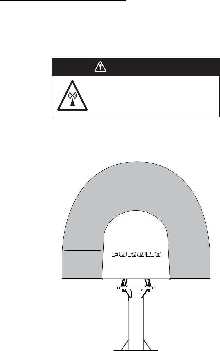
General
Interfering objects (especially metal objects like masts) near the antenna can, in the worst case,
prevent reception or transmission. Further, RF radiation from the antenna will affect the human
body. Keep these and the following guidelines in mind when selecting a mounting location for the
antenna unit.
Secure unobstructed path in all directions
The best mounting location secures an unobstructed path between the antenna unit and the sat-
ellites, from horizontal to zenith. In other words, whatever the direction the antenna unit is pointing
there are no interfering objects within the main beam (22° for FELCOM 500, 40° for FELCOM
250). While this might be feasible on some vessels, on others it is impossible due to space con-
siderations. The antenna unit should be located at least three meters away from masts having a
diameter less than 15 centimeters.
Select a location low in vibration
The maximum permissible vibration amplitude in three axis direction should be as shown in the
table below. Consult with the shipyard to determine the mounting location which meets the re-
quirements shown in the table.
Freq. Range Max. Amplitude
4 to 10 Hz 2.54 mm (max. 9.8 m/s2)
10 to 15 Hz 0.76 mm (max. 6.86 m/s2)
15 to 25 Hz 0.40 mm (max. 9.8 m/s2)
25 to 33 Hz 0.23 mm (max. 9.8 m/s2)
NOTICE
Do not apply paint, anti-corrosive sealant or contact spray
to coating or plastic parts of the equipment.
Those items contain organic solvents that can damage coating
and plastic parts, especially plastic connectors.
1. HOW TO INSTALL THE UNIT
2
Locate away from passengers and crew
Radio waves can be harmful to the human body. Because safe distances change by country and
ship construction, there is no standard formula to calculate safe distance. However, below are
general guidelines.
• FELCOM 500: Personnel should not approach an area in which the radiation level is higher than
10 W/m2, i.e., within 1.40 m from the radome surface.
Construct a protective fence around the antenna unit so that personnel can not approach the
antenna unit within 1.40 m. Also, to alert personnel not to approach the antenna unit, attach the
caution labels (supplied as installation materials) to any bulkhead which is at the position of 1.40
m from the antenna unit.
Do not approatch within 1.40 m of the
antenna radome when it is transmiting.
Microwave radiation can be harmful to
the human body, particularly the eyes.
WARNING
WARNING
MICROWAVE RADIATION !
NO ADMITTANCE WITHIN 1.40 m
1.4 m
1. HOW TO INSTALL THE UNIT
3
• FELCOM 250: Personnel should not approach an area in which the radiation level is higher than
10 W/m2, i.e., within 0.70 m from the radome surface.
Construct a protective fence around the antenna unit so that personnel can not approach the
antenna unit within 0.70 m. Also, to alert personnel not to approach the antenna unit, attach the
radiation warning sticker (supplied as installation materials) to any bulkhead which is at the po-
sition of 0.70 m from the antenna unit.
Minimum distance from other antennas
MF/HF antennas, communication/navigation antennas:
The antenna unit should be at least five meters from a MF/HF antenna. The VHF, satellite navi-
gation antenna and other communication antennas should be at least four meters away.
Radar:
The antenna unit should be at least 5 meters away to protect the low-noise amplifier in the FEL-
COM 500/FELCOM 250 antenna unit. If this distance cannot be secured be sure the antenna unit
is not within the radar beam. However, never install the antenna unit within 3 m of a radar antenna.
Distance from radar antenna
MICROWAVE RADIATION !
NO ADMITTANCE WITHIN 0.7 m
0.7 m
More than 5 m
If installed within 5 m of
radar antenna, the antenna
unit must not be within the
radar beam. Never install
the antenna unit within 3 m.
20
30
1. HOW TO INSTALL THE UNIT
4
Compass safe distance
Locating the antenna unit too close to a compass can affect the compass performance. Keep the
compass safe distance to prevent interference to the magnetic compass. See page i.
Other mounting guidelines
Other important mounting guidelines are
• Locate the antenna unit away from exhaust stacks (foreign material on the radome can interfere
with reception and transmission).
• Keep the unit away from heat sources.
• Locate the unit away from places where fuels and chemical solvents are stored.
• Keep in mind the length of the cable from the communication unit is maximum 100 meters
(when coaxial cable 12D-SFA-CV is used).
Guardrail, platform
To facilitate servicing, construct a mast of about one meter (40") in height. (See page 5.) The para-
graphs which follow provide guidelines for selection and construction of the mast.
Fit the mast with a guardrail and platform (or steps), for serviceman's safety. (In most installations
the serviceman stands on the platform while checking the radome. Thus this distance should be
secured for ease of servicing.) The height of the guardrail should be as tall as possible to ensure
safety.
Mast strength
The mast material must be sufficiently strong to meet the
demands of the marine environment. It should satisfy the
following requirements.
• It must be able to support radome mass plus at least 2.5
cm (1") of ice and snow. Special consideration should
be given if the unit is operated in areas of heavy snow or
freezing temperature.
• The mast bending moment must be able to withstand
expected maximum pitching, rolling and wind pressure.
• To prevent resonance at low frequencies (approximate-
ly 5 Hz), four stays can be fixed between the mast and
the mounting base.
Item FELCOM 500 FELCOM 250
Antenna unit mass 21 kg (46 lb) ± 10% 6.5 kg ± 10%
Platform, guardrail mass
Expected ice and snow
Maximum wind pressure (at wind speed 56 m/s) 280 N 36.3 N
Wind
Pressure
(Above figure: FELCOM 500)
1. HOW TO INSTALL THE UNIT
5
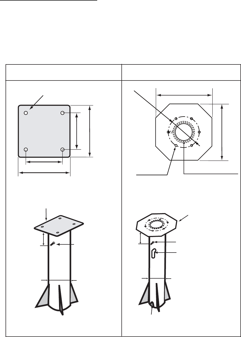
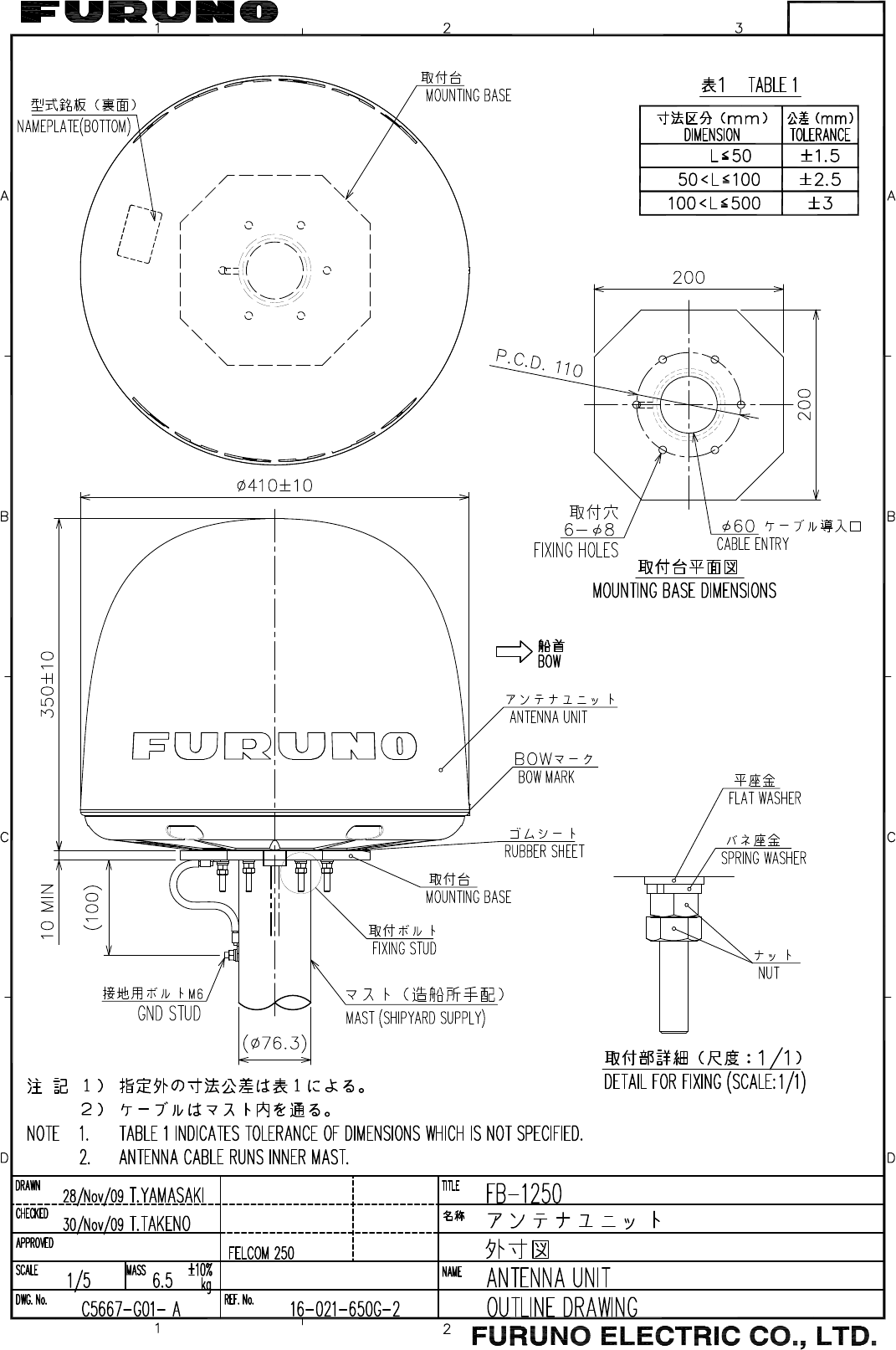
Antenna mast and mounting base
To get the best performance from the antenna electronics and mechanics, the antenna must be
installed properly on a specially designed mast with suitable flange and rubber gasket. Below are
guidelines for installation of the mounting mast and mounting base.
• The mounting base should be parallel to the ship's waterline (tolerance: ±3°).
• Weld a ground bolt of stainless steel to the mast (figure below). Connect the ground wire from
the antenna unit to the ground bolt.
6×
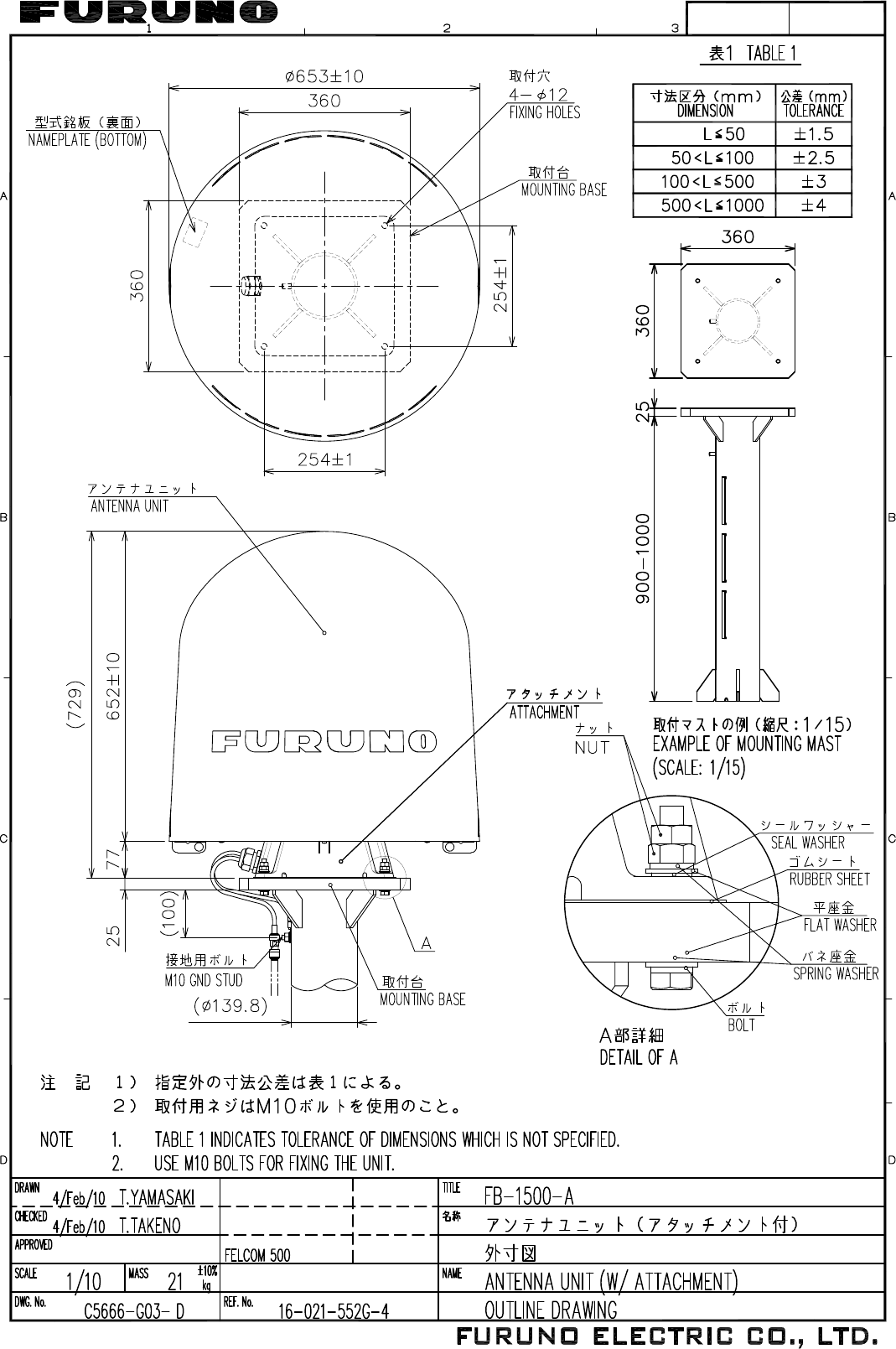
φ
8
Fixing Hole
φ
60 (
φ
2.36")
Cable Entry and Drain
110mm (4.33")
200 mm (7.87")
FELCOM 500 FELCOM 250
200 mm (7.87")
254 mm (10")
360 mm (14.17")
254 mm (10")
360 mm (14.17")
HOLE
DIA 12 mm (0.47")
[Mounting base]
[Antenna mast: Example]
Thickness:
Minimum 20 mm (0.79")
Weld a ground bolt
M10x40 (same
direction of the
cable gland of
the antenna unit)
Approx.
100 mm (4")
Approx.
100 mm (4")
Weld an elbow pipe
for the cable entrance.
The inner diameter
should be larger than
the outer diameter of
the cable.
Don't seal with putty.
[Antenna pole: Example]
Make a drain hole at the
base of the pole.
Thickness:
Minimum 10 mm (0.39")
[Mounting base]
Weld a ground bolt M6x40
φ
76.3
(
φ
3.00")
φ
139.8
(
φ
5.50")

1. HOW TO INSTALL THE UNIT
6
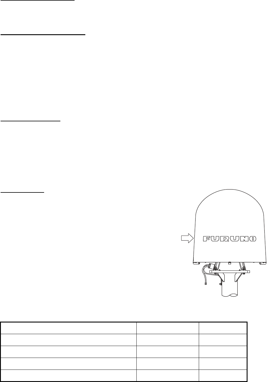
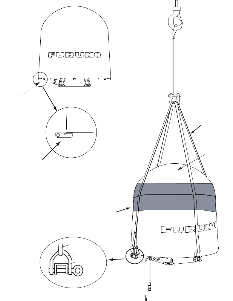
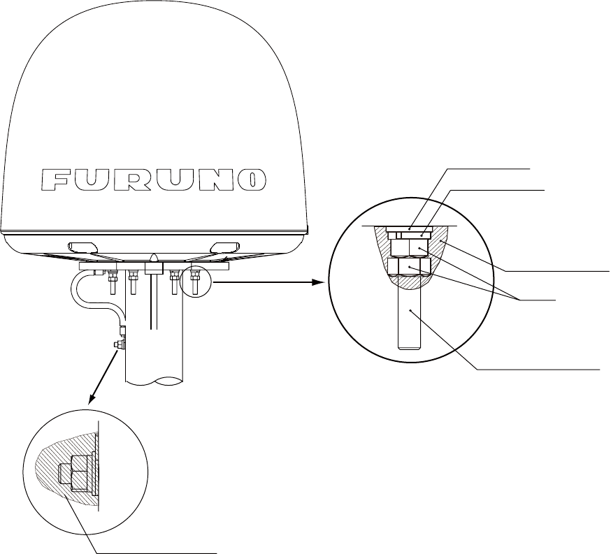
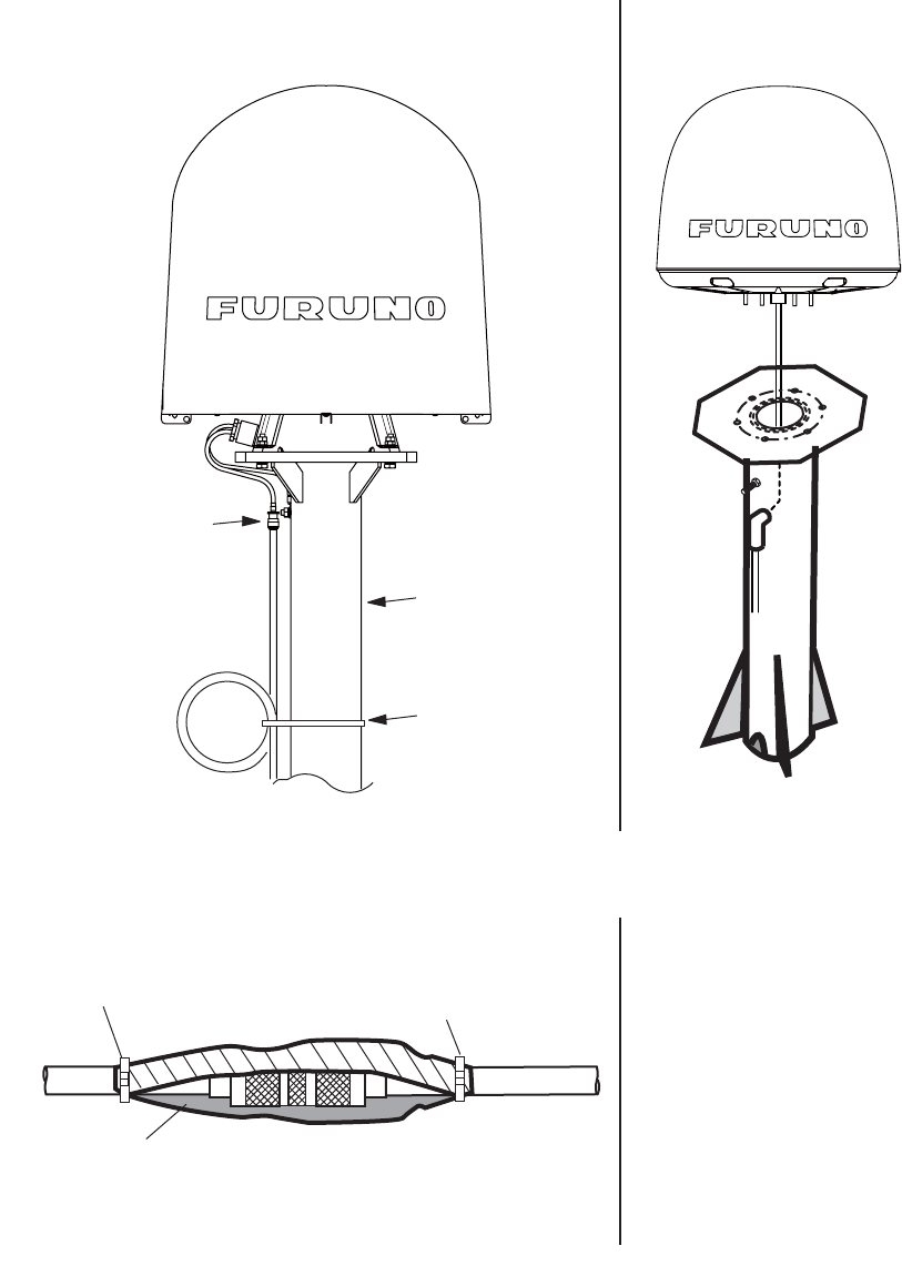
FELCOM 500: How to install the antenna unit
Carefully unpack the radome and check for damage.
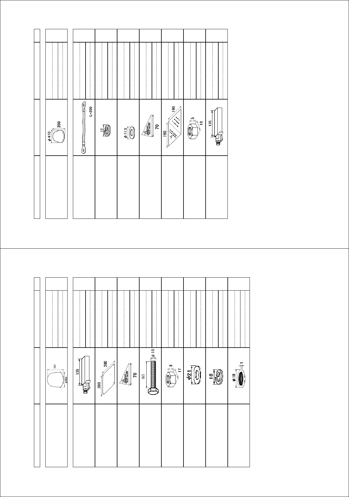
Antenna unit installation materials
Procedure
1. Loosen four lifting lugs and turn them to outside at the bottom of the radome as shown in the
figure on the next page. Then fasten four screws for lifting lugs firmly.
2. Run lifting rope with shackles through lifting lugs.
3. Cover the part of the radome which contacts the lifting rope with protective material (rubber
mat, etc.), to prevent damage to the radome when hoisting it to the mounting location.
4. Lift the antenna unit to the mounting location.
Item Quantity Remarks
Silicone sealant 1 50 g
Rubber mat 1
Radiation warning sticker 1
Hex bolt 4 M10x60
Hex nut 8 M10
Spring washer 8 M10
Flat washer 8 M10
Seal washer 4
1. HOW TO INSTALL THE UNIT
7
5. Lay the rubber mat on the mounting base and put the antenna unit on the rubber mat, keeping
in mind cable gland direction (standard direction is stern).
6. Fix the antenna unit with four sets of hexagonal bolts and nuts as shown on the next page.
Note: Tighten first nut with torque 36.5 Nm, then tighten second nut with the same torque.
7. Connect the ground wire to the ground bolt.
8. Coat all bolts and nuts with silicone sealant to prevent electrolytic corrosion.
Lifting rope
Radome
Protective
Material
Turn four lifting lugs
to outside.
Rope
Shackle
Lifting lug
Lifting lug
1. HOW TO INSTALL THE UNIT
8
9. Restore the lifting lugs to their original positions.
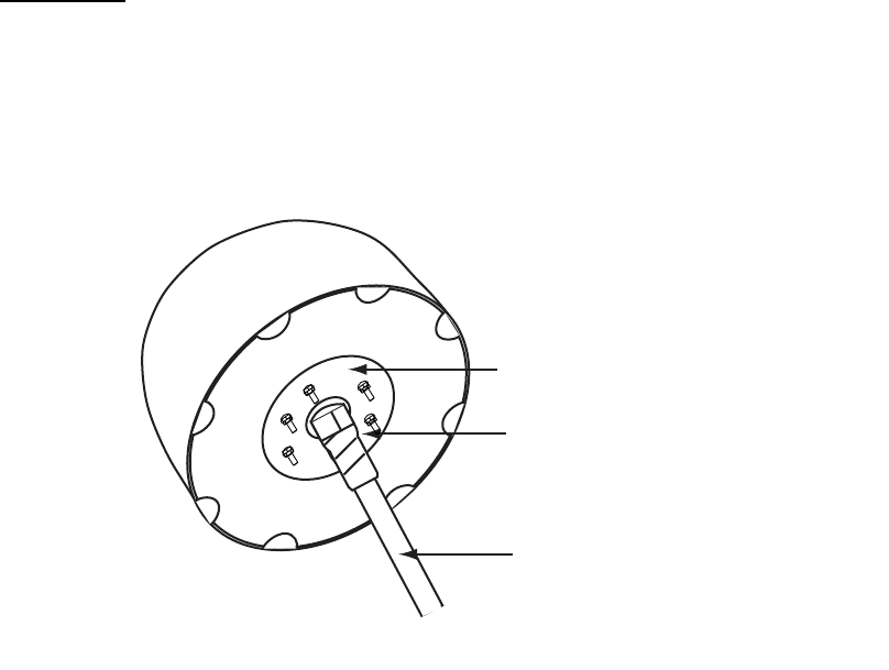
FELCOM 250: How to install the antenna unit
Carefully unpack the radome and check for damage. Run the antenna cable before installation of
the antenna unit.
Antenna unit installation materials
Item Quantity Remarks
Silicone sealant 1 50 g
Rubber mat 1 This mat may be pre-attached to the antenna unit
depending on the date of production.
Radiation warning sticker (S) 2
Radiation warning sticker (L) 1
Hex nut 12 M6
Spring washer 6 M6
Flat washer 6 M6
Ground wire 1 200 mm, W/6 mm crimp-on lug for both ends
Silicone sealant
Nut
Flat washer
Bolt
Spring washe
r
Silicone sealant
Seal washer
Silicone sealant
Rubber mat
Ground stud
1. HOW TO INSTALL THE UNIT
9
Procedure
1. Attach the rubber mat on the bottom of the antenna unit if the mat is supplied as the installation
material.
2. Connect the antenna cable to the coaxial plug on the bottom of the antenna unit.
3. Wrap the self-adhesive tape all around the coaxial connector for waterproofing and wrap the
vinyl tape on the self-adhesive tape.
4. Put the antenna unit on the mounting base.
The antenna unit is free of direction. However, preferably install the antenna unit, so the FU-
RUNO logos face the port/ starboard side.
5. Fasten the ground wire (supplied) to the antenna bolt near the ground stud on the antenna
mast and secure with hexagonal nut, spring washer and flat washer.
6. Secure other antenna bolts with a set of hexagonal nuts, spring washers and flat washers as
shown below on the next page.
Note: To fix the antenna bolt, tighten first nut with torque 7.65 Nm and then tighten the second
nut with the same torque.
7. Connect the ground wire to the ground stud on the antenna mast.
8. Attach the radiation warning sticker (small) to the bow and stern sides of the antenna radome.
If these locations are not suitable, attach the radiation warning stciker (big) to the ship’s body
near the antenna radome.
Wrap self-adhesive tape all around
the coaxial connector and wrap vinyl
tape on it for waterproofing.
Coaxial cable
Antenna unit bottom
Rubber mat
1. HOW TO INSTALL THE UNIT
10
9. Coat all bolts and nuts with silicone sealant to prevent electrolytic corrosion as shown below.
Note: The cable entry hole (φ60) at the bottom of the antenna functions as ventilation hole,
allowing trapped moisture to escape the dome. For that reason, ensure the hole is not
blocked.
Nut
Silicone sealant
Silicone sealant
Spring washer
Flat washer
Antenna fixing bolt
1. HOW TO INSTALL THE UNIT
11
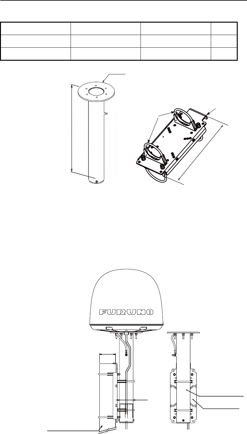
How to mount the FELCOM 250 antenna unit with optional pole mount kit
Pole mount kit: Type OP16-52, Code number 000-017-061
1. Ask the shipyard to prepare and mount an antenna mast (diameter φ89: 80A).
2. Attach the fixing plate SP-SAC-1032 to the antenna mast by hanging the lip of the fixing plate
on the top of the antenna mast.
3. Insert the mounting pole SP-SAC-1031 through the U-bolts of the fixing plate and fasten the
U-bolts.
4. Put the FELCOM 250 antenna unit on the mounting pole and fix it with nuts (see previous
page).
Name Type Code no. Qty
Mounting pole SP-SAC-1031 000-173-963-10 1
Fixing plate SP-SAC-1032 000-173-964-10 1
U-bolt
Lip
φ
180
507
333
Mounting pole
Fixing plate
Antenna unit
(Shipyead suplly)
φ76
(65A)
φ89
(80A)
1. HOW TO INSTALL THE UNIT
12
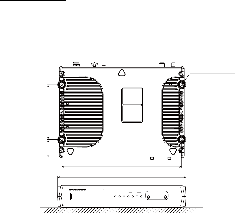
1.2 Communication Unit
Select a location for the communication unit (CU) by following the information shown below.
• The unit is not waterproof. Keep the unit away from water splash.
• Keep the unit away from direct sunlight.
• The temperature and humidity must meet the requirements shown in the equipment specifica-
tions.
• Set the unit away from the exhaust pipes and vents.
• The installation location must have enough cool air.
• Install the unit where shock and vibration meet the requirements shown in the equipment spec-
ifications.
• Keep the unit away from the equipment that creates an electromagnetic field, for example, mo-
tor and generator.
• For maintenance and checking, leave enough space at the sides and rear of the unit. Refer to
the outline drawing and provide some additional length in cables.
• Follow the recommended compass safe distances shown on page i to prevent the interference
to a magnetic compass.
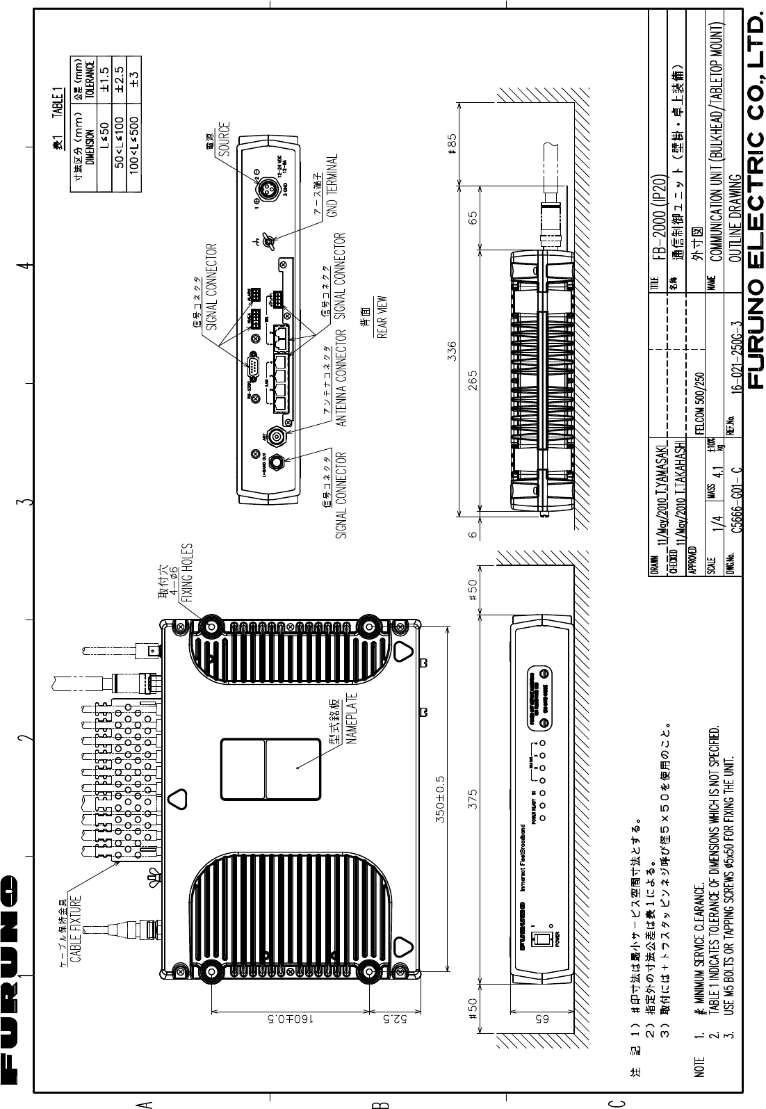
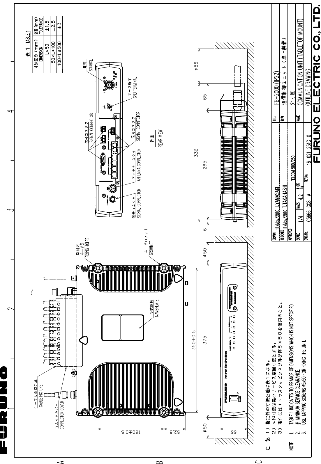
How to install the CU
Follow the procedure shown below to install the CU on a desktop. See the outline drawing on page
D-3 for details.
1. Place the template (supplied) of the CU on the installation site.
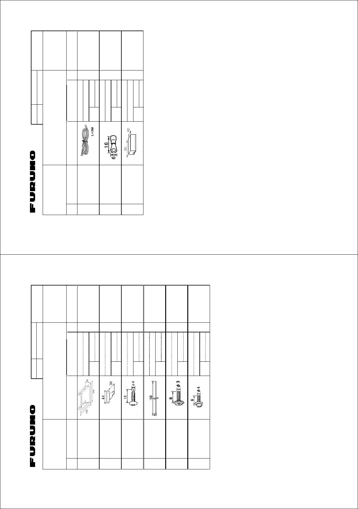
2. Mark the points for four pilot holes and makes the pilot holes for 5x50 self-tapping screws.
3. Put the unit on the installation site and fix it with four 5x50 self-tapping screws (supplied).
Note: It is necessary to install the Communication Unit on a desktop to comply with IPX2 (drip-
ping) standard. Refer to section 2.5 for directions to how to install on a desktop.
350±0.5 mm (13.78")
52.5 mm
(2.07") 160±0.5 mm (6.30")
375 mm (14.76")
SIM CARD INSIDE
POWER OFF BEFORE INSERTING
OR REMOVING SIM
―
○
POWER
○
I
POWER
1
TX
234
STATUS
Inmarsat FleetBroadband
READY
4-
φ
6 mm (0.24")
Fixing holes
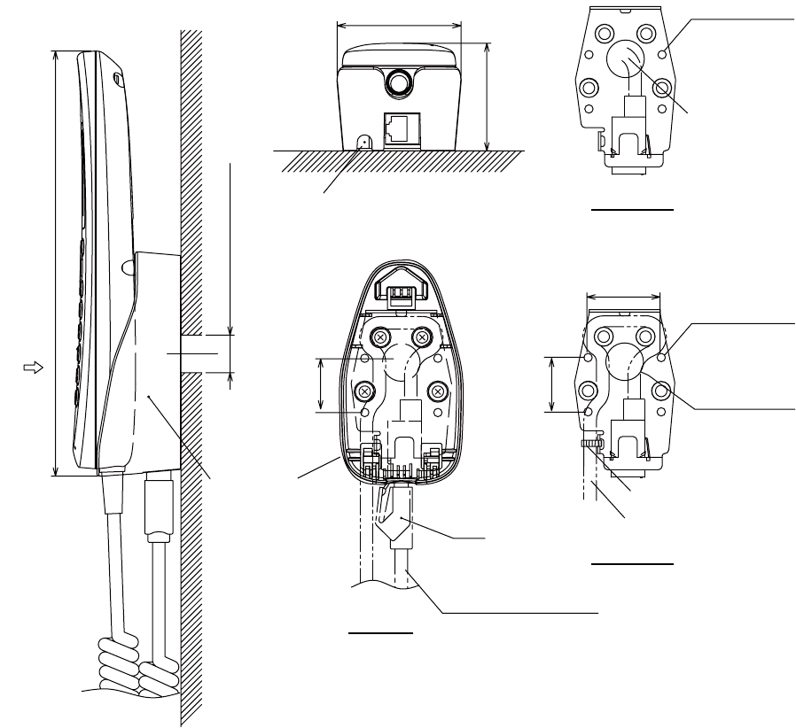
1. HOW TO INSTALL THE UNIT
13
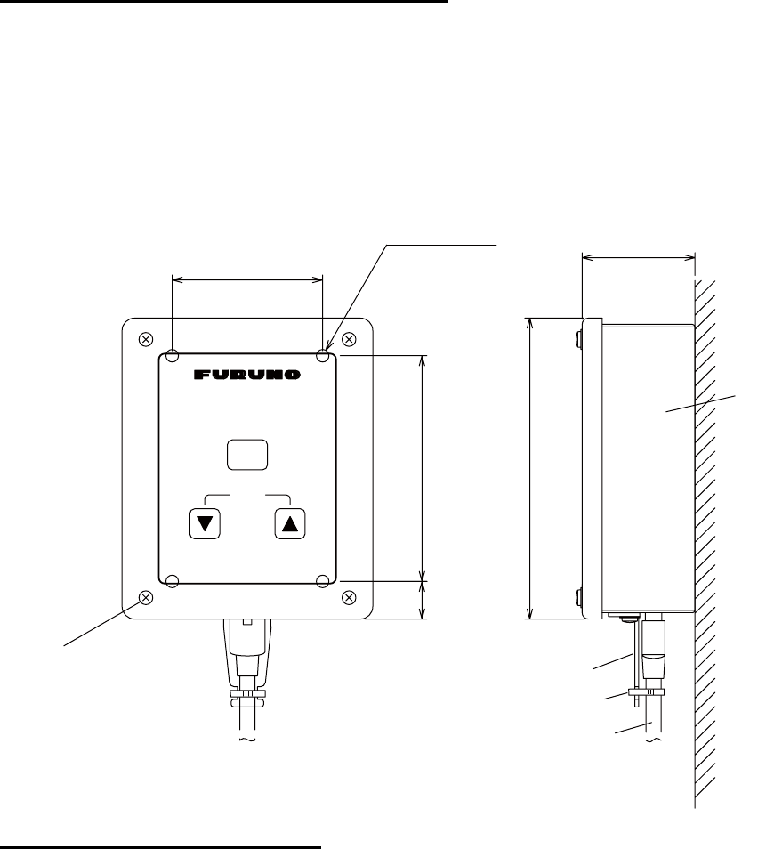
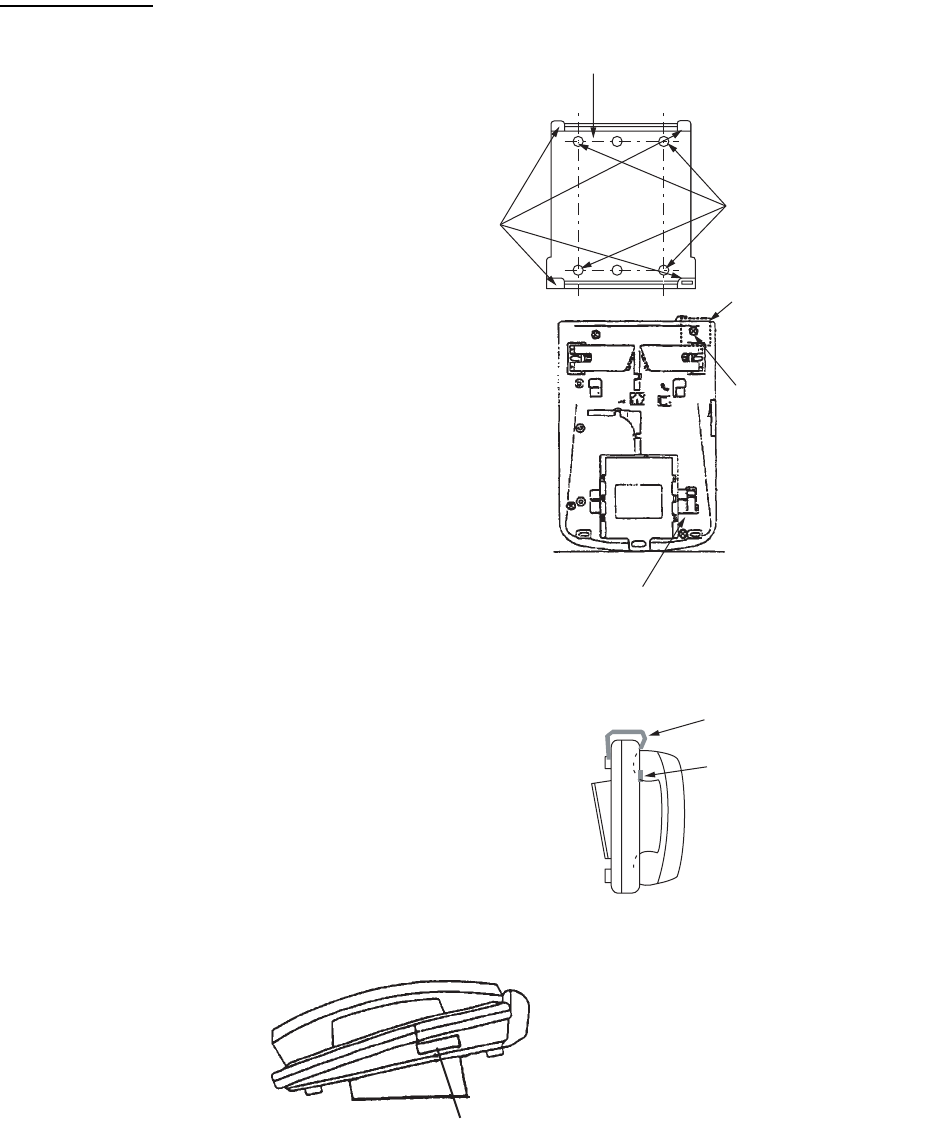
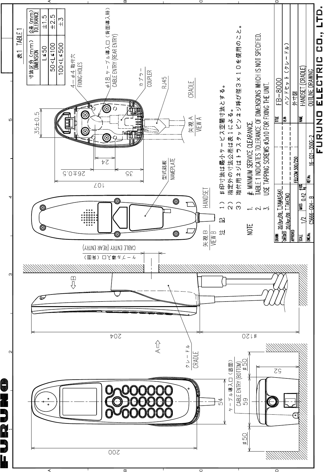
1.3 IP Handset
The IP handset functions as a display and it may also be used for normal voice communication.
The units (max 26 units) may be installed anywhere onboard the vessel. The IP handset is pro-
vided with a cradle. Fix the cradle to the bulkhead or installation panel. The cradle has two cable
entries for convenience; bottom and rear.
1. To use the rear cable entry, make a hole of 18 mm (0.71") diameter in the installation site,
Refer to the outline drawing.
2. Remove four screws from the cradle to separate the plastic case from the metal plate.
3. Fix the metal plate to the mounting site with four self-tapping screws.
4. Connect the LAN cable from the CU to the inner RJ45 port in the cradle.
5. If the bottom cable entry is used, run the LAN cable as shown in the figure below and fix it with
a cable-tie.
6. Reattach the plastic cover.
7. Connect the cable from the handset to the outer RJ-45 port of the cradle.
59 (2.32")
204 (8.03")
26 (1.02")
RJ45
52 (2.05”)
VIEW A
Cable entry
(bottom)
CRADLE
Cable entry (rear entry)
A
Cable from the handset
26 (1.02")
4-
φ
4
Fixing holes
φ
18 (0.71")
Cable entry
(rear )
35±0.5 (1.38")
Cable from the CU
Fix with a cable-tie
Metal plate
(Bottom)
Metal plate
(Rear)
4-
φ
4
Fixing holes
Cable entry
from the CU
1. HOW TO INSTALL THE UNIT
14
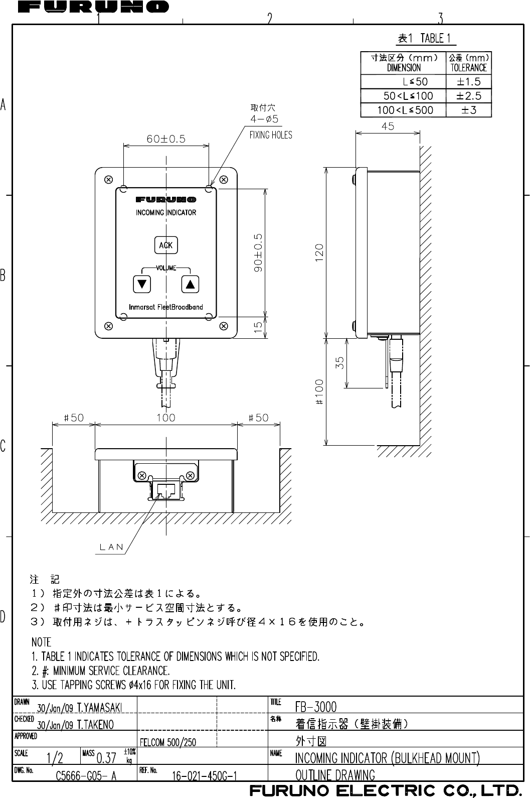
1.4 Incoming Indicator (option)
Select a location for the incoming indicator by following the information shown below.
• Keep the unit away from water splash.
• Keep the unit away from direct sunlight.
• Set the unit away from the exhaust pipes and vents.
• Follow the recommended compass safe distances shown on page i to prevent the interference
to a magnetic compass.
How to install on the bulkhead or bridge panel
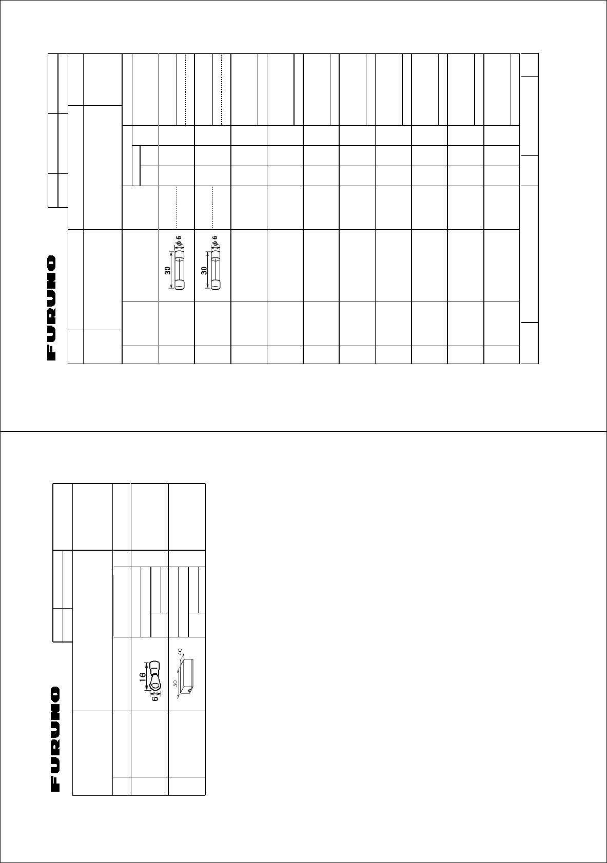
1. Remove four screws from the unit to remove the lid.
2. Fix the case with four 4x16 self-tapping screws (supplied).
3. Reattach the lid with four screws.
4. Connect the cable from the CU.
5. Attach the cable fixture (supplied) with two screws.
6. Fasten the cable to the cable fixture with the cable tie (supplied).
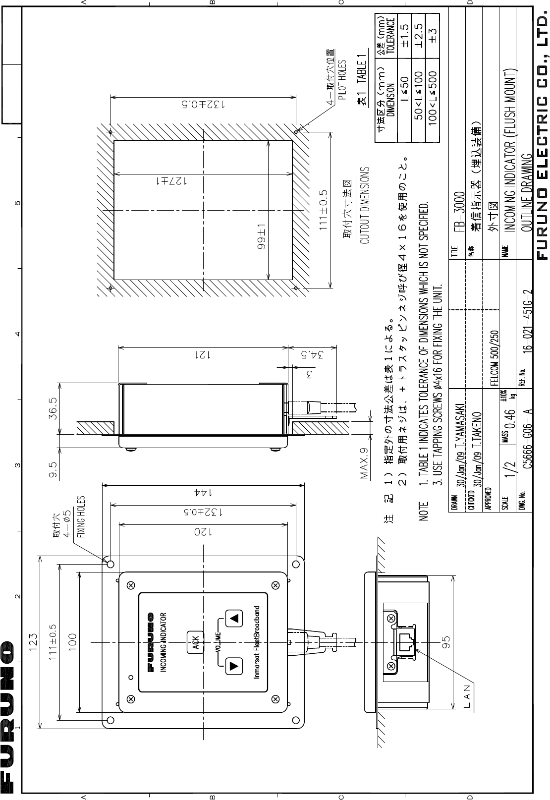
How to install by the flush mount
1. Prepare a cutout in the installation location and make four pilot holes. Refer to the outline
drawings.
2. Set the flush mount plate (supplied) to the cutout and fix it with four 4x16 self-tapping screws
(supplied).
3. Remove four screws from the unit to remove the lid.
45 (1.77")
4-
φ
5 (0.20")
15
(0.59") 90±0.5 (3.54")
120 (4.72")
60±0.5 (2.36")
Inmarsat FleetBroadband
VOLUME
INCOMING INDICATOR
ACK
FIXING HOLES
Case
Cable fixture
Cable from the CU
Remove 4 screws
to remove the lid. Cable tie
1. HOW TO INSTALL THE UNIT
15
4. Fix the case with four M4x8 screws (supplied) to the flush mount plate.
5. Pass the cable from the CU through the bottom of the case.
6. Connect the cable to the port on the lid.
7. Attach the cable fixture (supplied) with two screws.
8. Fasten the cable to the cable fixture with the cable tie (supplied).
9. Reattach the lid to the case with four screws.
111±0.5 (4.37")
132±0.5 (5.20")
144 (5.67")
123 (4.84")
99±1 (3.90")
127±1 (5.00")
132±0.5 (5.20")
111±0.5 (4.37")
4-
φ
5 (0.20")
36.5 (1.44")
Inmarsat FleetBroadband
VOLUME
INCOMING INDICATOR
ACK
FIXING HOLES
CUTOUT DIMENSIONS
4-PILOT HOLES
1. HOW TO INSTALL THE UNIT
16
1.5 Facsimile FAX-2820 (Option)
Note: The hooks supplied are not used in the installation.
1. Lay the facsimile on the top of the mounting plate.
2. Align right side and rear with the projection on the mounting plate.
3. Fasten fixing plates (left, right) to the facsimile with six M4x15 pan head screws.
Mounting plate
φ
6 Fixing hole
Four places
FRONT
Align
Fixing plate (left)
Fixing plate (right)
M4x15
Six places
Facsimile

1. HOW TO INSTALL THE UNIT
17
4. Attach the compass safe distance label at the location shown below.
How to change modem settings
1. Press [Menu/set], [*], [2], [8], [6] and [4] keys in this sequence to enter the maintenance mode.
The fax machine beeps for approximately one second and displays "MAINTENANCE" on the
LCD. This means the FAX is in the initial stage of the maintenance mode.
2. Press [1] and [0] keys in this order. "WSW00" is displayed on the LCD.
3. "Press [1] and [3] keys in this order. "WSW13=X1X2X3X4X5X6X7X8" appears on the LCD.
(default: WSW13=01011011)
4. Press [0], [0], [0], [1], [1], [0], [1], [0] and [Menu/Set] keys in this order.
(WSW13=00011010) "WSW00" appears after pressing [Menu/Set] key.
5. Press [Stop/Exit] key to return the machine to the initial stage of the maintenance mode.
6. Press [9] key twice to exit from the maintenance mode and return to standby.
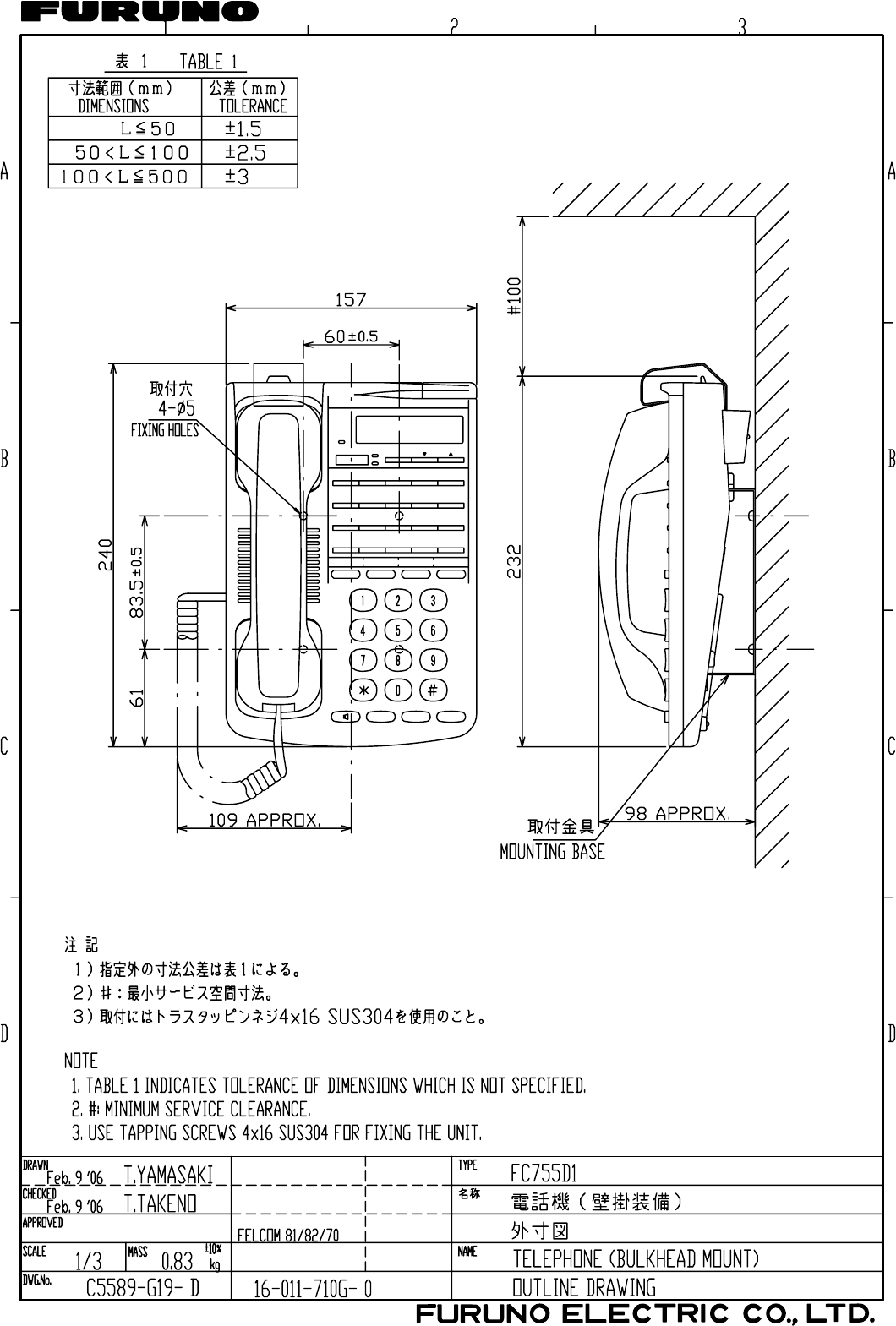
1.6 Telephone FC755D1 (Option)
General
The telephone can be installed on a desktop or a bulkhead. Select a location where the telephone
can easily be operated.
• For installation on a wooden table, use the mounting base and self-tapping screws (supplied).
• For installation on a steel table, fix the telephone with nuts and bolts.
• For bulkhead mounting, use the bulkhead mounting base (supplied with telephone accesso-
ries).
Mounting location
Select a location where temperature and humidity are moderate and stable. Secure sufficient
space around the unit for ease of operation and maintenance.
30
5
Compass safe distance label
1. HOW TO INSTALL THE UNIT
18
How to mount
The mounting dimensions are shown in
the outline drawing at the back of this
manual. Determine the mounting loca-
tion, leaving sufficient space around the
unit, and then fix the mounting base to
the mounting location. The mounting
base is different for bulkhead and desk-
top mounts, however the mounting pro-
cedure is the same for all.
1. Set the mounting base to the mount-
ing location with four self-tapping
screws (4x16).
2. On the bottom of the telephone, re-
lease the screw shown in the figure.
(The screw may be discarded.) At-
tach the vulcanizing tape (supplied)
to the handset fixture. Fasten the
handset fixture to the bottom of the
telephone with a screw (3x14, sup-
plied).
3. The catch in the receiver cradle func-
tions to hang up the handset. Set the
catch in the upward position. To de-
tach the handset from the hanger,
slide the handset upward.)
4. Set the telephone to the four catches
in the mounting base, then slide it to-
ward you until you hear a click.
5. Attach the "SLIDE" label (supplied) to
the handset.
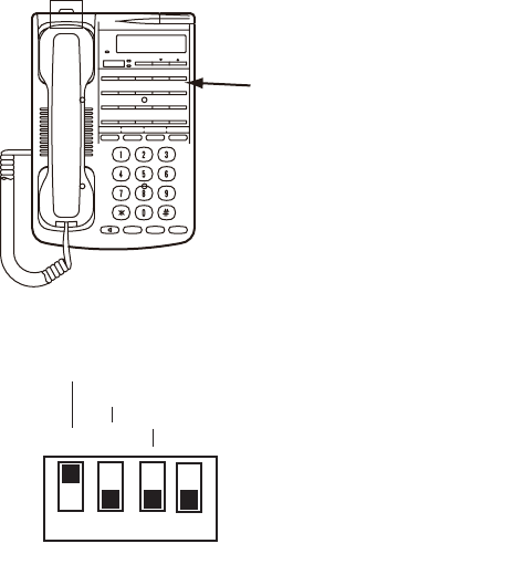
6. Attach the label (16-007-6927-0) for compass safe distance as shown below.
7. Set the line type of telephone to PB (Push Button) type from DP (Dial Pulse) type as follows.
Mounting base
(Desktop: Use installation materials,
Bulkhead: Use telephone accessories.)
Secure mounting
base with tapping
screws.
Attach handset
fixture here.
Unfasten this screw.
Bottom view
Mounting base stopper
Handset fixture
Catch
Catches
Label (16-007-6927-0)
1. HOW TO INSTALL THE UNIT
19
1) Remove the plastic sheet and recording sheet.
2) Set #1 DIP switch to ON (PB side).
3) Reattach the plastic sheet and recording sheet.
Remove plastic sheet and
recording sheet.
ON
OFF Set #1 to ON (PB).
1 2 3 4
Line type
Side tone
Bell off
PB䇭S
DP L
20
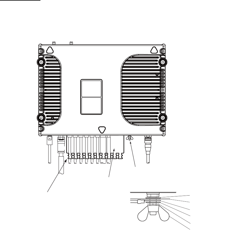
2. CONNECTIONS
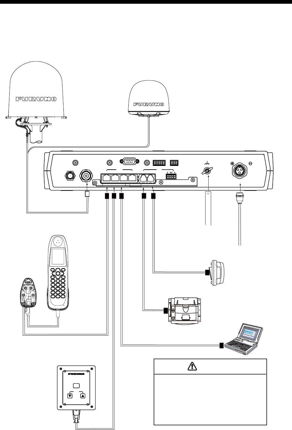
2.1 Standard Connection
Run and connect cables, refering to the figure below and the interconnection diagram (page S-1).
ALARMNMEARS-232C
LAN
ANT
1234
TEL
12 34
12-24 VDC
12-6A
12
L-BAND OUT
3 GND
Inmarsat FleetBroadband
VOLUME
INCOMING INDICATOR
ACK
FELCOM 500
Antenna unit
FB-1500
Communication unit
FB-2000
IP Handset
FB-8000
Incoming Indicator
FB-3000
Telephone
FC755D1
Facsimile
FAX-2820
Copper
strap
05-003-
0031-0
This unit is shipped with a 15 A fuse fitted
in the power cable, which is for use with
12 VDC ship’s battery.
For 24 VDC power, replace the fuse with
a 7 A fuse and attach the “7A” label
(supplied) to the power cable.
Use of wrong fuse can result in damage
to the equipment.
CAUTION
12-24 VDC
Ship
’
s power
distributor
MJ-A3SPF0018-
050ZC, 5m
8D-FB-CV, 30/40/50 m
12D-SFA-CV, 100 m
FR-FTPC-CY, 10/20/30/50/100 m
MOD-Z072, 5 m/2 m/10 m
FR-FTPC-CY
, 10/20/30/50/100 m
MOD-Z072, 2 m/5 m/10 m
MODULAR CABLE
MODULAR CABLE
PC
FR-FTPC-CY, 10/20/30/50/100 m
MOD-Z072, 5 m/2 m/10 m
Bolt or weld
to ship’ hull.
FELCOM 250
Antenna unit
FB-1250
2. CONNECTIONS
21
2.2 Antenna Cable
Run the antenna cable (coaxial cable 8D-FB-CV, 30 m, 40 m or 50 m supplied) between the an-
tenna unit and communication unit . Attach the connector plug of the antenna cable to the antenna
unit. Connect the coaxial connector (8D-FB-CV) to the other end of the antenna cable.
Wrap the junction point of connectors with the self-adhesive tape then vinyl tape. Bind the ends
of tape with a cable tie (local supply). Fix the cable to the mast with a cable tie (local supply).
Mast
Cable tie
(Weatherproofed)
See the figure below.
[FELCOM 250]
[FELCOM 500]
Cable tie
Inside: Self-adhesive tape
Outside: Vinyl tape
Cable tie
Mouting
Waterprooting the coaxial connector
2. CONNECTIONS
22
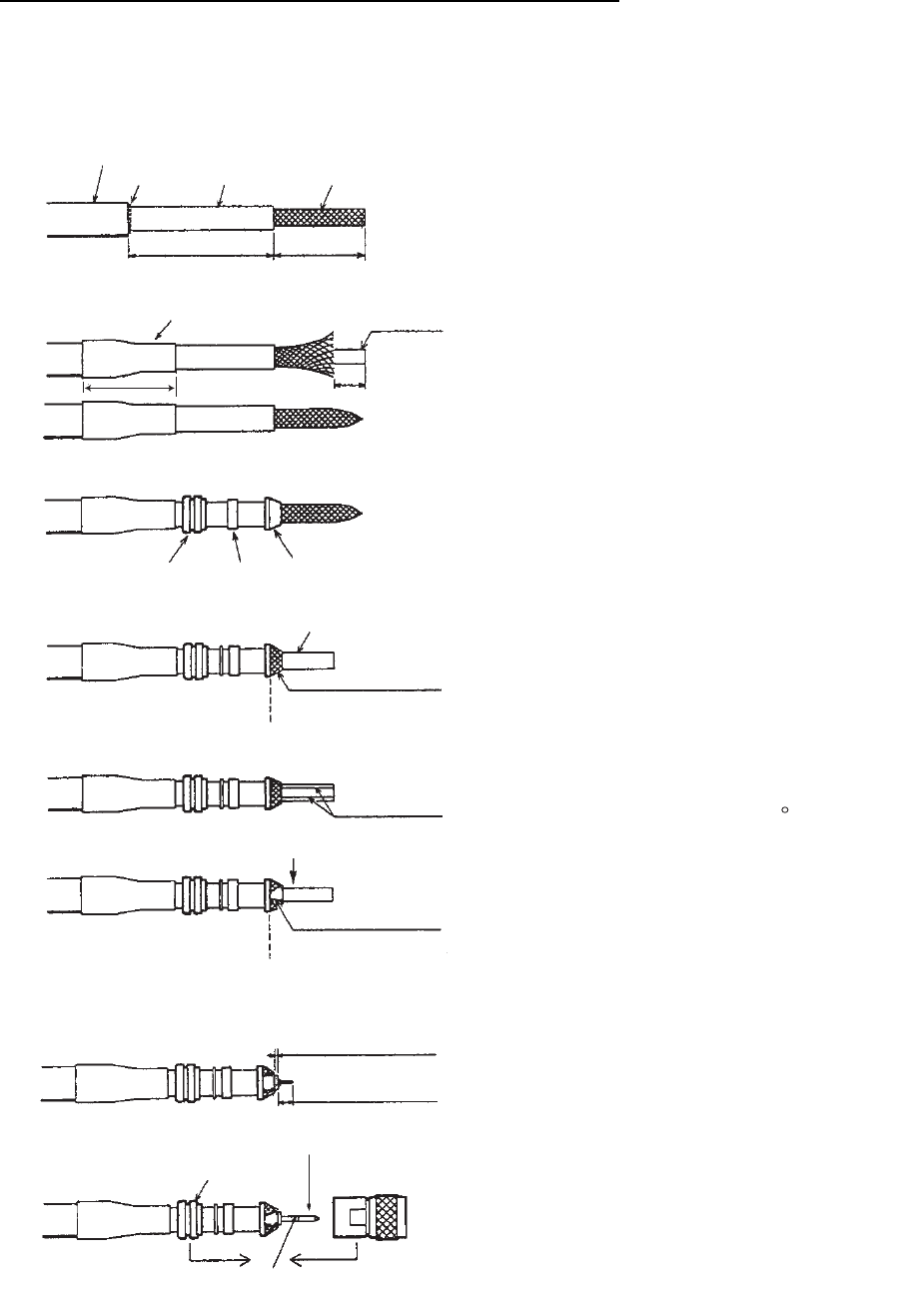
How to attach the antenna cable connector N-P-8DFB-CF
Attach the coaxial plug (supplied) to the other end of the coaxial cable to connect to the CU as
follows.
Outer Sheath
Armor Inner Sheath Shield
(Dimensions in millimeters.)
50 30
Cover with heat-shrink tubing and heat.
30 10
Clamp
Nut
Gasket
(reddish
brown)
Clamp
Trim shield here.
Aluminum Foil
Insulator
Trim aluminum
tape foil here.
1
5
Pin
Shell
Clamp Nut
Solder through
the hole.
Remove outer sheath and armor by the
dimensions shown left.
Expose inner sheath and shield by the
dimensions shown left.
Remove insulator and core by 10 mm.
Twist shield end.
Slip on clamp nut, gasket and clamp as shown
left.
Fold back shield over clamp and trim.
Cut aluminum foil at four places, 90 from one
another.
Fold back aluminum tape foil onto shield and trim.
Expose the insulator by 1 mm.
Expose the conductor (core) by 5 mm.
Slip the pin onto the conductor. Solder them
together through the hole on the pin.
Insert the pin into the shell. Screw the clamp
nut into the shell.
(Tighten by turning the clamp nut. Do not
tighten by turning the shell.)
2. CONNECTIONS
23
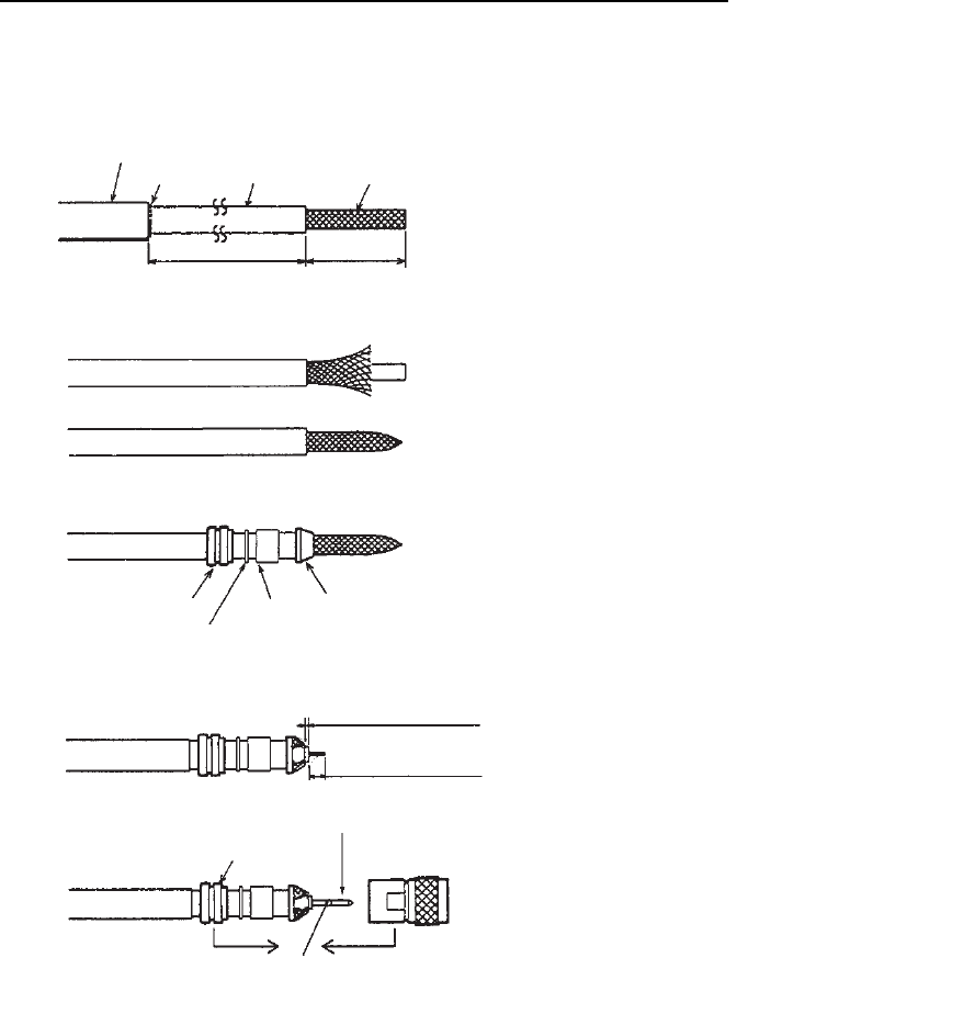
How to attach the antenna cable connector N-SP-12DSFA-CF
If the optional coaxial cable 12D-SFA-CV (100 m) is used, attach the optional coaxial plug N-SP-
12DSFA-CF as follows.
Outer Sheath
Armor Inner Sheath Shield
Dimensions in millimeters.
80 12
Clamp Nut
Washer
Gasket Clamp
2
4.5
Clamp Nut
Pin
Solder through
the hole.
Remove outer sheath and armor by the
dimensions shown left.
Expose inner sheath and shield by the
dimensions shown left.
Twist shield end.
Slip on clamp nut, gasket and clamp as shown left.
Expose the insulator by 2 mm.
Expose the core by 4 to 5 mm.
Slip the pin onto the conductor. Solder them
together through the hole on the pin.
Insert the pin into the shell. Screw the clamp
nut into the shell.
(Tighten by turning the clamp nut. Do not
tighten by turning the shell.)
2. CONNECTIONS
24
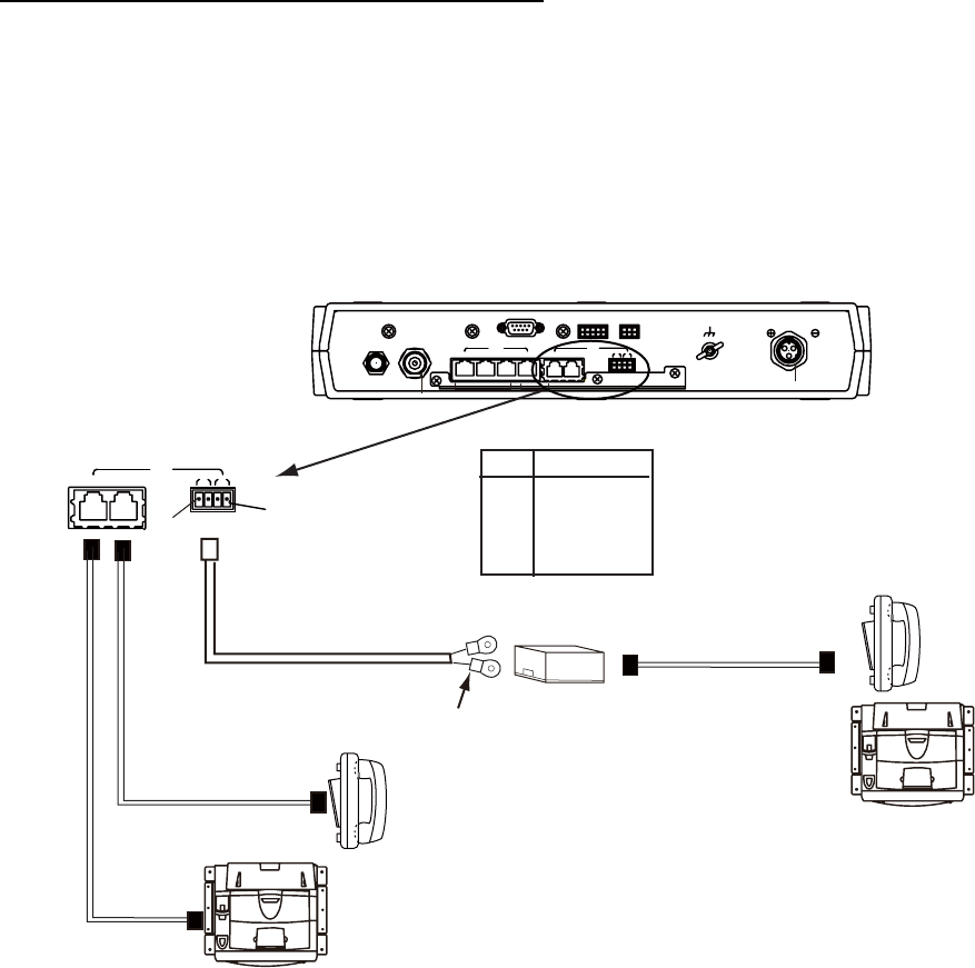
2.3 Communication Unit
Telephone FC755D1 and Facsimile FAX-2820
Connect the cable from the telephone or facsimile to TEL1, 2, 3 or 4 port of the communication
unit. The modular connector can be connected directly to the TEL1 or TEL2 as shown in the fig-
ure below.
To connect to the TEL3 or TEL4, use the modular jack box (optional supply) or the modular jack
set (optional supply). Connect TTYCS-1 (Japan Industry Standard cable, or equivalent, local sup-
ply) between the modular jack box and communication unit. Attach two crimp-on lugs (FV1.25-3
red, supplied with the modular jack box) to the modular jack box side of the above cable
Modular
jack box
MJ-2S
Telephone
FC755D1
Cable with
modular plug
Twisted
pair cable
TTYCS-1
TEL
12 34
Communication unit
FB-2000
Facsimile
FAX-2820
Telephone
FC755D1
Facsimile
FAX-2820
Crimp-on
lug
FMC connector
Cable with
modular plug
See below for
cable fabrication.
ALARMNMEARS-232C
LAN
ANT
123 4
TEL
12 34
12-24 VDC
12-6A
12
L-BAND OUT
3GND
#1
TEL3,4
No. Signal
1 TEL4 TIP
2 TEL4 RING
3 TEL3 TIP
4 TEL3 RING
#4
2. CONNECTIONS
25
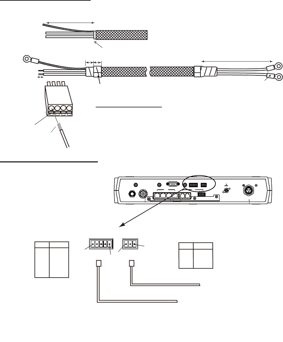
TTYCS-1 Cable fabrication
NMEA signal, External alarm
Approx. 50
6
Cut armor and sheath.
Taping
10
Crimp-on lug
FV1.25
Procedure to insert wire
1. Twist core.
2. Push spring-loaded catch with slotted-head screwdriver.
3. Insert core into hole.
4. Release the screwdriver.
5. Pull wire to confirm it is securely inserted.
FMC
connnector
Twist Wire
Push
10
Braided
shield
Cores
Approx. 40
Inner
φ3
MPYC-2
FMC
connector
See the figure on previous
page for how to fix FMC
connector.
ALARMNMEARS-232C
LAN
ANT
123 4
TEL
12 34
12-24 VDC
12-6A
12
L-BAND OUT
3GND
Communication unit
FB-2000
#3
#1
ALARMNMEA
#5 #1
FMC
connector
TTYCS-4
Alarm unit
Navigation equipment
ALARM
No. Signal
1 NC-A
2 NC-B
3 GND
NMEA
No. Signal
1 TD-A
2 TD-B
3 RD-A
4 RD-B
5 GND
NMEA input sentence
GGA, GLL, GNS, RMA, RMC, VTG, ZDA
(Talkers for GNS are GN, GP and GL only.
For other sentences any talker will do.)
2. CONNECTIONS
26
Cable fixture
To connect the LAN and TEL lines, attach the cable fixture (supplied) to the rear panel of the com-
munication unit. Then insert the connectors to each port. Fasten each cable with a cable tie (sup-
plied) to the cable fixture. Connect the braided shield wire of each cable to the ground terminal.
Cable fixture
Ground terminal
(Connect copper strap & braided shield
of each cable)
Fasten cable to this post
of cable fixture with a
cable tie.
Flat washer
Copper strap
Crimp-on lug
Flat washer
Spring washer
Wing nut

2. CONNECTIONS
27
2.4 Notice for network connection
With a hub(s), FELCOM500/FELCOM250 can establish a network configuration. If the hub(s) is
connected in loop form, the FELCOM500/FELCOM250 may not function normally.
Never connect as follows:
Note: If you install a switching hub that does not have an automatic function to distinguish straight/
cross (MDI/MDI-X) connections, you will need to select a proper cable:
• Use a straight connection cable for an MDI to MDI-X connection.
• Use a cross connection cable for an MDI to MDI or MDI-X to MDI-X connection.
Generally, it is advisable to use an auto MDI/MDI-X switching hub.
Communication unit
FB-2000
LAN
Hub
LAN LAN LAN
[Hub 1 set]
[Hub 2 sets] [Hub 3 sets]
Communication unit
FB-2000
Communication unit
FB-2000
Hub
Hub
Hub
Hub
Hub
2. CONNECTIONS
28
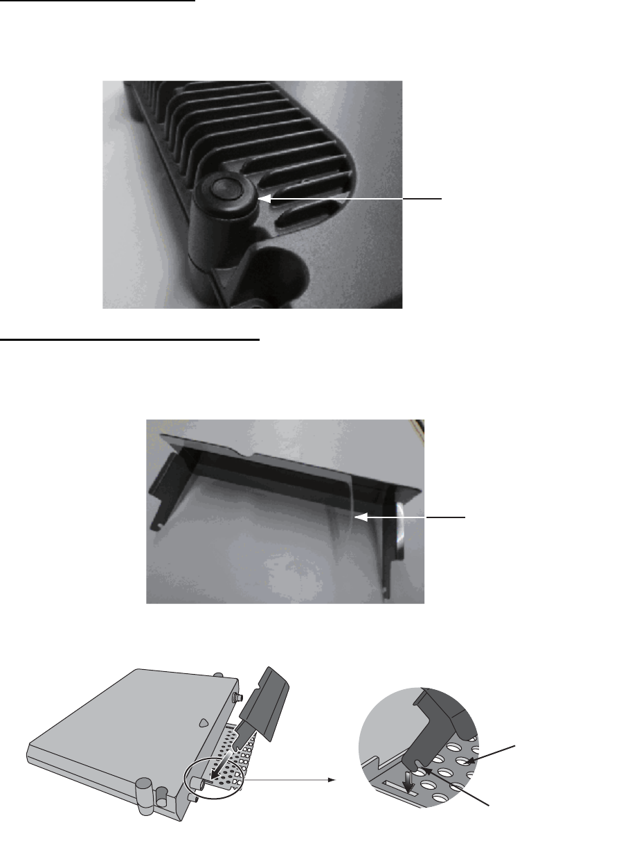
2.5 Desktop Installation of Communication Unit to-
comply with IPX2 (dripping) standard
How to inset the grommet
Be sure to install the Communication Unit to a desktop to protect from dripping. After installing,
affix the grommets over the mounting screws.
How to install the connector cover
After connecting the cables, perform the following to affix the connector cover.
1. Peel off the double sided tape (white) from the connector cover.
2. Plug the guide rail of the connector cover into the slots as shown, and pull slightly to hook into
the slot.
Grommet inset
(4 grommets)
Tape
Hook into slot
Cable fixture
Connector cover
guide rail
2. CONNECTIONS
29
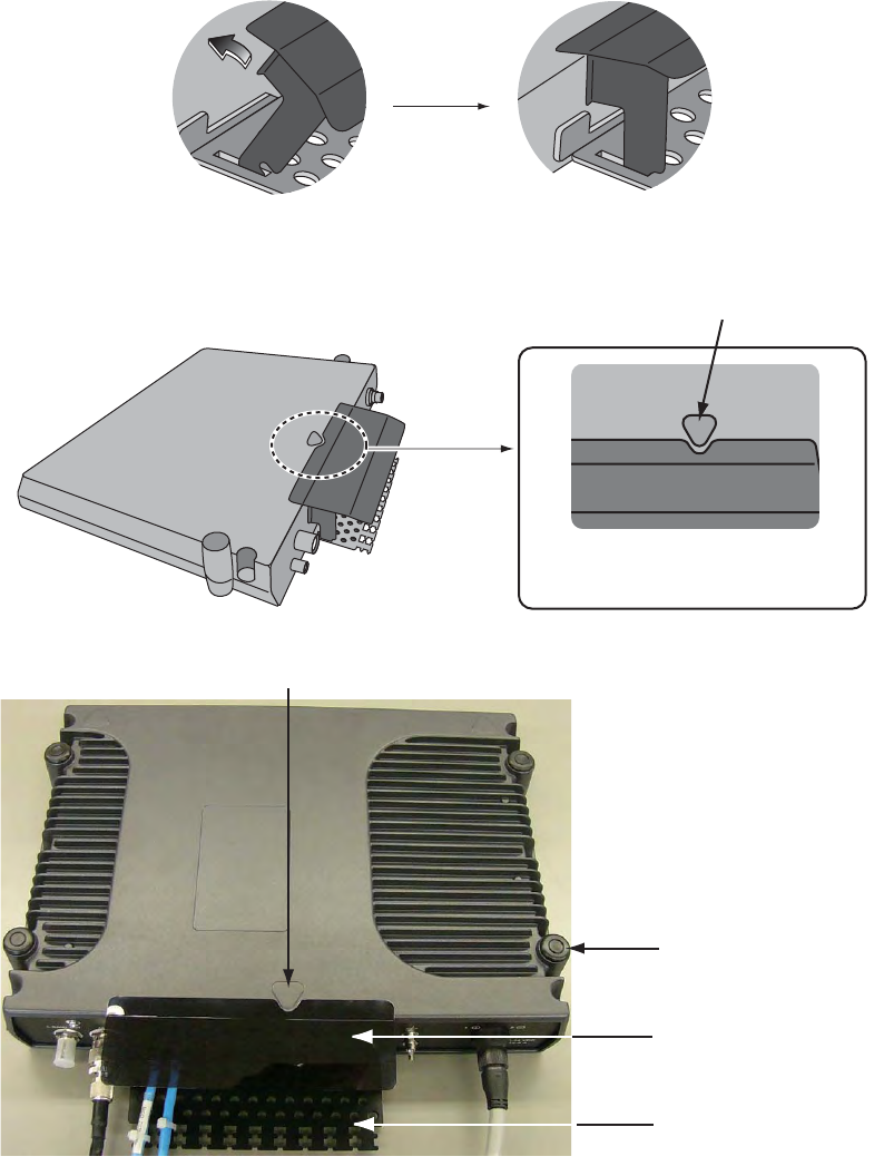
3. With the connector cover rail in the slot, raise the connector cover in the direction of the arrow
as shown below.
4. Push the connector cover in towards the triangle mark on the center top of the Communication
Unit to affix.
Raise
As seen from above
(push in towards mark䋩
Triangle
Triangle mark
Grommets (4)
Connector cover
Cable fixture
2. CONNECTIONS
30
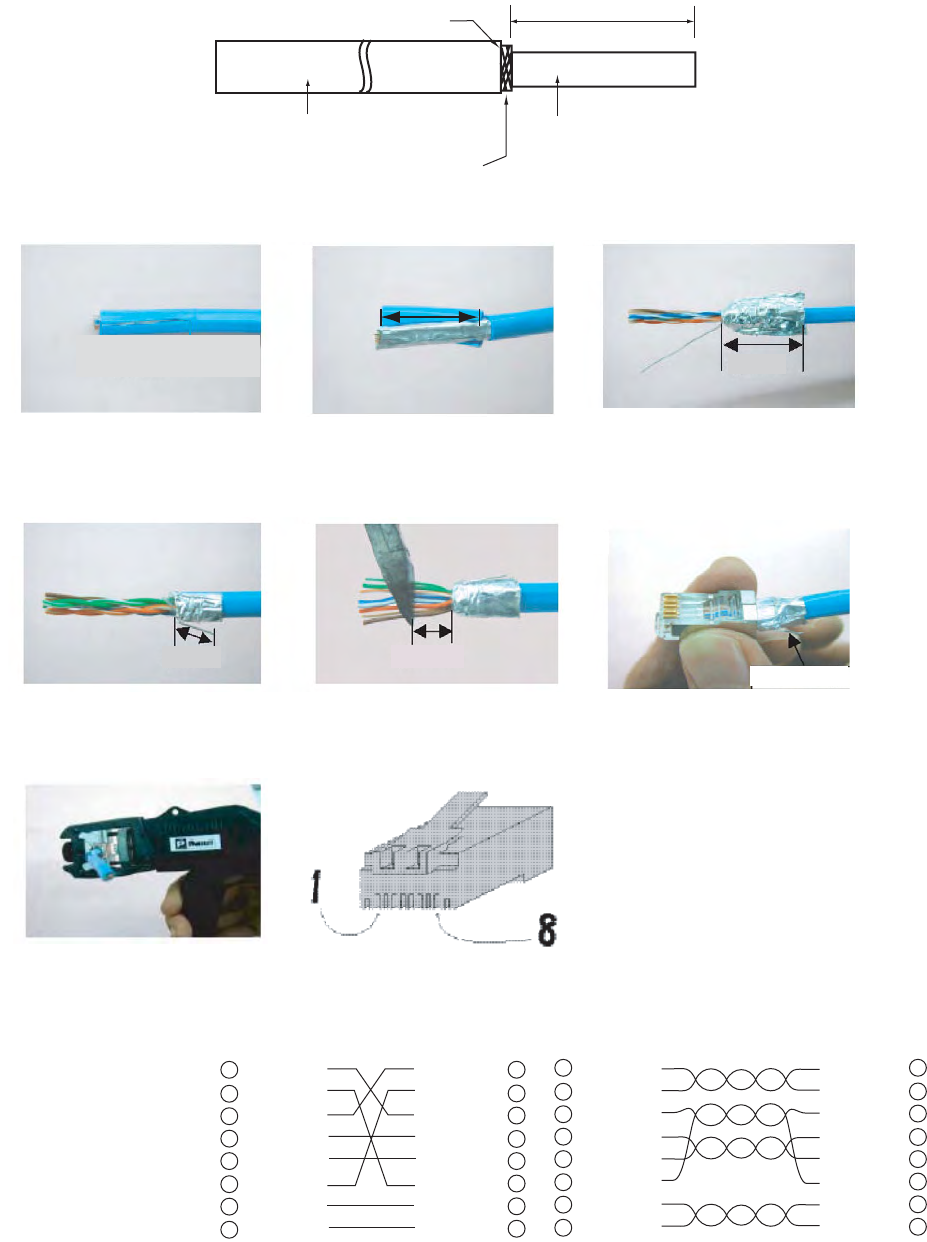
2.6 LAN Cable Fabrication
Fabricate an optional LAN cable (FR-FTPC-CY 10, 20, 30, 50 or 100 m) as follows. Cut armor and
outer vinyl sheath as shown below and then connect the modular connector MPS588-C (option)
to both ends.
Armor 150
Inner vinyl sheath
Outer vinyl sheath
Wrap vinyl tape
Using special crimping tool
MPT5-8 (PANDUIT CORP.),
crimp the modular plug.
Finally check the plug visually.
1 WHT/GRN
2 GRN
3 WHT/ORG
4 BLU
5 WHT/BLE
6 ORG
7 WHT/BRN
8 BRN
WHT/ORG 1
ORG 2
WHT/GRN 3
BLU 4
WHT/BLE 5
GRN 6
WHT/BRN 7
BRN 8
1 WHT/ORG
2 ORG
3 WHT/GRN
4 BLU
5 WHT/BLE
6 GRN
7 WHT/BRN
8 BRN
WHT/ORG 1
ORG 2
WHT/GRN 3
BLU 4
WHT/BLE 5
GRN 6
WHT/BRN 7
BRN 8
Expose inner vinyl sheath.
[Crose cable] [Straight cable]
Remove the outer sheath by
approx 25 mm. Be careful
not to damage inner shield
and cores.
Fold back the shield, wrap it
onto the outer sheath and
cut it, leaving 9 mm.
12
3
25mm
approx. 9mm
456
approx. 9mm approx. 11mm
Drain wire
Fold back drain wire and
cut it, leaving 9 mm.
Straighten and flatten the
core in order and cut them,
leaving 11 mm.
Insert the cable into the modular
plug so that the folded part of
the shield enters into the plug
housing. The drain wire should
be located on the tab side of
the jack.
7
31
3. SETTING AFTER INSTALLATION
This chapter shows how to enter basic settings, done by the installation technician. For the net-
work setting, request to an administrator of the ship network. (Refer to the Operator's Manual for
details.)
The SIM card is required to communicate via a satellite, but not required for the following system
settings. "(SIM): No SIM detected" appears in the Web software screen. Disregard the warning.
3.1 Preparation for Setting
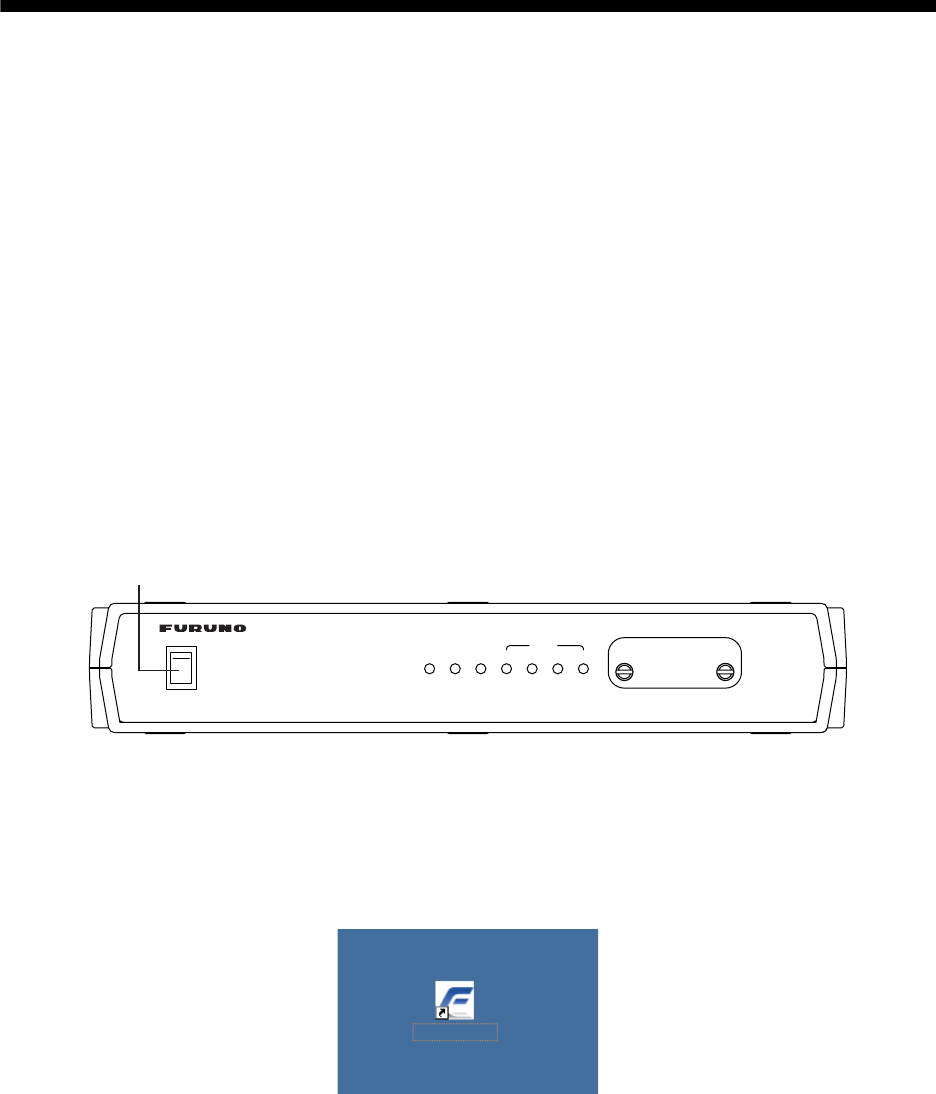
1. Turn on the PC and insert the CD-ROM (supplied with accessories) in the PC.
2. Open the CD-ROM and copy "FELCOM_FB" shortcut icon to the desktop of the PC.
This shortcut icon accesses the FELCOM 500/FELCOM 250 (IP address 192.168.1.1)
through the Internet Explorer.
3. Connect the PC to the Communication unit with a LAN cable.
4. Turn on the Communication unit. The initialization begins. Wait until all STATUS LEDs light.
During this time, the PC cannot access the Communication unit. Wait for a while.
5. To set the IP address of the PC, select "Obtain an IP address automatically" in the Internet
Protocol (TCP/IP) Preperties. If you set manually, set IP address according to the IP address
of the communication unit (default 192. 168.1.1).
6. Double-click the "FELCOM_FB" shortcut icon on the PC desktop.
SIM CARD INSIDE
POWER OFF BEFORE INSERTING
OR REMOVING SIM
―
○
POWER
○
I
POWER
1
TX
234
STATUS
Inmarsat FleetBroadband
READY
Power switch
Communication unit
FELCOM_FB
3. SETTING AFTER INSTALLATION
32
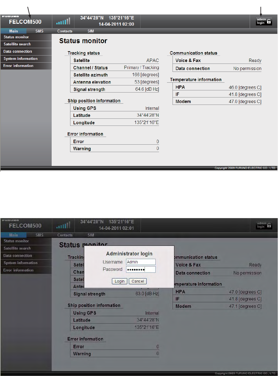
The browser starts and the main menu of the Web software in the FELCOM 250/500 opens.
7. Click the Administrator Login button on upper right hand side on the screen.The Login win-
dow opens.
8. Key in username "Admin" and password "01234567"(default value).The administrator can
change the password in another menu.
9. Click the Login button.
New menu items appear on the menu bar; Log, Settings, Device, and Selftest.
Administrator Login
For FELCOM 250, “FELCOM 250 is indicated.
3. SETTING AFTER INSTALLATION
33
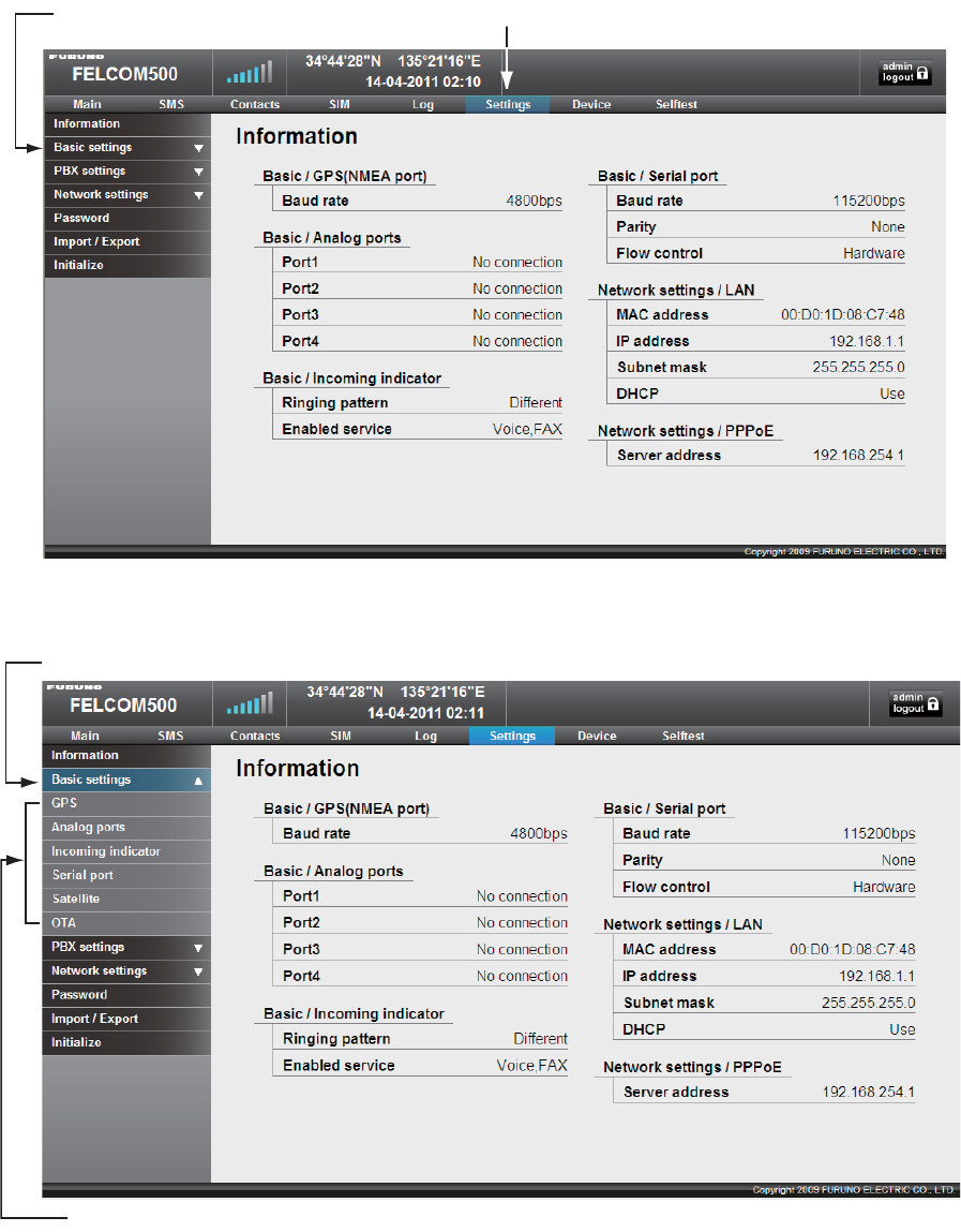
10. Click Settings on the menu bar.
The sub menu appears on left side and current setting appears in the Information window on
right side.
11. Click Basic settings on the sub menu.
The sub menu of the Basic settings appears
Use these sub menus to set the basic settings, following the procdeures on the next several pag-
es.
Basic settings Settings
Basic settings
Basic settings sub menu
3. SETTING AFTER INSTALLATION
34
3.2 GPS Setting
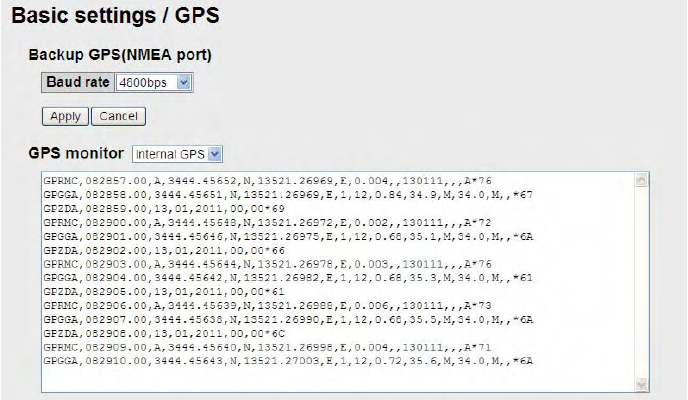
1. Click GPS on the Basic settings sub menu.
2. If an external GPS is connected to the NMEA port on the communication unit, set the baud
rate to 4800 bps or 38400 bps according to the GPS connected.
3. Click the Apply button.
4. To monitor output sentences from the GPS, select a GPS among Internal GPS, NMEA port,
and None. "None" displays no sentences.
3. SETTING AFTER INSTALLATION
35
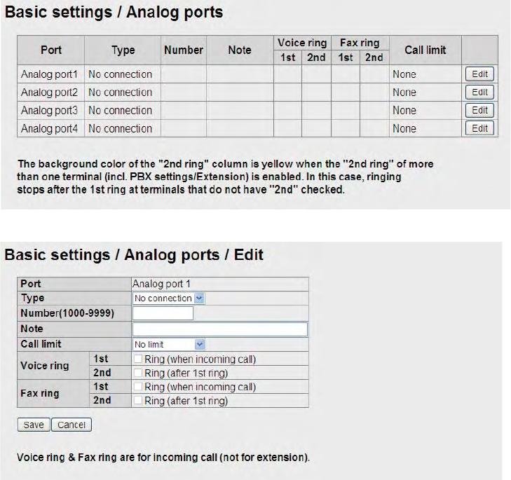
3.3 Analog Port Setting
Set for analog telephones/faxes that are connected to the TEL ports as follows.
1. Click Analog ports on the Basic settings sub menu.
2. In the Type box, select the equipment that is connected to the TEL port.
3. There are four TEL ports (TEL 1 to TEL 4), TEL 1 is analog port 1 in the table. The selections
are as follows:
• TEL: Analog telephone
• FAX: Facsimile
• TEL & FAX: Facsimile telephone
• No Connection: Nothing connected
4. Key in extension telephone number in the Number box. The setting range is between 1000
and 9999.
5. In the Note box, key in a name; user name, setting location, etc. This is the name a called
party sees. Up to 50 alphanumeric characters can be used. Do not use symbols, "?", "/", etc.
6. Set the call limit time in the Call limit box.
• No limit: No time limit
• Extension only: Limit call time on extension phones only
• Incoming only: Limit call time on incoming calls only
• Outside only: Limit call time on outside lines only
3. SETTING AFTER INSTALLATION
36
7. Set up outside line calls in the Voice ring box.
If you selected TEL at step 3, “1st” is checked. Then, any terminals that have ”1st” checked
ring first. Remove the check for no ring. Check “2nd” to ring 2nd terminal when there is no
answer at the terminal that have ”1st “checked. Ring duration time can be set on the PBX set-
tings/Incoming routing/Voice screen. (See the operator’s manual.)
8. Set up fax call in the Fax ring box. (Same as the Voice ring.)
If you selected FAX or TEL&FAX at step 3, “1st” is checked.
9. Click the [Save] button. The message "Setting Completed" at successful completioni of the
saving.
10. Click the [OK] button to erase the message
Note: If “2nd” is checked on the Basic settings/Analog ports screen or PBX settings/Extension
screen, the background color of the 2nd column on the Analog ports screen becomes yellow. In
this condition, terminals that do not have “2nd” checked stop ringing after the time specified has
elapsed.
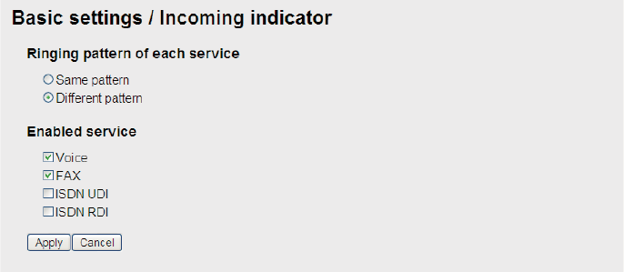
3.4 Incoming Indicator Setting
If the optional Incoming Indicator is connected, set it as follows.
1. Click Incoming Indicator in the Basic settings sub menu.
2. Select the ringing pattern of the incoming indicator in the "Ringing pattern of each service",
between same pattern and Different pattern.
Same pattern: Same ringing pattern for any communication service.
Different pattern: Different ringing pattern for each communication service.
3. Check a communication services to ring the incoming indicator.
• Voice: Ring for incoming telephone.
• FAX: Ring for incoming facsimile.
• ISDN UDI: Ring for incoming ISDN UDI data communication (FELCOM500 only) .
• ISDN RDI: Ring for incoming ISDN UDI data communication (FELCOM500 only).
4. Click the Apply button to conclude the setting.
3. SETTING AFTER INSTALLATION
37
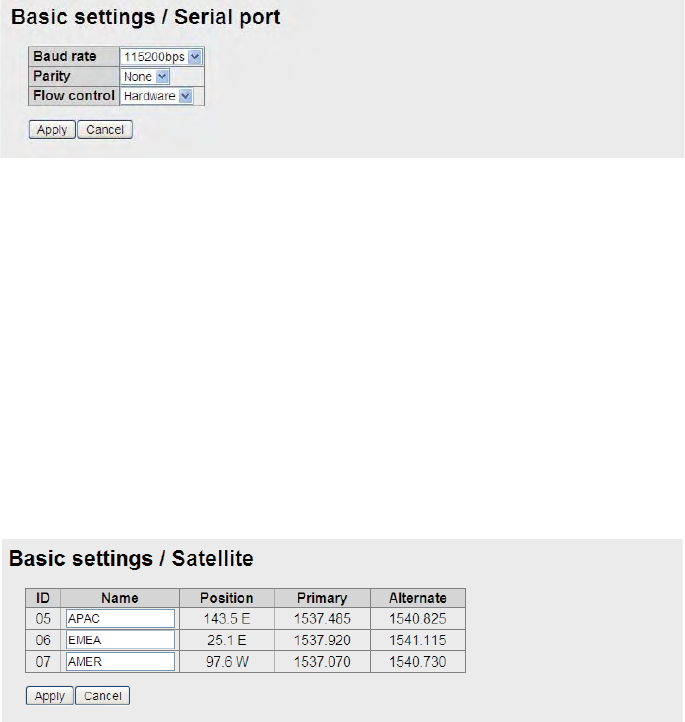
3.5 Serial Port Setting
Set for the equipment that is connected to the RS-232C port.
1. Click Serial port in the Basic settings sub menu.
2. Select a baud rate from the Baud rate drop-down list. The selections are 9600, 19200, 38400,
57600 and 115200 bps.
3. Set a parity bit in the Parity box. The selections are None, Even and Odd.
4. Select the Flow control among Hardware, Software and None.
5. Click the Apply button to complete the setting.
3.6 Satellite Setting
The three satellites are named APAC (Asia-pacific), EMEA (Europe-Middle east-Africa) and
AMER (America). To change satellite name, do as follows.
1. Click Satellite in the Basic settings sub menu.
2. Put the cursor in the Name box and enter the name of the satellite (max. 10 characters).
3. Click the Apply button to complete the setting.
The meaning of the table items is as follows.
• ID: Identification of the satellite
• Position: Position of the geostationary satellite (longitude)
• Primary: Frequency of the first global channel of the satellite
• Alternate: Frequency of the second global channel of the satellite
3. SETTING AFTER INSTALLATION
38
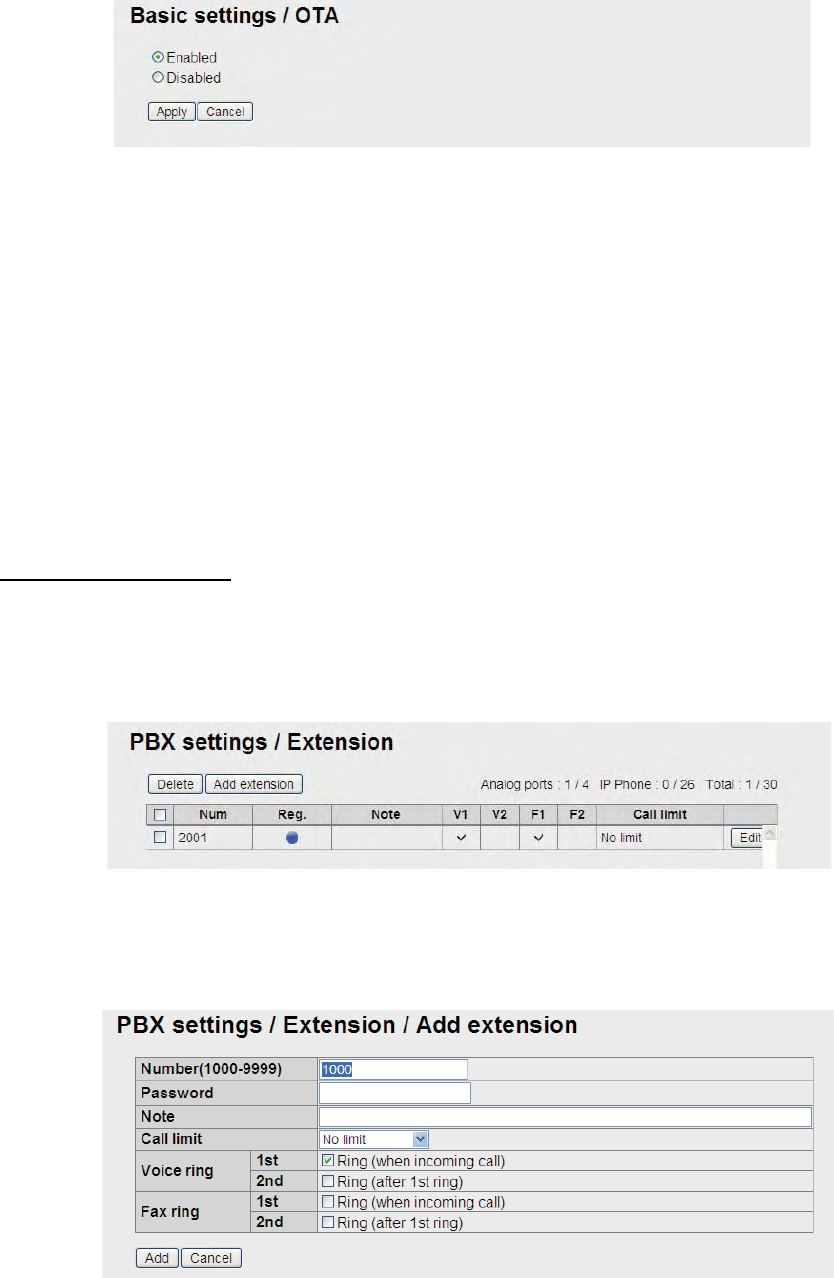
3.7 OTA Setting
OTA stands for Over The Air. The OTA function permits remote management of files in the SIM
card.
1. Click OTA in the Basic setting sub menu.
2. To enable the OTA, click the Enabled radio button. To disable the OTA, click the Disabled ra-
dio button.
3. Click the Apply button to complete the setting.
With Enabled, OTA functions as follows.
a) User requests a change of contract contents to a SIM maker.
b) The SIM maker transmits an OTA message to the terminal.
c) The terminal receives the OTA message and modifies the internal parameters according
to the contract contents.
3.8 Handset Setting
To use the IP handset, set the Web software and the IP handset as follows.
Web software setting
1. Click Settings in the menu bar.
2. Click PBX Settings in the Settings sub menu at the left side of the screen.
3. Click Extension in the PBX Setting sub menu.
4. Click the Add extension button.
The following window appears. The lowest unregistered number between 1000 and 9999 ap-
pears in the Number box. To use this number, go to step 6. To register a different number, go
to step 5.
3. SETTING AFTER INSTALLATION
39
5. Key in a new extension number in the Number box (1000-9999).
You cannot use a number that is already entered. If you enter the same number, an error mes-
sage will appear at the registration.
6. Key in a password in the Password box (a maximum of eight alphanumeric characters).
Upper case alphabet can be used.
Note: Do not forget to write down the telephone number and password.
7. If necessary, enter a comment in the Note box (a maximum of 50 characters), for example,
user name, setting location, etc.
8. Set the call limit time in the Call limit box.
• No limit: No time limit
• Extension only: Limit call time on extension phones only
• Incoming only: Limit call time on incoming calls only
• Outside only: Limit call time on outside lines only
9. Enter the outside line settings in the Voice ring box.
10. Enter the fax settings in the Fax ring box.
11. Click the [Add] button
12. Click the [OK] button.
The registered number appears on the Extension screen.
13. To register multiple telephones, repeat steps 4 to 12.
Setting in the IP handset
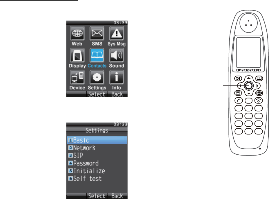
1. Push the Enter key at the idle screen to show the main menu.
2. Push 6 to select the Settings icon and then push the Enter key to
show the Settings menu.
1
. @
4
GHI
7
PQRS
5
JKL
8
TUV
6
MNO
9
WXYZ
2
ABC
3
DEF
CLR
0
* #
ENTER
Key
3. SETTING AFTER INSTALLATION
40
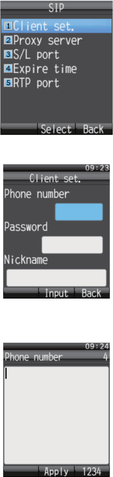
3. Push 3 key to show the SIP menu.
4. Push 1 key to show the Client setting screen.
5. With the Phone number box highlighted in blue, push the Enter key to show the phone num-
ber input screen.
6. Enter the extension number that is registered in the Web software and push the Enter key.
If something has been registered, push the CLR key to erase it.
7. Push T to select Password and then push the Enter key.
3. SETTING AFTER INSTALLATION
41
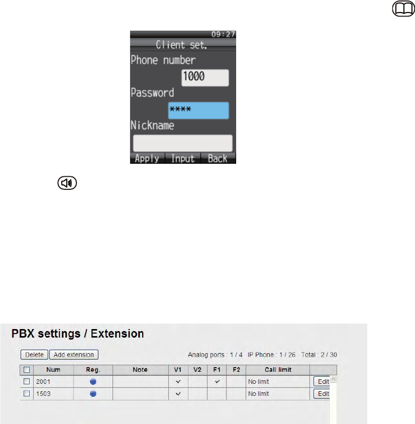
8. Enter the password which was registered in the Web software and then push the Enter key.If
the password contains both alphabet and numerals, switch input format with the soft key .
9. Push the soft key (Apply).
The message "Set" appears and the setting for one IP handset is completed.
10. Push the CLR key three times to return to the idle screen.
11. If multiple handsets are connected, repeat the above step 1 to 10 for each handset.
When the Web software-set extension number matches handset-set extension number, the mark
with a blue circle appears in the Settings/ PBX settings/ Extension window of the Web software.
These handsets can be used for communication. However, the following screen does not update
automatically. Press the Reload button of the browser to refresh the screen.
3. SETTING AFTER INSTALLATION
42
3.9 User Registration (for data connection)
Register the IP address of the handset and the PC to the user list to enable data connection. If no
IP address is entered, the standby screen of the handset shows “D: No permission”, and the Web
software screen shows “Data connection No permission”.
1. Click [Settings] on the menu bar.
2. Click [Network Settings].
3. Click [WAN].
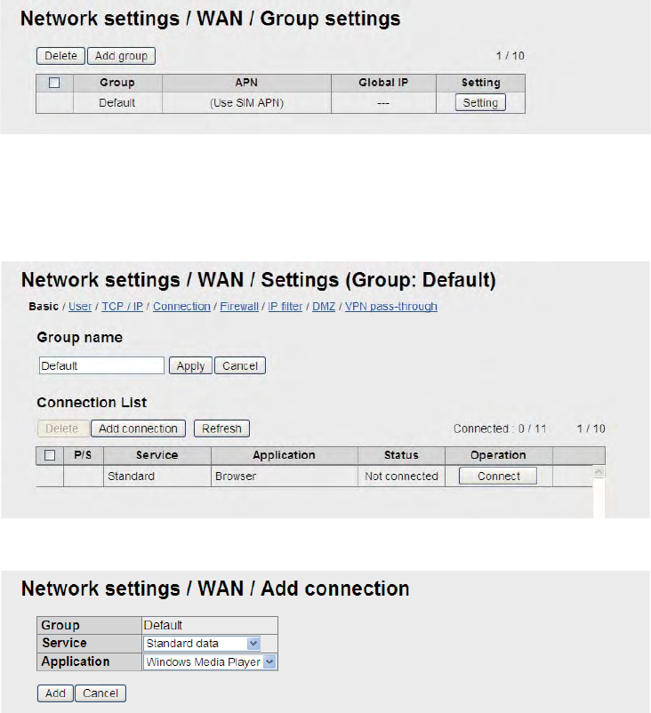
4. Click [Group Settings] to show the Network settings/WAN/Group settings screen.
5. Click the [Setting] button to show the basic setting screen.
The default setting is “standard IP packet communications service”. For SIM card and you
have applied for streaming IP packet communication service, go to step 6. If you have not ap-
plied, go to step 11.
6. Click the [Add connection] button to shown the Add connection screen.
7. Enter the service to use in the Service box.
Select one among Standard data, 8kbps Streaming, 16kbps Streaming, 32kbps Streaming,
64kbps Streaming, 128kbps Streaming, and 256kbps Streaming*/ * FELCOM 500 only
8. Enter the application to use in the Application box.
Select among Windows Media Player, Quick Time, Real Player, FTP, and Browser.
9. Click the [Add] button. The message “Completed” appears.
10. Click the [OK] button to erase the message.
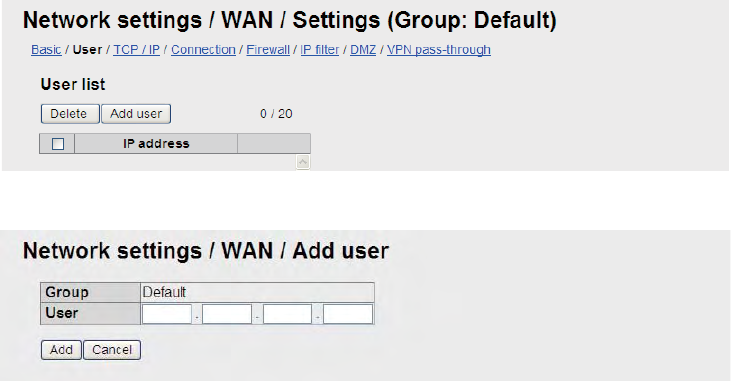
3. SETTING AFTER INSTALLATION
43
11. Click [User] to show the User List screen.
12. Click the [Add user] button to shown the Add user screen.
13. Enter the IP address in the User box. Do not use 127.0.0.1, 255.255.255.255, or the IP ad-
dress of the communication unit.
Note: If the IP addresses are the same, only one group can be registered. “192.168.1* and
“192.168.1.10” can be registered. * is a wildcard: show network. If you registered two groups
this way, the group having the narrowest range (192.168.1.10) has priority.
14. Click the [Add] button. The message "Setting Completed." appears.
15. Click the [OK] button to erase the message.
AP-1
APPENDIX 1 JIS CABLE GUIDE
D
T
M
TT
PY
CYS
-S
3. Sheath Type
4. Armor Type 5. Shielding Type 6. Core Sheath
Ethylene Propylene
2. Insulation Type 1. Core Type
Double core power line
Triple core power line
1mm Multi core
0.75mm twisted pair communications (1Q = quad cable)
Corrosive resistant
Steel
Vinyl
All cores in one sheath
Individually sheathed cores
DPYCYS - 1.5 EX:
The following reference table lists gives the measurements of JIS cables commonly used with Furuno products:
DPYC
TTYCS-4
MPYC-5
Type Area Diameter
Core Cable
Diameter
DPYC-1.5 1.5mm
2
1.56mm 11.7mm
DPYC-2.5 2.5mm
2
2.01mm
1 2 3 4 5 6
MPYC - 5
1 2 3 4
Designation type Core Area (mm ) Designation type # of cores
DPYCY-2.5
DPYCYS-1.5
DPYCYS-2.5
MPYC-7
MPYCY-12
MPYCY-19
TTYCS-1
TTYCS-1Q
TTYCS-4
TTYCYS-1
JIS cable names may have up to 6 alphabetical characters, followed by a dash and a numerical value (example: DPYC-2.5).
For core types D and T, the numerical designation indicates the cross-sectional Area (mm
2
) of the core wire(s) in the cable.
For core types M and TT, the numerical designation indicates the number of core wires in the cable.
TPYC
12.8mm
2.5mm
2
2.01mm 14.8mm
1.5mm
2
1.56mm 14.6mm
2.5mm
2
2.01mm 15.5mm
1mm
2
1.29mm 13.2mm
1mm
2
1.29mm 19.0mm
22.0mm1mm
2
1.29mm
0.75mm
2
1.11mm 10.1mm
11.3mm
16.3mm
21.1mm
2
0.75mm 1.11mm
2
0.75mm 1.11mm
2
0.75mm 1.11mm
2
Type Area Diameter
Core Cable
Diameter
MPYC-4
MPYC-2
TPYCY-1.5
TPYCY-2.5
TPYCY-4
TPYCYS-1.5
1mm
2
1mm
2
1.5mm
2
1.56mm 14.5mm
2.5mm
2
2.01mm 15.5mm
4mm
2
2.55mm 16.9mm
1.5mm
2
1.56mm 15.2mm
Cables listed in the manual are usually shown as Japanese Industrial Standard (JIS). Use the following guide to locate an
1.29mm
1.29mm 10.0mm
11.2mm
equivalent cable locally.
0#/' 176.+0' 36;&'5%4+26+10%1&'ͳ
㧼㧭㧯㧷㧵㧺㧳ޓ㧸㧵㧿㨀
#3:
($#,'ޔ$,'
0#/' 176.+0' 36;&'5%4+26+10%1&'ͳ
࡙࠾࠶࠻ 70+6
㩔㩧㩎㩨㩈㨹㩎
+2*#0&5'6
($
ㅢାᓮ㩟㩐㨹㩎
%1//70+%#6+1070+6
($#
$
ㅢାᓮ↪੍ຠ %1//70+%#6+1070+6ޓ52#4'2#465
੍ຠ
52#4'2#465
52
ㅢାᓮ↪Ꮏ᧚ %1//70+%#6+1070+6ޓ+056#..#6+10/#6'4+#.5 %2
㩃㨺㩖㩨㩣⚵ຠ.#0
.#0%#$.'#55'/$.;
/1&<
㩃㨺㩖㩨㩣⚵ຠ/,
%#$.'#55;
/,#52(<%
Ꮏ᧚ᢱ
+056#..#6+10/#6'4+#.5
%2
Ꮏ᧚ᢱ
+056#..#6+10/#6'4+#.5
%2
ㅢାᓮ↪ઃዻຠ %1//70+%#6+1070+6ޓ#%%'5514+'5 (2
%&41/⚵ຠ
%&41/
㩔㩧㩎㩨㩈㨹㩎Ꮏ᧚ *#0&5'6+056#..#6+10/#6'4+#.5
Ꮏ᧚ᢱ
+056#..#6+10/#6'4+#.5
%2
࿑ᦠ &1%7/'06
㨾㨼㩈㨼㩀㩔㩨㨺㨾㩢㨻㩙㨹㩖㩩
5#6'..+6'%18'4#)'#4'#/#2
%
⸳ቯ㓸
':#/2.'1(5'66+0)
ขᛒ⺑ᦠ
12'4#6145/#07#.
1/
ⵝⷐ㗔ᦠ
+056#..#6+10/#07#.
+/
ᠲⷐ㗔ᦠ㧔㩊㩃㩨㩧
12'4#6145)7+&'/.)
/.)
㩕㨷㨺㩇㩨ᄌᦝߩ߅㗿
016+%'(14(75'4'2.#%'/'06
%
✕ᕆ㩆㨺㩎
'/'4)'0%;%#..5*''6
'
ဳ⚕
2.#6'
%
䍘㪄䍢䍼⇟ภᧃየ䈱㪲㪁㪁㪴䈲䇮ㆬᛯຠ䈱ઍ䍘䍎䍢䍼䉕䈚䉁䈜䇯
㪚㪦㪛㪜㩷㪥㪬㪤㪙㪜㪩㩷㪜㪥㪛㪠㪥㪞㩷㪮㪠㪫㪟㩷㩹㪁㪁㩹㩷㪠㪥㪛㪠㪚㪘㪫㪜㪪㩷㪫㪟㪜㩷㪚㪦㪛㪜㩷㪥㪬㪤㪙㪜㪩㩷㪦㪝㩷㪩㪜㪧㪩㪜㪪㪜㪥㪫㪘㪫㪠㪭㪜㩷㪤㪘㪫㪜㪩㪠㪘㪣
㧔⇛࿑ߩኸᴺߪޔෳ⠨୯ߢߔޕ&+/'05+105+0&4#9+0)(144'('4'0%'10.;㧕
#
3
:
ဳᑼ䎒䱤䱚䱮䲈⇟ภ䬛䯾Ბ䬽႐ว䫺ਅᲑ䭗䭙Ბ䬺ઍ䭞䭚ㆊᷰᦼຠ䬶䬑䭙䫺䬸䬰䭘䬚䬛䬲䬵䬓䭍䬨䫻䫹䬹䬙䫺ຠ⾰䬾ᄌ䭞䭙䭍䬪䭢䫻
䎷䎺䎲䎃䎷䎼䎳䎨䎶䎃䎤䎱䎧䎃䎦䎲䎧䎨䎶䎃䎰䎤䎼䎃䎥䎨䎃䎯䎬䎶䎷䎨䎧䎃䎩䎲䎵䎃䎤䎱䎃䎬䎷䎨䎰䎑䎃䎃䎷䎫䎨䎃䎯䎲䎺䎨䎵䎃䎳䎵䎲䎧䎸䎦䎷䎃䎰䎤䎼䎃䎥䎨䎃䎶䎫䎬䎳䎳䎨䎧䎃䎬䎱䎃
䎳䎯䎤䎦䎨䎃䎲䎩䎃䎷䎫䎨䎃䎸䎳䎳䎨䎵䎃䎳䎵䎲䎧䎸䎦䎷䎑䎃䎴䎸䎤䎯䎬䎷䎼䎃䎬䎶䎃䎷䎫䎨䎃䎶䎤䎰䎨䎑
A-2
%1&'01
6;2'
⇛ޓޓ࿑
176.+0'
ฬޓޓ⒓
0#/'
ᢙ㊂
36;
↪ㅜ㧛⠨
4'/#4-5
⇟ภ
01
ဳฬ㧛ⷙᩰ
&'5%4+26+105
+056#..#6+10/#6'4+#.5
Ꮏ᧚ᢱ
#3:
#06'00#70+6
($#$
㨻㩧㩍㩏㩃㨺㩖㩨㩣⚵ຠ
#06'00#%#$.'#55; &($%8/
ㆬᛯޓޓޓޓޓޓޓ
61$'5'.'%6'&
%1&'01
㨻㩧㩍㩏㩃㨺㩖㩨㩣⚵ຠ
#06'00#%#$.'#55; &($%8/
ㆬᛯޓޓޓޓޓޓޓ
61$'5'.'%6'&
%1&'01
㨻㩧㩍㩏㩃㨺㩖㩨㩣⚵ຠ
#06'00#%#$.'#55; &($%8/
ㆬᛯޓޓޓޓޓޓޓ
61$'5'.'%6'&
%1&'01
㧔⇛࿑ߩኸᴺߪޔෳ⠨୯ߢߔޕޓ&+/'05+105+0&4#9+0)(144'('4'0%'10.;㧕
㧲㨁㧾㨁㧺㧻ޓ㧱㧸㧱㧯㨀㧾㧵㧯ޓ㧯㧻ޓ㧚
㧘
㧸㨀㧰
#3:
ڏ
ဳᑼ㩄㨺㩎㩨⇟ภ߇㧞Ბߩ႐วޔਅᲑࠃࠅᲑߦઍࠊࠆㆊᷰᦼຠߢࠅޔߤߜࠄ߆߇ߞߡ߹ߔޕޓߥ߅ޔຠ⾰ߪᄌࠊࠅ߹ߖࠎޕ
6916;2'5#0&%1&'5/#;$'.+56'&(14#0+6'/6*'.19'4241&7%6/#;$'5*+22'&+02.#%'1(6*'722'4241&7%6
37#.+6;+56*'5#/'
A
-1
%1&'01
6;2'
%2
⇛ޓޓ࿑
176.+0'
ฬޓޓ⒓
0#/'
ᢙ㊂
36;
↪ㅜ㧛⠨
4'/#4-5
⇟ภ
01
ဳฬ㧛ⷙᩰ
&'5%4+26+105
+056#..#6+10/#6'4+#.5
Ꮏ᧚ᢱ
#3:
+2*#0&5'6
($
㩎㩡㩇㩊㨹㩕㩩㩧㩒㩆㩨㩆㨷
5'.(6#22+0)5%4'9 :575
%1&'01
㩄㩧㩗㩨㨹㩂㩇
%#$.'ޓ6+' %80
%1&'01
㧔⇛࿑ߩኸᴺߪޔෳ⠨୯ߢߔޕޓ&+/'05+105+0&4#9+0)(144'('4'0%'10.;㧕
㧲㨁㧾㨁㧺㧻ޓ㧱㧸㧱㧯㨀㧾㧵㧯ޓ㧯㧻ޓ㧚
㧘
㧸㨀㧰
#3:
ဳᑼ㩄㨺㩎㩨⇟ภ߇㧞Ბߩ႐วޔਅᲑࠃࠅᲑߦઍࠊࠆㆊᷰᦼຠߢࠅޔߤߜࠄ߆߇ߞߡ߹ߔޕޓߥ߅ޔຠ⾰ߪᄌࠊࠅ߹ߖࠎޕ
6916;2'5#0&%1&'5/#;$'.+56'&(14#0+6'/6*'.19'4241&7%6/#;$'5*+22'&+02.#%'1(6*'722'4241&7%6
37#.+6;+56*'5#/'
A
-4
%1&'01
6;2'
%2
⇛ޓޓ࿑
176.+0'
ฬޓޓ⒓
0#/'
ᢙ㊂
36;
↪ㅜ㧛⠨
4'/#4-5
⇟ภ
01
ဳฬ㧛ⷙᩰ
&'5%4+26+105
+056#..#6+10/#6'4+#.5
Ꮏ᧚ᢱ
#3:
%1//70+%#6+1070+6
($#
㩕㨷㨺㩇㩨㩔㩢㩙㨺㩂
(75'.#$'. 41*5
%1&'01
㨻㨺㩇᧼
%122'4564#2 41*5
%1&'01
㩃㨺㩖㩨㩣㊄ౕ
%#$.'(+:674'
%1&'01
㩎㩡㩇㩊㨹㩕㩩㩧㩒㩆㩨㩆㨷
5'.(6#22+0)5%4'9 :575
%1&'01
㩂㩨㩥㩜㨹㩎
)41//'6 %5)#'27.
%1&'01
㩄㩧㩗㩨㨹㩂㩇
%#$.'ޓ6+' %80
%1&'01
㩔㩨㨼㩧㩎㩨㩈㩛㩇(
$+0&'4*'#&5%4'9( /:%9/$%4
%1&'01
㩄㩒㩂㩊0
%100'%614 02&($%(
%1&'01
㧔⇛࿑ߩኸᴺߪޔෳ⠨୯ߢߔޕޓ&+/'05+105+0&4#9+0)(144'('4'0%'10.;㧕
㧲㨁㧾㨁㧺㧻ޓ㧱㧸㧱㧯㨀㧾㧵㧯ޓ㧯㧻ޓ㧚
㧘
㧸㨀㧰
#3:
ဳᑼ㩄㨺㩎㩨⇟ภ߇㧞Ბߩ႐วޔਅᲑࠃࠅᲑߦઍࠊࠆㆊᷰᦼຠߢࠅޔߤߜࠄ߆߇ߞߡ߹ߔޕޓߥ߅ޔຠ⾰ߪᄌࠊࠅ߹ߖࠎޕ
6916;2'5#0&%1&'5/#;$'.+56'&(14#0+6'/6*'.19'4241&7%6/#;$'5*+22'&+02.#%'1(6*'722'4241&7%6
37#.+6;+56*'5#/'
A-3
㧼㧭㧯㧷㧵㧺㧳ޓ㧸㧵㧿㨀
#4:
($
0#/' 176.+0' &'5%4+26+10%1&'ͳ 36;
࡙࠾࠶࠻ 70+6
㨻㩧㩍㩏㩟㩐㨹㩎
#06'00#70+6
($
Ꮏ᧚ᢱ +056#..#6+10/#6'4+#.5 %2
㨻㨺㩇✢
)4170&%#$.'
ࡃࡀᐳ㊄
524+0)9#5*'4
/575
ᐔᐳ㊄
2.#+09#5*'4
/575
⼊ႎࠬ࠹࠶ࠞዊ㧕
4'&+#6+109#40+0)56+%-'4
⼊ႎࠬ࠹࠶ࠞᄢ㧕
4'&+#6+109#40+0)56+%-'4
ⷺ࠽࠶࠻
*':076
/575
㩃㩚㩆㨺㩣
5+.+%1047$$'4
59㨻㩣㩚㩋㨷㨺㩖㩨)
䋨㪁䋩䈲䇮䍞䍼䍮䍎䍘䍎䍢䍼䈮ઃ䈐䇮ᵈᢥ䈪䈐䉁䈞䉖䇯
䋨㪁䋩䇭㪫㪟㪠㪪㩷㪚㪦㪛㪜㩷㪚㪘㪥㪥㪦㪫㩷㪙㪜㩷㪦㪩㪛㪜㪩㪜㪛㪅
䋨⇛࿑䈱ኸᴺ䈲䇮ෳ⠨୯䈪䈜䇯㩷㩷㪛㪠㪤㪜㪥㪪㪠㪦㪥㪪㩷㪠㪥㩷㪛㪩㪘㪮㪠㪥㪞㩷㪝㪦㪩㩷㪩㪜㪝㪜㪩㪜㪥㪚㪜㩷㪦㪥㪣㪰㪅䋩
#4:
ဳᑼ㪆䍘䍎䍢䍼⇟ภ䈏䋲Ბ䈱႐ว䇮ਅᲑ䉋䉍Ბ䈮ઍ䉒䉎ㆊᷰᦼຠ䈪䈅䉍䇮䈬䈤䉌䈎䈏䈦䈩䈇䉁䈜䇯䇭䈭䈍䇮ຠ⾰䈲ᄌ䉒䉍䉁䈞䉖䇯
㪫㪮㪦㩷㪫㪰㪧㪜㪪㩷㪘㪥㪛㩷㪚㪦㪛㪜㪪㩷㪤㪘㪰㩷㪙㪜㩷㪣㪠㪪㪫㪜㪛㩷㪝㪦㪩㩷㪘㪥㩷㪠㪫㪜㪤㪅㩷㩷㪫㪟㪜㩷㪣㪦㪮㪜㪩㩷㪧㪩㪦㪛㪬㪚㪫㩷㪤㪘㪰㩷㪙㪜㩷㪪㪟㪠㪧㪧㪜㪛㩷㪠㪥㩷㪧㪣㪘㪚㪜㩷㪦㪝㩷㪫㪟㪜㩷㪬㪧㪧㪜㪩㩷
㪧㪩㪦㪛㪬㪚㪫㪅㩷㪨㪬㪘㪣㪠㪫㪰㩷㪠㪪㩷㪫㪟㪜㩷㪪㪘㪤㪜㪅
A-6
㧼㧭㧯㧷㧵㧺㧳ޓ㧸㧵㧿㨀
#3:
($#
0#/' 176.+0' &'5%4+26+10%1&'ͳ 36;
࡙࠾࠶࠻ 70+6
㨻㩧㩍㩏㩟㩐㨹㩎
#06'00#70+6
($#
Ꮏ᧚ᢱ +056#..#6+10/#6'4+#.5 %2
㩃㩚㩆㨺㩣
5+.+%1047$$'4
59㨻㩣㩚㩋㨷㨺㩖㩨)
㩄㩨㩛᧼
47$$'4/#6
/
⼊ႎ㩇㩍㨹㩀㨺
4#&+#6+109#40+0)56+%-'4
㧸
ⷺ㩘㩨㩣㩎
*':$1.6
/:575/
ⷺ㩏㨹㩎
*':076
/575/
ᐔᐳ㊄
2.#+09#5*'4
/575/
㩔㩨㩒ᐳ㊄
524+0)9#5*'4
/575/
㩆㨺㩣㩦㨹㩆㨶㨺
5'#.9#5*'4
/
䋨㪁䋩䈲䇮䍞䍼䍮䍎䍘䍎䍢䍼䈮ઃ䈐䇮ᵈᢥ䈪䈐䉁䈞䉖䇯
䋨㪁䋩䇭㪫㪟㪠㪪㩷㪚㪦㪛㪜㩷㪚㪘㪥㪥㪦㪫㩷㪙㪜㩷㪦㪩㪛㪜㪩㪜㪛㪅
䋨⇛࿑䈱ኸᴺ䈲䇮ෳ⠨୯䈪䈜䇯㩷㩷㪛㪠㪤㪜㪥㪪㪠㪦㪥㪪㩷㪠㪥㩷㪛㪩㪘㪮㪠㪥㪞㩷㪝㪦㪩㩷㪩㪜㪝㪜㪩㪜㪥㪚㪜㩷㪦㪥㪣㪰㪅䋩
#3:
ဳᑼ㪆䍘䍎䍢䍼⇟ภ䈏䋲Ბ䈱႐ว䇮ਅᲑ䉋䉍Ბ䈮ઍ䉒䉎ㆊᷰᦼຠ䈪䈅䉍䇮䈬䈤䉌䈎䈏䈦䈩䈇䉁䈜䇯䇭䈭䈍䇮ຠ⾰䈲ᄌ䉒䉍䉁䈞䉖䇯
㪫㪮㪦㩷㪫㪰㪧㪜㪪㩷㪘㪥㪛㩷㪚㪦㪛㪜㪪㩷㪤㪘㪰㩷㪙㪜㩷㪣㪠㪪㪫㪜㪛㩷㪝㪦㪩㩷㪘㪥㩷㪠㪫㪜㪤㪅㩷㩷㪫㪟㪜㩷㪣㪦㪮㪜㪩㩷㪧㪩㪦㪛㪬㪚㪫㩷㪤㪘㪰㩷㪙㪜㩷㪪㪟㪠㪧㪧㪜㪛㩷㪠㪥㩷㪧㪣㪘㪚㪜㩷㪦㪝㩷㪫㪟㪜㩷㪬㪧㪧㪜㪩㩷
㪧㪩㪦㪛㪬㪚㪫㪅㩷㪨㪬㪘㪣㪠㪫㪰㩷㪠㪪㩷㪫㪟㪜㩷㪪㪘㪤㪜㪅
A-5
%1&'01
6;2'
12
⇛ޓޓ࿑
176.+0'
ฬޓޓ⒓
0#/'
ᢙ㊂
36;
↪ㅜ㧛⠨
4'/#4-5
⇟ภ
01
ဳฬ㧛ⷙᩰ
&'5%4+26+105
㩝㩆㩨㨷㩡㨺㩄㨺㩎㩨
#(:
('.%1/
⚦ᦠ
&'5%4+26+10
㩝㩆㩨㨷㩡㨺㩄㨺㩎㩨
/1&7.'4%14& $%/+8
%1&'
01
$%/+8
⌕┵ሶ
%4+/210.7) (8.(
%1&'
01
㩥㨺㩈㩨㨹㩎
/1&7.#4,#%-$1: /,5)4
%1&'
01
㧲㨁㧾㨁㧺㧻ޓ㧱㧸㧱㧯㨀㧾㧵㧯ޓ㧯㧻ޓ㧚㧘㧸㨀㧰
#(:
㧔⇛࿑ߩኸᴺߪޔෳ⠨୯ߢߔޕޓ&+/'05+105+0&4#9+0)(144'('4'0%'10.;㧕
ဳᑼ㩄㨺㩎㩨⇟ภ߇㧞Ბߩ႐วޔਅᲑࠃࠅᲑߦઍࠊࠆㆊᷰᦼຠߢࠅޔߤߜࠄ߆߇ߞߡ߹ߔޕޓߥ߅ޔຠ⾰ߪᄌࠊࠅ߹ߖ
ࠎޕ
6916;2'5#0&%1&'5/#;$'.+56'&(14#0+6'/6*'.19'4241&7%6/#;$'5*+22'&+02.#%'1(6*'722'4
241&7%637#.+6;+56*'5#/'
A
-8
%1&'01
6;2'
%2
⇛ޓޓ࿑
176.+0'
ฬޓޓ⒓
0#/'
ᢙ㊂
36;
↪ㅜ㧛⠨
4'/#4-5
⇟ภ
01
ဳฬ㧛ⷙᩰ
&'5%4+26+105
+056#..#6+10/#6'4+#.5
Ꮏ᧚ᢱ
#3:
+0/#45#6(.''6$41#&$#0&
('.%1/
㩖㩡㨹㩆㨷㩙㨽㩧㩎㊄ౕ
(.75*/17062.#6'
%1&'01
㩃㨺㩖㩨㩣࿕ቯ㊄ౕ
%#$.'(+:674'
%1&'01
㩎㩡㩇㩊㨹㩕㩩㩧㩒㩆㩨㩆㨷
5'.(6#22+0)5%4'9 :575
%1&'01
㩄㩧㩗㩨㨹㩂㩇
%#$.'ޓ6+' %80
%1&'01
㩔㩨㨼㩧㩎㩨㩈㩛㩇(
$+0&'4*'#&5%4'9( /:%9/$%4
%1&'01
㩏㩗㩨㩈㩛㩇$
9#5*'4*'#&5%4'9$ /:575
%1&'01
㧔⇛࿑ߩኸᴺߪޔෳ⠨୯ߢߔޕޓ&+/'05+105+0&4#9+0)(144'('4'0%'10.;㧕
㧲㨁㧾㨁㧺㧻ޓ㧱㧸㧱㧯㨀㧾㧵㧯ޓ㧯㧻ޓ㧚
㧘
㧸㨀㧰
#3:
ဳᑼ㩄㨺㩎㩨⇟ภ߇㧞Ბߩ႐วޔਅᲑࠃࠅᲑߦઍࠊࠆㆊᷰᦼຠߢࠅޔߤߜࠄ߆߇ߞߡ߹ߔޕޓߥ߅ޔຠ⾰ߪᄌࠊࠅ߹ߖࠎޕ
6916;2'5#0&%1&'5/#;$'.+56'&(14#0+6'/6*'.19'4241&7%6/#;$'5*+22'&+02.#%'1(6*'722'4241&7%6
37#.+6;+56*'5#/'
A
-7
%1&'01
6;2'
52
+6'/
01
0#/'1(
2#46 176.+0'
&9)01
14
2'4
5'6
2'4
8'5
52#4'
914-+0)
37#06+6; 4'/#4-5%1&'01
$1:012
5*+201
52#4'2#465.+56(14 75'
5'652'4
8'55'.
6;2'01
#3:
('.%1/
㩕㨷㨺㩇㩨
()$18#
2$(
).#5567$'
(75'
㩕㨷㨺㩇㩨
()$18
#2$(
).#5567$'
(75'
/(450#/'
(74701'.'%64+%%1.6&
&9)01
㧔⇛࿑ߩኸᴺߪޔෳ⠨୯ߢߔޕޓ&+/'05+105+0&4#9+0)ޓ(144'('4'0%'10.;㧕
#3:
ဳᑼ㩄㨺㩎㩨⇟ภ߇㧞Ბߩ႐วޔਅᲑࠃࠅᲑߦઍࠊࠆㆊᷰᦼຠߢࠅޔߤߜࠄ߆߇ߞߡ߹ߔޕޓߥ߅ޔຠ
⾰ߪᄌࠊࠅ߹ߖࠎޕ
6916;2'5#0&%1&'5/#;$'.+56'&(14#0+6'/6*'.19'4241&7%6/#;$'5*+22'&+02.#%'1(
6*'722'4241&7%637#.+6;+56*'5#/'
A
-10
%1&'01
6;2'
12
⇛ޓޓ࿑
176.+0'
ฬޓޓ⒓
0#/'
ᢙ㊂
36;
↪ㅜ㧛⠨
4'/#4-5
⇟ภ
01
ဳฬ㧛ⷙᩰ
&'5%4+26+105
#3:
+0/#45#6(.''6$41#&$#0&
('.%1/
⚦ᦠ
&'5%4+26+10
⌕┵ሶ
%4+/210.7) (8.(
%1&'
01
㩥㨺㩈㩨㨹㩎
/1&7.#4,#%-$1: /,5)4
%1&'
01
㧲㨁㧾㨁㧺㧻ޓ㧱㧸㧱㧯㨀㧾㧵㧯ޓ㧯㧻ޓ㧚㧘㧸㨀㧰
#3:
㧔⇛࿑ߩኸᴺߪޔෳ⠨୯ߢߔޕޓ&+/'05+105+0&4#9+0)(144'('4'0%'10.;㧕
ဳᑼ㩄㨺㩎㩨⇟ภ߇㧞Ბߩ႐วޔਅᲑࠃࠅᲑߦઍࠊࠆㆊᷰᦼຠߢࠅޔߤߜࠄ߆߇ߞߡ߹ߔޕޓߥ߅ޔຠ⾰ߪᄌࠊࠅ߹ߖ
ࠎޕ
6916;2'5#0&%1&'5/#;$'.+56'&(14#0+6'/6*'.19'4241&7%6/#;$'5*+22'&+02.#%'1(6*'722'4
241&7%637#.+6;+56*'5#/'
Modular jack box
A
-9
8/Mar/10 R.Esumi
D-1
11/Dec/09 R.Esumi
D-2
17/May/2010 TAKAHASHI
D-3
17/May/2010 TAKAHASHI
D-4
11/May/09 R.Esumi
D-5
18/Feb/09 R.Esumi
D-6
18/Feb/09 R.Esumi
D-7
Y. Hatai
D-8
Feb.15'06 T.Matsuguchi
D-9
$
#
&
%
0#/'
ฬ⒓
6+6.'
MI
/#55
&9) 0Q
5%#.'
#22418'&
%*'%-'&
&4#90
4'(0Q
+06'4%100'%6+10 &+#)4#/
⋧⚿✢࿑
ࠗࡦࡑ࡞ࠨ࠶࠻ࡈ࠻ࡉࡠ࠼ࡃࡦ࠼
+0/#45#6 (.''6 $41#&$#0&
('.%1/
%1Z2 %152'885$% Z2Ǿ
%1Z2 %152'885$% Z2Ǿ
ᵈ⸥
㧖㧝㧕ㅧ⦁ᚲᚻ㈩ޕ
㧖㧞㧕ࠝࡊ࡚ࠪࡦޕ
016'
5*+2;#4& 5722.;
126+10
㧖㧟㧕Ꮏ႐⩄ᤨ㧦#
&'(#7.6 #
6;#/#5#-+
4,
4,
4,
4,
4,
4,
ห
&+661
ห
&+661
/1&7.#4 %#$.'
/1&7.#4 %#$.'
4,
4,
%4#&.'
ࠢ࠼࡞
+0&+%#614
($
+0%1/+0)
⌕ାᜰ␜ེ
0'6914- '37+2/'06
ࡀ࠶࠻ࡢࠢᯏེ
6.%#6
,1+06 $1:
'6%
(4(62%%;/#:O 14
(4(62%%; 14
ࡂࡦ࠼࠶࠻
*#0&5'6
($
ᄖㇱࠕࡓ
':6'40#. #.#4/
⥶ᴺⵝ⟎
0#8 '37+2/'06
0/'#
/1&<OǾ
/1&<OǾ
%1Z2 14
66;%5
/2;%
4,
/,5
/,5
&+661
ห
4,
6'.'2*10'
㔚ᯏ/1&7.#4 %#$.'
66;%5
66;%5
.
.
.
.
6&#
6&$
4&$
4&#
)0&
0%#
0%$
)0&
2
2
0/'#
#.#4/
6'.
.#0
.#0
.#0
.#0
6'.
6'.
2Q' .#0
6'.'2*10'
㔚ᯏ
O 8#%
Ǿ*\
Ǿ*\
8#%
O
64#05
6570'
O
) (#:
ࡈࠔࠢࠪࡒ
(#:
) (#:
ࡈࠔࠢࠪࡒ
(#:
4,
߹ߚߪ 14
߹ߚߪ 14
2
2
9O
#06'00# 70+6
ࠕࡦ࠹࠽࡙࠾࠶࠻
$0%
%1#: %#$.'ǡ
.$#0& 5'48+%'
4)7; .҇O 0277
4)7; .҇O
+8US
02&($
02&5(#
&5(#%8OǾ
&($%8OǾ
%1//70+%#6+10 70+6
ㅢାᓮ࡙࠾࠶࠻
($
&UWD2 45%
4&
6&
)0&
&54
&64
465
%65
&%&
4+ /1&'/
$ 2
#06
.$#0& 176
$ 2
*7$
)0&
/,#52(
# 8
#8
8&% /,#52(<%
OǾ
8&%
ࠢࡠ $.-
ࠪࡠ 9*6
8#%
Ǿ*\
&2;%
'
+8US
2'
&% 176&% +0
#%&% 219'4
5722.; 70+6
24
#%&%
㔚Ḯ࡙࠾࠶࠻
#%
+0
.#0ࠤࡉ࡞ធ⛯⚦
&'6#+. (14 %100'%6+10 1( .#0 %#$.'
562 %#$.'%#6
4,
6.%#6
4,
2
2
22
2
2
22
%4#&.' 14
ࡂࡦ࠼࠶࠻ ߹ߚߪ
*#0&5'6 14
0'6914- '37+2/'06
ࡀ࠶࠻ࡢࠢᯏེ
/1&<
ห
&+661
㨻㨿
㩊㩨㨼
㩋㨶
㩚㩎㩨㩢
(4(62%%;
($
.#0 4,
.#0 4,
6'.0
6'.2
6'.0
6'.2
4&
6&
)0&
&54
&64
465
%65
&%&
4+
&UWD2 ,'OǾ
2% 14 4176'4
ࡄ࠰ࠦࡦ࡞࠲
($#$
($
/1&'. #06'00# 70+6 4'/#4-
('.%1/
('.%1/
($# 9 #66#%*/'06
($
($$
66#-#*#5*+
$.7
14)
$40
)40
6.%#6
4, %4#&.' 14
9*6$.7
9*6)40
9*614)
9*6$40
㩆㩥㨻㨿
㩆㩥㩚㩎㩨㩢
㩆㩥㩊㩨㨼
㩆㩥㩋㨶
%% (
,WN
,WN
3/Aug/2010 Y.NISHIYAMA
S-1
