FGP(92751A) Edited FGV XY Manual
User Manual:
Open the PDF directly: View PDF ![]() .
.
Page Count: 32
Digital Force Gauge
Instruction Manual
Please read the entire manual before using your gauge.
FGV - 0.5/1/2/5/10/20/50/100/200 XY
NIDEC-SHIMPO CORPORATION
REVERSE
PEAK
PEAK
UNIT
UNIT
ZERO
ZERO
POWER
POWER
MEMORY
MEMORY
FGV-10XY
10.00lb/5.000kg/50.00N
REVERSE
PEAK
PEAK
UNIT
UNIT
ZERO
ZERO
POWER
POWER
MEMORY
MEMORY
FGV-10XY
10.00lb/5.000kg/50.00N
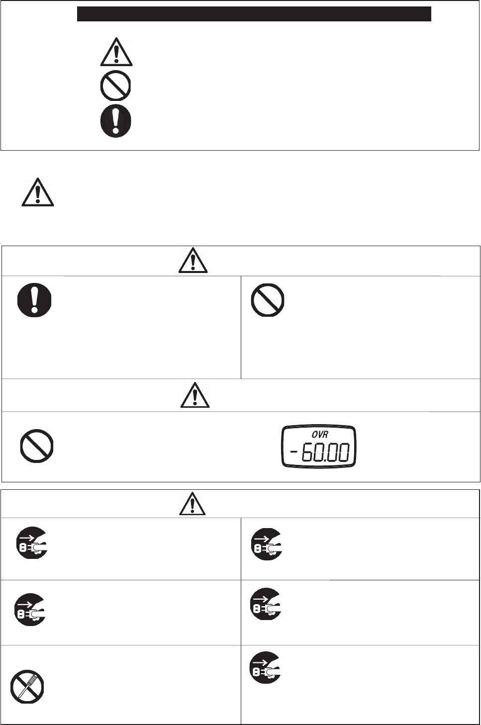
Only use the supplied AC adapter for
charging the FGV-XY.
Use of a third party AC adapter will void the unit's
warranty, and may cause circuit damage or fi re.
Plug in the AC adapter fi rmly.
Do not open, repair, or attempt to modify
your FGV-XY.
Do not attempt to power your AC adapter
with voltages other than 100-230V AC.
Do not operate the FGV-XY or
its AC adapter in wet conditions.
Unplug the AC adapter by grasping the
plugs, and not the cables.
Loose connections can cause a fi re or shock hazard.
Please contact your Shimpo dealer for information
regarding repairs and modifi cations.
Fire and shock hazards may occur if used improperly.
Shock hazards and malfunctions may occur.
Unnecessary tension on the power chord may
create a shock or fi re hazard.
Warning
Caution
Safety Precautions
Use appropriate safety equipment while
performing tests with the FGV-XY.
Use of a broken, deformed, or damaged
attachment or gauge is prohibited.
Weighing large masses, performing break tests,
and other uses may necessitate special safety
equipment. Please contact your supervisor
for the necessary safety equipment and test
procedures.
Contact your Shimpo dealer for information
regarding replacement accessories, additional
accessories, and repair.
Loading the FGV-XY with a force greater than
its rated capacity can damage the gauge.
OVR is displayed when the
gauge is overloaded. Remove
the load immediately to avoid
damage. Any measurement
during the OVR condition is not
accurate.
Caution
Observe the following safety symbols throughout this manual.
Warning
Prohibited Actions
Important Instructions
Failure to follow the instructions in this manual may result in serious injury or death.
Caution
Safety Precautions
Caution
•In or around water
•In direct sunlight
•In high humidity
Keep the AC adapter's plugs, and the
FGV-XY's power jack clean.
Do not use your FGV-XY in the following
conditions or environments:
Operate your FGV-XY
within 0~40°C (-32~104°F).
Dirt or corrosion may create a shock or fi re hazard.
Clean your FGV-XY with a damp cloth and a solution
of mild soap and water.
Do not use caustic or abrasive chemicals when
cleaning your FGV-XY.
Use of your FGV-XY outside this temperature range
may cause malfunctions or damage.
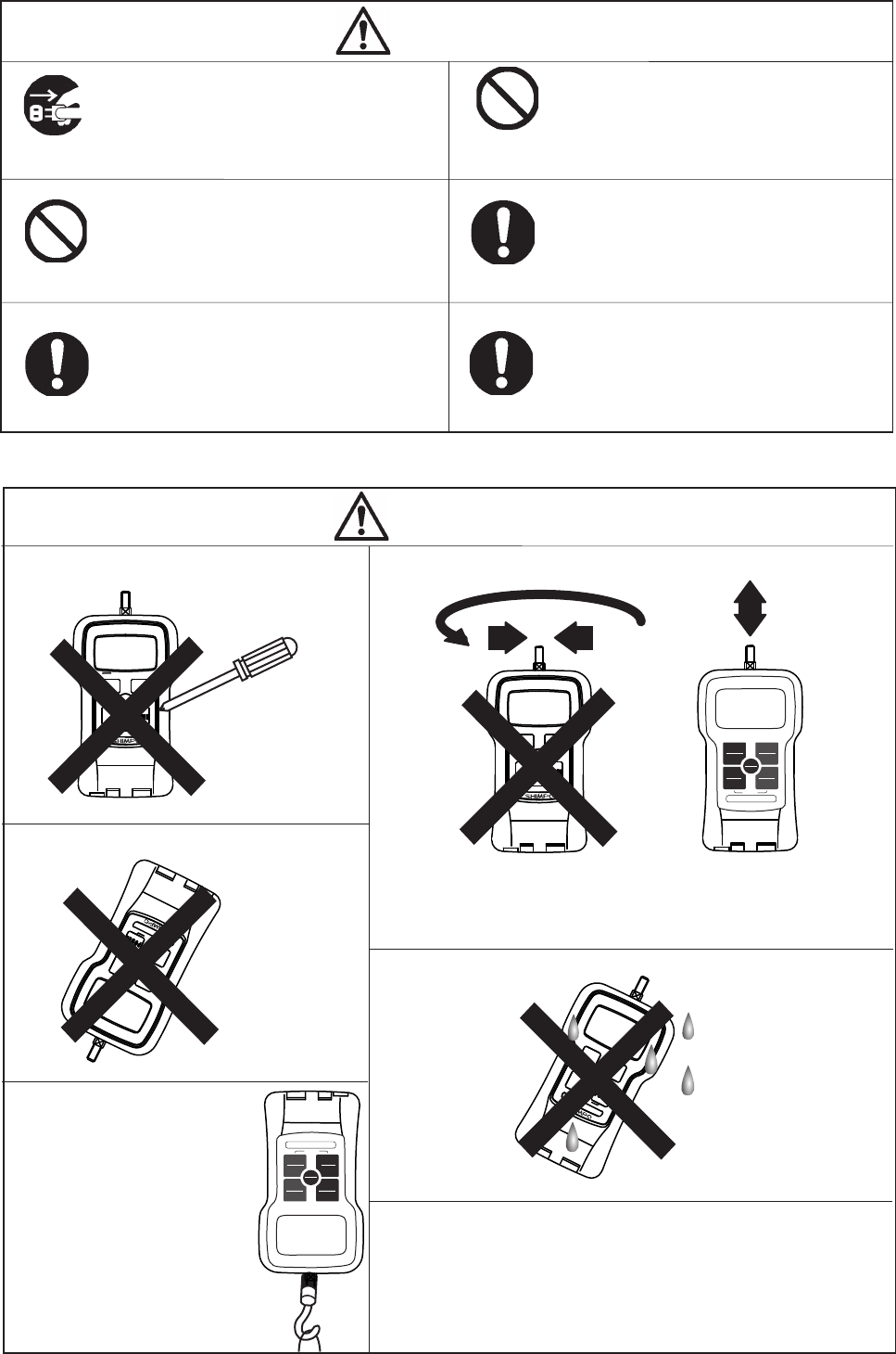
Do not press the buttons on the FGV-XY
with any objects other than your fi ngers. Do not apply side loads or torque to your FGV-XY.
PEAK
PEAK
ZERO
ZERO
MEM
MEM
UNIT
UNIT
PEAK
PEAK
ZERO
ZERO
MEM
MEM
UNIT
UNIT
PEAK
PEAK
ZERO
ZERO
MEM
MEM
UNIT
UNIT
Your FGV-XY has an internal mechanism which helps prevent overloading
when the measured force is applied in line with the sensor shaft. Applying
a twisting, bending or perpendicular force to the shaft will result in
permanent damage, and inaccurate measurements.
To ensure consistent accuracy, it is recommended
that your FGV-XY be calibrated at a minimum of
once per year.
Contact your Shimpo dealer for information regarding
calibration.
Avoid dropping your FGV-XY.
Your FGV-XY is not
designed to withstand
dynamic loads. A fall
of sufficient height can
permanently damage your
gauge.
PEAK
PEAK
ZERO
ZERO
MEM
MEM
UNIT
UNIT
Do not use your force gauge in, or around water.
Your FGV-XY is not waterproof,
and is not designed for wet, or
excessivley humid locations.
PEAK
PEAK
ZERO
ZERO
MEM
MEM
UNIT
UNIT
Measuring small loads.
Turn off Tracking function be-
fore measuring small forces.
Refer to section "4.4. Tracking"
for more information.
PEAK
PEAK
ZERO
ZERO
MEM
MEM
UNIT
UNIT
Operate your FGV-XY within 35~85% RH.
Use of your FGV-XY outside this humidity range
may cause malfunctions or damage.
•In excessively dusty or oily environments
•In caustic or corrosive environments
•In fl ammible or volitile environments
REVERSE
PEAK
PEAK
UNIT
UNIT
ZERO
ZERO
POWER
POWER
MEMORY
MEMORY
FGV-10XY
10.00lb/5.000kg/50.00N
REVERSE
PEAK
PEAK
UNIT
UNIT
ZERO
ZERO
POWER
POWER
MEMORY
MEMORY
FGV-10XY
10.00lb/5.000kg/50.00N

-3-
1. Product Features 4
2. Standard Accessory Checklist 4
3. Parts of your FGV-XY 5
3.1 Main Unit 5
3.2 Display 6
3.2.1 LCD Sections 6
3.2.2 Numeric Display 6
3.2.3 Display Indicators 6
3.2.4 MAX/MIN display 6
4. Setup 7
4.1 Battery 7
4.2 Measurement Accessories 7
4.3 Hanger 7
4.4 Tracking 8
4.5 Functions 8
4.5.1 Measurement Polarity: f01 9
4.5.2 Display Update Time: f02 9
4.5.3 Auto Power Off: f03 9
4.5.4 RS-232C Baud Rate: f04 10
4.5.5 Response Time: f05 10
4.5.6 External Output: f06 10
4.6 Reversing the Display 11
5. Features and Operation 11
5.1 Overview of Operation 11
5.2 Measuring Mode 12
5.2.1 Standard Measuring Mode 12
5.2.2 Peak Mode 12
5.3 Change Display Unit 12
5.4 Tare 12
5.5 Comparator 13
5.5.1 Comparator Overview 13
5.5.2 Comparator / Memory Settings Mode 13
5.5.3 Setting HI Limit 13
5.5.4 Setting LO Limit 14
5.5.5 Comparator Display 14
5.5.6 Comparator Output 14
5.6 Memory 14
5.6.1 Setting the Memory Mode 16
5.6.2 Recording Memory Data 17
5.6.2.1 Continuous Mode 17
5.6.2.2 Single Mode 17
5.6.2.3 Standard Mode 17
5.7 Reviewing Memory Data 18
5.7.1 Continuous Mode Memory 18
5.7.1.1 Accessing Memory Data 18
5.7.1.2 Statistics Data 19
5.7.2 Single Mode Memory 20
5.7.2.1 Accessing Memory Data 20
5.7.2.2 Statistics Data 21
5.7.3 Standard Mode Memory 22
5.7.3.1 Accessing Memory Data 22
5.7.3.2 Statistics Data 23
5.8 Clearing the Memory 23
5.8.1 Clearing the Last Record 23
5.8.2 Clearing All Memory 24
5.8.3 No Recorded Data 24
5.9 USB Communication 24
5.9.1 Features of ToriemonUSB 24
5.9.2 Download ToriemonUSB 24
5.9.3 Battery Life and USB 24
6. External Data Port 25
6.1 Pin Assignment 25
6.2 RS-232C Output 25
6.2.1 RS-232C Interface 25
6.2.2 RS-232C Communication Commands 26
6.2.3 Connection between FGV and Host 27
6.3 Analog Output 27
6.4 Overload/Comparator Output 27
7. Frequently Asked Questions 28
7.1 Troubleshooting 28
7.2 Technical Inquiries 28
8. Support 29
8.1 Repair and Calibration 29
8.2 Warranty 29
9. Specifi cations and Dimensions 29
Table of Contents
-4-
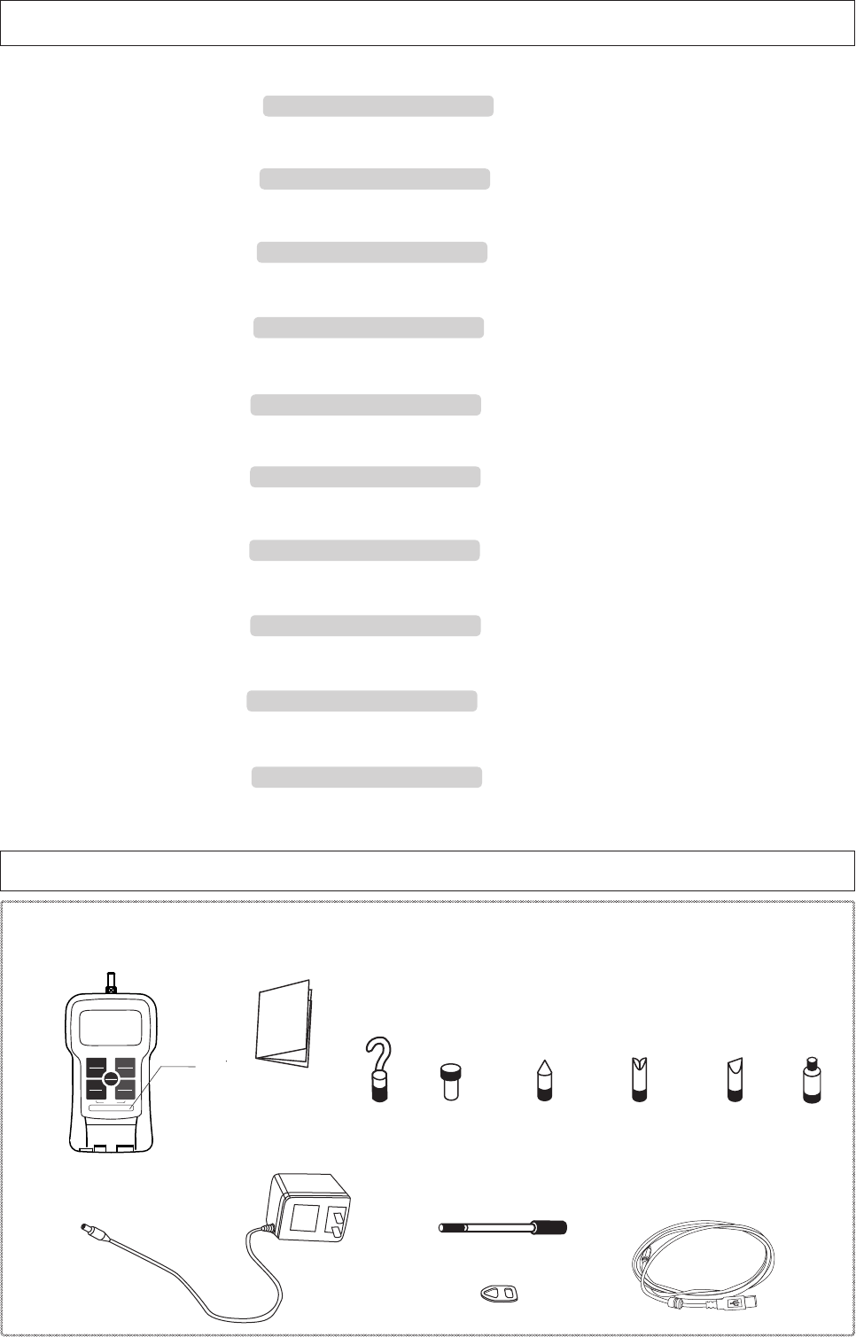
2. Standard Accessory Checklist
●Before use, please confi rm that the following items are included in the carrying case.
Force Gauge
AC Adapter
Measurement Adapters
Instruction Manual
Hanger
Flat Head Cone Head Notched Head Chisel
M6 12 70° 70° 70°
M4 8 60° 90° 60°
M4 adapters are included with FGV-2XY ~ 0.5XY.
M6 adapters are included with all other types.
Extension Rod L:92(M6)/L:86(M4)
Hook
USB Cable 2.0 (2.0 m)
PEAK
PEAK
ZERO
ZERO
MEM
MEM
UNIT
UNIT
Model
1. Product Features
●Nickel – Hydrogen battery allows for long periods of use.
→ 4.1 Battery
●Data can be downloaded to PC via USB.
→ 5.9 USB Communication
●1000 points of data storage.
→ 5.6. Memory
●Comparator feature for pass/fail testing.
→ 5.5. Comparator
●Broad range of capacities: 2.000N (200.0gf, 8oz) ~ 1000N (100.0kgf, 200lb).
→ 9 Specifi cations and Dimensions
●Reversible display with reversed key pad for easy upside down reading.
→ 4.6. Reverse the Display
●One touch operation to change the measurement unit N, kg(g), Lb(oz).
→ 5.3. Change Display Unit
●Measures peak values for tension and compression.
→ 5.2.2. Peak Hold Mode
●High speed measurement rate of 1000 times/second.
→ 5.2.2. Peak Hold Mode
●Display update time as fast as 20 times/second.
→ 5.2.1 Standard Measuring Mode
REVERSE
PEAK
PEAK
UNIT
UNIT
ZERO
ZERO
POWER
POWER
MEMORY
MEMORY
FGV-10XY
10.00lb/5.000kg/50.00N
Thread
Adapter
-5-
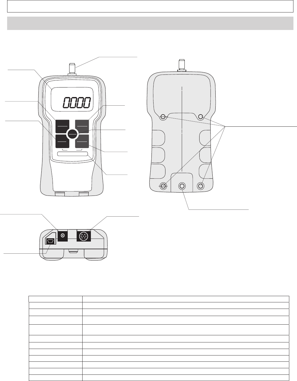
3. Parts of your FGV-XY
3.1.Main Unit
1. Sensor Shaft Apply your force in line with this threaded shaft. Use the included attachments for a your testing application.
2. Display LCD screen is unit's main information display,
3. PEAK Press PEAK to change measuring modes
4. UNIT Press UNIT to switch to available measurement units.
5. ZERO Press ZERO in Standard mode to tare gauge.
Pressing ZERO in Peak mode will clear the current peak value.
6. MEM Press MEM in standard mode to activate measurement recording
7. POWER Press POWER to turn gauge on and off.
8. AC Adapter Port Port used for the provided AC adapter.
9. Data Output Port Port used for data output options.
10. USB Port Port used to connect gauge to PC through USB.
11. Hanger Attachment Bolt Bolt secures the provided hanger attachment.
12. Threaded Holes Thread holes are used to attach gauge to a fi xture or stand.
REVERSE
PEAK
PEAK
UNIT
UNIT
ZERO
ZERO
POWER
POWER
MEMORY
MEMORY
FGV-10XY
10.00lb/5.000kg/50.00N
㪉㪅㩷㪛㫀㫊㫇㫃㪸㫐
㪈㪅㩷㪪㪼㫅㫊㫆㫉㩷㪪㪿㪸㪽㫋
㪊㪅㩷㪧㪜㪘㪢
㪋㪅㩷㪬㪥㪠㪫
㪌㪅㩷㪱㪜㪩㪦
㪎㪅㩷㪧㪦㪮㪜㪩㩷
㪍㪅㩷㪤㪜㪤
㪤㫆㪻㪼㫃
㪈㪉㪅㩷㪤㫆㫌㫅㫋㫀㫅㪾㩷㪧㫆㫀㫅㫋㫊㩷㩿㪤㪋㫏㪍㪀㩷
㪈㪈㪅㩷㪟㪸㫅㪾㪼㫉㩷㪘㫋㫋㪸㪺㪿㫄㪼㫅㫋㩷㪙㫆㫃㫋
㪈㪇㪅㩷㪬㪪㪙㩷㪧㫆㫉㫋
㪏㪅㩷㪘㪚㩷㪘㪻㪸㫇㫋㪼㫉㩷㪧㫆㫉㫋 㪐㪅㩷㪛㪸㫋㪸㩷㪦㫌㫋㫇㫌㫋㩷㪧㫆㫉㫋
-6-
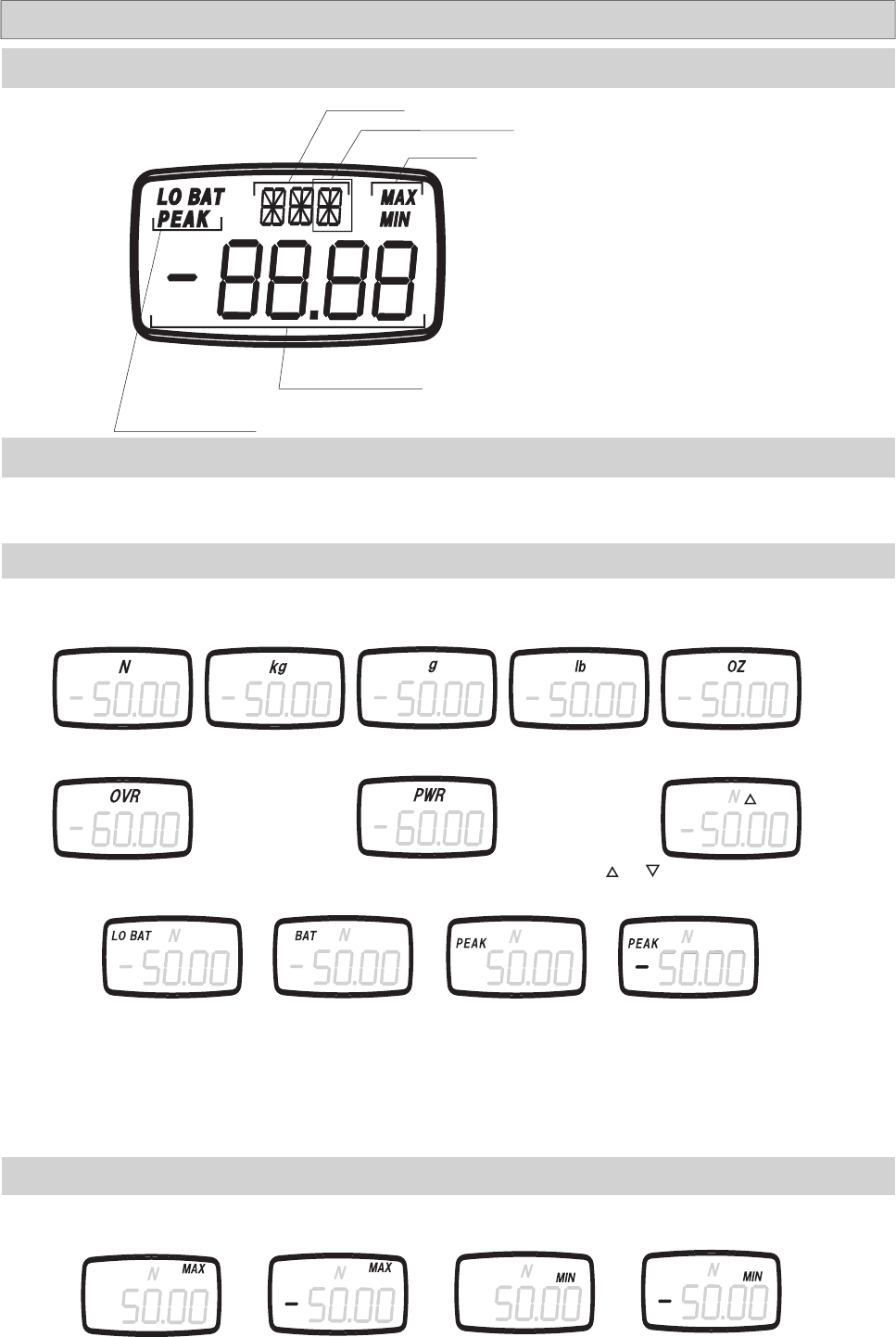
3.2 Display
Unit Type
Measurement Value
Peak Mode Indicator
The default setting for the four digit display shows compression loads as a positive force and tension loads as a negative force. To
reverse these settings, showing compression loads as negative and tension loads as positive, see section 4.5 for setting f01.
3.2.2 Numeric Display
3.2.3 Display Indicators
LO BAT flashes when
the battery needs to be
charged. Plug in the sup-
plied AC adapter.
BAT is displayed when
the battery is being
charged.
PEAK is displayed when the unit is in
Peak mode. The presence of " - " con-
fi rms negative Peak mode.
Newton Kilogram Gram
When displaying statistical data in memory mode, the following indictors are shown.
The polarity setting, f01, will determine which directional force is considered positive and negative. See section 4.5.
3.2.4 MAX/MIN Display
Maximum
(Positive)
3.2.1 LCD Sections
Max/Min
and are shown when the comparator is ON.
See section 5.5.5 for more information.
Comparator Indicator
The availability of kg or g, and lb or oz is determined by the gauge's capacity.
Ounce
Pound
PWR is displayed 1 minute before the gauge auto-
matically powers off.
OVR is displayed when the load has exceeded
the gauge's capacity by 20%.
Maximum
(Negative)
Minimum
(Positive)
Minimum
(Negative)
-7-
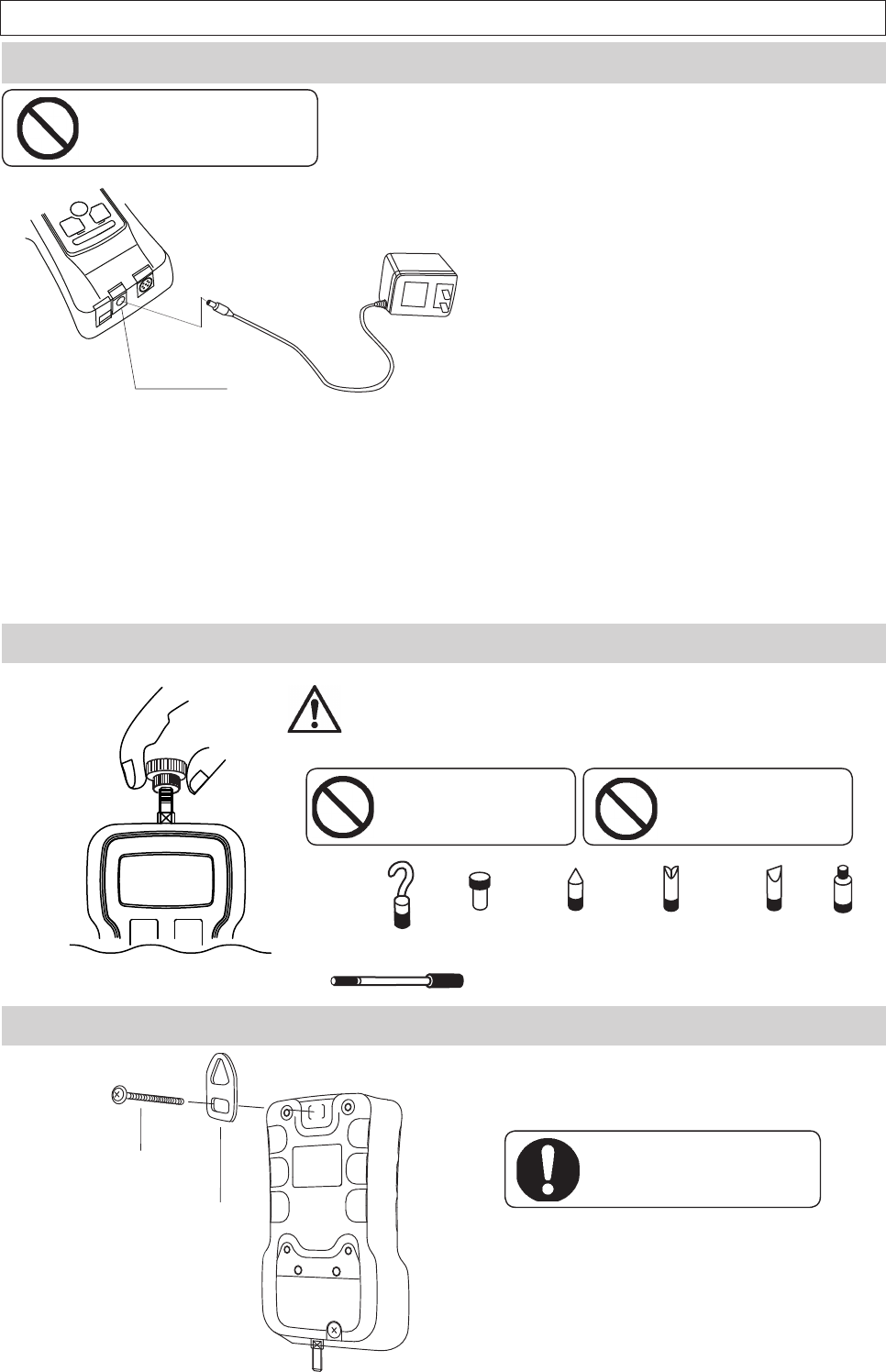
4.2 Measurement Accessories
Select the measurement adapter for your application, and lightly hand
tighten the accessory onto the sensor shaft. Over tightening an acces-
sory with your hand or a tool can cause permanent damage to the gauge.
Do not use a broken, bent,
or damaged attachment.
Flat Head Cone Head Notched Head Chisel
Extension Rod
Hook
PEAK
PEAK
ZERO
ZERO
4. Setup
4.1 Battery
Do not charge with
non-standard AC adapter.
Use only the AC adapter supplied with your FGV-XY. Do not use a third party adapt-
er. Doing so could cause a fi re or shock hazard. Contact your Shimpo dealer if you
need a new adapter.
Fully charge your FGV-XY before use.
1. To charge your FGV-XY, fi rmly plug the supplied AC adapter into the
gauge's power port, and then plug the adapter into a wall outlet.
•Charging will start automatically, and "BAT" will show on the LCD.
•Charging will stop automatically, and "BAT" will disappear from the LCD.
•Charge time: Up to 16 Hours.
•Operating time: Approximately 8 Hours.
2. To conserve battery life, only charge the unit when
"LO BAT" is displayed. Charging the unit before the
battery is close to empty will decrease the battery's life.
3. The FGV-XY is fully operable while charging.
4.3 Hanger
The hanger is shaped specifically to fit onto the
gauge. Remove the hanger bolt, place the square
end of the hanger in the recessed area on the gauge,
and tighten the hanger bolt.
Be sure that your fixture, stand, or
winch can support the gauge, and
the applied load..
4. When the battery's power is low, "LO BAT" will dis-
play on the LCD. If the unit is not connected to the AC
adapter, the gauge will power off in approximately one
minute.
Hanger Bolt
Hanger
AC Adapter Port
The hanger allows your FGV-XY to be hung from a fi xture or winch.
Do not tighten an attachment
with any tool. Do not over
tighten.
Thread
Adapter
-8-
Key Operation Display
Turn Power Off
PEAK ZERO
ZERO
MEM
MEM
UNIT
1. Hold down PEAK and UNIT.
2. Press POWER.
PEAK ZERO
ZERO
MEM
MEM
UNIT
3. Release POWER.
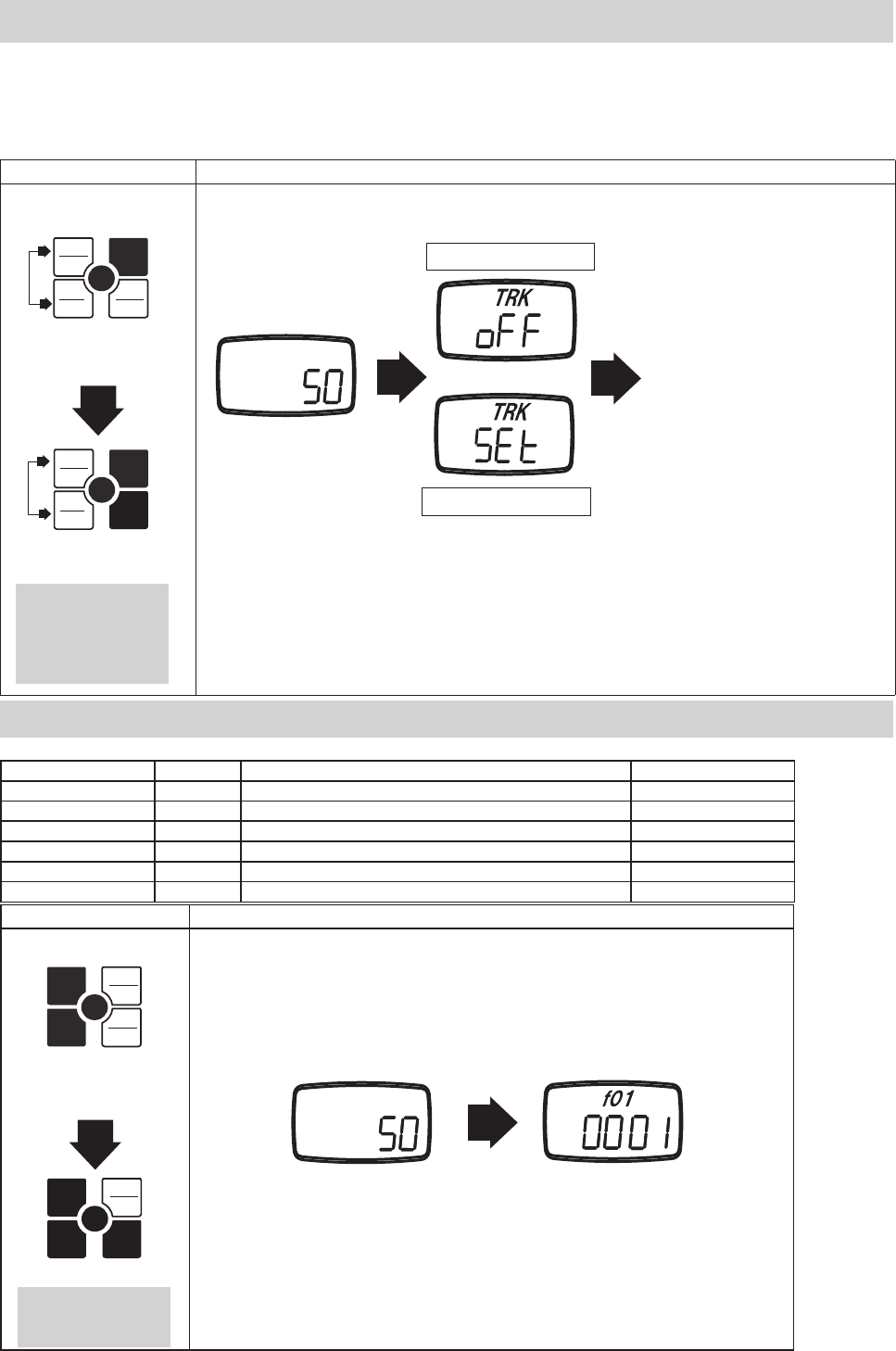
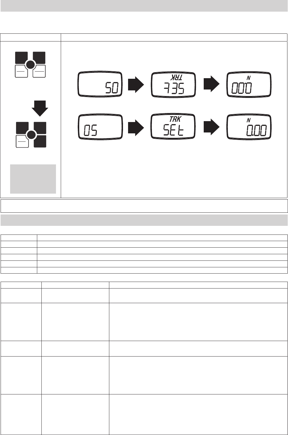
4.4 Tracking
The FGV-XY uses a load cell and strain gauge as its force sensor. The sensor is affected by environmental changes such as temperature and
humidity. The Tracking function, which is active by default, helps to negate the effects of these changes. Tracking can cause errors when
measuring very small forces. It is recommended that you turn off the Tracking function when measuring these smaller forces. With the gauge's
power off, hold PEAK and UNIT. Press POWER, and keep holding PEAK and UNIT until "oFF" is displayed. Repeat the process to turn Track-
ing back on. Instead of "oFF", "SEt" will be displayed.
Splash Screen
Tracking OFF
Tracking ON
Standard Measuring Mode
Release PEAK and UNIT
after the display shows
"SEt" or "oFF".
4.5 Functions
Key operation Display
Turn power off
PEAK ZERO
MEM
MEM
UNIT
1. Hold down ZERO.
2. Press POWER.
PEAK ZERO
MEM
MEM
UNIT
3. Release POWER.
Splash Screen Function Mode
Release ZERO after the
display shows "f01".
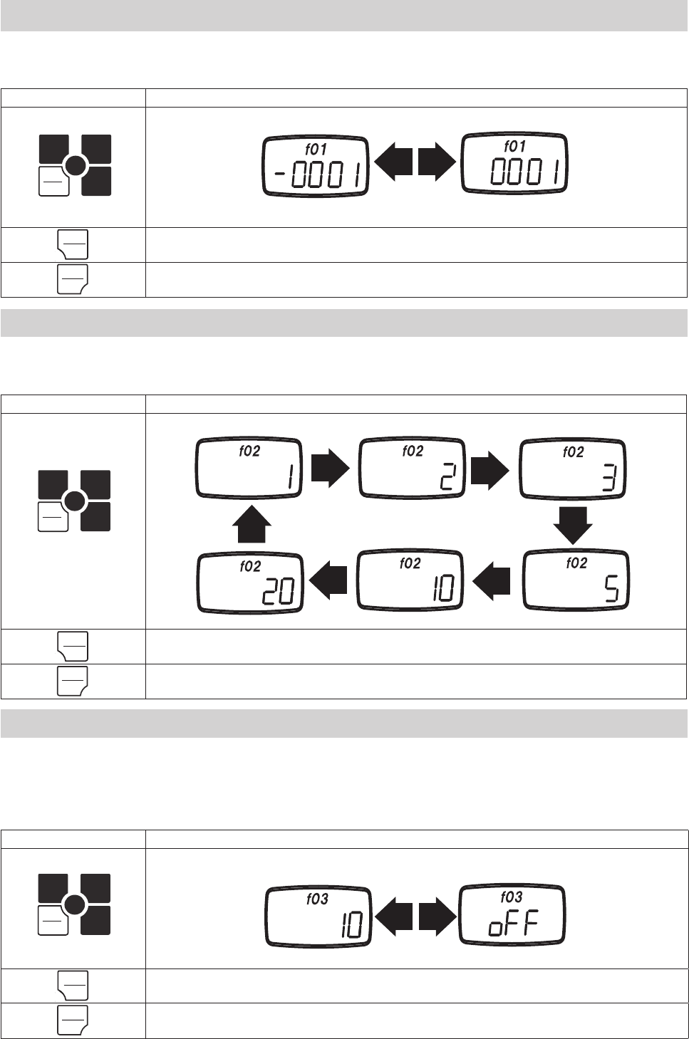
The following settings are available in Function mode.
Setting Unit Options Default
Measurement Polarity f01 -0001(minus), 0001 (plus) 0001
Display Update Time f02 1, 2, 3, 5, 10, 20 (times/second) 3
Auto Power Off f03 10 (10 minutes), oFF (always on) 10
RS-232C Baud Rate f04 2400, 4800, 9600, 19200 bps 2400
Response Time f05 3, 20, 150 (msec) 3
Output Type f06 ovEr, Hi-Lo ovEr
1.
2.
1.
2.
FGV
FGV
PEAK
PEAK
UNIT
UNIT
POWER
POWER
PEAK
PEAK
UNIT
UNIT
ZERO
ZERO
POWER
POWER
ZERO
ZERO
-9-
Key Operation Display
PEAK
PEAK
ZERO
MEM
MEM
UNIT
Press UNIT to cycle through
the available settings.
ZERO Save the current setting, and return to the standard measuring mode.
PEAK Save the current setting, and move to f03.
Key Operation Display
PEAK
PEAK
ZERO
MEM
MEM
UNIT
Press UNIT to change.
ZERO Save the current setting, and return to the standard measuring mode.
PEAK Save the current setting, and move to f02.
This function allows you to change whether compression is shown as a positive or negative force. Once the compression display has been
changed, the tension display will then read as the opposite of the compression. Press UNIT to change the setting, PEAK to save and move to
the next function, or ZERO to save and fi nish.
Negative Compression Positive Compression
4.5.2 Display Update Time: f02
This function allows you to change the rate at which the display is updated.
The update times available are 1, 2, 3, 5, 10, and 20 times a second.
Press UNIT to cycle through the settings, PEAK to save and move to the next function, or ZERO to save and fi nish.
1 time/sec 2 times/sec 3 times/sec
5 times/sec10 times/sec
20 times/sec
Key Operation Display
PEAK
PEAK
ZERO
MEM
MEM
UNIT
Press UNIT to change.
ZERO Save the current setting, and return to the standard measuring mode.
PEAK Save the current setting, and move to f04.
4.5.3 Auto Power Off: f03
If the gauge is on and there is no activity for 10 minutes*, the unit automatically powers off to conserve battery power.
This option may be disabled, and is automatically disabled when connected to the AC adapter.
Press UNIT to change the setting, PEAK to save and move to the next function, or ZERO to save and fi nish.
*Activity is defi ned as key operations, RS-232C communication, USB communication, or changes in measurement value.
Auto Power Off: 10 Minutes Auto Power Off: disabled
4.5.1 Measurement Polarity: f01
UNIT
UNIT
UNIT
UNIT
UNIT
UNIT
ZERO
ZERO
PEAK
PEAK
ZERO
ZERO
PEAK
PEAK
ZERO
ZERO
PEAK
PEAK
-10-
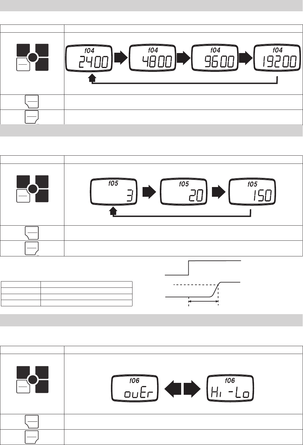
4.5.4 RS-232C Baud Rate: f04
This function allows you to change the RS-232C communication rate. The available baud rates are 2400, 4800, 9600, and 19200 bps.
Press UNIT to change the setting, PEAK to save and move to the next function, or ZERO to save and fi nish.
Key Operation Display
PEAK
PEAK
ZERO
MEM
MEM
UNIT
Press UNIT to cycle through
the available settings.
ZERO Save the current setting, and return to the standard measuring mode.
PEAK Save the current setting, and move to f05.
2400 bps 4800 bps 9600 bps 19200 bps
4.5.5 Response Time: f05
The response time function smooths out the gauge's sampling, and adjusts the sampling period accordingly.
The available response times are 3, 20, and 150 msec.
Press UNIT to change the setting, PEAK to save and move to the next function, or ZERO to save and fi nish.
Key Operation Display
PEAK
PEAK
ZERO
MEM
MEM
UNIT
Press UNIT to cycle through
the available settings.
ZERO Save the current setting, and return to the standard measuring mode.
PEAK Save the current setting, and move to f06.
Response Time: 3msec Response Time: 20msec Response Time: 150msec
The response time shows 90% of the step input.
Sampling and analog output rates are linked to
this setting.
Key Operation Display
PEAK
PEAK
ZERO
MEM
MEM
UNIT
Press UNIT to cycle through the
available settings.
ZERO Save the current setting, and return to the standard measuring mode.
PEAK Save the current setting, and return to f01.
4.5.6 External Output: f06
This function allows user to change between Overload and Comparator type output..*
Press UNIT to change the setting, PEAK to save and move to the next function, or ZERO to save and fi nish.
Application of Load
Measurement
Response Time
90%
Response time Sampling period • Analog output update period
3 msec 1 msec
20 msec 1 msec
150 msec 6.7 msec
Overload Output Comparator Output
UNIT
UNIT
UNIT
UNIT
UNIT
UNIT
PEAK
PEAK
PEAK
PEAK
PEAK
PEAK
ZERO
ZERO
ZERO
ZERO
ZERO
ZERO
-11-
Key Operation
POWER Turns the FGV-XY ON and OFF
ZERO Tares the gauge in Standard mode. Clears a peak value in Peak mode.
PEAK Switches between Standard, Positive Peak, and Negative Peak mode.
UNIT Cycles between the available measurement units.
MEM Stores a value in memory, or starts recording values.
Operation Key Key Functions
Tracking
ON / OFF
PEAK+UNIT
POWER
Turn POWER off. Press PEAK and UNIT simultaneously and hold. Press and release POWER.
Release PEAK and UNIT after "SEt" or "oFF" is displayed.
Enter
Function Mode
ZERO +
POWER
Turn POWER off. Press ZERO and hold. Press and release POWER.
Release ZERO after "f01" is displayed.
While in Function Mode:
UNIT: Changes the current setting.
PEAK: Saves current setting, and advances to the next the function.
ZERO: Saves the current setting, and returns to Standard mode.
Reverse Display UNIT +
POWER
Turn POWER off. Press UNIT and hold, then press and release POWER.
Release UNIT after the display has reversed.
Display Memory
Data
MEM +
POWER
Turn POWER off. Press MEM and hold, then press POWER.
Release MEM after the display shows memory data.
While in the Memory display:
UNIT: Cycles through the statistical data for the current memory block.
PEAK: Returns to Standard mode. ZERO: Deletes one memory block.
Hold ZERO to delete all memory data. MEM: Advances to the next memory block.
Comparator/
Memory Settings
PEAK +
POWER
Turn POWER off. Press PEAK and hold, then press POWER.
Release PEAK after the "HI" setting is displayed.
While in Comparator/Memory Settings:
UNIT: Selects HI/LO setting, advances digits, changes polarity, cycles memory modes.
PEAK: Cycles through HI, LO, MEM settings.
ZERO: Cycles through the digits in HI/LO settings.
MEM: Saves settings and returns to Standard mode.
5. Features and Operation
5.1 Overview of Operation
Basic Operations
Special Operations
Key Operation Display
Turn Power Off
PEAK ZERO
ZERO
MEM
MEM
UNIT
1. Hold down UNIT.
2. Press POWER.
PEAK ZERO
ZERO
MEM
MEM
UNIT
Release POWER.
If you have mounted your FGV-XY upside down, or are holding the unit upside down during measurement, the display may be reversed for
readablity.
4.6 Reversing the Display
Release UNIT after
the the Tracking
Mode status screen is
displayed in reverse.
Splash Screen
Standard Display
Standard Measuring Mode
Reversed Display
Reversed Display Standard Display
1. 2.
Tracking Mode Status
Reversed Display
Standard Display
FGV
FGV
UNIT
UNIT
POWER
POWER
UNIT
UNIT
-12-
This mode shows the current force applied, tension/compression, on the sensor shaft.
1. Turn on the FGV-XY by pressing POWER.
2. Press ZERO to tare the gauge.
3. If necessary, press and release PEAK until NO “PEAK” on display.
The measurement displayed is the average of the measured samples* over the display's update time.
The display update time is set to 3 times/second by default. This can be increased up to 20 times/second. Refer to section 4.5.2 for more
information.
To change the measurement unit, press UNIT. The units of measure available on each gauge depends on its capacity.
See the specifi cation sheet, section 9, to see which units are availablefor a particular model gauge.
Press ZERO to reset the measured value. This will allow the gauge to ignore any force currently applied to the sensor shaft. The ignored, or
tared, force is still counted with regards to the gauge's overload condition.
Overload will occur when the force applied to the sensor shaft exceeds the gauge's rated capacity by 20%. Stop measuring, and remove the load
immediately to avoid permanent damage to the gauge. Any measurements taken in the overload range are not accurate.
Tare is automatically performed when the gauge is fi rst powered on.
5.2.1Standard Measuring Mode
5.3 Change Display Unit
5.4 Tare
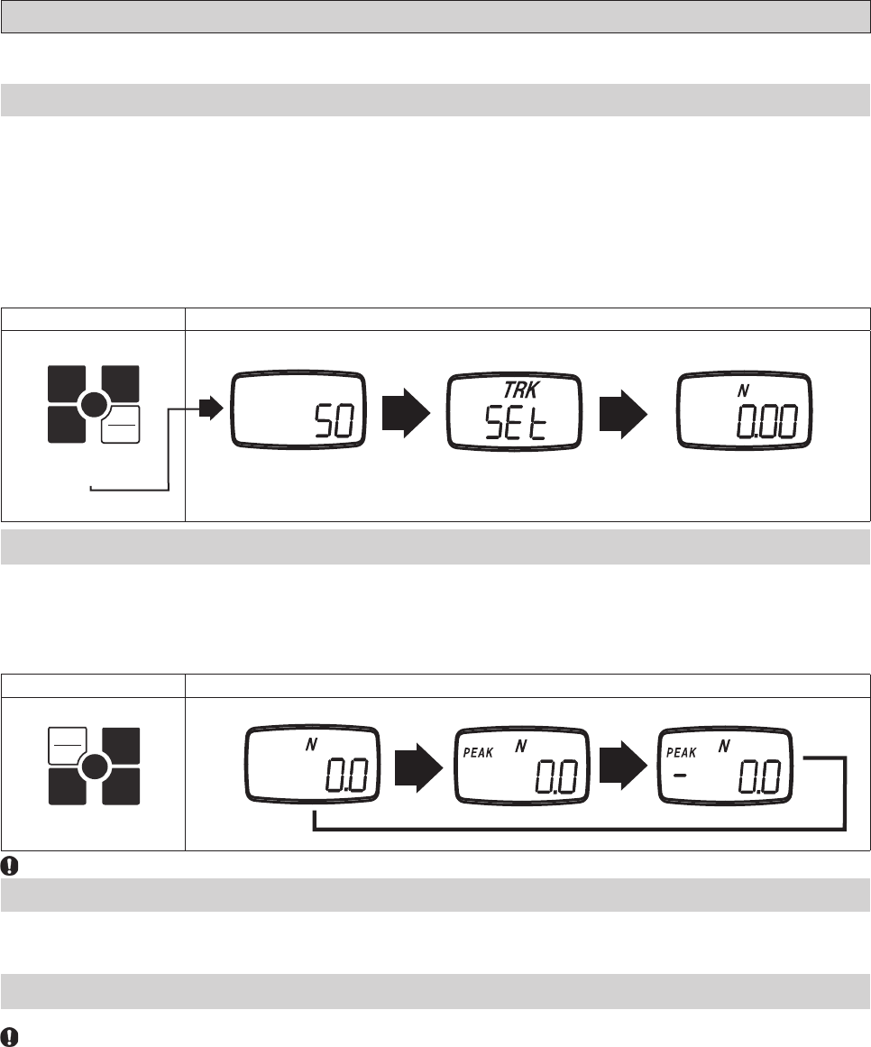
5.2.2 Peak Mode
Peak mode displays the greatest force in both the positive and negative direction. Sampling time is 1ms.*
Press PEAK to change from standard measuring mode, to positive peak mode, to negative peak mode.
In the positive peak mode, “PEAK” is displayed.
In the negative peak mode, “PEAK” and “- “ are displayed.
Key Operation Display
PEAK ZERO
ZERO
MEM
MEM
UNIT
Press PEAK.
Standard Measuring Mode Positive Peak Mode Negative Peak Mode
While in either peak mode, ZERO will clear the current peak value, but will not tare the gauge.
5.2 Measuring Mode
The two measurement modes available are Standard and Peak.
Key Operation Display
PEAK ZERO
ZERO
MEM
MEM
UNIT
Press POWER.
Splash Screen Standard Measuring ModeTracking Mode Status
*This is dependent on the Response Time function, f05. See section 4.5.5 for more information.
*This is dependent on the Response Time function, f05. See section 4.5.5 for more information.
FGV
POWER
POWER
PEAK
PEAK
-13-
Key operation Status
PEAK Move to LO limit setting.
MEM
Register the setting, then move
to standard measuring mode.
Turn power off without any change.
Key operation Display
Turn power off
PEAK ZERO
ZERO
MEM
MEM
UNIT
1. Hold down PEAK.
2. Press POWER.
PEAK ZERO
ZERO
MEM
MEM
UNIT
3. Release POWER.
5.5 Comparator
The Comparator function allows you to create conditions for Go/No Go testing. A high(HI), and low(LO) force limit may be set so that the
FGV-XY's display will show when a measurement is not within the HI and LO settings. In addition, the output port will respond relative to the
display. See section 6.4 regarding the comparator output.
The FGV-XY must be in Comparator mode, and not Overload mode to use the following settings. See section 4.5.6 regarding the output
mode.
5.5.1 Compatrator Overview
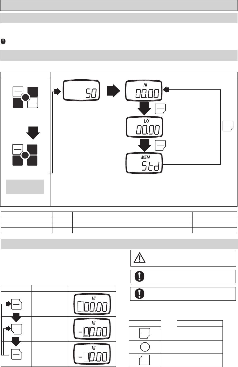
5.5.2 Comparator / Memory Settings Mode
Turn POWER off, press PEAK and hold. Press POWER and release (release PEAK after "HI" is displayed).
Splash Screen PEAK
PEAK
Comparator HI limit
Comparator LO limit
Memory mode
PEAK
Setting Display Content Default factory setting
Comparator HI limit HI Value for the HI limit* 0
Comparator LO limit LO Value for the LO limit* 0
Memory mode MEM Memory mode(Standard, Single, Continuous) Std
* When HI and LO are set to 00.00 the Comparator function is disabled.
5.5.3 Setting HI Limit
1. Press UNIT to select the HI setting. The digits will start fl ashing.
2. Press UNIT again to change the polarity.
3. Choose the digit to change by pressing ZERO.
4. Press UNIT to increase the selected digit to the desired value.
5. Repeat steps 3 and 4 until the desired value and polarity are correct.
6. Press PEAK. This saves the HI limit and displays the LO limit.
7. Press MEM if you are fi nished with the Comparator and Memory settings.
Key operation Status Display
UNIT Changes polarity
ZERO Selects the next digit.
UNIT
Changes the selected
digit.
Release PEAK after "HI"
is diaplayed.
The Comparator function's limits can be set outside of the
FGV-XY's working range. This may cause unpredictable
results, and is not reccomended.
1.
2.
The values entered for the HI and LO settings are displayed
in the measurement units last used in Standard mode.
The absolute value of the HI limit may never be lower than
the absolute value of the LO limit.
FGV
PEAK
PEAK
POWER
POWER
PEAK
PEAK
ZERO
ZERO
UNIT
UNIT
UNIT
UNIT
POWER
POWER
PEAK
PEAK
MEMORY
MEMORY
PEAK
PEAK
PEAK
PEAK
PEAK
PEAK
-14-
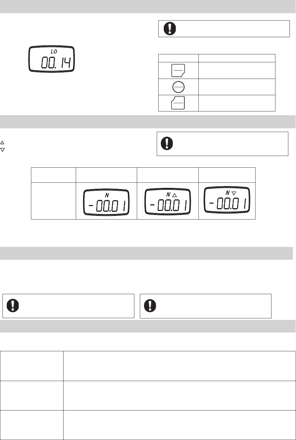
5.5.4 Setting LO Limit
The procedure to set the HI limit is used to set the LO limit.
Section 5.5.3 contains this information.
Key Operation
PEAK Move to memory mode.
MEM
Register the setting, then move
to standard measuring mode.
Turn power off without any change.
LO limit setting mode
5.5.5 Comparator Display
The following symbols are shown when the comparator function is active.
Measuring value > HI limit
Measuring value < LO limit
Data < HI limit
Data > LO limit Data > HI limit Data < LO limit
Comparator Display
Posibilities
5.5.6 Comparator Output
The Comparator function also allows control of an alarm or automated process through its data output port.
When the measured value is greater than the HI limit, the corresponding photo-couple is triggered.
When the measured value is lower than the LO limit, the corresponding photo-couple is triggered.
5.6 Memory
The FGV-XY has three memory modes.
Continuous memory
Allows the recording of up to 1000 data points. The recording starts when you push MEM, and stops when you
push MEM. In addition, the following statistics, gathered between that start and stop, are recorded: positive
maximum value, negative maximum value, positive minimum value, negative minimum value, positive peak
value, negative peak value, average value, standard deviation.
Single memory
Allows the recording of up to 100 data points. Every time MEM is pressed, the value shown on the display is
memorized. If the unit is in Standard mode then the current measured value is recorded. In Peak mode, the unit
records the displayed peak value. In addition, the following statistics are recorded: positive maximum value,
negative maximum value, positive minimum value, negative minimum value, average value, standard deviation.
Standard memory
Allows the recording of up to 50 data points. The recording process is similar to Continuous mode. MEM starts
the recording, and stops the recording. The measured value, when MEM is pushed the second time, is recorded
as a point. The following statistics, gathered between the start and stop, are recorded: positive maximum value,
negative maximum value, positive minimum value, negative minimum value.
In order for the Comparator function to display, the
comparator output option must be set in function f06.
See section 4.5.6 regarding this setting.
The absolute value of the LO limit may never be higher than
the absolute value of the HI limit.
In order for the Comparator function to display, the
comparator output option must be set in function f06.
See section 4.5.6 regarding this setting.
For connection and circuit information, pertaining to
the Comparator output, see section 6.4.
POWER
POWER
PEAK
PEAK
MEMORY
MEMORY
-15-
Memory terms defi ned:
Measurement value: The current displayed value in Standard mode.
Positive maximum value (+MAX): Maximum value in the positive direction.
Negative maximum value (-MAX): Maximum value in the negative direction.
Positive minimum value (+MIN): Minimum value in the positive direction.
Negative minimum value (-MIN): Minimum value in the negative direction.
Average value (AVE): Average of the recorded measurement values. Σ X i/n
Standard deviation (DEV): Standard deviation of the recorded measurement values. Σ( Xi-X )2/n
Positive peak value: Largest value in the positive direction. (This value is sampled at 1000 times/second).
Negative peak value: Largest value in the negative direction. (This value is sampled at 1000 times/second)
Last measurement value (LST): The last measurement value displayed at the corresponding time.
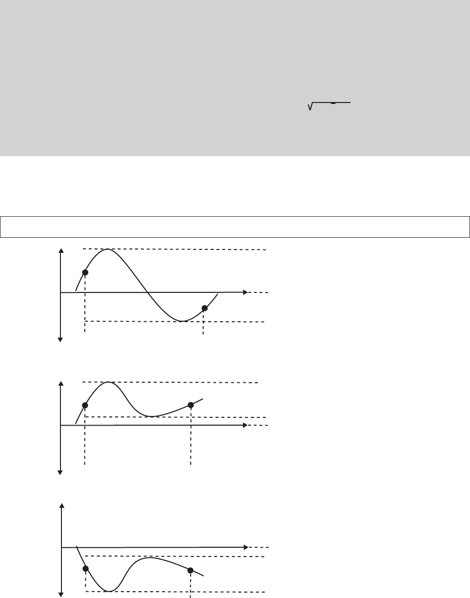
Example of +MAX, -MAX, +MIN, -MIN (Continuous memory mode)
Ex. 1
Ex. 2
Ex. 3
+MAX
+MAX
+MIN, -MIN
+MIN, +MAX
-MAX
-MAX
+MIN
-MIN
Start of Memory
Start of Memory
Start of Memory
End of Memory
End of Memory
End of Memory
+
+
+
-
-
-
0
0
0
-MIN, -MAX
-16-
Key Operation Display
Turn power off.
PEAK ZERO
ZERO
MEM
MEM
UNIT
1. Hold down PEAK.
2. Press POWER.
PEAK ZERO
ZERO
MEM
MEM
UNIT
Release POWER.
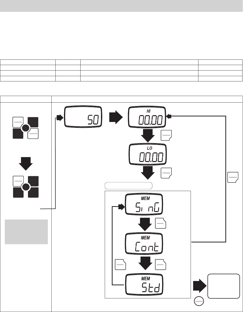
5.6.1 Setting the Memory Mode
Turn the POWER off.
Press PEAK and hold, then press and release POWER. The display will show the HI Comparator limit.
Press PEAK twice to display the current memory mode.
Press UNIT to cycle the Memory mode.
Press MEM to save and exit.
Splash Screen PEAK
PEAK
Comparator HI limit setting
Comparator LO limit setting
PEAK
There are following items are found in the Comparator/Memory mode settings.
Item Display Content Default factory setting
Comparator HI limit setting HI Displays the current HI limit. 0
Comparator LO limit setting LO Displays the current LO limit. 0
Memory mode setting MEM Displays the current Memory mode. Std
MEM
Saves changes,
and exits to
Standard mode.
UNIT
UNIT
Single
memory
Continuous
memory
Standard
memory
Memory mode setting
Release PEAK after the
unit displays the HI
comparator setting.
2.
UNIT
1.
FGV
PEAK
PEAK
POWER
POWER
PEAK
PEAK
PEAK
PEAK
PEAK
PEAK
PEAK
PEAK
MEMORY
MEMORY
UNIT
UNIT
UNIT
UNIT
UNIT
UNIT
-17-
5.6.2 Recording Memory Data
The following procedures explain how to activate memory recording for each memory mode.
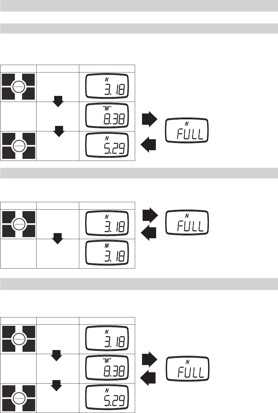
5.6.2.1 Continuous Mode
1. In continuos measurement mode, press MEM to start the recording. The letter M will appear and start blinking. Press M to stop the
recording.
2. If 1000 points of data are recorded, the display will show FULL and return to standard measurement mode.
Key operation Status Display("" means blinking)
MEM
Continuos
Measurement
Mode
Recording
MEM Recording Finished
1000 data points have been recorded.
5.6.2.2 Single Mode
1. In single measurement mode, press MEM. The letter M will appear to show that one data point has been recorded.
2. If 100 data points have been collected, the screen will show FULL, and return to standard measurement mode.
Key operation Status Display
MEM
Single
Measurement
Mode
Data Point Recorded
100 data points have been collected.
5.6.2.3 Standard Mode
1. In Standard Measurement mode, press MEM. The letter M will start blinking, which shows that maximum,
minimum, and peak values are being recorded.
2. Press MEM to stop the recording, and store the last measurement value.
Key operation Status Display("" means blinking)
MEM
Standard
Measurement
Mode
Recording +/- MAX,
MIN and PEAK.
MEM Recording Finished
50 data points have been collected.
MEMORY
MEMORY
MEMORY
MEMORY
MEMORY
MEMORY
MEMORY
MEMORY
MEMORY
MEMORY
-18-
Key operation Display
Turn power off.
PEAK
PEAK
ZERO
MEM
UNIT
1. Hold down MEM
2. Press POWER
PEAK
PEAK
ZERO
MEM
UNIT
3. Release POWER
ZERO Deletes the current data block, but only if you have the last block selected.
UNIT Cycles through the available statistics.
PEAK Transfers the recorded memory data via RS232C, and exits memory mode.
Powers down the FGV-XY.
5.7 Reviewing Memory Data
5.7.1 Continuous Mode Memory
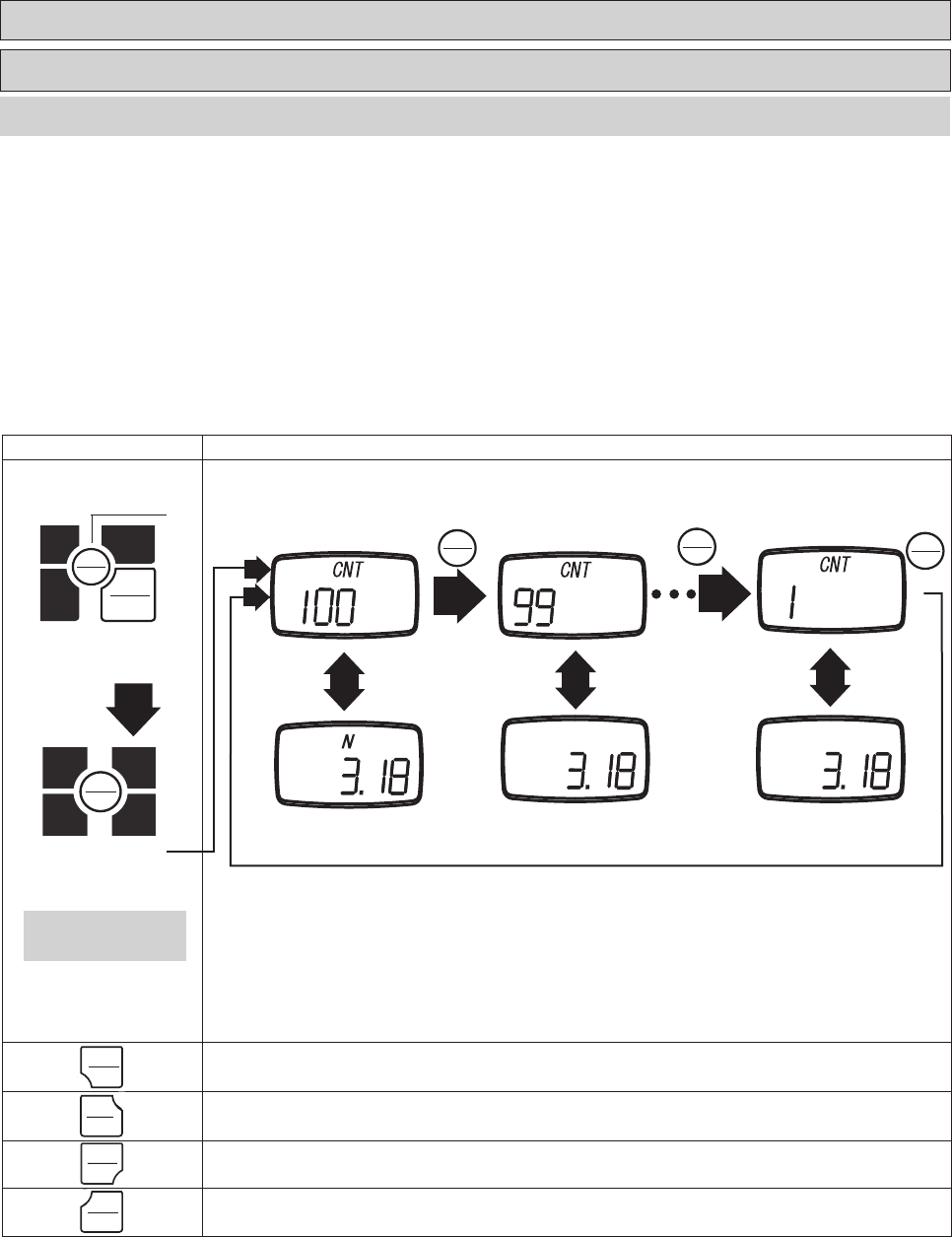
1. Turn the POWER off. Press MEM and hold, then press and release POWER. Release MEM when you see "CNT" on the display. The unit will alter-
nate between showing the data block number, and the recorded measurement value of that block.
2. Press MEM to review the previous data block recorded.
3. Press UNIT to cycle through the available recorded statistics. In Continuous mode the available statistics are as follows: positive maximum
value, negative maximum value, positive minimum value, negative minimum value, positive peak value, negative peak value, average value, stan-
dard deviation. This is covered in greater detail in the next section, 5.7.1.2.
4. Press PEAK to output the recorded memory via RS-232C. Refer to section 6.2 regarding RS232C communication.
Last memory number First memory block
MEM MEM
Release MEM after "CNT"
is displayed.
1.
2.
MEM
Previous memory
5.7.1.1 Accessing Memory Data
MEMORY
MEMORY
MEMORY
MEMORY
POWER
POWER
MEM
MEM
MEM
MEMORY
MEMORY
MEMORY
MEMORY
MEMORY
MEMORY
POWER
POWER
PEAK
PEAK
UNIT
UNIT
ZERO
ZERO
-19-
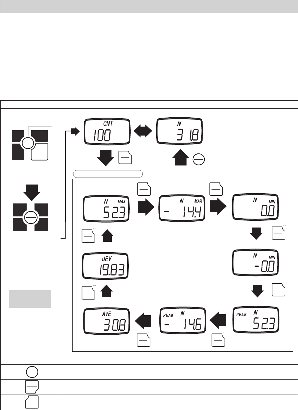
5.7.1.2 Statistics Data
1. When in memory mode, UNIT will cycle through the available statistics data.
2. Each press of UNIT will switch between the following items: positive maximum value, negative maximum value, positive minimum value, nega-
tive minimum value, positive peak value, negative peak value, average value, standard deviation.
3. Press MEM to exit to the recorded measurement values.
4. Press PEAK key to output the recorded memory via RS-232C. Refer to section 6.2 regarding RS232C communication.
Key operation Display
Turn power off
PEAK
PEAK
ZERO
MEM
UNIT
1. Hold down MEM
2. Press POWER
PEAK
PEAK
ZERO
MEM
UNIT
3. Release POWER
MEM Exits statistic mode, and returns to memory blocks.
PEAK Transfers the recorded memory data via RS232C, and exits memory mode.
Powers off the FGV-XY.
Positive Maximum Negative Maximum Positive Minimum
Standard deviation
UNIT UNIT
UNIT
UNIT
UNIT
UNIT
UNIT UNIT
Negative Minimum
Positive Peak
Negative Peak
Average
Memory block number Memory data
UNIT
Display statistical data
Release MEM when
"CNT" is displayed.
MEM
1.
2.
MEMORY
MEMORY
MEMORY
MEMORY
POWER
POWER
POWER
POWER
PEAK
PEAK
MEM
MEM
MEMORY
MEMORY
UNIT
UNIT
UNIT
UNIT
UNIT
UNIT
UNIT
UNIT
UNIT
UNIT
UNIT
UNIT
UNIT
UNIT
UNIT
UNIT
UNIT
UNIT
MEM
MEM
MEMORY
MEMORY
-20-
Key operation Display
Turn power off
PEAK
PEAK
ZERO
MEM
UNIT
1. Hold down MEM
2. Press POWER
PEAK
PEAK
ZERO
MEM
UNIT
Release POWER
ZERO Deletes the current data block, but only if you have the last block selected.
UNIT Cycles through the available statistics.
PEAK Transfers the recorded memory data via RS232C, and exits memory mode.
Powers down the FGV-XY.
5.7.2 Single Mode Memory
5.7.2.1 Accessing Memory Data
MEM MEM
Last memory block Previous memory block First memory block
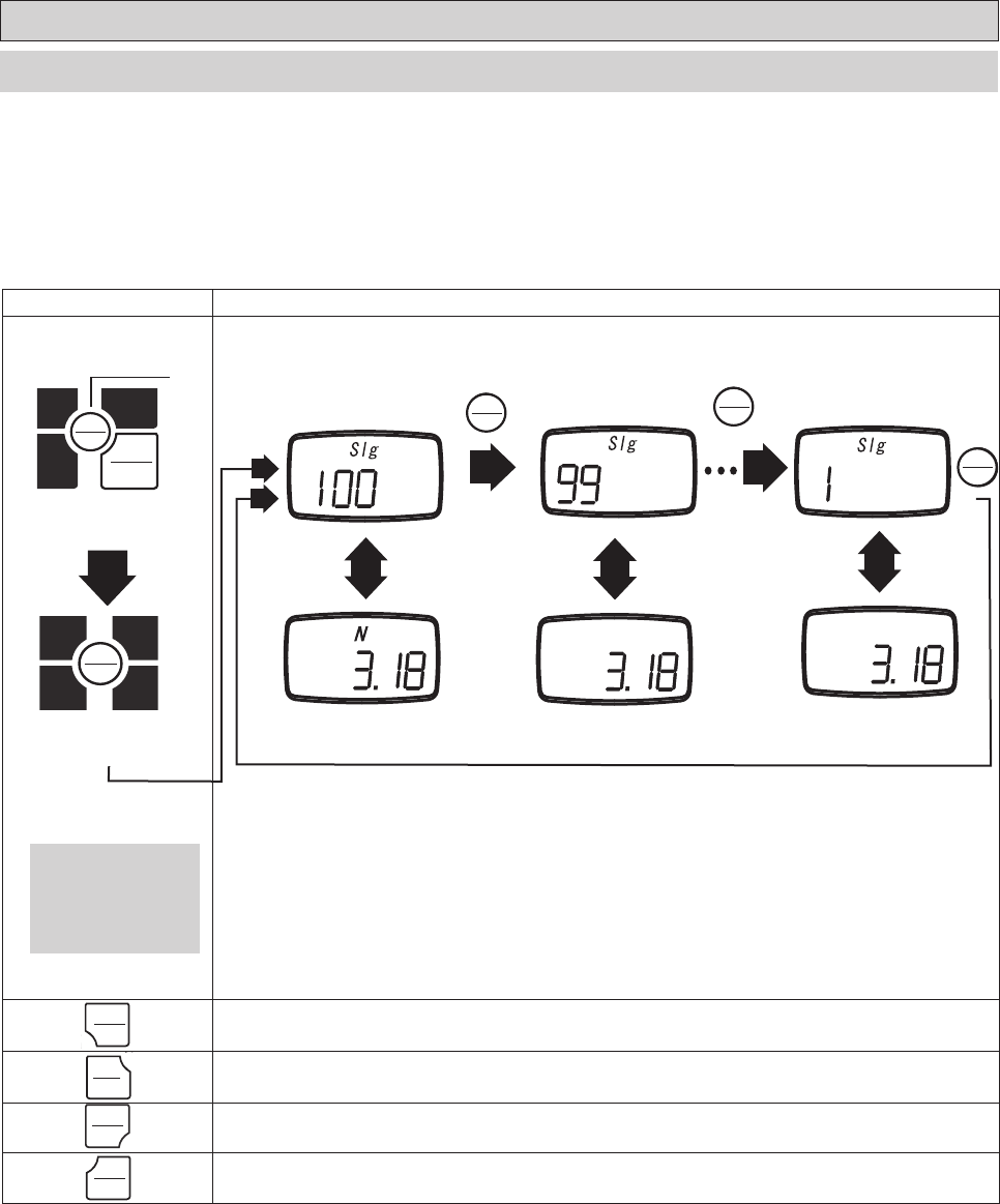
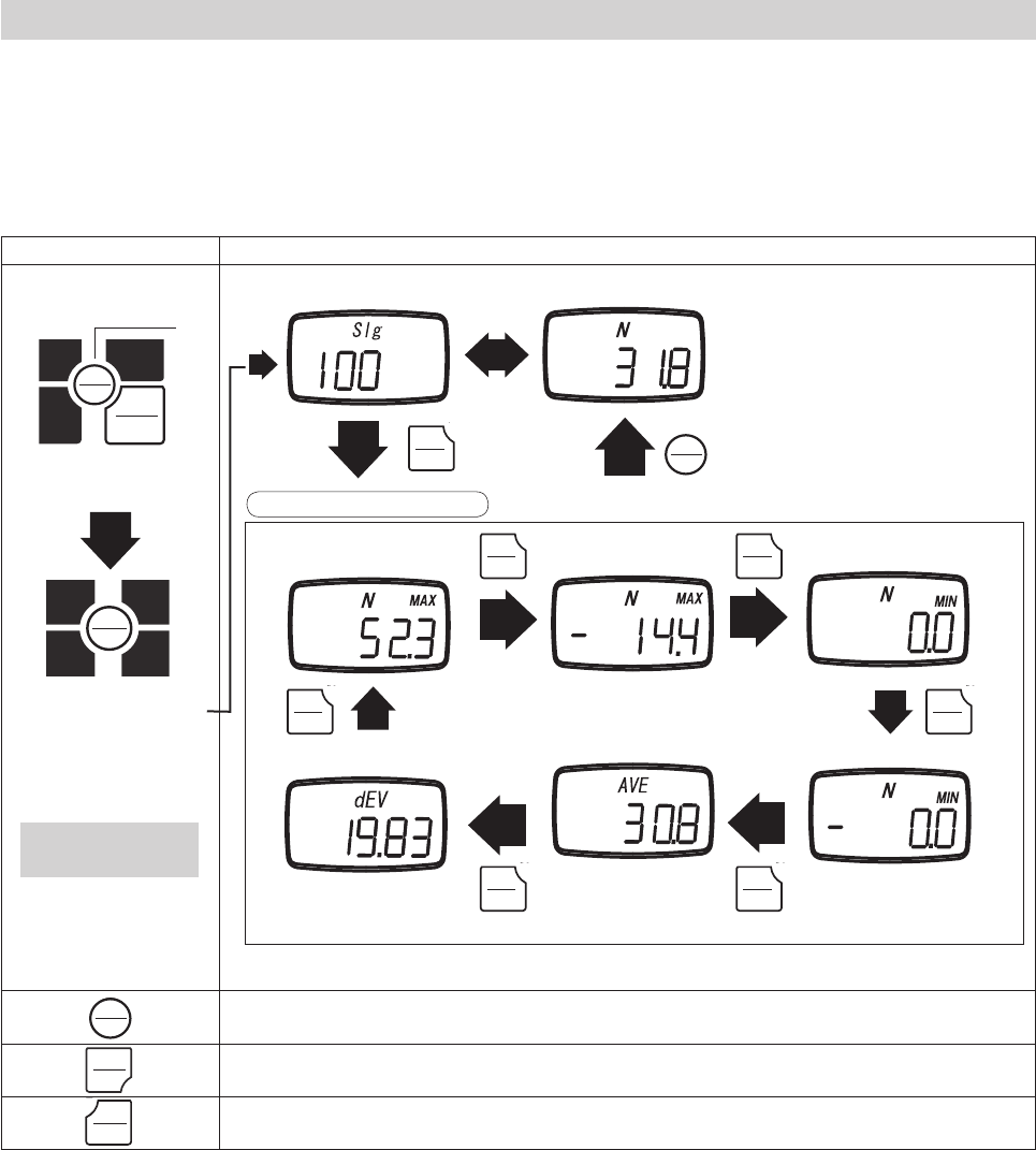
1. Turn the POWER off. Press MEM and hold, then press and release POWER. Release MEM when you see "SIg" on the display. The unit will
alternate between showing the data block number and the recorded measurement value of that block.
2. Press MEM to review the previous data block recorded.
3. Press UNIT to cycle through the available recorded statistics. In Single mode the available statistics are as follows: positive maximum value,
negative maximum value, positive minimum value, negative minimum value, average value, standard deviation. This is covered in greater detail in
the next section, 5.7.2.2.
4. Press PEAK to output the recorded memory via RS-232C. Refer to section 6.2 regarding RS232C communication.
Release MEM after the
display shows "CNT".
MEM
1.
2.
MEMORY
MEMORY
MEMORY
MEMORY
POWER
POWER
MEM
MEM
MEMORY
MEMORY
MEM
MEM
MEMORY
MEMORY
MEM
MEM
MEMORY
MEMORY
PEAK
PEAK
UNIT
UNIT
ZERO
ZERO
POWER
POWER
-21-
5.7.2.2 Statistics Data
1. When in memory mode, UNIT will cycle through the available statistics data.
2. Each press of UNIT will switch between the following items: positive maximum value, negative maximum value,
positive minimum value, negative minimum value, average value, standard deviation.
3. Press MEM to exit to the recorded measurement values.
4. Press PEAK key to output the recorded memory via RS-232C. Refer to section 6.2 regarding RS232C communication.
Key operation Display
Turn power off
PEAK
PEAK
ZERO
MEM
UNIT
1. Hold down MEM
2. Press POWER
PEAK
PEAK
ZERO
MEM
UNIT
3. Release POWER
MEM Exits statistic mode, and returns to memory blocks.
PEAK Transfers the recorded memory data via RS232C, and exits memory mode.
Powers off the FGV-XY.
Positive Maximum Negative Maximum Positive Minimum
Standard deviation
UNIT UNIT
UNIT
UNIT
UNIT UNIT
Negative Minimum
Average
Memory block Recorded Value
Display statistical data
UNIT
Release MEM after "CNT"
has displayed.
MEM
1.
2.
MEMORY
MEMORY
MEMORY
MEMORY
POWER
POWER
UNIT
UNIT
UNIT
UNIT
UNIT
UNIT
UNIT
UNIT
UNIT
UNIT
UNIT
UNIT
UNIT
UNIT
MEMORY
MEMORY
MEMORY
MEMORY
POWER
POWER
PEAK
PEAK
-22-
5.7.3 Standard Mode Memory
5.7.3.1 Accessing Memory Data
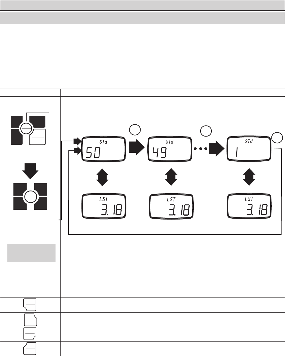
1. Turn the POWER off. Press MEM and hold, then press and release POWER. Release MEM when you see "STd" on the display. The unit will
alternate between showing the data block number, and the recorded measurement value of that block.
2. Press MEM to review the previous data block recorded.
3. Press UNIT to cycle through the available recorded statistics. In Standard mode, the available statistics are as follows: positive maximum value,
negative maximum value, positive minimum value, negative minimum value. This is covered in greater detail in the next section, 5.7.3.2.
4. Press PEAK to output the recorded memory via RS-232C. Refer to section 6.2 regarding RS232C communication.
Key operation Display
Turn power off
PEAK
PEAK
ZERO
MEM
UNIT
1. Hold down MEM
2. Press POWER
PEAK
PEAK
ZERO
MEM
UNIT
3. Release POWER
ZERO Deletes the current data block, but only if you have the last block selected.
UNIT Cycles through the available statistics.
PEAK Transfers the recorded memory data via RS232C, and exits memory mode.
Powers down the FGV-XY.
MEM
Release MEM when
"CNT" is displayed.
Last memory block Previous memory block First memory block
MEM
MEM
1.
2.
MEMORY
MEMORY
MEMORY
MEMORY
POWER
POWER
MEMORY
MEMORY
MEMORY
MEMORY
MEMORY
MEMORY
POWER
POWER
PEAK
PEAK
UNIT
UNIT
ZERO
ZERO
-23-
Key operation Display
Turn power off
PEAK
PEAK
ZERO
MEM
UNIT
1. Hold down MEN key
2. Press POWER key
PEAK
PEAK
ZERO
MEM
UNIT
Release POWER
MEM Exits statistic mode, and returns to memory blocks.
PEAK Transfers the recorded memory data via RS232C, and exits memory mode.
Powers off the FGV-XY.
Memory Block Recorded Value
Positive Maximum Negative Maximum Positive Minimum
UNIT
UNIT
Negative Minimum
UNIT
UNIT UNIT
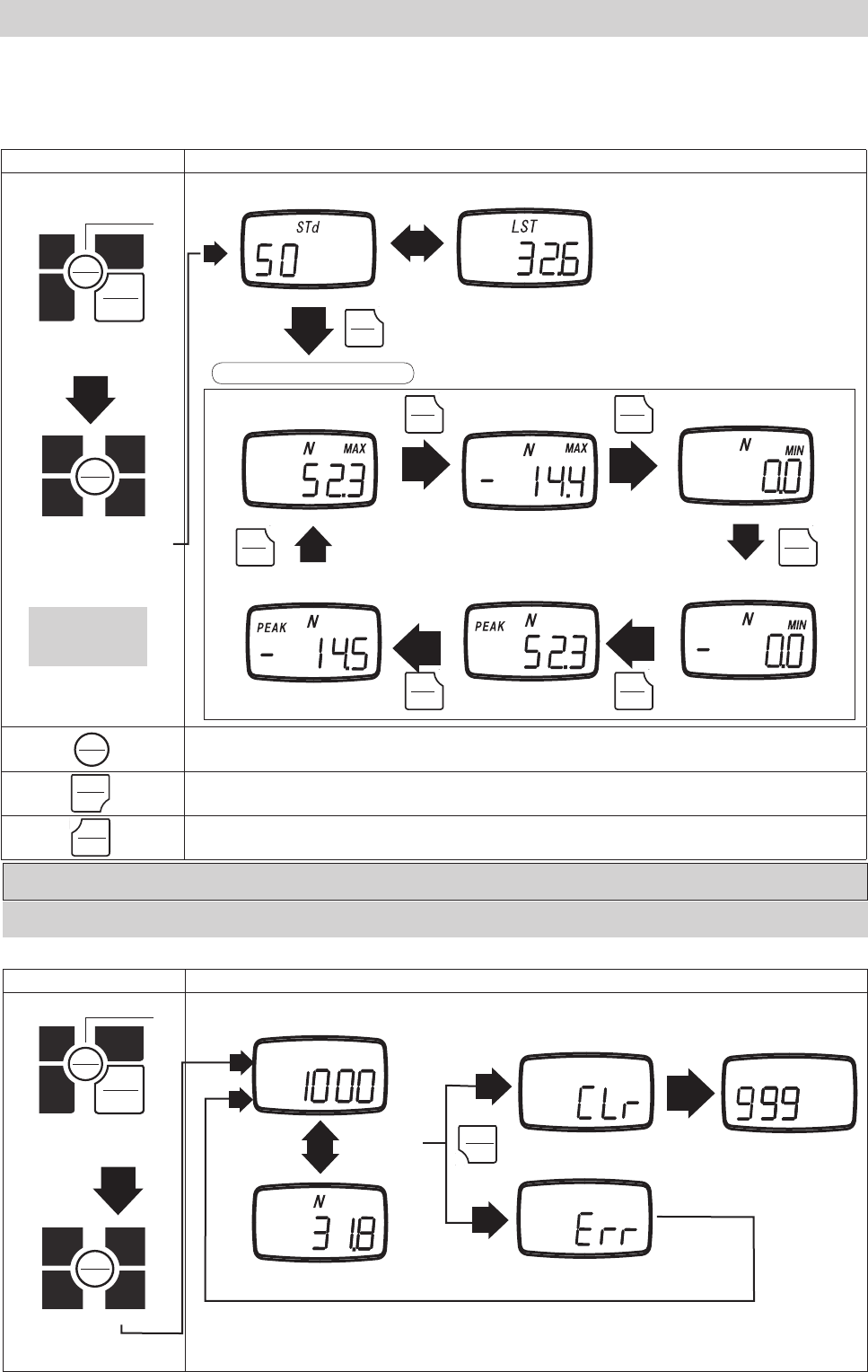
5.7.3.2 Statistics Memory Data
UNIT
Negative Peak Positive Peak
1. When in memory mode, UNIT will cycle through the available statistics data.
2. Each press of UNIT will switch between the following items: positive maximum value, negative maximum value, positive minimum value,
negative minimum value, positive peak value, and negative peak value.
3. Press MEM to exit to the recorded measurement values.
4. Press PEAK key to output the recorded memory via RS-232C. Refer to section 6.2 regarding RS232C communication.
5.8 Clearing the Memory
5.8.1 Clearing the Last Record
1. The last recorded memory block may be erased by pressing ZERO while viewing the last data point.
2. If ZERO is pressed while viewing any other data point, the display will show "Err", and will not delete anything.
Key operation Display
Turn power off
PEAK
PEAK
ZERO
MEM
UNIT
1. Hold MEM
2. Press POWER
PEAK
PEAK
ZERO
MEM
UNIT
Release POWER
ZERO
Not the last
memory block
Value Cleared
Error
Last Memory Block
Memory block number
Memory data
UNIT
Display statistical data
Release MEM after
"CNT" is displayed.
1.
1.
2.
2.
MEMORY
MEMORY
MEMORY
MEMORY
MEMORY
MEMORY
POWER
POWER
MEMORY
MEMORY
POWER
POWER
MEMORY
MEMORY
POWER
POWER
PEAK
PEAK
ZERO
ZERO
UNIT
UNIT
UNIT
UNIT
UNIT
UNIT
UNIT
UNIT
UNIT
UNIT
UNIT
UNIT
UNIT
UNIT
-24-
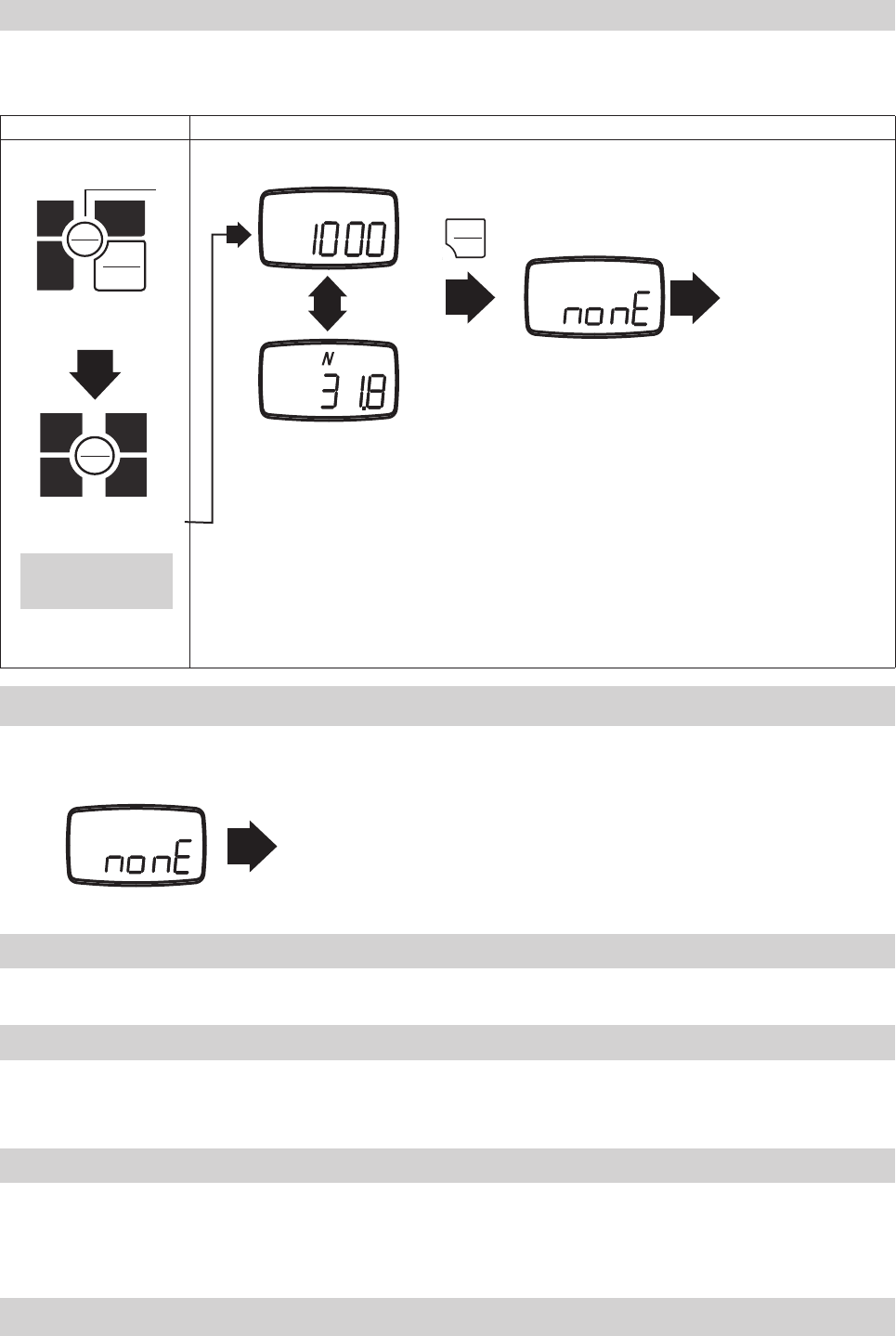
5.8.2 Clearing All Memory
1. While viewing the last memory point, press and hold ZERO.
2. The display will show "nonE".
3. All memory has now been cleared, which returns the unit to standard measurement mode.
Key operation Display
Turn power off
PEAK
PEAK
ZERO
MEM
UNIT
1. Hold down MEM
2. Press POWER
PEAK
PEAK
ZERO
MEM
UNIT
3. Release POWER
ZERO
(Push for 5 seconds or more)
No recorded data
Standard measuring mode
Memory block number
Memory data
5.8.3 No Recorded Data
The display will show "nonE" if switching to memory mode when there are no recorded memory points.
Standard Measuring Mode
5.9 USB Communication
5.9.3 Battery Life and USB
5.9.1 Features of ToriemonUSB
5.9.2 Download ToriemonUSB
The USB port allows you to connect your FGV-XY via the supplied USB cable to your PC. Our free software, ToriemonUSB, allows you to
capture data directly into Excel*.
ToriemonUSB allows you to capture measurement and memory data directly into Microsoft Excel.
ToriemonUSB is available for free at the following web address: http://www.shimpoinst.com/software.php
The manual is included with the software download, and is available separately.
Leaving the USB cable connected to the FGV-XY will drain the battery power at a faster rate. Only connect the gauge when taking data,
or use the AC adapater for power when accessing data frequently.
Release MEM after "CNT"
is displayed.
*Microsoft Excel is a registered trademark of Microsoft Corp.
1.
2.
MEMORY
MEMORY
MEMORY
MEMORY
POWER
POWER
ZERO
ZERO
-25-
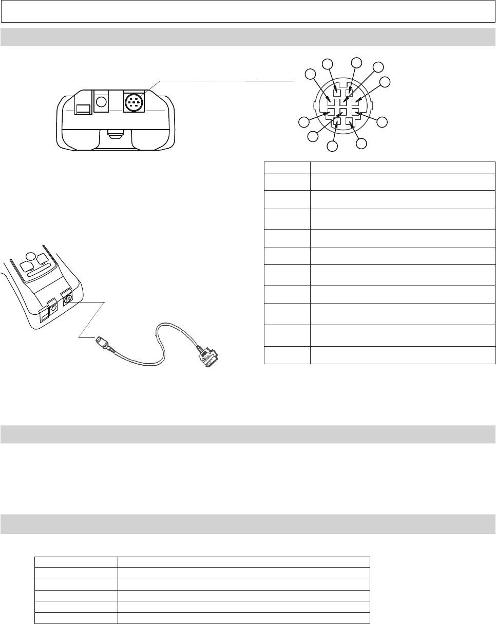
6. External Data Port
6.1 Pin Assignment
Pin Number Signal Name
1 Analog +
2 Analog GND
3RxD (RS-232C Received Data)
Host --> FGV
4 Digital GND
5 Connection Detection
6TxD (RS-232C Transmitted Data)
FGV --> Host
7 Not Used*
8Compression Overload /
LO Comparator Output
9Tension overload /
HI Comparator Output
10 Common (for Pins 8 and 9)
HR12-10RC-10SDL, by Hirose, is the output connector.
We recommend HR12-10PCAE300 with 10 conductor
shielded cable to make your own.
Please call your Shimpo dealer for information regard-
ing optional cables and accessories.
*Always leave pin 7 unconnected.
6.2.RS-232C Output
The RS-232C data connection allows control from external devices and data transfers.
6.2.1 RS-232C Interface
Baud rate* 2400, 4800, 9600, 19200 bps
Length of data bit 8 bit
Parity bit None
Length of stop bit 1 bit
Flow control None
*The baud rate is selectable through setting (f04). See section 4.5.4 for more information.
Default factory setting is 2400 bps. Consult your equipment's manual or manufacturer for the correct baud rate.
ASCII code, alpha numerics and carriage returns are used for RS-232C data transfer.
10
9
8
7
6
5
4
3
2
1
RS232C Output Cable
(Optional)
-26-
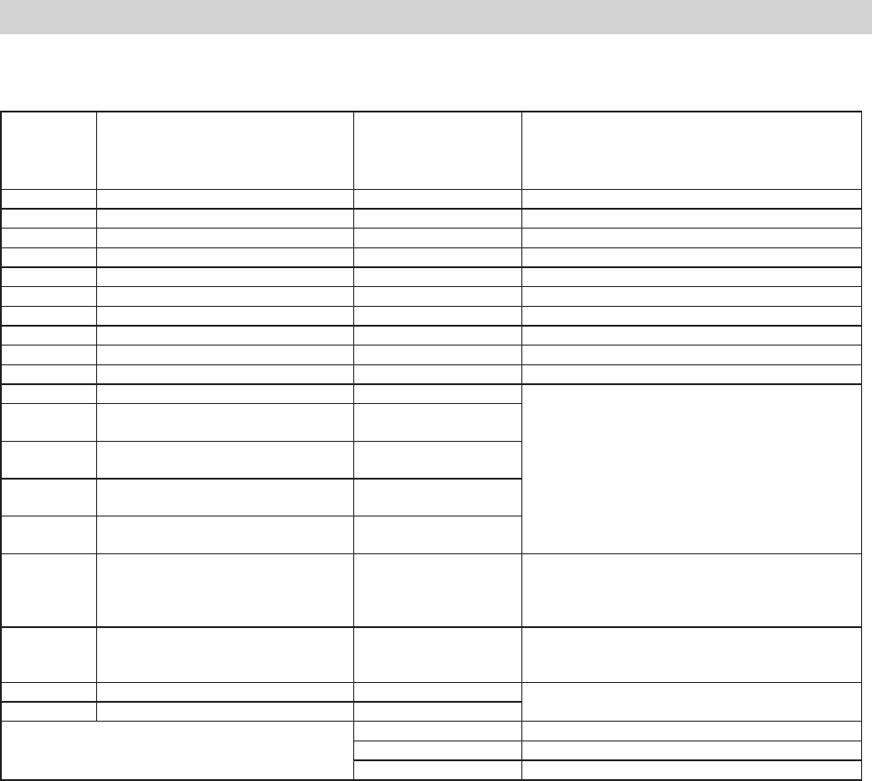
6.2.2 RS232C Communication Commands
Typical Host -> FGV commands.
"cr"means carriage return.
Commands Content Response Explanation of Response
AA cr Tare AA cr Tare
AB cr Cancel data transmission AB cr Cancel data transmission
AC cr Switch to positive peak mode AC cr Switch to positive peak mode
AD cr Switch to standard measuring mode AD cr Switch to standard measuring mode
AL cr Switch to negative peak mode AL cr Switch to negative peak mode
AE cr Clear peak values AE cr Clear peak values
AF cr Switch unit to Kg, g AF cr Switch unit to Kg, g
AG cr Switch unit to N AG cr Switch unit to N
AH cr Switch unit to lb AH cr Switch unit to lb
AK cr Switch unit to oz AK cr Switch unit to oz
BA cr Request current measurement BA cr NA xxxxxx cr
xxxxxx: Polarity, decimal point, 4 digit value
BB cr Request continuous transmission of
measurement data (10 times/second) BB cr NA xxxxxx cr
BB1 cr Request continuous transmission of
measurement data (20 times/second) BB1 cr NA xxxxxx cr
BB2 cr Request continuous transmission of
measurement data (50 times/second) BB2 cr NA xxxxxx cr
BB3 cr Request continuous transmission of
measurement data (100 times/second) BB3 cr NA xxxxxx cr
BC cr Transmission request of model BC cr NE xx cr
xx: 2-digit number indicating model
02: FGV-0.5, 03: FGV-1, 04: FGV-2, 05: FGV-5, 06: FGV-10,
07: FGV-20, 08: FGV-50, 09: FGV-100, 1A: FGV-200
BD cr Transmission request of unit BD cr NH x cr
x: one-digit number indicating unit
0: N, 1: kg, 2: g, 3: lb, 4: oz
BE cr Transmission request of plus peak value BE cr NB xxxxxx cr xxxxxx: Polarity, decimal point, 4 digit value
BF cr Transmission request of minus peak value BF cr NC xxxxxx cr
If the FGV-XY detects a communication error,
the following error codes are sent.
OB cr Format error (Command error)
OF cr Flaming error
OH cr Overrun error
-27-
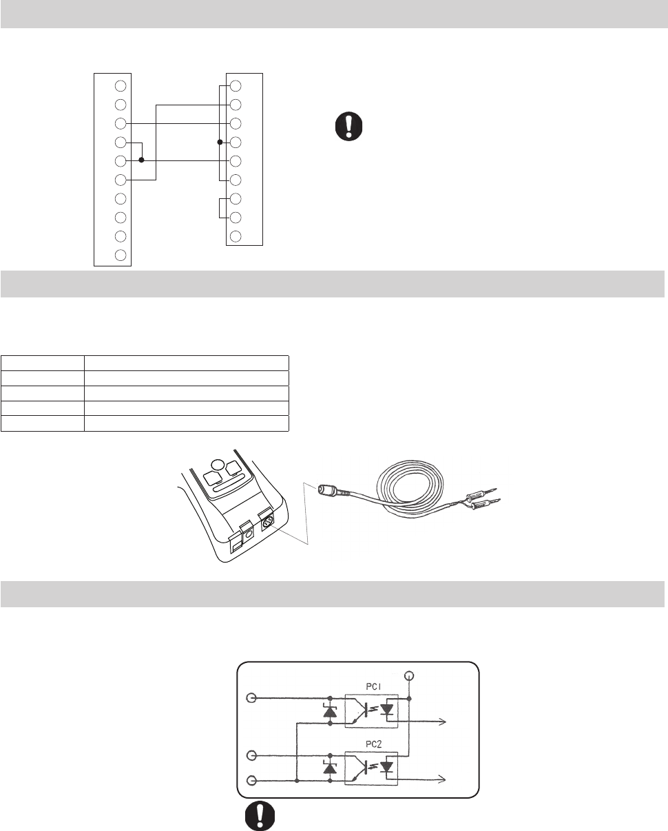
6.2.3 Connection between FGV and Host
Without the connection between the Digital GND and
pin 5, RS-232C communication will not work.
6.3 Analog Output
± 1V Analog Output
The output voltage's polarity corresponds to the polarity shown on the display during standard measurement mode.
The voltage will adjust to any tare command performed.
Output signal ± 1V
Signal method 12 bit D/A converter
Output update 1000 times/second*
Load resistance >10 k Ω
Output accuracy ± 50mV
The analog output has a default update rate of 1000 times/second. The output
voltage is linearly scaled so that the current zero point of the gauge corresponds
with 0V, and so that 1V corresponds with 100% of the gauge's rated capacity.
This means that the tare function, or any change in the gauge's zero point, will
change the maximum voltage shown before the gauge is overloaded.
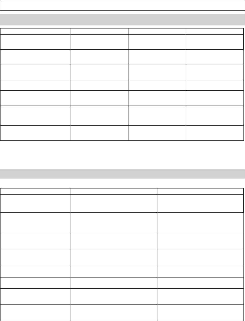
6.4 Overload/Comparator Output
Output overload/comparator signal.
Switch of output overload/comparator signal is set by external output setting (f06) of function mode.
Compression Overload /
LO Comparator Trigger
Tension Overload /
HI Comparator Trigger
Common
(For Pins 8 and 9)
30V / 5mA Maximum
Overload Output
When the overload condition is triggered, the corresponding overload output turns on. This can be used to stop a motorized test stand, or an
alarm to prevent damage from accidental overload.
When compression overload occurs photo-couple 1(PC1) turns on, and allows current to fl ow between Pin 8 and 10.
When tension overload occurs photo-couple 2(PC2) turns on, and allows current to fl ow between Pin 9 and 10.
If no overload condition exists, PC1 and PC2 should be closed, and will not allow current fl ow.
Overload occurs at about 120% of the gauge's rated capacity. This includes any weight zeroed during any tare operation.
Comparator Output
When the LO limit is reached, photo-couple 1(PC1) turns on, and allows current to fl ow between pins 8 and 10.
When the HI limit is reached, photo-couple 2(PC2) turns on, and allows current to fl ow between pins 9 and 10.
Refer to section 5.5 for information regarding the activation and setting of comparator limits.
I/F Circuit
1
2
3
4
5
6
7
8
9
10
1
2
3
4
5
6
7
8
9
RxD
TxD
Digital GND
Connection Detection
FGV
Data Ouput Port
Host
9 pin serial connection
Analog Cable
(Optional)
Red
Black
+
-
Pin 8
Pin 9
Pin 10
DCD
RxD
TxD
DTR
GND
DSR
RTS
CTS
RI
*This rate is determined by setting f05. Please refer to 4.5.5.
-28-
7. Frequently Asked Questions
7.2 Technical Inquiries
7.1 Toubleshooting
Questions Cause Presumable reason Procedure
At power on, "OVR" is displayed
without any load.
•Load cell damage The damage may have oc-
cured from a drop, dynamic
load , or extreme overload.
Contact your Shimpo dealer
for repair information.
"LO BAT" is still displayed after 16
hours of charging.
•Low battery voltage
•Charging circuit malfunction
•AC adapter malfunction
•Battery will no longer charge
•AC Adapter / PCB damaged
from misuse
Contact your Shimpo dealer
for repair information.
Unit will not power up under bat-
tery power.
•Low battery voltage
•Charging circuit malfunction
•AC adapter malfunction
•Battery will no longer charge
•AC Adapter / PCB damaged
from misuse
Contact your Shimpo dealer
for repair information.
While connected to the AC adapter,
"BAT" is not displayed.
•Charging circuit malfunction
•AC adapter malfunction
•AC Adapter / PCB damaged
from misuse
Contact your Shimpo dealer
for repair information.
When measuring small forces, the
display zeros itself.
•Tracking Function
Section 4.4
Tracking is on, and zeros the
small forces because it looks
like a temperature change.
Turn off Tracking.
Section 4.4
The measurement value changes
with the orientation of the gauge.
Weight of the sensor shaft. The gauge is measuring the
small weight of the sensor
shaft which is connected to
the load cell.
Press ZERO after the gauge is
in position to negate any dis-
cepencies due to the sensor
shaft's weight.
The software, Toriemon, doesn't
work with my FGV-XY.
•Toriemon isn't compatible
with the FGV-XY.
•Toriemon is only compatible
with DART and JAVELIN series
gauges.
•Download ToriemonUSB
from the following website.
Questions Explanation Reference
How long should my FGV-XY's bat-
tery last?
The nickle metal hydride battery should last
for 500 full charge cycles, and should opti-
mally last 8 hours on a full charge.
Please charge battery after discharging
electricity until “LO BAT” is displayed at
LCD.
What is the reason for different ca-
pacity gauges?
To obtain the best accuracy in each situation,
different capacities are available.
To acheive the best accuracy, choose a
gauge that will allow most of your measure-
ments to fall within 50 - 100% of the gauge's
rated capacity.
Why does measuring data show
variations?
Although there are many reasons, the mea-
suring value is affected by vibration if you
hold by hands.
Fluctuation will be reduced when using
stand.
How does side loading and torque
affect the gauge's readings?
Side loading and torque effects are not mea-
surable, can damage the internal compo-
nents, and will void your warranty.
How are the force gauges calibrat-
ed?
The FGV-XY is calibrated using dead weights
at the factory.
Contact your Shimpo dealer for information
regarding NIST certifi cation for your gauge.
Is the battery user servicable? The internal battery is not user servicable. Please contact your Shimpo dealer regard-
ing battery replacement, and repair.
Do you have CAD or techinical draw-
ings available?
CAD and technical drawings are availabale
for the FGV-XY.
Please contact your Shimpo dealer for infor-
mation regarding CAD and technical draw-
ings.
Is the FGV-XY case waterproof? No, the case is not waterproof or water resis-
tant. Do not use in or around water or high
levels of humidity or condensation.
-29-
9.Specifi cations and Dimensions
8. Support
8.1 Repair and Calibration
Please contact your Shimpo dealer for information regarding the repair and calibration of your FGV-XY.
8.2 Warranty
Nidec-Shimpo Corp. warrants, to the original purchaser of new products only, that this product shall be free from defects in workmanship and
materials under normal use and proper maintenance for one year from the date of original purchase. See fi nal page for full warranty disclosure.
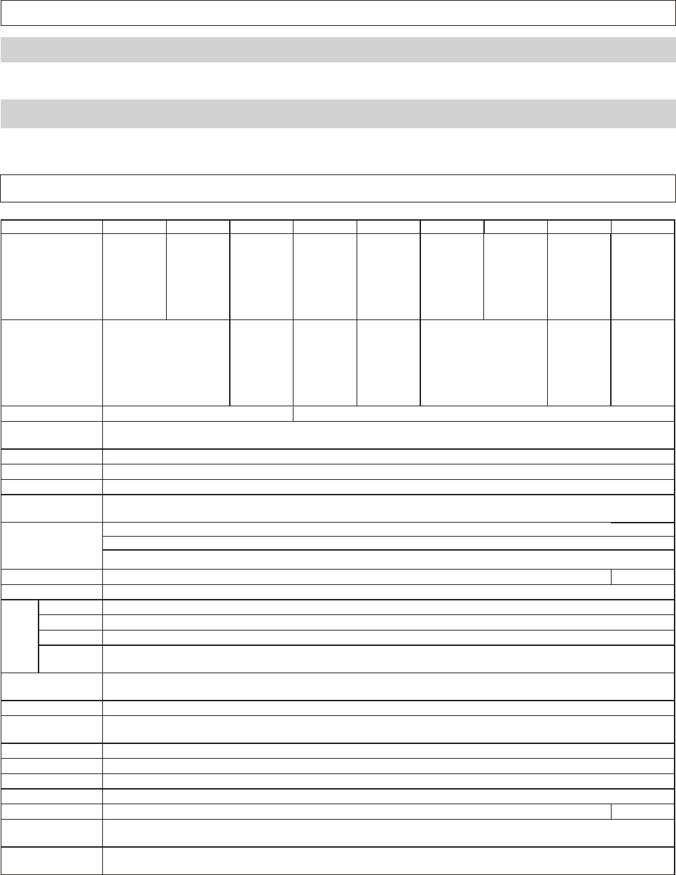
※ Dimension for FGP-0.2 ~ 0.5 is 141mm, FGP-100 is 149mm.
Model FGV-0.5XY FGV-1XY FGV-2XY FGV-5XY FGV-10XY FGV-20XY FGV-50XY FGV-100XY FGV-200XY
Capacity
0.500lb
2.000 N
1.000lb
5.000 N
2.000lb
10.00 N
20.00 N 50.00 N 100.0 N 200.0 N 500.0 N 1000 N
200.0 g 500.0 g 1000 g 2.000 kg 5.000 kg 10.00 kg 20.00 kg 50.00 kg 100.0 kg
8oz 16oz 2 lb 5 lb 10 lb 20 lb 50 lb 100 lb 200 lb
Resolution
0.001lb
0.001 N
0.001lb
0.01 N
0.01 N 0.01 N 0.1 N 0.1 N 1 N
0.1 kg 1 kg 0.001 kg 0.001 kg 0.01 kg 0.01 kg 0.1 kg
0.01 oz 0.001 lb 0.001 lb 0.01 lb 0.01 lb 0.1 lb 0.1 lb
Units of Measure lb / oz /g / N
Measurement
Modes Standard, Compression Peak, Tension Peak
Display Rate User Selectable: 1, 2, 3, 5, 10, 20 times per second
Sampling Rate 1000 times per second
Accuracy ± 0.2% F.S.
Infl uence of
temperature Gain : ± 0.01 LOAD / Zero : ±0.01 / R.C. / Drift of zero point can be cancelled with tracking function.
Display
Main display: 4-digits 12mm high, Reversible
Units display: 3-digits 7mm high
Other display: "LO BAT"(Low Battery Voltage), "BAT"(Battery Charging), "OVR"(Overload), "Peak"(Peak Hold)
Overload 200% of Full Scale 150% F.S.
Tracking User Selectable (ON/OFF)
Output
USB Allows communication between FGV-XY and ToriemonUSB via USB cable(included).
RS-232C Allows communication between the FGV-XY and RS-232C devices. RS-232C cable is an optional accessory.
Analog ± 1V, Accuracy is ± 50mV through a 12 bit D/A. ZERO affects this output, and is updated at 1000 times/second. Load is >10k Ω
Overload/
Comparator Open-collector output (Max DC30V/5mA).
Power Rechargeable Nickel hydride battery or AC adapter/charger. Usable while charging.
Operating Time: Approximately 8 hours after a full charge. Charging Time: 16 Hours Max.
Auto Power Off Default is 10 minutes. Can be disbaled. Automatically disabled when connected to AC adapter.
Memory function Continuous memory: 1000 data points, Single memory: 100 data points, Standard memory: 50 data points
Statistics functions (max, minimum, peak, average, standard deviation)
Comparator function User Selectable: HI and LO
Temperature range 0 ~ 40° C (-32 ~ 104° F)
Humidity range 35 ~ 85% RH
Dimensions 147mm ※ (L)x 75mm (W) x 38mm(H)
Weight Approx. 450g Approx. 500g
Accessories
(Included)
AC adapter/charger, carrying case, hook, chisel, flat head, notched head, hanger, cone head, thread Adapter,
extension rod, USB cable
Application
software Application software (USB version): Available at www.shimpoinst.com/software for free.
lb / kg / N
-30-
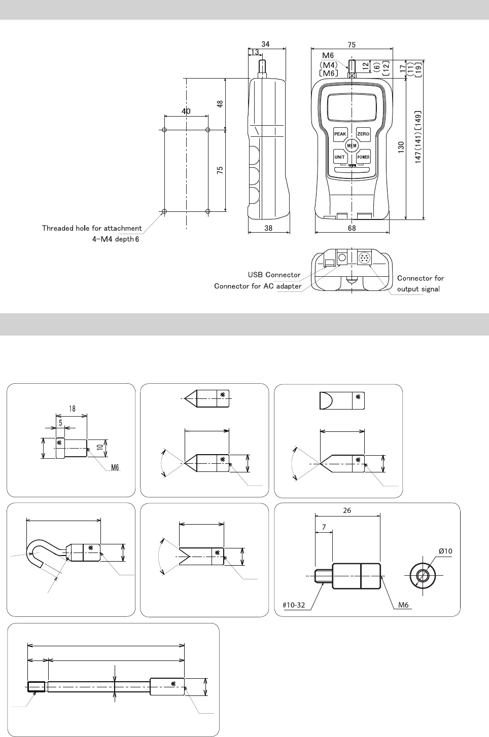
Measurement Attachments (standard accessories)
Flat Head: 12 Chisel: 70°
Hook Notched Head: 70° Thread Adapter
Cone Head: 70°
Dimensions
The following drawing is for the attachments included with the FGV-5 ~ 50XY (M6).
Please contact your Shimpo dealer for information on the attachments included with 0.5, 1, 2, and 200 models.
M6
26
70°
3.5
M6
8
(43)
R4
M6
26
70°
M6
26
70°
( ) shows dimensions for FGV-0.5, 1XY
[ ] shows dimensions for FGV-200XY
Other dimensions are common in all models.
Extension Rod: L = 92
M6
M6
12
92
80
6
10
10
10 10
10
12

LIMITEDEXPRESSWARRANTY
Shimpo Instruments warrants, to the original purchaser
of new products only, that this product shall be free
from defects in workmanship and materials under normal
use and proper maintenance for one year from the
date of original purchase. This warranty shall not be
effective if the product has been subject to overload,
misuse, negligence, or accident, or if the product has
been repaired or altered outside of Shimpo Instrument's
authorized control in any respect which in Shimpo
Instruments' judgment, adversely affects its condition or
operation.
DISCLAIMEROFALLOTHERWARRANTIES
The foregoing warranty constitutes the SOLE AND
EXCLUSIVE WARRANTY, and Shimpo Instruments hereby
disclaims all other warranties, expressed, statutory or
implied, applicable to the product, including, but not limited
to all implied warranties of merchantability and fitness.
LIMITATIONOFREMEDY
Under this warranty, Shimpo Instruments' SOLE
OBLIGATION SHALL BE TO REPAIR OR REPLACE the
defective product or part, at Shimpo Instrument's option.
Shimpo Instruments reserves the right to satisfy warranty
obligation in full by reimbursing Buyer for all payments
made to Shimpo Instruments, whereupon, title shall pass
to Shimpo Instruments upon acceptance of return goods.
To obtain warranty service, Purchaser must
obtain Shimpo Instruments' authorization before returning
the product, properly repackaged, freight pre-paid to
Shimpo Instruments.
INDEMNIFICATION&LIMITATIONOFDAMAGES
Buyer agrees to indemnify and hold Shimpo Instruments
harmless from and against all claims and damages
imposed upon or incurred arising, directly or indirectly,
from Buyer's failure to perform or satisfy any of the terms
described herein In no event shall Shimpo Instruments
be liable for injuries of any nature involving the product,
including incidental or consequential damages to
person or property, any economic loss or loss of use.
MERGERCLAUSE
Any statements made by the Sellers' representative do
not constitute warranties except to the extent that they
also appear in writing. This writing constitutes the entire
and fi nal expression of the parties' agreement.
