FL_683 FL 683
User Manual: FL_683
Open the PDF directly: View PDF ![]() .
.
Page Count: 64

®
68x Series
Enterprise LANMeter
®
Getting Started
PN 1546949
January 2000
© 2000 Fluke Corporation. All rights reserved. Printed in USA
All product names are trademarks of their respective companies.
LIMITED WARRANTY AND LIMITATION OF LIABILITY
Each Fluke product is warranted to be free from defects in material and workmanship
under normal use and service. The warranty period is one year and begins on the date of
shipment. Parts, product repairs, and services are warranted for 90 days. This warranty
extends only to the original buyer or end-user customer of a Fluke authorized reseller,
and does not apply to fuses, disposable batteries, or to any product which, in Fluke’s
opinion, has been misused, altered, neglected, contaminated, or damaged by accident or
abnormal conditions of operation or handling. Fluke warrants that software will operate
substantially in accordance with its functional specifications for 90 days and that it has
been properly recorded on non-defective media. Fluke does not warrant that software will
be error free or operate without interruption.
Fluke authorized resellers shall extend this warranty on new and unused products to end-
user customers only but have no authority to extend a greater or different warranty on
behalf of Fluke. Warranty support is available only if product is purchased through a Fluke
authorized sales outlet or Buyer has paid the applicable international price. Fluke re-
serves the right to invoice Buyer for importation costs of repair/replacement parts when
product purchased in one country is submitted for repair in another country.
Fluke’s warranty obligation is limited, at Fluke’s option, to refund of the purchase price,
free of charge repair, or replacement of a defective product which is returned to a Fluke
authorized service center within the warranty period.
To obtain warranty service, contact your nearest Fluke authorized service center to obtain
return authorization information, then send the product to that service center, with a de-
scription of the difficulty, postage and insurance prepaid (FOB Destination). Fluke as-
sumes no risk for damage in transit. Following warranty repair, the product will be re-
turned to Buyer, transportation prepaid (FOB Destination). If Fluke determines that failure
was caused by neglect, misuse, contamination, alteration, accident, or abnormal condition
of operation or handling, including overvoltage failures caused by use outside the prod-
uct’s specified rating, or normal wear and tear of mechanical components, Fluke will pro-
vide an estimate of repair costs and obtain authorization before commencing the work.
Following repair, the product will be returned to the Buyer transportation prepaid and the
Buyer will be billed for the repair and return transportation charges (FOB Shipping Point).
THIS WARRANTY IS BUYER'S SOLE AND EXCLUSIVE REMEDY AND IS IN LIEU OF
ALL OTHER WARRANTIES, EXPRESS OR IMPLIED, INCLUDING BUT NOT LIMITED
TO ANY IMPLIED WARRANTY OF MERCHANTABILITY OR FITNESS FOR A PAR-
TICULAR PURPOSE. FLUKE SHALL NOT BE LIABLE FOR ANY SPECIAL, INDIRECT,
INCIDENTAL, OR CONSEQUENTIAL DAMAGES OR LOSSES, INCLUDING LOSS OF
DATA, ARISING FROM ANY CAUSE OR THEORY.
Since some countries or states do not allow limitation of the term of an implied warranty,
or exclusion or limitation of incidental or consequential damages, the limitations and ex-
clusions of this warranty may not apply to every buyer. If any provision of this Warranty is
held invalid or unenforceable by a court or other decision-maker of competent jurisdiction,
such holding will not affect the validity or enforceability of any other provision.
Fluke Corporation
P.O. Box 9090
Everett, WA 98206-9090
U.S.A.
Fluke Europe B.V.
P.O. Box 1186
5602 BD Eindhoven
The Netherlands
11/99
i
Table of Contents
Title Page
Introduction .......................................................................................... 1
Fluke 68x Series Instruments................................................................ 1
Options ................................................................................................. 2
Functions.............................................................................................. 3
Equipment Supplied ............................................................................. 4
Interface Mode Icons............................................................................ 4
Setting Up Your Instrument ................................................................. 4
Connecting the AC Adapter.............................................................. 5
Changing the Network Interface....................................................... 6
User Interface ................................................................................... 6
LCD Display................................................................................. 8
Keyboard ...................................................................................... 10
LED Indicators ............................................................................. 21
Setup/Utils............................................................................................ 26
Network Configuration..................................................................... 28
Ethernet ........................................................................................ 28
Station List ....................................................................................... 30
Manage Options ............................................................................... 30
File Manager..................................................................................... 30
Terminal Emulator............................................................................ 31
System Information .......................................................................... 31
Update Software............................................................................... 31
Time and Date .................................................................................. 31
Display Configuration ...................................................................... 32
Self-Test ........................................................................................... 33
Self Test........................................................................................ 33
Keyboard Test .............................................................................. 33
Serial Test..................................................................................... 34
100 MHz Cable Remote Test........................................................ 34
Attaching Cables .................................................................................. 34
TO MAU, TO HUB, or BNC Connection .................................... 36
TO NIC Connection...................................................................... 39
Expert-T Autotest Connection...................................................... 40
Running a Test...................................................................................... 41
Auto Test.......................................................................................... 42
Overview of Tests................................................................................. 43
Index..................................................................................................... 51

68x Series
Getting Started
ii
iii
List of Tables
Table Title Page
1. LANMeter Instrument Network Configuration.............. 2
2. Valid Serial #s for Upgraded 67x Series......................... 2
3. Arrow Key Functions...................................................... 17
4. Battery Charger Status LED ........................................... 26
5. Cable and Media Information and Problems .................. 43
6. Ethernet NIC and Hub Problems .................................... 43
7. Ethernet Performance Information ................................. 44
8. Ethernet and Token Ring Network Information ............. 44
9. Token Ring Network Information .................................. 45
10. Token Ring NIC and MAU Problems ............................ 46
11. Novell NetWare Network Information ........................... 47
12. TCP/IP Configuration and Performance......................... 48
13. Banyan VINES Client/Server Connectivity.................... 49
14. NetBIOS Configuration and Performance...................... 49
15. Utilities............................................................................ 50

68x Series
Getting Started
iv
v
List of Figures
Figure Title Page
1. Network and AC Adapter Connectors (686/685 Shown) 5
2. LANMeter Instrument User Interface (Fluke 686 Shown) 7
3. LCD Display Areas......................................................... 8
4. Keyboard and LEDs (686/685 Shown)........................... 10
5. Ethernet Softkey Tree (Version 9.50)............................. 12
6. Token Ring Softkey Tree (Version 9.50) ....................... 13
7. Ethernet Top-Level Softkeys (Version 9.50).................. 14
8. Token Ring Top-Level Softkeys (Version 9.50) ............ 14
9. Alphanumeric Keys ........................................................ 20
10. Network and AC Adapter Connectors (686/685 Shown) 24
11. Network and AC Adapter Connectors (683/682 Shown) 25
12. Network and AC Adapter Connectors (680 Shown) ...... 25
13. Setup/Utils Softkeys (Version 9.50) ............................... 27
14. Configuration Pop-up Menu ........................................... 27
15. User Interface (Fluke 686 shown)................................... 35
16. TO HUB/MAU Connection Using RJ-45 Connector ..... 36
17. BNC Connection............................................................. 37
18. TO NIC Connection........................................................ 39
19. Expert-T Autotest Connections....................................... 40

68x Series
Getting Started
vi

1
68x Series
Enterprise LANMeter
Introduction
This manual helps you become familiar with and quickly begin using your 68x
Series LANMeter instrument. Basic information is provided that will allow
you to set up your instrument, configure and operate it. Detailed information
about specific features is provided in the Enterprise LANMeter 68x Series
Users Manual (P/N 1546951). The Users Manual is contained on the CD that
came with your instrument. Adobe Acrobat Reader is required to view the
Users Manual and is included on the CD or can be downloaded from
www.adobe.com.
Fluke 68x Series Instruments
The Fluke Enterprise LANMeter (68x Series) instruments are versatile battery-
operated handheld instruments used to isolate many problems that can occur on
your Ethernet and Token Ring networks. The Fluke Enterprise LANMeter
series consists of the Fluke 686, Fluke 685, Fluke 683, Fluke 682, and Fluke
680 LANMeter instruments.
68x Series
Getting Started
2
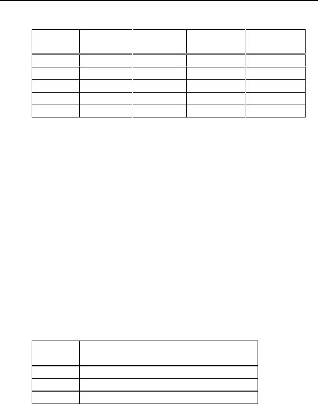
Table 1. LANMeter Instrument Network Configuration
Model # 10 Mbps
Ethernet
100 Mbps
Ethernet
4 Mbps
Token Ring
16 Mbps
Token Ring
680 X X
682 X
683 X X
685 X X X
686 X X X X
The majority of this manual describes operations common to the Fluke 686,
685, 683, 682, and 680. Any differences between the LANMeter instruments
are pointed out as appropriate.
Options
The 100 MHz Cable Test option (also called 100 MHz Remote) gives you
additional cable test capabilities. The 100 MHz Remote is compatible with all
Fluke 68x Series instruments except some Fluke 67x Series instruments
upgraded to 68x Series. Your 67x instrument is compatible with the 100 MHz
Remote if its serial number is as described in Table 2 or if your instrument
displays 100 MHz Cable Test Compatible in the power-on screen or
in the top-level softkey screen. The 100 MHz Cable Test option is covered in
the Users Manual, “Testing Cables and Connectors.”
Table 2. Valid Serial #s for Upgraded 67x Series
Model #
Valid Serial #s for Upgraded 67x Series
100 MHz Remote Compatibility
670 > 6311801
672 > 6296601
675 > 6281701
The SwitchWizard option enhances Segment Discovery and adds the
SwitchWizard MultiPort Statistics test. SwitchWizard gives you the ability to
discover and diagnose problems on the other side of Ethernet, Token Ring, and

Enterprise LANMeter
Functions
3
FDDI switches. SwitchWizard is compatible with all Fluke 68x Series
instruments with software version 7.0 or greater, and is covered in the Users
Manual, “SwitchWizard Option.”
The WideAreaWizard option enhances the Internet Toolkit’s Interface Table
by adding reporting and some configuration capabilities for discovered WAN
interfaces. WideAreaWizard gives you the ability to discover and diagnose
problems on Frame Relay, ISDN, and T1/E1 interfaces on routers, switches,
and bridges. WideAreaWizard also allows you to display and configure virtual
circuit information for appropriate technologies. WideAreaWizard is
compatible with all Fluke 68x Series instruments with software version 8.0 or
greater, and is covered in the Users Manual, “WideAreaWizard Option.”
The WebRemote Control option adds the ability to control your LANMeter
instrument remotely using a web browser. It is also required to use the
Network Inspector LANMeter Edition reporting and monitoring package (see
www.fluke.com\nettools for more information on Network Inspector).
WebRemote Control is compatible with all Fluke 68x Series instruments with
software version 9.0 or greater, and is covered in the Users Manual, “Web
Agent / WebRemote Control.”
The Terminal Emulator option adds a command line interface that allows you
to inspect or change the configuration of a network device by utilizing your
LANMeter instrument’s serial port connection. Terminal Emulator is included
whenever you purchase the SwitchWizard or WideAreaWizard options.
Terminal Emulator operation is covered in the Users Manual, “Terminal
Emulator.”
Functions
This manual generally refers to features common to all the Fluke 68x Series
LANMeter instruments as the “Enterprise LANMeter” or as the “LANMeter
instrument.” The individual Fluke 68x Series model number is used when
features are specific to an individual model of the Enterprise LANMeter.
Use the LANMeter instrument to perform the following functions on your
network:
r Diagnose problems with network cabling
r Test key network components
r Monitor important attributes of the network environment

68x Series
Getting Started
4
Refer to the Users Manual for specific information on using your LANMeter
instrument.
Equipment Supplied
The following equipment is supplied with the LANMeter instrument:
r Combination Wire Map and Cable Identifier #0 Remote Adapter
r Instrument Case
r Getting Started Manual
r Users Manual (on CD)
r AC Adapter/Battery Charger
r 3 ½-inch Utility Diskette
Interface Mode Icons
This icon is used in this manual to signify that the text that follows refers to the
Ethernet interface only. The Fluke 683 and 682 have the Ethernet interface
only and the Fluke 686 and 685 can be switched between the Ethernet and
Token Ring interfaces.
This icon is used in this manual to signify that the text that follows refers to the
Token Ring interface only. The Fluke 680 has the Token Ring interface only
and the Fluke 686 and 685 can be switched between the Ethernet and Token
Ring interfaces.
Setting Up Your Instrument
The following sections describe the initial setup and use of your instrument.
r Connecting the AC Adapter
r Changing the Network Interface
r User Interface
r Setup/Utils
r Attaching Cables
r Running a Test
Enterprise LANMeter
Setting Up Your Instrument
5
Connecting the AC Adapter
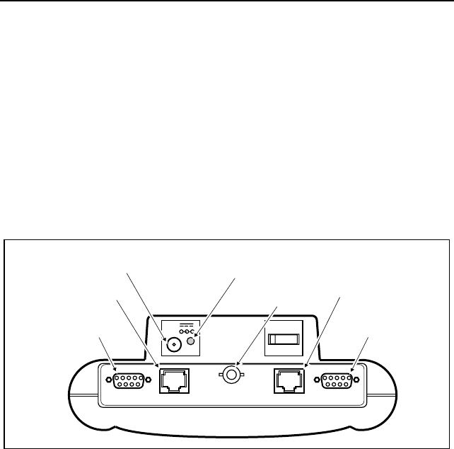
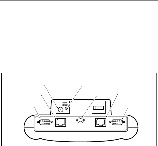
Connect the AC Adapter to the AC Adapter connector as shown in Figure 1.
The AC Adapter power cord must be connected to a power receptacle with
Earth Ground. Turn the power switch located on top of the instrument to ON.
You can now use your instrument while the battery is charging.
Before using the instrument without the AC Adapter, charge the
battery for about 3 hours.
Charge the battery or use the AC Adapter when the instrument displays a low
battery indicator on the status line just above the softkey labels. You can use a
fully charged battery for about 3 hours.
TO HUB/MAU TO NIC
18-28V
1.25A ON OFF
+-
TO HUB/MAU DB - 9
Connector
TO HUB/MAU RJ - 45
Connector
AC Adapter
Connector Battery Charger
Status LED TO NIC RJ - 45
Connector
TO NIC DB - 9
Connector
NOT FOR CONNECTION TO PUBLIC TELEPHONE SYSTEMS
BNC Connector
Figure 1. Network and AC Adapter Connectors (686/685 Shown)

68x Series
Getting Started
6
Changing the Network Interface
For the Fluke 686 and 685, use the following procedure to change the interface
between Ethernet and Token Ring:
1. Press B from the top-level softkeys.
2. Press I to confirm the change of interface or press G to cancel.
3. Wait about 20 seconds for the change of interface to be completed.
User Interface
The instrument’s user interface provides easy access to all functions and
consists of the following parts:
r LCD Display
r Keyboard
r Individual and Bargraph LEDs
The user interface is the same for all of the Fluke 68x Series Enterprise
LANMeter instruments. They differ only in the way the individual (status)
LEDs are labeled and in the name on the instrument. The Fluke 686 and 685
are labeled for both Ethernet and Token Ring functions, the Fluke 683 and 682
have an Ethernet label, and the Fluke 680 has a Token Ring label. Examples
of LANMeter instrument labeling are shown in Figures 2 and 4.

Enterprise LANMeter
Setting Up Your Instrument
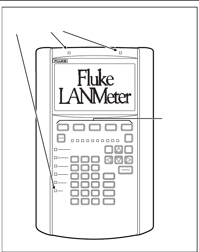
7
THESE LEDS INDICATE WHICH
LAN CONNECTORS TO USE
SOFTKEYS
EXIT
STOP MORE
MENUTAB
ENTER
RUN
PRINT
HELP
ALPHA
SHIFT
ABC
789
456
123
0•SPACE
DEF
% UTILIZATION
HUB/MAU NIC
FRAME ERROR
BEACON
POLARITY
WIRE FAULT
LINK ACTIVE
INSERT
TRANSMIT
16 Mb/S
BNC
4 Mb/S
GHI
JKL
MNO
PQR
STU
VWYXZ
COLLISION
RING ERROR
686 ENTERPRISE LANMETER
10/100 ETHERNET
TOKEN RING
Figure 2. LANMeter Instrument User Interface (Fluke 686 Shown)
The instrument softkeys are organized by commonly performed tasks. Tests
that are useful for several different tasks are accessible from all relevant modes
of operation. The available softkeys depend on which options are enabled (if
any) and which interface is selected (Fluke 686 and 685 only).
68x Series
Getting Started
8
LCD Display
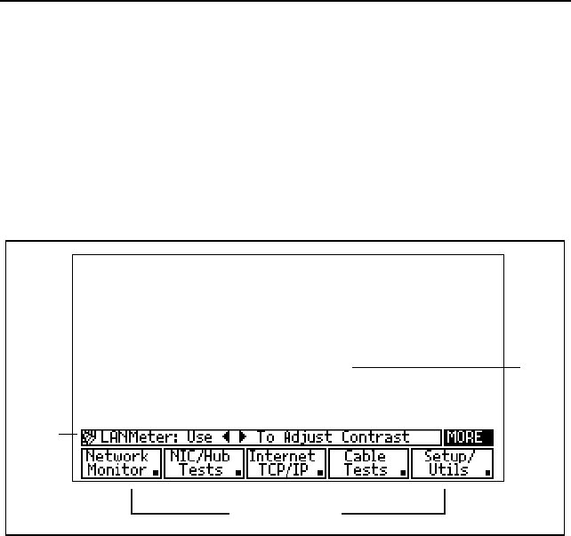
The instrument’s display consists of a LCD graphic screen for output as shown
in Figure 3. The display has the following specific areas for displaying
different types of information:
r Work Area
r Softkey Labels
r Status Line
Work
Area
Status
Line
Softkey Labels
Figure 3. LCD Display Areas
Use the Display Config softkey to control the screen backlight operation.
The Display Config softkey is accessed by pressing the Setup/Utils softkey
and then the E key. At any time, you can press and release H, then
press T to turn the LCD backlight on and off. Refer to the “Display
Configuration” section in this manual for more information on controlling the
screen backlight.
You can control the display contrast from the top-level (power-on) menu by
using K and J. Press K to make the display lighter and press J to make
the display darker.

Enterprise LANMeter
Setting Up Your Instrument
9
Work Area
The instrument provides test data and pop-up menus for selecting test and
configuration options. If you need to set any of these options, do so before
running a test. Pop-up menus cannot be accessed while running a test.
Whenever a procedure tells you to press C, doing so causes a pop-up menu
to appear. To move from one choice to another, press M or L. Press I
to accept a menu choice. Press G to close a pop-up menu without making a
selection.
You can access a pop-up Test Menu by highlighting a test softkey label and
then pressing C. Select Configure and then press I to configure the
selected test.
Pop-up Configuration Menus are available for most tests. You can access a
pop-up Configuration Menu by selecting a top-level softkey, highlighting the
desired test softkey label, pressing C, and selecting the desired action.
Softkey Labels
The softkey label area is found along the bottom of the display, directly above
the five blue softkeys as shown in Figure 3. For each softkey, the label and its
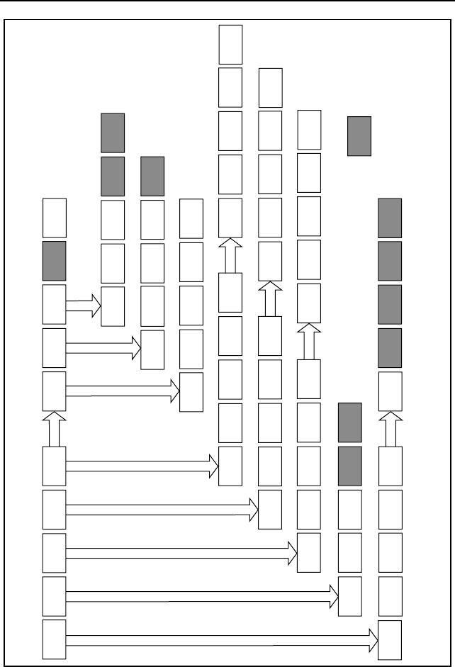
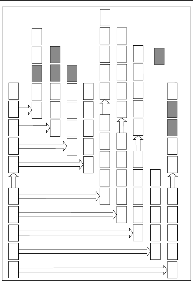
associated function changes as you move through the menu system. Figure 5
shows the Ethernet softkey tree and Figure 6 shows the Token Ring softkey
tree. The softkey trees are specific to the Ethernet or Token Ring interface,
depending on which LANMeter instrument is being used or which mode is
selected (Fluke 686 and 685 only). The softkeys show options or operations
available within a test.
Status Line
The instrument displays the status line above the softkey labels as shown in
Figure 3. The status line provides information about the state of your
instrument or about controlling your instrument. For example, from the top-
level softkeys, the status line indicates how to control the screen contrast, as
shown in Figure 3.
68x Series
Getting Started
10
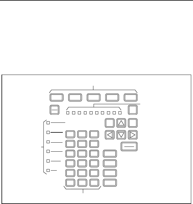
Keyboard
The instrument has a custom keyboard (shown in Figure 4). The keyboard
consists of the following types of keys:
r Softkeys
r Dedicated keys
r Alphanumeric keys
EXIT
STOP MORE
MENUTAB
ENTER
RUN
PRINT
HELP
ALPHA
SHIFT
ABC
789
456
123
0•
SPACE
DEF
% UTILIZATION
FRAME ERROR
BEACON
POLARITY
WIRE FAULT
LINK ACTIVE
INSERT
TRANSMIT
16 Mb/S
BNC
4 Mb/S
GHI
JKL
MNO
PQR
STU
VWYXZ
COLLISION
RING ERROR
SOFTKEYS
STATUS LEDs
BARGRAPH LEDS
ALPHANUMERIC KEYS
Figure 4. Keyboard and LEDs (686/685 Shown)

Enterprise LANMeter
Setting Up Your Instrument
11
Softkeys
Use the instrument softkeys to select functions, to configure tests, and to run
tests. The instrument displays softkey labels directly above each softkey.
Figure 5 shows the Ethernet softkey tree and Figure 6 shows the Token Ring
softkey tree. The softkey trees are specific to Ethernet or Token Ring
depending on which instrument is being used or which mode is selected (Fluke
686 and 685 only). Softkeys operate in one of two ways: some access a second
level of softkeys and some execute a function. Figures 7 and 8 show the
Ethernet and Token Ring top-level softkeys, respectively.
68x Series
Getting Started
12
Network
Monitor NIC/Hub
Tests Internet
TCP/IP Cable
Tests Setup/
Utils Novell
NetWare NetBIOS Web
Agent
Banyan
Vines
Address
Servers
IP Auto
Config
Server
List
Network
Config Station
List Display
Config
Time/
Date
Terminal
Emulator
File
Manager
Cable
Autotest
Cable
I.D. Fiber
Test
Wire
Map
Cable
Scan
Segment
Discovery
IP Auto
Config
Network
Stats MAC
Matrix Protocol
Mix Traffic
Gen Top
MAC
Error
Stats
Hub
Autotest NIC
Autotest Expert-T
Autotest
Multiport
Stats Trace
Route Internet
Toolkit
System
Info
Scan
Host ICMP
Monitor ICMP
Ping Top
IP IP
Matrix
Self
Test
Calibrate
Remote
Find
NVP
DC ContAttenNEXT
Update
Software
NetWare
Ping NetWare
Stats Routing
Analysis Top
NetWare
NetBIOS
Discovery NetBIOS
Ping Top
NetBIOS
Server
Discovery Top
VINES
Top Level Softkeys
Unused Softkeys
More
More
More
More
More
Manage
Options
Figure 5. Ethernet Softkey Tree (Version 9.50)
Enterprise LANMeter
Setting Up Your Instrument
13
Network
Monitor NIC/MAU
Tests Internet
TCP/IP Cable
Tests Setup/
Utils Novell
NetWare NetBIOS Banyan
VINES Network
Tests Web
Agent
Address
Servers
IP Auto
Config
Server
List
Network
Config Station
List Display
Config
Time/
Date
Terminal
Emulator
File
Manager
Cable
Autotest
Cable
I.D. Fiber
Test
Wire
Map
Cable
Scan
Segment
Discovery
IP Auto
Config
Network
Stats Ring
Stations Protocol
Mix Traffic
Gen Top
MAC MAC
Matrix Token
Rotation
Error
Stats
MAU
Autotest NIC
Autotest Expert-T
Autotest Lobe
Test MAU
Reset
Multiport
Stats Trace
Route Internet
Toolkit
System
Info
Scan
Host ICMP
Monitor ICMP
Ping Top
IP IP
Matrix
Self
Test
Calibrate
Remote
Find
NVP
DC ContAttenNEXT
Update
Software
NetWare
Ping NetWare
Stats Routing
Analysis Top
NetWare
NetBIOS
Discovery NetBIOS
Ping Top
NetBIOS
Server
Discovery Top
VINES
Station
Ping Phase
Jitter Adapter
Status Remove
Station
Top Level Softkeys
Unused Softkeys
More
More
More
More
More
Manage
Options
Figure 6. Token Ring Softkey Tree (Version 9.50)
68x Series
Getting Started
14
Use E to access additional softkeys on the current functional level. The
E key is operational only when the MORE label is displayed above the far
right softkey label (in the status line) as shown in Figure 3.
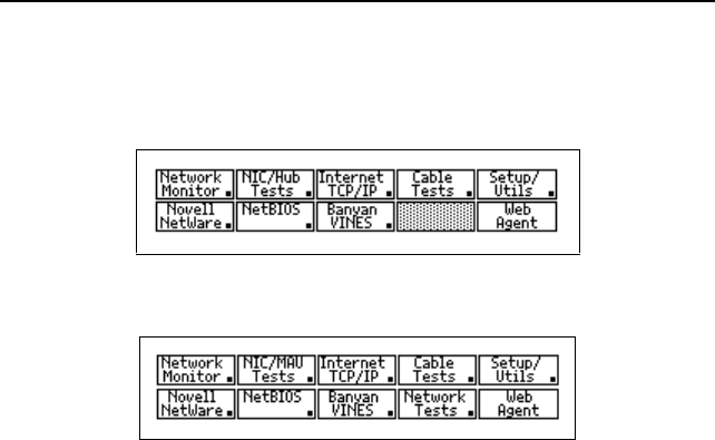
Figure 7. Ethernet Top-Level Softkeys (Version 9.50)
Figure 8. Token Ring Top-Level Softkeys (Version 9.50)
The softkey menu structure uses two kinds of softkey labels. The top-level
softkeys, with the exception of Setup/Utils, access test categories. The small
boxes in the lower right-hand corners of the top-level softkey labels indicate
that there is a second level of softkeys beneath these softkeys. Pressing one of
these softkeys causes the next level of softkeys to be displayed.
A test is selected when its softkey label is highlighted. A highlighted softkey
label is displayed in inverse video. In inverse-video, text is displayed in white
on a black background. Pressing a highlighted test softkey executes the test.

Enterprise LANMeter
Setting Up Your Instrument
15
Dedicated Keys
Dedicated keys provide access to commonly used functions. The following
paragraphs describe each dedicated key:
Note
Never press and hold down any key while pressing a second key.
Always press and release the first key and then press the second key.
For example, when you press and release H, the instrument
temporarily replaces the MORE display label (on the status line) with
SHIFT and executes the shift function of the next key pressed.
ENTER/RUN Press I in the following situations:
1. Press I to confirm operations or to close some
pop-up windows.
2. Press I to run the highlighted test.
3. Press I from the top-level display screen to run
Auto Test.
4. Press I while a test is running, or after it has
stopped, to zoom-in (or follow the hyperlinks).
The instrument will beep if you press I when
there are no additional zoom-in items.
When a test is stopped and displaying its result
screen, you must press the Run Again softkey, not
I to run the test again. For tests that run
simultaneous tests (like Network Stats) you can use
the available test softkeys to run the desired test.
MORE Press E to access an additional row of softkey labels.
The instrument displays the MORE label above the far
right softkey label when additional softkeys at the same
level are available but not displayed.

68x Series
Getting Started
16
EXIT/STOP Press G to stop the currently running test, to exit a
function (such as Setup or Help), to return to the top-level
softkeys, to return up hyperlink paths, to respond to a
pop-up menu prompt, or close a pop-up window.
Pressing G from a Configuration Menu or Station List
Menu saves the changes you have made to non-volatile
memory and exits the Menu.
TAB Use B in the following situations:
1. For most tests that display station addresses, press
B to switch the address display format from
symbolic name, dotted decimal, manufacturer prefix,
and hexadecimal. Selecting the Address Mode
softkey also allows this selection by use of a menu.
2. In tests that display configuration fields and scroll
lists on the same screen, such as Station Ping, press
B to move between configuration parameters and
output results.
3. From the top-level softkeys, press B, then press
I to switch between the Token Ring and
Ethernet interface (Fluke 686 and 685 only).
4. To jump between hyperlink objects press B, or
press H, then B to jump backwards between
hyperlink objects.
PRINT Use D in the following situations:
1. Press D to output the graphic image of the current
screen to the serial printer port or to the instrument’s
virtual disk. This depends on the Output Type
parameter in File Manager’s configuration.
2. To print scrollable lists and ASCII reports, press
C, Print All, or H, then D. Tests must be
stopped to print ASCII information.
3. For some tests, after you stop a test you can press and
release H, then D to print all of the
information collected by the test.
MENU Press C to access the pop-up test and configuration
menus.
UP/DOWN & Press M, L, K, and J for display

Enterprise LANMeter
Setting Up Your Instrument
17
LEFT/RIGHT navigation, screen page up and page down, and field
ARROW KEYS scrolling. Table 3 shows arrow key functions.
Table 3. Arrow Key Functions
Key Function
MUp one row
LDown one row
JAdjusts screen contrast (top-level only),
screen page down, steps through
configuration field selections, or Page Down
function in results screens.
KAdjusts screen contrast (top-level only),
screen page up, steps through configuration
field selections, or Page Up function in
results screens.
H, then LPage down
H, then MPage up
H, then JEnd of list (END)
H, then KBeginning of list (HOME)
SHIFT Press H to access extended functions and to enter a
secondary character from an alphanumeric key. When
you press and release H, the instrument temporarily
replaces the MORE display label with SHIFT and
executes the shift function of the next key pressed. Press
and release H each time you want to access the shift
function of a key. For an example, refer to the
“Alphanumeric Keys” section.

68x Series
Getting Started
18
ALPHA Press T in the following situations:
1. Press T to enter a secondary character from an
alphanumeric key. These secondary characters are
the same color (orange) as the lettering on the
ALPHA key. When you press and release T, the
instrument temporarily replaces the MORE display
label with ALPHA and executes the Alpha function
of the next key pressed. After pressing T, the
orange keyboard characters are active. Press and
release T each time you want to access the Alpha
function of a key. For an example, refer to the
“Alphanumeric Keys” section.
2. Press and release H and then press T to turn
the screen backlight on and off. Refer to the
“Display Configuration” section in this manual for
more information on controlling the screen backlight.
HELP Use A to access information on the highlighted test.
Use the following procedure to obtain help on any test:
Note
You must stop all tests prior to using A.
1. Select the desired test category.
2. Highlight the desired test softkey.
The exact steps required to highlight a test softkey
depends on which test you want to run. The first test
is automatically highlighted. Otherwise, you either
press the test softkey once or press E, then press
the test softkey once (if there is a second row of
tests).
3. Press A.
4. Use the arrow keys (as shown in Table 3) and the
Prev Page and Next Page softkeys to move
around in the help text.
5. Press G to exit the Help System.

Enterprise LANMeter
Setting Up Your Instrument
19
. (period key) Use O in the following situations:
1. Use as a period when entering alpha characters, such
as a station list name.
2. Press O to move from one address octet to the
next for editing IP addresses.
SPACE Press S to access configuration choices of the
selected configuration field or to bring up the Station List
when an address is selected.
Alphanumeric Keys
You can enter the numbers 0 through 9, the letters A through F, the period, and
the SPACE directly from the keyboard (also called base keys). For example,
press and release S to enter a space. To enter the letters G through W and
Y, press and release T, then press the correct base key. For example, press
and release T, then press S to input the character Y. To enter the
letters X and Z, press and release H, then press the correct base key. For
example, press and release H, then press S to input the character Z.
Figure 9 shows the Alphanumeric Keys.
68x Series
Getting Started
20
ABC
789
456
123
0•
SPACE
DEF
GHI
JKL
MNO
PQR
STU
VWYXZ
Figure 9. Alphanumeric Keys
The following procedure shows how to enter the string LAZY 8:
1. Press and release T, then press L.
2. Press A.
3. Press and release H, then press Z.
4. Press and release T, then press Y.
5. Press S.
6. Press 8.

Enterprise LANMeter
Setting Up Your Instrument
21
LED Indicators
The instrument LEDs include both status (individual) and bargraph LEDs that
indicate important network conditions. Figure 4 shows the status and bargraph
LEDs. You can use these LED indicators for quick problem isolation. The
Fluke 686 and 685 individual LEDs have two sets of labels, one for Ethernet
(the top label) and one for Token Ring (the bottom label). The instrument also
has two individual LEDs to indicate which network connector to use, what
Ethernet speed (686 and 683 only), and one LED to indicate battery charger
status. The following sections describe the meaning of these LEDs:
r Utilization Percentage Bargraph
r Frame Error/Beacon
r Collision/Ring Error
r Polarity/Wire Fault
r Link Active/Insert
r Transmit/16 Mb/s
r BNC/4 Mb/s
r HUB/MAU
r NIC
r Battery Charger Status
Utilization Percentage Bargraph
Utilization Percentage bargraph LEDs show the instantaneous network
utilization percentage. Each LED represents 10% utilization on the network up
to a total of 100% utilization when all 10 LEDs are lit. The more LEDs that
the instrument lights, the higher the network utilization.
When the instrument first inserts into a ring, the utilization LED’s will briefly
light while the instrument performs its Lobe Test.
Frame Error/Beacon
The red FRAME ERROR LED is on when the instrument detects a jabber
frame (a frame with greater than 1518 bytes), a short frame (one with less than
64 bytes), or a frame with a bad frame check sequence.
68x Series
Getting Started
22
The red BEACON LED is on when the instrument detects a beacon frame on
the network or when it transmits a Beacon frame. If this LED is on
continuously, your ring is in a beaconing state. Manual intervention is usually
required to recover a ring that has been in a beaconing state for more than a
minute.
Collision/Ring Error
The yellow COLLISION LED is on when the instrument detects a late, a local,
or a remote collision. Local and Remote collisions are not reported on 100
Mbps networks.
The yellow RING ERROR LED is on when the instrument detects any kind of
ring recovery frame on the network, such as soft error, ring purge, claim token,
or when the neighbor notification is incomplete.
Polarity/Wire Fault
The red POLARITY LED is on when the instrument detects reversed polarity
on the receive link for a 10BASE-T connection. The state of the Polarity LED
is only valid if the instrument is connected to a hub.
The red WIRE FAULT LED is on when the instrument detects a fault in the
lobe wiring between it and the MAU.
Link Active/Insert
The green LINK ACTIVE LED is on when the instrument receives the link
pulse from an Ethernet hub.
The green INSERT LED is on when the instrument inserts into the ring or, in
the Expert-T mode, when the attached station is inserted into the network
through the instrument.
Transmit/16 Mb/s
The yellow TRANSMIT LED is on when the instrument transmits a frame.
The yellow 16 Mb/s LED is on when the instrument detects the ring speed as
16 Mbps or, if doing a NIC Autotest, when it detects the NIC speed as 16
Mbps.
Enterprise LANMeter
Setting Up Your Instrument
23
BNC/4 Mb/s
The green BNC LED is on to indicate that you should connect to the BNC
connector. The BNC LED will flash when the instrument’s BNC connector is
terminated internally in 50 ohms.
The green 4 Mb/s LED is on when the instrument detects the ring speed as 4
Mbps or, if doing an NIC Autotest, when it detects the NIC speed as 4 Mbps.
HUB/MAU
The HUB/MAU LED is located near the TO HUB/MAU connectors. The
instrument turns on the green HUB/MAU LED to identify the correct port for
attaching a cable to run the selected test. The LED flashes green/blue on the
Fluke 686 and 683 instruments. The Fluke 680 labels this LED as MAU, the
Fluke 683 and 682 label this LED as HUB, and the Fluke 686 and 685 label
this LED as HUB/MAU.
For Fluke 686 and 683 instruments only, the HUB/MAU and HUB LEDs are
dual-color (green/blue) and have two functions: first, to identify the correct
port for attaching the cable to run the selected test and second, to identify the
Ethernet speed. When the LANMeter instrument’s Ethernet Speed is
configured for 100 Mbps, the LED is blue and when it is configured for 10
Mbps, the LED is green. When you configure the instrument’s Ethernet Speed
for Auto Detect, the LED flashes green/blue until a network connection is
made. The LED turns on solid blue when connected to a 100 Mbps network or
turns on solid green when connected to a 10 Mbps network.
NIC
The instrument turns on the green NIC (Network Interface Card) LED, located
near the TO NIC connectors, to identify the correct port for attaching a cable
to run the selected test. The LED flashes green/blue on the Fluke 686 and 683
instruments.
For Fluke 686 and 683 instruments only, the NIC LED is dual-color
(green/blue) and has two functions: first, to identify the correct port for
attaching the cable to run the selected test and second, to identify the Ethernet
speed. When the LANMeter instrument’s Ethernet Speed is configured for
100 Mbps, the LED is blue and when it is configured for 10 Mbps, the LED is
green. When you configure the instrument’s Ethernet Speed for Auto Detect,
68x Series
Getting Started
24
the LED is blue and stays blue when connected to a 100 Mbps network or
changes to green when connected to a 10 Mbps network.
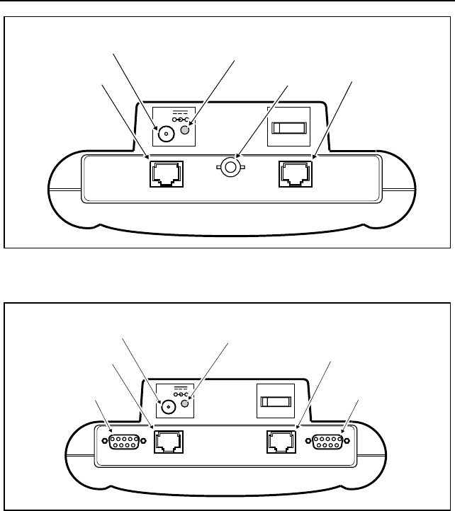
Battery Charger Status
The red Battery Charger Status LED is located next to the AC Adapter input
connector. Figure 10 shows the Fluke 686/685, Figure 11 shows the Fluke
683/682, and Figure 12 shows the Fluke 680. The Battery Charger Status LED
has several on/off patterns to indicate the charging state of the battery. The
Battery Charger Status LED is off when the AC Adapter is disconnected.
TO HUB/MAU TO NIC
18-28V
1.25A ON OFF
+-
TO HUB/MAU DB - 9
Connector
TO HUB/MAU RJ - 45
Connector
AC Adapter
Connector Battery Charger
Status LED TO NIC RJ - 45
Connector
TO NIC DB - 9
Connector
NOT FOR CONNECTION TO PUBLIC TELEPHONE SYSTEMS
BNC Connector
Figure 10. Network and AC Adapter Connectors (686/685 Shown)
Enterprise LANMeter
Setting Up Your Instrument
25
NOT FOR CONNECTION TO PUBLIC TELEPHONE SYSTEMS
TO HUB TO NIC
18-28V
1.25A
ON OFF
+-
TO HUB RJ - 45
Connector
AC Adapter
Connector Battery Charger
Status LED TO NIC RJ - 45
Connector
BNC Connector
Figure 11. Network and AC Adapter Connectors (683/682 Shown)
NOT FOR CONNECTION TO PUBLIC TELEPHONE SYSTEMS
TO MAU TO NIC
18-28V
1.25A
ON OFF
+-
TO MAU DB - 9
Connector
TO MAU RJ - 45
Connector
AC Adapter
Connector Battery Charger
Status LED TO NIC RJ - 45
Connector
TO NIC DB - 9
Connector
Figure 12. Network and AC Adapter Connectors (680 Shown)
The instrument has a fast charging capability to completely charge the battery
in about 2 1/2 hours. You can use a fully charged battery for about 3 hours.
Continuous use of the screen backlight reduces this time by about 30%.
You can leave the AC Adapter connected after the battery is completely
charged. It continues to trickle charge the battery and the Battery Charger
Status LED remains in the “charge complete” pattern.
68x Series
Getting Started
26
The instrument replaces the status line label with the battery icon when the
battery requires charging. Table 4 shows the battery charger status LED on/off
patterns. Refer to the “Maximizing Battery Life” section in Appendix C of the
Users Manual, for more information on the battery.
Table 4. Battery Charger Status LED
LED State Meaning
OFF External power is disconnected or battery is
absent.
ON Continuously Batteries are being fast-charged.
Fast (4 Hz) Blinking Battery charging has been completed; trickle
charging continues.
Slow (0.6 Hz) Blinking Batteries are not within the temperature and
voltage range for fast charging. Trickle
charging is occurring.
Setup/Utils
The instrument comes from the factory configured with default values. You
can configure test and setup parameters as required by your network or test
conditions. Refer to the appropriate section of the Users Manual for specific
information on test configurations. The following sections contain
configuration information accessible with the Setup/Utils softkey:
r Network Configuration
r Station List
r Manage Options
r File Manager
r Terminal Emulator
r System Information
r Update Software
r Time and Date
r Display Configuration
r Self Test
Enterprise LANMeter
Setup/Utils
27
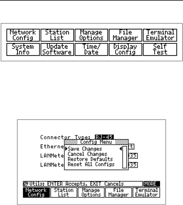
Figure 13 shows the Setup/Utils softkeys.
Figure 13. Setup/Utils Softkeys (Version 9.50)
Any configuration changes that you make are automatically saved to non-
volatile memory when you press G. You can undo configuration changes
before you press G by selecting Cancel Changes in the pop-up
Configuration Menu, and pressing I. Figure 14 shows a Configuration
Menu.
Figure 14. Configuration Pop-up Menu
You can use the factory defaults for the selected Setup/Utils category by
selecting Restore Defaults, and then pressing I from the Configuration
Menu (when available). The defaults are then saved to non-volatile memory
when you press G to exit the Setup/Utils category.
You can reset all Setup/Utils categories and test configurations by selecting
Reset All Configs, then pressing I from the Configuration Menu.
Resetting all configurations does not erase saved Station Lists.

68x Series
Getting Started
28
Note
For the Fluke 686 and 685, the
Reset All Configs
option has no
effect on the opposite interface mode. That is, selecting the
Reset
All Configs
option while in the Ethernet interface does not reset
configuration settings in the Token Ring interface, and vice versa.
Network Configuration
Press the top-level Setup/Utils softkey, and the Network Configuration
screen is automatically selected. Configure the following Ethernet or Token
Ring parameters to your specific testing requirements. The default parameters
are underlined.
Ethernet
Caution
Always configure the Fluke 686 and 683 LANMeter
instrument’s Ethernet Speed parameter to Auto Detect
when you are unsure whether you are attaching to a 10
Mbps or to a 100 Mbps Ethernet network.
Do not configure the LANMeter instrument for 100 Mbps
and then attach it to a 10 Mbps network. The presence of
the 100 Mbps link pulse on a 10 Mbps network effectively
brings down the network by preventing all stations from
transmitting.
Configuring the LANMeter instrument to 10 Mbps and then
attaching it to a 100 Mbps network causes erroneous
results (such as excessive collisions) to be reported.

Enterprise LANMeter
Setup/Utils
29
r Connector Type as RJ-45, or BNC
r Ethernet Speed as Auto Detect, 10 Mbps, or 100 Mbps (for RJ-45 only
and on Fluke 686 and 683 instruments only)
r LANMeter MAC as Predefined or user definable
The Auto Detect Ethernet Speed selection puts the instrument in a mode where
it automatically detects the network speed and sets its configuration to match
that speed. If the instrument is configured for Auto Detect and is then
connected to an auto-speed port, it automatically negotiates for a speed of 100
Mbps.
The LANMeter MAC is the MAC address used by the instrument while it is
inserted in the network.
Token Ring
Caution
Selecting an incorrect ring speed will cause the ring to
beacon.
r Connector Type as DB-9, or RJ-45
r Ring Speed as Auto, 4 Mbps, or 16 Mbps
r LANMeter MAC as Predefined or user definable
r Beacon Detect as Enable or Disable
The Auto ring speed selection puts the instrument in a mode where it
automatically detects the network speed and sets its configuration to match that
speed. The Auto ring speed selection should not be used when using smart
MAUs such as the IBM Controlled Access Unit (CAU), Lobe Attachment
Modules, or the Madge SmartCAU.
The Beacon Detect field enables or disables the Beacon pop-up window to
appear when a beacon frame is detected.

68x Series
Getting Started
30
Station List
A Station List is a list of symbolic station names (optional) and their associated
network addresses, which can be used in certain instrument tests. Refer to the
Users Manual, “Station List” chapter for more information on using Station
List.
Manage Options
Press the Manage Options softkey to enable software options such as
SwitchWizard and WideAreaWizard. Refer to the specific chapter in the
Users Manual for information on enabling any particular option. You can run
Manage Options to list the enabled options. The number of trial uses
remaining for software options (if any) is also listed.
File Manager
You can use File Manager to print, email, import, export, rename, or delete the
following types of saved files:
r Reports and Graphics
r Data Logs
r Station Lists
Press Setup/Utils and then press File Manager twice to access File
Manager. Refer to the Users Manual, “File Manager” chapter for more
information on File Manager functions. File Manager functions are also
available via the Web Agent measurement. Refer to the Users Manual, “Web
Agent/WebRemote Control” chapter for more information.

Enterprise LANMeter
Setup/Utils
31
Terminal Emulator
Terminal Emulator is a feature supported in the Fluke Enterprise LANMeter
(68x Series) instrument Software Version 9.50, and later, that gives you the
ability to use your LANMeter instrument to inspect and configure network
devices. Refer to the Users Manual, “Terminal Emulator Option” for more
information.
System Information
Pressing the top-level Setup/Utils softkey followed by the E key will
display the Sys Info screen. The System Info softkey will be highlighted.
You can view the instrument software and hardware revision levels, the
LANMeter instrument default MAC address (for the Fluke 686 and 685, both
Ethernet and Token Ring MAC addresses are shown) and whether the
backlight option is installed on your instrument.
Update Software
As new software becomes available, the instrument can be updated by using an
IBM-compatible computer and a Fluke supplied software update disk. Refer to
the “Software Update” section in Appendix D of the Users Manual, and the
documentation provided with the Fluke software update disk for information
on updating the LANMeter instrument software.
Time and Date
Use the following procedure to set the Time and Date:
1. Press the top-level Setup/Utils softkey.
2. Press E and then the Time/Date softkey.
3. Enter the current date and time using the numbers 0 through 9 and move
between fields using B, L, M or I.
4. Press G to save your changes to non-volatile memory and to return to
the top-level softkeys.

68x Series
Getting Started
32
Display Configuration
The Display Configuration screen allows you to configure the automatic screen
backlight. The following parameters can be configured for Display
Configuration (the defaults are underlined):
r Backlight Timeout as 1 minute, 5 minutes, or 10 minutes.
r Auto Backlight as Disable or Enable.
Use the following procedure to configure the automatic screen backlight:
1. Press the top-level Setup/Utils softkey.
2. Press E and then the Display Config softkey.
3. Use K and J to set the Backlight Timeout field to 1, 5, or 10 minutes.
4. Press L to select the Auto Backlight field.
5. Press K or J to enable or disable the backlight function.
After you set the Auto Backlight field to Enable, the screen backlight turns on
for the configured timeout period and then turns off. You can then turn on the
backlight again by pressing any key. While the backlight is on, you can press
and release H and then press T to turn off the backlight. Turning off
the backlight saves battery power when the instrument is not plugged in using
the AC adapter.
After you set the Auto Backlight field to Disable, the screen backlight turns
off after the configured timeout period. While the backlight is off, you can
press and release H and then press T to turn on the backlight for the
configured timeout period.

Enterprise LANMeter
Setup/Utils
33
Self-Test
The first time you turn on your LANMeter instrument on a particular day, the
instrument automatically performs extensive power-on self tests. All
subsequent power-on self tests for that day are less extensive and completed in
much less time.
You can verify correct operation of the instrument manually by using the
following procedure:
1. Press the top-level Setup/Utils softkey.
2. Press E and then the Self Test softkey.
3. Select the appropriate self-test and press I.
You can run the following self-tests on the LANMeter instrument:
1. LANMeter Self Test
2. LANMeter Keyboard Test
3. LANMeter Serial Test
4. 100 MHz Cable Remote Test
Self Test
When running the LANMeter Self Test, disconnect all cables from the
instrument TO MAU and TO NIC connectors. Verify that all tests pass. The
instrument displays the message Passed for each test to indicate proper
operation. These self tests are more extensive than the power-on self tests.
If the instrument reports a failure, perform the steps in the “Service Center
Repair” section of Appendix C “Maintenance” of the Users Manual.
Keyboard Test
When running the LANMeter Keyboard Test, manually perform the steps
displayed on the screen and verify that the test passed. The five softkeys
shown in Figure 4 are referred to as F1 through F5 with F1 being the leftmost
softkey and F5 the rightmost.

68x Series
Getting Started
34
Serial Test
When running the LANMeter Serial Test, attach a loopback connector to the
Serial connector on the lower left-hand side of the instrument. To make a
loopback connector, take a female DB-9 connector and connect jumpers
between pins 2 and 3 and between pins 6 and 7. Verify that all tests pass.
100 MHz Cable Remote Test
This test requires the optional 100 MHz Cable Remote. When running the 100
MHz Cable Remote Test, attach the supplied ScTP Cat 5 Patch Cable between
the LANMeter instrument’s TO HUB/MAU (686/685) or TO Hub (683/682)
and the 100 MHz Remote. Verify that all tests pass.
Attaching Cables
You attach cables to the instrument in one of the following three
configurations. The configuration that you use depends on the test you want to
run.
rTO MAU, TO HUB, or BNC Connection
rTO NIC Connection
rExpert-T Autotest Connection
The instrument lights the MAU (or HUB) and/or NIC LEDs on the top-front of
the instrument to indicate which of the LAN connectors you should use for the
selected test. The Fluke 680 has a MAU LED, the Fluke 683 and 682 have a
HUB LED, and the Fluke 686 and 685 have a HUB/MAU LED. Figure 2
shows these LEDs on the instrument’s user interface.
On the Fluke 686, 685, and 680 there are two TO MAU (or TO HUB) and two
TO NIC connectors, as shown in Figure 1. Each pair consists of an RJ-45 and
DB-9 type connector that are connected in parallel. Use only one TO MAU or
TO NIC connector at a time. If your network uses BNC connectors, use the
BNC connector as shown in Figure 1.
Warning
Do not connect the instrument to the public telephone
system. If you do, damage can occur to the LANMeter
instrument.
Enterprise LANMeter
Attaching Cables
35
THESE LEDS INDICATE WHICH
LAN CONNECTORS TO USE
SOFTKEYS
EXIT
STOP MORE
MENUTAB
ENTER
RUN
PRINT
HELP
ALPHA
SHIFT
ABC
789
456
123
0•SPACE
DEF
% UTILIZATION
HUB/MAU NIC
FRAME ERROR
BEACON
POLARITY
WIRE FAULT
LINK ACTIVE
INSERT
TRANSMIT
16 Mb/S
BNC
4 Mb/S
GHI
JKL
MNO
PQR
STU
VWYXZ
COLLISION
RING ERROR
686 ENTERPRISE LANMETER
10/100 ETHERNET
TOKEN RING
Figure 15. User Interface (Fluke 686 shown)
68x Series
Getting Started
36
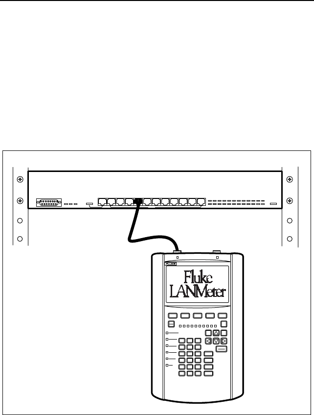
TO MAU, TO HUB, or BNC Connection
Most instrument tests require connecting only to the TO MAU (or TO HUB)
or BNC connector. Figure 16 and Figure 17 show the LANMeter instrument
connected to the network using the TO HUB/MAU and BNC connector,
respectively. Use one of the TO MAU (or TO HUB) or BNC connectors for
all cable tests. The Fluke 686 and 685 have TO HUB/MAU connectors and a
BNC connector, the Fluke 683 and 682 have a TO HUB connector and a BNC
connector, and the Fluke 680 has TO MAU connectors.
123456789101112
MDI-X
MDI-X/MD1
EXIT
STOP MORE
MENUTAB
ENTER
RUN
PRINT
HELP
ALPHA
SHIFT
ABC
789
456
123
0•
SPACE
DEF
% UTILIZATION
HUB NIC
FRAME ERROR
BEACON
POLARITY
WIRE FAULT
LINK ACTIVE
INSERT
TRANSMIT
16 Mb/S
BNC
4 Mb/S
GHI
JKL
MNO
PQR
STU
VWYXZ
COLLISION
RING ERROR
686 ENTERPRISE LANMETER
10/100 ETHERNET
TOKEN RING
HUB or MAU
Figure 16. TO HUB/MAU Connection Using RJ-45 Connector
Enterprise LANMeter
Attaching Cables
37
For 100BASE-TX or 10BASE-T cabling systems, select RJ-45 as the
connector type under Network Configuration, which is accessed by pressing
the Setup/Utils softkey. You can attach the instrument at the hub (a central
connecting point in a star-wired network) or at the station. When connecting at
the hub, use a cable connected between the hub and the instrument’s TO HUB
connector. When connecting at the station, disconnect the station’s cable from
the station and attach it to the instrument’s TO HUB connector. Figure 16
shows the instrument connected to a hub.
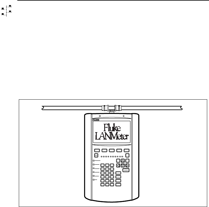
For a ThinLAN connection, select BNC as the connector type under Network
Configuration. Attach the instrument at the T-connector. Figure 17 shows a
BNC connection.
EXIT
STOP MORE
MENUTAB
ENTER
RUN
PRINT
HELP
ALPHA
SHIFT
ABC
789
456
123
0•
SPACE
DEF
% UTILIZATION
HUB NIC
FRAME ERROR
BEACON
POLARITY
WIRE FAULT
LINK ACTIVE
INSERT
TRANSMIT
16 Mb/S
BNC
4 Mb/S
GHI
JKL
MNO
PQR
STU
VWYXZ
COLLISION
RING ERROR
686 ENTERPRISE LANMETER
10/100 ETHERNET
TOKEN RING
Figure 17. BNC Connection
For an AUI connection, select RJ-45 as the connector type under Network
Configuration and use a 100BASE-TX-to-AUI or 10BASE-TX-to-AUI
adapter.

68x Series
Getting Started
38
For STP cabling systems, select DB-9; for UTP cabling systems, select RJ-45
as the connector type under Network Configuration. You can attach the
instrument at the Multi-station Access Unit (MAU) or at the station. When
connecting at the MAU, use a lobe cable connected between the MAU and the
instrument’s TO MAU connector. When connecting at the station, disconnect
the station’s lobe cable from the station and attach it to the instrument’s TO
MAU connector. Figure 16 shows the instrument connected to a MAU.
Note
In Token Ring networks and especially for the Phase Jitter test, it is
important to set the connector type correctly. Failure to do so could
result in excessive soft errors, ring purges, and/or beaconing. This is
due to the instrument’s internal termination being improperly set for
your network. The DB-9 setting provides a 150 ohm termination and
the RJ-45 setting provides a 100 ohm termination. Refer to the
“Running a Test” section in this manual for information on
configuring the Connector Type parameter.
Enterprise LANMeter
Attaching Cables
39
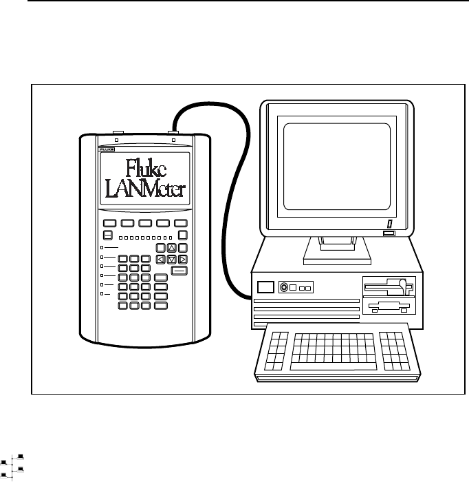
TO NIC Connection
Use the TO NIC connector for the NIC Autotest as shown in Figure 18.
EXIT
STOP MORE
MENUTAB
ENTER
RUN
PRINT
HELP
ALPHA
SHIFT
ABC
789
456
123
0•SPACE
DEF
% UTILIZATION
HUB NIC
FRAME ERROR
BEACON
POLARITY
WIRE FAULT
LINK ACTIVE
INSERT
TRANSMIT
16 Mb/S
BNC
4 Mb/S
GHI
JKL
MNO
PQR
STU
VWYXZ
COLLISION
RING ERROR
686 ENTERPRISE LANMETER
10/100 ETHERNET
TOKEN RING
Figure 18. TO NIC Connection
For 100BASE-TX or 10BASE-T networks, connect the NIC card to the
instrument’s TO NIC connector. Refer to the section on the test that you are
going to run for additional connection information.
For ThinLAN coaxial networks, the instrument and the NIC under test must be
the only devices on the network. The connection should be a relatively short
coaxial cable (less than 20 feet) with a single terminator and T connector at the
network interface card. The instrument automatically terminates its end of the
cable for this test.
68x Series
Getting Started
40
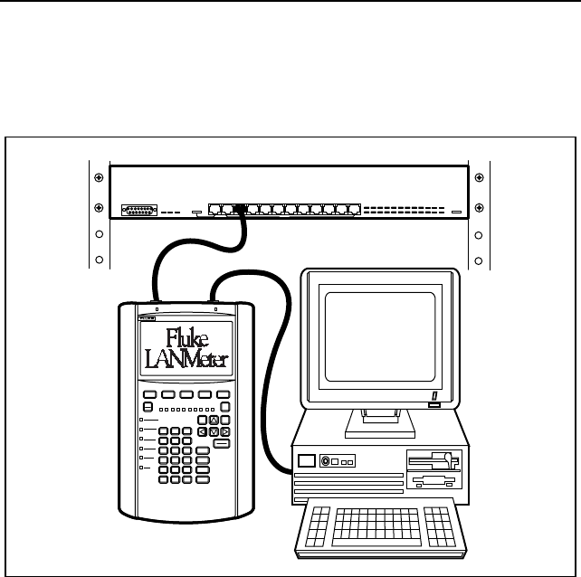
Expert-T Autotest Connection
Use both the TO MAU (or TO HUB) and TO NIC connectors for the Expert-T
Autotest as shown in Figure 19.
123456789101112
MDI-X
MDI-X/MD1
EXIT
STOP MORE
MENUTAB
ENTER
RUN
PRINT
HELP
ALPHA
SHIFT
ABC
789
456
123
0•SPACE
DEF
% UTILIZATION
HUB NIC
FRAME ERROR
BEACON
POLARITY
WIRE FAULT
LINK ACTIVE
INSERT
TRANSMIT
16 Mb/S
BNC
4 Mb/S
GHI
JKL
MNO
PQR
STU
VWYXZ
COLLISION
RING ERROR
686 ENTERPRISE LANMETER
10/100 ETHERNET
TOKEN RING
HUB or MAU
Figure 19. Expert-T Autotest Connections

Enterprise LANMeter
Running a Test
41
Running a Test
The instrument displays the top-level softkeys after it is turned on. The
MORE label above the Setup/Utils softkey label indicates that there are
additional softkeys on this level. Press E to access the second row of
softkeys. Figure 7 shows the instrument’s Ethernet top-level softkeys and
Figure 8 shows the instrument’s Token Ring top-level softkeys.
Use the following general procedure to run and stop a test.
1. Configure the instrument as required for your Ethernet or Token Ring
network. Verify that the Connector Type and the network speed
parameters are correct under Network Configuration, which is accessed by
pressing the Setup/Utils softkey from the top-level softkeys.
2. Select the desired test category by pressing the appropriate top-level
softkey. (Figures 5 and 6 show the LANMeter instrument’s softkey trees.)
3. Highlight the desired test to run.
The exact steps required to highlight a test depend on which test you want
to run. The first test is automatically highlighted. Otherwise, you either
press the test softkey once or press E, then press the test softkey once
(if there is a second row of tests).
4. Attach the appropriate cables. Refer to the previous “Attaching Cables”
section for more information.
5. Press the C softkey and select Configure to configure the test that
you are about to run unless you want to use the default settings. Some
tests do not have configurable parameters.
6. Press the test softkey a second time or press I to run the test.
7. Observe the test results.
8. Press G. (Some tests stop automatically and do not require pressing
G.)

68x Series
Getting Started
42
Auto Test
You can perform a quick analysis of the health of your network by running
Auto Test. After setting up your LANMeter instrument, configuring it and
connecting it to the network, as described in previous sections of this manual;
press I from the top-level softkey menu. This will automatically
configure the IP address of the LANMeter instrument using DHCP and initiate
the Segment Discovery test. Refer to the Users Manual, “Testing TCP/IP
Networks” chapter for more information on Auto Test, IP Auto Config and
Segment Discovery.

Enterprise LANMeter
Overview of Tests
43
Overview of Tests
Use the information in the following tables to help you select a test to
accomplish a particular task. Tables 5 through 15 show the appropriate test
category and test to use for the desired task. The test category is the same as
its top-level softkey.
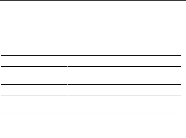
Table 5. Cable and Media Information and Problems
To Do the Following Task Use this Test Under this Test
Category
Verify a 100 MHz Cat 5 Cable installation. # Cable Autotest # Cable Tests
Measure cable lengths. Cable Scan Cable Tests
Find and isolate cable and connector
problems.
Cable Scan Cable Tests
Verify coax cable is terminated correctly. DC Continuity*Cable Tests
Map the physical layout of your network. Cable Identifier Cable Tests
Identify incorrect cable to connector wiring. Wire Map,
NEXT
Cable Tests
Determine the NVP of an unknown cable
type.
Find NVP Cable Tests
* Available only for Ethernet
# Requires the 100 MHz Cable Test Option
Table 6. Ethernet NIC and Hub Problems
To Do The Following Task Use This Test Under this Test
Category
Verify that a hub can successfully transmit
and receive traffic.
Hub Autotest NIC/Hub Tests
Test a NIC’s link pulse, transmit polarity,
and transmit level.
Identify the protocol a NIC is running.
NIC Autotest NIC/Hub Tests
Automatically check hub and NIC. Expert-T
Autotest
NIC/Hub Tests

68x Series
Getting Started
44
Table 7. Ethernet Performance Information
To Do The Following Task Use This Test Under this Test
Category
Identify the types and sources of collisions
and errors.
Error Statistics Network Monitor
Measure network utilization, collision, error,
and broadcast rates.
Network
Statistics
Network Monitor
Determine the affect of added traffic on the
collision and error rate.
Network
Statistics with
the Traffic
Generator
operating in the
background.
Network Monitor
Table 8. Ethernet and Token Ring Network Information
To Do The Following Task Use This Test Under this Test
Category
Identify the protocols running on the
network.
Protocol Mix Network Monitor
Determine the transmitting stations and
their protocols.
Protocol Mix Network Monitor
Identify stations (by MAC address) sending
and receiving the most traffic.
Top MAC or
MAC Matrix
Network Monitor
Determine the source and type of
broadcasts.
Top MAC (Top
Broadcasts)
Network Monitor
Test bridge, hub and router frame capacity. Traffic
Generator
Network Monitor
Test traffic patterns for switch placement. MAC Matrix Network Monitor
Discover the source of bottlenecks on
Cisco ISL trunk lines.
Protocol Mix Network Monitor

Enterprise LANMeter
Overview of Tests
45
Table 9. Token Ring Network Information
To Do The Following Task Use This Test Under this Test
Category
List stations currently attached to the ring.
Identify the active monitor.
Map stations to lobe cables.
Ring Stations Network Monitor
Determine if the network is operating
efficiently.
Network
Statistics
Network Monitor
Identify and locate a noisy lobe cable or
network interface card.
Determine the source and causes of soft
errors.
Error Statistics Network Monitor
Determine the route, maximum frame size,
and number of hops between stations
across Token Ring source routing bridges.
Verify network connectivity across Token
Ring source routing bridges.
Station Ping Network Tests
Identify stations performing Token Ring
functions, such as Ring Error Monitor.
Adapter Status Network Tests
Remove a station from the ring. Remove Station Network Tests
Troubleshoot a beaconing ring. Network
Statistics
Network Monitor
Determine ring speed as 4 Mbps or 16
Mbps.
Network
Statistics
configured for
AUTO speed in
Network Config
Network Monitor
Calculate the Adjusted Ring Length (ARL).
Measure the Token Rotation Time.
Token Rotation
Time
Network Monitor
Quantify what percentage of traffic is ring
maintenance.
Protocol Mix Network Monitor
Determine if your network is operating on
the secondary (backup) path.
Token Rotation
Time
Network Monitor
Verify that a lobe cable can pass 4 Mbps
and/or 16 Mbps traffic.
Lobe Test NIC/MAU Tests
Measure the relative noise level on your
network.
Phase Jitter Network Tests

68x Series
Getting Started
46
Table 10. Token Ring NIC and MAU Problems
To Do The Following Task Use This Test Under this Test
Category
Identify a stuck MAU port or verify MAU
operation.
MAU Autotest &
MAU Reset
NIC/MAU Tests
Monitor the NIC insertion process. NIC Autotest NIC/MAU Tests
Verify that an NIC can insert into a MAU. Expert-T
Autotest
NIC/MAU Tests
Determine why a NIC cannot insert into a
network.
Expert-T
Autotest
NIC/MAU Tests

Enterprise LANMeter
Overview of Tests
47
Table 11. Novell NetWare Network Information
To Do The Following Task Use This Test Under this Test
Category
Verify network connectivity across a
NetWare router.
NetWare Ping Novell NetWare
List nearest server and frame type.
List of all servers.
List of file servers.
Server List Novell NetWare
Identify stations (by IPX network address)
sending and receiving the most traffic.
Top NetWare
(Top Senders
and Top
Receivers)
Novell NetWare
Load balance NetWare traffic for segments
and rings.
Determine the percentage of traffic that is
routed.
Routing
Analysis
Novell NetWare
Identify overloaded servers.
Determine which stations are placing the
largest demand on servers.
NetWare Stats
(File Statistics
and Packet
Statistics)
Novell NetWare
Determine the percentage of traffic that is
burst mode.
NetWare Stats
(Packet
Statistics)
Novell NetWare
Determine the local IPX network number. Server List,
Routing
Analysis,
NetWare Stats
(File Statistics
and Packet
Statistics)
Novell NetWare
Identify the encapsulation types used. Server List
Protocol Mix
NetWare Ping
Novell NetWare
Network Monitor
Novell NetWare

68x Series
Getting Started
48
Table 12. TCP/IP Configuration and Performance
To Do the Following Task Use This Test Under this Test
Category
Automatically have the LANMeter
instrument assist in its own IP
configuration.
IP Auto Config Internet TCP/IP
Discover IP configuration of attached
network.
Segment
Discovery
Internet TCP/IP
Analyze a troublesome IP host. Scan Host Internet TCP/IP
Analyze the path through the network that
an IP session would follow.
Trace Route Internet TCP/IP
Focus on host identification, configuration
and attached interface health and
performance.
Internet Toolkit Internet TCP/IP
Identify Duplicate IP Addresses. Segment
Discovery
Scan Host
Internet TCP/IP
Monitor the status of important user
designated IP devices.
Segment
Discovery (Key
Devices)
Internet TCP/IP
Analyze the performance of remote LAN
segments.
Internet Toolkit Internet TCP/IP
Identify the Node names of TCP/IP stations
so that the LANMeter instrument can use
names instead of Hex addresses.
Segment
Discovery
Internet TCP/IP
Verify network connectivity.
Given an IP address, find out the MAC
address.
ICMP Ping Internet TCP/IP
Identify stations by IP address that are
sending and receiving the most traffic.
Top IP (Top
Senders and
Top Receivers)
Internet TCP/IP
Identify misconfigured routers and hosts.
Find congested routers and gateways.
Locate routing loops.
ICMP Monitor Internet TCP/IP
Find route to an IP host. Trace Route Internet TCP/IP
Analyze IP traffic flow for router load
balancing.
IP Matrix Internet TCP/IP

Enterprise LANMeter
Overview of Tests
49
Table 13. Banyan VINES Client/Server Connectivity
To Do the Following Task Use This Test Under this Test
Category
Identify available VINES devices that can
provide a VINES client with a dynamic VIP
address.
Address
Servers
Banyan VINES
Discover available VINES servers, local or
remote
Server
Discovery
Banyan VINES
Identify stations (by VIP Address) sending
and receiving the most traffic.
Top VINES
(Top Senders
and Top
Receivers)
Banyan VINES
Table 14. NetBIOS Configuration and Performance
To Do the Following Task Use This Test Under this Test
Category
Automatically have the LANMeter
instrument assist in its own IP configuration
for NetBIOS over TCP/IP environments.
IP Auto Config NetBIOS
Discover the available NetBIOS domains
and identify critical servers acting as
Master Domain Controllers and Master
Browsers.
NetBIOS
Discovery
NetBIOS
Identify the node names of NetBIOS
stations so that the LANMeter instrument
can use names instead of Hex addresses.
NetBIOS
Discovery
NetBIOS
Check the availability of a NetBIOS station
for a variety of protocols.
NetBIOS Ping NetBIOS
Identify NetBIOS stations that are sending
and receiving the most traffic.
Top NetBIOS
(Top Senders
and Top
Receivers)
NetBIOS

68x Series
Getting Started
50
Table 15. Utilities
To Do the Following Task Use This Test Under this Test
Category
Email, Print, Import, or Export files to or
from LANMeter.
File Manager Setup/Utils
Inspect or change the configuration of
network devices using the LANMeter’s
serial connection.
Terminal
Emulator
Setup/Utils
Remotely monitor the LANMeter
instrument using a web browser.
Web Agent Web Agent
Remotely control the LANMeter instrument
using a web browser.
Web Agent
(WebRemote
Control)
Web Agent
51
Index
100 MHz Cable Test Option, 2
100 MHz Remote, 2
Self Test, 34
100BASE-TX Cabling Systems
Selecting Connector Type, 37
100BASE-TX-to-AUI Adapter, 37
10BASE-T
Connection, 22
10BASE-T Cabling Systems
Selecting Connector Type, 37
10BASE-TX-to-AUI Adapter, 37
16 Mbps
LED Indicator, 22
3 ½-inch Utility Diskette, 4
4 Mbps
LED Indicator, 23
AC Adapter, 4, 5, 24, 25
Adapter
100BASE-TX-to-AUI, 37
10BASE-TX-to-AUI, 37
Address Mode, 16
Alphanumeric Keys, 18, 19
Attaching Cables, 34
AUI Connection
Selecting Connector Type, 37
Auto Detect
Ethernet Speed, 29
Auto Ring Speed, 29
Auto Screen Backlight, 32
Auto Test, 33, 42
Backlight
Screen
ALPHA Key, 18
Backlight, Auto, 32
Battery
Charge Time, 25
Charger Status LED, 21, 24, 25
Charging State, 24
Fast Charging, 25
Low-Battery Indicator, 26
Beacon Frame, 22, 29
BNC
Connection, 36
Connector, 23
Cable Identifier #0 Remote Adapter, 4
Cables
Attaching, 34
Caution
Fluke 686
and 683 Speed Configuration, 28
Selecting incorrect ring speed, 29
Changing the Network Interface, 6
Claim Token, 22
Collision Frame
Late, 22
Local, 22
Remote, 22
Configuration
Default Values, 26, 27
Fluke 686 and 683, 29
Menu, 27
Network Configuration, 28
Resetting Default Values, 27
Saving Changes, 27
Undoing Changes, 27
Configuring
Instrument, 26
Tests, 9
Connection
AC Adapter, 5

68x Series
Getting Started
52
BNC, 36
Expert-T Autotest, 40
NIC Autotest, 39
TO HUB, 36
TO MAU, 36
TO NIC, 39
Connector
AC Adapter, 5, 24
BNC, 23
Ethernet Types, 29
HUB/MAU, 23
Serial, 34
To NIC, 23
Token Ring Types, 29
Connector Type
Selecting
100BASE-TX Cabling Systems, 37
10BASE-T Cabling Systems, 37
AUI Connection, 37
STP Cabling Systems, 38
ThinLAN Cabling Systems, 37
Connectors
Fluke 680, 36
Fluke 682, 36
Fluke 683, 36
Fluke 685, 36
Fluke 686, 36
Default Configuration Values, 26, 27
Resetting, 27
Display
Changing Contrast, 8, 9, 17
Navigation, 17
Page Down, 17
Page Up, 17
Scrolling, 17
Display Configuration, 32
Enterprise LANMeter
Uses of, 3
Equipment Supplied, 4
Ethernet
Interface Icon, 4
Top-Level Softkeys, 41
Ethernet Speed
Auto Detect, 100 Mbps, and 10 Mbps,
29
Configuring, 29
HUB LED Indicator, 23
MAU LED Indicator, 23
NIC LED Indicator, 23
Expert-T Autotest
Connection, 40
Expert-T Mode, 22
File Manager
Introduction, 30
Fluke 680
Labeling, 23
TO MAU Connectors, 36
Fluke 682
Labeling, 23
TO HUB and BNC Connectors, 36
Fluke 683
Fast Ethernet Capability, 2
Labeling, 23
TO HUB
and BNC Connectors, 36
Fluke 685, 21
Labeling, 23
TO HUB/MAU and BNC Connectors,
36
Fluke 686, 21
and 683, Configuration, 29
and 683, Speed Configuration Caution,
28
Fast Ethernet Capability, 2
Labeling, 23
TO HUB/MAU and BNC Connectors,
36
Fluke 68x Series Instruments, 1
Frame Check Sequence
Bad, 21
Getting Started Manual, 4
Hardware Revision
Of the LANMeter Instrument, 31
Help Key, 18
Hub, 22
HUB/MAU Connector, 23
Icon

Contents
(continued)
53
Ethernet Interface, 4
Interface Mode, 4
Token Ring Interface, 4
Inserting Into the Ring, 22
Instrument
Case, 4
LEDs, 34
Setting Up for Use
AC Adapter, 5
Attaching Cables, 34
Running a Test, 41
Interface
Change, 6, 16
Interface Mode Icons, 4
Introduction, 1
Key
ALPHA, 18, 19
Alphanumeric, 10, 19
Arrow, 16
Dedicated, 10, 15
ENTER/RUN, 15
EXIT/STOP, 16
Extended (Shift) Functions, 17
HELP, 18
MENU, 16
MORE, 15, 17
Print, 16
Red (Secondary) Key
Functions, 18
SHIFT, 17
SPACE, 19
TAB, 16
I, 15
Keyboard, 6, 10
Keyboard Test, 33
LANMeter Instrument
Default MAC Address, 31
Equipment Supplied, 4
MAC Address of the, 29
Uses of, 3
LCD Display, 6, 8
Auto Backlight, 32
Display Configuration, 32
Parts of, 8
Screen Backlight
ALPHA Key, 18
LED Indicators, 6, 21
16 Mb/s, 22
4 Mb/s, 23
Bargraph, 21
Network Utilization, 21
Battery Status, 21, 24, 25
Beacon, 22
BNC, 23
Collision, 22
For Fluke 685, 21
For Fluke 686, 21
Frame Error, 21
HUB, 23
Dual-Color, 23
Ethernet Speed, 23
Individual (status), 6, 21
Insert, 22
Instrument, 34
Link Active, 22
MAU, 23
Dual-Color, 23
Ethernet Speed, 23
Network Connector, 21
NIC, 23
Dual-Color, 23
Ethernet Speed, 23
Polarity, 22
Ring Error, 22
Transmit, 22
Using for Problem Isolation, 21
Wire Fault, 22
Link Pulse, 22
Lobe Test, 21
Lobe Wiring Fault, 22
Loopback Connector, 34
Making a, 34
MAC Address
of the LANMeter Instrument, 29
Manage Options, 30
MAU, 22
Neighbor Notification
Incomplete, 22
Network Conditions
Shown on LEDs, 21

68x Series
Getting Started
54
Network Configuration, 28
Default Values, 28
NIC Autotest, 22, 23
Connection, 39
NIC Speed, 22, 23
Options
Cable Remote, 2
Cable Test, 2
Manage, softkey, 30
SwitchWizard, 2
Terminal Emulator, 3, 31
WebRemote Control, 3
WideAreaWizard, 3
Overview of Tests, 43
Page Down, 17
Page Up, 17
Patch Cable
ScTP Cat 5, 34
Polarity
Reversed, 22
Pop-Up Menus, 9, 16
Accessing, 9
Closing, 15
Responding to Choices, 16
Using, 9
Printing
ASCII Text, 16
To Serial Port, 16
To Virtual Disk, 16
Remote
Self Test, 34
Ring Error, 22
Ring Purge, 22
Ring Speed, 22, 23, 29
Auto, 29
Running
a Test, 41
Saving Configuration Changes, 27
ScTP Cat 5 Patch Cable, 34
Self Test, 33
100 MHz Cable Remote, 34
Auto Test, 33
Keyboard Test, 33
Running, 33
Serial Test, 34
Serial Connector, 34
Serial Test, 34
Setting Up Your Instrument, 4
Setup/Utils, 26
Softkey Labels, 8, 9
Highlighted, 14
Two Kinds, 14
Softkey Tree, 11
Softkeys, 7, 10, 11
Accessing Additional, 14, 15
Labels, 11
Second Level, 14
Top-Level, 9, 11, 14
Returning to, 16
Using, 11
Software
Updating the LANMeter Instrument,
31
Software Revision
Of the LANMeter Instrument, 31
Speed Configuration
Fluke 686 and 683 Caution, 28
Station Addresses, 16
Displaying Different Formats, 16
Dotted Decimal, 16
Hexadecimal (MAC), 16
Manufacturer Prefix, 16
Symbolic Name, 16, 30
Station List
Usage and Description, 30
Status Line, 8, 9
STP Cabling Systems
Selecting Connector Type, 38
Strings
Entering, 20
SwitchWizard
Option, 2
System Information, 31
Terminal Emulator, 3, 31
Test
Expert-T Autotest
Connection, 40
NIC Autotest

Contents
(continued)
55
Connection, 39
Overview of Tests, 43
Results, 16
Running, 14, 41
Stopping, 16
ThinLAN Cabling Systems
Selecting Connector Type, 37
Time and Date
Setting, 31
TO HUB Connection, 36
TO MAU Connection, 36
TO NIC Connection, 39
Token Ring
Interface Icon, 4
Top-Level Softkeys, 41
Top-Level Menu, 8
Top-Level Softkeys
Ethernet, 11
Ethernet, 41
Token Ring, 11, 41
Transmitting a Frame, 22
Updating the LANMeter Instrument
Software, 31
User Interface
Differences Between Ethernet and
Token Ring, 6
Parts of, 6
Users Manual, 4
Warning
Do not connect, 34
WebRemote Control, 3
WideAreaWizard
Option, 3
Wire Map/Cable Identifier #0 Remote
Adapter, 4
Work Area, 8

68x Series
Getting Started
56
