Manual FR77 2016 OCT FR 77 18' & 20' (Oct 2016)
User Manual: FR-77-18' & 20' Manual (Oct 2016)
Open the PDF directly: View PDF ![]() .
.
Page Count: 44
Aug. 2016
18' & 20' Tilt, 2P10T-7.7K
(Steel Plate Platform)
Frame Rack Machine
MODEL FR-77
USER’S MANUAL
2
FR-77
Aug. 2016
INTRODUCTION
With the development of automobile design and manufacturing technology, more and more new
materials are used on the body of the vehicle. Traditional vehicles are made by low or medium
carbon steel, while modern unibody vehicles are made by high-strength steel. So the repair
needs high technology and good equipments.
When the vehicle is damaged, the repair workers should use pulling system to adjust it but not
use fire if not necessary, because fire can change the structure of the metal and reduce the auto
body’s strength. When the vehicle is crashed again, the body cannot protect the passengers as
before.
Our auto collision repairing systems uses the hydraulic pulling system and many kinds of
accessories to pull the damaged parts into original. The measuring system will make the
adjustment the same as the given data from the dimension manual.
This manual is to talk about the installation, training, operation, and maintenance of Auto
Collision Repairing System. It will tell the repairmen how to use this product and the
accessories.
During the installation and operation, the workers must do exactly as this manual says, or it will
cause accidents and human’s injury. When the workers are operating the equipment, the
pressure and load cannot surpass the required maximum pressure and load.
FR-77 is especially designed for workers to do more quick adjustment and to better working
experience. We give these equipment users more humane care by sensible design and
configuration
3
FR-77
Aug. 2016
CONTENT
INTRODUCTION .............................................................................................................................................................. 2
CONTENT ......................................................................................................................................................................... 3
Chapter 1 SAFETY CAUTIONS........................................................................................................................................ 5
Chapter 2 SPECIFICATIONS ............................................................................................................................................ 6
Chapter 3 COMPONENTS ................................................................................................................................................. 7
Chapter 4 PACKAGE & TRANSPORT ........................................................................................................................... 14
4.1 Package ....................................................................................................................................................................... 14
4.2 Loading ....................................................................................................................................................................... 14
4.3 Transport ..................................................................................................................................................................... 15
Chapter 5 INTRODUCTIONS ......................................................................................................................................... 16
5.1 Auto supporting system .............................................................................................................................................. 16
5.3 Auto Pulling system .................................................................................................................................................... 16
5.4 Hydraulic system ........................................................................................................................................................ 17
5.4.1 Hydraulic elements and flow chart .................................................................................................................. 17
5.4.2 Hydraulic safety cautions ................................................................................................................................ 18
5.5 Other tools .......................................................................................................................................................... 18
Chapter 6 INSTALLATION & OPERATION .................................................................................................................. 19
6.1 Platform installation.................................................................................................................................................... 19
6.1.1 Location requirement ....................................................................................................................................... 19
6.1.2 Fixing support installation ............................................................................................................................... 19
6.1.3 Movable support installation. .......................................................................................................................... 20
6.1.4 Locking bar installation ................................................................................................................................... 20
6.1.5 Lifting support installation............................................................................................................................... 20
6.2 Pulling tower installation ............................................................................................................................................ 22
6.2.1 Tower rolling system installation ..................................................................................................................... 22
6.2.2 Post guiding system installation ...................................................................................................................... 23
6.2.3 Collar installation ............................................................................................................................................. 23
6.2.4 Cylinder, extend bar installation ...................................................................................................................... 24
6.2.5 Upper puller installation .................................................................................................................................. 25
6.2.6 Install the post on the platform ........................................................................................................................ 26
6.3 Main clamps installation ............................................................................................................................................. 27
6.4 Hydraulic system installation ..................................................................................................................................... 28
6.4.1 Safety caution .................................................................................................................................................. 28
6.4.2 Installation .................................................................................................................................................... 28
6.4.3 Maintenance ..................................................................................................................................................... 29
6.4.4 Hydraulic system specifications ...................................................................................................................... 29
6.4.5 Common problems of hydraulic system .......................................................................................................... 29
4
FR-77
Aug. 2016
6.5 Accessories installation ............................................................................................................................................... 30
6.5.1 Wheel trolley ................................................................................................................................................... 30
6.5.2 Wheel support bracket ..................................................................................................................................... 30
6.6 Loading and fixing the car .......................................................................................................................................... 31
6.6.1 Loading ............................................................................................................................................................ 31
6.6.2 Fixing the car ................................................................................................................................................... 33
Chapter 7 AUTO BODY REPAIR DEMONSTRATION ................................................................................................. 34
7.1 Auto body repair principle .......................................................................................................................................... 34
7.2 Chassis repair technology ........................................................................................................................................... 34
7.3 Collision repair process .............................................................................................................................................. 34
7.4 Pulling process ............................................................................................................................................................ 35
7.5 Auto repair .......................................................................................................................................................... 36
7.5.1 Auto front-end repair ....................................................................................................................................... 36
7.5.2 Auto back-end repair ........................................................................................................................................ 36
7.5.3 Auto side body repair ....................................................................................................................................... 37
7.5.4 Auto ceiling repair ........................................................................................................................................... 37
7.6 Cautions during Auto repair ................................................................................................................................ 37
Chapter 8 EQUIPMENT MAINTENANCE .................................................................................................................... 39
Chapter 9 TROUBLE SHOOTING .................................................................................................................................. 40
Chapter 10 END ............................................................................................................................................................... 41
5
FR-77
Aug. 2016
Chapter 1 SAFETY CAUTIONS
Safety is the most important requirement. The workers should use the products very
carefully.
1. Before repairing the damaged vehicle, the workers must refer to the service manual of the
manufacturer’s manual, do as what the book says.
2. Before repairing, the workers must measure and analyze the damaged vehicle, then make
adjustment process planning, and do according to it.
3. Before repairing the damaged vehicle, use the handbrake to avoid the movement of the
vehicle.
4. When the platform is lifted or descended, pay attention to the tools, hydraulic tubes and air
tubes, etc. it is forbidden to bake the hydraulic pump by fire.
5. Check the seal of hydraulic system often.
6. The workers who are not trained are forbidden strictly to operate the product.
7. Before pulling, the damaged vehicle must be clamped tightly. During the pulling, the
vehicle is forbidden to move.
8. The pulling tools must be clamped tightly on the damaged parts, make sure that the pulling
tools cannot come off during pulling.
9. During the pulling, it is forbidden to use jack to anchor the damaged vehicle, and the
workers are forbidden to stand under the vehicle.
10. During the pulling, the pressure gauge of the hydraulic pump should not surpass 6000PSI.
11. The workers are forbidden to stand beside the vehicle when the vehicle is lifting. Some
workers should help the driver to control the direction beside the platform when the vehicle
is loading. The workers are forbidden to stand behind the stressed chain or pulling tools.
12. Before using the chain, check whether there are any bend, twist, knot, damaged parts, if
there are, change the chain at once.
The chain is forbidden to use bolt or bend to make it longer or shorter, if necessary, use
the special tool (e.g. DC-G4120). It is forbidden to bake the chain by fire.

6
FR-77
Aug. 2016
Chapter 2 SPECIFICATIONS
Specifications:
ITEM FR-77-18 FR-77-20
Bench Length 18’ 20’
Bench Width 82.68” 82.68”
Bench Height 19.70” 19.70”
Hydraulic pressure 10,000 Psi 10,000Psi
Post Max. Tension 10 Ton 10 Ton
Post Working Rang 360º 360º
Pneumatic Pressure Range 115 Psi 115 Psi
Max. Lifting Weight 7700 lbs 7700 lbs
Total Weight 5071 lbs 5953 lbs
7
FR-77
Aug. 2016
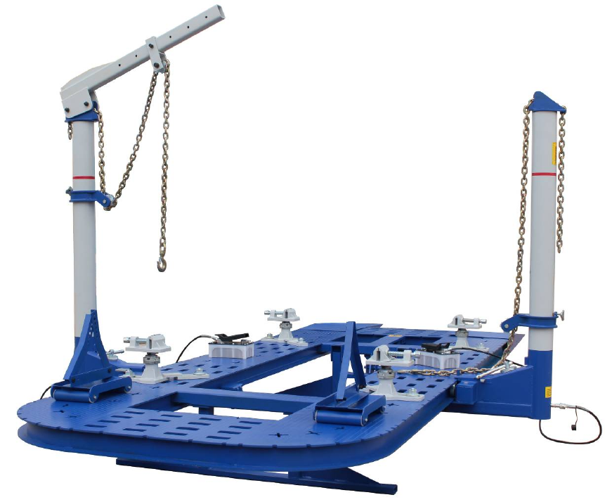
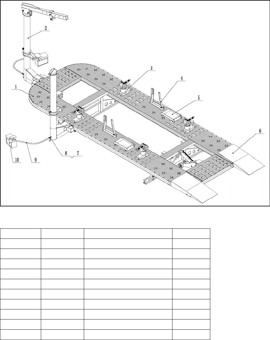
Chapter 3 COMPONENTS
Fig. 3-1
ITEM CODE DESCRIPTION QTY
1 154103*1-01 Platform assembly 1
2 154103*1-02 Tower component 2
3 154103*1-03 Main clamp 4
4 154103*1-04 Wheel support bracket 2
5 154103*1-05 Car trolly 2
6 154103*1-06 Ramps 2
7 154103*1-07 Direct connecting joint 2
8 154103*1-08 Female joint 2
9 154103*1-09 Oil tube 2.5m 2
10 154103*1-10 Pump 2
8
FR-77
Aug. 2016
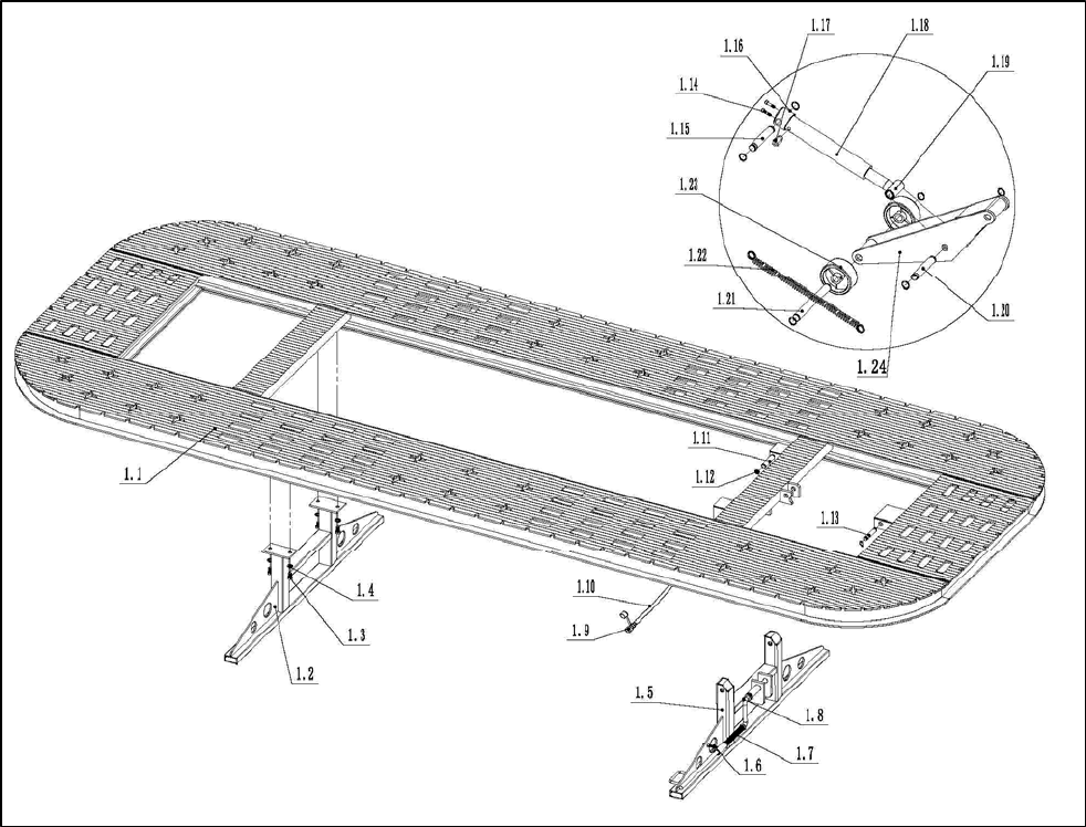
Fig. 3-2

9
FR-77
Aug. 2016
ITEM CODE DESCRIPTION QTY
1.1 154103-2-1.1 Platform welding 1
1.2 154103-2-1.2 Fixed support assembly 1
1.3 154103-2-1.3 Bolt M16*30 2
1.4 154103-2-1.4 Washer 16 2
1.5 154103-2-1.5 Movable support assembly 1
1.6 154103-2-1.6 Movable support below guide tube 1
1.7 154103-2-1.7 Press spring Ø26.5*Ø1.5*250 1
1.8 154103-2-1.8 Operate rod 1
1.9 154103-2-1.9 Female joint 1
1.10 154103-2-1.10 Oil tube 1.5m 1
1.11 154103-2-1.11 Movable support shaft 2
1.12 154103-2-1.12 Bead flange 26 14
1.13 154103-2-1.13 Lift shaft 1
1.14 154103-2-1.14 Screw M8*15 2
1.15 154103-2-1.15 Cylinder support shaft 1
1.16 154103-2-1.16 Cylinder basement 1
1.17 154103-2-1.17 0.4 throttle valve 1
1.18 154103-2-1.18 Cylinder RC1010 1
1.19 154103-2-1.19 Cylinder joint 1
1.20 154103-2-1.20 Cylinder support shaft 1
1.21 154103-2-1.21 Lift shaft 1
1.22 154103-2-1.22 Tension spring Ø25*Ø3*300 1
1.23 154103-2-1.23 Wheel Ø126*26*55 2
1.24 154103-2-1.24 Lift support welding 1
10
FR-77
Aug. 2016
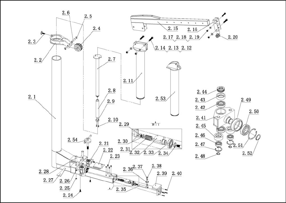
Fig. 3-3

11
FR-77
Aug. 2016
ITEM CODE DESCRIPTION QTY
2.1 154103*3-2.1 Hand bolt 2
2.2 154103*3-2.2 Collar assembly 2
2.3 154103*3-2.3 Collar axle 2
2.4 154103*3-2.4 Bead flange 26 4
2.5 154103*3-2.5 Sprocket wheel of collar 2
2.6 154103*3-2.6 Post assembly 2
2.7 154103*3-2.7 Upper puller base 2
2.8 154103*3-2.8 Cylinder RC1010 2
2.9 154103*3-2.9 Cylinder basement 2
2.10 154103*3-2.10 M8X20 screw 4
2.11 154103*3-2.11 Upper puller head assembly 2
2.12 154103*3-2.12 Bolt M20*110 6
2.13 154103*3-2.13 washer 20 6
2.14 154103*3-2.14 Nut M20 6
2.15 154103*3-2.15 Upper puller 2
2.16 154103*3-2.16 Hang ring 2
2.17 154103*3-2.17 Bolt M16*110 2
2.18 154103*3-2.18 washer 16 2
2.19 154103*3-2.19 Nut M16 2
2.20 154103*3-2.20 Ratchet wheel 2
2.21 154103*3-2.21 Traveling assembly 4
2.22 154103*3-2.22 Locking plate 2
2.23 154103*3-2.23 Screw M10*25 8
2.24 154103*3-2.24 Bolt M24*50 8
2.25 154103*3-2.25 Stop collar 8
2.26 154103*3-2.26 Cushion cover 4
2.27 154103*3-2.27 Locking plate 4
2.28 154103*3-2.28 Traveling assembly pin 2
2.29 154103*3-2.29 Flange side bolt M24 4
2.30 154103*3-2.30 washer 24 4

12
FR-77
Aug. 2016
ITEM CODE DESCRIPTION QTY
2.31 154103*3-2.31 Guide rod compress spring 2
2.32 154103*3-2.32 Bear basement 2
2.33 154103*3-2.33 bear 6024 2
2.34 154103*3-2.34 Stop collar 40 2
2.35 154103*3-2.35 Guide rod 2
2.36 154103*3-2.36 idler wheel 2
2.37 154103*3-2.37 Bear 2515 2
2.38 154103*3-2.38 Stop collar 25 2
2.39 154103*3-2.39 Hook plate 2
2.40 154103*3-2.40 Screw M12*30 8
2.41 154103*3-2.41 Traveling assembly basement 4
2.42 154103*3-2.42 Bear 6206 2
2.43 154103*3-2.43 Traveling inner spacer bush 4
2.44 154103*3-2.44 Bear 51206 4
2.45 154103*3-2.45 Traveling idler wheel 8
2.46 154103*3-2.46 Bear 6204 8
2.47 154103*3-2.47 Stop collar 47 8
2.48 154103*3-2.48 Stop collar 20 8
2.49 154103*3-2.49 Traveling idler wheel 4
2.50 154103*3-2.50 Bear 6208 4
2.51 154103*3-2.51 Stop collar 80 4
2.52 154103*3-2.52 Stop collar 40 4
2.53 154103*3-2.53 Extension head assembly 2
2.54 154103*3-2.54 Locking bolt assembly 2
13
FR-77
Aug. 2016
Fig. 3-4
ITEM CODE DESCRIPTION QTY
3.1 154103*4-3.1 Bolt M16*150 (12.9 degree) 4
3.2 154103*4-3.2 Main clamp slot fixing board 4
3.3 154103*4-3.3 Slide fixing board 4
3.4 154103*4-3.4 Rotational positioning block 8
3.5 154103*4-3.5 Screw M8*25 16
3.6 154103*4-3.6 Big nut 4
3.7 154103*4-3.7 Bolt M20*80 4
3.8 154103*4-3.8 Cone 4
3.9 154103*4-3.9 Movable jaw 4
3.10 154103*4-3.10 Stop collar 16
3.11 154103*4-3.11 Connecting plate 4
3.12 154103*4-3.12 spacer bush 8
3.13 154103*4-3.13 hexagon socket screw M14*40 8
3.14 154103*4-3.14 Main clamp basement 4
14
FR-77
Aug. 2016
Chapter 4 PACKAGE & TRANSPORT
4.1 Package
The equipment is packed with two lay
of stretch film and one lay of
corrugated paper. See Figure 4.1
Figure4.1
4.2 Loading
If loading with the traveling crane, the loading capacity of the traveling crane should no less
than 3T. In order to avoid incline, the cable sling should be tied at least 4 point at 4 corners of
the platform. If loading with the fork lift, the lift arm should be over 2 meter, and the lifting
capacity of the fork lift over 5T. The fork arm should goes into the platform from the long side.
Keep the whole equipment in balance while loading or unloading. See Figure 4.2
15
FR-77
Aug. 2016
Figure4.2
4.3 Transport
FR-77 during transport, should chose large-tonnage truck, also should take the length and
width into consideration according to the specifications of the equipment. The equipment should
be well packed and fixed to the truck to prevent from water stain and bump.
16
FR-77
Aug. 2016
Chapter 5 INTRODUCTIONS
FR-77 auto chassis straightening machine can be used for auto loading, fixing, repairing and
measuring. This chapter is meanly introducing the configuration and working theory. The
detailed information about installation and operation will be particularly introduced in chapter 6.
FR-77 series auto chassis straightening machine including:
5.1 Auto supporting system:Including platform, fixed support, movable support, lift
support. The auto supporting system is used to park the car on the platform, which is the
operating table for damaged vehicles. See figure 5.1
Figure 5.1
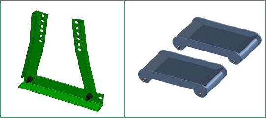
5.2 Auto fixing system:Include Main
clamp basement, clamp head, bolts and
nuts. See figure 5.2
Figure 5.2
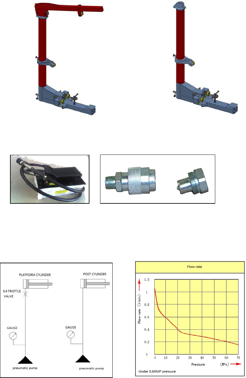
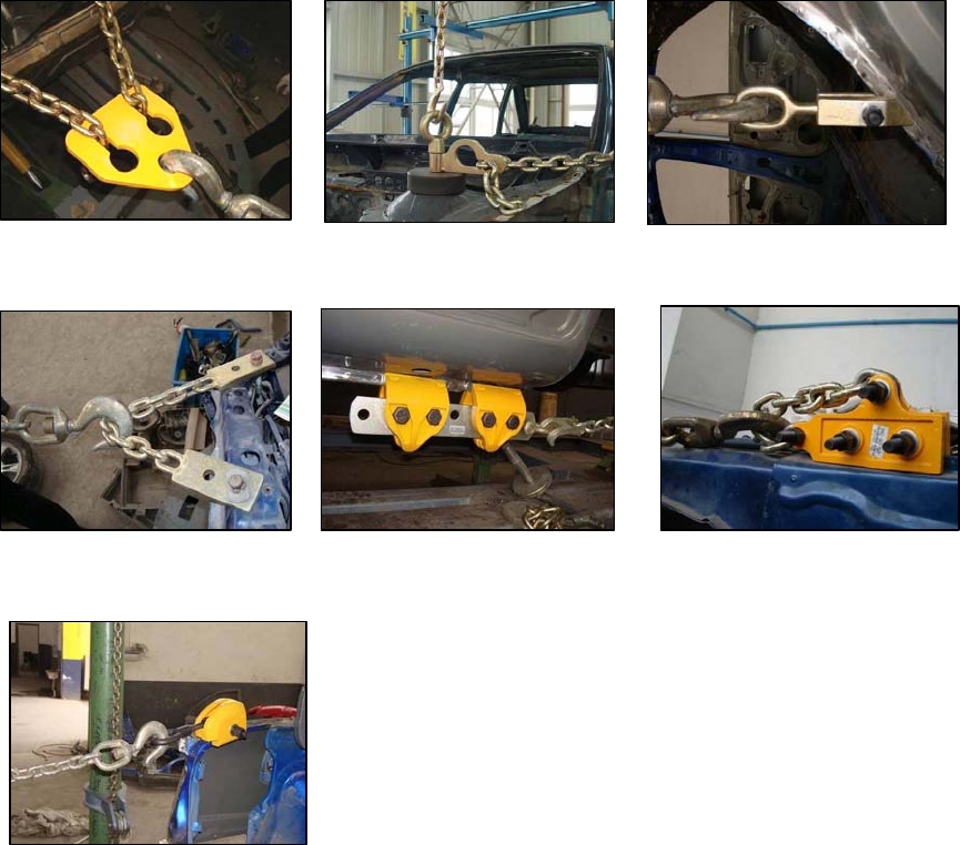
5.3 Auto Pulling system:Include tower, chains and some other components. Function:
pull on the damaged part of the car. See figure 5.3
17
FR-77
Aug. 2016
Figure 5.3
5.4 Hydraulic system:Include Hydraulic pumps, cylinders, oil gauge and oil tubes etc,
provide power to the whole equipment. See figure 5.4
Figure 5.4
5.4.1 Hydraulic elements and flow chart
FR-77 hydraulic system is simply included pneumatic pumps, connectors, oil tubes and oil
gauge. See following oil circuit in figure 5.5. And flow chart under certain pressure in figure 5.6.
Figure 5.5 Figure 5.6
18
FR-77
Aug. 2016
5.4.2 Hydraulic safety cautions
1. High class cleaning standard should be carried out before installing the hydraulic system.
The impurity in the oil will cause damage to the hydraulic system.
2. Check the oil tube before usage; make sure it is clean and well connected.
3. Check the cylinder and its components, leaking oil is forbidden.
4. Check the oil level in the pumps and charge up the oil in case of necessary.
5. Use PTFE tape to connect the oil tube and joints.
6. Vent the gas after connecting the hydraulic system. Other wise it will cause the cylinder
shake or return.
7. Check the hydraulic system periodically.
5.5 Other tools:include wheel support bracket, car trolley, etc. See figure 5.7
Figure 5.7
19
FR-77
Aug. 2016
Chapter 6 INSTALLATION & OPERATION
6.1 Platform installation
6.1.1 Location requirement
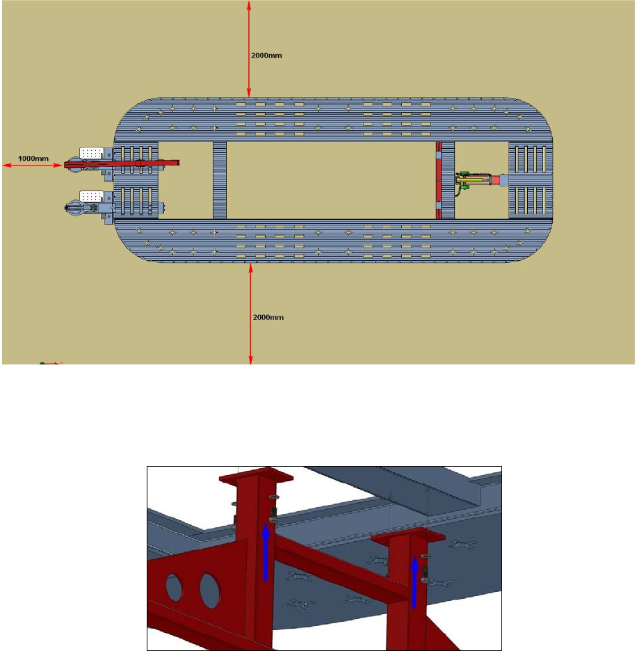
Working area of the auto chassis straightening machine, see figure 6.1
Figure 6.1
6.1.2 Fixing support installation:Lift the platform over 500mm, install the fixed support
with four bolts. See figure 6.2
Fig. 6.2
20
FR-77
Aug. 2016
6.1.3 Movable support installation.
Install the Movable support with two axes, remember o install the snap spring. See figure
6.3
Figure 6.3
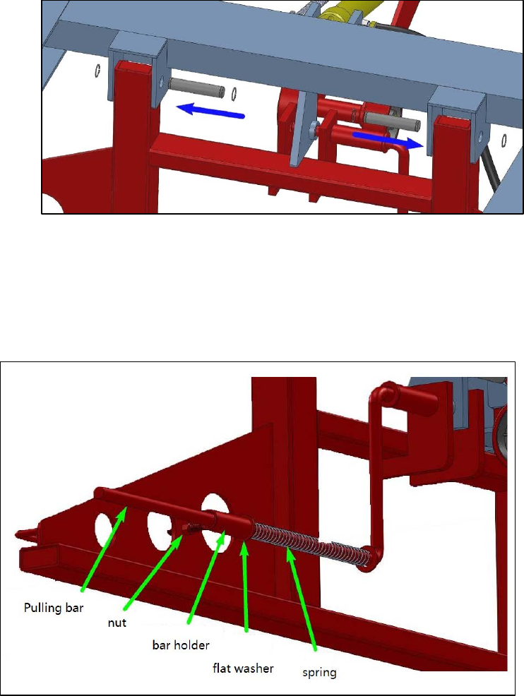
6.1.4 Locking bar installation:
Install all the components as the following figure shows, finally, fix the locking bar on to
the movable support. Make sure the locking bar is easy to lock and unlocked. See
figure 6.4
Figure 6.4
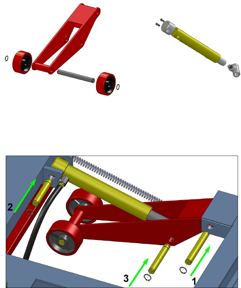
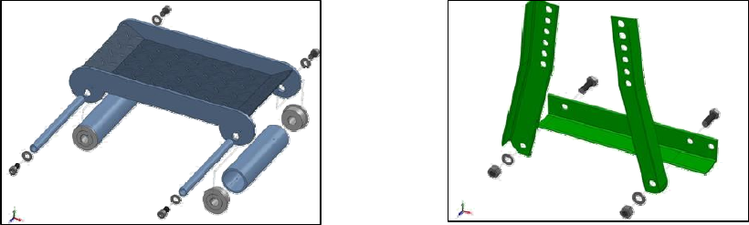
6.1.5 Lifting support installation:
1. Install two wheels onto the lifting support. See figure 6.5
21
FR-77
Aug. 2016
2. Install the cylinder according to the Figure 6.6 shows.
Figure 6.5 Figure 6.6
3. Install all the axes according to the figure 6.7, to install the lifting support on the platform.
Finally, install all the springs.
Figure 6.7
Caution: While installing No.3 axe, use the pump to push the cylinder pole out, then
install the axe.
22
FR-77
Aug. 2016
6.2 Pulling tower installation:
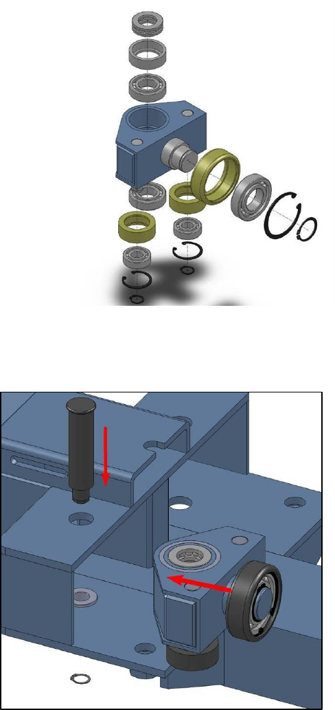
6.2.1 Tower rolling system installation:Install all the components according to the figure
6.8.
Figure 6.8
Then install the traveling system on the post. See figure 6.9
Figure 6.9
23
FR-77
Aug. 2016
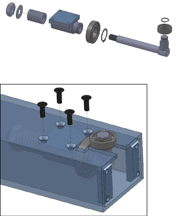
6.2.2 Post guiding system installation:install according to the figure shows. See figure
6.10
Figure 6.10
Then install the guiding system on the post, install the last 4 bolts. See figure 6.11
Figure6.11
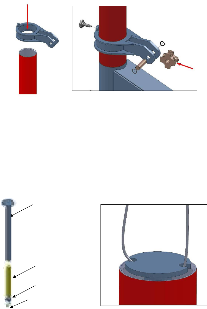
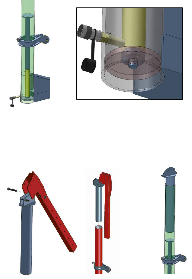
6.2.3 Collar installation:Firstly install the collar throw the top of the tower. See figure
6.12 Secondly, install the hand bolt, Sprocket wheel, axes onto the collar. See
figure 6.13
24
FR-77
Aug. 2016
Figure 6.12 Figure 6.13
6.2.4 Cylinder, extend bar installation:Firstly install the extending bar, cylinder, cylinder
base and socket head screw according to the figure 6.14. Then hang the extending
bar with a strong cable sling, put the whole cylinder assembly into the pulling tower.
See figure 6.15. Finally install the direct connector and female connector onto the
cylinder. See figure 6.16
Extend bar
Cylinder
Cylinder base
M8×25 Screw
Figure 6.14 Figure 6.15
25
FR-77
Aug. 2016
Figure 6.16
6.2.5 Upper puller installation:FR-77 includes two pulling tower, one of them is equipped
with upper puller system. Firstly install the top pole with upper puller. See figure 6.17.
Install the upper puller onto the pole with one M20*120 bolt, then put the pole into the
pulling tower. For the other kind of tower top pole, just put it into the tower. See
Figure6.18
Figure 6.17 Figure 6.18
26
FR-77
Aug. 2016
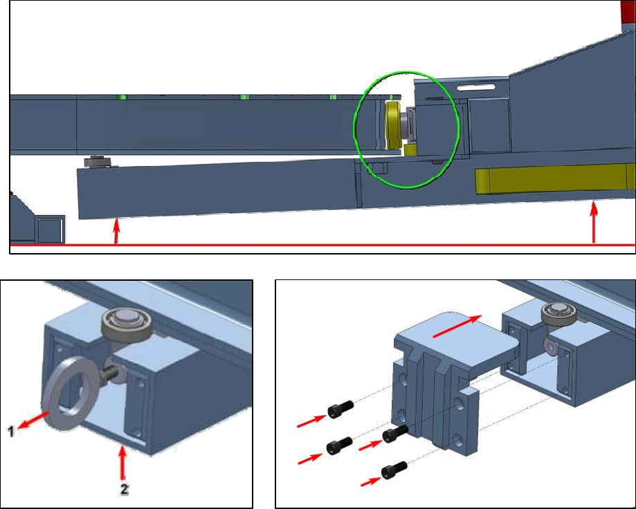
6.2.6 Install the post on the platform:
Descend the platform, lift the post with crane or forklift, put the post travel wheel on
the inferior plate of the platform, as the figure shows. Then pull out the guiding bar
assembly out toward 1 position. Pull it out and let the bearing goes into the platform
rail. Then install the hook plate. See Figure6.19
Figure 6.19
27
FR-77
Aug. 2016
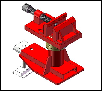
6.3 Main clamps installation
FR77 includes single head main clamps. This clamp is a table vice model one and is easy
to install. See figure 6.20
Main clamps
Table vice model
Figure 6.20
28
FR-77
Aug. 2016
6.4 Hydraulic system installation
6.4.1 Safety caution
A. Pay attention to the required pressure and bearing capacity. The working pressure
cannot surpass the required pressure given on the gauge.
B. Check the connectors. The connectors should be tightened with hands.
C. Check the connectors of the oil tube. If it is seriously bent or broken, change it at once.
D. The air pump should use water/oil separator. The workers should often empty the water
and replace worn parts.
6.4.2 Installation
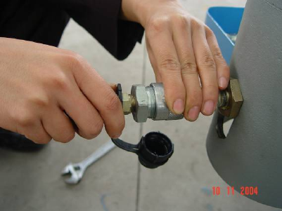
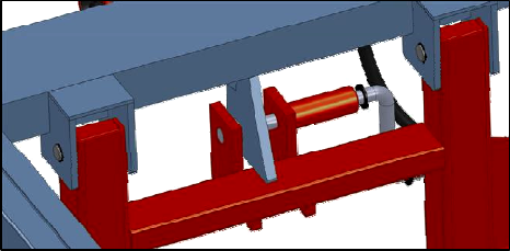
A. Before working, check the connectors and oil tubes.
B. Connect the oil tube with the lift cylinder under the platform. See figure 6.21
C. Connect the air pump to the air supplier. The required air pressure is 0.8Mpa.
D. When operating the air pump, the gauge works. Use the air pump to control the tower
pillar and platform.
ATTENTION: The air pressure cannot surpass 6000PSI.
E. Operate the pump slowly and the pressure outlet valve, make the pulling posts loosen
slowly.
Figure 6.21
29
FR-77
Aug. 2016
6.4.3 Maintenance
A. Check the joints and connectors regularly. The loosen connectors and oil leakage will
make the hydraulic system work unstably.
B. Check the hydraulic oil regularly.
C. The hydraulic oil must be changed after working of 200-300 hours. If the working
environment is dirty, the hydraulic oil must be changed after working of 35 hours.
D. Keep the hydraulic parts from the pollution of dust and grease.
E. Check the hydraulic oil after working of 40 hours every time.
6.4.4 Hydraulic system specifications
A. Air pump PATG-1102N
Power: 10000PSI
Air supply required: 0.8Mpa
B. Hydraulic cylinderRC1010:
The longest travel: 10 inches
Bearing capacity: 10T
6.4.5 Common problems of hydraulic system
A. The unstable trouble of cylinder. If air mixed in the hydraulic system, it will work
unsteadily. When the workers meet this problem, he can put the pump higher than the
tube and the cylinder, this process will make the air inside go back to the oil reservoir.
Turn off the valve. Repeat this process three to five times.
B. The cylinder cannot last for the whole process. Usually not enough oil in the reservoir
causes this problem. So the worker should check the reservoir. If needed, fulfill it with
oil.
C. The hydraulic cylinder cannot return. This problem is caused by too much air or oil. The
worker should check the reservoir to keep reasonable oil inside. The worker should also
check whether the bolt is bent or not and the connectors are broken or not.
D. The cylinder descends automatically when pressure is supplied. The worker should
check whether the oil valve is turned off or not. If it is turned off and the cylinder still
30
FR-77
Aug. 2016
descends, check the ball valve of the oil and use alcohol or kerosene to wash it. If there
is still trouble, repair the pump at once.
E. The system only work for one time. Maybe the valve is dirty, wash it and add some oil.
If the air pump, electric hydraulic pump, hydraulic cylinder, hydraulic pipe, gauge,
etc. don’t work well, and if these parts are still in the period of repair warranty,
they must be repaired by technician or the customer can send the bad tools to us,
or to our named agents for repair. If the customer takes apart these parts without
admission of us, furthermore, if there is any damage in the tools, the
manufacturer has no responsibility for it. The customer must pay it by himself or
herself.
6.5 Accessories installation
6.5.1 Wheel trolley
Install according to the figure 6.22.
6.5.2 Wheel support bracket
Install according to the figure 6.23.
Figure 6.22 Figure 6.23
31
FR-77
Aug. 2016
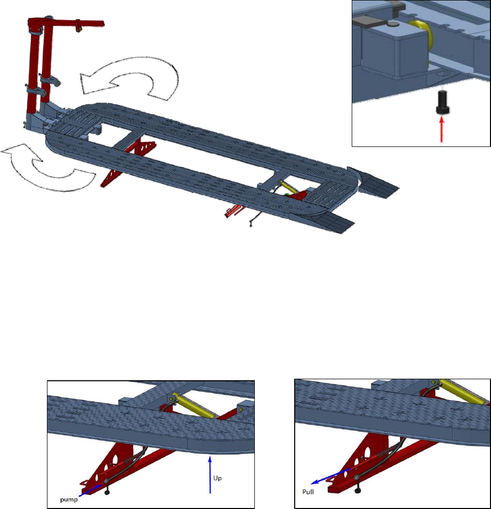
6.6 Loading and fixing the car
6.6.1 Loading
A. Before loading the car, two post should be fixed at the fixed support end of the platform.
See figure6.27
Figure 6.27
B. Connect the pneumatic pump with the air compressor (0.5-0.8Mpa), then connect the oil
tube of the pump together with the lift support cylinder. Then operate the pump to up
raise the platform till the movable support can swing freely. See figure 6.28
C. When the movable support left the ground, pull the locking bar out, swing the movable
support. See figure6.29
Figure 6.28 Figure 6.29
32
FR-77
Aug. 2016
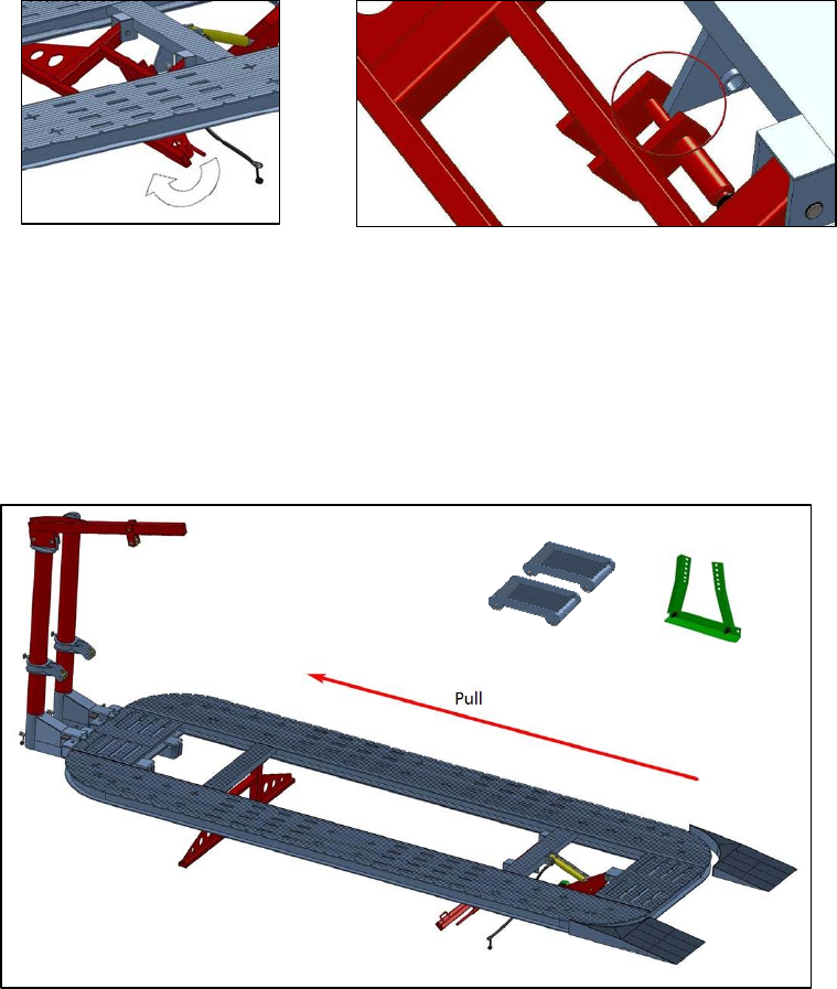
D. Swing the movable support backward, until the locking bar lock the movable support in a
declined degree. Then operate the pneumatic pump to let the platform descend onto
the ground. See figure 6.30
Figure 6.30
E. Put the Drive-on ramp aside the descending end of the platform. Now move the car onto
the platform with wheel trolley and hand wrench. If the wheels are removed, the wheel
bracket is necessary. See figure 6.31.
You may apply the tower to pull the car onto the platform.
Figure 6.31
F、Up raise the platform:
1. Check the equipment before raising the platform. Make sure the towers are locked, oil tube
and air pipe is safe.
33
FR-77
Aug. 2016
2. Locate the car wheel with wood, and park the car in neutral gear and brake with parking
brake.
3. Operate the pneumatic pump to lift the platform.
4. Lock the movable support with locking
bar. See figure 6.32
5. Operate the pneumatic pump to descend
the platform, until the movable support
reaches ground.
Figure 6.32
Caution: The worker should not stand behind the car when lifting and descending the
platform. The car should parked with neutral gear and brake with parking brake. During this
operation, fixing the car with wood or chain is necessary. Operator should keep safety distance
with the platform. When descending the platform, the pump should be loosen slowly, in case it
descend too fast to cause human injury or property loss.
Warning! Repairing the car without the movable support fixed is forbidden.
6.6.2 Fixing the car
A. Check the chassis of the damaged car, make a best tightening scheme.
B. Put the main clamp onto the platform, under the car chassis where can be snapped on.
C. Lift the car with lifting accessories (rolling beam, air bag etc.)
D. Rise the clamp head to a right height which can snap the edge of the car. Then loosen
the bolt of the main clamps.
E. Lift the car, put the clamps under the edge of the car.
F. Tighten the bolt of the main clamps.
G. Lock the clamp and the platform with the main clamp bolts. Tighten it with hook spanner.
Caution! Tighten the bolt of the main clamps every time finish a pulling work. Check all the
bolts to make sure the car will not slide when repairing. If the front tire is removed, the wheel
should be fixed with wheel support bracket.
34
FR-77
Aug. 2016
Chapter 7 AUTO BODY REPAIR
DEMONSTRATION
7.1 Auto body repair principle
If the damaged part is small, the worker can use pulling system to pull it out. But if there is a
big damaged part or knot, the worker cannot repair it by pulling to the opposite direction. So
collision repair needs the following tools:
A. Clamp system
B. Body repair tools
C. Pulling system
D. Measuring system
7.2 Chassis repair technology
One direction pulling is suitable for frame body. It is easy for workers to repair and adjust the
body. But it is not suit for unibody. The unibody is more complex, and the collision energy is
easier to expand to the whole body. Most of the unibody repair needs several pulling. During the
repair process, it needs more pulling points and directions. FR77 can fulfill the above
requirements. It gives you a long list of repair accessories to avoid the construction damage for
the vehicle.
7.3 Collision repair process
A. The analysis of damaged body
Before repairing, the worker should take off the damaged parts, for the collision energy
is easy to manage far away.
B. Pull
After analysis, the worker should plan the repair process and do as it.
C. The repair order
The metal of unibody is easy to move and bend. So the worker should repair the vehicle
35
FR-77
Aug. 2016
by different parts and direction. Or it may damage other normal parts.
7.4 Pulling process
A. Length. Pull the damaged parts by the direction parallel to the centerline.
B. Width. Pull the damaged parts by horizontal direction.
C. Height adjustment. If some damaged parts are folded tightly, during the pulling, the
worker should heat the damaged parts. The heated places can only be the edges or two
tightened metal plates. Heating is a kind of way to relieve the stress but not a good way
to soften any section. Pull the selected section to restore the original dimension slowly
and relieve the stress of the bent steel. The damaged vehicle will be repaired correctly.
For the reason of the unibody car is very sensitive to heat. So, never try to pull the car with
once pulling stroke. Instead of that, the worker should pull the car –keep the strength-pull
again- keep strength-pull again- keep strength. Etc.
If the car folded very seriously after accident, there will be risks of metal break down. Now the
worker needs to burn the metal. Only the connecting point and the two metal plates welded
together point need burn. If burn the cross chassis of the car, this will make the damage even
worse. Heating up can only be used as a way to avoid stress, not a way to soften the material
that is very important. The order of repairing a car should be: length repairing, width repairing
and height repairing.
36
FR-77
Aug. 2016
7.5 Auto repair
7.5.1 Auto front-end repair
The damage of the front section is decided by the crashing speed, inertia mass and
damage position, etc. If the beam, bender and other accessories are damaged, the worker
should pull the front beam on the side where the damaged parts should be changed.
Sometimes, the collision energy will expand to the A pillars. The worker should take apart
the front beam and bender and pull it, at the same time; the worker should push the
damaged part from inside.
DC-G1650 DC-G2450 DC-G0045
DC-G5622 DC-G4010 DC-G0750
DC-G0480 in usage
.
7.5.2 Auto back-end repair
The structure of rear section is more complex than the front section. The collision energy will
expand easier. Usually the rear bumper. The fender will be damaged and cause the quarter
37
FR-77
Aug. 2016
panel to move to the front side, this will also changes the gap of other parts. If it is possible,
the damage will also influence the ceiling doors and body center pillar. When the workers
use the pulling system to pull the damaged rear beam, floor or the rear hood. Then should
measure the dimension under the body and decide the repair process according to the gap
between the metals.
Sometimes, the damage of front section will cause the twist. The worker should clamp the
lower part of rear section. The basic adjustment can only adjust some lower parts. Then,
install the clamp system again to keep the adjustment and go on the adjusting other
damaged parts. Once the upper part can install the clamp system, the worker should install
the clamp system at once and take off the serious damaged parts and install a new one.
7.5.3 Auto side body repair
If the beside part of the vehicle is damaged. The floor will be changed also. To repair this
kind of damage, the worker should pull the front and rear section firstly if they want to pull
the damaged part from center section. If the worker wants to adjust the damaged part from
the upper section, they should fix the bottom on the platform to the opposite direction.
7.5.4 Auto ceiling repair
The damaged ceiling metal will cause the damage of the side pillar, bender and windshield.
When the worker to repair the damaged part, they can use hydraulic ram to push from inside
and use draw aligner to pull other parts.
The operation of down pulling.
7.6 Cautions during Auto repair
The basic rule of the collision repair is that: if the damaged part is impossible for adjustment,
the repairman repairs the part to the original shape. During the adjustment, the worker can
weld the damaged part when the bent edge become smooth or the cut welding part is
moved to the back on the same line. When the bent part becomes straight, the worker
should use the hammer to relieve the stress. If it is a unibody, usually the parts depend on
each other, so the damaged parts may be given more stress to the neighbor part. For this
38
FR-77
Aug. 2016
reason, the worker should pull it slowly and periodically, at the same time, check the
movement of the parts, make sure the pull of the damaged place is effective. If the damaged
part is not moved, the worker should change the pulling direction or pulling part.
The pull strength is opposite to the damaged strength. So the damaged part is as strong as
undamaged. The damaged parts all resist the pressure and there is a strong stress that
destroys the pull. In fact, the adjustment and part changing cannot be done for the same
time during the repair. So the worker has to measure the adjustment by eyes during the
adjustment. If the adjustment is good, before going on the next adjustment, the worker has
to finish every kind of repair.
When it is the time to repair the close bent part, the worker can use the clamp pincers
to clamp the bent part, then the adjustment direction is on the image line to the
strength and this line is the prolong line of the original position.
For the unibody, do not try to cut every part of the damaged part, and lately repair
the part by welding another strengthened part. Because the modern design body
construction is designed for the controlled damage, this can avoid delay the damage
of the important part. So if the part is broken, torn or not well repaired, the worker
should change the whole part. Usually the damaged part will meet the mort strong
stress than neighbor part, so during the repair, all the important control pointer must
be measured and controlled to avoid the excessive adjustment.
39
FR-77
Aug. 2016
Chapter 8 EQUIPMENT MAINTENANCE
1. After using the equipment, clean the working place.
2. It is forbidden to put other goods on the bench rack.
3. Check the hydraulic oil regularly.
4. Change all of the oil if the hydraulic oil is bad.
5. The hydraulic cylinder and pump cannot overload for a long time. Or the
leakage of the oil will damage the pump.
6. If the pump or the cylinder leaks oil, repair them at once.
7. The parts of hydraulic system and measuring system cannot be pressed
when used.
8. Check the joints often, if necessary, put some grease on them.
9. Check the chains often, if they are damaged, change them at once.

40
FR-77
Aug. 2016
Chapter 9 TROUBLE SHOOTING
No. Trouble Causation Treating
1 The pumps leaks oil or
the oil tank plump up The air intake valve of the pump locked Open the intake valve
2
The pump works but
does not provide
pressure
The quick connector is not tighten Tighten the quick connector
The working sound of the pump is low,
does not provide pressure, the pump room
might mixed with gas
Let out the gas, pressure to work and
release at the same time, to let out the
gas, operate like this 2~3 times, 2~3
minutes each time.
The working sound of the pump is low,
does not provide pressure, the oil intake of
pump room and the oil tank might have
dust inside.
Open the oil tank and clean. Change the
hydraulic oil.
The working sound is normal, but pump
does not provide pressure. Might be
caused by te lack of hydraulic oil in the oil
tank.
Fill in with hydraulic oil
The working sound is normal, but pump
does not provide pressure. The pump
room might have air inside.
Pressure to work and release at the
same time, to let out the gas, operate
like this 2~3 times, 2~3 minutes each
time.
If the pump still does not work, please call the seller of the pump as soon as possible.
3 The platform can not
be lifted up Check the pump The same with the way of “Pump works
but no pressure”
4 The platform
descending very slow
The 0.2mm hole of throttle valve is jammed
by impurity.
Clean the throttle valve with high
pressure gas. If still can not solve,
change the throttle valve.
5
Hard to lock the post
while at the corner of
the platform
The post is not at the center of the position.
Lock the post with the bolt first, then
push the post towards the platform. Lock
the locking plate.
6
One of the traveling
wheels of the post
goes astray.
The travel speed of the post is too fast, or
there is block on the rail.
1.check the rail, if not smooth, repair it
with sander.
2.push the post slowly, especially in the
corner of the platform
7
The post extension
head which with a
upper puller, cannot
reposition.
The head extension was jammed by the
post.
Fill in the post with lubricating oil. And
knock on the head extension with
hammer.
41
FR-77
Aug. 2016
Chapter 10 END
This manual introduces the universal using method of T160, pictures
and operating contents are for reference.
The main processes of the collision repair include: the bent adjustment,
reverse or change of the damaged welding steel panel. So the worker
must have a whole repair plan when repairing the collision. And the main
processes are as following:
1. Analyze the collision and make a plan
2. Dismount the decoration part and mechanical part.
3. Put the damaged vehicle on the bench rack, and decide to change or
to repair the damaged part according to the actual condition.
4. Pull the damaged vehicle.
5. Rusty dealing.
6. Paint.
7. Restore all the dismounted parts.
8. Exercise the vehicle
42
FR-77
Aug. 2016
The crash will influence the car very much. If the car is crashed, the body
design will let the front and rear part to be easy damaged, because this
steep will create an energy absorbing structure, and insure the safety of
passenger seat. At that time, the worker should find the data, construction,
direction, speed and the collision angle and direction, etc. before the right
estimate, try best to learn about the fact and make a decision of the
repairing plan.
This manual talks about the installation and the use of the equipment,
notice process, etc. and introduce clearly the collision analyzing. But for
each damaged car, the worker should analyze the car and make a clear plan.
43
FR-77
Aug. 2016
LIMITED WARRANTY
Structural Warranty:
The following parts and structural components carry a five year warranty:
Columns Arms Uprights Swivel Pins
Legs Carriages Overhead Beam
Tracks Cross Rails Top Rail Beam
Limited One-Year Warranty:
Tuxedo Distributors, LLC (iDEAL) offers a limited one-year warranty to the original purchaser of Lifts and Wheel
Service equipment in the United States and Canada. Tuxedo will replace, without charge, any part found defective
in materials or workmanship under normal use, for a period of one year after purchase. The purchaser is responsible
for all shipping charges. This warranty does not apply to equipment that has been improperly installed or altered or
that has not been operated or maintained according to specifications.
Other Limitations:
This warranty does not cover:
1. Parts needed for normal maintenance
2. Wear parts, including but not limited to cables, slider blocks, chains, rubber pads and pulleys
3. Replacement of lift and tire changer cylinders after the first 30 days. A seal kit and installation instructions
will be sent for repairs thereafter.
4. On-site labor
Upon receipt, the customer must visually inspect the equipment for any potential freight damage before signing
clear on the shipping receipt. Freight damage is not considered a warranty issue and therefore must be noted for
any potential recovery with the shipping company.
The customer is required to notify Tuxedo of any missing parts within 72 hours. Timely notification must be
received to be covered under warranty.
Tuxedo will replace any defective part under warranty at no charge as soon as such parts become available from
the manufacturer. No guarantee is given as to the immediate availability of replacement parts.
Tuxedo reserves the right to make improvements and/or design changes to its lifts without any obligation to
previously sold, assembled or fabricated equipment.
There is no other express warranty on the Tuxedo lifts and this warranty is exclusive of and in lieu of all other
warranties, expressed or implied, including all warranties of merchantability and fitness for a particular purpose.
44
FR-77
Aug. 2016
To the fullest extent allowed by law, Tuxedo shall not be liable for loss of use, cost of cover, lost profits,
inconvenience, lost time, commercial loss or other incidental or consequential damages.
This Limited Warranty is granted to the original purchaser only and is not transferable or assignable.
Some states do not allow exclusion or limitation of consequential damages or how long an implied warranty lasts,
so the above limitations and exclusions may not apply. This warranty gives you specific legal rights and you may
have other rights, which may vary from state to state.
1905 N Main St Suite C, Cleburne, TX 76033
Ph 817-558-9337 / Fax 817-558-9740
