FR A700 INSTRUCTION MANUAL (Applied) FRA700Manual
FR-A740-0.4k to 500k to the manual e0a7e440-a9a8-49a4-94c9-b8a33cfdb3b4
User Manual: FRA700Manual
Open the PDF directly: View PDF ![]() .
.
Page Count: 523 [warning: Documents this large are best viewed by clicking the View PDF Link!]
- FR-A700 INSTRUCTION MANUAL (Applied)
- This section is specifically about safety matters
- CONTENTS
- 1 OUTLINE
- 2 WIRING
- 2.1 Wiring
- 2.2 Main circuit terminal specifications
- 2.3 Control circuit specifications
- 2.4 Connection of motor with encoder (vector control)
- 2.5 Connection of stand-alone option units
- 2.5.1 Connection of the dedicated external brake resistor (FR-ABR)
- 2.5.2 Connection of the brake unit (FR-BU2)
- 2.5.3 Connection of the brake unit (FR-BU/MT-BU5)
- 2.5.4 Connection of the brake unit (BU type)
- 2.5.5 Connection of the high power factor converter (FR-HC/MT-HC)
- 2.5.6 Connection of the power regeneration common converter (FR-CV)
- 2.5.7 Connection of power regeneration converter (MT-RC)
- 2.5.8 Connection of the power factor improving DC reactor (FR-HEL)
- 3 PRECAUTIONS FOR USE OF THE INVERTER
- 4 PARAMETERS
- 4.1 Operation panel (FR-DU07)
- 4.2 Parameter List
- Parameters according to purposes
- 4.3 Control mode
- 4.4 Speed control by Real sensorless vector control, vector control
- 4.4.1 Setting procedure of Real sensorless vector control (speed control)
- 4.4.2 Setting procedure of vector control (speed control)
- 4.4.3 Torque limit level setting for speed control (Pr. 22, Pr. 157, Pr. 803, Pr. 810 to Pr. 817, Pr. 858, Pr. 868, Pr. 874)
- 4.4.4 To perform high accuracy/fast response operation (gain adjustment of Real sensorless vector control and vector control) (Pr. 818 to Pr. 821, Pr. 830, Pr. 831, Pr. 880)
- 4.4.5 Speed feed forward control, model adaptive speed control (Pr. 828, Pr. 877 to Pr. 881)
- 4.4.6 Torque biases (Pr. 840 to Pr. 848)
- 4.4.7 Prevent the motor from overrunning (Pr. 285, Pr. 853, Pr. 873)
- 4.4.8 Notch filter (Pr. 862, Pr. 863)
- 4.5 Torque control by Real sensorless vector control, vector control
- 4.5.1 Torque control
- 4.5.2 Setting procedure of Real sensorless vector control (torque control)
- 4.5.3 Setting procedure of vector control (torque control)
- 4.5.4 Torque command (Pr. 803 to Pr. 806)
- 4.5.5 Speed limit (Pr. 807 to Pr. 809)
- 4.5.6 Gain adjustment of torque control (Pr. 824, Pr. 825, Pr. 834, Pr. 835)
- 4.6 Position control by vector control
- 4.6.1 Position control
- 4.6.2 Simple position feed function by contact input (Pr. 419, Pr. 464 to Pr. 494)
- 4.6.3 Position control (Pr. 419, Pr. 428 to Pr. 430) by inverter pulse train input
- 4.6.4 Setting of the electronic gear (Pr. 420, Pr. 421, Pr. 424)
- 4.6.5 Setting of positioning adjustment parameter (Pr. 426, Pr. 427)
- 4.6.6 Gain adjustment of position control (Pr. 422, Pr. 423, Pr. 425)
- 4.6.7 Trouble shooting for when position control is not exercised normally
- 4.7 Adjustment of Real sensorless vector control, vector control
- 4.8 Adjustment of the output torque (current) of the motor
- 4.8.1 Manual torque boost (Pr. 0, Pr. 46, Pr. 112)
- 4.8.2 Advanced magnetic flux vector control (Pr. 71, Pr. 80, Pr. 81, Pr. 89, Pr. 450, Pr. 451, Pr. 453, Pr. 454, Pr. 569, Pr. 800)
- 4.8.3 Slip compensation (Pr. 245 to Pr. 247)
- 4.8.4 Stall prevention operation (Pr. 22, Pr. 23, Pr. 48, Pr. 49, Pr. 66, Pr. 114, Pr. 115, Pr. 148, Pr. 149, Pr. 154, Pr. 156, Pr. 157, Pr. 858, Pr. 868)
- 4.9 Limiting the output frequency
- 4.10 V/F pattern
- 4.11 Frequency setting by external terminals
- 4.12 Setting of acceleration/deceleration time and acceleration/deceleration pattern
- 4.12.1 Setting of the acceleration and deceleration time (Pr. 7, Pr. 8, Pr. 20, Pr. 21, Pr. 44, Pr. 45, Pr. 110, Pr. 111, Pr. 147)
- 4.12.2 Starting frequency and start-time hold function (Pr. 13, Pr. 571)
- 4.12.3 Acceleration/deceleration pattern (Pr. 29, Pr. 140 to Pr. 143, Pr. 380 to Pr. 383, Pr. 516 to Pr. 519)
- 4.12.4 Shortest acceleration/deceleration and optimum acceleration/deceleration (automatic acceleration/deceleration) (Pr. 61 to Pr. 63, Pr. 292, Pr. 293)
- 4.13 Selection and protection of a motor
- 4.13.1 Motor protection from overheat (Electronic thermal relay function) (Pr. 9, Pr. 51)
- 4.13.2 Applied motor (Pr. 71, Pr. 450)
- 4.13.3 Offline auto tuning (Pr. 71, Pr. 80 to Pr. 84, Pr. 90 to Pr. 94, Pr. 96, Pr. 450, Pr. 453 to Pr. 463, Pr. 684, Pr. 859, Pr. 860)
- 4.13.4 Online auto tuning (Pr. 95, Pr. 574)
- 4.14 Motor brake and stop operation
- 4.14.1 DC injection brake and zero speed control, servo lock (LX signal, X13 signal, Pr. 10 to Pr. 12, Pr. 802, Pr. 850)
- 4.14.2 Selection of regenerative brake and DC feeding (Pr. 30, Pr. 70)
- 4.14.3 Stop selection (Pr. 250)
- 4.14.4 Stop-on contact control function (Pr. 6, Pr. 48, Pr. 270, Pr. 275, Pr. 276)
- 4.14.5 Brake sequence function (Pr. 278 to Pr. 285, Pr. 292)
- 4.14.6 Orientation control (Pr. 350 to Pr. 366, Pr. 369, Pr. 393, Pr. 396 to Pr. 399)
- 4.15 Function assignment of external terminal and control
- 4.15.1 Input terminal function selection (Pr. 178 to Pr. 189)
- 4.15.2 Inverter output shutoff signal (MRS signal, Pr. 17)
- 4.15.3 Condition selection of function validity by the second function selection signal (RT) and third function selection signal (X9) (RT signal, X9 signal, Pr. 155)
- 4.15.4 Start signal operation selection (STF, STR, STOP signal, Pr. 250)
- 4.15.5 Magnetic flux decay output shutoff signal (X74 signal)
- 4.15.6 Output terminal function selection (Pr. 190 to Pr. 196)
- 4.15.7 Detection of output frequency (SU, FU, FU2 , FU3, FB, FB2, FB3, LS signal, Pr. 41 to Pr. 43, Pr. 50, Pr. 116, Pr. 865)
- 4.15.8 Output current detection function (Y12 signal, Y13 signal, Pr. 150 to Pr. 153, Pr. 166, Pr. 167)
- 4.15.9 Detection of output torque (TU signal, Pr. 864)
- 4.15.10 Remote output function (REM signal, Pr. 495 to Pr. 497)
- 4.16 Monitor display and monitor output signal
- 4.16.1 Speed display and speed setting (Pr. 37, Pr. 144, Pr. 505, Pr. 811)
- 4.16.2 DU/PU, FM, AM terminal monitor display selection (Pr. 52, Pr. 54, Pr. 158, Pr. 170, Pr. 171, Pr. 268, Pr. 563, Pr. 564, Pr. 891)
- 4.16.3 Reference of the terminal FM (pulse train output) and AM (analog voltage output) (Pr. 55, Pr. 56, Pr. 291, Pr. 866, Pr. 867)
- 4.16.4 Terminal FM, AM calibration (Calibration parameter C0 (Pr. 900), C1 (Pr. 901))
- 4.17 Operation selection at power failure and instantaneous power failure
- 4.18 Operation setting at fault occurrence
- 4.19 Energy saving operation and energy saving monitor
- 4.20 Motor noise, EMI measures
- 4.21 Frequency/torque setting by analog input (terminal 1, 2, 4)
- 4.21.1 Function assignment of analog input terminal (Pr. 858, Pr. 868)
- 4.21.2 Analog input selection (Pr. 73, Pr. 267)
- 4.21.3 Analog input compensation (Pr. 73, Pr. 242, Pr. 243, Pr. 252, Pr. 253)
- 4.21.4 Response level of analog input and noise elimination (Pr. 74, Pr. 822, Pr. 826, Pr. 832, Pr. 836, Pr. 849)
- 4.21.5 Bias and gain of frequency setting voltage (current) (Pr. 125, Pr. 126, Pr. 241, C2(Pr. 902) to C7(Pr. 905), C12(Pr. 917) to C15(Pr. 918))
- 4.21.6 Bias and gain of torque (magnetic flux) setting voltage (current) (Pr. 241, C16(Pr. 919) to C19(Pr. 920), C38 (Pr. 932) to C41 (Pr. 933))
- 4.22 Misoperation prevention and parameter setting restriction
- 4.22.1 Reset selection/disconnected PU detection/PU stop selection (Pr. 75)
- 4.22.2 Parameter write selection (Pr. 77)
- 4.22.3 Reverse rotation prevention selection (Pr. 78)
- 4.22.4 Display of applied parameters and user group function (Pr. 160, Pr. 172 to Pr. 174)
- 4.22.5 Password function (Pr. 296, Pr. 297)
- 4.23 Selection of operation mode and operation location
- 4.24 Communication operation and setting
- 4.24.1 Wiring and configuration of PU connector
- 4.24.2 Wiring and arrangement of RS-485 terminals
- 4.24.3 Initial settings and specifications of RS-485 communication (Pr. 117 to Pr. 124, Pr. 331 to Pr. 337, Pr. 341, Pr. 549)
- 4.24.4 Communication EEPROM write selection (Pr. 342)
- 4.24.5 Mitsubishi inverter protocol (computer link communication)
- 4.24.6 Modbus-RTU communication specifications (Pr. 331, Pr. 332, Pr. 334, Pr. 343, Pr. 539, Pr. 549)
- 4.24.7 USB communication (Pr. 547, Pr. 548)
- 4.25 Special operation and frequency control
- 4.25.1 PID control (Pr. 127 to Pr. 134, Pr. 575 to Pr. 577)
- 4.25.2 Bypass-inverter switchover function (Pr. 57, Pr. 58, Pr. 135 to Pr. 139, Pr. 159)
- 4.25.3 Load torque high speed frequency control (Pr. 4, Pr. 5, Pr. 270 to Pr. 274)
- 4.25.4 Droop control (Pr. 286 to Pr. 288)
- 4.25.5 Frequency setting by pulse train input (Pr. 291, Pr. 384 to Pr. 386)
- 4.25.6 Encoder feedback control (Pr. 144, Pr. 285, Pr. 359, Pr. 367 to Pr. 369)
- 4.25.7 Regeneration avoidance function (Pr. 665, Pr. 882 to Pr. 886)
- 4.26 Useful functions
- 4.27 Setting of the parameter unit and operation panel
- 4.28 Parameter clear and all parameter clear
- 4.29 Parameter copy and parameter verification
- 4.30 Check and clear of the faults history
- 5 PROTECTIVE FUNCTIONS
- 5.1 Reset method of protective function
- 5.2 List of fault or alarm display
- 5.3 Causes and corrective actions
- 5.4 Correspondences between digital and actual characters
- 5.5 Check first when you have a trouble
- 5.5.1 Motor does not start
- 5.5.2 Motor or machine is making abnormal acoustic noise
- 5.5.3 Inverter generates abnormal noise
- 5.5.4 Motor generates heat abnormally
- 5.5.5 Motor rotates in the opposite direction
- 5.5.6 Speed greatly differs from the setting
- 5.5.7 Acceleration/deceleration is not smooth
- 5.5.8 Speed varies during operation
- 5.5.9 Operation mode is not changed properly
- 5.5.10 Operation panel (FR-DU07) display is not operating
- 5.5.11 Motor current is too large
- 5.5.12 Speed does not accelerate
- 5.5.13 Unable to write parameter setting
- 5.5.14 Power lamp is not lit
- 6 PRECAUTIONS FOR MAINTENANCE AND INSPECTION
- 6.1 Inspection item
- 6.2 Measurement of main circuit voltages, currents and powers
- 6.2.1 Measurement of powers
- 6.2.2 Measurement of voltages and use of PT
- 6.2.3 Measurement of currents
- 6.2.4 Use of CT and transducer
- 6.2.5 Measurement of inverter input power factor
- 6.2.6 Measurement of converter output voltage (across terminals P/+ - N/-)
- 6.2.7 Measurement of inverter output frequency
- 6.2.8 Insulation resistance test using megger
- 6.2.9 Pressure test
- 7 SPECIFICATIONS
- APPENDICES
- REVISIONS
- Instruction Supplement (BCN-C22005-634)
- 1 PM sensorless vector control
- 1.1 Setting procedure of PM sensorless vector control
- 1.2 Initializing the parameters required for the PM sensorless vector control (Pr.998)
- 1.3 Offline auto tuning for an IPM motor (motor constant tuning) (Pr.1, Pr.9, Pr.18, Pr.71, Pr.80, Pr.81, Pr.83, Pr.84, Pr.90, Pr.92, Pr.93, Pr.96, Pr.684, Pr.706, Pr.707, Pr.711, Pr.712, Pr.721, Pr.724, Pr.725, Pr.859)
- 1.4 Applied motor (Pr. 71)
- 1.5 Position control under PM sensorless vector control (Pr.800)
- 1.6 Low-speed range torque characteristics (Pr.788)
- 1.7 Setting the acceleration/deceleration time in the low-speed range (Pr.791, Pr.792)
- 1.8 DC injection brake of the PM sensorless vector control
- 1.9 PM sensorless vector control specification
- 1.10 Motor specification
- 2 Voltage reduction selection during stall prevention operation (Pr.154)
- 3 Speed detection hysteresis (Pr.870)
- 4 Limit regeneration avoidance operation frequency (Pr. 885)
- 5 Break point setting for droop control (Pr.994, Pr.995)
- 6 Setting multiple parameters as a batch (Pr.999)
- 7 SERIAL number check
- 1 PM sensorless vector control
- Instruction Supplement (BCN-C22005-642)
HEAD OFFICE: TOKYO BUILDING 2-7-3, MARUNOUCHI, CHIYODA-KU, TOKYO 100-8310, JAPAN
3
4
5
6
7
1
2
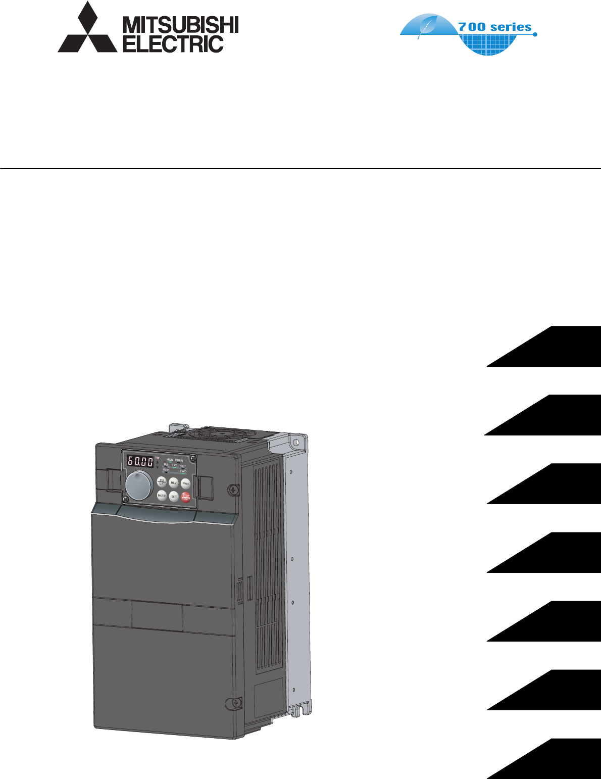
FR-A700
INSTRUCTION MANUAL (Applied)
INVERTER
PRECAUTIONS FOR USE
OF THE INVERTER
PARAMETERS
PROTECTIVE FUNCTIONS
PRECAUTIONS FOR
MAINTENANCE AND INSPECTION
SPECIFICATIONS
OUTLINE
WIRING
MODEL FR-A700
INSTRUCTION MANUAL (Applied)
MODEL
CODE 1A2-P10
FR-A720-0.4K to 90K
FR-A740-0.4K to 500K
IB(NA)-0600226ENG-E (1202)MEE Printed in Japan Specifications subject to change without notice.
FR-A700 INVERTER INSTRUCTION MANUAL (Applied)
E

A-1
Thank you for choosing this Mitsubishi Inverter.
1. Electric Shock Prevention
2. Fire Prevention
3. Injury Prevention
4. Additional Instructions
Also the following points must be noted to prevent an accidental failure, injury,
electric shock, etc.
This Instruction Manual provides instructions for advanced use of the FR-A700 series inverters.
Incorrect handling might cause an unexpected fault. Before using the inverter, always read this Instruction Manual and the Instruction Manual
(basic) [IB-0600225ENG] packed with the product carefully to use the equipment to its optimum.
This section is specifically about safety matters
Do not attempt to install, operate, maintain or inspect the inverter
until you have read through Instruction Manual (Basic) and
appended documents carefully and can use the equipment
correctly. Do not use the inverter until you have a full knowledge
of the equipment, safety information and instructions. In this
Instruction Manual, the safety instruction levels are classified into
"WARNING" and "CAUTION".
Incorrect handling may cause hazardous
conditions, resulting in death or severe
injury.
Incorrect handling may cause hazardous
conditions, resulting in medium or slight
injury, or may cause only material damage.
The level may even lead to a serious consequence
according to conditions. Both instruction levels must be followed
because these are important to personal safety.
•While power is ON or when the inverter is running, do not open
the front cover. Otherwise you may get an electric shock.
•Do not run the inverter with the front cover or wiring cover
removed.
Otherwise you may access the exposed high-voltage terminals
or the charging part of the circuitry and get an electric shock.
•Even if power is off, do not remove the front cover except for
wiring or periodic inspection. You may accidentally touch the
charged inverter circuits and get an electric shock.
•Before wiring, inspection or switching EMC filter ON/OFF
connector, power must be switched OFF. To confirm that, LED
indication of the operation panel must be checked. (It must be
OFF.) Any person who is involved in wiring, inspection or
switching EMC filter ON/OFF connector shall wait for at least
10 minutes after the power supply has been switched OFF and
check that there are no residual voltage using a tester or the
like. The capacitor is charged with high voltage for some time
after power OFF, and it is dangerous.
•This inverter must be earthed (grounded). Earthing (grounding)
must conform to the requirements of national and local safety
regulations and electrical code (NEC section 250, IEC 536
class 1 and other applicable standards).
A neutral-point earthed (grounded) power supply for 400V
class inverter in compliance with EN standard must be used.
•Any person who is involved in wiring or inspection of this
equipment shall be fully competent to do the work.
•The inverter must be installed before wiring. Otherwise you
may get an electric shock or be injured.
•Setting dial and key operations must be performed with dry
hands to prevent an electric shock. Otherwise you may get an
electric shock.
•Do not subject the cables to scratches, excessive stress,
heavy loads or pinching. Otherwise you may get an electric
shock.
•Do not replace the cooling fan while power is on. It is
dangerous to replace the cooling fan while power is on.
•Do not touch the printed circuit board or handle the cables with
wet hands. Otherwise you may get an electric shock.
•When measuring the main circuit capacitor capacity (Pr. 259
Main circuit capacitor life measuring = "1"), the DC voltage is
applied to the motor for 1s at powering off. Never touch the
motor terminal, etc. right after powering off to prevent an
electric shock.
WARNING
CAUTION
CAUTION
WARNING
•Inverter must be installed on a nonflammable wall without
holes (so that nobody touches the inverter heatsink on the rear
side, etc.). Mounting it to or near flammable material can cause
a fire.
•If the inverter has become faulty, the inverter power must be
switched OFF. A continuous flow of large current could cause a
fire.
•When using a brake resistor, a sequence that will turn OFF
power when a fault signal is output must be configured.
Otherwise the brake resistor may overheat due to damage of
the brake transistor and possibly cause a fire.
•Do not connect a resistor directly to the DC terminals P/+ and
N/-. Doing so could cause a fire.
•The voltage applied to each terminal must be the ones
specified in the Instruction Manual. Otherwise burst, damage,
etc. may occur.
•The cables must be connected to the correct terminals.
Otherwise burst, damage, etc. may occur.
•Polarity must be correct. Otherwise burst, damage, etc. may
occur.
•While power is ON or for some time after power-OFF, do not
touch the inverter since the inverter will be extremely hot.
Doing so can cause burns.
(1) Transportation and installation
•The product must be transported in correct method that
corresponds to the weight. Failure to do so may lead to injuries.
•Do not stack the boxes containing inverters higher than the
number recommended.
•The product must be installed to the position where withstands
the weight of the product according to the information in the
Instruction Manual.
•Do not install or operate the inverter if it is damaged or has
parts missing. This can result in breakdowns.
•When carrying the inverter, do not hold it by the front cover or
setting dial; it may fall off or fail.
•Do not stand or rest heavy objects on the product.
•The inverter mounting orientation must be correct.
•Foreign conductive objects must be prevented from entering
the inverter. That includes screws and metal fragments or
other flammable substance such as oil.
•As the inverter is a precision instrument, do not drop or subject
it to impact.
•The inverter must be used under the following environment:
Otherwise the inverter may be damaged.
*1 Temperature applicable for a short time, e.g. in transit.
*2 2.9m/s2 or less for the 160K or higher.
CAUTION
CAUTION
CAUTION
Environment
Surrounding air
temperature -10°C to +50°C (non-freezing)
Ambient humidity 90% RH or less (non-condensing)
Storage temperature -20°C to +65°C *1
Atmosphere Indoors (free from corrosive gas, flammable
gas, oil mist, dust and dirt)
Altitude, vibration
Maximum 1000m above sea level for
standard operation. 5.9m/s2 *2 or less at 10
to 55Hz (directions of X, Y, Z axes)

A-2
(2) Wiring
•Do not install a power factor correction capacitor, surge
suppressor or radio noise filter on the inverter output side.
These devices on the inverter output side may be overheated
or burn out.
•The connection orientation of the output cables U, V, W to the
motor affects the rotation direction of the motor.
(3) Test operation and adjustment
•Before starting operation, each parameter must be confirmed
and adjusted. A failure to do so may cause some machines to
make unexpected motions.
(4) Operation
•Any person must stay away from the equipment when the retry
function is set as it will restart suddenly after trip.
•Since pressing key may not stop output depending on
the function setting status, separate circuit and switch that
make an emergency stop (power OFF, mechanical brake
operation for emergency stop, etc.) must be provided.
•OFF status of the start signal must be confirmed before
resetting the inverter fault. Resetting inverter alarm with the
start signal ON restarts the motor suddenly.
•The inverter must be used for three-phase induction motors.
Connection of any other electrical equipment to the inverter
output may damage the equipment.
•Performing pre-excitation (LX signal and X13 signal) under
torque control (Real sensorless vector control) may start the
motor running at a low speed even when the start command
(STF or STR) is not input. The motor may also run at a low
speed when the speed limit value = 0 with a start command
input. It must be confirmed that the motor running will not
cause any safety problem before performing pre-excitation.
•Do not modify the equipment.
•Do not perform parts removal which is not instructed in this
manual. Doing so may lead to fault or damage of the inverter.
CAUTION
CAUTION
WARNING
•The electronic thermal relay function does not guarantee
protection of the motor from overheating. It is recommended to
install both an external thermal and PTC thermistor for
overheat protection.
•Do not use a magnetic contactor on the inverter input for
frequent starting/stopping of the inverter. Otherwise the life of
the inverter decreases.
•The effect of electromagnetic interference must be reduced by
using a noise filter or by other means. Otherwise nearby
electronic equipment may be affected.
•Appropriate measures must be taken to suppress harmonics.
Otherwise power supply harmonics from the inverter may heat/
damage the power factor correction capacitor and generator.
•When driving a 400V class motor by the inverter, the motor
must be an insulation-enhanced motor or measures must be
taken to suppress surge voltage. Surge voltage attributable to
the wiring constants may occur at the motor terminals,
deteriorating the insulation of the motor.
•When parameter clear or all parameter clear is performed, the
required parameters must be set again before starting
operations because all parameters return to the initial value.
•The inverter can be easily set for high-speed operation. Before
changing its setting, the performances of the motor and
machine must be fully examined.
•Stop status cannot be hold by the inverter's brake function. In
addition to the inverter's brake function, a holding device must
be installed to ensure safety.
•Before running an inverter which had been stored for a long
period, inspection and test operation must be performed.
•For prevention of damage due to static electricity, nearby metal
must be touched before touching this product to eliminate
static electricity from your body.
(5) Emergency stop
•A safety backup such as an emergency brake must be
provided to prevent hazardous condition to the machine and
equipment in case of inverter failure.
•When the breaker on the inverter input side trips, the wiring
must be checked for fault (short circuit), and internal parts of
the inverter for a damage, etc. The cause of the trip must be
identified and removed before turning ON the power of the
breaker.
•When any protective function is activated, appropriate
corrective action must be taken, and the inverter must be reset
before resuming operation.
(6) Maintenance, inspection and parts replacement
•Do not carry out a megger (insulation resistance) test on the
control circuit of the inverter. It will cause a failure.
(7) Disposing of the inverter
•The inverter must be treated as industrial waste.
General instructions
Many of the diagrams and drawings in this Instruction Manual
show the inverter without a cover or partially open for
explanation. Never operate the inverter in this manner. The
cover must be always reinstalled and the instruction in this
Instruction Manual must be followed when operating the inverter.
CAUTION
CAUTION
CAUTION
CAUTION

I
CONTENTS
1 OUTLINE 1
1.1 Product checking and parts identification ........................................................ 2
1.2 Inverter and peripheral devices.......................................................................... 3
1.2.1 Peripheral devices ..................................................................................................................... 4
1.3 Method of removal and reinstallation of the front cover.................................. 6
1.4 Installation of the inverter and enclosure design ............................................. 8
1.4.1 Inverter installation environment................................................................................................ 8
1.4.2 Cooling system types for inverter enclosure............................................................................ 10
1.4.3 Inverter placement ................................................................................................................... 10
2 WIRING 13
2.1 Wiring.................................................................................................................. 14
2.1.1 Terminal connection diagram .................................................................................................. 14
2.1.2 EMC filter................................................................................................................................. 15
2.2 Main circuit terminal specifications ................................................................. 16
2.2.1 Specification of main circuit terminal ....................................................................................... 16
2.2.2 Terminal arrangement of the main circuit terminal, power supply and the motor wiring. ........ 16
2.2.3 Cables and wiring length ......................................................................................................... 19
2.2.4 When connecting the control circuit and the main circuit separately
to the power supply ................................................................................................................. 23
2.3 Control circuit specifications ........................................................................... 25
2.3.1 Control circuit terminals ........................................................................................................... 25
2.3.2 Changing the control logic ....................................................................................................... 28
2.3.3 Wiring of control circuit ............................................................................................................ 30
2.3.4 Wiring instructions ................................................................................................................... 31
2.3.5 Mounting the operation panel (FR-DU07) or parameter unit (FR-PU07)
on the enclosure surface ......................................................................................................... 32
2.3.6 RS-485 terminal block ............................................................................................................. 32
2.3.7 Communication operation........................................................................................................ 32
2.4 Connection of motor with encoder (vector control) ....................................... 33
2.5 Connection of stand-alone option units .......................................................... 40
2.5.1 Connection of the dedicated external brake resistor (FR-ABR) .............................................. 40
2.5.2 Connection of the brake unit (FR-BU2) ................................................................................... 42
2.5.3 Connection of the brake unit (FR-BU/MT-BU5)....................................................................... 44
2.5.4 Connection of the brake unit (BU type) ................................................................................... 46
2.5.5 Connection of the high power factor converter (FR-HC/MT-HC)............................................. 46
2.5.6 Connection of the power regeneration common converter (FR-CV) ....................................... 48
CONTENTS

II
2.5.7 Connection of power regeneration converter (MT-RC)............................................................ 49
2.5.8 Connection of the power factor improving DC reactor (FR-HEL) ............................................ 49
3 PRECAUTIONS FOR USE OF THE INVERTER 51
3.1 EMC and leakage currents ................................................................................52
3.1.1 Leakage currents and countermeasures ................................................................................. 52
3.1.2 EMC measures ........................................................................................................................ 54
3.1.3 Power supply harmonics.......................................................................................................... 56
3.1.4 Harmonic Suppression Guidelines .......................................................................................... 57
3.2 Installation of a reactor......................................................................................60
3.3 Power-off and magnetic contactor (MC) ..........................................................61
3.4 Inverter-driven 400V class motor......................................................................62
3.5 Precautions for use of the inverter...................................................................63
3.6 Failsafe of the system which uses the inverter...............................................65
4 PARAMETERS 67
4.1 Operation panel (FR-DU07) ...............................................................................68
4.1.1 Parts of the operation panel (FR-DU07) .................................................................................. 68
4.1.2 Basic operation (factory setting) .............................................................................................. 69
4.1.3 Changing the parameter setting value..................................................................................... 70
4.1.4 Displaying the set frequency.................................................................................................... 70
4.2 Parameter List ....................................................................................................71
4.2.1 Parameter list........................................................................................................................... 71
4.3 Control mode..................................................................................................... 88
4.3.1 What is vector control? ........................................................................................................... 89
4.3.2 Change the control method (Pr. 80, Pr. 81, Pr. 451, Pr. 800)................................................. 92
4.4 Speed control by Real sensorless vector control, vector control................ 96
4.4.1 Setting procedure of Real sensorless vector control (speed control) .................................... 98
4.4.2 Setting procedure of vector control (speed control) ............................................................... 99
4.4.3 Torque limit level setting for speed control
(Pr. 22, Pr. 157, Pr. 803, Pr. 810 to Pr. 817, Pr. 858, Pr. 868, Pr. 874) .............................. 100
4.4.4 To perform high accuracy/fast response operation (gain adjustment of Real
sensorless vector control and vector control) (Pr. 818 to Pr. 821, Pr. 830,
Pr. 831, Pr. 880) ................................................................................................................ 105
4.4.5 Speed feed forward control, model adaptive speed control (Pr. 828, Pr. 877 to Pr. 881) ... 112
4.4.6 Torque biases (Pr. 840 to Pr. 848) ...................................................................................... 114
4.4.7 Prevent the motor from overrunning (Pr. 285, Pr. 853, Pr. 873) .......................................... 117

III
CONTENTS
4.4.8 Notch filter (Pr. 862, Pr. 863) ............................................................................................... 118
4.5 Torque control by Real sensorless vector control, vector control ............ 119
4.5.1 Torque control ...................................................................................................................... 119
4.5.2 Setting procedure of Real sensorless vector control (torque control) .................................. 123
4.5.3 Setting procedure of vector control (torque control) ............................................................ 124
4.5.4 Torque command (Pr. 803 to Pr. 806).................................................................................. 125
4.5.5 Speed limit (Pr. 807 to Pr. 809) ........................................................................................... 127
4.5.6 Gain adjustment of torque control (Pr. 824, Pr. 825, Pr. 834, Pr. 835) ................................ 130
4.6 Position control by vector control ................................................................ 132
4.6.1 Position control .................................................................................................................... 132
4.6.2 Simple position feed function by contact input (Pr. 419, Pr. 464 to Pr. 494) ....................... 134
4.6.3 Position control (Pr. 419, Pr. 428 to Pr. 430) by inverter pulse train input ........................... 137
4.6.4 Setting of the electronic gear (Pr. 420, Pr. 421, Pr. 424) .................................................... 139
4.6.5 Setting of positioning adjustment parameter (Pr. 426, Pr. 427) ........................................... 140
4.6.6 Gain adjustment of position control (Pr. 422, Pr. 423, Pr. 425) ........................................... 141
4.6.7 Trouble shooting for when position control is not exercised normally ................................. 143
4.7 Adjustment of Real sensorless vector control, vector control................... 144
4.7.1 Speed detection filter and torque detection filter (Pr. 823, Pr. 827, Pr. 833, Pr. 837) ........ 144
4.7.2 Excitation ratio (Pr. 854) ..................................................................................................... 145
4.8 Adjustment of the output torque (current) of the motor ............................. 146
4.8.1 Manual torque boost (Pr. 0, Pr. 46, Pr. 112)......................................................................... 146
4.8.2 Advanced magnetic flux vector control (Pr. 71, Pr. 80, Pr. 81, Pr. 89, Pr. 450,
Pr. 451, Pr. 453, Pr. 454, Pr. 569, Pr. 800) ......................................................................... 148
4.8.3 Slip compensation (Pr. 245 to Pr. 247)................................................................................. 151
4.8.4 Stall prevention operation (Pr. 22, Pr. 23, Pr. 48, Pr. 49, Pr. 66, Pr. 114, Pr. 115,
Pr. 148, Pr. 149, Pr. 154, Pr. 156, Pr. 157, Pr. 858, Pr. 868) ............................................... 152
4.9 Limiting the output frequency ....................................................................... 157
4.9.1 Maximum/minimum frequency (Pr. 1, Pr. 2, Pr. 18) ............................................................. 157
4.9.2 Avoiding mechanical resonance points (Frequency jump) (Pr. 31 to Pr. 36) ....................... 158
4.10 V/F pattern ....................................................................................................... 159
4.10.1 Base frequency, voltage (Pr. 3, Pr. 19, Pr. 47, Pr. 113) ....................................................... 159
4.10.2 Load pattern selection (Pr. 14) ............................................................................................ 161
4.10.3 Elevator mode (automatic acceleration/deceleration) (Pr. 61, Pr. 64, Pr. 292) ................... 163
4.10.4 Adjustable 5 points V/F (Pr. 71, Pr. 100 to Pr. 109) ............................................................. 164
4.11 Frequency setting by external terminals ...................................................... 165
4.11.1 Multi-speed setting operation (Pr. 4 to Pr. 6, Pr. 24 to Pr. 27, Pr. 232 to Pr. 239) ............... 165
4.11.2 Jog operation (Pr. 15, Pr. 16) ............................................................................................... 167
IV
4.11.3 Input compensation of multi-speed and remote setting (Pr. 28) ........................................... 169
4.11.4 Remote setting function (Pr. 59) ........................................................................................... 169
4.12 Setting of acceleration/deceleration time and
acceleration/deceleration pattern.................................................................. 172
4.12.1 Setting of the acceleration and deceleration time (Pr. 7, Pr. 8, Pr. 20, Pr. 21,
Pr. 44, Pr. 45, Pr. 110, Pr. 111, Pr. 147)............................................................................... 172
4.12.2 Starting frequency and start-time hold function (Pr. 13, Pr. 571).......................................... 175
4.12.3 Acceleration/deceleration pattern (Pr. 29, Pr. 140 to Pr. 143, Pr. 380 to Pr. 383,
Pr. 516 to Pr. 519) ................................................................................................................ 176
4.12.4 Shortest acceleration/deceleration and optimum acceleration/deceleration
(automatic acceleration/deceleration) (Pr. 61 to Pr. 63, Pr. 292, Pr. 293) ............................ 180
4.13 Selection and protection of a motor.............................................................. 183
4.13.1 Motor protection from overheat (Electronic thermal relay function) (Pr. 9, Pr. 51) ............... 183
4.13.2 Applied motor (Pr. 71, Pr. 450) ............................................................................................. 187
4.13.3 Offline auto tuning (Pr. 71, Pr. 80 to Pr. 84, Pr. 90 to Pr. 94, Pr. 96, Pr. 450,
Pr. 453 to Pr. 463, Pr. 684, Pr. 859, Pr. 860) .................................................................... 189
4.13.4 Online auto tuning (Pr. 95, Pr. 574) .................................................................................. 199
4.14 Motor brake and stop operation .................................................................... 203
4.14.1 DC injection brake and zero speed control, servo lock (LX signal, X13 signal,
Pr. 10 to Pr. 12, Pr. 802, Pr. 850) ......................................................................................... 203
4.14.2 Selection of regenerative brake and DC feeding (Pr. 30, Pr. 70) ......................................... 207
4.14.3 Stop selection (Pr. 250) ........................................................................................................ 213
4.14.4 Stop-on contact control function (Pr. 6, Pr. 48, Pr. 270, Pr. 275, Pr. 276) ........................... 214
4.14.5 Brake sequence function (Pr. 278 to Pr. 285, Pr. 292) ......................................................... 217
4.14.6 Orientation control (Pr. 350 to Pr. 366, Pr. 369, Pr. 393, Pr. 396 to Pr. 399) .................... 220
4.15 Function assignment of external terminal and control ............................... 231
4.15.1 Input terminal function selection (Pr. 178 to Pr. 189)............................................................ 231
4.15.2 Inverter output shutoff signal (MRS signal, Pr. 17)............................................................... 234
4.15.3 Condition selection of function validity by the second function selection signal (RT) and
third function selection signal (X9) (RT signal, X9 signal, Pr. 155)....................................... 235
4.15.4 Start signal operation selection (STF, STR, STOP signal, Pr. 250) ..................................... 236
4.15.5 Magnetic flux decay output shutoff signal (X74 signal) ........................................................ 238
4.15.6 Output terminal function selection (Pr. 190 to Pr. 196)......................................................... 239
4.15.7 Detection of output frequency (SU, FU, FU2 , FU3, FB, FB2, FB3, LS signal,
Pr. 41 to Pr. 43, Pr. 50, Pr. 116, Pr. 865).............................................................................. 246
4.15.8 Output current detection function
(Y12 signal, Y13 signal, Pr. 150 to Pr. 153, Pr. 166, Pr. 167) .............................................. 248
4.15.9 Detection of output torque (TU signal, Pr. 864) .................................................................... 249
4.15.10 Remote output function (REM signal, Pr. 495 to Pr. 497)..................................................... 250
4.16 Monitor display and monitor output signal .................................................. 251

V
CONTENTS
4.16.1 Speed display and speed setting (Pr. 37, Pr. 144, Pr. 505, Pr. 811).................................... 251
4.16.2 DU/PU, FM, AM terminal monitor display selection (Pr. 52, Pr. 54, Pr. 158, Pr. 170,
Pr. 171, Pr. 268, Pr. 563, Pr. 564, Pr. 891) .......................................................................... 253
4.16.3 Reference of the terminal FM (pulse train output) and AM (analog voltage
output) (Pr. 55, Pr. 56, Pr. 291, Pr. 866, Pr. 867) ................................................................. 259
4.16.4 Terminal FM, AM calibration (Calibration parameter C0 (Pr. 900), C1 (Pr. 901))................. 263
4.17 Operation selection at power failure and instantaneous power failure..... 266
4.17.1 Automatic restart after instantaneous power failure/flying start
(Pr. 57, Pr. 58, Pr. 162 to Pr. 165, Pr. 299, Pr. 611)............................................................. 266
4.17.2 Power failure-time deceleration-to-stop function (Pr. 261 to Pr. 266, Pr. 294 ) .................... 270
4.18 Operation setting at fault occurrence ........................................................... 273
4.18.1 Retry function (Pr. 65, Pr. 67 to Pr. 69) ................................................................................ 273
4.18.2 Fault code output selection (Pr. 76)...................................................................................... 275
4.18.3 Input/output phase loss protection selection (Pr. 251, Pr. 872)............................................ 276
4.18.4 Overspeed detection (Pr. 374) ............................................................................................. 276
4.18.5 Encoder signal loss detection (Pr. 376) ............................................................................... 276
4.18.6 Fault definition (Pr. 875) ....................................................................................................... 277
4.19 Energy saving operation and energy saving monitor ................................. 278
4.19.1 Energy saving control (Pr. 60) ............................................................................................. 278
4.19.2 Energy saving monitor (Pr. 891 to Pr. 899) .......................................................................... 279
4.20 Motor noise, EMI measures ........................................................................... 284
4.20.1 PWM carrier frequency and Soft-PWM control (Pr. 72, Pr. 240) .......................................... 284
4.21 Frequency/torque setting by analog input (terminal 1, 2, 4)....................... 285
4.21.1 Function assignment of analog input terminal (Pr. 858, Pr. 868) ......................................... 285
4.21.2 Analog input selection (Pr. 73, Pr. 267)................................................................................ 286
4.21.3 Analog input compensation (Pr. 73, Pr. 242, Pr. 243, Pr. 252, Pr. 253)............................... 290
4.21.4 Response level of analog input and noise elimination
(Pr. 74, Pr. 822, Pr. 826, Pr. 832, Pr. 836, Pr. 849).............................................................. 292
4.21.5 Bias and gain of frequency setting voltage (current)
(Pr. 125, Pr. 126, Pr. 241, C2(Pr. 902) to C7(Pr. 905), C12(Pr. 917) to C15(Pr. 918)) ........ 294
4.21.6 Bias and gain of torque (magnetic flux) setting voltage (current)
(Pr. 241, C16(Pr. 919) to C19(Pr. 920), C38 (Pr. 932) to C41 (Pr. 933)) ........................... 300
4.22 Misoperation prevention and parameter setting restriction ....................... 305
4.22.1 Reset selection/disconnected PU detection/PU stop selection (Pr. 75) ............................... 305
4.22.2 Parameter write selection (Pr. 77) ........................................................................................ 307
4.22.3 Reverse rotation prevention selection (Pr. 78) ..................................................................... 308
4.22.4 Display of applied parameters and user group function (Pr. 160, Pr. 172 to Pr. 174) .......... 308
4.22.5 Password function (Pr. 296, Pr. 297).................................................................................... 310
VI
4.23 Selection of operation mode and operation location .................................. 313
4.23.1 Operation mode selection (Pr. 79)........................................................................................ 313
4.23.2 Operation mode at power ON (Pr. 79, Pr. 340) .................................................................... 321
4.23.3 Start command source and frequency command source during
communication operation (Pr. 338, Pr. 339, Pr. 550, Pr. 551).............................................. 322
4.24 Communication operation and setting.......................................................... 328
4.24.1 Wiring and configuration of PU connector ............................................................................ 328
4.24.2 Wiring and arrangement of RS-485 terminals ...................................................................... 330
4.24.3 Initial settings and specifications of RS-485 communication
(Pr. 117 to Pr. 124, Pr. 331 to Pr. 337, Pr. 341, Pr. 549)...................................................... 333
4.24.4 Communication EEPROM write selection (Pr. 342) ............................................................. 334
4.24.5 Mitsubishi inverter protocol (computer link communication) ................................................. 335
4.24.6 Modbus-RTU communication specifications (Pr. 331, Pr. 332, Pr. 334, Pr. 343,
Pr. 539, Pr. 549) ................................................................................................................... 347
4.24.7 USB communication (Pr. 547, Pr. 548)................................................................................. 360
4.25 Special operation and frequency control...................................................... 361
4.25.1 PID control (Pr. 127 to Pr. 134, Pr. 575 to Pr. 577) .............................................................. 361
4.25.2 Bypass-inverter switchover function (Pr. 57, Pr. 58, Pr. 135 to Pr. 139, Pr. 159)................. 369
4.25.3 Load torque high speed frequency control (Pr. 4, Pr. 5, Pr. 270 to Pr. 274)......................... 374
4.25.4 Droop control (Pr. 286 to Pr. 288) ...................................................................................... 376
4.25.5 Frequency setting by pulse train input (Pr. 291, Pr. 384 to Pr. 386)..................................... 378
4.25.6 Encoder feedback control (Pr. 144, Pr. 285, Pr. 359, Pr. 367 to Pr. 369) ............................ 381
4.25.7 Regeneration avoidance function (Pr. 665, Pr. 882 to Pr. 886) ............................................ 383
4.26 Useful functions .............................................................................................. 385
4.26.1 Cooling fan operation selection (Pr. 244) ............................................................................. 385
4.26.2 Display of the life of the inverter parts (Pr. 255 to Pr. 259)................................................... 386
4.26.3 Maintenance timer alarm (Pr. 503, Pr. 504).......................................................................... 389
4.26.4 Current average value monitor signal (Pr. 555 to Pr. 557) ................................................... 390
4.26.5 Free parameter (Pr. 888, Pr. 889) ........................................................................................ 392
4.27 Setting of the parameter unit and operation panel ...................................... 393
4.27.1 PU display language selection (Pr. 145)............................................................................... 393
4.27.2 Setting dial potentiometer mode/key lock selection (Pr. 161)............................................... 393
4.27.3 Buzzer control (Pr. 990)........................................................................................................ 395
4.27.4 PU contrast adjustment (Pr. 991) ......................................................................................... 395
4.28 Parameter clear and all parameter clear ....................................................... 396
4.29 Parameter copy and parameter verification ................................................. 397
4.29.1 Parameter copy .................................................................................................................... 397
4.29.2 Parameter verification........................................................................................................... 398

VII
CONTENTS
4.30 Check and clear of the faults history ............................................................ 399
5 PROTECTIVE FUNCTIONS 401
5.1 Reset method of protective function ............................................................. 402
5.2 List of fault or alarm display ........................................................................... 403
5.3 Causes and corrective actions ....................................................................... 404
5.4 Correspondences between digital and actual characters ........................... 418
5.5 Check first when you have a trouble ............................................................. 419
5.5.1 Motor does not start............................................................................................................... 419
5.5.2 Motor or machine is making abnormal acoustic noise........................................................... 421
5.5.3 Inverter generates abnormal noise ........................................................................................ 421
5.5.4 Motor generates heat abnormally.......................................................................................... 421
5.5.5 Motor rotates in the opposite direction .................................................................................. 422
5.5.6 Speed greatly differs from the setting .................................................................................... 422
5.5.7 Acceleration/deceleration is not smooth................................................................................ 422
5.5.8 Speed varies during operation............................................................................................... 423
5.5.9 Operation mode is not changed properly .............................................................................. 424
5.5.10 Operation panel (FR-DU07) display is not operating............................................................. 424
5.5.11 Motor current is too large....................................................................................................... 424
5.5.12 Speed does not accelerate.................................................................................................... 425
5.5.13 Unable to write parameter setting.......................................................................................... 425
5.5.14 Power lamp is not lit .............................................................................................................. 425
6 PRECAUTIONS FOR MAINTENANCE AND INSPECTION 427
6.1 Inspection item................................................................................................. 428
6.1.1 Daily inspection ..................................................................................................................... 428
6.1.2 Periodic inspection ................................................................................................................ 428
6.1.3 Daily and periodic inspection ................................................................................................. 429
6.1.4 Display of the life of the inverter parts ................................................................................... 430
6.1.5 Checking the inverter and converter modules ....................................................................... 430
6.1.6 Cleaning ................................................................................................................................ 430
6.1.7 Replacement of parts ............................................................................................................ 431
6.1.8 Inverter replacement.............................................................................................................. 434
6.2 Measurement of main circuit voltages, currents and powers ..................... 435
6.2.1 Measurement of powers ........................................................................................................ 437
6.2.2 Measurement of voltages and use of PT ............................................................................... 437
6.2.3 Measurement of currents....................................................................................................... 438
6.2.4 Use of CT and transducer ..................................................................................................... 438

VIII
6.2.5 Measurement of inverter input power factor .......................................................................... 438
6.2.6 Measurement of converter output voltage (across terminals P/+ - N/-) ................................. 439
6.2.7 Measurement of inverter output frequency ............................................................................ 439
6.2.8 Insulation resistance test using megger ................................................................................ 439
6.2.9 Pressure test.......................................................................................................................... 439
7 SPECIFICATIONS 441
7.1 Inverter rating ...................................................................................................442
7.2 Motor rating ......................................................................................................444
7.3 Common specifications...................................................................................446
7.4 Outline dimension drawings ...........................................................................447
7.4.1 Inverter outline dimension drawings ...................................................................................... 447
7.4.2 Dedicated motor outline dimension drawings ........................................................................ 454
7.5 Heatsink protrusion attachment procedure...................................................459
7.5.1 When using a heatsink protrusion attachment (FR-A7CN).................................................... 459
7.5.2 Protrusion of heatsink of the FR-A740-160K or higher.......................................................... 459
APPENDICES 463
Appendix 1 For customers who are replacing the older model with
this inverter .........................................................................................464
Appendix 1-1 Replacement of the FR-A500 series ......................................................................... 464
Appendix 1-2 Replacement of the FR-A200 <EXCELENT> series ................................................. 465
Appendix 2 Control mode-based parameter (function) correspondence
table and instruction code list...........................................................466
Appendix 3 Specification change..........................................................................484
Appendix 3-1 Changed functions .................................................................................................... 484

1
3
4
5
6
7
1
2
1 OUTLINE
This chapter describes the basic "OUTLINE" for use of this
product.
Always read the instructions before using the equipment.
1.1 Product checking and parts identification................2
1.2 Inverter and peripheral devices ...............................3
1.3 Method of removal and reinstallation of the front
cover .......................................................................6
1.4 Installation of the inverter and enclosure design.....8
<Abbreviations>
DU ..........................................Operation panel (FR-DU07)
PU................................................Operation panel (FR-DU07) and parameter unit (FR-PU04/
FR-PU07)
Inverter ...................................Mitsubishi inverter FR-A700 series
FR-A700 .................................Mitsubishi inverter FR-A700 series
Pr. ...........................................Parameter number (Number assigned to function)
PU operation...........................Operation using the PU (FR-DU07/FR-PU04/FR-PU07).
External operation ..................Operation using the control circuit signals
Combined operation ...............Combined operation using the PU (FR-DU07/FR-PU04/
FR-PU07) and external operation.
Mitsubishi standard motor ......SF-JR
Mitsubishi constant-torque motor
.SF-HRCA
Vector dedicated motor...........SF-V5RU
<Trademarks>
• Microsoft and Visual C++ are registered trademarks of Microsoft Corporation in the
United States and/or other countries.
•L
ONWORKS® is a registered trademark of Echelon Corporation in the U.S.A and other
countries.
• DeviceNetTM is a registered trademark of ODVA (Open DeviceNet Vender
Association, Inc.).
• Other company and product names herein are the trademarks and registered
trademarks of their respective owners.
Harmonic suppression guideline
All models of general-purpose inverters used by specific consumers are covered by "Harmonic suppression
guideline for consumers who receive high voltage or special high voltage". (
For further details, refer to
page 57
)
2
Product checking and parts identification
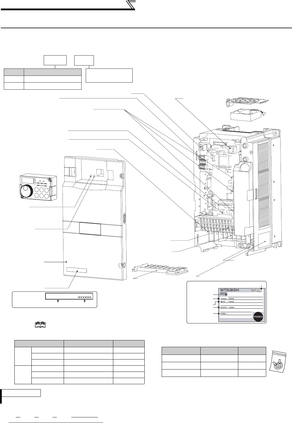
1.1 Product checking and parts identification
Unpack the inverter and check the capacity plate on the front cover and the rating plate on the inverter side face to
ensure that the product agrees with your order and the inverter is intact.
REMARKS
·For removal and reinstallation of covers, refer to page 6.
Rating plate example The SERIAL consists of one symbol, two characters indicating production year and month, and six
characters indicating control number.
The last digit of the production year is indicated as the Year, and the Month is indicated by 1 to 9,
X (October), Y (November), or Z (December.)
Symbol Year Month Control number
SERIAL (Serial No.)
Operation panel (FR-DU07)
Front cover
EMC filter ON/OFF connector
Control circuit
terminal block
AU/PTC switchover switch
Main circuit
terminal block
Power lamp
Lit when the control circuit
(R1/L11, S1/L21) is supplied
with power.
Cooling fan
PU connector
RS-485 terminals
Connector for plug-in option connection
(Refer to the instruction manual of options.)
There are three connection connectors, and they are called
connector 1, connector 2, and connector 3 from the top.
Alarm lamp
Lit when the inverter is
in the alarm status
(Fault).
Capacity plate
Inverter model Serial number
Capacity plate
Rating plate
USB connector
Voltage/current input switch
Charge lamp
Lit when power is supplied
to the main circuit
K
3.7
Represents inverter
capacity (kW)
FR-A720-3.7K
FR --A720
Symbol Voltage Class
A720 Three-phase 200V class
• Inverter Model
A740 Three-phase 400V class
Combed shaped
wiring cover
Rating plate
Inverter model
Input rating
Output rating
Serial number
Applied motor
capacity
FR-A720-3.7K
Production year and month
(Refer to page 27)
(Refer to page 68)
(Refer to page 15)
(Refer to page 16)
(Refer to page 431)
(Refer to page 330)
(Refer to page 25)
(Refer to the Instruction Manual (Applied).)
•Accessory
· Fan cover fixing screws (22K or lower)
(
Refer to
Instruction Manual (basic)
)
These screws are necessary for compliance with the EU
Directive.
Capacity Screw Size (mm) Quantity
200V
1.5K to 3.7K M3 × 35 1
5.5K to 11K M4 × 40 2
15K to 22K M4 × 50 1
400V
2.2K, 3.7K M3 × 35 1
5.5K to 15K M4 × 40 2
18.5K, 22K M4 × 50 1
(Refer to page 18)
(Refer to page 16)
(Refer to page 6)
(Refer to page 360)
(Refer to page 14)
· DC reactor supplied (75K or higher)
· Eyebolt for hanging the inverter (30K to 280K)
Capacity Eyebolt Size Quantity
30K M8 2
37K to 132K M10 2
160K to 280K M12 2
3
Inverter and peripheral devices
1
OUTLINE
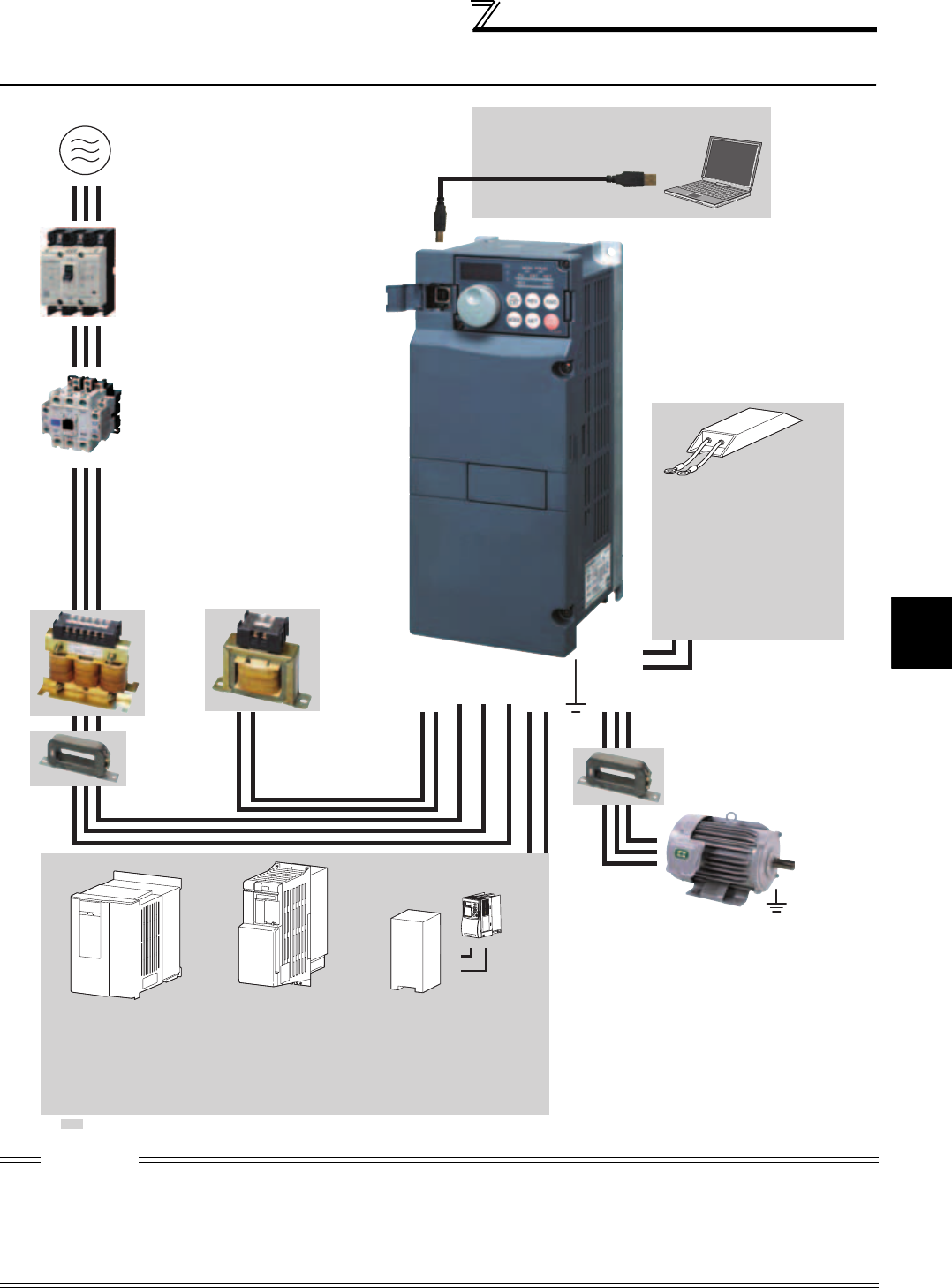
1.2 Inverter and peripheral devices
CAUTION
·
Do not install a power factor correction capacitor, surge suppressor or radio noise filter on the inverter output side. This will cause the
inverter to trip or the capacitor, and surge suppressor to be damaged. If any of the above devices are connected, immediately remove them.
· Electromagnetic wave interference
The input/output (main circuit) of the inverter includes high frequency components, which may interfere with the communication
devices (such as AM radios) used near the inverter.
In this case, set the EMC filter valid to minimize interference.
(Refer to page 15)
· Refer to the instruction manual of each option and peripheral devices for details of peripheral devices.
Line noise filter
Line noise filter
Motor
Devices connected to the output
P/+
P/+
PR
PR
AC reactor
(FR-HAL)
DC reactor (FR-HEL)
Install a line noise filter to
reduce the electromagnetic
noise generated from the
inverter.
Effective in the range from
about 1MHz to 10MHz. A wire
should be wound four turns at
a maximum.
Power supply harmonics can
be greatly suppressed.
Install this as required. Great braking capability is obtained.
Install this as required.
The regenerative braking
capability of the inverter can
be exhibited fully.
Install this as required.
Three-phase AC power supply
Use within the permissible power supply
specifications of the inverter.
USB connector
A personal computer and an inverter can
be connected with a USB (Ver1. 1) cable.
Moulded case circuit breaker (MCCB) or
earth leakage current breaker (ELB),
fuse
The breaker must be selected carefully
since an in-rush current flows in the inverter
at power on.
Magnetic contactor (MC)
Install the magnetic contactor to ensure safety.
Do not use the magnetic contactor for frequent
starting/stopping of the inverter. Doing so will
cause the inverter life to be shortened.
Do not install a power factor correction capacitor,
surge suppressor or radio noise filter on the output
side of the inverter. When installing a moulded case
circuit breaker on the output side of the inverter,
contact each manufacturer for selection of the
moulded case circuit breaker.
R/L1 S/L2 T/L3
P1P/+ N/-P/+
UW
P/+
PR
V
High power factor converter
(FR-HC
*1
, MT-HC
*2
)
Power regeneration
common converter (FR-CV
*1
)
Power regeneration
converter (MT-RC
*2
)
Resistor unit
(FR-BR
*1
, MT-BR5
*2
)
Brake unit
(FR-BU2
*3
, FR-BU
*1
, MT-BU5
*2
)
(FR-BLF)
Earth (Ground)
Earth (Ground)
To prevent an electric shock, always earth (ground) the
motor and inverter.
For reduction of induction noise from the power line of
the inverter, it is recommended to wire the earthing
(grounding) cable by returning it to the earth (ground)
terminal of the inverter.
Earth
(Ground)
: Install these options as required.
The 55K or lower has
a built-in common
mode choke.
For the 75K or higher, a
DC reactor is supplied.
Always install the reactor.
*1 Compatible with the 55K or lower.
*2 Compatible with the 75K or higher.
*3 Compatible with all capacities.
High-duty brake resistor
(FR-ABR
*4
)
Braking capability of the inverter built-
in brake can be improved. Remove
the jumper across terminal PR-PX
when connecting the high-duty brake
resistor. (7.5K or lower)
Always install a thermal relay when
using a brake resistor whose capacity
is 11K or higher.
*4 Compatible with the 22K or lower.
Reactor (FR-HAL, FR-HEL option)
Install reactors to suppress harmonics and to
improve the power factor. An AC reactor (FR-HAL)
(option) is required when installing the inverter
near a large power supply system (1000kVA or
more).
The inverter may be damaged if you do not use a
reactor. Select a reactor according to the model.
Remove the jumpers across terminals P/+ - P1 to
connect the DC reactor to the 55K or lower.
(Refer to page 442)
(Refer to page 5)
(Refer to page 360)
(Refer to page 61)
(Refer to page 60 )
Inverter (FR-A700)
The life of the inverter is influenced by
surrounding air temperature. The
surrounding air temperature should be as
low as possible within the permissible
range. This must be noted especially
when the inverter is installed in an
enclosure. (Refer to page 8.)
Wrong wiring might lead to damage of the
inverter. The control signal lines must be
kept fully away from the main circuit to
protect them from noise.(Refer to page 14)
Refer to page 15 for the built-in noise filter.
(Refer to page 40)
4
Inverter and peripheral devices
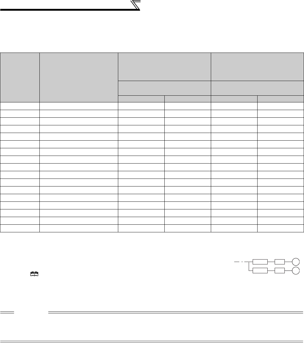
1.2.1 Peripheral devices
Check the inverter model of the inverter you purchased. Appropriate peripheral devices must be selected according to
the capacity. Refer to the following list and prepare appropriate peripheral devices:
200V class
Motor Output
(kW)
*1
Applicable Inverter Model
Moulded Case Circuit Breaker
(MCCB) *2 or Earth Leakage
Circuit Breaker (ELB)
(NF or NV type)
Input Side Magnetic Contactor*3
Power factor improving
(AC or DC) reactor
Power factor improving
(AC or DC) reactor
without with
without
with
0.4 FR-A720-0.4K 5A 5A S-N10 S-N10
0.75 FR-A720-0.75K 10A 10A S-N10 S-N10
1.5 FR-A720-1.5K 15A 15A S-N10 S-N10
2.2 FR-A720-2.2K 20A 15A S-N10 S-N10
3.7 FR-A720-3.7K 30A 30A S-N20, S-N21 S-N10
5.5 FR-A720-5.5K 50A 40A S-N25 S-N20, S-N21
7.5 FR-A720-7.5K 60A 50A S-N25 S-N25
11 FR-A720-11K 75A 75A S-N35 S-N35
15 FR-A720-15K 125A 100A S-N50 S-N50
18.5 FR-A720-18.5K 150A 125A S-N65 S-N50
22 FR-A720-22K 175A 150A S-N80 S-N65
30 FR-A720-30K 225A 175A S-N95 S-N80
37 FR-A720-37K 250A 225A S-N150 S-N125
45 FR-A720-45K 300A 300A S-N180 S-N150
55 FR-A720-55K 400A 350A S-N220 S-N180
75 FR-A720-75K ⎯400A ⎯
S-N300
90 FR-A720-90K ⎯400A ⎯
S-N300
*1 Motor Output (kW) in the above table indicates values when using the Mitsubishi 4-pole standard motor with power supply voltage of 200VAC
50Hz.
*2 Select the MCCB according to the power supply capacity. Install one MCCB per inverter.
For installation in the United States or Canada, select a fuse in accordance with UL, cUL, the National
Electrical Code and any applicable local codes, or use UL 489 Molded Case Circuit Breaker (MCCB).
(Refer to Instruction Manual (basics).)
*3 Magnetic contactor is selected based on the AC-1 class. The electrical durability of magnetic contactor is 500,000 times. When the magnetic
contactor is used for emergency stop during motor driving, the electrical durability is 25 times.
If using an MC for emergency stop during motor driving, select an MC regarding the inverter input side current as JEM1038-AC-3 class rated
current. When using an MC on the inverter output side for commercial-power supply operation switching using a general purpose motor, select an
MC regarding the motor rated current as JEM1038-AC-3 class rated current.
CAUTION
⋅When the inverter capacity is larger than the motor capacity, select an MCCB and a magnetic contactor according to the
inverter model and cable and reactor according to the motor output.
⋅When the breaker on the inverter primary side trips, check for the wiring fault (short circuit), damage to internal parts of the
inverter, etc. Identify the cause of the trip, then remove the cause and power on the breaker.
MCCB INV
MCCB INV
IM
IM

5
Inverter and peripheral devices
1
OUTLINE
400V class
Motor Output
(kW)
*1
Applicable Inverter Model
Moulded Case Circuit Breaker
(MCCB) *2 or Earth Leakage
Circuit Breaker (ELB)
(NF or NV type)
Input Side Magnetic Contactor*3
Power factor improving
(AC or DC) reactor
Power factor improving
(AC or DC) reactor
without with
without
with
0.4 FR-A740-0.4K 5A 5A S-N10 S-N10
0.75 FR-A740-0.75K 5A 5A S-N10 S-N10
1.5 FR-A740-1.5K 10A 10A S-N10 S-N10
2.2 FR-A740-2.2K 10A 10A S-N10 S-N10
3.7 FR-A740-3.7K 20A 15A S-N10 S-N10
5.5 FR-A740-5.5K 30A 20A S-N20, S-N21 S-N11, S-N12
7.5 FR-A740-7.5K 30A 30A S-N20, S-N21 S-N20, S-N21
11 FR-A740-11K 50A 40A S-N20, S-N21 S-N20, S-N21
15 FR-A740-15K 60A 50A S-N25 S-N20, S-N21
18.5 FR-A740-18.5K 75A 60A S-N25 S-N25
22 FR-A740-22K 100A 75A S-N35 S-N25
30 FR-A740-30K 125A 100A S-N50 S-N50
37 FR-A740-37K 150A 125A S-N65 S-N50
45 FR-A740-45K 175A 150A S-N80 S-N65
55 FR-A740-55K 200A 175A S-N80 S-N80
75 FR-A740-75K ⎯225A ⎯S-N95
90 FR-A740-90K ⎯225A ⎯S-N150
110 FR-A740-110K ⎯225A ⎯S-N180
132 FR-A740-132K ⎯400A ⎯S-N220
160 FR-A740-160K ⎯400A ⎯S-N300
185 FR-A740-185K ⎯400A ⎯S-N300
220 FR-A740-220K ⎯500A ⎯S-N400
250 FR-A740-250K ⎯600A ⎯S-N600
280 FR-A740-280K ⎯600A ⎯S-N600
315 FR-A740-315K ⎯700A ⎯S-N600
355 FR-A740-355K ⎯800A ⎯S-N600
400 FR-A740-400K ⎯900A ⎯S-N800
450 FR-A740-450K ⎯1000A ⎯1000A
Rated product
500 FR-A740-500K ⎯1200A ⎯1000A
Rated product
*1 Motor Output (kW) in the above table indicates values when using the Mitsubishi 4-pole standard motor with power supply voltage of 400VAC
50Hz.
*2 Select the MCCB according to the power supply capacity. Install one MCCB per inverter.
For installation in the United States or Canada, select a fuse in accordance with UL, cUL, the National
Electrical Code and any applicable local codes, or use UL 489 Molded Case Circuit Breaker (MCCB).
(Refer to Instruction Manual (basics).)
*3 Magnetic contactor is selected based on the AC-1 class. The electrical durability of magnetic contactor is 500,000 times. When the magnetic
contactor is used for emergency stop during motor driving, the electrical durability is 25 times.
If using an MC for emergency stop during motor driving, select an MC regarding the inverter input side current as JEM1038-AC-3 class rated
current. When using an MC on the inverter output side for commercial-power supply operation switching using a general purpose motor, select an
MC regarding the motor rated current as JEM1038-AC-3 class rated current.
CAUTION
⋅When the inverter capacity is larger than the motor capacity, select an MCCB and a magnetic contactor according to the
inverter model, and select cable and reactor according to the motor output.
⋅When the breaker on the inverter primary side trips, check for the wiring fault (short circuit), damage to internal parts of the
inverter, etc. Identify the cause of the trip, then remove the cause and power on the breaker.
MCCB INV
MCCB INV
IM
IM
6
Method of removal and reinstallation of the
front cover
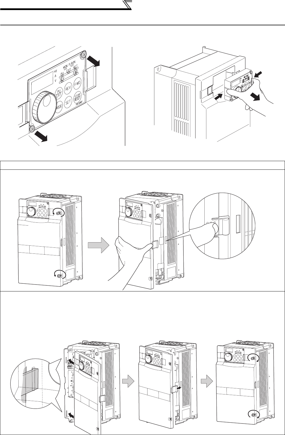
1.3 Method of removal and reinstallation of the front cover
•Removal of the operation panel
1) Loosen the two screws on the operation panel.
(These screws cannot be removed.)
2) Push the left and right hooks of the operation panel
and pull the operation panel toward you to remove.
When reinstalling the operation panel, insert it straight to reinstall securely and tighten the fixed screws of the
operation panel.
22K or lower
•Removal
•Reinstallation
Installation hook
Front cover Front cover
1) Loosen the mounting screws of the
front cover.
2) Pull the front cover toward you to remove by pushing an
installation hook using left fixed hooks as supports.
Front cover Front cover
Front cover
1) Insert the two fixed hooks on the left side of
the front cover into the sockets of the
inverter.
2) Using the fixed hooks as supports,
securely press the front cover
against the inverter.
(Although installation can be done
with the operation panel mounted,
make sure that a connector is
securely fixed.)
3) Tighten the mounting
screws and fix the front
cover.
7
Method of removal and reinstallation of the
front cover
1
OUTLINE
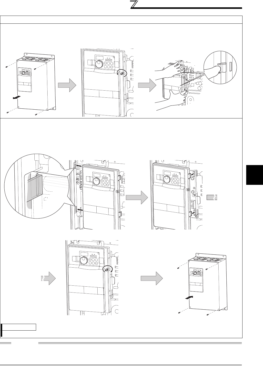
30K or higher
•Removal
•Reinstallation
CAUTION
1. Fully make sure that the front cover has been reinstalled securely. Always tighten the mounting screws of the front cover.
2. The same serial number is printed on the capacity plate of the front cover and the rating plate of the inverter. Before
reinstalling the front cover, check the serial numbers to ensure that the cover removed is reinstalled to the inverter from where
it was removed.
Front cover 2
Front cover 1
Installation hook
1) Remove mounting screws on the
front cover 1 to remove the front
cover 1.
2) Loosen the mounting
screws of the front cover 2.
3) Pull the front cover 2 toward you to remove
by pushing an installation hook on the right
side using left fixed hooks as supports.
Front cover 2 Front cover 2
Front cover 2
Front cover 1
1) Insert the two fixed hooks on the left side of the
front cover 2 into the sockets of the inverter.
2) Using the fixed hooks as supports, securely press the
front cover 2 against the inverter.
(Although installation can be done with the operation
panel mounted, make sure that a connector is
securely fixed.)
3) Fix the front cover 2 with the mounting screws. 4) Fix the front cover 1 with the mounting
screws.
REMARKS
⋅For the FR-A720-55K and the FR-A740-160K or higher, the front cover 1 is separated into two parts.

8
Installation of the inverter and enclosure
design
1.4 Installation of the inverter and enclosure design
When an inverter enclosure is to be designed and manufactured, heat generated by contained equipment, etc., the
environment of an operating place, and others must be fully considered to determine the enclosure structure, size and
equipment layout. The inverter unit uses many semiconductor devices. To ensure higher reliability and long period of
operation, operate the inverter in the ambient environment that completely satisfies the equipment specifications.
1.4.1 Inverter installation environment
As the inverter installation environment should satisfy the standard specifications indicated in the following table,
operation in any place that does not meet these conditions not only deteriorates the performance and life of the
inverter, but also causes a failure. Refer to the following points and take adequate measures.
*2.9m/s
2 or less for the 160K or higher.
(1) Temperature
The permissible surrounding air temperature of the inverter is between -10°C and +50°C. Always operate the inverter
within this temperature range. Operation outside this range will considerably shorten the service lives of the
semiconductors, parts, capacitors and others. Take the following measures so that the surrounding air temperature of
the inverter falls within the specified range.
1) Measures against high temperature
• Use a forced ventilation system or similar cooling system. (Refer to page 10.)
• Install the enclosure in an air-conditioned electrical chamber.
• Block direct sunlight.
• Provide a shield or similar plate to avoid direct exposure to the radiated heat and wind of a heat source.
• Ventilate the area around the enclosure well.
2) Measures against low temperature
• Provide a space heater in the enclosure.
• Do not power OFF the inverter. (Keep the start signal of the inverter OFF.)
3) Sudden temperature changes
• Select an installation place where temperature does not change suddenly.
• Avoid installing the inverter near the air outlet of an air conditioner.
• If temperature changes are caused by opening/closing of a door, install the inverter away from the door.
(2) Humidity
Normally operate the inverter within the 45 to 90% range of the ambient humidity. Too high humidity will pose problems
of reduced insulation and metal corrosion. On the other hand, too low humidity may produce a spatial electrical
breakdown. The insulation distance specified in JEM1103 "Control Equipment Insulator" is defined as humidity 45 to
85%.
1) Measures against high humidity
• Make the enclosure enclosed, and provide it with a hygroscopic agent.
• Take dry air into the enclosure from outside.
• Provide a space heater in the enclosure.
2) Measures against low humidity
What is important in fitting or inspection of the unit in this status is to discharge your body (static electricity)
beforehand and keep your body from contact with the parts and patterns, besides blowing air of proper humidity into
the enclosure from outside.
3) Measures against condensation
Condensation may occur if frequent operation stops change the in-enclosure temperature suddenly or if the outside-
air temperature changes suddenly.
Condensation causes such faults as reduced insulation and corrosion.
• Take the measures against high humidity in 1).
• Do not power OFF the inverter. (Keep the start signal of the inverter OFF.)
Environmental standard specifications of inverter
Item Description
Surrounding air
temperature -10 to +50°C (non-freezing)
Ambient humidity 90% RH maximum (non-condensing)
Atmosphere Indoors (free from corrosive gas, flammable gas, oil mist, dust and dirt)
Maximum Altitude 1,000m or less
Vibration 5.9m/s2 or less * at 10 to 55Hz (directions of X, Y, Z axes)

9
Installation of the inverter and enclosure
design
1
OUTLINE
(3) Dust, dirt, oil mist
Dust and dirt will cause such faults as poor contact of contact points, reduced insulation or reduced cooling effect due
to moisture absorption of accumulated dust and dirt, and in-enclosure temperature rise due to clogged filter.
In the atmosphere where conductive powder floats, dust and dirt will cause such faults as malfunction, deteriorated
insulation and short circuit in a short time.
Since oil mist will cause similar conditions, it is necessary to take adequate measures.
Countermeasures
• Place in a totally enclosed enclosure.
Take measures if the in-enclosure temperature rises. (Refer to page 10.)
• Purge air.
Pump clean air from outside to make the in-enclosure pressure higher than the outside-air pressure.
(4) Corrosive gas, salt damage
If the inverter is exposed to corrosive gas or to salt near a beach, the printed board patterns and parts will corrode or
the relays and switches will result in poor contact.
In such places, take the measures given in Section (3).
(5) Explosive, flammable gases
As the inverter is non-explosion proof, it must be contained in an explosion proof enclosure.
In places where explosion may be caused by explosive gas, dust or dirt, an enclosure cannot be used unless it
structurally complies with the guidelines and has passed the specified tests. This makes the enclosure itself expensive
(including the test charges).
The best way is to avoid installation in such places and install the inverter in a non-hazardous place.
(6) Highland
Use the inverter at the altitude of within 1000m.
If it is used at a higher place, it is likely that thin air will reduce the cooling effect and low air pressure will deteriorate
dielectric strength.
(7) Vibration, impact
The vibration resistance of the inverter is up to 5.9m/s2 (2.9m/s2 for the 160K or higher) at 10 to 55Hz frequency and
1mm amplitude for the directions of X, Y, Z axes.
Vibration or impact, if less than the specified value, applied for a long time may make the mechanism loose or cause
poor contact to the connectors.
Especially when impact is imposed repeatedly, caution must be taken as the part pins are likely to break.
Countermeasures
• Provide the enclosure with rubber vibration isolators.
• Strengthen the structure to prevent the enclosure from resonance.
• Install the enclosure away from sources of vibration.
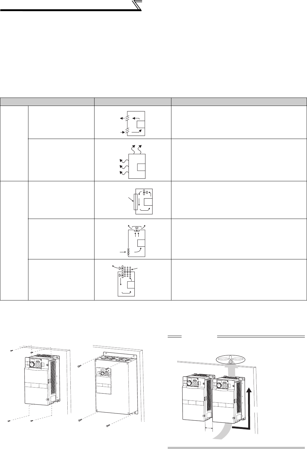
10
Installation of the inverter and enclosure
design
1.4.2 Cooling system types for inverter enclosure
From the enclosure that contains the inverter, the heat of the inverter and other equipment (transformers, lamps,
resistors, etc.) and the incoming heat such as direct sunlight must be dissipated to keep the in-enclosure temperature
lower than the permissible temperatures of the in-enclosure equipment including the inverter.
The cooling systems are classified as follows in terms of the cooling calculation method.
1) Cooling by natural heat dissipation from the enclosure surface (Totally enclosed type)
2) Cooling by heat sink (Aluminum fin, etc.)
3) Cooling by ventilation (Forced ventilation type, pipe ventilation type)
4) Cooling by heat exchanger or cooler (Heat pipe, cooler, etc.)
1.4.3 Inverter placement
(1) Installation of the Inverter
Cooling System Enclosure Structure Comment
Natural
cooling
Natural ventilation
(Enclosed, open type)
Low in cost and generally used, but the enclosure size
increases as the inverter capacity increases. For
relatively small capacities.
Natural ventilation (Totally
enclosed type)
Being a totally enclosed type, the most appropriate for
hostile environment having dust, dirt, oil mist, etc. The
enclosure size increases depending on the inverter
capacity.
Forced
cooling
Heatsink cooling Having restrictions on the heatsink mounting position
and area, and designed for relative small capacities.
Forced ventilation For general indoor installation. Appropriate for enclosure
downsizing and cost reduction, and often used.
Heat pipe Totally enclosed type for enclosure downsizing.
Installation on the enclosure
0.4K to 22K 30K or higher
INV
INV
INV
Heatsink
INV
INV
Heat
pipe
CAUTION
When encasing multiple inverters, install them in parallel
as a cooling measure. Install the inverter vertically.
* Refer to the clearances on the next page.
Vertical
*
Fix six positions for the FR-A740-160K to 355K
and fix eight positions for the FR-A740-400K to
500K.
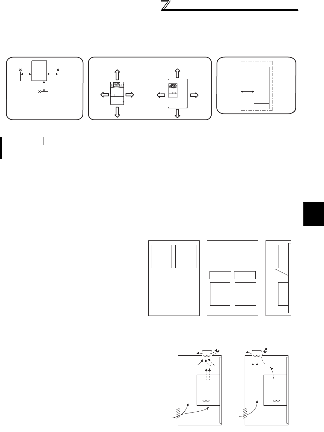
11
Installation of the inverter and enclosure
design
1
OUTLINE
(2) Clearances around the inverter
To ensure ease of heat dissipation and maintenance, leave at least the shown clearances around the inverter. At least the
following clearances are required under the inverter as a wiring space, and above the inverter as a heat dissipation space.
(3) Inverter mounting orientation
Mount the inverter on a wall as specified. Do not mount it horizontally or any other way.
(4) Above the inverter
Heat is blown up from inside the inverter by the small fan built in the unit. Any equipment placed above the inverter
should be heat resistant.
(5) Arrangement of multiple inverters
(6) Placement of ventilation fan and inverter
REMARKS
For replacing the cooling fan of the 160K or higher, 30cm of space is necessary in front of the inverter. Refer to page 431 for fan
replacement.
When multiple inverters are placed in the same
enclosure, generally arrange them horizontally as
shown in the right figure (a). When it is inevitable to
arrange them vertically to minimize space, take such
measures as to provide guides since heat from the
bottom inverters can increase the temperatures in the
top inverters, causing inverter failures.
When mounting multiple inverters, fully take caution
not to make the surrounding air temperature of the
inverter higher than the permissible value by providing
ventilation and increasing the enclosure size.
Arrangement of multiple inverters
Heat generated in the inverter is blown up from the bottom of
the unit as warm air by the cooling fan. When installing a
ventilation fan for that heat, determine the place of ventilation
fan installation after fully considering an air flow. (Air passes
through areas of low resistance. Make an airway and airflow
plates to expose the inverter to cool air.)
Placement of ventilation fan and inverter
ClearancesSurrounding air temperature and humidity
Measurement
position
Measurement
position
Inverter
Leave enough clearances and take
cooling measures.
55K or lower 75K or higher
5cm 5cm
5cm
10cm or more 20cm or more
20cm or more
10cm or more
5cm
or more *
5cm
or more *
10cm
or more
10cm
or more
Temperature:
-10°C to 50°C
Ambient humidity:
90% RH maximum
(front)
*1cm or more for 3.7K or lower
Clearances (side)
Inverter
5cm
or more
*
*1cm or more for 3.7K or lower
Guide Guide
Enclosure Enclosure
Guide
(a) Horizontal arrangement (b) Vertical arrangement
Inverter
Inverter
Inverter
Inverter Inverter
Inverter
Inverter Inverter
<Good example> <Bad example>
12
MEMO

13
3
4
5
6
7
1
2
2 WIRING
This chapter describes the basic "WIRING" for use of this
product.
Always read the instructions before using the equipment.
2.1 Wiring ......................................................................14
2.2 Main circuit terminal specifications..........................16
2.3 Control circuit specifications....................................25
2.4 Connection of motor with encoder (vector control) .33
2.5 Connection of stand-alone option units ...................40
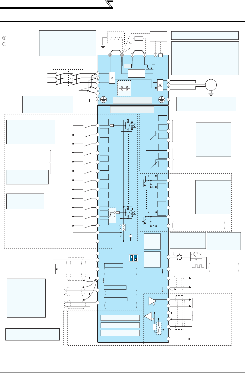
14
Wiring
2.1 Wiring
2.1.1 Terminal connection diagram
CAUTION
· To prevent a malfunction due to noise, keep the signal cables more than 10cm away from the power cables. Also separate the main circuit wire
of the input side and the output side.
· After wiring, wire offcuts must not be left in the inverter.Wire offcuts can cause an alarm, failure or malfunction. Always keep the inverter clean.
When drilling mounting holes in an enclosure etc., take care not to allow chips and other foreign matter to enter the inverter.
· Set the voltage/current input switch correctly. Different setting may cause a fault, failure or malfunction.
R/L1
S/L2
T/L3
R1/L11
S1/L21
PC
10E(+10V)
10(+5V)
2
(Analog common)
2
3
1
1
4
Jumper
C1
B1
A1
U
V
W
P1
0 to
±
10VDC
*1
0 to 5VDC
0 to 10VDC
MC
Main circuit
Control circuit
C2
B2
A2
IM
0 to 20mADC
AU
PTC
TXD+
TXD-
RXD+
RXD-
SG
GND
SINK
SOURCE
*4
*3
*5
STF
STR
STOP
RH
RM
RL
JOG
RT
MRS
RES
AU
CS
SD
RUN
SU
IPF
OL
FU
SE
(+)
(-)
5
ON
OFF
VCC
(+)
(-)
5V
*2 Earth (Ground)
PX PR N/-P/+
*8
*3.JOG terminal can be used
as pulse train input terminal.
Use Pr. 291 to select
JOG/pulse.
Main circuit terminal
Control circuit terminal
Three-phase AC
power supply
MCCB
Jumper
Earth
(Ground)
EMC filter
ON/OFF
connecter
Earth
(Ground)
selectable
selectable
0 to ±5VDC
*5
4 to 20mADC
0 to 5VDC
0 to 10VDC
selectable
*5
Option connector 1
Option connector 2
Option connector 3
Connector
for plug-in option
connection
Frequency setting signal (Analog)
Frequency setting
potentiometer
1/2W1kΩ
*6
Control input signals (No voltage input allowed)
Forward
rotation
start
Reverse
rotation
start
Start self-
holding selection
Terminal functions vary with
the input terminal
assignment (Pr. 178 to Pr. 189)
Middle
speed
High speed
Low speed
Multi-speed
selection
Jog operation
Second function selection
Output stop
Reset
Terminal 4 input selection
(Current input selection)
Selection of automatic restart
after instantaneous
power failure
USB
connector
PU
connector
Terminating
resistor
Data reception
Data transmission
RS-485 terminals
Open collector output common
Sink/source common
Frequency detection
Running
Up to frequency
Instantaneous
power failure
Overload
Terminal functions
vary with the output
terminal assignment
(Pr. 190 to Pr. 194)
Open collector output
(Permissible load
current 100mA)
Relay output 2
Relay output 1
(Fault output)
Terminal functions
vary with the output
terminal assignment
(Pr. 195, Pr. 196)
Relay output
Motor
*4. AU terminal can be
used as PTC input
terminal.
*2. To supply power to the
control circuit separately,
remove the jumper across
R1/L11 and S1/L21.
*10. It is not necessary
when calibrating the
indicator from the
operation panel.
*6. It is recommended to use 2W1kΩ
when the frequency setting signal
is changed frequently.
Jumper
(Initial value)
(Initial value)
(Initial value)
ON
42
OFF
Voltage/current
input switch
*5
Auxiliary
input
Terminal
4 input
(Current
input)
Brake unit
(Option)
CN8
*7
Jumper
*5.
Terminal input specifications
can be changed by analog
input specifications
switchover (Pr. 73, Pr. 267).
Set the voltage/current input
switch in the OFF position to
select voltage input (0 to 5V/0
to10V) and ON to select
current input (4 to 20mA).
R
R
*1. DC reactor (FR-HEL)
Be sure to connect the DC reactor
supplied with the 75K or higher.
When a DC reactor is connected to
the 55K or lower, remove the jumper
across P1 and P/+.
*7. A CN8 connector (for MT-BU5) is provided
with the 75K or higher.
Sink logic
*8. Brake resistor (FR-ABR)
Remove the jumper across terminal PR-PX
when connecting a brake resistor.
(0.4K to 7.5K)
Terminal PR is provided for the 0.4K to 22K.
Install a thermal relay to prevent an overheat
and burnout of the brake resistor.
*9
*9.The FR-A720-0.4K and 0.75K
are not provided with the EMC
filter ON/OFF connector. (Always on)
FM
SD
+-
AM
5
*11
*11. FM terminal can
be used for pulse
train output of open
collector output
using Pr.291.
(+)
(-) (0 to 10VDC)
Analog signal output
Moving-coil type
1mA full-scale
(Frequency meter, etc.)
Indicator
Calibration
resistor *10
24VDC power supply
(Common for external power supply transistor)
Contact input common 24V
Inrush current
limit circuit
(Refer to page 40)
(Refer to page 286)
(Refer to page 231)
(Refer to page 239)
(Refer to page 239)
(Refer to page 45)
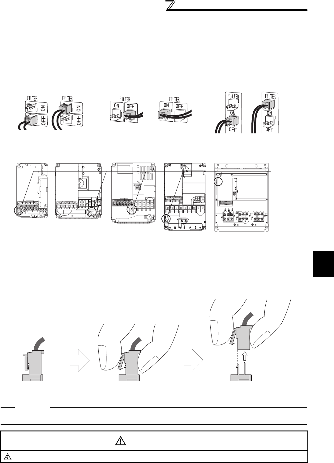
2
WIRING
15
Wiring
2.1.2 EMC filter
This inverter is equipped with a built-in EMC filter (capacitive filter) and common mode choke.
Effective for reduction of air-propagated noise on the input side of the inverter.
The EMC filter is factory-set to disable (OFF).
To enable it, fit the EMC filter ON/OFF connector to the ON position.
The input side common mode choke, built-in the 55K or lower inverter, is always valid regardless of on/off of the EMC
filter on/off connector.
The FR-A720-0.4K and 0.75K are not provided with the EMC filter ON/OFF connector. (The EMC filter is always valid.)
<How to disconnect the connector>
(1) Before removing a front cover, check to make sure that the indication of the inverter operation panel is OFF, wait
for at least 10 minutes after the power supply has been switched OFF, and check that there are no residual voltage
using a tester or the like. (Refer to page 6.)
(2) When disconnecting the connector, push the fixing tab and pull the connector straight without pulling the cable or
forcibly pulling the connector with the tab fixed. When installing the connector, also engage the fixing tab securely.
(If it is difficult to disconnect the connector, use a pair of long-nose pliers, etc.)
CAUTION
⋅Fit the connector to either ON or OFF.
⋅Enabling (turning on) the EMC filter increases leakage current. (Refer to page 53)
WARNING
While power is ON or when the inverter is running, do not open the front cover. Otherwise you may get an electric shock.
EMC filter OFF EMC filter OFF EMC filter OFFEMC filter ON EMC filter ON EMC filter ON
(initial setting) (initial setting) (initial setting)
EMC filter
ON/OFF
connector
VUW
3.7K or lower 5.5K, 7.5K 11K or higher
FR-A720-1.5K to 3.7K
FR-A740-0.4K to 3.7K
FR-A720-5.5K, 7.5K
FR-A740-5.5K to 7.5K
FR-A720-11K
FR-A740-11K, 15K
FR-A720-15K to 22K
FR-A740-18.5K to 22K
FR-A720-30K or higher
FR-A740-30K or higher
EMC filter
ON/OFF connector
(Side view)
Disengage connector fixing tab With tab disengaged,
pull up the connector straight.
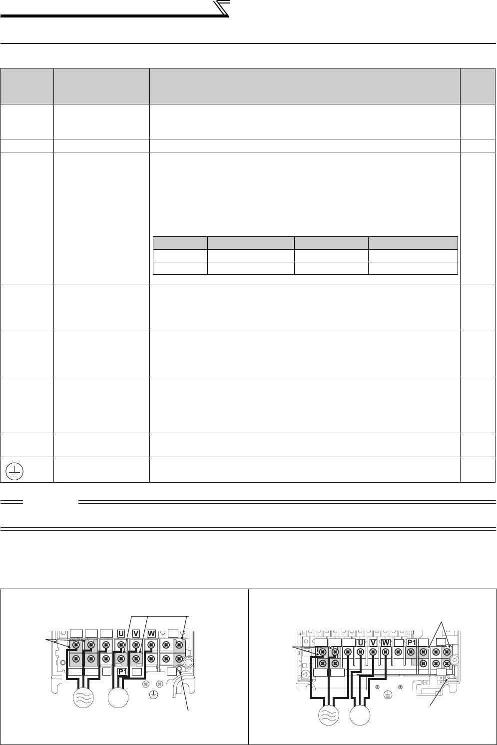
16
Main circuit terminal specifications
2.2 Main circuit terminal specifications
2.2.1 Specification of main circuit terminal
2.2.2 Terminal arrangement of the main circuit terminal, power supply and the motor
wiring.
Terminal
Symbol Terminal Name Description
Refer
to
page
R/L1,
S/L2,
T/L3
AC power input
Connect to the commercial power supply.
Keep these terminals open when using the high power factor converter (FR-
HC and MT-HC) or power regeneration common converter (FR-CV).
—
U, V, W Inverter output Connect a three-phase squirrel-cage motor. —
R1/L11,
S1/L21
Power supply for
control circuit
Connected to the AC power supply terminals R/L1 and S/L2. To retain the
fault display and fault output or when using the high power factor converter
(FR-HC and MT-HC) or power regeneration common converter (FR-CV),
remove the jumpers from terminals R/L1-R1/L11 and S/L2-S1/L21 and apply
external power to these terminals.
The power capacity necessary when separate power is supplied from R1/
L11 and S1/L21 differs according to the inverter capacity. 23
P/+, PR
Brake resistor
connection
(22K or lower)
Remove the jumper from terminals PR-PX (
7.5K
or lower) and connect an
optional brake resistor (FR-ABR) across terminals P/+-PR.
For the
22K
or lower, connecting the resistor further provides regenerative
braking power.
40
P/+, N/- Brake unit
connection
Connect the brake unit (FR-BU2, FR-BU, BU and MT-BU5), power
regeneration common converter (FR-CV), power regeneration converter
(MT-RC), high power factor converter (FR-HC and MT-HC) or DC power
supply (under the DC feeding mode).
42
P/+, P1 DC reactor
connection
For the 55K or
lower
, remove the jumper across terminals P/+ - P1 and
connect the DC reactor. (As a DC reactor is supplied with the 75K or higher
as standard, be sure to connect the DC reactor.)
Keep the jumper across P/+ and P1 attached when a DC reactor is not
connected.
49
PR, PX Built-in brake circuit
connection
When the jumper is connected across terminals PX-PR (initial status), the
built-in brake circuit is valid. (Provided for the 7.5K or
lower
.) —
Earth (Ground) For earthing (grounding) the inverter chassis. Must be earthed (grounded). 21
CAUTION
· When connecting a dedicated brake resistor (FR-ABR) and brake unit (FR-BU2, FR-BU, BU) remove jumpers across terminals
PR-PX (7.5K or lower). For details, refer to page 40.
FR-A720-0.4K, 0.75K FR-A720-1.5K to 3.7K
FR-A740-0.4K to 3.7K
11K or lower 15K 18.5K or higher
200V class
60VA
80VA
80VA
400V class
60VA
60VA
80VA
R/L1 S/L2 T/L3
N/- P/+
PR
PX
R1/L11 S1/L21
Charge lamp
Jumper
Jumper
Motor
Power supply
IM
R/L1 S/L2 T/L3 N/- P/+ PR
PX
R1/L11 S1/L21
IM Charge lamp
Jumper
Jumper
Motor
Power
supply

2
WIRING
17
Main circuit terminal specifications
FR-A720-5.5K, 7.5K
FR-A740-5.5K, 7.5K
FR-A720-11K
FR-A740-11K, 15K
FR-A720-15K to 22K
FR-A740-18.5K, 22K
FR-A720-30K to 45K
FR-A740-30K to 45K
FR-A720-55K FR-A740-55K
R/L1 S/L2 T/L3
N/- P/+ PR
PX
R1/L11 S1/L21
IM
Jumpe
r
Jumper
Charge lamp
Motor
Power supply
R1/L11 S1/L21
R/L1 S/L2 T/L3 N/-
P/+
PR
Charge lamp
Jumper
Jumper
Power supply
IM
Motor
R/L1 S/L2 T/L3 N/- P/+
PR
R1/L11 S1/L21
IM
Jumper
Jumper
Charge lamp
Motor
Power supply
R/L1 S/L2 T/L3 N/- P/+
R1/L11 S1/L21
IM
Jumper
Jumper
Charge lamp
Motor
Power
supply
Power supply
IM
Motor
R/L1 S/L2 T/L3 N/-
Jumper
Jumper
Charge lamp
R1/L11 S1/L21
P/+
IM
Jumper
Jumper
Charge lamp
Power
supply Motor
R/L1 S/L2 T/L3 N/- P/+
R1/L11 S1/L21
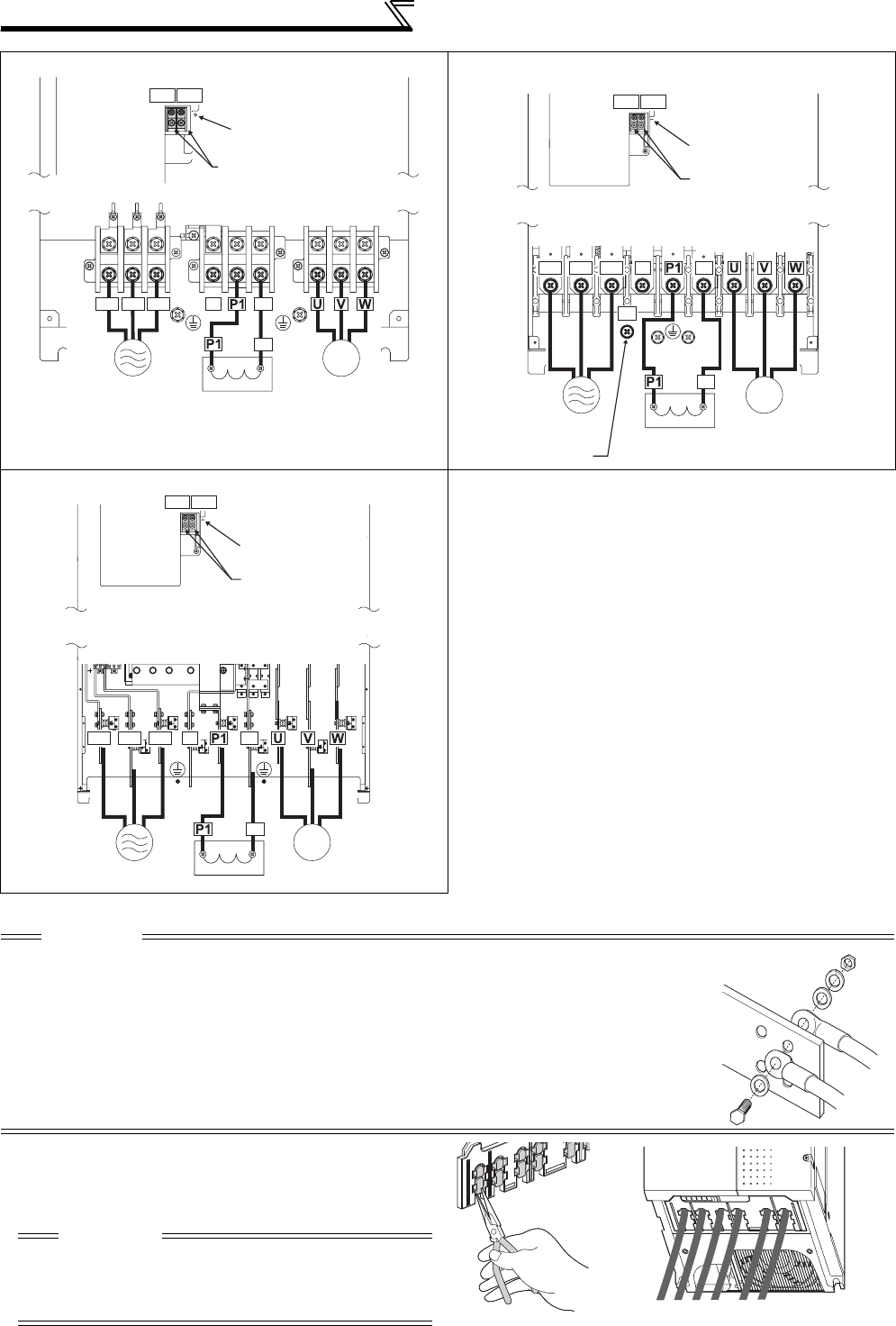
18
Main circuit terminal specifications
FR-A740-75K, 90K FR-A720-75K, 90K
FR-A740-110K to 185K
FR-A740-220K to 500K
CAUTION
· The power supply cables must be connected to R/L1, S/L2, T/L3. (Phase sequence needs not to be
matched.) Never connect the power cable to the U, V, W of the inverter. Doing so will damage the
inverter.
· Connect the motor to U, V, W. At this time, turning ON the forward rotation switch (signal) rotates the
motor in the counterclockwise direction when viewed from the motor shaft.
· When wiring the inverter main circuit conductor of the 220K or higher, tighten a nut from the right side
of the conductor. When wiring two wires, place wires on both sides of the conductor. (Refer to the
drawing on the right.) For wiring, use bolts (nuts) provided with the inverter.
•Handling of the wiring cover
(FR-A720-15K, 18.5K, 22K, FR-A740-18.5K, 22K)
For the hook of the wiring cover, cut off the necessary
parts using a pair of long-nose pliers etc.
IM
R/L1 S/L2 T/L3 N/- P/+
R1/L11 S1/L21
DC reactor
Power
supply Motor
Jumper
Charge lamp
P/+
R/L1 S/L2 T/L3 N/-
P/+
R1/L11 S1/L21
P/+
P/+
IM
Jumper
Charge lamp
Motor
For option
DC reactor
Power
supply
IM
R/L1 S/L2 T/L3 N/-
R1/L11 S1/L21
P/+
P/+
Jumper
Charge lamp
Motor
Power supply
DC reactor
CAUTION
Cut off the same number of lugs as wires. If parts where
no wire is put through has been cut off (10mm or more),
protective structure (JEM1030) becomes an open type
(IP00).
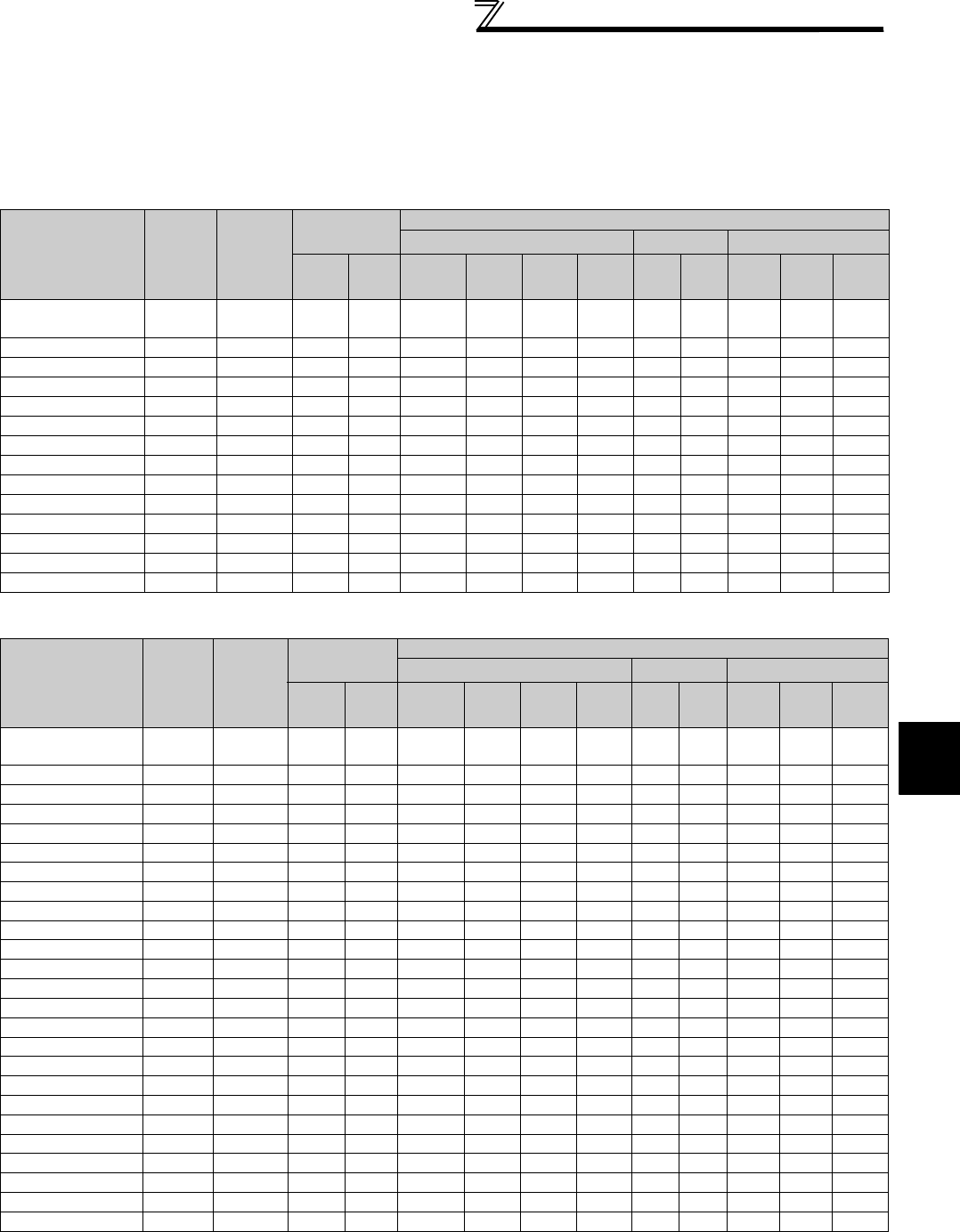
19
Main circuit terminal specifications
2
WIRING
2.2.3 Cables and wiring length
(1) Applied cable size
Select the recommended cable size to ensure that a voltage drop will be 2% max.
If the wiring distance is long between the inverter and motor, a main circuit cable voltage drop will cause the motor
torque to decrease especially at the output of a low frequency.
The following table indicates a selection example for the wiring length of 20m.
200V class (when input power supply is 220V)
400V class (when input power supply is 440V)
Applicable Inverter
Model
Terminal
Screw
Size *4
Tightening
Torque
N·m
Crimping
Terminal
Cable Sizes
HIV, etc. (mm2) *1 AWG/MCM *2 PVC, etc. (mm2) *3
R/L1,
S/L2,
T/L3
U, V, W
R/L1,
S/L2,
T/L3
U, V, W P/+, P1
Earthing
(grounding)
cable
R/L1,
S/L2,
T/L3
U, V, W
R/L1,
S/L2,
T/L3
U, V, W
Earthing
(grounding)
cable
FR-A720-0.4K to
2.2K M4 1.5 2-4 2-4 2 2 2 2 14 14 2.5 2.5 2.5
FR-A720-3.7K M4 1.5 5.5-4 5.5-4 3.5 3.5 3.5 3.5 12 12 4 4 4
FR-A720-5.5K M5(M4) 2.5 5.5-5 5.5-5 5.5 5.5 5.5 5.5 10 10 6 6 6
FR-A720-7.5K M5(M4) 2.5 14-5 8-5 14 8 14 5.5 6 8 16 10 16
FR-A720-11K M5 2.5 14-5 14-5 14 14 14 14 6 6 16 16 16
FR-A720-15K M6 4.4 22-6 22-6 22 22 22 14 4 4 25 25 16
FR-A720-18.5K M8(M6) 7.8 38-8 38-8 38 38 38 22 2 2 35 35 25
FR-A720-22K M8(M6) 7.8 38-8 38-8 38 38 38 22 2 2 35 35 25
FR-A720-30K M8(M6) 7.8 60-8 60-8 60 60 60 22 1/0 1/0 50 50 25
FR-A720-37K M10(M8) 14.7 80-10 80-10 80 80 80 22 3/0 3/0 70 70 35
FR-A720-45K M10(M8) 14.7 100-10 100-10 100 100 100 38 4/0 4/0 95 95 50
FR-A720-55K M12(M8) 24.5 100-12 100-12 100 100 100 38 4/0 4/0 95 95 50
FR-A720-75K
M12
(
M10
) 24.5 150-12 150-12 125 125 125 38 250 250 ⎯⎯⎯
FR-A720-90K
M12
(
M10
) 24.5 150-12 150-12 150 150 150 38 300 300 ⎯⎯⎯
Applicable Inverter
Model
Terminal
Screw
Size *4
Tightening
Torque
N·m
Crimping
Terminal
Cable Sizes
HIV, etc. (mm2) *1 AWG/MCM *2 PVC, etc. (mm2) *3
R/L1,
S/L2,
T/L3
U, V, W
R/L1,
S/L2,
T/L3
U, V, W P/+, P1
Earthing
(grounding)
cable
R/L1,
S/L2,
T/L3
U, V, W
R/L1,
S/L2,
T/L3
U, V, W
Earthing
(grounding)
cable
FR-A740-0.4K to
3.7K M4 1.5 2-4 2-4 2 2 2 2 14 14 2.5 2.5 2.5
FR-A740-5.5K M4 1.5 2-4 2-4 2 2 3.5 3.5 12 14 2.5 2.5 4
FR-A740-7.5K M4 1.5 5.5-4 5.5-4 3.5 3.5 3.5 3.5 12 12 4 4 4
FR-A740-11K M5 2.5 5.5-5 5.5-5 5.5 5.5 5.5 8 10 10 6 6 10
FR-A740-15K M5 2.5 8-5 8-5 8 8 8 8 8 8 10 10 10
FR-A740-18.5K M6 4.4 14-6 8-6 14 8 14 14 6 8 16 10 16
FR-A740-22K M6 4.4 14-6 14-6 14 14 22 14 6 6 16 16 16
FR-A740-30K M6 4.4 22-6 22-6 22 22 22 14 4 4 25 25 16
FR-A740-37K M8 7.8 22-8 22-8 22 22 22 14 4 4 25 25 16
FR-A740-45K M8 7.8 38-8 38-8 38 38 38 22 1 2 50 50 25
FR-A740-55K M8(M10) 7.8 60-8 60-8 60 60 60 22 1/0 1/0 50 50 25
FR-A740-75K M10 14.7 60-10 60-10 60 60 60 38 1/0 1/0 50 50 25
FR-A740-90K M10 14.7 60-10 60-10 60 60 80 38 3/0 3/0 50 50 25
FR-A740-110K
M10
(
M12)
14.7 80-10 80-10 80 80 80 38 3/0 3/0 70 70 35
FR-A740-132K
M10
(
M12)
14.7 100-10 100-10 100 100 100 38 4/0 4/0 95 95 50
FR-A740-160K
M12
(
M10)
24.5 150-12 150-12 125 150 150 38 250 250 120 120 70
FR-A740-185K
M12
(
M10)
24.5 150-12 150-12 150 150 150 38 300 300 150 150 95
FR-A740-220K
M12
(
M10)
46 100-12 100-12 2×100 2×100 2×100 60 2×4/0 2×4/0 2×95 2×95 95
FR-A740-250K
M12
(
M10)
46 100-12 100-12 2×100 2×100 2×125 60 2×4/0 2×4/0 2×95 2×95 95
FR-A740-280K
M12
(
M10)
46 150-12 150-12 2×125 2×125 2×125 60 2×250 2×250 2×120 2×120 120
FR-A740-315K
M12
(
M10)
46 150-12 150-12 2×150 2×150 2×150 100 2×300 2×300 2×150 2×150 150
FR-A740-355K
M12
(
M10)
46 C2-200
C2-200
2×200 2×200 2×200 100 2×350 2×350 2×185 2×185 2×95
FR-A740-400K
M12
(
M10)
46 C2-200
C2-200
2×200 2×200 2×200 100 2×400 2×400 2×185 2×185 2×95
FR-A740-450K
M12
(
M10)
46 C2-250
C2-250
2×250 2×250 2×250 100 2×500 2×500 2×240 2×240 2×120
FR-A740-500K
M12
(
M10)
46 C2-200
C2-250
3×200 2×250 3×200 2×100 2×500 2×500 2×240 2×240 2×120

20
Main circuit terminal specifications
*1 For the
55K
or lower, the cable size is that of the cable (HIV cable (600V class 2 vinyl-insulated cable) etc.) with continuous maximum permissible
temperature of
75°C
. Assumes that the surrounding air temperature is
50°C
or less and the wiring distance is 20m or less.
For the
75K
or higher, the recommended cable size is that of the cable (LMFC (heat resistant flexible cross-linked polyethylene insulated cable) etc.) with
continuous maximum permissible temperature of
90°C
. Assumes that the surrounding air temperature is
50°C
or less and wiring is performed in an
enclosure.
*2 For the
all capacity of 200V class, and FR-A740-
45K or lower, the recommended cable size is that of the cable (THHW cable) with continuous
maximum permissible temperature of
75°C
. Assumes that the surrounding air temperature is
40°C
or less and the wiring distance is 20m or less.
For the
FR-A740-
55K or higher, the recommended cable size is that of the cable (THHN cable) with continuous maximum permissible temperature of
90°C
. Assumes that the surrounding air temperature is
40°C
or less and wiring is performed in an enclosure.
(Selection example for use mainly in the United States.)
*3 For the
FR-A720-15K or lower, and FR-A740-
45K or lower, the recommended cable size is that of the cable (PVC cable) with continuous maximum
permissible temperature of
70°C
. Assumes that the surrounding air temperature is
40°C
or less and the wiring distance is 20m or less.
For the
FR-A720-18.5K or higher, and FR-A740-
55K or higher, the recommended cable size is that of the cable (XLPE cable) with continuous
maximum permissible temperature of
90°C
. Assumes that the surrounding air temperature is
40°C
or less and wiring is performed in an enclosure.
(Selection example for use mainly in Europe.)
*4 The terminal screw size indicates the terminal size for R/L1, S/L2, T/L3, U, V, W, PR, PX, P/+, N/-, P1 and a screw for earthing (grounding).
For the FR-A720-5.5K and 7.5K, screw size of terminal PR and PX is indicated in ( ).
A screw for earthing (grounding) of the FR-A720-18.5K or higher is indicated in ( ).
A screw for P/+, N/-, and P1 of the
FR-A740-
55K is indicated in ( ).
A screw for P/+ terminal for option connection of the FR-A740-110K and 132K is indicated in ( ).
A screw for earthing (grounding) of the FR-A740-160K or higher is indicated in ( ).
The line voltage drop can be calculated by the following formula:
Line voltage drop [V]=
Use a larger diameter cable when the wiring distance is long or when it is desired to decrease the voltage drop (torque
reduction) in the low speed range.
CAUTION
· Tighten the terminal screw to the specified torque.
A screw that has been tighten too loosely can cause a short circuit or malfunction.
A screw that has been tighten too tightly can cause a short circuit or malfunction due to the unit breakage.
· Use crimping terminals with insulation sleeve to wire the power supply and motor.
3 × wire resistance[mΩ/m] × wiring distance[m] × current[A]
1000

21
Main circuit terminal specifications
2
WIRING
(2) Notes on earthing (grounding)
Always earth (ground) the motor and inverter.
1)Purpose of earthing (grounding)
Generally, an electrical apparatus has an earth (ground) terminal, which must be connected to the ground before
use.
An electrical circuit is usually insulated by a insulating material and encased. However, it is impossible to
manufacture an insulating material that can shut off a leakage current completely, and actually, a slight current flow
into the case. The purpose of earthing (grounding) the case of an electrical apparatus is to prevent operator from
getting an electric shock from this leakage current when touching it.
To avoid the influence of external noises, this earthing (grounding) is important to audio equipment, sensors,
computers and other apparatuses that handle low-level signals or operate very fast.
2)Earthing (grounding) methods and earthing (grounding) work
As described previously, earthing (grounding) is roughly classified into an electrical shock prevention type and a
noise-affected malfunction prevention type. Therefore, these two types should be discriminated clearly, and the
following work must be done to prevent the leakage current having the inverter's high frequency components from
entering the malfunction prevention type earthing (grounding):
(a) If possible, use (l) independent earthing (grounding) in figure below for the inverter. If independent earthing
(grounding) is not available, use (ll) common earthing (grounding) in the figure below where the inverter is
connected with the other equipment at an earthing (grounding) point.
The (lll) common earthing (grounding) as in the figure below, which inverter shares a common earth (ground)
cable with the other equipment, must be avoided.
A leakage current including many high frequency components flows in the earth (ground) cables of the
inverter and inverter-driven motor. Therefore, use the independent earthing (grounding) and separate the
earthing (grounding) cable of the inverter from equipment sensitive to EMI.
In a high building, it may be effective to use the EMI prevention type earthing (grounding) connecting to an
iron structure frame, and electric shock prevention type earthing (grounding) with the independent earthing
(grounding) together.
(b) This inverter must be earthed (grounded). Earthing (Grounding) must conform to the requirements of national
and local safety regulations and electrical codes. (NEC section 250, IEC 536 class 1 and other applicable
standards).
Use an neutral-point earthed (grounded) power supply for 400V class inverter in compliance with EN
standard.
(c) Use the thickest possible earth (ground) cable. The earth (ground) cable size should be no less than the size
indicated in the table on the previous page.
(d) The earthing (grounding) point should be as close as possible to the inverter, and the earth (ground) wire
length should be as short as possible.
(e) Run the earth (ground) cable as far away as possible from the I/O wiring of equipment sensitive to noises and
run them in parallel in the minimum distance.
To be compliant with the EU Directive (Low Voltage Directive), refer to the Instruction manual (basic).
Inverter Other
equipment
(I) Independent earthing (grounding).......Good
Inverter Other
equipment
(II) Common earthing (grounding).......Good
Inverter Other
equipment
(III) Common earthing (grounding) cable.......Not allowed
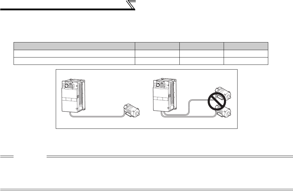
22
Main circuit terminal specifications
(3) Total wiring length
The overall wiring length for connection of a single motor or multiple motors should be within the value in the table below.
(The wiring length should be 100m maximum for vector control.)
When driving a 400V class motor by the inverter, surge voltages attributable to the wiring constants may occur at the
motor terminals, deteriorating the insulation of the motor.
Refer to page 62 for measures against deteriorated insulation.
(4) Cable size of the control circuit power supply (terminal R1/L11, S1/L21)
· Terminal screw size: M4
· Cable size: 0.75mm2 to 2mm2
· Tightening torque: 1.5N·m
Pr. 72 setting (carrier frequency) 0.4K 0.75K 1.5K or higher
2 (2kHz) or lower 300m 500m 500m
3 (3kHz) or higher 200m 300m 500m
Total wiring length (1.5K or higher)
CAUTION
· Especially for long-distance wiring, the inverter may be affected by a charging current caused by the stray capacitances of the
wiring, leading to a malfunction of the overcurrent protective function or fast response current limit function or a malfunction or fault
of the equipment connected on the inverter output side. If fast response current limit function malfunctions, disable this function.
(For Pr. 156 Stall prevention operation selection, refer to page 152 .)
· For details of
Pr. 72 PWM frequency selection , refer to
page 284
.
500m or less
300m
300m
300m + 300m = 600m
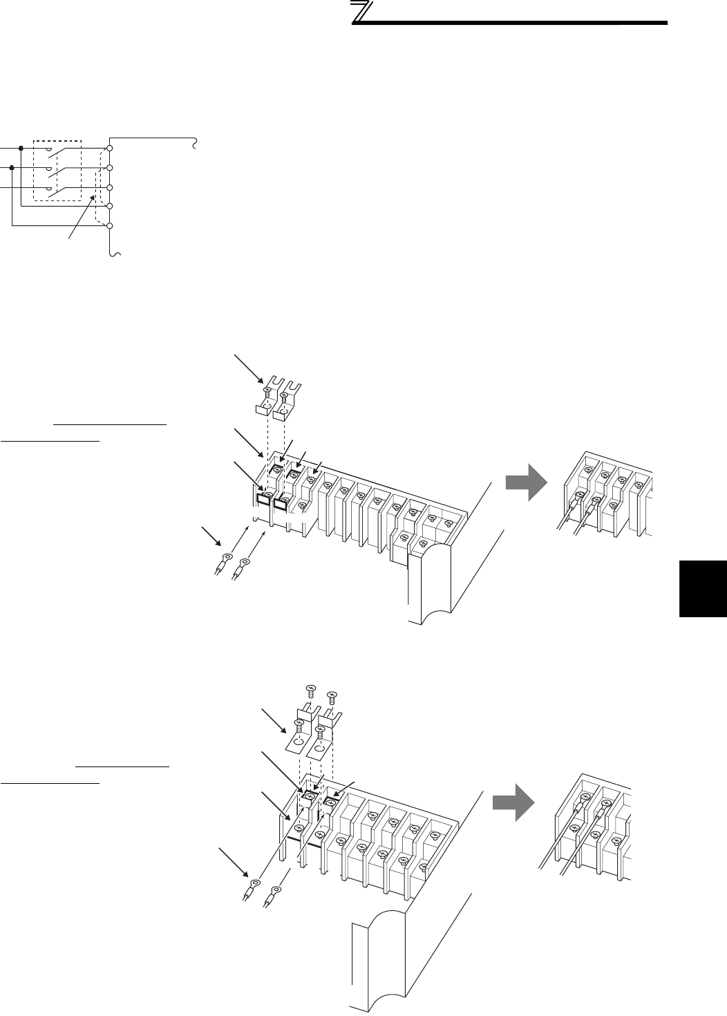
23
Main circuit terminal specifications
2
WIRING
2.2.4 When connecting the control circuit and the main circuit separately
to the power supply
• FR-A720-0.4K to 3.7K, FR-A740-0.4K to 3.7K
• FR-A720-5.5K, 7.5K, FR-A740-5.5K, 7.5K
<Connection diagram> When a fault occurs, opening of the electromagnetic contactor (MC) on the
inverter power supply side results in power loss in the control circuit,
disabling the fault output signal retention. Terminals R1/L11 and S1/L21 are
provided to hold a fault signal. In this case, connect the power supply
terminals R1/L11 and S1/L21 of the control circuit to the input side of the MC.
Do not connect the power cable to incorrect terminals. Doing so may
damage the inverter.
1)Loosen the upper screws.
2)Remove the lower screws.
3)Remove the jumper
4)Connect the separate power
supply cable for the control
circuit to the lower terminals
(R1/L11, S1/L21).
1)Remove the upper screws.
2)Remove the lower screws.
3)Remove the jumper.
4)Connect the separate power
supply cable for the control
circuit to the upper terminals
(R1/L11, S1/L21).
Inverter
MC
R/L1
S/L2
T/L3
R1/L11
S1/L21
Remove the jumper
Main circuit terminal block
R1/L11 S1/L21
3)
1)
2)
4)
S/L2
T/L3
R1/L11S1/L21
R/L1
3)
4)
1)
2)
Main circuit
terminal block
S1/L21
R1/L11
S/
L2 T/
L3
R/
L1
R1/L11
S1/L21
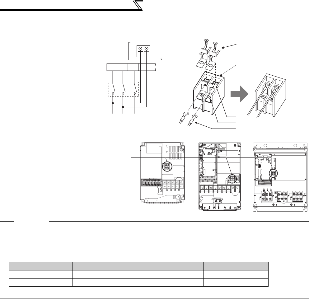
24
Main circuit terminal specifications
• FR-A720-11K or higher, FR-A740-11K or higher
1)Remove the upper screws.
2)Remove the lower screws.
3)Pull the jumper toward you to
remove.
4)
Connect the separate power supply
cable for the control circuit to the
upper terminals (R1/L11, S1/L21).
CAUTION
· When using separate power supply, always remove the jumper across terminals R/L1 and R1/L11 and across S/L2 and S1/L21.
The inverter may be damaged if you do not remove the jumper.
· The voltage should be the same as that of the main control circuit when the control circuit power is supplied from other than the
primary side of the MC.
· The power capacity necessary when separate power is supplied from R1/L11 and S1/L21 differs according to the inverter capacity.
· If the main circuit power is switched OFF (for 0.1s or more) then ON again, the inverter resets and a fault output will not be held.
S1/L21
R1/L11
3)
4)
1)
2)
Power supply
terminal block for
the control circuit
Power supply terminal block
for the control circuit
R/L1S/L2 T/L3
R1/
L11
S1/
L21
Power supply
terminal block
for the control circuit
Main power supply
MC
VUW
FR-A720-11K,
FR-A740-11K, 15K
FR-A720-15K, 18.5K, 22K,
FR-A740-18.5K, 22K
FR-A720-30K or higher,
FR-A740-30K or higher
11K or lower 15K 18.5K or higher
200V class 60VA 80VA 80VA
400V class 60VA 60VA 80VA

25
Control circuit specifications
2
WIRING
2.3 Control circuit specifications
2.3.1 Control circuit terminals
indicates that terminal functions can be selected using Pr. 178 to Pr. 196 (I/O terminal function selection) (Refer to page 231.)
(1) Input signals
Type
Terminal
Symbol
Terminal
Name Description Rated
Specifications
Refer to
page
Contact input
STF Forward
rotation start
Turn ON the STF signal to start forward
rotation and turn it OFF to stop.
When the STF and
STR signals are
turned ON
simultaneously, the
stop command is
given.
Input resistance
4.7kΩ
Voltage at
opening: 21 to
27VDC
Contacts at
short-circuited: 4
to 6mADC
231
STR Reverse
rotation start
Turn ON the STR signal to start reverse
rotation and turn it OFF to stop.
STOP
Start self-
holding
selection
Turn ON the STOP signal to self-hold the start signal. 231
RH,
RM, RL
Multi-speed
selection
Multi-speed can be selected according to the combination of RH,
RM and RL signals. 231
JOG
Jog mode
selection
Turn ON the JOG signal to select Jog operation (initial setting)
and turn ON the start signal (STF or STR) to start Jog operation. 231
Pulse train
input
JOG terminal can be used as pulse train input terminal. To use as
pulse train input terminal, the Pr. 291 setting needs to be changed.
(maximum input pulse: 100
k
pulses/
s
)
Input resistance
2kΩ
Contacts at
short-circuited: 8
to 13mADC
231
RT
Second
function
selection
Turn ON the RT signal to select second function.
When the second function such as "second torque boost" and
"second V/F (base frequency)" are set, turning ON the RT signal
selects these functions.
Input resistance
4.7kΩ
Voltage at
opening: 21 to
27VDC
Contacts at
short-circuited: 4
to 6mADC
231
MRS Output stop
Turn ON the MRS signal (20ms or more) to stop the inverter
output.
Use to shut off the inverter output when stopping the motor by
electromagnetic brake.
231
RES Reset
Use to reset fault output provided when fault occurs.
Turn ON the RES signal for more than 0.1s, then turn it OFF.
In the initial status, reset is set always-enabled. By setting Pr. 75,
reset can be set enabled only at fault occurrence. Recover about
1s after reset is cancelled.
231
AU
Terminal 4 input
selection
Terminal 4 is valid only when the AU signal is turned ON. (The
frequency setting signal can be set between 4 and 20mADC.)
Turning the AU signal ON makes terminal 2 (voltage input)
invalid.
286
PTC input
AU terminal is used as PTC input terminal (thermal protection of
the motor). When using it as PTC input terminal, set the AU/PTC
switch to PTC.
186
CS
Selection of
automatic
restart after
instantaneous
power failure
When the CS signal is left ON, the inverter restarts automatically
at power restoration. Note that restart setting is necessary for this
operation. In the initial setting, a restart is disabled.
(Refer to Pr. 57 Restart coasting time in
page
266)
231
SD
Contact input
common
(sink)
(initial setting)
Common terminal for contact input terminal (sink logic) and
terminal FM.
-------------------- —
External
transistor
common
(source)
Connect this terminal to the power supply common terminal of a
transistor output (open collector output) device, such as a
programmable controller, in the source logic to avoid malfunction
by undesirable currents.
24VDC power
supply
common
Common output terminal for 24VDC 0.1A power supply (PC
terminal).
Isolated from terminals 5 and SE.
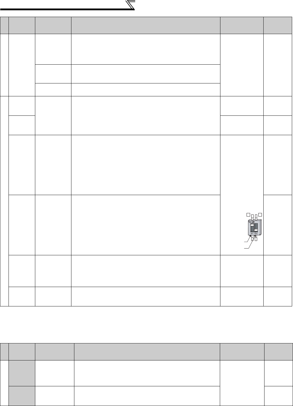
26
Control circuit specifications
*Set Pr. 73, Pr. 267, and a voltage/current input switch correctly, then input an analog signal in accordance with the setting.
Applying a voltage signal with voltage/current input switch ON (current input is selected) or a current signal with switch OFF (voltage input is
selected) could cause component damage of the inverter or analog circuit of signal output devices. (For details, refer to page 286.)
(2) Output signals
Contact input
PC
External
transistor
common
(sink)
(initial setting)
Connect this terminal to the power supply common terminal of a
transistor output (open collector output) device, such as a
programmable controller, in the sink logic to avoid malfunction by
undesirable currents.
Power supply
voltage range
19.2 to 28.8VDC
Permissible load
current 100mA
29
Contact input
common
(source)
Common terminal for contact input terminal (source logic).
24VDC power
supply Can be used as 24VDC 0.1A power supply.
Frequency setting
10E Frequency
setting power
supply
When connecting the frequency setting potentiometer at an initial
status, connect it to terminal 10.
Change the input specifications of terminal 2 when connecting it
to terminal 10E. (Refer to Pr. 73 Analog input selection page 290.)
10VDC±0.4V
Permissible load
current 10mA
286
10
5.2VDC±0.2V
Permissible load
current 10mA
286
2
Frequency
setting
(voltage)
Inputting 0 to 5VDC (or 0 to 10V, 0 to 20mA) provides the
maximum output frequency at 5V (10V, 20mA) and makes input
and output proportional. Use Pr. 73 to switch from among input 0
to 5VDC (initial setting), 0 to 10VDC, and 0 to 20mA.
Set the voltage/current input switch in the ON position to select
current input (0 to 20mA). *
Voltage input:
Input resistance
10kΩ ± 1kΩ
Maximum
permissible
voltage 20VDC
Current input:
Input resistance
245Ω ± 5Ω
Maximum
permissible
current 30mA
286
4
Frequency
setting
(current)
Inputting 4 to 20mADC (or 0 to 5V, 0 to 10V) provides the
maximum output frequency at 20mA makes input and output
proportional. This input signal is valid only when the AU signal is
ON (terminal 2 input is invalid). Use Pr. 267 to switch from among
input 4 to 20mA (initial setting), 0 to 5VDC, and 0 to 10VDC. Set
the voltage/current input switch in the OFF position to select
voltage input (0 to 5V/0 to 10V).* Use Pr. 858 to switch terminal
functions.
286
1
Frequency
setting
auxiliary
Inputting 0 to ±5 VDC or 0 to ±10VDC adds this signal to terminal
2 or 4 frequency setting signal. Use Pr. 73 to switch between the
input 0 to ±5VDC and 0 to ±10VDC (initial setting).
Input resistance
10kΩ ± 1kΩ
Maximum
permissible
voltage ± 20VDC
286
5
Frequency
setting
common
Common terminal for frequency setting signal (terminal 2, 1 or 4)
and analog output terminal AM. Do not earth (ground). -------------------- 2 8 6
Type
Terminal
Symbol
Terminal
Name Description Rated
Specifications
Refer to
page
Relay
A1,
B1,
C1
Relay output 1
(Fault output)
1 changeover contact output indicates that the inverter
protective function has activated and the output stopped.
Fault: No conduction across B-C (Across A-C Continuity),
Normal: Across B-C Continuity (No conduction across A-C)
Contact capacity:
230VAC 0.3A
(Power
factor = 0.4)
30VDC 0.3A
239
A2,
B2,
C2
Relay output 2 1 changeover contact output 239
Type
Terminal
Symbol
Terminal
Name Description Rated
Specifications
Refer to
page
Voltage/current
input switch
2
4
switch1
switch2

27
Control circuit specifications
2
WIRING
(3) Communication
Open collector
RUN Inverter
running
Switched low when the inverter output frequency is equal to or
higher than the starting frequency (initial value 0.5Hz). Switched
high during stop or DC injection brake operation.
*
Permissible load
24VDC (27VDC
maximum) 0.1A
(A voltage drop is
2.8V maximum
when the signal is
ON.)
Low is when the
open collector
output transistor is
ON (conducts).
High is when the
transistor is OFF
(does not conduct)
239
SU Up to
frequency
Switched low when the output
frequency reaches within the range of
±10% (initial value) of the set frequency.
Switched high during acceleration/
deceleration and at a stop.
Fault code (4bit)
output (Refer to page
275)
239
OL Overload
warning
Switched low when stall prevention is
activated by the stall prevention
function. Switched high when stall
prevention is cancelled.
239
IPF Instantaneous
power failure
Switched low when an instantaneous
power failure and under voltage
protections are activated.
239
FU Frequency
detection
Switched low when the inverter output
frequency is equal to or higher than the
preset detected frequency and high
when less than the preset detected
frequency.
239
SE Open collector
output common C o m m o n t e r m i n a l f o r t e r m i n a l s R U N , S U , O L , I P F, F U -------------------- -----
Pulse
FM
For meter
Select one e.g. output frequency from
monitor items. Not output during
inverter reset.
The output signal is proportional to the
magnitude of the corresponding
monitoring item.
Use Pr. 55, Pr. 56, and Pr. 866 to set full
scales for the monitored output
frequency, output current, and torque.
(Refer to page 259)
Output item:
Output frequency
(initial setting)
Permissible load
current 2mA
1440pulses/s at
60Hz
253
NPN open
collector output
signals can be output
from the open
collector terminals by
setting Pr. 291.
Maximum output
pulse: 50k
pulses/
s
Permissible load
current : 80mA
378
Analog
AM Analog signal
output
Output item:
Output frequency
(initial setting)
Output signal 0 to
10VDC
Permissible load
current 1mA
(load impedance
10kΩ or more)
Resolution 8 bit
253
Type
Terminal
Symbol
Terminal
Name Description Refer to
page
RS-485
-------------------- PU
connector
With the PU connector, communication can be made through RS-485.
(for connection on a 1:1 basis only)
. Conforming standard : EIA-485 (RS-485)
. Transmission format : Multidrop
. Communication speed : 4800 to 38400bps
. Overall length : 500m
328
RS-485 terminals
TXD+ Inverter
transmission
terminal With the RS-485 terminals, communication can be made through RS-485.
Conforming standard : EIA-485 (RS-485)
Transmission format : Multidrop link
Communication speed : 300 to 38400bps
Overall length : 500m
330
TXD-
RXD+ Inverter
reception
terminal
RXD-
SG
Earth (Ground)
USB
-------------------- USB
connector
FR Configurator can be used by connecting the inverter to the personal computer
through USB.
Interface: Conforms to USB1.1
Transmission speed: 12Mbps
Connector: USB B connector (B receptacle)
360
Type
Terminal
Symbol
Terminal
Name Description Rated
Specifications
Refer to
page
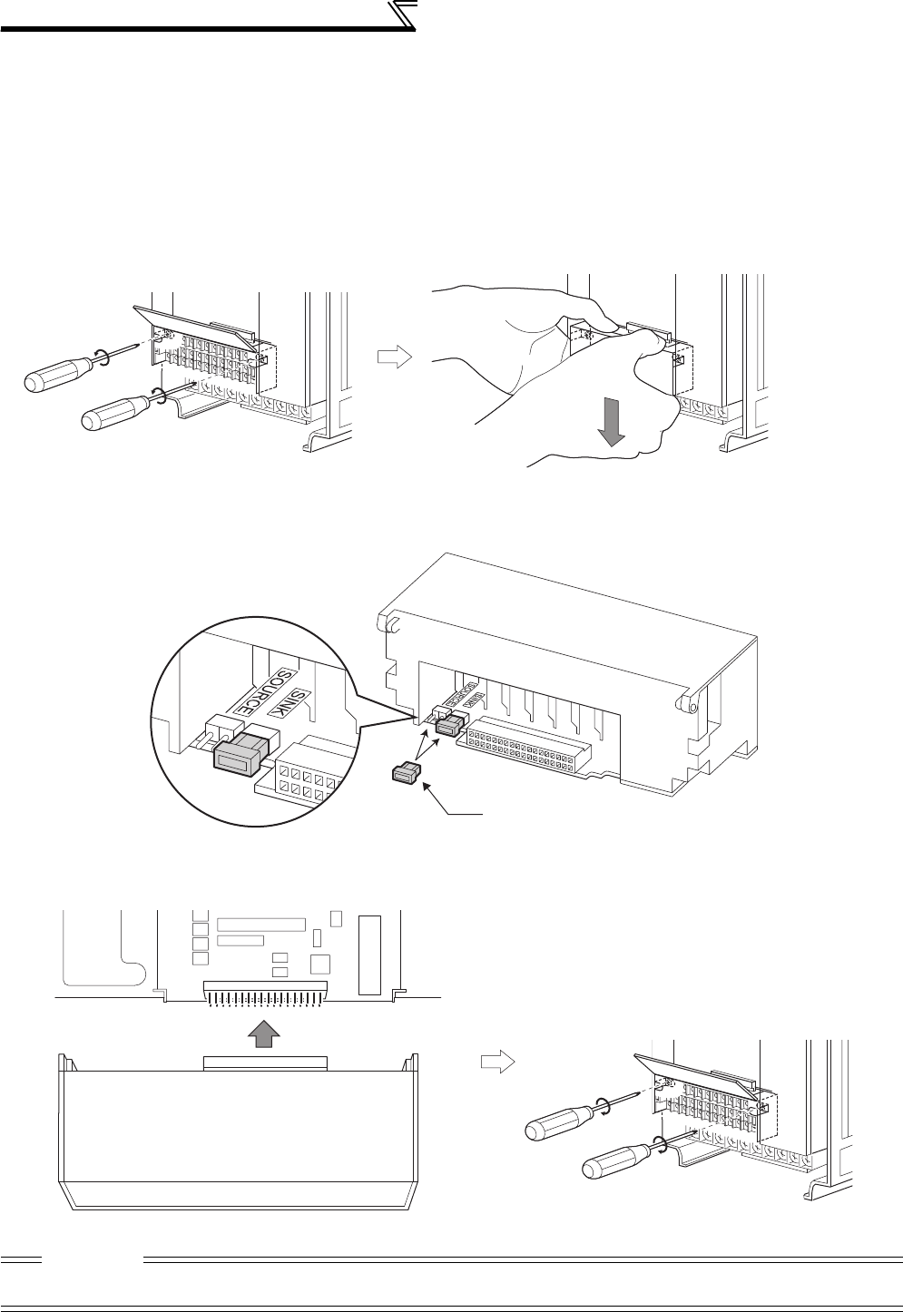
28
Control circuit specifications
2.3.2 Changing the control logic
The input signals are set to sink logic (SINK) when shipped from the factory.
To change the control logic, the jumper connector on the back of the control circuit terminal block must be moved to the
other position.
(The output signals may be used in either the sink or source logic independently of the jumper connector position.)
1) Loosen the two mounting screws in both ends of the control circuit terminal block. (These screws cannot be
removed.)
Pull down the terminal block from behind the control circuit terminals.
2) Change the jumper connector set to the sink logic (SINK) on the rear panel of the control circuit terminal block to
source logic (SOURCE).
3) Using care not to bend the pins of the inverter's control circuit connector, reinstall the control circuit terminal block
and fix it with the mounting screws.
CAUTION
1. Make sure that the control circuit connector is fitted correctly.
2. While power is ON, never disconnect the control circuit terminal block.
Jumper connector
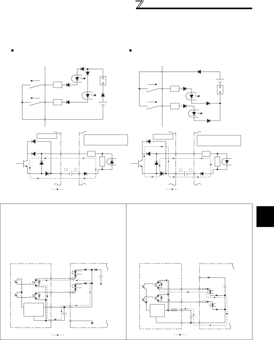
29
Control circuit specifications
2
WIRING
4)Sink logic and source logic
⋅In sink logic, a signal switches ON when a current flows from the corresponding signal input terminal.
Terminal SD is common to the contact input signals. Terminal SE is common to the open collector output signals.
⋅In source logic, a signal switches ON when a current flows into the corresponding signal input terminal.
Terminal PC is common to the contact input signals. Terminal SE is common to the open collector output signals.
•When using an external power supply for transistor output
Sink logic type
Use terminal PC as a common terminal, and perform
wiring as shown below. (Do not connect terminal SD of the
inverter with terminal 0V of the external power supply.
When using terminals PC-SD as a 24VDC power supply,
do not install an external power supply in parallel with the
inverter. Doing so may cause a malfunction in the inverter
due to undesirable currents.)
Source logic type
Use terminal SD as a common terminal, and perform
wiring as shown below. (Do not connect terminal PC of the
inverter with terminal +24V of the external power supply.
When using terminals PC-SD as a 24VDC power supply,
do not install an external power supply in parallel with the
inverter. Doing so may cause a malfunction in the inverter
due to undesirable currents.)
Current
PC
STF R
STR R
Source logic
Source
connecto
r
Current
SD
STF R
STR R
Sink
connector
Sink logic
Current flow concerning the input/output signal
when sink logic is selected
Current flow concerning the input/output signal
when source logic is selected
DC input (source type)
<Example: QX80>
24VDC
RUN
SE
TB1
TB18
R
Inverter
R
Current flow
+-
+
-
DC input (sink type)
<Example: QX40>
Inverter
24VDC
RUN
SE
TB1
TB17
R
R
Current flow
QY40P type transistor
output unit
TB1
TB2
TB17
TB18
24VDC SD
PC
STR
STF
Inverter
24VDC
(SD)
Current flow
Constant
voltage
circuit
QY80 type transistor
output unit
Constant
voltage
circuit
PC
TB1
TB2
TB17
Fuse
TB18
STF
STR
SD
Inverter
24VDC
(SD)
24VDC
Current flow
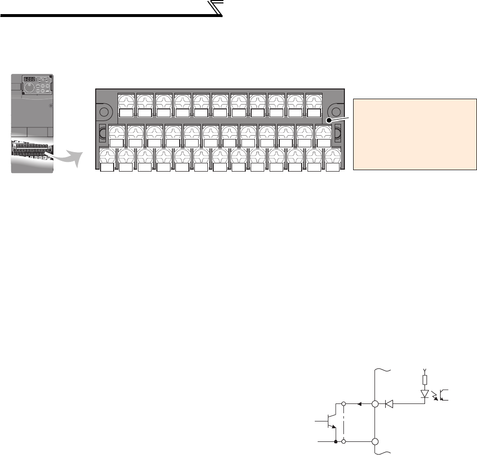
30
Control circuit specifications
2.3.3 Wiring of control circuit
(1) Control circuit terminal layout
(2) Common terminals of the control circuit (SD, 5, SE)
Terminals SD, 5, and SE are all common terminals (0V) for I/O signals and are isolated from each other. Do not earth
(ground) these terminals.
Avoid connecting the terminal SD and 5 and the terminal SE and 5.
Terminal SD is a common terminal for the contact input terminals (STF, STR, STOP, RH, RM, RL, JOG, RT, MRS, RES,
AU, CS) and frequency output signal (FM).
The open collector circuit is isolated from the internal control circuit by photocoupler.
Terminal 5 is a common terminal for frequency setting signal (terminal 2, 1 or 4) and analog output terminal AM.
It should be protected from external noise using a shielded or twisted cable.
Terminal SE is a common terminal for the open collector output terminal (RUN, SU, OL, IPF, FU).
The contact input circuit is isolated from the internal control circuit by photocoupler.
(3) Signal inputs by contactless switches
The contacted input terminals of the inverter (STF, STR, STOP, RH,
RM, RL, JOG, RT, MRS, RES, AU, CS) can be controlled using a
transistor instead of a contacted switch as shown on the right.
External signal input using transistor
A1 B1 C1 A2
STOP
AURTRHRMRL
OLIPFSU
RUN
B2 C2
10E
10
SD
RES
MRS
STF
SDSDFU PCCS
JOG
STR
254
1
AMFM
SE
Control circuit terminal *
Terminal screw size: M3.5
Tightening torque: 1.2N·m
* Refer to instruction manuals of
options for the available control
terminals other than the standard
control circuit terminal.
+24V
STF, etc
Inverter
SD
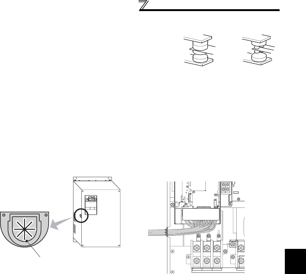
31
Control circuit specifications
2
WIRING
2.3.4 Wiring instructions
1) It is recommended to use the cables of 0.75mm2 gauge for
connection to the control circuit terminals.
If the cable gauge used is 1.25mm2 or more, the front cover may
be lifted when there are many cables running or the cables are
run improperly, resulting in an operation panel contact fault.
2) The wiring length should be 30m (200m for terminal FM)
maximum.
3) Use two or more parallel micro-signal contacts or twin contacts to prevent a contact faults when using contact
inputs since the control circuit input signals are micro-currents.
4) Use shielded or twisted cables for connection to the control circuit terminals and run them away from the main and
power circuits (including the 200V relay sequence circuit).
5) Do not apply a voltage to the contact input terminals (e.g. STF) of the control circuit.
6) Always apply a voltage to the fault output terminals (A, B, C) via a relay coil, lamp, etc.
zWiring of the control circuit of the 75K or higher
For wiring of the control circuit of the 75K or higher, separate away from wiring of the main circuit.
Make cuts in rubber bush of the inverter side and lead wires.
Micro signal contacts Twin contacts
<Wiring>
Rubber bush
(view from the inside)
Make cuts along the lines inside with
a cutter knife and such.
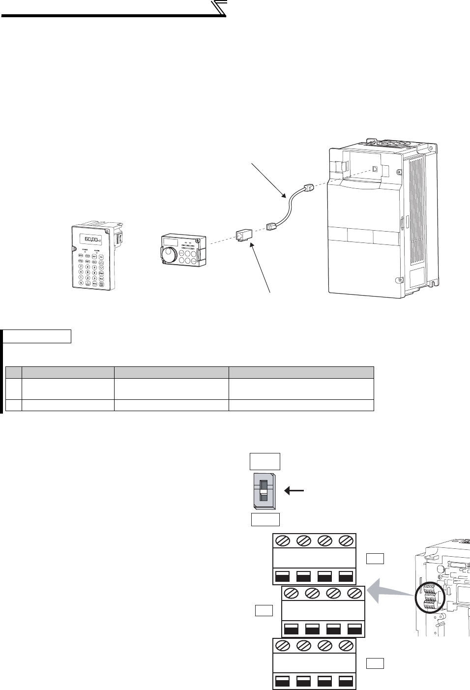
32
Control circuit specifications
2.3.5 Mounting the operation panel (FR-DU07) or parameter unit (FR-PU07)
on the enclosure surface
Having an operation panel or a parameter unit on the enclosure surface is convenient.
With a connection cable, you can mount the operation panel (FR-DU07) or the parameter unit (FR-PU07) to the
enclosure surface, and connect it to the inverter. Use the option FR-CB2
, or the connector and cable available on
the market.
(For mounting the operation panel (FR-DU07), the optional connector (FR-ADP) is required.)
Securely insert one end of connection cable until the stoppers are fixed.
2.3.6 RS-485 terminal block
⋅Conforming standard: EIA-485(RS-485)
⋅Transmission format: Multidrop link
⋅Communication speed: MAX 38400bps
⋅Overall length: 500m
⋅Connection cable:Twisted pair cable
(4 pairs)
2.3.7 Communication operation
Using the PU connector or RS-485 terminal, you can
perform communication operation from a personal
computer etc. When the PU connector is connected
with a personal, FA or other computer by a
communication cable, a user program can run and
monitor the inverter or read and write to parameters.
For the Mitsubishi inverter protocol (computer link
operation), communication can be performed with the
PU connector and RS-485 terminal.
For the Modbus-RTU protocol, communication can be
performed with the RS-485 terminal.
For further details, refer to 328.
REMARKS
· Refer to the following when fabricating the cable on the user side. Keep the total cable length within 20m.
Commercially available product examples (as of January 2010)
STF FWD PU
Parameter unit connection cable
(FR-CB2)(option)
Operation panel(FR-DU07)
Parameter unit (FR-PU07)
(option)
Operation panel connection connector
(FR-ADP)(option)
Product Type Manufacturer
1) Communication cable SGLPEV-T (Cat5e/300m)
24AWG × 4P Mitsubishi Cable Industries, Ltd.
2) RJ-45 connector 5-554720-3 Tyco Electronics Corporation
RXD
RDA1
(RXD1+)
RDB1
(RXD1-)
RDA2
(RXD2+)
RDB2
(RXD2-)
SDA1
(TXD1+)
SDB1
(TXD1-)
SDA2
(TXD2+)
SDB2
(TXD2-)
P5S
(VCC)
SG
(GND)
P5S
(VCC)
SG
(GND)
VCC
TXD
OPEN
100Ω
Terminating resistor switch
Factory-set to "OPEN".
Set only the terminating resistor switch of
the remotest inverter to the "100Ω" position.

33
Connection of motor with encoder (vector control)
2
WIRING
2.4 Connection of motor with encoder (vector control)
Orientation control and encoder feedback control, and speed control, torque control and position control by full-scale
vector control operation can be performed using a motor with encoder and a plug-in option FR-A7AP.
(1) Structure of the FR-A7AP
(2) Terminals of the FR-A7AP
Terminal Terminal Name Description
PA1 Encoder A-phase signal input terminal
A-, B- and Z-phase signals are input from the encoder.
PA2 Encoder A-phase inverse signal input terminal
PB1 Encoder B-phase signal input terminal
PB2 Encoder B-phase inverse signal input terminal
PZ1 Encoder Z-phase signal input terminal
PZ2 Encoder Z-phase inversion signal input terminal
PG Encoder power supply (positive side) input terminal Input terminal for the encoder power supply.
Connect the external power supply (5V, 12V, 15V, 24V) and the
encoder power cable. Make sure the voltage of the external
power supply is the same as the encoder output voltage. (Check
the encoder specification.)
SD Encoder power supply ground terminal
PIN Not used.
PO
CAUTION
When the input power supply voltage to the encoder and its output voltage differ, the signal loss detection (E.ECT) may occur.
Front view Rear view
Mounting
hole
Mounting
hole
Mounting
hole
Encoder specification selection switch (SW1)
Used to change the specification of encoder
(differential line driver/complementary).
Switch for manufacturer
setting (SW3)
Do not change from initially-
set status (1, 2:OFF ).
Terminating resistor selection
switch (SW2)
Switch ON/OFF of the internal
terminating resistor.
CON2 connector
Not used.
Terminal
block
Connector
Connect to the inverter
option connector.
Terminal layout
PA2
PB2
PZ2
SD
SD
PO
PA1
PB1
PZ1
PG
PG
PIN
1
2
3
4
O
N
1
2
O
N
1
2
O
N
SW2
SW1
LED1
LED2
LED3
SW3
FR-A7AP
PIN and PO are
not used.
(Refer to page 34.)
(Refer to page 34.)
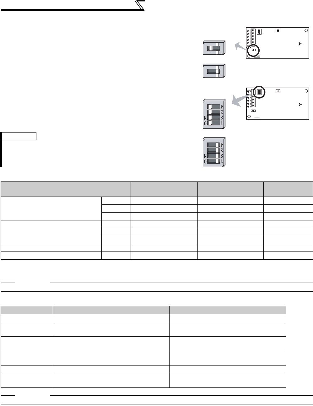
34
Connection of motor with encoder (vector control)
(3) Switches of the FR-A7AP
• Encoder specification selection switch (SW1)
Select either differential line driver or complementary
It is initially set to the differential line driver. Switch its position according
to output circuit.
• Terminating resistor selection switch (SW2)
Select ON/OFF of the internal terminating resistor. Set the switch to ON
(initial status) when an encoder output type is differential line driver and
set to OFF when complementary.
ON : with internal terminating resistor (initial status)
OFF : without internal terminating resistor
• Motor used and switch setting
• Encoder specification
REMARKS
· Set all switches to the same setting (ON/OFF).
· If the encoder output type is differential line driver, set the terminating resistor
switch to the "OFF" position when sharing the same encoder with other unit (NC
(numerical controller), etc) or a terminating resistor is connected to other unit.
Motor
Encoder Specification
Selection Switch (SW1)
Terminating Resistor
Selection Switch (SW2)
Power
Specifications *2
Mitsubishi standard motor with encoder
Mitsubishi high efficiency motor with
encoder
SF-JR Differential ON 5V
SF-HR Differential ON 5V
Others *1 *1 *1
Mitsubishi constant-torque motor with
encoder
SF-JRCA Differential ON 5V
SF-HRCA Differential ON 5V
Others *1 *1 *1
Vector control dedicated motor SF-V5RU Complementary OFF 12V
Other manufacturer motor with encoder – *1 *1 *1
*1 Set according to the motor (encoder) used.
*2 Choose a power supply (5V/12V/15V/24V) for encoder according to the encoder output voltage.
CAUTION
SW3 switch is for manufacturer setting. Do not change the setting.
Item Encoder for SF-JR Encoder for SF-V5RU
Resolution 1024 Pulse/Rev 2048 Pulse/Rev
Power supply
voltage 5VDC±10% 12VDC±10%
Current
consumption 150mA 150mA
Output signal form A, B phases (90° phase shift)
Z phase: 1 pulse/rev
A, B phases (90° phase shift)
Z phase: 1 pulse/rev
Output circuit Differential line driver 74LS113 equivalent Complementary
Output voltage H level: 2.4V or more
L level: 0.5V or less
H level: "Power supply for encoder-3V" or more
L level: 3V or less
CAUTION
Encoder with resolution of 1000 to 4096 pulse/rev is recommended.
Complementary
Differential line
driver (initial status)
1
2
3
4
O
N
1
2
O
N
SW2
SW1
SW3
FR-A7AP
Internal terminating
resistor-ON
(initial status)
Internal terminating resistor-OFF
1
2
3
4
O
N
1
2
O
N
SW2
SW1
SW3
FR-A7AP
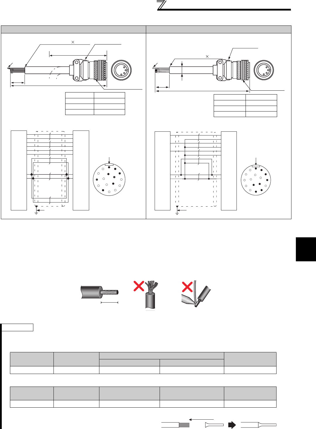
35
Connection of motor with encoder (vector control)
2
WIRING
(4) Encoder Cable
• When using the dedicated encoder cable (FR-JCBL, FR-V5CBL, etc.) for the conventional motor, cut the crimpling
terminal of the encoder cable and strip its sheath to make its cables loose.
Also, protect the shielded cable of the shielded twisted pair cable to ensure that it will not make contact with the
conductive area.
Wire the stripped cable after twisting it to prevent it from becoming loose. In addition, do not solder it.
SF-JR Motor with Encoder SF-V5RU, SF-THY
* As the terminal block of the FR-A7AP is an insertion type, earth cables need to be modified. (See below)
REMARKS
Information on blade terminals
Commercially available products (as of February 2012)
zPhoenix Contact Co.,Ltd.
zNICHIFU Co.,Ltd.
L
F-DPEVSB 12P 0.2mm2MS3057-12A
Earth cable
MS3106B20-29S
60mm
Approx. 140mm
Type Length L (m)
FR-JCBL5 5
FR-JCBL15 15
FR-JCBL30 30
*
PZ2
PZ1
PB2
PB1
PA2
PA1
PG
SD
P
B
N
A
R
C
H
K
Encoder
2mm
2
ABCD
E
K
F
G
H
J
L
M
S
N
R
P
T
MS3106B20-29S
(As viewed from wiring side)
Positioning keyway
FR-A700
(FR-A7AP)
LMS3106B20-29S
Earth cable F-DPEVSB 12P 0.2mm2
MS3057-12A
Encoder side
connector
Inverter side
60mm
11mm
Type Length L (m)
FR-V7CBL5 5
FR-V7CBL15 15
FR-V7CBL30 30
⋅A P clip for earthing (grounding) a
shielded cable is provided.
PZ2
PZ1
PB2
PB1
PA2
PA1
SD
PG
G
F
D
C
B
A
R
S
Encoder
2mm
2
FR-A700
(FR-A7AP)
ABCD
E
K
F
G
H
J
L
M
S
N
R
P
T
MS3106B20-29S
(As viewed from wiring side)
Positioning keyway
5mm
Cable stripping size
Terminal Screw
Size Wire Size (mm2)Blade Terminal Model Blade terminal
crimping tool
with insulation sleeve without insulation sleeve
M2 0.3, 0.5 AI 0,5-6WH A 0,5-6 CRIMPFOX 6
Terminal Screw
Size Wire Size (mm2)Blade terminal product
number
Insulation product
number
Blade terminal
crimping tool
M2 0.3 to 0.75 BT 0.75-7 VC 0.75 NH 69
When using the blade terminal (without insulation sleeve), use
care so that the twisted wires do not come out.
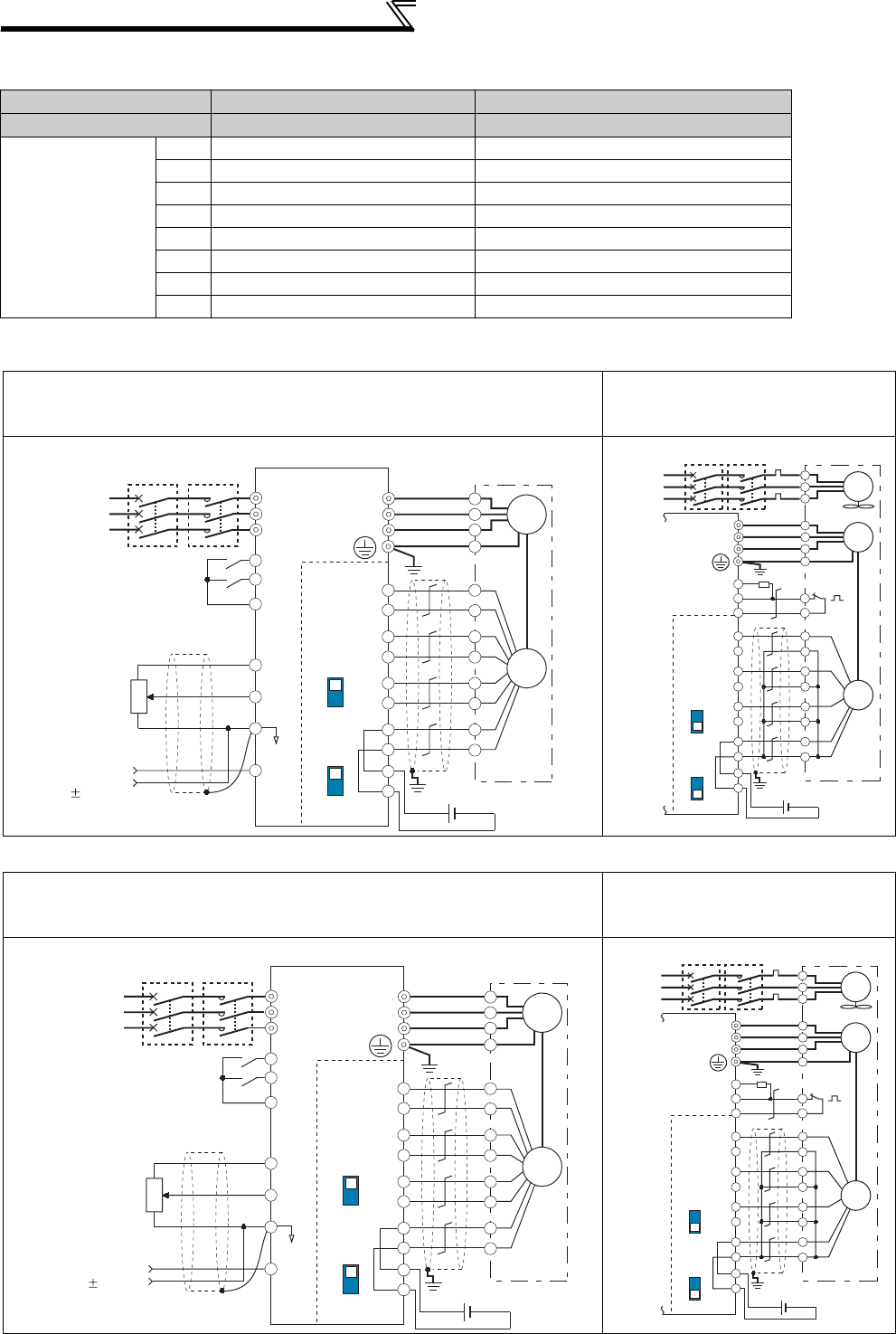
36
Connection of motor with encoder (vector control)
Connection terminal compatibility table
(5) Wiring
• Speed control
• Torque control
Motor SF-V5RU, SF-THY SF-JR/HR/JRCA/HRCA (with Encoder)
Encoder cable FR-V7CBL FR-JCBL
FR-A7AP terminal
PA1 PA PA
PA2 Keep this open. PAR
PB1 PB PB
PB2 Keep this open. PBR
PZ1 PZ PZ
PZ2 Keep this open. PZR
PG PG 5E
SD SD AG2
Standard motor with encoder (SF-JR), 5V differential line driver
Vector control dedicated motor
(SF-V5RU, SF-THY),
12V complementary
Standard motor with encoder (SF-JR), 5V differential line driver
Vector control dedicated motor
(SF-V5RU, SF-THY),
12V complementary
Three-phase
AC power
supply
MCCB
R/L1
S/L2
T/L3
SF-JR motor
with encoder
U
V
W
U
V
W
E
C
*3
*1
*2
*4
*6
R
PA1
FR-A7AP
PA2
PB1
PB2
PZ1
PZ2
PG
PG
SD
SD
Differential
Terminating
resistor ON
OFF
Complementary
A
N
B
P
H
K
IM
Forward rotation start
Reverse rotation start
Contact input common
STF
STR
SD
Encoder
Earth
(Ground)
Inverter
10
2
2
3
1
1
Frequency command
Frequency setting
potentiometer
1/2W1k
Ω
5
(+)
(-) 5VDC power supply
*5
(+) (-)
Torque limit
command
( 10V)
MC
SF-V5RU, SF-THY
A
B
C
G1
G2
FAN
*7
CS(OH)
SD
PC
2W1kΩ
Three-phase
AC power
supply
External
thermal
relay input
*8
Thermal relay
protector
U
V
W
U
V
W
E
IM
Inverter
Earth
(Ground)
MCCB MC OCR
*4
*3
PA1
FR-A7AP
PA2
PB1
PB2
PZ1
PZ2
*1
A
*2
B
C
D
F
G
S
R
(+) (-)
Differential
Terminating
resistor
ON
OFF
Complementary
Encoder
12VDC power supply *5
PG
PG
SD
SD
*8
R/L1
S/L2
T/L3
SF-JR motor
with encoder
U
V
W
U
V
W
E
C
*3
*1
*2
*4
*6
R
PA1
FR-A7AP
PA2
PB1
PB2
PZ1
PZ2
PG
PG
SD
SD
Differential
Terminating
resistor ON
OFF
Complementary
A
N
B
P
H
K
IM
Forward rotation start
Reverse rotation start
Contact input common
STF
STR
SD
Encoder
Earth
(Ground)
Inverter
10
2
2
3
1
1
Speed limit command
Frequency setting
potentiometer
1/2W1k
Ω
5
(+)
(-) 5VDC
power supply
*5
(+) (-)
Torque command
( 10V)
Three-phase
AC power
supply
MCCB MC
SF-V5RU, SF-THY
A
B
C
G1
G2
FAN
*7
CS(OH)
SD
PC
2W1kΩ
Three-phase
AC power
supply
External
thermal
relay input
*8
Thermal relay
protector
U
V
W
U
V
W
E
IM
Inverter
Earth
(Ground)
MCCB MC OCR
*4
*3
PA1
FR-A7AP
PA2
PB1
PB2
PZ1
PZ2
*1
A
*2
B
C
D
F
G
S
R
(+) (-)
Differential
Terminating
resistor
ON
OFF
Complementary
Encoder
12VDC power supply *5
PG
PG
SD
SD
*8
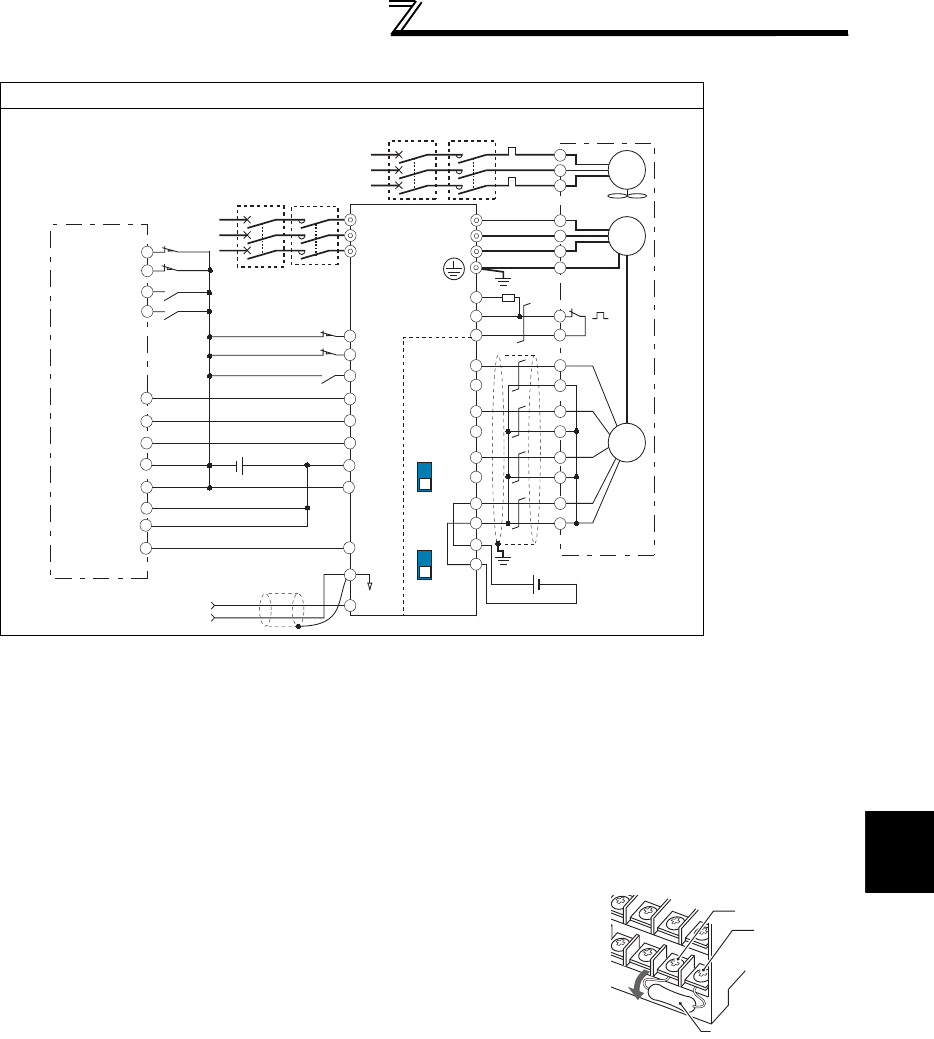
37
Connection of motor with encoder (vector control)
2
WIRING
• Position control
Vector control dedicated motor (SF-V5RU, SF-THY), 12V complementary
*1 The pin number differs according to the encoder used.
Speed control, torque control and position control by pulse train input could be normally performed with or without
connecting Z phase.
*2 Connect the encoder so that there is no looseness between the motor and motor shaft. Speed ratio should be 1:1.
*3 Earth (Ground) the shielded cable of the encoder cable to the enclosure with a P-clip, etc. (Refer to page 38.)
*4 For the complementary, set the terminating resistor selection switch to OFF position. (Refer to page 34.)
*5 A separate power supply of 5V/12V/15V/24V is necessary according to the encoder power specification.
Make the voltage of the external power supply the same as the encoder output voltage, and connect the external power
supply between PG and SD.
*6 For terminal compatibility of the FR-JCBL, FR-V7CBL and FR-A7AP, refer to page 36.
*7 For the fan of the 7.5kW or less dedicated motor, the power supply is single phase. (200V/50Hz, 200 to 230V/60Hz)
*8 Assign OH (external thermal input) signal to the terminal CS. (Set "7" in Pr. 186 )
Connect a 2W1kΩ resistor between the terminal PC and CS (OH). Install the
resistor pushing against the bottom part of the terminal block so as to avoid a
contact with other cables.
Refer to page 231 for details of Pr. 186 CS terminal function selection.
*9 Assign the function using Pr. 178 to Pr. 184, Pr. 187 to Pr. 189 (input terminal function
selection).
*10 When position control is selected, terminal JOG function is invalid and simple
position pulse train input terminal becomes valid.
*11 Assign the function using Pr. 190 to Pr. 194 (output terminal function selection).
SF-V5RU, SF-THY
A
B
C
G1
G2
FAN
*7
CS(OH)
SD
PC
2W1kΩ
Three-phase
AC power supply
Earth
(ground)
Thermal
protector
External thermal
relay input *8
MC OCR
MCCB
RDY
*11
NP *
9
CLR
*9
JOG
*10
LX *
9
1
5
(+)
(-)
R/L1
S/L2
T/L3
*4 *6
*3
PA1
FR-A7AP
PA2
PB1
PB2
PZ1
PZ2
Forward stroke end
Reverse stroke end
Pre-excitation/servo on
Clear signal
Pulse train
Sign signal
Preparation ready signal
STR
CLEAR
*1
OFF
U
V
W
U
V
W
E
A
*2
B
PA1
PA2
PB1
PB2
PZ1
PZ2
C
D
F
G
S
R
IM
Encoder
Inverter
Positioning unit
MELSEQ-Q QD75P1
12VDC
power supply
(+) (-)
*5
PULSE F
PULSE R
PULSE COM
CLEAR COM
RDY COM
READY
PC
SE
FLS
RLS
DOG
STOP
COM
24VDC power supply
Torque limit command
(
±
10V)
ON
Differential
line driver
Complementary
Terminating
resistor
PG
PG
SD
SD
MCCB
MC
Three-phase
AC power
supply
CS(OH)
Resistor (2W1kΩ)
PC
Control circuit
terminal block
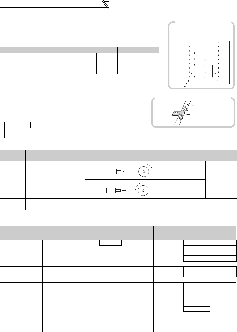
38
Connection of motor with encoder (vector control)
(6) Instructions for encoder cable wiring
• Use shielded twisted pair cables (0.2mm2 or larger) to connect the FR-A7AP
and position detector. Cables to terminals PG and SD should be connected in
parallel or be larger in size according to the cable length.
To protect the cables from noise, run them away from any source of noise (e.g.
the main circuit and power supply voltage).
* When differential line driver is set and a wiring length is 30m or more
The wiring length can be extended to 100m by slightly increasing the power by 5V (approx. 5.5V)
using six or more cables with gauge size of 0.2mm2 in parallel or a cable with gauge size of 1.25mm2
or more. Note that the voltage applied should be within power supply specifications of encoder.
• To reduce noise of the encoder cable, earth (ground) the encoder
shielded cable to the enclosure (as close as possible to the inverter)
with a P-clip or U-clip made of metal.
(7) Parameter for encoder (Pr. 359, Pr. 369)
(8) Motor for vector control and parameter setting
Wiring Length Parallel Connection Larger-Size Cable
Within 10m At least two cables in parallel Cable
gauge
0.2mm2
0.4mm2 or larger
Within 20m At least four cables in parallel 0.75mm2 or larger
Within 100m * At least six cables in parallel 1.25mm2 or larger
REMARKS
· For details of the optional encoder dedicated cable (FR-JCBL/FR-V7CBL), refer to page 35.
· The FR-V7CBL is provided with a P clip for earthing (grounding) shielded cable.
Parameter
Number Name Initial
Value
Setting
Range Description
359 Encoder rotation
direction 1
0 Set the rotation
direction
according to
the motor
specification.
1
369 Number of
encoder pulses 1024 0 to
4096
Set the number of encoder pulses output.
Set the number of pulses before it is multiplied by 4.
The above parameters can be set when the FR-A7AP/FR-A7AL (option) is mounted.
Motor Name
Pr. 9
Electronic thermal
O/L relay
Pr. 71
Applied motor
Pr. 80
Motor capacity
Pr. 81
Number of motor
poles
Pr. 359
Encoder rotation
direction
Pr. 369
Number of
encoder pulses
Mitsubishi standard
motor
SF-JR
Motor rated current
0 Motor capacity
Number of motor poles
1 1024
SF-JR 4P 1.5kW
or lower
Motor rated current
20 Motor capacity 4 1 1024
SF-HR
Motor rated current
40 Motor capacity
Number of motor poles
1 1024
Others
Motor rated current
3 *1 Motor capacity
Number of motor poles
*2 *2
Mitsubishi constant-
torque motor
SF-JRCA 4P
Motor rated current
1 Motor capacity 4 1 1024
SF-HRCA
Motor rated current
50 Motor capacity
Number of motor poles
1 1024
Others
Motor rated current
13 *1 Motor capacity
Number of motor poles
*2 *2
Mitsubishi vector
control dedicated
motor
SF-V5RU
(1500r/min series)
0 *3 30 Motor capacity 4 1 2048
SF-V5RU
(except for 1500r/
min series)
0 *3 13 *1 Motor capacity 4 1 2048
SF-THY 0 *3 33 *1 Motor capacity 4 1 2048
Other manufacturer's
standard motor —
Motor rated current
3 *1 Motor capacity
Number of motor poles
*2 *2
Other manufacturer's
constant-torque motor
—
Motor rated current
13 *1 Motor capacity
Number of motor poles
*2 *2
Values in the bolded frame are initial values.
*1 Offline auto tuning is necessary. (Refer to page 189)
*2 Set this parameter according to the motor (encoder) used.
*3 Use thermal protector input provided with the motor.
PZ2
PZ1
PA1
PA2
FB1
FB2
SD
PG
G
F
D
C
B
A
R
S
PLG
2mm
2
FR-A700
(FR-A7AP)
Example of parallel connection
with two cables
(with complementary encoder output)
Encoder cable
Shield
P-clip
Earthing (grounding) example using a P-clip
Forward rotation is clockwise
rotation when viewed from A.
A
Encoder
CW
A
Encoder
CCW
Forward rotation is counterclockwis
e
rotation when viewed from A.
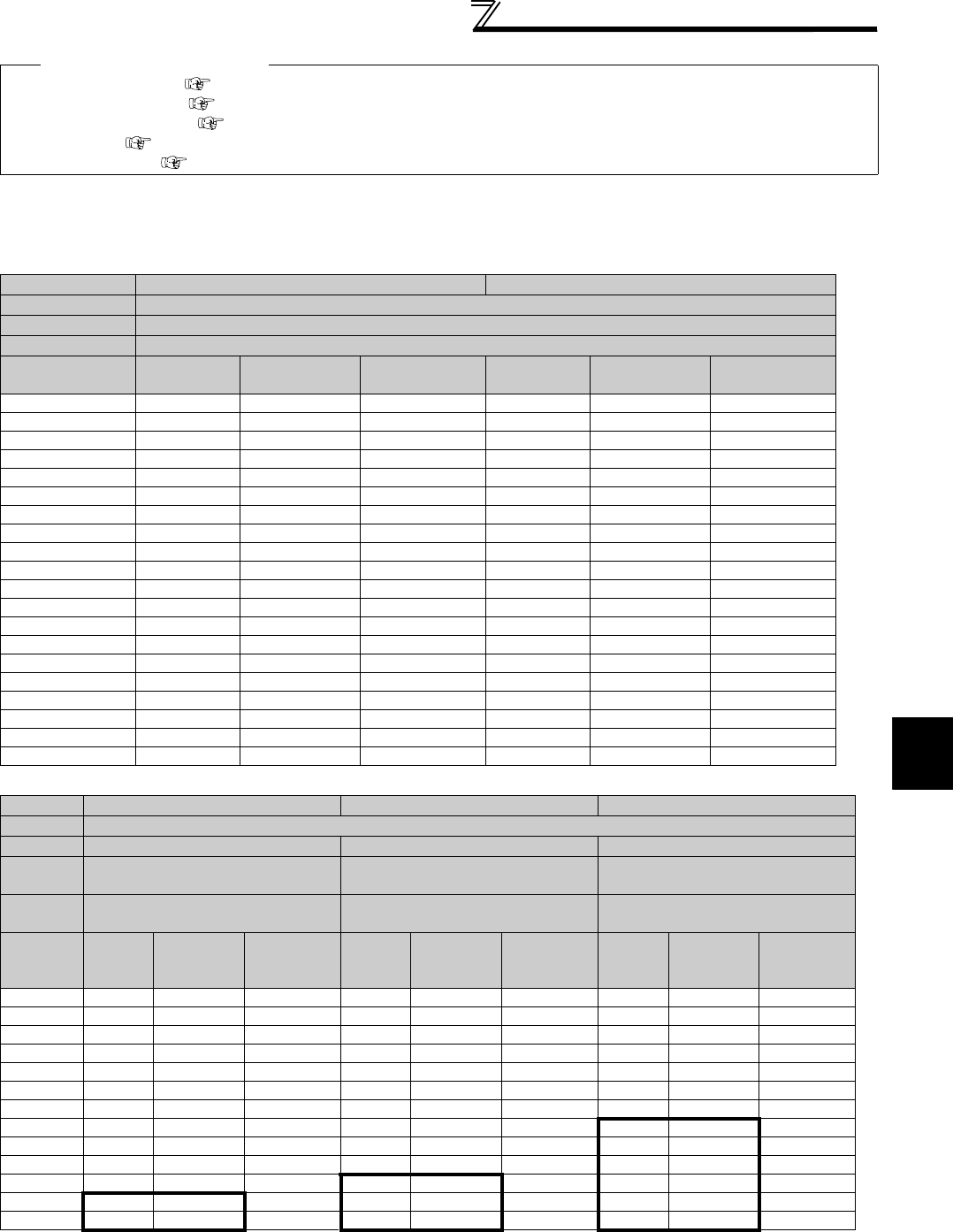
39
Connection of motor with encoder (vector control)
2
WIRING
(9) Combination with a vector control dedicated motor
Refer to the table below when using with a vector control dedicated motor.
• Combination with the SF-V5RU and SF-THY
• Combination with the SF-V5RU1, 3, 4 and SF-THY
Models surrounded by black borders and 400V class are developed upon receipt of order.
*1 The maximum speed is 2400r/min.
*2 80% output in the high-speed range. (The output is reduced when the speed is 2400r/min or more.)
*3 90% output in the high-speed range. (The output is reduced when the speed is 1000r/min or more.)
♦Parameters referred to♦
Vector control (speed control) Refer to page 98.
Vector control (torque control) Refer to page 124.
Vector control (position control) Refer to page 132.
Orientation control Refer to page 220.
Encoder feedback control Refer to page 381.
Voltage 200V class 400V class
Rated speed
1500r/min
Base frequency 50Hz
Maximum speed
3000r/min
Motor capacity Motor frame
number Motor type Inverter model Motor frame
number Motor type Inverter model
1.5kW 90L SF-V5RU1K FR-A720-2.2K 90L SF-V5RUH1K FR-A740-2.2K
2.2kW 100L SF-V5RU2K FR-A720-3.7K 100L SF-V5RUH2K FR-A740-2.2K
3.7kW 112M SF-V5RU3K FR-A720-5.5K 112M SF-V5RUH3K FR-A740-3.7K
5.5kW 132S SF-V5RU5K FR-A720-7.5K 132S SF-V5RUH5K FR-A740-7.5K
7.5kW 132M SF-V5RU7K FR-A720-11K 132M SF-V5RUH7K FR-A740-11K
11kW 160M SF-V5RU11K FR-A720-15K 160M SF-V5RUH11K FR-A740-15K
15kW 160L SF-V5RU15K FR-A720-18.5K 160L SF-V5RUH15K FR-A740-18.5K
18.5kW 180M SF-V5RU18K FR-A720-22K 180M SF-V5RUH18K FR-A740-22K
22kW 180M SF-V5RU22K FR-A720-30K 180M SF-V5RUH22K FR-A740-30K
30kW 200L *2 SF-V5RU30K FR-A720-37K 200L *2 SF-V5RUH30K FR-A740-37K
37kW 200L *2 SF-V5RU37K FR-A720-45K 200L *2 SF-V5RUH37K FR-A740-45K
45kW 200L *2 SF-V5RU45K FR-A720-55K 200L *2 SF-V5RUH45K FR-A740-55K
55kW 225S *1 SF-V5RU55K FR-A720-75K 225S *1 SF-V5RUH55K FR-A740-75K
75kW 250MD SF-THY FR-A720-90K 250MD SF-THY FR-A740-90K
90kW — — — 250MD SF-THY FR-A740-110K
110kW — — — 280MD SF-THY FR-A740-132K
132kW — — — 280MD SF-THY FR-A740-160K
160kW — — — 280MD SF-THY FR-A740-185K
200kW — — — 280L SF-THY FR-A740-220K
250kW — — — 315H SF-THY FR-A740-280K
SF-V5RU1 (1:2) SF-V5RU3 (1:3) SF-V5RU4 (1:4)
Voltage 200V class
Rated speed
1000r/min 1000r/min 500r/min
Base
frequency 33.33Hz 33.33Hz 16.6Hz
Maximum
speed
2000r/min 3000r/min 2000r/min
Motor
capacity
Motor
frame
number
Motor type Inverter
model
Motor
frame
number
Motor type Inverter
model
Motor
frame
number
Motor type Inverter
model
1.5kW 100L SF-V5RU1K1 FR-A720-2.2K 112M SF-V5RU1K3 FR-A720-2.2K 132M SF-V5RU1K4 FR-A720-2.2K
2.2kW 112M SF-V5RU2K1 FR-A720-3.7K 132S SF-V5RU2K3 FR-A720-3.7K 160M SF-V5RU2K4 FR-A720-3.7K
3.7kW 132S SF-V5RU3K1 FR-A720-5.5K 132M SF-V5RU3K3 FR-A720-5.5K 160L SF-V5RU3K4 FR-A720-7.5K
5.5kW 132M SF-V5RU5K1 FR-A720-7.5K 160M SF-V5RU5K3 FR-A720-7.5K 180L SF-V5RU5K4 FR-A720-7.5K
7.5kW 160M SF-V5RU7K1 FR-A720-11K 160L SF-V5RU7K3 FR-A720-11K 200L SF-V5RU7K4 FR-A720-11K
11kW 160L
SF-V5RU11K1
FR-A720-15K 180M
SF-V5RU11K3
FR-A720-15K 225S
SF-V5RU11K4
FR-A720-15K
15kW 180M
SF-V5RU15K1 FR-A720-18.5K
180L
SF-V5RU15K3 FR-A720-18.5K
225S
SF-V5RU15K4
FR-A720-22K
18.5kW 180L
SF-V5RU18K1
FR-A720-22K 200L
SF-V5RU18K3
FR-A720-22K
250MD
SF-THY FR-A720-22K
22kW 200L
SF-V5RU22K1
FR-A720-30K 200L
SF-V5RU22K3
FR-A720-30K
280MD
SF-THY FR-A720-30K
30kW 200L*3
SF-V5RU30K1
FR-A720-37K 225S*1
SF-V5RU30K3
FR-A720-37K
280MD
SF-THY FR-A720-37K
37kW 225S
SF-V5RU37K1
FR-A720-45K
250MD
*1 SF-THY FR-A720-45K
280MD
SF-THY FR-A720-45K
45kW
250MD
SF-THY FR-A720-55K
250MD
*1 SF-THY FR-A720-55K
280MD
SF-THY FR-A720-55K
55kW
250MD
SF-THY FR-A720-75K
280MD
*1 SF-THY FR-A720-75K 280L SF-THY FR-A720-75K
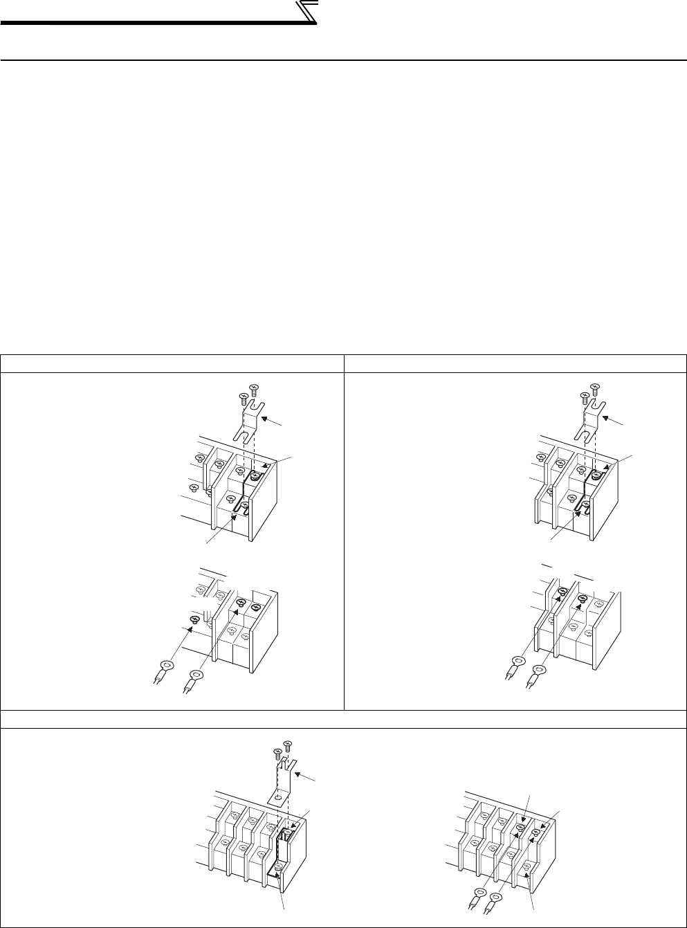
40
Connection of stand-alone option units
2.5 Connection of stand-alone option units
The inverter accepts a variety of stand-alone option units as required.
Incorrect connection will cause inverter damage or accident. Connect and operate the option unit carefully in
accordance with the corresponding option unit manual.
2.5.1 Connection of the dedicated external brake resistor (FR-ABR)
The built-in brake resistor is connected across terminals P/+ and PR. Fit the external dedicated brake resistor (FR-
ABR) when the built-in brake resistor does not have enough thermal capability for high-duty operation (22K or lower).
At this time, remove the jumper from across terminals PR and PX (7.5K or lower) and connect the dedicated brake
resistor (FR-ABR) across terminals P/+ and PR.
(For the locations of terminal P/+ and PR, refer to the terminal block layout (page 16).)
Removing jumpers across terminals PR and PX disables the built-in brake resistor (power is not supplied).
Note that the built-in brake resistor is not need to be removed from the inverter.
The lead wire of the built-in brake resistor is not need to be removed from the terminal.
Set parameters below.
⋅ Pr. 30 Regenerative function selection = "1"
⋅ Pr. 70 Special regenerative brake duty = "7.5K or lower: 10%, 11K or higher: 6%" (Refer to page 207)
FR-A720-0.4K to 0.75K FR-A720-1.5 to 3.7K, FR-A740-0.4K to 3.7K
FR-A720-5.5K, 7.5K, FR-A740-5.5K, 7.5K
1) Remove the screws in terminals
PR and PX and remove the jumper.
2) Connect the brake resistor across
terminals P/+ and PR. (The jumper
should remain disconnected.)
Jumper
Terminal PX
Terminal P/+
Terminal PR
Terminal PR
Brake resistor
1) Remove the screws in terminals
PR and PX and remove the jumper.
2) Connect the brake resistor across
terminals P/+ and PR. (The jumper
should remain disconnected.)
Jumper
Terminal PX
Brake resistor
Terminal PR
Terminal PR
Terminal P/+
1) Remove the screws in terminals PR
and PX and remove the jumper.
2) Connect the brake resistor across
terminals P/+ and PR. (The jumper
should remain disconnected.)
Jumper
Terminal PX Terminal PX
Terminal P/+
Terminal PR
Terminal PR
Brake resistor
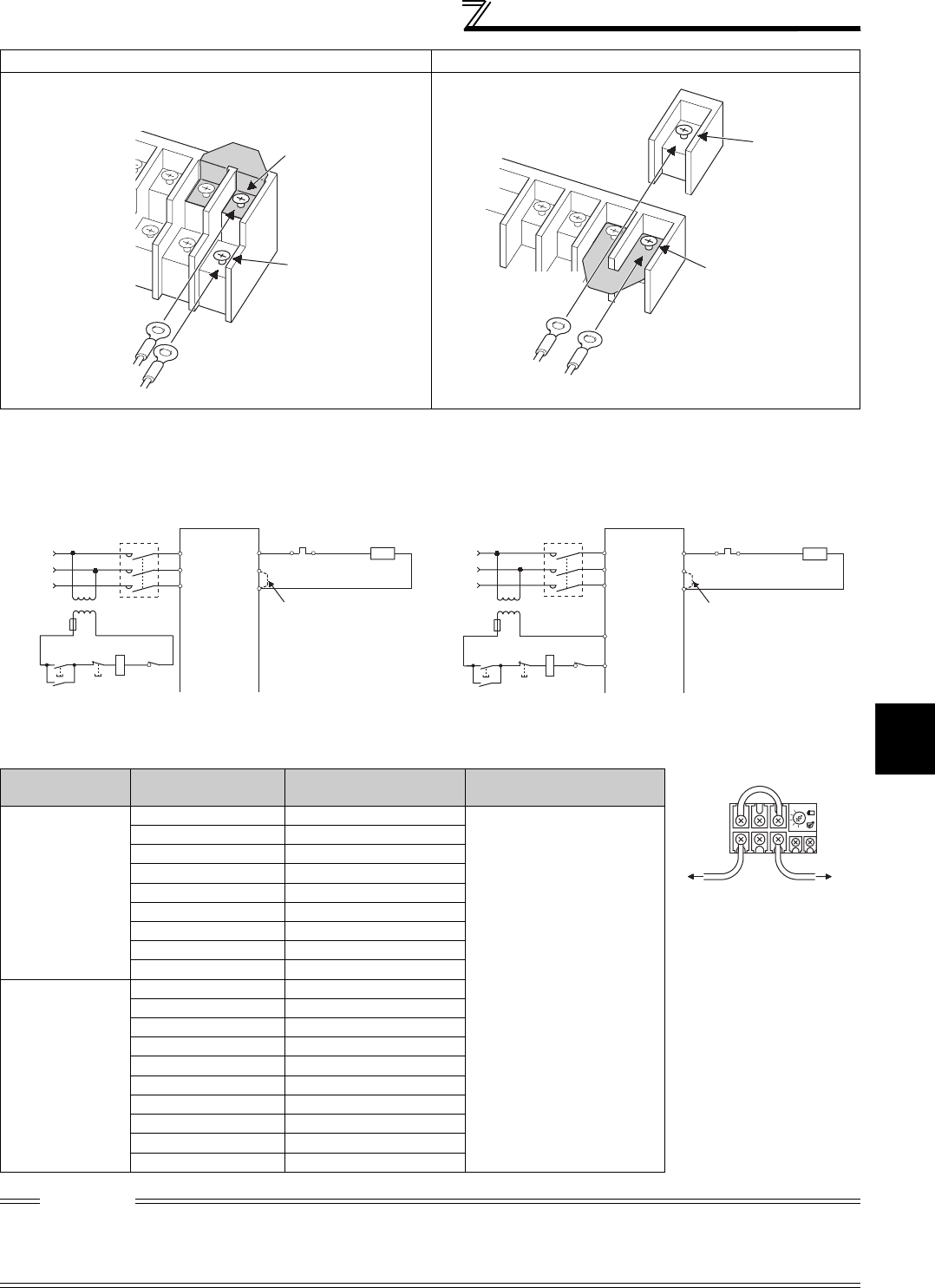
41
Connection of stand-alone option units
2
WIRING
* Do not remove the jumper across terminal P/+ and P1 except when connecting a DC reactor.
When the regenerative brake transistor is damaged, the following sequence is recommended to prevent overheat
and burnout of the brake resistor.
*1 Since the 11K or higher inverter is not provided with the PX terminal, a jumper is not need to be removed.
*2 Refer to the table below for the type number of each capacity of thermal relay and the diagram below for the connection. (Always install a thermal
relay when using the 11K or higher)
FR-A720-11K, FR-A740-11K, 15K FR-A720-15K to 22K, FR-A740-18.5K, 22K
Power Supply
Voltage
High-Duty Brake
Resistor
Thermal Relay Type
(Mitsubishi product) Contact Rating
200V
FR-ABR-0.4K TH-N20CXHZ-0.7A
110V 5AAC,
220V 2AAC(AC-11 class)
110V 0.5ADC,
220V 0.25ADC(DC-11 class)
FR-ABR-0.75K TH-N20CXHZ-1.3A
FR-ABR-2.2K TH-N20CXHZ-2.1A
FR-ABR-3.7K TH-N20CXHZ-3.6A
FR-ABR-5.5K TH-N20CXHZ-5A
FR-ABR-7.5K TH-N20CXHZ-6.6A
FR-ABR-11K TH-N20CXHZ-11A
FR-ABR-15K TH-N20CXHZ-11A
FR-ABR-22K TH-N60-22A
400V
FR-ABR-H0.4K TH-N20CXHZ-0.24A
FR-ABR-H0.75K TH-N20CXHZ-0.35A
FR-ABR-H1.5K TH-N20CXHZ-0.9A
FR-ABR-H2.2K TH-N20CXHZ-1.3A
FR-ABR-H3.7K TH-N20CXHZ-2.1A
FR-ABR-H5.5K TH-N20CXHZ-2.5A
FR-ABR-H7.5K TH-N20CXHZ-3.6A
FR-ABR-H11K TH-N20CXHZ-6.6A
FR-ABR-H15K TH-N20CXHZ-6.6A
FR-ABR-H22K TH-N20-9A
CAUTION
⋅The brake resistor connected should only be the dedicated brake resistor.
⋅The jumper across terminals PR and PX (7.5K or lower) must be disconnected before connecting the dedicated brake resistor.
Doing so may damage the inverter.
⋅Brake resistor cannot be used with the brake unit, high power factor converter, power supply regeneration converter, etc.
Jumper *
Terminal P/+
Terminal PR
Brake resistor
Connect the brake resistor
across terminals P/+ and PR.
Terminal P/+
Terminal PR
Brake resistor
Jumper
*
Connect the brake resistor
across terminals P/+ and PR.
R
MC
Power
Supply
High-duty
brake resistor
(FR-ABR)
Thermal
relay
(OCR)(*2)
Inverter
PX
PR
P/+
S/L2
T/L3
R/L1
Disconnect jumper. (*1)
MC
Power
Supply
T
F
ON OFF MC
MC
OCR
Contact
<Example 1> <Example 2>
PX
PR
P/+
S/L2
T/L3
R/L1
Inverter (OCR)(*2)
Thermal
relay
(FR-ABR)
High-duty
brake resisto
r
R
Disconnect jumper. (*1)
B
C
T
F
ON OFF
OCR
Contact
MC
MC
To the inverter
P/+ terminal
To the AB
R
TH-N20
1/L
1
5/L
3
2/T
1
6/T
3
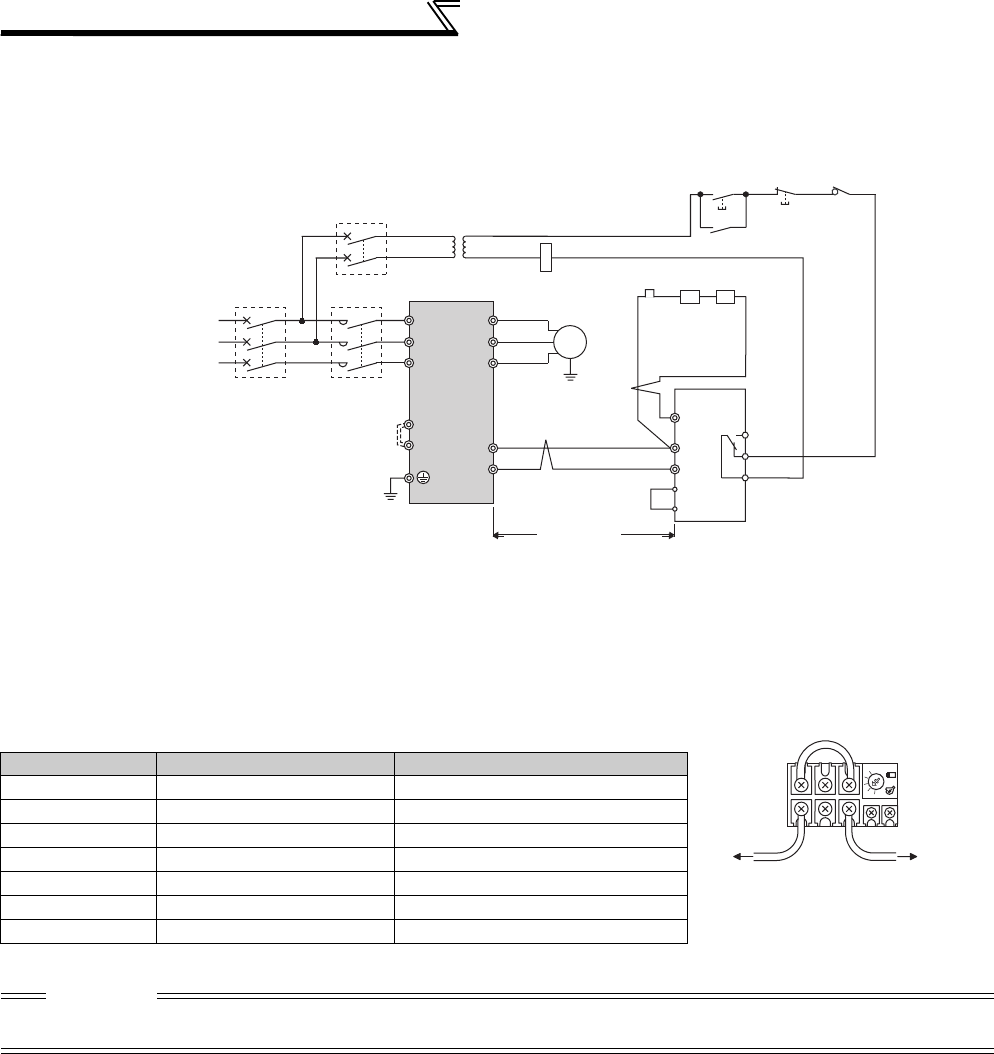
42
Connection of stand-alone option units
2.5.2 Connection of the brake unit (FR-BU2)
Connect the brake unit (FR-BU2) as shown below to improve the braking capability at deceleration.
(1) Connection example with the GRZG type discharging resistor
<Recommended external thermal relay>
*1 Connect the inverter terminals (P/+, N/-) and brake unit (FR-BU2) terminals so that their terminal names match with each other.
(Incorrect connection will damage the inverter and brake unit.)
*2 When the power supply is 400V class, install a step-down transformer.
*3 Be sure to remove the jumper across terminals PR and PX when using the FR-BU2 with the inverter of 7.5K or lower.
*4 Keep a wiring distance of within 5m between the inverter, brake unit (FR-BU2) and discharging resistor. Even when the wiring
is twisted, the cable length must not exceed 10m.
*5 It is recommended to install an external thermal relay to prevent overheat of discharging resistors.
*6 Refer to FR-BU2 manual for connection method of discharging resistor.
Brake Unit Discharging Resistor Recommended External Thermal Relay
FR-BU2-1.5K GZG 300W-50Ω (one) TH-N20CXHZ 1.3A
FR-BU2-3.7K GRZG 200-10Ω (three in series) TH-N20CXHZ 3.6A
FR-BU2-7.5K GRZG 300-5Ω (four in series) TH-N20CXHZ 6.6A
FR-BU2-15K GRZG 400-2Ω (six in series) TH-N20CXHZ 11A
FR-BU2-H7.5K GRZG 200-10Ω (six in series) TH-N20CXHZ 3.6A
FR-BU2-H15K GRZG 300-5Ω (eight in series) TH-N20CXHZ 6.6A
FR-BU2-H30K GRZG 400-2Ω (twelve in series) TH-N20CXHZ 11A
CAUTION
⋅Set "1" in Pr. 0 Brake mode selection of the FR-BU2 to use GRZG type discharging resistor.
⋅Do not remove a jumper across terminal P/+ and P1 except when connecting a DC reactor.
U
V
W
P/+
N/-
R/L1
S/L2
T/L3
Motor
IM
Inverter PR
N/-
BUE
SD
P/+
A
B
C
FR-BU2
GRZG type
discharging resistor
External thermal
relay
RR
Three-phase AC
power supply
MCCB MC
OFFON
MC
T
*1
*4
*4
*2
MC
*5
*6
OCR contact
OCR
5m or less
PR
PX
*3
To the brake
unit terminal P/+
To a resisto
r
TH-N20
1/L15/L3
2/T16/T3
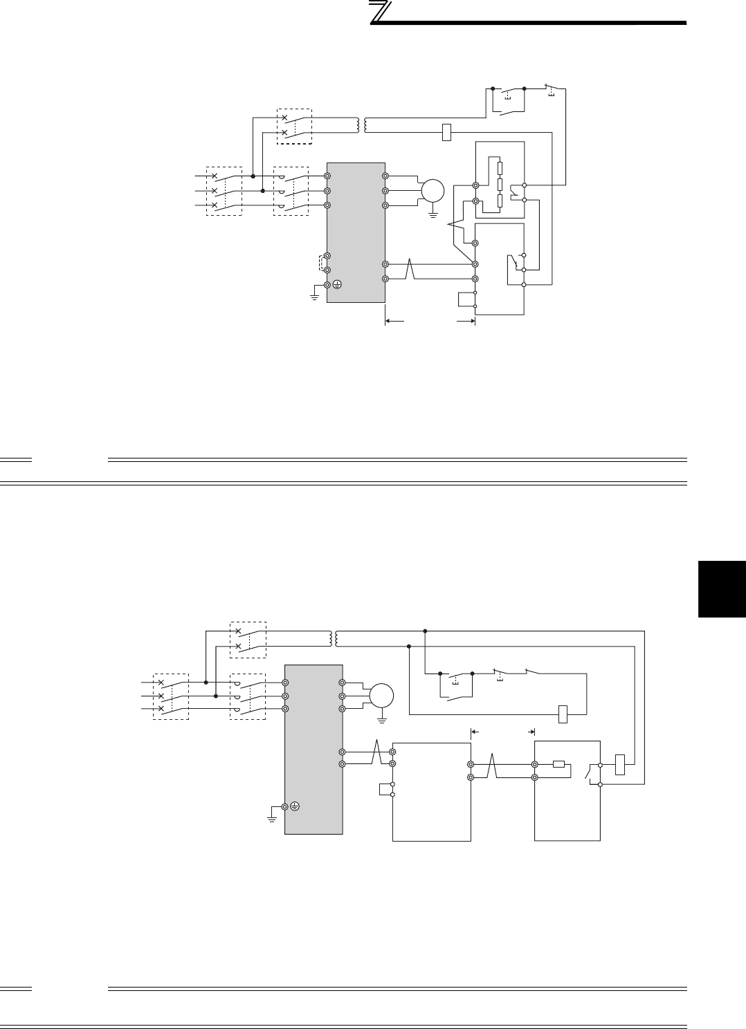
43
Connection of stand-alone option units
2
WIRING
(2) FR-BR-(H) connection example with resistor unit
(3) Connection example with MT-BR5 type resistor unit
After making sure that the wiring is correct, set the following parameters:
Pr. 30 Regenerative function selection = "1"
Pr. 70 Special regenerative brake duty = "0 (initial value)"
Set Pr. 0 Brake mode selection = "2" in the brake unit FR-BU2.
*1 Connect the inverter terminals (P/+, N/-) and brake unit (FR-BU2) terminals so that their terminal names match with each other.
(Incorrect connection will damage the inverter and brake unit.)
*2 When the power supply is 400V class, install a step-down transformer.
*3 Be sure to remove the jumper across terminals PR and PX when using the FR-BU with the inverter of 7.5K or lower.
*4 The wiring distance between the inverter, brake unit (FR-BU) and resistor unit (FR-BR) should be within 5m. Even when the
wiring is twisted, the cable length must not exceed 10m.
*5 The contact between TH1 and TH2 is closed in the normal status and is open at a fault.
CAUTION
⋅Do not remove a jumper across terminal P/+ and P1 except when connecting a DC reactor.
*1 Connect the inverter terminals (P/+, N/-) and brake unit (FR-BU2) terminals so that their terminal names match with each other.
(Incorrect connection will damage the inverter and brake unit.)
*2 When the power supply is 400V class, install a step-down transformer.
*3 The wiring distance between the inverter, brake unit (FR-BU2) and resistor unit (MT-BR5) should be within 5m. If twisted wires
are used, the distance should be within 10m.
*4 The contact between TH1 and TH2 is open in the normal status and is closed at a fault.
*5 CN8 connector used with the MT-BU5 type brake unit is not used.
CAUTION
⋅The stall prevention (overvoltage), oL, does not occur while Pr.30 Regenerative function selection = "1" and Pr.70 Special
regenerative brake duty = "0% (initial value)." (Refer to page 207 for details.)
U
V
W
P/+
N/-
R/L1
S/L2
T/L3
Motor
IM
Inverter PR
N/-
BUE
SD
P/+
P
A
B
C
FR-BU2
FR-BR
TH2
TH1
PR
Three phase AC
power supply
MCCB
MC
MC
OFFON
MC
T
PR
PX *1 *1
*5
5m or less
*4
*4
*3
*2
MC
R/L1 Motor
IM
Inverter
S/L2
T/L3
U
V
P/+
N/- P
PR
5m or less
W
Three phase AC
power supply
MCCB
TH1
TH2
MC
CR1
OFFON
MC
CR1
T
*3
*1 *1
*3
*5
*4
P
N
BUE
SD
P
PR
Brake unit
FR-BU2
Resistor unit
MT-BR5
*2
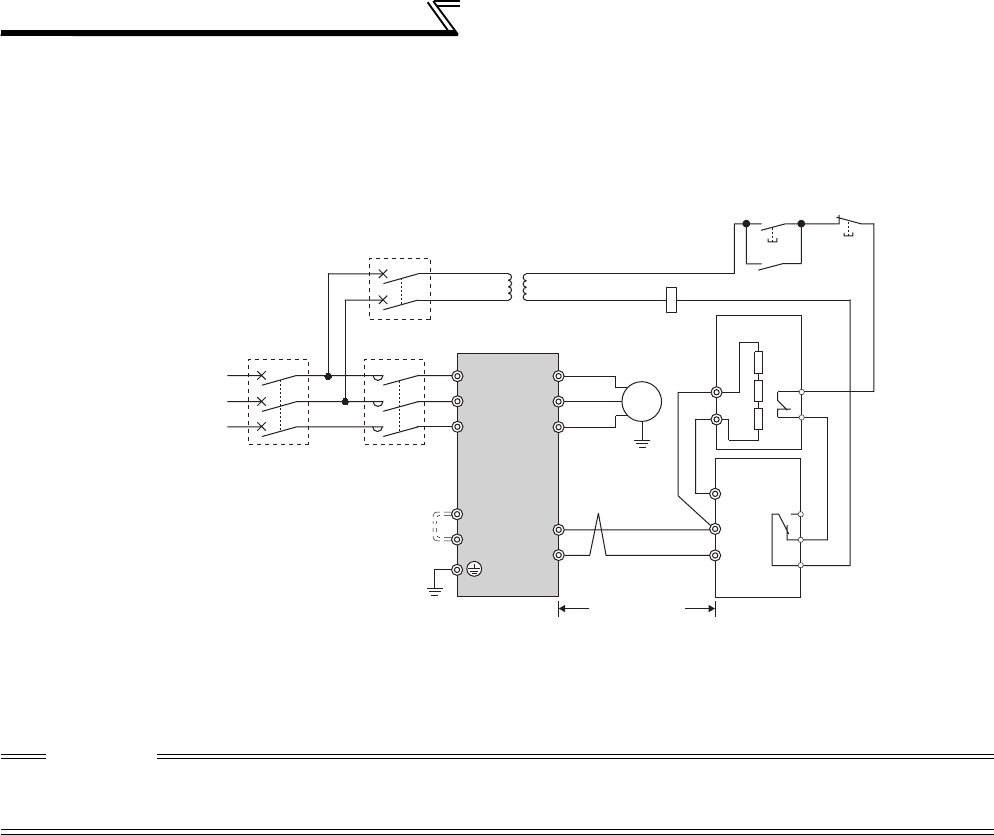
44
Connection of stand-alone option units
2.5.3 Connection of the brake unit (FR-BU/MT-BU5)
When connecting the brake unit (FR-BU(H)/MT-BU5) to improve the brake capability at deceleration, make connection
as shown below.
(1) Connection with the FR-BU (55K or lower)
*1 Connect the inverter terminals (P/+, N/-) and brake unit (FR-BU (H)) terminals so that their terminal signals match with each other.
(Incorrect connection will damage the inverter.)
*2 When the power supply is 400V class, install a step-down transformer.
*3 Be sure to remove the jumper across terminals PR and PX when using the FR-BU with the inverter of 7.5K or lower.
*4 The wiring distance between the inverter, brake unit (FR-BU) and resistor unit (FR-BR) should be within 5m. If twisted wires are
used, the distance should be within 10m.
CAUTION
⋅If the transistors in the brake unit should become faulty, the resistor can be unusually hot, causing a fire. Therefore, install a
magnetic contactor on the inverter's input side to configure a circuit so that a current is shut off in case of fault.
⋅Do not remove a jumper across terminal P/+ and P1 except when connecting a DC reactor.
U
V
W
P/+
N/−
R/L1
S/L2
T/L3
Motor
IM
Inverter
PR
N/−
P/+
P
HA
HB
HC
FR-BU
FR-BR
TH2
TH1
PR
*1
Three-phase AC
power supply
MCCB
MC
OFFON
MC
T *2
MC
*3 PR
PX
*4
5m or less
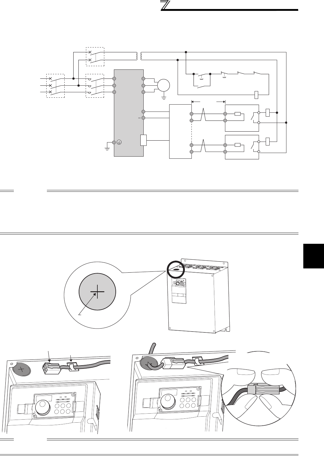
45
Connection of stand-alone option units
2
WIRING
(2) Connection with the MT-BU5 (75K or higher)
After making sure that the MT-BU5 is properly connected, set the following parameters.
Pr. 30 Regenerative function selection = "1"
Pr. 70 Special regenerative brake duty = "10%" (Refer to page 207)
<Inserting the CN8 connector>
Make cuts in rubber bush of the upper portion of the inverter and lead a cable.
1) Make cuts in the rubber bush for leading the CN8 connector cable with a nipper or cutter knife.
2) Insert a connector on the MT-BU5 side through a rubber bush to connect to a connector on the inverter side.
*1 When the power supply is 400V class, install a step-down transformer.
*2 The wiring length between the resistor unit and brake resistor should be 10m maximum when wires are twisted and 5m
maximum when wires are not twisted.
CAUTION
⋅Install the brake unit in a place where a cooling air reaches the brake unit heatsink and within a distance of the cable supplied
with the brake unit reaches the inverter.
⋅For wiring of the brake unit and inverter, use an accessory cable supplied with the brake unit. Connect the main circuit cable to
the inverter terminals P/+ and N/- and connect the control circuit cable to the CN8 connector inside by making cuts in the rubber
bush at the top of the inverter for leading the cable.
⋅The brake unit which uses multiple resistor units has terminals equal to the number of resistor units. Connect one resistor unit
to one pair of terminal (P, PR).
CAUTION
Clamp the CN8 connector cable on the inverter side with a wire clamp securely.
Do not connect the MT-BU5 to a CN8 connector of the FR-A740-55K.
MC
R/L1 Motor
IM
Inverter
Brake unit
MT-BU5
Resistor unit
MT-BR5
S/L2
T/L3
U
V
P/+
N/ P
PR
P
PR
P
PR
PTH1
TH2
PR
CN8
W
Three-phase
A
C power
supply
MCCB
TH1
TH2
MC
OFFON
MC
CR1 CR2
CR1
CR2
T
*1
5m or
less
*2
Rubber bushes
Make cuts in
rubber bush
Insert the connector until
you hear a click sound.
CN8 connector
Wire clamp
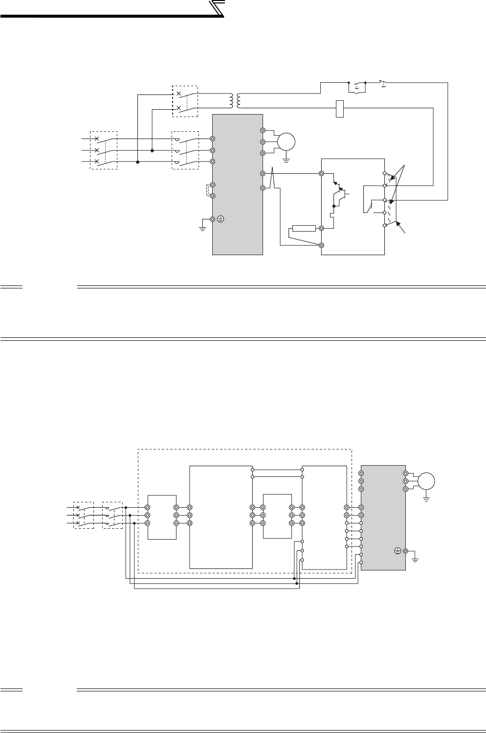
46
Connection of stand-alone option units
2.5.4 Connection of the brake unit (BU type)
Connect the brake unit (BU type) correctly as shown below. Incorrect connection will damage the inverter. Remove the
jumper across terminals HB-PC and terminals TB-HC of the brake unit and fit it across terminals PC-TB.
2.5.5 Connection of the high power factor converter (FR-HC/MT-HC)
When connecting the high power factor converter (FR-HC/MT-HC) to suppress power harmonics, perform wiring
securely as shown below.
Incorrect connection will damage the high power factor converter and inverter.
(1) Connection with the FR-HC (55K or lower)
After making sure the wiring is correct, set the following parameters.
Pr. 19 Base frequency voltage (under V/F control) or Pr. 83 Rated motor voltage (under a control method other than V/F
control) = "rated motor voltage"
Pr. 30 Regenerative function selection = "2"
*1 When the power supply is 400V class, install a step-down transformer.
*2 For capacity 7.5K or lower, remove the jumper across terminals PR and PX.
CAUTION
⋅The wiring distance between the inverter, brake unit and resistor unit should be within 2m. If twisted wires are used, the
distance should be within 5m.
⋅If the transistors in the brake unit should become faulty, the resistor can be unusually hot, causing a fire. Therefore, install a
magnetic contactor on the inverter's power supply side to configure a circuit so that a current is shut off in case of fault.
⋅Do not remove a jumper across terminal P/+ and P1 except when connecting a DC reactor.
*1 Remove the jumpers across the inverter terminals R/L1 and R1/L11, S/L2 and S1/L21, and connect the control circuit power supply to the R1/L11
and S1/L21 terminals. Always keep the power input terminals R/L1, S/L2, T/L3 open. Incorrect connection will damage the inverter. (E.OPT
(option alarm) will occur. (Refer to page 412.))
*2 Do not insert the MCCB between terminals P/+ and N/- (P/+ and P/+, N/- and N/-). Opposite polarity of terminals N/-, P/+ will damage the inverter.
*3 Use Pr. 178 to Pr. 189 (input terminal function selection) to assign the terminals used for the X10 (X11) signal. (Refer to page 231)
For communication where the start command is sent only once, e.g. RS-485 communication operation, use the X11 signal when making setting to
hold the mode at occurrence of an instantaneous power failure. (Refer to page 209.)
*4 Always connect the terminal RDY (of FR-HC) to a terminal where the X10 or MRS signal is assigned in the inverter. Always connect the terminal
SE (of FR-HC) to the terminal SD (of the inverter). Not doing so may damage FR-HC.
CAUTION
⋅The voltage phases of terminals R/L1, S/L2, T/L3 and terminals R4, S4, T4 must be matched.
⋅Use sink logic (factory setting) when the FR-HC is connected. The FR-HC cannot be connected when source logic is selected.
⋅Do not connect a DC reactor to the inverter when FR-HC is connected.
⋅Do not remove the jumper across P/+ and P1.
U
V
W
IM Brake unit
(BU type)
Discharging
resistor
R/L1
S/L2
T/L3
N/-
P/+
MC
P
PR
OCR
N
Remove the
jumper
Fit a jumper
HC
HB
HA
TB
OCR
PC
MC
OFFON
MC
T*1
Three-phase
A
C power
supply
MCCB Inverter
Motor
PR
PX
*2
Outside box
Reactor1
Inverter
Power
supply
MCCB
High power factor converter
(FR-HC)
(FR-HCB)
Reactor2
(FR-HCL02)
R/L1
(FR-HCL01)
phase
detection
S/L2
T/L3
P/+
N/-
X11
*3
X10
*3
RES
U
V
W
P
N
Y1orY2
RDY
RSO
MC1
MC2
R4
S4
T4
R
S
T
R4
S4
T4
R3
S3
T3
R3
S3
T3
R2
S2
T2
R2
S2
T2
R
S
T
MC1
MC2
SDSE
R1/L11
S1/L21
MC
*1
*4
*1
*2
Moto
r
IM
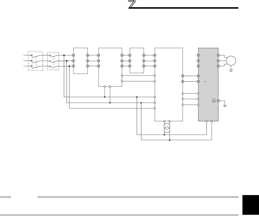
47
Connection of stand-alone option units
2
WIRING
(2) Connection with the MT-HC (75K or higher)
After making sure the wiring is correct, set the following parameters.
Pr. 19 Base frequency voltage (under V/F control) or Pr. 83 Rated motor voltage (under a control method other than V/F
control) = "rated motor voltage"
Pr. 30 Regenerative function selection = "2"
*1 Remove the jumper across terminals R/L1 and R1/L11, S/L2 and S1/L21 of the inverter, and connect the control circuit
power supply to the R1/L11 and S1/L21 terminals. The power input terminals R/L1, S/L2, T/L3 must be open. Incorrect
connection will damage the inverter. (E.OPT (option alarm) will occur. (Refer to page 412.)
*2 Do not insert the MCCB between terminals P/+ and N/- (P and P/+, N and N/-). Opposite polarity of terminals N, P will
damage the inverter.
*3 Use Pr. 178 to Pr. 189 (input terminal function selection) to assign the terminals used for the X10 (X11) signal. (Refer to page
231.) For communication where the start command is sent only once, e.g. RS-485 communication operation, use the X11
signal when making setting to hold the mode at occurrence of an instantaneous power failure. (Refer to page 209.)
*4 Connect the power supply to terminals R1 and S1 of the MT-HC via an insulated transformer.
*5 Always connect the terminal RDY (of MT-HC) to a terminal where the X10 or MRS signal is assigned in the inverter. Always
connect the terminal SE (of MT-HC) to the terminal SD (of the inverter). Not doing so may damage MT-HC.
CAUTION
⋅The voltage phases of terminals R/L1, S/L2, T/L3 and terminals R4, S4, T4 must be matched.
⋅Use sink logic (factory setting) when the MT-HC is connected. The MT-HC cannot be connected when source logic is selected.
⋅When connecting the inverter to the MT-HC, do not connect the DC reactor provided to the inverter.
Three-phase
A
C power
supply
MCCB
MT-HCL01 MT-HCB
R1 S1
R1 S1
R1/
L11
S1/
L21
MT-HCL02 MT-HC Inverter
MT-HCTR
Insulated transformer
R
S
T
R/L1
S/L2
T/L3
U
V
W
R2
S2
T2
R2
S2
T2
R3
S3
T3
R3
S3
T3
R4
S4
T4
R4
S4
T4
R
S
T
88R
88S
88R
88S
*2
RDY
RSO
SE
X10
RES
SD
*3
*1
*1
*4
*5
Motor
IM
P
N
P/+
N/
MC
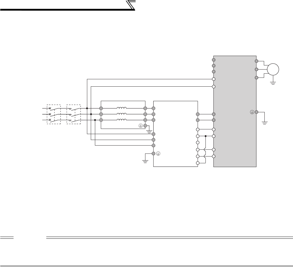
48
Connection of stand-alone option units
2.5.6 Connection of the power regeneration common converter (FR-CV)
When connecting the power regeneration common converter (FR-CV), make connection so that the inverter terminals
(P/+, N/-) and the terminal symbols of the power regeneration common converter (FR-CV) are the same (55K or lower).
After making sure that the wiring is correct, set "2" in Pr. 30 Regenerative function selection. (Refer to page 207.)
*1 Remove the jumpers across terminals R/L1 and R1/L11 and S/L2 and S1/L21 of the inverter, and connect the control
circuit power supply across terminals R1/L11 and S1/L21. Always keep the power input terminals R/L1, S/L2, T/L3 open.
Incorrect connection will damage the inverter. (E.OPT (option alarm) will occur. (Refer to page 412))
*2 Do not insert the MCCB between the terminals P/+ and N/- (between P/L+ and P/+, between N/L- and N/-). Opposite
polarity of terminals N/-, P/+ will damage the inverter.
*3 Assign the terminal for X10 signal using any of Pr. 178 to Pr. 189 (input terminal function selection). (Refer to page 231)
*4 Be sure to connect the power supply and terminals R/L11, S/L21, T/MC1.
Operating the inverter without connecting them will damage the power regeneration common converter.
*5 Always connect the terminal RDYB (of FR-CV) to a terminal where the X10 or MRS signal is assigned in the inverter.
Always connect the terminal SE (of FR-CV) to the terminal SD (of the inverter). Not doing so may damage FR-CV.
CAUTION
⋅The voltage phases of terminals R/L11, S/L21, T/MC1 and terminals R2/L1, S2/L2, T2/L3 must be matched.
⋅Use sink logic (factory setting) when the FR-CV is connected. The FR-CV cannot be connected when source logic is selected.
⋅Do not connect a DC reactor to the inverter when FR-CV is connected.
⋅Do not remove a jumper across terminal P/+ and P1.
R/L11
Dedicated stand-alone
reactor (FR-CVL)
S/L21
T/L31
R2/L12
S2/L22
T2/L32
R2/L1
S2/L2
T2/L3
R/L11
S/L21
T/MC1
P/L+
U
V
W
IM
FR-CV type
Power regeneration
common converter Inverter
PC
SD
X10
*3
RES
P24
SD
RDYB
RSO
SE
RDYA
N/L−
*2
*5
*4
R/L1
S/L2
T/L3
R1/L11
S1/L21
P/+
N/−
*1
Three-phase
AC power
supply
MCCB MC1

49
Connection of stand-alone option units
2
WIRING
2.5.7 Connection of power regeneration converter (MT-RC)
When connecting a power regeneration converter (MT-RC), perform wiring securely as shown below. Incorrect
connection will damage the regeneration converter and inverter (75K or higher). After connecting securely, set "1" in Pr.
30 Regenerative function selection and "0" in Pr. 70 Special regenerative brake duty.
2.5.8 Connection of the power factor improving DC reactor (FR-HEL)
(1) Keep the surrounding air temperature within the permissible range (-10°C to +50°C). Keep enough clearance
around the reactor because it heats up. (Take 10cm or more clearance on top and bottom and 5cm or more on left
and right regardless of the installation direction.)
(2) When using the DC reactor (FR-HEL), connect it between terminals P1 and P/+.
For the 55K or lower, the jumper connected across terminals P1 and P/+ must be removed. Otherwise, the reactor
will not exhibit its performance.
For the 75K or higher, a DC reactor is supplied. Always install the reactor.
CAUTION
⋅When using the FR-A700 series together with the MT-RC, install a magnetic
contactor (MC) at the input side of the inverter so that power is supplied to the
inverter after 1s or more has elapsed after powering ON the MT-RC. When power is
supplied to the inverter prior to the MT-RC, the inverter and the MT-RC may be
damaged or the MCCB may trip or be damaged.
⋅Refer to the MT-RC manual for precautions for connecting the power coordination
reactor and others.
CAUTION
⋅The wiring distance should be within 5m.
⋅
The size of the cables used should be equal to or larger than that of the power supply cables (R/L1, S/L2, T/L3).
(Refer to page 19)
DCL
P1 P1
R/L1
S/L2
T/L3
R1/L11
S1/L21
R
S
T
R
S
T
R1
S1
R2
S2
T2
R2
S2
T2
RES
STF
SD
C
B
A
U
V
W
Inverter
MT-RCL
PP/+ N/-
PN
RDY
SE
MT-RC
Reset signal
Alarm signal
Ready signal
Three-phase
A
C power
supply
MCCB MC2
IM
MC1
MT-RC power
supply (MC1)
Inverter input power
supply (MC2)
ON
ON
1s or more
5cm or more
5cm or more
10cm or more
5cm or more
5cm or more
P1
FR-HEL
Remove
the jumper.
P/+
50
MEMO

51
3
4
5
6
7
1
2
3
PRECAUTIONS FOR USE
OF THE INVERTER
This chapter explains the "PRECAUTIONS FOR USE OF THE
INVERTER" for use of this product.
Always read the instructions before using the equipment.
3.1 EMC and leakage currents......................................52
3.2 Installation of a reactor ............................................60
3.3 Power-off and magnetic contactor (MC)..................61
3.4 Inverter-driven 400V class motor ............................62
3.5 Precautions for use of the inverter ..........................63
3.6 Failsafe of the system which uses the inverter .......65
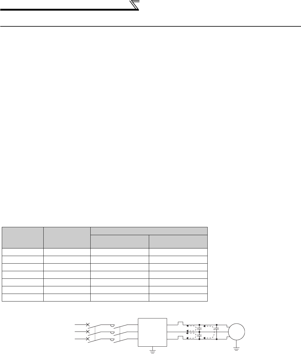
52
EMC and leakage currents
3.1 EMC and leakage currents
3.1.1 Leakage currents and countermeasures
Capacitances exist between the inverter I/O cables, other cables and earth and in the motor, through which a leakage
current flows. Since its value depends on the static capacitances, carrier frequency, etc., low acoustic noise operation
at the increased carrier frequency of the inverter will increase the leakage current. Therefore, take the following
measures. Select the earth leakage circuit breaker according to its rated sensitivity current, independently of the carrier
frequency setting.
(1) To-earth (ground) leakage currents
Leakage currents may flow not only into the inverter's own line but also into the other lines through the earth (ground)
cable, etc. These leakage currents may operate earth (ground) leakage circuit breakers and earth leakage relays
unnecessarily.
Suppression technique
⋅If the carrier frequency setting is high, decrease the Pr. 72 PWM frequency selection setting. Note that motor noise
increases.Selecting Pr. 240 Soft-PWM operation selection makes the sound inoffensive.
⋅By using earth leakage circuit breakers designed for harmonic and surge suppression in the inverter's own line and
other line, operation can be performed with the carrier frequency kept high (with low noise).
To-earth (ground) leakage currents
⋅Take caution as long wiring will increase the leakage current. Decreasing the carrier frequency of the inverter
reduces the leakage current.
⋅Increasing the motor capacity increases the leakage current. The leakage current of the 400V class is larger than
that of the 200V class.
(2) Line-to-line leakage currents
Harmonics of leakage currents flowing in static capacitances between the inverter output cables may operate the
external thermal relay unnecessarily. When the wiring length is long (50m or more) for the 400V class small-capacity
model (7.5K or lower), the external thermal relay is likely to operate unnecessarily because the ratio of the leakage
current to the rated motor current increases.
Line-to-line leakage current data example (200V class)
*The leakage currents of the 400V class are about twice as large.
Measures
⋅Use Pr. 9 Electronic thermal O/L relay.
⋅If the carrier frequency setting is high, decrease the Pr. 72 PWM frequency selection setting. Note that motor noise
increases. Selecting Pr. 240 Soft-PWM operation selection makes the sound inoffensive. To ensure that the motor is
protected against line-to-line leakage currents, it is recommended to use a temperature sensor to directly detect
motor temperature.
Installation and selection of moulded case circuit breaker
Install a moulded case circuit breaker (MCCB) on the power receiving side to protect the wiring of the inverter input
side. Select the MCCB according to the inverter input side power factor (which depends on the power supply voltage,
output frequency and load). Especially for a completely electromagnetic MCCB, one of a slightly large capacity must
be selected since its operation characteristic varies with harmonic currents. (Check it in the data of the corresponding
breaker.) As an earth (ground) leakage circuit breaker, use the Mitsubishi earth (ground) leakage breaker designed
for harmonics and surge suppression.
Motor
Capacity
(kW)
Rated Motor
Current(A)
Leakage Currents(mA)
Wiring length 50m Wiring length 100m
0.4 1.8 310 500
0.75 3.2 340 530
1.5 5.8 370 560
2.2 8.1 400 590
3.7 12.8 440 630
5.5 19.4 490 680
7.5 25.6 535 725
⋅Motor: SF-JR 4P
⋅Carrier frequency: 14.5kHz
⋅Used wire: 2mm2, 4cores
Cabtyre cable
Power
supply
Thermal relay
Line-to-line static
capacitances
MCCB MC
Line-to-line leakage currents path
Motor
Inverter IM
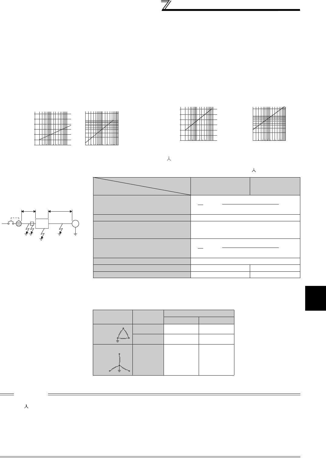
53
EMC and leakage currents
3
PRECAUTIONS FOR USE OF THE INVERTER
(3) Selection of rated sensitivity current of earth (ground) leakage breaker
When using the earth (ground) leakage circuit breaker with the inverter circuit, select its rated sensitivity current as
follows, independently of the PWM carrier frequency:
<Example>
z
Selection example (in the case of the left figure (400V class
connection))
zInverter leakage current (with and without EMC filter)
Input power conditions
(200V class: 220V/60Hz, 400V class: 440V/60Hz, power supply unbalance within 3%)
⋅Breaker designed for harmonic and surge suppression
Rated sensitivity current:
IΔn ≥ 10 × (Ig1 + Ign + Igi + Ig2 + Igm)
⋅Standard breaker
Rated sensitivity current:
IΔn ≥ 10 × {Ig1 + Ign + Igi + 3 × (Ig2 + Igm)}
Ig1, Ig2: Leakage currents in wire path during commercial
power supply operation
Ign: Leakage current of inverter input side noise filter
Igm: Leakage current of motor during commercial power
supply operation
Igi: Leakage current of inverter unit
Breaker Designed for
Harmonic and Surge
Suppression
Standard Breaker
Leakage current Ig1 (mA) × 66 ×5m
= 0.11
1000m
Leakage current Ign (mA) 0 (without noise filter)
Leakage current Igi (mA)
1 (without EMC filter)
Refer to the following table for the leakage
current of the inverter*
Leakage current Ig2 (mA) × 66 ×60m
= 1.32
1000m
Motor leakage current Igm (mA) 0.36
Total leakage current (mA) 2.79 6.15
Rated sensitivity current (mA) (≥ Ig × 10) 30 100
*Refer to page 15 for the EMC filter.
Voltage
(V)
EMC Filter
ON (mA) OFF (mA)
200 22(1)* 1
400 30 1
400 11
*For the FR-A720-0.4K and 0.75K, the EMC filter is always valid.
The leakage current is 1mA.
CAUTION
⋅Install the earth leakage breaker (ELB) on the input side of the inverter.
⋅In the connection earthed-neutral system, the sensitivity current is blunt against an earth (ground) fault in the inverter output
side. Earthing (Grounding) must conform to the requirements of national and local safety regulations and electrical codes. (NEC
section 250, IEC 536 class 1 and other applicable standards)
⋅When the breaker is installed on the output side of the inverter, it may be unnecessarily operated by harmonics even if the
effective value is less than the rating. In this case, do not install the breaker since the eddy current and hysteresis loss will
increase, leading to temperature rise.
⋅The following models are standard breakers....BV-C1, BC-V, NVB, NV-L, NV-G2N, NV-G3NA and NV-2F earth leakage relay
(except NV-ZHA), NV with AA neutral wire open-phase protection
The other models are designed for harmonic and surge suppression....NV-C/NV-S/MN series, NV30-FA, NV50-FA, BV-C2,
earth leakage alarm breaker (NF-Z), NV-ZHA, NV-H
(200V 60Hz)
(200V 60Hz)
1. 5 3. 7
2. 2
7. 5 1522
11
37
30
55
455.5 18. 5
0. 1
0. 2
0. 3
0. 5
0. 7
1. 0
2. 0
0
20
40
60
80
100
120
23.5
5.5
81422
30
38
60
80
100
150
Motor capacity (kW)
Example of leakage current of
cable path per 1km during the
commercial power supply operation
when the CV cable is routed in
metal conduit
Leakage current example of
three-phase induction moto
r
during the commercial
power supply operation
Leakage currents (mA)
Leakage currents (mA)
Cable size (mm
2
)
Motor capacity (kW)
For " " connection, the amount of leakage current is appox.1/3 of the above value.
(Three-phase three-wire delta
connection 400V60Hz)
Example of leakage current per 1km during
the commercial power supply operation
when the CV cable is routed in metal conduit
Leakage current example of three-
phase induction motor during the
commercial power supply operation
(Totally-enclosed fan-cooled
type motor 400V60Hz)
0
20
40
60
80
100
120
leakage currents (mA)
leakage currents (mA)
2 3.5
5.5
81422
30
38
60
80
100
150
Cable
size (mm2)
0. 1
0. 2
0. 3
0. 5
0. 7
1. 0
2. 0
1. 5 3. 7
2. 2
7. 5 1522
11
37
30
55
455.5 18. 5
Noise
filter
Inverter
ELB
Ig1 Ign
Igi
Ig2 Igm
IM
5.5mm
2
×
5m 5.5mm
2
×
60m
400V
2.2k
W
3φ
1
3
1
3
Phase
grounding
Earthed-neutral
system
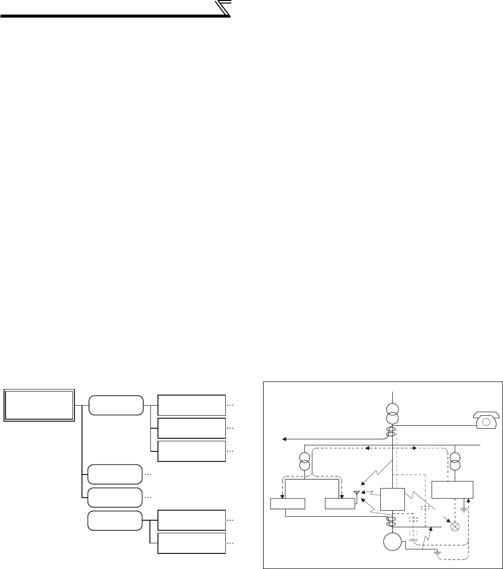
54
EMC and leakage currents
3.1.2 EMC measures
Some electromagnetic noises enter the inverter to malfunction it and others are radiated by the inverter to malfunction
peripheral devices. Though the inverter is designed to have high immunity performance, it handles low-level signals, so
it requires the following basic techniques. Also, since the inverter chops outputs at high carrier frequency, that could
generate electromagnetic noises. If these electromagnetic noises cause peripheral devices to malfunction, EMI
measures should be taken to suppress noises. These techniques differ slightly depending on EMI paths.
1) Basic techniques
⋅Do not run the power cables (I/O cables) and signal cables of the inverter in parallel with each other and do not
bundle them.
⋅Use shielded twisted pair cables for the detector connection and control signal cables, and connect the sheathes
of the shield cables to terminal SD.
⋅Earth (Ground) the inverter, motor, etc. at one point.
2) Techniques to reduce electromagnetic noises that enter and malfunction the inverter (Immunity measures)
When devices that generate many electromagnetic noises (which use magnetic contactors, magnetic brakes, many
relays, for example) are installed near the inverter and the inverter may be malfunctioned by electromagnetic noises,
the following measures must be taken:
⋅Provide surge suppressors for devices that generate many electromagnetic noises to suppress electromagnetic
noises.
⋅Fit data line filters (page 55) to signal cables.
⋅Earth (Ground) the shields of the detector connection and control signal cables with cable clamp metal.
3) Techniques to reduce electromagnetic noises that are radiated by the inverter to malfunction peripheral devices (EMI
measures)
Inverter-generated noises are largely classified into those radiated by the cables connected to the inverter and
inverter main circuits (I/O), those electromagnetically and electrostatically induced to the signal cables of the
peripheral devices close to the main circuit power supply, and those transmitted through the power supply cables.
Noise propagated through
power supply cable
Path 3)
Path 2)
Path 1)
Noise directly
radiated from inverter
Path 4), 5)
Air propagated
noise
Path 6)
Electrical path
propagated noise
Path 8)
Path 7)
Inverter generated
electromagnetic
noise
Electromagnetic
induction noise
Electrostatic
induction noise
Noise radiated from
power supply cable
Noise radiated from
motor connection cable
Noise from earth (ground)
cable due to leakage
current
Instrument Receiver
IM
Motor
Telephone
Sensor
1)
2)
3)
3)
8)
7)
5)
7)
4) 6)
Inverter
1)
Sensor
power supply
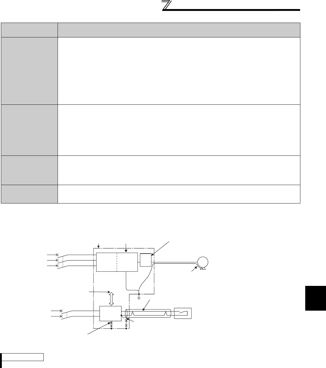
55
EMC and leakage currents
3
PRECAUTIONS FOR USE OF THE INVERTER
z Data line filter
Data line filter is effective as an EMC measure. Provide a data line filter for the detector cable, etc.
zEMC measures
Noise Propagation
Path Measures
1) 2) 3)
When devices that handle low-level signals and are liable to malfunction due to electromagnetic noises,
e.g. instruments, receivers and sensors, are contained in the enclosure that contains the inverter or when
their signal cables are run near the inverter, the devices may be malfunctioned by air-propagated
electromagnetic noises. The following measures must be taken:
(1) Install easily affected devices as far away as possible from the inverter.
(2) Run easily affected signal cables as far away as possible from the inverter and its I/O cables.
(3) Do not run the signal cables and power cables (inverter I/O cables) in parallel with each other and do
not bundle them.
(4) Set the EMC filter ON/OFF connector of the inverter to the ON position. (Refer to page 15)
(5) Inserting a line noise filter into the output suppresses the radiation noise from the cables.
(6) Use shield cables as signal cables and power cables and run them in individual metal conduits to
produce further effects.
4) 5) 6)
When the signal cables are run in parallel with or bundled with the power cables, magnetic and static
induction noises may be propagated to the signal cables to malfunction the devices and the following
measures must be taken:
(1) Install easily affected devices as far away as possible from the inverter.
(2) Run easily affected signal cables as far away as possible from the I/O cables of the inverter.
(3) Do not run the signal cables and power cables (inverter I/O cables) in parallel with each other and do
not bundle them.
(4) Use shield cables as signal cables and power cables and run them in individual metal conduits to
produce further effects.
7)
When the power supplies of the peripheral devices are connected to the power supply of the inverter in
the same line, inverter-generated noises may flow back through the power supply cables to malfunction
the devices and the following measures must be taken:
(1) Set the EMC filter ON/OFF connector of the inverter to the ON position. (Refer to page 15)
(2) Install the line noise filter (FR-BLF, FR-BSF01) to the power cables (output cables) of the inverter.
8)
When a closed loop circuit is formed by connecting the peripheral device wiring to the inverter, leakage
currents may flow through the earth (ground) cable of the inverter to malfunction the device. In such a
case, disconnection of the earth (ground) cable of the device may cause the device to operate properly.
REMARKS
For compliance with the EU EMC Directive, refer to the Instruction Manual (Basic).
Sensor
Use a shielded twisted pair cable
Inverter
power
supply
Control
power
supply
Enclosure
Decrease carrier
frequency
Motor
IM
FR-
BLF
Install a line noise filter (FR-BLF, FR-BSF01)
on the inverter output side
Power
supply
for sensor
EMC filter
Inverter
Do not earth (ground) shield
but connect it to signal common cable.
Do not earth (ground)
enclosure directly
Do not earth (ground)
control cable
Use 4-core cable for motor power cable
and use one cable as earth (ground) cable.
Separate the inverter and
power line by more than
30cm (at least 10cm) from
sensor circuit.
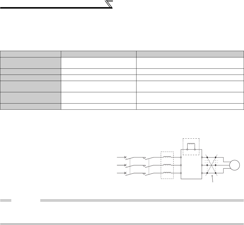
56
EMC and leakage currents
3.1.3 Power supply harmonics
The inverter may generate power supply harmonics from its converter circuit to affect the power generator, power
capacitor etc. Power supply harmonics are different from noise and leakage currents in source, frequency band and
transmission path. Take the following countermeasure suppression techniques.
The differences between harmonics and noises are indicated below:
zMeasures
Item Harmonics Noise
Frequency Normally number 40 to 50 max. (3kHz
or less) High frequency (several 10kHz to 1GHz order)
Environment To-electric channel, power impedance To-space, distance, wiring path
Quantitative understanding Theoretical calculation possible Random occurrence, quantitative grasping difficult
Generated amount Nearly proportional to load capacity Depending on the current fluctuation ratio (larger as
switching is faster)
Affected equipment immunity Specified in standard per equipment Different depending on maker's equipment
specifications
Suppression example Provide reactor. Increase distance.
The harmonic current generated from the inverter
to the input side differs according to various
conditions such as the wiring impedance, whether
a reactor is used or not, and output frequency and
output current on the load side.
For the output frequency and output current, we
understand that they should be calculated in the
conditions under the rated load at the maximum
operating frequency.
CAUTION
The power factor improving capacitor and surge suppressor on the inverter output side may be overheated or damaged by the
high frequency components of the inverter output. Also, since an excessive current flows in the inverter to activate overcurrent
protection, do not provide a capacitor and surge suppressor on the inverter output side when the motor is driven by the inverter.
For power factor improvement, install a reactor on the inverter input side or in the DC circuit.
AC reactor
(FR-HAL)
DC reactor
(FR-HEL)
Do not insert power
factor improving capacitor.
MCCB MC
Inverter
Power supply
R
S
TZ
Y
XU
V
W
P1
R/L1
S/L2
T/L3
P/+
IM
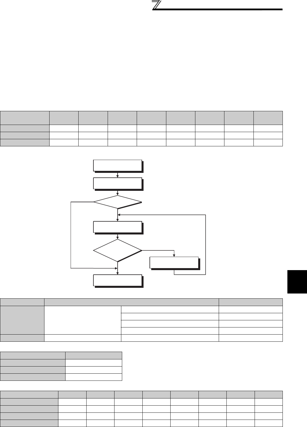
57
EMC and leakage currents
3
PRECAUTIONS FOR USE OF THE INVERTER
3.1.4 Harmonic Suppression Guidelines
Harmonic currents flow from the inverter to a power receiving point via a power transformer. The Harmonic
Suppression Guidelines were established to protect other consumers from these outgoing harmonic currents.
The three-phase 200V input specifications 3.7kW or less are previously covered by "Harmonic Suppression Guidelines
for Household Appliances and General-purpose Products" and other models are covered by "Harmonic Suppression
Guidelines for Consumers Who Receive High Voltage or Special High Voltage". However, the general-purpose inverter
has been excluded from the target products covered by "Harmonic Suppression Guidelines for Household Appliances
and General-purpose Products" in January 2004. Later, this guideline was repealed on 6 September 2004. All
capacities of all models are now target products of "Harmonic Suppression Guidelines for Consumers Who Receive
High Voltage or Special High Voltage" (hereinafter referred to as "Specific Consumer Guidelines").
"Specific Consumer Guidelines"
This guideline sets forth the maximum values of harmonic currents outgoing from a high-voltage or especially high-
voltage consumer who will install, add or renew harmonic generating equipment. If any of the maximum values is
exceeded, this guideline requires that consumer to take certain suppression measures.
(1) Application of the Specific Consumer Guidelines
Table 1 Maximum Values of Outgoing Harmonic Currents per 1kW Contract Power
Received Power
Voltage 5th 7th 11th 13th 17th 19th 23rd Over 23rd
6.6kV 3.5 2.5 1.6 1.3 1.0 0.9 0.76 0.70
22kV 1.8 1.3 0.82 0.69 0.53 0.47 0.39 0.36
33kV 1.2 0.86 0.55 0.46 0.35 0.32 0.26 0.24
Table 2 Conversion factors for FR-A700 series
Class Circuit Type Conversion Factor (Ki)
3Three-phase bridge
(Capacitor smoothing)
Without reactor K31 = 3.4
With reactor (AC side) K32 = 1.8
With reactor (DC side) K33 = 1.8
With reactor (AC, DC sides) K34 = 1.4
5 Self-excitation three-phase bridge When high power factor converter is used K5 = 0
Table 3 Equivalent Capacity Limits
Received Power Voltage Reference Capacity
6.6kV 50kVA
22/33kV 300kVA
66kV or more 2000kVA
Table 4 Harmonic content (Values of the fundamental current is 100%)
Reactor 5th 7th 11th 13th 17th 19th 23rd 25th
Not used 65 41 8.5 7.7 4.3 3.1 2.6 1.8
Used (AC side) 38 14.5 7.4 3.4 3.2 1.9 1.7 1.3
Used (DC side) 30 13 8.4 5.0 4.7 3.2 3.0 2.2
Used (AC, DC sides) 28 9.1 7.2 4.1 3.2 2.4 1.6 1.4
Install, add or renew
equipment
Calculation of equivalent
capacity total
Equivalent
capacity total
Calculation of outgoing
harmonic current
Not more than
harmonic current upper
limit?
Harmonic suppression
measures unnecessary
Harmonic suppression
measures necessary
Equal to or less
than upper limit
More than upper limit
Above reference
capacity
Equal to or less
than reference
capacity

58
EMC and leakage currents
1) Calculation of equivalent capacity P0 of harmonic generating equipment
The "equivalent capacity" is the capacity of a 6-pulse converter converted from the capacity of consumer's harmonic
generating equipment and is calculated with the following equation. If the sum of equivalent capacities is higher than
the limit in Table 3, harmonics must be calculated with the following procedure:
2) Calculation of outgoing harmonic current
Outgoing harmonic current = fundamental wave current (value converted from received power voltage) × operation
ratio × harmonic content
⋅Operation ratio: Operation ratio = actual load factor × operation time ratio during 30 minutes
⋅Harmonic content: Found in Table 4.
P0 = Σ (Ki × Pi) [kVA] * Rated capacity: Determined by the capacity of the applied motor and
found in Table 5. It should be noted that the rated capacity used here
is used to calculate generated harmonic amount and is different from
the power supply capacity required for actual inverter drive.
Ki: Conversion factor(According to Table 2)
Pi: Rated capacity of harmonic generating equipment* [kVA]
i : Number indicating the conversion circuit type
Table 5 Rated capacities and outgoing harmonic currents of inverter-driven motors
Applied
Motor
(kW)
Rated Current
(A)
Fundamental
Wave Current
Converted
from 6.6kV
(mA)
Rated
Capacity
(kVA)
Outgoing Harmonic Current Converted from 6.6kV (mA)
(No reactor, 100% operation ratio)
200V 400V 5th 7th 11th 13th 17th 19th 23rd 25th
0.4 1.61 0.81 49 0.57 31.85 20.09 4.165 3.773 2.107 1.519 1.274 0.882
0.75 2.74 1.37 83 0.97 53.95 34.03 7.055 6.391 3.569 2.573 2.158 1.494
1.5 5.5 2.75 167 1.95 108.6 68.47 14.20 12.86 7.181 5.177 4.342 3.006
2.2 7.93 3.96 240 2.81 156.0 98.40 20.40 18.48 10.32 7.440 6.240 4.320
3.7 13.0 6.50 394 4.61 257.1 161.5 33.49 30.34 16.94 12.21 10.24 7.092
5.5 19.1 9.55 579 6.77 376.1 237.4 49.22 44.58 24.90 17.95 15.05 10.42
7.5 25.6 12.8 776 9.07 504.4 318.2 65.96 59.75 33.37 24.06 20.18 13.97
11 36.9 18.5 1121 13.1 728.7 459.6 95.29 86.32 48.20 34.75 29.15 20.18
15 49.8 24.9 1509 17.6 980.9 618.7 128.3 116.2 64.89 46.78 39.24 27.16
18.5 61.4 30.7 1860 21.8 1209 762.6 158.1 143.2 79.98 57.66 48.36 33.48
22 73.1 36.6 2220 25.9 1443 910.2 188.7 170.9 95.46 68.82 57.72 39.96
30 98.0 49.0 2970 34.7 1931 1218 252.5 228.7 127.7 92.07 77.22 53.46
37 121 60.4 3660 42.8 2379 1501 311.1 281.8 157.4 113.5 95.16 65.88
45 147 73.5 4450 52.1 2893 1825 378.3 342.7 191.4 138.0 115.7 80.10
55 180 89.9 5450 63.7 3543 2235 463.3 419.7 234.4 169.0 141.7 98.10
Applied
Motor
(kW)
Rated Current
(A)
Fundamental
Wave Current
Converted
from 6.6kV
(mA)
Rated
Capacity
(kVA)
Outgoing Harmonic Current Converted from 6.6kV (mA)
(With DC reactor, 100% operation ratio)
200V 400V 5th 7th 11th 13th 17th 19th 23rd 25th
75 245 123 7455 87.2 2237 969 626 373 350 239 224 164
90 293 147 8909 104 2673 1158 748 445 419 285 267 196
110 357 179 10848 127 3254 1410 911 542 510 347 325 239
132 — 216 13091 153 3927 1702 1100 655 615 419 393 288
160 — 258 15636 183 4691 2033 1313 782 735 500 469 344
220 — 355 21515 252 6455 2797 1807 1076 1011 688 645 473
250 — 403 24424 286 7327 3175 2052 1221 1148 782 733 537
280 — 450 27273 319 8182 3545 2291 1364 1282 873 818 600
315 — 506 30667 359 9200 3987 2576 1533 1441 981 920 675
355 — 571 34606 405 10382 4499 2907 1730 1627 1107 1038 761
400 — 643 38970 456 11691 5066 3274 1949 1832 1247 1169 857
450 — 723 43818 512 13146 5696 3681 2191 2060 1402 1315 964
500 — 804 48727 570 14618 6335 4093 2436 2290 1559 1462 1072

59
EMC and leakage currents
3
PRECAUTIONS FOR USE OF THE INVERTER
3)Harmonic suppression technique requirement
If the outgoing harmonic current is higher than the maximum value per 1kW (contract power) × contract power, a
harmonic suppression technique is required.
4)Harmonic suppression techniques
No. Item Description
1Reactor installation
(FR-HAL, FR-HEL)
Install an AC reactor (FR-HAL) on the AC side of the inverter or a DC reactor (FR-HEL) on
its DC side or both to suppress outgoing harmonic currents.
2High power factor converter
(FR-HC, MT-HC)
This converter trims the current waveform to be a sine waveform by switching in the rectifier
circuit (converter module) with transistors. Doing so suppresses the generated harmonic
amount significantly. Connect it to the DC area of an inverter. The high power factor
converter (FR-HC, MT-HC) is used with the standard accessory.
3Installation of power factor
improving capacitor
When used with a series reactor, the power factor improving capacitor has an effect of
absorbing harmonic currents.
4Transformer multi-phase
operation
Use two transformers with a phase angle difference of 30° as in - , - combination
to provide an effect corresponding to 12 pulses, reducing low-degree harmonic currents.
5Passive filter
(AC filter)
A capacitor and a reactor are used together to reduce impedances at specific frequencies,
producing a great effect of absorbing harmonic currents.
6 Active filter
This filter detects the current of a circuit generating a harmonic current and generates a
harmonic current equivalent to a difference between that current and a fundamental wave
current to suppress a harmonic current at a detection point, providing a great effect of
absorbing harmonic currents.
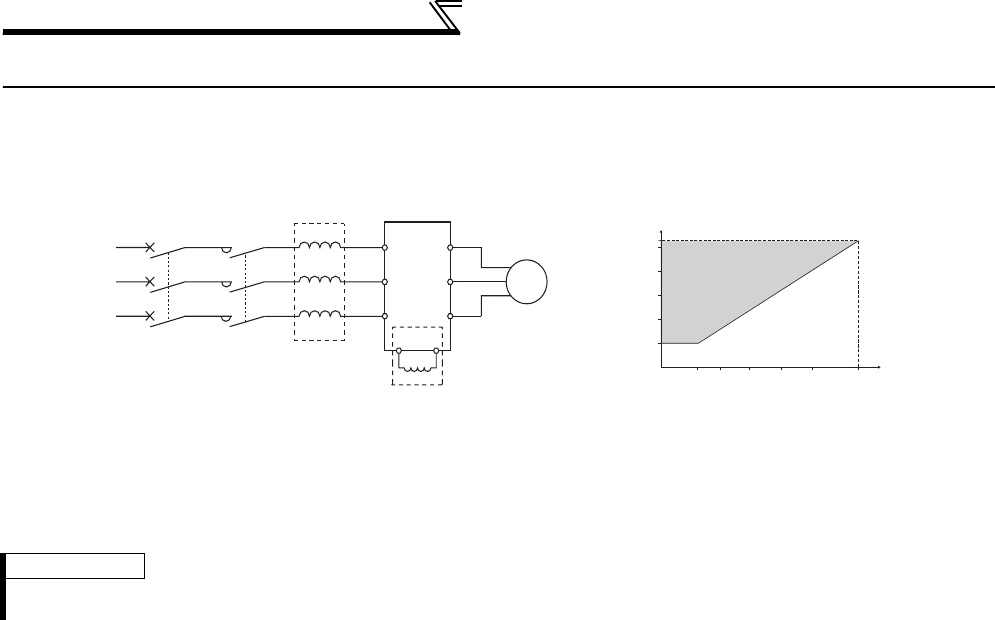
Installation of a reactor
60
3.2 Installation of a reactor
When the inverter is connected near a large-capacity power transformer (1000kVA or more) or when a power capacitor
is to be switched over, an excessive peak current may flow in the power input circuit, damaging the converter circuit. To
prevent this, always install the optional AC reactor (FR-HAL)
REMARKS
The wiring length between the FR-HEL and inverter should be 5m maximum and minimized. Use the same wire size as that of the
power supply wire (R/L1, S/L2, T/L3). (Refer to page 19)
MCCB MC Inverter
AC reactor
(FR-HAL)
Power
supply
R
S
TZ
Y
XU
V
W
P1
DC reactor (FR-HEL) *
R/L1
S/L2
T/L3
P/+
IM
5000
5300
4000
3000
2000
1000
110165 247 330 420 550 kV
A
Capacities requiring
installation of
AC reactor
Inverter capacity
Power supply system
capacity
(kVA)
* When connecting the FR-HEL to the 55K or lower, remove the jumper across terminals P/+ and P1. For the 75K or higher, a DC
reactor is supplied. Always install the reactor.
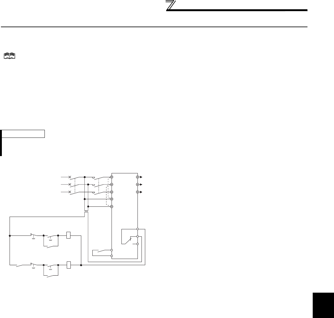
61
Power-off and magnetic contactor (MC)
3
PRECAUTIONS FOR USE OF THE INVERTER
3.3 Power-off and magnetic contactor (MC)
(1) Inverter input side magnetic contactor (MC)
On the inverter input side, it is recommended to provide an MC for the following purposes.
(Refer to page 4 for selection.)
1)To release the inverter from the power supply when a fault occurs or when the drive is not functioning (e.g.
emergency stop operation). For example, MC avoids overheat or burnout of the brake resistor when heat capacity of
the resistor is insufficient or brake regenerative transistor is damaged with short while connecting an optional brake
resistor.
2)
To prevent any accident due to an automatic restart at restoration of power after an inverter stop made by a power failure
3)To separate the inverter from the power supply to ensure safe maintenance and inspection work
If using an MC for emergency stop during operation, select an MC regarding the inverter input side current as
JEM1038-AC-3 class rated current.
(2) Handling of the inverter output side magnetic contactor
Switch the magnetic contactor between the inverter and motor only when both the inverter and motor are at a stop.
When the magnetic contactor is turned ON while the inverter is operating, overcurrent protection of the inverter and
such will activate. When an MC is provided to switch to a commercial power supply, for example, it is recommended to
use bypass operation Pr. 135 to Pr. 139 (Refer to page 369).
REMARKS
Since repeated inrush currents at power ON will shorten the life of the converter circuit (switching life is about 1,000,000 times.
(For the 200V class 30K or higher, switching life is about 500,000)), frequent starts and stops of the MC must be avoided. Turn on/
off the inverter start controlling terminals (STF, STR) to run/stop the inverter.
• Inverter start/stop circuit example
As shown on the left, always use the start signal (ON or
OFF of STF (STR) signal) to make a start or stop. (Refer
to page 236)
*1 When the power supply is 400V class, install a step-down
transformer.
*2 Connect the power supply terminals R1/L11, S1/L21 of the
control circuit to the primary side of the MC to hold an
alarm signal when the inverter's protective circuit is
activated. At this time, remove jumpers across terminals R/
L1 and R1/L11 and S/L2 and S1/L21. (Refer to page 23 for
removal of the jumper.)
Power
supply
MCCB
RA
U
V
A1
B1
C1
W
To the
motor
Inverter
MC
STF/STR
R/L1
S/L2
T/L3
R1/L11
S1/L21
OFF ON
MC
Stop
Start
RA
MC
Operation preparation
Start/Stop
MC
RA
T
*1
*2
SD

62
Inverter-driven 400V class motor
3.4 Inverter-driven 400V class motor
In the PWM type inverter, a surge voltage attributable to wiring constants is generated at the motor terminals.
Especially for a 400V class motor, the surge voltage may deteriorate the insulation. When the 400V class motor is
driven by the inverter, consider the following measures:
zMeasures
It is recommended to take either of the following measures:
(1) Rectifying the motor insulation and limiting the PWM carrier frequency according to the wiring length
For the 400V class motor, use an insulation-enhanced motor.
Specifically,
1)Specify the "400V class inverter-driven insulation-enhanced motor".
2)For the dedicated motor such as the constant-torque motor and low-vibration motor, use the "inverter-driven,
dedicated motor".
3)Set Pr. 72 PWM frequency selection as indicated below according to the wiring length
(2) Suppressing the surge voltage on the inverter side
Connect the surge voltage suppression filter (FR-ASF-H/FR-BMF-H) to the 55K or lower and the sine wave filter
(MT-BSL/BSC) to the 75K or higher on the inverter output side.
Wiring Length
50m or less 50m to 100m exceeding 100m
Pr. 72 PWM frequency selection 15 (14.5kHz) or less 9 (9kHz) or less 4 (4kHz) or less
CAUTION
· For details of Pr. 72 PWM frequency selection , refer to page 284. (When using an option sine wave filter (MT-BSL/BSC) for the 75K
or higher, set "25" (2.5kHz) in Pr. 72. )
· For explanation of surge voltage suppression filter (FR-ASF-H/FR-BMF-H) and sine wave filter (MT-BSL/BSC), refer to the
manual of each option.
· The surge voltage suppression filter (FR-ASF-H/FR-BMF-H) can be used under V/F control and Advanced magnetic flux vector
control. The sine wave filter (MT-BSL/BSC) can be used under V/F control.

3
PRECAUTIONS FOR USE OF THE INVERTER
63
Precautions for use of the inverter
3.5 Precautions for use of the inverter
The FR-A700 series is a highly reliable product, but using incorrect peripheral circuits or incorrect operation/handling
methods may shorten the product life or damage the product.
Before starting operation, always recheck the following items.
(1) Use crimping terminals with insulation sleeve to wire the power supply and motor.
(2) Application of power to the output terminals (U, V, W) of the inverter will damage the inverter. Never perform
such wiring.
(3) After wiring, wire offcuts must not be left in the inverter.
Wire offcuts can cause an alarm, failure or malfunction. Always keep the inverter clean. When drilling mounting holes in
an enclosure etc., take care not to allow chips and other foreign matter to enter the inverter.
(4) Use cables of the size to make a voltage drop 2% maximum.
If the wiring distance is long between the inverter and motor, a main circuit cable voltage drop will cause the motor torque
to decrease especially at the output of a low frequency.
Refer to page 19 for the recommended cable sizes.
(5) The total wiring length should be within the prescribed length.
Especially for long distance wiring, the fast-response current limit function may decrease, or the equipment connected to
the secondary side may malfunction. This is caused by a charging current due to the stray capacity of the wiring. Therefore,
note the overall wiring length. (Refer to page 22.)
(6) Electromagnetic wave interference
The input/output (main circuit) of the inverter includes high frequency components, which may interfere with the
communication devices (such as AM radios) used near the inverter. In this case, set the noise filter valid to minimize
interference.
(7) Do not install a power factor correction capacitor, surge suppressor or radio noise filter on the inverter output
side.
This will cause the inverter to trip or the capacitor, and surge suppressor to be damaged. If any of the above devices is
installed, immediately remove it.
(8) For some short time after the power is switched OFF, a high voltage remains in the smoothing capacitor.
When accessing the inverter for inspection, wait for at least 10 minutes after the power supply has been switched OFF,
and then make sure that the voltage across the main circuit terminals P/+ and N/- of the inverter is not more than 30VDC
using a tester.
(9) A short circuit or earth (ground) fault on the inverter output side may damage the inverter modules.
· Fully check the insulation resistance of the circuit prior to inverter operation since repeated short circuits may damage
the inverter modules. These short circuits may be caused by peripheral circuit inadequacy, an earth (ground) fault
caused by wiring inadequacy, or reduced motor insulation resistance.
· Fully check the to-earth (ground) insulation and phase to phase insulation of the inverter output side before power-on.
Especially for an old motor or use in a hostile atmosphere, securely check the motor insulation resistance etc.
(10) Do not use the inverter input side magnetic contactor to start/stop the inverter.
Since repeated inrush currents at power ON will shorten the life of the converter circuit (switching life is about 1,000,000
times. (For the 200V class 30K or higher, switching life is about 500,000)), frequent starts and stops of the MC must be
avoided.
Always use the start signal (ON/OFF of STF and STR signals) to start/stop the inverter.
(11) Across P/+ and PR terminals, connect only an external regenerative brake discharge resistor.
Do not connect a mechanical brake.
(12) Do not apply a voltage higher than the permissible voltage to the inverter I/O signal circuits.
Application of a voltage higher than the permissible voltage to the inverter I/O signal circuits or opposite polarity may
damage the I/O devices. Especially check the wiring to prevent the speed setting potentiometer from being connected
incorrectly to short across terminals 10E and 5.
(Refer to page 15)
(Refer to page 61)

64
Precautions for use of the inverter
(13) Provide electrical and mechanical interlocks for MC1 and
MC2 which are used for bypass operation.
When the wiring is incorrect or if there is an electronic bypass
circuit as shown on the right, the inverter will be damaged by
leakage current from the power supply when it is connected to
the inverter U, V, W terminals due to arcs generated at the time
of switch-over or chattering caused by a sequence error.
(Commercial operation cannot be performed with the vector
dedicated motor (SF-V5RU, SF-THY).)
(14) If the machine must not be restarted when power is restored after a power failure, provide a magnetic contactor
in the inverter's input side and also make up a sequence which will not switch ON the start signal.
If the start signal (start switch) remains ON after a power failure, the inverter will automatically restart as soon as the
power is restored.
(15) A motor with encoder is necessary for vector control. In addition, connect the encoder directly to the backlash-
free motor shaft. (An encoder is not necessary for Real sensorless vector control.)
(16) Inverter input side magnetic contactor (MC)
On the inverter input side, connect a MC for the following purposes. (Refer to page 4 for selection.)
1)To release the inverter from the power supply when a fault occurs or when the drive is not functioning (e.g. emergency
stop operation). For example, MC avoids overheat or burnout of the brake resistor when heat capacity of the resistor is
insufficient or brake regenerative transistor is damaged with short while connecting an optional brake resistor.
2)To prevent any accident due to an automatic restart at restoration of power after an inverter stop made by a power
failure
3)To separate the inverter from the power supply to ensure safe maintenance and inspection work.
If using an MC for emergency stop during operation, select an MC regarding the inverter input side current as
JEM1038-AC-3 class rated current.
(17) Handling of inverter output side magnetic contactor
Switch the magnetic contactor between the inverter and motor only when both the inverter and motor are at a stop. When
the magnetic contactor is turned ON while the inverter is operating, overcurrent protection of the inverter and such will
activate. When MC is provided for switching to the commercial power supply, for example, switch it ON/OFF after the
inverter and motor have stopped.
(18) Countermeasures against inverter-generated EMI
If electromagnetic noise generated from the inverter causes frequency setting signal to fluctuate and motor
rotation speed to be unstable when changing motor speed with analog signal, the following countermeasures are
effective.
· Do not run the signal cables and power cables (inverter I/O cables) in parallel with each other and do not bundle them.
· Run signal cables as far away as possible from power cables (inverter I/O cables).
· Use shield cables as signal cables.
· Install a ferrite core on the signal cable (Example: ZCAT3035-1330 TDK).
(19) Instructions for overload operation
When performing an operation of frequent start/stop with the inverter, rise/fall in the temperature of the transistor element
of the inverter will repeat due to a continuous flow of large current, shortening the life from thermal fatigue. Since thermal
fatigue is related to the amount of current, the life can be increased by reducing current at locked condition, starting
current, etc. Decreasing current may increase the life. However, decreasing current will result in insufficient torque and
the inverter may not start. Therefore, choose the inverter which has enough allowance for current (up to 2 rank larger in
capacity).
(20) Make sure that the specifications and rating match the system requirements.
Power
supply
Inverter
Undesirable current
MC2
MC1 Interlock
U
V
W
R/L1
S/L2
T/L3
IM
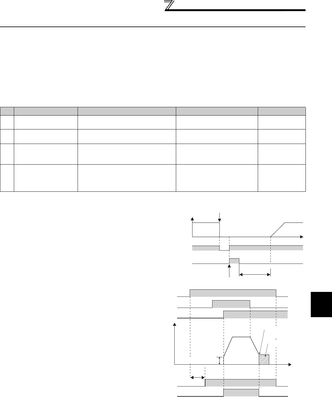
3
PRECAUTIONS FOR USE OF THE INVERTER
65
Failsafe of the system which uses
the inverter
3.6 Failsafe of the system which uses the inverter
When a fault occurs, the inverter trips to output a fault signal. However, a fault output signal may not be output at an inverter
fault occurrence when the detection circuit or output circuit fails, etc. Although Mitsubishi assures best quality products,
provide an interlock which uses inverter status output signals to prevent accidents such as damage to machine when the
inverter fails for some reason and at the same time consider the system configuration where failsafe from outside the inverter,
without using the inverter, is enabled even if the inverter fails.
(1) Interlock method which uses the inverter status output signals
By combining the inverter status output signals to provide an interlock as shown below, an inverter alarm can be
detected.
No. Interlock Method Check Method Used signals Refer to Page
1) Inverter protective
function operation
Operation check of an alarm contact
Circuit error detection by negative logic
Fault output signal
ALM signal 239
2) Inverter running status Operation ready signal check Operation ready signal
(RY signal) 239
3) Inverter running status Logic check of the start signal and
running signal
Start signal
(STF signal, STR signal)
Running signal (RUN signal)
231, 239
4) Inverter running status Logic check of the start signal and
output current
Start signal
(STF signal, STR signal)
Output current detection signal
Y12 signal
239, 248
1) Checking by the output of the inverter fault signal
When the inverter's protective function activates and the
inverter trips, the fault output signal (ALM signal) is output.
(ALM signal is assigned to terminal A1B1C1 in the initial
setting).
With this signal, you can check if the inverter is operating
properly.
In addition, negative logic can be set (ON when the inverter
is normal, OFF when the fault occurs).
2) Checking the inverter operating status by the inverter
operation ready completion signal
Operation ready signal (RY signal) is output when the
inverter power is ON and the inverter becomes operative.
Check if the RY signal is output after powering ON the
inverter.
3) Checking the inverter operating status by the start signal
input to the inverter and inverter running signal.
The inverter running signal (RUN signal) is output when the
inverter is running (RUN signal is assigned to terminal RUN
in the initial setting).
Check if RUN signal is output when inputting the start signal
to the inverter (forward signal is STF signal and reverse
signal is STR signal). For logic check, note that RUN signal
is output for the period from the inverter decelerates until
output to the motor is stopped, configure a sequence
considering the inverter deceleration time
ON
Reset processing
(about 1s)
OFF
Reset ON
Output frequency
ALM
(when output
at NC contact)
RES
Inverter fault occurrence
(trip)
Time
OFF
ON
Time
Power
supply
Output frequency
STF
RH
RY
Reset
processing
Pr. 13 Starting frequency
ON OFF
ON OFF
ON OFF
ON
DC injection brake
operation point
DC injection
brake operation
RUN ON OFF
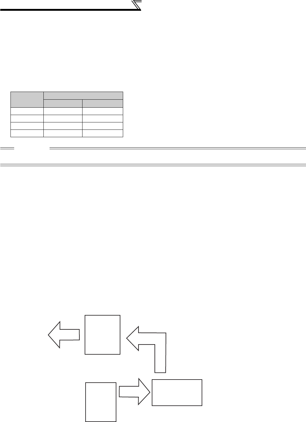
66
Failsafe of the system which uses the
inverter
(2) Backup method outside the inverter
Even if the interlock is provided by the inverter status signal, enough failsafe is not ensured depending on the failure
status of the inverter itself. For example, when the inverter CPU fails, even if the interlock is provided using the inverter
fault signal, start signal and RUN signal, there is a case where a fault signal is not output and RUN signal is kept output
even if an inverter fault occurs.
Provide a speed detector to detect the motor speed and current detector to detect the motor current and consider the
backup system such as checking up as below according to the level of importance of the system.
1) Start signal and actual operation check
Check the motor running and motor current while the start signal is input to the inverter by comparing the start signal to
the inverter and detected speed of the speed detector or detected current of the current detector. Note that the motor
current runs as the motor is running for the period until the motor stops since the inverter starts decelerating even if the
start signal turns off. For the logic check, configure a sequence considering the inverter deceleration time. In addition, it is
recommended to check the three-phase current when using the current detector.
2) Command speed and actual operation check
Check if there is no gap between the actual speed and commanded speed by comparing the inverter speed command
and detected speed of the speed detector.
4) Checking the motor operating status by the start signal input to the inverter and inverter output current detection signal.
The output current detection signal (Y12 signal) is output when the inverter operates and currents flows in the motor.
Check if Y12 signal is output when inputting the start signal to the inverter (forward signal is STF signal and reverse
signal is STR signal). Note that the current level at which Y12 signal is output is set to 150% of the inverter rated current
in the initial value, it is necessary to adjust the level to around 20% using no load current of the motor as reference with
Pr.150 Output current detection level.
For logic check, as same as the inverter running signal (RUN signal), the inverter outputs for the period from the inverter
decelerates until output to the motor is stopped, configure a sequence considering the inverter deceleration time.
Output
signal
Pr. 190 to Pr. 196 Setting
yWhen using various signals, assign functions to Pr. 190 to Pr.
196 (output terminal function selection) referring to the table on
the left.
Positive logic Negative logic
ALM 99 199
RY 11 111
RUN 0 100
Y12 12 112
CAUTION
⋅Changing the terminal assignment using Pr. 190 to Pr. 196 (output terminal function selection) may affect the other functions. Make
setting after confirming the function of each terminal.
Inverter
Controller
System failure
To the alarm detection sensor
Sensor
(speed, temperature,
air volume, etc.)

67
3
4
5
6
7
1
2
4
PARAMETERS
The following marks are used to indicate the controls
as below.
.... V/F control
.. Advanced magnetic flux vector control
.... Real sensorless vector control
.... Vector control
(Parameters without any mark are valid for all control.)
This chapter explains the "PARAMETERS" for use of this
product.
Always read this instructions before use.
V/F
V/F
V/F
Magnetic flux
Magnetic flux
Magnetic flux
Sensorless
Sensorless
Sensorless
Vector
Vector
Vector
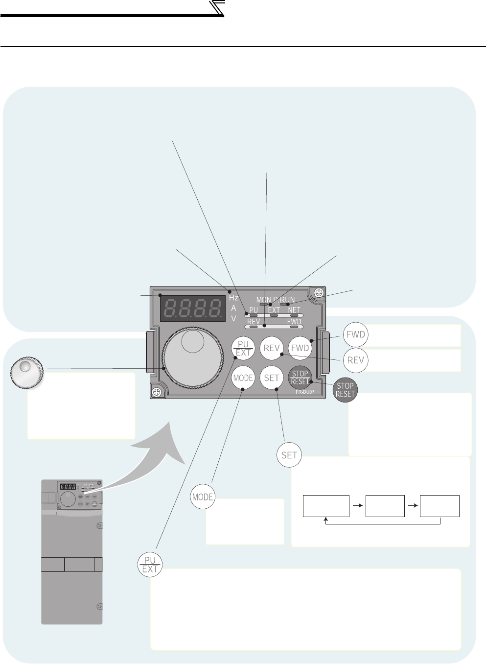
68
Operation panel (FR-DU07)
4.1 Operation panel (FR-DU07)
4.1.1 Parts of the operation panel (FR-DU07)
Setting dial
(Setting dial: Mitsubishi inverter
dial)
Used to change the
frequency setting and
parameter settings.
Operation mode switchover
Used to switch between the PU and External operation mode.
When using the External operation mode (operation using a separately
connected frequency setting potentiometer and start signal), press this key to
light up the EXT indicator. (Change the Pr.79 value to use the combined mode.)
PU: PU operation mode
EXT: External operation mode
Monitor (4-digit LED)
Shows the frequency, parameter
number, etc.
Monitor indicator
Lit to indicate monitoring mode.
PU: Lit to indicate PU operation mode.
EXT: Lit to indicate External operation mode.
NET: Lit to indicate Network operation mode.
Rotation direction indicator
REV: Lit when reverse rotation
FWD: Lit when forward rotation
Start command
forward rotation
Start command
reverse rotation
Stop operation
Used to stop Run
command.
Fault can be reset when
protective function is
activated (fault).
Mode
switchover
Used to change
each setting mode.
Unit indicator
· Hz: Lit to indicate frequency.
· A: Lit to indicate current.
· V: Lit to indicate voltage.
(Flicker when the set frequency monitor is
displayed.)
* Energy saving monitor is displayed when the
energy saving monitor of Pr. 52 is set.
Used to set each setting.
If pressed during operation, monitor
changes as below.
Running
frequency Output
current Output
voltage
Operation mode indicator
On: Forward/reverse operation
Flickering: When the frequency command is
not given even if the
forward/reverse command is given.
When the MRS signal is input.
*
No function
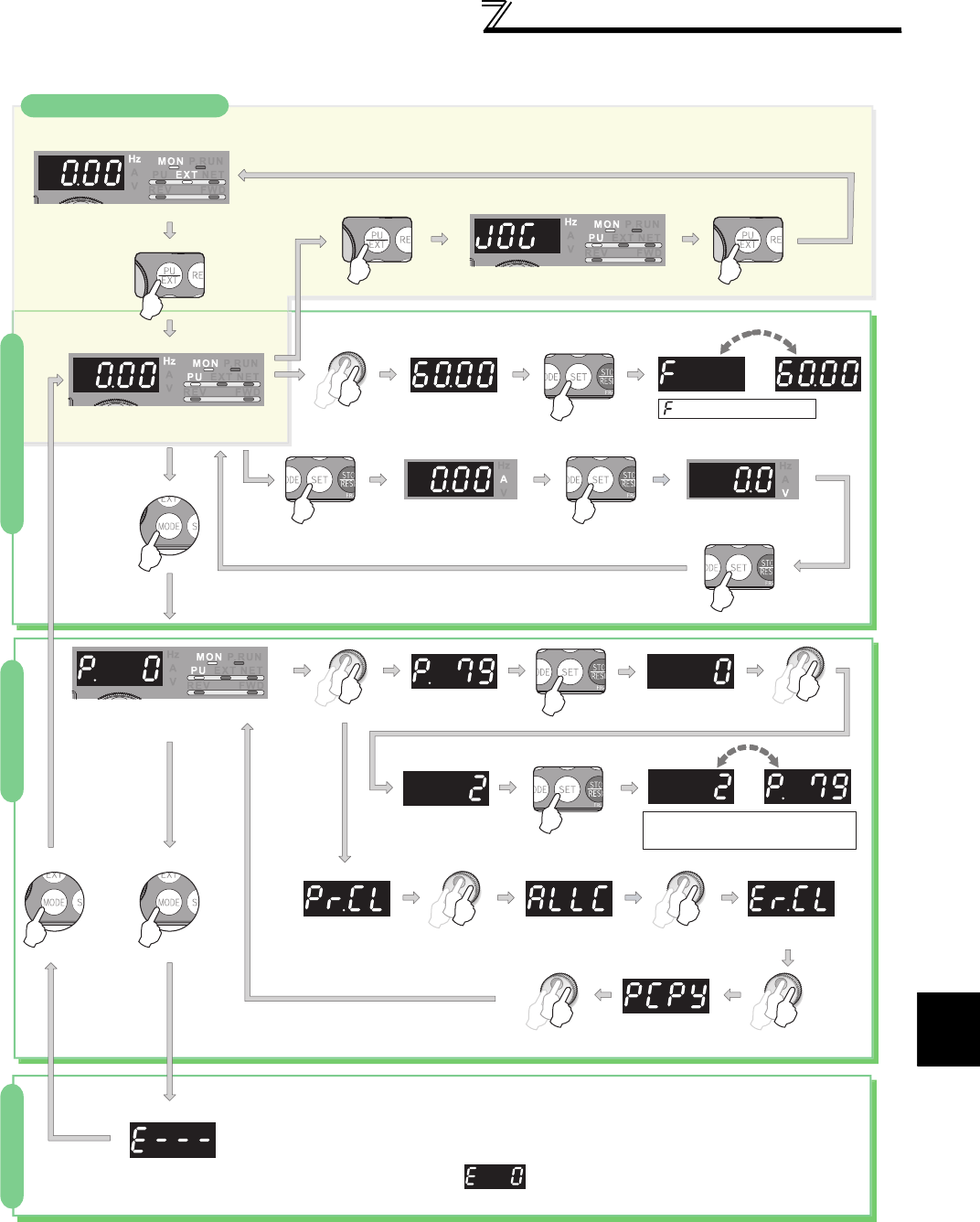
69
Operation panel (FR-DU07)
4
PARAMETERS
4.1.2 Basic operation (factory setting)
At power-ON (External operation mode)
PU operation mode
(output frequency monitor)
Parameter setting mode
PU Jog operation mode
Output current monitor Output voltage monitor
Display the present
setting
Value change
Value change
Parameter write is completed!!
Parameter and a setting value
flicker alternately.
Parameter clear All parameter
clear
Faults history clear
Parameter copy
(Example)
(Example)
Frequency setting has been
written and completed!!
and frequency flicker.
[Operation for displaying faults history]
Past eight faults can be displayed.
(The latest fault is ended by ".".)
When no fault history exists, is displayed.
Operation mode switchover
Parameter settingFaults history Monitor/frequency setting
(Refer to page 399)
(Refer to page 70)
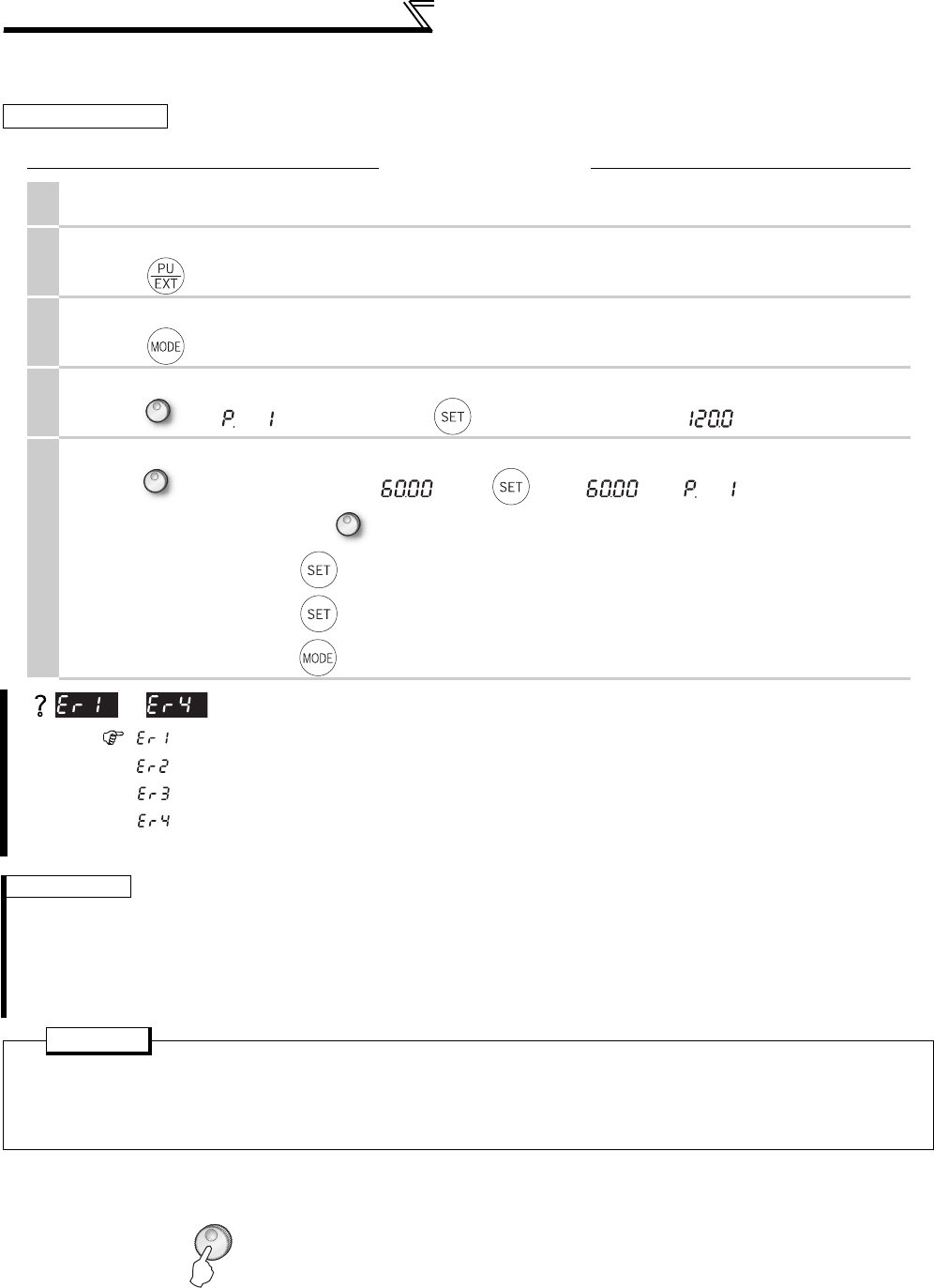
70
Operation panel (FR-DU07)
4.1.3 Changing the parameter setting value
4.1.4 Displaying the set frequency
Press the setting dial ( ) in the PU operation mode or in the External/PU combined operation mode 1 (Pr. 79 =
"3") to show the set frequency.
Changing example Change the Pr. 1 Maximum frequency .
Operation
1. Screen at power-ON
The monitor display appears.
2.
Operation mode change
Press to choose the PU operation mode. [PU] indicator is lit.
3.
Parameter setting mode
Press to choose the parameter setting mode. (The parameter number read previously appears.)
4.
Selecting the parameter
Turn until (Pr. 1) appears. Press to read the present set value. " " (initial value) appears.
5.
Changing the setting value
Turn to change it to the set value " ". Press to set. " " and " " flicker alternately.
·By turning , you can read another parameter.
·Press to show the setting again.
·Press twice to show the next parameter.
·Press twice to return the monitor to frequency monitor.
are displayed ... Why?
appears. ......Write disable error
appears. ......Write error during operation
appears. ......Calibration error
appears. ......Mode designation error
For details refer to page 404.
REMARKS
⋅The number of digits displayed on the operation panel (FR-DU07) is four.
If the values to be displayed have five digits or more including decimal places, the fifth or later numerals cannot be displayed nor
set.
(Example) When Pr. 1
When 60Hz is set, 60.00 is displayed.
When 120Hz is set, 120.0 is displayed and second decimal place is not displayed nor set.
POINT
When Pr.77 Parameter write selection = "0 (initial value)," the parameter setting change is only available while the
inverter is stopped under the PU operation mode.
To enable the parameter setting change while the inverter is running or under the operation mode other than PU
operation mode, change the Pr.77 setting
to

71
Parameter List
Parameter List
4
PARAMETERS
4.2 Parameter List
4.2.1 Parameter list
For simple variable-speed operation of the inverter, the initial value of the parameters may be used as they are. Set the
necessary parameters to meet the load and operational specifications. Parameter setting, change and check can be made
from the operation panel (FR-DU07).
REMARKS
⋅ indicates simple mode parameters. (initially set to extended mode)
⋅The shaded parameters in the table allow its setting to be changed during operation even if "0" (initial value) is set in Pr. 77 Parameter write
selection.
⋅Refer to Appendix 2 (page 466) for instruction codes for communication and availability of parameter clear, all clear, and parameter copy of
each parameter.
⋅Parameters with have different specifications according to the date assembled. Refer to page 484 to check the SERIAL number.
Func-
tion
Parameter
Name Setting Range
Minimum
Setting
Increments
Initial Value
Refer
to
Page
Customer
Setting
Basic functions
0 Torque boost 0 to 30% 0.1% 6/4/3/2/1% *1 146
1 Maximum frequency 0 to 120Hz 0.01Hz 120/60Hz *2 157
2 Minimum frequency 0 to 120Hz 0.01Hz 0Hz 157
3 Base frequency 0 to 400Hz 0.01Hz 60Hz 159
4 Multi-speed setting (high speed) 0 to 400Hz 0.01Hz 60Hz 165
5 Multi-speed setting (middle speed) 0 to 400Hz 0.01Hz 30Hz 165
6 Multi-speed setting (low speed) 0 to 400Hz 0.01Hz 10Hz 165
7 Acceleration time 0 to 3600/360s 0.1/0.01s 5/15s *3 172
8 Deceleration time 0 to 3600/360s 0.1/0.01s 5/15s *3 172
9 Electronic thermal O/L relay 0 to 500/0 to 3600A *2 0.01
/0.1
A
*2
Rated inverter
current 183
DC injection
brake
10 DC injection brake operation frequency 0 to 120Hz, 9999 0.01Hz 3Hz 203
11 DC injection brake operation time 0 to 10s, 8888 0.1s 0.5s 203
12 DC injection brake operation voltage 0 to 30% 0.1% 4/2/1%*4 203
⎯13 Starting frequency 0 to 60Hz 0.01Hz 0.5Hz 175
⎯14 Load pattern selection 0 to 5 1 0 161
Jog
operation
15 Jog frequency 0 to 400Hz 0.01Hz 5Hz 167
16 Jog acceleration/deceleration time 0 to 3600/360s 0.1/0.01s 0.5s 167
⎯17 MRS input selection 0, 2, 4 1 0 234
⎯18 High speed maximum frequency 120 to 400Hz 0.01Hz 120/60Hz *2 157
⎯19 Base frequency voltage 0 to 1000V, 8888, 9999 0.1V 9999 159
Acceleration/
deceleration
times
20 Acceleration/deceleration reference
frequency 1 to 400Hz 0.01Hz 60Hz 172
21 Acceleration/deceleration time
increments 0, 1 1 0 172
Stall
prevention
22 Stall prevention operation level
(torque limit level ) 0 to 400% 0.1% 150% 100,
152
23 Stall prevention operation level
compensation factor at double speed 0 to 200%, 9999 0.1% 9999 152
Multi-speed
setting
24 to 27 Multi-speed setting(4 speed to 7 speed) 0 to 400Hz, 9999 0.01Hz 9999 165
⎯28 Multi-speed input compensation selection 0, 1 1 0 169
⎯29 Acceleration/deceleration pattern
selection 0 to 5 1 0 176
⎯30 Regenerative function selection
0, 1, 2, 10, 11, 20, 21
1 0 207
Frequency
jump
31 Frequency jump 1A 0 to 400Hz, 9999 0.01Hz 9999 158
32 Frequency jump 1B 0 to 400Hz, 9999 0.01Hz 9999 158
33 Frequency jump 2A 0 to 400Hz, 9999 0.01Hz 9999 158
34 Frequency jump 2B 0 to 400Hz, 9999 0.01Hz 9999 158
35 Frequency jump 3A 0 to 400Hz, 9999 0.01Hz 9999 158
36 Frequency jump 3B 0 to 400Hz, 9999 0.01Hz 9999 158
⎯37 Speed display 0, 1 to 9998 1 0 251

72
Parameter List
Parameter List
Frequency
detection
41 Up-to-frequency sensitivity 0 to 100% 0.1% 10% 246
42 Output frequency detection 0 to 400Hz 0.01Hz 6Hz 246
43 Output frequency detection for reverse
rotation 0 to 400Hz, 9999 0.01Hz 9999 246
Second functions
44 Second acceleration/deceleration time 0 to 3600/360s 0.1/0.01s 5s 172
45 Second deceleration time 0 to 3600/360s, 9999 0.1/0.01s 9999 172
46 Second torque boost 0 to 30%, 9999 0.1% 9999 146
47 Second V/F (base frequency) 0 to 400Hz, 9999 0.01Hz 9999 159
48 Second stall prevention operation
current 0 to 220% 0.1% 150% 152
49 Second stall prevention operation
frequency 0 to 400Hz, 9999 0.01Hz 0Hz 152
50 Second output frequency detection 0 to 400Hz 0.01Hz 30Hz 246
51 Second electronic thermal O/L relay 0 to 500A, 9999/
0 to 3600A, 9999 *2 0.01/0.1A *2 9999 183
Monitor functions
52 DU/PU main display data selection
0, 5 to 14, 17 to 20,
22 to 25, 32 to 35, 39, 46,
50 to 57, 100
1 0 253
54 FM terminal function selection
1 to 3, 5 to 14, 17, 18,
21, 24, 32 to 34, 46, 50,
52, 53
1 1 253
55 Frequency monitoring reference 0 to 400Hz 0.01Hz 60Hz 259
56 Current monitoring reference 0 to 500/0 to 3600A *2 0.01/0.1A *2 Rated inverter
current 259
Automatic restart
57 Restart coasting time 0, 0.1 to 5s, 9999/
0, 0.1 to 30s, 9999 *2 0.1s 9999 266
58 Restart cushion time 0 to 60s 0.1s 1s 266
⎯59 Remote function selection 0, 1, 2, 3 1 0 169
⎯60 Energy saving control selection 0, 4 1 0 278
Automatic acceleration/
deceleration
61 Reference current 0 to 500A, 9999/
0 to 3600A, 9999 *2 0.01A/0.1A *2 9999 163,
180
62 Reference value at acceleration 0 to 220%, 9999 0.1% 9999 180
63 Reference value at deceleration 0 to 220%, 9999 0.1% 9999 180
64 Starting frequency for elevator mode 0 to 10Hz, 9999 0.01Hz 9999 163
⎯65 Retry selection 0 to 5 1 0 273
⎯66 Stall prevention operation reduction
starting frequency 0 to 400Hz 0.01Hz 60Hz 152
Retry
67 Number of retries at fault occurrence 0 to 10, 101 to 110 1 0 273
68 Retry waiting time 0 to 10s 0.1s 1s 273
69 Retry count display erase 01 0 273
⎯70 Special regenerative brake duty 0 to 30%/0 to 10% *2 0.1% 0% 207
⎯71 Applied motor
0 to 8, 13 to 18, 20, 23,
24, 30, 33, 34, 40, 43, 44,
50, 53, 54
1 0 148,
187
⎯72 PWM frequency selection 0 to 15/0 to 6, 25 *2 1 2 284
⎯73 Analog input selection 0 to 7, 10 to 17 1 1 290
⎯74 Input filter time constant 0 to 8 1 1 292
⎯75 Reset selection/disconnected PU
detection/PU stop selection 0 to 3, 14 to 17 114 305
⎯76 Fault code output selection 0, 1, 2 1 0 275
⎯77 Parameter write selection 0, 1, 2 1 0 307
⎯78 Reverse rotation prevention selection 0, 1, 2 1 0 308
⎯ 79 Operation mode selection 0, 1, 2, 3, 4, 6, 7 1 0 313
Func-
tion
Parameter
Name Setting Range
Minimum
Setting
Increments
Initial Value
Refer
to
Page
Customer
Setting

73
Parameter List
Parameter List
4
PARAMETERS
Motor constants
80 Motor capacity 0.4 to 55kW, 9999/
0 to 3600kW, 9999 *2 0.01/0.1kW *2 9999 148,
189
81 Number of motor poles 2, 4, 6, 8, 10, 12, 14, 16,
18, 20, 9999 19999 148,
189
82 Motor excitation current 0 to 500A, 9999/
0 to 3600A, 9999 *2
0.01/0.1A
*2 9999 189
83 Rated motor voltage 0 to 1000V 0.1V 200/400V *5 189
84 Rated motor frequency 10 to 120Hz 0.01Hz 60Hz 189
89
Speed control gain (Advanced magnetic
flux vector)
0 to 200%, 9999 0.1% 9999 148
90 Motor constant (R1) 0 to 50Ω, 9999/
0 to 400mΩ, 9999 *2
0.001Ω/
0.01mΩ *2 9999 189
91 Motor constant (R2) 0 to 50Ω, 9999/
0 to 400mΩ, 9999 *2
0.001Ω/
0.01mΩ *2 9999 189
92 Motor constant (L1)
0 to 50
Ω
(0 to 1000mH), 9999
/
0 to 3600m
Ω
(0 to 400mH), 9999
*2
0.001
Ω
(0.1mH)/
0.01m
Ω
(0.01mH)
*2
9999 189
93 Motor constant (L2)
0 to 50
Ω
(0 to 1000mH), 9999
/
0 to 3600m
Ω
(0 to 400mH), 9999
*2
0.001
Ω
(0.1mH)/
0.01m
Ω
(0.01mH)
*2
9999 189
94 Motor constant (X)
0 to 500
Ω
(0 to 100%), 9999/
0 to 100
Ω
(0 to 100%), 9999
*2
0.01Ω (0.1%)/
0.01Ω (0.01%)
*2
9999 189
95 Online auto tuning selection 0 to 2 1 0 199
96 Auto tuning setting/status 0, 1, 101 1 0 189
Adjustable 5 points V/F
100 V/F1(first frequency) 0 to 400Hz, 9999 0.01Hz 9999 164
101 V/F1(first frequency voltage) 0 to 1,000V 0.1V 0V 164
102 V/F2(second frequency) 0 to 400Hz, 9999 0.01Hz 9999 164
103 V/F2(second frequency voltage) 0 to 1,000V 0.1V 0V 164
104 V/F3(third frequency) 0 to 400Hz, 9999 0.01Hz 9999 164
105 V/F3(third frequency voltage) 0 to 1,000V 0.1V 0V 164
106 V/F4(fourth frequency) 0 to 400Hz, 9999 0.01Hz 9999 164
107 V/F4(fourth frequency voltage) 0 to 1,000V 0.1V 0V 164
108 V/F5(fifth frequency) 0 to 400Hz, 9999 0.01Hz 9999 164
109 V/F5(fifth frequency voltage) 0 to 1,000V 0.1V 0V 164
Third functions
110 Third acceleration/deceleration time 0 to 3600/360s, 9999 0.1/0.01s 9999 172
111 Third deceleration time 0 to 3600/360s, 9999 0.1/0.01s 9999 172
112 Third torque boost 0 to 30%, 9999 0.1% 9999 146
113 Third V/F (base frequency) 0 to 400Hz, 9999 0.01Hz 9999 159
114 Third stall prevention operation current 0 to 220% 0.1% 150% 152
115 Third stall prevention operation
frequency 0 to 400Hz 0.01Hz 0Hz 152
116 Third output frequency detection 0 to 400Hz 0.01Hz 60Hz 246
PU connector
communication
117 PU communication station number 0 to 31 1 0 333
118 PU communication speed 48, 96, 192, 384 1192 333
119 PU communication stop bit length 0, 1, 10, 11 1 1 333
120 PU communication parity check 0, 1, 2 1 2 333
121 Number of PU communication retries 0 to10, 9999 1 1 333
122 PU communication check time interval 0, 0.1 to 999.8s, 9999 0.1s 9999 333
123 PU communication waiting time setting 0 to 150ms, 9999 1ms 9999 333
124 PU communication CR/LF selection 0, 1, 2 1 1 333
⎯ 125 Terminal 2 frequency setting gain
frequency 0 to 400Hz 0.01Hz 60Hz 294
⎯ 126 Terminal 4 frequency setting gain
frequency 0 to 400Hz 0.01Hz 60Hz 294
Func-
tion
Parameter
Name Setting Range
Minimum
Setting
Increments
Initial Value
Refer
to
Page
Customer
Setting

74
Parameter List
Parameter List
PID operation
127 PID control automatic switchover
frequency 0 to 400Hz, 9999 0.01Hz 9999 361
128 PID action selection 10, 11, 20, 21, 50, 51, 60,
61 110 361
129 PID proportional band 0.1 to 1000%, 9999 0.1% 100% 361
130 PID integral time 0.1 to 3600s, 9999 0.1s 1s 361
131 PID upper limit 0 to 100%, 9999 0.1% 9999 361
132 PID lower limit 0 to 100%, 9999 0.1% 9999 361
133 PID action set point 0 to 100%, 9999 0.01% 9999 361
134 PID differential time 0.01 to 10.00s, 9999 0.01s 9999 361
Bypass
135 Electronic bypass sequence selection 0, 1 1 0 369
136 MC switchover interlock time 0 to 100s 0.1s 1s 369
137 Start waiting time 0 to 100s 0.1s 0.5s 369
138 Bypass selection at a fault 0, 1 1 0 369
139 Automatic switchover frequency from
inverter to bypass operation 0 to 60Hz, 9999 0.01Hz 9999 369
Backlash
measures
140 Backlash acceleration stopping
frequency 0 to 400Hz 0.01Hz 1Hz 176
141 Backlash acceleration stopping time 0 to 360s 0.1s 0.5s 176
142 Backlash deceleration stopping
frequency 0 to 400Hz 0.01Hz 1Hz 176
143 Backlash deceleration stopping time 0 to 360s 0.1s 0.5s 176
⎯144 Speed setting switchover 0, 2, 4, 6, 8, 10, 102,
104, 106, 108, 110 1 4 251
PU
145 PU display language selection 0 to 7 1 0 393
⎯147 Acceleration/deceleration time
switching frequency 0 to 400Hz, 9999 0.01Hz 9999 172
Current detection
148 Stall prevention level at 0V input 0 to 220% 0.1% 150% 152
149 Stall prevention level at 10V input 0 to 220% 0.1% 200% 152
150 Output current detection level 0 to 220% 0.1% 150% 248
151 Output current detection signal delay
time 0 to 10s 0.1s 0s 248
152 Zero current detection level 0 to 220% 0.1% 5% 248
153 Zero current detection time 0 to 1s 0.01s 0.5s 248
⎯154 Voltage reduction selection during stall
prevention operation 0, 1 1 1 152
⎯155 RT signal function validity condition
selection 0, 10 1 0 235
⎯156 Stall prevention operation selection 0 to 31, 100, 101 1 0 152
⎯157 OL signal output timer 0 to 25s, 9999 0.1s 0s 100,
152
⎯158 AM terminal function selection
1 to 3, 5 to 14, 17, 18,
21, 24, 32 to 34, 46, 50,
52, 53
1 1 253
⎯159 Automatic switchover frequency range
from bypass to inverter operation 0 to 10Hz, 9999 0.01Hz 9999 369
⎯ 160 User group read selection 0, 1, 9999 1 0 308
⎯161 Frequency setting/key lock operation
selection 0, 1, 10, 11 1 0 393
Automatic restart
functions
162 Automatic restart after instantaneous
power failure selection 0, 1, 2, 10, 11, 12 1 0 266
163 First cushion time for restart 0 to 20s 0.1s 0s 266
164 First cushion voltage for restart 0 to 100% 0.1% 0% 266
165 Stall prevention operation level for
restart 0 to 220% 0.1% 150% 266
Func-
tion
Parameter
Name Setting Range
Minimum
Setting
Increments
Initial Value
Refer
to
Page
Customer
Setting
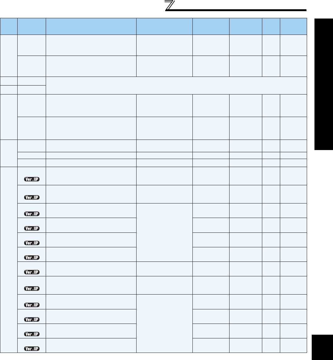
75
Parameter List
Parameter List
4
PARAMETERS
Current detection
166 Output current detection signal
retention time 0 to 10s, 9999 0.1s 0.1s 248
167 Output current detection operation
selection 0, 1 1 0 248
⎯168 Parameter for manufacturer setting. Do not set.
⎯169
Cumulative monitor
clear
170 Watt-hour meter clear 0, 10, 9999 19999 253
171 Operation hour meter clear 0, 9999 19999 253
User group
172 User group registered display/batch
clear 9999, (0 to 16) 1 0 308
173 User group registration 0 to 999, 9999 19999 308
174 User group clear 0 to 999, 9999 19999 308
Input terminal function assignment
178 STF terminal function selection
0 to 20, 22 to 28, 42 to
44, 60, 62, 64 to 71, 74,
83, 9999
160 231
179 STR terminal function selection
0 to 20, 22 to 28, 42 to 44,
61, 62, 64 to 71,
74, 83,
9999
161 231
180 RL terminal function selection
0 to 20, 22 to 28, 42 to
44, 62, 64 to 71, 74, 83,
9999
1 0 231
181 RM terminal function selection 1 1 231
182 RH terminal function selection 1 2 231
183 RT terminal function selection 1 3 231
184 AU terminal function selection 0 to 20, 22 to 28, 42 to
44, 62 to 71, 74, 83, 9999 1 4 231
185 JOG terminal function selection
0 to 20, 22 to 28, 42 to
44, 62, 64 to 71, 74, 76,
83, 9999
1 5 231
186 CS terminal function selection
0 to 20, 22 to 28, 42 to
44, 62, 64 to 71, 74, 83,
9999
1 6 231
187 MRS terminal function selection 124 231
188 STOP terminal function selection 125 231
189 RES terminal function selection 162 231
Func-
tion
Parameter
Name Setting Range
Minimum
Setting
Increments
Initial Value
Refer
to
Page
Customer
Setting

76
Parameter List
Parameter List
Output terminal function assignment
190 RUN terminal function selection
0 to 8, 10 to 20, 25 to 28,
30 to 36, 39, 41 to 47, 55,
64, 70, 83 to 85, 90 to 99,
100 to 108, 110 to 116,
120, 125 to 128,
130 to 136, 139,
141 to 147, 155, 164,
170, 183 to 185,
190 to 199, 9999
1 0 239
191 SU terminal function selection 1 1 239
192 IPF terminal function selection 1 2 239
193 OL terminal function selection 1 3 239
194 FU terminal function selection 1 4 239
195 ABC1 terminal function selection
0 to 8, 10 to 20, 25 to 28,
30 to 36, 39, 41 to 47, 55,
64, 70, 83 to 85, 90, 91,
94 to 99, 100 to 108,
110 to 116, 120,
125 to 128, 130 to 136,
139, 141 to 147, 155,
164, 170, 183 to 185,
190, 191, 194 to 199,
9999
199 239
196 ABC2 terminal function selection 19999 239
Multi-speed
setting
232 to 239 Multi-speed setting(8 speed to 15
speed) 0 to 400Hz, 9999 0.01Hz 9999 165
⎯240 Soft-PWM operation selection 0, 1 1 1 284
⎯241 Analog input display unit switchover 0, 1 1 0 294
⎯242 Terminal 1 added compensation
amount (terminal 2) 0 to 100% 0.1% 100% 290
⎯243 Terminal 1 added compensation
amount (terminal 4) 0 to 100% 0.1% 75% 290
⎯244 Cooling fan operation selection 0, 1 1 1 385
Slip compensation
245 Rated slip 0 to 50%, 9999 0.01% 9999 151
246 Slip compensation time constant 0.01 to 10s 0.01s 0.5s 151
247 Constant-power range slip
compensation selection 0, 9999 19999 151
⎯250 Stop selection 0 to 100s,1000 to 1100s,
8888, 9999 0.1s 9999 213
⎯251 Output phase failure protection
selection 0, 1 1 1 276
Frequency compensation
function
252 Override bias 0 to 200% 0.1% 50% 290
253 Override gain 0 to 200% 0.1% 150% 290
Life check
255 Life alarm status display (0 to 15) 1 0 386
256 Inrush current limit circuit life display (0 to 100%) 1% 100% 386
257 Control circuit capacitor life display (0 to 100%) 1% 100% 386
258 Main circuit capacitor life display (0 to 100%) 1% 100% 386
259 Main circuit capacitor life measuring 0, 1 1 0 386
Func-
tion
Parameter
Name Setting Range
Minimum
Setting
Increments
Initial Value
Refer
to
Page
Customer
Setting

77
Parameter List
Parameter List
4
PARAMETERS
Power failure stop
261 Power failure stop selection 0, 1, 2, 11, 12 1 0 270
262 Subtracted frequency at deceleration
start 0 to 20Hz 0.01Hz 3Hz 270
263 Subtraction starting frequency 0 to 120Hz, 9999 0.01Hz 60Hz 270
264 Power-failure deceleration time 1 0 to 3600/360s 0.1/0.01s 5s 270
265 Power-failure deceleration time 2 0 to 3600/360s,
9999 0.1/0.01s 9999 270
266 Power failure deceleration time
switchover frequency 0 to 400Hz 0.01Hz 60Hz 270
⎯267 Terminal 4 input selection 0, 1, 2 1 0 286
⎯268 Monitor decimal digits selection 0,1, 9999 19999 253
⎯269 Parameter for manufacturer setting. Do not set.
⎯270 Stop-on contact/load torque high-
speed frequency control selection 0, 1, 2, 3, 11, 13 1 0 214,
374
Load torque
high speed frequency control
271 High-speed setting maximum current 0 to 220% 0.1% 50% 374
272 Middle-speed setting minimum current 0 to 220% 0.1% 100% 374
273 Current averaging range 0 to 400Hz, 9999 0.01Hz 9999 374
274 Current averaging filter time constant 1 to 4000 116 374
Stop-on contact
control
275 Stop-on contact excitation current low-
speed multiplying factor 0 to 1000%, 9999 0.1% 9999 214
276 PWM carrier frequency at stop-on
contact
0 to 9, 9999/
0 to 4, 9999 *2 19999 214
Brake sequence function
278 Brake opening frequency 0 to 30Hz 0.01Hz 3Hz 217
279 Brake opening current 0 to 220% 0.1% 130% 217
280 Brake opening current detection time 0 to 2s 0.1s 0.3s 217
281 Brake operation time at start 0 to 5s 0.1s 0.3s 217
282 Brake operation frequency 0 to 30Hz 0.01Hz 6Hz 217
283 Brake operation time at stop 0 to 5s 0.1s 0.3s 217
284 Deceleration detection function
selection 0, 1 1 0 217
285 Overspeed detection frequency
(Excessive speed deviation detection frequency)
0 to 30Hz, 9999 0.01Hz 9999 117,
217
Droop control
286 Droop gain 0 to 100% 0.1% 0% 376
287 Droop filter time constant 0 to 1s 0.01s 0.3s 376
288 Droop function activation selection 0, 1, 2, 10, 11 1 0 376
⎯291 Pulse train I/O selection 0, 1, 10, 11, 20, 21, 100 1 0 259,
378
⎯292 Automatic acceleration/deceleration 0, 1, 3, 5 to 8, 11 1 0
163,
180,
217
⎯293 Acceleration/deceleration separate
selection 0 to 2 1 0 180
⎯294 UV avoidance voltage gain 0 to 200% 0.1% 100% 270
Password
function
296 Password lock level 0 to 6, 99, 100 to 106,
199, 9999 19999 310
297 Password lock/unlock (0 to 5), 1000 to 9998,
9999 19999 310
⎯299 Rotation direction detection selection
at restarting 0, 1, 9999 1 0 266
Func-
tion
Parameter
Name Setting Range
Minimum
Setting
Increments
Initial Value
Refer
to
Page
Customer
Setting

78
Parameter List
Parameter List
RS-485 communication
331 RS-485 communication station number 0 to 31(0 to 247) 1 0 333
332 RS-485 communication speed 3, 6, 12, 24,
48, 96, 192, 384 196 333
333 RS-485 communication stop bit length 0, 1, 10, 11 1 1 333
334 RS-485 communication parity check
selection 0, 1, 2 1 2 333
335 RS-485 communication retry count 0 to 10, 9999 1 1 333
336 RS-485 communication check time
interval 0 to 999.8s, 9999 0.1s 0s 333
337 RS-485 communication waiting time
setting 0 to 150ms, 9999 19999 333
338 Communication operation command
source 0, 1 1 0 322
339 Communication speed command
source 0, 1, 2 1 0 322
340 Communication startup mode
selection 0, 1, 2, 10, 12 1 0 321
341 RS-485 communication CR/LF
selection 0, 1, 2 1 1 333
342 Communication EEPROM write
selection 0, 1 1 0 334
343 Communication error count ⎯1 0 347
Orientation control
350 *6 Stop position command selection 0, 1, 9999 19999 220
351 *6 Orientation speed 0 to 30Hz 0.01Hz 2Hz 220
352 *6 Creep speed 0 to 10Hz 0.01Hz 0.5Hz 220
353 *6 Creep switchover position 0 to 16383 1511 220
354 *6 Position loop switchover position 0 to 8191 196 220
355 *6 DC injection brake start position 0 to 255 1 5 220
356 *6 Internal stop position command 0 to 16383 1 0 220
357 *6 Orientation in-position zone 0 to 255 1 5 220
358 *6 Servo torque selection 0 to 13 1 1 220
359 *6 Encoder rotation direction 0, 1 1 1 220
360 *6 16-bit data selection 0 to 127 1 0 220
361 *6 Position shift 0 to 16383 1 0 220
362 *6 Orientation position loop gain 0.1 to 100 0.1 1220
363 *6 Completion signal output delay time 0 to 5s0.1s 0.5s 220
364 *6 Encoder stop check time 0 to 5s0.1s 0.5s 220
365 *6 Orientation limit 0 to 60s, 9999 1s 9999 220
366 *6 Recheck time 0 to 5s, 9999 0.1s 9999 220
Encoder
feedback
367 *6 Speed feedback range 0 to 400Hz, 9999 0.01Hz 9999 381
368 *6 Feedback gain 0 to 100 0.1 1381
369 *6 Number of encoder pulses 0 to 4096 11024 220,
381
374 Overspeed detection level 0 to 400Hz 0.01Hz 140Hz 276
376 *6 Encoder signal loss detection enable/
disable selection 0, 1 1 0 276
S-pattern acceleration/
deceleration C
380 Acceleration S-pattern 1 0 to 50% 1% 0%176
381 Deceleration S-pattern 1 0 to 50% 1% 0%176
382 Acceleration S-pattern 2 0 to 50% 1% 0%176
383 Deceleration S-pattern 2 0 to 50% 1% 0%176
Pulse train input
384 Input pulse division scaling factor 0 to 250 1 0 378
385 Frequency for zero input pulse 0 to 400Hz 0.01Hz 0Hz 378
386 Frequency for maximum input pulse 0 to 400Hz 0.01Hz 60Hz 378
Func-
tion
Parameter
Name Setting Range
Minimum
Setting
Increments
Initial Value
Refer
to
Page
Customer
Setting

79
Parameter List
Parameter List
4
PARAMETERS
Orientation control
393 *6 Orientation selection 0, 1, 21 0 220
396 *6 Orientation speed gain (P term) 0 to 1000 160 220
397 *6 Orientation speed integral time 0 to 20s 0.001s 0.333s 220
398 *6 Orientation speed gain (D term) 0 to 100 0.1 1220
399 *6 Orientation deceleration ratio 0 to 1000 120 220
Position control
419 *6 Position command source selection 0 to 21 0 137
420 *6 Command pulse scaling factor
numerator 0 to 32767 1 1 139
421 *6 Command pulse scaling factor
denominator 0 to 32767 1 1 139
422 *6 Position loop gain 0 to 150s-1 1s-1 25s-1 141
423 *6 Position feed forward gain 0 to 100% 1% 0%141
424 *6 Position command acceleration/
deceleration time constant 0 to 50s 0.001s 0s 139
425 *6 Position feed forward command filter 0 to 5s 0.001s 0s 141
426 *6 In-position width 0 to 32767pulses 1pulse 100pulse 140
427 *6 Excessive level error 0 to 400K, 9999 1K40K140
428 *6 Command pulse selection 0 to 5 1 0 137
429 *6 Clear signal selection 0, 1 1 1 137
430 *6 Pulse monitor selection 0 to 5, 9999 19999 137
Second motor constants
450 Second applied motor
0 to 8, 13 to 18, 20, 23,
24, 30, 33, 34, 40, 43, 44,
50, 53, 54, 9999
19999 148,
187
451 Second motor control method
selection 10, 11, 12, 20, 9999 19999 148
453 Second motor capacity 0.4 to 55kW, 9999/
0 to 3600kW, 9999 *2
0.01kW/0.1kW
*2 9999 148
454 Number of second motor poles 2, 4, 6, 8, 10, 9999 19999 148
455 Second motor excitation current 0 to 500A,9999/
0 to 3600A, 9999 *2 0.01/0.1A *2 9999 189
456 Rated second motor voltage 0 to 1000V 0.1V 200/400V *5 189
457 Rated second motor frequency 10 to 120Hz 0.01Hz 60Hz 189
458 Second motor constant (R1) 0 to 50Ω, 9999/
0 to 400mΩ, 9999 *2
0.001Ω/
0.01mΩ *2 9999 189
459 Second motor constant (R2) 0 to 50Ω, 9999/
0 to 400mΩ, 9999 *2
0.001Ω/
0.01mΩ *2 9999 189
460 Second motor constant (L1)
0 to 50
Ω
(0 to 1000mH), 9999
/
0 to 3600m
Ω
(0 to 400mH), 9999
*2
0.001
Ω
(0.1mH)/
0.01m
Ω
(0.01mH)
*2
9999 189
461 Second motor constant (L2)
0 to 50
Ω
(0 to 1000mH), 9999
/
0 to 3600m
Ω
(0 to 400mH), 9999
*2
0.001
Ω
(0.1mH)/
0.01m
Ω
(0.01mH)
*2
9999 189
462 Second motor constant (X)
0 to 500
Ω
(0 to 100%), 9999/
0 to 100
Ω
(0 to 100%), 9999
*2
0.01Ω (0.1%)/
0.01Ω (0.01%)
*2
9999 189
463 Second motor auto tuning setting/
status 0, 1, 101 1 0 189
Func-
tion
Parameter
Name Setting Range
Minimum
Setting
Increments
Initial Value
Refer
to
Page
Customer
Setting

80
Parameter List
Parameter List
Simple position feed function
464 *6 Digital position control sudden stop
deceleration time 0 to 360s 0.1s 0s134
465 *6
First position feed amount lower 4 digits
0 to 9999 1 0 134
466 *6
First position feed amount upper 4 digits
0 to 9999 1 0 134
467 *6
Second position feed amount lower 4 digits
0 to 9999 1 0 134
468 *6
Second position feed amount upper 4 digits
0 to 9999 1 0 134
469 *6
Third position feed amount lower 4 digits
0 to 9999 1 0 134
470 *6
Third position feed amount upper 4 digits
0 to 9999 1 0 134
471 *6
Fourth position feed amount lower 4 digits
0 to 9999 1 0 134
472 *6
Fourth position feed amount upper 4 digits
0 to 9999 1 0 134
473 *6
Fifth position feed amount lower 4 digits
0 to 9999 1 0 134
474 *6
Fifth position feed amount upper 4 digits
0 to 9999 1 0 134
475 *6
Sixth position feed amount lower 4 digits
0 to 9999 1 0 134
476 *6
Sixth position feed amount upper 4 digits
0 to 9999 1 0 134
477 *6
Seventh position feed amount lower 4 digits
0 to 9999 1 0 134
478 *6
Seventh position feed amount upper 4 digits
0 to 9999 1 0 134
479 *6
Eighth position feed amount lower 4 digits
0 to 9999 1 0 134
480 *6
Eighth position feed amount upper 4 digits
0 to 9999 1 0 134
481 *6
Ninth position feed amount lower 4 digits
0 to 9999 1 0 134
482 *6
Ninth position feed amount upper 4 digits
0 to 9999 1 0 134
483 *6
Tenth position feed amount lower 4 digits
0 to 9999 1 0 134
484 *6
Tenth position feed amount upper 4 digits
0 to 9999 1 0 134
485 *6
Eleventh position feed amount lower 4 digits
0 to 9999 1 0 134
486 *6
Eleventh position feed amount upper 4 digits
0 to 9999 1 0 134
487 *6
Twelfth position feed amount lower 4 digits
0 to 9999 1 0 134
488 *6
Twelfth position feed amount upper 4 digits
0 to 9999 1 0 134
489 *6
Thirteenth position feed amount lower 4 digits
0 to 9999 1 0 134
490 *6
Thirteenth position feed amount upper 4 digits
0 to 9999 1 0 134
491 *6
Fourteenth position feed amount lower 4 digits
0 to 9999 1 0 134
492 *6
Fourteenth position feed amount upper 4 digits
0 to 9999 1 0 134
493 *6
Fifteenth position feed amount lower 4 digits
0 to 9999 1 0 134
494 *6
Fifteenth position feed amount upper 4 digits
0 to 9999 1 0 134
Remote output
495 Remote output selection 0, 1, 10, 11 1 0 250
496 Remote output data 1 0 to 4095 1 0 250
497 Remote output data 2 0 to 4095 1 0 250
Maintenance
503 Maintenance timer 0 (1 to 9998) 1 0 389
504 Maintenance timer alarm output set
time 0 to 9998, 9999 19999 389
⎯505 Speed setting reference 1 to 120Hz 0.01Hz 60Hz 251
S-pattern acceleration/
deceleration D
516 S-pattern time at a start of acceleration 0.1 to 2.5s 0.1s 0.1s 176
517 S-pattern time at a completion of
acceleration 0.1 to 2.5s 0.1s 0.1s 176
518 S-pattern time at a start of deceleration 0.1 to 2.5s 0.1s 0.1s 176
519 S-pattern time at a completion of
deceleration 0.1 to 2.5s 0.1s 0.1s 176
⎯539 Modbus-RTU communication check
time interval 0 to 999.8s, 9999 0.1s 9999 347
USB
547 USB communication station number 0 to 31 1 0 360
548 USB communication check time
interval 0 to 999.8s, 9999 0.1s 9999 360
Communication
549 Protocol selection 0, 1 1 0 347
550 NET mode operation command source
selection 0, 1, 9999 19999 322
551 PU mode operation command source
selection 1, 2, 3, 9999 19999 322
Func-
tion
Parameter
Name Setting Range
Minimum
Setting
Increments
Initial Value
Refer
to
Page
Customer
Setting

81
Parameter List
Parameter List
4
PARAMETERS
Current average
value monitor
555 Current average time 0.1 to 1.0s 0.1s 1s 390
556 Data output mask time 0.0 to 20s 0.1s 0s 390
557 Current average value monitor signal
output reference current 0 to 500/0 to 3600A *2 0.01/0.1A *2
Rated
inverter
current
390
⎯563 Energization time carrying-over times (0 to 65535) 1 0 253
⎯564 Operating time carrying-over times (0 to 65535) 1 0 253
Second motor
constants
569 Second motor speed control gain 0 to 200%, 9999 0.1% 9999 148
⎯571 Holding time at a start 0.0 to 10.0s, 9999 0.1s 9999 175
⎯574 Second motor online auto tuning 0, 1 1 0 199
PID control
575 Output interruption detection time 0 to 3600s, 9999 0.1s 1s 361
576 Output interruption detection level 0 to 400Hz 0.01Hz 0Hz 361
577 Output interruption cancel level 900 to 1100% 0.1% 1000% 361
⎯611 Acceleration time at a restart 0 to 3600s, 9999 0.1s 5/15s *2 266
⎯665 Regeneration avoidance frequency
gain 0 to 200% 0.1%100%383
⎯684 Tuning data unit switchover 0, 1 1 0 189
⎯800 Control method selection 0 to 5, 9 to 12, 20 120 92,
148
⎯802 *6 Pre-excitation selection 0, 1 1 0 203
Torque command
803 Constant power range torque
characteristic selection 0, 1 1 0 100,
125
804 Torque command source selection 0 to 6 1 0 125
805 Torque command value (RAM) 600 to 1400% 1% 1000% 125
806 Torque command value
(RAM,EEPROM) 600 to 1400% 1% 1000% 125
Speed limit
807 Speed limit selection 0, 1, 2 1 0 127
808 Forward rotation speed limit 0 to 120Hz 0.01Hz 60Hz 127
809 Reverse rotation speed limit 0 to 120Hz, 9999 0.01Hz 9999 127
Torque limit
810 Torque limit input method selection 0, 1 1 0 100
811 Set resolution switchover 0, 1, 10, 11 1 0 100,
251
812 Torque limit level (regeneration) 0 to 400%, 9999 0.1% 9999 100
813 Torque limit level (3rd quadrant) 0 to 400%, 9999 0.1% 9999 100
814 Torque limit level (4th quadrant) 0 to 400%, 9999 0.1% 9999 100
815 Torque limit level 2 0 to 400%, 9999 0.1% 9999 100
816 Torque limit level during acceleration 0 to 400%, 9999 0.1% 9999 100
817 Torque limit level during deceleration 0 to 400%, 9999 0.1% 9999 100
Easy gain
tuning
818 Easy gain tuning response level
setting 1 to 15 1 2 105
819 Easy gain tuning selection 0 to 2 1 0 105
Func-
tion
Parameter
Name Setting Range
Minimum
Setting
Increments
Initial Value
Refer
to
Page
Customer
Setting

82
Parameter List
Parameter List
Adjustment function
820 Speed control P gain 1 0 to 1000% 1% 60% 105
821 Speed control integral time 1 0 to 20s 0.001s 0.333s 105
822 Speed setting filter 1 0 to 5s, 9999 0.001s 9999 292
823 *6 Speed detection filter 1 0 to 0.1s 0.001s 0.001s 144
824 Torque control P gain 1 0 to 200% 1% 100% 130
825 Torque control integral time 1 0 to 500ms 0.1ms 5ms 130
826 Torque setting filter 1 0 to 5s, 9999 0.001s 9999 292
827 Torque detection filter 1 0 to 0.1s 0.001s 0s 144
828 Model speed control gain 0 to 1000% 1% 60% 112
830 Speed control P gain 2 0 to 1000%, 9999 1% 9999 105
831 Speed control integral time 2 0 to 20s, 9999 0.001s 9999 105
832 Speed setting filter 2 0 to 5s, 9999 0.001s 9999 292
833 *6 Speed detection filter 2 0 to 0.1s, 9999 0.001s 9999 144
834 Torque control P gain 2 0 to 200%, 9999 1% 9999 130
835 Torque control integral time 2 0 to 500ms, 9999 0.1ms 9999 130
836 Torque setting filter 2 0 to 5s, 9999 0.001s 9999 292
837 Torque detection filter 2 0 to 0.1s, 9999 0.001s 9999 144
Torque bias
840 *6 Torque bias selection 0 to 3, 9999 19999 114
841 *6 Torque bias 1 600 to 1400%, 9999 1% 9999 114
842 *6 Torque bias 2 600 to 1400%, 9999 1% 9999 114
843 *6 Torque bias 3 600 to 1400%, 9999 1% 9999 114
844 *6 Torque bias filter 0 to 5s, 9999 0.001s 9999 114
845 *6 Torque bias operation time 0 to 5s, 9999 0.01s 9999 114
846 *6 Torque bias balance compensation 0 to 10V, 9999 0.1V 9999 114
847 *6 Fall-time torque bias terminal 1 bias 0 to 400%, 9999 1% 9999 114
848 *6 Fall-time torque bias terminal 1 gain 0 to 400%, 9999 1% 9999 114
Additional function
849 Analog input offset adjustment 0 to 200% 0.1% 100% 292
850 Brake operation selection 0 to 2 1 0 203
853 *6 Speed deviation time 0 to 100s 0.1s 1s 117
854 Excitation ratio 0 to 100% 1% 100% 145
858 Terminal 4 function assignment 0, 1, 4, 9999 1 0 285
859 Torque current 0 to 500A, 9999/
0 to 3600A, 9999 *2 0.01A/0.1A *2 9999 189
860 Second motor torque current 0 to 500A, 9999/
0 to 3600A, 9999 *2 0.01A/0.1A *2 9999 189
862 Notch filter time constant 0 to 60 1 0 118
863 Notch filter depth 0, 1, 2, 3 1 0 118
864 Torque detection 0 to 400% 0.1% 150% 249
865 Low speed detection 0 to 400Hz 0.01Hz 1.5Hz 246
Indication
function
866 Torque monitoring reference 0 to 400% 0.1% 150% 259
⎯867 AM output filter 0 to 5s 0.01s 0.01s 259
⎯868 Terminal 1 function assignment 0 to 6, 9999 1 0 285
Protective
Functions
872 Input phase loss protection selection 0, 1 1 0 276
873 *6 Speed limit 0 to 120Hz 0.01Hz 20Hz 117
874 OLT level setting 0 to 200% 0.1% 150% 100
875 Fault definition 0, 1 1 0 277
Func-
tion
Parameter
Name Setting Range
Minimum
Setting
Increments
Initial Value
Refer
to
Page
Customer
Setting

83
Parameter List
Parameter List
4
PARAMETERS
Control system functions
877 Speed feed forward control/model
adaptive speed control selection 0, 1, 2 1 0 112
878 Speed feed forward filter 0 to 1s 0.01s 0s 112
879 Speed feed forward torque limit 0 to 400% 0.1% 150% 112
880 Load inertia ratio 0 to 200 times 0.1 times 7 times 105,
112
881 Speed feed forward gain 0 to 1000% 1% 0% 112
Regeneration avoidance function
882 Regeneration avoidance operation
selection 0, 1, 2 1 0 383
883 Regeneration avoidance operation
level 300 to 800V 0.1V 380/760VDC
*5 383
884 Regeneration avoidance at
deceleration detection sensitivity 0 to 5 1 0 383
885 Regeneration avoidance compensation
frequency limit value 0 to 10Hz, 9999 0.01Hz 6Hz 383
886 Regeneration avoidance voltage gain 0 to 200% 0.1% 100% 383
Free
parameters
888 Free parameter 1 0 to 9999 19999 392
889 Free parameter 2 0 to 9999 19999 392
Energy saving monitor
891 Cumulative power monitor digit shifted
times 0 to 4, 9999 19999 279
892 Load factor 30 to 150% 0.1% 100% 279
893 Energy saving monitor reference
(motor capacity) 0.1 to 55/0 to 3600kW *2 0.01/
0.1kW *2
Inverter
rated
capacity
279
894 Control selection during commercial
power-supply operation 0, 1, 2, 3 1 0 279
895 Power saving rate reference value 0, 1, 9999 19999 279
896 Power unit cost 0 to 500, 9999 0.01 9999 279
897 Power saving monitor average time 0, 1 to 1000h, 9999 1h 9999 279
898 Power saving cumulative monitor clear 0, 1, 10, 9999 19999 279
899 Operation time rate (estimated value) 0 to 100%, 9999 0.1% 9999 279
Calibration parameters
C0
(900)*7 FM terminal calibration ⎯ ⎯ ⎯ 263
C1
(901)*7 AM terminal calibration ⎯ ⎯ ⎯ 263
C2
(902)*7
Terminal 2 frequency setting bias
frequency 0 to 400Hz 0.01Hz 0Hz 294
C3
(902)*7 Terminal 2 frequency setting bias 0 to 300% 0.1% 0% 294
125
(903)*7
Terminal 2 frequency setting gain
frequency 0 to 400Hz 0.01Hz 60Hz 294
C4
(903)*7 Terminal 2 frequency setting gain 0 to 300% 0.1% 100% 294
C5
(904)*7
Terminal 4 frequency setting bias
frequency 0 to 400Hz 0.01Hz 0Hz 294
C6
(904)*7 Terminal 4 frequency setting bias 0 to 300% 0.1% 20% 294
126
(905)*7
Terminal 4 frequency setting gain
frequency 0 to 400Hz 0.01Hz 60Hz 294
C7
(905)*7 Terminal 4 frequency setting gain 0 to 300% 0.1% 100% 294
Func-
tion
Parameter
Name Setting Range
Minimum
Setting
Increments
Initial Value
Refer
to
Page
Customer
Setting

84
Parameter List
Parameter List
Calibration parameters
C12
(917)*7 Terminal 1 bias frequency (speed) 0 to 400Hz 0.01Hz 0Hz 294
C13
(917)*7 Terminal 1 bias (speed) 0 to 300% 0.1% 0% 294
C14
(918)*7 Terminal 1 gain frequency (speed) 0 to 400Hz 0.01Hz 60Hz 294
C15
(918)*7 Terminal 1 gain (speed) 0 to 300% 0.1% 100% 294
C16
(919)*7
Terminal 1 bias command (torque/
magnetic flux) 0 to 400% 0.1% 0% 300
C17
(919)*7 Terminal 1 bias (torque/magnetic flux) 0 to 300% 0.1% 0% 300
C18
(920)*7
Terminal 1 gain command (torque/
magnetic flux) 0 to 400% 0.1% 150% 300
C19
(920)*7 Terminal 1 gain (torque/magnetic flux) 0 to 300% 0.1% 100% 300
C38
(932)*7
Terminal 4 bias command (torque/
magnetic flux) 0 to 400% 0.1% 0% 300
C39
(932)*7 Terminal 4 bias (torque/magnetic flux) 0 to 300% 0.1% 20% 300
C40
(933)*7
Terminal 4 gain command (torque/
magnetic flux) 0 to 400% 0.1% 150% 300
C41
(933)*7 Terminal 4 gain (torque/magnetic flux) 0 to 300% 0.1% 100% 300
⎯989 Parameter copy alarm release 10/100 110/100 *2 397
PU
990 PU buzzer control 0, 1 1 1 395
991 PU contrast adjustment 0 to 63 158 395
Clear
parameters
Pr. CL Parameter clear 0, 1 1 0 396
ALLC All parameter clear 0, 1 1 0 396
Er.CL Faults history clear 0, 1 1 0 399
PCPY Parameter copy 0, 1, 2, 3 1 0 397
*1 Differ according to capacities.
6%: 0.4K, 0.75K
4%: 1.5K to 3.7K
3%: 5.5K, 7.5K
2%: 11K to 55K
1%: 75K or higher
*2 Differ according to capacities.
(55K or lower/75K or higher)
*3 Differ according to capacities.
5s: 7.5K or lower
15s: 11K or higher
*4 Differ according to capacities.
4%: 7.5K or lower
2%: 11K to 55K
1%: 75K or higher
*5 Differs according to the voltage class. (200V class/400V class)
*6 Setting can be made only when the FR-A7AP/FR-A7AL is mounted.
*7 The parameter number in parentheses is the one for use with the parameter unit (FR-PU04/FR-PU07).
Func-
tion
Parameter
Name Setting Range
Minimum
Setting
Increments
Initial Value
Refer
to
Page
Customer
Setting

85
Parameters according to purposes
4
PARAMETERS
Parameters according to purposes
4.3 Control mode 88
4.3.1 What is vector control?................................................................................................................................ 89
4.3.2 Change the control method (Pr. 80, Pr. 81, Pr. 451, Pr. 800)..................................................................... 92
4.4 Speed control by Real sensorless vector control, vector control 96
4.4.1 Setting procedure of Real sensorless vector control (speed control) ......................................................... 98
4.4.2 Setting procedure of vector control (speed control) ................................................................................... 99
4.4.3 Torque limit level setting for speed control
(Pr. 22, Pr. 157, Pr. 803, Pr. 810 to Pr. 817, Pr. 858, Pr. 868, Pr. 874) .................................................. 100
4.4.4 To perform high accuracy/fast response operation (gain adjustment of Real
sensorless vector control and vector control) (Pr. 818 to Pr. 821, Pr. 830,
Pr. 831, Pr. 880) ..................................................................................................................................... 105
4.4.5 Speed feed forward control, model adaptive speed control (Pr. 828, Pr. 877 to Pr. 881) ........................ 112
4.4.6 Torque biases (Pr. 840 to Pr. 848) ........................................................................................................... 114
4.4.7 Prevent the motor from overrunning (Pr. 285, Pr. 853, Pr. 873) .............................................................. 117
4.4.8 Notch filter (Pr. 862, Pr. 863) ................................................................................................................... 118
4.5 Torque control by Real sensorless vector control, vector control 119
4.5.1 Torque control ........................................................................................................................................... 119
4.5.2 Setting procedure of Real sensorless vector control (torque control) ...................................................... 123
4.5.3 Setting procedure of vector control (torque control) ................................................................................. 124
4.5.4 Torque command (Pr. 803 to Pr. 806) ...................................................................................................... 125
4.5.5 Speed limit (Pr. 807 to Pr. 809) ................................................................................................................ 127
4.5.6 Gain adjustment of torque control (Pr. 824, Pr. 825, Pr. 834, Pr. 835) .................................................... 130
4.6 Position control by vector control 132
4.6.1 Position control ......................................................................................................................................... 132
4.6.2 Simple position feed function by contact input (Pr. 419, Pr. 464 to Pr. 494) ............................................ 134
4.6.3 Position control (Pr. 419, Pr. 428 to Pr. 430) by inverter pulse train input ............................................... 137
4.6.4 Setting of the electronic gear (Pr. 420, Pr. 421, Pr. 424) ........................................................................ 139
4.6.5 Setting of positioning adjustment parameter (Pr. 426, Pr. 427) ............................................................... 140
4.6.6 Gain adjustment of position control (Pr. 422, Pr. 423, Pr. 425) ................................................................ 141
4.6.7 Trouble shooting for when position control is not exercised normally ...................................................... 143
4.7 Adjustment of Real sensorless vector control, vector control 144
4.7.1 Speed detection filter and torque detection filter (Pr. 823, Pr. 827, Pr. 833, Pr. 837) ............................. 144
4.7.2 Excitation ratio (Pr. 854) .......................................................................................................................... 145
4.8 Adjustment of the output torque (current) of the motor 146
4.8.1 Manual torque boost (Pr. 0, Pr. 46, Pr. 112) ............................................................................................. 146
4.8.2 Advanced magnetic flux vector control (Pr. 71, Pr. 80, Pr. 81, Pr. 89, Pr. 450,
Pr. 451, Pr. 453, Pr. 454, Pr. 569, Pr. 800) .............................................................................................. 148
4.8.3 Slip compensation (Pr. 245 to Pr. 247) ..................................................................................................... 151
4.8.4 Stall prevention operation (Pr. 22, Pr. 23, Pr. 48, Pr. 49, Pr. 66, Pr. 114, Pr. 115,
Pr. 148, Pr. 149, Pr. 154, Pr. 156, Pr. 157, Pr. 858, Pr. 868).................................................................... 152
4.9 Limiting the output frequency 157
4.9.1 Maximum/minimum frequency (Pr. 1, Pr. 2, Pr. 18).................................................................................. 157
4.9.2 Avoiding mechanical resonance points (Frequency jump) (Pr. 31 to Pr. 36) ............................................ 158
4.10 V/F pattern 159
4.10.1 Base frequency, voltage (Pr. 3, Pr. 19, Pr. 47, Pr. 113)............................................................................ 159
4.10.2 Load pattern selection (Pr. 14) ................................................................................................................. 161
4.10.3 Elevator mode (automatic acceleration/deceleration) (Pr. 61, Pr. 64, Pr. 292) ........................................ 163
4.10.4 Adjustable 5 points V/F (Pr. 71, Pr. 100 to Pr. 109).................................................................................. 164
4.11 Frequency setting by external terminals 165
4.11.1 Multi-speed setting operation (Pr. 4 to Pr. 6, Pr. 24 to Pr. 27, Pr. 232 to Pr. 239) .................................... 165
4.11.2 Jog operation (Pr. 15, Pr. 16).................................................................................................................... 167
4.11.3 Input compensation of multi-speed and remote setting (Pr. 28) ............................................................... 169
4.11.4 Remote setting function (Pr. 59) ............................................................................................................... 169
4.12 Setting of acceleration/deceleration time and
acceleration/deceleration pattern 172
4.12.1 Setting of the acceleration and deceleration time (Pr. 7, Pr. 8, Pr. 20, Pr. 21,
Pr. 44, Pr. 45, Pr. 110, Pr. 111, Pr. 147)................................................................................................... 172
4.12.2 Starting frequency and start-time hold function (Pr. 13, Pr. 571) .............................................................. 175
4.12.3 Acceleration/deceleration pattern (Pr. 29, Pr. 140 to Pr. 143, Pr. 380 to Pr. 383,

86
Pr. 516 to Pr. 519) .................................................................................................................................... 176
4.12.4 Shortest acceleration/deceleration and optimum acceleration/deceleration
(automatic acceleration/deceleration) (Pr. 61 to Pr. 63, Pr. 292, Pr. 293) ................................................ 180
4.13 Selection and protection of a motor 183
4.13.1 Motor protection from overheat (Electronic thermal relay function) (Pr. 9, Pr. 51) ................................... 183
4.13.2 Applied motor (Pr. 71, Pr. 450)................................................................................................................. 187
4.13.3 Offline auto tuning (Pr. 71, Pr. 80 to Pr. 84, Pr. 90 to Pr. 94, Pr. 96, Pr. 450,
Pr. 453 to Pr. 463, Pr. 684, Pr. 859, Pr. 860) ........................................................................................ 189
4.13.4 Online auto tuning (Pr. 95, Pr. 574) ...................................................................................................... 199
4.14 Motor brake and stop operation 203
4.14.1 DC injection brake and zero speed control, servo lock (LX signal, X13 signal,
Pr. 10 to Pr. 12, Pr. 802, Pr. 850) ............................................................................................................. 203
4.14.2 Selection of regenerative brake and DC feeding (Pr. 30, Pr. 70) ............................................................. 207
4.14.3 Stop selection (Pr. 250) ............................................................................................................................ 213
4.14.4 Stop-on contact control function (Pr. 6, Pr. 48, Pr. 270, Pr. 275, Pr. 276) ............................................... 214
4.14.5 Brake sequence function (Pr. 278 to Pr. 285, Pr. 292) ............................................................................. 217
4.14.6 Orientation control (Pr. 350 to Pr. 366, Pr. 369, Pr. 393, Pr. 396 to Pr. 399) ........................................ 220
4.15 Function assignment of external terminal and control 231
4.15.1 Input terminal function selection (Pr. 178 to Pr. 189)................................................................................ 231
4.15.2 Inverter output shutoff signal (MRS signal, Pr. 17) ................................................................................... 234
4.15.3 Condition selection of function validity by the second function selection signal (RT) and
third function selection signal (X9) (RT signal, X9 signal, Pr. 155)........................................................... 235
4.15.4 Start signal operation selection (STF, STR, STOP signal, Pr. 250) ......................................................... 236
4.15.5 Magnetic flux decay output shutoff signal (X74 signal) ............................................................................ 238
4.15.6 Output terminal function selection (Pr. 190 to Pr. 196)............................................................................. 239
4.15.7 Detection of output frequency (SU, FU, FU2 , FU3, FB, FB2, FB3, LS signal,
Pr. 41 to Pr. 43, Pr. 50, Pr. 116, Pr. 865).................................................................................................. 246
4.15.8 Output current detection function
(Y12 signal, Y13 signal, Pr. 150 to Pr. 153, Pr. 166, Pr. 167) .................................................................. 248
4.15.9 Detection of output torque (TU signal, Pr. 864) ........................................................................................ 249
4.15.10 Remote output function (REM signal, Pr. 495 to Pr. 497)......................................................................... 250
4.16 Monitor display and monitor output signal 251
4.16.1 Speed display and speed setting (Pr. 37, Pr. 144, Pr. 505, Pr. 811) ........................................................ 251
4.16.2 DU/PU, FM, AM terminal monitor display selection (Pr. 52, Pr. 54, Pr. 158, Pr. 170,
Pr. 171, Pr. 268, Pr. 563, Pr. 564, Pr. 891)............................................................................................... 253
4.16.3 Reference of the terminal FM (pulse train output) and AM (analog voltage
output) (Pr. 55, Pr. 56, Pr. 291, Pr. 866, Pr. 867) ..................................................................................... 259
4.16.4 Terminal FM, AM calibration (Calibration parameter C0 (Pr. 900), C1 (Pr. 901))..................................... 263
4.17 Operation selection at power failure and instantaneous power failure 266
4.17.1 Automatic restart after instantaneous power failure/flying start
(Pr. 57, Pr. 58, Pr. 162 to Pr. 165, Pr. 299, Pr. 611)................................................................................. 266
4.17.2 Power failure-time deceleration-to-stop function (Pr. 261 to Pr. 266, Pr. 294 ) ........................................ 270
4.18 Operation setting at fault occurrence 273
4.18.1 Retry function (Pr. 65, Pr. 67 to Pr. 69) .................................................................................................... 273
4.18.2 Fault code output selection (Pr. 76).......................................................................................................... 275
4.18.3 Input/output phase loss protection selection (Pr. 251, Pr. 872) ................................................................ 276
4.18.4 Overspeed detection (Pr. 374).................................................................................................................. 276
4.18.5 Encoder signal loss detection (Pr. 376) ................................................................................................... 276
4.18.6 Fault definition (Pr. 875) ........................................................................................................................... 277
4.19 Energy saving operation and energy saving monitor 278
4.19.1 Energy saving control (Pr. 60) ................................................................................................................. 278
4.19.2 Energy saving monitor (Pr. 891 to Pr. 899) .............................................................................................. 279
4.20 Motor noise, EMI measures 284
4.20.1 PWM carrier frequency and Soft-PWM control (Pr. 72, Pr. 240) .............................................................. 284
4.21 Frequency/torque setting by analog input (terminal 1, 2, 4) 285
4.21.1 Function assignment of analog input terminal (Pr. 858, Pr. 868).............................................................. 285
4.21.2 Analog input selection (Pr. 73, Pr. 267) .................................................................................................... 286
4.21.3 Analog input compensation (Pr. 73, Pr. 242, Pr. 243, Pr. 252, Pr. 253) ................................................... 290
4.21.4 Response level of analog input and noise elimination

87
Parameters according to purposes
4
PARAMETERS
(Pr. 74, Pr. 822, Pr. 826, Pr. 832, Pr. 836, Pr. 849) .................................................................................. 292
4.21.5 Bias and gain of frequency setting voltage (current)
(Pr. 125, Pr. 126, Pr. 241, C2(Pr. 902) to C7(Pr. 905), C12(Pr. 917) to C15(Pr. 918))............................. 294
4.21.6 Bias and gain of torque (magnetic flux) setting voltage (current)
(Pr. 241, C16(Pr. 919) to C19(Pr. 920), C38 (Pr. 932) to C41 (Pr. 933)) ................................................ 300
4.22 Misoperation prevention and parameter setting restriction 305
4.22.1 Reset selection/disconnected PU detection/PU stop selection (Pr. 75).................................................... 305
4.22.2 Parameter write selection (Pr. 77)............................................................................................................. 307
4.22.3 Reverse rotation prevention selection (Pr. 78).......................................................................................... 308
4.22.4 Display of applied parameters and user group function (Pr. 160, Pr. 172 to Pr. 174)............................... 308
4.22.5 Password function (Pr. 296, Pr. 297) ........................................................................................................ 310
4.23 Selection of operation mode and operation location 313
4.23.1 Operation mode selection (Pr. 79) ............................................................................................................ 313
4.23.2 Operation mode at power ON (Pr. 79, Pr. 340)......................................................................................... 321
4.23.3 Start command source and frequency command source during
communication operation (Pr. 338, Pr. 339, Pr. 550, Pr. 551) .................................................................. 322
4.24 Communication operation and setting 328
4.24.1 Wiring and configuration of PU connector................................................................................................. 328
4.24.2 Wiring and arrangement of RS-485 terminals........................................................................................... 330
4.24.3 Initial settings and specifications of RS-485 communication
(Pr. 117 to Pr. 124, Pr. 331 to Pr. 337, Pr. 341, Pr. 549) .......................................................................... 333
4.24.4 Communication EEPROM write selection (Pr. 342).................................................................................. 334
4.24.5 Mitsubishi inverter protocol (computer link communication) ..................................................................... 335
4.24.6 Modbus-RTU communication specifications (Pr. 331, Pr. 332, Pr. 334, Pr. 343,
Pr. 539, Pr. 549)........................................................................................................................................ 347
4.24.7 USB communication (Pr. 547, Pr. 548)..................................................................................................... 360
4.25 Special operation and frequency control 361
4.25.1 PID control (Pr. 127 to Pr. 134, Pr. 575 to Pr. 577)................................................................................... 361
4.25.2 Bypass-inverter switchover function (Pr. 57, Pr. 58, Pr. 135 to Pr. 139, Pr. 159) ..................................... 369
4.25.3 Load torque high speed frequency control (Pr. 4, Pr. 5, Pr. 270 to Pr. 274) ............................................. 374
4.25.4 Droop control (Pr. 286 to Pr. 288) .......................................................................................................... 376
4.25.5 Frequency setting by pulse train input (Pr. 291, Pr. 384 to Pr. 386) ......................................................... 378
4.25.6 Encoder feedback control (Pr. 144, Pr. 285, Pr. 359, Pr. 367 to Pr. 369) ................................................ 381
4.25.7 Regeneration avoidance function (Pr. 665, Pr. 882 to Pr. 886) ................................................................ 383
4.26 Useful functions 385
4.26.1 Cooling fan operation selection (Pr. 244).................................................................................................. 385
4.26.2 Display of the life of the inverter parts (Pr. 255 to Pr. 259) ....................................................................... 386
4.26.3 Maintenance timer alarm (Pr. 503, Pr. 504) .............................................................................................. 389
4.26.4 Current average value monitor signal (Pr. 555 to Pr. 557)........................................................................ 390
4.26.5 Free parameter (Pr. 888, Pr. 889)............................................................................................................. 392
4.27 Setting of the parameter unit and operation panel 393
4.27.1 PU display language selection (Pr. 145) ................................................................................................... 393
4.27.2 Setting dial potentiometer mode/key lock selection (Pr. 161) ................................................................... 393
4.27.3 Buzzer control (Pr. 990) ............................................................................................................................ 395
4.27.4 PU contrast adjustment (Pr. 991).............................................................................................................. 395
4.28 Parameter clear and all parameter clear 396
4.29 Parameter copy and parameter verification 397
4.29.1 Parameter copy......................................................................................................................................... 397
4.29.2 Parameter verification ............................................................................................................................... 398
4.30 Check and clear of the faults history 399

88
Control mode
4.3 Control mode
V/F control (initial setting), Advanced magnetic flux vector control, Real sensorless vector control and vector control are
available with this inverter.
(1) V/F control
⋅It controls frequency and voltage so that the ratio of frequency (F) to voltage (V) is constant when changing frequency.
(2) Advanced magnetic flux vector control
⋅This control divides the inverter output current into an excitation current and a torque current by vector calculation
and makes voltage compensation to flow a motor current which meets the load torque.
(3) Real sensorless vector control
⋅By estimating the motor speed, speed control and torque control with more advanced current control function are
enabled. When high accuracy and fast response is necessary, select the Real sensorless vector control and
perform offline auto tuning.
⋅This control can be applied to the following applications.
⋅ To minimize the speed fluctuation even at a severe load fluctuation
⋅ To generate low speed torque
⋅ To prevent machine from damage due to too large torque (torque limit)
⋅ To perform torque control
(4) Vector control
⋅When the FR-A7AP/FR-A7AL is mounted, full-scale vector control operation can be performed using a motor with
encoder. Fast response/high accuracy speed control (zero speed control, servo lock), torque control, and position
control can be performed.
⋅What is vector control?
Excellent control characteristics when compared to V/F control and other control techniques, achieving the control
characteristics equal to those of DC machines.
It is suitable for applications below.
⋅ To minimize the speed fluctuation even at a severe load fluctuation
⋅ To generate low speed torque
⋅ To prevent machine from damage due to too large torque (torque limit)
⋅ To perform torque control or position control
⋅ Servo-lock torque control which generates torque at zero speed (i.e. status of motor shaft = stopped)
POINT
If the following conditions are not satisfied, select V/F control since malfunction such as insufficient torque and uneven
rotation may occur.
· The motor capacity should be equal to or one rank lower than the inverter capacity. (Note that the capacity should be
0.4kW or higher.)
· Motor to be used is any of Mitsubishi standard motor (SF-JR 0.4kW or higher), high efficiency motor (SF-HR 0.4kW or
higher) or Mitsubishi constant torque motor (SF-JRCA 4P, SF-HRCA 0.4kW to 55kW). When using a motor other than
the above (other manufacturer's motor, SF-TH, etc.), perform offline auto tuning without fail.
· Single-motor operation (one motor run by one inverter) should be performed.
· Wiring length from inverter to motor should be within 30m. (Perform offline auto tuning in the state where wiring work is
performed when the wiring length exceeds 30m.)
POINT
If the following conditions are not satisfied, select V/F control since malfunction such as insufficient torque and uneven
rotation may occur.
· The motor capacity should be equal to or one rank lower than the inverter capacity. (note that the capacity should be
0.4kW or higher)
· Perform offline auto tuning without fail. Offline auto tuning is necessary under Real sensorless vector control even when
the Mitsubishi motor is used.
· Single-motor operation (one motor run by one inverter) should be performed.
POINT
If the conditions below are not satisfied, malfunction such as insufficient torque and uneven rotation may occur.
· The motor capacity should be equal to or one rank lower than the inverter capacity. (note that the capacity should be
0.4kW or higher)
· Motor to be used is any of Mitsubishi standard motor with encoder (SF-JR 0.4kW or higher), high efficiency motor with
encoder (SF-HR 0.4kW or higher) or Mitsubishi constant torque motor with encoder (SF-JRCA 4P, SF-HRCA 0.4kW to
55kW) or vector control dedicated motor (SF-V5RU (1500r/min series)). When using a motor other than the above (other
manufacturer's motor), perform offline auto tuning without fail.
· Single-motor operation (one motor run by one inverter) should be performed.
· Wiring length from inverter to motor should be within 30m. (Perform offline auto tuning in the state where wiring work is
performed when the wiring length exceeds 30m.)

4
PARAMETERS
89
Control mode
4.3.1 What is vector control?
Vector control is one of the control techniques for driving an induction motor. To help explain vector control, the
fundamental equivalent circuit of an induction motor is shown below:
In the above diagram, currents flowing in the induction motor can be classified into a current id (excitation current) for
making a magnetic flux in the motor and a current iq (torque current) for causing the motor to develop a torque.
Motor-generated torque (TM), slip angular velocity (ωs) and the motor's secondary magnetic flux (φ2) can be found by
the following calculation:
r1 : Primary resistance
r2 : Secondary resistance
1: Primary leakage inductance
2: Secondary leakage inductance
M : Mutual inductance
S: Slip
id : Excitation current
iq : Torque current
im : Motor current
In vector control, the voltage and output frequency are
calculated to control the motor so that the excitation current
and torque current (as shown in the left figure) flow to the
optimum as described below:
(1) The excitation current is controlled to place the internal
magnetic flux of the motor in the optimum status.
(2) Derive the torque command value so that the
difference between the motor speed command and the
actual speed (speed estimated value for Real
sensorless vector control) obtained from the encoder
connected to the motor shaft is zero. Torque current is
controlled so that torque as set in the torque command
is developed.
TM ∝ φ2 ⋅ iq
φ2 = M ⋅ id
ωs =
where, L2 = secondary inductance
L2 = 2 + M
Vector control provides the following advantages:
(1) Excellent control characteristics when compared to V/
F control and other control techniques, achieving the
control characteristics equal to those of DC machines.
(2) Applicable to fast response applications with which
induction motors were previously regarded as difficult
to use. Applications requiring a wide variable-speed
range from extremely low speed to high speed,
frequent acceleration/deceleration operations,
continuous four-quadrant operations etc.
(3) Allows torque control.
(4) Allows servo-lock torque control which generates a
torque at zero speed (i.e. status of motor shaft =
stopped). (Cannot be performed under Real sensor-
less vector control.)
1
im r
1
r
2
S
Mid iq
2
torque current
iq motor current im
excitation current
id
L2
r2
id
iq
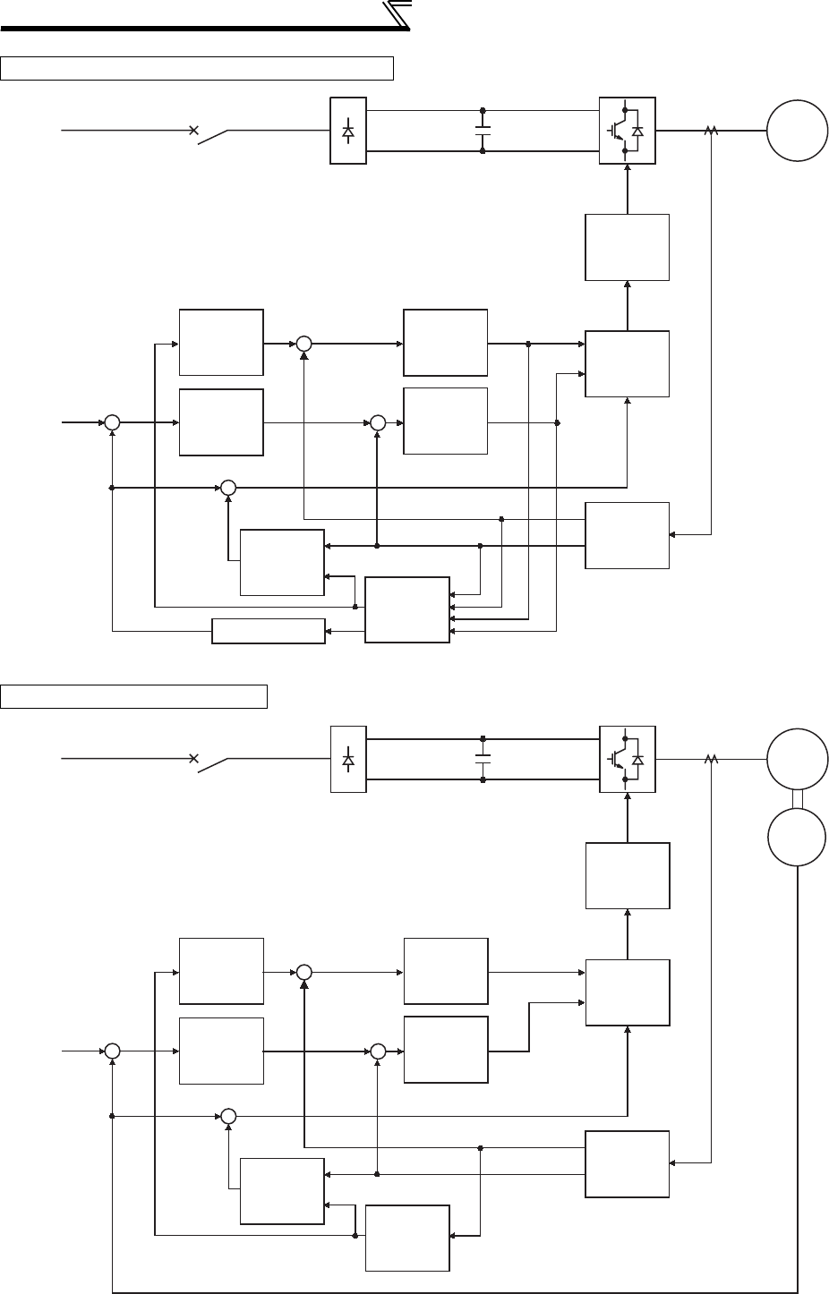
90
Control mode
Block diagram of Real sensorless vector control
Block diagram of vector control
PWM
modulation
output
voltage
conversion
torque
current
control
speed
control
slip
calculation
current
conversion
pre-excitation
current
control
magnetic
flux
control
ω*
ωFB
-
+
+
-
iq*
id
Vq
Vd
ω0
ωsiq
φ2
id
φ2id*
IM
ωFB
+
-
iq
ω0
+
+
iq
id
speed estimation calculation
flux
magnetic iq
Vd Vq
PWM
modulation
output
voltage
conversion
torque
current
control
speed
control
slip
calculation
current
conversion
pre-excitation
current
control
magnetic
flux
control
magnetic
flux
calculation
ω*
ωFB
-
+
+
-
iq*
id
Vq
Vd
ω0
ωsiq
φ2
id
φ2id*
IM
Encoder
ωFB
+
-
iq
ω0
+
+
iq
id

4
PARAMETERS
91
Control mode
(1) Speed control
Speed control operation is performed to zero the difference between the speed command (ω*) and actual rotation
detection value (ωFB). At this time, the motor load is found and its result is transferred to the torque current
controller as a torque current command (iq*).
(2) Torque current control
A voltage (Vq) is calculated to start a current (iq*) which is identical to the torque current command (iq) found by
the speed controller.
(3) Magnetic flux control
The magnetic flux (φ2) of the motor is derived from the excitation current (id). The excitation current command (id*)
is calculated to use that motor magnetic flux (φ2) as a predetermined magnetic flux.
(4) Excitation current control
A voltage (Vd) is calculated to start a current (id) which is identical to the excitation current command (id*) found by
magnetic flux control.
(5) Output frequency calculation
Motor slip (ωs) is calculated on the basis of the torque current value (iq) and magnetic flux (φ2). The output
frequency (w0) is found by adding that slip (ωs) to the feedback (ωFB) found by a feedback from the encoder.
The above results are used to make PWM modulation and run the motor.
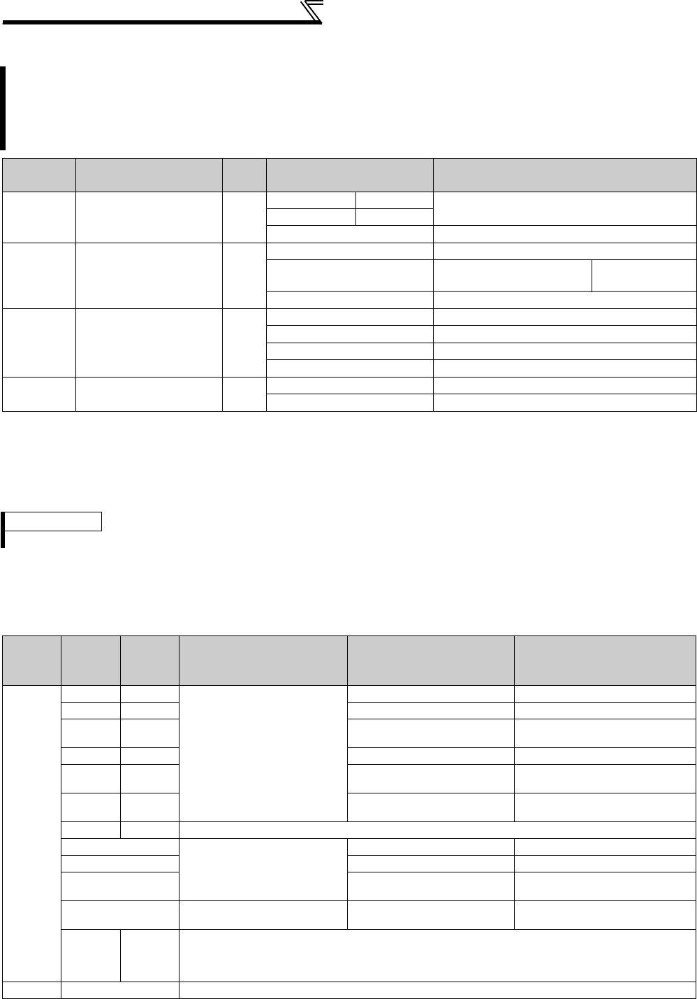
92
Control mode
4.3.2 Change the control method (Pr. 80, Pr. 81, Pr. 451, Pr. 800)
(1) Setting of the motor capacity and the number of motor poles (Pr. 80, Pr. 81 )
⋅Motor specifications(the motor capacity and the number of motor poles) must be set to select Advanced magnetic
flux vector control, Real sensorless vector control or vector control.
⋅Set the motor capacity (kW) in Pr. 80 Motor capacity and set the number of motor poles in Pr. 81 Number of motor
poles.
(2) Selection of control method and control mode
⋅Select the inverter control method for V/F control, Advanced magnetic flux vector control (speed control), Real
sensorless vector control (speed control, torque control) and vector control (speed control, torque control, and
position control).
*1 If FR-A7AP/FR-A7AL is not installed, the control method is Advanced magnetic flux vector control.
*2 Control method is V/F control regardless of the setting value of Pr. 800 when "9999" is set in Pr. 80 Motor capacity or Pr. 81 Number of motor poles.
Set when selecting the Advanced magnetic flux vector control, Real sensorless vector control or vector control.
Select a control mode from speed control mode, torque control mode and position control mode under Real
sensorless vector control or vector control. The initial value is V/F control.
Select a control method using Pr. 800 (Pr. 451) Control method selection .
Each control method can be switched using a method switching signal (MC).
Parameter
Number Name Initial
Value Setting Range Description
80
Motor capacity
9999
55K or lower 0.4 to 55kW Set the applied motor capacity.
75K or higher 0 to 3600kW
9999 V/F control
81
Number of motor poles
9999
2, 4, 6, 8, 10 Set the number of motor poles.
12, 14, 16, 18, 20 X18 signal-ON:V/F control Set 10 + number
of motor poles
9999 V/F control
800 Control method
selection 20
0 to 5 Vector control
9 Vector control test operation
10, 11, 12 Real sensorless vector control
20
V/F control (Advanced magnetic flux vector control)
451
Second motor control
method selection
9999 10, 11, 12 Real sensorless vector control
20, 9999
V/F control (Advanced magnetic flux vector control)
REMARKS
⋅
Setting number of motor poles in
Pr. 81
changes the
Pr. 144 Speed setting switchover
setting automatically. (Refer to
page 251
.)
Pr. 80,
Pr. 81
Setting
Pr. 800
Setting
Pr. 451
Setting Control Method Control Mode Remarks
Other
than
9999
0⎯
Vector control*1
Speed control ⎯
1⎯Torque control ⎯
2⎯Speed control-torque control
switchover
MC ON: Torque control
MC OFF: Speed control
3⎯Position control ⎯
4⎯Speed control-position
control switchover
MC ON: Position control
MC OFF: Speed control
5⎯Position control-torque
control switchover
MC ON: Torque control
MC OFF: Position control
9⎯Vector control test operation
10
Real sensorless vector
control
Speed control ⎯
11 Torque control ⎯
12 Speed control-torque control
switchover
MC ON: Torque control
MC OFF: Speed control
20
(Pr. 800 initial value)
Advanced magnetic flux
vector control Speed control ⎯
⎯
9999
(Pr. 451
initial
value)
V/F control, Advanced magnetic flux vector control
9999 ⎯ *2 V/F control

4
PARAMETERS
93
Control mode
(3) Vector control test operation (Pr. 800 = "9")
⋅Speed control test operation can be performed even when the motor is not connected.
The speed calculation value changes to track the speed command and the transition can be checked with the
operation panel and analog signal output at FM and AM.
(4) Control method switching by external terminals (RT signal, X18 signal)
⋅The switching of the control method (V/F control, Advanced magnetic flux vector control, Real sensorless vector
control and vector control) by the external terminal may be made in either of the following two ways: switching by
the second function selection signal (RT), or V/F switching signal (X18).
⋅Two types of control method can be switched with the RT signal by setting the type of motor to be used as second
motor in Pr. 450 Second applied motor and control method of the motor in Pr. 451 Second motor control method selection.
Turn ON the RT signal to select the second function.
⋅For switching by the X18 signal, setting "12, 14, 16, 18, 20" in Pr. 81 Number of motor poles and turning the X18
signal ON switches the present selected control method (Advanced magnetic flux vector control, Real sensorless
vector control and vector control) to V/F control. In this case, use this signal only for changing the control method of
one motor since second function as electronic thermal relay characteristic, etc. cannot be changed. (Use the RT
signal to change the second function.)
For the terminal used for X18 signal input, set "18" in any of Pr. 178 to Pr. 189 (input terminal function selection) to
assign the function.
*1 V/F control is selected when "12, 14, 16, 18, 20" is set in Pr. 81 and the X18 signal is ON. When the X18 signal is not assigned, turning the RT
signal ON selects V/F control as the RT signal shares this function.
CAUTION
⋅Since current is not detected and voltage is not output, monitors related to current and voltage such as output current and output
voltage, etc. and output signals do not function.
⋅For speed calculation, speed is calculated in consideration of Pr. 880 Load inertia ratio.
First Motor Control Method Second Motor Control Method
(RT signal is on)
Pr. 450
Setting
Pr. 453, Pr. 454
Setting
Pr. 451
Setting
V/F control
V/F control 9999 ⎯⎯
Other than
9999
9999 ⎯
Advanced magnetic flux vector control Other than
9999
20, 9999
Real sensorless vector control 10 to 12
Advanced magnetic flux vector
control
Real sensorless vector control
Same control as the first motor *1 9999 ⎯⎯
V/F control
Other than
9999
9999 ⎯
Advanced magnetic flux vector control Other than
9999
20, 9999
Real sensorless vector control 10 to 12
REMARKS
⋅The RT signal is assigned to the terminal RT in the initial setting. By setting "3" in any of Pr. 178 to Pr. 189 (input terminal function
selection), you can assign the RT signal to the other terminal.
⋅The RT signal acts as the second function selection signal and makes the other second functions valid. (Refer to page 235.)
⋅The control method could be changed by external terminals (RT signal, X18 signal) while the inverter is stopped.
If a signal is switched during the operation, the control method changes after the inverter stops.

94
Control mode
(5) Switching the control method from the external terminal (MC signal)
⋅When "12 (2)" is set in Pr. 800 (Pr. 451 ), speed control is selected when the control mode switching signal (MC) is
OFF, and torque control is selected when the signal is OFF under Real sensorless vector control and vector
control. Switching between speed control and torque control is always enabled.
Under vector control, speed control/position control switchover and torque control/position control switchover can be
made by setting "4, 5" in
Pr. 800
. For the terminal used for MC signal input, set "26" in any of
Pr. 178 to Pr. 189 (input
terminal function selection)
to assign the function.
⋅When an analog input terminal (terminal 1,4) is used for torque limit, torque command, etc., terminal functions also
switch as below if control mode is switched.
Terminal 1 function according to control
* This setting is valid under vector control.
Pr. 868 Setting Real Sensorless Vector Control (Pr. 800 = 12), Vector Control (Pr. 800 = 2)
Speed control (MC signal-OFF) Torque control (MC signal-ON)
0 (initial value) Speed setting auxiliary Speed limit auxiliary
1 Magnetic flux command * Magnetic flux command *
2 Regenerative torque limit (Pr. 810 = 1) ⎯
3⎯Torque command (Pr. 804 = 0)
4 Torque limit (Pr. 810 = 1) Torque command (Pr. 804 = 0)
5⎯Forward reverse speed limit (Pr. 807 = 2)
6⎯⎯
9999 ⎯⎯
Pr. 868 Setting Vector Control (Pr. 800 = 4)
Speed control (MC signal-OFF) Position control (MC signal-ON)
0 (initial value) Speed setting auxiliary ⎯
1 Magnetic flux command Magnetic flux command
2 Regenerative torque limit (Pr. 810 = 1) Regenerative torque limit (Pr. 810 = 1)
3⎯⎯
4 Torque limit (Pr. 810 = 1) Torque limit (Pr. 810 = 1)
5⎯⎯
6 Torque bias ⎯
9999 ⎯⎯
Pr. 868 Setting Vector Control (Pr. 800 = 5)
Position control (MC signal-OFF) Torque control (MC signal-ON)
0 (initial value) ⎯Speed setting auxiliary
1 Magnetic flux command Magnetic flux command
2 Regenerative torque limit (Pr. 810 = 1) ⎯
3⎯Torque command (Pr. 804 = 0)
4 Torque limit (Pr. 810 = 1) Torque command (Pr. 804 = 0)
5⎯Forward reverse speed limit (Pr. 807 = 2)
6⎯⎯
9999 ⎯⎯
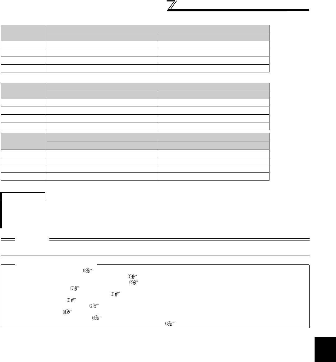
4
PARAMETERS
95
Control mode
Terminal 4 function according to control
* This setting is valid under vector control.
⎯ :No function
Pr. 858 Setting Real Sensorless Vector Control (Pr. 800 = 12), Vector Control (Pr. 800 = 2)
Speed control (MC signal-OFF) Torque control (MC signal-ON)
0 (initial value) Speed command (AU signal-ON) Speed limit (AU signal-ON)
1 Magnetic flux command * Magnetic flux command *
4 Torque limit (Pr. 810 = 1) ⎯
9999 ⎯⎯
Pr. 858 Setting Vector Control (Pr. 800 = 4)
Speed control (MC signal-OFF) Position control (MC signal-ON)
0 (initial value) Speed command (AU signal-ON) ⎯
1 Magnetic flux command Magnetic flux command
4 Torque limit (Pr. 810 = 1) Torque limit (Pr. 810 = 1)
9999 ⎯⎯
Pr. 858 Setting Vector Control (Pr. 800 = 5)
Position control (MC signal-OFF) Torque control (MC signal-ON)
0 (initial value) ⎯Speed limit (AU signal-ON)
1 Magnetic flux command Magnetic flux command
4 Torque limit (Pr. 810 = 1) ⎯
9999 ⎯⎯
REMARKS
⋅Switching between speed control and torque control is always enabled independently of whether the motor is at a stop or
running or the DC injection brake operation (pre-excitation).
⋅During motor operation, speed control/position control switchover and torque control/position control switchover is made when
frequency drops to the Pr. 865 Low speed detection.
CAUTION
⋅Changing the terminal assignment using Pr. 178 to Pr. 189 (input terminal function selection) may affect the other functions. Set
parameters after confirming the function of each terminal.
♦ Parameters referred to ♦
Advanced magnetic flux vector control Refer to page 148
Real sensorless vector control, vector control (speed control) Refer to page 96
Real sensorless vector control, vector control (torque control) Refer to page 119
Vector control (position control) Refer to page 132
Pr. 178 to Pr. 189 (input terminal function selection) Refer to page 231
Pr. 450 Second applied motor Refer to page 187
Pr. 804 Torque command source selection Refer to page 125
Pr. 807 Speed limit selection Refer to page 127
Pr. 810 Torque limit input method selection Refer to page 100
Pr. 858 Terminal 4 function assignment, Pr. 868 Terminal 1 function assignment Refer to page 285
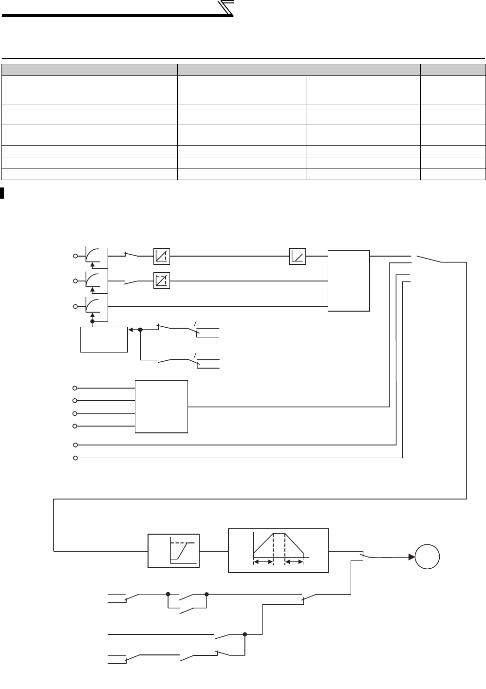
96
Speed control by Real sensorless vector
control, vector control
4.4 Speed control by Real sensorless vector control, vector
control
(1) Control block diagram
Purpose Parameter that should be Set Refer to Page
To perform torque limit during speed control Torque limit
Pr. 22, Pr. 803, Pr. 810,
Pr. 812 to Pr. 817,
Pr. 858, Pr. 868, Pr. 874
100
Gain adjustment of speed control Easy gain tuning
Gain adjustment
Pr. 818 to Pr. 821, Pr. 830,
Pr. 831, Pr. 880 105
To enhance the trackability of the motor in
response to a speed command change
Speed feed forward control,
model adaptive speed control Pr. 828, Pr. 877 to Pr. 881 112
Stabilize the speed detection signal Speed detection filter Pr. 823, Pr. 833 144
Accelerates the rise of the torque at a start Torque bias Pr. 840 to Pr. 848 114
Avoid mechanical resonance Notch filter Pr. 862, Pr. 863 118
Speed control is exercised to match the speed command and actual motor speed.
Terminal 2
Terminal 4
[Pr. 858 = 0]
Terminal 1
[Pr. 868 = 0]
RL
RM
RH
REX
Option
Operation panel
Multi-speed
selection
[Pr. 4 to 6,
24 to 27,
232 to 239]
Speed setting
filter
RT
RT
[Pr. 822]
[Pr. 832]
AU
AU
Terminal 2 bias [C2, C3 (Pr. 902)]
Terminal 2 gain [Pr. 125, C4 (Pr. 903)]
Terminal 4 bias [C5, C6 (Pr. 904)]
Terminal 4 gain [Pr. 126, C7 (Pr. 905)]
Analog input offset
adjustment [Pr. 849]
Analog
input
selection
[Pr. 73]
Operation Mode
[Pr. 79]
Servo lock
zero speed control
Zero speed control
DC injection brake operation
Maximum/minimum setting
[Pr. 1]
[Pr. 2]
[Pr. 13]
Acceleration/deceleration processing
[Pr. 10]
Vector control
[Pr. 800 = 0]
Real sensorless
Vector control
[Pr. 800 = 10]
[Pr. 802 = 1]
[Pr. 802 = 0]
[Pr. 850 = 1]
[Pr. 850 = 0]
LX
[Pr. 7] [Pr. 8]
A
[Pr. 74]
[Pr. 74]
[Pr. 832 = 9999]
[Pr. 832 = 9999]
[Pr. 822 = 9999]
[Pr. 822 = 9999]
Running
During stop
Decelerates to stop
[Pr. 11]
Zero speed control
LX
LX
Decelerates to stop
[Pr. 11]
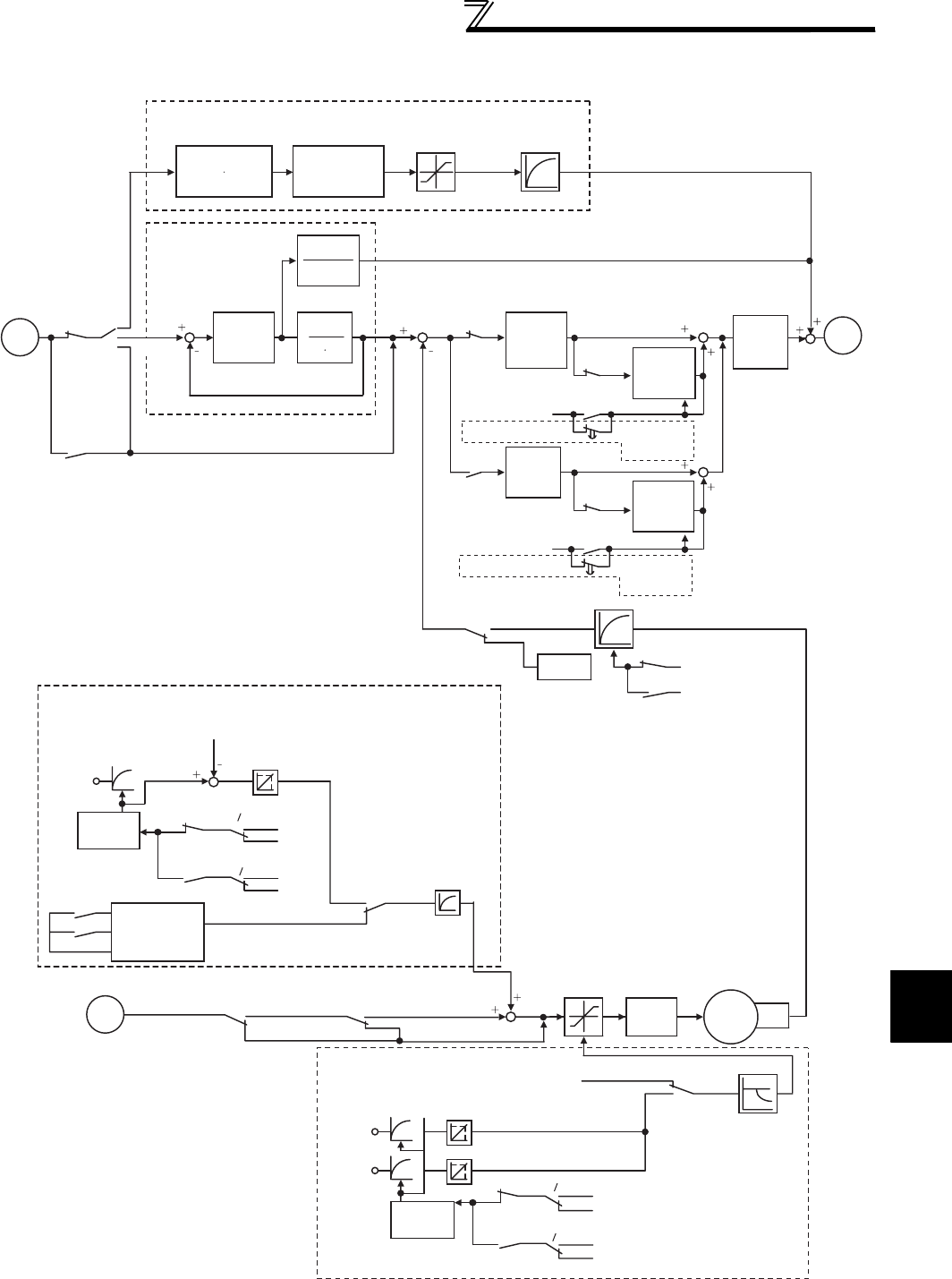
97
Speed control by Real sensorless
vector control, vector control
4
PARAMETERS
Load inertia ratio
J s
[Pr. 880]
Speed feed forward
gain
[Pr. 881]
Speed feed forward control
Model adaptive speed control
Model speed
control gain
[Pr. 828]
Speed feed forward
torque limit
[
Pr. 879
]
Speed feed
forward
filter [
Pr. 878
]
J [Pr. 880]
Model speed
calculation
1
J s
Speed
control
P gain 1
[Pr. 820]
Speed control
integral
time 1
[
Pr. 821
]
Speed control
integral
time 2
[
Pr. 831
]
Integration cleared to 0
Integration cleared to 0
Real sensorless
vector control
[Pr. 800 = 10]
Vector control
[Pr. 800 = 0]
Speed
estimation
RT RT
RT
RT
[Pr. 877 = 1]
[Pr. 877 = 0]
0
0
X44
X44
X44
X44
Speed detection filter
RT
RT
[Pr. 823]
[Pr. 833]
Torque bias selection
[Pr. 840 = 0 to 2]
Torque bias
Torque bias balance
compensation
[Pr. 846]Terminal 1 bias [C16, C17(Pr. 919)]
Terminal 1 gain [C18, C19(Pr. 920)]
Fall-time torque bias terminal 1 bias [Pr. 847]
Fall-time torque bias terminal 1 gain [Pr. 848]
Terminal 1
[Pr. 868 = 6]
Torque
setting
filter
Torque bias
[Pr. 841 to 843]
X42
X43
Torque bias
selection
[Pr. 840 = 1, 2]
Torque bias
filter
[Pr. 844]
[Pr. 840 = 0]
Torque limit
Terminal 1
[Pr. 868 = 4]
Terminal 4
[Pr. 858 = 4]
Torque
setting
filter
Terminal 1 bias [C16, C17(Pr. 919)]
Terminal 1 gain [C18, C19(Pr. 920)]
Terminal 4 bias [C38, C39(Pr. 932)]
Terminal 4 gain [C40, C41(Pr. 933)]
[Pr. 22, 812 to 817]
[Pr. 810 = 0]
[Pr. 810 = 1]
Torque limit
input method
selection
Constant power
range torque
characteristic
selection
[Pr. 803]
Torque
control Motor
Torque limit
Encoder
[Pr. 840 = 9999]
A
B
B
[Pr. 877 = 2]
Torque
coefficient
RT
RT
[Pr. 826]
[Pr. 826]
[Pr. 836]
[Pr. 74]
[Pr. 74]
[Pr. 826 = 9999]
[Pr. 836 = 9999]
[Pr. 836 = 9999]
[Pr. 826 = 9999]
RT
RT
Notch
filter
[Pr. 862]
[Pr. 863]
Torque bias
operation
time
[
Pr. 845
]
When torque bias is selected
Torque bias
operation
time
[
Pr. 845
]
Vector control
[Pr. 800 = 0]
Real sensorless
vector control
[Pr. 800 = 10]
Speed
control
P gain 2
[Pr. 830]
When torque bias is selected
[Pr. 826 = 9999]
[Pr. 826 = 9999]
[Pr. 836 = 9999]
[Pr. 836 = 9999]
[Pr. 74]
[Pr. 74]
[Pr. 836]
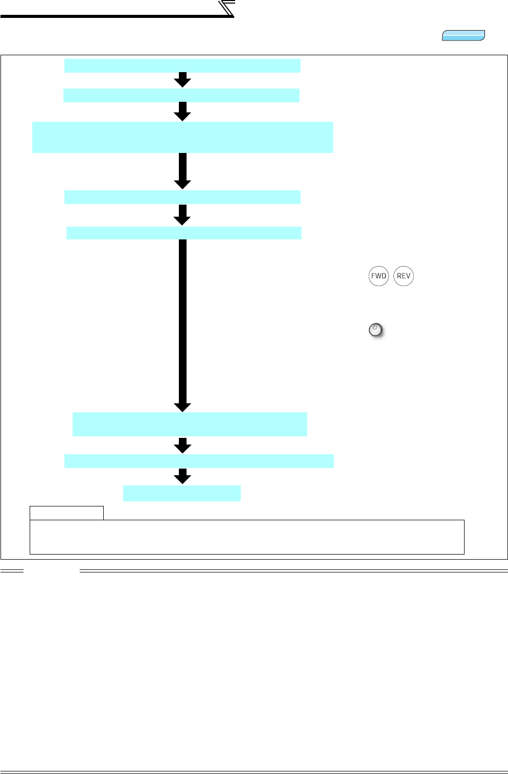
98
Speed control by Real sensorless vector
control, vector control
4.4.1 Setting procedure of Real sensorless vector control (speed control)
CAUTION
⋅Make sure to perform offline auto tuning before performing Real sensorless vector control.
⋅Speed command setting range is 0 to 120Hz for Real sensorless vector control.
⋅The carrier frequencies are selectable from among 2k, 6k, 10k, 14kHz for Real sensorless vector control.
⋅Torque control cannot be performed in the low speed (approx. 10Hz or less) regeneration range and with light load at low speed
(approx. 20% or less of rated torque at approx. 5Hz or less). Choose vector control.
⋅Performing pre-excitation (LX signal and X13 signal) under torque control may start the motor running at a low speed even when
the start command (STF or STR) is not input. The motor may run also at a low speed when the speed limit value = 0 with a start
command input. Perform pre-excitation after making sure that there will be no problem in safety if the motor runs.
⋅Do not switch between the STF (forward rotation command) and STR (reverse rotation command) during operation under torque
control. Overcurrent trip (E.OC) or opposite rotation deceleration fault (E.11) occurs.
⋅For the 0.4K to 3.7K, the speed deviation may become large at 20Hz or less and torque may become insufficient in the low speed
range under 1Hz during continuous operation under Real sensorless vector control. In this case, stop the inverter once, then start
again to improve.
⋅When the inverter is likely to start during motor coasting under Real sensorless vector control, set to make frequency search of
automatic restart after instantaneous power failure valid (Pr. 57 ≠ "9999", Pr. 162 = "10").
⋅Enough torque may not be generated in the ultra-low speed range less than approx. 2Hz when performing Real sensorless
vector control.
The guideline of speed control range is as shown below.
Driving: 1:200 (2, 4, 6 poles) Can be used at 0.3Hz or more at rated 60Hz
1:30 (8, 10 poles) Can be used at 2Hz or more at rated 60Hz
Regeneration:1:12 (2 to 10 poles) Can be used at 5Hz or more at rated 60Hz
Sensorless
Sensorless
Sensorless
Set the torque limit. (Pr. 810)
(Refer to page 100.)
Test run
Perform secure wiring. (Refer to page 14.)
Set the motor. (Pr. 71) (Refer to page 187.)
Perform offline auto tuning. (Pr. 96) (Refer to page 189.)
Select a control method
. (Refer to page 92)
As required
⋅Select online auto tuning. (Pr. 95) (Refer to page 199)
⋅Easy gain tuning (Refer to page 105)
⋅Manual input speed control gain adjustment (Refer to page 108)
Set "10" (speed control) or "12" (speed-torque switchover) in Pr. 800 and make
speed control valid.
Select the start command and speed command.
(1) Start command
1) Operation panel: Setting by pressing / of the operation panel
2) External command: Setting by forward rotation and reverse rotation
command (terminal STF or STR)
(2) Speed command
1) Operation panel: Setting by turning of the operation panel
2) External analog command (terminal 2 or 4) :
Give a speed command using the analog signal input to terminal 2 (or
terminal 4).
3) Multi-speed command:
The external signals (RH, RM, RL) may also be used to give speed
command.
Set the motor capacity and the number of motor poles.
(Pr. 80, Pr. 81)
(Refer to page 92.)
Set the operation command. (Refer to page 313)
Set the motor capacity (kW) in Pr. 80 Motor capacity and set the number of
motor poles (number of poles) in Pr. 81 Number of motor poles.
(V/F control is performed when the setting is "9999" (initial value).)
Set "3" (standard motor) or "13" (constant-torque motor) in Pr. 71
Applied motor.
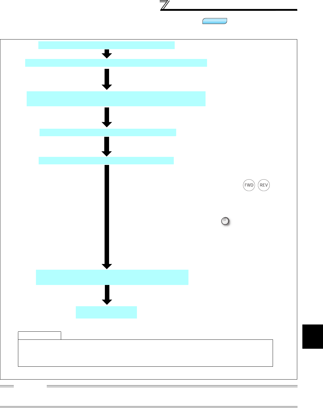
4
PARAMETERS
99
Speed control by Real sensorless
vector control, vector control
4.4.2 Setting procedure of vector control (speed control)
CAUTION
⋅Speed command setting range is 0 to 120Hz for vector control.
⋅The carrier frequencies are selectable from among 2k, 6k, 10k, 14kHz for vector control.
(2k and 6kHz for the 75K or higher)
Vector
Vector
Vector
Test run
Perform secure wiring. (Refer to page 36.)
Set the motor and encoder. (Pr. 71, Pr. 359, Pr. 369)
Set the run command. (Refer to page 313.)
As required
· Perform offline auto tuning. (Pr. 96) (refer to page 189).
· Select online auto tuning. (Pr. 95) (refer to page 199).
· Easy gain tuning (refer to page 105)
· Manual input speed control gain adjustment (refer to page 108)
Select the start command and speed command.
(1) Start command
1)Operation panel: Setting by pressing / of the
operation panel
2)External command: Setting by forward rotation or reverse
rotation command (terminal STF or STR)
(2)Speed command
1)
Operation panel: Setting by turning of the operation panel
2)External analog command (terminal 2 or 4) :
Give a speed command using the analog signal input to
terminal 2 (or terminal 4).
3)Multi-speed command:
The external signals (RH, RM, RL) may also be used to give
speed command.
Set the motor capacity and the number of motor poles
(Pr. 80, Pr. 81) (Refer to page 92.)
Set the motor capacity (kW) in
Pr. 80
Motor capacity
and set the number
of motor poles (number of poles) in
Pr. 81
Number of motor poles
. (V/F
control is performed when the setting is "9999" (initial value).)
Mount the FR-A7AP/FR-A7AL (option).
Set
Pr. 71 Applied motor
,
Pr. 359 Encoder rotation direction
and
Pr. 369
Number of encoder pulses
according to the motor and encoder used.
(Refer to page 38.)
Select a control method. (Refer to page 92.)
Make speed control valid by selecting "0" (speed control), "2" (speed-
torque switchover), or "4" (speed-position switchover) for
Pr. 800
.
Set the torque limit. (Pr. 810)
(Refer to page 100.)

100
Speed control by Real sensorless vector
control, vector control
4.4.3 Torque limit level setting for speed control
(Pr. 22, Pr. 157, Pr. 803, Pr. 810 to Pr. 817, Pr. 858, Pr. 868, Pr. 874)
* This parameter allows its setting to be changed during operation in any operation mode even if "0 (initial value) or 1" is set in Pr. 77 Parameter write
selection.
This function limits the output torque to the predetermined value during speed control under Real sensorless
vector control or vector control.
Set the torque limit level within the range 0 to 400% in Pr. 22.
When the TL signal is turned ON, torque limit level 2 is activated.
You can select whether the torque limit level is set using parameters or analog input terminals (terminal 1, 4).
In addition, you can set torque limit level for forward (power driving/regeneration) and reverse (power driving/
regeneration) operation individually.
Parameter
Number Name Initial Value Setting Range Description
22*
Stall prevention operation
level
(torque limit level)
150/200%* 0 to 400%
Set the torque limit level in % on the assumption
that the rated torque is 100%
* For the 3.7K or lower, the value changes from 150% to
200% when V/F control or Advanced magnetic flux
vector control is changed to Real sensorless vector
control or vector control.
157 OL signal output timer 0s 0 to 25s Set the output start time of the OL signal output
when torque limit is activated.
9999 Without the OL signal output
803
Constant power range
torque characteristic
selection
0
0Constant motor output
limit
Select the torque limit in
the constant output
region by torque limit
setting.
1 Constant torque limit
810 Torque limit input method
selection 00Internal torque limit (torque limit by parameter
settings)
1
External torque limit (torque limit by terminal 1, 4)
811 Set resolution switchover 0
Speed setting and
running speed monitor
increments from the
PU, RS-485
communication or
communication option.
Torque limit setting
increments
Pr. 22, Pr. 812 to Pr. 817
01r/min 0.1%
10.1r/min
10 1r/min 0.01%
11 0.1r/min
812 Torque limit level
(regeneration) 9999 0 to 400% Set the torque limit level for forward rotation
regeneration.
9999 Limit at the value of Pr. 22 or analog terminal.
813 Torque limit level (3rd
quadrant) 9999 0 to 400% Set the torque limit level for reverse rotation driving.
9999 Limit at the value of Pr. 22 or analog terminal.
814 Torque limit level (4th
quadrant) 9999 0 to 400% Set the torque limit level for reverse rotation
regeneration.
9999 Limit at the value of Pr. 22 or analog terminal.
815 Torque limit level 2 9999 0 to 400%
When the torque limit selection (TL) signal is
ON, the Pr. 815 value is a torque limit value
regardless of Pr. 810 .
9999 The torque limit set to Pr. 810 is valid.
816 Torque limit level during
acceleration 9999 0 to 400% Set the torque limit value during acceleration.
9999 Same torque limit as at constant speed
817 Torque limit level during
deceleration 9999 0 to 400% Set the torque limit value during deceleration.
9999 Same torque limit as at constant speed
858 Terminal 4 function
assignment 0 0, 1, 4, 9999 When "4" is set in, the torque limit can be
changed with a signal to terminal 4.
868 Terminal 1 function
assignment 0 0, 2 to 5, 9999 When "4" is set in, the torque limit can be
changed with a signal to terminal 1.
874 OLT level setting 150% 0 to 200%
This function can make an inverter trip if the
torque limit is activated to stall the motor. Set the
output at which an inverter trip is made.
CAUTION
⋅Under Real sensorless vector control, the lower limit of torque limit level is set 30% if the value less than 30% is input.
Sensorless
Sensorless
Sensorless
Vector
Vector
Vector
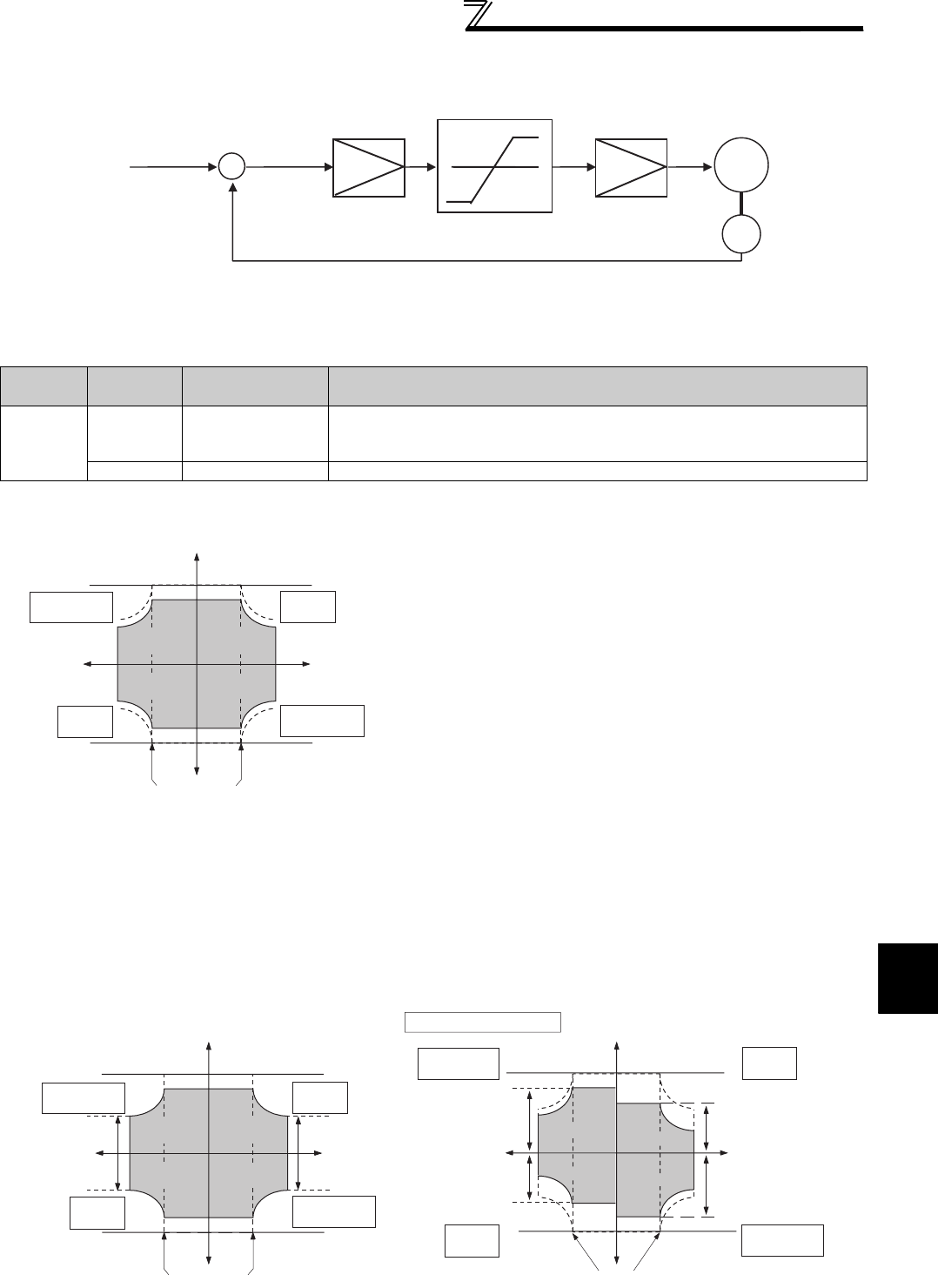
101
Speed control by Real sensorless
vector control, vector control
4
PARAMETERS
(1) Torque limit block diagram
(2) Selection of torque limit input method (Pr. 810)
⋅Set Pr. 810 Torque limit input method selection to select the method to limit output torque during speed control.
Torque limit by parameter setting is initially set.
(3) Torque limit level by parameter setting (Pr. 810 = "0", Pr. 812 to Pr. 814 )
(4) Torque limit level by analog input (terminal 1, 4) (Pr. 810 = "1", Pr. 858, Pr. 868 )
Parameter
Number
Setting
Range
Torque Limit Input
Method Description
810
0 (initial
value) Internal torque limit
Parameter-set torque limit operation is performed.
Changing the torque limit parameter value by communication enables torque limit
to be input by communication.
1 External torque limit Torque limit using analog voltage (current) to terminal 1 or terminal 4 is enabled.
⋅With the initial value, limit is made ON all quadrants on the
Pr. 22 Stall prevention operation level (torque limit level) .
⋅When you want to set the level on a quadrant basis, set the
torque limit level in Pr. 812 Torque limit level (regeneration), Pr.
813 Torque limit level (3rd quadrant), Pr. 814 Torque limit level
(4th quadrant).
When "9999" is set, Pr. 22 is the torque limit level.
⋅With the upper limit of torque limit as set in Pr. 22, the analog input from terminal 1 input is used as the torque limit
value within the Pr. 22 setting range.
⋅When torque limit value is input to terminal 1, set "4" in Pr. 868 Terminal 1 function assignment. When torque limit value
is input from terminal 4, set "4" in Pr. 858 Terminal 4 function assignment.
⋅When Pr. 858="4" and Pr. 868="2," torque is limited by analog input to terminal 1 for regeneration and to terminal 4 for
driving.
⋅Torque limit by analog input can be calibrated using calibration parameter C16 (Pr. 919) to C19 (Pr. 920), C38 (Pr. 932) to
C41 (Pr. 933) . (Refer to page 300)
* Analog input (terminal 1, 4) or internal torque control (
Pr. 22
etc.) whichever is smaller
Torque limit
<Vector control>
Speed control
Speed command +
-
Iq current control
IM
Encoder
quad1
( Pr. 22)
quad4
( Pr. 814)
( Pr. 813)
quad2
( Pr. 812)
Reverse
rotation
Forward
rotation
Torque limit
Speed
Reverse
driving
Reverse
regeneration
Rated speed
quad3
+
-
Forward
regeneration
Forward
driving
*
*
*
*
quad1
(Pr. 22)
quad4
(Pr. 814)
(Pr. 813)
quad2
( Pr. 812)
Reverse
rotation
Forward
rotation
Torque limit
Speed
Reverse
driving
Reverse
regeneration
Rated speed
quad3
+
-
Forward
regeneration
Forward
driving
When Pr.858=4, Pr.868=2
quad1
quad4
quad2
Reverse rotation Forward rotation
Torque limit
Rated speed
+
-
Terminal 1 input or
internal torque limit
(Pr.22 etc.) whichever
is smaller
Speed
quad3
Reverse
regeneration
Reverse
driving
Forward
driving
Forward
regeneration
Terminal 4 input or
internal torque limit
(Pr.22 etc.) whichever
is smaller
Terminal 4 input or
internal torque limit
(Pr.22 etc.) whicheve
r
is smaller
Terminal 1 input or
internal torque limit
(Pr.22 etc.) whichever
is smaller
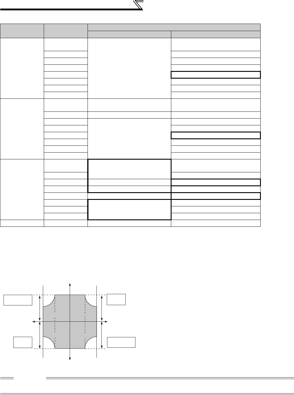
102
Speed control by Real sensorless vector
control, vector control
Terminal 1, 4 function according to control (⎯ : without function)
*1 When the Pr. 868 setting is other than "0", other functions of terminal 1 (auxiliary input, override function, PID control) do not function.
*2 When the Pr. 858 setting is other than "0", PID control and speed command from terminal 4 do not function even if the AU signal turns ON.
*3 When "1" (magnetic flux command) or "4" (torque limit) is set in both Pr. 858 and Pr. 868, function of terminal 1 has higher priority and terminal 4
has no function.
*4 Setting is valid only when exercising vector control with the FR-A7AP/FR-A7AL (option).
(5) Second torque limit level (TL signal, Pr. 815)
Pr. 858 Setting *1 Pr. 868 Setting *2
Real Sensorless Vector Control, Vector Control (Speed Control)
Terminal 4 function Terminal 1 function
0
(initial value)
0
(initial value)
Speed command
(AU signal-ON)
Speed setting auxiliary
1 Magnetic flux command *4
2⎯
3⎯
4 Torque limit (Pr. 810 = 1)
5⎯
6 Torque bias (Pr. 840 = 1 to 3) *4
9999 ⎯
1
0
(initial value) Magnetic flux command *4 Speed setting auxiliary
1⎯ *3 Magnetic flux command *4
2
Magnetic flux command *4
⎯
3⎯
4 Torque limit (Pr. 810 = 1)
5⎯
6 Torque bias (Pr. 840 = 1 to 3) *4
9999 ⎯
4 *2
0
(initial value) Torque limit (Pr. 810 = 1) Speed setting auxiliary
1 Magnetic flux command *4
2 Driving torque limit (Pr. 810 = 1) Regenerative torque limit (Pr. 810 = 1)
3 Torque limit (Pr. 810 = 1) ⎯
4⎯ *3 Torque limit (Pr. 810 = 1)
5
Torque limit (Pr. 810 = 1)
⎯
6 Torque bias (Pr. 840 = 1 to 3) *4
9999 ⎯
9999 ⎯⎯ ⎯
⋅For Pr. 815 Torque limit level 2 , the Pr. 815 value is a torque
limit value regardless of Pr. 810 Torque limit input method
selection when the torque limit selection signal (TL) is ON.
⋅Set "27" in Pr. 178 to Pr. 189 (input terminal function selection)
to assign a function to the TL signal.
CAUTION
⋅Changing the terminal assignment using Pr. 178 to Pr. 189 (input terminal function selection) may affect the other functions. Set
parameters after confirming the function of each terminal.
Pr.815 Pr.815
Pr.815Pr.815
quad4
quad2
Reverse
rotation
Forward
rotation
Torque limit
Speed
Reverse
driving
Reverse
regeneration
Rated speed
quad3
+
-
Forward
regeneration
Forward
driving
quad1

103
Speed control by Real sensorless
vector control, vector control
4
PARAMETERS
(6) Set a torque limit value during acceleration and deceleration individually (Pr. 816, Pr. 817 )
⋅You can set torque limit during acceleration and deceleration individually.
The following chart shows torque limit according to the settings of Pr. 816 Torque limit level during acceleration and Pr.
817 Torque limit level during deceleration.
(7) Setting increments switchover of the torque limit level (Pr. 811 )
⋅By setting "10, 11" in Pr. 811 Set resolution switchover, the setting increments of Pr. 22 Torque limit level and Pr. 812 to
Pr. 817 (torque limit level) can be switched to 0.01%.
(8) Change the torque characteristics in the constant power range (Pr. 803)
REMARKS
⋅The internal resolution of the torque limit is 0.024% (100/212) and the fraction less than the resolution is rounded off.
⋅When the torque limit setting increments have been changed (0.1%⇔0.01%), reset is necessary because the settings of Pr. 22
and Pr. 812 to Pr. 817 are multiplied by 1/10 (ten times).
For example, when 10 (0.01%) set in Pr. 811 is changed to 1 (0.1%) with Pr. 22 = 150.00%,
Pr. 22 = 1500.0% and the maximum torque is 400%.
⋅The fraction less than the resolution equivalent to 0.1% is rounded off even if "10 or 11" is set in Pr. 811 when Real sensorless
vector control is selected.
⋅Refer to page 251 for switchover of speed setting increments.
⋅You can select whether the torque limit in the constant
power range be constant torque limit (setting is "1") or
constant power limit (initial value is "0"), using Pr. 803
Constant power range torque characteristic selection under
torque limit operation.
Acceleration Constant speed Deceleration
Set
frequency
Output
frequency
(Hz)
Time
Torque limit level
1s
Pr. 816
Torque limit level during acceleration
Pr. 22
Torque limit level
Pr. 817
Torque limit level during deceleration
After the state where
difference between the
set speed and running
speed is within ±2Hz has
persisted for 1s, torque
limit level during
acceleration / deceleration
(Pr. 816 or Pr. 817) shifts to
torque limit level during
constant speed (Pr. 22).
Speed
Base speed
Torque
Pr. 803 =1:
constant torque limit
Pr. 803 =0:
constant power limit
(torque reduction)
Constant power range
Constant torque range
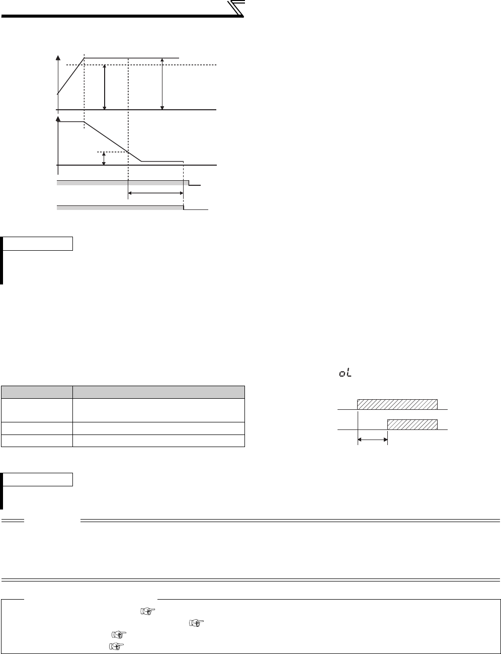
104
Speed control by Real sensorless vector
control, vector control
(9) Trip when torque limit is activated (Pr. 874 )
(10) Stall prevention operation signal output and output timing adjustment (OL signal, Pr. 157)
⋅When the output torque exceeds the torque limit level and torque limit is activated, the stall prevention operation
signal (OL signal) turns on for longer than 100ms. When the output torque falls to or below the torque limit level, the
output signal turns off.
⋅Use Pr. 157 OL signal output timer to set whether the OL signal is output immediately or after a preset period of time.
⋅This operation is also performed when the regeneration avoidance function (overvoltage stall) is executed.
⋅This function can cause a trip if the torque limit is activated
to stall the motor.
⋅The motor stalls if the torque limit is activated under a high
load applied during speed control or position control. At this
time, if the motor speed is lower than the speed set in Pr.
865 Low speed detection and also the output torque exceeds
the level set in Pr. 874 OLT level setting for 3s, it is regarded
as a stop effected by stall prevention and E. OLT is output,
resulting in a trip.
REMARKS
⋅If the frequency has fallen to 0.5Hz by stall prevention operation and remains for 3s under V/F control and Advanced magnetic
flux vector control, a fault (E.OLT) appears and trips the inverter. In this case, this function is activated regardless of Pr. 874 .
This fault is not provided under torque control.
Pr. 157 Setting Description
0
(initial value) Output immediately
0.1 to 25 Output after the set time (s) has elapsed
9999 Not output
REMARKS
⋅The OL signal is assigned to the terminal OL in the initial setting. The OL signal can also be assigned to the other terminal by
setting "3 (positive logic) or 103 (negative logic)" to any of Pr. 190 to Pr. 196 (output terminal function selection).
CAUTION
· When speed control is performed, a fault (E.OLT) is displayed and the inverter output is stopped if frequency drops to the Pr.
865 Low speed detection (initial value is 1.5Hz) setting by torque limit operation and the output torque exceeds Pr. 874 OLT level
setting (initial value is 150%) setting and remains for more than 3s.
· When terminal assignment is changed using Pr. 190 to Pr. 196 (output terminal function selection), the other functions may be
affected. Please set parameters after confirming the function of each terminal.
♦Parameters referred to♦
⋅Pr. 22 Stall prevention operation level Refer to page 152
⋅Pr. 178 to Pr. 189 (input terminal function selection) Refer to page 231
⋅Pr. 840 Torque bias selection Refer to page 114
⋅Pr. 865 Low speed detection Refer to page 246
Output torque
Output
frequency
Start
signal
(STF)
Fault
output
Pr. 874 Torque limit
Pr. 865
3s
Torque
Time
Time
E.OLT occurrence
Overload state
(OL operation)
OL output signal
Pr.157 Set time(s)
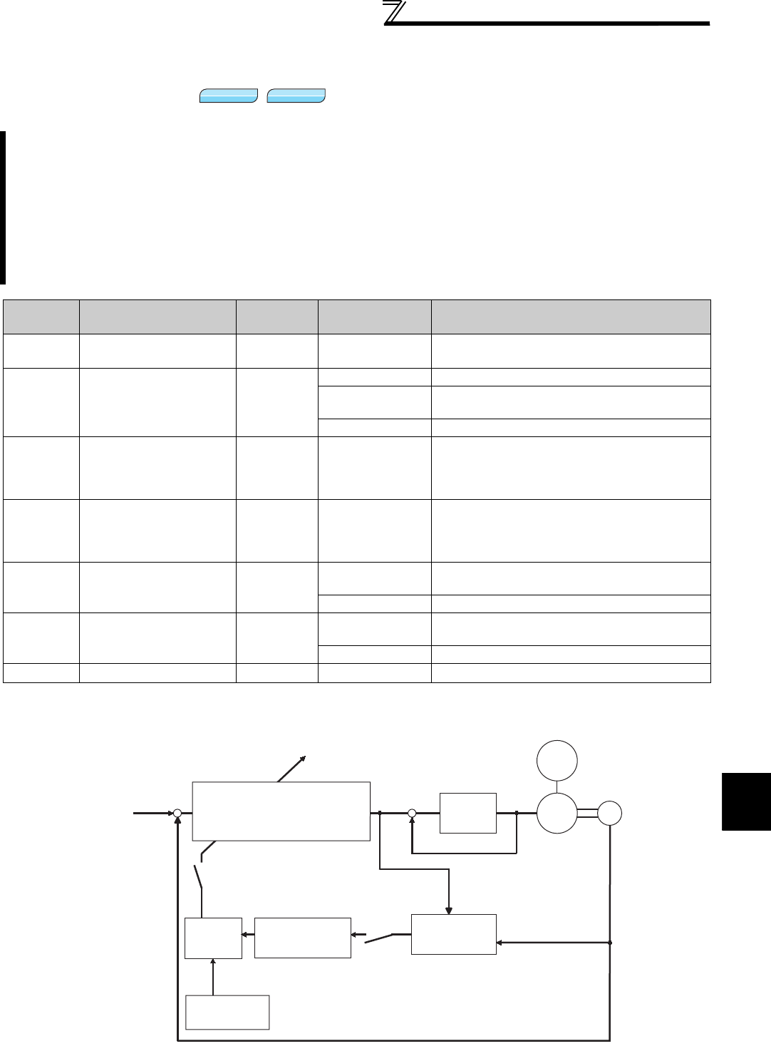
105
Speed control by Real sensorless
vector control, vector control
4
PARAMETERS
4.4.4 To perform high accuracy/fast response operation (gain adjustment of Real
sensorless vector control and vector control) (Pr. 818 to Pr. 821, Pr. 830,
Pr. 831, Pr. 880)
(1) Block diagram of easy gain tuning function
The ratio of the load inertia to the motor inertia (load inertia moment) is estimated in real time from the torque
command and speed during motor operation by vector control. As optimum gain of speed control and position
control are automatically set from the load inertia ratio and response level, time and effort of making gain
adjustment are reduced. (Easy gain tuning)
When the load inertia ratio cannot be estimated due to load fluctuation or Real sensorless vector control is
exercised, control gain is automatically set by manually inputting the load inertia ratio.
Make a manual input adjustment when vibration, noise or any other unfavorable phenomenon occurs due to
large load inertia or gear backlash, for example, or when you want to exhibit the best performance that matches
the machine.
Parameter
Number Name Initial Value Setting Range Description
818 Easy gain tuning
response level setting 2 1 to 15 Set the response level.
1: Slow response to 15: Fast response
819 Easy gain tuning
selection 0
0 Without easy gain tuning
1With load estimation, with gain calculation
(valid only during vector control)
2 With load (Pr. 880) manual input, gain calculation
820 Speed control P gain 1 60% 0 to 1000%
Set the proportional gain for speed control.
(Increasing the value improves trackability in
response to a speed command change and
reduces speed variation with disturbance.)
821 Speed control integral
time 1 0.333s 0 to 20s
Set the integral time during speed control.
(Decrease the value to shorten the time taken for
returning to the original speed if speed variation
with disturbance occurs.)
830 Speed control P gain 2 9999 0 to 1000% Second function of Pr. 820 (valid when RT signal is
on)
9999 No function
831 Speed control integral
time 2 9999 0 to 20s Second function of Pr. 821 (valid when RT signal is
on)
9999 No function
880 Load inertia ratio 7 times 0 to 200 times Set the load inertia ratio to the motor.
Sensorless
Sensorless
Sensorless Vector
Vector
Vector
<Vector control> Automatic setting
Speed control/position loop gain
Model speed control gain
[Pr. 820, Pr. 821, Pr. 828, Pr. 422]
Command ++
--
ON when [Pr. 819 = "1, 2"]
Gain table Load inertia ratio
[Pr. 880]
Response level
setting [Pr. 818]
ON when
[Pr. 819 = "1"]
Current
control
Load inertia
ratio estimation
section
Speed/position feedback
Actual motor speed
Motor
Detecto
r
Encoder
Load
inertia
moment
Torque command
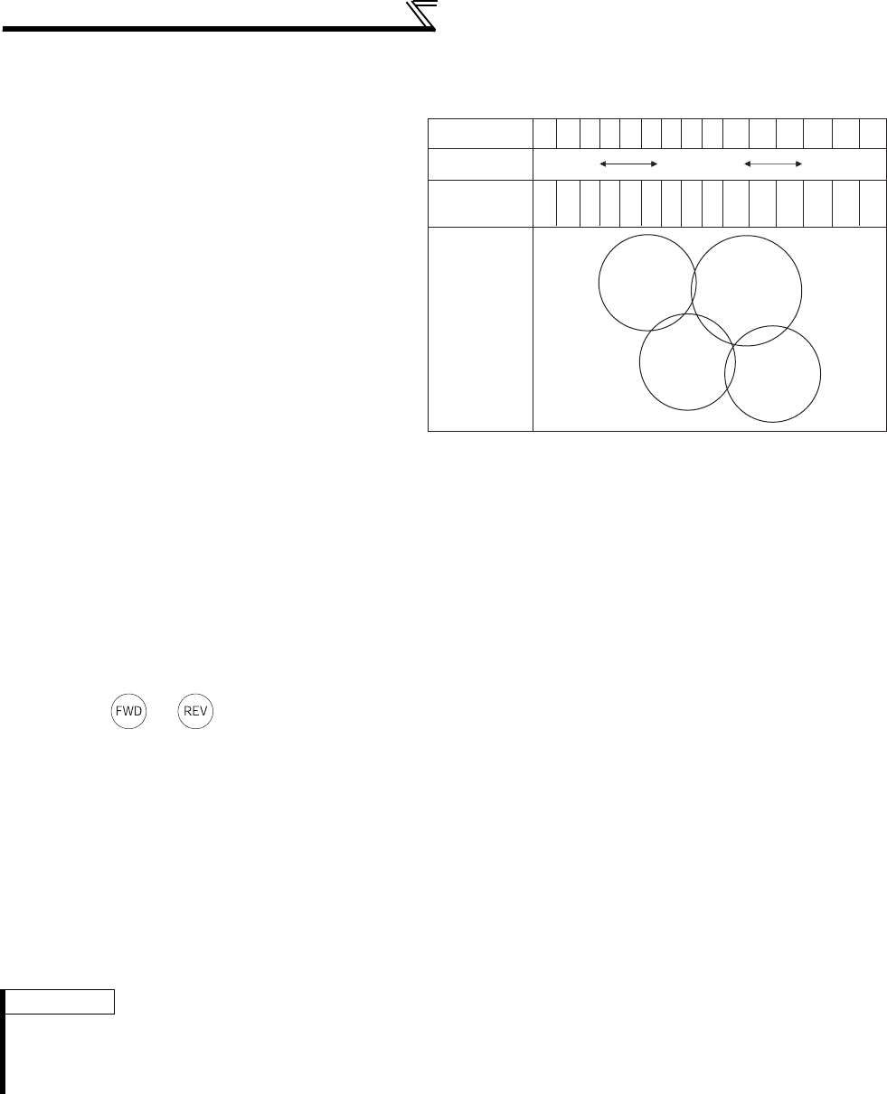
106
Speed control by Real sensorless vector
control, vector control
(2) Easy gain tuning execution procedure (Pr. 819 = "1" load inertia ratio automatic estimation)
Easy gain tuning (load inertia ratio automatic
estimation) is valid only in the speed control or
position control mode under vector control.
It is invalid under torque control, V/F control,
Advanced magnetic flux vector control and Real
sensorless vector control.
1) Set the response level using Pr. 818 Easy gain
tuning response level setting.
Refer to the diagram on the right and set the
response level.
Increasing the value will improve trackability
to the command, but too high value will
generate vibration. The relationship between
the setting and response level are shown on
the right.
2) Each control gain is automatically set from the
load inertia ratio estimated during
acceleration/deceleration operation and the Pr. 818 Easy gain tuning response level setting value.
Pr. 880 Load inertia ratio is used as the initial value of the load inertia ratio for tuning. Estimated value is set in Pr.
880 during tuning.
The load inertia ratio may not be estimated well, e.g. it takes a long time for estimation, if the following
conditions are not satisfied.
· Time taken for acceleration/deceleration to reach 1500r/min is 5s or less.
· Speed is 150r/min or more.
· Acceleration/deceleration torque is 10% or more of the rated torque.
· Abrupt disturbance is not applied during acceleration/deceleration.
· Load inertia ratio is approx. 30 times or less.
· No gear backlash nor belt looseness is found.
3) Press or to estimate the load inertia ratio or calculate gain any time. (The operation command for
External operation is the STF or STR signal.)
(3) Easy gain tuning execution procedure (Pr.819 = "2" load inertia manual input)
Easy gain tuning (load inertia ratio manual input) is valid only in the speed control mode under Real sensorless
vector control or in the speed control or position control mode under vector control.
1) Set the load inertia ratio to the motor in Pr. 880 Load inertia ratio.
2) Set "2" (with easy gain tuning) in Pr. 819 Easy gain tuning selection. Then, Pr. 820 Speed control P gain 1 and Pr. 821
Speed control integral time 1 are automatically set by gain calculation.
Operation is performed in a gain adjusted status from the next operation.
3) Perform a test run and set the response level in Pr. 818 Easy gain tuning response level setting. Increasing the value will
improve trackability to the command, but too high value will generate vibration. (When "2" (parameter write enabled
during operation) is set in Pr. 77 Parameter write selection , response level adjustment can be made during operation.)
REMARKS
· When "1 or 2" is set in Pr. 819 and then returned the Pr. 819 setting to "0" after tuning is executed, tuning results which are set in
each parameter remain unchanged.
· When good tuning accuracy is not obtained after executing easy gain tuning due to disturbance and such, perform fine
adjustment by manual input. Set "0" (without easy gain tuning) in Pr. 819.
Pr. 818 setting
Guideline of
mechanical resonance
frequency (Hz)
Response level
8 10 12 15 18 22 28 34 42 52 64 79 98 122 150
123456789101112131415
Slow
response
Fast
response
Middle
response
Large conveyor
Arm robot Precision
machine tool
General machine tool,
conveyor

107
Speed control by Real sensorless
vector control, vector control
4
PARAMETERS
(4) Parameters automatically set by easy gain tuning
The following table indicates the relationship between easy gain tuning function and gain adjustment parameter.
Easy Gain Tuning Selection (Pr. 819 ) Setting
0 1 2
Load inertia ratio
(Pr. 880) Manual input
a) Inertia estimation result (RAM) by
easy gain tuning is displayed.
b) Set the value in the following cases:
• Every hour after power-on
• When a value other than "1" is
set in Pr. 819
• When vector control is changed
to other control (V/F control etc.)
using Pr. 800
c) Write is enabled only during a stop
(manual input)
Manual input
Speed control P gain 1
(Pr. 820)
Speed control integral time 1
(Pr. 821)
Model speed control gain
(Pr. 828)
Position loop gain
(Pr. 422)
Manual input
a) Tuning result (RAM) is displayed. a) Gain is calculated when "2" is
set in Pr. 819 and the result is
set in the parameter.
b) Set the value in the following cases:
• Every hour after power-on
• When a value other than "1" is
set in Pr. 819
• When vector control is changed
to other control (V/F control etc.)
using Pr. 800
b) When the value is read, the
tuning result (parameter
setting value) is displayed.
c) Write (manual input) disabled c) Write (manual input) disabled
CAUTION
· Performing easy gain tuning with larger inertia than the specified value during vector control may cause malfunction such as
hunting. In addition, when the motor shaft is fixed with servo lock or position control, bearing may be damaged. To prevent these,
make gain adjustment by manual input without performing easy gain tuning.
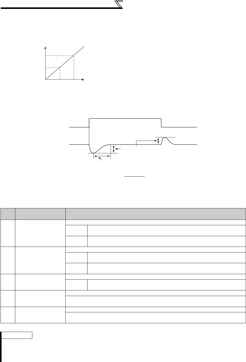
108
Speed control by Real sensorless vector
control, vector control
(5) Manual input speed control gain adjustment
· Make adjustment when any of such phenomena as unusual machine vibration/noise, low response level and
overshoot has occurred.
· When there is load inertia, the actual speed gain is as given below.
· Adjustment procedures are as below:
1)Check the conditions and simultaneously change the Pr. 820 value.
2)If you cannot make proper adjustment, change the Pr. 821 value and repeat step 1).
·Pr. 820 Speed control P gain 1 = "60%" (initial value) is equivalent to
120rad/s (speed response of the motor alone). (Half the value for
75K or higher or for Real sensorless vector control.) Increasing the
setting value improves the response level, but a too large gain will
produce vibration and/or unusual noise.
· Decreasing the Pr. 821 Speed control integral time 1 shortens the
return time taken at a speed change. However, a too short time will
generate an overshoot.
Actual speed gain = speed gain of motor without load × JM JM: Inertia of the motor
JL: Motor shaft-equivalent load inertia
JM+JL
No. Phenomenon/
Condition Adjustment Method
1Load inertia
is large
Set the Pr. 820 and Pr. 821 values a little higher.
Pr. 820 When a speed rise is slow, increase the value 10% by 10% until just before
vibration/noise is produced, and set about 0.8 to 0.9 of that value.
Pr. 821 If an overshoot occurs, double the value until an overshoot does not occur, and
set about 0.8 to 0.9 of that value.
2
Vibration/noise
generated from
mechanical system
Set the Pr. 820 value a little lower and the Pr. 821 value a little higher.
Pr. 820 Decrease the value 10% by 10% until just before vibration/noise is not produced,
and set about 0.8 to 0.9 of that value.
Pr. 821 If an overshoot occurs, double the value until an overshoot does not occur, and
set about 0.8 to 0.9 of that value.
3 Slow response
Set the Pr. 820 value a little higher.
Pr. 820 When a speed rise is slow, increase the value 5% by 5% until just before
vibration/noise is produced, and set about 0.8 to 0.9 of that value.
4Long return time
(response time)
Set the Pr. 821 value a little lower.
Decrease the Pr. 821 value by half until just before an overshoot or the unstable phenomenon
does not occur, and set about 0.8 to 0.9 of that value.
5
Overshoot
or unstable
phenomenon occurs.
Set the Pr. 821 value a little higher.
Increase the Pr. 821 value double by double until just before an overshoot or the unstable
phenomenon does not occur, and set about 0.8 to 0.9 of that value.
REMARKS
· When making manual input gain adjustment, set "0" (without easy gain tuning) (initial value) in Pr. 819 Easy gain tuning
selection.
·Pr. 830 Speed control P gain 2 and Pr. 831 Speed control integral time 2 are valid when the RT terminal is switched ON. Make
adjustments in the same way as Pr. 820 and Pr. 821.
Pr.820
Setting
100%
60%
(initial value)
Proportional gain
200 (100)rad/s*
120 (60)rad/s*
* The values for 75K or higher or for Real sensorless
vector control are indicated in parentheses.
Since increasing the proportional gain enhances the
response level and decreases the speed fluctuation.
Load
fluctuation
Speed
Decreasing the integral time shortens the return time taken.
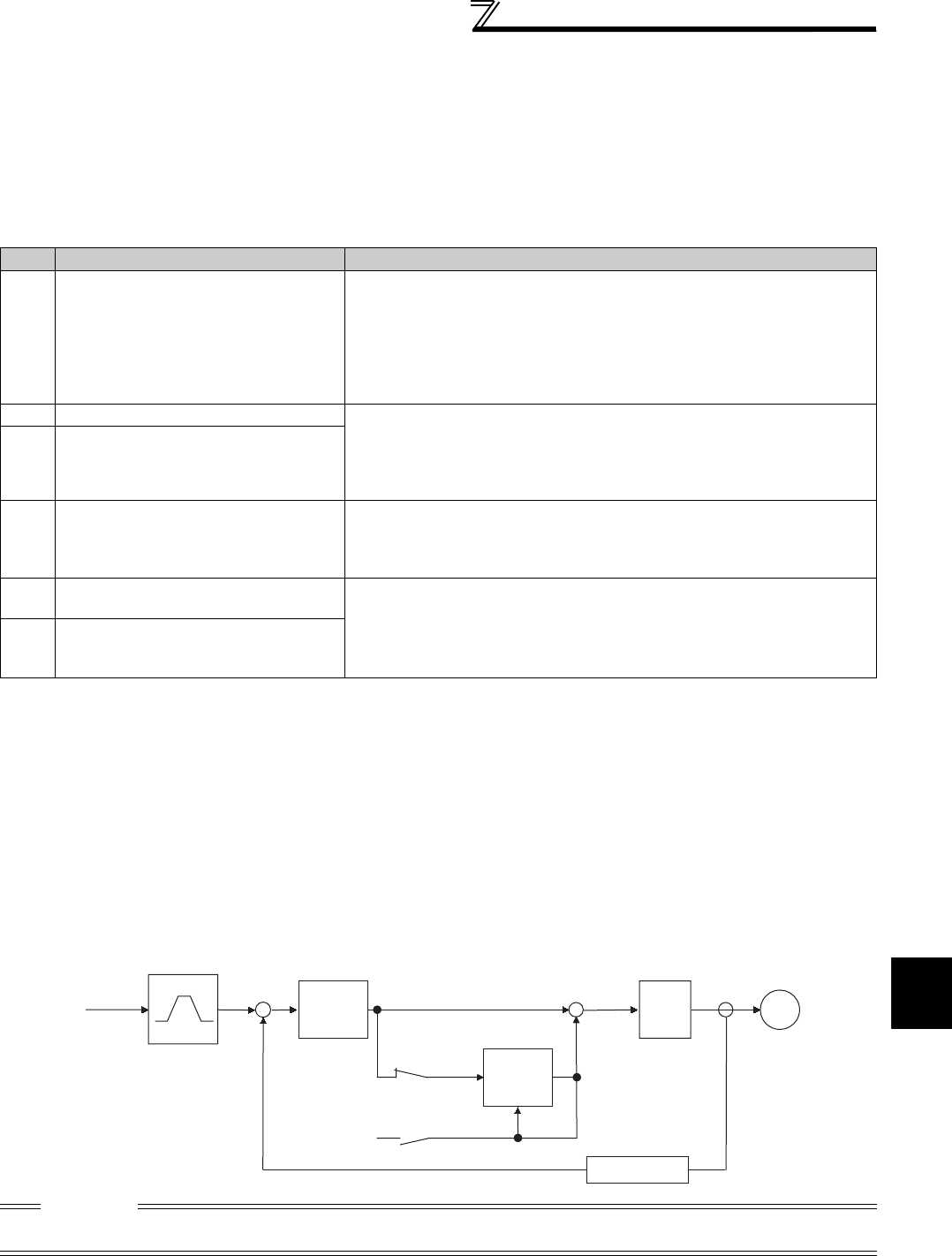
109
Speed control by Real sensorless
vector control, vector control
4
PARAMETERS
(6) When using a multi-pole motor (8 poles or more)
Specially when using a multi-pole motor with more than 8 poles under Real sensorless vector control or vector control,
adjust Pr. 820 Speed control P gain 1 and Pr. 824 Torque control P gain 1 according to the motor referring to the following
methods.
·For Pr. 820 Speed control P gain 1, increasing the setting value improves the response level, but a too large gain will
produce vibration and/or unusual noise.
·For Pr. 824 Torque control P gain 1, note that a too low value will produce current ripples, causing the motor to generate
sound synchronizing the cycle of current ripples.
Adjustment method
(7) P/PI switchover (X44 signal)
· By turning the P/PI control switching signal (X44) ON/OFF during seed control operation under Real sensorless
vector control or vector control, you can select whether to add the integral time (I) or not when performing gain
adjustment with P gain and integral time.
When the X44 signal is OFF ......... PI control
When the X44 signal is ON ........... P control
· For the terminal used for X44 signal input, set "44" in any of Pr. 178 to Pr. 189 (input terminal function selection) to
assign the function.
[Function block diagram]
No. Phenomenon/Condition Adjustment Method
1The motor rotation is unstable in the low
speed range.
Set a higher value in Pr. 820 Speed control P gain 1 according to the motor
inertia.
Since the self inertia of a multi-pole motor tends to become large, make
adjustment to improve the unstable phenomenon, then make fine adjustment
in consideration of the response level using that setting as reference.
In addition, when performing vector control with encoder, gain adjustment
according to the inertia can be easily done using easy gain tuning (Pr. 819 = 1).
2 Speed trackability is poor Set a higher value in Pr. 820 Speed control P gain 1.
Increase the value 10% by 10% until just before vibration or unusual noise is
produced, and set about 0.8 to 0.9 of that value.
If you cannot make proper adjustment, increase the value of Pr. 821 Speed
control integral time 1 double by double and make adjustment of Pr. 820 again.
3Speed variation at the load fluctuation is
large
4
Torque becomes insufficient or torque
ripple occurs at starting or in the low
speed range under Real sensorless
vector control.
Set the speed control gain a little higher. (same as No. 1)
If the problem still persists after gain adjustment, increase Pr. 13 Starting
frequency or set the acceleration time shorter if the inverter is starting to avoid
continuous operation in the ultra low speed range.
5Unusual motor and machine vibration,
noise or overcurrent occurs. Set a lower value in Pr. 824 Torque control P gain 1.
Decrease the value 10% by 10% until just before the phenomenon is
improved, and set about 0.8 to 0.9 of that value.
6
Overcurrent or overspeed (E.OS) occurs
at a start under Real sensorless vector
control.
CAUTION
⋅Changing the terminal assignment using Pr. 178 to Pr. 189 (input terminal function selection) may affect the other functions. Set
parameters after confirming the function of each terminal.
X44
X44
+
+
0
Speed
command
Speed
command
+
-
Speed
proportional
operation
Integration
cleared to 0
Speed
integral
operation
Speed estimator
Torque
control Motor
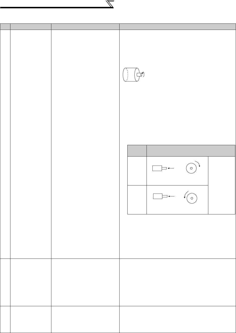
110
Speed control by Real sensorless vector
control, vector control
(8) Troubleshooting (speed)
Phenomenon Cause Countermeasures
1
Motor does not
rotate.
(Vector control)
(1) The motor wiring is wrong (1) Wiring check
Select V/F control (set "9999" in Pr. 80 or Pr. 81 ) and check
the rotation direction of the motor.
For the SF-V5RU (1500r/min series), set "170V(340V)" for
3.7kW or lower and "160V(320V)" for more in Pr. 19 Base
frequency voltage, and set "50Hz" in Pr. 3 Base frequency.
When the forward rotation signal is input, the
motor running in the counterclockwise direction
as viewed from the motor shaft is normal. (If it
runs in the clockwise direction, the phase
sequence of the inverter secondary side wiring
is incorrect.)
(2) Encoder specification selection
switch (FR-A7AP/FR-A7AL
(option)) is wrong.
(2) Check the encoder specifications.
Check the encoder specifications selection switch (FR-
A7AP/FR-A7AL (option)) of differential/complementary
(3) The encoder wiring is wrong. (3) Check that FWD is displayed when running the motor in the
counter-clockwise direction from outside during a stop of
the inverter with vector control setting.
If REV is displayed, the encoder phase sequence is wrong.
Check that the wiring is correct, and set the rotation
direction in Pr.359 Encoder rotation direction according to the
motor specification.
(4) The Pr. 369 Number of encoder
pulses setting and the number of
encoder used are different.
(4) The motor will not run if the parameter setting is smaller
than the number of encoder pulses used. Set the Pr. 369
Number of encoder pulses correctly.
(5) Encoder power specifications
are wrong. Or, power is not input.
(5) Check the power specifications (5V/12V/15V/24V) of
encoder and input the external power supply. Make the
voltage of the external power supply the same as the
encoder output voltage, and connect the external power
supply between PG and SD.
2
Motor does not run
at correct speed.
(Speed command
does not match
actual speed)
(1) The speed command from the
command device is incorrect.
The speed command is
compounded with noise.
(1) Check that a correct speed command comes from the
command device.
Decrease Pr. 72 PWM frequency selection.
(2) The speed command value
does not match the inverter-
recognized value.
(2) Readjust speed command bias/gain Pr. 125, Pr. 126, C2 to C7
and C12 to C15.
(3) The number of encoder pulses
setting is incorrect.
(3) Check the setting of Pr. 369 Number of encoder pulses. (vector
control)
3
Speed does not rise
to the speed
command.
(1) Insufficient torque.
Torque limit is actuated.
(1) -1 Increase the torque limit value.
(Refer to torque limit of speed control on page 100 )
(1) -2 Insufficient capacity
(2) Only P (proportional) control is
selected.
(2) When the load is heavy, speed deviation will occur under P
(proportional) control. Select PI control.
Pr. 359
Setting
Relationship between the Motor and
Encoder
0
Set the
rotation
direction
according to
the motor
specification.
1
(Initial
value)
A
Encoder
CW
Clockwise direction as viewed
from A is forward rotation
CCW
A
Encoder
Counter clockwise direction as
viewed from A is forward rotation

111
Speed control by Real sensorless
vector control, vector control
4
PARAMETERS
4Motor speed is
unstable.
(1) The speed command varies. (1) -1 Check that a correct speed command comes from the
command device. (Take measures against noises.)
(1) -2 Decrease Pr. 72 PWM frequency selection.
(1) -3 Increase Pr. 822 Speed setting filter 1. (Refer to page 292)
(2) Insufficient torque. (2) Increase the torque limit value.
(Refer to torque limit of speed control on page 100)
(3) The speed control gains do not
match the machine. (mechanical
resonance)
(3) -1 Perform easy gain tuning. (Refer to page 106)
(3) -2 Adjust Pr. 820, Pr. 821. (Refer to page 108)
(3) -3 Perform speed feed forward/model adaptive speed
control.
5
Motor or machine
hunts (vibration/
noise is produced).
(1) The speed control gain is high. (1) -1 Perform easy gain tuning. (Refer to page 106)
(1) -2 Decrease Pr. 820 and increase Pr. 821.
(1) -3 Perform speed feed forward control and model adaptive
speed control.
(2) The torque control gain is high. (2) Decrease the Pr. 824 value. (Refer to page 130)
(3) The motor wiring is wrong. (3) Check the wiring
6
Acceleration/
deceleration time
does not match the
setting.
(1) Insufficient torque. (1) -1 Increase the torque limit value.
(Refer to torque limit of speed control on page 100)
(1) -2 Perform speed feed forward control.
(2) Large load inertia. (2) Set the acceleration/deceleration time that meets the load.
7Machine operation is
unstable
(1) The speed control gains do not
match the machine.
(1) -1 Perform easy gain tuning. (Refer to page 106)
(1) -2 Adjust Pr. 820, Pr. 821. (Refer to page 108)
(1) -3 Perform speed feed forward control and model adaptive
speed control.
(2) Slow response because of
improper acceleration/
deceleration time of the inverter.
(2) Change the acceleration/deceleration time to an optimum
value.
8Speed fluctuates at
low speed.
(1) Adverse effect of high carrier
frequency.
(1) Decrease Pr. 72 PWM frequency selection.
(2) Low speed control gain. (2) Increase Pr. 820 Speed control P gain 1.
Phenomenon Cause Countermeasures
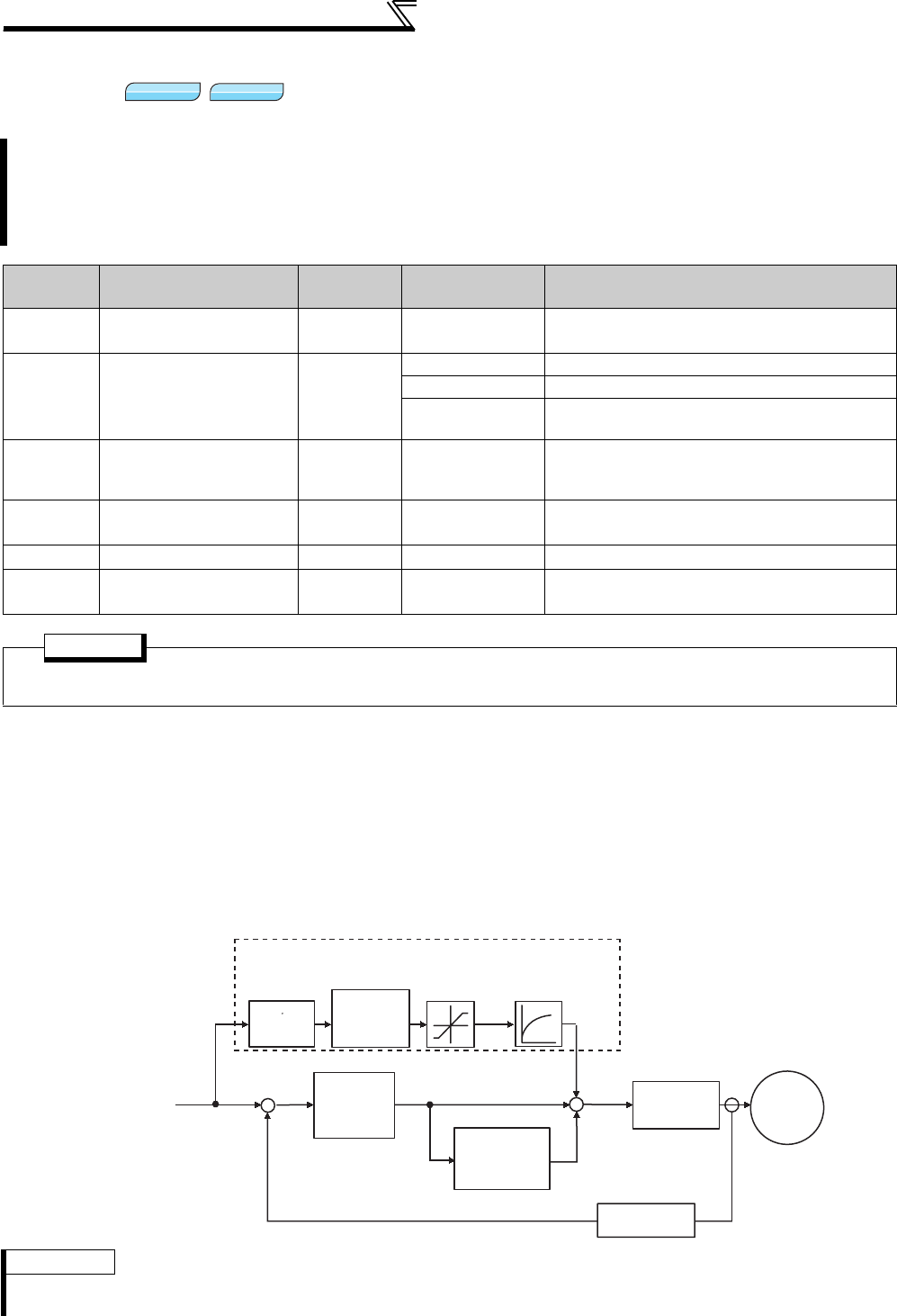
112
Speed control by Real sensorless vector
control, vector control
4.4.5 Speed feed forward control, model adaptive speed control (Pr. 828, Pr. 877 to Pr.
881)
(1) Speed feed forward control (Pr. 877 = "1")
⋅Calculate required torque in response to the acceleration/deceleration command for the inertia ratio set in Pr. 880 and
generate torque immediately.
⋅When the speed feed forward gain is 100%, the calculation result of the speed feed forward is reflected as-is.
⋅If the speed command changes suddenly, large torque is generated due to the speed feed forward calculation. The
maximum value of the speed feed forward is limited using Pr. 879 .
⋅Using Pr.878, the speed feed forward result can be dulled by the primary delay filter.
By making parameter setting, select the speed feed forward control or model adaptive speed control.
The speed feed forward control enhances the trackability of the motor in response to a speed command
change.
The model adaptive speed control enables individual adjustment of speed trackability and motor disturbance
torque response.
Parameter
Number Name Initial Value Setting Range Description
828 Model speed control
gain 60% 0 to 1000% Set the gain for model speed controller.
877
Speed feed forward
control/model
adaptive speed
control selection
0
0 Normal speed control is exercised.
1 Speed feed forward control is exercised.
2 Model adaptive speed control is enabled.
878 Speed feed forward
filter 0s 0 to 1s
Set the primary delay filter for the speed feed
forward result calculated using the speed
command and load inertia ratio.
879 Speed feed forward
torque limit 150% 0 to 400% Limits the maximum value of the speed feed
forward torque.
880 Load inertia ratio 7 times 0 to 200 times Set the load inertia ratio to the motor.
881 Speed feed forward
gain 0% 0 to 1000% Set the feed forward calculation result as a gain.
POINT
When model adaptive speed control is selected, the data obtained from easy gain tuning is used for Pr. 828 Model
speed control gain. Perform easy gain tuning also (simultaneously). (Refer to page 105)
REMARKS
· The speed feed forward control is enabled for the first motor.
· Even if the driven motor is switched to the second motor while Pr. 877 = 1, the second motor is operated as if Pr. 877 = 0.
Sensorless
Sensorless
Sensorless
Vector
Vector
Vector
Load inertia ratio
J s
[Pr. 880][Pr. 881]
[Pr. 820]
Speed feed forward control
Torque control
Speed estimator
Speed
control
P gain 1
Speed control
integral time 1
IM
Actual speed controller
+
-+
+
+
Speed command
[Block diagram]
Speed feed
forward
gain
Speed feed
forward torque
limit
Speed feed
forward
filter
[Pr. 879][Pr. 878]
[Pr. 821]
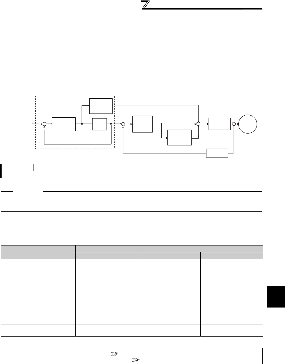
113
Speed control by Real sensorless
vector control, vector control
4
PARAMETERS
(2) Model adaptive speed control (Pr. 877 = "2")
⋅The motor's model speed is calculated to feed back the model side speed controller. This model speed is also used
as the actual speed controller command.
⋅The inertia ratio in Pr. 880 is used for calculation of the torque current command value given by the model side speed
controller.
⋅The torque current command value of the model side speed controller is added to the output of the actual speed
controller, and the result is used as the iq current control input.
Pr. 828 is used for model side speed control (P control), and the first gain in Pr. 820 is used for the actual speed
controller. The model adaptive speed control is valid for the first motor only.
(3) Combination of easy gain tuning
The following table indicates the relationships between the speed feed forward/model adaptive speed control and easy
gain tuning function.
REMARKS
· Even if the driven motor is switched to the second motor while Pr. 877 = 2, the second motor is operated as if Pr. 877 = 0.
CAUTION
The adequate gain value for the model and actual loop parts are set according to the response setting of easy gain tuning under
model adaptive speed control. To increase the response level, the Pr. 818 Easy gain tuning response level setting needs to be
changed (increased).
Easy Gain Tuning Selection (Pr. 819) Setting
0 1 2
Load inertia ratio
(Pr. 880) Manual input
Inertia ratio estimation value
found by easy gain tuning is
displayed.
Manual input enabled only
during a stop.
Manual input
Speed control P gain 1
(Pr. 820) Manual input Tuning results are displayed.
Write disabled
Tuning results are displayed.
Write disabled
Speed control integral time 1
(Pr. 821) Manual input Tuning results are displayed.
Write disabled
Tuning results are displayed.
Write disabled
Model speed control gain
(Pr. 828) Manual input Tuning results are displayed.
Write disabled
Tuning results are displayed.
Write disabled
Speed feed forward gain
(Pr. 881) Manual input Manual input Manual input
♦Parameters referred to♦
Pr. 820 Speed control P gain 1, Pr. 830 Speed control P gain 2 Refer to page 105
Pr. 821 Speed control integral time 1, Pr. 831 Speed control integral time 2 Refer to page 105
Torque
control
Speed
estimator
Speed control
P gain 1
Speed control
integral time 1
IM
Speed command
Actual speed controller
Model speed
calculation
+
-+
+
+
Model speed
control gain
[Pr. 828]
1
J s
J
Torque coefficient
(J: )
+
-
Model adaptive speed control
[Block diagram]
[Pr. 880]
[Pr. 820]
[Pr. 821]
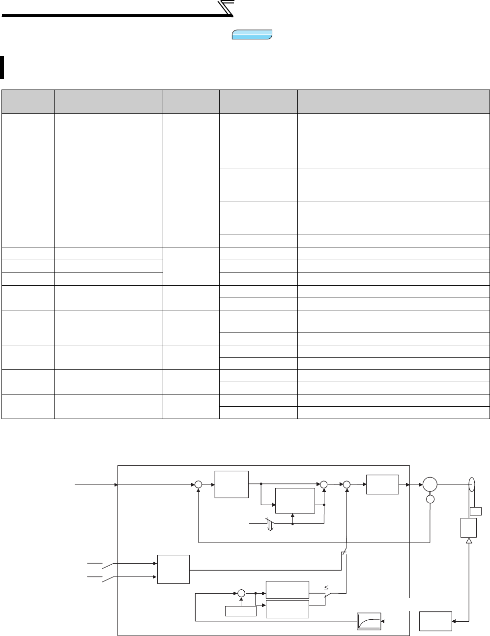
Speed control by Real sensorless vector
control, vector control
114
4.4.6 Torque biases (Pr. 840 to Pr. 848)
(1) Block diagram
This function accelerates the rise of the torque at a start. Adjust the torque at a motor start using the contact
signals or analog signals .
Parameter
Number Name Initial Value Setting Range Description
840 Torque bias selection 9999
0Set the torque bias amount with the contact signal
(X42, X43) using Pr. 841 to Pr. 843.
1
Set the terminal 1-based torque bias amount as
desired in C16 to C19 . (in the case a cage goes up
when a motor runs reversely)
2
Set the terminal 1-based torque bias amount as
desired in C16 to C19 . (in the case a cage goes up
when a motor runs forward)
3
The terminal 1-based torque bias amount can be
set automatically in C16 to C19, Pr. 846 according
to the load.
9999 Without torque bias, rated torque 100%
841 Torque bias 1
9999
600 to 999% Negative torque bias amount (-400% to -1%)
842 Torque bias 2 1000 to 1400% Positive torque bias amount (0% to 400%)
843 Torque bias 3 9999 Without torque bias setting
844 Torque bias filter 9999 0 to 5s Time until torque rises.
9999 Same operation as when 0s is set.
845 Torque bias operation
time 9999 0 to 5s Time for maintaining torque equivalent to the
torque bias amount.
9999 Same operation as when 0s is set.
846 Torque bias balance
compensation 9999 0 to 10V Set the voltage under balanced load.
9999 Same operation as when 0V is set.
847 Fall-time torque bias
terminal 1 bias 9999 0 to 400% Set the bias value of the torque command.
9999 Same as at a rise time (C16, C17 (Pr. 919)).
848 Fall-time torque bias
terminal 1 gain 9999 0 to 400% Set the gain value of the torque command.
9999 Same as at a rise time (C18, C19 (Pr. 920)).
The above parameters can be set when the FR-A7AP/FR-A7AL (option) is mounted.
Vector
Vector
Vector
Internal parameters [Pr. 840 = 0]
IM
CW
-
-
+
X42
X43
+
+
+
0
Integration cleared to 0
+
+
Speed command
Torque bias selection 1
Torque bias selection 2
Speed command
[Pr. 841]
[Pr. 842]
[Pr. 843]
Speed
control
P gain
Speed
control
integral time
Torque
control
[Pr. 840 = 1
,
2
,
3]
C16, C17
[Pr. 919]
C18, C19
[Pr. 920]
[Pr. 846]
[Pr. 845]
[Pr. 826]
Torque setting filter 1
Terminal 1
Encoder
Cage
Load
detector
CW Cage
CW > Cage
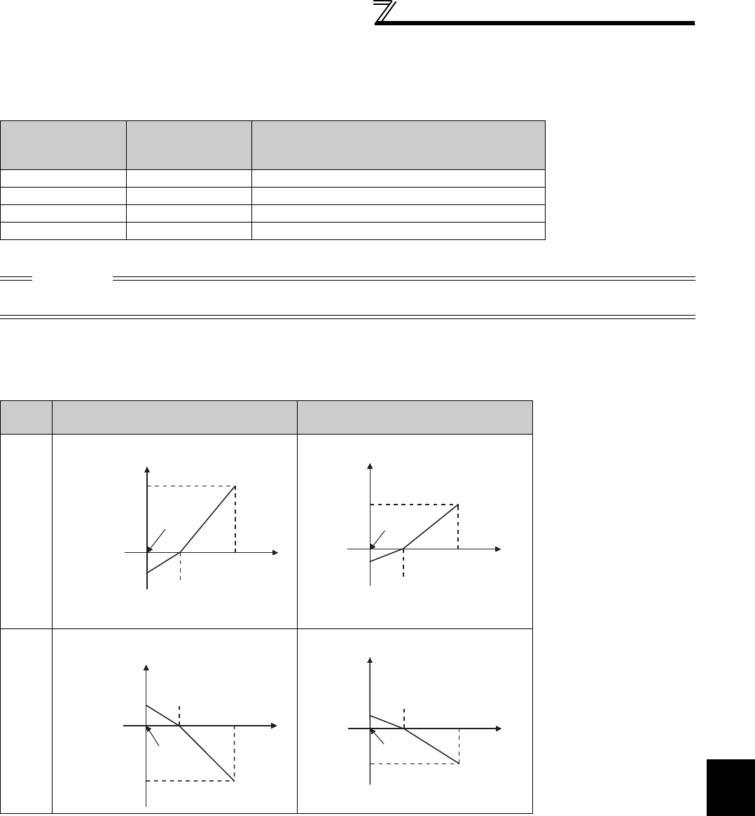
115
4
PARAMETERS
Speed control by Real sensorless vector
control, vector control
(2) Setting torque bias amount with the contact input (Pr. 840 = "0")
⋅Select the torque bias amount in the table below according to the combination of contact signals.
⋅Set "42" in Pr. 178 to Pr. 189 (input terminal function selection) for the terminal used for X42 signal input and set "43" for
the terminal used for X43 signal input to assign functions.
Example) when Pr. 841 = 1025, 25% when Pr. 842 = 975, -25% when Pr. 843 = 925, -75%
(3) Setting torque bias amount with terminal 1 (Pr. 840 = "1, 2")
⋅Calculate torque bias from the load input to terminal 1 as shown in the diagram below and provide torque bias.
⋅To set torque bias amount by the voltage input to terminal 1, set "6" in Pr. 868 Terminal 1 function assignment.
Torque Bias
Selection 1
(X42)
Torque Bias
Selection 2
(X43)
Torque Bias Amount
OFF OFF 0%
ON OFF Pr. 841 -400% to +400% (setting value : 600 to 1400%)
OFF ON Pr. 842 -400% to +400% (setting value : 600 to 1400%)
ON ON Pr. 843 -400% to +400% (setting value : 600 to 1400%)
CAUTION
Changing the terminal assignment using Pr. 178 to Pr. 189 (input terminal function selection) may affect the other functions. Set
parameters after confirming the function of each terminal.
Pr. 840
Setting Rise (Motor Forward Rotation) Fall (Motor Reverse Rotation)
1
2
Torque command
terminal 1 gain
C18(Pr. 920)
Torque command
terminal 1 bias
C16(Pr. 919)
Voltage for
max. load
C19(Pr. 920)
Voltage for
balanced load
Pr. 846
Terminal 1
input
Bias amount
C17(Pr. 919)
Voltage for
max. load
C19(Pr. 920)
Voltage for
balanced load
Pr. 846
Bias amount
Terminal 1
input
Fall-time
torque bias
terminal 1
gain
P
r. 847
Fall-time
torque bias
terminal 1
bias
Pr. 848
C17(Pr. 919)
Torque command
terminal 1 gain
C18(Pr. 920)
Voltage for
max. load
C19(Pr. 920)
Voltage for
balanced load
Pr. 846
Bias amount
Terminal 1
input
Torque command
terminal 1 bias
C16(Pr. 919)
C17(Pr. 919)
Voltage for
max. load
C19(Pr. 920)
Voltage for
balanced load
Pr. 846
Bias amount
Terminal 1
input
Fall-time
torque bias
terminal 1
bias
P
r. 847
Fall-time
torque bias
terminal 1
gain
P
r. 848
C17(Pr. 919)
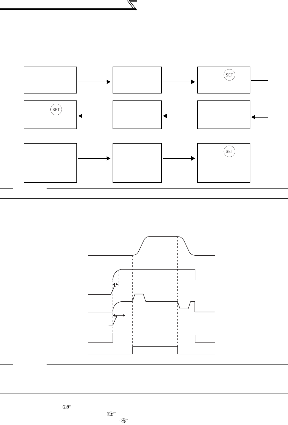
Speed control by Real sensorless vector
control, vector control
116
(4) Setting torque bias amount with terminal 1 (Pr. 840 = "3")
⋅C16 Terminal 1 bias command (torque/magnetic flux), C17 Terminal 1 bias (torque/magnetic flux), C18 Terminal 1 gain
command (torque/magnetic flux), C19 Terminal 1 gain (torque/magnetic flux), and Pr. 846 Torque bias balance compensation
can be set automatically according to the load.
⋅To set torque bias amount by the voltage input to terminal 1, set "6" in Pr. 868 Terminal 1 function assignment.
⋅Setting C16, C17 (Pr. 919) , C18, C19 (Pr. 920)
⋅Setting Pr. 846
(5) Torque bias operation
⋅When a value other than 9999 is set in Pr. 844 Torque bias filter, you can slow the rise of torque. At this time, the
torque rises according to the time constant of the primary delay filter.
⋅
Set the time for output torque be maintained with the torque bias command value alone in
Pr. 845 Torque bias operation time
.
* When pre-excitation is not made, the torque bias functions simultaneously with the start signal.
Operation without a
load
Read C16, C17
(Pr. 919) when
speed is stable
Press .
(setting C16, C17
(Pr. 919) is completed)
Press .
(setting C18, C19
(Pr. 920) is completed)
Read C18, C19
(Pr. 920) when
speed is stable
Operation with a
maximum load
Operation with a
balanced load Read Pr. 846
Press .
Torque balance
compensation under
power driving is
completed.
CAUTION
When starting torque bias operation after completion of automatic setting, set "1 or 2" in Pr. 840.
CAUTION
⋅
When torque bias is valid and "6" is set in
Pr. 868
, terminal 1 serves as torque command not as frequency setting auxiliary.
When override compensation is set by
Pr. 73
and terminal 1 acts as main speed, no main speed (main speed = 0Hz) is selected.
⋅
Changing the terminal assignment using
Pr. 178 to Pr. 189 (input terminal function selection) may affect the other functions. Set
parameters after confirming the function of each terminal.
Reference parameters
⋅Pr. 73 Analog input selection Refer to page 286.
⋅Pr. 178 to Pr. 189 (input terminal function selection) Refer to page 231.
⋅C16 to C19 (torque setting voltage (current) bias and gain) Refer to page 300.
Speed
Torque bias
Torque bias filter
primary delay time
constant
Time when torque is
generated by
torque bias setting
Pre-excitation LX
*
Start signal
Pr. 844
Pr. 845
Output torque
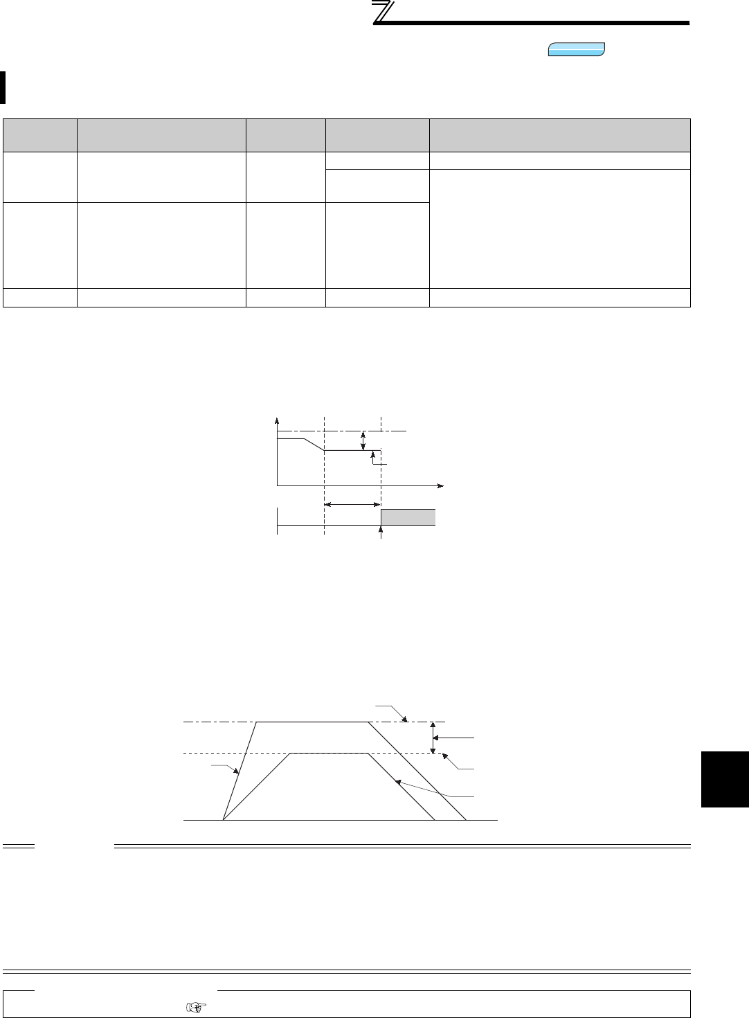
117
4
PARAMETERS
Speed control by Real sensorless vector
control, vector control
4.4.7 Prevent the motor from overrunning (Pr. 285, Pr. 853, Pr. 873)
(1) Speed deviation excessive (Pr. 285, Pr. 853)
When the deviation between the set frequency and actual speed is large, e.g. too large load torque, this function can
cause the inverter to provide a speed deviation excessive fault (E.OSD) and come to a trip.
(2) Speed limit (Pr. 873)
This function prevents the motor from overrunning when the setting of number of encoder pulses and the actual
number differ.
When the setting of number of encoder pulses is smaller than the actual number, the motor may increase its speed.
To prevent this, restrict the output frequency with frequency (obtained by adding the set frequency and Pr. 873 ).
This function prevents the motor from overrunning when the load torque is too large and incorrect number of the
encoder is set.
Parameter
Number Name Initial Value Setting Range Description
285
Excessive speed
deviation detection
frequency *1
9999
9999 Without speed deviation excessive
0 to 30Hz If the difference (absolute value) between the
speed command value and actual speed during
speed control under vector control exceeds the
Pr. 285 Excessive speed deviation detection
frequency for more than the time set in Pr. 853
Speed deviation time, speed deviation excessive
occurs and inverter fault (E. OSD) appears,
resulting in a trip.
853 *2 Speed deviation time 1.0s 0 to 100s
873 *2 Speed limit 20Hz 0 to 120Hz
Frequency is limited at the set frequency +
Pr. 873
.
*1 Acts as Overspeed detection frequency under encoder feed back operation. (Refer to page 217)
*2 This parameter can be set when the FR-A7AP/FR-A7AL (option) is mounted.
CAUTION
⋅If automatic restart after instantaneous power failure (Pr. 57 ≠ 9999) is selected when the setting of number of encoder pulses is
smaller than the actual number, the output speed is limited with the synchronous speed obtained by adding the maximum
setting (Pr. 1) and Pr. 873 setting.
⋅When speed limit function is activated due to regenerative torque limit, output torque may suddenly decrease. In addition,
output phase loss (E.LF) may occur when speed limit function is activated during pre-excitation.
When the setting of number of encoder pulses are correct, it is recommended to set a maximum value (120Hz) in Pr. 873.
⋅Even when the set frequency is lowered after the inverter has been started, the speed limit value does not decrease. Note that
the speed is limited to speed command + Pr. 873 setting during deceleration.
Reference parameters
Pr. 285 Overspeed detection frequency Refer to page 217.
Vector
Vector
Vector
Set frequency
Actual speed
Time
Speed deviation
excessive fault activated
(E. OSD)
ONOFF
Fault output
(across A-C)
Pr. 853
Pr. 285
Frequency
(Hz)
A
ctual speed
at error occurrence
Set speed + Pr. 873 value
Value of Pr. 873
Set speed
Speed during
normal operation.
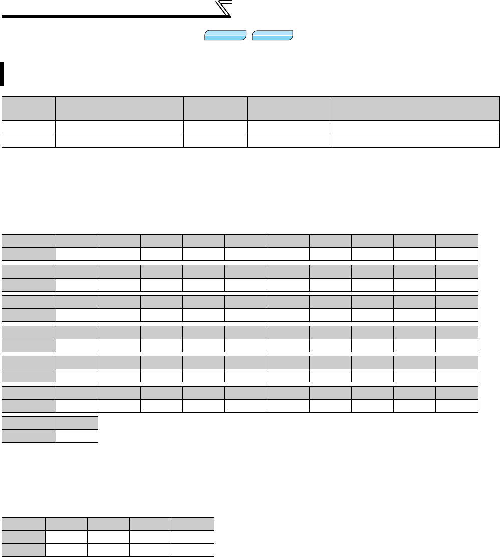
118
Speed control by Real sensorless
vector control, vector control
4.4.8 Notch filter (Pr. 862, Pr. 863)
(1) Pr. 862 Notch filter time constant
⋅If you do not know the mechanical resonance frequency, decrease notch frequency gradually from the highest value.
The point at which the smallest vibration is generated is the notch frequency setting.
⋅Machine characteristic can be obtained beforehand with machine analyzer by FR Configurator. Necessary notch
frequency can be determined from this.
(2) Pr. 863 Notch filter depth
⋅The notch filter with deeper depth has an effect on minimizing mechanical resonance. However, large vibration may
be generated adversely due to substantial phase delay. Make adjustment of notch depth in order of the shallower
depth.
You can reduce the response level of speed control in the resonance frequency band of the mechanical system
to avoid mechanical resonance.
Parameter
Number Name Initial Value Setting Range Description
862 Notch filter time constant 0 0 to 60 Refer to the following table
863 Notch filter depth 0 0 to 3 0 (deep) → 3 (shallow)
Setting 0 1 2 3 4 5 6 7 8 9
Frequency Invalid 1000 500 333.3 250 200 166.7 142.9 125 111.1
Setting 10 11 12 13 14 15 16 17 18 19
Frequency 100 90.9 83.3 76.9 71.4 66.7 62.5 58.8 55.6 52.6
Setting 20 21 22 23 24 25 26 27 28 29
Frequency 50 47.6 45.5 43.5 41.7 40 38.5 37 35.7 34.5
Setting 30 31 32 33 34 35 36 37 38 39
Frequency 33.3 32.3 31.3 30.3 29.4 28.6 27.8 27.0 26.3 25.6
Setting 40 41 42 43 44 45 46 47 48 49
Frequency 25.0 24.4 23.8 23.3 22.7 22.2 21.7 21.3 20.8 20.4
Setting 50 51 52 53 54 55 56 57 58 59
Frequency 20.0 19.6 19.2 18.9 18.5 18.2 17.9 17.5 17.2 16.9
Setting 60
Frequency 16.7
Setting 3 2 1 0
Depth Shallow →←Deep
Gain -4dB -8dB -14dB -40dB
Sensorless
Sensorless
Sensorless
Vector
Vector
Vector
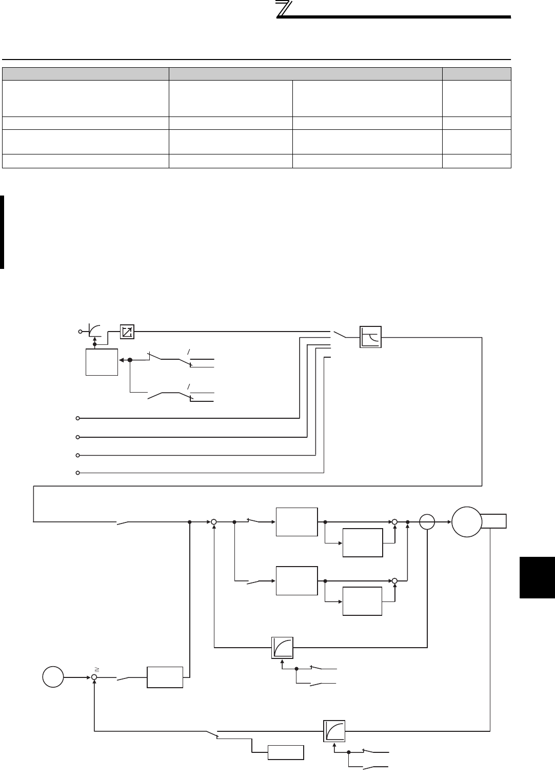
119
Torque control by Real sensorless
vector control, vector control
4
PARAMETERS
4.5 Torque control by Real sensorless vector control, vector
control
4.5.1 Torque control
(1) Block diagram
Purpose Parameter that must be Set Refer to Page
Selection of torque command
source and setting of torque
command value
Torque command Pr. 803 to Pr. 806 125
Prevent the motor overspeed Speed limit Pr. 807 to Pr. 809 127
Improve torque control accuracy Gain adjustment for
torque control Pr. 824, Pr. 825, Pr. 834, Pr. 835 130
Stabilize the torque detection signal Torque detection filter Pr. 827, Pr. 837 144
Torque control is exercised to develop torque as set in the torque command.
The motor speed becomes constant when the motor output torque and load torque are balanced.
For torque control, therefore, the speed is determined by the load.
For torque control, the motor gains speed as the motor output torque becomes greater than the motor load.
To prevent overspeed, set the speed limit value so that the motor speed does not increase too high.
(Torque control is disabled under speed limit since speed control is exercised.)
When speed limit is not set, the speed limit value setting is regarded as 0Hz to disable torque control.
[Pr. 824]
RT
RT
RT
RT
-
RT
RT
Speed detection filter
Vector control
Motor
Encoder
[Pr. 800 = 1]
++
+
+
+
Actual speed or estimated speed
< Speed limit value
Actual speed or estimated speed
Speed limit value
-
+
ASpeed
limit
value
Torque control
P gain 1
Torque control
integral time 1
Torque control
integral time 2
[Pr. 834]
[Pr. 827]
[Pr. 837]
[Pr. 823]
[Pr. 833]
Torque control
P gain 2
[Pr. 825]
[Pr. 835]
Torque detection filter
Real sensorless
vector control
Speed
estimation
Speed control
(proportional
control)
[Pr. 800 = 11]
Terminal 1
CC-Link
(FR-A7NC/FR-A7NCE)
16bit digital input
Torque command
source selection
Constant power range
torque characteristic selection
RT
RT
[Pr. 826]
[Pr. 74]
[Pr. 826 = 9999]
[Pr. 826 = 9999]
[Pr. 836]
[Pr. 74]
[Pr. 836 = 9999]
[Pr. 836 = 9999]
Terminal 1 bias [C16,C17 (Pr. 919)]
Terminal 1 gain [C18,C19 (Pr. 920)]
Parameter
[Pr. 805, Pr. 806]
[Pr. 868 = 3, 4]
(FR-A7AX)
[Pr. 804][Pr. 803]
Torque
setting
filter
Pulse train
(FR-A7AL)
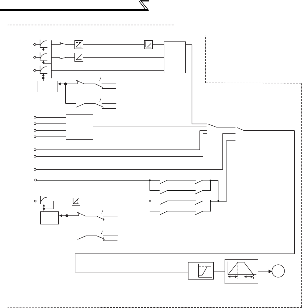
120
Torque control by Real sensorless vector
control, vector control
Terminal 2
Terminal 4
Terminal 1
Terminal 2 bias [C2, C3 (Pr. 902)]
Terminal 1 bias [C12,C13(Pr. 917)]
Terminal 2 gain [Pr. 125, C4 (Pr. 903)]
Terminal 1 gain [C14,C15(Pr. 918)]
Terminal 4 bias [C5, C6 (Pr. 904)]
Terminal 4 gain [Pr. 126, C7(Pr. 905)]
AU
AU
Analog
input
selection
[Pr. 73]
RL
RH
REX
Option
Multi-speed
selection
[Pr.4 to 6,
24 to 27,
232 to 239]
Operation
panel
Operation Mode
Speed
setting filter
Analog input offset
adjustment
[Pr. 849]
Terminal 1
Maximum/minimum
setting
Acceleration/deceleration processing
A
Speed
setting
filter
Parameter
Speed limit selection
Speed limit
RM
RT
RT
RT
RT
*
*When [Pr. 807 =2] and [Pr. 1 Maximum
frequency] is the speed limit,
acceleration/deceleration processing is not
performed.
Terminal 1 input 0 to 10V
Terminal 1 input 0 to 10V
Terminal 1 input -10 to 0V
Terminal 1 input -10 to 0V Reverse
rotation
Reverse
rotation
Forward
rotation
Forward
rotation
Maximum
frequency
[Pr. 807 = 2]
[Pr. 79]
[Pr. 74]
[Pr. 74]
[Pr. 832]
[Pr. 822]
[Pr. 807 = 1]
[Pr. 858 = 0]
[Pr. 868 = 0]
[Pr. 868 = 5]
[Pr. 808, Pr. 809]
[Pr. 822]
[Pr. 832]
[Pr. 74]
[Pr. 74]
[Pr. 1]
[Pr. 832 = 9999]
[Pr. 832 = 9999]
[Pr. 832 = 9999]
[Pr. 832 = 9999]
[Pr. 822 = 9999]
[Pr. 822 = 9999]
[Pr. 822 = 9999]
[Pr. 822 = 9999]
[Pr. 807 = 0]
[Pr.1]
[Pr.7][Pr.8]
[Pr.2]
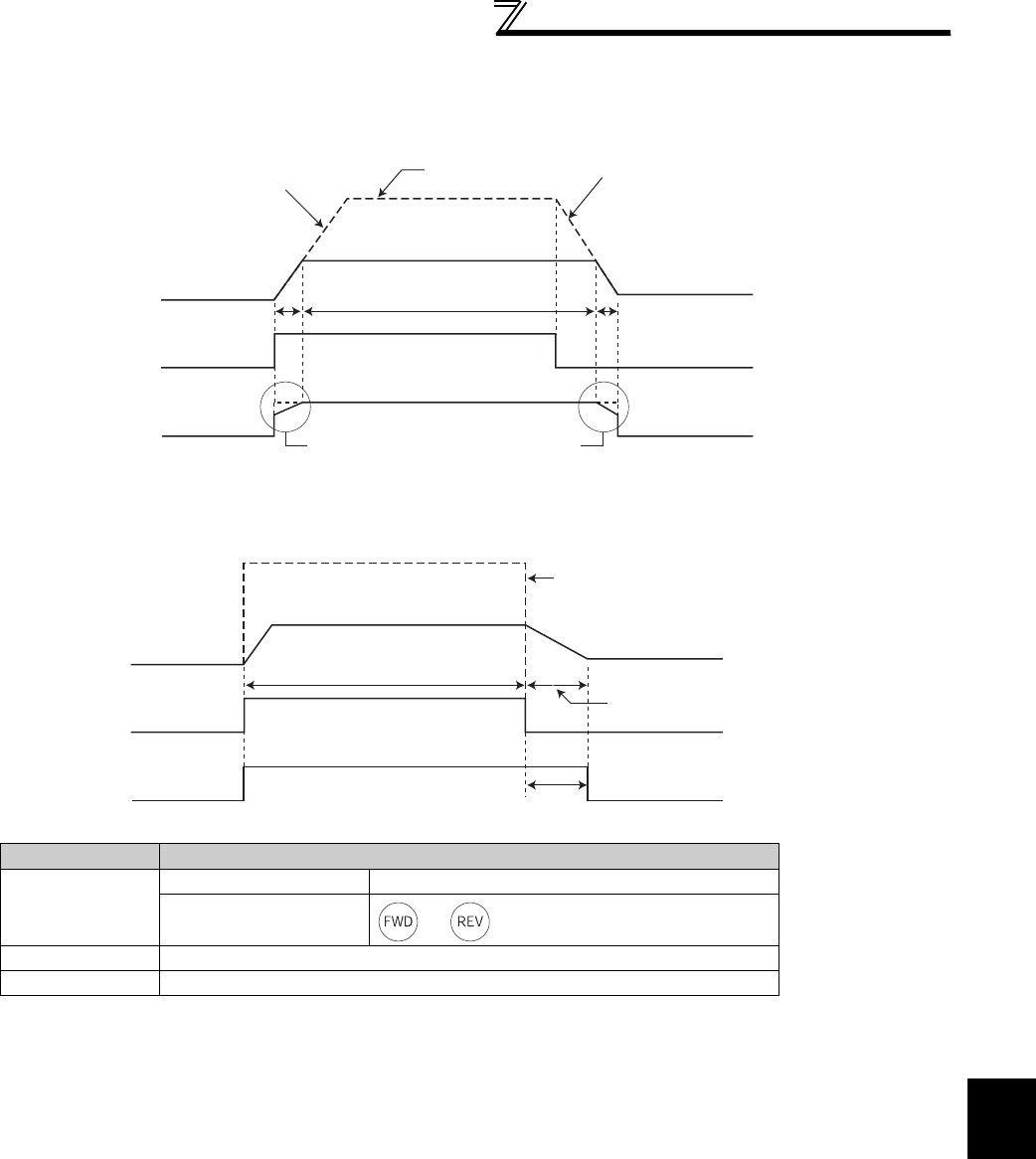
121
Torque control by Real sensorless
vector control, vector control
4
PARAMETERS
(2) Operation transition
⋅When "0" is set in Pr. 7 or Pr. 8, speed control is exercised upon powering OFF a start signal and the output torque is
limited at the torque limit value.
Item Description
Start signal
External operation STF, STR signal
PU operation and of FR-DU07, FR-PU07 or FR-PU04
Torque command Select the input method of torque command and input the torque command.
Speed limit Select the input method of speed limit and input the speed limit value.
Torque control
Speed limit
Speed limit value is
increased up to preset value
according to the Pr.7
Acceleration time setting. Speed limit value Speed limit value is decreased
down to zero according to the Pr.8
Deceleration time setting.
Speed
Start signal
Output torque
Speed limit
Output torque is provided
according to the terminal 1
setting.
Speed control is peformed during speed
limit. (Thus, torque according to the
commanded is not developed.)
Speed limit value
Start signal
Output torque
Speed
Limit at the torque limit value
Torque control
Speed control
(speed limit)
Output torque is provided
according to the terminal 1
setting.
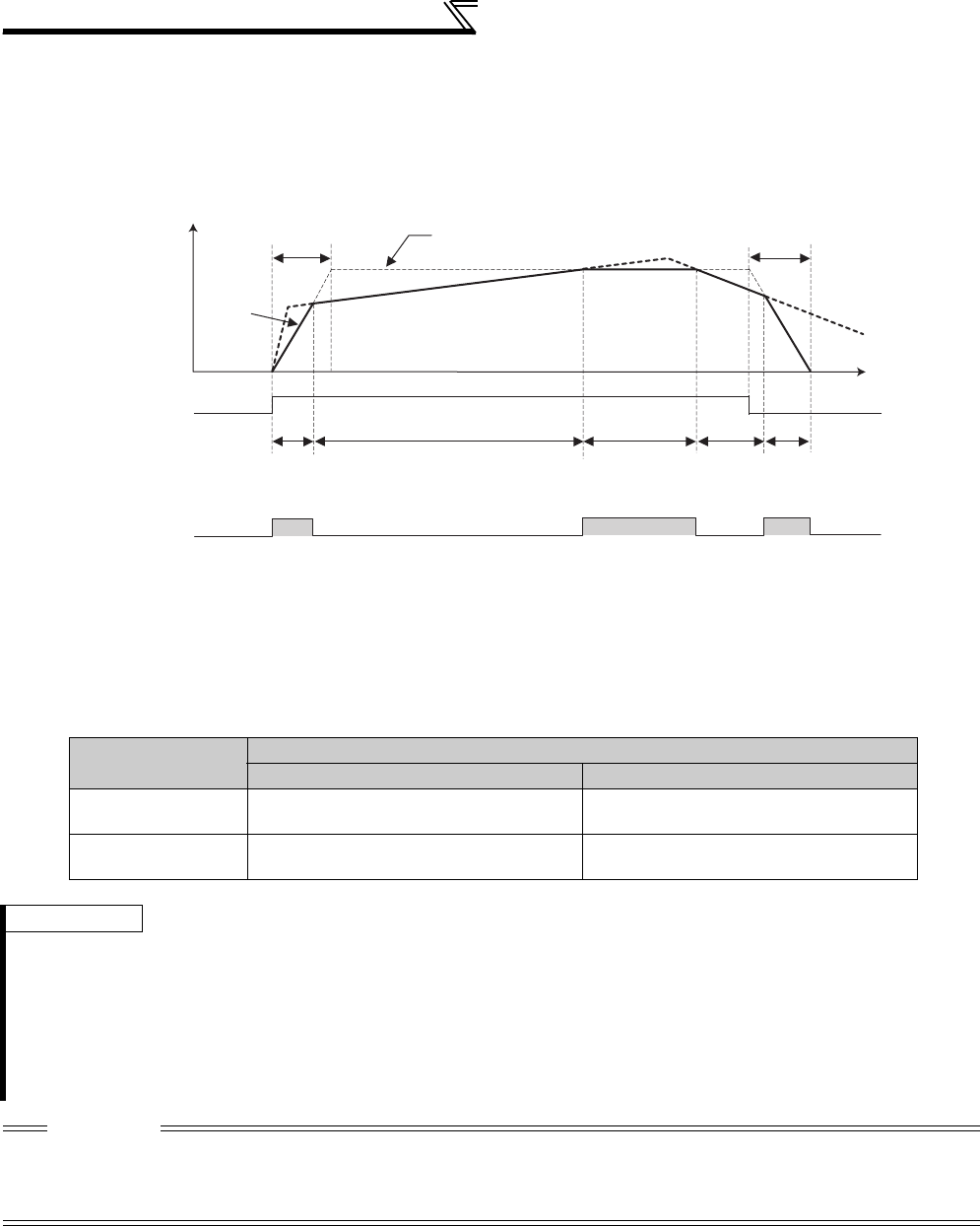
122
Torque control by Real sensorless vector
control, vector control
(3) Operation example (when Pr. 804 = "0")
Torque control is enabled if the actual speed is less than the speed limit value.
When the actual speed reaches or exceeds the speed limit value, speed limit operation starts, torque control is
stopped, and speed control (proportional control) starts.
The following shows the operations in response to the analog input command from terminal 1.
1) When STF signal is turned ON, the speed limit value is increased according to the time set in Pr. 7 .
2) Speed control operation is performed if the actual speed rises to or above the speed limit value.
3) When the STF signal is turned OFF, the speed limit value is decreased according to the time set in Pr. 8 .
4) For torque control, the actual speed becomes constant when the torque command and load torque are
balanced.
5) The motor torque developing direction is determined by the combination of the torque command input polarity
and start signal as indicated in the following table.
Torque Command
Polarity
Torque Developing Direction
STF signal ON STR signal ON
Positive torque
command
Forward rotation direction (forward rotation
driving/reverse rotation regeneration)
Reverse rotation direction (forward rotation
regeneration/reverse rotation driving)
Negative torque
command
Reverse rotation direction (forward rotation
regeneration/reverse rotation driving)
Forward rotation direction (forward rotation
driving/reverse rotation regeneration)
REMARKS
⋅When speed limit operation starts, speed control is exercised to enable internal torque limit (Pr. 22 torque limit level) (initial
value). Speed control may not be returned to torque control in this case.
Torque limit be set to external torque limit (terminal 1, 4). (Refer to page 100.)
⋅Undervoltage avoidance function (Pr. 261 = "11, 12") of power-failure deceleration stop function is invalid under torque control.
When Pr. 261 = "11 (12)", the inverter operates in the same manner as when "1 (2)" is set in Pr. 261.
⋅Set linear acceleration/deceleration (Pr. 29 = "0 (initial value)") when torque control is exercised. When acceleration/
deceleration patterns other than the linear acceleration/deceleration are selected, the protective function of the inverter may
function. (Refer to page 176)
CAUTION
⋅Performing pre-excitation (LX signal and X13 signal) under torque control (Real sensorless vector control) may start the motor
running at a low speed even when the start command (STF or STR) is not input. The motor may run also at a low speed when
the speed limit value = 0 with a start command input. Perform pre-excitation after making sure that there will be no problem in
safety if the motor runs.
*
STF
(Forward rotation
command)
Pr. 7 Speed limit value
Torque control operation Torque
control
operation
Pr. 8
Speed limit
operation
(Speed control)
Speed limit
operation
(Speed control)
Speed limit
operation
Speed
(Speed control)
Time
*When the speed limit activates, torque according to the commanded is not developed.
Speed
*
*
OL ON ON ON

123
Torque control by Real sensorless
vector control, vector control
4
PARAMETERS
4.5.2 Setting procedure of Real sensorless vector control (torque control)
CAUTION
⋅Make sure to perform offline auto tuning before performing Real sensorless vector control.
⋅The carrier frequencies are selectable from among 2k, 6k, 10k, 14kHz for Real sensorless vector control.
⋅Torque control cannot be performed in the low speed (approx. 10Hz or less) regeneration range and with light load at low speed
(approx. 20% or less of rated torque at approx. 5Hz or less). Choose vector control.
⋅Performing pre-excitation (LX signal and X13 signal) under torque control may start the motor running at a low speed even when
the start command (STF or STR) is not input. The motor may run also at a low speed when the speed limit value = 0 with a start
command input. Perform pre-excitation after making sure that there will be no problem in safety if the motor runs.
⋅Do not switch between the STF (forward rotation command) and STR (reverse rotation command) during operation under torque
control. Overcurrent trip (E.OC) or opposite rotation deceleration fault (E.11) occurs.
⋅For the 0.4K to 3.7K, the speed deviation may become large at 20Hz or less and torque may become insufficient in the low speed
region under 1Hz during continuous operation under Real sensorless vector control. In this case, stop the inverter once, then
start again to improve.
⋅When the inverter is likely to start during motor coasting under Real sensorless vector control, set to make frequency search of
automatic restart after instantaneous power failure valid (Pr. 57 ≠ "9999", Pr. 162 = "10").
⋅Enough torque may not be generated in the ultra-low speed range less than approx. 2Hz when performing Real sensorless
vector control.
The guideline of speed control range is as shown below.
Driving: 1:200(2, 4, 6 poles) Can be used at 0.3Hz or more at rated 60Hz
1:30(8, 10 poles) Can be used at 2Hz or more at rated 60Hz
Regeneration: 1:12(2 to 10 poles) Can be used at 5Hz or more at rated 60Hz
Sensorless
Sensorless
Sensorless
Test run
Perform secure wiring.
(Refer to page 14.)
Set the motor. (Pr. 71)
(Refer to page 187.)
Set the torque command. (Pr. 804)
(Refer to page 125.)
Set the speed limit. (Pr. 807)
(Refer to page 127.)
Perform offline auto tuning. (Pr. 96)
(Refer to page 189.)
Select a control method.
(Refer to page 92)
As required
⋅Select online auto tuning. (Pr. 95) (Refer to page 199.)
⋅Manual input torque control gain adjustment (Refer to page 130)
Set either "11" (torque control) or "12" (speed-torque switchover) in
Pr. 800 and make torque control valid.
Set the motor capacity and the number of motor poles. (Pr. 80, Pr. 81)
(Refer to page 92.)
Set "3" (standard motor) or "13" (constant torque motor) in Pr. 71
Applied motor.
Set the motor capacity (kW) in Pr. 80 Motor capacity and set the
number of motor poles in Pr. 81 Number of motor poles.
(V/F control is performed when the setting is "9999" (initial value).)
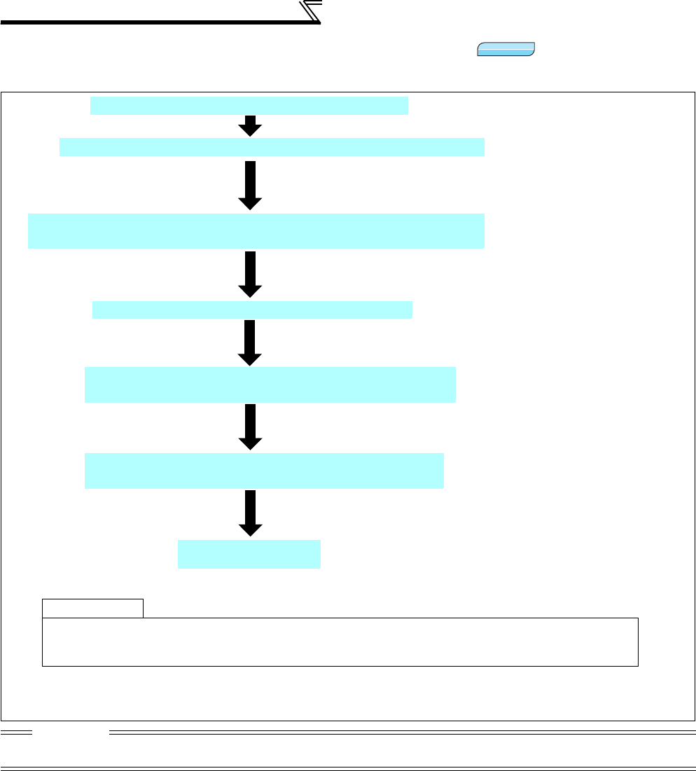
124
Torque control by Real sensorless vector
control, vector control
4.5.3 Setting procedure of vector control (torque control)
CAUTION
⋅The carrier frequencies are selectable from among 2k, 6k, 10k, 14kHz for vector control.
(2k and 6kHz for the 75K or higher)
Vector
Vector
Vector
Test run
Perform secure wiring. (Refer to page 36.)
Set the motor and encoder. (Pr. 71, Pr. 359, Pr. 369)
As required
· Perform offline auto tuning. (Pr. 96) (refer to page 189).
· Select online auto tuning. (Pr. 95) (refer to page 199).
· Manual input torque control gain adjustment (refer to page 130)
Set the motor capacity and the number of motor poles. (Pr. 80, Pr. 81)
(Refer to page 92.)
Set the motor capacity (kW) in
Pr. 80
Motor capacity
and set the number
of motor poles in
Pr. 81
Number of motor poles
.
(V/F control is performed when the setting is "9999" (initial value).)
Mount the FR-A7AP/FR-A7AL (option).
Set
Pr. 71 Applied motor
,
Pr. 359 Encoder rotation direction
and
Pr. 369
Number of encoder pulses
according to the motor and encoder used.
(Refer to page 38.)
Select a control method. (Refer to page 92.)
Set either "1" (torque control), "2" (speed-torque switchover) or "5"
(position-torque switchover) in
Pr. 800
and make torque control valid.
Set the torque command. (Pr. 804)
(Refer to page 125.)
Set the speed limit. (Pr. 807)
(Refer to page 127.)
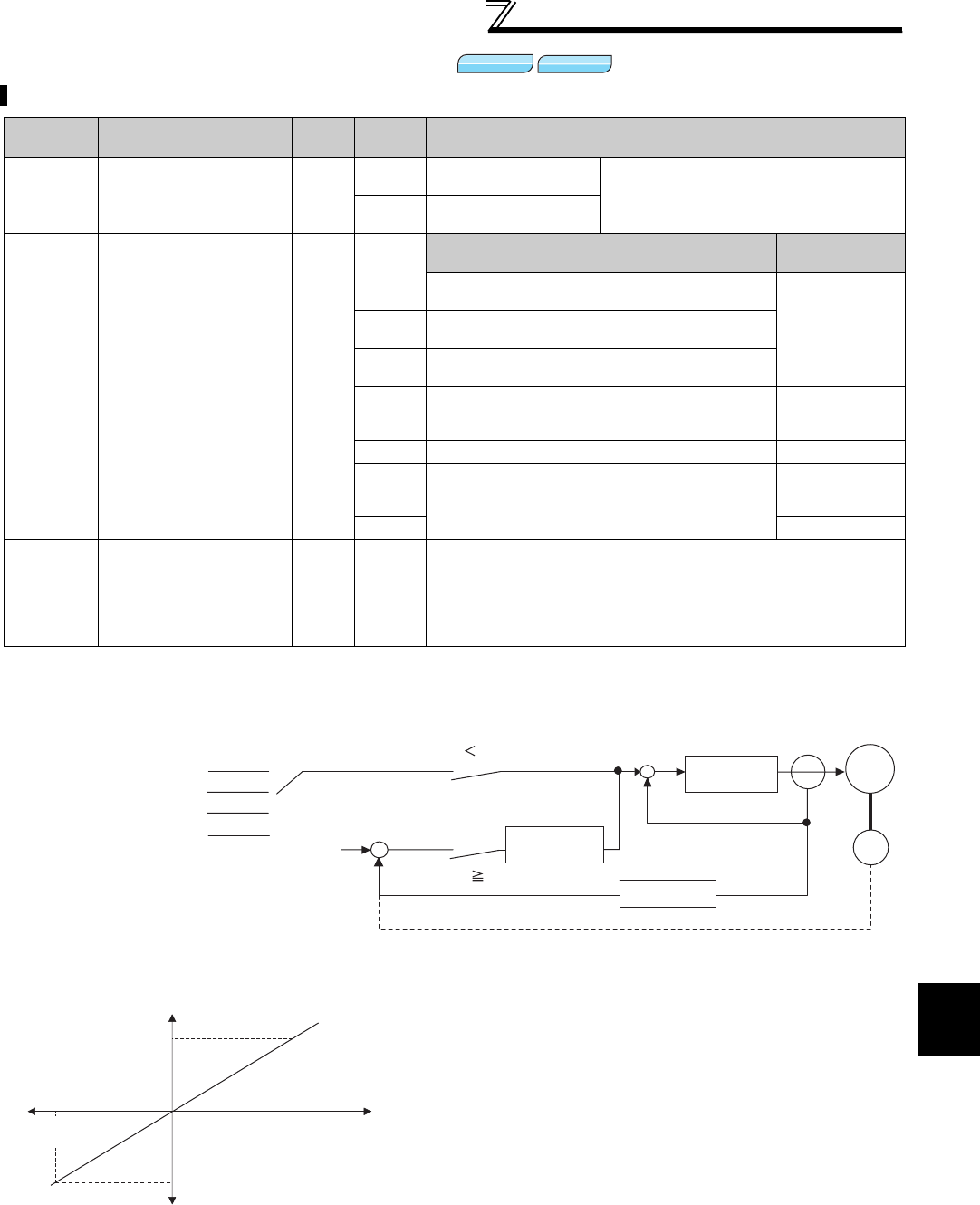
125
Torque control by Real sensorless vector
control, vector control
4
PARAMETERS
4.5.4 Torque command (Pr. 803 to Pr. 806)
* This parameter allows its setting to be changed during the operation in any operation mode even if "0 (initial value) or 1" is set in Pr. 77 Parameter
write selection.
(1) Control block diagram
(2) Torque command (Pr. 804 = "0" (initial value)) by analog input (terminal 1)
Torque command source for torque control can be selected.
Parameter
Number Name Initial
Value
Setting
Range Description
803
Constant power range
torque characteristic
selection
0
0Constant motor output
command Select the torque command in the
constant power region by torque
command setting.
1Constant torque
command
804 Torque command
source selection 0
0
Torque command input Speed limit
input method
Torque command by terminal1 analog input
(Refer to page 300)
As set in Pr. 807.1 Torque command by parameter setting (Pr. 805 or
Pr. 806) (-400% to 400%)
2Torque command by pulse train input
(FR-A7AL)
3Torque command with using CC-Link
communication (FR-A7NC/FR-A7NCE)
The Pr. 808 and
Pr. 809 settings
are speed limit.
4 12-bit/16-bit digital input (FR-A7AX) As set in Pr. 807.
5Torque command with using CC-Link
communication (FR-A7NC/FR-A7NCE)
The Pr. 808 and
Pr. 809 settings
are speed limit.
6 As set in Pr. 807.
805 * Torque command
value (RAM) 1000% 600 to
1400%
Writes the torque command value to the RAM.
On the assumption that 1000% is 0%, the torque command is set by
an offset from 1000%.
806 * Torque command
value (RAM,EEPROM) 1000% 600 to
1400%
Writes the torque command value to the RAM and EEPROM.
On the assumption that 1000% is 0%, the torque command is set by
an offset from 1000%.
⋅Torque command is given by voltage (current) input to
terminal 1.
⋅When torque command is input from terminal 1, set "3 or
4" in Pr. 868 Terminal 1 function assignment.
⋅Torque command by analog input can be calibrated using
calibration parameter C16 (Pr. 919) to C19 (Pr. 920) . (Refer
to page 300 )
Sensorless
Sensorless
Sensorless
Vector
Vector
Vector
Analog input
Parameter [Pr. 805, Pr. 806]
16-bit digital input (FR-A7AX)
0
1,3,5,6
4
2
[Pr. 804] Torque command
source selection
Speed limit input +
-
Speed limit value
Speed estimated
value
Speed limit value
Speed estimated
value
Real sensorless vector control
Vector control
Speed control
(proportional control)
Speed estimator
Torque control
+
-
Motor
Encoder
Pulse train input (FR-A7AL)
Torque command
150%
-100%
(-10V)
0 100%
(+10V)
-150%
Terminal 1
analog input
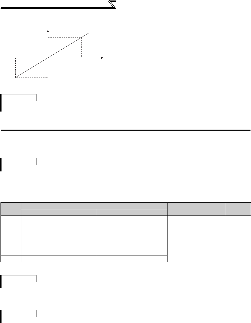
126
Torque control by Real sensorless
vector control, vector control
(3) Torque command using parameters (Pr. 804 = "1")
(4) Torque command by pulse train input (Pr.804 = "2")
Torque command is set by pulse train input from FR-A7AL (plug-in option).
FR-A7AL needs to be installed for this function.
(5) Torque command with using CC-Link communication (Pr. 804 = "1, 3, 5, 6")
⋅Torque command setting is available through FR-A7NC (CC-Link communication option) or FR-A7NCE (CC-Link IE
Field communication option).
*1 Setting from the operation panel and the parameter unit is also available.
*2 Negative torque command is unavailable from the operation panel or parameter unit.
(6) Torque command by 16-bit digital input (Pr. 804 = 4)
⋅Give a torque command by 16-bit or 12-bit digital input using the FR-A7AX (plug-in option).
⋅Torque command value can be set by setting Pr. 805
Torque command value (RAM) or Pr. 806 Torque command
value (RAM,EEPROM) .
⋅For Pr. 805 or Pr. 806, the torque command is set by an
offset from 1000% on the assumption that 1000% is 0%.
The relationship between the Pr. 805 or Pr. 806 setting
and actual torque command value at this time is shown
on the left.
⋅When changing the torque command frequently, write to
Pr. 805. Performing frequent parameter write to Pr. 806 will
shorten the life of the EEPROM.
⋅Torque command through FR-A7NCE (CC-Link IE Field
communication option) is valid only when FR-A7NCE is
installed.
REMARKS
⋅When torque command is set in Pr. 805 (RAM), powering OFF the inverter will erase the changed parameter values. Therefore,
the parameter value available when power is switched ON again is the value set in Pr. 806 (EEPROM).
CAUTION
⋅When giving a torque command by parameter setting, set the speed limit value to an appropriate value to prevent overspeed.
(Refer to page 127.)
REMARKS
For details of the setting with the FR-A7AL, refer to the FR-A7AL instruction manual.
Pr.804
setting
Torque Command Source Setting Range
Increments
FR-A7NC FR-A7NCE
1
Torque command by
Pr. 805
or
Pr. 806
*1
Same operation as setting value "3"
600 to 1400 (-400 to 400%) 1%
3
Torque command by Pr. 805 or Pr. 806 *1
Torque command from remote resister
(RWw1 or RWwC)
Torque command from remote
resister (RWw2 or RWw3)
5
Torque command by Pr. 805 or Pr. 806 *1
-32768 to 32767
(two's
complement)
(-327.68% to 327.67%) *2
0.01%
Torque command from remote resister
(RWw1 or RWwC)
Torque command from remote
resister (RWw2 or RWw3)
6
Torque command by
Pr. 805
or
Pr. 806
*1
Same operation as setting value "5"
REMARKS
⋅For details of the setting with the FR-A7NC or FR-A7NCE, refer to the instruction manual of each options.
REMARKS
⋅For details of the setting with the FR-A7AX, refer to the FR-A7AX instruction manual.
Torque command value
400%
600%
1000% 1400%
-400%
Pr.805,Pr.806
settings
Torque command value
=Pr.805(or Pr.806)-1000%
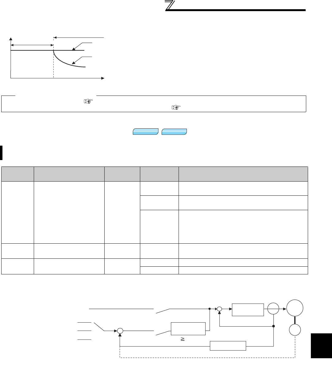
127
Torque control by Real sensorless vector
control, vector control
4
PARAMETERS
(7) Change the torque characteristics in the constant power (Pr. 803)
4.5.5 Speed limit (Pr. 807 to Pr. 809)
(1) Control block diagram
⋅Due to the motor characteristics, torque is reduced at or
above the base frequency. Set "1" in Pr. 803 Constant
power range torque characteristic selection when you want
to keep the torque to be constant even at or above the
base frequency.
♦Parameters referred to♦
Pr. 868 Terminal 1 function assignment Refer to page 100
Calibration parameter C16 (Pr. 919) to C19 (Pr. 920) (terminal 1 bias, gain torque) Refer to page 300
Set the speed limit value to prevent overspeed of the motor in case the load torque becomes less than the torque
command value, etc. during torque control operation.
Parameter
Number Name Initial Value Setting
Range Description
807 Speed limit selection 0
0Use the speed command value during speed control
as speed limit.
1According to Pr. 808 and Pr. 809 , set the speed limit in
forward and reverse rotation directions individually.
2
Forward/reverse rotation speed limit
The analog voltage of the terminal 1 input is used to
make speed limit.
The speed limit of the forward rotation and reverse
rotation is switched according to the polarity.
808 Forward rotation speed
limit 60Hz 0 to120Hz Set the speed limit for the forward rotation
direction
.
809 Reverse rotation speed
limit 9999 0 to120Hz Set the speed limit of the reverse rotation
side
.
9999 As set in Pr. 808 .
Speed
Base speed
Torque
Pr. 803 =1:
constant torque command
Pr. 803 =0:
constant power command
(torque reduction)
Constant power range
Constant torque range
Sensorless
Sensorless
Sensorless
Vector
Vector
Vector
Forward/reverse rotation speed limit
Same method
as speed command input
Parameter(Pr. 808, Pr. 809)
0
1
2
Pr. 807 Speed limit selection
Torque command
+
-
Speed estimated value < speed limit value +
-
Torque control Motor
Encoder
Speed estimator
Real sensorless vector control
Vector control
Speed control
(proportional control)
Speed estimated value speed limit value
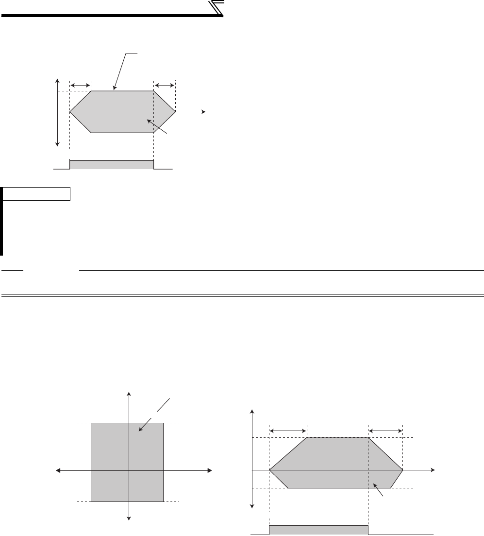
128
Torque control by Real sensorless
vector control, vector control
(3) Set the forward rotation and reverse rotation individually (Pr. 807 = "1")
Set the speed limit during forward rotation using Pr. 808 Forward rotation speed limit and the speed limit during reverse
rotation using Pr. 809 Reverse rotation speed limit.
The speed during forward and reverse rotation is limited at the setting value of Pr. 808 when "9999" (initial value) is set
in Pr. 809 .
(2) Use the speed command for speed control
(Pr. 807 = "0" initial value)
⋅Set the speed limit in the same method as speed setting
for speed control (speed setting by the PU (FR-DU07/
FR-PU07/FR-PU04), multi-speed setting, options, etc.)
⋅According to the acceleration time set in Pr. 7 Acceleration
time, the limit level is increased from 0Hz upon turning
ON of the start signal, and when the start signal turns
OFF, the speed limit level is decreased from the then
speed limit level to the DC injection brake operation
speed in Pr. 10 to a stop in accordance with the
deceleration time set in Pr. 8 Deceleration time.
REMARKS
⋅When the above speed limit command is greater than the Pr. 1 Maximum frequency value, the speed limit value is the Pr. 1
Maximum frequency value, and when the speed limit command is less than the Pr. 2 Minimum frequency value, the speed limit
value is the Pr. 2 Minimum frequency value. Similarly when the speed limit command is smaller than Pr. 13 Starting frequency , the
speed limit value is 0Hz.
⋅When speed limit is set by analog input, perform calibration of the analog input terminal 1, 2 and 4. (Refer to page 300.)
CAUTION
When speed limit is set by the analog command (terminal 1,2,4), turn OFF the external signals (RH, RM, RL). If any of external
signals (RH, RM, RL) is ON, multi-speed limits are valid.
STF(STR) ON OFF
Speed
Forward rotation
Speed setting
value during
speed control
Pr.7
Time
Torque controllable
range
The speed setting
value is a speed
limit value.
Pr.8
Reverse rotation
Pr.809
Speed
Reverse rotation
Pr.808
Torque controllable range
150 150
Output torque
(%)
0
Pr.7 Pr.8
STF(STR) ON OFF
Speed limit
Speed limit
Speed limit
Speed limit
Forward rotation
Pr.808
Pr.809
Pr.809
Pr.809
Torque controllable range
Torque controllable range
Torque controllable range
Time
Time
Time
Forward rotation
Reverse rotation

129
Torque control by Real sensorless vector
control, vector control
4
PARAMETERS
(4) Forward rotation/reverse rotation speed limit (Pr. 807 = "2")
⋅When making a speed limit using analog input from terminal 1, the speed limit of the forward and reverse rotation
can be switched according to the polarity of voltage.
⋅Forward/reverse rotation speed limit is valid when Pr. 868 Terminal 1 function assignment = "5".
⋅For 0 to 10V input, set the forward rotation speed limit. The reverse rotation speed limit at this time is the value of
Pr.1 Maximum frequency.
⋅For -10 to 0V input, set the reverse rotation speed limit. The forward rotation speed limit at this time is the value of
Pr. 1 Maximum frequency .
⋅The maximum speed of both the forward and reverse rotations is Pr. 1 Maximum frequency .
REMARKS
⋅When making speed limit from terminal 1, make calibration of terminal 1. (Refer to page 300.)
CAUTION
When the actual speed reaches or exceeds the speed limit value, torque control is switched to speed control to prevent
overspeed.
(SL) appears ON the operation panel during speed limit operation and the OL signal is output.
♦Parameters referred to♦
Pr. 1 Maximum frequency, Pr. 2 Minimum frequency Refer to page 157
Pr. 7 Acceleration time, Pr. 8 Deceleration time Refer to page 172
Pr. 13 Starting frequency Refer to page 175
Pr. 4 to Pr. 6, Pr. 24 to Pr. 27, Pr. 232 to Pr. 239 (Multi-speed operation) Refer to page 165
Pr. 868 Terminal 1 function assignment Refer to page 285
Pr. 125, Pr. 126, C2 to C7, C12 to C15 (frequency setting voltage (current) bias/gain) Refer to page 294
Pr.7
ONOFF
Start signal
Speed
Time
Speed
Forward rotation
Reverse rotation
Output
torque (%)
0
Speed
Reverse rotation
Forward rotation
Output torque (%)
Terminal 1 input
Pr.1
0
Torque controllable range
Torque controllable range
Torque controllable range
Terminal 1
input
Terminal 1 input
(-10 to 0V)
The reverse
rotation speed
limit
150 150 150 150
Pr.1
Pr.8
Pr.1 Pr.7
ONOFF
Start signal
Speed
Tim
e
Terminal 1 input (0 to 10V)
The forward rotation speed
limit
Pr.8
Pr.1
Torque controllable range
When terminal 1 input is "-10 to 0V" When terminal 1 input is "0 to 10V"
The reverse rotation
speed limit
The forward rotation
speed limit

130
Torque control by Real sensorless
vector control, vector control
4.5.6 Gain adjustment of torque control (Pr. 824, Pr. 825, Pr. 834, Pr. 835)
(1) Adjustment of current loop proportional (P) gain
⋅For general adjustment, make setting within the range 50 to 200% as a guideline.
⋅Set the proportional gain for torque control.
⋅Increasing the value improves trackability in response to a current command change and reduces current variation
with disturbance. However, a too large gain will cause instability, generating harmonic torque pulsation.
(2) Adjustment of current control integral time
⋅Set the integral time of current control during torque control.
⋅A small value enhances the torque response level, but a too small value will cause current fluctuation.
⋅Decreasing the value shortens the time taken to return to the original torque if current variation with disturbance
occurs.
(3) Use multiple gains
⋅When you want to change the gain according to applications, switch multiple motors with one inverter, etc., use
Torque control P gain 2 and Torque control integral time 2 .
⋅Pr. 834 Torque control P gain 2 and Pr. 835 Torque control integral time 2 are valid when the RT signal is ON.
Although stable operation is possible with the initial value, make adjustment when any of such phenomena as
unusual motor and machine vibration/noise and overcurrent has occurred.
Parameter
Number Name Initial Value Setting
Range Description
824 Torque control P gain 1 100% 0 to 200% Set the current loop proportional gain.
100% is equivalent to 2000rad/s.
825 Torque control integral
time 1 5ms 0 to 500ms Set the current loop integral compensation time.
834 Torque control P gain 2 9999 0 to 200% Set the current loop proportional gain when the RT
signal is ON.
9999 Without torque control P gain 2 function
835 Torque control integral
time 2 9999 0 to500ms Set the current loop integral compensation time when
the RT signal is ON.
9999 Without torque control integral time 2 function
REMARKS
⋅The RT signal acts as the second function selection signal and makes the other second functions valid. (Refer to page 235.)
⋅The RT signal is assigned to the terminal RT in the initial setting. By setting "3" in any of Pr. 178 to Pr. 189 (input terminal function
selection) , you can assign the RT signal to the other terminal.
Sensorless
Sensorless
Sensorless
Vector
Vector
Vector

131
Torque control by Real sensorless vector
control, vector control
4
PARAMETERS
(4) Adjustment procedure
Make adjustment when any of such phenomena as unusual motor and machine vibration/noise/current and
overcurrent has occurred.
1)Check the conditions and simultaneously change the Pr. 824 value.
2)If you cannot make proper adjustment, change the Pr. 825 value and repeat step 1).
(5) Troubleshooting (Torque)
Adjustment Method
Set Pr. 824 a little lower and Pr. 825 a little higher. First lower Pr. 824 and check the motor for unusual vibration/noise and
overcurrent. If the problem still persists, increase Pr. 825 .
Pr. 824
Decrease the value 10% by 10% until just before unusual noise and current are improved, and set about 0.8 to 0.9
of that value.
Note that a too low value will produce current ripples, causing the motor to generate sound synchronizing the cycle
of current ripples.
Pr. 825
Increase the current value double by double until just before an unusual noise and current does not occur, and set
about 0.8 to 0.9 of that value.
Note that taking a too long time will produce current ripples, causing the motor to generate sound synchronizing
the cycle of current ripples.
Phenomenon Cause Countermeasures
1Torque control is not
exercised normally.
(1) The phase sequence of the
motor or encoder wiring is
wrong.
(1) Check the wiring. (Refer to page 14)
(2) The Pr. 800 Control method
selection setting is improper.
(2) Check the Pr. 800 setting. (Refer to page 92)
(3) The speed limit value is not
input.
(3) Set the speed limit value. (If the speed limit value is not
input, the motor will not rotate since the speed limit
value is regarded as 0Hz.)
(4) The torque command varies. (4)-1 Check that the command device gives a correct
torque command.
(4)-2 Decrease Pr. 72 PWM frequency selection .
(4)-3 Increase Pr. 826 Torque setting filter 1
(5) The torque command does not
match the inverter-recognized
value.
(5) Recalibrate C16 Terminal 1 bias command (torque/
magnetic flux), C17 Terminal 1 bias (torque/magnetic flux),
C18 Terminal 1 gain command (torque/magnetic flux), C19
Terminal 1 gain (torque/magnetic flux). (Refer to page 300)
(6) Torque variation due to the
change in the motor
temperature.
(6) Select magnetic flux observer by setting Pr. 95 Online
auto tuning selection. (Refer to page 199)
2
When the torque
command is small, the
motor rotates in the
direction opposite to the
start signal.
The offset calibration of the torque
command does not match.
Recalibrate C16 Terminal 1 bias command (torque/magnetic
flux) and C17 Terminal 1 bias (torque/magnetic flux). (Refer to
page 300)
3
Normal torque control
cannot be exercised
during acceleration/
deceleration.
The motor vibrates.
The speed limit is activated.
(When Pr. 807 = "0, 2", the speed
limit may be activated since the
speed limit value changes with the
setting of the acceleration/
deceleration time in Pr. 7 and Pr. 8. )
Reduce the acceleration/deceleration time.
Or, set the acceleration/deceleration time to "0". (The
speed limit during acceleration/deceleration depends on
the speed limit during the constant speed.)
4
Output torque is not linear
in response to the torque
command.
Insufficient torque. Return the excitation ratio in Pr. 854 to the initial value.
♦Parameters referred to♦
Pr. 72 PWM frequency selection Refer to page 284
Pr. 178 to Pr. 189 (input terminal function selection) Refer to page 231
Pr. 800 Control method selection Refer to page 92
Pr. 807 Speed limit selection Refer to page 127
C16 to C19 (torque setting voltage (current) bias and gain) Refer to page 300
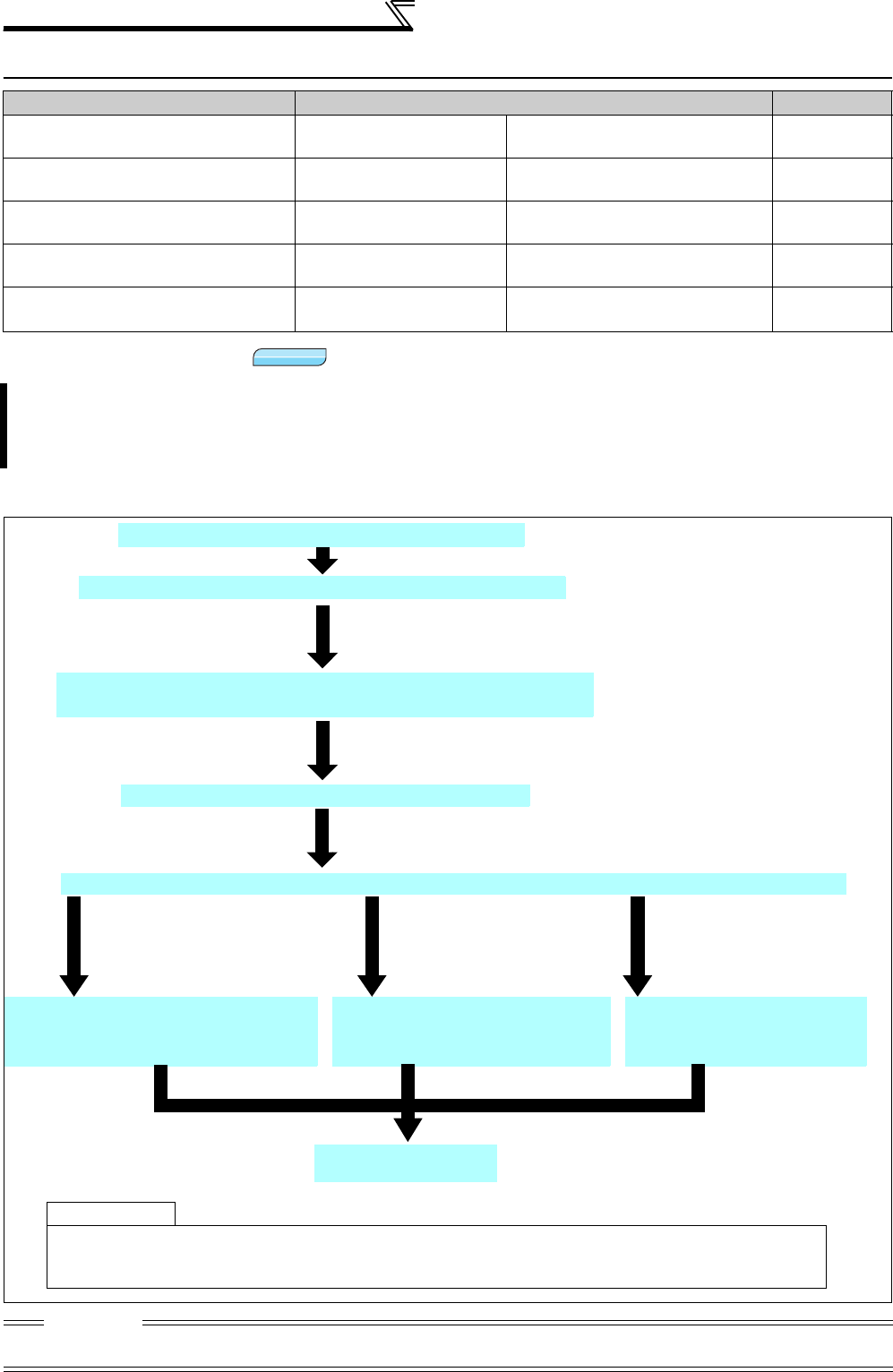
132
Position control by vector control
4.6 Position control by vector control
4.6.1 Position control
(1) Setting procedure
Purpose Parameter that must be Set Refer to Page
Simple position control by
parameter setting
Position command by
parameter Pr. 419, Pr. 464 to Pr. 494 134
Position control by pulse train input
of the inverter
Position command by
simple pulse train Pr. 419, Pr. 428 to Pr. 430 137
Adjust the gear ratio of motor and
machine
Setting the electronic
gear Pr. 420, Pr. 421, Pr. 424 139
Setting of positioning adjustment
parameter
In-position width
Excessive level error Pr. 426, Pr. 427 140
Improve position control accuracy Gain adjustment of
position control Pr. 422, Pr. 423, Pr. 425 141
In the position control, the speed command is calculated so that the difference between command pulse (or
parameter setting) and the number of feedback pulses from the encoder is zero in order to run the motor.
This inverter can perform simple position feed by contact input, position control by inverter simple pulse input,
and position control by FR-A7AL pulse train input.
CAUTION
⋅The carrier frequencies are selectable from among 2k, 6k, 10k, 14kHz for vector control.
(2k and 6kHz for the 75K or higher)
Vector
Vector
Vector
Perform secure wiring. (Refer to page 37.)
Set the motor and encoder. (Pr. 71, Pr. 359, Pr. 369)
As required
· Set the electronic gear. (Refer to page 139)
· Setting of positioning adjustment parameter (refer to page 140)
· Gain adjustment of position control (refer to page 141)
Set the motor capacity and the number of motor poles.
(Pr. 80, Pr. 81) (Refer to page 92.)
Set the motor capacity (kW) in
Pr. 80
Motor capacity
and set the number
of motor poles (number of poles) in
Pr. 81
Number of motor poles
. (V/F
control is performed when the setting is "9999" (initial value).)
Mount the FR-A7AP/FR-A7AL (option).
Set
Pr. 71 Applied motor
,
Pr. 359 Encoder rotation direction
and
Pr. 369
Number of encoder pulses
according to the motor and encoder used.
(Refer to page 38.)
Select a control method. (Refer to page
92
.)
Make speed control valid by selecting "3" (position control) "4" (speed-
position switchover) or "5" (position-torque switchover) for
Pr. 800
.
Refer to the Instruction Manual of
FR-A7AL.
Selection of position command source. (Pr. 419)
Setting of parameter for position feed
(Pr. 465 to Pr. 494).
(Refer to page 134.)
Selection of command pulse form
(Pr. 428).
(Refer to page 137.)
Position command by contact
input
Set "0" (initial value) in Pr. 419.
Position command by
inverter pulse train input
Set "2" in Pr. 419.
Position command from the
positioning module of the
programmable controller
system (through FR-A7AL)
Set Pr. 419 = "1"
Test run
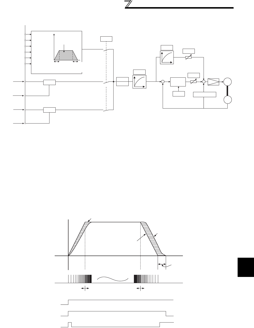
4
PARAMETERS
133
Position control by vector control
(2) Control block diagram
(3) Example of operation
The speed command given to rotate the motor is calculated to zero the difference between the number of internal
command pulse train pulses (when Pr. 419 = 0, the number of pulses set by parameter (Pr. 465 to Pr. 494) is changed to
the command pulses in the inverter) and the number of pulses fed back from the motor end encoder.
1)When a pulse train is input, pulses are accumulated in the deviation counter and these droop pulses act as position
control pulses to give the speed command.
2)As soon as the motor starts running under the speed command of the inverter, the encoder generates feed back
pulses and the droop of the deviation counter is counted down. The deviation counter maintains a given droop pulse
value to keep the motor running.
3)When the command pulse input stops, the droop pulses of the deviation counter decrease, reducing the speed. The
motor stops when there are no droop pulses.
4)When the number of droop pulses has fallen below the value set in Pr. 426 In-position width , it is regarded as
completion of positioning and the in-position signal (Y36) turns ON.
⋅For simple position control function by contact input, the STF and STR terminals provide the forward (reverse)
command signal. The motor can run only in the direction where the forward (reverse) signal is ON. Turning the STF
signal OFF does not run the motor forward and turning the STR signal OFF does not run the motor reverse.
⋅The pulse train is rough during acceleration and coarse at the maximum speed. During deceleration the pulse train is
rough and at last there are no pulses. The motor stops shortly after the command pulses stop.
This time lag is necessary for maintaining the stop accuracy and called stop settling time.
RH
RM
RL
REX
STF
STR
Pr. 4 to 6
Pr. 24 to 27
Pr. 232 to 239
Pr.7
Pr. 465 to Pr. 494
travel
Multi-speed,
communication
0
Pr. 419
Position command
source selection
1Pr. 420
Pr. 421
Position command
acceleration/deceleration
time constant
Pr. 424
Position feed
forward
command filter
Pr. 425
Command pulse selection
Electronic
gear
Position feed
forward gain
Pr. 423
+
-
Deviation
counter
Position
loop gain
Pr. 422 +
+
Encoder
IM
Speed control
-
Clear signal
selection
Pr. 429 Differentiation
(Pr. 44, Pr. 110)(Pr. 45, Pr. 111)
Pr.8
Command pulse selection
Command pulse
Command pulse
Pulse train
sign
PGP, PP
PGN, NP
JOG
NP
(FR-A7AL)
Command pulse
(FR-A7AL)
2
Pr. 428
Pr. 428
Acceleration
Time
Deceleration
Stop settling time
Motor speed
Pulse distribution
Droop pulse value
Pulse train Rough Fine Rough
LX signal
Servo on
STF (STR)
Forward (reverse)
Y36 signal
In-position signal
Command pulse frequency
[PPS]
Motor speed [r/min]

134
Position control by vector control
4.6.2 Simple position feed function by contact input (Pr. 419, Pr. 464 to Pr. 494)
REMARKS
⋅For the servo ON signal (LX), set "23" in Pr. 178 to Pr. 189 (input terminal function selection) to assign the function.
⋅For the in-position signal (Y36), set "36" in Pr. 190 to Pr. 196 (output terminal function selection) to assign the function.
CAUTION
Changing the terminal function using any of Pr. 178 to Pr. 189, 190 to Pr. 196 may affect the other functions. Set parameters after
confirming the function of each terminal.
♦Parameters referred to♦
Pr. 178 to Pr. 189 (input terminal function selection) Refer to page 231
Pr. 190 to Pr. 196 (output terminal function selection) Refer to page 239
Inputting the number of pulses (positions) in the parameters and setting multi-speed and forward (reverse)
commands enable position control. The motor does not return to the home position with this simple position feed
function.
Parameter
Number Name Initial Value Setting
Range Description
419 Position command source
selection 0
0Simple position control function by contact input.
(position command by parameter settings)
1
Pulse train position command from the positioning
module of the programmable controller system
(when FR-A7AL is installed)
2Simple pulse train position command by inverter
pulse train input
464
Digital position control
sudden stop deceleration
time
0s 0 to 360.0s
Set the time until the inverter stops when the
forward rotation (reverse rotation) command is
turned OFF with the position feed forward function.
Selection Method
(OFF: ×, ON: )Position feed
frequency
REX RH RM RL
465 First position feed amount
lower 4 digits 0 0 to 9999
×××High speed (Pr. 4)
466 First position feed amount
upper 4 digits 0 0 to 9999
467 Second position feed
amount lower 4 digits 0 0 to 9999
×××Middle speed (Pr. 5)
468 Second position feed
amount upper 4 digits 0 0 to 9999
469 Third position feed
amount lower 4 digits 0 0 to 9999
×××Low speed (Pr. 6)
470 Third position feed
amount upper 4 digits 0 0 to 9999
471 Fourth position feed
amount lower 4 digits 0 0 to 9999
××4 speed (Pr. 24)
472 Fourth position feed
amount upper 4 digits 0 0 to 9999
473 Fifth position feed amount
lower 4 digits 0 0 to 9999
××5 speed (Pr. 25)
474 Fifth position feed amount
upper 4 digits 0 0 to 9999
475 Sixth position feed
amount lower 4 digits 0 0 to 9999
× ×6 speed (Pr. 26)
476 Sixth position feed
amount upper 4 digits 0 0 to 9999
477 Seventh position feed
amount lower 4 digits 0 0 to 9999
×7 speed (Pr. 27)
478 Seventh position feed
amount upper 4 digits 0 0 to 9999
Vector
Vector
Vector

4
PARAMETERS
135
Position control by vector control
479 Eighth position feed
amount lower 4 digits 0 0 to 9999
×××8 speed (Pr. 232)
480 Eighth position feed
amount upper 4 digits 0 0 to 9999
481 Ninth position feed
amount lower 4 digits 0 0 to 9999
××9 Speed (Pr. 233)
482 Ninth position feed
amount upper 4 digits 0 0 to 9999
483 Tenth position feed
amount lower 4 digits 0 0 to 9999
××10 speed (Pr. 234)
484 Tenth position feed
amount upper 4 digits 0 0 to 9999
485 Eleventh position feed
amount lower 4 digits 0 0 to 9999
×11 speed (Pr. 235)
486 Eleventh position feed
amount upper 4 digits 0 0 to 9999
487 Twelfth position feed
amount lower 4 digits 0 0 to 9999
××12 speed (Pr. 236)
488 Twelfth position feed
amount upper 4 digits 0 0 to 9999
489 Thirteenth position feed
amount lower 4 digits 0 0 to 9999
×13 speed (Pr. 237)
490 Thirteenth position feed
amount upper 4 digits 0 0 to 9999
491 Fourteenth position feed
amount lower 4 digits 0 0 to 9999
×14 speed (Pr. 238)
492 Fourteenth position feed
amount upper 4 digits 0 0 to 9999
493 Fifteenth position feed
amount lower 4 digits 0 0 to 9999
15 speed (Pr. 239)
494 Fifteenth position feed
amount upper 4 digits 0 0 to 9999
The above parameters can be set when the FR-A7AP/FR-A7AL (option) is mounted.
Parameter
Number Name Initial Value Setting
Range Description
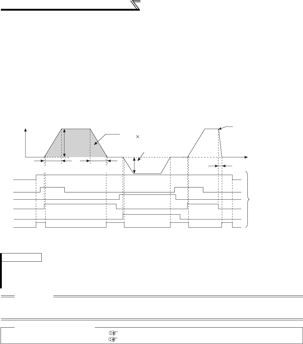
136
Position control by vector control
(1) Setting of position feed amount by parameter
⋅Set position feed amount in Pr. 465 to Pr. 494 .
⋅The feed amount set in each parameter is selected by multi-speed terminal (RH, RM, RL, REX).
⋅Set (encoder resolution × speed × 4 times) for position feed amount.
⋅For example, the formula for stopping the motor after 100 rotations using the SF-V5RU is as follows:
2048 (pulse/rev) × 100 (speed) × 4 = 819200 (feed amount)
To set 819200 for the first position feed amount, divide the value into upper four digits and lower four digits and set
81 (decimal) in Pr. 466 (upper) and 9200 (decimal) in Pr. 465 (lower).
(2) Position command operation by parameter
⋅For deceleration by turning the STF(STR) OFF, use Pr. 464 Digital position control sudden stop deceleration time to set
deceleration time.
REMARKS
⋅Acceleration/deceleration time is 0.1s minimum and 360s maximum.
⋅Pr. 20 Acceleration/deceleration reference frequency is clamped at a minimum of 16.66Hz (500r/min).
⋅The acceleration/deceleration patterns for position control are all linear acceleration and the setting of Pr. 29 Acceleration/
deceleration pattern selection is invalid.
CAUTION
Information on multi-speed command (position command by RL, RM, RH, and REX signals) is determined at rising of the forward
(reverse) command to perform position control. Therefore, set forward (reverse) command after multi-speed command (position
command). Position feed is invalid if the multi-speed command is given after forward (reverse) command.
♦Parameters referred to♦
Pr. 20 Acceleration/deceleration reference frequency Refer to page 172
Pr. 29 Acceleration/deceleration pattern selection Refer to page 176
Servo on (LX)
RH
STF
STR
RM
Feed speed
Pr. 4
First position feed amount
Pr. 5
Y
36
In-position
Pr. 464
Stops when the STF is
turned off
Shaded part is the travel
Pr. 7
(Pr. 44, Pr. 110)
Pr. 8
(Pr. 45, Pr. 111)
Frequency (Hz)
Second position
feed amount
Time
Position feed is
performed by sending
run command by
contact input or
communication.
Pr. 466 10000 + Pr. 465
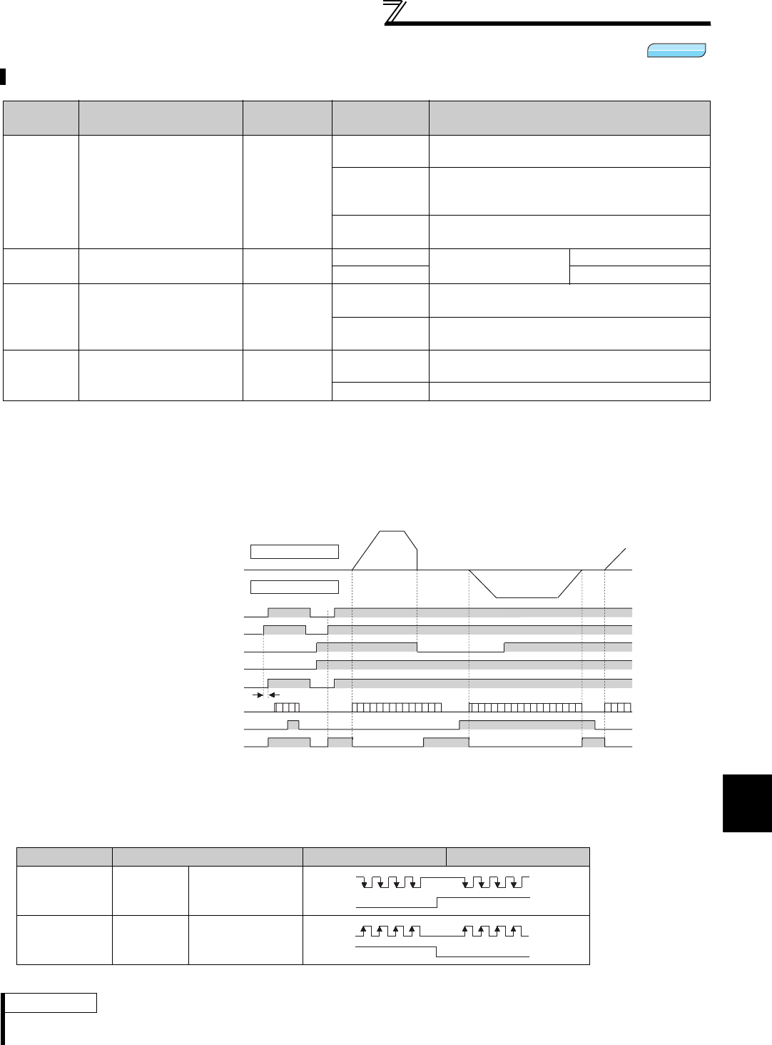
4
PARAMETERS
137
Position control by vector control
4.6.3 Position control (Pr. 419, Pr. 428 to Pr. 430) by inverter pulse train input
(1) Operation
Turning ON the servo ON signal (LX) cancels the output shut-off and the operation ready signal (RDY) turns ON after
0.1s. Turning ON the STF (forward stroke end signal) or STR (forward stroke end signal) runs the motor according to
the commanded pulse. When the forward (reverse) stroke end signal turns OFF, the motor does not run in that
direction.
(2) Pulse train form type selection (Pr. 428, NP signal)
1) Set "2"(simple pulse train position command) in Pr. 419.
2) Set "68" in Pr. 178 to Pr. 189 (input terminal function selection) to assign simple position pulse train sign (NP).
3) Select command pulse train using Pr. 428
4)Select vector control, then select position control.
Simple position pulse train command can be input by pulse train input and sign signal (NP) to the JOG terminal.
Parameter
Number Name Initial Value Setting
Range Description
419 Position command source
selection 0
0Simple position control function by contact input.
(position command by parameter settings)
1
Pulse train position command from the positioning
module of the programmable controller system
(when FR-A7AL is installed)
2Simple pulse train position command by inverter
pulse train input
428 Command pulse selection 00 to 2 Pulse train + rotation
signal sign
Negative logic
3 to 5 Positive logic
429 Clear signal selection 1
0Deviation counter is cleared at edge of turning ON
of the clear signal (CLR) from OFF.
1Deviation counter while the clear signal (CLR) is
ON
430 Pulse monitor selection 9999 0 to 5 The status of various pulses during running is
displayed.
9999 Frequency monitor is displayed.
The above parameters can be set when the FR-A7AP/FR-A7AL (option) is mounted.
Pr. 428 Setting Command Pulse Train Type At Forward Rotation At Reverse Rotation
0 to 2 Negative
logic
Pulse train +
rotation signal sign
3 to 5 Positive
logic
Pulse train +
rotation signal sign
REMARKS
⋅When Pr. 419 Position command source selection = "2" (simple pulse train position command), JOG terminal serves as simple
position pulse train input terminal regardless of the Pr. 291 Pulse train I/O selection setting.
Vector
Vector
Vector
Actual rotation
Forward rotation
Reverse rotation
Base signal
Operation ready completion (RDY)
Forward stroke end (STF)
Reverse stroke end (STR)
Inverter pulse train command
Sign signal (NP)
In-position (Y36)
Servo on (LX)
0.1s
JOG
NP H
L
JOG
NP HL
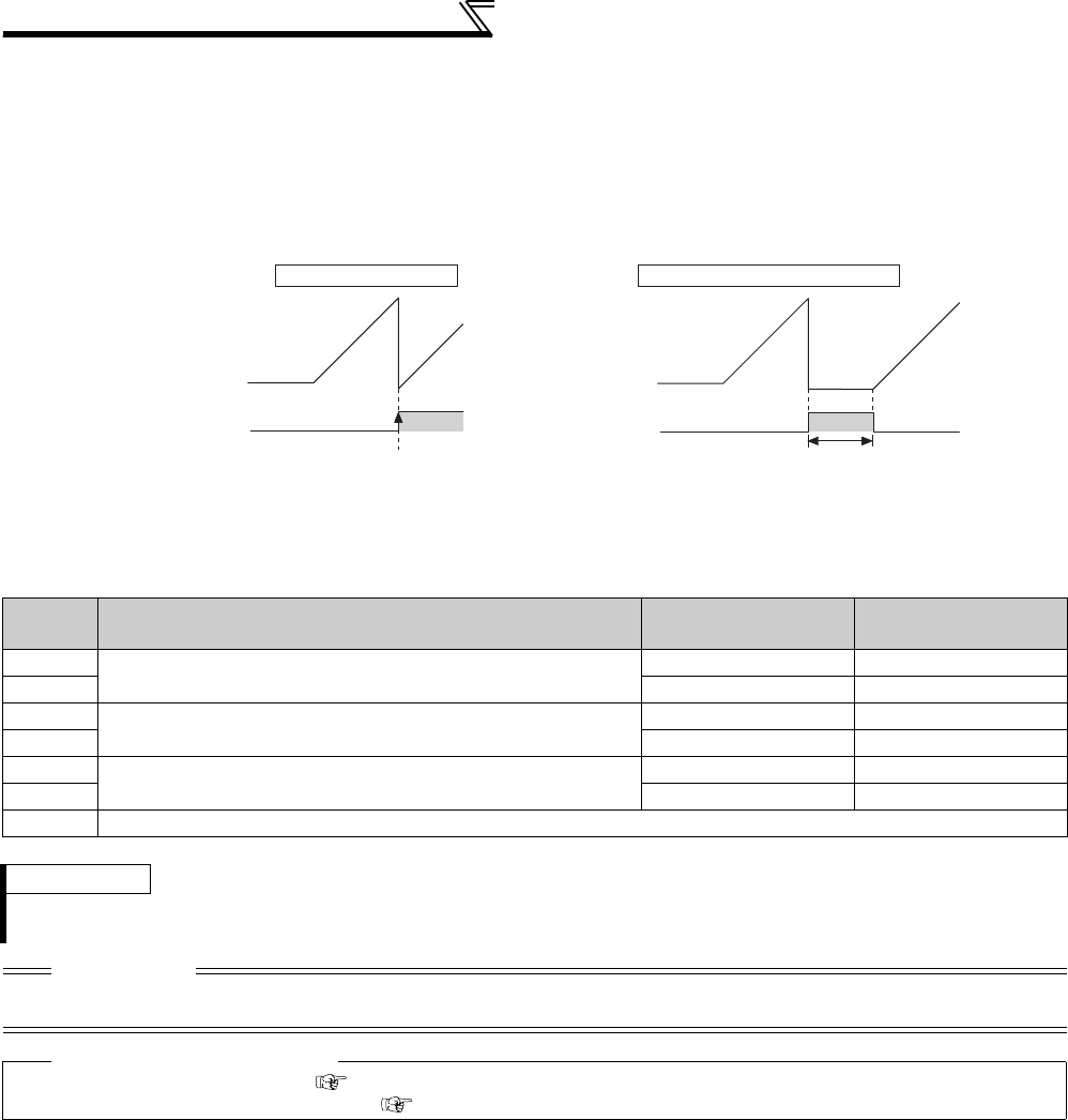
138
Position control by vector control
(3) Selection of clear signal (Pr. 429, CLR signal)
⋅Use this function to zero the droop pulse for home position operation, etc.
⋅When "0" is set in Pr. 429 , the deviation counter is cleared at the edge of turning ON of the clear signal (CLR). In
addition, the CLR signal turns ON in synchronization with zero pulse signal of the encoder at home position
operation, etc., deviation counter is cleared.
⋅For the terminal used for CLR signal, set "69" in any of Pr. 178 to Pr. 189 (input terminal function selection) to assign
the function.
(4) Pulse monitor selection (Pr. 430 )
The status of various pulses during running is displayed.
Set "0" in Pr. 52 DU/PU main display data selection to display output frequency monitor.
Pr. 430
Setting Description Display Range
(FR-DU07)
Display Range
(FR-PU04/FR-PU07)
0The cumulative command pulse value is displayed. Lower 4 digits Lower 5 digits
1Upper 4 digits Upper 5 digits
2The cumulative feedback pulse value is displayed. Lower 4 digits Lower 5 digits
3Upper 4 digits Upper 5 digits
4The droop pulses are monitored. Lower 4 digits Lower 5 digits
5Upper 4 digits Upper 5 digits
9999 Frequency monitor is displayed. (initial value)
REMARKS
⋅Count the number of pulses when the servo is ON.
⋅The cumulative pulse value is cleared when the base is shut off or the clear signal (CLR) is turned ON.
CAUTION
⋅Changing the terminal assignment using Pr. 178 to Pr. 189 (input terminal function selection) may affect the other functions. Set
parameters after confirming the function of each terminal.
♦Parameters referred to♦
Pr. 52 DU/PU main display data selection Refer to page 253
Pr. 178 to Pr. 189 (input terminal function selection) Refer to page 231
Deviation counter
image
CLR ON
When Pr. 429 = "0" When Pr. 429 = "1 (initial value)"
Deviation counter
image
CLR ON
Counter clear while ONCounter clear at the edge of
turning on of the signal

4
PARAMETERS
139
Position control by vector control
4.6.4 Setting of the electronic gear (Pr. 420, Pr. 421, Pr. 424)
(1) Calculation of the gear ratio (Pr. 420, Pr. 421)
⋅The position resolution (travel per pulse Δ [mm]) is determined by the travel per motor revolution Δs [mm] and the
feedback pulses Pf [pulse/rev] of the detector, and is represented by the following expression.
Using the parameters, the travel per command pulse can be set separately to set the travel per command pulse
without a fraction.
In addition, the relationship between the motor speed and internal command pulse frequency is as follows:
Set the ratio of the machine side gear and the motor side gear.
Parameter
Number Name Initial Value Setting
Range Description
420 Command pulse scaling
factor numerator 1 0 to 32767 * Set the electric gear.
Pr. 420 is a numerator and Pr. 421 is a denominator.
421 Command pulse scaling
factor denominator 1 0 to 32767 *
424
Position command
acceleration/deceleration
time constant
0s 0 to 50s
Used when rotation has become unsmooth at a
large electronic gear ratio (about 10 times or more)
and low speed.
The above parameters can be set when the FR-A7AP/FR-A7AL (option) is mounted.
* When the operation panel (FR-DU07) is used, the maximum setting is 9999. When a parameter unit is used, up to the maximum value within
the setting range can be set.
Δ:travel per pulse [mm]
Δs: travel per motor rotation [mm]
Pf: number of feedback pulses [pulse/rev] (number of pulses after multiplying the number of
encoder pulses by four)
Δ=Δs
Pf
Δ=Δs×Pr. 420
Pf Pr. 421
fo ×Pr. 420 =Pf×No fo : Internal command pulse frequency [pps]
Motor speed [r/min]
Pr. 421 60 No :
CAUTION
Set the electronic gear in the range of 1/50 to 20.
Note that too small a value will decrease the speed command and too large a value will increase the speed ripples.
[Setting example 1]
The electronic gear ratio is Δs = 10 (mm) when the travel per pulse Δ = 0.01 (mm) and the number of feedback
pulses Pf = 4000 (pulse/rev) in a drive system where the ballscrew pitch PB = 10 (mm) and the reduction ratio 1/n = 1.
According to the following expression,
Therefore, set "4" in Pr. 420 and "1" in Pr. 421 .
[Setting example 2]
Find the internal command pulse frequency of the dedicated motor rated speed.
Note that the command pulse scaling factor Pr. 420/Pr. 421 = 1.
Assuming that the number of encoder pulses is 2048 (pulses/rev) (feedback pulse Pf = 2048 × 4),
Therefore, the internal command pulse frequency is 204800 (pps).
Vector
Vector
Vector
Δ=Δs×Pr. 420
Pf Pr. 421
Pr. 420 =Δ×Pf
Pr. 421 Δs
= 0.01 ×4000 =4
10 1
fo = 2048 ×4
(multiplication) ×No ×Pr. 421
60 Pr. 420
= 204800

140
Position control by vector control
Relationship between position resolution Δ and overall accuracy
Since overall accuracy (positioning accuracy of machine) is the sum of electrical error and mechanical error, normally
take measures to prevent the electrical system error from affecting the overall error. As a guideline, refer to the
following relationship.
<Stopping characteristic of motor>
When parameters are used to run the motor, the internal command pulse frequency and motor speed have the
relationship as shown in the chart on page 133, and as the motor speed decreases, pulses are accumulated in the
deviation counter of the inverter. These pulses are called droop pulses (ε) and the relationship between command
frequency (fo) and position loop gain (Kp: Pr. 422) is as represented by the following expression.
When the initial value of Kp is 25s-1, the droop pulses (ε) are 8192 pulses.
Since the inverter has droop pulses during running, a stop settling time (ts) is needed from when the command has
zeroed until the motor stops. Set the operation pattern in consideration of the stop settling time.
When the initial value of Kp is 25s-1, the stop settling time (ts) is 0.12s.
The positioning accuracy Δε is (5 to 10) × Δ = Δε [mm]
(2) Position command acceleration/deceleration time constant (Pr. 424 )
⋅When the electronic gear ratio is large (about 10 or more times) and the speed is low, rotation will not be smooth,
resulting in pulse-wise rotation. At such a time, set this parameter to smooth the rotation.
⋅When acceleration/deceleration time cannot be provided for the command pulses, a sudden change in command
pulse frequency may cause an overshoot or error excess alarm. At such a time, set this parameter to provide
acceleration/deceleration time.
Normally set 0.
4.6.5 Setting of positioning adjustment parameter (Pr. 426, Pr. 427)
(1) In-position width (Pr. 426 )
The Y36 signal acts as an in-position signal.
When the number of droop pulses has fallen below the setting value, the in-position signal (Y36) turns ON.
For the Y36 signal, assign the function by setting "36" (positive logic) or "136" (negative logic) in any of Pr. 190 to Pr.
196 (output terminal function selection) .
(2) Excessive level error (Pr. 427 )
When droop pulses exceed the value set in Pr. 427 , excessive position error occurs and displays a fault (E.OD) to trip
the inverter. When you decreased the Pr. 422 Position loop gain setting, increase the error excessive level setting.
Also decrease the setting when you want to detect an error slightly earlier under large load.
When "9999" is set in Pr. 427 , excessive position error (E.OD) does not occur regardless of droop pulses.
Δ<(1to 1)×Δε Δε:positioning accuracy
510
ε=fo [pulse] ε=204800 [pulse] (rated motor speed)
Kp 25
ts = 3 ×1[s]
Kp
♦Parameters referred to♦
Pr. 422 Position loop gain Refer to page 141
Parameter
Number Name Initial Value Setting Range Description
426 In-position width 100 pulses
0 to 32767 pulses
*
When the number of droop pulses has fallen below the
setting value, the in-position signal (Y36) turns ON.
427 Excessive level error 40K 0 to 400K Excessive position error (E.OD) occurs when the
number of droop pulses exceeds the setting.
9999 Function invalid
The above parameters can be set when the FR-A7AP/FR-A7AL (option) is mounted.
* When the operation panel (FR-DU07) is used, the maximum setting is 9999. When a parameter unit is used, up to the maximum value within
the setting range can be set.
Vector
Vector
Vector

4
PARAMETERS
141
Position control by vector control
4.6.6 Gain adjustment of position control (Pr. 422, Pr. 423, Pr. 425)
(1) Position loop gain (Pr. 422 )
⋅Make adjustment when any of such phenomena as unusual vibration, noise and overcurrent of the motor/machine
occurs.
⋅Increasing the setting improves trackability for the position command and also improves servo rigidity at a stop, but
oppositely makes an overshoot and vibration more liable to occur.
⋅Normally set this parameter within the range about 5 to 50.
(2) Position feed forward gain (Pr. 423 )
⋅This function is designed to cancel a delay caused by the droop pulses of the deviation counter.
⋅When a tracking delay for command pulses poses a problem, increase the setting gradually and use this parameter
within the range where an overshoot or vibration will not occur.
⋅This function has no effects on servo rigidity at a stop.
⋅Normally set this parameter to 0.
Easy gain tuning is available as an easy tuning method. Refer to page 105 for easy gain tuning.
If it does not produce any effect, make fine adjustment by using the following parameters.
Set "0" in Pr. 819 Easy gain tuning selection before setting the parameters below.
Parameter
Number Name Initial Value Setting
Range Description
422 Position loop gain 25s-1 0 to 150s-1 Set the gain of the position loop.
423 Position feed forward gain 0% 0 to 100% Function to cancel a delay caused by the droop
pulses of the deviation counter.
425 Position feed forward
command filter 0s 0 to 5s Enters the primary delay filter in response to the
feed forward command.
The above parameters can be set when the FR-A7AP/FR-A7AL (option) is mounted.
Phenomenon/Condition Pr. 422 Adjustment
Slow response
Increase the setting value.
Increase the value 3s-1 by 3s-1 until just before an overshoot, stop-time vibration or other instable
phenomenon occurs, and set about 0.8 to 0.9 of that value.
Overshoot, stop-time
vibration or other instable
phenomenon occurs.
Decrease the setting value.
Decrease the value 3s-1 by 3s-1 until just before an overshoot, stop-time vibration or other instable
phenomenon does not occur, and set about 0.8 to 0.9 of that value.
Vector
Vector
Vector

142
Position control by vector control
(3) Troubleshooting (Position)
Phenomenon Cause Countermeasures
1 Motor does not rotate.
(1) The phase sequence of the
motor or encoder wiring is
wrong.
(1) Check the wiring. (Refer to page 36 )
(2) The control mode selection Pr.
800 setting is improper.
(2) Check the Pr. 800 setting. (Refer to page 92 )
(3) The servo ON signal or stroke
end signal (STF, STR) is not
input.
(3) Check that the signals are input normally.
(4) Command pulse, position pulse
sign (NP) are not correctly
input.
(4)-1 Check that the command pulses are input normally.
(Check the cumulative command pulse value in Pr.
430)
(4)-2 Check the command pulse form and command
pulse selection, Pr. 428, setting.
(4)-3 Check that the position pulse sign (NP) is assigned
to the input terminal. (inverter pulse input)
(5) Pr. 419 Position command source
selection setting is not correct.
(5) Check the position command source selection in Pr.
419.
(6) When "0" is set in Pr. 419
Position command source
selection, the settings of position
feed amount in Pr. 465 to Pr. 494
are not correct.
(6) Check the position feed amount in Pr. 465 to Pr. 494 .
2 Position shift occurs.
(1) The command pulses are not
input correctly.
(1)-1 Check the command pulse form and command
pulse selection, Pr. 428 setting.
(1)-2 Check that the command pulses are input normally.
(Check the cumulative command pulse value in Pr.
430 )
(1)-3 Check that the position pulse sign (NP) is assigned
to the input terminal. (inverter pulse input)
(2) The command is affected by
noise. Or the encoder feedback
signal is compounded with
noise.
(2)-1 Decrease the Pr. 72 PWM frequency selection value.
(2)-2 Change the earthing (grounding) point of shielded
wire. Or leave the cable suspended.
3 Motor or machine hunts.
(1) The position loop gain is high. (1) Decrease the Pr. 422 value.
(2) The speed gain is high. (2)-1 Perform easy gain tuning.
(2)-2 Decrease Pr. 820 and increase Pr. 821 .
4Machine operation is
unstable.
(1) The acceleration/deceleration
time setting has adverse effect.
(1) Decrease Pr. 7 and Pr. 8 .
♦Parameters referred to♦
Pr. 7 Acceleration time Refer to page 172
Pr. 8 Deceleration time Refer to page 172
Pr. 72 PWM frequency selection Refer to page 284
Pr. 800 Control method selection Refer to page 92
Pr. 802 Pre-excitation selection Refer to page 203
Pr. 819 Easy gain tuning selection Refer to page 105
Pr. 820 Speed control P gain 1 Refer to page 105
Pr. 821 Speed control integral time 1 Refer to page 105
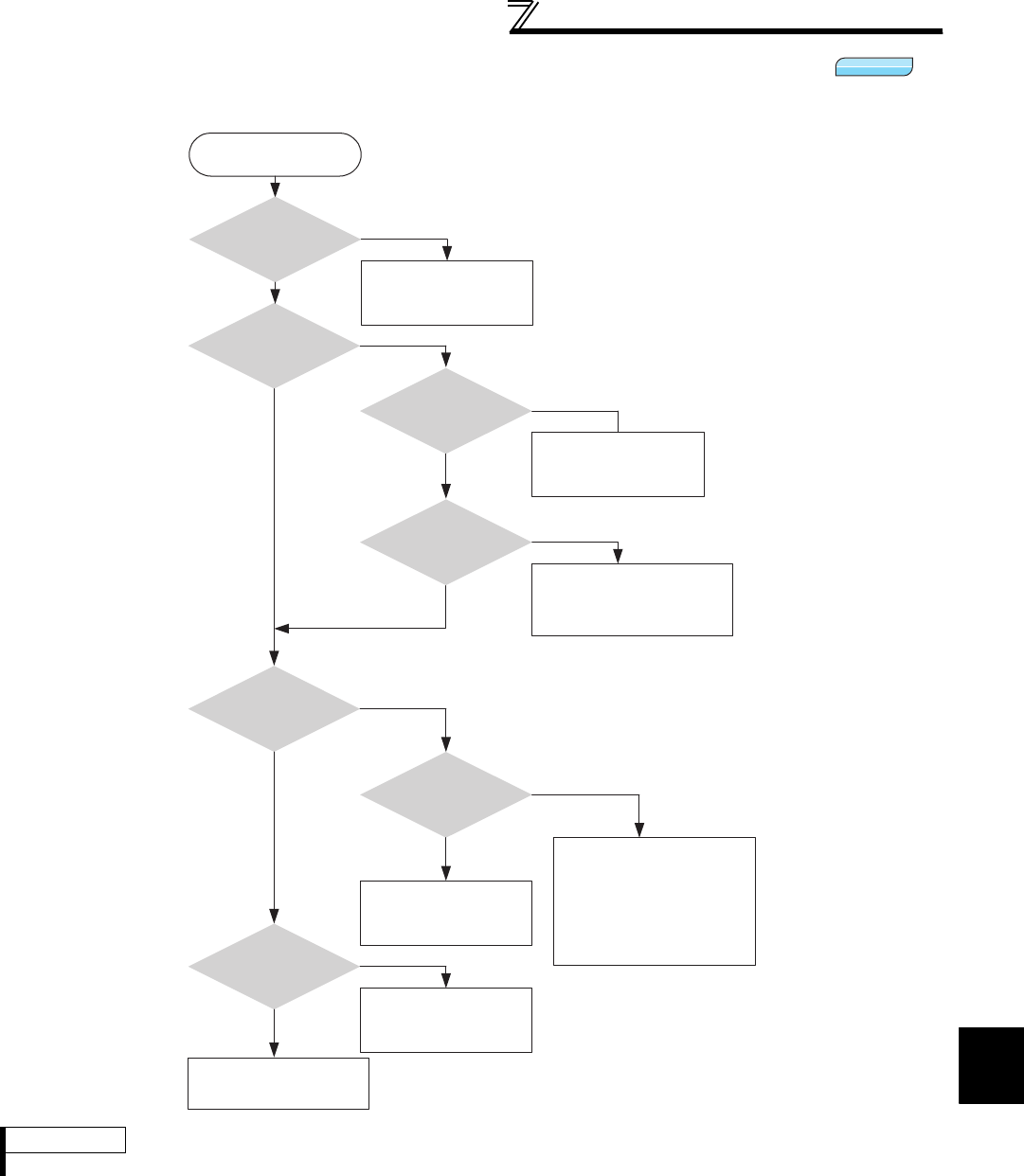
4
PARAMETERS
143
Position control by vector control
4.6.7 Trouble shooting for when position control is not exercised normally
REMARKS
The speed command of position control relates to speed control. (Refer to page 98 )
Vector
Vector
Vector
Motor or machine is
hunting.
Y
N
The position loop gain
(Pr. 422) is high.
Decrease
the position loop gain
(Pr. 422).
Set the electronic gear.
(Pr. 420, Pr. 421)
N
Have you made
the electronic gear
setting?
Y
Y
N
Perform easy gain tuning.
The speed control gain is high.
Decrease the speed control
proportional gain (Pr. 820).
Increase the speed control
integral time (Pr. 821).
Machine operation is
unstable.
Y
N
Do not turn off the forward
(reverse) rotation stroke end
signal before completion of
positioning.
Y
The forward (reverse)
rotation stroke end signal has
turned off before completion
of positioning.
N
Y
Position shift occurs.
N
Insufficient torque.
Increase the excitation
ratio (Pr. 854).
Check the speed
control measures.
N
Y
Position control is not
exercised normally
Have you checked
the speed control items?
Please contact your sales
representative.

Adjustment of Real sensorless vector
control, vector control
144
4.7 Adjustment of Real sensorless vector control, vector
control
4.7.1 Speed detection filter and torque detection filter (Pr. 823, Pr. 827, Pr. 833, Pr.
837)
(1) Stabilize speed detection (Pr. 823, Pr. 833 )
⋅Since the current loop response reduces, use it with the initial value.
Increase the setting value gradually and adjust the value to stabilize the speed when speed ripples occur due to
harmonic disturbance, etc. A too large value will run the motor unstably.
⋅Pr. 823 and Pr. 833 are valid only during vector control
(2) Stabilize speed detection (Pr. 827, Pr. 837 )
⋅Since the current loop response reduces, use it with the initial value.
Increase the setting value gradually and adjust the value to stabilize the speed when torque ripples occur due to
harmonic disturbance, etc. A too large value will run the motor unstably.
(3) Use multiple primary delay filters.
⋅Use Pr. 833 and Pr. 837 to change the filter according to applications. Pr. 833 and Pr. 837 are valid when the RT
signal is ON.
Purpose Parameter that should be Set Refer to Page
Stabilize speed and feedback signal Speed detection filter
Torque detection filter Pr. 823, Pr. 827, Pr. 833, Pr. 837 144
Change the excitation ratio Excitation ratio Pr. 854 145
Set the time constant of the primary delay filter relative to the speed feedback signal and torque feedback signal.
Since this function reduces the speed loop response, use it with the initial value.
Parameter
Number Name Initial Value Setting Range Description
823 *1 Speed detection filter 1 0.001s
0 Without filter
0.001 to 0.1s Set the time constant of the primary delay filter
relative to the speed feedback signal.
827 Torque detection filter 1 0s
0 Without filter
0.001 to 0.1s Set the time constant of the primary delay filter
relative to the torque feedback signal.
833 *1 Speed detection filter 2 9999 0 to 0.1s Second function of Pr. 823 (valid when RT signal is
on)
9999 Same as the Pr. 823 setting
837 Torque detection filter 2 9999 0 to 0.1s Second function of Pr. 827 (valid when RT signal is
on)
9999 Same as the Pr. 827 setting
*1 This parameter can be set when the FR-A7AP/FR-A7AL (option) is mounted.
REMARKS
⋅The RT signal acts as the second function selection signal and makes the other second functions valid. (Refer to page 235.)
⋅The RT signal is assigned to the RT terminal in the initial setting. By setting "3" in any of Pr. 178 to Pr. 189 (input terminal function
selection) , you can assign the RT signal to the other terminal.
Sensorless
Sensorless
SensorlessSensorless
Sensorless
SensorlessSensorless
Sensorless
Sensorless Vector
Vector
Vector

145
Adjustment of Real sensorless vector
control, vector control
4
PARAMETERS
4.7.2 Excitation ratio (Pr. 854)
Decrease the excitation ratio when you want to improve efficiency under light load. (Motor magnetic noise
decreases.)
Parameter
Number Name Initial Value Setting Range Description
854 Excitation ratio 100% 0 to 100% Set the excitation ratio under no load.
⋅Note that the rise of output torque becomes slow if
excitation ratio is decreased.
This function is appropriate for applications as machine
tools which repeat rapid acceleration/deceleration up to
high speed.
REMARKS
⋅When "1" (magnetic flux with terminal) is set in Pr. 858 Terminal 4 function assignment or Pr. 868 Terminal 1 function assignment, the
Pr. 854 setting is invalid.
Sensorless
Sensorless
SensorlessSensorless
Sensorless
SensorlessSensorless
Sensorless
Sensorless Vector
Vector
Vector
Excitation
ratio [%]
100
(initial value)
Pr. 854
set value
0 100 Load [%]
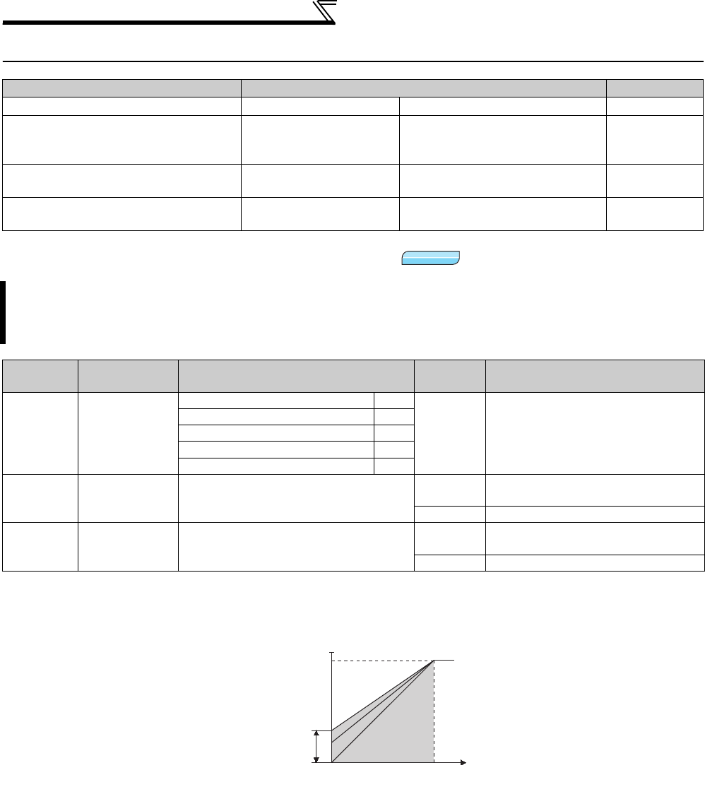
146
Adjustment of the output torque
(current) of the motor
4.8 Adjustment of the output torque (current) of the motor
4.8.1 Manual torque boost (Pr. 0, Pr. 46, Pr. 112)
(1) Starting torque adjustment
⋅
On the assumption that
Pr. 19 Base frequency voltage
is 100%, set the output voltage at 0Hz in % in
Pr. 0
(
Pr. 46, Pr. 112
).
⋅Adjust the parameter little by little (about 0.5%), and check the motor status each time. If the setting is too large, the
motor will overheat. The guideline is about 10% at the greatest.
Purpose Parameter that must be Set Refer to Page
Set starting torque manually Manual torque boost Pr. 0, Pr. 46, Pr. 112 146
Automatically control output current
according to load
Advanced magnetic flux
vector control
Pr. 71, Pr. 80, Pr. 81, Pr. 89, Pr. 450,
Pr. 451, Pr. 453, Pr. 454,
Pr. 569, Pr. 800
148
Compensate for motor slip to secure
low-speed torque Slip compensation Pr. 245 to Pr. 247 151
Limit output current to prevent inverter
trip Stall prevention operation Pr. 22, Pr. 23, Pr. 66,
Pr. 154, Pr. 156, Pr. 157 152
You can compensate for a voltage drop in the low-frequency region to improve motor torque reduction in the low-
speed range.
Motor torque in the low-frequency range can be adjusted to the load to increase the starting motor torque.
Three types of starting torque boost can be changed by switching terminals.
Parameter
Number Name Initial Value Setting
Range Description
0 Torque boost
0.4, 0.75K 6%
0 to 30% Set the output voltage at 0Hz as %.
1.5K to 3.7K
4%
5.5K, 7.5K 3%
11K to 55K 2%
75K or higher 1%
46 Second torque
boost 9999 0 to 30% Set the torque boost value when the
RT signal is ON.
9999 Without second torque boost
112 Third torque
boost 9999 0 to 30% Set the torque boost value when the
X9 signal is ON.
9999 Without third torque boost
V/F
V/F
V/F
Output
voltage
P
r.0
P
r.46 Setting
range
Base
frequency
0
100%
Output
frequency
(Hz)
P
r.11 2

147
4
PARAMETERS
Adjustment of the output torque
(current) of the motor
(2) Set multiple torque boost (RT signal, X9 signal, Pr. 46, Pr. 112)
⋅Use the second (third) torque boost when changing the torque boost according to application or when using
multiple motors by switching between them by one inverter.
⋅ Pr. 46 Second torque boost is valid when the RT signal turns ON.
⋅ Pr. 112 Third torque boost is valid when the X9 signal is ON. For the terminal used for X9 signal input, set "9" in any
of Pr. 178 to Pr. 189 (input terminal function selection) to assign the X9 signal function.
REMARKS
⋅The RT(X9) signal acts as the second (third) function selection signal and makes the other second (third) functions valid.
(Refer to page 235)
⋅The RT signal is assigned to the RT terminal in the default setting. By setting "3" in any of Pr. 178 to Pr. 189 (input terminal function
selection), you can assign the RT signal to the other terminal.
CAUTION
⋅Increase the setting when the distance between the inverter and motor is long or when motor torque is insufficient in the low-
speed range. If the setting is too large, an overcurrent trip may occur.
⋅The Pr. 0, Pr. 46, Pr. 112 settings are valid only when V/F control is selected.
⋅When using the inverter dedicated motor (constant torque motor) with the 5.5K or 7.5K, set the torque boost value to 2%. If the
initial set Pr. 71 value is changed to the setting for use with a constant-torque motor, the Pr. 0 setting changes to the
corresponding value in above.
⋅Changing the terminal assignment using Pr. 178 to Pr. 189 (input terminal function selection) may affect the other functions. Set
parameters after confirming the function of each terminal.
♦ Parameters referred to ♦
Pr. 3 Base frequency, Pr. 19 Base frequency voltage Refer to page 159
Pr. 71 Applied motor Refer to page 187
Pr. 178 to Pr. 189 (Input terminal function selection) Refer to page 231
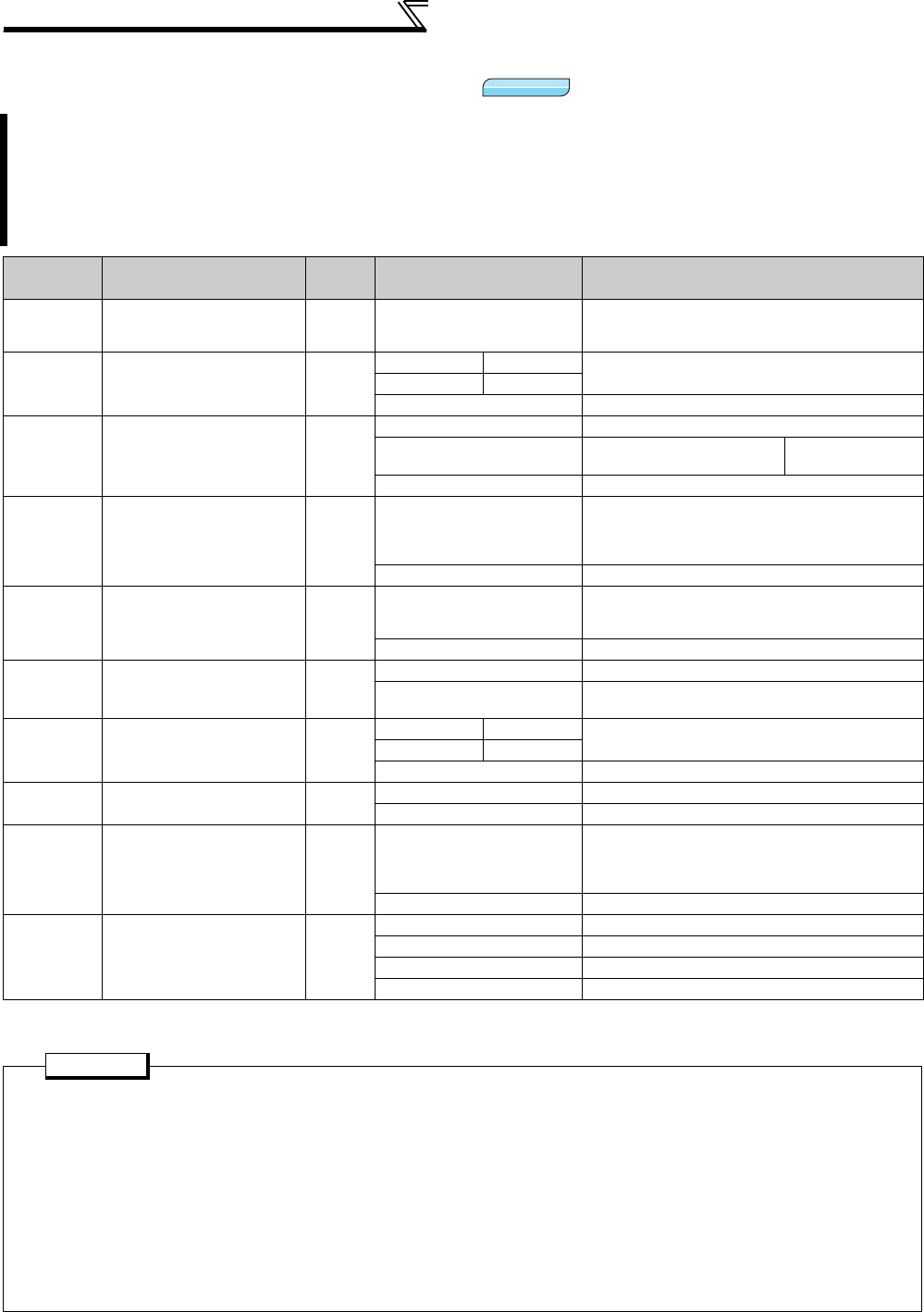
148
Adjustment of the output torque
(current) of the motor
4.8.2
Advanced magnetic flux vector control (Pr. 71, Pr. 80, Pr. 81, Pr. 89, Pr. 450,
Pr. 451, Pr. 453, Pr. 454, Pr. 569, Pr. 800)
*1 Use Pr. 178 to Pr. 189 to assign the terminals used for the X18 and MC signal. (Refer to page 231 )
*2 Valid when Pr. 450 ≠ "9999".
Advanced magnetic flux vector control can be selected by setting the capacity, number and type of motor to be
used in Pr. 80 and Pr. 81.
What is Advanced magnetic flux vector control?
The low speed torque can be improved by providing voltage compensation to flow a motor current which meets
the load torque. Output frequency compensation (slip compensation) is made so that the motor actual speed
approximates a speed command value. Effective when load fluctuates drastically, etc.
Parameter
Number Name Initial
Value Setting Range Description
71
Applied motor
0
0 to 8, 13 to 18,
20, 23, 24, 30, 33, 34, 40,
43, 44, 50, 53, 54
By selecting a standard motor or constant
torque motor, thermal characteristic and motor
constants of each motor are set.
80
Motor capacity
9999
55K or lower 0.4 to 55kW Set the applied motor capacity.
75K or higher 0 to 3600kW
9999 V/F control
81
Number of motor poles
9999
2, 4, 6, 8, 10 Set the number of motor poles.
12, 14, 16, 18, 20 X18 signal-ON:V/F control *1 Set 10 + number
of motor poles.
9999 V/F control
89
Speed control gain
(Advanced magnetic flux
vector)
9999 0 to 200%
Motor speed fluctuation due to load fluctuation
is adjusted during Advanced magnetic flux
vector control.
100% is a referenced value.
9999 Gain matching with the motor set in Pr. 71.
450
Second applied motor
9999
0 to 8, 13 to 18,
20, 23, 24, 30, 33, 34, 40,
43, 44, 50, 53, 54
Set when using the second motor.
(same specifications as Pr. 71 )
9999 Function invalid (Pr. 71 is valid)
451 *2
Second motor control
method selection
9999
10, 11, 12 Real sensorless vector control
20, 9999 V/F control (Advanced magnetic flux vector
control)
453 *2
Second motor capacity
9999
55K or lower 0.4 to 55kW Set the capacity of the second motor.
75K or higher 0 to 3600kW
9999 V/F control
454 *2
Number of second motor
poles
9999 2, 4, 6, 8, 10 Set the number of poles of the second motor.
9999 V/F control
569 *2
Second motor speed
control gain
9999 0 to 200%
Second motor speed fluctuation due to load
fluctuation is adjusted during Advanced
magnetic flux vector control.
100% is a referenced value.
9999 Gain matching with the motor set in Pr. 450.
800
Control method selection
20
0 to 5 Vector control
9 Vector control test operation
10, 11, 12 Real sensorless vector control
20
V/F control (Advanced magnetic flux vector control)
POINT
If the following conditions are not satisfied, select V/F control since malfunction such as insufficient torque and
uneven rotation may occur.
• The motor capacity should be equal to or one rank lower than the inverter capacity. (note that the capacity should
be 0.4kW or higher)
• Motor to be used is either Mitsubishi standard motor (SF-JR 0.4kW or higher), Mitsubishi high efficiency motor
(SF-HR 0.4kW or higher) or Mitsubishi constant torque motor (SF-JRCA 4P, SF-HRCA 0.4kW to 55kW). When
using a motor other than the above (SF-TH, other manufacturer's motors, etc.), perform offline auto tuning without
fail.
• Single-motor operation (one motor run by one inverter) should be performed.
• The wiring length from inverter to motor should be within 30m. (Perform offline auto tuning in the state where
wiring work is performed when the wiring length exceeds 30m.)
• For 75K or higher, do not use an option sine wave filter (MT-BSL/BSC) between the inverter and motor.
Magnetic flux
Magnetic flux
Magnetic flux
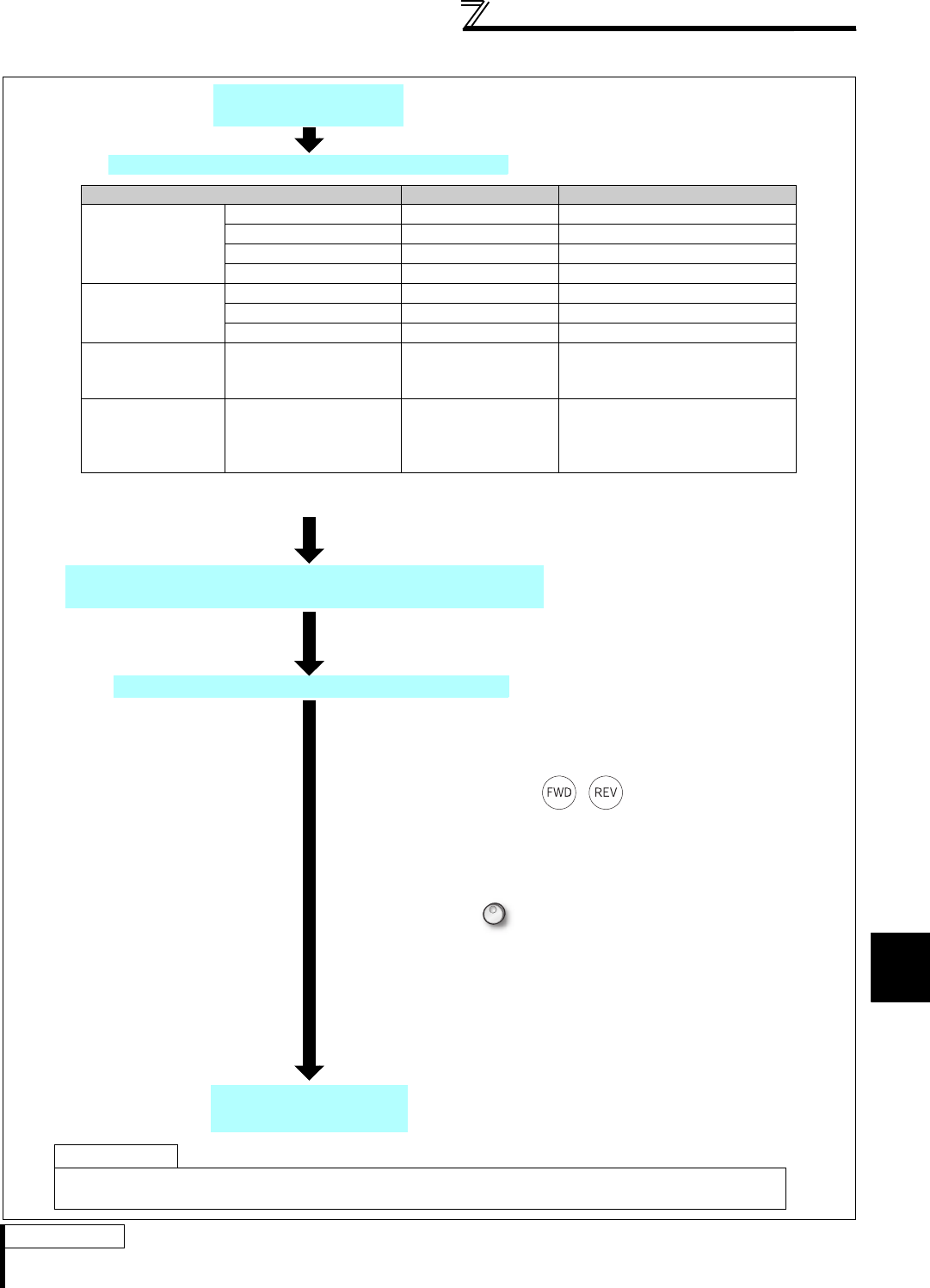
149
Adjustment of the output torque
(current) of the motor
4
PARAMETERS
(1) Selection method of Advanced magnetic flux vector control
REMARKS
· When higher accuracy operation is necessary, set online auto tuning after performing offline auto tuning and select Real
sensorless vector control.
Perform secure wiring.
(Refer to page 14)
Set the motor capacity and the number of motor poles.
(Pr. 80, Pr. 81) (Refer to page 92)
Test run
Set the motor. (Pr. 71)
Set the operation command. (Refer to page 313)
As required
· Perform offline auto tuning. (Pr. 96) (refer to page 189)
· Select online auto tuning. (Pr. 95) (refer to page 199)
Select the start command and speed command.
(1) Start command
1. Operation panel :
Setting by pressing / of the operation panel
2. External command : Setting by forward rotation or reverse
rotation command (terminal STF or STR)
(2) Speed command
1. Operation panel :
Setting by of the operation panel
2. External analog command (terminal 2 or 4) :
Give a speed command using the analog signal input to
terminal 2 (or terminal 4).
3. Multi-speed command :
The external signals (RH, RM, RL) may also be used to give
speed command.
Set motor capacity (kW) in Pr. 80 Motor capacity and the number
of motor poles (number of poles) in Pr. 81 Number of motor poles.
(V/F control is performed when the setting is "9999" (initial value).)
Motor Pr. 71 Setting *1 REMARKS
Mitsubishi standard
motor
Mitsubishi high
efficiency motor
SF-JR 0 (initial value)
SF-JR 4P 1.5kW or lower
20
SF-HR 40
Others 3 Offline auto tuning is necessary. *2
Mitsubishi constant-
torque motor
SF-JRCA 4P 1
SF-HRCA 50
Others (SF-JRC, etc.) 13 Offline auto tuning is necessary. *2
Other
manufacturer's
standard motor
⎯3 Offline auto tuning is necessary. *2
Other
manufacturer's
constant torque
motor
⎯13 Offline auto tuning is necessary. *2
*1 For other settings of Pr. 71 , refer to page 187.
*2 Refer to page 189 for offline auto tuning.

150
Adjustment of the output torque
(current) of the motor
(2) Adjust the motor speed fluctuation at load fluctuation (speed control gain)
(3) Advanced magnetic flux vector control is performed with two motors
• Turning the RT signal ON allows the second motor to be controlled.
• Set the second motor in Pr. 450 Second applied motor. (Initial value is "9999" (without second applied motor). Refer to
page 187.)
CAUTION
· Uneven rotation slightly increases as compared to the V/F control. (It is not suitable for machines such as grinding machine and
wrapping machine which requires less uneven rotation at low speed.)
· When a surge voltage suppression filter (FR-ASF-H/FR-BMF-H) is connected between the inverter and motor, output torque
may decrease. (55K or lower)
· When terminal assignment is changed using Pr. 178 to Pr. 189 (input terminal function selection), the other functions may be
affected. Set parameters after confirming the function of each terminal.
The motor speed fluctuation at load fluctuation can be adjusted using Pr. 89.
(It is useful when the speed command does not match the motor speed after
the FR-A500(L) series inverter is replaced with the FR-A700 series inverter,
etc.)
Function RT signal ON (second motor) RT signal OFF (first motor)
Applied motor Pr. 450 Pr. 71
Motor capacity Pr. 453 Pr. 80
Number of motor
poles Pr. 454 Pr. 81
Speed control gain Pr. 569 Pr. 89
Control method
selection Pr. 451 Pr. 800
REMARKS
• The RT signal acts as the second function selection signal and makes the other second functions valid. (Refer to page 235)
The RT signal is assigned to the terminal RT in the initial setting. By setting "3" in any of Pr. 178 to Pr. 189 (input terminal function
selection), the RT signal can be assigned to the other terminal.
CAUTION
• Changing the terminal assignment using Pr. 178 to Pr. 189 (input terminal function selection) may affect the other functions. Set
parameters after confirming the function of each terminal.
♦Parameters referred to♦
Pr. 71, Pr. 450 Applied motor Refer to page 187
Pr. 800, Pr. 451 Control method selection Refer to page 92
Load torque
Speed

151
4
PARAMETERS
Adjustment of the output torque
(current) of the motor
4.8.3 Slip compensation (Pr. 245 to Pr. 247)
⋅Slip compensation is validated when the motor rated slip calculated by the following formula is set in Pr. 245. Slip
compensation is not made when Pr. 245 = "0" or "9999".
The inverter output current may be used to assume motor slip to keep the motor speed constant.
Parameter
Number Name Initial Value Setting Range Description
245 Rated slip 9999 0.01 to 50% Used to set the rated motor slip.
0, 9999 No slip compensation
246 Slip compensation time
constant 0.5s 0.01 to 10s
Used to set the slip compensation response
time. When the value is made smaller,
response will be faster. However, as load
inertia is greater, a regenerative overvoltage
fault (E.OV) is more liable to occur.
247 Constant-power range slip
compensation selection 9999
0
Slip compensation is not made in the
constant power range (frequency range
above the frequency set in Pr. 3)
9999 Slip compensation is made in the constant
power range.
Rated slip =Synchronous speed at base frequency - rated speed ×100[%]
Synchronous speed at base frequency
REMARKS
When performing slip compensation, the output frequency may become greater than the set frequency. Set the Pr. 1 Maximum
frequency value a little higher than the set frequency.
♦ Parameters referred to ♦
Pr. 1 Maximum frequency Refer to page 157
Pr. 3 Base frequency Refer to page 159
V/F
V/F
V/F

152
Adjustment of the output torque
(current) of the motor
4.8.4 Stall prevention operation (Pr. 22, Pr. 23, Pr. 48, Pr. 49, Pr. 66, Pr. 114, Pr. 115,
Pr. 148, Pr. 149, Pr. 154, Pr. 156, Pr. 157, Pr. 858, Pr. 868)
* This parameter allows its setting to be changed during the operation in any operation mode even if "0 (initial value) or 1" is set in Pr.77 Parameter
write selection.
This function monitors the output current and automatically changes the output frequency to prevent the inverter
to trip due to overcurrent, overvoltage, etc. It can also limit stall prevention and fast response current limit
operation during acceleration/deceleration, driving or regeneration. Invalid under Real sensorless vector control
or vector control.
Stall prevention
If the output current exceeds the stall prevention operation level, the output frequency of the inverter is
automatically varied to reduce the output current.
Also the second stall prevention function can restrict the output frequency range in which the stall prevention
function is valid. (Pr. 49)
Fast response current limit
If the current exceeds the limit value, the output of the inverter is shut off to prevent an overcurrent.
Parameter
Number
Name Initial Value Setting
Range Description
22*Stall prevention operation
level 150%
0 Stall prevention operation selection becomes invalid.
0.1 to 400% Set the current value at which stall prevention
operation will be started.
23
Stall prevention operation
level compensation factor
at double speed
9999 0 to 200% The stall operation level can be reduced when
operating at a high speed above the rated frequency.
9999 Constant according to Pr. 22
48 Second stall prevention
operation current 150% 0 Second stall prevention operation invalid
0.1 to 220% The second stall prevention operation level can be set.
49 Second stall prevention
operation frequency 0Hz
0 Second stall prevention operation invalid
0.01 to 400Hz Set the frequency at which stall prevention operation
of Pr. 48 is started.
9999 Pr. 48 is valid when the RT signal is ON.
66
Stall prevention operation
reduction starting frequency
60Hz 0 to 400Hz Set the frequency at which the stall operation level
starts being reduced.
114 Third stall prevention
operation current 150%
0 Third stall prevention operation invalid
0.1 to 220% Stall prevention operation level can be changed with
the X9 signal.
115 Third stall prevention
operation frequency 0Hz
0 Third stall prevention operation invalid
0.01 to 400Hz Set the frequency at which stall prevention operation
when the X9 signal is ON starts.
148 Stall prevention level at
0V input 150% 0 to 220% Stall prevention operation level can be changed by
the analog signal input to terminal 1 (terminal 4).
149 Stall prevention level at
10V input 200% 0 to 220%
154
Voltage reduction
selection during stall
prevention operation
1
0With voltage
reduction
You can select whether to use
output voltage reduction
during stall prevention
operation or not.
1Without voltage
reduction
156 Stall prevention operation
selection 00 to 31,
100, 101
You can select whether stall prevention operation and
fast response current limit operation will be performed
or not.
157 OL signal output timer 0s 0 to 25s Set the output start time of the OL signal output when
stall prevention is activated.
9999 Without the OL signal output
858 Terminal 4 function
assignment 0 0, 1, 4, 9999 By setting "4", the stall prevention operation level can
be changed with a signal to terminal 4.
868 Terminal 1 function
assignment 0 0 to 6, 9999 By setting "4", the stall prevention operation level can
be changed with a signal to terminal 1.
(1) Setting of stall prevention operation level (Pr. 22)
⋅Set in Pr. 22 the ratio of the output current to the rated inverter current at
which stall prevention operation will be performed. Normally set 150%
(initial value).
⋅Stall prevention operation stops acceleration (makes deceleration) during
acceleration, makes deceleration during constant speed, and stops
deceleration during deceleration.
⋅When stall prevention operation is performed, the OL signal is output.
V/F
V/F
V/F
Magnetic flux
Magnetic flux
Magnetic flux
Stall prevention operation example
P
r. 22
OL
Output current
Output frequency
Acceleration
Constant
speed
Deceleration
Time
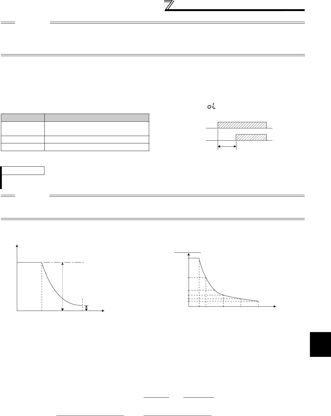
153
4
PARAMETERS
Adjustment of the output torque
(current) of the motor
(2) Stall prevention operation signal output and output timing adjustment (OL signal, Pr. 157)
⋅When the output power exceeds the stall prevention operation level and stall prevention is activated, the stall
prevention operation signal (OL signal) turns ON for longer than 100ms. When the output power falls to or below
the stall prevention operation level, the output signal turns OFF.
⋅Use Pr. 157 OL signal output timer to set whether the OL signal is output immediately or after a preset period of time.
⋅This operation is also performed when the regeneration avoidance function (overvoltage stall) is executed.
(3) Setting of stall prevention operation in high frequency range (Pr. 22, Pr. 23, Pr. 66)
⋅During high-speed operation above the rated motor frequency, acceleration may not be made because the motor
current does not increase. If operation is performed in a high frequency range, the current at motor lockup
becomes smaller than the rated output current of the inverter, and the protective function (OL) is not executed if the
motor is at a stop.
To improve the operating characteristics of the motor in this case, the stall prevention level can be reduced in the
high frequency range. This function is effective for performing operation up to the high-speed range on a centrifugal
separator etc. Normally, set 60Hz in Pr. 66 and 100% in Pr. 23.
⋅Formula for stall prevention operation level
⋅When Pr. 23 Stall prevention operation level compensation factor at double speed = "9999" (initial value), the stall
prevention operation level is kept constant at the Pr. 22 setting up to 400Hz.
CAUTION
⋅If an overload status lasts long, an inverter trip (e.g. electronic thermal relay function (E.THM)) may occur.
⋅When Pr. 156 has been set to activate the fast response current limit (initial value), the Pr. 22 setting should not be higher than
170%. The torque will not be developed by doing so.
⋅
When Real sensorless vector control or vector control is selected using
Pr. 800 Control method selection
,
Pr.22
serves as torque limit
level.
For the 3.7K or lower, the Pr. 22 setting changes from 150% (initial value) to 200%.
Pr. 157 Setting Description
0
(initial value) Output immediately
0.1 to 25 Output after the set time (s) has elapsed
9999 Not output
REMARKS
⋅The OL signal is assigned to the terminal OL in the initial setting. The OL signal can also be assigned to the other terminal by
setting "3 (positive logic) or 103 (negative logic)" to any of Pr. 190 to Pr. 196 (output terminal function selection).
CAUTION
· If the frequency has fallen to 0.5Hz by stall prevention operation and remains for 3s, a fault (E.OLT) appears to trip the inverter.
· Changing the terminal assignment using Pr. 190 to Pr. 196 (output terminal function selection) may affect the other functions. Set
parameters after confirming the function of each terminal.
Stall prevention operation level in
high frequency range (%) =A + B×[Pr. 22 - A ]×[Pr. 23 - 100 ]
Pr. 22 - B 100
However, A = Pr. 66(Hz) × Pr. 22(%) , B = Pr. 66(Hz) × Pr. 22(%)
Output frequency (H) 400Hz
Overload state
(OL operation)
OL output signal
Pr.157 Set time(s)
Output frequency (Hz)
Pr. 22
When Pr. 23 = 9999
Pr. 66 400Hz
Stall prevention operation
level (%)
Stall prevention operation level
as set in Pr. 23
When Pr. 23 = "9999", the stall prevention
operation level is as set in Pr. 22 to 400Hz.
150
90
60
45
30
22.5
600 100 200 300 400
Output frequency (Hz)
Setting example (Pr.22=150%, Pr.23=100%, Pr.66=60Hz)
Stall prevention operation level (%)

154
Adjustment of the output torque
(current) of the motor
(4) Set multiple stall prevention operation levels (Pr. 48, Pr. 49, Pr. 114, Pr. 115)
⋅Setting "9999" in Pr. 49 Second stall prevention operation frequency and
turning the RT signal ON make Pr. 48 Second stall prevention operation
current valid.
⋅In Pr. 48 (Pr. 114), you can set the stall prevention operation level at the
output frequency from 0Hz to that set in Pr. 49 (Pr. 115).
During acceleration, however, the operation level is as set in Pr. 22.
⋅This function can also be used for stop-on-contact or similar operation by
decreasing the Pr. 48 (Pr. 114) setting to weaken the deceleration torque
(stopping torque).
⋅Pr. 114 and Pr. 115 are valid when the X9 signal is ON. For the terminal
used for X9 signal input, set "9" in any of Pr. 178 to Pr. 189 input terminal
function selection to assign the X9 signal function.
REMARKS
⋅When Pr. 49 ≠ "9999" (level changed according to frequency) and Pr. 48 = "0%", the stall prevention operation level is 0% at or
higher than the frequency set in Pr. 49.
⋅In the initial setting, the RT signal is assigned to the RT terminal. By setting "3" to any of Pr. 178 to Pr. 189 (input terminal function
selection), you can assign the RT signal to the other terminal.
CAUTION
⋅Changing the terminal assignment using Pr. 178 to Pr. 189 (input terminal function selection) may affect the other functions. Set
parameters after confirming the function of each terminal.
⋅The RT(X9) signal acts as the second (third) function selection signal and makes the other second (third) functions valid. (Refer
to page 235)
Stall prevention
operation current
During acceleration
Running frequency
Pr.48
Pr.49
During deceleration/constant speed
During deceleration/constant speed
During deceleration/constant speed
P
r.11 4
Pr.115
Pr. 22
used
Output
frequency (Hz) Output
frequency
Stall
prevention
level
Set
frequency
Time
Pr.49
(Pr.115)
Set frequency exceeds Pr. 49(Pr.115)
Pr. 48
(Pr.114)
used
Pr. 22
used
Output
frequency (Hz)
Output
frequency
Set
frequency
Time
Pr.49
(Pr.115)
Pr. 48
(Pr.114)
used
Set frequency is Pr. 49 (Pr.115)or less
Pr. 49
Setting
Pr. 115
Setting Operation
0
(initial value)
The second (third) stall prevention operation is not
performed.
0.01Hz to 400Hz The second (third) stall prevention operation is
performed according to the frequency.*1
9999 *2
Setting
cannot
be
made.
The second (third) stall prevention function is
performed according to the RT signal.
RT signal ON ... Stall level Pr. 48
RT signal OFF ... Stall level Pr. 22
*1 The smaller setting of the stall prevention operation levels set in Pr. 22 and Pr. 48
has a higher priority.
*2 When Pr. 868 = "4" (Stall prevention operation level analog input), the stall
prevention operation level also switches from the analog input (terminal 1 input)
to the stall prevention operation level of Pr. 48 when the RT signal turns ON.
(The second stall prevention operation level cannot be input in an analog form.)
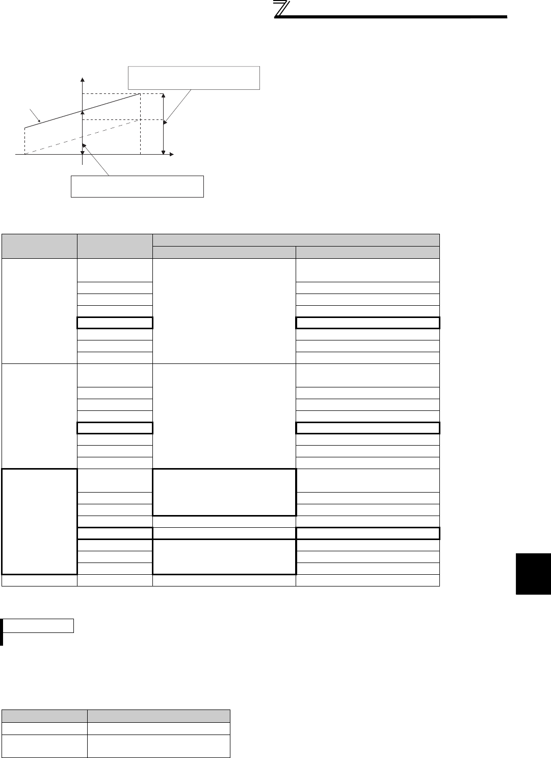
155
4
PARAMETERS
Adjustment of the output torque
(current) of the motor
(5) Stall prevention operation level setting by terminal 1 (terminal 4) (analog variable) (Pr. 148,
Pr. 149, Pr. 858, Pr. 868)
*1 When Pr. 868 = "4" (analog stall prevention), other functions of terminal 1 (auxiliary input, override function, PID control) do not function.
*2 When
Pr. 858
= "4" (analog stall prevention), PID control and speed command from terminal 4 do not function even if the AU signal turns ON.
*3 When "4" (stall prevention) is set in both Pr. 858 and Pr. 868, function of terminal 1 has higher priority and terminal 4 has no function.
(6) To further prevent a trip (Pr. 154)
⋅When Pr. 154 is set to "0", the output voltage reduces during stall prevention operation. By making setting to reduce
the output voltage, an overcurrent trip can further become difficult to occur.
⋅Use this function where a torque decrease will not pose a problem.
⋅To set the stall prevention operation level using
terminal 1 (analog input), set Pr. 868 Terminal 1
function assignment to "4".
⋅Input 0 to 5V (or 0 to 10V) to terminal 1. Select 5V or
10V using Pr. 73 Analog input selection. When Pr. 73 =
"1" (initial value), 0 to ±10V is input.
⋅To set stall prevention operation level using terminal
4 (analog current input), set "4" in Pr. 858 Terminal 4
function assignment.
Input 0 to 20mA to terminal 4. The AU signal need
not be turned ON.
⋅Set the current limit level at the input voltage of 0V
(0mA) in Pr. 148 Stall prevention level at 0V input
⋅Set the current limit level at the input voltage of 10V/
5V (20mA) in Pr. 149 Stall prevention level at 10V input.
Pr. 858 Setting Pr. 868 Setting V/F, Advanced Magnetic Flux Vector Control
Terminal 4 function Terminal 1 function
0
(initial value)
0
(initial value)
Frequency command
(AU signal-ON)
Frequency auxiliary
1⎯
2⎯
3⎯
4 *1 Stall prevention
5⎯
6⎯
9999 ⎯
1
0
(initial value)
⎯
⎯
1⎯
2⎯
3⎯
4 *1 Stall prevention
5⎯
6⎯
9999 ⎯
4 *2
0
(initial value) Stall prevention
Frequency auxiliary
1⎯
2⎯
3⎯⎯
4 *1 ⎯ *3 Stall prevention
5
Stall prevention
⎯
6⎯
9999 ⎯
9999 ⎯⎯ ⎯
REMARKS
⋅The fast response current limit level cannot be set.
Pr. 154 Setting Description
0 Output voltage reduced
1
(initial value) Output voltage not reduced
100%
50%
Current limit level (%)
(5V/10VDC)
(20mA)
(-5V/10VDC) Input voltage (V)
Set the current limit level at 10V/5V input
power (input current 20mA) using Pr. 149.
Set the current limit level at 0V input
voltage (input current 0mA) using Pr. 148.
0V
0mA Input current (mA)
200%
150%
Initial value

156
Adjustment of the output torque
(current) of the motor
(7) Limit the stall prevention operation and fast response current limit operation according to
the operating status (Pr. 156)
⋅Refer to the following table and select whether fast response current limit operation will be performed or not and
the operation to be performed at OL signal output.
*1 When "Operation not continued for OL signal output" is selected, the " " fault (stopped by stall prevention) is displayed and operation
stopped.
*2 Since both fast response current limit and stall prevention are not activated, OL signal and E.OLT are not output.
*3 The settings "100" and "101" allow operations to be performed in the driving and regeneration modes, respectively. The setting "101" disables the
fast response current limit in the driving mode.
Pr. 156
Setting
Fast response
Current Limit
: Activated
:
Not activated
Stall Prevention
Operation Selection
:Activated
:Not activated
OL signal
Output
:Operation
continued
:
Operation
not continued
*1
Pr. 156
Setting
Fast response
Current Limit
:Activated
:
Not activated
Stall Prevention
Operation Selection
:Activated
:Not activated
OL signal
Output
:Operation
continued
:
Operation
not continued
*1
Acceleration
Constant
speed
Deceleration
Acceleration
Constant
speed
Deceleration
0
(initial
value)
16
1 17
2 18
3 19
4 20
5 21
6 22
7 23
8 24
9 25
10 26
11 27
12 28
13 29
14 30
15 ⎯ *2 31 ⎯ *2
100
*3
Driving
101
*3
Driving
Regeneration
⎯ *2
Regeneration
⎯ *2
CAUTION
⋅When the load is heavy, or when the acceleration/deceleration time is short, stall prevention is activated and acceleration/
deceleration may not be made according to the preset acceleration/deceleration time. Set Pr. 156 and stall prevention operation
level to the optimum values.
⋅In vertical lift applications, make setting so that the fast response current limit is not activated. Torque may not be produced,
causing a drop due to gravity.
CAUTION
Do not set a small value as the stall prevention operation current.
Otherwise, torque generated will reduce.
Always perform test operation.
Stall prevention operation during acceleration may increase the acceleration time.
Stall prevention operation performed during constant speed may cause sudden speed changes.
Stall prevention operation during deceleration may increase the deceleration time, increasing the deceleration
distance.
♦ Parameters referred to ♦
⋅Pr. 22 Torque limit level Refer to page 100
⋅Pr. 73 Analog input selection Refer to page 286
⋅Pr. 178 to Pr. 189 (Input terminal function selection) Refer to page 231
⋅Pr. 190 to Pr. 196 (output terminal function selection) Refer to page 239
⋅Pr. 858 Terminal 4 function assignment, Pr. 868 Terminal 1 function assignment Refer to page 285
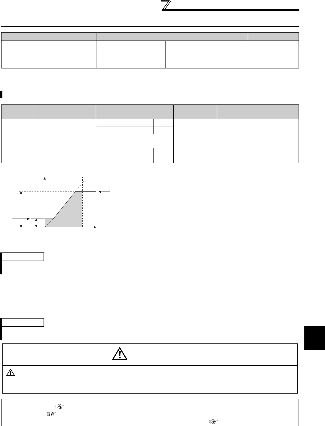
157
Limiting the output frequency
4
PARAMETERS
4.9 Limiting the output frequency
4.9.1 Maximum/minimum frequency (Pr. 1, Pr. 2, Pr. 18)
(2) Set minimum frequency
⋅Use Pr. 2 Minimum frequency to set the lower limit of the output frequency.
⋅The output frequency is clamped by the Pr. 2 setting even if the set frequency is equal to or less than the Pr. 2 setting
(The frequency will not decrease to the Pr. 2 setting.)
Purpose Parameter that must be Set Refer to Page
Set upper limit and lower limit of
output frequency
Maximum/minimum
frequency Pr. 1, Pr. 2, Pr. 18 157
Perform operation by avoiding
mechanical resonance points Frequency jump Pr. 31 to Pr. 36 158
You can limit the motor speed. Clamp the upper and lower limits of the output frequency.
Parameter
Number Name Initial Value Setting Range Description
1 Maximum frequency 55K or lower 120Hz 0 to 120Hz Set the upper limit of the output
frequency.
75K or higher 60Hz
2 Minimum frequency 0Hz 0 to 120Hz Set the lower limit of the output
frequency.
18 High speed maximum
frequency
55K or lower 120Hz 120 to 400Hz Set when performing the
operation at 120Hz or more.
75K or higher 60Hz
(1) Set maximum frequency
⋅Set the upper limit of the output frequency in Pr. 1 Maximum
frequency. If the value of the frequency command entered is
higher than the setting, the output frequency is clamped at the
maximum frequency.
⋅When you want to perform operation above 120Hz, set the upper
limit of the output frequency to Pr. 18 High speed maximum
frequency. (When Pr. 18 is set, Pr. 1 automatically switches to the
frequency of Pr. 18. When Pr. 18 is set, Pr. 18 automatically
switches to the frequency of Pr. 1.)
REMARKS
⋅When performing operation above 60Hz using the frequency setting analog signal, change Pr. 125 (Pr. 126) (frequency setting
gain). If only Pr. 1 or Pr. 18 is changed, operation above 60Hz cannot be performed.
REMARKS
⋅When Pr. 15 Jog frequency is equal to or less than Pr. 2, the Pr. 15 setting has precedence over the Pr. 2 setting.
⋅When stall prevention is activated to decrease the output frequency, the output frequency may drop to Pr. 2 or below.
CAUTION
Note that when Pr. 2 is set to any value equal to or more than Pr. 13 Starting frequency, simply turning ON the
start signal will run the motor at the preset frequency according to the set acceleration time even if the
command frequency is not input.
♦ Parameters referred to ♦
Pr. 13 Starting frequency Refer to page 175
Pr. 15 Jog frequency Refer to page 167
Pr. 125 Terminal 2 frequency setting gain frequency, Pr. 126 Terminal 4 frequency setting gain frequency Refer to page 294
Output frequency
(Hz)
Pr.1
Pr.18
Pr.2 Frequency setting
Clamped at the
maximum frequenc
y
Clamped at the
minimum frequency
5, 10V
(20mA)
0
(4mA)
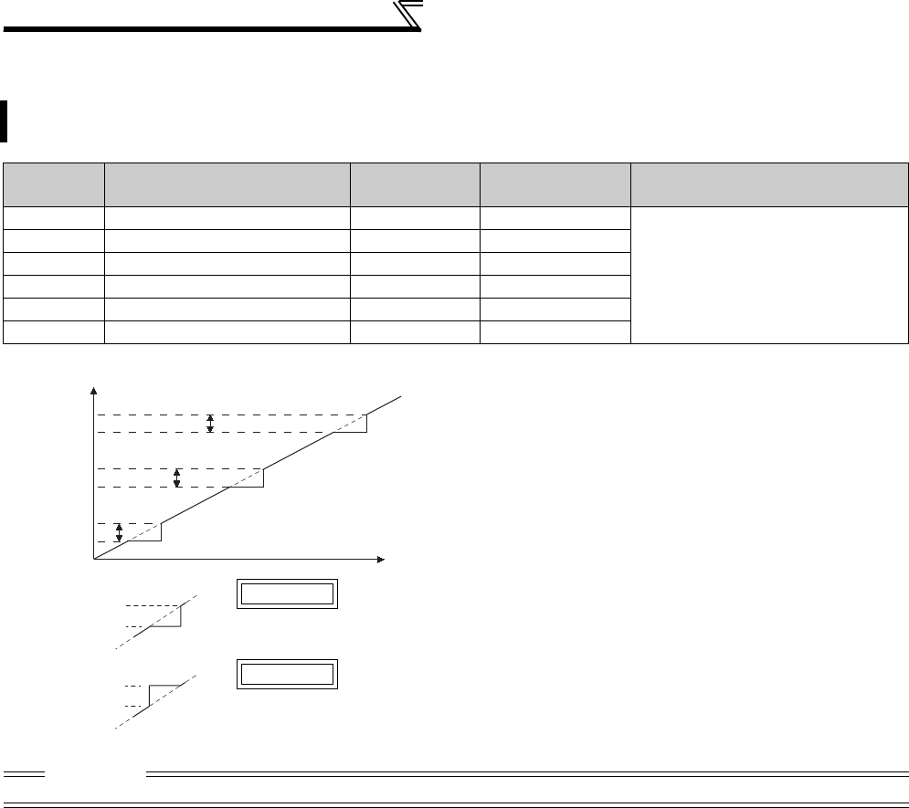
158
Limiting the output frequency
4.9.2 Avoiding mechanical resonance points (Frequency jump) (Pr. 31 to Pr. 36)
When it is desired to avoid resonance attributable to the natural frequency of a mechanical system, these
parameters allow resonant frequencies to be jumped.
Parameter
Number Name Initial Value Setting Range Description
31 Frequency jump 1A 9999 0 to 400Hz, 9999
1A to 1B, 2A to 2B, 3A to 3B is
frequency jumps
9999: Function invalid
32 Frequency jump 1B 9999 0 to 400Hz, 9999
33 Frequency jump 2A 9999 0 to 400Hz, 9999
34 Frequency jump 2B 9999 0 to 400Hz, 9999
35 Frequency jump 3A 9999 0 to 400Hz, 9999
36 Frequency jump 3B 9999 0 to 400Hz, 9999
⋅Up to three areas may be set, with the jump frequencies set
to either the top or bottom point of each area.
⋅The settings of frequency jumps 1A, 2A, 3A are jump points,
and operation is performed at these frequencies in the jump
areas.
Example 1 To fix the frequency to 30Hz in the range 30Hz to 35Hz, set 35Hz in Pr. 34
and 30Hz in Pr. 33.
Example 2 To jump the frequency to 35Hz in the range 30Hz to 35Hz, set 35Hz in Pr.
33 and 30Hz in Pr. 34.
CAUTION
⋅During acceleration/deceleration, the running frequency within the set area is valid.
Pr. 31
Frequency jump
Pr. 32
Pr. 33
Pr. 34
Pr. 35
Pr. 36
Set frequency (Hz)
Pr.34:35Hz
Pr.33:30Hz
Pr.33:35Hz
Pr.34:30Hz
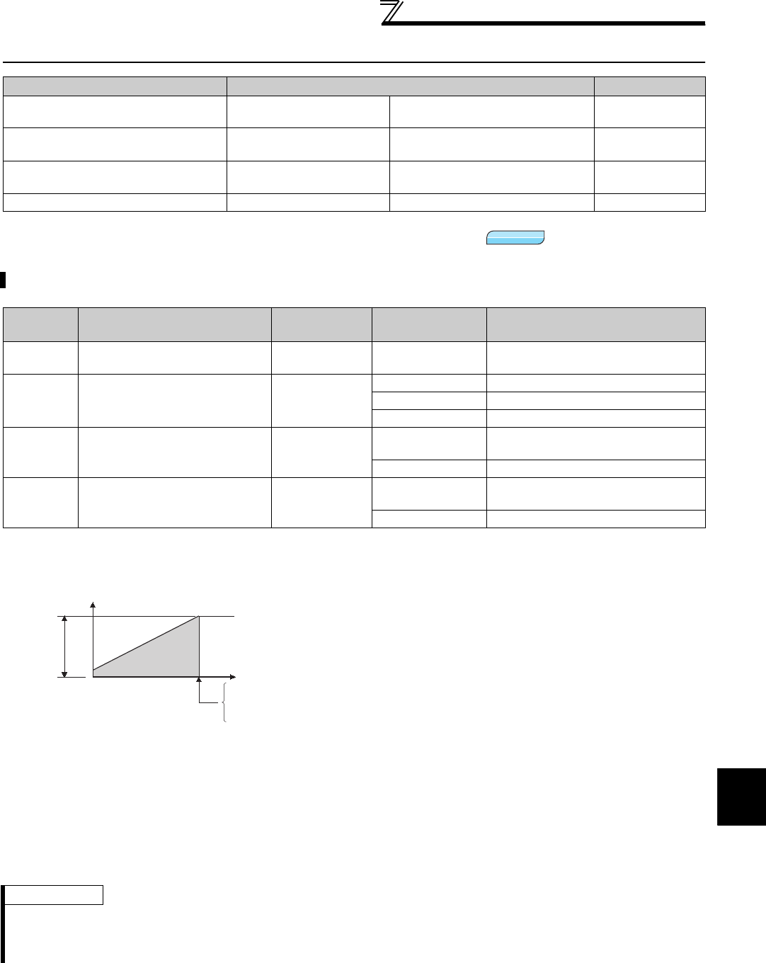
159
V/F pattern
4
PARAMETERS
4.10 V/F pattern
4.10.1 Base frequency, voltage (Pr. 3, Pr. 19, Pr. 47, Pr. 113)
(2) Set multiple base frequencies (Pr. 47, Pr. 113)
⋅When you want to change the base frequency when switching two motors with one inverter, use the Pr. 47 Second V/F
(base frequency).
⋅Pr. 47 Second V/F (base frequency) is valid when the RT signal in ON and Pr. 113 Third V/F (base frequency) is valid when
the X9 signal is ON. Assign the terminal for X9 signal input using any of Pr. 178 to Pr. 189 (input terminal function
selection).
Purpose Parameter that must be Set Refer to Page
Set motor ratings Base frequency, base
frequency voltage Pr. 3, Pr. 19, Pr. 47, Pr. 113 159
Select a V/F pattern according to
applications Load pattern selection Pr. 14 161
Automatically set a V/F pattern for
elevators
Elevator mode (automatic
acceleration/deceleration) Pr. 61, Pr. 64, Pr. 292 163
Use special motor Adjustable 5 points V/F Pr. 71, Pr. 100 to Pr. 109 164
Use the following parameters to adjust the inverter outputs (voltage, frequency) to the motor rating.
Parameter
Number Name Initial Value Setting Range Description
3 Base frequency 60Hz 0 to 400Hz Set the frequency when the motor
rated torque is generated. (50Hz/60Hz)
19 Base frequency voltage 9999
0 to 1000V Set the base voltage.
8888 95% of power supply voltage
9999 Same as power supply voltage
47 Second V/F (base frequency) 9999 0 to 400Hz Set the base frequency when the RT
signal is ON.
9999 Second V/F invalid
113 Third V/F (base frequency) 9999 0 to 400Hz Set the base frequency when the X9
signal is ON.
9999 Third V/F is invalid
(1) Setting of base frequency (Pr. 3)
⋅When operating a standard motor, generally set the rated
frequency of the motor to Pr. 3 Base frequency. When running
the motor using bypass operation, set Pr. 3 to the same value
as the power supply frequency.
⋅If the frequency given on the motor rating plate is "50Hz" only,
always set to "50Hz". Leaving the base frequency unchanged
from "60Hz" may make the voltage too low and the torque
insufficient. It may result in an inverter trip due to overload.
Special care must be taken when "1" (reduced torque load) is
set in Pr. 14 Load pattern selection.
⋅When using the Mitsubishi constant-torque motor, set Pr. 3 to
60Hz.
REMARKS
⋅The RT(X9) signal acts as the second (third) function selection signal and makes the other second (third) functions valid. (Refer
to page 235)
⋅In the initial setting, the RT signal is assigned to the RT terminal. By setting "3" in any of Pr. 178 to Pr. 189 (input terminal function
selection), you can assign the RT signal to the other terminal.
V/F
V/F
V/F
Pr.19
Output voltage (V)
Output frequency
(Hz)
Pr.3
Pr.47
Pr.113

160
V/F pattern
(3) Base frequency voltage setting (Pr. 19)
⋅Use Pr. 19 Base frequency voltage to set the base voltage (e.g. rated motor voltage).
⋅If the setting is less than the power supply voltage, the maximum output voltage of the inverter is as set in Pr. 19.
⋅Pr. 19 can be utilized in the following cases.
(a) When regeneration frequency is high (e.g. continuous regeneration)
During regeneration, the output voltage becomes higher than the reference and may cause an overcurrent trip
(E.OC) due to an increased motor current.
(b) When power supply voltage variation is large
When the power supply voltage exceeds the rated voltage of the motor, speed variation or motor overheat may
be caused by excessive torque or increased motor current.
⋅Set parameters as below when running the vector control dedicated motor (SF-V5RU, SF-V5RU1, SF-V5RU3, SF-
V5RU4, SF-VR) under V/F control.
Motor Type Pr. 19 Setting Pr. 3 Setting
SF-V5RU-3.7kW or lower 170V
50Hz
SF-V5RU-5.5kW or higher 160V
SF-V5RUH-3.7kW or lower 340V
SF-V5RUH-5.5kW or higher 320V
SF-V5RU1-30kW or lower 160V
33.33Hz
SF-V5RU1-37kW 170V
SF-V5RU3-22kW or lower 160V
SF-V5RU3-30kW 170V
SF-V5RU4-3.7kW, 7.5kW 150V 16.67Hz
SF-V5RU4-other than the above 160V
SF-VR 160V 50Hz
SF-VRH 320V
REMARKS
When operation is discontinued under vector control due to failure of an encoder, etc., setting "9999" in Pr. 80 Motor capacity or Pr. 81
Number of motor poles enables V/F control operation.
CAUTION
⋅When Advanced magnetic flux vector control mode, Real sensorless vector control or vector control is selected, Pr. 3, Pr. 47, Pr.
113 and Pr. 19 are invalid and Pr. 83 and Pr. 84 are valid.
Note that Pr. 3 or Pr. 47 and Pr. 113 values are valid as inflection points of S-pattern when Pr. 29 Acceleration/deceleration pattern
selection = "1" (S-pattern acceleration/deceleration A).
⋅When Pr. 71 Applied motor is set to "2" (adjustable 5 points V/F characteristic), the Pr. 47 and Pr. 113 setting becomes invalid. In
addition, you cannot set "8888" or "9999" in Pr. 19.
⋅Changing the terminal assignment using Pr. 178 to Pr. 189 (input terminal function selection) may affect the other functions. Set
parameters after confirming the function of each terminal.
♦ Parameters referred to ♦
Pr. 14 Load pattern selection Refer to page 161
Pr. 29 Acceleration/deceleration pattern selection Refer to page 176
Pr. 71 Applied motor Refer to page 187
Pr. 80 Motor capacity Refer to page 92
Pr. 83 Rated motor voltage, Pr. 84 Rated motor frequency Refer to page 189
Pr. 178 to Pr. 189 (input terminal function selection) Refer to page 231
Advanced magnetic flux vector control Refer to page 148
Real sensorless vector control Refer to page 92
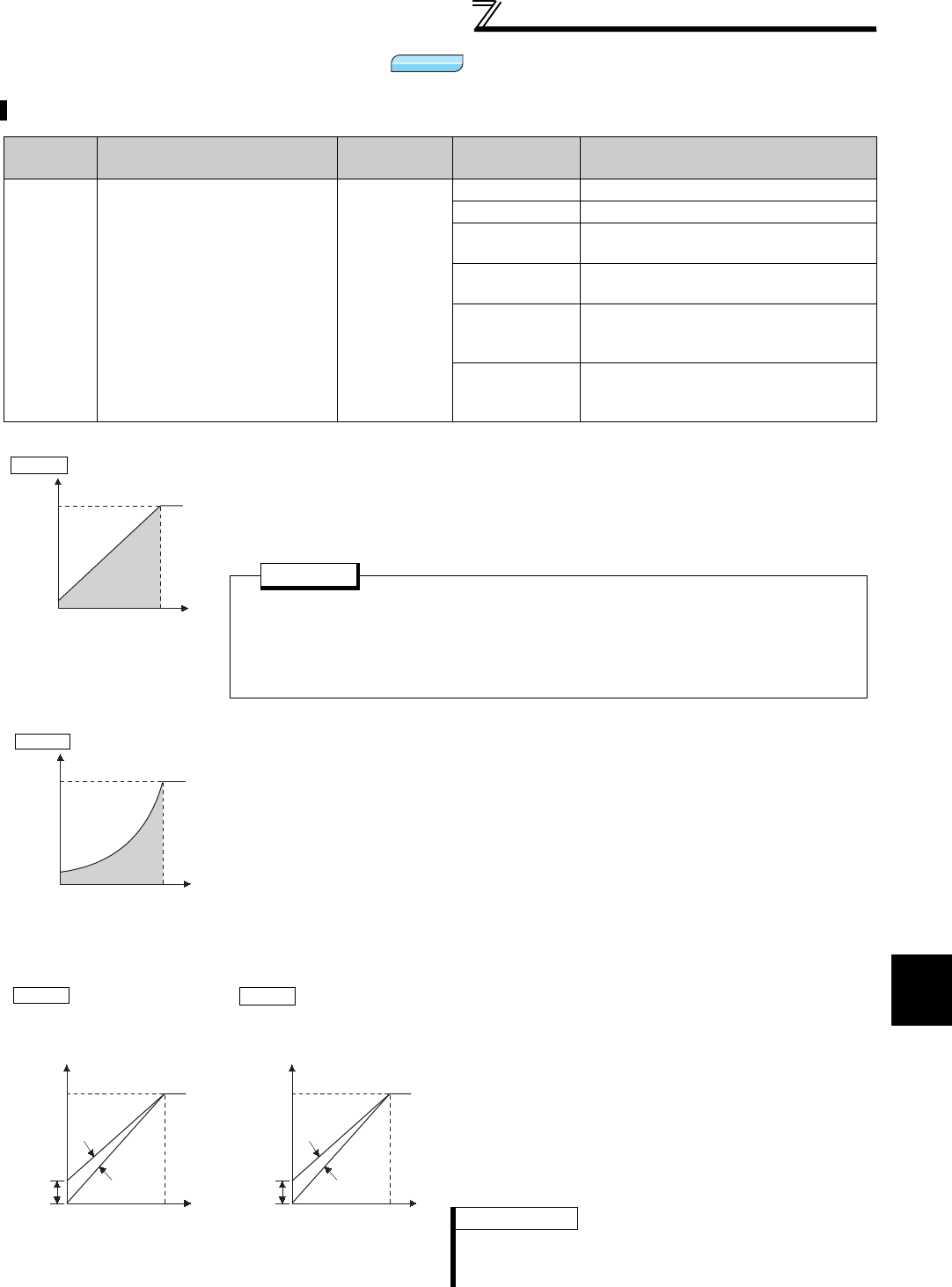
161
V/F pattern
4
PARAMETERS
4.10.2 Load pattern selection (Pr. 14)
You can select the optimum output characteristic (V/F characteristic) for the application and load characteristics.
Parameter
Number Name Initial Value Setting Range Description
14 Load pattern selection 0
0 For constant torque load
1 For variable-torque load
2For constant torque elevators
(at reverse rotation boost of 0%)
3For constant torque elevators
(at forward rotation boost of 0%)
4
RT signal ON..for constant torque load
RT signal OFF for constant torque
elevators at reverse rotation boost of 0%
5
RT signal ON..for constant torque load
RT signal OFF for constant torque
elevators at forward rotation boost of 0%
(1) For constant-torque load (Pr. 14 = "0", initial value)
⋅At or less than the base frequency, the output voltage varies linearly with the output
frequency.
⋅Set this value when driving the load whose load torque is constant even if the speed
varies, e.g. conveyor, cart or roll drive.
(2) For variable-torque load (Pr. 14 = "1")
⋅At or less than the base frequency, the output voltage varies with the output frequency
in a square curve.
⋅Set this value when driving the load whose load torque varies in proportion to the
square of the speed, e.g. fan or pump.
(3) Vertical lift load applications (Pr. 14 = "2,
3")
⋅Set "2" when a vertical lift load is fixed as power driving
load at forward rotation and regenerative load at
reverse rotation.
⋅Pr. 0 Torque boost is valid during forward rotation and
torque boost is automatically changed to "0%" during
reverse rotation.
⋅Set "3" for an elevated load that is in the driving mode
during reverse rotation and in the regenerative load
mode during forward rotation according to the load
weight, e.g. counterweight system.
REMARKS
⋅ When torque is continuously regenerated as vertical lift load, it
is effective to set the rated voltage in Pr. 19 Base frequency
voltage to prevent trip due to current at regeneration.
V/F
V/F
V/F
100%
Output voltage
Pr.3 Base frequency
Output frequency (Hz)
Pr.14=0
POINT
If the load is a fan or pump, select "for rated torque load (setting "0")" in any of the
following cases.
⋅When a blower of large moment of inertia (J) is accelerated in a short time
⋅For constant-torque load such as rotary pump or gear pump
⋅When load torque increases at low speed, e.g. screw pump
100%
Output voltage
Pr.3 Base frequency
Output frequency (Hz)
Pr.14=1
100%
Forward
rotation
Pr.0
Output
voltage
Base frequency
Output frequency (Hz)
For vertical lift loads
A
t forward rotation boost...Pr.0 setting
A
t reverse rotation boost...0%
Reverse
rotation
Pr.14=2
100%
Reverse
rotation
Pr.0
Output
voltage
Base frequency
Output frequency (Hz)
For vertical lift loads
A
t forward rotation boost...0%
A
t reverse rotation boost...Pr.0 setting
Forward
rotation
Pr.14=3

162
V/F pattern
Pr. 14
Setting RT(X17) Signal Output Characteristics (4) Change load pattern selection using
terminal (Pr. 14 = "4, 5")
⋅Output characteristic can be switched between for
constant torque load and for elevator using the RT
signal or X17 signal.
⋅For the terminal used for X17 signal input, set "17"
in any of Pr. 178 to Pr. 189 (input terminal function
selection) to assign the function.
When X17 is assigned, switchover by the RT signal
is invalid.
4
ON
For constant torque load
(same as when the setting
is "0")
OFF
For elevators at reverse
rotation boost of 0% (same
as when the setting is "2")
5
ON
For constant torque load
(same as when the setting
is "0")
OFF
For elevators at forward
rotation boost of 0% (same
as when the setting is "3")
REMARKS
⋅The RT signal is assigned to the terminal RT in the initial setting. By setting "3" in any of Pr. 178 to Pr. 189 (input terminal function
selection), the RT signal can be assigned to the other terminal.
CAUTION
⋅When Advanced magnetic flux vector control, Real sensorless vector control or vector control is selected, this parameter setting
is ignored.
⋅Changing the terminal assignment using Pr. 178 to Pr. 189 (input terminal function selection) may affect the other functions. Set
parameters after confirming the function of each terminal. When the RT signal is ON, the other second functions are also valid.
♦ Parameters referred to ♦
Pr. 0 Torque boost Refer to page 146
Pr. 3 Base frequency Refer to page 159
Pr. 178 to Pr. 189 (input terminal function selection) Refer to page 231
Advanced magnetic flux vector control Refer to page 148
Real sensorless vector control Refer to page 92
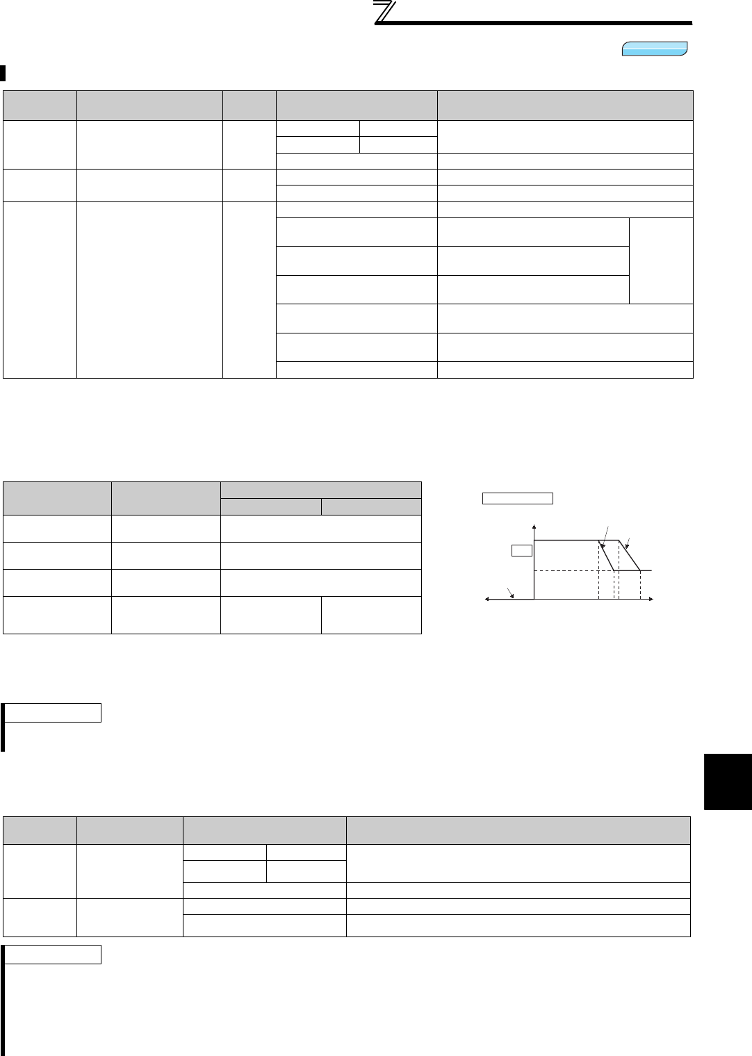
163
V/F pattern
4
PARAMETERS
4.10.3 Elevator mode (automatic acceleration/deceleration) (Pr. 61, Pr. 64, Pr. 292)
(1) Elevator mode
⋅When "5" or "6" is set in Pr. 292 Automatic acceleration/deceleration , elevator mode is selected and each setting is
changed as in the table below.
⋅Enough torque is generated during power driving and the torque boost value is automatically changed during
regeneration and operation without load so that overcurrent protection function does not activate due to over
excitation.
⋅When operating the elevator with load more than the rated inverter current, the maximum torque may become
insufficient. For the elevator without counterweight, setting "2 or 3" (for elevator load) in Pr. 14 Load pattern selection
and an appropriate value in Pr. 19 Base frequency voltage will generate larger maximum torque than when elevator
mode is selected.
(2) Adjustment of elevator mode (Pr. 61, Pr. 64)
⋅By setting the adjustment parameters Pr. 61 and Pr. 64, the application range can be made wider.
Operation matching a load characteristic of elevator with counterweight can be performed.
Parameter
Number Name Initial
Value Setting Range Description
61 Reference current 9999
55K or lower 0 to 500A Set the reference current for elevator mode.
75K or higher 0 to 3600A
9999 Rated inverter current value reference
64 Starting frequency for
elevator mode 9999 0 to 10%
Set the starting frequency for the elevator mode.
9999 Starting frequency 2Hz
292 Automatic acceleration/
deceleration 0
0 Normal operation mode
1Minimum acceleration/
deceleration mode (without brake)
(Refer to
page 180.)
11
Minimum acceleration/deceleration
mode (with brake)
3Optimum acceleration/
deceleration mode
5Elevator mode 1
(stall prevention operation level 150%)
6Elevator mode 2
(stall prevention operation level 180%)
7, 8
Brake sequence mode 1, 2
(Refer to page 217.)
Name Normal Mode Elevator Mode
Pr. 292 = 5 Pr. 292 = 6
Torque boost Pr. 0
(6/4/3/2/1%)
Changes according to the output
current (right chart)
Starting
frequency Pr. 13 (0.5Hz) Pr. 64 (2Hz)
Accelerate after maintaining 100ms
Base frequency
voltage Pr. 19 (9999) 220V (440V)
Stall prevention
operation level Pr. 22 (150%) etc. 150% 180%
REMARKS
⋅Stall prevention operation level automatically decreases according to the electronic thermal relay function cumulative value, to
prevent inverter overload trip (E.THT, E.THM).
Parameter
Number Name Setting Range Description
61 Reference
current
55K or lower 0 to 500A For example, when the motor and inverter are different in
capacity, set the rated motor current value. Set reference
current (A) of the stall prevention operation level
75K or higher 0 to 3600A
9999 (initial value) The rated inverter output current is defined as reference.
64
Starting
frequency for
elevator mode
0 to 10Hz Set the starting frequency for the elevator mode.
9999 (initial value) Starting frequency 2Hz
REMARKS
⋅Even if elevator mode has been selected, inputting the jog signal (jog operation), RT signal (second function selection) or X9
signal (third function selection) during an inverter stop will switch to the normal operation and give priority to jog operation or
second and third function selection. Note that JOG and RT signal input is invalid even if JOG signal and RT signal are input
during operation with acceleration/deceleration selected.
⋅Elevator mode is invalid when Advanced magnetic flux vector, Real sensorless vector control or vector control is selected.
⋅Since the Pr. 61 and Pr. 64 settings automatically return to the initial value (9999) if the Pr. 292 setting is changed, set Pr. 292 first
when you need to set Pr. 61 and Pr. 64.
V/F
V/F
V/F
6%
Pr.292= "5"
Driving
current
(%)
When Pr.0=6%
Torque boost (%)
Regenerative
current 0
Pr.0
3%
100115
Pr.292= "6"
120 140
Torque boost 0%
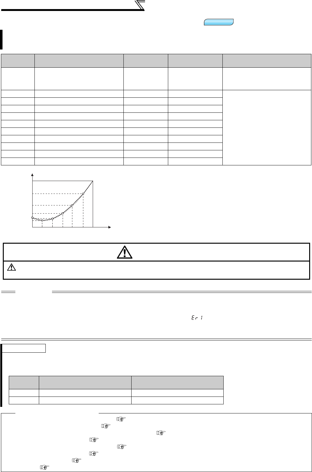
164
V/F pattern
4.10.4 Adjustable 5 points V/F (Pr. 71, Pr. 100 to Pr. 109)
A dedicated V/F pattern can be made by freely setting the V/F characteristic between a startup and the base
frequency and base voltage under V/F control (frequency voltage/frequency).
The torque pattern that is optimum for the machine's characteristic can be set.
Parameter
Number Name Initial Value Setting Range Description
71 Applied motor 0
0 to 8, 13 to 18,
20, 23, 24, 30, 33,
34, 40, 43, 44, 50,
53, 54
Set "2" for adjustable 5 points V/F
control.
100 V/F1(first frequency) 9999 0 to 400Hz, 9999
Set each points (frequency,
voltage) of V/F pattern.
9999: No V/F setting
101 V/F1(first frequency voltage) 0V 0 to 1000V
102 V/F2(second frequency) 9999 0 to 400Hz, 9999
103 V/F2(second frequency voltage) 0V 0 to 1000V
104 V/F3(third frequency) 9999 0 to 400Hz, 9999
105 V/F3(third frequency voltage) 0V 0 to 1000V
106 V/F4(fourth frequency) 9999 0 to 400Hz, 9999
107 V/F4(fourth frequency voltage) 0V 0 to 1000V
108 V/F5(fifth frequency) 9999 0 to 400Hz, 9999
109 V/F5(fifth frequency voltage) 0V 0 to 1000V
⋅Any V/F characteristic can be provided by presetting the parameters of
V/F1 (first frequency voltage/first frequency) to V/F5.
⋅For a machine of large static friction coefficient and small dynamic
static friction coefficient, for example, set a V/F pattern that will
increase the voltage only in a low-speed range since such a machine
requires large torque at a start.
(Setting procedure)
1)Set the rated motor voltage in Pr. 19 Base frequency voltage. (No
function at the setting of "9999" (initial value) or "8888".)
2)Set Pr. 71 Applied motor to "2" (Adjustable 5 points V/F characteristic).
3)Set the frequency and voltage you want to set in Pr. 100 to Pr. 109.
CAUTION
⋅
Adjustable 5 points V/F characteristics function only under V/F control. They do not function under Advanced magnetic flux
vector control, Real sensorless vector control or vector control.
⋅
When
Pr. 19 Base frequency voltage
= "8888" or "9999",
Pr. 71
cannot be set to "2". To set
Pr. 71
to "2", set the rated voltage value in
Pr. 19
.
⋅When the frequency values at each point are the same, a write disable error ( ) appears.
⋅Set the points (frequencies, voltages) of Pr. 100 to Pr. 109 within the ranges of Pr. 3 Base frequency and Pr. 19 Base frequency voltage.
⋅When "2" is set in Pr. 71, Pr. 47 Second V/F (base frequency) and Pr. 113 Third V/F (base frequency) will not function.
⋅When Pr. 71 is set to "2", the electronic thermal relay function makes calculation as a standard motor.
REMARKS
⋅
A greater energy saving effect can be expected by combining
Pr. 60 Energy saving control selection
and adjustable 5 points V/F.
⋅For the 5.5K, 7.5K, the Pr. 0 Torque boost and Pr. 12
DC injection brake operation voltage
settings are automatically changed
according to the Pr. 71 setting as follows.
♦ Parameters referred to ♦
⋅Pr. 3 Base frequency, Pr. 19 Base frequency voltage Refer to page 159
⋅Pr. 12 DC injection brake operation voltage Refer to page 203
⋅Pr. 47 Second V/F (base frequency), Pr. 113 Third V/F (base frequency) Refer to page 159
⋅Pr. 60 Energy saving control selection Refer to page 278
⋅Pr. 71 Applied motor, Pr. 450 Second applied motor Refer to page 187
⋅Advanced magnetic flux vector control Refer to page 148
⋅Real sensorless vector control Refer to page 92
⋅Vector control Refer to page 92
V/F
V/F
V/F
B
ase frequency
voltage
Pr.19
Base frequency
Pr.3
Torque boost
Pr.0
V/F Characteristic
0
V/F5
V/F4
V/F3
V/F2
V/F1
Frequency
Voltage
CAUTION
Make sure to set this parameter correctly according to the motor used.
Incorrect setting may cause the motor to overheat and burn.
Pr. 71 Standard Motor Setting
0, 2, 3 to 8, 20, 23, 24, 40, 43, 44
Constant Torque Motor Setting
1, 13 to 18, 50, 53, 54
Pr. 0 3% 2%
Pr. 12 4% 2%

165
Frequency setting by external terminals
4
PARAMETERS
4.11 Frequency setting by external terminals
4.11.1 Multi-speed setting operation (Pr. 4 to Pr. 6, Pr. 24 to Pr. 27, Pr. 232 to Pr. 239)
The above parameters allow its setting to be changed during operation in any operation mode even if "0" (initial value) is set in Pr. 77 Parameter write
selection.
(1) Multi-speed setting for 3 speeds (Pr. 4 to Pr. 6)
⋅Operation is performed at the frequency set in Pr. 4 when the RH signal turns ON, Pr. 5 when the RM signal turns
ON, and Pr. 6 when the RL signal turns ON.
Purpose Parameter that must be Set Refer to Page
Make frequency setting by
combination of terminals Multi-speed operation Pr. 4 to Pr. 6, Pr. 24 to Pr. 27,
Pr. 232 to Pr. 239 165
Perform jog operation Jog operation Pr. 15, Pr. 16 167
Added compensation for multi-speed
setting and remote setting
Multi-speed input
compensation selection Pr. 28 169
Infinitely variable speed setting by
terminals Remote setting function Pr. 59 169
Can be used to change the preset speed in the parameter with the contact terminals.
Any speed can be selected by simply turning ON-OFF the contact signals (RH, RM, RL, REX signals).
Parameter
Number Name Initial Value Setting Range Description
4Multi-speed setting (high
speed) 60Hz 0 to 400Hz Set the frequency when RH turns ON.
5Multi-speed setting (middle
speed) 30Hz 0 to 400Hz Set the frequency when RM turns ON.
6Multi-speed setting (low
speed) 10Hz 0 to 400Hz Set the frequency when RL turns ON.
24 Multi-speed setting (speed 4) 9999 0 to 400Hz, 9999
Frequency from speed 4 to speed 15
can be set according to the
combination of the RH, RM, RL and
REX signals.
9999: not selected
25 Multi-speed setting (speed 5) 9999 0 to 400Hz, 9999
26 Multi-speed setting (speed 6) 9999 0 to 400Hz, 9999
27 Multi-speed setting (speed 7) 9999 0 to 400Hz, 9999
232 Multi-speed setting (speed 8) 9999 0 to 400Hz, 9999
233 Multi-speed setting (speed 9) 9999 0 to 400Hz, 9999
234 Multi-speed setting (speed 10) 9999 0 to 400Hz, 9999
235 Multi-speed setting (speed 11) 9999 0 to 400Hz, 9999
236 Multi-speed setting (speed 12) 9999 0 to 400Hz, 9999
237 Multi-speed setting (speed 13) 9999 0 to 400Hz, 9999
238 Multi-speed setting (speed 14) 9999 0 to 400Hz, 9999
239 Multi-speed setting (speed 15) 9999 0 to 400Hz, 9999
REMARKS
⋅In the initial setting, if two or three speeds are simultaneously selected, priority is given to the set frequency of the lower signal.
For example, when the RH and RM signals turn ON, the RM signal (Pr. 5) has a higher priority.
⋅The RH, RM, RL signals are assigned to the terminal RH, RM, RL in the initial setting.
By setting "0 (RL)", "1 (RM)", "2 (RH)" in any of Pr.178 to Pr.189 (input terminal function assignment), the signals can be assigned
to other terminals.
ON
ON
ON
Output frequency (Hz)
Speed 1
(High speed)
Speed 2
(Middle speed)
Speed 3
(Low speed)
RH
Time
RM
RL
10
2
5
STF
RH
RM
RL
SD
Inverter
Multi-speed
selection
Frequency setting
potentiometer
Forward
rotation
Multi-Speed Operation
Connection Example
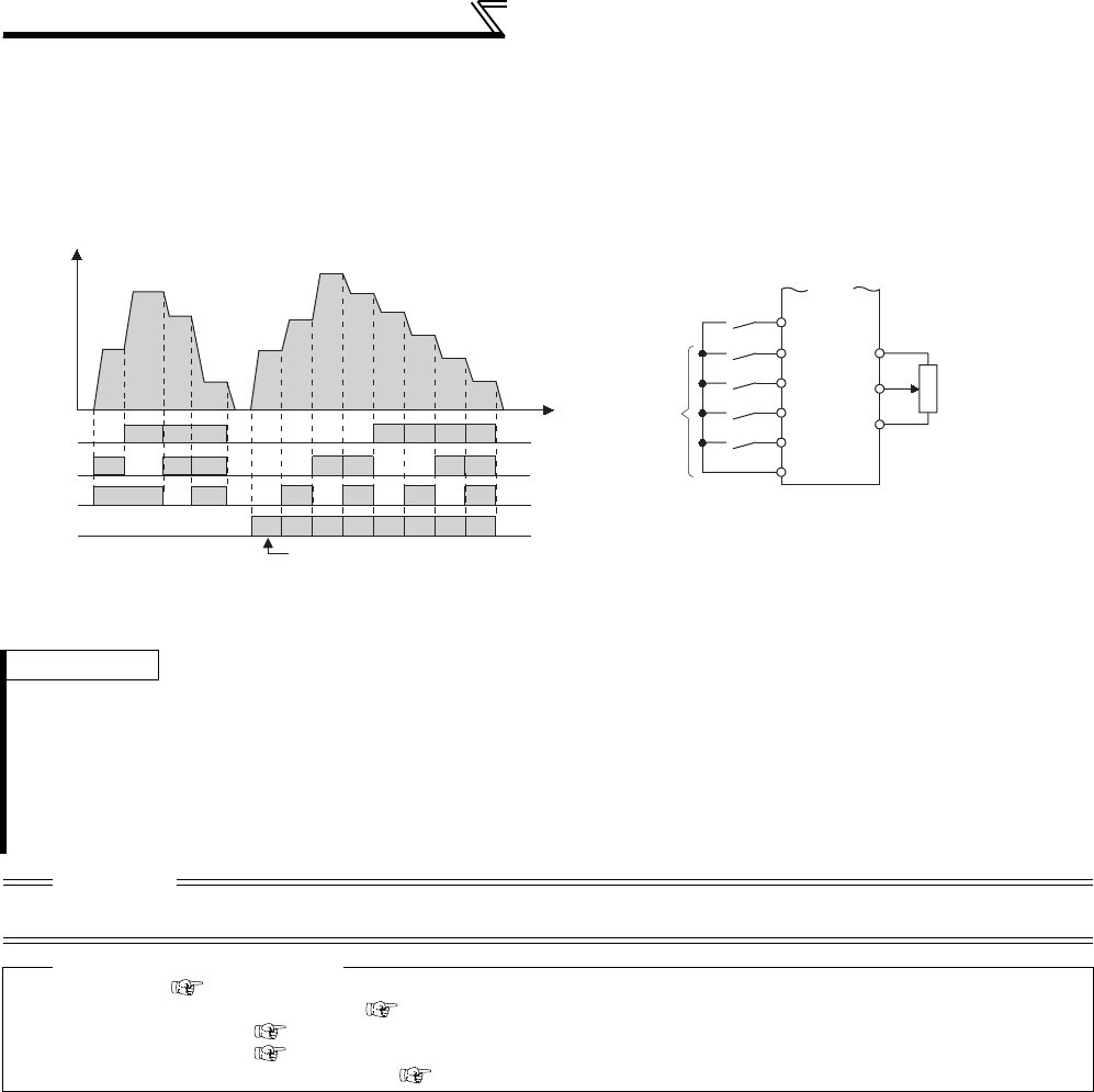
166
Frequency setting by external terminals
(2) Multi-speed setting for 4 or more speeds (Pr. 24 to Pr. 27, Pr. 232 to Pr. 239)
⋅Frequency from speed 4 to speed 15 can be set according to the combination of the RH, RM, RL and REX signals.
Set the running frequencies in Pr. 24 to Pr. 27, Pr. 232 to Pr. 239. (In the initial value setting, speed 4 to speed 15 are
invalid.).
⋅For the terminal used for REX signal input, set "8" in any of Pr. 178 to Pr. 189 (input terminal function selection) to
assign the function.
* When "9999" is set in Pr. 232 Multi-speed setting (speed 8), operation is performed at frequency set in Pr. 6 when RH, RM and RL are turned OFF and
REX is turned ON.
REMARKS
⋅The priorities of the frequency commands by the external signals are "jog operation > multi-speed operation > terminal 4
analog input > pulse train input > terminal 2 analog input". (Refer to page 294 for the frequency command by analog input)
⋅Valid in External operation mode or PU/External combined operation mode (Pr. 79 = "3" or "4").
⋅Multi-speed parameters can also be set in the PU or External operation mode.
⋅Pr. 24 to Pr. 27 and Pr. 232 to Pr. 239 settings have no priority between them.
⋅When a value other than “0” is set in Pr. 59 Remote function selection, the RH, RM and RL signals are used as the remote setting
signals and the multi-speed setting becomes invalid.
⋅When making analog input compensation, set "1" in Pr. 28 Multi-speed input compensation selection.
CAUTION
⋅Changing the terminal assignment using Pr. 178 to Pr. 189 (input terminal function selection) may affect the other functions. Set
parameters after confirming the function of each terminal.
♦ Parameters referred to ♦
Pr. 15 Jog frequency Refer to page 167
Pr. 28 Multi-speed input compensation selection Refer to page 169
Pr. 59 Remote function selection Refer to page 169
Pr. 79 Operation mode selection Refer to page 313
Pr. 178 to Pr. 189 (input terminal function selection) Refer to page 231
Time
Speed 8
Output frequency
(Hz)
*
Speed 9
Speed 10
Speed 11
Speed 12
Speed 13
Speed 14
Speed 15
Speed 4
Speed 5
Speed 6
Speed 7
ONON ON ON ON ON ON ON
ON ON ON ON
ON ON ON ON
ON ON ON ON
RH
RM
RL
REX
ON ON ON
ON ON
ONON
ON
10
2
5
Inverter
STF
REX
RH
RM
RL
Multi-speed selection
Frequency setting
potentiometer
Forward
rotation
SD
Multi-Speed Operation
Connection Example
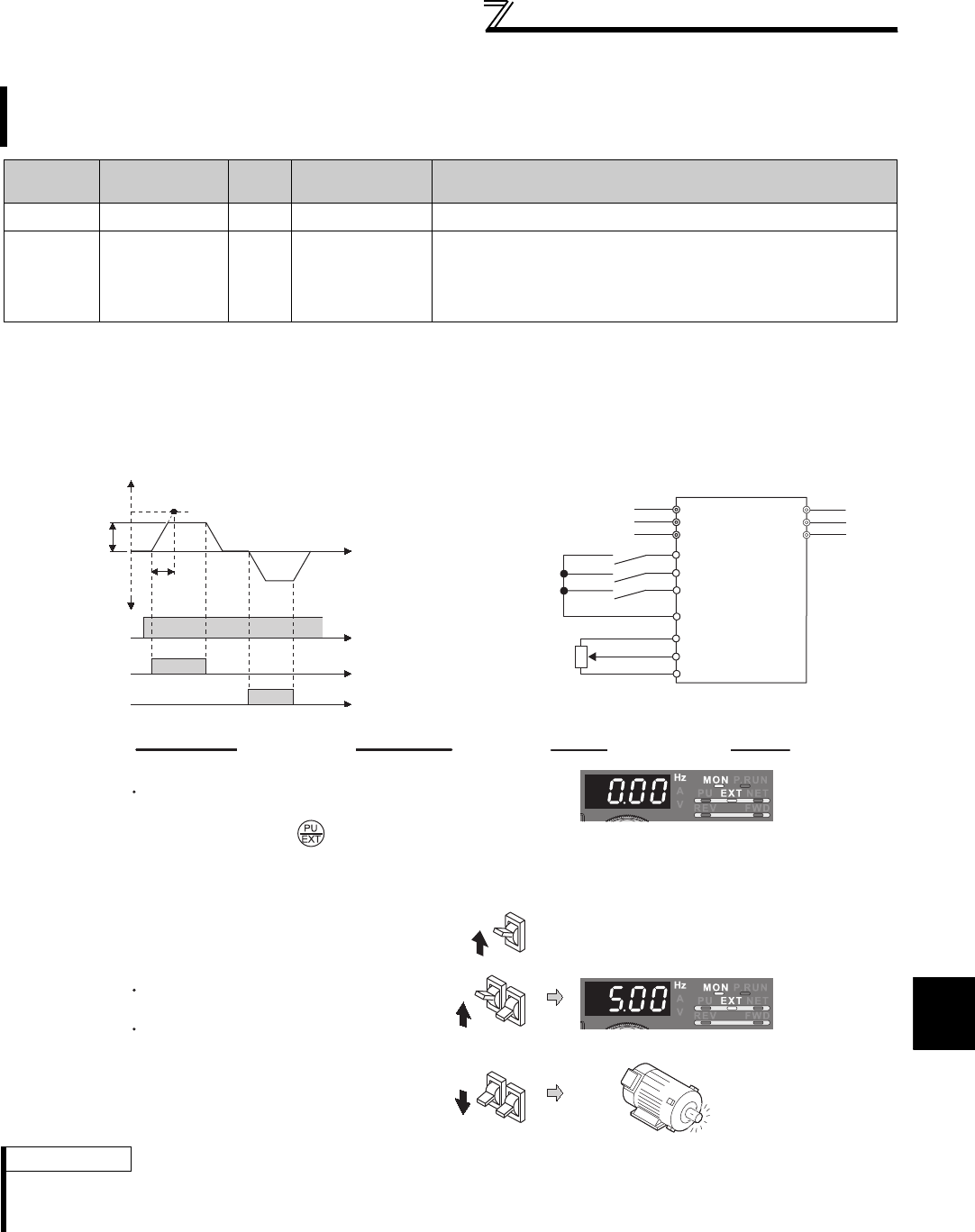
167
Frequency setting by external terminals
4
PARAMETERS
4.11.2 Jog operation (Pr. 15, Pr. 16)
The above parameters are displayed as simple mode parameters only when the parameter unit (FR-PU04/FR-PU07) is connected. When the
operation panel (FR-DU07) is connected, the above parameters can be set only when Pr. 160 User group read selection = "0". (Refer to page 308)
* When the setting of Pr. 21 Acceleration/deceleration time increments is "0" (initial value), the setting range is "0 to 3600s" and the setting increments are
"0.1s", and when the setting is "1", the setting range is "0 to 360s" and the setting increments are "0.01s"
(1) Jog operation from outside
⋅When the JOG signal is ON, a start and stop can be made by the start signal (STF, STR). (The JOG signal is
assigned to the terminal JOG in the initial setting)
You can set the frequency and acceleration/deceleration time for Jog operation. Jog operation can be performed
from either the outside or PU.
Can be used for conveyor positioning, test operation, etc.
Parameter
Number Name Initial
Value Setting Range Description
15 Jog frequency 5Hz 0 to 400Hz Set the frequency for Jog operation.
16
Jog
acceleration/
deceleration
time
0.5s 0 to 3600/360s*
Set the acceleration/deceleration time for Jog operation. Set the
time taken to reach the frequency (Initial value is 60Hz) set in Pr. 20
Acceleration/deceleration reference frequency for acceleration/
deceleration time.
The acceleration and deceleration time cannot be set separately.
REMARKS
⋅When you want to change the running frequency, change Pr. 15 Jog frequency . (initial value "5Hz")
⋅When you want to change the acceleration/deceleration time change Pr. 16 Jog acceleration/deceleration time . (initial value
"0.5s")
Output
frequency(Hz)
Pr.20
Pr.15
Jog frequency
setting range
Pr.16
Forward
rotation
Reverse
rotation
Time
ON
ON
ON
JOG signal
Forward
rotation STF
Reverse
rotation STR
STF
10
2
5
JOG
Motor
Inverter
R/L1
S/L2
T/L3
U
V
W
Connection diagram for external Jog operation
STR
Three-phase AC
power supply
Forward rotation start
Reverse rotation start
JOG signal
SD
1.
Screen at power-ON
Confirm that the External operation mode is selected.
([EXT] lit)
If not displayed, press to change to the
external [EXT] operation mode.
If the operation mode still does not change,
set Pr. 79 to change to the External operation mode.
Indication
Operation
2.
Turn the JOG switch on. ON
Forward
rotation
Forward
rotation
Reverse
rotation
Reverse
rotation
Rotates while ON
Stop
3.
Turn the start switch (STF or STR) on.
The motor rotates while start switch
(STF or STR) is ON.
Rotates at 5Hz. (Initial value of Pr. 15)
4.
Turn the start switch (STF or STR) off.
ON
OFF
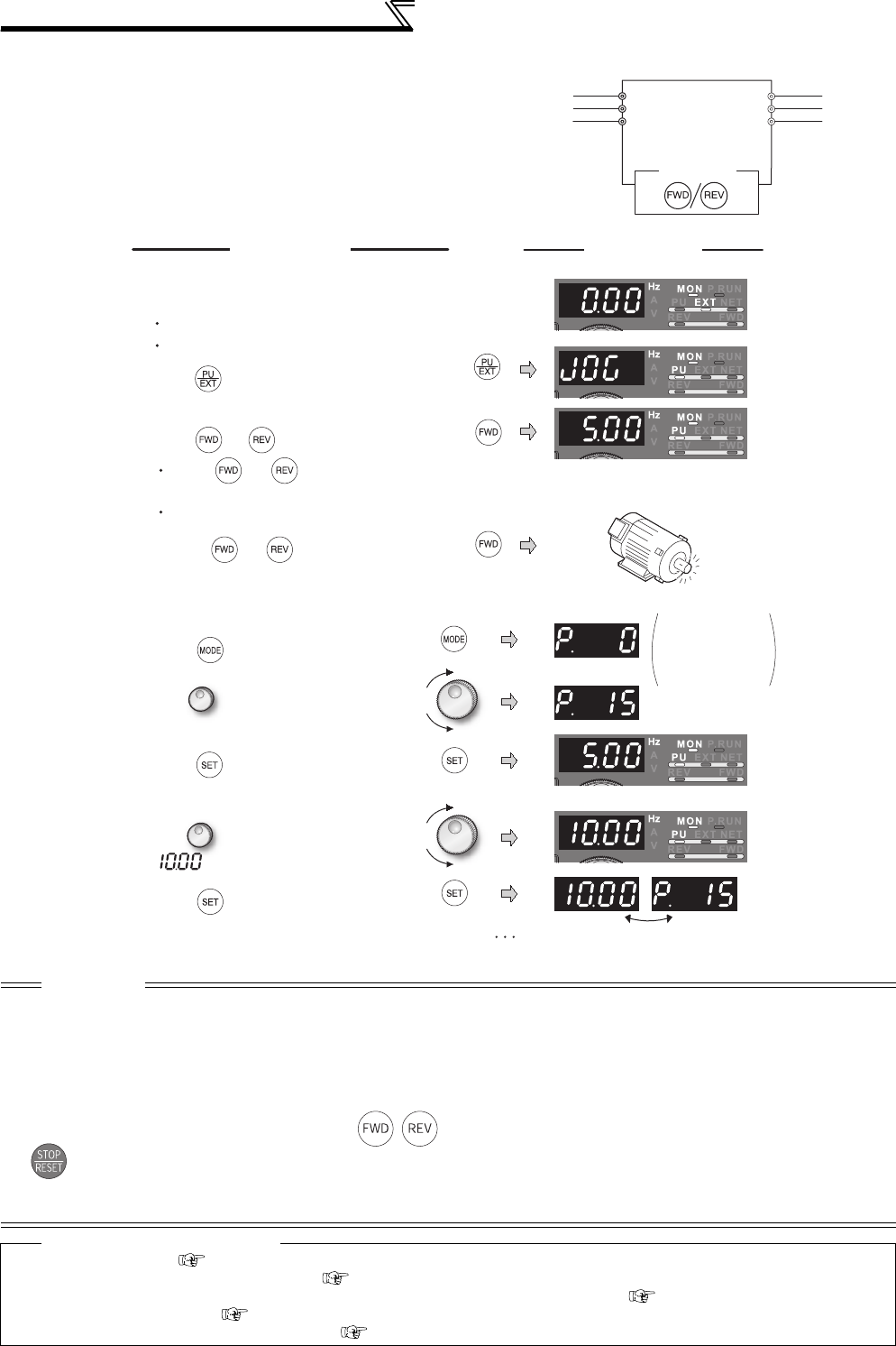
168
Frequency setting by external terminals
(2) Jog operation from PU
⋅Set the PU (FR-DU07/FR-PU07/FR-PU04) to the
jog operation mode. Operation is performed only
while the start button is pressed.
CAUTION
⋅When Pr. 29 Acceleration/deceleration pattern selection= "1" (S-pattern acceleration/deceleration A), the acceleration/deceleration
time is the period of time required to reach Pr. 3 Base frequency.
⋅The Pr. 15 setting should be equal to or higher than the Pr. 13 Starting frequency setting.
⋅
The JOG signal can be assigned to the input terminal using any of
Pr. 178 to Pr. 189 (input terminal function selection)
. When terminal
assignment is changed, the other functions may be affected. Set parameters after confirming the function of each terminal.
⋅During jog operation, the second acceleration/deceleration via the RT signal cannot be selected. (The other second functions
are valid. (Refer to page 235))
⋅When Pr. 79 Operation mode selection = "4", push / of the PU (FR-DU07/FR-PU04/FR-PU07) to make a start or push
to make a stop.
⋅This function is invalid when Pr. 79 = "3".
⋅Jog operation is invalid under position control.
♦ Parameters referred to ♦
⋅Pr. 13 Starting frequency Refer to page 175
⋅Pr. 29 Acceleration/deceleration pattern selection Refer to page 176
⋅Pr. 20 Acceleration/deceleration reference frequency, Pr. 21 Acceleration/deceleration time increments Refer to page 172
⋅Pr. 79 Operation mode selection Refer to page 313
⋅Pr. 178 to Pr. 189 (input terminal function selection) Refer to page 231
Motor
Inverter
R/L1
S/L2
T/L3
U
V
W
FR-DU07
Three-phase AC
power supply
1.
2.
6.
7.
8.
5.
9.
10.
IndicationOperation
Stop
The parameter
number read
previously
appears.
Press to choose the
PU JOG operation mode.
3.
Press (or ).
4.
Release (or ).
The monitor mode should have been selected.
The inverter should be at a stop.
While (or ) is pressed, the
motor rotates.
Rotates at 5Hz. (initial value of Pr. 15)
Hold down.
Press to set.
Flicker Parameter setting complete!!
Release
Press to choose the parameter
setting mode.
Perform the operations in steps 1 to 4.
The motor rotates at 10Hz.
Turn until Pr. 15 JOG frequency
appears.
Turn to set the value to
" ". (10Hz)
Press to show the present set
value. (5Hz)
Confirmation of the RUN indicator and
operation mode indicator
[When changing the frequency of PU JOG
operation]
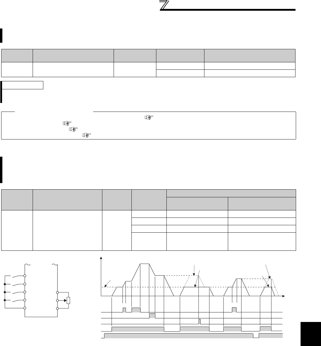
169
Frequency setting by external terminals
4
PARAMETERS
4.11.3 Input compensation of multi-speed and remote setting (Pr. 28)
4.11.4 Remote setting function (Pr. 59)
* External operation frequency (other than multi-speed) or PU running frequency
By inputting the frequency setting compensation signal (terminal 1, 2), the speed (frequency) can be
compensated for relative to the multi-speed setting or the speed setting by remote setting function.
Parameter
Number Name Initial Value Setting Range Description
28 Multi-speed input
compensation selection 00 Without compensation
1 With compensation
REMARKS
⋅Select the terminal (terminal 1, 2) used for compensation input voltage (0 to ±5V, 0 to ±10) using Pr. 73 Analog input selection.
⋅When using terminal 1 for compensation input, set "0" (initial value) in Pr. 868 Terminal 1 function assignment.
♦ Parameters referred to ♦
Pr. 4 to Pr. 6, Pr. 24 to Pr. 27, Pr. 232 to Pr. 239 (multi-speed operation) Refer to page 165
Pr. 73 Analog input selection Refer to page 286
Pr. 59 Remote function selection Refer to page 169
Pr. 868 Terminal 1 function assignment Refer to page 285
Even if the operation panel is located away from the enclosure, you can use contact signals to perform
continuous variable-speed operation, without using analog signals.
By simply setting this parameter, you can use the acceleration, deceleration and setting clear functions of the
motorized speed setter (FR-FK).
Parameter
Number Name Initial
Value
Setting
Range
Description
RH, RM, RL signal
function
Frequency setting
storage function
59 Remote function selection 0
0 Multi-speed setting ⎯
1 Remote setting Yes
2 Remote setting No
3 Remote setting
No
(Turning STF/STR OFF clears
remotely- set frequency.)
Acceleration
Deceleration
Clear
Inverter
STF
RH
RM 10
2
5
RL
Connection
diagram for remote setting
Forward
rotation
SD
Deceleration
(RM)
Clear (RL)
Acceleration
(RH)
Forward
rotation (STF) ON ON
Power supply ON
0Hz
*
ON
ON
ON
ON
ON
ON
When Pr. 59 = 1
When Pr. 59 = 2, 3
ON
ON
Output frequency
(Hz)
When Pr. 59 = 1, 2
When Pr. 59 = 3
Time
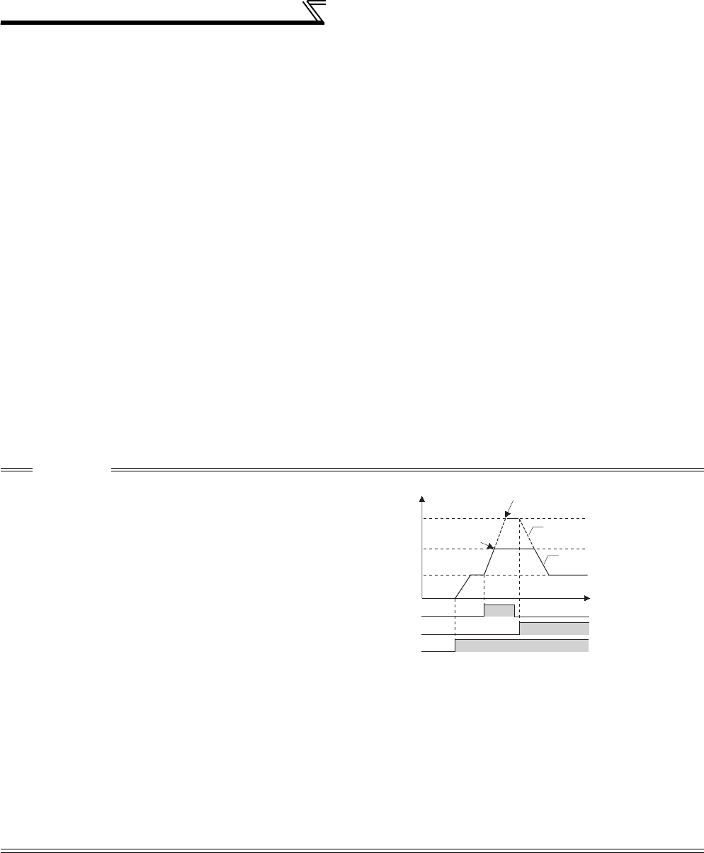
170
Frequency setting by external terminals
(1) Remote setting function
⋅Use Pr. 59 to select whether the remote setting function is used or not and whether the frequency setting storage
function in the remote setting mode is used or not.
When Pr. 59 is set to any of "1 to 3" (remote setting function valid), the functions of the RH, RM and RL signals are
changed to acceleration (RH), deceleration (RM) and clear (RL).
⋅When the remote function is used, the output frequency of the inverter can be compensated for as follows:
External operation
...Frequency set with RH and RM operation + external operation frequency other than multi-speed
(PU operation frequency when
Pr. 79
= "3" (external, PU combined)) and terminal 4 input.
(When making analog input compensation, set "1" in Pr. 28 Multi-speed input compensation
selection.
When Pr. 28 is set to "0" and acceleration/deceleration is made to reach the set frequency of
the analog voltage input (terminal 2 or terminal 4) by RH/RM, the auxiliary input by terminal 1
becomes invalid.)
PU operation .......... Frequency set by RH/RM operation + PU running frequency
(2) Frequency setting storage
⋅The frequency setting storage function stores the remotely-set frequency (frequency set by RH/RM operation) into
the memory (EEPROM). When power is switched OFF once, then ON, operation is resumed with that output
frequency value. (Pr. 59 = 1)
<Frequency setting storage conditions>
⋅Frequency at the point when the start signal (STF or STR) turns off
⋅Remotely-set frequency is stored every minute after turning OFF (ON) the RH (acceleration) and RM
(deceleration) signals together. (The frequency is overwritten if the latest frequency is different from the
previous frequency when comparing the two. The state of the RL signal does not affect writing.)
CAUTION
⋅The range of frequency changeable by RH
(acceleration) and RM (deceleration) is 0 to
maximum frequency (Pr. 1 or Pr. 18 setting). Note that
the maximum value of set frequency is (main speed
+ maximum frequency).
⋅When the acceleration or deceleration signal switches ON, acceleration/deceleration time is as set in Pr. 44 Second acceleration/
deceleration time and Pr. 45 Second deceleration time. Note that when the time set in Pr. 7 or Pr. 8 is longer than the time set in Pr.44
or Pr. 45, the acceleration/deceleration time is as set in Pr. 7 or Pr. 8. (when RT signal is OFF)
When the RT signal is ON, acceleration/deceleration is made in the time set to Pr. 44 and Pr. 45, regardless of the Pr. 7 or Pr. 8
setting.
⋅Even if the start signal (STF or STR) is OFF, turning ON the acceleration (RH) or deceleration (RM) signal varies the preset
frequency.
⋅When switching the start signal from ON to OFF, or changing frequency by the RH or RM signal frequently, set the frequency
setting value storage function (write to EEPROM) invalid (Pr. 59 = "2, 3"). If set valid (Pr. 59 = "1"), frequency is written to
EEPROM frequently, this will shorten the life of the EEPROM.
⋅The RH, RM, RL signals can be assigned to the input terminal using any Pr. 178 to Pr. 189 (input terminal function selection). When
terminal assignment is changed, the other functions may be affected. Set parameters after confirming the function of each
terminal.
⋅Also available for the Network operation mode.
Deceleration(RM)
Acceleration(RH)
Forward rotation(STF)
0Hz
ON
Time
(Hz)
Main speed setting
Pr.1
The set frequency is clamped at (main speed + Pr.1 )
Output frequency is
clamped at Pr.1
Set frequency
Output frequency
ON
ON
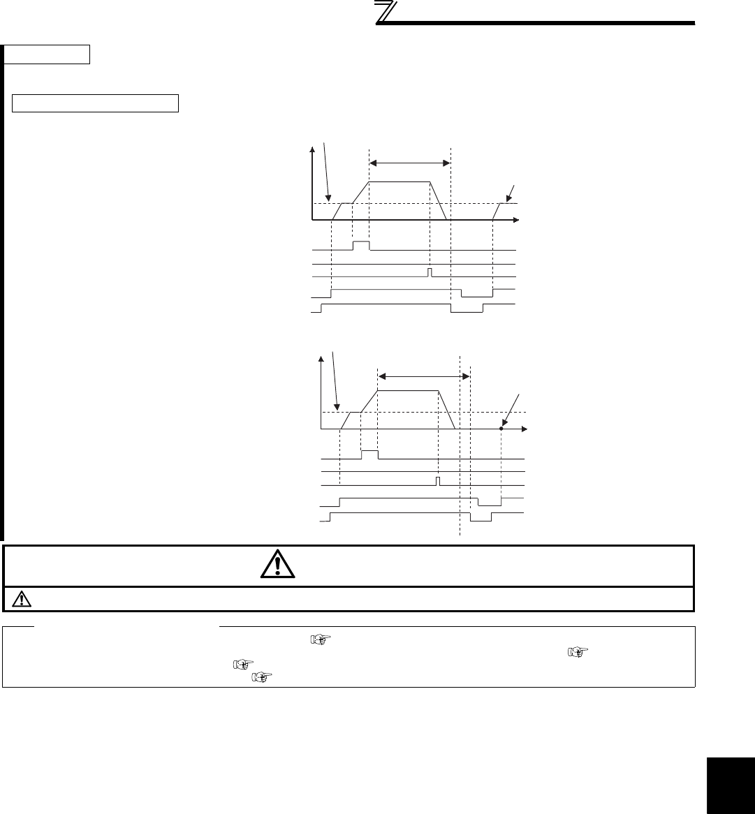
171
Frequency setting by external terminals
4
PARAMETERS
REMARKS
During Jog operation or PID control operation, the remote setting function is invalid.
⋅Even when the remotely-set
frequency is cleared by turning
ON the RL (clear) signal after
turn OFF (on) of both the RH
and RM signals, the inverter
operates at the remotely-set
frequency stored in the last
operation if power is reapplied
before one minute has elapsed
since turn OFF (on) of both the
RH and RM signals
⋅When the remotely-set
frequency is cleared by turning
ON the RL (clear) signal after
turn OFF (on) of both the RH
and RM signals, the inverter
operates at the frequency in the
remotely-set frequency cleared
state if power is reapplied after
one minute has elapsed since
turn OFF (on) of both the RH
and RM signals.
CAUTION
When selecting this function, re-set the maximum frequency according to the machine.
♦ Parameters referred to ♦
Pr. 1 Maximum frequency, Pr. 18 High speed maximum frequency Refer to page 157
Pr. 7 Acceleration time, Pr. 8 Deceleration time, Pr. 44 Second acceleration/deceleration time, Pr. 45 Second deceleration time Refer to page 172
Pr. 28 Multi-speed input compensation selection Refer to page 169
Pr. 178 to Pr. 189 (input terminal function selection) Refer to page 231
Setting frequency is "0"
Clear (RL)
Acceleration (RH)
ON
Power supply ON
ON
ON
ON
ON
Within 1 minute
Remotely-set frequency stored last time
Time
Remotely-set frequency stored last time
Deceleration (RM) OFF
Output frequency
(Hz)
Forward rotation
(STF)
Clear (RL)
Acceleration (RH)
Forward rotation (STF) ON
Power supply ON
ON
ON
ON
ON
Time
Remotely-set frequency stored last time One minute
Deceleration (RM) OFF
Output frequency
(Hz)
More than
one minute Operation is performed at the set
frequency 0Hz.
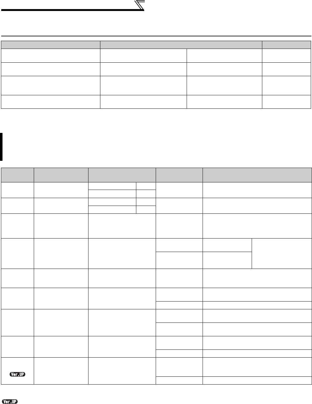
172
Setting of acceleration/deceleration time
and acceleration/deceleration pattern
4.12 Setting of acceleration/deceleration time and
acceleration/deceleration pattern
4.12.1 Setting of the acceleration and deceleration time (Pr. 7, Pr. 8, Pr. 20, Pr. 21,
Pr. 44, Pr. 45, Pr. 110, Pr. 111, Pr. 147)
...............Specifications differ according to the date assembled. Refer to page 484 to check the SERIAL number.
Purpose Parameter that must be Set Refer to Page
Motor acceleration/deceleration time
setting Acceleration/deceleration time Pr. 7, Pr. 8, Pr. 20, Pr. 21,
Pr. 44, Pr. 45, Pr. 110, Pr. 111 172
Starting frequency Starting frequency and start-
time hold Pr. 13, Pr. 571 175
Set acceleration/deceleration pattern
suitable for application
Acceleration/deceleration
pattern and backlash measures
Pr. 29, Pr. 140 to Pr. 143,
Pr. 380 to Pr. 383,
Pr. 516 to Pr. 519
176
Automatically set appropriate
acceleration/deceleration time
Automatic acceleration/
deceleration Pr. 61 to Pr. 63, Pr. 292 180
Use the following parameters to set motor acceleration/deceleration time.
Set a larger value for a slower speed increase/decrease or a smaller value for a faster speed increase/decrease.
For the acceleration time at automatic restart after instantaneous power failure, refer to Pr. 611 Acceleration time at
a restart (page 266).
Parameter
Number Name Initial Value Setting Range Description
7 Acceleration time 7.5K
or lower 5s 0 to 3600/360s *1 Set the motor acceleration time.
11K
or higher 15s
8 Deceleration time 7.5K
or lower 5s 0 to 3600/360s *1 Set the motor deceleration time.
11K
or higher 15s
20
Acceleration/
deceleration
reference frequency
60Hz 1 to 400Hz
Set the frequency that will be the basis of
acceleration/deceleration time.
As acceleration/deceleration time, set the
frequency change time from stop to Pr. 20.
21
Acceleration/
deceleration time
increments
0
0Increments: 0.1s
Range: 0 to 3600s
Increments and setting
range of acceleration/
deceleration time
setting can be
changed.
1Increments: 0.01s
Range: 0 to 360s
44
Second
acceleration/
deceleration time
5s 0 to 3600/360s *1 Set the acceleration/deceleration time when
the RT signal is ON.
45 Second
deceleration time 9999 0 to 3600/360s *1 Set the deceleration time when the RT
signal is ON.
9999 Acceleration time = deceleration time
110 Third acceleration/
deceleration time 9999
0 to 3600/360s *1 Set the acceleration/deceleration time when
the X9 signal is ON.
9999 Without the third acceleration/deceleration
function.
111 Third deceleration
time 9999 0 to 3600/360s *1 Set the deceleration time when the X9
signal is ON.
9999 Acceleration time = deceleration time
147
Acceleration/
deceleration time
switching
frequency
9999 0 to 400Hz
The frequency where the acceleration/
deceleration time switches to the time set in
Pr. 44 and Pr. 45.
9999 No function
*1 Depends on the Pr. 21 Acceleration/deceleration time increments setting. The initial value for the setting range is "0 to 3600s" and the setting
increments is "0.1s".

173
Setting of acceleration/deceleration time
and acceleration/deceleration pattern
4
PARAMETERS
(2) Deceleration time setting (Pr. 8, Pr. 20)
⋅Use Pr. 8 Deceleration time to set the deceleration time required to reach 0Hz from Pr. 20 Acceleration/deceleration
reference frequency.
⋅Set the deceleration time according to the following formula.
(3) Change the setting range and increments of the acceleration/deceleration time (Pr. 21)
⋅Use Pr. 21 to set the acceleration/deceleration time and minimum setting range.
Setting "0" (initial value)......................0 to 3600s (minimum setting increments 0.1s)
Setting "1"...........................................0 to 360s (minimum setting increments 0.01s)
(4) Set multiple acceleration/deceleration time (RT signal, X9 signal, Pr. 44, Pr. 45, Pr. 110, Pr. 111,
Pr. 147)
⋅Pr. 44 and Pr. 45 are valid when the RT signal is ON, or the output frequency reaches or exceeds the setting of Pr.
147. Pr. 110 and Pr. 111 are valid when the X9 signal is ON. When the RT signal (X9 signal) turns ON, the
acceleration/deceleration time switches to the second (third) acceleration/deceleration time even when the output
frequency has not reached the Pr. 147 setting. Priority of switching is X9 signal > RT signal > Pr. 147 setting.
⋅For the terminal used for X9 signal input, set "9" in any of Pr. 178 to Pr. 189 (input terminal function selection) to assign
the function.
⋅When "9999" is set in Pr. 45 or Pr. 111, the deceleration time becomes equal to the acceleration time (Pr. 44, Pr. 110).
⋅When Pr. 110 = "9999", third acceleration/deceleration time is invalid.
⋅If the Pr. 147 setting is lower than Pr. 10 DC injection brake operation frequency or Pr. 13 Starting frequency setting, the
acceleration/deceleration time switches to the Pr. 44 (Pr. 45) setting when the output frequency exceeds the Pr. 10 or
Pr. 13 setting.
(1) Acceleration time setting (Pr. 7, Pr. 20)
⋅Use Pr. 7 Acceleration time to set the acceleration time required to reach Pr.
20 Acceleration/deceleration reference frequency from 0Hz.
⋅Set the acceleration time according to the following formula.
Example) How to find the setting value for Pr. 7 when increasing the output
frequency to the maximum frequency of 50Hz in 10s with Pr.20 =
60Hz (initial value) and Pr.13=0.5Hz.
Example)How to find the setting value for Pr.8 when decreasing the output
frequency from the maximum frequency of 50Hz in 10s with Pr.
20 =120Hz and Pr. 10 = 3Hz.
CAUTION
⋅Changing the Pr. 21 setting changes the acceleration/deceleration time setting (Pr. 7, Pr. 8, Pr. 16, Pr. 44, Pr. 45, Pr. 110, Pr. 111, Pr.
264, Pr. 265).
(The Pr. 611 Acceleration time at a restart setting is not affected.)
<Example>
When Pr. 21 = "0", setting "5.0" s in Pr. 7 and "1" in Pr. 21 automatically changes the Pr. 7 setting to "0.5" s.
Pr. 147 Setting Acceleration/Deceleration Time Description
9999 (initial value) Pr. 7, Pr. 8 No automatic switching of the acceleration/
deceleration time
0.00Hz Pr. 44, Pr. 45 Second acceleration/deceleration time from a start
0.01Hz ≤ Pr. 147 ≤ Set frequency Output frequency < Pr. 147: Pr. 7, Pr. 8
Pr. 147 ≤ Output frequency: Pr. 44, Pr. 45 Acceleration/deceleration time automatic switching
Set frequency < Pr. 147 Pr. 7, Pr. 8 No automatic switching, since output frequency will
not reach the switching frequency
Running
frequency
Acceleration
time
Deceleration
time
Time
Pr.20
Pr.7 Pr.8
Output
frequency
(Hz)
Pr.110 Pr.111
Pr.44 Pr.45
(60Hz)
Acceleration
time setting =
Pr. 20
×Acceleration time from stop to
maximum operating frequency
Maximum operating
frequency - Pr. 13
Pr. 7 =60Hz ×10s 12.1s
50Hz - 0.5Hz
Deceleration
time setting =
Pr. 20
×Deceleration time from maximum
operating frequency to stop.
Maximum operating
frequency - Pr. 10
Pr. 8 =120Hz ×10s 25.5s
50Hz - 3Hz
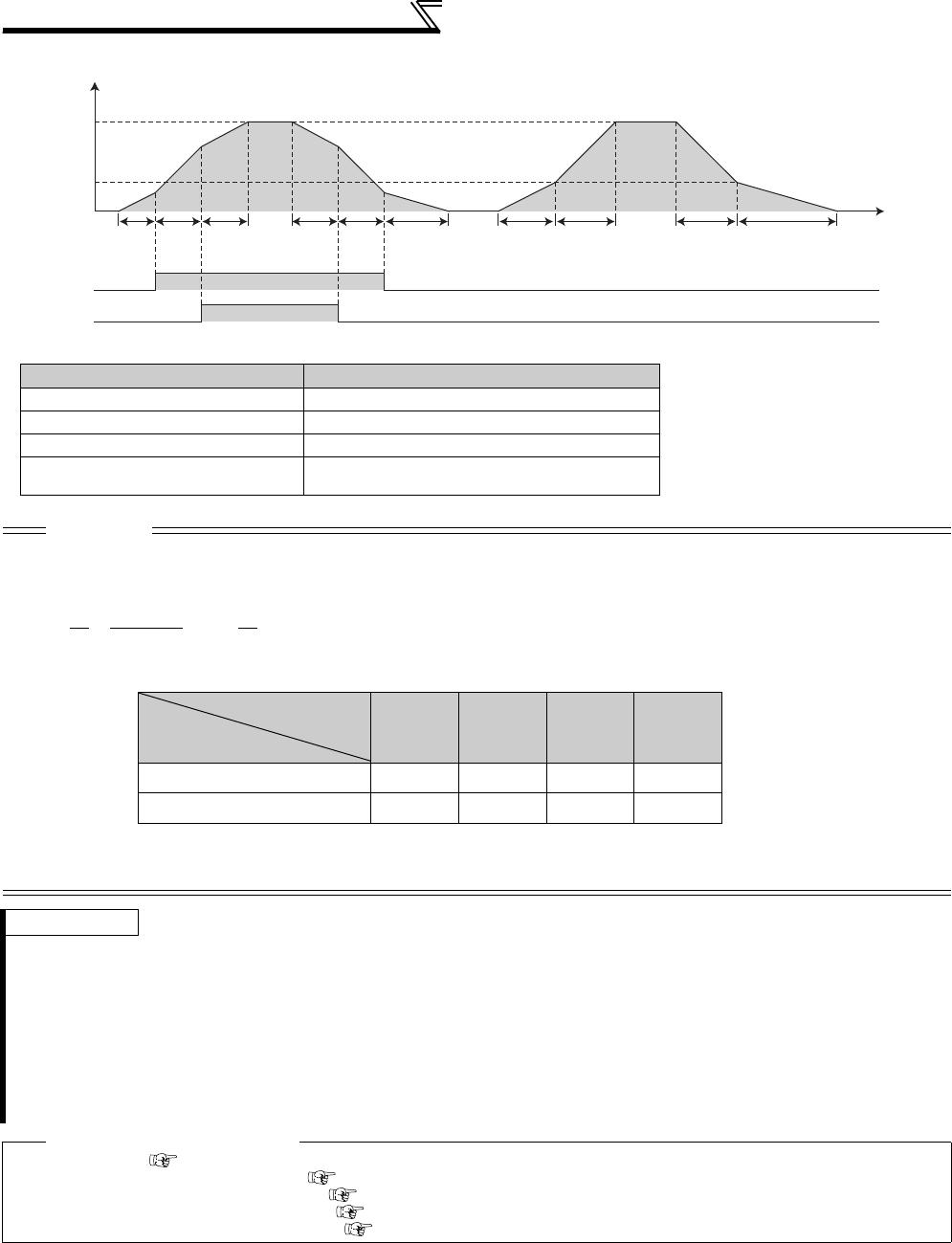
174
Setting of acceleration/deceleration time
and acceleration/deceleration pattern
⋅Switching frequency for each control method
Control Method Switching frequency
V/F control Output frequency
Advanced magnetic flux vector control Output frequency before the slip compensation
Real sensorless vector control Estimated speed converted as frequency
Vector control,
encoder feedback control Actual motor speed converted as frequency
CAUTION
⋅In S-shaped acceleration/deceleration pattern A (refer to page 176), the set time is the period required to reach the base
frequency set in Pr. 3 Base frequency.
⋅Acceleration/deceleration time formula when the set frequency is the base frequency or higher
⋅The RT, X9 signal can be assigned to the input terminal using any of Pr. 178 to Pr. 189 (input terminal function selection). When
terminal assignment is changed, the other functions may be affected. Set parameters after confirming the function of each
terminal.
REMARKS
⋅The RT (X9) signal acts as the second (third) function selection signal and makes the other second (third) function valid. (Refer
to page 235)
⋅The RT signal is assigned to the RT terminal in the default setting. By setting "3" in any of Pr. 178 to Pr. 189 (input terminal
function selection), you can assign the RT signal to the other terminal.
⋅If the Pr. 20 setting is changed, the Pr. 125 and Pr. 126 (frequency setting signal gain frequency) settings do not change. Set Pr. 125
and Pr. 126 to adjust the gains.
⋅When the Pr. 7, Pr. 8, Pr. 44, Pr. 45, Pr. 110 and Pr. 111 settings are 0.03s or less, the acceleration/deceleration time is 0.04s
(under V/F control, Advanced magnetic flux vector control). At that time, set Pr. 20 to "120Hz" or less.
⋅If the acceleration/deceleration time is set, the actual motor acceleration/deceleration time cannot be made shorter than the
shortest acceleration/deceleration time determined by the mechanical system J (moment of inertia) and motor torque.
♦ Parameters referred to ♦
Pr. 3 Base frequency Refer to page 159
Pr. 10 DC injection brake operation frequency Refer to page 203
Pr. 29 Acceleration/deceleration pattern selection Refer to page 176
Pr. 125, Pr. 126 (frequency setting gain frequency) Refer to page 294
Pr. 178 to Pr. 189 (input terminal function selection) Refer to page 231
Time
Output frequency
(Hz)
Set
frequency
Pr. 147
Setting
Pr.7 Pr.44 Pr.44
(Pr.45)
Pr.8
Pr.7 Pr.44 Pr.44
(Pr.45)
Pr.8
Pr.110 Pr.111
RT signal
X9 signal
ON
ON
⋅Guideline for acceleration/deceleration time when Pr. 3 Base frequency = 60Hz (0Hz to set frequency)
t = 4×T× f2 +
5TT: Acceleration/deceleration time setting value(s)
f : Set frequency(Hz)
9(Pr. 3)29
Frequency setting (Hz)
60 120 200 400
Acceleration/
deceleration time (s)
5 5 12 27 102
15 15 35 82 305
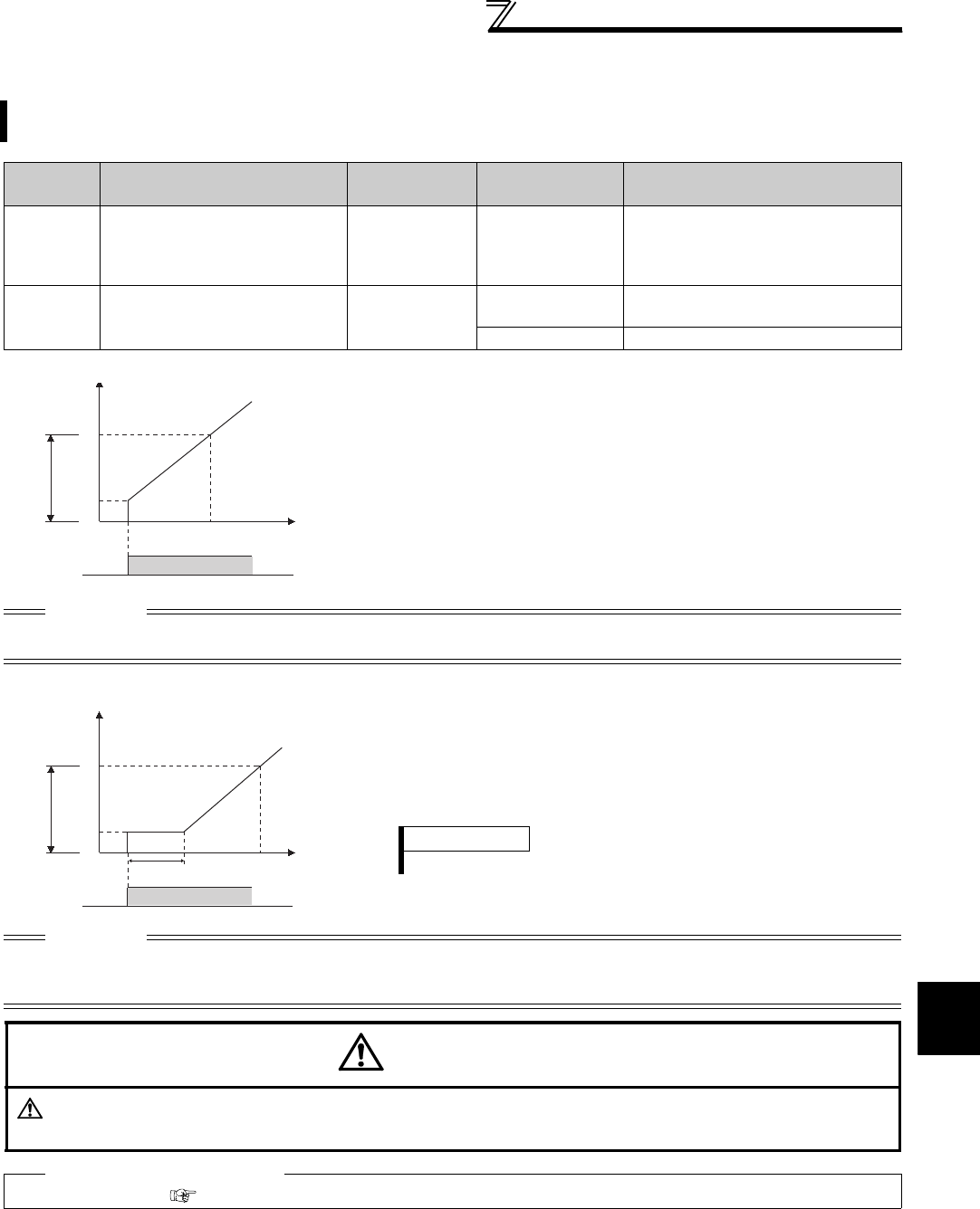
175
Setting of acceleration/deceleration time
and acceleration/deceleration pattern
4
PARAMETERS
4.12.2 Starting frequency and start-time hold function (Pr. 13, Pr. 571)
You can set the starting frequency and hold the set starting frequency for a certain period of time.
Set these functions when you need the starting torque or want to smooth motor drive at a start.
Parameter
Number Name Initial Value Setting Range Description
13 Starting frequency 0.5Hz 0 to 60Hz
Frequency at start can be set in the
range 0 to 60Hz.
You can set the starting frequency at
which the start signal is turned ON.
571 Holding time at a start 9999 0.0 to 10.0s Set the holding time of Pr. 13 Starting
frequency.
9999 Holding function at a start is invalid
(1) Starting frequency setting (Pr. 13)
⋅Frequency at start can be set in the range 0 to 60Hz.
⋅You can set the starting frequency at which the start signal is
turned ON.
CAUTION
The inverter will not start if the frequency setting signal is less than the value set in Pr. 13.
For example, when 5Hz is set in Pr. 13, the motor will not start running until the frequency setting signal reaches 5Hz.
(2) Start-time hold function (Pr. 571)
⋅This function holds the time set in Pr. 571 and the output
frequency set in Pr. 13 Starting frequency.
⋅This function performs initial excitation to smooth the motor drive
at a start.
CAUTION
⋅When the start signal was turned OFF during start-time hold, deceleration is started at that point.
⋅At switching between forward rotation and reverse rotation, the starting frequency is valid but the start-time hold function is
invalid.
CAUTION
Note that when Pr. 13 is set to any value equal to or less than Pr. 2 Minimum frequency, simply turning ON the start
signal will run the motor at the preset frequency even if the command frequency is not input.
♦ Parameters referred to ♦
Pr. 2 Minimum frequency Refer to page 157
O
utput
frequency
(Hz)
Time
60
Pr.13
Setting range
STF ON
0
Output
frequency
(Hz)
Time
Pr. 13
Pr. 571 setting time
STF ON
0
60
Setting range
REMARKS
When Pr. 13 = "0Hz", the starting frequency is held at 0.01Hz.

176
Setting of acceleration/deceleration time
and acceleration/deceleration pattern
4.12.3 Acceleration/deceleration pattern (Pr. 29, Pr. 140 to Pr. 143, Pr. 380 to Pr. 383,
Pr. 516 to Pr. 519)
You can set the acceleration/deceleration pattern suitable for application.
You can also set the backlash measures that stop acceleration/deceleration once at the parameter-set frequency
and time during acceleration/deceleration.
Parameter
Number Name Initial
Value
Setting
Range Description
29 Acceleration/deceleration pattern
selection 0
0 Linear acceleration/ deceleration
1 S-pattern acceleration/deceleration A
2 S-pattern acceleration/deceleration B
3 Backlash measures
4 S-pattern acceleration/deceleration C
5 S-pattern acceleration/deceleration D
140 Backlash acceleration stopping frequency 1Hz 0 to 400Hz
Set the stopping frequency and time for
backlash measures.
Valid when Pr. 29 = 3
141 Backlash acceleration stopping time 0.5s 0 to 360s
142 Backlash deceleration stopping frequency 1Hz 0 to 400Hz
143 Backlash deceleration stopping time 0.5s 0 to 360s
380 Acceleration S-pattern 1 0 0 to 50% Valid when S-pattern acceleration/
deceleration C (Pr. 29 = 4) is set.
Set the time taken for S-pattern from
starting of acceleration/deceleration to
linear acceleration as % to the
acceleration/deceleration time (Pr. 7, Pr. 8
etc.).
An acceleration/deceleration pattern can
be changed with the X20 signal.
381 Deceleration S-pattern 1 0 0 to 50%
382 Acceleration S-pattern 2 0 0 to 50%
383 Deceleration S-pattern 2 0 0 to 50%
516 S-pattern time at a start of acceleration 0.1s 0.1 to 2.5s
Valid when S-pattern acceleration/
deceleration D (Pr. 29 = 5) is set.
Set the time taken for S-pattern
acceleration/deceleration (S-pattern
operation).
517 S-pattern time at a completion of
acceleration 0.1s 0.1 to 2.5s
518 S-pattern time at a start of deceleration 0.1s 0.1 to 2.5s
519 S-pattern time at a completion of
deceleration 0.1s 0.1 to 2.5s
(1) Linear acceleration/ deceleration (
Pr. 29
= "0", initial value)
⋅When the frequency is changed for acceleration, deceleration, etc. in inverter
operation, the output frequency is changed linearly (linear acceleration/
deceleration) to reach the set frequency without straining the motor and inverter.
Linear acceleration/deceleration has a uniform frequency/time slope.
(2) S-pattern acceleration/deceleration A (
Pr. 29
=
"1")
⋅For machine tool spindle applications, etc.
Used when acceleration/deceleration must be made in a short time to a high-
speed range of not lower than the base frequency. In this acceleration/
deceleration pattern, Pr. 3 Base frequency (fb) is the inflection point of the S
pattern and you can set the acceleration/deceleration time appropriate for motor
torque reduction in a constant-power operation region of Pr. 3 Base frequency
(initial value = 60Hz) or higher.
CAUTION
⋅As the acceleration/deceleration time of S-pattern acceleration/deceleration A, set the time taken until Pr. 3 Base frequency is
reached, not Pr. 20 Acceleration/deceleration reference frequency.
Setting value "0"
[Linear acceleration
/ deceleration]
Output frequency
(Hz)
Time
fb
Output frequency
(Hz)
Setting value "1"
Time
[S-pattern acceleration
/deceleration A]
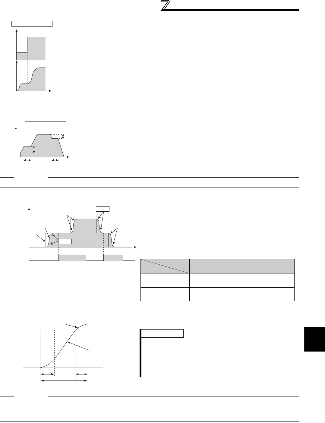
177
Setting of acceleration/deceleration time
and acceleration/deceleration pattern
4
PARAMETERS
(3) S-pattern acceleration/deceleration B (
Pr. 29
=
"2")
⋅For prevention of load shifting in conveyor and other applications
Since acceleration/deceleration is always made in an S shape from current
frequency (f2) to target frequency (f1), this function eases shock produced at
acceleration/deceleration and is effective for load collapse prevention, etc.
(4) Backlash measures (
Pr. 29
=
"3", Pr. 140 to Pr. 143)
⋅What is backlash?
Reduction gears have an engagement gap and have a dead zone between
forward rotation and reverse rotation. This dead zone is called backlash, and
this gap disables a mechanical system from following motor rotation.
More specifically, a motor shaft develops excessive torque when the direction of
rotation changes or when constant-speed operation shifts to deceleration,
resulting in a sudden motor current increase or regenerative status.
⋅To avoid backlash, acceleration/deceleration is temporarily stopped.
Set the acceleration/deceleration stopping frequency and time in Pr. 140 to Pr.
143.
CAUTION
Setting the backlash measures increases the acceleration/deceleration time by the stopping time.
(5) S-pattern acceleration/deceleration C (Pr. 29 =
"4", Pr. 380 to Pr. 383)
⋅With the S-pattern acceleration/deceleration C switch
signal (X20), an acceleration/deceleration curve S-pattern 1
or S-pattern 2 can be selected.
⋅For the terminal used for X20 signal input, set "20" in any of
Pr. 178 to Pr. 189 (input terminal function selection) to assign
the function.
Parameter setting (%) Ts / T × 100% ⋅Set % of time taken for forming an S-pattern in Pr. 380 to Pr.
383 as acceleration time is 100%.
CAUTION
⋅Change the S pattern acceleration/deceleration C switch (X20 signal) after the speed becomes constant.
⋅S pattern operation before switching continues even if the X20 signal is changed during acceleration or deceleration.
⋅The X20 signal can be assigned to the input terminal using any of Pr. 178 to Pr. 189 (input terminal function selection). Changing
the terminal assignment may affect the other functions. Set parameters after confirming the function of each terminal.
f1
Setting value "2"
[S-pattern acceleration
/deceleration B]
f2
Time
Set frequency
(Hz)
Output frequency
(Hz)
Pr. 142
Pr. 143
Pr. 141
Pr. 140
P
r. 13
Output frequency (Hz)
[Anti-backlash measure
function]
Setting value "3"
Time
Pr.382
Pr.383
Pr.381
S-pattern
acceleration/
deceleration
C switchover
(X20)
OFF OFF
ON
Output frequency
Output frequency
Output frequency
Set frequency
Set frequency
Set frequency
Pr.380
Frequency
Tim
e
Operation
X20 signal
During
Acceleration
During
Deceleration
OFF Pr. 380 Acceleration S-
pattern 1
Pr. 381 Deceleration
S-pattern 1
ON Pr. 382 Acceleration S-
pattern 2
Pr. 383 Deceleration
S-pattern 2
S-pattern
acceleration
Linear
acceleration
Ts
T
Ts
REMARKS
⋅At a start, the motor starts at Pr. 13 Starting frequency when the
start signal turns ON.
⋅If there is a difference between the speed command and speed
at a start of deceleration due to torque limit operation etc., the
speed command is matched with the speed to make
deceleration.
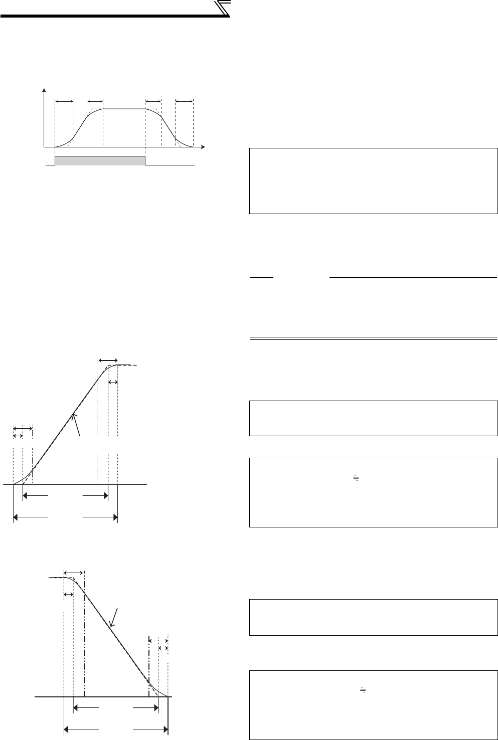
178
Setting of acceleration/deceleration time
and acceleration/deceleration pattern
(6) S-pattern acceleration/deceleration D (Pr. 29 =
"5", Pr. 516 to Pr. 519)
⋅Set the time taken for S-pattern operation of S-pattern
acceleration/deceleration using Pr. 516 to Pr. 519.
Set each S-pattern operation time for acceleration start (Pr.
516), acceleration completion (Pr. 517), deceleration start
(Pr. 518) and deceleration completion (Pr. 519).
⋅When S-pattern acceleration/deceleration D is set,
acceleration/deceleration time will become longer as
follows:
Set acceleration/deceleration time T1 indicates the actual
time taken for linear acceleration/deceleration calculated
based on the Pr. 7, Pr. 8, Pr. 44, Pr. 45, Pr. 110 and Pr. 111
setting.
⋅For example, the actual acceleration time when starting the
inverter with an S-pattern acceleration/deceleration pattern
D selected for a stop to 60Hz with the parameter initial
value is as shown left:
Therefore,
⋅The actual deceleration time when stopping the inverter
with an S-pattern acceleration/deceleration D selected from
running frequency to 0 Hz with the parameter initial value is
as shown left:
Therefore,
Pr. 516
ON
ON
ON
Start signal
Start signal
Start signal
Pr. 517 Pr. 518 Pr. 519
Output frequency
Time
T2
Acceleration/deceleration
reference frequency (Pr. 20)
T1
Starting frequency
(Pr. 13)
Pr. 517/2
Pr. 517
Pr. 516
Pr. 516/2 Linear acceleration
Slope of Pr. 7, Pr. 44, Pr. 110
Actual acceleration time T2 = set acceleration time T1 +
(S-pattern time at a start of acceleration+S-pattern
time at a completion of acceleration) /2
Actual deceleration time T2 = set deceleration time T1 +
(S-pattern time at a start of deceleration+S-pattern
time at a completion of deceleration) /2
CAUTION
⋅Even if the start signal is turned OFF during acceleration,
the inverter will not decelerate immediately to avoid sudden
frequency change. (Likewise, the inverter will not
immediately accelerate when deceleration is changed to
reacceleration by turning the start signal ON during
deceleration, etc.)
Set acceleration time T1 = (Set frequency -
Pr. 13)
×
Pr. 7/Pr. 20
Actual acceleration time T2 = set acceleration time T1 + (
Pr. 516
+
Pr. 517
) /2
Set acceleration time T1 = (60Hz - 0.5Hz) × 5s/60Hz
4.96s (actual acceleration time
at linear acceleration)
Actual acceleration time T2 = 4.96s + (0.1s + 0.1s)/2
= 5.06s (acceleration time at
S-pattern acceleration)
T2
A
cceleration/
deceleration
reference
frequency
(Pr. 20)
T1
DC injection
brake operation
frequency
(Pr. 10)
Pr. 519
Pr. 518
Pr. 518/2
Linear deceleration
Pr. 8, Pr. 45 Pr. 111
Pr. 519/2
* Pr.10.... DC injection brake operation frequency
Set deceleration time T1 = (Set frequency -
Pr. 10
*
)
×
Pr. 8/Pr. 20
Actual deceleration time T2 = Set deceleration time T1 + (
Pr. 518
+
Pr. 519
) /2
Set deceleration time T1 = (60Hz - 3Hz) × 5s/60Hz
4.75s (actual deceleration
time at linear deceleration)
Actual deceleration time T2 = 4.75 + (0.1s + 0.1s)/2
= 4.85 (deceleration time at
S-pattern deceleration)

179
Setting of acceleration/deceleration time
and acceleration/deceleration pattern
4
PARAMETERS
CAUTION
⋅When the acceleration/deceleration time (Pr. 7, Pr. 8, etc.) setting under Real sensorless vector control or vector control is 0s,
the S-pattern acceleration/deceleration A to D (Pr. 29 = "1, 2, 4, 5") is linear acceleration/deceleration.
⋅Set linear acceleration/deceleration (Pr. 29 = "0 (initial value)") when torque control is exercised under Real sensorless vector
control or vector control. When acceleration/deceleration patterns other than the linear acceleration/deceleration are selected,
the protective function of the inverter may function.
♦ Parameters referred to ♦
Pr. 3 Base frequency Refer to page 159
Pr. 7 Acceleration time, Pr. 8 Deceleration time, Pr. 20 Acceleration/deceleration reference frequency Refer to page 172
Pr. 178 to Pr. 189 ( Input terminal function selection ) Refer to page 231

180
Setting of acceleration/deceleration time
and acceleration/deceleration pattern
4.12.4 Shortest acceleration/deceleration and optimum acceleration/deceleration
(automatic acceleration/deceleration) (Pr. 61 to Pr. 63, Pr. 292, Pr. 293)
(1) Shortest acceleration/deceleration mode (Pr. 292 = "1, 11", Pr. 293)
⋅Set when you want to accelerate/decelerate the motor for the shortest time. It is desired to make acceleration/
deceleration in a shorter time for a machine tool etc. but the design values of machine constants are unknown.
⋅Acceleration/deceleration speed is automatically adjusted at a start of acceleration/deceleration so that
acceleration/deceleration is made with the maximum torque the inverter can output according to the setting value
of Pr. 7 Acceleration time and Pr. 8 Deceleration time. (The setting values of Pr. 7 and Pr. 8 are not changed)
⋅Either acceleration or deceleration can be made in the shortest time using Pr. 293 Acceleration/deceleration separate
selection.
When the setting value is "0" (initial value), both acceleration and deceleration can be made in the shortest time.
⋅Since the 7.5K or lower inverter has a built-in brake resistor, set Pr. 292 to "11". Set "11" also when a high-duty
brake resistor or brake unit is connected. Deceleration time can be further shortened.
⋅When the shortest acceleration/deceleration mode is selected under V/F control and Advanced magnetic flux
vector control, the stall prevention operation level during acceleration/deceleration becomes 150% (adjustable
using Pr. 61 to Pr. 63 ). The setting of Pr. 22 Stall prevention operation level and stall level by analog input are used
only during a constant speed operation.
Adjustment using Pr. 61 to Pr. 63 cannot be made under Real sensorless vector control or vector control since
torque limit level (Pr. 22 etc.) is used during acceleration/deceleration.
⋅It is inappropriate to use for the following applications.
a)Machine with a large inertia such as a fan (more than 10 times). Since stall prevention operation will be
activated for a long time, this type of machine may trip due to motor overloading, etc.
b)It is desired to always perform operation with a constant acceleration/deceleration time.
The inverter operates in the same conditions as when appropriate values are set in each parameter even if
acceleration/deceleration time and V/F pattern are not set. This function is useful when you just want to operate,
etc. without fine parameter setting.
Parameter
Number Name Initial
Value Setting Range Description
61 Reference current 9999
55K or
lower 0 to 500A Set the reference current during shortest/ optimum
acceleration/deceleration.
75K or
higher 0 to 3600A
9999 Rated inverter output current value is reference
62 Reference value
at acceleration 9999
0 to 220% Set the limit value/optimum value during shortest/
optimum acceleration.
9999
Shortest acceleration/deceleration: 150% is a limit value
Optimum acceleration/deceleration: 100% is an
optimum value
63 Reference value
at deceleration 9999
0 to 220% Set the limit value/optimum value during shortest/
optimum deceleration.
9999
Shortest acceleration/deceleration: 150% is a limit value
Optimum acceleration/deceleration: 100% is an
optimum value
292 Automatic
acceleration/
deceleration 0
0 Normal operation mode
1Shortest acceleration/deceleration mode (without
brake)
11 Shortest acceleration/deceleration mode (with brake)
3 Optimum acceleration/deceleration mode
5, 6 Elevator mode1, 2 (Refer to page 163)
7, 8 Brake sequence mode 1, 2 (Refer to page 217.)
293
Acceleration/
deceleration
separate
selection
0
0Both acceleration and deceleration are made in the
shortest/optimum acceleration/deceleration mode
1Only acceleration is made in the shortest/optimum
acceleration/deceleration mode
2Only deceleration is made in the shortest/optimum
acceleration/deceleration mode
REMARKS
⋅Even if automatic acceleration/deceleration mode has been selected, inputting the JOG signal (Jog operation), RT signal
(second function selection) or X9 signal (third function selection) during an inverter stop will switch to the normal operation and
give priority to jog operation, second function selection or third function selection. Note that JOG and RT signal input is invalid
even if JOG signal and RT signal are input during operation in automatic acceleration/deceleration mode.
⋅Since acceleration/deceleration is made with the stall prevention operation being activated, the acceleration/deceleration speed
always varies according to the load conditions.
⋅Note that when proper values are set in Pr. 7 and Pr. 8 , acceleration/deceleration time may be shorter than selecting shortest
acceleration/deceleration mode.

181
Setting of acceleration/deceleration time
and acceleration/deceleration pattern
4
PARAMETERS
(2) Optimum acceleration/deceleration mode (Pr. 292 = "3", Pr. 293)
⋅The optimum operation within the rating range where the inverter can be continuously used regardless of the
inverter capability is performed.
Automatically set torque boost and acceleration/deceleration time so that the average current during acceleration/
deceleration is the rated current by the self-learning of the inverter.
It is appropriate for applications such as automatic transfer machine, etc. which is small in load change and is
operated in a predetermined pattern.
⋅
At the initial time when the optimum acceleration/deceleration mode has been selected, operation is performed at
the values set in Pr. 0 Torque boost, Pr. 7 Acceleration time and Pr. 8 Deceleration time. After operation, the average
current and peak current are calculated from the motor current during acceleration/deceleration. These values are
compared with the reference current (initial value is rated inverter current) and calculated, then more appropriate
values are set in Pr. 0, Pr. 7 and Pr. 8.
After that, operation is performed under the conditions of Pr. 0, Pr. 7 and Pr. 8 set, and more appropriate values are
calculated.
Note that the Pr. 0 value will not change under Advanced magnetic flux vector control, Real sensorless vector
control or vector control.
⋅When overvoltage fault (E.OV3) occurs at deceleration, the Pr. 8 setting value becomes 1.4 times larger.
⋅Either acceleration or deceleration can be made in the optimum acceleration/deceleration mode using Pr. 293
Acceleration/deceleration separate selection.
When the setting value is "0" (initial value), both acceleration and deceleration are made in the optimum
acceleration/deceleration mode.
⋅It is inappropriate for machines which change in load and operation conditions.
Optimum values are saved for the next operation. If the operating condition changes before the next operation, a
fault such as overcurrent trip or a lack of acceleration/deceleration may occur.
⋅Storage of parameters
The optimum values of Pr. 0, Pr. 7 and Pr. 8 are written to both the
parameter RAM and EEPROM only three times of acceleration/
deceleration after the optimum acceleration/deceleration mode
has been selected or after the power is switched ON or the
inverter is reset. At of after the fourth attempt, they are not
stored into EEPROM. Hence, after power-on or inverter reset,
the values changed at the third time are valid. Note that the
values changed at the fourth or later time are calculated to
optimum and the values of Pr. 0, Pr. 7 and Pr. 8 are set to RAM,
the values can be stored into EEPROM by reading and writing
the values with the operation panel and parameter unit.
REMARKS
⋅If shortest acceleration/deceleration mode has been selected, inputting the jog signal (jog operation), RT signal (second
function selection) or X9 signal (third function selection) during an inverter stop will switch to the normal operation and give
priority to jog operation, second function selection or third function selection. Note that JOG and RT signal input is invalid even
if JOG signal and RT signal are input during operation in shortest/optimum acceleration/deceleration mode.
⋅Because of the learning system, this mode is not valid at the first operation after the optimum acceleration/deceleration mode is set.
⋅The optimum value are operated on only when acceleration is made from a stop to 30Hz or more or when deceleration is made
from 30Hz or more to stop.
⋅When the motor is not connected or output current is less than 5% of the rated inverter current, optimum acceleration/
deceleration mode will not function.
⋅Even when the optimum acceleration/deceleration mode is selected and Pr. 293 = "1" (acceleration only for the optimum
acceleration/deceleration mode), overvoltage fault (E.OV3) occurrence at deceleration makes the Pr. 8 setting value be set
again longer.
Number of
Optimum
Value
Changes
Pr. 0, Pr. 7, Pr. 8
Optimum
Conditions
EEPROM
value
RAM
value
1 to 3 times Updated Updated Updated
4 or more
times
Unchanged
from third
value
Updated Updated
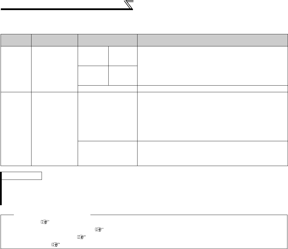
182
Setting of acceleration/deceleration time
and acceleration/deceleration pattern
(3) Adjustment of shortest and optimum acceleration/deceleration mode (Pr. 61 to Pr. 63)
⋅By setting the adjustment parameters Pr. 61 to Pr. 63, the application range can be made wider.
Parameter
Number Name Setting Range Description
61 Reference
current
55K or
lower 0 to 500A
For example, when the motor and inverter are different in capacity,
set the rated motor current value.
Shortest acceleration/deceleration: Set reference current (A) of the
stall prevention operation level during acceleration/deceleration
Optimum acceleration/deceleration: Set reference current (A) of the
optimum current during acceleration/deceleration
75K or
higher 0 to 3600A
9999 (initial value) The rated inverter current is defined as reference.
62
63
Reference value
at acceleration
Reference value
at deceleration
0 to 220%
Set when it is desired to change the reference level of acceleration
and deceleration.
Shortest acceleration/deceleration: Set the stall prevention
operation level (ratio to the current value of Pr. 61 ) during
acceleration/deceleration.
Optimum
acceleration/deceleration: Set the optimum current level
(ratio to the current value of Pr. 61 ) during acceleration/
deceleration.
9999
(initial value)
Shortest acceleration/deceleration: The 150% value during shortest
acceleration/deceleration is judged as the stall prevention operation
level.
Optimum acceleration/deceleration: 100% is the optimum value
REMARKS
⋅Pr. 61 to Pr. 63 are invalid when Real sensorless vector control or vector control is selected in the shortest acceleration/
deceleration mode.
⋅Since the Pr. 61 to Pr. 63 settings automatically return to the initial value (9999) if the Pr. 292 setting is changed, set Pr. 292 first
when you need to set Pr. 61 to Pr. 63.
♦ Parameters referred to ♦
Pr. 0 Torque boost Refer to page 146
Pr. 7 Acceleration time, Pr. 8 Deceleration time Refer to page 172
Pr. 22 Stall prevention operation level Refer to page 152
Pr. 22 Torque limit level Refer to page 100
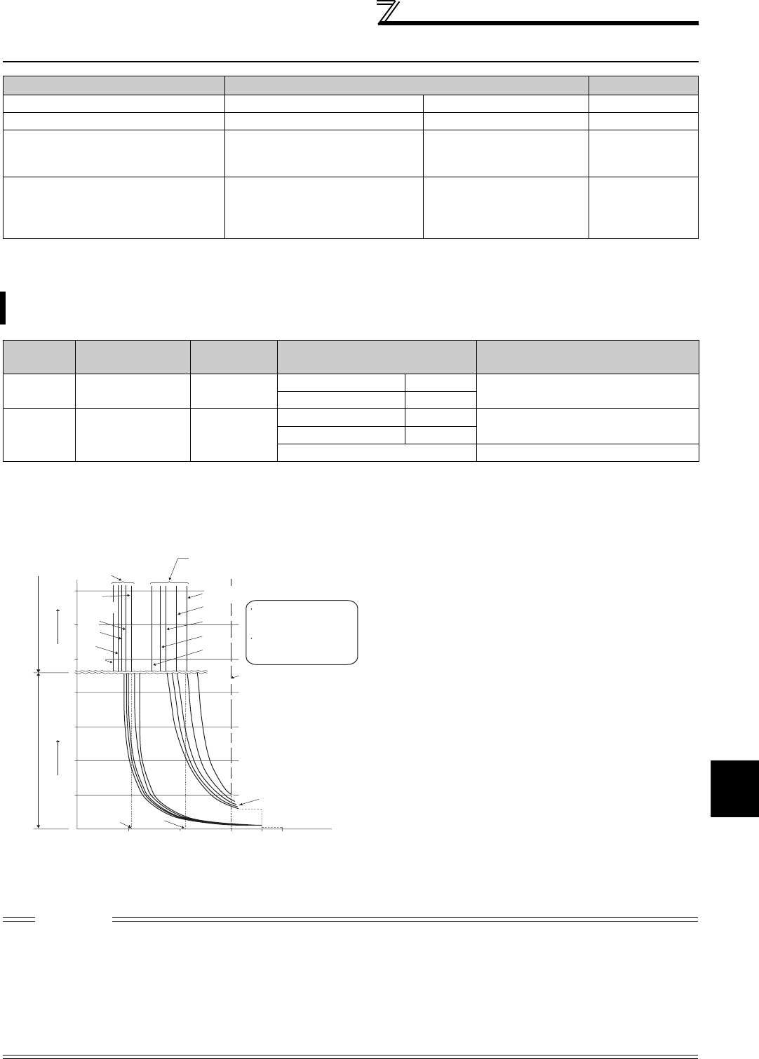
183
Selection and protection of a motor
4
PARAMETERS
4.13 Selection and protection of a motor
4.13.1 Motor protection from overheat (Electronic thermal relay function) (Pr. 9, Pr. 51)
*1 The initial value of the 0.4K and 0.75K is set to 85% of the rated inverter current.
*2 When parameter is read using the FR-PU04, a parameter name different from an actual parameter is displayed.
(1) Electronic thermal relay function operation characteristic (THM)
Purpose Parameter that must be Set Refer to Page
Motor protection from overheat Electronic thermal O/L relay Pr. 9, Pr. 51 183
Use the constant torque motor Applied motor Pr. 71 187
The motor performance can be
maximized for operation in magnetic
flux vector control system
Offline auto tuning Pr. 82 to Pr. 84,
Pr. 90 to Pr. 94, Pr. 96 189
High accuracy operation unaffected
by the motor temperature and stable
operation with high torque down to
ultra low speed are performed
Online auto tuning Pr. 95, Pr. 574 199
Set the current of the electronic thermal O/L relay to protect the motor from overheat. This feature provides the
optimum protective characteristics, including reduced motor cooling capability, at low speed.
Parameter
Number Name Initial Value Setting Range Description
9Electronic thermal
O/L relay
Rated inverter
current *1
55K or lower 0 to 500A Set the rated motor current.
75K or higher 0 to 3600A
51 Second electronic
thermal O/L relay *2 9999
55K or lower 0 to 500A Valid when the RT signal is ON.
Set the rated motor current.
75K or higher 0 to 3600A
9999
Second electronic thermal O/L relay invalid
[Electronic thermal relay function operation characteristic (E.THM)] This function detects the overload (overheat) of the
motor, stops the operation of the inverter's output
transistor, and trips. (The operation characteristic is
shown on the left)
⋅Set the rated current [A] of the motor in Pr. 9. (If the
motor has both 50Hz and 60Hz rating and the Pr. 3
Base frequency is set to 60Hz, set the 1.1 times of the
60Hz rated motor current.)
⋅Set "0" in Pr. 9 when you do not want to activate the
electronic thermal relay function, e.g. when using an
external thermal relay with the motor. (Note that the
output transistor protection of the inverter functions
(E.THT).)
⋅When using the Mitsubishi constant-torque motor
1) Set "1" or any of "13" to "18", "50", "53", "54" in
Pr. 71
.
(This provides a 100% continuous torque characteristic
in the low-speed range.)
2) Set the rated current of the motor in Pr. 9.
*1 When 50% of the rated inverter current (current value) is set in Pr. 9
*2 The % value denotes the percentage to the rated inverter current. It
is not the percentage to the motor rated current.
*3 When you set the electronic thermal relay function dedicated to the
Mitsubishi constant-torque motor, this characteristic curve applies
to operation at 6Hz or higher. (Refer to page 187 for the operation
characteristic.)
CAUTION
⋅Fault by electronic thermal relay function is reset by inverter power reset and reset signal input. Avoid unnecessary reset and
power-off.
⋅When using multiple motors with one inverter, or using a multi-pole motor or a specialized motor, provide an external thermal
relay (OCR) between the inverter and motor. And for the setting of the thermal relay, add the line-to line leakage current (refer to
page 52) to the current value on the motor rating plate. For low-speed operation where the cooling capability of the motor
reduces, it is recommended to use a thermal protector or thermistor-incorporated motor.
⋅When the difference between the inverter and motor capacities is large and the setting is small, the protective characteristics of
the electronic thermal relay function will be deteriorated. In this case, use an external thermal relay.
⋅Since a thermal protector is built in a motor dedicated for vector control (SF-V5RU), set "0" in Pr. 9 to use the motor
⋅Electronic thermal relay may not function when 5% or less of inverter rated current is set to electronic thermal relay setting.
Electronic thermal relay
function for transistor
protection
52.5% 105%
50 100 150
60
120
180
240
50
60
70
6Hz
20Hz
10Hz
6Hz
0.5Hz
30Hz or more*
3
20Hz
10Hz
0.5Hz
Pr. 9 = 50% setting of
inverter rating*1.2
Pr. 9 = 100% setting
of inverter rating*2
(s) unit display in this region (min) unit display in
this region
Operation time (min)Operation time (s)
Characteristic when
electronic thermal relay
function for motor
protection is turned off
(When Pr. 9 setting is 0(A))
30Hz
or more*
3
Inverter output current(%)
(% to the rated inverter current)
Operation region
Region on the right of
characteristic curve
Non-operation region
Region on the left of
characteristic curve
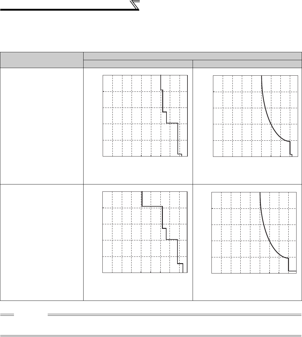
184
Selection and protection of a motor
(2) Electronic thermal relay function operation characteristic (THT)
Electronic thermal relay function (transistor protection thermal) operation characteristics of the inverter when the ratio
of the motor current to the inverter rated current is presented as transverse is shown. Transverse is calculated as
follows: (motor current [A]/inverter rated current [A]) × 100 [%].
Optimum Conditions Inverter Capacity
55K or lower 75K or higher
Running frequency : 1Hz or more
Carrier frequency: 2kHz
Running frequency : 1Hz or less
Carrier frequency: 2kHz
CAUTION
⋅Fault by electronic thermal relay function is reset by inverter power reset and reset signal input. Avoid unnecessary reset and
power-off.
⋅The operation time of the transistor protection thermal relay shortens when the Pr. 72 PWM frequency selection setting increases.
0
30
60
90
120
150
0 25 50 75 100 125 150 175 200
Ratio of the motor current
to the inverter rated current (%)
Operation time (S)
0
30
60
90
120
150
0 25 50 75 100 125 150 175 200
Ratio of the motor current
to the inverter rated current (%)
Operation time (S)
0
3
6
9
12
15
0 25 50 75 100 125 150 175 200
Ratio of the motor current
to the inverter rated current (%)
Operation time (S)
0
3
6
9
12
15
0 25 50 75 100 125 150 175 200
Ratio of the motor current
to the inverter rated current (%)
Operation time (S)
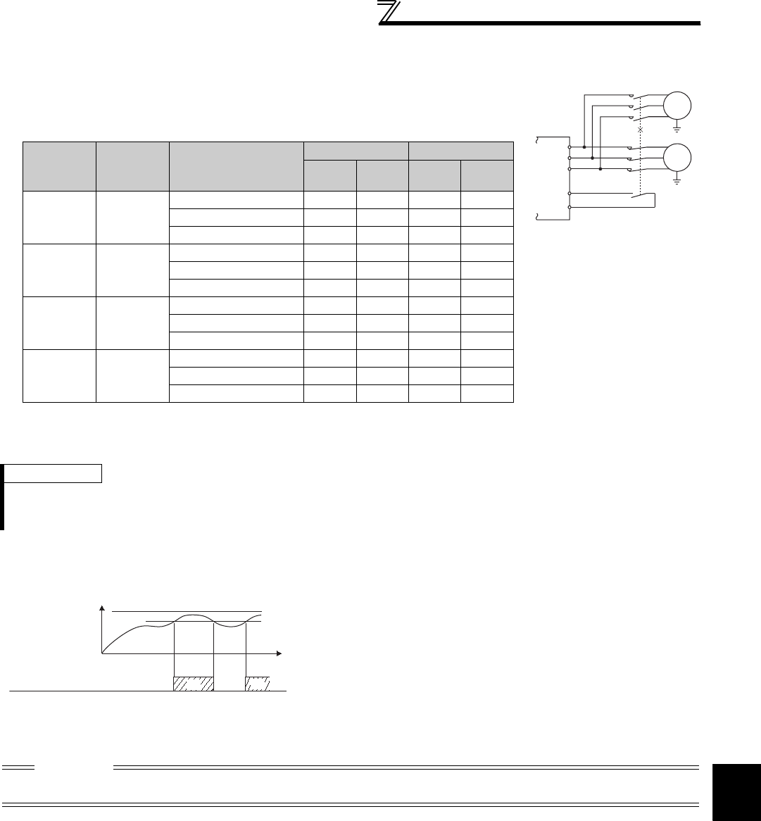
185
Selection and protection of a motor
4
PARAMETERS
(3) Set multiple electronic thermal relay functions (Pr. 51)
(4) Electronic thermal relay function pre-alarm (TH) and alarm signal (THP signal)
Use this function when rotating two motors of different rated currents individually by a
single inverter. (When rotating two motors together, use external thermal relays.)
⋅Set the rated current of the second motor in Pr. 51.
⋅When the RT signal is ON, thermal protection is provided based on the Pr. 51 setting.
REMARKS
⋅The RT signal acts as the second function selection signal and makes the other second functions valid. (Refer to page 235)
⋅The RT signal is assigned to the RT terminal in the initial setting. By setting "3" in any of Pr. 178 to Pr. 189 (input terminal function
selection), you can assign the RT signal to the other terminal.
100%: Electronic thermal relay function alarm operation value
⋅The alarm signal (THP) is output and an electronic thermal pre-
alarm (TH) is displayed when the electronic thermal relay
function cumulative value reaches 85% of the level set in Pr. 9
or Pr. 51. If it reaches 100% of the Pr. 9 Electronic thermal O/L
relay setting, electronic thermal relay function protection (E.
THM/E.THT) occurs.
⋅The inverter does not trip if the alarm signal is output.
⋅
For the terminal used for the THP signal output, assign the
function by setting "8" (positive logic) or "108" (negative logic) in
any of
Pr. 190 to Pr. 196 (output terminal function selection)
.
CAUTION
⋅Changing the terminal assignment using Pr. 190 to Pr. 196 (output terminal function selection) may affect the other functions. Set
parameters after confirming the function of each terminal.
.... Output current value is used to perform integration processing.
.... Output current is assumed as 0A to perform integration processing. (cooling processing)
×..... Electronic thermal relay function is not activated.
Pr. 450
Second applied
motor
Pr. 9
Electronic thermal
O/L relay
Pr. 51
Second electronic thermal O/L
relay
RT = OFF RT = ON
First
motor
Second
motor
First
motor
Second
motor
9999 0
9999 ××××
0××××
0.01 to 500 (0.1 to 3600)
××
9999 Other than
0
9999 ××
0××
0.01 to 500 (0.1 to 3600)
Other than
9999 0
9999 ××××
0××××
0.01 to 500 (0.1 to 3600)
××
Other than
9999
Other than
0
9999
0××
0.01 to 500 (0.1 to 3600)
RT
MC
MC
W
V
U
IM
IM
SD
OFF ON
100%
85%
Time
ON
Electronic thermal
relay function
operation level
Electronic thermal O/L
relay alarm (THP)
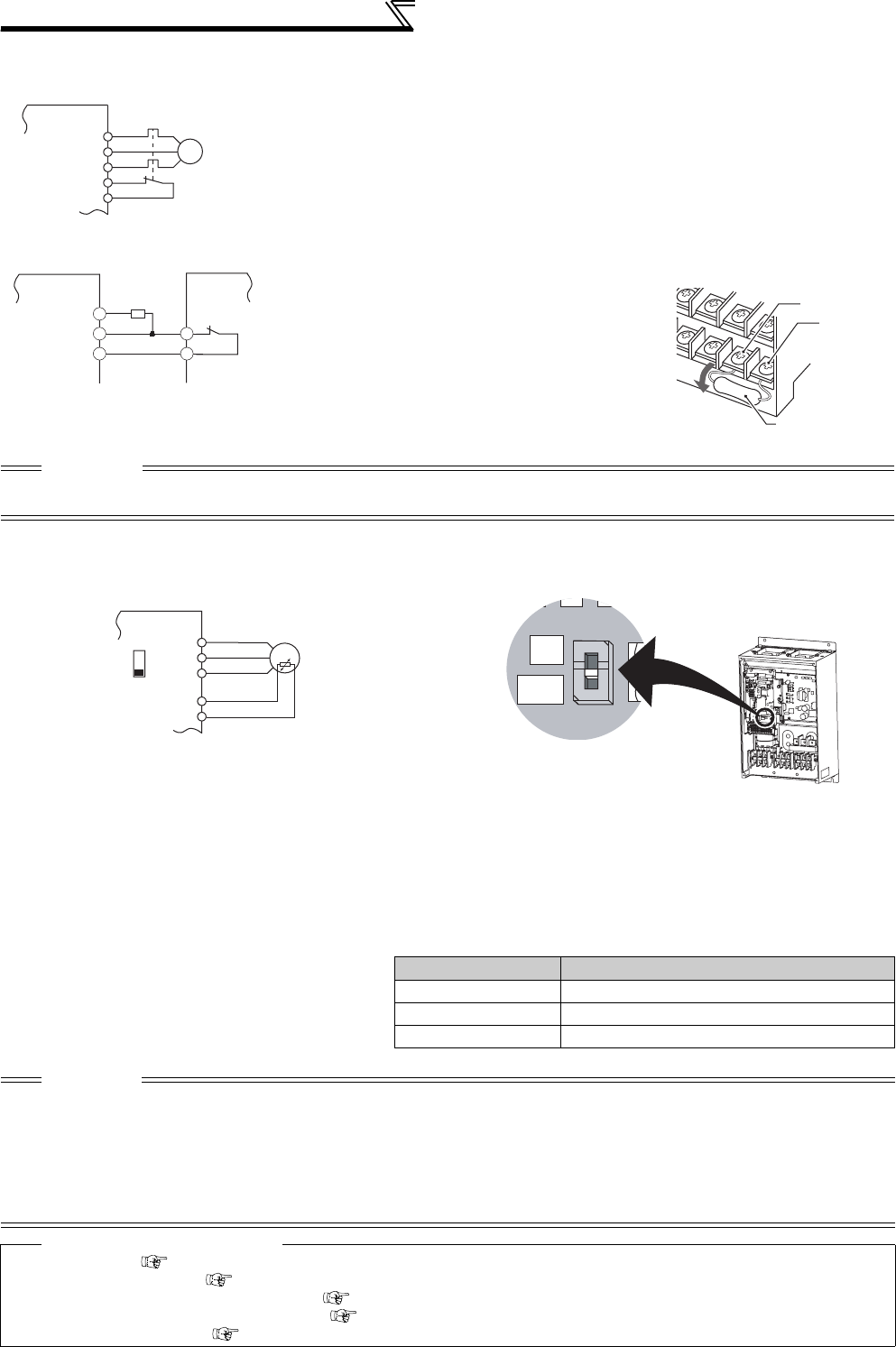
186
Selection and protection of a motor
(5) External thermal relay input (OH signal)
(6) PTC thermistor input (PTC signal)
Built-in PTC thermistor of the motor can be input to the PTC signal (AU terminal).
⋅For the terminal used for PTC signal input, assign the function by setting "63" in Pr. 184 AU terminal function selection
and also set the AU/PTC switchover switch to the PTC terminal function. (The initial setting is the AU terminal
function.)
⋅If a motor overheat state is detected for more than 10s according to the input from the PTC thermistor, the inverter
trips and outputs the PTC thermal fault signal (E.PTC).
External thermal relay input
connection example
⋅To protect the motor against overheat, use the OH signal when using an external
thermal relay or the built-in thermal protector of the motor.
⋅When the thermal relay operates, the inverter trips and outputs the fault signal
(E.OHT).
⋅For the terminal used for OH signal input, assign the function by setting "7" in any
of Pr. 178 to Pr. 189 (input terminal function selection)
⋅A thermal protector is provided for a vector control dedicated motor (SF-V5RU).
* Assign OH (external thermal input) signal to the CS terminal.
(Pr. 186 = "7")
Connect a 2W1kΩ resistor between the terminal PC and
CS(OH).
Install the resistor pushing it against the bottom part of the
terminal block so as to avoid a contact with other cables.
Refer to page 231 for details of Pr. 186 CS terminal function
selection.
CAUTION
⋅Changing the terminal assignment using Pr. 178 to Pr. 189 (input terminal function selection) may affect the other functions. Set
parameters after confirming the function of each terminal.
PTC thermistor input connection example
⋅The input specifications of the PTC thermistor
are shown on the right.
Motor Temperature PTC Thermistor Resistance Value (Ω)
Normal 0 to 500
Boundary 500 to 4k
Overheat 4k or higher
CAUTION
⋅
When the PTC signal was not assigned to Pr. 184 and the AU/PTC switchover switch was set to the PTC terminal function, the
function assigned to the AU terminal is always OFF. Reversely, when the PTC signal was assigned to Pr. 184 and the AU/PTC
switchover switch was set to the AU terminal function, a PTC thermal fault (E.PTC) occurs since the function is always in a
motor overheat state.
⋅When you want to input a current, assign the AU signal to the other signal.
⋅When terminal assignment is changed, the other functions may be affected. Set parameter after confirming the function of the
AU terminal.
♦ Parameters referred to ♦
Pr. 71 Applied motor Refer to page 187
Pr. 72 PWM frequency selection Refer to page 284
Pr. 178 to Pr. 189 (input terminal function selection) Refer to page 231
Pr. 190 to Pr. 196 (output terminal function selection) Refer to page 239
Specifications of the AU terminal Refer to page 25
Inverter
U
V
W
OH
Thermal relay protecto
r
Motor
IM
SD
G1
G2
CS(OH)
SD
PC
2W1kΩ
Inverter
SF-V5RU
*
Connection of the thermal
protector of the SF-V5RU
CS(OH)
Resistor (2W1kΩ)
PC
Control circuit
terminal block
Inverter
U
AU
PTC
V
W
AU(PTC)
Moto
r
SD
Inverter
AU/PTC switchover switch
AU
PTC
Factory-set to "AU".
Set to the "PTC" position to
validate the PTC signal input.
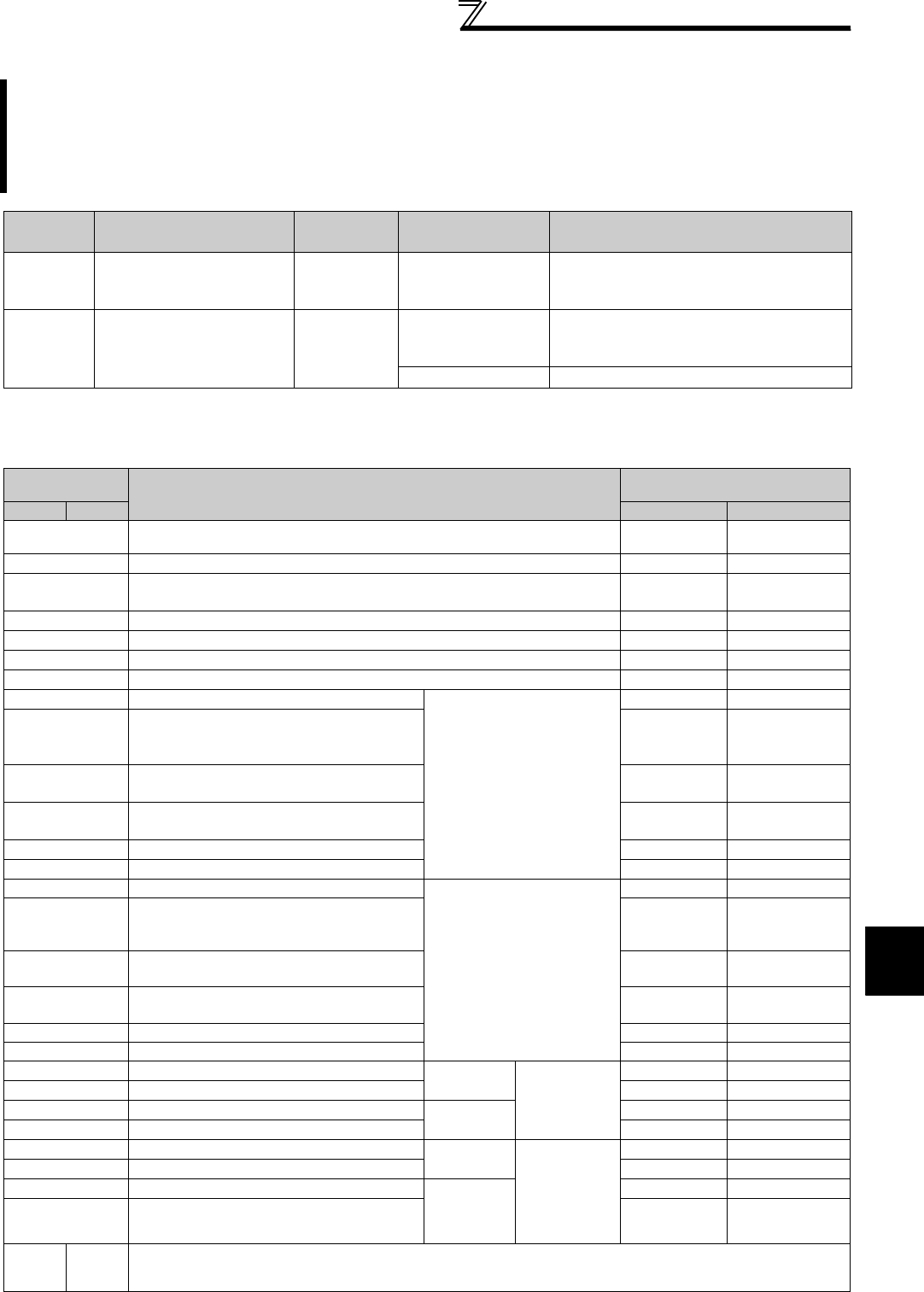
187
Selection and protection of a motor
4
PARAMETERS
4.13.2 Applied motor (Pr. 71, Pr. 450)
(1) Set the motor to be used
Refer to the following list and set this parameter according to the motor used.
Setting of the used motor selects the thermal characteristic appropriate for the motor.
Setting is necessary when using a constant-torque motor. Thermal characteristic of the electronic thermal relay
function suitable for the motor is set.
When Advanced magnetic flux vector, Real sensorless vector control or vector control is selected, the motor
constants (SF-JR, SF-HR, SF-JRCA, SF-HRCA, SF-V5RU (1500r/min series)) necessary for control are
selected as well.
Parameter
Number Name Initial Value Setting Range Description
71 Applied motor 0
0 to 8, 13 to 18, 20,
23, 24, 30, 33, 34,
40, 43, 44, 50, 53, 54
Selecting the standard motor or constant-
torque motor sets the corresponding motor
thermal characteristic.
450 Second applied motor 9999
0 to 8, 13 to 18, 20,
23, 24, 30, 33, 34,
40, 43, 44, 50, 53, 54
Set when using the second motor.
(same specifications as Pr. 71)
9999 Not function
Pr. 71 (Pr. 450)
Setting Motor
Electronic thermal relay function
operation characteristic
Pr. 71 Pr. 450 Standard
Constant torque
0
(Pr. 71 initial value) Standard motor (such as SF-JR)
1Mitsubishi constant-torque motor (such as SF-JRCA)
2Standard motor (such as SF-JR)
Adjustable 5 points V/F (Refer to page 164)
20 Mitsubishi standard motor (SF-JR 4P 1.5kW or lower)
30 Vector control dedicated motor SF-V5RU (1500r/min series)
40 Mitsubishi high efficiency motor SF-HR
50 Mitsubishi constant-torque motor SF-HRCA
3Standard motor
Select "offline auto tuning
setting"
13
Constant-torque motor
Vector control dedicated motor SF-V5RU
(except for 1500r/min series).
23 Mitsubishi standard motor
(SF-JR 4P 1.5kW or lower)
33 Vector control dedicated motor SF-V5RU
(1500r/min series), SF-THY
43 Mitsubishi High efficiency motor (SF-HR)
53
Mitsubishi constant-torque motor (SF-HRCA)
4 Standard motor
Auto tuning data can be read,
changed, and set
14
Constant-torque motor
Vector control dedicated motor SF-V5RU
(except for 1500r/min series).
24 Mitsubishi standard motor
(SF-JR 4P 1.5kW or lower)
34 Vector control dedicated motor SF-V5RU
(1500r/min series), SF-THY
44 Mitsubishi High efficiency motor (SF-HR)
54 Mitsubishi constant-torque motor (SF-HRCA)
5Standard motor Star
connection
Direct input of
motor
constants is
enabled
15 Constant-torque motor
6Standard motor Delta
connection
16 Constant-torque motor
7Standard motor Star
connection
Motor
constants
direct input
+
offline auto
tuning
17 Constant-torque motor
8Standard motor
Delta
connection
18 Constant-torque motor
—
9999
(initial
value)
Without second applied motor
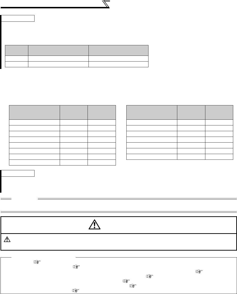
188
Selection and protection of a motor
(2) Use two types motors (Pr. 450)
⋅Set Pr. 450 Second applied motor to use two types motors with one inverter.
⋅When "9999" (initial value) is set, no function is selected.
⋅When Pr. 450 ≠ 9999, turning the RT signal ON makes the following parameter valid.
REMARKS
⋅When performing offline auto tuning, set "3, 7, 8, 13, 17, 18, 23, 33, 43, 53" in Pr. 71.
(Refer to page 189 for offline auto tuning)
⋅For the 5.5K and 7.5K, the Pr. 0 Torque boost and Pr. 12 DC injection brake operation voltage settings are automatically changed
according to the Pr. 71 setting as follows.
REMARKS
⋅The RT signal acts as the second function selection signal and makes the other second functions valid. (Refer to page 235)
⋅The RT signal is assigned to the terminal RT in the initial setting. By setting "3" in any of Pr. 178 to Pr. 189 (input terminal function
selection), you can assign the RT signal to the other terminal.
CAUTION
⋅Changing the terminal assignment using Pr. 178 to Pr. 189 (input terminal function selection) may affect the other functions. Set
parameters after confirming the function of each terminal.
CAUTION
Set this parameter correctly according to the motor used.
Incorrect setting may cause the motor to overheat and burn.
♦ Parameters referred to ♦
Pr. 0 Torque boost Refer to page 146
Pr. 12 DC injection brake operation voltage Refer to page 203
Pr. 80 Motor capacity, Pr. 81 Number of motor poles, Pr. 453 Second motor capacity, Pr. 454 Number of second motor poles Refer to page 148
Pr. 82 to Pr. 84, Pr. 90 to Pr. 94, Pr. 96, Pr. 455 to Pr. 463, Pr. 859, Pr. 860 (Motor constant) Refer to page 189
Pr. 95 Online auto tuning selection, Pr. 574 Second motor online auto tuning Refer to page 199
Pr. 451 Second motor control method selection, Pr. 800 Control method selection Refer to page 92
Pr. 100 to Pr. 109 (Adjustable 5 points V/F) Refer to page 164
Pr. 71 Standard Motor Setting
0, 2, 3 to 8, 20, 23, 24, 40, 43, 44
Constant Torque Motor Setting
1, 13 to 18, 50, 53, 54
Pr. 0 3% 2%
Pr. 12 4% 2%
Function
RT signal ON
(second
motor)
RT signal
OFF (first
motor)
Applied motor Pr. 450 Pr. 71
Control method selection Pr. 451 Pr. 800
Motor capacity Pr. 453 Pr. 80
Number of motor poles Pr. 454 Pr. 81
Motor excitation current Pr. 455 Pr. 82
Rated motor voltage Pr. 456 Pr. 83
Rated motor frequency Pr. 457 Pr. 84
Motor constant (R1) Pr. 458 Pr. 90
Motor constant (R2) Pr. 459 Pr. 91
Motor constant (L1) Pr. 460 Pr. 92
Motor constant (L2) Pr. 461 Pr. 93
Motor constant (X) Pr. 462 Pr. 94
Auto tuning setting/status Pr. 463 Pr. 96
Online auto tuning selection Pr. 574 Pr. 95
Torque current Pr. 860 Pr. 859
Function
RT signal ON
(second
motor)
RT signal
OFF (first
motor)

189
Selection and protection of a motor
4
PARAMETERS
4.13.3 Offline auto tuning (Pr. 71, Pr. 80 to Pr. 84, Pr. 90 to Pr. 94, Pr. 96, Pr. 450,
Pr. 453 to Pr. 463, Pr. 684, Pr. 859, Pr. 860)
The motor performance can be maximized with offline auto tuning.
•What is offline auto tuning?
When performing Advanced magnetic flux vector control, Real sensorless vector control or vector control, the
motor can be run with the optimum operating characteristics by automatically measuring the motor constants
(offline auto tuning) even when each motor constants differs, other manufacturer's motor is used, or the wiring
length is long.
Parameter
Number Name Initial
Value Setting Range Description
71 Applied motor 00 to 8, 13 to 18, 20, 23, 24, 30,
33, 34, 40, 43, 44, 50, 53, 54
By selecting a standard motor or constant
torque motor, thermal characteristic and
motor constants of each motor are set.
80 Motor capacity 9999
55K or lower 0.4 to 55kW Set the applied motor capacity.
75K or higher 0 to 3600kW
9999 V/F control
81 Number of motor poles 9999
2, 4, 6, 8, 10 Set the number of motor poles.
12, 14, 16, 18, 20 X18 signal-ON:V/F
control
Set 10 + number of
motor poles.
9999 V/F control
82 Motor excitation
current 9999
55K or lower 0 to 500A Tuning data
(The value measured by offline auto
tuning is automatically set.)
75K or higher 0 to 3600A
9999
Use the Mitsubishi motor (SF-JR, SF-HR,
SF-JRCA, SF-HRCA, SF-V5RU (1500r/
min series), etc.) constants
83 Rated motor voltage 200/
400V* 0 to 1000V
Set the rated motor voltage(V).
* The initial value differs according to the
voltage level. (200V/400V)
84 Rated motor frequency 60Hz 10 to 120Hz Set the rated motor frequency (Hz).
90 Motor constant (R1) 9999
55K or lower 0 to 50Ω, 9999
Tuning data
(The value measured by offline auto
tuning is automatically set.)
9999: Use the Mitsubishi motor (SF-JR,
SF-HR, SF-JRCA, SF-HRCA, SF-V5RU
(1500r/min series), etc.) constants
75K or higher 0 to 400mΩ,
9999
91 Motor constant (R2) 9999
55K or lower 0 to 50Ω, 9999
75K or higher 0 to 400mΩ,
9999
92 Motor constant (L1) 9999
55K or lower
0 to 50
Ω,
(0 to 1000mH)
,
9999
75K or higher
0 to 3600mΩ
(0 to 400mH)
,
9999
93 Motor constant (L2) 9999
55K or lower
0 to 50
Ω
(0 to 1000mH)
,
9999
75K or higher
0 to 3600mΩ
(0 to 400mH)
,
9999
94 Motor constant (X) 9999
55K or lower
0 to 500Ω
(0 to 100%)
,
9999
75K or higher
0 to 100Ω
(0 to 100%)
,
9999
96 Auto tuning setting/
status 0
0 Offline auto tuning is not performed
1Offline auto tuning is performed without
motor running
101 Offline auto tuning is performed with
motor running
450 Second applied motor 9999
0 to 8, 13 to 18, 20,
23, 24, 30, 33, 34, 40, 43, 44,
50, 53, 54
Set when using the second motor.
(same specifications as Pr. 71)
9999 Not function
Magnetic flux
Magnetic flux
Magnetic flux
Sensorless
Sensorless
Sensorless Vector
Vector
Vector

190
Selection and protection of a motor
453 Second motor capacity 9999
55K or lower 0.4 to 55kW Set the capacity of the second motor.
75K or higher 0 to 3600kW
9999 V/F control
454 Number of second
motor poles 9999 2, 4, 6, 8, 10
Set the number of poles of the second motor.
9999 V/F control
455 Second motor
excitation current 9999
55K or lower 0 to 500A Tuning data of the second motor
(The value measured by offline auto
tuning is automatically set.)
75K or higher 0 to 3600A
9999
Use the Mitsubishi motor (SF-JR, SF-HR,
SF-JRCA, SF-HRCA, SF-V5RU (1500r/
min series), etc.) constants
456 Rated second motor
voltage
200/400V
*0 to 1000V
Set the rated voltage (V) of the second
motor.
* The initial value differs according to the
voltage level. (200V/400V)
457 Rated second motor
frequency 60Hz 10 to 120Hz Set the rated motor frequency (Hz) of the
second motor.
458 Second motor
constant (R1) 9999
55K or lower 0 to 50Ω, 9999
Tuning data of the second motor
(The value measured by offline auto
tuning is automatically set.)
9999: Use the Mitsubishi motor (SF-JR,
SF-HR, SF-JRCA, SF-HRCA, SF-V5RU
(1500r/min series), etc.) constants
75K or higher 0 to 400mΩ,
9999
459 Second motor
constant (R2) 9999
55K or lower 0 to 50Ω, 9999
75K or higher 0 to 400mΩ,
9999
460 Second motor
constant (L1) 9999
55K or lower
0 to 50
Ω
(0 to 1000mH)
,
9999
75K or higher
0 to 3600mΩ
(0 to 400mH),
9999
461 Second motor
constant (L2) 9999
55K or lower
0 to 50
Ω
(0 to 1000mH)
,
9999
75K or higher
0 to 3600mΩ
(0 to 400mH),
9999
462 Second motor
constant (X) 9999
55K or lower
0 to 500Ω
(0 to 100%),
9999
75K or higher
0 to 100Ω
(0 to 100%),
9999
463 Second motor auto
tuning setting/status 0
0
Second motor auto tuning is not performed
1Offline auto tuning is performed without
second motor running
101 Offline auto tuning is performed with
second motor running
684 Tuning data unit
switchover 00 Internal data converted value
1 Displayed in "A, Ω, mH, %"
859 Torque current 9999
55K or lower 0 to 500A Tuning data
(The value measured by offline auto
tuning is automatically set.)
75K or higher 0 to 3600A
9999
Use the Mitsubishi motor (SF-JR, SF-HR,
SF-JRCA, SF-HRCA, SF-V5RU (1500r/
min series), etc.) constants
860 Second motor torque
current 9999
55K or lower 0 to 500A Tuning data of the second motor
(The value measured by offline auto
tuning is automatically set.)
75K or higher 0 to 3600A
9999
Use the Mitsubishi motor (SF-JR, SF-HR,
SF-JRCA, SF-HRCA, SF-V5RU (1500r/
min series), etc.) constants
Parameter
Number Name Initial
Value Setting Range Description

191
Selection and protection of a motor
4
PARAMETERS
(1) Before performing offline auto tuning
Check the following before performing offline auto tuning.
·Make sure Advanced magnetic flux vector control (Pr. 80, Pr. 81), Real sensorless vector control or vector control
(Pr. 800) is selected.
·A motor should be connected. Note that the motor should be at a stop at a tuning start.
· The motor capacity should be equal to or one rank lower than the inverter capacity. (note that the capacity is 0.4kW
or higher)
·
Motors such as high-slip motor, high-speed motor and special motor cannot be tuned. (The maximum frequency is 120Hz.)
·Even if tuning is performed without motor running (Pr. 96 Auto tuning setting/status = "1"), the motor may run slightly.
Therefore, fix the motor securely with a mechanical brake, or before tuning, make sure that there will be no
problem in safety if the motor runs. (Caution is required especially in vertical lift applications). Note that if the motor
runs slightly, tuning performance is unaffected.
·
Note the following when selecting offline auto tuning performed with motor running (
Pr. 96 Auto tuning setting/status
= "101").
Torque is not enough during tuning.
The motor may be run at nearly its rated speed.
The mechanical brake is open.
No external force is applied to rotate the motor.
·Offline auto tuning will not be performed properly if it is performed with a surge voltage suppression filter (FR-ASF-
H/FR-BMF-H) connected to the 55K or lower and sine wave filter (MT-BSL/BSC) connected to the 75K or higher
between the inverter and motor. Remove it before starting tuning.
·When exercising vector control, use the encoder that is coupled directly to the motor shaft without looseness.
Speed ratio should be 1:1.
POINT
·This function is valid only when a value other than "9999" is set in Pr. 80 and Pr. 81 and Advanced magnetic flux
vector control, Real sensorless vector control or vector control is selected.
·You can copy the offline auto tuning data (motor constants) to another inverter with the PU (FR-DU07/FR-PU07).
·Even when motors (other manufacturer's motor, SF-JRC, SF-TH, etc.) other than Mitsubishi standard motor (SF-
JR 0.4kW or higher), high efficiency motor (SF-HR 0.4kW or higher), Mitsubishi constant-torque motor (SF-JRCA
4P, SF-HRCA 0.4kW to 55kW) and vector control dedicated motor (SF-V5RU (1500r/min series)) are used or the
wiring length is long (30m or more as a reference), using the offline auto tuning function runs the motor with the
optimum operating characteristics.
·Tuning is enabled even when a load is connected to the motor. (As the load is lighter, tuning accuracy is higher.
Tuning accuracy does not change even if the inertia is large.)
·For the offline auto tuning, you can select either the motor non-rotation mode (Pr. 96 = "1") or rotation mode (Pr. 96
= "101").
·The rotation mode has higher tuning accuracy than the non-rotation mode.
·Reading/writing/copy of motor constants tuned by offline auto tuning are enabled.
·The offline auto tuning status can be monitored with the PU (FR-DU07/FR-PU07/FR-PU04).
· Do not connect a surge voltage suppression filter (FR-ASF-H/FR-BMF-H) to the 55K or lower and sine wave filter (MT-
BSL/BSC) to the 75K or higher between the inverter and motor.
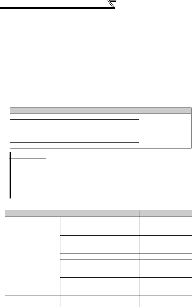
192
Selection and protection of a motor
(2) Setting
1) Select the Advanced magnetic flux vector control, Real sensorless vector control or vector control
(refer to page 92 )
.
2) Set "1" or "101" in Pr. 96 Auto tuning setting/status .
· When the setting is "1" . . . . . . . . Tuning is performed without motor running.
It takes approximately 25 to 120s * until tuning is completed.
(Excitation noise is produced during tuning.)
*Tuning time differs according to the inverter capacity and motor type.
· When the setting is "101" . . . . . . Tuning is performed with motor running.
It takes approximately 40s until tuning is completed.
The motor runs at nearly its rated frequency.
3) Set the rated motor current (initial value is rated inverter current) in
Pr. 9 Electronic thermal O/L relay (refer to page 183 )
.
4) Set the rated voltage of motor (initial value is 200V/400V) in
Pr. 83 Rated motor voltage
and rated frequency of motor
(initial value is 60Hz) in
Pr. 84 Rated motor frequency
.
(For a Japanese standard motor, etc. which has both 50Hz and 60Hz rated values, set 200V/60Hz or 400V/60Hz).)
For vector control dedicated motor SF-V5RU1 / V5RU3 / V5RU4, set as the following table.
5) Set Pr. 71 Applied motor according to the motor used.
* For other settings of Pr. 71 , refer to page 187.
Pr. 83 Setting Pr. 84 Setting
SF-V5RU1-30kW or lower 160V
33.33Hz
SF-V5RU1-37kW 170V
SF-V5RU3-22kW or lower 160V
SF-V5RU3-30kW 170V
SF-V5RU4-3.7kW, 7.5kW 150V 16.67Hz
SF-V5RU4-other than the above 160V
REMARKS
· When using the vector control dedicated motor SF-V5RU (1500r/min series) and SF-THY, setting 33 and 34 in Pr. 71
selects internal constants appropriate for dedicated motors. Therefore, Pr. 83 and Pr. 84 settings are unnecessary.
· Perform auto tuning for SF-V5RU (except for 1500 r/min series) with setting 13 or 14 in Pr. 71 ( For perform auto tuning,
set Pr. 83 and Pr. 84)
· When Pr. 11 DC injection brake operation time = "0" or Pr.12 DC injection brake operation voltage = "0," offline auto tuning is
performed at the initial value of Pr. 11 or Pr. 12.
· When the positioning control is selected (Pr. 800 = "3" or "5" (when MC signal is OFF)), offline auto tuning is not performed.
Motor Pr. 71 Setting *
Mitsubishi standard motor
Mitsubishi high efficiency
motor
SF-JR, SF-TH 3
SF-JR 4P-1.5kW or lower 23
SF-HR 43
Others 3
Mitsubishi constant-torque
motor
SF-JRCA 4P,
SF-TH (constant-torque) 13
SF-HRCA 53
Others (SF-JRC, etc.) 13
Vector control dedicated
motor
SF-V5RU (1500r/min series)
SF-THY 33
SF-V5RU (except for 1500r/min series) 13
Other manufacturer's
standard motor −3
Other manufacturer's
constant-torque motor −13
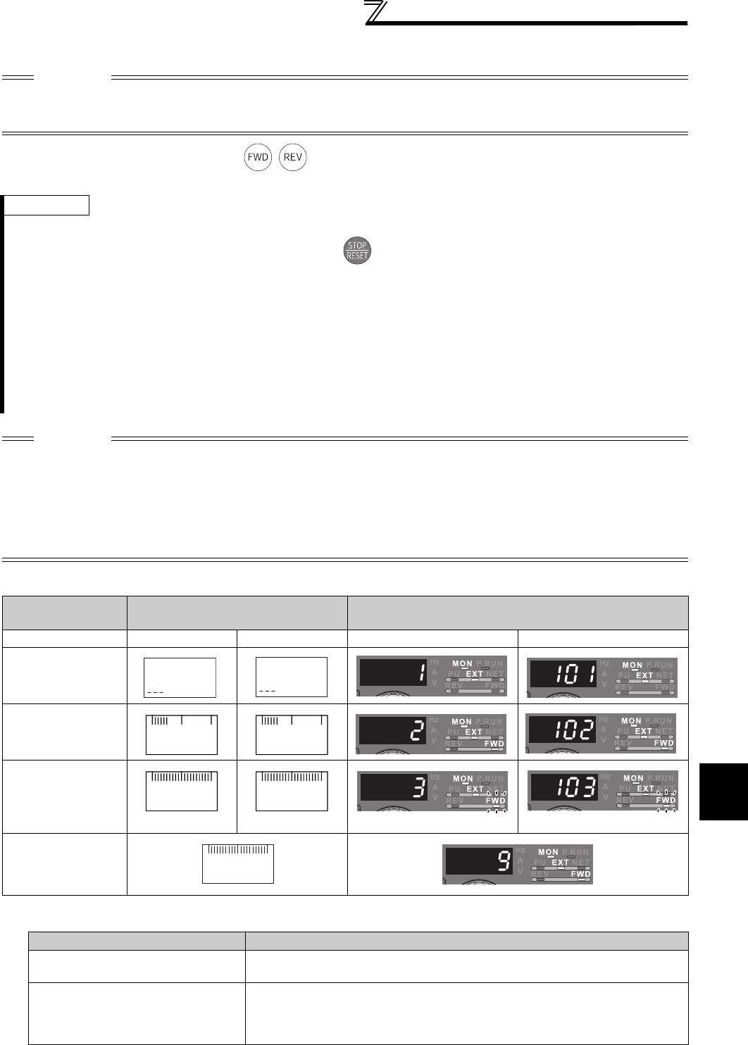
193
Selection and protection of a motor
4
PARAMETERS
(3) Execution of tuning
1)When performing PU operation, press / of the operation panel.
For External operation, turn ON the start command (STF signal or STR signal). Tuning starts.
2)Monitor is displayed on the operation panel (FR-DU07) and parameter unit (FR-PU07/FR-PU04) during tuning as below.
· Reference: Offline auto tuning time (when the initial setting is set)
CAUTION
· Before performing tuning, check the monitor display of the operation panel (FR-DU07) or parameter unit (FR-PU04/FR-
PU07) if the inverter is in the state ready for tuning. (Refer to 2) below) When the start command is turned ON under V/F
control, the motor starts.
REMARKS
· Satisfy the required inverter start conditions to start offline auto tuning. For example, stop the input of MRS signal.
· To force tuning to end, use the MRS or RES signal or press of the operation panel.
(Turning the start signal (STF signal or STR signal) OFF also ends tuning.)
· During offline auto tuning, only the following I/O signals are valid: (initial value)
· Input signals <valid signal> STOP, OH, MRS, RT, CS, RES, STF, STR
· Output terminal RUN, OL, IPF, FM, AM, A1B1C1
Note that the progress status of offline auto tuning is output in fifteen steps from AM and FM when speed and output
frequency are selected.
· Do not perform ON/OFF switching of the second function selection signal (RT) during execution of offline auto tuning. Auto
tuning is not executed properly.
· Setting offline auto tuning (Pr. 96 Auto tuning setting/status = "1 or 101") will make pre-excitation invalid.
CAUTION
· When selecting offline auto tuning performed with motor running (Pr. 96 Auto tuning setting/status = "101"), caution must be
taken since the motor runs.
· Since the RUN signal turns ON when tuning is started, caution is required especially when a sequence which releases a
mechanical brake by the RUN signal has been designed.
· When executing offline auto tuning, input the run command after switching ON the main circuit power (R/L1, S/L2, T/L3) of
the inverter.
·While Pr. 79 = "7," turn the X12 signal ON to tune in the PU operation mode.
Parameter Unit
(FR-PU07/FR-PU04) Display Operation Panel (FR-DU07) Display
Pr. 96 setting 1 101 1 101
(1) Setting
(2) Tuning in
progress
(3) Normal end
(4) Error end (when
the inverter
protective function
is activated)
Offline Auto Tuning Setting Time
Non-rotation mode (Pr. 96 = "1") Approximately 25 to 120s
(Tuning time differs according to the inverter capacity and motor type.)
Rotation mode (Pr. 96 = "101")
Approximately 40s
(Offline auto tuning time varies with the acceleration and deceleration time
settings as indicated below. Offline auto tuning time = acceleration time +
deceleration time + approx. 30s)
1
STOP PU
101
STOP PU
FWD PU
2
STF
TUNE
FWD PU
102
STF
TUNE
STOP PU
3
STF
TUNE
COMPLETION
STOP PU
103
STF
TUNE
COMPLETION
Flickerin
g
Flickering
STOP PU
9
STF
TUNE
ERROR
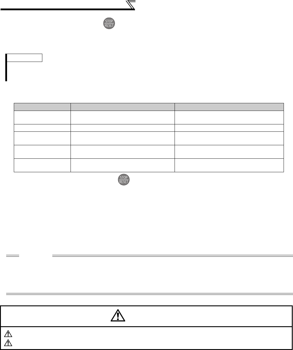
194
Selection and protection of a motor
3)When offline auto tuning ends, press of the operation panel during PU operation. For External operation, turn
OFF the start signal (STF signal or STR signal).
This operation resets the offline auto tuning and the PU's monitor display returns to the normal indication.
(Without this operation, next operation cannot be started.)
4)If offline auto tuning ended in error (see the table below), motor constants are not set.
Perform an inverter reset and restart tuning.
5)When tuning is ended forcibly by pressing or turning OFF the start signal (STF or STR) during tuning, offline
auto tuning does not end properly. (The motor constants have not been set.)
Perform an inverter reset and restart tuning.
6)When using the motor corresponding to the following specifications and conditions, reset Pr. 9 Electronic thermal O/
L relay as below after tuning is completed.
a)When the rated power specifications of the motor is 200/220V (400/440V) 60Hz, set 1.1 times rated motor
current value in Pr.9.
b)When performing motor protection from overheat using a PTC thermistor or motor with temperature detector
such as Klixon, set "0" (motor overheat protection by the inverter is invalid) in Pr. 9.
REMARKS
· The motor constants measured once in the offline auto tuning are stored as parameters and their data are held until the
offline auto tuning is performed again.
· Changing Pr. 96 setting from "3 or 103" after tuning completion will invalidate the tuning data. In this case, tune again.
Error Display Error Cause Remedy
8 Forced end Set "1" or "101" in Pr. 96 and perform tuning
again.
9 Inverter protective function operation Make setting again.
91 Current limit (stall prevention) function was
activated.
Increase acceleration/deceleration time.
Set "1" in Pr. 156 .
92 Converter output voltage reached 75% of
rated value. Check for fluctuation of power supply voltage.
93 Calculation error
A motor is not connected.
Check the motor wiring and make setting
again.
CAUTION
· An instantaneous power failure occurring during tuning will result in a tuning error.
After power is restored, the inverter goes into the normal operation mode. Therefore, when STF (STR) signal is ON, the
motor runs in the forward (reverse) rotation.
· Any alarm occurring during tuning is handled as in the ordinary mode. Note that if a fault retry has been set, retry is ignored.
· The set frequency monitor displayed during the offline auto tuning is 0Hz.
CAUTION
Note that the motor may start running suddenly.
When the offline auto tuning is used in vertical lift application, e.g. a lifter, it may drop due to insufficient torque.

195
Selection and protection of a motor
4
PARAMETERS
(4) Utilizing or changing offline auto tuning data for use
The data measured in the offline auto tuning can be read and utilized or changed.
<Operating procedure>
1)Set Pr. 71 according to the motor used.
*1 For other settings of Pr. 71, refer to page 187.
2)In the parameter setting mode, read the following parameters and set desired values.
Motor Pr. 71 Setting*
Mitsubishi standard motor
Mitsubishi high efficiency
motor
SF-JR, SF-TH 4
SF-JR 4P 1.5kW or lower 24
SF-HR 44
Others 4
Mitsubishi constant-torque
motor
SF-JRCA 4P
SF-TH (constant torque) 14
SF-HRCA 54
Others (SF-JRC, etc.) 14
Vector control dedicated
motor
SF-V5RU (1500r/min series)
SF-THY 34
SF-V5RU (except for 1500r/min series) 14
Other manufacturer's
standard motor −4
Other manufacturer's
constant torque motor −14
Parameter
Number Name Setting Range Setting
Increments
Initial
Value
82 Motor excitation current 0 to ***, 9999 1 9999
90 Motor constant (R1) 0 to ***, 9999 1 9999
91 Motor constant (R2) 0 to ***, 9999 1 9999
92 Motor constant (L1) 0 to ***, 9999 1 9999
93 Motor constant (L2) 0 to ***, 9999 1 9999
94 Motor constant (X) 0 to ***, 9999 1 9999
859 Torque current 0 to ***, 9999 1 9999
REMARKS
· The display units of the motor constants read using Pr. 684 Tuning data unit switchover can be changed. Note that parameter
values cannot be changed.
· When "9999" is set in Pr. 82, Pr. 90 to Pr. 94, Pr. 455, Pr. 458 to Pr. 462, Pr. 859, Pr. 860, Mitsubishi motor (SF-JR, SF-HR, SF-
JRCA, SF-HRCA, SF-V5RU (1500r/min series), etc.) constants are used.
· As the motor constants measured in the offline auto tuning have been converted into internal data (****), refer to the following
setting example when making setting:
Setting example To slightly increase Pr. 90 value (5%)
When Pr. 90 is displayed "2516",
set 2642, i.e. 2516 × 1.05 = 2641.8, in Pr. 90 .
(The value displayed has been converted into a value for internal use. Hence, simple addition of a given
value to the displayed value has no significance.)
Pr. 684
Setting
Pr. 82,
Pr. 455
Pr. 90,
Pr. 458
Pr. 91,
Pr. 459
Pr. 92,
Pr. 460
Pr. 93,
Pr. 461
Pr. 94,
Pr. 462
Pr. 859,
Pr. 860
0 Internal data converted value
155K or lower 0.01A 0.001Ω0.001Ω0.1mH 0.1mH 0.1% 0.01A
75K or higher 0.1A 0.01mΩ0.01mΩ0.01mH 0.01mH 0.01% 0.1A
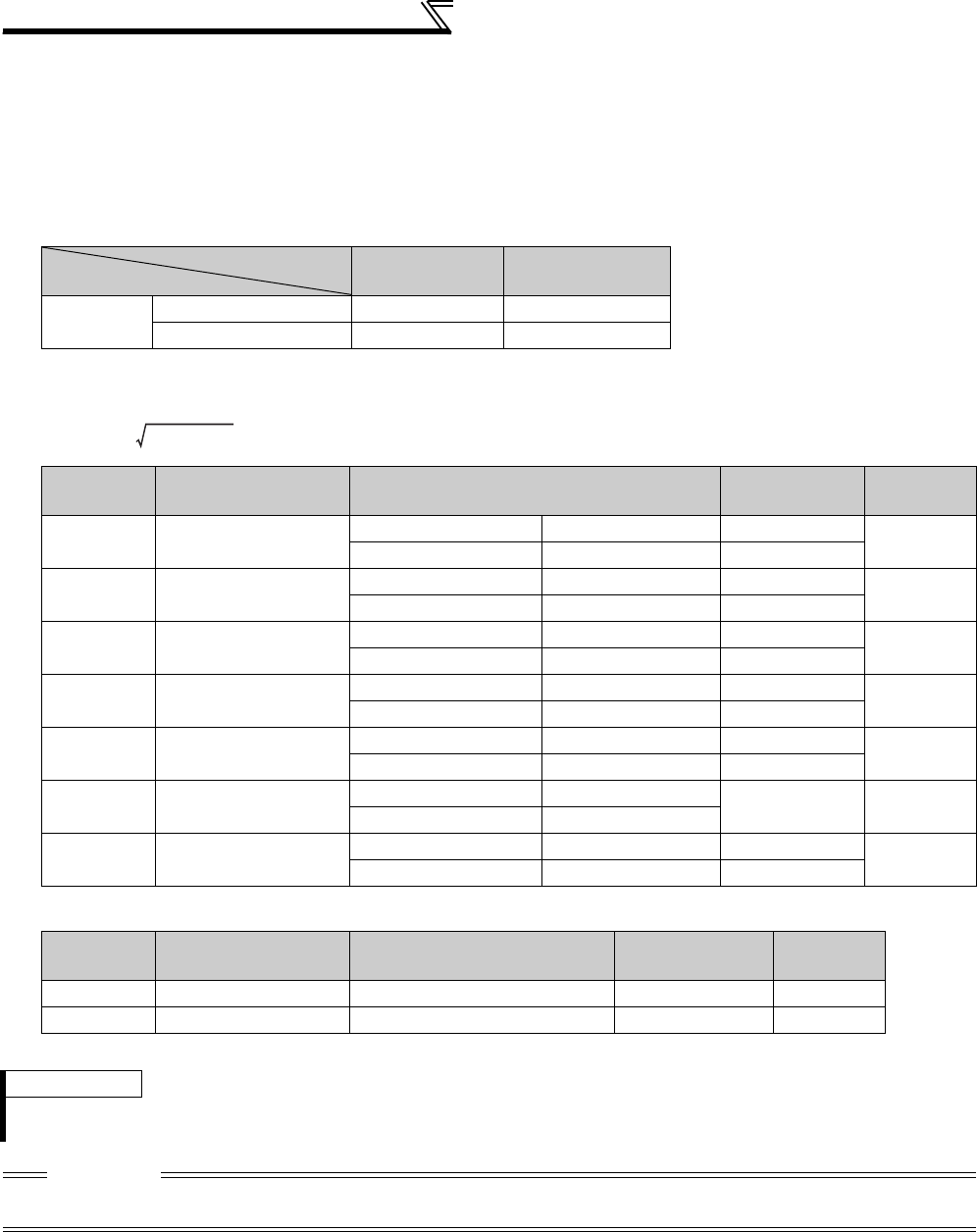
196
Selection and protection of a motor
(5) Method to set the motor constants without using the offline auto tuning data
The Pr. 92 and Pr. 93 motor constants may either be entered in [Ω] or in [mH]. Before starting operation, confirm which
motor constant unit is used.
• To enter the Pr. 92 and Pr. 93 motor constants in [Ω]
<Operating procedure>
1) Set Pr. 71 according to the motor used.
2) In the parameter setting mode, read the following parameters and set desired values.
3)Refer to the following table and set Pr. 83 and Pr. 84 .
* The initial value differs according to the voltage level. (200V/400V)
Star Connection
Motor
Delta Connection
Motor
Setting Standard motor 5 6
Constant-torque motor 15 16
Parameters
Number Name Setting Range Setting
Increments
Initial
Value
82 Motor excitation current
(no load current)
55K or lower 0 to 500A, 9999 0.01A 9999
75K or higher 0 to 3600A, 9999 0.1A
90 Motor constant (r1) 55K or lower 0 to 50Ω, 9999 0.001Ω9999
75K or higher 0 to 400mΩ, 9999 0.01mΩ
91 Motor constant (r2) 55K or lower 0 to 50Ω, 9999 0.001Ω9999
75K or higher 0 to 400mΩ, 9999 0.01mΩ
92 Motor constant (x1) 55K or lower 0 to 50Ω, 9999 0.001Ω9999
75K or higher 0 to 3600mΩ, 9999 0.01mΩ
93 Motor constant (x2) 55K or lower 0 to 50Ω, 9999 0.001Ω9999
75K or higher 0 to 3600mΩ, 9999 0.01mΩ
94 Motor constant (xm) 55K or lower 0 to 500Ω, 9999 0.01Ω 9999
75K or higher 0 to 100Ω, 9999
859 Torque current 55K or lower 0 to 500A, 9999 0.01A 9999
75K or higher 0 to 3600A, 9999 0.1A
Parameter
Number Name Setting Range Setting
Increments
Initial
Value
83 Rated motor voltage 0 to 1000V 0.1V 200V/400V*
84 Rated motor frequency 10 to 120Hz 0.01Hz 60Hz
REMARKS
· When "9999" is set in Pr. 82, Pr. 90 to Pr. 94, Pr. 859, Mitsubishi motor (SF-JR, SF-HR, SF-JRCA, SF-HRCA, SF-V5RU (1500r/
min series), etc.) constants are used.
CAUTION
· If "star connection" is mistaken for "delta connection" or vice versa during setting of Pr. 71, Advanced magnetic flux vector
control, Real sensorless vector control and vector control cannot be exercised properly.
Iq = I
100
2
-I
0
2
Iq = torque current, I
100 =
rated current, I
0 =
no load curren
t
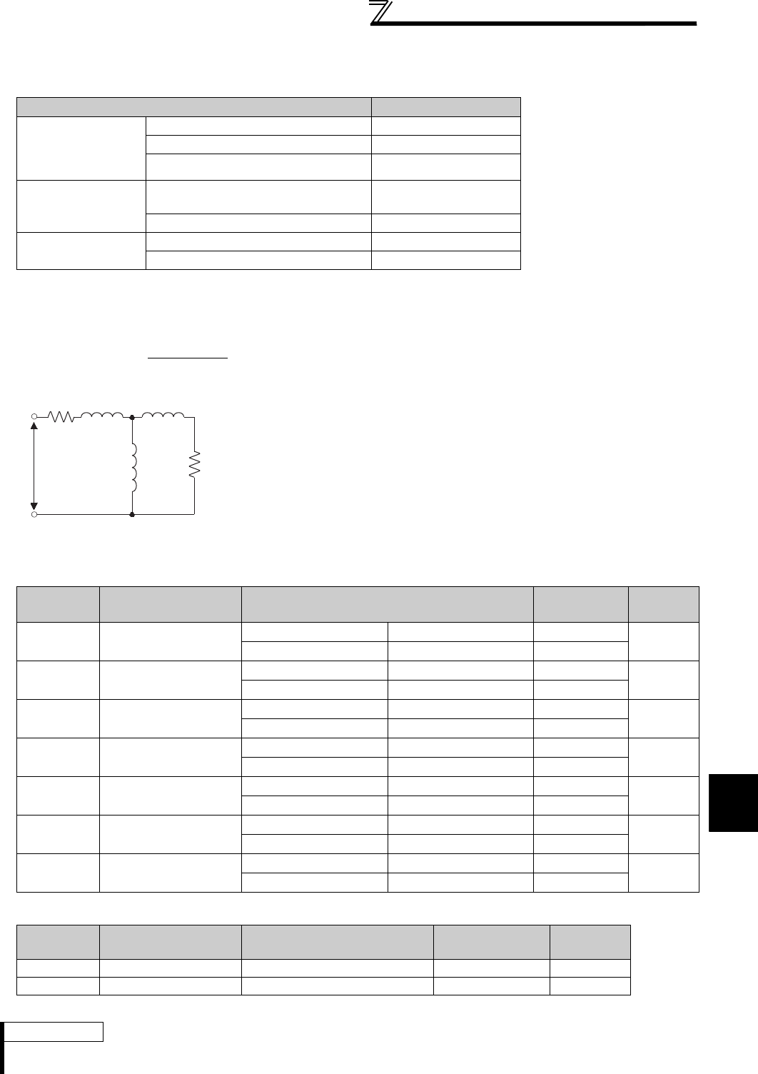
197
Selection and protection of a motor
4
PARAMETERS
• To enter the Pr. 92 and Pr. 93 motor constants in [mH]
<Operating procedure>
1) Set Pr. 71 according to the motor used.
*1 For other settings of Pr. 71, refer to page 187.
2) In the parameter setting mode, read the following parameters and set desired values.
Calculate the Pr. 94 value from the following formula.
3)Refer to the following table and set Pr. 83 and Pr. 84 .
* The initial value differs according to the voltage level. (200V/400V)
Motor Pr.71 Setting *1
Mitsubishi standard
motor
Mitsubishi high
efficiency motor
SF-JR 0
SF-JR 4P 1.5kW or lower 20
SF-HR 40
Mitsubishi constant-
torque motor
SF-JRCA 4P
SF-TH (constant torque) 1
SF-HRCA 50
Vector control
dedicated motor
SF-V5RU (1500r/min series) 30
SF-V5RU (except for 1500r/min series) 14
Pr. 94 setting = (1 - M2
) × 100 (%)
L1 × L2
Motor equivalent circuit diagram
Parameter
Number Name Setting Range Setting
Increments
Initial
Value
82 Motor excitation current
(no load current)
55K or lower 0 to 500A, 9999 0.01A 9999
75K or higher 0 to 3600A, 9999 0.1A
90 Motor constant (R1) 55K or lower 0 to 50Ω, 9999 0.001Ω9999
75K or higher 0 to 400mΩ, 9999 0.01mΩ
91 Motor constant (R2) 55K or lower 0 to 50Ω, 9999 0.001Ω9999
75K or higher 0 to 400mΩ, 9999 0.01mΩ
92 Motor constant (L1) 55K or lower 0 to 1000mH, 9999 0.1mH 9999
75K or higher 0 to 400mH, 9999 0.01mH
93 Motor constant (L2) 55K or lower 0 to 1000mH, 9999 0.1mH 9999
75K or higher 0 to 400mH, 9999 0.01mH
94 Motor constant (X) 55K or lower 0 to 100%, 9999 0.1% 9999
75K or higher 0 to 100%, 9999 0.01%
859 Torque current 55K or lower 0 to 500A, 9999 0.01A 9999
75K or higher 0 to 3600A, 9999 0.1A
Parameter
Number Name Setting Range Setting
Increments
Initial
Value
83 Rated motor voltage 0 to 1000V 0.1V 200V/400V*
84 Rated motor frequency 10 to 120Hz 0.01Hz 60Hz
REMARKS
· When "9999" is set in Pr. 82, Pr. 90 to Pr. 94, Pr. 859, Mitsubishi motor (SF-JR, SF-HR, SF-JRCA, SF-HRCA, SF-V5RU
(1500r/min series), etc.) constants are used.
L1= I1+ M: Primary inductance
L2= I2+ M: Secondary inductance
M
VR2/S
R1 I1 I2
R1: Primary resistance
I1: Primary leakage inductance
I2: Secondary leakage inductance
M: Excitation inductance
S: Slip
R2: Secondary resistance
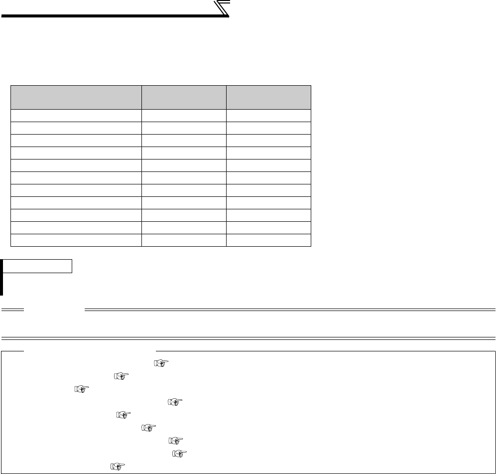
198
Selection and protection of a motor
(6) Tune second applied motor
· When you want to switch two motors with one inverter, set the second motor in Pr. 450 Second applied motor (refer to
page 187). Initial setting is without second applied motor.
· Turning the RT signal ON makes the following parameters for the second parameters valid.
Functions RT signal ON
(second motor)
RT signal OFF
(first motor)
Motor capacity Pr. 453 Pr. 80
Number of motor poles Pr. 454 Pr. 81
Motor excitation current Pr. 455 Pr. 82
Rated motor voltage Pr. 456 Pr. 83
Rated motor frequency Pr. 457 Pr. 84
Motor constant (R1) Pr. 458 Pr. 90
Motor constant (R2) Pr. 459 Pr. 91
Motor constant (L1) Pr. 460 Pr. 92
Motor constant (L2) Pr. 461 Pr. 93
Motor constant (X) Pr. 462 Pr. 94
Auto tuning setting/status Pr. 463 Pr. 96
REMARKS
· The RT signal is assigned to the terminal RT in the initial setting. By setting "3" in any of Pr. 178 to Pr. 189 (input terminal function
selection), you can assign the RT signal to the other terminal.
CAUTION
· Changing the terminal assignment using Pr. 178 to Pr. 189 (input terminal function selection) may affect the other functions. Set
parameters after confirming the function of each terminal.
♦ Parameters referred to ♦
Pr. 7 Acceleration time, Pr. 8 Deceleration time Refer to page 172
Pr. 9 Electronic thermal O/L relay Refer to page 183
Pr. 71 Applied motor Refer to page 187
Pr. 80 Motor capacity, Pr. 81 Number of motor poles Refer to page 92
Pr. 95 Online auto tuning selection Refer to page 199
Pr. 156 Stall prevention operation selection Refer to page 152
Pr. 178 to Pr. 189 (input terminal function selection) Refer to page 231
Pr. 190 to Pr. 196 (output terminal function selection) Refer to page 239
Pr. 800 Control method selection Refer to page 92

4
PARAMETERS
199
Selection and protection of a motor
4.13.4 Online auto tuning (Pr. 95, Pr. 574)
(1) Start-time online auto tuning (Pr. 95 = "1")
· By quickly tuning the motor constants at a start, high accuracy operation unaffected by the motor temperature and
stable operation with high torque down to ultra low speed can be performed.
· Make sure Advanced magnetic flux vector control (Pr. 80, Pr. 81), Real sensorless vector control or vector control (Pr.
800 ) is selected.
· Before performing online auto tuning, perform offline auto tuning without fail.
<Operation method>
1) Refer to page 189 to perform offline auto tuning.
2) Check that "3" or "103" (offline auto tuning completion) is set in Pr. 96 Auto tuning setting/status.
3) Set "1" (start-time online auto tuning) in Pr. 95 Online auto tuning selection.
Online auto tuning is performed from the next starting.
4) Before starting operation, check that the following parameters have been set.
5) When performing PU operation, press / of the operation panel.
For External operation, turn ON the run command (STF signal or STR signal).
When online auto tuning is selected under Advanced magnetic flux vector control, Real sensorless vector control
or vector control, excellent torque accuracy is provided by temperature compensation even if the secondary
resistance value of the motor varies with the rise of the motor temperature.
Parameter
Number Name Initial
Value Setting Range Description
95 Online auto tuning
selection 0
0 Online auto tuning is not performed
1 Start-time online auto tuning
2 Magnetic flux observer (normal tuning)
574 Second motor online
auto tuning 00, 1
Select the second motor online auto tuning.
(same as Pr. 95)
Parameter
Number Description
9 Used as rated motor current and electronic thermal relay parameters.
71 Applied motor
80 Motor capacity (down to one rank lower than the inverter capacity, note
that the capacity should be 0.4kW or higher)
81 Number of motor poles
CAUTION
· For using start-time online auto tuning in elevator, examine the utilization of a brake sequence for the brake opening timing at a
start. Though the tuning ends in about a maximum of 500ms after a start, torque is not provided fully during that period.
Therefore, note that there may be a possibility of drop due to gravity.
It is recommended to perform tuning using a start time tuning signal (X28). (Refer to page 201.)
Magnetic flux
Magnetic flux
Magnetic flux
Sensorless
Sensorless
Sensorless Vector
Vector
Vector

200
Selection and protection of a motor
(2) Magnetic flux observer (normal tuning) (Pr. 95 = "2")
· When exercising vector control using a motor with encoder, it is effective for torque accuracy improvement.
The current flowing in the motor and the inverter output voltage are used to estimate/observe the magnetic flux in
the motor.
The magnetic flux of the motor is always (including during operation) detected with high accuracy so that an
excellent characteristic is provided regardless of the change in the temperature of the secondary resistance.
· Vector control (Pr. 80, Pr. 81, Pr. 800) should be selected. (Refer to page 92.)
CAUTION
· For the SF-V5RU, SF-JR (with encoder), SF-HR (with encoder), SF-JRCA (with encoder) or SF-HRCA (with encoder), it is not
necessary to perform offline auto tuning to select adaptive magnetic flux observer. (Note that it is necessary to perform offline
auto tuning for the wiring length resistance to be reflected on the control when the wiring length is long (30m or longer as
reference)).
REMARKS
· Online auto tuning does not operate if the MRS signal is input, if the preset speed is less than the Pr. 13 Starting frequency (V/F
control or Advanced magnetic flux vector control), or if the starting conditions of the inverter are not satisfied, e.g. inverter error.
· Online auto tuning does not operate during deceleration or at a restart during DC brake operation.
· Invalid for jog operation.
· Automatic restart after instantaneous power failure overrides when automatic restart after instantaneous power failure is selected.
(Start-time online auto tuning is not performed at frequency search.)
Perform online auto tuning at a stop with the X28 signal when using automatic restart after instantaneous power failure together.
(Refer to the following for details.)
· Zero current detection and output current detection are valid during online auto tuning.
· The RUN signal is not output during online auto tuning. The RUN signal turns ON at a start.
· If the period from an inverter stop to a restart is within 4s, start-time tuning is performed but the tuning results are not reflected.
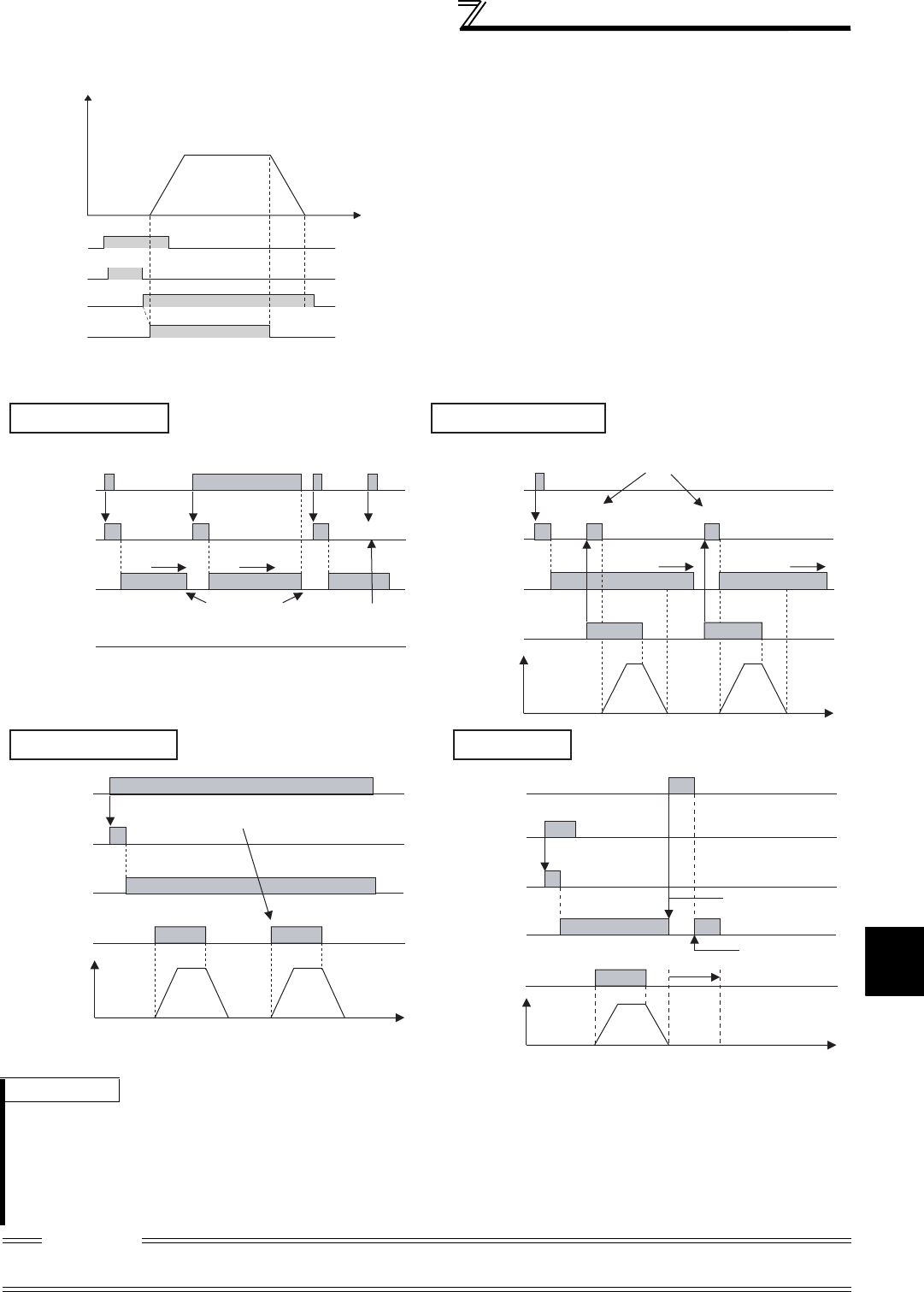
4
PARAMETERS
201
Selection and protection of a motor
(3) Start-time online auto tuning from external terminal (X28 signal, Y39 signal)
· By turning ON the start-time tuning signal (X28) before the
start signal (STF or STR) turns ON (at a stop), online tuning
is performed and a starting delay after start signal turns ON
due to tuning can be avoided.
· Perform offline auto tuning and set "1" (start-time tuning) in
Pr. 95.
· When the start-time tuning completion signal (Y39) is OFF,
start-time tuning with the X28 signal is performed.
· Start-time tuning ends within 500ms maximum.
· When using the X28 signal, set "28" in Pr. 178 to Pr. 189
(input terminal function selection) and assign functions to the
input terminal.
· When using the Y39 signal, set "39 (positive logic) or 139
(negative logic)" in Pr. 190 to Pr. 196 (output terminal function
selection) and assign functions to the output terminal.
REMARKS
· Start-time tuning is performed when the start signal is turned ON during zero speed control also.
· The Y39 signal is in ON status while secondary magnetic flux exists after the motor stop.
· While the Y39 signal is ON, the X28 signal is not valid.
· The STF, STR signals are valid after completion of the start-time tuning.
· The following output terminals (initial value) are valid during online auto tuning:
IPF, A1B1C1
· Tuning is invalid during V/F control.
CAUTION
· Changing the terminal assignment using Pr. 178 to Pr. 189 (input terminal function selection) or Pr. 190 to Pr. 196 (output terminal
function selection) may affect the other functions. Set parameters after confirming the function of each terminal.
Time
X28signal
Tuning status
at starting
Y39signal
Start signal
Tune
Completed
ON
(Hz)
Output frequency
X28 Signal
Tuning status
at starting
Y39 signal
Start signal
Output
frequency
OFF
OFF
OFF
OFF
OFF
OFF
OFF
OFF
OFF
ON
Tune
Completed
Completed
ON
Tune
CompletedCompleted
ON
Secondary magnetic
flux exists
a few seconds
Secondary magnetic
flux exists
a few seconds
Secondary magnetic
flux exists
Secondary magnetic
flux exists
a few seconds
Secondary magnetic
flux exists
a few seconds
ON
0Hz
0Hz
ON
Tune
ON
Tune
ON
Tune
ON
ON
Tune
Completed Completed
Tune
Completed
Completed
ON
ON
Tune
Y39 signal is OFF when the motor is stopped
and X28 is turned OFF. However if the
secondary magnetic flux exists after motor stop,
the signal remains ON.
Tuning is not
performed if the
Y39 signal is ON.
Tuning is performed at start when X28 signal is OFF
(even when Y39 is ON).
Tuning is not performed at start since X28 signal
and Y39 signal is ON.
Time
Time
X28 Signal
Tuning status
at starting
Y39 signal
Start signal
Output frequency
X28 Signal
Tuning status
at starting
Y39 signal
Start signal
Switching motor
Start
signal
Output
frequency
OFF
0Hz
Time
Y39 signal
OFF
OFF
ON
X28 signal
Tuning status
at starting
Motor
switching
RT signal
ON
First motor
Second motor
First motor
ON
Y39 turns OFF when the
driven motor is switched
to the second motor
Y39 turns ON due
to the residual second
magnetic flux at the
first motor.
ON
a few seconds
While the X28 signal is OFFWhile the motor is stopped
While the X28 signal is ON
202
Selection and protection of a motor
(4) Tune second applied motor
· When you want to switch two motors with one inverter, set the second motor in Pr. 450 Second applied motor.(Initial
setting is without second applied motor. (Refer to page 187))
Perform tuning using Pr. 574 Second motor online auto tuning.
Pr. 574 Second motor online auto tuning is valid when the RT signal turns ON.
Parameter
Number Description
51 Used as rated motor current and electronic thermal relay
parameters.
450 Applied motor
453 Motor capacity (down to one rank lower than the inverter
capacity, note that the capacity should be 0.4kW or higher)
454 Number of motor poles
REMARKS
· The RT signal acts as the second function selection signal and makes the other second functions valid. (Refer to page 235.)
The RT signal is assigned to the terminal RT in the initial setting. By setting "3" in any of Pr. 178 to Pr. 189 (input terminal function
selection), you can assign the RT signal to the other terminal.
CAUTION
· Changing the terminal assignment using Pr. 178 to Pr. 189 (input terminal function selection) may affect the other functions. Set
parameters after confirming the function of each terminal.
♦ Parameters referred to ♦
Pr. 9 Electronic thermal O/L relay Refer to page 183
Pr. 71 Applied motor Refer to page 187
Pr. 80 Motor capacity Refer to page 92
Pr. 81 Number of motor poles Refer to page 92
Pr. 96 Auto tuning setting/status Refer to page 189
Pr. 178 to Pr. 189 (input terminal function selection) Refer to page 231
Pr. 190 to Pr .196 (output terminal function selection) Refer to page 239
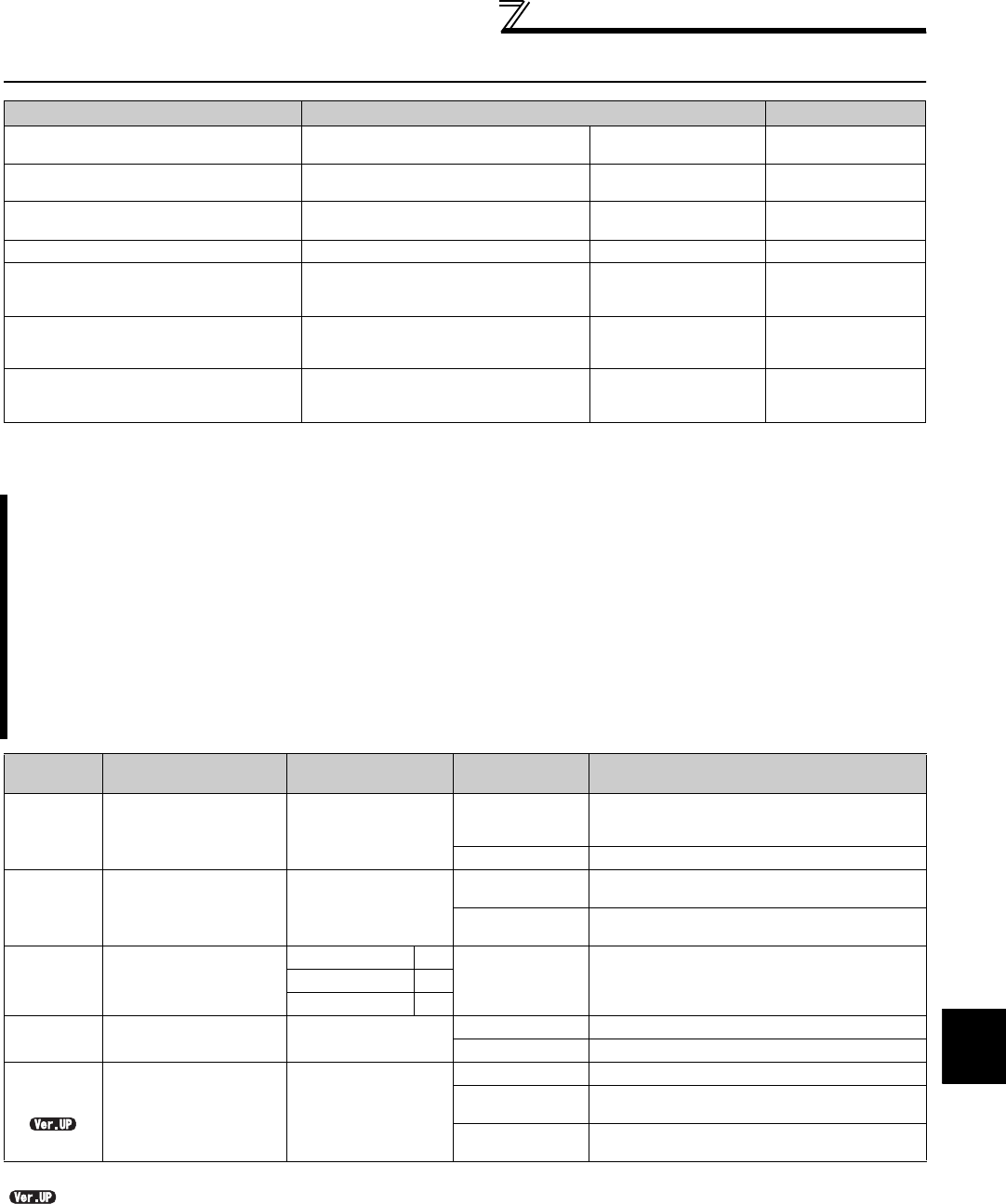
203
Motor brake and stop operation
4
PARAMETERS
4.14 Motor brake and stop operation
4.14.1 DC injection brake and zero speed control, servo lock (LX signal, X13 signal,
Pr. 10 to Pr. 12, Pr. 802, Pr. 850)
* This parameter can be set when the FR-A7AP/FR-A7AL (option) is mounted.
............Specifications differ according to the date assembled. Refer to page 484 to check the SERIAL number.
Purpose Parameter that must be Set Refer to Page
Motor braking torque adjustment DC injection brake and zero speed
control, servo lock
Pr. 10 to Pr. 12,
Pr. 802, Pr. 850 203
Improve the motor braking torque
with an option Selection of a regenerative brake Pr. 30, Pr. 70 207
Performing operation by DC current
input DC current feeding mode Pr. 30 207
Coast the motor to a stop Selection of motor stopping method Pr. 250 213
Used to stop the motor with a
mechanical brake (vibration restraint
at stop-on-contact)
Stop-on-contact control Pr. 270, Pr. 275,
Pr. 276 214
Used to stop the motor with a
mechanical brake (operation timing
of a mechanical brake)
Brake sequence function Pr. 278 to Pr. 285,
Pr. 292 217
Perform position stop (orientation)
control of the rotation shaft Orientation control
Pr. 350 to Pr. 366,
Pr. 369, Pr. 393,
Pr. 396 to Pr. 399
220
The DC injection brake can be operated at a motor stop to adjust the stop timing and braking torque.
Zero speed control can be selected during Real sensorless vector control and either zero speed control or
servo lock can be selected under vector control.
In DC injection brake operation, DC voltage is directly applied to the motor to prevent the motor shaft from
rotating when a motor decelerates to stop. While, in zero speed control, vector control is performed to maintain
0r/min. In either control, the motor will not return to the original position if the motor shaft rotates due to
external force.
The motor shaft position is maintained with servo lock. The motor will return to the original position if the motor
shaft rotates due to external force.
Select the magnetic flux decay output shutoff function to decay the magnetic flux before shutting off the output
at a stop.
Parameter
Number Name Initial Value Setting Range Description
10 DC injection brake
operation frequency 3Hz 0 to 120Hz
Set the operation frequency of the DC
injection brake (zero speed control, servo
lock).
9999 Operated at Pr. 13 or less.
11 DC injection brake
operation time 0.5s
0DC injection brake (zero speed control)
disabled
0.1 to 10s Set the operation time of the DC injection
brake (zero speed control, servo lock).
12 DC injection brake
operation voltage
7.5K or lower 4%
0 to 30% Set the DC injection brake voltage (torque).
When "0" is set, DC injection brake is disabled.
11K to 55K 2%
75K or higher 1%
802 * Pre-excitation
selection 00 Zero speed control
1Servo lock
850 Brake operation
selection 0
0 DC injection brake operation
1Zero speed control (during Real sensorless
vector control)
2Magnetic flux decay output shutoff (during
Real sensorless vector control)

204
Motor brake and stop operation
(3) Operation voltage (torque) setting (Pr. 12)
⋅Use Pr. 12 to set the percentage to the power supply voltage. (This parameter is not used during zero speed control
or servo lock.)
⋅When Pr. 12 = "0%", the DC injection brake is not operated. (At a stop, the motor coasts.)
⋅When using the constant-torque motor (SF-JRCA) and energy saving motor (SF-HR, SF-HRCA), change the Pr. 12
setting as follows.
SF-JRCA: 3.7K or lower ...4%, 5.5K to 55K...2%
SF-HR, SF-HRCA: 3.7K or lower...4%, 5.5K and 7.5K...3%, 11K to 55K...2%
(30K...1.5%)
(4) Brake operation selection during Real sensorless vector control (Pr. 850 = "0, 1")
⋅You can select DC injection brake (initial value) or zero speed control for brake operation during Real sensorless
vector control.
When Pr. 850 = "1", zero speed control is exercised when the frequency reaches or decreases below the frequency
set in Pr. 10.
When Pr. 11 = "0.1 to 10s"
When Pr. 11 = "8888"
(1) Operation frequency setting (Pr. 10)
⋅When the frequency at which the DC injection brake (zero speed control,
servo lock) operates is set in Pr. 10, the DC injection brake (zero speed
control, servo lock) is operated when this frequency is reached during
deceleration.
⋅At the Pr. 10 setting of "9999", the DC injection brake (zero speed control,
servo lock) is operated when deceleration is made to the frequency set in
Pr. 13 Starting frequency.
(2) Operation time setting (X13 signal, Pr. 11)
⋅Use Pr. 11 to set the duration period the DC injection brake (zero speed
control, servo lock) is applied.
⋅When the motor does not stop due to large load moment (J), increasing the
setting produces an effect.
⋅When Pr. 11 = "0s", the DC injection brake (zero speed control, servo lock)
is not operated. (At a stop, the motor coasts.)
⋅When Pr. 11 = "8888", the DC injection brake (zero speed control, servo
lock) is applied when X13 signal is turned ON.
⋅For the terminal used for X13 signal input, set "13" in any of Pr. 178 to Pr.
189 to assign the function. (Refer to page 231)
REMARKS
⋅For the 5.5K and 7.5K, when the Pr. 12 setting is as below, changing the Pr. 71 Applied motor setting changes the Pr. 12 setting
automatically, it is not necessary to change the Pr. 12 setting.
(a) When Pr. 12 is 4% (initial value)
The Pr. 12 setting is automatically changed to 2% if the Pr. 71 value is changed from the value selecting the standard motor
(0, 2 to 8, 20, 23, 24, 40, 43, 44) to the value selecting the constant torque motor (1, 13 to 18, 50, 53, 54).
(b) When Pr. 12 is 2%
The Pr. 12 setting is automatically changed to 4% (initial value) if the Pr. 71 value is changed from the value selecting the
constant torque motor (1, 13 to 18, 50, 53, 54) to the value selecting the standard motor (0, 2 to 8, 20, 23, 24, 40, 43, 44).
⋅Even if the Pr.12 setting is increased, braking torque is limited so that the output current is within the rated inverter current.
REMARKS
⋅When the X13 signal is ON with Pr. 11 = "8888", zero speed control is activated regardless of setting of Pr. 850 Brake operation
selection.
⋅When restarting from brake operation during Real sensorless vector control, set "1" (zero speed control) in Pr. 850. When the
setting value is "0" (DC injection brake), it may take approx. 2s until frequency is actually output from when the start command
is input.
Time
Pr. 10 Operation
frequency
Time
Pr.12
Operation
voltage
voltage
Pr. 11 Operation time
Output frequency (Hz)
DC injection
brake
Pr. 12
OFFON
STF ON
X13 signal
Output frequency
(Hz)
DC injection
brake
voltage ON
Time
Time
REMARKS
⋅Performing pre-excitation (zero speed control) under Real sensorless vector
may cause motor vibration, etc. at deceleration to stop. To prevent this, set
Pr.10 DC injection brake operation frequency to 0.5Hz or less.
⋅
The initial value of
Pr. 10
automatically changes to 0.5Hz during vector control.
REMARKS
⋅When the X13 signal is turned ON with Pr. 11 = "8888", zero speed control is
activated regardless of setting of Pr. 850 Brake operation selection.
⋅Under vector control, zero speed control or servo lock is activated depending
on the Pr. 802 setting.
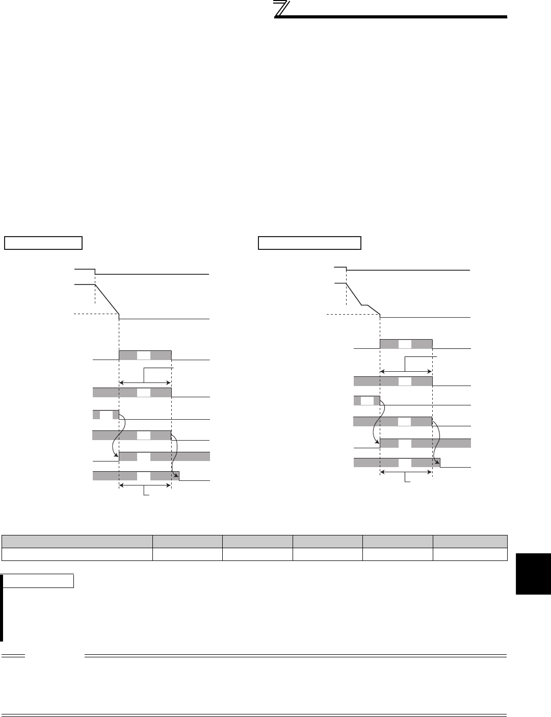
205
Motor brake and stop operation
4
PARAMETERS
(5) Magnetic flux decay output shutoff (Pr. 850 = "2")
⋅Frequent starts/stops (inching) under Real sensorless vector control may cause an inverter failure or create a
difference in operation with the motor. The reason is that some magnetic flux is left in the motor at shutoff of the
inverter output. If this is the case, set Pr. 850 ="2" to select the magnetic flux decay output shutoff, and decay the
magnetic flux before shutting off the output at a stop.
⋅Turning OFF the start command decelerates the speed. Then, when an estimated speed is lower than Pr. 10 DC
injection brake operation frequency, inverter starts the magnetic flux decay output shutoff function.
⋅When using brake sequence, the inverter starts the magnetic flux decay output shutoff function at 0.5Hz or Pr. 13
Starting frequency (whichever is lower) during deceleration.
⋅During magnetic flux decay output shutoff, the torque decreases. Set a mechanical brake to be activated during
magnetic flux decay output shutoff.
⋅When the MC is provided on the inverter output side, open the MC after magnetic flux decay processing time (refer
to the following) has passed.
⋅The magnetic flux decay output shutoff function is stopped at restart or when tuning ON the Pre-excitation signal
(LX)/External DC injection brake operation start signal (X13).
Inverter output voltage shutoff timing
* The maximum time for magnetic flux decaying
Motor capacity (Pr. 80 setting) 2.2kW or lower 3.7kW to 11kW 15kW to 30kW 37kW to 55kW 75kW or higher
Magnetic flux decay processing time 250ms 500ms 800ms 900ms 1100ms
REMARKS
⋅When some other factor affecting output shutoff (such as inverter fault or MRS signal ON) occurs during the magnetic flux
decay output shutoff function, the magnetic flux decay output shutoff function is immediately stopped and shuts off the output.
⋅Regardless of the Pr. 850 setting, turning ON the X74 (magnetic flux decay output shutoff signal) starts the magnetic flux decay
output shutoff. To operate the magnetic flux decay output shutoff function by turning ON the X74 signal, set "74" in any of Pr. 178
to Pr. 189 (input terminal function selection) to assign the function. (Refer to page 231)
CAUTION
⋅Voltage is output during magnetic flux decay processing. Take caution to avoid an electrical shock.
⋅If the timing of mechanical brake opening is early, motor shaft may be forced to turn by a gravity drop or external force. If the
timing of mechanical brake opening is late, overcurrent, stall prevention operation or electronic thermal relay function may be
activated. Use output frequency detection signal (FU) or output current detection signal (Y12) to perform the mechanical brake
opening suitable for the machine.
RY2 ON
RUN
ON
ON
ON
ON
ON
Start command
(STF, STR)
Pr. 10 DC injection
brake operation
f
requency
Mechanical brake
MC on the output side
Output voltage
Speed command
(rotation per
second)
Magnetic flux decay
processing time*
Magnetic flux decaying
Do not turn OFF MC
during this period
Normal operation
RY2 ON
RUN ON
ON
ON
ON
ON
Start command
(STF, STR)
Mechanical brake
MC on the output side
Output voltage
Speed command
(rotation per
minute)
Magnetic flux
decay
processing time*
Magnetic flux decaying
Do not turn OFF MC
during this period
Pr. 13 Starting
frequency or 0.5Hz
(whichever is lower)
During brake sequence
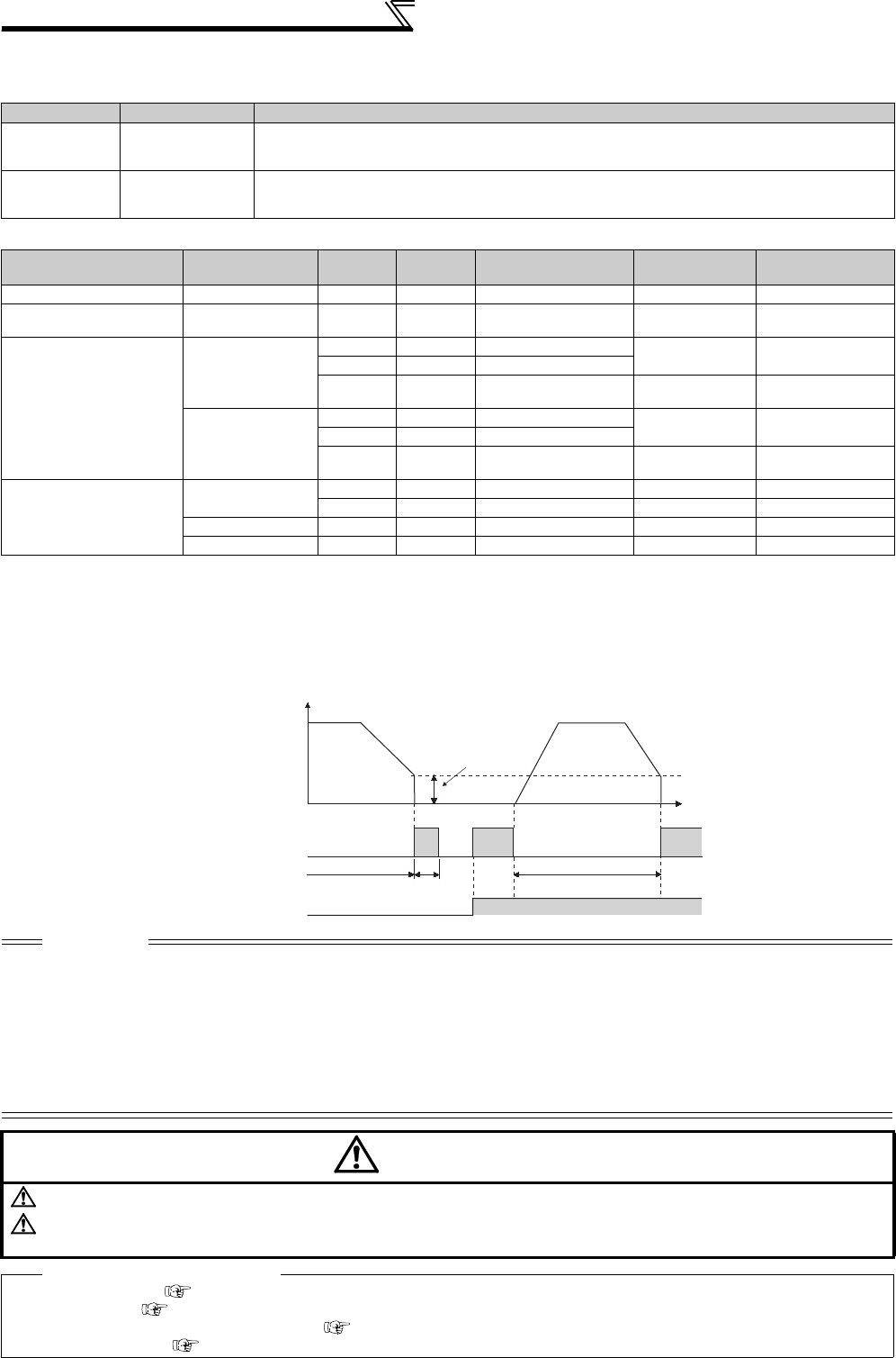
206
Motor brake and stop operation
(6) Brake operation selection under vector control (Pr. 802)
⋅When pre-excitation is performed, select zero speed control or servo lock using Pr. 802.
⋅The relationship between the DC injection brake operation and pre-excitation operation under each control
(7) Pre-excitation signal (LX signal)
⋅When the LX signal is turned ON under Real sensorless vector control or vector control, pre-excitation (zero speed
control or servo lock) is exercised during a stop.
⋅For the terminal used for LX signal input, set "23" in any of Pr. 178 to Pr. 186 to assign the function.
Pr. 802 Setting Pre-excitation Description
0 (initial value) Zero speed control
Even under load, an attempt is made to maintain 0r/min to keep the motor shaft stopped. Note that
if the shaft is overcome and turned by external force, it does not return to the original position.
Position control is not exercised and only speed control is carried out to perform operation.
1 Servo lock
Even under load, an attempt is made to maintain the motor shaft position. Note that if the shaft is
turned by external force, it returns to the original position after the external force has gone away.
Since position control is exercised, you can adjust this position loop gain using
Pr. 422 Position loop gain
.
Control Method Control Mode Pr. 802 Pr. 850 Decelerates to Stop LX-ON X13-ON
(Pr. 11 = "8888")
V/F control ⎯⎯⎯DC Injection brake ⎯DC Injection brake
Advanced magnetic flux
vector control ⎯⎯⎯DC Injection brake ⎯DC Injection brake
Real sensorless vector
control
Speed
⎯0 DC Injection brake Zero speed Zero speed
⎯1 Zero speed
⎯2Magnetic flux decay
output shutoff Zero speed Zero speed
Torque
⎯0 DC Injection brake Zero speed Zero speed
⎯1 Zero speed
⎯2Magnetic flux decay
output shutoff Zero speed Zero speed
Vector control
Speed 0⎯Zero speed Zero speed Zero speed
1⎯Servo lock Servo lock Servo lock
Torque ⎯⎯ Zero speed Zero speed Zero speed
Position ⎯⎯ ⎯ Servo lock ⎯
CAUTION
⋅Changing the terminal assignment using Pr. 178 to Pr. 189 (input terminal function selection) may affect the other functions. Set
parameters after confirming the function of each terminal.
⋅Performing pre-excitation (LX signal and X13 signal) under torque control (Real sensorless vector control) may start the motor
running at a low speed even when the start command (STF or STR) is not input.The motor may run also at a low speed when
the speed limit value=0 with a start command input. Perform pre-excitation after making sure that there will be no problem in
safety if the motor runs.
⋅Although FWD/REV of the operation panel is not lit during pre-excitation, note that voltage is applied to the motor.
⋅Note that when offline auto tuning (Pr. 96 Auto tuning setting/status = "1 or 101") is performed during pre-excitation, offline auto
tuning is not executed but the motor starts.
CAUTION
Do not set
Pr. 11
to "0, 8888" and
Pr. 12
to "0" under orientation operation. Otherwise, the motor will not stop properly.
As stop holding torque is not produced, install a mechanical brake.
After the machine stops fully and the mechanical brake is applied, switch the LX signal (pre-excitation) OFF.
♦ Parameters referred to ♦
Pr. 13 Starting frequency Refer to page 175
Pr. 71 Applied motor Refer to page 187
Pr. 178 to Pr. 189 (Input terminal function selection) Refer to page 231
Pr. 422 Position loop gain Refer to page 141
Operation
frequency
Time
Pr. 10
Zero speed control
Servo lock
When Pr. 850 = 1
Operation time ON
Normal operation
Normal operation Pr. 11
(Hz)
Output frequency
LX signal

207
Motor brake and stop operation
4
PARAMETERS
4.14.2 Selection of regenerative brake and DC feeding (Pr. 30, Pr. 70)
*1 Used in combination with GZG, GRZG, or FR-BR.
*2 Used in combination with MT-BR5
<55K or lower>
When making frequent starts/stops, use the optional high-duty brake resistor (FR-ABR), brake unit (FR-BU2,
BU, FR-BU, MT-BU5) to increase the regenerative brake duty.
Use a power regeneration common converter (FR-CV) or power regeneration converter (MT-RC) for continuous
operation in regenerative status.
Use a high power factor converter (FR-HC, MT-HC) to reduce harmonics, improve the power factor, or
continuously use the regenerative mode.
You can select either DC feeding mode 1 in which operation is performed with DC power (terminal P/+, N/-) or
DC feeding mode 2 in which operation is performed normally with the AC power (terminal R/L1, S/L2, T/L3) and
performed with DC power such as battery at occurrence of power failure.
Parameter
Number Name Initial
Value Setting Range Description
30 Regenerative function
selection 0
Regeneration unit
Terminal for power
supply to the inverter
0Built-in brake resistor, inverter
without regenerative function,
brake unit (FR-BU2 *1, FR-BU,
BU type)
R/L1, S/L2, T/L3
10 P/+, N/-
(DC feeding mode 1)
20 R/L1, S/L2, T/L3 - P/+, N/-
(DC feeding mode 2)
1High-duty brake resistor, brake
unit (FR-BU2 *2, MT-BU5),
power regeneration converter
(MT-RC)
R/L1, S/L2, T/L3
11 P/+, N/-
(DC feeding mode 1)
21 R/L1, S/L2, T/L3 - P/+, N/-
(DC feeding mode 2)
2
High power factor converter
(FR-HC, MT-HC), power
regeneration common
converter (FR-CV)
P/+, N/-
70 Special regenerative
brake duty 0%
55K or
lower 0 to 30%
Set the %ED of the built-in brake transistor operation.
75K or
higher 0 to 10%
Regeneration Unit Power Supply to
the Inverter
Pr. 30
Setting
Pr. 70
Setting Remarks
Built-in brake (7.5K or lower)
,
brake unit (FR-BU2 *1, FR-BU, BU)
R/L1, S/L2, T/L3 0
(initial value)
⎯
The regenerative brake duty is as follows.
⋅FR-A720-0.4K to 3.7K . . . . . 3%
⋅FR-A720-5.5K, 7.5K . . . . . . . 2%
⋅FR-A740-0.4K to 7.5K . . . . . 2%
⋅Other than the above . . . . . . 0%
(without built-in brake resistor)
P/+, N/- 10
R/L1, S/L2, T/L3 -
P/+, N/- 20
High-duty brake resistor (FR-ABR)
(22K or lower)
R/L1, S/L2, T/L3 1
10/6%
Change the setting according to the
capacity.
(7.5K or lower / 11K or higher)
P/+, N/- 11
R/L1, S/L2, T/L3 -
P/+, N/- 21
High power factor converter (FR-HC),
power regeneration common
converter (FR-CV)
P/+, N/- 2 0
(initial value)
⎯

208
Motor brake and stop operation
<75K or higher>
*1 Used in combination with GZG, GRZG, or FR-BR.
*2 Used in combination with MT-BR5.
(1) When the built-in brake resistor, the brake unit (FR-BU2, BU, FR-BU) is used
⋅Set Pr. 30 = "0 (initial value), 10, or 20" for the built-in brake resistor operation, the FR-BU2 operation with GZG/
GRZG/FR-BR, or the BU/FR-BU operation. The Pr.70 setting becomes invalid.
At this time, the regenerative brake duty is as follows. (The built-in brake resistor is provided for the 7.5K or lower.)
⋅FR-A720-0.4K to 3.7K ............3%
⋅FR-A720-5.5K, 7.5K ...............2%
⋅FR-A740-0.4K to 7.5K ............2%
⋅Other than the above..............0% (without built-in brake resistor)
(2) When using the high-duty brake resistor (FR-ABR) (22K or lower)
⋅Set "1, 11 or 21" in Pr. 30.
⋅Set Pr. 70 as follows.
7.5K or lower.......................... 10%
11K or higher ........................... 6%
(3) When the FR-BU2 brake unit is used (in combination with MT-BR5) (75K or higher)
⋅Set the following parameter to use FR-BU2 with MT-BR5.
Set "1, 11, or 21" in Pr. 30.
Set "0% (initial value)" in Pr. 70.
Set Pr. 0 Brake mode selection = "2" in the brake unit FR-BU2.
Regeneration Unit Power Supply to the
Inverter
Pr. 30
Setting
Pr. 70
Setting
Without regenerative function
R/L1, S/L2, T/L3 0
(initial value)
⎯
P/+, N/- 10
R/L1, S/L2, T/L3 - P/+, N/- 20
Brake unit (FR-BU2 *2)
R/L1, S/L2, T/L3 1 0%
(initial value)
P/+, N/- 11
R/L1, S/L2, T/L3 - P/+, N/- 21
Power regeneration converter (MT-RC) R/L1, S/L2, T/L3 1 0%
(initial value)
Brake unit (MT-BU5)
R/L1, S/L2, T/L3 1
10%P/+, N/- 11
R/L1, S/L2, T/L3 - P/+, N/- 21
High power factor converter (FR-HC) P/+, N/- 2 ⎯
CAUTION
⋅Do not operate the MT-BU5 type brake unit and FR-BU2 in parallel. Doing so could cause an alarm or brake unit failure. Use
the FR-BU2 only when performing parallel operation.
REMARKS
⋅The stall prevention (overvoltage), oL, does not occur while Pr. 30 Regenerative function selection = "1, 11, or 21"
(4) When using a brake unit (MT-BU5) and power regeneration converter (MT-RC)
⋅Set "1, 11 or 21" in Pr. 30.
⋅Set "10%" in Pr. 70 when using a brake unit (MT-BU5).
Set "0%" in Pr. 70 when using a power regeneration converter (MT-RC).
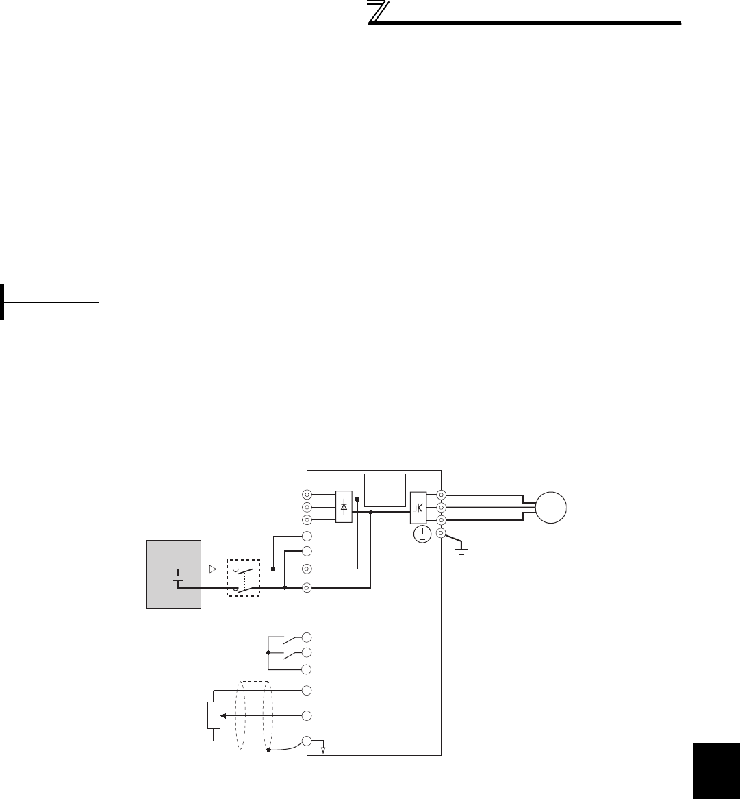
209
Motor brake and stop operation
4
PARAMETERS
(5) When using the high power factor converter (FR-HC, MT-HC) or power regeneration
common converter (FR-CV)
⋅Set "2" in Pr. 30. The Pr. 70 setting is invalid.
⋅Use any of Pr. 178 to Pr. 189 (input terminal function assignment) to assign the following signals to the contact input
terminals.
(a)X10 signal: FR-HC, MT-HC connection, FR-CV connection (inverter operation enable signal)
To make protective coordination with the FR-HC, MT-HC or FR-CV, use the inverter operation enable signal
to shut off the inverter output. Input the RDY signal of the FR-HC, MT-HC (RDYB signal of the FR-CV).
(b)X11 signal: FR-HC, MT-HC connection (instantaneous power failure detection signal)
When the setting has been made to hold the mode at occurrence of an instantaneous power failure for RS-
485 communication operation, use this signal to hold the mode. Input the Y1 or Y2 signal (instantaneous
power failure detection signal) of the FR-HC, MT-HC.
⋅For the terminal used for X10 or X11 signal input, assign its function by setting "10" (X10) or "11" (X11) in any of Pr.
178 to Pr. 189.
(6) DC feeding mode 1 (Pr. 30 = "10, 11")
⋅Setting "10, 11" in Pr. 30 enables DC power supply operation.
⋅Leave the AC power supply connection terminal R/L1, S/L2, and T/L3 open and connect the DC power supply to
terminal P/+ and N/-. Also, remove jumpers across terminal R/L1 and R1/L11 as well as S/L2 and S1/L21, and
connect terminals R1/L11 and S1/L21 to terminal P/+ and N/-.
⋅The diagram below is a connection example.
REMARKS
⋅Setting Pr. 30 = "2" will reset the inverter, and "Err" is displayed on the operation panel during the reset.
R/L1
S/L2
T/L3
U
V
W
P/+
N/-
IM
STF
STR
R1/L11
S1/L21
10
2
2
3
15
(+)
(-)
MC
Inrush
current
limit circuit
DC power
Forward rotation start
Reverse rotation start
Contact input common
Frequency command
Frequency setting
potentiometer
1/2W1kΩ
Earth
(Ground)
Inverter
SD
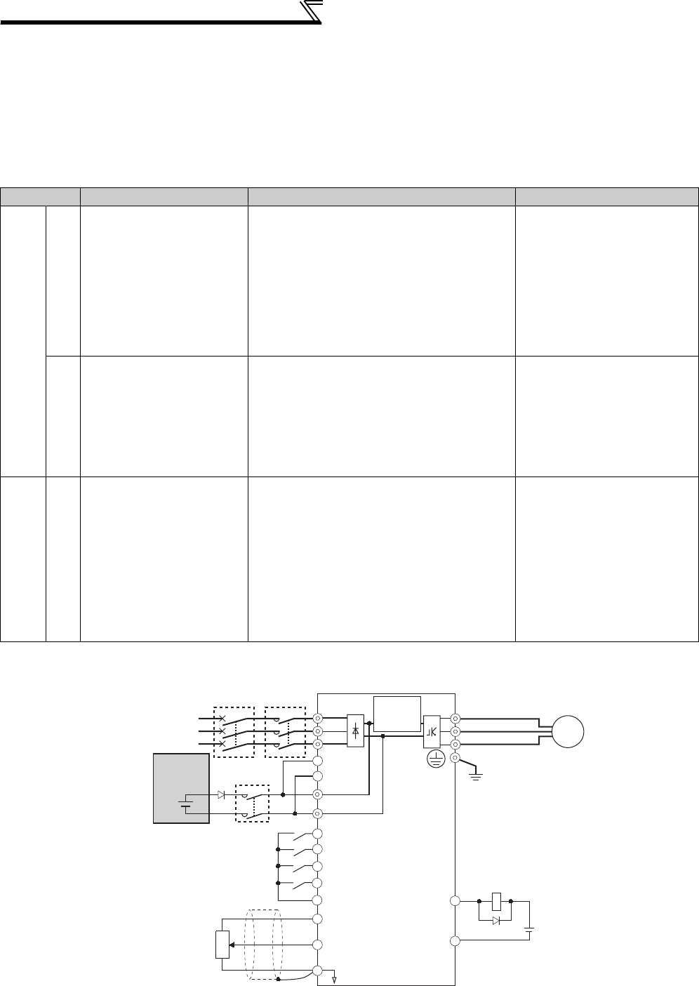
210
Motor brake and stop operation
(7) DC feeding mode 2 (Pr. 30 = "20, 21")
⋅When "20 or 21" is set in Pr. 30, operation is performed with AC power supply normally and with DC power supply
such as battery at power failure.
⋅Connect the AC power supply to terminal R/L1, S/L2, and T/L3 and connect the DC power supply to terminal P/+
and N/-. Also, remove jumpers across terminal R/L1 and R1/L11 as well as S/L2 and S1/L21, and connect
terminals R1/L11 and S1/L21 to terminal P/+ and N/-.
⋅Turning ON the DC feeding operation permission signal (X70) enables DC power supply operation. Refer to the
table below for I/O signals.
⋅The following shows the connection diagram when switching to a DC power using inverter power failure detection.
*1 Assign the function using Pr. 178 to Pr. 189 (input terminal function selection).
*2 Assign the function using Pr. 190 to Pr. 196 (output terminal function selection).
signal Name Description Parameter Setting
Input
X70 DC feeding operation
permission signal
When performing operation with DC feeding, turn
ON the X70 signal.
When the inverter output is shut off because of
power failure, the inverter starts about 150ms
after switching ON X70 signal. (When automatic
restart operation is valid, the inverter starts after
additional Pr. 57 set time has elapsed.)
When the X70 signal turns OFF during inverter
operation, output is shutoff (Pr .261 = 0) or the
inverter is decelerated to a stop (Pr. 261 ≠ 0).
Set 70 in any of Pr. 178 to Pr. 189.
X71 DC feeding cancel signal
Turn this signal ON to stop DC feeding.
When the X71 signal is turned ON during inverter
operation with turning ON the X70 signal, output
is shutoff (Pr. 261 = 0) or the inverter is
decelerated to a stop (Pr. 261 ≠ 0), then the X85
signal turns OFF after the inverter stop.
After turning ON the X71 signal, operation cannot
be performed even if the X70 signal is turned ON.
Set 71 in any of Pr. 178 to Pr. 189.
Output Y85 DC feeding signal
This signal turns ON during power failure or under
voltage of AC power.
The signal turns OFF when the X71 signal turns
ON or power is restored.
The Y85 signal does not turn OFF during inverter
operation even if the power is restored and turns
OFF after an inverter stop.
When the Y85 signal turns ON because of
undervoltage, the Y85 signal does not turn OFF
even if undervoltage is eliminated.
ON/OFF status is retained at an inverter reset.
Set "85 (positive logic) or 185
(negative logic)" in any of Pr. 190
to Pr. 196
DC power
MCCB MC
R/L1
S/L2
T/L3
U
V
W
P/+
N/-
SE
Y85
IM
STF
STR
X70
X71
SD
R1/L11
S1/L21 Earth
(Ground)
10
2
2
3
15
(+)
(-)
*1
MC1
MC1
Three-phase AC
power supply
DC feeding permission signal
DC feeding cancel signal
Contact input common
Reverse rotation start
Forward rotation start
*1
*2
Inverter
Inrush
current
limit circuit
Frequency command
Frequency setting
potentiometer
1/2W1kΩ
24VDC
DC feeding signal
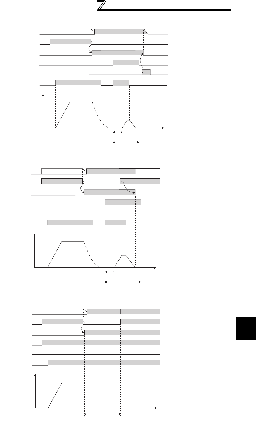
211
Motor brake and stop operation
4
PARAMETERS
⋅Operation example 1 at power failure
⋅Operation example 2 at power failure (when DC power is restored)
⋅Operation example 3 at power failure (when continuous operation is performed)
Time
ON ON
Back up operation
Motor
coasting
Approx. 150ms
STF(STR)
DC power supplyAC power supply
ON
AC power supply
ON
Y85(MC)
ON
X70
ON
X71
Control power
supply
Output
frequency
(Hz)
Time
ON ON
Back up operation
Motor
coasting
Approx. 150ms
Output
frequency
(Hz)
STF(STR)
DCAC AC
Control power
supply
ON Power restoration
A
C power supply
ON
Y85(MC)
ON
OFF
X70
X71
Turns off after
stop while running
Time
ON
Back up operation
Output
frequency
(Hz)
STF(STR)
DCAC AC
Control power
supply
ON Power restoration
A
C power supply
ON
Y85(MC)
ON
OFF
X70
X71
Remains on while running

212
Motor brake and stop operation
(8) Power supply specification at DC feeding
(9) Regenerative brake duty alarm output and alarm signal (RBP signal)
200V class Rated input DC voltage 283VDC to 339VDC
Permissible fluctuation 240VDC to 373VDC
400V class Rated input DC voltage 537VDC to 679VDC
Permissible fluctuation 457VDC to 740VDC
CAUTION
⋅As voltage between P/+, N/- becomes 415V (830V) or more temporarily at regeneration, make selection of DC power supply
carefully.
100%: regenerative overvoltage protection operation value
⋅[RB] appears on the operation panel and an alarm signal
(RBP) is output when 85% of the regenerative brake duty
set in Pr. 70 is reached. If the regenerative brake duty
reaches 100% of the Pr. 70 setting, a regenerative
overvoltage (E.OV1 to E.OV3) occurs.
⋅The inverter does not trip when the alarm signal is output.
⋅For the terminal used for the RBP signal output, assign the
function by setting "7" (positive logic) or "107" (negative
logic) in any of Pr. 190 to Pr. 196 (output terminal function
selection).
REMARKS
⋅The MRS signal can also be used instead of the X10 signal. (Refer to page 234.)
⋅Refer to pages 44 to 48 for the connection of high-duty brake resistor (FR-ABR), brake unit, high power factor converter (FR-HC,
MT-HC) and power regeneration common converter (FR-CV).
⋅When AC power is connected to terminal R/L1, S/L2, T/L3 during DC feeding with "2, 10 or 11" (DC feeding) set in Pr. 30, an
option fault (E.OPT) occurs.
⋅When DC feeding operation is performed with "2, 10, 11, 20, or 21" (DC feeding) set in Pr. 30, undervoltage protection (E.UVT)
and instantaneous power failure (E.IPF) are not detected.
CAUTION
⋅Changing the terminal assignment using Pr. 178 to Pr. 189 (input terminal function selection) or Pr. 190 to Pr. 196 (output terminal
function selection) may affect the other functions. Set parameters after confirming the function of each terminal. (Refer to page 231)
WARNING
The value set in Pr. 70 must not exceed the setting of the brake resistor used.
Otherwise, the resistor can overheat.
♦ Parameters referred to ♦
Pr. 57 Restart coasting time Refer to page 266
Pr. 178 to Pr.189 (input terminal function selection) Refer to page 231
Pr. 190 to Pr.196 (output terminal function selection) Refer to page 239
Pr. 261 Power failure stop selection Refer to page 270
Ratio of brake duty
to the Pr. 70 setting
Regenerative
brake pre-alarm
(RBP) OFF ON
100%
85%
Time
ON
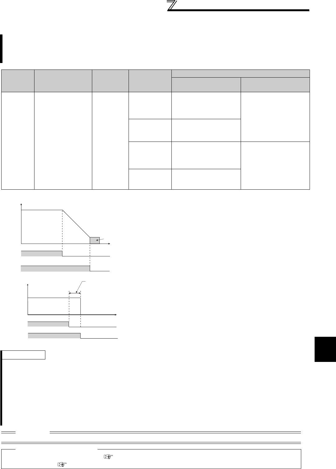
213
Motor brake and stop operation
4
PARAMETERS
4.14.3 Stop selection (Pr. 250)
Use this function to select the stopping method (deceleration to a stop or coasting) when the start signal turns
OFF. Use this function to stop the motor with a mechanical brake, etc. together with switching OFF of the start
signal.
You can also select the operations of the start signals (STF/STR). (Refer to page 236 for start signal selection)
Parameter
Number Name Initial Value Setting Range
Description
Start signal (STF/STR)
(Refer to page 236) Stop operation
250 Stop selection 9999
0 to 100s
STF signal: Forward
rotation start
STR signal: Reverse
rotation start
The motor is coasted to a
stop when the preset time
elapses after the start
signal is turned OFF.The
motor is coasted to a stop
(Pr. 250 - 1000)s after the
start signal is turned OFF.
1000s to 1100s
STF signal: Start signal
STR signal: Forward/
reverse signal
9999
STF signal: Forward
rotation start
STR signal: Reverse
rotation start
When the start signal is
turned OFF, the motor
decelerates to stop.
8888
STF signal: Start signal
STR signal: Forward/
reverse signal
(1) Decelerate the motor to a stop
⋅Set Pr. 250 to "9999" (initial value) or "8888".
⋅The motor decelerates to a stop when the start
signal (STF/STR) turns OFF.
(2) Coast the motor to a stop
⋅Use Pr. 250 to set the time from when the start signal
turns OFF until the output is shut off. When any of
"1000" to "1100" is set, the output is shut off after
(Pr. 250 − 1000)s.
⋅The output is shut off when the time set in Pr. 250
has elapsed after the start signal had turned OFF.
The motor coasts to a stop.
⋅The RUN signal turns OFF when the output stops.
REMARKS
Stop selection is invalid when the following functions are activated.
⋅Position control (Pr. 419 = 0)
⋅Power failure stop function (Pr. 261)
⋅PU stop (Pr. 75)
⋅Deceleration stop because of fault definition (Pr. 875)
⋅Deceleration stop because of communication error (Pr. 502)
⋅Offline auto tuning (with motor running)
⋅Emergency stop by LONWORKS communication
When setting of Pr. 250 is not 9999 nor 8888, acceleration/deceleration is performed according to the frequency command, until
start signal is OFF and output is shutoff.
CAUTION
⋅When the start signal is turned ON again during motor coasting, the motor starts at Pr. 13 Starting frequency.
♦ Parameters referred to ♦
Pr. 7 Acceleration time , Pr. 8 Deceleration time Refer to page 172
Pr. 13 Starting frequency Refer to page 175
Time
ON OFF
Start
signal
Deceleration starts
when start signal turns OFF
Deceleration time
(Time set in Pr. 8, etc.)
DC brake
Output frequency
(Hz)
ON OFF
RUN
signal
OFF
ON
Start signal
Output is shut off when set
time elapses after start signal
turns OFF
Pr.250
Motor coasts to stop
Time
O
FF
RUN signal
Output frequency
(Hz)
ON
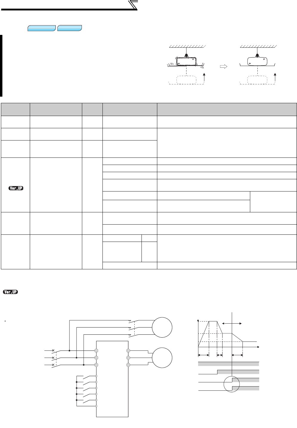
214
Motor brake and stop operation
4.14.4 Stop-on contact control function (Pr. 6, Pr. 48, Pr. 270, Pr. 275, Pr. 276)
*1 This parameter allows its setting to be changed during operation in any operation mode even if "0 (initial value) or 1" is set in Pr. 77 Parameter write
selection.
*2 This parameter allows its setting to be changed during operation even if "0" (initial value) is set in Pr. 77 Parameter write selection.
.............Specifications differ according to the date assembled. Refer to page 484 to check the SERIAL number.
<Connection and operation example>
To ensure accurate positioning at the upper limit etc. of
a lift, stop-on-contact control causes a mechanical
brake to be closed while the motor is developing a
holding torque to keep the load in contact with a
mechanical stopper etc.
This function suppresses vibration which is liable to
occur when the load is stopped upon contact in vertical
motion applications, ensuring steady precise
positioning.
Parameter
Number Name Initial
Value Setting Range Description
6Multi-speed setting
(low speed) 10Hz 0 to 400Hz Set the output frequency for stop-on-contact control.
22 *1 Stall prevention
operation level 150% 0 to 400% Set the stall prevention operation level for stop-on-contact
control.
The smaller value set in either Pr. 22 or Pr. 48 has a priority.
48
Second stall
prevention
operation current
150% 0 to 220%
270 Stop-on contact/
load torque high-
speed frequency
control selection
0
0 Normal operation
1 Stop-on-contact control
2 Load torque high speed frequency control (Refer to page 374)
3Stop-on-contact+load torque high speed frequency control
(Refer to page 374)
11 Stop-on-contact control E.OLT invalid under
stop-on-contact
control
13 Stop-on-contact+load torque high speed
frequency control (Refer to page 374)
275 *2
Stop-on contact
excitation current
low-speed
multiplying factor
9999
0 to 1000% Set the force (holding torque) for stop-on-contact control.
Normally set 130% to 180%.
9999 No compensation.
276
PWM carrier
frequency at stop-
on contact
9999
55K or lower 0 to 9 Set a PWM carrier frequency for stop-on-contact control.
For Real sensorless vector control, carrier frequency is
always 2Hz when a setting value is 0 to 5 and always 6Hz
when a setting value is 6 to 9. (Valid at the frequency of 3Hz
or less.)
75K or higher 0 to 4
9999 As set in Pr. 72 PWM frequency selection .
Magnetic flux
Magnetic flux
Magnetic flux
Sensorless
Sensorless
Sensorless
<Without stop-on-contact control>
Vibration Complete stop
Lift Lift
<With stop-on-contact control>
Power
supply
Forward rotation command
High-speed operation command
Middle-speed operation command
Stop-on contact selection 0
Stop-on contact selection 1
MCCB
R/L1
S/L2
T/L3
STF
RH *
RM *
RL *
RT *
U
V
W
MC
Mechanical
brake
Motor
* The input terminal used differs according to the Pr. 180 to Pr. 189 settings.
SD
Sink logic
(a) (b) (c)
Time
Pr. 4
RH
RM
RL
RT
Pr. 5
Pr. 6
Output frequency
0
Normal mode Stop-on contact
control mode
(a):Acceleration time (Pr. 7 )
(b):Deceleration time (Pr. 8 )
(c):Second deceleration time (Pr. 44/Pr. 45 )
*
ONOFF
ONOFF
ONOFF
ON
Goes into stop-on-contact control mode when
both RL and RT switch on.
*RL and RT may be switched on in any order
with any time difference

215
Motor brake and stop operation
4
PARAMETERS
(1) Set stop-on-contact control
⋅Make sure that the inverter is in External operation mode. (Refer to page 313 )
⋅Select either Real sensorless vector control or Advanced magnetic flux vector control.
⋅Set "1, 3, 11 or 13" in Pr. 270 Stop-on contact/load torque high-speed frequency control selection .
⋅Set output frequency during stop-on-contact control in Pr. 6 Multi-speed setting (low speed).
The frequency should be as low as possible (about 2Hz). If it is set to more than 30Hz, the operating frequency will
be 30Hz.
⋅When both the RT and RL signals are switched ON, the inverter enters the stop-on-contact mode, in which operation
is performed at the frequency set in Pr. 6 independently of the preceding speed.
⋅Setting Pr. 270 = "11 or 13" disables E.OLT (stall prevention stop) during stop-on-contact control (with both RL and RT
signals ON).
⋅To input the RT signal, set "3" in any of Pr.178 to Pr.184 (Input terminal function selection) to assign the function to the
terminal. To input the RL signal, set "0" in any of Pr.178 to Pr.184 (Input terminal function selection) to assign the function
to the terminal.
(2) Function switching of stop-on-contact control selection
* When RL and RT are ON, Pr. 49 Second stall prevention operation frequency is invalid.
CAUTION
⋅By increasing the Pr. 275 setting, the low-speed (stop-on-contact) torque increases, but overcurrent fault (E.OCT) may occur or
the machine may oscillate in a stop-on-contact state.
⋅The stop-on-contact function is different from servo-lock function, and if used to stop or hold a load for an extended period, this
function can cause the motor to overheat.
After a stop, immediately reset this function and use a mechanical brake to hold the load.
⋅Under the following operating conditions, the stop-on-contact function is invalid:
PU operation (Pr. 79) · JOG operation (JOG signal) · PU+external operation (Pr. 79) · PID control function operation (Pr. 128)
· Remote setting function operation (Pr. 59) · Automatic acceleration/deceleration (Pr. 292) · Start time tuning · Orientation
control function operation
⋅When performing stop-on-contact control during encoder feedback control, encoder feedback control is invalid due to a mode
shift to the stop-on-contact control mode.
Useful Functions
Normal Operation
(either RL or RT is OFF or both are off)
With Stop-on-Contact Control
(both RL and RT are on)
Real sensorless
vector control
Advanced
magnetic flux vector
control
Real sensorless
vector control
Advanced
magnetic flux vector
control
Output frequency
Multi-speed
0 to 5V, 0 to 10V
4 to 20mA etc.
Pr. 6 setting
Stall prevention operation level ⎯Pr. 22 setting ⎯The smaller value set
in either Pr. 22 or Pr. 48.
*
Torque limit level Pr. 22 setting ⎯Pr. 22 setting ⎯
Excitation current low speed
scaling factor ⎯⎯
The current is
compensated for by Pr.
275 (0 to 1000%)
settings from normal
operation.
Carrier frequency Pr. 72 setting Pr. 276 setting when output frequency is 3Hz or
less (Pr. 72 when Pr. 276 = "9999")
Fast response current limit ⎯Valid ⎯Invalid
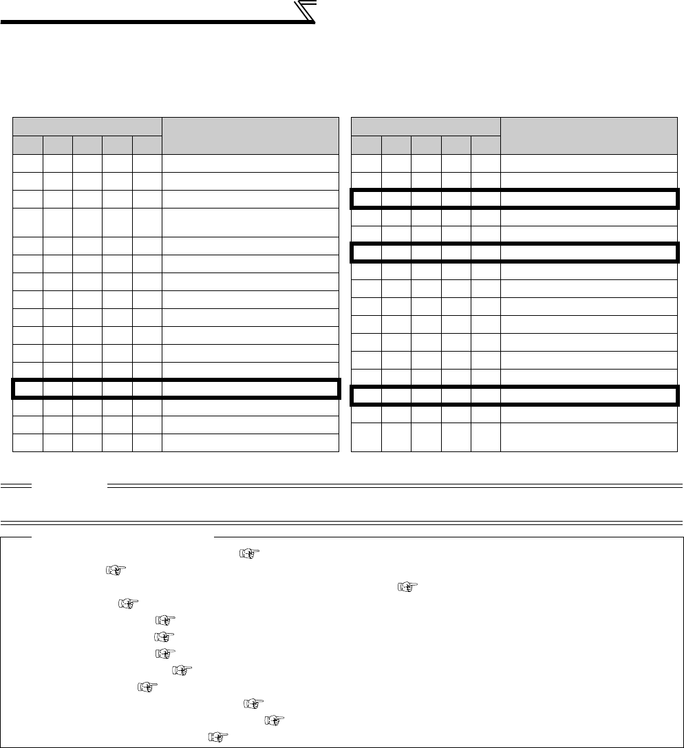
216
Motor brake and stop operation
(3) Set frequency when stop-on-contact control (Pr. 270 = 1, 3, 11 or 13) is selected
⋅The following table lists the frequencies set when the input terminals (RH, RM, RL, RT, JOG) are selected together.
Bold frame indicates stop-on-contact control is valid.
⋅Stop-on-contact control is disabled when remote setting function is selected (Pr. 59 = 1 to 3).
CAUTION
⋅Changing the terminal assignment using Pr. 178 to Pr. 189 (input terminal function selection) may affect the other functions. Set
parameters after confirming the function of each terminal.
♦ Parameters referred to ♦
Pr. 4 to Pr. 6, Pr. 24 to Pr. 27 (multi-speed setting) Refer to page 165
Pr. 15 Jog frequency Refer to page 167
Pr. 22 Stall prevention operation level, Pr. 48 Second stall prevention operation current Refer to page 152
Pr. 22 Torque limit level Refer to page 100
Pr. 59 Remote function selection Refer to page 169
Pr. 72 PWM frequency selection Refer to page 284
Pr. 79 Operation mode selection Refer to page 313
Pr. 95 Online auto tuning selection Refer to page 199
Pr. 128 PID action selection Refer to page 361
Pr. 178 to Pr. 189 (input terminal function selection) Refer to page 231
Pr. 270 = 2, 3 (load torque high speed frequency control) Refer to page 374
Pr. 292 Automatic acceleration/deceleration Refer to page 163, 180
Input signal (
= on) Set Frequency
RH RM RL RT
JOG
Pr. 4
Multi-speed setting (high speed)
Pr. 5
Multi-speed setting (middle speed)
Pr. 6 Multi-speed setting (low speed)
By 0 to 5V(0 to 10V), 4 to 20mA
input
Pr. 15 Jog frequency
Pr. 26 Multi-speed setting (speed 6)
Pr. 25 Multi-speed setting (speed 5)
Pr. 4 Multi-speed setting (high speed)
Pr. 15 Jog frequency
Pr. 24 Multi-speed setting (speed 4)
Pr. 5
Multi-speed setting (middle speed)
Pr. 15 Jog frequency
Pr. 6 Multi-speed setting (low speed)
Pr. 15 Jog frequency
Pr. 15 Jog frequency
Pr. 15 Jog frequency
Pr. 15 Jog frequency
Pr. 15 Jog frequency
Pr. 6 Multi-speed setting (low speed)
Pr. 15 Jog frequency
Pr. 15 Jog frequency
Pr. 6 Multi-speed setting (low speed)
Pr. 15 Jog frequency
Pr. 26 Multi-speed setting (speed 6)
Pr. 27 Multi-speed setting (speed 7)
Pr. 15 Jog frequency
Pr. 15 Jog frequency
Pr. 15 Jog frequency
Pr. 15 Jog frequency
Pr. 6 Multi-speed setting (low speed)
Pr. 15 Jog frequency
By 0 to 5V(0 to 10V), 4 to 20mA
input
Input signal (
= on) Set Frequency
RH RM RL RT
JOG
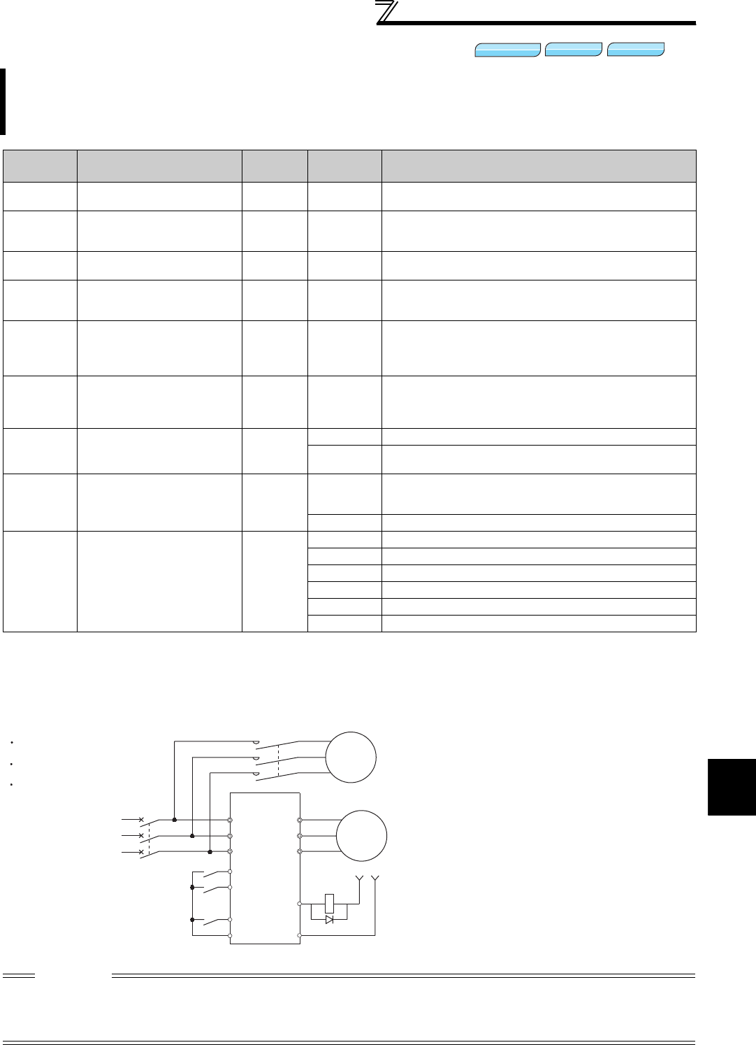
217
Motor brake and stop operation
4
PARAMETERS
4.14.5 Brake sequence function (Pr. 278 to Pr. 285, Pr. 292)
*1 When exercising vector control with the FR-A7AP/FR-A7AL (option), this parameter changes to excessive speed deviation detection frequency
(For details, refer to page 117)
<Connection diagram>
This function is used to output from the inverter the mechanical brake operation timing signal in vertical lift and
other applications.
This function prevents the load from dropping with gravity at a start due to the operation timing error of the
mechanical brake or an overcurrent alarm from occurring at a stop, ensuring secure operation.
Parameter
Number Name
Initial
Value
Setting
Range
Description
278 Brake opening frequency 3Hz
0 to 30Hz
Set to the rated slip frequency of the motor + about 1.0Hz.
This parameter may be only set if Pr. 278 ≤ Pr. 282.
279 Brake opening current 130%
0 to 220%
Generally, set this parameter to about 50 to 90%. If the setting
is too low, the load is liable to drop due to gravity at start.
Suppose that the rated inverter current is 100%.
280
Brake opening current
detection time
0.3s 0 to 2s Generally, set this parameter to about 0.1 to 0.3s.
281 Brake operation time at start 0.3s 0 to 5s
Set the mechanical delay time until the brake is loosened.
Set the mechanical delay time until the brake is loosened +
about 0.1 to 0.2s when Pr. 292 = "8".
282 Brake operation frequency 6Hz
0 to 30Hz
Set the frequency to activate the mechanical brake by turning
OFF the brake opening request signal (BOF). Generally, set
this parameter to the Pr. 278 setting + 3 to 4Hz.
Setting is enabled only when Pr. 282 ≥ Pr. 278.
283 Brake operation time at stop 0.3s 0 to 5s
Set the mechanical delay time until the brake is closed + 0.1s
when Pr. 292=7.
Set the mechanical delay time until the brake is closed + 0.2
to 0.3s when Pr. 292 = 8.
284 Deceleration detection
function selection 0
0 Deceleration is not detected.
1If deceleration is not normal during deceleration operation,
the inverter fault is provided.
285 Overspeed detection
frequency *1 9999
0 to 30Hz
If (detected frequency) - (output frequency) ≥ Pr. 285 during
encoder feedback control, the inverter fault (E.MB1) is
provided.
9999 Overspeed is not detected.
292 Automatic acceleration/
deceleration 0
0 Normal operation mode
1, 11 Shortest acceleration/deceleration mode (Refer to page 180)
3 Optimum acceleration/deceleration mode (Refer to page 181)
5, 6 Elevator mode 1, 2 (Refer to page 163)
7 Brake sequence mode 1
8 Brake sequence mode 2
CAUTION
⋅When brake sequence mode is selected, automatic restart after instantaneous power failure is invalid.
⋅When using this function, set the acceleration time to 1s or longer.
⋅Changing the terminal assignment using Pr. 178 to Pr. 189 (input terminal function selection) or Pr. 190 to Pr. 196 (output terminal
function selection) may affect the other functions. Set parameters after confirming the function of each terminal.
Magnetic flux
Magnetic flux
Magnetic flux
Sensorless
Sensorless
Sensorless Vector
Vector
Vector
Mechanical
brake
R/L1
S/L2
T/L3
Motor
MC
STF
RH
AU(BRI) *1
SD
MC
24VDC
Brake opening request
signal (BOF)
Start signal
Multi-speed signal
Brake opening completion signal
(BRI)
Sink logic
Pr.184 = 15
Pr.190 = 20
Power
supply
U
V
W
RUN(BOF)
SE
*2 *3
MCCB
*1 The input signal terminal used differs
according to the Pr. 178 to Pr. 189
settings.
*2 The output signal terminal used differs
according to the Pr. 190 to Pr. 19
6
settings.
*3 The current should be within the
permissible current of transistor in the
inverter. (24V 0.1ADC)
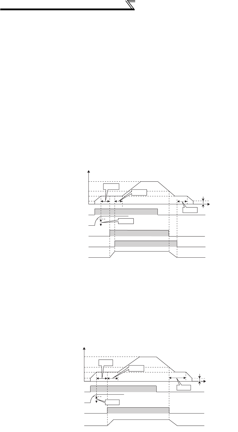
218
Motor brake and stop operation
(1) Set the brake sequence mode
⋅Select either Real sensorless vector control, vector control (speed control) or Advanced magnetic flux vector control.
The brake sequence function is valid only when the External operation mode, External/PU combined operation mode
1 or Network operation mode is selected.
⋅
Set "7 or 8" (brake sequence mode) in Pr. 292 .
To ensure more complete sequence control, it is recommended to set "7" (brake opening completion signal input) in
Pr. 292 .
⋅Set "15" in any of Pr. 178 to Pr. 189 (input terminal function selection) and assign the brake opening completion signal
(BRI) to the input terminal.
⋅Set "20 (positive logic)" or "120 (negative logic)" in any of Pr. 190 to Pr. 196 (output terminal function selection) and
assign the brake opening request signal (BOF) to the output terminal.
(2) With brake opening completion signal input
(Pr. 292
= "7")
⋅When the start signal is input to the inverter, the inverter starts running. When the internal speed command reaches
the value set in Pr. 278 and the output current is not less than the value set in Pr. 279 , the inverter outputs the brake
opening request signal (BOF) after the time set in Pr. 280 has elapsed.
When the time set in Pr. 281 elapses after the brake opening completion signal (BRI) was activated, the inverter
increases the output frequency to the set speed.
⋅When the inverter decelerates to the frequency set in Pr.282 during deceleration, the inverter turns OFF the BOF
signal and decelerates further to the frequency set in Pr.278. After electromagnetic brake operation completes and
inverter recognizes the turn OFF of BRI signal, the inverter holds the frequency set in Pr.278 for the time set in
Pr.283. And after the time set in Pr.283 passes, the inverter decelerates again. The inverter finally stops when its
frequency reaches to Pr.13 Starting frequency setting or 0.5Hz, whichever is lower.
(3) Without brake opening completion signal input
(Pr. 292
= "8")
⋅
When the start signal is input to the inverter, the inverter starts running. When the internal speed command reaches
the value set in Pr. 278 and the output current is not less than the value set in Pr. 279 , the inverter outputs the brake
opening request signal (BOF) after the time set in Pr. 280 has elapsed.
When the time set in Pr. 281 elapses after the BOF signal is output, the inverter increases the output frequency to the
set speed.
⋅When the inverter decelerates to the frequency set in Pr.282 during deceleration, the inverter turns OFF the BOF
signal and decelerates further to the frequency set in Pr.278. After the turn OFF of BOF signal, the inverter holds the
frequency set in Pr.278 for the time set in Pr.283. And after the time set in Pr.283 passes, the inverter decelerates
again. The inverter finally stops when its frequency reaches to Pr.13 Starting frequency setting or 0.5Hz, whichever is
lower.
STF ON
Output current
Brake opening request
(BOF signal)
ON
Electromagnetic brake
operation
Opened
Closed Closed
Time
Brake opening completion
(BRI signal)
ON
Pr.278
Pr.282
Target frequency
Pr.13
Pr.280
Pr.281
Output frequency(Hz)
Pr.283
Pr.279
Pr.13 setting
or 0.5Hz,
whichever is lowe
r
STF ON
ON
Pr.278
Pr.282
Target frequency
(Hz)
Pr.281
Pr.283
Pr.280
Pr.279
Pr.13
Output frequency
Brake opening request
(BOF signal)
Electromagnetic brake
operation
Closed Opened Closed
Time
Pr.13 setting
or 0.5Hz,
whichever is lowe
r
Output current

219
Motor brake and stop operation
4
PARAMETERS
(4) Protective functions
If any of the following errors occurs in the brake sequence mode, the inverter results in a fault, trips, and turns OFF the
brake opening request signal (BOF).
REMARKS
⋅Even if brake sequence mode has been selected, inputting the jog signal (jog operation), RT signal (second function selection)
or X9 signal (third function selection) during an inverter stop will switch to the normal operation and give priority to jog operation
or second and third function selection. Note that JOG and RT signal input is invalid even if JOG signal and RT signal are input
during automatic acceleration/deceleration operation.
Fault Display Description
E.MB1 (Detection frequency) - (output frequency) > Pr. 285 during encoder feedback control
When Pr. 285 Overspeed detection frequency = 9999, overspeed is not detected.
E.MB2 Deceleration is not normal during deceleration operation from the set frequency to the frequency set in
Pr. 282. (when Pr. 284 =1) (except stall prevention operation)
E.MB3 Brake opening request signal (BOF) turned ON though the motor is at a stop. (gravity drop prevention function)
E.MB4 Although more than 2s have elapsed after the start command (forward or reverse rotation) is input, the brake
opening request signal (BOF) does not turn ON.
E.MB5 Although more than 2s have elapsed after the brake opening request signal (BOF) turned ON, the brake opening
completion signal (BRI) does not turn ON.
E.MB6 Though the inverter had turned ON the brake opening request signal (BOF), the brake opening completion signal
(BRI) turned OFF midway.
E.MB7 Although more than 2s have elapsed after the brake opening request signal (BOF) turned OFF at a stop, the
brake opening completion signal (BRI) does not turn OFF.
CAUTION
⋅During deceleration, inverter output is shut OFF when the frequency reaches Pr.13 Starting frequency or 0.5Hz, whichever is lower.
For Pr. 278 Brake opening frequency, set Pr. 13 or a frequency equal to or higher than 0.5Hz.
⋅Overspeed detection (Pr. 285) is valid under encoder feedback control (used with the FR-A7AP/FR-A7AL (option)) even if a value
other than "7 or 8" is set in Pr. 292.
⋅Setting Pr. 278 Brake opening frequency too high activates the stall prevention and may cause E.MB4.
⋅If the sum of the time between Pr. 13 Starting frequency and Pr. 278
Brake opening frequency + Pr. 280 Brake opening current detection time
is more than 2s, E.MB4 occurs.
♦ Parameters referred to ♦
Pr. 80 Motor capacity, Pr. 81 Number of motor poles Refer to page 92
Pr. 180 to Pr. 186 (input terminal function selection) Refer to page 231
Pr. 190 to Pr. 195 (output terminal function selection) Refer to page 239
Pr. 800 Control method selection Refer to page 92
Encoder feedback control Refer to page 381
ON
Time
Output
frequency
(Hz)
Less than 2s
Output frequency (Hz)
Pr. 278
Pr. 13
Brake opening request
(BOF signal)
Pr. 280
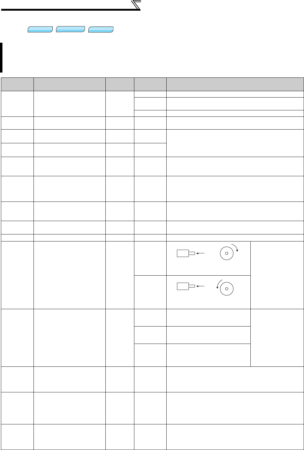
220
Motor brake and stop operation
4.14.6 Orientation control (Pr. 350 to Pr. 366, Pr. 369, Pr. 393, Pr. 396 to Pr. 399)
This function is used with a position detector (encoder) installed to the spindle of a machine tool, etc. to allow a
rotation shaft to be stopped at the specified position (oriented).
Option FR-A7AP/FR-A7AL is necessary.
Pr. 350 Stop position command selection is initially set to "9999", orientation control function is invalid.
Parameter
Number Name Initial
Value
Setting
Range Description
350 Stop position command
selection 9999
0 Internal stop position command (Pr. 356)
1External stop position command (FR-A7AX 16-bit digital
input)
9999 Orientation control invalid
351 Orientation speed 2Hz 0 to 30Hz Decrease the motor speed to the set value when the
orientation command (X22) is given.
352 Creep speed 0.5Hz 0 to 10Hz After the speed reaches the orientation speed, the speed
decreases to the creep speed set in Pr. 352 as soon as the
current position pulse reaches the creep switchover
position set in Pr. 353.
353 Creep switchover
position 511 0 to 16383*
354 Position loop switchover
position 96 0 to 8191
As soon as the current position pulse reaches the set
position loop switchover position, control is changed to
position loop.
355 DC injection brake start
position 5 0 to 255
After changed to position loop, DC injection brake is
applied and the motor stops as soon as the current
position pulse reaches the set DC injection brake start
position.
356 Internal stop position
command 0 0 to 16383*
When "0" is set in Pr. 350, the internal position command is
activated and the setting value of Pr. 356 becomes a stop
position.
357 Orientation in-position
zone 5 0 to 255 Set the in-position zone at a stop of the orientation.
358 Servo torque selection 1 0 to 13 Functions at orientation complete can be selected.
359 Encoder rotation
direction 1
0
Set the rotation
direction according
to the motor
specification.
1
360 16-bit data selection 0
0 Speed command
When 1 is set in Pr.
350 and the FR-
A7AX is mounted,
set a stop position
using 16-bit data.
Stop position
command is input as
binary regardless of
the Pr. 304 setting.
116 bit data is used as external
position command as is.
2 to 127
Set the stop position dividing up to
128 stop positions at regular
intervals.
361 Position shift 0 0 to 16383*
Shift the origin using a compensation value without
changing the origin of the encoder. The stop position is a
position obtained by adding the setting value of Pr. 361 to
the position command.
362 Orientation position loop
gain 1 0.1 to 100
When servo torque function is selected using Pr. 358,
output frequency for generating servo torque increases to
the creep speed of Pr. 352 gradually according to the slope
set in Pr. 362. Although the operation becomes faster
when the value is increased, a machine may hunt, etc.
363 Completion signal output
delay time 0.5s 0 to 5.0s
The orientation complete signal is output delaying the set
time after in-position zone is entered. Also, the signal
turns OFF delaying the set time after in-position zone is
out.
V/F
V/F
V/F
Magnetic flux
Magnetic flux
Magnetic flux
Vector
Vector
Vector
A
Encoder
CW
Clockwise direction as viewed
from A is forward rotation
CCW
A
Encoder
Counter clockwise direction as
viewed from A is forward rotation

221
Motor brake and stop operation
4
PARAMETERS
364 Encoder stop check time 0.5s 0 to 5.0s
Orientation fault signal (ORM) is output when the encoder
remains stopped for the set time without orientation
complete in the state where no orientation complete signal
(ORA) is output. ORM signal is output when orientation is
not completed again in the set time in the state where
ORA signal is output.
365 Orientation limit 9999 0 to 60.0s
Measure the time taken after passing the creep
switchover position and output the orientation fault signal
(ORM) if orientation is not completed within the set time.
9999 Set to 120s.
366 Recheck time 9999 0 to 5.0s
Turning OFF the start signal with orientation command
(X22) ON after stopping the motor by orientation control,
the present position is checked again after the set time
elapses and the orientation complete signal (ORA) or
orientation fault signal (ORM) is output.
9999 Not checked.
369 Number of encoder
pulses 1024 0 to 4096 Set the number of pulses of the encoder.
Set the number of pulses before multiplied by four.
393 Orientation selection 0
0 Orientation is executed from the current rotation direction.
1 Orientation is executed from the forward rotation direction.
2 Orientation is executed from the reverse rotation direction.
396 Orientation speed gain (P
term) 60 0 to 1000 Response level during position control loop (servo rigidity)
at orientation stop can be adjusted.
397 Orientation speed
integral time 0.333 0 to 20.0s
398 Orientation speed gain (D
term) 1 0 to 100.0 Lag/advance compensation gain can be adjusted.
399 Orientation deceleration
ratio 20 0 to 1000 Make adjustment when the motor runs back at orientation
stop or the orientation time is long.
The above parameters can be set when the FR-A7AP/FR-A7AL (option) is mounted.
* When the operation panel (FR-DU07) is used, the maximum setting is 9999. When a parameter unit is used, up to the maximum value within
the setting range can be set.
Parameter
Number Name Initial
Value
Setting
Range Description
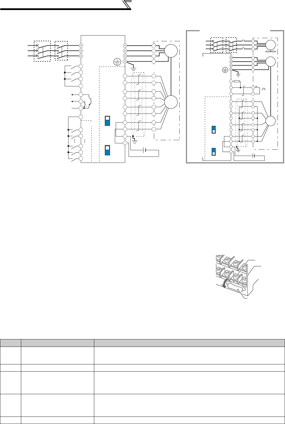
222
Motor brake and stop operation
(1) Connection example
*1 The pin number differs according to the encoder used.
*2 Use Pr. 178 to Pr. 189 (input terminal function selection) to assign the function to any of terminal. (Refer to page 231.)
*3 Use Pr. 190 to Pr. 196 (output terminal function selection) to assign the function to any of terminal. (Refer to page 239.)
*4 Connect the encoder so that there is no looseness between the motor and motor shaft. Speed ratio should be 1:1.
*5 Earth (Ground) the shielded cable of the encoder cable to the enclosure with a P clip, etc. (Refer to page 38.)
*6 For the differential line driver, set the terminating resistor selection switch to ON position (initial status) to use. (Refer to page 34.)
Note that the terminating resistor switch should be set to OFF position when sharing the same encoder with other unit (NC, etc) or a terminating
resistor is connected to other unit.
For the complementary, set the switch to OFF position.
*7 For terminal compatibility of the FR-JCBL, FR-V7CBL and FR-A7AP, refer to page 36.
*8 A separate power supply of 5V/12V/15V/24V is necessary according to the encoder power specification. Make the voltage of the external power
supply the same as the encoder output voltage, and connect the external power supply between PG and SD.
When performing encoder feedback control and vector control together, an encoder and power supply can be shared.
*9 When a stop position command is input from outside, a plug-in option FR-A7AX is necessary. Refer to page 223 for external stop position
command.)
*10 For the fan of the 7.5kW or lower dedicated motor, the power supply is single phase. (200V/50Hz, 200 to 230V/60Hz)
*11 Assign OH (external thermal input) signal to the terminal CS. (Set "7" in Pr. 186 )
Connect a 2W1kΩ resistor between the terminal PC and CS(OH).
Install the resistor pushing it against the bottom part of the terminal block so as to avoid a contact with
other cables.
<Setting>
If the orientation command signal (X22) is turned ON during operation after the various
parameters have been set, the speed will decelerate to the "orientation switchover speed". After the "orientation stop
distance" is calculated, the speed will further decelerate, and the "orientation state" (servo lock) will be entered. The
"orientation complete signal" (ORA) will be output when the "orientation complete width" is entered.
(2) Setting I/O signals
Signal Signal Name Application Explanation
X22*1 Orientation command input
Used to enter an orientation signal for orientation.
For the terminal used for X22 signal input, set "22" in any of Pr. 178 to Pr. 189 to assign
the function.
SD Contact input common Common terminal for the orientation signal.
ORA*2 Orientation complete signal
output
Switched low if the orientation has stopped within the in-position zone while the start
and orientation signals are input.
For the terminal used for the ORA signal output, assign the function by setting "27
(positive logic) or 127 (negative logic)" in any of Pr. 190 to Pr. 196.
ORM*2 Orientation fault signal output
Switched low if the orientation has not stopped within the in-position zone while the
start and orientation signals are input.
For the terminal used for the ORM signal output, assign the function by setting "28
(positive logic) or 128 (negative logic)" in any of Pr. 190 to Pr. 196.
SE Open collector output common Common terminal for the ORA and ORM open collector output terminals.
*1 For X22 signals, assign functions to any of terminal using Pr. 178 to Pr. 189 (output terminal function selection). (Refer to page 231)
*2 For ORA and ORM signals, assign functions to any of terminal using Pr. 190 to Pr. 196 (output terminal function selection). (Refer to page 239)
SF-V5RU
U
V
W
U
A
B
C
V
W
E
G1
G2
Earth (Ground)
2W1kΩ
Three-phase
AC power
supply
MCCB MC
IM
FAN
External
thermal relay
input *11
Thermal
relay
protector
*10
CS(OH)
SD
PC
OCR
Inverter
For complementary type (SF-V5RU)
Three-phase
AC power
supply
MCCB
R/L1
S/L2
T/L3
DY
SF-JR motor with encoder
U
V
W
U
V
W
E
C
*5
*1
*4
*9
*6
*7
*1
*4
*6 *7
X0
X1
X14
X15
R
PA1
FR-A7AP
PA2
PB1
PB2
PZ1
PZ2
PG
PG
SD
SD
Differential
Terminating
resistor ON
OFF
Complementary
A
N
B
P
H
K
IM
Differential
Terminating
resistor ON
OFF
Complementary
Forward rotation start
Reverse rotation start
Orientation command
Contact input common
STF
STR
SD
SD
X22*2
Encoder
Earth (Ground)
Inverter
ORM
ORA*3
SE
*3
FR-A7AX
A
*5
B
PA1
FR-A7AP
PA2
PB1
PB2
PZ1
PZ2
PG
PG
SD
SD
C
D
F
G
S
R
Encoder
5VDC power
supply*8
(+) (-)
12VDC power
supply *8
(+) (-)
MC
CS(OH)
Resistor (2W1kΩ)
PC
Control circuit
terminal block
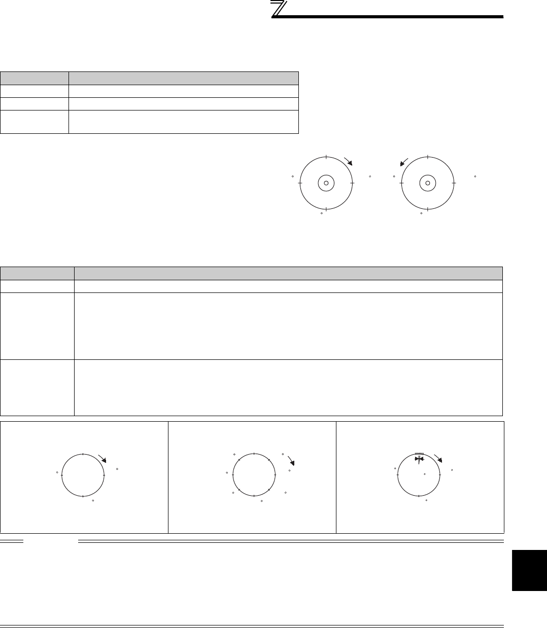
223
Motor brake and stop operation
4
PARAMETERS
(3) Selecting stop position command (Pr. 350 Stop position command selection )
⋅Select either the internal stop position command (Pr. 356) or the external stop position command (16-bit data using
the FR-A7AX).
2)External stop position command (Pr. 350 = "1")
Mount the option FR-A7AX and set a stop position using 16-bit data (binary input).
⋅ The value set in Pr. 360 16-bit data selection should be the number of stop positions less 1.
Pr. 350 Setting Stop Position Command Source
0 Internal stop position command (Pr. 356: 0 to 16383)
1 External stop position command (FR-A7AX) 16-bit data
9999
(Initial value) Orientation control invalid
1)Internal stop position command (Pr. 350 = "0")
The value set in Pr. 356 is the stop position.
When the number of encoder pulses is 1024p/r, one
revolution of the encoder is divided into 4096 positions,
i.e. 360°/4096 pulses = 0.0879°/pulses per address, as
shown on the right. The stop positions (addresses) are
indicated in parentheses.
Pr. 360 Setting Description
0 External position command is invalid (speed command or torque command with the FR-A7AX)
1
Position command direct input
The 16-bit digital signal from the FR-A7AX is directly serves as stop position command.
<Example>
When the Pr. 369 Number of encoder pulses setting is 1024, stop position command from 0 to 4095 can be
directly input using the FR-A7AX and input digital signal of 2048 (H800) to stop the motor at 180° position. The
command more than 4096 is considered as 4095.
2 to 127
Set the stop position command dividing up to 128 stop positions at regular intervals.
If the external stop command entered is greater than the setting, the stop positions are the same as those in
the maximum external stop command value.
<Example>
When the number of stop positions is 90 (divided at intervals of 4°), 90 - 1 = 89. Hence, set "89".
[Example] When Pr. 369 = "1024" [Example 2] 8 stop positions [Example 3] 120 stop positions
Pr. 360 = "1" Pr. 360 = "7" Pr. 360 = "119"
CAUTION
⋅Values in parentheses indicate binary data entered from the terminals. Even if the position pulse monitor (Pr. 52 DU/PU main
display data selection = 19) is selected, the data monitored is not the number of stop positions but is 0 to 65535 pulses.
⋅FR-A7AX parameters (Pr. 300 to Pr. 305) are invalid. (Valid when Pr. 360 = "0")
⋅Terminal DY (data read timing input signal) is invalid during vector control. (The position data is downloaded at the start of
orientation.)
⋅Internal stop position command is given even if "1" (external stop position command) is set in Pr. 350 when an option card (FR-
A7AX) is not mounted or Pr. 360 = "0".
Origin (0) Origin (0)
CW CCW
270
(3072)
90
(1024)
Pr. 359 = 1
270
(3072
)
180 (2048)
Pr. 359 = 1
180 (2048)
90
(1024)
270
(3072(HC00))
180
(2048(H800))
90
(1024(H400))
CW
Origin (0) Origin(0)
(7 or more)
315
(6)270
(5)225
(1)
45
135
(3)
180
(4)
90
(2)
CW
Origin (0) CW
At intervals
of 3
270
(90)
180
(60)
90
(30)

224
Motor brake and stop operation
• Relationship between stop position command and 16-bit data
3) Pr. 361 Position shift (initial value "0")
The stop position is a position obtained by adding the setting value of Pr. 361 to the position command.
<Position shift function>
Shift the origin using a compensation value without changing the origin of the position detector (encoder).
(4) Monitor display change
(5) Pr. 357 Orientation in-position zone (initial value "5")
Pr. 350
Stop position
command selection
Pr. 360
16-bit data selection
Operation
Stop position command 16-bit data
(FR-A7AX) Speed command
0: internal
0: speed command Internal (Pr. 356) Speed command 16 bit data
1, 2 to 127: position
command Internal (Pr. 356) Invalid External command
(or PU)
1: external
0: speed command Internal (Pr. 356) Speed command 16 bit data
1, 2 to 127: position
command
External
(Internal when the FR-A7AX is not
mounted (Pr. 356))
Position command External command
(or PU)
REMARKS
• When orientation control is valid using Pr. 350 Stop position command selection with the FR-A7AP/FR-A7AL (option) mounted, the
rotation direction of encoder is displayed on the rotation direction display of the PU (FR-DU07/FR-PU04/FR-PU07).
Set the parameter so that turning ON the STF signal displays FWD or turning ON the STR signal displays REV.
Monitor REMARKS
Position pulse monitor When "19" is set in Pr. 52 , position pulse monitor is displayed instead of output voltage monitor
of the PU. (Displayed only when the FR-A7AP/FR-A7AL (option) is mounted.)
Orientation status*
When "22" is set in Pr. 52 , orientation status is displayed instead of output voltage monitor of
the PU. (Displayed only when the FR-A7AP/FR-A7AL (option) is mounted.)
0: Other than orientation operation or orientation speed is not reached
1: Orientation speed is reached
2: Creep speed is reached
3: Position loop is reached
4: Orientation complete
5: Orientation fault (pulse stop)
6: Orientation fault (orientation limit)
7: Orientation fault (recheck)
8: Continuous multi-point orientation
* Invalid during vector control. ("0" is always displayed )
• The positioning width for orientation stop can be set.
The initial value of Pr. 357 is "5". To change the Δθ
value, finely adjust with ±10 increments, and make
fine adjustment.
• If the position detection value from the encoder
enters ±Δθ during orientation stop, the orientation
complete signal (ORA) will be output.
Example of operation
Set
Pr.369
Number of encoder pulses
360 Pr. 35
7
four times
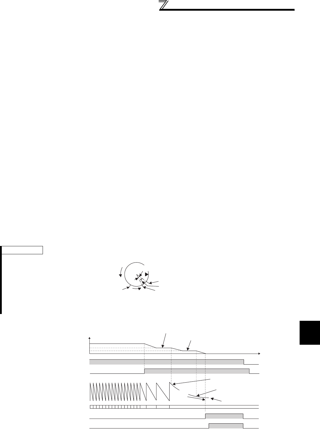
225
Motor brake and stop operation
4
PARAMETERS
(6) Orientation operation (under V/F control, Advanced magnetic flux vector control)
Orientation during running
1) When the orientation command (X22) is input, the motor speed decreases to the orientation speed set in Pr. 351
Orientation speed . (Pr. 351 initial value: 2Hz)
2) After the speed reaches the orientation speed, the speed decreases to the creep speed set in Pr. 352 Creep speed
as soon as the current position pulse reaches the creep switchover position set in Pr. 353 Creep switchover position
(Pr. 352 initial value:0.5Hz, Pr. 353 initial value: 511)
3) Moreover, as soon as the current position pulse reaches the set position loop switchover position in Pr. 354 Position
loop switchover position , control is changed to position loop. (Pr. 354 initial value: 96)
4) After switching to position loop, the inverter decelerates and stops with DC injection brake as soon as the current
position pulse has reached the DC injection brake start position set in Pr. 355 DC injection brake start position. (Pr. 355
initial value: 5)
5) When the position pulse has stopped within the in-position zone set in Pr. 357 Orientation in-position zone , the
orientation complete signal (ORA) is output after the completion signal output delay time set in Pr. 363 Completion
signal output delay time has elapsed. If the motor does not stop within the in-position zone due to external force, etc.,
the orientation complete signal is turned OFF after the time set in Pr. 363 Completion signal output delay time has
elapsed. (Pr. 357 initial value: 5)
6) If the orientation is not completed continuously for the time set in Pr. 365 Orientation limit after passing the creep
switchover position, the orientation fault signal (ORM) is output.
7) When the motor stops before the position pulse reaching the in-position zone due to external force after orientation
start and orientation complete signal (ORA) is not output, orientation fault signal (ORM) is output after the time set in
encoder stop check time set in Pr. 364 Encoder stop check time has elapsed. Moreover, the orientation complete signal
(ORA) is turned OFF after the time set in Pr. 363 Completion signal output delay time has elapsed if the position pulse
is outside the in-position zone due to external force, etc. after outputting the orientation complete signal (ORA), and
the orientation fault signal (ORM) is output if the orientation has not completed within the time set in Pr. 364 Encoder
stop check time .
8) When the start signal (STF or STR) is turned OFF with the orientation command ON after outputting the orientation
complete signal (ORA) and orientation fault signal (ORM), the orientation complete signal (ORM) or orientation fault
signal (ORM) is output again after recheck time set in Pr. 366 Recheck time has elapsed.
9) The orientation complete signal (ORA) and orientation fault signal (ORM) are not output when the orientation
command is OFF.
• Action time chart
REMARKS
• When the orientation command is OFF with the start signal ON, the speed accelerates to the command speed.
• If the hunting of the motor shaft occurs, set a larger value in Pr. 354 Position loop switchover position or a smaller value in Pr. 352
Creep speed to prevent it.
Orientation stop position command
DC injection brake
Position loop switchover position
Creep switchover position
Orientation
speed Origin
Creep
speed
Position loop
Main spindle speed (encoder)
Pr. 351
Pr. 352
Start signal (STF, STR)
Orientation command (X22)
Current position signal
Origin signal
Orientation speed (set with Pr. 351 )
Creep speed (set with Pr. 352 )
Creep switchover position
(set with Pr. 353)
Position loop switchover
(set with Pr. 354 )
DC injection
brake start
position
(set with Pr. 355 )
Stop position command
0
DC injection brake OFF OFF
ON
Orientation complete signal (ORA) OFF OFF
ON
OFF
OFF
Time
ON
OFF ON
1) 2) 3) 4)
5)
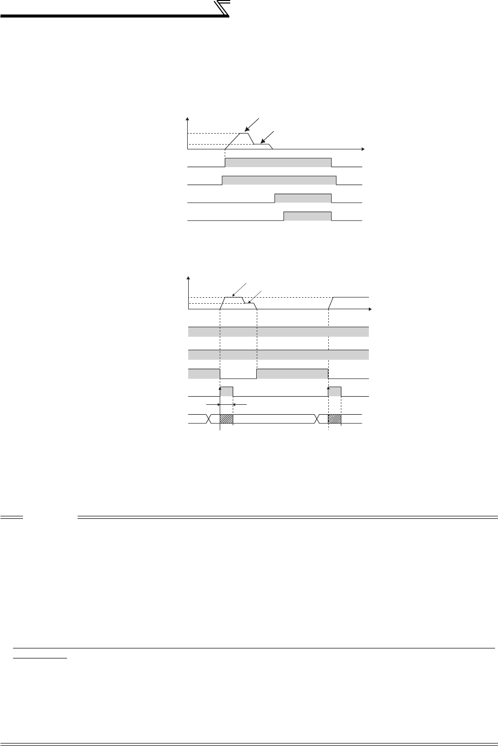
226
Motor brake and stop operation
Orientation from stop
After turning ON the orientation command (X22), turning ON the start signal will increase the motor speed to the
orientation speed set in Pr. 351 Orientation speed, then orientation operation same as when "orientation during running"
is performed.
Note that, DC injection brake is operated if the position signal is within the DC injection brake start position.
• Action time chart
Continuous multi-point orientation
Orientation command and orientation with STF/STR ON
(Orientation in servo in status)
• Read the position data at starting up of DY (refer to the FR-A7AX instruction manual ).
• When the position signal is within the creep switchover position, the speed starts up to the creep speed not to the
orientation speed.
• When the position signal is not within the creep switchover position, the speed starts up to the orientation speed.
• The DC injection brake is operated if the position signal is within the DC injection brake start position.
• 16-bit data with the FR-A7AX is valid only when the DY signal is ON.
CAUTION
• The encoder should be coupled with the motor shaft or main spindle oriented with a speed ratio of 1 to 1 without any mechanical
looseness.
• DC injection brake operates when orientation stop is made. Release the DC injection brake in a time as short as possible (within
several seconds) since continuous operation of the DC injection brake will cause the motor to overheat, leading to burnout.
• Since no servo lock function is available after orientation stop, provide a holding mechanism such as mechanical brake or knock
pin when secure holding of a main spindle is required.
• To ensure correct positioning, the encoder must be set in the proper rotation direction and the A and B phases connected correctly.
• When the pulse signal from the encoder stops due to the encoder signal loss, etc. during orientation, the orientation fault signal
(ORM) may be output.
• When the DC injection brake is set to disabled using parameter for DC injection brake adjustment (voltage, frequency, speed, time)
when performing orientation control, orientation operation cannot be completed. Always set the DC injection brake enabled.
• To terminate orientation, the start signal (STF or STR) must be first switched OFF and the orientation signal (X22) must be
switched OFF. As soon as this orientation signal is switched OFF, orientation control ends.(Depending on the Pr. 358 Servo torque
selection setting, orientation status continues if the orientation signal remains ON even if DC injection brake is released at turning
OFF of the start signal. Therefore, the orientation status of the monitor function is not 0.)
• When retry function of
Pr. 358 Servo torque selection
is selected, the retry operation is performed three times including the first orientation.
• When performing orientation control, make proper setting of Pr. 350 Stop position command selection and Pr. 360 16-bit data selection
(external position command selection). If the values set are incorrect, proper orientation control will not be performed.
• When
Pr. 11 DC injection brake operation time
= "8888" (DC injection brake external selection), DC injection brake does not operate if the
X13 signal is not turned ON. Note that the DC injection brake is applied under orientation control regardless of the X13 signal status.
• When orientation control is exercised, PID control is invalid.
Orientation speed (orientation switchover speed)
Creep speed (orientation deceleration ratio)
Time
OFF ON
ON
ON
ON
OFF
OFF
OFF
OFF
OFF
OFF
OFF
Main spindle speed (encoder)
Pr. 351
Pr. 352
Start signal (STF, STR)
Orientation command (X22)
DC injection brake
Orientation complete signal (ORA)
DY
Position signal
Servo-in
ON
ON
Position command latch
50ms or more is necessary
Servo-in
ON ON
Position command latch
Main spindle speed (encoder)
Pr. 351
Pr. 352
Start signal
Orientation command
Orientation complete signal
Orientation speed (orientation switchover speed)
Creep speed (orientation deceleration ratio)
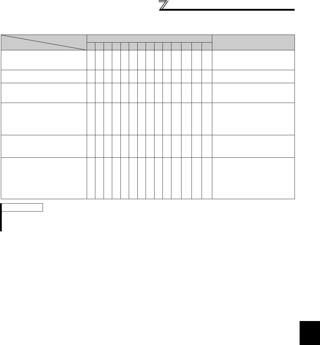
227
Motor brake and stop operation
4
PARAMETERS
Servo torque selection (Pr. 358 )
Valid only under V/F control and Advanced magnetic flux vector control.
1)Servo torque function selection until output of the orientation complete signal
Whether servo torque is available or not is selected using Pr. 358 Servo torque selection. Servo torque is not generated
if the current position pulse is in between the orientation stop position and DC injection brake start position. Although,
the shaft is retained by the DC injection brake, servo torque is generated to return the shaft within the width if the
shaft moves out of the width by external force, etc. Once the orientation complete signal (ORA) is output, the motor
runs according to the setting made in 4).
2)Retry function selection
Select retry function using Pr. 358 Servo torque selection. Note that servo torque function cannot be used together.
When the motor shaft is not stopped within the in-position zone when the motor stop is checked, orientation
operation is performed again by retry function.
With this retry function, three orientations including the first one are performed. More than three times retry
operations are not made. (The orientation fault signal (ORM) is not output during retry operation)
3)Frequency compensation function when the motor stops outside the orientation in-position zone
When the motor stops before entering the in-position zone due to external force, etc., output frequency is increased
to move the shaft to the orientation stop position. The output frequency is gradually increased to the creep speed of
Pr. 352 Creep speed .
Note that retry function cannot be used together.
4)DC injection brake and servo torque selection when the position pulse comes off the in-position zone after output of
the orientation complete signal (ORA)
If the position pulse comes off the orientation in-position width, you can select a setting either fixing a shaft with the
DC injection brake or returning the motor to the orientation stop position with servo torque.
5)Orientation operation end switch operation selection between DC injection brake or servo torque
When ending the orientation operation, turn OFF the start signal (STF or STR), then turn OFF the orientation
command (X22). At this time, you can select when to turn OFF the orientation complete signal (ORA) from between
at turning OFF of the start signal or turning OFF of the orientation command signal.
6)Selection of completion signal OFF or ON when the motor stops outside of the in-position zone after output of the
orientation complete signal (ORA)
You can select the mode to turn OFF the completion signal or keep the completion signal ON (orientation fault signal
(ORM) is not output) when the motor stops outside of the in-position zone.
Pr. 358 Setting
Function Remarks
0 1 2 3 4 5 6 7 8 9 10 11 12 13
1) Servo torque function selection
until output of the orientation
complete signal (ORA)
× ×××××: With servo torque function
×: Without servo torque function
2) Retry function selection ××××××××× × ××
: With retry function
×: Without retry function
3) Output frequency is compensated
when the motor stops outside the
in-position zone
×× × ××× × ×
: With frequency compensation
×: Without frequency compensation
4) DC injection brake and servo
torque selection when the position
pulse comes off the in-position
zone after output of the orientation
complete signal (ORA)
×××× : With DC injection brake
×: With servo torque
5) End switch selection of the DC
injection brake and orientation
complete signal (ORA)
×× ×××××
: When the start signal (STF, STR) or
orientation command is turned OFF
×: When the orientation command is
turned OFF
6) Completion signal OFF selection
when the position pulse comes off
the in-position zone after output of
the orientation complete signal
(ORA)
×××××× × × ×
: Turn OFF the completion signal when
the motor stops outside of the in-
position zone
×: Completion signal remains ON even if
the position pulse comes off the
completion zone
(orientation fault signal (ORM) is not
output)
REMARKS
• When the orientation command is OFF with the start signal ON, the speed accelerates to the command speed.
• When the motor shaft stops outside of the set setting range of stop position, the motor shaft is returned to the stop position by
servo torque function (if enough torque is generated).
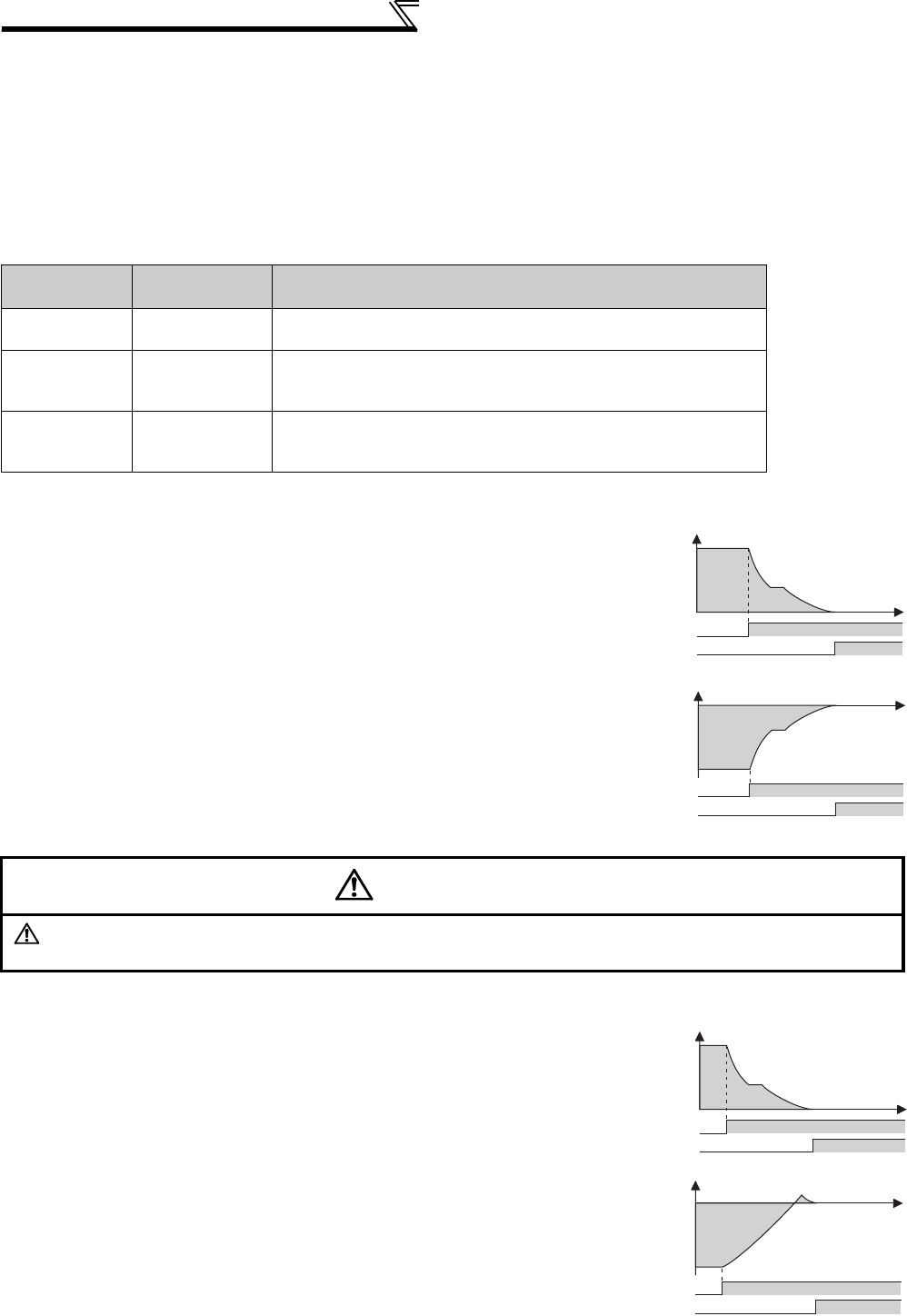
228
Motor brake and stop operation
Position loop gain (Pr. 362 )
When servo torque function is selected using Pr. 358 Servo torque selection , output frequency for generating servo
torque increases to the creep speed of Pr. 352 Creep speed gradually according to the slope set in Pr. 362 Orientation
position loop gain .
Although the operation becomes faster when the value is increased, a machine may hunt, etc.
(7) Orientation operation explanation (during vector control)
Setting the rotation direction (Pr. 393 Orientation selection )
1) Orientation from the current rotation direction
2) Orientation from the forward rotation direction
Pr. 393 Setting Rotation
Direction Remarks
0
(initial value) Pre-orientation Orientation is executed from the current rotation direction.
1Forward rotation
orientation
Orientation is executed from the forward rotation direction.
(If the motor is running in reverse, orientation is executed from the
forward rotation direction after deceleration.)
2Reverse rotation
orientation
Orientation is executed from the reverse rotation direction.
(If the motor is running in forward, orientation is executed from the
reverse rotation direction after deceleration.)
• When the orientation command (X22) is input, the motor speed will
decelerate from the running speed to Pr. 351 Orientation speed.
At the same time, the orientation stop position command will be read in.
(The stop position command is determined by the setting of Pr. 350 and Pr.
360. Refer to the right chart.)
• When the orientation switchover speed is reached, the encoder Z phase
pulse will be confirmed, and the mode will change from speed control to
position control (Pr. 362 Orientation position loop gain ).
• The distance to the orientation stop position is calculated at switching of
the control, and the motor decelerates and stops with a set deceleration
pattern (Pr. 399) and the orientation (servo lock) state will be entered.
• When entered in the Pr. 357 Orientation in-position zone, the orientation
complete signal (ORA) will be output.
• The zero point position (origin) can be moved using Pr. 361 Position shift .
WARNING
If the orientation command (X22) is turned OFF while the start signal is input, the motor will accelerate toward
the speed of the current speed command. Thus, to stop, turn the forward rotation (reverse rotation) signal OFF.
• This method is used to improve the stopping precision and maintain the
mechanical precision when the backlash is large.
• If the motor is running in the forward rotation direction, it will make an
orientation stop with the same method as "orientation from the current
rotation direction".
• If the motor is running in reverse, it will decelerate, the rotation direction
will be changed to forward run, and then orientation stop will be executed.
OFF ON
X22
Speed
(forward rotation)
OFF ON
ORA
[t]
OFF ON
X22
Speed
(reverse rotation)
OFF ON
ORA
[t]
Speed
(forward rotation)
X22
ORA
[t]
Speed
(reverse rotation)
X22
ORA
[t]

229
Motor brake and stop operation
4
PARAMETERS
3)Orientation from the reverse rotation direction
Servo rigidity adjustment (Pr. 362, Pr. 396 to Pr. 398)
•To increase the servo rigidity *1 during orientation stop using Pr. 396 or Pr. 397 , adjust with the following procedures.
1) Increase the Pr. 362 Orientation position loop gain value to the extent that rocking *2 does not occur during
orientation stop.
2) Increase Pr. 396 and Pr. 397 at the same rate.
Generally adjust Pr. 396 in the range from 10 to 100, and Pr. 397 from 0.1 to 1.0s.
(Note that these do not need to be set to the same rate.)
<Example>
When the Pr. 396 value is multiplied by 1.2, divide the Pr. 397 value by 1.2.
If vibration occurs during orientation stop, the scale cannot be raised any higher.
3) Pr. 398 is the lag/advance compensation gain.
The limit cycle *3 can be prevented by increasing the value, and the running can be stopped stably. However, the
torque in regard to the position deviation will drop, and the motor will stop with deviation.
*1 Servo rigidity: This is the response when a position control loop is configured.
When the servo rigidity is raised, the holding force will increase, the running will stabilize, but vibration will occur easily.
When the servo rigidity is lowered, the holding force will drop, and the setting time will increase.
*2 Rocking: Movement in which return occurs if the stopping position is exceeded.
*3 Limit cycle: This is a phenomenon that generates ± continuous vibration centering on the target position.
• If the motor is running in the reverse rotation direction, it will make an
orientation stop with the same method as "orientation from the current
rotation direction".
• If the motor is running in forward, it will decelerate, the rotation direction
will be changed to reverse run, and then orientation stop will be executed.
CAUTION
• The encoder should be coupled with the motor shaft oriented with a speed ratio of 1 to 1 without any mechanical looseness.
• To ensure correct positioning, the encoder must be set in the proper rotation direction and the A and B phases connected
correctly.
• Orientation may not be completed if the pulse signals are not received from the encoder during orientation due to a break in the
cable or the like.
• To terminate orientation, the start signal (STF or STR) must be first switched OFF and the orientation signal (X22) must be
switched OFF. As soon as this orientation signal is switched OFF, orientation control ends.
• When performing orientation control, make proper setting of Pr. 350 Stop position command selection and Pr. 360 16-bit data selection.
If the values set are incorrect, proper orientation control will not be performed.
• When orientation control is exercised, PID control is invalid.
REMARKS
If "E.ECT" (no encoder signal) is displayed causing the inverter to trip when the orient signal (X22) is ON, check for a break in the
cable of the Z phase of the encoder.
POINT
Application of lag/advance control and PI control
PI control can be applied by setting Pr. 398 to 0. Normally, the lag/advance control is selected. Note that PI control
should be used when using a machine with a high spindle stationary friction torque and requires a stopping position
precision.
Speed
(forward rotation)
X22
ORA
[t]
Speed
(reverse rotation)
X22
ORA
[t]
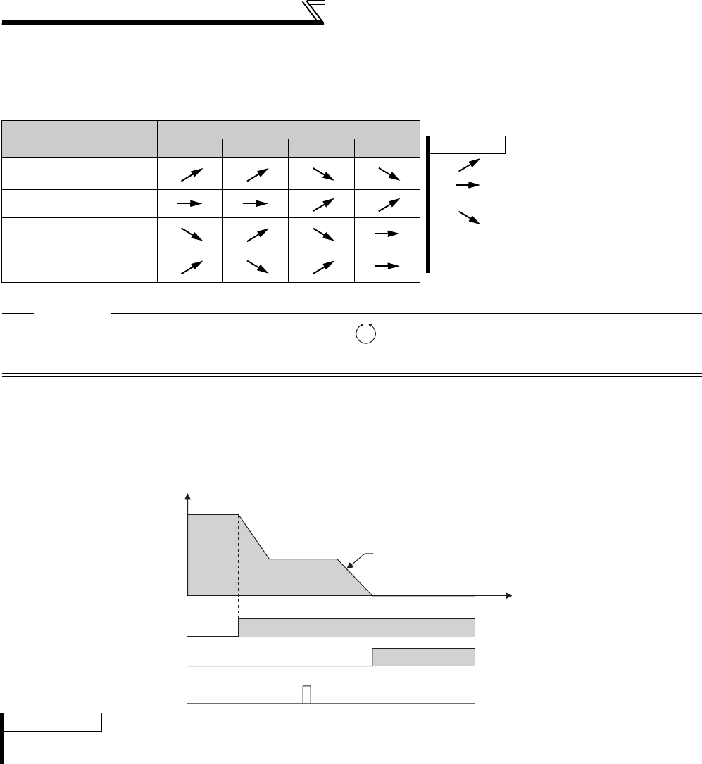
230
Motor brake and stop operation
Pr. 399 Orientation deceleration ratio (initial value is 20)
• Make adjustments as shown below according to the orientation status.
(Refer to the Pr. 396 and Pr. 397 details also.)
Generally adjust Pr. 362 in the range from 5 to 20, and Pr. 399 from 5 to 50.
Pr. 351 Orientation speed (initial value: 2Hz)
• Set the speed when switching between the speed control mode and the position control mode is performed under
orientation operation.
Decreasing the set speed enables stable orientation stop. Note that the orientation time will increase.
Phenomenon Adjustment Procedure
Pr. 396 Pr. 397 Pr. 362 Pr. 399
Rocking occurs during
stopping 3) 3) 2) 1)
The orientation time is long 2) 1)
Hunting occurs when
stopping 2) 2) 1)
The servo rigidity during
stopping is low 1) 1) 2)
CAUTION
Or, if the motor does forward/reverse reciprocation operation , the parameter setting value for the orientation detector
installation direction may be incorrect. Review Pr. 393 Orientation selection (refer to page 221) and Pr. 359 Encoder rotation direction
(refer to page 220).
REMARKS
When "19" is set in Pr. 52 DU/PU main display data selection , position pulse monitor is displayed instead of PU output voltage
monitor.
REMARKS
1. :Increase the parameter setting value.
:Do not change the parameter setting
value.
:Decrease the parameter setting value.
2. The numbers 1) , 2) and 3) in the table show
the order of priority for changing the
parameters setting value.
Frequency
[Hz]
OFF ON
Orientation start
(X22)
Orientation complete
(ORA)
Encoder Z phase pulse
Pr.351 Orientation speed
Orientation command completion
Decelerate according to the deceleration ratio of Pr. 399
Time[t]
ON
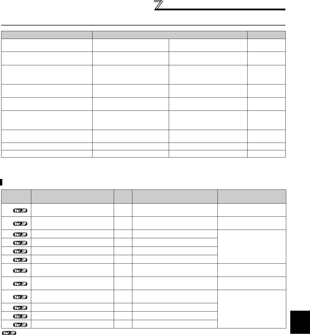
231
Function assignment of external terminal and control
4
PARAMETERS
4.15 Function assignment of external terminal and control
4.15.1 Input terminal function selection (Pr. 178 to Pr. 189)
.............. Specifications differ according to the date assembled. Refer to page 484 to check the SERIAL number.
Purpose Parameter that must be Set Refer to Page
Assign function to input terminal Input terminal function
selection Pr. 178 to Pr. 189 231
Set MRS signal (output shutoff) to
normally closed contact specification MRS input selection Pr. 17 234
Make the second (third) function
valid only during constant speed
operation
RT reflection time selection Pr. 155 235
Assign start signal and forward/
reverse command to other signals
Start signal (STF/STR)
operation selection Pr. 250 236
Assign function to output terminal Output terminal function
assignment Pr. 190 to Pr. 196 239
Detect output frequency
Up-to-frequency sensitivity
Output frequency detection
Low speed detection
Pr. 41 to Pr. 43, Pr. 50, Pr. 116,
Pr. 865 246
Detect output current Output current detection
Zero current detection
Pr. 150 to Pr. 153, Pr. 166,
Pr. 167 248
Remote output function Remote output Pr. 495 to Pr. 497 250
Detect output torque Output torque detection Pr. 864 249
Use these parameters to select/change the input terminal functions.
Parameter
Number Name Initial
Value Initial signal Setting Range
178 STF terminal function selection 60 STF (forward rotation command) 0 to 20, 22 to 28, 42 to 44, 60,
62, 64 to 71, 74, 83, 9999
179 STR terminal function selection 61 STR (reverse rotation command) 0 to 20, 22 to 28, 42 to 44, 61,
62, 64 to 71, 74, 83, 9999
180 RL terminal function selection 0 RL (low-speed operation command)
0 to 20, 22 to 28, 42 to 44,
62, 64 to 71, 74, 83, 9999
181 RM terminal function selection 1 RM (middle-speed operation command)
182 RH terminal function selection 2 RH (high speed operation command)
183 RT terminal function selection 3 RT (second function selection)
184 AU terminal function selection 4 AU (terminal 4 input selection) 0 to 20, 22 to 28, 42 to 44, 62
to 71, 74, 76, 83, 9999
185 JOG terminal function selection 5 JOG (Jog operation selection) 0 to 20, 22 to 28, 42 to 44,
62, 64 to 71, 74, 76, 83, 9999
186 CS terminal function selection 6CS (selection of automatic restart
after instantaneous power failure)
0 to 20, 22 to 28, 42 to 44,
62, 64 to 71, 74, 83, 9999
187 MRS terminal function selection 24 MRS (output stop)
188 STOP terminal function selection 25 STOP (start self-holding selection)
189 RES terminal function selection 62 RES (inverter reset)

232
Function assignment of external terminal and control
(1) Input terminal function assignment
⋅Use Pr. 178 to Pr. 189 to set the functions of the input terminals.
⋅Refer to the following table and set the parameters:
Setting Signal
Name Function Related Parameters Refer to
Page
0RL
Pr. 59 = 0 (initial value) Low-speed operation command Pr. 4 to Pr. 6, Pr. 24 to Pr. 27,
Pr. 232 to Pr. 239 165
Pr. 59 = 1 to 3 *1 Remote setting (setting clear) Pr. 59 169
Pr. 270 = 1, 3, 11 or 13 *2 Stop-on-contact selection 0 Pr. 270, Pr. 275, Pr. 276 214
1RM
Pr. 59 = 0 (initial value) Middle-speed operation command Pr. 4 to Pr. 6, Pr. 24 to Pr. 27,
Pr. 232 to Pr. 239 165
Pr. 59 = 1 to 3 *1 Remote setting (deceleration) Pr. 59 169
2RH
Pr. 59 = 0 (initial value) High-speed operation command Pr. 4 to Pr. 6, Pr. 24 to Pr. 27,
Pr. 232 to Pr. 239 165
Pr. 59 = 1 to 3 *1 Remote setting (acceleration) Pr. 59 169
3RT
Second function selection Pr. 44 to Pr. 51, Pr. 450 to Pr. 463,
Pr. 569, Pr. 832, Pr. 836, etc. 235
Pr. 270 = 1, 3, 11 or 13 *2 Stop-on-contact selection 1 Pr. 270, Pr. 275, Pr. 276 214
4 AU Terminal 4 input selection Pr. 267 286
5 JOG Jog operation selection Pr. 15, Pr. 16 167
6CS
Selection of automatic restart after instantaneous power failure,
flying start
Pr. 57, Pr. 58, Pr.162 to Pr.165,
Pr. 299, Pr. 611 266
Commercial power supply-inverter switchover function Pr. 57, Pr. 58, Pr.135 to Pr.139,
Pr. 159 369
7 OH External thermal relay input *3 Pr. 9 183
8REX
15-speed selection (combination with three speeds RL, RM,
RH)
Pr. 4 to Pr. 6, Pr. 24 to Pr. 27,
Pr.232 to Pr.239 165
9 X9 Third function selection Pr. 110 to Pr. 116 235
10 X10 Inverter run enable signal (FR-HC, MT-HC, FR-CV connection) Pr. 30, Pr. 70 207
11 X11
FR-HC or MT-HC connection, instantaneous power failure detection
Pr. 30, Pr. 70 207
12 X12 PU operation external interlock Pr. 79 313
13 X13 External DC injection brake operation start Pr. 10 to Pr. 12 203
14 X14 PID control valid terminal
Pr. 127 to Pr. 134, Pr. 575 to Pr. 577
361
15 BRI Brake opening completion signal Pr. 278 to Pr. 285 217
16 X16 PU/External operation switchover (turning ON X16 selects
External operation) Pr. 79, Pr. 340 319
17 X17
Load pattern selection forward/reverse rotation boost (turning ON
X17 changes the output characteristics to constant torque load)
Pr. 14 161
18 X18 V/F switchover (V/F control is performed when X18 is on) Pr. 80, Pr. 81, Pr. 800 92, 148
19 X19 Load torque high-speed frequency Pr. 270 to Pr. 274 374
20 X20 S-pattern acceleration/deceleration C switching terminal Pr. 380 to Pr. 383 176
22 X22 Orientation command (for FR-A7AP/FR-A7AL) *4, *6 Pr. 350 to Pr. 369 220
23 LX Pre-excitation/servo on *5 Pr. 850 203
24 MRS
Output stop Pr. 17 234
Commercial power supply-inverter switchover function Pr. 57, Pr. 58, Pr.135 to Pr.139,
Pr. 159 369
25 STOP Start self-holding selection ⎯236
26 MC Control mode changing Pr. 800 92
27 TL Torque limit selection Pr. 815 100
28 X28 Start-time tuning start external input Pr. 95 199
42 X42 Torque bias selection 1 (for FR-A7AP/FR-A7AL) *6 Pr. 840 to Pr. 845 114
43 X43 Torque bias selection 2 (for FR-A7AP/FR-A7AL) *6 Pr. 840 to Pr. 845 114
44 X44 P/PI control switchover (turning ON X44 selects P control) Pr. 820, Pr. 821, Pr. 830, Pr. 831 105
60 STF Forward rotation command
(assigned to STF terminal (Pr. 178) only) ⎯236
61 STR Reverse rotation command
(assigned to STR terminal (Pr. 179) only) ⎯236
62 RES Inverter reset ⎯⎯
63 PTC PTC thermistor input (assigned to AU terminal (Pr. 184) only) Pr. 9 183
64 X64 PID forward/reverse action switchover Pr. 127 to Pr. 134, Pr. 5 361
65 X65
PU/NET operation switchover (turning ON X65 selects PU operation)
Pr. 79, Pr. 340 320
66 X66 External/NET operation switchover (turning ON X66 selects
NET operation) Pr. 79, Pr. 340 320
67 X67 Command source switchover (turning ON X67 makes Pr. 338
and Pr. 339 commands valid) Pr. 338, Pr. 339 322
68 NP Simple position pulse train sign (for FR-A7AP/FR-A7AL) *6 Pr. 291, Pr. 419 to Pr. 430, Pr. 464 137

233
Function assignment of external terminal and control
4
PARAMETERS
*1 When Pr. 59 Remote function selection = "1 or 2", the functions of the RL, RM and RH signals change as listed above.
*2 When
Pr. 270 Stop-on contact/load torque high-speed frequency control selection
= "1, 3, 11 or 13", the functions of the RL and RM signals change as listed
above.
*3 The OH signal turns ON when the relay contact "opens".
*4 The FR-A7AX (16-bit digital input) is needed to externally input a stop position under orientation control.
*5 Servo ON is valid during position control under vector control operation.
*6 Available only when the plug-in option is mounted. For details, refer to the instruction manuals of each plug-in options.
(2) Response time of each signal
⋅The response time of the X10 signal is within 2ms. However, when the X10 signal is not assigned at the Pr. 30
Regenerative function selection setting of "2" (FR-HC, MT-HC/FR-CV connection), the response time of the MRS
signal is within 2ms.
Pr. 17 MRS input selection is invalid.
69 CLR Simple position droop pulse clear (for FR-A7AP/FR-A7AL) *6 Pr. 291, Pr. 419 to Pr. 430, Pr. 464 137
70 X70 DC feeding operation permission
Pr. 30, Pr. 70
207
71 X71 DC feeding cancel
Pr. 30, Pr. 70
207
74 X74 Magnetic flux decay output shutoff signal ⎯238
76 X76 Proximity dog (assigned to JOG terminal (Pr. 185) only) (for FR-
A7NS) *6 ⎯⎯
83 X83 0V calibration request (for FR-A7AD) *6 ⎯⎯
9999 ⎯No function ⎯⎯
REMARKS
⋅Same function can be assigned to two or more terminals. In this case, the logic of terminal input is OR.
⋅The priorities of the speed commands are in order of JOG > multi-speed setting (RH, RM, RL, REX) > PID (X14).
⋅When the X10 signal (FR-HC, MT-HC, FR-CV connection - inverter operation enable signal) is not set or when the PU
operation external interlock (X12) signal is not assigned at the Pr. 79 Operation mode selection setting of "7", the MRS signal
shares this function.
⋅Same signal is used to assign multi-speeds (7 speeds) and remote setting. They cannot be set individually.
(Same signal is used since multi-speed (7 speeds) setting and remote setting are not used to set speed at the same time.)
⋅When V/F switching (X18) signal and load pattern selection forward/reverse rotation boost (X17) signal are not assigned, the
RT signal shares this function. (Pr. 81 Number of motor poles = "12, 14, 16, 18, 20")
In this case, V/F control is controlled by the second function.
CAUTION
⋅Changing the terminal assignment using Pr. 178 to Pr. 189 (input terminal function selection) may affect the other functions. Also
check that wiring is correct, since the terminal name and the signal function became different. Set parameters after confirming
the function of each terminal.
Pr. 30
Setting
MRS
Assignment
X10
Assignment
Response Time Pr. 17
MRS X10
2
×Within 2ms ⎯Invalid
×⎯Within 2ms ⎯
Within 20ms Within 2ms Valid
Other than 2
×Within 20ms ⎯Valid
×⎯⎯⎯
Within 20ms ⎯Valid
Setting Signal
Name Function Related Parameters Refer to
Page
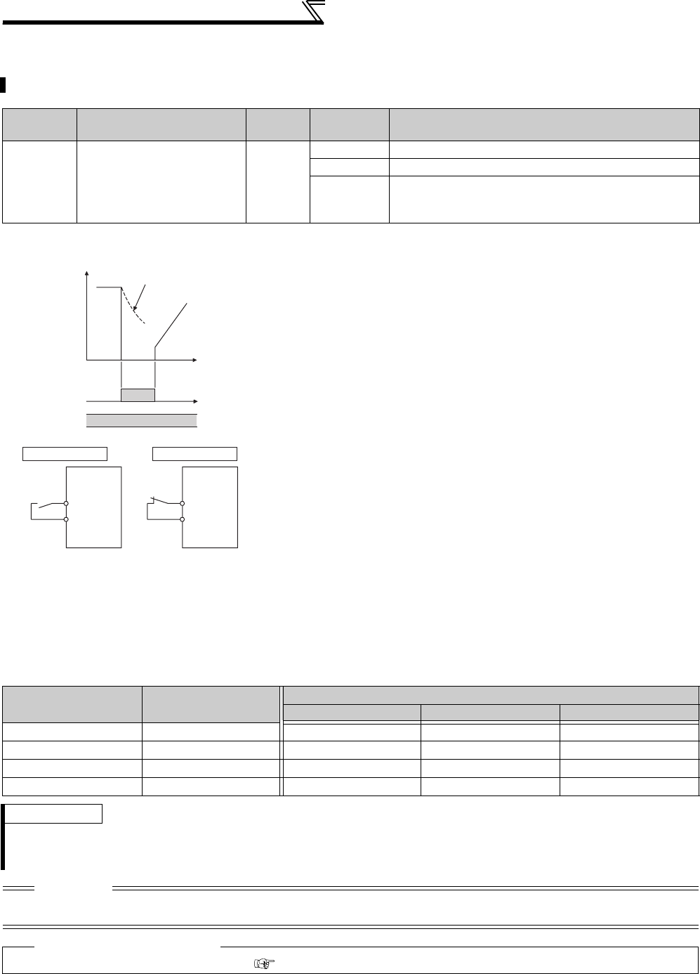
234
Function assignment of external terminal and control
4.15.2 Inverter output shutoff signal (MRS signal, Pr. 17)
The inverter output can be shut off from the MRS signal. The logic of the MRS signal can also be selected.
Parameter
Number Name Initial
Value
Setting
Range Description
17 MRS input selection 0
0 Normally open input
2 Normally closed input (NC contact input specifications)
4
External terminal: Normally closed input
(NC contact input specifications)
Communication: Normally open input
(1) Output shutoff signal (MRS signal)
⋅Turning on the output shutoff signal (MRS) during inverter running shuts
off the output immediately.
⋅Terminal MRS may be used as described below.
(a) When mechanical brake (e.g. electromagnetic brake) is used to stop
motor
The inverter output is shut off when the mechanical brake operates.
(b) To provide interlock to disable operation by the inverter
With the MRS signal ON, the inverter cannot be operated if the start
signal is entered into the inverter.
(c) Coast the motor to a stop
When the start signal is turned OFF, the inverter decelerates the
motor to a stop in the preset deceleration time, but when the MRS
signal is turned ON, the motor coasts to a stop
(2) MRS signal logic inversion (Pr. 17 = "2")
⋅When Pr. 17 is set to "2", the MRS signal (output stop) can be changed
to the normally closed (NC contact) input specification. When the MRS
signal turns ON (opens), the inverter shuts off the output.
(3) Assign a different action for each MRS signal input from communication and external terminal
(
Pr. 17
= "4")
⋅When Pr. 17 is set to "4", the MRS signal from external terminal (output stop) can be changed to the normally
closed (NC contact) input, and the MRS signal from communication can be changed to the normally open (NO
contact) input.
This function is useful to perform operation by communication with MRS signal from external terminal remained
ON.
External MRS Communication MRS Pr. 17 Setting
0 2 4
OFF OFF Operation enabled Output shutoff Output shutoff
OFF ON Output shutoff Output shutoff Output shutoff
ON OFF Output shutoff Output shutoff Operation enabled
ON ON Output shutoff Operation enabled Output shutoff
REMARKS
⋅The MRS signal is assigned to the terminal MRS in the initial setting. By setting "24" in any of Pr. 178 to Pr. 189 (input terminal
function selection), the MRS signal can be assigned to the other terminal.
⋅When using an external terminal to input the MRS signal, the MRS signal shuts off the output in any of the operation modes.
CAUTION
⋅Changing the terminal assignment using Pr. 178 to Pr. 189 (input terminal function selection) may affect the other functions. Set
parameters after confirming the function of each terminal.
♦ Parameters referred to ♦
Pr. 178 to Pr. 189 (Input terminal function selection) Refer to page 231
ON
ON
MRS signal
STF (STR)
signal
Motor coasts
to stop
Time
(Initial
value)
Output
stop
Output
stop
MRS
Inverter
MRS
Inverter
Setting value "0" Setting value "2"
SD SD
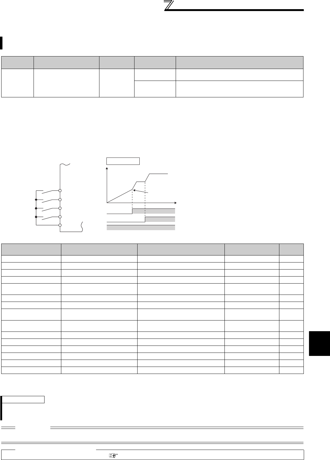
235
Function assignment of external terminal and control
4
PARAMETERS
4.15.3
Condition selection of function validity by the second function selection signal (RT) and
third function selection signal (X9) (RT signal, X9 signal, Pr. 155)
⋅When the RT signal turns ON, the second function becomes valid.
⋅When the X9 signal turns ON, the third function becomes valid.
For the X9 signal, set "9" in any of Pr. 178 to Pr. 189 (input terminal function selection) to assign the function.
⋅The second (third) function has the following applications.
(a)Switching between normal use and emergency use
(b)Switching between heavy load and light load
(c)Changing of acceleration/deceleration time by broken line acceleration/deceleration
(d)Switching of characteristic between main motor and sub motor
⋅When the RT (X9) signal is ON, the other functions such as the second (third) are also selected.
*1 The function could be changed by switching the RT signal ON/OFF while the inverter is stopped.
If a signal is switched during the operation, the operation method changes after the inverter stops.
*2 When the RT signal is OFF, the first function is valid. When it is ON, the second function is valid.
You can select the second (third) function using the RT(X9) signal.
You can also set the condition (reflection condition) where the second function and third function become valid.
Parameter
Number Name Initial Value Setting Range Description
155 RT signal function validity
condition selection 0
0Second (third) function is immediately valid with ON of
the RT(X9) signal.
10
Second (third) function is valid only during the RT (X9)
signal is ON and constant speed operation. (invalid
during acceleration/deceleration)
Second function
connection diagram Second acceleration/deceleration time example
Function First Function
Parameter Number Second Function
Parameter Number Third Function
Parameter Number Refer to
Page
Torque boost Pr. 0 Pr. 46 Pr. 112 146
Base frequency Pr. 3 Pr. 47 Pr. 113 159
Acceleration time Pr. 7 Pr. 44 Pr. 110 172
Deceleration time Pr. 8 Pr. 44, Pr. 45 Pr. 110, Pr. 111 172
Electronic thermal relay
function *1 Pr. 9 Pr. 51 *2 183
Stall prevention Pr. 22 Pr. 48, Pr. 49 Pr. 114, Pr. 115 152
Applied motor *1 Pr. 71 Pr. 450 *2 187
Motor constant *1 Pr. 80 to Pr. 84, Pr. 89,
Pr. 90 to Pr. 94, Pr. 96, Pr. 859 Pr. 453 to Pr. 457, Pr. 569,
Pr. 458 to Pr. 462, Pr. 463, Pr. 860 *2 189
Online auto tuning
selection *1 Pr. 95 Pr. 574 *2 199
Motor control method *1 Pr. 800 Pr. 451 *2 92
Speed control gain Pr. 820, Pr. 821 Pr. 830, Pr. 831 *2 105
Analog input filter Pr. 822, Pr. 826 Pr. 832, Pr. 836 *2 292
Speed detection filter Pr. 823 Pr. 833 *2 144
Torque control gain Pr. 824, Pr. 825 Pr. 834, Pr. 835 *2 130
Torque detection filter Pr. 827 Pr. 837 *2 144
REMARKS
⋅The RT signal is assigned to the RT terminal in the initial setting. By setting "3" in any of Pr. 178 to Pr. 189 (input terminal function
selection), the RT signal can be assigned to the other terminal.
⋅When both the RT and X9 signals are ON, the X9 signal (third function) is prioritized.
CAUTION
⋅Changing the terminal assignment using Pr. 178 to Pr. 189 (input terminal function selection) may affect the other functions. Set
parameters after confirming the function of each terminal.
♦ Parameters referred to ♦
Pr. 178 to Pr.189 (input terminal function selection) Refer to page 231
STF/STR
Inverter
Start
Second
function
selection RT
High speed RH
Middle speed RM
SD
(initial value)
RT
Output frequency
Setting value "0"
RH
RM
Acceleration
time is reflected
Time
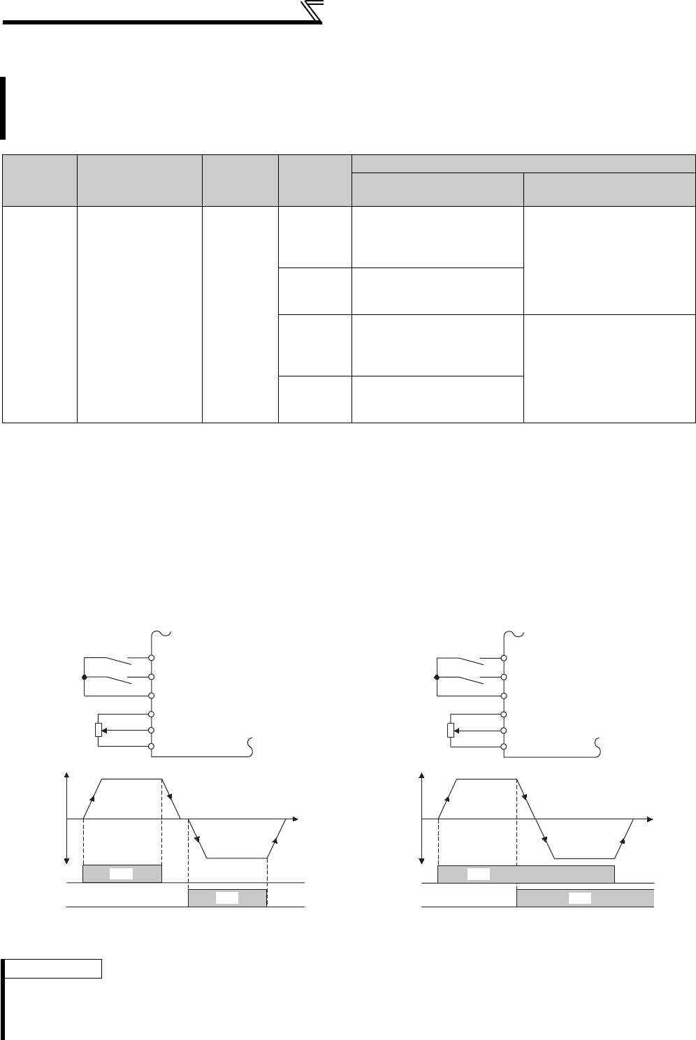
236
Function assignment of external terminal and control
4.15.4 Start signal operation selection (STF, STR, STOP signal, Pr. 250)
(1) 2-wire type (STF, STR signal)
⋅A two-wire type connection is shown below.
⋅In the initial setting, the forward/reverse rotation signals (STF/STR) are used as start and stop signals. Turn on
either of the forward and reverse rotation signals to start the motor in the corresponding direction. If both are turned
OFF (or on) during operation, the motor decelerates to a stop.
⋅The speed setting signal may either be given by entering 0 to 10VDC across the speed setting input terminal 2-5,
by setting the required values in Pr. 4 to Pr. 6 Multi-speed setting (high, middle, low speeds), etc. (For multi-speed
operation, refer to page 165)
⋅When Pr. 250 is set to any of "1000 to 1100, 8888", the STF signal becomes a start command and the STR signal a
forward/reverse command.
You can select the operation of the start signal (STF/STR).
You can select the stopping method (deceleration to a stop or coasting) when the start signal turns OFF.
You can stop the motor with a mechanical brake, etc. together with switching OFF of the start signal.
(Refer to page 213 for stop selection)
Parameter
Number Name Initial
Value
Setting
Range
Description
Start signal (STF/STR) Stop operation
(Refer to page 213)
250 Stop selection 9999
0 to 100s
STF signal: Forward rotation
start
STR signal: Reverse rotation
start
The motor is coasted to a stop
when the preset time elapses
after the start signal is turned
OFF. When the setting is any
of 1000s to 1100s, the inverter
coasts to a stop in (Pr. 250 -
1000)s.
1000s to
1100s
STF signal: Start signal
STR signal: Forward/reverse
rotation signal
9999
STF signal: Forward rotation
start
STR signal: Reverse rotation
start
When the start signal is turned
OFF, the motor decelerates to
stop.
8888
STF signal: Start signal
STR signal: Forward/reverse
rotation signal
2-wire connection example (Pr. 250 = "9999") 2-wire connection example (Pr. 250 = "8888")
REMARKS
⋅When Pr. 250 is set to any of "0 to 100, 1000 to 1100", the motor coasts to a stop if the start command is turned OFF. (Refer to
page 213)
⋅The STF and STR signals are assigned to the STF and STR terminals in the initial setting. The STF signal can be assigned to
Pr. 178 STF terminal function selection and the STR signal to Pr. 179 STR terminal function selection only.
Forward
rotation start
Reverse
rotation start
STF
ON
Time
STF
STR Inverter
Output frequency
ON
STR
10
2
5
Forward
rotation
Reverse
rotation
SD
Start signal
Forward/
reverse
signal
STF
Time
STF
STR Inverter
Output frequency
STR
10
2
5
Forward
rotation
Reverse
rotation
ON
ON
SD
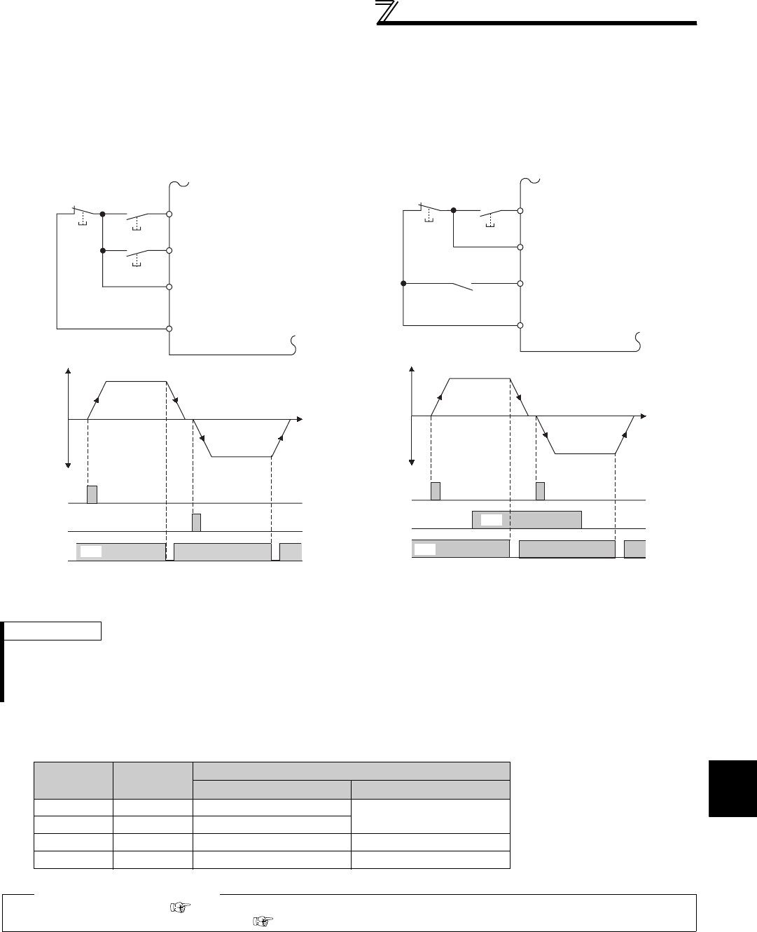
237
Function assignment of external terminal and control
4
PARAMETERS
(2) 3-wire type (STF, STR, STOP signal)
⋅A three-wire type connection is shown below.
⋅The start self-holding selection becomes valid when the STOP signal is turned ON. In this case, the forward/
reverse rotation signal functions only as a start signal.
⋅If the start signal (STF or STR) is turned ON and then OFF, the start signal is held and makes a start. When
changing the direction of rotation, turn STR (STF) ON once and then OFF.
⋅To stop the inverter, turning OFF the STOP signal once decelerates it to a stop.
(3) Start signal selection
Three-Wire Type Connection Example (Pr. 250 = "9999") Three-Wire Type Connection Example (Pr. 250 = "8888")
REMARKS
⋅The STOP signal is assigned to the terminal STOP in the initial setting. By setting "25" in Pr. 178 to Pr. 189, the STOP signal can
also be assigned to the other terminal.
⋅When the JOG signal is turned on to enable jog operation, the STOP signal becomes invalid.
⋅If the MRS signal is turned on to stop the output, the self-holding function is not canceled.
STF STR Pr. 250 Setting Inverter Status
0 to 100s, 9999 1000s to 1100s, 8888
OFF OFF Stop Stop
OFF ON Reverse rotation
ON OFF Forward rotation Forward rotation
ON ON Stop Reverse rotation
♦ Parameters referred to ♦
Pr. 4 to Pr. 6 (Multi-speed setting) Refer to page 165
Pr. 178 to Pr. 189 (Input terminal function selection) Refer to page 231
Stop Forward
rotation start
Reverse
rotation start
STF
STR
STOP
Inverter
Time
STF
STR
ON
STOP
OFF
Output frequency
ON
Forward
rotation
Reverse
rotation
OFF
ON
ON
PC
Time
Stop
Forward rotation
/reverse rotation
Start
STF
STR
ON
STOP ON
STF
STR
STOP
Inverter
Output frequency
ON
ON
OFF OFF
Forward
rotation
Reverse
rotation
SD
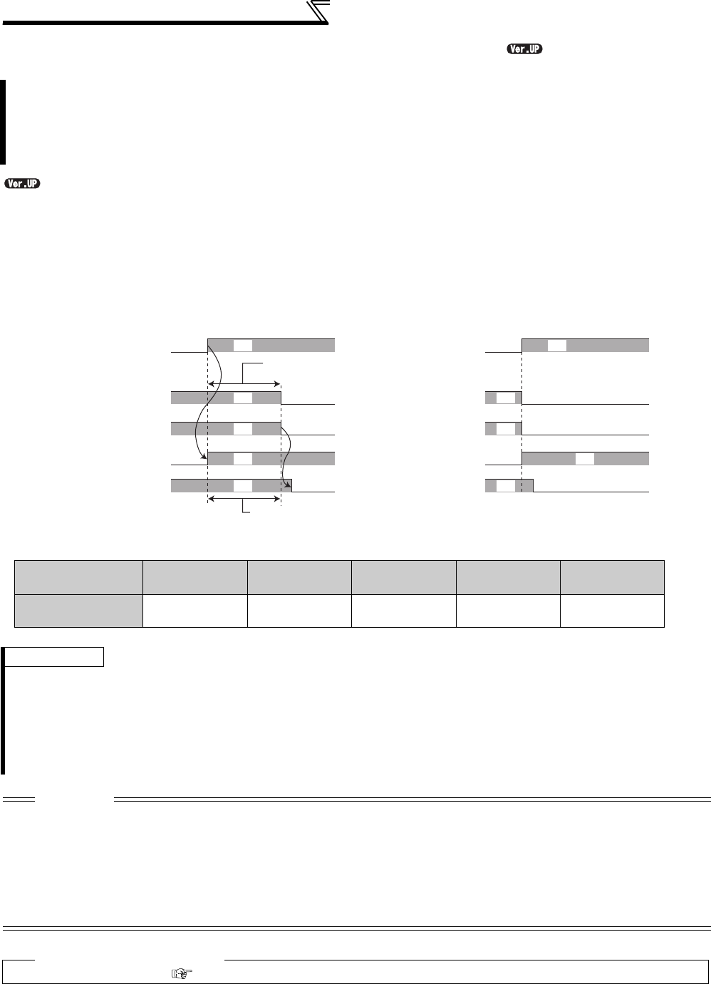
238
Function assignment of external terminal and control
4.15.5 Magnetic flux decay output shutoff signal (X74 signal)
...............Specifications differ according to the date assembled. Refer to page 484 to check the SERIAL number.
⋅For the X74 signal, set "74" in any of Pr. 178 to Pr. 189 (input terminal function selection) to assign the function.
⋅Operate a mechanical brake after turning X74 signal ON.
⋅When the MC is provided on the inverter output side, turn X74 signal ON and open the MC after magnetic flux decay
operation time (refer to below) has elapsed.
* Maximum time of magnetic flux decay operation
Performing frequent start/stop (inching operation) during Real sensorless vector control may cause an inverter
fault (electronic thermal relay function fault: E.THT, etc) due to residual magnetic flux and an error in monitor
output (running speed, motor torque, load meter, torque command, torque current command, motor output).
In such a case, use magnetic flux decay output shutoff signal (X74) as output shutoff signal.
Turning X74 signal ON shuts off output after decaying motor residual magnetic flux.
Motor Capacity
(Pr. 80 setting) 2.2kW or lower 3.7kW to 11kW 15kW to 30kW 37kW to 55kW 75kW or higher
Magnetic flux decay
processing time 250ms 500ms 800ms 900ms 1100ms
REMARKS
⋅When performing operation other than Real sensorless vector control, turning X74 signal ON immediately shuts off inverter
output.
⋅During an automatic restart after instantaneous power failure or start-time online auto tuning under Real sensorless vector
control, turning X74 signal ON immediately shuts off inverter output.
⋅When some other factor affecting output shutoff (inverter alarm, MRS signal ON, etc.) occurs during magnetic flux decay
operation, magnetic flux decay operation is stopped to immediately shut off output.
⋅Pr.850 Brake operation selection is also available to enable the magnetic flux decay output shutoff.
CAUTION
⋅Changing the terminal assignment using Pr. 178 to Pr. 189 (input terminal function selection) may affect the other functions. Set
parameters after confirming the function of each terminal.
⋅Different from MRS signal, voltage is output during magnetic flux decay processing even if X74 signal turns ON. Take care not
to have an electrical shock.
⋅If the timing of mechanical brake opening is early, motor shaft may be forced to turn by a gravity drop or external force. If the
timing of mechanical brake opening is late, overcurrent, stall prevention operation or electronic thermal relay function may be
activated. Use output frequency detection signal (FU) or output current detection signal (Y12) to perform the mechanical brake
opening suitable for the machine.
♦ Parameters referred to ♦
Pr. 850 Brake operation selection Refer to page 203
X74
Output voltage
RUN
Magnetic flux decay
processing time*
Do not turn off MC
during this processing time
ON
ON
ON
ON
Mechanical brake
MC on the output side
Output voltage
RUN
Mechanical brake
MC on the output side
ON ON
Inverter output voltage shutoff timing
X74 signal
MRS ON
ON
ON
ON
MRS signal
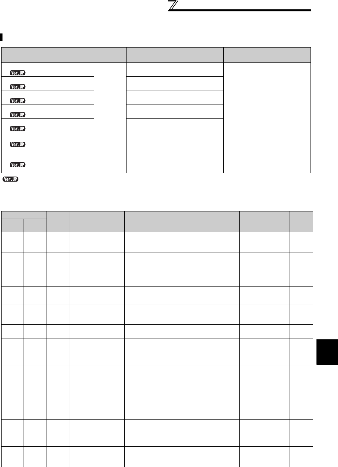
239
Function assignment of external terminal and control
4
PARAMETERS
4.15.6 Output terminal function selection (Pr. 190 to Pr. 196)
.............Specifications differ according to the date assembled. Refer to page 484 to check the SERIAL number.
(1) Output signal list
⋅You can set the functions of the output terminals.
⋅Refer to the following table and set the parameters: (0 to 99: Positive logic, 100 to 199: Negative logic)
You can change the functions of the open collector output terminal and relay output terminal.
Parameter
Number Name Initial
Value Initial signal Setting Range
190 RUN terminal
function selection
Open
collector
output
terminal
0 RUN (inverter running)
0 to 8, 10 to 20, 25 to 28, 30 to 36,
39, 41 to 47, 55, 64, 70, 83 to 85,
90 to 99, 100 to 108, 110 to 116,
120, 125 to 128, 130 to 136, 139,
141 to 147, 155, 164, 170, 183 to
185, 190 to 199, 9999
191 SU terminal function
selection 1 SU (up to frequency)
192 IPF terminal function
selection 2IPF (instantaneous power
failure, undervoltage)
193 OL terminal function
selection 3 OL (overload alarm)
194 FU terminal function
selection 4FU (output frequency
detection)
195 ABC1 terminal
function selection Relay
output
terminal
99 ALM (fault output)
0 to 8, 10 to 20, 25 to 28, 30 to 36,
39, 41 to 47, 55, 64, 70, 83 to 85,
90, 91, 94 to 99, 100 to 108, 110 to
116, 120, 125 to 128, 130 to 136,
139, 141 to 147, 155, 164, 170, 183
to 185, 190, 191, 194 to 199, 9999
196 ABC2 terminal
function selection 9999 No function
Setting Signal
Name Function Operation Related
Parameters
Refer
to Page
Positive
Logic
Negative
Logic
0 100 RUN Inverter running
Output during operation when the inverter
output frequency rises to or above Pr. 13 Starting
frequency.
-242
1 101 SU Up to frequency *1 Output when the output frequency is reached to
the set frequency. Pr. 41 246
2102IPF
Instantaneous power
failure/undervoltage
Output at occurrence of an instantaneous power
failure or when undervoltage protection is
activated.
Pr. 57 266
3 103 OL Overload alarm Output while stall prevention function is
activated.
Pr. 22, Pr. 23,
Pr. 66, Pr. 148,
Pr. 149, Pr. 154
152
4104FU
Output frequency
detection
Output when the output frequency reaches the
frequency set in Pr. 42 (Pr. 43 for reverse
rotation).
Pr. 42, Pr. 43 246
5105FU2
Second output
frequency detection
Output when the output frequency reaches the
frequency set in Pr. 50. Pr. 50 246
6106FU3
Third output frequency
detection
Output when the output frequency reaches the
frequency set in Pr. 116. Pr. 116 246
7107RBP
Regenerative brake
pre-alarm
Output when 85% of the regenerative brake
duty set in Pr. 70 is reached. Pr. 70 207
8108THP
Electronic thermal O/L
relay pre-alarm
Output when the electronic thermal relay
function cumulative value reaches 85% of the
trip level.
(Electronic thermal relay function protection
(E.THT/E.THM) activates, when the value
reached 100%.)
Pr. 9 185
10 110 PU PU operation mode Output when the PU operation mode is
selected. Pr. 79 313
11 111 RY Inverter operation
ready
Output when the inverter power is turned ON,
then output after reset process is completed
(when the inverter can be started by switching
the start signal ON or while it is running).
-242
12 112 Y12 Output current
detection
Output when the output current is higher than
the Pr. 150 setting for longer than the time set in
Pr. 151.
Pr. 150, Pr. 151 248

240
Function assignment of external terminal and control
13 113 Y13 Zero current detection
Output when the output power is lower than the
Pr. 152 setting for longer than the time set in Pr.
153.
Pr. 152, Pr. 153 248
14 114 FDN PID lower limit Output when the feedback value falls below the
lower limit of PID control.
Pr. 127 to Pr. 134,
Pr. 575 to Pr. 577 36115 115 FUP PID upper limit Output when the feedback value rises above
the upper limit of PID control
16 116 RL PID forward/reverse
rotation output
Output when forward rotation is performed in
PID control.
17 ⎯MC1 Electronic bypass MC1 Used when the commercial power supply-
inverter switchover function is used.
Pr. 135 to Pr. 139,
Pr. 159 36918 ⎯MC2 Electronic bypass MC2
19 ⎯MC3 Electronic bypass MC3
20 120 BOF Brake opening
request
Output to open the brake when the brake
sequence function is selected.
Pr. 278 to Pr. 285,
Pr. 292 217
25 125 FAN Fan fault output Output at the time of a fan fault. Pr. 244 385
26 126 FIN Heatsink overheat
pre-alarm
Output when the heatsink temperature reaches
about 85% of the heatsink overheat protection
providing temperature.
-410
27 127 ORA
Orientation complete
(for FR-A7AP/FR-
A7AL) *3 When orientation is valid
Pr. 350 to Pr. 366,
Pr. 369, Pr. 393,
Pr. 396 to Pr. 399
220
28 128 ORM Orientation fault (for
FR-A7AP/FR-A7AL) *3
30 130 Y30
Forward rotation output
(for FR-A7AP/FR-
A7AL)
*3
Output when the motor is running in forward
direction.
-
244
31 131 Y31
Reverse rotation output
(for FR-A7AP/FR-
A7AL) *3
Output when the motor is running in reverse
direction. 244
32 132 Y32
Regenerative status
output (for FR-A7AP/
FR-A7AL) *3
Output in the regenerative status under vector
control operation. 244
33 133 RY2 Operation ready 2 Output during pre-excitation or operation under
Real sensorless vector control. -242
34 134 LS Low speed output Output when the output frequency drops below
the Pr. 865 setting. Pr. 865 246
35 135 TU Torque detection Output when the motor torque rises above the
Pr. 864 value. Pr. 864 249
36 136 Y36 In-position (for FR-
A7AP/FR-A7AL) *3
Output when the number of droop pulses has
fallen below the setting value. Pr. 426 140
39 139 Y39 Start time tuning
completion Output on completion of start-time tuning. Pr. 95, Pr. 574 199
41 141 FB Speed detection Output when the actual motor speed (estimated
actual speed value) reaches the Pr. 42 (Pr. 50,
Pr.116) setting.
Pr. 42, Pr. 50,
Pr. 116 24642 142 FB2 Second speed
detection
43 143 FB3 Third speed detection
44 144 RUN2 Inverter running 2
⋅Output during forward rotation or the reverse
rotation signal is ON.
⋅
Output at deceleration even during forward
rotation or the reverse rotation signal is OFF.
(Does not output during pre-excitation LX is
ON.)
⋅Output during the orientation command signal
(X22) is ON.
⋅Switched ON when the servo is ON (LX-ON)
under position control. (Switched OFF when
the servo is OFF (LX-OFF))
-242
45 145 RUN3 Inverter running and
start command is on
Output when the inverter is running and start
command is ON. -242
46 146 Y46
During deceleration at
occurrence of power
failure
Output when the power failure-time deceleration
function is executed.
(retained until release)
Pr. 261 to Pr. 266 270
Setting Signal
Name Function Operation Related
Parameters
Refer
to Page
Positive
Logic
Negative
Logic

241
Function assignment of external terminal and control
4
PARAMETERS
47 147 PID During PID control
activated Output during PID control. Pr. 127 to Pr. 134,
Pr. 575 to Pr. 577 361
55 155 Y55
Motor temperature
detection (for FR-
A7AZ) *3
Output when the temperature of the vector
control dedicated motor with thermistor (SF-
V5RU
T/A) exceeds the detection level.
Pr. 750 -
64 164 Y64 During retry Output during retry processing. Pr. 65 to Pr. 69 273
70 170 SLEEP PID output interruption Output when the PID output interruption
function is executed.
Pr. 127 to Pr. 134,
Pr. 575 to Pr. 577 361
83 183 Y83 During 0V calibration
(for FR-A7AD) *3 Output during 0V calibration
Pr.525, Pr.527,
Pr.529, Pr.531,
Pr.900
-
84 184 RDY
Position control
preparation ready (for
FR-A7AP/FR-A7AL) *3
Output when the servo is ON (LX-ON) and
ready to operate.
Pr. 419, Pr. 428 to
Pr. 430 137
85 185 Y85 DC feeding Output during power failure or under voltage of
AC power. Pr. 30, Pr. 70 207
90 190 Y90 Life alarm
Output when any of the control circuit capacitor,
main circuit capacitor and inrush current limit
circuit or the cooling fan approaches the end of
its service life.
Pr. 255 to Pr. 259 386
91 191 Y91 Fault output 3 (power-
off )
Output when a fault occurs due to the circuit
failure of the inverter wiring mistake. -245
92 192 Y92
Energy saving
average value
updated timing
Turned ON and OFF alternately every time the
power saving average value is updated when
the power saving monitor is used.
Cannot be set to Pr. 195 and Pr. 196 (relay output
terminal).
Pr. 52, Pr. 54,
Pr. 158, Pr. 891 to
Pr. 899
279
93 193 Y93 Current average value
monitor signal
Average current value and maintenance timer
value are output as pulses.
Cannot be set to Pr. 195 and Pr. 196 (relay output
terminal).
Pr. 555 to Pr. 557 390
94 194 ALM2 Fault output 2
Output when the fault occurs. Continue
outputting the signal during inverter reset and
stop outputting after reset status is finished. *2
-245
95 195 Y95 Maintenance timer
signal
Output when Pr. 503 rises to or above the Pr. 504
setting. Pr. 503, Pr. 504 389
96 196 REM Remote output Output to the terminal when a value is set to the
parameter. Pr. 495 to Pr. 497 250
97 197 ER Alarm output 2
When Pr. 875 = "0" (initial value), the signal is
output when the fault occurs.
When Pr. 875 = "1", the signal is output when the
inverter protective function is activated at
occurrence of OHT/THM/PTC fault and
deceleration is started.
Output when other protective functions are
activated and the inverter trips.
Pr. 875 277
98 198 LF Alarm output Output when an alarm (fan failure or
communication error warning) occurs. Pr. 121, Pr. 244 333, 385
99 199 ALM Fault output Output when the fault occurs. The signal output
is stopped when the fault is reset. -245
9999 - No function - - -
*1 Note that when the frequency setting is varied using an analog signal or of the operation panel (FR-DU07), the output of the SU (up to
frequency) signal may alternate ON and OFF depending on that varying speed and the timing of the varying speed due to acceleration/
deceleration time setting. (The output will not alternate on and OFF when the acceleration/deceleration time setting is "0s".)
*2 When a power supply reset is performed, the fault output 2 signal (ALM2) turns OFF as soon as the power supply switches OFF.
*3 Available only when the plug-in option is mounted.
REMARKS
⋅The same function may be set to more than one terminal.
⋅When the function is executed, the terminal conducts at the setting of any of "0" to "99", and does not conduct at the setting of
any of "100" to "199".
⋅When Pr. 76 Fault code output selection = "1", the output signals of the terminals SU, IPF, OL and FU are switched as set in Pr. 76.
(When an inverter fault occurs, the signal output is switched to the fault code output.)
⋅The output assignment of the terminal RUN and alarm output relay are as set above regardless of Pr. 76.
Setting Signal
Name Function Operation Related
Parameters
Refer
to Page
Positive
Logic
Negative
Logic
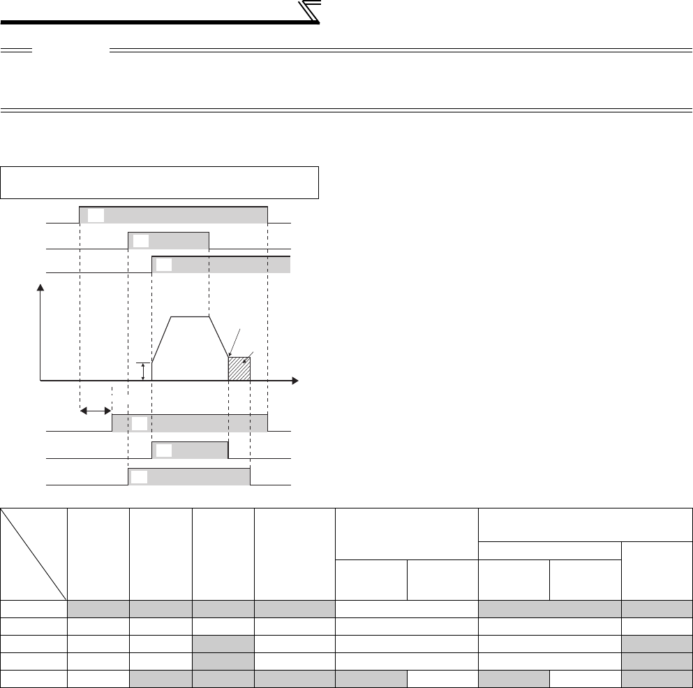
242
Function assignment of external terminal and control
(2) Inverter operation ready signal (RY, RY2 signal) and inverter running signal (RUN, RUN2,
RUN3 signal)
*1 This signal turns OFF during power failure or undervoltage.
*2 Output is shutoff in conditions like a fault and when the MRS signal is ON.
CAUTION
⋅When terminal assignment is changed using Pr. 190 to Pr. 196 (output terminal function selection), the other functions may be
affected. Set parameters after confirming the function of each terminal.
⋅Do not assign signals which repeat frequent ON/OFF to A1, B1, C1, A2, B2, C2. Otherwise, the life of the relay contact
decreases.
Under V/F control, Advanced magnetic flux
vector control
⋅When the inverter is ready to operate, the output of the
operation ready signal (RY) is ON. (It is also on during
inverter running.)
⋅When the output frequency of the inverter rises to or above
Pr. 13 Starting frequency, the output of the inverter running
signals (RUN, RUN2) is turned ON. During an inverter stop or
DC injection brake operation, the output is OFF.
⋅For the RUN3 signal, output is ON while the inverter running
and the start signal is ON.
(For the RUN3 signal, output is ON if the starting command is
ON even when the inverter protective function is activated or
the MRS signal is ON.)
The output is ON during DC injection brake operation and
OFF during an inverter stop.
Inverter
Status
Output
Signal
Start
Signal is
OFF
(during
stop)
Start
Signal is
ON
(during
stop)
Start
Signal is
ON
(during
running)
Under DC
Injection
Brake
Output Shutoff *2
Automatic Restart after
Instantaneous Power Failure
Coasting
Restarting
Start signal
is ON
Start signal
is OFF
Start signal
is ON
Start signal
is OFF
RY ON ON ON ON OFF ON *1 ON
RY2 OFF OFF OFF OFF OFF OFF OFF
RUN OFF OFF ON OFF OFF OFF ON
RUN2 OFF OFF ON OFF OFF OFF ON
RUN3 OFF ON ON ON ON OFF ON OFF ON
Power
supply
Output frequency
STF
RH
RY
RUN3
Pr. 13
Starting
frequency
DC injection brake
operation point
DC injection
brake
operation
Reset
processing Time
ON
ON
ON
ON
ON
ON
OFF
OFF
OFF
OFF
OFF
RUN
(RUN2)
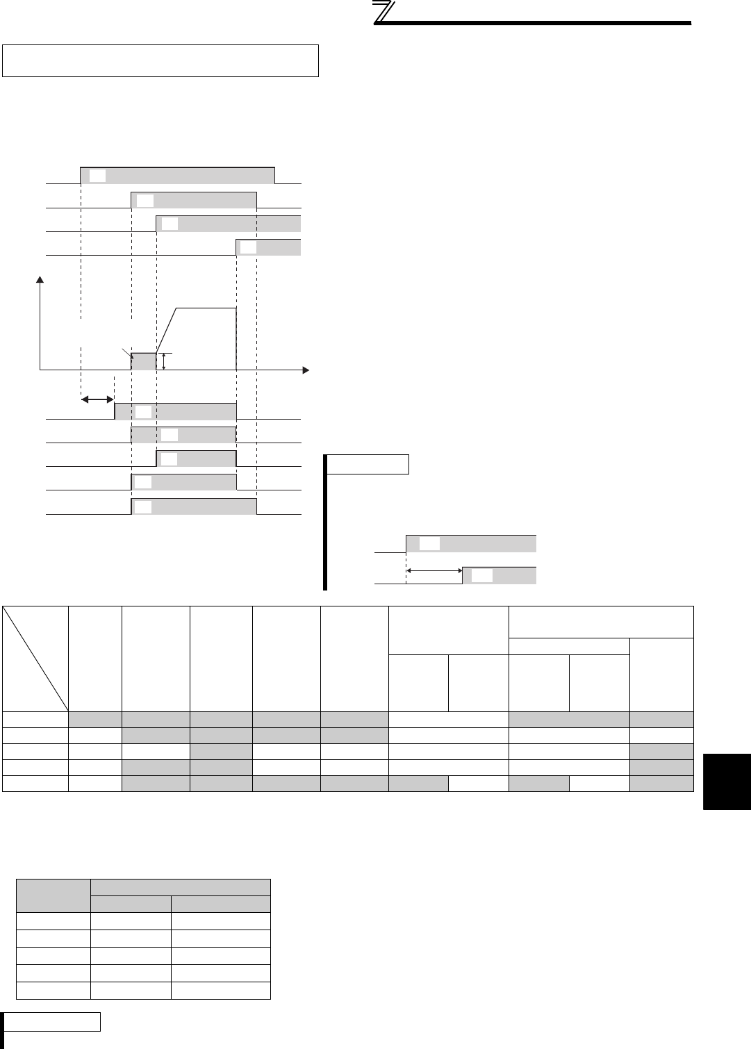
243
Function assignment of external terminal and control
4
PARAMETERS
*1 Pre-excitation is made when the start signal is ON and frequency command is 0Hz.
*2 This signal turns OFF during power failure or undervoltage.
*3 There is a delay of 100ms (500ms for the 75K or higher) when the signal is ON.
*4 This signal turns ON during servo ON (LX signal is ON) under position control.
*5 Output is shutoff in conditions like a fault and when the MRS signal is ON.
Under Real sensor less vector control,
vector control ⋅When the inverter is ready to operate, the output of the
operation ready signal (RY) is ON.
(It is also on during inverter running.)
⋅When the inverter output frequency rises to or above the Pr.
13 Starting frequency setting, the output of the inverter running
signal (RUN) is turned ON. During an inverter stop, DC
injection brake operation, start time tuning or pre-excitation,
the output is OFF.
⋅For the RUN2 signal, the output is ON while the inverter is
running and the start signal is ON. (For the RUN2 signal, the
output is OFF when the inverter protective function is
activated and the MRS signal is ON.)
⋅For the RUN3 signal, the output is ON while the inverter is
running and the start signal is ON.
⋅The RUN2 and RUN3 signals are on when the start command
is ON and even during pre-excitation with "0" set in speed
command. (Note that the RUN2 signal turns OFF during pre-
excitation by turning the LX signal ON.)
⋅The RY2 signal turns ON at the start of pre-excitation.
The signal is ON while pre-excitation is activated even during
an inverter stop. The signal turns OFF while the output is shut
off (MRS signal).
Inverter
Status
Output
Signal
Start
Signal
is OFF
(during
stop)
Start
Signal is
ON *1
(pre-
excitation)
Start
Signal is
ON
(during
running)
LX Signal
is ON
(pre-
excitation)
DC
Injection
Brake
Operation
(pre-
excitation)
Output Shutoff *5
Automatic Restart after
Instantaneous Power Failure
Coasting
Restarting
Start
signal is
ON
Start
signal is
OFF
Start
signal is
ON
Start
signal is
OFF
RY ON ON ON ON ON OFF ON *2 ON
RY2 OFF ON ON ON *3 ON OFF OFF OFF
RUN OFF OFF ON OFF OFF OFF OFF ON
RUN2 OFF ON ON OFF *4 OFF OFF OFF ON
RUN3 OFF ON ON ON ON ON OFF ON OFF ON
⋅When using the RY, RY2, RUN, RUN2 and RUN3 signals, assign
functions to Pr. 190 to Pr. 196 (output terminal selection function)
referring to the table on the left.
REMARKS
⋅The RUN signal is assigned to the terminal RUN in the initial setting.
Time
Power
supply
STF
RH
RY
RY2
Reset
processing
ON OFF
OFF
OFF
OFF
MRS
Pr. 13
RUN
RUN2
OFF
OFF
RUN3 OFF
Output frequency
ON
ON
ON
ON
ON
ON
ON
ON
Pre-excitation
(0 speed control)
REMARKS
For pre-excitation by pre-excitation signal (LX), the RY2 signal
turns ON when 100ms has elapsed after LX signal turn ON
(500ms for the 75K or higher).
100(500)ms
LX
RY2
ON
ON
Output
signal
Pr. 190 to Pr. 196 Setting
Positive logic Negative logic
RY 11 111
RY2 33 133
RUN 0 100
RUN2 44 144
RUN3 45 145
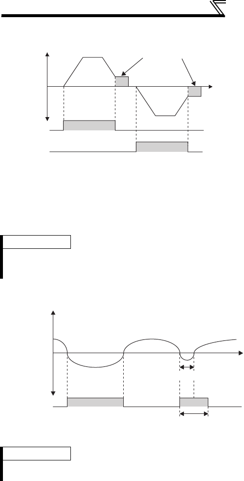
244
Function assignment of external terminal and control
(3) Forward rotation and reverse rotation signal (Y30, Y31 signal)
(4) Regenerative mode output signal (Y32 signal)
⋅The status during forward rotation (Y30) and reverse
rotation (Y31) are output from the actual motor speed
under vector control.
⋅Y30 and Y31 signals turn OFF during pre-excitation
(zero speed, servo lock) under speed control or torque
control operation. Note that signals are output
according to the motor rotation during servo lock under
position control as same as inverter running.
⋅When using the Y30 signal, set "30 (positive logic) or
130 (negative logic)" to any of Pr. 190 to Pr. 196 (output
terminal function selection) to assign the function to the
output terminal.
⋅When using the Y31 signal, set "31 (positive logic) or
131 (negative logic)" to any of Pr. 190 to Pr. 196 (output
terminal function selection) to assign the function to the
output terminal.
REMARKS
⋅This signal is always OFF during V/F control, Advanced magnetic flux vector control or Real sensorless vector control.
⋅If the motor is made to run by external force, etc. during an inverter stop, Y30 and Y31 remain OFF.
⋅The FR-A7AP/FR-A7AL (option) is necessary for vector control.
⋅While the motor is in regenerative status (motor is in
power regenerative status), the regenerative status
output signal (Y32) is turned ON.
If the signal is turned on once, it will be retained for at
least 100ms.
⋅It turns OFF while the inverter is stopped and during
pre-excitation.
⋅When using the Y32 signal, set "32 (positive logic) or
132 (negative logic)" to any of Pr. 190 to Pr. 196 (output
terminal function selection) to assign the function to the
output terminal.
REMARKS
⋅This signal is always OFF during V/F control, Advanced magnetic flux vector control or Real sensorless vector control.
⋅The FR-A7AP/FR-A7AL (option) is necessary for vector control.
Time
Pre-excitation
ON
Y31
Y30
ON
Actual
motor
speed
Forward
rotation
Reverse
rotation
Time
OFFON ON
Signal is retained for 100ms.
Y32
Regeneration
-
Driving
+
Less than 100ms
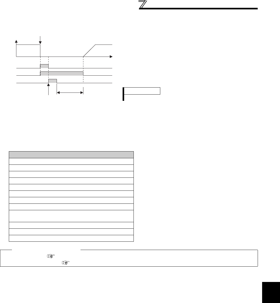
245
Function assignment of external terminal and control
4
PARAMETERS
(5) Fault output signal (ALM, ALM2 signal)
(6) Input MC shutoff signal (Y91 signal)
⋅The Y91 signal is output at occurrence of a fault attributable to the failure of the inverter circuit or a fault caused by
a wiring mistake.
⋅When using the Y91 signal, set "91 (positive logic)" or "191 (negative logic)" to any of Pr. 190 to Pr. 196 (output
terminal function selection) to assign the function to the output terminal.
⋅The following table indicates the faults that will output the Y91 signal. (Refer to page 404 for the fault description.)
⋅If the inverter comes to trip, the ALM and ALM2 signals are
output.
⋅The ALM2 signal remains on during a reset period after fault
occurrence.
⋅When using the ALM2 signal, set "94 (positive logic)" or "194
(negative logic)" to any of Pr. 190 to Pr. 196 (output terminal
function selection) to assign the function to the output
terminal.
⋅The ALM signal is assigned to the A1B1C1 contact in the
initial setting.
Fault Description
Inrush current limit circuit fault (E.IOH)
CPU fault (E.CPU)
CPU fault (E.5)
CPU fault (E.6)
CPU fault (E.7)
Parameter storage device fault (E.PE)
Parameter storage device fault (E.PE2)
24VDC power output short circuit (E.P24)
Operation panel power supply short circuit, RS-485 terminal
power supply short circuit (E.CTE)
Output side earth (ground) fault overcurrent protection (E.GF)
Output phase loss (E.LF)
Brake transistor alarm detection (E.BE)
♦ Parameters referred to ♦
Pr. 13 Starting frequency Refer to page 175
Pr. 76 Fault code output selection Refer to page 275
ON OFF
ON
ON OFF
Reset ON
Output frequency
ALM
A
LM2
RES
OFF
Inverter fault occurrence
(trip)
Reset processing
(about 1s)
Time
REMARKS
Refer to page 404 for the inverter fault description.
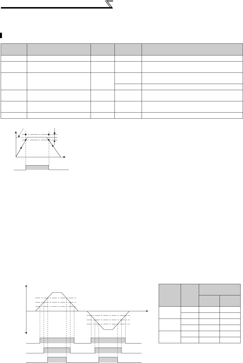
246
Function assignment of external terminal and control
4.15.7 Detection of output frequency (SU, FU, FU2 , FU3, FB, FB2, FB3, LS signal,
Pr. 41 to Pr. 43, Pr. 50, Pr. 116, Pr. 865)
The inverter output frequency is detected and output to the output signal.
Parameter
Number Name Initial
Value
Setting
Range Description
41 Up-to-frequency sensitivity 10% 0 to 100% Set the level where the SU signal turns ON.
42 Output frequency detection 6Hz 0 to 400Hz Set the frequency where the FU (FB) signal turns
ON.
43 Output frequency detection
for reverse rotation 9999 0 to 400Hz Set the frequency where the FU (FB) signal turns ON
in reverse rotation.
9999 Same as Pr. 42 setting
50 Second output frequency
detection 30Hz 0 to 400Hz Set the frequency where the FU2 (FB2) signal turns
ON.
116 Third output frequency
detection 60Hz 0 to 400Hz Set the frequency where the FU3 (FB3) signal turns
ON.
865 Low speed detection 1.5Hz 0 to 400Hz Set the frequency where the LS signal turns ON.
(1) Up-to-frequency sensitivity (SU signal, Pr. 41)
⋅When the output frequency reaches the set frequency, the up-to-frequency
signal (SU) is output.
⋅The Pr. 41 value can be adjusted within the range ±1% to ±100% on the
assumption that the set frequency is 100%.
⋅This parameter can be used to ensure that the set frequency has been
reached to provide the operation start signal etc. for related equipment.
(2) Output frequency detection (FU (FB) signal, FU2 (FB2) signal, FU3 (FB3) signal, Pr. 42, Pr. 43,
Pr. 50, Pr. 116)
⋅When the output frequency rises to or above the Pr. 42 setting, the output frequency detection signal (FU, FB) is
output.
⋅This function can be used for electromagnetic brake operation, open signal, etc.
⋅The FU (FU2, FU3) signal is output when the output frequency (frequency command) reaches the set frequency.
The FB (FB2, FB3) signal is output when the actual rotation detection speed (estimated speed in Real sensorless
vector control, feedback value in vector control) of the motor reaches the set frequency. The FU signal and FB
signal are output simultaneously during V/F control, Advanced magnetic flux vector control and encoder feedback
control.
⋅When the detection frequency is set in Pr. 43, frequency detection used exclusively for reverse rotation can also be
set. This function is effective for switching the timing of electromagnetic brake operation between forward rotation
(rise) and reverse rotation (fall) during elevator operation, etc.
⋅When Pr. 43 ≠ "9999", the Pr. 42 setting applies to forward rotation and the Pr. 43 setting applies to reverse rotation.
⋅When outputting a frequency detection signal besides the FU signal, set the detection frequency in Pr. 50 or Pr. 116.
The FU2 (FB2) signal (FU3(FB3) signal if Pr. 116 or more) is output when the output frequency reaches or exceeds
the Pr. 50 setting.
⋅For each signal, assign functions to Pr. 190 to Pr. 196 (output terminal function selection) referring to the table below.
Output frequency
(Hz)
ON
Set frequency Adjustment
range Pr.41
SU
Time
OFFOFF
Forward
rotation
Pr.116
Pr.50
Pr.42
Pr.43
Pr.50
Pr.116
OFFONOFFONOFF
Time
(Hz)
FU/FB
FU2/FB2
FU3/FB3
Output
signal
OFF
OFF
ON
ON
OFF
OFF
ON
ON
OFF
OFF
Output frequency
Reverse
rotation
Parameter
Number
Output
Signal
Pr. 190 to Pr. 196
Setting
Positive
logic
Negative
logic
42, 43 FU 4 104
FB 41 141
50 FU2 5 105
FB2 42 142
116 FU3 6 106
FB3 43 143
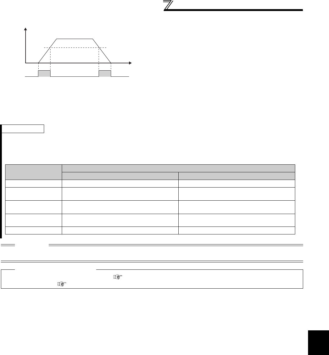
247
Function assignment of external terminal and control
4
PARAMETERS
(3) Low speed detection (LS signal, Pr. 865)
⋅The low speed detection signal (LS) is output when the
output frequency drops below the Pr. 865 Low speed
detection setting.
⋅When speed control is performed by Real sensorless
vector control or vector control, a fault (E.OLT) is
displayed and the inverter trips if frequency drops to the
Pr. 865 setting by torque limit operation and the output
torque exceeds Pr. 874 OLT level setting and remains for
more than 3s.
⋅
For the LS signal, set "34 (positive logic) or 134 (negative
logic)" in
Pr. 190 to Pr. 196 (output terminal function
selection)
and assign functions to the output terminal.
REMARKS
⋅The FU signal is assigned to the terminal FU and the SU signal is assigned to the terminal SU in the initial setting.
⋅All signals are OFF during DC injection brake, pre-excitation (zero speed control, servo lock), or start time tuning.
⋅The type of frequency (output as the following signals), which is compared with the set frequency, differs by the
control method.
CAUTION
⋅When terminal assignment is changed using Pr. 190 to Pr. 196 (output terminal function selection), the other functions may be
affected. Set parameters after confirming the function of each terminal.
♦ Parameters referred to ♦
Pr. 190 to Pr. 196 (output terminal function selection) Refer to page 239
Pr. 874 OLT level setting Refer to page 100
ONLS ONOFF
Pr.865
Output frequency
(Hz)
Time
Control Method Compared frequency
FU, FU2, FU3 FB, FB2, FB3, SU, LS
V/F control Output frequency Output frequency
Advanced magnetic
flux vector control Output frequency before the slip compensation. Output frequency before the slip compensation.
Real sensorless
vector control Frequency command Estimated frequency (estimated from the actual
motor speed)
Encoder feedback
control Actual motor speed converted as frequency Actual motor speed converted as frequency
Vector control Frequency command Actual motor speed converted as frequency
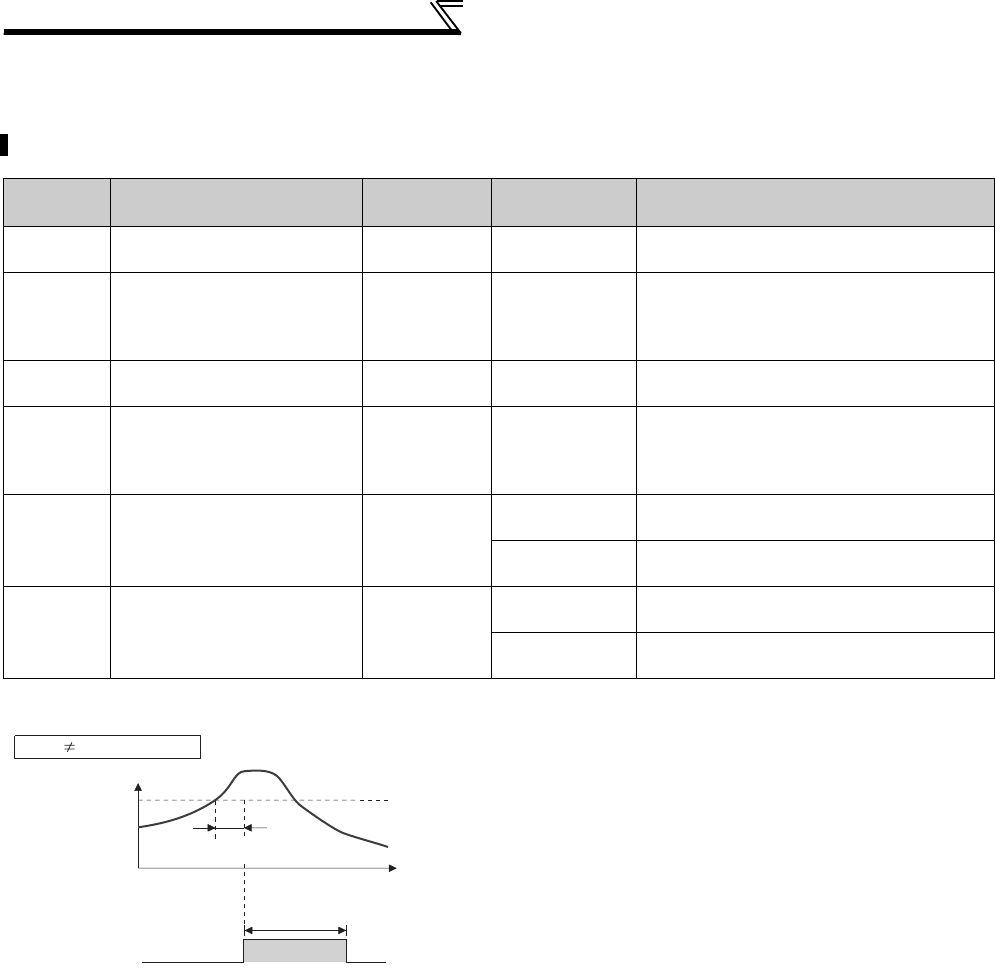
248
Function assignment of external terminal and control
4.15.8 Output current detection function
(Y12 signal, Y13 signal, Pr. 150 to Pr. 153, Pr. 166, Pr. 167)
The output power during inverter running can be detected and output to the output terminal.
Parameter
Number Name Initial Value Setting Range Description
150 Output current detection
level 150% 0 to 220% Set the output current detection level. 100%
is the rated inverter current.
151 Output current detection
signal delay time 0s 0 to 10s
Set the output current detection period. Set
the time from when the output current has
risen above the setting until the output current
detection signal (Y12) is output.
152 Zero current detection level 5% 0 to 220% Set the zero current detection level. The rated
inverter current is assumed to be 100%.
153 Zero current detection time 0.5s 0 to 1s
Set this parameter to define the period from
when the output current drops below the Pr.
152 value until the zero current detection
signal (Y13) is output.
166 Output current detection
signal retention time 0.1s
0 to 10s Set the retention time when the Y12 signal is
ON.
9999 The Y12 signal ON status is retained. The
signal is turned OFF at the next start.
167 Output current detection
operation selection 0
0Operation continues when the Y12 signal is
on
1The inverter trips when the Y12 signal is ON.
(E.CDO)
(1) Output current detection (Y12 signal, Pr. 150, Pr.
151, Pr. 166, Pr. 167 )
⋅The output current detection function can be used for excessive
torque detection, etc.
⋅If the output current remains higher than the Pr. 150 setting during
inverter operation for longer than the time set in Pr. 151, the
output current detection signal (Y12) is output from the inverter's
open collector or relay output terminal.
⋅When the Y12 signal turns ON, the ON state is held for the time
set in Pr. 166 .
⋅When Pr. 166 = "9999", the ON state is held until a next start.
⋅At the Pr. 167 setting of "1", the inverter trips and the output
current detection fault (E.CDO) is displayed when the Y12 signal
turns ON. When fault occurs, the Y12 signal is ON for the time
set in Pr. 166 at the Pr. 166 setting of other than "9999", and
remains on until a reset is made at the Pr. 166 setting of "9999".
E.CDO does not occur even if "1" is set in Pr. 167 while Y12 is
ON. The Pr. 167 setting is valid after Y12 turns OFF.
⋅Set "12 (positive logic)" or "112 (negative logic)" to any of Pr. 190
to Pr. 196 (output terminal function selection) to assign the function
of the Y12 signal to the output terminal.
Time
Pr. 150
OFF ON OFF
Output current
detection signal
(Y12)
Pr. 166
Minimum 0.1s
(initial value)
Output current
Pr. 166 9999, Pr. 167 = 0
Pr. 151
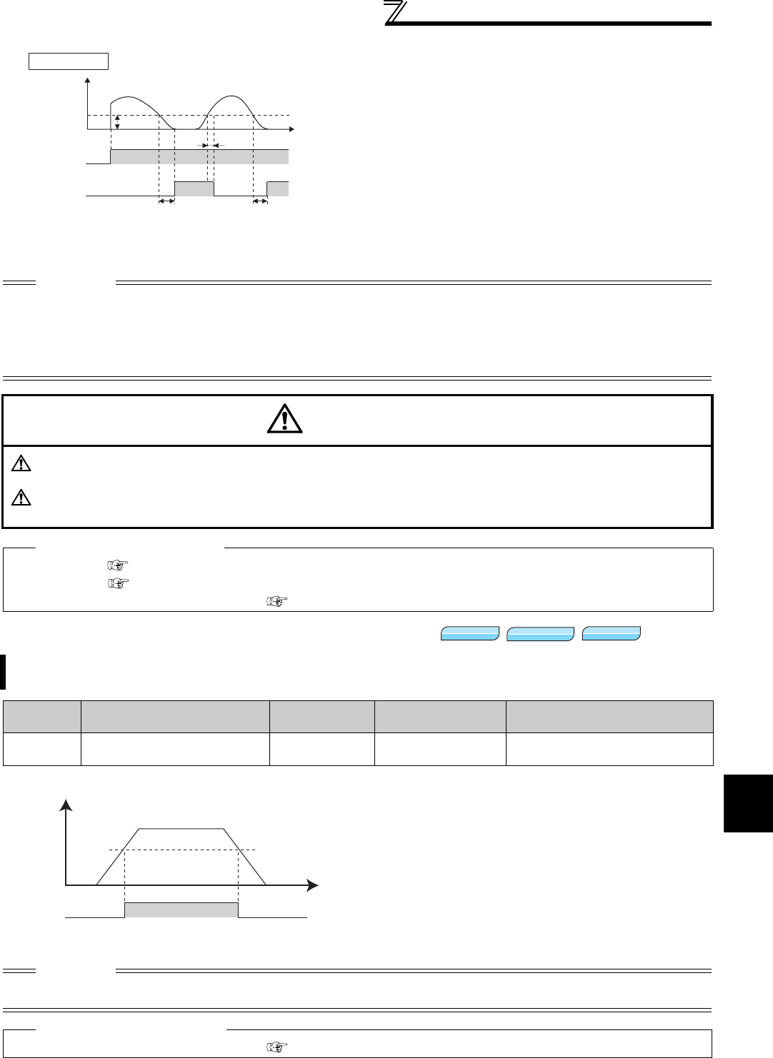
249
Function assignment of external terminal and control
4
PARAMETERS
4.15.9 Detection of output torque (TU signal, Pr. 864)
(2) Zero current detection (Y13 signal, Pr. 152, Pr. 153)
⋅If the output current remains lower than the Pr. 152 setting
during inverter operation for longer than the time set in Pr.
153, the zero current detection (Y13) signal is output from
the inverter's open collector or relay output terminal.
⋅When the inverter's output current falls to "0", torque will not
be generated. This may cause a drop due to gravity when
the inverter is used in vertical lift application. To prevent this,
the Y13 signal can be output from the inverter to close the
mechanical brake when the output current has fallen to
"zero".
⋅Set "13 (positive logic)" or "113 (negative logic)" in any of Pr.
190 to Pr. 196 (output terminal function selection) to assign the
function of the Y13 signal to the output terminal.
CAUTION
⋅This function is also valid during execution of the online or offline auto tuning.
⋅The response time of Y12 and Y13 signals is approximately 0.1s. Note that the response time changes according to the load
condition.
⋅When Pr. 152 = "0", detection is disabled.
⋅When terminal assignment is changed using Pr. 190 to Pr. 196 (output terminal function selection), the other functions may be
affected. Set parameters after confirming the function of each terminal.
CAUTION
The zero current detection level setting should not be too low, and the zero current detection time setting not too
long. Otherwise, the detection signal may not be output when torque is not generated at a low output current.
To prevent the machine and equipment from resulting in hazardous conditions by use of the zero current
detection signal, install a safety backup such as an emergency brake.
♦ Parameters referred to ♦
Online auto tuning Refer to page 199
Offline auto tuning Refer to page 189
Pr. 190 to Pr. 196 (output terminal function selection) Refer to page 239
Output the signal when the motor torque rises above the setting value.
This function can be used for electromagnetic brake operation, open signal, etc.
Parameter
Number Name Initial Value Setting Range Description
864 Torque detection 150% 0 to 400% Set the torque value where the TU
signal turns ON.
⋅When the output torque reaches or exceeds the
detected torque value set in Pr. 864 under Real
sensorless vector control, Advanced magnetic flux
vector control or vector control, the torque detection
signal (TU) turns ON.
It turns OFF when the torque falls below the detection
torque value.
⋅For the TU signal, set "35 (positive logic) or 135
(negative logic)" in Pr. 190 to Pr. 196 (output terminal
function selection) and assign functions to the output
terminal.
CAUTION
⋅When terminal assignment is changed using Pr. 190 to Pr. 196 (output terminal function selection), the other functions maybe
affected. Set parameters after confirming the function of each terminal.
♦ Parameters referred to ♦
Pr. 190 to Pr. 196 (output terminal function selection) Refer to page 239
OFF ON
Start signal
Time
Output
current
OFF ON
Zero current
detection time
(Y13) Pr. 153
Detection time
Pr. 153
Detection time
Pr.152
OFF ON
0[A] 0.1s*
Pr.152
* Once turned ON, the zero current detection time
signal (Y13) is held ON for at least 0.1s.
Pr. 167 = 0 or 1
Sensorless
Sensorless
Sensorless
Magnetic flux
Magnetic flux
Magnetic flux
Vector
Vector
Vector
Output torque (%)
Time
ONTU OFF
Pr.864

250
Function assignment of external terminal and control
4.15.10 Remote output function (REM signal, Pr. 495 to Pr. 497)
You can utilize the ON/OFF of the inverter's output signals instead of the remote output terminal of the
programmable logic controller.
Parameter
Number Name Initial
Value
Setting
Range Description
495 Remote output selection 0
0 Remote output data clear at powering OFF Remote output data
is cleared during an
inverter reset
1Remote output data retention even at
powering OFF
10 Remote output data clear at powering OFF Remote output data
is retained during an
inverter reset
11 Remote output data retention even at
powering OFF
496 * Remote output data 1 0 0 to 4095 Refer to the following diagram.
497 * Remote output data 2 0 0 to 4095
* The above parameters allow its setting to be changed during operation in any operation mode even if "0" (initial value) is set in Pr.
77 Parameter write selection.
<Remote output data>
Pr. 496
Pr. 497
*1 As desired
*2 Y0 to Y6 are available only when the extension output option (FR-A7AY)
is fitted
*3 RA1 to RA3 are available only when the relay output option (FR-A7AR) is
fitted
⋅The output terminal can be turned ON/OFF depending
on the Pr. 496 or Pr. 497 setting. The remote output
selection can be controlled ON/OFF by computer link
communication from the PU connector or RS-485 port
or by communication from the communication option.
⋅Set "96" (positive logic) or "196" (negative logic) to any
of Pr. 190 to Pr. 196 (output terminal function selection),
and assign the remote output (REM) signal to the
terminal used for remote output,
⋅When you refer to the diagram on the left and set 1 to
the terminal bit (terminal where the REM signal has
been assigned) of Pr. 496 or Pr. 497, the output terminal
turns ON (OFF for negative logic). By setting 0, the
output terminal turns OFF (ON for negative logic).
Example)When "96" (positive logic) is set in Pr. 190 RUN terminal function selection and "1" (H01) is set in Pr. 496,
the terminal RUN turns ON.
ON/OFF example for positive logic
Signal condition during a reset
* When Pr. 495 = "1," the signal condition saved in EEPROM
(condition of the last power OFF) is applied.
⋅When Pr. 495 = "0 (initial value), 10", performing a power
supply reset (including a power failure) clears the REM signal
output. (The ON/OFF status of the terminals are as set in Pr.
190 to Pr. 196.) The Pr. 496 and Pr. 497 settings are also "0".
When Pr. 495 = "1, 11", the remote output data before power
supply-off is stored into the EEPROM, so the signal output at
power recovery is the same as before power supply-OFF.
However, it is not stored when the inverter is reset (terminal
reset, reset request through communication).
(See the chart on the left)
⋅When Pr. 495 = "10, 11", the signal before the reset is held
even during an inverter reset.
REMARKS
⋅The output terminal where the REM signal is not assigned using any of Pr. 190 to Pr. 196 does not turn ON/OFF if 0/1 is set to the
terminal bit of Pr. 496 or Pr. 497. (It turns ON/OFF with the assigned function.)
CAUTION
⋅When Pr. 495 = "1, 11" (remote output data retention at power OFF), connect R1/11 with P/+, and S1/L21 with N/- so that the
control power is retained. If you do not take such a step, the output signals provided after power-ON are not guaranteed.
♦ Parameters referred to ♦
⋅ Pr. 190 to Pr. 196 (output terminal function selection) Refer to page 239
b11 b0
ABC1
ABC2
*1
*1
*1
*1
*1
FU
OL
IPF
SU
RUN
b11 b0
Y5 *2
Y6 *2
RA1 *3
RA2 *3
RA3 *3
*1
*1
Y4 *2
Y3 *2
Y2 *2
Y1 *2
Y0 *2
Power
supply
Power
supply
OFF OFF
ONOFF REMREM
REM signal clear REM signal held
Inverter
reset time
(about 1s)
Pr. 495 = 0, 10 Pr. 495 = 1, 11
REM signal is saved
Reset ON
ON OFF ONREMREM
Pr. 495 = 0, 1 Pr. 495 = 10, 11
Reset ON
∗

251
Monitor display and monitor output signal
4
PARAMETERS
4.16 Monitor display and monitor output signal
4.16.1 Speed display and speed setting (Pr. 37, Pr. 144, Pr. 505, Pr. 811)
* The maximum value of the setting range differs according to the Pr. 1 Maximum frequency and Pr. 505 Speed setting reference settings
and it can be calculated from the following formula.
Maximum setting value of Pr. 37 <
Note that the maximum setting value of Pr. 37 is 9998 if the result of the above formula exceeds 9998.
Purpose Parameter that must be Set Refer to Page
Display motor speed
Set speed
Speed display and speed
setting Pr. 37, Pr. 144, Pr. 505, Pr. 811 251
Change PU monitor display data
DU/PU main display data
selection
Cumulative monitor clear
Pr. 52, Pr. 170, Pr. 171, Pr. 268, Pr. 891 253
Change of the monitor output
from terminal FM and AM
Terminal FM, AM function
selection Pr. 54, Pr. 158, Pr. 291, Pr. 866, Pr. 867 253
Set the reference of the monitor
output from terminal FM and AM
Setting of reference of
terminal FM and AM Pr. 55, Pr. 56, Pr. 291, Pr. 866, Pr. 867 259
Adjust terminal FM, AM outputs Terminal FM, AM
calibration Pr. 900, Pr. 901 263
You can change the PU (FR-DU07/FR-PU04/FR-PU07) monitor display or frequency setting to motor speed or
machine speed.
Parameter
Number Name Initial
Value
Setting
Range Description
37 Speed display 00 Frequency display, setting
1 to 9998* Set the machine speed at Pr. 505.
144 Speed setting switchover 4
0, 2, 4, 6, 8,
10, 102, 104,
106, 108, 110
Set the number of motor poles when displaying the motor speed.
505 Speed setting reference 60Hz 1 to 120Hz Set the reference speed for Pr. 37.
811 Set resolution switchover 0
Speed setting and running
speed monitor increments from
the PU, RS-485 communication
or communication option.
Torque limit setting increments
Pr. 22, Pr. 812 to Pr. 817
0 1r/min 0.1%
1 0.1r/min
10 1r/min 0.01%
11 0.1r/min
65535 × Pr. 505
Setting value of Pr. 1 (Hz)
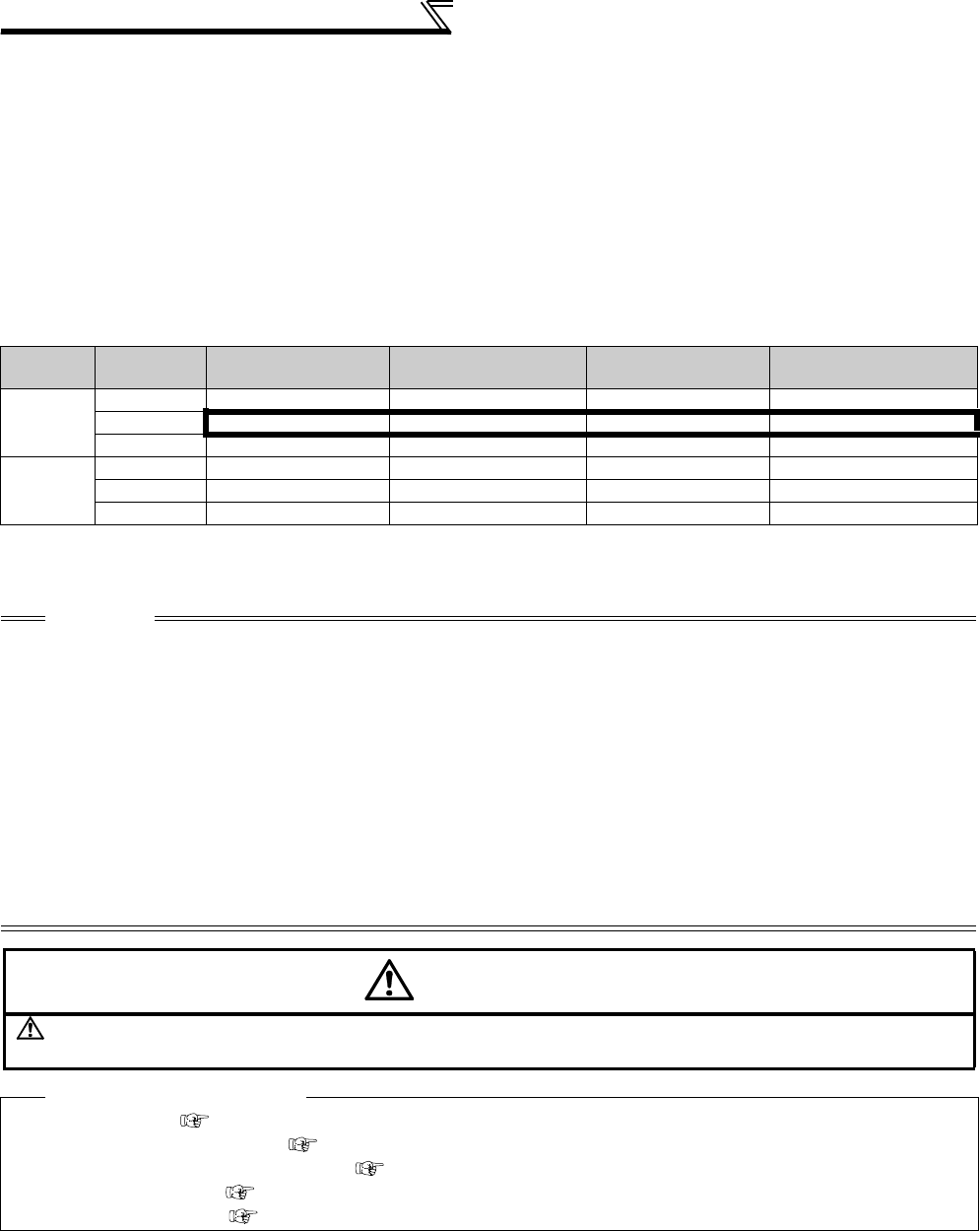
252
Monitor display and monitor output signal
⋅To display the machine speed, set in Pr. 37 the machine speed for operation with frequency set in Pr. 505.
For example, when Pr. 505 = "60Hz" and Pr. 37 = "1000", "1000" is displayed on the running speed monitor when the
running frequency is 60Hz. When running frequency is 30Hz, "500" is displayed.
⋅When displaying the motor speed, set the number of motor poles (2, 4, 6, 8, 10) or number of motor poles + 100
(102, 104, 106, 108, 110) in Pr. 144.
⋅The Pr. 144 setting is automatically changed if the number of motor poles is set in Pr. 81 Number of motor poles. The Pr.
81 setting is not automatically changed even if the setting of Pr. 144 is changed.
Example 1) When the initial value of Pr. 81 is changed to "2" or "12", the Pr. 144 setting changes from "4" to "2".
Example 2) When Pr. 144 = "104", setting "2" in Pr. 81 changes the Pr. 144 setting from "104" to "102".
⋅When "1, or 11" is set in Pr. 811, the setting increments of speed setting from the PU, speed setting from RS-485
communication or communication options (other than FR-A7ND, FR-A7NL) and running speed monitor is 0.1r/min.
⋅A combination of the Pr.37 and Pr. 144 settings determines the setting increment as shown in the table below.
(Initial value are outlined with bold borders.)
Pr. 37
Setting
Pr. 144
Setting
Output Frequency
Monitor
Set Frequency
Monitor
Running Speed
Monitor
Frequency Setting
Parameter Setting
0
(initial
value)
0 0.01Hz 0.01Hz 1r/min *1 0.01Hz
2 to 10 0.01Hz 0.01Hz 1r/min *1 0.01Hz
102 to 110 1r/min *1 1r/min *1 1r/min *1 1r/min *1
1 to 9998
0 0.01Hz 0.01Hz 1 (Machine speed *1) 0.01Hz
2 to 10 1 (Machine speed *1) 1 (Machine speed *1) 1 (Machine speed *1) 1 (Machine speed *1)
102 to 110 0.01Hz 0.01Hz 1r/min *1 0.01Hz
*1 Motor speed r/min conversion formula............ frequency × 120/number of motor poles (Pr. 144)
Machine speed conversion formula................... Pr. 37 × frequency/Pr. 505
For Pr. 144 in the above formula, the value is "Pr. 144 - 100" when "102 to 110" is set in Pr. 144 and the value is "4" when Pr. 37 = 0 and Pr. 144 = 0.
Pr. 505 is always set as frequency (Hz).
CAUTION
⋅The inverter's output frequency is displayed as synchronous speed under V/F control. The displayed value is "actual motor
speed" + "motor slip." This display changes to the actual speed (estimated value calculated based on the motor slip) when the
Advanced magnetic flux vector control or Real sensorless vector control is selected, and actual speed from the encoder when
encoder feedback control or vector control is performed.
⋅When the running speed display is selected at the setting of Pr. 37 = "0" and Pr. 144 = "0", the monitor display is provided on the
assumption that the number of motor poles is 4. (1800r/min is displayed at 60Hz)
⋅Refer to Pr. 52 when you want to change the PU main monitor (PU main display).
⋅Since the panel display of the operation panel (FR-DU07) is 4 digits in length, the monitor value of more than "9999" is
displayed "----".
⋅After setting the running speed in 0.1r/min increments (Pr. 811 = "1, 11"), changing the setting increments to 1r/min increments
(Pr. 811 = "0, 10") changes the speed resolution from 0.1r/min to 0.3r/min (four poles), which may round down 0.1r/min
increments.
⋅When the machine speed is displayed on the FR-PU04/FR-PU07, do not change the speed by using an up/down key in the
state where the set speed exceeding 65535 is displayed. The set speed may become arbitrary value.
⋅When an optional FR-A7ND or FR-A7NL card is mounted, frequency is displayed regardless of Pr. 37 and Pr. 144 setting.
CAUTION
Make sure that the settings of the running speed and number of motor poles are correct. Otherwise, the motor
might run at extremely high speed, damaging the machine.
♦ Parameters referred to ♦
Pr. 1 Maximum frequency Refer to page 157
Pr. 52 DU/PU main display data selection Refer to page 253
Pr. 80 Motor capacity, Pr. 81 Number of motor poles Refer to page 148
Pr. 800 Control system selection Refer to page 92
Pr. 811 Set resolution switchover Refer to page 100
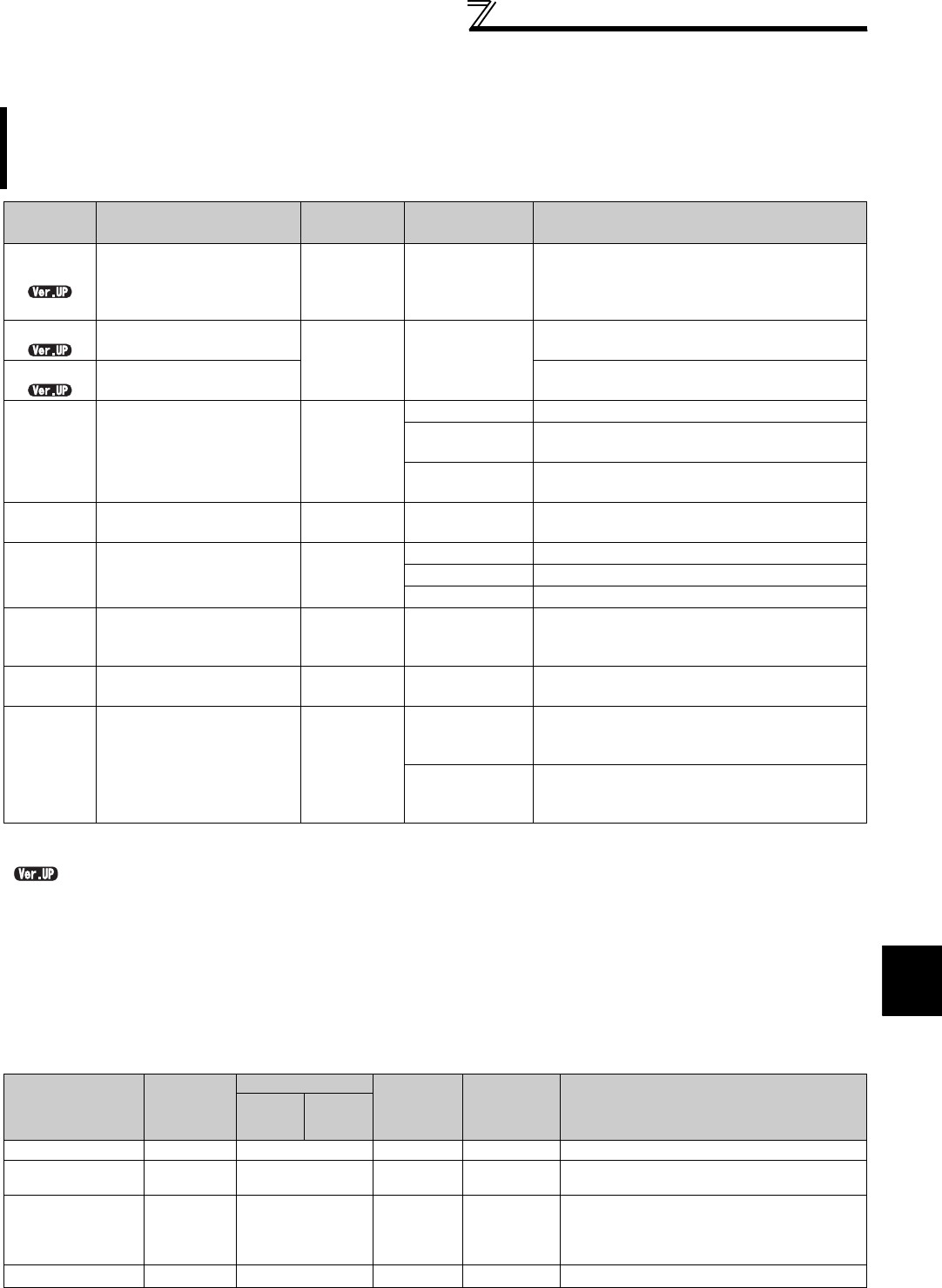
253
Monitor display and monitor output signal
4
PARAMETERS
4.16.2 DU/PU, FM, AM terminal monitor display selection (Pr. 52, Pr. 54, Pr. 158, Pr. 170,
Pr. 171, Pr. 268, Pr. 563, Pr. 564, Pr. 891)
(1) Monitor description list (Pr. 52)
⋅Set the monitor to be displayed on the operation panel (FR-DU07) and parameter unit (FR-PU04/FR-PU07) in Pr.
52 DU/PU main display data selection.
⋅Set the monitor to be output to the terminal FM (pulse train output) in Pr. 54 FM terminal function selection.
⋅Set the monitor to be output to the terminal AM (analog voltage output (0 to 10VDC voltage output)) in Pr. 158 AM
terminal function selection.
⋅Refer to the following table and set the monitor to be displayed. (The signals marked × cannot be selected for
monitoring)
The monitor to be displayed on the main screen of the operation panel (FR-DU07)/parameter unit (FR-PU04/FR-
PU07) can be selected.
In addition, signals to be output from the terminal FM (pulse train output) and AM (analog voltage output) can be
selected.
Parameter
Number Name Initial Value Setting Range Description
52* DU/PU main display data
selection
0
(output
frequency)
0, 5 to 14, 17 to
20, 22 to 25,
32 to 35, 39, 46,
50 to 57, 100
Select the monitor to be displayed on the
operation panel and parameter unit.
Refer to the following table for monitor description.
54* FM terminal function
selection 1
(output
frequency)
1 to 3, 5 to 14,
17, 18, 21, 24, 32
to 34, 46, 50, 52,
53
Select the monitor output to terminal FM.
158* AM terminal function
selection Select the monitor output to terminal AM.
170 Watt-hour meter clear 9999
0 Set "0" to clear the watt-hour meter monitor.
10 Sets the maximum value for the monitoring from
communication to 9999kWh.
9999 Sets the maximum value for the monitoring from
communication to 65535kWh.
171 Operation hour meter clear 9999 0, 9999 Set "0" to clear the operation time monitor.
Setting "9999" has no effect.
268* Monitor decimal digits
selection 9999
0 Displayed as integral value
1 Displayed in 0.1 increments
9999 No function
563 Energization time
carrying-over times 00 to 65535
(reading only)
The numbers of cumulative energization time
monitor exceeded 65535h is displayed. Reading
only
564 Operating time carrying-
over times 00 to 65535
(reading only)
The numbers of operation time monitor
exceeded 65535h is displayed. Reading only
891 Cumulative power monitor
digit shifted times 9999
0 to 4
Set the number of times to shift the cumulative
power monitor digit.
Clamp the monitoring value at maximum.
9999
No shift
Clear the monitor value when it exceeds the
maximum value.
* The above parameters allow its setting to be changed during operation in any operation mode even if "0" (initial value) is set in
Pr. 77 Parameter write selection.
............. Specifications differ according to the date assembled. Refer to page 484 to check the SERIAL number.
Types of Monitor Increments
Pr. 52 Setting Pr. 54 (FM)
Pr. 158 (AM)
Setting
Full-scale
Value of the
Terminal FM
and AM
Description
DU LED
PU main
monitor
Output frequency 0.01Hz 0/100 1
Pr. 55
Display the inverter output frequency.
Output current *7 0.01A/0.1A
*5 0/100 2
Pr. 56
Display the inverter output current effective
value.
Output voltage 0.1V 0/100 3
200V class:
400V
400V class:
800V
Display the inverter output voltage.
Fault display ⎯0/100 ×⎯Display 8 past alarms individually.

254
Monitor display and monitor output signal
Frequency setting
value 0.01Hz 5 *1 5
Pr. 55
Display the set frequency.
Running speed 1(r/min) 6 *1 6
The value
converted
with the Pr.
37 value
from Pr. 55
Display the motor speed
(The display differs depending on the Pr. 37
and Pr. 144 settings. The running speed is the
actual speed by the encoder signal during
encoder feedback control and vector control.
For details, refer to page 251.)
Motor torque 0.1% 7 *1 7
Pr. 866
Display the motor torque in percentage on the
assumption that the rated motor torque is 100%
(0% is displayed during V/F control)
Converter output
voltage 0.1V 8 *1 8
200V class:
400V
400V class:
800V
Display the DC bus voltage value.
Regenerative brake
duty 0.1% 9 *1 9
Pr. 70
Brake duty set in Pr. 30 and Pr. 70
Electronic thermal
relay function load
factor
0.1% 10 *1 10 100%
Display the motor thermal cumulative value
on the assumption that the thermal operation
level is 100%.
Output current
peak value 0.01A/0.1A
*5 11 *1 11
Pr. 56
Retain the peak value of the output current
monitor and display (clears at every start)
Converter output
voltage peak value 0.1V 12 *1 12
200V class:
400V
400V class:
800V
Retain the peak value of the DC bus voltage
value and display (clears at every start)
Input power
0.01kW
/
0.1kW *5 13 *1 13
Rated
inverter
power × 2
Display power on the inverter input side
Output power *7
0.01kW
/
0.1kW *5 14 *1 14
Rated
inverter
power × 2
Display power on the inverter output side
Load meter 0.1% 17 17
Pr. 866
Torque current is displayed in % on the
assumption that the Pr. 56 setting is 100%
(displayed on the assumption that rated
motor torque is 100% during sensorless
vector and vector control)
Motor excitation
current 0.01A/0.1A
*5 18 18
Pr. 56
Display the excitation current of the motor
Position pulse *8 ⎯19 ×⎯
Display the number of pulses per rotation of
the motor when orientation control is valid (for
FR-A7AP/FR-A7AL)
Cumulative
energization time *2 1h 20 ×⎯
Cumulative energization time since the
inverter shipment is displayed.
You can check the numbers of the monitor
value exceeded 65535h with Pr. 563.
Reference voltage
output ⎯⎯21 ⎯
Te rmin al FM:
1440 pulse/s is output when Pr. 291 = 0, 1.
50k pulse/s is output when Pr. 291 ≠ 0, 1.
Te rmin al FM:
1440 pulse/s is output when Pr.291 = 0, 1.
50k pulse/s is output when Pr.291 ≠ 0, 1.
Terminal AM: 10V is output
Orientation status
*8 122
×⎯Display only when orientation control is valid
(for FR-A7AP/FR-A7AL) (Refer to page 220)
Actual operation
time *2, *3 1h 23 ×⎯
Cumulative inverter running time is displayed.
You can check the numbers of the monitor
value exceeded 65535h with
Pr. 564
.
Use
Pr. 171
to clear the value.
(Refer to
page
258)
Motor load factor 0.1% 24 24 200%
On the assumption that the rated inverter
current value is 100%, the output current
value is displayed in %.
Monitor value = output current monitor value/
rated inverter current × 100 [%]
Cumulative power
*6
0.01kWh
/
0.1kWh *4 *5 25 ×⎯
Cumulative power amount is displayed
according to the output power monitor.
Use Pr. 170 to clear the value. (Refer to page
258)
Torque command 0.1% 32 32
Pr. 866
Display torque command value obtained from
vector control
Types of Monitor Increments
Pr. 52 Setting Pr. 54 (FM)
Pr. 158 (AM)
Setting
Full-scale
Value of the
Terminal FM
and AM
Description
DU LED
PU main
monitor

255
Monitor display and monitor output signal
4
PARAMETERS
*1 Frequency setting to output terminal status on the PU main monitor are selected by "other monitor selection" of the parameter unit (FR-PU04
, FR-PU07
).
*2 The cumulative energization time and actual operation time are accumulated from 0 to 65535 hours, then cleared, and accumulated again from 0.
When the operation panel (FR-DU07) is used, the time is displayed up to 65.53 (65530h) in the indication of 1h = 0.001, and thereafter, it is added
up from 0.
*3 The actual operation time is not added up if the cumulative operation time before power supply-off is less than 1h.
*4 When using the parameter unit (FR-PU04/FR-PU07), "kW" is displayed.
*5 The setting depends on the inverter capacity. (55K or lower / 75K or higher)
*6 Since the panel display of the operation panel (FR-DU07) is 4 digits in length, the monitor value of more than "9999" is displayed as "----".
*7 When the output current is less than the specified current level (5% of the rated inverter current), the output current is monitored as 0A. Therefore,
the monitored value of an output current and output power may be displayed as "0" when using a much smaller-capacity motor compared to the
inverter or in other instances that cause the output current to fall below the specified value.
*8 Available only when the plug-in option is mounted.
Torque current
command 0.1% 33 33
Pr. 866
Display torque current command value
Motor output 0.01kW/
0.1kW *5 34 34 Rated motor
capacity
Multiply the motor speed by the then output
torque and display the machine output of the
motor shaft end
Feedback pulse
*6, *8 ⎯35 ×⎯
Display the number of pulses fed back from
the encoder during one sampling (display
during a stop). (for FR-A7AP/FR-A7AL)
The sampling time varies with the Pr.369
Number of encoder pulses setting.
1050 or less: 1s
1051 to 2100: 0.5s
2101 to 4096: 0.25s
SSCNET III
communication
status *8
139
×⎯Display the SSCNET III communication
status. (for FR-A7NS)
Motor temperature
*8 1ºC 46 46
Pr. 751
Display the temperature of the vector control
dedicated motor with thermistor (SFV5RU
T/A) (for FR-A7AZ)
Power saving effect Variable
according to
parameters
50 50 Inverter
capacity
Display energy saving effect monitor
You can change the monitor to power saving,
power saving average value, charge display
and % display using parameters.
(For details, refer to page 280.)
Cumulative saving
power *6 51 ×⎯
PID set point 0.1% 52 52 100%
Display the set point, measured value and
deviation during PID control (For details, refer
to page 366)
PID measured
value 0.1% 53 53 100%
PID deviation 0.1% 54 ×⎯
Input terminal
status ⎯
55
*1 ×⎯Display the input terminal ON/OFF status on
the PU (refer to page 257 for DU display)
Output terminal
status ⎯*1 ×⎯Display the output terminal ON/OFF status
on the PU (refer to page 257 for DU display)
Option input
terminal status *8 ⎯56 ×× ⎯Display the input terminal ON/OFF status of
the digital input option (FR-A7AX) on the DU
(refer to page 257 for details)
Option output
terminal status *8 ⎯57 ×× ⎯
Display the output terminal ON/OFF states of
the digital output option (FR-A7AY) or relay
output option (FR-A7AR) on the DU (refer to
page 257 for details)
Types of Monitor Increments
Pr. 52 Setting Pr. 54 (FM)
Pr. 158 (AM)
Setting
Full-scale
Value of the
Terminal FM
and AM
Description
DU LED
PU main
monitor
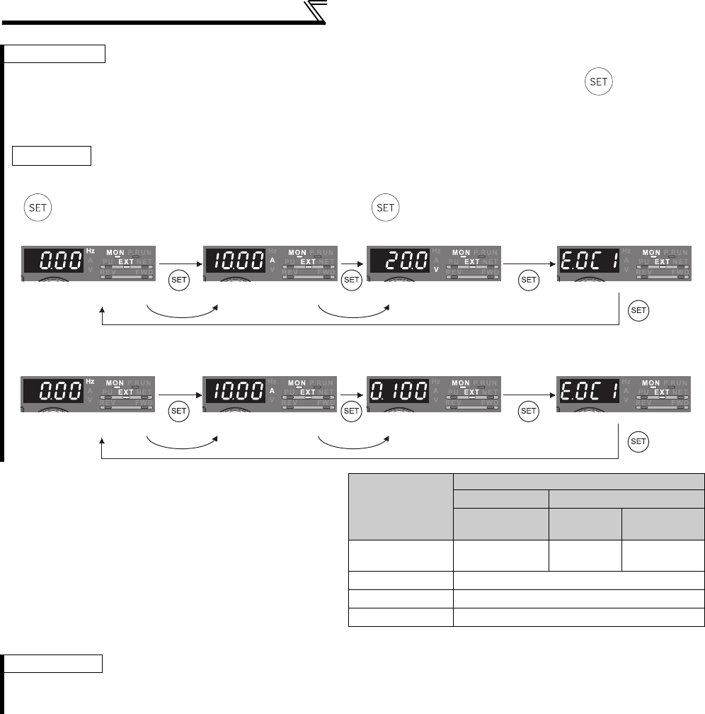
256
Monitor display and monitor output signal
REMARKS
⋅By setting "0" in Pr. 52, the monitoring of output frequency to fault display can be selected in sequence by .
⋅When the operation panel (FR-DU07) is used, the displayed units are Hz, V and A only and the others are not displayed.
⋅The monitor set in Pr. 52 is displayed in the third monitor position (The output voltage monitor is changed).
Note that load meter, motor excitation current, and motor load factor are displayed in the second monitor (output current).
* The monitor displayed at power-ON is the first monitor. Display the monitor you want to display on the first monitor and hold down
for 1s. (To return to the output frequency monitor, hold down for 1s after displaying the output frequency monitor.)
Example)
When
Pr. 52
is set to "20" (cumulative energization time), the monitor is displayed on the operation panel as described below.
(2) Display set frequency during stop (Pr. 52)
⋅When Pr. 52 is set to "100", the set frequency monitor
is displayed during a stop and the output frequency
monitor is displayed during operation. (LED of Hz
flickers during stop and is lit during running.)
⋅When Pr. 52 = "100", the set frequency displayed at a
stop indicates frequency to be output when the start
command is ON.
Different from the frequency setting displayed when
Pr. 52 = "5", the value based on maximum/minimum
frequency and frequency jump is displayed.
Type of Monitor
Pr. 52
0100
During
running/stop
During
stop
During
running
Output
frequency
Output
frequency
Set
frequency
Output
frequency
Output current Output current
Output voltage Output voltage
Fault display Fault display
REMARKS
⋅During an error, the output frequency at error occurrence appears.
⋅During MRS, the values displayed are the same as during a stop.
⋅During offline auto tuning, the tuning status monitor has priority.
Initial value
• Power-on monitor (first monitor) • Second monitor • Third monitor • Fault monitor
With fault
Output current monitor Output voltage monitor
Output frequency monitor
• Power-on monitor (first monitor) • Second monitor • Third monitor • Fault monitor
With fault
Output current monitor
Output frequency monitor Cumulative energization time monitor
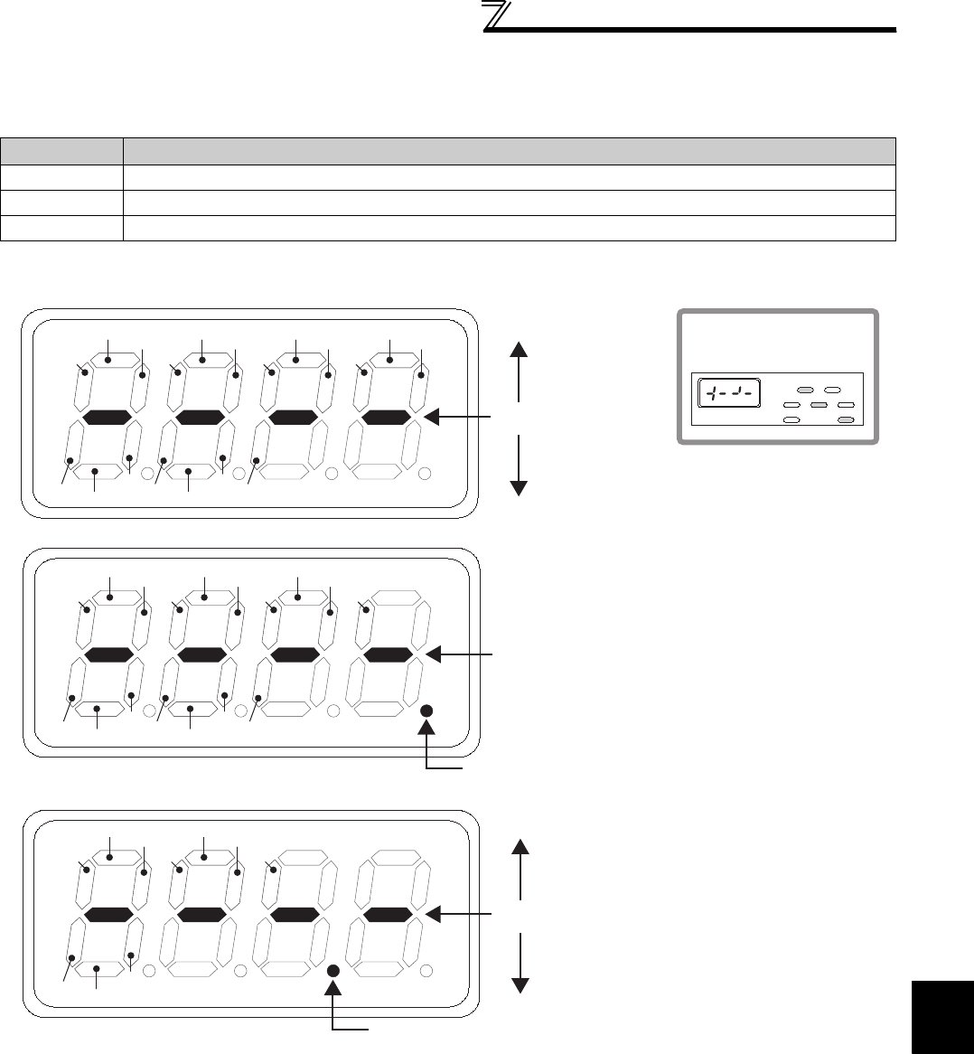
257
Monitor display and monitor output signal
4
PARAMETERS
(3) Operation panel (FR-DU07) I/O terminal monitor (Pr. 52)
⋅When Pr. 52 is set to any of "55 to 57", the I/O terminal states can be monitored on the operation panel (FR-DU07).
⋅The I/O terminal monitor is displayed on the third monitor.
⋅
The LED is ON when the terminal is ON, and the LED is OFF when the terminal is OFF. The center line of LED is always ON.
⋅On the unit I/O terminal monitor (Pr. 52 = "55"), the upper LEDs denote the input terminal status and the lower the
output terminal status.
⋅On the input option terminal monitor (Pr. 52 = "56"), the decimal point LED of the first digit LED is ON.
⋅On the input option terminal monitor (Pr. 52 = "57"), the decimal point LED of the second digit LED is ON.
Pr. 52 Setting Monitor Description
55 Display the I/O and output terminal ON/OFF status of the inverter unit.
56 * Display the input terminal ON/OFF status of the digital input option (FR-A7AX).
57 * Display the output terminal ON/OFF status of the digital output option (FR-A7AY) or relay output option (FR-A7AR).
* You can set "56" or "57" even if the option is not fitted. When the option is not fitted, the monitor displays are all OFF.
RM
RL
RH
RT MRS STR
AU RES JOG
SU IPF
OLRUN FUABC1 ABC2
STOP STF CS
Center line is always ON
Input terminal
- Display example -
When signals STF,
RH and RUN are on
Output terminal
MON P.RUN
EXT NETPU
FWD
REV
Hz
A
V
X1
X0
X2
X3 X6 X9
X4 X7
X13 X14
X15X12 DYX10 X11
X5 X8
Center line is always ON
Decimal point LED of first digit LED is always ON
Y1
Y0
Y2
Y3 Y6
Y4
RA3
RA1 RA2
Y5
Center line is always ON
Decimal point LED of second digit LED is always ON
FR-A7AY
FR-A7AR
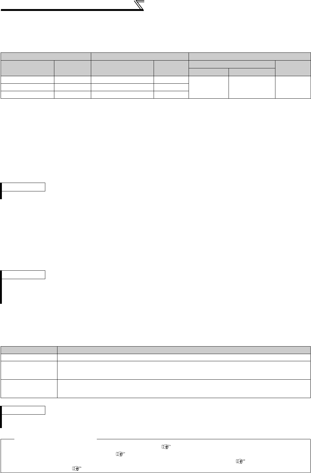
258
Monitor display and monitor output signal
(4) Cumulative power monitor and clear (Pr. 170, Pr. 891)
⋅On the cumulative power monitor (Pr. 52 = "25"), the output power is added up and updated every hour.
⋅The operation panel (FR-DU07), parameter unit (FR-PU04, FR-PU07) and communication (RS-485 communication,
communication option) display increments and display ranges are as indicated below.
⋅The monitor data digit can be shifted to the right by the number of Pr. 891 settings.
For example, if the cumulative power value is 1278.56kWh when Pr. 891 = "2", the PU/DU display is 12.78 (display
in 100kWh increments) and the communication data is 12.
⋅If the maximum value is exceeded at Pr. 891 = "0 to 4", the monitor value is clamped at the maximum value,
indicating that a digit shift is necessary. If the maximum value is exceeded at Pr. 891 = "9999", the monitor value
returns to 0 and is recounted.
If the maximum value is exceeded at Pr. 891 = "9999", the monitor value returns to 0 and is recounted.
⋅Writing "0" in Pr. 170 clears the cumulative power monitor.
(5) Cumulative energization time and actual operation time monitor (Pr. 171, Pr. 563, Pr. 564)
⋅On the cumulative energization time monitor (Pr. 52 = "20"), the inverter running time is added up every hour.
⋅On the actual operation time monitor (Pr. 52 = "23"), the inverter running time is added up every hour. (Time is not
added up during a stop.)
⋅If the numbers of monitor value exceeds 65535, it is added up from 0. You can check the numbers of cumulative
energization time monitor exceeded 65535h with Pr. 563 and the numbers of actual operation time monitor
exceeded 65535h with Pr. 564.
⋅Writing "0" in Pr. 171 clears the actual operation time monitor. (Energization time monitor cannot be cleared.)
(6) You can select the decimal digits of the monitor (Pr. 268)
⋅As the operation panel (FR-DU07) display is 4 digits long, the decimal places may vary at analog input, etc. The
decimal places can be hidden by selecting the decimal digits.
In such a case, the decimal digits can be selected by Pr. 268.
Operation Panel *1 Parameter Unit *2 Communication
Range Increments Range Increments Range Increments
Pr. 170 = 10 Pr. 170 = 9999
0 to 99.99kWh 0.01kWh 0 to 999.99kWh 0.01kWh
0 to 9999kWh 0 to 65535kWh
(initial value) 1kWh100.0 to 999.9kWh 0.1kWh 1000.0 to 9999.9kWh 0.1kWh
1000 to 9999kWh 1kWh 10000 to 99999kWh 1kWh
*1 Power is measured in the range 0 to 9999.99kWh, and displayed in 4 digits.
When the monitor value exceeds "99.99", a carry occurs, e.g. "100.0", so the value is displayed in 0.1kWh increments.
*2 Power is measured in the range 0 to 99999.99.99kWh, and displayed in 5 digits.
When the monitor value exceeds "999.99", a carry occurs, e.g. "1000.0", so the value is displayed in 0.1kWh increments.
REMARKS
⋅If "0" is written in Pr. 170 and Pr. 170 is read again, "9999" or "10" is displayed.
REMARKS
⋅The cumulative energization time does not increase if the power is ON for less than an hour.
⋅The actual operation time does not increase if the cumulative running time during power-ON status is less than an hour.
⋅If "0" is written in Pr. 171 and Pr. 171 is read again, "9999" is always displayed. Setting "9999" does not clear the actual operation
time meter.
Pr. 268 Setting Description
9999 (initial value) No function
0
When 1 or 2 decimal places (0.1 increments or 0.01 increments) are monitored, the decimal places are
dropped and the monitor displays an integer value (1 increments).
The monitor value of 0.99 or less is displayed as 0.
1
When 2 decimal places (0.01 increments) are monitored, the 0.01 decimal place is dropped and the
monitor displays the first decimal place (0.1 increments).
When the monitor display digit is originally in 1 increments, it is displayed unchanged in 1 increments.
REMARKS
⋅The number of display digits on the cumulative energization time (Pr. 52 = "20"), actual operation time (Pr. 52 = "23"), cumulative
power (Pr. 52 = "25") or cumulative saving power monitor (Pr. 52 = "51") does not change.
♦ Parameters referred to ♦
Pr. 30 Regenerative function selection, Pr. 70 Special regenerative brake duty Refer to page 207
Pr. 37 Speed display, Pr. 144 Speed setting switchover Refer to page 251
Pr. 55 Frequency monitoring reference, Pr. 56 Current monitoring reference, Pr. 866 Torque monitoring reference Refer to page 259
Pr. 291 Pulse train I/O selection Refer to page 259
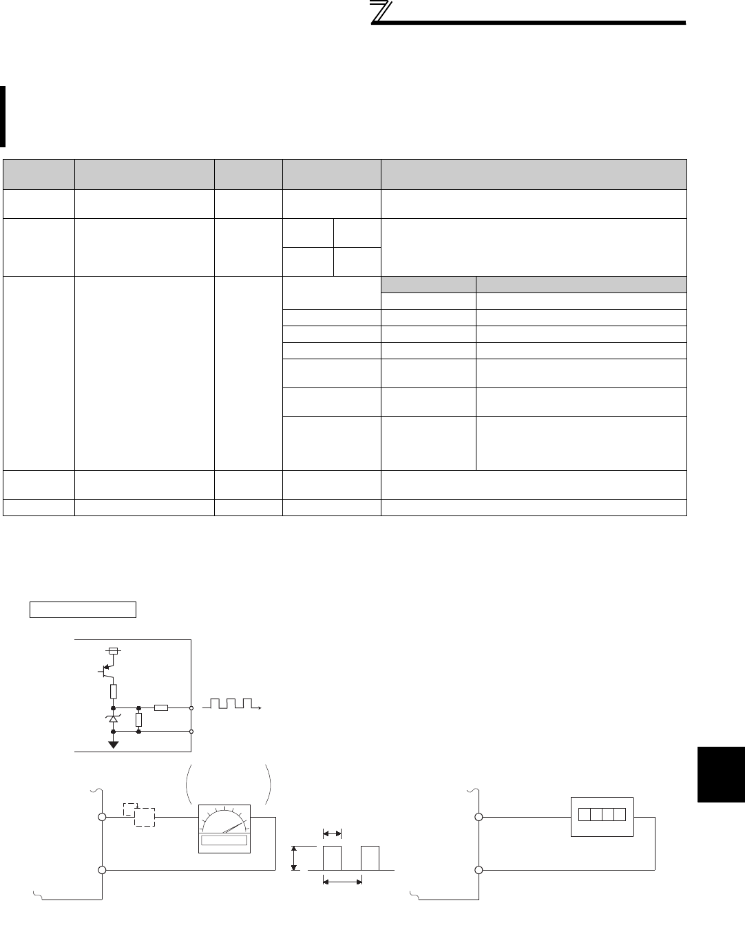
259
Monitor display and monitor output signal
4
PARAMETERS
4.16.3 Reference of the terminal FM (pulse train output) and AM (analog voltage
output) (Pr. 55, Pr. 56, Pr. 291, Pr. 866, Pr. 867)
(1) Pulse train output of the terminal FM (Pr. 291)
• Two types of pulse train can be output to the terminal FM.
Two types of monitor output, pulse train output from the terminal FM and analog voltage output from the terminal
AM, are available. In addition, pulse train output by voltage output and by open collector output can be selected
for terminal FM.
Set the reference of the signal output from terminal FM and AM.
Parameter
Number Name Initial
Value Setting Range Description
55 * Frequency monitoring
reference 60Hz 0 to 400Hz Set the full-scale value to output the output frequency
monitor value to terminal FM and AM.
56 * Current monitoring
reference
Rated
inverter
current
55K or
lower
0 to
500A Set the full-scale value to output the output current
monitor value to terminal FM and AM.
75K or
higher
0 to
3600A
291 Pulse train I/O
selection 0
Pulse train input Pulse train output
0 Terminal JOG FM output
1 Pulse train input FM output
10 Terminal JOG
High speed pulse train output (50%Duty)
11 Pulse train input
High speed pulse train output (50%Duty)
20 Terminal JOG High speed pulse train output (ON
width is always same)
21 Pulse train input High speed pulse train output (ON
width is always same)
100 Pulse train input
High speed pulse train output (ON
width is always same)
The inverter outputs the signal input
as pulse train as is
866 * Torque monitoring
reference 150% 0 to 400% Set the full-scale value to output the torque monitor value
to terminal FM and AM.
867 AM output filter 0.01s 0 to 5s Set the output filter of terminal AM.
* The above parameters allow its setting to be changed during operation in any operation mode even if "0" (initial value) is set in Pr.
77 Parameter write selection.
FM output circuit • When Pr. 291 Pulse train I/O selection = "0 (initial value) or 1",
FM output is selected and pulse train with maximum of
8VDC 2400pulses/s is output.
The pulse width can be adjusted by calibration parameter C0
(Pr. 900) FM terminal calibration using the operation panel
and parameter unit.
• Output frequency, etc. of the inverter can be indicated by
connecting a DC ammeter of full-scale 1mA, digital indicator,
etc.
*1 Not needed when the operation panel (FR-DU07) or parameter unit (FR-PU04/FR-PU07) is used for calibration.
Use a calibration resistor when the indicator (frequency meter) needs to be calibrated by a neighboring device because the indicator is
located far from the inverter.
Note that the needle of the frequency meter may not deflect to full-scale when the calibration resistor is connected. In this case, use this
resistor and perform calibration of operation panel or parameter unit.
*2 The initial setting is 1mA full-scale and 1440 pulse/s terminal FM frequency at 60Hz.
Inverter
24V
2.2K
20K
3.3K
SD
FM
8VDC
T2
T1
Pulse width T1: Adjust using calibration parameter C0
Pulse cycle T2: Set with Pr. 55 (frequency monitor)
Set with Pr.56 (current monitor)
(Digital indicator)
(-)
1440 pulses/s(+)
FM
SD
Indicator
1mA full-scale
analog meter
(+)
1mA
FM
SD
Calibration
resistor*1
(-)
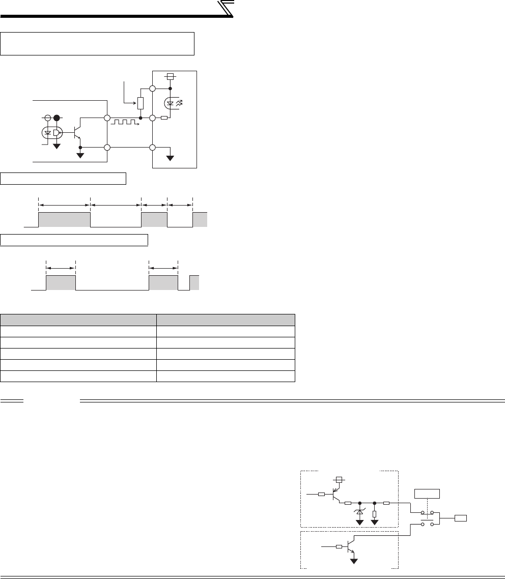
260
Monitor display and monitor output signal
High speed pulse train output specifications
* The output pulse rate is 50kpps when a monitor output value is 100%.
High speed pulse train output circuit
(connection example with a pulse counter)
• When Pr. 291 Pulse train I/O selection = "10, 11, 20, 21, 100",
high speed pulse train is output by open collector output.
Pulse train of maximum of 55k pulses/s is output.
Two types of pulse width, 50% Duty and fixed ON width, are
available. Adjustment by calibration parameter C0 (Pr. 900)
FM terminal calibration cannot be performed.
* When the output wiring length is long, a pulse shape is deformed due to the stray
capacitances of the wiring and output pulse cannot be recognized. If the wiring
length is long, connect the open collector output signal and the power supply using
an external pull up resistance.
Check specifications of a pulse counter for a resistance value to pull up. Select an
appropriate resistance value so that the load current is 80mA or less.
Pulse when Pr. 291 = "10, 11" • When Pr. 291 = "10, 11", the pulse cycle is 50% Duty (ON
width and OFF width are the same).
• When Pr. 291 = "20, 21, 100", fixed ON width of pulse is out-
put (approx. 10µs).
• When the setting value is "100", the pulse train from the
pulse train input (terminal JOG) is output as is. Use this
value for synchronous speed operation of multiple inverters.
(Refer to page 378)
* Hi indicates that the open collector output transistor is ON.
Pulse when Pr. 291 = "20, 21, 100"
Item Specifications
Output method NPN open collector output
Voltage between a collector and emitter 30V (max)
Maximum permissible load current 80mA
Output pulse rate 0 to 55kpps *
Output resolution 3pps (excluding a jitter)
CAUTION
⋅Input specifications of terminal JOG (pulse train input or contact input) can be selected with Pr. 291.
Change the setting value using care not to change input specifications of terminal JOG. (Refer to page 378 for pulse train input.)
⋅After changing a setting value of Pr. 291, connect a meter between terminal FM and SD. Take care that a voltage should not be
applied to terminal FM when FM output (voltage output) pulse train is selected.
⋅The FM output of the inverter cannot be connected to devices which have source logic type pulse input.
⋅When high speed pulse train output (Pr. 291 = "10, 11, 20, 21, 100") is
selected, performing parameter all clear returns the Pr. 291 setting to the
initial value of "0", changing the terminal FM output from high speed pulse
train output to FM output (voltage output).
FM
SD
Inverter
Pull up resistance *
Pulse counte
r
Hi * Low
50%duty 50%duty
Hi * Low
Approx. 10
μs
Approx. 10
μs
3.3kΩ
Terminal FM
0, 1
10, 11,
20, 21, 100
Pr.291
8.2V
FM output circuit
Open collector output circuit

261
Monitor display and monitor output signal
4
PARAMETERS
(2) Frequency monitoring reference (Pr. 55)
• Set the full scale value when outputting the frequency monitor from terminal FM or AM.
• For the calibration of terminal FM, set the full-scale value of the connected meter when the pulse speed of terminal
FM is 1440 pulse/s (50k pulse/s).
Set the frequency to be indicated as the full scale value on the frequency meter (1mA analog meter) connected
between terminal FM and SD. (For example, 60Hz or 120Hz.)
Pulse speed is proportional to the output frequency of the inverter. (Maximum pulse train output is 2400 pulse/s
(55k pulse/s)).
• For the calibration of terminal AM, set the full-scale value of the connected meter when output voltage of terminal
AM is 10VDC.
Set the frequency to be indicated as the full scale value on the meter (10VDC voltmeter) connected between
terminal AM and 5. (For example, 60Hz or 120Hz)
Output voltage is proportional to the frequency. (Maximum output voltage is 10VDC.)
(3) Current monitoring reference (Pr. 56)
• Set the full scale value when outputting the current monitor from terminal FM or AM.
• For calibration of terminal FM, set the full-scale value of the connected current meter when the pulse speed of
terminal FM is 1440 pulse/s (50k pulse/s).
Set the current to be indicated as the full scale value on the meter (1mA analog meter) connected between terminal
FM and SD.
Pulse speed is proportional to the monitored value of output current. (Maximum pulse train output is 2400 pulse/s
(55k pulse/s).)
• For the calibration of terminal AM, set the full-scale value of the connected current meter when the output voltage
of terminal AM is 10VDC.
Set the current to be indicated as the full scale value on the meter (10VDC voltmeter) connected between terminal
AM and 5.
Output voltage is proportional to the monitored value of output current. (Maximum output voltage is 10VDC.)
2400
(55K)
1440
(50K)
1Hz Output frequency 400Hz
Setting range of Pr. 55
Pulse speed (pulses/s)
60Hz
(initial value)
Setting range of Pr. 55
1Hz 400Hz60Hz
(initial value)
Output voltage
10VDC
2400
(55K)
1440
(50K)
Rated current
(initial value)
500A
Setting range of Pr. 56
Pulse speed (pulses/s)
Setting range of Pr. 56
Rated current
(initial value)
10VDC
500A
Output voltage
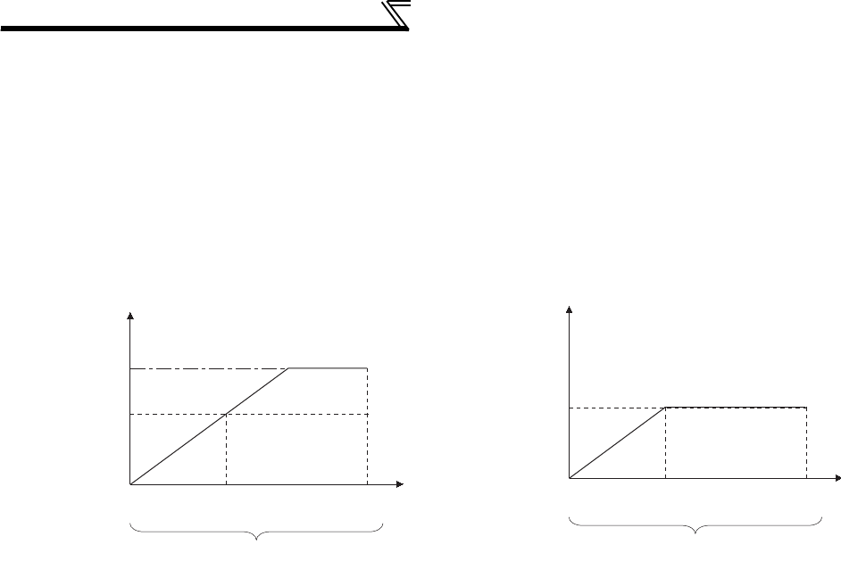
262
Monitor display and monitor output signal
(4) Reference of torque monitor (Pr. 866)
• Set the full scale value when outputting the torque monitor from terminal FM or AM.
• For calibration of terminal FM, set the full-scale value of the connected torque meter when the pulse speed of
terminal FM is 1440 pulse/s (50k pulse/s).
Set the torque to be indicated as the full scale value on the meter (1mA analog meter) connected between terminal
FM and SD.
Pulse speed is proportional to the monitored value of torque. (Maximum pulse train output is 2400 pulse/s (55k
pulse/s).)
• For the calibration of terminal AM, set the full-scale value of the connected current meter when the output voltage
of terminal AM is 10VDC.
Set the torque to be indicated as the full scale value on the meter (10VDC voltmeter) connected between terminal
AM and 5.
Output voltage is proportional to the monitored value of torque. (Maximum output voltage is 10VDC.)
(5) Terminal AM response adjustment (Pr. 867)
• Using Pr. 867, the output voltage response of the terminal AM can be adjusted within the range 0 to 5s.
• Increasing the setting stabilizes the terminal AM output more but reduces the response level. (Setting "0" sets the
response level to 7ms)
2400
(55k)
1440
(50k)
(Pulse/s)
150%
(initial value)
400%
Setting range of Pr. 866
Pulse speed (pulses/s)
10VDC
150%
(initial value)
400%
Setting range of Pr. 866
Output voltage
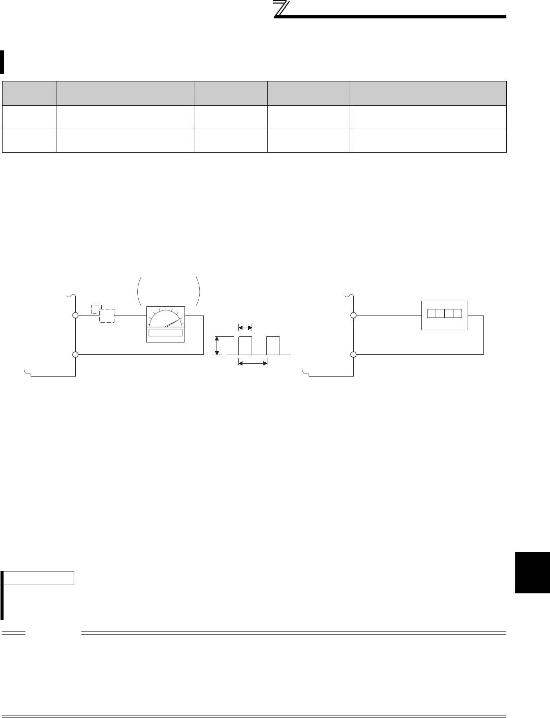
263
Monitor display and monitor output signal
4
PARAMETERS
4.16.4 Terminal FM, AM calibration (Calibration parameter C0 (Pr. 900), C1 (Pr. 901))
(1) FM terminal calibration (C0(Pr. 900))
⋅The terminal FM is preset to output pulses. By setting the Calibration parameter C0 (Pr. 900), the meter connected to
the inverter can be calibrated by parameter setting without use of a calibration resistor.
⋅Using the pulse train output of the terminal FM, a digital display can be provided by a digital counter. The monitor
value is 1440 pulses/s output at the full-scale value of the table on the previous page (Pr. 54 FM terminal function
selection).
⋅Calibrate the terminal FM in the following procedure.
1) Connect an indicator (frequency meter) across the terminals FM-SD of the inverter. (Note the polarity. The
terminal FM is positive.)
2) When a calibration resistor has already been connected, adjust the resistance to "0" or remove the resistor.
3) Refer to the output signal list (page 253) and set Pr. 54. When you selected the running frequency or inverter
output current as the output signal, preset the running frequency or current value, at which the output signal will
be 1440 pulses/s, to Pr. 55 Frequency monitoring reference or Pr. 56 Current monitoring reference. At 1440 pulses/s,
the meter generally deflects to full-scale.
By using the operation panel or parameter unit, you can calibrate terminal FM and terminal AM to full scale
deflection.
Parameter
Number Name Initial Value Setting Range Description
C0(900) FM terminal calibration ⎯⎯
Calibrate the scale of the meter
connected to terminal FM.
C1(901) AM terminal calibration ⎯⎯
Calibrate the scale of the analog meter
connected to terminal AM.
*1 The parameter number in parentheses is the one for use with the parameter unit (FR-PU04/FR-PU07).
*2 The above parameters allow its setting to be changed during operation in any operation mode even if "0" (initial value) is set in Pr. 77 Parameter
write selection.
*1 Not needed when the operation panel (FR-DU07) or parameter unit (FR-PU04/FR-PU07) is used for calibration.
Use a calibration resistor when the indicator (frequency meter) needs to be calibrated by a neighboring device because the indicator
is located far from the inverter.
Note that the needle of the frequency meter may not deflect to full-scale when the calibration resistor is connected. In this case, use
this resistor and perform calibration of operation panel or parameter unit.
*2 The initial settings are 1mA full-scale and 1440 pulses/s terminal FM frequency at 60Hz.
REMARKS
⋅When outputting such an item as the output current, which cannot reach a 100% value easily by operation, set Pr. 54 = "21"
(reference voltage output) and make calibration. 1440 pulses/s are output from the terminal FM.
⋅The wiring length of the terminal FM should be 200m maximum.
CAUTION
⋅The initial value of the calibration parameter C0 (Pr. 900) is set to 1mA full-scale and 1440 pulses/s FM output frequency at
60Hz. The maximum pulse train output of terminal FM is 2400 pulses/s.
⋅When a frequency meter is connected across terminals FM-SD to monitor the running frequency, the FM terminal output is
filled to capacity at the initial setting if the maximum output frequency reaches or exceeds 100Hz. In this case, the Pr. 55 setting
must be changed to the maximum frequency.
⋅When Pr. 291 Pulse train I/O selection = "10, 11, 20, 21, 100" (high speed pulse train output), calibration using calibration
parameter C0 (Pr. 900) cannot be made.
8VDC
T2
T1
Pulse width T1: Adjust using calibration parameter C0
Pulse cycle T2: Set with Pr. 55 (frequency monitor)
Set with Pr.56 (current monitor)
(Digital indicator)
(-)
1440 pulses/s(+)
FM
SD
Indicator
1mA full-scale
analog meter
(+)
1mA
FM
SD
Calibration
resistor*1
(-)
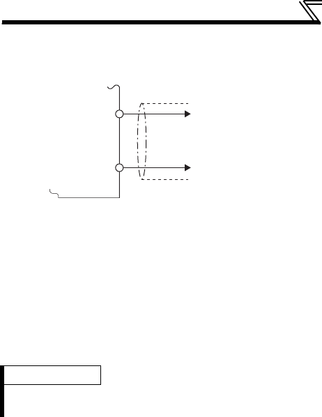
264
Monitor display and monitor output signal
(2) AM terminal calibration (C1 (Pr. 901))
⋅Calibrate the AM terminal in the following procedure.
1) Connect a 0-10VDC meter (frequency meter) to across inverter terminals AM-5. (Note the polarity. The terminal
AM is positive.)
2) Refer to the monitor description list (page 253) and set Pr. 158.
When you selected the running frequency, inverter output current, etc. as monitor, preset in Pr. 55 or Pr. 56 the
running frequency or current value at which the output signal will be 10V.
3) When outputting the item that cannot achieve a 100% value easily by operation, e.g. output current, set "21"
(reference voltage output) in Pr. 158 and perform the following operation. After that, set "2" (output current, for
example) in Pr. 158.
⋅Terminal AM is factory-set to provide a 10VDC output in the full-scale
status of the corresponding monitor item. Calibration parameter C1 (Pr.
901) allows the output voltage ratios (gains) to be adjusted according
to the meter scale. Note that the maximum output voltage is 10VDC.
REMARKS
⋅When outputting such an item as the output current, which cannot reach a 100% value easily by operation, set Pr. 158 = "21"
(reference voltage output) and make calibration. 10VDC is output from the terminal AM.
AM
Inverter
10VDC
5
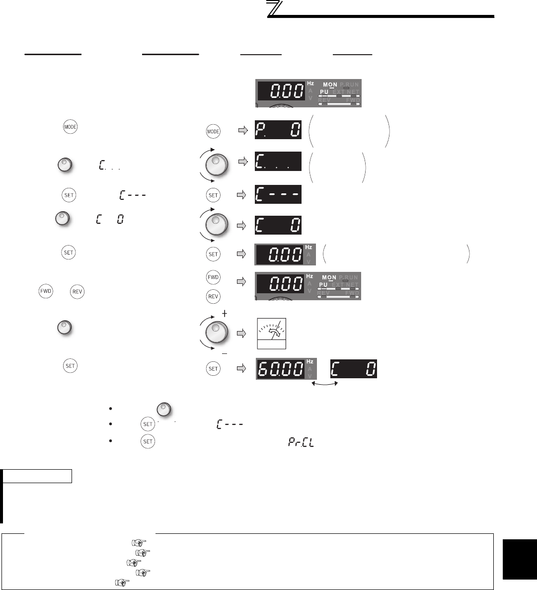
265
Monitor display and monitor output signal
4
PARAMETERS
(3) How to calibrate the terminal FM when using the operation panel (FR-DU07)
REMARKS
⋅Calibration can also be made for external operation. Set the frequency in External operation mode, and make calibration in the
above procedure.
⋅Calibration can be made even during operation.
⋅For the operating procedure using the parameter unit (FR-PU04/FR-PU07), refer to the parameter unit instruction manual.
♦ Parameters referred to ♦
Pr. 54 FM terminal function selection Refer to page 253
Pr. 55 Frequency monitoring reference Refer to page 259
Pr. 56 Current monitoring reference Refer to page 259
Pr. 158 AM terminal function selection Refer to page 253
Pr. 291 Pulse train I/O selection Refer to page 378
Press to return to the display (step 4).
9.
Press . Setting is complete.
2.
Press to choose the parameter
setting mode.
3.
Turn until appears.
Flicker...Parameter setting complete!!
1.
Confirmation of the RUN indicator and
operation mode indicator
4.
Press to display .
6.
Press to enable setting.
7.
If the inverter is at a stop, (press
or ) to start the inverter.
(Motor needs not be connected.)
8.
Turn to adjust the indicator needle
to the desired position.
By turning , you can read another parameter.
(When Pr. 54=1)
Press twice to show the next parameter ( ).
Display
Operation
( )
The parameter
number read
previously appears.
C0 to C41
setting
is enabled.
Analog indicator
5.
Turn until appears.
Set to C0 FM terminal calibration.
The monitor set to Pr. 54 FM terminal
function selection is displayed.

266
Operation selection at power failure
and instantaneous power failure
4.17 Operation selection at power failure and instantaneous
power failure
4.17.1 Automatic restart after instantaneous power failure/flying start
(Pr. 57, Pr. 58, Pr. 162 to Pr. 165, Pr. 299, Pr. 611)
Purpose Parameter that must be Set Refer to Page
At instantaneous power failure
occurrence, restart inverter without
stopping motor
Automatic restart operation
after instantaneous power
failure/flying start
Pr. 57, Pr. 58, Pr. 162 to Pr. 165,
Pr. 299, Pr. 611 266
When undervoltage or a power
failure occurs, the inverter can be
decelerated to a stop.
Power failure-time
deceleration-to-stop
function
Pr. 261 to Pr. 266, Pr. 294 270
You can restart the inverter without stopping the motor in the following cases.
⋅when commercial power supply operation is switched to inverter operation
⋅when power comes back ON after an instantaneous power failure
⋅when motor is coasting at start
Parameter
Number Name Initial Value Setting Range Description
57 Restart coasting
time 9999
0
⋅1.5K or lower .................................................... 0.5s,
⋅2.2K to 7.5K.................................................1s,
⋅11K to 55K...................................................3.0s,
⋅75K or higher.................................................... 5.0s,
The above times are coasting time.
55K or
lower
0.1 to
5s Set the waiting time for inverter-triggered restart after
an instantaneous power failure.
75K or
higher
0.1 to
30s
9999 No restart
58 Restart cushion
time 1s 0 to 60s Set a voltage starting time at restart.
162
Automatic restart
after
instantaneous
power failure
selection
0
0 With frequency search
1 Without frequency search (reduced voltage system)
2 Encoder detection frequency search
10 Frequency search at every start
11 Reduced voltage system at every start
12 Encoder detection frequency search at every start
163 First cushion time
for restart 0s 0 to 20s Set a voltage starting time at restart.
Consider using these parameters according to the load
(moment of inertia, torque) magnitude.
164 First cushion
voltage for restart 0% 0 to 100%
165
Stall prevention
operation level for
restart
150% 0 to 220% Consider the rated inverter current as 100% and set the
stall prevention operation level during restart operation.
299
Rotation direction
detection
selection at
restarting
0
0Without rotation direction detection
1With rotation direction detection
9999 When Pr. 78 = "0", the rotation direction is detected.
When Pr. 78 = "1","2", the rotation direction is not detected.
611 Acceleration time
at a restart
55K
or lower 5s
0 to 3600s, 9999
Set the acceleration time that takes to reach Pr. 20
Acceleration/deceleration reference frequency setting at a
restart.
Acceleration time for restart is the normal acceleration
time (e.g. Pr. 7 ) when "9999" is set.
75K
or higher 15s
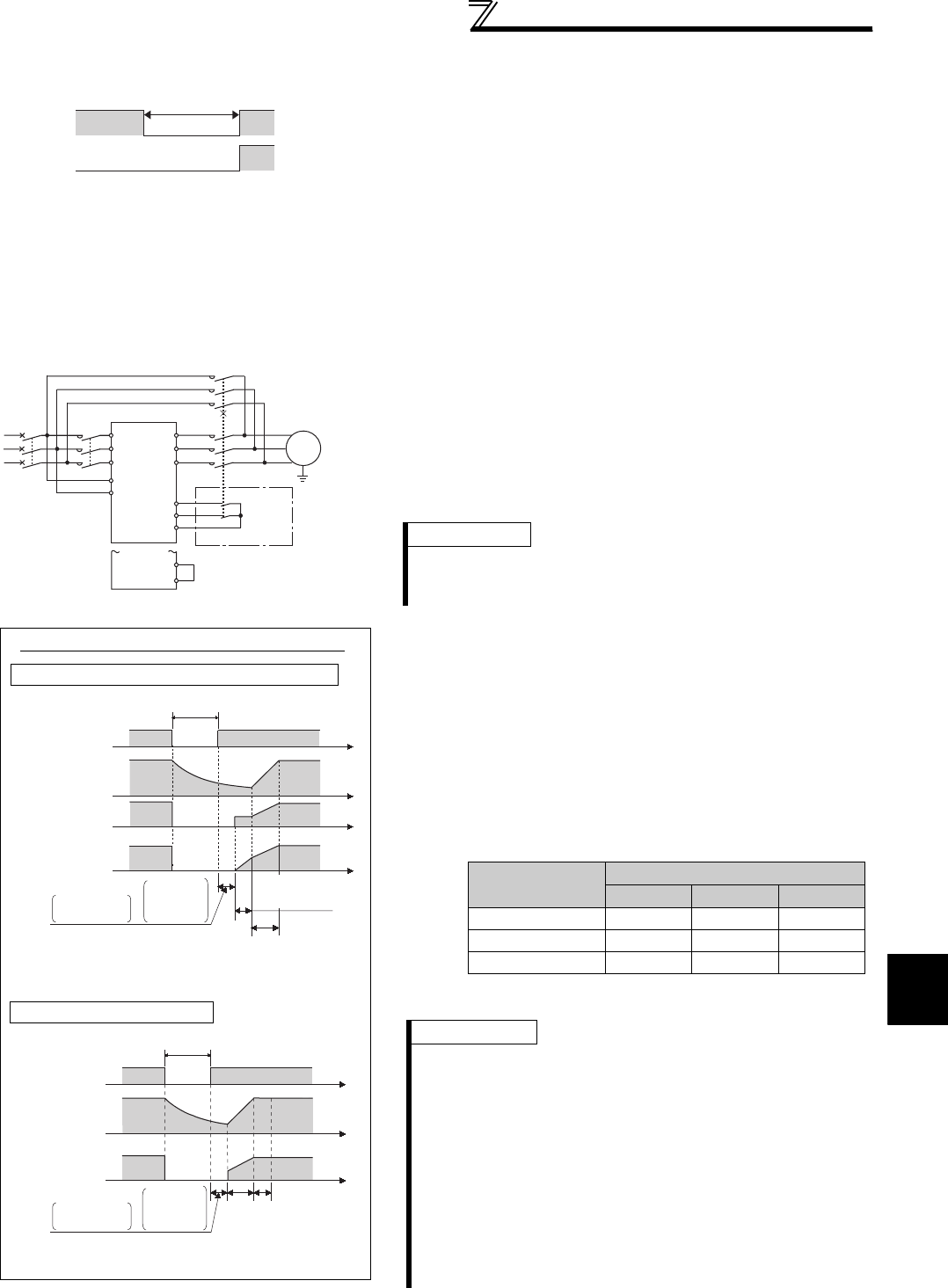
267
Operation selection at power failure
and instantaneous power failure
4
PARAMETERS
(1) Automatic restart after instantaneous power failure operation
⋅When instantaneous power failure protection (E.IPF) and undervoltage
protection (E.UVT) are activated, the inverter trips. (Refer to page 411 for
E.IPF and E.UVT.)
When automatic restart after instantaneous power failure operation is set,
the motor can be restarted if power is restored after an instantaneous
power failure or undervoltage is corrected. (E.IPF and E.UVT are not
activated.)
⋅When E.IPF and E.UVT are activated, instantaneous power failure/under
voltage signal (IPF) is output.
⋅The IPF signal is assigned to the terminal IPF in the initial setting. The IPF
signal can also be assigned to the other terminal by setting "2 (positive
logic) or 102 (negative logic)" to any of Pr. 190 to Pr. 196 (output terminal
function selection).
(2) Connection (CS signal)
⋅When the automatic restart after instantaneous power failure
selection signal (CS) is turned ON, automatic restart operation
is enabled.
⋅When Pr. 57 is set to other than "9999" (automatic restart
operation enabled), the inverter will not operate if used with the
CS signal remained OFF.
(3) Automatic restart operation selection (Pr. 162, Pr.
299)
With frequency search
When "0 (initial value), 10" is set in Pr. 162, the inverter
smoothly starts after detecting the motor speed upon power
restoration.
⋅During reverse rotation, the inverter can be restarted smoothly
as the direction of rotation is detected.
⋅You can select whether to make rotation direction detection or
not with Pr. 299 Rotation direction detection selection at restarting.
When capacities of the motor and inverter differ, set "0"
(without rotation direction detection) in Pr. 299.
ON
Power
supply OFF
15ms to 100ms
ONIPF OFF
STF
IM
MCCB
CS
CS
S1/L21
R1/L11
T/L3
S/L2
R/L1
MC1
MC2
MC3
W
V
U
MC
switchover
sequence
SD
SD
For use for only
automatic restart
after instantaneous
power failure or flying start,
short CS and SD in advance.
REMARKS
⋅The CS signal is assigned to the terminal CS in the initial setting.
By setting "6" in any of Pr. 178 to Pr. 189 (input terminal function
selection), you can assign the CS signal to the other terminal.
When Pr. 162 = 0, 10 (with frequency search)
V/F control, Advanced magnetic flux vector control
Instantaneous (power failure) time
Power supply
(R/L1, S/L2,
T/L3)
Motor speed N
(r/min)
Inverter output
frequency f(Hz)
Inverter output
voltage E(V)
Coasting
time (Pr.57)
Speed
detection
time
+
Acceleration time
at a restart
(Pr.611 setting)
Restart cushion
time (Pr.58 setting)
*
* The output shut off timing differs
according to the load condition.
Real sensorless vector control
*
Power supply
(R/L1, S/L2,
T/L3)
Motor speed N
(r/min)
Inverter output
frequency f(Hz)
output voltage
E(V)
Instantaneous (power failure) time
Coasting
time (Pr.57)
Speed
detection
time
+Acceleration time
at a restart
(Pr.611 setting)
* The output shut off timing differs
according to the load condition.
:with rotation direction detection
× :without rotation direction detection
Pr. 299 Setting Pr. 78 Setting
012
9999 ××
0 (initial value) ×××
1
REMARKS
⋅Speed detection time (frequency search) changes according to
the motor speed. (maximum 500ms)
⋅When the inverter capacity is two rank or more larger than the
motor capacity, the inverter may not start due to overcurrent trip
(E.OC ).
⋅If two or more motors are connected to one inverter, the inverter
functions abnormally. (The inverter does not start smoothly.)
⋅Since the DC injection brake is operated instantaneously when
the speed is detected at a restart, the speed may reduce if the
inertia moment (J) of the load is small.
⋅When reverse rotation is detected when Pr. 78 = "1" (reverse
rotation disabled), the rotation direction is changed to forward
rotation after decelerates in reverse rotation when the start
command is forward rotation. The inverter will not start when the
start command is reverse rotation.
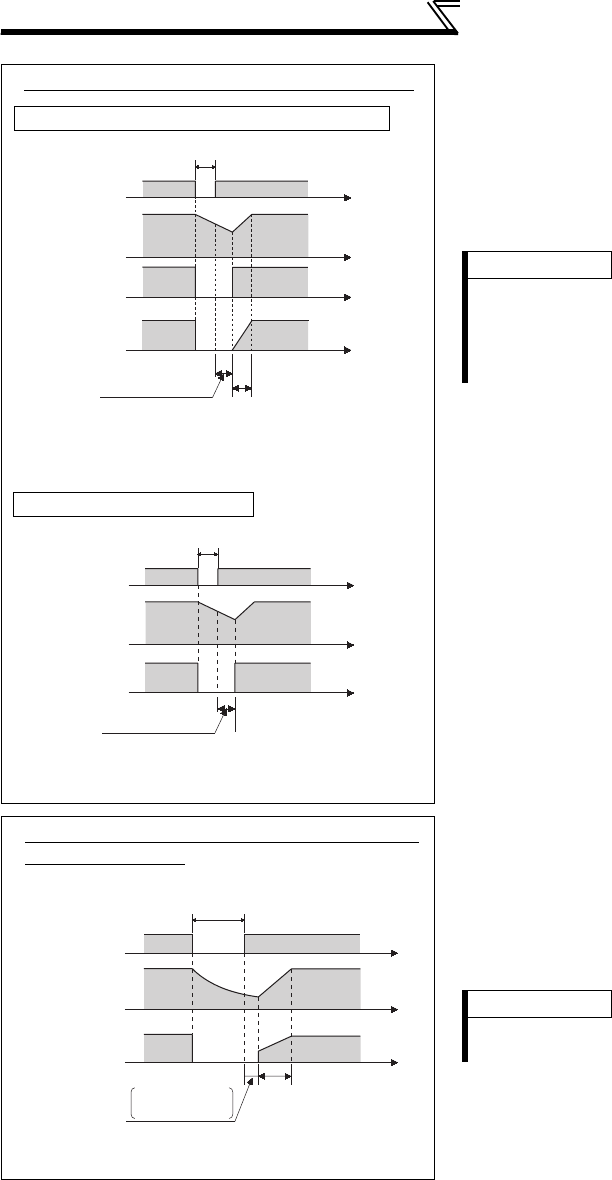
268
Operation selection at power failure
and instantaneous power failure
Without frequency search
When Pr. 162 = "1" or "11", automatic restart operation is
performed in a reduced voltage system, where the voltage is
gradually risen with the output frequency unchanged from prior
to an instantaneous power failure independently of the
coasting speed of the motor.
For Real sensorless vector control, output frequency and
voltage before instantaneous power failure are output. (Pr. 58 is
invalid.)
Encoder detection frequency search
⋅When "2 or 12" is set in Pr. 162 under encoder feedback
control, the motor starts at the motor speed and in the rotation
direction detected from the encoder at power restoration.
⋅Encoder detection frequency search is performed regardless
of the Pr. 162 setting under vector control.
⋅The Pr. 58 and Pr. 299 settings are invalid for encoder detection
frequency search.
Restart operation at every start
When Pr. 162 = "10, 11 or 12", automatic restart operation is
also performed every start, in addition to the automatic restart
after instantaneous power failure. When Pr. 162 = "0, 1 or 2",
automatic restart operation is performed at the first start after
power supply-on, but the inverter starts at the starting
frequency at the second time or later.
When
Pr. 162
= 1, 11 (without frequency search)
V/F control, Advanced magnetic flux vector control
Real sensorless vector control
Coasting time
Pr.57 setting
*
Instantaneous (power failure) time
Power supply
(R/L1, S/L2,
T/L3)
Motor speed N
(r/min)
Inverter output
frequency f(Hz)
Inverter output
voltage E(V)
Restart cushion time
(Pr.58 setting)
* The output shut off timing differs
according to the load condition.
Coasting time
Pr.57 setting
*
Instantaneous (power failure) time
Power supply
(R/L1, S/L2,
T/L3)
Motor speed N
(r/min)
Inverter output
frequency f(Hz)
output voltage
E(V)
* The output shut off timing differs
according to the load condition.
REMARKS
⋅This system stores the output frequency prior to an
instantaneous power failure and increases the voltage.
Therefore, if the instantaneous power failure time exceeds 0.2s,
the inverter starts at Pr. 13 Starting frequency (initial value = 0.5Hz)
since the stored output frequency cannot be retained.
Instantaneous
(power failure) time
Power supply
(R/L1, S/L2, T/L3)
Motor speed N
(r/min)
Inverter output
frequency f(Hz)
Output voltage E(V)
Coasting time
(Pr.57)
* The output shut off timing differs according to the load condition.
*
Acceleration time
at a restart
(Pr.611 setting)
When Pr. 162 = 2, 12 (encoder detection
frequency search)
REMARKS
⋅When encoder feedback control is invalid, setting "2 or 12" in Pr.
162 enables frequency search (Pr. 162 = "0, 10").
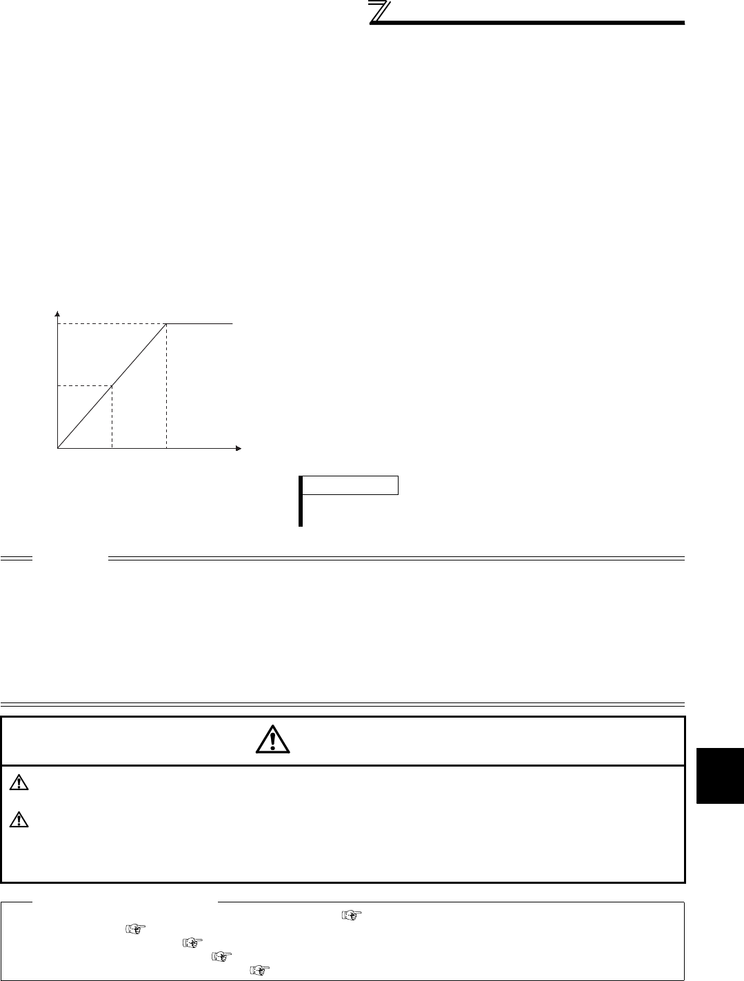
269
Operation selection at power failure
and instantaneous power failure
4
PARAMETERS
(4) Restart coasting time (Pr. 57)
⋅Coasting time is the time from when the motor speed is detected until automatic restart control is started.
⋅Set Pr. 57 to "0" to perform automatic restart operation. The coasting time is automatically set to the value below.
Generally this setting will pose no problems.
1.5K or lower . . . . . 0.5s, 2.2K to 7.5K. . . . . . 1s, 11K to 55K . . . . . . . . . 3.0s, 75K or higher . . . . . 5.0s
⋅Operation may not be performed well depending on the magnitude of the moment of inertia (J) of the load or
running frequency. Adjust the coasting time between 0.1s and 5s according to the load specifications.
(5) Restart cushion time (Pr. 58)
⋅Cushion time is the length of time taken to raise the voltage appropriate to the detected motor speed (output
frequency prior to instantaneous power failure when Pr. 162 = "1" or "11").
⋅Normally the initial value need not be changed for operation, but adjust it according to the magnitude of the
moment of inertia (J) of the load or torque.
⋅Pr. 58 is invalid during Real sensorless vector control or vector control.
(6) Automatic restart operation adjustment (Pr. 163 to
Pr. 165, Pr. 611)
⋅Using Pr. 163 and Pr. 164, you can adjust the voltage rise time at
a restart as shown on the left.
⋅Using Pr. 165, you can set the stall prevention operation level at
a restart.
⋅Using Pr. 611, you can set the acceleration time until Pr. 20
Acceleration/deceleration reference frequency is reached when
automatic restart operation is performed besides the normal
acceleration time.
CAUTION
⋅Changing the terminal assignment using Pr. 178 to Pr. 189 (input terminal function selection) may affect the other functions. Set
parameters after confirming the function of each terminal.
⋅When automatic restart operation is selected, undervoltage protection (E.UVT) and instantaneous power failure protection
(E.IPF) among the fault output signals will not be provided at occurrence of an instantaneous power failure.
⋅The SU and FU signals are not output during a restart. They are output after the restart cushion time has elapsed.
⋅Automatic restart operation will also be performed after a reset made by an inverter reset is canceled or when a retry is made
by the retry function.
⋅Automatic restart after instantaneous power failure function is invalid when load torque high speed frequency control (Pr. 270 =
"2, 3 or 13") is set.
CAUTION
Provide mechanical interlocks for MC1 and MC2. The inverter will be damaged if the power supply is input to the
inverter output section.
When automatic restart after instantaneous power failure has been selected, the motor and machine will start
suddenly (after the reset time has elapsed) after occurrence of an instantaneous power failure. Stay away from
the motor and machine. When you have selected automatic restart after instantaneous power failure function,
apply in easily visible places the CAUTION stickers supplied to the instruction manual (basic).
♦ Parameters referred to ♦
Pr. 7 Acceleration time, Pr. 21 Acceleration/deceleration time increments Refer to page 172
Pr. 13 Starting frequency Refer to page 175
Pr. 65, Pr. 67 to Pr. 69 Retry function Refer to page 273
Pr. 78 Reverse rotation prevention selection Refer to page 308
Pr. 178 to Pr. 189 (input terminal function selection) Refer to page 231
Voltage
100%
Pr.164
(Pr.163) Pr.58 Time
REMARKS
⋅If the setting of Pr. 21 Acceleration/deceleration time increments is
changed, the setting increments of Pr. 611 does not change.
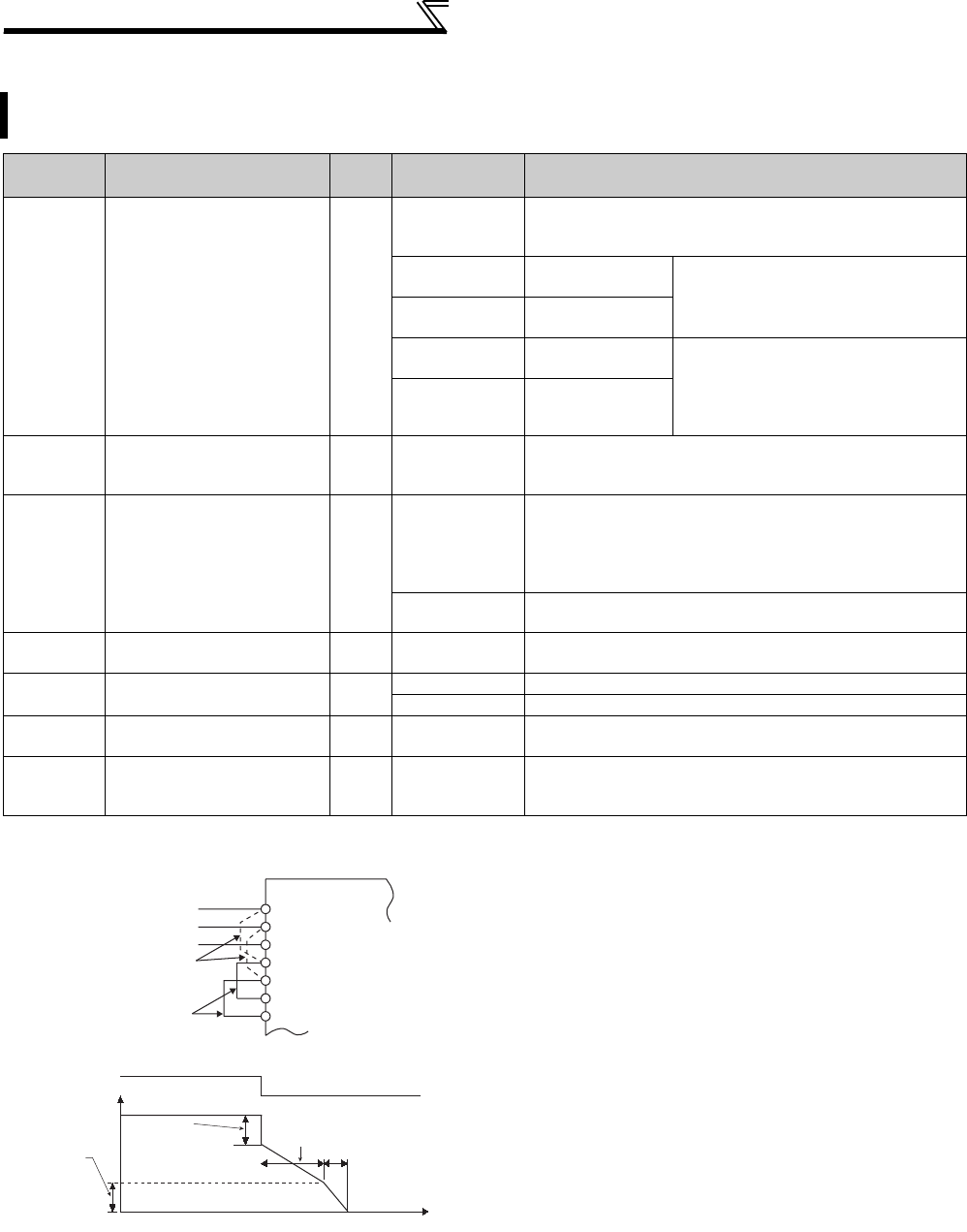
270
Operation selection at power failure
and instantaneous power failure
4.17.2 Power failure-time deceleration-to-stop function (Pr. 261 to Pr. 266, Pr. 294 )
* When the setting of Pr. 21 Acceleration/deceleration time increments is "0" (initial value), the setting range is "0 to 3600s" and the setting increments are
"0.1s", and when the setting is "1", the setting range is "0 to 360s" and the setting increments are "0.01s"
When a power failure or undervoltage occurs, the inverter can be decelerated to a stop or can be decelerated
and re-accelerated to the set frequency.
Parameter
Number Name Initial
Value Setting Range Description
261 Power failure stop
selection 0
0
Coasting to stop
When undervoltage or power failure occurs, the inverter output
is shut off.
1Without under
voltage avoidance When undervoltage or a power failure
occurs, the inverter can be decelerated
to a stop.
11 With under
voltage avoidance
2Without under
voltage avoidance
When undervoltage or a power failure
occurs, the inverter can be decelerated
to a stop.
If power is restored during a power
failure, the inverter accelerates again.
12 With under
voltage avoidance
262 Subtracted frequency at
deceleration start 3Hz 0 to 20Hz
Normally operation can be performed with the initial value
unchanged. But adjust the frequency according to the
magnitude of the load specifications (moment of inertia, torque).
263 Subtraction starting
frequency 60Hz
0 to 120Hz
When output frequency ≥ Pr. 263
Decelerate from the speed obtained from output frequency
minus Pr. 262.
When output frequency < Pr. 263
Decelerate from output frequency
9999 Decelerate from the speed obtained from output frequency
minus Pr. 262.
264 Power-failure deceleration
time 1 5s
0 to 3600/ 360s *
Set a deceleration slope down to the frequency set in Pr. 266.
265 Power-failure deceleration
time 2 9999
0 to 3600/ 360s *
Set a deceleration slope below the frequency set in Pr. 266.
9999 Same slope as in Pr. 264
266 Power failure deceleration
time switchover frequency 60Hz 0 to 400Hz Set the frequency at which the deceleration slope is switched
from the Pr. 264 setting to the Pr. 265 setting.
294 UV avoidance voltage gain 100% 0 to 200%
Adjust the response level during undervoltage avoidance
operation. A larger setting will improve responsiveness to the
bus voltage change.
(1) Connection and parameter setting
⋅Remove the jumpers across terminals R/L1-R1/L11 and
across terminals S/L2-S1/L21, and connect terminals R1/
L11 and P/+ and terminals S1/L21 and N/-.
⋅When setting of Pr. 261 is not "0", the motor decelerates to a
stop if an undervoltage, power failure or input phase loss
(when Pr. 872 ="1"(input phase loss enabled)) occurs.
(2) Operation outline of deceleration to stop at
power failure
⋅If an undervoltage or power failure occurs, the output
frequency is dropped by the frequency set in Pr. 262 .
⋅Deceleration is made in the deceleration time set in Pr. 264.
(The deceleration time setting is the time required from Pr. 20
Acceleration/deceleration reference frequency to a stop.)
⋅When the frequency is low and enough regeneration energy
is not provided, for example, the deceleration time (slope)
from Pr. 265 to a stop can be changed.
Power supply
Remove the jumper
Inverter
S/L2
T/L3
S1/L21
P/+
N/−
R1/L11
R/L1
Connect terminals
R1/L11 and P/+
and terminals
S1/L21 and N/-.
Pr.264
Power-failure
deceleration time 1
Pr.265
Power-failure
deceleration
time 2
Time
Power supply
Output
frequency Subtracted
frequency at
deceleration start
Pr.262
Power-failure
deceleration
time switchover
frequency
P
r.266
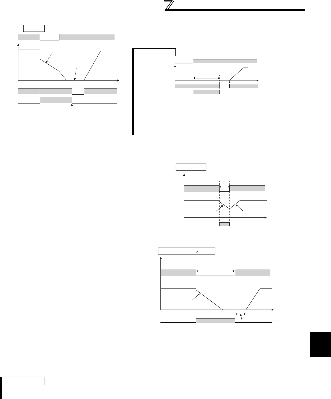
271
Operation selection at power failure
and instantaneous power failure
4
PARAMETERS
(4) Original operation continuation at instantaneous power failure function (Pr. 261 = "2, 12")
(5) Undervoltage avoidance function (Pr. 261 = "11, 12", Pr. 294 )
⋅When Pr. 261 = "11, 12", the deceleration time is automatically adjusted (shortened) to prevent undervoltage from
occurring during deceleration at an instantaneous power failure.
⋅Adjust the slope of frequency decrease and response level with Pr. 294. A larger setting will improve
responsiveness to the bus voltage.
(3) Power failure stop function (Pr. 261 = "1, 11")
⋅If power is restored during power failure deceleration, deceleration to
a stop is continued and the inverter remains stopped. To restart, turn
OFF the start signal once, then turn it ON again.
⋅When power is restored during deceleration after
an instantaneous power failure, acceleration is
made again up to the set frequency.
⋅When this function is used in combination with
the automatic restart after instantaneous power
failure operation, deceleration can be made at a
power failure and acceleration can be made
again after power restoration. When power is
restored after a stop by deceleration at an
instantaneous power failure, automatic restart
operation is performed if automatic restart after
instantaneous power failure has been selected
(Pr. 57 ≠ "9999")
REMARKS
Undervoltage avoidance function is invalid during torque control by Real sensorless vector control. When Pr. 261 = "11 (12)", the
inverter operates in the same manner as when "1 (2)" is set in Pr. 261.
During deceleration at
occurrence of power failure
During stop at
occurrence of
power failure
STF
Y46
Time
Turn OFF STF once to make acceleration again
Power
supply
Output frequency
Pr.261 = 1
REMARKS
⋅When automatic restart after instantaneous power failure is selected (Pr.
57 ≠ "9999"), deceleration to stop function is invalid and the restart after
instantaneous power failure operation is performed.
⋅
When the power failure stop function is active (
Pr.261
= "1, 11"), the inverter will
not start even if the power is turned ON with the start signal (STF/STR) ON. After
switching ON the power supply, turn OFF the start signal once and then ON again
to make a start.
STF
Power supply
Y46
Not started as inverter
is stopped due to power
failure
ON
OFF ON
Output
frequency
Time
ON
IPF
Power
supply
Time
Output
frequency
Y46
During deceleration
at occurrence of
power failure Reacceleration*
When power is restored during
deceleration at occurrence of
power failure
* Acceleration time depends on Pr. 7 (Pr. 44 ).
Pr. 261 = 2
During power failure
Power
supply
Output
frequency
Y46
During deceleration
at occurrence of
power failure
Automatic restart
after instantaneous
power failure
Reset time + Pr.57
Pr.261 = 2, Pr.57 9999 When used with automatic restart
after instantaneous power failure
Time
272
Operation selection at power failure
and instantaneous power failure
(6) Power failure deceleration signal (Y46 signal)
⋅After deceleration at an instantaneous power failure, inverter cannot start even if the start command is given. In this
case, check the power failure deceleration signal (Y46 signal). (at occurrence of input phase failure protection
(E.ILF), etc.)
⋅The Y46 signal is ON during deceleration at an instantaneous power failure or during a stop after deceleration at an
instantaneous power failure.
⋅For the Y46 signal, set "46 (positive logic)" or "146 (negative logic)" in any of Pr. 190 to Pr. 196 (output terminal
function selection) to assign the function.
CAUTION
⋅When Pr. 30 Regenerative function selection = "2" (FR-HC, MT-HC, FR-CV is used), the power failure deceleration function is
invalid.
⋅When the (output frequency - Pr. 262) at undervoltage or power failure occurrence is negative, the calculation result is regarded
as 0Hz. (DC injection brake operation is performed without deceleration).
⋅During a stop or error, the power failure stop selection is not performed.
⋅Y46 signal turns ON when undervoltage occurs even when the motor is not decelerating at an instantaneous power failure.
For this reason, Y46 signal outputs instantly at powering OFF, which is not a fault.
⋅When power failure deceleration stop function is selected, undervoltage protection (E.UVT), instantaneous power failure
protection (E.IPF), and input phase loss protection (E.ILF) do not function.
⋅Changing the terminal assignment using Pr. 190 to Pr. 196 (output terminal function selection) may affect the other functions. Set
parameters after confirming the function of each terminal.
CAUTION
If power-failure deceleration stop function is set, some loads may cause the inverter to trip and the motor to
coast. The motor will coast if enough regenerative energy is given from the motor.
♦ Parameters referred to ♦
Pr. 12 DC injection brake operation voltage Refer to page 203
Pr. 20 Acceleration/deceleration reference frequency, Pr. 21 Acceleration/deceleration time increments Refer to page 172
Pr. 30 Regenerative function selection Refer to page 207
Pr. 57 Restart coasting time Refer to page 266
Pr. 190 to Pr. 196 (output terminal function selection) Refer to page 239
Pr. 872 Input phase loss protection selection Refer to page 276
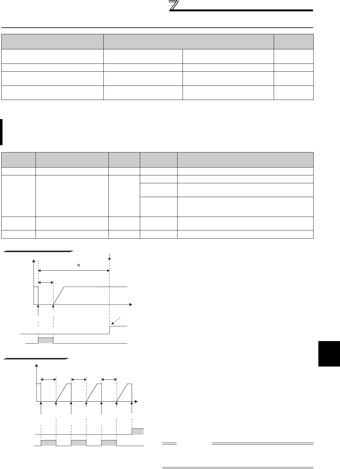
273
Operation setting at fault occurrence
4
PARAMETERS
4.18 Operation setting at fault occurrence
4.18.1 Retry function (Pr. 65, Pr. 67 to Pr. 69)
⋅Retry operation automatically resets a fault and
restarts the inverter at the starting frequency when the
time set in Pr. 68 elapses after the inverter tripped due
to the fault.
⋅Retry operation is performed by setting Pr. 67 to any
value other than "0". Set the number of retries at fault
occurrence in Pr. 67.
⋅When retries fail consecutively more than the number
of times set in Pr. 67 , a retry count excess fault
(E.RET) occurs, and the inverter trips.
(Refer to retry failure example)
⋅Use Pr. 68 to set the waiting time from when an inverter
fault occurs until a retry is made in the range 0 to 10s.
(When the setting value is "0s", the actual time is 0.1s.)
⋅Reading the Pr. 69 value provides the cumulative
number of successful restart times made by retry. The
cumulative count in Pr. 69 is increased by 1 when a
retry is regarded as successful after normal operation
continues without faults occurring for more than four
times longer than the time set in Pr. 68 after a retry start.
(When retry is successful, cumulative number of retry
failure is cleared.)
⋅Writing "0" in Pr. 69 clears the cumulative count.
⋅During a retry, the Y64 signal is ON. For the Y64
signal, assign the function by setting "64 (positive
logic)" or "164 (negative logic)" in any of Pr. 190 to Pr.
196 (output terminal function selection) .
Purpose Parameter that must be Set Refer to
Page
Recover by retry operation at fault
occurrence Retry operation Pr. 65, Pr. 67 to Pr. 69 273
Output fault code from terminal Fault code output function Pr. 76 275
Do not output input/output phase
failure alarm
Input/output phase failure
protection selection Pr. 251, Pr. 872 276
The motor is decelerated to stop at
motor thermal activation Fault definition Pr. 875 277
If a fault occurs, the inverter resets itself automatically to restart. You can also select the fault for a retry.
When automatic restart after instantaneous power failure is selected (Pr. 57 Restart coasting time ≠ "9999"), restart
operation is performed at retry operation as at an instantaneous power failure. (Refer to page 266 for the restart
function.)
Parameter
Number Name Initial
Value
Setting
Range Description
65 Retry selection 0 0 to 5 A fault for retry can be selected. (Refer to the next page)
67 Number of retries at fault
occurrence 0
0 No retry function
1 to 10 Set the number of retries at fault occurrence.
A fault output is not provided during retry operation.
101 to 110
Set the number of retries at fault occurrence. (The
setting value of minus 100 is the number of retries.)
A fault output is provided during retry operation.
68 Retry waiting time 1s 0 to 10s Set the waiting time from when an inverter fault occurs
until a retry is made.
69 Retry count display erase 0 0 Clear the number of restarts succeeded by retry.
CAUTION
When terminal assignment is changed using Pr. 190 to Pr.
196, the other functions may be affected. Set parameters
after confirming the function of each terminal.
Retry failure example
Inverter
output
frequency
Fault
occurrence
First
retry Fault
occurrence
Second
retry Fault
occurrence
Third
retry Retry failure
(E.RET)
ON
0
Fault signal
(ALM)
Pr.68 Pr.68 Pr.68
Time
Y64 ON ON ON
Inverter
output
frequency
0
Y64
Pr.68
Pr.68 5
Retry success
Retry success example
Success count + 1
Time
ON
Fault occurrence
Retry success count
Retry start
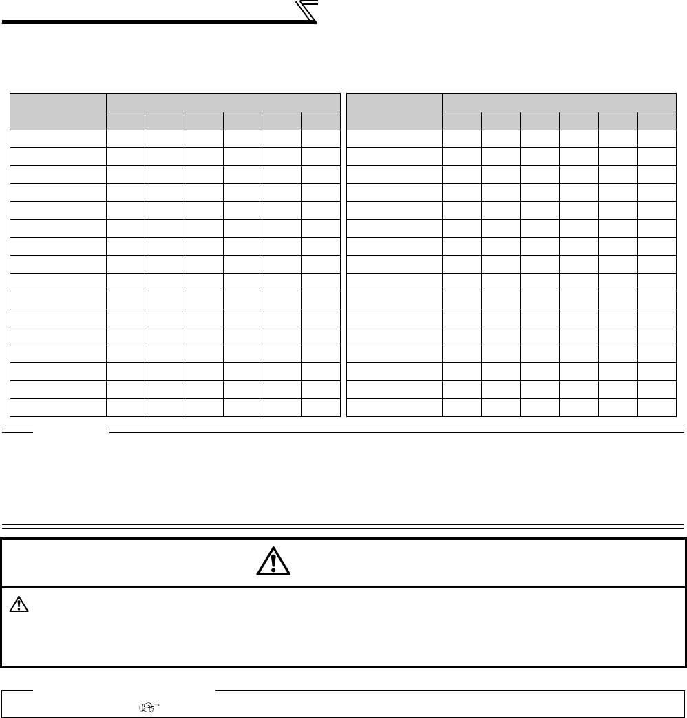
274
Operation setting at fault occurrence
⋅Using Pr. 65 you can select the fault that will cause a retry to be executed. No retry will be made for the fault not
indicated. (Refer to page 404 for the fault description.)
indicates the errors selected for retry.
Fault for
Retry
Pr. 65 Setting Fault for
Retry
Pr. 65 Setting
0 1 2 3 4 5 0 1 2 3 4 5
E.OC1 E. PE
E.OC2 E.MB1
E.OC3 E.MB2
E.OV1 E.MB3
E.OV2 E.MB4
E.OV3 E.MB5
E.THM E.MB6
E.THT E.MB7
E.IPF
E.OS
E.UVT
E.OSD
E. BE
E.OD
E. GF
E.PTC
E.OHT E.CDO
E.OLT
E.SER
E.OPT
E.USB
E.OP3
E.ILF
CAUTION
⋅For a retry error, only the description of the first fault is stored.
⋅When an inverter fault is reset by the retry function at the retry time, the accumulated data of the electronic thermal relay
function, regenerative brake duty converter duty etc. are not cleared. (Different from the power-on reset.)
⋅Retry is not performed if E.PE (Parameter storage device fault) occurred at power ON.
⋅If a fault that is not selected for a retry occurs during retry operation (retry waiting time), the retry operation stops while the fault
indication is still displayed.
CAUTION
When you have selected the retry function, stay away from the motor and machine in the case of the inverter is
tripped. The motor and machine will start suddenly (after the reset time has elapsed) after the inverter trip.
When you have selected the retry function, apply in easily visible places the CAUTION stickers supplied to the
Instruction Manual (Basic).
♦ Parameters referred to ♦
Pr. 57 Restart coasting time Refer to page 266
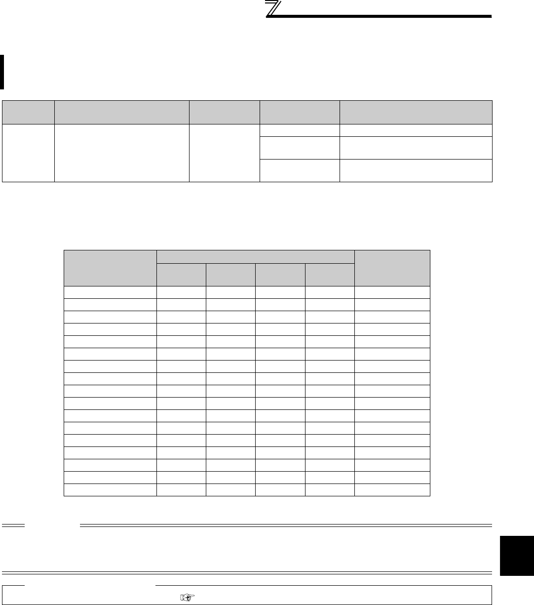
275
Operation setting at fault occurrence
4
PARAMETERS
4.18.2 Fault code output selection (Pr. 76)
⋅By setting Pr. 76 = "1" or "2", the fault code can be output to the output terminals.
⋅When the setting is "2", a fault code is output at only fault occurrence, and during normal operation, the terminals
output the signals assigned to Pr. 191 to Pr. 194 (output terminal function selection).
⋅The following table indicates fault codes to be output. (0: output transistor OFF, 1: output transistor ON)
At fault occurrence, its description can be output as a 4-bit digital signal from the open collector output terminals.
The fault code can be read by a programmable controller, etc., and its corrective action can be shown on a
display, etc.
Parameter
Number Name Initial Value Setting Range Description
76 Fault code output selection 0
0 Without fault code output
1With fault code output
(Refer to the following table)
2Fault code output at fault occurrence
only (Refer to the following table)
Operation Panel
Indication
(FR-DU07)
Output of Output Terminals
Fault Code
SU IPF OL FU
Normal *0000 0
E.OC1 0001 1
E.OC2 0010 2
E.OC3 0011 3
E.OV1 to E.OV3 0100 4
E.THM 0101 5
E.THT 0110 6
E.IPF 0111 7
E.UVT 1000 8
E.FIN 1001 9
E. BE 1010 A
E. GF 1011 B
E.OHT 1100 C
E.OLT 1101 D
E.OPT 1110 E
E.OP3 1110 E
Other than the above 1111 F
* When Pr. 76 = "2", the output terminals output the signals assigned to Pr. 191 to Pr. 194 .
CAUTION
⋅When a value other than "0" is set in Pr. 76
When a fault occurs, the output terminals SU, IPF, OL, FU output the signal in the above table, independently of the Pr. 191 to
Pr. 194 (output terminal function selection) settings. Please be careful when inverter control setting has been made with the output
signals of Pr. 191 to Pr. 194.
♦ Parameters referred to ♦
Pr. 191 to Pr. 194 (output terminal function selection) Refer to page 239
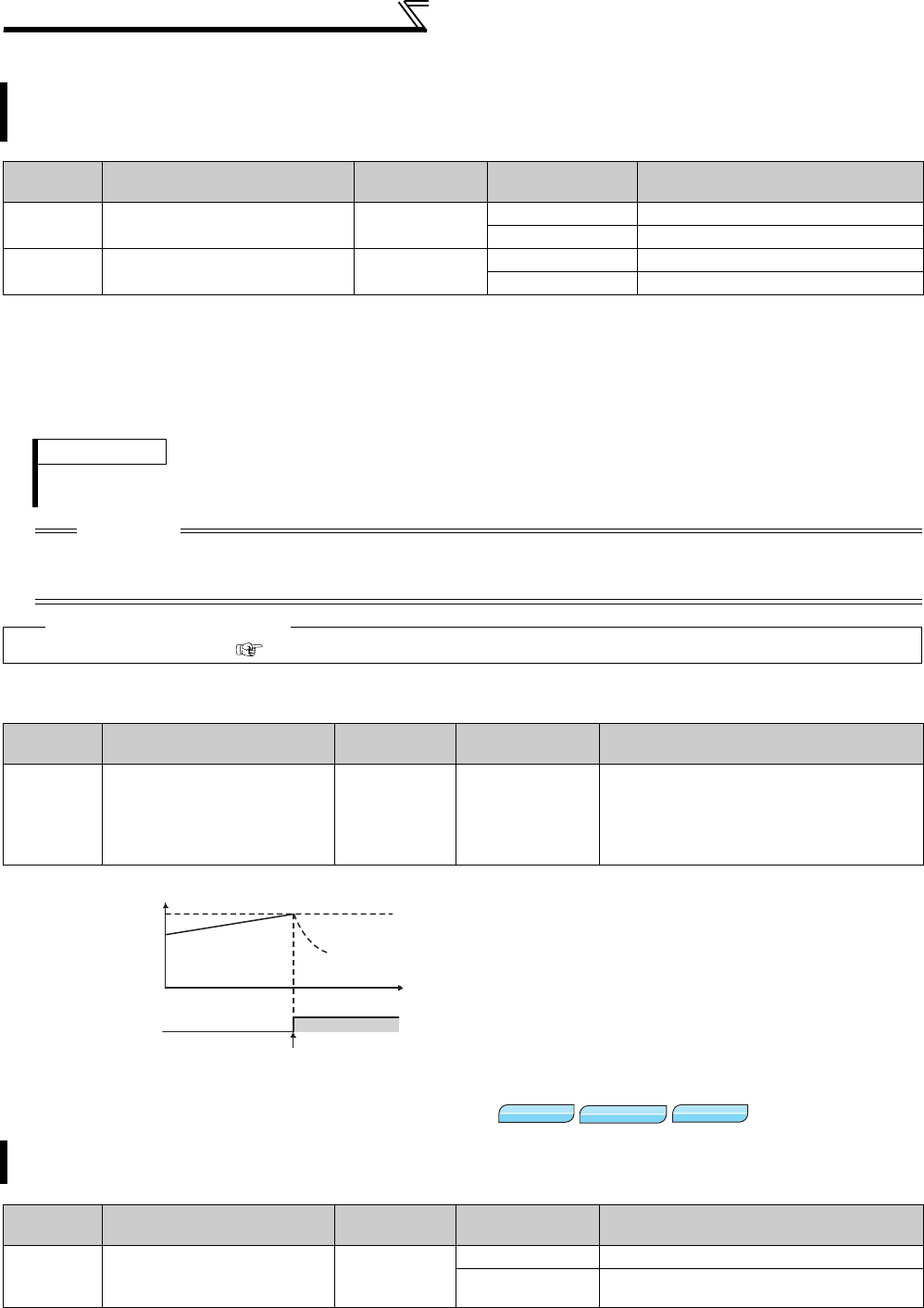
276
Operation setting at fault occurrence
4.18.3 Input/output phase loss protection selection (Pr. 251, Pr. 872)
(1) Output phase loss protection selection (Pr. 251)
⋅When Pr. 251 is set to "0", output phase loss protection (E.LF) becomes invalid.
(2) Input phase loss protection selection (Pr. 872)
⋅When Pr. 872 is set to "1", input phase loss protection (E.ILF) is provided if a phase loss of one phase among the
three phases is detected for 1s continuously.
4.18.4 Overspeed detection (Pr. 374)
4.18.5 Encoder signal loss detection (Pr. 376)
* Setting can be made only when the FR-A7AP/FR-A7AL (option) is mounted.
You can disable the output phase loss protection function that trips the inverter if one phase of the inverter output
side (load side) three phases (U, V, W) is lost.
The input phase loss protection function of the inverter input side (R/L1, S/L2, T/L3) can be valid.
Parameter
Number Name Initial Value Setting Range Description
251 Output phase loss protection
selection 10 Without output phase loss protection
1 With output phase loss protection
872 Input phase loss protection
selection 00 Without input phase loss protection
1 With input phase loss protection
REMARKS
If an input phase loss has occurred when Pr. 872 = "1" (input phase loss protected) and a value other than "0" (power failure stop
function valid) is set in Pr. 261, input phase loss protection (E.ILF) is not provided but power-failure deceleration is made.
CAUTION
⋅When an input phase loss occurs in the R/L1 and S/L2 phases, input phase loss protection is not provided but the inverter
output is shut off.
⋅If an input phase loss continues for a long time, the converter section and capacitor lives of the inverter will be shorter.
♦ Parameters referred to ♦
Pr. 261 Power failure stop selection Refer to page 270
Parameter
Number Name Initial Value Setting Range Description
374 Overspeed detection level 140Hz 0 to 400Hz
When the motor speed reaches or exceeds
the speed set in Pr. 374 during encoder
feedback control, Real sensorless vector
control, or vector control, over speed (E.OS)
occurs and the inverter trips.
When the encoder signal is lost during encoder feedback control, orientation control, or vector control, signal loss
detection (E.ECT) is activated to trip the inverter.
Parameter
Number Name Initial Value Setting Range Description
376
Encoder signal loss
detection enable/disable
selection
0
0Signal loss detection is invalid
1Signal loss detection is valid
ALM
Motor speed *
Time
E.OS
Coast to stop
ON
P
r. 374
* The output frequency and Pr. 374 are compared during
Real sensorless vector control.
V/F
V/F
V/F
Magnetic flux
Magnetic flux
Magnetic flux
Vector
Vector
Vector
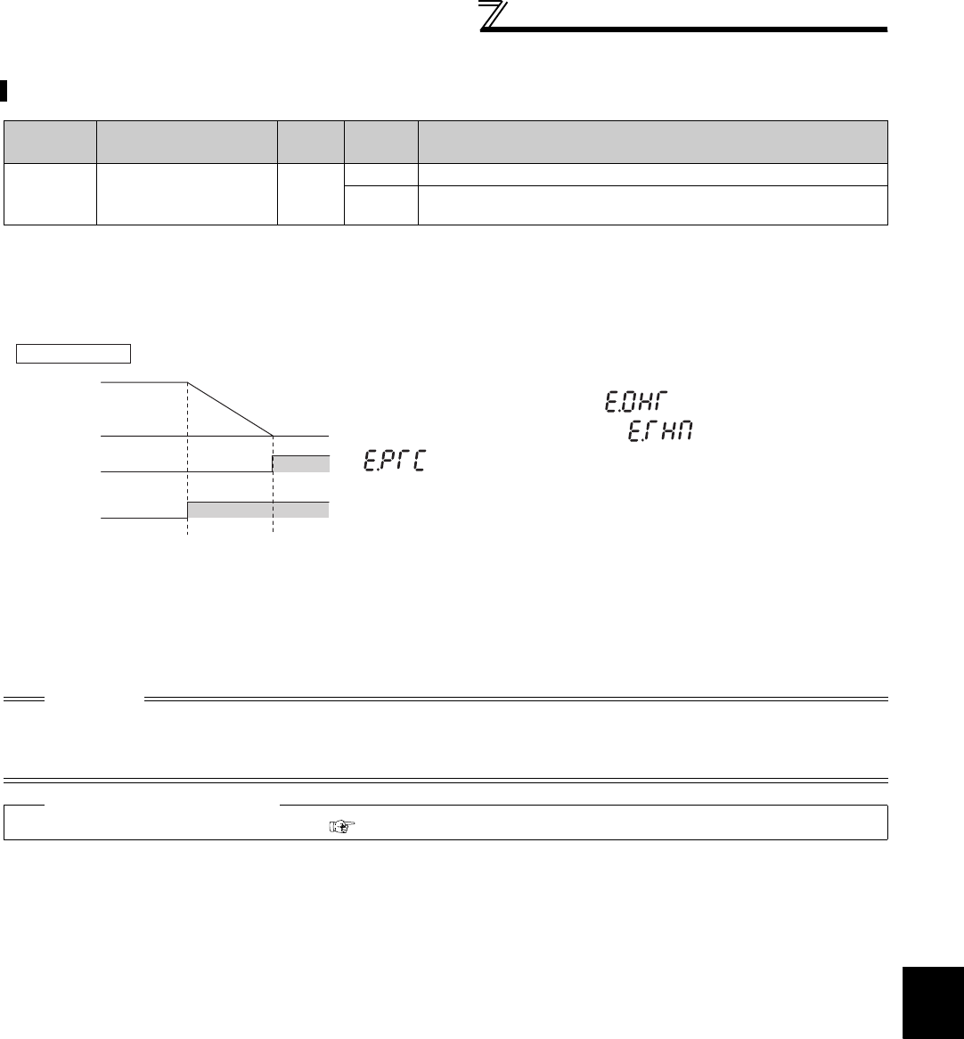
277
Operation setting at fault occurrence
4
PARAMETERS
4.18.6 Fault definition (Pr. 875)
When motor thermal protection is activated, a fault can be output after the motor decelerates to a stop.
Parameter
Number Name Initial
Value
Setting
Range Description
875 Fault definition 0
0 Normal operation
1The motor decelerates to stop when motor thermal protection is
activated.
(1) Inverter trips immediately at occurrence of any fault
(setting value is "0", initial value)
⋅Inverter trips immediately and a fault signal output is provided at fault
occurrence.
(2) The motor decelerates to stop when motor thermal
protection is activated (setting value is "1")
⋅When external thermal relay (OHT), motor overload trip
(electronic thermal relay function) (THM) or PTC thermistor
(PTC) is activated, turning ON the alarm output 2 signal (ER)
starts the motor to decelerate and a fault is provided after deceleration
to a stop.
⋅When the ER signal turns ON, decrease load, etc. to allow the inverter
to decelerate.
⋅At occurrence of a fault other than OHT, THM and PTC, inverter trips
immediately and a fault signal is output.
⋅Set "97 (positive logic) or 197 (negative logic)" in Pr. 190 to Pr. 196
(output terminal function selection) and assign the ER signal to the output
terminal.
⋅This function is invalid during position control.
CAUTION
⋅The value "0" is recommended for the system in which the motor continues running without deceleration due to a large torque
on the load side.
⋅Changing the terminal assignment using Pr. 190 to Pr. 196 (output terminal function selection) may affect the other functions. Set
parameters after confirming the function of each terminal.
♦ Parameters referred to ♦
Pr. 190 to Pr. 196 (output terminal function selection) Refer to page 239
Output
speed
Fault output
(ALM, ALM2)
OHT
occurrence
A
larm output 2
(ER)
E.OHT
display
ON
ON
When Pr.875 = "1"

278
Energy saving operation and energy saving monitor
4.19 Energy saving operation and energy saving monitor
4.19.1 Energy saving control (Pr. 60)
Energy saving operation mode (setting "4")
⋅When "4" is set in Pr. 60, the inverter operates in the energy saving operation mode.
⋅In the energy saving operation mode, the inverter automatically controls the output voltage to minimize the inverter
output voltage during a constant operation.
Purpose Parameter that must be Set Refer to
Page
Energy saving operation Energy saving operation Pr. 60 278
How much energy can be saved Energy saving monitor Pr. 52, Pr. 54, Pr. 158,
Pr. 891 to Pr. 899 279
Without a fine parameter setting, the inverter automatically performs energy saving control.
This inverter is optimum for fan and pump applications.
Parameter
Number Name Initial Value Setting Range Description
60 Energy saving control selection* 00 Normal operation mode
4 Energy saving operation mode
* When parameter is read using the FR-PU04, a parameter name different from an actual parameter is displayed.
REMARKS
⋅For applications a large load torque is applied to or machines repeat frequent acceleration/deceleration, an energy saving effect
is not expected.
CAUTION
⋅When the energy saving mode is selected, deceleration time may be longer than the setting value. Since overvoltage alarm
tends to occur as compared to the constant torque load characteristics, set a longer deceleration time.
⋅The energy saving operation mode functions only under V/F control. When the Advanced magnetic flux vector control, Real
sensorless vector control and vector control are selected, the energy saving mode is invalid.
⋅Since output voltage is controlled in energy saving operation mode, output current may slightly increase.
V/F
V/F
V/F

279
Energy saving operation and energy saving monitor
4
PARAMETERS
4.19.2 Energy saving monitor (Pr. 891 to Pr. 899)
From the power consumption estimated value during commercial power supply operation, the energy saving
effect by use of the inverter can be monitored/output.
Parameter
Number
Name Initial
Value Setting Range Description
52 DU/PU main display data
selection
0
(output
frequency)
0, 5 to 14, 17 to 20, 22 to 25,
32 to 35, 39, 46, 50 to 57, 100
50:Power saving monitor
51:Cumulative saving power monitor
54 FM terminal function
selection 1
(output
frequency)
1 to 3, 5 to 14, 17, 18, 21, 24,
32 to 34, 46, 50, 52, 53 50:Power saving monitor
158 AM terminal function
selection
891 Cumulative power monitor
digit shifted times 9999
0 to 4
Set the number of times to shift the
cumulative power monitor digit
Clamps the monitoring value at
maximum.
9999
No shift
Clears the monitor value when it
exceeds the maximum value.
892 Load factor 100% 30 to 150%
Set the load factor for commercial
power-supply operation. Multiplied by
the power consumption rate (page 282)
during commercial power supply
operation.
893 Energy saving monitor
reference (motor capacity)
Inverter
rated
capacity
55K
or lower 0.1 to 55kW Set the motor capacity (pump
capacity). Set when calculating power
saving rate, power saving rate average
value, commercial operation power.
75K
or higher 0 to 3600kW
894
Control selection during
commercial power-supply
operation
0
0 Discharge damper control (fan)
1 Inlet damper control (fan)
2 Valve control (pump)
3Commercial power-supply drive (fixed
value)
895 Power saving rate
reference value 9999
0Consider the value during commercial
power-supply operation as 100%
1
Consider the
Pr. 893
setting as 100%.
9999 No function
896 Power unit cost 9999 0 to 500
Set the power unit cost. Displays the
power saving amount charge on the
energy saving monitor.
9999 No function
897 Power saving monitor
average time 9999
0 Average for 30 minutes
1 to 1000h Average for the set time
9999 No function
898 Power saving cumulative
monitor clear 9999
0 Cumulative monitor value clear
1 Cumulative monitor value hold
10 Totalization continued
(communication data upper limit 9999)
9999
Totalization continued
(communication data upper limit
65535)
899 Operation time rate
(estimated value) 9999 0 to 100%
Use for calculation of annual power
saving amount. Set the annual
operation ratio (consider 365 days ×
24h as 100%).
9999 No function
The above parameters allow its setting to be changed during operation in any operation mode even if "0" (initial value) is set in Pr. 77 Parameter write
selection.

280
Energy saving operation and energy saving monitor
(1) Energy saving monitor list
⋅The following provides the items that can be monitored by the power saving monitor (Pr. 52, Pr. 54, Pr. 158 = "50").
(Only 1) power saving and 3) power saving average value can be output to Pr. 54 (terminal FM) and Pr. 158
(terminal AM))
⋅The following shows the items which can be monitored by the cumulative saving power monitor (Pr. 52 = "51").
(The monitor value of the cumulative monitor can be shifted to the right with Pr. 891 Cumulative power monitor digit
shifted times.)
Energy Saving
Monitor Item Description and Formula Incre-
ments
Parameter Setting
Pr. 895 Pr. 896 Pr. 897 Pr. 899
1) Power saving
Difference between the estimated value of power
necessary for commercial power supply operation
and the input power calculated by the inverter
Power during commercial power supply
operation − input power monitor
0.01kW/
0.1kW *3 9999
⎯9999
⎯
2) Power saving rate
Ratio of power saving on the assumption that power
during commercial power supply operation is 100%
× 100
0.1%
0
Ratio of power saving on the assumption that Pr.
893 is 100%
× 100
1
3) Power saving
average value
Average value of power saving amount per hour
during predetermined time (Pr. 897)0.01kWh
/0.1kWh
*3
9999
9999
0 to
1000h
4) Power saving rate
average value
Ratio of power saving average value on the
assumption that the value during commercial
power supply operation is 100%
× 100
0.1%
0
Ratio of power saving average value on the
assumption that Pr. 893 is 100%
× 100
1
5) Average power cost
savings
Power saving average value represented in terms
of cost
3) Power saving average value × Pr. 896
0.01/0.1
*3 ⎯0 to
500
Energy Saving
Monitor Item Description and Formula Incre-
ments
Parameter Setting
Pr. 895 Pr. 896 Pr. 897 Pr. 899
6) Power saving
amount
Power saving is added up per hour.
Σ ( 1) Power saving × Δt)
0.01kWh
/0.1kWh
*1*2*3
⎯9999
⎯
9999
7) Power cost
savings
Power saving amount represented in terms of cost
6) Power saving amount × Pr. 896 0.01/0.1
*1*3
⎯0 to
500
8) Annual power
saving amount
Estimated value of annual power saving amount
×
24
×
365
×
0.01kWh
/0.1kWh
*1*2*3
⎯9999
0 to
100%
9) Annual power
cost savings
Annual power saving amount represented in terms of
cost
8) Annual power saving amount × Pr. 896
0.01/0.1
*1*3
⎯0 to
500
*1 For communication (RS-485 communication, communication option), the display increments are 1. For example, the communication data is
"10" for "10.00kWh".
*2 When using the parameter unit (FR-PU04/FR-PU07), "kW" is displayed.
*3 The setting depends on capacities. (55K or lower/75K or higher)
REMARKS
⋅As the operation panel (FR-DU07) is 4-digit display, it displays in 0.1 increments since a carry occurs, e.g. "100.0", when a
monitor value in 0.01 increments exceeds "99.99". The maximum display is "9999".
⋅As the operation panel (FR-PU04/FR-PU07) is 5-digit display, it displays in 0.1 increments since a carry occurs, e.g. "1000.0",
when a monitor value in 0.01 increments exceeds "999.99". The maximum display is "99999".
⋅The upper limit of communication (RS-485 communication, communication option) is "65535" when Pr. 898 Power saving
cumulative monitor clear = "9999". The upper limit of 0.01 increments monitor is "655.35" and that of 0.1 increments monitor is
"6553.5".
Power during commercial
power supply operation
1) Power saving
1) Power saving
Pr. 893
Σ ( 1) Power saving × Δt)
Pr. 897
Σ ( 2) Power saving rate × Δt)
Pr. 897
3) Power saving average value
Pr. 893
6) Power saving amount
Operation time during accumulation
of power saving amount
Pr. 899
100
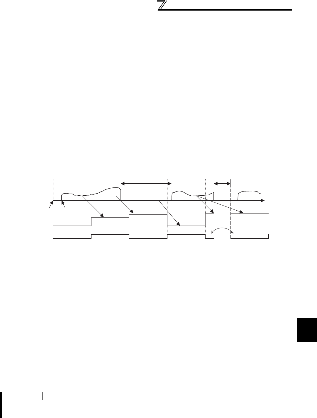
281
Energy saving operation and energy saving monitor
4
PARAMETERS
(2) Power saving instantaneous monitor ( 1) power savings, 2) power saving rate )
⋅On the power saving monitor ( 1)), an energy saving effect as compared to the power consumption during
commercial power supply operation (estimated value) is calculated and displays on the main monitor.
⋅In the following case, the power saving monitor ( 1)) is "0".
(a)Calculated values of the power saving monitor are negative values.
(b)During the DC injection brake operation
(c)Motor is not connected (output current monitor is 0A)
⋅On the power saving rate monitor ( 2)), setting "0" in Pr. 895 Power saving rate reference value displays the power
saving rate on the assumption that power (estimated value) during commercial power supply operation is 100%.
When Pr. 895 = "1", the power saving rate on the assumption that the Pr. 893 Energy saving monitor reference (motor
capacity) value is 100% is displayed.
(3) Power saving average value monitor ( 3) power saving average value, 4) average power
saving rate average value, 5) average power cost savings)
⋅Power saving average value monitor can be displayed when a value other than "9999" is set in Pr. 897 Power saving
monitor average time.
⋅The power saving average value monitor ( 3)) displays the average value per unit time of the power saving amount
at averaging.
⋅The average value is updated every time an average time has elapsed after the Pr. 897 setting is changed, power is
turned ON or the inverter is reset, assuming as a starting point. The power savings average value update timing
signal (Y92) is inverted every time the average value is updated.
⋅The power saving average value monitor ( 4)) displays the average value per unit time of power saving rate ( 2)) at
every average time by setting "0" or "1" in Pr. 895 Power saving rate reference value.
⋅By setting the charge (power unit) per 1kWh of power amount in Pr. 896 Power unit cost, the power saving amount
average value monitor ( 5)) displays the charge relative to the power saving average value (power saving average
value ( 3)) × Pr. 896).
(4) Cumulative saving power monitor ( 6) power saving amount, 7) power cost savings, 8)
annual power saving amount, 9) annual power cost savings)
⋅On the cumulative saving power monitor, the monitor data digit can be shifted to the right by the number of Pr. 891
Cumulative power monitor digit shifted times settings. For example, if the cumulative power value is 1278.56kWh
when Pr. 891 = "2", the PU/DU display is 12.78 (display in 100kWh increments) and the communication data is 12.
If the maximum value is exceeded at Pr. 891 = "0 to 4", the power is clamped at the maximum value, indicating that
a digit shift is necessary. If the maximum value is exceeded at Pr. 891 = "9999", the power returns to 0 and is
recounted. The other monitors are clamped at the display maximum value.
⋅The cumulative saving power monitor ( 6)) can measure the power amount during a predetermined period.
Measure according to the following steps
1) Write "9999" or "10" in Pr. 898 Power saving cumulative monitor clear.
2) Write "0" in Pr. 898 at measurement start timing to clear the cumulative saving power monitor value and start
totalization of power saving.
3) Write "1" in Pr. 898 at measurement end timing to hold the cumulative saving power monitor value.
REMARKS
⋅The cumulative saving power monitor value is stored every hour. Hence, when the power supply is switched ON again within
one hour after it was switched OFF, the previously stored monitor value is displayed and totalization starts. (The cumulative
monitor value may decrease)
048121620T
When Pr.897=4 [Hr]
Power saving
instantaneous
value [kW]
Pr. 897 setting
Power saving
average value
[kW]
Y92: power saving
average value
update timing signal
Operation start
0 in the first
measurement
Average Average
During stop
Average
Average
Power
is off
Last value
Stores Hi/Low when the
power is off and starts.
40 8 12 16 0 4
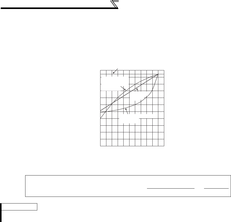
282
Energy saving operation and energy saving monitor
(5) Power estimated value of commercial power supply operation (Pr. 892, Pr. 893, Pr. 894)
⋅Select the commercial power supply operation pattern from among the four patterns of discharge damper control
(fan), inlet damper control (fan), valve control (pump) and commercial power supply drive, and set it to Pr. 894
Control selection during commercial power-supply operation.
⋅Set the motor capacity (pump capacity) in Pr. 893 Energy saving monitor reference (motor capacity).
⋅The power consumption rate (%) during commercial power supply operation is estimated from the operation
pattern and the ratio of speed to rating (current output frequency/Pr. 3 Base frequency) in the following chart.
⋅From the motor capacity set in Pr. 893 and Pr. 892 Load factor, the power estimated value (kW) during commercial
power supply operation is found by the following formula.
Power estimated value (kW) during commercial power supply operation
= Pr. 893 (kW) × ×
REMARKS
⋅Since the speed does not increase above the power supply frequency in commercial power supply operation, it becomes
constant when the output frequency rises to or above Pr. 3 Base frequency.
0
10
20
30
40
50
60
70
80
90
100
110
0 10 20 30 40 50 60 70 80 90100110
Ratio of speed to rating [%]
Discharge side
damper control
(fan)
Inlet damper control
(fan)
Valve control
(pump)
Commercial power-supply drive
Power consumption [%]
Power consumption (%)
100
Pr. 892 (%)
100

283
Energy saving operation and energy saving monitor
4
PARAMETERS
(6) Annual power saving amount, power cost (Pr. 899)
⋅By setting the operation time rate [%] (ratio of time when the motor is actually driven by the inverter during a year)
in Pr. 899, the annual energy saving effect can be predicted.
⋅When the operation pattern is predetermined to some degree, the estimated value of the annual power saving
amount can be found by measurement of the power saving amount during a given measurement period.
⋅Refer to the following and set the operation time rate.
1) Predict the average time [h/day] of operation in a day.
2) Find the annual operation days [days/year]. (Monthly average operation days × 12 months)
3) Calculate the annual operation time [h/year] from 1) and 2).
4) Calculate the operation time rate and set it to Pr. 899.
⋅Calculate the annual power saving amount from Pr. 899 Operation time rate (estimated value) and power saving
average value monitor
⋅The annual power saving amount charge can be monitored by setting the power charge per hour in Pr. 896 Power
unit cost.
Calculate the annual power saving amount charge in the following method.
Annual operation time (h/year) = Average time (h/day) × Operation days (days/year)
Operation time rate (%) = × 100(%)
REMARKS
⋅Operation time rate setting example: When operation is performed for about 21 hours per day and the monthly average
operation days are 16 days
Annual operation time = 21 (h/day) × 16 (days/month) × 12 months = 4032 (h/year)
Operation time rate (%) = × 100(%) = 46.03%
Set 46.03% to Pr. 899.
Annual power saving amount (kWh/year) = × 24h × 365 days ×
Annual power saving amount charge = Annual power saving amount (kWh/year) × Pr. 896
REMARKS
In the regeneration mode, make calculation on the assumption that "power saving = power during commercial power supply
operation (input power = 0)".
♦ Parameters referred to ♦
Pr. 3 Base frequency Refer to page 159
Pr. 52 DU/PU main display data selection Refer to page 253
Pr. 54 FM terminal function selection Refer to page 253
Pr. 158 AM terminal function selection Refer to page 253
Annual operation time (h/year)
24 (h/day) × 365 (days/year)
4032 (h/year)
24 (h/day) × 365 (days/year)
Power saving average value
(kW) during totalization
when Pr. 898 = 10 or 9999
Pr. 899
100
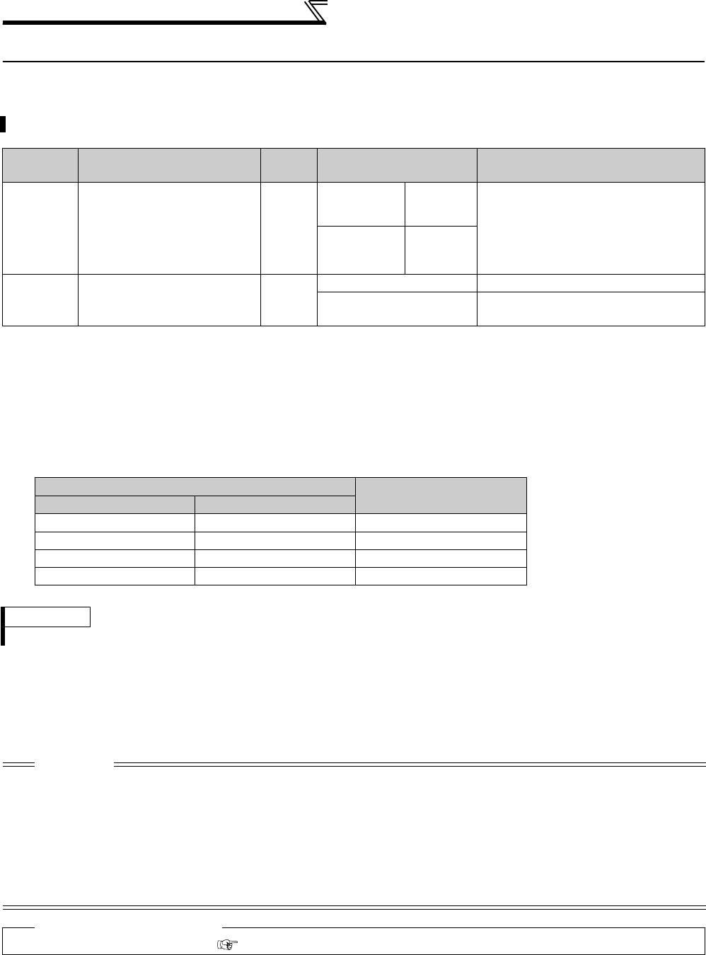
284
Motor noise, EMI measures
4.20 Motor noise, EMI measures
4.20.1 PWM carrier frequency and Soft-PWM control (Pr. 72, Pr. 240)
(1) PWM carrier frequency changing (Pr. 72)
⋅You can change the PWM carrier frequency of the inverter.
⋅Changing the PWM carrier frequency produces an effect on avoiding the resonance frequency of a mechanical
system or motor or on EMI measures or on leakage current reduction caused by the PWM switching.
⋅Carrier frequencies under Real sensorless vector control or vector control are as shown below.
(2) Soft-PWM control (Pr. 240)
⋅Soft-PWM control is a control method that changes the motor noise from a metallic tone into an unoffending
complex tone.
You can change the motor sound.
Parameter
Number Name Initial
Value Setting Range Description
72 *1 PWM frequency selection 2
55K or lower 0 to 15
PWM carrier frequency can be changed.
The setting displayed is in [kHz]. Note
that 0 indicates 0.7kHz, 15 indicates
14.5kHz and 25 indicates 2.5kHz.
(Setting value "25" is for the sine wave
filter.)
75K or higher 0 to 6, 25
240 *1 Soft-PWM operation selection 1
0 Soft-PWM is invalid
1When Pr. 72 = "0 to 5" ("0 to 4" for 75K or
higher), soft-PWM is valid.
*1 The above parameters allow its setting to be changed during operation in any operation mode even if "0" (initial value) is set in
Pr. 77 Parameter write selection.
Pr. 72 Setting Carrier Frequencies (kHz)
55K or lower 75K or higher
0 to 5 0 to 5 2
6 to 9 6 6
10 to 13 ⎯10
14, 15 ⎯14
⋅When using an option sine wave filter (MT-BSL/BSC) for the 75K or higher, set "25" (2.5kHz) in Pr. 72.
REMARKS
When "25" (available with the 75K or higher) is set in Pr. 72, V/F control is forcibly selected.
CAUTION
⋅When operating the inverter of 75K or higher with a value larger than 2kHz set in Pr. 72 PWM frequency selection, derate the
inverter rated output current. (Refer to page 442)
⋅When operating the inverter of 55K or lower with a value larger than 2kHz set in Pr. 72 PWM frequency selection, the carrier
frequency will automatically decrease as low as 2kHz if the inverter is overloaded during low speed operation (output frequency
is 3Hz or less). This may cause the motor noise to increase, but not a fault.
⋅Decreasing the PWM carrier frequency effect on EMI measures and on leakage current reduction, but increases motor noise.
⋅When PWM carrier frequency is set to 1kHz or less (Pr. 72 ≤ 1), fast response current limit may function prior to stall prevention
operation due to increase in harmonic currents depending on the motor, resulting in insufficient torque. In such case, set fast
response current limit operation invalid using Pr. 156 Stall prevention operation selection.
♦ Parameters referred to ♦
Pr. 156 Stall prevention operation selection Refer to page 152

285
Frequency/torque setting by analog
input (terminal 1, 2, 4)
4
PARAMETERS
4.21 Frequency/torque setting by analog input (terminal 1, 2, 4)
4.21.1 Function assignment of analog input terminal (Pr. 858, Pr. 868)
⋅For the terminal 1 and terminal 4 used for analog input, frequency (speed) command, magnetic flux command,
torque command, etc. can be selected.
Functions change according to the control mode as in the table below.
Terminal 1 function according to control
Terminal 4 function according to control
⎯ :No function
* This setting is valid under vector control.
Purpose Parameter that must be Set Refer to Page
Function assignment of analog input
terminal
Terminal 1 and terminal 4 function
assignment Pr. 858, Pr. 868 285
Selection of voltage/current input
(terminal 1, 2, 4) Perform forward/
reverse rotation by analog input
Analog input selection Pr. 73, Pr. 267 286
Adjust the main speed by analog
auxiliary input
Analog auxiliary input and
compensation (added
compensation and override
function)
Pr. 73, Pr. 242, Pr. 243,
Pr. 252, Pr. 253 290
Noise elimination at the analog input Input filter Pr. 74, Pr. 822, Pr. 826,
Pr. 832, Pr. 836, Pr. 849 292
Adjustment (calibration) of analog
input frequency and voltage (current)
Bias and gain of frequency
setting voltage (current)
Pr. 125, Pr. 126, Pr. 241,
C2 to C7 (Pr. 902 to Pr. 905)
C12 to C15 (Pr. 917 to Pr. 918)
294
Adjustment (calibration) of analog
input torque and voltage (current)
Bias and gain of torque setting
voltage (current)
Pr. 241,
C16 to C19 (Pr. 919 to Pr. 920),
C38 to C41 (Pr. 932 to Pr. 933)
300
Function assignment of terminal 1 and terminal 4 of analog input can be selected and changed by parameter.
Parameter
Number Name Initial Value Setting Range Description
858 Terminal 4 function assignment 0 0, 1, 4, 9999 Select the terminal 4 function.
(Refer to the following list)
868 Terminal 1 function assignment 0 0 to 6, 9999 Select the terminal 1 function.
(Refer to the following list)
Pr. 868
Setting
V/F Control,
Advanced Magnetic
Flux Vector Control
Real Sensorless Vector Control, Vector Control Vector Control
Speed control Torque control Position control
0
(Initial value) Frequency setting auxiliary Speed setting auxiliary Speed limit auxiliary ⎯
1⎯Magnetic flux command * Magnetic flux command * Magnetic flux command
2⎯Regenerative torque limit
(Pr. 810 = 1) ⎯Regenerative torque
limit (Pr. 810 = 1)
3⎯⎯
Torque command
(Pr. 804 = 0) ⎯
4
Stall prevention operation
level input
(Pr. 810 = 1)
Torque limit (Pr. 810 = 1) Torque command
(Pr. 804 = 0) Torque limit (Pr. 810 = 1)
5⎯⎯
Forward/reverse rotation
speed limit (Pr. 807 = 2) ⎯
6⎯Torque bias input
(Pr. 840 = 1, 2, 3) * ⎯⎯
9999 ⎯⎯⎯⎯
Pr. 858
Setting
V/F Control,
Advanced Magnetic Flux
Vector Control
Real Sensorless Vector Control, Vector Control Vector Control
Speed control Torque control Position control
0
(Initial value)
Frequency command
(AU signal-ON)
Speed command
(AU signal-ON)
Speed limit
(AU signal-ON) ⎯
1⎯Magnetic flux command * Magnetic flux command * Magnetic flux command
4
Stall prevention operation
level input
(Pr. 810 = 1)
Torque limit (Pr. 810 = 1) ⎯Torque limit (Pr. 810 = 1)
9999 ⎯⎯⎯⎯
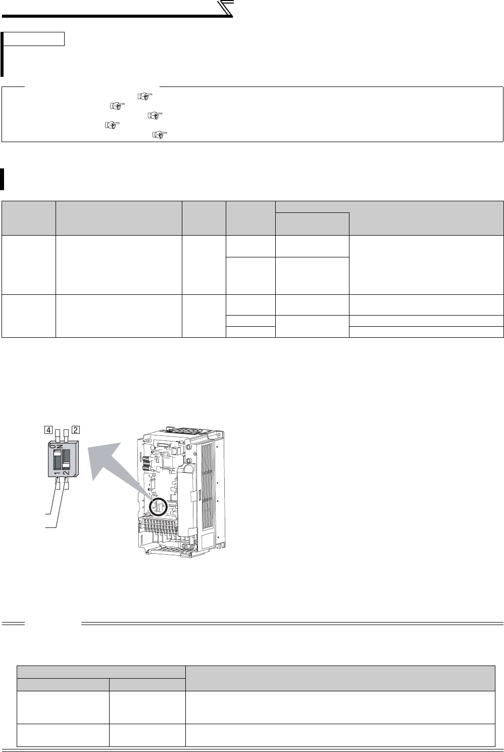
286
Frequency/torque setting by analog
input (terminal 1, 2, 4)
4.21.2 Analog input selection (Pr. 73, Pr. 267)
(1) Selection of analog input specifications
⋅For the terminals 2, 4 used for analog input, voltage input (0 to 5V, 0 to 10V) or current input (0 to 20mA) can be
selected.
Change parameters (Pr. 73, Pr. 267 ) and a voltage/current input switch (switch 1, 2) to change input specifications.
Switch 1:Terminal 4 input
ON: Current input (initial status)
OFF: Voltage input
Switch 2: Terminal 2 input
ON: Current input
OFF: Voltage input (initial status)
⋅Rated specifications of terminal 2 and 4 change according to the voltage/current input switch setting.
Voltage input: Input resistance 10kΩ ± 1kΩ, Maximum permissible voltage 20VDC
Current input: Input resistance 245Ω ± 5Ω, Maximum permissible current 30mA
REMARKS
⋅When "1 or 4" is set in both Pr. 868 and Pr. 858, terminal 1 is valid and terminal 4 has no function.
⋅When "1" (magnetic flux), "4" (stall prevention/torque limit) is set in Pr. 868, functions of terminal 4 become valid independently
of whether the AU terminal is ON or OFF.
♦ Parameters referred to ♦
Advanced magnetic flux vector control Refer to page 148
Real sensorless vector control Refer to page 92
Pr. 804 Torque command source selection Refer to page 125
Pr. 807 Speed limit selection Refer to page 127
Pr. 810 Torque limit input method selection Refer to page 100
You can select the function that switches between forward rotation and reverse rotation according to the analog
input terminal selection specifications, the override function and the input signal polarity.
Parameter
Number Name Initial
Value
Setting
Range
Description
Voltage/current
input switch
73 Analog input selection 1
0 to 5,
10 to 15
Switch 2 - OFF
(initial status)
You can select the input specifications
of terminal 2 (0 to 5V, 0 to 10V, 0 to
20mA) and input specifications of
terminal 1 (0 to ±5V, 0 to ±10V).
Override and reversible operation can
be selected.
6, 7,
16, 17 Switch 2 - ON
267 Terminal 4 input selection 0
0Switch 1 - ON
(initial status) Terminal 4 input 0 to 20mA
1Switch 1 - OFF Terminal 4 input 0 to 5V
2 Terminal 4 input 0 to 10V
CAUTION
⋅Set Pr. 73, Pr. 267, and a voltage/current input switch correctly, then input an analog signal in accordance with the setting.
Incorrect setting as in the table below could cause component damage. Incorrect settings other than below can cause abnormal
operation.
Voltage/current
input switch
Switch 1
Switch 2
Setting Causing Component Damage Operation
Switch setting Terminal input
ON (Current input) Voltage input
This could cause component damage to the analog signal output circuit of
signal output devices.
(electrical load in the analog signal output circuit of signal output devices increases)
OFF (Voltage input) Current input This could cause component damage of the inverter signal input circuit .
(output power in the analog signal output circuit of signal output devices increases)
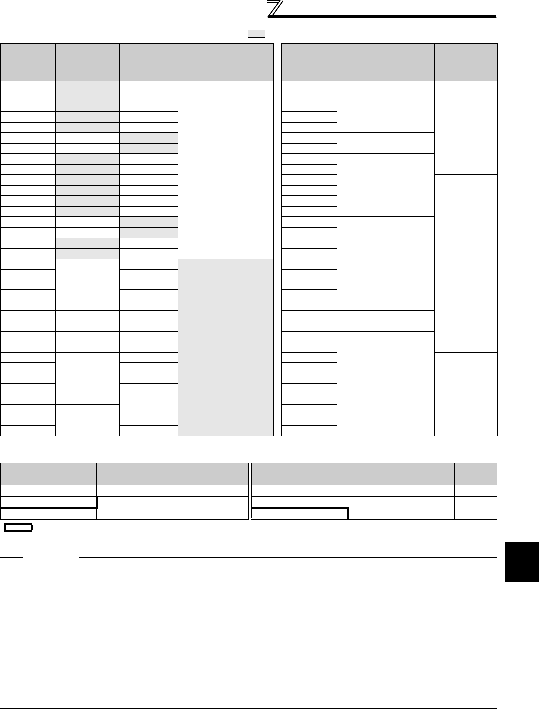
287
Frequency/torque setting by analog
input (terminal 1, 2, 4)
4
PARAMETERS
⋅Refer to the following table and set Pr. 73 and Pr. 267. ( indicates the main speed setting)
⎯: Invaild
⋅Set the voltage/current input switch referring to the table below.
Pr. 73
Setting
Terminal 2
Input
Terminal 1
Input
Terminal 4 Input
Pr. 73
Setting
Compensation Input
Terminal and
Compensation
Method
Polarity
Reversible
AU
signal
00 to 10V 0 to ±10V
Off ⎯
0
Ter mi n al 1
Added compensation
No
(Indicates that
a frequency
command
signal of
negative
polarity is not
accepted.)
1
(
initial value
)
0 to to 5V 0 to ±10V 1
(initial value)
20 to 10V 0 to ±5V 2
30 to 5V 0 to ±5V 3
4 0 to 10V 0 to ±10V 4 Ter mi n al 2
Override
50 to 5V
0 to ±5V 5
60 to 20mA 0 to ±10V 6
Ter mi n al 1
Added compensation
70 to 20mA 0 to ±5V 7
10 0 to 10V 0 to ±10V 10
Yes
11 0 to 5V 0 to ±10V 11
12 0 to 10V 0 to ±5V 12
13 0 to 5V 0 to ±5V 13
14 0 to 10V 0 to ±10V 14 Termin al 2
Override
15 0 to 5V 0 to ±5V 15
16 0 to 20mA 0 to ±10V 16 Termin al 1
Added compensation
17 0 to 20mA 0 to ±5V 17
0
⎯
0 to ±10V
On
According to
Pr. 267 setting
0: 4 to 20mA
(
initial value
)
1: 0 to 5V
2: 0 to 10V
0
Ter mi n al 1
Added compensation
No
(Indicates that
a frequency
command
signal of
negative
polarity is not
accepted.)
1 (initial
value) 0 to ±10V 1
(initial value)
2 0 to ±5V 2
3 0 to ±5V 3
4 0 to 10V ⎯4Termin al 2
Override
50 to 5V 5
6⎯0 to ±10V 6
Ter mi n al 1
Added compensation
7 0 to ±5V 7
10
⎯
0 to ±10V 10
Yes
11 0 to ±10V 11
12 0 to ±5V 12
13 0 to ±5V 13
14 0 to 10V ⎯14 Termin al 2
Override
15 0 to 5V 15
16 ⎯0 to ±10V 16 Term in al 1
Added compensation
17 0 to ±5V 17
Terminal 2 Input
Specifications Pr. 73 Setting Switch 2 Terminal 4 Input
Specifications Pr. 267 Setting Switch 1
Voltage input (0 to 10V) 0, 2, 4, 10, 12, 14 OFF Voltage input (0 to 10V) 2 OFF
Voltage input (0 to 5V) 1 (initial value), 3, 5, 11, 13, 15 OFF Voltage input (0 to 5V) 1 OFF
Current input (0 to 20mA) 6, 7, 16, 17 ON Current input (4 to 20mA) 0 (initial value) ON
CAUTION
⋅Turn the AU signal ON to make terminal 4 valid.
⋅Match the setting of parameter and switch. A different setting may cause a fault, failure or malfunction.
⋅The terminal 1 (frequency setting auxiliary input) signal is added to the main speed setting signal of the terminal 2 or 4.
⋅When an override is selected, the terminal 1 or 4 is used for the main speed setting and the terminal 2 for the override signal
(50% to 150% at 0 to 5V or 0 to 10V). (When the main speed of the terminal 1 or terminal 4 is not input, compensation by the
terminal 2 is invalid.))
⋅Use Pr. 125 (Pr. 126) (frequency setting gain) to change the maximum output frequency at input of the maximum output frequency
command voltage (current). At this time, the command voltage (current) need not be input.
Also, the acceleration/deceleration time, which is a slope up/down to the acceleration/deceleration reference frequency, is not
affected by the change in Pr. 73 setting.
⋅When Pr. 858 Terminal 4 function assignment, Pr. 868 Terminal 1 function assignment = "4", the value of the terminal 1 or terminal 4 is as
set to the stall prevention operation level. When terminal 1 and terminal 4 are used for frequency setting, set "0" (initial value) in Pr.
858 and Pr. 868.
⋅When the voltage/current input specifications were changed using Pr. 73 and Pr. 267, be sure to make calibration.
indicates an initial value.
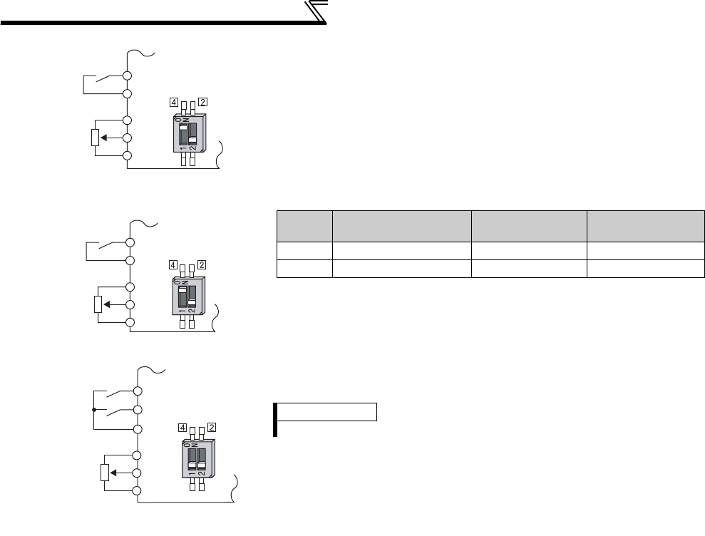
288
Frequency/torque setting by analog
input (terminal 1, 2, 4)
(2) Perform operation by analog input voltage
⋅The frequency setting signal inputs 0 to 5VDC (or 0 to 10VDC) to across
the terminals 2 and 5. The 5V (10V) input is the maximum output
frequency. The maximum output frequency is reached when 5V (10V) is
input.
⋅The power supply 5V (10V) can be input by either using the internal
power supply or preparing an external power supply. The internal power
supply outputs 5VDC across terminals 10 and 5, or 10V across terminals
10E and 5.
⋅When inputting 10VDC to the terminal 2, set any of "0, 2, 4, 10, 12, 14"
in Pr. 73. (The initial value is 0 to 5V)
⋅Setting "1 (0 to 5VDC)" or "2 (0 to 10VDC)" in Pr. 267 and a voltage/
current input switch in the OFF position changes the terminal 4 to the
voltage input specification. When the AU signal turns ON, the terminal 4
input becomes valid.
STF
Inverter
Forward
rotation
Frequency
setting
0 to 5VDC 10
2
5
Connection diagram using
terminal 2 (0 to 5VDC)
Voltage/current
input switch
SD
STF
Inverter
Forward
rotation
Frequency
setting
0 to 10VDC 10E
2
5
Connection diagram
using terminal 2 (0 to 10VDC)
Voltage/current
input switch
SD
STF
AU
DC0 to 5V 10
4
5
Forward
rotation
Frequency
setting
Terminal 4
input selection
Inverter
Voltage/current
input switch
Connection diagram
using terminal 4 (0 to 5VDC)
SD
Terminal
Inverter Built-in Power
Supply Voltage
Frequency Setting
Resolution
Pr. 73 (terminal 2
input voltage)
10 5VDC 0.030Hz/60Hz 0 to 5VDC input
10E 10VDC 0.015Hz/60Hz 0 to 10VDC input
REMARKS
The wiring length of the terminal 10, 2, 5 should be 30m maximum.
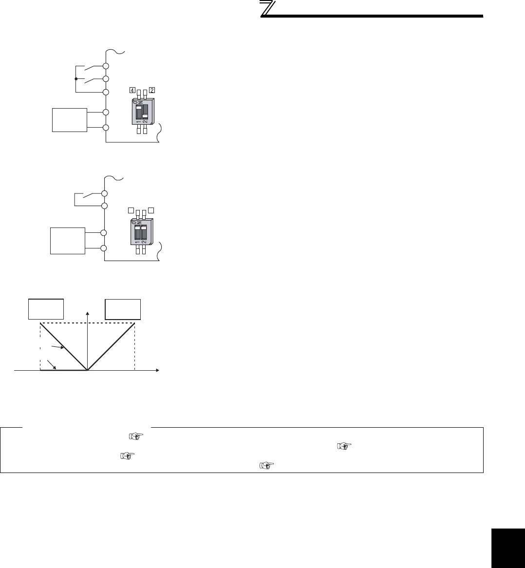
289
Frequency/torque setting by analog
input (terminal 1, 2, 4)
4
PARAMETERS
(3) Perform operation by analog input current
⋅When the pressure or temperature is controlled constant by a fan, pump,
etc., automatic operation can be performed by inputting the output signal
0 to 20mADC of the adjuster to across the terminals 4 and 5.
⋅The AU signal must be turned ON to use the terminal 4.
⋅Setting any of "6, 7, 16, 17" in Pr. 73 and a voltage/current input switch in
the ON position changes the terminal 2 to the current input specification.
At this time, the AU signal need not be turned ON.
Compensation input characteristic
when STF is on
(4) Perform forward/reverse rotation by analog input
(polarity reversible operation)
⋅Setting any of "10 to 17" in Pr. 73 enables polarity reversible operation.
⋅Providing ± input (0 to ±5V or 0 to ±10V) to the terminal 1 enables
forward/reverse rotation operation according to the polarity.
♦ Parameters referred to ♦
Pr. 22 Stall prevention operation level Refer to page 152
Pr. 125 Terminal 2 frequency setting gain frequency, Pr. 126 Terminal 4 frequency setting gain frequency Refer to page 294
Pr. 252, Pr. 253 Override bias/gain Refer to page 290
Pr. 858 Terminal 4 function assignment, Pr. 868 Terminal 1 function assignment Refer to page 285
STF
Inverter
Forward
rotation
Frequency
setting
4
5
AU
Connection diagram using
terminal 4 (4 to 20mADC)
4 to 20mADC
Current
input
equipment
Voltage/current
input switch
SD
STF
2
5
2
4
Forward
rotation
Frequency
setting
Current
input
equipment
Inverter
Voltage/current
input switch
Connection diagram using
terminal 2 (4 to 20mADC)
4 to 20mADC
SD
Forward
rotation
Reverse
rotation
Terminal 1 input (V)
+5
(+10)
-5
(-10)
0
60
Set frequency
(Hz)
Reversible
Not reversible

290
Frequency/torque setting by analog
input (terminal 1, 2, 4)
4.21.3 Analog input compensation (Pr. 73, Pr. 242, Pr. 243, Pr. 252, Pr. 253)
(1) Added compensation (Pr. 242, Pr. 243)
Auxiliary input characteristics
A fixed ratio of analog compensation (override) can be made by the added compensation or terminal 2 as an
auxiliary input for multi-speed operation or the speed setting signal (main speed) of the terminal 2 or terminal 4.
Parameter
Number Name Initial
Value
Setting
Range Description
73 Analog input selection 1
0 to 3, 6, 7, 10
to 13, 16, 17 Added compensation
4, 5, 14, 15 Override compensation
242 Terminal 1 added compensation
amount (terminal 2) 100% 0 to 100% Set the ratio of added compensation amount
when terminal 2 is the main speed.
243 Terminal 1 added compensation
amount (terminal 4) 75% 0 to 100% Set the ratio of added compensation amount
when terminal 4 is the main speed.
252 Override bias 50% 0 to 200% Set the bias side compensation value of
override function.
253 Override gain 150% 0 to 200% Set the gain side compensation value of
override function.
Added compensation
connection example
⋅The compensation signal can be input for the main speed setting for
synchronous/continuous speed control operation, etc.
⋅Setting any of "0 to 3, 6, 7, 10 to 13, 16, 17" in Pr. 73 adds the voltage across
terminals 1-5 to the voltage signal across terminals 2-5.
⋅If the result of addition is negative, it is regarded as 0 at the Pr. 73 setting of any
of "0 to 3, 6, 7", or reverse rotation operation (polarity reversible operation) is
performed when the STF signal turns ON at the Pr. 73 setting of any of "10 to
13, 16, 17".
⋅The compensation input of the terminal 1 can also be added to the multi-speed
setting or terminal 4 (initial value 4 to 20mA).
⋅The added compensation for terminal 2 can be adjusted by Pr. 242, and the
compensation for terminal 4 by Pr. 243.
Analog command value using terminal 2
= Terminal 2 input + Terminal 1 input ×
Analog command value using terminal 4
= Terminal 4 input + Terminal 1 input ×
CAUTION
⋅When the Pr. 73 setting was changed, check the voltage/current input switch setting. Different setting may cause a fault, failure
or malfunction. (Refer to page 286 for setting.)
10
2
5
Forward
rotation
Inverter
STF
1
Auxiliary input
0 to 10V( 5V)
SD
Pr. 242
100(%)
Pr. 243
100(%)
Output frequency
When voltage across
terminals 2 and 5 is 2.5V
(5V)
When voltage
across terminals
2 and 5 is 0V
+5V
(+10V)
Terminal 1
0
-2.5V
(-5V)
-5V
(-10V)
STF Signal
ON
STF Signal
ON
Forward rotation
Forward rotation
(a) When Pr. 73 setting is 0 to 5
Output frequency
When voltage across
terminals 2 and 5 is 2.5V
(5V)
When voltage
across terminals
2 and 5 is 0V
+5V
(+10V)
Terminal 1
0
-2.5V
(-5V)
-5V
(-10V)
Forward rotation
Forward rotation
(b) When Pr. 73 setting is 10 to 15
Reverse rotation
Reverse rotation
+2.5V
(+5V)
+2.5V
(+5V)
STF Signal
ON
STF Signal
ON

291
Frequency/torque setting by analog
input (terminal 1, 2, 4)
4
PARAMETERS
(2) Override function (Pr. 252, Pr. 253)
Override connection diagram
⋅Use the override function to change the main speed at a fixed ratio.
⋅Set any of "4, 5, 14, 15" in Pr. 73 to select an override.
⋅When an override is selected, the terminal 1 or terminal 4 is used for the main speed
setting and the terminal 2 for the override signal. (When the main speed of the
terminal 1 or terminal 4 is not input, compensation made by the terminal 2 becomes
invalid.)
⋅Using Pr. 252 and Pr. 253, set the override range.
⋅How to find the set frequency for override
Set frequency (Hz) = Main speed set frequency (Hz) ×
Main speed set frequency (Hz): Terminal 1, 4 input, multi-speed setting
Compensation amount (%): Terminal 2 input
Example)When Pr. 73 = "5"
The set frequency changes as shown below according to the
terminal 1 (main speed) and terminal 2 (auxiliary) inputs.
CAUTION
⋅When the Pr. 73 setting was changed, check the voltage/current input switch setting. Different setting may cause a fault, failure
or malfunction. (Refer to page 286 for setting.)
REMARKS
⋅The AU signal must be turned ON to use the terminal 4.
⋅When inputting compensation to multi-speed operation or remote setting, set "1" (compensation made) in Pr. 28 Multi-speed input
compensation selection. (Initial value is "0")
♦ Parameters referred to ♦
Pr. 28 Multi-speed input compensation selection Refer to page 169
Pr. 73 Analog input selection Refer to page 286
10
2
5
Forward
rotation
Main
speed
Inverter
STF
1
(-)
(+)
Override
setting
SD
Compensation amount (%)
100(%)
P
r.252
0V 2.5V
(5V)
5V
(10V)
0
50
100
150
200
Initial value
(50% to 150%)
Voltage across terminals 2 and 5
P
r.253
Override value (%)
0 2.5 5
0
Terminal 1 input voltage (V)
Set frequency (Hz)
Terminal 2 5VDC
input(150%)
Terminal 2 0V
input(50%)
Terminal 2 2.5VDC
input(100%)
30
15
60
45
90
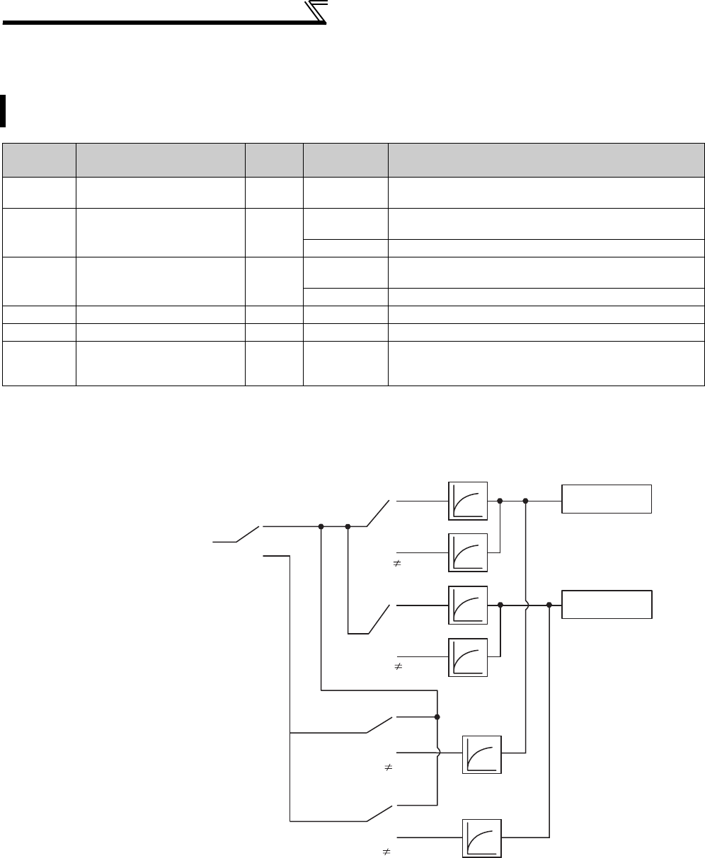
292
Frequency/torque setting by analog
input (terminal 1, 2, 4)
4.21.4 Response level of analog input and noise elimination
(Pr. 74, Pr. 822, Pr. 826, Pr. 832, Pr. 836, Pr. 849)
(1) Block diagram
Response level and stability of frequency reference command and torque reference command by analog input
(terminal 1, 2, 4) signal can be adjusted.
Parameter
Number Name Initial
Value
Setting
Range Description
74 Input filter time constant 1 0 to 8 The primary delay filter time constant for the analog input
can be set. A larger setting results in slower response.
822 Speed setting filter 1 9999 0 to 5s Set the time constant of the primary delay filter relative to
the external speed command (analog input command).
9999 Pr. 74 used
826 Torque setting filter 1 9999 0 to 5s Set the time constant of the primary delay filter relative to
the external torque command (analog input command).
9999 Pr. 74 used
832 Speed setting filter 2 9999 0 to 5s, 9999 Second function of Pr. 822 (valid when RT terminal is on)
836 Torque setting filter 2 9999 0 to 5s, 9999 Second function of Pr. 826 (valid when RT terminal is on)
849 Analog input offset
adjustment 100% 0 to 200%
This function provides speed command by analog input
(terminal 2) with offset. Motor rotation due to noise, etc.
by analog input can be avoided at zero speed command.
Terminal 1 (2, 4 ) input
RT-OFF
RT-ON
Pr. 822 = 9999
Pr. 822 9999
Pr. 826 = 9999
Pr. 826 9999
Pr. 832 = 9999
Pr. 832 9999
Pr. 836 = 9999
Pr. 836 9999
Pr. 836
Pr. 832
Pr. 826
Pr. 74
Pr. 822
Pr. 74
Speed command
Torque command
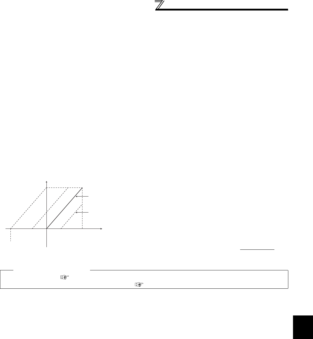
293
Frequency/torque setting by analog
input (terminal 1, 2, 4)
4
PARAMETERS
(2) Time constant of analog input (Pr. 74)
⋅Effective for eliminating noise in the frequency setting circuit.
⋅Increase the filter time constant if steady operation cannot be performed due to noise.
A larger setting results in slower response (The time constant can be set between approximately 5ms to 1s with the
setting of 0 to 8).
(3) Time constant of analog speed command input (Pr. 822, Pr. 832)
⋅Set the time constant of the primary delay filter relative to the external torque command (analog input command)
using Pr. 822 Speed setting filter 1.
Set a large time constant when you want to delay the tracking of the speed command, when the analog input
voltage fluctuates, etc.
⋅When you want to change time constant when switching two motors with one inverter, use the Pr. 832 Speed setting
filter 2.
⋅Pr. 832 Speed setting filter 2 is valid when the RT signal turns ON.
(4) Time constant of analog torque command input (Pr. 826, Pr. 836)
⋅Set the time constant of the primary delay filter relative to the external torque command (analog input command)
using Pr. 826 Torque setting filter 1.
Set a large time constant value when you want to delay the tracking of the torque command, when the analog input
voltage fluctuates, etc.
⋅When you want to change time constant when switching two motors with one inverter, etc., use Pr. 836 Torque setting
filter 2.
⋅Pr. 836 Torque setting filter 2 is valid when the RT signal turns ON.
(5) Offset adjustment of analog speed command
input (Pr. 849)
⋅When speed command by analog input is set, create the
range where the motor remains stop to prevent malfunction
at very low speed.
⋅On the assumption that the Pr. 849 setting 100% as 0, the
offset voltage is offset as follows:
100% < Pr. 849 ........ positive side
100% > Pr. 849 ........negative side
The offset voltage is found by the following formula.
♦ Parameters referred to ♦
Pr. 73 Analog input selection Refer to page 286
Pr. 125, C2 to C4 (Bias and gain of the terminal 2 frequency setting) Refer to page 294
0% 100%
(10V or 5V)
Pr.849 setting
Frequency
command
Speed setting
signal
Slope determined
according to Pr.125
and C2 to C4
Slope does not
change.
0% 200%100%
* According to the Pr. 73 setting
Offset voltage = Voltage at 100%
(5V or 10V *) ×Pr. 849 − 100 [V]
100

294
Frequency/torque setting by analog
input (terminal 1, 2, 4)
4.21.5 Bias and gain of frequency setting voltage (current)
(Pr. 125, Pr. 126, Pr. 241, C2(Pr. 902) to C7(Pr. 905), C12(Pr. 917) to C15(Pr. 918))
Frequency setting bias/gain parameter
Speed limit bias/gain parameter
You can set the magnitude (slope) of the output frequency as desired in relation to the frequency setting signal (0
to 5V, 0 to 10V or 0 to 20mADC).
Set Pr. 73, Pr. 267 and voltage/current input switch to switch between 0 to 5VDC, 0 to 10VDC and 4 to 20mADC.
(Refer to page 286)
Parameter
Number Name Initial Value Setting
Range Description
125 Terminal 2 frequency setting gain
frequency 60Hz 0 to 400Hz
Set the frequency of terminal 2 input gain
(maximum).
126 Terminal 4 frequency setting gain
frequency 60Hz 0 to 400Hz Set the frequency of terminal 4 input gain
(maximum).
241 *2 Analog input display unit
switchover 00 Displayed in % Select the unit of
analog input display.
1 Displayed in V/mA
C2(902) *1 Terminal 2 frequency setting bias
frequency 0Hz 0 to 400Hz Set the frequency on the bias side of
terminal 2 input.
C3(902) *1 Terminal 2 frequency setting bias 0% 0 to 300% Set the converted % of the bias side
voltage (current) of terminal 2 input.
C4(903) *1 Terminal 2 frequency setting gain 100% 0 to 300% Set the converted % of the gain side
voltage (current) of terminal 2 input.
C5(904) *1 Terminal 4 frequency setting bias
frequency 0Hz 0 to 400Hz Set the frequency on the bias side of
terminal 4 input.
C6(904) *1 Terminal 4 frequency setting bias 20% 0 to 300% Set the converted % of the bias side
current (voltage) of terminal 4 input.
C7(905) *1 Terminal 4 frequency setting gain 100% 0 to 300% Set the converted % of the gain side
current (voltage) of terminal 4 input.
Parameter
Number Name Initial Value Setting
Range Description
C12(917) *1 Terminal 1 bias frequency (speed) 0Hz 0 to 400Hz Set the frequency (speed) on the bias side
of terminal 1 input.
C13(917) *1 Terminal 1 bias (speed) 0% 0 to 300% Set the converted % of the bias side
voltage of terminal 1 input.
C14(918) *1 Terminal 1 gain frequency (speed) 60Hz 0 to 400Hz Set the frequency (speed) of terminal 1
input gain (maximum).
C15(918) *1 Terminal 1 gain (speed) 100% 0 to 300% Set the converted % of the gain side
voltage of terminal 1 input.
*1 The parameter number in parentheses is the one for use with the parameter unit (FR-PU04/FR-PU07).
*2 The above parameters allow its setting to be changed during operation in any operation mode even if "0" (initial value) is set in Pr. 77 Parameter write selection.

295
Frequency/torque setting by analog
input (terminal 1, 2, 4)
4
PARAMETERS
(1) The relationship between analog input terminal and calibration parameter
Terminal 1 functional calibration parameter
Terminal 4 functional calibration parameter
⎯ : No function
*Use Pr. 148 Stall prevention level at 0V input and Pr. 149 Stall prevention level at 10V input to adjust bias/gain of stall prevention operation level
Pr. 868
Setting Terminal Function Calibration Parameters
Bias setting Gain setting
0
(initial
value)
Frequency (speed) setting
auxiliary
C2(Pr. 902) Terminal 2 frequency setting bias frequency
C3(Pr. 902) Terminal 2 frequency setting bias
C5(Pr. 904) Terminal 4 frequency setting bias frequency
C6(Pr. 904) Terminal 4 frequency setting bias
Pr. 125 Terminal 2 frequency setting gain frequency
C4(Pr. 903) Terminal 2 frequency setting gain
Pr. 126 Terminal 4 frequency setting gain frequency
C7(Pr. 905) Terminal 4 frequency setting gain
1 Magnetic flux command
C16(Pr.919) Terminal 1bias command (torque/magnetic flux)
C17(Pr.919) Terminal 1bias (torque/magnetic flux)
C18(Pr. 920) Terminal 1 gain command (torque/magnetic flux)
C19(Pr. 920) Terminal 1 gain (torque/magnetic flux)
2 Regenerative torque limit
C16(Pr. 919) Terminal 1 bias command (torque/magnetic flux)
C17(Pr. 919) Terminal 1 bias (torque/magnetic flux)
C18(Pr. 920) Terminal 1 gain command (torque/magnetic flux)
C19(Pr. 920) Terminal 1 gain (torque/magnetic flux)
3 Torque command
4Stall prevention operation level */
torque limit/torque command
5Forward/reverse rotation speed
limit
C12(Pr. 917) Terminal 1 bias frequency (speed)
C13(Pr. 917) Terminal 1 bias (speed)
C14(Pr. 918) Terminal 1 gain frequency (speed)
C15(Pr. 918) Terminal 1 gain (speed)
6 Torque bias input
C16(Pr. 919) Terminal 1 bias command (torque/magnetic flux)
C17(Pr. 919) Terminal 1 bias (torque/magnetic flux)
C18(Pr. 920) Terminal 1 gain command (torque/magnetic flux)
C19(Pr. 920) Terminal 1 gain (torque/magnetic flux)
9999 ⎯⎯ ⎯
Pr. 858
Setting Terminal Function Calibration Parameters
Bias setting Gain setting
0
(initial
value)
Frequency command/speed
command
C5(Pr. 904) Terminal 4 frequency setting bias frequency
C6(Pr. 904) Terminal 4 frequency setting bias
Pr. 126 Terminal 4 frequency setting gain frequency
C7(Pr. 905) Terminal 4 frequency setting gain
1 Magnetic flux command
C38(Pr.932) Terminal 4 bias command (torque/magnetic flux)
C39(Pr.932) Terminal 4 bias (torque/magnetic flux)
C40(Pr.933) Terminal 4 gain command (torque/magnetic flux)
C41(Pr.933) Terminal 4 gain (torque/magnetic flux)
4Stall prevention operation level */
torque limit
C38(Pr. 932) Terminal 4 bias command (torque/magnetic flux)
C39(Pr. 932) Terminal 4 bias (torque/magnetic flux)
C40(Pr. 933) Terminal 4 gain command (torque/magnetic flux)
C41(Pr. 933) Terminal 4 gain (torque/magnetic flux)
9999 ⎯⎯ ⎯
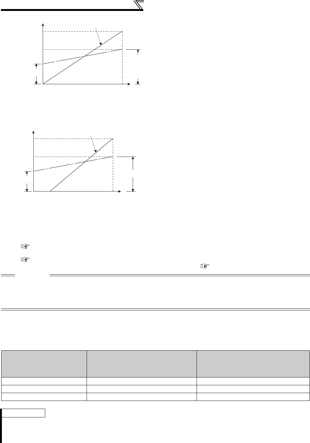
296
Frequency/torque setting by analog
input (terminal 1, 2, 4)
.
(4) Analog input display unit changing (Pr. 241)
⋅You can change the analog input display unit (%/V/mA) for analog input bias/gain calibration.
⋅Depending on the terminal input specification set to Pr. 73, Pr. 267 and voltage/current input switch, the display units of
C3 (Pr. 902), C4 (Pr. 903), C6 (Pr. 904) C7 (Pr. 905) change as shown below.
(2) Change the frequency at maximum
analog input. (Pr. 125, Pr. 126)
⋅Set a value in Pr. 125 (Pr. 126) when changing only
the frequency setting (gain) of the maximum analog
input power (current). (C2 (Pr. 902) to C7 (Pr. 905)
setting need not be changed)
(3) Analog input bias/gain calibration (C2(Pr.
902) to C7(Pr. 905), C12(Pr. 917) to C15(Pr.
918))
⋅The "bias" and "gain" functions are used to adjust the
relationship between the input signal entered from
outside the inverter to set the output frequency, e.g. 0
to 5V, 0 to 10V or 4 to 20mADC, and the output
frequency.
⋅Set the bias frequency of the terminal 2 input using
C2 (Pr. 902). (Initial value is the frequency at 0V.)
⋅Using Pr. 125, set the output frequency relative to the
frequency command voltage (current) set in Pr. 73
Analog input selection.
⋅Set the bias frequency of the terminal 1 input using
C12 (Pr. 917). (Initial value is the frequency at 0V.)
⋅Set the gain frequency of the terminal 1 input using
C14 (Pr. 918). (Initial value is the frequency at 10V.)
⋅Set the bias frequency of the terminal 4 input using
C5 (Pr. 904). (Initial value is the frequency at 4mA.)
⋅Using Pr. 126, set the output frequency relative to
20mA of the frequency command current (4 to
20mA).
There are three methods to adjust the frequency setting voltage (current) bias/gain.
(a) Method to adjust any point by application of voltage (current) across the terminals 2 and 5 (4 and 5).
page 297
(b) Method to adjust any point without application of a voltage (current) across terminals 2 and 5(4 and 5).
page 298
(c) Adjusting only the frequency without adjusting the voltage (current). page 299
CAUTION
⋅When the terminal 2 is calibrated to change the inclination of the set frequency, the setting of the terminal 1 is also changed.
⋅When a voltage is input to the terminal 1 to make calibration, (terminal 2 (4) analog value + terminal 1 analog value) is the
analog calibration value.
⋅When the voltage/current input signal was changed using Pr. 73, Pr. 267 and voltage/current input switch, be sure to make
calibration.
Analog Command
(terminal 2, 4)
(according to Pr. 73, Pr. 267,
voltage/current input switch)
Pr. 241 = 0 (initial value) Pr. 241 = 1
0 to 5V input 0 to 5V → displayed in 0 to 100% (0.1%). 0 to 100% → displayed in 0 to 5V (0.01V).
0 to 10V input 0 to 10V → displayed in 0 to 100% (0.1%). 0 to 100% → displayed in 0 to 10V (0.01V).
0 to 20mA input 0 to 20mA → displayed in 0 to 100% (0.1%). 0 to 100% → displayed in 0 to 20mA (0.01mA).
REMARKS
⋅Analog input display is not displayed correctly if voltage is applied to terminal 1 when terminal 1 input specifications (0 to ±5V, 0
to ±10V) and main speed (terminal 2, terminal 4 input) specifications (0 to 5V, 0 to 10V, 0 to 20mA) differ. (For example, 5V
(100%) is analog displayed when 0V and 10V are applied to terminal 2 and terminal 1 respectively in the initial status.
In this case, set "0" (initial value is 0% display) in Pr. 241 to use.
60Hz
Output frequency
(Hz)
Pr. 125
C14 (Pr. 918)
0
0
0
Frequency setting signal
100%
10V
20mA
Initial value
Bias
Gain
05V
C2 (Pr. 902)
C12 (Pr. 917)
C3 (Pr. 902)
C13 (Pr. 917)
C4 (Pr. 903)
C15 (Pr. 918)
Output frequency
(Hz)
Pr. 126
0
Frequency setting signal
100%
Initial value
Bias
Gain
0
20
420mA
05V
0
1
2 10V
C5
(Pr. 904)
C6 (Pr. 904) C7 (Pr. 905)
60Hz
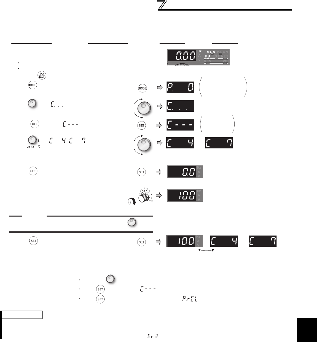
297
Frequency/torque setting by analog
input (terminal 1, 2, 4)
4
PARAMETERS
(5) Frequency setting voltage (current) bias/gain adjustment method
(a)Method to adjust any point by application of voltage (current) to across the terminals 2 and 5 (4 and 5).
REMARKS
⋅If the frequency meter (indicator) connected across terminals FM and SD does not indicate exactly 60Hz, set calibration
parameter C0 FM terminal calibration. (Refer to page 263)
⋅If the gain and bias frequency settings are too close, an error ( ) may be displayed at the time of write.
DisplayOperation
Analog voltage (current)
value (%) across terminals 2 and 5
(across terminals 4 and 5)
Flicker...Parameter setting complete!!
*
*
* The value is nearly 100 (%) in the maximum
position of the potentiometer.
* The value is nearly 100 (%) in the maximum
position of the potentiometer.
CAUTION
After performing the operation in step 6, do not touch until
completion of calibration.
(Adjustment completed)
Press twice to show the next parameter ( ).
C0 to C41
setting
is enabled.
Terminal 2 input Terminal 4 input
Terminal 2 input Terminal 4 input
By turning , you can read another parameter.
Press to return to the display (step 4).
The parameter
number read
previously appears.
1. Confirm the RUN indicator and operation mode
indicator.
The inverter must be at a stop.
The inverter must be in the PU operation mode.
(Using )
2.Press to choose the parameter setting mode.
3.
Turn until appears.
4. Press to display .
5.
Turn until ( )
appears. Set to
C4 Terminal 2 frequency
setting gain.
6. Press to display the analog voltage (current)
value (%).
7. Apply a 5V (20mA) voltage (current).
(Turn the external potentiometer connected
across terminals 2 and 5 (across terminals 4
and 5) to maximum (any position).)
8.Press to set.
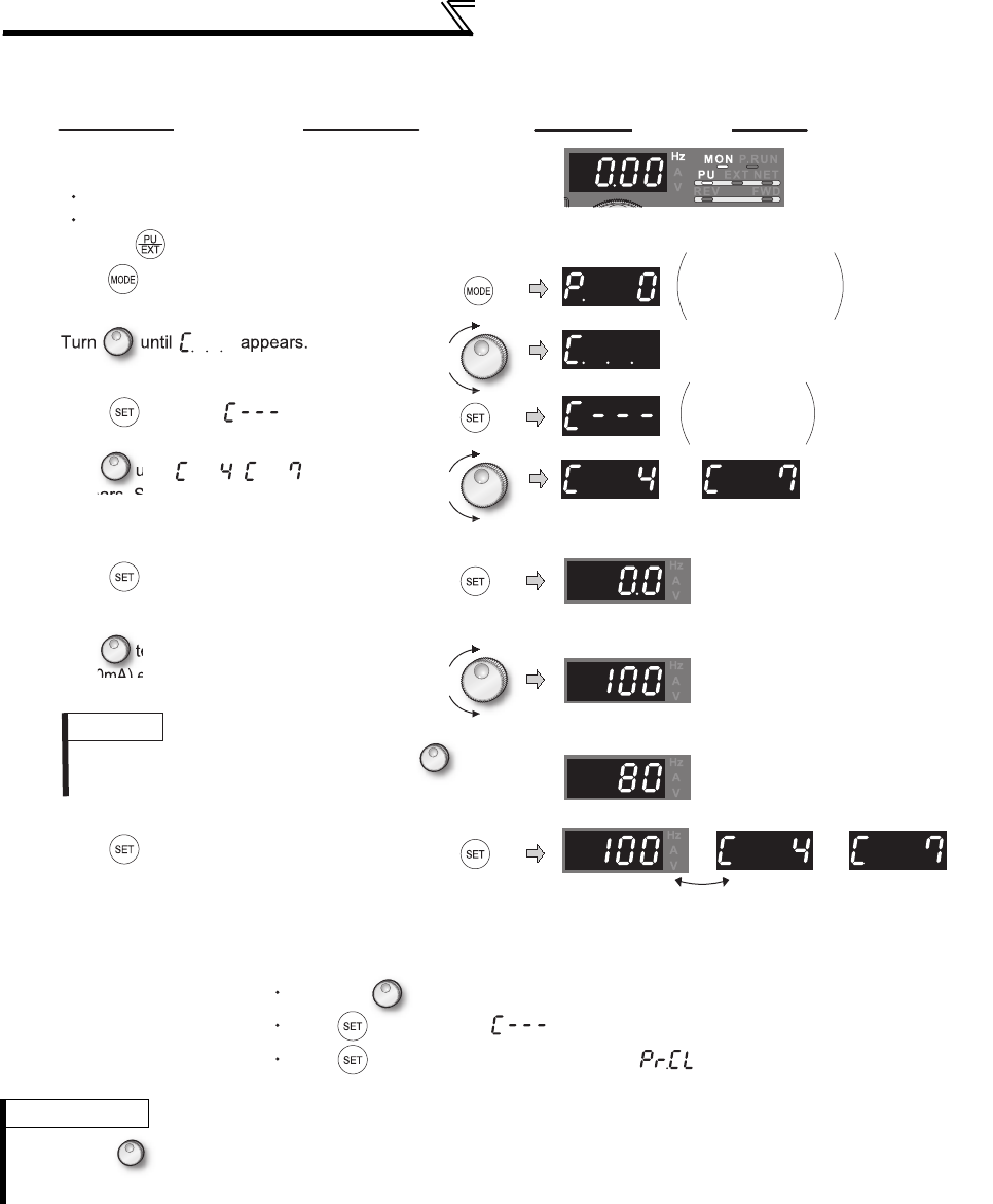
298
Frequency/torque setting by analog
input (terminal 1, 2, 4)
(b) Method to adjust any point without application of a voltage (current) across terminals 2 and 5(4 and 5).
(To change from 4V (80%) to 5V (100%))
REMARKS
By pressing after step 6, you can confirm the current frequency setting bias/gain setting.
It cannot be confirmed after execution of step 7.
DisplayOperation
Analog voltage (current)
value (%) across terminals 2 and 5
(across terminals 4 and 5)
Flicker...Parameter setting complete!!
(Adjustment completed)
C0 to C41
setting
is enabled.
Terminal 2 input Terminal 4 input
Terminal 2 input Terminal 4 input
The parameter
number read
previously appears.
1. Confirm the RUN indicator and operation mode
indicator.
The inverter must be at a stop.
The inverter must be in the PU operation mode.
(Using )
2. Press to choose the parameter
setting mode.
3.
4. Press to display .
5.
Turn until ( )
appears. Set to
C4 Terminal 2 frequency
setting gain.
6. Press to display the analog voltage
(current) value (%).
7.
Turn to set the gain voltage (%).
"0V (0mA) equals to 0%, 5V (10V, 20mA) to 100%"
8. Press to set.
REMARKS
The present setting at the instant of turning
is displayed.
By turning , you can read another parameter.
Press to return to the display (step 4).
Press twice to show the next parameter ( ).
The gain frequency is reached
when the analog
voltage (current) value across
terminals 2 and 5 (across terminals
4 and 5) is 100%.
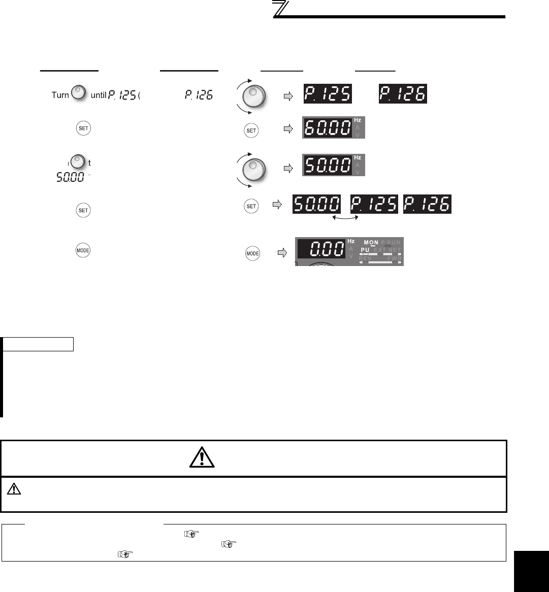
299
Frequency/torque setting by analog
input (terminal 1, 2, 4)
4
PARAMETERS
(c) Method to adjust only the frequency without adjustment of a gain voltage (current).
(When changing the gain frequency from 60Hz to 50Hz)
REMARKS
⋅Changing C4 (Pr. 903) or C7 (Pr. 905) (gain adjustment) value will not change the Pr. 20 value. The input of terminal 1 (frequency
setting auxiliary input) is added to the frequency setting signal.
⋅For the operating procedure using the parameter unit (FR-PU04/FR-PU07), refer to the FR-PU04/FR-PU07 instruction manual.
⋅When setting the value to 120Hz or more, it is necessary to set Pr. 18 High speed maximum frequency to 120Hz or more. (Refer to
page 157)
⋅Make the bias frequency setting using calibration parameter C2 (Pr. 902) or C5 (Pr. 904). (Refer to page 296)
CAUTION
Be cautious when setting any value other than "0" as the bias frequency at 0V (0mA). Even if a speed command
is not given, simply turning ON the start signal will start the motor at the preset frequency.
♦ Parameters referred to ♦
Pr. 20 Acceleration/deceleration reference frequency Refer to page 172
Pr. 73 Analog input selection, Pr. 267 Terminal 4 input selection Refer to page 286
Pr. 79 Operation mode selection Refer to page 313
Display
Operation
Flicker...Parameter setting complete!!
1. Pr. 125) or
(Pr. 126
)
appears.
4. Press to set.
5. Mode/monitor check
Press twice to choose the
monitor/frequency monitor.
or
Terminal 2 input Terminal 4 input
Terminal 2 input Terminal 4 input
3.
Tu
r
n
t
o c
h
an
g
e t
h
e set va
l
ue to
" ". (50.00Hz)
2. Press to show the present set value.
(60.00Hz)
6. Apply a voltage across the inverter
terminals 2 and 5 (across 4 and 5) and
turn on the start command (STF, STR).
Operation starts at 50Hz.

300
Frequency/torque setting by analog
input (terminal 1, 2, 4)
4.21.6 Bias and gain of torque (magnetic flux) setting voltage (current)
(Pr. 241, C16(Pr. 919) to C19(Pr. 920), C38 (Pr. 932) to C41 (Pr. 933))
(1) Change functions of analog input terminal
In the initial setting status, terminal 1 and terminal 4 used for analog input are respectively set to speed setting
auxiliary (speed limit auxiliary) and speed command (speed limit). To use an analog input terminal as torque
command, torque limit input or magnetic flux command input, set Pr. 868 Terminal 1 function assignment and Pr. 858
Terminal 4 function assignment to change functions. (Refer to page 285)
Magnetic flux command is valid only under vector control.
(2) The relationship between analog input terminal and calibration parameter
Terminal 1 functional calibration parameter
—: No function
* Use Pr. 148 Stall prevention level at 0V input and Pr. 149 Stall prevention level at 10V input to adjust bias/gain of stall prevention operation level.
You can set the magnitude (slope) of the torque as desired in relation to the torque setting signal (0 to 5VDC, 0 to
10V or 4 to 20mA).
Use Pr. 73 and Pr. 267 to switch from among 0 to 5V, 0 to 10V, 4 to 20mADC. (Refer to page 286)
Parameter
Number Name Initial
Value
Setting
Range Description
241 *2 Analog input display unit
switchover 00 Displayed in % Select the unit of analog input
display.
1 Displayed in V/mA
C16(919) *1 Terminal 1 bias command (torque/
magnetic flux) 0% 0 to 400% Set the torque (magnetic flux) on the bias side of
terminal 1 input.
C17(919) *1 Terminal 1 bias (torque/magnetic
flux) 0% 0 to 300% Set the converted % of the bias side voltage
(current) of terminal1 input.
C18(920) *1 Terminal 1 gain command (torque/
magnetic flux) 150% 0 to 400% Set the torque (magnetic flux) of the terminal 1 input
gain (maximum).
C19(920) *1 Terminal 1 gain (torque/magnetic
flux) 100% 0 to 300% Set the converted % of the gain side voltage of
terminal1 input.
C38(932) *1 Terminal 4 bias command (torque/
magnetic flux) 0% 0 to 400% Set the torque (magnetic flux) on the bias side of
terminal 4 input.
C39(932) *1 Terminal 4 bias (torque/magnetic
flux) 20% 0 to 300% Set the converted % of the bias side current
(voltage) of terminal 4 input.
C40(933) *1 Terminal 4 gain command (torque/
magnetic flux) 150% 0 to 400% Set the torque (magnetic flux) of the terminal 4 input
gain (maximum).
C41(933) *1 Terminal 4 gain (torque/magnetic
flux) 100% 0 to 300% Set the converted % of the gain side current
(voltage) of terminal 4 input.
*1 The parameter number in parentheses is the one for use with the parameter unit (FR-PU04/FR-PU07).
*2 The above parameters allow its setting to be changed during operation in any operation mode even if "0" (initial value) is set in Pr. 77 Parameter
write selection .
Pr. 868
Setting
Terminal
Function
Calibration Parameters
Bias setting Gain setting
0
(initial
value)
Frequency (speed)
setting auxiliary
C2(Pr. 902) Terminal 2 frequency setting bias frequency
C3(Pr. 902) Terminal 2 frequency setting bias
C5(Pr. 904) Terminal 4 frequency setting bias frequency
C6(Pr. 904) Terminal 4 frequency setting bias
Pr. 125 Terminal 2 frequency setting gain frequency
C4(Pr. 903) Terminal 2 frequency setting gain
Pr. 126 Terminal 4 frequency setting gain frequency
C7(Pr. 905) Terminal 4 frequency setting gain
1Magnetic flux
command
C16(Pr. 919) Terminal 1bias command (torque/magnetic flux)
C17(Pr. 919) Terminal 1bias (torque/magnetic flux)
C18(Pr. 920) Terminal 1 gain command (torque/magnetic flux)
C19(Pr. 920) Terminal 1 gain (torque/magnetic flux)
2Regenerative
torque limit
C16(Pr. 919) Terminal 1 bias command (torque/magnetic flux)
C17(Pr. 919) Terminal 1 bias (torque/magnetic flux)
C18(Pr. 920) Terminal 1 gain command (torque/magnetic flux)
C19(Pr. 920) Terminal 1 gain (torque/magnetic flux)
3 Torque command
4
Stall prevention
operation level */
torque limit/torque
command
5Forward/reverse
rotation speed limit
C12(Pr. 917) Terminal 1 bias frequency (speed)
C13(Pr. 917) Terminal 1 bias (speed)
C14(Pr. 918) Terminal 1 gain frequency (speed)
C15(Pr. 918) Terminal 1 gain (speed)
6 Torque bias input
C16(Pr. 919) Terminal 1 bias command (torque/magnetic flux)
C17(Pr. 919) Terminal 1 bias (torque/magnetic flux)
C18(Pr. 920) Terminal 1 gain command (torque/magnetic flux)
C19(Pr. 920) Terminal 1 gain (torque/magnetic flux)
9999 ⎯⎯ ⎯
Sensorless
Sensorless
Sensorless Vector
Vector
Vector
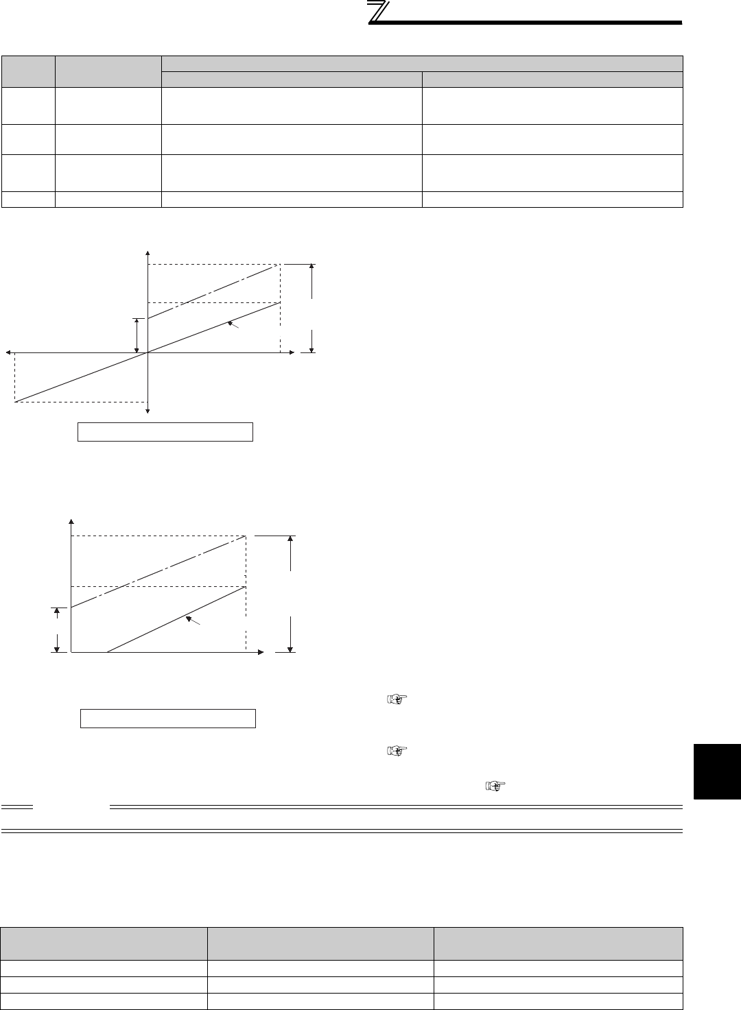
301
Frequency/torque setting by analog
input (terminal 1, 2, 4)
4
PARAMETERS
Terminal 4 functional calibration parameter
⎯ : No function
* Use Pr. 148 Stall prevention level at 0V input and Pr. 149 Stall prevention level at 10V input to adjust bias/gain of stall prevention operation level.
(5) Analog input display unit changing (Pr. 241)
· You can change the analog input display unit (%/V/mA) for analog input bias/gain calibration.
· Display unit of C17 (Pr. 919), C19 (Pr. 920), C39 (Pr. 932), C41 (Pr. 933) changes as follows according to the terminal
input specifications set in Pr. 73 and Pr. 267 .
Pr. 858
Setting
Terminal
Function
Calibration Parameters
Bias setting Gain setting
0
(initial
value)
Frequency (speed)
command/speed
limit
C5(Pr. 904) Terminal 4 frequency setting bias frequency
C6(Pr. 904) Terminal 4 frequency setting bias
Pr. 126 Terminal 4 frequency setting gain frequency
C7(Pr. 905) Terminal 4 frequency setting gain
1Magnetic flux
command
C38(Pr. 932) Terminal 4 bias command (torque/magnetic flux)
C39(Pr. 932) Terminal 4 bias (torque/magnetic flux)
C40(Pr. 933) Terminal 4 gain command (torque/magnetic flux)
C41(Pr. 933) Terminal 4 gain (torque/magnetic flux)
4
Stall prevention
operation level */
torque limit
C38(Pr. 932) Terminal 4 bias command (torque/magnetic flux)
C39(Pr. 932) Terminal 4 bias (torque/magnetic flux)
C40(Pr. 933) Terminal 4 gain command (torque/magnetic flux)
C41(Pr. 933) Terminal 4 gain (torque/magnetic flux)
9999 ⎯⎯ ⎯
(3) Change the torque at maximum analog
input. (C18(Pr. 920), C40(Pr. 933))
·Set C18(Pr. 920), C40(Pr. 933) when changing only
torque setting (gain) of the maximum analog input
voltage (current).
(4) Calibration of analog input bias and gain
(C16(Pr. 919) to C19(Pr. 920), C38 (Pr. 932) to
C41 (Pr. 933))
· The "bias" and "gain" functions are used to adjust the
relationship between the input signal entered from
outside the inverter to set the torque command and
torque limit, e.g. 0 to 5V, 0 to 10V or 4 to 20mADC, and
the torque.
· Set the bias torque of terminal 1 input in C16 (Pr. 919) .
(Initial value is the torque at 0V)
· Set the torque in C18 (Pr. 920) for the torque command
voltage set with Pr. 73 Analog input selection.
(initial value is 10V)
· Set the bias torque of terminal 4 input in C38 (Pr. 932) .
(Initial value is the torque at 4mA)
· Set the torque in C40 (Pr. 933) for 20mA of the torque
command current (4 to 20mA).
· There are the following three methods to adjust the
torque setting voltage (current) bias and gain.
a) Method to adjust any point without application of
voltage (current) across terminals 1 and 5(4 and 5)
page 302
b) Method to adjust any point without application of
voltage (current) across terminals 1 and 5(4 and 5)
page 303
c) Method to adjust torque only without adjustment of
voltage (current) page 304
CAUTION
· When voltage/current input specifications were switched using Pr. 73 and Pr. 267 , perform calibration without fail.
Analog Command (terminal 1,4)
(according to Pr. 73, Pr. 267 ) Pr. 241 = 0 (initial value) Pr. 241 = 1
0 to 5V input 0 to 5V → displayed in 0 to 100% (0.1%) 0 to 100% → displayed in 0 to 5V (0.01V)
0 to 10V input 0 to 10V → displayed in 0 to 100% (0.1%) 0 to 100% → displayed in 0 to 10V (0.01V)
0 to 20mA input 0 to 20mA → displayed in 0 to 100% (0.1%) 0 to 100% → displayed in 0 to 20mA (0.01mA)
Calibration example of terminal 1
400
150
-150
0
0
Torque setting signal 100%
10V
Bias
05V
(-5V)
-100%
(-10V)
C18(Pr.920)
Gain
C16(Pr.919)
C17(Pr.919) C19(Pr.920)
Torque(%)
Initial value
400
150
Torque(%)
0
Torque setting signal
100%
Bias
0
20
4 20mA
C40
(Pr.933)
Gain
C38
(Pr.932)
C39(Pr.932) C41(Pr.933)
Initial value
Calibration example of terminal 4
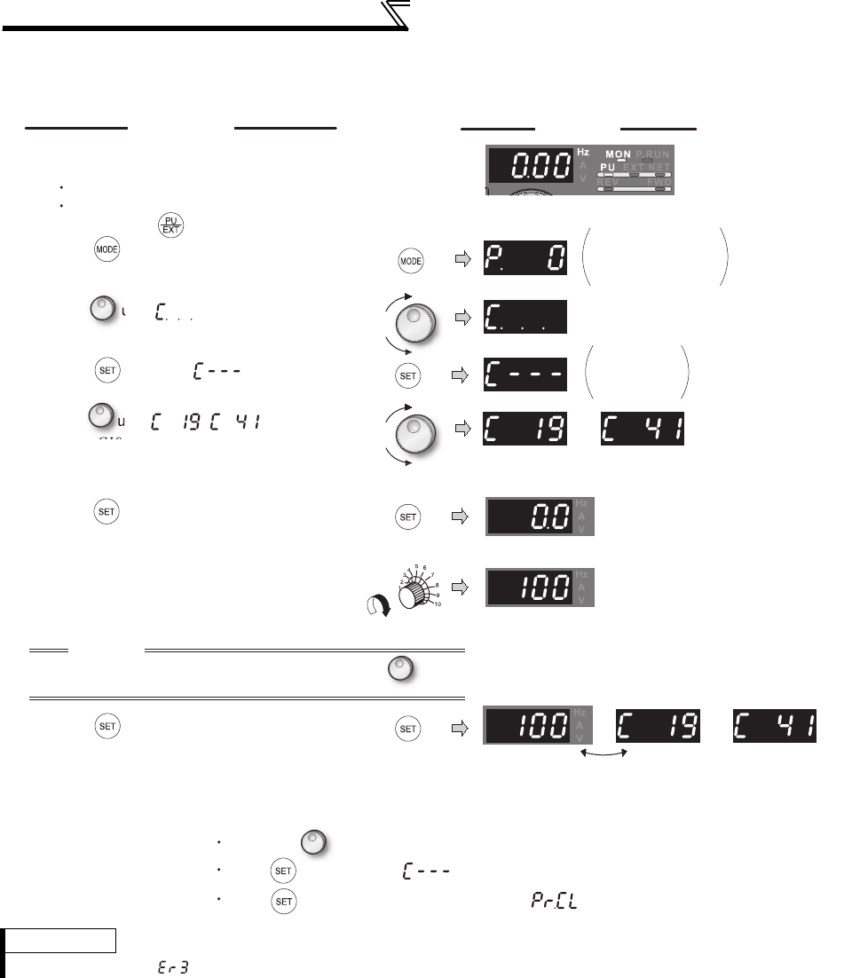
302
Frequency/torque setting by analog
input (terminal 1, 2, 4)
(6) Adjustment method of torque setting voltage (current) bias and gain
a) Method to adjust any point without application of a voltage (current) across terminals 1 and 5(4 and 5)
REMARKS
· An error at writing ( ) may appear if torque setting value of gain and bias are too close.
DisplayOperation
Analog voltage (current)
value (%) across terminals 1 and 5
(across terminals 4 and 5)
Flicker...Parameter setting complete!!
The value is nearly 100 (%) in
the maximum position of the
potentiometer.
CAUTION
After performing the operation in step 6, do not touch until
completion of calibration.
(Adjustment completed)
C0 to C41
setting
is enabled.
Terminal 1 input Terminal 4 input
Terminal 1 input Terminal 4 input
The parameter
number read
previously appears.
1. Confirm the RUN indicator and operation mode
indicator.
The inverter must be at a stop.
The inverter must be in the PU operation
mode.(Using )
2. Press to choose the parameter setting
mode.
3.
Turn until appears.
4. Press to display .
5.
Turn until ( ) appears.
Set to
C19 Terminal 1 gain (torque)
.
6. Press to display the analog voltage
(current) value (%).
7. Apply a 10V (20mA) voltage (current).
(Turn the external potentiometer connected
across terminals 1 and 5 (across terminals 4
and 5) to maximum (any position).)
8. Press to set.
By turning , you can read another parameter.
Press to return to the display (step 4).
Press twice to show the next parameter ( ).
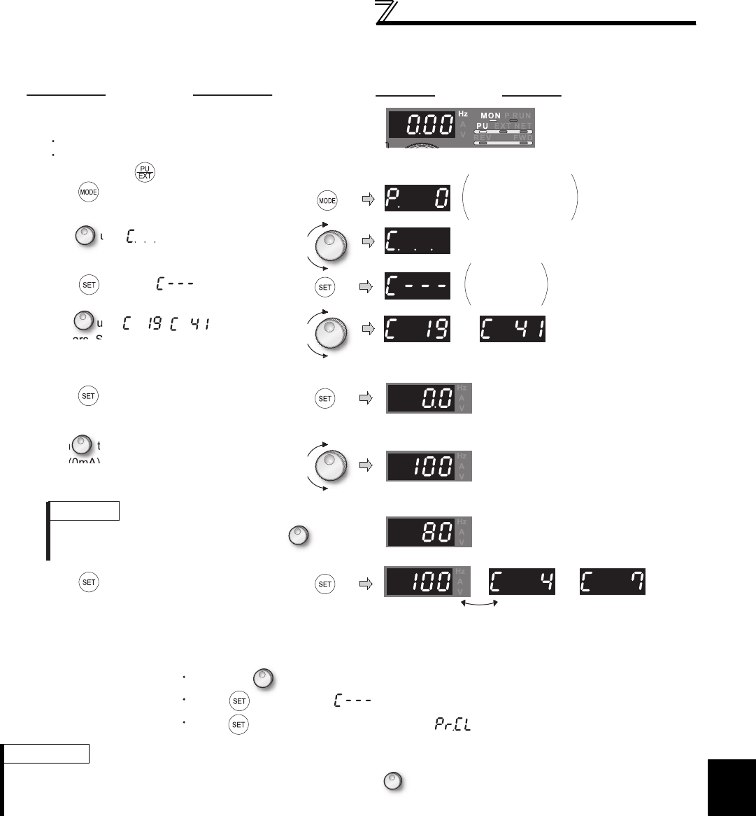
303
Frequency/torque setting by analog
input (terminal 1, 2, 4)
4
PARAMETERS
b) Method to adjust any point without application of a voltage (current) across terminals 1 and 5(4 and 5)
(To change from 8V (80%) to 10V (100%))
REMARKS
You can check the current torque setting bias/gain setting by pressing after step 6.
You cannot check after performing operation in step 7.
1. Confirm the RUN indicator and operation mode
indicator.
The inverter must be at a stop.
The inverter must be in the PU operation
mode. (Using )
DisplayOperation
Analog voltage (current)
value (%) across terminals 1 and 5
(across terminals 4 and 5)
The gain torque is
reached when the analog
voltage (current) value across
terminals 1 and 5 (across terminals
4 and 5) is 100%.
Flicker...Parameter setting complete!!
(Adjustment completed)
C0 to C41
setting
is enabled.
Terminal 1 input Terminal 4 input
Terminal 1 input Terminal 4 input
The parameter
number read
previously appears.
2. Press to choose the parameter
setting mode.
3.
Turn until appears.
4. Press to display .
5.
Turn until ( )
appears. Set to
C19 Terminal 1 gain (torque).
6. Press to display the analog voltage
(current) value (%).
7.
Turn to set the gain voltage (%).
"0V (0mA) equals to 0%, 10V (5V,
20mA) to 100%"
8. Press to set.
REMARKS
The present setting at the instant of turning
is displayed.
By turning , you can read another parameter.
Press to return to the display (step 4).
Press twice to show the next parameter ( ).
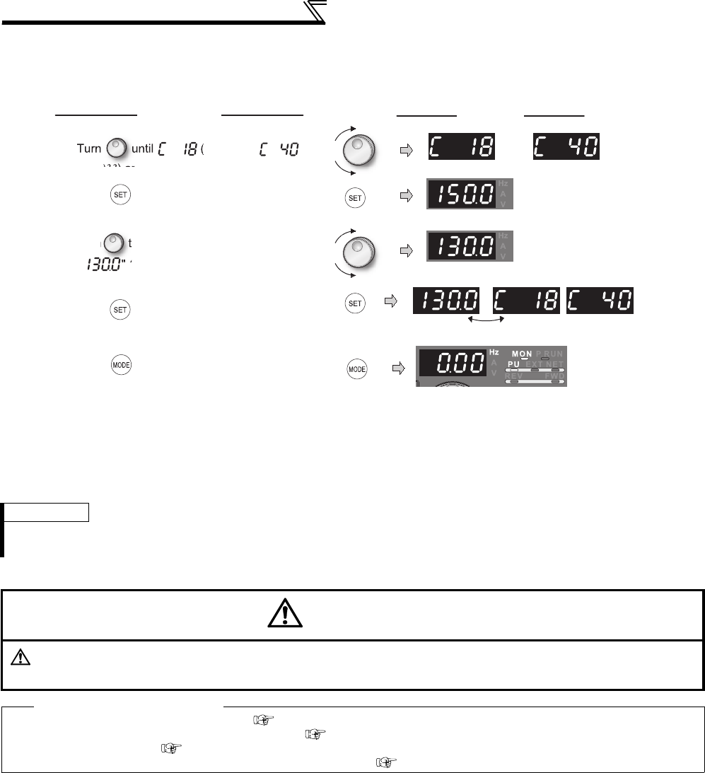
304
Frequency/torque setting by analog
input (terminal 1, 2, 4)
c) Method to adjust torque only without adjustment of gain voltage (current)
(when changing gain torque from 150% to 130%)
REMARKS
· For operation from the parameter unit (FR-PU04/FR-PU07), refer to the instruction manual of the FR-PU04/FR-PU07.
· Set bias torque setting using calibration parameter C16 (Pr. 919) or C38 (Pr. 932). (Refer to page 301)
CAUTION
Be cautious when setting any value other than "0" as the bias torque at 0V (0mA). Torque is applied to the motor
by merely tuning ON the start signal without torque command.
♦ Parameters referred to ♦
Pr. 20 Acceleration/deceleration reference frequency Refer to page 172
Pr. 73 Analog input selection, Pr. 267 Terminal 4 input selection Refer to page 286
Pr. 79 Operation mode selection Refer to page 313
Pr. 858 Terminal 4 function assignment, Pr. 868 Terminal 1 function assignment Refer to page 285
Flicker...Parameter setting complete!!
DisplayOperation
1. Pr.920) or
(
Pr.933
) appears.
3.
T
ur
n
o c
h
an
g
e t
h
e set va
l
ue to
" " (130.0%)
4. Press to set.
5. Mode/monitor check
Press twice to choose the
monitor/frequency monitor.
6. Apply a voltage across the inverter
terminals 1 and 5 (across 4 and 5) and
turn on the start command (STF, STR).
Operation starts with 130% torque.
2. Press to show the present set value.
(150%)
or
Terminal 1 input Terminal 4 input
Terminal 1 input Terminal 4 input

305
Misoperation prevention and parameter
setting restriction
4
PARAMETERS
4.22 Misoperation prevention and parameter setting restriction
4.22.1 Reset selection/disconnected PU detection/PU stop selection (Pr. 75)
(1) Reset selection
• You can select the operation timing of reset function (RES signal, reset command through communication) input.
• When Pr. 75 is set to any of "1, 3, 15, 17", a reset can be input only when the protective function is activated.
Purpose Parameter that must be Set Refer to Page
Limit reset function
Trips when PU is disconnected
Stop from PU
Reset selection/disconnected
PU detection/PU stop selection Pr. 75 305
Prevention of parameter rewrite Parameter write disable
selection Pr. 77 307
Prevention of reverse rotation of the
motor
Reverse rotation prevention
selection Pr. 78 308
Display necessary parameters Display of applied parameters
and user group function Pr. 160, Pr. 172 to Pr. 174 308
Parameter restriction using password Password function Pr. 296, Pr. 297 310
Control of parameter write by
communication EEPROM write selection Pr. 342 334
You can select the reset input acceptance, disconnected PU (FR-DU07/FR-PU04/FR-PU07) connector detection
function and PU stop function.
Parameter
Number Name Initial
Value Setting Range Description
75 Reset selection/disconnected
PU detection/PU stop selection 14 0 to 3, 14 to 17
For the initial value, reset always enabled,
without disconnected PU detection, and
with PU stop function are set.
This parameter allows its setting to be changed during operation in any operation mode even if "0 (initial value) or 1" is set in Pr. 77 Parameter write
selection. Also, if parameter (all) clear is executed, this setting will not return to the initial value.
Pr. 75
Setting Reset Selection Disconnected PU Detection PU Stop Selection
0 Reset input is always enabled If the PU is disconnected, operation
will be continued.
Pressing decelerates the motor to
a stop only in the PU operation mode.
1Reset input enabled only when a
fault occurs
2 Reset input is always enabled When the PU is disconnected, the
inverter trips.
3Reset input enabled only when a
fault occurs
14
(initial
value)
Reset input is always enabled If the PU is disconnected, operation
will be continued. Pressing decelerates the motor to
a stop in any of the PU, External and
communication operation modes.
15 Reset input enabled only when a
fault occurs
16 Reset input is always enabled When the PU is disconnected, the
inverter trips.
17 Reset input enabled only when a
fault occurs
CAUTION
⋅When the reset signal (RES) is input during operation, the motor coasts since the inverter being reset shuts off the output.
Also, the cumulative value of the electronic thermal relay function and regenerative brake duty is cleared.
⋅The reset key of the PU is valid only when the protective function is activated, independently of the Pr. 75 setting.
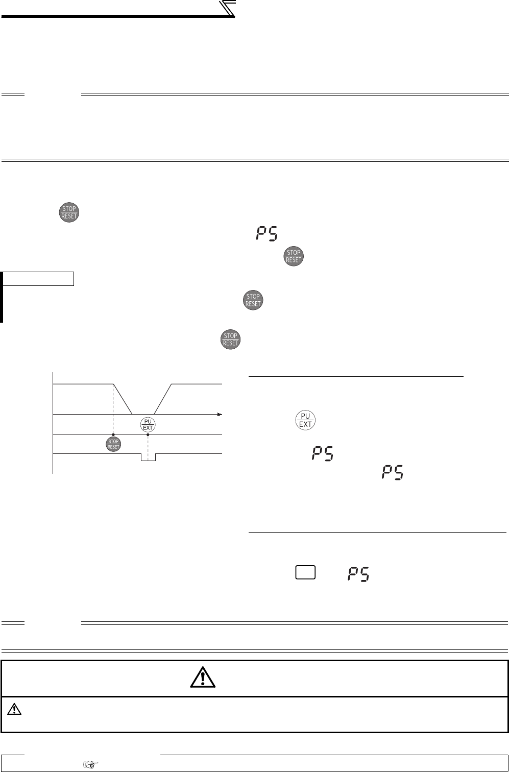
306
Misoperation prevention and parameter
setting restriction
(2) Disconnected PU detection
• This function detects that the PU (FR-DU07/FR-PU04/FR-PU07) has been disconnected from the inverter for
longer than 1s and causes the inverter to provide a fault output (E.PUE) and come to trip.
• When Pr. 75 is set to any of "0, 1, 14, 15", operation is continued if the PU is disconnected.
(3) PU stop selection
• In any of the PU operation, External operation and Network operation modes, the motor can be stopped by
pressing of the PU.
• When the inverter is stopped by the PU stop function, " " is displayed. A fault signal output is not provided.
• When Pr. 75 is set to any of "0 to 3", deceleration to a stop by is valid only in the PU operation mode.
(4) How to restart the motor stopped by input from the PU in External operation mode (PU
stop (PS) reset method)
• The motor can be restarted by making a reset using a power supply reset or RES signal.
CAUTION
⋅When the PU has been disconnected since before power-on, it is not judged as a fault.
⋅To make a restart, confirm that the PU is connected and then reset the inverter.
⋅The motor decelerates to a stop when the PU is disconnected during PU jog operation with Pr. 75 set to any of "0, 1, 14, 15"
(operation is continued if the PU is disconnected).
⋅When RS-485 communication operation is performed through the PU connector, the reset selection/PU stop selection function
is valid but the disconnected PU detection function is invalid.
REMARKS
The motor will also decelerate to a stop (PU stop) when is input during operation in the PU mode through RS-485
communication with Pr. 551 PU mode operation command source selection set to "1" (PU mode RS-485 terminals).
(a) When operation panel (FR- DU07) is used
1)After the motor has decelerated to a stop, turn OFF the
STF or STR signal.
2)Press three times.
(When Pr. 79 Operation mode selection = "0 (initial value)
or 6"••••••( cancel)
Pressing it once cancels when Pr. 79 Operation
mode selection = "2, 3, or 7."
3)Turn ON the STF or STR signal.
(b)
Connection of the parameter unit (FR-PU04/FR-PU07)
1)After the motor has decelerated to a stop, turn OFF the
STF or STR signal.
2)Press .••••••( canceled)
3)Turn ON the STF or STR signal.
CAUTION
⋅If Pr. 250 Stop selection is set to other than "9999" to select coasting to a stop, the motor will not be coasted to a stop but
decelerated to a stop by the PU stop function during external operation
CAUTION
Do not reset the inverter with the start signal ON. Doing so will cause the inverter to start immediately after a
reset, leading to hazardous conditions.
♦ Parameters referred to ♦
Pr. 250 Stop selection Refer to page 213
Speed
Time
Key
Key
Stop/restart example for external operation
Operation
panel
STF ON
(STR) OFF
EXT
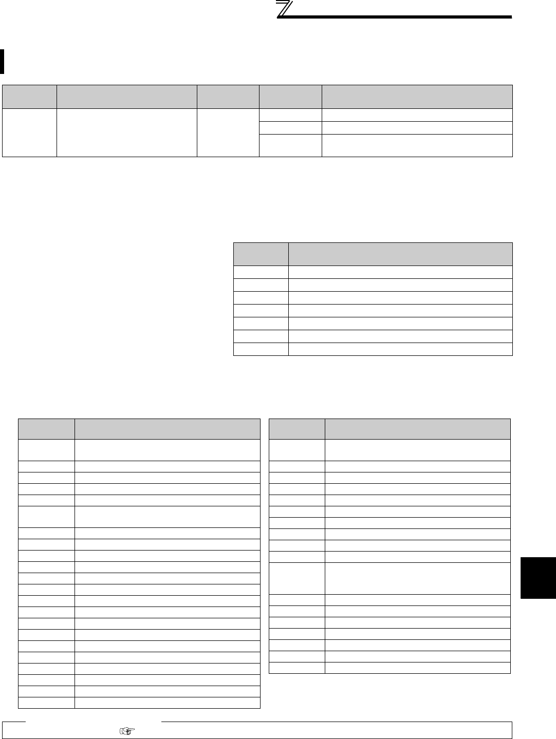
307
Misoperation prevention and parameter
setting restriction
4
PARAMETERS
4.22.2 Parameter write selection (Pr. 77)
(1) Write parameters only at a stop (setting "0", initial value)
⋅Parameters can be written only during a stop in the PU operation mode.
⋅The shaded parameters in the parameter list (page 71) can always be written, regardless of the operation mode and
operating status. However, Pr. 72 PWM frequency selection, Pr. 240 Soft-PWM operation selection and Pr. 275 Stop-on
contact excitation current low-speed multiplying factor can be written during operation in the PU operation mode, but
cannot be written in External operation mode.
(3) Write parameters during operation (setting "2")
⋅Parameters can always be written.
⋅The following parameters cannot be written during operation if Pr. 77 = "2". Stop operation when changing their
parameter settings.
You can select whether write to various parameters can be performed or not. Use this function to prevent
parameter values from being rewritten by misoperation.
Parameter
Number Name Initial Value Setting
Range Description
77 Parameter write selection 0
0 Write is enabled only during a stop.
1 Parameter write is not enabled.
2Parameter write is enabled in any operation
mode regardless of operating status.
Pr. 77 can be always set independently of the operation mode and operating status.
(2) Disable parameter write (setting "1")
⋅Parameter write is not enabled. (Reading is
enabled.)
⋅Parameter clear and all parameter clear cannot
be performed, either.
⋅The parameters given on the right can be written
even if Pr. 77 = "1".
Parameter
Number Name
22 Stall prevention operation level
75
Reset selection/disconnected PU detection/PU stop selection
77 Parameter write selection
79 Operation mode selection
160 User group read selection
296 Password lock level
297 Password lock/unlock
♦ Parameters referred to ♦
Pr. 79 Operation mode selection Refer to page 313
Parameter
Number Name
23 Stall prevention operation level compensation
factor at double speed
48 Second stall prevention operation current
49 Second stall prevention operation frequency
60 Energy saving control selection
61 Reference current
66 Stall prevention operation reduction starting
frequency
71 Applied motor
79 Operation mode selection
80 Motor capacity
81 Number of motor poles
82 Motor excitation current
83 Rated motor voltage
84 Rated motor frequency
90 to 94 (Motor constants)
95 Online auto tuning selection
96 Auto tuning setting/status
100 to 109 (Adjustable 5 points V/F parameter)
135 to 139 (Parameter for electronic bypass sequence)
178 to 196 (I/O terminal function selection)
291 Pulse train I/O selection
292 Automatic acceleration/deceleration
293 Acceleration/deceleration separate selection
329 Digital input unit selection
(Parameter for the plug-in option FR-A7AX)
450 Second applied motor
451 Second motor control method selection
453 Second motor capacity
454 Number of second motor poles
455 Second motor excitation current
456 Rated second motor voltage
457 Rated second motor frequency
458 to 462 (Second motor constant)
463 Second motor auto tuning setting/status
541
Frequency command sign selection (CC-Link)
(Parameter for the plug-in option FR-A7NC/
FR-A7NCE)
574 Second motor online auto tuning
800 Control method selection
819 Easy gain tuning selection
858 Terminal 4 function assignment
859 Torque current
860 Second motor torque current
868 Terminal 1 function assignment
Parameter
Number Name

308
Misoperation prevention and parameter
setting restriction
4.22.3 Reverse rotation prevention selection (Pr. 78)
⋅Set this parameter when you want to limit the motor rotation to only one direction.
⋅This parameter is valid for all of the reverse rotation and forward rotation keys of the operation panel (FR-DU07),
parameter unit (FR-PU04/FR-PU07), start signals (STF, STR signals) via external terminals, and the forward and
reverse rotation commands through communication.
4.22.4 Display of applied parameters and user group function (Pr. 160, Pr. 172 to Pr. 174)
(1) Display of simple mode parameters and extended parameters (Pr. 160)
⋅When Pr. 160 = "9999", only the simple mode parameters can be displayed on the operation panel (FR-DU07) and
parameter unit (FR-PU04/FR-PU07). (Refer to the parameter list, pages 71 to 84, for the simple mode parameters.)
⋅With the initial value (Pr. 160 = "0"), simple mode parameters and extended parameters can be displayed.
This function can prevent reverse rotation fault resulting from the incorrect input of the start signal.
Parameter
Number Name Initial Value Setting Range Description
78 Reverse rotation prevention
selection 0
0Both forward and reverse rotations
enabled
1 Reverse rotation disabled
2 Forward rotation disabled
Parameter which can be read from the operation panel and parameter unit can be restricted.
Parameter
Number Name Initial Value Setting Range Description
160 *1 User group read selection 0
9999 Only the simple mode parameters can
be displayed.
0The simple mode and extended
parameters can be displayed
1Only parameters registered in the user
group can be displayed.
172 User group registered
display/batch clear 0(0 to 16) Displays the number of cases registered
as a user group. (Reading only)
9999 Batch clear the user group registration
173 *2 User group registration 9999 0 to 999, 9999 Set the parameter numbers to be
registered to the user group.
174 *2 User group clear 9999 0 to 999, 9999 Set the parameter numbers to be cleared
from the user group.
*1 This parameter allows its setting to be changed during operation in any operation mode even if "0 (initial value) or 1" is set in Pr. 77 Parameter
write selection.
*2 The values read from Pr. 173 and Pr. 174 are always "9999".
REMARKS
⋅When a plug-in option is fitted to the inverter, the option parameters can also be read.
⋅When reading the parameters using the communication option, all parameters can be read regardless of the Pr. 160 setting.
⋅Pr. 15 Jog frequency, Pr. 16 Jog acceleration/deceleration time Pr. 991 PU contrast adjustment are displayed as simple mode
parameters when the parameter unit (FR-PU04/FR-PU07) is mounted.
⋅When reading the parameters using the RS-485
terminals, all parameters can be read regardless of the
Pr. 160 setting by setting Pr.550 NET mode operation
command source selection and Pr. 551 PU mode operation
command source selection.
* OP indicates a communication option
Pr. 551 Pr. 550 Pr. 160 Valid/Invalid
1 (RS-485) ⎯Valid
2 (PU)
(initial value)
3 (USB)
0 (OP) Valid
1 (RS-485) Invalid (all readable)
9999
(auto-detect)
(initial value)
With OP: valid
Without OP: invalid
(all readable)
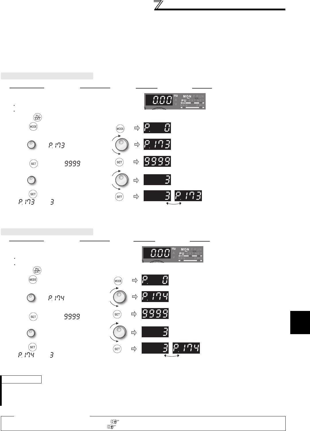
309
Misoperation prevention and parameter
setting restriction
4
PARAMETERS
(2) User group function (Pr. 160, Pr. 172 to Pr. 174)
⋅The user group function is designed to display only the parameters necessary for setting.
⋅From among all parameters, a maximum of 16 parameters can be registered to a user group. When Pr. 160 is set to
"1", only the parameters registered to the user group can be accessed. (Reading of parameters other than the user
group registration is disabled.)
⋅To register a parameter to the user group, set its parameter number to Pr. 173.
⋅To delete a parameter from the user group, set its parameter number to Pr. 174. To batch-delete the registered
parameters, set Pr. 172 to "9999".
(3) Registration of parameter to user group (Pr. 173)
(4) Deletion of parameter from user group (Pr. 174)
When registering Pr. 3 to user group
When deleting Pr. 3 from user group
REMARKS
⋅Pr. 77, Pr. 160 and Pr. 991 can always be read, independently of the user group setting.
⋅Pr. 77, Pr. 160 and Pr. 172 to Pr. 174 cannot be registered to the user group.
⋅When Pr. 174 is read, "9999" is always displayed. Although "9999" can be written, no function is available.
⋅When any value other than "9999" is set to Pr. 172, no function is available.
♦ Parameters referred to ♦
Pr. 550 NET mode operation command source selection Refer to page 322
Pr. 551 PU mode operation command source selection Refer to page 322
IndicationOperation
Parameter setting mode
Pr. 173 User group
registration is displayed.
When Pr. 173 is read,
"9999" is displayed.
Select the parameter
number to be registered.
Flicker ··· Registration of Pr. 3 to user group
completed!!
1.Confirm the operation display and operation
mode display.
The inverter must be at a stop.
The inverter must be in the PU operation mode.
(Press in the External operation mode.)
2.Press to choose the parameter setting
mode.
3.Turn until appears.
5.
Turn until
Pr. 3 appears.
6.Press to set.
" " and " " are displayed alternately.
To continue parameter registration, repeat
steps 3 to 6.
4.Press to display. " "
Operation
1.Confirm the operation display and operation
mode display.
The inverter must be at a stop.
The inverter must be in the PU operation mode.
(Press in the External operation mode.)
2.Press to choose the parameter setting
mode.
3.Turn until appears.
5.
Turn until
Pr. 3 appears.
6.Press to clear.
" " and " " are displayed alternately.
To continue parameter registration, repeat
steps 3 to 6.
4.Press to display. " "
Indication
Parameter setting mode
Pr. 174 User group
clear is displayed.
When Pr. 174 is read,
"9999" is displayed.
Select the parameter
number to be deleted.
Flicker ··· Deletion of Pr. 3 from user group
completed!!
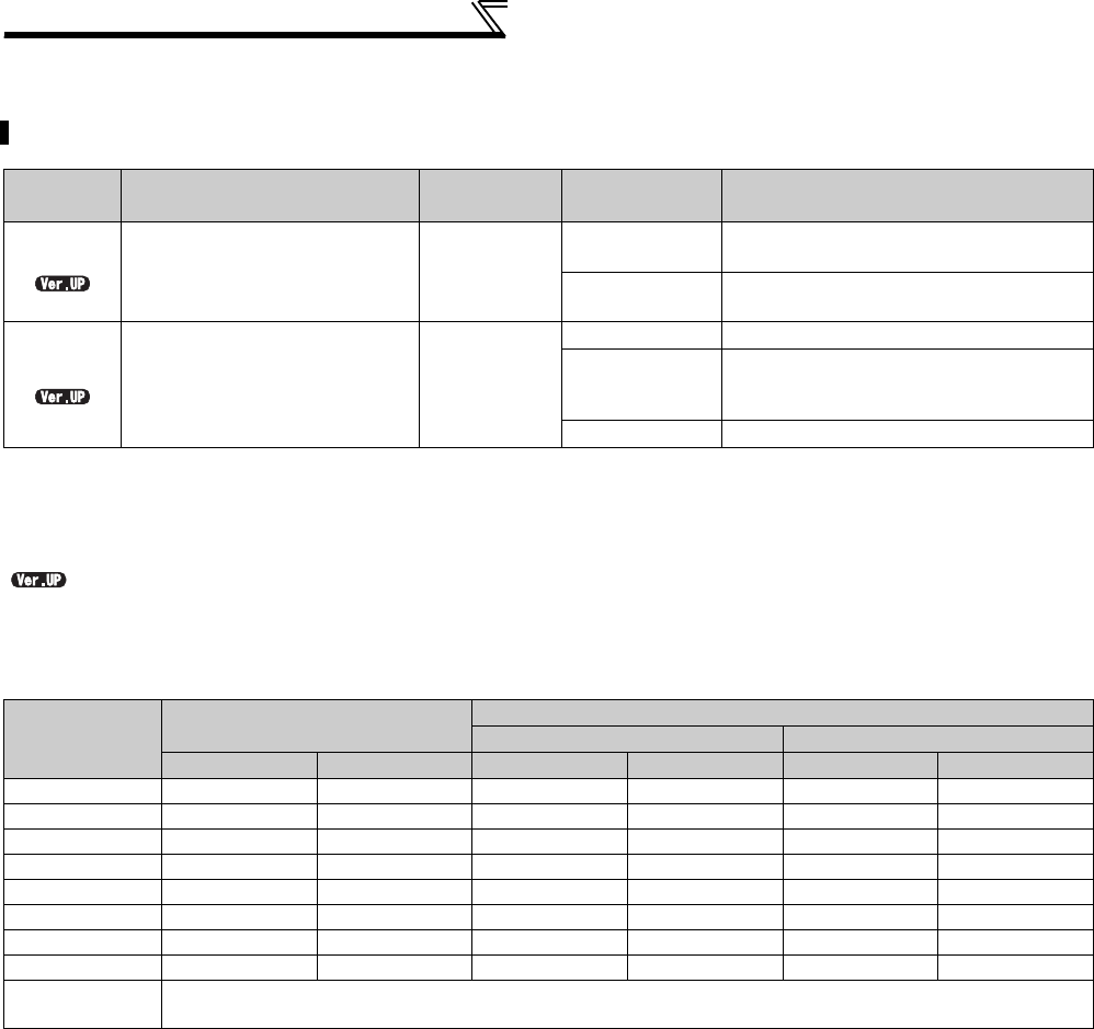
310
Misoperation prevention and parameter
setting restriction
4.22.5 Password function (Pr. 296, Pr. 297)
(1) Parameter reading/writing restriction level (Pr. 296)
Level of reading/writing restriction by PU/NET operation mode operation command can be selected by Pr. 296.
Registering a 4-digit password can restrict parameter reading/writing.
Parameter
Number Name Initial Value Setting Range Description
296 *2 Password lock level 9999
0 to 6, 99, 100 to
106, 199
Select restriction level of parameter reading/
writing when a password is registered.
9999 No password lock
297 *2 Password lock/unlock 9999
1000 to 9998 Register a 4-digit password
(0 to 5) *1
Displays password unlock error count.
(Reading only) (Valid when Pr. 296 = "100"
to "106", "199")
9999 *1 No password lock
The above parameters can be set when Pr. 160 User group read selection = "0".
When Pr. 296 ≠ "9999" (with password lock), note that Pr. 297 is always available for setting regardless of Pr. 160 setting.
*1 Only Pr.297 can be set anytime as Pr.297 = "0 or 9999." However, the setting is invalid (the displayed value does not change).
*2 This parameter allows its setting to be changed during operation in any operation mode even if "0 (initial value) or 1" is set in Pr. 77 Parameter
write selection.
...............Specifications differ according to the date assembled. Refer to page 484 to check the SERIAL number.
Pr. 296 Setting
PU Operation Mode Operation
Command *3
NET Operation Mode Operation Command *4
RS-485 Terminals Communication Option
Read *1 Write *2 Read Write *2 Read Write *2
9999
0, 100 *6 ××××××
1, 101 ×××
2, 102 ×
3, 103 ××
4, 104 ×××××
5, 105 ××
6, 106 ×××
99, 199 Only parameters registered in the user group can be read/written. *5
(For the parameters not registered in the user group, same restriction level as "4, 104" applies.)
: enabled, ×: restricted
*1 If the parameter reading is restricted by the Pr. 160 setting, those parameters are unavailable for reading even when "" is indicated.
*2 If the parameter writing is restricted by the Pr. 77 setting, those parameters are unavailable for writing even when "" is indicated.
*3 This restricts parameter access from the command source that can write a parameter under the PU operation mode (initially the operation panel
(FR-DU07) or the parameter unit). (For how to select the PU mode command source, refer to page 322.)
*4 This restricts parameter access from the command source that can write a parameter under the Network operation mode (initially the RS-485
terminals or a communication option). (For how to select the NET mode command source, refer to page 322.)
*5 Read/write is enabled only in the simple mode parameters registered in the user group when Pr.160 User group read selection = "9999".
Pr.296 and Pr.297 are always read/write enabled whether registered to a user group or not.
*6 If a communication option is installed, option fault (E.OPT) occurs, and inverter trips. (Refer to page 412.)
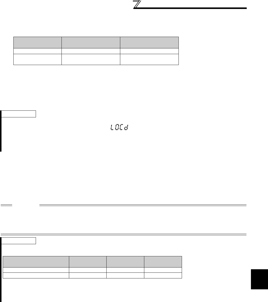
311
Misoperation prevention and parameter
setting restriction
4
PARAMETERS
(2) Password lock/unlock (Pr.296, Pr.297)
<Lock>
1) Set parameter reading/writing restriction level. (Pr. 296 ≠ 9999)
* If password unlock error has occurred 5 times when Pr. 296 = "100 to 106, 199", correct password will not unlock the restriction. All parameter clear can
unlock the restriction.
(In this case, parameter setting are cleared.)
2) Write a four-digit number (1000 to 9998) in Pr. 297 as a password.
(When Pr. 296 = "9999", Pr. 297 cannot be written.)
When password is registered, parameter reading/writing is restricted with the restriction set level in Pr. 296 until
unlocking.
<Unlock>
There are two ways of unlocking the password.
Enter a password in Pr. 297.
Unlocked when a password is correct. If a password is incorrect, an error occurs and not unlocked.
If password unlock error has occurred 5 times when Pr. 296 = "100 to 106, 199", correct password will not unlock the
restriction. (During password lock)
Perform all parameter clear.
Pr.296 Setting Restriction of Password
Unlock Error Pr.297 Display
0 to 6, 99 No restriction Always 0
100 to 106, 199 Restricted at fifth error Displays error count
(0 to 5)
REMARKS
After registering a password, a read value of Pr. 297 is always "0" to "5".
When a password restricted parameter is read/written, is displayed.
Even if a password is registered, parameters which the inverter itself writes, such as inverter parts life, are overwritten as
needed.
Even if a password is registered, Pr. 991 PU contrast adjustment can be read/written when a parameter unit (FR-PU04/FR-PU07)
is connected.
CAUTION
If the password has been forgotten, perform all parameter clear to unlock the parameter restriction. In that case, other
parameters are also cleared.
All parameter clear cannot be performed during the operation.
yDo not use FR Configurator under the conditions that parameter read is restricted (Pr. 296 = "0, 4, 5, 99, 100, 104, 105, 199").
FR Configurator may not function properly.
REMARKS
The password unlock method is different for operation panel (FR-DU07)/FR-PU07, RS-485 communication, and communication
option.
For parameter clear and all parameter clear from the communication option or the parameter unit (FR-PU07), refer to the
instruction manual of each options. (Refer to page 396 for the operation panel, refer to page 342 for the Mitsubishi inverter protocol
with RS-485 terminal communication, and refer to page 355 for Modbus-RTU communication protocol.)
FR-DU07/
FR-PU07
RS-485
Communication
Communication
Option
All Parameter Clear
Parameter Clear ××
: Password can be unlocked, ×: Password cannot be unlocked
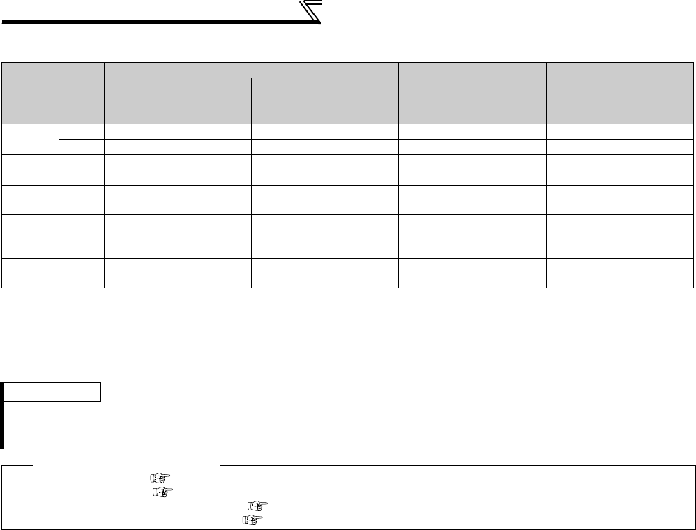
312
Misoperation prevention and parameter
setting restriction
(3) Parameter operation during password locked/unlocked
Parameter
Operation
Password Unlocked Password Registered Password Locked
Pr. 296 = 9999
Pr. 297 = 9999
Pr. 296 ≠ 9999
Pr. 297 = 9999
Pr. 296 ≠ 9999
Pr. 297 = 0 to 4
(Read value)
Pr. 296 = 100 to 106, 199
Pr. 297 = 5
(Read value)
Pr. 296 Read *1
Write *1 *1 ××
Pr. 297 Read *1
Write × *3
Performing
Parameter Clear × *4 × *4
Performing
All Parameter
Clear
*2 *2
Performing
Parameter Copy ××
: enabled, ×: restricted
*1 Reading/writing is unavailable when there is restriction to reading by the Pr. 160 setting.
(Reading is available in NET operation mode regardless of Pr. 160 setting.)
*2 Unavailable during the operation.
*3 Correct password will not unlock the restriction.
*4 Parameter clear is available only from the communication option.
REMARKS
When Pr.296 = "4, 5, 104, 105" (password lock), the setting screen for PU JOG frequency is not displayed in the parameter unit (FR-
PU04 or FR-PU07).
Parameter copy is not available with operation panel (FR-DU07)/parameter unit (FR-PU07) when password is registered.
♦ Parameters referred to ♦
Pr. 77 Parameter write selection Refer to page 307
Pr. 160 User group read selection Refer to page 308
Pr. 550 NET mode operation command source selection Refer to page 322
Pr. 551 PU mode operation command source selection Refer to page 322
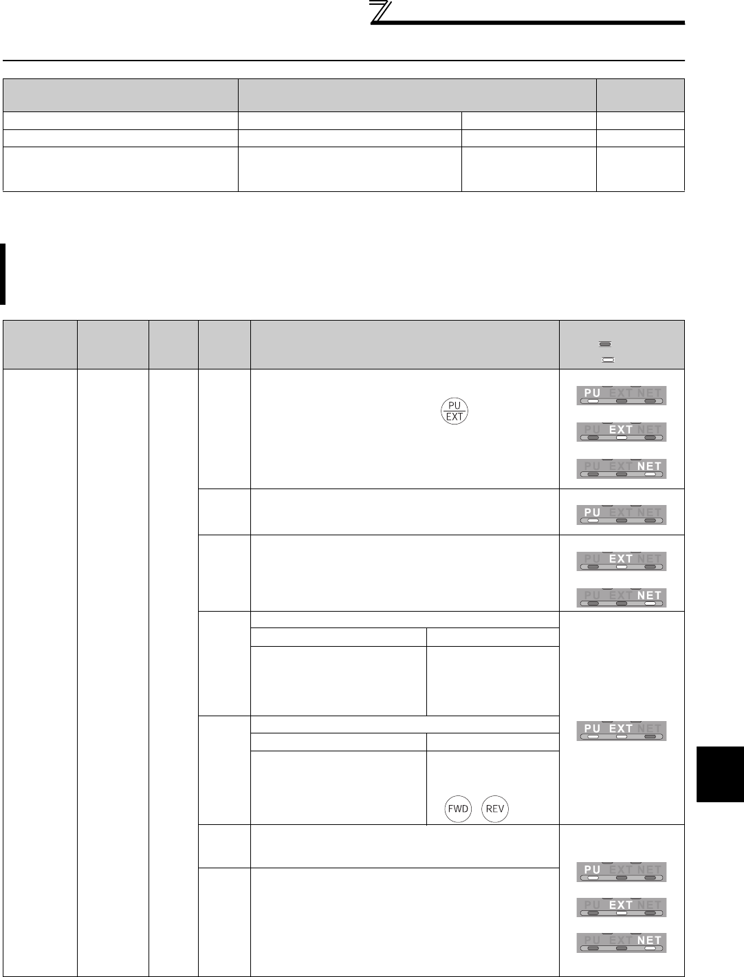
313
Selection of operation mode and operation location
4
PARAMETERS
4.23 Selection of operation mode and operation location
4.23.1 Operation mode selection (Pr. 79)
*1 This parameter allows its setting to be changed in any operation mode even if "0 (initial value) or 1" is set in Pr. 77 Parameter write selection.
*2 The priorities of the frequency commands when Pr. 79 = "3" are "Multi-speed operation (RL/RM/RH/REX) > PID control (X14) > terminal 4 analog
input (AU) > digital input from the operation panel".
Purpose Parameter that must be Set Refer to
Page
Operation mode selection Operation mode selection Pr. 79 313
Started in Network operation mode Operation mode at power on Pr. 79, Pr. 340 321
Selection of control location
Selection of control source, speed
command source and control location
during communication operation
Pr. 338, Pr. 339,
Pr. 550, Pr. 551 322
Use the following parameter to select the operation mode of the inverter.
Mode can be changed as desired between operation using external signals (external operation), operation from
the PU (FR-DU07/FR-PU07/FR-PU04), combined operation of PU operation and external operation (external/PU
combined operation, and network operation (when RS-485 terminals or a communication option is used).
Parameter
Number Name Initial
Value
Setting
Range Description
LED Indication
: OFF
: ON
79 *1
Operation
mode
selection
0
0
Use external/PU switchover mode ( ) to switch
between the PU and External operation mode.
At power ON, the inverter is in the External operation
mode.
PU operation mode
External operation mode
NET operation mode
1 Fixed to PU operation mode
PU operation mode
2
Fixed to External operation mode
Operation can be performed by switching between the
external and NET operation mode.
External operation mode
NET operation mode
3
External/PU combined operation mode 1
External/PU combined
operation mode
Running frequency Start signal
PU (FR-DU07/FR-PU04/FR-
PU07) setting or external signal
input (multi-speed setting,
across terminals 4 and 5 (valid
when AU signal turns on)).*2
External signal input
(terminal STF, STR)
4
External/PU combined operation mode 2
Running frequency Start signal
External signal input
(Terminal 2, 4, 1, JOG, multi-
speed selection, etc.)
Input from the PU (FR-
DU07/FR-PU04/FR-
PU07)
(, )
6
Switch-over mode
Switch among PU operation, external operation, and NET
operation while keeping the same operating status. PU operation mode
External operation mode
NET operation mode
7
External operation mode (PU operation interlock)
X12 signal ON
Operation mode can be switched to the PU operation
mode.
(output stop during external operation)
X12 signal OFF
Operation mode cannot be switched to the PU
operation mode.
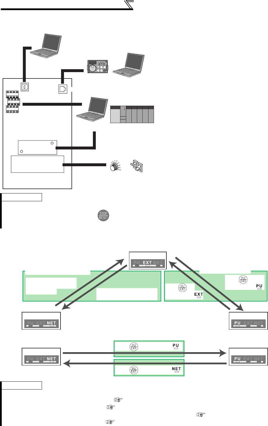
314
Selection of operation mode and operation location
(1) Operation mode basics
(2) Operation mode switching method
⋅The operation mode is to specify the source of
inputting the start command and frequency
command of the inverter.
⋅Basically, there are following operation modes.
External operation mode: For inputting start
command and frequency command by an external
potentiometer and switches which are connected
to the control circuit terminal.
PU operation mode: For inputting start command
and frequency command by operation panel (FR-
DU07), parameter unit (FR-PU04/FR-PU07) and
RS-485 communication with PU connector.
Network operation mode (NET operation
mode): For inputting start command and
frequency command by RS-485 terminal and
communication options.
⋅The operation mode can be selected from the
operation panel or with the communication
instruction code.
REMARKS
⋅Either "3" or "4" may be set to select the PU/external combined operation, and these settings differ in starting method.
⋅In the initial setting, the stop function by of the PU (FR-DU07/FR-PU07) (PU stop selection) is valid also in other than the
PU operation mode. (Pr. 75 Reset selection/disconnected PU detection/PU stop selection. Refer to page 305.)
REMARKS
⋅For switching of operation by external terminals, refer to the following:
PU operation external interlock signal (X12 signal) page 318
PU-external operation switch-over signal (X16) page 319
PU-NET operation switchover signal (X65), External-NET operation switchover signal (X66) page 320
Pr. 340 Communication startup mode selection page 321
Network operation mode
Network operation
mode
External
operation
mode
PU operation
mode
Personal
computer
Personal
computer
Operation
panel
Programmable controlle
r
Potentiometer Switch
RS-485
terminals
Inverter
Communication
option
External terminal
Personal
computer
USB
connector PU
connector
Switching through the network
Switch to the Network operation
mode through the network.
Switch to External
operation mode through
the network.
External operation
Switching with the PU
Press on
the PU to light
Network operation PU operation
Network operation PU operation
When "0, 1, or 2" is set in Pr. 340
When "10 or 12" is set in Pr. 340
Press on the PU to light
Press on
the PU to light
Press on the PU to light
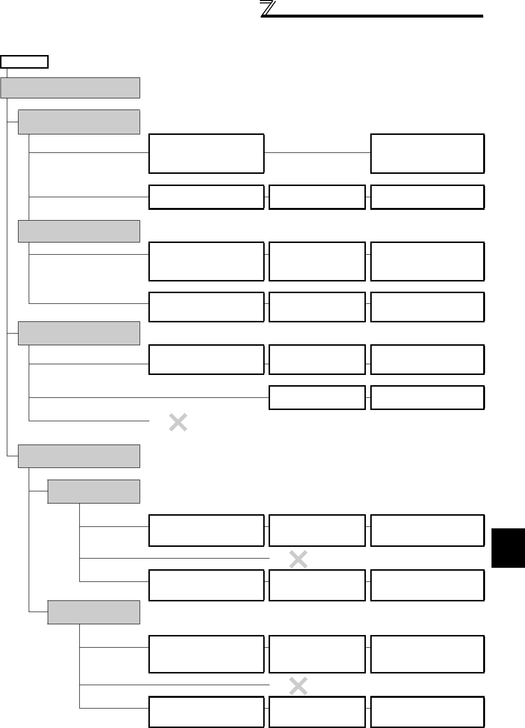
315
Selection of operation mode and operation location
4
PARAMETERS
(3) Operation mode selection flow
In the following flowchart, select the basic parameter setting and terminal connection related to the operation mode.
START Connection Parameter setting Operation
Where is the start command
source?
From external (STF/STR terminal)
Where is the frequency set?
From external (Terminal 2, 4,
JOG, multi-speed, etc.)
STF (forward rotation)/STR
(reverse rotation)
(Refer to page 231.)
Terminal 2, 4 (analog), RL, RM,
RH, JOG, etc.
Frequency setting terminal ON
STF(STR) ON
From PU (Digital setting) STF (forward rotation)/STR
(reverse rotation)
(Refer to page 231.)
Pr. 79 = "3"
(External/PU combined
operation 1)
DU digital setting
STF(STR) ON
From communication (RS-485 terminals/communication option)
RS-485 terminals or
communication option?
RS-485 terminals STF (forward rotation)/STR
(reverse rotation)
(Refer to page 231.)
Connection of RS-485 terminals
(Refer to page 330.)
Pr. 338 = "1"
Pr. 340 = "1, 2"
Communication frequency setting
command sending
STF(STR) ON
Communication option Connection of communication
option
(Refer to the corresponding communication
option instruction manual)
Pr. 338 = "1"
Pr. 340 = "1"
Communication frequency setting
command sending
STF(STR) ON
From PU (FWD/REV key)
Where is the frequency set?
From external (Terminal 2, 4, JOG,
multi-speed, etc.) Terminal 2, 4 (analog), RL, RM,
RH, JOG, etc.
Pr. 79 = "4"
(External/PU combined
operation 2)
Frequency setting terminal ON
FWD/REV key ON
From PU (Digital setting) Pr. 79 = "1"
(Fixed to PU operation)
Digital setting
FWD/REV key ON
From communication
(RS-485 terminals/communication option)
From communication (RS-485 terminals/communication option)
RS-485 terminals or
communication option?
RS-485 terminals
Where is the frequency set?
From external (Terminal 2, 4, JOG, multi-speed, etc.)
Connection of RS-485 terminals
(Refer to page 330.)
Terminal 2, 4 (analog), RL, RM,
RH, JOG, etc.
Pr. 339 = "1"
Pr. 340 = "1, 2"
Frequency setting terminal ON
Communication start command
sending
From PU (Digital setting)
From communication
RS-485 terminals Connection of RS-485 terminals
(Refer to page 330.) Pr. 340 = "1, 2"
Communication frequency setting
command sending
Communication start command
sending
Communication option
Where is the frequency set?
From
external
(Terminal 2, 4, JOG, multi-speed, etc.)
Connection of communication option
(Refer to the corresponding communication
option instruction manual)
Terminal 2, 4 (analog), RL, RM,
RH, JOG, etc.
Pr. 339 = "1"
Pr. 340 = "1"
Frequency setting terminal ON
Communication start command
sending
From PU (Digital setting)
From communication (
communication option)
Connection of communication option
(Refer to the corresponding communication
option instruction manual)
Pr. 340 = "1"
Communication frequency setting
command sending
Communication start command
sending
Disabled
Disabled
Disabled
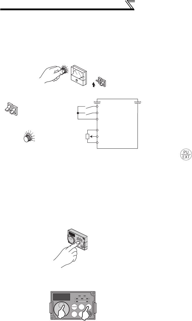
316
Selection of operation mode and operation location
(4) External operation mode (setting "0" (initial value), "2")
(5) PU operation mode (setting "1")
⋅Select the External operation mode when the start
command and the frequency command are applied
from a frequency setting potentiometer, start switch, etc.
externally and connecting them to the control circuit
terminals of the inverter.
⋅Generally, parameter change cannot be performed with
the operation panel in the External operation mode.
(Some parameters can be changed. Refer to the
detailed description of each parameter.)
⋅When "0" or "2" is selected for Pr. 79, the inverter enters
the External operation mode at power ON. (When using
the Network operation mode, refer to page 321)
⋅When parameter changing is seldom necessary, setting
"2" fixes the operation mode to External operation
mode. When frequent parameter changing is
necessary, setting "0" (initial value) allows the operation
mode to be changed easily to PU operation mode by
pressing of the operation panel. When you
switched to PU operation mode, always return to
External operation mode.
⋅The STF and STR signal are used as a start command,
and the voltage or current signal to terminal 2, 4,
multispeed signal, JOG signal, etc. are used as
frequency command.
⋅Select the PU operation mode when performing
operation by only the key operation of the operation
panel (FR-DU07) or parameter unit (FR-PU04/FR-
PU07). Also select the PU operation mode when
making communication using the PU connector.
⋅When "1" is selected for Pr. 79, the inverter enters the
PU operation mode at power ON. You cannot change to
the other operation mode.
⋅The setting dial of the operation panel can be used for
setting like a potentiometer. (Pr. 161 Frequency setting/key
lock operation selection, refer to page 393.)
⋅When PU operation mode is selected, the PU operation
mode signal (PU) can be output.
For the terminal used for the PU signal output, assign
the function by setting "10 (positive logic) or 110
(negative logic)" in any of Pr. 190 to Pr. 196 (output
terminal function selection).
3456
7
8
9
10
Hz
5
10
2
STF
STR
SD
Reverse rotation start
Frequency setting
potentiometer
Inverter
Switch
Potentiometer
Forward rotation start
Operation panel
(FR-DU07)
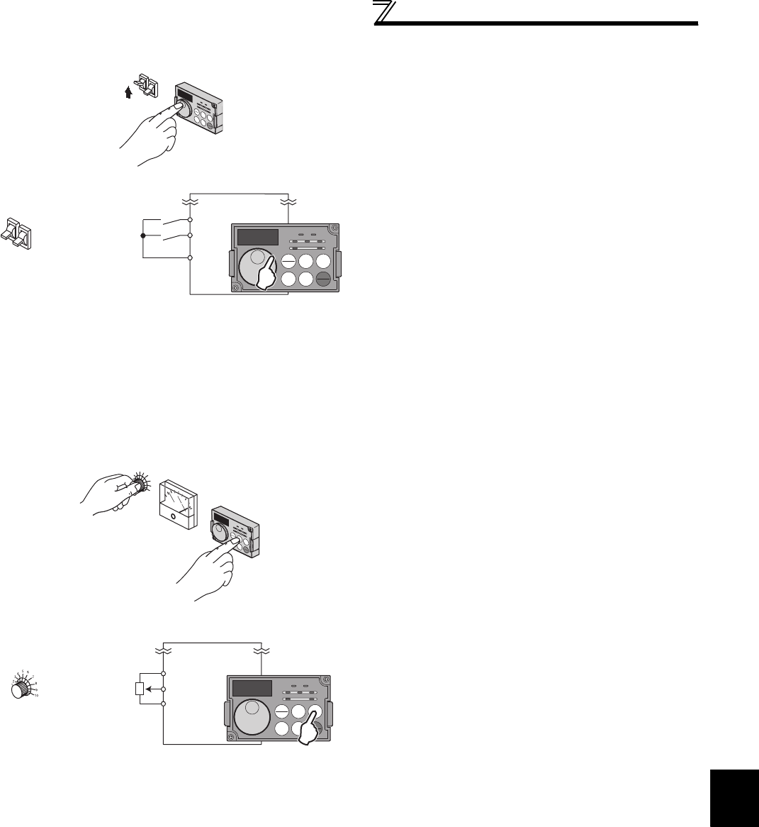
317
Selection of operation mode and operation location
4
PARAMETERS
(6) PU/External combined operation mode 1 (setting "3")
(7) PU/External combined operation mode 2 (setting "4")
⋅Select the PU/External combined operation mode 1
when applying frequency command from the operation
panel (FR-DU07) or parameter unit (FR-PU04/FR-
PU07) and inputting the start command with the
external start switch.
⋅Select "3" for Pr. 79. You cannot change to the other
operation mode.
⋅When a frequency is input from the external signal by
multi-speed setting, it has a higher priority than the
frequency setting from the PU. When AU is on, the
command signal to terminal 4 is used.
⋅Select the PU/External combined operation mode 2
when applying frequency command from the external
potentiometer, multi-speed or JOG signal and inputting
the start command by key operation of the operation
panel (FR-DU07) or parameter unit (FR-PU04/FR-
PU07).
⋅Select "4" for Pr. 79. You cannot change to the other
operation mode.
Operation panel
(FR-DU07)
SD
STF
STR
Forward rotation
start
Reverse rotation
start
Inverter
Switch
3456
7
8
9
10
Hz
Operation panel
(FR-DU07)
5
10
2
Inverter
Frequency setting
potentiometer

318
Selection of operation mode and operation location
(8) Switchover mode (setting "6")
⋅While continuing operation, you can switch among PU operation, External operation and Network operation (when
RS-485 terminals or communication option is used).
(9) PU operation interlock (setting "7")
⋅The PU operation interlock function is designed to forcibly change the operation mode to External operation mode when
the PU operation interlock signal (X12) input turns OFF. This function prevents the inverter from being inoperative by
the external command if the mode is accidentally left unswitched from PU operation mode.
⋅Set "7" (PU operation interlock) in Pr. 79.
⋅For the terminal used for X12 signal (PU operation interlock signal) input, set "12" in any of Pr. 178 to Pr. 189 (input
terminal function selection) to assign the function. (Refer to page 231 for Pr. 178 to Pr. 189.)
⋅When the X12 signal has not been assigned, the function of the MRS signal switches from MRS (output stop) to the
PU operation interlock signal.
<Function/operation changed by switching ON/OFF the X12 (MRS) signal>
Operation Mode Switching
Switching Operation/Operating Status
External operation → PU
operation
Select the PU operation mode with the operation panel or parameter unit.
⋅Rotation direction is the same as that of external operation.
⋅The frequency set with the potentiometer (frequency setting command), etc. is used unchanged. (Note
that the setting will disappear when power is switched off or the inverter is reset.)
External operation → NET
operation
Send the mode change command to Network operation mode through communication.
⋅Rotation direction is the same as that of external operation.
⋅The value set with the setting potentiometer (frequency setting command) or like is used unchanged.
(Note that the setting will disappear when power is switched off or the inverter is reset.)
PU operation → external
operation
Press the external operation key of the operation panel, parameter unit.
⋅The rotation direction is determined by the input signal of the external operation.
⋅The set frequency is determined by the external frequency command signal.
PU operation → NET
operation
Send the mode change command to Network operation mode through communication.
⋅Rotation direction and set frequency are the same as those of PU operation.
NET operation → external
operation
Send the mode change command to External operation mode through communication.
⋅The rotation direction is determined by the input signal of the external operation.
⋅The set frequency is determined by the external frequency command signal.
NET operation → PU
operation
Select the PU operation mode with the operation panel or parameter unit.
⋅
The rotation direction and frequency command in Network operation mode are used unchanged.
X12 (MRS)
signal
Function/Operation
Operation mode Parameter write
ON
Operation mode (external, PU, NET) switching
enabled
Output stop during external operation
Parameter write enabled (Pr. 77 Parameter write selection,
depending on the corresponding parameter write
condition (Refer to page 71 for the parameter list))
OFF
Forcibly switched to External operation mode
External operation allowed
Switching to the PU or NET operation mode from
the External operation mode is disabled.
Parameter write disabled with exception of Pr. 79
Operating Condition X12 (MRS)
signal
Operation
Mode Operating Status
Switching to
PU, NET
Operation Mode
Operation
mode Status
PU/NET During stop ON→OFF *1 External *2
If external operation frequency setting and start signal
are entered, operation is performed in that status.
Disallowed
Running ON→OFF *1 Disallowed
External
During stop OFF→ON
External *2
During stop Allowed
ON→OFF Disallowed
Running OFF→ON During operation → output stop Disallowed
ON→OFF Output stop → operation Disallowed
*1 The operation mode switches to External operation mode independently of whether the start signal (STF, STR) is ON or OFF. Therefore,
the motor is run in External operation mode when the X12 (MRS) signal is turned OFF with either of STF and STR is ON.
*2 At alarm occurrence, pressing on the operation panel resets the inverter.
CAUTION
⋅
If the X12 (MRS) signal is ON, the operation mode cannot be switched to PU operation mode when the start signal (STF, STR) is ON.
⋅When the MRS signal is used as the PU interlock signal, the MRS signal serves as the normal MRS function (output stop) by
turning ON the MRS signal and then changing the Pr. 79 value to other than "7" in the PU operation mode. Also as soon as "7"
is set in Pr. 79, the signal acts as the PU interlock signal.
⋅When the MRS signal is used as the PU operation interlock signal, the logic of the signal is as set in Pr. 17. When Pr. 17 = "2",
read ON as OFF and OFF as ON in the above explanation.
⋅Changing the terminal assignment using Pr. 178 to Pr. 189 (input terminal function selection) may affect the other functions. Set
parameters after confirming the function of each terminal.

319
Selection of operation mode and operation location
4
PARAMETERS
(10) Switching of operation mode by external signal (X16 signal)
⋅When external operation and operation from the operation panel are used together, use of the PU-external
operation switching signal (X16) allows switching between the PU operation mode and External operation mode
during a stop (during a motor stop, start command off).
⋅When Pr. 79 = any of "0, 6, 7", the operation mode can be switched between the PU operation mode and External
operation mode. (Pr. 79 = "6" At switch-over mode, operating mode can be changed during operation)
⋅For the terminal used for X16 signal input, set "16" in any of Pr. 178 to Pr. 189 (input terminal function selection) to
assign the function.
Pr. 79
Setting
X16 signal State Operation Mode Remarks
ON (external) OFF (PU)
0 (initial value) External operation
mode PU operation mode Can be switched to external, PU or NET operation mode
1 PU operation mode Fixed to PU operation mode
2 External operation mode Fixed to External operation mode (Can be switched to NET
operation mode)
3, 4 External/PU combined operation mode External/PU combined mode fixed
6External operation
mode PU operation mode Can be switched to External, PU or NET operation mode with
operation continued
7
X12 (MRS)
ON
External operation
mode PU operation mode Can be switched to external, PU or NET operation mode (Output
stop in External operation mode)
X12 (MRS)
OFF External operation mode Fixed to External operation mode (Forcibly switched to External
operation mode)
REMARKS
⋅The operation mode status changes depending on the setting of Pr. 340 Communication startup mode selection and the ON/OFF
status of the X65 and X66 signals. (For details, refer to page 320.)
⋅The priorities of Pr. 79, Pr. 340 and signals are Pr. 79 > X12 > X66 > X65 > X16 > Pr. 340.
CAUTION
⋅Changing the terminal assignment using Pr. 178 to Pr. 189 (input terminal function selection) may affect the other functions. Set
parameters after confirming the function of each terminal.
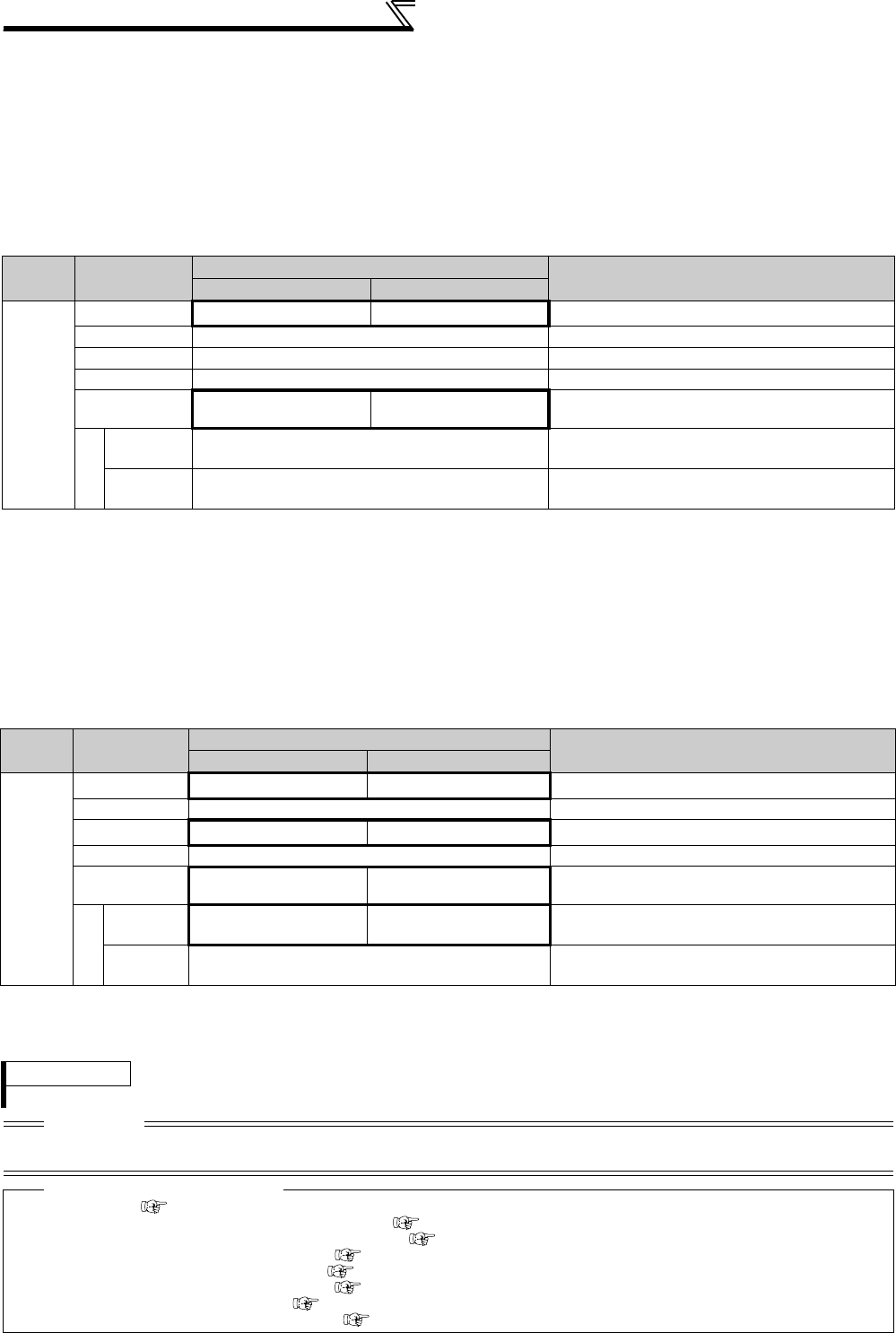
320
Selection of operation mode and operation location
(11) Switching of operation mode by external terminal (X65, X66 signal)
⋅When Pr. 79 = any of "0, 2, 6", the operation mode switching signals (X65, X66) can be used to change the PU or
External operation mode to Network operation mode during a stop (during a motor stop or start command off). (Pr.
79 = "6" switch-over mode can be changed during operation)
⋅When switching between the Network operation mode and PU operation mode
1) Set Pr. 79 to "0" (initial value) or "6".
2) Set "10 or 12" in Pr. 340 Communication startup mode selection.
3) Set "65" in any of Pr. 178 to Pr. 189 to assign the NET-PU operation switchover signal (X65) to the terminal.
4) The operation mode changes to PU operation mode when the X65 signal turns ON, or to Network operation mode
when the X65 signal turns OFF.
⋅When switching between the Network operation mode and External operation mode
1)Set Pr. 79 to "0" (initial value), "2", "6" or "7". (At the Pr. 79 setting of "7", the operation mode can be switched when the
X12 (MRS) signal turns ON.)
2)Set "0 (initial value), 1 or 2" in Pr. 340 Communication startup mode selection.
3)Set "66" in any of Pr. 178 to Pr. 189 to assign the NET-external operation switchover signal (X66) to the terminal.
4)The operation mode changes to Network operation mode when the X66 signal turns ON, or to External operation mode
when the X66 signal turns OFF.
Pr. 340
Setting
Pr. 79
Setting
X65 signal State Remarks
ON (PU) OFF (NET)
10, 12
0 (initial value) PU operation mode *1 NET operation mode *2 ⎯
1 PU operation mode Fixed to PU operation mode
2 NET operation mode Fixed to NET operation mode
3, 4 External/PU combined operation mode External/PU combined mode fixed
6PU operation mode *1 NET operation mode *2 Operation mode can be switched with operation
continued
7
X12(MRS)
ON
Switching between the External and
PU operation mode is enabled *2 Output stop in External operation mode
X12(MRS)
OFF External operation mode Forcibly switched to External operation mode
*1 NET operation mode when the X66 signal is ON.
*2 PU operation mode when the X16 signal is OFF. PU operation mode also when Pr. 550 NET mode operation command source selection =
"0" (communication option control source) and the communication option is not fitted.
External operation mode when the X16 signal is ON.
Pr. 340
Setting
Pr. 79
Setting
X66 signal State Remarks
ON (NET) OFF(external)
0
(initial
value)
,
1, 2
0 (initial value) NET operation mode *1
External operation mode
*2
⎯
1 PU operation mode Fixed to PU operation mode
2NET operation mode *1 External operation mode Cannot be switched to PU operation mode
3, 4 External/PU combined operation mode External/PU combined mode fixed
6 NET operation mode *1
External operation mode
*2
Operation mode can be switched with operation
continued
7
X12(MRS)
ON NET operation mode *1
External operation mode
*2
Output stop in External operation mode
X12(MRS)
OFF External operation mode Forcibly switched to External operation mode
*1 PU operation mode is selected when Pr. 550 NET mode operation command source selection = "0" (communication option control source) and the
communication option is not fitted.
*2 PU operation is selected when the X16 signal is OFF. When the X65 signal has been assigned, the operation mode changes with the ON/OFF
state of the X65 signal.
REMARKS
⋅The priorities of Pr. 79, Pr. 340 and signals are Pr. 79 > X12 > X66 > X65 > X16 > Pr. 340.
CAUTION
⋅Changing the terminal assignment using Pr. 178 to Pr. 189 (input terminal function selection) may affect the other functions. Set
parameters after confirming the function of each terminal.
♦ Parameters referred to ♦
Pr. 15 Jog frequency Refer to page 167
Pr. 4 to 6, Pr. 24 to 27, Pr. 232 to Pr. 239 Multi-speed operation Refer to page 165
Pr. 75 Reset selection/disconnected PU detection/PU stop selection Refer to page 305
Pr. 161 Frequency setting/key lock operation selection Refer to page 393
Pr. 178 to Pr. 189 (input terminal function selection) Refer to page 231
Pr. 190 to Pr. 196 (output terminal function selection) Refer to page 239
Pr. 340 Communication startup mode selection Refer to page 321
Pr. 550 NET mode operation command source selection Refer to page 322
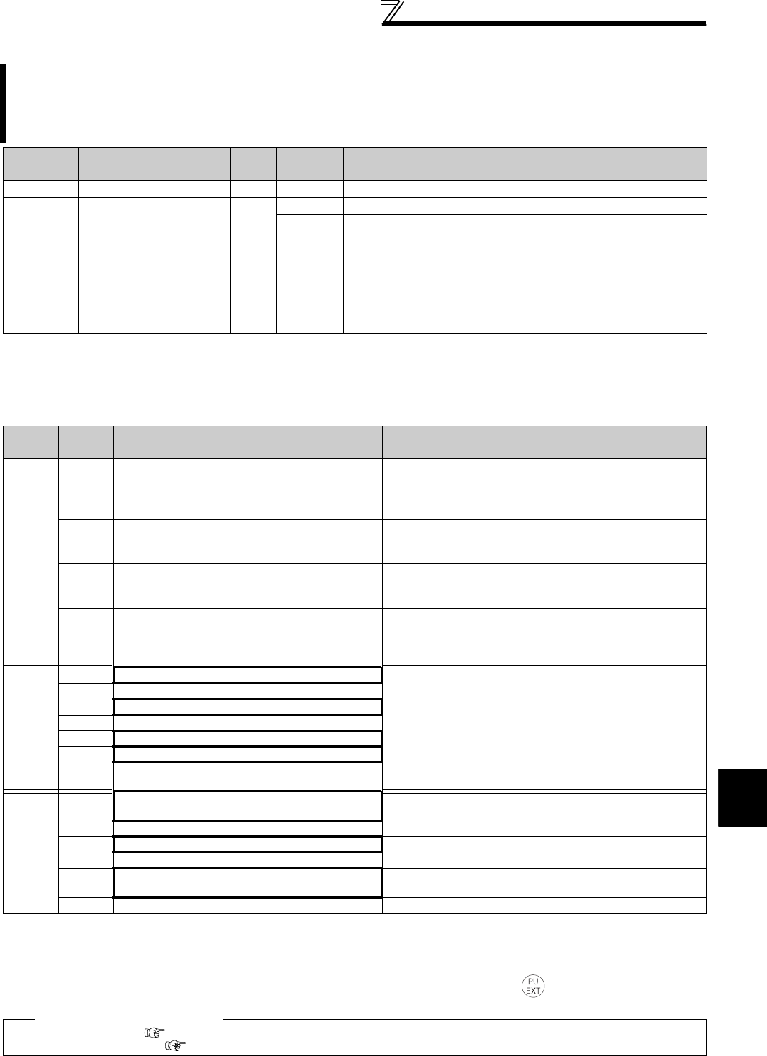
321
Selection of operation mode and operation location
4
PARAMETERS
4.23.2 Operation mode at power ON (Pr. 79, Pr. 340)
(1) Specify operation mode at power ON (Pr. 340)
⋅Depending on the Pr. 79 and Pr. 340 settings, the operation mode at power ON (reset) changes as described below.
When power is switched ON or when power comes back ON after instantaneous power failure, the inverter can
be started up in Network operation mode.
After the inverter has started up in the Network operation mode, parameter write and operation can be performed
from a program.
Set this mode for communication operation using the RS-485 terminals or communication option.
Parameter
Number Name Initial
Value
Setting
Range Description
79 *1
Operation mode selection
0 0 to 4, 6, 7 Select the operation mode. (Refer to page 315.)
340 *2*3 Communication startup
mode selection 0
0 As set in Pr. 79.
1, 2
Started in Network operation mode.
When the setting is "2", it will resume the pre-instantaneous power
failure operation mode after an instantaneous power failure occurs.
10, 12
Started in Network operation mode. Operation mode can be
changed between the PU operation mode and Network operation
mode from the operation panel. When the setting is "12", it will
resume the pre-instantaneous power failure operation mode after
an instantaneous power failure occurs.
The above parameters can be changed during a stop in any operation mode.
*1 This parameter allows its setting to be changed in any operation mode even if "0 (initial value) or 1" is set in Pr. 77 Parameter write selection.
*2 This parameter allows its setting to be changed in any operation mode even if "0 (initial value)" is set in Pr. 77 Parameter write selection.
*3 The parameters can be set whenever the communication option is connected. (Refer to page 308.).
Pr. 340
Setting
Pr. 79
Setting
Operation Mode at Power ON, Power
Restoration, Reset Operation Mode Switching
0
(initial
value)
0
(initial
value)
External operation mode Switching among the external, PU, and NET operation mode is
enabled *2
1PU operation mode Fixed to PU operation mode
2External operation mode
Switching between the external and Net operation mode is
enabled
Switching to PU operation mode is disabled
3, 4 External/PU combined operation mode Operation mode switching is disabled
6External operation mode Switching among the external, PU, and NET operation mode is
enabled while running
7
External operation mode when X12 (MRS) signal
ON
Switching among the external, PU, and NET operation mode is
enabled *2
External operation mode when X12 (MRS) signal
OFF
Fixed to External operation mode (forcibly switched to External
operation mode.)
1, 2 *1
0NET operation mode
Same as when Pr. 340 = "0"
1PU operation mode
2NET operation mode
3, 4 External/PU combined operation mode
6NET operation mode
7
NET operation mode when X12 (MRS) signal ON
External operation mode when X12 (MRS) signal
OFF
10, 12
*1
0NET operation mode Switching between the PU and NET operation mode is
enabled *3
1PU operation mode Same as when Pr. 340 = "0"
2NET operation mode Fixed to NET operation mode
3, 4 External/PU combined operation mode Same as when Pr. 340 = "0"
6NET operation mode Switching among the external, PU, and NET operation mode is
enabled while running *3
7External operation mode Same as when Pr. 340 = "0"
*1 The Pr. 340 setting "2" or "12" is mainly used for communication operation using the inverter RS-485 terminals. When a value other than "9999"
(selection of automatic restart after instantaneous power failure) is set in Pr. 57 Restart coasting time, the inverter will resume the same operation
state which was in before after power has been restored from an instantaneous power failure.
When Pr. 340 = "1, 10", a start command turns OFF if power failure has occurred and then restored during a start command is ON.
*2 The operation mode cannot be switched directly between the PU operation mode and Network operation mode.
*3 Operation mode can be changed between the PU operation mode and Network operation mode with key of the operation panel (FR-
DU07) and X65 signal.
♦ Parameters referred to ♦
Pr. 57 Restart coasting time Refer to page 266.
Pr. 79 Operation mode selection Refer to page 313.
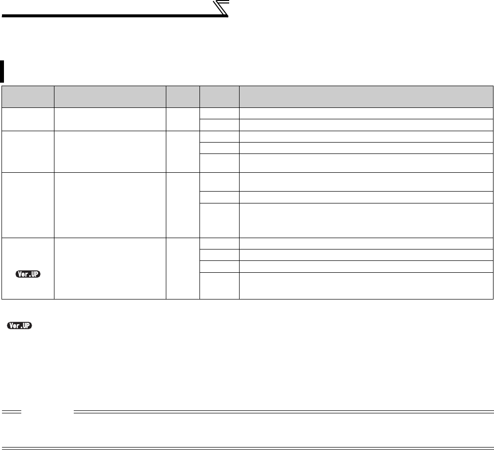
322
Selection of operation mode and operation location
4.23.3 Start command source and frequency command source during
communication operation (Pr. 338, Pr. 339, Pr. 550, Pr. 551)
(1) Select the command source of the Network operation mode (Pr. 550)
⋅Either the RS-485 terminals or communication option can be specified as the command source in the Network
operation mode.
⋅For example, set Pr. 550 to "1" when executing parameter write, start command or frequency command from the
inverter RS-485 terminals in the Network operation mode independently of whether the communication option is
connected or not.
When the RS-485 terminals or communication option is used, the external operation command and speed
command can be valid. Command source in the PU operation mode can be selected.
Parameter
Number Name Initial
Value
Setting
Range Description
338 Communication operation
command source 00Start command source communication
1Start command source external
339 Communication speed
command source 0
0Frequency command source communication
1Frequency command source external
2Frequency command source external (Frequency command from
communication is valid, frequency command from terminal 2 is invalid)
550 *
NET mode operation
command source
selection
9999
0
The communication option is the command source when NET
operation mode.
1
RS-485 terminals are the command source when NET operation mode.
9999
Automatic communication option recognition
Normally, the RS-485 terminals are the command source. When a
communication option is mounted, the communication option is the
command source.
551 * PU mode operation
command source selection 9999
1RS-485 terminals are the command source when PU operation mode.
2PU connector is the command source when PU operation mode.
3USB connector is the command source when PU operation mode.
9999
USB automatic recognition
Normally, the PU connector is the command source. During USB
connection, the USB connector is the command source.
The above parameters can be set whenever the communication option is connected. (Refer to page 308.)
* This parameter allows its setting to be changed in any operation mode even if "0 (initial value)" is set in Pr. 77 Parameter write selection.
...............Specifications differ according to the date assembled. Refer to page 484 to check the SERIAL number.
CAUTION
⋅Since Pr. 550 = "9999" (automatic recognition of the communication option) in the initial setting, parameter write, start command
and frequency command cannot be executed by communication using the inverter RS-485 terminals when the communication
option is fitted. (Monitor and parameter read can be performed.)

323
Selection of operation mode and operation location
4
PARAMETERS
(2) Select the command source of the PU operation mode (Pr. 551)
⋅Any of the PU connector, RS-485 terminals, or USB connector can be specified as the command source in the PU
operation mode.
⋅Set Pr.551="1" to use the RS-485 terminals to write parameters or send start and frequency commands in the PU
operation mode. Set Pr.551="3 or 9999" to use the USB connector to do those in the PU operation mode.
*1 The Modbus-RTU protocol cannot be used in the PU operation mode. When using the Modbus-RTU protocol, set Pr. 551 to "2".
*2 When the communication option is not fitted, the operation mode cannot be switched to Network operation mode.
*3 When Pr. 551 = "9999", the priorities of the PU command source is USB connector > PU connector.
CAUTION
⋅The PU operation mode has a higher priority when Pr. 550 = "1" (NET mode RS-485 terminals) and Pr. 551 = "1" (PU mode RS-485
terminals). When the communication option is not fitted, therefore, the operation mode cannot be switched to Network operation
mode.
⋅Changed setting value is valid when powering ON or resetting the inverter.
Pr. 550
Setting
Pr. 551
Setting
Command Source Remarks
PU connector USB connector RS-485 terminals
Communication option
0
1××
PU operation mode *1 NET operation mode *2
2 PU operation mode ××NET operation mode *2
3×PU operation mode ×NET operation mode *2
9999
(initial
value)
PU operation mode
*3
PU operation mode
*3 ×NET operation mode *2
1
1××
PU operation mode *1 ×Switching to NET
operation mode disabled
2 PU operation mode ×NET operation mode ×
3×PU operation mode NET operation mode ×
9999
(initial
value)
PU operation mode
*3
PU operation mode
*3 NET operation mode ×
9999
(initial
value)
1××PU operation mode *1 NET operation mode *2
2 PU operation mode ×
×NET operation mode *2 Communication option
fitted
NET operation mode ×Communication option
not fitted
3×PU operation mode
×NET operation mode *2 Communication option
fitted
NET operation mode ×Communication option
not fitted
9999
(initial
value)
PU operation mode
*3
PU operation mode
*3
×NET operation mode *2 Communication option
fitted
NET operation mode ×Communication option
not fitted

324
Selection of operation mode and operation location
(3) Controllability through communication
Operation
Location
Condition
(Pr. 551
Setting)
Operation
Mode
Item
PU
Operation
External
Operation
External/PU
Combined
Operation Mode
1
(
Pr. 79
= 3)
External/PU
Combined
Operation
Mode 2
(Pr. 79 = 4)
NET Operation
(when RS-485
terminals are
used)
*6
NET Operation
(when
communication
option is used)
*7
Control by RS-485 communication from PU connector
2
(PU
connector)
9999
(automatic
recognition,
without USB
connection)
Run command
(start) ×× ×
Run command
(stop)
*3 *3 *3
Running frequency
setting ×××
Monitor
Parameter write *4 × *5 *4 *4 × *5
Parameter read
Inverter reset
Other than
the above
Run command
(start) ×× × × ×
Run command
(stop) *3 *3 *3 *3 *3
Running frequency
setting ×× × × ×
Monitor
Parameter write × *5 × *5 × *5 × *5 × *5
Parameter read
Inverter reset
Control by communication from
RS-485 terminals
1
(RS-485
terminals)
Run command
(start, stop) ×× ×
Running frequency
setting ×××
Monitor
Parameter write *4 × *5 *4 *4 × *5
Parameter read
Inverter reset
Other than
the above
Run command
(start, stop) ×× × × *1 ×
Running frequency
setting ×× × × *1 ×
Monitor
Parameter write × *5 × *5 × *5 × *5 *4 × *5
Parameter read
Inverter reset ×× × × *2 ×
Operation from the USB connector
3
(USB
connector)
9999
(automatic
recognition,
with USB
connection)
Run command
(start, stop) ×× ×
Running frequency
setting ×××
Monitor
Parameter write *4 × *5 × *5 × *5 × *5
Parameter read
Inverter reset
Other than
the above
Run command
(start, stop) ×× × × ×
Running frequency
setting ×× × × ×
Monitor
Parameter write × *5 × *5 × *5 × *5 × *5
Parameter read
Inverter reset
Control by communication
from communication option
⎯
Run command
(start, stop) ×× × × × *1
Running frequency
setting ×× × × × *1
Monitor
Parameter write × *5 × *5 × *5 × *5 × *5 *4
Parameter read
Inverter reset ×× × × × *2
: Enabled, ×: Disabled, : Some are enabled
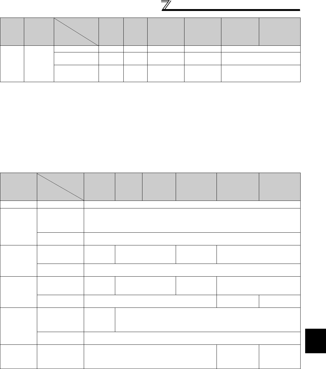
325
Selection of operation mode and operation location
4
PARAMETERS
*1 As set in Pr. 338 Communication operation command source and Pr. 339 Communication speed command source. (Refer to page 322)
*2 At occurrence of RS-485 communication error, the inverter cannot be reset from the computer.
*3 Enabled only when stopped by the PU. At a PU stop, PS is displayed on the operation panel. As set in Pr. 75 Reset selection/disconnected PU
detection/PU stop selection. (Refer to page 305)
*4 Some parameters may be write-disabled according to the Pr. 77 Parameter write selection setting and operating status. (Refer to page 307)
*5 Some parameters are write-enabled independently of the operation mode and command source presence/absence. When Pr. 77 = 2, write is
enabled. (Refer to page 71 for the parameter list)Parameter clear is disabled.
*6 When Pr. 550 NET mode operation command source selection = 1 (RS-485 terminals valid) or Pr. 550 NET mode operation command source selection =
9999 and the communication option is not fitted.
*7 When Pr. 550 NET mode operation command source selection = 0 (communication option valid) or Pr. 550 NET mode operation command source selection
= 9999 and the communication option is fitted.
(4) Operation at alarm occurrence
*1 Can be selected using Pr. 75 Reset selection/disconnected PU detection/PU stop selection
*2 Can be selected using Pr. 122 PU communication check time interval, Pr. 336 RS-485 communication check time interval or Pr. 548 USB communication
check time interval.
*3 As controlled by the communication option.
*4 In the PU jog operation mode, operation is always stopped when the PU is disconnected. Whether fault (E.PEU) occurrence is allowed or not is as
set in Pr. 75 Reset selection/disconnected PU detection/PU stop selection.
*5 When Pr. 550 NET mode operation command source selection = 1 (RS-485 terminals valid) or Pr. 550 NET mode operation command source selection =
9999 and the communication option is not fitted
*6 When Pr. 550 NET mode operation command source selection = 0 (communication option valid) or Pr. 550 NET mode operation command source selection
= 9999 and the communication option is fitted
Control circuit
external terminals
⎯
Inverter reset
Run command
(start, stop) × ×× *1
Frequency setting ××× *1
Alarm
Definition
Operation
Mode
Condition
(
Pr. 551
setting)
PU
Operation
External
Operation
External/PU
Combined
Operation
Mode 1
(Pr. 79 = 3)
External/PU
Combined
Operation Mode
2
(Pr. 79 = 4)
NET Operation
(when RS-485
terminals are
used) *5
NET Operation
(when
communication
option is used)
*6
Inverter fault ⎯Stop
PU
disconnection
of the PU
connector
2 (PU connector)
9999 (automatic
recognition, without
USB connection)
Stop/continued *1, 4
Other than the
above Stop/continued *1
Communication
alarm of PU
connector
2 (PU connector)
Stop/
continued
*2
Continued Stop/continued
*2 Continued
Other than the
above Continued
Communication
alarm of RS-
485 terminals
1 (RS-485 terminals)
Stop/
continued
*2
Continued Stop/continued
*2 Continued
Other than the
above Continued Stop/continued
*2 Continued
Communication
alarm of USB
connector
3 (USB connector)
9999 (automatic
recognition, with
USB connection)
Stop/
continued
*2
Continued
Other than the
above Continued
Communication
alarm of
communication
option
⎯Continued Stop/continued
*3 Continued
Operation
Location
Condition
(Pr. 551
Setting)
Operation
Mode
Item
PU
Operation
External
Operation
External/PU
Combined
Operation Mode
1
(
Pr. 79
= 3)
External/PU
Combined
Operation
Mode 2
(Pr. 79 = 4)
NET Operation
(when RS-485
terminals are
used)
*6
NET Operation
(when
communication
option is used)
*7
: Enabled, ×: Disabled, : Some are enabled

326
Selection of operation mode and operation location
(5) Selection of command source in Network operation mode (Pr. 338, Pr. 339)
⋅There are two control sources: operation command source, which controls the signals related to the inverter start
command and function selection, and speed command source, which controls signals related to frequency setting.
⋅In Network operation mode, the commands from the external terminals and communication (RS-485 terminals or
communication option) are as listed below.
Operation
Location
Selection
Pr. 338 Communication operation command
source
0: NET 1: External
Remarks
Pr. 339 Communication speed command
source 0: NET
1:External 2:External
0: NET
1:External 2:External
Fixed function
(Terminal-
equivalent
function)
Running frequency from
communication
NET ⎯NET NET ⎯NET
Terminal 2
⎯External ⎯⎯
External ⎯
Terminal 4
⎯External ⎯External
Terminal 1
Compensation
Selective function
Pr. 178 to Pr. 189 setting
0RL
Low speed operation com-
mand/remote setting clear
stop-on-contact selection 0
NET External NET External Pr. 59 = "0" (multi-
speeds)
Pr. 59 = "1 , 2"
(remote)
Pr. 270 = "1, 3, 11
or 13"
(stop-on-contact)
1RM
Middle-speed operation
command/remote setting
deceleration
NET External NET External
2RH
High speed operation
command/remote setting
acceleration
NET External NET External
3RT
Second function selection/
Stop-on contact selection 1
NET External
Pr. 270 = "1, 3, 11
or 13"
(stop-on-contact)
4AU
Current input selection
⎯Combined ⎯Combined
5JOG
Jog operation selection
⎯External
6CS
Selection of automatic restart
after instantaneous power
failure
External
7OH
External thermal relay input
External
8REX
Fifteen speed selection
NET External NET External Pr. 59 = "0"
(multi-speeds)
9X9
Third function selection
NET External
10 X10
Inverter operation enable
signal
External
11 X11
FR-HC connection,
instantaneous power failure
detection
External
12 X12
PU operation external
interlock
External
13 X13
External DC injection brake
operation start
NET External
14 X14
PID control valid terminal
NET External NET External
15 BRI
Brake opening completion
signal
NET External
16 X16
PU-external operation
switchover
External
17 X17
Load pattern selection forward
rotation reverse rotation boost
NET External
18 X18
V/F switching
NET External
19 X19
Load torque high-speed fre-
quency
NET External
20 X20
S-pattern acceleration/decel-
eration C switchover
NET External
22 X22
Orientation command
NET External
23 LX
Pre-excitation
NET External
24 MRS
Output stop
Combined External Pr. 79 ≠ "7"
PU operation interlock
External
Pr. 79 = "7"
When X12 signal
is not assigned
25 STOP
Start self-holding selection
⎯External
26 MC
Control mode switchover
NET External
27 TL
Torque limit selection
NET External
28 X28
Start-time tuning start external
input
NET External
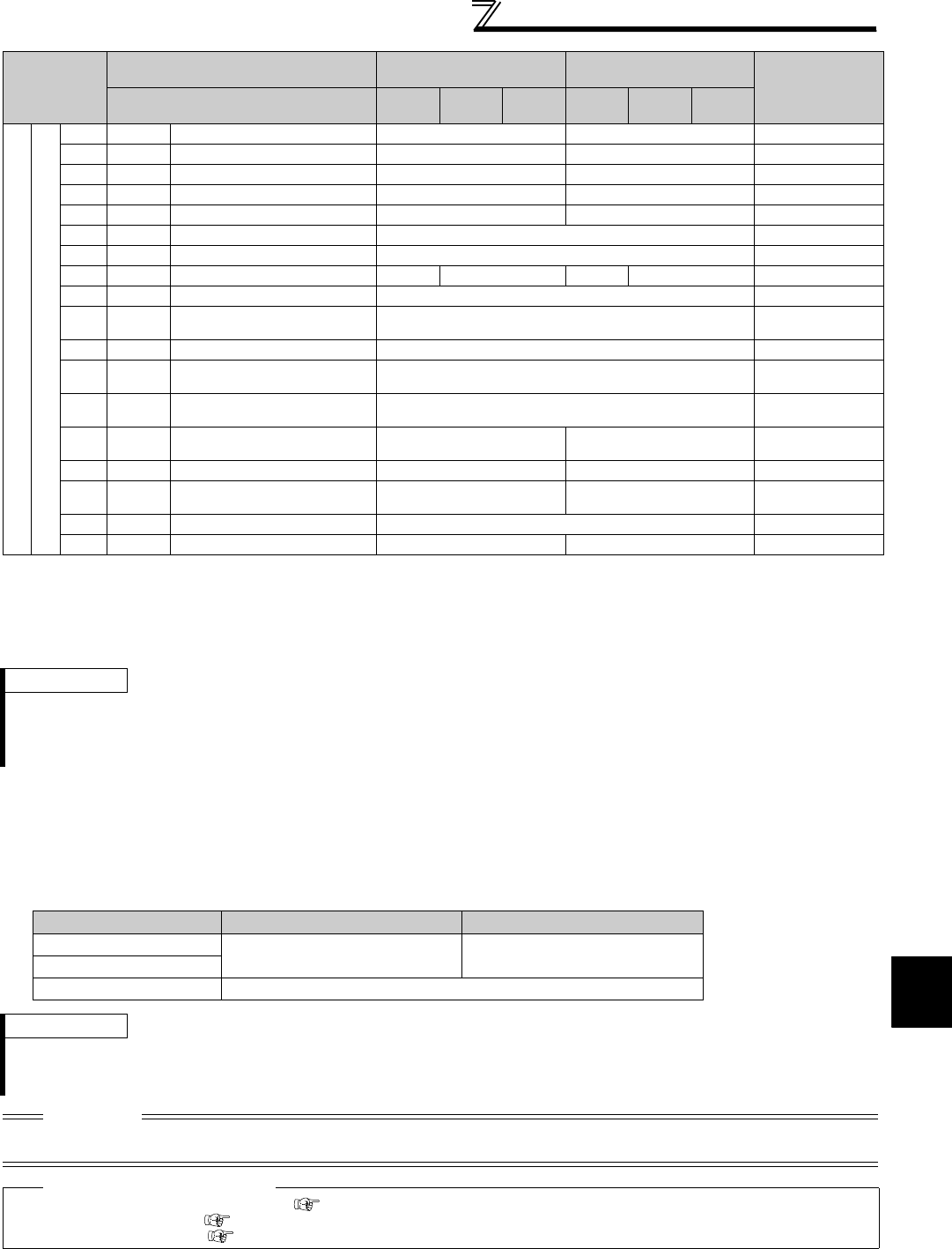
327
Selection of operation mode and operation location
4
PARAMETERS
[Explanation of table]
External : Control is valid only from external terminal signal.
NET : Control only from communication is valid
Combined : Control is valid from either of external terminal and communication.
⎯: Control is invalid from either of external terminal and communication.
Compensation : Control by signal from external terminal is only valid when Pr. 28 Multi-speed input compensation selection = "1"
(6) Switching of command source by external terminal (X67)
⋅In Network operation mode, the command source switching signal (X67) can be used to switch the start command
source and speed command source. This signal can be utilized to control the signal input from both the control
terminal and communication.
⋅Set "67" in any of Pr. 178 to Pr. 189 (input terminal function selection) to assign the X67 signal to the control terminal.
⋅When the X67 signal is off, the start command source and speed command source are control terminal.
Selective function
Pr. 178 to Pr. 189 setting
42 X42
Torque bias selection 1
NET External
43 X43
Torque bias selection 2
NET External
44 X44
P/PI control switchover
NET External
60 STF
Forward rotation command
NET External
61 STR
Reverse rotation command
NET External
62 RES
Reset
External
63 PTC
PID forward action switchover
External
64 X64
PID forward action switchover
NET External NET External
65 X65
PU-NET operation switchover
External
66 X66
External-NET operation
switchover
External
67 X67
Command source switchover
External
68 NP
Simple position pulse train
sign
External
69 CLR
Simple position droop pulse
clear
External
70 X70
DC feeding operation
permission
NET External
71 X71
DC feeding cancel
NET External
74 X74
Magnetic flux decay output
shutoff
NET External
76 X76
Proximity dog
External
83 X83
0V calibration request
NET External
REMARKS
⋅The command source of communication is as set in Pr. 550 and Pr. 551.
⋅The Pr. 338 and Pr. 339 settings can be changed while the inverter is running when Pr. 77 = 2. Note that the setting change is
reflected after the inverter has stopped. Until the inverter has stopped, communication operation command source and
communication speed command source before the setting change are valid.
X67 Signal State Start Command Source Speed Command Source
No signal assignment According to Pr. 338 According to Pr. 339
ON
OFF Command is valid only from control terminal signal.
REMARKS
⋅The ON/OFF state of the X67 signal is reflected only during a stop. It is reflected after a stop when the terminal is switched
during operation.
⋅When the X67 signal is OFF, a reset via communication is disabled.
CAUTION
⋅Changing the terminal assignment using Pr. 178 to Pr. 189 (input terminal function selection) may affect the other functions. Set
parameters after confirming the function of each terminal.
♦ Parameters referred to ♦
Pr. 28 Multi-speed input compensation selection Refer to page 169.
Pr. 59 Remote function selection Refer to page 169.
Pr. 79 Operation mode selection Refer to page 313.
Operation
Location
Selection
Pr. 338 Communication operation command
source
0: NET 1: External
Remarks
Pr. 339 Communication speed command
source 0: NET
1:External 2:External
0: NET
1:External 2:External
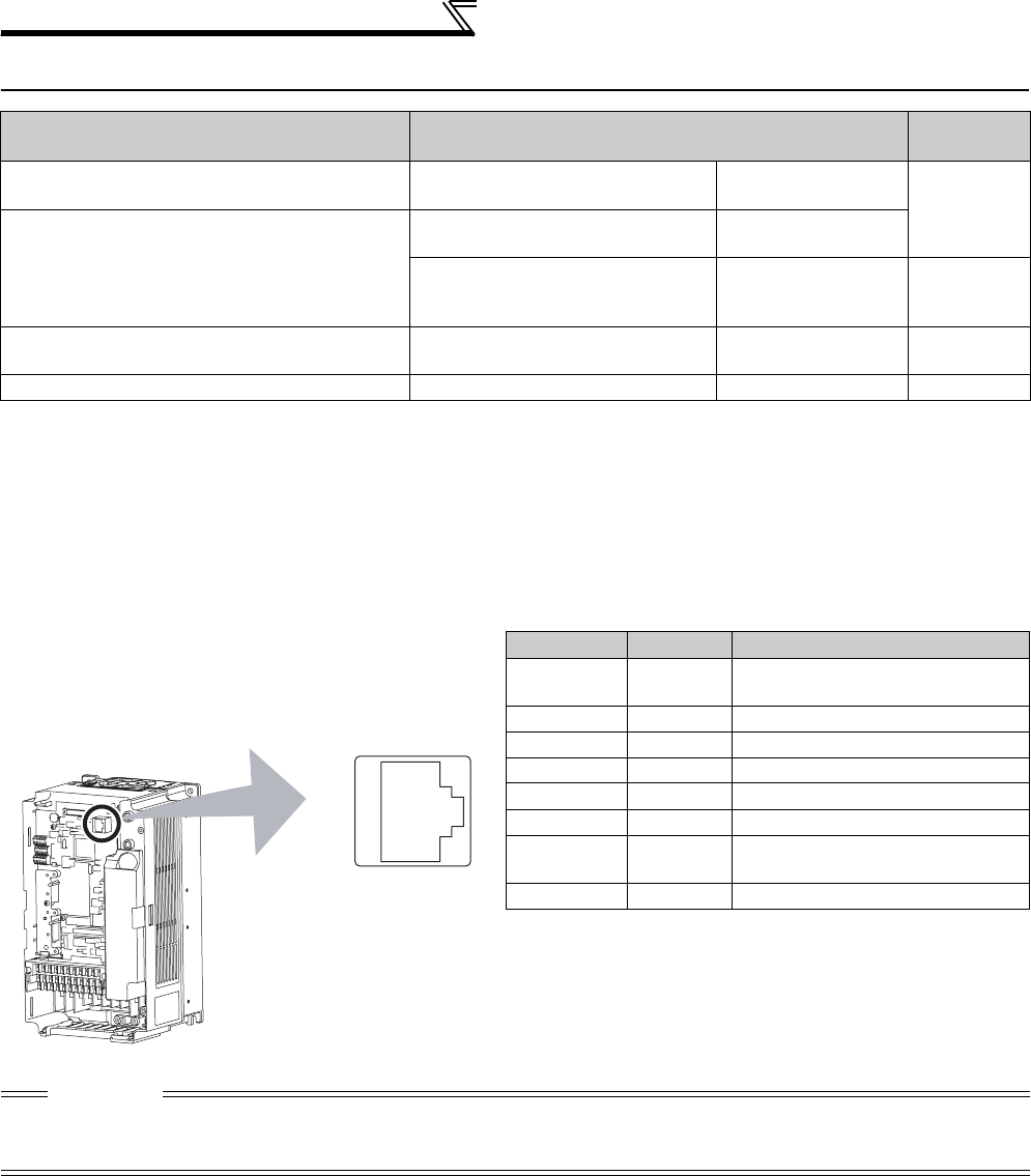
328
Communication operation and setting
4.24 Communication operation and setting
4.24.1 Wiring and configuration of PU connector
Using the PU connector, you can perform communication operation from a personal computer etc.
When the PU connector is connected with a personal, FA or other computer by a communication cable, a user program
can run and monitor the inverter or read and write to parameters.
(1) PU connector pin-outs
Purpose Parameter that must be Set Refer to
Page
Communication operation from PU connector Initial setting of computer link
communication (PU connector) Pr. 117 to Pr. 124
333
Communication operation from RS-485
terminals
Initial setting of computer link
communication (RS-485 terminals)
Pr. 331 to Pr. 337,
Pr. 341
Modbus-RTU communication
specifications
Pr. 331, Pr. 332,
Pr. 334, Pr. 343,
Pr. 549
347
Restrictions on parameter write through
communication
Communication EEPROM write
selection Pr. 342 334
Communication using USB (FR Configurator) USB communication Pr. 547, Pr. 548 360
Pin Number Name Description
1) SG Earth (Ground)
(connected to terminal 5)
2) ⎯Operation panel power supply
3) RDA Inverter receive+
4) SDB Inverter send-
5) SDA Inverter send+
6) RDB Inverter receive-
7) SG Earth (Ground)
(connected to terminal 5)
8) ⎯Operation panel power supply
CAUTION
⋅Pins No. 2 and 8 provide power to the operation panel or parameter unit. Do not use these pins for RS-485 communication.
⋅Do not connect the PU connector to the computer's LAN board, FAX modem socket or telephone modular connector. The
product could be damaged due to differences in electrical specifications.
8)
to
1)
Inverter
(Receptacle side
)
Front view

329
Communication operation and setting
4
PARAMETERS
(2) PU connector communication system configuration and wiring
zSystem configuration
zConnection with RS-485 computer
* Make connections in accordance with the manual of the computer used. Fully check the terminal numbers of the computer since
they change with the model.
REMARKS
⋅Refer to the following when fabricating the cable on the user side.
Commercially available product examples (as of January 2010)
CAUTION
When performing RS-485 communication with multiple inverters, use the RS-485 terminals. (Refer to page 331)
PU
connector
Inverter
Station 0
Computer
PU
connector
Inverter
FR-DU07
Communication cable 1)
RJ-45 connector 2)
RJ-45 connector 2)
PU
connector
Inverter
Station 0
Computer
Communication cable 1)Communication cable 1)
RS-232C-RS-485
converter
RS-232C
cable
Operation
panel
connector
FR-ADP
(option)
RS-485
interface/
terminals
RJ-45
connector 2)
RJ-45
connector 2)
Maximum
15m
RS-232C
connector
Computer Side Terminals
Send data
Send data
Receive data
Receive data
Description
Frame ground
Signal ground
Clear to send
Clear to send
Request to send
Request to send
SDB
SDA
RDB
RDA
Signal name
FG
SG
CSB
CSA
RSB
RSA
RDB
RDA
SDB
SDA
PU connector
SG
Inverter
*
0.2mm2 or more
Cable connection and signal direction
Communication cable RS-485 terminal
* Do not use pins No. 2, 8 of the communication cable.
Product Type Manufacturer
1) Communication cable SGLPEV-T (Cat5e/300m)
24AWG × 4P ∗ Mitsubishi Cable Industries, Ltd.
2) RJ-45 connector 5-554720-3 Tyco Electronics
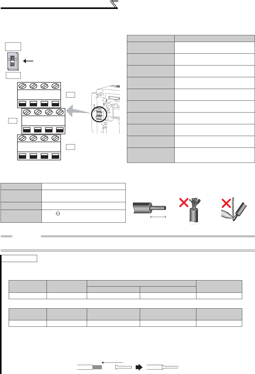
330
Communication operation and setting
4.24.2 Wiring and arrangement of RS-485 terminals
(1) RS-485 terminal layout
(2) Connection of RS-485 terminals and wires
Loosen the terminal screw and insert the cable into the terminal.
Name Description
RDA1
(RXD1+) Inverter receive+
RDB1
(RXD1-) Inverter receive-
RDA2
(RXD2+)
Inverter receive+
(for branch)
RDB2
(RXD2-)
Inverter receive-
(for branch)
SDA1
(TXD1+) Inverter send+
SDB1
(TXD1-) Inverter send-
SDA2
(TXD2+)
Inverter send+
(for branch)
SDB2
(TXD2-)
Inverter send-
(for branch)
P5S
(VCC)
5V
Permissible load current 100mA
SG
(GND)
Earth (Ground)
(connected to terminal SD)
Screw size M2 Wire the stripped cable after twisting it to prevent it from
becoming loose. In addition, do not solder it.
Use a blade terminal as necessary.
Tightening
torque 0.22N•m to 0.25N•m
Cable size 0.3mm2 to 0.75mm2
Screwdriver Small flathead screwdriver
(Tip thickness: 0.4mm /tip width: 2.5mm)
CAUTION
Undertightening can cause signal loss or malfunction. Overtightening can cause a short circuit or malfunction due to damage to
the screw or unit.
REMARKS
Information on blade terminals
Introduced products (as of February 2012)
zPhoenix Contact Co.,Ltd.
zNICHIFU Co.,Ltd.
Use shielded or twisted cables for connection to the control circuit terminals and run them away from the main and power circuits
(including the 200V relay sequence circuit).
When using the blade terminal (without insulation sleeve), use care so that the twisted wires do not come out.
RXD
RDA1
(RXD1+)
RDB1
(RXD1-)
RDA2
(RXD2+)
RDB2
(RXD2-)
SDA1
(TXD1+)
SDB1
(TXD1-)
SDA2
(TXD2+)
SDB2
(TXD2-)
P5S
(VCC)
SG
(GND)
P5S
(VCC)
SG
(GND)
VCC
TXD
OPEN
100Ω
Terminating resistor switch
Factory-set to "OPEN".
Set only the terminating resistor switch of
the remotest inverter to the "100Ω" position.
5mm
Cable stripping size
Terminal Screw
Size Wire Size (mm2)Blade Terminal Model Blade Terminal
Crimping tool
with insulation sleeve without insulation sleeve
M2 0.3, 0.5 AI 0,5-6WH A 0,5-6 CRIMPFOX 6
Terminal Screw
Size Wire Size (mm2)Blade Terminal Product
Number
Insulation Product
Number
Blade Terminal
Crimping tool
M2 0.3 to 0.75 BT 0.75-7 VC 0.75 NH 69

331
Communication operation and setting
4
PARAMETERS
(3) RS-485 terminal system configuration
zConnection of a computer to the inverter (1:1 connection)
zCombination of computer and multiple inverters (1:n connection)
Computer
Twisted pair cable Twisted pair cable
*Set the terminating resistor switch to the "100Ω" position.
Inverter
RS-485
terminals
*
Computer
Converter
RS-232C
cable
Inverter
RS-485
terminals
*
RS-485
interface/
terminals
Maximum
15m
Computer
Twisted pair cable
Twisted pair cable
RS-485
interface terminals
Inverter
RS-485
terminals
*
Inverter
RS-485
terminals
*
Inverter
RS-485
terminals
*
Station 0 Station 1 Station n
*Set only the terminating resistor switch of the
remotest inverter to the "100Ω" position.
*Set only the terminating resistor switch of the
remotest inverter to the "100Ω" position.
Computer
RS-232C
converter
RS-232C
cable
Maximum
15m
Converter
InverterInverter
Inverter
Station 0 Station 1 Station n
RS-485
terminals
*
RS-485
terminals
*
RS-485
terminals
*
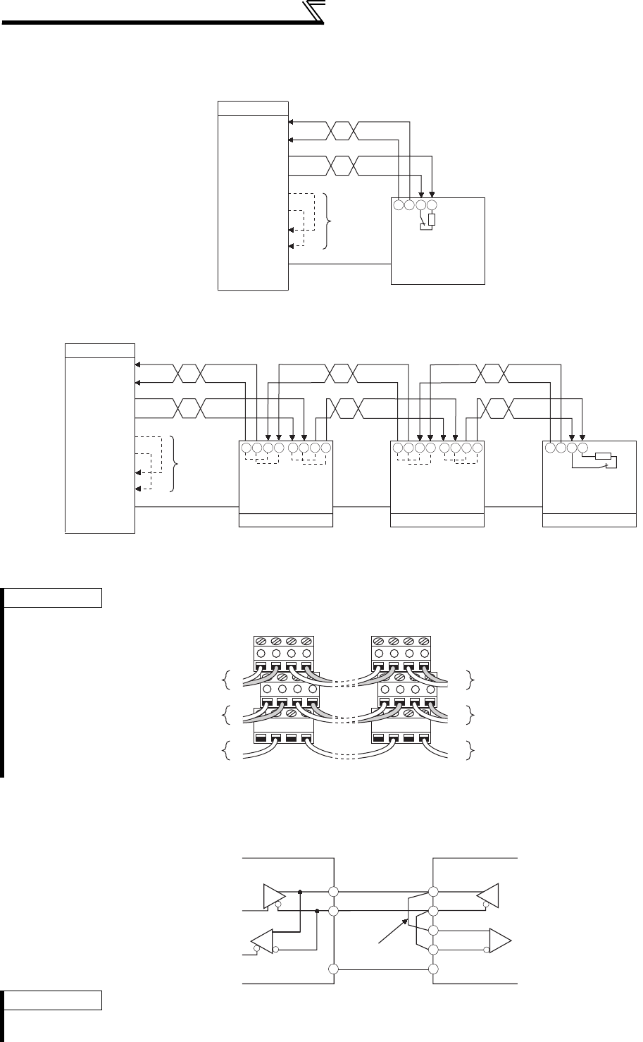
332
Communication operation and setting
(4) RS-485 terminal wiring method
zWiring of one RS-485 computer and one inverter
zWiring of one RS-485 computer and "n" inverters (several inverters)
*1 Make connections in accordance with the manual of the computer used.
Fully check the terminal numbers of the computer since they change with the model.
*2 For the inverter farthest from the computer, set the terminating resistor switch to ON (100Ω side).
(5) 2-wire type connection
If the computer is 2-wire type, pass wires across receiving terminals and transmission terminals of the RS-485
terminals to enable 2-wire type connection with the inverter.
REMARKS
For branching, connect the wires as shown below.
REMARKS
⋅ A program should be created so that transmission is disabled (receiving state) when the computer is not sending and reception
is disabled (sending state) during sending to prevent the computer from receiving its own data.
*1
Computer
RDA
RDB
SDA
SDB
RSA
SG
RSB
CSA
CSB
FG
SG
*2
-
+
-
+
SDB1
SDA1
RDB1
RDA1
*1
Computer
RDA
RDB
SDA
SDB
RSA
SG
RSB
CSA
CSB
FG Station 0
SG SG
-
+
-
+
-
+
-
+
Station 1
SG SG
-
+
+
-
-
+
+
-
Station n
SG
*2
-
+
SDB1
SDA1
RDB1
RDA1
RDA2
RDB2
SDA2
SDB2
SDB1
SDA1
RDB1
RDA1
SDB1
SDA1
RDB1
RDA1
RDA2
RDB2
SDA2
SDB2
-
+
To computer send
To computer receive
To computer ground
TXD
RXD
VCC
RXD
VCC
TXD
SGSG SGSG
+-+
-
+-+-
+-+
+
++++ -
-- +-
+-+
+-+-
To receiving terminal
of the next inverter
To receiving terminal
of the next inverter
To next inverter
To earth (ground)
terminal
To computer send
To computer receive
To computer ground
TXD
RXD
VCC
RXD
VCC
TXD
SGSG SGSG
+-+
-
+-+-
+-+
+
++++ -
-- +-
+-+
+-+-
To receiving terminal
of the next inverter
To receiving terminal
of the next inverter
To next inverter
To earth (ground)
terminal
TXD+
TXD-
RXD+
RXD-
SG
SG
InverterComputer
Pass a wire
Transmission
enable
Reception
enable

333
Communication operation and setting
4
PARAMETERS
4.24.3 Initial settings and specifications of RS-485 communication
(Pr. 117 to Pr. 124, Pr. 331 to Pr. 337, Pr. 341, Pr. 549)
[PU connector communication related parameter]
Use the following parameters to perform required settings for communication between the inverter and personal
computer.
There are two different communications: communication using the PU connector of the inverter and
communication using the RS-485 terminals.
You can perform parameter setting, monitor, etc. from the PU connector or RS-485 terminals of the inverter
using the Mitsubishi inverter protocol (computer link communication).
To make communication between the personal computer and inverter, initialization of the communication
specifications must be made to the inverter.
Data communication cannot be made if the initial settings are not made or there is any setting error.
Parameter
Number Name Initial Value Setting Range Description
117 PU communication station
number 0 0 to 31
Specify the inverter station number.
Set the inverter station numbers when two or
more inverters are connected to one
personal computer.
118 PU communication speed 192 48, 96, 192, 384
Set the communication speed.
The setting value × 100 equals the
communication speed.
For example, the communication speed is
19200bps when the setting value is "192".
119 PU communication stop bit
length 1
Stop bit length Data length
01 bit
8 bits
1 2 bits
10 1 bit 7 bits
11 2 bits
120 PU communication parity
check 2
0 Without parity check
1 With odd parity check
2 With even parity check
121 Number of PU
communication retries 1
0 to 10
Set the permissible number of retries at
occurrence of a data receive error. If the
number of consecutive errors exceeds the
permissible value, the inverter trips.
9999 If a communication error occurs, the inverter
will not trip.
122 PU communication check
time interval 9999
0 No PU connector communication
0.1 to 999.8s
Set the interval of communication check
(signal loss detection) time.
If a no-communication state persists for
longer than the permissible time, the inverter
trips.
9999 No communication check (signal loss
detection)
123 PU communication waiting
time setting 9999 0 to 150ms Set the waiting time between data
transmission to the inverter and response.
9999 Set with communication data.
124 PU communication CR/LF
selection 1
0 Without CR/LF
1With CR
2 With CR/LF

334
Communication operation and setting
[RS-485 terminal communication related parameter]
4.24.4 Communication EEPROM write selection (Pr. 342)
⋅
When changing the parameter values frequently, set "1" in
Pr. 342
to write them to the RAM. The life of the EEPROM will
be shorter if parameter write is performed frequently with the setting unchanged from "0 (initial value)" (EEPROM write).
Parameter
Number Name Initial
Value Setting Range Description
331 RS-485 communication station
number 00 to 31 (0 to 247)
*1 *5
Set the inverter station number. (same
specifications as Pr. 117)
332 RS-485 communication speed 96 3, 6, 12, 24, 48,
96, 192, 384
Used to select the communication speed.
(same specifications as Pr. 118)
333 *2 RS-485 communication stop bit
length 1 0, 1, 10, 11 Select stop bit length and data length. (same
specifications as Pr. 119)
334 RS-485 communication parity
check selection 2 0, 1, 2
Select the parity check specifications. (same
specifications as Pr. 120)
335 *3 RS-485 communication retry
count 1 0 to 10, 9999
Set the permissible number of retries at
occurrence of a data receive error.
(same specifications as Pr. 121)
336 *3 RS-485 communication check
time interval 0s
0RS-485 communication can be made, but the
inverter trips in the NET operation mode.
0.1 to 999.8s
Set the interval of communication check
(signal loss detection) time. (same
specifications as Pr. 122)
9999 No communication check (signal loss
detection)
337 *3 RS-485 communication waiting
time setting 9999 0 to 150ms,
9999
Set the waiting time between data
transmission to the inverter and response.
(same specifications as Pr. 123)
341 *3 RS-485 communication CR/LF
selection 1 0, 1, 2
Select presence/absence of CR/LF.
(same specifications as Pr. 124)
549 Protocol selection 0
0 Mitsubishi inverter (computer link) protocol
1 Modbus-RTU protocol *4
*1 When "1" (Modbus-RTU protocol) is set in Pr. 549, the setting range within parentheses is applied.
*2 For the Modbus-RTU protocol, the data length is fixed to 8 bits and the stop bit depends on the Pr. 334 setting. (Refer to page 347)
*3 Invalid during the Modbus-RTU protocol.
*4 The Modbus-RTU protocol is valid for only communication from the RS-485 terminals.
*5 The inverter works with the initial value if a value other than the setting range is set.
CAUTION
⋅If communication is made without Pr. 336 RS-485 communication check time interval being changed from "0" (initial value), monitor,
parameter read, etc. can be performed, but the inverter results in a fault as soon as it is switched to the NET operation mode. If
the operation mode at power ON is the Network operation mode, a communication fault (E.SER) occurs after first
communication.
When performing operation or parameter write through communication, set "9999" or a greater value to Pr. 336. (The setting
depends on the computer side program.) (Refer to page 339)
⋅Always reset the inverter after making the initial settings of the parameters. After you have changed the communication-related
parameters, communication cannot be made until the inverter is reset.
When parameter write is performed from PU connector, RS-485 terminal, USB communication, and
communication option connected to the inverter, parameter’s storage device can be changed from EEPROM +
RAM to only RAM. Set this parameter when frequent parameter changes are required.
Parameter
Number Name Initial Value Setting
Range Description
342 Communication EEPROM write
selection 0
0Parameter values written by communication
are written to the EEPROM and RAM.
1Parameter values written by communication
are written to the RAM.
The above parameters can be set any time when the communication option is connected. (Refer to page 308)
REMARKS
⋅When Pr. 342 is set to "1" (only RAM write), the new values of the parameters will be cleared at power supply-off of the inverter.
Therefore, the parameter values available when power is switched ON again are the values stored in EEPROM previously.
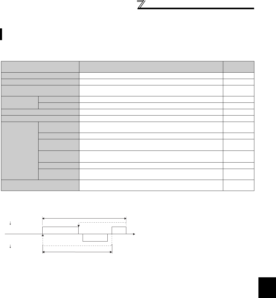
335
Communication operation and setting
4
PARAMETERS
4.24.5 Mitsubishi inverter protocol (computer link communication)
(1) Communication specifications
⋅The communication specifications are given below.
(2) Communication procedure
*1 If a data error is detected and a retry must be made, execute retry operation with the user program. The inverter trips if the number of consecutive
retries exceeds the parameter setting.
*2 On receipt of a data error occurrence, the inverter returns "reply data 3)" to the computer again. The inverter trips if the number of consecutive
data errors reaches or exceeds the parameter setting.
You can perform parameter setting, monitor, etc. from the PU connector or RS-485 terminals of the inverter using
the Mitsubishi inverter protocol (computer link communication).
Item Description Related
Parameters
Communication protocol Mitsubishi protocol (computer link) Pr. 551
Conforming standard EIA-485 (RS-485) ⎯
Number of inverters connected 1:N (maximum 32 units), setting is 0 to 31 stations Pr. 117
Pr. 331
Communication
speed
PU connector Selected among 4800/9600/19200/38400bps Pr. 118
RS-485 terminal Selected among 300/600/1200/2400/4800/9600/19200/38400bps Pr. 332
Control protocol Asynchronous system ⎯
Communication method Half-duplex system ⎯
Communication
specifications
Character system ASCII (7 bits or 8 bits can be selected) Pr. 119
Pr. 333
Start bit 1bit ⎯
Stop bit length 1 bit or 2 bits can be selected Pr. 119
Pr. 333
Parity check Check (with even or odd parity) or no check can be selected Pr. 120
Pr. 334
Error check Sum code check ⎯
Terminator CR/LF (presence or absence can be selected) Pr. 124
Pr. 341
Waiting time setting Selectable between presence and absence Pr. 123
Pr. 337
⋅Data communication between the computer and
inverter is made in the following procedure.
1)Request data is sent from the computer to the
inverter. (The inverter will not send data unless
requested.)
2)After waiting for the waiting time
3)The inverter sends reply data to the computer in
response to the computer request.
4)After having waited for the time taken for inverter
processing
5)Answer from computer in response to reply data
3) is sent. (Even if 5) is not sent, subsequent
communication is made properly.)
When data is read
When data is written
1) 5)4)
3)2)
*1
*2
Computer
(Data flow)
Inverter
Computer
(Data flow)
Inverter
Time
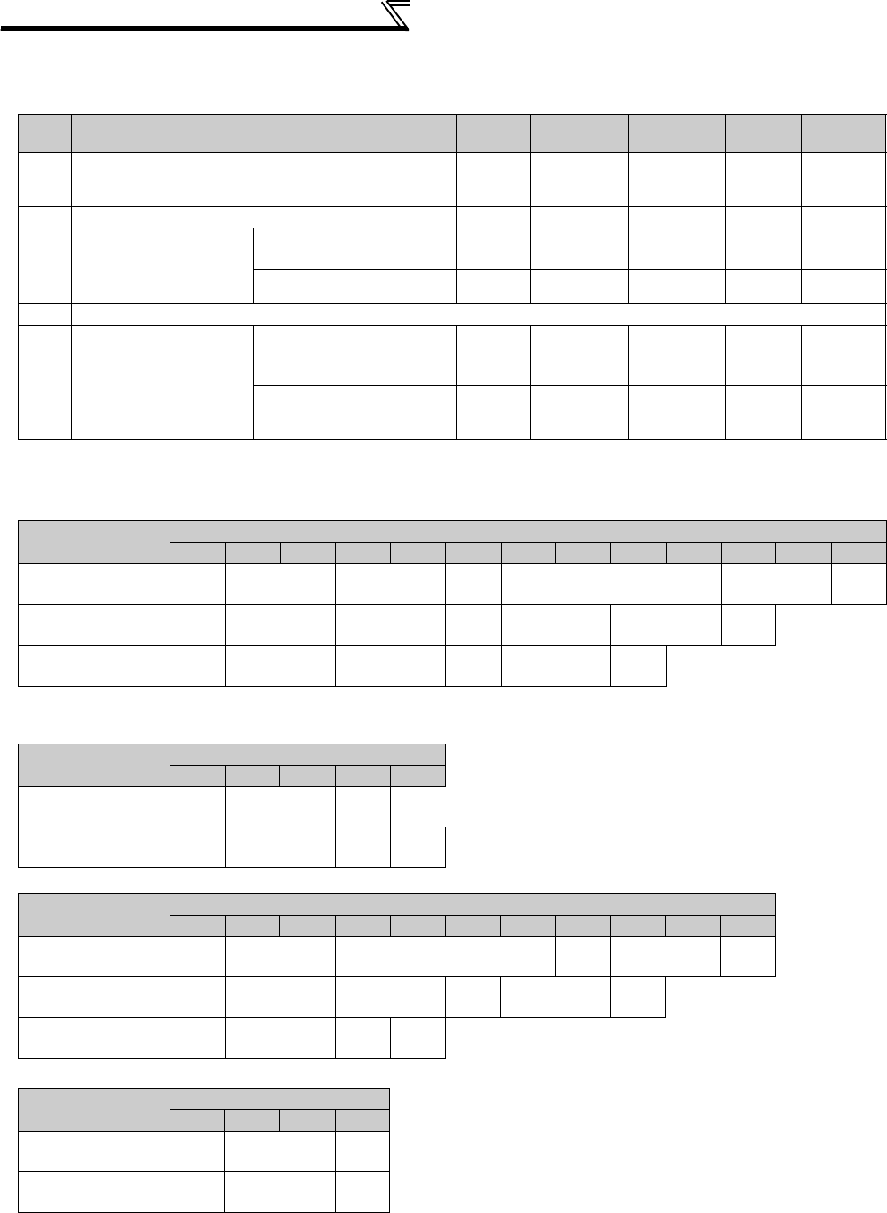
336
Communication operation and setting
(3) Communication operation presence/absence and data format types
⋅Data communication between the computer and inverter is made in ASCII code (hexadecimal code).
⋅Communication operation presence/absence and data format types are as follows:
1)Communication request data from the computer to the inverter
3)Reply data from the inverter to the computer
⋅When data is written
⋅When data is read
5)Send data from the computer to the inverter during data read
*1 Indicate a control code
*2 Specify the inverter station numbers between H00 and H1F (stations 0 to 31) in hexadecimal.
*3 When Pr. 123, Pr. 337 (waiting time setting) ≠ "9999", create the communication request data without "waiting time" in the data format. (The number
of characters decreases by 1.)
*4 CR, LF code
When data is transmitted from the computer to the inverter, CR (carriage return) and LF (line feed) codes are automatically set at the end of a data
group on some computers. In this case, setting must also be made on the inverter according to the computer. Whether the CR and LF codes will
be present or absent can be selected using Pr. 124 or Pr. 341 (CR, LF presence/absence selection).
Symbol
Operation
Run
Command
Running
Frequency
Parameter
Write
Inverter
Reset
Monitor
Parameter
Read
1)
Communication request is sent to the
inverter in accordance with the user
program in the computer.
A
A’ AA ABB
2) Inverter data processing time Present Present Present Absent
Present
Present
3)
Reply data from the
inverter (Data 1) is
checked for error)
No error *1
(Request accepted) CC C C *2 E
E’ E
With error.
(Request rejected) DD D D *2 DD
4) Computer processing delay time 10ms or more
5)
Answer from computer in
response to reply data 3)
(Data 3) is checked for
error)
No error *1
(No inverter
processing)
Absent Absent Absent Absent Absent
(C)
Absent
(C)
With error
(Inverter re-
outputs 3))
Absent Absent Absent Absent F F
*1 In the communication request data from the computer to the inverter, 10ms or more is also required after "no data error (ACK)". (Refer to page
337)
*2 The inverter response to the inverter reset request can be selected. (Refer to page 342)
Format Number of Characters
12345678910 11 12 13
A
(Data write)
ENQ
*1
Inverter station
number *2 Instruction code Waiting
time *3 Data Sum check *4
A'
(Data write)
ENQ
*1
Inverter station
number *2 Instruction code Waiting
time *3 Data Sum check *4
B
(Data read)
ENQ
*1
Inverter station
number *2 Instruction code Waiting
time *3 Sum check *4
Format Number of Characters
1 2 3 4 5
C
(No data error detected)
ACK
*1
Inverter station
number *2
*4
D
(Data error detected)
NAK
*1
Inverter station
number *2
Error
Code *4
Format Number of Characters
1 2 3 4 5 6 7 8 9 10 11
E
(No data error detected)
STX
*1
Inverter station
number *2 Read data ETX
*1 Sum check *4
E'
(No data error detected)
STX
*1
Inverter station
number *2 Read data ETX
*1 Sum check *4
D
(Data error detected)
NAK
*1
Inverter station
number *2
Error
Code *4
Format Number of Characters
1 2 3 4
C
(No data error detected)
ACK
*1
Inverter station
number *2
*4
F
(Data error detected)
NAK
*1
Inverter station
number *2
*4
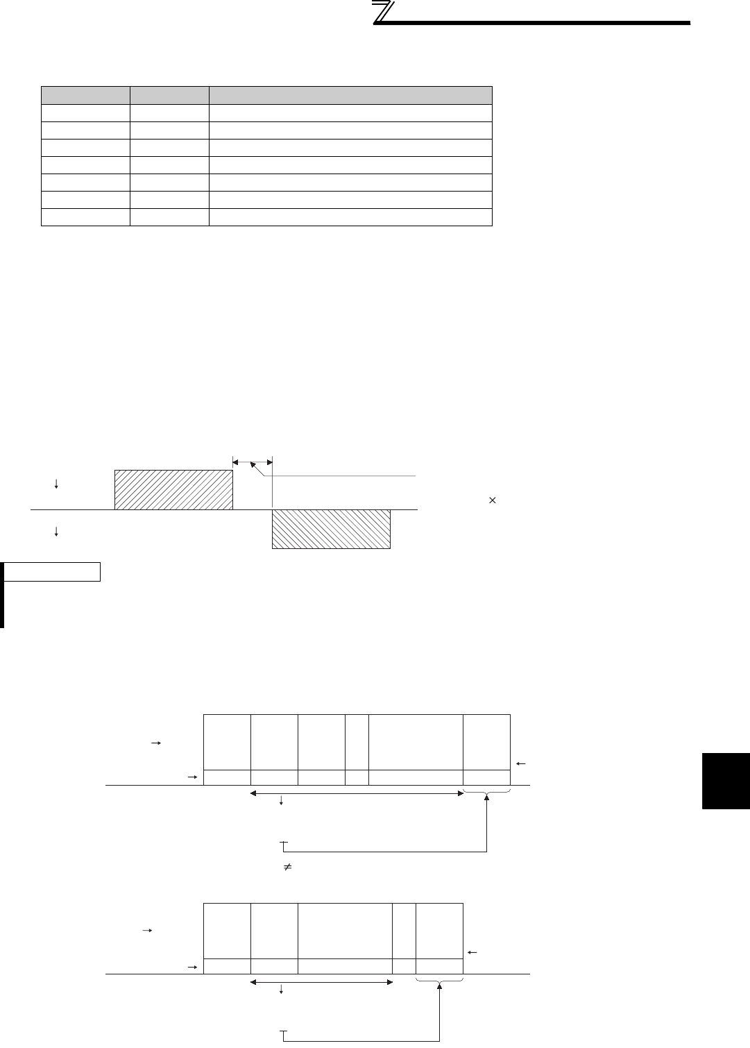
337
Communication operation and setting
4
PARAMETERS
(4) Data definitions
1) Control codes
2) Inverter station number
Specify the station number of the inverter which communicates with the computer.
3) Instruction code
Specify the processing request, e.g. operation or monitoring, given by the computer to the inverter. Hence, the
inverter can be run and monitored in various ways by specifying the instruction code as appropriate. (Refer to page
466)
4) Data
Indicates the data such as frequency and parameters transferred to and from the inverter. The definitions and
ranges of set data are determined in accordance with the instruction codes. (Refer to page 466)
5) Waiting time
Specify the waiting time between the receipt of data at the inverter from the computer and the transmission of
reply data. Set the waiting time in accordance with the response time of the computer between 0 and 150ms in
10ms increments (e.g. 1 = 10ms, 2 = 20ms).
6) Sum check code
The sum check code is 2-digit ASCII (hexadecimal) representing the lower 1 byte (8 bits) of the sum (binary)
derived from the checked ASCII data
Signal Name ASCII Code Description
STX H02 Start Of Text (start of data)
ETX H03 End Of Text (end of data)
ENQ H05 Enquiry (communication request)
ACK H06 Acknowledge (no data error detected)
LF H0A Line Feed
CR H0D Carriage Return
NAK H15 Negative Acknowledge (data error detected)
REMARKS
⋅When Pr. 123, Pr. 337 (waiting time setting) ≠ "9999", create the communication request data without "waiting time" in the data
format. (The number of characters decreases by 1.)
⋅The data check time changes depending on the instruction code. (Refer to page 338)
Computer
Inverter
Inverter
Computer
Inverter data processing time
=+
Waiting time
(setting 10ms)
data check time
(About 10 to 30ms,
which depends on the
instruction code)
(Example 1)
Computer Inverter ENQ
*Waiting
time
1
Instruction
code
Station
number
01
Data
E1 07 ADF4
H05 H30 H31 H31H45 H31 H30 H37 H41 H44 H46 H34
Binary code
H30+H31+H45+H31+H31+H30+H37+H41+H44
= H1F4
Sum
(Example 2)
STX Data read
Station
number
0117 0 30
H02 H30 H31 H37H31 H37 H30 H03 H33 H30
Sum
ETX
7
* When the Pr. 123 Waiting time setting "9999", create the communication request
data without "waiting time" in the data format. (The number of characters decreases by 1.)
Inverter
ASCII Code
ASCII Code
Binary code
H30+H31+H31+H37+H37+H30
= H130
Sum
check
code
Sum
check
code
Computer
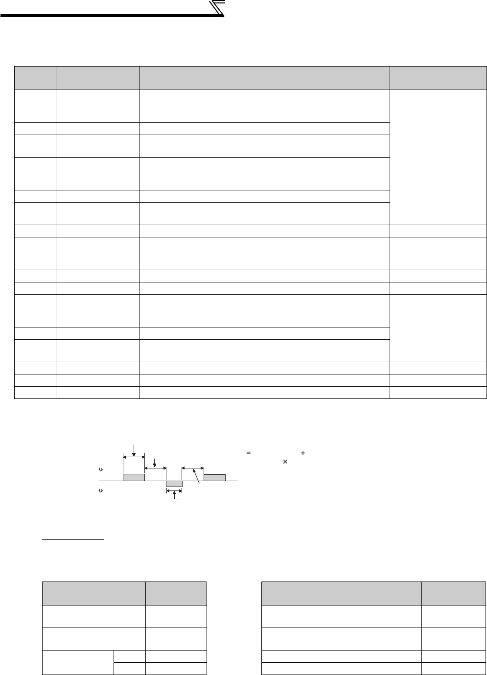
338
Communication operation and setting
7) Error Code
If any error is found in the data received by the inverter, its definition is sent back to the computer together with the
NAK code.
(5) Response time
[Formula for data sending time]
Communication specifications Data check time
Error
Code Error Item Error Description Inverter Operation
H0 Computer NAK error
The number of errors consecutively detected in communication
request data from the computer is greater than allowed number of
retries.
Trips if error occurs
continuously more than
the allowable number of
retries. (E.PUE/E.SER)
H1 Parity error The parity check result does not match the specified parity.
H2 Sum check error The sum check code in the computer does not match that of the
data received by the inverter.
H3 Protocol error
The data received by the inverter has a grammatical mistake.
Alternatively, data receive is not completed within the
predetermined time. CR or LF is not as set in the parameter.
H4 Framing error The stop bit length differs from the initial setting.
H5 Overrun error New data has been sent by the computer before the inverter
completes receiving the preceding data.
H6 ⎯⎯ ⎯
H7 Character error The character received is invalid (other than 0 to 9, A to F, control
code).
Does not accept
received data but does
not trip.
H8 ⎯⎯ ⎯
H9 ⎯⎯ ⎯
HA Mode error
Parameter write was attempted in other than the computer link
operation mode, when operation command source is not selected
or during inverter operation. Does not accept
received data but does
not trip.
HB Instruction code error The specified command does not exist.
HC Data range error Invalid data has been specified for parameter write, frequency
setting, etc.
HD ⎯⎯ ⎯
HE ⎯⎯ ⎯
HF ⎯⎯ ⎯
1
×
Number of data
characters
(Refer to page 336)
×
Communication specifications
(total number of bits) = Data send time (s)
(See below.)
Communication
speed (bps)
Name Number of
Bits Item Check Time
Stop bit length 1 bit
2 bits
Various monitors, run command,
frequency setting (RAM) < 12ms
Data length 7 bits
8 bits
Parameter read/write, frequency setting
(EEPROM) < 30ms
Parity check Yes 1 bit Parameter clear/all clear < 5s
No 0 Reset command No answer
In addition to the above, 1 start bit is necessary.
Minimum number of total bits....... 9 bits
Maximum number of total bits...... 12 bits
10ms or more necessary
Computer
Inverter
Inverter
Computer
Data sending time (refer to the following formula)
Inverter data processing time
Data sending time (refer to the following formula)
Waiting time
(setting 10ms)
Data check time
(depends on the
instruction code (see the
following table))
Time
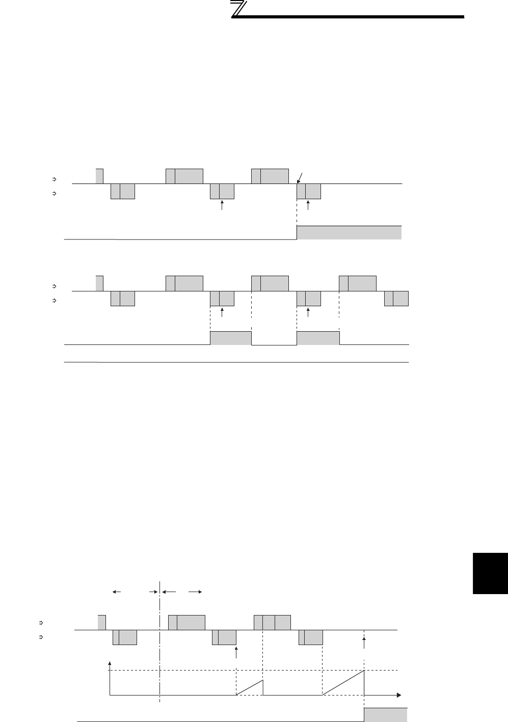
339
Communication operation and setting
4
PARAMETERS
(6) Retry count setting (Pr. 121, Pr. 335)
⋅Set the permissible number of retries at occurrence of a data receive error. (Refer to page 338 for data receive error
for retry)
⋅When data receive errors occur consecutively and exceed the permissible number of retries set, an inverter trip
(E.PUE) may occur and stops the motor.
⋅When "9999" is set, an inverter will not trip even if data receive error occurs but an alarm output signal (LF) is output.
For the terminal used for the LF signal output, assign the function by setting "98 (positive logic) or 198 (negative
logic)" in any of Pr. 190 to Pr. 196 (output terminal function selection).
(7) Signal loss detection (Pr. 122, Pr. 336 RS-485 communication check time interval)
⋅If a signal loss (communication stop) is detected between the inverter and computer as a result of a signal loss
detection, a communication fault (PU connector communication: E.PUE, RS-485 terminal communication: E.SER)
occurs and the inverter trips.
⋅When the setting is "9999", communication check (signal loss detection) is not made.
⋅When the setting is "0", communication from the PU connector cannot be performed. For communication via the RS-
485 terminals, monitor, parameter read, etc. can be performed, but a communication fault (E.SER) occurs as soon as
the inverter is switched to Network operation mode.
⋅A signal loss detection is made when the setting is any of "0.1s" to "999.8s". To make a signal loss detection, it is
necessary to send data (control code refer to page 337) from the computer within the communication check time
interval. (The send data has nothing to do with the station number)
⋅Communication check is started at the first communication in the operation mode having the operation source (PU
operation mode for PU connector communication in the initial setting or Network operation mode for RS-485 terminal
communication).
Computer
Example: PU connector communication, Pr. 121 = "1" (initial value)
Example: PU connector communication, Pr. 121 = "9999"
Reception error Reception error
Fault (E.PUE)
Inverter
Computer
Inverter
Computer Inverter
Computer
Inverter
ENQ
ACK
NAK
NAK
LF OFF
OFF
ENQ
ACK
NAK
NAK
ON ON
Wrong
Wrong
ENQ
ACK
Normal
ENQ
Wrong
ENQ
Wrong
Reception error
Reception error
ALM ON
ALM
Operation Mode
Example: PU connector communication, Pr. 122 = "0.1 to 999.8s"
External PU
Check start
Fault (E.PUE)
Time
Pr.122
ENQ
Communication
check counter
Computer Inverter
Computer
Inverter
ALM OFF ON

340
Communication operation and setting
(8) Instructions for the program
1) When data from the computer has any error, the inverter does not accept that data. Hence, in the user program,
always insert a retry program for data error.
2) All data communication, e.g. run command or monitoring, are started when the computer gives a communication
request. The inverter does not return any data without the computer's request. Hence, design the program so that
the computer gives a data read request for monitoring, etc. as required.
3) Program example
To change the operation mode to computer link operation
Programming example of Microsoft® Visual C++® (Ver.6.0)
#include <stdio.h>
#include <windows.h>
void main(void){
HANDLE hCom; // Communication handle
DCB hDcb; // Structure for communication setting
COMMTIMEOUTS hTim; // Structure for time out setting
char szTx[0x10]; // Send buffer
char szRx[0x10]; // Receive buffer
char szCommand[0x10];// Command
int nTx,nRx; // For buffer size storing
int nSum; // For sum code calculation
BOOL bRet;
int nRet;
int i;
//∗∗∗∗ Opens COM1 port∗∗∗∗
hCom = CreateFile ("COM1", (GENERIC_READ | GENERIC_WRITE), 0, NULL, OPEN_EXISTING, FILE_ATTRIBUTE_NORMAL, NULL);
if (hCom != NULL) {
//∗∗∗∗ Makes a communication setting of COM1 port∗∗∗∗
GetCommState(hCom,&hDcb); // Retrieves current communication information
hDcb.DCBlength = sizeof(DCB); // Structure size setting
hDcb.BaudRate = 19200; // Communication speed=19200bps
hDcb.ByteSize = 8; // Data length=8bit
hDcb.Parity = 2; // Even parity
hDcb.StopBits = 2; // Stop bit=2bit
bRet = SetCommState(hCom,&hDcb); // Sets the changed communication data
if (bRet == TRUE) {
//∗∗∗∗ Makes a time out setting of COM1 port∗∗∗∗
Get CommTimeouts(hCom,&hTim); // Obtains the current time out value
hTim.WriteTotalTimeoutConstant = 1000; // Write time out 1s
hTim.ReadTotalTimeoutConstant = 1000; // Read time out 1s
SetCommTimeouts(hCom,&hTim); // Changed time out value setting
//∗∗∗∗ Sets the command to switch the operation mode of the station 1 inverter to the Network operation mode ∗∗∗∗
sprintf(szCommand,"01FB10000"); // Send data (NET operation write)
nTx = strlen(szCommand); //Send data size
//∗∗∗∗ Generates sum code∗∗∗∗
nSum = 0; // Initialization of sum data
for (i = 0;i < nTx;i++) {
nSum += szCommand[i]; // Calculates sum code
nSum &= (0xff); // Masks data
}
//∗∗∗∗ Generates send data∗∗∗∗
memset(szTx,0,sizeof(szTx)); // Initialization of send buffer
memset(szRx,0,sizeof(szRx)); // Initialization of receive buffer
sprintf(szTx,"\5%s%02X",szCommand,nSum);// ENQ code+send data+sum code
nTx = 1 + nTx + 2; // Number of ENQ code+number of send data+number of sum code
nRet = WriteFile(hCom,szTx,nTx,&nTx,NULL);
//∗∗∗∗ Sending ∗∗∗∗
if(nRet != 0) {
nRet = ReadFile(hCom,szRx,sizeof(szRx),&nRx,NULL);
//∗∗∗∗ Receiving ∗∗∗∗
if(nRet != 0) {
//∗∗∗∗ Displays the receive data ∗∗∗∗
for(i = 0;i < nRx;i++) {
printf("%02X ",(BYTE)szRx[i]);// Consol output of receive data
// Displays ASCII coder in hexadecimal. Displays 30 when "0"
}
printf("\n\r");
}
}
}
CloseHandle(hCom); // Close communication port
}
}

341
Communication operation and setting
4
PARAMETERS
General flowchart
Port open
Communication setting
Time out setting
Send data processing
Data setting
Sum code calculation
Data transmission
Receive data waiting
Receive data processing
Data retrieval
Screen display
CAUTION
Always set the communication check time interval before starting operation to prevent hazardous conditions.
Data communication is not started automatically but is made only once when the computer provides a
communication request. If communication is disabled during operation due to signal loss etc., the inverter cannot
be stopped. When the communication check time interval has elapsed, the inverter will come to a trip (E.PUE,
E.SER). The inverter can be coasted to a stop by switching ON its RES signal or by switching power OFF.
If communication is broken due to signal loss, computer fault etc., the inverter does not detect such a fault. This
should be fully noted.
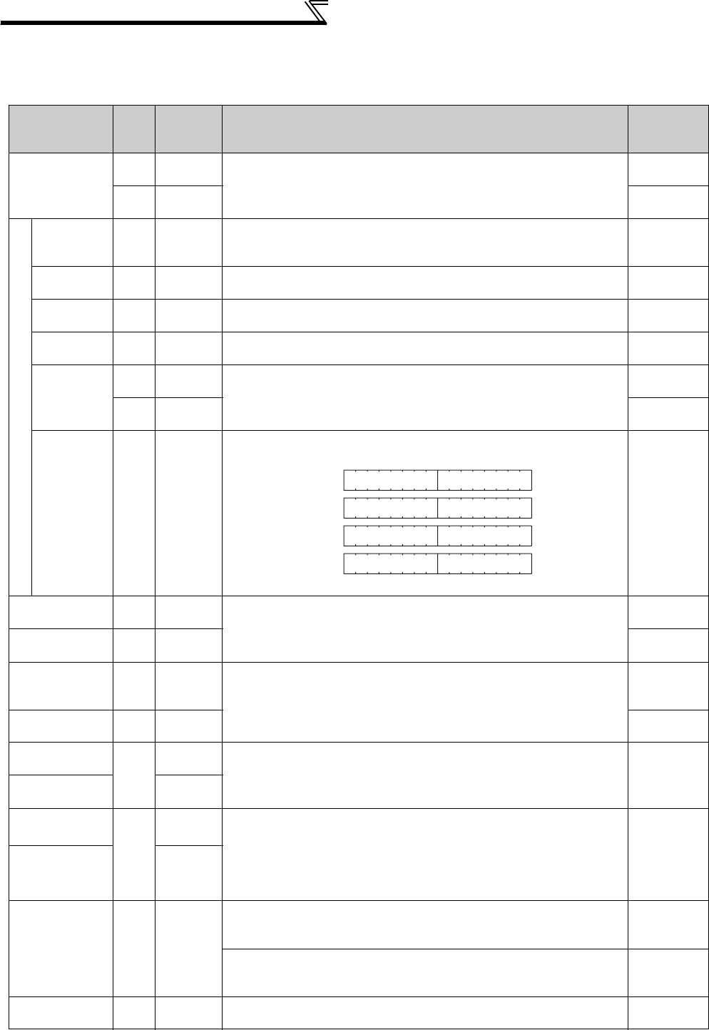
342
Communication operation and setting
(9) Setting items and set data
After completion of parameter setting, set the instruction codes and data then start communication from the computer
to allow various types of operation control and monitoring.
Item Read/
Write
Instruction
Code
Data Description
Number of
Data Digits
(format)
Operation mode
Read H7B H0000: Network operation
H0001: External operation
H0002: PU operation
(RS-485 communication operation via PU connector)
4 digits
(B.E/D)
Write HFB 4 digits
(A,C/D)
Monitor
Output
frequency/
speed
Read H6F
H0000 to HFFFF: Output frequency in 0.01Hz increments
Speed in 1r/min increments (when Pr. 37 = 1 to 9998 or Pr. 144 = 2 to 10,
102 to 110)
4 digits
(B.E/D)
Output
current Read H70 H0000 to HFFFF: Output current (hexadecimal) in 0.01A increments (55K
or lower) / 0.1A increments (75K or higher)
4 digits
(B.E/D)
Output
voltage Read H71 H0000 to HFFFF: Output voltage (hexadecimal) in 0.1V increments 4 digits
(B.E/D)
Special
monitor Read H72 H0000 to HFFFF: Monitor data selected in instruction code HF3 4 digits
(B.E/D)
Special
monitor
selection No.
Read H73 H01 to H3C: Monitor selection data
Refer to the special monitor No. table (page 344)
2digits
(B.E'/D)
Write HF3 2digits
(A',C/D)
Fault record Read H74 to
H77
H0000 to HFFFF: Two most recent fault records
Refer to the fault data table (page 345)
4 digits
(B.E/D)
Run command
(extended) Write HF9 You can set the control input commands such as the forward rotation
signal (STF) and reverse rotation signal (STR). (Refer to page 345 for
details)
4 digits
(A,C/D)
Run command Write HFA 2digits
(A',C/D)
Inverter status
monitor
(extended)
Read H79 You can monitor the status of the output signals such as forward rotation,
reverse rotation and inverter running (RUN). (Refer to page 346 for details)
4 digits
(B.E/D)
Inverter status
monitor Read H7A 2digits
(B.E'/D)
Set frequency
(RAM) Read
H6D Read the set frequency/speed from the RAM or EEPROM.
H0000 to HFFFF: Set frequency in 0.01Hz increments
Speed in 1r/min increments (When Pr. 37 = 1 to 9998 or Pr. 144 = 2 to 10,
102 to 110)
4 digits
(B.E/D)
Set frequency
(EEPROM) H6E
Set frequency
(RAM)
Write
HED Write the set frequency/speed into the RAM or EEPROM.
H0000 to H9C40 (0 to 400.00Hz) : frequency in 0.01Hz increments
H0000 to H270E (0 to 9998) : speed in r/min increments (when Pr
. 37 = 1
to 9998 or Pr. 144 = 2 to 10, 102 to 110)
⋅To change the running frequency consecutively, write data to the
inverter RAM. (Instruction code: HED)
4 digits
(A,C/D)
Set frequency
(
RAM, EEPROM
)HEE
Inverter reset Write HFD
H9696: Resets the inverter.
⋅As the inverter is reset at start of communication by the computer, the
inverter cannot send reply data back to the computer.
4 digits
(A,C/D)
H9966: Resets the inverter.
⋅When data is sent normally, ACK is returned to the computer and then
the inverter is reset.
4 digits
(A,D)
Faults history
batch clear Write HF4 H9696: Clears the faults history as a batch. 4 digits
(A,C/D)
Refer to page 336 for data formats (A, A', B, B', C, D)
b15 b8 b7 b0
Latest faultSecond fault in past
Third fault in pastFourth fault in past
Fifth fault in pastSixth fault in past
Seventh fault in pastEighth fault in past
H74
H75
H76
H77
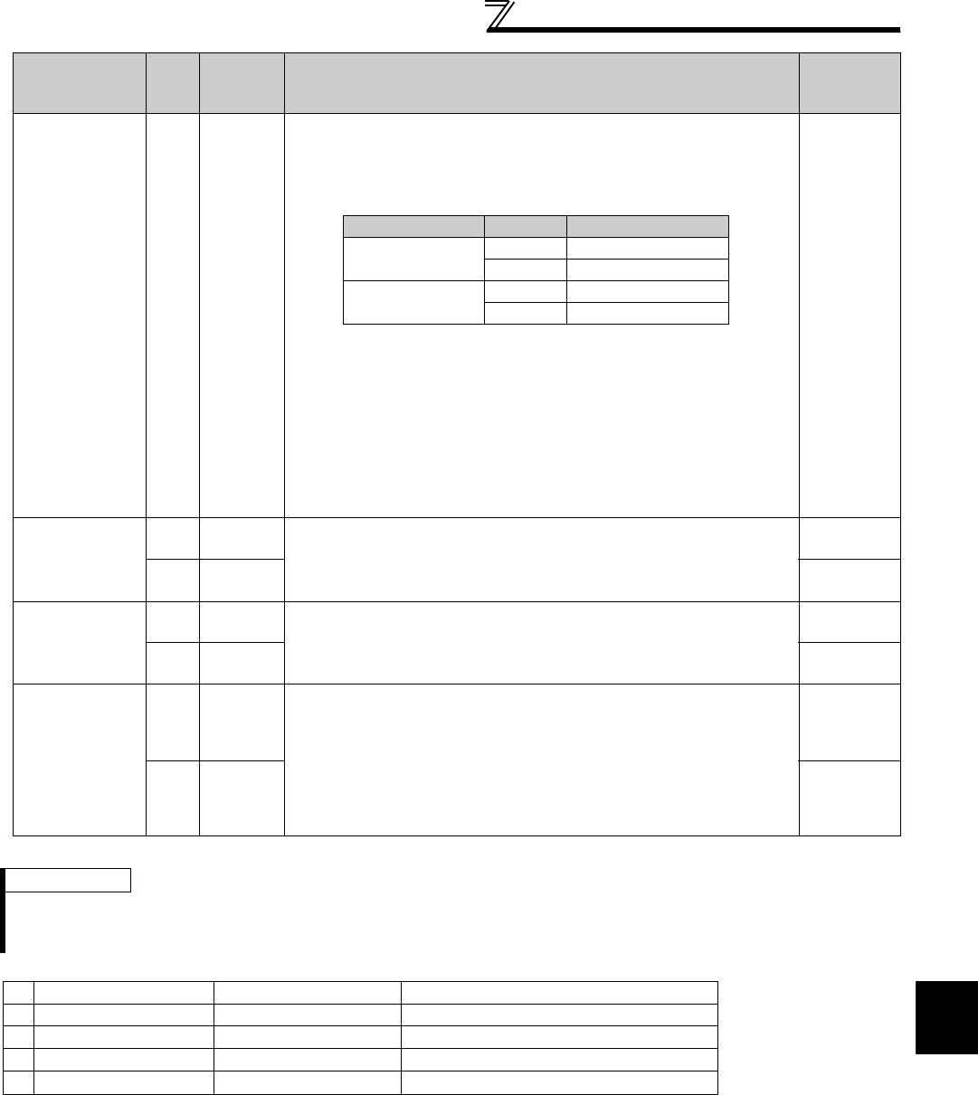
343
Communication operation and setting
4
PARAMETERS
Example) When reading the C3 (Pr. 902) and C6 (Pr. 904) settings from the inverter of station 0
To read/write C3 (Pr. 902) and C6 (Pr. 904) after inverter reset or parameter clear, execute from 1) again.
Parameter clear
All clear Write HFC
All parameters return to the initial values.
Whether to clear communication parameters or not can be
selected according to data. ( : Clear, ×: Not clear)
Refer to page 466 for parameter clear, all clear, and communication
parameters.
When clear is executed for H9696 or H9966, communication-related
parameter settings also return to the initial values. When resuming
operation, set the parameters again.
Executing clear will clear the instruction code HEC, HF3, and HFF
settings.
In the password locked status (refer to page 310), only H9966 and H55AA
(all parameter clear) are valid.
*1 Turning OFF the power supply while clearing parameters with H5A5A or
H55AA also clears the communication parameter settings back to the initial
values.
4 digits
(A,C/D)
Parameters
Read H00 to
H63
Refer to the instruction code (Refer to page 466) and write and/or read the
values as required.
When setting Pr. 100 and later, link parameter extended setting must be
set.
4 digits
(B.E/D)
Write H80 to
HE3
4 digits
(A,C/D)
Link parameter
extended setting
Read H7F Parameter description is changed according to the H00 to H09 setting.
For details of the setting, refer to the instruction code (Refer to page 466).
2 digits
(B.E'/D)
Write HFF 2 digits
(A',C/D)
Second
parameter
changing
(instruction code
HFF=1, 9)
Read H6C
When setting the calibration parameters *1
H00:Frequency *2
H01: Parameter-set analog value
H02: Analog value input from terminal
*1 Refer to the list of calibration parameters on the next page for calibration
parameters.
*2 The gain frequency can also be written using Pr. 125 (instruction code H99) or
Pr. 126 (instruction code H9A).
2 digits
(B.E'/D)
Write HEC 2 digits
(A',C/D)
REMARKS
⋅Set 65520 (HFFF0) as a parameter value "8888" and 65535 (HFFFF) as "9999".
⋅For the instruction codes HFF, HEC and HF3, their values are held once written but cleared to zero when an inverter reset or all
clear is performed.
Computer Send Data Inverter Send Data Description
1) ENQ 00 FF 0 01 82 ACK 00 Set "H01" in the extended link parameter.
2) ENQ 00 EC 0 01 7E ACK 00 Set "H01" in second parameter changing.
3) ENQ 00 5E 0 0F STX 00 0000 ETX 25 C3 (Pr. 902) is read. 0% is read.
4) ENQ 00 60 0 FB STX 00 0000 ETX 25 C6 (Pr. 904) is read. 0% is read.
Item Read/
Write
Instruction
Code
Data Description
Number of
Data Digits
(format)
Refer to page 336 for data formats (A, A', B, B', C, D)
Clear Type Data Communication Pr.
Parameter clear H9696
H5A5A × *1
All parameter clear H9966
H55AA × *1
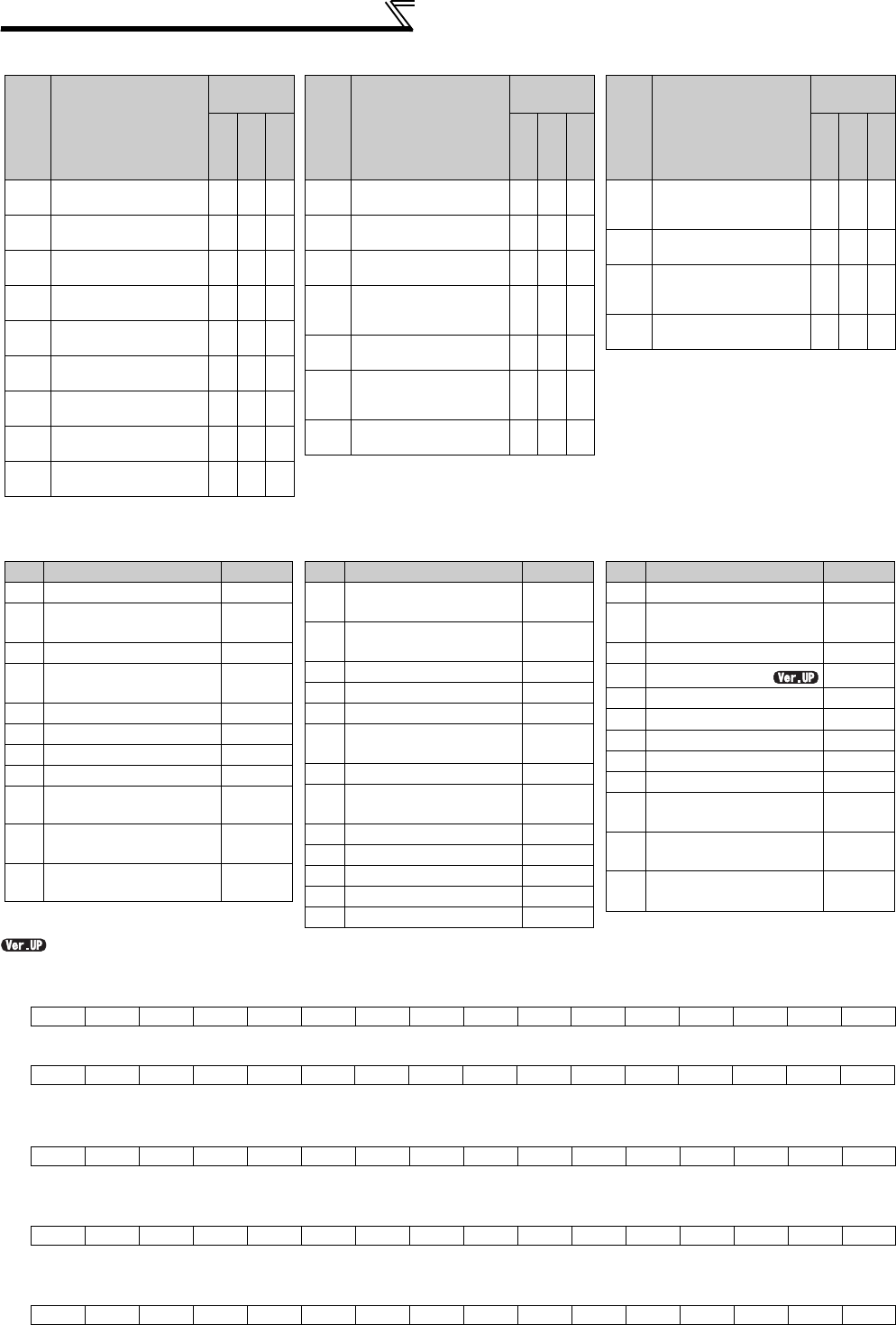
344
Communication operation and setting
List of calibration parameters
[Special monitor selection No.]
Refer to page 253 for details of the monitor description.
...........Specifications differ according to the date assembled. Refer to page 484 to check the SERIAL number.
*1 The setting depends on capacities. (55K or lower / 75K or higher)
*2 Input terminal monitor details (when the terminal is ON: 1, when the terminal is OFF: 0, —: undetermined value)
*3 Output terminal monitor details (when the terminal is ON: 1, when the terminal is OFF: 0, —: undetermined value)
*4 Details of option input terminal monitor 1 (input terminal status of FR-A7AX when the terminal is ON: 1, when the terminal is OFF: 0)-all terminals
are OFF when an option is not fitted
*5 Details of option input terminal monitor 2 (input terminal status of FR-A7AX when the terminal is ON: 1, when the terminal is OFF: 0, —:
undetermined value)-all terminals are OFF when an option is not fitted
*6 Details of option output terminal monitor (output terminal status of FR-A7AY/A7AR when the terminal is ON: 1, when the terminal is OFF: 0, —:
undetermined value)-all terminals are OFF when an option is not fitted
*7 When Pr. 37 = "1 to 9998" or Pr. 144 = "2 to 10, 102 to 110," the unit is an integral value (one increment). (Refer to page 251)
b15 b0
⎯⎯⎯⎯CS RES
STOP
MRS JOG RH RM RL RT AU STR STF
b15 b0
⎯⎯⎯⎯⎯⎯⎯⎯⎯ABC2 ABC1 FU OL IPF SU RUN
b15 b0
X15 X14 X13 X12 X11 X10 X9 X8 X7 X6 X5 X4 X3 X2 X1 X0
b15 b0
⎯⎯⎯⎯⎯⎯⎯⎯⎯⎯⎯⎯⎯⎯⎯DY
b15 b0
⎯⎯⎯⎯⎯⎯RA3RA2RA1Y6Y5Y4Y3Y2Y1Y0
Para
meter Name
Instruction
code
Read
Write
Extended
C2
(902)
Terminal 2 frequency
setting bias frequency 5E DE 1
C3
(902)
Terminal 2 frequency
setting bias 5E DE 1
125
(903)
Terminal 2 frequency
setting gain frequency 5F DF 1
C4
(903)
Terminal 2 frequency
setting gain 5F DF 1
C5
(904)
Terminal 4 frequency
setting bias frequency 60 E0 1
C6
(904)
Terminal 4 frequency
setting bias 60 E0 1
126
(905)
Terminal 4 frequency
setting gain frequency 61 E1 1
C7
(905)
Terminal 4 frequency
setting gain 61 E1 1
C12
(917)
Terminal 1 bias
frequency (speed) 11 91 9
C13
(917)
Terminal 1 bias
frequency (speed) 11 91 9
C14
(918)
Terminal 1 gain
frequency (speed) 12 92 9
C15
(918)
Terminal 1 gain
(speed) 12 92 9
C16
(919)
Terminal 1 bias
command (torque/
magnetic flux)
13 93 9
C17
(919)
Terminal 1 bias
(torque/magnetic flux) 13 93 9
C18
(920)
Terminal 1 gain
command (torque/
magnetic flux)
14 94 9
C19
(920)
Terminal 1 gain
(torque/magnetic flux) 14 94 9
Para
meter Name
Instruction
code
Read
Write
Extended
C38
(932)
Terminal 4 bias
command (torque/
magnetic flux)
20 A0 9
C39
(932)
Terminal 4 bias
(torque/magnetic flux) 20 A0 9
C40
(933)
Terminal 4 gain
command (torque/
magnetic flux)
21 A1 9
C41
(933)
Terminal 4 gain
(torque/magnetic flux) 21 A1 9
Para
meter Name
Instruction
code
Read
Write
Extended
Data Description
Increments
H01
Output frequency/speed
*7
0.01Hz/1
H02 Output current 0.01A/
0.1A *1
H03 Output voltage 0.1V
H05 Frequency setting value/
speed setting *7 0.01Hz/1
H06 Running speed 1r/min
H07 Motor torque 0.1%
H08 Converter output voltage 0.1V
H09 Regenerative brake duty 0.1%
H0A Electronic thermal relay
function load factor 0.1%
H0B Output current peak
value
0.01A/
0.1A *1
H0C Converter output voltage
peak value 0.1V
H0D Input power 0.01kW/
0.1kW *1
H0E Output power 0.01kW/
0.1kW *1
H0F Input terminal status *2 ⎯
H10 Output terminal status *3 ⎯
H11 Load meter
0.1%
H12 Motor excitation current 0.01A/
0.1A *1
H13 Position pulse ⎯
H14 Cumulative energization
time 1h
H16 Orientation status ⎯
H17 Actual operation time 1h
H18 Motor load factor 0.1%
H19 Cumulative power 1kWh
H20 Torque command 0.1%
Data Description
Increments
H21 Torque current command 0.1%
H22 Motor output 0.01kW/
0.1kW *1
H23 Feedback pulse ⎯
H2E
Motor temperature
1°C
H32 Power saving effect Variable
H33 Cumulative saving power Variable
H34 PID set point 0.1%
H35 PID measured value 0.1%
H36 PID deviation value 0.1%
H3A Option input terminal
status1 *4 ⎯
H3B Option input terminal
status2 *5 ⎯
H3C Option output terminal
status *6 ⎯
Data Description
Increments
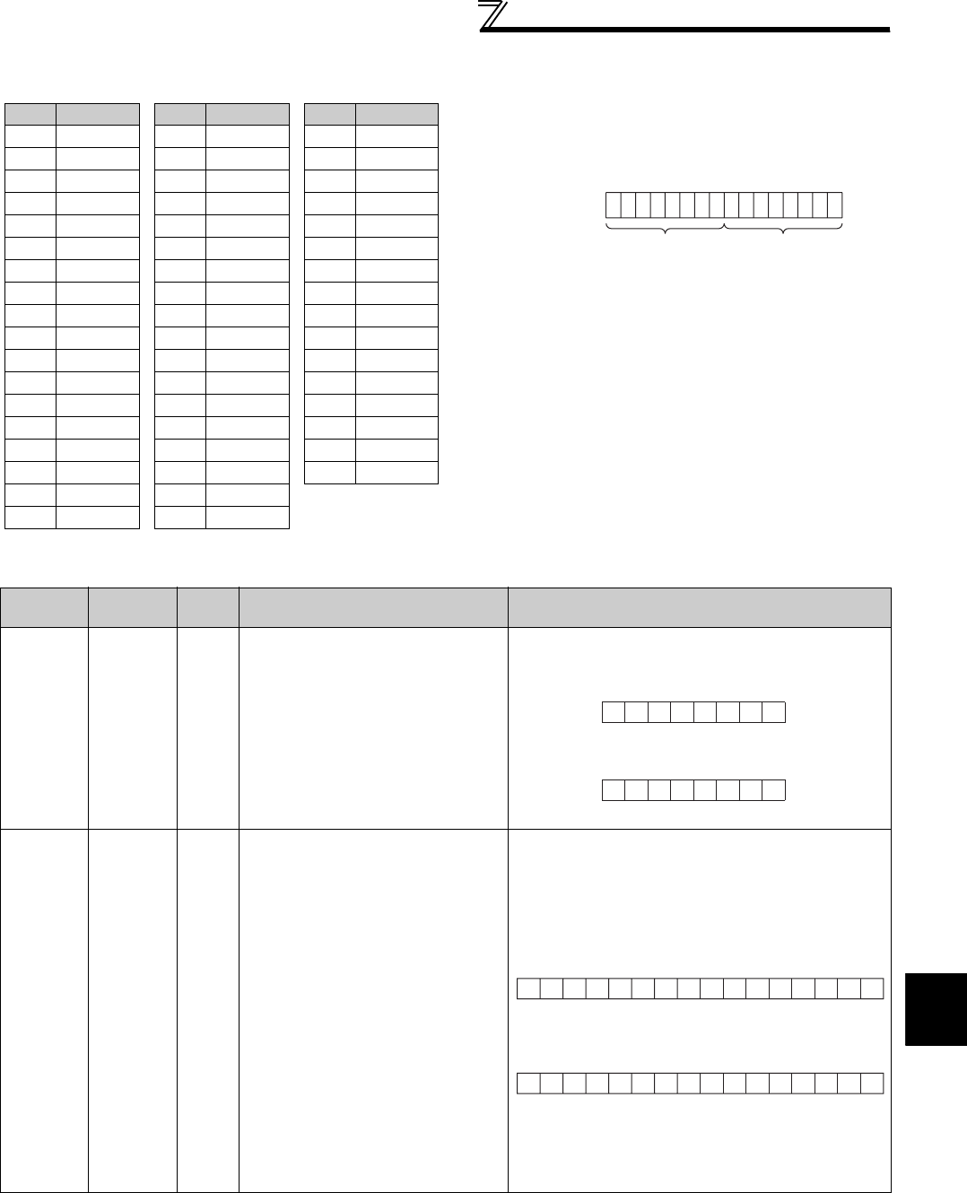
345
Communication operation and setting
4
PARAMETERS
[Fault data]
Refer to page 403 for details of fault description.
[Run command]
*1 The signal within parentheses is the initial setting. The description changes depending on the setting of Pr. 180 to Pr. 184, Pr. 187 (input terminal
function selection) (page 231).
*2 The signal within parentheses is the initial setting. Since jog operation/selection of automatic restart after instantaneous power failure/start self-
holding/reset cannot be controlled by the network, bit 8 to bit 11 are invalid in the initial status. When using bit 8 to bit 11, change the signals with
Pr. 185, Pr. 186, Pr. 188, Pr. 189 (input terminal function selection) (page 231). (Reset can be executed with the instruction code HFD.)
*3 Only forward rotation command and reverse rotation command are available for RS-485 communication using PU connector.
Item
Instruction
Code
Bit
Length
Description Example
Run
command HFA 8 bits
b0: AU (current input selection) *1 *3
b1: Forward rotation command
b2: Reverse rotation command
b3:
RL (low speed operation
command) *1 *3
b4: RM (middle speed operation
command) *1 *3
b5: RH (high speed operation
command) *1*3
b6: RT (second function selection) *1 *3
b7: MRS (output stop) *1 *3
Run
command
(extended)
HF9 16 bits
b0:AU (current input selection) *1 *3
b1:Forward rotation command
b2:Reverse rotation command
b3:RL (low speed operation
command)
*1
*3
b4:RM (middle speed operation
command) *1 *3
b5: RH (high speed operation
command) *1*3
b6:RT (second function selection) *1 *3
b7:MRS (output stop) *1 *3
b8:JOG (Jog operation) *2 *3
b9:
CS (selection of automatic restart
after instantaneous power failure)
*2 *3
b10: STOP (start self-holding) *2 *3
b11:RES (reset) *2 *3
b12:⎯
b13:⎯
b14:⎯
b15:⎯
Fault record display example (instruction code H74)
Data
Description
H00 No alarm
H10 E.OC1
H11 E.OC2
H12 E.OC3
H20 E.OV1
H21 E.OV2
H22 E.OV3
H30 E.THT
H31 E.THM
H40 E.FIN
H50 E.IPF
H51 E.UVT
H52 E.ILF
H60 E.OLT
H70 E.BE
H80 E.GF
H81 E.LF
H90 E.OHT
H91 E.PTC
HA0 E.OPT
HA3 E.OP3
HB0 E.PE
HB1 E.PUE
HB2 E.RET
HB3 E.PE2
HC0 E.CPU
HC1 E.CTE
HC2 E.P24
HC4 E.CDO
HC5 E.IOH
HC6 E.SER
HC7 E.AIE
HC8 E.USB
HD0 E.OS
HD1 E.OSD
HD2 E.ECT
Data
Description
HD3 E.OD
HD5 E.MB1
HD6 E.MB2
HD7 E.MB3
HD8 E.MB4
HD9 E.MB5
HDA E.MB6
HDB E.MB7
HDC E.EP
HF1 E.1
HF2 E.2
HF3 E.3
HF6 E.6
HF7 E.7
HFB E.11
HFD E.13
Data
Description
For read data H30A0
(Previous fault ...... THT)
(Latest fault ...... OPT)
01
010000 0 0 0000
11
b15 b8 b7 b0
Latest fault
(HA0)
Previous fault
(H30)
00000010
b7 b0
[Example 1] H02 Forward rotation
[Example 2] H00 Stop
00000000
b7 b0
00000010
b0
[Example 1] H0002 Forward rotation
00000000
b15
00000000
b0
[Example 2] H0800 low speed operation
(When Pr. 189 RES terminal function selection is set to "0")
00001000
b15
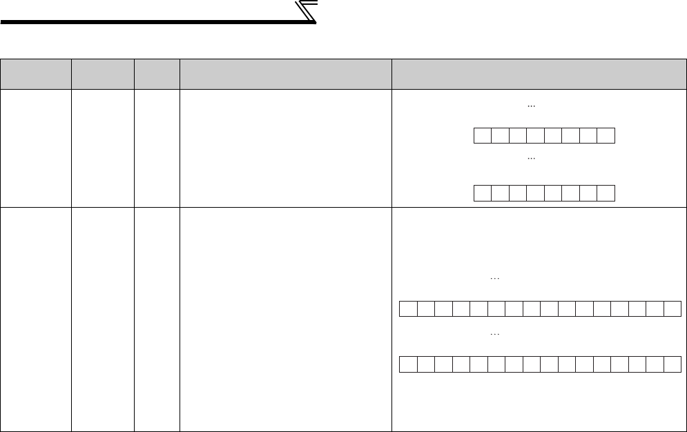
346
Communication operation and setting
[Inverter status monitor]
* The signal within parentheses is the initial setting. The description changes depending on the setting of Pr. 190 to Pr. 196 (output terminal function
selection).
Item
Instruction
Code
Bit
Length
Description Example
Inverter
status
monitor
H7A 8 bits
b0:RUN (inverter running)*
b1:Forward rotation
b2:Reverse rotation
b3:SU (up to frequency) *
b4:OL (overload) *
b5:
IPF (instantaneous power failure)
*
b6:FU (frequency detection)*
b7:ABC1 (fault) *
Inverter
status
monitor
(
extended
)
H79 16 bits
b0:RUN (inverter running) *
b1:Forward rotation
b2:Reverse rotation
b3:SU (up to frequency) *
b4:OL (overload) *
b5:
IPF (instantaneous power failure)
*
b6:FU (frequency detection) *
b7:ABC1 (fault) *
b8:ABC2 (⎯)*
b9:⎯
b10:⎯
b11:⎯
b12:⎯
b13:⎯
b14:⎯
b15: Fault occurrence
00000010
b7 b0
10000000
b7 b0
[Example 2] H80
[Example 1] H02
Stop at fault
occurrence
During forward
rotation
00000010
b0
00000000
b15
[Example 1] H0002 During forward rotation
10000000
b0
10000000
b15
[Example 2] H8080 Stop at fault occurrence

347
Communication operation and setting
4
PARAMETERS
4.24.6 Modbus-RTU communication specifications (Pr. 331, Pr. 332, Pr. 334, Pr. 343,
Pr. 539, Pr. 549)
(1) Communication specifications
⋅The communication specifications are given below.
Using the Modbus-RTU communication protocol, communication operation or parameter setting can be
performed from the RS-485 terminals of the inverter.
Parameter
Number Name Initial Value Setting Range Description
331 RS-485 communication station
number 0
0 Broadcast communication is selected.
1 to 247
Specify the inverter station number.
Set the inverter station numbers when two
or more inverters are connected to one
personal computer.
332 RS-485 communication speed 96 3, 6, 12, 24, 48,
96, 192, 384
Set the communication speed.
The setting value × 100 equals the
communication speed.
For example, the communication speed is
9600bps when the setting value is "96".
334 RS-485 communication parity
check selection 2
0Without parity check
Stop bit length 2bits
1With odd parity check
Stop bit length 1bit
2With even parity check
Stop bit length 1bit
343 Communication error count 0⎯Display the number of communication
errors during Modbus-RTU
communication. Reading only
539 Modbus-RTU communication
check time interval 9999
0
Modbus-RTU communication can be
made, but the inverter trips in the NET
operation mode.
0.1 to 999.8s
Set the interval of communication check time.
(same specifications as Pr. 122)
9999 No communication check (signal loss
detection)
549 Protocol selection 0
0Mitsubishi inverter (computer link)
protocol
1 Modbus-RTU protocol
CAUTION
When Modbus-RTU communication is performed from the master with address 0 (station 0) set, broadcast communication is
selected and the inverter does not send a response message to the master.
When response from the inverter is necessary, set a value other than "0" in Pr. 331 (initial value 0).
Some functions are invalid for broadcast communication. (Refer to page 349)
REMARKS
⋅When using the Modbus-RTU protocol, set Pr. 549 Protocol selection to "1".
⋅When the communication option is fitted with Pr. 550 NET mode operation command source selection set to "9999" (initial value), the
command source (e.g. run command) from the RS-485 terminals is invalid. (Refer to page 322)
Item Description Related
Parameters
Communication protocol Modbus-RTU protocol Pr. 549
Conforming standard EIA-485 (RS-485) ⎯
Number of inverters connected 1: N (maximum 32 units), setting is 0 to 247 stations Pr. 331
Communication speed Selected among 300/600/1200/2400/4800/9600/19200/38400bps Pr. 332
Control protocol Asynchronous system ⎯
Communication method Half-duplex system ⎯
Communication
specifications
Character system Binary(fixed to 8 bits) ⎯
Start bit 1bit ⎯
Stop bit length Select from the following three types
⋅ No parity, stop bit length 2 bits
⋅ Odd parity, stop bit length 1 bit
⋅ Even parity, stop bit length 1 bit
Pr. 334
Parity check
Error check CRC code check ⎯
Terminator Not used ⎯
Waiting time setting Not used ⎯
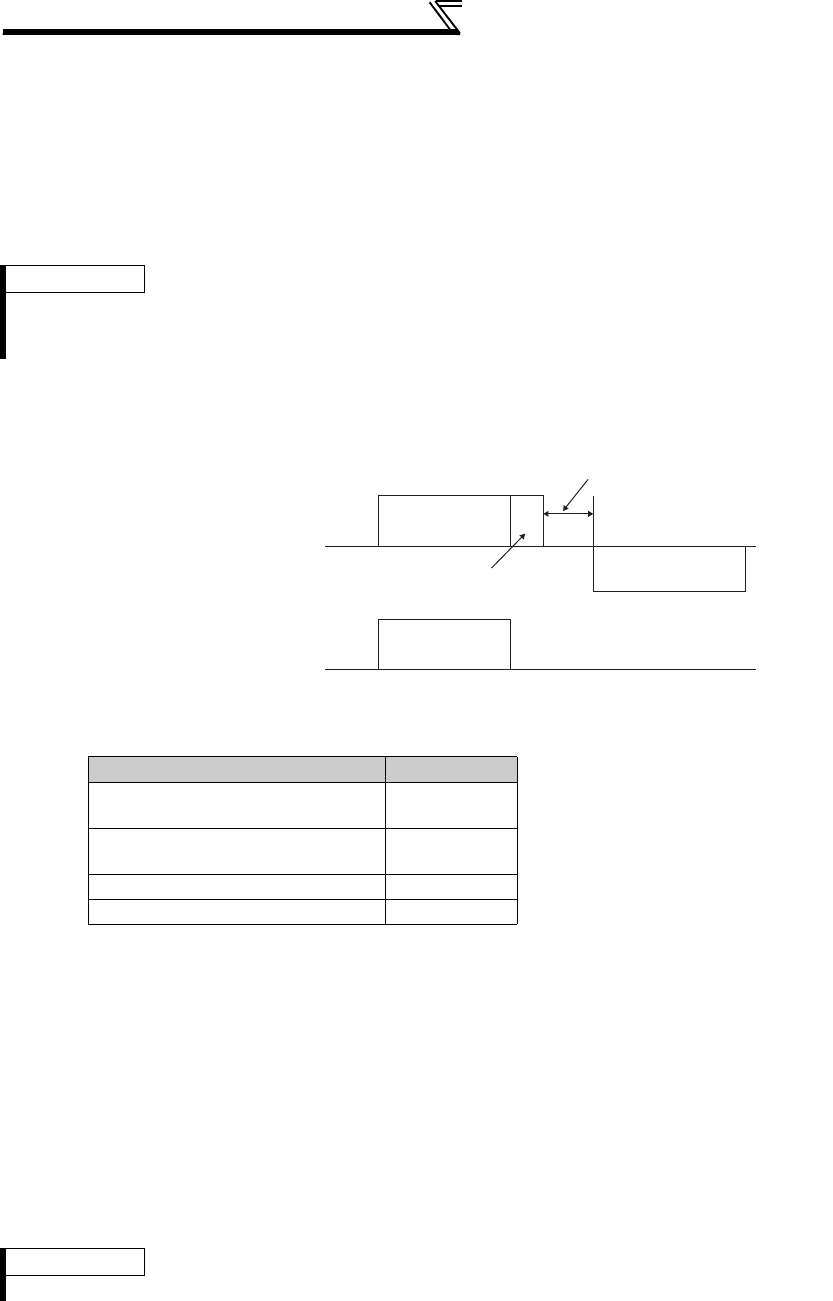
348
Communication operation and setting
(2) Outline
The Modbus protocol is the communication protocol developed by Modicon for programmable controller.
The Modbus protocol performs serial communication between the master and slave using the dedicated message
frame. The dedicated message frame has the functions that can perform data read and write. Using the functions,
you can read and write the parameter values from the inverter, write the input command of the inverter, and check
the operating status. In this product, the inverter data are classified in the holding register area (register addresses
40001 to 49999). By accessing the assigned holding register address, the master can communicate with the inverter
which is a slave.
(3) Message format
Data check time
1) Query
The master sends a message to the slave (= inverter) at the specified address.
2) Normal Response
After receiving the query from the master, the slave executes the requested function and returns the corresponding
normal response to the master.
3) Error Response
If an invalid function code, address or data is received, the slave returns it to the master.
When a response description is returned, the error code indicating that the request from the master cannot be
executed is added.
No response is returned for the hardware-detected error, frame error and CRC check error.
4) Broadcast
By specifying address 0, the master can send a message to all slaves. All slaves that received the message from the
master execute the requested function. In this communication, the slaves do not return a response to the master.
REMARKS
There are two different serial transmission modes: ASCII (American Standard Code for Information Interchange) mode and RTU
(Remote Terminal Unit) mode. This product supports only the RTU mode in which 1-byte (8-bit) data is transmitted as-is.
Only the communication protocol is defined by the Modbus protocol, and the physical layer is not stipulated.
Item Check Time
Various monitors, operation command,
frequency setting (RAM) < 12ms
Parameter read/write, frequency
setting (EEPROM) < 30ms
Parameter clear/all clear < 5s
Reset command No answer
REMARKS
The slave executes the function independently of the inverter station number setting (Pr. 331) during broadcast communication.
Query communication
Broadcast communication
Query Message
Query Message
Response Message
Inverter (slave)
Inverter (slave)
Programmable controller
(Master)
Programmable controller
(Master) No Response
Inverter response time
(Refer to the following table for the
data check time)
Data absence time
(3.5 bytes or more)

349
Communication operation and setting
4
PARAMETERS
(4) Message frame (protocol)
Communication method
Basically, the master sends a query message (question) and the slave returns a response message
(response). When communication is normal, Device Address and Function Code are copied as they are, and
when communication is abnormal (function code or data code is illegal), bit 7 (= 80h) of Function Code is
turned ON and the error code is set to Data Bytes.
The message frame consists of the four message fields as shown above.
By adding the no-data time (T1: Start, End) of 3.5 characters to the beginning and end of the message data,
the slave recognizes it as one message.
Protocol details
The four message fields will be explained below.
Query message from Master
Device Address Device Address
Function Code Function Code
Eight-Bit
Data Bytes
Eight-Bit
Data Bytes
Error Check Error Check
Response message from slave
Start 1) ADDRESS 2) FUNCTION 3) DATA 4) CRC CHECK End
T1 8 bits 8 bits n × 8 bits L
8 bits
H
8 bits T1
Message Field Description
1) ADDRESS field
The address is 1 byte long (8 bits) and any of 0 to 247 can be set. Set 0 to send a broadcast
message (all-address instruction) or any of 1 to 247 to send a message to each slave.
When the slave responds, it returns the address set from the master.
The value set to Pr. 331 RS-485 communication station number is the slave address.
2) FUNCTION field
The function code is 1 byte long (8 bits) and any of 1 to 255 can be set. The master sets the
function that it wants to request from the slave, and the slave performs the requested
operation. The following table gives the supported function codes. An error response is
returned if the set function code is other than those in the following table.
When the slave returns a normal response, it returns the function code set by the master.
When the slave returns an error response, it returns H80 + function code.
3) DATA field The format changes depending on the function code (refer to page 350). Data includes the byte
count, number of bytes, description of access to the holding register, etc.
4) CRC CHECK field
The received message frame is checked for error. CRC check is performed, and 2 byte long
data is added to the end of the message. When CRC is added to the message, the low-order
byte is added first and is followed by the high-order byte.
The CRC value is calculated by the sending side that adds CRC to the message. The receiving
side recalculates CRC during message receiving, and compares the result of that calculation
and the actual value received in the CRC CHECK field. If these two values do not match, the
result is defined as error.
Code Function Name Outline Broadcast
Communication
H03 Read Holding Register Reads the holding register data. Disallowed
H06 Preset Single Register Writes data to the holding register. Allowed
H08 Diagnostics Makes a function diagnosis.
(communication check only) Disallowed
H10 Preset Multiple Registers Writes data to multiple consecutive
holding registers. Allowed
H46 Read Holding Register
Access Log
Reads the number of registers that
succeeded in communication last
time.
Disallowed
Table 1: Function code list

350
Communication operation and setting
(5) Message format types
The message formats corresponding to the function codes in Table 1 on page 349 will be explained.
zRead holding register data (H03 or 03)
Can read the description of 1) system environment variables, 2) real-time monitor, 3) faults history, and 4)
inverter parameters assigned to the holding register area (refer to the register list (page 355)).
Query Message
Normal response (Response message)
⋅Query message setting
⋅Description of normal response
1) Slave Address 2) Function 3) Starting Address 4) No. of Points CRC Check
(8 bits) H03
(8 bits)
H
(8 bits)
L
(8 bits)
H
(8 bits)
L
(8 bits)
L
(8 bits)
H
(8 bits)
1) Slave Address 2) Function 5) Byte Count 6) Data CRC Check
(8 bits) H03
(8 bits) (8 bits) H
(8 bits)
L
(8 bits)
...
(n × 16 bits)
L
(8 bits)
H
(8 bits)
Message Setting Description
1)Slave Address Set the address to which the message will be sent. Broadcast
communication cannot be made (0 is invalid).
2)Function Set H03.
3)Starting Address
Set the address at which holding register data read will be started.
Starting address = starting register address (decimal) − 40001
For example, setting of the starting address 0001 reads the data of the
holding register 40002.
4)No. of Points Set the number of holding registers from which data will be read. The
number of registers from which data can be read is a maximum of 125.
Message Setting Description
5)Byte Count The setting range is H02 to HFA (2 to 250).
Twice greater than the No. of Points specified at 4) is set.
6)Data
The number of data specified at 4) is set. Data are read in order of Hi byte
and Lo byte, and set in order of starting address data, starting address + 1
data, starting address + 2 data, ...
Example) To read the register values of 41004 (Pr. 4) to 41006 (Pr. 6) from the slave address 17 (H11)
Query message
Normal response (Response message)
Read value
Register 41004 (Pr. 4): H1770 (60.00Hz)
Register 41005 (Pr. 5): H0BB8 (30.00Hz)
Register 41006 (Pr. 6): H03E8 (10.00Hz)
Slave Address Function Starting Address No. of Points CRC Check
H11
(8 bits)
H03
(8 bits)
H03
(8 bits)
HEB
(8 bits)
H00
(8 bits)
H03
(8 bits)
H77
(8 bits)
H2B
(8 bits)
Slave Address Function Byte Count Data CRC Check
H11
(8 bits)
H03
(8 bits)
H06
(8 bits)
H17
(8 bits)
H70
(8 bits)
H0B
(8 bits)
HB8
(8 bits)
H03
(8 bits)
HE8
(8 bits)
H2C
(8 bits)
HE6
(8 bits)

351
Communication operation and setting
4
PARAMETERS
Write multiple holding register data (H06 or 06)
You can write the description of 1) system environment variables and 4) inverter parameters assigned to the
holding register area (refer to the register list (page 355)).
Query message
Normal response (Response message)
⋅Query message setting
⋅Description of normal response
1) to 4) (including CRC check) of the normal response are the same as those of the query message.
No response is made for broadcast communication.
1) Slave Address 2) Function 3) Register Address 4) Preset Data CRC Check
(8 bits) H06
(8 bits) H (8 bits) L (8 bits) H (8 bits) L (8 bits) L (8 bits) H (8 bits)
1) Slave Address 2) Function 3) Register Address 4) Preset Data CRC Check
(8 bits) H06
(8 bits) H (8 bits) L (8 bits) H (8 bits) L (8 bits) L (8 bits) H (8 bits)
Message Setting Description
1) Slave Address Set the address to which the message will be sent. Setting of address 0
enables broadcast communication
2) Function Set H06.
3)RegisterAddress
Set the address of the holding register to which data will be written.
Register address = holding register address (decimal) − 40001
For example, setting of register address 0001 writes data to the holding
register address 40002.
4) Preset Data Set the data that will be written to the holding register. The written data is
fixed to 2 bytes.
Example) To write 60Hz (H1770) to 40014 (running frequency RAM) at slave address 5 (H05).
CAUTION
For broadcast communication, no response is returned in reply to a query. Therefore, the next query must be made
when the inverter processing time has elapsed after the previous query.
Query message
Normal Response (Response message)
Same data as the query message
Slave Address Function Register Address Preset Data CRC Check
H05
(8 bits)
H06
(8 bits)
H00
(8 bits)
H0D
(8 bits)
H17
(8 bits)
H70
(8 bits)
H17
(8 bits)
H99
(8 bits)

352
Communication operation and setting
Function diagnosis (H08 or 08)
A communication check can be made since the query message sent is returned unchanged as a response
message (function of subfunction code H00).
Subfunction code H00 (Return Query Data)
Query Message
Normal Response (Response message)
⋅Query message setting
⋅Description of normal response
1) to 4) (including CRC check) of the normal response are the same as those of the query message.
Write multiple holding register data (H10 or 16)
You can write data to multiple holding registers.
Query message
Normal Response (Response message)
⋅Query message setting
1) Slave Address 2) Function 3) Subfunction 4) Date CRC Check
(8 bits) H08
(8 bits)
H00
(8 bits)
H00
(8 bits)
H
(8 bits)
L
(8 bits)
L
(8 bits)
H
(8 bits)
1) Slave Address 2) Function 3) Subfunction 4) Date CRC Check
(8 bits) H08
(8 bits)
H00
(8 bits)
H00
(8 bits)
H
(8 bits)
L
(8 bits)
L
(8 bits)
H
(8 bits)
Message Setting Description
1) Slave Address Set the address to which the message will be sent. Broadcast
communication cannot be made (0 is invalid).
2) Function Set H08.
3)Subfunction Set H0000.
4) Data Any data can be set if it is 2 bytes long. The setting range is H0000
to HFFFF.
CAUTION
For broadcast communication, no response is returned in reply to a query. Therefore, the next query must be made when
the inverter processing time has elapsed after the previous query.
1)
Slave
Address
2)
Function
3)
Starting Address
4) No. of
Registers
5)
ByteCount 6) Data CRC Check
(8 bits) H10
(8 bits)
H
(8 bits)
L
(8 bits)
H
(8 bits)
L
(8 bits) (8 bits) H
(8 bits)
L
(8 bits)
...
(n
×
2
×
8 bits)
L
(8 bits)
H
(8 bits)
1) Slave Address 2) Function
3) Starting Address
4) No. of Registers CRC Check
(8 bits) H10
(8 bits)
H
(8 bits)
L
(8 bits)
H
(8 bits)
L
(8 bits)
L
(8 bits)
H
(8 bits)
Message Setting Description
1) Slave Address Set the address to which the message will be sent. Setting of address 0
enables broadcast communication.
2) Function Set H10.
3) Starting Address
Set the address where holding register data write will be started.
Starting address = starting register address (decimal) − 40001
For example, setting of the starting address 0001 reads the data of the
holding register 40002.
4) No. of Points Set the number of holding registers where data will be written. The number of
registers where data can be written is a maximum of 125.
5) Byte Count The setting range is H02 to HFA (2 to 250).
Set a value twice greater than the value specified at 4).
6) Data
Set the data specified by the number specified at 4). The written data are set
in order of Hi byte and Lo byte, and arranged in order of the starting address
data, starting address + 1 data, starting address + 2 data ...

353
Communication operation and setting
4
PARAMETERS
⋅Description of normal response
1) to 4) (including CRC check) of the normal response are the same as those of the query message.
Read holding register access log (H46 or 70)
A response can be made to a query made by the function code H03 or H10.
The starting address of the holding registers that succeeded in access during previous communication and the
number of successful registers are returned.
In response to the query for other than the above function code, 0 is returned for the address and number of
registers.
Query Message
Normal Response (Response message)
⋅Query message setting
⋅Description of normal response
Example) To write 0.5s (H05) to 41007 (Pr. 7) at the slave address 25 (H19) and 1s (H0A) to 41008 (Pr. 8).
1) Slave Address 2) Function CRC Check
(8 bits) H46
(8 bits)
L
(8 bits)
H
(8 bits)
1) Slave Address 2) Function 3)
Starting Address
4) No. of Points CRC Check
(8 bits) H46
(8 bits)
H
(8 bits)
L
(8 bits)
H
(8 bits)
L
(8 bits)
L
(8 bits)
H
(8 bits)
Message Setting Description
1) Slave Address Set the address to which the message will be sent. Broadcast
communication cannot be made (0 is invalid)
2) Function Set H46.
Message Setting Description
3) Starting Address
The starting address of the holding registers that succeeded in access is
returned.
Starting address = starting register address (decimal) − 40001
For example, when the starting address 0001 is returned, the address of the
holding register that succeeded in access is 40002.
4) No. of Points The number of holding registers that succeeded in access is returned.
Example) To read the successful register starting address and successful count from the slave address 25 (H19).
Query Message
Response message (Response message)
Slave
Address
Function
Starting
Address No. of Points Byte
Count Data CRC Check
H19
(8 bits)
H10
(8 bits)
H03
(8 bits)
HEE
(8 bits)
H00
(8 bits)
H02
(8 bits)
H04
(8 bits)
H00
(8 bits)
H05
(8 bits)
H00
(8 bits)
H0A
(8 bits)
H86
(8 bits)
H3D
(8 bits)
Slave
Address
Function
Starting
Address No. of Points CRC Check
H19
(8 bits)
H10
(8 bits)
H03
(8 bits)
HEE
(8 bits)
H00
(8 bits)
H02
(8 bits)
H22
(8 bits)
H61
(8 bits)
Query Message
Normal Response (Response message)
Success of two registers at starting address 41007 (Pr. 7) is returned.
Slave Address Function CRC Check
H19
(8 bits)
H46
(8 bits)
H8B
(8 bits)
HD2
(8 bits)
Slave Address Function Starting Address No. of Points CRC Check
H19
(8 bits)
H10
(8 bits)
H03
(8 bits)
HEE
(8 bits)
H00
(8 bits)
H02
(8 bits)
H22
(8 bits)
H61
(8 bits)

354
Communication operation and setting
Error response
An error response is returned if the query message received from the master has an illegal function, address or
data. No response is returned for a parity, CRC, overrun, framing or busy error.
Error response (Response message)
Error code list
*1 An error will not occur in the following cases.
1) Function code H03 (Read Holding Register Data )
When the No. of Points is 1 or more and there is one or more holding registers from which data can be read
2) Function code H10 (Write Multiple Holding Register Data)
When the No. of Points is 1 or more and there is 1 or more holding registers to which data can be written
Namely, when the function code H03 or H10 is used to access multiple holding registers, an error will not occur if a non-existing holding
register or read disabled or write disabled holding register is accessed.
⋅Message data mistake detection
To detect the mistakes of message data from the master, they are checked for the following errors. If an error
is detected, a trip will not occur.
Error check item
CAUTION
No response message is sent in the case of broadcast communication also.
1) Slave Address 2) Function 3) Exception Code CRC Check
(8 bits) H80 + Function
(8 bits) (8 bits) L
(8 bits)
H
(8 bits)
Message Setting Description
1) Slave address Set the address received from the master.
2) Function The master-requested function code + H80 is set.
3) Exception code The code in the following table is set.
Code Error Item Error Definition
01 ILLEGAL FUNCTION The set function code in the query message from the master cannot be
handled by the slave.
02 ILLEGAL DATA ADDRESS *1
The set register address in the query message from the master cannot be
handled by the inverter.
(No parameter, parameter read disabled, parameter write disabled)
03 ILLEGAL DATA VALUE
The set data in the query message from the master cannot be handled by
the inverter.
(Out of parameter write range, mode specified, other error)
REMARKS
An error will occur if all accessed holding registers do not exist.
Data read from a non-existing holding register is 0, and data written there is invalid.
Error Item Error Definition Inverter Side Operation
Parity error The data received by the inverter differs from the
specified parity (Pr. 334 setting).
1) Pr. 343 is increased by 1 at error
occurrence.
2) The terminal LF is output at error
occurrence.
Framing error The data received by the inverter differs from the
specified stop bit length (Pr. 334).
Overrun error The following data was sent from the master before
the inverter completes data receiving.
Message frame
error
The message frame data length is checked, and the
received data length of less than 4 bytes is regarded
as an error.
CRC check error
A mismatch found by CRC check between the
message frame data and calculation result is
regarded as an error.
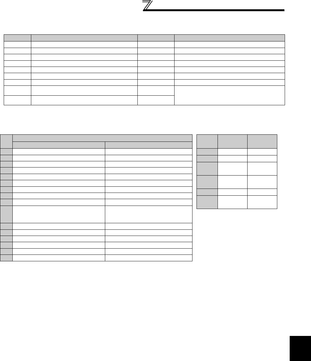
355
Communication operation and setting
4
PARAMETERS
(6) Modbus registers
System environment variable
*1 The communication parameter values are not cleared.
*2 For write, set the data as a control input instruction. For read, data is read as an inverter operating status.
*3 For write, set data as the operation mode setting. For read, data is read as the operation mode status.
Register Definition Read/Write Remarks
40002 Inverter reset Write Any value can be written
40003 Parameter clear Write Set H965A as a written value.
40004 All parameter clear Write Set H99AA as a written value.
40006 Parameter clear *1 Write Set H5A96 as a written value.
40007 All parameter clear *1 Write Set HAA99 as a written value.
40009 Inverter status/control input instruction *2 Read/write See below.
40010 Operation mode/inverter setting *3 Read/write See below.
40014 Running frequency (RAM value) Read/write According to the Pr. 37 and Pr. 144 settings, the
frequency and selectable speed are in 1r/min
increments.
40015 Running frequency (EEPROM value) Write
<Inverter status/control input instruction>
*1 The signal within parentheses is the initial setting. The description changes depending on the setting of Pr. 180 to Pr. 189 (input
terminal function selection) (page 231).
Each assigned signal is valid or invalid depending on NET. (Refer to page 322)
*2 The signal within parentheses is the initial setting. The description changes depending on the setting of Pr. 190 to Pr. 196 (output
terminal function selection) (page 239).
Bit Definition
Control input instruction Inverter status
0 Stop command RUN (inverter running) *2
1 Forward rotation command Forward rotation
2 Reverse rotation command Reverse rotation
3 RH (high speed operation command) *1 SU (up to frequency) *2
4 RM (middle speed operation command) *1 OL (overload) *2
5 RL (low speed operation command) *1 IPF (instantaneous power failure) *2
6 JOG (Jog operation) *1 FU (frequency detection) *2
7 RT (second function selection) *1 ABC1 (fault) *2
8 AU (current input selection) *1 ABC2 (⎯) *2
9
CS
(selection of automatic restart after
instantaneous power failure) *1
0
10 MRS (output stop) *1 0
11 STOP (start self-holding) *1 0
12 RES (reset) *1 0
13 0 0
14 0 0
15 0 Fault occurrence
<Operation mode/inverter setting>
*Writing is available depending on the
Pr. 79 and Pr. 340 setting. Refer to page
321 for details.
The restrictions depending on the
operation mode changes according
to the computer link specifications.
Mode Read
Value
Written
Value
EXT H0000 H0010*
PU H0001 H0011*
EXT
JOG H0002 ⎯
PU
JOG H0003 ⎯
NET H0004 H0014
PU+
EXT H0005 ⎯

356
Communication operation and setting
Real-time monitor
Refer to page 253 for details of the monitor description.
...........Specifications differ according to the date assembled. Refer to page 484 to check the SERIAL number.
*1 The setting depends on capacities. (55K or lower / 75K or higher)
*2 When Pr. 37 = "1 to 9998" or Pr. 144 = "2 to 10, 102 to 110," the unit is an integral value (one increment). (Refer to page 251)
*3 Input terminal monitor details (when the terminal is ON: 1, when the terminal is OFF: 0, —: undetermined value)
*4 Output terminal monitor details (when the terminal is ON: 1, when the terminal is OFF: 0, —: undetermined value)
*5 Details of option input terminal monitor 1 (input terminal status of FR-A7AX when the terminal is ON: 1, when the terminal is OFF: 0)-all terminals
are OFF when an option is not fitted
*6 Details of option input terminal monitor 2 (input terminal status of FR-A7AX when the terminal is ON: 1, when the terminal is OFF: 0, —:
undetermined value)-all terminals are OFF when an option is not fitted
*7 Details of option output terminal monitor (output terminal status of FR-A7AY/A7AR when the terminal is ON: 1, when the terminal is OFF: 0, —:
undetermined value)-all terminals are OFF when an option is not fitted
b15 b0
⎯⎯⎯⎯CS RES STOP MRS JOG RH RM RL RT AU STR STF
b15 b0
⎯⎯⎯⎯⎯⎯⎯⎯⎯ABC2 ABC1 FU OL IPF SU RUN
b15 b0
X15 X14 X13 X12 X11 X10 X9 X8 X7 X6 X5 X4 X3 X2 X1 X0
b15 b0
⎯⎯⎯⎯⎯⎯⎯⎯⎯⎯⎯⎯⎯⎯⎯DY
b15 b0
⎯⎯⎯⎯⎯⎯RA3RA2RA1Y6Y5Y4Y3Y2Y1Y0
Register Definition
Increments
40201 Output frequency/
speed *2 0.01Hz/1
40202 Output current 0.01A/
0.1A *1
40203 Output voltage 0.1V
40205
Frequency setting
value/speed setting
*2
0.01Hz/1
40206 Running speed 1r/min
40207 Motor torque 0.1%
40208 Converter output
voltage 0.1V
40209 Regenerative brake
duty 0.1%
40210
Electronic thermal
relay function load
factor
0.1%
40211 Output current peak
value
0.01A/
0.1A *1
40212 Converter output
voltage peak value 0.1V
40213 Input power 0.01kW/
0.1kW *1
40214 Output power 0.01kW/
0.1kW *1
40215 Input terminal
status *3 ⎯
40216 Output terminal
status *4 ⎯
40217 Load meter 0.1%
40218 Motor excitation
current
0.01A/
0.1A *1
40219 Position pulse ⎯
40220 Cumulative
energization time 1h
40222 Orientation status ⎯
40223 Actual operation
time 1h
40224 Motor load factor 0.1%
40225 Cumulative power 1kWh
40232 Torque command 0.1%
Register Definition
Increments
40233 Torque current
command 0.1%
40234 Motor output 0.01/
0.1kW *1
40235 Feedback pulse ⎯
40246 Motor temperature 1°C
40250 Power saving effect Variable
40251 Cumulative saving
power Variable
40252 PID set point 0.1%
40253 PID measured
value 0.1%
40254 PID deviation value 0.1%
40258 Option input
terminal status1 *5 ⎯
40259 Option input
terminal status2 *6 ⎯
40260 Option output
terminal status *7 ⎯
Register Definition
Increments

357
Communication operation and setting
4
PARAMETERS
Parameter
Parameters
Register Parameter Name Read/Write Remarks
0 to 999 41000 to
41999
Refer to the parameter list (page 71) for
the parameter names. Read/write The parameter number + 41000 is the
register number.
C2(902) 41902 Terminal 2 frequency setting bias
(frequency) Read/write
C3(902)
42092 Terminal 2 frequency setting bias
(analog value) Read/write The analog value (%) set to C3 (902) is
read.
43902 Terminal 2 frequency setting bias
(terminal analog value) Read The analog value (%) of the voltage
(current) applied to the terminal 2 is read.
125(903) 41903 Terminal 2 frequency setting gain
(frequency) Read/write
C4(903)
42093 Terminal 2 frequency setting gain
(analog value) Read/write The analog value (%) set to C4 (903) is
read.
43903 Terminal 2 frequency setting gain
(terminal analog value) Read The analog value (%) of the voltage
(current) applied to the terminal 2 is read.
C5(904) 41904 Terminal 4 frequency setting bias
(frequency) Read/write
C6(904)
42094 Terminal 4 frequency setting bias
(analog value) Read/write The analog value (%) set to C6 (904) is
read.
43904 Terminal 4 frequency setting bias
(terminal analog value) Read The analog value (%) of the current
(voltage) applied to the terminal 4 is read.
126(905) 41905 Terminal 4 frequency setting gain
(frequency) Read/write
C7(905)
42095 Terminal 4 frequency setting gain
(analog value) Read/write The analog value (%) set to C7 (905) is
read.
43905 Terminal 4 frequency setting gain
(terminal analog value) Read The analog value (%) of the current
(voltage) applied to the terminal 4 is read.
C12(917) 41917 Terminal 1 bias frequency (speed) Read/write
C13(917)
42107 Terminal 1 bias (speed) Read/write Analog value (%) set in C13 (917) is read.
43917 Terminal 1 bias (speed)
(terminal analog value) Read Analog value (%) of the voltage applied to
terminal 1 is read.
C14(918) 41918 Terminal 1 gain frequency (speed) Read/write
C15(918)
42108 Terminal 1 gain (speed) Read/write Analog value (%) set in C15 (918) is read.
43918 Terminal 1 gain (speed)
(terminal analog value) Read Analog value (%) of the voltage applied to
terminal 1 is read.
C16(919) 41919 Terminal 1 bias command (torque/
magnetic flux) Read/write
C17(919)
42109 Terminal 1 bias (torque/magnetic flux) Read/write Analog value (%) set in C17 (919) is read.
43919 Terminal 1 bias (torque/magnetic flux)
(terminal analog value) Read Analog value (%) of the voltage applied to
terminal 1 is read.
C18(920) 41920 Terminal 1 gain command (torque/
magnetic flux) Read/write
C19(920)
42110 Terminal 1 gain (torque/magnetic flux) Read/write Analog value (%) set in C19 (920) is read.
43920 Terminal 1 gain (torque/magnetic flux)
(terminal analog value) Read Analog value (%) of the voltage applied to
terminal 1 is read.
C38(932) 41932 Terminal 4 bias command (torque/
magnetic flux) Read/write
C39(932)
42122 Terminal 4 bias (torque/magnetic flux) Read/write Analog value (%) set in C39 (932) is read.
43932 Terminal 4 bias (torque/magnetic flux)
(terminal analog value) Read Analog value (%) of the current (voltage)
applied to terminal 4 is read.
C40(933) 41933
Terminal 4 gain command (torque/
magnetic flux)
Read/write
C41(933)
42123 Terminal 4 gain (torque/magnetic flux) Read/write Analog value (%) set in C41 (933) is read.
43933 Terminal 4 gain (torque/magnetic flux)
(terminal analog value) Read Analog value (%) of the current (voltage)
applied to terminal 4 is read.
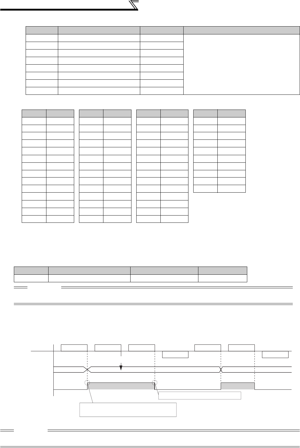
358
Communication operation and setting
Faults history
Fault code list
(7) Pr. 343 Communication error count
You can check the cumulative number of communication errors.
(8) Output signal LF "alarm output (communication error warnings)"
During a communication error, the alarm signal (LF signal) is output by open collector output. Assign the used
terminal using any of Pr. 190 to Pr. 196 (output terminal function selection).
Register Definition Read/Write Remarks
40501 Fault history 1 Read/write
Being 2 bytes in length, the data is stored as
"H00". Refer to the lowest 1 byte for the fault
code.
Performing write using the register 40501 batch-
clears the faults history. Set any value as data.
40502 Fault history 2 Read
40503 Fault history 3 Read
40504 Fault history 4 Read
40505 Fault history 5 Read
40506 Fault history 6 Read
40507 Fault history 7 Read
40508 Fault history 8 Read
Parameters Setting Range Minimum Setting Range Initial Value
343 (Read only) 1 0
CAUTION
The number of communication errors is temporarily stored into the RAM. As it is not stored into the EEPROM, performing
a power supply reset or inverter reset clears the value to 0.
CAUTION
The LF signal can be assigned to the output terminal using any of Pr. 190 to Pr. 196. When terminal assignment is changed, the
other functions may be affected. Set parameters after confirming the function of each terminal.
* Refer to page 403 for details of fault description.
Data
Description
H00 No alarm
H10 E.OC1
H11 E.OC2
H12 E.OC3
H20 E.OV1
H21 E.OV2
H22 E.OV3
H30 E.THT
H31 E.THM
H40 E.FIN
H50 E.IPF
H51 E.UVT
H52 E.ILF
H60 E.OLT
H70 E.BE
H80 E.GF
H81 E.LF
H90 E.OHT
H91 E.PTC
HA0 E.OPT
HA3 E.OP3
HB0 E.PE
HB1 E.PUE
HB2 E.RET
HB3 E.PE2
HC0 E.CPU
HC1 E.CTE
HC2 E.P24
Data
Description
HC4 E.CDO
HC5 E.IOH
HC6 E.SER
HC7 E.AIE
HC8 E.USB
HD0 E.OS
HD1 E.OSD
HD2 E.ECT
HD3 E.OD
HD5 E.MB1
HD6 E.MB2
HD7 E.MB3
HD8 E.MB4
HD9 E.MB5
Data
Description
HDA E.MB6
HDB E.MB7
HDC E.EP
HF1 E.1
HF2 E.2
HF3 E.3
HF6 E.6
HF7 E.7
HFB E.11
HFD E.13
Data
Description
Alarm data
Reply data
Master
Slave
0
Signal LF
Normal dataAlarm data Alarm data
12
OFF ON OFF OFF
ON
Not increased
Turns off when normal data is received
Alarm data :
Normal data
Reply data
Communication error count is increased in
synchronization with leading edge of LF signal
Data resulting in
communication error.
Communication
Error count
(Pr. 343)
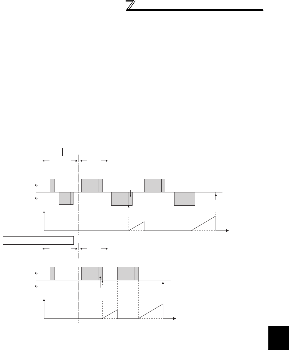
359
Communication operation and setting
4
PARAMETERS
(9) Signal loss detection (Pr. 539 Modbus-RTU communication check time interval)
If a signal loss (communication stop) is detected between the inverter and master as a result of a signal loss
detection, a communication fault (E.SER) occurs and the inverter trips.
· When the setting is "9999", communication check (signal loss detection) is not made.
· When the setting value is "0", monitor, parameter read, etc. can be performed. However, a communication fault
(E.SER) occurs as soon as the inverter is switched to the Network operation mode.
· A signal loss detection is made when the setting is any of "0.1s to 999.8s". To make a signal loss detection, it is
necessary to send data from the master within the communication check time interval. (The inverter makes
communication check (clearing of communication check counter) regardless of the station number setting of the data
sent from the master.)
· Communication check is started from the first communication after switching to the Network operation mode (use Pr.
551 PU mode operation command source selection to change).
· Communication check time of query communication includes data absence time (3.5 byte).
Since this data absence time differs according to the communication speed, make setting considering this absence
time.
Operation mode
Example: RS-485 terminal communication, Pr. 539 = "0.1 to 999.8s"
External NET
Check start Time
Inverter (slave)
Inverter (slave)
Communication
check counter
Pr.539
PLC (master)
PLC (master)
Query Message1 Query Message2
Data absence time
(3.5 bytes or more)
Response Message1 Response Message2
Fault
(E.SER)
Operation mode External NET
Check start Time
Inverter (slave)
Inverter (slave)
Communication
check counter
Pr.539
PLC (master)
PLC (master)
Query Message2
Fault
(E.SER)
Data absence time
(3.5 bytes or more)
Query Message1
Query communication
Broadcast communication
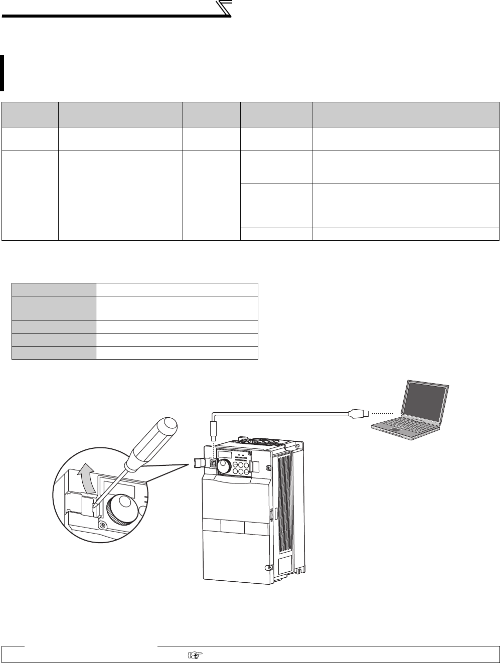
360
Communication operation and setting
4.24.7 USB communication (Pr. 547, Pr. 548)
* Changed setting value is valid when powering ON or resetting the inverter.
zUSB communication specifications
· When using USB communication, set "3" in Pr. 551 PU mode operation command source selection.
· You can perform parameter setting and monitoring with the FR Configurator. Refer to the instruction manual of the
FR Configurator for details.
Inverter setup can be easily performed using the FR Configurator by connecting the inverter and personal
computer with a USB cable.
A personal computer and inverter can be easily connected with one USB cable.
Parameter
Number Name Initial Value Setting Range Description
547* USB communication station
number 0 0 to 31 Specify the inverter station number.
548* USB communication check
time interval 9999
0
USB communication is enabled. However, the
inverter will trip (E. USB) if operation is changed
to PU operation mode.
0.1 to 999.8s
Set the interval of communication check time.
If a no-communication state persists for longer
than the permissible time, the inverter will trip
(E.USB).
9999 No communication check
Interface Conforms to USB1.1
Transmission
speed: 12Mbps
Connector USB B connector (B receptacle)
Cable Shielded twisted pair cable 5m maximum
Power supply Self-power supply
♦ Parameters referred to ♦
Pr. 551 PU mode operation command source selection Refer to page 322
USB cable USB connector
Place a flathead screwdriver,
etc. in a slot and push up the
cover to open.
Removal of cover

361
Special operation and frequency control
4
PARAMETERS
4.25 Special operation and frequency control
4.25.1 PID control (Pr. 127 to Pr. 134, Pr. 575 to Pr. 577)
Purpose Parameter that must be Set Refer
to Page
Perform process control such as pump and air
volume. PID control Pr. 127 to Pr. 134,
Pr. 575 to Pr. 577 361
Switch between the inverter operation and
bypass operation to operate.
Bypass-inverter switchover
function Pr. 135 to Pr. 139, Pr. 159 369
Increase speed when the load is light. Load torque high speed
frequency control Pr. 4, Pr. 5, Pr. 270 to Pr. 274 374
Frequency control appropriate for the load torque Droop control Pr. 286 to Pr. 288 376
Frequency setting by pulse train input Pulse train input Pr. 291, Pr. 384 to Pr. 386 378
Make the motor speed constant by encoder Encoder feedback control Pr. 144, Pr. 285, Pr. 359,
Pr. 367 to Pr. 369 381
Avoid overvoltage alarm due to regeneration by
automatic adjustment of output frequency
Regeneration avoidance
function Pr. 882 to Pr. 886 383
The inverter can be used to exercise process control, e.g. flow rate, air volume or pressure.
The terminal 2 input signal or parameter setting is used as a set point and the terminal 4 input signal used as a
feedback value to constitute a feedback system for PID control.
Parameter
Number Name Initial
Value
Setting
Range Description
127 PID control automatic
switchover frequency 9999 0 to 400Hz Set the frequency at which the control is automatically
changed to PID control.
9999 Without PID automatic switchover function
128 PID action selection 10
10 PID reverse action Deviation value signal input
(terminal 1 )
11 PID forward action
20 PID reverse action Measured value (terminal 4 )
Set point (terminal 2 or Pr. 133)
21 PID forward action
50 PID reverse action Deviation value signal input
(LONWORKS , CC-Link communication)
51 PID forward action
60 PID reverse action Measured value, set point input
(LONWORKS , CC-Link communication)
61 PID forward action
129 *1 PID proportional band 100% 0.1 to 1000%
If the proportional band is narrow (parameter setting is small),
the manipulated variable varies greatly with a slight change of
the measured value. Hence, as the proportional band narrows,
the response sensitivity (gain) improves but the stability
deteriorates, e.g. hunting occurs.
Gain Kp = 1/proportional band
9999 No proportional control
130 *1 PID integral time 1s 0.1 to 3600s
When deviation step is input, time (Ti) is the time required for
integral (I) action to provide the same manipulated variable as
proportional (P) action.
As the integral time decreases, the set point is reached earlier
but hunting occurs more easily.
9999 No integral control
131 PID upper limit 9999 0 to 100%
Set the maximum value. If the feedback value exceeds the
setting, the FUP signal is output. The maximum input (20mA/
5V/10V) of the measured value (terminal 4) is equivalent to
100%.
9999 No function
132 PID lower limit 9999 0 to 100%
Set the minimum value. If the measured value falls below the
setting range, the FDN signal is output. The maximum input
(20mA/5V/10V) of the measured value (terminal 4) is
equivalent to 100%.
9999 No function
133 *1 PID action set point 9999 0 to 100% Used to set the set point for PID control.
9999 Terminal 2 input is the set point.
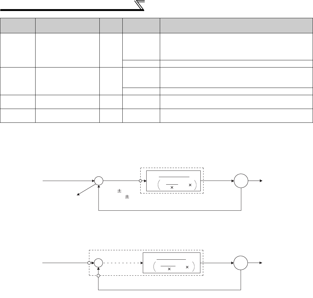
362
Special operation and frequency control
(1) PID control basic configuration
⋅Pr. 128 = "10, 11" (Deviation value signal input)
*Set 0 in Pr. 868 Terminal 1 function assignment. PID control is invalid when Pr. 868 ≠ 0.
⋅Pr. 128 = "20, 21" (Measured value input)
*1 Note that terminal 1 input is added to the set point of terminal 2 input.
*2 Set 0 in Pr. 858 Terminal 4 function assignment. PID control is invalid when Pr. 858 ≠ 0
134 *1 PID differential time 9999
0.01 to
10.00s
For deviation lamp input, time (Td) required for providing only
the manipulated variable for the proportional (P) action. As the
differential time increases, greater response is made to a
deviation change.
9999 No differential control
575 Output interruption
detection time 1s 0 to 3600s
The inverter stops operation if the output frequency after PID
operation remains at less than the Pr. 576 setting for longer
than the time set in Pr. 575.
9999 Without output interruption function
576 Output interruption
detection level 0Hz 0 to 400Hz Set the frequency at which the output interruption processing
is performed.
577 Output interruption
cancel level 1000% 900 to 1100% Set the level (Pr. 577 minus 1000%) at which the PID output
interruption function is canceled.
*1 Pr. 129, Pr. 130, Pr. 133 and Pr. 134 can be set during operation. They can also be set independently of the operation mode.
Parameter
Number Name Initial
Value
Setting
Range Description
+-M
Deviation signal
Feedback signal (measured value)
Ti S
1
1+ +Td S
Kp
PID operation
To outside
Set point
Inverter circuit
Motor
Terminal 1
0 to 10VDC
(0 to 5V)
Kp: Proportionality constant Ti: Integral time S: Operator Td: Differential time
Manipulated
variable
*
+-M
Ti S
Kp 1+ +Td S
1
PID operation
Pr. 133 or
terminal 2
Set point
Inverter circuit
Motor
Feedback signal (measured value)
Terminal 4
Kp: Proportionality constant Ti: Integral time S: Operator Td: Differential time
Manipulated
variable
0 to 5VDC
(0 to 10V, 4 to 20mA)
4 to 20mADC (0 to 5V, 0 to 10V)
*1
*2
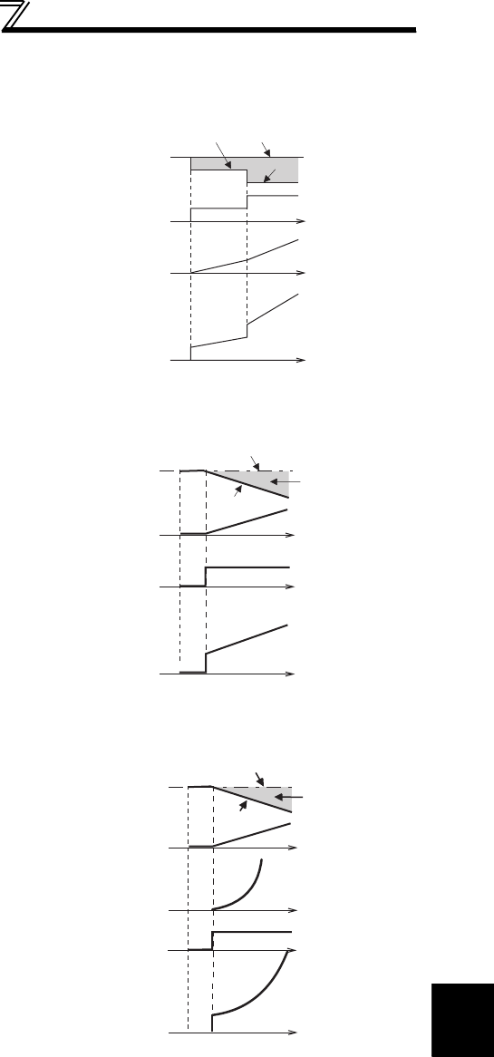
363
Special operation and frequency control
4
PARAMETERS
(2) PID action overview
1) PI action
2) PD action
3) PID action
A combination of P action (P) and I action (I) for providing a
manipulated variable in response to deviation and changes with time.
[Operation example for stepped changes of measured value]
(Note) PI action is the sum of P and I actions.
A combination of P action (P) and differential control action (D) for
providing a manipulated variable in response to deviation speed to
improve the transient characteristic.
[Operation example for proportional changes of measured value]
(Note) PD action is the sum of P and D actions.
The PI action and PD action are combined to utilize the advantages of both
actions for control.
(Note) PID action is the sum of P, I and D actions.
Deviation Set point
Measured value
Time
Time
Time
PI action
I action
P action
Deviation
Set point
Measured value
Time
Time
Time
PD
action
D action
P action
Deviation
Set point
Measured value
Time
Time
Time
PID action
D action
P action
I action
Time
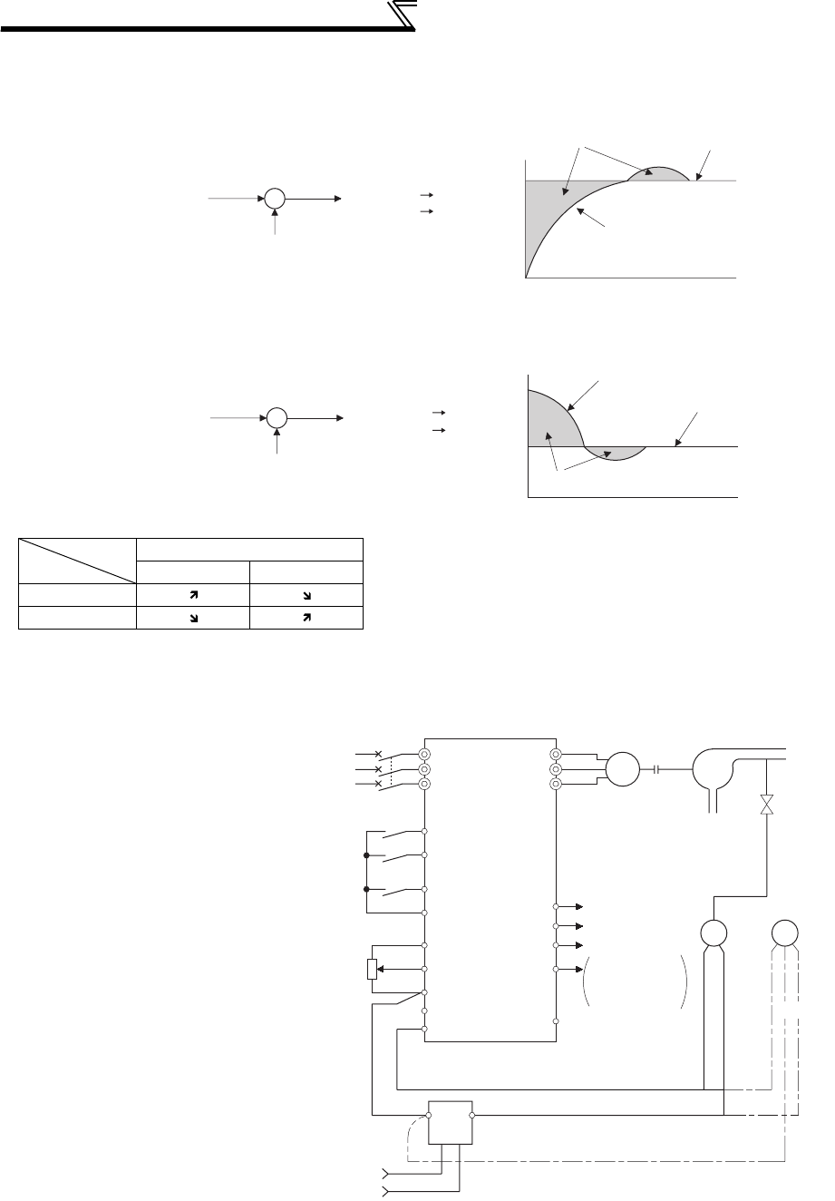
364
Special operation and frequency control
4)Reverse action
Increases the manipulated variable (output frequency) if deviation X = (set point - measured value) is positive, and
decreases the manipulated variable if deviation is negative.
5)Forward action
Increases the manipulated variable (output frequency) if deviation X = (set point - measured value) is negative, and
decreases the manipulated variable if deviation is positive.
Relationships between deviation and manipulated variable (output frequency)
(3) Connection diagram
Deviation
Positive Negative
Reverse action
Forward action
⋅ Sink logic
⋅ Pr. 128 = 20
⋅ Pr. 183 = 14
⋅ Pr. 191 = 47
⋅ Pr. 192 = 16
⋅ Pr. 193 = 14
⋅ Pr. 194 = 15
*1 The power supply must be selected in accordance with the power specifications of the detector used.
*2 The used output signal terminal changes depending on the Pr. 190 to Pr. 196 (output terminal selection) setting.
*3 The used input signal terminal changes depending on the Pr. 178 to Pr. 189 (input terminal selection) setting.
*4 The AU signal need not be input.
Set
point
X>0
X<0
Feedback signal
(measured value)
+
-
[Heating]
Deviation Set point
Measured value
Cold
Hot
Increase
Decrease
Set
point
X>0
X<0
Feedback signal
(measured value)
+
-
[Cooling]
Deviation
Set point
Measured value
Too cold
Hot
Decrease
Increase
Power supply
MCCB Inverter
Forward
rotation
Reverse
rotation
PID control
selection
Setting
Potentiometer
(Set point setting)
0 24V
Power
supply *1
AC1φ
200/220V 50/60Hz
R/L1
S/L2
T/L3
STF
STR
RT(X14)*3
10
2
5
4
U
V
W
*2(FUP)FU
*2(FDN)OL
SE
(Measured value) 4 to 20mA
Motor
IM
Pump
P
Upper limit
*2(PID)SU During PID action
Lower limit
Output signal common
2-wire type
Detector
3-wire
type
-
++ +
-
(OUT) (24V)
Forward rotation
output
Reverse rotation
output
*2(RL)IPF
1(COM)
*4
SD

365
Special operation and frequency control
4
PARAMETERS
(4) I/O signals and parameter setting
⋅Turn ON the X14 signal to perform PID control. When this signal is OFF, PID action is not performed and normal
inverter operation is performed. (Note that it is not necessary to turn ON X14 signal when performing PID control
with using LONWORKS or CC-Link communication. )
⋅Enter the set point across inverter terminals 2 and 5 or into Pr. 133 and enter the measured value signal across
inverter terminals 4 and 5. At this time, set "20" or "21" in Pr. 128.
⋅When entering the externally calculated deviation signal, enter it across terminals 1 and 5. At this time, set "10" or
"11" in Pr. 128.
Signal Terminal
Used Function Description Parameter Setting
Input
X14
Depending on
Pr. 178 to Pr.
189
PID control selection
Turn ON X14 to perform PID control. Set 14 in any of Pr. 178 to Pr. 189.
X64
PID forward/
reverse action
switchover
By turning ON X64, forward action can be
selected for PID reverse action (
Pr. 128
=
10, 20), and reverse action for forward
action (
Pr. 128
= 11, 21).
Set 64 in any of Pr. 178 to Pr. 189.
22
*4 Set point input
Enter the set point for PID control. Pr. 128 = 20, 21, Pr. 133 = 9999
0 to 5V............... 0 to 100% Pr. 73 = 1 *1, 3, 5, 11, 13, 15
0 to 10V............. 0 to 100% Pr. 73 = 0, 2, 4, 10, 12, 14
0 to 20mA.......... 0 to 100% Pr. 73 = 6, 7, 16, 17
PU ⎯Set point input Set the set value (Pr. 133) from the
operation panel or parameter unit. Pr. 128 = 20, 21, Pr. 133 = 0 to 100%
11
Deviation signal
input
Input the deviation signal calculated
externally. Pr. 128 = 10 *1, 11
-5V to +5V ......... -100% to +100% Pr. 73 = 2, 3, 5, 7, 12, 13, 15, 17
-10V to +10V ..... -100% to +100%
Pr. 73
= 0, 1
*1
, 4, 6, 10, 11, 14, 16
44 *4 Measured value
input
Input the signal from the detector
(measured value signal). Pr. 128 = 20, 21
4 to 20mA.0 to 100% Pr. 267 = 0 *1
0 to 5V......0 to 100% Pr. 267 = 1
0 to 10V....0 to 100% Pr. 267 = 2
Commu-
nication
*2
⎯
Deviation value
input
Input the deviation value from
LONWORKS
,
CC-Link communication. Pr. 128 = 50, 51
Set value, measured
value input
Input the set value and measured value from
LONWORKS
,
CC-Link communication
.
Pr. 128 = 60, 61
Output
FUP
Depending on
Pr. 190 to Pr.
196
Upper limit output
Output to indicate that the measured
value signal exceeded the maximum
value (Pr. 131).
Pr. 128 = 20, 21, 60, 61
Pr. 131 ≠ 9999
Set 15 or 115 in any of
Pr. 190 to Pr. 196
.
*3
FDN Lower limit output
Output when the measured value signal
falls below the minimum value
(Pr. 132)
.
Pr. 128 = 20, 21, 60, 61
Pr. 132 ≠ 9999
Set 14 or 114 in any of
Pr. 190 to Pr. 196
.
*3
RL
Forward (reverse)
rotation direction
output
"Hi" is output to indicate that the output
indication of the parameter unit is forward
rotation (FWD) or "Low" to indicate that it
is reverse rotation (REV) or stop (STOP).
Set 16 or 116 in any of Pr. 190 to Pr.
196. *3
PID During PID control
activated Turns ON during PID control. Set 47 or 147 in any of Pr. 190 to Pr.
196. *3
SLEEP PID output
interruption
Turns ON when the PID output
interruption function is performed.
Pr. 575 ≠ 9999
Set 70 or 170 in any of
Pr. 190 to Pr. 196
.
*3
SE SE Output terminal
common
Common terminal for terminals FUP,
FDN, RL, PID and SLEEP
*1 The shaded area indicates the parameter initial value.
*2 For the setting method via LONWORKS communication, refer to the LONWORKS communication option (FR-A7NL) instruction manual.
For the setting method via CC-Link communication, refer to the CC-Link communication option (FR-A7NC, FR-A7NCE) instruction manual.
*3 When 100 or larger value is set in any of Pr. 190 to Pr. 196 (output terminal function selection), the terminal output has negative logic. (Refer to page
239 for details)
*4 When the voltage/current input specifications were changed using Pr. 73 and Pr. 267, be sure to make calibration. (Refer to page 367 for
calibration examples for PID control.)
CAUTION
⋅Changing the terminal function using any of Pr. 178 to Pr. 189, 190 to Pr. 196 may affect the other functions. Set parameters after
confirming the function of each terminal.
⋅When the Pr. 73 and Pr. 267 settings were changed, check the voltage/current input switch setting. Different setting may cause a
fault, failure or malfunction. (Refer to page 286 for setting.)
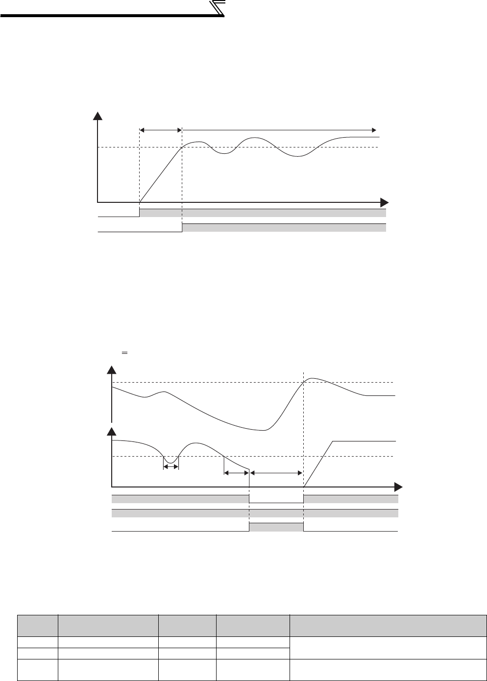
366
Special operation and frequency control
(5) PID control automatic switchover control (Pr. 127)
⋅The inverter can be started up without PID control only at a start.
⋅When the frequency is set to Pr. 127 PID control automatic switchover frequency within the range of 0 to 400Hz, the
system starts up without PID control from a start until Pr. 127 reaches, and then it shifts to PID control operation
mode. Once the system has entered PID control operation, it continues PID control if the output frequency falls to
or below Pr. 127.
(6) PID output suspension function (SLEEP function) (SLEEP signal, Pr. 575 to Pr. 577 )
⋅The inverter stops operation if the output frequency after PID operation remains at less than the Pr. 576 Output
interruption detection level setting for longer than the time set in Pr. 575 Output interruption detection time. This function
can reduce energy consumption in the low-efficiency, low-speed range.
⋅When the deviation (= set value - measured value) reaches the PID output shutoff cancel level (Pr. 577 setting -
1000%) while the PID output interruption function is ON, the PID output interruption function is canceled and PID
control operation is resumed automatically.
⋅While the PID output interruption function is ON, the PID output interruption signal (SLEEP) is output. At this time,
the inverter running signal (RUN) is OFF and the PID control operating signal (PID) is ON.
(7) PID monitor function
⋅The PID control set value, measured value and deviation value can be displayed on the operation panel and output
from terminal FM, AM.
⋅Integral value indicating a negative % can be displayed on the deviation monitor. 0% is displayed as 1000. (The
deviation monitor cannot be output from the terminal FM, AM.)
⋅For the monitors, set the following values in Pr. 52 DU/PU main display data selection, Pr. 54 FM terminal function
selection, and Pr. 158 AM terminal function selection.
Setting Monitor Description Minimum
Increments
Terminal FM,
AM Full Scale Remarks
52 PID set point 0.1% 100% For deviation input (Pr. 128 = 10, 11), the monitor
value is always displayed as 0.
53 PID measurement value 0.1% 100%
54 PID deviation value 0.1% ⎯Value cannot be set to Pr. 54 or Pr. 158.
The PID deviation value of 0% is displayed as 1000.
Output frequency
P
r.127
STF
Time
PID
PID control
Without PID
control
Output frequency
Deviation
Reverse action (Pr.128 10)
Pr.576
Pr.577 - 1000%
RUN
Time
ON
OFF
SLEEP
Less than Pr. 575
Pr. 575 or more SLEEP period
PID
Cancel
level
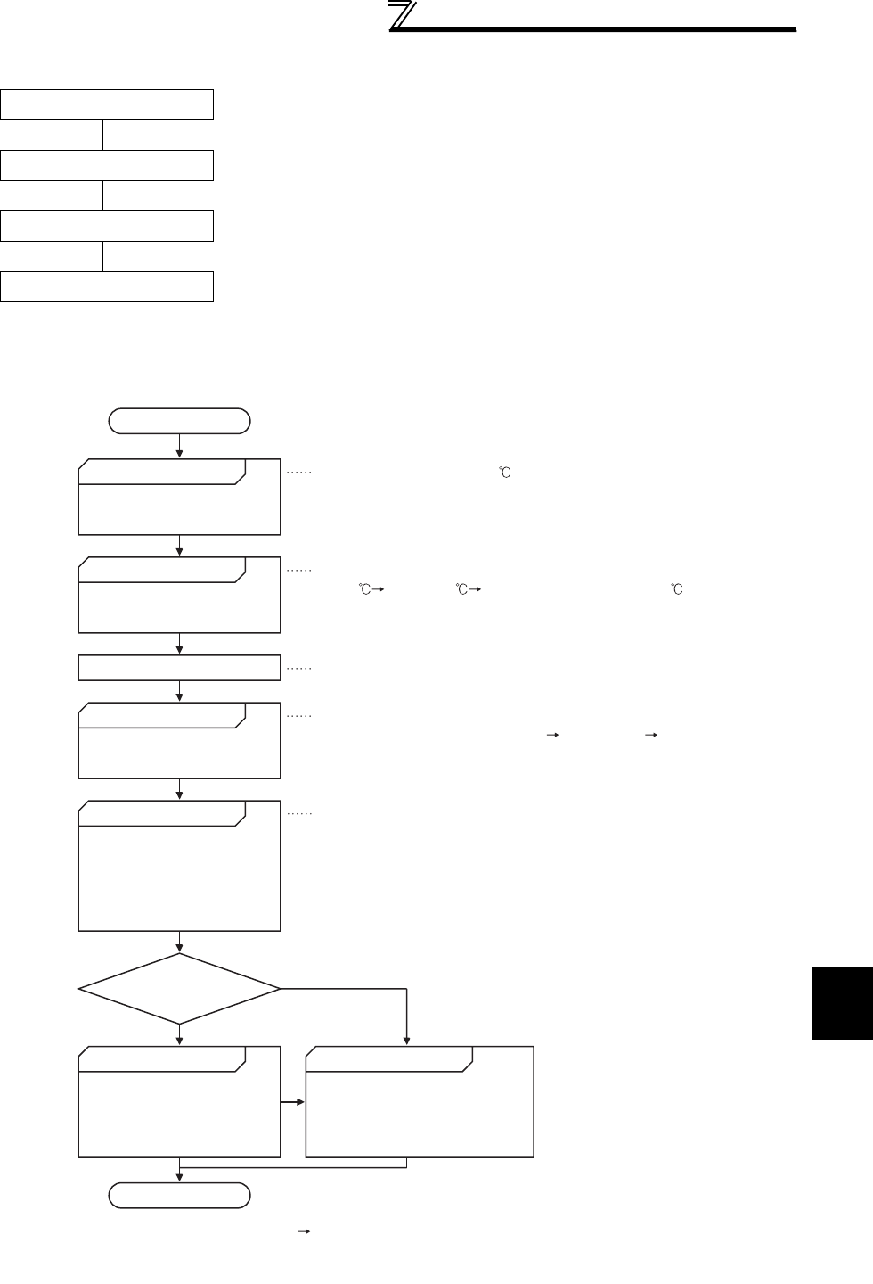
367
Special operation and frequency control
4
PARAMETERS
(8) Adjustment procedure
(9) Calibration example
(A detector of 4mA at 0°C and 20mA at 50°C is used to adjust the room temperature to 25°C under PID control.
The set point is given to across inverter terminals 2 and 5 (0 to 5V).)
Parameter setting Adjust the PID control parameters, Pr. 127 to Pr. 134 and Pr. 575 to Pr. 577.
Terminal setting Set the I/O terminals for PID control. (Pr. 178 to Pr. 189 (input terminal
function selection), Pr. 190 to Pr. 196 (output terminal function selection))
Turn ON the X14 signal
Operation
Start
Determination of set point
Conversion of set point into %
Make calibration.
Setting of set point
Operation
Is the set point stable?
Parameter adjustment Parameter optimization
Adjustment end
Yes
No
When the parameter unit is used for operation, input the set point (0 to
100%) in Pr. 133.
When performing operation, first set the proportional band (Pr. 129 ) to a
slightly larger value, the integral time (Pr. 130 ) to a slightly longer time,
and the differential time (Pr. 134 ) to "9999" (no function), and while looking
at the system operation, decrease the proportional band (Pr. 129 ) and
increase the integral time (Pr. 130 ). For slow response system where a
deadband exists, differential control (Pr. 134 ) should be turned ON and
increased slowly.
Determine the set point of
what is desired to be adjusted.
Calculate the ratio of the set
point to the detector output.
Input a voltage across terminals
2-5 according to the set value %.
To stabilize the measured value,
change the proportional band (Pr.
129 ) to a larger value, the integral
time (Pr. 130 ) to a slightly longer
time, and the differential time (Pr.
134 ) to a slightly shorter time.
While the measured value is stable
throughout the operation status, the
proportional band (Pr. 129 ) may be
decreased, the integral time (Pr. 130 )
decreased, and the differential time
(Pr. 134 ) increased.
Set the proportional band (Pr.
129 ) to a slightly larger value,
the integral time (Pr. 130 ) to a
slightly longer time, and the
differential time (Pr. 134 ) to
"9999" (no function), and turn
on the start signal.
Set the room temperature to 25 .
Set Pr. 128 and turn on the X14 signal to enable PID control.
Detector specifications
When 0 4mA and 50 20mA are used, the set point 25 is 50% on
the assumption that 4mA is 0% and 20mA is 100%.
Make the following calibration* when the target setting input (0 to 5V) and
detector output (4 to 20mA) must be calibrated.
When the set point is 50%
As the terminal 2 specifications are 0% 0V and 100% 5V, input 2.5V
to the terminal 2 for the set point of 50%.
When calibration
is required
Using calibration Pr. 902 and Pr. 903 (terminal 2) or Pr. 904 and Pr. 905 (terminal
4), calibrate the detector output and target setting input.
Make calibration in the PU mode during an inverter stop.
*
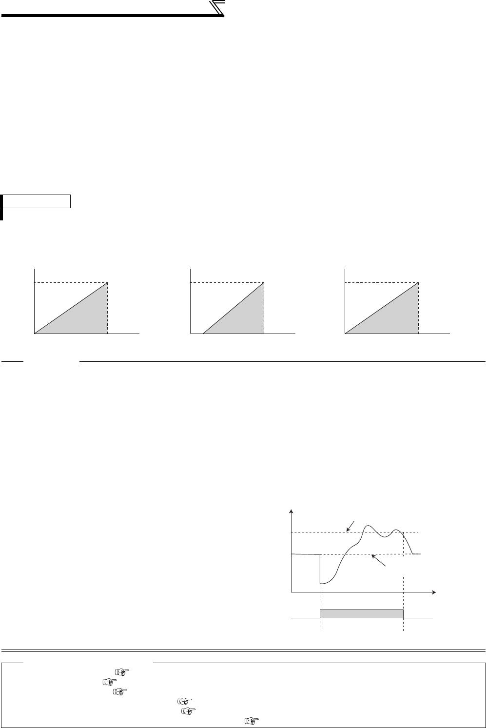
368
Special operation and frequency control
<Set point input calibration>
1. Apply the input voltage of 0% set point setting (e.g. 0V) across terminals 2 and 5.
2. Enter in C2 (Pr. 902) the frequency which should be output by the inverter at the deviation of 0% (e.g. 0Hz).
3. In C3 (Pr. 902), set the voltage value at 0%.
4. Apply the voltage of 100% set point (e.g. 5V) across terminals 2 and 5.
5. Enter in Pr. 125 the frequency which should be output by the inverter at the deviation of 100% (e.g. 60Hz).
6. In C4 (Pr. 903), set the voltage value at 100%.
<Measured value calibration>
1. Apply the input current of 0% measured value (e.g. 4mA) across terminals 4 and 5.
2. Make calibration using C6 (Pr. 904).
3. Apply the input current of 100% measured value (e.g. 20mA) across terminals 4 and 5.
4. Make calibration using C7 (Pr. 905).
The results of the above calibration are as shown below:
REMARKS
⋅The frequency set in C5 (Pr. 904) and Pr. 126 should be the same as set in C2 (Pr. 902) and Pr. 125.
CAUTION
⋅If the RH, RM, RL, REX signal (multi-speed) or JOG signal (Jog operation) is entered with the X14 signal ON, PID control is
stopped and multi-speed or jog operation is started.
⋅If the setting is as follows, PID control becomes invalid.
Pr. 79 Operation mode selection = "6" (switchover mode)
⋅When the Pr. 128 setting is "20" or "21", note that the input across inverter terminals 1 and 5 is added to the set value across
terminals 2-5.
⋅When using terminal 4 (measured value input) and terminal 1 (deviation input) under PID control, set "0" (initial value) in Pr. 858
Terminal 4 function assignment and "0" (initial value) in Pr. 868 Terminal 1 function assignment. PID control cannot be performed
when a value other than 0 is set.
⋅Changing the terminal function using any of Pr. 178 to Pr. 189, Pr. 190 to Pr. 196 may affect the other functions. Set parameters
after confirming the function of each terminal.
⋅When PID control is selected, the minimum frequency is the frequency set in Pr. 902 and the maximum frequency is the
frequency set in Pr. 903. (Pr. 1 Maximum frequency and Pr. 2 Minimum frequency settings are also valid.)
⋅The remote operation function is invalid during PID operation.
⋅When the control is switched to PID control during
normal operation, the frequency command value
calculated by PID operation using 0Hz as standard is
used without the frequency during the operation.
♦ Parameters referred to ♦
Pr. 59 Remote function selection Refer to page 169
Pr. 73 Analog input selection Refer to page 286
Pr. 79 Operation mode selection Refer to page 313
Pr. 178 to Pr. 189 (input terminal function selection) Refer to page 231
Pr. 190 to Pr. 196 (output terminal function selection) Refer to page 239
C2 (Pr. 902) to C7 (Pr. 905) Frequency setting voltage (current) bias/gain Refer to page 294
100
0
05(V)
(%)
[Set point setting]
100
0
020 (mA)
(%)
[Measured value]
4
0
0100 Deviation (%)
[Manipulated variable]
Manipulated variable (Hz)
60
PID action
Frequency
command
PID set point
Frequency command
during normal operation
ON
Operation when control is switched to PID control during normal operation
Normal operation PID operation Normal operation

369
Special operation and frequency control
4
PARAMETERS
4.25.2
Bypass-inverter switchover function (Pr. 57, Pr. 58, Pr. 135 to Pr. 139, Pr. 159)
⋅When the motor is operated at 60Hz (or 50Hz), more efficient operation can be performed by the commercial power
supply than by the inverter. When the motor cannot be stopped for a long time for the maintenance/inspection of the
inverter, it is recommended to provide the commercial power supply circuit.
⋅To avoid commercial power supply being applied to the inverter output side when switching between inverter
operation and commercial power supply operation, provide an interlock which the MC of the commercial power
supply side turns ON only when the MC of the inverter output side is OFF. Using the electronic bypass sequence
function that outputs the timing signal for operation of the magnetic contactor, a complicated commercial power
supply switchover interlock can be provided by the inverter.
The complicated sequence circuit for bypass operation is built in the inverter. Hence, merely inputting the start,
stop or automatic switchover selection signal facilitates the interlock operation of the switchover magnetic
contactor.
Parameter
Number Name Initial
Value Setting Range Description
57 Restart coasting time 9999
0
⋅1.5K or lower..................................................... 0.5s,
⋅2.2K to 7.5K.................................................1s,
⋅11K to 55K...................................................3.0s,
⋅75K or higher .................................................... 5.0s,
The above times are coasting time.
55K or
lower
0.1 to
5s Set the waiting time for inverter-triggered restart after an
instantaneous power failure.
75K or
higher
0.1 to
30s
9999 No restart
58 Restart cushion time 1s 0 to 60s Set a voltage starting time at restart.
135 Electronic bypass
sequence selection 00 Without electronic bypass sequence
1 With electronic bypass sequence
136 MC switchover interlock
time 1s 0 to 100s Set the operation interlock time of MC2 and MC3.
137 Start waiting time 0.5s 0 to 100s Set the time slightly longer (0.3 to 0.5s or so) than the time from
when the ON signal enters MC3 until it actually turns ON.
138 Bypass selection at a
fault 0
0 Inverter output is stopped (motor coast) at inverter fault.
1
Operation is automatically switched to bypass operation at
inverter fault (Not switched when an external thermal relay
operation (E.OHT) or CPU fault (E.CPU) occurs).
139
Automatic switchover
frequency from inverter
to bypass operation
9999 0 to 60Hz
Set the frequency to switch inverter operation to bypass
operation.
Inverter operation is performed from a start until Pr. 139 is
reached, and when the output frequency is at or above Pr.
139, inverter operation is automatically switched to bypass
operation.
9999 Without automatic switchover
159
Automatic switchover
frequency range from
bypass to inverter
operation
9999
0 to 10Hz
Valid during automatic switchover operation (Pr. 139 ≠ 9999)
When the frequency command decreases below (Pr. 139 -
Pr. 159) after operation is switched from inverter operation to
bypass operation, the inverter automatically switches
operation to inverter operation and operates at the
frequency of frequency command. When the inverter start
command (STF/STR) is turned OFF, operation is switched to
inverter operation also.
9999
Valid during automatic switchover operation (Pr. 139 ≠ 9999)
When the inverter start command (STF/STR) is turned OFF
after operation is switched from inverter operation to bypass
operation, operation is switched to inverter operation and
the motor decelerates to stop.
CAUTION
Commercial operation cannot be performed with the Mitsubishi vector motor (SF-V5RU).

370
Special operation and frequency control
(1) Connection diagram
⋅The following shows the connection diagram of a typical electronic bypass sequence. Sink logic, Pr. 185 = "7", Pr.
192 = "17", Pr. 193 = "18", Pr. 194 = "19"
⋅Operations of magnetic contactors (MC1, MC2, MC3)
Electronic bypass sequence connection diagram
*1 Take caution for the capacity of the sequence output terminal.
The used terminal changes depending on the setting of Pr. 190 to
Pr. 196 (output terminal function selection).
*2 When connecting a DC power supply, insert a protective diode.
When connecting an AC power supply, connect a relay output
option (FR-A7AR) and use a contact output.
*3 The used terminal changes depending on the setting of Pr. 180 to
Pr. 189 (input terminal function selection).
CAUTION
⋅Use the bypass operation function in External operation mode. Be sure to connect the other power supply since the function is
not performed normally unless the connection terminals R1/L11, S1/L21 are not connected to the other power supply (power
supply that does not pass MC1).
⋅Be sure to provide mechanical interlocks for MC2 and MC3.
Magnetic
Contactor Installation Place
Operation ({: Shorted, ×: Open)
Bypass operation During inverter
operation
At an inverter fault
occurrence
MC1 Between power supply and
inverter input ×
(Shorted by reset)
MC2 Between power supply and motor ×
×
(Can be selected using
Pr. 138, always open
when external thermal
relay is ON)
MC3 Between inverter output and
motor ××
Inverter start
(forward rotation)
MC1
R/L1
S/L2
T/L3
STF
R1/L11
S1/L21
CS
MRS
RES
10
2
5
U
V
W
External
thermal relay
IM
(MC1)IPF
(MC2)OL
SE
MC3
MC2
24VDC
MC1
External
thermal reset
Frequency
setting signal
(MC3)FU
Inverter/bypass
operation interlock MC2
MC3
*3
*1
*2
*1
*1
JOG(OH)
MCCB
MC2
MC3
SD
Output Terminal Capacity Output Terminal
Permissible Load
Inverter open collector output
(RUN, SU, IPF, OL, FU) 24VDC 0.1A
Inverter relay output (A1-C1, B1-
C1, A2-B2, B2-C2)
Relay output option (FR-A7AR)
230VAC 0.3A
30VDC 0.3A

371
Special operation and frequency control
4
PARAMETERS
⋅The input signals are as indicated below.
⋅The output signals are as indicated below.
Signal Terminal Used Function Operation MC Operation *6
MC1 *5 MC2 MC3
MRS MRS Operation enable/disable
selection *1
ON .....Bypass-inverter operation
enabled ⎯⎯
OFF ... Bypass-inverter operation
disabled ×No
change
CS CS Inverter/bypass *2
ON......Inverter operation ×
OFF ... Bypass operation ×
STF
(STR) STF(STR) Inverter operation command
(Invalid for bypass) *3
ON......Forward rotation (reverse
rotation) ×
OFF.... Stop ×
OH Set "7" in any of
Pr. 180 to Pr. 189.External thermal relay input ON ..... Motor normal ⎯⎯
OFF.... Motor abnormal ×××
RES RES Operating status initialization
*4
ON......Initialization No
change ×No
change
OFF.... Normal operation ⎯⎯
*1 Unless the MRS signal is turned ON, neither bypass operation nor inverter operation can be performed.
*2 The CS signal functions only when the MRS signal is ON.
*3 STF (STR) functions only when both the MRS signal and CS signal are ON.
*4 The RES signal enables reset input acceptance selection using Pr. 75 Reset selection/disconnected PU detection/PU stop selection.
*5 MC1 turns OFF when an inverter fault occurs.
*6 MC operation
: MC-ON
×: MC-OFF
⎯: Inverter operation ................ MC2 is OFF and MC3 is ON
Bypass operation ................ MC2 is ON and MC3 is OFF
No change : The status before the signal turns ON or OFF is held.
Signal Terminal Used
(Pr. 190 to Pr. 196 setting) Description
MC1 17 Control signal output of inverter input side magnetic
contactor MC1
MC2 18 Control signal output of bypass operation magnetic
contactor MC2
MC3 19 Control signal output of inverter output side
magnetic contactor MC3
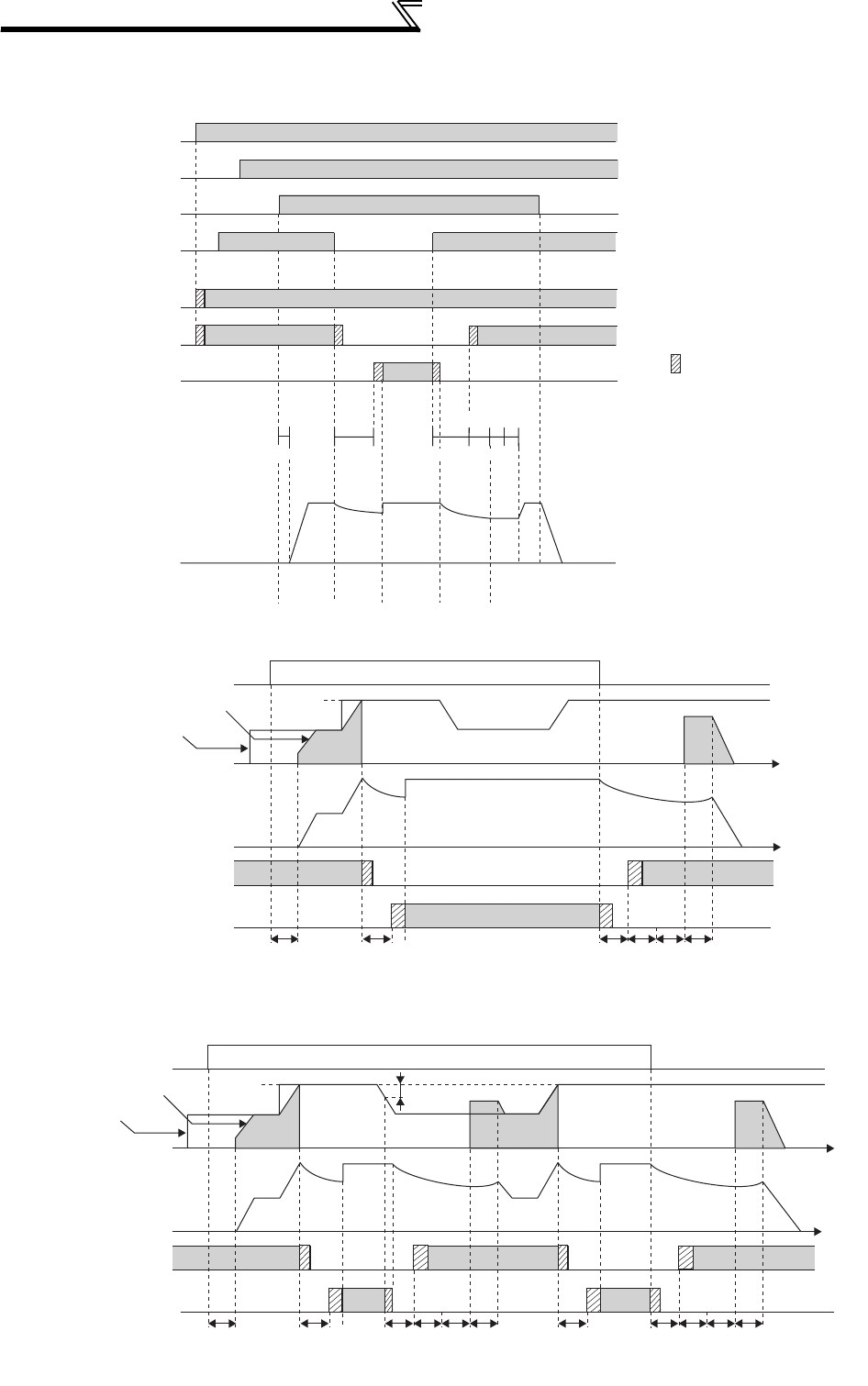
372
Special operation and frequency control
(2) Electronic bypass operation sequence
⋅Operation sequence example when there is no automatic switchover sequence (Pr. 139 = "9999")
⋅Operation sequence example when there is automatic switchover sequence (Pr. 139 ≠ "9999", Pr. 159 = "9999")
⋅Operation sequence example when there is automatic switchover sequence (Pr. 139 ≠ "9999", Pr. 159 ≠ "9999")
ON
OFF
Power supply
ON
OFF
Operation interlock
ON
OFF
Inverter run command
ON
OFF
(MRS)
(STF)
ON
OFF
Inverter input side MC
(MC1)
ON
OFF
ON
OFF
Each timer
Coasting StopCoasting
ON : Operation enabled
OFF: Operation disabled
ON : Forward rotation
OFF: Stop
ON : Inverter operation
OFF: Bypass operation
Pr. 136 MC switchover interlock time
Pr. 137 MC3 start (waiting time)
Pr. 57 Reset time
Pr. 58 Switchover cushion time
Off only at inverter alarm
Inverter output side MC
(MC3)
Pr. 136
Pr. 57 Pr. 136 Pr. 57
Pr. 58
Pr. 137
Inverter/bypass (CS)
MC for bypass
operation (MC2)
Operating status
(motor speed)
INV
operation
Bypass
operation
INV
operation
Indicates the delay time until
the MC turns on (off).
STF
Frequency command
Output frequency Pr. 139
Time
Time
Actual motor speed
A : Pr. 136 MC switchover interlock time B : Pr. 137 Start waiting time
C : Pr. 57 Restart coasting time D : Pr. 58 Restart cushion time
MC3 ON
OFF
ON
OFF
MC2 ON
OFF
CAAB C D
INV
operation
Bypass
operation
STF
Frequency command
Output frequency Pr. 139 Pr. 159
Time
Time
Actual motor speed
A : Pr. 136 MC switchover interlock time B : Pr. 137 Start waiting time
C : Pr. 57 Restart coasting time D : Pr. 58 Restart cushion time
MC3 ON
OFF
ON
OFF
MC2 ON
OFF
CAAB C D AAB C D
INV
operation
Bypass
operation
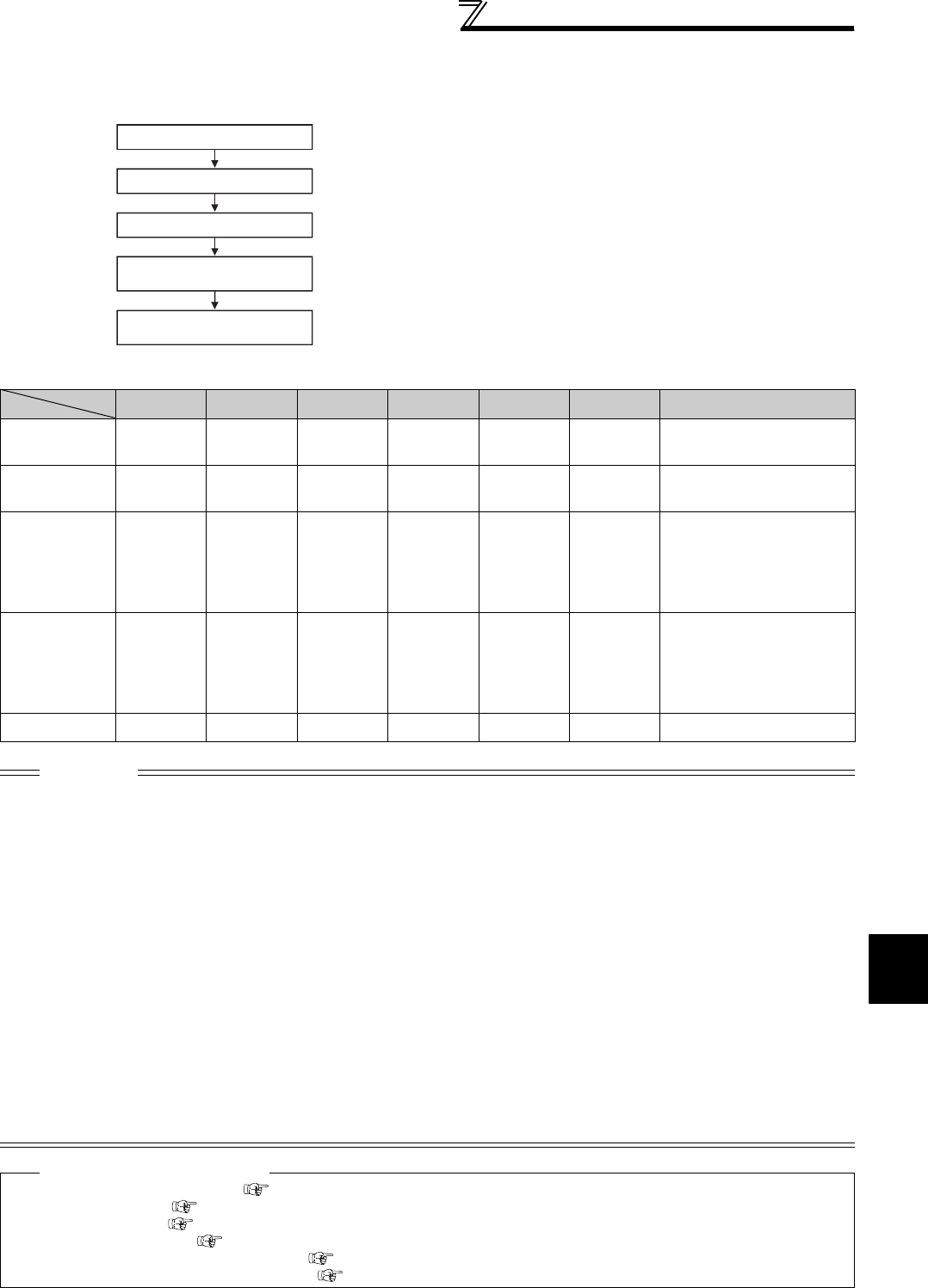
373
Special operation and frequency control
4
PARAMETERS
(3) Operating procedure
1)Procedure for operation
Operation pattern
2)Signal ON/OFF after parameter setting
MRS CS STF MC1 MC2 MC3 Remarks
Power supply
ON
OFF
(OFF)
OFF
(OFF)
OFF
(OFF)
OFF
→
ON
(OFF
→
ON)
OFF
(OFF)
OFF
→
ON
(OFF
→
ON)
External operation mode
(PU operation mode)
At start
(inverter)
OFF
→
ON OFF
→
ON OFF
→
ON
ON OFF ON
At constant
speed
(commercial
power supply)
ON
ON
→
OFF
ON ON
OFF
→
ON ON
→
OFF
MC2 turns ON after MC3
turns OFF
(coasting status during this
period)
Waiting time 2s
Switched to
inverter for
deceleration
(inverter)
ON
OFF
→
ON
ON ON
ON
→
OFF OFF
→
ON
MC3 turns ON after MC2
turns OFF
(coasting status during this
period)
Waiting time 4s
Stop ON ON
ON
→
OFF
ON OFF ON
CAUTION
⋅Connect the control power supply (R1/L11, S1/L21) in front of input side MC1. If the control power supply is connected behind
input side MC1, the electronic bypass sequence function is not executed.
⋅The electronic bypass sequence function is valid only when Pr. 135 = "1" in the external operation or combined operation mode
(PU speed command, external operation command Pr. 79 = "3"). When Pr. 135 = "1" in the operation mode other than the above,
MC1 and MC3 turn ON.
⋅When the MRS and CS signals are ON and the STF (STR) signal is OFF, MC3 is ON, but when the motor was coasted to a stop
from bypass operation last time, a start is made after the time set in Pr. 137 has elapsed.
⋅Inverter operation can be performed when the MRS, STF (STR) and CS signals turn ON. In any other case (MRS signal - ON),
bypass operation is performed.
⋅When the CS signal is turned OFF, the motor switches to bypass operation. However, when the STF (STR) signal is turned
OFF, the motor is decelerated to a stop in the inverter operation mode.
⋅When both MC2 and MC3 are OFF and either MC2 or MC3 is then turned ON, there is a waiting time set in Pr. 136.
⋅If electronic bypass sequence is valid (Pr. 135 = "1"), the Pr. 136 and Pr. 137 settings are ignored in the PU operation mode. The
input terminals (STF, CS, MRS, OH) of the inverter return to their normal functions.
⋅When the electronic bypass sequence function (Pr. 135 = "1") and PU operation interlock function (Pr. 79 = "7") are used
simultaneously, the MRS signal is shared by the PU operation external interlock signal unless the X12 signal is assigned.
(When the MRS and CS signals turn ON, inverter operation is enabled)⋅
⋅Set the acceleration time to the level that does not activate the stall prevention operation.
⋅Changing the terminal function using any of Pr. 178 to Pr. 189, 190 to Pr. 196 may affect the other functions. Set parameters after
confirming the function of each terminal.
♦ Parameters referred to ♦
Pr. 11 DC injection brake operation time Refer to page 203
Pr. 57 Restart coasting time Refer to page 266
Pr. 58 Restart cushion time Refer to page 266
Pr. 79 Operation mode selection Refer to page 313
Pr. 178 to Pr. 189 (Input terminal function selection) Refer to page 231
Pr. 190 to Pr. 196 (Output terminal function selection) Refer to page 239
Power supply ON
Setting the parameters
Start inverter operation
Constant-speed bypass
operation
Deceleration (stop)
inverter operation
⋅Pr. 135 = "1" (open collector output terminal of inverter)
⋅Pr. 136 = "2.0s"
⋅Pr. 137 = "1.0s" (Set the time longer than the time from when
MC3 actually turns ON until the inverter and motor are
connected. If the time is short, a restart may not function
properly.)
⋅Pr. 57 = "0.5s"
⋅Pr. 58 = "0.5s" (Be sure to set this parameter when bypass
operation is switched to inverter operation.)
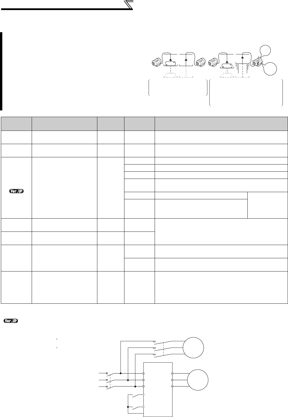
374
Special operation and frequency control
4.25.3 Load torque high speed frequency control (Pr. 4, Pr. 5, Pr. 270 to Pr. 274)
<Connection diagram>
Load torque high speed frequency control is a function
which automatically sets the operational maximum
frequency according to the load.
The load size during power driving is estimated by
detecting average currents at set timings after a start.
When the load is light, the frequency is increased from
the originally-set frequency. (During regenerative
driving, the frequency is not increased.)
This function is designed to increase speed
automatically under light load, for example to minimize
the incoming/outgoing time in a multi-story parking lot.
Parameter
Number Name Initial
Value
Setting
Range Description
4Multi-speed setting (high
speed) 60Hz 0 to 400Hz Set the higher-speed frequency.
5Multi-speed setting
(middle speed) 30Hz 0 to 400Hz Set the lower-speed frequency.
270
Stop-on contact/load
torque high-speed
frequency control
selection
0
0 Normal operation
1 Stop-on-control (refer to page 214)
2 Load torque high speed frequency control
3Stop-on-contact (refer to page 214) + load torque high speed
frequency control
11 Stop-on-control E.OLT is invalid
under stop-on-
control
13
Stop-on-contact + load torque high
speed frequency control (refer to page
214)
271 *1 High-speed setting
maximum current 50% 0 to 220% Set the upper and lower limits of the current at high and
middle speeds.
272 *1 Middle-speed setting
minimum current 100% 0 to 220%
273 *1 Current averaging range 9999
0 to 400Hz Average current during acceleration from (Pr. 273 × 1/2) Hz
to (Pr. 273) Hz can be achieved.
9999 Average current during acceleration from (Pr. 5 × 1/2) Hz to
(Pr. 5) Hz is achieved.
274 *1 Current averaging filter
time constant 16 1 to 4000
Set the time constant of the primary delay filter relative to
the output current.
The time constant [ms] is 0.75 × Pr. 274 and the initial value
is 12ms.
A larger setting provides higher stability but poorer response.
*1 This parameter allows its setting to be changed during the operation in any operation mode even if "0 (initial value) or 1" is set in Pr.77 Parameter
write selection.
.......... Specifications differ according to the date assembled. Refer to page 484 to check the SERIAL number.
<Without high-speed
frequency control>
<With high-speed
frequency control>
Light
Faster
Whether there is a load or
not, the lift is moved
vertically at the same speed.
The lift with a light load or without
a load is moved faster than the lift
with a load.
(The output frequency is increased
only during power driving.)
Mechanical
brake
R/L1
S/L2
T/L3
Motor
MC
STF
CS(X19)
*
Start signal
Load torque high-speed frequency
MCCB
Power supply
U
V
W
Pr. 186 = 19
Sink logic
SD
* The used terminal changes according to the Pr. 180 to Pr. 189 (input terminal function selection) settings.
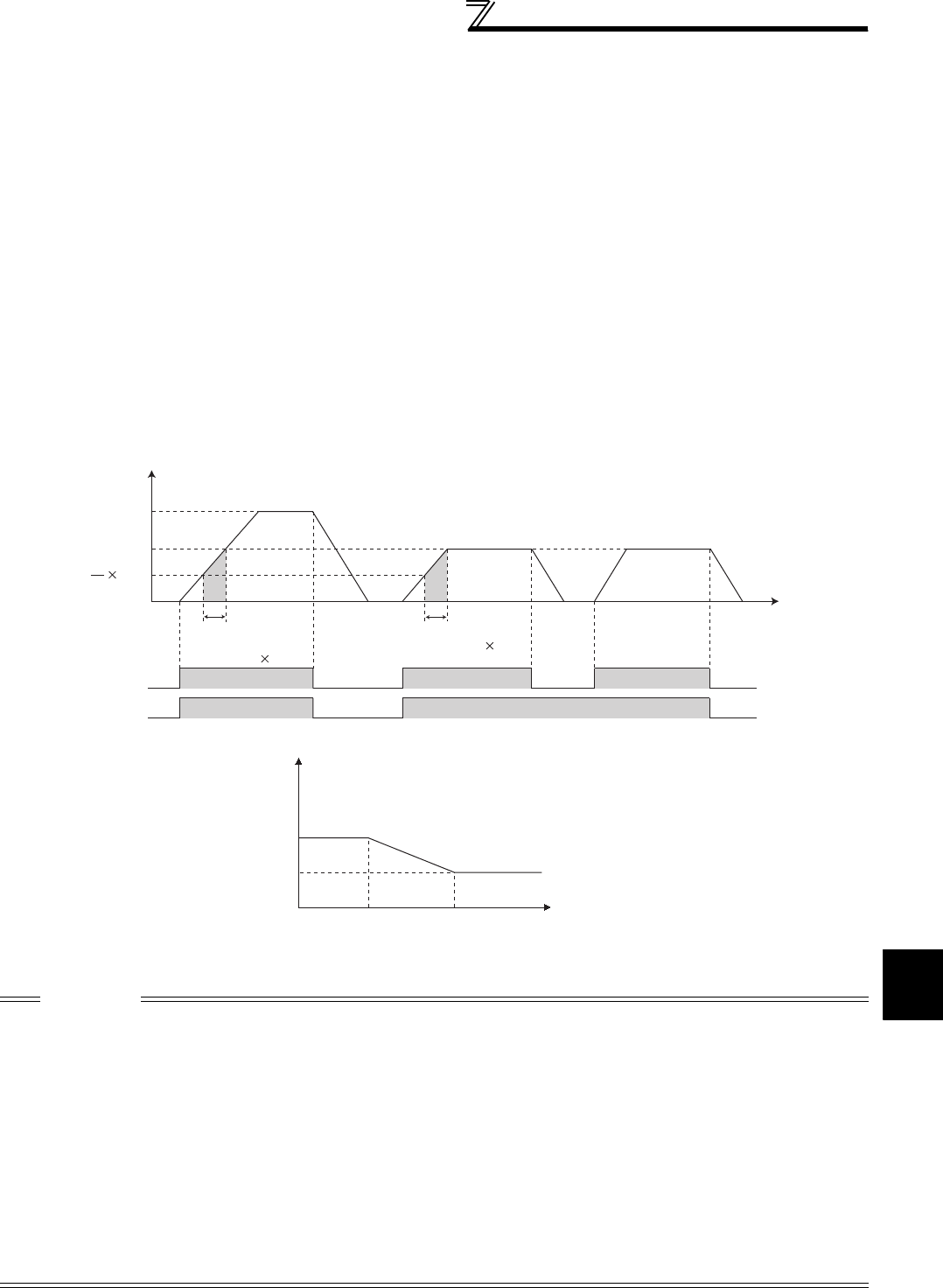
375
Special operation and frequency control
4
PARAMETERS
(1) Load torque high speed frequency control setting
· Set "2, 3 or 13" in Pr. 270 Stop-on contact/load torque high-speed frequency control selection.
· When operating with the load torque high speed frequency function selection signal (X19) ON, the inverter
automatically changes the maximum frequency within the setting range of Pr. 4 Multi-speed setting (high speed) and
Pr. 5 according to the magnitude of the average current during the time to accelerate from 1/2 of the frequency set
in Pr. 5 Multi-speed setting (middle speed) to the frequency set in Pr. 5 .
·Set "19" in Pr. 178 to Pr. 189 (input terminal function selection) and assign the X19 signal function to the input terminal.
· Made valid only in the External operation mode.
· This control can be activated at every start.
(2) Operation of load torque high speed frequency control setting
· When the average current of the current averaging range (chart A below) during operation with the X19 signal ON
is less than the "rated inverter current × Pr. 271 setting (%)", the maximum frequency automatically becomes the
Pr. 4 Multi-speed setting (high speed) setting value.
· When the average current of the current averaging range (chart B below) during operation with the X19 signal ON
is more than the "rated inverter current × Pr. 272 setting (%)", the maximum frequency automatically becomes the
Pr. 5 Multi-speed setting (middle speed) setting value.
· During regeneration load operation, setting of Pr. 5 is the maximum frequency regardless of the average current.
· The current averaging range can be set between 1/2 frequency of the Pr. 273 setting value and Pr. 273 set frequency.
CAUTION
· When the current averaging range includes the constant power range, the output current may become large in the constant
power range.
· When the average current value in the current averaging range is small, deceleration time becomes longer as the running
frequency increases.
· The maximum output frequency is 120Hz. The output frequency is 120Hz even when the setting is above 120Hz.
· Restart after instantaneous power failure function, fast-response current limit function, shortest acceleration/deceleration and
optimum acceleration/deceleration are invalid.
· Changing the terminal function using any of Pr. 178 to Pr. 189 may affect the other functions. Set parameters after confirming the
function of each terminal.
· The load torque high speed frequency function is invalid in the following operation conditions.
PU operation (Pr. 79) , PU+external operation (Pr. 79) , JOG operation (JOG signal) , PID control function operation (X14 signal),
remote setting function operation (Pr. 59), orientation control function operation, multi-speed setting (RH, RM, RL signal ), 16-bit
digital input option (FR-A7AX)
· When the average current during acceleration is too small, it may be judged as regeneration and the maximum frequency
becomes the setting of Pr. 5.
(STR)
X19
STF ON ON ON
ON ON
OFF
OFF
OFF
OFF
OFF
Pr. 5
Pr. 4
Pr. 5
1
2
Power running Reganerating
AB
Current averaging range
Current averaging range
Current averaging range Current averaging range
Current averaging range
Current averaging range
Output frequency
Time
Less than
Pr. 271 setting rated current
Less than
Pr. 271 setting rated current
Less than
Pr. 271 setting rated current
Pr. 272 setting rated current
or more
Pr. 272 setting rated current
or more
Pr. 272 setting rated current
or more
Pr. 5
(30Hz)
Pr. 271
(50%)
Average current
Frequency
Pr. 272
(100%)
Value in parentheses is initial value.
Pr. 4
(60Hz)
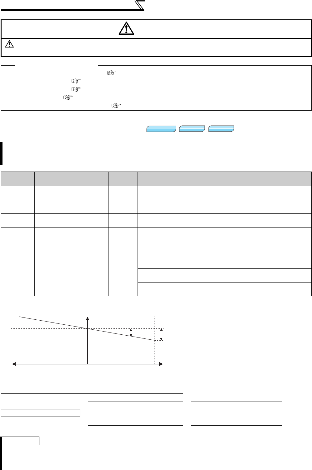
376
Special operation and frequency control
4.25.4 Droop control (Pr. 286 to Pr. 288)
CAUTION
When the load is light, the motor may suddenly accelerate to 120Hz maximum, causing hazard.
Securely provide mechanical interlock on the machine side to perform.
♦ Parameters referred to ♦
Pr. 4 to Pr. 6, Pr. 24 to Pr. 27 (multi-speed setting) Refer to page 165
Pr. 59 Remote function selection Refer to page 169
Pr. 79 Operation mode selection Refer to page 313
Pr. 128 PID action selection Refer to page 361
Pr. 178 to Pr. 189 (input terminal function selection) Refer to page 231
This function is designed to balance the load in proportion to the load torque to provide the speed drooping
characteristic under Advanced magnetic flux vector control, Real sensorless vector control and vector control.
This function is effective for balancing the load when using multiple inverters
Parameter
Number Name Initial
Value
Setting
Range Description
286 Droop gain 0%
0 Normal operation
0.1% to
100%
Droop control is valid
Set the drooping amount at the rated torque as a
percentage with respect to the rated motor frequency.
287 Droop filter time constant 0.3s 0 to 1s Set the time constant of the filter applied on the torque
amount current.
288 Droop function activation
selection 0
0Droop control is not exercised during acceleration/
deceleration.
1Droop control is always exercised during operation. (with
0 limit)
2Droop control is always exercised during operation.
(without 0 limit)
10 Droop control is not exercised during acceleration/
deceleration. (Motor speed is referenced)
11 Droop control is always exercised during operation.
(Motor speed is referenced)
(1) Droop control
· The output frequency is changed according to
the magnitude of torque amount current under
Advanced magnetic flux vector control, Real
sensorless vector control and vector control.
The drooping amount at the rated torque is set
by the droop gain as a percentage using the
rated frequency (Motor speed when Pr. 288 =
"10, 11") as a reference.
· The maximum droop compensation frequency
is 120Hz.
When Pr. 288 = "0 to 2", or under Advanced magnetic flux vector control
Droop compensation frequency = Amount of torque current after filtering ×Rated motor frequency × Droop gain
Rated value of torque current 100
When Pr. 288 = "10, 11"
Droop compensation frequency = Amount of torque current after filtering ×Motor speed × Droop gain
Rated value of torque current 100
REMARKS
Set the droop gain to about the rated slip of the motor.
Magnetic flux
Magnetic flux
Magnetic flux
Sensorless
Sensorless
Sensorless Vector
Vector
Vector
Droop compensation
frequency
Rated frequency
Torque
100%
Droop
gain
-100%
Frequency
0
Rated slip =Synchronous speed at base frequency - Rated speed ×100[%]
Synchronous speed at base frequency
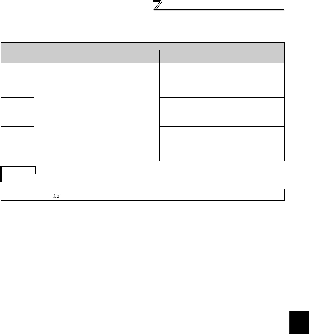
377
Special operation and frequency control
4
PARAMETERS
(2) Limit the frequency after droop compensation (0 limit)
· Setting Pr. 288 under Real sensorless vector control or vector control can limit the frequency command when the
frequency after droop compensation is negative.
Pr. 288
Setting
Description
Under Advanced magnetic flux vector control Under Real sensorless vector control
or vector control
0
(initial value),
10
Droop control is not exercised during acceleration/
deceleration.
Note that the frequency command after droop control is
limited at 0.5Hz when the frequency command after
droop control is negative.
Droop compensation amount is determined using the
rated motor frequency as reference.
Droop control is not exercised during acceleration/
deceleration.
Note that the frequency command is limited at 0Hz when
the frequency command after droop control is negative.
When Pr. 288 = "10", droop compensation amount is
determined using the motor speed as reference.
1, 11
Droop control is always exercised during operation.
Note that the frequency command is limited at 0Hz when
the frequency command after droop control is negative.
When Pr. 288 = "11", droop compensation amount is
determined using the motor speed as reference.
2
Droop control is always exercised during operation.
Note that under vector control, the frequency command
is not limited at 0Hz even when the frequency command
after droop control is negative.
(The frequency command is limited at 0Hz under Real
sensorless vector control.)
REMARKS
The maximum value of frequency after droop compensation is either 120Hz or Pr. 1 Maximum frequency , whichever is smaller.
♦ Parameters referred to ♦
Pr. 1 Maximum frequency Refer to page 157
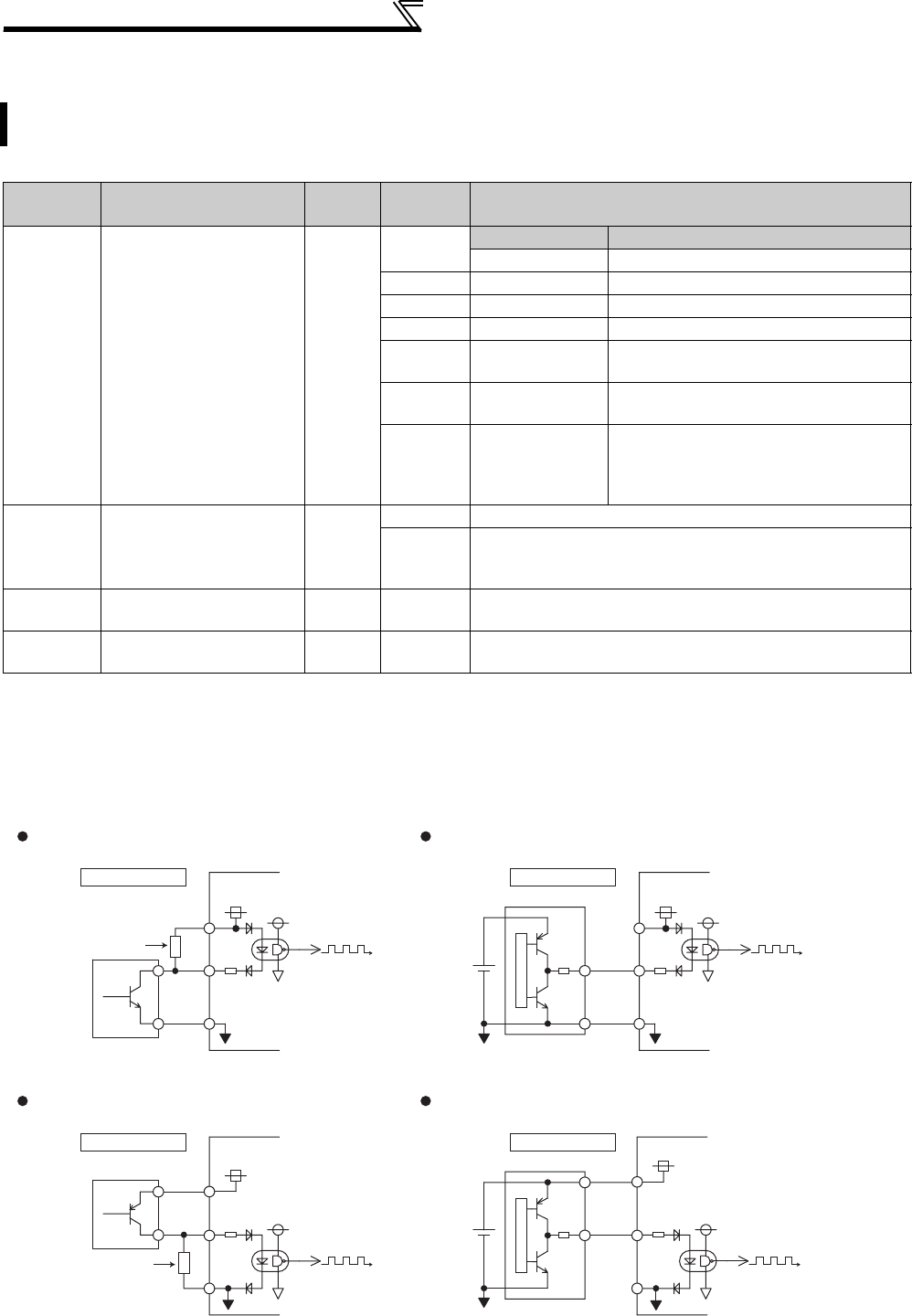
378
Special operation and frequency control
4.25.5 Frequency setting by pulse train input (Pr. 291, Pr. 384 to Pr. 386)
(1) Pulse train input selection (Pr. 291)
· Setting any of "1, 11, 21, 100" in Pr. 291 Pulse train I/O selection and a value other than "0" in Pr. 384 Input pulse division
scaling factor switches terminal JOG to pulse train input terminal and frequency setting of the inverter can be
performed. (The initial value is JOG signal)
Pulse train input of maximum of 100k pulse/s is enabled.
The inverter speed can be set by inputting pulse train from terminal JOG.
In addition, synchronous speed operation of inverters can be performed by combining pulse train I/O.
Parameter
Number Name Initial
Value
Setting
Range Description
291 Pulse train I/O selection 0
Pulse train input Pulse train output
0 Terminal JOG FM output
1 Pulse train input FM output
10 Terminal JOG High speed pulse train output (50%Duty)
11 Pulse train input High speed pulse train output (50%Duty)
20 Terminal JOG High speed pulse train output (ON width is
always same)
21 Pulse train input High speed pulse train output (ON width is
always same)
100 Pulse train input
High speed pulse train output (ON width is
always same)
The inverter outputs the signal input as
pulse train as it
384 Input pulse division
scaling factor 0
0 Pulse train input invalid
1 to 250
Indicates division scaling factor to the input pulse and the
frequency resolution to the input pulse changes according to
the value.
385 Frequency for zero input
pulse 0Hz 0 to 400Hz Set the frequency when the input pulse is 0 (bias).
386 Frequency for maximum
input pulse 60Hz 0 to 400Hz Set the frequency when the input pulse is maximum (gain).
JOG
PC
SD
Sink logic Inverter
Pull up resistance
*
2kΩ
Connection with an open collector output system
pulse generator
JOG
PC
SD
Sink logic Inverter
2kΩ
Connection with a complementary output system
pulse generator
24V power
JOG
PC
SD
Source logic Inverter
Pull down resistance
*
2kΩ
Connection with an open collector output system
pulse generator
Source logic
Connection with a complementary output system
pulse generator
24V power JOG
PC
SD
Inverter
2kΩ
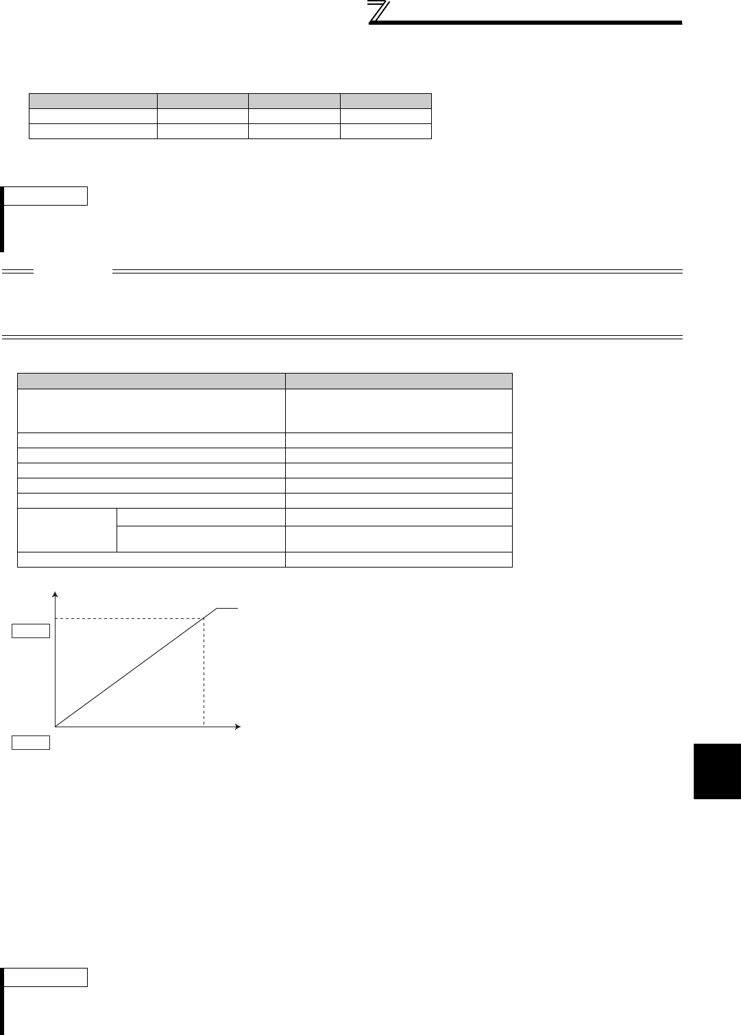
379
Special operation and frequency control
4
PARAMETERS
* When the wiring length of the open collector output connection is long, input pulse cannot be recognized because of a pulse shape deformation due to the
stray capacitances of the wiring.
When wiring length is long (10m or more of 0.75mm2 twisted cable is recommended), connect an open collector output signal and power supply using a pull
up resistance. The reference of resistance value to the wiring length is as in the table below,
Stray capacitances of the wiring greatly differ according to the cable type and cable laying, the above cable length is not a guaranteed value.
When using a pull up/down resistance, check the permissible power of the resistor and permissible load current of output transistor and use them within a
permissible range.
zPulse train input specifications
(3) Calculation method of division scaling factor of input pulse (Pr. 384 )
· Maximum input pulse can be calculated from the following formula using Pr. 384 Input pulse division scaling factor.
Maximum of input pulse (pulse/s) = Pr. 384 × 400
(maximum of 100kpulse/s)
(Detectable pulse = 11.45 pulse/s)
· For example, when you want to operate at 0Hz when pulse train input is zero and operate at 30Hz when pulse train
is 4000 pulse/s, set parameters as below.
Pr. 384 = 10
(maximum input pulse 4000 pulse/s)
Pr. 385 = 0Hz, Pr. 386 = 30Hz
(pulse train limit value is 33Hz)
Wiring Length Less than 10m 10 to 50m 50 to 100m
Pull up/down resistance Not necessary 1kΩ470Ω
Load current (for reference) 10mA 35mA 65mA
REMARKS
· When pulse train input is selected, a function assigned to terminal JOG using Pr. 185 JOG terminal function selection is invalid.
· When Pr. 419 Position command source selection = "2" (simple position pulse train command by inverter pulse train input), JOG
terminal serves as simple position pulse train terminal regardless of the Pr. 291.
CAUTION
· Since Pr. 291 is a selection parameter for pulse train output/FM output, check the specifications of a device connected to
terminal FM when changing the setting value. (Refer to page 259 for pulse train output.)
· Output specifications (high speed pulse train output or FM output) of terminal FM can be selected using Pr. 291. Change the
setting value using care not to change output specifications of terminal FM. (Refer to page 259 for pulse train output.)
Item Specifications
Available pulse method
Open collector output
Complementary output
(power supply voltage 24V)
* The wiring length of complementary
output depends on the output wiring
specifications of complementary
output device.
Stray capacitances of the wiring
greatly differ according to the cable
type and cable laying, the
maximum cable length is not a
guaranteed value.
H input level 20V or more (voltage between JOG-SD)
L input level 5V or less (voltage between JOG-SD)
Maximum input pulse rate 100kpps
Minimum input pulse width 2.5us
Input resistance/load current 2kΩ (typ) / 10mA (typ)
Maximum wiring
length
(reference value)
Open collector output system 10m (0.75mm2/ twisted pair)
Complementary output system 100m (output resistance 50Ω) *
Detection resolution 1/3750
(2) Adjustment of pulse train input and frequency
(Pr. 385, Pr. 386 )
· Frequency for zero input pulse can be set using Pr. 385
Frequency for zero input pulse and frequency at maximum input
pulse can be set using Pr. 386 Frequency for maximum input
pulse.
* Limit value can be calculated from the following formula.
(Pr. 386 - Pr. 385 ) × 1.1 + Pr. 385
REMARKS
The priorities of the frequency commands by the external signals are "Jog operation > multi-speed operation > terminal 4 analog
input > pulse train input".
When pulse train input is valid (when Pr. 291 = "1, 11, 21, or 100" and Pr. 384 ≠ "0"), terminal 2 analog input is invalid.
60Hz
Pr. 386
0Hz
Maximum input pulse
Limit value *
Input pulse
(pulse/s)
(Hz)
Output
frequency
0
Pr. 385
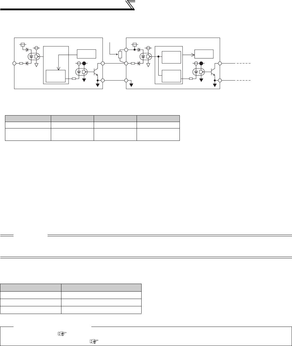
380
Special operation and frequency control
(4) Synchronous speed operation by pulse I/O
* When the wiring length between FM and JOG is long, a pulse shape is deformed due to the stray capacitances of the wiring and input pulse cannot be
recognized.
When wiring length is long (10m or more of 0.75mm2 twisted cable is recommended), connect terminal JOG and terminal PC using an external pull up
resistance. The reference of resistance value to the wiring length is as in the table below.
Stray capacitances of the wiring greatly differ according to the cable type and cable laying, the above cable length is not a guaranteed value.
When using a pull up resistance, check the permissible power and permissible load current (terminal PC : 100mA, high speed pulse train output : 85mA) of the
resistor and use them within a permissible range.
· By setting "100" in Pr. 291, pulse train input can be output at pulse train output (terminal FM) as it is.
Synchronous speed operation of multiple inverters can be enabled by daisy chain connection.
· Since maximum pulse train output is maximum of 50k pulse/s, set "125" in Pr. 384 of the inverter receiving pulse train.
· When operating two or more inverters synchronously, perform wiring according to the following steps. (so that 24V
contact input will not be applied to terminal FM)
1) Set pulse train output (a value other than "0, 1") in Pr. 291 of the master side inverter.
2) Turn OFF the inverter power
3) Perform wiring of the master side terminal FM-SD and slave side terminal JOG-SD
4) Turn ON the inverter power
zSpecifications of synchronous speed operation
* When a pulse transmission delay in a slave is approximately 1 to 2μs and wiring length is long, the delay further increases.
Wiring Length Less than 10m 10m to 50m 50m to 100m
Pull up resistance Not necessary 1kΩ470Ω
Load current (for
reference) 10mA 35mA 65mA
CAUTION
· After changing a setting value of Pr. 291, connect JOG terminal between terminal FM and SD. Take note that a voltage should
not be applied to terminal FM specially when FM output (voltage output) pulse train is selected.
· For the slave side inverter, use sink logic (factory setting). The inverter will not function properly if source logic is selected.
Item Specifications
Output pulse type Pulse width is fixed (10μs)
Pulse rate 0 to 50kpps
Pulse transmission delay 1 to 2μs per inverter *
♦ Parameters referred to ♦
Pr. 291 (pulse train output ) Refer to page 259
Pr. 419 (Position command source selection) Refer to page 137
Pulse train
input
Inverter (master) To next inverter (slave)
To next inverter (slave)
FM
SD
FM
SD
JOG
PC
JOG
SD
Speed
command
Pulse train
output
Pull up
resistance*
Pulse train
output
Speed
command
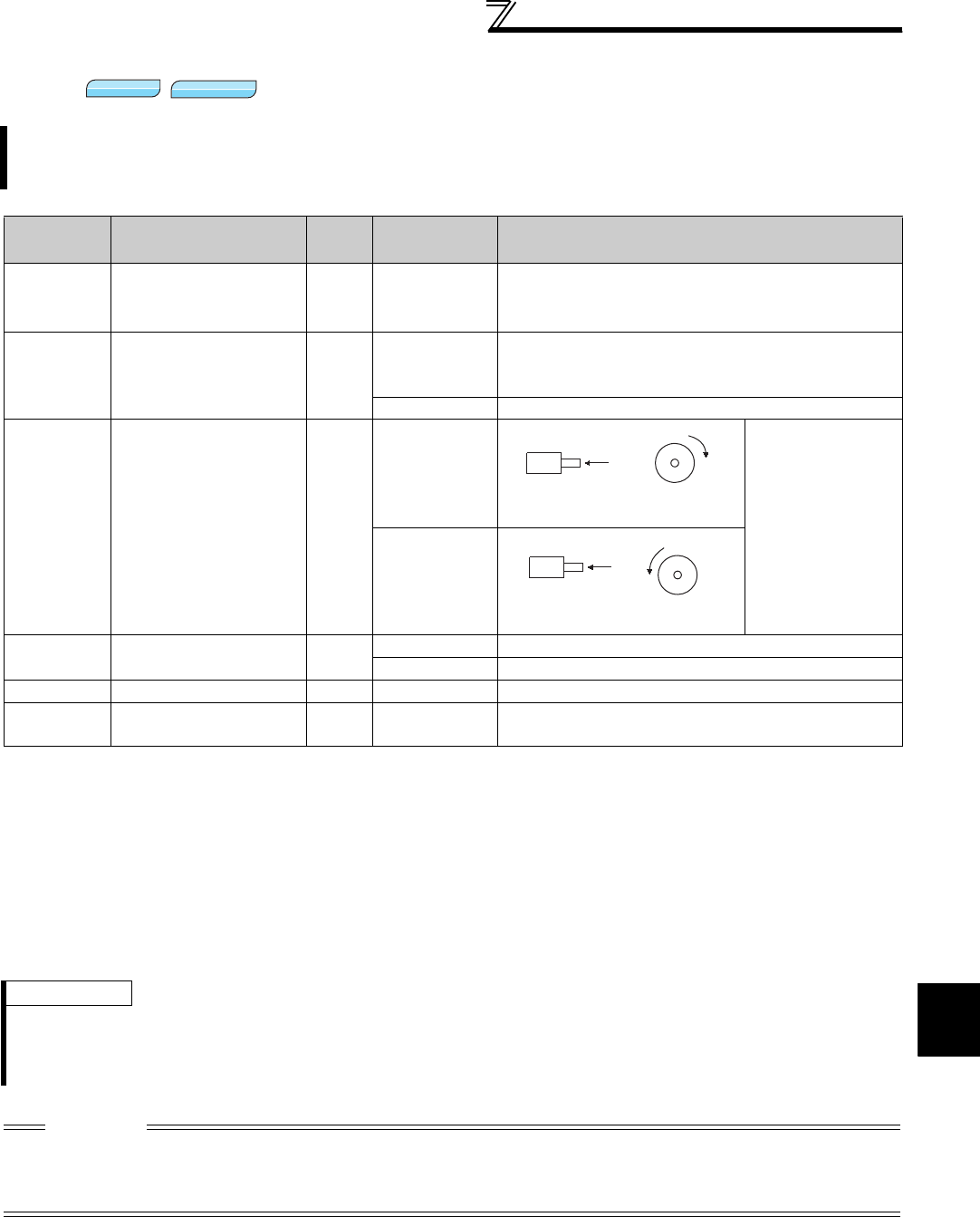
381
Special operation and frequency control
4
PARAMETERS
4.25.6 Encoder feedback control (Pr. 144, Pr. 285, Pr. 359, Pr. 367 to Pr. 369)
(1) Setting before the operation (Pr. 144, Pr. 359, Pr. 369 )
⋅When performing encoder feedback control under V/F control, set the number of motor poles in Pr. 144 Speed setting
switchover according to the motor used. Because the number of motor poles is set in Pr. 81 Number of motor poles
under Advanced magnetic flux vector control, it is unnecessary to change Pr. 144.
⋅Set the rotation direction and the number of encoder pulses of the encoder using Pr. 359 Encoder rotation direction and
Pr. 369 Number of encoder pulses.
This controls the inverter output frequency so that the motor speed is constant to the load variation by detecting the
motor speed with the speed detector (encoder) to feed it back to the inverter.
Option FR-A7AP/FR-A7AL is necessary.
Parameter
Numbers Name Initial
Value Setting Range Description
144 Speed setting
switchover 4
0, 2, 4, 6, 8, 10,
102, 104, 106,
108, 110
Set the number of motor poles when performing encoder
feedback control under V/F control.
285
Overspeed detection
frequency
(Speed deviation excess
detection frequency) *1
9999 0 to 30Hz
If (detected frequency) - (output frequency) > Pr. 285 during
encoder feedback control, the inverter fault (E.MB1) is
provided.
9999 Overspeed is not detected.
359 *2 Encoder rotation
direction 1
0
Set the rotation
direction according to
the motor
specification.
1
367 *2 Speed feedback range 9999 0 to 400Hz Set the region of speed feedback control.
9999 Encoder feedback control is invalid
368 *2 Feedback gain 1 0 to 100 Set when the rotation is unstable or response is slow.
369 *2 Number of encoder
pulses 1024 0 to 4096 Set the number of pulses of the encoder.
Set the number of pulses before multiplied by four.
*1 When exercising vector control with the FR-A7AP/FR-A7AL (option), this parameter changes to excessive speed deviation detection frequency.
(For details, refer to page 117)
*2 The above parameters can be set when the FR-A7AP/FR-A7AL (option) is mounted.
REMARKS
⋅When "0, 10, 110" is set in Pr. 144 and run the inverter, fault E.1 to E.3 occurs.
⋅When "102, 104, 106, 108" is set in Pr. 144, the value subtracting 100 is set as the number of motor poles.
⋅Setting Pr. 81 Number of motor poles changes the Pr. 144 setting automatically. However, changing the Pr. 144 setting will not
change the Pr. 81 setting automatically.
CAUTION
⋅If the number of motor poles is wrong, control at correct speed cannot be performed. Always check before operation.
⋅Encoder feedback control cannot be performed when the setting of encoder rotation direction is wrong. (Inverter operation is
enabled.)
Encoder rotation direction can be checked with the rotation direction display of the parameter unit.
V/F
V/F
V/F
Magnetic flux
Magnetic flux
Magnetic flux
A
Encoder
CW
Clockwise direction as viewed
from A is forward rotation
CCW
A
Encoder
Counter clockwise direction as
viewed from A is forward rotation
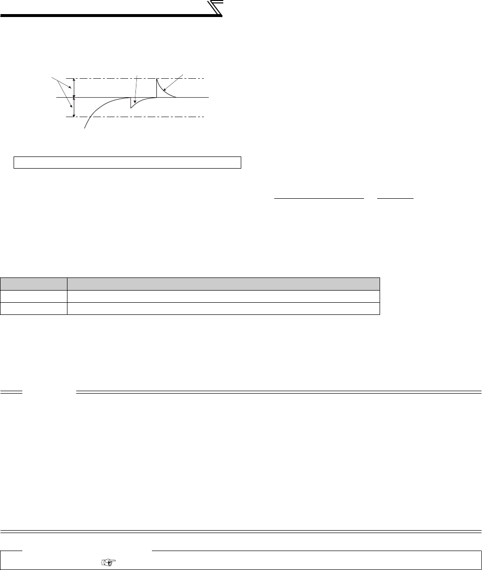
382
Special operation and frequency control
(2) Selection of encoder feedback control (Pr. 367 )
(3) Feedback gain (Pr. 368 )
⋅Set Pr. 368 Feedback gain when the rotation is unstable or response is slow.
⋅If the acceleration/deceleration time is long, feedback response becomes slower. In this case, increase the Pr. 368
setting.
⋅
(4) Overspeed detection (Pr. 285 )
⋅If (detection frequency) - (output frequency) > Pr. 285 under encoder feedback control, E.MB1 occurs and the inverter
output is stopped to prevent malfunction when the accurate pulse signal from the encoder cannot be detected.
Overspeed is not detected when Pr. 285 = "9999".
⋅When a value other than "9999" is set in Pr. 367 Speed
feedback range, encoder feedback control is valid.
Using the set point (frequency at which stable speed
operation is performed) as reference, set the higher and
lower setting range. Normally, set the frequency
converted from the slip amount (r/min) of the rated motor
speed (rated load). If the setting is too large, response
becomes slow.
Example: Rated speed of a 4-pole motor is 1740r/min (60Hz)
Slip Nsp = Synchronous speed - Rated speed Frequency equivalent to slip (fsp)
= 1800 - 1740 = 60(r/min) fsp = Nsp × Number of poles =60 × 4 =2 (Hz)
120 120
Pr. 368 Setting Description
Pr. 368 > 1 Although the response becomes faster, overcurrent or unstable rotation is liable to occur.
1 < Pr. 368 Although the response becomes slower, the motor rotation becomes stable.
CAUTION
⋅The encoder should be coupled on the same axis with the motor shaft without any mechanical looseness with a speed ratio of
1 to 1.
⋅During acceleration/deceleration, encoder feedback control is not performed to prevent unstable phenomenon such as hunting.
⋅Encoder feedback control is performed once output frequency has reached within [set frequency] ± [speed feedback range].
⋅If the following conditions occur during encoder feedback control, the inverter operates at the frequency within [set speed] ±
[speed feedback range] without coming to trip nor tracking the motor speed.
⋅ The pulse signals are not received from the encoder due to a signal loss, etc.
⋅ The accurate pulse signal from the encoder cannot be detected due to induction noise, etc.
⋅ The motor has been forcibly accelerated (regeneration) or decelerated (motor lock or the like) by large external force.
⋅For the motor with brake, use the RUN signal (inverter running) to open the brake. (The brake may not be opened if the FU
(output frequency detection) signal is used.)
⋅Do not turn OFF the external power supply of the encoder during encoder feedback control. Encoder feedback control
functions abnormally.
♦ Parameters referred to ♦
Pr. 81 Number of motor poles Refer to page 148
Speed feedback range
Set value
(Set command)
Driven load Regeneration load
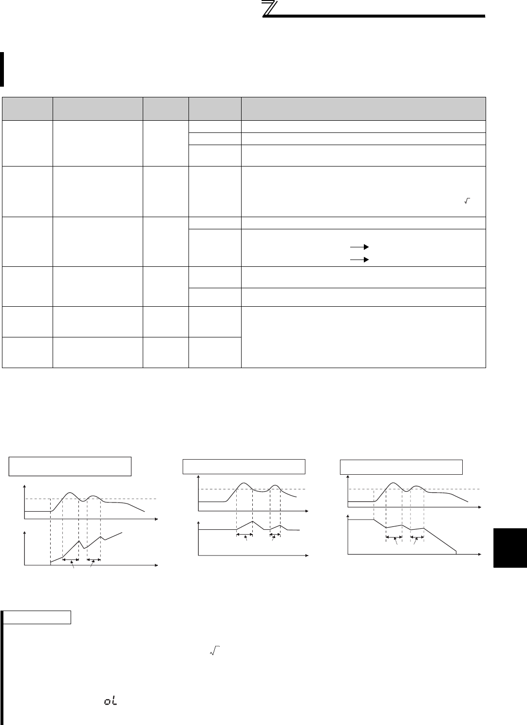
383
Special operation and frequency control
4
PARAMETERS
4.25.7 Regeneration avoidance function (Pr. 665, Pr. 882 to Pr. 886)
(1) What is regeneration avoidance function? (Pr. 882, Pr. 883)
⋅When the regenerative status is serious, the DC bus voltage rises and an overvoltage fault (E. OV) may occur.
When this bus voltage rise is detected and the bus voltage level reaches or exceeds Pr. 883, increasing the
frequency avoids the regenerative status.
⋅For regeneration avoidance operation, you can select whether it is always activated or activated only at a constant
speed.
⋅Setting Pr. 882 to "1, 2" validates the regeneration avoidance function.
This function detects a regenerative status and increases the frequency to avoid the regenerative status.
Possible to avoid regeneration by automatically increasing the frequency and continue operation if the fan
happens to rotate faster than the set speed due to the effect of another fan in the same duct.
Parameter
Number Name Initial
Value
Setting
Range Description
882
Regeneration
avoidance operation
selection
0
0 Regeneration avoidance function invalid
1 Regeneration avoidance function is always valid
2Regeneration avoidance function is valid only during a constant
speed operation
883
Regeneration
avoidance operation
level
380VDC/
760VDC * 300 to 800V
Set the bus voltage level at which regeneration avoidance operates.
When the bus voltage level is set to low, overvoltage error will be
less apt to occur. However, the actual deceleration time increases.
The set value must be higher than the power supply voltage × .
* The initial value differs according to the voltage level. (200V / 400V)
884
Regeneration
avoidance at
deceleration
detection sensitivity
0
0 Regeneration avoidance by bus voltage change ratio is invalid
1 to 5
Set sensitivity to detect the bus voltage change ratio
Setting 1 5
Detection sensitivity low high
885
Regeneration
avoidance
compensation
frequency limit value
6Hz
0 to 10Hz Set the limit value of frequency which rises at activation of
regeneration avoidance function.
9999 Frequency limit invalid
886
Regeneration
avoidance voltage
gain
100% 0 to 200% Adjust responsiveness at activation of regeneration avoidance. A
larger setting will improve responsiveness to the bus voltage
change. However, the output frequency could become unstable.
When vibration is not suppressed by decreasing the Pr. 886
setting, set a smaller value in Pr. 665.
665
Regeneration
avoidance frequency
gain
100% 0 to 200%
REMARKS
⋅The inclination of the frequency increased or decreased by the regeneration avoidance function changes depending on the
regenerative status.
⋅The DC bus voltage of the inverter is normally about times greater than the input voltage.
When the input voltage is 220VAC (440VAC), the bus voltage is about 311VDC (622VDC).
However, it varies with the input power supply waveform.
⋅The Pr. 883 setting should be kept higher than the DC bus voltage level. Otherwise, the regeneration avoidance function is
always ON even in the non-regeneration status and the frequency increases.
⋅While overvoltage stall ( ) is activated only during deceleration and stops the decrease in output frequency, the regeneration
avoidance function is always ON (Pr. 882 = 1) or activated only during a constant speed (Pr. 882 = 2) and increases the
frequency according to the regeneration amount.
2
Pr. 883
Time
Time
Regeneration avoidance operation
example for acceleration
Bus voltage
(VDC)
Output
frequency(Hz)
During regeneration
avoidance function operation
Pr. 883
Time
Time
Regeneration avoidance operation
example for constant speed
Bus voltage
(VDC)
Output
frequency(Hz)
During regeneration
avoidance function operation
Pr. 883
Time
Time
Bus voltage
(VDC)
Output
frequency(Hz)
During regeneration
avoidance function operation
Regeneration avoidance operation
example for deceleration
2
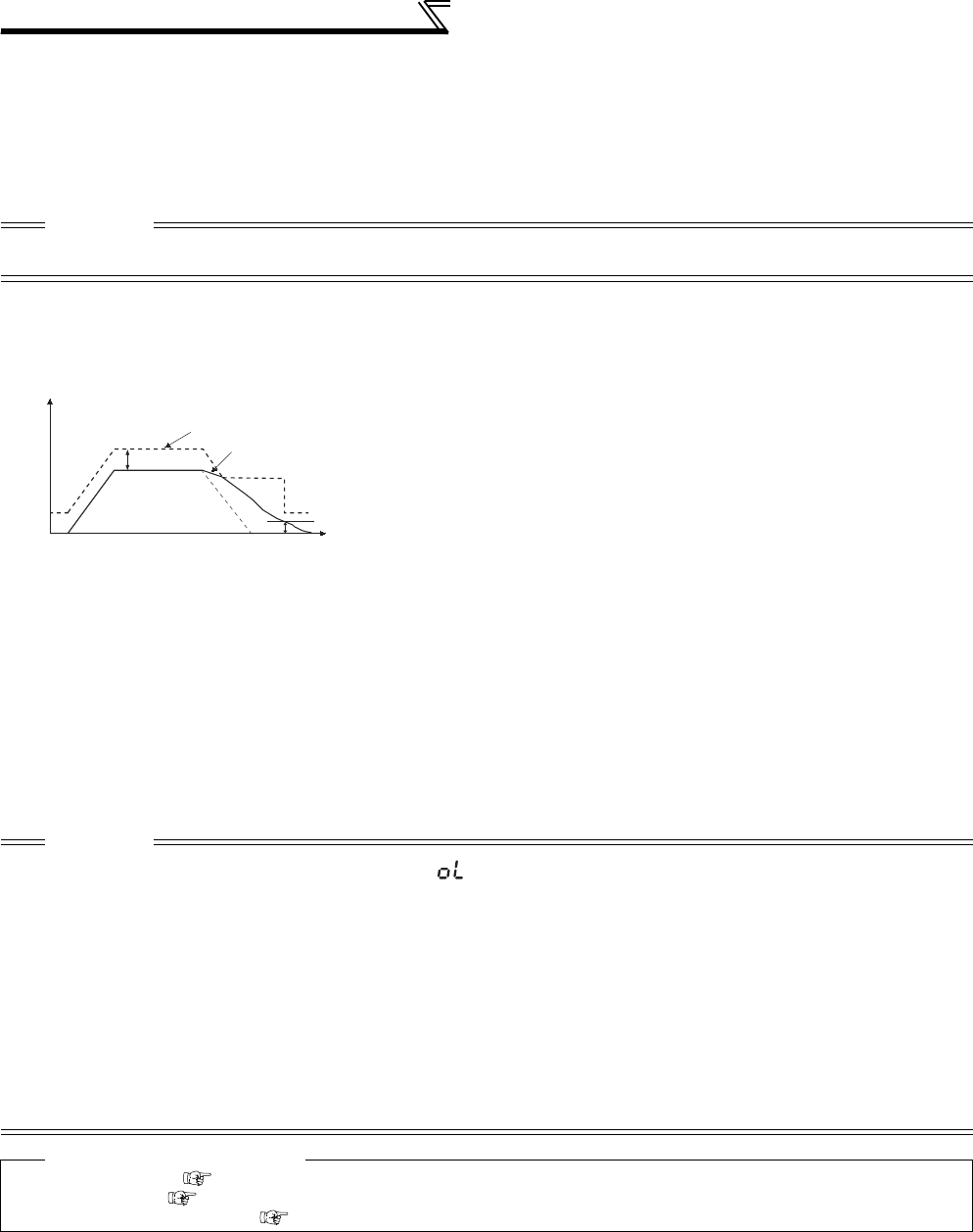
384
Special operation and frequency control
(2) To detect the regenerative status during deceleration faster (Pr. 884)
⋅As the regeneration avoidance function cannot respond to an abrupt voltage change by detection of the bus
voltage level, the ratio of bus voltage change is detected to stop deceleration if the bus voltage is less than Pr. 883
Regeneration avoidance operation level.
Set that detectable bus voltage change ratio to Pr. 884 as detection sensitivity.
Increasing the setting raises the detection sensitivity.
(4) Regeneration avoidance function adjustment (Pr. 665, Pr. 886)
⋅If the frequency becomes unstable during regeneration avoidance operation, decrease the setting of Pr. 886
Regeneration avoidance voltage gain. Reversely, if sudden regeneration causes an overvoltage alarm, increase the
setting.
⋅When vibration is not suppressed by decreasing the Pr. 886 Regeneration avoidance voltage gain setting, set a smaller
value in Pr. 665 Regeneration avoidance frequency gain.
CAUTION
Too small setting (low detection sensitivity) will disable detection, and too large setting will turn ON the regeneration avoidance
function if the bus voltage is varied by an input power change, etc.
(3) Limit regeneration avoidance operation frequency
(Pr. 885)
You can limit the output frequency compensated for (increased) by
the regeneration avoidance function.
⋅The frequency is limited to the output frequency (frequency prior to
regeneration avoidance operation) + Pr. 885 Regeneration avoidance
compensation frequency limit value during acceleration or constant
speed. If the frequency increased by regeneration avoidance
function exceeds the limit value during deceleration, the limit value
is held until the output frequency falls to 1/2 of Pr. 885.
⋅When the frequency increased by regeneration avoidance function
has reached Pr. 1 Maximum frequency, it is limited to the maximum
frequency.
⋅When Pr. 885="9999," the regeneration avoidance compensation
frequency limit is disabled.
CAUTION
⋅When regeneration avoidance operation is performed, (overvoltage stall) is displayed and the OL signal is output. Set the
operation pattern at an OL signal output using Pr.156 Stall prevention operation selection. Set the output timing of the OL signal
using Pr.157 OL signal output timer.
⋅When regeneration avoidance operation is performed, stall prevention is also activated.
⋅The regeneration avoidance function cannot shorten the actual deceleration time taken to stop the motor. The actual
deceleration time depends on the regeneration energy consumption capability. When shortening the deceleration time,
consider using the regeneration unit (FR-BU2, BU, FR-BU, MT-BU5, FR-CV, FR-HC, MT-HC) or the brake resistor (FR-ABR,
etc.) to consume regeneration energy at constant speed.
⋅When using the regeneration unit (FR-BU2, BU, FR-BU, MT-BU5, FR-CV, FR-HC, MT-HC) or the brake resistor (FR-ABR, etc.),
set Pr. 882 to "0 (initial value)" (regeneration avoidance function invalid). When using the regeneration unit, etc. to consume
regeneration energy at deceleration, set Pr. 882 to "2" (regeneration avoidance function valid only at a constant speed).
⋅Under vector control, unusual noise may be generated from the motor during deceleration when using regeneration avoidance
function. To prevent this, make gain adjustment, e.g. by performing easy gain tuning. (Refer to page 105)
♦ Parameters referred to ♦
Pr. 1 Maximum frequency Refer to page 157
Pr. 8 Deceleration time Refer to page 172
Pr. 22 Stall prevention operation level Refer to page 152
Limit level
Time
Pr.885
Output frequency (Hz)
Pr.885/2
Output
frequency(Hz)

385
Useful functions
4
PARAMETERS
4.26 Useful functions
4.26.1 Cooling fan operation selection (Pr. 244)
⋅In either of the following cases, fan operation is regarded as faulty, [FN] is shown on the operation panel, and the fan
fault (FAN) and alarm (LF) signals are output.
⋅Pr. 244 = "0"
When the fan comes to a stop with power on
⋅Pr. 244 = "1"
When the fan stops during the fan ON command while the inverter is running
⋅For the terminal used for FAN signal output, set "25" (positive logic) or "125" (negative logic) in any of Pr. 190 to Pr.
196 (output terminal function selection), and for the LF signal, set "98" (positive logic) or "198" (negative logic).
Purpose Parameter that must be Set Refer to
Page
Increase cooling fan life Cooling fan operation selection Pr. 244 385
To determine the maintenance time
of parts.
Inverter part life display Pr. 255 to Pr. 259 386
Maintenance output function Pr. 503, Pr. 504 389
Current average value monitor
signal Pr. 555 to Pr. 557 390
Freely available parameter Free parameter Pr. 888, Pr. 889 392
You can control the operation of the cooling fan (FR-A720-1.5K or higher, FR-A740-2.2K or higher) built in the
inverter.
Parameter
Number Name Initial Value Setting Range Description
244 Cooling fan operation selection 1
0
A cooling fan operates at power on
Cooling fan ON/OFF control invalid (The
cooling fan is always ON at power ON)
1
Cooling fan ON/OFF control valid
The fan is always ON while the inverter is
running. During a stop, the inverter status
is monitored and the fan switches ON-
OFF according to the temperature.
CAUTION
⋅When terminal assignment is changed using Pr. 190 to Pr. 196 (output terminal function selection), the other functions may be
affected. Set parameters after confirming the function of each terminal.
♦ Parameters referred to ♦
Pr. 190 to Pr. 196 (output terminal function selection) Refer to page 239

386
Useful functions
4.26.2 Display of the life of the inverter parts (Pr. 255 to Pr. 259)
Degrees of deterioration of main circuit capacitor, control circuit capacitor, cooling fan and inrush current limit
circuit can be diagnosed by monitor.
When any part has approached the end of its life, an alarm can be output by self diagnosis to prevent a fault.
(Use the life check of this function as a guideline since the life except the main circuit capacitor is calculated
theoretically.)
For the life check of the main circuit capacitor, the alarm signal (Y90) will not be output if a measuring method of
(4) is not performed.
Parameter
Number Name Initial Value Setting Range Description
255 Life alarm status display 0 (0 to 15)
Display whether the control circuit capacitor,
main circuit capacitor, cooling fan, and each
parts of the inrush current limit circuit has
reached the life alarm output level or not.
Reading only
256 Inrush current limit circuit
life display 100% (0 to 100%) Display the deterioration degree of the inrush
current limit circuit. Reading only
257 Control circuit capacitor life
display 100% (0 to 100%) Display the deterioration degree of the control
circuit capacitor. Reading only
258 Main circuit capacitor life
display 100% (0 to 100%)
Display the deterioration degree of the main
circuit capacitor. Reading only
The value measured by Pr. 259 is displayed.
259 Main circuit capacitor life
measuring 00, 1
(2, 3, 8, 9)
Setting "1" and switching the power supply OFF
starts the measurement of the main circuit
capacitor life.
When the Pr. 259 value is "3" after powering ON
again, the measuring is completed. Read the
deterioration degree in Pr. 258.
CAUTION
⋅Since repeated inrush currents at power ON will shorten the life of the converter circuit, frequent starts and stops of the
magnetic contactor must be avoided.
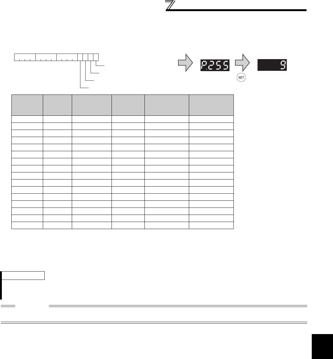
387
Useful functions
4
PARAMETERS
(1) Life alarm display and signal output (Y90 signal, Pr. 255)
⋅Whether any of the control circuit capacitor, main circuit capacitor, cooling fan and inrush current limit circuit has
reached the life alarm output level or not can be checked by Pr. 255 Life alarm status display and life alarm signal (Y90).
⋅The life alarm signal (Y90) turns ON when any of the control circuit capacitor, main circuit capacitor, cooling fan and
inrush current limit circuit reaches the life alarm output level.
⋅For the terminal used for the Y90 signal, set "90" (positive logic) or "190" (negative logic) to any of Pr. 190 to Pr. 196
(output terminal function selection).
(2) Life display of the inrush current limit circuit (Pr. 256)
⋅The life of the inrush current limit circuit (relay, contactor and inrush resistor) is displayed in Pr. 256.
⋅The number of contact (relay, contactor, thyristor) ON times is counted, and it is counted down from 100% (0 time)
every 1%/10,000 times. As soon as 10% (900,000 times) is reached, Pr. 255 bit 3 is turned ON and also an alarm is
output to the Y90 signal.
(3) Control circuit capacitor life display (Pr. 257)
⋅The deterioration degree of the control circuit capacitor is displayed in Pr. 257 as a life.
⋅In the operating status, the control circuit capacitor life is calculated from the energization time and temperature,
and is counted down from 100%. As soon as the control circuit capacitor life falls below 10%, Pr. 255 bit 0 is turned
ON and also an alarm is output to the Y90 signal.
Pr. 255
(decimal)
Bit
(binary)
Inrush
Current Limit
Circuit Life
Cooling
Fan Life
Main Circuit
Capacitor Life
Control Circuit
Capacitor Life
15 1111
14 1110 ×
13 1101 ×
12 1100 ××
11 1011 ×
10 1010 ××
9 1001 ××
8 1000 ×× ×
7 0111 ×
60110 × ×
5 0101 ××
4 0100 ×××
30011 ××
2 0010 ×× ×
1 0001 ×× ×
0 0000 ×× × ×
: With warnings, ×: Without warnings
REMARKS
⋅The digital output option (FR-A7AY, FR-A7AR, FR-A7NC and FR-A7NCE) allows the control circuit capacitor life signal (Y86),
main circuit capacitor life signal (Y87), cooling fan life signal (Y88) and inrush current limit circuit life signal (Y89) to be output
individually.
CAUTION
⋅When terminal assignment is changed using Pr. 190 to Pr. 196 (output terminal function selection), the other functions may be
affected. Set parameters after confirming the function of each terminal.
0 0 0 0 0 0 0 0 0 0 0 0 1 0 0
bit0 Control circuit capacitor life
1
15bit 7 0
bit1 Main circuit capacitor life
bit2 Cooling fan life
bit3 Inrush current limit circuit life
• Pr.255 read
Bit image is displayed
in decimal
• Pr.255 setting read

388
Useful functions
(4) Main circuit capacitor life display (Pr. 258, Pr. 259)
⋅The deterioration degree of the main circuit capacitor is displayed in Pr. 258 as a life.
⋅On the assumption that the main circuit capacitor capacitance at factory shipment is 100%, the capacitor life is
displayed in Pr. 258 every time measurement is made. When the measured value falls to or below 85%, Pr. 255 bit 1
is turned ON and also an alarm is output to the Y90 signal.
⋅Measure the capacitor capacity according to the following procedure and check the deterioration level of the
capacitor capacity.
1) Check that the motor is connected and at a stop.
2) Set "1" (measuring start) in Pr. 259
3) Switch power OFF. The inverter applies DC voltage to the motor to measure the capacitor capacity while the
inverter is OFF.
4) After making sure that the power lamp is OFF, switch ON the power supply again.
5) Check that "3" (measuring completion) is set in Pr. 259, read Pr. 258, and check the deterioration degree of the
main circuit capacitor.
(5) Cooling fan life display
⋅The cooling fan speed of 50% or less is detected and "FN" is displayed on the operation panel (FR-DU07) and
parameter unit (FR-PU04/FR-PU07). As an alarm display, Pr. 255 bit 2 is turned ON and also an alarm is output to
the Y90 signal.
Pr. 259 Description Remarks
0No measurement Initial value
1 Measurement start
Measurement starts when the
power supply is switched
OFF.
2 During measurement
Only displayed and cannot be
set
3 Measurement complete
8 Forced end
9 Measurement error
REMARKS
⋅When the main circuit capacitor life is measured under the following conditions, "forced end" (Pr. 259 = "8") or "measuring error"
(Pr. 259 ="9") occurs or it remains in "measuring start" (Pr. 259 = "1").
When measuring, avoid the following conditions beforehand. In addition, even when "measurement completion" (Pr. 259 = "3")
is confirmed under the following conditions, proper measurement cannot be taken.
(a)The FR-HC, MT-HC, FR-CV, MT-RC or sine wave filter is connected
(b) Terminals R1/L11, S1/L21 or DC power supply is connected to the terminal P/+ and N/-.
(c) Switch power ON during measuring.
(d) The motor is not connected to the inverter.
(e) The motor is running. (The motor is coasting.)
(f) The motor capacity is two rank smaller as compared to the inverter capacity.
(g) The inverter is tripped or a fault occurred when power is OFF.
(h) The inverter output is shut off with the MRS signal.
(i) The start command is given while measuring.
⋅
Operating environment: Surrounding air temperature (annual average 40
°
C (free from corrosive gas, flammable gas, oil mist, dust and dirt))
Output current (80% of the inverter rated current)
POINT
For the accurate life measuring of the main circuit capacitor, perform after more than 3h passed since the turn OFF
of the power as it is affected by the capacitor temperature.
WARNING
When measuring the main circuit capacitor capacity (Pr. 259 Main circuit capacitor life measuring = "1"), the DC
voltage is applied to the motor for 1s at powering OFF. Never touch the motor terminal, etc. right after powering
OFF to prevent an electric shock.
REMARKS
⋅When the inverter is mounted with two or more cooling fans, "FN" is displayed with one or more fans with speed of 50% or less.
CAUTION
⋅For replacement of each part, contact the nearest Mitsubishi FA center.
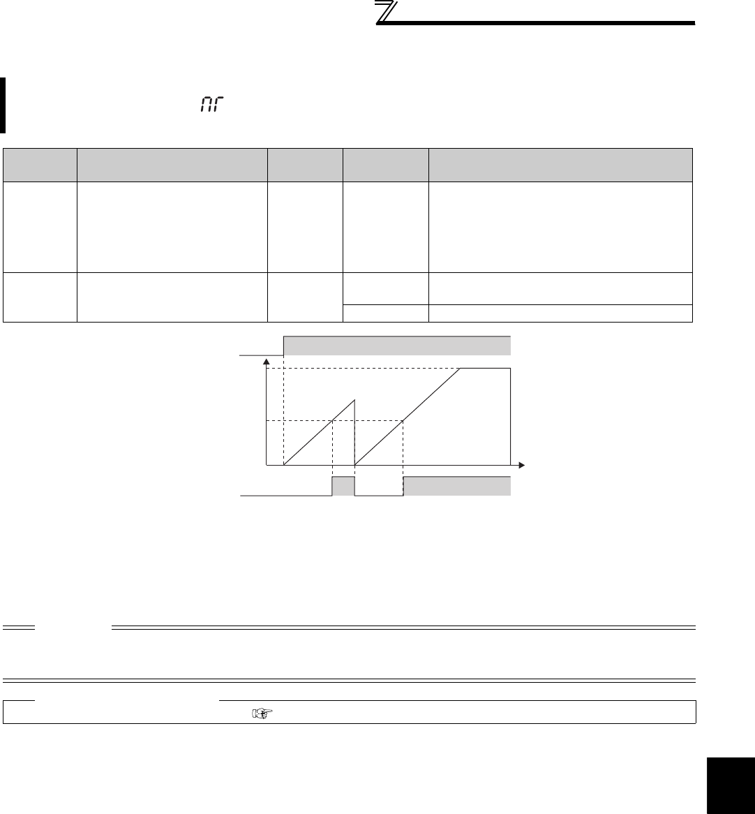
389
Useful functions
4
PARAMETERS
4.26.3 Maintenance timer alarm (Pr. 503, Pr. 504)
⋅The cumulative energization time of the inverter is stored into the EEPROM every hour and indicated in Pr. 503
Maintenance timer in 100h increments. Pr. 503 is clamped at 9998 (999800h).
⋅When the Pr. 503 value reaches the time set in Pr. 504 Maintenance timer alarm output set time (100h increments), the
maintenance timer alarm output signal (Y95) is output.
⋅For the terminal used for the Y95 signal output, assign the function by setting "95" (positive logic) or "195" (negative
logic) to any of Pr. 190 to Pr. 196 (output terminal function selection).
When the cumulative energization time of the inverter reaches the parameter set time, the maintenance timer
output signal (Y95) is output. (MT) is displayed on the operation panel (FR-DU07).
This can be used as a guideline for the maintenance time of peripheral devices.
Parameter
Number Name Initial
Value
Setting
Range Description
503 Maintenance timer 0 0 (1 to 9998)
Display the cumulative energization time of the
inverter in 100h increments.(Reading only)
When Pr. 503 = "1 to 9998", writing the setting
value of "0" clears the cumulative energization
time.
(Writing is disabled when Pr. 503 = "0".)
504 Maintenance timer alarm output
set time 9999 0 to 9998 The time taken until when the maintenance
timer alarm output signal (Y95) is output.
9999 No function
CAUTION
⋅The cumulative energization time is counted every hour. The energization time of less than 1h is not counted.
⋅When terminal assignment is changed using Pr. 190 to Pr. 196 (output terminal function selection), the other functions may be
affected. Set parameters after confirming the function of each terminal.
♦ Parameters referred to ♦
Pr. 190 to Pr. 196(output terminal function selection) Refer to page 239
First power ON
Maintenance
timer
(Pr. 503)
Set "0" in Pr.503
Y95 signal
MT display
OFF ON
Time
ON
Pr.504
9998
(999800h)
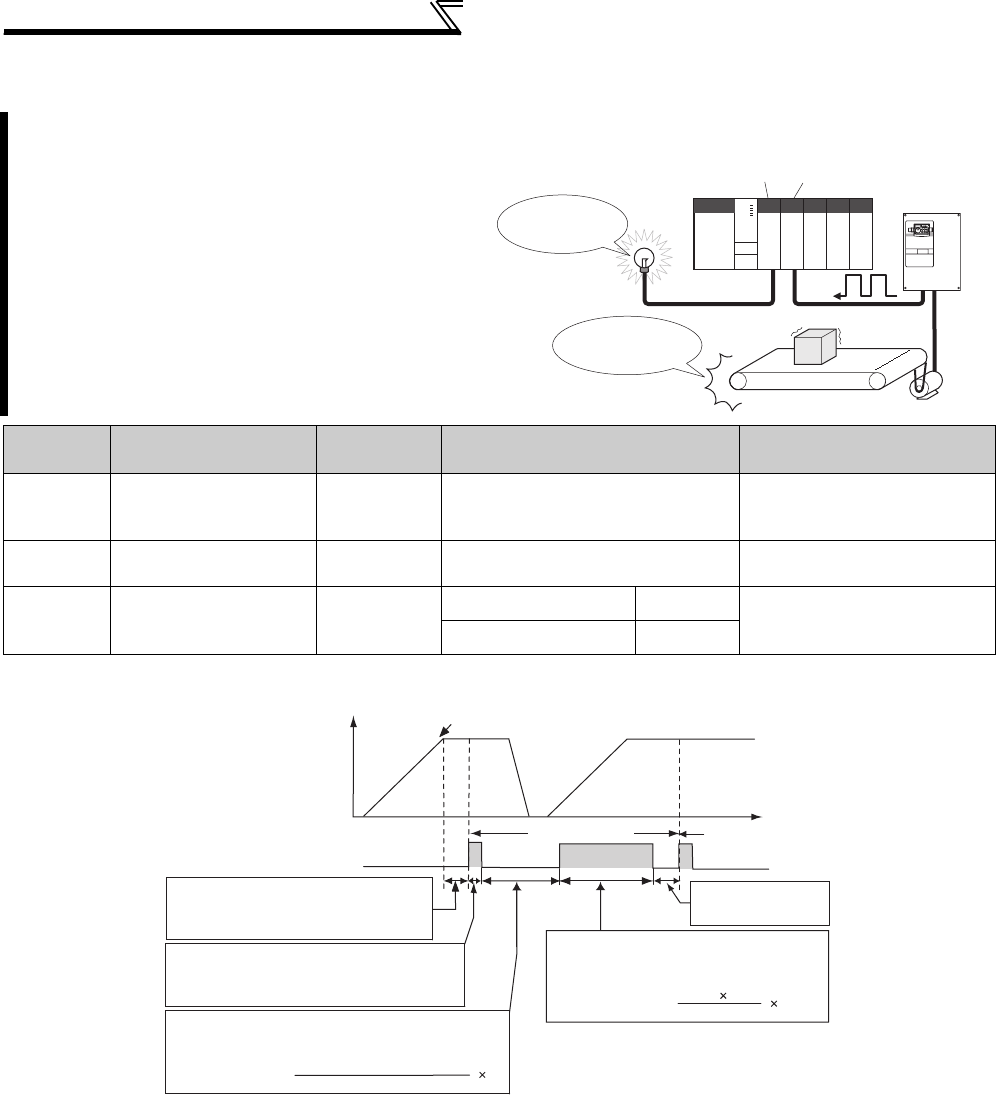
390
Useful functions
4.26.4 Current average value monitor signal (Pr. 555 to Pr. 557)
⋅The pulse output of the current average value monitor signal (Y93) is shown above.
⋅For the terminal used for the Y93 signal output, assign the function by setting "93" (positive logic) or "193" (negative
logic) to any of Pr. 190 to Pr. 194 (output terminal function selection). (The function cannot be assigned to Pr. 195 ABC1
terminal function selection and Pr. 196 ABC2 terminal function selection.)
(1) Setting of Pr. 556 Data output mask time
The output current is unstable (transient state) right after the operation is changed from the acceleration/
deceleration state to the constant speed operation. Set the time for not obtaining (mask) transient state data in Pr.
556.
(2) Setting of the Pr. 555 Current average time
The average output current is calculated during Hi output of start pulse (1s). Set the time taken to average the
current during start pulse output in Pr. 555.
The average value of the output current during
constant speed operation and the maintenance
timer value are output as a pulse to the current
average value monitor signal (Y93).
The pulse width output to the I/O module of the
programmable controller etc. can be used as a
guideline due to abrasion of machines and
elongation of belt and for aged deterioration of
devices to know the maintenance time.
The current average value monitor signal (Y93) is
output as pulse for 20s as 1 cycle and repeatedly
output during constant speed operation.
Parameter
Number Name Initial Value Setting Range Description
555 Current average time 1s 0.1 to 1.0s
Set the time taken to average
the current during start pulse
output (1s).
556 Data output mask time 0s 0.0 to 20.0s Set the time for not obtaining
(mask) transient state data.
557
Current average value
monitor signal output
reference current
Rated inverter
current
55K or lower 0 to 500A Set the reference (100%) for
outputting the signal of the
current average value.
75K or higher 0 to 3600A
The above parameters allow its setting to be changed during operation in any operation mode even if "0" (initial value) is set in Pr. 77 Parameter write
selection.
Programmable controller
Output
unit
Input
unit
maintenance
time
parts have
reached their life
Inverter
Y93 signal
1) Data output mask time
2) Start pulse
1 cycle (20s)
3) Output current average value pulse
Next cycle
Time
Output
frequency
From acceleration to constant speed operation
Signal output time=
output current average value (A)
Pr. 557 (A) 5s
4) Maintenance timer pulse
Signal output time= 5s
40000h
5) End pulse
The averaged current value is output as low pulse shape for
0.5 to 9s (10 to 180%) during start pulse output.
When the speed has changed to constant
from acceleration/deceleration, Y93 signal is
not output for Pr. 556 time.
Pr. 503 100h
output as low pulse
shape for 1 to 16.5s
The maintenance timer value (Pr. 503) is output
as Hi output pulse shape for 2 to 9s (16000h to
72000h).
Output as Hi pulse shape for 1s (fixed)
The output currents are averaged during the time
period set in Pr.555.
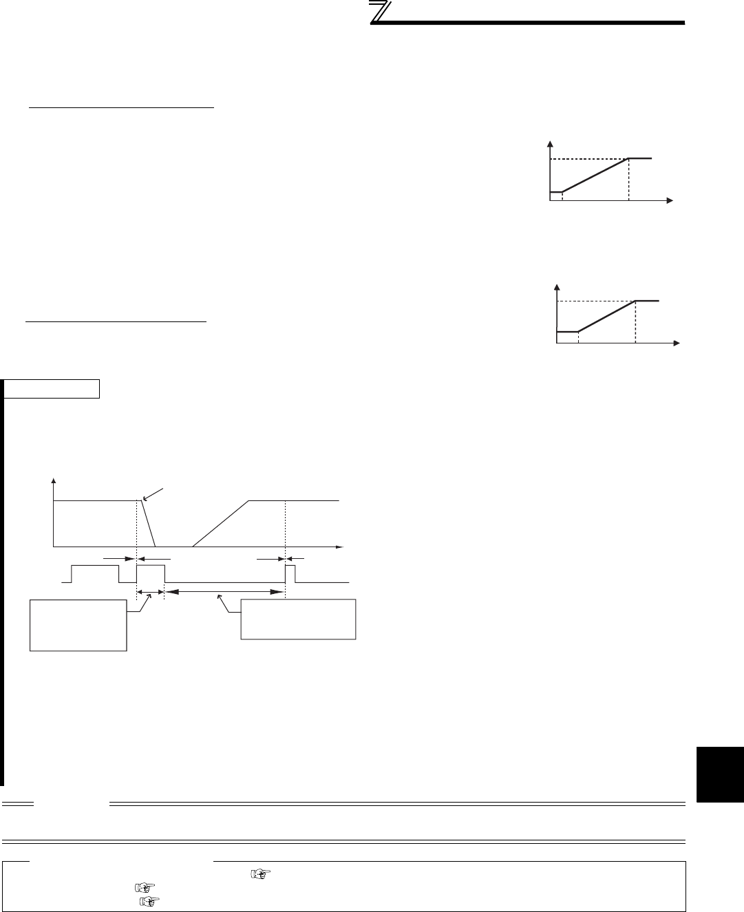
391
Useful functions
4
PARAMETERS
(3) Setting of Pr. 557 Current average value monitor signal output reference current
Set the reference (100%) for outputting the signal of the current average value. Obtain the time to output the signal
from the following formula.
(4) Output of Pr. 503 Maintenance timer
Note that the output time range is 0.5 to 9s, and it is 0.5s when the output current
average value is less than 10% of the setting value of Pr. 557 and 9s when exceeds
180%.
Example)When Pr. 557 = 10A and the average value of output current is 15A
As 15A/10A × 5s = 7.5, the current average value monitor signal is output
as low pulse shape for 7.5s.
After the output current average value is output as low pulse shape, the
maintenance timer value is output as high pulse shape. The output time of the
maintenance timer value is obtained from the following formula.
Note that the output time range is 2 to 9s, and it is 2s when Pr. 503 is less than
16000h and 9s when exceeds 72000h.
REMARKS
⋅Mask of data output and sampling of output current are not performed during acceleration/deceleration.
⋅When the speed is changed to acceleration/deceleration from constant speed during start pulse output, the data is judged as
invalid, the start pulse is output as high pulse shape for 3.5s, and the end signal is output as low pulse shape for 16.5s.
The signal is output for at least 1 cycle even when acceleration/deceleration state continues after the start pulse output is
completed.
⋅When the output current value (inverter output current monitor) is 0A on completion of the 1 cycle signal output, the signal is not
output until the speed becomes constant next time
⋅The current average value monitor signal (Y93) is output as low pulse shape for 20s (without data output) under the following
condition.
(a)When the motor is in the acceleration/deceleration state on completion of the 1 cycle signal output
(b)When 1-cycle signal output was ended during restart operation with the setting of automatic restart after instantaneous power
failure (Pr. 57 ≠ "9999")
(c)When automatic restart operation was being performed with automatic restart after instantaneous power failure selected (Pr.
57 ≠ "9999") on completion of the data output mask
CAUTION
⋅When terminal assignment is changed using Pr. 190 to Pr. 196 (output terminal function selection), the other functions may be
affected. Set parameters after confirming the function of each terminal.
♦ Parameters referred to ♦
Pr. 190 to Pr. 196(output terminal function selection) Refer to page 239
Pr. 503 Maintenance timer Refer to page 389
Pr. 57 Restart coasting time Refer to page 266
Output current average value × 5s (output current average value 100%/5s)
Pr. 557 setting
9
0.5
10 (%)
(s)
Output current average value
180
Signal output time
Pr. 503 × 100 × 5s (maintenance timer value 100%/5s)
40000h
9
2
16000 (h)
(s)
Maintenance timer value
72000
Signal output time
5) End signal
Y93
signal
2) Start pulse
Invalid cycle (20s) Next cycle
Time
Output frequency The speed is changed to deceleration from
the constant speed during start pulse output
Previous cycle
Output as high
pulse shape for
3.5s
Output as low pulse
shape for 16.5s

392
Useful functions
4.26.5 Free parameter (Pr. 888, Pr. 889)
You can input any number within the setting range 0 to 9999.
For example, the number can be used:
⋅As a unit number when multiple units are used.
⋅As a pattern number for each operation application when multiple units are used.
⋅As the year and month of introduction or inspection.
Parameter
Number Name Initial Value Setting Range Description
888 Free parameter 1 9999 0 to 9999 Desired values can be input.
Data is held even if the inverter
power is turned OFF.
889 Free parameter 2 9999 0 to 9999
The above parameters allow its setting to be changed during operation in any operation mode even if "0" (initial value) is set in Pr. 77 Parameter write
selection.
REMARKS
⋅Pr. 888 and Pr. 889 do not influence the inverter operation.

393
Setting of the parameter unit and
operation panel
4
PARAMETERS
4.27 Setting of the parameter unit and operation panel
4.27.1 PU display language selection (Pr. 145)
4.27.2 Setting dial potentiometer mode/key lock selection (Pr. 161)
Purpose Parameter that must be Set Refer to Page
Switch the display language of the
parameter unit PU display language selection Pr. 145 393
Use the setting dial of the operation
panel like a potentiometer for
frequency setting.
Key lock of operation panel
Operation panel operation selection Pr. 161 393
Control of the parameter unit,
operation panel buzzer PU buzzer control Pr. 990 395
Adjust the LCD contrast of the
parameter unit PU contrast adjustment Pr. 991 395
You can switch the display language of the parameter unit (FR-PU04/FR-PU07) to another.
Parameter
Number Name Initial Value Setting Range Description
145 PU display language selection 0
0 Japanese
1English
2Germany
3 French
4Spanish
5Italian
6Swedish
7Finnish
The setting dial of the operation panel (FR-DU07) can be used like a potentiometer to perform operation.
The key operation of the operation panel can be disabled.
Parameter
Number Name Initial Value Setting
Range Description
161 Frequency setting/key lock
operation selection 0
0 Setting dial frequency setting mode Key lock
invalid
1 Setting dial potentiometer mode
10 Setting dial frequency setting mode Key lock
valid
11 Setting dial potentiometer mode
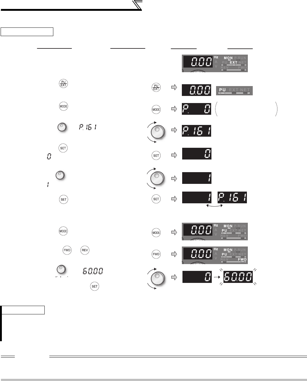
394
Setting of the parameter unit and
operation panel
(1) Using the setting dial like a potentiometer to set the frequency.
Operation example Changing the frequency from 0Hz to 60Hz during operation
REMARKS
⋅If the display changes from flickering "60.00" to "0.00", the setting of Pr. 161 Frequency setting/key lock operation selection may not
be "1".
⋅Independently of whether the inverter is running or at a stop, the frequency can be set by simply turning the dial.
⋅When the frequency is changed, it will be stored in EEPROM as the set frequency after 10s.
CAUTION
· When setting frequency by turning setting dial, the frequency goes up to the set value of Pr. 1 Maximum frequency (initial value is
120Hz for 55K or lower/60Hz for 75K or higher).
Adjust Pr. 1 Maximum frequency setting according to the application.
DisplayOperation
PU indicator is lit.
Flicker ··· Parameter setting complete!!
7. Press to set.
The parameter number
previously read appears.
1. Screen at power-ON
The monitor display appears.
2. Press to choose the PU operation
mode.
3. Press to choose the parameter
setting mode.
The frequency flickers for about 5s.
8. Mode/monitor check
Press twice to choose
monitor/frequency monitor.
9. Press (or ) to start the inverter.
4. Turn until (Pr. 161) appears.
5. Press to read the present set value.
" " (initial value) appears.
6. Turn to change it to the setting value
" ".
10.
Turn until " " appears.
The flickering frequency is the set frequency.
You need not press .
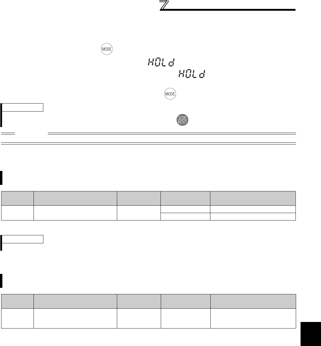
395
Setting of the parameter unit and
operation panel
4
PARAMETERS
(2) Disable the setting dial and key operation of the operation panel (Press [MODE] long (2s))
⋅Operation using the setting dial and key of the operation panel can be invalid to prevent parameter change, and
unexpected start or frequency setting.
⋅Set "10 or 11" in Pr. 161, then press for 2s to make the setting dial and key operation invalid.
⋅When the setting dial and key operation are invalid, appears on the operation panel. If dial or key
operation is attempted while dial and key operation are invalid, appears (When dial or key is not
touched for 2s, monitor display appears. )
⋅To make the setting dial and key operation valid again, press for 2s.
4.27.3 Buzzer control (Pr. 990)
The above parameters allow its setting to be changed during operation in any operation mode even if "0" (initial value) is set in Pr. 77 Parameter write
selection.
4.27.4 PU contrast adjustment (Pr. 991)
The above parameters are displayed as simple mode parameters only when the parameter unit (FR-PU04/FR-PU07) is connected.
REMARKS
⋅Even if the setting dial and key operation are disabled, the monitor display is valid.
CAUTION
• Release the operation lock to release the PU stop by key operation.
You can make the buzzer "beep" when you press key of the operation panel (FR-DU07) and parameter unit (FR-
PU04/FR-PU07).
Parameter
Number Name Initial Value Setting Range Description
990 PU buzzer control 10 Without buzzer sound
1 With buzzer sound
REMARKS
Inverter alert faults with buzzer sounds when this parameter is set to activate the buzzer sound.
Contrast adjustment of the LCD of the parameter unit (FR-PU04/FR-PU07) can be performed.
Decreasing the setting value makes the contrast lighter.
Parameter
Number Name Initial Value Setting Range Description
991 PU contrast adjustment 58 0 to 63
0 : Light
↓
63: Dark
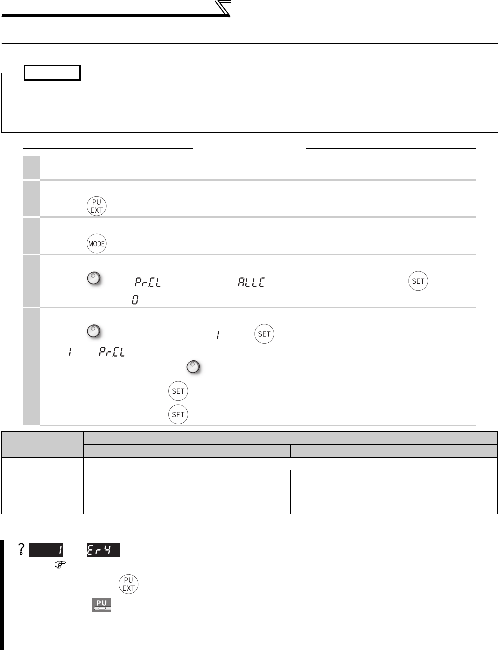
396
Parameter clear and all parameter clear
4.28 Parameter clear and all parameter clear
* Refer to the list of parameters on page 466 for availability of parameter clear and all parameter clear.
POINT
· Set "1" in Pr. CL parameter clear or ALLC All parameter clear to initialize all parameters. (Parameters are not cleared
when "1" is set in Pr. 77 Parameter write selection. Calibration parameters are not cleared with Pr.CL either. In
addition, calibration parameters are not cleared.)
· Refer to the list of parameters on page 466 for availability of parameter clear
Operation
1. Screen at power-ON
The monitor display appears.
2.
Operation mode change
Press to choose the PU operation mode. [PU] indicator is lit.
3.
Parameter setting mode
Press to choose the parameter setting mode. (The parameter number read previously appears.)
4.
Selecting the parameter number
Turn until " parameter clear" (" all parameter clear") appears. Press to read the
present set value. " " (initial value) appears.
5.
Parameter clear
Turn to change it to the set value " ". Press to set.
" " and " " flicker alternately after parameters are cleared.
·By turning , you can read another parameter.
·Press to show the setting again.
·Press twice to show the next parameter.
Setting Description
Pr. CL parameter clear ALLC All parameter clear
0 Not executed.
1
Returns all parameters to the initial values except for
calibration parameters, terminal function selection
parameters, etc.
Returns all the parameters that can be cleared to
their initial values. Examples include calibration
parameters and terminal function selection
parameters.
and are displayed alternately ... Why?
The inverter is not in the PU operation mode.
1. Press .
is lit and the monitor (4 digit LED) displays "0" (Pr. 79 = "0" (initial value)).
2. Carry out operation from step 5 again.
· Stop the inverter. Parameter clear is unavailable when the inverter is running, and will cause the write disable
error.
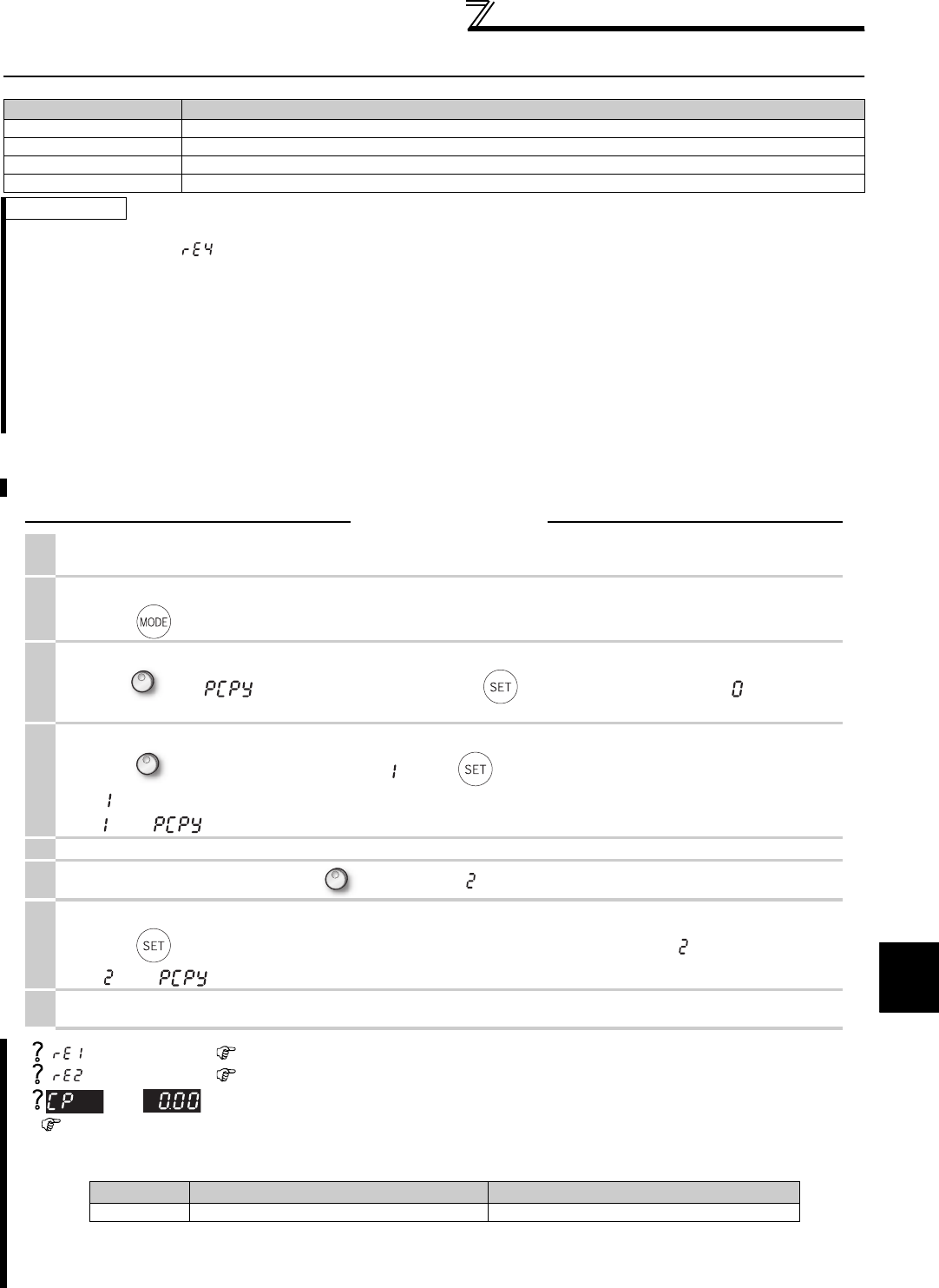
397
Parameter copy and parameter verification
4
PARAMETERS
4.29 Parameter copy and parameter verification
4.29.1 Parameter copy
PCPY Setting Description
0 Cancel
1 Copy the source parameters to the operation panel.
2 Write the parameters copied to the operation panel into the destination inverter.
3 Verify parameters in the inverter and operation panel. (Refer to page 398.)
REMARKS
· When the copy destination inverter is not the FR-A700 series or parameter copy write is performed after parameter copy read is
stopped, "model error ( )" is displayed.
· Refer to the parameter list on page 466 and later for availability of parameter copy.
· When the power is turned OFF or an operation panel is disconnected, etc. during parameter copy write, perform write again or
check the values by parameter verification.
· Initial settings of certain parameters are different for different capacities, so some parameter settings may be automatically
changed when parameter copy is performed from a different-capacity inverter. After performing a parameter copy from a
different-capacity inverter, check the parameter settings. (Refer to the parameter list (page 71) for the parameters with different
initial settings for different capacities.)
· If parameters are copied to the inverter with additional parameters (version up model) from the inverter without additional
parameters, a value out of the setting range may be written to the inverter. In this case the inverter operates as if the initial value
is written to the parameter.
Parameter settings can be copied to multiple inverters.
Operation
1. Connect the operation panel to the copy source inverter.
Connect it during a stop.
2.
Parameter setting mode
Press to choose the parameter setting mode. (The parameter number read previously appears.)
3.
Selecting the parameter number
Turn until " " (parameter copy) appears. Press to read the currently set value. " " (initial value)
appears.
4.
Copying to the operation panel
Turn to change it to the setting value " ". Press to copy the source parameters to the operation panel.
(" " flickers for about 30s.)
" " and " " flicker alternately after parameters are copied.
5. Connect the operation panel to the copy destination inverter.
6. After performing steps 2 and 3, turn to change it to "".
7.
Writing to the inverter
Press to write the parameters copied to the operation panel to the destination inverter. (" " flickers for about 30s.)
" " and " " flicker alternately after parameters are copied.
8. After writing the parameter values to the copy destination inverter, always reset the inverter,
e.g. switch power off once, before starting operation.
appears...Why? Parameter read error. Perform operation from step 3 again.
appears...Why? Parameter write error. Perform operation from step 6 again.
and flicker alternately
Appears when parameters are copied between the inverter of 55K or lower and 75K or higher.
1. Set "0" (initial value) in Pr. 160 User group read selection.
2. Set the following setting (initial value) in Pr. 989 Parameter copy alarm release.
3. Reset Pr. 9, Pr. 30, Pr. 51, Pr. 52, Pr. 54, Pr. 56, Pr. 57, Pr. 61, Pr. 70, Pr. 72, Pr. 80, Pr. 82, Pr. 90 to Pr. 94 , Pr. 158,
Pr. 455, Pr. 458 to Pr. 462, Pr. 557, Pr. 859, Pr. 860, Pr. 893.
55K or lower 75K or higher
Pr. 989 Setting 10 100
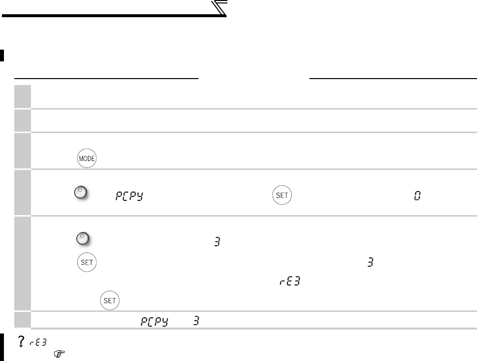
398
Parameter copy and parameter verification
4.29.2 Parameter verification
Whether same parameter values are set in other inverters or not can be checked.
Operation
1. Move the operation panel to the inverter to be verified.
Move it during a stop.
2. Screen at power-ON
The monitor display appears.
3.
Parameter setting mode
Press to choose the parameter setting mode. (The parameter number read previously appears.).
4.
Selecting the parameter number
Turn until " " (parameter copy) appears. Press to read the currently set value. " " (initial value)
appears.
5.
Parameter verification
Turn to change it to the setting value " " (parameter copy verification mode).
Press to read the parameter setting of the verified inverter to the operation panel. (" " flickers for about 30s.)
If different parameters exist, different parameter numbers and " " flicker.
Hold down to verify.
6. If there is no difference, " " and " " flicker to complete verification.
flickers ... Why?
Set frequencies, etc. may be different. Check set frequencies.
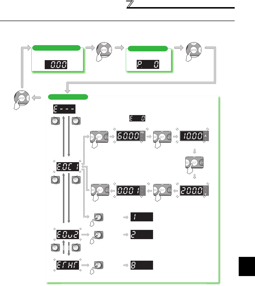
4
PARAMETERS
399
Check and clear of the faults history
4.30 Check and clear of the faults history
(1) Check for the faults history
* The cumulative energization time and actual operation time are accumulated from 0 to 65535 hours, then cleared, and accumulated again from 0.
When the operation panel (FR-DU07) is used, the time is displayed up to 65.53 (65530h) in the indication of 1h = 0.001, and thereafter, it is added
up from 0.
Faults history
Monitor/frequency setting
[Operation panel is used
for operation]
Parameter setting
[Parameter setting change]
[Operation for displaying faults history]
Eight past faults can be displayed with the setting dial.
(The latest fault is ended by ".".)
When no alarm exists, is displayed.
Output current
Flickering
Output voltage
Flickering
Flickering
Flickering
Press the
setting
dial.
Press the
setting
dial.
Press the
setting
dial.
Energization time *
Faults history number
(The number of past faults is displayed.)
Flickering
Output frequency
Flickering Flickering
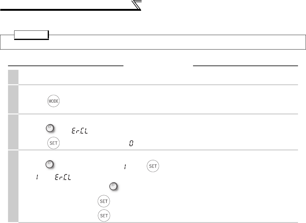
400
Check and clear of the faults history
(2) Clearing procedure
POINT
· The faults history can be cleared by setting "1" in Er.CL Faults history clear.
Operation
1. Screen at power-ON
The monitor display appears.
2.
Parameter setting mode
Press to choose the parameter setting mode.
(The parameter number previously read appears.)
3.
Selecting the parameter number
Turn until " " (faults history clear) appears.
Press to read the present set value. " " (initial value) appears.
4.
Faults history clear
Turn to change it to the set value " ". Press to set.
" " and " " flicker alternately after the faults history is cleared.
·By turning , you can read another parameter.
·Press to show the setting again.
·Press twice to show the next parameter.

401
3
4
5
6
7
1
2
5
PROTECTIVE FUNCTIONS
This chapter describes the basic "PROTECTIVE FUNCTION" for
use of this product.
Always read the instructions before using the equipment.
5.1 Reset method of protective function........................402
5.2 List of fault or alarm display ....................................403
5.3 Causes and corrective actions ................................404
5.4 Correspondences between digital and actual
characters ...............................................................418
5.5 Check first when you have a trouble .......................419
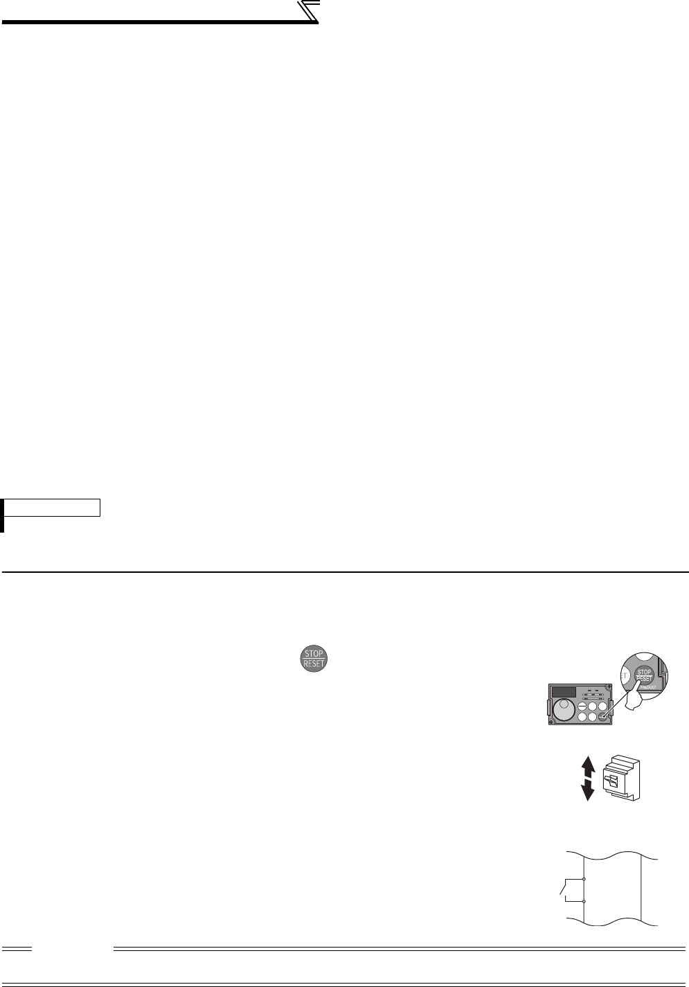
402
Reset method of protective function
When a fault occurs in the inverter, the inverter trips and the PU display automatically changes to one of the following
fault or alarm indications.
If the fault does not correspond to any of the following faults or if you have any other problem, please contact your sales
representative.
•Retention of fault output signal ................ When the magnetic contactor (MC) provided on the input side of the
inverter is opened when a fault occurs, the inverter's control power will be
lost and the fault output will not be held.
•Fault or alarm indication .......................... When a fault or alarm occurs, the operation panel display automatically
switches to the fault or alarm indication
•Resetting method..................................... When a fault occurs, the inverter output is kept stopped. Unless reset,
therefore, the inverter cannot restart. (Refer to page 402.)
•When any fault occurs, take the appropriate corrective action, then reset the inverter, and resume operation.
Not doing so may lead to the inverter fault and damage.
Inverter fault or alarm indications are roughly categorized as below.
(1) Error message
A message regarding operational fault and setting fault by the operation panel (FR-DU07) and parameter unit (FR-
PU04 /FR-PU07) is displayed. The inverter does not trip.
(2) Warning
The inverter does not trip even when a warning is displayed. However, failure to take appropriate measures will
lead to a fault.
(3) Alarm
The inverter does not trip. You can also output an alarm signal by making parameter setting.
(4) Fault
When a fault occurs, the inverter trips and a fault signal is output.
5.1 Reset method of protective function
The inverter can be reset by performing any of the following operations. Note that the internal thermal integrated value
of the electronic thermal relay function and the number of retries are cleared (erased) by resetting the inverter.
Inverter recovers about 1s after the reset is released.
REMARKS
· Past eight faults can be displayed using the setting dial. (Refer to page 399 for the operation.)
Operation 1: ..... Using the operation panel, press to reset the inverter.
(This may only be performed when a fault occurs. (Refer to page 408 for
fault.))
Operation 2: ...... Switch power OFF once, then switch it ON again.
Operation 3: . .... Turn ON the reset signal (RES) for more than 0.1s. (If the RES signal is
kept ON, "Err." appears (flickers) to indicate that the inverter is in a
reset status.)
ON
OFF
Inverter
RES
SD
CAUTION
· OFF status of the start signal must be confirmed before resetting the inverter fault. Resetting inverter fault with the start signal
ON restarts the motor suddenly.
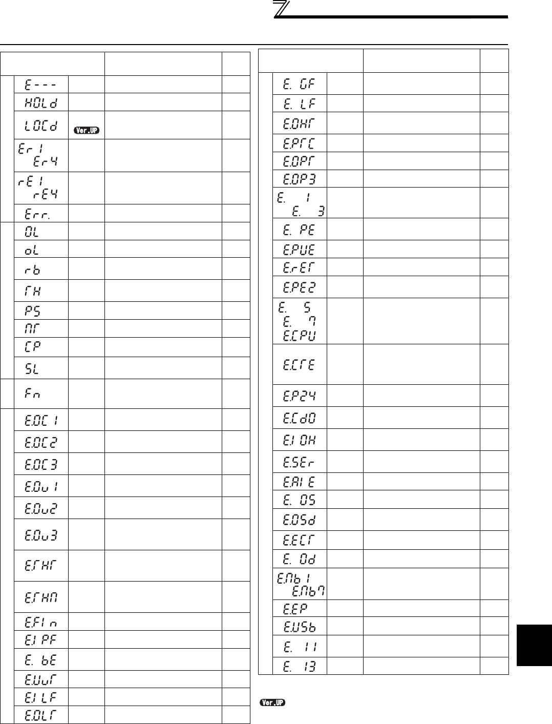
403
List of fault or alarm display
5
PROTECTIVE FUNCTIONS
5.2 List of fault or alarm display
* If a fault occurs when using the FR-PU04, "Fault 14" is displayed on
the FR-PU04.
....... Specifications differ according to the date assembled. Refer to
page 484 to check the SERIAL number.
Operation Panel
Indication Name
Refer
to
Error message
E - - - Faults history 399
HOLD Operation panel lock 404
LOCD Password locked 404
Er1 to 4
Parameter write error 404
rE1 to 4
Copy operation error 405
Err. Error 405
Warning
OL Stall prevention (overcurrent) 406
oL Stall prevention (overvoltage) 406
RB Regenerative brake pre-
alarm 407
TH Electronic thermal relay
function pre-alarm 407
PS PU stop 406
MT Maintenance signal output 407
CP Parameter copy 407
SL Speed limit indication
(Output during speed limit) 407
Alarm
FN Fan alarm 408
Fault
E.OC1 Overcurrent trip during
acceleration 408
E.OC2 Overcurrent trip during
constant speed 408
E.OC3 Overcurrent trip during
deceleration or stop 409
E.OV1 Regenerative overvoltage
trip during acceleration 409
E.OV2 Regenerative overvoltage
trip during constant speed 409
E.OV3
Regenerative overvoltage
trip during deceleration or
stop
409
E.THT
Inverter overload trip
(electronic thermal relay
function)
410
E.THM
Motor overload trip
(electronic thermal relay
function)
410
E.FIN Heatsink overheat 410
E.IPF Instantaneous power failure 410
E.BE Brake transistor alarm
detection 411
E.UVT Undervoltage 411
E.ILF* Input phase loss 411
E.OLT Stall prevention stop 411
to
to
Fault
E.GF Output side earth (ground)
fault overcurrent 411
E.LF Output phase loss 412
E.OHT External thermal relay
operation *2 412
E.PTC*
PTC thermistor operation 412
E.OPT Option fault 412
E.OP3 Communication option fault 413
E. 1 to
E. 3 Option fault 413
E.PE Parameter storage device
fault 413
E.PUE PU disconnection 413
E.RET Retry count excess 414
E.PE2*
Parameter storage device
fault 413
to E. 5 to
E. 7
E.CPU
CPU fault 414
E.CTE
Operation panel power
supply short circuit, RS-485
terminal power supply short
circuit
414
E.P24 24VDC power output short
circuit 416
E.CDO*
Output current detection
value exceeded 416
E.IOH* Inrush current limit circuit
fault 416
E.SER*
Communication fault
(inverter) 416
E.AIE* Analog input fault 416
E.OS Overspeed occurrence 414
E.OSD Speed deviation excess
detection 415
E.ECT Signal loss detection 415
E.OD Excessive position fault 415
E.MB1
to
E.MB7
Brake sequence fault 414
E.EP Encoder phase fault 415
E.USB* USB communication fault 416
E.11 Opposite rotation
deceleration fault 417
E.13 Internal circuit fault 417
Operation Panel
Indication Name
Refer
to
to
to
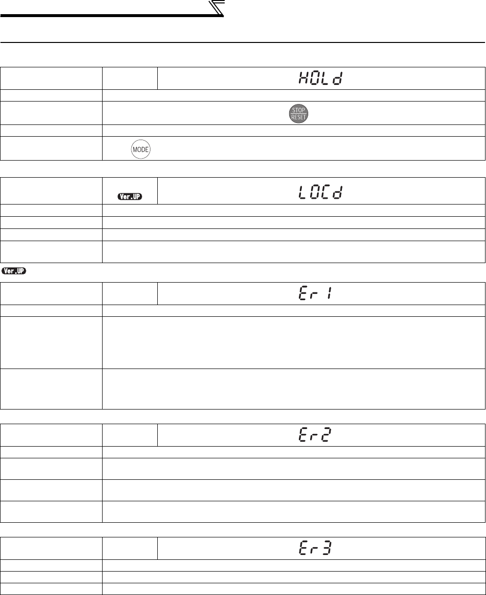
404
Causes and corrective actions
5.3 Causes and corrective actions
(1) Error message
A message regarding operational troubles is displayed. Output is not shut off.
....... Specifications differ according to the date assembled. Refer to page 484 to check the SERIAL number.
Operation Panel
Indication HOLD
Name Operation panel lock
Description Operation lock mode is set. Operation other than is invalid. (Refer to page 395.)
Check point --------------
Corrective action Press for 2s to release lock.
Operation Panel
Indication
LOCD
Name Password locked
Description Password function is active. Display and setting of parameter is restricted.
Check point --------------
Corrective action Enter the password in Pr. 297 Password lock/unlock to unlock the password function before operating.
(Refer to page 310.)
Operation Panel
Indication Er1
Name Write disable error
Description
· You attempted to make parameter setting when Pr. 77 Parameter write selection has been set to
disable parameter write.
· Frequency jump setting range overlapped.
· Adjustable 5 points V/F settings overlapped
· The PU and inverter cannot make normal communication
Check point
· Check the setting of Pr. 77 Parameter write selection (Refer to page 307.)
· Check the settings of Pr. 31 to 36 (frequency jump). (Refer to page 158.)
· Check the settings of Pr. 100 to Pr. 109 (adjustable 5 points V/F). (Refer to page 164.)
· Check the connection of the PU and inverter.
Operation Panel
Indication Er2
Name Write error during operation
Description When parameter write was performed during operation with a value other than "2" (writing is enabled
independently of operating status in any operation mode) is set in Pr. 77 and the STF (STR) is ON.
Check point · Check the Pr. 77 setting. (Refer to page 307.)
· Check that the inverter is not operating.
Corrective action ·Set "2" in Pr. 77.
· After stopping operation, make parameter setting.
Operation Panel
Indication Er3
Name Calibration error
Description Analog input bias and gain calibration values are too close.
Check point Check the settings of C3, C4, C6 and C7 (calibration functions). (Refer to page 294.)
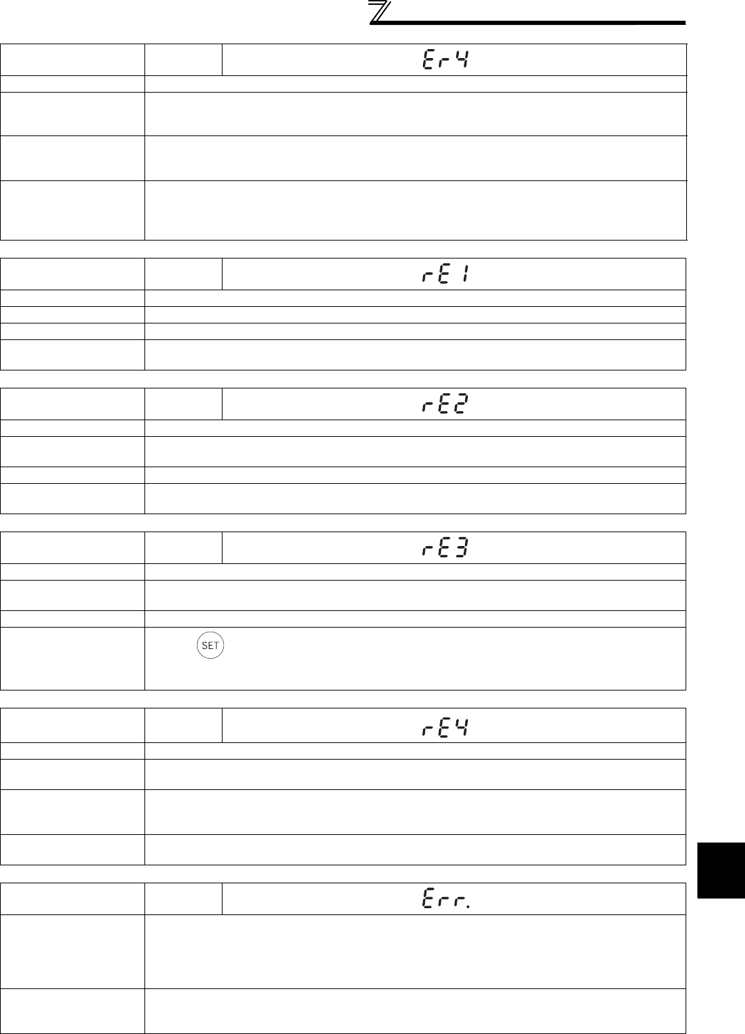
405
Causes and corrective actions
5
PROTECTIVE FUNCTIONS
Operation Panel
Indication Er4
Name Mode designation error
Description
·Appears if a parameter setting is attempted in the External or NET operation mode with Pr. 77 ≠ "2".
·Appears if a parameter setting is attempted when the command source is not at the operation panel. (FR-
DU07).
Check point
· Check that operation mode is "PU operation mode".
· Check the Pr. 77 setting. (Refer to page 307.)
· Check the Pr. 551 setting.
Corrective action
· After setting the operation mode to the "PU operation mode", make parameter setting. (Refer to page
307.)
· After setting Pr. 77 = "2", make parameter setting.
·Set Pr.551 = "2 (initial value)". (Refer to page 322.)
Operation Panel
Indication rE1
Name Parameter read error
Description An error occurred in the EEPROM on the operation panel side during parameter copy reading.
Check point --------------
Corrective action · Make parameter copy again. (Refer to page 397.)
· Check for an operation panel (FR-DU07) failure. Please contact your sales representative.
Operation Panel
Indication rE2
Name Parameter write error
Description · You attempted to perform parameter copy write during operation.
· An error occurred in the EEPROM on the operation panel side during parameter copy writing.
Check point Is the FWD or REV LED of the operation panel (FR-DU07) lit or flickering?
Corrective action · After stopping operation, make parameter copy again. (Refer to page 397.)
· Check for an operation panel (FR-DU07) failure. Please contact your sales representative.
Operation Panel
Indication rE3
Name Parameter verification error
Description · Data on the operation panel side and inverter side are different.
· An error occurred in the EEPROM on the operation panel side during parameter verification.
Check point Check for the parameter setting of the source inverter and inverter to be verified.
Corrective action · Press to continue verification.
Make parameter verification again. (Refer to page 398.)
· Check for an operation panel (FR-DU07) failure. Please contact your sales representative.
Operation Panel
Indication rE4
Name Model error
Description · A different model was used for parameter write and verification during parameter copy.
· When parameter copy write is stopped after parameter copy read is stopped
Check point
· Check that the verified inverter is the same model.
· Check that the power is not turned OFF or an operation panel is not disconnected, etc. during
parameter copy read.
Corrective action · Use the same model (FR-A700 series) for parameter copy and verification.
· Perform parameter copy read again.
Operation Panel
Indication Err.
Description
· The RES signal is on
· The PU and inverter cannot make normal communication (contact fault of the connector)
· When the voltage drops in the inverter's input side.
· When the control circuit power (R1/L11, S1/L21) and the main circuit power (R/L1, S/L2, T/L3) are
connected to a separate power, it may appear at turning ON of the main circuit. It is not a fault.
Corrective action
· Turn OFF the RES signal.
· Check the connection of the PU and inverter.
· Check the voltage on the inverter's input side.
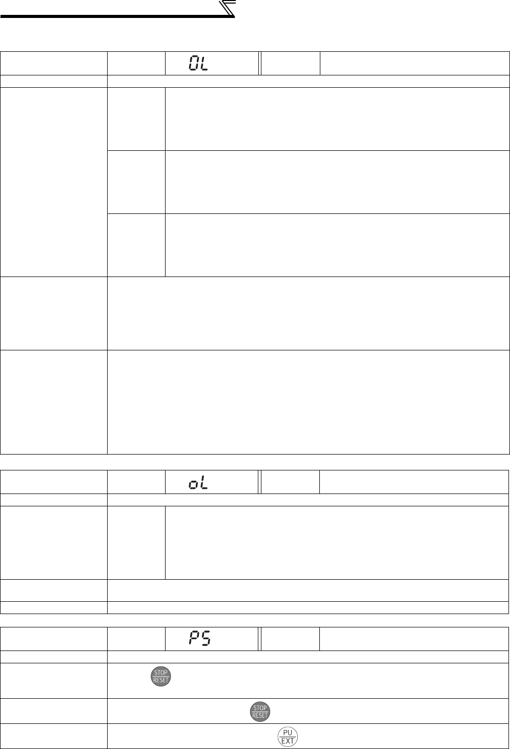
406
Causes and corrective actions
(2) Warning
When the protective function is activated, the output is not shut off.
Operation Panel
Indication OL FR-PU04
FR-PU07 OL
Name Stall prevention (overcurrent)
Description
During
acceleration
When the output current (output torque during Real sensorless vector control or vector
control) of the inverter exceeds the stall prevention operation level (Pr. 22 Stall prevention
operation level, etc.), this function stops the increase in frequency until the overload
current decreases to prevent the inverter from resulting in overcurrent trip. When the
overload current has decreased below stall prevention operation level, this function
increases the frequency again.
During
constant
speed
operation
When the output current (output torque during Real sensorless vector control or vector
control) of the inverter exceeds the stall prevention operation level (Pr. 22 Stall prevention
operation level, etc.), this function reduces frequency until the overload current
decreases to prevent the inverter from resulting in overcurrent trip. When the overload
current has decreased below stall prevention operation level, this function increases the
frequency up to the set value.
During
deceleration
When the output current (output torque during Real sensorless vector control or vector
control) of the inverter exceeds the stall prevention operation level (Pr. 22 Stall prevention
operation level, etc.), this function stops the decrease in frequency until the overload
current decreases to prevent the inverter from resulting in overcurrent trip. When the
overload current has decreased below stall prevention operation level, this function
decreases the frequency again.
Check point
· Check that the Pr. 0 Torque boost setting is not too large.
· Check that the Pr. 7 Acceleration time and Pr. 8 Deceleration time settings are not too small.
· Check that the load is not too heavy.
· Are there any failure in peripheral devices?
· Check that the Pr. 13 Starting frequency is not too large.
· Check the motor for use under overload.
· Check that Pr. 22 Stall prevention operation level is appropriate.
Corrective action
· Increase or decrease the Pr. 0 Torque boost value 1% by 1% and check the motor status. (Refer to page
146.)
· Set a larger value in Pr. 7 Acceleration time and Pr. 8 Deceleration time. (Refer to page 172.)
· Reduce the load weight.
· Try Advanced magnetic flux vector control, Real sensorless vector control or vector control.
· Change the Pr. 14 Load pattern selection setting.
· Set stall prevention operation current in Pr. 22 Stall prevention operation level. (The initial value is
150%.) The acceleration/deceleration time may change. Increase the stall prevention operation level
with Pr. 22 Stall prevention operation level, or disable stall prevention with Pr. 156 Stall prevention
operation selection. (Use Pr. 156 to set either operation continued or not at OL operation.)
Operation Panel
Indication oL FR-PU04
FR-PU07 oL
Name Stall prevention (overvoltage)
Description During
deceleration
· If the regenerative energy of the motor becomes excessive and exceeds the
regenerative energy consumption capability, this function stops the decrease in
frequency to prevent overvoltage trip. As soon as the regenerative energy has
decreased, deceleration resumes.
· If the regenerative energy of the motor becomes excessive when regeneration
avoidance function is selected (Pr. 882 = 1), this function increases the speed to
prevent overvoltage trip. (Refer to page 383.)
Check point · Check for sudden speed reduction.
· Regeneration avoidance function (Pr. 882 to Pr. 886) is being used? (Refer to page 383.)
Corrective action The deceleration time may change. Increase the deceleration time using Pr. 8 Deceleration time.
Operation Panel
Indication PS FR-PU04
FR-PU07 PS
Name PU stop
Description Stop with of the PU is set in Pr. 75 Reset selection/disconnected PU detection/PU stop selection. (For
Pr. 75, refer to page 305.)
Check point Check for a stop made by pressing of the operation panel.
Corrective action Turn the start signal OFF and release with .

407
Causes and corrective actions
5
PROTECTIVE FUNCTIONS
Operation Panel
Indication RB FR-PU04
FR-PU07 RB
Name Regenerative brake pre-alarm
Description
Appears if the regenerative brake duty reaches or exceeds 85% of the Pr. 70 Special regenerative brake
duty value. When the setting of Pr. 70 Special regenerative brake duty is the initial value (Pr. 70 = "0"), this
warning does not occur. If the regenerative brake duty reaches 100%, a regenerative overvoltage (E.
OV_) occurs.
The RBP signal can be simultaneously output with the [RB] display. For the terminal used for the RBP
signal output, assign the function by setting "7" (positive logic) or "107" (negative logic) in any of Pr. 190
to Pr. 196 (output terminal function selection). (Refer to page 239)
Check point
· Check that the brake resistor duty is not high.
· Check that the Pr. 30 Regenerative function selection and Pr. 70 Special regenerative brake duty values are
correct.
Corrective action · Increase the deceleration time.
· Check the Pr. 30 Regenerative function selection and Pr. 70 Special regenerative brake duty values.
Operation Panel
Indication TH FR-PU04
FR-PU07 TH
Name Electronic thermal relay function pre-alarm
Description
Appears if the cumulative value of the Pr. 9 Electronic thermal O/L relay reaches or exceeds 85% of the
preset level. If it reaches 100% of the Pr. 9 Electronic thermal O/L relay setting, a motor overload trip (E.
THM) occurs.
The THP signal can be simultaneously output with the [TH] display. For the terminal used for the THP
signal output, assign the function by setting "8" (positive logic) or "108" (negative logic) in any of Pr. 190
to Pr. 196 (output terminal function selection). (Refer to page 239)
Check point · Check for large load or sudden acceleration.
·Is the Pr. 9 Electronic thermal O/L relay setting is appropriate? (Refer to page 183.)
Corrective action · Reduce the load weight or the number of operation times.
· Set an appropriate value in Pr. 9 Electronic thermal O/L relay. (Refer to page 183.)
Operation Panel
Indication MT FR-PU04 ————
FR-PU07 MT
Name Maintenance signal output
Description
Indicates that the cumulative energization time of the inverter has reached a given time.
When the setting of Pr. 504 Maintenance timer alarm output set time is the initial value (Pr. 504 = "9999"),
this warning does not occur.
Check point The Pr. 503 Maintenance timer setting is larger than the Pr. 504 Maintenance timer alarm output set time
setting. (Refer to page 389.)
Corrective action Setting "0" in Pr. 503 Maintenance timer erases the signal.
Operation Panel
Indication CP FR-PU04 ————
FR-PU07 CP
Name Parameter copy
Description Appears when parameters are copied between models with capacities of 55K or lower and 75K or higher.
Check point Resetting of Pr. 9, Pr. 30, Pr. 51, Pr. 52, Pr. 54, Pr. 56, Pr. 57, Pr. 61, Pr. 70, Pr. 72, Pr. 80, Pr. 82, Pr. 90 to Pr.
94, Pr. 158, Pr. 455, Pr. 458 to Pr. 462, Pr. 557, Pr. 859, Pr. 860 and Pr. 893 is necessary.
Corrective action Set the initial value in Pr. 989 Parameter copy alarm release.
Operation Panel
Indication SL FR-PU04 ————
FR-PU07 SL
Name Speed limit indication (output during speed limit)
Description Output if the speed limit level is exceeded during torque control.
Check point · Check that the torque command is not larger than required.
· Check that the speed limit level is not low.
Corrective action · Decrease the torque command.
· Increase the speed limit level.

408
Causes and corrective actions
(3) Alarm
When an alarm occurs, the output is not shut off. You can also output an alarm signal by making parameter setting. (Set
"98" in any of
Pr. 190 to Pr. 196 (output terminal function selection)
.
(Refer to
page 239
.)
)
(4) Fault
When a fault occurs, the inverter trips and a fault signal is output.
Operation Panel
Indication FN FR-PU04
FR-PU07 FN
Name Fan alarm
Description For the inverter that contains a cooling fan, appears on the operation panel when the cooling fan
stops due to a fault or different operation from the setting of Pr. 244 Cooling fan operation selection.
Check point Check the cooling fan for a fault.
Corrective action Check for fan fault. Please contact your sales representative.
Operation Panel
Indication E.OC1 FR-PU04
FR-PU07 OC During Acc
Name Overcurrent trip during acceleration
Description When the inverter output current reaches or exceeds approximately 220% of the rated current during
acceleration, the protective circuit is activated to stop the inverter output.
Check point
· Check for sudden acceleration.
· Check that the downward acceleration time is not long in vertical lift application.
· Check for output short circuit.
· Check that the Pr. 3 Base frequency setting is not 60Hz when the motor rated frequency is 50Hz.
· Check if the stall prevention operation level is set too high.
· Check if the fast-response current limit operation is disabled.
· Check that the regeneration is not performed frequently. (Check that the output voltage becomes larger
than the V/F reference voltage at regeneration and overcurrent occurs due to the high voltage.)
· Check that the power supply for RS-485 terminal is not shorted. (under vector control)
· Check that the rotation direction is not switched from forward to reverse rotation (or from reverse to
forward) during torque control under Real sensorless vector control.
Corrective action
· Increase the acceleration time.
(Shorten the downward acceleration time in vertical lift application.)
· When "E.OC1" is always lit at starting, disconnect the motor once and start the inverter.
If "E.OC1" is still lit, contact your sales representative.
· Check the wiring to make sure that output short circuit does not occur.
·Set the Pr. 3 Base frequency to 50Hz. (Refer to page 159.)
·
Lower the setting of stall prevention operation level.
· Activate the fast-response current limit operation.(Refer to page 152.)
· Set base voltage (rated voltage of the motor, etc.) in Pr. 19 Base frequency voltage. (Refer to page 159.)
· Check RS-485 terminal connection. (under vector control)
· Prevent the motor from switching the rotation direction from forward to reverse (or from reverse to
forward) during torque control under Real sensorless vector control.
Operation Panel
Indication E.OC2 FR-PU04
FR-PU07 Stedy Spd OC
Name Overcurrent trip during constant speed
Description When the inverter output current reaches or exceeds approximately 220% of the rated current during
constant speed operation, the protective circuit is activated to stop the inverter output.
Check point
· Check for sudden load change.
· Check for output short circuit.
· Check if the stall prevention operation level is set too high.
· Check if the fast-response current limit operation is disabled.
· Check that the power supply for RS-485 terminal is not shorted. (under vector control)
· Check that the rotation direction is not switched from forward to reverse rotation (or from reverse to
forward) during torque control under Real sensorless vector control.
Corrective action
· Keep load stable.
· Check the wiring to make sure that output short circuit does not occur.
·
Lower the setting of stall prevention operation level.
· Activate the fast-response current limit operation.(Refer to page 152.)
· Check RS-485 terminal connection. (under vector control)
· Prevent the motor from switching the rotation direction from forward to reverse (or from reverse to
forward) during torque control under Real sensorless vector control.
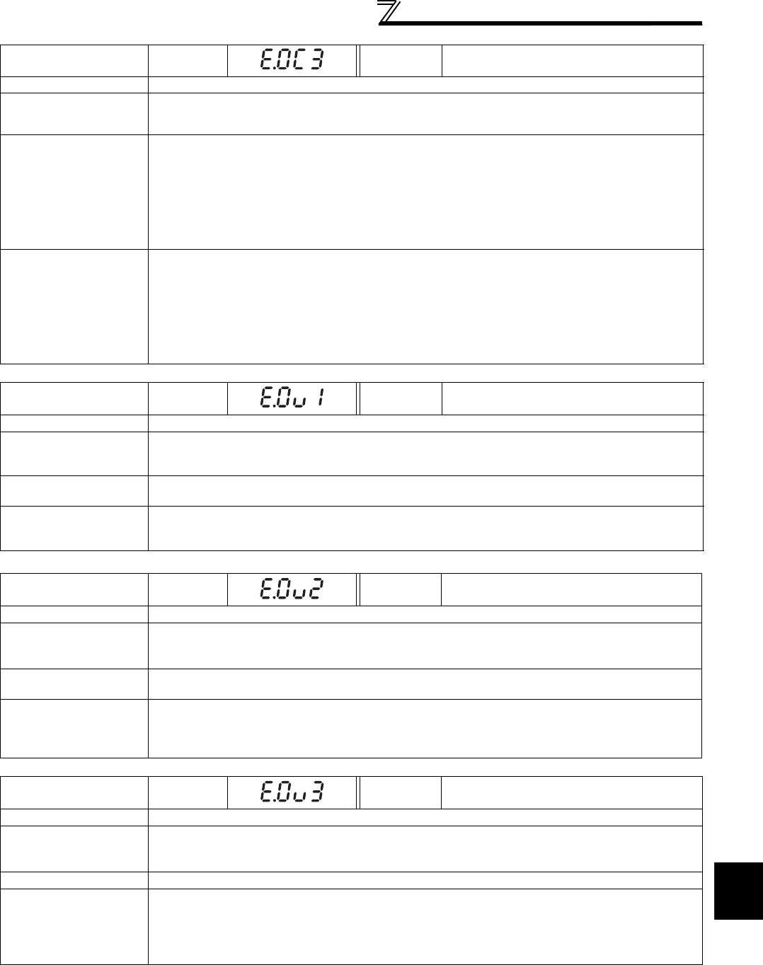
409
Causes and corrective actions
5
PROTECTIVE FUNCTIONS
Operation Panel
Indication E.OC3 FR-PU04
FR-PU07 OC During Dec
Name Overcurrent trip during deceleration or stop
Description
When the inverter output current reaches or exceeds approximately 220% of the rated inverter current
during deceleration (other than acceleration or constant speed), the protective circuit is activated to
stop the inverter output.
Check point
· Check for sudden speed reduction.
· Check for output short circuit.
· Check for too fast operation of the motor's mechanical brake.
· Check if the stall prevention operation level is set too high.
· Check if the fast-response current limit operation is disabled.
· Check that the power supply for RS-485 terminal is not shorted. (under vector control)
· Check that the rotation direction is not switched from forward to reverse rotation (or from reverse to
forward) during torque control under Real sensorless vector control.
Corrective action
· Increase the deceleration time.
· Check the wiring to make sure that output short circuit does not occur.
· Check the mechanical brake operation.
·
Lower the setting of stall prevention operation level.
· Activate the fast-response current limit operation. (Refer to page 152.)
· Check RS-485 terminal connection. (under vector control)
· Prevent the motor from switching the rotation direction from forward to reverse (or from reverse to
forward) during torque control under Real sensorless vector control.
Operation Panel
Indication E.OV1 FR-PU04
FR-PU07 OV During Acc
Name Regenerative overvoltage trip during acceleration
Description
If regenerative energy causes the inverter's internal main circuit DC voltage to reach or exceed the
specified value, the protective circuit is activated to stop the inverter output. The circuit may also be
activated by a surge voltage produced in the power supply system.
Check point · Check for too slow acceleration. (e.g. during descending acceleration in vertical lift load)
· Check that the Pr. 22 Stall prevention operation level is not lower than the no load current.
Corrective action
· Decrease the acceleration time.
· Use regeneration avoidance function (Pr. 882 to Pr. 886). (Refer to page 383.)
· Set a value larger than the no load current in Pr. 22 Stall prevention operation level.
Operation Panel
Indication E.OV2 FR-PU04
FR-PU07 Stedy Spd OV
Name Regenerative overvoltage trip during constant speed
Description
If regenerative energy causes the inverter's internal main circuit DC voltage to reach or exceed the
specified value, the protective circuit is activated to stop the inverter output. The circuit may also be
activated by a surge voltage produced in the power supply system.
Check point · Check for sudden load change.
· Check that the Pr. 22 Stall prevention operation level is not lower than the no load current.
Corrective action
· Keep load stable.
· Use regeneration avoidance function (Pr. 882 to Pr. 886). (Refer to page 383.)
· Use the brake unit or power regeneration common converter (FR-CV) as required.
· Set a value larger than the no load current in Pr. 22 Stall prevention operation level.
Operation Panel
Indication E.OV3 FR-PU04
FR-PU07 OV During Dec
Name Regenerative overvoltage trip during deceleration or stop
Description
If regenerative energy causes the inverter's internal main circuit DC voltage to reach or exceed the
specified value, the protective circuit is activated to stop the inverter output. The circuit may also be
activated by a surge voltage produced in the power supply system.
Check point Check for sudden speed reduction.
Corrective action
·
Increase the deceleration time. (Set the deceleration time which matches the moment of inertia of
the load)
· Longer the brake cycle.
· Use regeneration avoidance function (Pr. 882 to Pr. 886). (Refer to page 383.)
· Use the brake unit or power regeneration common converter (FR-CV) as required.

410
Causes and corrective actions
*1 Resetting the inverter initializes the internal thermal integrated data of the electronic thermal relay function.
*2 Resetting the inverter initializes the internal thermal integrated data of the electronic thermal relay function.
Operation Panel
Indication E.THT FR-PU04
FR-PU07 Inv. Ovrload
Name Inverter overload trip (electronic thermal relay function)
Description
If a current not less than 150% of the rated output current flows and overcurrent trip does not occur
(220% or less), the electronic thermal relay activates to stop the inverter output in order to protect the
output transistors. (Overload capacity 150% 60s, inverse-time characteristic)
Check point
· Check that acceleration/deceleration time is not too short.
· Check that torque boost setting is not too large (small).
· Check that load pattern selection setting is appropriate for the load pattern of the using machine.
· Check the motor for use under overload.
Corrective action
· Increase acceleration/deceleration time.
· Adjust the torque boost setting.
· Set the load pattern selection setting according to the load pattern of the using machine.
· Reduce the load weight.
Operation Panel
Indication E.THM FR-PU04
FR-PU07 Motor Ovrload
Name Motor overload trip (electronic thermal relay function) *2
Description
The electronic thermal relay function in the inverter detects motor overheat due to overload or reduced
cooling capability during constant-speed operation and pre-alarm (TH display) is output when the
integrated value reaches 85% of the Pr. 9 Electronic thermal O/L relay setting and the protection circuit is
activated to stop the inverter output when the integrated value reaches the specified value. When
running a special motor such as a multi-pole motor or multiple motors, provide a thermal relay on the
inverter output side since such motor(s) cannot be protected by the electronic thermal relay function.
Check point
· Check the motor for use under overload.
· Check that the setting of Pr. 71 Applied motor for motor selection is correct. (Refer to page 187.)
· Check that stall prevention operation setting is correct.
Corrective action
· Reduce the load weight.
· For a constant-torque motor, set the constant-torque motor in Pr. 71 Applied motor.
· Check that stall prevention operation setting is correct. (Refer to page 152.)
Operation Panel
Indication E.FIN FR-PU04
FR-PU07 H/Sink O/Temp
Name Heatsink overheat
Description
If the heatsink overheats, the temperature sensor is actuated to stop the inverter output.
The FIN signal can be output when the temperature becomes approximately 85% of the heatsink
overheat protection operation temperature.
For the terminal used for the FIN signal output, assign the function by setting "26" (positive logic) or
"126" (negative logic) in any of Pr. 190 to Pr. 196 (output terminal function selection). (Refer to page 239)
Check point
· Check for too high surrounding air temperature.
· Check for heatsink clogging.
· Check that the cooling fan is stopped. (Check that is displayed on the operation panel.)
Corrective action
· Set the surrounding air temperature to within the specifications.
· Clean the heatsink.
· Replace the cooling fan.
Operation Panel
Indication E.IPF FR-PU04
FR-PU07 Inst. Pwr. Loss
Name Instantaneous power failure
Description
If a power failure occurs for longer than 15ms (this also applies to inverter input shut-off), the
instantaneous power failure protective function is activated to trip the inverter in order to prevent the
control circuit from malfunctioning. If a power failure persists for longer than 100ms, the fault output is
not provided, and the inverter restarts if the start signal is ON upon power restoration. (The inverter
continues operating if an instantaneous power failure is within 15ms.) In some operating status (load
magnitude, acceleration/deceleration time setting, etc.), overcurrent or other protection may be
activated upon power restoration.
When instantaneous power failure protection is activated, the IPF signal is output. (Refer to page 266)
Check point Find the cause of instantaneous power failure occurrence.
Corrective action
· Remedy the instantaneous power failure.
· Prepare a backup power supply for instantaneous power failure.
· Set the function of automatic restart after instantaneous power failure (Pr. 57). (Refer to page 266.)
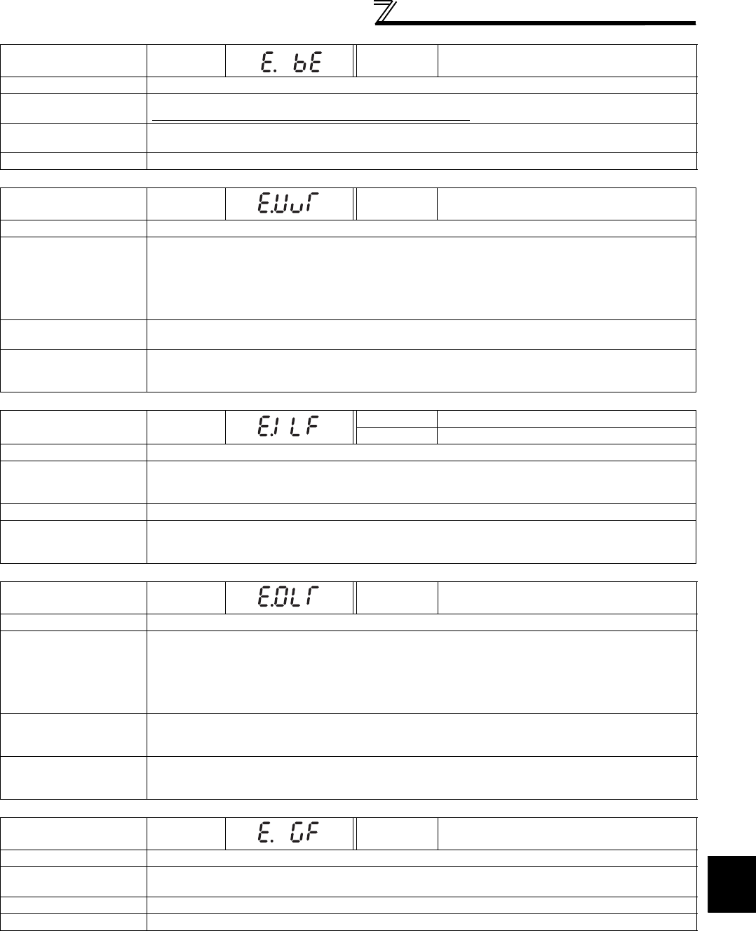
411
Causes and corrective actions
5
PROTECTIVE FUNCTIONS
Operation Panel
Indication E.BE FR-PU04
FR-PU07 Br. Cct. Fault
Name Brake transistor alarm detection
Description
This function stops the inverter output if an alarm occurs in the brake circuit, e.g. damaged brake transistors.
In this case, the inverter must be powered OFF immediately.
Check point · Reduce the load inertia.
· Check that the frequency of using the brake is proper.
Corrective action Replace the inverter.
Operation Panel
Indication E.UVT FR-PU04
FR-PU07 Under Voltage
Name Undervoltage
Description
If the power supply voltage of the inverter decreases, the control circuit will not perform normal functions.
In addition, the motor torque will be insufficient and/or heat generation will increase. To prevent this, if
the power supply voltage decreases below about 150VAC (300VAC for the 400V class), this function
stops the inverter output.
When a jumper is not connected across P/+ and P1, the undervoltage protective function is activated.
When undervoltage protection is activated, the IPF signal is output. (Refer to page 266)
Check point · Check for start of large-capacity motor.
· Check that a jumper or DC reactor is connected across terminals P/+ and P1.
Corrective action
· Check the power supply system equipment such as the power supply.
· Connect a jumper or DC reactor across terminals P/+ and P1.
If the problem still persists after taking the above measure, please contact your sales representative.
Operation Panel
Indication E.ILF FR-PU04 Fault 14
FR-PU07 Input phase loss
Name Input phase loss
Description
This fault is output when function valid setting (= 1) is set in Pr. 872 Input phase loss protection selection
and one phase of the three phase power input is lost. When the setting of Pr. 872 Input phase loss
protection selection is the initial value (Pr. 872 = "0"), this fault does not occur. (Refer to page 276.)
Check point Check for a break in the cable for the three-phase power supply input.
Corrective action
· Wire the cables properly.
· Repair a break portion in the cable.
· Check the Pr. 872 Input phase loss protection selection setting.
Operation Panel
Indication E.OLT FR-PU04
FR-PU07 Stll Prev STP
Name Stall prevention stop
Description
If the frequency has fallen to 0.5Hz by stall prevention operation and remains for 3s, a fault (E.OLT)
appears and trips the inverter. OL appears while stall prevention is being activated.
When speed control is performed by Real sensorless vector control or vector control, a fault (E.OLT) is
displayed and the inverter output is stopped if frequency drops to the Pr. 865 Low speed detection (initial
value is 1.5Hz) setting by torque limit operation and the output torque exceeds Pr. 874 OLT level setting
(initial value is 150%) setting and remains for more than 3s.
Check point
· Check the motor for use under overload. (Refer to page 152.)
· Check that the Pr. 865 Low speed detection and Pr. 874 OLT level setting values are correct. (Check the
Pr. 22 Stall prevention operation level setting if V/F control is exercised.)
Corrective action
· Reduce the load weight.
· Change the Pr. 22 Stall prevention operation level, Pr. 865 Low speed detection and Pr. 874 OLT level
setting values. (Check the Pr. 22 Stall prevention operation level setting if V/F control is exercised.)
Operation Panel
Indication E.GF FR-PU04
FR-PU07 Ground Fault
Name Output side earth (ground) fault overcurrent
Description This function stops the inverter output if an earth (ground) fault overcurrent flows due to an earth
(ground) fault that occurred on the inverter's output (load) side.
Check point Check for an earth (ground) fault in the motor and connection cable.
Corrective action Remedy the earth (ground) fault portion.

412
Causes and corrective actions
Operation Panel
Indication E.LF FR-PU04
FR-PU07 E.LF
Name Output phase loss
Description This function stops the inverter output if one of the three phases (U, V, W) on the inverter's output side
(load side) is lost.
Check point · Check the wiring (Check that the motor is normal.)
· Check that the capacity of the motor used is not smaller than that of the inverter.
Corrective action · Wire the cables properly.
· Check the Pr. 251Output phase loss protection selection setting.
Operation Panel
Indication E.OHT FR-PU04
FR-PU07 OH Fault
Name External thermal relay operation
Description
If the external thermal relay provided for motor overheat protection, or the internally mounted
temperature relay in the motor, etc. switches ON (contacts open), the inverter output is stopped.
This function is available when "7" (OH signal) is set in any of Pr. 178 to Pr. 189 (input terminal function
selection).
When the initial value (without OH signal assigned) is set, this protective function is not available.
Check point · Check for motor overheating.
·
Check that the value of 7 (OH signal) is set correctly in any of
Pr. 178 to Pr. 189 (input terminal function selection)
.
Corrective action · Reduce the load and operating duty.
· Even if the relay contacts are reset automatically, the inverter will not restart unless it is reset.
Operation Panel
Indication E.PTC FR-PU04 Fault 14
FR-PU07 PTC activated
Name PTC thermistor operation
Description
Stops the inverter output when the motor overheat status is detected for 10s or more by the external
PTC thermistor input connected to the terminal AU.
This fault is available when "63" is set in Pr. 184 AU terminal function selection and AU/PTC switchover
switch is set in PTC side. When the initial value (Pr. 184 = "4") is set, this protective function is not
available.
Check point
· Check the connection between the PTC thermistor switch and thermal protector.
· Check the motor for operation under overload.
· Is valid setting ( = 63) selected in Pr. 184 AU terminal function selection ? (Refer to page 186, 231.)
Corrective action Reduce the load weight.
Operation Panel
Indication E.OPT FR-PU04
FR-PU07 Option Fault
Name Option fault
Description
· Appears when the AC power supply is connected to the terminal R/L1, S/L2, T/L3 accidentally when
a high power factor converter is connected.
· Appears when torque command by the plug-in option is selected using Pr. 804 Torque command source
selection and no plug-in option is mounted during torque control.
· Appears when the switch for the manufacturer setting of the plug-in option is changed.
· Appears when a communication option is connected while Pr. 296 = "0 or 100."
Check point
· Check that the AC power supply is not connected to the terminal R/L1, S/L2, T/L3 when a high
power factor converter (FR-HC, MT-HC) or power regeneration common converter (FR-CV) is
connected.
· Check that the plug-in option for torque command setting is connected.
· Check for the password lock with a setting of Pr. 296 = "0, 100"
Corrective action
· Check the parameter (Pr. 30) setting and wiring.
· The inverter may be damaged if the AC power supply is connected to the terminal R/L1, S/L2, T/L3
when a high power factor converter is connected. Please contact your sales representative.
· Check for connection of the plug-in option. Check the Pr. 804 Torque command source selection setting.
· Return the switch for the manufacturer setting of the plug-in option to the initial status. (Refer to
instruction manual of each option)
· To apply the password lock when installing a communication option, set Pr.296 ≠ "0,100". (Refer to
page 310.)
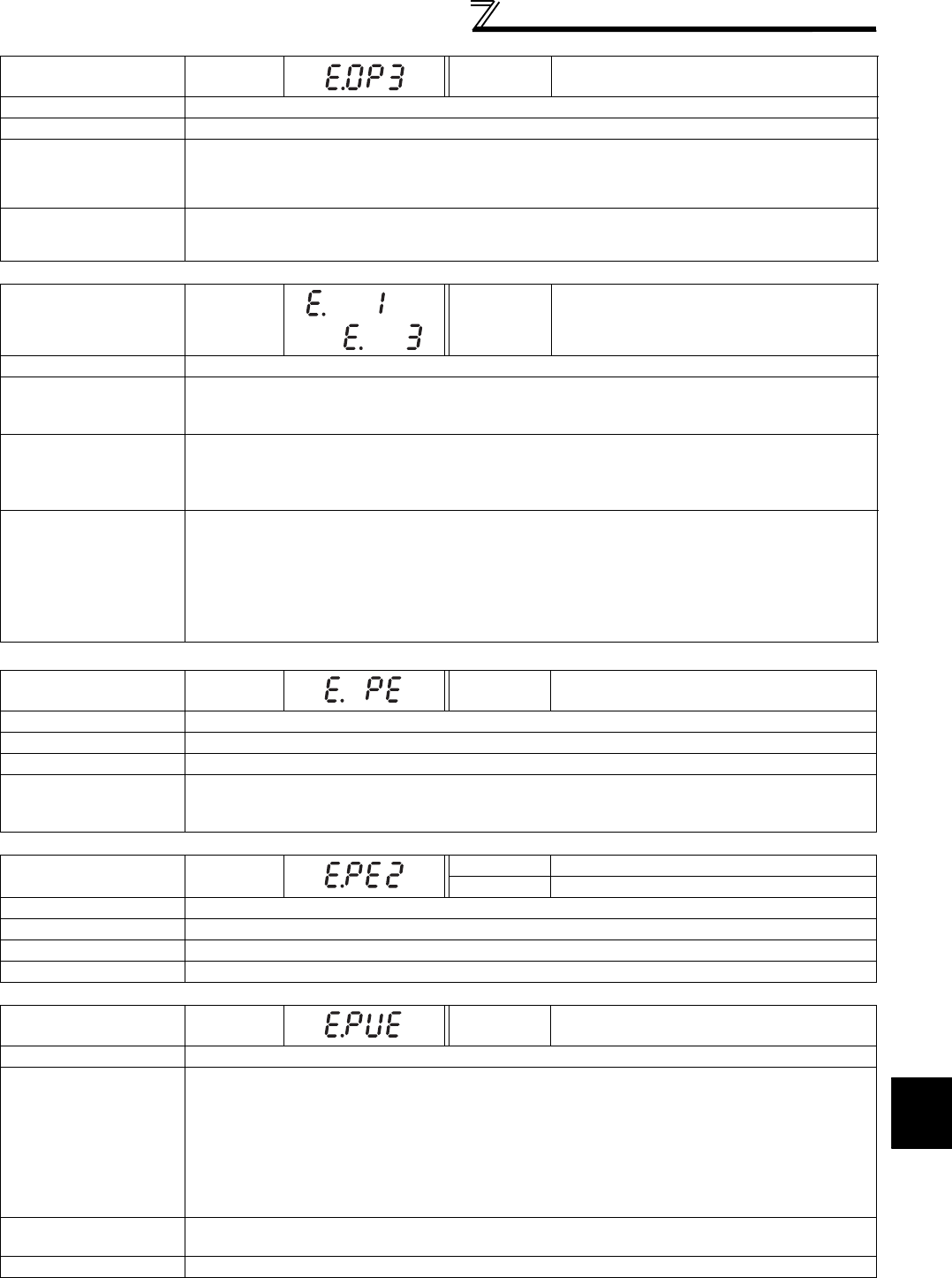
413
Causes and corrective actions
5
PROTECTIVE FUNCTIONS
Operation Panel
Indication E.OP3 FR-PU04
FR-PU07 Option3 Fault
Name Communication option fault
Description Stops the inverter output when a communication line error occurs in the communication option.
Check point
· Check for a wrong option function setting and operation.
· Check that the plug-in option is plugged into the connector securely.
· Check for a break in the communication cable.
· Check that the terminating resistor is fitted properly.
Corrective action
· Check the option function setting, etc.
· Connect the plug-in option securely.
· Check the connection of communication cable.
Operation Panel
Indication
E. 1 to
E. 3
FR-PU04
FR-PU07 Fault 1 to Fault 3
Name Option fault
Description
Stops the inverter output if a contact fault, etc. of the connector between the inverter and plug-in option
occurs or if a communication option is fitted to the connector 1 or 2.
Appears when the switch for the manufacturer setting of the plug-in option is changed.
Check point
· Check that the plug-in option is plugged into the connector securely.
(1 to 3 indicate the option connector numbers.)
· Check for excess electrical noises around the inverter.
· Check that the communication option is not fitted to the connector 1 or 2.
Corrective action
· Connect the plug-in option securely.
· Take measures against noises if there are devices producing excess electrical noises around the inverter.
If the problem still persists after taking the above measure, please contact your sales representative
or distributor.
· Fit the communication option to the connector 3.
· Return the switch position for the manufacturer setting of the plug-in option to the initial status. (Refer
to instruction manual of each option)
Operation Panel
Indication E.PE FR-PU04
FR-PU07 Corrupt Memry
Name Parameter storage device fault (control circuit board)
Description Stops the inverter output if fault occurred in the parameter stored. (EEPROM failure)
Check point Check for too many number of parameter write times.
Corrective action
Please contact your sales representative.
When performing parameter write frequently for communication purposes, set "1" in Pr. 342 to enable
RAM write. Note that powering OFF returns the inverter to the status before RAM write.
Operation Panel
Indication E.PE2 FR-PU04 Fault 14
FR-PU07 PR storage alarm
Name Parameter storage device fault (main circuit board)
Description Stops the inverter output if fault occurred in the parameter stored. (EEPROM failure)
Check point ——————
Corrective action Please contact your sales representative.
Operation Panel
Indication E.PUE FR-PU04
FR-PU07 PU Leave Out
Name PU disconnection
Description
· This function stops the inverter output if communication between the inverter and PU is suspended,
e.g. the operation panel and parameter unit is disconnected, when "2, 3, 16 or 17" was set in Pr. 75
Reset selection/disconnected PU detection/PU stop selection.
· This function stops the inverter output when communication errors occurred consecutively for more
than permissible number of retries when a value other than "9999" is set in Pr. 121 Number of PU
communication retries during the RS-485 communication with the PU connector.
· This function stops the inverter output if communication is broken within the period of time set in Pr.
122 PU communication check time interval during the RS-485 communication with the PU connector.
Check point · Check that the FR-DU07 or parameter unit (FR-PU04/FR-PU07) is connected properly.
· Check the Pr. 75 setting.
Corrective action Fit the FR-DU07 or parameter unit (FR-PU04/FR-PU07) securely.
to
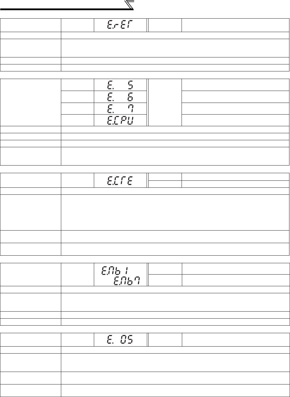
414
Causes and corrective actions
Operation Panel
Indication E.RET FR-PU04
FR-PU07 Retry No Over
Name Retry count excess
Description
If operation cannot be resumed properly within the number of retries set, this function trips the inverter.
This function is available only when Pr. 67 Number of retries at fault occurrence is set. When the initial value
(Pr. 67 = "0") is set, this fault does not occur.
Check point Find the cause of alarm occurrence.
Corrective action Eliminate the cause of the error preceding this error indication.
Operation Panel
Indication
E. 5
FR-PU04
FR-PU07
Fault 5
E. 6 Fault 6
E. 7 Fault 7
E.CPU CPU Fault
Name CPU fault
Description Stops the inverter output if the communication error of the built-in CPU occurs.
Check point Check for devices producing excess electrical noises around the inverter.
Corrective action
· Take measures against noises if there are devices producing excess electrical noises around the
inverter.
· Please contact your sales representative.
Operation Panel
Indication E.CTE FR-PU04 ⎯⎯
FR-PU07 E.CTE
Name Operation panel power supply short circuit, RS-485 terminal power supply short circuit
Description
When the operation panel power supply (PU connector) is shorted, this function shuts off the power
output and stops the inverter. At this time, the operation panel (parameter unit) cannot be used and
RS-485 communication from the PU connector cannot be made. When the internal power supply for
RS-485 terminals are shorted, this function shuts off the power output.
At this time, communication from the RS-485 terminals cannot be made.
To reset, enter the RES signal or switch power OFF, then ON again.
Check point · Check for a short circuit in the PU connector cable.
· Check that the RS-485 terminals are connected correctly.
Corrective action · Check the PU and cable.
· Check the connection of the RS-485 terminals
Operation Panel
Indication E.MB1 to 7
FR-PU04 ⎯⎯
FR-PU07 E.MB1 Fault to E.MB7 Fault
Name Brake sequence fault
Description
The inverter output is stopped when a sequence error occurs during use of the brake sequence
function (Pr. 278 to Pr. 285). This fault is not available in the initial status (brake sequence function is
invalid). (Refer to page 219)
Check point Find the cause of alarm occurrence.
Corrective action Check the set parameters and perform wiring properly.
Operation Panel
Indication E.OS FR-PU04
FR-PU07 E.OS
Name Overspeed occurrence
Description
Trips the inverter when the motor speed exceeds the Pr. 374 Overspeed detection level during encoder
feedback control Real sensorless vector control and vector control. This fault is not available in the
initial status.
Check point · Check that the Pr. 374 Overspeed detection level value is correct.
· Check that the number of encoder pulses does not differ from the actual number of encoder pulses.
Corrective action ·Set the Pr. 374 Overspeed detection level value correctly.
· Set the correct number of encoder pulses in Pr. 369 Number of encoder pulses.
to
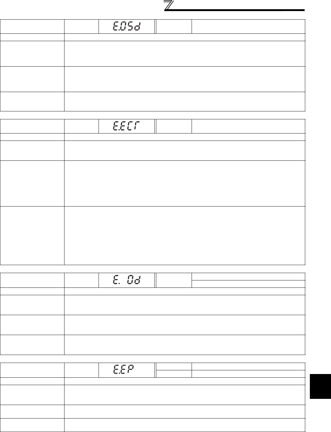
415
Causes and corrective actions
5
PROTECTIVE FUNCTIONS
Operation Panel
Indication E.OSD FR-PU04
FR-PU07 E.OSd
Name Speed deviation excess detection
Description
Trips the inverter if the motor speed is increased or decreased under the influence of the load etc.
during vector control with Pr. 285 Excessive speed deviation detection frequency set and cannot be
controlled in accordance with the speed command value.
This fault is not available in the initial status.
Check point
· Check that the values of Pr. 285 Excessive speed deviation detection frequency and Pr. 853 Speed deviation
time are correct.
· Check for sudden load change.
· Check that the number of encoder pulses does not differ from the actual number of encoder pulses.
Corrective action
·Set Pr. 285 Excessive speed deviation detection frequency and Pr. 853 Speed deviation time correctly.
· Keep load stable.
· Set the correct number of encoder pulses in Pr. 369 Number of encoder pulses.
Operation Panel
Indication E.ECT FR-PU04
FR-PU07 E.ECT
Name Signal loss detection
Description
Trips the inverter when the encoder signal is shut off under orientation control, encoder feedback
control or vector control.
This fault is not available in the initial status.
Check point
· Check for the encoder signal loss.
· Check that the encoder specifications are correct.
· Check for a loose connector.
· Check that the switch setting of FR-A7AP/FR-A7AL (option) is correct.
· Check that the power is supplied to the encoder. Or, check that the power is not supplied to the
encoder later than the inverter.
· Check that the voltage of the power supplied to the encoder is same as the encoder output voltage.
Corrective action
· Remedy the signal loss.
· Use an encoder that meets the specifications.
· Make connection securely.
· Make a switch setting of FR-A7AP/FR-A7AL (option) correctly. (Refer to page 34)
· Supply the power to the encoder. Or supply the power to the encoder at the same time when the
power is supplied to the inverter.
If the power is supplied to the encoder after the inverter, check that the encoder signal is securely
sent and set "0" in Pr. 376.
· Make the voltage of the power supplied to the encoder the same as the encoder output voltage.
Operation Panel
Indication E.OD FR-PU04
FR-PU07
Fault 14
E.Od
Name Excessive position fault
Description
Trips the inverter when the difference between the position command and position feedback exceeds
Pr. 427 Excessive level error under position control.
This fault is not available in the initial status.
Check point
· Check that the position detecting encoder mounting orientation matches the parameter.
· Check that the load is not large.
· Check that the Pr. 427 Excessive level error and Pr. 369 Number of encoder pulses are correct.
Corrective action
· Check the parameters.
· Reduce the load weight.
· Set the Pr. 427 Excessive level error and Pr. 369 Number of encoder pulses correctly.
Operation Panel
Indication E.EP FR-PU04 Fault 14
FR-PU07 E.EP
Name Encoder phase fault
Description
Trips the inverter when the rotation command of the inverter differs from the actual motor rotation
direction detected from the encoder.
This fault is not available in the initial status.
Check point · Check for mis-wiring of the encoder cable.
· Check for wrong setting of Pr. 359 Encoder rotation direction.
Corrective action · Perform connection and wiring securely.
· Change the Pr. 359 Encoder rotation direction value.

416
Causes and corrective actions
Operation Panel
Indication E.P24 FR-PU04
FR-PU07 E.P24
Name 24VDC power output short circuit
Description
When the 24VDC power output from the PC terminal is shorted, this function shuts off the power output.
At this time, all external contact inputs switch OFF. The inverter cannot be reset by entering the RES
signal. To reset it, use the operation panel or switch power OFF, then ON again.
Check point · Check for a short circuit in the PC terminal output.
Corrective action · Remedy the earth (ground) fault portion.
Operation Panel
Indication E.CDO FR-PU04 Fault 14
FR-PU07 OC detect level
Name Output current detection value exceeded
Description
Trips the inverter when the output current exceeds the setting of Pr. 150 Output current detection level.
This function is available when Pr. 167 Output current detection operation selection is set to "1". When the
initial value (Pr. 167 = "0") is set, this protective function is not available.
Check point
Check the settings of Pr. 150 Output current detection level, Pr. 151 Output current detection signal delay time,
Pr. 166 Output current detection signal retention time, Pr. 167 Output current detection operation selection.
(Refer to page 248.)
Operation Panel
Indication E.IOH FR-PU04 Fault 14
FR-PU07 Inrush overheat
Name Inrush current limit circuit fault
Description Stops the inverter output when the resistor of inrush current limit circuit overheated. The inrush current
limit circuit failure
Check point
· Check that frequent power ON/OFF is not repeated.
· Check that the primary side fuse (5A) in the power supply circuit of the inrush current limit circuit
contactor (FR-A740-110K or higher) is not fused.
· Check that the power supply circuit of inrush current limit circuit contactor is not damaged.
Corrective action Configure a circuit where frequent power ON/OFF is not repeated.
If the problem still persists after taking the above measure, please contact your sales representative.
Operation Panel
Indication E.SER FR-PU04 Fault 14
FR-PU07 VFD Comm error
Name Communication fault (inverter)
Description
This function stops the inverter output when communication error occurs consecutively for more than
permissible retry count when a value other than "9999" is set in Pr. 335 RS-485 communication retry count
during RS-485 communication from the RS-485 terminals. This function also stops the inverter output if
communication is broken for the period of time set in Pr. 336 RS-485 communication check time interval.
Check point Check the RS-485 terminal wiring.
Corrective action Perform wiring of the RS-485 terminals properly.
Operation Panel
Indication E.AIE FR-PU04 Fault 14
FR-PU07 Analog in error
Name Analog input fault
Description
Stops the inverter output when a 30mA or higher current or a 7.5V or higher voltage is input to terminal
2 while the current input is selected by Pr. 73 Analog input selection, or to terminal 4 while the current
input is selected by Pr. 267 Terminal 4 input selection.
Check point Check the setting of Pr. 73 Analog input selection, Pr. 267 Terminal 4 input selection and voltage/current
input switch. (Refer to page 286.)
Corrective action Either give a frequency command by current input or set Pr. 73 Analog input selection, Pr. 267 Terminal 4
input selection, and voltage/current input switch to voltage input.
Operation Panel
Indication E.USB FR-PU04 Fault 14
FR-PU07 USB comm error
Name USB communication fault
Description When the time set in Pr. 548 USB communication check time interval has broken, this function stops the
inverter output.
Check point Check the USB communication cable.
Corrective action
· Check the Pr. 548 USB communication check time interval setting.
· Check the USB communication cable.
· Increase the Pr. 548 USB communication check time interval setting. Or, change the setting to 9999.
(Refer to page 360)

417
Causes and corrective actions
5
PROTECTIVE FUNCTIONS
Operation Panel
Indication E.11 FR-PU04
FR-PU07 Fault 11
Name Opposite rotation deceleration fault
Description
The speed may not decelerate during low speed operation if the rotation direction of the speed
command and the estimated speed differ when the rotation is changing from forward to reverse or from
reverse to forward during torque control under Real sensorless vector control. At this time, the inverter
output is stopped if the rotation direction will not change, causing overload. This fault is not available in
the initial status (V/F control). (It is available only during Real sensorless vector control.)
Check point Check that the rotation direction is not switched from forward to reverse rotation (or from reverse to
forward) during torque control under Real sensorless vector control.
Corrective action
· Prevent the motor from switching the rotation direction from forward to reverse (or from reverse to
forward) during torque control under Real sensorless vector control.
· Please contact your sales representative.
Operation Panel
Indication E.13 FR-PU04
FR-PU07 Fault 13
Name Internal circuit fault
Description Stop the inverter output when an internal circuit fault occurred.
Corrective action Please contact your sales representative.
CAUTION
• If protective functions of E.ILF, E.PTC, E.PE2, E.EP, E.OD, E.CDO, E.IOH, E.SER, E.AIE, E.USB are activated when using the
FR-PU04, "Fault 14" appears.
Also when the faults history is checked on the FR-PU04, the display is "E.14".
• If faults other than the above appear, contact your sales representative.

418
Correspondences between digital and
actual characters
5.4 Correspondences between digital and actual characters
There are the following correspondences between the actual alphanumeric characters and the digital characters
displayed on the operation panel.
Actual Digital
0
1
2
3
4
5
6
7
8
9
Actual Digital
A
B
C
E
F
G
H
I
J
L
D
Actual Digital
M
N
O
o
P
T
U
V
r
-
S

419
Check first when you have a trouble
5
PROTECTIVE FUNCTIONS
5.5 Check first when you have a trouble
Refer to troubleshooting on page 110 (speed control), page 131 (torque control) and page 143 (position control) in
addition to the following check points.
5.5.1 Motor does not start
POINT
· If the cause is still unknown after every check, it is recommended to initialize the parameters (initial value) then reset the
required parameter values and check again.
Check
points Possible Cause Countermeasures
Refer
to
page
Main
Circuit
Appropriate power supply voltage is not applied.
(Operation panel display is not provided.)
Power ON a moulded case circuit breaker (MCCB), an earth
leakage circuit breaker (ELB), or a magnetic contactor (MC).
—
Check for the decreased input voltage, input phase loss,
and wiring.
If only the control power is ON when using a separate
power source for the control circuit, turn ON the main
circuit power.
23
Motor is not connected properly.
Check the wiring between the inverter and the motor.
If commercial power supply-inverter switchover function is
active, check the wiring of the magnetic contactor
connected between the inverter and the motor.
16
The jumper across P/+ and P1 is disconnected.
(55K or lower)
Securely fit a jumper across P/+ and P1.
When using a DC reactor (FR-HEL), remove the jumper
across P/+ and P1, and then connect the DC reactor.
16
Input
signal
Start signal is not input.
Check the start command source, and input a start signal.
PU operation mode: /
External operation mode : STF/STR signal
315
Both the forward and reverse rotation start signals (STF,
STR) are input simultaneously.
Turn ON only one of the forward and reverse rotation start
signals (STF or STR).
If STF and STR signals are turned ON simultaneously in
the initial setting, a stop command is given.
25
Frequency command is zero.
(FWD or REV LED on the operation panel is flickering.)
Check the frequency command source and enter a
frequency command. 315
AU signal is not ON when terminal 4 is used for
frequency setting.
(FWD or REV LED on the operation panel is flickering.)
Turn ON the AU signal.
Turning ON the AU signal activates terminal 4 input. 286
Output stop signal (MRS) or reset signal (RES) is ON.
(FWD or REV LED on the operation panel is flickering.)
Turn MRS or RES signal OFF.
Inverter starts the operation with a given start command
and a frequency command after turning OFF MRS or RES
signal.
Before turning OFF, ensure the safety.
25
CS signal is OFF when automatic restart after
instantaneous power failure function is selected (Pr. 57 ≠
"9999").
(FWD or REV LED on the operation panel is flickering. )
Turn ON the CS signal.
Restart operation is enabled when restart after
instantaneous power signal (CS) is ON.
266
Jumper connector of sink - source is wrongly selected.
(FWD or REV LED on the operation panel is flickering.)
Check that the control logic switchover jumper connector is
correctly installed.
If it is not installed correctly, input signal is not recognized.
28
Wiring of encoder is incorrect.
(Under encoder feedback control or vector control) Check the wiring of encoder. 36
Voltage/current input switch is not correctly set for analog
input signal (0 to 5V/0 to 10V, 4 to 20mA).
(FWD or REV LED on the operation panel is flickering.)
Set Pr. 73, Pr. 267, and a voltage/current input switch
correctly, then input an analog signal in accordance with
the setting.
25

420
Check first when you have a trouble
Parameter
Setting
was pressed.
(Operation panel indication is (PS).)
During the External operation mode, check the method of
restarting from a input stop from PU. 406
Two-wire or three-wire type connection is wrong. Check the connection.
Connect STOP signal when three-wire type is used. 236
Pr. 0 Torque boost setting is improper when V/F control is
used.
Increase Pr. 0 setting by 0.5% increments while observing
the rotation of a motor.
If that makes no difference, decrease the setting.
146
Pr. 78 Reverse rotation prevention selection is set.
Check the Pr. 78 setting.
Set Pr. 78 when you want to limit the motor rotation to only
one direction.
308
Pr. 79 Operation mode selection setting is wrong. Select the operation mode which corresponds with input
methods of start command and frequency command. 313
Bias and gain (calibration parameter C2 to C7) settings
are improper.
Check the bias and gain (calibration parameter C2 to C7)
settings. 294
Pr. 13 Starting frequency setting is greater than the
running frequency.
Set running frequency higher than Pr. 13.
The inverter does not start if the frequency setting signal is
less than the value set in Pr. 13.
175
Frequency settings of various running frequency (such
as multi-speed operation) are zero.
Especially, Pr. 1 Maximum frequency is zero.
Set the frequency command according to the application.
Set Pr. 1 higher than the actual frequency used. 157
Pr. 15 Jog frequency setting is lower than Pr. 13 Starting
frequency.Set Pr. 15 Jog frequency higher than Pr. 13 Starting frequency. 167
The Pr.359 Encoder rotation direction setting is incorrect
under encoder feedback control or under vector control.
If the "REV" on the operation panel is lit even though the
forward-rotation command is given, set Pr. 359 ="1." 38
Operation mode and a writing device do not match. Check Pr. 79, Pr. 338, Pr. 339, Pr. 550, Pr. 551, and select an
operation mode suitable for the purpose.
313,
322
Start signal operation selection is set by the Pr. 250 Stop
selection
Check Pr. 250 setting and connection of STF and STR
signals. 236
Inverter decelerated to a stop when power failure
deceleration stop function is selected.
When power is restored, ensure the safety, and turn OFF
the start signal once, then turn ON again to restart.
Inverter restarts when Pr. 261="2, 12".
270
Auto tuning is being performed.
In the PU operation, press on the operation panel
after the offline auto tuning completes.
In the External operation, turn OFF the start signal (STF,
STR).
By this operation, offline auto tuning is cancelled, and the
monitor display on the PU goes back to normal.
(If this operation is not performed, you cannot proceed to
the next operation.)
189
Automatic restart after instantaneous power failure
function or power failure stop function is activated.
(Performing overload operation during input phase loss
may cause voltage insufficiency, and that may result in
detection of power failure.)
Set Pr. 872 Input phase loss protection selection = "1" (input
phase failure protection active).
Disable the automatic restart after instantaneous power
failure function and power failure stop function.
Reduce the load.
Increase the acceleration time if the automatic restart
after instantaneous power failure function or power
failure stop function occurred during acceleration.
266,
270,
276
Load Load is too heavy. Reduce the load. —
Shaft is locked. Inspect the machine (motor). —
Check
points Possible Cause Countermeasures
Refer
to
page

421
Check first when you have a trouble
5
PROTECTIVE FUNCTIONS
5.5.2 Motor or machine is making abnormal acoustic noise
Even if the carrier frequency (Pr. 72) is set to a value higher than 3kHz for a 55K or lower capacity inverter, the carrier
frequency is automatically lowered to as low as 2kHz in an overloaded operation at a low speed (output frequency lower than
3Hz). Acoustic noise from the motor increases, but it is not a fault. (Refer to page 284 for Pr. 72)
5.5.3 Inverter generates abnormal noise
5.5.4 Motor generates heat abnormally
Check
points Possible Cause Countermeasures
Refer
to
page
Input
signal Disturbance due to EMI when frequency command is
given from analog input (terminal 1, 2, 4).
Take countermeasures against EMI. 52
Parameter
Setting
Increase the Pr. 74 Input filter time constant if steady
operation cannot be performed due to EMI. 292
Parameter
Setting
No carrier frequency noises (metallic noises) are
generated.
In the initial setting, Pr. 240 Soft-PWM operation selection is
enabled to change motor noise to an unoffending
complex tone. Therefore, no carrier frequency noises
(metallic noises) are generated.
Set Pr. 240 = "0" to disable this function.
284
Resonance occurs. (output frequency)
Set Pr. 31 to Pr. 36 (Frequency jump).
When it is desired to avoid resonance attributable to the
natural frequency of a mechanical system, these
parameters allow resonant frequencies to be jumped.
158
Resonance occurs. (carrier frequency)
Change Pr. 72 PWM frequency selection setting.
Changing the PWM carrier frequency produces an effect
on avoiding the resonance frequency of a mechanical
system or a motor.
284
Set a notch filter. 11 8
Auto tuning is not performed under Advanced magnetic
flux vector control, Real sensorless vector control, or
vector control.
Perform offline auto tuning. 189
Gain adjustment during PID control is insufficient.
To stabilize the measured value, change the proportional
band (Pr. 129) to a larger value, the integral time (Pr. 130)
to a slightly longer time, and the differential time (Pr. 134)
to a slightly shorter time.
Check the calibration of set point and measured value.
361
The gain is too high under Real sensorless vector
control or vector control.
During speed control, check the setting of Pr. 820 (Pr.
830) speed control P gain.105
During torque control, check the setting of Pr. 824 (Pr.
834) torque control P gain.130
Others Mechanical looseness Adjust machine/equipment so that there is no
mechanical looseness. —
Contact the motor manufacturer.
Motor Operating with output phase loss Check the motor wiring. —
Check
points Possible Cause Countermeasures
Refer
to
page
Fan Fan cover was not correctly installed when a cooling fan
was replaced. Install the fan cover correctly. 431
Check
points Possible Cause Countermeasures
Refer
to
page
Motor
Motor fan is not working
(Dust is accumulated.)
Clean the motor fan.
Improve the environment. —
Phase to phase insulation of the motor is insufficient. Check the insulation of the motor. —
Main
Circuit The inverter output voltage (U, V, W) are unbalanced. Check the output voltage of the inverter.
Check the insulation of the motor. 429
Parameter
Setting The Pr. 71 Applied motor setting is wrong. Check the Pr. 71 Applied motor setting. 187
—Motor current is large. Refer to "5.5.11 Motor current is too large" 424

422
Check first when you have a trouble
5.5.5 Motor rotates in the opposite direction
5.5.6 Speed greatly differs from the setting
5.5.7 Acceleration/deceleration is not smooth
Check
points Possible Cause Countermeasures
Refer
to
page
Main
Circuit
Phase sequence of output terminals U, V and W is
incorrect.
Connect phase sequence of the output cables (terminal
U, V, W) to the motor correctly. 16
Input
signal
The start signals (forward rotation, reverse rotation) are
connected improperly.
Check the wiring. (STF: forward rotation , STR: reverse
rotation) 25
The polarity of the frequency command is negative
during the polarity reversible operation set by Pr. 73
Analog input selection.
Check the polarity of the frequency command. 286
Input
signal
Parameter
setting
Torque command is negative during torque control
under vector control. Check the torque command value. 125
Check
points Possible Cause Countermeasures
Refer
to
page
Input
signal
Frequency setting signal is incorrectly input. Measure the input signal level. —
The input signal lines are affected by external EMI. Take countermeasures against EMI such as using
shielded wires for input signal lines. 54
Parameter
Setting
Pr. 1, Pr. 2, Pr. 18, calibration parameter C2 to C7 settings
are improper.
Check the settings of Pr. 1 Maximum frequency, Pr. 2
Minimum frequency, Pr. 18 High speed maximum frequency. 157
Check the calibration parameter C2 to C7 settings. 294
Pr. 31 to Pr. 36 (frequency jump) settings are improper. Narrow down the range of frequency jump. 158
Load
Stall prevention (torque limit) function is activated due to
a heavy load.
Reduce the load weight. —
Parameter
Setting
Set Pr. 22 Stall prevention operation level (Torque limit level)
higher according to the load. (Setting Pr. 22 too large
may result in frequent overcurrent trip (E.OC).)
152
(100)
Motor Check the capacities of the inverter and the motor. —
Check
points Possible Cause Countermeasures
Refer
to
page
Parameter
Setting
Acceleration/deceleration time is too short. Increase acceleration/deceleration time. 172
Torque boost (Pr. 0, Pr. 46, Pr. 112) setting is improper
under V/F control, so the stall prevention function is
activated.
Increase/decrease Pr. 0 Torque boost setting value by
0.5% increments to the setting. Deactivate stall
prevention.
146
The base frequency setting and the motor characteristic
does not match.
For V/F control, set Pr. 3 Base frequency, Pr. 47 Second V/F
(base frequency), and Pr.113 Third V/F (base frequency). 159
For vector control, set Pr.84 Rated motor frequency.189
Regeneration avoidance operation is performed
If the frequency becomes unstable during regeneration
avoidance operation, decrease the setting of Pr. 886
Regeneration avoidance voltage gain.
383
Load
Stall prevention (torque limit) function is activated due to
a heavy load.
Reduce the load weight. —
Parameter
Setting
Set Pr. 22 Stall prevention operation level (Torque limit level)
higher according to the load. (Setting Pr. 22 too large
may result in frequent overcurrent trip (E.OC).)
152
(100)
Motor Check the capacities of the inverter and the motor. —

423
Check first when you have a trouble
5
PROTECTIVE FUNCTIONS
5.5.8 Speed varies during operation
When Advanced magnetic flux vector control, Real sensorless vector control, vector control or encoder feedback control is
exercised, the output frequency varies with load fluctuation between 0 and 2Hz. This is a normal operation and is not a fault.
Check
points Possible Cause Countermeasures
Refer
to
page
Load Load varies during an operation.
Select Advanced magnetic flux vector control, Real
sensorless vector control, vector control, or encoder
feedback control.
92, 381
Input
signal
Frequency setting signal is varying. Check the frequency setting signal. —
The frequency setting signal is affected by EMI.
Set filter to the analog input terminal using Pr. 74 Input
filter time constant, Pr. 822 Speed setting filter 1. 292
Take countermeasures against EMI, such as using
shielded wires for input signal lines. 54
Malfunction is occurring due to the undesirable current
generated when the transistor output unit is connected.
Use terminal PC (terminal SD when source logic) as a
common terminal to prevent a malfunction caused by
undesirable current.
29
Multi-speed command signal is chattering. Take countermeasures to suppress chattering. —
Feedback signal from the encoder is affected by EMI.
Place the encoder cable far from the EMI source such
as main circuit and power supply voltage.
Earth (ground) the shield of the encoder cable to the
enclosure using a metal P-clip or U-clip.
36
Parameter
Setting
Fluctuation of power supply voltage is too large. Change the Pr. 19 Base frequency voltage setting (about
3%) under V/F control. 159
Pr.80 Motor capacity and Pr.81 Number of motor poles are
not appropriate for the motor capacity under Advanced
magnetic flux vector control, Real sensorless vector
control, or vector control.
Check the settings of Pr.80 Motor capacity and Pr.81
Number of motor poles.92
Wiring length exceeds 30m when Advanced magnetic
flux vector control, Real sensorless vector control, or
vector control is selected.
Perform offline auto tuning. 189
Wiring length is too long for V/F control, and the a
voltage drop occurs.
Adjust the Pr. 0 Torque boost setting by increasing with
0.5% increments for the low-speed operation. 146
Change the control method to Advanced magnetic flux
vector control or Real sensorless vector control. 92
Hunting occurs by the generated vibration, for example,
when structural rigidity at load side is insufficient.
Disable automatic control functions, such as the energy
saving operation, the fast-response current limit function,
the torque limit, the regeneration avoidance function,
Advanced magnetic flux vector control, Real sensorless
vector control, vector control, encoder feedback control,
droop control, the stall prevention, online auto tuning, the
notch filter, and orientation control.
During the PID control, set smaller values to Pr.129 PID
proportional band and Pr.130 PID integral time.
Lower the control gain, and adjust to increase the
stability.
—
Change Pr. 72 PWM frequency selection setting. 284

424
Check first when you have a trouble
5.5.9 Operation mode is not changed properly
5.5.10 Operation panel (FR-DU07) display is not operating
5.5.11 Motor current is too large
Check
points Possible Cause Countermeasures
Refer
to
page
Input
signal Start signal (STF or STR) is ON.
Check that the STF and STR signals are OFF.
When either is ON, the operation mode cannot be
changed.
313
Parameter
Setting
Pr. 79 setting is improper.
When Pr. 79 Operation mode selection setting is "0" (initial
value), the inverter is placed in the External operation
mode at input power ON. To switch to the PU operation
mode, press on the operation panel (press
when the parameter unit (FR-PU04/FR-PU07) is used) .
At other settings (1 to 4, 6, 7), the operation mode is
limited accordingly.
313
Operation mode and a writing device do not
correspond.
Check Pr. 79, Pr. 338, Pr. 339, Pr. 550, Pr. 551, and select
an operation mode suitable for the purpose.
313,
322
Check
points Possible Cause Countermeasures
Refer
to
page
Main
Circuit,
Control
Circuit
Power is not input. Input the power. 14
Front
cover
Operation panel is not properly connected to the
inverter.
Check if the inverter front cover is installed securely.
The inverter cover may not fit properly when using wires
whose size are 1.25mm
2
or larger, or when using many wires,
and this could cause a contact fault of the operation panel.
6
Check
points Possible Cause Countermeasures
Refer
to
page
Parameter
Setting
Torque boost (Pr. 0, Pr. 46, Pr. 112) setting is improper
under V/F control, so the stall prevention function is
activated.
Increase/decrease Pr. 0 Torque boost setting value by
0.5% increments to the setting. 146
V/F pattern is improper when V/F control is performed.
(Pr. 3, Pr. 14, Pr. 19)
Set rated frequency of the motor to Pr. 3 Base frequency.
Use Pr. 19 Base frequency voltage to set the base voltage
(e.g. rated motor voltage).
159
Change Pr. 14 Load pattern selection according to the load
characteristic. 161
Stall prevention (torque limit) function is activated due to
a heavy load.
Reduce the load weight. —
Set Pr. 22 Stall prevention operation level (Torque limit level)
higher according to the load. (Setting Pr. 22 too large
may result in frequent overcurrent trip (E.OC).)
152
(100)
Check the capacities of the inverter and the motor. —
Auto tuning is not performed under Advanced magnetic
flux vector control, Real sensorless vector control, or
vector control.
Perform offline auto tuning. 189

425
Check first when you have a trouble
5
PROTECTIVE FUNCTIONS
5.5.12 Speed does not accelerate
5.5.13 Unable to write parameter setting
5.5.14 Power lamp is not lit
Check
points Possible Cause Countermeasures
Refer
to
page
Input
signal
Start command and frequency command are chattering. Check if the start command and the frequency
command are correct. —
The wiring length used for analog frequency command
is too long, and it is causing a voltage (current) drop. Perform analog input bias/gain calibration. 294
Input signal lines are affected by external EMI. Take countermeasures against EMI, such as using
shielded wires for input signal lines. 54
Parameter
Setting
Pr. 1, Pr. 2, Pr. 18, calibration parameter C2 to C7 settings
are improper.
Check the settings of Pr. 1 Maximum frequency and Pr. 2
Minimum frequency. If you want to run the motor at 120Hz
or higher, set Pr. 18 High speed maximum frequency.
157
Check the calibration parameter C2 to C7 settings. 294
The maximum voltage (current) input value is not set
during the external operation. (Pr.125, Pr.126, Pr.18)
Check the Pr.125 Terminal 2 frequency setting gain
frequency and Pr.126 Terminal 4 frequency setting gain
frequency settings. To operate at 120Hz or higher, set
Pr.18 High speed maximum frequency.
157,
294
Torque boost (
Pr. 0, Pr. 46, Pr. 112
) setting is improper under
V/F control, so the stall prevention function is activated.
Increase/decrease Pr. 0 Torque boost setting value by
0.5% increments so that stall prevention does not occur. 146
V/F pattern is improper when V/F control is performed.
(Pr. 3, Pr. 14, Pr. 19)
Set rated frequency of the motor to Pr. 3 Base frequency.
Use Pr. 19 Base frequency voltage to set the base
voltage (e.g. rated motor voltage).
159
Change Pr. 14 Load pattern selection according to the load
characteristic. 161
Stall prevention (torque limit) function is activated due to
a heavy load.
Reduce the load weight. —
Set Pr. 22 Stall prevention operation level (Torque limit level)
higher according to the load. (Setting Pr. 22 too large
may result in frequent overcurrent trip (E.OC).)
152
(100)
Check the capacities of the inverter and the motor. —
Auto tuning is not performed under Advanced magnetic
flux vector control, Real sensorless vector control, or
vector control.
Perform offline auto tuning. 189
The setting of pulse train input is improper.
Check the specification of the pulse generator (open
collector output or complementary output) and check the
adjustment of the pulse train and frequency (Pr. 385 and
Pr. 386).
378
During PID control, output frequency is automatically controlled to make measured value = set point. 361
Main
Circuit
Brake resistor is connected across terminals P/+ and
P1 or across P1 and PR by mistake. (22K or lower)
Remove the jumper across terminals PR and PX (7.5K
or lower) and connect an option brake resistor (FR-ABR)
across terminals P/+ and PR.
14
Check
points Possible Cause Countermeasures
Refer
to
page
Input
signal
Operation is being performed (signal STF or STR is
ON).
Stop the operation.
When Pr. 77 = "0" (initial value), write is enabled only
during a stop.
307
Parameter
Setting
You are attempting to set the parameter in the External
operation mode.
Choose the PU operation mode.
Or, set Pr. 77 = "2" to enable parameter write regardless
of the operation mode.
307
Parameter is disabled by the Pr. 77 Parameter write
selection setting. Check Pr. 77 Parameter write selection setting. 307
Key lock is activated by the Pr. 161 Frequency setting/key
lock operation selection setting.
Check Pr. 161 Frequency setting/key lock operation selection
setting. 393
Operation mode and a writing device do not
correspond.
Check Pr. 79, Pr. 338, Pr. 339, Pr. 550, Pr. 551, and select
an operation mode suitable for the purpose.
313,
322
Check
points Possible Cause Countermeasures
Refer
to
page
Main
Circuit,
Control
Circuit
Wiring or installation is improper.
Check for the wiring and the installation.
Power lamp is lit when power is input to the control
circuit (R1/L11, S1/L21).
16
426
MEMO

427
3
4
5
6
7
1
2
6
PRECAUTIONS FOR
MAINTENANCE AND INSPECTION
This chapter provides the "PRECAUTIONS FOR MAINTENANCE
AND INSPECTION" of this product.
Always read the instructions before using the equipment.
6.1 Inspection item ........................................................428
6.2 Measurement of main circuit voltages, currents and
powers.....................................................................435

428
Inspection item
The inverter is a static unit mainly consisting of semiconductor devices. Daily inspection must be performed to prevent
any fault from occurring due to the adverse effects of the operating environment, such as temperature, humidity, dust,
dirt and vibration, changes in the parts with time, service life, and other factors.
• Precautions for maintenance and inspection
For some short time after the power is switched OFF, a high voltage remains in the smoothing capacitor. When
accessing the inverter for inspection, wait for at least 10 minutes after the power supply has been switched OFF, and
then make sure that the voltage across the main circuit terminals P/+ and N/− of the inverter is not more than 30VDC
using a tester, etc.
6.1 Inspection item
6.1.1 Daily inspection
Basically, check for the following faults during operation.
(1) Motor operation fault
(2) Improper installation environment
(3) Cooling system fault
(4) Unusual vibration and noise
(5) Unusual overheat and discoloration
6.1.2 Periodic inspection
Check the areas inaccessible during operation and requiring periodic inspection.
Consult us for periodic inspection.
1) Check for cooling system fault ................ Clean the air filter, etc.
2) Tightening check and retightening .......... The screws and bolts may become loose due to vibration, temperature
changes, etc.
Tighten them according to the specified tightening torque. (Refer to page 19)
3) Check the conductors and insulating materials for corrosion and damage.
4) Measure insulation resistance.
5) Check and change the cooling fan and relay.

429
Inspection item
6
PRECAUTIONS FOR MAINTENANCE AND INSPECTION
6.1.3 Daily and periodic inspection
*1 It is recommended to install a device to monitor voltage for checking the power supply voltage to the inverter.
*2 One to two years of periodic inspection cycle is recommended. However, it differs according to the installation environment.
Consult us for periodic inspection.
Area of
Inspection
Inspection Item Description
Interval
Corrective Action at
Alarm Occurrence
Customer's
Check
Daily
Periodic
*2
General
Surrounding
environment
Check the surrounding air temperature, humidity,
dirt, corrosive gas, oil mist , etc. Improve environment
Overall unit Check for unusual vibration and noise. Check alarm location and
retighten
Check for dirt, oil, and other foreign material. Clean
Power supply
voltage
Check that the main circuit voltages and control
voltages are normal.*1
Inspect the power supply
Main
circuit
General
(1) Check with megger (across main circuit
terminals and earth (ground) terminal). Contact the manufacturer
(2)Check for loose screws and bolts. Retighten
(3) Check for overheat traces on parts. Contact the manufacturer
(4) Check for stains. Clean
Conductors, cables
(1) Check conductors for distortion.
(2) Check cable sheaths for breakage and
deterioration (crack, discoloration, etc.).
Contact the manufacturer
Contact the manufacturer
Transformer/reactor Check for unusual odors and abnormal increase
in whining sound. Stop the device and contact
the manufacturer.
Terminal block Check for damage. Stop the device and contact
the manufacturer.
Smoothing
aluminum
electrolytic
capacitor
(1)Check for liquid leakage. Contact the manufacturer
(2) Check for safety valve projection and bulge. Contact the manufacturer
(3) Visual check and judge by the life check of the
main circuit capacitor. (Refer to page 430)
Relay/contactor Check that the operation is normal and no chatter
is heard. Contact the manufacturer
Resistor (1) Check for crack in resistor insulation. Contact the manufacturer
(2)Check for a break in the cable. Contact the manufacturer
Control
circuit
protective
circuit
Operation check
(1) Check that the output voltages across phases
with the inverter operated alone is balanced. Contact the manufacturer
(2) Check that no fault is found in protective and
display circuits in a sequence protective
operation test.
Contact the manufacturer
Parts check
Overall (1)Check for unusual odors and discoloration. Stop the device and contact
the manufacturer.
(2)Check for serious rust development. Contact the manufacturer
Aluminum
electrolytic
capacitor
(1) Check for liquid leakage in a capacitor and
deformation trace. Contact the manufacturer
(2)
Visual check and judge by the life check of the
control circuit capacitor.
(Refer to page 386.)
Cooling
system
Cooling fan
(1)Check for unusual vibration and noise. Replace the fan
(2)Check for loose screws and bolts. Fix with the fan cover fixing
screws
(3) Check for stains. Clean
Heatsink (1)Check for clogging. Clean
(2) Check for stains. Clean
Air filter, etc. (1)Check for clogging. Clean or replace
(2) Check for stains. Clean or replace
Display
Indication (1)Check that display is normal. Contact the manufacturer
(2) Check for stains. Clean
Meter Check that reading is normal. Stop the device and contact
the manufacturer.
Load
motor Operation check Check for vibration and abnormal increase in
operation noise. Stop the device and contact
the manufacturer.
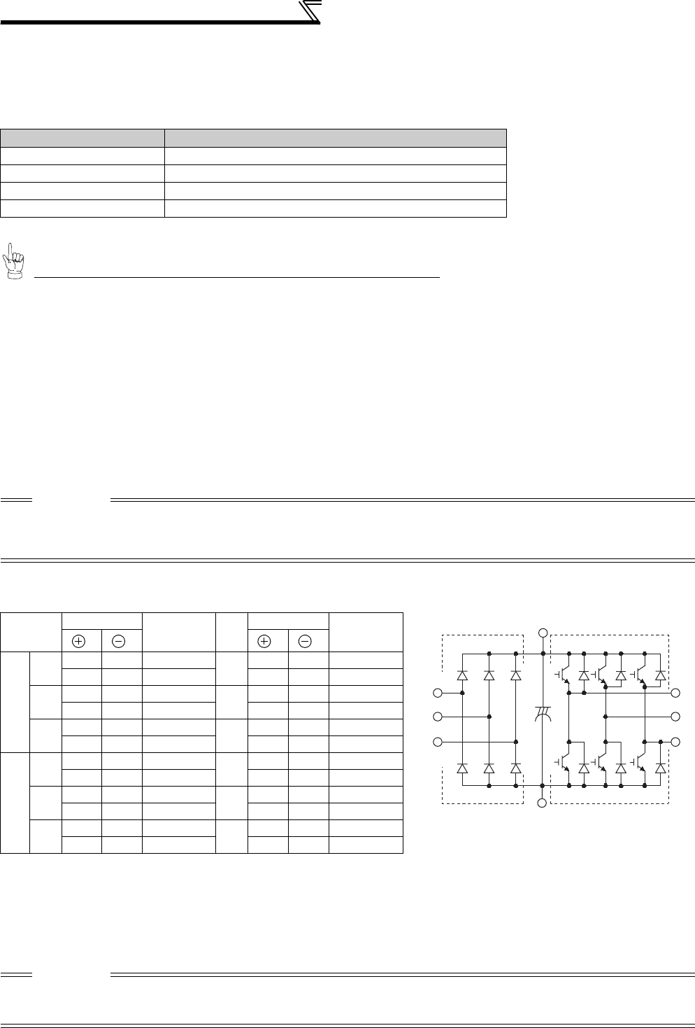
430
Inspection item
6.1.4 Display of the life of the inverter parts
The self-diagnostic alarm is output when the life span of the control circuit capacitor, cooling fan, each parts of the
inrush current limit circuit is near its end. It gives an indication of replacement time .
The life alarm output can be used as a guideline for life judgement.
Refer to page 386 to perform the life check of the inverter parts.
6.1.5 Checking the inverter and converter modules
<Preparation>
(1) Disconnect the external power supply cables (R/L1, S/L2, T/L3) and motor cables (U, V, W).
(2) Prepare a tester. (Use 100Ω range.)
<Checking method>
Change the polarity of the tester alternately at the inverter terminals R/L1, S/L2, T/L3, U, V, W, P/+ and N/−, and check
for conduction.
<Module device numbers and terminals to be checked>
(Assumes the use of an analog meter.)
6.1.6 Cleaning
Always run the inverter in a clean status.
When cleaning the inverter, gently wipe dirty areas with a soft cloth immersed in neutral detergent or ethanol.
Parts Judgement Level
Main circuit capacitor 85% of the initial capacity
Control circuit capacitor Estimated 10% life remaining
Inrush current limit circuit Estimated 10% life remaining (Power on: 100,000 times left)
Cooling fan Less than 50% of the predetermined speed
CAUTION
1. Before measurement, check that the smoothing capacitor is discharged.
2. At the time of electric discontinuity, due to the smoothing capacitor, the tester may not indicate ∞. At the time of electric
continuity, the measured value is several to several ten's-of ohms depending on the module type, circuit tester type, etc. If all
measured values are almost the same, the modules are without fault.
Tester Polarity
Measured
Value
Tester Polarity
Measured
Value
Converter
module
D1 R/L1 P/+Discontinuity D4 R/L1 N/−Continuity
P/+R/L1 Continuity N/−R/L1 Discontinuity
D2 S/L2 P/+Discontinuity D5 S/L2 N/−Continuity
P/+S/L2 Continuity N/−S/L2 Discontinuity
D3 T/L3 P/+Discontinuity D6 T/L3 N/−Continuity
P/+T/L3 Continuity N/−T/L3 Discontinuity
Inverter
module
TR1 UP/+Discontinuity TR4 UN/−Continuity
P/+U Continuity N/−U Discontinuity
TR3 VP/+Discontinuity TR6 VN/−Continuity
P/+V Continuity N/−V Discontinuity
TR5 WP/+Discontinuity TR2 WN/−Continuity
P/+W Continuity N/−W Discontinuity
CAUTION
Do not use solvent, such as acetone, benzene, toluene and alcohol, as they will cause the inverter surface paint to peel off.
The display, etc. of the operation panel (FR-DU07) and parameter unit (FR-PU04/FR-PU07) are vulnerable to detergent and
alcohol. Therefore, avoid using them for cleaning.
Converter module Inverter module
D1 D2 D3
D4 D5 D6
TR1 TR3 TR5
TR4 TR6 TR2
U
V
W
R/L1
S/L2
T/L3
C
P/+
N/−

431
Inspection item
6
PRECAUTIONS FOR MAINTENANCE AND INSPECTION
6.1.7 Replacement of parts
The inverter consists of many electronic parts such as semiconductor devices.
The following parts may deteriorate with age because of their structures or physical characteristics, leading to reduced
performance or fault of the inverter. For preventive maintenance, the parts must be replaced periodically.
Use the life check function as a guidance of parts replacement.
*1 Estimated lifespan for when the yearly average surrounding air temperature is 40°C
(without corrosive gas, flammable gas, oil mist, dust and dirt etc)
*2 Output current : 80% of the inverter rated current
(1) Cooling fan
The replacement interval of the cooling fan used for cooling the parts generating heat such as the main circuit
semiconductor is greatly affected by the surrounding air temperature. When unusual noise and/or vibration is noticed
during inspection, the cooling fan must be replaced immediately.
Part Name Estimated lifespan *1 Description
Cooling fan 10 years Replace (as required)
Main circuit smoothing capacitor 10 years *2 Replace (as required)
On-board smoothing capacitor 10 years *2 Replace the board (as required)
Relays −as required
Fuse (160K or higher) 10 years Replace the fuse (as required)
CAUTION
For parts replacement, consult the nearest Mitsubishi FA Center.
• Removal (FR-A720-1.5K to 90K, FR-A740-2.2K to 132K)
1) Push the hooks from above and remove the fan cover.
2)Disconnect the fan connectors.
3)Remove the fan.
FR-A720-1.5K to 3.7K
FR-A740-2.2K, 3.7K
FR-A720-5.5K to 22K
FR-A740-5.5K to 22K
FR-A720-30K or higher
FR-A740-30K to 132K
* The number of cooling fans differs according to the inverter capacity.
FR-A720-1.5K to 3.7K
FR-A740-2.2K, 3.7K
FR-A720-5.5K to 22K
FR-A740-5.5K to 22K
FR-A720-30K or higher
FR-A740-30K to 132K
Fan cover
Fan cover
Fan cover
Fan
Fan Fan
Fan connection
connector
Fan connection
connector
Fan connection
connector
**
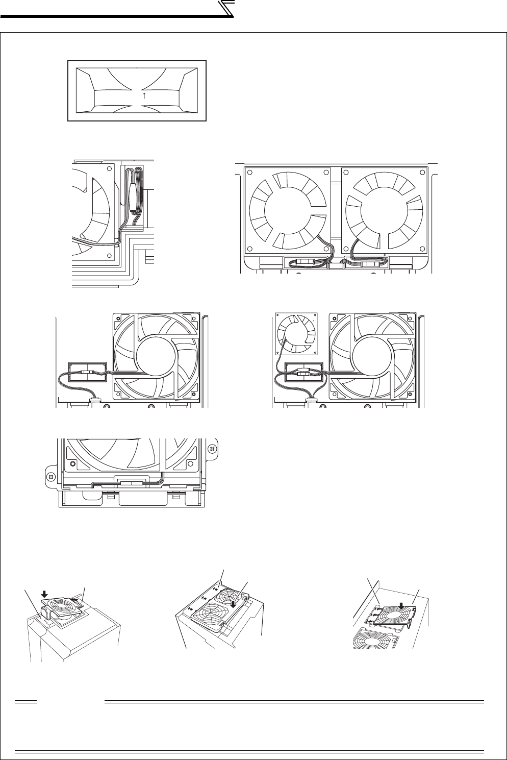
432
Inspection item
• Reinstallation (FR-A720-1.5K to 90K, FR-A740-2.2K to 132K)
1)After confirming the orientation of the fan, reinstall the fan so that the arrow on the left of "AIR FLOW" faces up.
<Fan side face>
2)Reconnect the fan connectors.
3)Reinstall the fan cover.
AIR FLOW
FR-A720-5.5K to 11K
FR-A740-5.5K to 15K
FR-A720-1.5K to 3.7K
FR-A740-2.2K, 3.7K
FR-A720-22KFR-A720-15K, 18.5K
FR-A740-18.5K, 22K
FR-A720-30K or higher
FR-A740-30K to 132K
2. Insert hooks until
you hear a click
sound. 1. Insert hooks into
holes.
FR-A720-1.5K to 3.7K
FR-A740-2.2K, 3.7K
2. Insert hooks until
you hear a click
sound.
1. Insert hooks into
holes.
FR-A720-5.5K to 22K
FR-A740-5.5K to 22K
2. Insert hooks until
you hear a click
sound.
1. Insert hooks into
holes.
FR-A720-30K or higher
FR-A740-30K to 132K
CAUTION
• Installing the fan in the opposite of air flow direction can cause the inverter life to be shorter.
• Prevent the cable from being caught when installing a fan.
• Switch the power off before replacing fans. Since the inverter circuits are charged with voltage even after power off,
replace fans only when the inverter cover is on the inverter to prevent an electric shock accident.
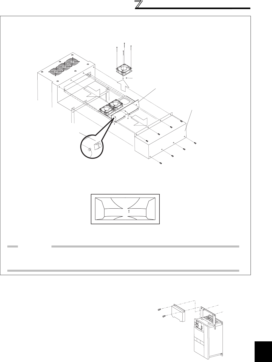
433
Inspection item
6
PRECAUTIONS FOR MAINTENANCE AND INSPECTION
(2) Replacement procedure of the cooling fan when using a heatsink protrusion attachment
(FR-A7CN)
• Removal (FR-A740-160K or higher)
1) Remove a fan cover.
2) After removing a fan connector, remove a fan block.
3) Remove the fan. (Make sure to remove the fan cable from the clamp of the fan block beforehand.)
* The number of cooling fans differs according to the inverter capacity.
• Reinstallation (FR-A740-160K or higher)
1) After confirming the orientation of the fan, reinstall the fan so that the arrow on the left of "AIR FLOW" faces up.
<Fan side face>
2) Install fans referring to the above figure.
When replacing a cooling fan, remove a top cover of the
heatsink protrusion attachment and perform replacement.
After replacing the cooling fan, replace the top cover in the
original position.
Fan *
Fan connection
connector
1)
2)
3)
Fan cove
r
Fan block
Unlock the clamp, and
pull out the cable.
AIR FLOW
CAUTION
• Installing the fan in the opposite air flow direction can cause the inverter life to be shorter.
• Prevent the cable from being caught when installing a fan.
• Switch the power OFF before replacing fans. Since the inverter circuits are charged with voltage even after power
OFF, replace fans only when the inverter cover is on the inverter to prevent an electric shock accident.
Top cover
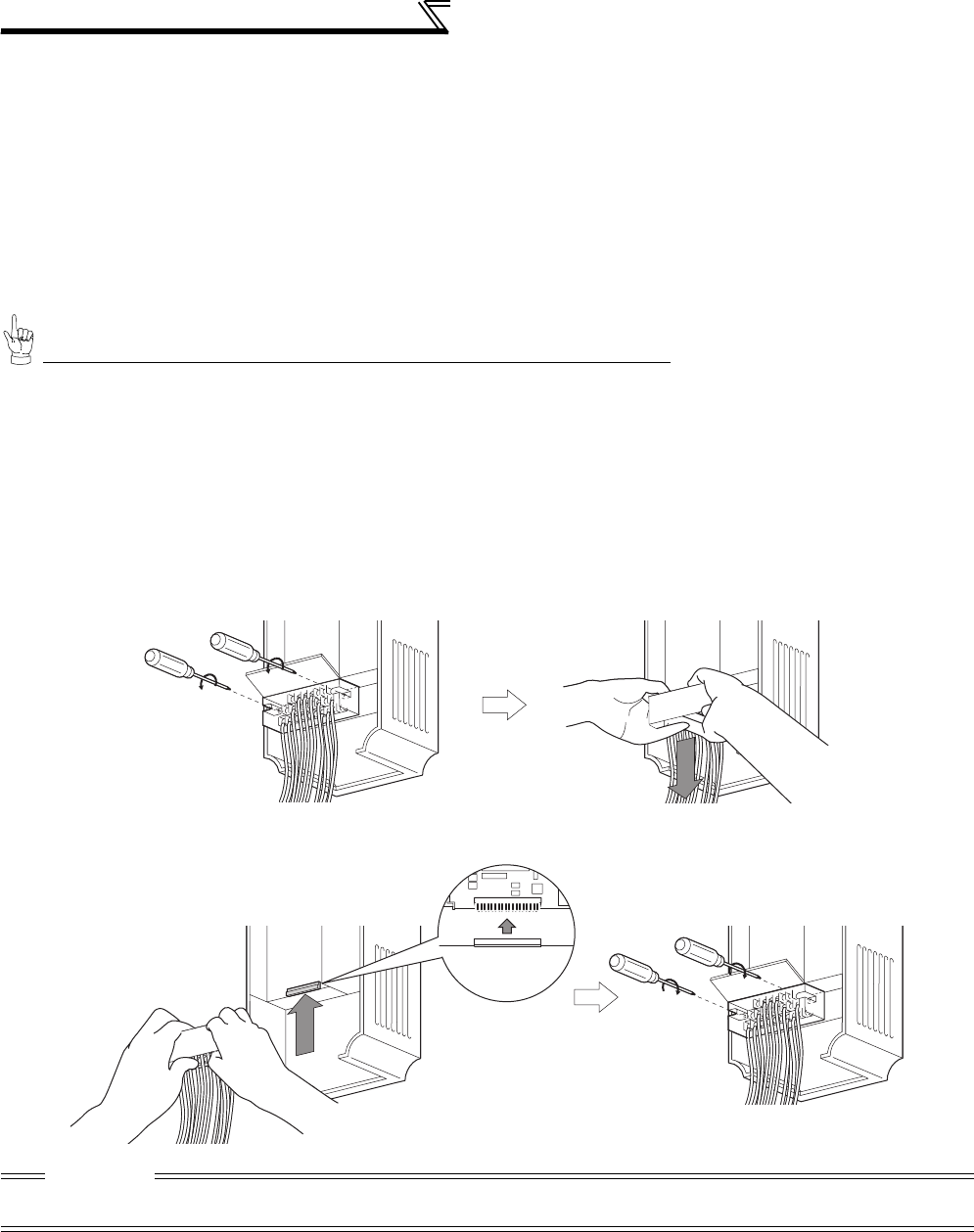
434
Inspection item
(3) Smoothing capacitors
A large-capacity aluminum electrolytic capacitor is used for smoothing in the main circuit DC section, and an aluminum
electrolytic capacitor is used for stabilizing the control power in the control circuit. Their characteristics are deteriorated
by the adverse effects of ripple currents, etc.
The replacement intervals greatly vary with the surrounding air temperature and operating conditions. When the
inverter is operated in air-conditioned, normal environment conditions, replace the capacitors about every 10 years.
The appearance criteria for inspection are as follows:
1) Case: Check the side and bottom faces for expansion
2) Sealing plate: Check for remarkable warp and extreme crack.
3) Check for external crack, discoloration, fluid leakage, etc. Judge that the capacitor has reached its life when the
measured capacitance of the capacitor reduced below 80% of the rating.
Refer to page 386 to perform the life check of the main circuit capacitor.
(4) Relays
To prevent a contact fault, etc., relays must be replaced according to the cumulative number of switching times
(switching life).
6.1.8 Inverter replacement
The inverter can be replaced with the control circuit wiring kept connected. Before replacement, remove the wiring
cover of the inverter.
1) Loosen the two mounting screws in both ends of the control circuit terminal block. (These screws cannot be removed.)
Pull down the terminal block from behind the control circuit terminals.
2) Using care not to bend the pins of the inverter's control circuit connector, reinstall the control circuit terminal block
and fix it with the mounting screws.
CAUTION
Before starting inverter replacement, switch power OFF, wait for at least 10 minutes, and then check the voltage with a tester and
such to ensure safety.
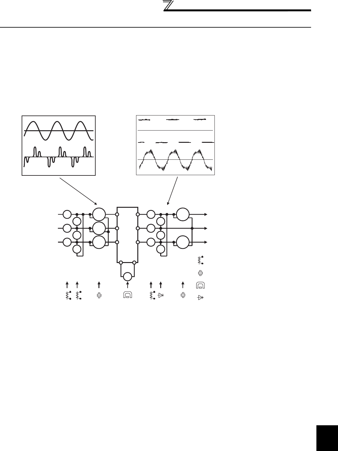
435
Measurement of main circuit voltages,
currents and powers
6
PRECAUTIONS FOR MAINTENANCE AND INSPECTION
6.2 Measurement of main circuit voltages, currents and powers
Since the voltages and currents on the inverter power supply and output sides include harmonics, measurement data
depends on the instruments used and circuits measured.
When instruments for commercial frequency are used for measurement, measure the following circuits with the
instruments given on the next page.
When installing meters etc. on the inverter output side
When the inverter-to-motor wiring length is large, especially in the 400V class, small-capacity models, the meters
and CTs may generate heat due to line-to-line leakage current. Therefore, choose the equipment which has enough
allowance for the current rating.
When measuring and indicating the output voltage and output current of the inverter, it is recommended to utilize the
terminals AM and FM output function of the inverter.
Examples of Measuring Points and Instruments
+-
Ar
As
At
Vr
Vs
Vt
W11
W12
W13
Au
Av
Aw
Vu
Vv
Vw
W21
W22
V
U
V
W
Inverter
Three
phase
power
supply
To the motor
Instrument
types
Input voltage
Input current
Output voltage
Output current
: Moving-iron type
: Electrodynamometer type
: Moving-coil type
: Rectifier type
R/L1
S/L2
T/L3
P/+ N/-

436
Measurement of main circuit voltages,
currents and powers
Measuring points and instruments
*1 Use an FFT to measure the output voltage accurately. A tester or general measuring instrument cannot measure accurately.
*2 When the carrier frequency exceeds 5kHz, do not use this instrument since using it may increase eddy-current losses produced in metal parts
inside the instrument, leading to burnout. If the wiring length between the inverter and motor is long, the instrument and CT may generate heat
due to line-to-line leakage current.
*3 When the setting of Pr. 195 ABC1 terminal function selection is positive logic
*4 A digital power meter (designed for inverter) can also be used to measure.
Item Measuring Point Measuring Instrument Remarks (Reference Measured Value)
Power supply voltage
V1
Across R/L1 and S/L2,
S/L2 and T/L3,
T/L3 and R/L1
Moving-iron type AC voltmeter *4
Commercial power supply
Within permissible AC voltage fluctuation
(Refer to page 444)
Power supply side
current
I1
R/L1, S/L2, and T/L3
line currents Moving-iron type AC ammeter *4
Power supply side
power
P1
R/L1, S/L2, T/L3 and
R/L1 and S/L2,
S/L2 and T/L3,
T/L3 and R/L1
Digital power meter (designed for
inverter) or electrodynamic type
single-phase wattmeter
P1=W11+W12+W13 (3-wattmeter method)
Power supply side
power factor
Pf1
Calculate after measuring power supply voltage, power supply side current and power supply side power.
Output side voltage
V2
Across U and V,
V and W,
W and U
Rectifier type AC voltage meter *1*4
(Moving-iron type cannot
measure)
Difference between the phases is within ±1% of
the maximum output voltage.
Output side current
I2
U, V and W line
currents Moving-iron type AC ammeter *2*4 Difference between the phases is 10% or lower
of the rated inverter current.
Output side power
P2
U, V, W and
U and V,
V and W
Digital power meter (designed for
inverter) or electrodynamic type
single-phase wattmeter
P2 = W21 + W22
2-wattmeter method (or 3-wattmeter method)
Output side power
factor
Pf2
Calculate in similar manner to power supply side power factor.
Converter output Across P/+ and N/−Moving-coil type (such as tester) Inverter LED display is lit. 1.35 × V1
Frequency setting
signal
Across 2, 4(+) and 5
Moving-coil type
(Tester and such may be used)
(Internal resistance: 50kΩ or
larger)
0 to 10VDC, 4 to 20mA
"5" is
common
Across 1(+) and 5 0 to ±5VDC, 0 to ±10VDC
Frequency setting
power supply
Across 10 (+) and 5 5.2VDC
Across 10E(+) and 5 10VDC
Frequency meter
signal
Across AM(+) and 5 Approximately 10VDC at maximum
frequency (without frequency meter)
Across FM(+) and SD
Approximately 5VDC at maximum
frequency
(without frequency meter)
Pulse width T1:
Adjusted by C0 (Pr. 900)
Pulse cycle T2: Set by Pr. 55
(Valid for frequency
monitoring only)
"SD" is
common
Start signal
Select signal
Across SD and the
following: STF, STR,
RH, RM, RL, JOG, RT,
AU, STOP, CS (+)
When open
20 to 30VDC
ON voltage: 1V or less
Reset
Across RES (+) and SD
Output stop
Across MRS (+) and SD
Fault signal Across A1and C1
Across B1and C1
Moving-coil type
(such as tester)
Conduction check *3
<Abnormal> <Normal>
Across A1 and C1 No conduction
Conduction
Across B1 and C1
Conduction
No conduction
Pf1 = ————— × 100%
P1
3 V1 × I1
Pf2 = ————— × 100%
P2
3 V2 × I2
8VDC
T1
T2
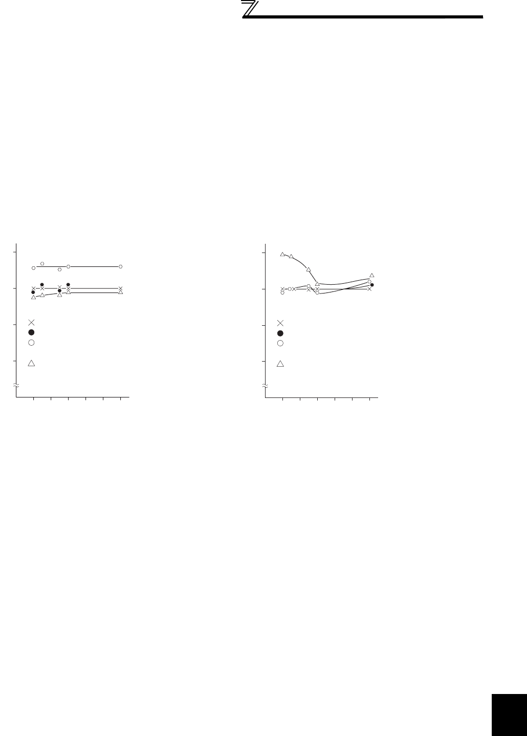
437
Measurement of main circuit voltages,
currents and powers
6
PRECAUTIONS FOR MAINTENANCE AND INSPECTION
6.2.1 Measurement of powers
Use digital power meters (for inverter) for the both of inverter input and output side. Alternatively, measure using
electrodynamic type single-phase wattmeters for the both of inverter input and output side in two-wattmeter or three-
wattmeter method. As the current is liable to be imbalanced especially in the input side, it is recommended to use the
three-wattmeter method.
Examples of measured value differences produced by different measuring meters are shown below.
An error will be produced by difference between measuring instruments, e.g. power calculation type and two- or three-
wattmeter type three-phase wattmeter. When a CT is used in the current measuring side or when the meter contains a
PT on the voltage measurement side, an error will also be produced due to the frequency characteristics of the CT and
PT.
6.2.2 Measurement of voltages and use of PT
(1) Inverter input side
As the input side voltage has a sine wave and it is extremely small in distortion, accurate measurement can be made
with an ordinary AC meter.
(2) Inverter output side
Since the output side voltage has a PWM-controlled rectangular wave, always use a rectifier type voltmeter. A needle
type tester cannot be used to measure the output side voltage as it indicates a value much greater than the actual
value. A moving-iron type meter indicates an effective value which includes harmonics and therefore the value is larger
than that of the fundamental wave. The value monitored on the operation panel is the inverter-controlled voltage itself.
Hence, that value is accurate and it is recommended to monitor values (provide analog output) using the operation
panel.
(3) PT
No PT can be used in the output side of the inverter. Use a direct-reading meter. (A PT can be used in the input side of
the inverter.)
[Measurement conditions]
Constant-torque (100%) load, constant-power at 60Hz
or more.
3.7kW, 4-pole motor, value indicated in 3-wattmeter
method is 100%.
[Measurement conditions]
Constant-torque (100%) load, constant-power at 60Hz
or more.
3.7kW, 4-pole motor, value indicated in 3-wattmeter
method is 100%.
Example of measuring inverter input power Example of measuring inverter output power
3-wattmeter method (Electro-dynamometer type)
2-wattmeter method (Electro-dynamometer type)
Clip AC power meter
(For balanced three-phase load)
Clamp-on wattmeter
(Hall device power arithmetic type)
0 20 40 60 80 100 120Hz
60
80
100
120
%
3-wattmeter method (Electro-dynamometer type)
2-wattmeter method (Electro-dynamometer type)
Clip AC power meter
(For balanced three-phase load)
Clamp-on wattmeter
(Hall device power arithmetic type)
0 20 40 60 80 100 120Hz
60
80
100
120
%
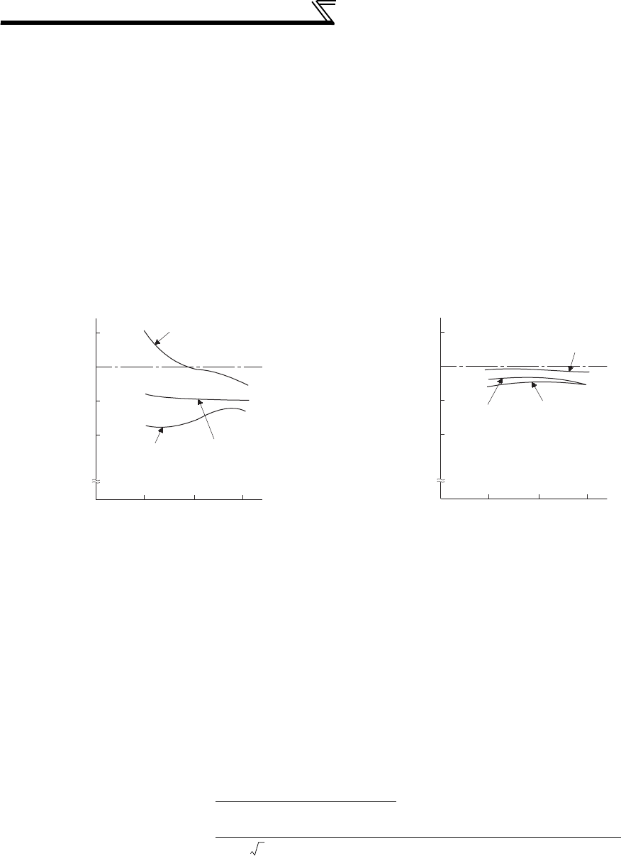
438
Measurement of main circuit voltages,
currents and powers
6.2.3 Measurement of currents
Use a moving-iron type meter on both the input and output sides of the inverter. However, if the carrier frequency
exceeds 5kHz, do not use that meter since an overcurrent losses produced in the internal metal parts of the meter will
increase and the meter may burn out. In this case, use an approximate-effective value type.
As the inverter input side current is easily imbalanced, measurement of currents in all three phases is recommended.
Correct values cannot be measured in one or two phases. On the other hand, the phase imbalanced ratio of the output
side current must be within 10%.
When using a clamp ammeter, always use an effective value detection type. A mean value detection type produces a
large error and may indicate an extremely smaller value than the actual value. The value monitored on the operation
panel is accurate if the output frequency varies, and it is recommended to monitor values (provide analog output) using
the operation panel.
An example of the measured value difference produced by different measuring meters is shown below.
6.2.4 Use of CT and transducer
A CT may be used in both the input and output sides of the inverter, but the one used should have the largest possible
VA ability because an error will increase if the frequency gets lower.
When using a transducer, use the effective value calculation type which is immune to harmonics.
6.2.5 Measurement of inverter input power factor
Use the effective power and apparent power to calculate the inverter input power factor. A power-factor meter cannot
indicate an exact value.
[Measurement conditions]
Value indicated by moving-iron type ammeter is 100%.
[Measurement conditions]
Value indicated by moving-iron type ammeter is 100%.
Example of measuring inverter input current Example of measuring inverter output current
Total power factor of the inverter = Effective power
Apparent power
=
Three-phase input power found by 3-wattmeter method
× V (power supply voltage) × I (input current effective value)
120
100
80
60
060Hz40
20
%
Moving-iron
type
Clamp-on wattmeter
current measuremen
t
Clamp meter
Clip AC
power meter
120
100
80
60
060Hz40
20
%
Moving-iron type
Clip AC
power meter
Clamp-on wattmeter
current measurement
Clamp meter
3

439
Measurement of main circuit voltages,
currents and powers
6
PRECAUTIONS FOR MAINTENANCE AND INSPECTION
6.2.6 Measurement of converter output voltage (across terminals P/+ - N/-)
The output voltage of the converter is developed across terminals P/+ and N/- and can be measured with a moving-coil
type meter (tester). Although the voltage varies according to the power supply voltage, approximately 270V to 300V
(approximately 540V to 600V for the 400V class) is output when no load is connected and voltage decreases when a
load is connected.
When regenerative energy is returned from the motor during deceleration, for example, the converter output voltage
rises to nearly 400V to 450V (800V to 900V for the 400V class) maximum.
6.2.7 Measurement of inverter output frequency
A pulse train proportional to the output frequency is output across the frequency meter signal output terminal FM-SD of
the inverter. This pulse train output can be counted by a frequency counter, or a meter (moving-coil type voltmeter) can
be used to read the mean value of the pulse train output voltage. When a meter is used to measure the output
frequency, approximately 5VDC is indicated at the maximum frequency.
For detailed specifications of the frequency meter signal output terminal FM, refer to page 263.
6.2.8 Insulation resistance test using megger
For the inverter, conduct the insulation resistance test on the main circuit only as shown below and do not perform the
test on the control circuit. (Use a 500VDC megger.)
6.2.9 Pressure test
Do not conduct a pressure test. Deterioration may occur.
CAUTION
• Before performing the insulation resistance test on the external circuit, disconnect the cables from all terminals of the
inverter so that the test voltage is not applied to the inverter.
• For the conduction test of the control circuit, use a tester (high resistance range) and do not use the megger or buzzer.
U
V
W
Inverter
500VDC
megger
Power
supply IM
Moto
r
R/L1
S/L2
T/L3
Earth (ground)
440
MEMO

441
3
4
5
6
7
1
2
7
SPECIFICATIONS
This chapter provides the "SPECIFICATIONS" of this product.
Always read the instructions before using the equipment.
7.1 Rating ......................................................................442
7.2 Motor rating .............................................................444
7.3 Common specifications ...........................................446
7.4 Outline dimension drawings ....................................447
7.5 Heatsink protrusion attachment procedure .............459
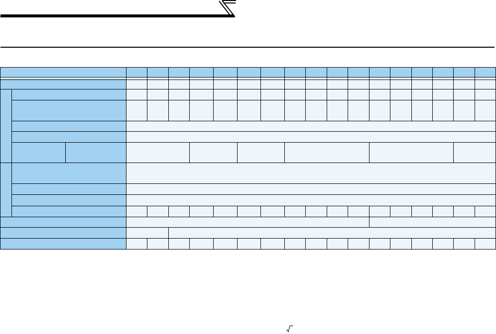
442
Inverter rating
7.1 Inverter rating
200V class
Model FR-A720-K0.4
0.75
1.5 2.2 3.7 5.5 7.5 11 15
18.5
22 30 37 45 55 75 90
Applicable motor capacity (kW) *1 0.4
0.75
1.5 2.2 3.7 5.5 7.5 11 15
18.5
22 30 37 45 55 75 90
Output
Rated capacity (kVA) *2 1.1 1.9 3.1 4.2 6.7 9.2
12.6 17.6 23.3
29 34 44 55 67 82
110 132
Rated current (A) *3 3 5 8 11
17.5
24 33 46 61 76 90 115 145 175 215 288
(245)
346
(294)
Overload current rating *4 150% 60s, 200% 3s (inverse-time characteristics) surrounding air temperature 50°C
Rated voltage *5 Three-phase 200 to 240V
Regenerative
braking torque
Maximum value/
permissible duty
150% torque/
3%ED*6
100% torque/
3%ED
*6
100% torque/
2%ED
*6
20% torque/
continuous *6
20% torque/
continuous
10% torque/
continuous
Power supply
Rated input
AC voltage/frequency Three-phase 200 to 220V 50Hz, 200 to 240V 60Hz
Permissible AC voltage fluctuation
170 to 242V 50Hz,170 to 264V 60Hz
Permissible frequency fluctuation
±5%
Power supply capacity (kVA) *7 1.5 2.5 4.5 5.5 9
12
17 20 28 34 41 52 66 80 100 110 132
Protective structure (JEM 1030) *9 Enclosed type (IP20) *8 Open type (IP00)
Cooling system
Self-cooling
Forced air cooling
Approx. mass (kg) 1.9 2.3 3.8 3.8 3.8 7.1 7.1 7.5 13 13 14 23 35 35 58 70 70
*1. The applicable motor capacity indicated is the maximum capacity applicable for use of the Mitsubishi 4-pole standard motor.
*2. The rated output capacity indicated assumes that the output voltage is 220V.
*3. When operating the inverter of 75K or higher with a value larger than 2kHz set in Pr. 72 PWM frequency selection, the rated output current is the value in
parentheses.
*4. The % value of the overload current rating indicated is the ratio of the overload current to the inverter's rated output current. For repeated duty, allow time for
the inverter and motor to return to or below the temperatures under 100% load.
*5. The maximum output voltage does not exceed the power supply voltage. The maximum output voltage can be changed within the setting range. However,
the pulse voltage value of the inverter output side voltage remains unchanged at about that of the power supply.
*6. With the dedicated external brake resistor FR-ABR (option), the 0.4K and 0.75K, 1.5K to 7.5K, 11K to 22K will achieve the performance of 150% torque/
10%ED, 100% torque/10%ED and 100% torque/6%ED respectively.
*7. The power supply capacity varies with the value of the power supply side inverter impedance (including those of the input reactor and cables).
*8. When the hook of the inverter front cover is cut off for installation of the plug-in option, protective structure of the inverter changes to an open type (IP00).
*9. FR-DU07:IP40 (except for the PU connector)
2
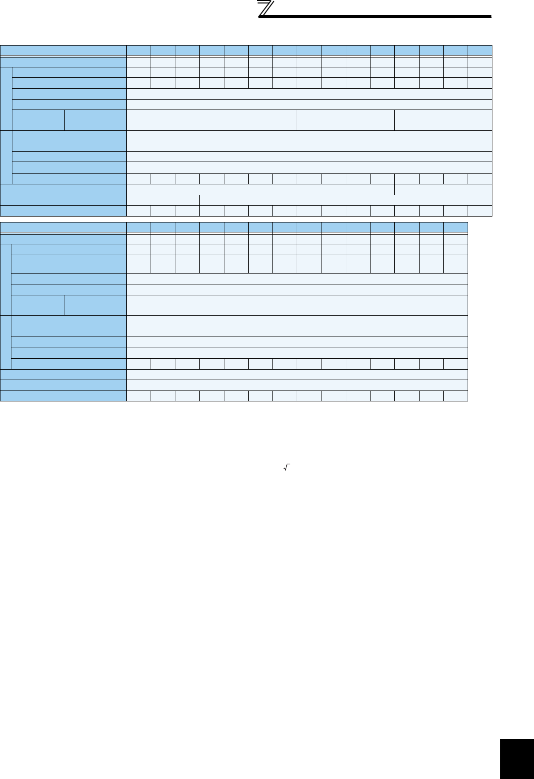
443
Inverter rating
7
SPECIFICATIONS
400V class
Model FR-A740-K0.4 0.75 1.5 2.2 3.7 5.5 7.5 11 15 18.5 22 30 37 45 55
Applicable motor capacity (kW)
*1 0.4 0.75 1.5 2.2 3.7 5.5 7.5 11 15 18.5 22 30 37 45 55
Output
Rated capacity (kVA) *2 1.1 1.9 34.6 6.9 9.1 13 17.5 23.6 29 32.8 43.4 54 65 84
Rated current (A) 1.5 2.5 4 6 9 12 17 23 31 38 44 57 71 86 110
Overload current rating *5 150% 60s, 200% 3s (inverse-time characteristics) surrounding air temperature 50°C
Rated voltage *6 Three-phase 380 to 480V
Regenerative
braking torque
Maximum value/
permissible duty
100% torque/2%ED*6 20% torque/continuous *6 20% torque/continuous
Power supply
Rated input
AC voltage/frequency Three-phase 380 to 480V 50Hz/60Hz
Permissible AC voltage fluctuation
323 to 528V 50Hz/60Hz
Permissible frequency fluctuation
±5%
Power supply capacity (kVA) *7 1.5 2.5 4.5 5.5 912 17 20 28 34 41 52 66 80 100
Protective structure *9 Enclosed type (IP20) *9 Open type (IP00)
Cooling system Self-cooling Forced air cooling
Approx. mass (kg) 3.8 3.8 3.8 3.8 3.8 7.1 7.1 7.5 7.5 13 13 23 35 35 37
Model FR-A740-K75 90 110 132 160
185 220 250 280 315 355 400 450 500
Applicable motor capacity (kW)
*1 75 90 110 132 160 185 220 250 280 315 355 400 450 500
Output
Rated capacity (kVA) *2 110 137 165 198 248 275 329 367 417 465 521 587 660 733
Rated current (A)*3 144
(122)
180
(153)
216
(184)
260
(221)
325
(276)
361
(307)
432
(367)
481
(409)
547
(465)
610
(519)
683
(581)
770
(655)
866
(736)
962
(818)
Overload current rating *4 150% 60s, 200% 3s (inverse-time characteristics) surrounding air temperature 50°C
Rated voltage*5 Three-phase 380 to 480V
Regenerative
braking torque
Maximum value/
permissible duty
10% torque/continuous
Power supply
Rated input
AC voltage/frequency Three-phase 380 to 480V 50Hz/60Hz
Permissible AC voltage fluctuation
323 to 528V 50Hz/60H
Permissible frequency fluctuation
±5%
Power supply capacity (kVA) *7 110 137 165 198 248 275 329 367 417 465 521 587 660 733
Protective structure (JEM 1030) *9 Open type (IP00)
Cooling system Forced air cooling
Approx. mass (kg) 50 57 72 72 110 110 175 175 175 260 260 370 370 370
*1. The applicable motor capacity indicated is the maximum capacity applicable for use of the Mitsubishi 4-pole standard motor.
*2. The rated output capacity indicated assumes that the output voltage is 440V.
*3. When operating the inverter of 75K or higher with a value larger than 2kHz set in Pr. 72 PWM frequency selection, the rated output current is the value in
parentheses.
*4. The % value of the overload current rating indicated is the ratio of the overload current to the inverter's rated output current. For repeated duty, allow time for
the inverter and motor to return to or below the temperatures under 100% load.
*5. The maximum output voltage does not exceed the power supply voltage. The maximum output voltage can be changed within the setting range. However,
the pulse voltage value of the inverter output side voltage remains unchanged at about that of the power supply.
*6. With the dedicated external brake resistor FR-ABR-H (option), the 0.4K to 7.5K and 11K to 22K will achieve the performance of 100% torque/10%ED and
100% torque/6%ED respectively.
*7. The power supply capacity varies with the value of the power supply side inverter impedance (including those of the input reactor and cables).
*8. When the hook of the inverter front cover is cut off for installation of the plug-in option, protective structure of the inverter changes to an open type (IP00).
*9. FR-DU07:IP40 (except for the PU connector)
2

444
Inverter rating
7.2 Motor rating
(1) SF-V5RU
*1 80% output in the high-speed range. (The output is reduced when the speed is 2400r/min or more. Contact us separately for details.)
*2 A dedicated motor of 3.7kW or less can be run at the maximum speed of 3600 r/min. Consult our sales office when using the motor at the maximum speed.
*3 Power (current) at 50Hz/60Hz.
*4 Since a motor with brake has a window for gap check, the protective structure of both the cooling fan section and brake section is IP20. S of IP23S is an
additional code indicating the condition that protection from water intrusion is established only when a cooling fan is not operating.
*5 The value when high carrier frequency is set (Pr.72 = 6, Pr.240 = 0).
*6 The 12V power supply or the control terminal option (FR-A7PS) is required as the power supply for the encoder.
*7 The cooling fan is equipped with a thermal protector. The cooling fan stops when the coil temperature exceeds the specified value in order to protect the fan
motor. A restrained cooling fan or degraded fan motor insulation could be causes for the rise in coil temperature.The cooling fan re-starts when the coil
temperature drops to normal.
z200V class (Mitsubishi dedicated motor [SF-V5RU (1500r/min series)])
Motor type
SF-V5RUK1 2 3 5 7 11 15 18 22 30 37 45 55
Applicable inverter model
FR-A720-K2.2 3.7 5.5 7.5 11 15 18.5 22 30 37 45 55 75
Rated output (kW) 1.5 2.2 3.7 5.5 7.5 11 15 18.5 22 30 *1 37 *1 45 *1 55
Rated torque (N·m) 9.55 14.1 23.6 35.0 47.7 70.0 95.5 118 140 191 235 286 350
Maximum torque 150%
60s (N·m) 14.3 21.1 35.4 52.4 71.6 105 143 176 211 287 353 429 525
Rated speed (r/min) 1500
Maximum speed (r/min)
3000 *2 2400
Frame No. 90L 100L 112M 132S 132M 160M 160L 180M 180M 200L 200L 200L 225S
Inertia moment J
(×10-4kg·m2)67.5 105 175 275 400 750 875 1725 1875 3250 3625 3625 6850
Noise *5 75dB or less 80dB or less 85dB
or less
Cooling fan
(with thermal
protector)
*7
Voltage
Single-phase 200V/50Hz
Single-phase 200V to 230V/60Hz
Three-phase 200V/50Hz
Three-phase 200 to 230V/60Hz
Input *3 36/55W
(0.26/0.32A)
22/28W
(0.11/0.13A)
55/71W
(0.39/0.39A)
100/156W
(0.47/0.53A)
85/130W
(0.46/0.52A)
Surrounding air
temperature, humidity
-10 to +40°C (non-freezing), 90%RH or less (non-condensing)
Structure
(Protective structure)
Totally enclosed forced draft system
(Motor: IP44, cooling fan: IP23S) *4
Detector Encoder 2048P/R, A phase, B phase, Z phase +12VDC power supply *6
Equipment Encoder, thermal protector, fan
Heat resistance class F
Vibration rank V10
Approx. mass (kg) 24 33 41 52 62 99 113 138 160 238 255 255 320
z400V class (Mitsubishi dedicated motor [SF-V5RUH (1500r/min series)])
Motor type
SF-V5RUHK1 2 3 5 7 11 15 18 22 30 37 45 55
Applicable inverter model
FR-A740-K2.2 2.2 3.7 7.5 11 15 18.5 22 30 37 45 55 75
Rated output (kW) 1.5 2.2 3.7 5.5 7.5 11 15 18.5 22 30 *1 37 *1 45 *1 55
Rated torque (N·m) 9.55 14.1 23.6 35.0
47.7 70.0 95.5 118 140 191 235 286 350
Maximum torque 150% 60s
(N·m) 14.3 21.1 35.4 52.4 71.6 105 143 176 211 287 353 429 525
Rated speed (r/min) 1500
Maximum speed (r/min)
3000 *2 2400
Frame No. 90L 100L 112M 132S 132M 160M 160L 180M 180M 200L 200L 200L 225S
Inertia moment J
(×10-4kg·m2)67.5 105 175 275 400 750 875 1725 1875 3250 3625 3625 6850
Noise *5 75dB or less 80dB or less 85dB or
less
Cooling fan
(with thermal
protector)
*7
Voltage
Single-phase 200V/50Hz
Single-phase 200V to 230V/60Hz
Three-phase 380 to 400V/50Hz
Three-phase 400 to 460V/60Hz
Input *3 36/55W
(0.26/0.32A)
22/28W
(0.11/0.13A)
55/71W
(0.19/0.19A)
100/156W
(0.27/0.30A)
85/130W
(0.23/0.26A)
Surrounding air
temperature, humidity
-10 to +40°C (non-freezing), 90%RH or less (non-condensing)
Structure
(Protective structure)
Totally enclosed forced draft system
(Motor: IP44, cooling fan: IP23S) *4
Detector Encoder 2048P/R, A phase, B phase, Z phase +12VDC power supply *6
Equipment Encoder, thermal protector, fan
Heat resistance class F
Vibration rank V10
Approx. mass (kg) 24 33 41 52 62 99 113 138 160 238 255 255 320

445
Inverter rating
7
SPECIFICATIONS
(2) SF-THY
Motor type SF-THY
Applicable inverter FR-A720-KFR-A740-K
90 90 110 132 160 185 220 280
Rated output (kW) 75 75 90 110 132 160 200 250
Rated torque (kgf·m)
(N·m)
48.7
477
48.7
477
58.4
572
71.4
700
85.7
840
103.9
1018
129.9
1273
162.3
1591
Maximum torque(kgf·m)
150%60s (N·m)
73.0
715
73.0
715
87.6
858
107.1
1050
128.5
1260
155.8
1527
194.8
1909
243.4
2386
Rated speed (r/min) 1500 1500
Maximum speed (r/min) 2400 2400 1800
Frame No. 250MD 250MD 250MD 280MD 280MD 280MD 280L 315H
Inertia moment J (kg·m2)1.1 1.1 1.7 2.3 2.3 4.0 3.8 5.0
Noise 90dB 90dB 95dB
Cooling
fan
Voltage Three-phase, 200V/50Hz, 200V/60Hz, 220V/60Hz
(400V class cooling fan is available upon order)
Input (W) 50Hz 750 400 400 400 400 400 750 750
60Hz 750 750 750 750 750 1500 1500
Approx. mass (kg) 610 610 660 870 890 920 1170 1630
Common specifications
Surrounding air
temperature, humidity -10 to +40°C (non-freezing), 90%RH or less (non-condensing)
Structure Totally enclosed forced draft system
Detector Encoder 2048P/R, A phase, B phase, Z phase +12VDC power supply *1
Equipment Encoder, thermal protector*2, fan
Insulation Class F
Vibration rank V10
Dedicated encoder
Resolution 2048 pulse/rev
Power supply voltage
12VDC±10%
Current
consumption 90mA
Output signal form A, B phases (90° phase shift) Z phase: 1 pulse/rev
Output circuit Complementary (constant voltage output matched by emitter follow)
Output voltage "H" level: Power supply voltage 9V or more (IOH: -20mA)
"L" level: Power supply voltage 3V or less (IOL: 20mA)
*1 The 12V power supply or the control terminal option (FR-A7PS) is required as the power supply for the encoder.
*2 A motor with a thermal protector is also available. Contact your sales representative.

446
Common specifications
7.3 Common specifications
Control specifications
Control method Soft-PWM control/high carrier frequency PWM control (V/F control, Advanced magnetic flux vector control and Real sensorless
vector control are available) / vector control *1
Output frequency range 0.2 to 400Hz (The maximum frequency is 120Hz under Real sensorless vector control and vector control*1.)
Frequency
setting
resolution
Analog input
0.015Hz/60Hz (terminal 2, 4: 0 to 10V/12bit)
0.03Hz/60Hz (terminal 2, 4: 0 to 5V/11bit, 0 to 20mA/about 11bit, terminal 1: 0 to ±10V/12bit)
0.06Hz/60Hz (terminal 1: 0 to ±5V/11bit)
Digital input 0.01Hz
Frequency
accuracy
Analog input Within ±0.2% of the max. output frequency (25°C±10°C)
Digital input Within 0.01% of the set output frequency
Voltage/frequency characteristics Base frequency can be set from 0 to 400Hz Constant torque/variable torque pattern or adjustable 5 points V/F can be selected
Starting torque 200% at 0.3Hz (0.4K to 3.7K), 150% at 0.3Hz (5.5K or higher) (under Real sensorless vector control or vector control *1)
Torque boost Manual torque boost
Acceleration/deceleration time
setting
0 to 3600s (acceleration and deceleration can be set individually), linear or S-pattern acceleration/deceleration mode, backlash
measures acceleration/deceleration mode are available.
DC injection brake Operation frequency (0 to 120Hz), operation time (0 to 10s), operation voltage (0 to 30%) can be changed
Stall prevention operation level Operation current level can be set (0 to 220% adjustable), whether to use the function or not can be selected
Torque limit level Torque limit value can be set (0 to 400% variable)
Operation specifications
Frequency
setting
signal
Analog input • Terminal 2, 4: 0 to 10V, 0 to 5V, 4 to 20mA (0 to 20mA) can be selected• Terminal 1: -10 to +10V, -5 to +5V can be selected
Digital input Input using the setting dial of the operation panel or parameter unit
Four-digit BCD or 16-bit binary (when used with option FR-A7AX)
Start signal Forward and reverse rotation or start signal automatic self-holding input (3-wire input) can be selected.
Input signals (twelve terminals)
The following signals can be assigned to
Pr. 178 to Pr. 189 (input terminal function selection)
: multi speed selection, remote setting, stop-
on-contact, second function selection, third function selection, terminal 4 input selection, JOG operation selection, selection of
automatic restart after instantaneous power failure, flying start, external thermal relay input, inverter run enable signal (FR-HC/FR-CV
connection), FR-HC connection (instantaneous power failure detection), PU operation/external inter lock signal, external DC injection
brake operation start, PID control enable terminal, brake opening completion signal, PU operation/External operation switchover, load
pattern selection forward rotation reverse rotation boost, V/F switching, load torque high-speed frequency, S-pattern acceleration/
deceleration C switchover, pre-excitation, output stop, start self-holding selection, control mode changing, torque limit selection, start-
time tuning start external input, torque bias selection 1, 2
*1
, P/PI control switchover, forward rotation command, reverse rotation
command, inverter reset, PTC thermistor input, PID forward reverse operation switchover, PU-NET operation switchover, NET-
External operation switchover, command source switchover, simple position pulse train sign
*1
, simple position droop pulse clear
*1
,
DC feeding operation permission, DC feeding cancel, magnetic flux decay output shutoff, proximity dog
*3
, 0V calibration request
*5
.
Pulse train input 100kpps
Operational functions
Maximum/minimum frequency setting, frequency jump operation, external thermal relay input selection, polarity reversible operation,
automatic restart after instantaneous power failure operation, electronic bypass operation, forward/reverse rotation prevention,
remote setting, brake sequence, second function, third function, multi-speed operation, original operation continuation at
instantaneous power failure, stop-on-contact control, load torque high speed frequency control, droop control, regeneration
avoidance, slip compensation, operation mode selection, offline auto tuning function, online auto tuning function, PID control,
computer link operation (RS-485), motor end orientation *1, machine end orientation *2, pre-excitation, notch filter, machine analyzer
*1, easy gain tuning, speed feed forward, and torque bias *1
Output signals
Open collector output
(5 terminals)
Relay output (2 terminals)
The following signals can be assigned to Pr. 190 to Pr. 196 (output terminal function selection): inverter running, inverter running/start
command on, up-to-frequency, instantaneous power failure/undervoltage, overload warning, output frequency (speed) detection,
second output frequency (speed) detection, third output frequency (speed) detection, regenerative brake pre-alarm, electronic
thermal relay function pre-alarm, PU operation mode, inverter operation ready, output current detection, zero current detection, PID
lower limit, PID upper limit, PID forward rotation reverse rotation output, electronic bypass MC1, electronic bypass MC2, electronic
bypass MC3, orientation complete *1, orientation fault *1, brake opening request, fan fault output, heatsink overheat pre-alarm,
deceleration at an instantaneous power failure, PID control activated, motor temperature detection *4, during retry, PID output
interruption, during 0V calibration *5, position control preparation ready *1, DC feeding, life alarm, fault output 1, 2, 3 (power-off
signal), power savings average value update timing, current average monitor, maintenance timer alarm, remote output, forward
rotation output *1, reverse rotation output *1, low speed output, torque detection, regenerative status output *1, start-time tuning
completion, in-position completion *1, alarm output and fault output. Alarm code of the inverter can be output (4 bit) from the open
collector.
Operating status
When used with the FR-
A7AY, FR-A7AR (option)
In addition to above, the following signal can be assigned to Pr.313 to Pr. 319 (extension output terminal function selection): control circuit
capacitor life, main circuit capacitor life, cooling fan life, inrush current limit circuit life. (only positive logic can be set for extension
terminals of the FR-A7AR)
Pulse train output 50kpps
For meter
Pulse train output
(Max. 2.4kHz: one terminal)
Analog output
(Max. 10VDC: one terminal)
The following signals can be assigned to
Pr. 54 FM terminal function selection (pulse train output)
and
Pr. 158 AM terminal function selection
(analog output)
: output frequency, motor current (steady or peak value), output voltage, frequency setting, operation speed, motor
torque, converter output voltage (steady or peak value), electronic thermal relay function load factor, input power, output power, load
meter, motor excitation current, reference voltage output, motor load factor,
motor temperature *4
, power saving effect, regenerative
brake duty, PID set point, PID measured value, motor output, torque command, torque current command, and torque monitor.
Indication
Operation
panel
(FR-DU07)
Parameter
unit (FR-
PU07)
Operating status
The following operating status can be displayed: Output frequency, motor current (steady or peak value), output voltage, frequency
setting, running speed, motor torque, overload, converter output voltage (steady or peak value), electronic thermal relay function
load factor, input power, output power, load meter, motor excitation current, position pulse *1, cumulative energization time,
orientation status *1, actual operation time, motor load factor, cumulative power, energy saving effect, cumulative saving power,
regenerative brake duty, PID set point, PID measured value, PID deviation, inverter I/O terminal monitor, input terminal option
monitor*6, output terminal option monitor *6, option fitting status *7, terminal assignment status *7, torque command, torque current
command, feed back pulse *1, motor output, SSCNET III communication status *3, motor temperature *4
Fault record Fault definition is displayed when a fault occurs, the output voltage/current/frequency/cumulative energization time right before the
fault occurs and past 8 fault records are stored.
Interactive guidance Function (help) for operation guide *7
Protective/
warning
function
Protective function
Overcurrent during acceleration, overcurrent during constant speed, overcurrent during deceleration, overvoltage during
acceleration, overvoltage during constant speed, overvoltage during deceleration, inverter protection thermal operation, motor
protection thermal operation, heatsink overheat, instantaneous power failure occurrence, undervoltage, input phase loss *10, motor
overload, output side earth (ground) fault overcurrent, output short circuit, main circuit element overheat, output phase loss, external
thermal relay operation *10, PTC thermistor operation *10, option fault, parameter error, PU disconnection, retry count excess *10,
CPU fault, operation panel power supply short circuit, 24VDC power output short circuit, output current detection value excess *10,
inrush current limit circuit fault, communication fault (inverter), USB fault, opposite rotation deceleration fault*10, analog input fault,
brake transistor alarm, speed deviation large *1*10, overspeed *1*10, position error large *1*10, signal loss detection *1*10, brake
sequence fault*10, encoder phase error *1*10
Warning function
Fan fault, overcurrent stall prevention, overvoltage stall prevention, regenerative brake pre-alarm *10, electronic thermal relay
function pre-alarm, PU stop, maintenance timer alarm *10, parameter write error, copy operation error, operation panel lock,
password locked, parameter copy alarm, speed limit indication
Environment
Surrounding air temperature -10°C to +50°C (non-freezing)
Ambient humidity 90%RH maximum (non-condensing)
Storage temperature *8 -20°C to +65°C
Atmosphere Indoors (without corrosive gas, flammable gas, oil mist, dust and dirt etc.)
Altitude/vibration Maximum 1000m above sea level for standard operation. 5.9m/s2 or less *9 at 10 to 55Hz (directions of X, Y, Z axes)
*1 Available only when the option (FR-A7AP/FR-A7AL) is mounted.
*2 Available only when the option (FR-A7AL) is mounted.
*3 Available only when the option (FR-A7NS) is mounted.
*4 Available only when the option (FR-A7AZ) is mounted and SF-
V5RUT/A is used.
*5 Available only when the option (FR-A7AD) is mounted.
*6 Can be displayed only on the operation panel (FR-DU07).
*7 Can be displayed only on the parameter unit (FR-PU07).
*8 Temperature applicable for a short period in transit, etc.
*9 2.9m/s2 or less for the 160K or higher.
*10 This protective function is not available in the initial status.
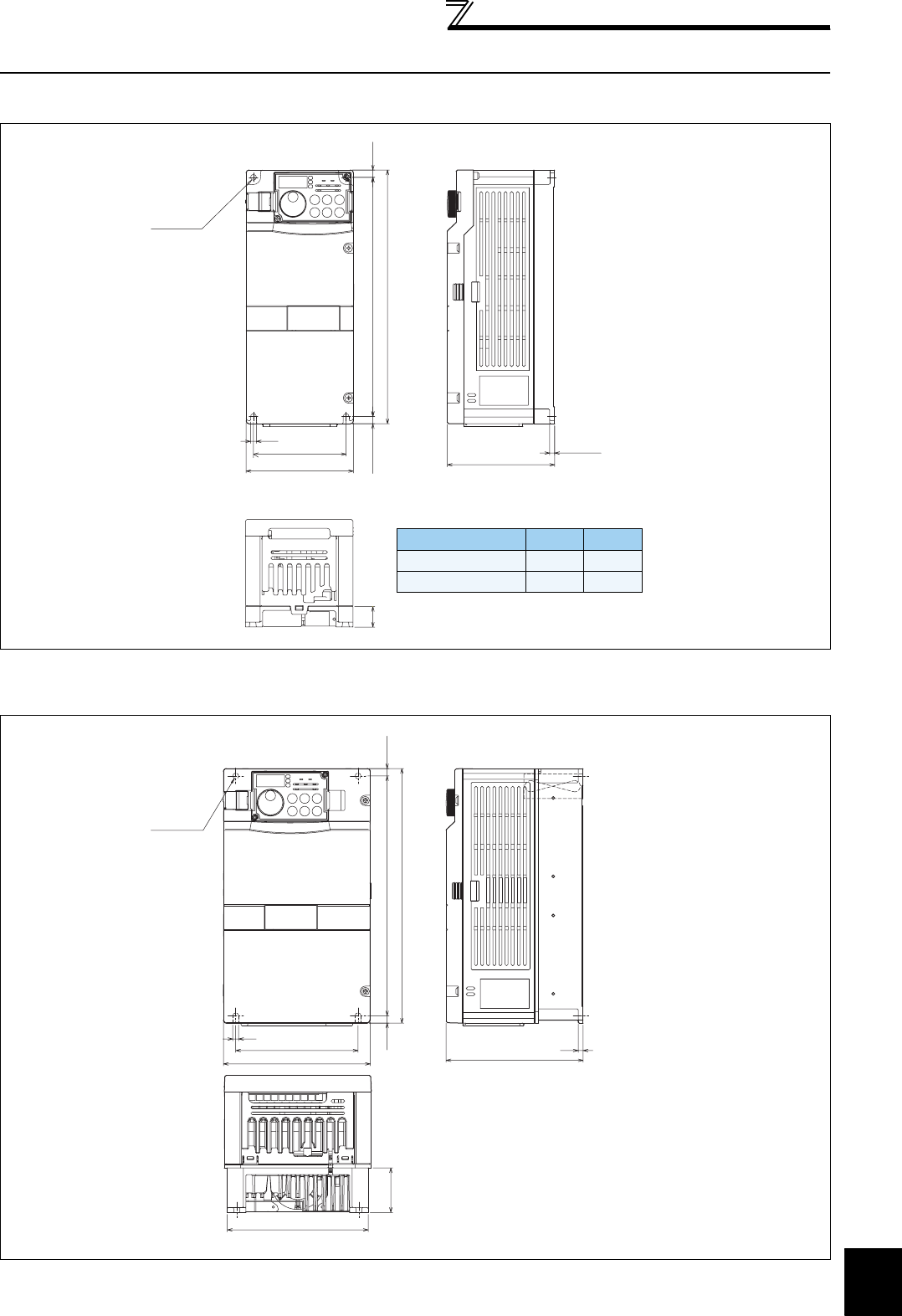
447
Outline dimension drawings
7
SPECIFICATIONS
7.4 Outline dimension drawings
7.4.1 Inverter outline dimension drawings
FR-A720-0.4K, 0.75K
FR-A720-1.5K, 2.2K, 3.7K
FR-A740-0.4K, 0.75K, 1.5K, 2.2K, 3.7K
(Unit: mm)
(Unit: mm)
2-φ6 hole
260
245
7.5
6
110 D
5
7.5
95
D1
Inverter Model DD1
FR-A720-0.4K 110 21
FR-A720-0.75K 125 36
260
150
125
6
140 5
7.5 7.5245
2-φ6 hole
144
45.5
* The FR-A740-0.4K to
1.5K are not provided
with a cooling fan.
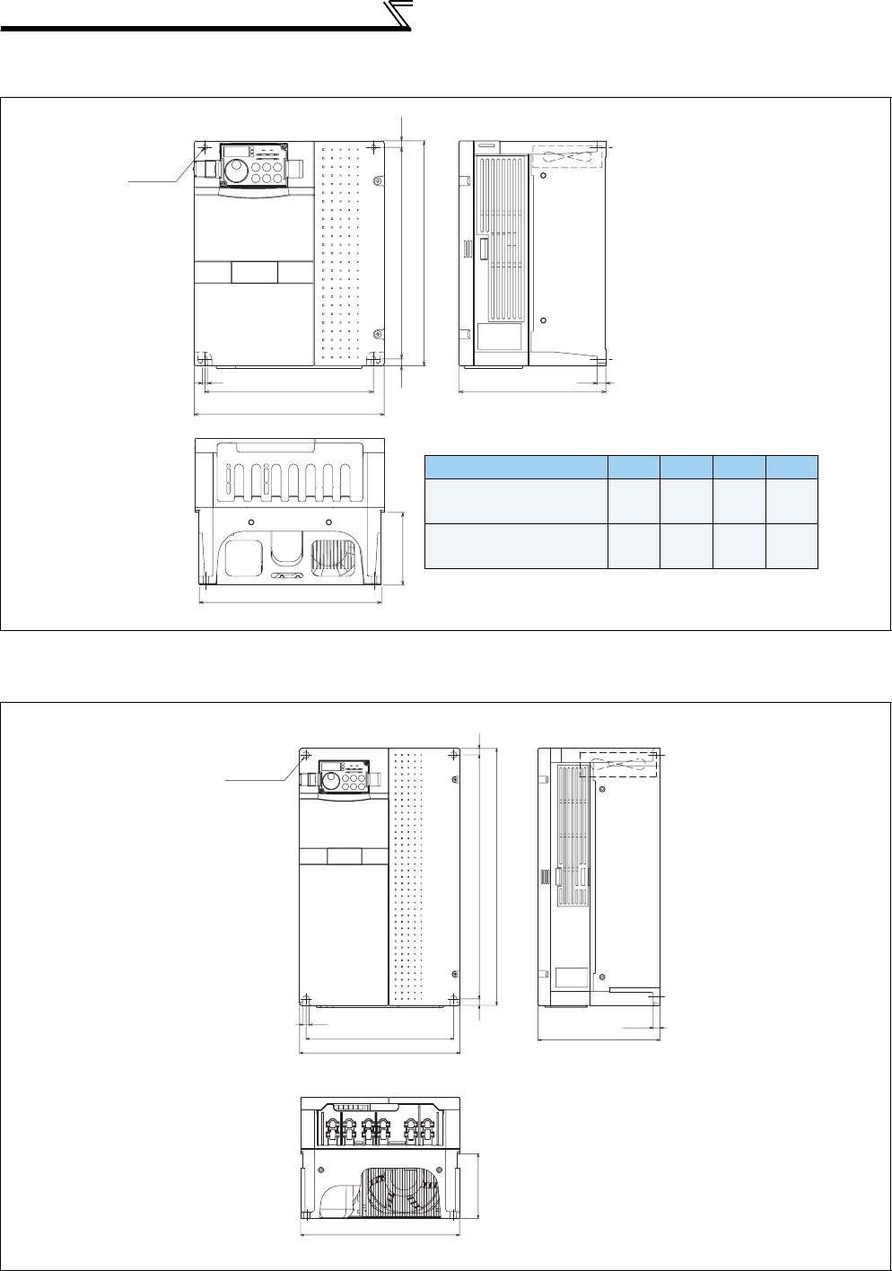
448
Outline dimension drawings
FR-A720-5.5K, 7.5K, 11K
FR-A740-5.5K, 7.5K, 11K, 15K
FR-A720-15K, 18.5K, 22K
FR-A740-18.5K, 22K
(Unit: mm)
(Unit: mm)
H1
H
D
2-φ6 hole
7.5
220
195
211
10
6
7.5
D1
Inverter Model HH1 DD1
FR-A720-5.5K, 7.5K
FR-A740-5.5K, 7.5K 260 245 170 84
FR-A720-11K
FR-A740-11K, 15K 300 285 190
101.5
10
230
250
380 10
10
400
190
10.5
101.5
250
2-φ10 hole
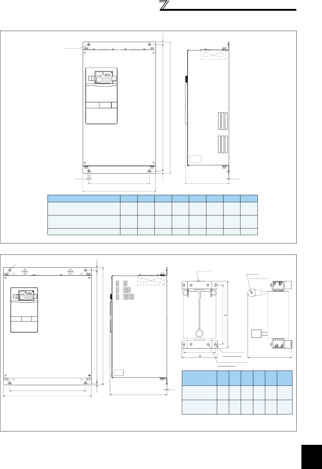
449
Outline dimension drawings
7
SPECIFICATIONS
FR-A720-30K, 37K, 45K, 55K
FR-A740-30K, 37K, 45K, 55K
FR-A740-75K, 90K
(Unit: mm)
(Unit: mm)
W2
W
W1
H1
H
H2
10
D
3.2
2-φd hole
Inverter Model WW1 W2 HH1 H2 d D
FR-A720-30K
FR-A740-30K 325 270 10 550 530 10 10 195
FR-A720-37K, 45K
FR-A740-37K, 45K, 55K 435 380 12 550 525 15 12 250
FR-A720-55K 465 410 12 700 675 15 12 250
300
3.2
465
400
2-φ12hole
620
59510 15
(for M6 screw)
4-mounting hole
(for M6 screw)
Earth (ground) terminal
Rating plate
2-terminal
E
P1 P
P1, P
(for M12 bolt)
Within D
W1
H1
H 10
W 2
DC Reactor
Model W
W1
HH1 D
Mass
(Kg)
FR-HEL-H75K
(FR-A740-75K) 140 120 320 295 185 16
FR-HEL-H90K
(FR-A740-90K) 150 130 340 310 190 20
DC reactor supplied
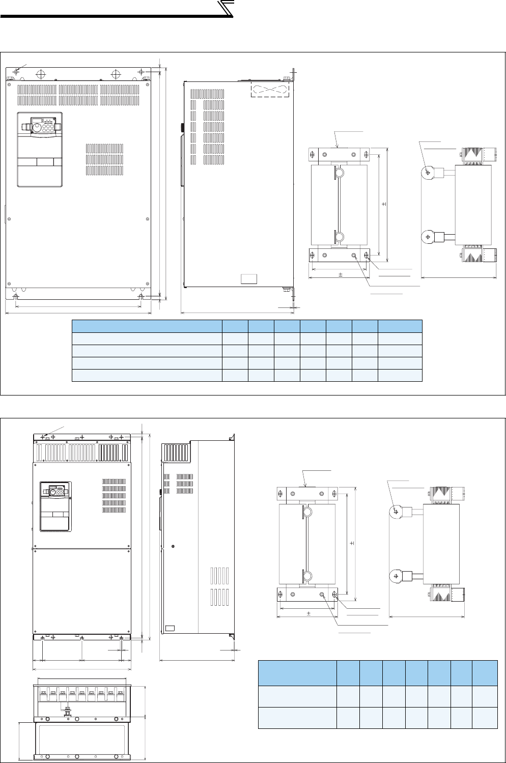
450
Outline dimension drawings
FR-A720-75K, 90K
FR-A740-110K, 132K
FR-A740-160K, 185K
(Unit: mm)
360
715
740
465
400
10 15
3.2
2-φ12 hole
E
P1
P
P1
P
W1
Within
D
(for S screw)
4-mounting hole
(for M6 screw)
Earth (ground) terminal
Rating plate
(for M12 bolt)
2-terminal
H1
H
10
W 2
DC reactor supplied
DC Reactor Model
WW1 HH1 D S Mass (kg)
FR-HEL-75K (FR-A720-75K) 150 130 340 310 190 M6 17
FR-HEL-90K (FR-A720-90K) 150 130 340 310 200 M6 19
FR-HEL-H110K (FR-A740-110K) 150 130 340 310 195 M6 22
FR-HEL-H132K (FR-A740-132K) 175 150 405 370 200 M8 26
1598510
1010
4920020049
498
12
380
3.2
450
148.5
214.5
185
3-φ12 hole
E
P1
P
P1
P
W1
Within
D
(for S screw)
4-mounting hole
(for M6 screw)
Earth (ground) terminal
Rating plate
(for M12 bolt)
2-terminal
H1
H
10
W 2
DC Reactor
Model
WW1 HH1 D S Mass
(kg)
FR-HEL-H160K
(FR-A740-160K) 175 150 405 370 205 M8 28
FR-HEL-H185K
(FR-A740-185K) 175 150 405 370 240 M8 29
DC reactor supplied
(Unit: mm)

451
Outline dimension drawings
7
SPECIFICATIONS
FR-A740-220K, 250K, 280K
FR-A740-315K, 355K
(Unit: mm)
(Unit: mm)
984
1010
3-φ12 hole
12
300 300
680
3.2
380
R/L1
S/L2
T/L3 P1
N/- P/+
UW
V
148214
185
E
P1
P
P1
P
370 10
405 10
Earth (ground) terminal
(for M6 screw)
Rating plate
2-M6 eye nut (only for FR-HEL-H220K)
* Remove the eye nut after installation of the product.
4-mounting hole
(for M8 screw) Within 240
2-terminal (for M12 bolt)
150 1
175 2
DC Reactor
Model
WW1 HH1 D S S1 S2
φ
Mass
(kg)
FR-HEL-H220K
(FR-A740-220K)
175 150 405 370 240 M8 M6 M6 M12
30
FR-HEL-H250K
(FR-A740-250K)
190 165 440 400 250 M8 M8 M8 M12
35
FR-HEL-H280K
(FR-A740-280K)
190 165 440 400 255 M8 M8 M8 M16
38
DC reactor supplied
3-φ12 hole
R/L1
S/L2
T/L3
N/-
P1
P/+
UW
V
790 440
4.5 4.5
185
222 194 1300 1515
1330
315
12
315
E
P1
P
P1
P
185
210
450 10
495 10
Earth (ground) terminal
(for M8 screw)
Rating plate
2-M8 eye nut
* Remove the eye nut after installation of the product.
4-mounting hole
(for M10 screw) Within 250
2-terminal (for M16 bolt)
DC reactor supplied
DC Reactor Model
Mass (kg)
FR-HEL-H315K (FR-A740-315K)
42
FR-HEL-H355K (FR-A740-355K)
46
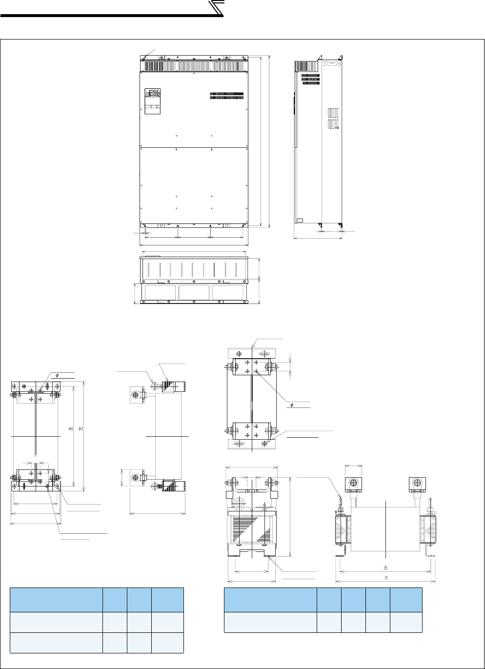
452
Outline dimension drawings
FR-A740-400K, 450K, 500K
(Unit: mm)
R/L1 S/L2 T/L3 N/-
UVW
300300300
12
995
1580
440
1550
950
222 194
4-φ12 hole
4.54.5
P1 P/+
185
E
P
P1
P1
P
75
40
40
500 10
455 10
220
195
Rating plate
2-M8 eye nut
2-terminal
4- 15 hole
* Remove the eye nut after installation of the product.
Earth (ground) terminal
(for M8 screw)
Within D
Within W
4-mounting hole
(for M10 screw)
DC Reactor Model W D
Mass
(kg)
FR-HEL-H400K
(FR-A740-400K)
235 250 50
FR-HEL-H450K
(FR-A740-450K)
240 270 57
P
P1
PP1
E
40
75
40
150
215
D1 10
D 10
* Remove the eye nut after installation of the product.
Rating plate
2-terminal
4- 15 hole
Earth (ground) terminal
(for M12 screw)
Within 245
Within H
2-M12 eye nut
4-mounting hole
(for M10 screw)
DC Reactor Model H D D1
Mass
(kg)
FR-HEL-H500K
(FR-A740-500K)
345 455 405 67
DC reactor supplied DC reactor supplied

453
Outline dimension drawings
7
SPECIFICATIONS
Operation panel (FR-DU07)
(Unit: mm)
Parameter unit (option) (FR-PU07)
(Unit: mm)
2-M3 screw
Panel
Cable
Air-
bleeding
hole
FR-DU07
Operation panel connection connecto
r
(FR-ADP option)
<Outline drawing> <Panel cutting dimension drawing>
78
50
44
723 3
81
33
16
25
3.2max
72
44
21
20
22
27.8
6
80.3
(14.2)
2.5
50
(11.45)
25.05
135
83
*1
*1
*1
*1
67 51
40
56.8
57.8
26.5
4-R1
4-φ4 hole
(
Effective depth of the mounting
screws hole 5.0)
M3 screw *2
26.5
40
Air-bleeding
hole
<Outline drawing> <Panel cutting dimension drawing>
*1 When installing the FR-PU07 on the enclosure, etc., remove screws for fixing
the FR-PU07 to the inverter or fix the screws to the FR-PU07 with M3 nuts.
*2 Select the mounting screws whose length will not exceed the effective depth
of the mounting screw hole.
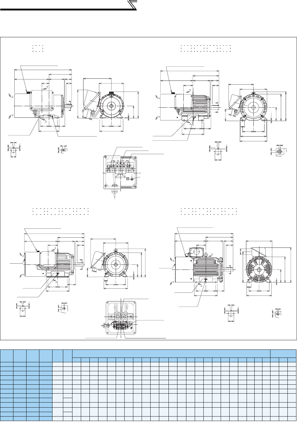
454
Outline dimension drawings
7.4.2 Dedicated motor outline dimension drawings
Dedicated motor (SF-V5RU(H)) outline dimension drawings (standard horizontal type)
Dimensions table (Unit: mm)
Note) 1. Install the motor on the floor and use it with the shaft horizontal.
2.
Leave an enough clearance between the fan suction port and wall to ensure adequate cooling.
Also, check that the ventilation direction of a fan is from the opposite load side to the load side.
3 The size difference of top and bottom of the shaft center height is
4 The 400V class motor has -H at the end of its type name.
Frame Number 90L
SF-V5RU(H)
Frame Number 100L, 112M, 132S, 132M
SF-V5RU(H) , , ,
Frame Number 160M, 160L, 180M, 180L
SF-V5RU(H) , , ,
Frame Number 200L, 225S
SF-V5RU(H) , , ,
SF-V5RU
K
SF-V5RU
K1
SF-V5RU
K3
SF-V5RU
K4
Frame
No.
Mass
(kg)
Motor
Terminal Screw
Size
A B C D E F H I KA KG
KL(KP)
L M ML NXB QQK R S T U W
U,V,W A,B,(C)
G1,G2
1———90L 24
256.5
114 90
183.6
70 62.5 198 —53 65
220(210)
425 175 —150 56 — —
168.5
24j6 748M6 M4 M4
2 1 — — 100L 33 284 128 100 207 80 70
203.5
230 65 78 231 477 200 212 180 63 60 45 193 28j6 748M6 M4 M4
321—11 2M 41 278 135 112 228 95 70 226 253 69 93 242 478 230 242 180 70 60 45 200 28j6 748M6 M4 M4
532—132S 52 303 152 132 266 108 70 265 288 75 117 256 542 256 268 180 89 80 63 239
38k6
8 5 10 M6 M4 M4
7 5 3 1 132M 62 322 171 132 266 108 89 265 288 94 117 256 580 256 268 218 89 80 63 258
38k6
8 5 10 M6 M4 M4
11 7 5 2 160M 99 412 198 160 318 127 105 316 367 105 115 330 735 310 —254 108 — — 323
42k6
8 5 12 M8 M4 M4
15 11 7 3 160L 113 434 220 160 318 127 127 316 367 127 115 330 779 310 —298 108 — — 345
42k6
8 5 12 M8 M4 M4
18 ———180M 138
438.5 225.5
180 363
139.5 120.5
359 410 127 139 352 790 335 —285 121 — —
351.5 48k6
95.5 14 M8 M4 M4
22 15 11 —160
—18 15 5180L 200
457.5 242.5
180 363
139.5 139.5
359 410 146 139 352 828 335 —323 121 — —
370.5 55m6
10 616 M8 M4 M4
30 — — 7200L 238
483.5 267.5
200 406 159
152.5
401 —145 487
(546)
909 390 —361 133 — —
425.5 60m6
11 718 M10 M4 M4
37, 45 22, 30 18, 22 —255
55 37 30 11, 15 225S 320 500 277 225 446 178 143 446 —145 533
(592)
932 428 —342 149 — — 432
65m6
11 718 M10 M4 M4
1K 2K 3K 5K 7K
S
T
W
U
Section AA
15
9
Frame leg viewed from above
Sliding distance
Earth (ground) terminal (M5)
Mark for earthing
(grounding)
Direction of
cooling fan wind
Exhaust
Suction
40
50
L
A
Connector (for encoder)
MS3102A20-29P
XB
FF
N
KA
B
R
A
A
D
φ27
4
C
H
KG
KL
EE
M
KP
4
12
Sliding distance
Frame leg viewed
from above
S
U
T
W
Section AA
Mark for earthing
(grounding)
Earth (ground) terminal (M5)
φ27
40
EE
M
ML
6.5
C
H
I
KG
D
KL
Connector (for encoder)
MS3102A20-29P
Direction of
cooling fan wind
Exhaust
Suction
XB
FF
N
QK
KA
QB
A
R
L
A
A
For motor (U, V, W)
For cooling fan (A, B)
Thermal protector (G1, G2)
ABG2G1
UVW
Earthing (grounding) terminal (M4)
11K 15K 18K 22K 30K 37K 45K 55K
Direction of
cooling fan wind
Mark for earthing
(grounding)
Earth (ground)
terminal (M8)
With guard
wires
Exhaust
Suction
Connector (for encoder)
MS3102A20-29P
φ56
KG
XB
FF
N
90
KA
110
BA
R
L
50
E
E
M
D
KL
8
C
H
I
A
A
Section AA
T
U
S
W
14.5
4
Sliding distance
Frame leg viewed
from above
Frame leg viewed
from above
4
18.5
Sliding distance
S
W
T
U
Section AA
Connector (for encoder)
MS3102A20-29P
Mark for earthing
(grounding)
Earth (ground)
terminal (M12)
With guard
wires
KG
KP
L
A
Direction of
cooling fan wind
Exhaust
Suction
φ90
70
EE
M
11
C
H
D
XB
FF
N
110
KA
140
B
R
A
A
For motor (U, V, W)
For cooling fan (A, B, C) For thermal protector (G1, G2)
Earthing (grounding)
terminal (M8)
Make sure to earth the earth terminal of the frame installation foot
as well as the earth terminal in the terminal box.
0
-0.5
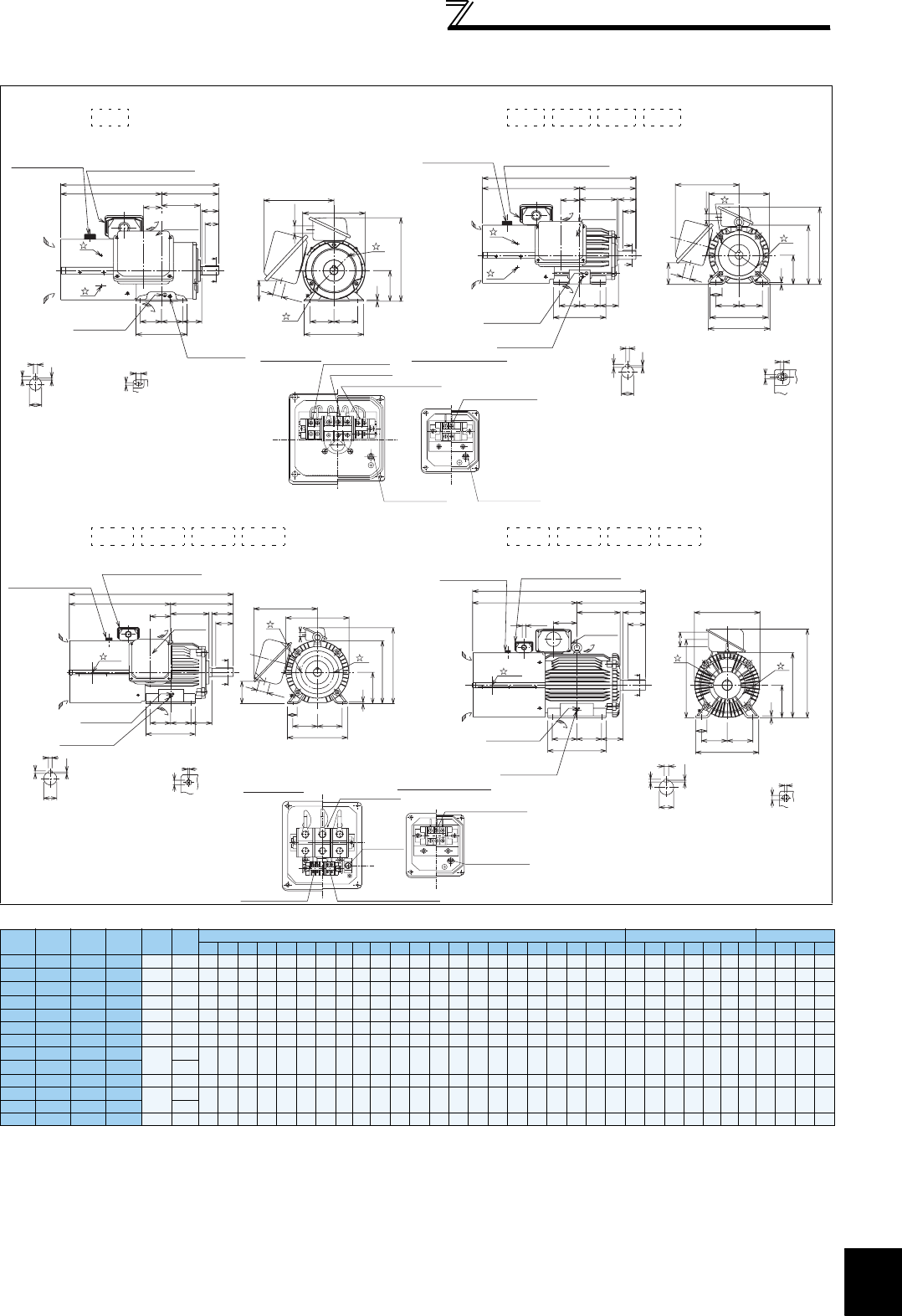
455
Outline dimension drawings
7
SPECIFICATIONS
Dedicated motor (SF-V5RU(H)) outline dimension drawings
(standard horizontal type with brake)
Dimensions table (Unit: mm)
Note)1. Install the motor on the floor and use it with the shaft horizontal.
2.
Leave an enough clearance between the fan suction port and wall to ensure adequate cooling.
Also, check that the ventilation direction of a fan is from the opposite load side to the load side.
3 The size difference of top and bottom of the shaft center height is
4 The 400V class motor has -H at the end of its type name.
5. Since a brake power device is a stand-alone, install it inside the enclosure.
(This device should be arranged at the customer side.)
Frame Number 90L
SF-V5RU(H)
Frame Number 100L, 112M, 132S, 132M
SF-V5RU(H) , , ,
Frame Number 160M, 160L, 180M, 180L
SF-V5RU(H) , , ,
Frame Number 200L, 225S
SF-V5RU(H) , , ,
SF-V5RU
KB
SF-V5RU
K1B
SF-V5RU
K3B
SF-V5RU
K4B
Frame
No.
Mass
(kg)
Motor Shaft End
Terminal Screw Size
A B C D E F G H I J KA KD KG KL KP L M ML N X XB Z Q QK R S T U W
U,V,W
A,B,(C)
G1,G2 B1,B2
1———90L 29
296.5
114 90
183.6
70
62.5
4 — — — 53 27 65 220 245 465 175 —150 15 56 950 40
168.5
24j6
748M6 M4 M4 M4
2 1 — — 100L 46
333.5
128 100 207 80 70 6.5 — — 40 65 27 78 231 265
526.5
200 212 180 463 12 60 45 193
28j6
748M6 M4 M4 M4
321—112M 53 355 135 112 228 95 70 6.5 — — 40 69 27 93 242 290 555 230 242 180 470 12 60 45 200
28j6
748M6 M4 M4 M4
532—132S 70 416 152 132 266 108 70 6.5 — — 40 75 27 117 256 329 655 256 268 180 489 12 80 63 239
38k6
8 5 10 M6 M4 M4 M4
7531132M 80 435 171 132 266 108 89 6.5 — — 40 94 27 117 256 329 693 256 268 218 489 12 80 63 258
38k6
8 5 10 M6 M4 M4 M4
11 752160M 140
522.5
198 160 318 127 105 8 — — 50 105 56 11 5 330 391
845.5
310 —254 4108
14.5
110 90 323
42k6
8 5 12 M8 M4 M4 M4
15 11 7 3 160L 155
544.5
220 160 318 127 127 8 — — 50 127 56 11 5 330 391
889.5
310 —298 4108
14.5
110 90 345
42k6
8 5 12 M8 M4 M4 M4
18 ———180M 185
568.5 225.5
180 363
139.5 120.5
8 — — 50 127 56 139 352 428 920 335 —285 4121
14.5
110 90
351.5
48k6
95.5 14 M8 M4 M4 M4
22 15 11 —215
—18 15 5180L 255
587.5 242.5
180 363
139.5 139.5
8 — — 50 146 56 139 352 428 958 335 —323 4121 14.5 110 90
370.5
55m6
10 616 M8 M4 M4 M4
30 ——7200L 305
644.5 267.5
200 406 159
152.5
11 — — 70 145 90 487 —546
1070
390 —361 4133
18.5
140 110
425.5
60m6
11 718
M10
M4 M4 M4
37, 45 22, 30 18, 22 —330
55 37 30 11, 1 5 225S 395 659 277 225 446 178 143 11 — — 70 145 90 533 —592
1091
428 —342 4149
18.5
140 110 432
65m6
11 718
M10
M4 M4 M4
1KB 2KB 3KB 5KB 7KB
Sliding distance
Frame leg viewed
from above
Z
X
Section AA
U
W
T
S
Connector (for encoder)
MS3102A20-29P
Mark for earthing
(grounding)
Earth (ground)
terminal (M5)
A
A
R
B
N
F F XB
50
40
Suction
Exhaust
Direction of
cooling fan wind
Terminal box for cooling fan
L
A
KA
M
E E
C
G
D
φ22
2
2
1
1
KL
KP
KG
φ27
Main
terminal box
Connector (for encoder)
MS3102A20-29P
Earth (ground)
terminal (M5)
Mark for earthing
(grounding)
Suction
Exhaust
Direction of
cooling fan wind
A
A
R
N
F F XB
C
G
D
ML
M
E E
J
B Q
QK
Main
terminal box
A
L
Terminal box for cooling fan
φ22
φ27
KA
KL
KP
H
KG
Section AA
W
S
U
T
Sliding distance
Frame leg viewed
from above
Z
X
1
2
1
2
VU
B2B1
W
G1 G2
CBA
For motor (U, V, W)
For cooling fan (A, B)
For brake (B1, B2)
For thermal protector (G1, G2)
Earthing (grounding)
terminal (M4)
Main terminal box
Earthing (grounding)
terminal (M4)
Terminal box for cooling fan
11KB 15KB 18KB 22KB 30KB 37KB 45KB 55KB
Sliding distance
Frame leg viewed
from above
X
Z
W
S
U
T
Section AA
Connector (for encoder)
MS3102A20-29P
Earth (ground)
terminal (M8)
Mark for earthing
(grounding)
Suction
Direction of
cooling fan wind
Terminal box for cooling fan
1, 2
1
2
A
A
R
B110
KA
Exhaust 90
N
F F XB
L
A
H
C
G
D
M
EE
J
KG
φ56
φ22
KL
KP
Main
terminal box
Sliding distance
Z
X
Frame leg viewed
from above
Section AA
U
T
W
S
Connector (for encoder)
MS3102A20-29P
Earth (ground)
terminal (M12)
Mark for earthing
(grounding)
1
2
D
H
C
G
M
E E
J
φ90
KP
KG
A
A
R
B140
KA 110
N
F F XB
Suction Exhaust
Direction of
cooling fan wind
L
A
Terminal box for cooling fan
1, 2
φ22
Main
terminal box
B2B1
U
G2G1
WV
CBA
For cooling fan (A, B, C)
For motor (U, V, W)
Earthing
(grounding)
terminal (M8) Earthing (grounding)
terminal (M4)
For brake (B1, B2) For thermal protector (G1, G2)
Main terminal box Terminal box for cooling fan
indicates an inserting position of a bolt with hex head
holes for manual opening.
Make sure to earth the earth terminal of the frame installation
foot as well as the earth terminal in the terminal box.
0
-0.5
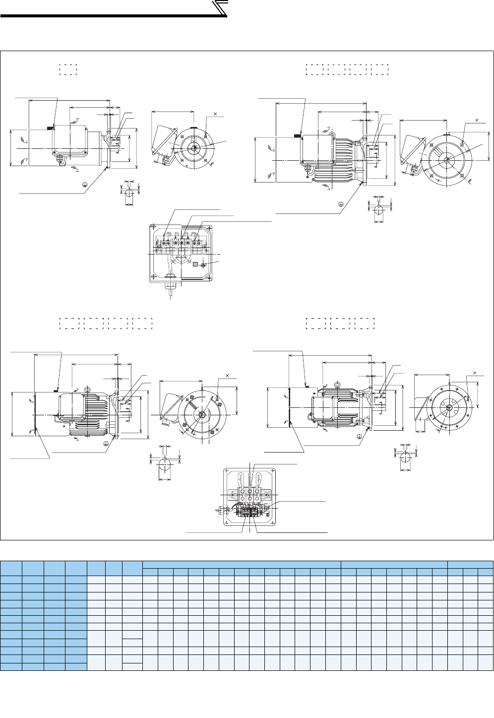
456
Outline dimension drawings
Dedicated motor (SF-V5RU(H)) outline dimension drawings (flange type)
Dimensions table (Unit: mm)
Note) 1. Install the motor on the floor and use it with the shaft horizontal.
For use under the shaft, the protection structure of the cooling fan is IP20.
2.
Leave an enough clearance between the fan suction port and wall to ensure adequate cooling.
Also, check that the ventilation direction of a fan is from the opposite load side to the load side.
3 The size difference of top and bottom of the shaft center height is
4 The 400V class motor has -H at the end of its type name.
Frame Number 90L
SF-V5RUF(H)
Frame Number 100L, 112M, 132S, 132M
SF-V5RUF(H) , , ,
Frame Number 160M, 160L, 180M, 180L
SF-V5RUF(H) , , ,
Frame Number 200L
SF-V5RUF(H) , ,
SF-V5RU
F
K
SF-V5RU
F
K1
SF-V5RU
F
K3
SF-V5RU
F
K4
Flange
Number
Frame
No.
Mass
(kg)
Motor Shaft End
Terminal Screw Size
DIE KB KD KL LA LB LC LE LG LL LN LZ LR QQK S T U W
U,V,W
A,B,(C)
G1,G2
1———FF165 90L 26.5
183.6
—198.5 27 220 165 130j6 200 3.5 12 402 412 50 50 40 24j6 7 4 8 M6 M4 M4
2 1 — — FF215 100L 37 207 130 213 27 231 215 180j6 250 416 432 414.5 60 60 45 28j6 7 4 8 M6 M4 M4
321—FF215 112M 46 228 141 239 27 242 215 180j6 250 416 448 414.5 60 60 45 28j6 7 4 8 M6 M4 M4
532—FF265 132S 65 266 156 256 27 256 265 230j6 300 420 484 414.5 80 80 63 38k6 8 5 10 M6 M4 M4
7 5 3 1 FF265 132M 70 266 156 294 27 256 265 230j6 300 420 522 414.5 80 80 63 38k6 8 5 10 M6 M4 M4
11 7 5 2 FF300 160M 110 318 207 318 56 330 300 250j6 350 520 625 418.5 110 110 90 42k6 8 5 12 M8 M4 M4
15 11 7 3 FF300 160L 125 318 207 362 56 330 300 250j6 350 520 669 418.5 110 110 90 42k6 8 5 12 M8 M4 M4
18 ———FF350 180M 160 363 230 378.5 56 352 350 300j6 400 520 690 418.5 110 110 90 48k6 95.5 14 M8 M4 M4
22 15 11 —185
—18 15 5FF350 180L 225 363 230 416.5 56 352 350 300j6 400 520 728 418.5 110 110 90 55m6 10 616 M8 M4 M4
30 ——7FF400 200L 270 406 255 485 90 346 400 350j6 450 522
823.5
818.5 140 140 110 60m6 11 718 M10 M4 M4
37, 45 22, 30 18, 22 —290
1K 2K 3K 5K 7K
LN LZ
KL
KD
LA
A
A
Section BB
U
W
T
S
Earth (ground) terminal (M5)
Mark for earthing (grounding)
Connector (for encoder)
MS3102A20-29P LL
KB LR
LG LE QK
Q
LC
LB
B
B
Section
AA
D
Suction
Direction of
cooling fan wind
Exhaust
Section BB
W
U
T
S
LN LZ
KD
KL
IE
A
A
LA
Connector (for encoder)
MS3102A20-29P
Earth (ground) terminal (M5)
Mark for earthing (grounding)
LL
KB LR
LG LE QK
Q
LC
LB
Section
AA
B
B
D
Suction
Direction of
cooling fan wind
Exhaust
For motor (U, V, W)
For cooling fan (A, B)
For thermal protector (G1, G2)
ABG2G1
UVW
Earthing (grounding)
terminal (M4)
11K 15K 18K 22K 30K 37K 45K
Section BB
W
S
T
U
A
A
LN LZ
LA
IE
KL
KD
QK
Q
Connector (for encoder)
MS3102A20-29P
Earth (ground) terminal (M8)
Mark for earthing (grounding)
With guard wires
Section
AA
LC
LB
B
B
LR
KB
LG LE
LL
D
Suction
Direction of
cooling fan wind
Exhaust
Section BB
W
S
T
U
LR Q
QK
Connector (for encoder)
MS3102A20-29P
Earth (ground) terminal (M12)
Mark for earthing (grounding)
With guard wires
Section
AA
LC
LB
B
B
KB
LG LE
LL
D
Suction
Direction of
cooling fan wind
Exhaust
A
A
LN LZ
LA
IE
KL
KD
For motor (U, V, W)
For cooling fan (A, B, C) For thermal protector (G1, G2)
Earthing (grounding)
terminal (M8)
Make sure to earth the earth terminal of the flange section
as well as the earth terminal in the terminal box.
0
-0.5
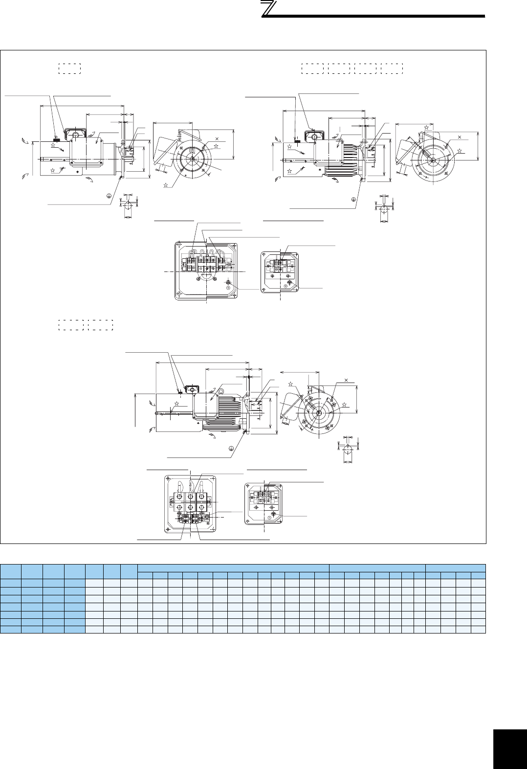
457
Outline dimension drawings
7
SPECIFICATIONS
Dedicated motor (SF-V5RU(H)) outline dimension drawings (flange type with brake)
Dimensions table (Unit: mm)
Note)1. Install the motor on the floor and use it with the shaft horizontal.
2.
Leave an enough clearance between the fan suction port and wall to ensure adequate cooling.
Also, check that the ventilation direction of a fan is from the opposite load side to the load side.
3 The size difference of top and bottom of the shaft center height is
4 The 400V class motor has -H at the end of its type name.
5. Since a brake power device is a stand-alone, install it inside the enclosure.
(This device should be arranged at the customer side.)
Frame Number 90L
SF-V5RUF(H)
Frame Number 100L, 112M, 132S, 132M
SF-V5RUF(H) , , ,
Frame Number 160M, 160L
SF-V5RUF(H) ,
SF-V5RU
F
KB
SF-V5RU
F
K1B
SF-V5RU
F
K3B
SF-V5RU
F
K4B
Flange
Number
Frame
No.
Mass
(kg)
Motor Shaft End
Terminal Screw Size
DKB KD KL KP LA LB LC LE LG LL LN LZ LR QQK S T U W
U,V,W
A,B,(C)
B1,B2 G1,G2
1 — — — FF165 90L 31.5
183.6
198.5
27 220 155 165
130j6
200 3.5 12 442 412 50 50 40 24j6 7 4 8 M6 M4 M4 M4
2 1 — — FF215 100L 50 207 213 27 231 165 215
180j6
250 416
481.5
414.5 60 60 45 28j6 7 4 8 M6 M4 M4 M4
321—FF215 112M 58 228 239 27 242 178 215
180j6
250 416 525 414.5 60 60 45 28j6 7 4 8 M6 M4 M4 M4
532—FF265 132S 83 266 256 27 256 197 265
230j6
300 420 597 414.5 80 80 63
38k6
8 5 10 M6 M4 M4 M4
7531FF265 132M 88 266 294 27 256 197 265
230j6
300 420 635 414.5 80 80 63
38k6
8 5 10 M6 M4 M4 M4
11 752FF300 160M 151 318 318 56 330 231 300
250j6
350 520
735.5
418.5 110 110 90
42k6
8 5 12 M8 M4 M4 M4
15 11 7 3 FF300 160L 167 318 362 56 330 231 300
250j6
350 520
779.5
418.5 110 110 90
42k6
8 5 12 M8 M4 M4 M4
1KB 2KB 3KB 5KB 7KB
Connector (for encoder)
MS3102A20-29P
Earth (ground) terminal (M5)
Mark for earthing (grounding)
Suction
Exhaust
Direction of
cooling fan wind
Terminal box for cooling fan
1
2
B
B
Section
AA
LC
LB
LG LE
LL
LR
Q
QK
D
KB
LN LZ
1
2
KD
A
A
LA
KL
φ22
KP
Section BB
U
W
T
S
Main
terminal box
Section BB
W
S
U
T
Connector (for encoder)
MS3102A20-29P
QK
Q
Earth (ground) terminal (M5)
Mark for earthing (grounding)
Suction
Exhaust
Direction of
cooling fan wind
Terminal box for cooling fan
1
2
Section
AA
LC
LB
B
B
LR
LG LE
LL
D
KB
ALN LZ
A
1
2
LA
KD
KL
φ22
KP
Main
terminal box
VU
B2B1
W
G1 G2
CBA
For motor (U, V, W)
For cooling fan (A, B)
For brake (B1, B2)
For thermal protector (G1, G2)
Earthing
(grounding)
terminal (M4)
Earthing
(grounding)
terminal (M4)
Main terminal box Terminal box for cooling fan
11KB 15KB
Section B
B
W
S
U
T
A
A
LN LZ
2
1
LA
KD
KL
φ22
KP
Connector (for encoder)
MS3102A20-29P
QK
Q
D
Earth (ground) terminal (M8)
Mark for earthing (grounding)
Suction
Direction of
cooling fan wind
Terminal box for cooling fan
1, 2
Section
AA
LC
LB
B
B
LL
KB LR
LG LE
Exhaust
Main
terminal box
B2B1
U
G2G1
WV
CBA
For cooling fan (A, B, C)
For motor (U, V, W)
Earthing
(grounding)
terminal (M8)
Earthing
(grounding)
terminal (M4)
For brake (B1, B2) For thermal protector (G1, G2)
Terminal box for cooling fan
Main terminal box
indicates an inserting position of a bolt with hex head holes
for manual opening.
Make sure to earth the earth terminal of the flange section
as well as the earth terminal in the terminal box.
0
-0.5
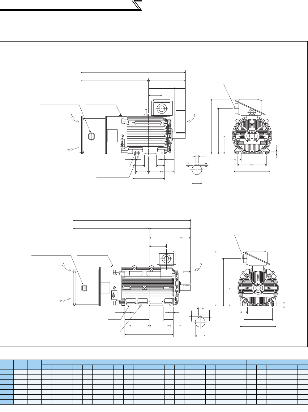
458
Outline dimension drawings
Dedicated motor (SF-THY) outline dimension drawings (1500r/min series)
Dimensions table (Unit: mm)
Note) The tolerance of the top and bottom of the center shaft height *C is for the 250 frame and for the 280 frame or more.
Frame Number 250MD, 280MD
75kW to 160kW
Frame Number 280L, 315H
200kW, 250kW
Output Frame
No.
Mass
(kg)
Motor Shaft End Size
A B C D E F G H J K K1 K2 L M N R Z XB KA KG QQK S W T U
75
250MD
610
988.5
340.5
250 557 203
174.5 30
775 100 130 168 50
1471
486 449
482.5
24 168
157.5
635 140 110
φ
75m6
20 12 7.5
90
250MD
660
988.5
340.5
250 557 203
174.5 30
775 100 130
168
50
1471
486 449
482.5
24 168
157.5
635 140 110
φ
75m6
20 12 7.5
110
280MD
870
1049.5
397.5
280 607
228.5 209.5 30
845 110 130 181 40
1619
560 449
569.5
24 190
210.5
705 170 140
φ
85m6
22 14 9
132
280MD
890
1049.5
397.5
280 607
228.5 209.5 30
845 110 130 181 40
1619
560 449
569.5
24 190
210.5
705 170 140
φ
85m6
22 14 9
160
280MD
920
1049.5
397.5
280 607
228.5 209.5
30 845 110 130 181 40
1619
560 499
569.5
24 190
210.5
705 170 140
φ
85m6
22 14 9
200
280L 1170
1210.5
416.5
280 652
228.5 228.5 30
885 110 160
160
75
1799
560 607
588.5
24
190
214.5
745 170 140
φ
85m6
22 14 9
250
315H 1630
1343
565 315 717 254 355
35
965 130 175
428
80
2084
636 870 741
28
216 306 825 170 140
φ
95m6
25 14 9
L
AR
B
KA
Q
QK
Exhaust
Connector (for encoder)
MS3102A20-29P
Suction
K2 K2
K1
FFXB
N
K
4-φZ hole
This hole is not used.
PF4 Class B screw
J
EE
S
W
M
H
KG
C
T
U
G
Terminal box for cooling fan
Direction of
cooling fan wind
Terminal box for cooling fan
L
AR
B
K2
K1 K
K2
XB
FF
N
KA
Q
QK
Exhaust
Suction
4-φZ hole
This hole is not used.
PF4 Class B screw
S
W
T
U
H
KG
G
C-1.0
J
EE
M
0
Connector (for encoder)
MS3102A20-29P
Direction of
cooling fan wind
0
-0.5 0
-1.0

7
SPECIFICATIONS
459
Heatsink protrusion attachment
procedure
7.5 Heatsink protrusion attachment procedure
When encasing the inverter in an enclosure, the generated heat amount in an enclosure can be greatly reduced by
installing the heatsink portion of the inverter outside the enclosure. When installing the inverter in a compact enclosure,
etc., this installation method is recommended.
7.5.1 When using a heatsink protrusion attachment (FR-A7CN)
For the FR-A720-1.5K to 90K, FR-A740-0.4K to 132K, a heatsink can be protruded outside the enclosure using a
heatsink protrusion attachment (FR-A7CN). (For the FR-A740-160K or higher, attachment is not necessary when the
heatsink is to be protruded.)
For a panel cut dimension drawing and an installation procedure of the heatsink protrusion attachment (FR-A7CN) to
the inverter, refer to a manual of "heatsink protrusion attachment".
7.5.2 Protrusion of heatsink of the FR-A740-160K or higher
(1) Panel cutting
Cut the panel of the enclosure according to the inverter capacity.
• FR-A740-160K, 185K
Unit: mm
• FR-A740-220K, 250K, 280K
Unit: mm
• FR-A740-315K, 355K
Unit: mm
• FR-A740-400K, 450K, 500K
Unit: mm
200 200
484
1395418
985
Hole
6-M10 screw
Hole
300 300
662
1595415
984
6-M10 screw
6-M10 screw
771
1300
21125821
Hole
315 315
8-M10 screw
300 300 300
976
21
150821
1550
Hole
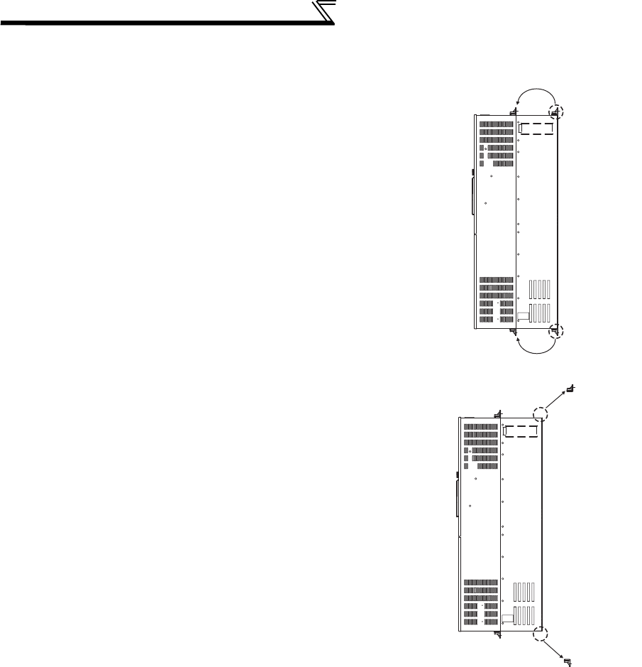
460
Heatsink protrusion attachment
procedure
(2) Shift and removal of a rear side installation frame
• FR-A740-160K to 280K
One installation frame is attached to each of the upper and lower
parts of the inverter. Change the position of the rear side
installation frame on the upper and lower sides of the inverter to
the front side as shown on the right. When changing the
installation frames, make sure that the installation orientation is
correct.
• FR-A740-315K or higher
Two installation frames each are attached to the upper and lower
parts of the inverter. Remove the rear side installation frame on
the upper and lower sides of the inverter as shown on the right.
Upper
installation
frame
Lower
installation
frame
Shift
Shift
Removal
Upper installation
frame (rear side)
Removal
Lower installation
frame (rear side)
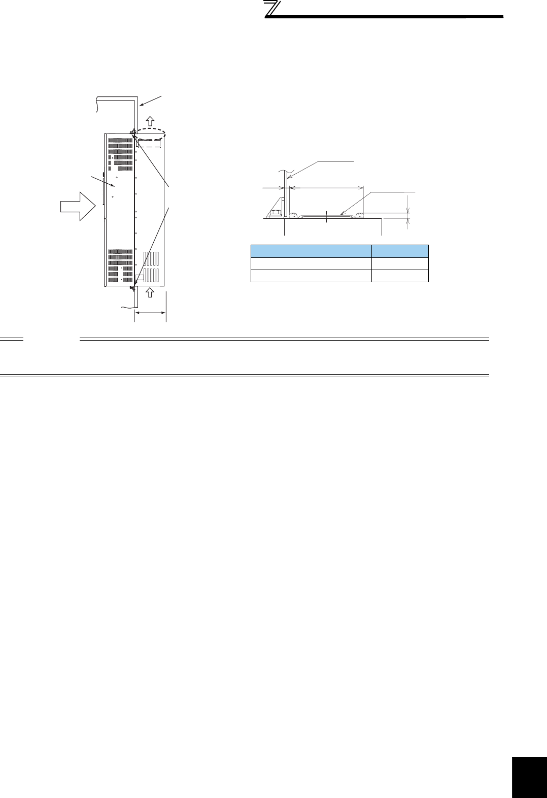
7
SPECIFICATIONS
461
Heatsink protrusion attachment
procedure
(3) Installation of the inverter
Push the inverter heatsink portion outside the enclosure and fix the enclosure and inverter with upper and lower instal-
lation frame.
CAUTION
· Having a cooling fan, the cooling section which comes out of the enclosure cannot be used in the environment of water
drops, oil, mist, dust, etc.
· Be careful not to drop screws, dust etc. into the inverter and cooling fan section.
Inverter
Inside the
enclosure
Enclosure
Exhausted air
Installation
frame
Dimension of
the outside of
the enclosure
Cooling
wind
D1
*
* For the FR-A740-160K or higher, there are finger
guards behind the enclosure. Therefore, the
thickness of the panel should be less than 10mm
(*1) and also do not place anything around finger
guards to avoid contact with the finger guards.
Unit: mm
Inverter Model D1
FR-A740-160K, 185K 185
FR-A740-220K to 500K 184
Enclosure
Finger guard
10*1140
6
462
MEMO

463
APPENDICES
This chapter provides the "APPENDICES" of this product.
Always read the instructions before using the equipment.
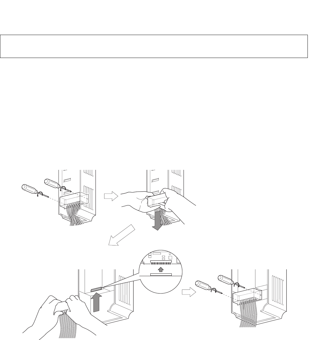
464
Appendix 1-1 Replacement of the FR-A500 series
(1) Instructions for installation
1) Removal procedure of the front cover was changed. (with screws) Please note. (Refer to page 6.)
2) Removal procedure of the operation panel was changed. (with screws) Please note. (Refer to page 6.)
3) Plug-in options of the A500 series are not compatible.
4) Operation panel (FR-DU04) cannot be used.
5) Setup software (FR-SW0-SETUP/FR-SW1-SETUP) cannot be used.
(2) Wiring instructions
1) The control circuit terminal block can be used for the FR-A700 series without removing wiring.
Note that the wiring cover (0.4K to 22K) is not compatible.
(Note that the relay output 2 (A2, B2, C2) specific for the FR-A700 series cannot be used with the FR-A500 series
terminals.)
(3) Instructions for continuous use of the FR-PU04 (parameter unit)
1) For the FR-A700 series, many functions (parameters) have been added. When setting these parameters, the
parameter name and setting range are not displayed. User initial value list and user clear of the HELP function
cannot be used.
2) For the FR-A700 series, many protective functions have been added. These functions activate, but all faults
are displayed as "Fault 14". When the faults history has been checked, "E.14" appears. Added faults display
will not appear on the parameter unit.
3) User initial value setting cannot be used.
4) User registration/clear (user group 2) cannot be used.
5) Parameter copy/verification function cannot be used.
(4) Parameter resetting
It is easy if you use setup software (FR Configurator).
Appendix 1 For customers who are replacing the older model with
this inverter
FR-A500 series
FR-A700 series

465
(5) Main differences and compatibilities with the FR-A500(L) series
Appendix 1-2 Replacement of the FR-A200 <EXCELENT> series
Instructions for installation
• When using the mounting holes of the FR-A200(E) series, FR-A5AT (intercompatibility attachment) is necessary.
Item FR-A500(L) FR-A700
Added
functions
Control
method
V/F control
Advanced magnetic flux vector control
V/F control
Advanced magnetic flux vector control
Real sensorless vector control
Vector control
(used with a plug-in option FR-A7AP/FR-A7AL)
PID control PID action set point setting
(Pr. 133)
Addition of "9999" to PID action set point (Pr. 133)
setting
(a value input from terminal 2 is a set point)
Changed
functions
Intelligent
mode
selection
Pr. 60
Parameter number change
(Pr. 60 Energy saving control selection)
(Pr. 292 Automatic acceleration/deceleration)
Motor poles Number of motor poles
(Pr. 81 , Pr. 144)
Setting the number of motor poles in Number of motor
poles (Pr. 81) automatically changes the speed setting
switchover (Pr. 144) setting.
User group User group 1 (16 parameters), User group 2 (16
parameters) (Pr.160, Pr.173 to Pr.175)
User group (16 parameters) only
Setting methods were partially changed
(Pr.160, Pr.172 to Pr.173)
Communication
option
Performing the parameter clear or all parameter
clear (H5A96 or HAA99) from the DeviceNet
communication option (FR-A5ND) clears the Pr.
345 and Pr. 346 settings.
Performing the parameter clear or all parameter clear
(H5A96 or HAA99) from the DeviceNet communication
option (FR-A7ND) does not clear the Pr. 345 and Pr. 346
settings.
Deleted
functions
User initial
value setting
(Pr. 199)
Available
Not available
Substitutable with the copy function of the operation
panel (FR-DU07)
Long wiring
mode Pr. 240 setting 10, 11 Setting is not necessary
(Pr. 240 settings "10" and "11" were cleared)
Program
operation Pr. 200 to Pr. 231 Function was cleared
Terminal block Removable terminal block
Removable terminal block
Upward compatibility (FR-A500 terminal block
mountable)
PU FR-PU04, DU04
FR-PU07
FR-DU07
FR-PU04 (Some functions, such as parameter copy,
are unavailable.)
FR-DU04 unavailable
Plug-in options
Dedicated plug-in option (incompatible)
Computer link, relay output option
FR-A5NR
Built into the inverter
(RS-485 terminals, relay output 2 points)
Installation size
· FR-A720-0.4K to 90K, FR-A740-0.4K to 7.5K, 18.5K to 55K, 110K, 160K are compatible in mounting
dimensions.
For the FR-A740-11K, 15K, an optional intercompatibility attachment (FR-AAT) is necessary.
· Heatsink protrusion attachment is not compatible.
Also, the panel cut dimension of 3.7K or lower, 200V class 30K, 55K or higher, 400V class 11K, 15K, 75K
or higher is not compatible.

466
*1 These instruction codes are used for parameter read and write by using Mitsubishi inverter protocol with the RS-485 communication.
(Refer to page 333 for RS-485 communication)
*2 Validity and invalidity according to operation mode are as follows:
:Usable parameter
×:Unusable parameter
Δ:Parameters available only during position control set by parameter
*3 "" indicates valid and "×" indicates invalid of "parameter copy", "parameter clear", and "all parameter clear".
*4 Parameters can be used with conditions. Refer to page 203 for details.
*5 These parameters are communication parameters that are not cleared when parameter clear (all clear) is executed from RS-485 communication.
(Refer to page 328 for RS-485 communication)
*6 When a communication option is installed, parameter clear (lock release) during password lock (Pr. 297 ≠ 9999) can be performed only from the
communication option.
Symbols in the table indicate parameters which function when an option is mounted.
......FR-A7AX, ......FR-A7AY, .............FR-A7AR, .........FR-A7AP, ..........FR-A7AL, .........FR-A7AZ, .........FR-A7AD,
......FR-A7NC, ......FR-A7NCE, .........FR-A7ND, .........FR-A7NL, .........FR-A7NP, .........FR-A7NS, .........FR-A7NF
Appendix 2 Control mode-based parameter (function) correspondence
table and instruction code list
Parameter
Name
Instruction
Code * 1 Control Mode-based Correspondence Table *2
Parameter Copy
*3
Parameter Clear
*3
All Parameter Clear
*3
Read
Write
Extended
V/F
control
Advanced
magnetic
flux
vector
control
Vector control Real sensorless
vector control
Speed
control
Torque
control
Position
control
Speed
control
Torque
control
0 Torque boost 00 80 0 × ×××××
1 Maximum frequency 01 81 0
2 Minimum frequency 02 82 0
×
3 Base frequency 03 83 0× × × × × ×
4
Multi-speed setting (high speed)
04 84 0
Δ
5
Multi-speed setting (middle speed)
05 85 0 Δ
6
Multi-speed setting (low speed)
06 86 0
Δ
7 Acceleration time 07 87 0 Δ
8 Deceleration time 08 88 0
Δ
9 Electronic thermal O/L relay 09 89 0
10 DC injection brake operation
frequency 0A 8A 0
×
11 DC injection brake operation
time 0B 8B 0 ×
12 DC injection brake operation
voltage 0C 8C 0 ×××*4 *4
13 Starting frequency 0D 8D 0 ×
14 Load pattern selection 0E 8E 0 × ×××××
15 Jog frequency 0F 8F 0 ×
16 Jog acceleration/
deceleration time 10 90 0
×
17 MRS input selection 11 91 0
18 High speed maximum
frequency 12 92 0 ×××××
19 Base frequency voltage 13 93 0× × × × × ×
20 Acceleration/deceleration
reference frequency 14 94 0
Δ
21 Acceleration/deceleration
time increments 15 95 0 Δ
22 Stall prevention operation
level (torque limit level ) 16 96 0 × ×
23
Stall prevention operation
level compensation factor at
double speed
17 97 0 × × × × ×
24 Multi-speed setting (speed
4) 18 98 0
Δ
25
Multi-speed setting (speed 5)
19 99 0 Δ

467
26
Multi-speed setting (speed 6)
1A 9A 0
Δ
27
Multi-speed setting (speed 7)
1B 9B 0 Δ
28 Multi-speed input
compensation selection 1C 9C 0
×
29 Acceleration/deceleration
pattern selection 1D 9D 0 ×
30 Regenerative function
selection 1E 9E 0
31 Frequency jump 1A 1F 9F 0 ×
32 Frequency jump 1B 20 A0 0
×
33 Frequency jump 2A 21 A1 0 ×
34 Frequency jump 2B 22 A2 0 ×
35 Frequency jump 3A 23 A3 0 ×
36 Frequency jump 3B 24 A4 0
×
37 Speed display 25 A5 0
41 Up-to-frequency sensitivity 29 A9 0
××
×
42 Output frequency detection 2A AA 0
43 Output frequency detection
for reverse rotation 2B AB 0
44 Second acceleration/
deceleration time 2C AC 0 Δ
45 Second deceleration time 2D AD 0
Δ
46 Second torque boost 2E AE 0× × × × × ×
47
Second V/F (base frequency)
2F AF 0 × ×××××
48 Second stall prevention
operation current 30 B0 0 ×××××
49 Second stall prevention
operation frequency 31 B1 0 ×××××
50 Second output frequency
detection 32 B2 0
51 Second electronic thermal
O/L relay 33 B3 0
52 DU/PU main display data
selection 34 B4 0
54 FM terminal function
selection 36 B6 0
55 Frequency monitoring
reference 37 B7 0
56 Current monitoring
reference 38 B8 0
57 Restart coasting time 39 B9 0 ×
58 Restart cushion time 3A BA 0 ×××××
59 Remote function selection 3B BB 0 ×
60 Energy saving control
selection 3C BC 0 × ×××××
61 Reference current 3D BD 0 × × ×
62 Reference value at
acceleration 3E BE 0
××
×
63 Reference value at
deceleration 3F BF 0 × × ×
64 Starting frequency for
elevator mode 40 C0 0 × ×××××
65 Retry selection 41 C1 0 ×
66 Stall prevention operation
reduction starting frequency 42 C2 0 ×××××
Parameter
Name
Instruction
Code * 1 Control Mode-based Correspondence Table *2
Parameter Copy
*3
Parameter Clear
*3
All Parameter Clear
*3
Read
Write
Extended
V/F
control
Advanced
magnetic
flux
vector
control
Vector control Real sensorless
vector control
Speed
control
Torque
control
Position
control
Speed
control
Torque
control

468
67 Number of retries at fault
occurrence 43 C3 0 ×
68 Retry waiting time 44 C4 0
×
69 Retry count display erase 45 C5 0 ×
70 Special regenerative brake duty 46 C6 0
71 Applied motor 47 C7 0
72 PWM frequency selection 48 C8 0
73 Analog input selection 49 C9 0 ×
74 Input filter time constant 4A CA 0
×
75 Reset selection/disconnected
PU detection/PU stop selection 4B CB 0 × ×
76 Fault code output selection 4C CC 0
77 *Parameter write selection 4D CD 0
78 Reverse rotation prevention
selection 4E CE 0
79 *Operation mode selection 4F CF 0
80 Motor capacity 50 D0 0 ×
81 Number of motor poles 51 D1 0×
82 Motor excitation current 52 D2 0 ×
×
83 Rated motor voltage 53 D3 0×
84 Rated motor frequency 54 D4 0 ×
89 Speed control gain (Advanced
magnetic flux vector) 59 D9 0×× × × × × ×
90 Motor constant (R1) 5A DA 0 ×
×
91 Motor constant (R2) 5B DB 0× ×
92 Motor constant (L1) 5C DC 0 × ×
93 Motor constant (L2) 5D DD 0× ×
94 Motor constant (X) 5E DE 0 ×
×
95 Online auto tuning selection 5F DF 0×
96 Auto tuning setting/status 60 E0 0 ×
×
100 V/F1(first frequency) 00 80 1× × × × × ×
101 V/F1(first frequency voltage) 01 81 1 × ×××××
102 V/F2(second frequency) 02 82 1× × × × × ×
103 V/F2(second frequency
voltage) 03 83 1 × ×××××
104 V/F3(third frequency) 04 84 1× × × × × ×
105 V/F3(third frequency voltage) 05 85 1 × ×××××
106 V/F4(fourth frequency) 06 86 1× × × × × ×
107 V/F4(fourth frequency
voltage) 07 87 1 × ×××××
108 V/F5(fifth frequency) 08 88 1× × × × × ×
109 V/F5(fifth frequency voltage) 09 89 1 × ×××××
110 Third acceleration/
deceleration time 0A 8A 1 Δ
111 Third deceleration time 0B 8B 1 Δ
112 Third torque boost 0C 8C 1× × × × × ×
113 Third V/F (base frequency) 0D 8D 1 × ×××××
* Read and write from communication with PU connector only is enabled.
Parameter
Name
Instruction
Code * 1 Control Mode-based Correspondence Table *2
Parameter Copy
*3
Parameter Clear
*3
All Parameter Clear
*3
Read
Write
Extended
V/F
control
Advanced
magnetic
flux
vector
control
Vector control Real sensorless
vector control
Speed
control
Torque
control
Position
control
Speed
control
Torque
control

469
114 Third stall prevention
operation current 0E 8E 1 ×××××
115 Third stall prevention
operation frequency 0F 8F 1 ×××××
116 Third output frequency
detection 10 90 1
117 PU communication station
number 11 91 1 *5 *5
118 PU communication speed 12 92 1 *5 *5
119 PU communication stop bit
length 13 93 1 *5 *5
120 PU communication parity
check 14 94 1 *5 *5
121 Number of PU
communication retries 15 95 1 *5 *5
122 PU communication check
time interval 16 96 1 *5 *5
123 PU communication waiting
time setting 17 97 1 *5 *5
124 PU communication CR/LF
selection 18 98 1 *5 *5
125 Terminal 2 frequency setting
gain frequency 19 99 1 × ×
126 Terminal 4 frequency setting
gain frequency 1A 9A 1
×
×
127 PID control automatic
switchover frequency 1B 9B 1 × × ×
128 PID action selection 1C 9C 1
××
×
129 PID proportional band 1D 9D 1 × × ×
130 PID integral time 1E 9E 1 ×××
131 PID upper limit 1F 9F 1 × × ×
132 PID lower limit 20 A0 1
××
×
133 PID action set point 21 A1 1 × × ×
134 PID differential time 22 A2 1
××
×
135 Electronic bypass sequence
selection 23 A3 1 × × ×
136 MC switchover interlock
time 24 A4 1 ×××
137 Start waiting time 25 A5 1 × × ×
138 Bypass selection at a fault 26 A6 1
××
×
139
Automatic switchover
frequency from inverter to
bypass operation
27 A7 1 × × ×
140 Backlash acceleration
stopping frequency 28 A8 1
×
141 Backlash acceleration
stopping time 29 A9 1 ×
142 Backlash deceleration
stopping frequency 2A AA 1 ×
143 Backlash deceleration
stopping time 2B AB 1 ×
144 Speed setting switchover 2C AC 1
145 PU display language
selection 2D AD 1 × ×
147 Acceleration/deceleration
time switching frequency 2F AF 1
Parameter
Name
Instruction
Code * 1 Control Mode-based Correspondence Table *2
Parameter Copy
*3
Parameter Clear
*3
All Parameter Clear
*3
Read
Write
Extended
V/F
control
Advanced
magnetic
flux
vector
control
Vector control Real sensorless
vector control
Speed
control
Torque
control
Position
control
Speed
control
Torque
control

470
148 Stall prevention level at 0V
input 30 B0 1 × × × × ×
149 Stall prevention level at 10V
input 31 B1 1 ×××××
150 Output current detection
level 32 B2 1
151 Output current detection
signal delay time 33 B3 1
152 Zero current detection level 34 B4 1
153 Zero current detection time 35 B5 1
154
Voltage reduction selection
during stall prevention
operation
36 B6 1 × × × × ×
155 RT signal function validity
condition selection 37 B7 1 ×××
156 Stall prevention operation
selection 38 B8 1 × × × × ×
157 OL signal output timer 39 B9 1
158 AM terminal function
selection 3A BA 1
159
Automatic switchover
frequency range from
bypass to inverter operation
3B BB 1 ×××
160 User group read selection 00 80 2
161 Frequency setting/key lock
operation selection 01 81 2 ×
162
Automatic restart after
instantaneous power failure
selection
02 82 2 ×
163 First cushion time for restart 03 83 2 ×××××
164 First cushion voltage for
restart 04 84 2 × × × × ×
165 Stall prevention operation
level for restart 05 85 2 ×××××
166 Output current detection
signal retention time 06 86 2
167 Output current detection
operation selection 07 87 2
168 Parameter for manufacturer setting. Do not set.
169
170 Watt-hour meter clear 0A 8A 2 ×
171 Operation hour meter clear 0B 8B 2 ×××
172 User group registered
display/batch clear 0C 8C 2 × ×
173 User group registration 0D 8D 2 ×××
174 User group clear 0E 8E 2 × × ×
178 STF terminal function
selection 12 92 2
×
179 STR terminal function
selection 13 93 2 ×
180 RL terminal function
selection 14 94 2
×
181 RM terminal function
selection 15 95 2 ×
182 RH terminal function
selection 16 96 2
×
Parameter
Name
Instruction
Code * 1 Control Mode-based Correspondence Table *2
Parameter Copy
*3
Parameter Clear
*3
All Parameter Clear
*3
Read
Write
Extended
V/F
control
Advanced
magnetic
flux
vector
control
Vector control Real sensorless
vector control
Speed
control
Torque
control
Position
control
Speed
control
Torque
control

471
183 RT terminal function
selection 17 97 2 ×
184 AU terminal function
selection 18 98 2 ×
185 JOG terminal function
selection 19 99 2 ×
186 CS terminal function
selection 1A 9A 2
×
187 MRS terminal function
selection 1B 9B 2 ×
188 STOP terminal function
selection 1C 9C 2
×
189 RES terminal function
selection 1D 9D 2 ×
190 RUN terminal function
selection 1E 9E 2
×
191 SU terminal function
selection 1F 9F 2 ×
192 IPF terminal function
selection 20 A0 2
×
193 OL terminal function
selection 21 A1 2 ×
194 FU terminal function
selection 22 A2 2 ×
195 ABC1 terminal function
selection 23 A3 2 ×
196 ABC2 terminal function
selection 24 A4 2
×
232 Multi-speed setting (speed 8) 28 A8 2 Δ
233 Multi-speed setting (speed 9) 29 A9 2
Δ
234 Multi-speed setting (speed 10) 2A AA 2 Δ
235 Multi-speed setting (speed 11) 2B AB 2
Δ
236 Multi-speed setting (speed 12) 2C AC 2 Δ
237 Multi-speed setting (speed 13) 2D AD 2 Δ
238 Multi-speed setting (speed 14) 2E AE 2 Δ
239 Multi-speed setting (speed 15) 2F AF 2
Δ
240 Soft-PWM operation
selection 30 B0 2
241 Analog input display unit
switchover 31 B1 2
242
Terminal 1 added
compensation amount
(terminal 2)
32 B2 2 ×
243
Terminal 1 added
compensation amount
(terminal 4)
33 B3 2 ×
244 Cooling fan operation
selection 34 B4 2
245 Rated slip 35 B5 2 × ×××××
246 Slip compensation time
constant 36 B6 2× × × × × ×
247 Constant-power region slip
compensation selection 37 B7 2 × ×××××
250 Stop selection 3A BA 2 ×
251 Output phase loss
protection selection 3B BB 2
Parameter
Name
Instruction
Code * 1 Control Mode-based Correspondence Table *2
Parameter Copy
*3
Parameter Clear
*3
All Parameter Clear
*3
Read
Write
Extended
V/F
control
Advanced
magnetic
flux
vector
control
Vector control Real sensorless
vector control
Speed
control
Torque
control
Position
control
Speed
control
Torque
control

472
252 Override bias 3C BC 2 ×
253 Override gain 3D BD 2 ×
255 Life alarm status display 3F BF 2 × × ×
256 Inrush current limit circuit life
display 40 C0 2
×××
257 Control circuit capacitor life
display 41 C1 2 × × ×
258 Main circuit capacitor life
display 42 C2 2
×××
259 Main circuit capacitor life
measuring 43 C3 2
261 Power failure stop selection 45 C5 2
×
262 Subtracted frequency at
deceleration start 46 C6 2 ×
263 Subtraction starting
frequency 47 C7 2
×
264 Power-failure deceleration
time 1 48 C8 2 ×
265 Power-failure deceleration
time 2 49 C9 2
×
266 Power failure deceleration
time switchover frequency 4A CA 2 ×
267 Terminal 4 input selection 4B CB 2
×
268 Monitor decimal digits
selection 4C CC 2
269 Parameter for manufacturer setting. Do not set.
270
Stop-on contact/load torque
high-speed frequency
control selection
4E CE 2 × × ×
271 High-speed setting
maximum current 4F CF 2
××
×
272 Middle-speed setting
minimum current 50 D0 2 × × ×
273 Current averaging range 51 D1 2 ×××
274 Current averaging filter time
constant 52 D2 2 × × ×
275
Stop-on contact excitation
current low-speed
multiplying factor
53 D3 2 ××××
×
276 PWM carrier frequency at
stop-on contact 54 D4 2×× × × ×
278 Brake opening frequency 56 D6 2 ××××
279 Brake opening current 57 D7 2× × × ×
280 Brake opening current
detection time 58 D8 2 ×
××
×
281 Brake operation time at start 59 D9 2× × × ×
282 Brake operation frequency 5A DA 2 ×
××
×
283 Brake operation time at stop 5B DB 2× × × ×
284 Deceleration detection
function selection 5C DC 2 ××××
285
Overspeed detection
frequency (Excessive speed
deviation detection frequency)
5D DD 2 × × ×
286 Droop gain 5E DE 2 ×
××
×
287 Droop filter time constant 5F DF 2× × × ×
Parameter
Name
Instruction
Code * 1 Control Mode-based Correspondence Table *2
Parameter Copy
*3
Parameter Clear
*3
All Parameter Clear
*3
Read
Write
Extended
V/F
control
Advanced
magnetic
flux
vector
control
Vector control Real sensorless
vector control
Speed
control
Torque
control
Position
control
Speed
control
Torque
control

473
288 Droop function activation
selection 60 E0 2 ×××××
291 Pulse train I/O selection 63 E3 2 × ×
292 Automatic acceleration/
deceleration 64 E4 2 ×××
293 Acceleration/deceleration
separate selection 65 E5 2 × × ×
294 UV avoidance voltage gain 66 E6 2
×
296 Password lock level 68 E8 2 ×
297 Password lock/unlock 69 E9 2 *6
299 Rotation direction detection
selection at restarting 6B EB 2 × × × ×
300 BCD input bias 00 80 3
×
301 BCD input gain 01 81 3 ×
302 BIN input bias 02 82 3 ×
303 BIN input gain 03 83 3 ×
304
Digital input and analog
input compensation enable/
disable selection
04 84 3
×
305 Read timing operation
selection 05 85 3 ×
306 Analog output signal
selection 06 86 3
307 Setting for zero analog
output 07 87 3
308 Setting for maximum analog
output 08 88 3
309
Analog output signal
voltage/current
switchover
09 89 3
310 Analog meter voltage output
selection 0A 8A 3
311 Setting for zero analog
meter voltage output 0B 8B 3
312 Setting for maximum analog
meter voltage output 0C 8C 3
313 DO0 output
selection 0D 8D 3
314 DO1 output
selection 0E 8E 3
315 DO2 output
selection 0F 8F 3
316 DO3 output selection 10 90 3
317 DO4 output selection 11 91 3
318 DO5 output selection 12 92 3
319 DO6 output selection 13 93 3
320 RA1 output selection 14 94 3
321 RA2 output selection 15 95 3
322 RA3 output selection 16 96 3
323 AM0 0V adjustment 17 97 3 ×
324 AM1 0mA adjustment 18 98 3
×
Parameter
Name
Instruction
Code * 1 Control Mode-based Correspondence Table *2
Parameter Copy
*3
Parameter Clear
*3
All Parameter Clear
*3
Read
Write
Extended
V/F
control
Advanced
magnetic
flux
vector
control
Vector control Real sensorless
vector control
Speed
control
Torque
control
Position
control
Speed
control
Torque
control
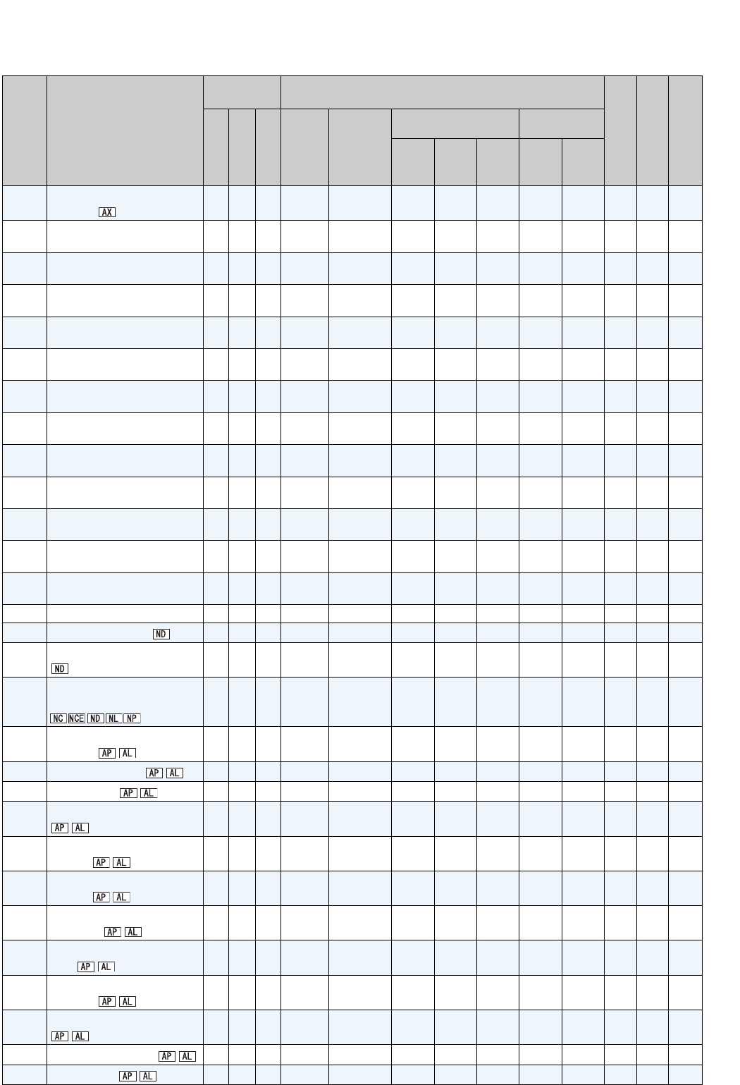
474
329 Digital input unit
selection 1D 9D 3 × ×
331 RS-485 communication
station number 1F 9F 3 *5 *5
332 RS-485 communication
speed 20 A0 3 *5 *5
333 RS-485 communication stop
bit length 21 A1 3 *5 *5
334 RS-485 communication
parity check selection 22 A2 3 *5 *5
335 RS-485 communication
retry count 23 A3 3 *5 *5
336 RS-485 communication
check time interval 24 A4 3 *5 *5
337 RS-485 communication
waiting time setting 25 A5 3 *5 *5
338 Communication operation
command source 26 A6 3 *5 *5
339 Communication speed
command source 27 A7 3 *5 *5
340 Communication startup
mode selection 28 A8 3 *5 *5
341 RS-485 communication CR/
LF selection 29 A9 3 *5 *5
342 Communication EEPROM
write selection 2A AA 3
343 Communication error count 2B AB 3
×××
345 DeviceNet address 2D AD 3 *5 *5
346 DeviceNet baud rate 2E AE 3 *5 *5
349
Communication reset
selection 31 B1 3 *5 *5
350 Stop position command
selection 32 B2 3
××××
351 Orientation speed 33 B3 3 × × × ×
352 Creep speed 34 B4 3 ××××
353 Creep switchover position 35 B5 3 × × × ×
354 Position loop switchover
position 36 B6 3 ××××
355 DC injection brake start
position 37 B7 3 × × × ×
356 Internal stop position
command 38 B8 3
××××
357 Orientation in-position
zone 39 B9 3 × × × ×
358 Servo torque
selection 3A BA 3
××××
359 Encoder rotation direction 3B BB 3 × ×
360 16-bit data selection 3C BC 3
××××
361 Position shift 3D BD 3 × × × ×
Parameter
Name
Instruction
Code * 1 Control Mode-based Correspondence Table *2
Parameter Copy
*3
Parameter Clear
*3
All Parameter Clear
*3
Read
Write
Extended
V/F
control
Advanced
magnetic
flux
vector
control
Vector control Real sensorless
vector control
Speed
control
Torque
control
Position
control
Speed
control
Torque
control
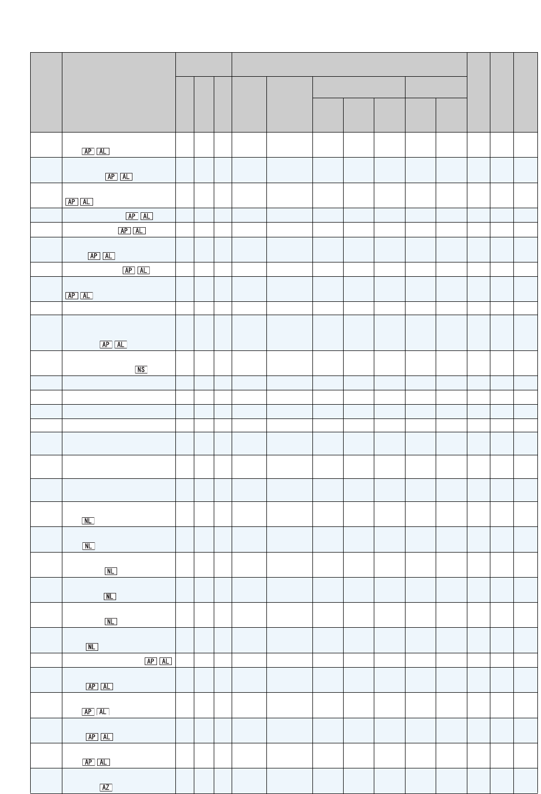
475
362 Orientation position loop
gain 3E BE 3 ××××
363 Completion signal output
delay time 3F BF 3 × × × ×
364 Encoder stop check time 40 C0 3
××××
365 Orientation limit 41 C1 3 × × × ×
366 Recheck time 42 C2 3
××××
367 Speed feedback
range 43 C3 3 × × × ×
368 Feedback gain 44 C4 3 ×××××
369 Number of encoder pulses 45 C5 3 × ×
374 Overspeed detection level 4A CA 3 ××
376
Encoder signal loss
detection enable/disable
selection
4C CC 3 × ×
379 SSCNET III rotation
direction selection 4F CF 3 ××
××
380 Acceleration S-pattern 1 50 D0 3 ×
381 Deceleration S-pattern 1 51 D1 3
×
382 Acceleration S-pattern 2 52 D2 3 ×
383 Deceleration S-pattern 2 53 D3 3
×
384 Input pulse division scaling
factor 54 D4 3 ×
385 Frequency for zero input
pulse 55 D5 3
×
386 Frequency for maximum
input pulse 56 D6 3 ×
387 Initial communication delay
time 57 D7 3
388 Send time interval at heart
beat 58 D8 3
389 Minimum sending time at
heart beat 59 D9 3
390 % setting reference
frequency 5A DA 3
391 Receive time interval at
heart beat 5B DB 3
392 Event driven detection
width 5C DC 3
393 Orientation selection 5D DD 3 ××××××
396 Orientation speed gain (P
term) 60 E0 3× × × × × ×
397 Orientation speed integral
time 61 E1 3 ××××××
398 Orientation speed gain (D
term) 62 E2 3× × × × × ×
399 Orientation deceleration
ratio 63 E3 3 ××××××
406 High resolution analog input
selection 06 86 4 ×
Parameter
Name
Instruction
Code * 1 Control Mode-based Correspondence Table *2
Parameter Copy
*3
Parameter Clear
*3
All Parameter Clear
*3
Read
Write
Extended
V/F
control
Advanced
magnetic
flux
vector
control
Vector control Real sensorless
vector control
Speed
control
Torque
control
Position
control
Speed
control
Torque
control

476
407 Motor temperature detection
filter 07 87 4
408 Motor thermistor
selection 08 88 4
413 Encoder pulse division ratio 0D 8D 4
419 Position command source
selection 13 93 4× × × × × ×
420 Command pulse scaling
factor numerator 14 94 4 ××××
××
421 Command pulse scaling
factor denominator 15 95 4× × × × × ×
422 Position loop gain 16 96 4 ××××
××
423 Position feed forward gain 17 97 4× × × × × ×
424
Position command
acceleration/deceleration
time constant
18 98 4 ××××
××
425 Position feed forward
command filter 19 99 4× × × × × ×
426 In-position width 1A 9A 4 ××××××
427 Excessive level error 1B 9B 4× × × × × ×
428 Command pulse selection 1C 9C 4 ××××
××
429 Clear signal
selection 1D 9D 4× × × × × ×
430 Pulse monitor
selection 1E 9E 4 ××××
××
432 Pulse train torque command
bias 20 A0 4× × × × ×
433 Pulse train torque command
gain 21 A1 4 ×××××
434 Network number (CC-Link
IE) 22 A2 4
435 Station number (CC-Link IE) 23 A3 4
447 Digital torque command
bias 2F AF 4× × × × ×
448 Digital torque command
gain 30 B0 4 ×××
××
449 SSCNET III input filter
setting 31 B1 4× × × ×
450 Second applied motor 32 B2 4 ×××
451 Second motor control
method selection 33 B3 4 × × ×
453 Second motor capacity 35 B5 4 ××××
454 Number of second motor
poles 36 B6 4×× × ×
455 Second motor excitation
current 37 B7 4 ××××
×
456 Rated second motor voltage 38 B8 4×× × ×
457 Rated second motor
frequency 39 B9 4 ××××
Parameter
Name
Instruction
Code * 1 Control Mode-based Correspondence Table *2
Parameter Copy
*3
Parameter Clear
*3
All Parameter Clear
*3
Read
Write
Extended
V/F
control
Advanced
magnetic
flux
vector
control
Vector control Real sensorless
vector control
Speed
control
Torque
control
Position
control
Speed
control
Torque
control
477
458 Second motor constant (R1) 3A BA 4×× × × ×
459 Second motor constant (R2) 3B BB 4 ×××××
460 Second motor constant (L1) 3C BC 4×× × × ×
461 Second motor constant (L2) 3D BD 4 ××××
×
462 Second motor constant (X) 3E BE 4×× × × ×
463 Second motor auto tuning
setting/status 3F BF 4 ×××××
464
Digital position control
sudden stop deceleration
time
40 C0 4× × × × × ×
465 First position feed amount
lower 4 digits 41 C1 4 ××××
××
466 First position feed amount
upper 4 digits 42 C2 4× × × × × ×
467
Second position feed
amount lower 4 digits 43 C3 4 ××××
××
468
Second position feed
amount upper 4 digits 44 C4 4× × × × × ×
469 Third position feed amount
lower 4 digits 45 C5 4 ××××
××
470 Third position feed amount
upper 4 digits 46 C6 4× × × × × ×
471 Fourth position feed amount
lower 4 digits 47 C7 4 ××××
××
472 Fourth position feed amount
upper 4 digits 48 C8 4× × × × × ×
473 Fifth position feed amount
lower 4 digits 49 C9 4 ××××
××
474 Fifth position feed amount
upper 4 digits 4A CA 4× × × × × ×
475 Sixth position feed amount
lower 4 digits 4B CB 4 ××××××
476 Sixth position feed amount
upper 4 digits 4C CC 4× × × × × ×
477
Seventh position feed
amount lower 4 digits 4D CD 4 ××××
××
478
Seventh position feed
amount upper 4 digits 4E CE 4× × × × × ×
479 Eighth position feed amount
lower 4 digits 4F CF 4 ××××
××
480 Eighth position feed amount
upper 4 digits 50 D0 4× × × × × ×
481 Ninth position feed amount
lower 4 digits 51 D1 4 ××××
××
482 Ninth position feed amount
upper 4 digits 52 D2 4× × × × × ×
483 Tenth position feed amount
lower 4 digits 53 D3 4 ××××××
484 Tenth position feed amount
upper 4 digits 54 D4 4× × × × × ×
Parameter
Name
Instruction
Code * 1 Control Mode-based Correspondence Table *2
Parameter Copy
*3
Parameter Clear
*3
All Parameter Clear
*3
Read
Write
Extended
V/F
control
Advanced
magnetic
flux
vector
control
Vector control Real sensorless
vector control
Speed
control
Torque
control
Position
control
Speed
control
Torque
control
478
485
Eleventh position feed
amount lower 4
digits
55 D5 4 ××××
××
486
Eleventh position feed
amount upper 4
digits
56 D6 4× × × × × ×
487
Twelfth position feed
amount lower 4
digits
57 D7 4 ××××
××
488
Twelfth position feed
amount upper 4
digits
58 D8 4× × × × × ×
489
Thirteenth position feed
amount lower 4
digits
59 D9 4 ××××
××
490
Thirteenth position feed
amount upper 4
digits
5A DA 4× × × × × ×
491
Fourteenth position feed
amount lower 4
digits
5B DB 4 ××××××
492
Fourteenth position feed
amount upper 4
digits
5C DC 4× × × × × ×
493
Fifteenth position feed
amount lower 4
digits
5D DD 4 ××××
××
494
Fifteenth position feed
amount upper 4
digits
5E DE 4× × × × × ×
495 Remote output selection 5F DF 4
496 Remote output data 1 60 E0 4 × × ×
497 Remote output data 2 61 E1 4
×××
499 SSCNET III operation
selection 63 E3 4× × × ×
500
Communication error
execution waiting time 00 80 5
501
Communication error
occurrence count display 01 81 5 ×
502
Stop mode selection at
communication error 02 82 5
503 Maintenance timer 03 83 5 × × ×
504 Maintenance timer alarm
output set time 04 84 5
×
505 Speed setting reference 05 85 5
516 S-pattern time at a start of
acceleration 10 90 5
×
517 S-pattern time at a
completion of acceleration 11 91 5 ×
518 S-pattern time at a start of
deceleration 12 92 5
×
519 S-pattern time at a
completion of deceleration 13 93 5 ×
Parameter
Name
Instruction
Code * 1 Control Mode-based Correspondence Table *2
Parameter Copy
*3
Parameter Clear
*3
All Parameter Clear
*3
Read
Write
Extended
V/F
control
Advanced
magnetic
flux
vector
control
Vector control Real sensorless
vector control
Speed
control
Torque
control
Position
control
Speed
control
Torque
control

479
525 DA2 output selection 19 99 5
526 DA2 scale 1A 9A 5
527 DA3 output selection 1B 9B 5
528 DA3 scale 1C 9C 5
529 DA4 output selection 1D 9D 5
530 DA4 scale 1E 9E 5
531 DA5 output selection 1F 9F 5
532 DA5 scale 20 A0 5
533 DD0 output selection 21 A1 5
534 DD1 output selection 22 A2 5
535 DD2 output selection 23 A3 5
536 DD3 output selection 24 A4 5
537 High-speed DA output filter 25 A5 5
539
Modbus-RTU
communication check time
interval
27 A7 5 *5 *5
541 Frequency command sign
selection (CC-Link) 29 A9 5
××
×*5 *5
542 Communication station
number (CC-Link) 2A AA 5 *5 *5
543 Baud rate selection (CC-
Link) 2B AB 5 *5 *5
544 CC-Link extended
setting 2C AC 5 *5 *5
547 USB communication station
number 2F AF 5 *5 *5
548 USB communication check
time interval 30 B0 5 *5 *5
549 Protocol selection 31 B1 5 *5 *5
550 NET mode operation
command source selection 32 B2 5 *5 *5
551 PU mode operation
command source selection 33 B3 5 *5 *5
555 Current average time 37 B7 5
556 Data output mask time 38 B8 5
557
Current average value
monitor signal output
reference current
39 B9 5
563 Energization time carrying-
over times 3F BF 5 ×××
564 Operating time carrying-
over times 40 C0 5 × × ×
569 Second motor speed control
gain 45 C5 5 ××××××
×
571 Holding time at a start 47 C7 5 ×
574 Second motor online auto
tuning 4A CA 5 ××××
575 Output interruption detection
time 4B CB 5 × × ×
576 Output interruption detection
level 4C CC 5
××
×
577 Output interruption cancel
level 4D CD 5 × × ×
Parameter
Name
Instruction
Code * 1 Control Mode-based Correspondence Table *2
Parameter Copy
*3
Parameter Clear
*3
All Parameter Clear
*3
Read
Write
Extended
V/F
control
Advanced
magnetic
flux
vector
control
Vector control Real sensorless
vector control
Speed
control
Torque
control
Position
control
Speed
control
Torque
control

480
611 Acceleration time at a
restart 0B 8B 6 ×××
665 Regeneration avoidance
frequency gain 41 C1 6 × × ×
684 Tuning data unit switchover 54 D4 6 ×
750 Motor temperature
detection level 32 B2 7
751 Reference motor
temperature 33 B3 7
800 Control method selection 00 80 8
802 Pre-excitation selection 02 82 8 ××
××××
803
Constant power range
torque characteristic
selection
03 83 8× ×
804 Torque command source
selection 04 84 8 ×××
××
805 Torque command value
(RAM) 05 85 8× × × × × ×
806 Torque command value
(RAM,EEPROM) 06 86 8 ×××××
807 Speed limit selection 07 87 8× × × × ×
808 Forward rotation speed limit 08 88 8 ×××
××
809 Reverse rotation speed limit 09 89 8× × × × ×
810 Torque limit input method
selection 0A 8A 8 ××
× ×
811 Set resolution switchover 0B 8B 8
812 Torque limit level
(regeneration) 0C 8C 8 ××
× ×
813
Torque limit level (3rd quadrant)
0D 8D 8× × × ×
814
Torque limit level (4th quadrant)
0E 8E 8 ××× ×
815 Torque limit level 2 0F 8F 8× × × ×
816 Torque limit level during
acceleration 10 90 8 ××
× ×
817 Torque limit level during
deceleration 11 91 8× × × ×
818 Easy gain tuning response
level setting 12 92 8 ××
× ×
819 Easy gain tuning selection 13 93 8× × × ××
820 Speed control P gain 1 14 94 8 ××× ×
821
Speed control integral time 1
15 95 8× × × ×
822 Speed setting filter 1 16 96 8 ××
×
823 Speed detection filter 1 17 97 8× × × ×
824 Torque control P gain 1 18 98 8 ××
825
Torque control integral time 1
19 99 8× ×
826 Torque setting filter 1 1A 9A 8 ××
827 Torque detection filter 1 1B 9B 8× ×
828 Model speed control gain 1C 9C 8 ××
× ×
829 Number of machine end
encoder pulses 1D 9D 8 × × × ×
830 Speed control P gain 2 1E 9E 8 ××
× ×
831
Speed control integral time 2
1F 9F 8× × × ×
832 Speed setting filter 2 20 A0 8 ××
×
Parameter
Name
Instruction
Code * 1 Control Mode-based Correspondence Table *2
Parameter Copy
*3
Parameter Clear
*3
All Parameter Clear
*3
Read
Write
Extended
V/F
control
Advanced
magnetic
flux
vector
control
Vector control Real sensorless
vector control
Speed
control
Torque
control
Position
control
Speed
control
Torque
control
481
833 Speed detection filter 2 21 A1 8× × ×× ×
834 Torque control P gain 2 22 A2 8 ××
835
Torque control integral time 2
23 A3 8× ×
836 Torque setting filter 2 24 A4 8 ××
837 Torque detection filter 2 25 A5 8× ×
838 DA1 terminal function
selection 26 A6 8
839 DA1 output filter 27 A7 8
840 Torque bias selection 28 A8 8 ××××××
841 Torque bias 1 29 A9 8× × × × × ×
842 Torque bias 2 2A AA 8 ××
××××
843 Torque bias 3 2B AB 8× × × × × ×
844 Torque bias filter 2C AC 8 ××
××××
845 Torque bias operation time 2D AD 8× × × × × ×
846 Torque bias balance
compensation 2E AE 8 ××
××××
847 Fall-time torque bias
terminal 1 bias 2F AF 8× × × × × ×
848 Fall-time torque bias
terminal 1 gain 30 B0 8 ××××××
849 Analog input offset
adjustment 31 B1 8
850 Brake operation selection 32 B2 8 × × ×××
853 Speed deviation time 35 B5 8× × × × × ×
854 Excitation ratio 36 B6 8 ××
857 DA1-0V adjustment 39 B9 8 ×
858 Terminal 4 function
assignment 3A BA 8
×
859 Torque current 3B BB 8× ×
860 Second motor torque
current 3C BC 8 ××××
×
862 Notch filter time constant 3E BE 8× × × ×
863 Notch filter depth 3F BF 8 ××
× ×
864 Torque detection 40 C0 8× ×
865 Low speed detection 41 C1 8 ××
866 Torque monitoring reference 42 C2 8×
867 AM output filter 43 C3 8
868 Terminal 1 function
assignment 44 C4 8 ×
872 Input phase loss protection
selection 48 C8 8
873 Speed limit 49 C9 8× × × × × ×
874 OLT level setting 4A CA 8 ××× ×
875 Fault definition 4B CB 8 ×
877
Speed feed forward control/
model adaptive speed
control selection
4D CD 8 ××
× ×
878 Speed feed forward filter 4E CE 8× × × ×
Parameter
Name
Instruction
Code * 1 Control Mode-based Correspondence Table *2
Parameter Copy
*3
Parameter Clear
*3
All Parameter Clear
*3
Read
Write
Extended
V/F
control
Advanced
magnetic
flux
vector
control
Vector control Real sensorless
vector control
Speed
control
Torque
control
Position
control
Speed
control
Torque
control

482
879 Speed feed forward torque
limit 4F CF 8 ××× ×
880 Load inertia ratio 50 D0 8× × × ××
881 Speed feed forward gain 51 D1 8 ××
× ×
882 Regeneration avoidance
operation selection 52 D2 8 × × ×
883 Regeneration avoidance
operation level 53 D3 8 ×××
884
Regeneration avoidance at
deceleration detection
sensitivity
54 D4 8 × × ×
885
Regeneration avoidance
compensation frequency
limit value
55 D5 8
××
×
886 Regeneration avoidance
voltage gain 56 D6 8 × × ×
888 Free parameter 1 58 D8 8 ××
889 Free parameter 2 59 D9 8 × ×
891 Cumulative power monitor
digit shifted times 5B DB 8
892 Load factor 5C DC 8
893 Energy saving monitor
reference (motor capacity) 5D DD 8
894
Control selection during
commercial power-supply
operation
5E DE 8
895 Power saving rate reference
value 5F DF 8
896 Power unit cost 60 E0 8
897 Power saving monitor
average time 61 E1 8
898 Power saving cumulative
monitor clear 62 E2 8 ×
899 Operation time rate
(estimated value) 63 E3 8
C0
(900) FM terminal calibration 5C DC 1 ×
C1
(901) AM terminal calibration 5D DD 1
×
C2
(902)
Terminal 2 frequency setting
bias frequency 5E DE 1 ×
C3
(902)
Terminal 2 frequency setting
bias 5E DE 1
×
125
(903)
Terminal 2 frequency setting
gain frequency 5F DF 1 ×
C4
(903)
Terminal 2 frequency setting
gain 5F DF 1
×
C5
(904)
Terminal 4 frequency setting
bias frequency 60 E0 1 ×
C6
(904)
Terminal 4 frequency setting
bias 60 E0 1
×
126
(905)
Terminal 4 frequency setting
gain frequency 61 E1 1 ×
C7
(905)
Terminal 4 frequency setting
gain 61 E1 1
×
Parameter
Name
Instruction
Code * 1 Control Mode-based Correspondence Table *2
Parameter Copy
*3
Parameter Clear
*3
All Parameter Clear
*3
Read
Write
Extended
V/F
control
Advanced
magnetic
flux
vector
control
Vector control Real sensorless
vector control
Speed
control
Torque
control
Position
control
Speed
control
Torque
control

483
C12
(917)
Terminal 1 bias frequency
(speed) 11 91 9× × ×
C13
(917) Terminal 1 bias (speed) 11 91 9 ××
×
C14
(918)
Terminal 1 gain frequency
(speed) 12 92 9× × ×
C15
(918) Terminal 1 gain (speed) 12 92 9 ××
×
C16
(919)
Terminal 1 bias command
(torque/magnetic flux) 13 93 9× × ×
C17
(919)
Terminal 1 bias (torque/
magnetic flux) 13 93 9 ××
×
C18
(920)
Terminal 1 gain command
(torque/magnetic flux) 14 94 9× × ×
C19
(920)
Terminal 1 gain (torque/
magnetic flux) 14 94 9 ××
×
C29
(925)
Motor temperature detection
calibration (analog
input)
19 99 9 ×
C30
(926)
Terminal 6 bias frequency
(speed) 1A 9A 9 ×
C31
(926) Terminal 6 bias (speed) 1A 9A 9 ×
C32
(927)
Terminal 6 gain frequency
(speed) 1B 9B 9 ×
C33
(927) Terminal 6 gain (speed) 1B 9B 9 ×
C34
(928)
Terminal 6 bias command
(torque) 1C 9C 9 ×××
C35
(928) Terminal 6 bias (torque) 1C 9C 9× × ×
C36
(929)
Terminal 6 gain command
(torque) 1D 9D 9 ×××
C37
(929) Terminal 6 gain (torque) 1D 9D 9× × ×
C38
(932)
Terminal 4 bias command
(torque/magnetic flux) 20 A0 9 ×××
C39
(932)
Terminal 4 bias (torque/
magnetic flux) 20 A0 9× × ×
C40
(933)
Terminal 4 gain command
(torque/magnetic flux) 21 A1 9 ×××
C41
(933)
Terminal 4 gain (torque/
magnetic flux) 21 A1 9× × ×
989 Parameter copy alarm
release 59 D9 9 ×
990 PU buzzer control 5A DA 9
991 PU contrast adjustment 5B DB 9
×
Parameter
Name
Instruction
Code * 1 Control Mode-based Correspondence Table *2
Parameter Copy
*3
Parameter Clear
*3
All Parameter Clear
*3
Read
Write
Extended
V/F
control
Advanced
magnetic
flux
vector
control
Vector control Real sensorless
vector control
Speed
control
Torque
control
Position
control
Speed
control
Torque
control

484
Appendix 3-1 Changed functions
(1) Addition of X74 signal
The change applies to the July 2006 production or later.
Magnetic flux decay output shutoff signal (X74) becomes a valid input by setting "74" in any of Pr. 178 to Pr. 189 (input
terminal function selection). (Refer to page 238)
(2) Writing/reading of Pr. 296 Password lock level and Pr. 297 Password lock/unlock, and output of
Password locked error (LOCD) (Refer to page 310)
The changes apply to the April 2010 production or later.
(3) Magnetic flux decay output shutoff function (Pr. 850 = "2")
The change applies to the December 2010 production or later.
Use this parameter to activate the magnetic flux decay output shutoff (Pr. 850 = "2") under Real sensorless vector control to
decay the leftover magnetic flux before shutting off outputs. (Refer to page 203)
(4) Addition of the stop-on contact and the load torque high-speed frequency control selection
(Pr. 270 = "11 or 13")
The change applies to the December 2010 production or later.
Use this parameter to enable/disable E.OLT (Stall prevention stop) detection under stop-on contact control.
(Refer to page 214)
(5) Motor temperature detection signal (when using a dedicated vector motor with thermistor
and FR-A7AZ)
The change applies to the December 2010 production or later.
When using a dedicated vector motor with thermistor (SF-V5RUT/A) and FR-A7AZ, motor temperature detection is
available. When motor temperature exceeds the detection level, motor temperature detection signal (Y55) is output. (For the
details, refer to the Instruction Manual of FR-A7AZ. )
Appendix 3 Specification change

485
(6) Motor temperature monitor output (when using a dedicated vector motor with thermistor
and FR-A7AZ)
The change applies to the December 2010 production or later.
When using a dedicated vector motor with thermistor (SF-V5RUT/A) and FR-A7AZ, motor temperature monitoring
is available from PU, DU, terminal AM, terminal FM, RS-485 communication, output options and communication options. (For
the details, refer to the Instruction Manual of FR-A7AZ. )
Refer to the following when monitoring motor temperature from communications.
(7) Acceleration/deceleration time switching frequency (Pr.147)
The changes apply to the December 2011 production or later.
When output frequency reaches Pr. 147 Acceleration/deceleration time switching frequency or higher, the acceleration/
deceleration time automatically switches to Pr. 44 Second acceleration/deceleration time and Pr. 45 Second deceleration time
settings. (Refer to page 172)
(8) USB automatic recognition (Pr. 551 PU mode operation command source selection = "9999")
The initial value of Pr. 551 PU mode operation command source selection has been changed from "2" to "9999".
The changes apply to the December 2011 production or later.
The inverter can automatically recognize the USB connection and switch the command source during PU operation mode.
(Refer to page 322)
(9) X83 signal (0V voltage calibration request) and Y83 signal (during 0V voltage calibration)
The changes apply to the December 2011 production or later.
The inverter is compatible with the FR-A7AD plug-in option. X83 signal (0V voltage calibration request) and Y83 signal (during
0V voltage calibration) are added for 0V voltage calibration of high speed analog output. (For the details, refer to the Instruction
Manual of FR-A7AD.)
Communications Monitor reading
Mitsubishi inverter protocol
(computer link communication) Special monitor selection No. write data: H2E
Modbus-RTU communication Register: 40246
Communication option
FR-A7NC (CC-Link) Monitor code: H2E
FR-A7NL (LonWorks) nviInvMonCode: H002E
FR-A7ND (DeviceNet) Class: 0x80, Instance: 1, Attribute: 56
FR-A7NP (Profibus)
PPO type support specification PNU: P1.46
(PNU number 1, Sub-Index number 46)
PPO type non-support specification IND: 0000H PNU: 2DH
FR-A7NF (FL remote) H100001EA

486
REVISIONS
*The manual number is given on the bottom left of the back cover.
For Maximum Safety
• Mitsubishi inverters are not designed or manufactured to be used in equipment or systems in situations that
can affect or endanger human life.
• When considering this product for operation in special applications such as machinery or systems used in
passenger transportation, medical, aerospace, atomic power, electric power, or submarine repeating
applications, please contact your nearest Mitsubishi sales representative.
• Although this product was manufactured under conditions of strict quality control, you are strongly advised to
install safety devices to prevent serious accidents when it is used in facilities where breakdowns of the product
are likely to cause a serious accident.
• Please do not use this product for loads other than three-phase induction motors.
Print Date *Manual Number Revision
Aug. 2005 IB(NA)-0600226ENG-A First edition
Oct. 2005 IB(NA)-0600226ENG-B
FR-A720-75K, 90K
FR-A740-0.4K to 500K
FR-A7AP is supported
• Vector control
• Orientation control
• Encoder feedback control
Feb. 2007 IB(NA)-0600226ENG-C
•Pr.539 Modbus-RTU communication check time interval
• Setting value "4" of Pr.17 MRS input selection
• Setting values "10, 11" of Pr.495 Remote output selection
• Setting value "74" of Pr.178 to Pr.189
• Connection of the FR-BU2
• Change in specification of a voltage/current input switch and addition of a
switch to the 3.7K or lower.
•Pr.81 Number of motor poles (automatic conversion function of the Pr.144 Speed
setting switchover setting)
Mar. 2010 IB(NA)-0600226ENG-D
•Pr.296 Password lock level
•Pr.297 Password lock/unlock
• Compatibility with FR-A7AL
Pr.829 Digital input unit selection
Setting value "1" of Pr.419 Position command source selection
Setting value "2" of Pr.804 Torque command source selection
• Compatibility with FR-A7NS
Pr.379 SSCNET III rotation direction selection
Pr.449 SSCNET III input filter setting
Pr.499 SSCNET III operation selection
• Compatibility with FR-A7NF
• Failsafe
• 5.5 Check first when you have a trouble
Feb. 2012 IB(NA)-0600226ENG-E
• Setting values "11, 13" for Pr. 270 Stop-on contact/load torque high-speed frequency
control selection
• Setting value "2" for Pr. 850 Brake operation selection
• Motor temperature detection signal (Y55)
• Motor temperature monitor
•Pr. 147 Acceleration/deceleration time switching frequency
• Setting value "9999" for Pr. 551 PU mode operation command source selection
• Compatible with FR-A7AD
Addition
Addition
Modification
Addition
Modification
Addition
IB(NA)-0600226ENG-E

1/24 BCN-C22005-634
FR-A700 Series
Instruction Manual Supplement
The FR-A700 series that has the SERIAL on page 24 or later are compatible with the following
specifications. Check the serial number printed on the rating plate of the inverter.
In the following sections, indicates the functions that are driven by PM sensorless vector control.
1 PM sensorless vector control
sIPt
Highly efficient motor control and highly accurate motor speed control can be performed by using the inverter with an
IPM (internal permanent magnet) motor, which is more efficient than an induction motor.
The motor speed is calculated based on the output voltage and current from the inverter. It does not require a speed
detector such as an encoder. The inverter drives the IPM motor with the least required current when a load is applied
in order to achieve the highest motor efficiency.
Purpose Parameters to be Set Refer to Page
To perform IPM parameter initialization IPM parameter initialization Pr. 998 4
To select the torque characteristic in a
low-speed range.
Low-speed range torque
characteristics Pr. 788 14
To adjust the gain for PM sensorless
vector control
Adjusting the speed control
gain Pr. 820, Pr. 821
Chapter 4 of the
Instruction Manual
(Applied)
POINT
The following conditions must be met to perform PM sensorless vector control.
· For the motor model, IPM motor must be used.
· The motor capacity must be equal to or one rank lower than the inverter capacity.
· Single-motor operation (one motor run by one inverter) must be performed.
· The overall wiring length with the motor must be 100m or less. (When the wiring length exceeds 30m,
offline auto tuning must be performed.)
CAUTION
· The speed setting range for an MM-CF IPM motor is between 0 and 200Hz.
· The carrier frequency is limited during PM sensorless vector control. (Refer to page 16)
· Constant-speed operation cannot be performed in the low-speed range of 200r/min or less under current
synchronization operation. (Refer to page 14)
· During PM sensorless vector control, the RUN signal is output about 100ms after turning ON the start command (STF,
STR). The delay is due to the magnetic pole detection.
· During PM sensorless vector control, the automatic restart after instantaneous power failure function operates only
when an MM-CF IPM motor is connected. When a built-in brake or a regeneration unit is used, the frequency search
may not be available at 2200r/min or higher. The restart operation cannot be performed until the motor speed drops to
a frequency where the frequency search is available.
PM
P M
PM
PMP MPM
bcnc22005634.fm 1 ページ 2012年7月3日 火曜日 午前9時43分
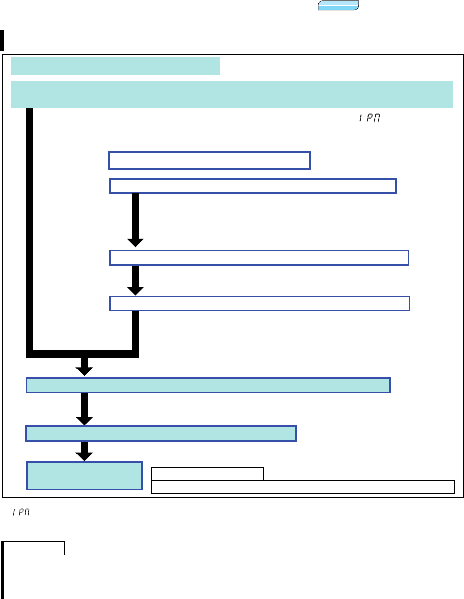
2/24 BCN-C22005-634
1.1 Setting procedure of PM sensorless vector control
* Two IPM parameter initialization methods are available for MM-CF IPM motors; setting Pr.998 IPM parameter initialization, and selecting
(IPM parameter initialization) mode on the operation panel. One of the two methods can be selected.
To change to the PM sensorless vector control, perform IPM parameter initialization at first. If parameter initialization is performed after
setting other parameters, some of those parameters will be initialized too. (Refer to page 6 for the parameters that are initialized.)
· This inverter is set for a general-purpose motor in the initial setting. Follow the following procedure to change the
setting for the PM sensorless vector control.
REMARKS
· "Er1" appears if IPM parameter initialization is performed while Pr.72 = "25."
· To use a motor capacity that is one rank lower than the inverter capacity, set Pr. 80 Motor capacity before performing
IPM parameter initialization.
· To perform PM sensorless vector control on an IPM motor other than MM-CF, contact your sales representative.
PMP MPM
Test run
Perform IPM parameter initialization by selecting IPM in the parameter setting mode on the operation
panel.* (Refer to page 3)
Set the operation command. (Refer to the Instruction Manual.)
Set "3003" (MM-CF IPM motor parameter setting (rotations per minute)) in (IPM parameter
initialization) to select the PM sensorless vector control.
P.RUN on the operation panel (FR-DU07) is lit when PM sensorless vector control is set.
Select the start command and speed command.
Set parameters such as the acceleration/deceleration time and multi-speed setting.
Set parameters such as the acceleration/deceleration time and multi-speed setting
as required.
Perform offline auto tuning for an IPM motor. (Pr.96) (Refer to page 7)
Use Pr.998 to perform IPM parameter initialization. (Refer to page 4)
Setting "8009" or "8109" in Pr. 998 IPM parameter initialization selects the IPM
motor parameter settings.
"8009":
Parameter (rotations per minute) settings for an IPM motor other than MM-CF
"8109": Parameter (frequency) settings for an IPM motor other than MM-CF
To perform tuning, set "1" (offline auto tuning without rotating motor (for other
than MM-CF)) in Pr. 96.
Make the motor setting. (Pr. 71, Pr. 80, Pr. 81, etc.) (Refer to page 7)
Set "8093" (IPM motor other than MM-CF) in Pr. 71 Applied motor, the motor
capacity (kW) in Pr. 80 Motor capacity, and the number of poles in Pr. 81
Number of motor poles. Refer to page 7 for other parameters.
(Setting "9999 (initial value)" in Pr. 80 or Pr. 81 selects V/F control.)
Driving an IPM motor other than MM-CF
Driving an MM-CF IPM motor
As required for MM-CF.
· Perform offline auto tuning for an IPM motor. (Refer to page 7)
bcnc22005634.fm 2 ページ 2012年7月3日 火曜日 午前9時43分
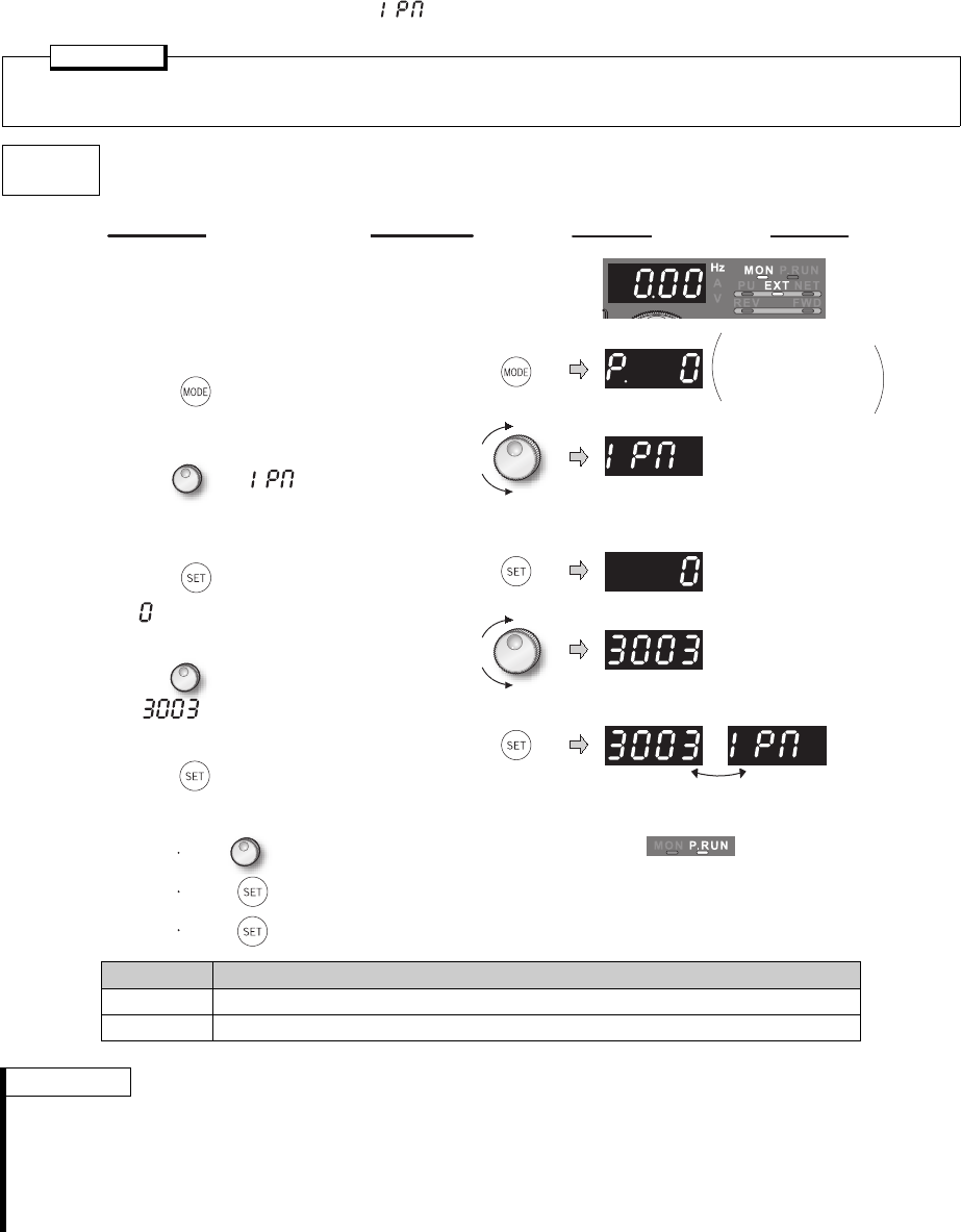
3/24 BCN-C22005-634
(1) PM sensorless vector control setting by selecting IPM in the parameter setting
mode on the operation panel ()
POINT
· The parameters required to drive an MM-CF IPM motor are automatically changed as a batch. (Refer to
page 6)
Operation
example
Initialize the parameter setting for an MM-CF IPM motor by selecting IPM in the parameter setting mode on the
operation panel.
Setting Description
0Parameter settings for a general-purpose motor
3003 Parameter settings for an IPM motor MM-CF (rotations per minute)
REMARKS
· Performing IPM parameter initialization by selecting IPM in the parameter setting mode on the operation panel
automatically changes the Pr. 998 IPM parameter initialization setting.
· In the initial parameter setting, the capacity same as the inverter capacity is set in Pr. 80 Motor capacity. (Refer to page
16.) To use a motor capacity that is one rank lower than the inverter capacity, set Pr. 80 Motor capacity before
performing IPM parameter initialization by selecting the mode on the operation panel.
· To set a speed or to display monitored items in frequency, set Pr. 998. (Refer to page 4.)
Display
Operation
Flicker ... Parameter setting complete!!
Turn to read another parameter.
Press twice to show the automatic parameter setting (AUTO).
Press to show the setting again.
The parameter
number read
previously appears.
P.RUN indicator is lit.
1. Screen at power-ON
The monitor display appears.
2. Parameter setting mode
Press to choose the parameter setting
mode.
3. Selecting the parameter
Turn until (IPM parameter
initialization) appears.
4. Displaying the setting
Press to read the currently set value.
" " (initial value) appears.
5. Selecting the setting
Turn to change it to the set value
" ".
6. Parameter setting
Press to set.
bcnc22005634.fm 3 ページ 2012年7月3日 火曜日 午前9時43分
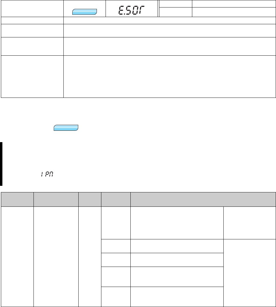
4/24 BCN-C22005-634
(2) PM sensorless vector control display and PM sensorless vector control signal
P.RUN on the operation panel (FR-DU07) is lit and the PM sensorless vector control signal (IPM) is output
during PM sensorless vector control.
For the terminal to output the PM sensorless vector control signal, assign the function by setting "57 (positive
logic)" or "157 (negative logic)" in any of Pr.190 to Pr.196 (Output terminal function selection).
(3) Loss of synchronism detection
1.2 Initializing the parameters required for the PM sensorless vector control
(Pr.998)
*1 This parameter allows its setting to be changed in any operation mode even if "0 (initial value)" is set in Pr. 77 Parameter write selection.
*2 To use an IPM motor other than MM-CF, offline auto tuning must be performed for the IPM motor.
Operation Panel
Indication
E.SOT FR-PU04 Fault 14
FR-PU07 Motor step out
Name Loss of synchronism detection
Description Stops the output when the operation is not synchronized. (This function is only available
under PM sensorless vector control.)
Description
· Check that the IPM motor is not driven overloaded.
· Check if a start command is given to the inverter while the IPM motor is coasting.
· Check if a motor other than the IPM motor (MM-CF series) is driven.
Corrective action
· Set the acceleration time longer.
· Reduce the load.
· If the inverter restarts during coasting, set Pr.57 Restart coasting time "9999," and select
the automatic restart after instantaneous power failure.
· Drive an IPM motor (MM-CF series).
· To perform PM sensorless vector control on an IPM motor other than MM-CF, contact your
sales representative.
· By performing IPM parameter initialization, PM sensorless vector control is selected and the
parameters, which are required to drive an IPM motor, are selected. Initial settings and setting ranges
of the parameters are adjusted automatically to drive an IPM motor.
· Two IPM parameter initialization methods are available; setting Pr.998 IPM parameter initialization, and
selecting (IPM parameter initialization) mode on the operation panel. One of the two methods
can be selected.
Parameter
number Name Initial
value
Setting
range Description
998 *1 IPM parameter
initialization 0
0Parameter settings for a general-
purpose motor (frequency)
Initial parameter
settings required to
drive a general-
purpose motor are
set.
3003 Parameter settings for an MM-CF IPM
motor (rotations per minute)
Initial parameter
settings required to
drive an IPM motor
are set.
3103 Parameter settings for an MM-CF IPM
motor (frequency)
8009
Parameter (rotations per minute)
settings for an IPM motor other than
MM-CF (after tuning) *2
8109
Parameter (frequency) settings for an
IPM motor other than MM-CF (after
tuning) *2
PMP MPM
PM
P M
PM
bcnc22005634.fm 4 ページ 2012年7月3日 火曜日 午前9時43分

5/24 BCN-C22005-634
(1) IPM parameter initialization (Pr.998)
· To use a motor capacity that is one rank lower than the inverter capacity, set Pr.80 Motor capacity before
performing IPM parameter initialization. By performing IPM parameter initialization, initial settings required
to drive an IPM motor are set in parameters.
· When Pr. 998 = "3003," the monitor is displayed and the frequency is set using the motor rotations per
minute. To use frequency to display or set, set Pr. 998 = "3103."
·Set Pr. 998 = "0" to change the PM sensorless vector control parameter settings to the parameter settings
required to drive a general-purpose motor.
· When using an IPM motor other than MM-CF, set Pr. 998 = "8009 or 8109" to select the parameter settings
required to perform PM sensorless vector control. The setting can be made after performing offline auto
tuning for an IPM motor.
Pr.998 Setting Description Operation IPM in the
parameter setting mode
0
(initial value) Parameter settings for a general-purpose motor (frequency) (IPM) Write "0"
3003 Parameter settings for an IPM motor MM-CF (rotations per minute) (IPM) Write "3003"
3103 Parameter settings for an IPM motor MM-CF (frequency)
8009 Parameter (rotations per minute) settings for an IPM motor other
than MM-CF (after tuning)
8109 Parameter (frequency) settings for an IPM motor other than MM-CF
(after tuning)
REMARKS
· Make sure to set Pr. 998 before setting other parameters. If the Pr. 998 setting is changed after setting other
parameters, some of those parameters will be initialized too. (Refer to "(2) " for the parameters that are initialized.)
· To change back to the parameter settings required to drive a general-purpose motor, perform parameter clear or all
parameter clear.
· If the setting of Pr. 998 IPM parameter initialization is changed from "3003, 8009 (rotations per minute)" to "3103, 8109
(frequency)," or from "3103, 8109" to "3003, 8009," all the target parameters are initialized.
The purpose of Pr. 998 is not to change the display units. Use Pr. 144 Speed setting switchover to change the display
units between rotations per minute and frequency. Pr. 144 enables switching of display units between rotations per
minute and frequency without initializing the parameter settings.
Example) Changing the Pr. 144 setting between "6" and "106" switches the display units between frequency and
rotations per minute.
· To perform PM sensorless vector control on an IPM motor other than MM-CF, contact your sales representative.
bcnc22005634.fm 5 ページ 2012年7月3日 火曜日 午前9時43分

6/24 BCN-C22005-634
(2) IPM parameter initialization list
The parameter settings in the following table are changed to the settings required to perform PM sensorless
vector control by selecting PM sensorless vector control with the IPM parameter initialization mode on the
operation panel or with Pr. 998 IPM parameter initialization setting. The changed settings differ according to the
IPM motor specification (capacity).
Performing parameter clear or all parameter clear sets back the parameter settings to the settings required to
drive a general-purpose motor.
*1 Initial values differ according to the inverter capacity. (55K or lower/75K or higher)
*2 Setting Pr. 71 Applied motor = one of "333, 334, 8093, 8094" does not change the Pr. 71 Applied motor setting.
*3 Setting Pr. 80 Motor capacity "9999" does not change the Pr. 80 Motor capacity setting.
*4 This parameter can be set when FR-A7NL is mounted.
*5 200r/min when Pr. 788 Low-speed range torque characteristics = "0".
*6 13.33Hz when Pr. 788 Low-speed range torque characteristics = "0".
Parameter
Name
Setting Setting
increments
General-
purpose motor
IPM motor
(rotations per minute)
IPM motor
(frequency)
Pr.998 0
(Initial setting)
3003
(MM-CF)
8009 (other
than MM-CF)
3103
(MM-CF)
8109 (other
than MM-CF)
3003,
8009
0, 3103,
8109
1 Maximum frequency 120/60Hz *1 3000r/min 200Hz 1r/min 0.01Hz
4
Multi-speed setting (high speed)
60Hz 2000r/min Pr. 84 133.33Hz Pr. 84 1r/min 0.01Hz
9 Electronic thermal O/L relay
Rated inverter
current
Rated motor
current
(Refer to
page 16
)
Rated motor
current
(Refer to
page 16
)
0.01A/0.1A *1
13 Starting frequency 0.5Hz 8r/min *5 Pr. 84 10% 0.5Hz *6 Pr. 84 10% 1r/min 0.01Hz
15 Jog frequency 5Hz 200r/min Pr. 84 10% 13.33Hz Pr. 84 10% 1r/min 0.01Hz
18
High speed maximum frequency
120/60Hz *1 3000r/min 200Hz 1r/min 0.01Hz
20 Acceleration/deceleration
reference frequency 60Hz 2000r/min Pr. 84 133.33Hz Pr. 84 1r/min 0.01Hz
22
Stall prevention operation level
150% 150% 0.1%
37 Speed display 0 0 1
55
Frequency monitoring reference
60Hz 2000r/min Pr. 84 133.33Hz Pr. 84 1r/min 0.01Hz
56 Current monitoring reference
Rated inverter
current
Rated motor
current
(Refer to
page 16
)
Pr. 859
Rated motor
current
(Refer to
page 16
)
Pr. 859 0.01A/0.1A *1
71 Applied motor 0 330 *2 330 *2 1
80 Motor capacity 9999
Motor capacity
(MM-CF)
*3
Motor capacity
(MM-CF)
*3
0.01kW/0.1kW
*1
81 Number of motor poles 9999 8 81
84 Rated motor frequency 60Hz 2000r/min 133.33Hz 1r/min 0.01Hz
125 (903)
Terminal 2 frequency setting
gain frequency 60Hz 2000r/min Pr. 84 133.33Hz Pr. 84 1r/min 0.01Hz
126 (905)
Terminal 4 frequency setting
gain frequency 60Hz 2000r/min Pr. 84 133.33Hz Pr. 84 1r/min 0.01Hz
144 Speed setting switchover 4 108 Pr. 81 +100 8 Pr. 81 1
240 Soft-PWM operation selection 1 0 1
263 Subtraction starting frequency 60Hz 2000r/min Pr. 84 133.33Hz Pr. 84 1r/min 0.01Hz
266 Power failure deceleration
time switchover frequency 60Hz 2000r/min Pr. 84 133.33Hz Pr. 84 1r/min 0.01Hz
374 Overspeed detection level 140Hz 3150r/min Pr. 1 (Pr. 18)
105% 210Hz Pr. 1 (Pr. 18)
105% 1r/min 0.01Hz
386
Frequency for maximum input pulse
60Hz 2000r/min Pr. 84 133.33Hz Pr. 84 1r/min 0.01Hz
390 *4 % setting reference frequency 60Hz 133.33Hz Pr. 84 133.33Hz Pr. 84 0.01Hz
505 Speed setting reference 60Hz 133.33Hz Pr. 84 133.33Hz Pr. 84 0.01Hz
557 Current average value
monitor signal output
reference current
Rated inverter
current
Rated motor
current
(Refer to
page 16
)
Pr. 859
Rated motor
current
(Refer to
page 16
)
Pr. 859 0.01A/0.1A *1
820 Speed control P gain 1 60% 30% 1%
821 Speed control integral time 1 0.333s 0.333s 0.001s
824 Torque control P gain 1 100% 100% 1%
825 Torque control integral time 1 5ms 20ms 0.1ms
870 Speed detection hysteresis 0Hz 8r/min 0.5Hz 1r/min 0.01Hz
885
Regeneration avoidance
compensation frequency limit value
6Hz 200r/min Pr. 84 10% 13.33Hz Pr. 84 10% 1r/min 0.01Hz
893 Energy saving monitor
reference (motor capacity)
Rated inverter
capacity
Motor capacity (Pr. 80) 0.01kW/0.1kW
*1
C14 (918)
Terminal 1 gain frequency (speed)
60Hz 2000r/min Pr. 84 133.33Hz Pr. 84 1r/min 0.01Hz
: The setting does not change.
REMARKS
If IPM parameter initialization is performed in rotations per minute (Pr. 998 = "3003" or "8009"), the parameters not
listed in the table above are also set and displayed in rotations per minute.
bcnc22005634.fm 6 ページ 2012年7月3日 火曜日 午前9時43分

7/24 BCN-C22005-634
1.3 Offline auto tuning for an IPM motor (motor constant tuning)
(Pr.1, Pr.9, Pr.18, Pr.71, Pr.80, Pr.81, Pr.83, Pr.84, Pr.90, Pr.92, Pr.93, Pr.96,
Pr.684, Pr.706, Pr.707, Pr.711, Pr.712, Pr.721, Pr.724, Pr.725, Pr.859)
The offline auto tuning for an IPM motor enables the optimal operation of an IPM motor.
What is offline auto tuning?
Under PM sensorless vector control, setting motor constants automatically (offline auto tuning) enables
optimal operation of motors even when motor constants vary or when the wiring distance is long. The offline
auto tuning also enables the operation with an IPM motor other than MM-CF.
Parameter
Number
Name Initial
Value Setting Range Description
1Maximum frequency
120/
60Hz
*1
0
to
120Hz
Set the upper limit of the output frequency.
9Electronic thermal O/
L relay
Rated
inverter
current
0 to 500A Set the rated motor current.
18 High speed maximum
frequency
120/
60Hz
*1
120 to 400Hz
Set when performing the operation at
120Hz or more. (Limited at 300Hz under
PM sensorless vector control)
71 Applied motor 0
0 to 8, 13 to 18, 20, 23, 24, 30,
33, 34, 40, 43, 44, 50, 53, 54,
330, 333, 334, 8093, 8094
Setting a motor type selects its thermal
characteristic and the motor constant.
80 Motor capacity 9999
55K or lower 0.4 to 55kW Set the applied motor capacity.
75K or higher 0 to 3600kW
9999 V/F control
81 Number of motor
poles 9999
2, 4, 6, 8, 10 Set the number of motor poles.
12, 14, 16, 18, 20 X18 signal-ON:V/F
control
Set 10 + number of
motor poles.
9999 V/F control
83 Rated motor voltage 200/
400V
*2
0 to 1000V Set the rated motor voltage (V).
84 Rated motor
frequency 60Hz 10 to 300Hz
Set the rated motor frequency (Hz).
(Limited at 120Hz when Pr. 71 is set to a
motor other than IPM)
90 Motor constant (R1) 9999
55K or lower 0 to 50, 9999
Tuning data
(The value measured by offline auto tuning
is automatically set.)
9999: Motor constant of the MM-CF IPM
motor. (Except 9999, the set value is the
motor constant.)
75K or higher 0 to 400m,
9999
92 Motor constant (L1)/d-
shaft inductance 9999
55K or lower
0 to 50,
(0 to 1000mH),
9999
75K or higher
0 to 3600m
(0 to 400mH)
,
9999
93 Motor constant (L2)/q-
shaft inductance 9999
55K or lower
0 to 50
,
(0 to 1000mH)
,
9999
75K or higher
0 to 3600m
(0 to 400mH)
,
9999
96 Auto tuning setting/
status 0
0 Offline auto tuning is not performed
1Offline auto tuning is performed without
motor running (other than MM-CF)
11 Offline auto tuning is performed without
motor running (MM-CF)
101
Offline auto tuning by rotating a general-
purpose motor (no tuning during PM
sensorless vector control)
PMP MPM
bcnc22005634.fm 7 ページ 2012年7月3日 火曜日 午前9時43分
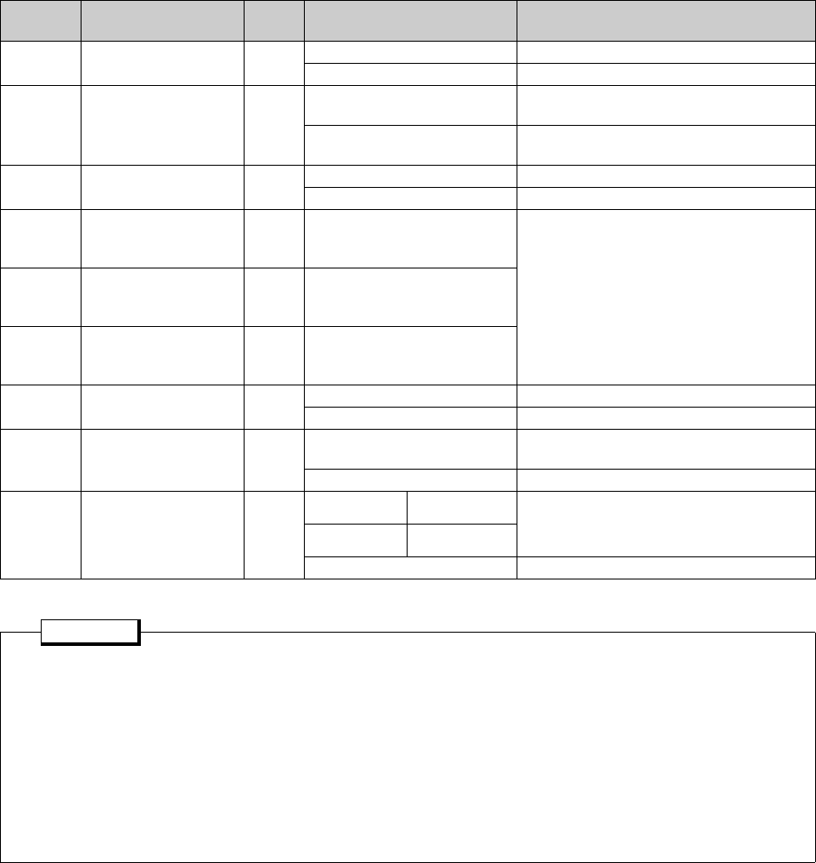
8/24 BCN-C22005-634
*1 Initial values differ according to the inverter capacity. (55K or lower/75K or higher)
*2 The initial value differs according to the voltage level. (200V/400V)
(1) Before performing offline auto tuning
Check the following before performing offline auto tuning.
· The PM sensorless vector control should be selected.
· A motor should be connected. Note that the motor should be at a stop at a tuning start.
·The motor capacity should be equal to or one rank lower than the inverter capacity.
· The maximum frequency under PM sensorless vector control should be 300Hz.
· Even if tuning is performed without motor running (Pr. 96 Auto tuning setting/status = "11"), the motor may
run slightly. Therefore, fix the motor securely with a mechanical brake, or before tuning, make sure that
there will be no problem in safety if the motor runs. (Caution is required especially in vertical lift
applications). Note that if the motor runs slightly, tuning performance is unaffected.
· Tuning is not available during position control under PM sensorless vector control.
684 Tuning data unit
switchover 00 Internal data converted value
1 Displayed in "A, , mH, %"
706 Induced voltage
constant 9999
0
to 5000mV • s/rad Adjust the constant if the current fluctuates
during operation after tuning.
9999 Constant value calculated based on the
tuning data
707 Motor inertia (integer) 9999 10 to 999 Set the motor inertia.
9999 Uses the inertia of the MM-CF IPM motor
711
Motor d-shaft
inductance Ld decay
ratio
9999 0 to 100%, 9999
Tuning data
(The value measured by offline auto tuning
is automatically set.)
9999: Motor constant of the MM-CF IPM
motor. (Except 9999, the set value is the
motor constant.)
712
Motor q-shaft
inductance Lq decay
ratio
9999 0 to 100%, 9999
721
Starting magnetic
pole position
detection pulse width
9999 0 to 6000µs, 9999
724 Motor inertia
(exponent) 9999 1 to 7 Set the motor inertia.
9999 Uses the inertia of the MM-CF IPM motor
725 Motor protection
current level 9999 0 to 500% Set the maximum current (OCT) level of the
motor (%).
9999 Uses the maximum current of MM-CF
859 Torque current 9999
55K or lower 0 to 500A Tuning data
(The value measured by offline auto tuning
is automatically set.)
75K or higher 0 to 3600A
9999 Uses the constant of the MM-CF IPM motor
POINT
· The settings are valid only under the PM sensorless vector control.
· When the wiring length between the inverter and the motor is long (30m or longer as a reference), use the
offline auto tuning function to drive the motor in the optimum operation characteristic.
· The offline auto tuning enables the operation with an IPM motor other than MM-CF.
· Tuning is enabled even when a load is connected to the motor. (As the load is lighter, tuning accuracy is higher.
Tuning accuracy does not change even if the inertia is large.)
· Reading/writing of motor constants tuned by offline auto tuning are enabled. You can copy the offline auto
tuning data (motor constants) to another inverter with the PU (FR-DU07/FR-PU07).
· The offline auto tuning status can be monitored with the PU (FR-DU07/FR-PU07/FR-PU04).
· Do not connect a surge voltage suppression filter (FR-ASF-H/FR-BMF-H) to the 55K or lower and sine wave
filter (MT-BSL/BSC) to the 75K or higher between the inverter and motor.
Parameter
Number
Name Initial
Value Setting Range Description
bcnc22005634.fm 8 ページ 2012年7月3日 火曜日 午前9時43分
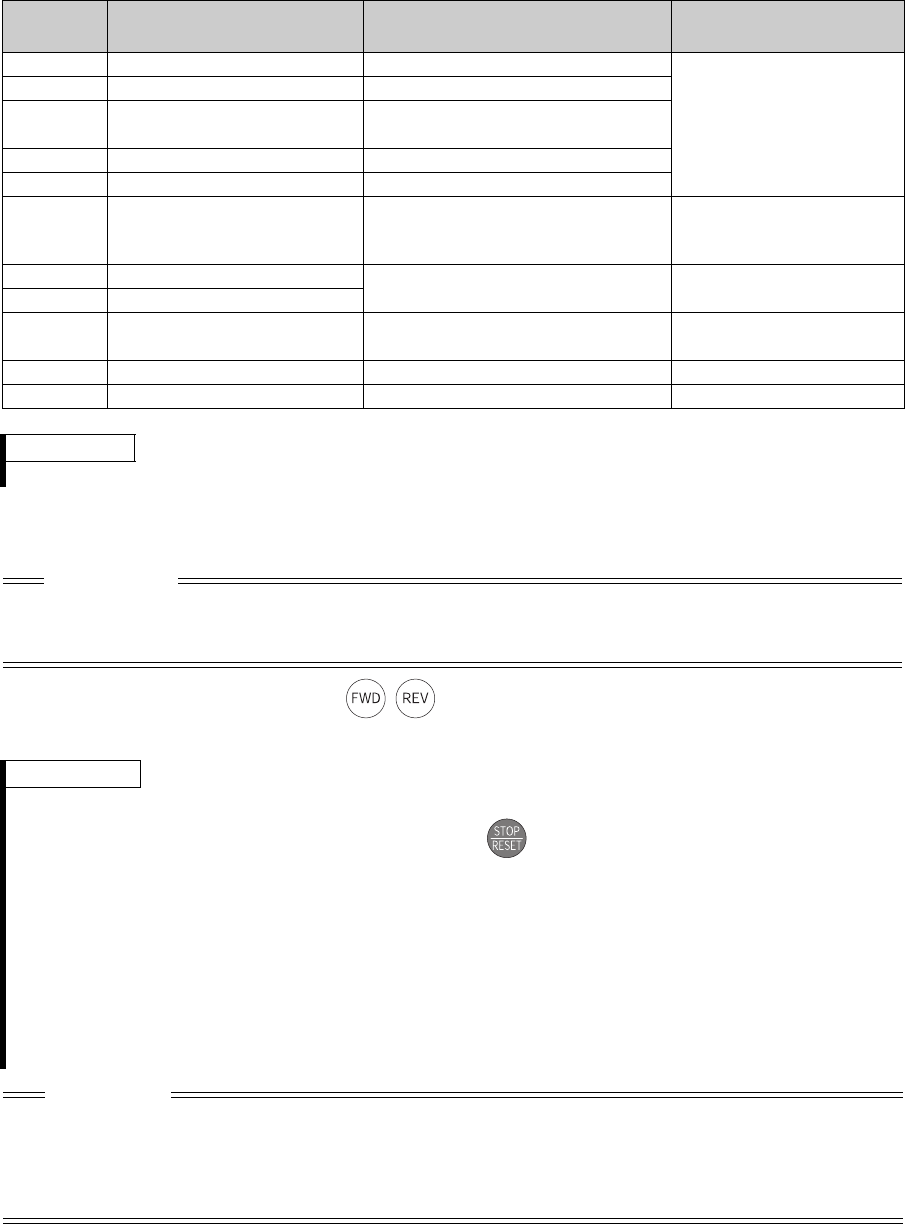
9/24 BCN-C22005-634
(2) Setting
To perform tuning, set the following parameters about the motor.
(3) Execution of tuning
1)When performing PU operation, press / on the operation panel.
For External operation, turn ON the start command (STF signal or STR signal). Tuning starts.
Parameter
Number Name Setting for an IPM motor other
than MM-CF Setting for MM-CF
80 Motor capacity Motor capacity (kW)
Set by the IPM parameter
initialization
(Refer to page 4.)
81 Number of motor poles Number of motor poles
1(18) Maximum frequency
(High speed maximum frequency) The maximum motor frequency (Hz)
9 Electronic thermal O/L relay Rated motor current (A)
84 Rated motor frequency Rated motor frequency (Hz)
83 Rated motor voltage Rated motor voltage (V)
Rated motor voltage (V)
printed on the motor's rating
plate.
707 Motor inertia (integer) Motor inertia
Jm = Pr.707 10(-Pr.724 ) (kgm2)9999 (Initial value)
724 Motor inertia (exponent)
725 Motor protection current level Maximum current (OCT) level of the
motor (%) 9999 (Initial value)
71 Applied motor 8093 333
96 Auto tuning setting/status 1 11
REMARKS
· To perform offline auto tuning on an IPM motor other than MM-CF, contact your sales representative.
CAUTION
· Before performing tuning, check the monitor display of the operation panel (FR-DU07) or parameter unit (FR-PU04/
FR-PU07) if the inverter is in the state ready for tuning. (Refer to 2) below) Turning ON the start command while
tuning is unavailable starts the motor.
REMARKS
· Satisfy the required inverter start conditions to start offline auto tuning. For example, stop the input of MRS signal.
· To force tuning to end, use the MRS or RES signal or press on the operation panel.
(Turning the start signal (STF signal or STR signal) OFF also ends tuning.)
· During offline auto tuning, only the following I/O signals are valid (initial value):
· Input signals <valid signal> STOP, OH, MRS, RT, RES, STF, STR
· Output terminal RUN, OL, IPF, FM, AM, A1B1C1
Note that the progress status of offline auto tuning is output in fifteen steps from AM and FM when speed and
output frequency are selected.
· Do not perform ON/OFF switching of the second function selection signal (RT) during execution of offline auto
tuning. Auto tuning is not executed properly.
· Setting offline auto tuning (Pr. 96 Auto tuning setting/status = "1 or 11") will make pre-excitation invalid.
CAUTION
· Since the RUN signal turns ON when tuning is started, caution is required especially when a sequence which
releases a mechanical brake by the RUN signal has been designed.
· When executing offline auto tuning, input the run command after switching ON the main circuit power (R/L1, S/L2,
T/L3) of the inverter.
·While Pr. 79 = "7," turn the X12 signal ON to tune in the PU operation mode.
bcnc22005634.fm 9 ページ 2012年7月3日 火曜日 午前9時43分
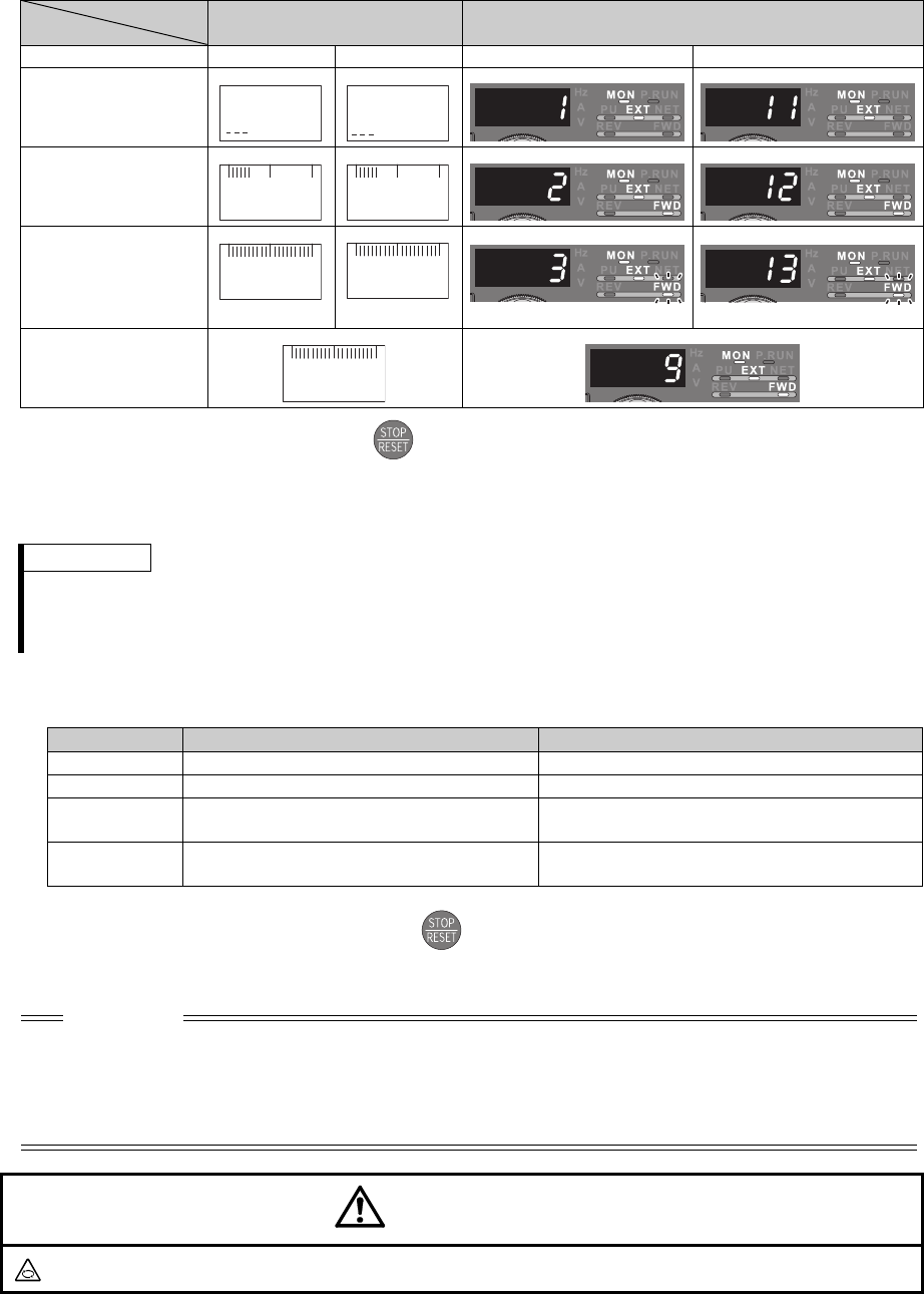
10/24 BCN-C22005-634
2)Monitor is displayed on the operation panel (FR-DU07) and parameter unit (FR-PU07/FR-PU04) during
tuning as below.
3)When offline auto tuning ends, press of the operation panel during PU operation. For External
operation, turn OFF the start signal (STF signal or STR signal).
This operation resets the offline auto tuning and the PU's monitor display returns to the normal indication.
(Without this operation, next operation cannot be started.)
4)If offline auto tuning ended in error (see the table below), motor constants are not set.
Perform an inverter reset and restart tuning.
5)When tuning is ended forcibly by pressing or turning OFF the start signal (STF or STR) during
tuning, offline auto tuning does not end properly. (The motor constants have not been set.)
Perform an inverter reset and restart tuning.
Parameter Unit
(FR-PU07/FR-PU04) Display Operation Panel (FR-DU07) Display
Pr. 96 setting 111 1 11
(1) Setting
(2) Tuning in progress
(3) Normal end
(4) Error end
(when the inverter
protective function
is activated)
REMARKS
· The motor constants measured once in the offline auto tuning are stored as parameters and their data are held
until the offline auto tuning is performed again.
· Changing Pr. 96 setting from "3 or 13" after tuning completion will invalidate the tuning data. In this case, tune
again.
Error Display Error Cause Remedy
8 Forced end Set "1" or "11" in Pr. 96 and perform tuning again.
9 Inverter protective function operation Make setting again.
92 Converter output voltage has reached 75%
of rated value. Check for fluctuation of power supply voltage.
93 Calculation error
A motor is not connected. Check the motor wiring and make setting again.
CAUTION
· An instantaneous power failure occurring during tuning will result in a tuning error.
After power is restored, the inverter goes into the normal operation mode. Therefore, when STF (STR) signal is
ON, the motor runs in the forward (reverse) rotation.
· Any alarm occurring during tuning is handled as in the ordinary mode. Note that even if a retry operation has been
set, retry is not performed.
· The set frequency monitor displayed during the offline auto tuning is 0Hz.
CAUTION
Note that the motor may start running suddenly.
STOP PU
1
READ:List
STOP PU
11
READ:List
FWD PU
2
STF
TUNE
FWD PU
12
STF
TUNE
STOP PU
3
STF
TUNE
COMPLETION
STOP PU
13
STF
TUNE
COMPETION
Flickering Flickering
STOP PU
9
STF
TUNE
ERROR
bcnc22005634.fm 10 ページ 2012年7月3日 火曜日 午前9時43分

11/24 BCN-C22005-634
(4) Utilizing or changing offline auto tuning data
The data measured in the offline auto tuning can be read and utilized or changed.
<Operating procedure>
1)Set Pr. 71 according to the motor used.
2) In the parameter setting mode, read the following parameters and set desired values.
The display units of the read motor constants can be changed with Pr. 684 Tuning data unit switchover.
Setting Pr.684 = "1" does not change the parameter settings.
If the current fluctuates after tuning, adjust the constant by referring to the induced voltage constant, which can
be found in the data sheet.
Motor Pr. 71 Setting
IPM motor MM-CF 334
Other than MM-CF 8094
Parameter
Number Name Setting Increments Read Value Setting
Range
Pr.684 = 0 Pr.684 = 1 Pr.71 = 334 Pr.71 = 8094
90 Motor constant (R1) Internal data 0.001/
0.01m
*3
Tuned data
*1
Tuned data
*1
0 to ***, 9999
92 Motor constant (L1)/d-
shaft inductance Internal data 0.1mH/
0.01mH
*3
9999
*2
Tuned data
*1
0 to ***, 9999
93 Motor constant (L2)/q-
shaft inductance Internal data 0.1mH/
0.01mH
*3
9999
*2
Tuned data
*1
0 to ***, 9999
711
Motor d-shaft
inductance Ld decay
ratio
Internal data 0.1% 9999
*2
Tuned data
*1
0 to ***, 9999
712
Motor q-shaft
inductance Lq decay
ratio
Internal data 0.1% 9999
*2
Tuned data
*1
0 to ***, 9999
721
Starting magnetic pole
position detection
pulse width
Internal data 1(s) 9999
*2
Tuned data
*1
0 to ***, 9999
859 Torque current Internal data 0.01A/0.1A
*3
Tuned data
*1
Tuned data
*1
0 to ***, 9999
*1 As the motor constants measured in the offline auto tuning have been converted into internal data (****), refer to the following setting
example when making setting:
Setting example To slightly increase Pr. 90 value (5%)
When Pr. 90 is displayed "2516",
set 2642, i.e. 2516 1.05 = 2641.8, in Pr. 90 .
(The value displayed has been converted into a value for internal use. Hence, simple addition of a given value to the
displayed value has no significance.)
*2 Setting "9999" selects the IPM motor (MM-CF) constant.
*3 Initial values differ according to the inverter capacity. (55K or lower/75K or higher)
Parameter
Number Name Setting Range Setting Increments Initial Setting
706 Induced voltage constant 0 to 5000, 9999 0.1(mV/(rad/s)) 9999
*
* Setting "9999" sets a calculated value based on tuning.
bcnc22005634.fm 11 ページ 2012年7月3日 火曜日 午前9時43分
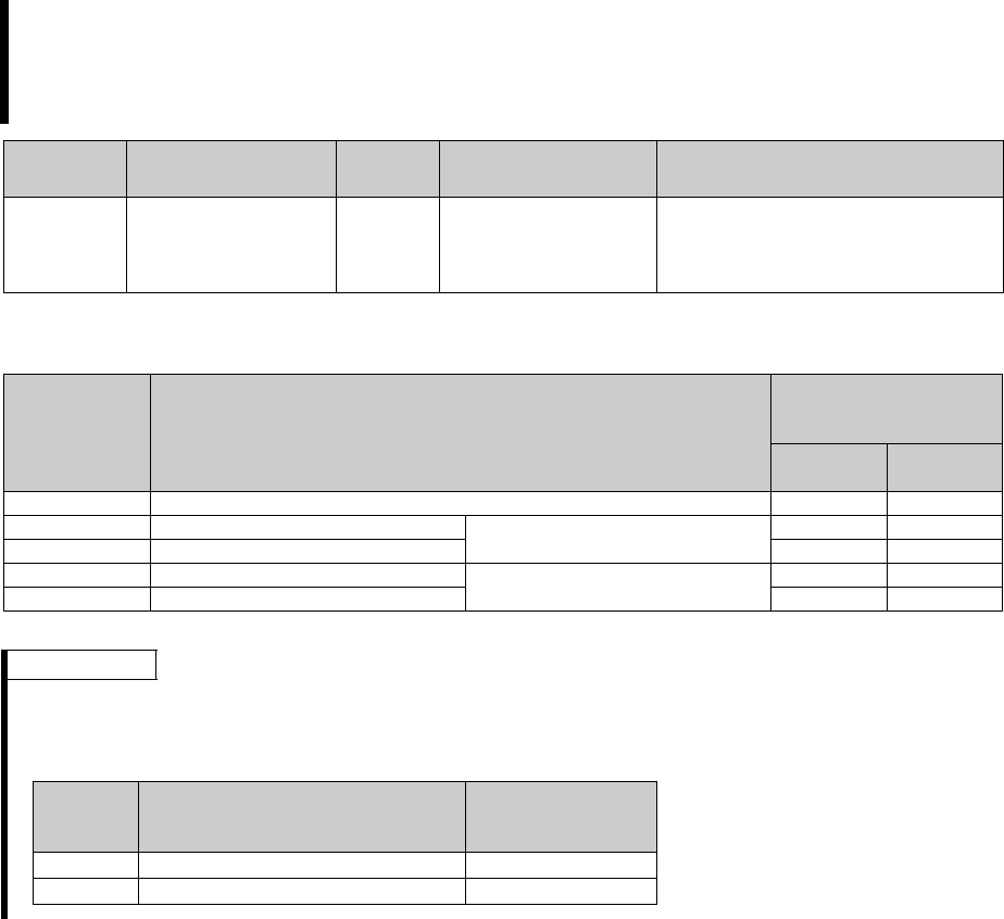
12/24 BCN-C22005-634
1.4 Applied motor (Pr. 71)
(1) Set the motor to be used
Refer to the following list and set this parameter according to the motor used.
Setting of the used motor selects the thermal characteristic appropriate for the motor.
Setting is necessary when using a constant-torque motor. Thermal characteristic of the electronic
thermal relay function suitable for the motor is set.
When PM sensorless vector control is selected, the motor constants (MM-CF etc.) necessary for control
are selected as well.
Parameter
Number Name Initial
Value Setting Range Description
71 Applied motor 0
0 to 8, 13 to 18, 20, 23,
24, 30, 33, 34, 40, 43,
44, 50, 53, 54, 330, 333,
334, 8093, 8094
Selecting the standard motor or constant-
torque motor sets the corresponding
motor thermal characteristic.
Pr. 71 Setting Motor
Electronic thermal relay
function operation
characteristic
Constant
torque IPM
330*IPM Motor MM-CF
333*IPM Motor MM-CF Select "offline auto tuning setting"
8093 IPM Motor (other than MM-CF)
334*IPM Motor MM-CF Auto tuning data can be read,
changed, and set
8094 IPM Motor (other than MM-CF)
* The setting is available for FR-A720-11K or lower.
REMARKS
When performing offline auto tuning, set "3, 7, 8, 13, 17, 18, 23, 33, 43, 53, 333, 8093" in Pr. 71.
(Refer to page 7 for offline auto tuning)
For the 5.5K and 7.5K, the Pr. 0 Torque boost and Pr. 12 DC injection brake operation voltage settings are automatically
changed according to the Pr. 71 setting as follows.
Pr.71
Standard Motor Setting
0, 2, 3 to 8, 20, 23, 24, 40, 43, 44,
330, 333, 334, 8093, 8094
Constant Torque
Motor Setting
1, 13 to 18, 50, 53, 54
Pr. 0 3% 2%
Pr. 12 4% 2%
bcnc22005634.fm 12 ページ 2012年7月3日 火曜日 午前9時43分
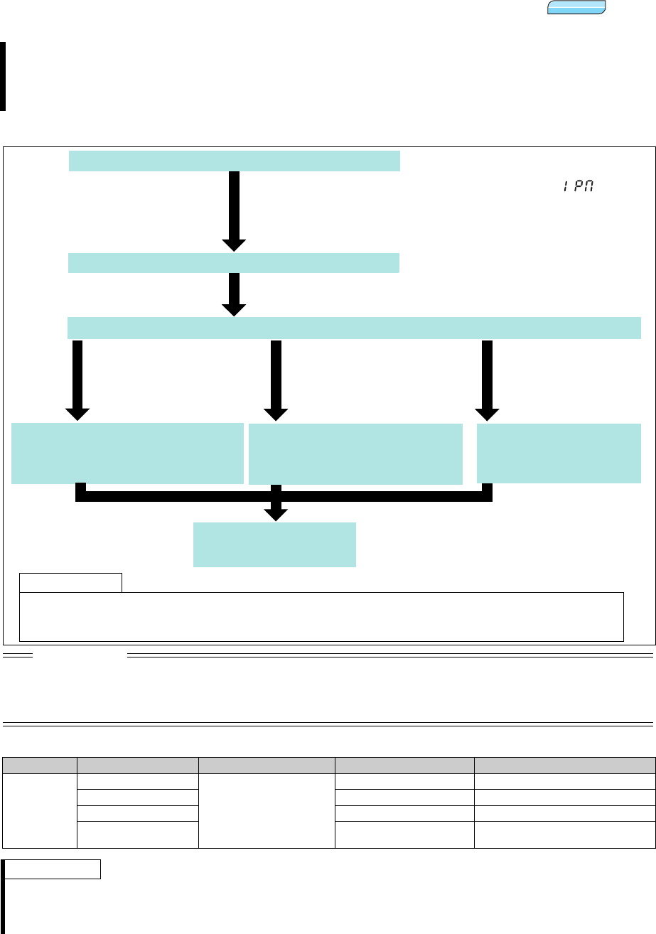
13/24 BCN-C22005-634
1.5 Position control under PM sensorless vector control (Pr.800)
(1) Setting procedure
(2) Select the control method
Refer to Chapter 4 of the Instruction Manual (Applied) for the detail of the position control.
-In position control, speed commands, which are calculated to eliminate the difference between the
command pulse (parameter setting) and the estimated feedback pulse, are output to rotate the motor.
-This inverter can perform simple position feed by contact input, position control by inverter simple pulse
input, and position control by FR-A7AL pulse train input.
CAUTION
The carrier frequency is limited during PM sensorless vector control. (Refer to page 16.)
Position deviation may occur due to motor temperature changes. In such case, shut off the inverter outputs, and restart.
The Z-phase outputs cannot be made under PM sensorless vector control. When Pr.419 = "1" is set to send positioning
commands in pulses via a programmable controller positioning module and FR-A7AL, use the home position return
operation that does not require Z-phase signals.
Pr.998 Pr.998 Setting Control Method Control Type Remarks
3003, 3103
(MM-CF)
Other than 9, 13, 14
PM sensorless vector
control
Speed control
9 Test operation
13 Position control
14 Speed control/position
control switchover
MC signal ON: position control
MC signal OFF: speed control
REMARKS
Perform position control under PM sensorless vector control only when using an MM-CF IPM motor. Moreover, perform it only
when the high frequency superposition control is selected. (Pr.788 = "9999 (initial value)")
Position control is performed on the assumption of 4096 pulses/motor rotation.
The positioning accuracy is 200 pulses/rev for 1.5K or lower, and 100 pulses/rev for 2K or higher (under no load).
PMP MPM
Test run
Selection of position command source. (Pr. 419)
Select the control mode. (Pr.800)
As required
· Set the electronic gear. (Refer to Chapter 4 of the Instruction Manual (Applied))
· Setting of positioning adjustment parameter (Refer to Chapter 4 of the Instruction Manual (Applied))
· Gain adjustment of position control (Refer to Chapter 4 of the Instruction Manual (Applied))
Set
Pr.800
= "13" (position control) or "14" (speed/position switchover) to
enable position control.
Set by IPM parameter initialization (Refer to page 4.)
Setting of parameter for position feed
(Pr. 465 to Pr. 494).
(Refer to Chapter 4 of the Instruction
Manual (Applied).)
Selection of command pulse
form (Pr. 428).
(Refer to Chapter 4 of the
Instruction Manual (Applied).)
Position command by contact
input
Set "0" (initial value) in
Pr. 419
.
Position command by inverter
pulse train input
Set "2" in
Pr. 419
.
Refer to the Instruction
Manual of FR-A7AL.
Position command from the
positioning module of the
programmable controller
system (through FR-A7AL)
Set
Pr. 419
= "1"
Set
Pr.998 IPM parameter initialization
= "3003 or 3103" or (IPM
parameter initialization) to "3003"
"3003": Parameter (rotations per minute) settings for MM-CF IPM motor
"3103": Parameter (frequency) settings for MM-CF IPM motor
bcnc22005634.fm 13 ページ 2012年7月3日 火曜日 午前9時43分

14/24 BCN-C22005-634
1.6 Low-speed range torque characteristics (Pr.788)
Åt ÅsIPMÅt
* Current synchronization operation is always performed for IPM motors other than MM-CF, even if "9999" is set.
(1) When the low-speed range torque characteristic is enabled ("9999" (initial value))
· The high frequency superposition control provides enough torque in the low-speed range operation.
· Refer to page 17 for the torque characteristics.
(2) When the low-speed range torque characteristic is disabled ("0")
· The current synchronization operation reduces much motor noise compared with the high frequency superposition
control.
· The torque in a low-speed range is low. Use this setting for an operation with light start-up load.
· Refer to page 17 for the torque characteristics.
1.7 Setting the acceleration/deceleration time in the low-speed range
(Pr.791, Pr.792)
Torque characteristics in a low-speed range can be changed.
Parameter
Number Name Initial
Setting
Setting
Range Operation
788 Low-speed range torque
characteristics 9999
0Disables the low-speed range torque characteristic
(current synchronization operation).
9999*Enables the low-speed range torque characteristic
(high frequency superposition control)
REMARKS
Position control under PM sensorless vector control is not available when the current synchronization operation is selected.
Parameter
Number Name Initial
Value Setting Range Description
791 Acceleration time in
low-speed range 9999
0 to 3600/360s*
Set the acceleration time in a low-speed
range (less than 1/10 of the rated motor
frequency).
9999
The acceleration time set in Pr.7 is applied.
(When the second functions are enabled,
the settings are applied.)
792 Deceleration time in
low-speed range 9999
0 to 3600/360s*
Set the deceleration time in a low-speed
range (less than 1/10 of the rated motor
frequency).
9999
The deceleration time set in Pr.8 is applied.
(When the second functions are enabled,
the settings are applied.)
* Depends on the Pr. 21 Acceleration/deceleration time increments setting. The initial value for the setting range is "0 to 3600s" and the setting
increments is "0.1s".
PMP MPM
PMP MPM
PMP MPM
PMP MPM
PMP MPM
bcnc22005634.fm 14 ページ 2012年7月3日 火曜日 午前9時43分

15/24 BCN-C22005-634
If torque is required in a low-speed range (less than 1/10 of the rated motor frequency), set Pr.791 Acceleration time in
low-speed range and Pr.792 Deceleration time in low-speed range settings higher than the Pr.7 Acceleration time and Pr.8
Deceleration time settings so that the mild acceleration/deceleration is performed in the low-speed range. (For an
operation with second acceleration/deceleration times, set the acceleration/deceleration times longer than the second
acceleration/deceleration times.)
1.8 DC injection brake of the PM sensorless vector control
DC injection brake under PM sensorless vector control is performed as below.
REMARKS
Set Pr.791 higher than Pr.7, and Pr.792 higher than Pr.8. If set as Pr.791 < Pr.7, the operation is performed as Pr.791 = Pr.7. If
set as Pr.792 < Pr.8, the operation is performed as Pr.792 = Pr.8.
Refer to page 6 for the rated motor frequency of MM-CF.
REMARKS
The X13 signal is disabled during PM sensorless vector control.
Low-speed range
(rated motor frequency/10
)
Acceleration time
Slope set by Pr.7
Deceleration time
Slope set by Pr.8
Deceleration time
in low-speed range
Slope set by Pr.792
A
cceleration time
in low-speed range
Slope set by Pr. 791
Time
Output
frequency
(Hz)
PMP MPM
Time Time
Time
Pr.11
Calculated speedCalculated speed
<High frequency superposition control (Pr.788 = "9999 (initial value)")>
Commanded speed Commanded speed
Pr.10 Pr.10
Output frequency
(Hz)
Output frequency
(Hz)
DC braking voltage
(V)
When Pr.11 = "0"When Pr.11 "0"
DC injection brake applied
when:
The commanded speed = 0Hz
The calculated speed
Pr.10
Motor coasting when:
The commanded speed Pr.10
The calculated speed Pr.10
Motor coasting when:
The commanded speed Pr.10
The calculated speed Pr.10
Pr.11
Tim
e
Pr.10
Time
Time
<Current synchronization operation Pr.788 = "0">
When Pr.11 = "0"
When Pr.11 "0"
Calculated speed
Commanded
speed
DC injection brake applied when
the commanded and calculated
speeds are 0Hz
Output frequency
(Hz)
Output frequency
(Hz)
DC braking voltage
(V)
bcnc22005634.fm 15 ページ 2012年7月3日 火曜日 午前9時43分
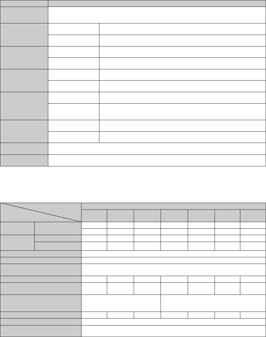
16/24 BCN-C22005-634
1.9 PM sensorless vector control specification
* To perform PM sensorless vector control on an IPM motor other than MM-CF, contact your sales representative.
1.10 Motor specification
(1) Specifications
Item Specification
Control method
Sensorless vector control
Low-speed range: Control method in a low-speed range can be selected by parameter (high frequency
superposition control (initial setting) / current synchronization operation)
Starting torque
High frequency
superposition control 200% (1.5kW or lower with MM-CF: 200%, 2.0kW or higher: 150%)
Current synchronization
operation 50%
Speed control
range
High frequency
superposition control 1:1000 (Use a one rank higher inverter for the ratio of 1:1000)
Current synchronization
operation 1:10
Zero speed
High frequency
superposition control Possible (Use a one rank higher inverter for zero-speed 200%)
Current synchronization
operation Not available
Carrier frequency
High frequency
superposition control
6kHz (Pr.72 = "0 to 9"), 10kHz (Pr.72 = "10 to 13"), 14kHz (Pr.72 = "14, 15")
(6kHz in a low-speed range of 10kHz or higher. 2kHz is not selectable.)
Current synchronization
operation
2kHz (Pr.72 = "0 to 5"), 6kHz (Pr.72 = "6 to 9"), 10kHz (Pr.72 = "10 to 13"), 14kHz
(Pr.72 = "14, 15")
(6kHz in a low-speed range of 10kHz or higher.)
Position control
High frequency
superposition control Possible
Current synchronization
operation Not available
Offline auto tuning
for an IPM motor Possible
Applicable motor Mitsubishi MM-CF series IPM motors (0.5 to 7.0kW)
IPM motors other than MM-CF (tuning required) (no capacity limit) *
Motor 2000r/min Series
Item
MM-CF
52(C)(B)
MM-CF
102(C)(B)
MM-CF
152(C)(B)
MM-CF
202(C)(B)
MM-CF
352(C)(B)
MM-CF
502(C)
MM-CF
702(C)
Compatible
inverter FR-A720-0.4K 0.75K 1.5K 2.2K 3.7K 5.5K 7.5K
0.75K *6 1.5K *6 2.2K *6 3.7K *6 5.5K *6 7.5K *6 11K *6
Continuous
characteristics
*1
Rated output [kW] 0.5 1.0 1.5 2.0 3.5 5.0 7.0
Rated torque [N•m] 2.39 4.78 7.16 9.55 16.70 23.86 33.41
Rated speed *1 [r/min] 2000
Max. speed [r/min] 3000
Instantaneous permissible speed
[r/min] 3450
Max. torque [N•m] 4.78 9.56 14.32 19.09 33.41 47.73 66.82
Inertia moment J *5
[10-4kg•m2]
6.6
(7.0)
13.7
(14.9)
20.0
(21.2)
45.5
(48.9)
85.6
(89.0) 120.0 160.0
Recommended ratio of load
inertia moment to motor shaft
inertia moment *2
100 times max. 50 times max.
Rated current [A] 1.81 3.70 5.22 7.70 12.5 20.5 27.0
Insulation rank Class F
Structure Totally-enclosed, self-cooling
(protective system:IP44 *3, IP65 *3, *4)
bcnc22005634.fm 16 ページ 2012年7月3日 火曜日 午前9時43分
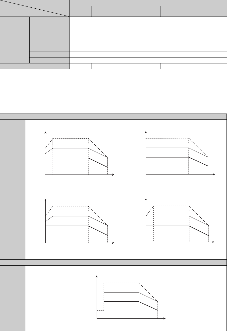
17/24 BCN-C22005-634
*1 When the power supply voltage drops, we cannot guarantee the above output and rated speed.
*2 When the load torque is 20% of the motor rating. The permissible load inertia moment ratio is smaller when the load torque is larger.
Consult us if the load inertia moment ratio exceeds the above value.
*3 This does not apply to the shaft through portion.
*4 Value for MM-CF2C.
*5 The value for MM-CF2B is indicated in parentheses.
*6 Applicable one-rank higher inverters for the lifted low-speed range torque operation.
(2) Torque characteristics
Environmental
conditions
Surrounding air
temperature and
humidity
-10C to +40C (non-freezing) 90%RH or less (non-condensing)
Storage
temperature and
humidity
-20C to +70C (non-freezing) 90%RH or less (non-condensing)
Ambience Indoors (no direct sunlight), free from corrosive gas, flammable gas, oil mist, dust and dirt
Altitude Max. 1000m above sea level
Vibration X: 9.8m/s2, Y: 24.5m/s2
Mass *5 [kg] 5.1 (7.8) 7.2 (11) 9.3 (13) 13 (20) 19 (28) 27 36
Under high frequency superposition control
MM-CF
1.5kW or
lower
With one rank higher inverter
MM-CF
2.0kW or
higher
With one rank higher inverter
During current synchronization operation
MM-CF
all
capacities
Motor 2000r/min Series
Item
MM-CF
52(C)(B)
MM-CF
102(C)(B)
MM-CF
152(C)(B)
MM-CF
202(C)(B)
MM-CF
352(C)(B)
MM-CF
502(C)
MM-CF
702(C)
2000100
150
200
100
Torque %
Speed r/min
Instantaneous
(3s) operation region
Continuous
operation region
120
3000
Short duration
(60s) operation region
2000
150
200
100
Torque % Instantaneous
(3s) operation region
Continuous
operation region
Speed r/min
3000
Short duration
(60s) operation region
2000100
150
200
100
Continuous
operation region
120
Instantaneous
(3s) operation region
Torque %
Speed r/min
3000
Short duration
(60s) operation region
2000100
150
200
100
Instantaneous
(3s) operation region
Continuous
operation region
Torque %
* Zero speed up to a 150% instantaneous output torque
Speed r/min
3000
Short duration
(60s) operation region
2000 3000200
150
200
100
Torque %
Speed r/min
Instantaneous
(3s) operation region
Continuous
operation region
50
Short duration
(60s) operation region
bcnc22005634.fm 17 ページ 2012年7月3日 火曜日 午前9時43分
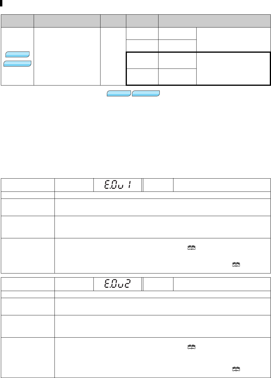
18/24 BCN-C22005-634
2 Voltage reduction selection during stall prevention operation (Pr.154)
(1) To further prevent a trip (Pr. 154)
When Pr. 154 is set to "0, 10", the output voltage reduces during stall prevention operation. By making this
setting, an overcurrent trip becomes less likely to occur. Use this function when torque reduction does not pose
a problem.
Set Pr.154 = "10, 11" when the overvoltage protective function (E.OV) activates during stall prevention
operation in an application with large load inertia. Note that turning OFF the start signal (STF/STR) or
varying the frequency signal during stall prevention operation may delay the acceleration/deceleration
start.
(2) Causes and corrective actions
The setting values "10 and 11" are added for Pr.154 Voltage reduction selection during stall prevention operation.
Parameter
Number
Name Initial
Value
Setting
Range Description
154 Voltage reduction selection
during stall prevention
operation
1
0With voltage
reduction You can select whether to use
output voltage reduction during
stall prevention operation or not.
1Without voltage
reduction
10 With voltage
reduction
Use these settings when the
overvoltage protective function
(E.OV) activates during stall
prevention operation in an
application with large load inertia.
11 Without voltage
reduction
Operation Panel
Indication E.OV1 FR-PU04
FR-PU07 OV During Acc
Name Regenerative overvoltage trip during acceleration
Description
If regenerative energy causes the inverter's internal main circuit DC voltage to reach or exceed the
specified value, the protective circuit is activated to stop the inverter output. The circuit may also be
activated by a surge voltage produced in the power supply system.
Check point
· Check for too slow acceleration. (e.g. during descending acceleration with lifting load)
· Check if Pr.22 Stall prevention operation level is set too low like the no-load current.
Check if the stall prevention operation is frequently activated in an application with a large
load inertia.
Corrective action
· Decrease the acceleration time.
· Use the regeneration avoidance function (Pr. 882 to Pr. 886). ( Refer to Chapter 4 of the Instruction
Manual (Applied).)
· Set a value larger than the no load current in Pr. 22 Stall prevention operation level.
Set Pr.154 Voltage reduction selection during stall prevention operation = "10 or 11". ( Refer to
Chapter 4 of the Instruction Manual (Applied).)
Operation Panel
Indication E.OV2 FR-PU04
FR-PU07 Stedy Spd OV
Name Regenerative overvoltage trip during constant speed
Description
If regenerative energy causes the inverter's internal main circuit DC voltage to reach or exceed the
specified value, the protective circuit is activated to stop the inverter output. The circuit may also be
activated by a surge voltage produced in the power supply system.
Check point
· Check for sudden load change.
· Check if Pr.22 Stall prevention operation level is set too low like the no-load current.
Check if the stall prevention operation is frequently activated in an application with a large
load inertia.
Corrective action
· Keep load stable.
· Use the regeneration avoidance function (Pr. 882 to Pr. 886). ( Refer to Chapter 4 of the Instruction
Manual (Applied).)
· Use the brake unit or power regeneration common converter (FR-CV) as required.
· Set a value larger than the no load current in Pr. 22 Stall prevention operation level.
Set Pr.154 Voltage reduction selection during stall prevention operation = "10 or 11". ( Refer to
Chapter 4 of the Instruction Manual (Applied).)
V/F
V/F
V/F
Magnetic fluxMagnetic fluxMagnetic flux
V/F
V/F
V/F
Magnetic fluxMagnetic fluxMagnetic flux
bcnc22005634.fm 18 ページ 2012年7月3日 火曜日 午前9時43分
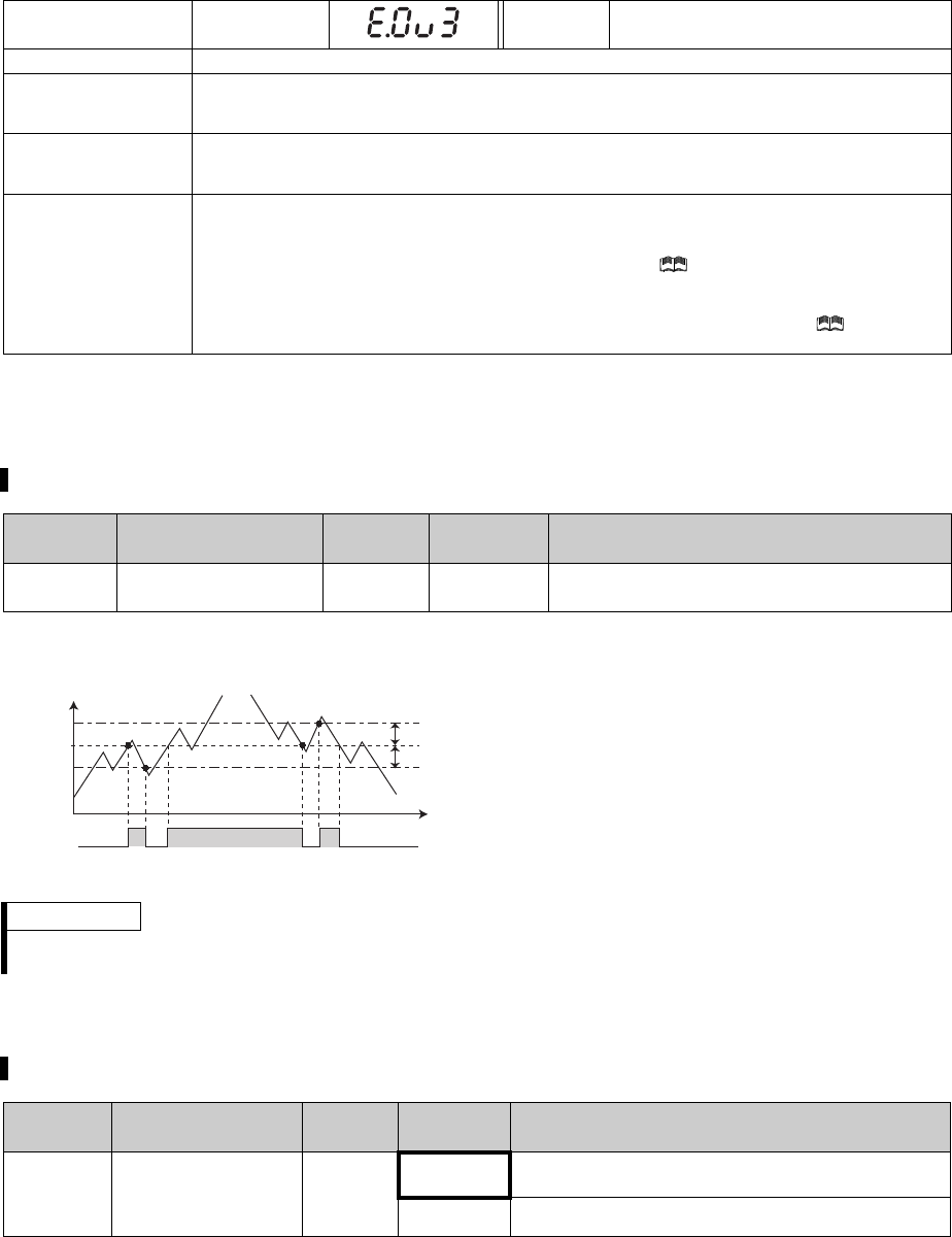
19/24 BCN-C22005-634
3 Speed detection hysteresis (Pr.870)
4 Limit regeneration avoidance operation frequency (Pr. 885)
Operation Panel
Indication E.OV3 FR-PU04
FR-PU07 OV During Dec
Name Regenerative overvoltage trip during deceleration or stop
Description
If regenerative energy causes the inverter's internal main circuit DC voltage to reach or exceed the
specified value, the protective circuit is activated to stop the inverter output. The circuit may also be
activated by a surge voltage produced in the power supply system.
Check point
· Check for sudden speed reduction.
Check if the stall prevention operation is frequently activated in an application with a large
load inertia.
Corrective action
· Increase the deceleration time. (Set the deceleration time which matches the moment of inertia of the
load)
· Set the brake cycle longer.
· Use the regeneration avoidance function (Pr. 882 to Pr. 886). ( Refer to Chapter 4 of the Instruction
Manual (Applied).)
· Use the brake unit or power regeneration common converter (FR-CV) as required.
Set Pr.154 Voltage reduction selection during stall prevention operation = "10 or 11". ( Refer to
Chapter 4 of the Instruction Manual (Applied).)
This function prevents chattering of the speed detection signals.
Parameter
Number Name Initial
Value
Setting
Range Description
870 Speed detection
hysteresis 0Hz* 0 to 5Hz Set the hysteresis width for the detected frequency.
* Performing IPM parameter initialization changes the settings. (Refer to page 6)
When an output frequency fluctuates, the following
signals may repeat ON/OFF (chatters).
Up to frequency (SU)
Speed detection (FB, FB2, FB3)
Low speed output (LS)
Setting hysteresis to the detected frequency prevents
chattering of these signals.
REMARKS
Setting a higher value to this parameter slows the response of frequency detection signals (SU, FB, FB2, FB3, and LS).
The ON/OFF logic for the LS signal is opposite for the FB signal.
The setting range of Pr.885 Regeneration avoidance compensation frequency limit value has been changed.
Parameter
Number Name Initial
Value
Setting
Range Description
885
Regeneration
avoidance
compensation
frequency limit value
6Hz
0 to 30Hz Set the limit value of frequency which rises at
activation of regeneration avoidance function.
9999 Frequency limit invalid
Pr.870
Pr.42
Output
frequency
(Hz)
ON
ON
ON
FB
Example of the speed detection (FB) signal
OFF OFF
bcnc22005634.fm 19 ページ 2012年7月3日 火曜日 午前9時43分
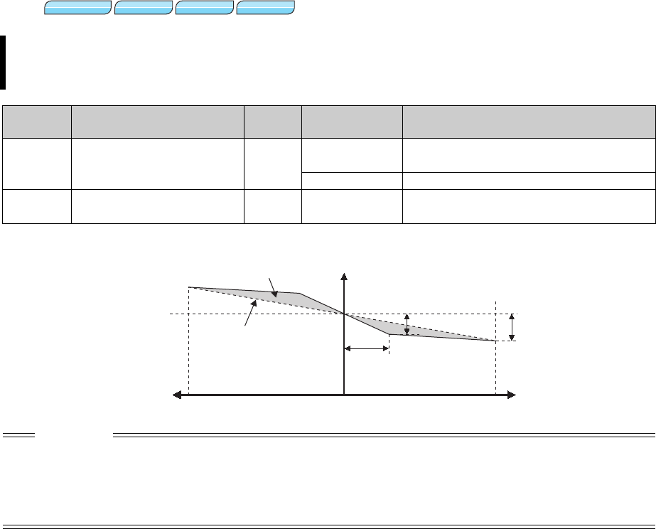
20/24 BCN-C22005-634
5 Break point setting for droop control (Pr.994, Pr.995)
Set Pr.994 and Pr.995 to have a break point on a droop compensation frequency line. Setting a break point
allows the inverter to raise the droop compensation frequency for light-load (no load) operation without
raising it for heavy-load operation.
Parameter
Number Name Initial
Value Setting Range Description
994 Droop break point gain 9999 0.1 to 100% Set the changing droop amount as a percentage
value of the rated motor frequency.
9999 No function
995 Droop break point torque 100% 0.1 to 100% Set the torque where the droop amount is
changed.
CAUTION
The droop break point function is disabled when any of the following conditions is met. (Linear compensation by Pr.286 is
performed.)
Pr.995 = "100% (initial value)"
Pr.286 < Pr.994
Pr.994 Pr.995 Pr.286 / 100%
Magnetic fluxMagnetic fluxMagnetic flux
Sensorless
Sensorless
Sensorless Vector
Vector
Vector
PMP MPM
Torque100%
Droop gain
(Pr.286)
-100%
Frequency
0
Rated frequency
Increased amount of the
droop compensation
frequency
Droop compensation
frequency
Droop break point torque
(Pr.995)
Droop break point gain
(Pr.994)
bcnc22005634.fm 20 ページ 2012年7月3日 火曜日 午前9時43分
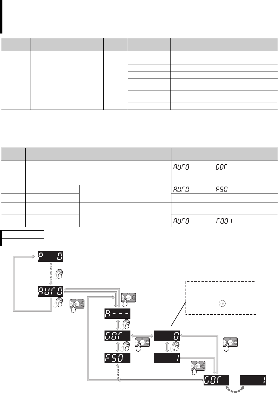
21/24 BCN-C22005-634
6 Setting multiple parameters as a batch (Pr.999)
*1 This parameter allows its setting to be changed in any operation mode even if "0 (initial value)" is set in Pr. 77 Parameter write selection.
*2 The read value is always "9999."
(1) Automatic parameter setting (Pr.999)
Select which parameters to be automatically set, and set that to Pr. 999. Multiple parameter settings are
changed automatically. Refer to page 22 for the list of parameters that are changed automatically.
Parameter settings are changed as a batch. Those include communication parameter settings for the
Mitsubishi human machine interface (GOT) connection, rated frequency settings of 50Hz/60Hz, and
acceleration/deceleration time increment settings.
Multiple parameters are changed automatically. Users do not have to consider each parameter
number. (Automatic parameter setting mode)
Parameter
Number Name Initial
Value Setting Range Description
999 *1 Automatic parameter setting 9999 *2
10 GOT initial setting (PU connector)
11 GOT initial setting (RS-485 terminals)
20 50Hz rated frequency
21 60Hz rated frequency
30 Acceleration/deceleration time
(0.1s increment)
31 Acceleration/deceleration time
(0.01s increment)
9999 No action
Pr.999
setting Description Operation in the automatic parameter
setting mode
10 Automatically sets the communication parameters for the GOT
connected with a PU connector (AUTO) (GOT) Write "1"
11 Automatically sets the communication parameters for the GOT
connected with RS-485 terminals —
20 50Hz rated frequency Sets the related parameters of the
rated frequency according to the power
supply frequency
(AUTO) (F50) Write "1"
21 60Hz rated frequency —
30 0.1s increment Changes the setting increments of
acceleration/deceleration time
parameters without changing
acceleration/deceleration settings
—
31 0.01s increment (AUTO) (T0.01) Write "1"
REMARKS
If the automatic setting is performed, the selected settings including the changed parameter settings will be changed.
Flickers
<Automatic parameter setting mode> Always displayed as "0" when the
parameter is read.
Write "1" to select the automatic
setting. Pressing in the "0"
setting displays the next Pr.
(Lit)
(Lit)
bcnc22005634.fm 21 ページ 2012年7月3日 火曜日 午前9時43分

22/24 BCN-C22005-634
(2) List of automatically-set parameters
The following tables show which parameters are changed in each of the automatic parameter settings.
GOT initial setting (PU connector) (Pr.999 = "10")
GOT initial setting (RS-485 terminals) (Pr.999 = "11")
CAUTION
If the automatic setting is performed with Pr.999 or the automatic parameter setting mode, the listed settings including
the changed parameter settings (changed from the initial setting) will be automatically changed. Before performing
the automatic setting, confirm that changing the listed parameters will not cause any problem.
Parameter Name Initial
value Automatically set to Refer to
79 Operation mode selection 01
Chapter 4 of the
Instruction Manual
(Applied)
118 PU communication speed 192 192
119 PU communication stop bit length 110
120 PU communication parity check 21
121 Number of PU communication
retries 19999
122 PU communication check time
interval 9999 9999
123 PU communication waiting time
setting 9999 0ms
124 PU communication CR/LF selection 11
340 Communication startup mode
selection 00
REMARKS
Always perform an inverter reset after the initial setting.
Parameter Name Initial
value Automatically set to Refer to
79 Operation mode selection 00
Chapter 4 of the
Instruction Manual
(Applied)
332 RS-485 communication speed 96 192
333 RS-485 communication stop bit
length 110
334 RS-485 communication parity check
selection 21
335 RS-485 communication retry count 19999
336 RS-485 communication check time
interval 0s 9999
337 RS-485 communication waiting time
setting 9999 0ms
340 Communication startup mode
selection 01
341 RS-485 communication CR/LF
selection 11
549 Protocol selection 00
REMARKS
Always perform an inverter reset after the initial setting.
bcnc22005634.fm 22 ページ 2012年7月3日 火曜日 午前9時43分

23/24 BCN-C22005-634
Rated frequency (Pr. 999 = "20(50Hz), 21(60Hz)")
* This parameter can be set when the option FR-A7NL is mounted.
Acceleration/deceleration time increment (Pr.999 = "30(0.1s) or 31(0.01s)")
* The set value is changed for Pr. 21.
Parameter Name Initial value Pr.999 = "21"
Pr.999 = "20"
Automatic parameter
setting
Refer to
3 Base frequency 60Hz 60Hz 50Hz
Chapter 4 of
the Instruction
Manual
(Applied)
4Multi-speed setting (high
speed) 60Hz 60Hz 50Hz
20 Acceleration/deceleration
reference frequency 60Hz 60Hz 50Hz
37 Speed display 00
55 Frequency monitoring
reference 60Hz 60Hz 50Hz
66 Stall prevention operation
reduction starting frequency 60Hz 60Hz 50Hz
116 Third output frequency
detection 60Hz 60Hz 50Hz
125 (903) Terminal 2 frequency setting
gain frequency 60Hz 60Hz 50Hz
126 (905) Terminal 4 frequency setting
gain frequency 60Hz 60Hz 50Hz
263 Subtraction starting
frequency 60Hz 60Hz 50Hz
266 Power failure deceleration
time switchover frequency 60Hz 60Hz 50Hz
386 Frequency for maximum
input pulse 60Hz 60Hz 50Hz
390*% setting reference
frequency 60Hz 60Hz 50Hz FR-A7NL
manual
505 Speed setting reference 60Hz 60Hz 50Hz Chapter 4 of
the Instruction
Manual
(Applied)
808 Forward rotation speed limit 60Hz 60Hz 50Hz
C14 (918) Terminal 1 gain frequency
(speed) 60Hz 60Hz 50Hz
Parameter Name Initial set
increment Pr.999 = "30"
Pr.999 = "31"
Automatic parameter
setting
Refer to
7 Acceleration time 0.1s 0.1s 0.01s
Chapter 4 of
the Instruction
Manual
(Applied)
8 Deceleration time 0.1s 0.1s 0.01s
16 Jog acceleration/deceleration
time 0.1s 0.1s 0.01s
21 Acceleration/deceleration
time increments 10
*1 *
44 Second acceleration/
deceleration time 0.1s 0.1s 0.01s
45 Second deceleration time 0.1s 0.1s 0.01s
110 Third acceleration/
deceleration time 0.1s 0.1s 0.01s
111 Third deceleration time 0.1s 0.1s 0.01s
264 Power-failure deceleration
time 1 0.1s 0.1s 0.01s
265 Power-failure deceleration
time 2 0.1s 0.1s 0.01s
791 Acceleration time in low-
speed range 0.1s 0.1s 0.01s
792 Deceleration time in low-
speed range 0.1s 0.1s 0.01s
REMARKS
When a parameter is set as the acceleration/deceleration time (0.1s), the 0.01s increment is dropped.
When a parameter is set as the acceleration/deceleration time (0.01s), the parameters are limited at the maximum
value of the parameter setting range. For example, Pr.7 = "361.0s" when 0.1s increment is selected, and Pr.7 =
"360.00s" when 0.01s increment is selected.
bcnc22005634.fm 23 ページ 2012年7月3日 火曜日 午前9時43分

24/24 BCN-C22005-634
7 SERIAL number check
The description on this supplemental sheet applies to the inverters that are manufactured in June 2012 or later and
have the following SERIAL or later on their rating plates. Check the SERIAL of your inverter (printed on its rated
plate) against the list of SERIAL numbers shown below.
-SERIAL number check
Refer to the inverter manual for the location of the rating plate.
Rating plate example
2
Symbol Year Month Control number
SERIAL
The SERIAL consists of one symbol, two characters indicating production
year and month, and six characters indicating control number.
The last digit of the production year is indicated as the Year, and the Month
is indicated by 1 to 9, X (October), Y (November), or Z (December.)
Inverter Model Symbol
FR-A720-0.4K B
FR-A720-0.75K B
FR-A720-1.5K E
FR-A720-2.2K E
FR-A720-3.7K D
FR-A720-5.5K C
FR-A720-7.5K C
FR-A720-11K H
FR-A720-15K E
FR-A720-18.5K E
FR-A720-22K E
FR-A720-30K B
FR-A720-37K A
FR-A720-45K A
FR-A720-55K Z
FR-A720-75K B
FR-A720-90K B
FR-A740-0.4K L
FR-A740-0.75K K
FR-A740-1.5K K
FR-A740-2.2K L
FR-A740-3.7K L
FR-A740-5.5K J
FR-A740-7.5K J
FR-A740-11K N
FR-A740-15K N
FR-A740-18.5K L
FR-A740-22K L
FR-A740-30K G
FR-A740-37K H
FR-A740-45K H
FR-A740-55K H
FR-A740-75K H
FR-A740-90K H
Inverter Model Symbol
FR-A740-110K L
FR-A740-132K K
FR-A740-160K H
FR-A740-185K H
FR-A740-220K G
FR-A740-250K G
FR-A740-280K G
FR-A740-315K G
FR-A740-355K G
FR-A740-400K D
FR-A740-450K D
FR-A740-500K D
Inverter Model Symbol
bcnc22005634.fm 24 ページ 2012年7月3日 火曜日 午前9時43分

1/1 BCN-C22005-642
FR-V500, A700, A701 Series
Instruction Manual Supplement
When installing a thermal relay to the cooling fan of the vector-control dedicated motors (SF-
V5RU), use the following recommended thermal relay settings.
-200V class (Mitsubishi dedicated motor [SF-V5RU (1500r/min series)])
-400V class (Mitsubishi dedicated motor [SF-V5RUH (1500r/min series)])
*1 Power (current) at 50Hz/60Hz.
*2 The cooling fan is equipped with a thermal protector. The cooling fan stops when the coil temperature exceeds
the specified value in order to protect the fan motor. A restrained cooling fan or degraded fan motor insulation
may causes the rise in coil temperature. The fan motor re-starts when the coil temperature drops to normal.
*3 The voltage and input values are the standard specifications of the cooling fan in free air. When the cooling fan
is used with a motor, it requires more energy to perform its work, and thus the above input values become
slightly larger. The cooling fan can, however, be used as it is without causing problems. When a thermal relay is
to be prepared at the customer's side, use the recommended thermal relay settings.
Motor type
SF-V5RUK1 2 3 5 7 11 15 18 22 30 37 45 55
Cooling fan (with
thermal protector)*2*3
Voltage Single-phase 200V/50Hz
Single-phase 200V to 230V/60Hz
Three-phase 200V/50Hz
Three-phase 200 to 230V/60Hz
Input *1 36/55W
(0.26/0.32A)
22/28W
(0.11/0.13A)
55/71W
(0.37/0.39A)
100/156W
(0.47/0.53A)
85/130W
(0.46/0.52A)
Thermal relay
settings 0.36A 0.18A 0.51A 0.69A 0.68A
Motor type
SF-V5RUHK1 2 3 5 7 11 15 18 22 30 37 45 55
Cooling fan (with
thermal protector)*2*3
Voltage Single-phase 200V/50Hz
Single-phase 200V to 230V/60Hz
Three-phase 380 to 400V/50Hz
Three-phase 400 to 460V/60Hz
Input *1 36/55W
(0.26/0.32A)
22/28W
(0.11/0.13A)
55/71W
(0.19/0.19A)
100/156W
(0.27/0.30A)
85/130W
(0.23/0.26A)
Thermal relay
settings 0.36A 0.18A 0.25A 0.39A 0.34A
bcnc22005642.fm 1 ページ 2013年1月21日 月曜日 午後3時17分

HEAD OFFICE: TOKYO BUILDING 2-7-3, MARUNOUCHI, CHIYODA-KU, TOKYO 100-8310, JAPAN
3
4
5
6
7
1
2
FR-A700
INSTRUCTION MANUAL (Applied)
INVERTER
PRECAUTIONS FOR USE
OF THE INVERTER
PARAMETERS
PROTECTIVE FUNCTIONS
PRECAUTIONS FOR
MAINTENANCE AND INSPECTION
SPECIFICATIONS
OUTLINE
WIRING
MODEL FR-A700
INSTRUCTION MANUAL (Applied)
MODEL
CODE 1A2-P10
FR-A720-0.4K to 90K
FR-A740-0.4K to 500K
IB(NA)-0600226ENG-E (1202)MEE Printed in Japan Specifications subject to change without notice.
FR-A700 INVERTER INSTRUCTION MANUAL (Applied)
E
