FUNda MENTALs Topic 4
User Manual: FUNdaMENTALs-Topic-4 Fundamentals Of Design
Open the PDF directly: View PDF ![]() .
.
Page Count: 62

1/1/2008© 2008 Alexander Slocu
m
4-0
FUNdaMENTALSofDesign
Topic 4
Linkages

Linkages
Linkages are perhaps the most fundamental class
of machines that humans employ to turn thought into
action. From the first lever and fulcrum, to the most
complex shutter mechanism, linkages translate one type
of motion into another. It is probably impossible to
trace the true origin of linkages, for engineers have
always been bad at documentation. Images of levers
drawn in Egyptian tombs may themselves be document-
ing ancient (to them!) history. But given their useful-
ness, linkages will be with us always. They form a link
to our past and extend an arm to our future. As long as
we keep turning the technological crank, they will cou-
ple our efforts together so all followers of technology
can move in sync.
As you read this chapter on linkages, it is impor-
tant to realize that history plays a vital role in the devel-
opment of your own personal attitude towards becoming
competent at creating and using linkages. As it was
with many other areas of engineering, applied mathema-
ticians and their curiosity for how their new analysis
tools could be used to understand problems (opportuni-
ties!) catalyzed the discovery of linkages and analysis
methods. The study of linkages is a very mature and
rich subject area but it is by no means over. On the con-
trary, entire courses are dedicated to teaching students
how to master what is and is not known about the design
of linkages. Perhaps what is not known is just waiting
for someone like you to make the next discovery! In
particular, most of us are confined to using simple four
or six bar linkages that move in a plane, but the world is
three dimensional and waiting for you!1
Fortunately, for us mere mortal linkage designers,
there is powerful linkage design software that seem-
lessly links to many solid modelling programs. Just
lkike snowboarding, you have to learn on the bunny
slope before you ride extreme slopes, and you must
learn the basics of linkage design before you attempt to
zoom from the top! Accordingly, this chapter will focus
on the fundamentals of linkage design: physics, synthe-
sis and robust design & manufacturing.2
1. An awesome book containing many great mechanism ideas is N. Sclater and N. Chironis, Mecha-
nisms and Mechanical Devices, McGraw-Hill, New York, 2001
2. If the design of machines is of real interest, you should take a course on the design of mechanisms
where the entire focus of the course would be on the details of designing many different types of mecha-
nisms from linkages to gear trains. An excellent reference is A. Erdman, G. Sandor, S. Kota, Mechanism
Design, 2001 Prentice Hall Upper Saddle River, NJ USA
1/1/2008© 2008 Alexander Slocu
m
4-1
Topic 4
Linkages
Topics
• History
• Definitions
• Links
• Joints
• Instantaneous Center of Rotation
• 3-Bar Linkages
• 4-Bar Linkages
• 5-Bar Linkages
• 6-Bar Linkages
• Extending Linkages
• Compliant Mechanisms
• Manufacturing & Robust Design
•Mechanism Mania!
Peter Bailey’s HyperHex™
hexapod machining center

History
A machine is the combination of two or more machine elements that
work together to transform power from one form to another. While the first
tools used by humans are likely to have been rocks or sticks, the first machine
was likely to have been a lever and fulcrum. More advanced machines also
utilize control systems, which in the early days were also mechanical. This
allowed machines to do work without humans attending to the their every
function.
Could it be that the simple levers were mistakenly discovered when
Ogette stepped on a fallen tree and she saw one end of the tree lift up another
heavier tree that had fallen across it? Something was observed somewhere,
and the lever was born as a means to amplify the force of a human. Simple
cranes are also likely to have emerged, where the simplest crane merely used
rope to extend the reach of the lever and the means of force application. From
there, the idea that things could be combined to magnify and/or direct forces
likely catalyzed the development of many new machines.
Was it watching a farmer turn over soil that gave Archimedes the idea
for the screw? Who thought of using a screw to move an abject and thus cre-
ated the first machine tool? Who first thought of toothed wheels and why?
Leonardo da Vinci drew gears as wheels with protruding pegs, but these early
ears wore quickly. Who observed the wear that accompanies simple peg-type
gears might be done away with by using an involute tooth form so motion
between the teeth could be made to be rolling like that of a wheel? Who put all
these elements together to create machine tools to form metal faster so we
could make more machines? Humans’ curiosity and drive were amplified by
religion as perhaps best described by Francis Bacon:
"The introduction of new inventions seems to be the very chief of all
human actions. The benefits of new inventions may extend to all mankind uni-
versally; but the good of political achievements can respect but some particu-
lar cantons of men; these latter do not endure above a few ages, the former
forever inventions make all men happy, without either injury or damage to any
one single person. Furthermore, new inventions are, as it were, new erections
and imitations of God's own works."
A consistent theme in the development of precision linkages has been
time, although it was not until 1000 AD that the first Chinese water clocks
appeared. In the 1300’s mechanical clocks appeared in Europe and their value
in navigation became a strategic technology that was mastered by one of the
greatest precision mechanicians of all time John Harrison1. The more accurate
the timepiece, the more accurate the navigation, and this trend continues to this
day. This quest for precision in timepieces and the machines used to make
them and other tools and instruments is well documented by Evans.2 In addi-
tion, a review of the development of the most accurate machine tools which
formed the foundation of our modern society is given by Moore3. Without pre-
cision mechanical machines, we would still be an agrarian society.
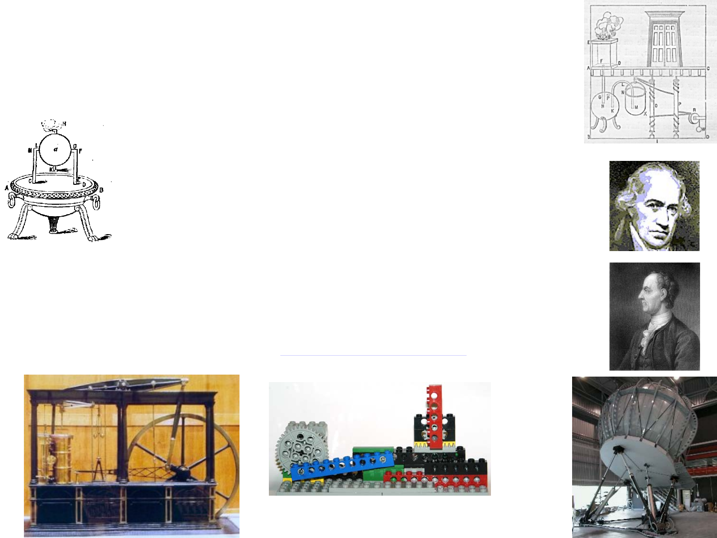
The birth of the modern history of linkages is often associated with
James Watt who some say invented the steam engine; however, it was not Watt
who invented the steam engine which perhaps had its origins in ancient Egypt
as a means to open temple doors.4 However, it was Watt who recognized the
need for the application of thermodynamics, even though the subject was not
yet invented, to increase efficiency of steam engines. He then give birth to the
flyball governor to control the speed of an engine. Once steam was harnessed,
the industrial revolution took off, and many other great minds linked together
to create new machines and analytical tools to predict their performance in
order to conserve scare resources.
Think about what people have done through the ages with observation
and curiosity and the drive to understand! So it should be with you! With a few
hours application of fundamental principles, catalyzed by simple experiments,
countless days of frustration in the shop can be saved!
1. Dave Sobel, Longitude: The True Story of a Lone Genius Who Solved the Greatest Scientific Prob-
lem of His Time
2. Chris Evans, Precision Engineering: An Evolutionary View, 1989 Cranfield Press, Cranfield, Bed-
ford, England.
3. Wayne Moore, Foundations of Mechanical Accuracy, Moore Special Tool Co.
4. See for example http://www.history.rochester.edu/steam/thurston/1878/
1/1/2008© 2008 Alexander Slocu
m
4-2
History
• The weaving of cloth gave rise to the need for more complex machines to convert
waterwheels’ rotary motion into complex motions
• The invention of the steam engine created a massive need for new mechanisms and
machines
– Long linear motion travel was required to harness steam power
•James Watt (1736-1819) applied thermodynamics (though he did not know it) and rotary joints
and long links to create efficient straight line motion
– Watt also created the flyball governor, the first servomechanism, which made steam
engines safe and far more useful
•Leonard Euler (1707-1783) was one of the first mathematicians to study the mathematics of
linkage design (synthesis)
• Most linkages are planar, their motion is confined to a plane
– The generic study of linkage motions, planar and spatial, is called screw theory
•Sir Robert Stawell Ball (1840-1913) is considered the father of screw theory
• There is a HUGE variety of linkages that can accomplish a HUGE variety of tasks
– It takes an entire course just to begin to appreciate the finer points of linkage design
• History is a GREAT teacher: See http://kmoddl.library.cornell.edu/ for a fantastic collection
of linkages created through the years, many of which are still very useful today!
http://www.fcs-
cs.com/motionsystems/productsandappl
http://visite.artsetmetiers.free.fr/watt.html

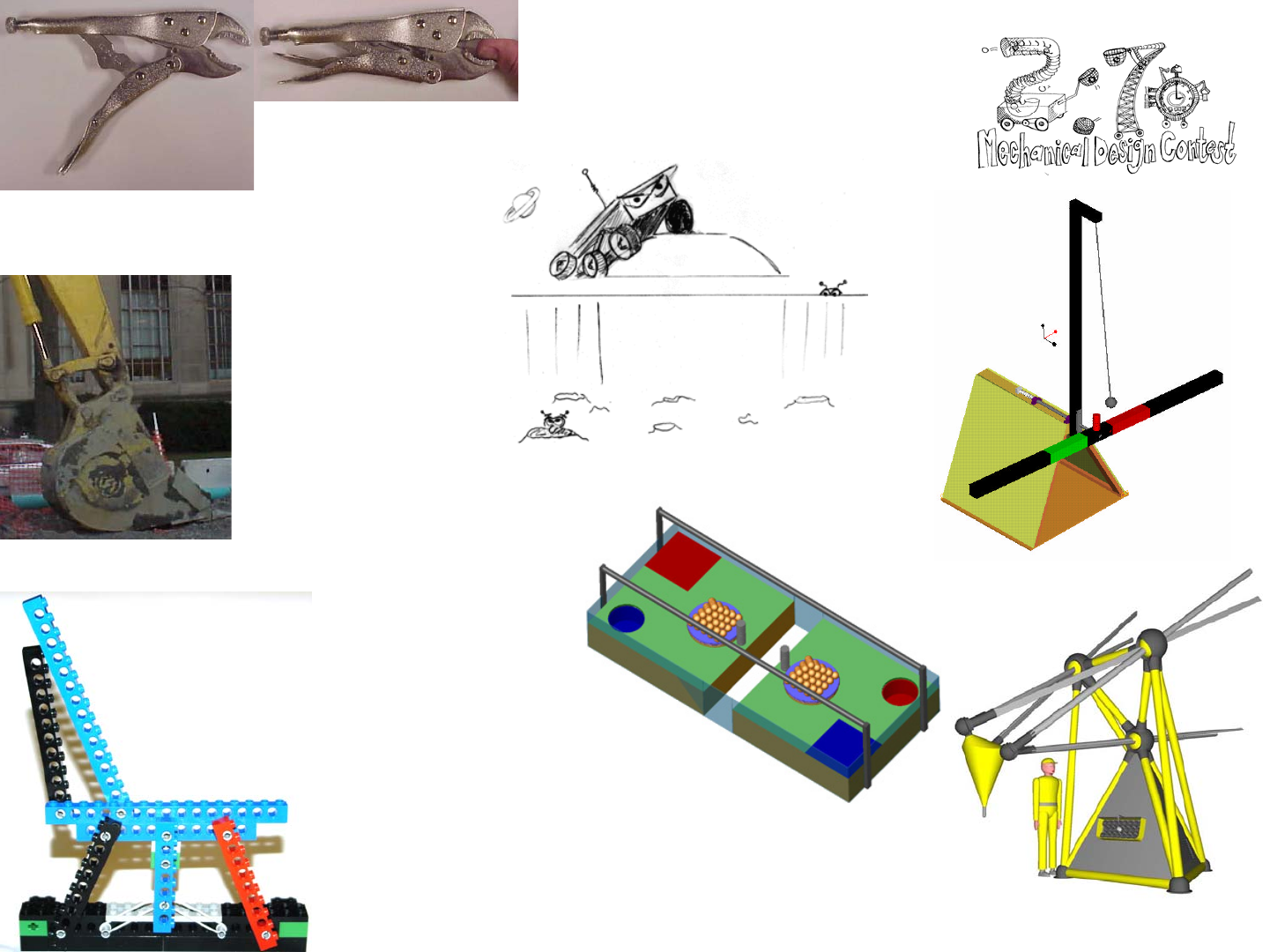
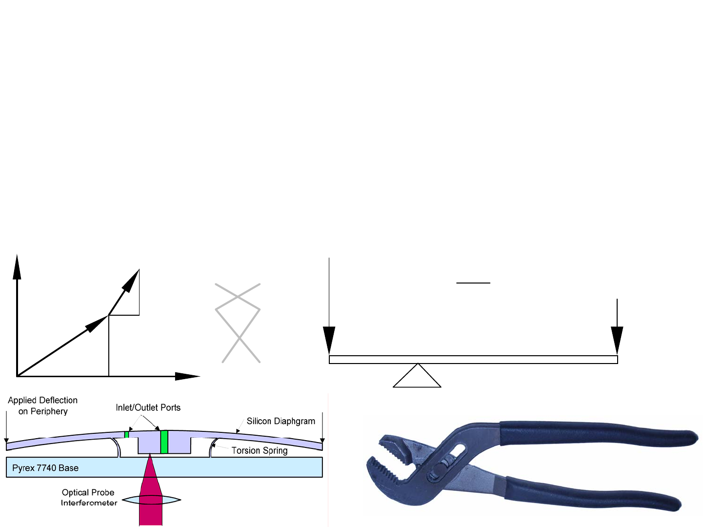
The First Mechanism: The Lever is a 2-bar Linkage
The simplest mechanism, and perhaps the first, is a lever and a ful-
crum. The lever is a link, the fulcrum a joint, and the ground is also a link.
Together they form a 2-bar linkage. These simple elements (a tree branch and
a rock) with a force (Og) can create huge forces to do useful work. Once a per-
son witnesses the mechanical advantage offered by a lever, they never seem to
forget it, and often use it. From using a pry bar, or sometimes naughtily a
screwdriver, to pry open a box, to a wine bottle opener, many of us use levers
in our daily lives. Got pliers? A pair of pliers is essentially two levers that
share a common fulcrum and hence are essentially levers placed back-to-back.
Got scissors? Scissors shear paper (and rock smashes scissors) and the mecha-
nism is again a pair of levers placed back-to-back with a common pivot.
Have you ever tried to cut thick wire or a bolt with a pair of wire cut-
ters and just could not do it? Have you ever then taken the time to do the job
right so you went and got a pair of bolt cutters and then found the job was eas-
ier? Thinking of the philosophy of physics and fundamental laws, why did the
bolt cutters work so well and the wire cutters did not? You might have thought
that the bolt cutters had longer handles and thus gave you more leverage, and
that is partially correct. Energy is essentially conserved and the bolt cutters let
you apply the force of your muscles over a much longer distance, so the cutting
force acting over a small distance of travel becomes very high.
What differentiates bolt cutters from a simple giant size pair of wire
cutters, is that the bolt cutters have a linkage that allows them to achieve in a
much smaller space the amplification of force. Large bolt cutters use what is
known as a 5-bar linkage, and if you count the links and the joints in the pic-
ture, you see that there are 5 of each. You will soon see from Gruebler’s Equa-
tion that there are 3*(5 - 1) - 2*5 = 2 degrees of freedom, which means that you
need to control each handles’ motion in order to control the motion of the link-
age. This actually gives great versatility in their use as to how you grab and
squeeze the handles, or place on of them on the floor and then lean your belly
onto the other handle... Smaller cheaper bolt cutters have just a 4-bar linkage
with 4 links and 4 joints and 3*(4 - 1) - 2*4 = 1 degree of freedom. This means
they will not open as wide which makes them less ergonomic for monster cut-
ting applications, but they will often do the job. Returning to the pliers, they
have two links and one joint or 3*(2 - 1) - 2*1 = 1 degree of freedom.
The right linkage must be selected and engineered for the right job,
BUT if you want higher performance with more action in less space, you often
have to use a more complex linkage! Fortunately, even higher order linkages
are essentially just cascaded series of levers. Regardless of the type of linkage,
they are all based on simple elements, and the analysis of their motion is based
on simple trigonometric relations. Likewise, an analysis of their force capabil-
ities is based on simple vector cross products, which are also themselves based
on simple trigonometry. In either case, the forces on bolt cutters are huge.
Consider you might apply 100 Newtons of force over 500 mm of motion, but
the jaws may only close over a range of 5 mm; hence the force on the cutting
edges may be 10,000 Newtons! What about the links and joints?
With this simple introduction, your curiosity should be piqued, but in
order to move along the desired path of learning to design linkages, definitions
must first be established, followed by an understanding of the different types of
links and joints and how they operate together. Then different types of link-
ages, their mechanics, and the synthesis (creation) of their designs can be con-
sidered in detail. For example, starting with the idea of a simple 2D lever, the
micro silicon Nanogate is essentially a circular plate whose outer circumfer-
ence is bent down, causing it to pivot about an annular ring and open a small
gap up between the center of the plate and a bottom plate.1
The pendulums in the robot design contest The MIT and the Pendu-
lum represent significant scoring potential if you could clamp on to them,
climb up to the supporting axle, and spin them like a propellor. How could you
engage the round support shaft in order to cause the pendulum to spin? Again,
how could you ensure that the clamping force remains sufficient and constant?
Is some sort of suspension system in order? Might this suspension system use
some sort of linkage? On the other hand, maybe you want to block pendulum
motion and focus on scooping balls and pucks and dumping them in the scor-
ing zone. Take a close look at construction equipment! In either case, remem-
ber, you have other duties and a vibrant social life, so you need tools to enable
you to rapidly create and engineer awesome linkages. Taking the time to learn
how to engineer linkages, as opposed to just blindly trying stuff will save you
a LOT of fruitless failures! Read on and read carefully!
1. The Nanogate is a Micro Electro Mechanical System (MEMS), and it is the thesis topic of James
White, who is one of Prof. Slocum’s graduate students. See US Patent #5,964,242 and White, J., Ma. H.,
Lang, J. and Slocum, A. "An instrument to control parallel plate separation for nanoscale flow control."
Rev. Sci. Inst. v. 74 no. 11, Nov. 2003.
1/1/2008© 2008 Alexander Slocu
m
4-3
The First Mechanism: The Lever is a 2-bar Linkage
• A lever (link) can be used with a fulcrum (pivot) against the ground (link) to allow a small
force moving over a large distance to create a large force moving over a short distance…
– When one considers the means to input power, a lever technically becomes a 4-bar linkage
• The forces are applied through pivots, and thus they may not be perpendicular to the lever
– Torques about the fulcrum are thus the best way to determine equilibrium, and torques are best
calculated with vector cross product
– Many 2.007 machines have used levers as flippers to assist other machines onto their backs…
Fout
Fin
L2L1
Ffulcrum
outF=in
F
1L
2L
fulcrum
F
=out
F
+in
F
R
F
c
d
b
a
j
i
R = ai + bj
F = ci + dJ
Γ = ad - bc
The Nanogate is a MEMS diaphragm-type
lever for nanoscale flow control
Definitions
A linkage, or kinematic chain, is an assembly of links and joints that
provide a desired output motion in response to a specified input motion. A link
is a nominally rigid body that possess at least 2 nodes. A node is an attach-
ment point to other links via joints. The order of a link indicates the number of
joints to which the link is connected (or the number of nodes per link). There
are binary (2 nodes), ternary (3 nodes), and quaternary (4 nodes) links. A
joint is a connection between two or more links at their nodes, which allows
motion to occur between the links. A pivot is a joint that allows rotary motion,
and a slider is a joint that allows linear motion. A mechanism is a kinematic
chain in which at least one link is connected to a frame of reference (ground),
where the ground is also counted as a link.
Even a lever with some sort of means to apply an input force is a link-
age. One of the most common types of linkages is the 4-bar linkage, which is
comprised of four links and four joints. A ground link acts as the reference for
all motions of the other three links, and attached to it is the power input device,
usually a motor, and another joint. The motor output shaft is connected to the
link called the rocker, in the case of oscillating input motion, but the same link
is called the crank, in the case of continuous input motion. The follower is
connected to the ground link through a joint at one end. The coupler link cou-
ples the ends of the crank (or rocker) and the follower links. These four links
are thus geometrically constrained to each other; however, their motion may
not be deterministic, for there are link lengths and ground joint locations that
can lead to instability in the linkage. Even though two points define a line, a
straight line structure need not connect the region between the nodes of a link.
A link may be curved or have a notch-shape to prevent interference with some
other part of the structure or linkage as it moves.
Because each end of the coupler is connected to links which may not
be of the same length or orientation, the coupler is a link not connected to
ground that undergoes complex motion. It is often the “output” link for the
mechanism (particularly in a 4-bar linkage) and its motion is often very non-
linear and of the highest interest. One very important and insightful means of
describing the motion of the coupler at any instant in time, is the instant cen-
ter. For very small motions, the instant center is the point about which a link
appears to rotate. Because the coupler’s ends are constrained to move with the
ends of the crank and follower links, whose ends themselves trace out circles,
the instant center is the imaginary center of a circle which has radii that are
coincident with the radii of the crank and follower links’ circles. Hence the
instant center can be found by drawing lines through the link’s pivots, and the
point at which they intersect is called the instant center. The instant center can
also be used to help determine stability, but more on this later (see pages 4-16
to 4-18)
The number of degrees-of-freedom (DOF) of a linkage is equal to the
number of input motions needed to define the motions of the linkage. When
one looks at a 4-bar linkage and sees the coupler translating and rotating as it
moves, the coupler does not have 3 degrees of freedom (x, y, θ) because the
motions are all related. Indeed, the linkage has only 1 DOF. Is there a way to
quickly look at a linkage and determine its degrees-of-freedom? Gruebler’s
Equation as described on the facing page is perhaps the most commonly used
equation for evaluating simple linkages. From Gruebler’s Equation we can see
that a 2-bar linkage, an arm attached to a motor’s output shaft will have 1 DOF.
A 3-bar linkage with 3 links and 3 joints will have 0 DOF, as expected, and
hence triangles make stable structures! A 4-bar linkage has 4 links and 4 joints
and 1 DOF. 5-bar linkages can be configured many different ways and thus
may have more than 1 DOF. However, these are not generally stable unless
multiple input power sources are used. 6-bar linkages can have 1 DOF and
they can be extraordinarily useful.
There are many different processes for designing linkages. Synthesis
is the process used to create a linkage. Number synthesis is the determination
of the number and order of links needed to produce desired motion. Kinematic
synthesis is the determination of the size and configuration of links needed to
produce desired motion. In either method, precision points are the defined
desired position and orientations of a link at a point in its motion.
What sort of motions may require you to create a linkage for your
machine? Can a linkage enable your machine to meet the starting space con-
straints and then unfold into a bigger machine?
1/1/2008© 2008 Alexander Slocu
m
4-4
Definitions
•Linkage: A system of links connected at joints with rotary or linear bearings
–Joint (kinematic pairs): Connection between two or more links at their nodes, which allows
motion to occur between the links
–Link: A rigid body that possess at least 2 nodes, which are the attachment points to other links
•Degrees of Freedom (DOF):
– The number of input motions that must be provided in order to provide the desired output, OR
– The number of independent coordinates required to define the position & orientation of an object
–For a planar mechanism, the degree of freedom (mobility) is given by Gruebler’s Equation:
–n= Total number of links (including a fixed or single ground link)
–f1= Total number of joints (some joints count as f = ½, 1, 2, or 3)
• Example: Slider-crank n= 4, f1= 4, F= 1
• Example: 4-Bar linkage n= 4, f1= 4, F = 1
• The simplest linkage with at least one degree of freedom (motion) is thus a 4-bar linkage!
• A 3-bar linkage will be rigid, stable, not moving unless you bend it, break it, or throw it!
(
)
1
312Fn f
=−−
crank
slider
4 links (including ground), 4 joints
coupler
Crank or rocker (the
link to which the
actuator is attached
follower
4 links, 4 joints

Links
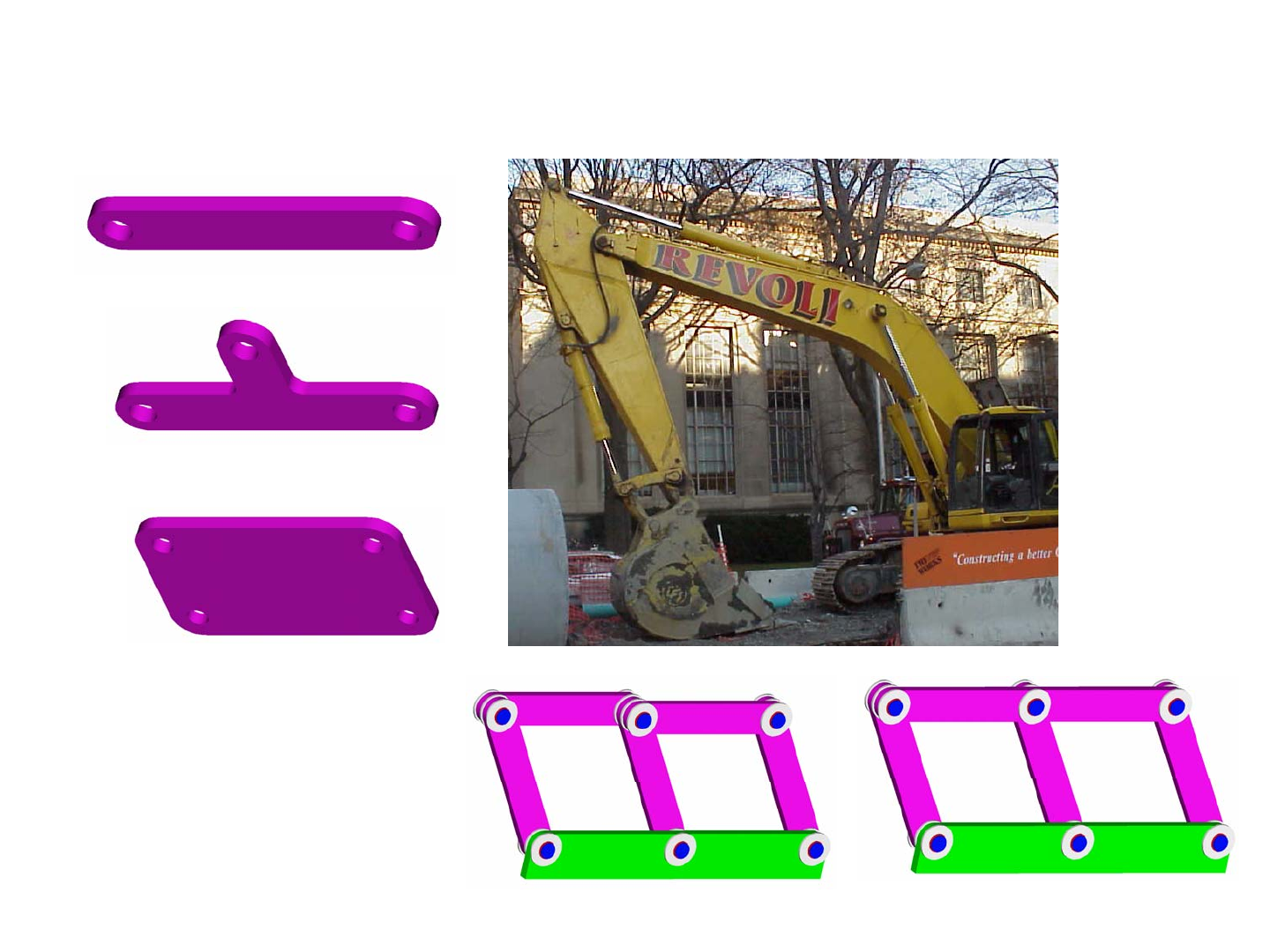
The four most common links are known as binary, ternary, quater-
nary and pentanary links and they have two, three, four and five joints (nodes)
respectively on their structures. Look closely at the picture of the excavator
and try to identify each of these types of links. What types of links represent
the hydraulic cylinders? The hydraulic cylinders have pivot joints at each end,
and the rod slides inside the cylinder; thus a hydraulic cylinder is comprised of
two binary links, each with a pivot joint and a slider in between. Note the first
link, which has the name of the excavation company printed on it. What type
of link is it? This link has a pivot at its base, which cannot be seen but obvi-
ously it must be present, a pivot at its end for the second link, and two other
pivots to which hydraulic cylinders are attached; thus it is a quaternary link.
How about the second major link? How many joints are on it and what type of
link is it? Look closely and you can see it is a pentanary link.
Examine the bucket, which itself is a binary link, and see that is con-
nected with several other links to form what type of linkage? Imagine that the
hydraulic cylinder was taken off for repair. The bucket is connected to the
boom link and to a binary link which is connected to another binary link that is
also connected to the boom link. The bucket could be said to be a follower, and
the binary link opposite it is a rocker link. Thus the bucket linkage is a 4-bar
linkage. The rocker is driven by the hydraulic cylinder which is connected to
the boom link. Recall from above that the hydraulic cylinder is modeled as
two binary links with pivots at their ends, but they happen to share a slider
joint. Thus the bucket system is comprised of two 4-bar linkages that share a
common link. The follower for one (the hydraulic cylinder side) and the rocker
for the other (the bucket side). Together, they actually form a 6-bar linkage.
Gruebler’s Equation was developed to enable a designer to quickly
ascertain the mobility or degrees of freedom in a linkage. For the bucket link-
age, there clearly are 4 links and 4 joints, and so 3*(4 - 1) - 2*4 = 1 degree of
freedom. Physically, this means the bucket can only move in a single pre-
scribed path and observation of an excavator will show this to be true.1 Simi-
larly, the hydraulic cylinder side of the linkage has 4 links and 4 joints so it is
also a single degree of freedom linkage. If the bucket is removed, the small
binary link that is attached to the end of the hydraulic cylinder rod will also
move in a prescribed path. What would happen if we just counted all the links
and joints at once? The boom forms one ternary link for consideration of the
bucket motion linkage. The bucket is a binary link and there are two other
binary links to which it is attached. The hydraulic cylinder is comprised of two
binary links, and hence the total number of links is 6. There are 5 pivots and
one slider joint which is the joint between the hydraulic cylinder the rod.
Gruebler’s Equation would then indicate that there are 3*(6 - 1) - 2*6 = 3
degrees of freedom! Something is wrong, because we indeed know that there
is just one deterministic motion the bucket makes and there is just one actuator.
Indeed the joint where the hydraulic cylinder rod and the two binary links are
joined at a common node is called a second order pin joint, and it counts as 2
joints in Gruebler’s Equation. Thus the bucket actuation systems has 3*(6 - 1)
- 2*7 = 1 degree of freedom. As linkages get more complex, the use of Grue-
bler’s Equation becomes more apparent, for we want mechanism to be exactly
constrained to have the number of degrees of freedom desired.
Consider the two linkage systems shown. Although they appear simi-
lar, they are different in that the “coupler” link in one is a single ternary link,
whereas the other has two binary links instead. In the latter system, which is
similar to the bucket linkage in that it is two 4-bar linkages linked together (do
not forget the second order pin joint!), Gruebler’s Equation gives 3*(6 - 1) -
2*7 = 1! In the former system, Gruebler’s Equation gives 3*(5 - 1) - 2*6 = 0!
Indeed, unless all the dimensions of all the links were perfect, or the joints had
enough clearance in them, the linkage would lock up or it would produce very
high forces on the joints that would cause premature wear.
Links are indeed considered as rigid elements for the purpose of syn-
thesis of a linkage, but of course they are subject to real loads; hence before a
linkage is to be manufactured, a careful stress analysis must be performed.
This may sometimes require the size of the links to be increased, which may
interfere with the motion of the links; thus some design iteration may be
required. In fact, out-of-plane motion and loading often requires links and
joints to be substantially sized to also accommodate out-of-plane forces.
How would you resign the overconstrained linkage with 2 followers?
What sort of links might your system need? Will your ideas for a linkage have
enough room to accommodate structurally appropriate links?
1. If you have never watched an excavator work, you must rent one of those great construction videos
little kids like to watch. Ask someone you are interested in to watch one with you as a date movie!
1/1/2008© 2008 Alexander Slocu
m
4-5
Links
• Binary Link: Two nodes:
• Ternary Link: Three nodes:
• Quaternary Link: Four nodes:
• Pentanary Link: Five nodes!
(Can you find it?!)
Can you identify all the links?
!?

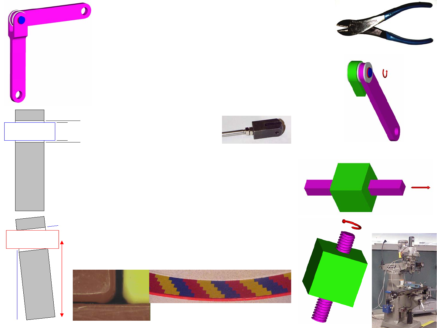
Joints: Single Degree-of-Freedom
Recall that a pivot is a joint that allows rotary motion and a slider is a
joint that allows linear motion. They are single degree of freedom joints for
which f = 1 in Gruebler’s Equation. They and others share the common char-
acteristic that they must transmit loads from one member to another, and they
must do so with a certain amount of precision lest the joint wobble too much
and reduce mechanism quality and robustness. Thus they need bearings which
must be carefully engineered as discussed in Chapters 10 and 11.
The simplest joint that allows rotational motion to occur between two
links is the revolute (R) joint. Also called a pin joint or a pivot, generally it is
formed by a pin that passes through both links. One end of the pin has typi-
cally been formed and after the pin is placed in the joint, a snap-on clip is
placed on the other end. Sometimes the other end is cold-formed in placed to
create a permanent joint that is not likely to fail by means of a fastener coming
off. The crudest form of a pin joint, often used in simple robot design contests,
is made with a screw, but the motion of the joint acts on the threads which can
cause a lot of wear and a lot of error. It can also literally screw itself apart. It
is far better to use a shoulder bolt or a shaft with snap-on clips on the ends.
Even better, it would be desirable to press-fit the pin in one of the links and to
provide clearance between the pin and the other link.
Note that a revolute joint is referred to as a planar joint because the
links are nominally confined to move in a plane; however, the links are actu-
ally offset from each other. Therefore loads are offset by the half-thicknesses
of the links and a moment is transmitted across the joint. The moment can
cause bending in the links and the pins in the joints, and the resulting stresses
will have to be evaluated. The best pivot joint is symmetrical with the end of
one link flared into a U shape and the other link between it, so there are no
moment loads on the links. This is called a clevis. The pin is primarily in
shear, and at worst, acts as a simply supported beam. This is the way many
highly loaded joints on construction equipment are designed.
The next most common joint is the prismatic (P) joint, which is also
called a slider or sliding joint, and it allows for linear motion to occur between
two links. From drawers to windows, sliders are commonplace, but beware
Saint-Venant when selecting proportions of the joint elements as discussed on
page 3-3 in order to minimize the chances of the joint jamming. Crank mecha-
nisms also often use sliders, and they have the same precision issues as revo-
lute joints do as far as loads and errors are concerned.
Helical (H) joints, also called screws, are another common joint
which form the basis for a common means to transform rotary power into lin-
ear power. Beware of thread strength, friction and efficiency, all of which are
discussed in detail in Chapter 6! Screws can be used in place of hydraulic cyl-
inders to actuate linkages, where they can have the advantage of they are not
backdriveable and thus fail-safe.
Return to the issue of clearances between joint components, which
can be too large and create quality and robustness problems. Recall Abbe-type
(sine) errors discussed beginning on page 3-8. Shown here are pictures of the
gaps that must exist between LegoTM bricks and the cumulative effect allow-
ing a long wall to be curved. In addition, a diagram of how these sine errors
manifest themselves in a pivot joint are also shown. Note the large amplifica-
tion δ of the angular error ε on the end of the link! For a pin to fit into a joint
and allow easy motion, there must be some clearance between the pin and the
joint. This allows the links to twist about their length, causing the planes of the
links to no longer be parallel. How would you calculate the twist error that
could occur? Drawing the system in the ideal and twisted cases shows that the
tilt
ε
of the shaft in the hole and the amplified sine error δ are:
A design engineer must often develop a closed-form expression that
can be used to select a clearance or a dimension before one details a mecha-
nism. Solid modeling software generally does not allow a designer to design a
machine with all the clearances required, and then enter “wiggle” to see how
floppy the mechanism might be. The all too common method of “build it and
see what happens, and if it’s too floppy we can tighten it up” is costly and in
the case of a design contest, you do not have such time to waste. When assess-
ing the risk of a mechanism, you must ask yourself “what unwanted error
motions can the clearance in the joints cause?”
What is the effect on machine performance of clearances in joints on
the accuracy or repeatability of mechanisms you are contemplating?
arctan Dd L
t
ε
δ
ε
−
⎛⎞
==
⎜⎟
⎝⎠
1/1/2008© 2008 Alexander Slocu
m
4-6
Joints: Single Degree-of-Freedom
•Lower pairs (first order joints) or full-joints (counts as f = 1 in Gruebler’s
Equation) have one degree of freedom (only one motion can occur):
–Revolute (R)
• Also called a pin joint or a pivot, take care to ensure that the axle member is
firmly anchored in one link, and bearing clearance is present in the other link
• Washers make great thrust bearings
• Snap rings keep it all together
•A
rolling contact joint also counts as a one-degree-of-freedom revolute joint
Prismatic (P)
• Also called a slider or sliding joint, beware Saint-Venant!
–Helical (H)
• Also called a screw, beware of thread strength, friction and efficiency
t
dD
ε
δ
L

Joints: Multiple Degree-of-Freedom
Some joints allow for multiple degrees of freedom, which can yield
large space savings; however, this also means that much more care needs to be
taken when considering joint clearance and the potential for error motions to
cause problems. A common two degree of freedom joint is the Cylindrical (C)
joint in which f = 2 in Gruebler’s Equation. This joint is formed by a bushing,
a round sliding bearing, that fits over a round rod, which allows the bushing to
slide or rotate on the rod. It is a superposition of a pivot and a slider. Some-
times the motions are large, as would be required for some types of robot
manipulators where an insertion and twist is required. In the earlier discussion
of hydraulic cylinders, it was said that the piston rod and cylinder have a slider
joint between them, which would count as 1 in Gruebler’s Equation when ana-
lyzing linkages such as that in the excavator. This is true for the analysis of a
planer linkage problem. However, the rod is actually free to rotate in the cylin-
der, so it would be possible to use this joint as a cylindrical joint if needed.
A Spherical (S) joint is a three degree of freedom joint in which f = 3
in Gruebler’s Equation. This joint is commonly found in automotive and air-
craft linkages where the primary degree of freedom is the revolute motion.
The other two rotational degrees of freedom provide for small motions to
accommodate deflections that usually occur in a suspension system. A com-
mon machine element that incorporates these features is called a rod-end, and
it is typically threaded onto the end of a link, and the threaded connection
allows for an adjustment in length. Spherical bearings can use sliding contact
bearing interfaces or spherical rollers to allow rolling motion to minimize fric-
tion. Such bearings allow for large shaft deflections without the shaft deflec-
tion causing moment loads on the bearings which could cause excessive
loading. In addition, they accommodate manufacturing misalignment errors.
All linkages must accommodate error motions between components
ranging from joint tolerance errors to deformations caused by heavy loads. In
a machine like an excavator, for example, revolute joints must have some
clearance between the pins and the bearings to allow for small angular motions
(misalignments). This effectively gives them some very limited spherical
motion capacity, but they should not be considered spherical joints. When rea-
sonably large errors or deflections must be accommodated, an actual spherical
joint must be used.
The generic spherical joint shown consists of a spherical socket with a
mating ball, such as found in your hip! Unfortunately, the ball can never be
made to exactly fit the socket, and friction will also always be present in a slid-
ing contact joint. When greater accuracy and lower friction are required, small
rolling balls can be used as the interface between the socket and ball. A com-
mon machine component with this design is a ball transfer. Ball transfers are
used in large arrays to allow heavy planar objects to roll across them. INA
Corp. also manufactures a precision version of this concept as a spherical roll-
ing element joint for precision parallel kinematic machine tools. An example
is a hexapod which uses six extendable legs to support a moving platform.
A Planar (F) joint is a three degree of freedom joint that allows for
two translational motions and a rotational motion in a plane (X, Y, and θ) so
f = 3 in Gruebler’s Equation. As mentioned above, ball transfers can be placed
on a plane to allow for this type of motion. A more exotic, but increasingly
common use of this type of joint is in planer stepper motor named a Sawyer
Motor after its inventor. The plane is comprised of raised square iron features
where the gaps between them are filled in with epoxy. The platen containing
the three motor coils floats above this surface using pressurized air (air bear-
ings). Two of the motor coils are orthogonal to each other and provide the two
translational motions. The third coil is parallel and offset from one of the other
coils. Together, two coils form a force couple that can provide small rotational
motion and rotational stiffness. This design forms a planar robot, and such
machines have formed the basis for high speed high precision pick-and-place
machines used in the semiconductor industry1. Their primary advantage is that
as stepper motors, they do not require feedback measurements to control their
position; however, their primary drawback is that they require a service loop
(cable bundle) to deliver power to the coils. At high speed, with many robots
on a single surface, entanglement can occur; thus typically only one or two
such robots are used on a surface at a time. Because of their simplicity, the
mean time between failure (MTBF) and the mean time between service
(MTBS) can be in the thousands or tens of thousands of hours.
Can the use of a multiple degree of freedom joint be used to reduce
complexity or increase design flexibility in your robot?
1. See for example W. J. Kim, D.L. Trumper, J.H. Lang, “Modelling and Vector Control of Planar
Magnetic Levitator”, IEEE Trans. Industry Applications, VOL. 34, NO. 6, 1998, pp 1254-1262

1/1/2008© 2008 Alexander Slocu
m
4-7
Joints: Multiple Degree-of-Freedom
•Lower Pair joints with multiple degrees of freedom:
– Cylindrical (C) 2 DOF
•A multiple-joint (f= 2)
– Spherical (S) 3 DOF
»A multiple-joint not used in planar mechanisms (f= 3)
– Planar (F) 3 DOF
•A multiple-joint (f= 3)
Machine concept
by Peter Bailey
From Kim,
Trumper, & Lang
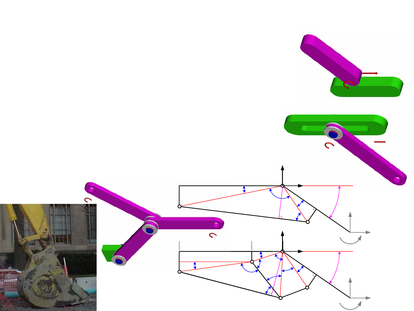
Joints: Higher Pair Multiple Degree-of-Freedom
Higher pair joints are those comprised of multiple elements that can
also allow for multiple degrees of freedom. A link acting against a plane is an
example of a higher order pair that allows for one linear and one rotary degree
of freedom. The link also requires a force to preload it (keep it in contact with
the plane) and keep it a form-closed joint, and f = 2 in Gruebler’s Equation.
Such a link may be used in a walking mechanism, but it is not very common.
A more common higher pair is a pin-in-slot joint where a pin allows a
link to rotate and the pin itself can slide in a slot. The geometry keeps the joint
constrained or closed (form closed). This joint can be considered the combina-
tion of a pivot joint and a slider joint into one compact unit. It is commonly
used in mechanisms such as those used to open and close casement windows. It
it is a multiple-joint for which f = 2 in Gruebler’s Equation.
Another common joint is a second order pin joint, in which 3 links
are joined at a single node. Since the links can move in different directions,
depending on how their ends are constrained, it is considered a multiple-joint
and so f = 2 in Gruebler’s Equation. As shown in the picture, this joint is what
enables the hydraulic piston to produce a very large range of motion in the
excavator bucket. Indeed, this type of linkage is very commonly used in con-
struction equipment to allow a linear actuator to actuate a link through a very
large angular range of motion with a much more even torque capability than
would be possible if the cylinder pushed directly on the load.
Part of the fun of designing linkages is the geometry problem that one
encounters when trying to evaluate ranges of motions and the relationship
between actuator force and joint torques. No matter how complex the linkage,
imaginary lines can be drawn between nodes to form triangles. Then its just a
matter of using trigonometry, especially the laws of sines and cosines, to solve
for the unknowns. Analysis is often used during the concept phase to deter-
mine the best type of linkage to use. For example, compare two linkages for
moving an arm (boom): a simple piston attached to a pivoting arm (a 4-bar
linkage with pin joints at points A, B, and D) and a more complex 6-bar link-
age, such as used for an excavator bucket, with pin joints at points A, B, D, E,
and H. The lengths of the segments and the angles defined are coded by color,
where the black letters are known dimensions and the red and blue dimensions
are intermediate calculations. This is helpful for documenting one’s analysis
so other engineers can follow your work. The solutions for the 4-bar linkage
are:
The solutions for the 6-bar linkage are a bit more involved:
In both cases, the angle
θ
and the radius R on which the piston acts to
create a moment on the output link would be determined for the piston length
L as it increases from its contracted to extended states. Plots of
θ
and R for the
4 and 6-bar linkages can then be done to determine which is the most appropri-
ate for the system being designed. When a large range of motion is required,
the 6-bar linkage is well-worth the design and manufacturing effort!
Study the figures carefully and derive the above equations indepen-
dently. Where in you machine might you want to use a more complex, but
larger range of motion 6-bar linkage? Check out the spreadsheets!
22 22
11
22
22
22
11
sin sin
cos cos
22
sin
ef
dc ab
db
ef
ff
ee
LL
ef fL
Rf
αγ
βφ
θπαβγ φ
−−
−−
=+ =+
⎛⎞
⎛⎞
==
⎜⎟
⎜⎟
⎝⎠ ⎝⎠
⎛⎞⎛⎞
+− +−
==
⎜⎟⎜⎟
⎝⎠⎝⎠
=−−− =
()
()
2
2
2222
2
22
11 1
1
12
11
312 12
22
22 2 2
211
223
3
1
41
tan cos tan
2
222
2 cos cos cos
22
tan
ij k
df
f
eabc
df f
g
kL
ckge
gj
im m h
mig
g
iim mj
b
a
ββ α
ππ
πππ
βββ ββ
αα
βαα
φ
α
−− −
−−
−
=+ =+ =+
−
⎛⎞
+−
−
⎛⎞ ⎛⎞
== =
⎜⎟
⎜⎟ ⎜⎟
⎝⎠ ⎝⎠
⎝⎠
= − −−−− − =−−+
⎛⎞⎛⎞
+− +−
=+− = =
⎜⎟⎜⎟
⎝⎠⎝⎠
⎛⎞
==
⎜⎟
⎝⎠
()
22
22 2
2
11
2
1234 12
cos cos
22
sin
gg
mi k
L
gm gL
Rm
φ
θπ φφ
αααα
−−
⎛⎞⎛⎞
+− +−
=
⎜⎟⎜⎟
⎝⎠⎝⎠
=− − − − = +
1/1/2008© 2008 Alexander Slocu
m
4-8
Joints: Higher Pair Multiple Degree-of-Freedom
•Higher Pair joints with multiple degrees of freedom:
– Link against a plane
• A force is required to keep the joint closed (force closed)
–A half-joint (f= 2 in Gruebler’s equation)
• The link may also be pressed against a rotating cam to create oscillating motion
– Pin-in-slot
• Geometry keeps the joint closed (form closed)
–A multiple-joint (f= 2 in Gruebler’s equation)
– Second order pin joint, 3 links joined, 2-DOF
•A multiple-joint (f= 2 in Gruebler’s equation)
c
da
b
j
D
A
B
θ
e
k
h
m
R
g
fi
H
β
1
β
2
α
1
α
2
α
3
α
4
φ
2
φ
1
β
3
E
L
piston
L
boom
F
x
F
y
M
Y
X
x
F
, y
F
c
d
a
b
L
piston
eRf
D
A
B
α
βγθ
φ
L
boom
F
x
F
y
M
Y
X
x
F
, y
F

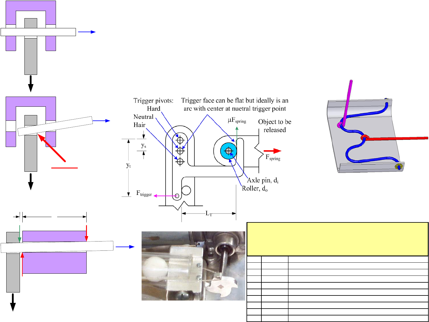
2-Bar Linkages: Triggers
A lever and fulcrum is a simple two-bar linkage that has many differ-
ent uses. Recall that the lever itself is a link to which the input and output
forces are both applied. The fulcrum acts as the pivot, and the structure to
which the fulcrum is attached is the ground link. Gruebler’s Equation gives
3*(2 - 1) - 2*1 = 1 degree of freedom. Pliers allow a small grip force to apply
a large grip force. Another particularly useful class of 2-bar linkages are trig-
gers. Triggers are used to hold back large forces, such as those from constant
force springs, and release them with a small force.
A lever-type (latch) trigger is a simple 2-bar linkage, where the loca-
tion of the pivot point with respect to the force being resisted (the latch force)
determines if the trigger is hard, neutral, or hair. A hard trigger is when the
dimension ys is positive so the force acts to keep the trigger from misfiring;
however, it requires more force to trigger. A neutral trigger is when ys = 0, and
it is easy to release. A hair trigger is where ys is negative and the only thing
that keeps it from firing is friction. The equilibrium equation is:
Friction is dealt with by using a roller, or a curved surface as shown in
the figure. If a hard surface is used (no roller), then μi is set to a very large
number in the above equation. The spreadsheet trigger.xls can be a useful
design tool to determine if a roller should be used. it can also be used to ensure
that the actuation method used to release the trigger has enough force.
A variation on this type of design is the bent-wire trigger. The wire is
shown in blue and is released by pulling up on the purple string. The red string
is shown tied, so when it releases its total stroke is limited, but a hook that
releases can be used if needed. Be careful of flying parts! Why is the blue
wire shown with the wavy bends? Are they really needed?
A simple pin-type trigger uses a pin in a bore. One end of the pin
sticks out of the bore and resists a shear force. An axial force applied to the
other end of the pin will pull the pin into the bore and release the applied force.
Although conceptually simple, the existence of friction can cause the pull force
to be large. How should L1 be determined?
Despite the simplicity of triggers, it is amazing the number of novice
designers who do not use these simple equations to optimize their trigger
designs. Often they are stuck with triggers that do not release, or release too
easily. Use the equations to design your trigger before you build it!
Often a machine designed for a contest will want to launch a projec-
tile the moment the contest starts and the machine starts moving. The use of
one channel on the control system and one actuator can be saved by using the
motion of the machine’s wheels as the trigger. To do this, use a pawl1 trigger
as shown where the pawl would be attached to the same shaft that supports one
of the machine’s drive wheels. A string can be held in the root of the pawl
tooth, and when the wheel starts turning the string is either let go or drawn in to
release a trigger. Just make sure that with continued motion of the wheel the
string falls clear and does not wind up around the axle.
Look for triggers on common objects in your home. Have you exam-
ined a classic mousetrap lately? If not, go buy one and examine it (carefully)
and take it apart. Sketch a free body diagram of the parts and see if you can
determine with what force the mouse steps to trigger the trap. Given the
strength of the spring and inertia properties of the moving member, can you
determine how long it takes the trap to close? How fast does the mouse have to
be? Does it even have a chance to accelerate out of the way? Do you need a
trigger in your machine? Can you scale one of the triggers you have seen?
How will you analyze your trigger before you build it to make sure it will
work?
(0,1,1)*(, 0
i
i
stts o
st s
o
d
IF MIN
yy y
FFLF d
μ
μ
⎛⎞
−+ <− =
⎜⎟
⎜⎟
⎝⎠
1. A pawl is a toothed wheel where the teeth are angled so in one direction of motion they grab, but
slide in the other direction.
()
12 12 12
12 1
12
22
12
12
2
0() 0
()
2
Trigger
M
FL F L L F F F F
FL L FL
FF
LL
LL
FFF F
FL
μμ
== + + == − −
+
==
⎛⎞
+
=++⇒
⎜⎟
⎝⎠
∑
∑
1/1/2008© 2008 Alexander Slocu
m
4-9
2-Bar Linkages: Triggers
• A trigger is a mechanism that uses a small input to release a big output
– Stable (hard trigger), neutrally stable, or marginally stable (hair trigger)
– Beware of fundamentals, e.g., Saint Venant, and stress reliability!
• Leverage is often the key!
L1L2
F
F
F
2
F
1
F
Trigger
F
FTrigger
F
FTrigger
Jammed!
Pawl trigger: A pawl is attached to a shaft (which may also
hold a wheel), that releases when the shaft turns
LT 50
ys 0
yt 35
di 6
mi 0.05
do 12
mo 0.1
Fs 100
Ft 3.6
Stable Force to release load
Trigger stability
Be consistent with units (e.g., mm, N)
Trigger latch pin friction coefficient
Trigger latch roller diameter
Trigger latch-to-roller friction coefficient
Force to be held by trigger
Horizontal distance between trigger pivot and trigger latch
Vertical distance between trigger pivot and trigger latch
Vertical distace between trigger pull and pivot
Trigger latch pin diameter
Trigger.xls
To design a trigger
By Alex Slocum 8/28/2005
Enter numbers in BOLD, results are in RED

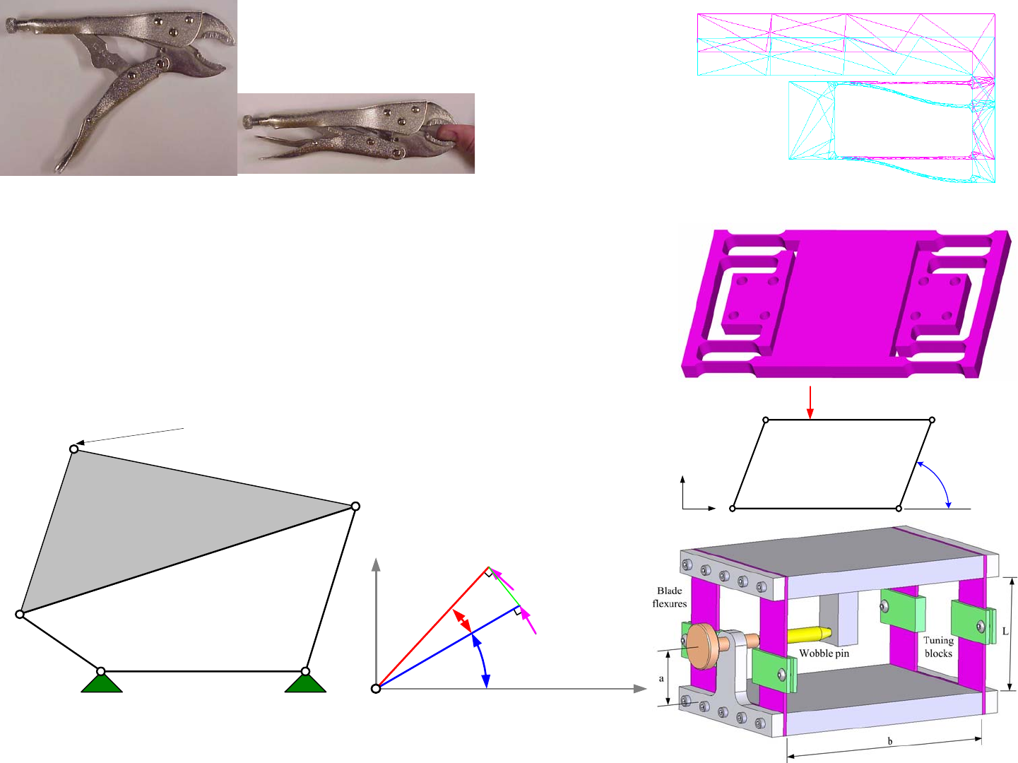
3-Bar Linkages (?!)
A 3-bar linkage has three links and 3 pivots, and Gruebler’s Equation
gives 3*(3 - 1) - 2*3 = 0 degrees of freedom. However, being a triangle, it is
stable even if the links inadvertently change length! Consider the development
of a concept for a large low-cost precision gantry machine. In order to achieve
precision linear motion, bearings must be spaced apart so they act as a force
couples to resist moments. This generally means that the surfaces on which
they move are also spaced apart; however, it is not possible for two elements to
be exactly parallel, so the ground link’s length is not always constant.
Misalignment between bearing rails can be accommodated in many
different ways. The simplest way in which misalignment is accommodated is
by allowing for clearance between the bearing and the rail. If the loading of
the system is always from the same direction, this configuration can still pro-
vide acceptable accuracy. The clearance provided can accommodate misalign-
ment, but then this places a limit on the accuracy of the system being
supported. Another method that allows for rail misalignment is to mount one
of the bearing assemblies rigidly to the moving structure, and compliantly
mount the other bearing. This can be achieved with metal flexures or even
resilient mounts, such as rubber. However, the product of the misalignment
and the flexure stiffness is a force that must be subtracted from the load capac-
ity of the bearing. The use of clearance or compliance in a machine with rea-
sonable precision can typically accommodate 0.1 mm of rail misalignment
over the length of the rail.
In order to accommodate misalignment without sacrificing as much
performance, the principle of reciprocity can be used. Misalignment is funda-
mentally an angular error motion that is amplified by distance into a larger dis-
placement between the bearing rails. There must be a way to use angular
motion to counter these effects. A sine error, as discussed starting on page 3-8,
is a linear distance that results from an angular error being amplified by the
length of a machine component on which it acts. It thus makes sense that there
should be a way to properly constrain the bearings on two misaligned rails,
such that the misaligned rail’s errors are accommodated by sine errors.
As shown in the figure, this can be achieved by having one side of a
machine’s bridge rigidly mounted to a bearing on a rail and the other side
mounted to a pivot located atop a link whose base pivot is mounted to a bear-
ing on the misaligned bearing rail. As long as the bearings can accommodate
linear as well as rotary motion, they can be preloaded to move with zero clear-
ance. As one bearing rail starts to diverge from the other, the connection via
the link with the pivot to the bridge rotates about its bearing mounted on the
rail. This also results in some small vertical motion of the bridge, a cosine
error, but it can be predicted and in most cases, it is negligible.
Hence the system is stable and rigid as required for a machine tool.
It is a 3 bar linkage with 3 pivots. When the spacing between the bearing rails
changes, what was the ground link is actually a slider, and the system essen-
tially becomes a 4 bar linkage. The pivots accommodate motion, but for any
instant in time, it is a stable 0 degree of freedom 3 bar linkage!
This clever design1 is an exact constraint design, as discussed in prin-
ciple on page 3-24. If a flexure, or spherical pivot, was not used between the
riser and the bridge, then bearing rail misalignment must to be allowed for by
bearing clearance or by elastic deformation. This common issue can result in
the bearings failing early unless the product of the misalignment and the bear-
ing stiffness is accounted for in the assessment of the load/life analysis for the
bearing (see page 10-32). This same lesson can be applied to machines and to
linkages. As you read this book, keep thinking of how the links and joints
would be designed to have the exactly proper constraints so that they can move
just the way they are supposed to be, without overloading and prematurely
wearing out the bearings!
Think of your machine as a series of links, some of which are pinned
and cannot move, and some that change shape and cause the machine to move.
Whatever your machine does, make sure it does only what you want it to!
1. This great patentable idea seemed too simple to the author, so he did a patent search and found US
patent 4,637,738. The patent claims the use of angular motion about a round rail and a angularly compli-
ant connection between the bearing and the carriage to compensate for a varying center distance between
round rails. This patent was issued January 20, 1987, and a company was worried about using this princi-
ple. Since there were no products on the market that appeared to have used this principle, the company
was encouraged to check to see if perhaps the independent inventor got tired of paying the maintenance
fees and just abandoned the patent. It turns out they did, and so the patent was then in the public domain.
The company did the right thing. Of course this did not address US patent 5,176,454 which was essen-
tially the same patent but with a double flexure (X and Y), but its claims were very narrow.

1/1/2008© 2008 Alexander Slocu
m
4-10
3-Bar Linkages (?!)
• A 3-Bar linkage (is there really a “3-bar” linkage?!) system can minimize the
need for precision alignment of bearing ways
– Accommodates change in way parallelism if machine foundation changes
– US Patent (4,637,738) now available for royalty-free public use
• Round shafts are mounted to the structure with reasonable parallelism
• One bearing carriage rides on the first shaft, and it is bolted to the bridge structure risers
• One bearing carriage rides on the second shaft, and it is connected to the bridge structure
risers by a spherical bearing or a flexure
• Alignment errors (pitch and yaw) between the round shafts are accommodated by the
spherical or flexural bearing
• Alignment errors (δ) between the shafts are accommodated by roll (θ) of the bearing
carriage
• Vertical error motion (Δ) of the hemisphere is a second order effect
• Example: δ= 0.1”, H = 4”, θ= 1.4 degrees, and Δ= 0.0012”
• Abbe’s Principle is used to the advantage of the designer!
()
()
2
arcsin
1cos 2
H
HH
δ
θ
δ
θ
=
Δ= − ≈
US patent 4,637,738
US patent 5,176,454
4-Bar Linkages
A 4-bar linkage has four binary links and 4 revolute joints; hence
from Gruebler’s Equation there are 3*(4 - 1) - 2*4 = 1 degree of freedom. This
means that only one input is required to make the linkage move. If designed
properly, the instant center never becomes coincident with a joint and it will
move in a deterministic manner. Because of its simplicity, and perhaps also
because of the rapid increase in design complexity suffered by linkages with
more than 4 bars, the 4-bar linkage is one of the most commonly used linkages.
Thus considerable attention will be paid to its operation and its creation or syn-
thesis. In its simplest manifestation, a 4-bar linkage is a parallelogram so the
rocker and follower links are parallel and of equal length so the coupler moves
without rotation. In this case, the velocities of the coupler in the X and Y
directions are respectively:
If the crank is driven by a motor with maximum rated torque
Γ
, then
what is the maximum force Fy that the coupler can support? The easiest way to
determine the maximum force is to equate the work-in with the work-out. In
addition, we will consider the effect of friction
μ
in the pin joints of diameter
dpin (we know the pin rotation equals the rocker rotation for this configura-
tion):
For the generic 4-bar linkage with different length links, as shown on
the previous page in the context of instant centers, the same method of equat-
ing the work-in to the work-out can be applied. As shown, a force F acting at a
radius from a pivot and moving through an angle increment d
θ
moves a dis-
tance ds and does work Fds. This is a very important principle that greatly
simplifies finding linkage output forces given input forces. It allows the engi-
neer to create a spreadsheet or program to determine the position of the linkage
given an input parameter, such as crank angle, and then numerically determine
ds by incrementing the crank angle by say 0.001 radians. When the forces are
significant, or friction high, as is the case for sliding contact bearings, the
energy dissipated by friction can be accounted for in the analysis:
One may design a 4-bar linkage as a parallelogram to provide hori-
zontal motion of the coupler; however, the horizontal X motion will also be
accompanied by vertical Y motion. Unwanted deflections in the Y direction
are known as parasitic error motions. Parasitic error motions also plague
structural linkage systems and can lead to a reduction in quality and decreased
robustness. For small horizontal motions, the parasitic error motion is deter-
mined using small angle approximations to be:
Must pinned joints always be used? No, and in fact, flexural mem-
bers can be used which are constrained at each end by a zero-slope condition.
However, the actuation force must overcome the spring force of the flexures.
To avoid pitching motions on flexural element supported platforms that are not
subject to external loads, the actuator force should be applied at a point mid-
way between the moving and fixed platforms.1 Can the error motions and sen-
sitivities to actuation force placement be reduced? The fundamental principle
of Reciprocity, as discussed on page 3-14, comes to the rescue! The error
motion of one set of flexures can accommodate the error motion of the second
set by placing both sets back-to-back to create a folded flexure stage as shown
in the solid model image. These flexures are discussed in detail on page 4-24.
Given the simplicity of a 4-bar flexure, can you think of applications
in your machine? How about for a module to scoop up balls or hockey pucks?
Or maybe you want to create a linkage that can help your opponent to turn over
so they can show the crowds what a nice paint job they did on their machine’s
belly?!
sin cos
xy
aa
VV
ω
ω
=Ω =Ω
()
2sincos
2cos
yy
pin y
y
pin
dyadyad
dd
FF
Fa
d
μ
μ
Γ− Ω= = Ω = Ω Ω
Γ
=+Ω
1. Section 8.6, A. Slocum, Precision Machine Design, 1995, Society of Manufacturing Engineers,
Dearborn, MI
2
2
22
rocker_torque 2
2
2in in in
x y x y out
pin
out out
dy
dx
F
ddxdy d
FF FF F dy
dx
μ
+
Ω= + + + =
Γ+
2
2
x
yL
δ
δ
=
1/1/2008© 2008 Alexander Slocu
m
4-11
4-Bar Linkages
• 4-Bar linkages are commonly used for moving platforms, clamping, and for
actuating buckets on construction equipment
• They are perhaps the most common linkage
– They are relatively easy to create
– One cannot always get the motion and force one wants
• In that case, a 5-Bar or 6-bar linkage may be the next best thing
a
b
X
Y
Ω, ω
F
X
Y
d
θ
θ
F
R
x, y
x+dx, y+dy
ds = (dx
2
+ dy
2
)
1/2
c
d
b
aA
B
C
D
Coupler point: move it to get the
coupler curve to be the desired shape

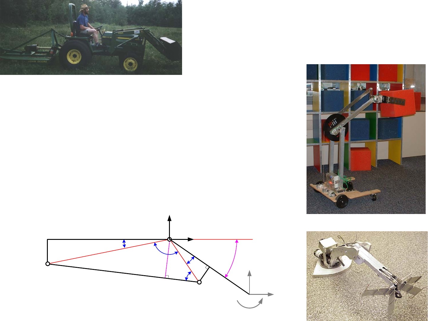
4-Bar Linkages: Booms
4-bar linkages are often used to actuate booms or robot arms. Page 4-
8 gave us our first glimpse of a piston actuated 4-bar linkage boom, where
equations were presented for the determination of the perpendicular distance
from the piston to the pivot point. The analysis showed that if we know the
loads applied to the end of the boom, we can find the moment on the pivot A
and the required piston force Fpiston. Although the term piston is used here, it
could just as easily be a leadscrew actuator that is used. Furthermore, note the
inclusion of elements of length b and d which represent offsets for the piston
attachment points from boom and link c respectively. These offsets represent a
more real-world design than if the pivots were located on the link lines and
then the designer would have to do small rotations to align these virtual links
up with the reference planes in an actual structure. This small increase in com-
plexity for analysis makes actual dimensioning of mechanism much more real-
istic and hence faster and less prone to errors.1
The spreadsheet 4barpistonlinkage.xls shows that as a piston extends,
the effective radius upon which it acts to create a moment about the boom pivot
point A decreases substantially. As a result, the required piston force to sup-
port the load increases. In some situations, this may mean that the boom also
becomes more vertical and the load would be creating less of a moment on the
boom. Because this is not always the case, this type of analysis is very valu-
able. Note that the effect of a moment on the end of the boom is included.
This moment could be created by another boom cantilevered off the first boom.
One can see this type of arrangement in some types of cranes and in concrete
pump trucks’ booms.
4barpistonlinkage.xls shows the ground link in a horizontal plane.
When the piston retracts, the boom is angled down almost 56 degrees, and then
when the piston is fully extended, the boom is nearly horizontal. The ground
link c could just as well be in the vertical plane, and the spreadsheet is equally
valid and useful. All that must be done is to be careful with the magnitude and
direction of the input forces. It is also useful to note that the total length of the
piston in the extended state is about 50% longer than the contracted length.
This reflects the overhead associated with the space required for the end pivots
and the structure of the piston. If one needed more stroke from a piston, one
would use a telescoping cylinder. Telescoping leadscrews have also been used
in applications such as aircraft control surfaces.
The above analysis only considers the kinematics and overall loading.
It does not consider the effect of the loads on the stress in the links. Given the
forces from the applied loads and the piston and the angles between links, it is
a straightforward exercise to determine the bending moments and hence the
required link cross sections to support them. The spreadsheet provided is just a
starting point and can easily be modified for your application.
Have you any 4-bar linkages that could be actuated by an extending
actuator such as a piston or leadscrew? Would a 4-bar linkage be useful for
preloading your vehicle to the square plastic tube so you can drive up to the
support tube, engage it and rapidly spin the tube for a large score multiplier?
Could you design a 4-bar linkage that lifts up your opponent and perhaps help
them turn over onto their back so they could have a nice gentle rest, but keeps
the lifting force close to your vehicle so you do not tip over? Synthesize and
analyze these linkages and determine what geometries could minimize the
forces required to actuate them.
1. The author’s first boss and dear friend Donald Blomquist used to say “Silicon is cheaper than cast
iron, and it does not rust” to mean use computers in analysis and control to help you minimize mechanical
complexity. Don was the Chief of the Automated Production Technology Division at the National Institute
of Standards and Technology. He was one of those rare people who understood mechanical and electrical
and digital hardware AND software. He died in a boating accident, but he has never left my thoughts. I
know that in the future I will join him to ride (although he will be on his skis, but maybe he has had time to
learn to snowboard) the deep powder formed by the galaxies that make up our universe.
1/1/2008© 2008 Alexander Slocu
m
4-12
4-Bar Linkages: Booms
• Linkages for cranes and booms are 4-bar linkages that replace
one of the pivot joints with a slider
–The boom is the follower even though it is used as the output link
–The piston rod is the “coupler”
–The piston cylinder is the “rocker”, and the connection between
the “rocker” and the “coupler” is a slider joint
• Link configurations can be determined using parametric
sketches, sketch models, or spreadsheets
– Their simple nature makes them particularly well-suited for
development by a spreadsheet
Ayr Muir-Harmony’s 2.007 machine!
c
d
a
b
L
piston
eRf
D
A
B
α
βγθ
φ
L
boom
F
x
F
y
M
Y
X
x
F
, y
F
Mark Cote's winning 2005 2.007 "Tic-Tech-Toe" machine
4-Bar Linkages: Kinematic Synthesis
If you are given all the dimensions of a linkage and the input angle of
the crank, you can easily determine the position of the coupler. The problem of
determining the position of a linkage’s elements given their dimensions and
constraints, either relative to each other or to the positions of the actuators, is
called the forward (or direct) kinematics problem. What if you were given
desired positions of a coupler and had to find the link parameters that would
enable the linkage to move the coupler through the desired positions? This is
called the inverse kinematics problem when determining the position, such as
crank angle, of the actuator(s). Linkage synthesis is when the lengths and posi-
tions of the links themselves must also be determined.
Image a coupler in three different required positions. The pivots at
each end of the coupler in each of these three positions are called precision
points. The crank and follower must each be attached to the coupler at its ends
respectively, and since the crank and follower are also fixed to the ground link
by pivots, the task is simply to find the location of the ground pivots. The key
skill required for synthesizing 4-bar linkages is to be able to find the center of a
circle that passes through three points.
As shown in the figure, to find the center of a circle that passes
through three points, first connect the points with lines. Next, find the per-
pendicular bisector of each red line by drawing equal radii arcs with their
centers at each end the line. Connect the arcs’ intersections with a line,
which will be the perpendicular bisector for that line. The center of the
circle (arc) that contains all three points will lie at the intersection of the
perpendicular bisectors. If this process is done for each end of a coupler,
then you will have located the ground pivot locations for both the crank and the
follower! This method is called the three precision point linkage synthesis
method. Finding the center of a circle that contains the three precision points
can also be done with the 3-point-circle icon on many CAD systems.
The next step is to find the curve that plots the locations of the cou-
pler’s instant center as the linkage moves through its desired range of motion.
If the instant center ever passes through one of the linkage’s joints, then at that
point an instability can occur, and the linkage can move in one of two different
directions. This generally is not a desirable situation, and thus different preci-
sion points might have to be selected, or the follower might have to become the
rocker and vice versa!
When a 4-bar linkage is a parallelogram, the instability will never
occur; so then why would anyone want to use anything else? When designing
a bucket for a scoop, for example, it is desired for the coupler to also rotate as it
translates. In addition, when the actuation method is a hydraulic or pneumatic
piston that causes the crank’s length to change, rotation will occur! The mech-
anism shown modeled with LegosTM uses a 4-bar linkage to raise a scoop and
dump it behind itself. This system might be used, for example, to scoop balls
or pucks and dump them into a collection bin for later dumping into a scoring
bin. This linkage would be actuated by a motor/gearbox driving the rocker.
Here it is a rocker because it does not keep revolving, but rather its motion will
be oscillatory. How might a crank be used instead?
One of the advantages of physically modelling a linkage is that you
can move it and experience whether it will lock up, and discover the mechani-
cal advantages/disadvantages with respect to the force inputs and outputs.
Even though a linkage may have some unstable points, some regions may pro-
duce highly desirable motion. James Watt invented such a linkage to create
near straight-line motion to guide the connecting rod of one of his steam
engines! As shown, his 4-bar linkage creates nearly straight-line motion for a
limited range of motion of the rocker.
Creating linkage sketch models from LegosTM or other construction
toys is a great way to rapidly experiment with potential linkage designs. Even
though the spacing between possible pivot points is relatively coarse, they can
enable you to converge on an overall linkage configuration that can then be
optimized using the equations discussed earlier (or write your own!). This will
help you develop a physical instinct for the design of linkages. The next step
would be to learn to use one of the many CAD programs specifically devel-
oped to help synthesize and analyze linkages.
Do you need linkages for suspensions or preload mechanisms? Do
you need linkages for large motions for buckets to scoop up stuff? Can you
connect a motor up to a crank or rocker, or should your motor power a screw?
Generate ideas by visiting construction equipment (web) sites and look at how
machines move and work.

1/1/2008© 2008 Alexander Slocu
m
4-13
4-Bar Linkages: Kinematic Synthesis
• 4-Bar linkage motion can be developed using kinematic synthesis:
–3 Point Circle Construction (Precision Point Method)
•3 Precision Point Example
•Loader Example
–Experimentation
Instant Center and pivot point become
coincident and linkage becomes unstable
Apply reversal to the
geometry and unstable
becomes stable!
Kinematic Synthesis: 3 Precision Point Example
A good way to synthesize a design is to start with a search to see what
exists. Ideally you can scale or evolve an existing design. There are so many
different linkage designs for so many different pieces of equipment, that
chances are what you need already exists, and you merely have to scale it.
There is no loss of design genius in scaling an existing design, as long as you
do not infringe a patent. Once you have identified a linkage to scale, or even if
a new linkage is needed, its development can proceed either graphically or ana-
lytically. Often the former is used to generate the overall shape, and then equa-
tions can be created to optimize it or to understand its mechanics so links and
joints and the actuator can be properly sized.
Consider a linkage for a single degree of freedom scoop to collect
objects and then dump them into a bin. This would allow a machine to zoom
around gathering balls from all sides of a contest table. In addition to the steps
described above, the concept of bracketing the solution will be used. This
means that one of the pivots on the coupler will be assumed fixed, and the
other point will be assumed to be in one of two extremes. Whichever extreme
yields the better linkage can then be further optimized. This means that we are
using the fundamental principle of reciprocity from the start to investigate two
very different ideas that will then be compared.
In the first case shown, the coupler pivots lie on a line parallel with
the bottom of the scoop. The sequence of sketches shows the rocker and fol-
lower base pivot point locations. In the second case, the pivots lie on a line
that is perpendicular with the bottom of the scoop. The sequence of sketches
shows the rocker and follower base pivot point locations. A solution appears
to have been found for the first case, where the pivots on the coupler are paral-
lel to the bottom of the scoop, but the system is very long and takes up a lot of
space. A long rocker would mean that for a given power source high speed
could be obtained, at the expense of torque, or in this case, lifting capacity.
Conceptually, one can also see that the instant center stability criteria
is met, but the pivot on the couplers exchange position. What was in front is
now in back, so the rocker and follower links will have to cross each other. If
one is offset from the other, than this can be made to happen, but what are the
implications for stability and robustness? Does this create a point where the
instant center moves near a pivot point? Here again is where a physical model
can aid in the synthesis process, and it turns out, that crossing the links is not
necessarily a bad thing with respect to stability. However, it may sometimes
cause some difficulty in manufacturing.
In the second case, the pivots lie on a line perpendicular to the bottom
of the scoop. In general, it will be easier to manufacture the linkage when the
rocker and follower base pivots are further apart. In addition, it is also desir-
able to not have the links cross so they can both reside on the same side of the
base structure and are less likely to collide with other associated mechanism.
By translating and rotating the coupler in the neighborhood of the desired pre-
cision points, the bottom sketch emerges which mostly meets the above crite-
ria. As the center drawing shows, a kink needs to be added in the follower to
clear the rocker base pivot. This is a simple and common thing to do, particu-
larly if you are cutting your links out using a programmable torch or abrasive
waterjet cutter.
These two cases illustrate the concept of bracketing a design. The
optimal probably lies somewhere between. It is analogous to limit analysis,
trying the extremes, or bracketing exposures in photography. If you try the
extremes and observe the effects, you can converge on the best middle posi-
tion. So what is better for synthesis by bracketing: sketch models or CAD sys-
tems? The former has more of a feel to it, but the resolution of the part size
limits your creativity. On the other hand, it does help develop insight and
physical feel, which are very important for developing your bio neural linkage
net! The CAD system allows you to explore variations far more rapidly, and it
is not resolution limited. The 3 point precision method is still where the points
are defined using the sketching feature. Solid elements can then be added, and
the system moved through its motions to check for interferences. The next step
would be to size members and actuators and again check to make sure every-
thing still fits.
You must now have a good idea of what sort of 4-bar linkages might
be useful for your machine. Use the 3 precision point method to synthesize
potential linkage designs and build sketch models to verify the designs. Now
is a good time to turn on the CAD system and try to create some linkages.
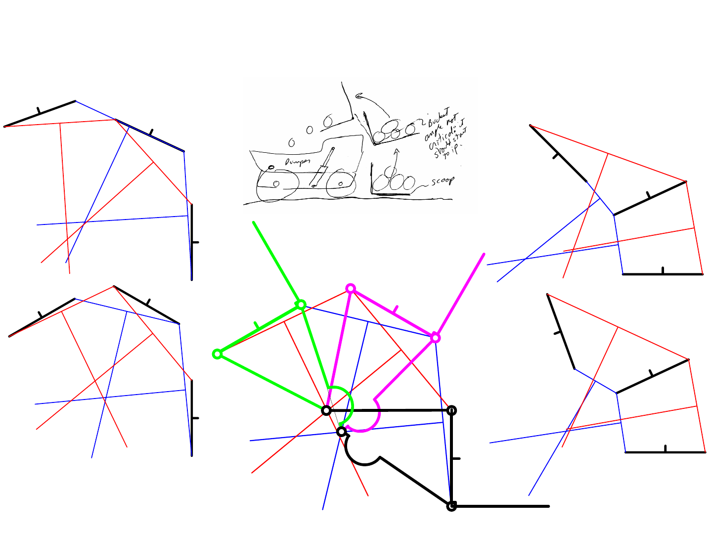
1/1/2008© 2008 Alexander Slocu
m
4-14
Kinematic Synthesis: 3 Precision Point Example
Use the 3 precision point method to find the ground pivot point for the crank and follower links
1st try, joints
overlap, bad
4th try, good!
Add the links, with a kink
in the follower to clear
the rocker ground pivot
2nd try, better, but
links cross
3rd try, crossing
links
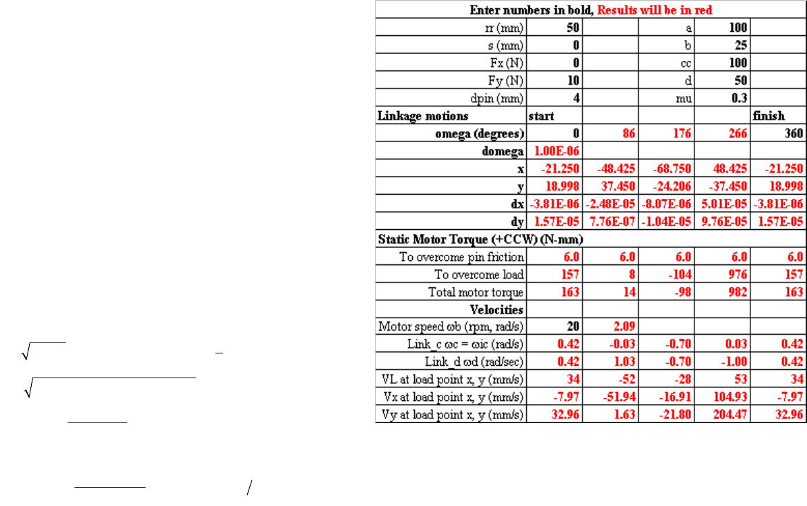
Kinematic Synthesis: Analysis
Once a linkage design has been synthesized, for example by the 3
point method just shown, the next step is to perform the analysis needed to
determine the velocities, accelerations, and loads in the system. This will
enable you to size the links and the actuator to make sure that they are strong
enough throughout their range of motion. Given the analysis tools and formu-
las available, it is rare and unacceptable to build a serious linkage by trial and
error, particularly to build it and then find out that it is not strong enough to do
the job. Perhaps when designing a machine totally from construction toy com-
ponents, one could more rapidly build and test a system; however, where you
are cutting and assembling components, synthesis and analysis will save you a
lot of time in the shop. Once synthesized, the linkage should be sketch mod-
eled, even by printing the CAD synthesis drawing and then cut out the links
and pin them together with push-pins and then carefully move it for a geometry
check. You may even wish to make a full-scale foam core sketch model and
use it in a sketch model derby. If you are lucky, LegoTM pieces will be of
close-enough size that you could make a Lego sketch model.
In order to determine the motor torque to move the rocker which
moves the load acting on the coupler, we can build on the instant center analy-
sis from page 4-9. The drawing shows the added geometry in green. The goal
is to determine the x, y global position of the loads Fx and Fy applied to the
coupler at points r and s in the coupler reference frame. A spreadsheet can be
used to numerically differentiate the closed form non-linear equations for the x
and y coordinates of the loads to find dx/d
Ω
and dy/d
Ω
for the energy calcula-
tions needed to determine the required motor torque:
From the spreadsheet 4baranalysis.xls, the motor torque as a function
of loads applied to the coupler can be determined. This spreadsheet uses a
numerical differential method to determine motor torque to move the applied
load as a function of rocker angle. It is also possible to add rows to input link
dimensions and calculate inertias and stresses and accelerations. In addition,
note the Grashof criteria for initially selecting link lengths to obtain the gen-
eral type of motion desired. Have a look at a portion of the spreadsheet:.
You now have the tools and methods to synthesize and analyze a 4-
bar linkage for your machine. Do so for your most critical linkage. If you can
achieve good motions, excellent. If not, you may need a higher order linkage
as will soon be discussed.
()
() ()
()
1
2
28
22 876
222
1
9
99
ker_
sin
2cos
cos 2
cos sin
2
xy
roc torque x y pin
s
ts
rt
utb
tb
but
bu
xu yu
dx dy
FF d
FF
d
α
ααα
α
αα
μ
−
−
⎛⎞
=+ = ⎜⎟
⎝⎠
=+− ++
+−
⎛⎞
=⎜⎟
⎝⎠
=Ω+ =Ω+
+
=++
ΓΩ
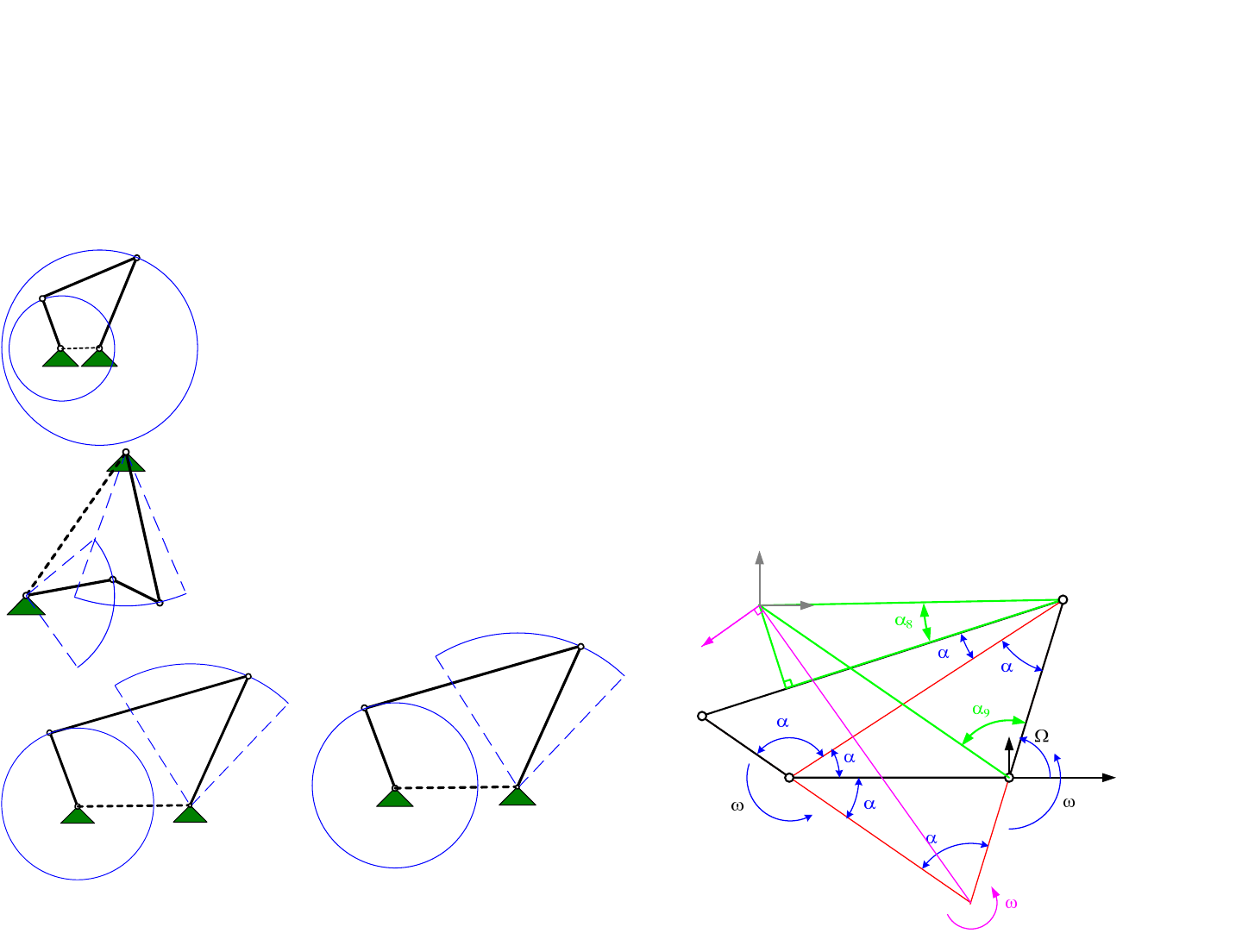
1/1/2008© 2008 Alexander Slocu
m
4-15
Kinematic Synthesis: Analysis
• Code or a spreadsheet can be written to analyze the a general 4-bar linkage, but types
of motion can be anticipated using the Grashof criteria:
–The sum of the shortest (S) and longest (L) links of a planar four-bar linkage cannot be
greater than the sum of the remaining two links (P, Q) if there is to be continuous relative
motion between two links
• If L + S < P + Q, four Grashof mechanisms exist: crank-rocker, double-crank,
rocker-crank, double-rocker
• If L + S = P + Q, the same four mechanisms exist, but, change-point condition occurs
where the centerlines of all links become collinear and the mechanism can toggle
• If L + S > P + Q, non-Grashof triple-rocker mechanisms exist, depending on which is
the ground link, but continuous rotation is not possible
•Geometric inversions occur when different pivots are made the ground pivots (this is
simply an application of reciprocity)
Driver
S
L
L+S<P+Q crank-rocker
Q
P
S
Driver
L+S<P+Q
double-crank
P
Q
L
Driver
S
L
L+S<P+Q rocker-crank
Q
P
Driver
S
LQ
P
L+S<P+Q
rocker-rocker
76
5
c
d
d'
b'
b
a
A
B
C
D
ic
Ric
VL
t
rr
s
u
x, y Fx
Fy
X
Y
4
2
3
db

Kinematic Synthesis: Coupler Curves
Linkages are often drawn with more than just binary links connecting
pivots. Sometimes ternary or even quaternary links are shown connecting piv-
ots. The other nodes on the link represent attachment points for other objects
such as a bucket on a loader on a robot for a design contest! By providing
points on the coupler link away from the line connecting its pivots, different
types of motions can be obtained. The paths that these points trace are called
coupler curves. Coupler curves are the business end of a linkage, so it is
extremely important to be able to select link lengths and a crank1 to obtain the
desired motions. The best way to rapidly synthesize linkages with desired cou-
pler curves is to use an appropriate combination of bio-neural-net application
of fundamental principles, curve outputs from analysis programs, and playing
with sketch models. Optimization or fine tuning, can often be accomplished by
calculating a penalty function and using the analysis program to search for, or
tweak, link lengths to minimize the penalty function.
Fortunately, the analysis we have just completed forms the foundation
for selecting linkage lengths to obtain desired coupler curves. Unfortunately,
spreadsheets have limited numerical precision, typically 32 bits, so roundoff
errors in trigonometric functions can create errors near singular points in link-
age motion. However, a simple Internet search for “four bar linkage synthesis”
yields many excellent web sites that people have created to assist in the synthe-
sis and analysis of 4-bar linkages. Still, having your own code is useful to
allow you to customize and calculate exactly what you want. When you create
linkage analysis spreadsheets, and for example enter in equal link lengths, you
may see that some cells say #DIV/0! Why is this? The error can be traced to
the calculation of angle alpha5 between the crank and follower link line exten-
sions used to find the instant center. Use IF statements to force the value to be
a small distance so you do not divide by zero. For example, in the spreadsheet
use: alpha5 =IF(ABS(PI()-L51-B51)<1e-6,1e-6,PI()-L51-B51)
The spreadsheet 4baranalysis.xls also calculates and plots coupler
curves. Consider the two plots shown. The first plot shows a coupler curve for
a parallelogram linkage, and it can give happiness. However, if you make a
sketch model of a parallelogram linkage, for example using LegosTM, and play
with it by grabbing the coupler and moving it, you can make the coupler move
so it is always parallel to the ground link, hence tracing out an elliptical coupler
curve. Why then does the spreadsheet, or any other program, yield a kinked
plot? Move the sketch model’s crank link and see that when the instant center
moves from being at infinity to being at one of the pivots, which is when all the
links are colinear. A singularity nearly occurs and the next motion can have
the coupler either remaining parallel to the ground link, or starting to become
inclined to the ground link. In fact, in a vertical plane, you will find that when
the coupler link is below the plane of the ground link, it is parallel to the
ground link, and when it is above the plane of the ground link, it tilts and is
inclined to it. Joint clearance, friction, gravity and inexact link lengths create
just enough of a bias to make the linkage stay far enough away from the singu-
larity, making the linkage produce predictable motion. With a load attached to
the coupler, one should make sure the load is attached to give the desired path a
definite bias to maximize linkage determinism.
The other plot, on the other hand, shows a linkage where the rocker is
50 mm long, and the follower is 25 mm long. This linkage has a very limited
range of motion, because the rocker reaches a position where its motion cause
the follower and coupler to be colinear; and continued motion of the rocker
places the follower and coupler in tension, so the linkage locks up. If the
motion of the rocker is reversed, then the follower and coupler are placed in
compression and they “buckle”. The linkage motion continues until they are
again colinear, but overlapping, and the linkage again locks up. On the other
hand, what if the follower is now the crank because it can move through 360
degrees. When it is colinear with the coupler, its input torque cannot create
tensile forces along its length so the follower can never be colinear with the
coupler. In fact, it will cause the follower, the previous rocker, to oscillate
back and forth between what were its singularity points! We now have a very
useful linkage where a continuous rotary motion from a motor produces oscil-
lating output motion. When continuous rotary motion is the input, the crank
should be shorter than the follower, and one linkage can drive another linkage
to get even more interesting coupler curves.
Make some sketch models of linkages and play with them. Compare
their coupler curve motions to those that the spreadsheet generates. What
modules might benefit from oscillating motion and what modules may benefit
from continuous quasi-elliptical motions? Are neither appropriate and you
require something more like a crane boom?
1. Remember, a rocker is an input link that has oscillating motion, and a crank is an input link that
rotates continuously.
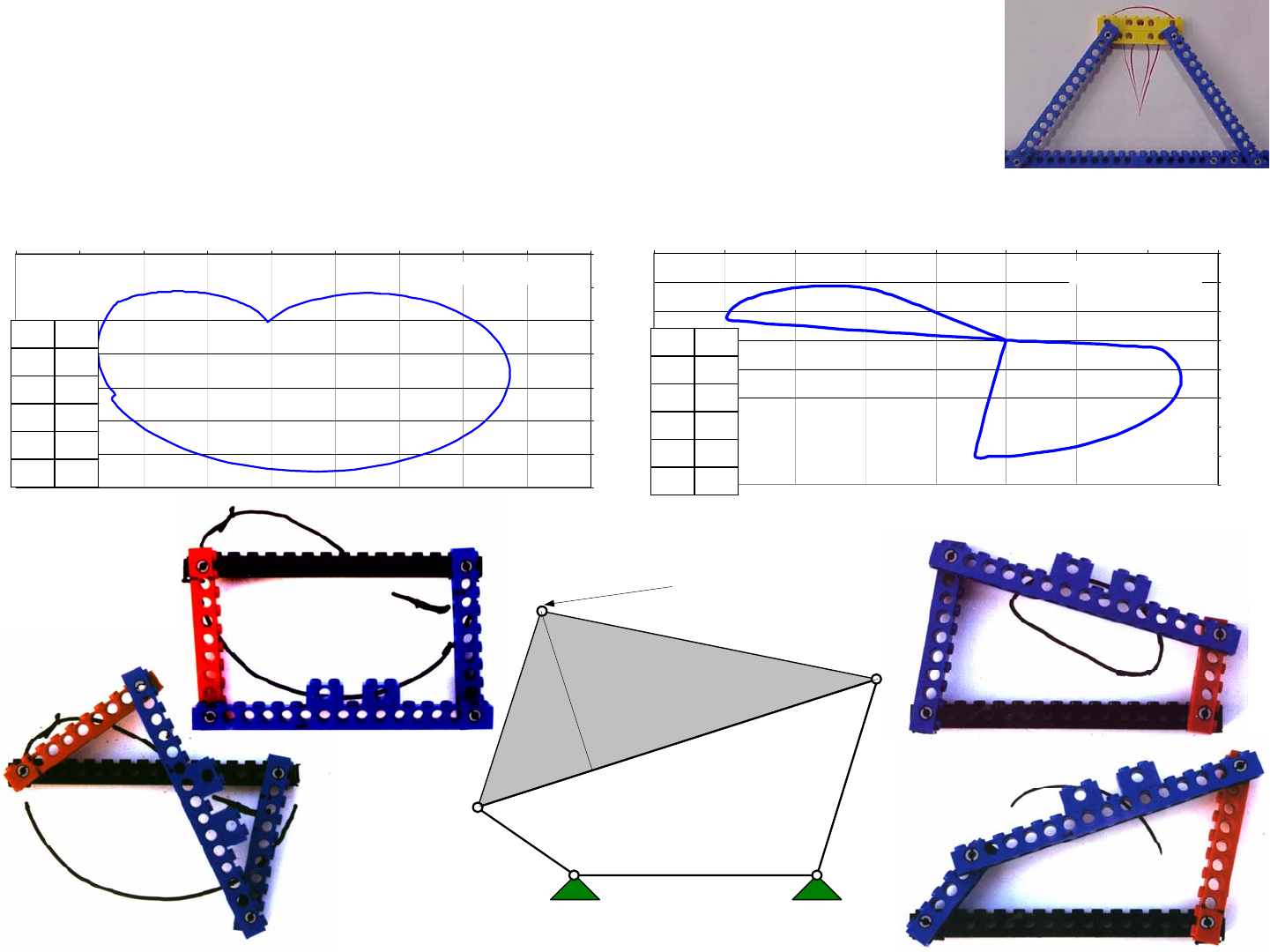
1/1/2008© 2008 Alexander Slocu
m
4-16
Coupler Point Motion
-100
-80
-60
-40
-20
0
20
40
60
-100 -80 -60 -40 -20 0 20 40 60
X position
Y position
Coupler Point Motion
-80
-60
-40
-20
0
20
40
60
-100 -80 -60 -40 -20 0 20 40 60 80
X position
Y position
Kinematic Synthesis: Coupler Curves
• From the same analysis, the motions of the coupler point can be plotted:
– See Linkage_4_bar_Analysis.xls
rr 30
s10
a 100
b25
cc 100
d25
cc
d
b
aA
B
C
D
Coupler point
rr
s
rr 50
s0
a 100
b50
cc 100
d25

Instant Centers
A link’s motion is a function of the motions of its endpoints, and the
pivot points must follow the contour of curves traced out by the endpoints of
other links. All these pivots following curves can become complex and make
it nearly impossible to visualize what is going on. Fortunately, for an instant in
time, a link’s velocity vector at any point can be determined using the concept
of the instantaneous center of rotation: The instant center is the point about
which every point on a link acts as if it is rotating about for an instant in time.
Furthermore, the velocity vector of any point on the link is perpendicular to the
imaginary radius from the instant center to the point of interest. The product of
the instant center of rotation’s angular velocity (or acceleration) and the radius
from the link’s center of mass to the instant center is used to determine the
link’s center of mass, velocity, and acceleration.
The instant center allows for the calculation of linear and angular
velocities of points and links, which when combined with the fact that power =
force (torque) x velocity (angular velocity) allows us to determine, for exam-
ple, the mechanical advantage of a linkage. If we know the input torque and
angular velocity for the crank, and we can compute the angular velocity of the
coupler or the follower, we can determine the potential output torque at the
coupler or the follower.
Consider the simple case of a wheel rolling on the ground. The wheel
may be rotating about its center, but for an instant in time, the point of the
wheel that contacts the ground is NOT moving. In fact, the center of the wheel
is rotating about the ground contact point, as is the top of the wheel! What is
the forward velocity of the center of the wheel (the axle)? What is the forward
velocity of the top of the wheel? Can you see that the top of the wheel is mov-
ing forward with twice the velocity of the center of the wheel (the car’s veloc-
ity)?
Study the circle with the chord and the two radii connecting the ends
of the chord to the center of the circle. If the radii are joined by pivots to the
chord and by a second-order pin joint to the center, then the chord can spin
around the circle. The instant center is at the center of the circle, and each end
of the chord would be moving tangent to the circle if the radii starting rotating
at a velocity ω. In addition to translating, the chord is also rotating.
For a linkage, one can actually identify many instant centers associ-
ated with the different links. Each pivot joint itself is an instant center, and
there are instantaneous (they move in time) centers associated with every pair
of links. The instant center of velocity (rotation) for two bodies in plane
motion is a point, common to the two bodies, which has the same instantaneous
velocity in each body. This point may be a virtual point physically located off
of the two bodies. Some of these points are not very interesting with respect to
analysis of the linkage, and some, as we shall see, are extremely interesting
from both a graphical and analytical perspective. How many instant centers
are there for a linkage comprised of N links? The number of combinations
possible for N subjects in groups of k, and for k = 2 is:
A 4-bar linkage thus has 6 instant centers, and a 6-bar linkage has 15
instant centers. It is not immediately obvious which ones are most useful for
the purposes of analyzing a linkage either graphically or analytically; however,
being able to identify a point that, for an instant in time, is the common center
of rotation of all points on a link is an extremely powerful boundary condi-
tion.1 This raises the delicious potential for creating a linkage where the
mechanical advantage is extremely large. Such linkages are often called toggle
linkages, and they are used on machines ranging from pliers to injection mold-
ing machines, to compactors and crushers.
Draw long dashed lines between each of the pivot joints in a linkage
on your machine. For sliding joints, draw a dashed line perpendicular to the
slider (the instant center is at infinity), and label all the intersections. How do
links move with respect to these instant centers?
1. See for example R. Norton, Design of Machinery: An Introduction to the Synthesis and Analysis of
Mechanisms and Machines, 2001 Mcgraw-Hill, New York
() ()
12
11
!2
ik
ik
Ni NN
CC
k
=
==
−+
−
==
∏
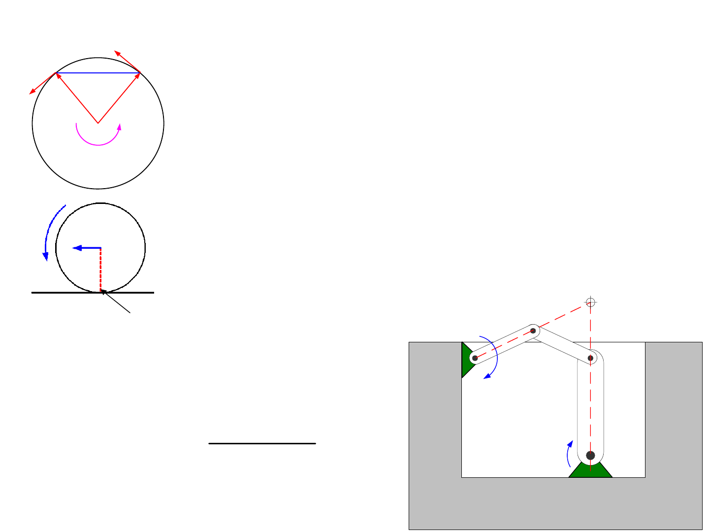
1/1/2008© 2008 Alexander Slocu
m
4-17
Instant Centers
• The instant center of velocity (rotation) for two bodies in plane motion
is a point, common to the two bodies, which has the same
instantaneous velocity in each body
– This point may be a virtual point physically located off of the two bodies
• The instant center can be used to determine relative velocities between
various links
– Knowing the relative velocity between links, and the torque input to one
link, allows you to use conservation of energy to determine the output
torque
– Can linkages be designed with immense mechanical advantages?
ω
Rolling wheel
ground pivot &
Instant Center
V=ωD/2
RR
R
ω
R
ω
ic
Instant Center
b
c
d
ω
b
ω
d
= ?
input output
input output
input input
output
output
ωω
ω
ω
=
ΓΓ
Γ
=
Γ

Instant Centers: 4-Bar Linkages
With the instant center located at the intersection of lines drawn along
the crank and follower, it is a simple trigonometry problem to find radii lengths
Rb and Rd from the instant center to the coupler’s pivot points, or the distance
Ric to any other point, such as the point on the coupler to where another load
may be attached. For geometric compatibility, the product of the distance Rb
from the instant center to the coupler link pivot and the instant center’s (also
the coupler link’s) angular velocity
ω
ic must be equal to the product of the
rocker link length b and the rocker angular velocity
ω
b. The angular velocity
of link d is found in a similar manner:
If the crank and the follower are of the same length, and the coupler
and the ground link are also of the same length, then the linkage forms a paral-
lelogram. The instant center is at infinity, the velocity vectors of the coupler’s
pivots are always parallel, and the coupler only translates, it never rotates. In
addition, if the input angular acceleration is known, then the accelerations of
the other links can be found, and combined with links’ inertial properties yields
torques and forces. The products of the torques and forces with the velocities
gives power, which yields an expression for the motor torque required to accel-
erate the linkage. The spreadsheet 4baranalysis.xls implements the above
equations and allows a designer to quickly study 4 bar linkage parameters and
determine if a gearmotor has sufficient torque and speed.
Instant centers also help to graphically evaluate the stability of a link-
age. A mathematical and physical instability occurs if as a linkage moves, the
instant center becomes coincident with one of the pivots. Other interesting
phenomena also occur. For example, automobile suspension linkage designers
must make sure that the line from the instant center to the center of wheel rota-
tion is parallel to the ground (see page 5-18). Else, if one wheel goes over a
bump and the suspension deflects, the wheel’s axle may see relative motion
with respect to the car’s forward velocity, which will cause that corner of the
car to speed forward. This is called bump-steer and it will cause the car to turn,
which could result in an accident.
The concept of the instant center, however, must be used with care.
For example, assume you have a system that is to pivot about a point in front of
itself. You can use a 4-bar linkage or you could use an arc-shaped bearing rail
and bearings that ride on the rail. A 4-bar linkage will work just fine for small
motions, but for larger motions, the instant center will also translate. Further-
more, if the structure were oriented vertically with the instant center above the
coupler, gravity would act to cause the linkage to keep moving and the actuator
would have to work to keep the linkage in a stable position. An arc-shaped
bearing rail, on the other hand, would have its instant center fixed at the center
of curvature of the bearing rail.
Assume the system just described is a new type of rocking chair.
Sketch the concept for a 4-bar linkage to locate the instant center in front of the
coupler and compare it to a design for a system supported by an arc-shaped
bearing rail. What are the strengths and weaknesses of each? How would you
choose between these two design options? Find the instant centers of other
linkages you have thought of using, as these linkages go through their motions.
Are the linkages stable? Should you consider changing the link lengths or
attachment points?
()
222
1
22
112
222
1
6123 432
22 2
12
2
547
22
22
12
8678
5
2cos cos 2
cos 2
cos 2
cos 2 cos
2
sin
''
sin
ic b
b
eab
eab
ab ea
dec
de
ced ts
r
ce
ts
rt
t
RR
R
rt
a
db
π
ααα
ππ
αααα ααα
π
ααα
αααα
α
−
−
−
−
+−
⎛⎞
=−Ω = + − = ⎜⎟
⎝⎠
+−
⎛⎞
=− − = =− −
⎜⎟
⎝⎠
+−
⎛⎞
=− −Ω = = +
⎜⎟
⎝⎠
+−
⎛⎞
==−++
+
⎜⎟
⎝⎠
Ω
==
4
5
sin ''
sin db
db ic
ic d L ic ic
b
add bb
RR
bRVR
d
R
α
α
ω
ωω
ωω
=+ =+
===
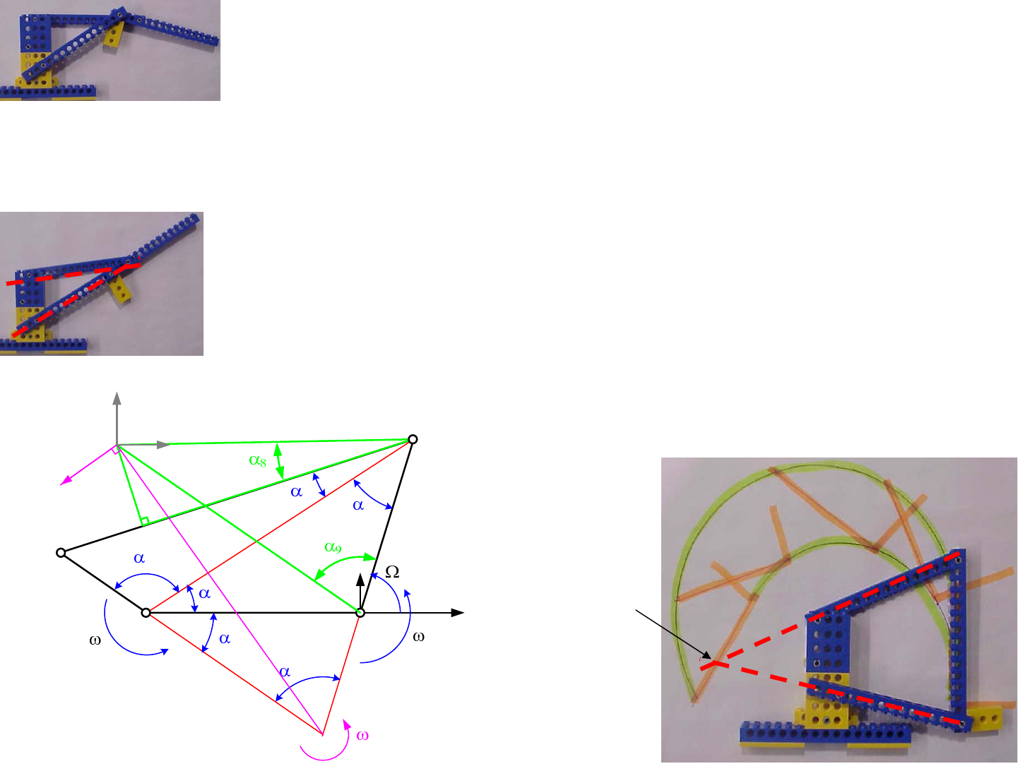
1/1/2008© 2008 Alexander Slocu
m
4-18
Instant Centers: 4-Bar Linkages
• One can visualize the instant center for a point on a moving body as the center of the
circular arc that coincides with the point’s motion path at an instant in time
– For a 4-bar linkage, draw lines through the crank and follower pivots, and the point at which the
lines intersect is called the instant center
– The velocity of any point on the coupler at any point is perpendicular to an
imaginary line from the instant center to the point of interest
– The instant center is used to determine the linear and angular velocity and
acceleration of the coupler’s center of mass or the coupler point
– If the instant center is coincident with a joint on the coupler, the linkage can become unstable
and can lock up, or the crank must reverse its direction
• A sketch model is a great physical way to check your linkage design!
This linkage’s instant
Center is always behind the
pivots
76
5
c
d
d'
b'
b
a
A
B
C
D
ic
Ric
VL
t
rr
s
u
x, y Fx
Fy
X
Y
4
2
3
db

Instant Centers: Example
A detailed analysis of a problem can yield detailed results, but it can
also take time. Many CAD programs are linked to or are included with mech-
anism analysis programs that allow a design engineer to play what-if games
and obtain plots of link and joint velocities, accelerations etc. So why is it
important to be able to use the principle of the instant center to analyze a sys-
tem? Being able to rapidly graphically evaluate a linkage trains the designer’s
eye to look at a system, “see” problems. and synthesize solutions. Thus it
helps to develop the designer’s intuition. A historical analogy is the slide rule
verses the calculator. Slide rules allowed an engineer to get two to three signif-
icant digits of accuracy, but the user had to know where to place the decimal
point and keep track of the exponent. As a result, slide rule using engineers
developed amazing intuitive feelings for the order-of-magnitude of a solution.
Calculator users, on the other hand, would punch in numbers and get an answer
and often blindly move forward.
The detailed analysis for a 4-bar linkage, and the principle of the
instant center can be used to study a system at the instant shown. With known
dimensions and crank angular velocity
ω
, what is the magnitude and direction
of the linear velocity of the coupler point? Point C connected to link d, which
is the crank turning at
ω
c, must move at the same velocity (magnitude and
direction) as Point C connected to link LicC. Hence the rotation speed
ω
ic at the
instant center is found from:
The magnitude of the velocity of the coupler point is just the product
of the instant center rotational velocity and the distance from the instant center
to the coupler point (or similar for any other point):
The direction, is determined by drawing the velocity vector perpen-
dicular to the imaginary line from the instant center to the point of interest. In
mechanisms such as suspensions, this graphical check can be a fast and simple
method to ensure that the velocity vector of the axle never has a forward com-
ponent, else when you go over a bump the car can lurch forward. It is nice to
know that during design reviews, using the instant center can enable you to do
quick design robustness evaluations!
What about acceleration? If you know the angular acceleration of the
crank, can you determine the acceleration of the instant center? Yes! Can you
find the linear and angular accelerations of each of the links’ centers of mass,
and along with their moments of inertia about their centers of mass, can you
determine how much torque is required to accelerate the linkage? Yes! Before
this level of detail, however, it makes sense from a design layout perspective to
assume all the mass of the links is located on the coupler, and just do the calcu-
lation based on the coupler. If the design is feasible, you could input the
detailed design, via a solid model for example, into a mechanism design pack-
age that can be used to determine the exact velocities and accelerations for all
the links given a torque input to the crank.
Once again, appropriate analysis is vital to minimizing the cost of
developing a product. Remember, time is expensive! Many times you may
want to do a back of the envelope calculation and then build and try something.
However, often you will find in today’s world of CAD that the “build and try”
phase can best be done with solid models. When is a physical model best? To
generalize would be wrong. This is why you need to develop your designer’s
intuition so you will better be able to determine what is the best way and when!
Look at linkages on familiar mechanisms and identify the “crank” and
the “coupler”. From pliers to car hoods, how do the instant centers move with
the linkage motions? Does the instant center ever get near any of the joints? Is
there any position of the linkage that looks like it may go unstable? One of the
best ways to build up your “designer’s” intuition is to observe and analyze
things around you. This can also be a great way to get a date! Try asking
someone of interest if they would like to take a walk and look at linkages with
you! You will be amazed at the reactions you will get!
icC ic c
c
ic
icC
d
L
d
L
ω
ω
ω
ω
=
=
icCP
ic
VL
ω
=
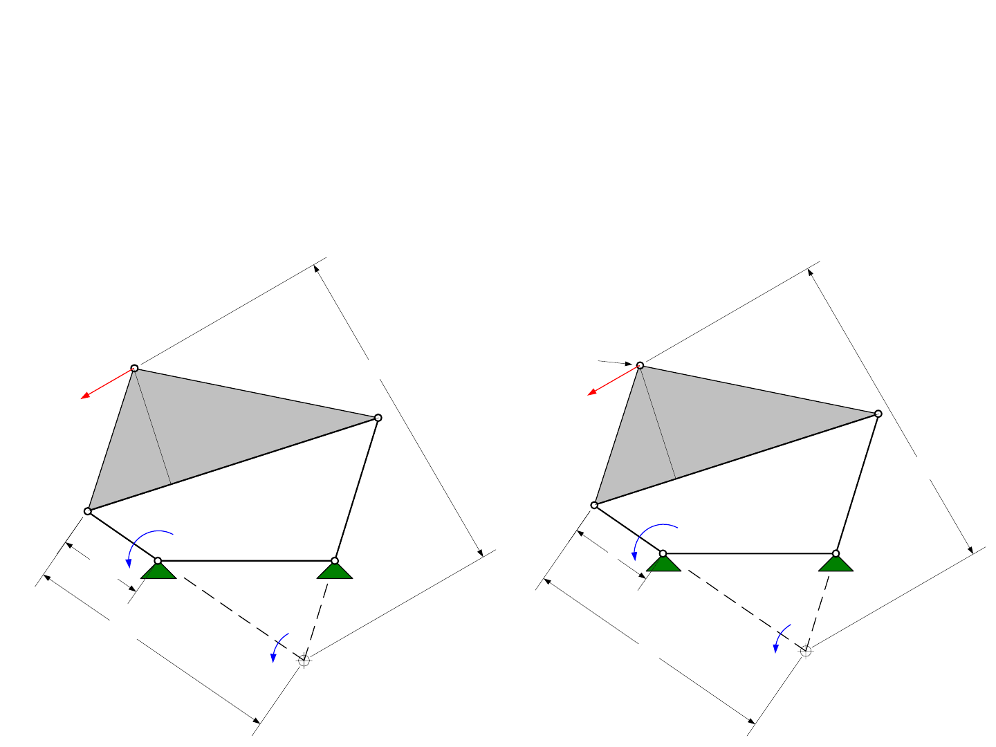
1/1/2008© 2008 Alexander Slocu
m
4-19
Instant Centers: Example
• Show the magnitude and direction of the Coupler Point for this 4-bar linkage:
– Draw lines through the crank and follower pivots, and the point at which the lines intersect is
called the instant center
– The velocity of the Coupler Point is perpendicular to an imaginary line from the
instant center to the point of interest
cc
b
A
B
C
D
rr
s
ω
c
= 1 rad/sec
V = 12.6 cm/sec
ω
ic
= 0.33 rad/sec
29.9 cm
9.8 cm
38.4 cm
cc
b
A
B
C
D
Coupler Point
rr
s
Instant Center
L
icC
d
L
icCP
Crank angular velocity ω
c
V
Instant Center
angular velocity ω
ic

5-Bar Linkages
When a 4-bar linkage cannot be synthesized to create the desired
motion, one usually makes the jump to a 6-bar linkage. But what about 5-bar
linkages? Considering Gruebler’s Equation, if we try to solve for the number
of joints f that give 1 degree of freedom, we get f = 5.5. Referring to the types
of joints available starting on page 4-6, the only way to get f = 5.5 would be to
use a combination of links against a plane (half joints) and single joints. In
fact, the “?” linkage on page 4-5 becomes properly constrained when one of
the ground pivots becomes a link sliding on the plane; however, this is not a
very useful linkage. Are there any other configurations that might be useful?
If you were told “there are no useful single degree of freedom 5-bar linkages”
would you try to invent one anyway?! :)>
How about 2 degrees of freedom? In this case, f = 5 and we ask our-
selves why would we want 2 degrees of freedom? Or perhaps an equally valid
questions is what does 5 links get us that 4 or 6 links do not? The primary rea-
son to use 5 instead of six links would be cost, because 6 links requires 7 joints.
Carefully compare the bolt cutters in the picture, especially the edge-views.
The 4-bar bolt cutters on the right have a single pivot joint formed between the
cutting blade links. Even though the center of the joint is essentially in-line
with the cutting edges, there will always be some offset and hence some
moment on the pin joint. If the joint were to be made as a yoke, a U-shape into
which fits in a blade to form a joint such as shown in the upper left hand side of
page 4-6, then two identical parts could not be used for the cutting blade links.
Thus we could conclude that the design for 4-bar linkage bolt cutters are for
smaller size units.
Carefully examine the 5-bar bolt cutters shown. The cutting blade
links are joined by connection links, which counts as one link since it functions
as a yoke. There are 5 links and 5 pivots and thus there are 3*(5 - 1) - 2*6 = 2
degrees of freedom. In practice, the friction of the pivots in the connection link
often makes only one of the cutting blades move with respect to the connection
link, so why not eliminate the connection link and one of the joints? This
would actually increase complexity, and it would greatly reduce the ergonom-
ics of the design. This is because these large cutters are often used where one
handle is placed on the ground, causing one cutting blade to also be parallel to
the ground, and one’s bulk is applied to the other handle which rises up from
the linkage. If the connection link were fixed to one of the cutting blade links,
then the design would be asymmetrical, and one would have to think about
which side goes down before one applies one’s bulk to the handle. It is inter-
esting to note that of the 2 degrees of freedom, only one is used actively, while
the other is used momentarily to set up the tool for ergonomic use. Which one
becomes dominant depends on how the tool is first picked up.
Returning to the world of synthesis and analysis, let us compare the 4-
bar clamping pliers to the 5-bar bolt cutters. Which design can produce more
force? The answer lies in which design can have the greatest ratio of handle
opening to jaw opening, because ultimately the forces can be calculated from
conservation of energy:
See, that was really easy. You probably thought “this is going to be a
painful analytical experience...” The 4-bar design typically allows for larger
jaw opening, but it cannot generate anywhere near the force of the 5-bar cutter.
As the picture of the locking pliers with the link outlines added
shows, links are not represented merely as straight lines, but often as triangles,
where external forces or potential attachments to other links could be applied.
The picture also shows a common feature in linkages, that of the toggle action.
Toggling occurs when then angle between two links passes from 180- degrees
to 180+ degrees. This means the linkage goes from one stable position to a
momentary unstable position, to a new stable position. In general, this means
going from an open or free state to a closed or locked state. This is very com-
mon in links used to close and clamp on a structure Also note the yellow link
and its pivot, which is used as a release lever. When the pliers are first picked
up and the handles squeezed, they are functioning as a 4-bar linkage. How-
ever, once clamped onto an object, the yellow link and its pivot connection to
the purple handle link and its half-joint connection to the black link make the
pliers a 1 degree of freedom 5-bar linkage with 5.5 joints! This design was ini-
tially patented and marketed as Vice-GripTM pliers.
Could you design a toggling linkage to allow you to easily place your
machine around the pendulum beam and then with a flick of a lever, clamp
onto it so your machine’s wheels were now preloaded to the beam and ready to
climb it, engage the support shaft and then cause it to spin!?
handles jaws
handles jaws
efficiency
FF
η
δδ
=
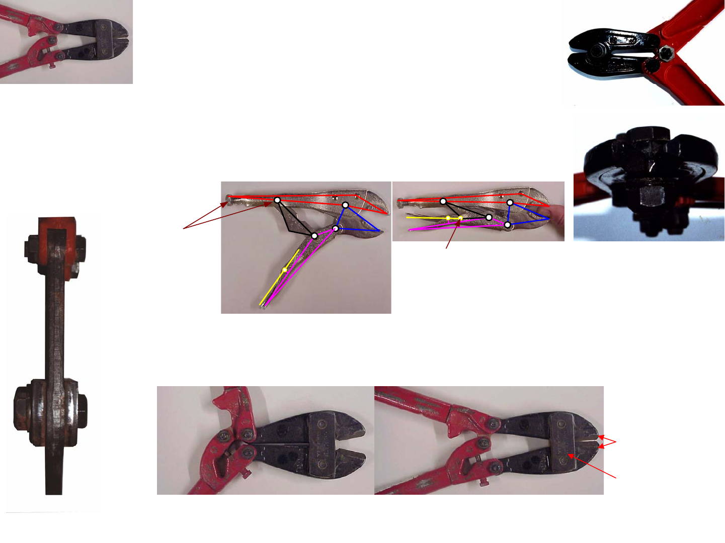
1/1/2008© 2008 Alexander Slocu
m
4-20
5-Bar Linkages
• Compare a simple 4-bar linkage for pliers or small bolt cutters to
a 5-bar linkage (5 bars, 5 joints, 2 DOF) for bolt cutters
• Where are the 2 degrees of freedom?
– The FRs of the pliers are for wide range of motion and modest
clamping force
– The FRs of the bolt cutters are for modest motion with extreme force
• A 5-bar linkage can also act like a toggle mechanism
Cutting
blade links
Connection
link
momentary
half-joint
What effect does
the screw have
on the pivot?

5-Bar Linkages: Analysis
We have seen how the 4-bar linkage pliers revert to a 5-bar linkage
with f=5.5 when the handle link pivot angle θ goes from 180- degrees to 180+
degrees. In terms of determining the jaw force Fj as a function of the handle
force Fh and the angle θ:
The spreadsheet Linkage_4_bar_locking.xls shows that the locking
pliers can generate substantial jaw forces at the toggle point:
The 5-bar bolt cutters with 5 pivots is assumed to be operated in a
symmetric mode, where the person would apply forces to the handles by press-
ing inwards on the handles. In this case, the bolt cutters can actually be mod-
elled as a 3-bar linkage with 2 pivots and a half joint C, which is constrained to
slide along the dotted line; Gruebler’s Equation yields 3*(3 - 1) - 2*2.5 = 1 dof:
The spreadsheet Linkage_5_bar.xls shows how the force amplifica-
tion ratio is greatest near the end of a cut, but also very high at the beginning,
which is where it is needed the most. The force amplification is far greater
than that for the 4-bar linkage pliers, but the jaw range of motion is much less.
Note that the final angle that yields the maximum force can be found in a
spreadsheet using the solver tool.
Can a toggle mechanism or a 5-bar clamping linkage preload your
machine’s wheels to the pendulum? Sketch it and use the spreadsheet to help
determine the forces achievable. Be careful, as these forces act on the links
and joints too!
11
22 23
222
11 1
11
1
1 2
22
3 3
2
22
3
11
44514
sin sin
2cos sin sin
sin sin
cos sin sin
2
2cos
sin
sin cos 2
ab
eab
ab ee
dc
cde
cd e e
gbh
bh
hj
dk
gdj
θ
θ
θβ
α
β
β
ββ
α
πθ
αα
απ
ββββ
α
−−
−− −
−−
⎛⎞ ⎛⎞
=+− = =
⎜⎟ ⎜⎟
⎝⎠ ⎝⎠
+−
⎛⎞ ⎛⎞ ⎛⎞
== =
⎜⎟ ⎜⎟ ⎜⎟
⎝⎠ ⎝⎠
⎝⎠
=− = + −
⎛⎞
⎛⎞ +−
===−−
⎜⎟
⎜⎟
⎝⎠ ⎝⎠
()
()
2
2
12
2
2
4
5
124
5
cos cos
sin sin hh
j
j
h
jj
jh
h
icg
xx
ig
yy dy
dx
F
Fdy
dx
βααα
βααα
==−++
+
=+
+
=− =− + +
2
22
111
1
12 2
21
23
423
2
2
2
2
44
cos cos
2
sin sin cos
sin
cos sin
cos sin hhh
j
j
j
hh
jj
g
bh eb
bg
fd
fb ma
a
j
cme k j
ik
dy
dx
F
Fdy
cg g
y
x
kd
k
y
xx
d
γπθγ
αα
αα α
α
πβ θ θ
ααα
αα
−
−
−
⎛⎞
+−
==−−=
⎜⎟
⎝⎠
−
⎛⎞
===
⎜⎟
⎝⎠
⎛⎞
=+ = + = ⎜⎟
⎝⎠
=−+ −
+
=+
=− − =
==−
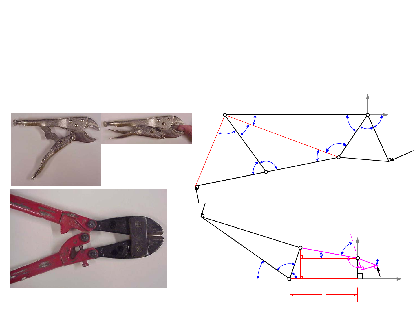
1/1/2008© 2008 Alexander Slocu
m
4-21
5-Bar Linkages: Analysis
• To determine the force on the jaws caused by a force on the handles, equate the
work done:
– The product of the force applied with an incremental input motion equals the product of
the jaw force with the incremental jaw (output) motion
• Because of long lever lengths, pin joint inefficiency is minor
– The differentiation can be done closed form or numerically in the spreadsheet
d
b
aA
B
F
h
x
h
, y
h
h
α
3
α
1
θ
x
j
, y
j
F
j
C
g
X
Y
α
2
α
3
γ
e
fm
c
ij
β
k
α
4
β
1
β
2
β
3
c
d
e
b
a
A
B
D
F
h
x
h
, y
h
h
α
2
α
1
k
θ
x
j
, y
j
F
j
β
5
β
4
C
g
j
α
3
α
4
X
Y
See Linkage_5_bar.xls

6-Bar Linkages
When a 4-bar linkage cannot create required motions, one typically
resorts to a 6-bar linkage. Within most 6-bar linkages, one can find what is
essentially an input stage and out output stage; thus the simple linear input
becomes a complex input to the second stage thereby producing an even more
interesting output. Unfortunately, there are no simple synthesis methods, like 3
precision points, for 6-bar linkages. However, thinking of them as combina-
tions of 4-bar linkages, with some links and joints shared, can help. In addi-
tion, there are several standard known 6-bar linkages that can be good
synthesis starting points.
The Watt I 6-bar linkage is essentially a 4-bar linkage stacked on top
of another 4-bar linkage. It starts with a 4-bar linkage, and the coupler and
crank links are made as ternary links and their free pivot points become attach-
ment points for links 5 and 6. Links 5 and 6 can also be made as ternary links,
and thus either can be output links. With either link 5 or 6 assumed to be a
binary link, only 12 link parameters need to be determined. The Watt II 6-bar
linkage uses one 4-bar linkage to drive the rocker of another 4-bar linkage; this
allows continuous rotary input to generate a reciprocating arc motion. The
linkage can be optimize to minimize the curve of the arc and create as close to
straight-line motion by determining only 11 link parameters. The LegoTM
sketch model, shown with its near straight-line motion coupler curve, would be
driven by another 4-bar to create a Watt II linkage
The Stephenson I 6-bar linkage replaces the Watt I binary follower
with a ternary link and thus stacks what would appear to be a 5-bar linkage on
top of a 4-bar linkage, but the ternary nature of the crank and follower make
the system have one degree of freedom, and only requires the determination of
12 link parameters. The Stephenson II 6-bar linkage is a 4-bar linkage on top
of a 5-bar linkage, again with the coupling between the two making the system
have one degree of freedom; however, it requires the determination of 14 link
parameters. The Stephenson III 6-bar linkage is a variation of the Watt II,
where a 4-bar linkage is used to drive another 4-bar linkage, but instead of
driving the rocker, it essentially forms a variable length rocker (or crank)!
Hence the system behaves as a 4-bar linkage, where the crank’s length varies
with its input angle. This can be a very useful design, where synthesis only
requires determination of 10 parameters!
These linkages use rotary input and the output can be any point that is
attached to the output link. Another common 6-bar linkage, as has been dis-
cussed in the context of the excavator bucket on page 4-8, is where two of the
links are actually the rod and cylinder of a hydraulic actuator, or the screw and
nut of a leadscrew actuator. This allows a link to move through 180 degrees of
motion, with high moment capacity, which could not be obtained with a simple
4-bar linkage such as shown on page 4-15.
Synthesis of 6-bar linkages can get very complicated very quickly,
and this is where analysis programs rapidly take over from intuition and sketch
models. An analysis program can allow you to program nested loops that vary
each of the link geometries through reasonable ranges by using a field search.
If each of N parameters are allowed to vary over a range of K values, while the
crank link position moves through M increments, then only J = M*NK calcula-
tion steps need to be made. Each step may itself require a couple dozen param-
eters to be computed to relate the output point to the crank angle and the link
length parameters. The plot, where M = 35, shows how painfully large J can
become. Compare the number of calculations needed for brute-force synthesis
of a 4-bar linkage compared to a 6-bar linkage. This is where brute force cal-
culations can then yield to more sophisticated search algorithms which incor-
porate logical conditions to direct the search.
A very useful half-step to sophisticated searches is to use a coarse-
fine field search. In the first coarse search, the link lengths are varied over a
large range, but with only 4 steps each. Hence only 109 cycles are required,
which is tolerable for those with a 1 GHz or faster processor1. From this
coarse search, a set of reasonable link lengths can usually be selected that
yields a useful coupler curve. The fine search is then run, again with 4 steps,
where the total range of change in each link parameter is the step size used in
the course search. This allows one to converge on a reasonable design within a
few hours. This design can then be input into a CAD program or linkage anal-
ysis program for refinement and calculation of other parameters.
Where might you need a 6-bar linkage? Try creating a linkage syn-
thesis program with a nested coarse-fine field search capability!
1. If however, as Weird Al points out in his song “Its All About the Pentium”, if your computer chip is
a DoritoTM, then you are going to be out to lunch!
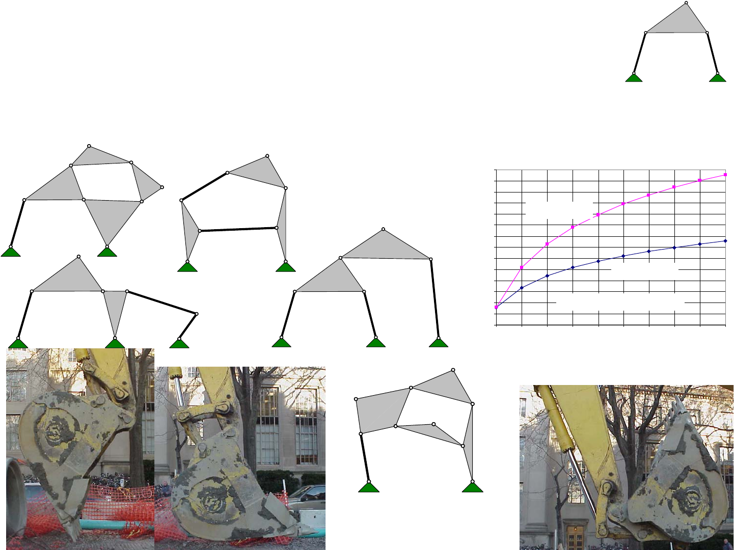
1/1/2008© 2008 Alexander Slocu
m
4-22
1E+00
1E+01
1E+02
1E+03
1E+04
1E+05
1E+06
1E+07
1E+08
1E+09
1E+10
1E+11
1E+12
1E+13
1E+14
12345678910
Number of dimension increments
Number of calculation steps
6-Bar Linkages
• Simple linkages often cannot meet FRs for large motion or extreme force
– A linear actuator cannot be effectively (huge stroke or huge forces are required) attached to
a point on a 4-bar linkage to allow the output link to move through 180 degree motion
• E.g., excavator bucket, concrete pump booms….use a 6-bar linkage
11
2
3
4
5
6
11
2
3
4
5
6
1
Watt I
Watt II
11
2
3
4
5
6
Stephenson I
11
2
3
45
6
Stephenson II
11
2
3
4
5
6
1
Stephenson III
12 parameters
6 parameters
35 crank input angular increments
11
2
3
4
See Linkage_6_bar.xls

Extending Linkages
Linkages have been shown that convert simple input motions to more
complex motions, or to magnify forces. Another common use of linkages is to
magnify displacements, the reciprocal of magnifying forces. These linkages
convert large forces applied over small distances to small forces applied over
large distances. There are three types of extending linkages commonly encoun-
tered: folding, telescoping, and scissor. All meet the functional requirements
of compactness for transport, ready-to-use with minimal set up (outriggers
deployed to increase vehicle stability), and long reach capability.
Folding linkages use the same type of 6-bar linkage as used for exca-
vator buckets. The equations relating piston length and force to output position
and force were given on page 4-8, and the spreadsheet 6barpistonlinkage.xls
shows how large moments can be supported throughout the range of motion of
the piston. Although the results here are by no means optimized, they show
that 180 degrees of boom motion can be obtained.
Folding linkages are commonly used on concrete pump trucks
because each stage can be actuated independently; hence the boom need not be
straight, and this gives it the capability of being deployed to reach into build-
ings. Note that steel technology made large structures practical, but the ability
to pump concrete made them truly economical.
Telescoping booms typically use nested tubes with the first segment
mounted with a pivot to the base, and a hydraulic cylinder to actuate it as dis-
cussed on page 4-11. Some systems, such as battery-operated portable lifts,
use nested cables or chains and pulleys or sprockets respectively. This is also a
good solution for contest robots.
Sliding bearing surfaces between the telescoping sections should typi-
cally be spaced at 3-5x the tube size (see Saint-Venant’s principle on page 3-5).
The number of required sections is a function of how much they overlap each
other. If one gets too greedy and lets the sections extend too far, the ratio γ of
the bearing spacing Lbearing to the section length L decreases too much. As
shown in the graph, as this ratio decreases, the ratio of the front bearing force
FBf to the applied force F increases dramatically. Considering that other sec-
tions also impose a moment M, the bearing forces can become quite large:
It may seem like a straightforward calculation to determine the force
required to extend the booms. However, since sliding contact bearings are
used, the frictional forces can become significant, especially as the boom nears
horizontal. In order to determine the cable force required to extend the boom,
the product of the coefficient of friction with the bearing reaction forces, which
the engineer has of course calculated, must be added to the weight of the tele-
scoping sections and the supported load.
What might be the functional requirements of a defensive or an offen-
sive extending linkage module? Should it extend across the table and clamp on
to the other side and block all other motions? When you design a boom to
withstand forces, you are also designing a means to defeat the boom! How
might you counteract a boom extended at you? The 2001 2.007 winners used
extending booms that came up under their opponents’ side of the tilting table
beam. Few of the opponents were listening in Prof. Slocum’s lectures where
he specifically said it was likely an extending boom would be used. So do as
Sami Busch did in the 1996 contest Niagara Balls and use the fact that you
have a huge moment advantage when the boom gets near you. It is simple to
design a module that uses a sweeping arm to knock away booms!
(
)
1
Br Bf
bearing bearing
FMFM
FF
LL
γ
γγ
−
=+ =+
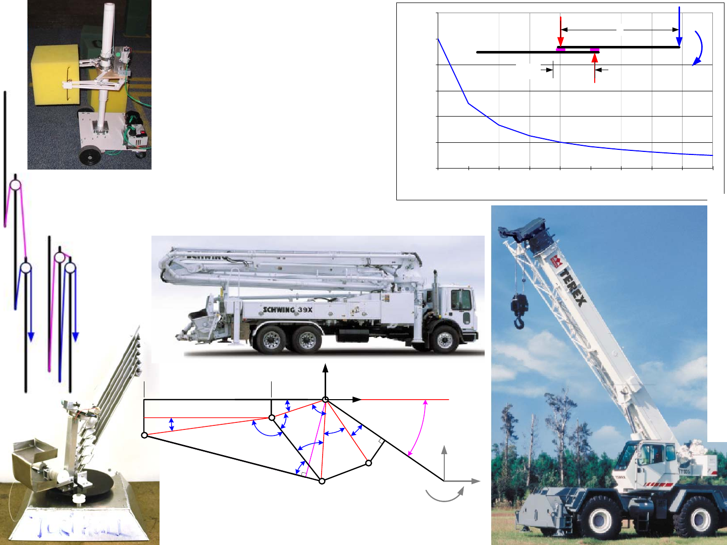
1/1/2008© 2008 Alexander Slocu
m
4-23
0.00
20.00
40.00
60.00
80.00
100.00
120.00
0.01 0.02 0.03 0.04 0.05 0.06 0.07 0.08 0.09 0.10
Bearing spacing/section length
Front bearing force/Applied tip force
c
da
b
j
D
A
B
θ
e
k
h
m
R
g
fi
H
β
1
β
2
α
1
α
2
α
3
α
4
φ
2
φ
1
β
3
E
L
piston
L
boom
F
x
F
y
M
Y
X
x
F
, y
F
Extending Linkages
• Many extending systems
have the following FRs
– Compact for transport
– Rapid set-up
– Long reach during use
http://www.terexlift.com/catolog/catopdfs/rt300ser.pdf
http://www.schwing.com/products/pdf/39X.pdf
L
L
bearing
F
M
F
Br
F
Bf
Terri Hall
Helen Tsaih's extending column
with dual 4-bar gripper (cranks
synchronized with gears
attached to their ends)
See Linkage_6_bar.xls
Extending Linkages: Scissor Linkages
Because of the difficulty in making telescoping segments, and the
complexity of cabling or telescoping cylinders required to actuate them, scis-
sor linkages, or lazy tongs, are often used in both industry and in robot con-
tests! They are called scissor linkages because the basic modular element of
the system is a pair of ternary links joined at the middle to each other, and their
ends are joined to the ends of another set of ternary links...
Like any other linkage, a scissor linkage’s input force can be related
to the output force by the work done, although with all the pin joints, one can
typically account for the friction in the joints by assuming an efficiency of η
per section. Thus for N sections:
The spreadsheet lazy_tongs.xls calculates the extended and retracted
conditions for a lazy tongs linkage, and can be used to size members and deter-
mine design feasibility.
In addition to designing a scissor linkage to have the desired reach
and force, one must consider the accuracy of the linkage, and its repeatability.
Scissor linkages can suffer from large deflections perpendicular to the plane of
the operation, which are caused by clearances in the bearings that make up the
pivots, as well as deflection of the links. Recall the lesson of Abbe’s Principle
on page 3-11, and the example of LegosTM, which, when stacked together in a
long chain, can curve due to all the little micro spaces between each brick
amplified by the length of each brick. Each little displacement adds together
to create a curved section. In addition, as shown, all the clearances in the joints
will prevent the linkage from fully retracting, hence reducing its repeatability.
Is it feasible to create a lazy tongs linkage to reach out and touch
someone, and assist them in not having to worry about how they will do in later
rounds of the competition? Can the spreadsheet help you to determine feasibil-
ity? Analysis is an awesome creativity catalyst and reality barometer!
()
()
12
sin
22
sin sin
cos cos
link
link
retracked link extended link
link link
retracted extended
Nretracked extended
squeeze
extend
extended retracted
h
L
DL DL
LL
DD
F
FN
ππ
αβα
α
β
α
α
λλ
η
λλ
−⎛⎞
−⎜⎟
⎝⎠
==−
==
==
−
=−
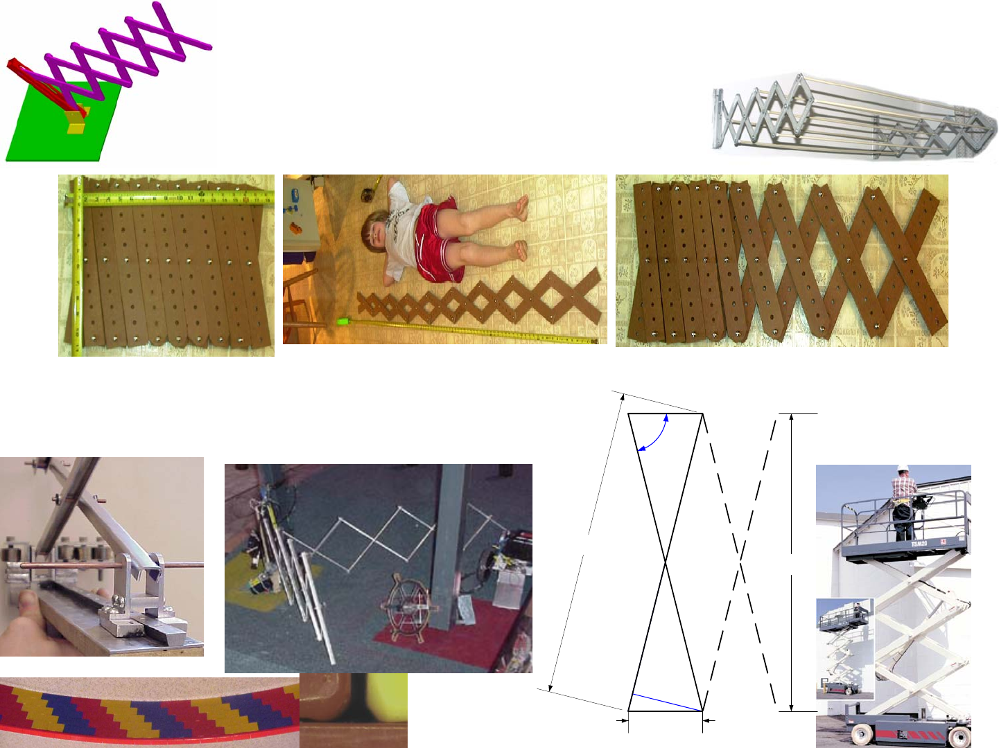
1/1/2008© 2008 Alexander Slocu
m
4-24
Extending Linkages: Scissor Linkages
• Scissor Linkages (Lazy Tongs) are a great way to get a
LARGE range of motion in a small package
• How does one develop a system as simple in principle, but as complex in
detail as the Lazy Tongs?
– The devil is in the details
http://www.terexlift.com/catolog/catopdfs/tsm202630.pdf
h
link
L
link
λ
retracted
α
D
retracted
Eric Tung’s Scissor
Blockers!
Bryan Ruddy’s dovetail
bearings to guide his scissors
See Linkage_Lazy_Tongs.xls
Big John & Tongs
Towel rack tongs
(photo by Pat Willoughby)
Tolerances lead to scissor wobble…

Extending Linkages: Scissor Linkage Example
Tables 1 and 2 below show the development of concepts for an offen-
sive module to be attached to a stationary scoring module that focuses on spin-
ning its own pendulum for The MIT and the Pendulum contest.
The result is the Attacking Scissor Links1 shown on the opposite
FRDPARRC sheet. These table entries are frugal, and thus they should get you
thinking “wait a minute, what about...” Once complete, the details of the
design must be worked out by dividing the Attacking Scissor Links module into
its own sub modules for development and testing:
Links module: The sketch shows the plane of the linkage horizontal,
but reciprocity tells us to also ask what would be the performance if it was ver-
tical? It would sag less, but the gripper design would be a little more complex.
This seems worth the trade-off! The spreadsheet will tell you how many sets
of links are needed, and you will have to see if you have enough material. Do
you need thickness to provide some lateral stability? Do you want to laminate
wood between sheet metal, or do you want to bend the edges of sheet metal
links to form them into channels? The former would increase the length/diam-
eter ratio of the pins in the joints and reduce cumulative sine errors. If you are
to use a laminated design, do you laminate an entire sheet and then cut into
links, or do you laminate each link?
Force module: One of the links can be pinned, and the other one
needs to be in a pin-in-slot joint and be pulled toward the pivot as shown in the
solid model on the previous page. A leadscrew nut can have an integral pivot
to which the pin-in-slot joint attaches. The nut should have a square outside
shape so it can slide inside the square tube which thus resists the leadscrew
actuation torque. The leadscrew would be driven by a motor. Evaluate motor/
leadscrew calculations to select the proper motor.
Gripper module: The one-way gripper will probably take some itera-
tion to get it right and robust, but since nothing else is attached to it, it is the
least critical. If your opponent’s pendulum is missed, make the gripper also
have ability to grab onto the opponent’s wall?!
Aiming module: If we aim high and engage the other beam, perhaps
we can passively disengage a ramp that will let the initial linkage inclination
angle decrease so the links end up more horizontal? The complexity of this
and the requirement for a longer travel means we should probably just launch
from a slightly inclined angle to accommodate linkage sag, and move fast and
minimize complexity.
Table 1: FRs, DPs, & As for Offensive Module
Functional
Requirements Design Parameters
(possibilities) Analysis (dominant
physics)
Rapidly get across the table to
pin opponent 1) Vehicle
2) Projectile
3) Linkage
1) F = ma and traction
2) F=ma and angle of projection
2) Fsqueeze*Xsqueeze =
ηFpush*Dpush
Locks after being deployed 1) Clamp onto pendulum and
opposite wall
2) Tether line and grapple hook
3) One-way gripper at end, non-
backdriveable leadscrew
1) Need to do experiments
2) Need to do experiments
3) Need to do experiments
Hard to block 1) Massive force
2) Aim high, and then descend to
lower level
1) Impact or static
2) Same as above, but must also
push against gravity
Table 2: Rs, Rs, & Cs for Offensive Module
References Risks Countermeasures
1) 2.007 notes & past contests
2) 2.007 notes & past contests
3) 2.007 notes & past contests
1) Forces too small, too easily
blocked
2) Too easy to block, or tether
string causes entanglement and
disqualification
3) Complexity
1) Super high speed from spring
launcher
2) No tether
3) Scissor linkage is made from
many of same parts
1) Past contests
2) Past contests
3) Past contests
1) Too easily deflected
2) Entanglement
3) Minimal if done right
1) Make it very maneuverable
2) Do not use this idea
3) Lots of testing
1) Freshman physics text
2) Freshman physics text 1) Hard to generate
2) Lateral stability, length
change, aiming
1) Maximize velocity
2) Make sure system is revers-
ible for another try, OR make
gripper also able to lock on to
opponent’s wall!
1. As Dave Barry would note, a GREAT name for a rock band!
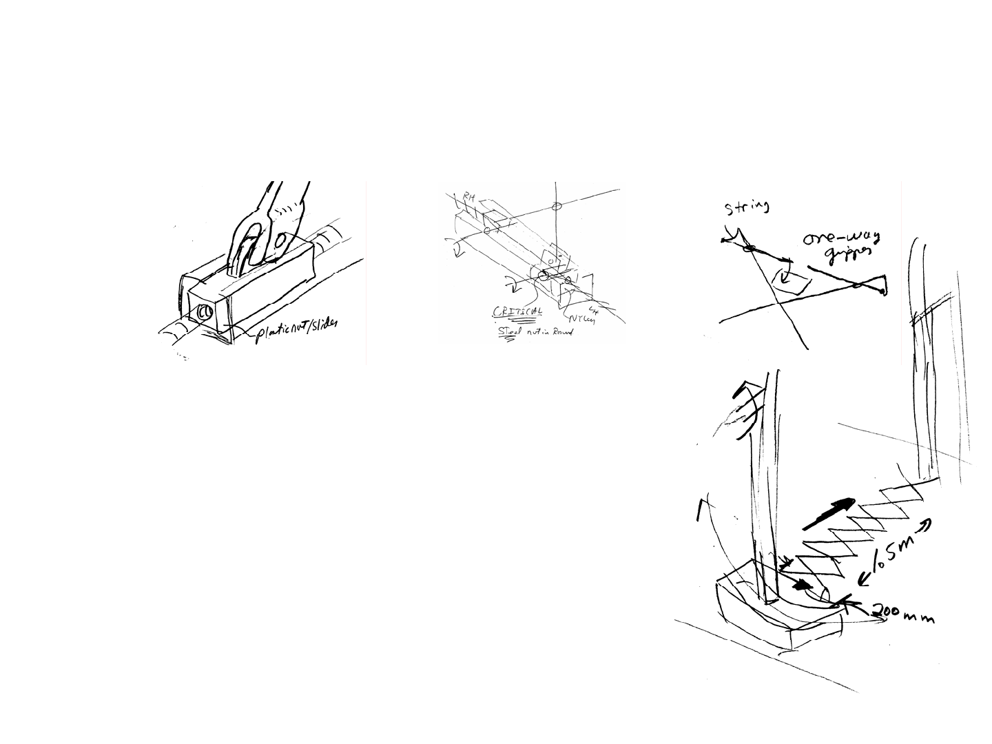
1/1/2008© 2008 Alexander Slocu
m
4-25
FRDPARRC Sheet Topic: Long Reach System
Functional Requirement (Event) Long reach system to rapidly zoom over to opponent and jam their machine and pendulum, and also
prevent them from moving around on the table (create a baby gate!)
Design Parameter (description of idea) Scissor linkage (Lazy Tongs) actuated by one base link pin fixed and the other sliding using a pin-
in-slot joint
Sketch:
Analysis (physics in words) The input force will act over a short distance, and the output over a
long distance, so it will be much less. However, to resist collapsing by opponent pushing against
us will be easier since friction in the pins now will work against opponent. Use lazy_tongs.xls to
determine feasibility and optimize.
Analysis
See spreadsheet output. To first order, we have a 7.5:1 ratio, so if we generate 300 N of force
with a screw to compress the ends, with 50% efficiency we can get 20N of force to jam our
opponent and their pendulum.
References: Topic 4 notes and lazy_tongs spreadsheet and Niagara Balls contest
Risks: Not enough force, opponent will deflect or push us away.
Countermeasures: shoot high and passive on-way gripper captures beam, and then slide down
their beam; thus we form a tether to their pendulum to gumfoozilate them.
Extending Linkages: Scissor Linkage Example

Compliant Mechanisms
Linkages are really useful and wonderful; however, their many joints
sometimes are the source of errors which are amplified to create unacceptable
overall performance. One way to minimize unwanted motions in linkage joints
is to use preloaded rolling element bearings. This is often the case for preci-
sion robots; however, for mechanisms with limited travel, a more effective
alternative is to use structures with local compliances at the joints whose
deflections emulate small joint motions. These locally compliant elements are
called flexures, and mechanisms that use flexures for their joints are called
compliant mechanisms or flexural linkages1 (flinkages!). The compliant ele-
ments can either be long thin blades that bend along their length, or they can be
hourglass shaped hinges. The former allow for more deflection, but are also
more compliant in out-of-plane directions.
Monolithic compliant mechanisms can be made from a solid block of
material, which can be made on a macro scale most cheaply by using an abra-
sive waterjet machining process. For blades thinner than 3/4 mm, the taper
from the waterjet becomes too great, and the blades can be cut by electro-dis-
charge machining (EDM). Hourglass flexures can easily by cut on a milling
machine. Clamped compliant mechanisms can be made by clamping thin
material sheets to rigid structures.
Consider the robot gripper shown for use in a hostile environment.
Robot grippers are designed for dedicated systems, such as picking up standard
sized trays of parts. Only a small gripping motion is required, so a compliant
mechanism is an ideal way to minimize the number of parts. The flexures are
not affected by dirt, and alloys can be selected that are not affected by oven
temperatures. The entire linkage system shown was designed to operate in an
oven in a 200 oC environment where a single rotary actuator located outside of
the environment was used to actuate two grippers at once. This double gripper
allows the robot to pick up a part from an input and operation station, rotate 90
degrees, and place the parts on operation and output stations respectively
A problem that affects compliant mechanisms in the same way that
affects linkages with conventional pivots, is that of parasitic error motions as
discussed on pages 4-11 and 3-8. As has been shown, in a parallelogram link-
age, when the members are nominally orthogonal to each other, relatively pure
translation of a platform can occur which is essentially a sine motion that is
equal to the product of the rocker arm length and the rocker arm angle. How-
ever, some small vertical parasitic cosine error motion also occurs.
Parasitic error motions can often be dealt with using the principle of
reciprocity, as discussed on pages 3-11 - 3-13, to create a folded beam flexure.
Four 4-bar compliant mechanisms in which the error motions of one are
accommodated by another, are used together support a moving platform in a
manner similar to a simply supported beam. This design is called a folded
flexure and it is a relatively common type of 12-bar flexure with two pairs of
first stage flexural elements, two intermediate floating platforms that move in
mainly in the Y direction and have parasitic X error motions, two pairs of final
stage flexural elements, and a platform that moves only in the Y direction. The
final two flexural links’ parasitic error motions have been cancelled by the
intermediate floating platforms’ error motions! By Gruebler, this system has
3*(12 - 1) - 2*16 = 1 degree of freedom.
Micro Electro Mechanical Systems (MEMS) are miniature devices
typically made from etched silicon using standard photolithographic tech-
niques developed by the semiconductor industry, and they are creating a link-
age renaissance. From micro mirrors developed by Texas Instruments for
projectors to accelerometers developed by Analog Devices for automotive air
bag sensors, to countless pressure gauges that use thin film diaphragms and
capacitive or piezoresistive sensing elements, MEMs systems are having a
huge impact on our lives. In the future, we will likely experience them with
energy harvesters that use ambient vibration to power tiny sensors, circuits,
and radio transmitters. Flexures can also be used to create bistable devices for
miniature relays2 that will likely change the nature of electronics and power
systems!
1. Prof. Sridhar Kota at UMI has an entire laboratory devoted to the design of compliant mechanisms.
From staplers to windshield washer blades to sophisticated MEMs devices, he has created field-search
algorithms to find “optimum” compliant mechanism designs to meet user defined FRs constraints. See
http://www.engin.umich.edu/labs/csdl/index.htm. Sandia National laboratories have also created an amaz-
ing array of compliant mechanisms. See www.sandia.gov.
2. For his Ph.D. thesis, Jin Qiu created a bistable double-beam flexure, which flexuralistically quasi
emulates Watt’s 4-Bar linkage, see Qiu, J. Lang, A. Slocum, "A Centrally-Clamped Parallel-Beam
Bistable MEMS Mechanism" MEMS 2001 Digest 353-356, Interlaken, Switzerland, January 2001
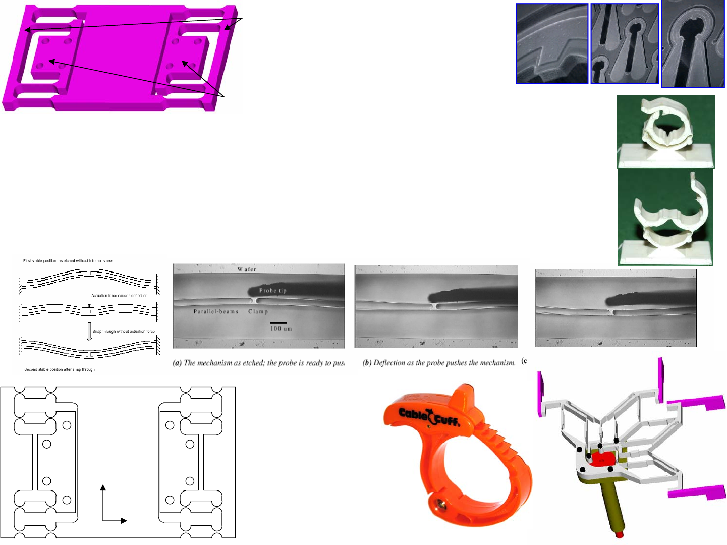
1/1/2008© 2008 Alexander Slocu
m
4-26
Compliant Mechanisms
• The pin joints in linkages are often the major source of error motions
– See page 10-24 and the flexure design spreadsheets!
• When only small motions are required, the pin joints can be replaced with
flexural elements, thus forming a compliant mechanism
– Extremely high accuracy small range of motion devices can be made this way
– Many Micro Electro Mechanical Systems (MEMS) use tiny silicon flexures
Floating Moving Platform
Anchor to
ground
X
Y
Moving
platform
Floating structures
Fixed to ground
What is this thing used for?
CableCuff® US Patent 6,101,684
(www.cableclamp.com)
a) Note the nifty flexural pawl/ratchet
b) Could the pivot have been made as a snap-
fit or a “living” (flexural) hinge
c) If patented and so simple (machines could
make and assemble) can it be made
domestically?
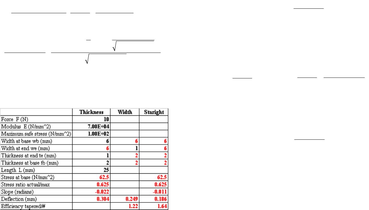
Compliant Mechanisms: Analysis
Compliant mechanism design requires careful analysis to maximize
desired deflections while minimizing link stress. The ratio of work done to
create motion to the amount of useful work the linkage does in a system is a
measure of its efficiency. Hourglass-shaped flexures are the least efficient, but
they can be made by drilling holes close to each other... HourglassFlex.xls
computes the moment and angular deflection θ (typically only a few degrees)
for radii R, web thickness t, width w, and maximum allowable stress:
Beams, or blades, are very efficient. Consider the following cantile-
vered beam comparison illustrated by the spreadsheet taperedbeam.xls:
These different types of links can be used in a 4-bar flexure to support
a platform. As the FEA plots of deflected blades show, a uniform thickness
blade of length L deflected in a 4-bar flexural linkage, behaves like two cantile-
ver beams each of length L/2 that are placed end-to-end so their slopes match
and they are essentially springs in series. The force F applied is the same in the
two beams causing each beam to deflect FL3/24EI, so the compliance of a sin-
gle blade is L3/12EI. Thus the platform, supported by 2 blades that act in par-
allel, will have a stiffness of:
A curious effect is that the moments created by anchoring the ends of
the blades causes deflections in the blades. To prevent actuator misalignment
forces from causing further error motions, the drawing shows a wobble pin
coupling pushing on a flexure supported stage at a height a that is one-half the
blade length. The vertical and pitch error motions are:
Folded flexure platforms use symmetry to cancel out these errors. A
simple folded flexure with blades of equal modulus E, length L, and moment of
inertia I behaves like 2 sets of 4-bar flexures in parallel acting in series with 2
sets of 4-bar flexures in parallel, and hence the stiffness is still just:
If one really wanted to optimize the efficiency of a folded beam flex-
ure supported platform, one would taper the folded beam flexure’s blades so
they are thinnest in the middle.
A compliant mechanism would probably be an ideal mechanism to
use to allow you to preload a machine around the pendulum. Try to design a
compliant mechanism to preload a module’s wheels to the pendulum so it can
climb up and engage the axles and spin the pendulum!
() ()
()
() ()
()
2
22
2
1
22
2
2
22
311
0.5 0.5
20.5
30.5 tan
20.5
20.5
0.5 0.5
MR
tR tR
Ew t R R
R
R
RtR tR R
tR
R
tR tR R
θ
π
−
⎧
⎪
=+×
⎨+
⎡⎤ −+
−+ ⎪
⎩
⎣⎦
⎫
⎡⎤
⎛⎞
⎛⎞
−
⎪
⎢⎥
⎜⎟
⎜⎟
+−
⎪
⎢⎥
⎜⎟
⎜⎟
⎜⎟
⎜⎟
−
+
++
⎪
⎢⎥
⎪
⎝⎠
⎝⎠
+⎬
⎢⎥
+
⎪
−+
⎢⎥
⎪
⎢⎥
⎪
⎢⎥
⎪
⎣⎦
⎭
4_ _ 3
24 blade blade
bar flexure platform
blade
EI
KL
−=
(
)
2
2
_22 2
_
62
336
2
translation
translation
vertical error pitch error
at
x
xa
bt t
θ
δ
−⎛⎞
⎛⎞
=
=⎜⎟
⎜⎟
−+
⎝⎠
⎝⎠
A
AAA
A
__ 3
24 blade blade
folded flexure platform
blade
EI
KL
=

1/1/2008© 2008 Alexander Slocu
m
4-27
Compliant Mechanisms: Analysis
• Finite Element Analysis is a powerful design tool
– Design Parameters (dimensions) are changed until
desired performance (stress, deflection) is obtained
• A 4-bar compliant mechanisms was designed to be
made from titanium for strength, weight, and
temperature resistance
– It was machined by an OMAX abrasive jet
machining center for $200 ($1000 to wire EDM)
– When installed, it was strong enough to resist
damage by the controls engineers!

Manufacturing & Robust Design
Even though most linkages are planar (their motion is confined to a
plane), forces are never exactly in a plane, so slight out-of-plane moments are
created. Scissor linkages represent the most extreme case of this problem,
where many small sine errors, as discussed on page 3-11 - 3-113, add up to
potentially cause the scissor linkage to severely deflect out of its plane of
motion. One must first ask if this really matters, is this a sensitive direction
(see page 3-23)? Then one must identify the most sensitive parameter, and
operate on that parameter. This is the essence of manufacturing and robust
design, which go hand-in-hand.
Consider the case of a scissor linkage, and how it might be made more
robust. One can seek to minimize each incremental sine error by decreasing
the clearance between the pivots’ pins and the links’ bores, and increasing the
thickness of the links. However, Saint-Venant, see pages 3-6 - 3-9, indicates
that this is not an efficient use of resources. To prevent out-of-plane motion of
the tip, mechanism must act on the tip. If the tip deflects out of the plane,
apply reciprocity, as discussed on page 3-14 - 3-16. One linkage causes errors,
so if one is not sufficient, try two? Next use errors to cancel errors. The result
is the idea to flip one scissor linkage over to cancel the errors of another; thus
make two thin and simple scissor linkages and join them to form an isosceles
triangle whose height changes as the links extend.
Robust linkage design is also heavily concerned with avoiding over-
constraint and singularities. Both can place large loads on the bearings in the
joints. Rotary motion joints often use pins in bores, and these can typically
handle very large loads with proper lubrication. Linear sliding elements are
often the biggest cause of jamming, so one should make use of Saint-Venant’s
Principle when designing sliders. Furthermore, it is often the unanticipated
out-of-plane loads that can overload linkage bearings. Fortunately, Chapters
10 and 11 focus on the details of designing systems with bearings.
Actuators that create linkage motion can also damage themselves or
the linkages if the forces or torques are not applied using proper couplings,
such as a clevis for linear actuators or a rotary coupling. Clearance in a joint
can be used to accommodate misalignment only when loads are low, or the
intended life of the device is limited anyway. Out-of-plane forces or moments
must not be transferred between the actuator and the linkage! This is where
exact constraint design, as discussed on page 3-24, becomes really importance.
When a linkage design is synthesized and then drawn on a solid mod-
eler, the part drawings are easily generated. Since links are typically planer, it
becomes a simple task to cut them, often all in one set up, using an Abrasive
Waterjet Machining CenterTM such as the OMAX1 2626 shown. In fact, the
wiffle tree components shown were cut with a waterjet and were used to dis-
tribute a centrally applied force to each of 32 points for a special processing
machine. Recall wiffle trees accomplish even load distribution by using the
principle of elastic averaging as discussed on page 3-28.
Whatever methods are used to make the components, manufacture
and assembly must be done with sufficient precision to maintain alignment
between elements, else the motion of the linkage itself may create the forces
that wear it out. Hence manufacturing the parts to ensure pivot bores are per-
pendicular to links, is of very high importance. Punching holes with a hand
drill is not recommended.
To achieve long life, linkage joint stress must be controlled and the
joint must be lubricated. For lightly loaded systems, solid lubrication can typi-
cally be incorporated into the joint design by using self-lubricated bearings.
For heavily loaded systems, liquid lubrication is typically required either in the
form of grease or oil. The former must typically be reapplied comparatively
frequently, depending on the loads. In the case of a car, the undercarriage
joints typically are re-lubed every time the engine oil is changed. For
extremely heavily loaded systems, such as construction equipment, the joints
may have to be greased every week or more. The challenge, however, is that
lubricants can leak out of joints causing damage to the environment, as well as
damage to the joint. Fortunately, most robots for design contests can typically
use lubricious plastic bearings running on smooth surfaces, and thus really
should not need any lubricant applied other than an initial dab of grease.
Conduct a manufacturing review of all linkages you have planned on
using, and make sure that they are minimally complex and easy to manufac-
ture. If they present challenges, make sure to consider them for early develop-
ment as most-critical-modules!
1. See www.omax.com and www.waterjets.org
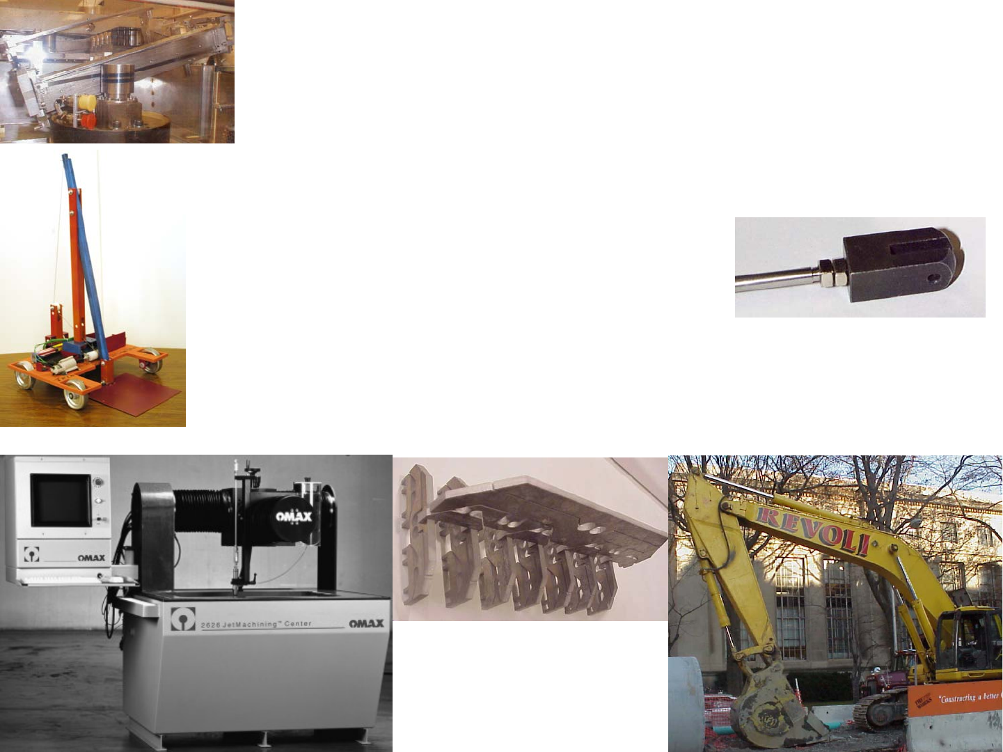
1/1/2008© 2008 Alexander Slocu
m
4-28
Manufacturing & Robust Design
• Most machining processes can be used (milling, abrasive waterjet, wire EDM)
• Abrasive waterjet machining allows for very complex compliant mechanisms to
be machined very rapidly
– Example: A wiffle tree evenly spreads out a point load
• Windshield wipers are the most common example
• A wiffle tree was cut on an abrasive waterjet machine in only an hour
– NOTE the use of a large blade flexure to support the right side of the OMAX
machine’s X axis, to allow for thermal growth
» Example of a machine-tool-precision very-small-range-of-motion 4-bar linkage
Jorge Renjifo's 2005 2.007 "Tic-Tech-Toe" machine
Damn software!

Mechanism Mania!
This chapter has just introduced the concept of simple linkages that
act in planes. More advanced linkages can work together to create complex
motions such as walking or full three dimensional motion! Indeed, walking
machines have been the dream of engineers for centuries, and perhaps it is
ironic that simple walking action is readily achieved by many toys. Real walk-
ing motion that correctly emulates bipeds or quadrupeds is an extremely diffi-
cult task to accomplish, and represents an exciting area of robotics. However,
note the neato walker that Linus park built for his 2.007 robot; thus proving
that the most important thing in any student “contest” is that you should create
a design about which you personally are most passionate. The design may not
“win” in terms of points scored, but you will “win” in terms of showing your
engineering prowess!
What about 3D motion? Spatial linkages move a coupler point in
three dimensions, and are extremely challenging to synthesize. An interesting
spatial linkage was discovered in the age of steam engines when James Watt
was creating complex planar linkages to try and achieve straight-line motion to
guide steam engine pistons. Pure translational motion with only rotary joints
was considered an impossibility, and so engineers made do with clever com-
plex planer linkages. Then along came Sarrus and his mechanism in 1853!
Did his bio-neural net feel it could not achieve what it wanted to in a plane, and
did he jump out of the plane to create the simple and ingenious device shown?1
We also have not even begun to touch on the subject of cams, which
can also be used to convert simple rotary motion into interesting reciprocating
motion. Like linkages, cams require careful analytical modelling to create the
exact desired motion, and to calculate parameters such as position, velocity,
and acceleration as a function of the input angular velocity. Like linkages, the
calculations required are straight-forward, a geometrist’s delight; thus you
should be confident that you can design cams!
Looking at machines in the world around you (and on the web) can
help make up for a lack of experience, and will help you become experienced!
Having said this, remember, to become good at linkage design, or any other
type of design, requires experience. Those who succeed, do so with practice,
and an in-depth understanding of fundamental principles and analytical model-
ling skills catalyzed and tempered with manufacturing knowledge, and a high
degree of professional ethics.
Dive into your machine’s design with delight, dream what you want it
to do, and then synthesize the linkages you need to realize your dreams. There
is always a mechanism that can be created to give you motion happiness!
1. The beautiful model shown is on display in the Mathematical Models section of Boston Museum of
Science.
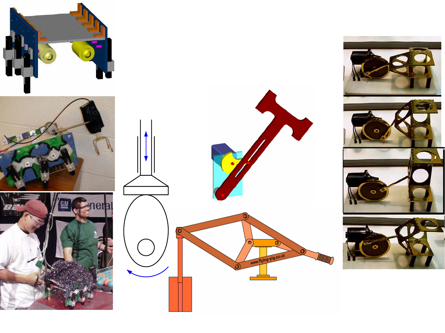
1/1/2008© 2008 Alexander Slocu
m
4-29
Mechanism Mania!
Linus Park created an awesome walker for
2.007 2000 MechaImpactAgeddon!
http://www.flying-pig.co.uk/pages/straight.htm
• Mechanisms can be created to accomplish
virtually any task
– They are essentially mechanical computers
– Seek and you will find!
Pictures taken at
Boston Museum of Science
Topic 4 Study Questions
Which suggested answers are correct (there may be more than one, or none)?
Can you suggest additional and/or better answers?
1. The weaving of cloth gave rise to the need for more complex machines to
convert waterwheels’ rotary motion into complex motions
True
False
2. The invention of the steam engine helped to create a great need for new
mechanisms and machines
True
False
3. James Watt (1736-1819) applied thermodynamics (though he did not
know it) and rotary joints and long links to create efficient straight line
motion, although many other more efficient linkages were later discovered
by others:
True
False
4. James Watt invented the flyball governor, the first servomechanism,
which made steam engines safe and far more useful
True
False
5. Leonard Euler (1707-1783) was one of the first mathematicians to study
the mathematics of linkage design (synthesis):
True
False
6. Conservation of energy (work) can be used to determine the output force
of a linkage if the input force and displacement are known as well as the
output displacement and efficiency:
True
False
7. Degrees of Freedom (DOF) are:
The number of input motions that must be provided in order to
provide the desired output
The number of independent coordinates required to define the
position & orientation of an object
8. For a planar mechanism, the degree of freedom (mobility) is given by
Gruebler’s Equation
n = Total number of links (including a fixed or single ground
link)
f1 = Total number of joints (some joints count as f = ½, 1, 2, or 3)
9. Links can have different numbers of nodes (i.e., joints) to which other
links are attached:
True
False
10. Lower pairs (first order joints) or full-joints (counts as f = 1 in Gruebler’s
Equation) have one degree of freedom (only one motion can occur), and
they include:
Revolute (R): Also called a pin joint or a pivot, and a rolling
contact joint also counts as a one-degree-of-freedom revolute
joint
Prismatic (P): Also called a slider or sliding joint, beware Saint-
Venant!
Helical (H): Also called a screw
11. Lower Pair joints with multiple degrees of freedom include:
Cylindrical (C) 2 DOF (translates and rotates) multiple-joint (f =
2)
Spherical (S) 3 DOF multiple-joint (f = 3)
Planar (F) 3 DOF multiple-joint (f = 3)
12. Higher Pair joints with multiple degrees of freedom include:
()
1
312Fn f
=−−
Link against a plane where a force is required to keep the joint
closed (force closed) is a half-joint (f = 2 in Gruebler’s equation)
Pin-in-slot where the slot geometry keeps the joint closed (form
closed) is a multiple-joint (f = 2 in Gruebler’s equation)
Second order pin joint, has 3 links joined together and thus has 2-
DOF and is a multiple-joint (f = 2 in Gruebler’s equation)
13. The sum of the shortest (S) and longest (L) links of a planar four-bar
linkage cannot be greater than the sum of the remaining two links (P, Q) if
there is to be continuous relative motion between two links
True
False
14. Two-bar linkages are simply levers
True
False
15. Two bar linkages should never be used in triggers
True
False
16. A three bar linkage usually has three degrees of freedom
True
False
17. Four-bar parallelogram linkage type supported stage provides mostly error
free translation of the coupler:
True
False
18. 4-Bar linkages are commonly used for moving platforms, clamping, and
for actuating buckets on construction equipment
True
False
19. 4-Bar linkages typically include:
Ground link
Crank link to which power is applied, which has joints between it
and the ground and coupler link
Follower link which has joints between it and the ground and
coupler link
Coupler link which has joints between it and the follower and
coupler links
Driver link which connects the crank link to the power source
20. 4-Bar linkage motion can be developed using kinematic synthesis:
3 Precision Point Circle Construction
Spreadsheet or other synthesis software
Experimentation
Copy another design and hope it works for your application
21. The parasitic error motions of a four-bar linkage parallelogram type
flexure supported stage include:
Pitch error caused by the applied load or actuation force not
being applied through the system center of stiffness
Even though it may be a large radius arc, the stage is still moving
along an arc-shaped trajectory which includes a component
perpendicular to the desired motion
22. The center of stiffness of a four-bar linkage parallelogram type flexure
supported stage is typically located halfway between the bottom of the
moving stage and the top of the anchoring structure:
True
False
23. The instant center of velocity (rotation) for two bodies in plane motion is a
point, common to the two bodies, which has the same instantaneous
velocity in each body:
True
False
24. The instant center is always located inside the perimeter of a linkage:
True
False
25. The instant center can be used to determine relative velocities between
various links
True
False
26. Knowing the relative velocity between links, and the torque input to one
link, allows you to use conservation of energy to determine the output
torque
True
False
27. The instant center of a link will be located at the intersection of lines
colinear with links on either side of the link
True
False
28. One can visualize the instant center for a point on a moving body as the
center of the circular arc that coincides with the point’s motion path at an
instant in time
True
False
29. For a 4-bar linkage, the instant center is found by drawing lines through
the crank and follower pivots:
True
False
30. The velocity of any point on the coupler at any point is perpendicular to an
imaginary line from the instant center to the point of interest
True
False
31. The instant center can be used to determine the linear and angular velocity
and acceleration of the coupler’s center of mass or the coupler point
True
False
32. If the instant center is coincident with a joint on the coupler, the linkage
can become unstable and can lock up, or the crank must reverse its
direction
True
False
33. A linear actuator cannot be effectively (huge stroke or huge forces are
required) attached to a point on a 4-bar linkage to allow the output link to
move through 180 degree motion, and so a 6-bar linkage should be used:
True
False
34. Linear motion bearings are typically used to achieve long range rotary
motion
True
False
35. The output force of a scissor linkage equals the product of the input force
and the output stroke divided by the input stroke
True
False
36. When only small motions are required, linkages’ pin joints can be
replaced with flexural elements, to form a compliant mechanism
True
False
37. Abrasive waterjet machining allows for very complex compliant
mechanisms to be machined very rapidly
True
False
