Service Manual FW D5 FWD5
User Manual: FWD5
Open the PDF directly: View PDF ![]() .
.
Page Count: 100
PCS 103 795
FW-D5/21/21M/22/30/37
TABLE OF CONTENTS
Page
Location of pc boards & Version variations ................1-2
Technical Specifications .............................................1-3
Measurement setup ....................................................1-4
Service Aids, Safety Instruction, etc...........................1-5
Instruction for use: Overseas version excerpt ..........2-1
Additional features .................. 2-10
Disassembly Instructions & Service positions ...........3-1
Service Test Programs ...............................................3-4
Set Block diagram .........................................................4
Set Wiring diagram ........................................................ 5
Front Board .................................................................... 6
Tuner Board: ECO5 Sys .......................................... 7B
Tuner 95............................................. 7D
AV Board ........................................................................ 8
DVD Module .................................................................. 9
3CDC-LC Module ........................................................10
Power 5 DVD Module .................................................. 11
Set Mechanical Exploded view & parts list .................12
© Copyright 2000 Philips Consumer Electronics B.V. Eindhoven, The Netherlands
All rights reserved. No part of this publication may be reproduced, stored in a retrieval system or
transmitted, in any form or by any means, electronic, mechanical, photocopying, or otherwise
without the prior permission of Philips.
Published by KC 0026 Service Audio Printed in The Netherlands Subject to modification
DVD Mini System
CLASS 1
LASER PRODUCT
Service
Servic
e
Service
Servic
e
Service
Service Manual
GB
3139 785 22300
1-2
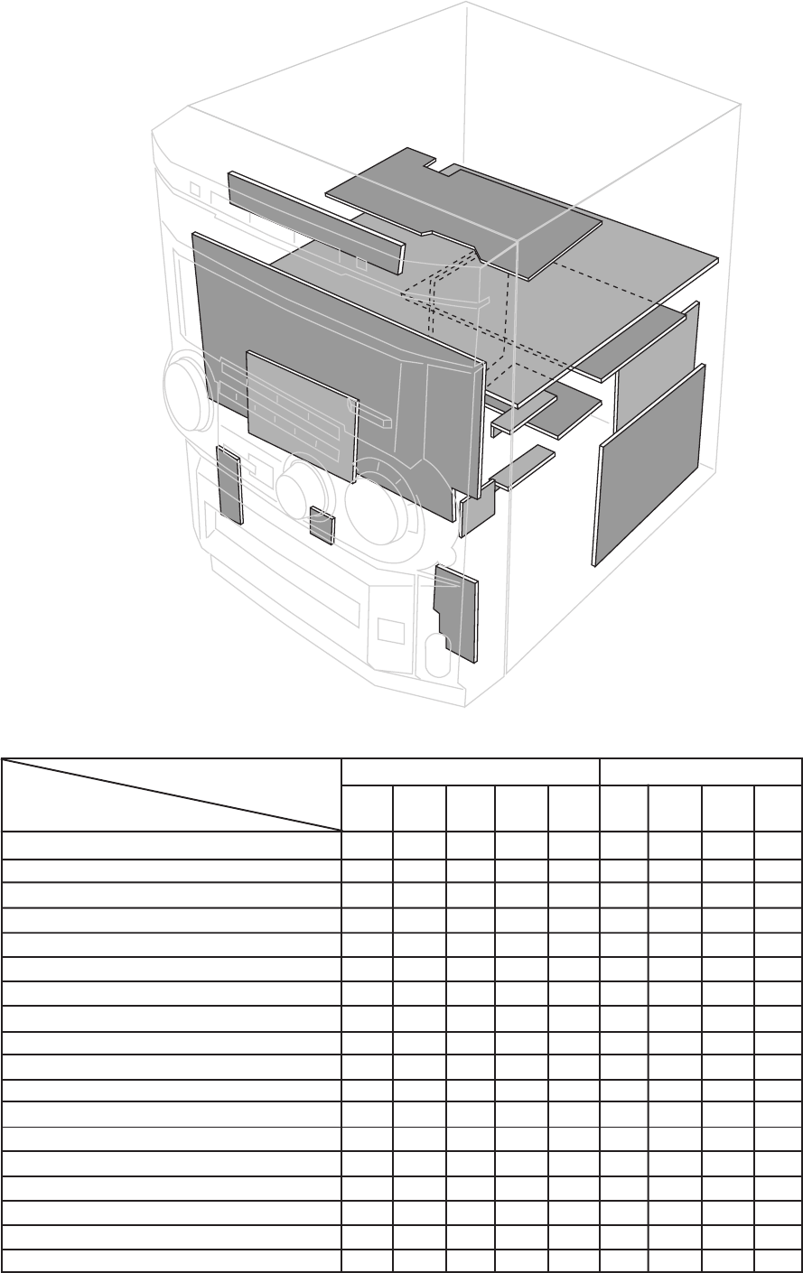
LOCATION OF PC BOARDS
PCS 103 796
/21 /21M /22 /30 /37
Karaoke x x
News x
RDS x
CD Text x
Low Power Standby (No display) x x
Voltage Selector x x
Aux / CDR Input xxxxx
Digital Output xxxxx
Headphone Socket xxxxx
Line Output xxxxx
Subwoofer Output xxxxx
Surround Output xxxxx
S-Video Output xxxxx
SCART connector x
Remote Control RC2516/01 x x x
Remote Control RC2567/01 x x
Tuner board - ECO5 Sys x x x x
Tuner board - Tuner 95 x
VERSION VARIATIONS:
Type /Versions: FW-D5
Features &
Board in used:
CDC Board
CDC Board
AV Board
3-CDC Key
Deck
Keys
Disc
Type
LED
DVD
Logo
LED
Mic &
DVD
open/
close
Head-
phone
Mains Board
Center / Surround
Amplifier
Supply Board
DAC Board
Primary
Secondary
Left/Right
Amplifier
PCS 103 797
1-3
SPECIFICATIONS
GENERAL:
Mains voltage : 110-127V/220-240V Switchable for /21/21M
120V for /37
220V for /33
220-230V for /22
230-240V for /30
Mains frequency : 50/60Hz
Power consumption Active : < 230W
< 280W for /37
Standby : < 22W
Low Power Standby : < 2W
Clock accuracy : < 4 seconds per day
Dimension centre unit : 265 x 310 x 390mm
TUNER:
FM
Tuning range : 87.5-108MHz
Grid : 50kHz
100kHz for /37
IF frequency : 10.7MHz ± 25kHz
Aerial input : 75Ω coaxial
300Ω click fit for /37
Sensitivity at 26dB S/N : < 7µV
Selectivity at 600kHz bandwidth : > 25dB
Image rejection : > 25dB [> 75dB]
Distortion at RF=1mV, dev. 75kHz : < 3%
-3dB Limiting point : < 8µV
Crosstalk at RF=1mV, dev. 40kHz : > 18dB
MW
Tuning range : 531-1602kHz
530-1700kHz for /21/37
Grid : 9kHz
10kHz for /21/37
IF frequency : 450kHz ± 1kHz
Aerial input : Frame aerial
Sensitivity at 26dB S/N : < 4.0mV/M
Selectivity at 18kHz bandwidth : > 18dB
IF rejection : > 45dB
Image rejection : > 28dB
Distortion at RF=50mV, m=80% : < 5%
LW
Tuning range : 153-279kHz
Grid : 3kHz
IF frequency : 450kHz ± 1kHz
Aerial input : Frame aerial
Sensitivity at 26dB S/N : [< 7.0mV/M]
Selectivity at 18kHz bandwidth : [> 22dB]
IF rejection : [> 26dB]
Image rejection : [> 35dB]
Distortion at RF=50mV, m=80% : [< 5%]
AMPLIFIER:
Output power Left/Right : 2 x 50W FTC 1) @ 6Ω
2 x 50W RMS 2) @ 6Ω /37
Center : 1 x 50W @ 6Ω
Surround : 2 x 5W @ 6Ω
Frequency response within ± 3dB : 20Hz-20kHz
Dynamic Bass Boost : Beat, Punch, Blast, DBB Off 3)
Digital Sound Control : Optimal, Classic, Techno, Vocal,
Rock, Jazz 3)
Personal Control : 6 presets
VEC Control : Hall, Club, Disco, Concert,Arcade 3)
Input sensitivity
Aux/CDR in : 500mV ± 2dB at 1kΩ
Mic : {2.5mV ± 2dB} at 600Ω
Output sensitivity
Line out : 1.0V ± 2dB at 22kΩ
Surround out : 750mV ± 2dB at 22kΩ
Sub-woofer : 1.5V ± 2dB at 22kΩ
Headphone : 15mW ± 2dB at 32Ω
Digital Out : IEC958 for CDDA / LPCM
IEC1937 for MPEG1, MPEG2 and AC-3
DTS
COMPACT DISC:
Measurement done at output conn. of the CDC module.
Frequency response within ± 1.5dB: 20Hz - 20kHz
Output level (in Vrms) : 550mV, Zout = 100Ω
Signal/Noise ratio (A-weighted) : > 76dBA
Distortion at 1kHz : < 0.02%
Channel unbalance : < ± 1dB
Channel separation at 1kHz : > 60dB
De-emphasis : 0 or 15/50 mS (Switched by subcode
on the disc)
DVD PLAYER:
Playback system : DVD-Video, Video CD, CD (CD-R &
CD-RW)
Video (CVBS) output 4) :1Vp-p ± 0.1V
S-Video output 4)
Y level : 1Vp-p ± 0.1V
C level : 300mV +1/-4dB
[....] Values indicated are for "Tuner 95 Board" only
{....} Values indicated are for Karaoke version only
1) ±1dB, 60Hz - 12,5kHz, 10% THD
2) ±1dB, 1kHz, 10% THD
3) Frequency response in each setting is software controlled.
4) Output terminated with 75Ω
1-4
PCS 90 113
LF Generator
e.g. PM5110
Recorder
Use Universal Test Cassette CrO2 SBC419 4822 397 30069
LEVEL METER
e.g. Sennheiser UPM550
with FF-filter
S/N and distortion meter
e.g. Sound Technology ST1700B
L
R
DUT
or Universal Test Cassette Fe SBC420 4822 397 30071
LEVEL METER
e.g. Sennheiser UPM550
with FF-filter
S/N and distortion meter
e.g. Sound Technology ST1700B
L
R
DUT
CD
Use Audio Signal Disc
(replaces test disc 3) SBC429 4822 397 30184
Bandpass
250Hz-15kHz
e.g. 7122 707 48001
LF Voltmeter
e.g. PM2534
DUT
S/N and distortion meter
e.g. Sound Technology ST1700B
Frame aerial
e.g. 7122 707 89001
Tuner AM (MW,LW)
To avoid atmospheric interference all AM-measurements have to be carried out in a Faraday´s cage.
Use a bandpass filter (or at least a high pass filter with 250Hz) to eliminate hum (50Hz, 100Hz).
RF Generator
e.g. PM5326
Ri=50Ω
Bandpass
250Hz-15kHz
e.g. 7122 707 48001
LF Voltmeter
e.g. PM2534
DUT
RF Generator
e.g. PM5326
S/N and distortion meter
e.g. Sound Technology ST1700B
Use a bandpass filter to eliminate hum (50Hz, 100Hz) and disturbance from the pilottone (19kHz, 38kHz).
Ri=50Ω
Tuner FM
MEASUREMENT SETUP
SERVICE AIDS
Service Tools:
Universal Torx driver holder .................................. 4822 395 91019
Torx bit T10 150mm ............................................. 4822 395 50456
Torx driver set T6 - T20 ......................................... 4822 395 50145
Torx driver T10 extended ...................................... 4822 395 50423
Cassette:
SBC419 Test cassette CrO2 ................................. 4822 397 30069
SBC420 Test cassette Fe ..................................... 4822 397 30071
MTT150 Dolby level 200nWb/M ............................ 4822 397 30271
Compact Disc:
SBC426/426A Test disc 5 + 5A ............................ 4822 397 30096
SBC442 Audio Burn-in Test disc 1kHz ................. 4822 397 30155
SBC429 Audio Signals disc .................................. 4822 397 30184
Dolby Pro-logic Test Disc ...................................... 4822 395 10216
ESD Equipment:
Anti-static table mat - large 1200x650x1.25mm ... 4822 466 10953
Anti-static table mat - small 600x650x1.25mm ..... 4822 466 10958
Anti-static wristband .............................................. 4822 395 10223
Connector box (1MΩ)............................................ 4822 320 11307
Extension cable
(to connect wristband to conn. box) .................. 4822 320 11305
Connecting cable
(to connect table mat to conn. box) .................. 4822 320 11306
Earth cable (to connect product to mat or box) .... 4822 320 11308
Complete kit ESD3
(combining all above products) ......................... 4822 320 10671
Wristband tester .................................................... 4822 344 13999
1-5
PCS 90 114
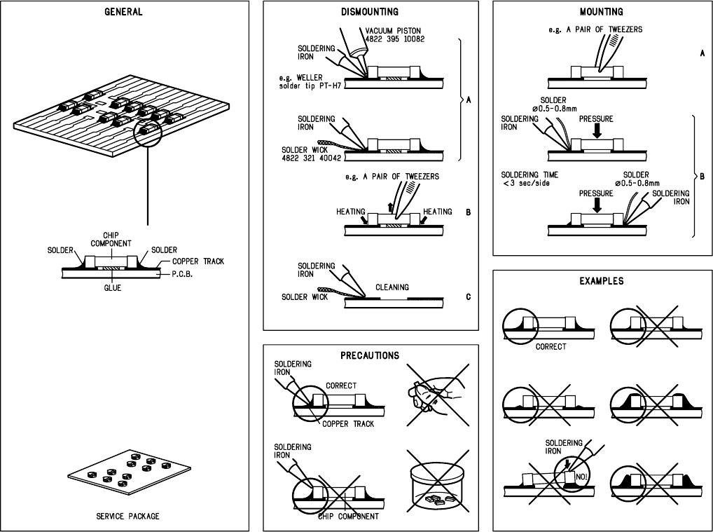
HANDLING CHIP COMPONENTS
GB
WARNING
All ICs and many other semi-conductors are
susceptible to electrostatic discharges (ESD).
Careless handling during repair can reduce life
drastically.
When repairing, make sure that you are
connected with the same potential as the mass
of the set via a wrist wrap with resistance.
Keep components and tools also at this
potential.
F
ATTENTION
Tous les IC et beaucoup d’autres
semi-conducteurs sont sensibles aux
décharges statiques (ESD).
Leur longévité pourrait être considérablement
écourtée par le fait qu’aucune précaution n’est
prise à leur manipulation.
Lors de réparations, s’assurer de bien être relié
au même potentiel que la masse de l’appareil et
enfiler le bracelet serti d’une résistance de
sécurité.
Veiller à ce que les composants ainsi que les
outils que l’on utilise soient également à ce
potentiel.
ESD
D
WARNUNG
Alle ICs und viele andere Halbleiter sind
empfindlich gegenüber elektrostatischen
Entladungen (ESD).
Unsorgfältige Behandlung im Reparaturfall kan
die Lebensdauer drastisch reduzieren.
Veranlassen Sie, dass Sie im Reparaturfall über
ein Pulsarmband mit Widerstand verbunden
sind mit dem gleichen Potential wie die Masse
des Gerätes.
Bauteile und Hilfsmittel auch auf dieses gleiche
Potential halten.
NL
WAARSCHUWING
Alle IC’s en vele andere halfgeleiders zijn
gevoelig voor electrostatische ontladingen
(ESD).
Onzorgvuldig behandelen tijdens reparatie kan
de levensduur drastisch doen verminderen.
Zorg ervoor dat u tijdens reparatie via een
polsband met weerstand verbonden bent met
hetzelfde potentiaal als de massa van het
apparaat.
Houd componenten en hulpmiddelen ook op
ditzelfde potentiaal.
I
AVVERTIMENTO
Tutti IC e parecchi semi-conduttori sono
sensibili alle scariche statiche (ESD).
La loro longevità potrebbe essere fortemente
ridatta in caso di non osservazione della più
grande cauzione alla loro manipolazione.
Durante le riparazioni occorre quindi essere
collegato allo stesso potenziale che quello della
massa dell’apparecchio tramite un braccialetto
a resistenza.
Assicurarsi che i componenti e anche gli utensili
con quali si lavora siano anche a questo
potenziale.
“Pour votre sécurité, ces documents
doivent être utilisés par des spécia-
listes agréés, seuls habilités à réparer
votre appareil en panne”.
GB
Safety regulations require that the set be restored to its original
condition and that parts which are identical with those specified,
be used.
NL
Veiligheidsbepalingen vereisen, dat het apparaat bij reparatie in
zijn oorspronkelijke toestand wordt teruggebracht en dat onderdelen,
identiek aan de gespecificeerde, worden toegepast.
F
Les normes de sécurité exigent que l’appareil soit remis à l’état
d’origine et que soient utiliséés les piéces de rechange identiques
à celles spécifiées.
D
Bei jeder Reparatur sind die geltenden Sicherheitsvorschriften zu
beachten. Der Original zustand des Geräts darf nicht verändert werden;
für Reparaturen sind Original-Ersatzteile zu verwenden.
I
Le norme di sicurezza esigono che l’apparecchio venga rimesso
nelle condizioni originali e che siano utilizzati i pezzi di ricambio
identici a quelli specificati.
"After servicing and before returning set to customer perform a
leakage current measurement test from all exposed metal parts to
earth ground to assure no shock hazard exist. The leakage current
must not exceed 0.5mA."
CLASS 1
LASER PRODUCT
3122 110 03420
GB
Warning !
Invisible laser radiation when open.
Avoid direct exposure to beam.
S
Varning !
Osynlig laserstrålning när apparaten är öppnad och spärren
är urkopplad. Betrakta ej strålen.
SF
Varoitus !
Avatussa laitteessa ja suojalukituksen ohitettaessa olet alttiina
näkymättömälle laserisäteilylle. Älä katso säteeseen!
DK Advarse !
Usynlig laserstråling ved åbning når sikkerhedsafbrydere er
ude af funktion. Undgå udsaettelse for stråling.
1-6
PCS 90 115
2-1
PCS 103 798
7
English
Accessories
(Supplied)
– Remote control
– Batteries (two AA size) for remote
control
–AM loop antenna1
–FM wire antenna
– AC power cord
–
For model FW-D5 only
CS-05 speaker package (includes one
pair of surround speakers and one
centre speaker)
–CVBS cable cinch
GENERAL INFORMATION SAFETY INFORMATION
Safety Information
•Before operating the system, check that
the operating voltage indicated on the
typeplate (or the voltage indication
beside the voltage selector) of your
system is identical with the voltage of
your local power supply. If not, please
consult your dealer. The typeplate is
located at the rear of your system.
•When the system is switched on, do not
move it around.
• Place the system on a solid base (e.g. a
cabinet).
• Place the system in a location with
adequate ventilation to prevent internal
heat build-up in your system. Allow at
least 10 cm (4 inches) clearance from
the rear and the top of the unit and 5 cm
(2 inches) from each side.
• Do not place the system on soft carpet
that will cover the ventilation hole at
the bottom.
• Do not expose the system to excessive
moisture, rain, sand or heat sources.
• Under no circumstances should you
repair the system yourself, as this will
invalidate the warranty!
IMPORTANT:
IMPORTANT:
PLEASE NOTE THAT THE
PLEASE NOTE THAT THE
VOLTAGE SELECTOR
VOLTAGE SELECTOR
LOCATED AT THE REAR OF
LOCATED AT THE REAR OF
THIS SYSTEM IS PRESET AT
THIS SYSTEM IS PRESET AT
220V FROM THE FACTORY.
220V FROM THE FACTORY.
FOR COUNTRIES THAT
FOR COUNTRIES THAT
OPERATE AT 110V, PLEASE
OPERATE AT 110V, PLEASE
ADJUST TO 110V BEFORE YOU
ADJUST TO 110V BEFORE YOU
SWITCH ON THE SYSTEM.
SWITCH ON THE SYSTEM.
General Information
•The typeplate (which contains the
serial number) is located at the rear
of the system.
•Recording is permissible if
copyright or other rights of third
parties are not infringed.
Environmental Information
All unnecessary packaging has been
omitted. We have tried to make the
packaging easy to separate into three
materials: cardboard (box), polystyrene
foam (buffer) and polyethylene (bags,
protective foam sheet).
Your system consists of materials which
can be recycled and reused if disassembled
by a specialized company. Please observe
the local regulations regarding the disposal
of packaging materials, exhausted
batteries and old equipment.
• If the system is brought directly from a
cold to a warm location, or is placed in a
very damp room, moisture may
condense on the lens of the CD/DVD
unit inside the system. Should this
occur, the player will not operate
normally. Leave the power on for about
one hour with no disc in the system until
normal playback is possible.
•Electrostatic discharge may cause
unexpected problems. See whether
these problems disappear if you unplug
the AC power cord and plug it in again
after a few seconds.
•To disconnect the system from the
power supply completely, remove
the AC power plug from the wall
socket.
8
English
PREPARATION
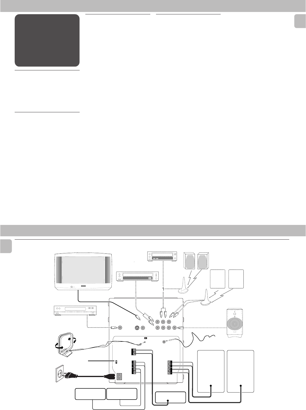
Rear Connections
AM ANTENNA
SUB-
WOOFER
OUT
LINE-OUT
AUDIO OUT
L
R
HIGH POWER SUBWOOFER
S
U
B
W
O
O
F
E
R
L
E
V
E
L
C
O
N
T
R
O
L
STANDBY ON
CUT OFF FREQUENCY
60Hz 150Hz
MIN MAX
AUDIO IN
B
REAR
SURROUND
L
surr.
R
surr.
L
+
–
R
–
+
D
A
C
FRONT
LR
L
+
–
R
–
+
F
surr.
Lsurr.
R
SURROUND OUTAUX/CDR-IN
S-VIDEO
OUT
(Y/C)
VIDEO OUT
(CVBS)
AUDIO
DIGITAL
OUT
W
G
H
I
K
J
AC
MAINS
~
M
VOLTAGE
SELECTOR
110V-
127V
220V-
240V
L
E
CENTER
CENTER
+
–
FM ANTENNA 75Ω
2-2
PCS 103 799
9
English
PREPARATION
FSubwoofer Out Connection
Connect the optional active subwoofer to
the SUBWOOFER OUT terminal. The
subwoofer reproduces just the low bass
sound effect (e.g. explosions, the rumble of
spaceships, etc.). Be sure to follow the
instructions supplied with the subwoofer.
GWireless Surround Out
Connection
(for model FW-D5
only)
You may connect the transmitter of the
wireless rear speakers (not supplied) to the
SURROUND OUT terminal.
Note:
–Availability of a wireless transmitter and
its peripherals are subjected to the
approval of local authorities. Please
check with the respective local safety or
approving authority.
CAUTION:
–For optimal sound performance, it is
recommended to use the supplied
speakers.
– Do not connect more than one speaker
to any one pair of
+
/
-
speaker
terminals.
– Do not connect speakers with
impedance lower than the speakers
supplied. Please refer to the
SPECIFICATIONS section of this manual.
DCentre Speaker Connection
(for model FW-D5 only)
Connect the black (non-marked) wires to
the black CENTER terminal and the blue
(marked wires) to the blue CENTER
terminal.
ERear Surround Speakers’
Connection
(for model FW-D5
only)
Connect the black (non-marked) wires to
the black REAR SURROUND terminals and
the coloured (marked) wires to the grey
REAR SURROUND terminals.
HLine Out Connection
(wireless
ready)
You can connect the audio left and right
LINE OUT terminals to a optional CD
Recorder's ANALOGUE IN terminals. This
allows you to record in an analogue format.
You can also install additional optional
front active speakers away from the system
(e.g. in another room) to reduce the
inconvenience of running long speaker
wires across rooms. You can place as many
remote speakers as you like provided they
operate at the same radio frequency.
Connect the wireless radio frequency
transmitter to the LINE OUT terminals.
Place the active speakers at your preferred
location. Be sure to follow the instructions
supplied with the active speakers.
IConnecting other
equipment to your system
You can connect the audio left and right
OUT terminals of a TV, VCR, Laser Disc
player, DVD player or CD Recorder to the
AUX/CDR IN terminals at the rear of the
system.
AAM Loop Antenna
Connection
Connect the supplied loop antenna to the
AM ANTENNA terminal. Place the AM loop
antenna far away from the system and
adjust its position for the best reception.
BFM Wire Antenna
Connection
Connect the supplied FM wire antenna to
the FM ANTENNA 75 Ω terminal. Adjust
the position of the FM antenna for the best
reception.
Outdoor Antenna
For better FM stereo reception connect an
outdoor FM antenna to the FM ANTENNA
75 Ω terminal using a 75 Ω coaxial wire.
CSpeakers Connection
• Connect the right speaker to Front
terminal R, with the coloured wire to +
and the black wire to -.
• Connect the left speaker to Front
terminal L, with the coloured wire to +
and the black wire to -.
•Clip the stripped portion of the speaker
wire as shown.
unlock lock
12 mm
10
English
J Video Out Connection
Connect the VIDEO OUT (CVBS) terminal at
the rear of the system to the TV or VCR
VIDEO IN terminal for viewing or recording.
Note:
–You can also choose to connect the
S-VIDEO OUT (Y/C) terminal at the rear
of the system to the S-VIDEO IN of the
TV using an optional S-VIDEO cable.
KAudio Digital Out
Connection
You can record the digital sound from the
CD/DVD, through this output, on any audio
equipment with digital input (e.g. CD
Recorder, Digital Audio Tape (DAT) deck,
Digital to Analogue Converter and Digital
Signal Processor).
Connect one end of the cinch cable (not
supplied) to the DIGITAL OUT socket and
the other end to the audio equipment's
digital input. When connecting the cinch
cable, make sure it is fully inserted.
L Adjusting the Operating
Voltage
(not available for all
versions)
Before connecting the AC power cord to a
wall outlet, make sure that the voltage
selector at the rear of the system is set to
the local power line voltage. If not, reset
the selector before connecting to the wall
outlet.
MAC Power Supply
After all other connections have been
made, connect the AC power cord to the
system and to the wall outlet.
PREPARATION
Inserting batteries into the
Remote Control
• Insert the batteries (Type R06 or AA)
into the remote control as shown in the
battery compartment.
•To avoid damage from possible battery
leakage, remove dead batteries or
batteries that will not be used for a long
time. For replacement, use type R06 or
AA batteries.
2-3
PCS 103 800
11
English
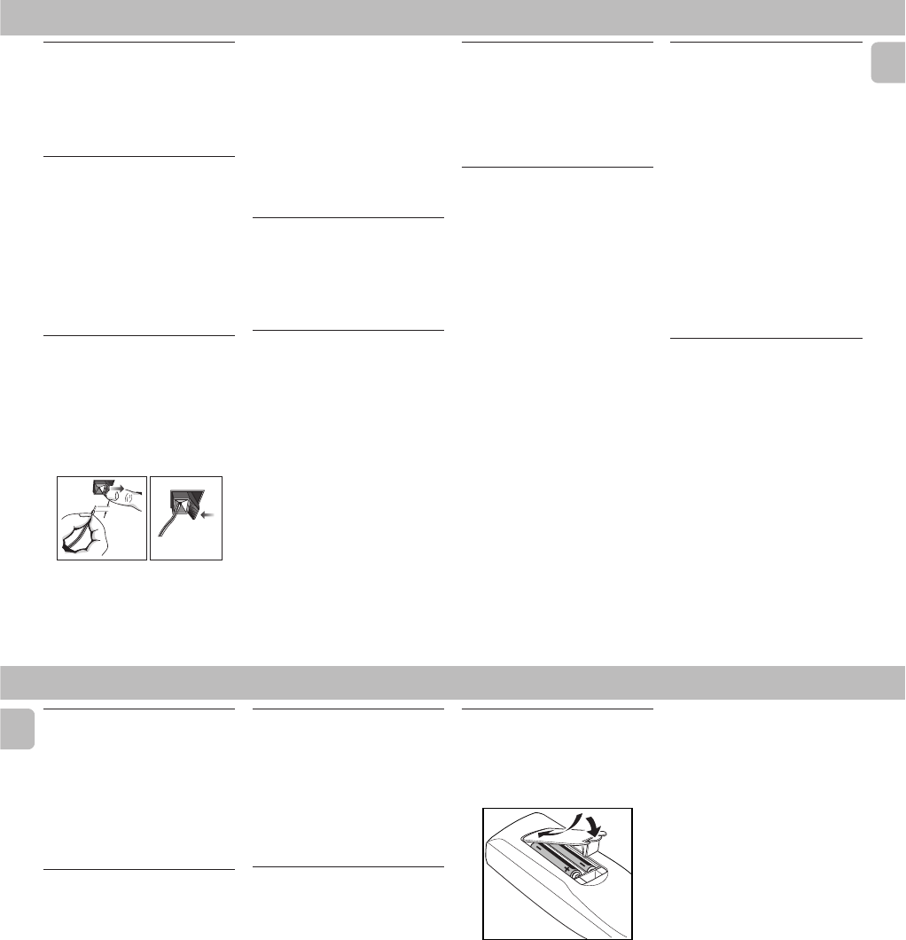
CONTROLS
R
E
T
U
R
N
P
E
R
S
O
N
A
L
V
E
C
D
S
C
D
B
B
DISC CHANGE
CD 1 CD 2 CD 3
OPEN•CLOSE
STANDBY
ON
DC
3
CHANGER
DVD MINI HIFI SYSTEM
DIM
PROG
POWER SAVE
IR SENSOR
RDS/ CD TEXT
NEWS /T.A.
9
CLOCK/
TIMER
VOLUME
AXIS OK
DVD
MENU
DVD
SOUND JOG
DVD JOG
PLAYBACK
MODE
DVD
VCD
CD
OPEN/ CLOSE
MIC LEVEL
MIC
DVD / VCD / CD PLAYBACK
0
P3 P6P1 P2 P5P4
FTS TITLE CHAP. SLEEP DIM TIMERLWFM A M W
TUNER
DVD CD AUX
A
-
B
P
B
C
1
3
º
⁄
≥
4
5
8
67
!
Å
É
13
2
46
5
79
8
VOLUME
0
2
AUX/CDR
TV/AV
DVD CD TUNER
SHUFFLEREPEAT
FTS
¤
^
≤
‹
*‡
fi
fl
!
∞
§
^
‚
DSC VEC DBB TIMER
#
BAND
VCD • CD CD 1 •2•3 CDR
2
LEFT CENTER RIGHT
SURR SURR
SURROUND CONTROL
!
°
0
3
STOP•CLEAR
SEARCH•TUNING PLAY PAUSE PREV NEXTSIDE
PRESET ▲
▲
S
C
A
N
CHANNEL
5.1CH / STEREO / SURR / 3D
É
É
É
DVD OK
OSD SURR.
MENU
PROG. AUDIO A-B KARAOKE
ECHO KEY CONTROL
STOP PLAY
É
á
à
ë
í
Ç
ª
•
∞
&
*
^
%
$
#
@
(ª
£
≤
§
)
!!
¡
™
·
›
12
English
CONTROLS
Controls on the system and
remote control
11
11
1STANDBY ON
–to switch the system on or to standby
mode.
–to use for EASY SET.
22
22
2IR SENSOR
–sensor for the infrared remote control.
33
33
3SOURCE –to select the following:
DVD / (VCD•CD)
–to select DVD mode. When in DVD
mode, you can play DVD, VCD or CD.
CD / (CD 1•2•3)
–to select CD mode. When CD playback
is stopped, press to select disc tray 1,
2 or 3.
TUNER / (BAND)
–to select Tuner mode. When in tuner
mode, press to select the waveband:
FM or MW.
AUX / (CDR)
–to select sound from an external
source (e.g. TV, VCR, Laser Disc player,
DVD player or CD Recorder). When in
AUX mode, press to select either AUX
or CDR.
TV/AV
(only on the remote control)
–to select TV or Video mode.
44
44
4DISPLAY SCREEN
–to view the current setting of the
system.
55
55
5CD CAROUSEL TRAY
66
66
6DISC CHANGE
–to change CD(s).
77
77
7OPEN•CLOSE
– to open or close the CD carousel tray.
88
88
8CD 1 / CD 2 / CD 3 (CD DIRECT
PLAY)
– to select a CD tray for playback.
99
99
9SURROUND SOUND DISPLAY
PANEL
(for model FW-D5 only)
– to view the selected Surround setting.
00
00
0SURROUND CONTROL (SURR)
(for
model FW-D5 only)
– to select Multichannel Sound, Stereo,
Surround or 3D Sound mode for DVD
operation only.
!!
!!
!MODE SELECTION
SEARCH•TUNING àá
(12 )
for DVD/VCD/CD
–to search backward/forward
(except for CD playback in DVD-
VIDEO tray)
.
for TUNER
–to tune to a lower or higher radio
frequency.
for CLOCK
(on the system only)
–to set the hour.
for TV VOL.
–to adjust the TV volume if the
remote operates your TV.
STOP•CLEAR Ç
for DVD/VCD/CD
–to stop playback
(in DVD mode
only)
.
for CD
–to stop playback or to clear a
programme
(in CD mode only)
.
for TUNER
–to stop programming.
for DEMO
(on the system only)
–to start or stop demonstration
mode.
PLAY PAUSE ÉÅ
for DVD/VCD/CD
–to start or interrupt playback.
for DVD/VCD
–to watch a still picture.
í PREV / NEXT ë
(PRESET)
for DVD/VCD/CD
–to skip to the beginning of the
current, previous, or next title or
track.
for VCD only
–to select next or previous MENU
(for VCD with PBC on)
.
– to select next or previous VCD track
during playback
(for VCD with PBC
off)
.
for TUNER
–to select a preset radio station in
memory.
for CLOCK
(on the system only)
–to set the minute .
@@
@@
@CLOCK/TIMER
– to view the clock, set the clock or set
the timer.
##
##
#SOUND CONTROL
– to select the desired sound feature :
VEC, PERSONAL, DSC or DBB.
$$
$$
$SOUND JOG
–to select the desired sound effect of
VEC/PERSONAL/DSC/DBB setting.
You must select the respective sound
feature first.
VEC
–to select the desired Virtual
Environment Control effect : HALL,
CLUB, DISCO, CINEMA, CONCERT or
ARCADE.
PERSONAL
–to select up to 6 personal preferred
Spectrum Analyser settings :
PERSONAL 1-6.
DSC
–to select the desired Digital Sound
Control effect : OPTIMAL, CLASSIC,
TECHNO, VOCAL, ROCK or JAZZ.
DBB
–to select a Dynamic Bass Boost level :
BEAT, PUNCH or BLAST.
%%
%%
%n
–to connect headphones.
^^
^^
^VOLUME
–to increase or decrease the volume.
&&
&&
&DIM
–to select brightness for the display
screen : DIM 1, DIM 2, DIM 3 or DIM
OFF.
2-4
PCS 103 801
13
English
CONTROLS
**
**
*PROGram (FTS- Favourite track
selection)
for DVD/VCD/CD
–to programme disc tracks.
for TUNER
–to programme preset radio
stations.
for CLOCK
(on the system only)
–to select 12 or 24 hour in clock
setting mode.
((
((
(DVD-VIDEO DISC TRAY
))
))
)OPEN/CLOSE 0
–to open or close the DVD-VIDEO tray.
¡¡
¡¡
¡MIC LEVEL
(not available for all
versions)
–to adjust the mixing level for karaoke
in DVD mode only.
™™
™™
™MIC
(not available for all versions)
–to connect microphone jack.
££
££
£PLAYBACK MODE
–to view the selected playback mode :
DVD, VCD or CD.
≤≤
≤≤
≤DVD MENU
–to access the DVD disc menu.
∞∞
∞∞
∞OK
–to confirm the selection.
§§
§§
§AXIS ( 1 2 3 4 )
–to select the direction of cursor
movement : up/down or left/right.
–
(on the remote control only)
to select movement of cursor: left,
right, up or down.
≥≥
≥≥
≥DVD JOG
– to move the cursor up/down or left/
right. You must select the AXIS
movement direction first.
••
••
•SCAN
for DVD
–to playback the first 10 seconds of
each chapter within a title.
for VCD/CD
–to playback the first 10 seconds of
each track.
ªª
ªª
ªA - B
(in DVD mode only)
– to playback a certain scene or passage
of a disc repeatedly.
– to repeat playback a Chapter/Index,
Title/Track or Disc.
ºº
ºº
ºPBC (PLAYBACK CONTROL)
– to switch on or off PBC mode
(for VCD
version 2.0 only).
⁄⁄
⁄⁄
⁄RETURN
– to return to the previous MENU level
during playback.
¤¤
¤¤
¤REPEAT
(in CD mode only)
– to repeat a disc track, a disc, or all
available discs.
‹‹
‹‹
‹OSD MENU (ON SCREEN
DISPLAY)
– to switch on or off the on screen
display on the TV screen.
››
››
›ECHO -/+
(not available for all
versions)
– to adjust the echo level for karaoke.
fifi
fifi
fiAUDIO
– to select different audio languages
available in the DVD disc.
flfl
flfl
flTIMER
–to switch on or off the timer.
‡‡
‡‡
‡KARAOKE
(not available for all
versions)
–to switch the Karaoke features ON/
OFF mode.
°°
°°
°KEY CONTROL -/+
(not
available for all versions)
–to adjust the key to suit your vocal
range.
··
··
·SHUFFLE
–to play all the available discs and their
tracks in random order.
‚‚
‚‚
‚DIGIT 0 – 9
(numbers consisting more than two
figures must be keyed in within 2
seconds.)
for DVD/VCD/CD
–to key in a disc title or track for
playback or programming.
for VCD with PBC on only
–to select a track.
for TUNER
–to key in a preset radio station.
B
–to switch the system to standby mode.
Notes for remote control:
–First select the source you wish to
control by pressing one of the
source select keys on the remote
control (e.g. DVD, TUNER, etc.).
–Then select the desired function
(
É
,
í
,
ë
, etc.).
14
English
Important:
Before you operate the system,
complete the preparation procedures.
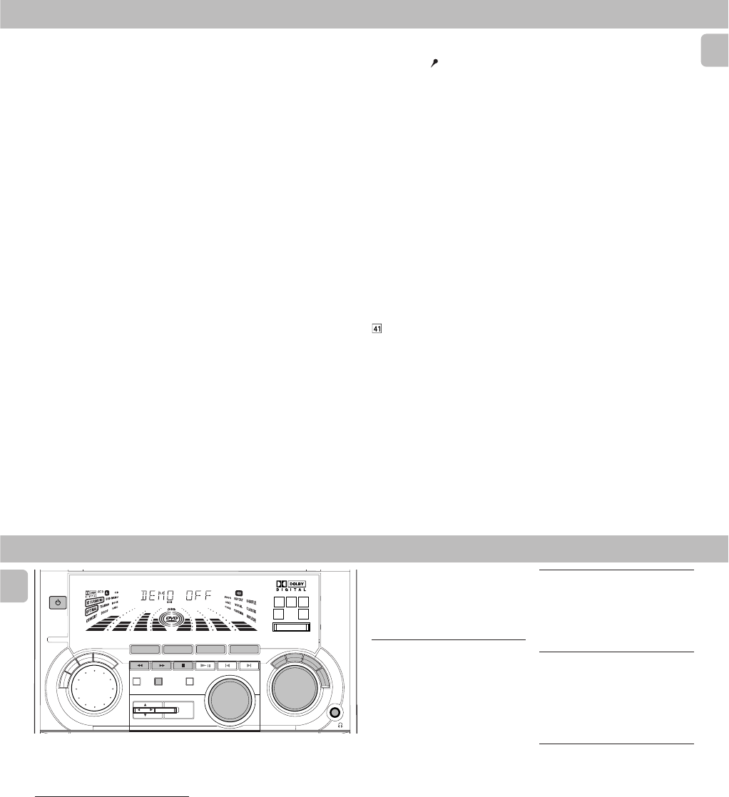
Demonstration mode
The system has a demonstration mode that
shows the various features offered by the
system.
When the system is switched
on for the first time, the demonstration
mode will start automatically.
Notes:
–During the demonstration, if you press
any source (or standby-on) button, the
system will switch to the respective
mode (or standby).
– When the system is switched to standby
mode, the demonstration will resume 5
seconds later.
To stop the demonstration mode
•Press and hold Ç
(on the system only)
for
5 seconds
when the system is in
demonstration mode.
™The demonstration will stop.
™"DEMO OFF" will be displayed.
™The system will switch to standby
mode.
Notes:
–When the system is switched on from
the main power outlet, the CD carousel
tray may open and close again to
initialize the set.
–Even though the AC power cord is
removed from and reconnected to the
wall socket, the demonstration will
remain off until it is switched on again.
OPERATING THE SYSTEM
To start the demonstration mode
•Press and hold Ç
(on the system only)
for
5 seconds
when the system is in
standby mode.
™The demonstration will begin.
Easy Set
EASY SET allows you to store all available
radio stations automatically.
•Press and hold STANDBY ON
(on the
system only)
for
5 seconds
; when the
system is in standby or demonstration
mode.
™"EASY SET" will be displayed, and
followed by "TUNER" and then
"AUTO".
™EASY SET will start searching for all
radio on FM band and then followed
by radio stations on MW band.
™All available radio stations with
sufficient signal strength will be
stored. Up to 40 presets may be
stored.
Notes:
– EASY SET will start with the FM band, if
there are still presets available, the
system will continue to store the MW
band.
–When EASY SET is used, all previously
stored radio stations will be replaced.
–The last preset radio station will appear
on the display when EASY SET is
completed.
Switching the system ON
•Press DVD,CD,TUNER or AUX.
You can also switch on the system by
pressing any one of the CD DIRECT PLAY
buttons.
Switching the system to
standby mode
•Press STANDBY ON or B on the
remote control.
™The system will switch to standby
mode.
Selecting the Source
•Press the desired source selection
button: DVD,CD,TUNER or AUX.
™The display indicates the selected
source.
Note:
–For an external source, make sure you
have connected the audio left and right
OUT terminals of the external
equipment (TV, VCR, Laser Disc player,
DVD player or CD Recorder) to the AUX/
CDR IN terminals.
R
E
T
U
R
N
P
E
R
S
O
N
A
L
V
E
C
D
S
C
D
B
B
STANDBY
ON
DVD MINI HIFI SYSTEM
DIM
PROG
POWER SAVE
IR SENSOR
RDS/ CD TEXT
NEWS /T.A.
CLOCK/
TIMER
VOLUME
AXIS OK
DVD
MENU
SOUND JOG
DVD JOG
P3 P6P1 P2 P5P4
CHAP. SLEEP DIM TIMERLWFM AMW
TUNER
DVD CD AUX
A
-
B
P
B
C
BAND
VCD •CD CD 1 •2•3 CDR
LEFT CENTER RIGHT
SURR SURR
STOP•CLEAR
SEARCH•TUNING PLAY PAUSE PREV NEXTSIDE
PRESET ▲
▲
S
C
A
N
CHANNEL
DVD
SURROUND CONTROL
5.1CH / STEREO / SURR / 3D
FTS TITLE
2-5
PCS 103 802
15
English
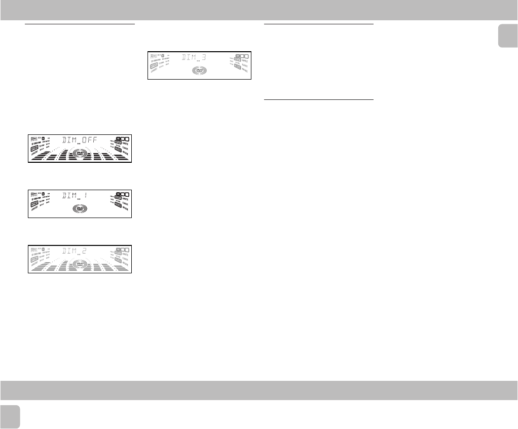
Dim mode
You can select the desired brightness for
the display.
•Press DIM to select DIM 1, DIM 2,
DIM 3 or DIM OFF display mode.
™The
DIM
appears on the display.
™"DIM 1", "DIM 2", "DIM 3" or
"DIM OFF" will be displayed
depending on the mode selected.
DIM OFF - normal brightness with
Spectrum Analyser On
P3 P6P1 P2 P5P4
FTS TITLE CHAP. SLEEP DIM TIMERLWFM A M W
DIM 1 - normal brightness with
Spectrum Analyser Off
P3 P6P1 P2 P5P4
FTS TITLE CHAP. SLEEP DIM TIMERLWFM A M W
DIM 2 - half brightness with Spectrum
Analyser On
P3 P6P1 P2 P5P4
FTS TITLE CHAP. SLEEP DIM TIMERLWFM A M W
OPERATING THE SYSTEM
DIM 3 - half brightness with Spectrum
Analyser Off and all LEDs on the
system will be switched off.
P3 P6P1 P2 P5P4
FTS TITLE CHAP. SLEEP DIM TIMERLWFM A M W
Volume Control
Adjust VOLUME to increase or decrease
the sound level.
For Personal Listening
Connect the headphones plug to the n
socket at the front of the system. The
speakers will be muted.
Sound Control
For Optimal sound listening, you can
only select one of the following sound
controls at a time : VEC, PERSONAL or
DSC .
VIRTUAL ENVIRONMENT CONTROL
(VEC)
The VEC feature enables you to adjust the
system to select a type of environment.
1Press to select the VEC feature.
2Adjust the JOG to select the desired
VEC setting : HALL, CLUB, DISCO,
CINEMA, CONCERT or ARCADE.
™The selected environment is
encircled.
™"HALL, CLUB, DISCO,
CINEMA, CONCERT or
ARCADE" will be displayed.
PERSONAL SOUND
You can store up to 6 personal settings.
1Press to select the PERSONAL feature.
2Adjust the JOG to select the desired
Personal setting.
™The selected personal setting number
will appear on the display.
™If no name has been stored
previously, "PERSONAL X" will be
displayed. "X" is the setting number.
Personal Setting
You can adjust the personal setting to your
desired level with the JOG control.
1Press and hold PERSONAL for about
5
seconds
to switch on the personal
setting mode.
™"SELECT PRESET NUMBER" will
be displayed.
2Adjust the JOG to select the desired
preset number for personal setting and
press á to confirm the selection.
™"ADAPT LOW FREQ LEVEL" will
be displayed.
3Adjust the JOG to select the desired
Spectrum Analyser band level for low
frequency.
™The level will increase or decrease
between+3 and -3.
4Press á to confirm the selection.
™"ADAPT MID FREQ LEVEL" will
be displayed, followed by "ADAPT
HIGH FREQ LEVEL".
16
English
OPERATING THE SYSTEM
•Repeat
step 3 - 4
to select the desired
middle and high frequencies of the
Spectrum Analyser band levels.
5You can edit the name for the personal
setting.
™The first character of the setting
name will be flashing.
6Adjust the JOG to select the desired
letter, number or symbol.
™"A to Z", "0 to 9" or "*,-,+, \, /, _".
7Press á to confirm the selection.
™The next character for editing will be
flashing.
•Repeat
steps 6 - 7
to store up to 10
characters.
8To store the setting, press PERSONAL
again.
•Before storing the setting, you can
press
à
to retrace the steps.
•To exit without storing the setting,
press
Ç
.
Notes:
–During personal setting, if no button is
pressed within 90 seconds, the system
will exit personal setting mode
automatically.
– It is not possible to adjust the DBB level
during personal setting, "
USE JOG
"
will be displayed.
DIGITAL SOUND CONTROL (DSC)
The DSC feature enables you to adjust the
system to suit your type of music.
1Press to select the DSC feature.
2Adjust the JOG to select the desired
DSC setting : OPTIMAL, CLASSIC,
TECHNO, VOCAL, ROCK or JAZZ.
™The selected digital sound is
encircled.
™"OPTIMAL, CLASSIC, TECHNO,
VOCAL, ROCK or JAZZ" will be
displayed.
Note:
–For a neutral setting, select CLASSIC.
DYNAMIC BASS BOOST (DBB)
There are three DBB settings to enhance
the bass response.
•Press DBB briefly to select a bass boost
level.
™The DBB button wll be lit.
™“BEAT”, “PUNCH” or “BLAST”
will be displayed.
To switch off DBB
•Press DBB briefly until “DBB OFF” is
displayed.
Note:
– Some CDs might be recorded in high
modulation, which causes a distortion at
high volume. If this occurs, switch off
DBB or reduce the volume.
Automatic DSC-DBB / VEC-DBB
selection
The best DBB setting is generated
automatically for each DSC or VEC
selection. You can manually select the DBB
setting that best suits your listening
environment.
2-6
PCS 103 803
17
English
DVD-VIDEO
General Information
•Digital video discs provide perfect
digital, studio-quality pictures; three
dimensional digital; multi-channel
audio; story sequences screened from
your choice of camera angle; sound
tracks in as many as eight languages;
and up to 32 subtitles if available on
disc.
• DVD-Video uses state-of-the-art MPEG2
data compression technology to register
an entire movie on the single 5-inch
disc. DVD's variable bitrate
compression, running up to 9.8 Mbits/
second, captures even the most complex
pictures in their original quality.
• The crystal-clear digital pictures have a
horizontal resolution of over 500 lines,
with 720 pixels (picture elements) to
each line. This resolution is more than
double that of VHS, superior to Laser
Disc, and entirely comparable with
digital masters made in recording
studios.
• In addition to the DVD-Video discs, you
will be able to play all Video CDs and
Audio CDs (including finalised CD
Recordable and CD Rewritable).
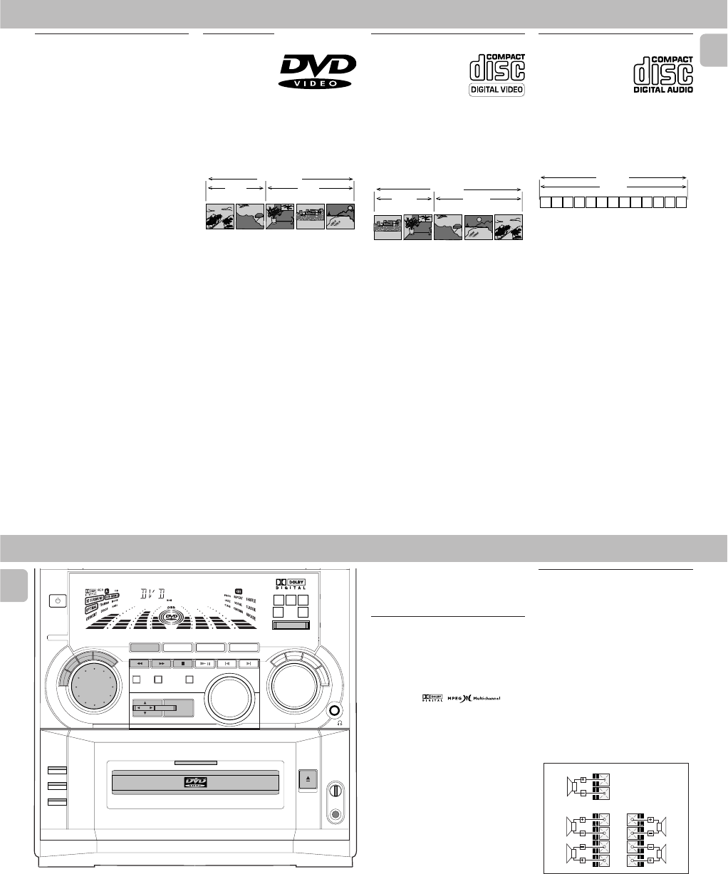
DVD-Video
You will recognise
DVD-Video discs by
the logo shown at
right. Depending on
the material on the disc (a movie, video
clips, a drama series, etc.) the disc may
have one or more Titles. Each Title may
have one or more Chapters. To make
playback easy and convenient, your player
lets you select Titles and Chapters.
TITLE 1 TITLE 2
CHAPTER 1 CHAPTER 2 CHAPTER 1 CHAPTER 2 CHAPTER 3
DVD-VIDEO DISC
Video CD
You will recognise Video
CDs by the logo shown at
right. Depending on the
material on the disc (a
movie, video clips, a
drama series, etc.) the disc may have one
or more tracks. Tracks may have one or
more indexes, as indicated on the disc
case. To make playback easy and
convenient, your player lets you select
tracks and indexes.
INDEX 1 INDEX 2 INDEX 1 INDEX 2 INDEX 3
VIDEO CD
TRACK 1 TRACK 2
Audio CD
Audio CDs contain music
tracks only.
You will recognise CDs by
their logo which is shown
at right. You can play them in conventional
style through a stereo system, using the
keys on the remote control and/or front
panel, or via the TV using the On-Screen
Display (OSD).
23 56789101112...41
TRACKS
AUDIO CD
18
English
Surround Setup
(for FW-D5
DVD operation only)
Multichannel sound
MULTICHANNEL SOUND gives you a
completely new listening sensation. You
will have the feeling of being in the middle
of the action, because sound is coming
from everywhere around you. Look for
discs with the mark
which indicates the material is encoded for
multichannel surround sound.
Notice that DVDs do not always carry full
multichannel surround. To be sure that a
disc is multichannel encoded, consult your
dealer.
Most ordinary stereo tapes and discs can
be replayed using surround sound settings
with good results. If the reproduction is
distorted in surround mode, switch to
normal stereo mode.
The availability of the various surround
sound modes described depends on the
number of speakers used and the incoming
sound information.
Setting up the Multichannel
system
You must set up the system properly in
order to enjoy the MULTICHANNEL to the
fullest. First, connect the speakers.
5-Speaker Connection
•Front speakers: Connect the front
speakers to the FRONT terminals.
•Centre speaker: Connect the centre
speaker to the CENTER terminals.
•Rear (surround) speakers: Connect
either the wired rear surround speakers
or a pair of wireless rear speakers (not
supplied) to the SURROUND OUT
terminals.
SURROUND FRONT
CENTER
REAR
RIGHT
FRONT
LEFT
FRONT
RIGHT
REAR
LEFT
REAR
DVD-VIDEO
R
E
T
U
R
N
P
E
R
S
O
N
A
L
V
E
C
D
S
C
D
B
B
STANDBY
ON
DVD MINI HIFI SYSTEM
DIM
PROG
POWER SAVE
IR SENSOR
RDS/ CD TEXT
NEWS /T.A.
CLOCK/
TIMER
VOLUME
AXIS OK
DVD
MENU
SOUND JOG
DVD JOG
PLAYBACK
MODE
DVD
VCD
CD
OPEN/ CLOSE
MIC LEVEL
MIC
DVD / VCD / CD PLAYBACK
P3 P6P1 P2 P5P4
FTS TITLE CHAP. SLEEP DIM TIMERLWFM A M W
TUNER
DVD CD AUX
A
-
B
P
B
C
BAND
VCD • CD CD 1 • 2 • 3 CDR
LEFT CENTER RIGHT
SURR SURR
STOP•CLEAR
SEARCH•TUNING PLAY PAUSE PREV NEXTSIDE
PRESET ▲
▲
S
C
A
N
CHANNEL
DVD
SURROUND CONTROL
5.1CH / STEREO / SURR / 3D
2-7
PCS 103 804
19
English
DVD-VIDEO
Positioning the Speakers
To get the best surround sound effect,
place the speakers as follows.
TV
CENTER
SPEAKER
SURROUND
RIGHT
SURROUND
LEFT
FRONT
LEFT
FRONT
RIGHT
MINI HIFI
SYSTEM
SUB-
WOOFER
Front Left and Right Speakers
For the best sound, place the Left and Right
speakers at an angle of approximately 45
degrees to the listener. If the speakers'
magnetic field affects the television
picture, increase the distance between the
TV and the speakers.
Centre Speaker
For the best sound, place the centre
speaker at the same height as the left and
right speakers. Place the centre speaker
directly above or beneath the television.
Rear (surround) Speakers
The surround speakers should be placed at
normal listening ear level or mounted on
the wall at the back of the room. Most
important, experiment when placing the
surround speakers in order to obtain the
best sound.
LEFT CENTER RIGHT
SURR SURR
CHANNEL
LEFT CENTER RIGHT
SURR SURR
CHANNEL
Switching Surround Control
Sound
You can switch through the different
surround modes. Note that the
possibilities are related to speaker setup as
defined.
•Press SURROUND CONTROL
(or
SURR on the remote control)
to select :
MULTICHANNEL, STEREO, SURROUND
or 3D SURROUND mode.
™The message "DOLBY DIGITAL
AC3 5.1 CHANNEL,STEREO,
SURROUND or 3D SURROUND"
will be displayed.
Multichannel (5.1)
In addition to SURROUND,
the surround mode used
will be displayed. AC3
must be available on the
source material.
Stereo
All sound is reproduced and
played through the front left
and right speakers. This
enables standard stereo
reproduction.
Surround
This surround mode enables
normal surround sound
reproduction with two
speakers. Depending on the source
material, Dolby Pro Logic or MPEG is
reproduced (for connection to another
Dolby Pro Logic decoder).
3D Surround
The sound of the rear
channel is simulated by the
front left and right
speakers.
Note:
–Always refer to OSD when selecting
surround control sound. When in stop
mode, the player will not display the
correct surround selection.
LEFT CENTER RIGHT
SURR SURR
CHANNEL
LEFT CENTER RIGHT
SURR SURR
CHANNEL
20
English
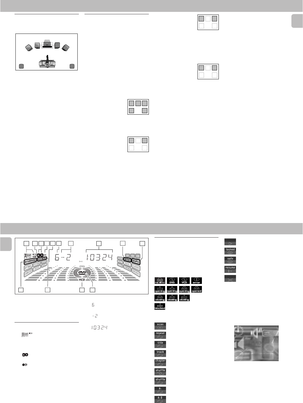
66
66
6
TITLE
–DVD TITLE number
77
77
7
CHAP.
–DVD CHAPTER number
88
88
8
– TRACK/TOTAL TIME in hours, minutes
and seconds
99
99
9REPEAT
–REPEAT active
00
00
0SHUFFLE
–SHUFFLE active
!!
!!
!DVD
–DVD disc inserted
@@
@@
@VCD
–(Video)CD disc inserted
##
##
#DVD MENU
–DVD MENU active
$$
$$
$3D SURROUND
(for model FW-D5
only)
–3D SURROUND active
On Screen Display
information
DISPLAY indications
11
11
1
(for model FW-D5 only)
– AC-3 active
22
22
2SCAN
–SCAN active
33
33
3
– Repeat A-B active
44
44
4
–Remote control active (flashing)
55
55
5FTS
–Favourite Track Selection active
P3 P6P1 P2 P5P4
FTS TITLE CHAP. SLEEP DIM TIMERLWFM A M W
12345 6 8910
11
121314
7
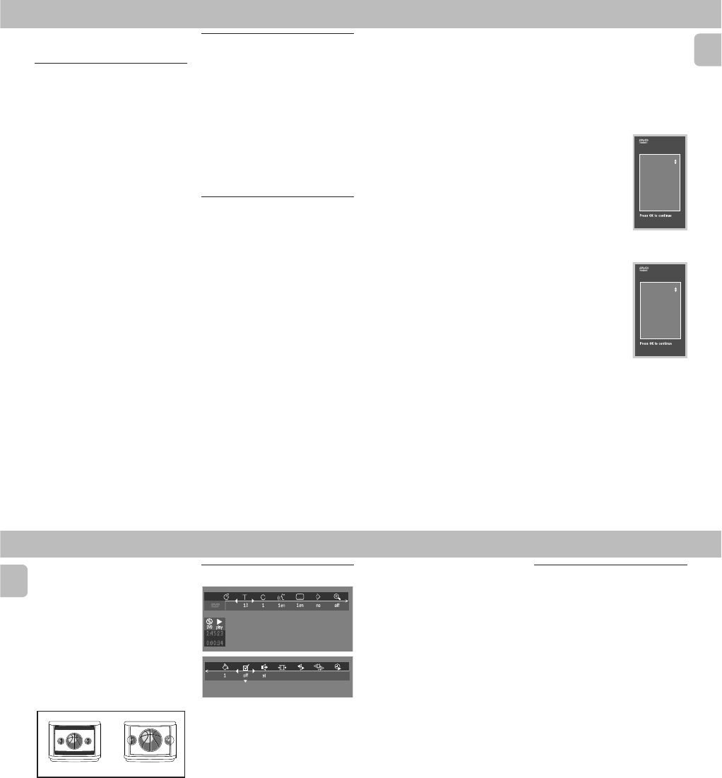
Menu bar/Status window
The status window displays the current
status of the player and appears with the
first part of the menu bar. (You must
activate this in the Features Menu, see
Personal Preferences for details).
General
Disc type
Tr ay status
Temporary feedback field icons
Scan
Repeat All
Repeat Title
Repeat Track
Repeat Chapter
Shuffle
Shuffle Repeat
Repeat A to end
Repeat A-B
Angle
Child Lock On
Child Safe
Resume
Action prohibited
Default screen
The default screen is displayed when the
player is in STOP mode. It may contain a
'Status Window' and a 'Temporary
Feedback Field'. This screen gives
information concerning prohibited actions,
playback modes, available angles, etc.
DVD-VIDEO
PCS 103 805
2-8
21
English
Preparation
NTSC/PAL Setting
Before viewing the DVD or VCD, ensure
that the PAL or NTSC setting of the system
matches your TV set.
1Before connecting the system to the
power source, press and hold DVD and
à
(on the system only)
. While holding
DVD and à, plug in the power cord.
2After PAL or NTSC appears on the
display, release DVD and àat the
same time.
™The PAL or NTSC that appears on the
display indicates the current setting.
•To change the setting, press ë within
3 seconds
.
™After selected, the set will
automatically switch to the last
NTSC or PAL setting everytime the
DVD or VCD source is selected.
Turning On the power
1Switch on the TV and select the video in
channel to which you connected your
DVD-Video player.
2Press DVD.
™The player display lights and the
"Initial Setup" screen appears.
The ‘Initial Setup’ will only appear the very
first time you turn on the player. In ‘Initial
Setup’, you may have to set your personal
preferences for some of the player’s most
relevant items. See ‘Initial Setup’.
Initial Setup
Manual Operation
After switching on the player for the very
first time, the ‘Initial Setup Screen’ will
appear.
The menu for the first item to be set is
displayed and the first option is
highlighted.
1Use the 3 or 4 keys to go through the
options in the menu.
™The icon of the selected option will
be highlighted.
2Press OK to confirm your selection and
to go to the next menu.
Automatic setting
When settings will be taken from your TV
or Home Cinema system, the message
‘Auto configuring in process’ will appear.
Menus for which no settings are available
will be displayed. They have to be set
manually.
Notes:
–Preferences have to be set in the order
in which the item menus will appear on
the screen.
–The ‘Initial Setup’ screen will only
disappear after the settings for the last
item have been confirmed.
–If any keys other than
3
or
4
or OK are
pressed,
Ä
will appear on the screen.
– If the player is switched off while
setting personal preferences, all
preferences have to be set again after
switching the player on again.
DVD-VIDEO
The following items may have to be set in
INITIAL SETUP:
Menu language
The On Screen Menus will be displayed in
the language you choose. You can choose
from different languages.
Audio language
The sound will be in the
language you choose if it
is available on the disc in
play. If the language you
select is not available,
speech will revert to the
first spoken language on
the disc. You can choose
from different languages.
Subtitle language
The subtitles will be in the
language you choose if it
is available on the disc in
play. If the language you
select is not available,
subtitles will revert to the
first subtitle language on
the disc. You can choose
from different languages.
Initial Setup
Audio language
English
Español
Français
Português
Russian
Polish
Initial Setup
Subtitle language
English
Español
Français
Português
Russian
Polish
22
English
DVD-VIDEO
TV Shape
If you have a wide screen (16:9) TV, select
16:9.
If you have a regular (4:3) TV, select 4:3.
If you have a 4:3 TV, you can also select
between:
Letterbox for a ‘wide-screen’ picture with
black bars top and bottom, or Pan Scan, for
a full-height picture with the sides
trimmed. If a disc has Pan Scan, the picture
then moves (scans) horizontally to keep the
main action on the screen.
Country
Select your country. This also is used as
input for the ‘Parental Control’ feature. (see
‘Access Control’)
Note:
–All these items may have to be set
during ‘Initial Setup’. After that, they
can always be changed in the Personal
Preferences Menu.
•The menu bar can be accessed by
pressing any of the following keys on
the remote control: OSD MENU and
AUDIO.
•The various items can be selected by
pressing the OSD MENU button, then
the 4 or 3 keys or by pressing the
relevant keys on the remote control.
•Pressing OSD MENU while the menu
bar is displayed will clear the menu bar
from the screen.
• When selecting an item in the menu bar,
the selected item will be highlighted
and the appropriate cursor keys to
operate this item will be displayed
below the icon.
•< or > indicates that more items are
available at the left/right of the menu
bar. Press 1 or 2 to select these items.
Personal preferences
You can set your personal preferences for
some of the player features : PICTURE,
SOUND, LANGUAGE and FEATURE.
General operation:
1Press OSD MENU on the remote
control.
2Select V in the menu bar.
™The Personal Preferences menu
appears.
•Use the 1 or 2 / 3 or 4 keys
(or DVD
JOG)
to toggle through the menus, sub
menus and submenu options.
™When a menu item is selected, the
cursor keys (on the remote control) to
operate the item are displayed next
to the item.
3Press OK to confirm and return to the
main menu.
Note:
–The DVD JOG can only move within one
direction at a time, either up/down or
left/right. Press AXIS on the system to
select the movement direction before
using DVD JOG.
OSD Menu
A number of operations can be carried out
via the menu bar on the screen. The
following functions are available via the
menu bar:
VPersonal preference
WTitle/Track
XChapter/Index
YAudio language
ZSubtitle language
}Angle
aZoom
cFTS-Video
dSound
ePicture by Picture
fSlow motion
gFast motion
hTime search
LETTERBOX PAN SCAN
2-9
PCS 103 806
23
English
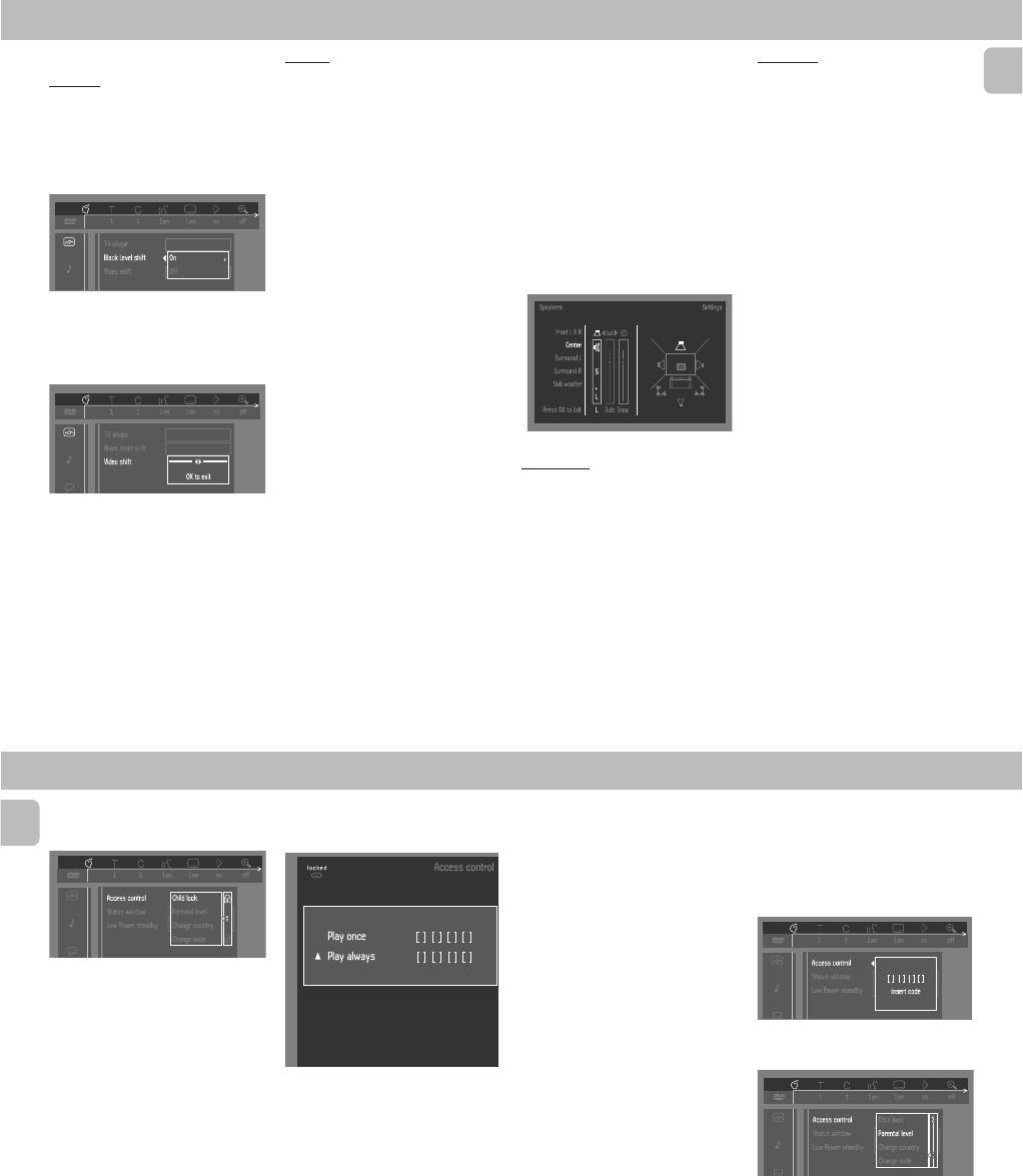
The following items can be adapted:
Picture
–TV Shape
See ‘Initial Setup’
–Black level shift (NTSC only)
Adapts the colour dynamics to obtain
richer contrasts. Select ON or OFF.
–Video shift
The factory centres the video on your
screen. Use this setting to personalize
the position of the picture on your TV by
scrolling it to the left or right.
Sound
–Digital output
Factory setting: ALL. This means that
both coaxial and optical outputs are
switched on. If you are not connecting
equipment with a digital input, change
the setting to OFF.
If your equipment doesn’t include a
digital multi-channel decoder, set the
digital output to PCM (Pulse Code
Modulation). Both coaxial and optical
outputs are switched on.
–Analogue output
Select Stereo, Surround, 3D Sound or
Multichannel.
Note:
–After selecting the desired Analogue
Output , if the message appeared on the
TV OSD and the system display screen
do not match with the setting, press
SURROUND CONTROL (or SURR on the
remote control) until the selected
setting reached.
–Night Mode
Optimises the dynamics of the sound
with low volume playback.
–Karaoke vocal
(not available for all
versions)
Put this setting to ON only when a
multi-channel karaoke DVD is being
played. The karaoke channels on the
disc will then be mixed into a normal
stereo sound.
–Speaker
Allows you to select speaker settings,
volume balance and delay time and to
test the speaker settings.
Speaker settings are only active on the
Analogue Multi-Channel Output (see
Appendix - page 30).
Language
Select the required Menu, Audio and
Subtitle language. See ‘Initial Setup’.
Audio language and Subtitle language can
also be adapted via the Menu bar on the
screen.
Features
–Access Control
Access Control contains the following
features:
Child Lock…When Child Lock is set to
ON, a 4-digit code needs to
be entered in order to play
discs.
Parental control…Allows the
conditional presentation of
DVDs containing Parental
Control information. (see
‘Access Control’)
–Status Window
Displays the current status of the player
and is displayed with the menu bar.
When disc playback is stopped, it is
displayed with the ‘Temporary Feedback
Field’ in the default screen.
Factory setting is ON. Select OFF to
suppress display of the Status
Window.
–Low power Standby
(not applicable
for this model)
–PBC (Playback Control)
The PBC can be set to ON or OFF
(only
applicable for Video CD playback)
.
DVD-VIDEO
24
English
Access control; child lock
(DVD and VCD)
Activating/deactivating the child lock
1When disc playback is stopped, select
ACCESS CONTROL in the
features menu using the 3 or 4 keys.
2Enter a 4-digit code of your own choice.
3Enter the code a second time.
4Move to Child lock using the 3 or 4
keys.
5Move to LOCK/UNLOCK icons using
the 2 key.
6Select LOCK icon using the 3 or 4
keys.
7Press OK or 1 to confirm, then press 1
again to exit the menu.
™Now unauthorised discs will not be
played unless the 4-digit code is
entered.
8Select UNLOCK icon to deactivate the
Child Lock.
Note:
– Confirmation of the 4-digit code is
necessary when the code is entered for
the very first time, changed or
cancelled.
Authorising discs
•Insert the disc. See ‘Loading disc’.
™The 'child protect' screen will appear.
Choose 'Play always' to remove the disk from the
child-safe list
You will be asked to enter your secret code
for ‘Play Once ‘or ‘Play Always.’ If you
select ‘Play Once’, the disc can be played
as long as it is in the player and the player
is ON. If you select ‘Play Always’, the disc
will become child safe (authorised) and can
always be played, even if the Child Lock is
set to ON.
Notes:
–The player memory maintains a list of
50 authorised (‘Child safe’) disc titles. A
disc will be placed in the list when ‘Play
Always’ is selected in the ‘child protect’
screen. Each time a ‘child safe’ disc is
played, it will be placed on top of the
list. When the list is full and a new disc
is added, the last disc in the list will be
removed from the list.
–Double sided DVDs may have a different
ID for each side. In order to make the
disc ‘child safe’, each side has to be
authorised.
–Multi-volume VCDs may have a different
ID for each volume. In order to make the
complete set ‘child safe’, each volume
has to be authorised.
DeAuthorising discs
•Insert the disc. See ‘Loading disc’.
™Playback starts automatically.
• Press Ç while { is visible.
™The | will appear and the disc is
now deauthorised.
Access control; Parental
control (DVD-Video only)
Movies on DVDs may contain scenes not
suitable for children. Therefore, disc may
contain ‘Parental Control’ information
which applies to the complete disc or to
certain scenes on the disc. These scenes
are rated from 1 to 8, and alternative, more
suitable scenes are available on the disc.
Ratings are country dependent. The
‘Parental Control’ feature allows you to
prevent discs from being played by your
children or to have certain discs played
with alternative scenes.
Activating/Deactivating Parental
Control
1When disc playback is stopped, select
ACCESS CONTROL in the Features
menu using the 3 or 4 keys.
2Enter your 4-digit code. If necessary,
enter the code a second time.
3Move to Parental Control using the 3 or
4 keys.
4Move to VALUE ADJUSTMENT (1-8)
using the 2 key.
5Then use the 3 or 4 keys or the digit
keys ( 0-9) on the remote control to
select a rating from 1 to 8 for the disc
inserted.
Rating 0 (displayed as ‘– –’):
Parental Control is not activated. The
Disc will be played in full.
DVD-VIDEO

PCS 103 807
2-10
25
English
DVD-VIDEO
Ratings 1 to 8:
The disc contains scenes not suitable for
children. If you set a rating for the
player, all scenes with the same rating
or lower will be played. Higher rated
scenes will not be played unless an
alternative is available on the disc. The
alternative must have the same rating or
a lower one. If no suitable alternative is
found, play will stop and the 4-digit
code has to be entered.
6Press OK or 1 to confirm, then press 1
again to exit the menu.
Country
1When disc playback is stopped, select
ACCESS CONTROL in the Features
menu using the 3 or 4 keys.
2Enter the 4-digit code.
3Move to CHANGE COUNTRY using the
4 key.
4Press the 2 key.
5Select a country using 3 or 4.
6Press OK or 1 to confirm, then press 1
again to exit the menu.
Changing the 4-digit code
1When disc playback is stopped, select
ACCESS CONTROL in the Features
menu using the 3 or 4 keys.
2Enter the old code.
3Move to CHANGE CODE using the 4
key.
4Press the 2 key.
5Enter the new 4-digit code.
6Enter the code a second time and
reconfirm by pressing OK.
7Press 1 to exit the menu.
Note:
– If you forget your 4 digit code, it can be
cancelled by pressing 9 four times in the
‘Access Control’ dialog. You can then
enter a new code (twice!) as described
above.
Parental Control Disclaimer
This DVD player features the PARENTAL
CONTROL system which is intended to
activate when playing DVD discs made
with certain software coding. This is
according to technical standards adopted
by the set maker and disc content
industries.
Please note that the PARENTAL CONTROL
system will not operate if the DVD disc
does not have the appropriate software
coding. Also note that at the time of
release of this DVD player, certain aspects
of the said technical standards had not
been fully settled among the set maker and
the disc content industries.
On this basis, Philips cannot warrant
functioning of the PARENTAL CONTROL
system and disclaims any liability of
unintended watching of disc content.
If in doubt, please check the system with
the disc before you allow children access
or apply to the relevant disc publisher for
more information.
Operation
Loading discs
1Press OPEN/CLOSE 0 on the front of
the player. The disc tray opens.
2Load your chosen disc in the tray, label
side up (also when a double sided DVD
is inserted). Make sure it is sitting
properly in the correct recess.
3Gently push the tray, or press OPEN/
CLOSE 0 to close the tray.
™"READ" appears in the status
window and on the player display,
and playback starts automatically.
Notes:
– If ‘Child Lock’ is set to ON and the disc
inserted is not in the ‘child safe’ list (not
authorised), the 4-digit code must be
entered and/or the disc must be
authorised. (see ‘Access Control’)
–The DVD tray will open or close only
when the system is in DVD mode.
Playing a DVD
Playing a title
1After inserting the disc and closing the
tray, playback starts automatically.
™The status window and the display
show the type of disc loaded, as well
as information about the disc’s
contents and playing time.
• The disc may invite you to select an
item from a menu. If the selections are
numbered, press the appropriate
numerical key; if not, use the 1 or 2 /
3 or 4 keys to highlight your selection,
then press OK.
™The currently playing title and
chapter number are shown in the
menu bar and display.
™The elapsed playing time is shown in
the status window and the display.
•
For model FW-D5 only
- If required, you
can use the SURROUND CONTROL
(or
SURR on the remote control)
key to
select Multichannel, Stereo, Surround or
3D-Surround. Play may stop at the end
of the Title, and the player may return to
the DVD menu. To go on to the next title,
press 2.
2To stop play at any other time, press
Ç.
™The default screen will appear, giving
information about the current status
of the player.
26
English
•You can RESUME play from the point at
which you stopped play. Press 2 (PLAY);
when you see the RESUME icon . on
the screen, press 2 (PLAY) again.
™The RESUME feature applies not only
to the disc in the player, but also to
the last four discs you have played.
Simply reload the disc, press
2 (PLAY); when you see the RESUME
icon . on the screen , press
2 (PLAY) again.
Note:
–Since it is usual for DVD movies to be
released at different times in
different regions of the world, all
players have region codes. Discs can
have an optional region code. If you load
a disc of a different region code into
your player, you will see the region code
notice on the screen. The disc will not
play and should be removed from the
player.
Playing a VCD
Playing a disc
1After inserting the disc and closing the
tray, playback starts automatically.
™The status window and the display
show the type of disc loaded, as well
as information about the disc’s
contents and playing time.
•The disc may invite you to select an
item from a menu. If the selections are
numbered.
™The currently playing track number is
shown in the menu bar and the
display. The elapsed playing time is
shown in the status window and the
display.
•
For model FW-D5 only
- If required, you
can use the SURROUND CONTROL
(or
SURR on the remote control)
key to
select Multichannel, Stereo, Surround or
3D-Surround.
2To stop play at any time, press Ç.
™The default screen will then appear.
•You can RESUME play from the point at
which you stopped play. Press 2 (PLAY);
when you see the RESUME icon . on
the screen, press 2 (PLAY) again.
™The RESUME feature applies not only
to the disc in the player, but also to
the last four discs you have played.
Simply reload the disc, press
2 (PLAY); when you see the RESUME
icon . on the screen , press
2 (PLAY) again.
Note:
– When PBC mode is switched on,
RESUME play is not available.
General features
Note:
–Unless stated otherwise, all operations
described are based on remote control
operation. A number of operations can
also be carried out via the menu bar on
the screen.
Moving to another title/TRACK
When a disc has more than one title or
track (which you can see from both the
menu bar and the display), you can move to
another title/track as follows:
1Select W (TITLE/TRACK) in the menu
bar.
2Press ë briefly during play to select
the next title/track.
•Press í briefly during play to return to
the beginning of the current title/track.
Press í briefly again to step back to
the previous title/track.
3To exit, press 1 or 2.
Moving to another chapter/index
When a title has more than one chapter or
a track has more than one index (which you
can see from the display and on the menu
bar), move to another chapter/index as
follows:
1Select X (CHAPTER/INDEX) in the menu
bar.
2Press ë briefly during play to select
the next chapter/index.
•Press í briefly during play to return to
the beginning of the current chapter/
index. Press í twice briefly to step
back to the previous chapter/index.
•To go directly to any chapter or index,
enter the number using the digit keys
(0-9).
3To exit, press 1 or 2.
Note:
– If the number has more than one digit,
press the keys in rapid succession.
DVD-VIDEO

PCS 103 808
27
English
Still Picture and Frame-by-frame
playback
1Select e (PICTURE BY PICTURE) in
the menu bar.
2Use the 4 key to enter the picture by
picture menu.
™The player will go into PAUSE mode.
3Use the cursor keys 1 or 2 to select the
previous or next picture frame.
4To exit Picture by picture mode, press
2 (PLAY) or 3 on the remote control.
Search
1Select g (FAST MOTION) in the menu
bar.
2Use the 4 keys to enter the Fast Motion
menu.
3Use the 1 or 2 keys to select the
required speed: -32,-8 or -4
(backward), or +4,+8,+32 (forward).
4Select 1 to play at normal speed again.
5To exit Fast Motion mode, press
2 (PLAY) or 3 on the remote control.
To search forward or backward through
different speeds, you can also hold down
à or á.
Repeat A-B
To repeat a sequence in a title:
•Press Repeat A-B at your chosen
starting point;
™
A
- appears briefly on the screen.
•Press Repeat A-B again at your chosen
end point;
™
A
-
B
repeat appears briefly on the
display, and the repeat sequence
begins.
•To exit the sequence, press Repeat A-B.
Scan
Plays the first 10 seconds of each chapter/
index on the disc.
• Press SCAN.
•To continue play at your chosen chapter/
index, press SCAN again or press
2 (PLAY) on the remote control.
Shuffle
DVDs
This shuffles the playing order of chapters
within a title, if the title has more than one
chapter.
•Press SHUFFLE during play.
™
SHUFFLE
appears on the screen for
about two seconds.
•To return to normal play, press
SHUFFLE again.
VCDs
This shuffles the playing order of the
tracks, if the disc has more than one track.
• Press SHUFFLE during play.
™
SHUFFLE
appears on the screen for
about two seconds.
•To return to normal play, press
SHUFFLE again.
Time search
The Time Search function allows you to
start playing at any chosen time on the
disc.
1Select h (TIME SEARCH) in the menu
bar.
2Press 4.
™The player will go into PAUSE mode.
™A time edit box appears on the
screen, showing the elapsed playing
time of the current disc.
3Use the digit keys ( 0-9) to enter the
required start time. Enter hours, minutes
and seconds from right to left in the box.
™Each time an item has been entered,
the next item will be highlighted.
4Press OK to confirm the start time.
™The time edit box will disappear and
play starts from the selected
time position on the disc.
Zoom
The Zoom function allows you to enlarge
the video image and to pan through the
enlarged image.
1Select a (ZOOM) in the menu bar.
2Press 3 or 4 to activate the ZOOM
function and select the required zoom
factor: 1.33 or 2 or 4.
™The player will go into PAUSE mode.
™The selected zoom factor appears
below the Zoom icon in the
menu bar and ‘
Press OK to pan
’
appears below the menu bar.
™The picture will change accordingly.
3Press OK to confirm the selection.
™The panning icons appear on the
screen: 1 or 2 / 3 or 4 and OK.
4Use the 1 or 2 / 3 or 4 keys to pan
across the screen.
5When OK is pressed only the zoomed
picture will be shown on the screen.
6If you wish to zoom at any moment,
press a (ZOOM) and select the
required zoom factor as described
above.
7To exit Zoom mode, press 2 (PLAY),Ç
or OSD MENU.
™If you press 2 (PLAY), playback will
resume.
DVD-VIDEO
28
English
FTS-Video
–The FTS-Video function allows you to
store your favourite titles and chapters
(DVD) and favourite tracks and indexes
(VCD) for a particular disc in the player
memory.
–Each FTS programme can contain 20
items (titles, chapters).
–Each time an FTS programme is played
it will be placed on top of the list. When
the list is full and a new programme is
added, the last programme in the list
will be removed from the list.
–The selections can be played at any
time.
–For VCD, FTS programme is not
available whenever PBC mode is
switched on.
Storing a FTS-Video Program
1In STOP mode, select FTS-Video c in
the menu bar.
2Press 4 to open the menu.
™The FTS-Video menu appears.
3Press 1 or 2 or FTS to select ON or
OFF.
Storing titles/tracks
1Press 4 to select TITLES/TRACK.
2Use 1 or 2 to select the required title/
track.
3Press OK if you wish to store the entire
title/track.
™The title/track number will be added
to the list of selections.
Storing chapters/indexes
1Press 4 on the selected title/track
number.
™The title/track number will be marked
and the highlight moves to the first
available chapter/index number for
this title/track.
2Use 1 or 2 to select the required
chapter/index number.
3Press OK to confirm the selection.
™The title-chapter/track-index
selection will be added to the list of
selections.
4Press OSD MENU to exit the FTS-
Video c menu.
Erasing a FTS-Video Program
1In STOP mode, select FTS-Video c in
the menu bar.
2Use 4 to select PROGRAM.
3Use 1 or 2 to select the required
selection number.
4Press OK to erase the selection.
5Press OSD MENU to exit.
If you wish to erase all selections:
1In STOP mode, select FTS-Video c in
the menu bar.
2Use 4 to select CLEAR ALL.
3Press OK.
™All selections will now be erased.
4Press OSD MENU to exit.
Special DVD-features
Checking the contents of DVD : Menus
For titles and chapters, selection menus
may be included on the disc. The DVD’s
menu feature allows you to make
selections from these menus.
• Press the appropriate digit keys (0-9);
or use the 1 or 2 / 3 or 4 keys to
highlight your selection, then press OK.
Title menus
1Press DVD MENU.
™If the current title has a menu, the
menu will appear on the
screen. If no menu is present in the
title, the disc menu will be
displayed.
2The menu can list camera angles,
spoken language and subtitle options,
and chapters for the title.
3To remove the title menu, press DVD
MENU again.
Disc menu
1Select W (TITLE/TRACK) in the menu
bar, then press DVD MENU.
™The disc menu is displayed.
•To remove the disc menu, select W
(TITLE/TRACK) in the menu bar, then
press DVD MENU again.
Camera Angle
If the disc contains sequences recorded
from different camera angles, the angle
icon appears, showing the number of
available angles and the angle being
shown currently. You can then change the
camera angle if you wish.
1Select } (ANGLE) in the menu bar.
2Use the 3 or 4 keys to select the
required angle in the angle icon.
™After a small delay, play changes to
the selected angle. The angle icon
remains displayed until multiple
angles are no longer available.
Changing the audio language
1Select Y (AUDIO) in the menu bar or
press AUDIO on the remote control.
2Press 3 or 4 repeatedly to see the
different languages.
DVD-VIDEO
2-11
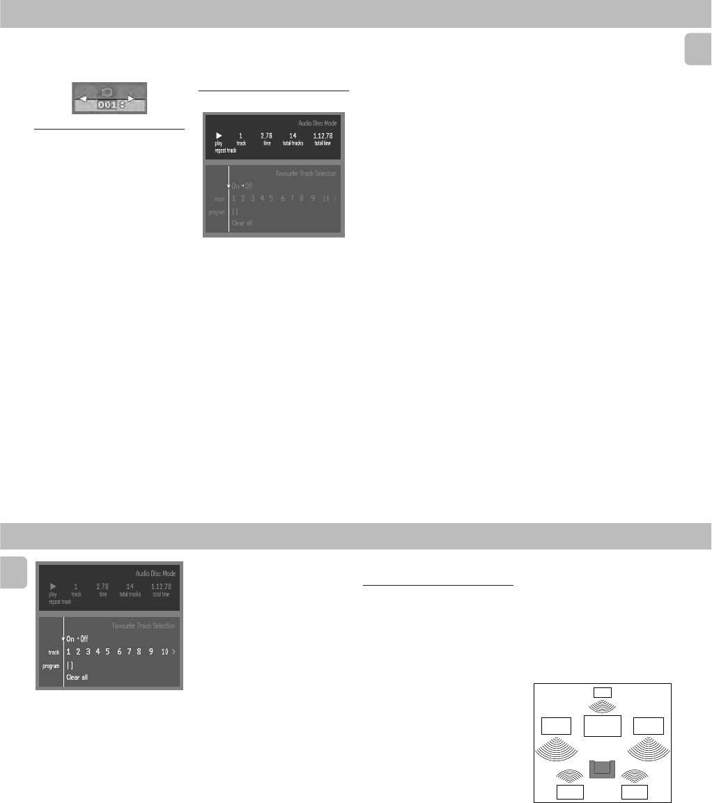
PCS 103 809
2-12
29
English
Subtitles
1Select Z (SUBTITLE) in the menu bar.
2Press 3 or 4 repeatedly to see the
different subtitles.
Special VCD-Features
Playback Control (PBC)
When PBC ON
1Press PBC to switch on PBC mode.
2Load a Video CD with PBC and press
2 (PLAY).
™The PBC menu appears on the TV
screen.
•Go through the menu with the keys
indicated on the TV screen until your
chosen passage starts to play. If a PBC
menu consists of a list of titles, you can
select a title directly.
3Enter your choice with the digit keys
(0-9).
4Press RETURN to go back to the
previous menu.
When PBC OFF
1Press PBC to switch off PBC mode.
2Playback will resume when press
2 (PLAY).
™The PBC menu does not appear on
the TV screen.
Note:
–When PBC menu consists of more than
one page, use
í
or
ë
keys to go
through the pages.
Playing an audio CD
1After loading the disc, playback starts
automatically.
•If the TV is on, the Audio CD screen
appears.
™The number of tracks and the total
playing time will be shown on the
screen and on the player display.
™During play, the current track number
and its elapsed playing time will be
shown on the screen and on the
player display.
2Playback will stop at the end of the disc.
•To stop play at any other time, press
Ç.
Pause
• Press ; during play.
•To return to play, press 2 (PLAY).
Moving to another track
• Press ë briefly during play to go to the
next track.
• Press í briefly during play to return to
the beginning of the current track. Press
í briefly again to step back to the
previous track.
•To go directly to any track, enter the
track number using the digit keys (0-9).
Shuffle
• Press SHUFFLE during play.
™The order of the tracks is changed.
•To return to normal play, press
SHUFFLE again.
Repeat A-B
To repeat a sequence:
•Press Repeat A-B at your chosen
starting point;
™
A
- appears briefly on the player
display.
•Press Repeat A-B again at your chosen
end point;
™
A
-
B
appears briefly on the display,
and the sequence begins to play
repeatedly.
•To exit the sequence, press Repeat A-B
again.
Scan
Plays the first 10 seconds of each track on
the disc.
•Press SCAN.
•To continue play at your chosen track,
press SCAN again or press 2 (PLAY).
FTS (Favourite Track Selection)
–The FTS feature allows you to store your
favourite tracks for a particular disc in
the player memory.
–Each FTS programme can contain 20
tracks.
–Each time an FTS programme is played it
will be placed on top of the list. When
the list is full and a new programme is
added, the last programme in the list
will be removed from the list.
–The selections can be played at any
time.
DVD-VIDEO
30
English
Storing an FTS Program
1Load a disc and stop playback.
2Use 4 to go to the list of available
tracks.
3Use 1 or 2 to select tracks from the list.
To go directly to any track, enter the
track number using the digit keys (0-9).
4Store each track by pressing OK.
™The track numbers will be added to
the list of selected tracks.
™The number of tracks and the playing
time of the programme will be
shown on the screen and the player
display.
When your FTS Program is complete, press
É(PLAY) to start play, or Ç to go back to
Stop mode. In either case, the FTS Program
will be automatically memorised.
DVD-VIDEO
Appendix
6 Channel settings
Front speakers
L (Large): When the front speakers can
reproduce low frequency
signals below 120Hz
S (Small): When the front speakers
cannot produce low frequency
signals below 120Hz
Centre speaker*
L (Large): When the centre speaker can
reproduce low frequency
signals below 120Hz
S (Small): When the centre speaker
cannot produce low frequency
signals below 120Hz
Off: When the centre speaker is not
connected.
Surround speakers
L (Large): When the surround speakers
can reproduce low frequency
signals below 120Hz
S (Small): When the surround speakers
cannot produce low frequency
signals below 120Hz
Off: When the surround speakers
are not connected.
Subwoofer
On: When you connect a subwoofer
Off: When the subwoofer is not
connected.
*You can use your TV as centre speaker.
When centre speaker is turned on, the
audio L/R as well as the audio from the
scart will contain the centre speaker
audio.
TV
Front speaker
right
Front speaker
left
Center
speaker
Rear speaker
(left surround)
Rear speaker
(right surround)
Delay times
The DVD player is set to reproduce
correctly synchronised Digital Surround
Sound in a listening area where the
surround speakers are about 150cm nearer
to the listening position than the front
speakers, and the centre speaker is in line
with the front speakers. To adjust for other
listening area arrangements, certain delay
times required.
Switching FTS ON/OFF
1Use 3 or 4 to move to the top.
2Use 1 or 2 to select either ON or OFF.
Erasing a track from an FTS-
programme
1Use 4 to go to the list of selected
tracks in programme.
2Use 1 or 2 to select the track number
you wish to erase.
3Press OK.
™The track number will be erased from
the list of selected tracks.
Erasing the complete programme
•Use 4 to select CLEAR ALL and press
OK.
™The complete FTS programme for the
disc will be erased.
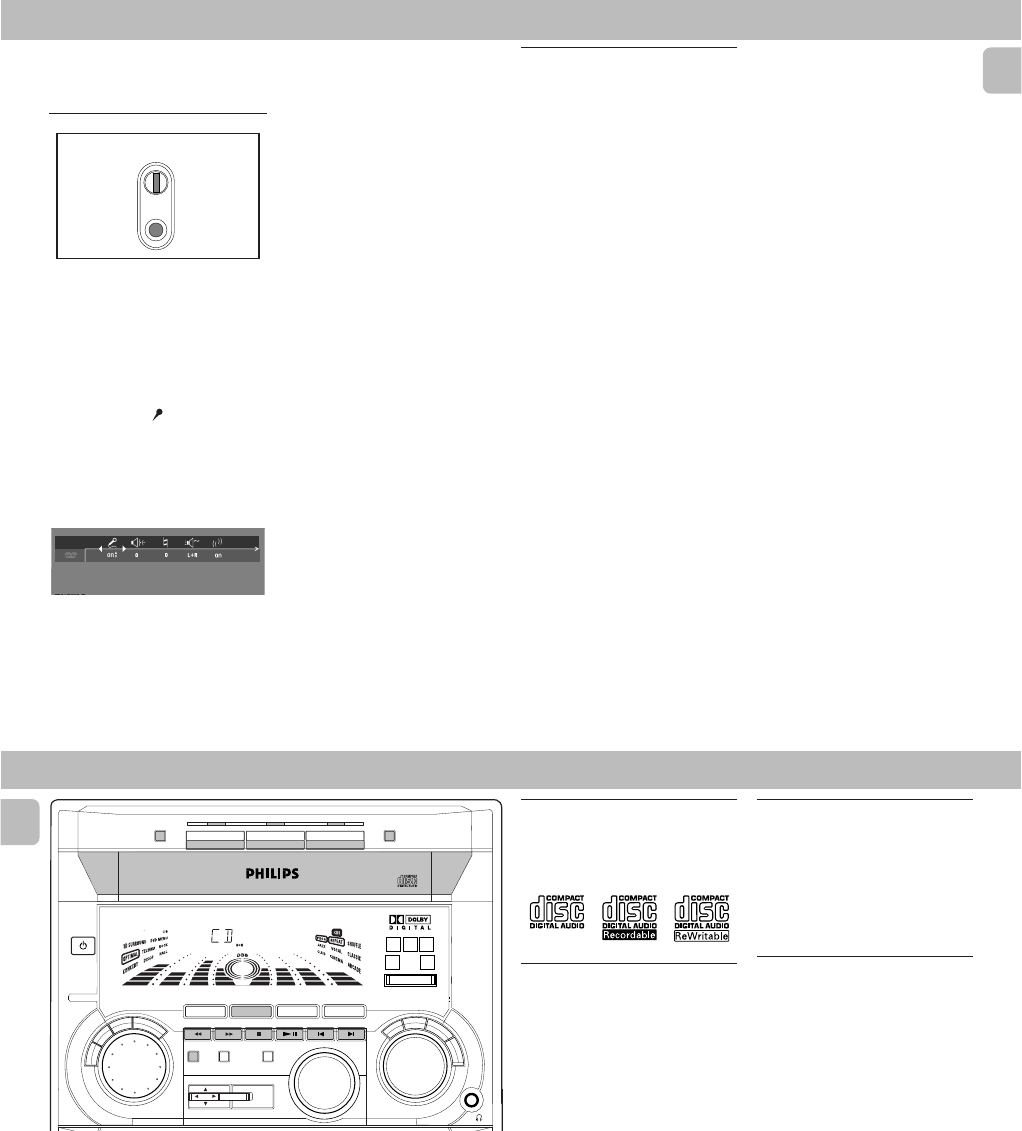
PCS 103 810
2-13
31
English
Setting up Karaoke
(in DVD
mode only)
(not available for all versions)
1Load a karaoke disc into the player.
2Set the MIC LEVEL control to the
minimum level to prevent acoustic
feedback (e.g. loud howling sound)
before connecting the microphone.
3Connect a microphone to MIC socket.
4Press 2 (PLAY) to start playback.
5Press KARAOKE on the remote
control to switch on the Karaoke mode.
6Karaoke menu bar appears.
™Move to the function you want to
change using 3 or 4 keys then use
1 or 2 keys to scroll to your
preferred option.
7Adjust the MIC LEVEL control.
8Adjust ECHO -/+ ( j ) to the level
you desire.
9Adjust KEY CONTROL -/+(k ) to
change the key of your vocal range.
10 Select the different MODE SELECTION
l you desire.
(see Karaoke General
Features).
11 Shift to VOCAL m to fade out the
original vocal from a karaoke disc.
When you start singing or talking
through the microphone, the original
vocal will fade out automatically.
12 Shift to VOCAL CANCEL to cancel out
the original vocal from the sound.
13 Press KARAOKE button to exit the
menu screen.
DVD-VIDEO
MIC LEVEL
MIC
General features
Karaoke ON/OFF ( i )
•To switch karaoke features ON/OFF
mode.
Echo -/+ ( j )
•Can be adjusted in the range of
{0.....+7).
Key Control -/+ ( k )
•Can be adjusted in the range of
{-7 ......0.....+7).
Mode Selection ( l )
•Works correctly only on karaoke disc.
• Only two channels are available.
•For VCD Karaoke disc,
™Selection between L+R / L / R
L+R - Left + Right
L - Left
R - Right
•For DVD Karaoke disc,
™Selection between M1 / M2 / V1 / V2
M1 - All channels
M2 - Music channels only
V1 - Vocal 1 output
V2 - Vocal 2 output
Note:
– In the karaoke disc, karaoke L, R, M1,
M2, V1, V2 are recorded. In some
discs, the M1, M2, V1, V2 may not be
recorded in the disc.
Vocal ( m )
•Available options for vocal are:.
ON – normal mode, all music
and vocals are played.
CANCEL –cancel original vocals.
FADE –removes original vocals
when you start singing
through the microphone.
32
English
CD
Warning!
1) This system is designed for conventional CDs. Do not use any accessories
such as disc stabilizer rings or CD treatment sheets, etc., which may damage
the CD mechanism.
2) Do not load more than one disc into each tray.
3) When the CD carousel tray is loaded with CDs, do not turn over or shake the
system. This may jam the changer.
You may load three discs in the CD carousel tray for continuous playback without
interruption.
Discs for playback
This system can play all digital audio CD,
finalised digital audio CD-Recordable and
finalised digital audio CD-Rewritable
format discs.
Loading the CD Changer
1Press CD to select CD mode.
2Press OPEN•CLOSE.
™The CD carousel tray slides out.
3Load a CD with the printed side up in
the right tray.
•You can load another disc in the left
tray.
•To load the third disc, press the DISC
CHANGE button.
™The CD carousel will rotate until the
empty tray is ready for loading.
4Press OPEN•CLOSE to close the CD
carousel tray.
™The total number of tracks and the
playing time of the selected disc
appear on the display.
Note:
–To ensure good system performance,
wait until the CD changer completely
reads the disc(s) before proceeding.
CD Direct Play
•You can play a CD directly by pressing
the CD 1,CD 2 or CD 3 button. The CD
player will stop at the end of playback of
the selected disc.
™A lit button indicates that a disc is
loaded in the disc tray.
™The selected disc is encircled.
Playing a CD
1Press 2 (PLAY) to start playback.
™The disc tray, track number and
elapsed playing time of the current
track appear on the display.
•To interrupt playback, pressÅ.
™The playing time flashes.
•To resume playback, press 2 (PLAY)
again.
2To stop playback, press Ç.
Notes:
–All the available discs will play once,
then stop.
– When the CD has stopped playing, the
system will switch to standby mode
after 30 minutes if no button is pressed.
R
E
T
U
R
N
P
E
R
S
O
N
A
L
V
E
C
D
S
C
D
B
B
DISC CHANGE OPEN•CLOSE
STANDBY
ON
DC
3
CHANGER
DVD MINI HIFI SYSTEM
DIM
PROG
POWER SAVE
IR SENSOR
RDS/ CD TEXT
NEWS /T.A.
CLOCK/
TIMER
VOLUME
AXIS OK
DVD
MENU
SOUND JOG
DVD JOG
P3 P6P1 P2 P5P4
CHAP. SLEEP DIM TIMERLWFM A M W
TUNER
DVD CD AUX
A
-
B
P
B
C
BAND
VCD • CD CD 1 • 2 • 3 CDR
LEFT CENTER RIGHT
SURR SURR
STOP•CLEAR
SEARCH•TUNING PLAY PAUSE PREV NEXTSIDE
PRESET ▲
▲
S
C
A
N
CHANNEL
CD 1 CD 2 CD 3
DVD
SURROUND CONTROL
5.1CH / STEREO / SURR / 3D
FTS TITLE

PCS 103 811
2-14
33
English
Disc Change
You can change the outer two discs while
the third inner disc is stopped or is playing.
1Press DISC CHANGE.
™The CD carousel tray slides out.
2Replace the discs in the left and right
disc trays.
• If you wish to change the inner disc
during playback, press DISC CHANGE
again.
™"DISC CHANGE" will be displayed.
™The CD will stop playing.
™The CD carousel tray will close to
retrieve the inner CD then open again
with the inner CD accessible.
3Press OPEN•CLOSE to close the CD
carousel tray.
Selecting a desired track
Selecting a desired track when
playback is stopped
1Press í or ë
(or Digit 0-9 on the
remote control)
until the desired track
appears on the display.
2Press 2 (PLAY) to start playback.
™The selected track number and
elapsed playing time appear on the
display.
Selecting a desired track during
playback
•Press í or ë
(or Digit 0-9 on the
remote control)
until the desired track
appears on the display.
™The selected track number and
elapsed playing time appear on the
display.
• If you press í once it will skip to the
beginning of the current track and play
the track again.
Note:
–Pressing
í
during shuffling can only
skip to the beginning of the current
track.
Searching for a particular
passage during playback
•Press and hold à or á until the
desired passage is located.
™The volume will be reduced.
•Play returns to normal when à or á
is released.
CD
Programming Tracks
Programming tracks of a loaded CD is
possible when playback is stopped. The
display will indicate the total tracks stored
in the programme. Up to 40 tracks can be
stored in the memory in any order. When
40 tracks are stored and you attempt to
store another track, the display will show
"PROGRAM FULL".
1Load the desired discs in the disc trays.
2Press PROG to start programming.
™The
PROG
starts flashing.
3Press the CD (CD 1•2•3) or CD 1/2/3
button to select the disc.
4Press í or ë
(or Digit 0-9 on the
remote control)
to select the desired
track.
5Press PROG to store the track.
•Repeat steps
3
to
5
to store other discs
and tracks.
6Press Ç once to end programming.
™The total number of tracks
programmed and total playing time
appear on the display.
Notes:
– If the total playing time is more than
"
99:59
"
or if one of the programmed
tracks has a number greater than 30,
then "
--:--
" appears on the display
instead of the total playing time.
– If the system is reading the disc,
programming is not possible,
"
READING
" will be displayed and
followed by "
DISC X
" "
X
" is the
current read disc number.
–During programming, if no button is
pressed within 20 seconds, the system
will exit programme mode
automatically.
Reviewing the programme
Reviewing of the programme is possible
only when playback is stopped.
1Press í or ë repeatedly to review
the programmed tracks.
2Press Ç once to exit review mode.
Playing the programme
1Press 2 (PLAY) to start programme
playback.
™"PLAY PROGRAM" will be
displayed.
™The track number and elapsed
playing time of the current track will
appear on the display.
• If you press REPEAT during programme
playback, the current track or all
programmed tracks will be played
repeatedly.
™"TRACK" or "PROGRAM" will be
displayed.
™The
REPEAT
and
PROG
appear on the
display.
34
English
CD
2Press Ç to stop programme playback.
Notes:
–If you press any of the CD DIRECT PLAY
buttons, the system will play the
selected disc or track and the stored
programme will be ignored temporarily.
The
PROG
display also will disappear
temporarily from the display. It will
reappear when playback of the selected
disc ends.
–REPEAT DISC mode is not available
when programme playback begins.
Erasing the programme
(when
playback is stopped)
•Press Ç.
™"PROGRAM CLEARED" will be
displayed.
Note:
–The programme will be erased when the
system is disconnected from the power
supply or when the CD carousel tray is
opened.
Shuffle
(only on remote control)
In shuffle mode, the system plays all the
available discs and their tracks in random
order. Shuffle may be used also when
tracks are programmed.
To shuffle all the discs and tracks
1Press SHUFFLE.
™"SHUFFLE" will be displayed.
™The
SHUFFLE
, the disc and the track
selected at random appear on the
display.
•The discs and the tracks will be played
in random order until you press Ç.
•If you press REPEAT during shuffling,
the current track or all available discs
will be played repeatedly.
™"TRACK" or "ALL DISC" will be
displayed.
™The
REPEAT
and
SHUFFLE
appear on the
display.
2Press SHUFFLE again to resume normal
playback.
™The
SHUFFLE
disappears from the
display.
Note:
–REPEAT DISC mode is not available
when shuffle is selected.
Repeat
(only on remote control)
You can play the current track, a disc or all
available discs repeatedly.
1Press REPEAT on the remote control to
select the various repeat modes.
™"TRACK", "DISC", "ALL DISC" or
"OFF" will be displayed.
™The
REPEAT
appears on the display.
•The selected track, selected disc or all
available discs will now be played
repeatedly until you press Ç.
2Press REPEAT until the "OFF" mode is
displayed to resume normal playback.
™The
REPEAT
disappears from the
display.
Notes:
–REPEAT DISC mode is not available
during programme play or shuffle mode.
–You can also repeat shuffling a
programme.
™"
TRACK
"
or
"
PROGRAM
" will be
displayed.
™
The
REPEAT
,
PROG
and
SHUFFLE
appear
on the display.
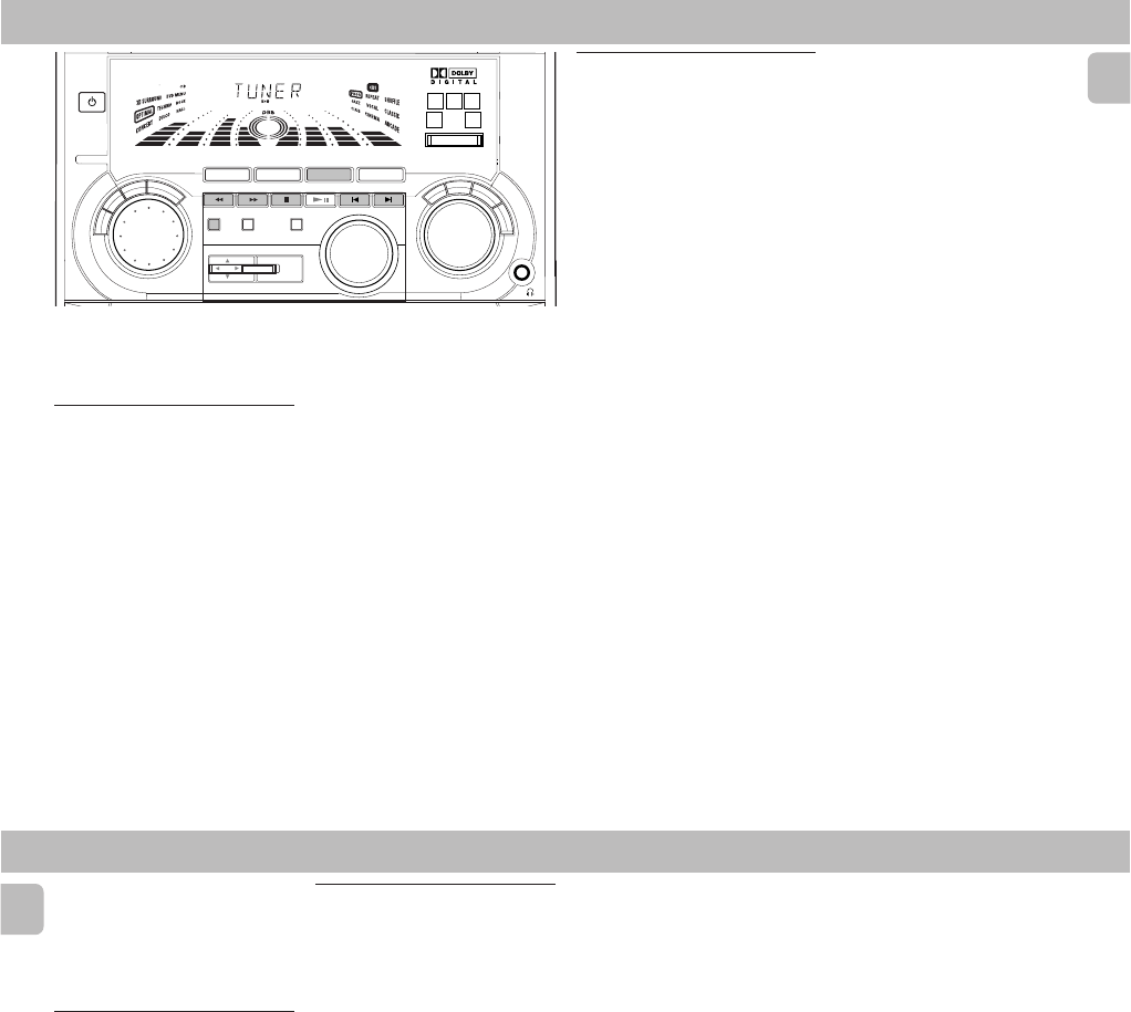
PCS 103 812
2-15
35
English
Note:
–For 'EASY SET' feature, please refer to
page 14.
Tuning to radio stations
1Press TUNER (BAND) to select TUNER
mode.
™"TUNER" will be displayed.
A few seconds later, the current radio
frequency will be displayed.
2Press TUNER (BAND) again to select
the desired waveband : FM or MW.
3Press à or á for more than one
second, then release.
™The display will show "SEARCH"
until a radio station with sufficient
signal strength is found.
•Repeat this procedure until the desired
radio station is reached.
•To tune to a weak radio station, briefly
press à or á repeatedly until the
display shows the desired frequency
and/or when the best reception has
been obtained.
TUNER
Storing Preset Stations
You can store up to 40 radio stations in the
memory. When a preset radio station is
selected, the preset number appears next
to the frequency on the display.
Automatic programming
1Press TUNER (BAND).
2Press PROG for more than one second.
™The
PROG
starts flashing and "AUTO"
will be displayed.
™The system will search for every
available radio station in the FM
waveband first, then search the MW
waveband.
™All available radio stations will be
stored automatically. The frequency
and preset number will be displayed
briefly.
™The system will stop searching when
all the available radio stations are
stored or when the memory for 40
preset radio stations is used.
™The system will remain tuned to the
last stored preset radio station.
Notes:
–You can cancel the automatic
programming by pressing PROG or
Ç
(on the system only).
– If you want to reserve a section of
preset numbers, for example preset
numbers 1 to 9, select preset 10 before
starting automatic programming, only
the preset numbers 10 to 40 will be
programmed.
Manual programming
1Press TUNER (BAND).
2Press TUNER (BAND) again to select
the desired waveband : FM or MW.
3Press PROG for less than one second.
™The
PROG
starts flashing.
™The next available preset number will
be displayed for selection.
4Press à or á to tune to the desired
frequency.
• If you wish to store the radio station to
another preset number, press í or ë
(or Digit 0-9 on the remote control)
to
select the desired preset number.
5Press PROG again.
™The
PROG
disappears and the radio
station will be stored.
•Repeat
steps 3 – 5
to store other preset
radio stations.
Notes:
– When 40 radio stations are stored and
you attempt to store another radio
station, the display will show
"
PROGRAM FULL
". If you want to
change an existing preset number,
repeat steps 3 – 5.
R
E
T
U
R
N
P
E
R
S
O
N
A
L
V
E
C
D
S
C
D
B
B
STANDBY
ON
DVD MINI HIFI SYSTEM
DIM
PROG
POWER SAVE
IR SENSOR
RDS/ CD TEXT
NEWS /T.A.
CLOCK/
TIMER
VOLUME
AXIS OK
DVD
MENU
SOUND JOG
DVD JOG
P3 P6P1 P2 P5P4
CHAP. SLEEP DIM TIMERLWFM AMW
TUNER
DVD CD AUX
A
-
B
P
B
C
BAND
VCD • CD CD 1 • 2 • 3 CDR
LEFT CENTER RIGHT
SURR SURR
STOP•CLEAR
SEARCH•TUNING PLAY PAUSE PREV NEXTSIDE
PRESET ▲
▲
S
C
A
N
CHANNEL
DVD
SURROUND CONTROL
5.1CH / STEREO / SURR / 3D
FTS TITLE
36
English
TUNER
.
–You can cancel manual programming by
pressing
Ç
(on the system only).
– During programming, if no button is
pressed within 20 seconds, the system
will exit programme mode
automatically.
Tuning to Preset Radio
Stations
•Press í or ë
(or Digit 0-9 on the
remote control)
to select the desired
preset number.
™The preset number, radio frequency,
and waveband appear on the display.
Changing the MW tuning grid
(not available for all versions)
The frequency step can be changed if
necessary. In North and South America, the
frequency step between adjacent channels
in the MW band is 10 kHz. In other parts of
the world, it is 9 kHz. The frequency step
presetted in the factory is 9 kHz.
For MW band
To change from 9 kHz to 10 kHz or vice
versa
Changing of tuning grid will erase all
previously stored preset stations.
1Disconnect the system from the AC
power supply
(pull out the AC power
cord)
.
2Press TUNER and TUNING á
depressed while reconnecting the
system to the AC power supply.
™Display will show "GRID 9" or
"GRID 10".
Notes:
– GRID 9 indicates that the tuning grid is
in step of 9 kHz in MW band. GRID 10
indicates that the tuning grid is in step
of 10 kHz in MW band.
–FM tuning grid will also be changed
from 50 kHz to 100 kHz or vice versa.
All preset radio stations will also be
erased.
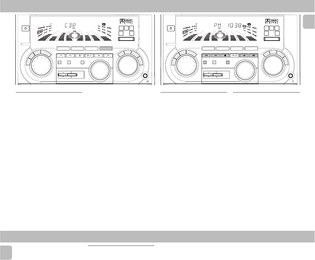
PCS 103 813
2-16
37
English
AUX/CDR CLOCK
View Clock
You can view the clock (if it is set) if the
system is in Standby mode or when any
sound source is selected (CD, TUNER, etc.).
The clock will be displayed for about seven
seconds.
•Press CLOCK/TIMER briefly.
™"PM 10:38 or 22:38" (the
current time) will be displayed
depending on whether you have
selected 12- or 24-hour mode.
™"--:--" will be displayed if the
clock is not set.
Clock Setting
The clock can be set in either 12- or 24-
hour mode, e.g. "AM 12:00" or
"00:00". Before setting the clock, you
must be in the View Clock mode.
1Press CLOCK/TIMER to select clock
mode.
2Press PROG
(on the system only)
to
select 12- and 24- hour mode.
™If 12-hour mode is selected,
"AM 12:00" starts flashing.
™If 24-hour mode is selected, "00:00"
starts flashing.
3Set the hour with à or áon the
system.
4Set the minute with í or ëon the
system.
R
E
T
U
R
N
P
E
R
S
O
N
A
L
V
E
C
D
S
C
D
B
B
STANDBY
ON
DVD MINI HIFI SYSTEM
DIM
PROG
POWER SAVE
IR SENSOR
RDS/ CD TEXT
NEWS /T.A.
CLOCK/
TIMER
VOLUME
AXIS OK
DVD
MENU
SOUND JOG
DVD JOG
P3 P6P1 P2 P5P4
CHAP. SLEEP DIM TIMERLWFM AMW
TUNER
DVD CD AUX
A
-
B
P
B
C
BAND
VCD • CD CD 1 • 2 • 3 CDR
LEFT CENTER RIGHT
SURR SURR
STOP•CLEAR
SEARCH•TUNING PLAY PAUSE PREV NEXTSIDE
PRESET ▲
▲
S
C
A
N
CHANNEL
DVD
SURROUND CONTROL
5.1CH / STEREO / SURR / 3D
FTS TITLE
Selecting External Equipment
If you have connected the audio out
terminals of the external equipment (TV,
VCR, Laser Disc player, DVD player, or CD
Recorder) to the AUX/CDR IN terminals,
you can hear the enhanced sound from the
system.
1Press AUX (CDR) to select the CDR
mode.
™"CDR" will be displayed.
2Press AUX (CDR) again to select
external (normal AUX) mode.
™"AUX" will be displayed.
Notes:
–There are two Auxiliary modes:
i. the normal AUX mode.
ii. the CDR mode, where the LINE OUT
of this mini system is muted. You will
not be able to record or listen to the
sound from the LINE OUT.
–You are advised not to listen to and
record from the same source
simultaneously.
–All the sound control features (e.g. DSC,
DBB, etc.) are available for selection.
R
E
T
U
R
N
P
E
R
S
O
N
A
L
V
E
C
D
S
C
D
B
B
STANDBY
ON
DVD MINI HIFI SYSTEM
DIM
PROG
POWER SAVE
IR SENSOR
RDS/ CD TEXT
NEWS /T.A.
CLOCK/
TIMER
VOLUME
AXIS OK
DVD
MENU
SOUND JOG
DVD JOG
P3 P6P1 P2 P5P4
CHAP. SLEEP DIM TIMERLWFM A M W
TUNER
DVD CD AUX
A
-
B
P
B
C
BAND
VCD • CD CD 1 • 2 • 3 CDR
LEFT CENTER RIGHT
SURR SURR
STOP•CLEAR
SEARCH•TUNING PLAY PAUSE PREV NEXTSIDE
PRESET ▲
▲
S
C
A
N
CHANNEL
DVD
SURROUND CONTROL
5.1CH / STEREO / SURR / 3D
FTS TITLE
38
English
TIMER
5Press CLOCK/TIMER again to store the
setting.
™The clock starts.
•To exit without storing the setting, press
Ç on the system.
Notes:
– During clock setting, if no button is
pressed within 90 seconds, the system
will exit clock setting mode
automatically.
– When a power interruption occurs, the
clock setting is erased.
Timer Setting
•The system can switch on to CD or
TUNER mode automatically at a preset
time. It can serve as an alarm to wake
you up.
•Before setting the timer, make sure the
clock is set correctly.
•The timer will always be switched on
once it is set.
•The volume of the timer will
increase from the minimum level
until the volume level before the set
is switched to standby mode.
1Press and hold CLOCK/TIMER for more
than
2 seconds
to select timer mode.
™"AM 12:00" or "00:00" or the last
timer setting starts flashing
depending on whether you have
selected 12- or 24-hour mode.
™The
TIMER
starts flashing.
™The selected source is lit while other
available sources are flashing.
2Press CD or TUNER to select the
desired source.
•Before selecting CD, make sure a CD is
loaded in the CD tray.
3Press à or á on the system to set
the hour for the timer to start.
4Press í or ë on the system to set
the minute for the timer to start.
5Press CLOCK/TIMER to store the start
time.
™The timer is now set.
™The
TIMER
remains on the display.
•At the preset time, the timer will be
activated.
™The selected source will be played.
Notes:
–During timer setting, if no button is
pressed within 90 seconds, the system
will exit timer setting mode
automatically.
– If the source selected is TUNER, the last
tuned frequency will be switched on.
– If the source selected is CD, playback
will begin with the first track of the
selected disc or programme. If the CD
trays are empty, TUNER will be selected
instead.
To switch off the TIMER
•Press TIMER on the remote control.
™The timer is now switched off.
™The display will show "CANCEL"
and the
TIMER
disappears.
To start the TIMER again
(for the same
preset time and source)
•Press TIMER on the remote control.
™The timer is now on.
™The
TIMER
appears on the display.

PCS 103 814
2-17
English
TROUBLESHOOTING
CD Player Operation
"NO DISC" is displayed.
• The disc is inserted upside down.
™
Place disc with printed side up.
• Moisture condensation at the lens.
™
Wait until lens has adjusted to normal
room temperature.
• There is no disc in the CD tray.
™
Insert a disc.
• The disc is dirty, badly scratched or
warped.
™
Clean or replace the disc.
• The disc lens is dirty or dusty.
™
See section under Maintenance (page
40).
"DISC NOT FINALIZED" is
displayed.
• The CD-RW or CD-R disc is not properly
recorded for use with a standard CD
player.
™
Read the instruction booklet of your CD-
Rewritable or CD-Recorder on how to
finalise a recording.
• The CD is badly scratched or dirty.
™
Replace or clean CD.
Radio Reception
Poor radio reception.
•The signal is too weak.
™
Adjust the antenna.
™
Connect an external antenna for better
reception.
•The TV or VCR is too closed to the
stereo system.
™
Separate the stereo system from the TV
or VCR.
Cannot tune to radio station.
•Wrong tuning grid.
™
Switch to the correct tuning grid.
General
System does not react when any
button is pressed.
• Electrostatic discharge.
™
Press STANDBY ON to switch the
system off. Remove the AC power plug
from the wall outlet, then reconnect the
power plug and switch on the system
again.
No or poor sound.
•Volume is not turned up.
™
Adjust VOLUME.
•The headphones are connected.
™
Disconnect the headphones.
•Speakers are not connected or are
connected wrongly.
™
Check that the speakers are connected
correctly.
™
Make sure the stripped speaker wire is
clamped.
Reversed left and right sound.
•Speakers are connected wrongly.
™
Check the speaker connections and
location.
Lack of bass sound or apparently
imprecise physical location of musical
instruments.
•Speakers are connected wrongly.
™
Check the speaker connection for
proper phasing, coloured/black wires to
coloured/black terminals.
Remote control has no effect on the
system.
•Wrong source is selected.
™
Select the source (CD, TUNER, etc.)
before pressing the function button
(
É
,
í
,
ë
, etc.).
•The distance to the system is too large.
™
Reduce the distance.
•Batteries are inserted incorrectly.
™
Insert the batteries with their polarities
(+/– signs) as indicated.
•Batteries are exhausted.
™
Replace the batteries.
Timer is not working.
•Clock is not set.
™
Set the clock.
•Timer is not switched on.
™
Press TIMER to switch on the timer.
Clock setting is erased.
•There was a power failure.
™
Reset the clock.
System displays features
automatically; buttons flash
continuously.
•Demonstration mode is switched on.
™
Press and hold
Ç
(on the system) for
five seconds to switch off the
demonstration.
There is a howling sound at the
external source.
•You hear feedback when you are
listening in AUX mode
™
Press AUX to select CDR mode.
All lighted buttons are not lit.
•Display is switched on in DIM 3 mode.
™
Press DIM until DIM OFF display mode
is shown.
English
MAINTENANCE TROUBLESHOOTING
Maintenance
Cleaning the Cabinet
• Use a soft cloth slightly moistened with
a mild detergent solution. Do not use a
solution containing alcohol, spirits,
ammonia or abrasives.
Cleaning Discs
•When a disc becomes
dirty, clean it with a
cleaning cloth. Wipe
the disc from the
centre out.
• Do not use solvents
such as benzine,
thinner, commercially available cleaners,
or antistatic spray intended for analogue
records.
Cleaning the disc lens
• After prolonged use, dirt or dust may
accumulate at the disc lens. To ensure
good playback quality, clean the disc
lens with Philips CD Lens Cleaner or any
commercially available cleaner. Follow
the instructions supplied with cleaner.
Warning! Under no circumstances
should you try to repair the set
yourself as this will invalidate the
guarantee. Do not open the set as
there is a risk of electric shock.
• If a fault occurs, check the points listed
below before taking the system for
repair.
• Should any problems persist after you
have made these checks, consult your
nearest dealer or service centre.
DVD-Video Player Operation
Distorted picture or no colour with
player menu.
• The disc format does not match your
TV's video signal (PAL/NTSC).
™
Replace a recommended disc (refer to
the instruction of this manual).
• The system setting is not correct.
™
Make sure the NTSC/PAL setting at the
player matches the video signal of your
television (see NTSC/PAL setting).
•Check the disc for fingerprints.
™
Clean with a soft cloth, wiping from
centre to edge.
™
Sometimes a small amount of picture
distortion may appear, this is not
malfunction.
No return to start-up screen when disc
is removed.
• Check to see if the programme requires
another disc to be loaded.
™
Reload a disc.
™
Reset by switching the player off, then
on again.
Player does not respond to all
operating commands during playback.
•Operations are not permitted by the
disc.
™
Refer to the instruction of the disc.
No audio at digital output.
• The digital connections are not properly
connected or connected wrongly
™
Check the digital connections.
• Incorrect digital output settings.
™
Check the settings menu to make sure
the digital output is set to ALL or PCM.
™
Check if the audio format of the
selected audio language matches the
receiver capabilities.
No picture on TV screen.
• The video cable is not connected.
™
Connect the cable between the system
and TV.

PCS 103 815
2-18
ADDITIONAL FEATURES FOR OTHER VERSIONS
1
English
OPERATING THE SYSTEM CD / TUNER
Easy Set
EASY SET allows you to store all available
radio stations and RDS stations
automatically.
1Press and hold STANDBY ON
(on the
system only)
for
5 seconds
; when the
system is in standby or demonstration
mode.
™"EASY SET" will be displayed, and
followed by "TUNER" and then
"AUTO".
™EASY SET will start searching for all
RDS radio stations with sufficient
signal strength and then followed by
radio stations on FM, MW and LW
band respectively. Weak RDS radio
stations may be stored in later
presets.
™All available RDS and radio stations
with sufficient signal strength will be
stored. Up to 40 presets may be
stored.
2The system will proceed to set the RDS
time automatically with the stored RDS
preset station.
• If no RDS station is available in the first
preset station, the programme will exit
automatically.
™After a radio station is found, "EASY
SET" will be displayed and followed
by "TIME".
•When searching RDS time;
™"SEARCH RDS TIME" will be
displayed.
™When RDS time is read, "RDS
TIME" will be displayed. The current
time will be displayed for 2 seconds
and stored automatically.
Notes:
– EASY SET will start with the RDS
station, if there are still presets
available, it will continue to store the
FM, MW and LW bands respectively.
–When EASY SET is used, all previously
stored radio stations will be replaced.
–The last preset radio station or the first
available RDS station will appear on the
display when EASY SET is completed.
– If RDS station does not transmit RDS
time within 90 seconds, the programme
will exit automatically and the display
will show “
NO RDS TIME
”.
Switching the system to power
save mode
(when Demonstration mode
is disabled)
•Press POWER SAVE to switch to
energy saving mode ( < 2 watts ).
™"LOW POWER STANDBY ON" will
be displayed, after which the display
screen goes blank.
™The low power STANDBY ON LED
will be lit.
Note:
– if the demonstration mode has not been
disabled, it will resume 5 seconds later.
CD Text
It will enable you to know which album and
its track you are selecting or playing on
specially encoded CD.
•Press RDS/CD TEXT.
At stop mode
™The title of album or total playing
time will be displayed.
During Playback
™The title of album, track title or
elapsed time will be displayed.
• If the album and track title are not
known.
™"NO TEXT ON DISC" will be
displayed.
Receiving RDS Radio Station Ç
RDS (Radio Data System) is a broadcasting
service that allows FM stations to send
additional information along with the
regular FM radio signal. This additional
information can contain:
•STATION NAME: The radio station
name is displayed.
•PROGRAMME TYPE: The following
programme types exist and can be
received by your tuner: News, Affairs,
Info, Sport, Educate, Drama, Culture,
Science, Varied, Pop M, Rock M, M.O.R.
(middle of the road music), Light M,
Classics, Other M, No type.
•RADIO TEXT (RT): text messages
appear in the display.
When you have tuned to a RDS station, the
RDS logo (Ç) and the radio station name
will appear on the display:
•The display normally shows the radio
station name if available.
By repeatedly pressing RDS/CD TEXT
button you can change the type of
display information:
™The display shows in turn:
STATION NAME ™
PROGRAMME TYPE ™ RADIO
TEXT ™
TUNED FREQUENCY
™
STATION NAME ...
Note:
–When you press the RDS/CD TEXT
button and the display shows "
NO
RDS
", it indicates that either the tuned
station is not transmitting RDS signal or
it is a non RDS station.
RDS Clock
Some RDS station may be transmitting a
real clock time at an interval of every
minute.
Setting the time with RDS clock
1Press CLOCK/TIMER.
™"--:----:--
--:----:--
--:--" or current time appears on
the display.
2Press CLOCK/TIMER once more to
enter clock setting mode.
2
English
TUNER SLEEP TIMER
Sleep
(only on remote control)
This feature allows you to select a length
of time after which the system will switch
to the standby mode automatically.
1Press SLEEP on the remote control
repeatedly to select a period of time.
™The selections are as follows (time in
minutes):
60 ™™
™™
™45 ™™
™™
™30 ™™
™™
™15 ™™
™™
™OFF ™™
™™
™
60 …
™"SLEEP XX" or "OFF" will be
displayed. "XX" is the time in
minutes.
2When you reach the desired length of
time, stop pressing the SLEEP button.
™After this amount of time passes, the
system will switch to the standby
mode.
To switch off the Sleep Timer
•Press SLEEP repeatedly until "OFF" is
displayed, or press the STANDBY ON
button.
stations, it will switch to TUNER mode
automatically.
NEWS/TA key toggles in the following
sequence :
NEWS ™TA ™OFF ™NEWS
To start NEWS or TA function
1Press NEWS/TA to select NEWS
function.
™The
NEWS
and "NEWS" will be
displayed.
•If you want to select TA function, press
NEWS/TA again.
™The
TA
and "TA" will be displayed.
2When NEWS or TA is selected;
• It will scan stations stored in the first 5
preset and wait for the News
Programme Type / Traffic Announcement
data to be available in any of these RDS
stations. During the search :
™The current source activity will
remain uninterrupted.
™If no RDS station is found in the first
5 presets, the NEWS/TA function will
be switched off. The display will
show "NO RDS NEWS" or "NO
RDS TA" and
NEWS
or
TA
will
disappear from the display.
•When NEWS/TA transmission is
detected, the system will switch to
Tuner mode.
™The
NEWS
or
TA
starts flashing.
To cancel NEWS or TA function
•Press NEWS/TA until the
NEWS
or
TA
disappears and "TA OFF" is displayed.
Notes:
– If you are listening to a non RDS TUNER
radio station and should you decide to
hear NEWS or TA, first select other
source (e.g. CD, DVD or AUX), then
press NEWS/TA.
–Before using the NEWS or TA feature,
ensure that the first 5 presets are RDS
stations.
– The NEWS/TA works only once for each
activation.
–During News bulletin or Traffic
Announcement, you can press any
available source or Tuner function keys
to cancel NEWS/TA function and
execute the relevant source mode.
– If set is switched to Tuner source, the
NEWS/TA function will be cancelled,
"
NEWS OFF
" or "
TA OFF
" will be
displayed immediately after the
"
TUNER
" message.
™"00:0000:00
00:0000:00
00:00" or current time starts
flashing.
3Press RDS/CD TEXT.
™The message "SEARCH RDS
TIME" will be displayed.
™If the station does not transmit RDS
clock, "NO RDS TIME" will be
displayed.
™When the RDS clock is read, "RDS
TIME" will be displayed. The
current clock time is displayed for 2
seconds and will be stored
automatically.
™If within 90 seconds, the RDS time is
not detected, "NO RDS TIME" will
be displayed.
Note:
–Some RDS station may be transmitting a
real time clock at a minute interval. The
accuracy of the transmitted time
depends on the transmitting RDS
station.
NEWS/TA (Traffic
Announcement)
(only available in Radio Station with
RDS)
You can activate NEWS or TA function in
Standby, Demonstration or any source
mode except Tuner mode. Once the News
Programme Type (for NEWS function) or
Traffic Announcement data (for TA function)
is detected in any of the selected RDS
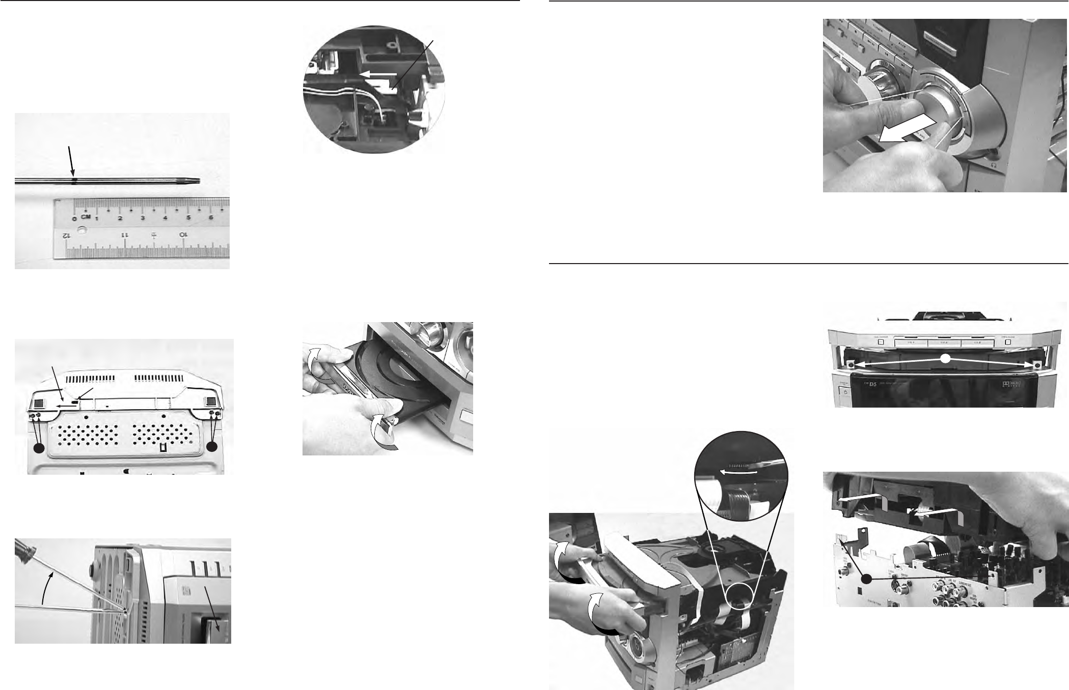
3-1 3-1
PCS 103 816
DISMANTLING INSTRUCTIONS
a) Loosen 16 screws to remove the Cabinet Cover (pos
259).
-5 screws on each side
-6 screws on the rear
b) Slide out the CDC Tray as shown by using a finger or a
flat screw driver to turn the gear towards the front and
remove the Cover Tray CDC assembly (pos 106 & 107)
as shown below.
Figure 7
c) Loosen 2 screws A on the front as shown below.
Figure 8
A
d) Loosen 2 screws B at the Rear and remove the CDC
Module (pos 1104) as shown below.
Figure 9
B
3. Open the CDC Tray / Removal of Cover CDC Tray & CDC module manually
a) Insert a strong string into the slot between the Jog Sound
knob (pos 135) and Ring Ornamental (pos 144). Looped
it 1,5 turns securely around the Jog Sound knob and
pulled it out as shown in fig. 6
b) Do likewise for the Jog DVD knob (pos 135) and Volume
knob (pos 139).
Figure 6
2. Removal of the Jog Shuttle & Volume knobs
Note: Steps a) and b) are meant strictly for sets with
a jammed tray that cannot be open via the
Open/Close button.
a) With a Torx screw driver, make a marking of about 5.5cm
from the tip as shown below.
Figure 1
Marking 5.5cm
from the bit end
Torx Screw bit diameter 3.5mm
b) Insert the tip of the screw driver into the slot S1 provide
at the bottom of the Cabinet Front.
Figure 2
S1
Direction of
screw bit
CC
Keep the marking just outside the slot & rotate the screw
driver upwards lightly as shown below.
Figure 3
Rotate upwards
Cover DVD Tray
The DVD Tray should jerked outwards slightly.
This process is a simulation of pushing the white lever on
the DVD Module inwards (see Figure 4).
Figure 4
Push white lever
inwards as indicated
to open the DVD Tray
Note: This procedure is best done with the set laying on
its side as shown, but when there is any jammed
or foreign material in the tray it has to be done with
the set placed upright at the edge of the table or
work bench.
c) Pull the tray out and the Cover DVD Tray (pos 160) or any
jammed disc can be removed. The Cover DVD Tray is
removed as shown below.
Figure 5
1. Open DVD Tray / Removal of Cover DVD Tray manually
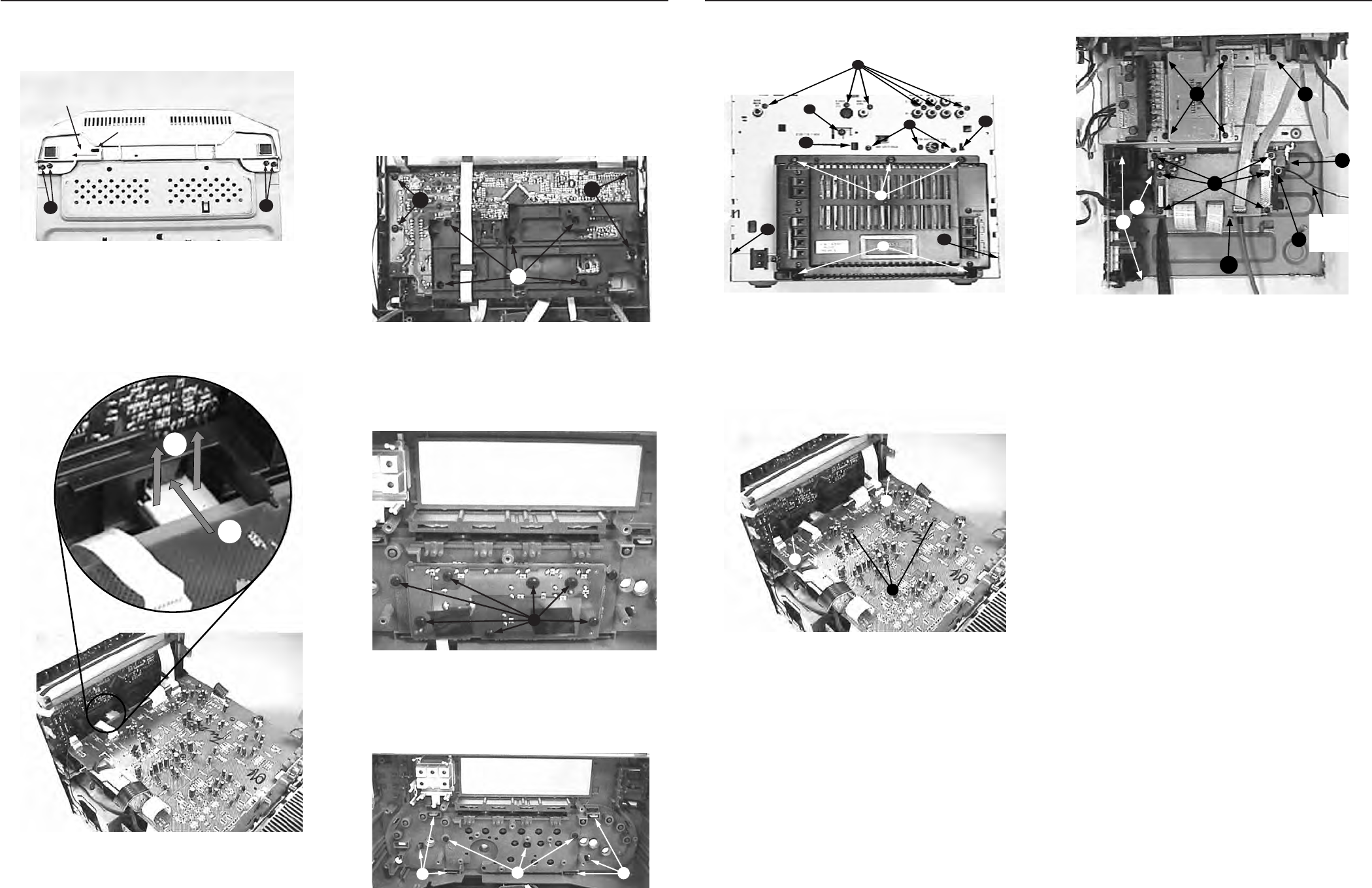
3-2 3-2
PCS 103 817
a) Loosen 4 screws C at the bottom of the Cabinet Front as
shown below.
Figure 2
S1
Direction of
screw bit
CC
b) Release the Bar Tuner (pos 263) from the Plate Front
(pos 254) as shown below while pushing the Front Panel
assembly towards the front.
Figure 10
1
2
Note: It may be necessary to release screws S (see
figure 16) if the flex cables to the front are too tight.
c) Loosen 5 screws J to remove the Plate Front (pos 254)
and 4 more screws K to remove the Front µProcessor
Board (pos 1102-A) as shown below.
Figure 11
J
KK
d) Loosen 7 screws L to remove the Deck Key Board as
shown below.
Figure 12
L
e) Loosen 3 screws M & 6 catches C4 to remove the Front
Cover Ornamental assembly (pos 145 + all button con-
trols) as shown below.
Figure 13
MC4
C4
4. Dismantling the Front Panel Assembly
a) Loosen 6 screws D at the rear as shown below.
Figure 14
D
E
G
F
C3
C3
C2
C2
H
b) Loosen 3 screws I on the AV Board (pos 1101) and
release 2 catches C1 to remove the Board as shown
below.
Figure 15
C1
C1
I
c) Loosen 1 screw E and remove the Bar Tuner (pos 263)
by uncatching it from the Plate Front (pos 254) as shown
in fig. 10.
d) Loosen 4 screws P to remove the Mains Transformer
(pos 5280) as shown in figure 16.
5. Dismantling the AV Board / Mains Transformer / Tuner Module / Plate Rear / Power 5 DVD Module
Figure 16
P
Q
R
R
N
S
T
L1
Ground
Tag
Wire
e) Loosen 3 screws F and 2 catches C3 to remove the Tuner
Module (pos 257 & 1100) as shown in figure 14
f) Loosen 3 screws H, 2 screws G and releasing 2 catches
C2 (see figure 14), it is also possible to remove the Plate
Rear (pos 234) and Tuner Module together by skipping
step e).
g) Loosen 1 screw N to release the grounding tag wire and
the Power 5 Module can be removed by pulling out of the
2 catches H1 (see figure 17).
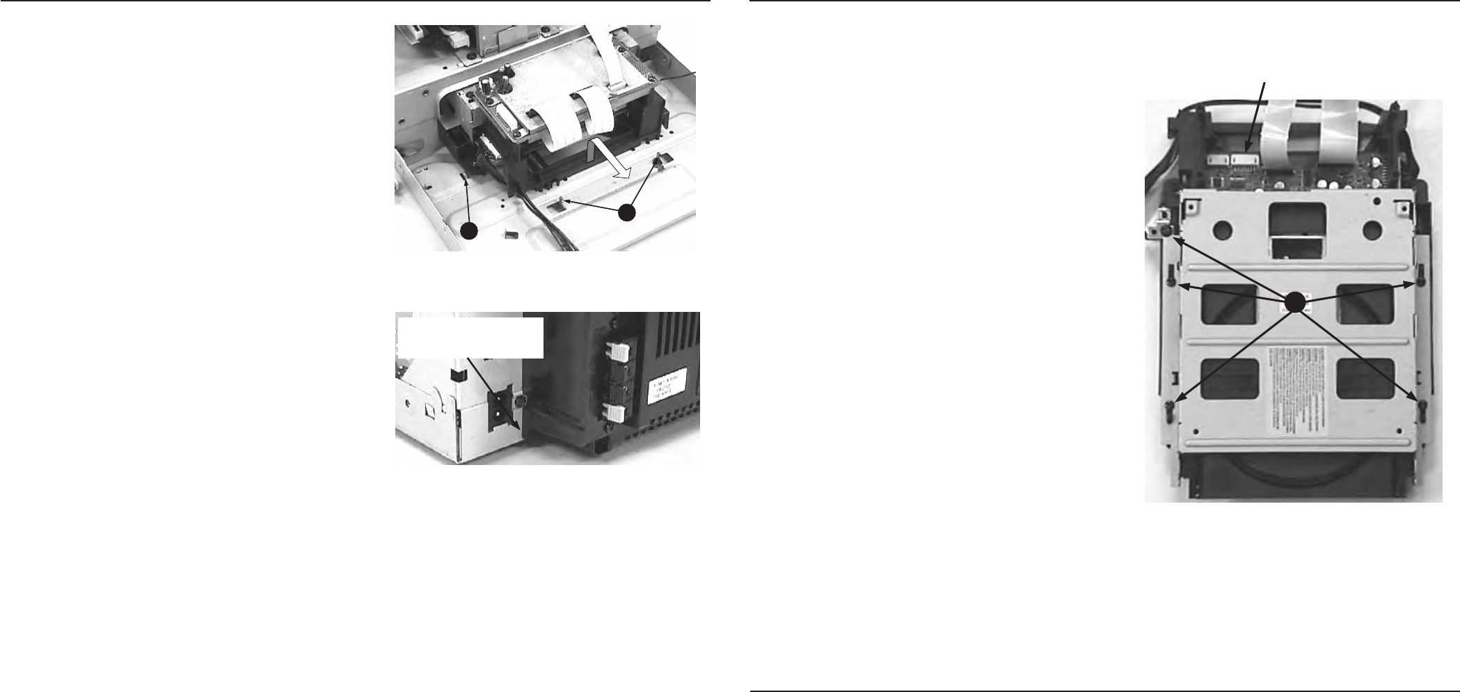
PCS 103 818
3-3
3-3
a) Remove the Cover DVD Tray (See point 1)
b) Dismantle the Rear Panel Assembly. (See point 6)
c) Loosen 2 screws Q and unhook H2 (see figure 16 & 17)
to remove the Mains Board (pos 1106-A) so that the
Standby Transformer will not obstruct the sliding move-
ment of the DVD / DAC Module assembly.
Note: Due to Standby Transformer size variation, the
removal of Mains Board may not be required in
some version.
d) Loosen 2 screws R (see figure 16), lift the rear portion of
the DVD Module / DAC Module slightly to clear the
stopper and slide it out towards the rear as shown figure
17.
e) Loosen 6 screws T (see figure 16) to separate the DAC
Module.
f) Release the lug L1 by twisting and bend open the Shield
EMC DAC cover (pos 205) to remove the DAC Board
(pos 1102-C).
Note: Do not bend the Shield EMC DAC cover beyond
45
˚
, otherwise the hindges may be broken.
g) Loosen 5 screws U to separate the DVD module from the
Bracket Mound DVD (pos 197) as shown in figure 18.
7. Dismantling of DVD / DAC Module
Figure 18
7pin Connector for
PC cable for ComPair
U
6. Dismantling the Rear Panel / AV Board / Tuner Module as a complete assembly
a) Loosen 2 screws G on the Rear as shown in figure 14.
b) Release the Bar Tuner (pos 263) from the Plate Front
(pos 254) as shown in figure 10.
c) Release the 2 catches C2 on both sides of the Rear Panel
(see figure 14), pull the complete Rear Panel assembly
backwards slightly and lift it out of the Plate Bottom (pos
236).
d) Remove 1 screw N mounting the ground tag wire, Shield
EMC DAC (pos 205) and Bracket Mound DVD (pos 197)
to Plate Bottom (pos 236) will free the assembly com-
pletely (see figure 16).
Note: During re-assembly of this Rear Panel assembly
it is very important that the Power 5 DVD Module's
bracket be slotted back into the 2 hooks H1 (see
figure 17) on the Bottom Pate and there should be
no gap between the Module's Rucksack (pos
1103-47) and the Plate Rear (pos 234) as shown
in figure 18.
It may be easier to dismantle the Power 5 DVD
Module from the Rear Panel (pos 234) and re-
assemble this Module to the Bottom Plate first
followed by the rest fo the Rear Panel assembly.
Figure 17
H1
H2
Figure 18
There should not be any
gap between the Rucksack
and the Plate Rear
Repair hints on the Left/Right Loudspeaker Box
a) Remove the Cloth Frame assembly.
b) Pull out the 4 Grommet & loosen the 4 screws under the
Grommet mounting location to remove the Woofer Ring.
c) To reach the Tweeter forced open the Front Panel As-
sembly from the wooden LS Box with the help of a minus
screw driver.
Note: This procedure is not recommended because
of high risk that the LS Box will be damaged.
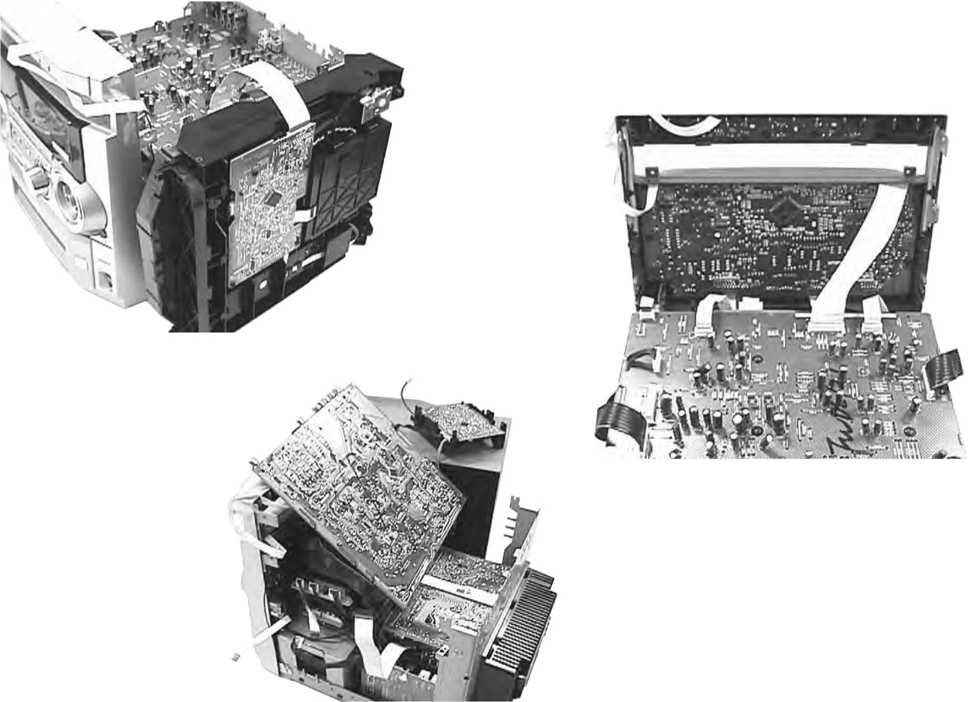
Service pos A - 3CDC-LC Module
3-4
PCS 103 819
3-4
Service pos B - AV Board / Tuner Board
Note: The following cables from the AV board should be
disconnected to achieve this Service position:
1) Conn. 1517 to DAC board conn. 1905
(there will not be any signal in AV circuit part 3
because of this disconnection)
2) Ground pin 1504
3) Conn. 1510 / 1523 to 3CDC-LC module
4) Conn. 1528 to Headphone 1702
5) Conn. 1529 / 1511 to Front 1476 / 1474
Service pos C - Front Board
Note: The following cables should be disconnected to
achieve this Service position:
1) Conn. 1510 / 1523 to 3CDC-LC module
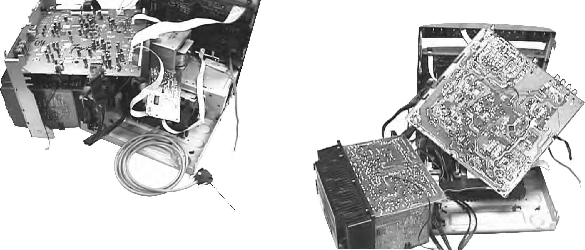
PCS 103 820
3-5 3-5
Service pos D - DAC Board
Note: The following cables should be disconnected to
achieve this Service position:
From AV board
1) conn. 1510 / 1523 to 3CDC-LC module
2) conn. 1528 to Headphone 1702
3) conn. 1529 / 1511 to Front conn. 1476 / 1474 (if
necessary)
4) conn 1517 to DAC board conn. 1905
(there will not be any signal in AV circuit part 3
because of this disconnection)
From Tuner board:
1) conn. 1121 / 1126 to Front conn. 44 / 43.
Connecting cable for PC
(ComPair connection)
Service pos E - AV Board / Supply & Amplifiers Board
Note: The following cables should be disconnected to
achieve this Service position:
From AV board
1) conn. 1510 / 1523 to 3CDC-LC module
2) conn. 1528 to Headphone conn. 1702
3) conn. 21 to Tuner conn 1124
4) conn 1529 / 1511 to Front conn.1476 / 1474
5) conn 1517 to DAC board conn. 1905
(there will not be any signal in AV circuit part 3
because of this disconnection)
From Tuner board:
1) conn. 1121 / 1126 to Front conn. 44 / 43.
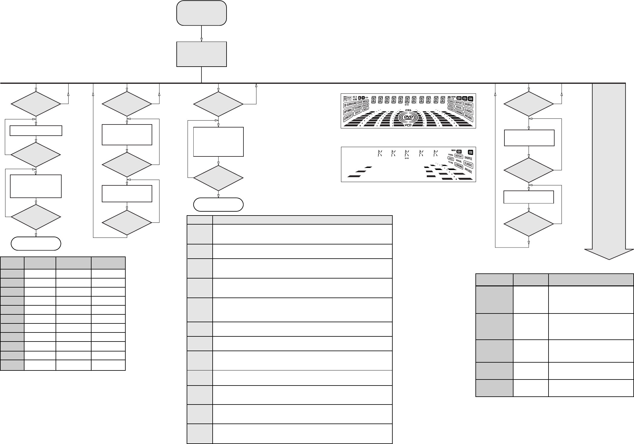
3-6
PCS 103 821
3-6
Various
other Tests
Activated with ACTION
TEST
QEEPROM FORMAT Load default data (including Virgin Mode).
Display shows "NEW" for 1 second.
Caution!
All presets from the customer will be lost!!
Please refer to Chapter 9.
DVD DEALER &
PLAYER TEST
R
9 to Exit
EEPROM TEST A test pattern will be sent to the EEPROM.
"PASS" is displayed if the uProcessor read
back the test pattern correctly, otherwise
"ERROR" will be displayed.
Volume Knob
or
Jog Shuttle knob
ENCODER TEST Display shows value for 2 seconds.
Values increases or decreases in steps of 1
until 0 (Min.) or 40 (Max.) is reached.
Disconnect
mains cord
LEAVE SERVICE
TESTPROGRAM
POWER
Button pressed?
Y
N
Set is in Service PLAY Mode. This Service Play Mode is intended to
detect and identify the failures in the CD Mode.
In this mode the electronics will still function
even when an error is detected so that
repair activities can be carried out.
SERVICE
PLAY MODE
In case of failures, error
codes according to table 2
will be displayed.
Disconnect
Mains cord ?
N
Y
Service Mode left
O
Button pressed?
Y
Y
Y
N
N
N
O
Button pressed?
9
Button pressed?
Display shows
12M
Output at (Front Board)
pin 11 of uP = 2,929.6875Hz
Display shows
32K
Output at (Front Board)
pin 11 of uP = 2048Hz
QUARTZ
TEST
TUNER
Button pressed?
Disconnect
Mains cord ?
Y
N
N
Y
Service frequencies are
copied to the RAM (see Table1)
Tuner works normally
except:
PROGRAM button
Service Mode left
TUNER
TEST
Display Tuner Version
"ccc"
TUNER
Button pressed?
N
Y
PRESET
1
2
3
4
5
6
7
8
9
10
11
Europe
"EUR"
87.5MHz
108MHz
531kHz
1602kHz
558kHz
1494kHz
153kHz
279kHz
198kHz
87.5MHz
87.5MHz
USA
"USA"
87.5MHz
108MHz
530kHz
1700kHz
560kHz
1500kHz
98MHz
87.5MHz
87.5MHz
87.5MHz
87.5MHz
Oversea
"OSE"
87.5MHz
108MHz
531/530kHz*
1602/1700kHz*
558/560kHz*
1494/1500kHz*
87.5/98MHz*
87.5MHz
87.5MHz
98MHz
98/87.5MHz*
Table 1
* Note: Depending on the selected grid frequency (9 or 10kHz).
By holding the TUNER and R buttons depressed while
switching on the Mains supply, the tuning grid frequency is
toggled between 9kHz and 10kHz for the "OSC" version.
Y
N
Y
N
Y
N
2
Button pressed?
2
Button pressed?
9
Button pressed?
DISPLAY
TEST
Display shows Fig. 1
and switch all LEDs on
Display shows Fig. 2
and selected LEDs on
(see note 1)
P3 P6P1 P2 P5P4
FTS TITLE CHAP. SLEEP DIM TIMERLWFM A M W
Figure 1
Figure 2
P6P1 P2 P5P4
TITLE
SLEEP
DIMLW AMW
note 1: CD1, CD3, CD (playback mode), DVD,
CD (Source), AUX, Surr Left & Center
Table 2
Error code
E1000
E1001
E1002
E1003
E1005
E1006
E1007
E1008
E1020
E1070
E1071
E1079
Error Description
Focus Error
Triggered when the focus could not be found within a certain time when starting up the CD
or when the focus is lost for a certain time during play.
Radial Error
Triggered when the radial servo is off-track for a certain time during play.
Sledge In Error
The sledge did not reach its inner position (inner-switch is still close) before approximately
6 Sec. have passed by. Inner-switch or sledge motor problem.
Sledge Out Error
The sledge did not come out of its inner position (inner-switch is still open) before approximately
250 mSec. have passed by. Inner-switch or sledge motor problem.
Jump-offtrack error
Triggered in normal play when the jump destination could not be found within a certain time.
When this error occurred, software will try to recover by initiating the jump command again.
If it is recoverable, the disc will continue to play.
Subcode Error
Triggered when a new subcode was missing for a certain time during play.
PLL Error
The Phase Lock Loop could not lock within a certain time.
Turntable Motor Error
Generated when the CD could not reached 75% of speed during startup within a certain time.
Discmotor problem.
Focus Search Error
The focus point has not been found within a certain time.
The carousel switch is not open within certain time. This can happen when either the switch is
defective and closed all the time, or when the carousel is blocked when located exactly at a
disc position.
The carousel position switch did not close within a certain time. This can happen when the
switch is defective and never closes electrically, or when the carousel is blocked in between
two disc positions. The time-out is approximately 5 Sec.
The drawer could not enter the inside position is opening again. This can be caused because
the drawer is blocked by something and cannot go fully inside, or the drawer switch is defective
and does not close.
To start service test program
hold P & AUX
depressed while
plugging in the mains cord
Display shows the
ROM version *
"S-Vyy"
(Main menu)
S refers to Service Mode.
V refers to Version.
yy refers to Software version number of µProcessor.
(Counting up from 01 to 99)
SERVICE TEST PROGRAM
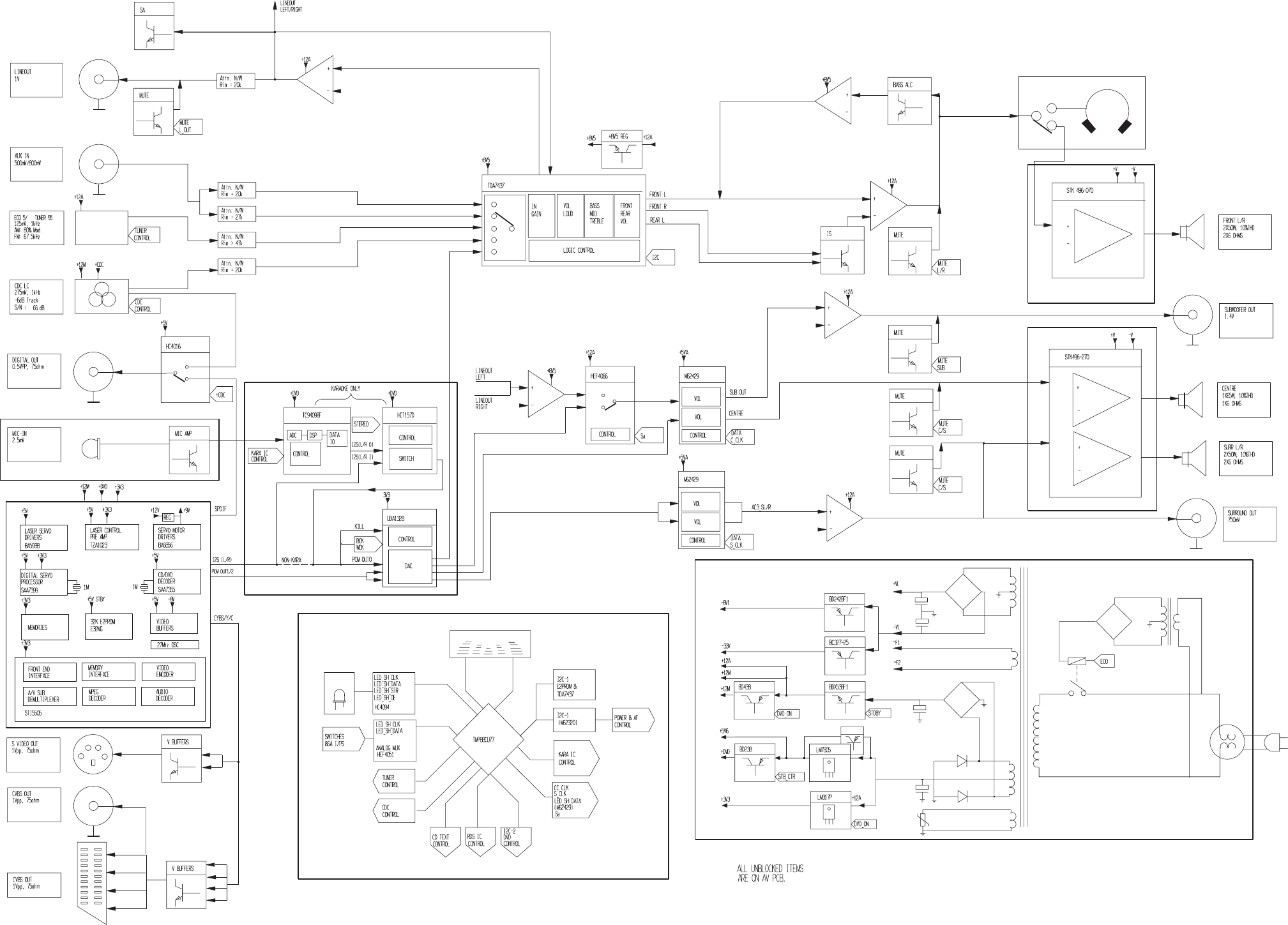
4-1 4-1
SET BLOCK DIAGRAM
PCS 103 822
L/R POWER AMP
C/S POWER AMP
SUPPLY
DVD
FM-95.00
DAC
FRONT
MIC
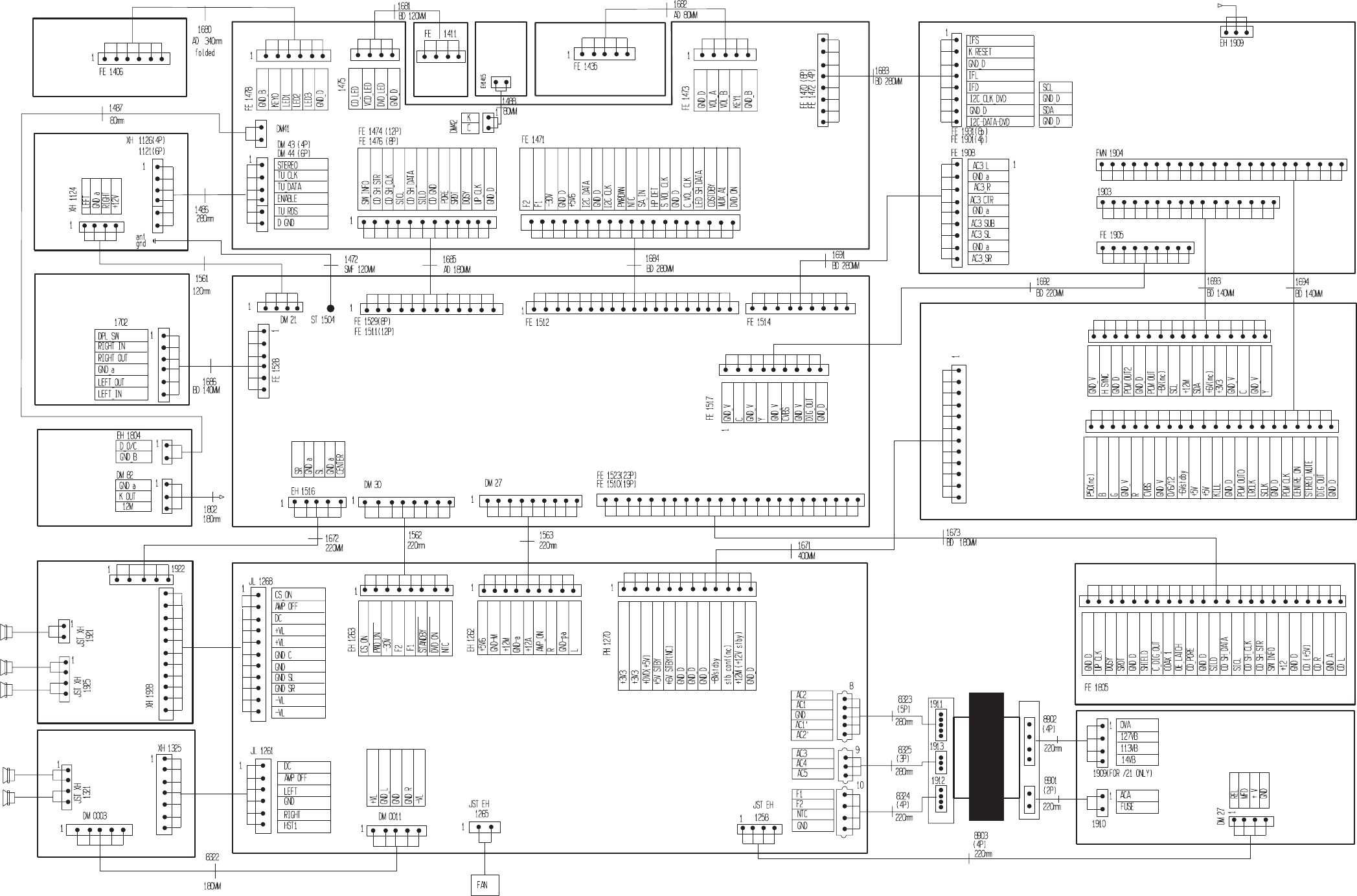
5-1
SET WIRING DIAGRAM
5-1
PCS 103 823
SUPPLY
LEFT/RIGHT
3 CDC KEY
FRONT
EC0 5
TUNER 95
MIC AMP
HEADPHONE
AV
DVD
DAC
CDC-LC
CENTER/
SURROUND
AMP
VOL & KEY
AMP
LOGO
LED
DVD
LEDS
TO DAC
FROM MIC
MAINS
TRAFO
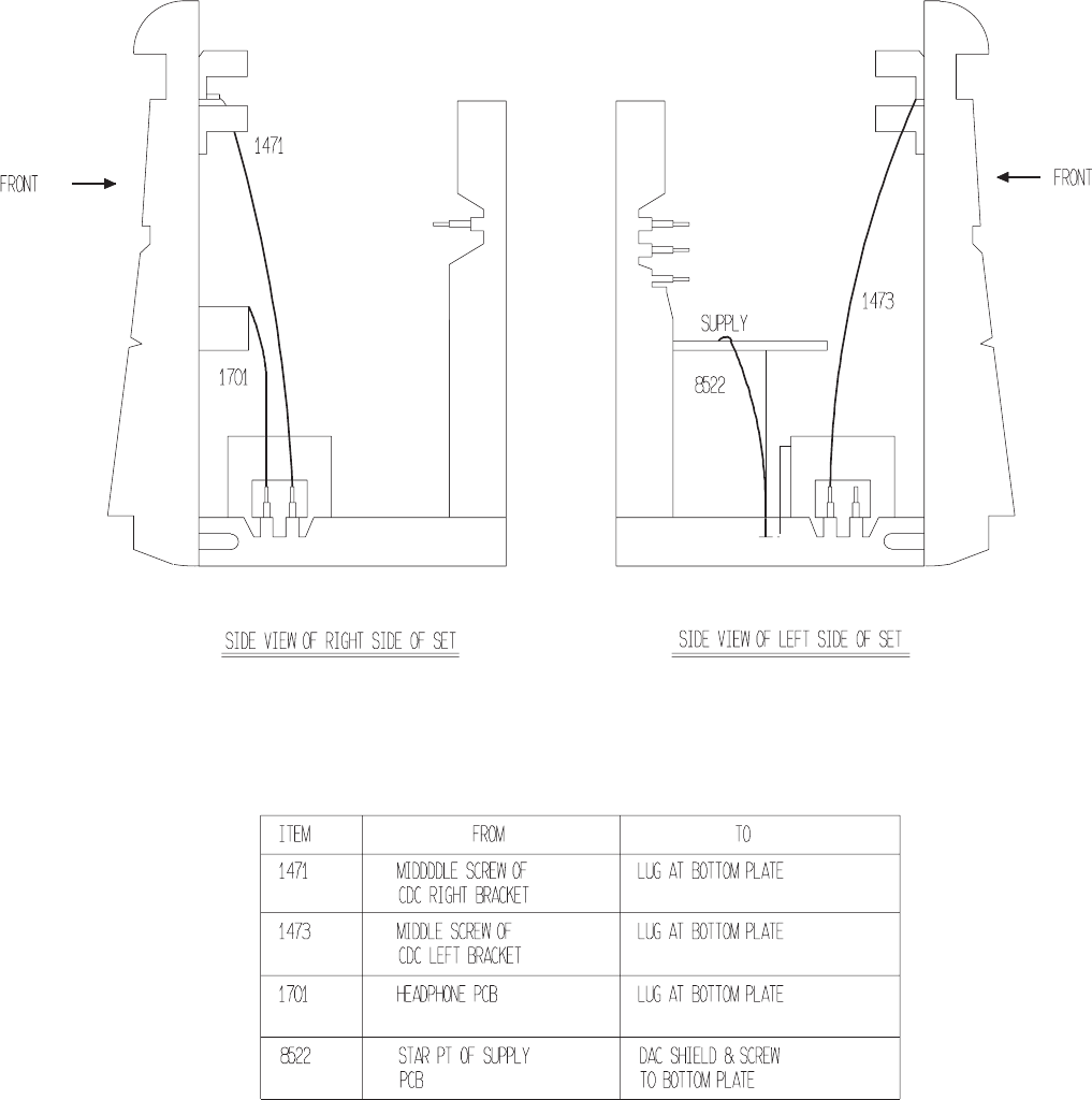
5-2
PCS 103 824
SET GROUND WIRING DIAGRAM
DO NOT PRINT
------- BLANK PAGE -------
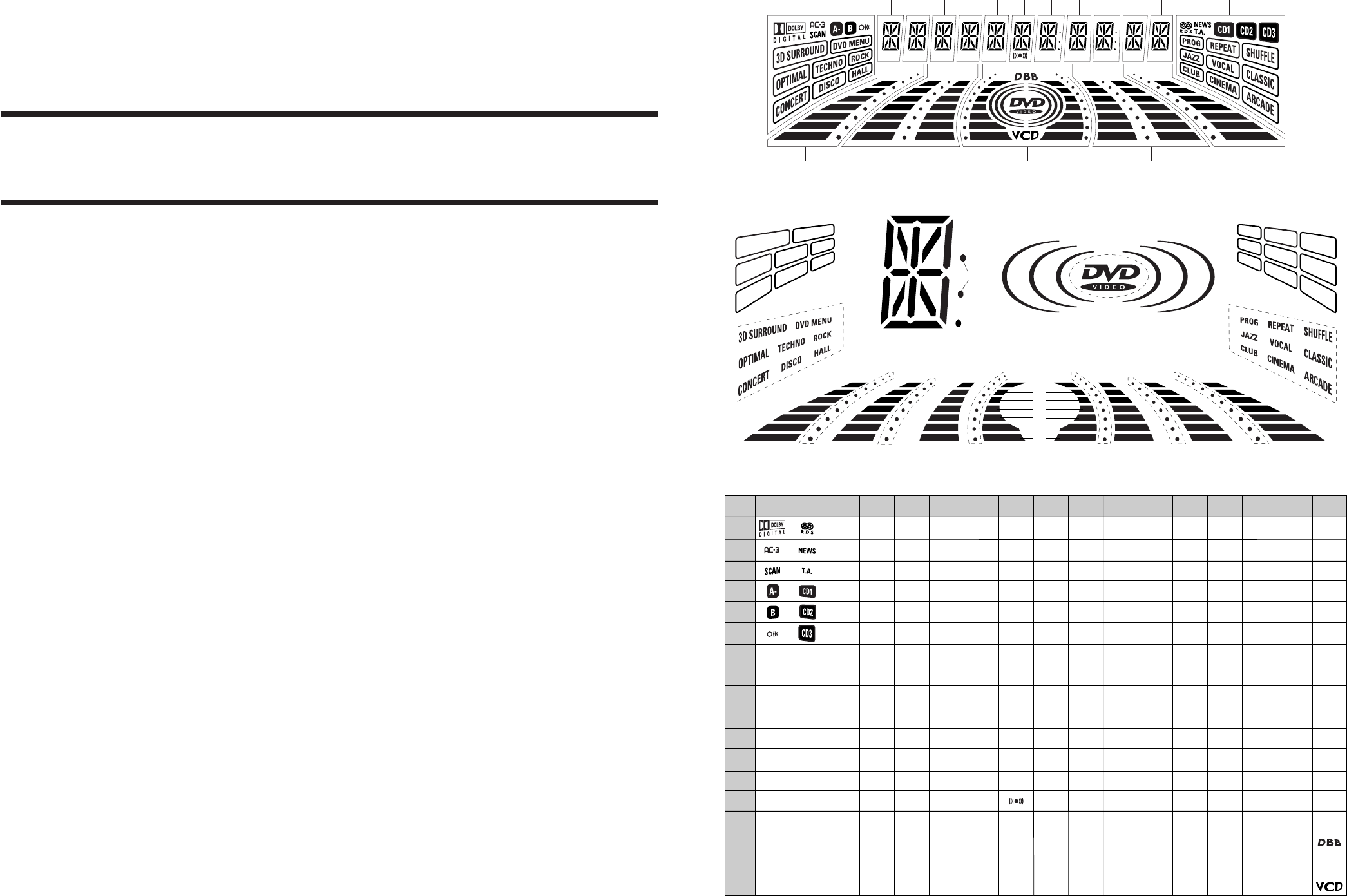
P3 P6P1 P2 P5P4
FTS TITLE CHAP. SLEEP DIM TIMERLWFM A M W
1G
14G 15G
3G 4G 5G 6G 7G 8G 9G 10G 11G 12G 13G
17G 16G 14G
2G
P1
P2
P3
P4
P5
P6
P7
P8
P9
P10
P11
P12
P13
P14
P15
P16
P17
P18
1G
S2
S3
S4
S5
S6
S7
S8
S9
S1
-
-
-
2G
S2
S3
S4
S5
S6
S7
S8
S9
S10
S1
-
-
3G
a
h
j , p
k
b
f
m
g
c
e
r
n
d
-
-
-
-
4G
a
h
j , p
k
b
f
m
g
c
e
r
n
d
-
-
-
-
5G
a
h
j , p
k
b
f
m
g
c
e
r
n
d
-
-
-
-
-
6G
a
h
j , p
k
b
f
m
g
c
e
r
n
d
-
-
-
-
-
7G
a
h
j , p
k
b
f
m
g
c
e
r
n
d
-
-
-
-
8G
a
h
j , p
k
b
f
m
g
c
e
r
n
d
-
-
-
-
9G
a
h
j , p
k
b
f
m
g
c
e
r
n
d
col
Dp
-
14G
B1
B2
B3
B4
B5
B6
B7
S1
B8
B9
B10
B11
B12
B13
B14
S2
15G
B1
B2
B3
B4
B5
B6
B7
S1
B8
B9
B10
B11
B12
B13
B14
-
16G
B1
B2
B3
B4
B5
B6
B7
S1
B8
B9
B10
B11
B12
B13
B14
-
FTD DISPLAY PIN CONNECTIONS
17G
B1
B2
B3
B4
B5
B6
B7
S1
S2
S3
S4
S5
S7
S8
S9
S6
10G
a
h
j , p
k
b
f
m
g
c
e
r
n
d
-
-
11G
a
h
j , p
k
b
f
m
g
c
e
r
n
d
-
col
Dp
-
12G
a
h
j , p
k
b
f
m
g
c
e
r
n
d
-
-
-
-
13G
a
h
j , p
k
b
f
m
g
c
e
r
n
d
-
-
-
-
P3
P6
P1 P2
P5
P4
FTS TITLE CHAP. SLEEP DIM TIMER
LW
FM A
M
W
B7
B6
B5
B4
B3
B2
B1
B7
B6
B5
B4
B3
B2
B1
S1 S1
B8
B9
B10
B11
B12
S1
B13
B14
S2 S1 S2
B8
B9
B10
B11
B12
B13
B14
B8
B9
B10
B11
B12
B13
B14
B7
B6
B5
B4
B3
B2
B1
a
b
c
d
e
f
g
hjk
m
n
p
r
Dp
col
S6
S3 S4 S5 S7 S8 S9
S2
S3
S6
S9
S4
S7
S5
S8
S2 S3
S6
S9
S4
S7
S5
S8
S10
S1
S1
B7B6
B5
B4
B3
B2
B1
FRONT BOARD
TABLE OF CONTENTS
FTD display pin connection .............................................6-1
Deck Key part - Layouts & Circuit diagram .....................6-2
DVD Logo LED part - Layout & Circuit diagram ............. 6-2
Key CDC part - Layouts & Circuit diagram .....................6-3
Headphone part - Layouts & Circuit diagram ..................6-3
Front Board - Circuit diagram .......................................... 6-4
Front Board - Component and Chip layouts ...................6-5
DAC part - Layouts & Circuit diagram ............................. 6-6
Microphone & DVD Open/Close part - Layouts & Circuit
diagram ............................................................................6-7
Disc Type LED part - Layout & Circuit diagram ..............6-7
Electrical parts list............................................................6-8
6-1 6-1
PCS 103 825
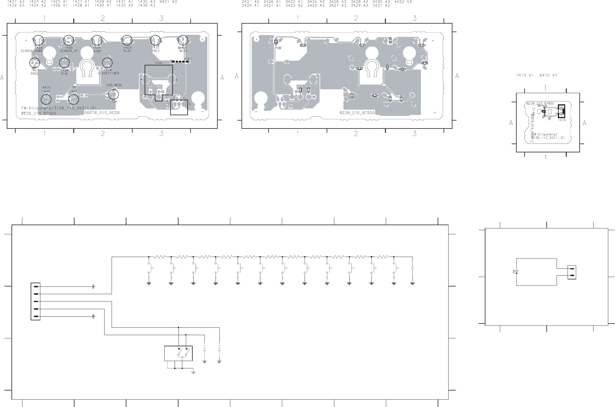
FROM
FRONT
12345678
12345678
A
B
C
A
B
C
1421 A3
1422 A3 1423 A4
1424 A4 1425 A5
1426 A5 1427 A5
B
D
1428 A6 1429 A6
1430 A7 1431 A7
1432 A8 1435 A1
1436 C3 2421 A8
2425 C4 2426 C4
3421 A3 3422 A4
D
3423 A4 3424 A4
3425 A5 3426 A5
3427 A6 3428 A6
3429 A7 3430 A7
3431 A7
PLAY DVD_MENU
1432
BB
1426
SEARCH_DOWN
3421
B
3422
220R 4K7
3430 3431
10K
B
1435
FE-ST-VK-N
1
2
3
4
5
B
220R
100p
BB
1431
OK
1424
STOP
2421
3425
SEARCH_UP
1425
BB
560R
BBB
10n
2426
10n
2425
D
3424
390R
NEXT
1421
D
3
MT1
4
MT2
5
1429
CLOCK/TIMER
3423
270R 1K8
3428
1436
EC16 1 2
B
3429
2K7
3426
820R
1427
PROG
1430
AXIS
1422
PREV
1423
3427
1K2
VOL_A
VOL_B
KEY_1 DIM
1428
Note : Some values may varies, see respective parts list for correct value. 3139 118 53360...87500 for...3431 pt1 dd wk0023
This assembly drawing shows a summary of all possible versions.
For components used in a specific version see schematic diagram and respective parts list. 3139 113 3431 pt1 dd wk0023
This assembly drawing shows a summary of all possible versions.
For components used in a specific version see schematic diagram and respective parts list. 3139 113 3431 pt1 dd wk0023
DECK KEY PART - CIRCUIT DIAGRAM
DECK KEY BOARD - COMPONENT LAYOUT DECK KEY BOARD - CHIP LAYOUT
EH-B
1415
1
2
C
A
FRONT
FROM
12
12
A
B
A
B
1415 A2 6415 A1
6415
LB3333
Note : Some values may varies, see respective parts list for correct value.
3139 118 53360...87850 for...3431 pt1 dd wk0023
This assembly drawing shows a summary of all possible versions.
For components used in a specific version see schematic diagram
and respective parts list.
3139 113 3431 pt1 dd wk0023
DVD LOGO LED BOARD - COMPONENT
LAYOUT
DVD LOGO LED PART - CIRCUIT DIAGRAM
PCS 103 826
6-2 6-2
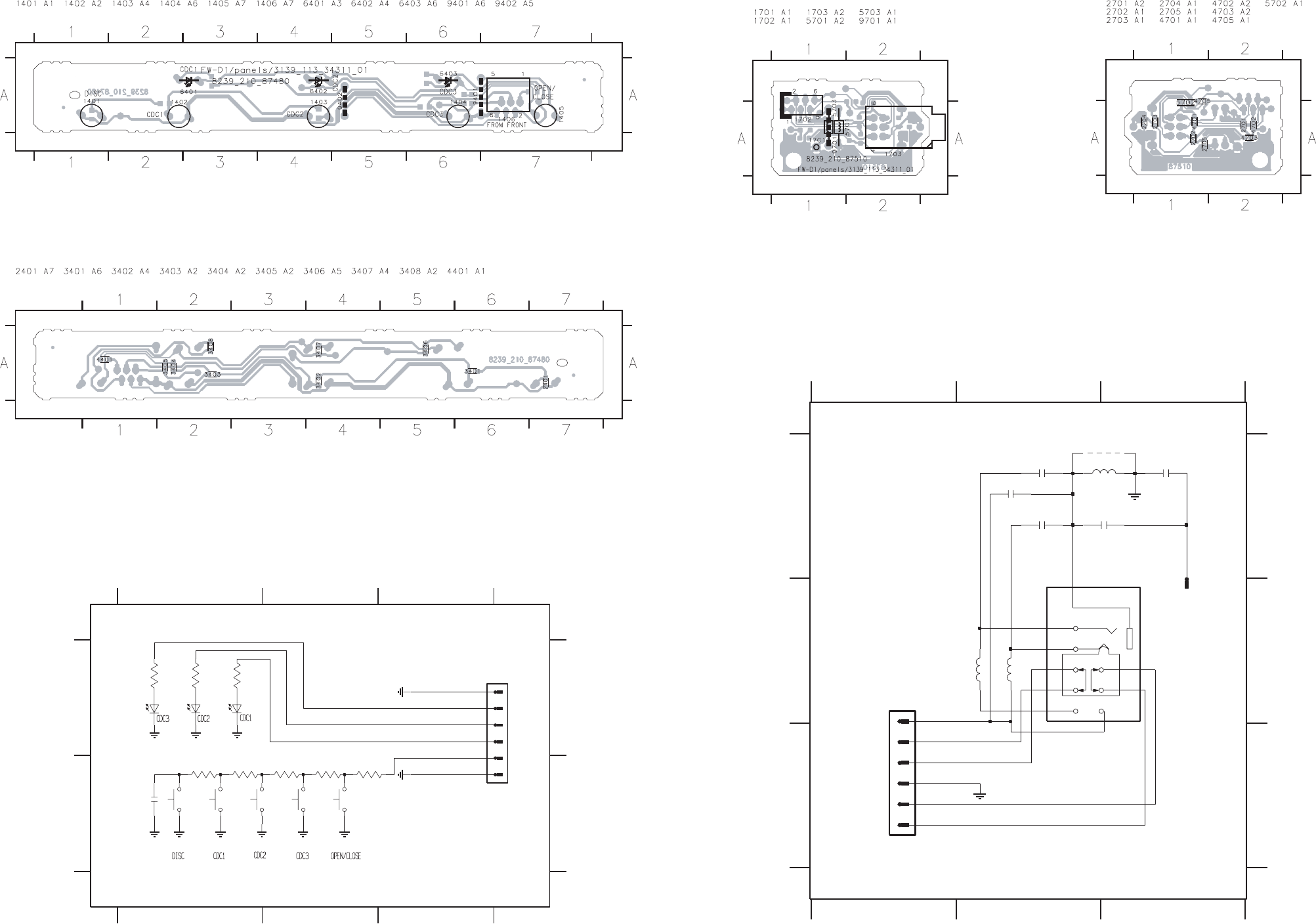
6-3 6-3
PCS 103 827
KEY CDC PART - CIRCUIT DIAGRAM
DD
A
32
123
1
FRONT
FROM
B
A
B
1401 B1
1402 B1 1403 B2
1404 B2 1405 B2
1406 A3 2401 B1
3401 B1 3402 B1
3403 B2 3404 B2
3405 B2 3406 A1
3407 A1 3408 A1
6401 A1 6402 A1
6403 A1
3408
B
1
2
3
4
5
6
D
6401
B
1406
FE-ST-VK-N
6402
3406
180R
3407
180R
180R
6403
BB
BB
1401
B
10K
1402
4K7
34023401
1K2
3405
100p
2401
1405
1404
3404
1K8
1403
2K7
3403
CDC_LED2
CDC_LED1
D
CDC_LED3
Note : Some values may varies, see respective parts list for correct value. 3139 118 53360...87480 for...3431 pt1 dd wk0023
This assembly drawing shows a summary of all possible versions. For components used in a specific version see schematic diagram and respective parts list.
3139 113 3431 pt1 dd wk0023
This assembly drawing shows a summary of all possible versions. For components used in a specific version see schematic diagram and respective parts list.
3139 113 3431 pt1 dd wk0023
KEY CDC BOARD - COMPONENT LAYOUT
KEY CDC BOARD - CHIP LAYOUT
FROM AV
123
123
A
B
C
A
B
C
1701 A3
1702 B1 1703 B2
2701 A3 2702 A2
2703 A2 2704 A3
2705 A2 5701 B2
5702 B2 5703 A3
9701 A3
2705
22n
1
2
3
4
5
6
a
6
2704
100n
a
1701
1
1702
FE-BT-VK-N
TC38
1703
9
8
7
1
2
3
4
5
5701
5702
2u2
# 9701
2u2
22n
# 2701
100n
2703
5703
2u2
# 2702
22n
L
Lhp
DPL_SW
R
Rhp
GNDa
Note : Some values may varies, see respective parts list for correct value.
# : Provision
3139 118 53360...87510 for...3431 pt1 dd wk0023
This assembly drawing shows a summary of all possible versions.
For components used in a specific version see schematic diagram
and respective parts list.
3139 113 3431 pt1 dd wk0023
This assembly drawing shows a summary of all possible versions.
For components used in a specific version see schematic diagram
and respective parts list.
3139 113 3431 pt1 dd wk0023
HEADPHONE BOARD - COMPONENT
LAYOUT HEADPHONE BOARD - CHIP LAYOUT
HEADPHONE PART - CIRCUIT DIAGRAM
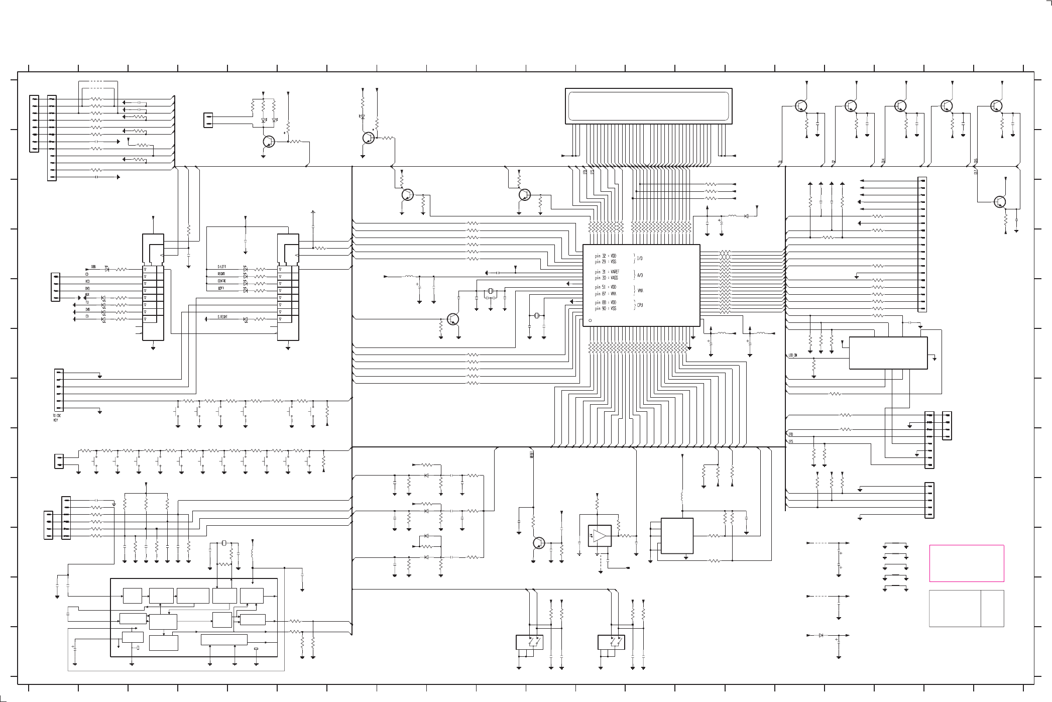
FRONT BOARD - CIRCUIT DIAGRAM
PCS 103 828
6-4 6-4
+C = 4.7V
~F1/~F2 = 4.25V
+D = 4.7V
+E = 4.7V
-30V = -33.4V
+5V6 +5V6 +5V6
+5V6
+5V6
+5V
+5V6
+5V
+5V
-30V
+5V
+5V6
-30V
+5V6
-30V
+5V6
+5V6
-30V-30V-30V-30V-30V
+5V6
+D
+C
+D+D
+D +D
+D+D+D+D
+D
+D
+D
+D
+D
+D
+D
+D
+C
+E
+E
+E
+E+E
+E
+E
+D
+D
+C
+D
+C
-30V
-30V
-30V
STB
D1
EN1
SRG8
BIT
QUALITY
DIVIDER
AND
OSCILLATOR
FILTER
RECONSTRUCTION
(8th ORDER)
BANDPASS
ANTI-
ALIASING
FILTER
CLOCKED
COMPARATOR
REFERENCE
VOLTAGE CLOCK
REGENERATION
AND SYNC
COSTAS LOOP
VARIABLE AND
FIXED DIVIDER
57 Khz
GENERATOR
DIFFERENTIAL
DECODER
BIPHASE
SYMBOL
DECODER
TEST LOGIC AND OUTPUT
SELECTOR SWITCH
VP1
STB
D1
EN1
SRG8
6454 E2
6455 D2
6457 A7
6458 A6
6459 A5
6460 J12
6461 L16
6463 C15
6471 H9
6472 I9
6473 J9
6474 J9
7441 D14
7442 I13
7443 D5
7444 C3
7445 J2
7448 E9
7449 J11
7451 B7
7452 B5
7454 A16
7455 A17
7456 A18
7457 A19
7458 A20
7459 C20
7491 F18
7492 C8
7493 C10
3695 F16
3696 G17
3697 G17
3698 C8
3699 C8
3700 C10
3701 C11
3702 G17
3703 H16
3704 H16
4691 A2
4692 A2
4693 J16
4694 K16
4695 J12
5441 E10
5442 E11
5443 D8
5444 C15
5445 F15
5446 F14
5448 I14
5450 J5
5451 J4
6441 E5
6442 E5
6443 D5
6444 D5
6445 E5
6451 E2
6452 E2
6453 E2
G
H
I
J
K
L
41 H1
42 A4
43 I1
44 I1
1441 H6
1442 H6
1443 H5
1444 H5
1445 H5
1446 H4
1447 H4
1448 H3
1449 H3
1450 H2
1451 H2
1457 A11
1458 L10
1459 L12
1461 G6
1462 G6
1464 G5
1465 G4
1466 G4
1467 G4
1234567891011121314151617181920
12345678910
TO DAC
11 12 13 14 15 16 17 18 19 20
A
B
C
D
E
F
G
H
I
J
K
L
A
B
C
D
E
F
DVD
TO
1470 G19
1471 B18
1472 G19
1473 H19
1474 A1
1475 D1
1476 A1
1478 F1
1479 J13
2441 E8
2442 E9
2443 C14
2444 F15
2445 F14
2446 C14
2447 E10
2448 E9
2449 E9
2450 E11
2451 E10
2455 I10
2456 J11
2457 J11
2458 I15
2461 J12
2462 J13
2463 L11
2464 L11
TO AV
TO DVD
(80HZ)
TO VOL & KEY
TO
TO MIC
TO ECO5
2466 J3
2467 J3
2468 J3
2469 J2
2470 I2
2471 J4
2472 J5
2473 K1
2474 K1
2475 K1
2476 L1
2477 J6
2480 D5
2482 C6
2483 D4
2488 L13
2489 L13
2490 B2
2491 B2
CDC_LED1
(10KHz)
2492 A3
2493 A3
2501 I9
2502 I9
2503 H9
2504 I9
2505 J9
2506 I8
2507 I8
2508 J8
2509 J12
2511 J17
2512 K17
2513 J17
2514 A16
2516 A17
2518 A18
2520 A19
2522 A20
2524 C20
2531 C16
2532 C17
2533 D10
2534 L17
2591 E18
3441 F12
3442 F12
3443 F12
TUNER 95
LOGO LED
CDC_LED3
LEDs
3444 F12
3445 F12
3446 F12
3447 F12
3448 F12
3449 F12
3450 F12
3451 F12
3452 F13
3453 F13
3454 F13
3455 F13
3456 F13
3457 F13
3458 F13
3459 F13
3460 F13
3461 F13
3462 F13
3463 F13
3464 F13
3465 F13
3466 F14
3467 F14
3468 F14
3470 E14
3471 E14
*
3546
PROVISION
3472 E14
3473 E14
3474 E14
3475 E14
3476 E14
3477 E14
3478 E14
3479 D14
3480 D14
3481 D14
3482 D14
3483 D14
3484 D14
3485 D14
3486 D14
3487 D14
3488 A7
3489 A6
3490 D14
3491 D14
3492 D14
3493 D13
3494 D13
3495 D13
3496 D13
3497 D13
3498 D13
FWD5/21, /21M, /33
FWD1/21, /21M
# OPTION DELECT
V-RE
FWD5/37, /30
FWD5/22
A-RE
CDC_LED2
3499 D13
3500 D13
3501 D13
3502 D13
3503 D13
3504 D13
3505 D13
3506 D13
3509 D12
3510 D12
3511 D12
3512 D12
3513 D12
3514 D12
3515 D12
3516 D12
3517 D12
3518 D12
3519 C9
3520 C9
(1KHz)
3521 D9
3522 D9
3523 D9
3524 D9
3525 F10
3526 F10
3527 F10
3528 F10
3529 G10
3531 A3
3532 E9
3533 I11
3534 J11
3535 B3
3536 J14
3537 J14
3538 I14
3539 I15
3541 I12
3542 I12
3543 J13
3544 H15
3545 H14
3546 H14
3547 K11
3548 K11
3551 I2
3552 I2
3553 I2
3554 J2
3555 I3
3556 I3
3557 I2
3558 L6
3559 L6
3560 J3
3561 I2
3562 J4
3563 J5
3564 K6
3565 L6
3566 J3
3567 J4
3568 B8
3569 A7
3570 A2
3571 A2
3572 A2
3573 A2
3574 A2
3575 B2
3576 B2
3577 B3
3578 B2
3579 B3
3582 I16
3583 G6
3584 H6
3585 G6
(TEXT)
3586 G6
3587 G5
3588 G5
3589 G4
3590 G4
3591 H6
3592 H6
3593 H5
3594 H5
3595 H4
3596 H4
3597 H3
3598 H3
3599 H3
3600 H2
3601 H2
3603 D6
3605 E5
3606 D5
3607 E5
3608 D5
3609 E5
3610 D4
3615 E2
#
8K2
4K7
*
2K7
*
*
0 ohm
*
*
*
*
3616 E2
3617 E2
3618 E2
3619 D2
3620 H9
3621 I9
3622 J9
3623 H9
3624 I9
3625 J8
3626 I9
3627 I9
3628 J9
3629 I8
3630 I8
3631 J8
3636 K13
3637 K13
3640 C18
3641 C18
3642 C17
3643 D17
3644 C16
3645 D18
3646 E17
3647 E17
3648 E17
3649 E17
3650 E17
3655 I17
3656 I17
3663 A16
3664 A17
3665 A18
3666 A19
3667 A20
3668 C20
3669 B6
3670 A5
3671 A5
3672 A5
3675 C14
3676 C14
3677 C14
3691 E18
3692 F16
3693 F16
3694 F17
4K7
3544
100K
CD
1448
3669
3506 1K
47p
2466
3587
270R
B
D
10n
2489
1459
EC16 1 2
3
MT1
4
MT2
5
3618 180R
C
O6
11 O7 9
Os
10
Os’
1
STR
16
VDD
VSS
8
3523
1K
7491
HEF4094BT
3
CP
2
D
15
E0
4O0
5O1
O2
6
7O3
14 O4
13 O5
12
270R
5
100p
2518
3593
FE-ST-VK-N
1473
1
2
3
4
3693
10K
C
3648 1K
2K7
D
C
3546
3575 E
2467
47p
D
470R 4K7
3535
2534
47u
BC847B
7492
1465
D
1
2
3
4
5
6
PERSONAL
E
D
1478
4u7
2513
3563
2K2
3676 82K
2464
10n
3475 100R
D
D3608270R
100R3470
47p
2469
3509 220R
270R 3606
B
3527
100R
B
10K
47K
3627
5443
3548
100R
D
D
2u2
3551
D
3473
E
1K
1K 3462
3582
2K7
D
3702
1K
3520
470R
B
3472
3517 3K9
1K
100R
6445
3543
D
3666
82K
B
D
D
4K7
3568
D
100p
2514
3656
10K
3500 1K
E
ECO
1442
41
1
2
BC847B
7456
1M3642
DIPMATE
11
12
2
3
4
5
6
7
8
9
3477 100R
D
FE-ST-VK-N
1474
1
10
2474
47p
3641
220R
100R
3479
D
1K3505
47n
2461
10K
3555
87
88
89
9
90
91
92
93
94
95
96
97
98
99
7273747576777879
8
80
81
82
83
84
85
86
5859
6
60616263646566676869
7
7071
43
44
45
46
47
48
49
5
50
51525354555657
293 30
31
32
33
34
35
36
37
38
39
4
40
41
42
14 15 16 17 18 192202122232425262728
7441
TMP88CU77F
110
100
11 12 13
3623
680K
470R
3603
D
1K8
3598
1443
SCAN
D
3574 470R
D
DT-38
5442 32K768
2591
100p
B
1K3515
180R
3672
6444
3456
DD
1K3491
1K
1K3498
1K
3533
470R 3465
390R
100R
3697
1447
DVD
3594
4693
2488
10n
2u2
5444
12
11
9
10
1
16
8
3567
10K
74HC4094D
3
2
15
4
5
6
7
14
13
3566
E
7443
220R
3586
D
10K
1K 3525
680K
34611K
1461
SURR
3624
D
B
2K2
3699
3447
1K
6454
D
34511K
2447
BC847B
7448
3573
22p
100n
2477
470R
470R3576
82K
3667
470R
3610
470u
2446
47p
2472
100R
3481
D1K5
3622
2511
4u7
220n
2507
D
6451
3484 100R
E
C
2458
100n
6442
C
E
10K
3556
2490
8K2
3698
560p
2475
100n
100p
2516
E
3694
10K
270R 3605
D
19
2
3
4
5
6
7
8
9
3599
2K7
1471
FE-ST-VK-N
1
10
11
12
13
14
15
16
17
18
3631
470K
100R
3480
6452
3504 1K
1K 3444
7493
BC847B
7454
BC847B
2
VSUP
2451
22p
6460
GR1U28XP
3
GND
4
MT
1
OUT
M24C02
7442
E0
1
E1
2
E2
3
SCL
6
SDA
5
VCC
8
4
VSS
WC_
7
B
3547
10K
3626
47K
390R
3588
3531 4K7
10K
3637
1K 3441
3565
10K
B
D
3K9
3518
10K
3559
7451
BC847B
3564
10K
82p
5450
2u2
1479
RT-01T1
2471
100n
2509
3558
10K
4K7
3600
D
D
1K 3528
34521K
1K 3529
2K7
3583
1
2
3
4
5
6
7
8
D
1476
FE-ST-VK-N
3488
10K
6471
1N4148
2503
2K7
3584
3560
47K
47n
5
MT2
5441
EC16
1458 12
34
MT1
180R
1K 3468
D
3671
3621
1K5
10K
3601
6474
1N4148
3597
1K2
3579 10K
10n
2457
3514 220R
100n
2443
1K 3458
C
10K
3532
1
2
3
4
5
6
7
8
3503 1K
180R
3617
1470
FE-ST-VK-N
D
7452
BC847B
3645
1K
2480
100n
470K
3629
1K 3455
B
STANDBY
1441
B
C
D
D
3557
10K
6459
4695
9
MODE
4
MUX
13
OSCI
14
OSCO
1
QUAL
16
RDCL
2
RDDA
8
SCOUT
15
T57
10
TEST
VDDA
5
12
VDDD
3
VREF
6
VSSA VSSD
11
3490
7445
SAA6579T
7
CIN
D
1K
BB
100n
2491
470R3570
47p
2492
B
2531 10p
C
B
1K3495
B
3443
1K
100p
2483
220R
3585
34571K
1N4148
6473
1K
7455
BC847B
82K
3663
3487
3578 1K
D
3703
5K6
1
2
3
4
D
100K
3577
C
43
DIPMATE
D
2482
100p
270R 3607
470K
3630
D
3485 100R
C
E
2456
100n
1K 3467
47R
3541
1
2
3
4
D
1449
TUNER
1472
FE-ST-VK-N
1M3644
1466
3516 1K
40414243444546474849606162
DSC
23242526272829 33033343536373839 113141516171819 2202122
1K 3442
BJ764GNK
1457
3640
220R
NEWS/TA
1462
C
1K 3524
D
10K
3489
C
D
5K6
3704
D
D
D
10K
3542
220R3513
3561 1K
6455
D
3615 180R
1451
VEC
1K 3463
470R3572
3496
3696
100R
D
1K
2508
220n
10K
3692
2473
3701
2K2
BC847B
7457
560p
D
2442
100n
3620
6441
D
6443
1K5
3536
1K
E
B
3482 100R
2502
3534
100K
5448
2u2
100n
D
3609270R
C
3649 1K
D
D
3590
820R
2449
22p
1K
E
100R
3554
680K
3643
3537
1K 3521
D
2520
C
D
100p
220R3511
D
3675 82K
A-B
1444
3512 220R
1K 3450
3539
3552 1K
10K
3545
10K
2450
22p
2u2
5445
D
D
D
3501 1K
220R
3592
3474 100R
3483 100R
D
330R
3569
1K 3445
1450
2n2
2462
3647 470R
AUX
D
3499 1K
D
470R 3519
82K
3665
D
D
DBB
1467
C
D
560R
3595
3493 1K
470R
3646
10K
3655
FE-ST-VK-N
1475
1
2
3
4
2444
47u
B
6453
3596
820R
RETURN
1446
D
34661K
D
6463
1N4148
D
560R
3589
C
E
D
34601K
47R3650
100R 3526
1445
PBC
47p
2493
3668
82K
3571 470R
D
D
1K3492
100p
D
2504
6n8
2524
11
9
10
1
16
8
3691
470R
7444
3
2
15
4
5
6
7
14
13
12
B
E
74HC4094D
2506
220n
2501
1u
D
2448
15p
7458
BC847B
2445
D
47p
2468
D
47u
6472
1N4148
6458
3628
47K
100R3471
D
3619
180R
1K 3446
D
D
D
3677 82K
100n
4691
2533
180R
5446
2u2
4694
3616
C
1K 3449
D
3538 10K
3700
8K2
220R
3591
3664
82K
D
B
3494 1K
220R
42
DIPMATE
1
2
100R
3476
3510
10n
3636
10K
3486 100R
2463
1
2
3
4
5
6
2505
820p
1K
44
DIPMATE
680K
3625
3502
B
D
180R
3670
D
D
7449
BC847B
220K
B
6457
D
3562
B
D
2522
1K 3453
10p2532
100p
1464
RDS/TEXT
3497 1K
D
3553 470R D
3522
100R
D
2441
47u
BC847B
7459
1K 3454
2470 100p
C
1N4003
6461
34481K
4692
34641K
1K 3459
2512
1u
10n
2455
E
D
D
2476
2u2
AT-51
5451
D
3695
10K
TU_CLK
TU_STEREO
CdTXTIN
TU_CE
100R
3478
STDBY_LIT
K_RESET
BLUE_LIT
IFL
CdShCLK
CdShSTR
LEDShCLK
-F1
TuRDSCLK
TuRDSDATA
TU_DATA
LEDShSTR
LEDShSTR
LEDShCLK
KEY_1
VOL_A
VOL_B
D10
CdShSTR
CdShCLK
LEDShDATA
LEDShCLK
LED_ON
A_JOG_A
A_JOG_B
V_JOG_A
V_JOG_B
TuRDSDATA
D10
CdSICL
CdSILD
CdPore
CdTxtDQSV
I2C_DATA_DVD
I2C_CLK_DVD
-F2
~F2
RC6
I2C_CLK
SA_IN
SA3
NTC
OPTIONS
SA1
~F1
SA2
I2C_DATA
KEY_2
KEY_1
KEY_0
I2C_CLK
VOL_B
VOL_A
A_JOG_B
A_JOG_A
C_VOL_CLK
S_VOL_CLK
CdPore
CdSwInfo
CDTXTin
CDTXTCLK
PWDN
TuRDSCLK
RC6
CdTxtDQSV
KEY_2
I2C_CLK_DVD
TU_DATA
I2C_DATA
KEY_0
V_JOG_B
V_JOG_A
HP_DET
TU_STEREO
OPTIONS
NTC
SA3
SA2
SA1
G14
CdStdby
G15
G16
MUX_Sa
G17
DVD_ON
MPOscShift
RESET
CdShDATA
I2C_DATA_DVD
SA_IN
G3
G4
HP_DET
G5
G6
S_VOL_CLK
G7
G8
G9
G10
C_VOL_CLK
G11
G12
LEDShDATA
G13
CdSiCL
TU_CLK
LEDShSTR
TU_CE
I2C_DATA
CdStdby
I2C_CLK
DVD_ON
LED_ON
PWDN
MUX_Sa P1
NTC
G1
MPOscShift
LEDShCLK
G2
G17’
P2
P3
P4
P5
P6
P7
P8
P9
P10
P11
P12
P13
P14
P15
P16
P17
P18
LEDShDATA
LED_ON
LEDShSTR
CdSiLD
G6
G7
G8
G9
G10
G11
G12
G13
G14’
G15’
G16’
G17’
STDBY_LIT
BLUE_LIT
CdTXTClk
P18
P17
P16
P15
P14
P13
P12
P11
P10
P9
P8
P7
P6
P5
P4
P3
P2
P1
G1’
G2’
G3
G4
G5
CdSwInfo
CdShDATA
G16’
G15’
G15
G14’
G2’
G1’
3139 118 53360...87490 for...3431 pt1 dd wk0023
Note : Some values may varies, see
respective parts list for correct value.
*
~F2
~F1
-F1
-F2
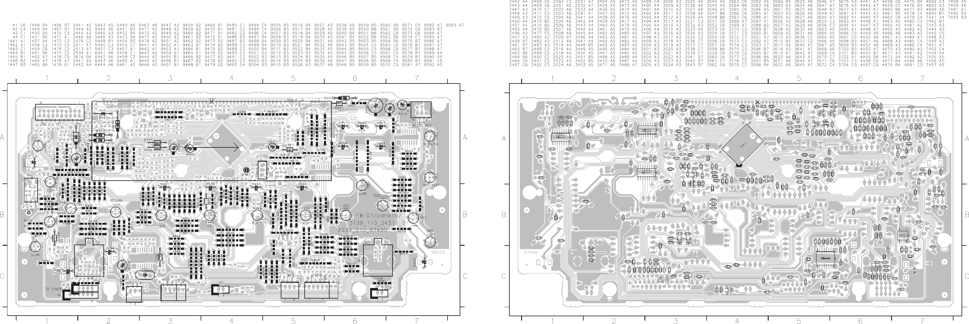
PCS 103 829
6-5 6-5 6-5
FRONT BOARD - CHIP LAYOUT
This assembly drawing shows a summary of all possible versions. For components used in a specific version see schematic diagram and respective parts list. 3139 113 3431 pt1 dd wk0023 This assembly drawing shows a summary of all possible versions. For components used in a specific version see schematic diagram and respective parts list. 3139 113 3431 pt1 dd wk0023
FRONT BOARD - COMPONENT LAYOUT
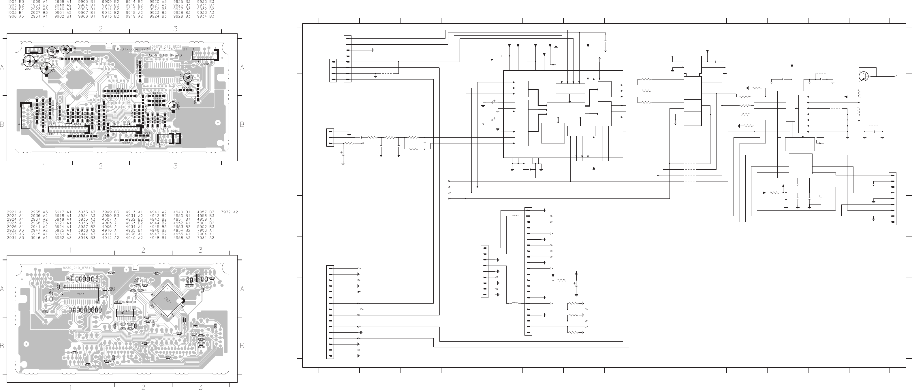
6-6 6-6 6-6
PCS 103 830
This assembly drawing shows a summary of all possible versions. For components used in a specific version see schematic diagram and respective parts list.
3139 113 3431 pt1 dd wk0023
This assembly drawing shows a summary of all possible versions. For components used in a specific version see schematic diagram and respective parts list.
3139 113 3431 pt1 dd wk0023
DIGITAL ANALOG CONVERTOR (DAC) PART -
CIRCUIT DIAGRAM
DIGITAL ANALOG CONVERTOR (DAC) BOARD -
COMPONENT LAYOUT
DRAM
MICOM uF
DSP
IN DIGITAL
OUT
IN
MIC
IN
TIMING GENE.
OUT
ANALOG
ANALOG
DIGITAL
CONTROL
INTERFACE
DAC’S
VOL/MUTE/DEEMPH
INTERPOL FILTER
NOISE SHAPER
NC
DIGITAL
INTERFACE
EN
G1
1
MUX1~
I2C_DATA_DVD
K_RESET
IFD
3916 B11
QE50
3918 C11
*
3917 B113915 B11
TO DVD
2923 E13
2924 B12
2925 B13
2926 C14
2927 E12
2931 D1
2932 C2
2933 C2
2934 C2
2935 C3
2936 A5
2937 A6
2938 A7
2939 B5
2940 C5
2941 A10
2946 G7
2947 D6
PROVISION
13 14
#
1234567891011121314
123456789101112
+5Vd
NON-KARAOKE ONLY
2922 E12
TO AV
TO
FROM
MIC
DVD
A
B
C
D
E
F
G
H
A
B
C
D
E
F
G
H
1901 A1
1903 F1
1904 E6
1905 F4
1908 D14
1909 C1
1931 A1
2921 E12
IFS
3919 C11
3921 D12
3924 B14
3925 B14
3931 C1
3932 C2
3933 C2
3934 C3
3935 C3
3936 B9
3937 B9
3938 B9
3947 G6
3948 G7
3949 G7
3950 H7
4905 A12
4910 B13
4911 B13
4912 D6
4913 A13
4931 D10
4932 D10
4933 D10
4934 D10
4935 A2
4936 C14
5901 E5
5902 G5
7903 B12
7904 B14
I2C_CLK_DVD
FROM
0V (Karaoke on)
FRONT
7931 A5
7932 A9
+5Vadc = 4.6V
+3V3 = 3.3V
+3V3A = 3.0V
STEREOMUTE =
IFL
3.3V (Karaoke off)
+5Vd = 4.7V
a
7931
220u
2923
4910
22
3
4
5
6
7
8
9
D
2924
22n
+5Vd
+5Vd
a47R
3918
8
9
100p
2941
a
#
2932
470n
D
+5Vd
2940
4u7
*
4935
3
4
5
6
7
8
9
a
D
FMN
1904
V
XI
21
XO
22
3932
470R
3931
D
a
22n
2938
100u
2931
D
VO4 2
VO54 VO6 5
VREFA
303
VSSA
VSSD
20
WS11
V
dd
3948
82R
+5Vd
5901
2u2
a
2921
3n3
2933
a
4u7
2939
5902
2u2
D
10K
3915
+5Vd
D
10K
3925
5K6
82R
3949
D
4n7
2934
a
3934
2927
100u
+5Vadc
82p
2935
10K
a
2926
22n
D
+5Vd
D
MIC1
2
RESN
35
RI
19
RZ
18
SDI
31 28
SDO
TEST
41
VDA1
1
VDA2
17
VDD1
24
VDD2
42
VDL
43
VDX
20
VR2
15
VRA1
4
VRA2
7
GNDA2
13
GNDD
34
GNDL
44
GNDX
23
IFD
36
IFL
38
IFS
37
LI
11
LPFO1
3
LPFO2
6
LPFO3
9
33
LRCKI LRCKO
30
LZ
12
27 26
TC9409BF
AIL
5
AIR
8
AOL
14
AOR
16
BCKI
32
BCKO
29
CKS
25
EMP
39
EXTO
40
GNDA1
10
23
7
8
15
9STATIC
SYSCLK16
TST127
22TST2
6
VDDA
VDDD
21
VO1N29
VO1P28
VO2N 31
VO2P 32
VO31
7903
BCK10
DEEM0 25
DEEM1 24DI1212
DI3413
DI5614
DS 26
L3CLK 18
L3DATA 19
17L3MODE
MUTE
100u
2946
D
UDA1328T
7904
BC817-25
3933
10K
3919
10K
a
*
4933
dd
D
2K2
3924
3916
47R
D
a
a
47R
3921
+5Vadc
D
dd
a
D
a
+3V3
3V3A
4936
+5Vadc
dd
4911
#
4913
V
*
4932
4934
47R
3938
D
D
4905
+3V3
47R
*
4931
7
11
10 9
14
13 12
15 8
GND
116
VCC
3936
D
74HCT157D
7932
2
34
5
6
2925
100n
V
22n
2936
a
16
2
3
4
5
6
7
8
9
22K
3935
1903
FMN
1
10
11
12
13
14
15
FE-BT-VK-N
1901
1
2
3
4
a
10n
2947
D
470R
3947
a
4912
V
2922
100n
3
4
5
6
7
8
V
V
FE-BT-VK-N
1931
1
2
1905
FE-BT-VK-N
1
2
3
4
5
6
7
D
V
V
D
3937
47R
22n
2937
22n
3917
47R
1
10
11
12
13
14
15
16
17
18
19
2
20
21
V
1908
FE-BT-VK-N
1
2
3950
82R
V
1909
EH-B
1
2
3
Y
C
SDA
H_SYNC
PCM_OUT2
PCM_OUT1 G
B
R
DIG_OUT
CVBS
3V3A
AC3_SR
AC3_SL
AU3_CTR
AC3_R
AC3_L
KILL
STEREO_MUTE
AC3_SUB
Y
C
PCM_CLK
+12Vstby
SCL
+3V3
KILL
+12Vstby
STEREO_MUTE
LRCLK
SCLK
PCM_OUT0
PCM_OUT0
SCLK
LRCLK
PCM_CLK
3139 118 53360...87540 for...3431 pt1 dd wk0023
Note : Some values may varies, see respective
parts list for correct value.
#
DIGITAL ANALOG CONVERTOR (DAC) BOARD -
CHIP LAYOUT
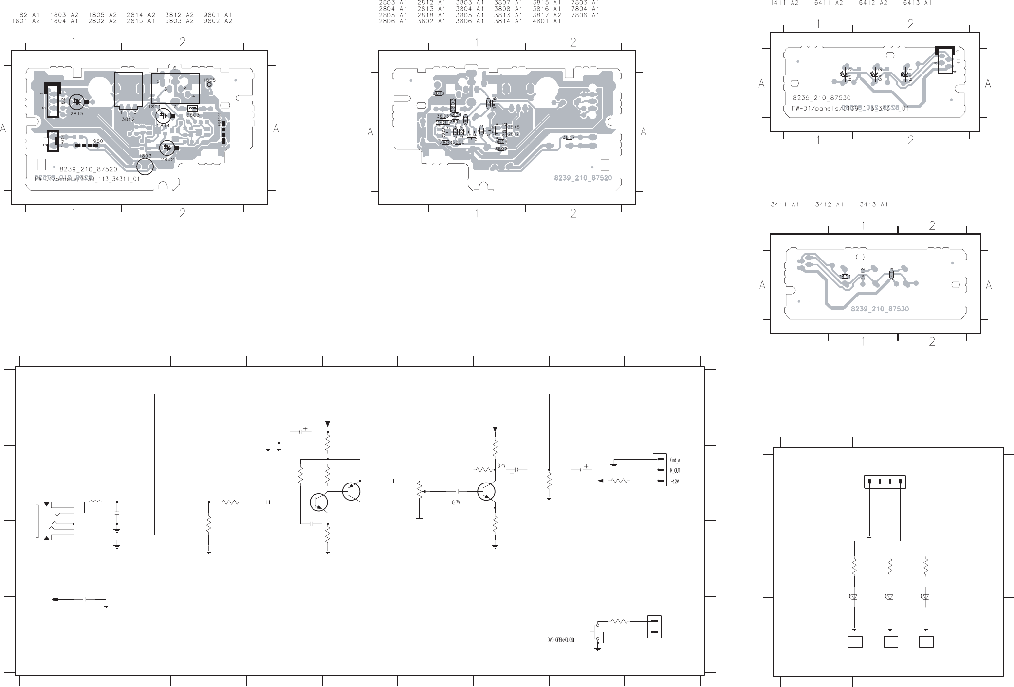
6-7 6-7
PCS 103 831
This assembly drawing shows a summary of all possible versions.
For components used in a specific version see schematic diagram and respective parts list.
3139 113 3431 pt1 dd wk0023
This assembly drawing shows a summary of all possible versions.
For components used in a specific version see schematic diagram and respective parts list.
3139 113 3431 pt1 dd wk0023
MIC. & DVD OPEN/CLOSE PART - CIRCUIT DIAGRAM
MIC. & DVD OPEN/CLOSE BOARD -
COMPONENT LAYOUT MIC. & DVD OPEN/CLOSE BOARD - CHIP LAYOUT
123456789
123456789
A
B
C
D
A
B
C
D
82 B9
1801 B1
4K7
3804
1803 D8
1804 D9
1805 C1
2802 A4
2803 B2
2804 B4
2805 B4
2806 B5
2812 B6
2813 B6
2814 B7
2815 B8
2818 C1
3802 B8
3803 C3
3804 B3
3805 A5
3806 B4
3807 B5
3808 C5
3812 B6
3813 B7
3814 B7
3815 C7
3816 B8
3817 D8
5803 B1
7803 B5
7804 B5
7806 B7
FROM
FRONT
TO DAC
3812
20K
+12A
820R
3817
2806
470n
2815
47u
1M
3806
2814
10u
a
3813
2K2
B
7
1
2
3
4
5
3803
10K
1801
TC38
6
100K
3816
Mic
470n
2812
3802
560R
Mic
a
22R
3808
a
a
Mic a
a
3807
2K7
1n
2805
82
DIPMATE
1
2
3
2K7
3805
BC847B
2813 1n
Mic
7806
+12A
RT-01T
# 1805
1100n
# 2818
220n
2804
a
BC847B
7803
3815
820R
3814
1M
7804
BC857B
4n7
2803
1804
EH-B
1
2
+12A
5803
2u2
1803
SKQNAB
2802
47u
3139 118 53360...87520 for...3431 pt1 dd wk0023
Note : Some values may varies, see respective parts list for correct value.
# : Provision
DISC
VCD
DISC
FROM
DISC
DVD
FRONT
CD
123
123
A
B
C
A
B
C
1411 A2 3411 B1 3412 B2 3413 B2 6411 B1 6412 B2 6413 B2
DD
D
220R
3411
D
3412
220R
LTL-1CHGE
6411
220R
3413
6413
6412
LTL-1CHGE
FE-BT-VK-N
1411
12 34
LTL-1CHGE
Note : Some values may varies, see respective parts list for correct value.
3139 118 53360...87530 for...3431 pt1 dd wk0023
This assembly drawing shows a summary of all possible versions.
For components used in a specific version see schematic diagram and respective parts list.
3139 113 3431 pt1 dd wk0023
This assembly drawing shows a summary of all possible versions.
For components used in a specific version see schematic diagram and respective parts list.
3139 113 3431 pt1 dd wk0023
DISC TYPE LED PART - CIRCUIT DIAGRAM
DISC TYPE LED BOARD - COMPONENT
LAYOUT
DISC TYPE LED BOARD - CHIP LAYOUT

1401 4822 276 13775 Tact Switch
1402 4822 276 13775 Tact Switch
1403 4822 276 13775 Tact Switch
1404 4822 276 13775 Tact Switch
1405 4822 276 13775 Tact Switch
1406 4822 265 11207 Flex Connector 6P
1411 4822 267 10733 Flex Connector 4P
1421 4822 276 13775 Tact Switch
1422 4822 276 13775 Tact Switch
1423 4822 276 13775 Tact Switch
1424 4822 276 13775 Tact Switch
1425 4822 276 13775 Tact Switch
1426 4822 276 13775 Tact Switch
1427 4822 276 13775 Tact Switch
1428 4822 276 13775 Tact Switch
1429 4822 276 13775 Tact Switch
1430 4822 276 13775 Tact Switch
1431 4822 276 13775 Tact Switch
1432 4822 276 13775 Tact Switch
1435 4822 267 10958 Flex Connector 5P
1436 2422 129 16348 Rotary Encoder 24P
1441 4822 276 13775 Tact Switch
1442 4822 276 13775 Tact Switch
1443 4822 276 13775 Tact Switch
1444 4822 276 13775 Tact Switch
1445 4822 276 13775 Tact Switch
1446 4822 276 13775 Tact Switch
1447 4822 276 13775 Tact Switch
1448 4822 276 13775 Tact Switch
1449 4822 276 13775 Tact Switch
1450 4822 276 13775 Tact Switch
1451 4822 276 13775 Tact Switch
1457 3139 110 52380 FTD Display
1458 2422 129 16385 Rotary Encoder 12P
1459 2422 129 16385 Rotary Encoder 12P
1461 4822 276 13775 Tact Switch
1462 4822 276 13775 Tact Switch
1464 4822 276 13775 Tact Switch
1465 4822 276 13775 Tact Switch
1466 4822 276 13775 Tact Switch
1467 4822 276 13775 Tact Switch
1470 4822 265 11535 Flex Connector 8P
1471 4822 265 11545 Flex Connector 19P
1472 4822 265 11183 Flex Connector 4P
1473 4822 267 10958 Flex Connector 5P
1474 4822 267 51453 Flex Connector 12P
1475 4822 265 11183 Flex Connector 4P
1476 4822 265 11535 Flex Connector 8P
1478 4822 265 11207 Flex Connector 6P
1702 4822 267 10731 Flex Connector 6P
1703 4822 265 11529 Headphone Socket
1801 2422 026 05059 Microphone Socket
1803 4822 276 13775 Tact Switch
1901 4822 267 10733 Flex Connector 4P
1903 2422 025 16525 Flex Connector 16P
1904 2422 025 16526 Flex Connector 22P
1905 2422 025 14518 Flex Connector 9P
1908 2422 025 14518 Flex Connector 9P
1931 4822 265 11515 Flex Connector 8P
CAPACITORS
2401 5322 122 32531 100pF 5% 50V
2421 5322 122 32531 100pF 5% 50V
2425 4822 122 33177 10nF 20% 50V
2426 4822 122 33177 10nF 20% 50V
2441 4822 124 80483 47µF 20% 6,3V
2442 4822 126 14585 100nF 10% 50V
2443 4822 126 14585 100nF 10% 50V
2444 4822 124 80483 47µF 20% 6,3V
2445 4822 124 80483 47µF 20% 6,3V
2446 4822 124 80195 470µF 20% 10V
2447 5322 122 32658 22pF 5% 50V
2448 4822 126 13486 15pF 2% 63V
2449 5322 122 32658 22pF 5% 50V
2450 5322 122 32658 22pF 5% 50V
2451 5322 122 32658 22pF 5% 50V
2455 4822 122 33177 10nF 20% 50V
2456 4822 126 14585 100nF 10% 50V
2457 4822 122 33177 10nF 20% 50V
2458 4822 126 14585 100nF 10% 50V
2461 4822 126 13751 47nF 10% 63V
2462 4822 122 33127 2,2nF 10% 63V
2463 4822 122 33177 10nF 20% 50V
2464 4822 122 33177 10nF 20% 50V
2466 4822 126 13692 47pF 1% 63V
2467 4822 126 13692 47pF 1% 63V
2468 4822 126 13692 47pF 1% 63V
2469 4822 126 13692 47pF 1% 63V
2470 5322 122 32531 100pF 5% 50V
2471 4822 126 13695 82pF 1% 63V
2472 4822 126 13692 47pF 1% 63V
2473 4822 122 33173 560pF 10% 50V
2474 4822 126 13692 47pF 1% 63V
2475 4822 122 33173 560pF 10% 50V
2476 4822 124 22652 2,2µF 20% 50V
2477 4822 126 14585 100nF 10% 50V
2480 4822 126 14585 100nF 10% 50V
2482 5322 122 32531 100pF 5% 50V
2483 5322 122 32531 100pF 5% 50V
2488 4822 122 33177 10nF 20% 50V
2489 4822 122 33177 10nF 20% 50V
2490 4822 126 14585 100nF 10% 50V
2491 4822 126 14585 100nF 10% 50V
2501 4822 126 14043 1µF +80/-20% 16V
2502 4822 126 14585 100nF 10% 50V
2503 4822 126 13751 47nF 10% 63V
2504 5322 122 31866 6,8nF 10% 63V
2505 4822 122 33806 820pF 10% 63V
2506 4822 126 14076 220nF +80/-20% 25V
2507 4822 126 14076 220nF +80/-20% 25V
2508 4822 126 14076 220nF +80/-20% 25V
2511 4822 124 12032 4,7µF 20% 50V
2512 4822 126 14043 1µF +80/-20% 16V
2513 4822 124 12032 4,7µF 20% 50V
2514 5322 122 32531 100pF 5% 50V
2516 5322 122 32531 100pF 5% 50V
2518 5322 122 32531 100pF 5% 50V
2520 5322 122 32531 100pF 5% 50V
2522 5322 122 32531 100pF 5% 50V
2524 5322 122 32531 100pF 5% 50V
2531 5322 122 32448 10pF 5% 63V
2532 5322 122 32448 10pF 5% 63V
2533 4822 126 13838 100nF +80/-20% 50V
2534 4822 124 40433 47µF 20% 25V
2591 5322 122 32531 100pF 5% 50V
2702 5322 122 32654 22nF 10% 63V
2703 4822 126 14585 100nF 10% 50V
2704 4822 126 14585 100nF 10% 50V
2705 5322 122 32654 22nF 10% 63V
2802 4822 124 40433 47µF 20% 25V
2803 5322 126 10223 4,7nF 10% 63V
2804 4822 126 14076 220nF +80/-20% 25V
2805 5322 122 31647 1nF 10% 63V
2806 4822 126 13482 470nF +80/-20% 16V
2812 4822 126 13482 470nF +80/-20% 16V
2813 5322 122 31647 1nF 10% 63V
2814 4822 124 21732 10µF 20% 25V
2815 4822 124 80231 47µF 20% 16V
2921 5322 122 32654 22nF 10% 63V
2922 4822 126 14585 100nF 10% 50V
2923 4822 124 11912 220µF 20% 6,3V
2924 5322 122 32654 22nF 10% 63V
2925 4822 126 14585 100nF 10% 50V
2926 5322 122 32654 22nF 10% 63V
2927 4822 124 41584 100µF 20% 10V
2931 4822 124 40207 100µF 20% 25V
2932 4822 126 13482 470nF +80/-20% 16V
2933 4822 122 33891 3,3nF 10% 63V
2934 5322 126 10223 4,7nF 10% 63V
2935 4822 126 13695 82pF 1% 63V
2936 5322 122 32654 22nF 10% 63V
2937 5322 122 32654 22nF 10% 63V
2938 5322 122 32654 22nF 10% 63V
2939 4822 124 40769 4,7µF 20% 100V
2940 4822 124 40769 4,7µF 20% 100V
2941 5322 122 32531 100pF 5% 50V
2946 4822 124 40207 100µF 20% 25V
RESISTORS
3401 4822 117 10833 10k 1% 0,1W
3402 4822 051 20472 4k7 5% 0,1W
3403 4822 117 12955 2k7 1% 0,1W
3404 4822 051 20182 1k8 5% 0,1W
3405 4822 051 20122 1k2 5% 0,1W
3406 4822 117 11448 180R 1% 0,1W
3407 4822 117 11448 180R 1% 0,1W
3408 4822 117 11448 180R 1% 0,1W
3411 4822 117 11503 220R 1% 0,1W
3412 4822 117 11503 220R 1% 0,1W
3413 4822 117 11503 220R 1% 0,1W
3421 4822 117 11503 220R 1% 0,1W
3422 4822 117 11503 220R 1% 0,1W
3423 4822 117 11504 270R 1% 0,1W
3424 4822 051 20391 390R 5% 0,1W
3425 4822 051 20561 560R 5% 0,1W
3426 4822 117 11454 820R 1% 0,1W
3427 4822 051 20122 1k2 5% 0,1W
3428 4822 051 20182 1k8 5% 0,1W
3429 4822 117 12955 2k7 1% 0,1W
3430 4822 051 20472 4k7 5% 0,1W
3431 4822 117 10833 10k 1% 0,1W
3441 4822 051 10102 1k 2% 0,25W
3442 4822 051 10102 1k 2% 0,25W
3443 4822 051 10102 1k 2% 0,25W
3444 4822 051 10102 1k 2% 0,25W
3445 4822 051 10102 1k 2% 0,25W
3446 4822 051 10102 1k 2% 0,25W
3447 4822 051 10102 1k 2% 0,25W
3448 4822 051 10102 1k 2% 0,25W
3449 4822 051 10102 1k 2% 0,25W
3450 4822 051 10102 1k 2% 0,25W
3451 4822 051 10102 1k 2% 0,25W
3452 4822 051 10102 1k 2% 0,25W
3453 4822 051 10102 1k 2% 0,25W
3454 4822 051 10102 1k 2% 0,25W
3455 4822 051 10102 1k 2% 0,25W
3456 4822 051 10102 1k 2% 0,25W
3457 4822 051 10102 1k 2% 0,25W
3458 4822 051 10102 1k 2% 0,25W
3459 4822 051 10102 1k 2% 0,25W
3460 4822 051 10102 1k 2% 0,25W
3461 4822 051 10102 1k 2% 0,25W
3462 4822 051 10102 1k 2% 0,25W
3463 4822 051 10102 1k 2% 0,25W
ELECTRICAL PARTS LIST - FRONT BOARD
MISCELLANEOUS
ELECTRICAL PARTS LIST - FRONT BOARD
PCS 103 832
6-8 6-8

6-9
ELECTRICAL PARTS LIST - FRONT BOARD
RESISTORS
6-9
ELECTRICAL PARTS LIST - FRONT BOARD
PCS 103 833
3464 4822 051 10102 1k 2% 0,25W
3465 4822 051 20471 470R 5% 0,1W
3466 4822 051 10102 1k 2% 0,25W
3467 4822 051 10102 1k 2% 0,25W
3468 4822 051 10102 1k 2% 0,25W
3470 4822 051 20101 100R 5% 0,1W
3471 4822 051 20101 100R 5% 0,1W
3472 4822 051 20101 100R 5% 0,1W
3473 4822 051 20101 100R 5% 0,1W
3474 4822 051 20101 100R 5% 0,1W
3475 4822 051 20101 100R 5% 0,1W
3476 4822 051 20101 100R 5% 0,1W
3477 4822 051 20101 100R 5% 0,1W
3478 4822 051 20101 100R 5% 0,1W
3479 4822 051 20101 100R 5% 0,1W
3480 4822 051 20101 100R 5% 0,1W
3481 4822 051 20101 100R 5% 0,1W
3482 4822 051 20101 100R 5% 0,1W
3483 4822 051 20101 100R 5% 0,1W
3484 4822 051 20101 100R 5% 0,1W
3485 4822 051 20101 100R 5% 0,1W
3486 4822 051 20101 100R 5% 0,1W
3487 4822 051 10102 1k 2% 0,25W
3490 4822 051 10102 1k 2% 0,25W
3491 4822 051 10102 1k 2% 0,25W
3492 4822 051 10102 1k 2% 0,25W
3493 4822 051 10102 1k 2% 0,25W
3494 4822 051 10102 1k 2% 0,25W
3495 4822 051 10102 1k 2% 0,25W
3496 4822 051 10102 1k 2% 0,25W
3497 4822 051 10102 1k 2% 0,25W
3498 4822 051 10102 1k 2% 0,25W
3499 4822 051 10102 1k 2% 0,25W
3500 4822 051 10102 1k 2% 0,25W
3501 4822 051 10102 1k 2% 0,25W
3502 4822 051 10102 1k 2% 0,25W
3503 4822 051 10102 1k 2% 0,25W
3504 4822 051 10102 1k 2% 0,25W
3505 4822 051 10102 1k 2% 0,25W
3506 4822 051 10102 1k 2% 0,25W
3509 4822 117 11503 220R 1% 0,1W
3510 4822 117 11503 220R 1% 0,1W
3511 4822 117 11503 220R 1% 0,1W
3512 4822 117 11503 220R 1% 0,1W
3513 4822 051 10102 1k 2% 0,25W
3513 4822 117 11503 220R 1% 0,1W /21/21M
3514 4822 051 10102 1k 2% 0,25W
3514 4822 117 11503 220R 1% 0,1W /21/21M
3515 4822 051 10102 1k 2% 0,25W
3516 4822 051 10102 1k 2% 0,25W
3517 4822 051 20392 3k9 5% 0,1W
3518 4822 051 20392 3k9 5% 0,1W
3519 4822 051 20471 470R 5% 0,1W
3520 4822 051 20471 470R 5% 0,1W
3521 4822 051 10102 1k 2% 0,25W
3522 4822 051 20101 100R 5% 0,1W
3523 4822 051 10102 1k 2% 0,25W
3524 4822 051 10102 1k 2% 0,25W
3525 4822 051 10102 1k 2% 0,25W
3526 4822 051 20101 100R 5% 0,1W
3527 4822 051 20101 100R 5% 0,1W
3528 4822 051 10102 1k 2% 0,25W
3529 4822 051 10102 1k 2% 0,25W
3531 4822 051 20472 4k7 5% 0,1W
3532 4822 117 10833 10k 1% 0,1W
3533 4822 051 10102 1k 2% 0,25W
3534 4822 117 10837 100k 1% 0,1W
3535 4822 051 20472 4k7 5% 0,1W
3536 4822 051 10102 1k 2% 0,25W
3537 4822 051 10102 1k 2% 0,25W
3538 4822 117 10833 10k 1% 0,1W
3539 4822 117 10833 10k 1% 0,1W
3541 4822 051 20479 47R 5% 0,1W
3542 4822 117 10833 10k 1% 0,1W
3543 4822 051 10102 1k 2% 0,25W
3544 4822 117 10837 100k 1% 0,1W
3545 4822 117 10833 10k 1% 0,1W
3546 4822 117 12955 2k7 1% 0,1W /21/21M
3546 4822 051 20472 4k7 5% 0,1W /22
3546 4822 051 20822 8k2 5% 0,1W /30/37
3547 4822 117 10833 10k 1% 0,1W
3548 4822 117 10833 10k 1% 0,1W
3551 4822 051 10102 1k 2% 0,25W
3552 4822 051 10102 1k 2% 0,25W
3553 4822 051 20471 470R 5% 0,1W
3554 4822 051 20101 100R 5% 0,1W
3555 4822 117 10833 10k 1% 0,1W
3557 4822 117 10833 10k 1% 0,1W
3558 4822 117 10833 10k 1% 0,1W
3559 4822 117 10833 10k 1% 0,1W
3561 4822 051 10102 1k 2% 0,25W
3562 4822 117 13579 220k 1% 0,1W
3563 4822 117 11449 2k2 5% 0,1W
3564 4822 117 10833 10k 1% 0,1W
3565 4822 117 10833 10k 1% 0,1W
3566 4822 117 10833 10k 1% 0,1W
3567 4822 117 10833 10k 1% 0,1W
3568 4822 051 20472 4k7 5% 0,1W
3569 4822 117 13577 330R 1% 1,25W
3570 4822 051 20471 470R 5% 0,1W
3573 4822 051 20471 470R 5% 0,1W
3574 4822 051 20471 470R 5% 0,1W
3575 4822 051 20471 470R 5% 0,1W
3576 4822 051 20471 470R 5% 0,1W
3577 4822 117 10837 100k 1% 0,1W
3578 4822 051 10102 1k 2% 0,25W
3579 4822 117 10833 10k 1% 0,1W
3582 4822 117 12955 2k7 1% 0,1W
3583 4822 117 12955 2k7 1% 0,1W
3584 4822 117 12955 2k7 1% 0,1W
3585 4822 117 11503 220R 1% 0,1W
3586 4822 117 11503 220R 1% 0,1W
3587 4822 117 11504 270R 1% 0,1W
3588 4822 051 20391 390R 5% 0,1W
3589 4822 051 20561 560R 5% 0,1W
3590 4822 117 11454 820R 1% 0,1W
3591 4822 117 11503 220R 1% 0,1W
3592 4822 117 11503 220R 1% 0,1W
3593 4822 117 11504 270R 1% 0,1W
3594 4822 051 20391 390R 5% 0,1W
3595 4822 051 20561 560R 5% 0,1W
3596 4822 117 11454 820R 1% 0,1W
3597 4822 051 20122 1k2 5% 0,1W
3598 4822 051 20182 1k8 5% 0,1W
3599 4822 117 12955 2k7 1% 0,1W
3600 4822 051 20472 4k7 5% 0,1W
3601 4822 117 10833 10k 1% 0,1W
3603 4822 051 20471 470R 5% 0,1W
3605 4822 117 11504 270R 1% 0,1W
3606 4822 117 11504 270R 1% 0,1W
3607 4822 117 11504 270R 1% 0,1W
3608 4822 117 11504 270R 1% 0,1W
3609 4822 117 11504 270R 1% 0,1W
3610 4822 051 20471 470R 5% 0,1W
3615 4822 117 11448 180R 1% 0,1W
3616 4822 116 52213 180R 5% 0,5W
3617 4822 117 11448 180R 1% 0,1W
3618 4822 117 11448 180R 1% 0,1W
3619 4822 117 11448 180R 1% 0,1W
3620 4822 117 11139 1k5 1% 0,1W
3621 4822 117 11139 1k5 1% 0,1W
3622 4822 117 11139 1k5 1% 0,1W
3623 4822 051 20684 680k 5% 0,1W
3624 4822 051 20684 680k 5% 0,1W
3625 4822 051 20684 680k 5% 0,1W
3626 4822 117 10834 47k 1% 0,1W
3627 4822 117 10834 47k 1% 0,1W
3628 4822 117 10834 47k 1% 0,1W
3629 4822 051 20474 470k 5% 0,1W
3630 4822 051 20474 470k 5% 0,1W
3631 4822 051 20474 470k 5% 0,1W
3636 4822 117 10833 10k 1% 0,1W
3637 4822 117 10833 10k 1% 0,1W
3640 4822 117 11503 220R 1% 0,1W
3641 4822 117 11503 220R 1% 0,1W
3642 4822 051 20105 1M 5% 0,1W
3643 4822 051 20684 680k 5% 0,1W
3644 4822 051 20105 1M 5% 0,1W
3645 4822 051 10102 1k 2% 0,25W
3646 4822 051 20471 470R 5% 0,1W
3647 4822 051 20471 470R 5% 0,1W
3648 4822 051 10102 1k 2% 0,25W
3649 4822 051 10102 1k 2% 0,25W
3650 4822 051 20479 47R 5% 0,1W
3655 4822 117 10833 10k 1% 0,1W
3656 4822 117 10833 10k 1% 0,1W
3663 4822 117 11149 82k 1% 0,1W
3664 4822 117 11149 82k 1% 0,1W
3665 4822 117 11149 82k 1% 0,1W
3666 4822 117 11149 82k 1% 0,1W
3667 4822 117 11149 82k 1% 0,1W
3668 4822 117 11149 82k 1% 0,1W
3669 4822 051 20472 4k7 5% 0,1W
3670 4822 117 11448 180R 1% 0,1W
3671 4822 117 11448 180R 1% 0,1W
3672 4822 117 11448 180R 1% 0,1W
3675 4822 117 11149 82k 1% 0,1W
3676 4822 117 11149 82k 1% 0,1W
3677 4822 117 11149 82k 1% 0,1W
3691 4822 051 20471 470R 5% 0,1W
3692 4822 117 10833 10k 1% 0,1W
3693 4822 117 10833 10k 1% 0,1W
3694 4822 117 10833 10k 1% 0,1W
3695 4822 117 10833 10k 1% 0,1W
3696 4822 051 20101 100R 5% 0,1W
3697 4822 051 20101 100R 5% 0,1W
3698 4822 051 20822 8k2 5% 0,1W
3699 4822 117 11449 2k2 5% 0,1W
3700 4822 051 20822 8k2 5% 0,1W
3701 4822 117 11449 2k2 5% 0,1W
3702 4822 051 10102 1k 2% 0,25W
3703 4822 117 10833 10k 1% 0,1W
3704 4822 117 10833 10k 1% 0,1W
3802 4822 051 20561 560R 5% 0,1W
3803 4822 117 10833 10k 1% 0,1W
3804 4822 051 20472 4k7 5% 0,1W
3805 4822 117 12955 2k7 1% 0,1W
3806 4822 051 20105 1M 5% 0,1W
3807 4822 117 12955 2k7 1% 0,1W
3808 4822 051 20229 22R 5% 0,1W
3812 2120 366 90292 POTM CAR LOG 20k
3813 4822 117 12955 2k7 1% 0,1W
3814 4822 051 20105 1M 5% 0,1W
3815 4822 117 11454 820R 1% 0,1W

RESISTORS
ELECTRICAL PARTS LIST - FRONT BOARD ELECTRICAL PARTS LIST - FRONT BOARD
6-10 6-10
3816 4822 117 10837 100k 1% 0,1W
3817 4822 117 11454 820R 1% 0,1W
3915 4822 117 10833 10k 1% 0,1W
3916 4822 051 20479 47R 5% 0,1W
3917 4822 051 20479 47R 5% 0,1W
3918 4822 051 20479 47R 5% 0,1W
3919 4822 117 10833 10k 1% 0,1W
3921 4822 051 20479 47R 5% 0,1W
3924 4822 117 11449 2k2 5% 0,1W
3925 4822 051 20562 5k6 5% 0,1W
3931 4822 051 20471 470R 5% 0,1W
3932 4822 117 10833 10k 1% 0,1W
3933 4822 117 10833 10k 1% 0,1W
3934 4822 117 10833 10k 1% 0,1W
3935 4822 051 20223 22k 5% 0,1W
3936 4822 051 20479 47R 5% 0,1W
3937 4822 051 20479 47R 5% 0,1W
3938 4822 051 20479 47R 5% 0,1W
3947 4822 051 20471 470R 5% 0,1W
3948 4822 051 20829 82R 5% 0,1W
3949 4822 051 20829 82R 5% 0,1W
3950 4822 051 20829 82R 5% 0,1W
4401 4822 051 20008 0R Jumper 0805
4422 4822 051 20008 0R Jumper 0805
4441 4822 051 20008 0R Jumper 0805
4442 4822 051 20008 0R Jumper 0805
4443 4822 051 20008 0R Jumper 0805
4444 4822 051 20008 0R Jumper 0805
4445 4822 051 20008 0R Jumper 0805
4446 4822 051 20008 0R Jumper 0805
4447 4822 051 20008 0R Jumper 0805
4448 4822 051 20008 0R Jumper 0805
4449 4822 051 20008 0R Jumper 0805
4450 4822 051 20008 0R Jumper 0805
4451 4822 051 20008 0R Jumper 0805
4452 4822 051 20008 0R Jumper 0805
4453 4822 051 20008 0R Jumper 0805
4454 4822 051 20008 0R Jumper 0805
4455 4822 051 20008 0R Jumper 0805
4456 4822 051 20008 0R Jumper 0805
4457 4822 051 20008 0R Jumper 0805
4458 4822 051 20008 0R Jumper 0805
4459 4822 051 20008 0R Jumper 0805
4460 4822 051 20008 0R Jumper 0805
4461 4822 051 20008 0R Jumper 0805
4462 4822 051 20008 0R Jumper 0805
4463 4822 051 20008 0R Jumper 0805
4464 4822 051 20008 0R Jumper 0805
4465 4822 051 20008 0R Jumper 0805
4466 4822 051 20008 0R Jumper 0805
4467 4822 051 20008 0R Jumper 0805
4468 4822 051 20008 0R Jumper 0805
4469 4822 051 20008 0R Jumper 0805
4470 4822 051 20008 0R Jumper 0805
4471 4822 051 20008 0R Jumper 0805
4472 4822 051 20008 0R Jumper 0805
4473 4822 051 20008 0R Jumper 0805
4474 4822 051 20008 0R Jumper 0805
4475 4822 051 20008 0R Jumper 0805
4476 4822 051 20008 0R Jumper 0805
4477 4822 051 20008 0R Jumper 0805
4478 4822 051 20008 0R Jumper 0805
4479 4822 051 20008 0R Jumper 0805
4480 4822 051 20008 0R Jumper 0805
4481 4822 051 20008 0R Jumper 0805
4482 4822 051 20008 0R Jumper 0805
4483 4822 051 20008 0R Jumper 0805
4484 4822 051 20008 0R Jumper 0805
4485 4822 051 20008 0R Jumper 0805
4486 4822 051 20008 0R Jumper 0805
4490 4822 051 20008 0R Jumper 0805
4491 4822 051 20008 0R Jumper 0805
4492 4822 051 20008 0R Jumper 0805
4494 4822 051 20008 0R Jumper 0805
4607 4822 051 20008 0R Jumper 0805
4691 4822 051 20008 0R Jumper 0805
4692 4822 051 20008 0R Jumper 0805
4693 4822 051 20008 0R Jumper 0805
4694 4822 051 20008 0R Jumper 0805
4695 4822 051 20008 0R Jumper 0805
4701 4822 051 20008 0R Jumper 0805
4702 4822 051 20008 0R Jumper 0805
4703 4822 051 20008 0R Jumper 0805
4705 4822 051 20008 0R Jumper 0805
4801 4822 051 20008 0R Jumper 0805
4905 4822 051 20008 0R Jumper 0805
4906 4822 051 20008 0R Jumper 0805
4910 4822 051 20008 0R Jumper 0805
4911 4822 051 20008 0R Jumper 0805
4912 4822 051 20008 0R Jumper 0805
4931 4822 051 20008 0R Jumper 0805
4932 4822 051 20008 0R Jumper 0805
4933 4822 051 20008 0R Jumper 0805
4934 4822 051 20008 0R Jumper 0805
4935 4822 051 20008 0R Jumper 0805
4940 4822 051 20008 0R Jumper 0805
4941 4822 051 20008 0R Jumper 0805
4942 4822 051 20008 0R Jumper 0805
4943 4822 051 20008 0R Jumper 0805
4944 4822 051 20008 0R Jumper 0805
4945 4822 051 20008 0R Jumper 0805
4946 4822 051 20008 0R Jumper 0805
4947 4822 051 20008 0R Jumper 0805
4948 4822 051 20008 0R Jumper 0805
4949 4822 051 20008 0R Jumper 0805
4950 4822 051 20008 0R Jumper 0805
4951 4822 051 20008 0R Jumper 0805
4952 4822 051 20008 0R Jumper 0805
4953 4822 051 20008 0R Jumper 0805
4954 4822 051 20008 0R Jumper 0805
4955 4822 051 20008 0R Jumper 0805
4956 4822 051 20008 0R Jumper 0805
4957 4822 051 20008 0R Jumper 0805
COILS & FILTERS
5441 5322 242 73686 RES CER 12MHz
5442 2422 543 01069 RES XTL 32kHz768
5443 4822 157 62552 Coil 2,2µH 5%
5444 4822 157 62552 Coil 2,2µH 5%
5445 4822 157 62552 Coil 2,2µH 5%
5446 4822 157 62552 Coil 2,2µH 5%
5448 4822 157 62552 Coil 2,2µH 5%
5450 4822 157 62552 Coil 2,2µH 5%
5451 4822 242 72195 QUARZ 4,332MHz
5701 4822 157 62552 Coil 2,2µH 5%
5702 4822 157 10586 Coil 2,2µH 10%
5703 4822 157 62552 Coil 2,2µH 5%
5803 4822 157 62552 Coil 2,2µH 5%
5901 4822 157 10586 Coil 2,2µH 10%
5902 4822 157 10586 Coil 2,2µH 10%
DIODES
6401 4822 130 10791 LTL-1CHGE
6402 4822 130 10791 LTL-1CHGE
6403 4822 130 10791 LTL-1CHGE
6411 4822 130 10791 LTL-1CHGE
6412 4822 130 10791 LTL-1CHGE
6413 4822 130 10791 LTL-1CHGE
6415 9322 153 37676 LB3333RT-E7898
6441 9322 153 38676 LO3336UV-E7898
6442 9322 153 38676 LO3336UV-E7898
6443 9322 153 38676 LO3336UV-E7898
6444 9322 153 38676 LO3336UV-E7898
6445 9322 153 38676 LO3336UV-E7898
6451 4822 130 10791 LTL-1CHGE
6452 4822 130 10791 LTL-1CHGE
6453 4822 130 10791 LTL-1CHGE
6454 4822 130 10791 LTL-1CHGE
6455 4822 130 11589 LTL-1CHAE
6457 4822 130 82978 LTL-1CHPE
6458 9322 153 53676 LED VS LB5416
6459 9322 153 53676 LED VS LB5416
6460 4822 130 10165 GR1U28XP
6461 4822 130 31878 1N4003G
6463 4822 130 30621 1N4148
6471 4822 130 30621 1N4148
6472 4822 130 30621 1N4148
6473 4822 130 30621 1N4148
6474 4822 130 30621 1N4148
TRANSISTORS & INTEGRATED CIRCUITS
7441 3139 110 52370 TMP88CU77 - 'D51S52371'
7442 9322 145 26668 M24C02-WMN6
7443 4822 209 15449 74HC4094D
7444 4822 209 15449 74HC4094D
7445 4822 209 31981 SAA6579T/V1
7448 5322 130 60159 BC847B
7449 5322 130 60159 BC847B
7451 5322 130 60159 BC847B
7452 5322 130 60159 BC847B
7454 5322 130 60159 BC847B
7455 5322 130 60159 BC847B
7456 5322 130 60159 BC847B
7457 5322 130 60159 BC847B
7458 5322 130 60159 BC847B
7459 5322 130 60159 BC847B
7491 5322 209 11306 HEF4094BT
7492 5322 130 60159 BC847B
7493 5322 130 60159 BC847B
7803 5322 130 60159 BC847B
7804 4822 130 60373 BC857B
7806 5322 130 60159 BC847B
7903 4822 209 17423 UDA1328T/N1
7904 4822 130 42804 BC817-25
7931 4822 209 15973 TC9409BF
7932 9337 137 50653 74HCT157D
Note : Only the parts mentioned in this list are normal
service spare parts.
PCS 103 834
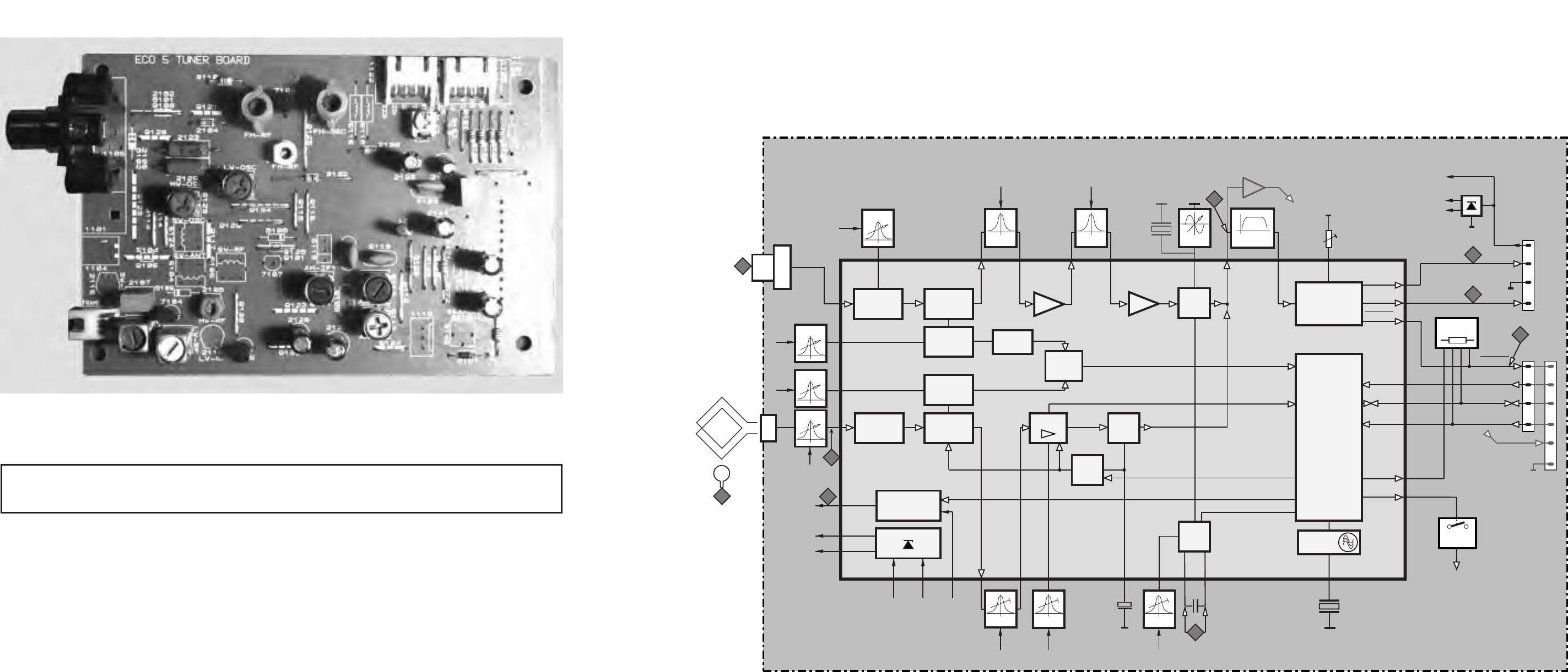
7B-1 7B-1 7B-1
CS 52 930
1
FM
frontend
AM
Frontend
FM
Osc.
FM
Mixer
AM
Mixer
AM
Osc.
AM IF
IF1 IF2 FM
Det.
AM
Det.
2
3393733
FM
RADIO IC
TEA 5757T
TUNER BOARD
ECO 5
systems
1101
(1102) LF filter
1018 11 15
14
24
left left
buffer ampl.
RDS
(MPX)
RDS
(MPX)
right
right
stereo
VCO
4140 36 193244 25
Stereo
Decoder
1124
Vcc1
Vdd
Vcc2
AFC
AFC +
AFC -
4
4
AGC
Pre-
scaler Multi-
plexer
Charge
pump
CONTROL
AM-FRAME AERIAL
Reference
Oscillator
1126
1
4
1
46
1
stereo
27
28
29
clock
data
enable
clock
data
enable
Version
P1
P0
MW/LW
31
30
programmable
output ports
AM-RF,
AM-Osc.
3
5
1121
VLoop
VLoop
VLoop
VLoop
VLoop
2
6
5
43
1103
B
C
450kHz450kHz450kHz
20
75kHz
VStabAV
StabBV
StabB
VStabA VStabB
10,7 MHz 10,7 MHz
35 9
Vcc
Vdd Vcc1
723
VStabA
VStabB
38
34
22
Vcc2
8
ECO5 sys., 240698
A
AM-RF
AM-Osc.
FM-Osc.
FM-RF
Discriminator
10,7 MHz
TABLE OF CONTENTS
Blockdiagram ..................................................................7B-1
Adjustmant table .............................................................7B-2
Component layout...........................................................7B-2
Circuit diagram ................................................................7B-3
Partslist ...........................................................................7B-4
TUNER BOARD ECO5
BLOCKDIAGRAM
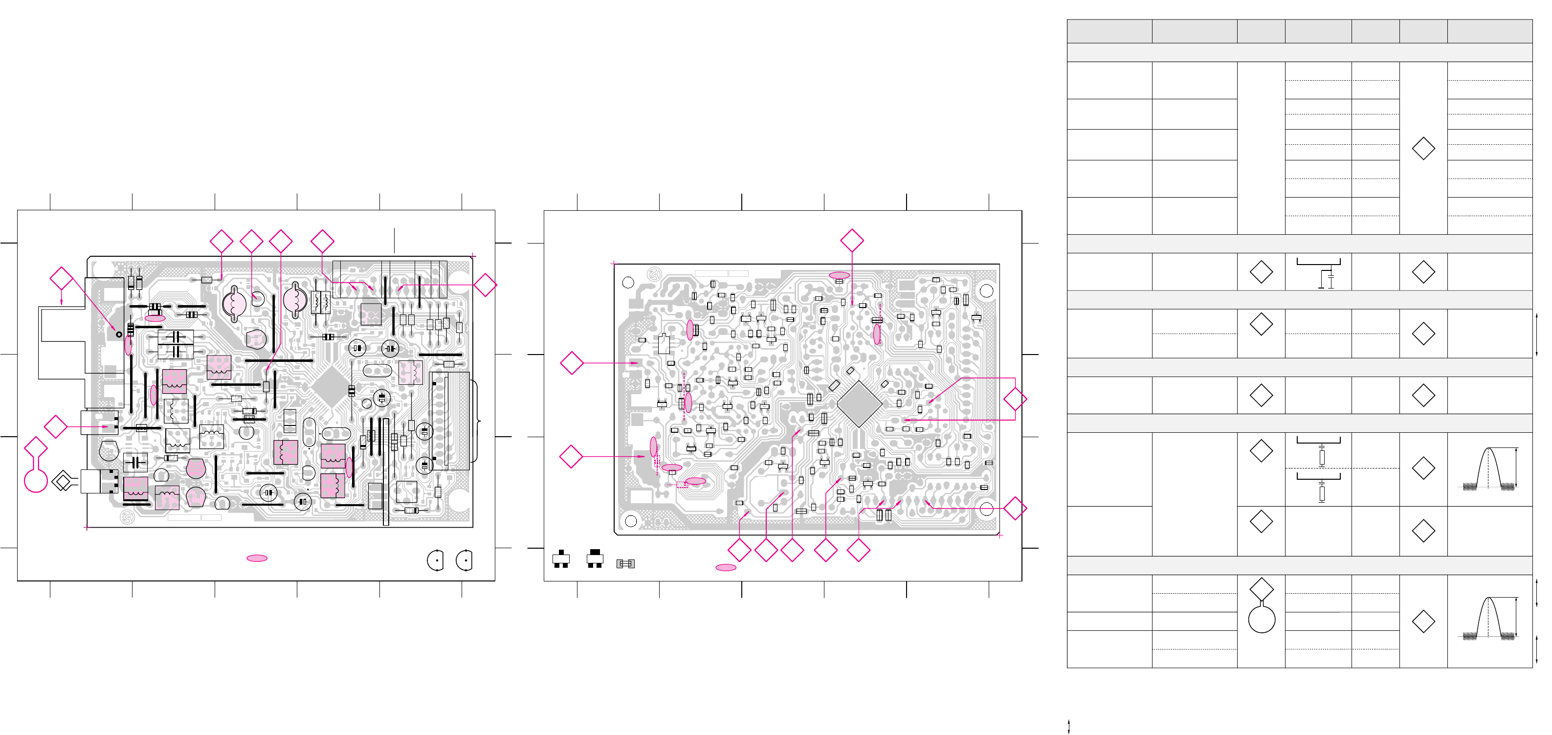
7B-2 7B-2 7B-2
PCS 100 945
marked components to be assembled
as service solution for
Local/DX
- switching
SW
FM E
C
A
C
A
A
C
B
C
C
34
E
11
FRAME
1
45
AM
98-05-14
B
339623033103
B
1
A
B
C
A
B
C
12345
12345
ECO 5 TUNER BOARD / component side view
VCC
VCC2
GND
MPX
ENABLE
DATA
CLOCK
STEREO
DATA
ENABLE
LEFT
GND
RIGHT
FM 300 OHM
FM 75 OHM
Connector for
AM - stereo Module
2SA...
E
C
B
C
B
E
BC...
SW
VCC
GND
VCC2
1101
1102
2162
3110
6101
6103
6104
5130
5131 7102
9125
5115
1126
1127
3160
5116
9136
9137
1122
1120
3158
3159
3161
1123
1124
1125
1121
1105
SW-OSC
MW-OSC
9113
9117
9121
9123
9128
9100
9105
9114
7104
5106
5123
5124
6102
2123
2125
1104
2104
2105
3105
9101
9115
9134
7107
5126
6106
FM-OSC
5109
5113
5122
FM-RF
LW-OSC
SW-RF
FM-RF
2155 2130
VCO
9118
5127
9120
9126
9131
3173
5110
5121
6120
3157
3170
31713172
3142
3147
2144
2148
2133
2135
2138
11301131
AM-IF
GND
+FM
R-FM
L-FM
L out
3152
6109
SW-RF
MW-RF
LW-RF
9111
2107
5103
5104
5102
1103
2106
2110
2115
LW-RF
MW-RF
SW-ANT
9122
9130
9133
AM-IF1
5111
7105
5105
2128
2129
AM-AFC
AM-IF2
6107
9119
9124
5112
5114
3149
3154
1119
2137
SEARCH
SENS.
R out
VCOkill
STSIG
STEREO
V+
1
AM FRAME AERIAL
1
ECO5 3396 stage .2, 250698
Voltage multiplier board
This assembly drawing shows a summary
of all possible versions.
For components used in a specific version
see schematic diagram respectively partslist.
1
11
1
1
7119
5120
9129
3132
5119
DISCRIMI-
NATOR
A
1 CF 4
3
D
B
marked components to be assembled
as service solution for
Local/DX
- switching
SW
FM E
C
A
C
A
A
C
B
C
C
34
E
11
FRAME
1
45
AM
98-05-14
B
339623033103
B
1
ECO 5 TUNER BOARD / copper side view
This assembly drawing shows a summary
of all possible versions.
For components used in a specific version
see schematic diagram respectively partslist.
ECO5 3396 stage .2, 250698
41..
in schematic diagram)
(not all items shown
Chip jumper
EB
C
A
C
1
23
34
12
54
18
2102
2103
3101
3143
3167
4154
3176
6111
7123
7124
3134
9114
3136
3137
4106
4107
4108
4153
2120
2157
3106
2112
2118
2119
7122 7101
7120
6130
6131
4150
4151
4152
4157
3126
3128
3168
4105
4120
3102
3103
3118
3120 3122
2153
2154
2158
2160
3104
2101
2116
2122
2149
2150
2152
2159
7103
4103
3153
3169
2166
2167
3141
3145
2145
2146
2151
2134
2136
2147
2131
2132
4111
6105
6110
3108
3133
4101
4102
4155
2108
2109
2113
2124 7108
4109
4110
4156
3112
3114
3116
3117
3121
2114
2117
3109
3177
3113
4159
3155
3156
3175
2143
2163
3181
2105
6101
9119
A
B
C
A
B
C
54321
54321
3148
3146
3178
3179
4160
4161
7111
7125
4158
3144
4162
4163
2126
2165
2156
3119
2111
4104
2161
2127
7121
3127
2141
2142
2164
2139 2168
3140
7106
3125
7109
3111
3123
3115
3180
51 CF 4
3
A
D
2
E
1101 A1
1102 A1
1103 C1
1104 B1
1105 A1
1119 C5
1120 A5
1130 B5
1131 B5
2104 A2
2105 A1
2106 C2
2107 C2
2110 C2
2115 C1
2123 A2
2125 A2
2128 C3
2129 C4
2130 A4
2133 A4
2135 B5
2137 C5
2138 A5
2144 B5
2148 B4
2155 A3
2162 A2
3105 B3
3110 A2
3132 B3
3142 A4
3147 B5
3149 C5
3152 A5
3154 C5
3157 B5
3158 A5
3159 A5
3160 A5
3161 A5
3170 C5
3171 C5
3172 C5
3173 A5
5102 C2
5103 C2
5104 C2
5105 B2
5106 B2
5109 B4
5110 B4
5111 C3
5112 C4
5113 B3
5114 C4
5115 A4
5116 A4
5119 B5
5120 B4
5121 B4
5122 B3
5123 B2
5124 B2
5126 B3
5127 B4
5130 A3
5131 A3
6101 A2
6102 A1
6103 A1
6104 A2
6106 B3
6107 C5
6109 C2
6120 C4
7102 A3
7104 C2
7105 C3
7107 B3
7119 C4
9100 A2
9101 B3
9105 B2
9111 C2
9113 B2
9114 B2
9115 B3
9117 B2
9118 B4
9119 C4
9120 B4
9121 A2
9122 C3
9123 B1
9124 C4
9125 A3
9126 B5
9128 A2
9129 B3
9130 C3
9131 A5
9133 C3
9134 B3
9136 A5
9137 A5
2101 C4
2102 C4
2103 C3
2108 A4
2109 A4
2111 A2
2112 B5
2113 A4
2114 A4
2116 B3
2117 A3
2118 B4
2119 B4
2120 B4
2122 B3
2124 A5
2126 C2
2127 C2
2131 C2
2132 C1
2134 C1
2136 B1
2139 B2
2141 B1
2142 B1
2143 A1
2145 C1
2146 C1
2147 C1
2149 B2
2150 B2
2151 C2
2152 C3
2153 C3
2154 C3
2156 C4
2157 B4
2158 B4
2159 C2
2160 C4
2161 A3
2163 A2
2164 B1
2165 B3
2166 B2
2167 B2
2168 B 1
3101 C3
3102 C3
3103 C3
3104 B3
3106 C4
3108 A4
3109 A4
3111 A3
3112 A3
3113 A2
3114 A3
3115 A3
3116 A3
3117 B4
3118 B3
3119 A3
3120 B4
3121 A3
3122 B3
3123 A3
3125 A3
3126 B3
3127 B3
3128 B3
3133 B4
3134 B4
3136 B4
3137 B4
3140 B2
3141 C2
3143 C2
3144 C2
3145 C2
3146 A1
3148 A1
3153 C2
3155 A2
3156 A1
3167 C2
3168 B3
3169 B2
3175 A2
3176 C2
3177 A1
3178 A1
3179 A1
3180 A4
3181 C3
4101 A4
4102 A4
4103 C2
4104 A2
4105 B3
4106 B4
4107 C4
4108 B4
4109 A3
4110 A3
4111 C1
4120 C2
4150 B2
4151 B3
4152 B3
4153 B4
4154 C3
4155 A4
4156 A2
4157 B3
4158 C2
4159 A2
4160 A1
4161 A1
4162 C1
4163 C1
6105 A4
6110 A4
6111 B4
6130 C2
6131 C3
7101 B2
7103 C2
7106 A3
7108 A3
7109 A3
7111 A1
7120 B4
7121 B3
7122 B4
7123 B4
7124 C4
7125 A1
VARICAP ALIGNMENT
FM RF
FM IF
VCO
AM IF
AM RF
3)
108MHz
87.5MHz
(65.81MHz)
87.5MHz
(65.81MHz)
87.5MHz
(65.81MHz)
279kHz
153kHz
1602kHz
531kHz
5130
check
5122
check
5123
check
8V ±0.2V
4.3V ±0.5V
(1.2V ±0.5V)
8V ±0.2V
1.1V ±0.4V
8V ±0.2V
1.1V ±0.4V
1494kHz
558kHz
560kHz 5102
1500kHz
5103198kHz
1494kHz
558kHz
560kHz
1500kHz
198kHz
2106
5102
2106
3142 152kHz ±1kHz 1)
98MHz
5112
MAX
FM
87.5 - 108MHz
(65.81 - 74, 87.5 - 108MHz)
LW
153 - 279kHz
MW
FM/MW/LW- version, 9kHz grid
531 - 1602kHz
1700kHz
530kHz
5123
check
8V ±0.2V
1.1V ±0.4V
1602kHz
531kHz
5123
check
6.9V ±0.2V
1.1V ±0.4V
108MHz 108MHz 2155
5131
MW
FM/AM-version, 10kHz grid
530 - 1700kHz
FM
MW
LW
98MHz, 1mV
continuous wave
450kHz
connect pin 6 of
IC 7101 (AM Osc.)
with short wire to
ground (pin 4)
Use service test program. By selecting the TUNER TEST test frequencies will be stored as preset frequencies automatically.
4
1
3
4
4
A
A
5119FM 10.7MHz, 50mV
continuous wave 2F
mod=1kHz
∆f=±22.5kHz
1)
If sensitivity of frequency counter is too low adjust to max. channel separation
(input signal: stereo left 90% + 9%, adjust output on right channel to minimum)
Repeat
ECO5, discr. coil, 090797
TUNER ADJUSTMENT TABLE (ECO5 FM/MW- and FM/MW/LW - versions with AM-frame aerial )
∆f=±15kHz
VRF = 3mV
C
see
remark 2)
220R
100nF
36
IC 7101
220R
100nF
40
IC 7101
2141
shortcircuit
to block AFC
21
IC 7101
max.
symmetric
fo
AM AFC
MW C
continuous wave
VRF = 10mV
5111
5114 20± 2 mV DC
0± 3 mV DC
MW 4)
FM/MW/LW- and FM/MW-version
( 9kHz grid)
531 - 1602kHz
B
∆f = ±30kHz
V
RF
as low as
possible
max.
symmetric
fo
MW
FM/AM-version, 10kHz grid
530 - 1700kHz
3)
For AM RF adjustments the original frame antenna has to be used !
2)
RC network serves for damping the IF-filter while adjusting the other one.
4)
MW has to be aligned before LW.
Waverange Input frequency Input Tuned to Adjust Output Scope/Voltmeter
FM
87.5 - 108MHz
(65.81 - 74, 87.5 - 108MHz)
FM/MW-version, 9kHz grid
531 - 1602kHz
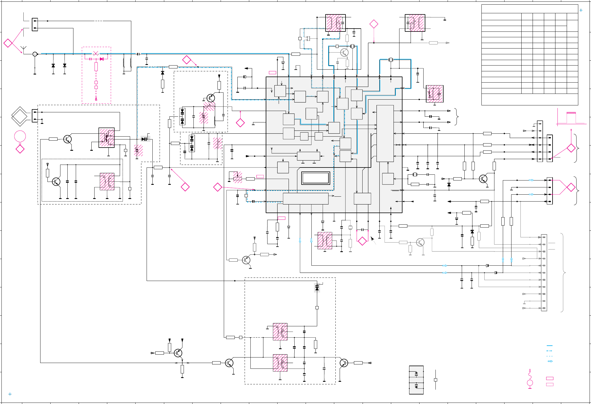
7B-3
PCS 100 946
7B-3
to 1130,1131
AM Stereo module
z
3175
2k7
AM-IF
z
5113
SFU450B
to/from
AM-stereo module
AM-IF
P0
Low=AM mono
P1
T030
T031
T038
T039
z
AM-IF
GND
+FM
R-FM
L-FM
L-out
R-out
VCO-kill
STSIG
stereo
V+
1131
z
1130
11
10
9
8
7
6
5
4
3
2
1
T033
T034
T035
T036
z
3177
10k
3147
3M3
7125
BC848C
3179
1M
z
z
z
3178
3M3
z
z_100R
2111
100p
7119
2SC1047
3113
1k
t
3119
t
t
t
330R
3
6
5
4
1
2
1121
MPX
GND
r
3143
22k
Vcc1
7103
BC858C
r
r
3144
1k
r
3176
1k
r
MPX
MPX
to 1121
buffer amplifier
from 3144
r....for RDS version only
Vcc2
Vdd
AGC
AM IF
CONTROL
AGC
AM Det.
CONTROL AGC IF
AM
Charge
Pump
DECODER
STEREO
AFC
DET
AM
DET
IF2
IF1
FM
FM
FM
STABILIZER
OSC
AM
AM
MIXER
AM
Frontend
AGC
Frontend
FM
FM
MIXER
FM
Pre-
scaler Multi-
plexer
OSC
x
-
-
-
-
-
-
-
-
-
-
-
-
-
-
-
-
-
-
-
-
-
-
-
x
x
-
x
x
xx
x
x
x
x
-
x
x
x
-
-
x
x
x
VERSION PROGRAMMING COMPONENTS
3170 remark
7111
not mounted
315731566120
/15 FM/MW/SW-Eu
/.. FM/MW/2xSW
/17 FM/AM
/14 FM-OIRT/MW/LW
--xx/14 FM-OIRT/MW
/13 FM/MW-Stereo
/06 FM-Japan/MW-stereo
/01 FM/MW/SW-Ov
/01 FM/MW
/01 FM/MW-Stereo
/00 FM/MW/LW/SW-Eu
/00 FM/MW/LW
x = component mounted
---x/17 FM/AM-Stereo
SW
SW
SW
SW = Software initialisation
t....for Japanese version (/06/26) only
Stereo
Mono/
Ripple
Mixout
Mixout
FM-IF2
Enable
OSC.
Stereo
FILTER
printed
printed
AGC
FM-In
RF-GND
AM-IF1-in
AM
FM
FM-IF1 in
AM-IF2
V
STAB
BV
STAB
A
FM-IF2
AM-AFC
P1
P0
Write
DATA
CLOCK
Dig.GND
XTAL
Mono/
Vdd Vdd
Vdd
Vcc2
Fieldstrength Indic.
AFC+
AFC-
FM-Demod.
IF GND
PILOT
right
left
MUTE
LPF
MPX-IN
AF-Out
VCO
I-TUNE
Vcc1
AM-OSC.
FM-OSC.
RF-GND
FM-RF
AM-RF
Ripple
y....for USA version (/17/37) only
z....for AM-STEREO (/06/13/26/33) versions only
x....not for all versions
w...for LW only
v...for SW-version 3.9-12.1MHz only
u...for 2-band (FM/AM) version only
AM-AFC
450 kHz
AM-IF2AM-IF1
FM-IF2
FM-IF1
to 3103
FM-RF
Q-MULTIPLIER
TUNER BOARD ECO5 /
Systems
MW/LW-RF
MW
MW
VCO
AM-OSCILLATOR
version detection
DISCRIMINATOR
6131 D 7
6130 E 7
6120 G16
6107 H17
6105 E 6
6106 C 6
6105 K12
6104 C 3
6103 C 2
5131 D 8
5130 E 8
5123 L11
5122 M11
5121 F15
5119 I 12
5120 H13
5114 C16
5113 B12
5112 A15
5111 A13
5110 B14
5109 B13
5103 F 4
5102 E 4
4108 L 9
4106 K12
4105 B11
4104 B13
4103 G 9
4102 F 5
4101 G 5
3177 I18
3176 J 9
3175 B16
3179 I16
3180 M7
3178 I15
3171 H15
3170 F17
3169 G15
3167 G18
3161 E18
3160 E18
3159 F18
3158 F18
3157 F17
3156 G17
3155 H17
3154 H18
3153 H19
3152 H18
3147 I15
3146 I17
3145 H10
3143 I10
3144 I10
3142 G 9
3141 G10
3137 M13
3140 I13
3134 M12
3132 L 9
3128 M 8
3125 M 6
3123 M 7
3110 F 6
3120 C 6
3113 C13
3119 B13
3109 F 2
3108 E 3
3105 C 7
3104 B11
3103 C 8
3102 E 7
3101 E 7
2167 F16
2168 I 13
2166 G16
2165 C 9
2164 H14
2163 E16
2161 D16
2160 M12
2159 F 9
2158 M11
2155 D 8
2154 E 7
2153 E 8
2152 F 7
2150 B13
2149 C15
2148 F16
2147 F16
2146 F15
2145 G16
2144 H17
2143 I17
2142 H14
2141 H14
2140 H14
2138 H12
2139 H13
2137 J18
2136 J17
2135 J18
2134 J17
2133 H11
2132 I10
2131 I10
2130 H17
2129 C 9
2128 C11
2127 G10
2126 G 9
2125 M11
2123 M11
2122 N11
2120 L11
2109 G 3
2111 C13
2108 G 3
2107 G 6
2106 F 5
2104 B 6
2103 D 9
2102 G 7
2101 C 6
1130 I20
1131 I20
1126 E20
1124 G20
1121 E20
1103 D 2
1102 B 2
1101 A 1
9128 A 4
9117 L10
9101 C 6
9100 B 4
7124 M13
7125 I16
7122 M 9
7119 B13
7111 F18
7109 M 7
7105 F 2
7104 E 3
7103 I 9
7102 D 8
7101 G11
45167891011121314152 16 17 18 19 20 213
K
J
N
I
H
G
F
E
D
C
B
A
M
L
K
J
N
I
H
G
F
E
D
C
B
A
M
L
45167891011121314152 16 17 18 19 20 213
HN1V02H
Chip jumper
8
7
6
54
3
2
1
6105
z_TEA5759
to/from
COMBI BOARD /
Source Selector part
to/from
CONTROL BOARD
x
x
x
x
FM 50 OHM
LW
LW
MW
w
w
w
w_27p
2166
1n
2165
100n
x
2163
100n
10p_w
2158
2159
33p
2126
330p
2142
100n
2145
220p
2150
100n
1u
2107
2146
220p
2147
220p
2148
22n
2143
220n
2141
100n
470n
2164
2136
15n_y22n
2134
15n_y22n
2149
22n
2104
100p
2103
1n
2101
100p
(if 1102 is used)
2130
22n
2132
470n
2131
470n
2127
220n
w
2109
10p
w
2108
100p
w
2122
3n3
2125
560p
w
2123
390p 22p
2120
x
2154
4p7
2102
10n
u
2160
22n
x
2161
100n
2167
12p
3169
150k
3105
220R
3132
47R
3146
22R 3157
100k
3161
Programmable
Output Ports
470R
3160
470R
3159
470R
3158
470R
3156
100k
470R
3155
150R
3154
3167
220R
3153
470R
3152
470R
3141
56k
3145
2k2
4k7
w
3109
3108
2k2
w
3128
2k2
3125
10k
3134
22k
w
3137
22k
3170
100k
s_5k6
3101
33k
3102
100k
t_18k
47p
(if 1101 is used)
3103
18k
3104
180R
3110
47R
3171
330R
4k7
3123
6104
1N4148
6103
1N4148
6120
1N4148
y
9128
9101
9100
u
9117
P0
P0
P0
P0
P1
P1
Vcc1
Vcc1
Vdd
REF
REF
Vdd
AM FRAME AERIAL
7101 TEA5757
10
11
12 13 14 15 16 17 18 19
1
20 21 22
23
24
25
26
27
28
29
2
30
31
32
33
343536373839
3
4041424344
4
5
6
7
8
9
7104
7111
BC848C
w
7105
BC338-40
BC338-40
w
7122
BC848C
w
7124
BC848C
T001
T002
T003
T005
T006
T013
T012
T011
T009
T014
T015
T017
T016
T018
T020
T021
T022
T023
T024
T025
T026
T027
T032
T037
T045
T041
T042
T040
T043
T044
T046
T047
2144
1u
2138
2u2
2128
10u
2129
100u
2133
1u
2135
220n
2137
220n
stereo
clock
data
enable
1126
1
4
3
2
Vcc
right
GND
left
1124
1
4
3
2
4105
u
4102
u
4101
4103
4104
4108
4106
FM
300 OHM
y
1101
1
2
1103
1
2
5112
1
2
34
6
5111
1
2
34
6
x
1102 1
2
1SV228
6131
5131
2155
3-11p
3142
100k
w_4-20p
2106
3-11p
3
6105
56
HN1V02H
26105
17
HN1V02H
w
5103
1
2
34
6
w
5122
1
2
34
6
5123
1
2
34
6
7109
BC858B
7102
2SA838B
5109
5110
6107
BZX79-C11
5114
1
3
5102
1
2
3
4
5
6
5121
75KHz
3180
22k
41..
ECO5 systems, discr.coil, 030998
V
STAB
BV
STABA
ww
450 kHz 450 kHz
s...for East European version (/14/34) only
6106
1N4148
3120
0R
2139
15p
(2140)
2140 exchanged by 2164
(SMD type 0805)
from layout stage 3317.9 onwards
respectively 3103 303 3380.1
and 3103 308 3396.1
2168
82p
5119
1
2
34
6
w
5120
CDA10.7MG61KA
3140
150R
3140 and 5120
provisional as
alternative
FM-OSCILLATOR
15p s_12pt_2p2
s_560p
2152
33n 6130
5130
LW=high
MW=high
LW=high
MW=high
0.7V
0.1V
V
1.3V
0.15V 0.7V 1V 0.7V 0.7V1.4V 1.4V 1.4V 1.4V 1.4V
1.4V
0.7V
0.3V
0.2V
5V
0V
150kHz, 50mVpp
stereo stereomono
(11 - 14V)
typ. 12V
11V
8V 8V
8V
1.2V 2V
1.3V
stereo 0.3V
mono 4.9V
stereo 0.5V
mono 4.9V
1.2V1V1V0.7V0.7V0.7V0.8V
1.2V
0.7V
1V
0V
8V
0V
0V
0V
2.1V
............. Vdc FM mode stereo
Vdc MW mode
Vdc LW mode
Voltages measured while set is tuned to a strong transmitter
EVM
V
V
4
3
C
1
2
B
E
6101
remove
Service Solution for
Local/DX - switching
BA484
2105
100p
3106
10k
9114
9119 41554156
P0
A
5
F
Signal path
FM
AF - left/right
AM
MPX (Audio Frequency)

PCS 100 947
7B-4 7B-4
ELECTRICAL PARTS LIST - ECO5 TUNER BOARD
MISCELLANEOUS
1101 4822 267 31505 Antenna Socket 300R
1102 4822 267 10283 Antenna Socket Coax IEC 75R
CAPACITORS
2101 5322 122 32531 100pF 5% 50V
2101 4822 126 13692 47pF 1% 63V for USA
2102 4822 122 33177 10nF 20% 50V
2103 5322 122 34123 1nF 10% 50V
2104 4822 122 33195 100pF 10% 50V
2106 4822 125 50355 Trimmer 4-20pF for LW version
2106 4822 125 60101 Trimmer 3-11pF 100V
2107 4822 121 51319 1µF 10% 63V
2108 5322 122 32531 100pF 5% 50V for LW version
2109 5322 122 32448 10pF 5% 50V for LW version
2120 4822 126 13691 27pF 1% 63V for LW version
2120 5322 122 32658 22pF 5% 50V
2122 4822 122 33891 3,3nF 10% 63V for LW version
2125 4822 121 51381 560pF 5% 400V
2126 5322 122 31863 330pF 5% 50V
2127 4822 126 13473 220nF +80/-20% 50V
2128 4822 124 41579 10µF 20% 50V
2129 4822 124 41584 100µF 20% 10V
2130 4822 126 11585 22nF+80/- 20% 25V
2131 4822 122 33325 470nF 16V
2132 4822 122 33325 470nF 16V
2131 4822 126 13482 470nF +80/- 20% 16V
2132 4822 126 13482 470nF +80/- 20% 16V
2133 4822 124 40242 1µF 20% 63V
2134 4822 126 13188 15nF 5% 63V
2134 5322 122 32654 22nF 10% 63V for USA
2135 4822 124 40746 0,22µF 20% 63V
2136 4822 126 13188 15nF 5% 63V
2136 5322 122 32654 22nF 10% 63V for USA
2137 4822 124 40746 0,22µF 20% 63V
2138 4822 124 41576 2,2µF 20% 50V
2139 4822 126 14236 50V 15pF 5%
2140 4822 121 51252 470nF 5% 63V
2141 4822 126 10002 100nF 20% 25V
2142 4822 126 10002 100nF 20% 25V
2143 4822 126 13473 220nF +80/-20% 50V
2144 4822 124 40242 1µF 20% 63V
2145 4822 122 33575 220pF 5% 50V
2146 4822 122 33575 220pF 5% 50V
2147 4822 122 33575 220pF 5% 50V
2148 4822 126 11585 22nF+80/- 20% 25V
2149 5322 122 32654 22nF 10% 63V
2150 4822 122 31947 100nF 20% 63V
2152 5322 116 80853 560pF 5% 63V for East. Europe
2152 4822 126 12105 33nF 5% 63V
2153 4822 122 32139 12pF 2% 63V for East. Europe
2153 4822 122 32504 15pF 2% 63V
2155 4822 125 60101 Trimmer 3-11pF 100V
2158 5322 122 32448 10pF 5% 50V for LW version
2159 5322 122 32659 33pF 5% 50V
2160 5322 122 32654 22nF 10% 63V
2161 4822 126 10002 100nF 20% 25V
2163 4822 126 10002 100nF 20% 25V
2164 4822 126 13482 470nF +80/- 20% 16V
2165 4822 126 10002 100nF 20% 25V
2166 5322 122 34123 1nF 10% 50V
2167 4822 122 32139 12pF 2% 63V
2168 4822 126 13695 82pF 1% 63V
RESISTORS
3101 4822 051 20562 5k6 5% 0,1W for East. Europe
3101 4822 051 20333 33k 5% 0,1W
3102 4822 051 20104 100k 5% 0,1W
3103 4822 117 10965 18k 1% 0,1W
3104 4822 117 11448 180R 1% 0,1W
3105 4822 116 83872 220R 5% 0,5W
3108 4822 117 11449 2k2 1% 0,1W for LW version
3109 4822 051 20472 4k7 5% 0,1W for LW version
3110 4822 116 52195 47R 5% 0,5W
3120 4822 051 20008 0R Jumper 0805
3123 4822 051 20472 4k7 5% 0,1W for LW version
3125 4822 117 10833 10k 1% 0,1W for LW version
3128 4822 117 11449 2k2 1% 0,1W for LW version
3132 4822 116 52195 47R 5% 0,5W
3134 4822 051 20223 22k 5% 0,1W
3137 4822 051 20223 22k 5% 0,1W for LW version
3140 4822 051 20008 0R Jumper 0805
5120=CDA10.7MG40K
3140 4822 117 10353 150R 1% 0,1W
5120=CDA10.7MG61KA
3141 4822 051 20563 56k 5% 0,1W
3142 4822 100 11163 Trimmer 100k 30% 0,1W
3143 4822 051 20223 22k 5% 0,1W for RDS version
3144 4822 051 10102 1k 2% 0,25W for RDS version
3145 4822 117 11449 2k2 1% 0,1W
3146 4822 051 20229 22R 5% 0,1W
3152 4822 116 83883 470R 5% 0,5W
3153 4822 051 20471 470R 5% 0,1W
3154 4822 116 83868 150R 5% 0,5W
3155 4822 051 20471 470R 5% 0,1W
3156 4822 051 20104 100k 5% 0,1W for /21/30/33 only
3157 4822 116 52234 100k 5% 0,5W for East. Europe
3158 4822 116 83883 470R 5% 0,5W
3159 4822 116 83883 470R 5% 0,5W
3160 4822 116 83883 470R 5% 0,5W
3161 4822 116 83883 470R 5% 0,5W
3167 4822 117 11503 220R 1% 0.1W
3169 4822 051 20154 150k 5% 0,1W
3170 4822 116 52234 100k 5% 0,5W
3171 4822 116 52219 330R 5% 0,5W
3176 4822 051 10102 1k 2% 0,25W for RDS version
3180 4822 051 20223 22k 5% 0,1W for LW version
4101 4822 051 20008 0R Jumper 0805 for 2-Band only
4102 4822 051 20008 0R Jumper 0805 for 2-Band only
4103 4822 051 20008 0R Jumper 0805
4104 4822 051 20008 0R Jumper 0805
4105 4822 051 20008 0R Jumper 0805
4106 4822 051 20008 0R Jumper 0805
4108 4822 051 20008 0R Jumper 0805
4111 4822 051 20008 0R Jumper 0805
4120 4822 051 20008 0R Jumper 0805
4150 4822 051 10008 0R Jumper 1206
4151 4822 051 20008 0R Jumper 0805
4152 4822 051 10008 0R Jumper 1206
4153 4822 051 10008 0R Jumper 1206
4154 4822 051 10008 0R Jumper 1206
4155 4822 051 10008 0R Jumper 1206
4156 4822 051 20008 0R Jumper 0805
4157 4822 051 10008 0R Jumper 1206
4158 4822 051 10008 0R Jumper 1206
4159 4822 051 10008 0R Jumper 1206
4162 4822 051 10008 0R Jumper 1206
COILS & FILTERS
5102 4822 157 71634 MW RF Coil
5103 4822 157 71635 LW RF Coil for LW version
5109 4822 242 70665 Ceram Filter 10,7MHz
5110 4822 242 70665 Ceram Filter 10,7MHz
5111 4822 158 60511 AM-IF Filter 450kHz
5112 4822 157 70302 AM-IF Filter 450kHz
5114 4822 157 70302 AM-IF Filter 450kHz
5119 4822 157 11443 Discriminator 10,7MHz
5120 4822 242 82065 Cer. Disc. 10,7MG40K
5120 4822 242 10251 Cer. Disc.10,7MG61KA-TF21
5121 4822 242 10261 Quartz 75kHz
5122 4822 157 60517 Osc. Coil LW for LW version
5123 4822 157 60517 Osc. Coil MW
5130 4822 156 30947 RF-Coil 1.5T
5131 4822 156 30947 RF-Coil 1.5T
DIODES
6103 4822 130 30621 1N4148
6104 4822 130 30621 1N4148
6105 4822 130 83075 HN1V02H-B
6106 4822 130 30621 1N4148
6107 4822 130 34488 BZX79-B11
6120 4822 130 30621 1N4148 not for /21/30/33
6130 4822 130 82833 1SV228
6131 4822 130 82833 1SV228
TRANSISTORS & INTEGRATED CIRCUITS
7101 4822 209 90924 TEA5757H/V1
7102 4822 130 60093 2SA838B
7103 4822 130 42513 BC858C for RDS version
7104 5322 130 44779 BC338-40 for LW version
7105 5322 130 44779 BC338-40 for LW version
7109 5322 130 41983 BC858B for LW version
7111 5322 130 42136 BC848C
7122 5322 130 42136 BC848C for LW version
7124 5322 130 42136 BC848C for LW version
Note: Only the parts mentioned in this list are normal
service spare parts.
ELECTRICAL PARTS LIST - ECO5 TUNER BOARD

7D-1 7D-1 7D-1
PCS 83 453
IF1
FM
VCC1
VCC1 VDD VCC2
7
VDD
23
STABILIZER
FM-IF1I In37
IF2
FM
FM-IF2
35
V Stab B
34 33
FM-IF2I V Stab A
38
AM-MIX Out
40
AM-IF1 In
41 36
AM-IF2
32
AM-AFC
AM
IF
AM
DET
DET
FM
AFC
19
AFC-
20
AFC+
44
AGC
AGC
10
AF-Out
18
FM-Demod
AM
MIXER
2 AM-RF
AM
FRONTEND
AM
OSC.
STEREO
DECODER
CONTROL
MPX-In
11
VC0
3142
9
LPF
12
Right 15
16
Left 14
13Mute
Stereo
21
Indc.
XTAL
OSC
25
P0 30
39
FM/AM
31
P1
27
CLOCK
28
DATA
29
WRITE Enable
5 FM Osc.
CHARGE
PUMP
8 I-Tune
24
Mono/
FM GND
34
RF GND
17
IF GND
26
Dig. GND
42
RF GND
1
Ripple AM-Osc.
MW/LW-SELECTION
6
PILOT
Filter
Fieldstrength
22
VCC2
TEA5762
FM FRONTEND
1102
A
B
+B AGC
63
Fo
Osc Out
IF OutAnt1 71
GND4 8
a
F
if
F 10,7 MHz
f
0
= f
in
+ f
if
+FM
MT
MT 5
VT
75kHz
10,7MHz
VC0
IF-AM IF-AM AM-DET
ANTI BIRDY FILTER
2 1
450kHz450kHz
5111 5112 5114
450kHz
3
DATA
ENABLE
RDS
4
CLOCK
5
STEREO
6
GND
2
1
1121
4
GND
3
2
LEFT
RIGHT
1
VCC
1124
10,7MHz
10,7MHz
2106
5102
MW
5103
LW
3
4
+FM
VCC1
VDD
VCC2
RDS
RDS
AM-RF AM-OSC
5123
MW
5122
LW
7
6
C
TABLE OF CONTENTS
Blockdiagram ..................................................................7D-1
Adjustmant table .............................................................7D-2
Component layout...........................................................7D-2
Circuit diagram................................................................7D-3
Partslist ...........................................................................7D-4
TUNER 95 BOARD
BLOCKDIAGRAM
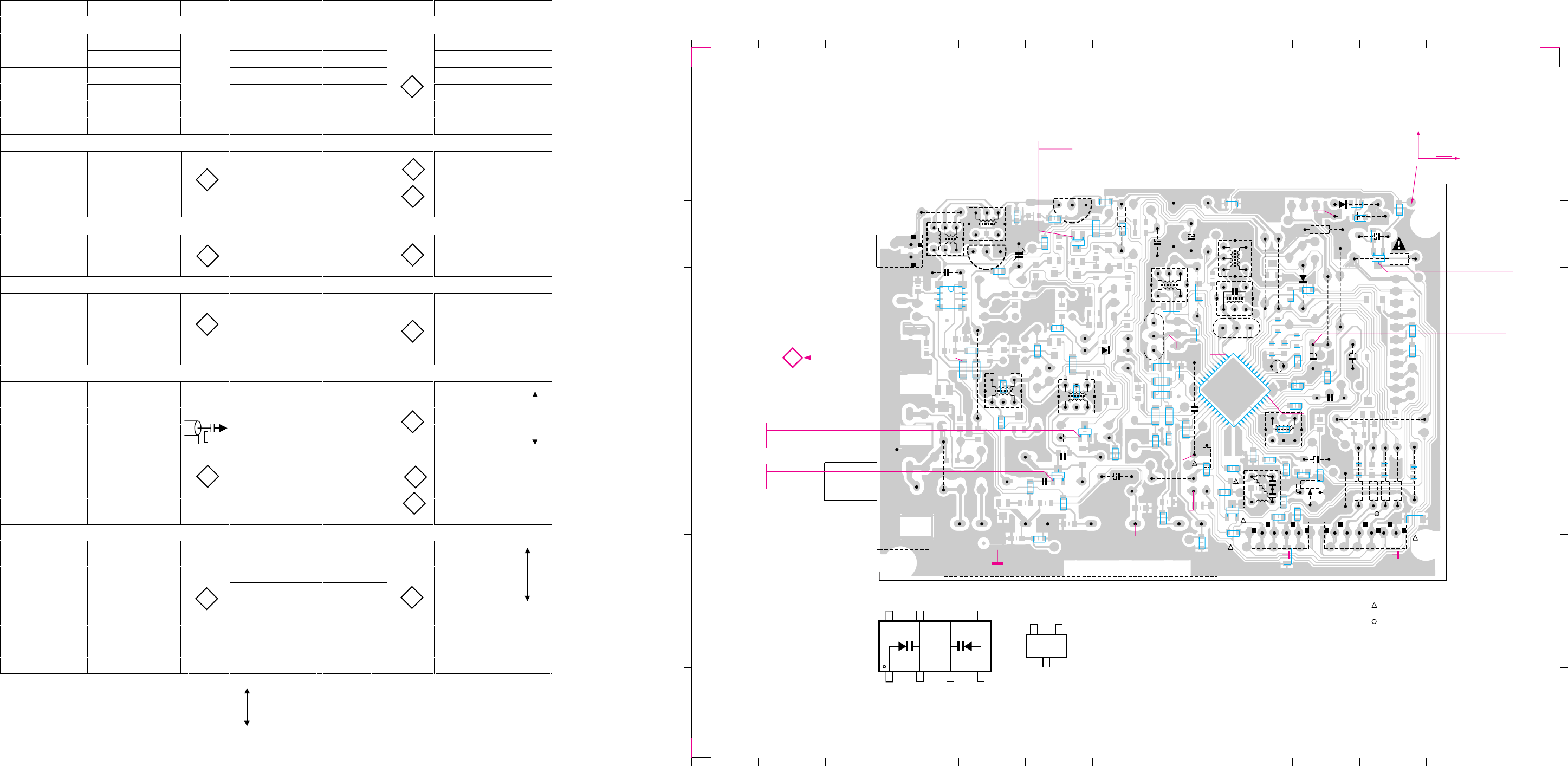
PCS 100 948
7D-2 7D-2 7D-2
TUNER 95 bis Adjustment Table (FM, MW, LW with Frame antenna)
Waverange Input frequency Input Set tuned to Adjust Output Scope / Voltmeter
VARICAP ALIGNMENT
FM (50) 108 MHz check 7 ... 9V
87.5 - 108 MHz 87.5 MHz check 1.3 ... 2V
MW (9) 1602 kHz 5123 8.3V ± 0.2V
531 - 1602 kHz 531 kHz check 1V ± 0.4V
LW (3) 279 kHz 5122 8.3V ± 0.2V
153 - 279 kHz 153 kHz check 1V ± 0.4V
FM – DETECTION
FM
98 MHz 1mV
continuous wave
short pin 21 (IC7101)
to ground
98 MHz 5107 0mV ± 3mV
FM – VCO
98 MHz 1 mV
FM
continuous wave 98 MHz 3142 152kHz ± 1 kHz
DISTORTION
98 MHz 1 mV mixcoil
FM
90 % L + 98MHz inside Distortion
9 % pilot Tuner minimum
mod = 1kHz 1110
AM – IF
450kHz 5111
∆f = 10kHz symmetrical and
Low as possible max. height
MW
Swept signal MW 5112
450kHz 5114 0mV ± 2mV
continuous wave
AM - RF
558kHz 558kHz 5102
MW
Mod = 1kHz MAX
30 % AM
1494 kHz 1494kHz 2106
198kHz *
LW
mod = 1kHz 198kHz 5103 MAX
30 % AM
* Signal send via a frame antenna
adjtable for 3104 217 04121/04341
(..) = tuning grid in kHz repeat
100nF
50E
2
1
A
C
A
A
2
1
B7
7
4
3
6
3104 213 34853
8204 090 55323
3104 217 04121/04341 bl. 110 - 01
TUNER 95 bis
1
IC 6105
c
eb
1
1
2
cbe
cbe
9813
LEU0149
8
41
4
6
only in RDS version (04121)
not in RDS version (04341)
1
1
TUNER 95 bis Combi: Copper side view
6106
2162
3164
2138
6107
3154
3155
6120
9121
9123
9120
2144
5121
9126
9115
3125
5111
2128
2129
9125
5114
5109
5110
5112
9102
9107
9108
3160
3161
3159
3158
1126
1121
2140
5107
2133
9118
3142
5115
1124
3167
2130
9116
9119
2106
9101
9104
5103
7104
9111
5102
2107
7105
1103
5122
5123
2123 3128
2102
1110
2125
9114
1102
9100
1
1
2
2
3
3
4
4
5
5
6
6
7
7
8
8
9
9
10
10
11
11
12
12
13
13
AA
BB
CC
DD
EE
FF
GG
HH
II
JJ
1102 F4
1103 C4
1110 G7
1121 H11
1124 H9
1126 G10
2102 G7
2106 C5
2107 C4
2108 C6
2109 C5
2120 F5
2122 E6
2123 F6
2125 G6
2127 F9
2128 C7
2129 C8
2130 F8
2131 F9
2132 F9
2133 F10
2134 G10
2135 G11
2136 G10
2137 E11
2138 E10
2139 E8
2140 F10
2141 E10
2142 E9
2143 C10
2144 E10
2145 G11
2147 G11
2148 E9
2150 F8
2151 F9
2152 F9
2158 D10
2160 E9
2161 E9
2162 C11
3103 H6
3104 G6
3107 G7
3108 C6
3109 B7
3120 D6
3123 E4
3124 E5
3125 C7
3128 F6
3129 E6
3130 E6
3131 C6
3132 E5
3134 E5
3137 G5
3138 D9
3139 F8
3140 H8
3141 G9
3142 G10
3143 G8
3144 H9
3145 F9
3146 B10
3147 H9
3150 C11
3151 C10
3152 G9
3153 G9
3154 C10
3155 C10
3158 G11
3159 G11
3160 G11
3161 G11
3162 D9
3163 F8
3164 C11
3165 D8
3167 F8
3169 D5
3171 D11
3172 F7
3173 F7
3176 D9
3177 F7
3178 B8
3181 D8
3183 E7
3184 E7
3185 E7
3186 G8
3188 G11
3192 D8
3197 C7
5102 C4
5103 C5
5107 F10
5109 D7
5110 E9
5111 C8
5112 C9
5114 D8
5115 G9
5121 E9
5122 E7
5123 E5
6105 D4
6106 E7
6107 B10
6120 D10
7101 E9
7103 G9
7104 D5
7105 B6
7109 C6
7110 D11
7122 F7
7124 G6
9100 F4
9101 E7
9102 D10
9104 E6
9107 F11
9108 G11
9111 C4
9114 E5
9115 C8
9116 G8
9118 G10
9119 G7
9120 D10
9121 D9
9123 D9
9125 D8
9126 C8
e
b
c
be
c
4
1
5
8
c
eb
be
c
1
12
23
34
b
c
e
3147
3178
2139
3120
3150
3146
3151
7110
2137
3171
2158
3176
2161
2148
3162
3138
3165
3197
3192
3181
3185
2143
2135
2147
2145
3188
2141
2152
2131 3145
2151
2142
2136
2134
3141
7103 3153
3152
2132
3139
3183
3184
2150
3173
3172
3163
3186
3143
3140
3107
3144
2127
7101
2160
3131
7109
2108
2109
3108
3129
3130
3169
3124
3132
6105
3109
2122
3177
7122
7124
3137
3103
3104
3134
2120
3123
+12V
MW
LW
MW
LW
=
=
0,7V
0V
=
=
0V
0,7V
VT
6
=
=
AM
FM
VDD
7V
6V
+12V
+FM
+8V
+1,4V
+1,4V
VCC +12V
RIGHT
LEFT
+9,6V
STEREO
CLOCK
DATA
+9,6V
ENABLE
MPX
0V
V
AM FM
12V
<0,5V
VDD
AM
FM
7V=
6V=
AM
FM
=
=
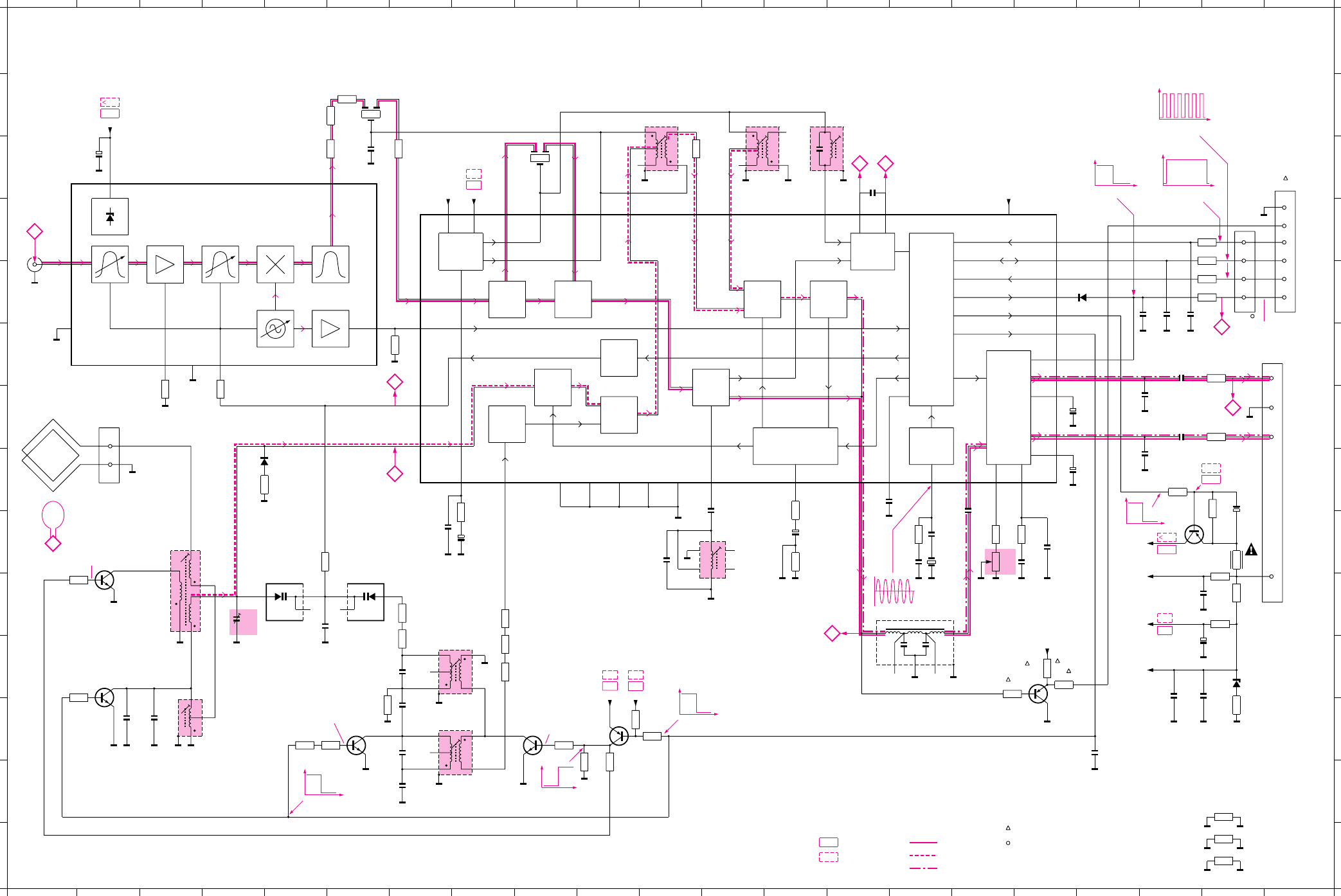
7D-3
PCS 100 949
7D-3
+12V
A
MW
0V
V
LW
+8V
0V 1V 0,8V2V
+8V
2V
+8V
+9,6V
+6V
+7V
+6V
+7V
MW
0V
V
LW
0V MW
V
LW
MW
LW = 0V
= 0,7V
6
C
75 kHz
0,7V
0,9V
21
1,4V1,4V
+7V
+6V +9,6V
+7V
+6V
11,8V
11,2V
+12V
+12V
0V FMAM
V
4
3STEREO = LOW
mono
0V
V
stereo
During communication
0
V
0V = No communication
1,3V
1,3V
High = During communication
0
V
FM.....V
.....V AM
FM
AM
.....V FM mode stereo Signal path
AF
0,5V
0,5V
MW
LW = 0V
= 0,7V
7
MW
LW = 0V
= 0,7V
B
+B
6
Fo
Osc Out 8
1
Ant1
4
a
F
if
F 10,7 MHz
o
Fa
= F + Fi
µ47
+FM
0E
FM
ANT.
9813
LEU0150
f
3104 217 04121/04341 bl. 130 - 01
IF1
FM
VCC1
7
VCC1
VDD
23
VDD
STABILIZER
1µ
FM-IF1I In37
IF2
FM
FM-IF2
35
V Stab B
34 33
FM-IF2I
10,7 MHz
V Stab A
38
100n 34
16
2
0E
AM-MIX Out
40
AM-IF1 In
41
34
1
2
6
450 kHz450 kHz
36
AM-IF2
450 kHz
3
1
32
AM-AFC
AM
IF
AM
DET
DET
FM
AFC
19
AFC-
20
AFC+
470n
44
0E
AGC
AGC
10
AF-Out
18
FM-Demod
µ10
0E
AM
MIXER
2 AM-RF
AM
FRONTEND
AM
OSC.
STEREO
DECODER
CONTROL
231
46
MPX-In
11
56k
VC0
9
100k
2k2
LPF
12
470n
470n
Right 15
16
µ2
Left 14
1
13
µ
Mute
2
Stereo
100n
21
Indc.
XTAL
OSC
25
220n
15n
15n
220n
470E
470E RIGHT
4
GND
3
2
LEFT
1
P0 30
39
FM/AM
31
P1
27
CLOCK
28
DATA
29
WRITE Enable
5 FM Osc.
CHARGE
PUMP
8 I-Tune
10,7 MHz
24
Mono/
1N4148
220p
470E
470E
470E
470E ENABLE
3
DATA
4
CLOCK
5
STEREO
6
GND
MPX-RDS
2
1
220p 22n
FM GND
34
RF GND
17
IF GND
26
Dig. GND
42
RF GND
GND
MT
MT
330E
5
VT
1k
AM-FRAME SOCKET
1
2
4
3
5
6
HN1V02H
5p2-
1
470n
5
0E
30p
7
2
6
3
0E
HN1V02H
BC338-40
27p82p
BC338-40
2k2
2k2
2
1
3
6
4
33p
390p 1
2
3
6
4
3n9
560p
22k
2
3
1
1
2
10k
BC848C
0E 2k2
BC848C
BC858B
4k7
VDDVDD
10k
0E 0E 0E
BC858C
1k
22k
VCC1
1k
1
Ripple
0E
220n
BC858B
68k
220E
+FM
100n
µ1
C11
BZX79/
47E 220E
330E
220n
VCC1
VDD
VCC2
22n
IF Out
7
0E
0E 0E 0E
AM-Osc.
6
82E
PILOT
Filter
Fieldstrength
(VCC2)
0E
VCC2
22
VCC2
VCC
VT
4k7
100n
75 kHz
1n
220k
12p
4E7
µ22
0E
FE415-G23
22k
not in RDS version (04341)
only in RDS version (04121)
4
3
1
2
15p
Toko 7KM
1
3
MT
2
5
4
82p
AGC
3
1N4148
0E
100n
0E
0E
IF - AM
FM FRONTEND
TUNER 95 bis
ANTI BIRDY
FILTER
VC0
MW-OSC
LW-OSC
LW
MW
TEA5762
IF - AM AM - DET
3147
3178
2139
3120
6106
3173
2158
1110
2102
3103
1102
2129
5110
2150 3192
5111 5112 5114
2140
3183
2128
3185
5115
3141
3142
3145
2132
2131
2138
2133
2141
2137
2136
2134
2135 3152
3153
1124
5109
6120
2145
3158
3159
3160
3161
1121
2147 2148
3140
3104
1103
5102
2106
6105a
2107
3131
3123
6105b
7104
21092108
7105
3109
3108
5123
2120
2123
5122
2122
2125
3134
5103
3137
7124
3169 3128
7122
7109
3197
3125
3130
3129
3163
7103
3186
3143
3144
3184 2127
7110
3167
2142
2144
6107
3146
3154
3155
2143
2130
3172
3124
3132
31813107
7101
3188
3150
5121
2161
3162 2160
3164
2162
3151
3177
1126
2151
5107
2152
1
1
2
2
3
3
4
4
5
5
6
6
7
7
8
8
9
9
10
10
11
11
12
12
13
13
14
14
15
15
16
16
17
17
18
18
19
19
20
20
21
21
AA
BB
CC
DD
EE
FF
GG
HH
II
JJ
KK
LL
MM
NN
1102 D1
1103 G2
1110 D4
1121 C21
1124 F21
1126 E20
2102 C2
2106 J4
2107 J6
2108 L2
2109 L3
2120 K7
2122 M7
2123 L7
2125 L7
2127 H16
2128 I13
2129 I8
2130 J20
2131 I17
2132 I17
2133 G18
2134 G19
2135 F19
2136 H19
2137 G19
2138 H18
2139 I7
2140 C14
2141 H15
2142 K19
2143 K20
2144 K20
2145 E19
2147 E19
2148 E19
2150 C6
2151 H12
2152 I11
2158 L18
2160 I15
2161 I15
2162 H20
3103 G3
3104 G4
3107 C6
3108 J1
3109 K1
3120 H5
3123 I6
3124 K7
3125 L11
3128 L9
3129 K8
3130 K8
3131 M10
3132 J7
3134 L6
3137 L5
3140 F7
3141 I16
3142 I16
3143 K17
3144 K17
3145 I17
3146 L20
3147 N20
3150 H19
3151 I20
3152 F20
3153 G20
3154 J20
3155 J20
3158 E19
3159 E19
3160 D19
3161 D19
3162 I15
3163 J8
3164 I20
3167 I20
3169 L5
3172 B6
3173 B6
3177 M10
3178 N20
3181 C7
3183 I13
3184 I8
3185 I13
3186 K16
3188 M20
3192 C12
3197 L11
5102 I3
5103 L4
5107 J12
5109 B6
5110 C9
5111 C11
5112 C12
5114 C13
5115 J15
5121 I15
5122 L7
5123 K7
6105a I5
6105b I6
6106 H5
6107 K20
6120 E17
7101 C15
7103 K17
7104 J2
7105 K2
7109 L10
7110 I19
7122 L9
7124 L6

PCS 100 950
7D-4 7D-4
ELECTRICAL PARTS LIST - TUNER 95 BOARD ELECTRICAL PARTS LIST - TUNER 95 BOARD
1102 4822 267 10283 Socket Coaxial IEC 75R
1103 4822 265 31184 JST Connector 2 pin
1110 4822 210 10739 Frontend Assembly FE415-G23
CAPACITORS
2102 4822 124 40433 47µF 20% 25V
2106 4822 125 60102 Trimmer 5,2-30pF 100V
2107 4822 121 51252 470nF 5% 63V
2108 4822 126 13695 82pF 1% 63V
2109 4822 126 13691 27pF 1% 63V
2120 5322 122 32659 33pF 5% 50V
2122 5322 126 10465 3,9nF 10% 50V
2123 4822 121 10766 390pF 1% 630V
2125 4822 121 10578 560pF 1% 630V
2127 4822 122 32927 220nF +80/-20% 50V
2128 4822 124 41579 10µF 20% 50V
2129 4822 124 40242 1µF 20% 63V
2130 4822 126 11585 22nF +80/-20% 25V
2131 4822 122 33325 470nF 16V
2132 4822 122 33325 470nF 16V
2133 4822 124 40242 1µF 20% 63V
2134 4822 126 13188 15nF 5% 63V
2135 4822 122 32927 220nF +80/-20% 50V
2136 4822 126 13188 15nF 5% 63V
2137 4822 122 32927 220nF +80/-20% 50V
2138 4822 124 41576 2,2µF 20% 50V
2139 4822 126 10002 100nF 20% 25V
2140 4822 121 51252 470nF 5% 63V
2141 4822 122 31947 100nF 20% 63V
2142 4822 122 31947 100nF 20% 63V
2143 4822 122 32927 220nF +80/-20% 50V
2144 4822 124 40242 1µF 20% 63V
2145 4822 122 33575 220pF 5% 50V
2147 4822 122 33575 220pF 5% 50V
2148 4822 122 33809 22nF 20% 50V
2150 4822 122 31947 100nF 20% 63V
2151 4822 126 14236 15pF 5% 50V
2152 4822 126 13695 82pF 1% 63V
2158 4822 122 31947 100nF 20% 63V
2160 4822 122 32139 12pF 2% 63V
2161 5322 122 34123 1nF 10% 50V
2162 4822 124 81151 22µF 50V
RESISTORS
3103 4822 051 20008 0R Jumper 0805
3104 4822 051 10102 1k 2% 0,25W
3107 4822 051 20829 82R 5% 0,1W
3108 4822 117 11449 2k2 1% 0,1W
3109 4822 117 11449 2k2 1% 0,1W
3120 4822 051 20008 0R Jumper 0805
3123 4822 051 10008 0R Jumper 1206
3124 4822 051 10008 0R Jumper 1206
3125 4822 116 83864 10k 5% 0,5W
3128 4822 116 52256 2k2 5% 0,5W
3129 4822 051 20008 0R Jumper 0805
3130 4822 051 10008 0R Jumper 1206
3131 4822 051 10008 0R Jumper 1206
3132 4822 051 20008 0R Jumper 0805
3134 4822 051 20223 22k 5% 0,1W
3137 4822 117 10833 10k 1% 0,1W
3138 4822 051 20008 0R Jumper 0805
3139 4822 051 10008 0R Jumper 1206
3140 4822 051 20331 330R 5% 0,1W
3141 4822 117 11148 56k 1% 0,1W
3142 4822 100 11163 Trimmer 100k 30% 0,1W
3143 4822 051 20223 22k 5% 0,1W
3144 4822 051 10102 1k 2% 0,25W
3145 4822 117 11449 2k2 1% 0,1W
3146 4822 051 20479 47R 5% 0,1W
3147 4822 051 10008 0R Jumper 1206
3150 4822 051 20472 4k7 5% 0,1W
3151 4822 051 20683 68k 5% 0,1W
3152 4822 051 20471 470R 5% 0,1W
3153 4822 051 20471 470R 5% 0,1W
3154 4822 116 83872 220R 5% 0,5W
3155 4822 116 52219 330R 5% 0,5W
3158 4822 116 83883 470R 5% 0,5W
3159 4822 116 83883 470R 5% 0,5W
3160 4822 116 83883 470R 5% 0,5W
3161 4822 116 83883 470R 5% 0,5W
3162 4822 117 13579 220k 1% 0,1W
3163 4822 051 10008 0R Jumper 1206
3164 4822 052 10478
!
4R7 5% 0,33W
3165 4822 051 10008 0R Jumper 1206
3167 4822 116 83872 220R 5% 0,5W
3169 4822 051 20008 0R Jumper 0805
3171 4822 051 20008 0R Jumper 0805
3172 4822 051 10008 0R Jumper 1206
3173 4822 051 20008 0R Jumper 0805
3176 4822 051 20008 0R Jumper 0805
3177 4822 051 20223 22k 5% 0,1W
3178 4822 051 10008 0R Jumper 1206
3181 4822 051 10008 0R Jumper 1206
3183 4822 051 10008 0R Jumper 1206
3184 4822 051 10008 0R Jumper 1206
3185 4822 051 10008 0R Jumper 1206
3186 4822 051 10102 1k 2% 0,25W
3188 4822 051 10008 0R Jumper 1206
3192 4822 051 20008 0R Jumper 0805
3197 4822 051 20472 4k7 5% 0,1W
COILS & FILTERS
5102 4822 157 71634 MW Aerial
5103 4822 157 71635 LW Aerial
5107 4822 157 11443 FM Discriminator 10,7MHz
5109 4822 157 71639 Ceram Filter 10,7MHz
5110 4822 242 70665 Ceram Filter 10,7MHz
5111 4822 158 60511 AM-IF Filter 450kHz
5112 4822 157 70302 AM-IF Filter 450kHz
5114 4822 157 70302 AM_IF Filter 450kHz
5115 4822 157 71636 Anti-Birdy Filter
5121 4822 242 10261 X’tal Resonator 75kHZ
5122 4822 157 60517 RF Coil AM
5123 4822 157 60517 RF Coil AM
DIODES
6105 4822 130 83075 HN1V02H-B
6106 4822 130 30621 1N4148
6107 4822 130 34488 BZX79-C11
6120 4822 130 30621 1N4148
TRANSISTORS & INTEGRATED CIRCUITS
7101 4822 209 90315 TEA5762H/V1
7103 4822 130 42513 BC858C
7104 5322 130 44779 BC338-40
7105 5322 130 44779 BC338-40
7109 5322 130 41983 BC858B
7110 5322 130 41983 BC858B
7122 5322 130 42136 BC848C
7124 5322 130 42136 BC848C
Note : Only the parts mentioned in this list are normal
service spare parts.
MISCELLANEOUS

AV BOARD
TABLE OF CONTENTS
AV Board - Chip Layout ...................................................8-2
AV Board - Component Layout........................................8-3
AV Board - Circuit Diagram (Part 1) ................................8-4
AV Board - Circuit Diagram (Part 2) ................................8-5
AV Board - Circuit Diagram (Part 3) ................................8-6
Electrical parts list............................................................8-7
8-1 8-1
PCS 103 835
NOTE :
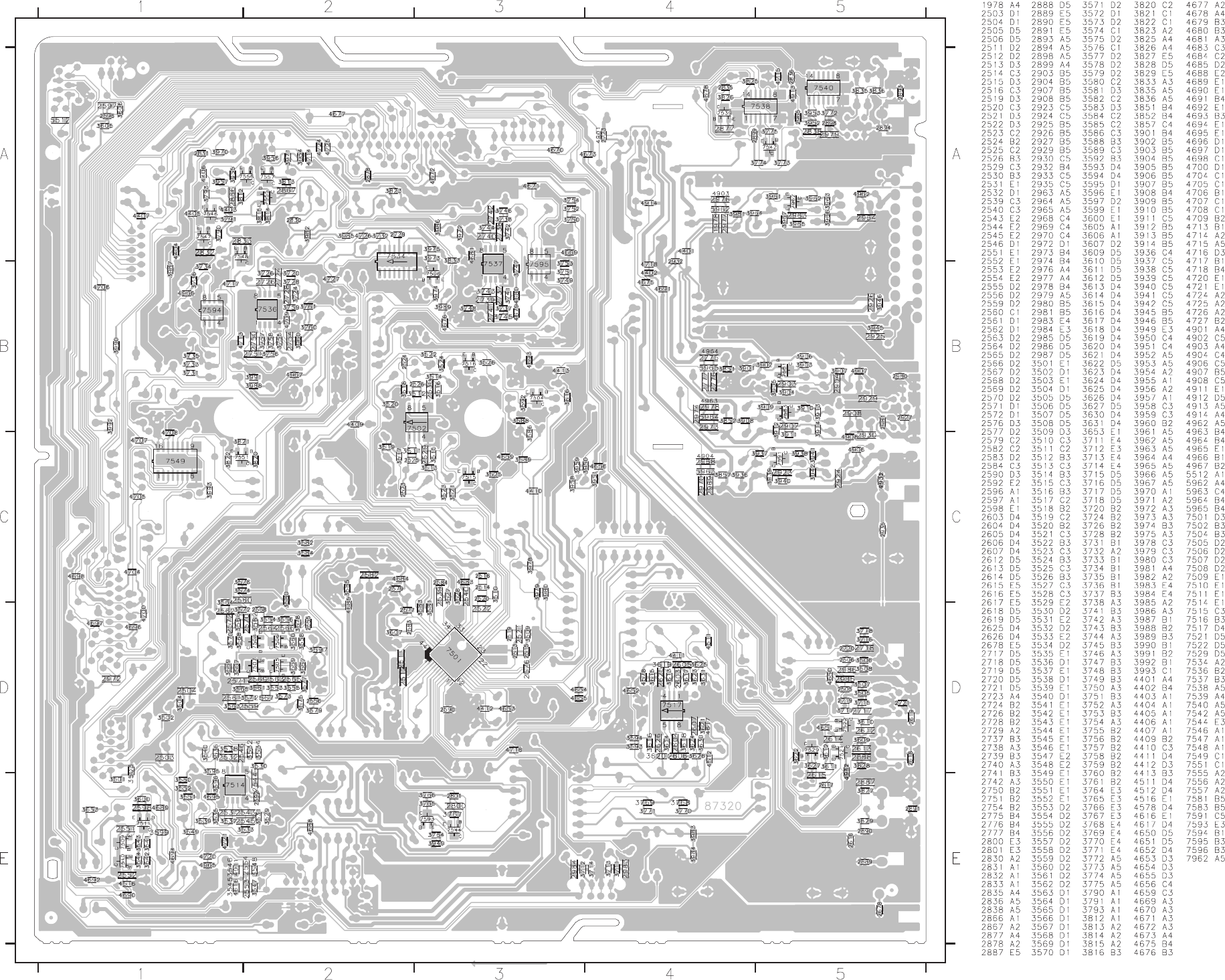
This assembly drawing shows a summary of all possible versions. For components used in a specific version see schematic diagram and respective parts list. 3139 113 3430 pt1 dd wk0025
AV BOARD - CHIP LAYOUT
PCS 103 836
8-2 8-2
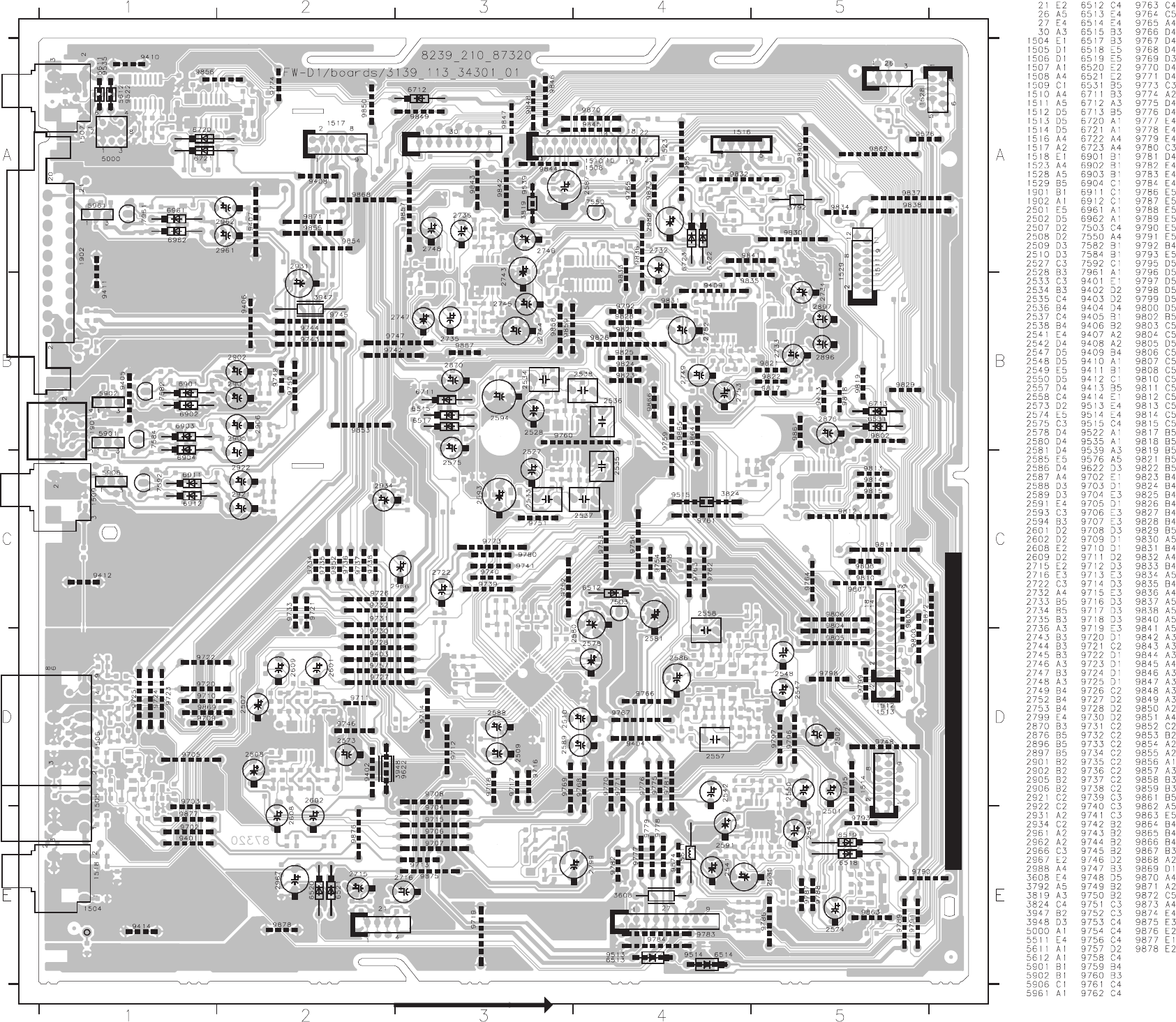
This assembly drawing shows a summary of all possible versions. For components used in a specific version see schematic diagram and respective parts list. 3139 113 3430 pt1 dd wk0025
AV BOARD - COMPONENT LAYOUT
8-3 8-3
PCS 103 837
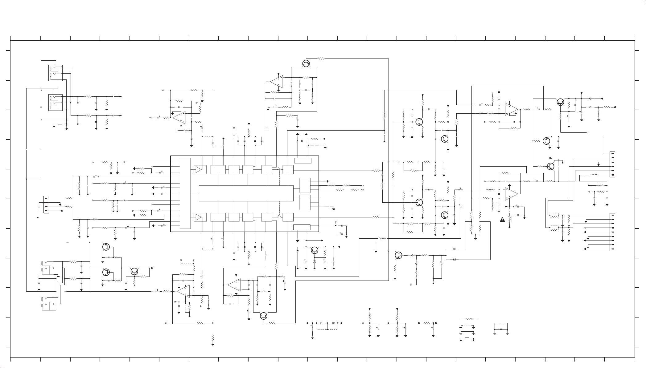
AV BOARD - CIRCUIT DIAGRAM (PART 1)
PCS 103 838
8-4 8-4
6V
6V
0.6V
0.6V
0.6V
4.8V
6V
2.7V
4.1V
4.1V
6V
4.8V
-2.6V
8.5V
6V
0.1V
0V
-9V
4.2V
4.2V
4.1V
6V
5V
6V
4.2V
4.2V
6V
4.1V
9.1V
0.1V
9.3V
0V
9.3V
4.2V
-9V
0V
6V
4.7V
11.5V
8.3V
4.2V
1.1V
1.1V
0V
0.6V
6V
5V
6V
4.1V
0V
4.7V
4.1V
+8.5V
+8.5V
+8.5V
+8.5V
MIDDLE BASS VOLUME 2
FADER
MUTE
LOGIC CONTROL
DIGITAL SUPPLY
ANALOG SUPPLY
MUTE CONTROL
I2C INTERFACE
SOURCE SELECTOR
TREBLE
LOUDNESS
VOLUME
IN GAIN
MUTE
FADER
VOLUME 2
BASSMIDDLETREBLE
LOUDNESS
VOLUME
IN GAIN
CHANNEL
LEFT
RIGHT-
CHANNEL
2509 D8
2508 G7
J
A
B
C
D
E
F
G
H
I
J
21 E2
27 F21
1504 F1
1505-B H2
1505-C C2
1506-A I2
1506-B B2
1528 D21
2501 E4
2502 F4
2503 E5
2504 G5
2505 D4
2506 E4
2507 D7
2715 E3
2626 I7
2678 F12593 C10
2594 H10
2596 E20
2597 E21
2598 B19
2601 C7
2602 H7
2603 C7
2604 I7
2605 B6
2606 H6
2607 I6
2608 I5
2609 C5
2612 H3
2613 H3
2614 H4
2615 G4
2616 H1
2617 H4
2618 D1
2619 D1
2625 C7
H
G
I
891011 12 13 14 15 16 17 18 19 20 21
A
B
C
D
E
F
3570 E15
3540 E18
3541 B19
3542 E19
3543 D18
3544 D18
3545 F19
3546 G19
3547 F19
3548 G19
3549 F16
3550 F16
3551 F16
3552 F16
3553 C14
3554 E14
3555 C14
3556 F14
3557 B14
3558 E14
3559 C14
3560 F14
3561 C15
3562 E15
3563 D15
3564 F15
3565 C15
3566 F15
3567 C15
3568 E15
3569 C15
0V
7
123456789101112 13 14 15 16 17 18 19 20 21
123456
FROM POWER
FROM TUNER
3511 B9
3512 I8
2716 F3
2717 B3
2718 C3
2719 B4
2720 C4
2721 B2
2934 F5
2966 E6
2967 C20
2983 E3
2984 F3
2985 D4
2986 F4
2987 J17
3501 E4
3502 F4
3503 E4
3504 G4
3505 D4
3506 F4
3507 E4
3508 F4
3509 C8
3510 G8
3537 C17
3539 B18
3538 E17
3513 B10
3514 I8
3515 A10
3516 H9
3517 B10
3518 I9
3519 B11
3520 I9
3521 C9
3522 H9
3523 C10
3524 H10
3525 A11
3526 J9
3527 C13
3528 G13
3529 B17
3530 E17
3531 B17
3532 F17
3533 C17
3534 E17
3535 C17
3536 E17
A
2535 B10
2534 H9
2533 B10
A
2510 G8
2511 C8
2512 G8
2513 D8
2514 G8
2515 D8
2516 G8
2519 D9
2520 G9
2521 D9
2522 G9
2523 C9
2524 G9
2525 B9
2526 I8
2527 B9
2528 I8
2529 B10
2530 H8
2531 C17
2532 E17
#
2536 I9
2537 B11
2538 H9
2539 C13
2540 G13
2541 B16
2542 F16
2543 B17
2544 F17
2545 B17
2546 E17
2547 C16
2548 E16
2549 B18
2550 E18
2551 D19
2552 D19
2553 F19
2554 G19
2555 E13
2556 E13
2557 D14
2558 F14
2559 D14
2560 F14
2561 D15
2562 F15
2563 C14
TO H/P PCB
2564 E14
2565 C14
2566 F14
2567 B15
2568 E15
2569 C15
2570 F15
2571 C15
2572 F15
2573 J13
2574 C19
2575 H15
2576 F11
2577 F12
2578 G12
2579 G10
2580 H10
2581 H11
2582 H11
2583 D11
2584 D10
2585 J14
2586 J15
2587 J11
2588 E6
2589 F6
2590 E6
2591 F18
2592 F18
3571 D15
3572 F15
3573 D14
3574 F14
3575 E14
3576 G14
3577 E13
3578 E13
3579 E13
3580 F13
3581 E11
3582 E12
3583 E12
3584 E12
3585 G11
3586 H15
3588 G14
3589 H14
3592 H13
3593 I13
3594 J13
3595 I13
3596 J13
3597 J15
3599 C19
3600 B19
3605 E20
3606 E20
3607 C11
3608 F17
3609 H3
3610 H3
3611 H4
3612 H4
3613 C7
3614 H7
3615 C6
3616 I7
3617 B6
3618 H6
3619 B7
3620 H7
3621 I6
3622 H5
3623 C6
3624 I6
3625 B7
3626 J7
3627 H5
3630 J7
3631 B7
3653 J16
3711 E2
3712 F2
3713 E3
3714 F3
3715 B3
AUX_IN
#
LINE_OUT
3716 C3
3717 B4
3718 C4
3950 F5
3951 E5
3958 D5
3959 F5
3983 B21
3984 C20
4511 C7
4512 G7
4516 J16
4578 H6
4616 F19
4617 I6
4911 F19
4912 J17
5511 F17
5512 E20
6512 H11
6513 J11
6514 J11
6515 G14
6517 H14
6518 G15
6519 G15
6520 B20
6521 B20
7501 D6
#
7502-A B10
7502-B H8
7503 G11
7504 G13
7505 C14
7506 F14
7507 D15
7508 F15
7509 C18
7510 D18
7511 B19
7514-A C17
7514-B E17
7515 A10
7516 I9
7517-A C6
7517-B I6
7521 G4
3565
A
A
#
7522 H4
7529 H5
9513 J11
9514 J11
9576 E20
2594
220u
2545
a
a
3626
4K7
aa
2504
100p
47K
3536
3519
4K7
3515
47K
2K7
39K
3619
1N4148
6515
a
9576
a
3592
22K
7511
BC857B
2543
47p
2546
a
4K7
3627
2519
22n
4617
3615
100K
4u7
2617
270p
2986
a
4u7
2715
47R
3542
12K
3508
2602
4u7
3528
220R
2577
22n
5K6
3573
3623
a
3585
a
+12M
2604
680p
2615
10p
1K
3567
4u7
2574
470n
2534
a
a
1u
2523
2560
1n8
1u
2575
470n
2533
2562
1n
2561
+IS
3556
220K
a
2580
100R
3607
47K
a2536
470n
2528
47u
3544
1K
a
3503
3K9
100n
2584
BC817-25
7509
33n
2556
22n
2592
4K7
3595
a
22u
2549
2512
6n8
3614
2K2
5K6
3533
a
2505
100n
a
3951270R
1u
2524
10R
3608
a
10u
2588
a
3K3
3580
2566
470p
D
a
3514
2K2
1n
2539
47R
3540
1n
2593
220u
100p
2551
2616
100n
470p
2529
47R
3546
3549
68K
2564
3n3
15K
3605
470n
M
2614
10p
2538
3K9
3958
9514
2718
470p
2598
100p
3624
1K
2625
220p
1K
3543
a
2606
33p
3581
470R
10K
3622
a
4u7
2507
4u7
2502
100n
2583
4K7
3510
3531
10K
27K
3551
2578
47u
a
a
a
a
2555
33n
680K
3553
2503
100p
3511
22K
3522
820R
3597
3714
47K
2K2
150K
3525
4K7
3520
a
a
1K
3631
2716
4u7
RT-01T
15041
BC547B
7503
3552
27K
a
5K6
3578
a
a
1K
3610
a
220p
470n
2535
video_o_gnd 2569
2619
100n
+12A
2570
220p
470p
220p
2626
7506
BC847B
470K
3588
3570
220R
a
7
1011
8
BZX79-C9V1
YKC21-3427
1505-C
9
3
2
1
8
4
6512
33p
2605
7517-A
NJM4560M
10n
2590
aa
aa
470p
470p
4n7
2521
2601
4u7
2530
3506
22K
a
4512
D
+IS
+IS
4911
3562
8K2
1u
2608
820R
3530
2721
100n
3
2
1
8
4
2508
4u7
a
D
aa
NJM4560M
7502-A
a
3501
1K
7522
BC847B
150K
3526
3548
3K9
a
a
+5V6
M
2526
470p
2520
22n
120K
2581
100u
a
+12M
4K7
3509
3618
3K9
3504
2966
220n
3517
4K7
3n3
2563
7
8
4
100K
3616
D
3950 270R
7502-B
NJM4560M 5
6
3611
2K2
2587
470u
aa
10K
3560
22K
3505
10K
3559
5512
2u2
a
47p
2544
a
a
2719
100n
3538
aa
3577
5K6
12K
4u7
2541
a
1505-B
YKC21-3427
6
4
5
BC847B
7504
2567
47R
3539
3554
680K
100n
220R
3527
100p
2607
3535
47K
M
2K2
3612
3550
68K
3K9
3547
2511
6n8
27K
3576
5K6
NJM4556AM
7514-B
5
6
7
8
4
3717
2613
2n2
M
7521
BC847B
3521
2K2
8STEREO_1R
17 STEREO_2L
9STEREO_2R
18 STEREO_3L
10 STEREO_3R
15 STEREO_4L
7STEREO_4R
44
TREBLE_L
1
TREBLE_R
1K
IN_L
2
IN_R
12
LOUD_L
4
LOUD_R
22
MID_IN_L
31
MID_IN_R
23
MID_OUT_L
30
MID_OUT_R
11 MONO
21
MUXOUT_L
3
MUXOUT_R
35
PAUSE
32REAR_L
29REAR_R
28
SMEXT
16 STEREO_1L
BASS_IN_L
26
BASS_IN_R
25
BASS_OUT_L
27
BASS_OUT_R
38
CLK
39CREF
19
CSM
37
DATA
36
DGND
13 DIFF_GND_L
5DIFF_GND_R
14 DIFF_L
6DIFF_R
41
DVDD
34
FRONT_L
33
FRONT_R
20
3502
TDA7437T
7501
40
ADDR
43
AGND
42
AVDD
24
2568
100n
1K
47u
2591
3K3
3579
a
a
100n
2516
470p
2553
100n
2506
aa
YKC21-3424
1506-A
1
2
3
470p
M
100u
3584
470R
2571
1K
3609
a
a
3534
5K6
470p
2565
3512
10u
2589
4511 a
22K
1K
3600
2548
4u7
YKC21-3424
4
5
7
6
+12A
47u
2527
1506-B
680p
2603
a
3518
4K7
47R
3621
12K
3718
27K
21
DIPMATE
1
2
3
4
3537
6518
1N4148
+12A
aa
a
39K
3620
1n
100n
2579
a
BC847B
7508
2540
3572
8K2
D
1N4003
6513
dd
470R
3583
47R
3712
470p
2717
3513
2K2
a
3625
4K7
+12M
aa
+12
3566
47K
a
1K
3653
a
2612
2n2
7507
BC847B
2537
470n
470n
2509
3593
4u7
2542
7514-A
NJM4556AM
3
2
1
8
4
4K7
2720
100n
2547
4u7
10K
3557
3575
5K6
a
4n7
2522
a
6517
1N4148
BC857B
7516
3574
5K6
D
a
100n
2678
3K9
3959
100p
2597
a
47R
2582
2n2
4516
a
3711
2557
470n
2934
220n
a
2514
22n
1M
3586
2525
a
a
8K2
3571
470p
4u7
2501
2554
470p
3532
10K
3599
4K7
220R
3569
a
2573
47u
BC857B
7529
a
82K
3983
1u
1N4148
6521
a
2596
470R
3582
a
100p
2552
a
7505
a
+5V_MUTE_1
BC847B
+12M +12A
8K2
3561
3523
220R
+12A
a
D
a
470n
2558
6
7
8
4
3617
120K
3716
15K
7517-B
NJM4560M 5
1
2
3
4
5
6
2u2
5511
2576
FE-BT-VK-N
1528
3568
1K
100n
47R
3541
470n
2510
3606
2585
100u
a
5K6
a6519
1N4148
47p
2983
1n5
7510
BC817-25
2531
4578
a
22n
+5V6
a
100u
2586
2513
+IS
22u
2550
47K
3516
100K
3984
3545
47R
1K
3630
2
3
4
5
6
7
8
9
a
a
DIPMATE
27
1
a
a
8K2
3563
a
1K
3589
4616
+12A
220K
2985
270p
a
a
+5V_MUTE_1
3555
+12A
a
2532
47p
3596
a
a
a
470p
2572
4K7
12K
3507
3529
820R
3613
220R
3524
9513
a
2K2
a
a
15K
1n5
2984
a
8K2
3564
3715
a
a
1n8
2559
a
a
a
6514
1N4003
+5V6
100n
2618
a
1u
2609
4912
100n
2987
a
7515
BC857B
3558
10K
4K7
3594
1N4148
6520
+IS
a
470u
2967
100n
2515
3713
47K
a
L_OLEFT
L_ORIGHT
AUX2_R
CD_R
AUX2_L
SUB_R
SUB_L
R
L
B_ref2
L_OLEFT
AUX1_R
AUX1_L
AUX1_L
AUX1_R
CD_L
ALC_EN
AC3_L
REF
I2C_CLK
AUX2_R
AUX2_L
MUTE_LO
BREF K_OUT
BREF
B_ref2
BREF
K_OUT
AMP_ON
DPLsw
I2C_DATA
HPREF
BREF
B_ref3
HPREF
HPREF
HPREF
B_ref3
HPREF
AC3_R
HP_DET
Lhp
Rhp
SET_MUTE
3139 118 53330...87320 for...3430 pt1 dd wk0025
Note : Some values may varies, see respective
parts list for correct value.
# : Provision
#
#
##
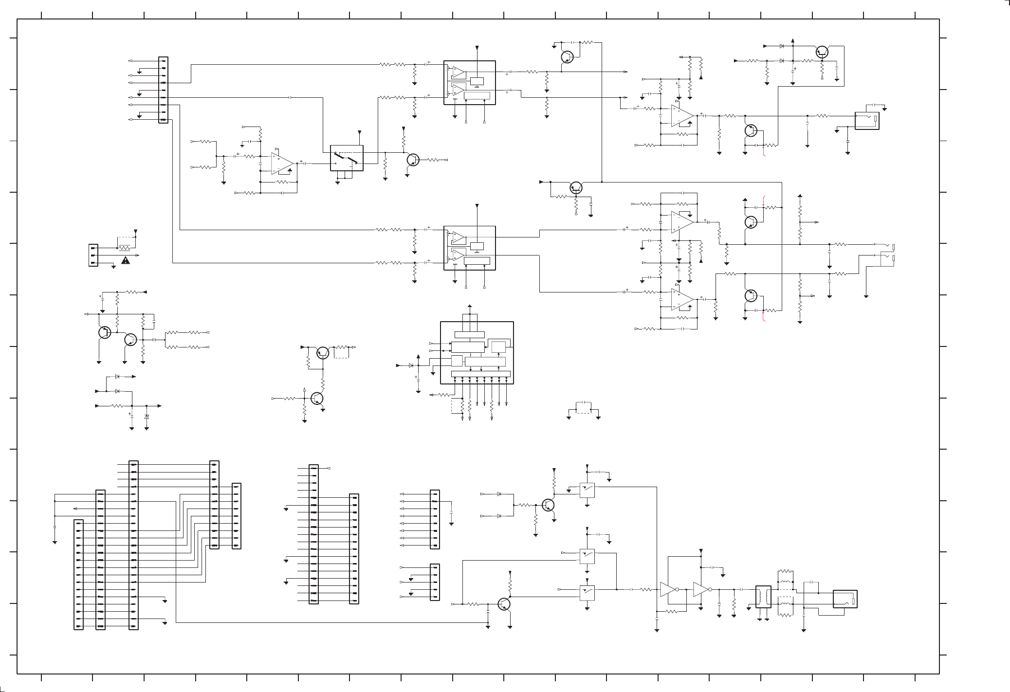
AV BOARD - CIRCUIT DIAGRAM (PART 2)
8-5 8-5
PCS 103 839
+5V6
+8.5V
+5V6
+5V
+5V6
+5V6
6V
12V
12V
0.6V
2.4V
2.4V
2.4V
2.4V 0V
MUTE = 5V
6V
6V
6V
6V
6V
6V
6V
6V
6V
MUTE = 0.6V
MUTE = 0.6V
MUTE = 5V
MUTE = 0.6V
5V
2.4V
2.4V
2.4V
2.4V
6V
6V
3.7V
3.1V
0.6V
0.6V
4.9V
5.6V
5.6V
0.6V
0.6V
0V
LOGIC CTRL
VREF
LOGIC CTRL
VREF
88
88 8
CHIP SELECT
I2C BUS
TRANSCEIVER
I/O PORT
DATA LATCHES
PWR
RES OUT I/O IN
SHIFT
REG
8
3760 A13
3758 A13
3759 A13
3731 A7
3732 B7
3733 A7
3734 B7
3735 A8
3736 B8
3737 D12
3738 F12
3741 D12
3742 E12
3743 D13
3744 F13
3745 E13
3746 E13
3747 E13
3748 E13
3749 D7
3750 E7
3751 D7
3752 E7
3753 E8
3754 E8
3755 B12
3756 C12
3757 B13
SURR
FROM CDC MODULE
7534-A C6
7536-A B13
6723 A15
7537-A D13
7536-B C5
3985 A14
3986 E14
3987 A10
3988 B14
3989 D14
3990 H9
3991 B14
3992 G8
3993 H9
4901 H11
5000 K14
5611 K15
5612 K15
6531 G8
6711 H2
6712 G2
6713 G2
6720 I9
6721 J9
6722 A15
3724 C5
3728 B5
3720 C5
OUT
2988 A15
3726 C5
2838 L12
2866 D14
2867 F14
2870 H2
2876 G8
2877 L9
2878 J1
2887 E16
2888 E16
2889 B17
2890 B15
2891 C16
2893 K15
2894 L15
2896 B10
2897 A10
2898 K14
2899 I11
2965 K12
2972 J9
2979 L14
SHIELD
3982 A15
FROM DAC
SUBW
CD TX
DIGITAL
OUT
3827 D16
3828 E16
3829 B16
3833 E13
3835 K15
3836 L15
3948 E2
3949 E2
3952 K12
3953 L13
3954 E15
3955 D15
3956 F15
3957 D15
3960 B10
3970 A10
3971 E14
3972 F14
3973 C7
3974 C8
3975 C8
3978 C4
3979 B4
3980 C4
BASIC
TO MIC
TO POWER
OUT
2836 K14
2835 J11
TO FRONT
2833 C14
2736 E12
2737 D12
2738 F12
2739 C13
2740 F13
2741 D12
2742 E12
2743 E13
2744 E13
2745 D13
2746 E13
2747 D8
2748 E8
2749 B12
2750 C13
2751 B12
2752 A13
2753 B13
2754 B12
2799 F2
2800 F3
2801 F3
2830 D11
2831 A16
2832 A11
2734 B8
2735 D12
H
I
J
K
L
26 D2
30 K8
1505-A E17
1507 K16
1508 L1
1510 L2
1511 K4
1512 L6
1513 L6
1514 A3
1516 L8
1518 B17
1523 L2
1529 K4
2722 C4
2723 H11
2724 C5
2726 C5
2728 B5
2729 B5
2732 C6
2733 A8
1234567891011121314151617
123456
FROM POWER
TO/FROM FRONT
7891011121314151617
A
B
C
D
E
F
G
H
I
J
K
L
A
B
C
D
E
F
G
CD TEXT
DIG_OUT
3761 A13
3764 F2
3765 F2
3766 G2
3767 F2
3768 F3
3769 F3
3770 F3
3771 F3
3772 L14
3773 J10
3774 I10
3775 J10
3790 A11
3791 C15
3792 A16
3793 A15
3812 D15
3813 F15
3814 D11
3815 D11
3816 H2
3819 F6
3820 G6
3821 H6
3822 G5
3823 G6
3824 H9
3825 K9
3826 K10
NO CD TX
7537-B F13
7538-B I11
7538-C K11
7538-D K11
7539 K10
7540-A K13
7540-B K13
7542 J10
7544 F2
7546 A16
7547 A11
7548 B14
7549 F8
7550 F6
7551 G6
7555 C11
7556 D14
7557 E14
7593 F2
7594 A8
7595 D8
7596 C8
9515 H8
9522 K15
9535 K15
9539 G6
9622 D2
2832
2724
22p
2878
100n
+12A
11514 FE-BT-VK-N
2u2
2831
D
8
9
a
a3791
1K
a
47p
2742
15p
D
14
15
16
17
18
19
2
3
4
5
6
7
8
9
2
2870
100u
+5VD
3993
470R
BC847B
7596
D
3732
1K
D
BC847B
a a
2833
1507
YKC21-3416
1
3
2
11
12
13
FE-BT-VK-N
1510
1
10
22p
D
3734
180R
100n
2723
10K
3756
9622
3986
820R
6
7
14
89
5611
2u2
a
220p
2877
3980
47K
1K5
3978
a
3829
220R
a
2747
10u
a
a
3768
150K
180R
3952
4
NJM4556AM
7536-B
5
6
7
8
5
6
7
7537-B
NJM4556AM
3767
22p
2738
7538-C
74HC4016D
CS_OFF
STANDBY
AMP_ON
100K
3745
7547
BC847B
BC857B
7546
47K
3775
3726
8K2
3948
4R7
+5V_MUTE_2
D
+5VD
3835
33R
3757
120K
100n
2890
a
4u7
2897
2n2
2887
D
22u
2876
2735
4u7
9522
#
+5VA
BZX79-C5V1
6711
a
5000
1
2
34
6
78
10K
3742
2737
22p
3741
10K
a
1K3824
180R
3751
+5V_MUTE_2
a
5K6
3823
18K
D
2K2
VCC
1
8
2
7
2K2
3953
D
D
3833
100R
3720
10K
1N4148
82K
3766
7
8
9
47K
3973
BC327-25
a
a
2835
47n
15p
2800
a
7539
100K
3728
a
BC857B
7593
D
3985
82K
6723
1N4148
10p
3970
18K
6531
3759
4K7
15p
2740
a
4u7
2896
2746
2u2
560R
3772
2u2
5612
+5VD
D
a
a
26
DIPMATE
1
2
3
a
+12A
D
47K
3754
a
2
3
4
5
6
7
8
9
D
1511
FE-BT-VK-N
1
10
11
12
a
3771
33K
3790
2K2
+5VA
YKC21-3427
1505-A
3
1
2
3
4
5
6
7
8
9
4u7
2736
EH-B
1516
1
2
3
4
5
10K
3738
#9535
7548
2750
3755
10K
100n
2965
3982
100K
D
+12A
6722
1N4148
2722
4u7
4u7
2749
a
47p
2754
220R
3954
a
a
47K
3979
3974
10K
2753
4901
3746
100K
2u2
10K
D
1N4148
6720
3821
a
100R
3761
12
7
14
11 10
1N4148
6712
10u
2748
7538-D
74HC4016D
7536-A
3
2
1
8
4
D_DIG
NJM4556AM
470u
2988
2899
47n
8
4
2729
1u
D
YKC21-3416
1518
1
3
2
7550
2K2
3813
FE-BT-VK-N
1
10
11
12
13
14
15
2
3
4
5
6
10K
3975
D
1513
+12A
a
3960
a
560R
3956
D
a
47u
2744
a
4K7
3748
180R
3752
BC857B
7555
M62429FP
7594
5
CLK
4
DATA
3
GND
6
VCC
1
8
2
7
a
7
8
9
7557
BC847B
1
10
11
12
13
14
15
2
3
4
5
6
10p
2866
FE-BT-VK-N
1508
a
a
M
47n
2894
a
1
2
3
4
5
6
7
8
+5VA
3747
4K7
a
30
2728
a
2u2
2745
47p
2898
100n
a
D
D
2739
15p
M62429FP
7595
5
CLK
4
DATA
3
GND
6
3753
47K
47K
3826
47K
3825
a
2838
47p
D
3770
33K
9515
#
3827
220R
74HC04D
7540-B
3
7
14 4
6721
1N4148
47u
BC847B
7551
47n
2836
2743
3812
2K2
10K
3814
7
8
9
2889
100n
11
12
13
14
15
16
17
18
19
2
3
4
5
6
1K
3750
FE-BT-VK-N
1512
1
10
3737
10K
4K7
3815
10p
a
D
7
14
43
a
2830
4u7
74HC4016D
7538-B
5
HEF4053BT
7534-A
E
6
S11
Vdd
16
Vee
7
Vss
8
Y0
12
Y1
13 Z14
390R
3764
7CHA
a
a
2799
47u
#
3828
220R
3816
120R
9539
a
3773
47K
D
2751
7542
BC847B
3749
1K
33R
3836
a
D
+12A
3736
47K
3971
18K
2867
10p
1N4148
6713
BC847B
7556
330K
2734
10u
1529
FE-BT-VK-N
1
2
3
4
5
6
7
10K
3792
a
1K
3731
a
a
a
D
2752
47u
D
470R
3992
1n
2972
a
470R
3990
3765
1K2
D
D
D
150R
M
100n
2891
3
4
5
6
7
8
9
D
3949
10
11
12
13
14
15
16
17
18
19
2
20
23
22
21
2801
100n
1523
FE-BT-VK-N
1
2n2
2888
+12A
3955
220R
2R2
3819
7544
BC847B
3774
47K
D
150K
3769
18K
3972
2726
470p
D4
10
D5
11
D6
12
D7
8 GND
2 SCL
3 SDA 1
SO
13 VDD
3957
560R
M62320FP
7549 16
CS0
15
CS1
14
CS2
4
D0
5
D1
6
D2
7
D3
9
4K7
3793
NJM4556AM
7537-A
3
2
1
8
4
D
10u
2733
2893
47n
3758
100K
+12A
47K
3735
a
4K7
150p
2979
18K
3991
3760
3822
3820
5K6
39K
3744
3724
10K
47p
2741
2u2
2732
820R
3989
a
14 2
820R
3987
3988
820R
a
74HC04D
7540-A
1
7
3733
180R
3743
39K
SUR_L
SUR_R
CD_STANDBY
+VCD
+CD
A1
SUB_L
SUB_R
DVD_ON
DVD_ON
+5VD
+CD
DVD_ON
AC3_SUB
CENTER
C_DIG_OUT
GND_COAX
GND_COAX
OE_LATCH
PORE
CD_GND
SILD
CDSHDATA
SICL
CD_L
SUBWOOFER
Cref
Cref
REF_d1
REF_d1
DVD_ON
-30V
F1
F2
+5VD
C_DIG_OUT
CDSHCLK
STR
SW_INFO
+12
+CD
CD_R
C_DIG_OUT
+5V6
D
HP_DET
SA_IN
NTC
PWRDWN
I2C_CLK
D
D
CS_OFF
GND_TXT
SRDT
DQSY
up_CLK
S_VOL_CLK
I2C_DATA
SUR_L
CENTER
LED_SH_CLKLED_SH_DATA
S_VOL_CLK
AC3_SR
AC3_SL
Cref
REF_d1
Cref
AC3_CTR
LED_SH_DATA
MUTE_SUR
PWRDWN
-30V
F2
F1
STANDBY
NTC
SA_IN
L_OLEFT
L_ORIGHT
K_OUT
+5VD
+5VD
DIG_OUT
AC3_L
AC3_R
SUR_R
CSref
CSref
CSref
REF_d
REF_d
LED_SH_CLK
LED_SH_DATA
A1
SET_MUTE
ALC_EN
I2C_DATA
I2C_CLK
MUTE_SUR
MUTE_SUB
CD_STANDBY
MUTE_LO
MUTE_SUB
3139 118 53330...87320 for...3430 pt1 dd wk0025
Note : Some values may varies, see respective
parts list for correct value.
# : Provision
#
#
#
BC847B
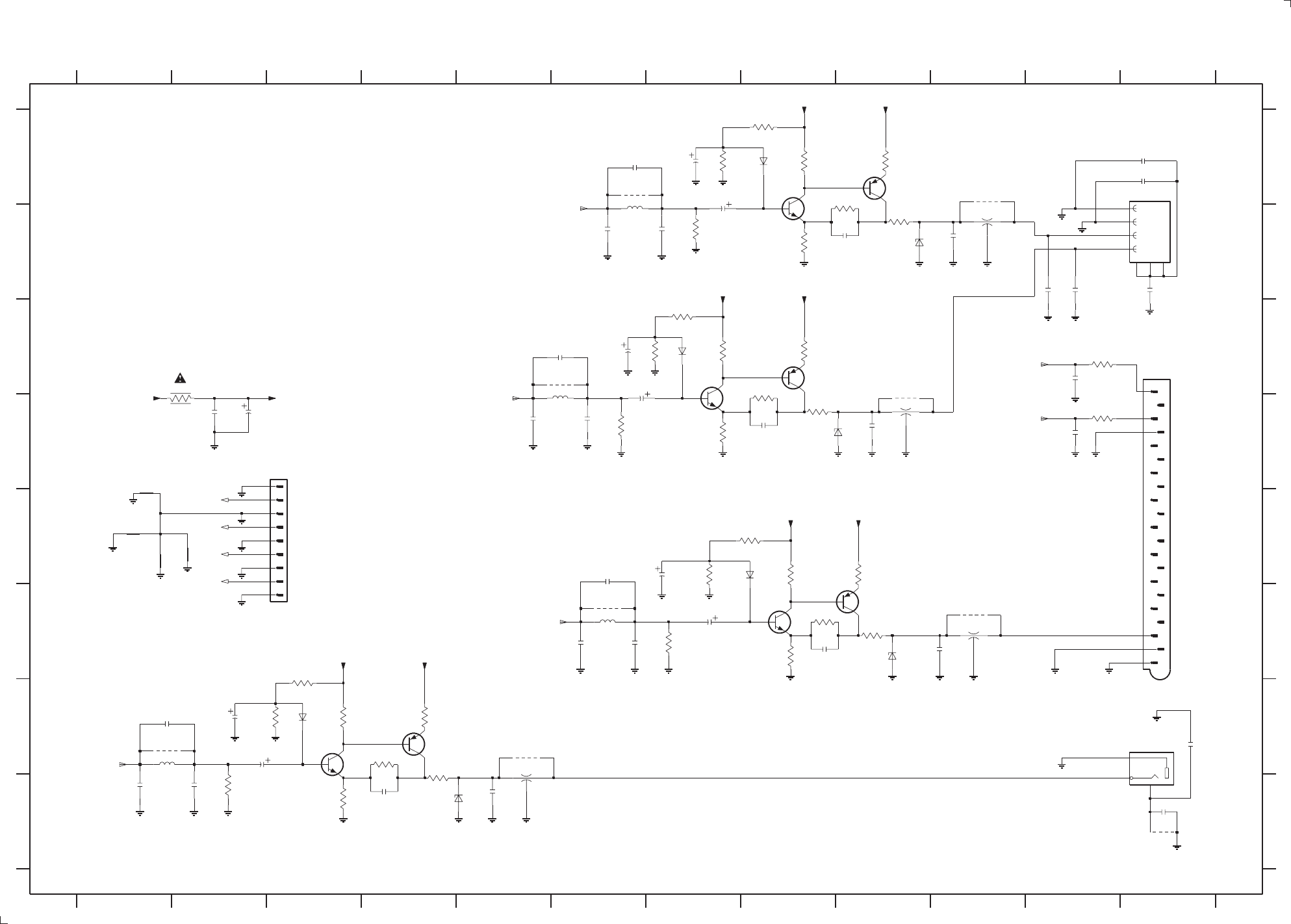
AV BOARD - CIRCUIT DIAGRAM (PART 3)
PCS 103 840
8-6 8-6
+12V +12V
+12V +12V
+12V +12V
+12V
+12V +12V
1.9V
1.1V 2.6V
11.8V
11.2V
1.9V
1.1V 2.6V
11.8V
11.2V
1.9V
1.1V 2.6V
11.8V
11.2V
1.9V
1.1V 2.6V
11.8V
11.2V
CVBS
A
12
FROM DAC PCB
OUT
B
123456789101112
1234567891011
3912 B8
S-VIDEO
SCART
2961 E7
2962 F7
2963 F8
2964 F10
2968 G1
2969 H2
2970 H1
2973 B7
2974 B6
2976 E6
2977 F6
2978 A6
2980 A12
2981 A12
3851 D6
3852 B7
3857 H2
3901 C7
3902 C7
3903 C7
3904 C8
3905 D7
3906 C8
3907 D8
3908 A7
3909 A8
3910 A8
3911 A92921 G2
C
D
E
F
G
H
A
B
C
D
E
F
G
H
1509 G12
1517 F3
1901 A12
1902 C12
1978 F6
2775 C6
2776 D6
2777 D5
2901 C6
2902 C6
2903 D8
2904 D9
2905 A7
2906 A7
2907 B9
2908 B10
2908
220p
V_Y
2935 G12
2922 G2
2923 H4
2924 H5
2925 C11
2926 D11
2927 B12
2929 B11
2930 B11
2931 D2
2932 D2
2933 H12
6911
1N4148
3913 A9
3914 B9
3936 G3
3937 F3
3938 G3
3939 H3
3940 G4
3941 G4
3942 G4
3945 C11
3946 D11
3947 C2
3961 E8
3962 E8
3963 E9
3964 E7
3965 F8
3966 F9
3967 F8
3981 F7
4902 H12
4903 F6
4904 G1
4906 G5
4907 D9
4908 A10
4962 F10
4963 A6
4964 C6
3946
470R
5901 B10
5902 D9
5906 H5
5961 F10
5962 F6
5963 G1
5964 A6
5965 C6
220p
2930
6901 C7
6902 D8
6903 A8
6904 B9
6911 G3
6912 H4
6961 E8
6962 F9
7581 D7
7582 C8
7583 B8
7584 A9
7591 G3
7592 G4
4964
7961 F9
7962 F8
1u
2905
D_DIG
V_Y
V_CVBS
1u
2961
3908
470R
67
DSS306
# 5902
V_CVBS_S 4
5
6
7
8
9
47R
3913
V_Y
2u7
# 5962
DSS306
# 5906
2
V_C
2924
220p
V
220R
3911
3902
V
2K2
YKC21-3564
100n
2932
3851
82R
120R
3905
2901
1u
4903
3945
470R
V_CVBS
V
390p
# 2977
7583
V_CVBS_S
270R
3910
V_CVBS_S
FE-BT-VK-N
1517
1
2
3
V_CVBS_S
3947
4R7
2
31
47R
3907
V_C
1901
9217A
1
2
3
4
5
7581
V_CVBS_S
390p
# 2970
6904
BZX79-C6V8
47n
V_Y
# 2969
390p
V_C
47n
2981
2980
V_Y
220p
2926
3914
47R
V_Y
220p
2907
3906
47R
22n
2933
V_CVBS
# 1978
390p
V
3961
2K2
6901
1N4148
180p
# 2968
V_CVBS
V_CVBS_S
a
3940
220R
4907
1509
3
2
1
2927
22n
3903
270R
1u
2922
# 5901
DSS306
2
31
V_CVBS
V_CVBS_S
a
2921
1u
V_C a
82R
3857
2931
220u
7962
3966
47R
220p
2963
3909
2K2
V
7592
BC557B
V_CVBS
V_C
V_Y
3904
220R
120R
3939
220p
3967
120R
1N4148
6961
2903
4962
V_C
82R
3852
V_CVBS_S
V_CVBS
390p
# 2974
2962
1u
1u
2902
2u7
# 5965
47R
3942
# 5961
DSS306
2
31
390p
# 2776
270R
3962
# 2973
390p
# 5964
2u7
1N4148
6903
BZX79-C6V8
6912
3964
470R
# 2775
180p
3938
270R
V_C
220p
2929
31
video_o_gnd
2964
220p
180p
# 2978
V_Y V_Y
V_Y
4963
V_CVBS
BC557B
7961
2923
220p
2K2
3937
# 2777
390p
BZX79-C6V8
6902
6962
BZX79-C6V8
V_CVBS
# 5963
2u7
2935
100n
4902
# 2976
180p
V_CVBS_S
2925
220p
BC557B
7584
V_C
4906
4904
V_CVBS
V_CVBS_S
V_CVBS_S
7591
V_CVBS
V_CVBS_S
V_Y
V_C
220p
2904
V_CVBS
V_C
3912
120R
7582
BC557B
2906
1u
3941
47R
V_C
V
V_Y
3981
82R
20
21
3
4
5
6
7
8
9
1
10
11
12
13
14
15
16
17
18
19
2
220R
3965
1902
470R
3936
4908
470R
3901
47R
3963
CVBS
CVBS
C
Y
CVBS
DIG_OUT
Y
C
V_C
+12M
L_OLEFT
L_ORIGHT
3139 118 53330...87320 for...3430 pt1 dd wk0025
Note : Some values may varies, see respective parts list for correct value.
# : Provision
BC847B
BC847B
BC847B
BC847B

8-7
ELECTRICAL PARTS LIST - AV BOARD
MISCELLANEOUS
8-7
ELECTRICAL PARTS LIST - AV BOARD
1505 4822 267 31449 Cinch Socket - Aux-in/Line-out/
Surround Out
1507 4822 267 31729 Cinch Socket - Audio Digital Out
1509 4822 267 31996 Cinch Socket - Video Out (CVBS)
1510 4822 265 11553 Flex Connector 19P
1511 4822 267 10732 Flex Connector 12P
1512 4822 265 11553 Flex Connector 19P
1514 2422 025 14518 Flex Connector 9P
1517 2422 025 14518 Flex Connector 9P
1518 4822 267 31729 Cinch Socket - Sub-Woofer Out
1523 4822 267 10757 Flex Connector 23P
1528 4822 267 10731 Flex Connector 6P
1529 4822 265 11515 Flex Connector 8P
1901 4822 267 10994 S-Video Out Socket
1902 2422 025 12352 Scart Connector
CAPACITORS
2501 4822 124 40769 4,7µF 20% 100V
2502 4822 124 40769 4,7µF 20% 100V
2503 5322 122 32531 100pF 5% 50V
2504 5322 122 32531 100pF 5% 50V
2505 4822 126 14585 100nF 10% 50V
2506 4822 126 14585 100nF 10% 50V
2507 4822 124 40769 4,7µF 20% 100V
2508 4822 124 40769 4,7µF 20% 100V
2509 4822 124 41407 0,47µF 20% 63V
2510 4822 124 41407 0,47µF 20% 63V
2511 5322 122 31866 6,8nF 10% 63V
2512 5322 122 31866 6,8nF 10% 63V
2513 5322 122 32654 22nF 10% 63V
2514 5322 122 32654 22nF 10% 63V
2515 4822 126 13838 100nF +80/-20% 50V
2516 4822 126 13838 100nF +80/-20% 50V
2519 5322 122 32654 22nF 10% 63V
2520 5322 122 32654 22nF 10% 63V
2521 5322 126 10223 4,7nF 10% 63V
2522 5322 126 10223 4,7nF 10% 63V
2523 4822 126 14043 1µF +80/-20% 16V
2524 4822 126 14043 1µF +80/-20% 16V
2525 5322 122 32268 470pF 10% 50V
2526 5322 122 32268 470pF 10% 50V
2527 4822 124 40433 47µF 20% 25V
2528 4822 124 40433 47µF 20% 25V
2529 5322 122 34099 470pF 10% 63V
2530 5322 122 34099 470pF 10% 63V
2531 4822 126 13692 47pF 1% 63V
2532 4822 126 13692 47pF 1% 63V
2533 4822 121 51252 470nF 5% 63V
2534 4822 121 51252 470nF 5% 63V
2535 4822 121 51252 470nF 5% 63V
2536 4822 121 51252 470nF 5% 63V
2537 4822 121 51252 470nF 5% 63V
2538 4822 121 51252 470nF 5% 63V
2539 5322 122 31647 1nF 10% 63V
2540 5322 122 31647 1nF 10% 63V
2541 4822 124 40769 4,7µF 20% 100V
2542 4822 124 40769 4,7µF 20% 100V
2543 4822 126 13692 47pF 1% 63V
2544 4822 126 13692 47pF 1% 63V
2545 5322 122 34099 470pF 10% 63V
2546 5322 122 34099 470pF 10% 63V
2547 4822 124 40769 4,7µF 20% 100V
2548 4822 124 40769 4,7µF 20% 100V
2549 4822 124 81151 22µF 50V
2550 4822 124 81151 22µF 50V
2551 5322 122 32531 100pF 5% 50V
2552 5322 122 32531 100pF 5% 50V
2553 5322 122 34099 470pF 10% 63V
2554 5322 122 34099 470pF 10% 63V
2555 4822 126 12105 33nF 5% 50V
2556 4822 126 12105 33nF 5% 50V
2557 4822 121 51252 470nF 5% 63V
2558 4822 121 51252 470nF 5% 63V
2559 4822 126 10847 1,8nF 10% 63V
2560 4822 126 10847 1,8nF 10% 63V
2561 5322 122 31647 1nF 10% 63V
2562 5322 122 31647 1nF 10% 63V
2563 4822 122 33891 3,3nF 10% 63V
2564 4822 122 33891 3,3nF 10% 63V
2565 5322 122 34099 470pF 10% 63V
2566 5322 122 34099 470pF 10% 63V
2567 4822 126 14585 100nF 10% 50V
2568 4822 126 14585 100nF 10% 50V
2569 4822 122 33575 220pF 5% 63V
2570 4822 122 33575 220pF 5% 63V
2571 5322 122 34099 470pF 10% 63V
2572 5322 122 34099 470pF 10% 63V
2573 4822 124 40433 47µF 20% 25V
2574 4822 124 40769 4,7µF 20% 100V
2575 4822 124 21913 1µF 20% 63V
2576 4822 126 14585 100nF 10% 50V
2577 5322 122 32654 22nF 10% 63V
2578 4822 124 40433 47µF 20% 25V
2579 4822 126 14585 100nF 10% 50V
2580 4822 124 40207 100µF 20% 25V
2581 4822 124 40207 100µF 20% 25V
2582 4822 122 33127 2,2nF 10% 63V
2583 4822 126 13838 100nF +80/-20% 50V
2584 4822 126 14585 100nF 10% 50V
2585 4822 124 40207 100µF 20% 25V
2586 4822 124 40207 100µF 20% 25V
2587 4822 124 80791 470µF 20% 16V
2588 4822 124 40248 10µF 20% 63V
2589 4822 124 40248 10µF 20% 63V
2590 5322 122 34098 10nF 10% 63V
2591 4822 124 40433 47µF 20% 25V
2592 5322 122 32654 22nF 10% 63V
2593 4822 124 80144 220µF 20% 25V
2594 4822 124 80144 220µF 20% 25V
2596 4822 126 14043 1µF +80/-20% 16V
2597 5322 122 32531 100pF 5% 50V
2598 5322 122 32531 100pF 5% 50V
2601 4822 124 40769 4,7µF 20% 100V
2602 4822 124 40769 4,7µF 20% 100V
2603 4822 122 32535 680pF 10% 63V
2604 4822 122 32535 680pF 10% 63V
2605 5322 122 32659 33pF 5% 50V
2606 5322 122 32659 33pF 5% 50V
2607 5322 122 32531 100pF 5% 50V
2608 4822 124 21913 1µF 20% 63V
2609 4822 124 21913 1µF 20% 63V
2612 4822 122 33127 2,2nF 10% 63V
2613 4822 122 33127 2,2nF 10% 63V
2614 5322 122 32448 10pF 5% 63V
2615 5322 122 32448 10pF 5% 63V
2616 4822 126 14585 100nF 10% 50V
2617 2020 552 96305 4,7µF +80/-20% 10V
2618 4822 126 13838 100nF +80/-20% 50V
2619 4822 126 13838 100nF +80/-20% 50V
2625 4822 122 33575 220pF 5% 63V
2626 4822 122 33575 220pF 5% 63V
2678 4822 126 14585 100nF 10% 50V
2715 4822 124 40769 4,7µF 20% 100V
2716 4822 124 40769 4,7µF 20% 100V
2717 5322 122 34099 470pF 10% 63V
2718 5322 122 34099 470pF 10% 63V
2719 4822 126 13838 100nF +80/-20% 50V
2720 4822 126 13838 100nF +80/-20% 50V
2721 4822 126 13838 100nF +80/-20% 50V
2722 4822 124 40769 4,7µF 20% 100V
2723 4822 126 13838 100nF +80/-20% 50V
2724 5322 122 32658 22pF 5% 50V
2726 5322 122 34099 470pF 10% 63V
2728 4822 126 13692 47pF 1% 63V
2729 4822 126 14043 1µF +80/-20% 16V
2732 4822 124 22652 2,2µF 20% 50V
2733 4822 124 40248 10µF 20% 63V
2734 4822 124 40248 10µF 20% 63V
2735 4822 124 40769 4,7µF 20% 100V
2736 4822 124 40769 4,7µF 20% 100V
2737 5322 122 32658 22pF 5% 50V
2738 5322 122 32658 22pF 5% 50V
2739 4822 126 13486 15pF 2% 63V
2740 4822 126 13486 15pF 2% 63V
2741 4822 126 13692 47pF 1% 63V
2742 4822 126 13692 47pF 1% 63V
2743 4822 124 41751 47µF 20% 50V
2744 4822 124 41751 47µF 20% 50V
2745 4822 124 22652 2,2µF 20% 50V
2746 4822 124 22652 2,2µF 20% 50V
2747 4822 124 40248 10µF 20% 63V
2748 4822 124 40248 10µF 20% 63V
2749 4822 124 40769 4,7µF 20% 100V
2750 4822 126 13486 15pF 2% 63V
2751 5322 122 32658 22pF 5% 50V
2752 4822 124 41751 47µF 20% 50V
2753 4822 124 22652 2,2µF 20% 50V
2754 4822 126 13692 47pF 1% 63V
2799 4822 124 41751 47µF 20% 50V
2800 4822 126 13486 15pF 2% 63V
2801 4822 126 14585 100nF 10% 50V
2830 2020 552 96305 4,7µF +80/-20% 10V
2831 2020 552 96305 4,7µF +80/-20% 10V
2832 5322 122 32448 10pF 5% 63V
2833 5322 122 32448 10pF 5% 63V
2835 4822 126 13751 47nF 10% 63V
2836 4822 126 13751 47nF 10% 63V
2838 4822 126 13692 47pF 1% 63V
2866 5322 122 32448 10pF 5% 63V
2867 5322 122 32448 10pF 5% 63V
2870 4822 124 41584 100µF 20% 10V
2876 4822 126 14585 100nF 10% 50V
2876 4822 124 81151 22µF 50V /22
2877 4822 122 33575 220pF 5% 63V
2878 4822 126 13838 100nF +80/-20% 50V
2887 4822 122 33127 2,2nF 10% 63V
2888 4822 122 33127 2,2nF 10% 63V
2889 4822 126 14585 100nF 10% 50V
2890 4822 126 14585 100nF 10% 50V
2891 4822 126 13838 100nF +80/-20% 50V
2893 4822 126 13751 47nF 10% 63V
2894 4822 126 13751 47nF 10% 63V
2896 4822 124 40769 4,7µF 20% 100V
2897 4822 124 40769 4,7µF 20% 100V
2898 4822 126 13838 100nF +80/-20% 50V
2899 4822 126 13751 47nF 10% 63V
2901 4822 124 21913 1µF 20% 63V
2902 4822 124 21913 1µF 20% 63V
2903 4822 122 33575 220pF 5% 63V
2904 4822 122 33575 220pF 5% 63V
2905 4822 124 21913 1µF 20% 63V
2906 4822 124 21913 1µF 20% 63V
2907 4822 122 33575 220pF 5% 63V
2908 4822 122 33575 220pF 5% 63V
2921 4822 124 21913 1µF 20% 63V
2922 4822 124 21913 1µF 20% 63V
2923 4822 122 33575 220pF 5% 63V
2924 4822 122 33575 220pF 5% 63V
PCS 103 841

PCS 103 842
CAPACITORS
ELECTRICAL PARTS LIST - AV BOARD ELECTRICAL PARTS LIST - AV BOARD
8-8 8-8
2925 4822 122 33575 220pF 5% 63V
2926 4822 122 33575 220pF 5% 63V
2927 5322 122 32654 22nF 10% 63V
2929 4822 122 33575 220pF 5% 63V
2930 4822 122 33575 220pF 5% 63V
2931 4822 124 80144 220µF 20% 25V
2932 4822 126 13838 100nF +80/-20% 50V
2933 5322 122 32654 22nF 10% 63V
2934 4822 124 40746 0,22µF 20% 63V
2935 4822 126 13838 100nF +80/-20% 50V
2961 4822 124 21913 1µF 20% 63V
2962 4822 124 21913 1µF 20% 63V
2963 4822 122 33575 220pF 5% 63V
2964 4822 122 33575 220pF 5% 63V
2965 4822 126 13838 100nF +80/-20% 50V
2966 4822 124 40746 0,22µF 20% 63V
2967 4822 124 81044 470µF 20% 6,3V
2972 5322 126 10511 1nF 5% 50V
2979 5322 122 33538 150pF 2% 63V
2980 4822 126 13751 47nF 10% 63V
2981 4822 126 13751 47nF 10% 63V
2985 4822 122 33216 270pF 5% 50V
2986 4822 122 33216 270pF 5% 50V
2987 4822 126 13838 100nF +80/-20% 50V
2988 4822 124 81044 470µF 20% 6,3V
RESISTORS
3501 4822 051 10102 1k 2% 0,25W
3502 4822 051 10102 1k 2% 0,25W
3503 4822 051 20392 3k9 5% 0,1W
3504 4822 051 20392 3k9 5% 0,1W
3505 4822 051 20223 22k 5% 0,1W
3506 4822 051 20223 22k 5% 0,1W
3507 4822 117 11383 12k 1% 0,1W
3508 4822 117 11383 12k 1% 0,1W
3509 4822 051 20472 4k7 5% 0,1W
3510 4822 051 20472 4k7 5% 0,1W
3511 4822 051 20223 22k 5% 0,1W
3512 4822 051 20223 22k 5% 0,1W
3513 4822 117 11449 2k2 5% 0,1W
3514 4822 117 11449 2k2 5% 0,1W
3515 4822 117 10834 47k 1% 0,1W
3516 4822 117 10834 47k 1% 0,1W
3517 4822 051 20472 4k7 5% 0,1W
3518 4822 051 20472 4k7 5% 0,1W
3519 4822 051 20472 4k7 5% 0,1W
3520 4822 051 20472 4k7 5% 0,1W
3521 4822 117 11449 2k2 5% 0,1W
3522 4822 117 11449 2k2 5% 0,1W
3523 4822 117 11503 220R 1% 0,1W
3524 4822 117 11503 220R 1% 0,1W
3525 4822 051 20154 150k 5% 0,1W
3526 4822 051 20154 150k 5% 0,1W
3527 4822 117 11503 220R 1% 0,1W
3528 4822 117 11503 220R 1% 0,1W
3529 4822 117 11454 820R 1% 0,1W
3530 4822 117 11454 820R 1% 0,1W
3531 4822 117 10833 10k 1% 0,1W
3532 4822 117 10833 10k 1% 0,1W
3533 4822 051 20562 5k6 5% 0,1W
3534 4822 051 20562 5k6 5% 0,1W
3535 4822 117 10834 47k 1% 0,1W
3536 4822 117 10834 47k 1% 0,1W
3537 4822 117 11383 12k 1% 0,1W
3538 4822 117 11383 12k 1% 0,1W
3539 4822 051 20479 47R 5% 0,1W
3540 4822 051 20479 47R 5% 0,1W
3541 4822 051 20479 47R 5% 0,1W
3542 4822 051 20479 47R 5% 0,1W
3543 4822 051 10102 1k 2% 0,25W
3544 4822 051 10102 1k 2% 0,25W
3545 4822 051 20479 47R 5% 0,1W
3546 4822 051 20479 47R 5% 0,1W
3547 4822 051 20392 3k9 5% 0,1W
3548 4822 051 20392 3k9 5% 0,1W
3549 4822 051 20683 68k 5% 0,1W
3550 4822 051 20683 68k 5% 0,1W
3551 4822 051 20273 27k 5% 0,1W
3552 4822 051 20273 27k 5% 0,1W
3553 4822 051 20684 680k 5% 0,1W
3554 4822 051 20684 680k 5% 0,1W
3555 4822 117 13579 220k 1% 0,1W
3556 4822 117 13579 220k 1% 0,1W
3557 4822 117 10833 10k 1% 0,1W
3558 4822 117 10833 10k 1% 0,1W
3559 4822 117 10833 10k 1% 0,1W
3560 4822 117 10833 10k 1% 0,1W
3561 4822 051 20822 8k2 5% 0,1W
3562 4822 051 20822 8k2 5% 0,1W
3563 4822 051 20822 8k2 5% 0,1W
3564 4822 051 20822 8k2 5% 0,1W
3565 4822 117 10834 47k 1% 0,1W
3566 4822 117 10834 47k 1% 0,1W
3567 4822 051 10102 1k 2% 0,25W
3568 4822 051 10102 1k 2% 0,25W
3569 4822 117 11503 220R 1% 0,1W
3570 4822 117 11503 220R 1% 0,1W
3571 4822 051 20822 8k2 5% 0,1W
3572 4822 051 20822 8k2 5% 0,1W
3573 4822 051 20562 5k6 5% 0,1W
3574 4822 051 20562 5k6 5% 0,1W
3575 4822 051 20562 5k6 5% 0,1W
3576 4822 051 20562 5k6 5% 0,1W
3577 4822 051 20562 5k6 5% 0,1W
3578 4822 051 20562 5k6 5% 0,1W
3579 4822 051 20332 3k3 5% 0,1W
3580 4822 051 20332 3k3 5% 0,1W
3581 4822 051 20471 470R 5% 0,1W
3582 4822 051 20471 470R 5% 0,1W
3583 4822 051 20471 470R 5% 0,1W
3584 4822 051 20471 470R 5% 0,1W
3585 4822 117 12955 2k7 1% 0,1W
3586 4822 051 20105 1M 5% 0,1W
3588 4822 051 20474 470k 5% 0,1W
3589 4822 051 10102 1k 2% 0,25W
3592 4822 051 20223 22k 5% 0,1W
3593 4822 051 20472 4k7 5% 0,1W
3594 4822 051 20472 4k7 5% 0,1W
3595 4822 051 20472 4k7 5% 0,1W
3596 4822 051 20472 4k7 5% 0,1W
3597 4822 117 11454 820R 1% 0,1W
3599 4822 051 20472 4k7 5% 0,1W
3600 4822 051 10102 1k 2% 0,25W
3605 4822 116 83933 15k 1% 0,1W
3606 4822 051 20562 5k6 5% 0,1W
3607 4822 051 20101 100R 5% 0,1W
3608 4822 052 10109
!
10R 5% 0,33W
3609 4822 051 10102 1k 2% 0,25W
3610 4822 051 10102 1k 2% 0,25W
3611 4822 117 11449 2k2 5% 0,1W
3612 4822 117 11449 2k2 5% 0,1W
3613 4822 117 11449 2k2 5% 0,1W
3614 4822 117 11449 2k2 5% 0,1W
3615 4822 117 10837 100k 1% 0,1W
3616 4822 117 10837 100k 1% 0,1W
3617 4822 051 20124 120k 5% 0,1W
3618 4822 051 20124 120k 5% 0,1W
3619 4822 051 20393 39k 5% 0,1W
3620 4822 051 20393 39k 5% 0,1W
3621 4822 051 20479 47R 5% 0,1W
3622 4822 117 10833 10k 1% 0,1W
3623 4822 051 10102 1k 2% 0,25W
3624 4822 051 10102 1k 2% 0,25W
3625 4822 051 20472 4k7 5% 0,1W
3626 4822 051 20472 4k7 5% 0,1W
3627 4822 051 20472 4k7 5% 0,1W
3630 4822 051 10102 1k 2% 0,25W
3631 4822 051 10102 1k 2% 0,25W
3653 4822 051 10102 1k 2% 0,25W
3711 4822 051 20479 47R 5% 0,1W
3712 4822 051 20479 47R 5% 0,1W
3713 4822 117 10834 47k 1% 0,1W
3714 4822 117 10834 47k 1% 0,1W
3715 4822 116 83933 15k 1% 0,1W
3716 4822 116 83933 15k 1% 0,1W
3717 4822 051 20273 27k 5% 0,1W
3718 4822 051 20273 27k 5% 0,1W
3720 4822 117 10833 10k 1% 0,1W
3724 4822 117 10833 10k 1% 0,1W
3726 4822 051 20822 8k2 5% 0,1W
3728 4822 117 10837 100k 1% 0,1W
3731 4822 051 10102 1k 2% 0,25W
3732 4822 051 10102 1k 2% 0,25W
3733 4822 117 11448 180R 1% 0,1W
3734 4822 117 11448 180R 1% 0,1W
3735 4822 117 10834 47k 1% 0,1W
3736 4822 117 10834 47k 1% 0,1W
3737 4822 117 10833 10k 1% 0,1W
3738 4822 117 10833 10k 1% 0,1W
3741 4822 117 10833 10k 1% 0,1W
3742 4822 117 10833 10k 1% 0,1W
3743 4822 051 20393 39k 5% 0,1W
3744 4822 051 20393 39k 5% 0,1W
3745 4822 117 10837 100k 1% 0,1W
3746 4822 117 10837 100k 1% 0,1W
3747 4822 051 20472 4k7 5% 0,1W
3748 4822 051 20472 4k7 5% 0,1W
3749 4822 051 10102 1k 2% 0,25W
3750 4822 051 10102 1k 2% 0,25W
3751 4822 117 11448 180R 1% 0,1W
3752 4822 117 11448 180R 1% 0,1W
3753 4822 117 10834 47k 1% 0,1W
3754 4822 117 10834 47k 1% 0,1W
3755 4822 117 10833 10k 1% 0,1W
3756 4822 117 10833 10k 1% 0,1W
3757 4822 051 20124 120k 5% 0,1W
3758 4822 117 10837 100k 1% 0,1W
3759 4822 051 20472 4k7 5% 0,1W
3760 4822 116 52283 4k7 5% 0,5W
3760 4822 051 20472 4k7 5% 0,1W /22
3761 4822 051 20101 100R 5% 0,1W
3764 4822 051 20391 390R 5% 0,1W
3765 4822 051 20122 1k2 5% 0,1W
3766 4822 117 11149 82k 1% 0,1W
3767 4822 051 20334 330k 5% 0,1W
3768 4822 051 20154 150k 5% 0,1W
3769 4822 051 20154 150k 5% 0,1W
3770 4822 051 20333 33k 5% 0,1W
3771 4822 051 20333 33k 5% 0,1W
3772 4822 051 20561 560R 5% 0,1W
3773 4822 117 10834 47k 1% 0,1W
3774 4822 117 10834 47k 1% 0,1W
3775 4822 117 10834 47k 1% 0,1W
3790 4822 117 11449 2k2 5% 0,1W
3791 4822 117 11449 2k2 5% 0,1W
3791 4822 051 10102 1k 2% 0,25W /22
3792 4822 050 21003 10k 1% 0,6W
3793 4822 051 20472 4k7 5% 0,1W

RESISTORS
ELECTRICAL PARTS LIST - AV BOARD
8-9 8-9
3812 4822 117 11449 2k2 5% 0,1W
3813 4822 117 11449 2k2 5% 0,1W
3814 4822 117 10833 10k 1% 0,1W
3815 4822 051 20472 4k7 5% 0,1W
3816 4822 051 20121 120R 5% 0,1W
3819 4822 116 81154 2R2 5% 0,5W
3820 4822 051 20562 5k6 5% 0,1W
3821 4822 117 10833 10k 1% 0,1W
3822 4822 117 11449 2k2 5% 0,1W
3823 4822 051 20562 5k6 5% 0,1W
3824 4822 050 11002 1k 1% 0,4W
3825 4822 117 10834 47k 1% 0,1W
3826 4822 117 10834 47k 1% 0,1W
3827 4822 051 10102 1k 2% 0,25W
3827 4822 117 11503 220R 1% 0,1W /22
3828 4822 051 10102 1k 2% 0,25W
3828 4822 117 11503 220R 1% 0,1W /22
3829 4822 051 10102 1k 2% 0,25W
3829 4822 117 11503 220R 1% 0,1W /22
3833 4822 051 20101 100R 5% 0,1W
3836 4822 051 20339 33R 5% 0,1W
3851 4822 051 20829 82R 5% 0,1W
3852 4822 051 20829 82R 5% 0,1W
3857 4822 051 20829 82R 5% 0,1W
3901 4822 051 20471 470R 5% 0,1W
3902 4822 117 11449 2k2 5% 0,1W
3903 4822 117 11504 270R 1% 0,1W
3904 4822 117 11503 220R 1% 0,1W
3905 4822 051 20121 120R 5% 0,1W
3906 4822 051 20479 47R 5% 0,1W
3907 4822 051 20479 47R 5% 0,1W
3908 4822 051 20471 470R 5% 0,1W
3909 4822 117 11449 2k2 5% 0,1W
3910 4822 117 11504 270R 1% 0,1W
3911 4822 117 11503 220R 1% 0,1W
3912 4822 051 20121 120R 5% 0,1W
3913 4822 051 20479 47R 5% 0,1W
3914 4822 051 20479 47R 5% 0,1W
3936 4822 051 20471 470R 5% 0,1W
3937 4822 117 11449 2k2 5% 0,1W
3938 4822 117 11504 270R 1% 0,1W
3939 4822 051 20121 120R 5% 0,1W
3940 4822 117 11503 220R 1% 0,1W
3941 4822 051 20479 47R 5% 0,1W
3942 4822 051 20479 47R 5% 0,1W
3945 4822 051 20471 470R 5% 0,1W
3946 4822 051 20471 470R 5% 0,1W
3947 4822 052 10478
!
4R7 5% 0,33W
3948 4822 052 10478
!
4R7 5% 0,33W
3949 4822 117 10353 150R 1% 0,1W
3950 4822 117 11504 270R 1% 0,1W
3951 4822 117 11504 270R 1% 0,1W
3952 4822 117 11448 180R 1% 0,1W
3953 4822 117 11449 2k2 5% 0,1W
3954 4822 051 10102 1k 2% 0,25W
3954 4822 117 11503 220R 1% 0,1W /22
3955 4822 051 10102 1k 2% 0,25W
3955 4822 117 11503 220R 1% 0,1W /22
3956 4822 051 20561 560R 5% 0,1W
3957 4822 051 20561 560R 5% 0,1W
3958 4822 051 20392 3k9 5% 0,1W
3959 4822 051 20392 3k9 5% 0,1W
3960 4822 117 10965 18k 1% 0,1W
3961 4822 117 11449 2k2 5% 0,1W
3962 4822 117 11504 270R 1% 0,1W
3963 4822 051 20479 47R 5% 0,1W
3964 4822 051 20471 470R 5% 0,1W
3965 4822 117 11503 220R 1% 0,1W
3966 4822 051 20479 47R 5% 0,1W
3967 4822 051 20121 120R 5% 0,1W
3970 4822 117 10965 18k 1% 0,1W
3971 4822 117 10965 18k 1% 0,1W
3972 4822 117 10965 18k 1% 0,1W
3973 4822 117 10834 47k 1% 0,1W
3974 4822 117 10833 10k 1% 0,1W
3975 4822 117 10833 10k 1% 0,1W
3978 4822 117 11139 1k5 1% 0,1W
3979 4822 117 10834 47k 1% 0,1W
3980 4822 117 10834 47k 1% 0,1W
3982 4822 117 10837 100k 1% 0,1W
3983 4822 117 11149 82k 1% 0,1W
3984 4822 117 10837 100k 1% 0,1W
3985 4822 117 11149 82k 1% 0,1W
3986 4822 117 11454 820R 1% 0,1W
3987 4822 117 11454 820R 1% 0,1W
3988 4822 117 11454 820R 1% 0,1W
3989 4822 117 11454 820R 1% 0,1W
3990 4822 051 20471 470R 5% 0,1W
3991 4822 117 10965 18k 1% 0,1W
3992 4822 051 20471 470R 5% 0,1W
3993 4822 051 20471 470R 5% 0,1W
4401 4822 051 20008 0R Jumper 0805
4402 4822 051 20008 0R Jumper 0805
4403 4822 051 20008 0R Jumper 0805
4404 4822 051 20008 0R Jumper 0805
4405 4822 051 20008 0R Jumper 0805
4406 4822 051 20008 0R Jumper 0805
4407 4822 051 20008 0R Jumper 0805
4408 4822 051 20008 0R Jumper 0805
4409 4822 051 20008 0R Jumper 0805
4410 4822 051 20008 0R Jumper 0805
4411 4822 051 20008 0R Jumper 0805
4412 4822 051 20008 0R Jumper 0805
4413 4822 051 20008 0R Jumper 0805
4516 4822 051 20008 0R Jumper 0805
4578 4822 051 20008 0R Jumper 0805
4650 4822 051 20008 0R Jumper 0805
4651 4822 051 20008 0R Jumper 0805
4652 4822 051 20008 0R Jumper 0805
4653 4822 051 20008 0R Jumper 0805
4654 4822 051 20008 0R Jumper 0805
4655 4822 051 20008 0R Jumper 0805
4656 4822 051 20008 0R Jumper 0805
4658 4822 051 20008 0R Jumper 0805
4659 4822 051 20008 0R Jumper 0805
4669 4822 051 20008 0R Jumper 0805
4670 4822 051 20008 0R Jumper 0805
4671 4822 051 20008 0R Jumper 0805
4672 4822 051 20008 0R Jumper 0805
4673 4822 051 20008 0R Jumper 0805
4674 4822 051 20008 0R Jumper 0805
4675 4822 051 20008 0R Jumper 0805
4676 4822 051 20008 0R Jumper 0805
4677 4822 051 20008 0R Jumper 0805
4678 4822 051 20008 0R Jumper 0805
4679 4822 051 20008 0R Jumper 0805
4680 4822 051 20008 0R Jumper 0805
4681 4822 051 20008 0R Jumper 0805
4683 4822 051 20008 0R Jumper 0805
4684 4822 051 20008 0R Jumper 0805
4685 4822 051 20008 0R Jumper 0805
4688 4822 051 20008 0R Jumper 0805
4689 4822 051 20008 0R Jumper 0805
4690 4822 051 20008 0R Jumper 0805
4691 4822 051 20008 0R Jumper 0805
4692 4822 051 20008 0R Jumper 0805
4693 4822 051 20008 0R Jumper 0805
4694 4822 051 20008 0R Jumper 0805
4695 4822 051 20008 0R Jumper 0805
4696 4822 051 20008 0R Jumper 0805
4697 4822 051 20008 0R Jumper 0805
4698 4822 051 20008 0R Jumper 0805
4700 4822 051 20008 0R Jumper 0805
4704 4822 051 20008 0R Jumper 0805
4705 4822 051 20008 0R Jumper 0805
4706 4822 051 20008 0R Jumper 0805
4707 4822 051 20008 0R Jumper 0805
4708 4822 051 20008 0R Jumper 0805
4709 4822 051 20008 0R Jumper 0805
4710 4822 051 20008 0R Jumper 0805
4711 4822 051 20008 0R Jumper 0805
4712 4822 051 20008 0R Jumper 0805
4713 4822 051 20008 0R Jumper 0805
4714 4822 051 20008 0R Jumper 0805
4715 4822 051 20008 0R Jumper 0805
4716 4822 051 20008 0R Jumper 0805
4717 4822 051 20008 0R Jumper 0805
4718 4822 051 20008 0R Jumper 0805
4720 4822 051 20008 0R Jumper 0805
4721 4822 051 20008 0R Jumper 0805
4722 4822 051 20008 0R Jumper 0805
4723 4822 051 20008 0R Jumper 0805
4724 4822 051 20008 0R Jumper 0805
4725 4822 051 20008 0R Jumper 0805
4726 4822 051 20008 0R Jumper 0805
4727 4822 051 20008 0R Jumper 0805
4902 4822 051 20008 0R Jumper 0805
4903 4822 051 20008 0R Jumper 0805
4904 4822 051 20008 0R Jumper 0805
4906 4822 051 20008 0R Jumper 0805
4907 4822 051 20008 0R Jumper 0805
4908 4822 051 20008 0R Jumper 0805
4912 4822 051 20008 0R Jumper 0805
4913 4822 051 20008 0R Jumper 0805
4914 4822 051 20008 0R Jumper 0805
4962 4822 051 20008 0R Jumper 0805
4963 4822 051 20008 0R Jumper 0805
4964 4822 051 20008 0R Jumper 0805
4965 4822 051 20008 0R Jumper 0805
4966 4822 051 20008 0R Jumper 0805
4967 4822 051 20008 0R Jumper 0805
COILS & FILTERS
5000 4822 157 70601 Coil 100µH 10%
5511 4822 157 62552 Coil 2,2µH 5%
5512 4822 157 10586 Coil 2,2µH 10%
DIODES
6512 4822 130 30862 BZX79-C9V1
6513 4822 130 31878 1N4003G
6514 4822 130 31878 1N4003G
6515 4822 130 30621 1N4148
6517 4822 130 30621 1N4148
6518 4822 130 30621 1N4148
6519 4822 130 30621 1N4148
6520 4822 130 30621 1N4148
6521 4822 130 30621 1N4148
6531 4822 130 30621 1N4148
6711 4822 130 34233 BZX79-C5V1
6712 4822 130 30621 1N4148
6713 4822 130 30621 1N4148
6720 4822 130 30621 1N4148
6721 4822 130 30621 1N4148
6722 4822 130 30621 1N4148
6723 4822 130 30621 1N4148
6901 4822 130 30621 1N4148
6902 4822 130 34278 BZX79-C6V8
6903 4822 130 30621 1N4148
ELECTRICAL PARTS LIST - AV BOARD
PCS 103 843

6904 4822 130 34278 BZX79-C6V8
6911 4822 130 30621 1N4148
6912 4822 130 34278 BZX79-C6V8
6961 4822 130 30621 1N4148
6962 4822 130 34278 BZX79-C6V8
TRANSISTORS & INTEGRATED CIRCUITS
7501 4822 209 17386 TDA7437T
7502 4822 209 83357 NJM4560M
7503 4822 130 40959 BC547B
7504 5322 130 60159 BC847B
7505 5322 130 60159 BC847B
7506 5322 130 60159 BC847B
7507 5322 130 60159 BC847B
7508 5322 130 60159 BC847B
7509 4822 130 42804 BC817-25
7510 4822 130 42804 BC817-25
7511 4822 130 60373 BC857B
7514 4822 209 31378 NJM4556AM
7515 4822 130 60373 BC857B
7516 4822 130 60373 BC857B
7517 4822 209 83357 NJM4560M
7521 5322 130 60159 BC847B
7522 5322 130 60159 BC847B
7529 4822 130 60373 BC857B
7534 5322 209 14481 HEF4053BT
7536 4822 209 31378 NJM4556AM
7537 4822 209 31378 NJM4556AM
7538 4822 209 16262 74HC4016D
7539 5322 130 60159 BC847B
7540 9337 142 60653 74HC04D
7542 5322 130 60159 BC847B
7544 5322 130 60159 BC847B
7546 4822 130 60373 BC857B
7547 5322 130 60159 BC847B
7548 5322 130 60159 BC847B
7549 4822 209 17345 M62320FP
7550 4822 130 41246 BC327-25
7551 5322 130 60159 BC847B
7555 4822 130 60373 BC857B
7556 5322 130 60159 BC847B
7557 5322 130 60159 BC847B
7581 5322 130 60159 BC847B
7582 4822 130 44568 BC557B
7583 5322 130 60159 BC847B
7584 4822 130 44568 BC557B
7591 5322 130 60159 BC847B
7592 4822 130 44568 BC557B
7593 4822 130 60373 BC857B
7594 4822 209 17349 M62429FP
7595 4822 209 17349 M62429FP
7596 5322 130 60159 BC847B
7961 4822 130 44568 BC557B
7962 5322 130 60159 BC847B
Note : Only the parts mentioned in this list are normal
service spare parts.
PCS 103 844
8-10 8-10
ELECTRICAL PARTS LIST - AV BOARD
DIODES

DVD Module
9-1
PCS 103 845
TABLE OF CONTENTS
Diagnostic Software:
Dealer Script ..............................................................9-2
Player Script ...............................................................9-3
Interactive Tests .........................................................9-4
Error Log & Bits..........................................................9-6
Loop Test ....................................................................9-7
Servicing DVD module & Mono board ............................9-8
Reset of Virgin Mode .......................................................9-8
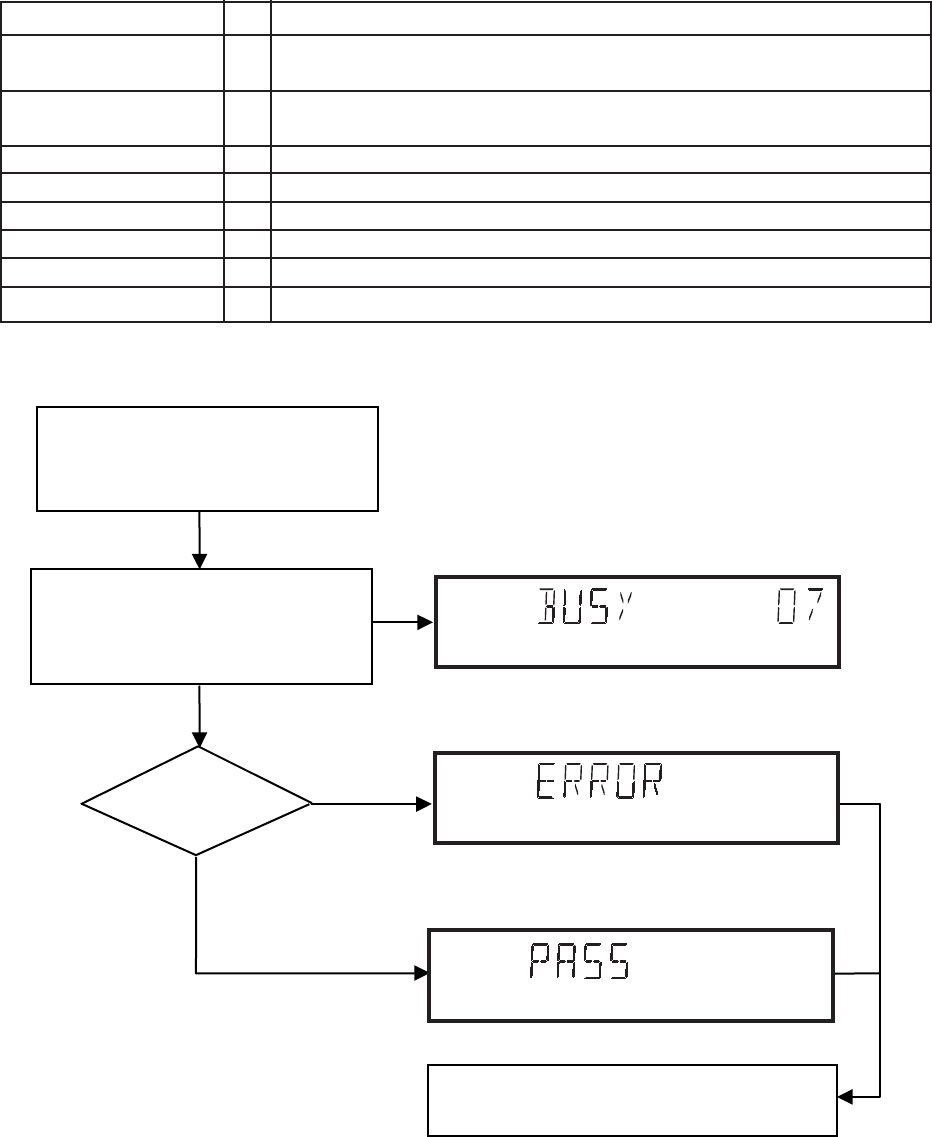
9-2
PCS 103 846
1. DEALER SCRIPT
Purpose of Dealer Script
The dealer script can give a diagnosis on a standalone DVD
player; no other equipment is needed to perform a number
of hardware tests to check if the DVD player is faulty. The
diagnosis is simply a “error” or “pass” message; no indication
is given of faulty hardware modules. Only tests within the
scope of the diagnostic software will be executed hence only
faults within this scope can be detected.
Contents of Dealer Script
The dealer script executes all diagnostic nuclei that do not
need any user interaction and are meaningful on a standalone
DVD player.
The nuclei called in the dealer script are the following (the
number after each nucleus name corresponds with the
number being on the local display when the nucleus is
executed during the dealer script):
Nucleus
VideoColSetupComm
VideoScartSwComm
PapChksFl
PapDramWrR
PapI2cDisp
PapS2bEcho
PapI2cNvram
PapNvramWrR
CompSdramWrR
9
8
7
6
5
4
3
2
1
Description
Check the I2C interface with the RGB video processor on the
Audio/Video board (only for DVD players with RGB video processor).
Checks the I2C interface with the scart switch on the Audio/Video board
Calculate and verify checksum of FLASH memory
Pattern test of all locations in the DRAM(s)
Checks the I2C interface with the slave processor on the display PCB
Checks the I2C interface to the basic engine
Checks the I2C interface with the NVRAM
Pattern test of all locations in the NVRAM
Pattern test of all locations in the SDRAM(s)
Press 2 keys simultaneously
<OPEN/CLOSE> + <PLAY>
Connect to mains.
During the test, the following display
is shown: the counter counts down
from the number of nuclei to be run
before the test finishes. Example:
SET O.K.?
YES
NO
To exit DEALER SCRIPT ,disconnect from mains.
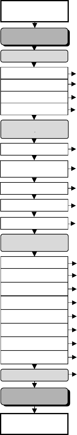
2. PLAYER SCRIPT
Purpose of Player Script
The Player script will give the opportunity to perform a test
that will determine which of the DVD player’s modules are
faulty, to read the error log and error bits and to perform an
endurance loop test.
To successfully perform the tests, the DVD player must be
connected to a TV set to check the output of a number of
nuclei. For DVDv2B a multi-channel amplifier, a set of 6
boxes and an external video source are necessary to test.
To be able to check results of certain nuclei, the player script
expects some interaction of the user (i.e. to approve a test
picture or a test sound). Some nuclei (e.g. nuclei that test
functionality of the Basic Engine module) require that the
DVD player itself is opened, to enable the user to observe
moving parts and approve their movement visually.
Only tests within the scope of the diagnostic software will be
executed hence only faults within this scope can be de-
tected.
Contents of Player Script
The player script contains all nuclei that are useful on a DVD
player that is connected to a TV-set and help to determine
which module of the DVD player is faulty, as well as to read
out the contents of the error logs.
Structure of Player Script
The player script consists of a set of nuclei testing the three
hardware modules in the DVD player: the Display PCB*, the
Digital PCB and the Basic Engine.
*Note: Display PCB tests are not relevant to FW-D1 &
FW-D5 sets
Nuclei run by the player test need some user interaction; in
the next paragraph this interaction is described. The player
test is done in two phases:
1. Interactive tests:
This part of the player test depends strongly on user
interaction and input to determine nucleus results and to
progress through the full test. Reading the error log and
error bits information can be useful to determine any
errors that occurred recently during normal operation of
the DVD player.
2. The loop test will perform the same nuclei as the dealer
test, but it will loop through the list of nuclei indefinitely.
SLEDGE TEST
BeSledgeOut/In(41ab)
FOCUS TEST
BeFocusOn(38a)
DISC MOTOR TEST
BeDiscMotorOn(39a)
RADIAL TEST
BeRadialOn(40a)
JUMP TEST
BeGroovesIn/Mid/Out(42abc)
Press 2 keys simultaneously
<OPEN/CLOSE> + <STOP>
Connect to main
s
To exit player test,
disconnect from mains
INTERACTIVE TESTS
DISPLAY TEST
DispDisplay(30)
LED TEST
DispLed(29)
KEYBOARD TEST
DispKeyb(27)
SCART LOOP TEST
AudioPinkNoiseOn(20a)
VideoScartSwDvd(54a)
VideoColDencOn(23a)
PICTURE TEST
DISPLAY PCB*
MONO PCB(SERVO)
& BASIC ENGINE
MONO PCB(DIGITAL)
AUDIO/VIDEO PCB
TRAY TEST
BeTrayOut/In(43ab)
VERSION NUMBER
BeVer(37)
REMOTE CONTROL
DispRc(28)
TRAY TEST
BeTrayOut/In(43ab)
ERROR LOG & BITS
LogReadErr(31)
LogReadbits(32)
LOOP TEST
= Dealer script exclusive of test2
AudioSineOn(21a)
VideoColSetupHi(53a)
VideoColSetupLo(53b)
SOUND 1 TEST
SCART DVD TEST
SOUND 2 TEST
COLOUR SETUP TEST
VideoScartSwPass(54b)
* Display PCB test is not relevant
for FW-D1 & FW-D5 due to
hardware variations
9-3
PCS 103 847
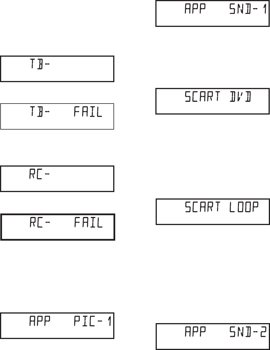
3. INTERACTIVE TESTS
3.1 DISPLAY PCB*
*Note: The tests on this Display PCB are not relevant to
FW-D1 and FW-D5 families.
DISPLAY TEST & LED TEST
Press 2 times the NEXT key to skip the Display and LED
test.
KEYBOARD TEST
The display shows:
Press the NEXT key for more than 1 second, the display will
change to:
Press NEXT key to proceed to the next test.
REMOTE CONTROL TEST
The display shows:
Press the NEXT key for more than 1 second, the display will
change to:
Press NEXT key to proceed to the next test.
3.2 MONO PCB DIGITAL PART
PICTURE TEST
This test is performed by sending a predefined picture
(colour bar) to the TV screen (nucleus VideoColDencOn)
and asking the user for confirmation. The display will show
the following message:
By pressing PLAY the user confirms the test, pressing PREV
will indicate the picture was invisible or incorrect. Pressing
NEXT will proceed to the next test
SOUND 1 & SCART DVD TEST
The first soundtest is performed by starting a pink noise
9-4
PCS 103 848
sound that needs confirmation from the user (nucleus
AudioPinkNoiseOn); the display will show the following
message very shortly:
This sound will only be audible from version cut3.1 of Sti5505
(item7503 on mono board) onwards. After starting up sound
1, SCART loop-trough will be simultaneously active during
this test. SCART loop-trough will be measured with the aid
of an external video source.
When entering the SCART loop-trough, the local display
indicates:
On the TV screen a colour bar (generated by nucleus
VideoColDencOn) is visual and the internally generated
pinknoise is audible. By pressing PLAY the user confirms
the test, pressing PREV will indicate the sound was inaudi-
ble or incorrect. Pressing NEXT will proceed to the next test;
if the user presses NEXT without pressing PLAY or PREV
first, the result of this test will be TRUE (sound ok).
By pressing the NEXT button there will be switched over to
the external source, this must become now visible on the TV
screen (using the SCART). The local display indicates:
The internally generated colour bar is still available on the
CVBS and Y/C outputs. And the pinknoise-signal is still
available on the cinch audio outputs. By pressing the PREV
button, the internal generated colour bar becomes visual
again. The test can be left by pressing the NEXT key for
more than one second.
SOUND 2 TEST
The second soundtest is performed by producing a sine
sound (nucleus AudioSineOn). The signal can be stopped by
pressing the STOP-key. The display will show the following
message:
By pressing PLAY the user confirms the test, pressing PREV
will indicate that something went wrong. Pressing NEXT will
proceed to the next; if the user presses NEXT without
pressing PLAY or PREV first, the result of this test will be
TRUE (sound ok).
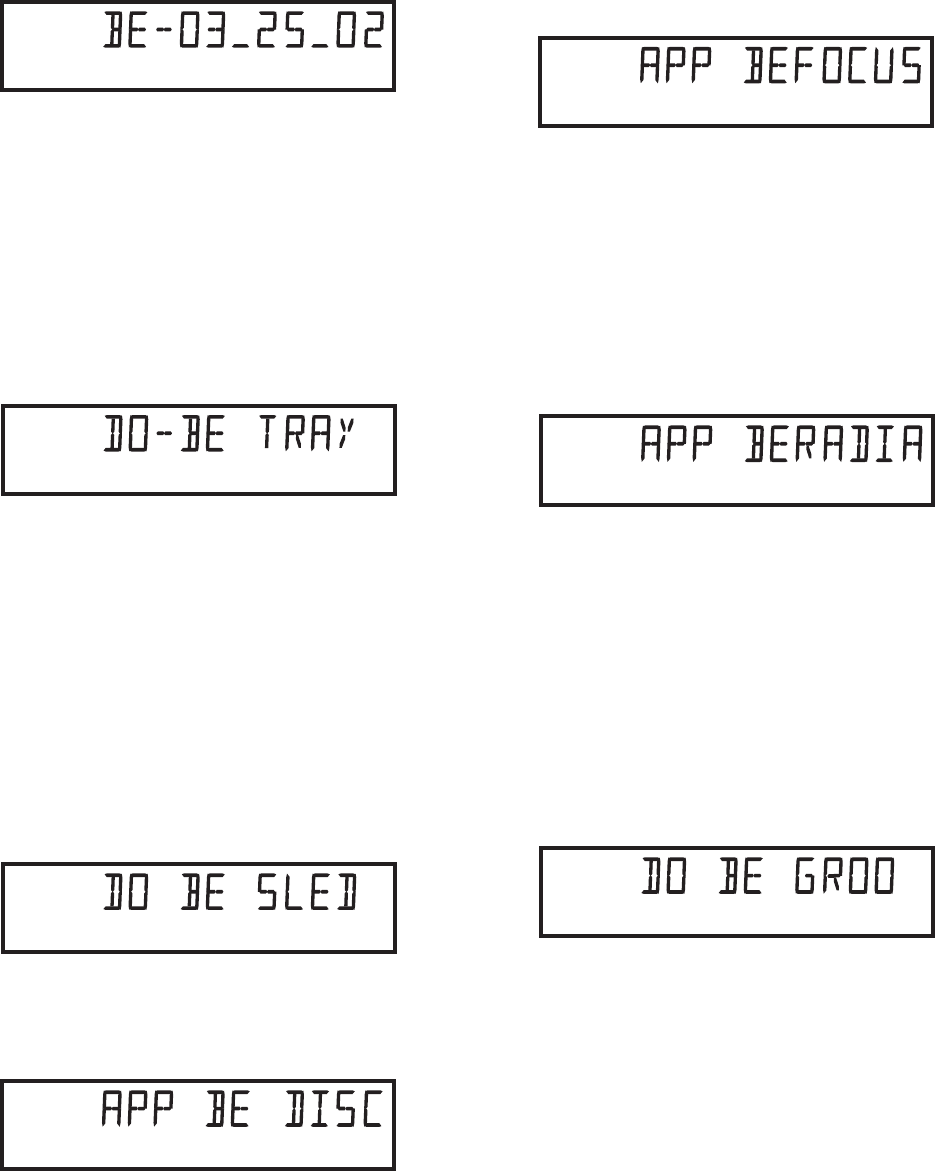
9-5
PCS 103 849
3.3 BASIC ENGINE
VERSION NUMBER
In the basic engine tests, the version number of the Basic
Engine will be shown first, as the following example:
By pressing the NEXT key, the Basic Engine tests are
started.
TRAY TEST
First, the tray is tested. The purpose of this test is also to give
the user the opportunity to put a disc in the tray of the DVD
player. Some tests on the Basic Engine require that a
disc(e.g. DVD MPTD test disc) is present in the player. At the
end of the Basic Engine tests this tray test will be repeated
solely to enable the user to remove the disc in the tray. The
local display will look as follows:
By pressing PLAY the user can toggle the position of the tray.
Note that this test will not contribute to the test result of the
Basic Engine. Pressing NEXT will proceed to the next test,
after the tray has been closed (by the software) if it was open.
SLEDGE TEST(visual test)
The second Basic Engine test tests the sledge; the user can
move the sledge as many times as desired by using PLAY
(nucleus BeSledgeOut) and PREV (nucleus BeSledgeIn).
Pressing NEXT on the local keyboard proceeds to the next
test. Note that this test will not contribute to the test result of
the Basic Engine. The local display will look as follows during
the sledge test:
DISC MOTOR TEST(visual test)
The third Basic Engine test tests the disc motor (nucleus
BeDiscMotorOn); the local display looks as follows:
By pressing PLAY the user confirms that the disc motor is
running; pressing PREV indicates the disc motor does not
work. Pressing NEXT proceeds to the next test, after a reset
of the disc motor (nucleus BeDiscMotorOff). If the user
presses NEXT before pressing PLAY or PREV, the result of
this test will be TRUE (disc motor is running).
FOCUS TEST(visual test)
The fourth Basic Engine test tests the focusing; first focusing
is turned on by calling nucleus BeFocusOn. The display will
look as follows:
By pressing PLAY the user confirms that the focusing was
succesful; pressing PREV indicates a focusing failure. Press-
ing NEXT proceeds to the next test after a reset of the
focussing (nucleus BeFocusOff); if NEXT is pressed before
PLAY or PREV, the result of this test will be TRUE (focus
successful).
RADIAL TEST(visual & listening test)
The fifth Basic Engine test tests the radial functionality
(nucleus BeRadialOn); the local display looks as follows:
By pressing PLAY the user confirms that the radial function
worked; pressing PREV indicates the function does not
work. Pressing NEXT proceeds to the next test, after a reset
of the radial (nucleus BeRadialOff). If the user presses NEXT
before pressing PLAY or PREV, the result of this test will be
TRUE (radial successful).
JUMP TEST(listening test)
The sixth and last Basic Engine test tests the jumping by
calling nuclei BeGroovesIn, BeGroovesMid and
BeGroovesOut. During this test, the local display looks as
follows:
The user can switch between the three different types of
groove settings by pressing PLAY (forward to next nucleus
in the list In-Mid-Out) or PREV (backward in the list In-Mid-
Out). This is done in a cyclic manner; note that this test will
not contribute to the test result of the Basic Engine. Pressing
NEXT proceeds to the next test, after the disc motor has
been shut off with a call to nucleus BeDiscMotorOff.
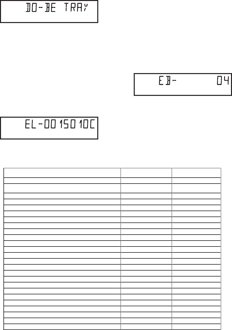
9-6
PCS 103 850
TRAY TEST
As a last action for the Basic Engine tests, the tray test is
repeated. The local display will look as follows:
This test is meant to give the user the opportunity to remove
the disc in the tray. The tray position can be toggled using the
PLAY key. The tray will be closed (by the software, if it is
open) before proceeding to the next test when the user
presses the NEXT key.
3.4 ERROR LOG & BITS
ERROR LOG
Reading the error log and error bits information can be useful
to determine any errors that occurred recently during normal
operation of the DVD player. Reading the error log is done by
nucleus LogReadErr. The display during the errorlog readout
looks as follows :
By pressing PLAY or PREV the user can move forward or
backward (respectively) through the logged error codes. The
highlighted number indicates which errorcode is currently on
display (in the example above, errorcode number 4 is dis-
played). If “0000” is displayed at all positions, the error log is
empty. Display of the logged errors is done in a cyclic
manner. The errorcode with the lowest highlighted number is
the most recent.
By pressing NEXT on the local keyboard, the user can
proceed to the next test.
ERROR BITS
Reading the error bits is done by nucleus LogReadBits. The
display during the errorbits readout looks as follows:
Only the set errorbits will be shown by their (decimal)
number. Refer to the appropriate documentation for the
explanation of each bit number. If the display only shows
“EB-0”, no error bits were set.
By pressing NEXT the user can continue to the next test.
Read Error LOG in player
script Read error bits in player
script
Basic engine errors Value: Value:
Command to the Basic Engine not allowed in this state or
unknown command 150101 8
Parameter(s) from the command to the Basic Engine is not valid 150102 7
Sledge could not be moved to the inner home position 150103 6
Focus failure 150104 5
Turntable motor could not be reached within timeout 150105 4
Radial servo could get on track on the disc 150106 3
PLL could not lock in the accessing or tracking state 150107 2
Subcode or sector information could not be read 150108 1
requested subcode could not be found 150109 16
Tray could not be closed or opened completely 15010A 15
TOC could not be read within timeout 15010B 14
The requested seek on the disc could not be executed 15010C 13
A requested lead is not on the disc 15010D 12
A non existing burst cutting area is requested 15010E 11
S2b communication error 1501F0 10
S2b communication error 1501F1 9
S2b communication error 1501F3 24
S2b communication error 1501F4 23
S2b communication error 1501F5 22
Digital PWB errors
Communication error with the Sti 5505 90000 32
Communication error with the Sti 5505 90001 31
Display processor errors
Communication error with the display processor 190000 40
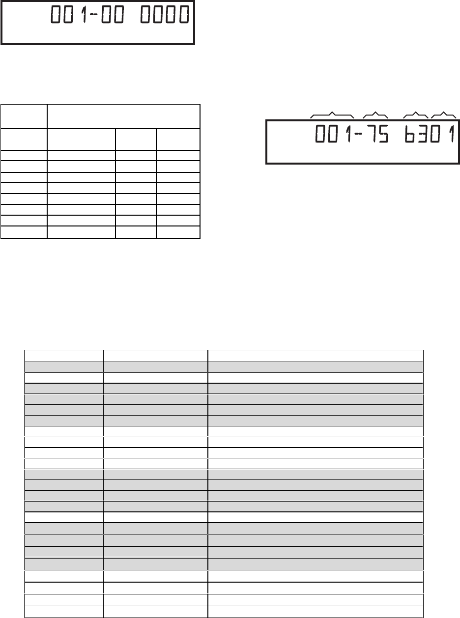
9-7
PCS 103 851
3.5 LOOP TEST
At the start of the loop test, the display will show the result of
the interactive player test:
The left side of the display contains a 3-digit code, which can
have a value between 000 and 111. these values are to be
interpreted as follows:
Display
Value
000
001
010
011
100
101
110
111
Indication for each module
Basic Engine
ok
ok
ok
ok
faulty
faulty
faulty
faulty
Mono
PCB
ok
ok
faulty
faulty
ok
ok
faulty
faulty
Display
PCB
ok
faulty
ok
faulty
ok
faulty
ok
faulty
The loop test will perform the same nuclei as the dealer test,
but it will loop through the list of nuclei indefinitely.
The display of the DVD player will show not only the 3-digits
indicating the correctly/faulty modules and the last found
error code, but also a loop counter indicating how many
times the loop has been gone through.
Note: Only faults within the scope of the diagnostic
software are detected.
Example:
FAULTY
MODULE(S) LOOP
COUNTER NUCLEUS ERROR
The 2-digit after the hyphen indicates the number of times
the loop test has been performed.
The following 4-digits show the last error that was found
while running the loop test. The first 2 digits of this code
indicate which nucleus resulted in a fault and the next 2 digits
refer to the faultcode within that nucleus.
For further explanation of the error code, see list of error
codes on below.
ERROR CODES LOOP TEST
ERROR CODE NUCLEUS NUMBER ERROR DESCRIPTION
0601 6 Calculated checksum of FLASH is not correct
0901 9 The DVD DRAM is faulty
1101 11 I2C bus busy before start
1102 NVRAM access time-out
1103 No NVRAM Acknowledge
1104 NVRAM reply time-out
1201 12 I2C bus busy
1202 I2C bus not working
1203 Slave controller not responding
1204 Slave response is not correct
1301 13 Parity error from basic engine to serial
1302 Parity error from serial to basic engine
1303 No communication between serial and basic engine
1304 Communication time-out error
1601 16 The SDRAM is faulty
5201 52
I2c bus busy
5202
I2c bus not working
5203
Colour setup controller not responding
5204
Colour setup controller response not correct
5401 54
I2c bus busy
5402
I2c bus not working
5403
Scart switch controller not responding
5404
Scart switch controller response not correct

9-8
PCS 103 852
SERVICING THE DVD MODULE AND MONO BOARD
For repair on the DVD module (Basic Engine and the mono board), refer to Service Document:
2nd line Service Manual DVD-Monoboard....................................................... 3122 785 10045
Caution
This information is confidential and may not be distributed. Only a qualified service person
should
reprogram the mono board.
After replacement/repair of the mono board, the customer settings and also the region code may be lost.
Reprogramming of the mono board will put the player back in the state in which it has left the factory,
i.e. with the default settings and the allowed region code.
Reprogramming is limited to 25 times.
When the counter reaches 25, reprogramming is not possible anymore.
Reprogramming will be done by way of the remote control.
Put the player in stop mode, no disc loaded.
Press the following keys on the remote control:
<PLAY>
followed by numerical keys
<1> <5> <9>
The display shows:
“
- - - - - - - - - - -
”
Press now successively the following keys :
for FW-D1/21 :
<0><4><4> <0><0><0> <0><0><0> <0><0><0> Latam
for FW-D1/21M :
<0><4><2> <0><0><0> <0><0><0> <0><0><0> AP
for FW-D1/33 :
<0><4><2> <0><0><0> <0><0><0> <0><0><0> AP
for FW-D5/21 :
<0><1><4> <0><0><0> <0><0><0> <0><0><0> Latam
for FW-D5/21M :
<0><0><5> <0><0><0> <0><0><0> <0><0><0> AP
for FW-D5/22 :
<0><0><1> <0><0><0> <0><0><0> <0><0><0> Europe
for FW-D5/30 :
<0><1><2> <0><0><0> <0><0><0> <0><0><0> AP
for FW-D5/33 :
<0><0><5> <0><0><0> <0><0><0> <0><0><0> AP
for FW-D5/37 :
<0><0><4> <0><0><0> <0><0><0> <0><0><0> US
Press
<PLAY>
again.
The TV screen will become BLUE during a short time to confirm that the digital board has been
reprogrammed, then the set goes to standby mode.
Reprogramming of Mono Board
RESET OF VIRGIN MODE
After the player has been powered up for test by the dealer,
it would have gone through the Virgin Mode. It is possible to
reset the settings made during that mode before the delivery
of player to the customer.
This is done by executing the Eeprom Format while in the
Service Test Program (see page 3-6)
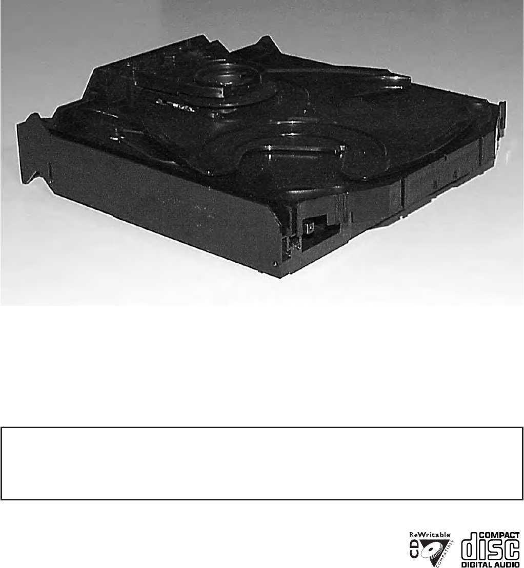
10-1
CS 53 300
TABLE OF CONTENTS
Servicing Hints ..................................................................10-2
Wiring................................................................................10-4
Blockdiagram ....................................................................10-5
Component Layout Main Board ........................................10-6
Circuit Diagram part1 ........................................................10-7
Component Layout Main Board ........................................10-8
Circuit Diagram part2 ........................................................10-9
Exploded View ..................................................................10-10
Partslist .............................................................................10-12
3CDC-LC
(3 Disc Carrousel Changer)
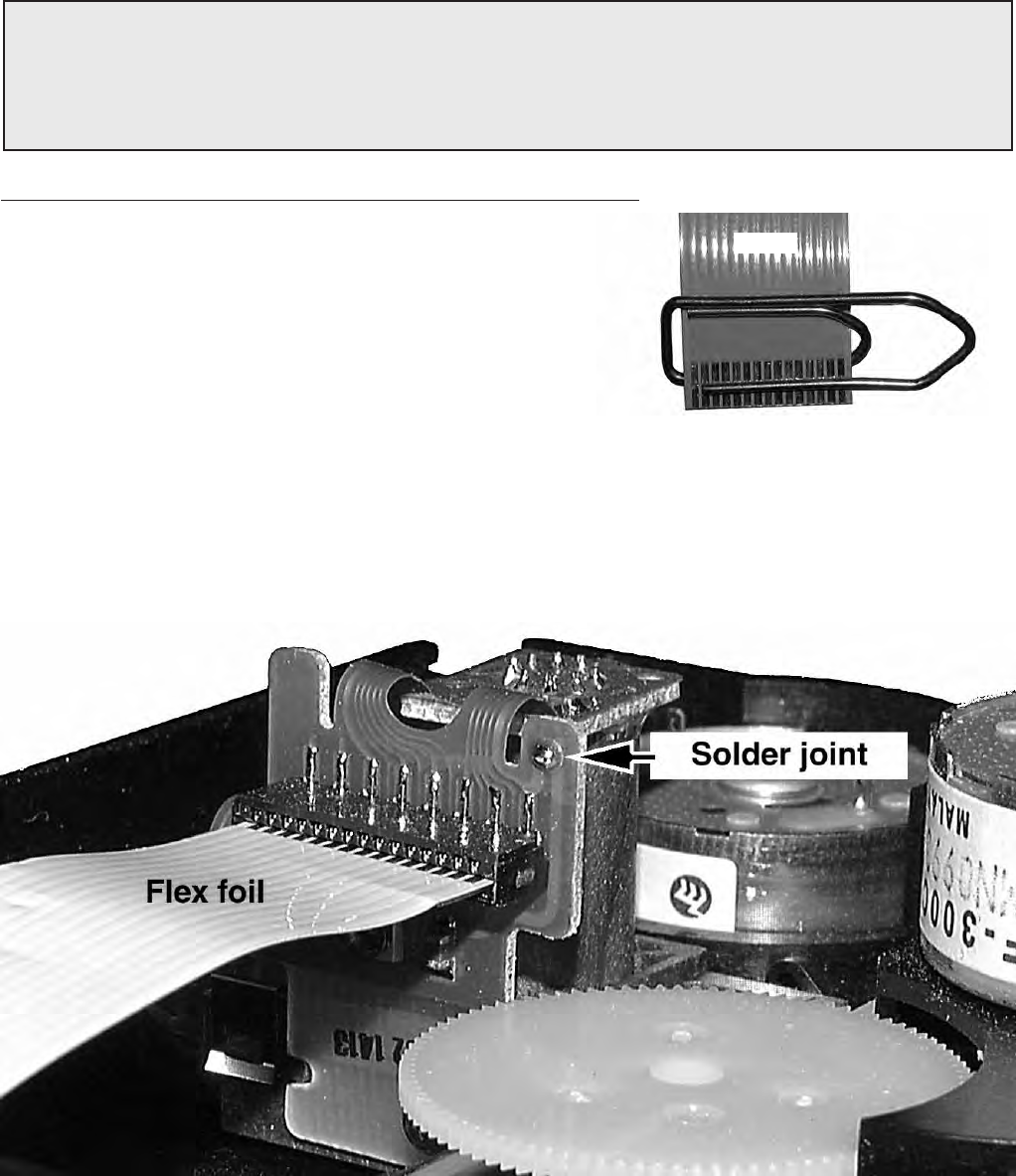
10-2
CS 53 301
The following steps have to be done when replacing the CD mechanism:
1. Disconnect CD drive flexfoil from old CD drive
2. Connect paperclip to CD drive flexfoil to short-circuit flexfoil (fig.1)
3. Remove old CD drive
4. Remove short-circuit from flexfoil
5. Connect flexfoil to new CD drive
6. Position new CD drive in its studs
7. Remove short-circuit from Laserunit
CHARGED CAPACITORS ON THE SERVO BOARD MAY DAMAGE THE CD DRIVE ELECTRONICS WHEN
CONNECTING A NEW CDM MECHANISM. THAT´S WHY, BESIDES THE SAFETY MEASURES LIKE
• SWITCH OFF POWER SUPPLY
• ESD PROTECTION
ADDITIONAL ACTIONS MUST BE TAKEN BY THE REPAIR TECHNICIAN.
WARNING
fig.1
Attention: The laser diode of this CD drive is protected against ESD by a solder joint which shortcircuits the
laserdiode to ground.
For proper functionality of the CD drive this solder joint must be removed after connection the drive to
the set.
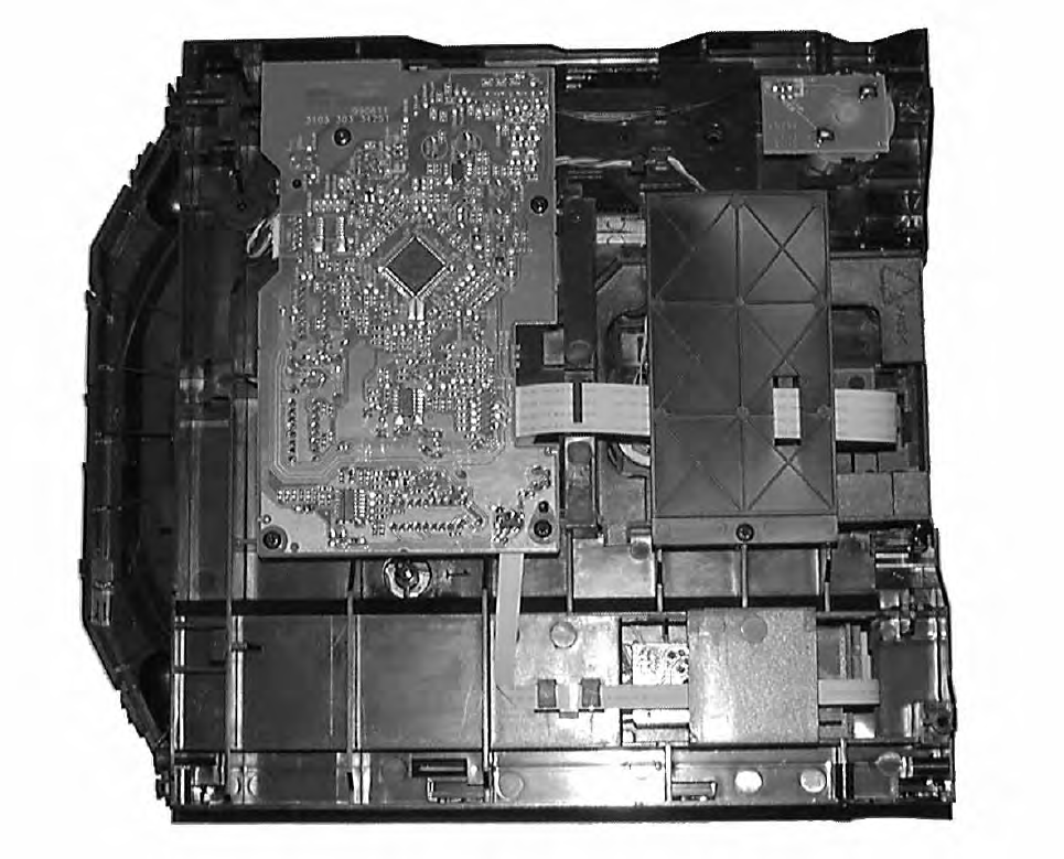
10-3
CS 53 302
Service Position
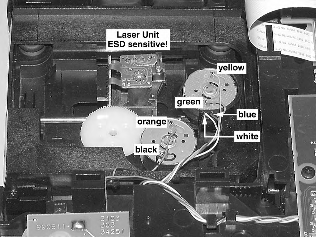
10-4
CS 53 303
Wiring
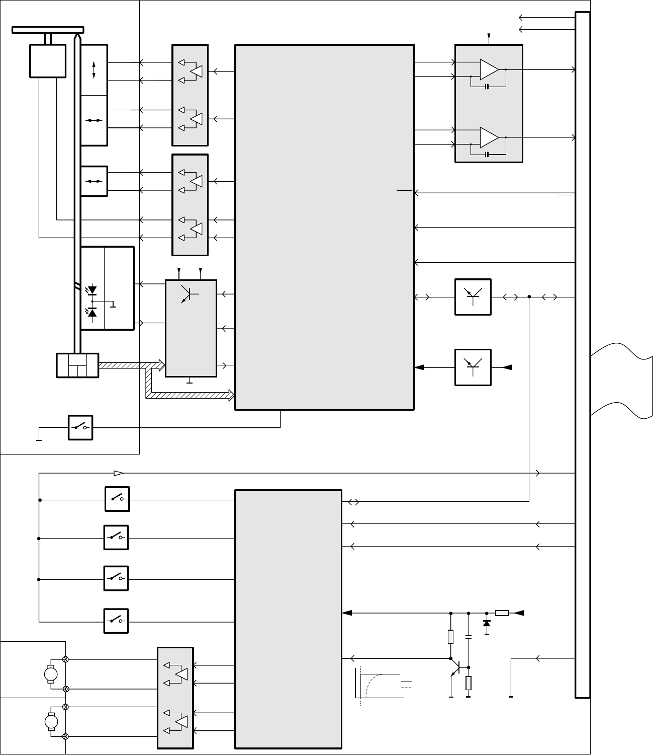
10-510-5
CS 53 304
DATA
SDA
VCC
1805
D1-D5
D2-D4
7807
7806
7871
7873
TDA7073A
TDA7073A
TDA7073A
HEF4094BT
TTM+
TTM-
MOT2
LD ON
LD
MON CD R/W
HF IN
V1
D1
D2
D3
D4
R1,R2
MOT1
SLEDGEB-
SLEDGEB+
RADB-
RADB+
FOCB-
FOCB+
+5V
+10V
SHR_CL
STR-OUTP
OE_LATCH
FLEX-FOIL
8001
REGISTER
SHIFT
SERVO - DECODER
CD10
SAA7324 (SAA7325)
Active low pass
Filter
TDA1308
MOTOR
TRAY MOTOR
CARROUSEL
CD DRIVE UP/DOWN SWITCH
1881
1880
TRAY SWITCH
1882
7874
CD POS.1 SWITCH
SL
O2
O0
O1
O7
VDD +10V
O6
O5
O4
RA
FO
DIODES
PHOTO
D3D2 D5D1 D4
INNER SWITCH
SWITCH INFO
LASER &
MONITOR
DIODE
TURNTABLE
MOTOR
DISC
CD MECHANISM
FOCUS
MOTOR
RADIAL
MOTOR
SLEDGE
MOTOR
MOTOR
TURNTABLE
PHOTODIODE & HF AMPLIFIER - LOADER CONTROL PCB
EN1
DATA
STB
SHR_CL
SICL
SILD
PORE
7875
7801
+3,3V
CD LEFT
78057877
CD RIGHT
Laser Control
&
HF AMPLIFIER
TZA1024 (TZA1025)
55
54
56
38
7
18
20
21
23
15
5
2
3
22
23
18
19
2
4
6
5
9
SWITCH INFO
17
16
15
6
42
40
39
5,17,21,52,57
59
60
64
113
+5V
2
+5,6V
8
4
5
7
V4
61
15
63
10
11
6,14
7
14
4
15
2
1
3
16
5
9
11
12
13
5V1
+5V
+3,3V
SCL
SILD
RN
RP
LN
LP
PORE
+
-
+
-
Blockdiagram 3CDC-LC 1999 09 21
Closed if carrousel is in Position 1.
1883
O3
Open if carrousel is in a valid Play-Position.
Closed if the tray is in one endposition.
Open during movement.
Open if the drive is in one endposition.
Closed during movement.
V
t
VDD (pin 16)
EN1 (pin 15)
Power on
Blockdiagram

10-6 10-6
CS 53 305
A
1
2
3
4
5
6
7
8
1
2
3
4
5
6
7
8
EBC D
AEBC D
This assembly drawing shows a summary
of all possible versions.
For components used in a specific version
see schematic diagram respectively partslist. 3CDC-LC Mainboard Layout stage .2 990920
3CDC-LC Mainboard Componentside view
E
1
2
3
4
5
6
7
8
1
2
3
4
5
6
7
8
ADC B
EADC B
This assembly drawing shows a summary
of all possible versions.
For components used in a specific version
see schematic diagram respectively partslist. 3CDC-LC Mainboard Layout stage .2 990920
3CDC-LC Mainboard Copperside view
Copperside
2800 B6
2801 B4
2802 B6
2803 B4
2805 B4
2806 B4
2807 B6
2808 B4
2810 B5
2811 B4
2815 C6
2816 C3
2818 B3
2822 C5
2823 C5
2824 C5
2825 B5
2829 C8
2830 B3
2831 C2
2832 B3
2833 B3
2834 B4
2835 D5
2840 E4
2841 D5
2842 D6
2844 D5
2850 C3
2852 D3
2853 D4
2854 D4
2855 B5
2856 C3
2857 D5
2859 C5
2862 B3
2863 B3
2864 D4
2865 C2
2867 B2
2869 B6
2872 D7
2877 E8
2878 E8
2879 D5
2882 C2
2887 B3
2891 D7
2892 C6
2893 E8
3700 D4
3705 E3
3706 D3
3707 D3
3708 D3
3709 C3
3711 D3
3712 C1
3713 C7
3714 D7
3715 D7
3716 D4
3717 D4
3718 D3
3727 C3
3728 C3
3730 C3
3731 D3
3732 D3
3733 D3
3734 D4
3735 C5
3736 C5
3740 B3
3741 B3
3742 B3
3743 C3
3744 B2
3746 C2
3750 B2
3751 B2
3770 C3
3771 A2
3772 A2
3780 C3
3781 C2
3782 A2
3800 B6
3801 B5
3802 B6
3803 B4
3804 C3
3805 B4
3806 B4
3807 B4
3808 B4
3809 D4
3811 B6
3814 B4
3819 C3
3820 B6
3821 B6
3822 B6
3823 C6
3824 C6
3825 C5
3826 C5
3827 B4
3828 D4
3831 D3
3832 C3
3833 B5
3834 B6
3837 D4
3838 D4
3839 D5
3840 C5
3841 D4
3842 D4
3843 D5
3844 D6
3845 D4
3846 D5
3847 D7
3848 C4
3849 D5
3850 E5
3853 B5
3854 A2
3855 A2
3856 B5
3857 B5
3858 A2
3859 A2
3860 B2
3861 B3
3862 B3
3863 D4
3864 B2
3866 C6
3867 B3
3868 C2
3869 B6
3870 B6
3871 E8
3872 C2
3873 C3
3874 C2
3875 D3
3876 D3
3877 E8
3878 A1
3879 C8
3880 C7
3881 D7
3882 D8
3883 C8
3884 C8
3885 C8
3886 D8
3887 D7
3888 E8
3889 D3
3890 D8
3891 D8
3892 D3
3893 D7
3894 B5
3895 C5
3897 D6
3898 D7
3899 A4
4800 A1
4801 B1
4802 B1
4803 D2
4804 A1
4805 A1
4806 A1
4807 A1
4808 A1
4809 A2
4810 B2
4811 D6
4812 D6
4813 B1
4814 B1
4815 B1
4816 B1
4817 C1
4818 C1
4819 C1
4820 B3
4821 D2
4822 A3
4823 A3
4824 A3
4825 C2
4826 C3
4827 B1
4828 D3
4829 D2
4830 D5
4831 B8
4832 D4
4833 C5
4834 B5
4835 C6
4836 B6
4837 C5
4838 C5
4839 C5
4840 C6
4841 D7
4842 C5
4843 C6
4844 C6
4845 B7
4846 B6
4847 B6
4848 B7
4849 B1
4876 A3
6871 E8
6872 D8
6873 D8
6874 C7
6875 D7
6876 A3
6877 B3
6878 D8
6879 D3
7801 C6
7805 B2
7812 C7
7850 A2
7851 A2
7860 A2
7861 A2
7873 D8
7874 D3
7875 B4
7876 D3
7877 C4
Componentside
1800 A6
1801 E3
1805 B1
1810 B3
1875 A8
1878 C2
1880 E2
1881 A7
2809 D5
2826 C5
2828 D4
2837 D5
2838 C6
2839 D6
2849 B5
2851 B3
2858 B2
2860 A3
2861 A3
2873 B8
2875 B7
2876 B2
2881 C7
2884 C6
2885 B5
2888 C7
3812 D6
3815 C7
3835 E6
3851 B7
3852 E5
5802 D2
7806 E6
7807 E5
7871 C8
Mapping
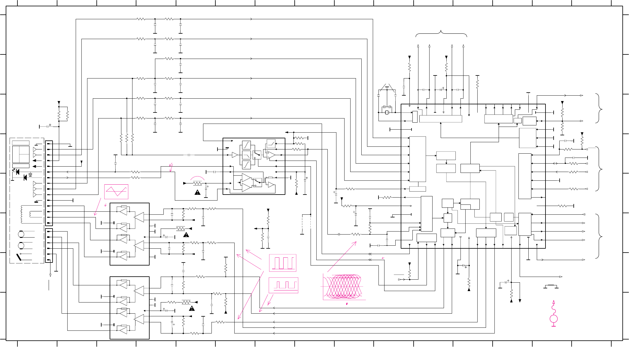
10-710-7
CS 53 306
SER. DATA
LOOPBACK
INTERF.
KILL
TIMING
BITSTREAM DAC SER. DATA
INTERFACE VERSAT.
INTERF.
EBU
INTERF.
CORR.
ERROR
CONTROL
FUNCTION
PRE-
PROCESSING
AUDIO
PROCESSOR
MICROCONTROLLER
INTERFACE
SUBCODE
PROCESSOR
ADDR
SRAM
PEAK
DET.
MOTOR
CONTROL
OUTPUT
STAGES
DIG.
PLL
EFM
DEMOD
VERSATILE
INTERFACE
ADC
VREF GEN.
FRONT
END
VDD
-
+
-
+
2x
4x
1x
V/I
V/I
Vgap
VDD
-
+
-
+
(Quartz used)
SLIDE
SLIDE
Signal Processor
F+
L
MP855 E10
MP858 F9
MP859 F10
MP860 C2
MP861 E8
MP870 D8
MP872 C15
MP873 H4
MP875 G13
MP877 E4
MP878 B13
MP828 G9
MP829 B3
MON
MP879 B11
MP883 E5
SLIDE
D
D2
D5
D4
D
E
F
G
H
1800 D1
1801 G1
1810 C10
2800 C4
2801 C5
2802 C4
2803 C5
2805 B5
2806 B5
2807 A4
2808 A5
T+
on
#
123456789101112131415
123456
D3 (CD10)
D2 (CD10)
DISC
R2 (CD10)
D2
D
3863 = 33R
D1
891011 12 13 14 15
A
B
C
D
E
F
G
H
A
2809 H4
+
HF-Amplifier
Motor Driver
+
CD Drive
D4 (CD10)
VREF
LD
GND
D3
+
GND
+
2810 A4
2811 A5
2815 D5
2816 B12
2818 B11
2822 F9
2823 F10
2824 F10
2825 F9
2826 G12
2828 G13
7
D2
F-
D
PIN50
2835 F7
2837 H4
2838 E8
2839 F4
2840 G4
2841 F5
2842 F5
2844 F5
2849 C1
2850 D14
2851 B11
2855 B4
2856 D15
B
C
3CDC-LC-mainboard
DOBM
dig. out circuitry
part 1
D3
_
2869 D3
2879 H5
2884 E8
2885 F9
2887 B10
2888 E5
2891 F4
2892 D5
3709 C14
3727 B12
3728 E14
3735 G6
3736 H6
3800 C4
3801 C4
3802 C4
3803 C4
3804 C14
3805 B42833 C10
2834 C10
#.... for provision only
VCC / SAA7325
D1 (CD10)
D5
3811 B4
3812 H4
3815 E5
3819 D14
3820 D3
3821 D3
3822 D3
3823 D8
3824 D8
3825 F9
3826 F9
3827 E10
3828 G10
3832 D15
3833 A4
3834 A4
3835 F5
3837 F7
3838 F7
3839 H6
3840 G5
3841 G5
3842 E5
2857 H5
2859 G5
#
_
TRACK
FOCUS
_
for Coax out versions
for basic version
only for digital out versions
/ TZA1025
FOCUS
3845 F5
3846 F5
3847 F5
3848 H6
3849 H5
3850 H5
3852 H5
3853 E9
3856 C1
3857 C2
3862 B10
3863 H13
3866 D83806 B4
3807 A4
D
part 2
3808 A4 3870 E3
3873 D14
3889 D15
3892 E15
3894 E9
3895 G12
3897 E7
4811 F8
4812 F8
7801 E7
7806 G4
7807 H4
7877 D12
MP713 C5
MP715 C5
MP716 A5
MP717 A5
MP729 B5
MP730 B5
MP731 B13
MP743 D2
3843 E5
3844 F5
TRACK
FOCUS
for digital out version:
D4
+
TRACK
Laser power control
from 1801
MP800 E3
MP802 B15
MP809 E10
MP812 F2
MP813 C3
MP814 F2
MP815 C3
MP816 A3
MP817 A3
MP818 D3
MP819 G9
MP820 F8
MP821 D15
MP827 B10
3867 B11
3869 D3
D
DISC
+
DISC
_
D
to 7877
D
R1 (CD10)
Servo driver
MP837 E3
MP838 G6
MP839 G6
MP840 E6
MP841 F6
MP842 H6
MP843 F6
MP844 E9
MP845 F4
MP846 G1
MP847 G2
MP848 E2
MP849 F2
MP850 F2
MP851 E2
MP744 D2
MP745 E2
VAM2201
D4
T-
D1
D3
INNERSW.
D5
_
_
D1
MP884 E5
MP893 F10
MP895 E14
MP896 B12
MP852 F2
MP853 F2
#
to
33p
2833
3735
+3.3V
680K
3736
680K
10u
2838
120R
3867
33K 3827
3897 100R
100K
3839
2810
180p
3728
4K7
+3.3V
2849 4u7
2834
33p
2811
220p
MP893
100K
3849
2857
10n
3826
22K
+10V
27p
2856
2824
47n
3850
3K9
3807
10K
3815
4R7
3832
4u7
2888
+3.3V
10K
2816
1n5
3824 1K
4K7
3727
3806
10K
3862
120R
100n
2887
+3servo
+3.3V
3853
470R
3805
10K
33
VSSD1
50
VSSD2
58
VSSD3
35
WCLI
28
WCLK
3852
2R2
31
TEST2
44
TEST3
63
V1
34
V2|V3
61
V4
62
V5
5
VDDA1
17
VDDA2
52
VDDD1P
57
VDDD2C
20
VNEG
21
VPOS
7
VRIN
4
VSSA1
14
VSSA2
RESETn
22
RN
23
RP
48
SBSY
40
SCL
37
SCLI
29
SCLK
39
SDA
36
SDI
24
SELPLL
47
SFSY
42
SILD
SL
56
43
STATUS
46
SUB
25
TEST1
1
HFREF
6
IREF
3
ISLICE
32
KILL
64
LDON
18
LN
19
LP
59
MOTO1
60
MOTO2
12
R1
13
R2
54
RA
RAB
41
45
RCK
38
53
CFLG
49
CL11|4
26
CL16
16
CRIN
15
CROUT
8
D1
9
D2
10
D3
11
D4
27
DATA
51
EF
30
55
FO
2
HFIN
3844
+10V
SAA7324
7877
47u
4K7
10K
3803
2828
4K73820
3812
2R2
270p
3892
470R
2841
3800
56K
MP844
2805
220p
22K
3834
+3.3V
10K
3804
10
11
12
13
14
15
2
3
4
5
6
7
8
9
1800 1
270p
2844
8
11
15
14
10
2
1
6
7
16
13
9
12 5
3
4
47K
TDA7073A 7807
470R3873
3845
+3.3V
47n
2879
3828
22K
2806
220p
+3.3V
10K
3801
VCCL
11
CDRW
3
CFIL
8
CMFB
5
DIN
12
EQSEL
6GND
1
LD
4
MON
7
PWRON
10
RFEQO
9
RFFB
14
RGADJ
13
VCC2
2
4R7
7801
TZA1024
3869
470R
3889
2808
220p
EBUGND
3856
68R
180p
2802
22K
3833
2839
47u
4u72884
+3servo
4K73821
+3.3V
3843
2826
47u
2859
10n
33K 47K
3842
1n5
2818
1K
3823
6K8
3847
10n
2825
220p
2803
3709
4K7
3841
1R
2800
180p
3825
1K
330p
2807
1K3838
3840
2842
2n2
100K
100R3870
100n
10K
2840
3808
4811
10K
3866
4812
+5V
3811
18K
2891
1n5
220p
2801
2823
47p
3822
2851
220u
2809
2K7
47u
2837
0u47
470p
2855
2885
4u7
+3.3V
68R
3857
4n72892
+3servo
3802
16
13
9
12 5
3
4
8
11
15
56K
7806TDA7073A
14
10
2
1
6
7
1
2
3
4
5
6
1801
PH-S
1810
TF01
2850
1n
3895
15R
+5V
470R
3819
3846
1K
3837
33K
220n
2815
47n
2869
3848
100K
2835
2822
47n
2n2
100R
3R3
3835
3863
M1
3894
100R
VrefCD10
HFIN
KILL_R
Vref
Innersw
Vref
VrefCD10
FO
Vref
DOBM
CL11
KILL_L
LPLN
RAM2
RN
RCK
SBSY
RP
SFSY
SL
SUB
Innersw
SILD
SICL
SDA
PORE
HFOUT
Vref
3CDC-LC Part1 1999 10 13
To 7876 on part 2
(CD-Text IC) To 1805 on part 2
(µP-Interface) To 3770,3780 on part 2
(Mute)
To 7805 on part 2
0V
for CD TEXT only
4.7V
during Focus search
1V
1.6V
0V
3.2V
3.4V
0.9V
1.7V
1.7V
3.0V
for CD_DA : 0V
3V
3V
1.6V
1.6V
3.2V
0.8V
5.1V
1.6V
4.8V
0.3V
1.6V
0V
->Laser damaged !
3.2V
1.6V
0V
1.7V
1.6V
1.6V
0.3V
0V
3V
1.6V
3V
1.6V
0.2V
0V
1.9V
2.9V
ESD sensitive lines!
2.9V
5V
1.6V
EYE-PATTERN
1.6V
4.7V
3.2V
0.8V
2.1V
3.2V
1.6V
10V
1.6V
11.3 MHz
0V
U >400mV
4.7V
1.6V
1.6V
1.6V
4.6V
5V
1.6V
1.6V
10V
5V
for CD_RW : 3V
TB = 0.5us/div
1.7V
3V
1.6V
1.6V
4.9V
0V
1.6V
800mVpp
EVM
V
...DC voltages measured
in Play mode
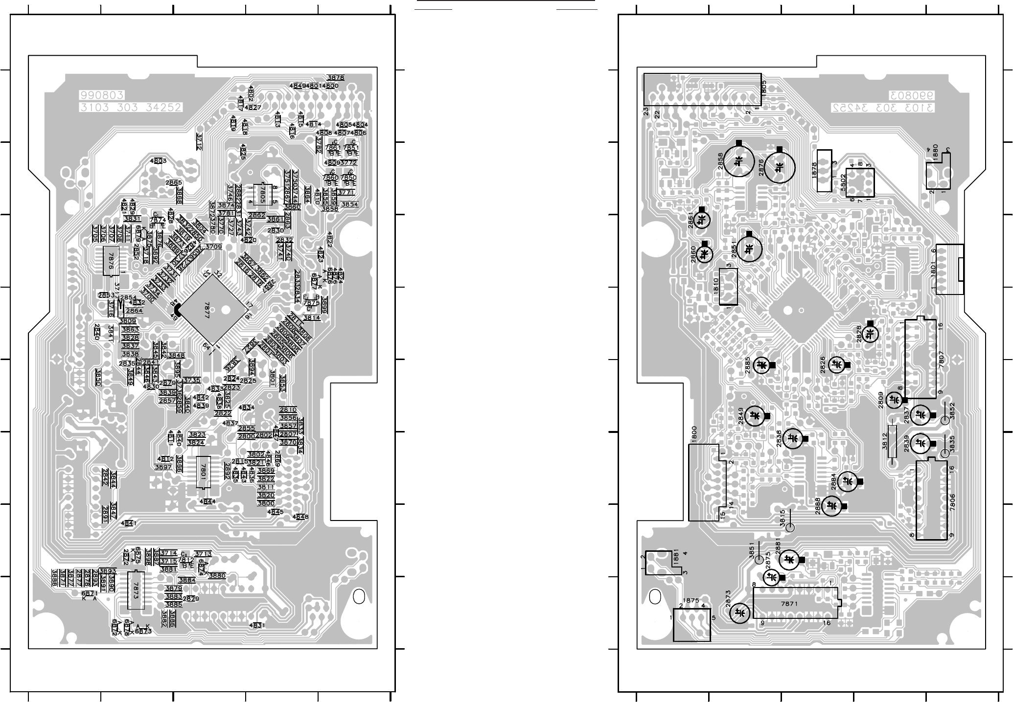
10-8 10-8
CS 53 307
A
1
2
3
4
5
6
7
8
1
2
3
4
5
6
7
8
EBC D
AEBC D
This assembly drawing shows a summary
of all possible versions.
For components used in a specific version
see schematic diagram respectively partslist. 3CDC-LC Mainboard Layout stage .2 990920
3CDC-LC Mainboard Componentside view
E
1
2
3
4
5
6
7
8
1
2
3
4
5
6
7
8
ADC B
EADC B
This assembly drawing shows a summary
of all possible versions.
For components used in a specific version
see schematic diagram respectively partslist. 3CDC-LC Mainboard Layout stage .2 990920
3CDC-LC Mainboard Copperside view
Copperside
2800 B6
2801 B4
2802 B6
2803 B4
2805 B4
2806 B4
2807 B6
2808 B4
2810 B5
2811 B4
2815 C6
2816 C3
2818 B3
2822 C5
2823 C5
2824 C5
2825 B5
2829 C8
2830 B3
2831 C2
2832 B3
2833 B3
2834 B4
2835 D5
2840 E4
2841 D5
2842 D6
2844 D5
2850 C3
2852 D3
2853 D4
2854 D4
2855 B5
2856 C3
2857 D5
2859 C5
2862 B3
2863 B3
2864 D4
2865 C2
2867 B2
2869 B6
2872 D7
2877 E8
2878 E8
2879 D5
2882 C2
2887 B3
2891 D7
2892 C6
2893 E8
3700 D4
3705 E3
3706 D3
3707 D3
3708 D3
3709 C3
3711 D3
3712 C1
3713 C7
3714 D7
3715 D7
3716 D4
3717 D4
3718 D3
3727 C3
3728 C3
3730 C3
3731 D3
3732 D3
3733 D3
3734 D4
3735 C5
3736 C5
3740 B3
3741 B3
3742 B3
3743 C3
3744 B2
3746 C2
3750 B2
3751 B2
3770 C3
3771 A2
3772 A2
3780 C3
3781 C2
3782 A2
3800 B6
3801 B5
3802 B6
3803 B4
3804 C3
3805 B4
3806 B4
3807 B4
3808 B4
3809 D4
3811 B6
3814 B4
3819 C3
3820 B6
3821 B6
3822 B6
3823 C6
3824 C6
3825 C5
3826 C5
3827 B4
3828 D4
3831 D3
3832 C3
3833 B5
3834 B6
3837 D4
3838 D4
3839 D5
3840 C5
3841 D4
3842 D4
3843 D5
3844 D6
3845 D4
3846 D5
3847 D7
3848 C4
3849 D5
3850 E5
3853 B5
3854 A2
3855 A2
3856 B5
3857 B5
3858 A2
3859 A2
3860 B2
3861 B3
3862 B3
3863 D4
3864 B2
3866 C6
3867 B3
3868 C2
3869 B6
3870 B6
3871 E8
3872 C2
3873 C3
3874 C2
3875 D3
3876 D3
3877 E8
3878 A1
3879 C8
3880 C7
3881 D7
3882 D8
3883 C8
3884 C8
3885 C8
3886 D8
3887 D7
3888 E8
3889 D3
3890 D8
3891 D8
3892 D3
3893 D7
3894 B5
3895 C5
3897 D6
3898 D7
3899 A4
4800 A1
4801 B1
4802 B1
4803 D2
4804 A1
4805 A1
4806 A1
4807 A1
4808 A1
4809 A2
4810 B2
4811 D6
4812 D6
4813 B1
4814 B1
4815 B1
4816 B1
4817 C1
4818 C1
4819 C1
4820 B3
4821 D2
4822 A3
4823 A3
4824 A3
4825 C2
4826 C3
4827 B1
4828 D3
4829 D2
4830 D5
4831 B8
4832 D4
4833 C5
4834 B5
4835 C6
4836 B6
4837 C5
4838 C5
4839 C5
4840 C6
4841 D7
4842 C5
4843 C6
4844 C6
4845 B7
4846 B6
4847 B6
4848 B7
4849 B1
4876 A3
6871 E8
6872 D8
6873 D8
6874 C7
6875 D7
6876 A3
6877 B3
6878 D8
6879 D3
7801 C6
7805 B2
7812 C7
7850 A2
7851 A2
7860 A2
7861 A2
7873 D8
7874 D3
7875 B4
7876 D3
7877 C4
Componentside
1800 A6
1801 E3
1805 B1
1810 B3
1875 A8
1878 C2
1880 E2
1881 A7
2809 D5
2826 C5
2828 D4
2837 D5
2838 C6
2839 D6
2849 B5
2851 B3
2858 B2
2860 A3
2861 A3
2873 B8
2875 B7
2876 B2
2881 C7
2884 C6
2885 B5
2888 C7
3812 D6
3815 C7
3835 E6
3851 B7
3852 E5
5802 D2
7806 E6
7807 E5
7871 C8
Mapping
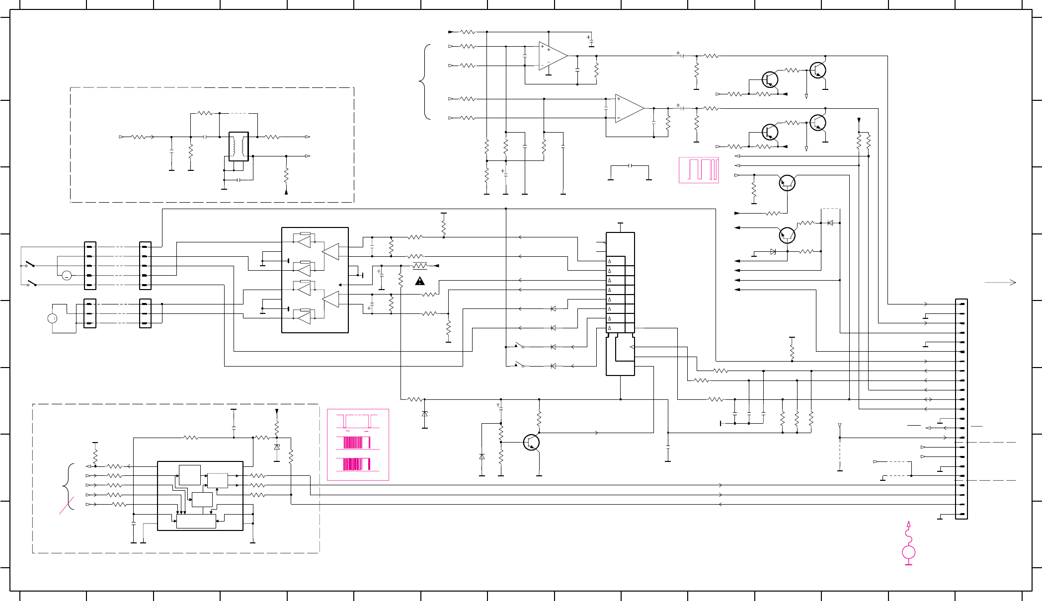
10-910-9
CS 53 308
SRG8
EN1
1D
STB
+
-
+
-
VDD
PROTECTION
TIMING & SYNC
CHECK
CRC
INTERF
CPU
RAM
2 PORT
32 x 8
M
M
1234
#
5
(19 Pin)
#
+10V
from digital-out circuitry
part1
15
A
B
C
D
E
F
G
H
DIPMATE
DIGout
POS rec
uP_CLK
A
B
C
D
E
F
G
H
1805 D15
1875 D2
#
3
logic
SHR_CL
GND
5.6V version only
to 1805
GND
#
Output enable
56789101112131415
1234567891011121314
8003
PORE
#
1883
COAX2/EBU
on
to 7877 on part 1
SILD
POS1 rec
1878 D2
1880 E8
1881 E8
2829 D6
2830 B10
2831 B9
2832 A8
2852 H2
2853 F4
2854 B3
2858 A10
2860 A10
2861 B10
2862 B9
2863 B8
2864 B3
2865 C4
2867 A9
GNDA
FE-ST-VK-N
LEFT
CD-Text circuitry (not for all versions)
+5V(+5.6V)
#
CD-TEXT
GND
1877
RF-500TB
#
1876
RIGHT
2872 G10
2873 D6
2875 E6
2876 C8
2877 F11
2878 F11
2881 F8
2882 B10
2893 F12
3700 H2
3705 G4
3706 G4
3707 G4
3708 G4
3711 G5
8002
3CDC-LC-mainboard
SW_INFO
to combi-
(15 Pin)
KILL_L
BASIC VERSION
Changer Control
from
TRAY POS
3712 B4
3713 F8
3714 F8
3715 G8
3716 B3
3717 B3
3718 G3
3730 G2
3731 G2
3732 G2
3733 G2
3734 G2
3740 A7
3741 A7
3742 B7
3743 A7
3744 A9
3746 B10
#
1882
#
EBU_GND
delay circuitry
voltage stab.
GND/KILL_R
#
3750 B7
3751 C7
3770 A11
3771 A12
3772 A12
3780 B11
3781 B12
3782 B12
3809 B2
3814 C12
3831 F4
3851 D6
3854 A11
3855 B11
3858 A11
3859 B11
3860 B8
3861 B8
3864 A7
DOWN
DQSY
SICL
7877
#
board
to/from 7877 on part 1
3
2
SRDT
3868 C4
3871 F12
3872 B13
3874 B13
3875 C12
3876 C11
3877 F12
3878 E12
3879 D7
3880 E6
3881 E7
3882 C7
3883 D6
3884 D6
3885 C6
3886 E7
3887 D6
3888 F12
3890 F11
3891 F11
#
#
DRIVE UP/
digital out circuitry (not for all versions)
#
SHR_STR
RF-500TB
CAROUSEL-MOTOR
3893 F11
3898 F6
3899 D12
4803 B4
4813 G14
4827 G14
4849 G13
4876 C13
5802 B4
6871 E8
6872 E8
6873 E8
6874 G7
6875 F6
6876 C13
6877 D12
6878 E8
6879 G4
7805-A A10
DATA
DRAWER-MOTOR
part 2
#
7805-B A9
7812 G8
7850 A12
7851 A13
7860 B12
7861 B13
7871 C5
7873 C9
7874 C12
7875 C12
7876 G3
MP721 C8
MP722 E8
MP723 C8
MP724 D8
MP725 D8
MP726 D8
MP740 H14
MP741 G14
MP891 B5
MP892 B5
MP897 D12
MP898 D13
MP899 E14
(23 Pin)
2
MP742 G14
MP801 D12
MP803 F10
MP804 G14
MP805 E13
MP806 F13
MP807 F14
MP808 E13
MP810 F13
MP811 F13
MP822 E3
MP823 D3
MP824 D4
MP825 D4
MP830 A9
MP832 G9
MP833 F13
MP834 G14
MP835 F14
MP854 A13
MP856 E14
MP857 B13
1
4
COAX1/+3V
1
MP862 G13
MP863 C11
MP865 D11
MP866 E8
MP867 E8
MP868 F8
MP869 C12
MP871 D6
MP874 D12
MP881 G2
MP882 G2
MP886 G3
MP887 H5
MP888 G5
MP889 G5
MP890 B3
8
3707 470R
2
15
O0
4
O1
5
O2
6
O3
7
14
O4
O5
13
O6
12
O7
11
9
Os
10
STR
1
VDD 16
VSS
HEF4094BT
7873
CP
3
D
220p
2862
3718
4K7
1
2
34
6
78
5802
920927152B
4813
10K
3770
2865
22n
GNDA
1K
3891
10K3731
3880
3K9
220p
2893
6878
BAS216
2861
10u
BC847B
47n
2830
7874
10K
3871
470R
3716
10K
3860
2853
22n
GNDA
33R
3814
4876
GNDA
3872
2882
220p
10K
470R
3893
BC817-40
7861
BC857B
7860
TDA1308T
7805-A
3
2
1
3732 4827
7805-B
5
6
7
8
4
470R
TDA1308T
470R3708
BAS216
6873
3859
22K
GNDA
1881
47u
3746
10K
2873
3886
47K
1
6
7
16
OUT1-
13
9
12 5
3
4
8
11
15
7
8
9
7871
TDA7073A
14
10
2
18
19
2
20
21
22
23
3
4
5
6
1
10
11
12
13
14
15
16
17
FE-ST-VK-N
1805
3780
10K
BAS216
6872
33K
3730
GNDA
100R
3864
BZX284-C3V9
6877
7851
BC817-40
3884
270R
EXCK
GND
7
MCK5
2 SBSO
SCLK 11
SCOR3 SRDT 12
SW1 9
SW2 10
TEST 8
VDD 14
WFCK4
XMODE6
7876
LC89170M
DQSY 13
1
330R
3809
3858
1880
GNDA
22K
2877
47p
3831
100R
10K
2832
100p
3744
1K
3750
3717
1R
2876
220u
2858
220u
2872
47n
220R
22K
3713
10K
3888
3705
6876
BAS216
GNDA
470R3734
3772
1K
3890
100K
3881
1K
3782
1K
6879
BZX284-C3V9
6874
BAS216
7875
BC847B
GNDA
BZX284-C5V1
6875
2863
10K
3877
220p
3R3
3851
3700
GNDA
3742
470R
22K
22K
3771
3879
100K
1878
DIPMATE
1
2
3
10K3711
2867
220p
3751
1K
3743
22K
2829
3861
10K
22n
1875
FE-ST-VK-N
1
2
3
4
5
2875
10u
2860
10u
3740
22K
2852
47n
4849
3883 10K
2854
47n 10R
3712
EBUGND
10K
3714
3855
100R
2831
100p
3899
100R
3885
3741
22K
3781
22K
10K
2878
220p
7850
BC857B
EBUGND
3874 10K
3878
10K
GNDA
220R
3898
470R3706
GNDA
470R3733
3715
100K
BAS216
6871
3854
100R
3875 10K
2864
22p
3882
47K
4u7
2881
220R
3887
3876
100K
4803
7812
BC847B
+3.3V
+5.6V
+10V
KILL_L_out
SDA
3868
33R
+3.3V
SICL
SILD
+3.3V
+5V
+4V
+5.6V
+5.6V
+10V
KILL_R_out
KILL_L_out
LP
LN
+3.3V
+3.3V
KILL_L
KILL_R
RCK
CL11
SUB
SBSY
SFSY
DOBM
+3.3V
COAX2
COAX1
RN
RP
COAX2
COAX1
PORE
KILL_R_out
3CDC-LC Part2 19990920
From 7877 on part 1
(Signal Processor)
From 7877 on part 1
(Signal Processor)
3.2V
0V
10V
4.9V
3V-5V log.
Levelconverter
2V
2.3V
4.2V
2V
5,1V
CD-TEXT INFO
0V
4.9V
4V
2.3V
0V
0V
0V
3.3ms
4V
4.5V
0V
5,1V
2V
5.1V
5.1V
0V
4.1V
0V
SRDT
SDA
3.3V
7.35KHz
0V
0V
SCLK
11MHz
4.9V
0V
0V
only during
4V
4.9V
5.1V
5V(5.6V)
TOC-reading
0V
DQSY
5.1V
0V
2V
EVM
V
...DC voltages measured
in Play mode
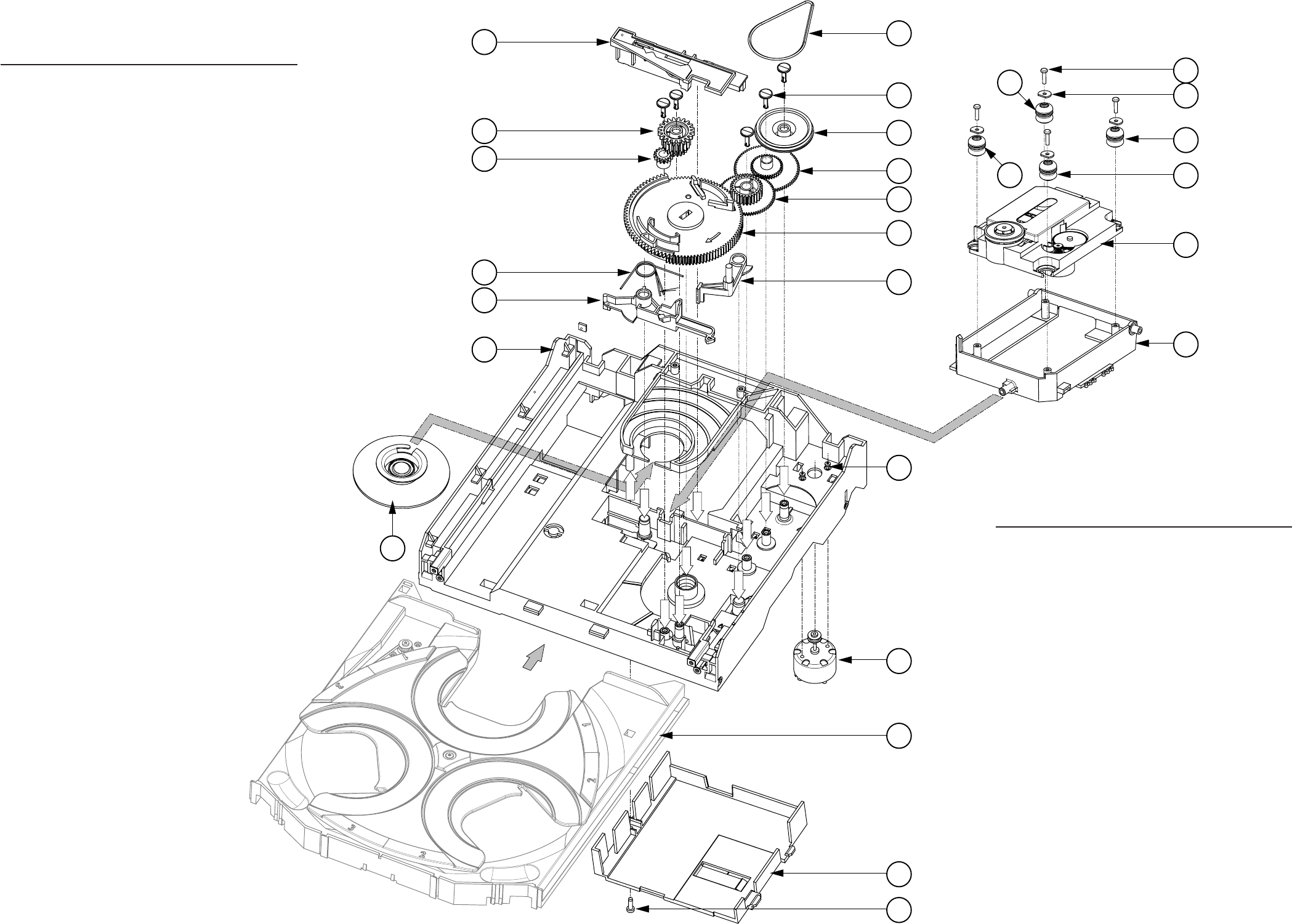
PCS 103 853
10-10 10-10
3CDC-LC Exploded view 1999 09 13
Pos. 51
Pos. 53
Pos. 52
Pos. 47
Pos. 48
Pos. 49
Pos. 43
Pos. 44
Pos. 42
Pos. 57
54
53
47
55
56
31
30
35
32
31
32
33
34
57
58
52
48
45 5x 4x
4x
46
49
44
43
42
41
21
20
51
2x
EXPLODED VIEW (3CDC-LC MODULE)
Mechanical Parts List - 3CDC-LC Module
21 314011758650 CLAMPER ASSY-VAM
30 310330466560 SUPPORT
31 482252910431 DAMPER - RUBBER (25DEG)
32 482252910431 DAMPER - RUBBER (25DEG)
33 310330406970 WASHER
35 482269110772 VAM2201/01
41 310330466480 FRAME
42 310330466540 BRACKET-GUIDING
43 310330106460 SPRING-GUIDING
44 310330406890 GEAR-3
45 310330406980 NAIL
46 310330406880 GEAR-2
47 310330466530 BRACKET-LOAD
48 310330406910 CAM
49 310330466510 GUIDING
51 310330406900 GEAR-4
52 310330406870 GEAR-1
53 310330406960 PULLEY-FRAME
54 310330466910 DRIVING-BELT-DRAWER
55 482236110753 MOTOR ASSY
56 482250212548 SCREW M2,6X2,9
57 310330468890 COVER-VAM
59 482246612146 RUBBER
Notes: Only the parts mentioned in this list are normal
service spare parts.
Mechanical Parts list - Drawer Top & Bottom view
20 3103 304 66500 DRAWER
21 3103 304 66490 CARROUSELL
22 3103 304 06860 PULLEY-DRAWER
23 3103 304 06850 ECCENTRIC
24 3103 304 06980 NAIL
25 3103 304 66850 DRIVING-BELT
27 3103 304 07100 BUSH DRAWER
29 3103 304 66550 BRACKET-DISC
30 3103 304 66520 TUMBLER
31 3103 301 06470 SPRING-DISC
32 3103 304 06920 CONTROL-DISC
33 3103 304 06970 WASHER
34 3103 304 06870 GEAR-1
37 4822 361 10753 MOTOR ASSY
Notes: Only the parts mentioned in this list are normal
service spare parts.
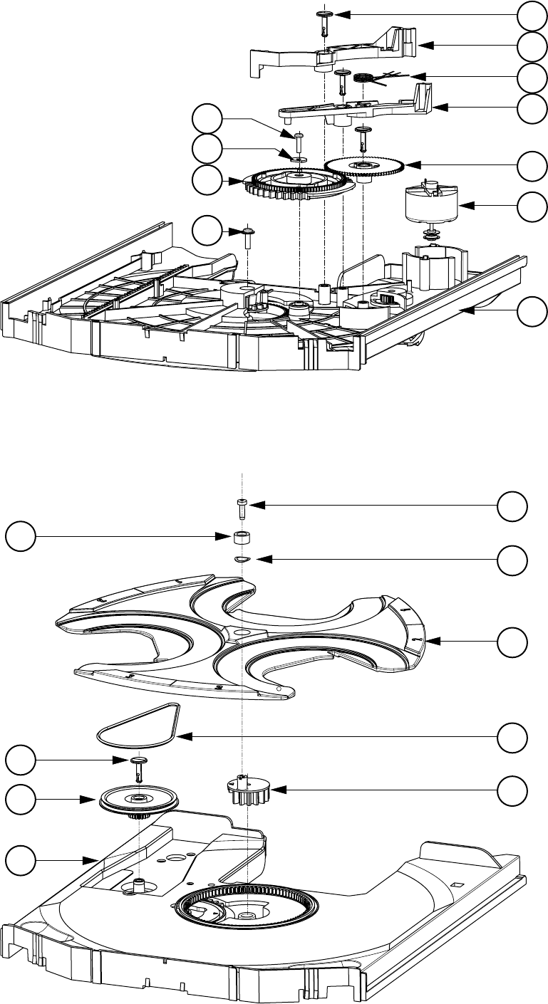
PCS 103 854
10-11
3CDC-LC Drawer assy 1999 09 13
37
20
32
35
33
36 29
31
34
24
30
3x
27
24
22
20
23
25
21
26
28
Drawer top view
Drawer bottom view

PCS 103 855
10-12
MISCELLANEOUS
1800 482226510925 Flex Foil Connector 15P
1805 482226510979 Flex Foil Connector 15P
1805 482226511545 Flex Foil Connector 19P
1805 482226511182 Flex Foil Connector 23P
1810 482224210849 RES XTL 8MHz4672
1810 482224273557 RES CER 8MHz467
1875 482226710958 Flex Foil Connector 5P
1876 242202508332 Flex Foil Connector 5P
1880 482227613503 Switch
1881 482227613503 Switch
1882 482227613503 Switch
1883 482227613503 Switch
8002 310330891990 Flex Foil 5P 200mm
8005 310330891980 Flex Foil 15P 170mm
CAPACITORS
2800 482212610326 180pF 5% 63V
2801 482212233575 220pF 5% 63V
2802 482212610326 180pF 5% 63V
2803 482212233575 220pF 5% 63V
2805 482212233575 220pF 5% 63V
2806 482212233575 220pF 5% 63V
2807 532212231863 330pF 5% 63V
2808 482212233575 220pF 5% 63V
2809 532212441948 470nF 20% 50V
2810 482212610326 180pF 5% 63V
2811 482212233575 220pF 5% 63V
2815 482212614076 220nF +80/-20% 25V
2816 482212613344 1,5nF 5% 63V
2818 482212613344 1,5nF 5% 63V
2822 222286115222 2,2nF 5% 50V
2823 482212613692 47pF 1% 63V
2824 482212613751 47nF 10% 63V
2825 482212233177 10nF 20% 50V
2826 482212412362 47µF 20% 4V
2828 482212412362 47µF 20% 4V
2829 532212232654 22nF 10% 63V
2830 482212613751 47nF 10% 63V
2831 532212232531 100pF 5% 50V
2832 532212232531 100pF 5% 50V
2833 532212232659 33pF 5% 50V
2834 532212232659 33pF 5% 50V
2835 482212613751 47nF 10% 63V
2837 482212440433 47µF 20% 25V
2838 482212440248 10µF 20% 63V
2839 482212440433 47µF 20% 25V
2840 482212614585 100nF 10% 50V
2841 482212233216 270pF 5% 50V
2842 482212233127 2,2nF 10% 63V
2844 482212233216 270pF 5% 50V
2849 482212440769 4,7µF 20% 100V
2850 532212231647 1nF 10% 63V
2851 482212442383 220µF 20% 4V
2852 482212613751 47nF 10% 63V
2853 532212232654 22nF 10% 63V
2854 482212613751 47nF 10% 63V
2855 532212234099 470pF 10% 63V
2856 482212613691 27pF 1% 63V
2857 482212233177 10nF 20% 50V
2858 482212412245 220µF 20%
2859 482212233177 10nF 20% 50V
2860 482212411947 10µF 20% 16V
2861 482212411947 10µF 20% 16V
2862 482212233575 220pF 5% 63V
2863 482212233575 220pF 5% 63V
2864 532212232658 22pF 5% 50V
2865 532212232654 22nF 10% 63V
2867 482212233575 220pF 5% 63V
2869 482212613751 47nF 10% 63V
2872 482212613751 47nF 10% 63V
2873 482212480231 47µF 20% 16V
2875 482212411947 10µF 20% 16V
2876 482212412245 220µF 20%
2877 482212613692 47pF 1% 63V
2878 482212233575 220pF 5% 63V
2879 482212613751 47nF 10% 63V
2881 482212440769 4,7µF 20% 100V
2882 482212233575 220pF 5% 63V
2884 482212440769 4,7µF 20% 100V
2885 482212440769 4,7µF 20% 100V
2887 482212614585 100nF 10% 50V
2888 482212440769 4,7µF 20% 100V
2891 532212231865 1,5nF 10% 63V
2892 532212610223 4,7nF 10% 63V
2893 482212233575 220pF 5% 63V
RESISTORS
3700 482205120471 470R 5% 0,1W
3705 482211711503 220R 1% 0,1W
3706 482205120471 470R 5% 0,1W
3707 482205120471 470R 5% 0,1W
3708 482205120471 470R 5% 0,1W
3709 482205120108 1R 5% 0,1W
3711 482211710833 10k 1% 0,1W
3712 482205120109 10R 5% 0,1W
3713 482205120223 22k 5% 0,1W
3714 482211710833 10k 1% 0,1W
3715 482211710837 100k 1% 0,1W
3716 482205120471 470R 5% 0,1W
3718 482205120472 4k7 5% 0,1W
3727 482205120472 4k7 5% 0,1W
3728 482205120472 4k7 5% 0,1W
3730 482205120333 33k 5% 0,1W
3731 482211710833 10k 1% 0,1W
ELECTRICAL PARTS LIST - 3CDC-LC MODULE

PCS 103 856
10-13
RESISTORS
3732 482205120471 470R 5% 0,1W
3733 482205120471 470R 5% 0,1W
3734 482205120471 470R 5% 0,1W
3740 482205120223 22k 5% 0,1W
3741 482205120223 22k 5% 0,1W
3742 482205120223 22k 5% 0,1W
3743 482205120223 22k 5% 0,1W
3744 482211710833 10k 1% 0,1W
3746 482211710833 10k 1% 0,1W
3750 482205110102 1k 2% 0,25W
3751 482205110102 1k 2% 0,25W
3800 482211711148 56k 1% 0,1W
3801 482211710833 10k 1% 0,1W
3802 482211711148 56k 1% 0,1W
3803 482211710833 10k 1% 0,1W
3804 482211710833 10k 1% 0,1W
3805 482211710833 10k 1% 0,1W
3806 482211710833 10k 1% 0,1W
3807 482211710833 10k 1% 0,1W
3808 482211710833 10k 1% 0,1W
3809 482211713577 330R 1% 1,25W
3811 482211710965 18k 1% 0,1W
3812 482205310228 2R2 5% 1W
3814 482205120339 33R 5% 0,1W
3815 482205210478
!
4R7 5% 0,33W
3819 482205120471 470R 5% 0,1W
3820 482205120472 4k7 5% 0,1W
3821 482205120472 4k7 5% 0,1W
3822 482211712955 2k7 1% 0,1W
3823 482205110102 1k 2% 0,25W
3824 482205110102 1k 2% 0,25W
3825 482205110102 1k 2% 0,25W
3826 482205120223 22k 5% 0,1W
3827 482205120333 33k 5% 0,1W
3828 482205120223 22k 5% 0,1W
3831 482205120101 100R 5% 0,1W
3832 482211710833 10k 1% 0,1W
3833 482205120223 22k 5% 0,1W
3834 482205120223 22k 5% 0,1W
3835 482205210338
!
3R3 5% 0,33W
3837 482205110102 1k 2% 0,25W
3838 482205110102 1k 2% 0,25W
3839 482211710837 100k 1% 0,1W
3840 482211710837 100k 1% 0,1W
3841 482205120472 4k7 5% 0,1W
3842 482211710834 47k 1% 0,1W
3843 482205120333 33k 5% 0,1W
3844 482205120472 4k7 5% 0,1W
3845 482211710834 47k 1% 0,1W
3846 482205120333 33k 5% 0,1W
3847 482211711507 6k8 1% 0,1W
3848 482211710837 100k 1% 0,1W
3849 482211710837 100k 1% 0,1W
3850 482205120392 3k9 5% 0,1W
3851 482205210338
!
3R3 5% 0,33W
3852 482205210228
!
2R2 5% 0,33W
3853 482205120471 470R 5% 0,1W
3854 482205120101 100R 5% 0,1W
3855 482205120101 100R 5% 0,1W
3856 482211712521 68R 1% 0,1W
3857 482211712521 68R 1% 0,1W
3858 482205120223 22k 5% 0,1W
3859 482205120223 22k 5% 0,1W
3860 482211710833 10k 1% 0,1W
3861 482211710833 10k 1% 0,1W
3862 482205120121 120R 5% 0,1W
3863 482205120101 100R 5% 0,1W
3863 482205120339 33R 5% 0,1W
3864 482205120101 100R 5% 0,1W
3866 482211710833 10k 1% 0,1W
3867 482205120121 120R 5% 0,1W
3869 482205120478 4R7 5% 0,1W
3870 482205120101 100R 5% 0,1W
3871 482211710833 10k 1% 0,1W
3873 482205120471 470R 5% 0,1W
3875 482211710833 10k 1% 0,1W
3876 482211710837 100k 1% 0,1W
3877 482211710833 10k 1% 0,1W
3878 482211710833 10k 1% 0,1W
3879 482211710837 100k 1% 0,1W
3880 482205120392 3k9 5% 0,1W
3881 482211710837 100k 1% 0,1W
3882 482211710834 47k 1% 0,1W
3883 482211710833 10k 1% 0,1W
3884 482211711504 270R 1% 0,1W
3885 482211710833 10k 1% 0,1W
3886 482211710834 47k 1% 0,1W
3887 482211711503 220R 1% 0,1W
3888 482211710833 10k 1% 0,1W
3889 482205120471 470R 5% 0,1W
3890 482205110102 1k 2% 0,25W
3891 482205110102 1k 2% 0,25W
3892 482205120471 470R 5% 0,1W
3893 482205120471 470R 5% 0,1W
3894 482205120101 100R 5% 0,1W
3895 482205120159 15R 5% 0,1W
3897 482205120101 100R 5% 0,1W
3898 482211711503 220R 1% 0,1W
3899 482205120101 100R 5% 0,1W
4800 482205120008 0R Jumper 0805
4801 482205120008 0R Jumper 0805
4802 482205120008 0R Jumper 0805
4804 482205120008 0R Jumper 0805
4805 482205120008 0R Jumper 0805
4806 482205120008 0R Jumper 0805
4807 482205120008 0R Jumper 0805
ELECTRICAL PARTS LIST - 3CDC-LC MODULE

PCS 103 857
10-14
4808 482205120008 0R Jumper 0805
4810 482205120008 0R Jumper 0805
4812 482205120008 0R Jumper 0805
4817 482205120008 0R Jumper 0805
4818 482205120008 0R Jumper 0805
4819 482205120008 0R Jumper 0805
4820 482205120008 0R Jumper 0805
4821 482205120008 0R Jumper 0805
4822 482205120008 0R Jumper 0805
4823 482205120008 0R Jumper 0805
4824 482205120008 0R Jumper 0805
4825 482205120008 0R Jumper 0805
4826 482205120008 0R Jumper 0805
4827 482205120008 0R Jumper 0805
4828 482205120008 0R Jumper 0805
4830 482205120008 0R Jumper 0805
4831 482205120008 0R Jumper 0805
4832 482205120008 0R Jumper 0805
4833 482205120008 0R Jumper 0805
4834 482205120008 0R Jumper 0805
4835 482205120008 0R Jumper 0805
4836 482205120008 0R Jumper 0805
4837 482205120008 0R Jumper 0805
4838 482205120008 0R Jumper 0805
4839 482205120008 0R Jumper 0805
4840 482205120008 0R Jumper 0805
4841 482205120008 0R Jumper 0805
4842 482205120008 0R Jumper 0805
4843 482205120008 0R Jumper 0805
4844 482205120008 0R Jumper 0805
4845 482205120008 0R Jumper 0805
4846 482205120008 0R Jumper 0805
4847 482205120008 0R Jumper 0805
4848 482205120008 0R Jumper 0805
4849 482205120008 0R Jumper 0805
4876 482205120008 0R Jumper 0805
COILS & FILTERS
5802 482215631058 100µH
DIODES
6871 482213083757 BAS216
6872 482213083757 BAS216
6873 482213083757 BAS216
6874 482213083757 BAS216
6875 482213011383 BZX284-C5V1
6877 482213011366 BZX284-C3V9
6878 482213083757 BAS216
6879 482213011366 BZX284-C3V9
TRANSISTORS & INTEGRATED CIRCUITS
7801 935262236118 IC SM TZA1025T/V2
7805 482220933165 TDA1308T/N1
7806 482220932852 TDA7073A/N2
7807 482220932852 TDA7073A/N2
7812 482213060511 BC847B
7871 482220932852 TDA7073A/N2
7873 532220911306 HEF4094BT
7874 482213060511 BC847B
7875 482213060511 BC847B
7876 482220916143 LC89170M
7877 482220917324 SAA7325H
Note: Only the parts mentioned in this list are normal
service spare parts.
RESISTORS
ELECTRICAL PARTS LIST - 3CDC-LC MODULE

11-1 11-1
PCS 103 858
POWER 5 DVD Module
(Include Mains Board)
TABLE OF CONTENTS
Wiring Diagram .............................................................. 11-2
Mains Board - Component Layout & Circuit Diagram ... 11-3
Supply part - Component Layout .................................. 11-4
Supply part - Circuit Diagram ........................................ 11-5
L/R Amplifier part - Component Layout ......................... 11-6
L/R Amplifier part - Circuit Diagram .............................. 11-7
C/S Amplifier part - Component Layout ........................ 11-8
C/S Amplifier part - Circuit Diagram .............................. 11-9
Exploded View ............................................................. 11-10
Electrical parts list........................................................ 11-11
NOTES
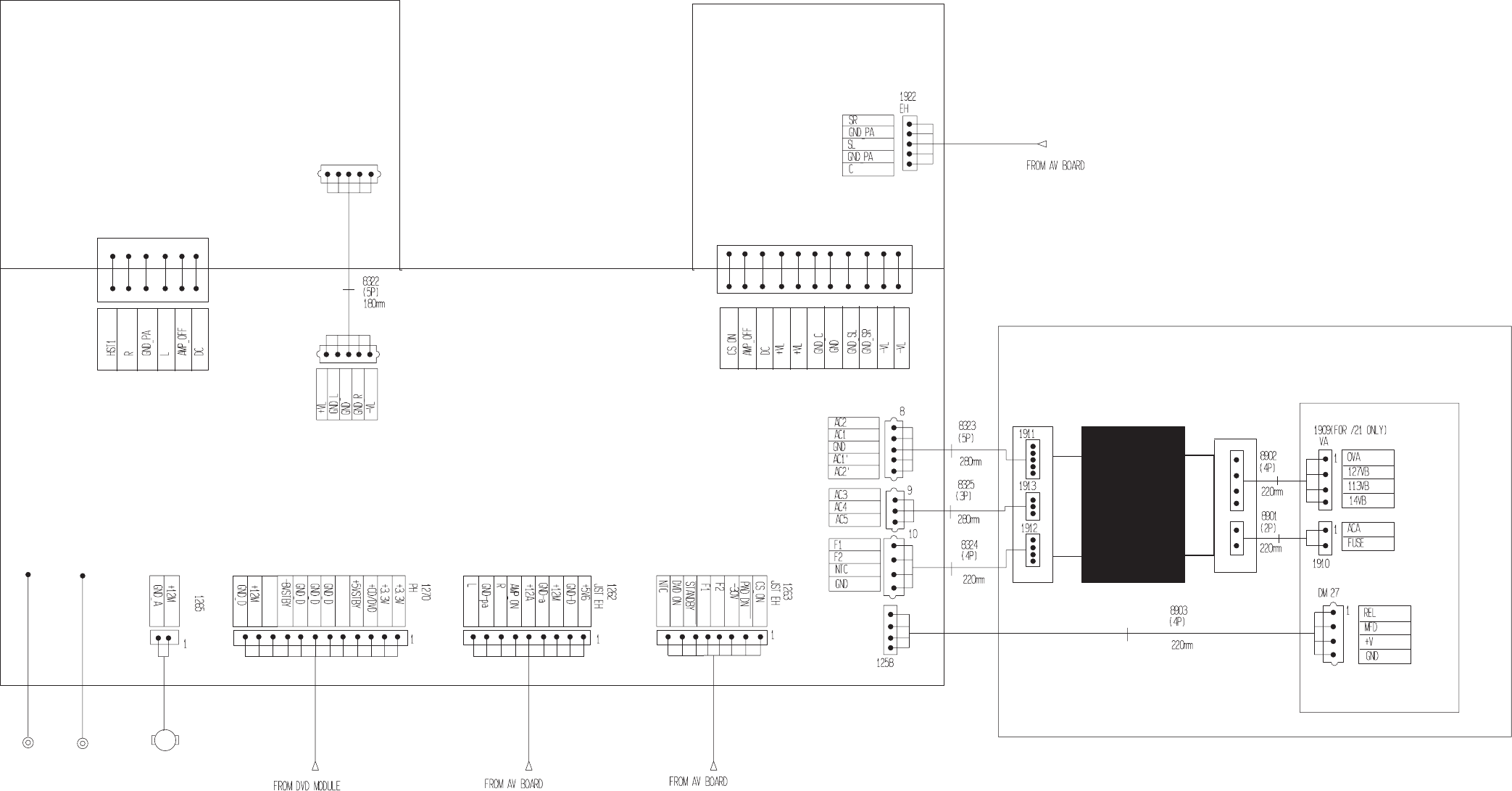
11-2 11-2
PCS 103 859
L/R
1268
1928
DVD MODULE
8522
PRIMARY
SECONDARY
MAINS BOARD AND TRANSFORMER
C/S
-
FAN
11
3
HEATSINK
EH
8520
-
+
1
-
1
MAINS
SUPPLY
TRAFO
1
1
1
JL 1261
1325
1
1
JL
WIRING DIAGRAM
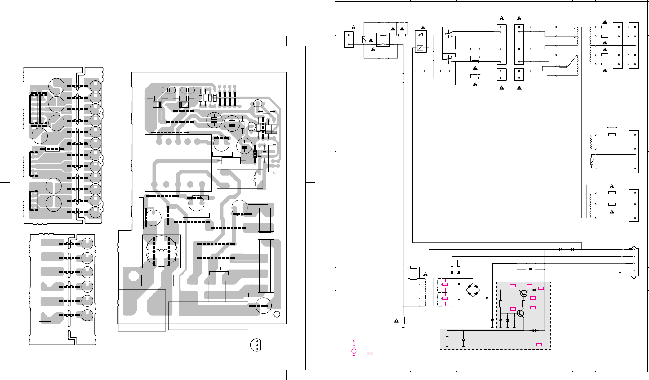
11-3 11-3
PCS 103 860
Interconnection Board Mains Board
primary side secondary side
This assembly drawing shows a summary
of all possible versions.
For components used in a specific version
see schematic diagram respectively partslist. E
C
B
Transistor pinning
Interconnection Board
Transformer secondary
Interconnection Board
Transformer primary
1
3
trf21
1
4
5
1
1
5
trf10
1925
1913
9941
9942
9928
1912
1922
1923
3920 9930
1924
9935
9936
9937
9938
9939
9940
9927
1914
1921
1911
1920
9931
9932
9933
9934
12345
12345
E
D
C
B
A
E
D
C
B
A
8901 E 5
8902 D 5
9920 E 4
9921 E 4
9922 E 4
9923 D 4
9924 D 4
9925 D 4
trf3 E 4
trf4 E 4
trf5 E 4
trf6 D 4
trf7 D 4
trf8 D 4
1911 A 5
1912 B 5
1913 C 5
1914 A 5
1920 A 4
1921 A 4
1922 A 4
1923 B 5
1924 C 4
1925 C 4
3920 B 4
9927 A 5
9928 A 5
9930 B 4
9931 A 4
9932 A 4
9933 A 4
9934 A 4
9935 B 4
9936 B 4
9937 B 4
9938 B 4
9939 C 4
9940 C 4
9941 C 4
9942 C 4
trf10 A 3
trf11 A 3
trf12 A 3
trf13 A 3
trf14 B 3
trf15 B 3
trf16 B 3
trf17 B 3
trf18 C 3
trf19 C 3
trf20 C 3
trf21 C 3
trf7
trf8
4
1
trf3
trf4
trf5
trf6
2
1
9924
9925
8902
9920
9921
9922
9923
8901
Mains Board Copperside view
Power5VA MainsBoard Layout stage .4 1999 06 14
1
4
1
2
4
1
1
654
32
4
95
12 3
NEUTRAL
LIFE
1907
9906
89058904
1909
IEC T-5A
1910
5905
IEC T-5A
27
2906
6911
6912 9910
6900
2905 3905
6909
6910
7901
7902
1902
240V
99-03-15
34174
3103 303
9915
9917
9904
9900
5903
1903
3901
9926
IEC T-200mA
9916
3908
T-200mA
1906
6908
9905
9929
9909
9911
9912
9913
9914
1904
6902
6904
6905
9907
9908
6906
2903
2904
3904
3906
3902
3903
1901
9918
120V
UL/CSA T-6,3A
IEC T-5A
9903
1905
3907
5901
5902
9901
9902
9919
2902
6901
6903
27 B 1
1901 E 3
1902 E 2
1903 C 2
1904 B 2
1905 C 3
1906 C 1
1907 E 1
1909 D 1
1910 C 1
2902 A 3
2903 A 2
2904 A 2
2905 A 1
2906 B 1
3901 B 1
3902 A 2
3903 A 2
3904 B 1
3905 A 1
3906 A 1
3907 E 3
3908 C 2
5901 D 3
5902 D 3
5903 B 2
5905 C 1
6900 B 1
6901 A 3
6902 A 2
6903 A 3
6904 A 2
6905 A 2
6906 A 2
6908 B 1
6909 B 1
6910 B 1
6911 B 1
6912 B 1
7901 A 1
7902 B 1
8904 D 1
8905 C 1
9900 B 1
9901 D 3
9902 D 3
9903 C 3
9904 D 2
9905 C 1
9906 E 1
9907 B 3
9908 A 2
9909 A 2
9910 B 1
9911 A 1
9912 A 1
9913 A 2
9914 A 2
9915 D 2
9916 D 2
9917 D 1
9918 C 3
9919 C 3
9926 C 2
9929 B 2
MAINS BOARD - CIRCUIT DIAGRAMMAINS BOARD - COMPONENT VIEW
ELECTRONIC VOLTAGE SELECTOR
FOR STAND BY CIRCUIT
FOR /21 ONLY
10V
110V
120V
PRIMARY TRAFO
( 4 )
( 3 )
( 2 )
( 1 )
( 2 )
( 1 )
REL
MFD
+V
GND
230V
120V
120V
230V
15k for
/00,/17
4561789101112 1323
L
K
J
I
O
H
G
F
E
D
C
B
A
N
M
L
K
J
I
O
H
G
F
E
D
C
B
A
N
M
4561789101112 1323
6904
1N4003
6903
1N4003
6902
1N4003
6901
1N4003
BZX79C8V2
6908
BYV10-40
6909
1N4003
6910
1N4148
6911
1N4148
6912
1N4148
6905
1N4148
6906
1N4003
6900
T-5A
1922
T-5A
1920
T-2,5A
1924
T-2,5A
1925
T-5A
1921
T-5A
1923
T6.3A UL
1905
T5A IEC
T-5A
1907
T-5A
1906
4k7
3904
2k2
3905
1k
3903
1k
3902
3908 not /21
10M
3901
10k
3906
100u/25V
2906
100u/50V
2904
100u/25V
2905
BC547B
7902
3907
V
3920
1R
9930
99279928
9925
9920
9921
9922
9923
9924
9917
9910
9902
9901 9903
9915
9916
9904
9906
9905
9918
9900
47n
2903
47n
2902
trf14
trf13
trf12
trf11
trf10
trf18
trf17
trf21
trf20
trf19
1911
1
trf16
trf15
2
4
1912
1
2
3
4
1913
1
2
3
5
3
1914
1
2
4
5
3
trf8
trf3
trf4
trf5
trf6
trf7
2
3
1
8902
4
1
8901
2
4
3
2
1
6
7
8
10
1909
7
1
1
1910
3
3
5
2
1901
1
27
1
2
3
4
9
5903
5
1
23
4
56
5905
SPST - 9V
5902
trf-ee25
LC121503-PCT
5901
BC327-25
7901
470Ω
1903 for /21only
T200mA
V
............. Vdc measured during AMPLIFIER ON
Vdc measured during AMPLIFIER OFF (mute)
Voltages measured at nominal mains voltage and low output signal
EVM
V
120V
6,5V
230V
25V
12V
8,3V
12,6V
25V
25,3V 3V
MAINS VOLTAGE
12V
12V
7,2V
12,7V 12,7V
10V
5,5V
10V
5,5V
Voltage Selector for /21 only
120Ω for/37
5902 A 2
5901 B 2
3920 F12
3907 B 1
3908 L 4
3906 N 5
3905 M 8
3904 M 7
3903 K 6
3902 K 5
3901 N 3
2906 N 7
2905 N 6
2904 N 7
2903 M 7
2902 L 6
27 J13
6902 M 6
6903 L 7
1925 I12
1924 H12
1923 C12
1922 B12
1921 A12
1920 A12
1914 A13
1913 H13
1912 E13
1911 A13
1910 D 7
1909 A 7
1907 C 6
1906 C 6
1905 A 3
1901 A 1
1903 L4 6901 L 6
5905 A 4
5903 L 4 trf8 A10
trf7 A10
trf6 B10
trf5 B10
trf4 C10
trf3 C10
trf21 I11
trf20 I11
trf19 H11
trf18 G11
trf17 G12
trf16 F11
trf15 F12
trf14 C11
trf13 B11
trf12 B11
trf11 A11
trf10 A11
9930 E12
9928 C13
9927 A13
9925 A 9
9924 A 9
9923 B 9
9922 C 9
9921 C 9
9920 C 9
9918 C 3
9917 C 5
9916 C 4
9915 B 6
9914 G 1
9913 G 1
9912 G 1
9911 F 1
9910 K 9
9906 B 6
9905 C 6
9904 B 4
9903 A 3
9902 B 2
9901 A 2
9900 N 8
8902 A 8
8901 D 8
7902 M 8
7901 L 8
6912 K11
6911 K10
6910 N 9
6909 L 9
6908 N 8
6906 L 5
6905 L 5
6904 M 6
6900 K 9
Note : Some values may varies, see respective parts list for correct value.
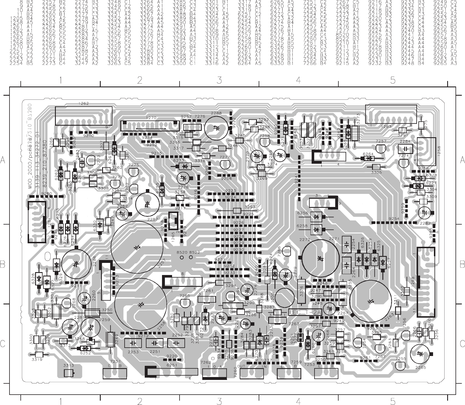
11-4 11-4
PCS 103 861
This assembly drawing shows a summary of all possible versions. For components used in a specific version see schematic diagram and respective parts list. 3139 113 3427 pt2 dd wk0023
SUPPLY PART - COMPONENT VIEW
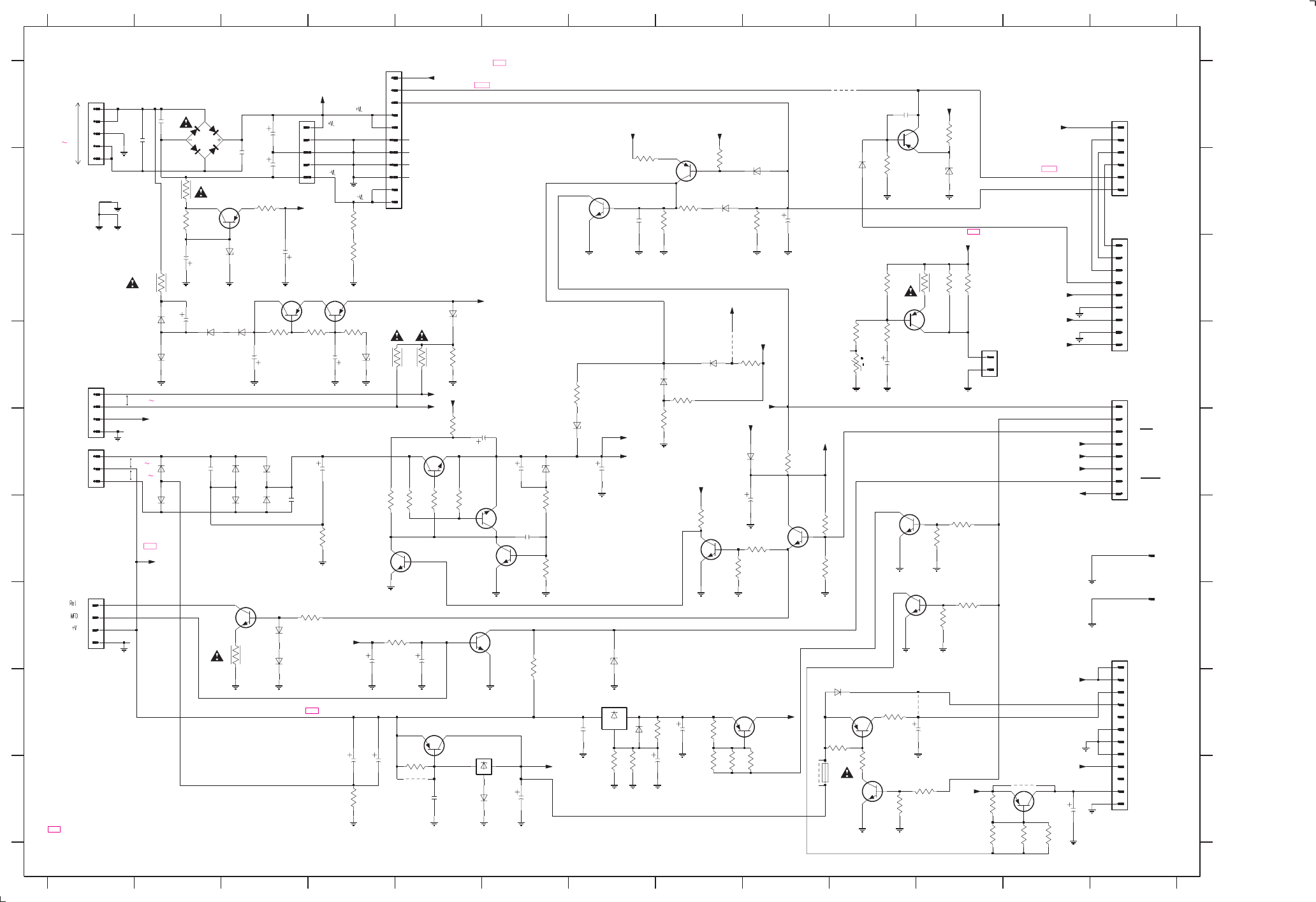
SUPPLY PART - CIRCUIT DIAGRAM
11-5 11-5
PCS 103 862
-55V
-32V
-44.6V
-44V
+32V
48V
-34.6
-34V
CS_ON = +5V CS OFF = 0V
-28.5V
-11V
-10.3V
-32V
-33V
-28V
5.0V -28V +25V
+13.7V
9.6V
9.6V
+25V
0V
+22V
+13.7V
+32V
+4.0V
+1.2V
-9V
-32V +3.1V
-0.2V
+0.5V
+12V
+5V
-8V
+12.5V
+0.7V
+0.6V
+5.0V
+5.6V
+1.5V +11V
+0.7V
AMP_ON = +5V AMP OFF = 0V
+5.0V
+5.6V
+5.6V
+8.2V
+5V6
+5V
5V6
5V6
+5V6
+4.0V
+4.6V
+5.6V
-32V +3.1V
+5.0V
+12.5V
+12.5V
+12.5V
+0.7V
0V
+5.6V
+2.3V
+3.3V
+0.7V
0V
+4.9V
+11.8V
+12.5V
-9.0V
-8V
+3.3V
-33V
+3.3V
+5V6
+11V
Voltages measured at nominal mains voltage and low output signal
V Vdc measured during AMPLIFIER OFF (mute)
.... Vdc measured during AMPLIFIER ON
+11V
+12V
+11V
+0.6V
+5.6V
+5V6
+2.6V
t
GND
+12M
GND_SR
-30
BZX79-C11
PCB
SECONDARY
TO TRAFO
MODULE
TO AV
SECONDARY
TO TRAFO
PWD_DN
+12M
+5Vstby
AMP OFF
AMP OFF
L
D
GND_pa
+12M
9259 A10
+12A
CS_ON
9258 I9
9257 I12
NOT USED
+5V6
+3.3V
SECONDARY
TO MAINS
F1
TO CENTER/SURROUND
PCB TO L/R
AMP. PCB
TO AV
AMP_ON
BZX79-B11
+12M
7275 C4
7276 I12
7277 G11
8520 F13
8522 G13
9235 D8
9251 I5
9252 H10
GND
6277 B11
6278 B10
6325 E3
5R6
R
PCB
TO DVD
6251 A2
6252 C3
6254 D4
6255 C5
6256 E2
6257 E3
6258 F2
6259 F3
6260 E6
6261 E7
6262 D8
6263 D8
6264 G3
6265 G3
6270 I5
6271 G7
6272 H7
6273 H10
6274 E9
6275 B8
6276 B9
D
STBY
NOT USED
PCB
BC556B
TO TRAFO
R
NTC
GND_L
HST1
7274 A11
A
7272 B8
GND_C
7273 B7
+12M
6326 F3
6327 C2
6328 D2
6329 D2
6330 D3
7251 B3
7252 C3
7253 E5
7254 F4
7255 F6
7256 F6
7257 G3
7258 G6
7259 H5
7260 H6
7261 H8
7262 H7
7263 H10
7264 I10
7265 F11
7266 F9
7267 F8
7268 D10
GND_R
3295 F9
HEATSINK
3262 D7
3263 F6
3264 E8
3265 B8
3266 D8
3267 D9
3269 G4
3273 G3
3274 G5
3275 G6
3276 I4
3277 I5
3278 I8
3279 I8
3280 I9
3282 H8
3283 I7
3284 I7
3285 H8
3286 I10
3287 H10
3288 I10
3289 I11
3290 H10
3291 F10
3292 F10
3293 F11
3294 F11
TO DVD MODULE
D
G
H
I
A
B
C
D
E
F
G
H
I
8 A1
9 E1
10 D1
11 B4
BYV28-200/24
NTC
L7805CP
# : PROVISION
#
#
F2
BDX53BFP
GND_SL
123456
+CD/DVD
100U/100V
78910111213
12345678910111213
A
B
C
D
E
F
/100V
L
DC
1205 I10
1258 G1
1261 A13
1262 D13
1263 F13
1265 D11
1268 A4
1270 G13
2251 A2
2252 A2
2253 B3
2254 F3
2257 A3
2258 B3
2259 C2
2260 C3
2262 D4
2263 E4
2264 E2
2265 E6
2266 F6
2267 E7
2268 E6
2269 G5
2270 G4
2271 I4
2272 I4
2273 I5
LM317P
CS_ON
2274 I6
2275 H7
2276 I7
2277 H8
2278 H10
2279 F9
2281 D10
2282 B9
2283 B7
2284 A10
2286 C2
2287 D3
2288 I12
3245 G11
3246 G11
3247 D4
3248 B2
3249 B2
3250 C2
3251 D4
3252 D5
3253 D4
3254 D5
3255 F4
3256 F5
3257 F5
3258 F5
3259 F5
3260 E5
3261 F6
-8Vstby
GND_pa
DC
GND
*
+12M
3296 F9
3297 F8
3298 E9
3299 D10
3300 C10
3301 C11
3302 C11
3303 C11
3304 B10
3305 A11
3306 B8
3307 B8
3308 B7
3309 B9
3310 C4
3311 B4
3312 B3
3313 D10
3314 D3
3315 I11
3316 I11
3317 I12
3318 I12
3319 D10
2252
100n
1
2
3
4
3276
0R33
3245
12K
39K
3296
1
2
3
6325
1N5392
A
PH-B
1270
2272
6m8
A
470R
3319
2269
1u
D
3315
6K8
A
6K8
3282
6272
1N4003
EH-B
1265
1
2
6276
BZX79-C6V8
3246
47K
2276
10u
2264
100n
D
47K
3306
3295
10K
2267
47u
47K
3294
D
3317
BZX79-C5V6
1R
3277
1N4148
6274
BYV28-200/24
#
#
#
#
#
##
DVD_ON
A
D
2277
1u
120R
3261
D
D
D
2270
100u
EH-S
1258
1
2
3
4
4m7
2258
10K
3297
2K7
3310
D
7266
BC547B
1K
3283
2259
100u
3284
1K8
6264
1N4148
2271
10m
1
2
3
4
5
6
7
8
9
BC327-40
7275
2K2
3260
1262
3249
47R
7252
BC327-40
1261
JL
1
2
3
4
5
6
A
A
1N4148
6265
9257
3313
D
1u
2278
2K2
3311
2262
22u
A
IO
8522
D
7262
1N4003
6270
56K
3291
7263
BD438
BC547B
7277
9
1K2
1N4003
6273
9258
2266
3n3
9235
3259
470R
2254
100n
1K
3299
100n
2251
0R22
3290
A
6259
1N5392
2274
10u
6254
BZX79-C33
2273
100n
33K
3257
7253
100u
2275
100n
7273
BC547B
2265
6260
8
1
2
3
4
5
2279
10u
3256
2K2
1K
3269
D
1K
3264
2281
100u
D
470R
3258
5K6
3287
220R
3247
2268
4u7
9251
3254
22K
GND
IN OUT
BC547B
7267
DD
7260
2K2
3289
8520
0R33
3255
1K2
3316
D
A
220R
3300
1K
3285
7268
BC327-25
3248
3K3
6277
BZX79-C3V3
9252
100K
3307
47R
3253
7264
BC547B
2257
4m7
6258
100K
3309
1N4148
6275
100n
2253
2283
10n
BC547B
7258
A
BD438
7276
D
680R
3308
BD242BFP
7251
6255
47R
3252
33K
3265
6271
BZX79-C8V2
2287
T2A
1205
6330
1N4003
1N5392
6257
1
2
3
4
5
3274
120K
7254
BC547B
11
3263
3251
3K3
120R
3304
47K
10R
3273
7257
BC337-25
2284
10n
10K
3288
47R
3250
7272
BC557B
680R
3280
D
10K
3262
1N4148
6263
22R
3312
BD242BFP
7259
6262
1N4148
6252
6
7
8
9
D
1268
1
10
11
2
3
4
5
7
8
1N5392
6326
EH-S 1263 1
2
3
4
5
6
6256 6328
1N4003
12K
3293
10
680R
3298
10K
3305
7255
BC547B
6251
GBU6D
2263
4m7
2282
100u
12K
3266
1
10
11
12
2
3
4
5
6
7
8
9
9259
7261
BD438
3318
1K2
3302
330R
15K
3267
3301
2260
1u
1N4003
6329
10K
3275
3K3
3314
3278
680R
D
3286
1K
BC547B
7256
2286
47u
680R
3279
D
7265
BC547B
47K
3292
330R
3303
6261
BZX79-C15
1N4003
6327
D
1N4148
6278
470u
2288
7274
HST1
+VL
+V
NTC
F1
NTC
F2
CS_ON
+V
+12A
CS_ON
+VL
HST1
+12A
F1
F2 +VL
3139 118 53250...87380 for ...3427 pt2 dd wk0023
Note : Some values may varies, see respective parts list for correct value.
#
#
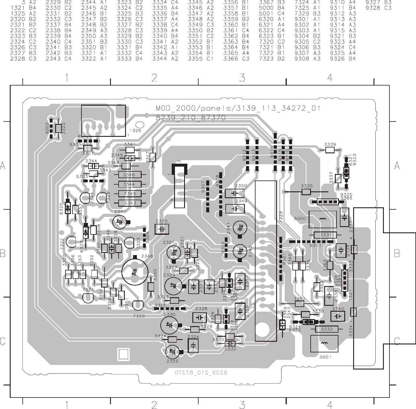
11-6 11-6
PCS 103 863
This assembly drawing shows a summary of all possible versions.
For components used in a specific version see schematic diagram and respective parts list. 3139 113 3427 pt2 dd wk0023
LEFT/RIGHT AMPLIFIER PART - COMPONENT VIEW
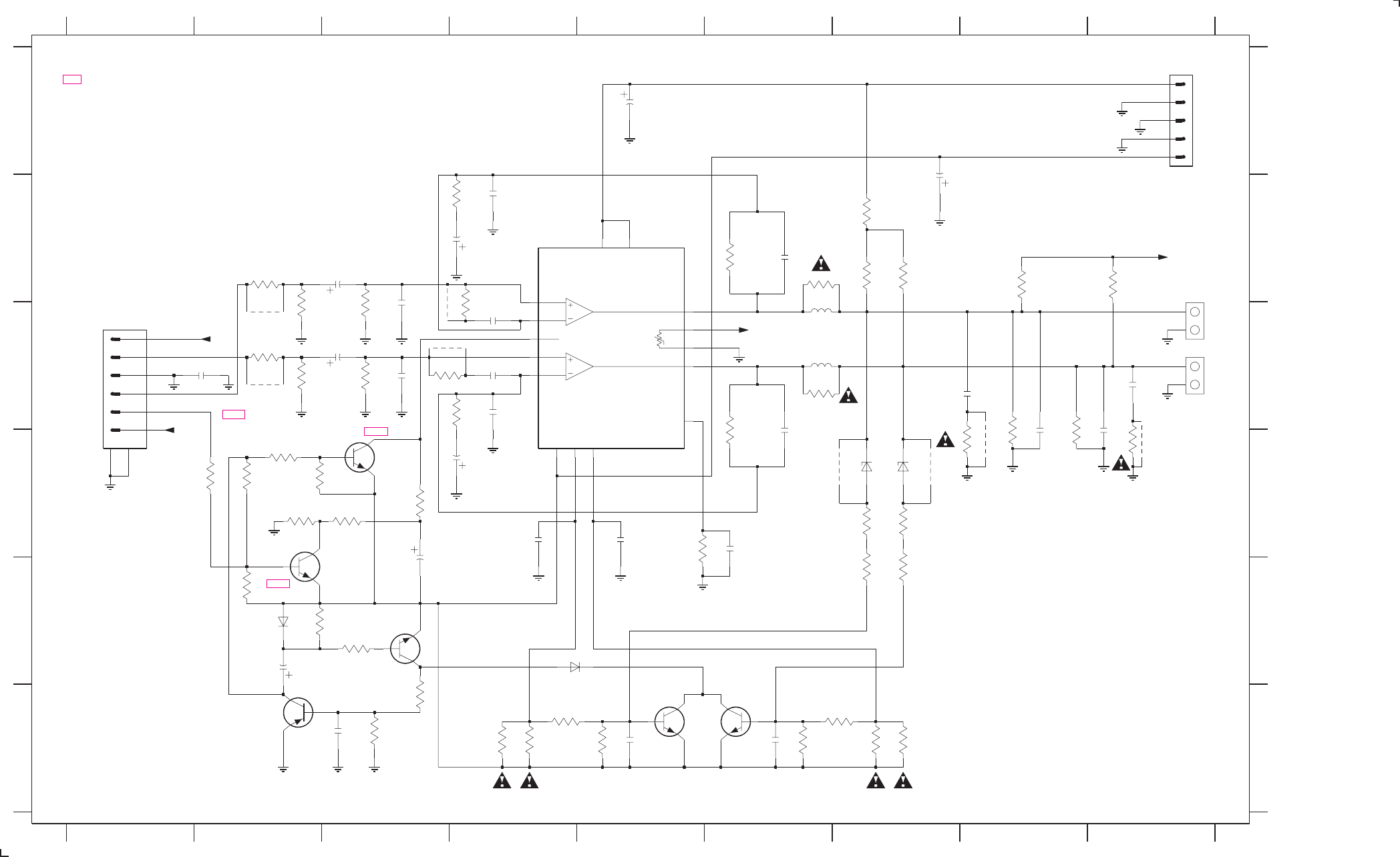
11-7 11-7
PCS 103 864
.... Vdc measured during AMPLIFIER ON
V Vdc measured during AMPLIFIER OFF (mute)
Voltages measured at nominal mains voltage and low output signal
+3.1V
-32V -30V
-32V
-32V
-32V
-32V
-31V
-32V
0V
0V
-32V
-32V -32V
-32V
+32V
-32V
0V
-32V
-32V
-32V
-32V -32V
+32V
-32V
3356 E2
3355 D3
3354 D2
3329 B6
3330 D6
3331 B6
3332 C6
3333 D8
3334 D8
3335 B8
3336 B9
3337 D7
3338 D7
3339 E7
3340 E7
3341 F5
3342 F6
3343 F4
3344 F7
3345 F4
3346 F7
3347 F4
3348 F7
3349 D6
3350 D3
3351 D3
3352 D2
3353 D2
+VL
GND_pa
A
GND
F
# : Provision
123456789
123456789
A
B
C
D
E
AMP OFF
R
BC546B
RIGHT
B
C
D
E
F
3 A9
1321-A C9
1321-B B9
1325 C1
2320 C2
2321 B3
2322 C3
2323 C3
2324 C3
2326 C4
2327 B4
2328 C4
2329 B4
2330 D4
2331 B6
2332 D6
2337 C8
2338 C9
2339 D8
2340 D8
2341 A5
2342 B7
2343 D6
0V
L
GND_L
BC556B
TO SUPPLY PCB
2344 F6
2345 F5
2346 F3
2347 E2
2348 E3
2349 D4
2350 D5
2351 B4
3320 D2
3321 B2
3322 C2
3323 C2
3324 C2
3325 C3
3326 C3
3327 B4
3328 C4
DC
TO SUPPLY PCB
HST1
GND_R
3357 E3
3358 E3
3359 F3
3360 F3
3361 B7
3362 B7
3363 B7
3364 D9
3365 D8
3366 C3
3367 C4
5000 C6
5001 C6
6320 E2
6321 D7
6322 D7
6323 E4
7320 D3
7321 E2
7322 E3
7323 F2
7324 F6
7325 F5
9324
7329 B4
9301 C2
9302 C2
9323 D7
9324 D7
9325 D8
9326 C9
9327 B3
9328 C4
LEFT
#
#
#
#
##
#
#
#
STK496-070C
-VL
BZX79-C15
6321
2339
4n7
GND_R
BC547B
7324
4p7
2332
3352
100K
pa pa
9327
9328
1321-B
3
0V
6322
BZX79-C15
4R7
3332
220p
2328
5001
1u
5K6
3340
6323
1N4148
10K
3334
7323
3357
100K
7322
1K
3348
3342
1K
22n
2344
GND_L
GND_L
2327
220p
4
2340
4n7
GND_R
3321
12K
pa
10u
2341
papa
2338
100n
2323
1n
2330
47u
3366
1u
5000
3367
470R
470R
3359
1K
3360
22K
0R22
3346
3325
56K
2n2
2326
9302
56K
3326
12K
3322
BC547B
2322
2u2
82K
3338
7325
9323
3327
680R
2345
22n
10u
2347
47u
2329
10K
3356
3339
5K6
3320
100K
2u2
2321
2331
4p7
BC547B
7321
3
1
2
3
4
5
3365
4R7
4R7
3364
3333
10K
9301
0R22
3345
56K
3330
2346
22n
680R
3328
3344
0R22
1
100K
3358
pa
1321-A
2
pa
3331
4R7
pa
pa
pa
-VC2
1
-VP
8
CCC
12
IN1
10
IN2
14
NF1
11
NF2
13
OUT1
6
OUT2
7
SUBSTR
15
T1
5
T2
4
2351
2n2
7329
+VC
3
+VP
9
-VC1
2
3349
22R
1n
2324
2348
1m 3350
1K
100n
2337
100n
2349
9326
3323
1K2
9325
78
1
2
3
4
5
6
3347
1K
1325
2320
4n7
3139 118 53250...87370 for ...3427 pt2 dd wk0023
2342
10u
GND_L
3343
0R22
3355
560R
GND_R
GND
3354
33K
56K
3361
2K7
7320
BC547B
pa
3329
100K
3353
1K
3341
1N4148
6320
1K2
3324
3362
82K
82K
3363
pa
3351
10K
2343
47n
47K
3336
3337
82K
pa
3335
47K
2350
100n
HST1
DC
DC
HST1
Note : Some values may varies, see respective parts list for correct value.
LEFT/RIGHT AMPLIFIER PART - CIRCUIT DIAGRAM
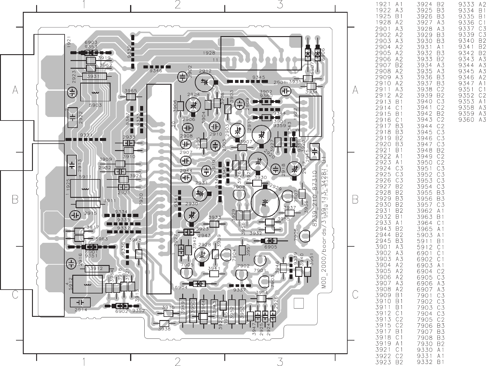
11-8 11-8
PCS 103 865
CENTER/SURROUND AMPLIFIER PART - COMPONENT VIEW
This assembly drawing shows a summary of all possible versions.
For components used in a specific version see schematic diagram and respective parts list.
3139 113 3428 pt1 dd wk0023
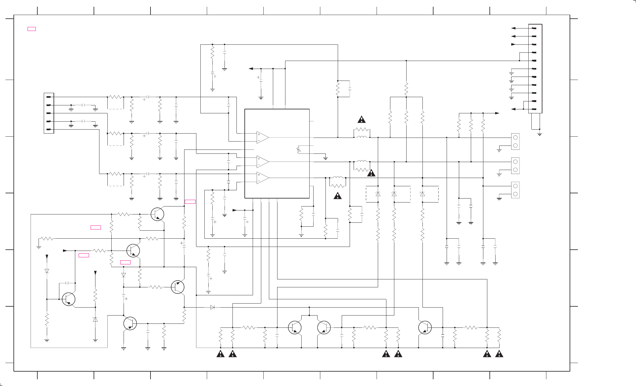
CENTER/SURROUND AMPLIFIER PART - CIRCUIT DIAGRAM
-32V
-30V
CS_ON = +5V CS OFF = 0V
-32V
-32V
-32V
-31V
+3.1V
-32V
0V
-32V
0V
-32V
-32V
-32V
-32V
-32V
+32V
0V
0V
-32V
0V
0V
-32V
+32V
-32V
+32V
-32V
-32V -32V
Voltages measured at nominal mains voltage and low output signal
V Vdc measured during AMPLIFIER OFF (mute)
.... Vdc measured during AMPLIFIER ON
3951 F8
3952 F9
3953 F9
3954 F8
3955 D3
3956 D3
3957 E2
3962 B7
3963 B7
3964 B7
3965 B7
5903 C6
5911 C6
5912 C6
6901 D7
6902 D7
6903 C6
6904 F4
6905 E2
#
#
###
#
# : PROVISION
3919 B8
3921 D7
3922 D7
3923 D5
3924 B6
3925 A4
3926 B3
3927 B2
3928 B2
3929 D2
3930 D2
3931 B6
3932 D2
3933 D1
3934 F1
3935 E1
3936 D2
3937 E2
3938 D7
C
3939 E3
3940 D7
3941 F3
3942 F3
3943 F4
3944 F4
3945 F4
3946 F5
3947 F6
3948 F6
3949 F7
3950 F7
TO AV PCB
TO SUPPLY PCB
B
C
D
E
F
1921 B9
1922 B1
1925-A C9
GND
SURROUND RIGHT
GND_SL
-VL
-VL
3918 B8
CENTER
9360 C2
SR
6906 E1
6907 F2
7901 F8
7902 F6
7903 F5
7904 E3
7905 F2
7906 E1
7907 D2
7908 D3
7930 B4
9351 D7
9352 D8
9353 D6
9358 B2
9359 C2
#
F
3917 B8
+VL
2922 D8
2923 D8
2924 F5
2925 F6
2926 F8
2927 F3
2928 E2
2929 D3
2930 D4
2931 B4
2932 D6
2933 D6
2943 D5
2944 B4
2945 E1
3901 B2
3902 C2
3903 C2
3904 C2
3905 C3
3906 C3
3907 E4
3908 D4
3909 D6
3910 D6
3911 C6
3912 C6
3913 D7
3915 D7
2918 B3
2919 A4
DC
BC546B
GND_pa
GND_pa
A
CS_ON
SL
123456789
123456789
A
B
C
D
E
2920 A3
SURROUND LEFT
+VL
GND_SR
AMP OFF
GND_C
2921 B6
BC556B
1925-B C9
1928 A9
2901 B1
2902 B1
2903 C2
2904 C2
2905 C3
2906 C3
2907 C4
2908 C4
2909 E4
2910 D4
2911 E4
2912 D4
2913 D8
2914 D8
2915 D8
2916 D9
2917 B2
pa
3940
5K6
2K7
3965
BC547B
7907
GND_C
470R
3902
3962
82K
10n
2945
3957
100K
6907
BZX79-C3V3
82K
3964
GND_SL
2u2
2917
3931
4R7 1921
2
1
1u
5903
2927
22n
0R22
3943
2912
47u
5K6
3915
2930
10u
3922
5K6
3930
10K
3936
100K
3955
560R
NF2
NF317
8
OUT1
9
OUT2
OUT3 20
PT1 6
PT2 7
1
SUBSTR
3933
33K
5
+VC
11
+VP
4
-VC1
3
-VC2
-VC3
1910
-VP
14
CCC
12
IN1
16
IN2
IN318
2
NC
13
NF1
15
3923
22R
STK496-270
7930
pa
3909
56K
1K
3948
3947
1K
2908
56K
3906
470p
2904
2u2
7903
BC547B BC547B
7902
9360
pa
pa
3903
100K
2932
33p
3927
100K
4n7
2915
3919
47K
pa
2918
1n
10K
3937
2916
4n7
82K
3913
560R
3908
3921
82K
22n
2925
pa
pa
3938
82K
10u
2928
GND_SR
9353
8
9
GND_SL
1928
12 13
1
10
11
2
3
4
5
6
7
7905
GND
JL
2924
22n
6906
1N4148
GND
2u2
2903
3905
56K
GND_SL
7904
2926
22n
0R22
1N4148
6905
3907
560R
3953
100K
3932
4
5
100K
3904
pa
EH-S
1922
1
2
3
2943
47n
10u
2931
3949
0R22
2901
4n7
0R22
3950
2914
100n
pa
56K
3910
33p
2933
47K
3918
2905
1n
82K
3963
2929
1m
GND_SR
1u
5912
1K
3946
3945
1K
2907
470p
pa
BC557B
7906
9359
3917
47K
3929
100K
6901
BZX79-C15
GND_C
pa
BZX79-C15
6903
GND_C
7908
BC547B
9352
pa
100K
3939
7901
BC547B
pa
1925-A
2
1
0R22
3952
4n7
2902
2909
220p
47u
2911
2923
4n7
1K
3951
3912
4R7
GND_SR
9358
3926
56K
2919
220p
6904
1N4148
3956
1K
9351
3942
1K
3941
22K
1n
2906
47u
2920
4R7
3911
pa
3954
1K
5911
1u
3944
0R22
220p
2910
pa
3928
470R
2922
100n
1925-B
3
4
47K
3934
100n
2913
pa
BZX79-C15
6902
3924
56K
3925
560R
2944
470p
2921
33p
3935
10K
pa pa
CS_ON
-VL
AMPOFF
+VL
-VL
AMPOFF
CS_ON
DC
+VL
3901
470R
DC
Note : Some values may varies, see respective parts list for correct value.
3139 118 53260...87310 for...3428 pt1 dd wk0023
11-9 11-9
PCS 103 866
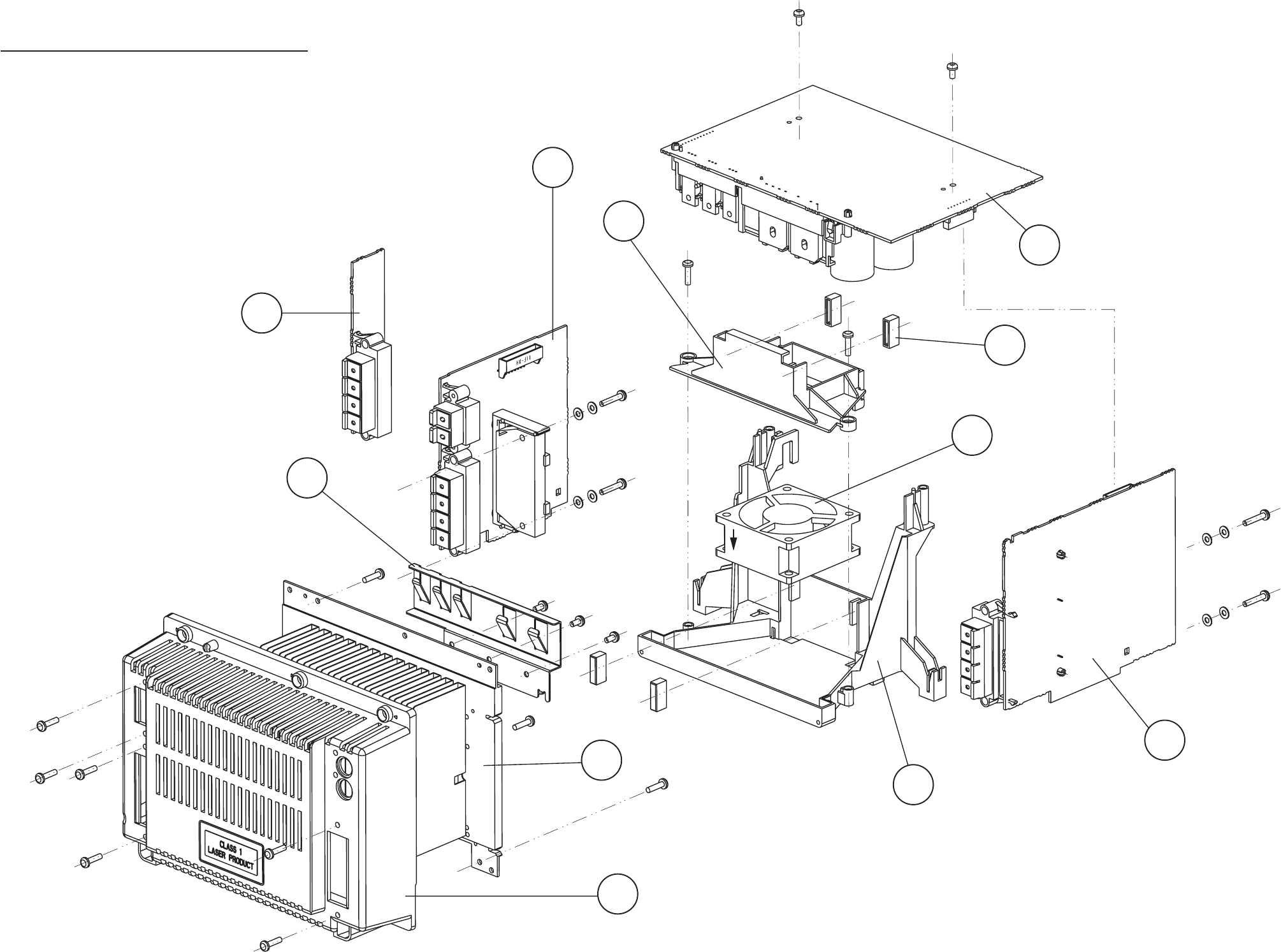
SUPPLY PART
SCREW
3x10 TORX (4x)
SCREW
3x10 TORX (2x)
SCREW
3x10 TORX (2x)
AIRFLOW
SCREW
3x16 TORX (2x)
SCREW
2.9x13 TORX (3x)
3139 118 5330 dd wk0021
SCREW
3x10 TORX (2x)
SCREW
3x10 TORX
LEFT/RIGHT
AMPLIFIER PART
CENTER/SURROUND
AMPLIFIER PART
SCREW
3x16 TORX (2x)
1246
6
1246
MATRIX
SURROUND PART
1245-C
1245-A
0041
1241
0045
(4x)
0042
1245-B
0038
0047
0031
EXPLODED VIEW
11-10 11-10
PCS 103 867
Mechanical parts
0047 3103 304 69030 Rucksack P5-DVD (L/R & C/S)
1241 4822 361 11161 Fan KD1206PTS3
Note: Only the parts mentioned in this list are normal
service spare parts.

MISCELLANEOUS
1901 4822 265 31015
!
Mains Socket
1901# 2422 030 00328
!
Mains Socket
1902* 4822 272 10269
!
Voltage Selector
1903* 4822 071 52001
!
Fuse T200mA 250V IEC
1905^ 4822 071 55002
!
Fuse T5A 250V IEC
1905# 4822 252 51123
!
Fuse T6,3A 250V UL
1906* 4822 071 55002
!
Fuse T5A 250V IEC
1907* 4822 071 55002
!
Fuse T5A 250V IEC
1909* 4822 267 10728
!
Primary Connector 4P
1910 4822 265 20723
!
Primary Connector 2P
1920 4822 071 55002
!
Fuse T5A 250V IEC
1923 4822 071 55002
!
Fuse T5A 250V IEC
1924 4822 071 52502
!
Fuse T2,5A 250V IEC
1925 4822 071 52502
!
Fuse T2,5A 250V IEC
CAPACITORS
2902 4822 121 43526 47nF 5% 250V
2903 4822 121 43526 47nF 5% 250V
2904* 4822 124 40255 100µF 20% 63V
2905* 4822 124 40207 100µF 20% 25V
RESISTORS
3901# 4822 053 21106
!
10M 5% 0,5W
3902 4822 050 11002 1k 1% 0,4W
3903 4822 050 11002 1k 1% 0,4W
3904* 4822 116 52283 4k7 5% 0,5W
3904** 4822 116 52244 15k 5% 0,5W
3905* 4822 116 52256 2k2 5% 0,5W
3906* 4822 050 21003 10k 1% 0,6W
3908^ 4822 053 10471 470R 5% 1W
3908# 4822 053 10121 120R 5% 1W
3920* 4822 052 10108
!
1R 5% 0,33W
COILS & FILTERS
5901^ 4822 157 11832
!
400µH 3A
5902* 4822 157 11628
!
Mains Choke
5903* 4822 146 11144
!
Standby Transformer
5903^ 4822 146 11143
!
Standby Transformer
5903# 4822 146 11142
!
Standby Transformer
5905 4822 280 10382
!
Relay 1P
DIODES
6900** 4822 130 31878 1N4003G
6901 4822 130 31878 1N4003G
6902 4822 130 31878 1N4003G
6903 4822 130 31878 1N4003G
6904 4822 130 31878 1N4003G
6905 4822 130 30621 1N4148
6906 4822 130 30621 1N4148
6908* 4822 130 34382 BZX79-C8V2
6909* 4822 130 32245 BYV10-40
6910* 4822 130 31878 1N4003G
6911 4822 130 30621 1N4148
6912 4822 130 30621 1N4148
TRANSISTORS & INTEGRSTED CIRCUITS
7901* 4822 130 41246 BC327-25
7902* 4822 130 40959 BC547B
*For /21/21M only
** Not for /21/21M
^For /22/30 only
#For /37 only
Note : Only the parts mentioned in this list are normal
service spare parts.
MISCELLANEOUS
1205 4822 071 52002
!
Fuse T2A 250V IEC
1321 4822 267 31176 L/R Loudspeaker Terminal
CAPACITORS
2251 5322 121 42578 100nF 5% 250V
2252 5322 121 42578 100nF 5% 250V
2253 5322 121 42578 100nF 5% 250V
2254 5322 121 42578 100nF 5% 250V
2257 4822 124 80415 4700µF 20% 50V
2258 4822 124 80415 4700µF 20% 50V
2259 4822 124 40255 100µF 20% 63V
2260 4822 124 21913 1µF 20% 63V
2262 4822 124 81151 22µF 50V
2263 4822 124 80563 4700µF 20% 35V
2264 5322 121 42578 100nF 5% 250V
2265 4822 124 40255 100µF 20% 63V
2266 4822 122 10577 3,3nF 10% 16V
2267 4822 124 40433 47µF 20% 25V
2268 4822 124 40769 4,7µF 20% 100V
2269 4822 124 21913 1µF 20% 63V
2270 4822 124 41584 100µF 20% 10V
2271 2020 012 93745 10000µF 20% 16V
2273 4822 126 12882 100nF +80/-20% 50V
2274 4822 124 40248 10µF 20% 63V
2275 4822 126 12882 100nF +80/-20% 50V
2276 4822 124 11947 10µF 20% 16V
2277 4822 124 21913 1µF 20% 63V
2278 4822 124 21913 1µF 20% 63V
2279 4822 124 40248 10µF 20% 63V
2281 4822 124 40207 100µF 20% 25V
2282 4822 124 41584 100µF 20% 10V
2283 4822 121 51387 10nF 20% 16V
2284 4822 122 30043 10nF 80% 63V
2286 2020 012 93594 47µF 20% 100V
2287 2020 012 93741 100µF 20% 100V
2288 4822 124 11767 470µF 20% 25V
2320 5322 122 32261 4,7nF 10% 100V
2321 4822 124 22652 2,2µF 20% 50V
2322 4822 124 22652 2,2µF 20% 50V
2323 5322 122 32331 1nF 10% 100V
2324 5322 122 32331 1nF 10% 100V
2326 5322 122 32818 2,2nF 10% 100V
2329 4822 124 41751 47µF 20% 50V
2330 4822 124 41751 47µF 20% 50V
2331 4822 122 10465 4,7pF 10% 50V
2332 4822 122 10465 4,7pF 10% 50V
2337 5322 121 42386 100nF 5% 63V
2338 5322 121 42386 100nF 5% 63V
2339 5322 122 32261 4,7nF 10% 100V
2340 5322 122 32261 4,7nF 10% 100V
2341 4822 124 40248 10µF 20% 63V
2342 4822 124 40248 10µF 20% 63V
2344 4822 126 11585 22nF +80/-20% 25V
2345 4822 126 11585 22nF +80/-20% 25V
2346 4822 126 11585 22nF +80/-20% 25V
2347 4822 124 40248 10µF 20% 63V
2348 4822 124 81144 1000µF 16V
2349 5322 121 42386 100nF 5% 63V
2350 5322 121 42386 100nF 5% 63V
2351 5322 122 32818 2,2nF 10% 100V
RESISTORS
3245 4822 116 52238 12k 5% 0,5W
3246 4822 116 83884 47k 5% 0,5W
3247 4822 116 83872 220R 5% 0,5W
3248 4822 116 52269 3k3 5% 0,5W
3249 4822 052 10479
!
47R 5% 0,33W
3250 4822 052 10479
!
47R 5% 0,33W
3251 4822 116 52269 3k3 5% 0,5W
3252 4822 052 10479
!
47R 5% 0,33W
3253 4822 052 10479
!
47R 5% 0,33W
3254 4822 116 52257 22k 5% 0,5W
3255 4822 117 11342 0R33 5% 2W
3256 4822 116 52256 2k2 5% 0,5W
3258 4822 116 83883 470R 5% 0,5W
3260 4822 116 52256 2k2 5% 0,5W
3261 4822 116 52206 120R 5% 0,5W
3262 4822 050 21003 10k 1% 0,6W
3263 4822 116 52206 120R 5% 0,5W
3264 4822 050 11002 1k 1% 0,4W
3265 4822 050 23303 33k 1% 0,6W
3266 4822 116 52238 12k 5% 0,5W
3269 4822 050 11002 1k 1% 0,4W
3273 4822 052 10109
!
10R 5% 0,33W
3274 4822 116 52239 120k 5% 0,5W
3275 4822 050 21003 10k 1% 0,6W
3276 4822 117 11342 0R33 5% 2W
3277 4822 116 80176 1R 5% 0,5W
3278 4822 116 52228 680R 5% 0,5W
3279 4822 116 52228 680R 5% 0,5W
3280 4822 116 52228 680R 5% 0,5W
3282 4822 116 83961 6k8 5%
3284 4822 116 52249 1k8 5% 0,5W
3285 4822 050 11002 1k 1% 0,4W
3286 4822 050 11002 1k 1% 0,4W
3287 4822 116 52289 5k6 5% 0,5W
3288 4822 050 21003 10k 1% 0,6W
3289 4822 116 52256 2k2 5% 0,5W
3290 4822 117 11744 0R22 5% 1W
3291 4822 116 52291 56k 5% 0,5W
3292 4822 116 83884 47k 5% 0,5W
3293 4822 116 52238 12k 5% 0,5W
3294 4822 116 83884 47k 5% 0,5W
3295 4822 050 21003 10k 1% 0,6W
ELECTRICAL PARTS LIST - MAINS BOARD ELECTRICAL PARTS LIST - SUPPLY & LEFT/RIGHT AMPLIFIER BOARD
11-11 11-11
PCS 103 868

6329 4822 130 31878 1N4003G
6330 4822 130 31878 1N4003G
TRANSISTORS & INTEGRATED CIRCUITS
7251 9322 139 22687 BD242BFP
7252 4822 130 41327 BC327-40
7253 9322 139 23687 BDX53BFP
7254 4822 130 40959 BC547B
7256 4822 130 40959 BC547B
7257 4822 130 40981 BC337-25
7258 4822 130 40959 BC547B
7259 9322 139 22687 BD242BFP
7260 4822 209 31841 L7805CP
7261 4822 130 40995 BD438
7262 4822 209 81351 LM317P
7263 4822 130 40995 BD438
7264 4822 130 40959 BC547B
7265 4822 130 40959 BC547B
7266 4822 130 40959 BC547B
7267 4822 130 40959 BC547B
7268 4822 130 41246 BC327-25
7272 4822 130 44568 BC557B
7273 4822 130 40959 BC547B
7274 4822 130 41691 BC556B
7275 4822 130 41327 BC327-40
7276 4822 130 40995 BD438
7277 4822 130 40959 BC547B
7320 4822 130 40959 BC547B
7321 4822 130 40959 BC547B
7322 4822 130 44461 BC546B
7323 4822 130 41691 BC556B
7324 4822 130 40959 BC547B
7325 4822 130 40959 BC547B
7329 9322 148 56682 STK496-070C
Note : Only the parts mentioned in this list are normal
service spare parts.
ELECTRICAL PARTS LIST - SUPPLY & LEFT/RIGHT AMPLIFIER BOARD
3296 4822 116 83882 39k 5% 0,5W
3297 4822 050 21003 10k 1% 0,6W
3298 4822 116 52228 680R 5% 0,5W
3299 4822 050 11002 1k 1% 0,4W
3300 4822 116 83872 220R 5% 0,5W
3301 4822 052 10568
!
5R60 5% 0,33W
3302 4822 116 52219 330R 5% 0,5W
3303 4822 116 52219 330R 5% 0,5W
3304 4822 116 83884 47k 5% 0,5W
3305 4822 050 21003 10k 1% 0,6W
3306 4822 116 83884 47k 5% 0,5W
3307 4822 116 52234 100k 5% 0,5W
3308 4822 116 52228 680R 5% 0,5W
3309 4822 116 52234 100k 5% 0,5W
3310 4822 116 52263 2k7 5% 0,5W
3311 4822 116 52256 2k2 5% 0,5W
3312 4822 116 52186 22R 5% 0,5W
3313 4822 117 12063 NTC DC 5W 10k 5%
3314 4822 116 52269 3k3 5% 0,5W
3315 4822 116 83961 6k8 5%
3316 4822 116 52207 1k2 5% 0,5W
3317 4822 116 52207 1k2 5% 0,5W
3318 4822 116 52207 1k2 5% 0,5W
3319 4822 116 83883 470R 5% 0,5W
3320 4822 116 52234 100k 5% 0,5W
3321 4822 116 52238 12k 5% 0,5W
3322 4822 116 52238 12k 5% 0,5W
3323 4822 116 52207 1k2 5% 0,5W
3324 4822 116 52207 1k2 5% 0,5W
3325 4822 116 52291 56k 5% 0,5W
3326 4822 116 52291 56k 5% 0,5W
3327 4822 116 52228 680R 5% 0,5W
3328 4822 116 52228 680R 5% 0,5W
3329 4822 116 52291 56k 5% 0,5W
3330 4822 116 52291 56k 5% 0,5W
3331 4822 053 10478
!
4R7 5% 1W
3332 4822 053 10478
!
4R7 5% 1W
3333 4822 050 21003 10k 1% 0,6W
3334 4822 050 21003 10k 1% 0,6W
3335 4822 116 83884 47k 5% 0,5W
3336 4822 116 83884 47k 5% 0,5W
3337 4822 116 52304 82k 5% 0,5W
3338 4822 116 52304 82k 5% 0,5W
3339 4822 116 52289 5k6 5% 0,5W
3340 4822 116 52289 5k6 5% 0,5W
3341 4822 050 11002 1k 1% 0,4W
3342 4822 050 11002 1k 1% 0,4W
3343 4822 117 11744
!
0R22 5% 1W
3344 4822 117 11744
!
0R22 5% 1W
3345 4822 117 11744
!
0R22 5% 1W
3346 4822 117 11744
!
0R22 5% 1W
3347 4822 050 11002 1k 1% 0,4W
3348 4822 050 11002 1k 1% 0,4W
3349 4822 116 52186 22R 5% 0,5W
3350 4822 050 11002 1k 1% 0,4W
3351 4822 050 21003 10k 1% 0,6W
3352 4822 116 52234 100k 5% 0,5W
3353 4822 116 52234 100k 5% 0,5W
3354 4822 050 23303 33k 1% 0,6W
3355 4822 116 52226 560R 5% 0,5W
3356 4822 050 21003 10k 1% 0,6W
3357 4822 116 52234 100k 5% 0,5W
3358 4822 116 52234 100k 5% 0,5W
3359 4822 050 11002 1k 1% 0,4W
3360 4822 116 52257 22k 5% 0,5W
3361 4822 116 52263 2k7 5% 0,5W
3362 4822 116 52304 82k 5% 0,5W
3363 4822 116 52304 82k 5% 0,5W
3366 4822 116 83883 470R 5% 0,5W
3367 4822 116 83883 470R 5% 0,5W
COILS & FILTERS
5000 4822 157 62255 Coil 18,5 Turns
5001 4822 157 62255 Coil 18,5 Turns
DIODES
6251 4822 130 10944
!
GBU6D
6252 9337 129 20673 BZX79-C11
6254 3198 010 53390 BZX79-B33
6255 4822 130 34173 BZX79-C5V6
6256 9340 550 66112 BYV28-200/24
6257 5322 130 80686 1N5392
6258 9340 550 66112 BYV28-200/24
6259 5322 130 80686 1N5392
6260 9331 668 80133 BZX79-B11
6261 4822 130 34281 BZX79-C15
6262 4822 130 30621 1N4148
6264 4822 130 30621 1N4148
6265 4822 130 30621 1N4148
6270 4822 130 31878 1N4003G
6271 4822 130 34382 BZX79-C8V2
6272 4822 130 31878 1N4003G
6273 4822 130 31878 1N4003G
6274 4822 130 30621 1N4148
6275 4822 130 30621 1N4148
6276 4822 130 34278 BZX79-C6V8
6277 5322 130 31504 BZX79-C3V3
6278 4822 130 30621 1N4148
6320 4822 130 30621 1N4148
6323 4822 130 30621 1N4148
6325 5322 130 80686 1N5392
6326 5322 130 80686 1N5392
6327 4822 130 31878 1N4003G
6328 4822 130 31878 1N4003G
ELECTRICAL PARTS LIST - SUPPLY & LEFT/RIGHT AMPLIFIER BOARD
RESISTORS
11-12 11-12
PCS 103 869

1921 4822 265 10464 Center Speaker Terminal
1925 4822 265 10912 Surround Speaker Terminal
CAPACITORS
2901 5322 122 32261 4,7nF 10% 100V
2902 5322 122 32261 4,7nF 10% 100V
2903 4822 124 22652 2,2µF 20% 50V
2904 4822 124 22652 2,2µF 20% 50V
2905 5322 122 32331 1nF 10% 100V
2906 5322 122 32331 1nF 10% 100V
2907 5322 122 32311 470pF 10% 100V
2908 5322 122 32311 470pF 10% 100V
2909 5322 122 32334 220pF 10% 100V
2910 5322 122 32334 220pF 10% 100V
2911 4822 124 41751 47µF 20% 50V
2912 4822 124 41751 47µF 20% 50V
2913 5322 121 42386 100nF 5% 63V
2914 5322 121 42386 100nF 5% 63V
2915 5322 122 32261 4,7nF 10% 100V
2916 5322 122 32261 4,7nF 10% 100V
2917 4822 124 22652 2,2µF 20% 50V
2918 5322 122 32331 1nF 10% 100V
2919 5322 122 32334 220pF 10% 100V
2920 4822 124 41751 47µF 20% 50V
2921 4822 122 33069 33pF 5% 50V
2922 5322 121 42386 100nF 5% 63V
2923 5322 122 32261 4,7nF 10% 100V
2924 4822 126 11585 22nF +80/-20% 25V
2925 4822 126 11585 22nF +80/-20% 25V
2926 4822 126 11585 22nF +80/-20% 25V
2927 4822 126 11585 22nF +80/-20% 25V
2928 4822 124 40248 10µF 20% 63V
2929 4822 124 81144 1000µF 16V
2930 4822 124 40248 10µF 20% 63V
2931 4822 124 40248 10µF 20% 63V
2932 4822 122 33069 33pF 5% 50V
2933 4822 122 33069 33pF 5% 50V
2944 5322 122 32311 470pF 10% 100V
2945 4822 122 30043 10nF 80% 63V
RESISTORS
3903 4822 116 52234 100k 5% 0,5W
3904 4822 116 52234 100k 5% 0,5W
3905 4822 116 52291 56k 5% 0,5W
3906 4822 116 52291 56k 5% 0,5W
3907 4822 116 52226 560R 5% 0,5W
3908 4822 116 52226 560R 5% 0,5W
3909 4822 116 52291 56k 5% 0,5W
3910 4822 116 52291 56k 5% 0,5W
3911 4822 053 10478
!
4R7 5% 1W
3912 4822 053 10478
!
4R7 5% 1W
3913 4822 116 52304 82k 5% 0,5W
3915 4822 116 52289 5k6 5% 0,5W
3917 4822 116 83884 47k 5% 0,5W
3918 4822 116 83884 47k 5% 0,5W
3919 4822 116 83884 47k 5% 0,5W
3921 4822 116 52304 82k 5% 0,5W
3922 4822 116 52289 5k6 5% 0,5W
3923 4822 116 52186 22R 5% 0,5W
3924 4822 116 52291 56k 5% 0,5W
3925 4822 116 52226 560R 5% 0,5W
3926 4822 116 52291 56k 5% 0,5W
3927 4822 116 52234 100k 5% 0,5W
3929 4822 116 52234 100k 5% 0,5W
3930 4822 050 21003 10k 1% 0,6W
3931 4822 053 10478
!
4R7 5% 1W
3932 4822 116 52234 100k 5% 0,5W
3933 4822 050 23303 33k 1% 0,6W
3934 4822 116 83884 47k 5% 0,5W
3935 4822 050 21003 10k 1% 0,6W
3936 4822 116 52234 100k 5% 0,5W
3937 4822 050 21003 10k 1% 0,6W
3938 4822 116 52304 82k 5% 0,5W
3939 4822 116 52234 100k 5% 0,5W
3940 4822 116 52289 5k6 5% 0,5W
3941 4822 116 52257 22k 5% 0,5W
3942 4822 050 11002 1k 1% 0,4W
3943 4822 117 11744
!
0R22 5% 1W
3944 4822 117 11744
!
0R22 5% 1W
3945 4822 050 11002 1k 1% 0,4W
3946 4822 050 11002 1k 1% 0,4W
3947 4822 050 11002 1k 1% 0,4W
3948 4822 050 11002 1k 1% 0,4W
3949 4822 117 11744
!
0R22 5% 1W
3950 4822 117 11744
!
0R22 5% 1W
3951 4822 050 11002 1k 1% 0,4W
3952 4822 117 11744
!
0R22 5% 1W
3953 4822 117 11744
!
0R22 5% 1W
3954 4822 050 11002 1k 1% 0,4W
3955 4822 116 52226 560R 5% 0,5W
3956 4822 050 11002 1k 1% 0,4W
3957 4822 116 52234 100k 5% 0,5W
3962 4822 116 52304 82k 5% 0,5W
3963 4822 116 52304 82k 5% 0,5W
3964 4822 116 52304 82k 5% 0,5W
3965 4822 116 52263 2k7 5% 0,5W
COILS & FILTERS
5903 4822 157 62255 Coil 18,5 Turns
5911 4822 157 62255 Coil 18,5 Turns
5912 4822 157 62255 Coil 18,5 Turns
DIODES
6904 4822 130 30621 1N4148
ELECTRICAL PARTS LIST - CENTER/SURROUND AMPLIFIER BOARD
MISCELLANEOUS
11-13
PCS 103 870

6905 4822 130 30621 1N4148
6906 4822 130 30621 1N4148
6907 5322 130 31504 BZX79-C3V3
TRANSISTORS & INTEGRATED CITCUITS
7901 4822 130 40959 BC547B
7902 4822 130 40959 BC547B
7903 4822 130 40959 BC547B
7904 4822 130 44461 BC546B
7905 4822 130 41691 BC556B
7906 4822 130 44568 BC557B
7907 4822 130 40959 BC547B
7908 4822 130 40959 BC547B
7930 4822 209 17447 STK496-270
Note : Only the parts mentioned in this list are normal
service spare parts.
ELECTRICAL PARTS LIST - CENTER/SURROUND AMPLIFIER BOARD
11-14
PCS 103 871
DIODES
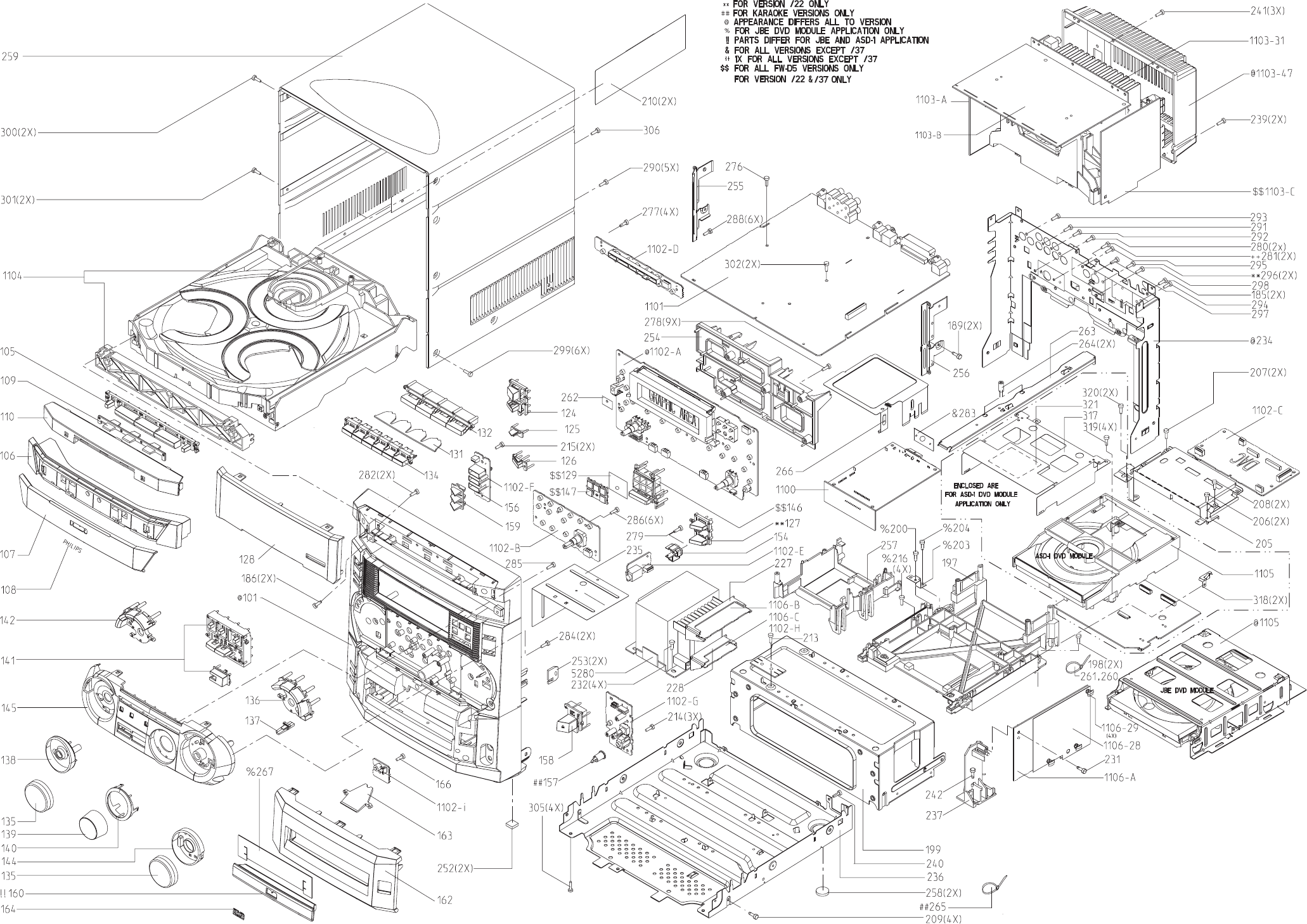
PCS 103 872
12-1 12-1
EXPLODED VIEW - MAIN UNIT
;;
;;
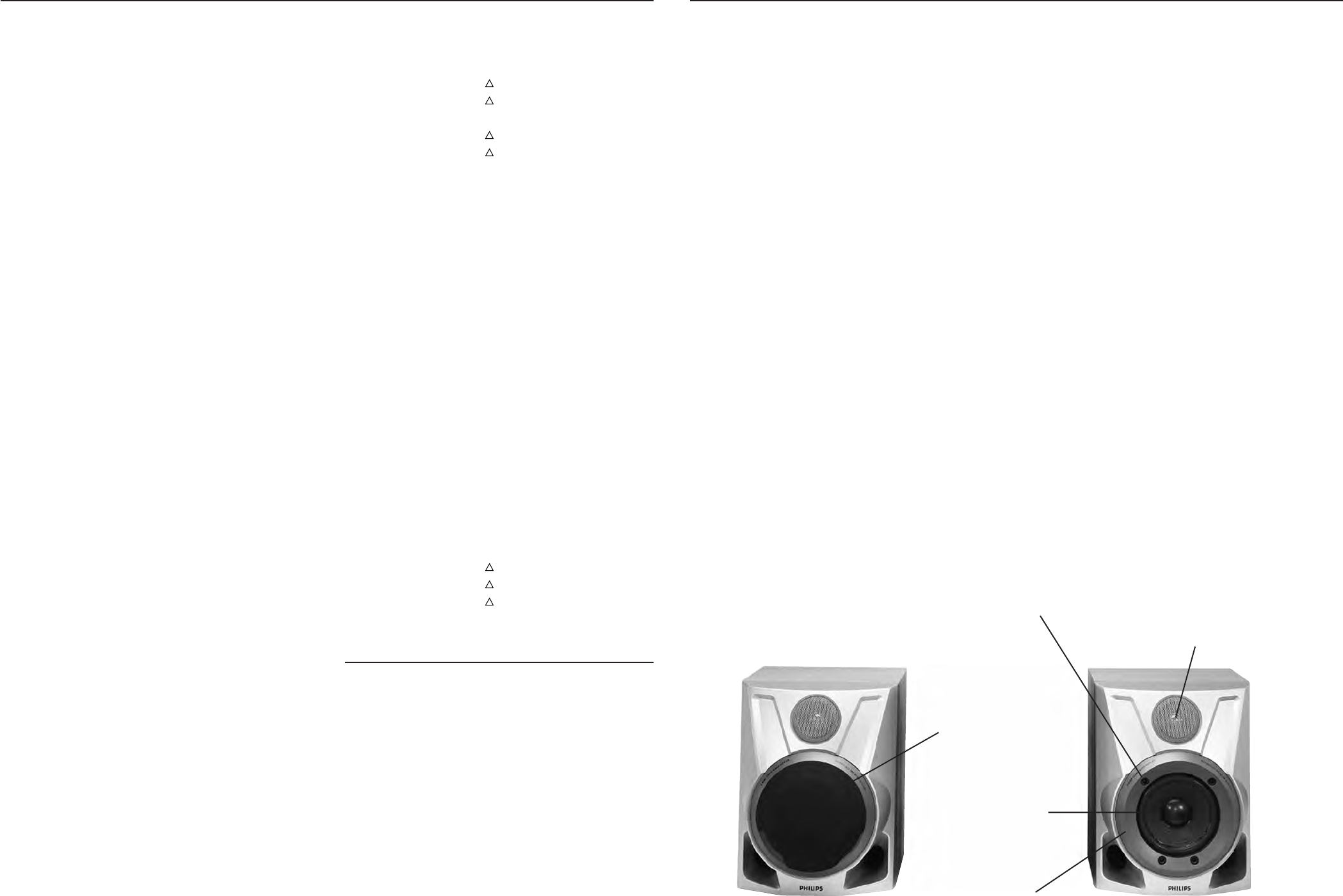
PCS 103 873
12-2
MECHANICAL & ACCESSORIES PARTS LIST - MAIN UNIT SCREW LISTS - MAIN UNIT
166 D3 x 12
185 D3 x 12
186 D3 x 25
189 D3 x 12
198 M3 x 16
200 D3 x 12
204 M3 x 16
206 M3 x 6
207 D3 x 16
208 M3 x 6
209 M3 x 6
213 M3 x 6
214 D3 x 12
215 D3 x 12
216 D3 x 12
231 D3 x 12
232 M3 x 10
239 M3 x 10
240 D3 x 12
241 M3 x 10
242 M3 x 10
276 D3 x 12
277 D3 x 12
278 D3 x 12
279 D3 x 12
12-2
0101 3139 118 11820 Cabinet Front /21/21M
0101 3139 118 11790 Cabinet Front /22
0101 3139 118 13850 Cabinet Front /30
0101 3139 118 11680 Cabinet Front /37
0105 3139 118 12110 Button Set CDC Select
0106 3139 118 11070 Cover Tray CDC
0107 3139 118 11080 Cover Ornament CDC Tray
0108 4822 454 13408 Badge, Philips
0110 3139 118 12100 Cover Ornament CDC
0124 3139 118 11420 Button Power /21/21M/30
0124 3139 118 11090 Button Power /22/37
0126 3139 114 69060 Window IR
0127 3139 118 11410 Button RDS/News /22
0128 3139 118 12590 Window Display
0128 3139 118 11690 Window Display /37
0131 3139 114 68810 Lightguide Source Select
0132 3139 118 12150 Button Set Source Select
0134 3139 118 11140 Button Set Control
0135 3139 118 11110 Knob Jog Rotary
0136 3139 118 11740 Button Set Jog Sound
0138 3139 114 70220 Lightguide Jog DVD Rotary
0139 3139 118 11710 Knob Volume Rotary
0140 3139 118 11720 Ring Ornament Volume
0141 3139 118 11770 Button Set DVD Control
0142 3139 118 11730 Button Set Jog DVD
0144 3139 118 11170 Ring Ornament Jog Sound
0145 3139 118 11750 Cover Ornament Control
0146 3139 118 12170 Button Set DPL
0157 3139 118 11810 Knob Karaoke /21/21M
0158 3139 118 11780 Button Open/Close DVD
0160 3139 118 11800 Cover Tray DVD
0162 3139 118 11760 Cover Ornament Front
0164 3139 240 00010 DVD Logo
0210 3139 113 10570 Felt Cloth 0.2x160x53mm
0252 4822 462 40683 Foot Rubber (SQ)
0258 4822 462 40683 Foot Rubber (SQ)
0259 3139 114 69230 Cabinet Rear
0259 3139 114 71450 Cabinet Rear /37
0283 3139 114 70330 Plate FM Socket
0350 3139 118 77820 Left/Right LS Box
9965 000 05697 Center Box
9965 000 05698 Surround Box
0351 4822 303 50063 FM Aerial
0351 4822 320 11094 FM Aerial Wire /37
0356 3139 228 85410 Remote Control RC2567/01
0356 3139 228 84540 Remote Control RC2516/01
0383 4822 320 11642 Cinch Cable 1.7m
0384 4822 303 50082 AM Frame Aerial
0385 4822 321 10249
!
Mains Cord
0385 4822 321 10954
!
Mains Cord /30
0385 4822 321 11466
!
Mains Cord /37
0386 4822 263 21092
!
Adapter Plug /21
0387 3139 115 20050 Instruct. For Use /21/21M/30
0387 3139 115 20030 Instruct. For Use /22
0387 3139 116 19770 Instruct. For Use /37
1106-29 4822 466 93148 Spacer 5mm
1673 3139 110 34800 Flex Cable 19pin 18cm BD
1673 3139 110 34790 Flex Cable 23pin 18cm BD
1680 4822 320 12713 Flex Cable 6pin 34cm AD
1681 3139 110 33960 Flex Cable 4pin 12cm BD
1682 3139 110 34750 Flex Cable 5pin 8cm AD
1683 3139 110 34920 Flex Cable 8pin 28cm BD
1683 3139 110 34780 Flex Cable 4pin 28cm BD
1684 3139 110 34560 Flex Cable 19pin 28cm BD
1685 3139 110 34740 Flex Cable 8pin 18cm AD
1685 3139 110 34730 Flex Cable 12pin 18cm AD
1686 4822 320 12702 Flex Cable 6pin 14cm BD
1691 3139 110 34760 Flex Cable 9pin 28cm BD
1692 3139 110 34870 Flex Cable 9pin 22cm BD
1693 3139 110 34810 Flex Cable 16pin 14cm
1694 3139 110 34820 Flex Cable 22pin 14cm
5280 3139 118 32210
!
Mains Transformer /21/21M
5280 3139 118 32220
!
Mains Transformer /22/30
5280 3139 118 32200
!
Mains Transformer /37
Left/Right Loudspeaker Box breakdown
9965 000 05538 Wire Assy w/Elco 2,2µF 50V
9965 000 05539 Woofer D5,25" 6R 50W Black
9965 000 04255 Tweeter D2,5" 8R 10W
9965 000 04256 Woofer Ring
9965 000 03233 Grommet
9965 000 04260 Cloth Frame Assembly
Note: Only the part mentioned in this list are normal
service spare parts.
280 D3 x 12
281 D3 x 12
282 D3 x 12
284 D3 x 12
285 D3 x 16
286 D3 x 12
288 D3 x 12
290 M3 x 10
291 D3 x 12
292 D3 x 12
293 D3 x 12
294 D3 x 12
295 D3 x 12
297 M3 x 10
298 M3 x 10
299 M3 x 10
300 M3 x 10
301 M3 x 10
302 D3 x 16
305 M3 x 10
306 M3 x 10
Grommet
Cloth Frame Assembly
Woofer Ring
Tweeter D2,5"
8R 10W
Woofer D5,25"
6R 50W Black
Note: The screw D3 x 10 for Woofer Ring is below the Gromet
