Fifo Pi Ultimate Manual V1.0
User Manual:
Open the PDF directly: View PDF ![]() .
.
Page Count: 10

Page 1 2018-12-30 Revised 2019-03-10 iancanada.mail@gmail.com
FifoPi Ultimate 768KHz PCM/DSD/DoP FIFO user’s guide
By Ian Jin and Greg Stewart, March 10, 2019 Ver. 1.0
A. Introduction
The FiFoPi is designed to lower jitter on the digital audio produced by a RaspberryPi player before passing it onto
the downstream DAC. It does this by:
1. Buffering and reclocking the digital audio stream using lower-jitter clocks and low-jitter logic components. These
improve on the non-audio clock in the RaspberryPi that has to be converted via non-integer division to an
audio-related clock frequency, a jitter-producing process. You have control over how good these clocks are as they
are mounted in sockets and user-replaceable.
2. Using built-in galvanic isolation devices that isolate both the reclocking process and the downstream DAC from
the processing noise produced in the RaspberryPi AND the power supply noise produced by that process and
inherent in the DC-DC converters used to create the lower voltage rails needed by the circuits in the RaspberryPi.
3. Using a power supply separate from that of the RaspberryPi for the reclocking process and the clocks. Using a
high-quality power supply here helps the FiFoPi produce a low-jitter digital audio output stream. Just as you control
the quality of the clocks, you can make this power supply as good as you desire. Based on our experiences, we
recommend directly-connected LiFePO4 or Ultracap supplies as the absolute best power supplies you can provide.
We firmly believe the FiFoPi to be one of the most effective and flexible solutions you can use to improve the sound
quality of RaspberryPi-based digital audio playback.
B. Features and Specifications
Fully RaspberryPi-Hat compliant single-board FIFO solution with built-in galvanic isolators and clocks.
Supports the full range of PCM I2S up to 768KHz.
Supports Native DSD from DSD64 to DSD1024.
On-board DoP decoder enables RaspberryPi native DSD play back over GPIO via DoP via PCM I2S.
Built-in PCM I2S 16bit to 32bit lossless converter to work with DACs that don’t support 16bit PCM I2S format.
Two user-replaceable socket-mounted clocks (XOs or OCXOs) support a full range of frequencies from
5.6448MHz to 98.3040MHz and both 44.1 and 48 sampling frequency families.
FIFO time-delay is held constant across different audio formats and frequencies. Delay time adjustment
function already included for adjustment via a future external display/controller.
Two separate DC inputs to provide both clean power to the FiFoPi and optional isolated RaspberryPi power
via GPIO.
Pre-isolation GPIO connector to run DAC controller or other RPi accessories in isolated mode.
Works with all RaspberryPi DAC HATs and external DACs using synchronous master clock (Sync mode) to
reduce jitter.
Page 2 2018-12-30 Revised 2019-03-10 iancanada.mail@gmail.com
Runs in transparent mode, no driver required on the RaspberryPi.
Flexible and DIY friendly including user-changeable clocks and many other options.
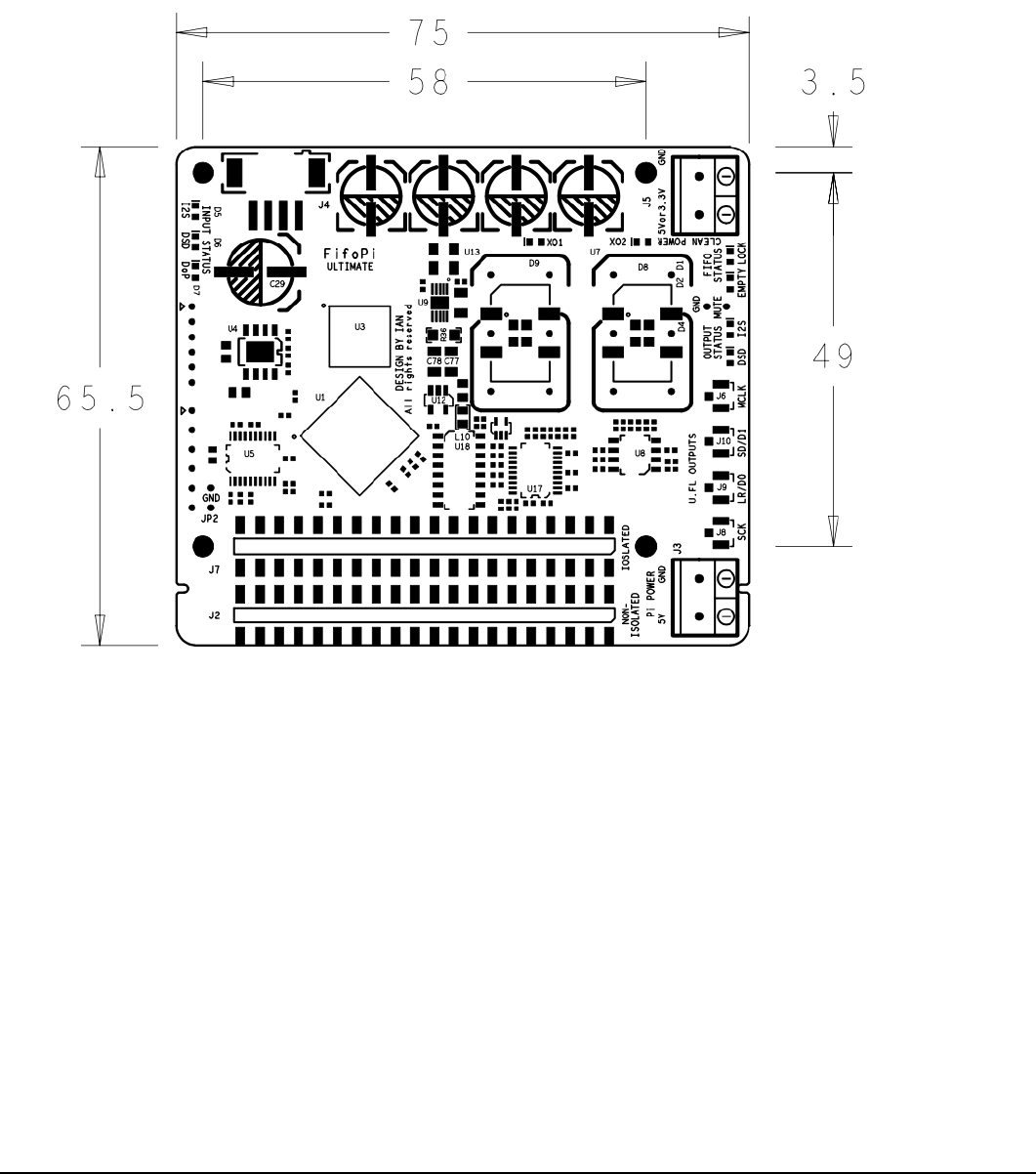
C. Layout and Dimensions (in mm)
Page 3 2018-12-30 Revised 2019-03-10 iancanada.mail@gmail.com
D. Quick-Start Guide
1. Connect the FifoPi on top of RaspberryPi.
2. Connect the DAC HAT on top of FifoPi (or connect to an external DAC through the U.FL connectors).
3. Install a micro SD card loaded with your preferred distro and player combination into your RaspberryPi.
4. Connect a 5V DC power supply (or a 3.3V LifePO4 battery/Ultra Capacitor supply) to J5 (FiFoPi power).
5. Power the RaspberryPi with 5V DC at either J3 of FifoPi (via GPIO, recommended) or a micro-USB cable to
RaspberryPi.
6. Make other connections and perform configuration as needed to enable your RaspberryPi and DAC HAT to
operate as desired.
7. Enjoy the music.
E. Connectors
J5: Clean isolated FiFoPi DC power input
Connect a 3.3V to 6V DC / 200mA (minimum) power supply to J5 to power the FiFoPi, MAINTAINING CORRECT
POLARITY!!! The FiFoPi consumes about 100mA average current with typical 45.1584/49.1520 MHz XO clocks, a
little higher with higher frequency clocks. If you use OCXOs or other high current-consuming clocks, you MUST
account for the additional current required in your clocks in your choice of a power supply. We prefer to use a 3.3V
ultra capacitor / LifePO4 battery direct power supply. In this case, also connect it to J5. The internal low noise
Low-Drop-Out regulators (LDOs) will be bypassed automatically.

Page 4 2018-12-30 Revised 2019-03-10 iancanada.mail@gmail.com
J3: Optional RaspberryPi power input
You can power your RaspberryPi via GPIO through J3, bypassing the Micro-USB connection. To do so, connect a 5V
2A DC power supply to J3, MAINTAINING CORRECT POLARITY!!! We highly recommend you power your
RaspberryPI via GPIO through J3 to lower power supply noise on your RaspberryPi. DO NOT connect power to J3 if
you already power your RaspberryPi via another method, such as the Micro-USB port.
J6, J11: MCLK outputs (U.FL coaxial cable socket)
MCLK (master clock) output for DAC HAT or external DAC. To operate a DAC (HAT or external) in synchronized clock
mode you must connect this to your DAC. J11, a second MCLK output socket, is located at the bottom side of PCB.
J8: SCK outputs (U.FL coaxial cable socket)
SCK (bit clock) output for external DAC. This output is the same for both PCM and DSD format.
J9: LRCK/D1 output (U.FL coaxial cable socket)
LRCK/D1 (PCM left/right clock or DSD data 1) output for external DAC. This Serial Audio Data line is formatted as
LRCK when the signal is PCM I2S or D1 when the signal is DSD.
J10: SD/D2 output (U.FL coaxial cable socket)
SD/D2 (PCM data or DSD data 2) output for external DAC. This Serial Audio Data line is formatted as SD when the
signal is PCM I2S or D2 when the signal is DSD
40PIN GPIO connectors
J1
J2
J7
PIN#
GPIO connecting RaspberryPi
to FiFoPi
Non-isolated (directly connected)
GPIO for a controller or other
digital devices
Isolated GPIO for a DAC
HAT or other audio devices
1,17
RaspberryPi 3.3V output
RaspberryPi 3.3V output
FiFoPi Isolated 3.3V
2,4
RaspberryPi 5V input/output
RaspberryPi 5V input/output
FiFoPi Isolated 5V
internally connected to J5+
6,9,14,20,
25,30,34,
39
RaspberryPi GND
RaspberryPi GND
Isolated GND
3
I2C DA
Non-isolated I2C DA
Isolated I2C DA
4
I2C CL
Non-isolated I2C CL
Isolated I2C CL
12
SCK Input
Non-isolated non-reclocked SCK
output
Isolated reclocked SCK
output
35
LRCK Input
Non-isolated non-reclocked
LRCK/D1 output
Isolated reclocked
LRCK/D1output
40
SD/D2 Input
Non-isolated non-reclocked
SD/D2 output
Isolated reclocked SD/D2
output
All other pins
Connected to the GPIO
pins of the RaspberryPi
Duplicating the same # GPIO
pins of the RaspberryPi
Not connected
Page 5 2018-12-30 Revised 2019-03-10 iancanada.mail@gmail.com
MUTE/GND
Isolated MUTE signal. A logic high output indicates DAC should be muted. This signal is optional. Most DACs or DAC
HATs do not need this signal.
J4: External Display/Control Panel connector (for future external display/controller)
4pin PH2.0mm connector
1
2
3
4
GND
RXd
5V
TXd
Note1:
All input/output signals are at
LVTTL (3.3V) logic level.
F. Jumper settings
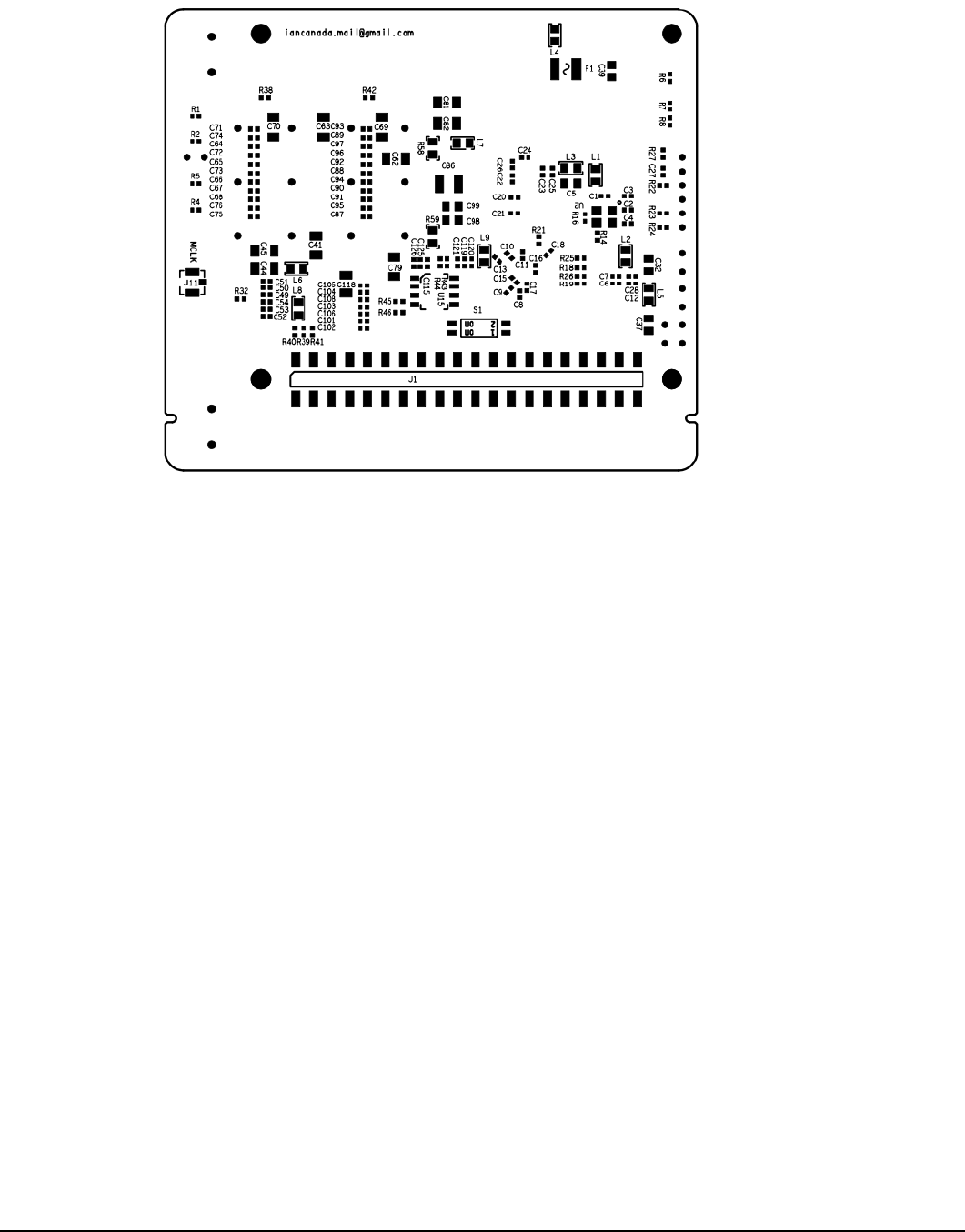
Jumper switch S1 is located at bottom side of PCB.
Jumper Switch
S1
OFF (default)
ON
1
DoP decoding enabled
DoP decoding disabled
2
Output format bit depth same as
original input format
Force lossless conversion of16bit PCM
I2S into 32bit
Switch 1 Note: Some DAC chips (such as ES9038Q2M) have a built-in DoP decoder. If you want to use the internal
DoP decoder, you need to disable FifoPi’s DoP decoding function. Otherwise, any DoP stream will be converted into
DSD format using FifoPi’s internal DoP decoder. When DoP decoder is disabled, DoP stream will be treated as PCM
format and passed through un-converted.
Switch 2 Note: Some DAC chips (for example some early ESS DAC chips) do not play 16bit PCM I2S datastreams. If
you are connecting to a DAC using one of those chips, you can enable the internal 16bit to 32bit converter to allow
these chips to play these datastreams. This converter does not change non-16bit PCM or DSD/DoP format
datastreams. This function does not operate correctly when you are sending 16bit left justified or right justified format
datastreams from your RaspberryPi. Also our ES9028Q2MPi and ES9038Q2MPi DAC HATs DO support 16bit PCM
natively and do not need this function enabled. AND finally, if you have set your DAC's driver on the RaspberryPi to do
this conversion, you can enable this on the FiFoPi and turn it off in your DAC's driver.
Page 6 2018-12-30 Revised 2019-03-10 iancanada.mail@gmail.com
G. LED indicators
Group
LED
Description
On Indicates...
Input
status
D5
PCM
PCM I2S format input
D6
DSD
DSD format input
D7
DoP
DoP format input and converted into DSD format
Output
status
D4
PCM
PCM I2S format output
D3
DSD
DSD format output
FIFO
status
D1
LOCK
FiFoPi locked onto input
D2
EMPTY
FiFoPi is empty
Clock
Selection
D9
XO1
XO1 is MCLK
D8
XO2
XO2 is MCLK
H. Clocks
The FiFoPi has two sockets for clocks, XO1 (U13) and XO2 (U7).
A clock appropriate to your serial audio data stream's
sampling frequency must be installed in at least one of them. Standard DIP 3.3V clock oscillators with 14- or 8- pin
configurations are good for XO1 and XO2. Surface mount (SMT) oscillators can also be used by mounting them on
SMT adapters.
IF your incoming PCM I2S or DSD stream will always have the same or same Fs family, you can install a clock for that
Fs family and leave the other socket empty. The clock or clocks you use can be installed in either socket, the FiFoPi
will recognize the clock frequencies and use them as appropriate.
Clock frequencies must be selected from the following two frequency groups.
Clock frequency group 1
Fs supported
44.1KHz
DSD64
88.2KHz
DSD128
176.4KHz
DSD256
352.8KHz
DSD512
705.6KHz
DSD1024
XO/OCXO
Frequencies
can be used *
5.6448MHz
√
11.2896 MHz
√
√
22.5792 MHz
√
√
√
45.1584 MHz
√
√
√
√
90.3168 MHz
√
√
√
√
√
Page 7 2018-12-30 Revised 2019-03-10 iancanada.mail@gmail.com
Clock frequency group 2
Fs supported
48KHz
96KHz
192KHz
384KHz
768KHz
XO/OCXO
Frequencies
can be used *
6.144MHz
√
12.2880 MHz
√
√
24.5760 MHz
√
√
√
49.1520 MHz
√
√
√
√
98.3040 MHz
√
√
√
√
√
Clock Note 1: When using 2 clocks, they have to be selected from two different frequency groups, but don’t have to be
a frequency pair nor do they have to both be XOs or OCXOs.
For example, a 22.5792 MHz XO can work together with
a 49.1520 MHz XO. AND one of them can be an XO and the other an OCXO.
Clock Note 2: When you install a clock in both sockets, they have to be devices that have an OE (output enable/disable
function) pin. When you install only one clock, it does not have to be one that has an OE pin.
I. How to produce the best sound quality using your FiFoPi
Install great clocks
The primary mechanism the FifoPi uses to lower jitter and improve the sound is by recreating the serial audio data
stream referenced to low-jitter clocks. The two XO oscillators supplied with the board are low-cost generic units that
allow you to confirm proper operation of the FiFoPi in your setup. While the supplied clocks MIGHT produce better
sound quality than the RaspberryPi's non-audio clocking system, they are not intended to do so. The better clock you
use, the more improvement you can get from your FiFoPi. Replacing the supplied clocks with a really nice pair of low
jitter XO oscillators is your key to the best sound quality improvement from your FiFoPi. We have tested the
CCHD-957 series XO oscillators from Crystek and found to be a good choice with very low phase noise at a
reasonable price. Another good choice are the SDA series from NDK, but these are very small and difficult for many to
solder.
You may also use OCXOs with better phase noise performance for even better results as long as you factor in the
higher current requirements of these devices. Trying different clocks for better sound is an interesting experience
similar to capacitor, tube or opamp rolling.

Page 8 2018-12-30 Revised 2019-03-10 iancanada.mail@gmail.com
Power your FiFoPi from a directly-connected 3.3V ultra capacitor or LiFePO4 battery supply
The quality of your FiFoPi power supply directly impacts both FiFoPi and clock performance. As an alternative to very
good quality power supplies, we have used a directly-connected 3.3V LiFePO4 or Ultra Capacitor supplies. Our
experience is that these types of supplies do a very good job of improving the resulting sound quality AND are very
hard to better with a traditional power supply. You can connect this type of supply directly to the isolated DC input
terminal J5. With a 3.3V DC input on J5, the on-board LDOs are automatically bypassed internally because of the
dropout voltage is lower than the minimal dropout voltage (about 0.3V).
It is theoretically better to physically bypass on-board LDOs when using one of these supplies. You can solder a 0R
0805 jumper resistor or just a short piece of wire at positions R58, R59 which are located at bottom side of the FiFoPi.
CRITICALLY IMPORTANT NOTE: After you short R58 and R59, the ABSOLUTE MAXIMUM VOLTAGE you can
connect to J5 is 3.6V!!!! Any higher voltage means you will likely damage your FifoPi and clocks.
XO frequency and the sound
When connecting the MCLK line to a DAC to run it in synchronous mode, for a given sampling rate frequency ratio (Fs),
using different frequency clock may produce slightly different results. This is caused by the differences in the internal
processing in the DAC chips as they perform the digital-to-analog conversion. For example, we listened to a 44.1 KHz
audio stream reproduced by some DAC chips (not all), first with a 22.5792 MHz (512Fs) and then with a 11.2896 MHz
(256Fs) clock installed. We found the sound stage changed slightly based on the clock. And with some DAC chips, we
preferred the results using 90.3168/98.3040 MHz clocks than the more commonly used 45.1584/49.1520 MHz. Feel
free to not only try clock types, but also different clock frequencies according to your personal preference.
Potentials of generic XO clock oscillators
For some generic XO clock oscillators, the internal crystal may not be that bad. The problem is usually that generic
oscillators do not have good power supply and clock output driver. In many cases, when powered from a high quality,
low noise power supply and interfaced with a low jitter fan-out buffer such as we use in the FiFoPi, they will perform
better than originally.
XO warm-up time
All XO and OCXO oscillators take time to warm-up and stabilize before producing their lowest jitter, best sounding
clock signal. This will take anywhere from a couple of minutes to a half hour or even longer. Please allow for your
clocks to warm up and stabilize before performing any critical evaluations.
Page 9 2018-12-30 Revised 2019-03-10 iancanada.mail@gmail.com
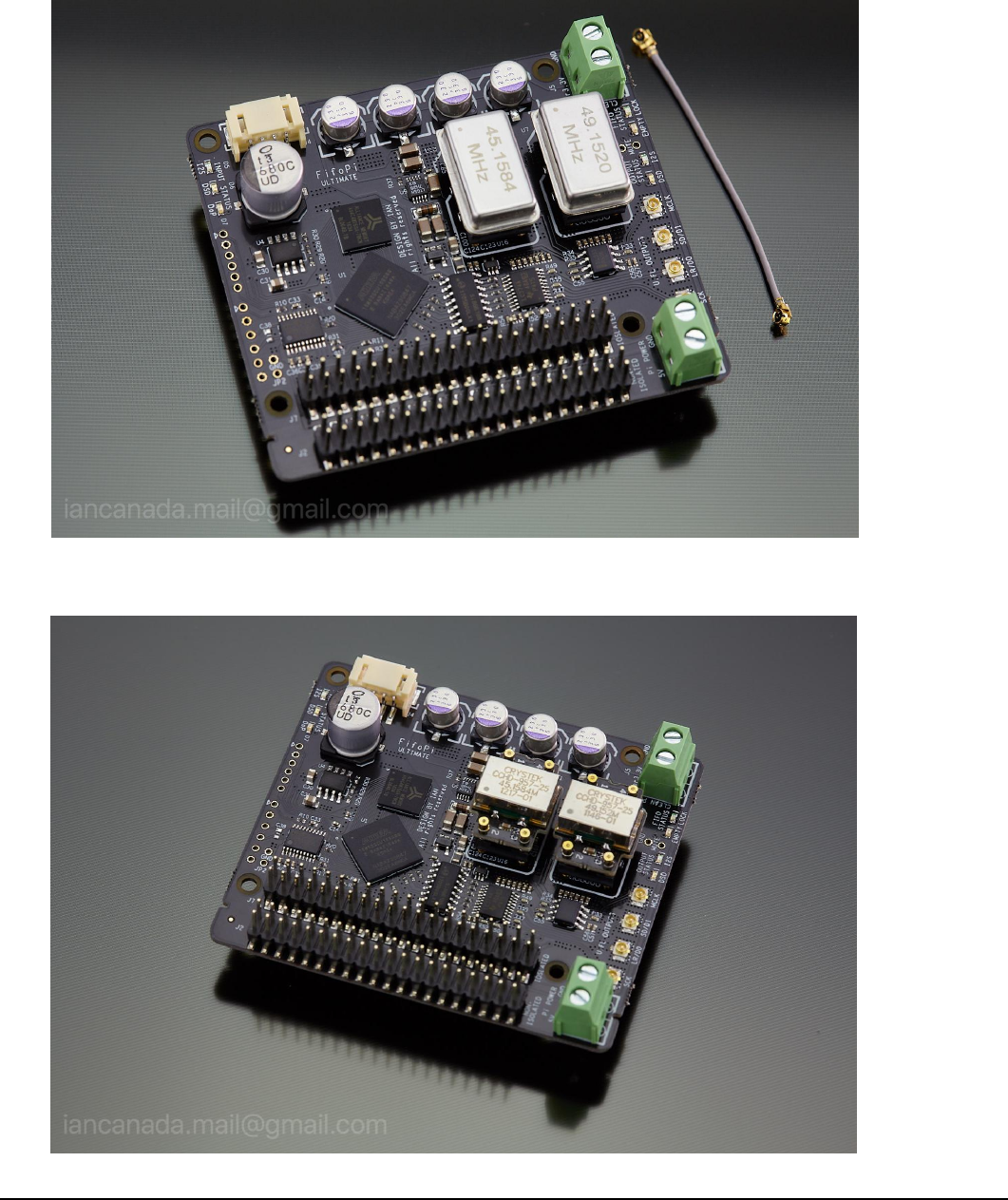
J. FifoPi pictures
1. FifoPi Ultimate as shipped
2. FifoPi Ultimate with CCHD975 upgraded clocks
Page 10 2018-12-30 Revised 2019-03-10
iancanada.mail@gmail.com
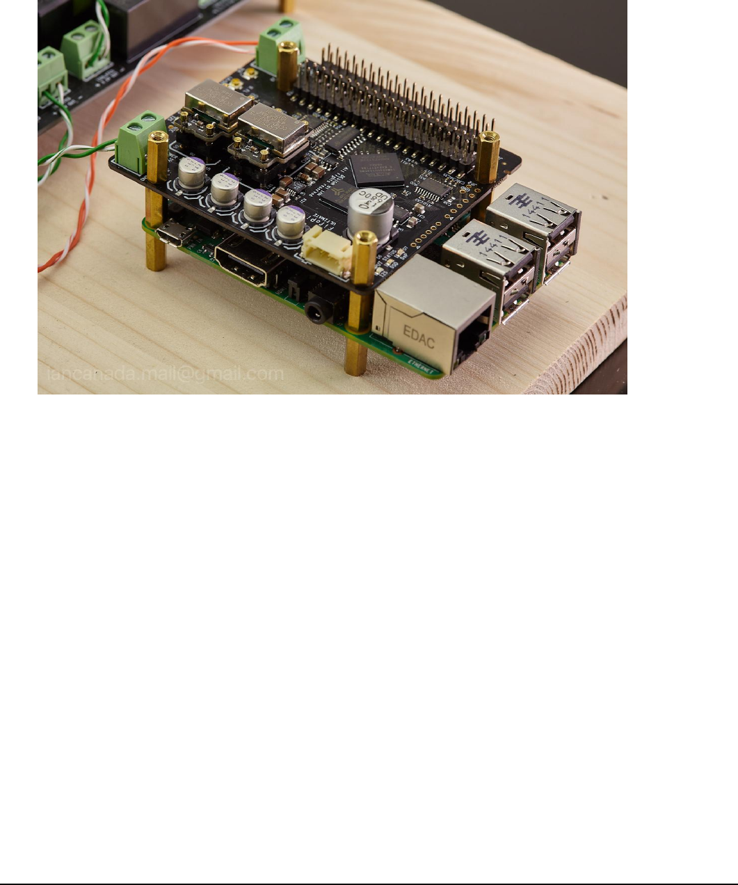
3. FifoPi on RaspberryPi
© 2018 Ian Jin. The firmware code embedded in the FiFoPi is the property of Ian Jin. You are granted a non-exclusive,
non-transferable, non-sublicense-able, royalty-free right to use the FiFoPi board solely for your own, non-commercial purposes.
You may not distribute, sell, lease, transfer, modify, adapt, translate, reverse engineer, prepare derivative works of, decompile, or
disassemble the software provided. All rights reserved.
