FIRE BIRD 2 V ATMEGA2560 Hardware Manual V1.08 2012 10 12
Fire%20Bird%20V%20ATMEGA2560%20Hardware%20Manual%20V1.08%202012-10-12
User Manual:
Open the PDF directly: View PDF ![]() .
.
Page Count: 121 [warning: Documents this large are best viewed by clicking the View PDF Link!]
Fire Bird V ATMEGA2560 Hardware Manual
© NEX Robotics Pvt. Ltd. and ERTS Lab, CSE, IIT Bombay, INDIA 1

Fire Bird V ATMEGA2560 Hardware Manual
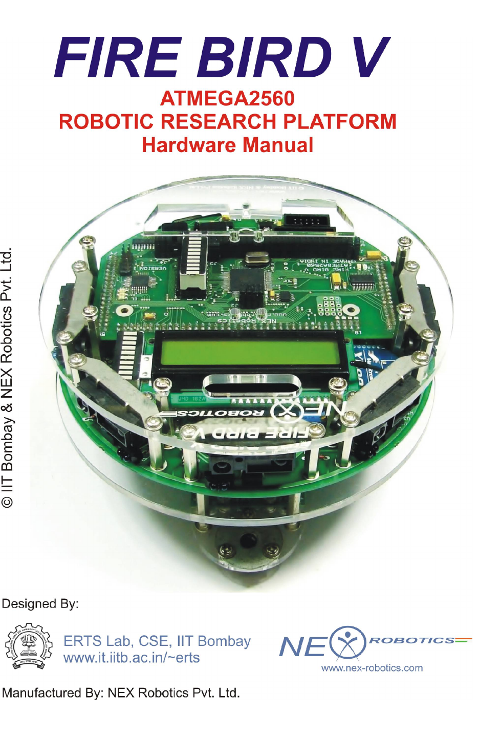
FIRE BIRD V
HARDWARE MANUAL
© NEX Robotics Pvt. Ltd. and ERTS Lab, CSE, IIT Bombay, INDIA 2

Fire Bird V ATMEGA2560 Hardware Manual
Version 7.00
15th August 2012
Documentation author
Sachitanand Malewar, NEX Robotics Pvt. Ltd.
Dr. Anant Malewar, NEX Robotics Pvt. Ltd.
Credits (Alphabetically)
Aditya Sharma, NEX Robotics
Amey Apte, NEX Robotics
Amit Yadav, NEX Robotics
Ashish Gudhe, CSE, M.Tech, IIT Bombay
Behlul Sutarwala, NEX Robotics
Gaurav Lohar, NEX Robotics
Gurulingesh R. CSE, M.Tech, IIT Bombay
Inderpreet Arora, EE, M.Tech, IIT Bombay
Prof. Kavi Arya, CSE, IIT Bombay
Prof. Krithi Ramamritham, CSE, IIT Bombay
Kunal Joshi, NEX Robotics
Nandan Salunke, RA, CSE, IIT Bombay
Pratim Patil, NEX Robotics
Preeti Malik, RA, CSE, IIT Bombay
Prakhar Goyal, CSE, M.Tech, IIT Bombay
Raviraj Bhatane, RA, CSE, IIT Bombay
Rohit Chauhan, NEX Robotics
Rajanikant Sawant, NEX Robotics
Saurabh Bengali, RA, CSE, IIT Bombay
Vaibhav Daghe, RA, CSE, IIT Bombay
Vibhooti Verma, CSE, M.Tech, IIT Bombay
Vinod Desai, NEX Robotics
© NEX Robotics Pvt. Ltd. and ERTS Lab, CSE, IIT Bombay, INDIA 3
Fire Bird V ATMEGA2560 Hardware Manual
Notice
The contents of this manual are subject to change without notice. All efforts have been made to
ensure the accuracy of contents in this manual. However, should any errors be detected, NEX
Robotics welcomes your corrections. You can send us your queries / suggestions at
info@nex-robotics.com
Content of this manual is released under the Creative Commence cc by-nc-sa license. For legal
information refer to: http://creativecommons.org/licenses/by-nc-sa/3.0/legalcode
•Robot’s electronics is static sensitive. Use robot in static free environment.
•Read the hardware and software manual completely before using this robot
Recycling:
Almost all of the robot parts are recyclable. Please send the robot parts to the recycling plant
after its operational life. By recycling we can contribute to cleaner and healthier environment for
future generations.
© NEX Robotics Pvt. Ltd. and ERTS Lab, CSE, IIT Bombay, INDIA 4

Fire Bird V ATMEGA2560 Hardware Manual
Revision History:
1. User must go through the Fire Bird V’s Hardware and Software manuals
before using the robot.
2. This hardware manual is applicable from Main board Version 11 dated 12th
August 2012 onwards and ATMEGA2560 microcontroller board Version 7
dated 15th August 2012.
3. Crystal of the ATMEGA2560 microcontroller is upgraded to 14.7456MHz
from 11.0592Mhz in all the Fire Bird V ATMEGA2560 robots delivered on
or after 1st December 2010. This documentation is updated considering
crystal frequency as 14.7456MHz.
4. Following are the upgrades made in Main board Version 11 dated 12th
August 2012 and ATMEGA2560 microcontroller board Version 7 dated 15th
August 2012.
•Main board supports any microcontroller working on 3.3V and 5V.
•On-board NiMH Battery charger along with battery level indicator.
•Auxiliary power connector and battery charging connectors are separated
and require a single unified connector from the AC adapter.
•3mm IR proximity Sensors are replaced with 5mm IR Proximity sensor for
better range.
•3 times reduction in power consumed by IR proximity sensors.
•Added support for 7 channel white line sensors with all 7 sensor calibration
potentiometers on main board.
•All Motor, Sensor pod & battery connectors are replaced with relimate 2510
type connectors for better reliability.
•Added Fuse protection.
•Removable battery pack with Velcro battery strap.
•Bottom acrylic plate is replaced with high strength aluminum metal plate.
•Easy to replace motors than previous model.
•Added support for MaxBotix Ultrasonic Range Sensors.
•Added pins to measure signal strength of XBee wireless module.
•Larger heat sink area for the on-board voltage regulators.
•Tin plated power and motor tracks for further increasing power rating of the
main board.
© NEX Robotics Pvt. Ltd. and ERTS Lab, CSE, IIT Bombay, INDIA 5

Fire Bird V ATMEGA2560 Hardware Manual
Index
1. Introduction 7
2. Fire Bird V ATMEGA2560 8
3. Using Fire Bird V Robot 13
4. Pin Functionality 78
5. Upgrading Robot’s Hardware 88
6. PC Based Control Using Serial Communication 96
7. Robot Control using ‘GUI’ for Fire Bird V ATMEGA2560 111
8 Errata 121
© NEX Robotics Pvt. Ltd. and ERTS Lab, CSE, IIT Bombay, INDIA 6

Fire Bird V ATMEGA2560 Hardware Manual
1. Introduction
Thanks for choosing the Fire Bird V mobile robotics platform. Fire Bird V will help you gain
exposure to the world of robotics and embedded systems. With help of its innovative architecture
and adoption of the ‘Open Source Philosophy’ in its software and hardware design, you will be
able to create and contribute to complex applications that run on this platform, helping you
acquire expertise as you spend more time with them.
Safety precautions:
•Robot’s electronics is static sensitive. Use robot in static free environment.
•Read the assembling and operating instructions before working with the robot.
•If robot’s battery low buzzer starts beeping, immediately charge the batteries.
•To prevent fire hazard, do not expose the equipment to rain or moisture.
•Refrain from dismantling the unit or any of its accessories once robot is assembled.
•Charge the NiMH battery only with the charger provided on the robot.
•Never allow NiMH battery to deep discharge.
•Mount all the components with correct polarity.
•Keep wheels away from long hair or fur.
•Keep the robot away from the wet areas. Contact with water will damage the robot.
•To avoid risk of fall, keep your robot in a stable position.
•Do not attach any connectors while robot is powered ON.
•Never leave the robot powered ON when it is not in use.
•Disconnect the battery charger after charging the robot.
Inappropriate Operation:
Inappropriate operation can damage your robot. Inappropriate operation includes, but is not
limited to:
•Dropping the robot, running it off an edge, or otherwise operating it in irresponsible
manner.
•Interfacing new hardware without considering compatibility.
•Overloading the robot above its payload capacity.
•Exposing the robot to wet environments.
•Continuing to run the robot after hair, yarn, string, or any other item is entangled in the
robot’s axles or wheels.
•All other forms of inappropriate operations.
•Using robot in areas prone to static electricity.
•Read carefully paragraphs marked with caution symbol.
© NEX Robotics Pvt. Ltd. and ERTS Lab, CSE, IIT Bombay, INDIA 7
Fire Bird V ATMEGA2560 Hardware Manual
2. Fire Bird V ATMEGA2560
The Fire Bird V robot is the 5th in the Fire Bird series of robots. First two versions of the robots
were designed for the Embedded Real-Time Systems Lab, Department of Computer Science and
Engineering, IIT Bombay. Theses platforms were made commercially available from the version
3 onwards. All the Fire Bird V series robots share the same main board and other accessories.
Different family of microcontrollers can be added by simply changing top microcontroller
adapter board. Fire Bird V supports ATMEGA2560 (AVR), P89V51RD2 (8051) and LPC2148
(ARM7) microcontroller adapter boards. This modularity in changing the microcontroller
adapter boards makes Fire Bird V robots very versatile. You can also add your own custom
designed microcontroller adapter board.
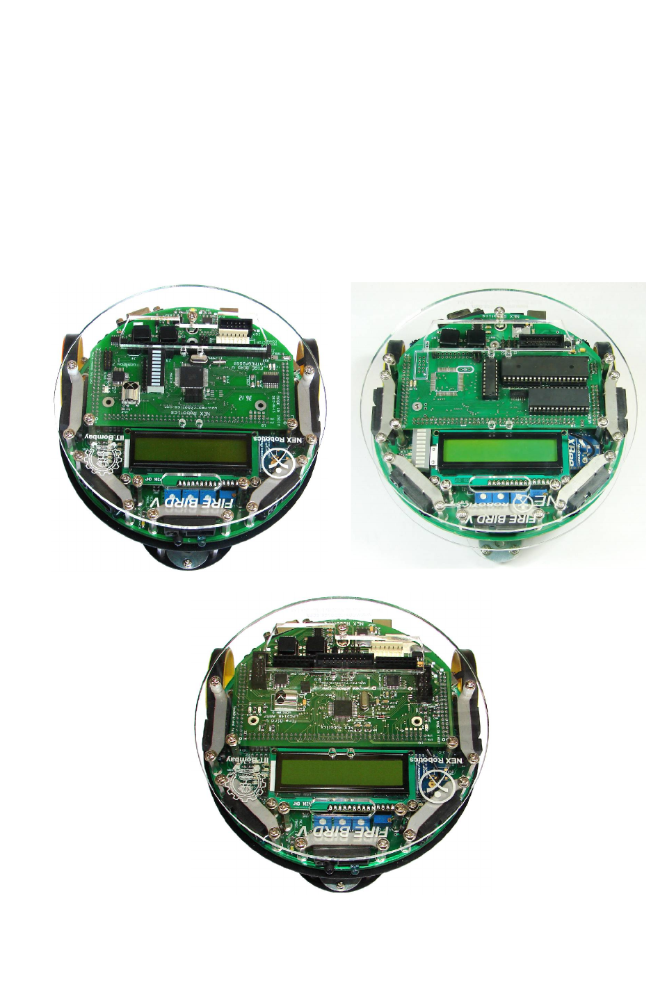
Fire Bird V ATMEGA2560 (AVR) Fire Bird V P89V51RD2 (8051)
Figure Bird V LPC2148 (ARM7 TDMI)
Figure 2.1: Fire Bird V Robots
© NEX Robotics Pvt. Ltd. and ERTS Lab, CSE, IIT Bombay, INDIA 8
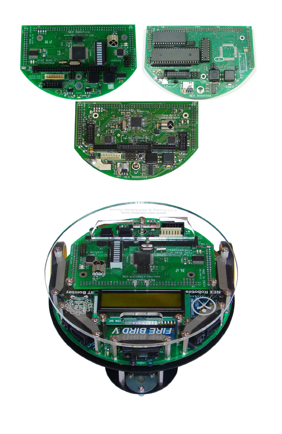
Fire Bird V ATMEGA2560 Hardware Manual
Figure 2.2: ATMEGA2560 (AVR), P89V51RD2 (8051) and LPC2148 ARM7
microcontroller adapter boards for Fire Bird V
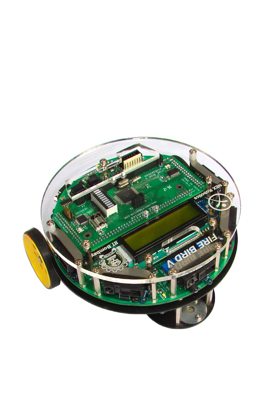
Figure 2.3 Fire Bird V ATMEGA2560 robot
© NEX Robotics Pvt. Ltd. and ERTS Lab, CSE, IIT Bombay, INDIA 9
Fire Bird V ATMEGA2560 Hardware Manual
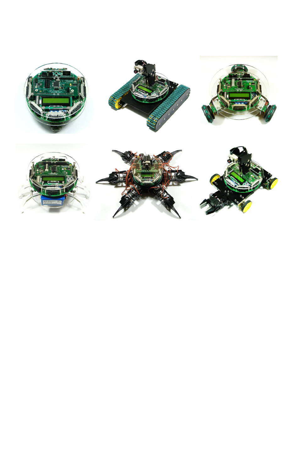
2.1 Avatars of Fire Bird V Robot
All Fire Bird V Robots share the same unified architecture. All Robots use the same main board
and microcontroller adapter boards.
Fire Bird V Fire Bird V Tank Fire Bird V Omnidirectional Robot
Fire Bird V Insect Fire Bird V Hexapod Fire Bird V 4WD with Gripper
Figure 2.4: Avatars of Fire Bird V Robot
© NEX Robotics Pvt. Ltd. and ERTS Lab, CSE, IIT Bombay, INDIA 10
Fire Bird V ATMEGA2560 Hardware Manual
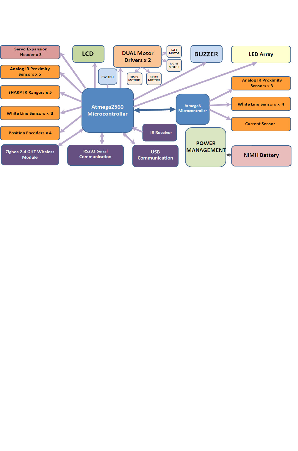
2.2 Fire Bird V Block Diagram:
Figure 2.5: Fire Bird V ATMEGA2560 robot block diagram
© NEX Robotics Pvt. Ltd. and ERTS Lab, CSE, IIT Bombay, INDIA 11

Fire Bird V ATMEGA2560 Hardware Manual
2.3 Fire Bird V ATMEGA2560 technical specification
Microcontroller:
Atmel ATMEGA2560 as Master microcontroller (AVR architecture based Microcontroller)
Atmel ATMEGA8 as Slave microcontroller (AVR architecture based Microcontroller)
Sensors:
Three white line sensors (extendable to 7)
Five Sharp GP2Y0A02YK IR range sensor (One in default configuration)
Eight analog IR proximity sensors
Two position encoders (extendable to four)
Battery voltage sensing
Current Sensing (Optional)
Five MaxBotix Ultrasonic Range Sensors (Optional)
Indicators:
2 x 16 Characters LCD
Buzzer and Indicator LEDs
Control:
Autonomous Control
PC as Master and Robot as Slave in wired or wireless mode
Communication:
USB Communication
Wired RS232 (serial) communication
Wireless ZigBee Communication (2.4GHZ) (if XBee wireless module is installed)
Wi-Fi communication (if Wi-Fi module is installed)
Bluetooth communication (if Bluetooth wireless module is installed)
Simplex infrared communication (From infrared remote to robot)
Dimensions:
Diameter: 16cm
Height: 8.5cm
Weight: 1100gms
Power:
9.6V Nickel Metal Hydride (NiMH) battery pack and external Auxiliary power from battery
charger.
On Board Battery monitoring and intelligent battery charger.
Battery Life:
2 Hours, while motors are operational at 75% of time
Locomotion:
Two DC geared motors in differential drive configuration and caster wheel at front as support
Top Speed: 24 cm / second
Wheel Diameter: 51mm
Position encoder: 30 pulses per revolution
Position encoder resolution: 5.44 mm
© NEX Robotics Pvt. Ltd. and ERTS Lab, CSE, IIT Bombay, INDIA 12
Fire Bird V ATMEGA2560 Hardware Manual
3. Using Fire Bird V Robot
In this chapter various components of the robot and their principal of operations are explained in
detail. It is very important that user go through chapter before starting to use robot.
Fire Bird V robot has 6 important modules:
1. Power management
2. Sensing
3. Actuation (locomotion)
4. Other peripherals
5. Communication
6. Intelligence (microcontroller)
Figure 3.1 Fire Bird V ATMEGA2560 robot
© NEX Robotics Pvt. Ltd. and ERTS Lab, CSE, IIT Bombay, INDIA 13
Fire Bird V ATMEGA2560 Hardware Manual
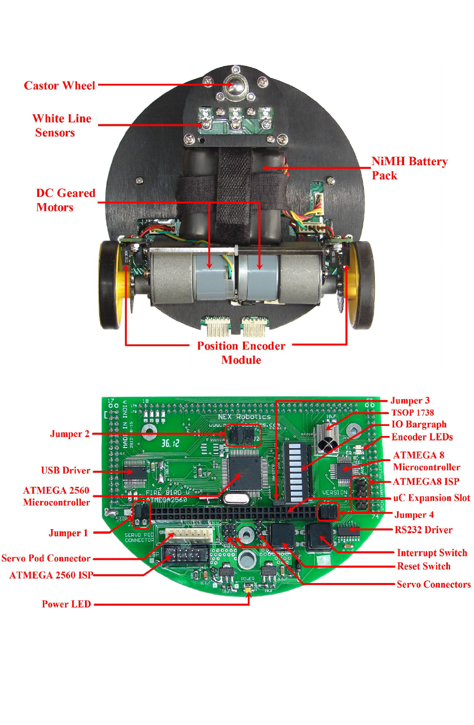
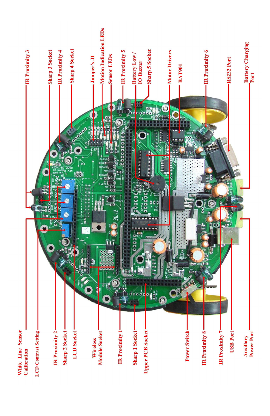
3.1 Connections
Figure 3.2: Fire Bird V ATMEGA2560 robot bottom view
Figure 3.3: ATMEGA2560 microcontroller adapter board
© NEX Robotics Pvt. Ltd. and ERTS Lab, CSE, IIT Bombay, INDIA 14
Fire Bird V ATMEGA2560 Hardware Manual
Figure 3.4: Top view of the main board
© NEX Robotics Pvt. Ltd. and ERTS Lab, CSE, IIT Bombay, INDIA 15
Fire Bird V ATMEGA2560 Hardware Manual
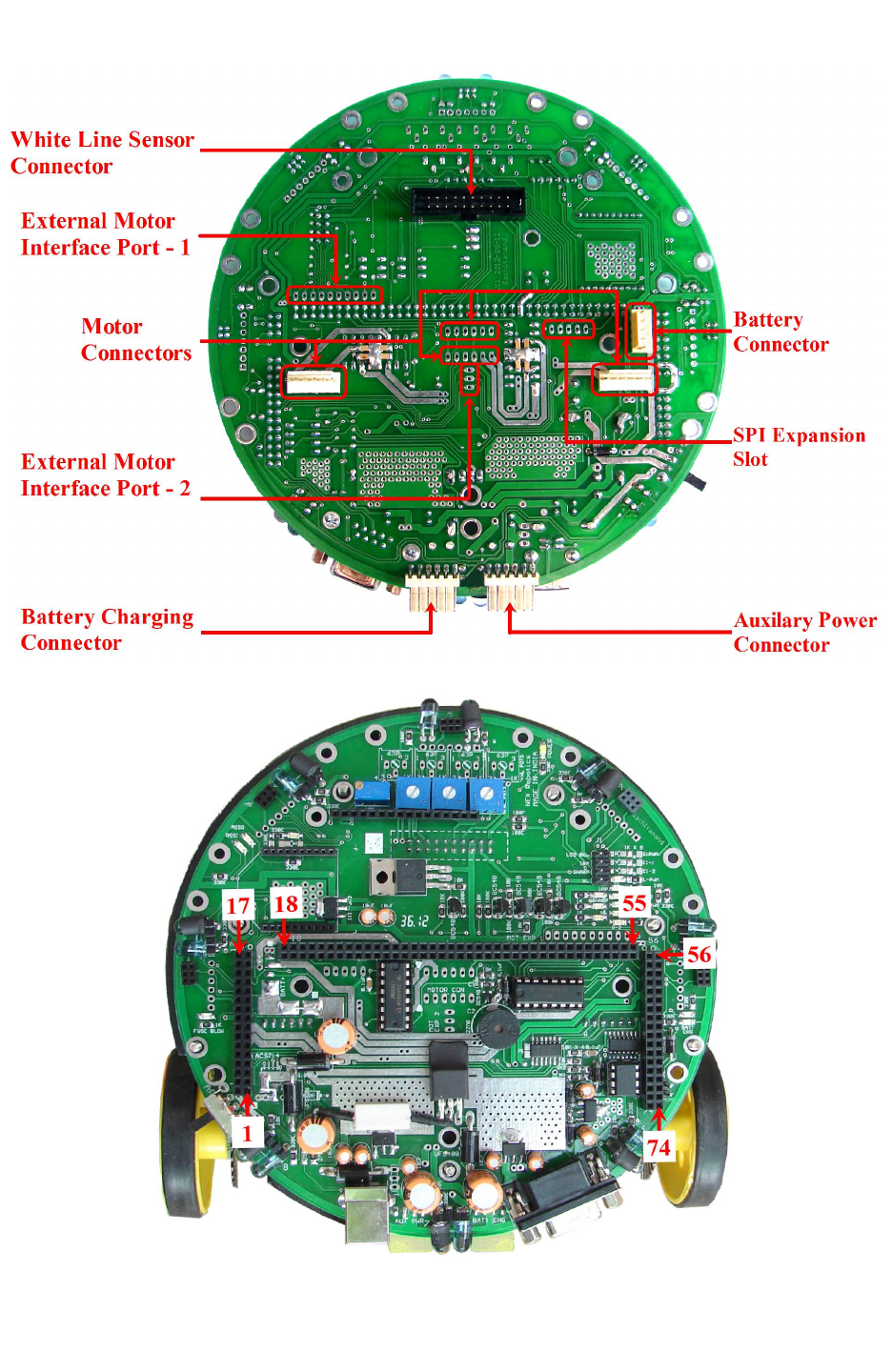
Figure 3.5: Bottom view of the main board
Figure 3.6: Microcontroller adapter board socket connection numbers on the main board
© NEX Robotics Pvt. Ltd. and ERTS Lab, CSE, IIT Bombay, INDIA 16
Fire Bird V ATMEGA2560 Hardware Manual
3.2 Powering up Fire Bird V
Fire Bird V has on board rechargeable 9.6V, 2.1Ah Nickel Metal Hydride battery which can
power the robot for approximately 2 hours. Battery is fixed using Velcro strap so that it can be
replaced easily. In case the experiments are to be performed for an extended period, robot can
also be powered by external auxiliary power supply.
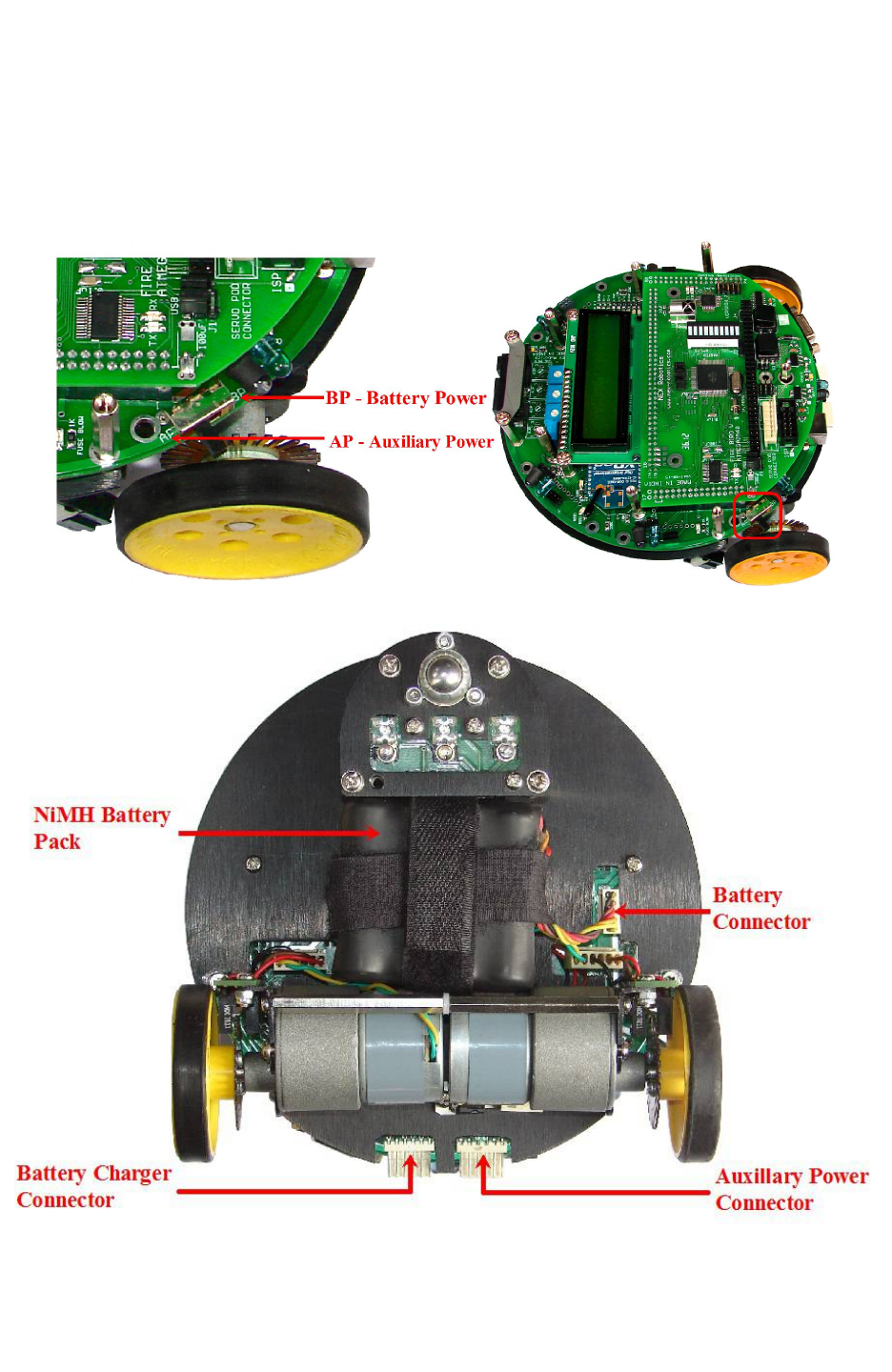
Figure 3.7: Power Switch
Figure 3.8: Connecting the battery on the Fire Bird V main board
© NEX Robotics Pvt. Ltd. and ERTS Lab, CSE, IIT Bombay, INDIA 17

Fire Bird V ATMEGA2560 Hardware Manual
Figure 3.7 shows the power switch. Power switch can either be “BP” (Battery Power) or “AP”
(Auxiliary Power) position. When auxiliary power or battery charger connector is not connected,
robot can be turned ON when power switch is in BP position. Use of Auxiliary power to power
the robot for extended amount of time will be covered in subsequent sections.
For the safety during transportation, robot’s battery is disconnected. Before connecting battery to
the robot, make sure that robot is turned OFF. To do this, move the power switch towards the
“AP”. Figure 3.8 shows the battery connector. Insert battery's 5 pin relimate connector in the
socket. To turn ON the robot, move power switch towards the “BP”.
The NiMH batteries are fully charged before delivery. However, NiMH batteries will get
discharged over the period of time. Therefore its recommended to charge the batteries before
using the robot.
Robot is pre-loaded with a program to move robot in repeatedly in forward, backward, left and
right directions.
Refer to section 3.4 for battery charging. For running the robot on battery power or auxiliary
power, refer to the section 3.5 and 3.6.
© NEX Robotics Pvt. Ltd. and ERTS Lab, CSE, IIT Bombay, INDIA 18

Fire Bird V ATMEGA2560 Hardware Manual
3.3 Power management system on the Fire Bird V
Fire Bird V is powered by 9.6V rechargeable Nickel Metal Hydride battery pack. The battery
voltage can vary between 12V (fully charged) to 8V (discharged). Battery pack should not be
discharged below 8V (1V per cell) for extended battery life. Fire Bird V robot has on-board
intelligent NiMH battery charger which follows the correct charging profile for the batteries. To
avoid any accidental damage to the batteries, do not use external battery charger.
Warning: Charge the battery as per the instructions given in this manual. Do not use any
external charger to charge the battery. Using external charger may damage the battery
permanently.
Power management block on the Fire Bird V performs following functions.
1. Battery voltage monitoring and Smart battery charging
2. Regulated supply for on-board payload
3. Battery current sensing*
* Current sensing is an optional accessory.
© NEX Robotics Pvt. Ltd. and ERTS Lab, CSE, IIT Bombay, INDIA 19
Fire Bird V ATMEGA2560 Hardware Manual
3.3.1 Battery
Fire Bird V is powered by 9.6V rechargeable Nickel Metal Hydride battery pack. When fully
charged, battery pack gives 12V and when it is fully discharged, voltage drops to about 8V.
NiMH battery pack has 5 pin 2510 relimate connector which will fit into the connector on the
main board only in one orientation. Do not force the connection in any other way.
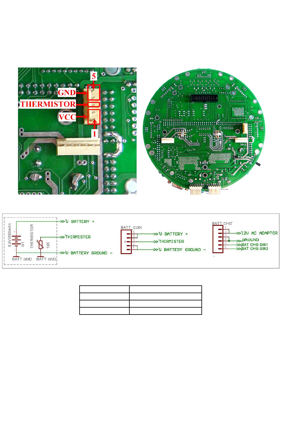
Figure 3.9: Battery Connector on the main board
Figure 3.10: Battery for Fire Bird V ATMEGA2560
Pin Number Function
1,2 Battery Positive (VCC)
3 Thermistor
4,5 Battery Negative (GND)
Table 3.1: Battery connections
© NEX Robotics Pvt. Ltd. and ERTS Lab, CSE, IIT Bombay, INDIA 20
Fire Bird V ATMEGA2560 Hardware Manual
3.3.2 Power sources and voltage regulation on the main board
Fire Bird V is primarily powered by NiMH battery. In order to continue use for longer duration
without worrying about the battery getting low, robot can be powered by external power source
which is also known as auxiliary power source. Auxiliary supply provides regulated 12V, 1Amp
supply. When robot is powered by battery, it can use maximum of 2Amp current while Auxiliary
supply will provide only 1Amp current.
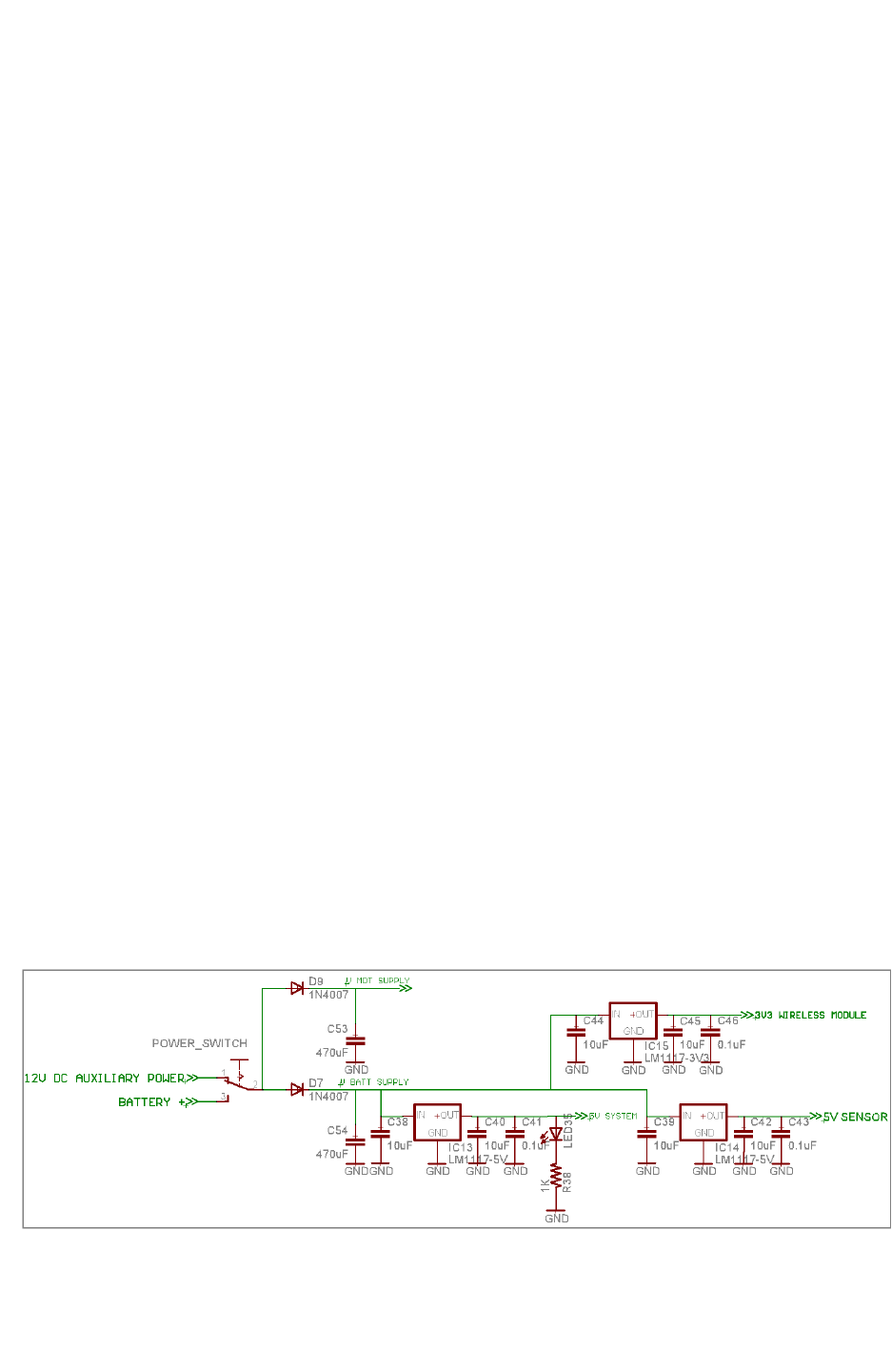
Robot's power is divided in two separate power rails. “V Mot Supply” provides power to all the
noisy devices on the robot such as motors and other heavy loads. “V Batt Supply” powers most
of the electronics on the robot. Most of the systems on the robot are powered by 3.3V and 5V via
voltage regulators.
1. V Batt Supply
“V Batt Supply” stands for stabilized supply coming from the battery. This supply line is
used to power almost all the payload on the robot.
When battery is almost discharged (about 30% power remaining) and onboard payload draws
current in excess of 2 amperes, then the battery voltage can fall below 6.3V momentary.
Voltage regulators will not be able to function properly below 6.3V and their output will fall
below 5V. In this case the microcontroller can reset. To extend the usable battery life and to
reduce the probability of microcontroller getting reset when battery is about to fully
discharge, diodes D7 along with the capacitor C54 is used. When battery voltage suddenly
drops, diode D7 prevents the reverse flow of the current and capacitor C54 maintains voltage
within safe limits for about 100 milliseconds. For this duration capacitor C54 acts as small
battery. Similar arrangement is done in the “V Mot Supply” using diodes D9 and capacitor
C53. This scheme extends usable range of the fully charged battery.
2. V Mot Supply
“V Mot Supply” stands for motor supply. It is used to power DC motors and other heavy
loads which have lots of current fluctuations. It is the nosiest supply line on the robot. It
should be used for heavy loads that require large amount of current. This supply can be
varied between 8V to 11.3V depending on the battery's charging state and type of power
source (battery / auxiliary power) used. This line can supply additional 500mA to the
external load.
Figure 3.11: Voltage regulators on the main board
© NEX Robotics Pvt. Ltd. and ERTS Lab, CSE, IIT Bombay, INDIA 21
Fire Bird V ATMEGA2560 Hardware Manual
3. 5V System
“5V System” is used to power various modules of the robots which does not require high
current and where voltage stability is very important. It is used to power logic supply of the
ICs, Sharp sensors , LCD etc. It is the most stable source of the supply on the main board. It
can source 400mA current for the external load.
4. 3.3V Sensor
“3.3V Sensor” is used to power 8 IR proximity sensors, up to 7 white line sensors. In fully
loaded Fire Bird V robot this supply should not be used to power external load having current
requirement more than 100mA.
5. 3.3V Wireless module
3.3V Wireless module supply is used to power XBee wireless module.
6. 3.3V Batt Mon supply
Batt Mon Supply provides 3.3V to the Smart battery monitoring and charger circuit.
Note: Apart from these four voltage regulators Fire Bird V ATMEGA2560 has two voltage
regulators for powering microcontrollers and servo motors on the microcontroller adapter socket.
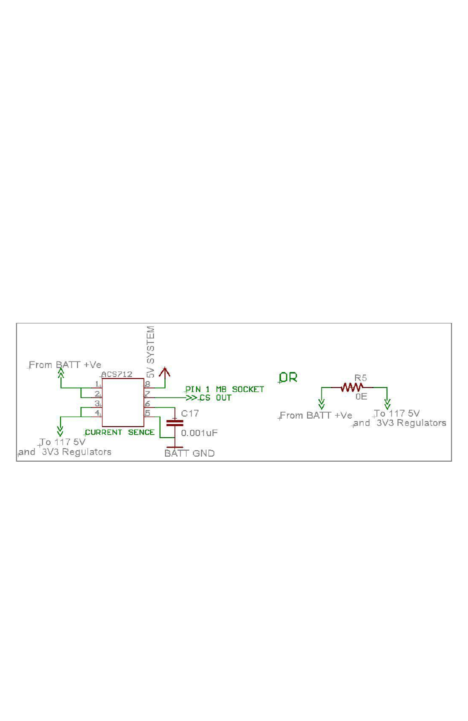
3.3.3 Current sensing.
Fire Bird V robot can sense its current consumption using optional Hall Effect current sensor
ACS712 / ACS714.
Figure 3.12: Current sensing in Fire Bird V
Sensor’s current sensing element is located between battery's positive terminal and robot's
electronics. When no current is flowing through the sensor, it gives 2.5V output. This output
value reduces by 185mV per ampere of current flow if 5 Ampere current sensor is installed. If 20
Ampere current sensor is installed then value is reduced by 100mV per ampere. This sensor is an
optional accessory. When this sensor is absent, the sensing path is shorted with 0 ohm resistor or
with a wire. For more information on the sensor operation, refer to its datasheet which is located
in the “Datasheets” folder of the documentation CD.
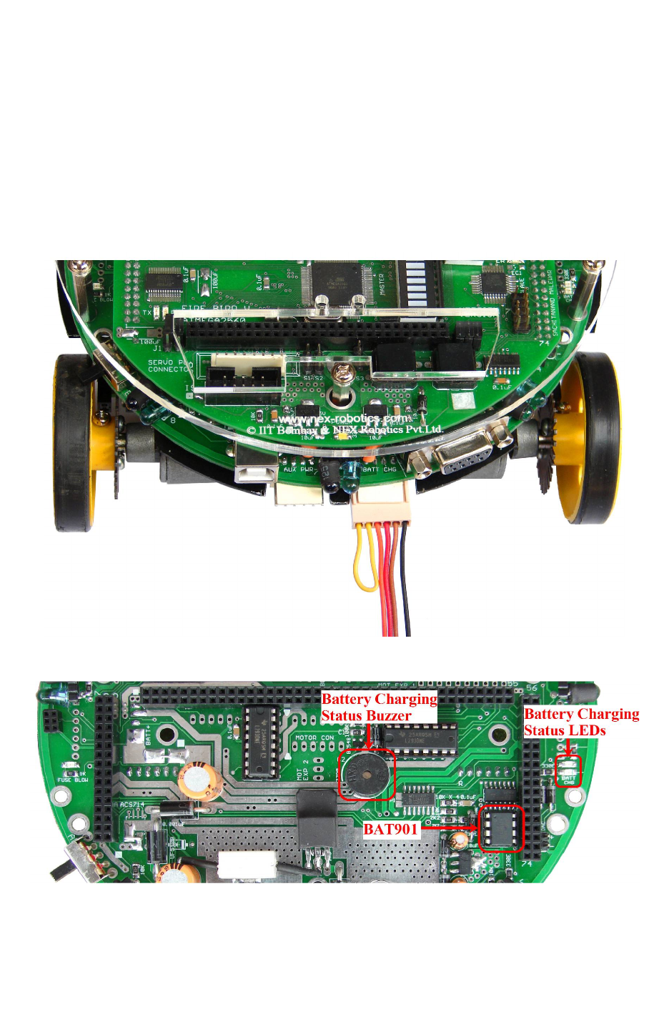
3.3.4 Battery low indication
Fire Bird V uses smart battery monitoring system based on IC BAT901. When battery voltage
goes below 8V, buzzer starts giving one long beep followed by 2 short beeps with delay of half
second. At the same time red led marked in figure 3.14 starts flashing.
© NEX Robotics Pvt. Ltd. and ERTS Lab, CSE, IIT Bombay, INDIA 22
Fire Bird V ATMEGA2560 Hardware Manual
3.4 Battery Charging
Fire Bird V is powered by 9.6V NiMH rechargeable battery. The on-board NiMH charger will
charge the battery in 3 to 5 hours depending on the battery state.
Battery charger checks state of battery before initiating the charging process. While charging the
battery, by looking at battery voltage, current and temperature it selects optimal charging
algorithm. Battery charge status is indicated by a buzzer, a red LED and a green LED shown in
figure 3.14.
Figure 3.13: Connection for battery charging
Figure 3.14: Battery charging status indicator LEDs & Buzzer
© NEX Robotics Pvt. Ltd. and ERTS Lab, CSE, IIT Bombay, INDIA 23

Fire Bird V ATMEGA2560 Hardware Manual
Battery charging procedure:
1. Make sure that battery is inserted in battery connector, and robot is turned off.
2. Connect AC adapter in the mains. Connect the 6pin 2510 relimate battery charging
connector to the main board in the battery charge socket as shown in figure 3.13.
3. Now turn on the AC adapter. After a small delay, green LED will turn on along with the
one long beep two short beeps followed by delay of 1 second. This tone will be sounded
only once. This audio tone confirms that robot is entered in the battery charging mode. If
you do not here this tone, then repeat steps 1, 2 and 3.
4. When battery is fully charged, green LED will turn off and buzzer gives 2 short beeps
followed by 1 second delay continuously. Depending on the version sometimes robot will
also give 1 long beep followed by delay.
5. If there is any fault then charger will give different buzzer beeps to indicate nature of
fault. Following section describes the interpretation of the battery state with beeping
buzzer.
Battery status indication based on the buzzer beeps and red and green LEDs:
Important: Battery status indicator Red LED blinks in sync with buzzer. So in the following
text only buzzer's status is mentioned.
1. Battery Low: (only applicable when robot is running on battery power)
One long beep followed by 2 short beeps repeated after delay of 1 second continuously.
2. Battery entered in the charging mode:
When AC adapter is connected to the battery charging connector and powered up and if robot
enters in battery charging mode, it gives One long beep followed by 2 short beeps only once.
During battery charging mode green LED remains ON. It blinks for 3-4 seconds after 3-4
minutes.
3. Battery is fully charged:
When battery is fully charged, green LED will turn off and buzzer gives 2 short beeps followed
by 1 second delay. Depending on the version, sometimes robot will also give 1 long beep
followed by delay.
4. Charge termination due to over current:
During charging process, if charge current exceeds safe threshold value then robot terminates
charging and buzzer gives 1 short beep repeated after delay of 1 second continuously.
5. Charge termination due to time out:
If battery is not fully charged in 6 hours, then robot stops battery charging and buzzer gives 3
short beeps repeated after delay of 1 second. If battery is unused for long time then it is possible
that robot terminates battery charging due to timeout. In such case, discharge the battery fully
and again start charging. You should repeat this 3 to 4 times till issue gets resolved. If still the
issue is not resolved then batteries have reached end of its usable life but you can still use battery
with the robot. However the run time of the charged battery will be reduced significantly.
© NEX Robotics Pvt. Ltd. and ERTS Lab, CSE, IIT Bombay, INDIA 24

Fire Bird V ATMEGA2560 Hardware Manual
6. Charge termination due to battery failure:
At any time during battery charging if robot detects failure in the battery then it stops battery
charging and buzzer gives 1 very long beep with a very short delay in between. In this case
battery needs to be replaced.
Note: Buzzer is shared between battery monitoring circuit and main microcontroller socket.
Important:
If you are using battery which is not used for long time then you have to charge it and
discharge it at least few times to bring the battery to its full storage capacity. To do this you
can load any motion program from the “Experiments” folder which is located in the
documentation CD and discharge the batteries after charging.
Warning:
Never ever attempt to charge the robot while its powered on. In case, if robot is powered up first
and if you insert the battery charging socket, it will not enter in charging mode. In case, when
you insert battery charging socket first and start charging, and then power up the robot, the robot
will be powered up and at the same time battery will get charged. This is a very dangerous
scenario where robot's battery charging circuit may get confused because of noise from motors
and both battery and robot may get permanently damaged.
© NEX Robotics Pvt. Ltd. and ERTS Lab, CSE, IIT Bombay, INDIA 25
Fire Bird V ATMEGA2560 Hardware Manual
3.5 Powering the robot on battery power
To turn ON the robot on the battery power, make sure that battery is connected to the robot and
move the power switch towards back direction (BP) as shown in the figure 3.7
Warning:
Do not run the robot if battery is low. It will reduce the battery life cycle.
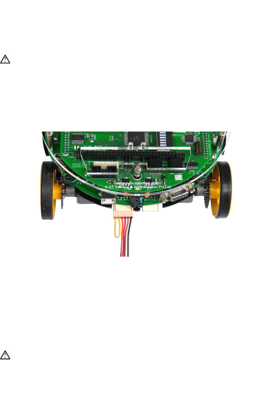
3.6 Powering the robot on auxiliary power
Under normal condition robot is powered by on-board battery. In order to do experiments for
longer duration without worrying about the battery running low, robot can also be powered by
external power source. Auxiliary power source provides regulated 12V, 1Amp supply to the
robot.
Figure 3.15: Robot Powering via Battery and Auxiliary supply
To run the robot on the auxiliary power, use following steps:
1. Disconnect the battery by removing the 5pin relimate connector on the main board which
is located at the bottom of the robot. (refer to figure 3.8)
2. Move the power switch to the BP position (refer to figure 3.3). This is off state for
Auxiliary power mode.
3. Connect AC adapter in the mains. Connect other end of AC adapter in the AUX PWR
relimate male connector on the main board (connector on the right side) and turn on the
AC adapter.
4. Now to turn on the robot, move power switch towards “AP” (figure 3.3).
Warning:
Do not connect auxiliary power while battery is connected to the robot. In such case, robot will
either run on the battery power or on auxiliary power depending on the position of the switch.
Robot can not be turned off in this scenario.
© NEX Robotics Pvt. Ltd. and ERTS Lab, CSE, IIT Bombay, INDIA 26
Fire Bird V ATMEGA2560 Hardware Manual
3.7 Battery Maintenance
If not used, fully charged NiMH battery can get completely discharged within few weeks.
Always charge the battery before use. If fully charged battery is kept in storage for about a
month and afterward even if it is fully charged again, it can deliver only 1/3rd power of its rating.
In such case, to restore the battery to its full potential again, perform at least 2-3 charge
discharge cycles.
To ensure long life, charge battery at least once a week and discharge it till robot starts giving
battery low warning. Before storage, charge the battery again.
For discharging the battery quickly, you can load any program from the “Experiments” folder of
the documentation CD. Program involving motion discharges battery quickly. You can put robot
upside down and let motors run for faster discharge.
Disconnect the battery connector if robot is to be stored for long duration.
3.7A Current limiting and short circuit protection:
In the Version 11 of main board, solder pads for the fuse are added. These pads are shorted
together as shown in left side image of figure 3.18. You can mount fuse of 2A to 10A rating on
these pads as shown in the right side image of figure 3.16.
Figure 3.16: Optional Fuse on the main board
© NEX Robotics Pvt. Ltd. and ERTS Lab, CSE, IIT Bombay, INDIA 27
Fire Bird V ATMEGA2560 Hardware Manual
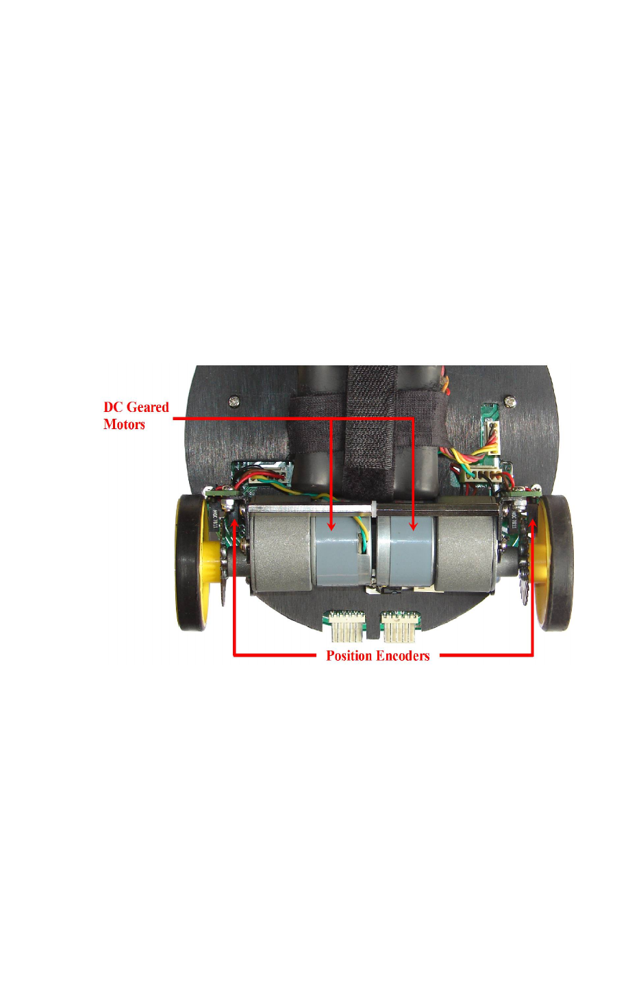
3.8 Motion control
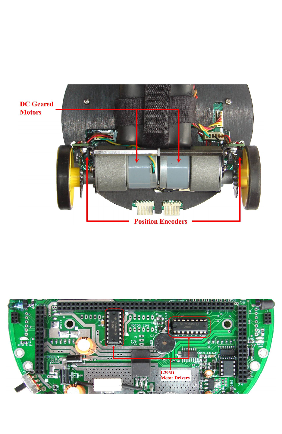
Fire Bird V robot has two 75 RPM DC geared motors in differential drive configuration along
with the third caster wheel for the support. Robot has top speed of about 24cm per second. Using
this configuration, the robot can turn with zero turning radius by rotating one wheel in clockwise
direction and other in counterclockwise direction. Position encoders are mounted on both the
motor’s axles to give a position feedback to the microcontroller.
Figure 3.17: DC geared motors and position encoders
Motion control involves velocity and direction control. Motors are controlled by L293D dual
motor driver which can provide up to 600mA of current to each motor. To change the direction
of the motor, appropriate logic levels (High/Low) are applied to L293D’s direction control pins.
Velocity control is done using Pulse Width Modulation (PWM).
LEDs are connected at the input stage of the motor driver for quick interpretation of the motion
commands.
Figure 3.18: Motor Drivers
© NEX Robotics Pvt. Ltd. and ERTS Lab, CSE, IIT Bombay, INDIA 28
Fire Bird V ATMEGA2560 Hardware Manual
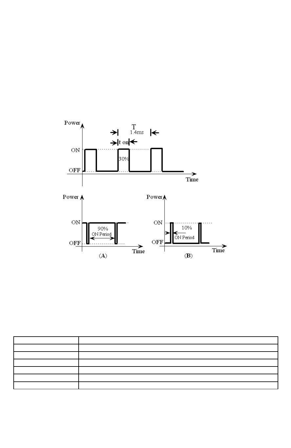
Pulse Width Modulation for velocity control:
Pulse width modulation is a process in which duty cycle of constant frequency square wave is
modulated to control power delivered to the load i.e. motor.
Duty cycle is the ratio of ‘TON/ T’. Where ‘TON’ is ON time and ‘T’ is the time period of the
wave. Power delivered to the motor is proportional to the ‘TON’ time of the signal. In case of
PWM the motor reacts to the time average of the signal.
PWM is used to control total amount of power delivered to the load without power losses which
generally occur in resistive methods of power control.
Figure 3.19: Pulse Width Modulation (PWM)
Figure 3.19 shows the PWM waveforms for motor velocity control. In case (A), ON time is 90%
of time period. This wave has more average value and hence more power is delivered to the
motor. In case (B), the motor will run slower, as the ON time is just 10% of time period.
For the Fire Bird V ATMEGA2560 version, logic level for the motor direction control is given in
the table 3.4.
Microcontroller Pin Function
PL3 (OC5A) Pulse width modulation for the left motor (velocity control)
PL4 (OC5B) Pulse width modulation for the right motor (velocity control)
PA0 Left motor 1 direction control
PA1 Left motor 2 direction control
PA2 Right motor 1 direction control
PA3 Right motor 2 direction control
Table 3.3: Pin functions for the motion control
© NEX Robotics Pvt. Ltd. and ERTS Lab, CSE, IIT Bombay, INDIA 29
Fire Bird V ATMEGA2560 Hardware Manual
DIRECTION
LEFT
BWD (LB)
PA0 (L1)
LEFT
FWD(LF)
PA1 (L2)
RIGHT
FWD(RF)
PA2 (R1)
RIGHT
BWD(RB)
PA3 (R2)
PWM
PL3 (PWML) for
left motor
PL4 (PWMR) for
right motor
FORWARD 0 1 1 0 As per velocity
requirement
REVERSE 1 0 0 1 As per velocity
requirement
RIGHT (Left wheel
forward, Right wheel
backward) 0 1 0 1
As per velocity
requirement
LEFT(Left wheel
backward, Right wheel
forward,) 1 0 1 0
As per velocity
requirement
SOFT RIGHT(Left wheel
forward,, Right wheel
stop) 0 1 0 0
As per velocity
requirement
SOFT LEFT(Left wheel
stop, Right wheel
forward,) 0 0 1 0
As per velocity
requirement
SOFT RIGHT 2 (Left
wheel stop, Right wheel
backward) 0 0 0 1
As per velocity
requirement
SOFT LEFT 2 (Left
wheel backward, Right
wheel stop) 1 0 0 0
As per velocity
requirement
HARD STOP 0 0 0 0 As per velocity
requirement
SOFT STOP (Free
running stop) X X X X 0
Table 3.4: Logic table for motor direction control
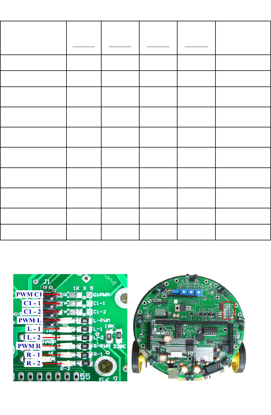
We can observe all the commands given on the LEDs located at the top right side on the robot.
Figure 3.20 shows the location and function of indicator LEDs related to motion control.
Figure 3.20: Motion status LED indication on the Fire Bird V main board
© NEX Robotics Pvt. Ltd. and ERTS Lab, CSE, IIT Bombay, INDIA 30
Fire Bird V ATMEGA2560 Hardware Manual
Note: C1 and C2 motor connectors are used in omnidirectional and 4 wheel drive robots. LEDs
for C1 motor channels are present if C1 motor channel is used.
Warning:
Auxiliary power can supply current up to 1 Ampere while Battery can supply current up to 2
Ampere. When both motors of the robot change direction suddenly without stopping, it produces
large current surge. When robot is powered by Auxiliary power which can supply only 1 Ampere
of current, sudden direction change in both the motors will cause current surge which can reset
the microcontroller because of sudden fall in voltage. It is a good practice to stop the motors for
at least 0.5 seconds before changing the direction. This will also increase the useable time of the
fully charged battery.
Robot has two IC holders for two L293D motor drivers with each having two 6 pin 2510
relimate connectors for two DC motors. Each 6 pin relimate connector provides connections for
the DC motor and the associated position encoder. Each connector can drive motor with up to
600mA current rating. Figure 3.18 shows the locations of the two L293D dual motor drivers on
the main board. Left side L293D drives C1 and C2 motors and right side L293D drives Left and
Right side motors. In the two wheel drive robot left side L293D is absent as its not used however
to use C1 and C2 motor driver channels you can insert L293D in the left side IC holder.
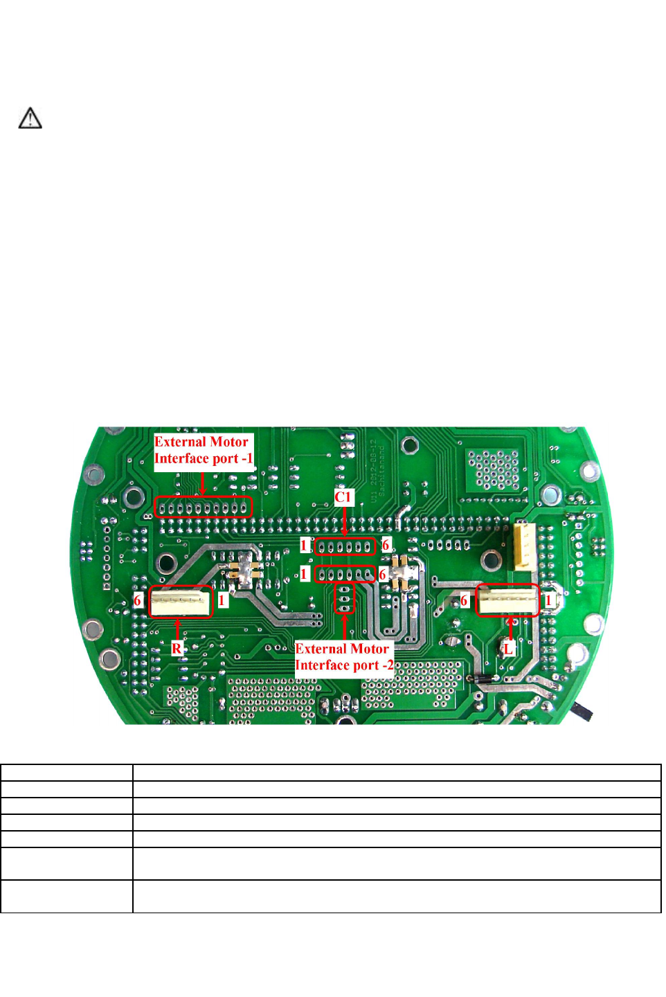
Figure 3.21: Motion control connections on the main board
Connector Name Description
L Left motor connector 1
R Right motor connector 2
C1 C1 motor connector
C2 C2 motor connector
External Motor
Interface Port1
Logic signals of pins 47 to 55 of the main board socket for interfacing external high power
motor drivers for L,R and C1 motors
External Motor
Interface Port2
Logic signals of pins 66 to 68 of the main board socket for interfacing external high power
motor drivers for C2 motor
Table 3.5: Use of connectors of the motion control module
© NEX Robotics Pvt. Ltd. and ERTS Lab, CSE, IIT Bombay, INDIA 31
Fire Bird V ATMEGA2560 Hardware Manual
Pin No. Function
1 VCC, 5V System
2 Position Encoder data
3 NC
4 GND
5 Motor 2
6 Motor 1
Table 3.6: Motor connector port pin connections
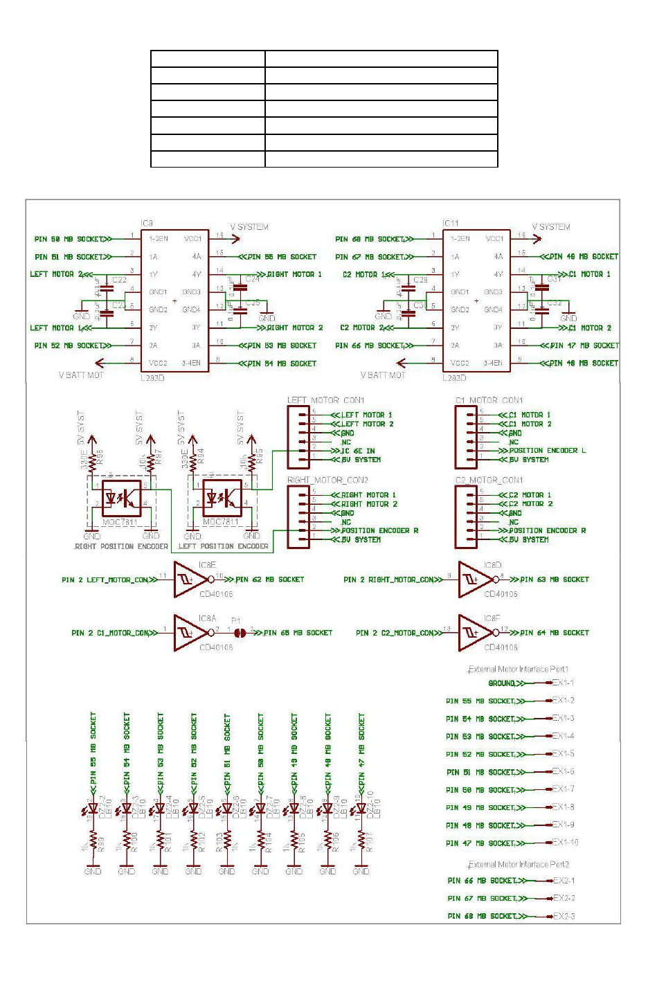
Figure 3.22: Schematic of the motion control module and the position encoder
© NEX Robotics Pvt. Ltd. and ERTS Lab, CSE, IIT Bombay, INDIA 32
Fire Bird V ATMEGA2560 Hardware Manual
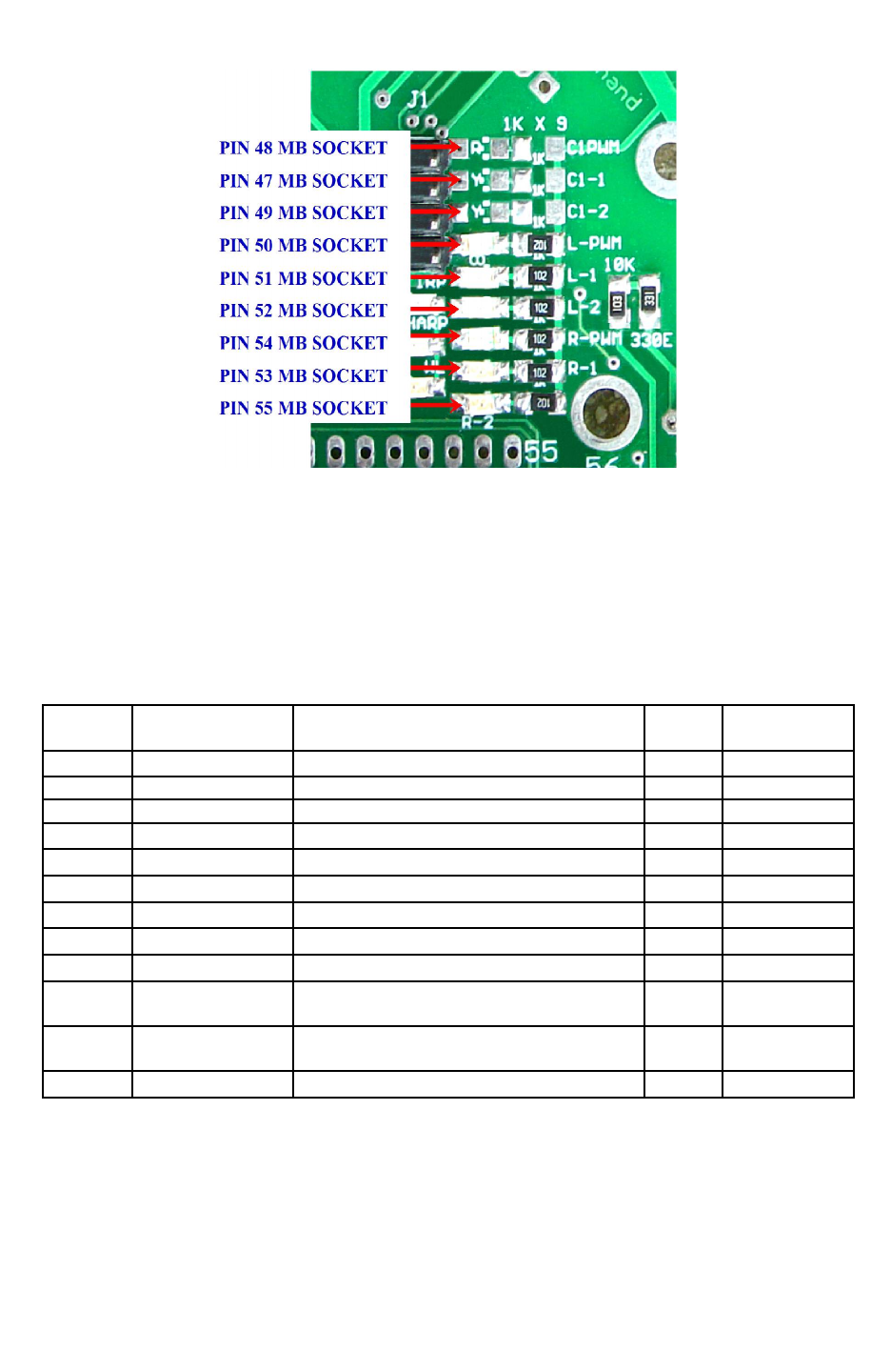
Figure 3.23: Motion status LED indication in terms of microcontroller adapter socket pin
number
“5V system supply” is used for driving L293Ds logic circuits. “V Batt Mot” is used to supply
power to the motors. C22 – C25 and C29 – C32 is used for noise suppression. Logic signals to
drive the two L293D comes from the pins 47 to 55 and pins 66 to 68 of the microcontroller
adapter board socket. Logic level on the pins 47 to 55 are also connected to the motion LEDs the
main board as shown above.
uC PIN
NO
Pin name USED FOR Status Main Board
Pin No.
5 OC3A/AIN1/PE3 PWM output for C2 motor drive Output 68
38 OC5A/PL3 PWM for left motor. Output 50
39 OC5B/PL4 PWM for right motor. Output 54
40 OC5C/PL5 PWM for C1 motor. Output 48
71 PA7 C2-2 Logic input 2 for C2 motor drive Output 66
72 PA6 C2-1 Logic input 1 for C2 motor drive Output 67
73 PA5 C1-2 Logic input 2 for C1 motor drive Output 49
74 PA4 C1-1 Logic input 1 for C1 motor drive Output 47
75 PA3 Logic input 1 for Right motor (Right back) Output 53
76 PA2 Logic input 2 for Right motor (Right
forward) Output 55
77 PA1 Logic input 2 for Left motor (Left
forward) Output 52
78 PA0 Logic input 1 for Left motor (Left back) Output 51
Table 3.7: Connections of the motor driver with the ATMEGA2560 microcontroller
© NEX Robotics Pvt. Ltd. and ERTS Lab, CSE, IIT Bombay, INDIA 33
Fire Bird V ATMEGA2560 Hardware Manual
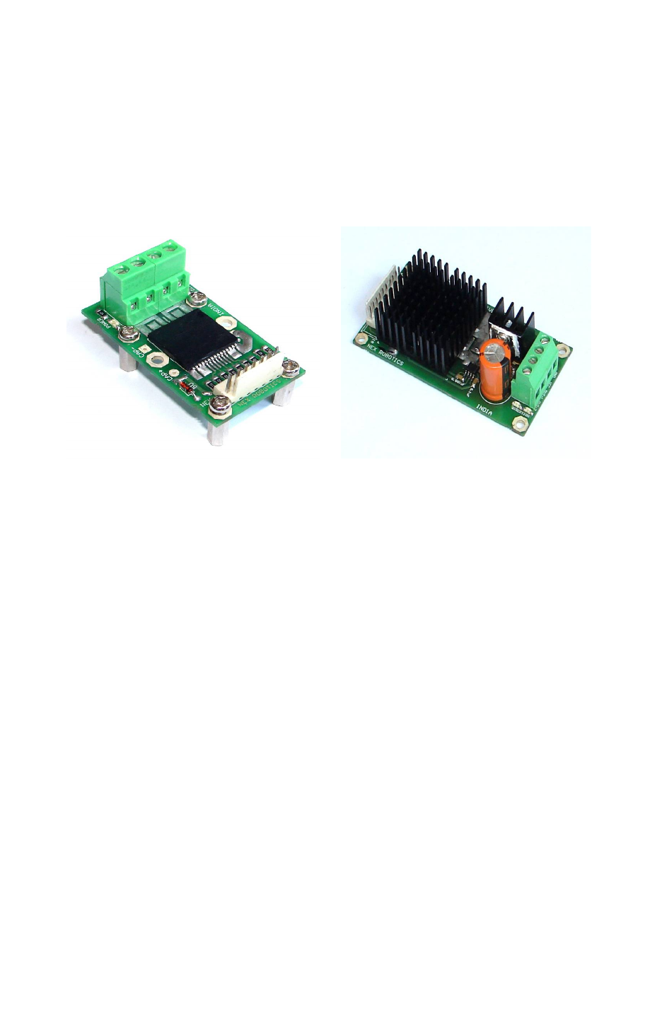
Connecting Fire Bird V robot board to bigger robot
L293D motor drivers on the main board can only provide current up to 600mA per motor. If you
want to drive bigger robot using Fire Bird V main board then remove L293D motor drivers from
their IC sockets. You can interface high power motor drivers such as Hercules or Hercules lite
from NEX Robotics which can drive motors up to 36V and 30Amps to the external motor
interface ports. Location of L293D ICs is shown in figure 3.18 and External Motor Interface port
1 and External Motor Interface Port 2 in figure 3.21.
Figure 3.24: Hercules series 30Amp. Motor Drivers
Important:
Give high current power supply to the motor drivers directly without going through Fire Bird V's
main board and make sure that Robot's ground and motor driver's ground are common.
© NEX Robotics Pvt. Ltd. and ERTS Lab, CSE, IIT Bombay, INDIA 34
Fire Bird V ATMEGA2560 Hardware Manual
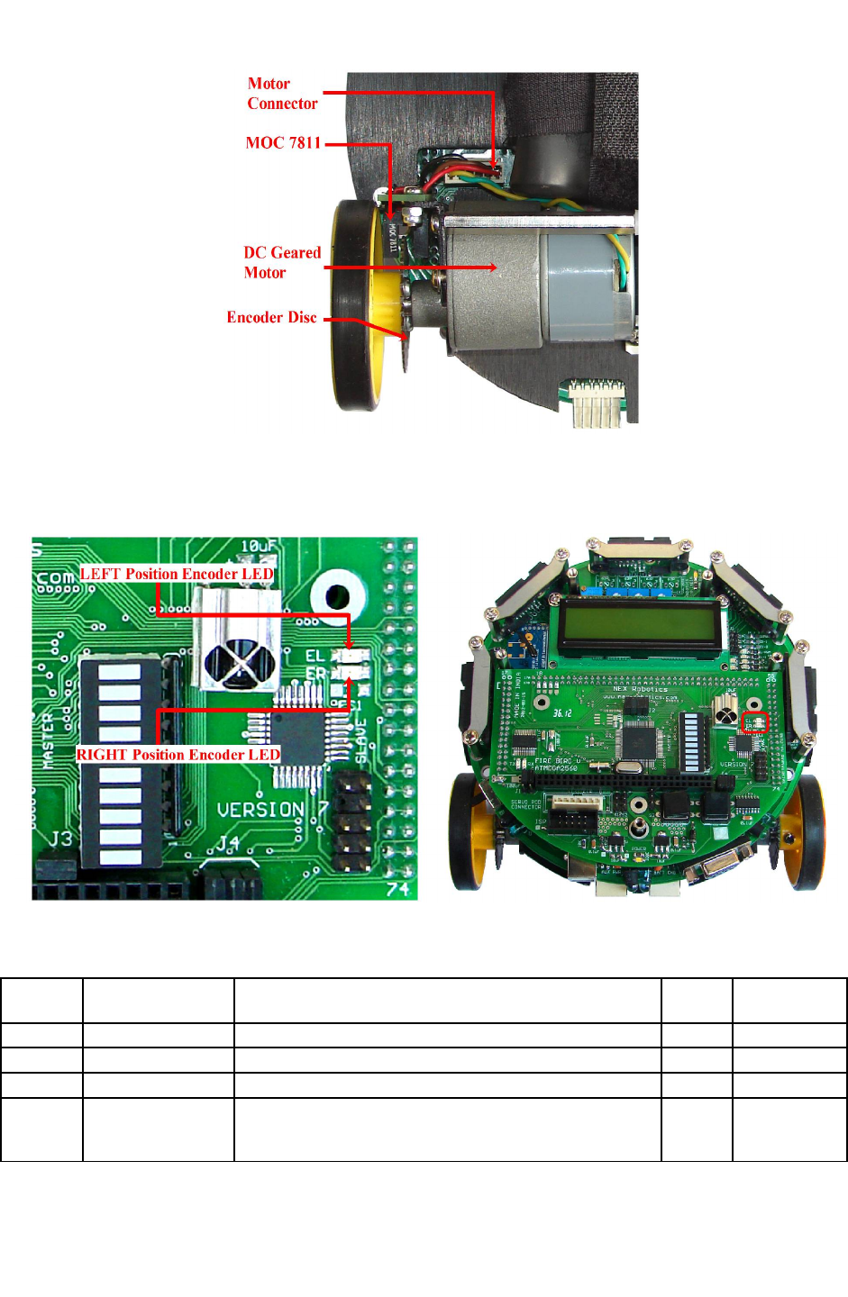
3.9 Position Encoders
Position encoders give position / velocity feedback to the robot. It is used in closed loop to
control robot’s position and velocity. Position encoder consists of slotted disc which rotates
between optical encoder (optical transmitter and receiver). When slotted disc moves in between
the optical encoder we get square wave signal whose pulse count indicates position and time
period / frequency indicates velocity.
Optical encoder MOC7811 is used as position encoder on the robot. It consists of IR LED and
the photo transistor mounted in front of each other separated by a slot and encased in black
opaque casing and facing each other through narrow window. When IR light falls on the photo
transistor it gets in to saturation and gives logic 0 as the output. In absence of the IR light it gives
logic 1 as output. A slotted encoder disc is mounted on the wheel is placed in between the slot of
MOC7811. When encoder disc rotates it cuts IR illumination alternately because of which photo
transistor gives square pulse train as output. Output from the position encoder is cleaned using
Schmitt trigger based inverter (not gate) IC CD40106.
Figure 3.25: DC geared motors and position encoders
© NEX Robotics Pvt. Ltd. and ERTS Lab, CSE, IIT Bombay, INDIA 35
Fire Bird V ATMEGA2560 Hardware Manual
Figure 3.26: Position encoder assembly
Position encoder output is displayed on the microcontroller socket board. Figure 3.27 shows
location of the position encoder LEDs
Figure 3.27: Position encoder pulse LEDs on ATMEGA2560 microcontroller adapter
board
uC PIN
NO
Pin name USED FOR Status Main Board
Pin No.
6 OC3B/INT4/PE4 External Interrupt for the left motor’s position encoder Input 62
7 OC3C/INT5/PE5 External Interrupt for the right motor’s position encoder Input 63
8 T3/INT6/PE6 External Interrupt for the C2 motor’s position encoder Input 64
9CLK0/ICP3/INT7
/ PE7
External Interrupt for Interrupt switch on the
microcontroller board, External Interrupt for the C1
motor’s position encoder *
Input 65
Table 3.8: Pin Connection of the position encoder’s outputs
© NEX Robotics Pvt. Ltd. and ERTS Lab, CSE, IIT Bombay, INDIA 36
Fire Bird V ATMEGA2560 Hardware Manual
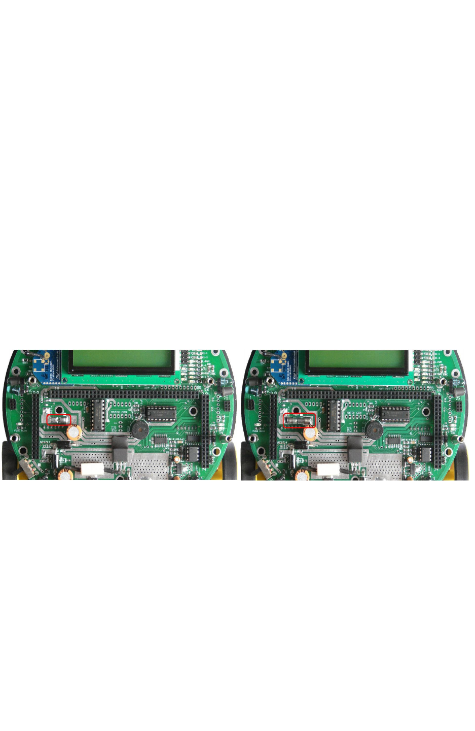
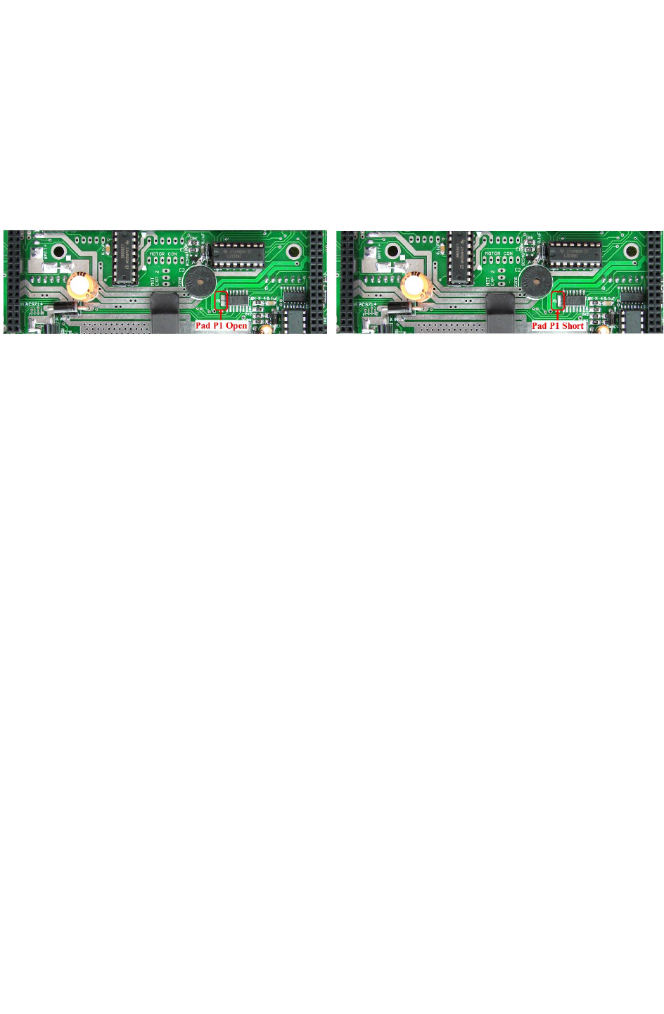
* Position encoder of the motor C1 is connected to the INT7 pin of the ATMEGA2560
microcontroller via soldering pad P1. INT7 interrupt pin is also connected to bootloader switch
and TSOP1738 (via pad on microcontroller socket). If you want to use position encoder of C1,
then make sure that bootloader code is removed from the the ATMEGA2560 microcontroller
and soldering pad for TSOP1738 connection on the microcontroller socket is open. After these
two precautions are taken, solder pad P1 on the main board to connect C1 motor's position
encoder to the ATMEGA2560 microcontroller socket. This is very important. If not done then
because of pulse from C1 motor's position encoder, ATMEGA2560 microcontroller will go in to
boot mode. Figure 3.28 shows location of the pad P1 on the main board.
Figure 3.28: Pad P1 open and with short
© NEX Robotics Pvt. Ltd. and ERTS Lab, CSE, IIT Bombay, INDIA 37

Fire Bird V ATMEGA2560 Hardware Manual
Calculation of position encoder resolution:
Case 1: Robot is moving forward or backward (encoder resolution is in mm)
Wheel diameter: 5.1cm
Wheel circumference: 5.1cm * 3.14 = 16.014cm = 160.14mm
Number slots on the encoder disc: 30
Position encoder resolution: 163.2 mm / 30 = 5.44mm / pulse.
Case 2: Robot is turning with one wheel rotating clockwise while other wheel is rotating
anti clockwise. Center of rotation is in the center of line passing through wheel axel and
both wheels are rotating in opposite direction (encoder resolution is in degrees)
Distance between Wheels = 15cm
Radius of Circle formed in 3600 rotation of Robot = Distance between Wheels / 2
= 7.5 cm
Distance Covered by Robot in 3600 Rotation = Circumference of Circle traced
= 2 x 7.5 x 3.14
= 47.1 cm or 471mm
Number of wheel rotations of in 3600 rotation of robot
= Circumference of Traced Circle / Circumference of Wheel
= 471 / 160.14
= 2.941
Total pulses in 3600 Rotation of Robot
= Number of slots on the encoder disc / Number of wheel rotations of in 3600 rotation of robot
= 30 x 2.941
= 88.23 (approximately 88)
Position Encoder Resolution in Degrees = 360 / 88
= 4.090 degrees per count
© NEX Robotics Pvt. Ltd. and ERTS Lab, CSE, IIT Bombay, INDIA 38

Fire Bird V ATMEGA2560 Hardware Manual
Case 3: Robot is turning with one wheel stationary while other wheel is rotating clockwise
or anti clockwise. Center of rotation is center of the stationary wheel (encoder resolution is
in degrees)
In this case only one wheel is rotating and other wheel is stationary so robot will complete its
3600 rotation with stationary wheel as its center.
Radius of Circle formed in 3600 rotation of Robot = Distance between Wheels
= 15 cm
Distance Covered by Robot in 3600 Rotation = Circumference of Circle traced
= 2 x 15 x 3.14
= 94.20 cm or 942 mm
Number of wheel rotations of in 3600 rotation of robot
= Circumference of Traced Circle / Circumference of Wheel
= 942 / 160.14
= 5.882
Total pulses in 3600 Rotation of Robot
= Number of slots on the encoder disc / Number of wheel rotations of in 3600 rotation of robot
= 30 x 5.882
= 176.46 (approximately 176)
Position Encoder Resolution in Degrees = 360 /176
= 2.045 degrees per count
© NEX Robotics Pvt. Ltd. and ERTS Lab, CSE, IIT Bombay, INDIA 39
Fire Bird V ATMEGA2560 Hardware Manual
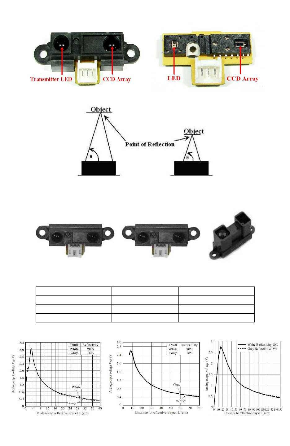
3.10 Sharp IR range sensors
For accurate distance measurement, robot uses Sharp IR range sensors. Robot can be fitted with
five IR range sensors as shown in figure 3.29. Sharp IR range sensors consists of IR LED and
linear CCD array, both encapsulated in the housing with precision lens assembly mounted in
front of them. IR LED with the help of the leans transmits a narrow IR beam. When light hits the
obstacle and reflects back to the linear CCD array, depending on the distance from the obstacle,
angle of the reflected light varies. This angle is measured using the CCD array to estimate
distance from the obstacle. It gives same response to different colored objects as measured
distance is function of the angle of reflection and not on the reflected light intensity.
Figure 3.30 shows the internals of the sensor. Figure 3.31 explains how change in the distance
from the obstacle can be measured by measuring angle of reflection of the reflected light beam
from the obstacle. Since sensor measurement is based on triangulation and not on intensity of the
reflected light, it is immune to disturbance caused by ambient light.
Sensor gives out analog voltage corresponding to angle of reflection. Relationship between the
angle of reflection and output voltage is not linear because of trigonometry involved. These
sensors have blind spot in the range of 0mm to some specific distance depending on the type of
the sensor. In the blind spot region sensor gives incorrect readings. Table 3.9 gives information
about sensing range and the blind spot distance for the particular sensor.
Figure 3.29: Sharp Sensors mounted on Fire Bird V
© NEX Robotics Pvt. Ltd. and ERTS Lab, CSE, IIT Bombay, INDIA 40
Fire Bird V ATMEGA2560 Hardware Manual
Figure 3.30: Infrared Range finder sensor and its inside view
Figure 3.31: Distance measurement based on angel of reflection
Fire Bird V supports three types of IR range sensors from Sharp Microelectronics.
GP2D120 GP2D12 GP2Y0A02YK
Figure 3.32: Sharp IR Range sensors for Fire Bird V
Sensor Range Blind Spot
GP2D120X 30cm to 20cm 4cm to 0cm
GP2Y0A02YK 80cm to 10cm 10cm to 0cm
GP2Y0A02 150cm to 20cm 20cm to 0cm
Table 3.9: Sharp IR Range sensors coverage
Figure 3.33: Distance Vs. Output voltage of GP2D120, GP2Y0A02YK and GP2Y0A02YK
© NEX Robotics Pvt. Ltd. and ERTS Lab, CSE, IIT Bombay, INDIA 41
Fire Bird V ATMEGA2560 Hardware Manual
Figure 3.33 shows the typical output character of the GP2D120, GP2D12 and GP2Y0A02YK
sensors. In these graphs X axis represents distance from the obstacle and Y axis represents the
output voltage. The sensor’s output characteristic is slightly logarithmic in nature hence to get
the distance in millimeters we have to use following formulas.
Distance in mm for GP2D120 = 10.00*((1.00/ ((0.001240875*(float) ADC value) + 0.005)) –
0.42)
Distance in mm for GP2Y0A02YK =
(int)(10.00 * (2799.6 * (1.00 / (float)((double)(ADC_Value)^(double)(1.1546)))));
UC
PIN
No.
Pin name USED FOR UC pin correct
I/O setting
15 OC4A/PH3 Sharp IR ranges sensor 1 to 5 disable.
Turns off these sensors, when output is logic 1* Output
84 PK5/ADC13/PCINT2
1ADC input for Sharp IR range sensor 5 Input (Floating)
85 PK4/ADC12/PCINT2
0ADC input for Sharp IR range sensor 4 Input (Floating)
86 PK3/ADC11/PCINT1
9ADC input for Sharp IR range sensor 3 Input (Floating)
87 PK2/ADC10/PCINT1
8ADC input for Sharp IR range sensor 2 Input (Floating)
88 PK1/ADC9/PCINT17 ADC input for Sharp IR range sensor 1 Input (Floating)
Table 3.10: Connections of the Sharp IR range sensors and its power control MOSFETs
with the ATMEGA2560 microcontroller
* Sharp IR range sensor enabling and disabling is covered in section 3.10A
© NEX Robotics Pvt. Ltd. and ERTS Lab, CSE, IIT Bombay, INDIA 42
Fire Bird V ATMEGA2560 Hardware Manual
3.10A Avoiding sensor interference in multirobot environment
Many of the sensors used in the Fire Bird V emits some sort of signals to sense the object such as
Sharp IR range sensors, ultrasonic range sensors, IR proximity sensors, white line sensors etc.
All these sensors are known as active sensors.
If many robots with such active sensors are placed in same space then their sensors will interfere
with each other. Only way to operate many robots in same space without jamming each other
sensor is to use, sensors on each robots in time division multiplexing way. This can be done by
synchronizing each robot's sensor switching using wireless modules such as XBee, WiFi or
Bluetooth of the robots.
All the sensors on the Fire Bird V robots can be turned on or off by software. This enables Fire
Bird V to work in multirobot environment without jamming each other.
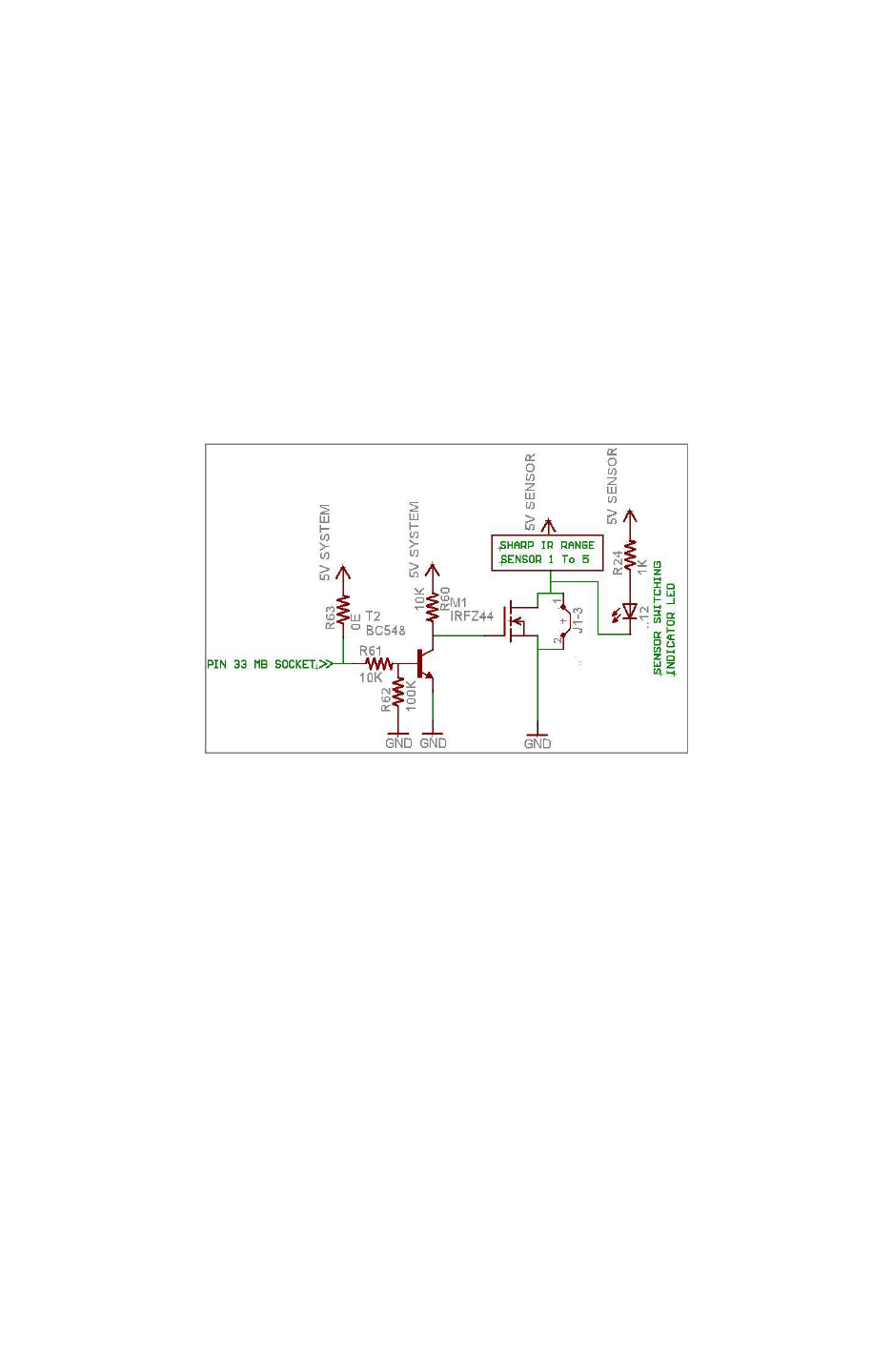
Figure 3.34: Sharp IR range sensor’s power control circuit
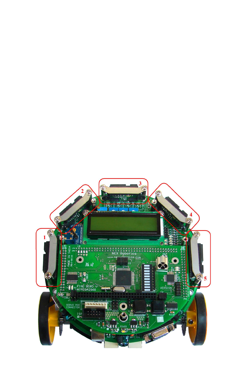
Figure 3.29 shows the location of the Sharp IR range sensors on the robot. They are numbered
from 1 to 5 in the clockwise direction. Figure 3.34 shows the schematics of the MOSFET and
jumper which controls switching on/off of the sensors. Sharp IR range sensor 1 to 5 are
controlled by the MOSFET M1. PH3 (pin15) of the ATMEGA2560 microcontroller is connected
to the Sharp IR range sensor's power switching circuit via pin 33 of the main board socket. Sharp
sensors can be turned on and off by switching circuit via microcontroller when Jumper J1-3
shown in figure 3.34 is open (absent). If jumper is inserted then sensors remain permanently ON.
Microcontroller will no be able to turn them OFF the sensor once this jumper is inserted.
When microcontroller's pin is at logic low, Transistor T2 is off hence gate of MOSFET M1 is
pulled up at 5V which turns on the MOSFET which turns on the Sharp IR range sensors. When
Logic 1 is applied at the base of transistor T2 it gets turn on and it pulls down the gate of the
MOSFET M1 to turn it OFF. Location of the jumper is shown in figure 3.38.
Same way White line sensors and IR proximity sensors can be switched ON and OFF, which can
bee permanently turned ON by placing respective jumpers. Their switching circuits are discussed
in their respective topics.
© NEX Robotics Pvt. Ltd. and ERTS Lab, CSE, IIT Bombay, INDIA 43
Fire Bird V ATMEGA2560 Hardware Manual
Sensors Main board socket pin
number
ATMEGA2560 uC
Pin
Logic state
Sharp IR range sensor 1 to 5 33 PH3 (pin 15) 0: Sensors are turned on
1: Sensors are turned off
white line sensors (left,
center, right) 40 PG2 (pin 70) 0: Sensors are turned on
1: Sensors are turned off
IR proximity sensors 1 to 8 34 PH3 (pin 14) 0: Sensors are turned on
1: Sensors are turned off
Table 3.11: Sensor power control pins and jumpers (Assuming corresponding jumper at J1
is open)
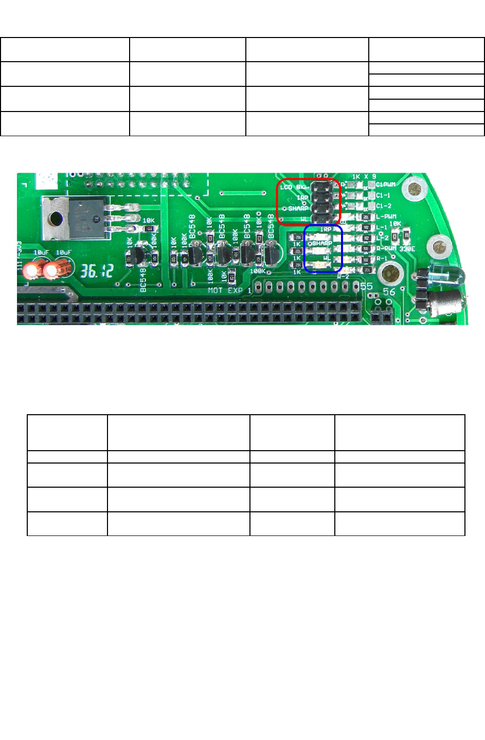
Figure 3.35: Sensor status indicator LEDs
Jumper 1 set is shown by red rectangle in figure 3.35. It consists of set of 4 jumpers. On / Off
status of the sensor is shown by 3 yellow LEDs are highlighted by blue rectangle. ON LEDs
indicate that sensor is ON. Table 3.11A shows the functions of these jumpers and corresponding
sensor power indicating LEDs.
Jumper Name Function
(If jumper is inserted)
Sensor power
indicating LED
name
Current consumption
J1-1(LCD BKL) Turn on LCD back light LCD Back-light 20mA
J1-2(IRP) Turns on all 8 IR proximity
sensors IRP 51mA (all 8 IR proximity
sensors)
J1-3(SHARP) Turns on installed Sharp IR
range sensors SHARP 25mA per sensor installed
J4-1(WL) Turns on all white line sensors WL 16mA typical for 3 channel
white line sensor
Table 3.11A: Sensor power on Jumpers and LED indicators
Important
•Robots are factory shipped with all jumpers inserted. So as per factory setting all sensors
will remain permanently ON. If you are not going to switch sensors on/off using
MOSFETs then leave jumpers as it is.
•Sharp GP2Y0A02 sensors body is made up of conductive plastic. Hence foam tape is
added as an insulator between the sensor and the metal strip which holds the sensor in
place. If this isolation is not provided then sensor will get partially off when
corresponding MOSFET is turned off. In such case sensor will still consume power and
might give incorrect reading when sensor is turned off. To avoid this small insulator foam
is inserted between the sensor and the metal stripe which holds the sensor in place.
© NEX Robotics Pvt. Ltd. and ERTS Lab, CSE, IIT Bombay, INDIA 44
Fire Bird V ATMEGA2560 Hardware Manual
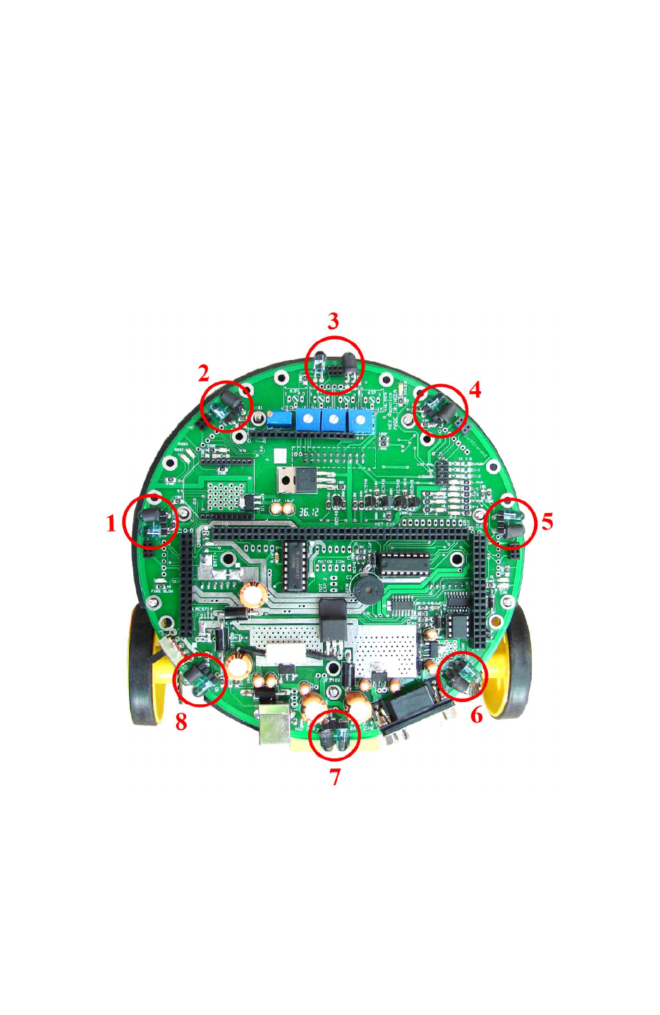
3.11 Infrared proximity and directional light intensity sensors
Infrared proximity sensors are used to detect proximity of any obstacles in the short range. IR
proximity sensors have about 10cm sensing range. These sensors sense the presence of the
obstacles in the blind spot region of the Sharp IR range sensors. Fire Bird V robot has 8 IR
proximity sensors. Figure 3.36 shows the location of the 8 IR proximity sensors. Sensors are
numbered as 1 to 8 from left to right in clockwise direction. In all the manuals same numbering
convention will be used for addressing the particular IR sensor.
In the absence of the obstacle there is no reflected light hence no leakage current will flow
through the photo diode and output voltage of the photo diode will be around 3.3V. As obstacle
comes closer, more light gets reflected and falls on the photo diode and leakage current flowing
through the photo diode starts to increase which causes voltage across the diode to fall.
Figure 3.36: Eight IR proximity sensors on Fire Bird V
When enabled 8 IR proximity sensors combined together consumes about 51mA current. You
can save power by turning on theses sensors only when required. Refer to table 3.11, these
sensors can be turned off by applying logic 1 (5V) to the pin no. 34 of the main board. To enable
these sensors permanently connect the IRP jumper on J1 of main board. For jumper location
refer to figure 3.38.
© NEX Robotics Pvt. Ltd. and ERTS Lab, CSE, IIT Bombay, INDIA 45
Fire Bird V ATMEGA2560 Hardware Manual
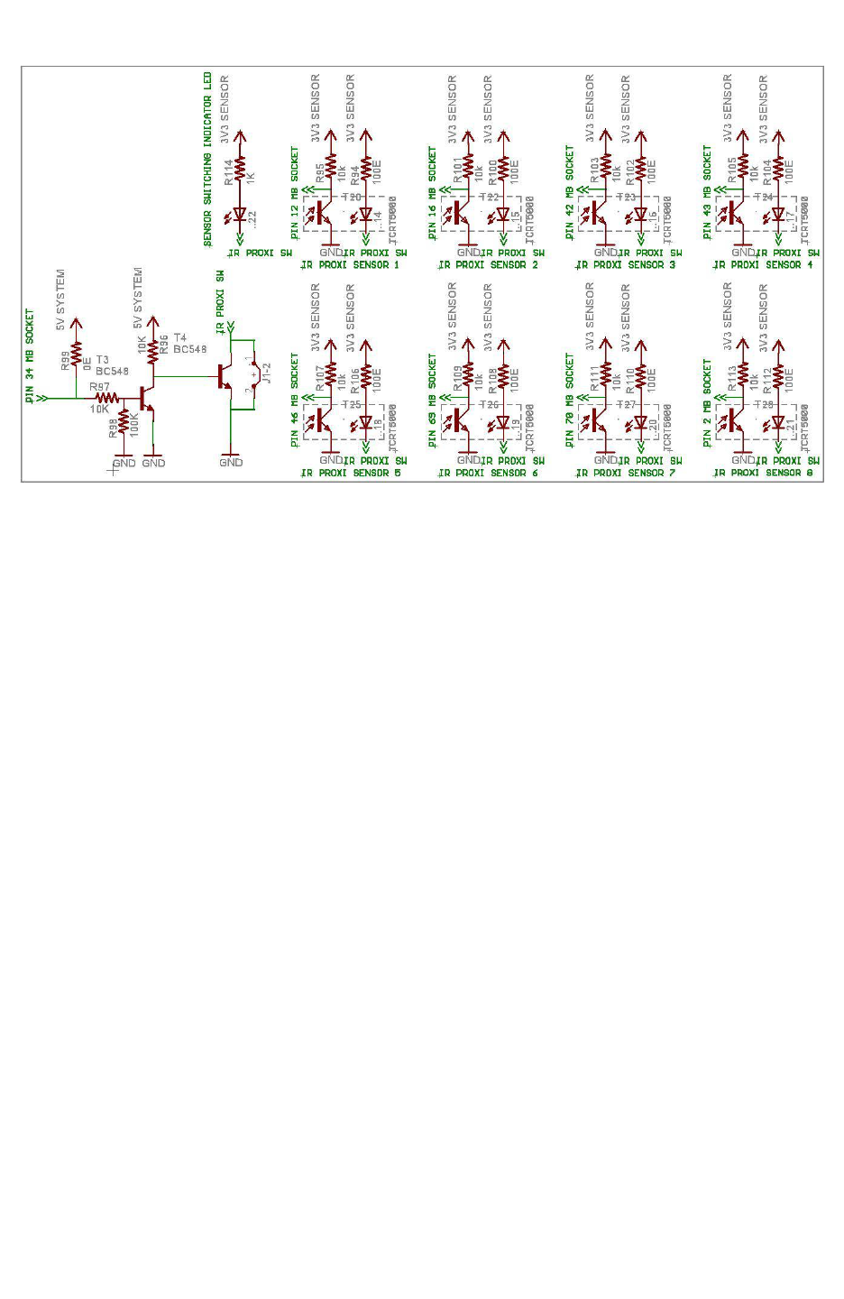
Figure 3.37: IR Proximity sensors
Figure 3.37 shows IR proximity senator’s circuit. IR proximity sensors 1 to 5 are connected to m
the ATMEGA2560 main microcontroller and IR proximity sensors 6 to 8 are connected to the
ATMEGA8 slave microcontroller.
Power switching circuit for IR Proximity sensors is shown in bottom left corner of figure 3.37.
Sensors can be permanently turned by inserting jumper. For location of the jumper, refer to
figure 3.38. You can turn on / off this sensor if this jumper is open. If logic 1 is applied to the
base of the transistor T3 by the microcontroller then it goes in to saturation and pulls base of the
transistor T4 and turns off the T4 and IR proximity sensors. When no signal is applied transistor
T3 remains off hence resistor R96 drives transistor T4 in to saturation and T4 turns on the IR
proximity sensor's IR LEDs.
Important:
You can also use IR proximity sensor's photo diode as directional light intensity sensor by
turning off IR LEDs. You can also remove effect of ambient light on the proximity detection by
taking reading while IR LED is on and off and checking difference between the readings.
© NEX Robotics Pvt. Ltd. and ERTS Lab, CSE, IIT Bombay, INDIA 46
Fire Bird V ATMEGA2560 Hardware Manual
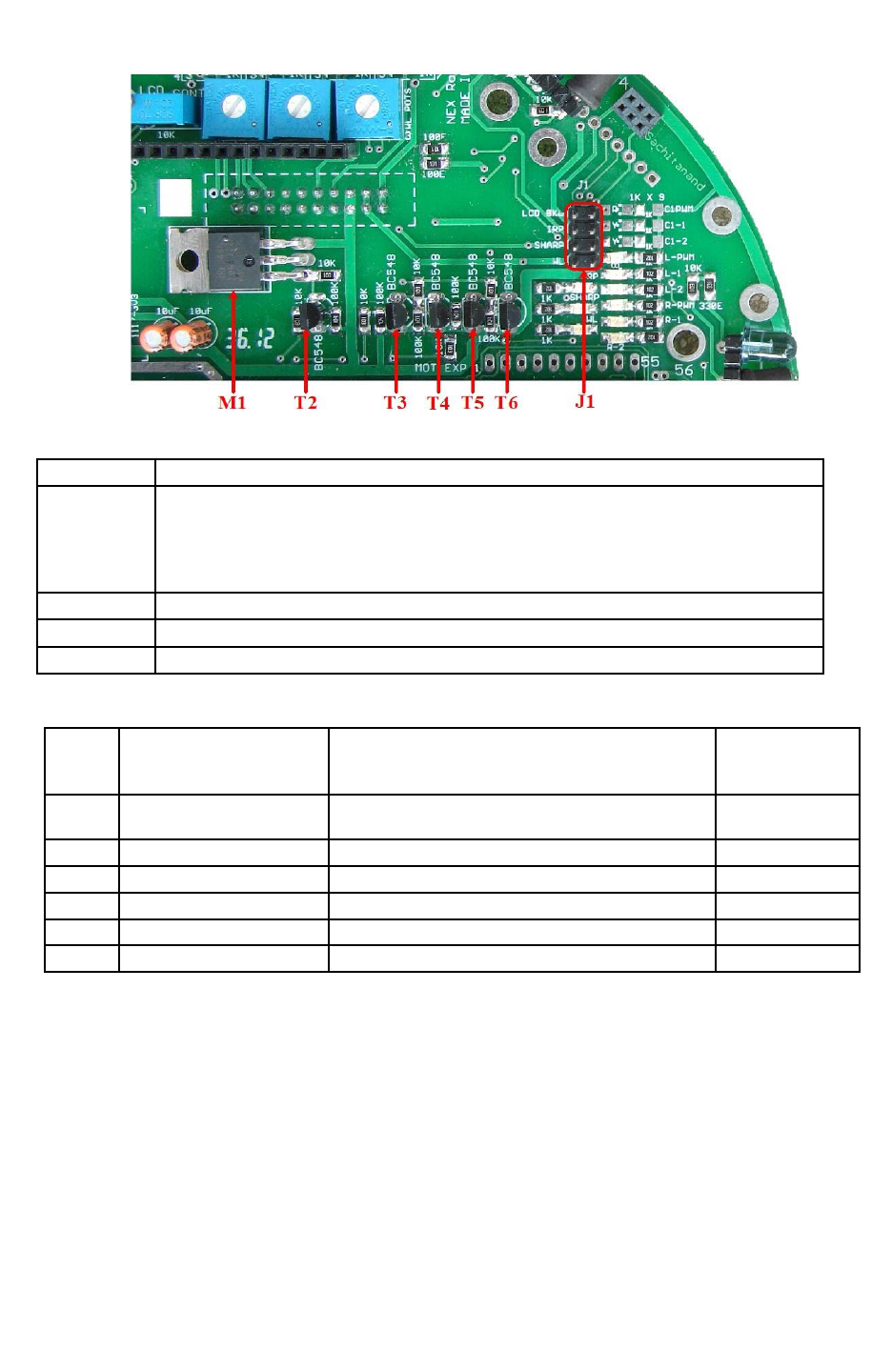
Figure 3.38: Sensor Control Switches and Jumpers
Name Function
J1 LCD Back-light Enable/Disable jumper
IR proximity sensor Enable/Disable jumper
Sharp sensor Enable/Disable jumper
White line sensor Enable/Disable jumper
M1 & T2 MOSFET M1 and Transistor T2 for Sharp IR range sensors switching
T3 & T4 Transistor T3 and T4 for IR Proximity Sensor switching
T5 & T6 Transistor T5 and T6 for White Line Sensor switching
Table 3.12: Sensor Control Switches and Jumpers functions
PINN
O
Pin name
(ATMEGA2560
master uC)
USED FOR Status
15 XCK2/ PH2 IR proximity sensors 1 to 8 disable.
Turns off these sensors when output is logic 1 * Output
89 PK0/ADC8/PCINT16 ADC input for IR proximity analog sensor 5 Input (Floating)
90 PF7(ADC7/TDI) ADC input for IR proximity analog sensor 4** Input (Floating)
91 PF6/(ADC6/TD0) ADC input for IR proximity analog sensor 3** Input (Floating)
92 PF5(ADC5/TMS) ADC input for IR proximity analog sensor 2** Input (Floating)
93 PF4/ADC4/TCK ADC input for IR proximity analog sensor 1** Input (Floating)
Table 3.13: Connections of the IR Proximity sensors and its power control transistor with
the ATMEGA2560 microcontroller (main microcontroller)
* For more details refer to section 3.10 and 3.12.
**For using Analog IR proximity (1, 2, 3 and 4) sensors short the jumper J2 on the
microcontroller adapter board. For more details refer to section 3.19.6. To use JTAG via
expansion slot of the microcontroller socket remove these jumpers.
© NEX Robotics Pvt. Ltd. and ERTS Lab, CSE, IIT Bombay, INDIA 47

Fire Bird V ATMEGA2560 Hardware Manual
PIN
NO
Pin name
(ATMEGA8 slave uC)
USED FOR
14 (SS/OC1B) PB2
ISP (In System Programming) and SPI Communication with
ATMEGA2560. *
15 (MOSI/OC2) PB3
16 (MISO) PB4
17 PB5 (SCK)
19 ADC6 ADC input for IR proximity analog sensor 7
22 ADC7 ADC input for IR proximity analog sensor 8
28 PC5 (ADC5/SCL) ADC input for IR proximity analog sensor 6
Table 3.14: Connections of the IR Proximity sensors with the ATMEGA8 (slave
microcontroller)
* In System programming and Multi-processor communication between master and salve
microcontroller
MOSI, MISO, SCK and SS pins of ATMEGA2560 (master microcontroller) are connected to the
ISP (In System programming) port as well as the SPI bus of ATMEGA8 (slave microcontroller).
Hence to do ISP you need to disconnect jumper J4 on the microcontroller adaptor board. To
access data from the slave microcontroller ATMEGA8 over SPI bus Jumper J4 on the
microcontroller socket needs to be connected.
© NEX Robotics Pvt. Ltd. and ERTS Lab, CSE, IIT Bombay, INDIA 48
Fire Bird V ATMEGA2560 Hardware Manual
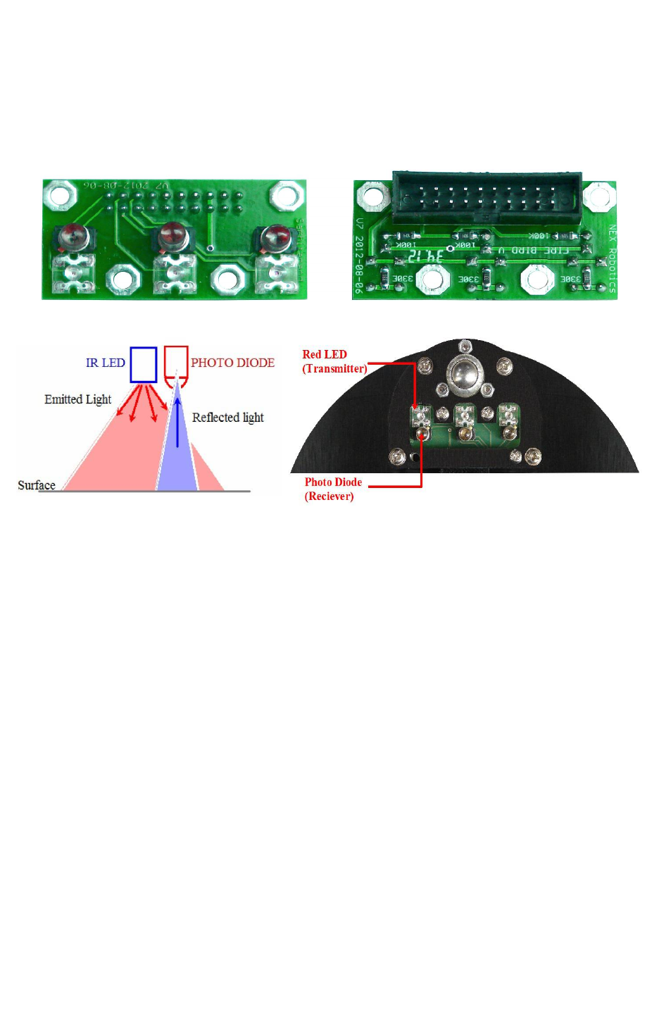
3.12 White Line Sensor:
White line sensors are used for detecting white line on the ground surface. White lines are used
to give robot sense of localization. White line sensor consists of a highly directional photo
transistor for line sensing and bright red LED for the illumination. Due to the directional nature
of the photo diode it does not get affected with ambient light unless it is very bright.
Figure 3.39: White line sensor
Figure 3.40: White Line sensor
When the robot is not on a white line, amount of light reflected is less, hence less leakage current
flows through the photo transistor. In this case, the line sensor gives an output in the range of 2V
to 3.3V. When the sensor is on a white line, more light gets reflected resulting in considerable
increase in the leakage current which causes voltage across the sensor to fall between 2 to 0.1V.
Power to the red LEDs of white line sensor is controlled PG5 of ATMEGA2560 microcontroller
to extend robot’s battery life. Switching action of the power control circuit is exactly same as
power switching circuit of IR proximity sensors as discussed in section 3.11. Line sensors can be
permanently turned on by inserting jumper in the Jumper J1-4. For more information refer to
figure 3.35 and table 3.11.
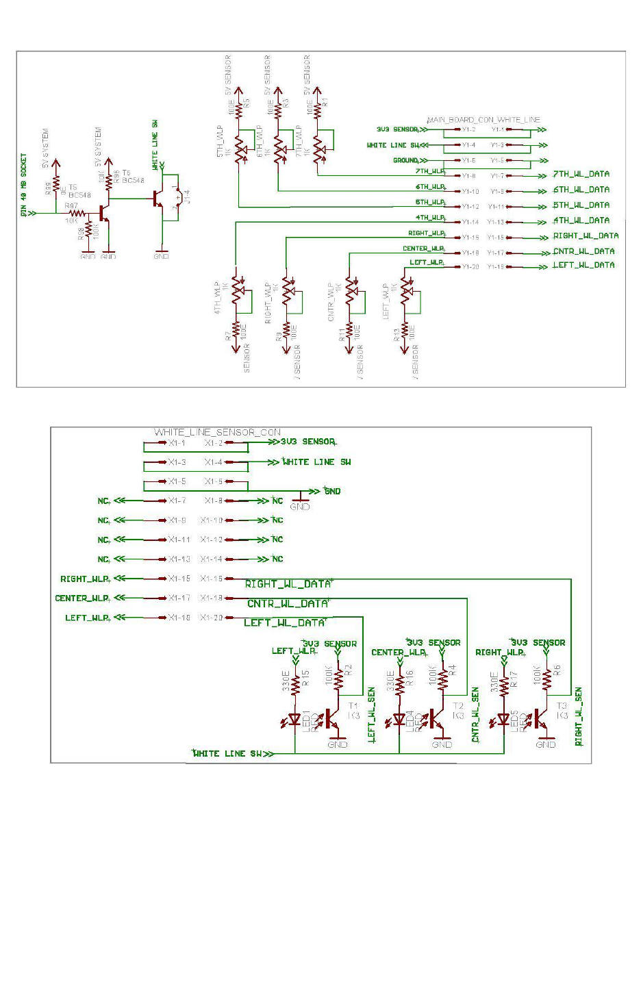
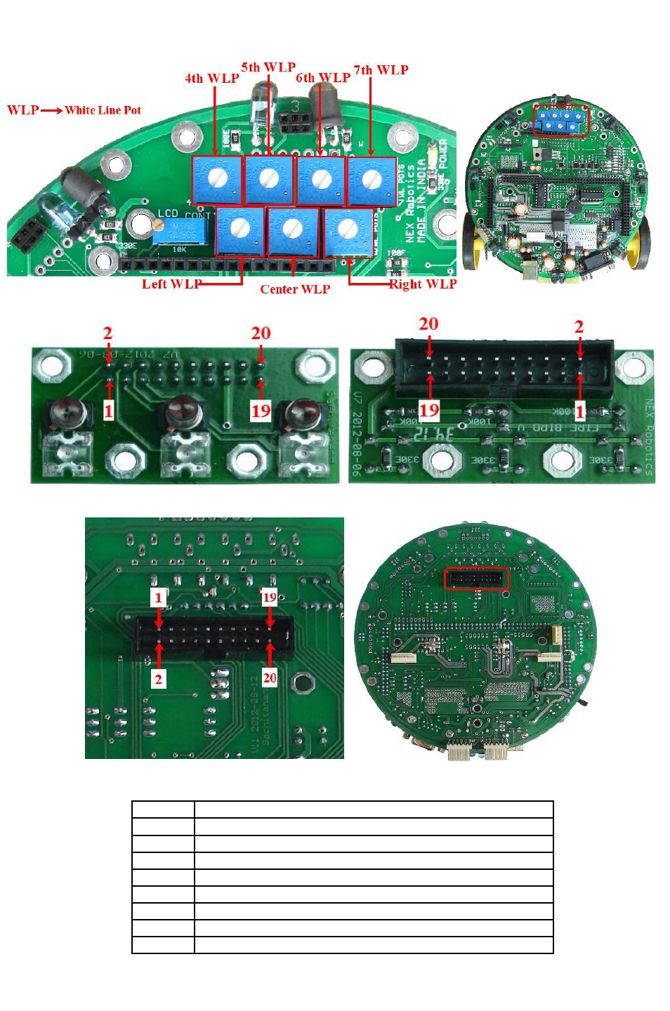
Figure 3.41a shows schematic of the whiteline sensor module on the main board and figure 3.42
shows location of potentiometers for the white line sensor calibration. Standard Fire Bird V robot
has 3 channel white line sensor module. It can also be seamlessly upgraded to 7 channel white
line sensor module using the same connector. Main board has potentiomenters for 7 ch white line
sensors. For more information regarding upgrade, refer to the application note in the application
notes section in the documentation CD.
Important:
Standard Fire Bird V robot is shipped with 3 potentiomentrs for 3 channel white line sensor
module. Additional 4 potentiomenters can be readly soldered on the main board. Figure 3.42
shows all seven potentiomenters but robot is shipped with only 3 potentiomentrs for left, centre
and right side white line sensor.
© NEX Robotics Pvt. Ltd. and ERTS Lab, CSE, IIT Bombay, INDIA 49
Fire Bird V ATMEGA2560 Hardware Manual
Figure 3.41a. White line sensor module on main board schematic
Figure 3.41b. White line sensor PCB schematic
Note:
White line sensor number 4 t o7 uses ADC of the ATMEGA8 slave microcontroller.
© NEX Robotics Pvt. Ltd. and ERTS Lab, CSE, IIT Bombay, INDIA 50
Fire Bird V ATMEGA2560 Hardware Manual
Figure 3.42: Potentiometers for white line sensor calibration
Figure 3.43: White line sensor pin connections (White line Sensor Board)
Figure 3.44: White line white line sensor connector pin configuration on main board
Pin No. Function
1 White line sensor 1 (Left sensor) Data Out
2 White line sensor 1 LED via potentiometer
3 White line sensor 2 (Center Sensor) Data Out
4 White line sensor 2 LED via potentiometer
5 White line sensor 3 (Right sensor) Data Out
6 White line sensor 3 LED via potentiometer
7 White line sensor 4 Data Out
8 White line sensor 4 LED via potentiometer*
© NEX Robotics Pvt. Ltd. and ERTS Lab, CSE, IIT Bombay, INDIA 51

Fire Bird V ATMEGA2560 Hardware Manual
9 White line sensor 5 Data Out
10 White line sensor 5 LED via potentiometer*
11 White line sensor 6 Data Out
12 White line sensor 6 LED via potentiometer*
13 White line sensor 7 Data Out
14 White line sensor 7 LED via potentiometer*
15 GND
16 GND
17 White Line switch(Jumper). Refer to figure 3.41a and 3.41b
18 White Line switch(Jumper). Refer to figure 3.41a and 3.41b
19 3V3 Sensor supply
20 3V3 Sensor supply
Table 3.15: White line sensor pin connections
* Potentiometers for white line sensor no. 5 to 7 needs to be soldered and are not included in the
package. They are not soldered at the factory.
Pin
No
ATMEGA2560 master
microcontroller pin name
USED FOR Status
70 PG2/ALE
Sharp IR ranges sensor 2, 3, 4 and red LEDs of
white line sensor 1, 2, 3 disable. *
Turns off these sensors when output is logic 1
Output
94 PF3/ADC3 Channel 3 for ADC Left input for white line sensor Input (Floating)
95 PF2/ADC2 Channel 2 for ADC Center input for white line
sensor Input (Floating)
96 PF1/ADC1 Channel 1 for ADC Right input for white line
sensor Input (Floating)
Table 3.16 White line sensor connections with ADC of ATMEGA2560 (Master
microcontroller)
* For more details refer to section 3.10 and 3.12.
Pin
No.
ATMEGA8 slave
microcontroller pin name
USED FOR
14 (SS/OC1B) PB2
ISP (In System Programming) and SPI Communication with
ATMEGA2560. *
15 (MOSI/OC2) PB3
16 (MISO) PB4
17 PB5 (SCK)
23 PC0 (ADC0) ADC input for white line sensor 4
24 PC1 (ADC1) ADC input for white line sensor 5/Servo pod
25 PC2 (ADC2) ADC input for white line sensor 6
26 PC3 (ADC3) ADC input for white line sensor 7/Servo pod
Table 3.17 Connections of the IR Proximity sensors with the ATMEGA8 (slave
microcontroller)
© NEX Robotics Pvt. Ltd. and ERTS Lab, CSE, IIT Bombay, INDIA 52

Fire Bird V ATMEGA2560 Hardware Manual
* In System programming and Multi-processor communication between master and salve
microcontroller
MOSI, MISO, SCK and SS pins of ATMEGA2560 (master microcontroller) are connected to the
ISP (In System programming) port as well as the SPI bus of ATMEGA8 (slave microcontroller).
Hence to do ISP you need to disconnect jumper J4 on the microcontroller adaptor board. To
access data from the slave microcontroller ATMEGA8 over SPI bus Jumper J4 on the
microcontroller socket needs to be connected.
White Line sensor calibration
By using trimming potentiometers located on the top center of the main board, line sensors can
be calibrated for optimal performance. Line sensors are factory calibrated for optimal
performance. Using these potentiometers we can adjust the intensity of the red LEDs of the white
line sensor. Sensitivity adjustment is needed, when color contrast between the white and non-
white surface in a white line grid is not adequate. In such cases the sensors can be tuned to give
maximum difference between white and non white surfaces. You can also turn on and turn off
red LEDs and take sensor readings at the same place and nullify the effect of the ambient light.
Robot comes with a flex stripe printed white line. You can use it to calibrrate robots white line
sensors by putting them on blace and white sensors.
Effect of ambient light on the white line sensors
White line sensors are highly directional in nature hence they are immune to the illumination
from tube light or CFL. Note that tube light which uses simple inductive chock actually blinks 50
times a second and this blink is captured by the white line sensors as ADC can acquire data at
very fast rates. Hence it is recommended that use CFL lights or tube lights with electronic chock
or ballast. These tube lights are the one which turns on like a bulb without flickering.
White line sensors are essentially sensitive photo transistors with precision lens assembly. All the
photo diodes and photo transistors are many times sensitive to infrared than to red light. Hence
for consistent result avoid room which have large windows even if they have curtains. Also
avoid using robots in area illuminated with filament based bulbs as they have large infrared light
radiation
Why red LEDs are used instead of IR LEDs in the white line sensors?
Photo transistors are many times sensitive to IR than to visible light but we still use red light
illumination because of following reasons:
•Red light is nearer to the infrared
•Since we can see red light its easier to calibrate it using eyes
•Any color appears black because it does not reflect visible light. Which means black
surface can be ultraviolet or infrared in color. If black is infrared color then robot's white
line sensors will not be able to distinguish between white and black as black will reflect
all infrared waves as effectively as white surface. In case of red illumination which has
very less infrared radiation even infrared black is still considered as black which makes
red light as color of choice.
© NEX Robotics Pvt. Ltd. and ERTS Lab, CSE, IIT Bombay, INDIA 53
Fire Bird V ATMEGA2560 Hardware Manual
3.12A Ultrasonic sensor Interfacing:
Fire Bird V primarily uses Sharp IR range sensors but sometime they are not easily available in
market. In year 2010 and 2011 they ware in acute shortage. Hence Fire Bird V's main board
version 11 also have support for ultrasonic range sensors. But as a designer I will always prefer
Sharp IR range sensors.
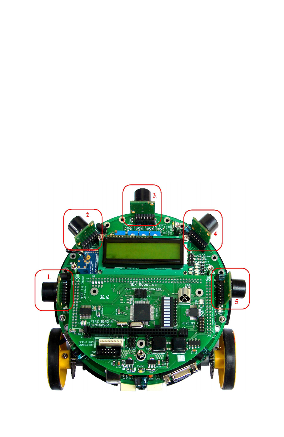
FireBird V robot can be equipped with the 5 ultrasonic sensors from MaxBotix. Each sensor can
sense distance range from 6 inches to 254 inches. Ultrasonic sensor transmits a narrow beam of
ultrasonic pulse and measures time taken for echo of the beam. It gives output proportional to
time taken for the ultrasonic beam to return echo from the obstacle.
FireBird V robot supports almost all compact ultrasonic range sensors from MaxBotix. Most of
the time robot uses EZ0 to EZ4 series sensors from MaxBotix. Sensor gives out analog output
with 1 inch resolution. It gives output voltage of 9.8mV per inch. After powering up, for first
100mS sensor runs calibration cycle. After that it can give readings with 49mS interval.
Figure below shows locations of the ultrasonic sensors. They are numbered as 1 to 5 from left to
right in clockwise direction.
Figure 3.44a: Five Ultrasonic Range Sensors on Fire Bird V
© NEX Robotics Pvt. Ltd. and ERTS Lab, CSE, IIT Bombay, INDIA 54
Fire Bird V ATMEGA2560 Hardware Manual
Enabling the Ultrasonic range sensors
The analog output of sharp sensor and analog output of Ultrasonic sensor is connected to the
same ADC channels of the microcontroller. Therefore at any given sensor location either Sharp
sensor or Ultrasonic range sensor can be used. Both sensors can not remain active at the same
time.
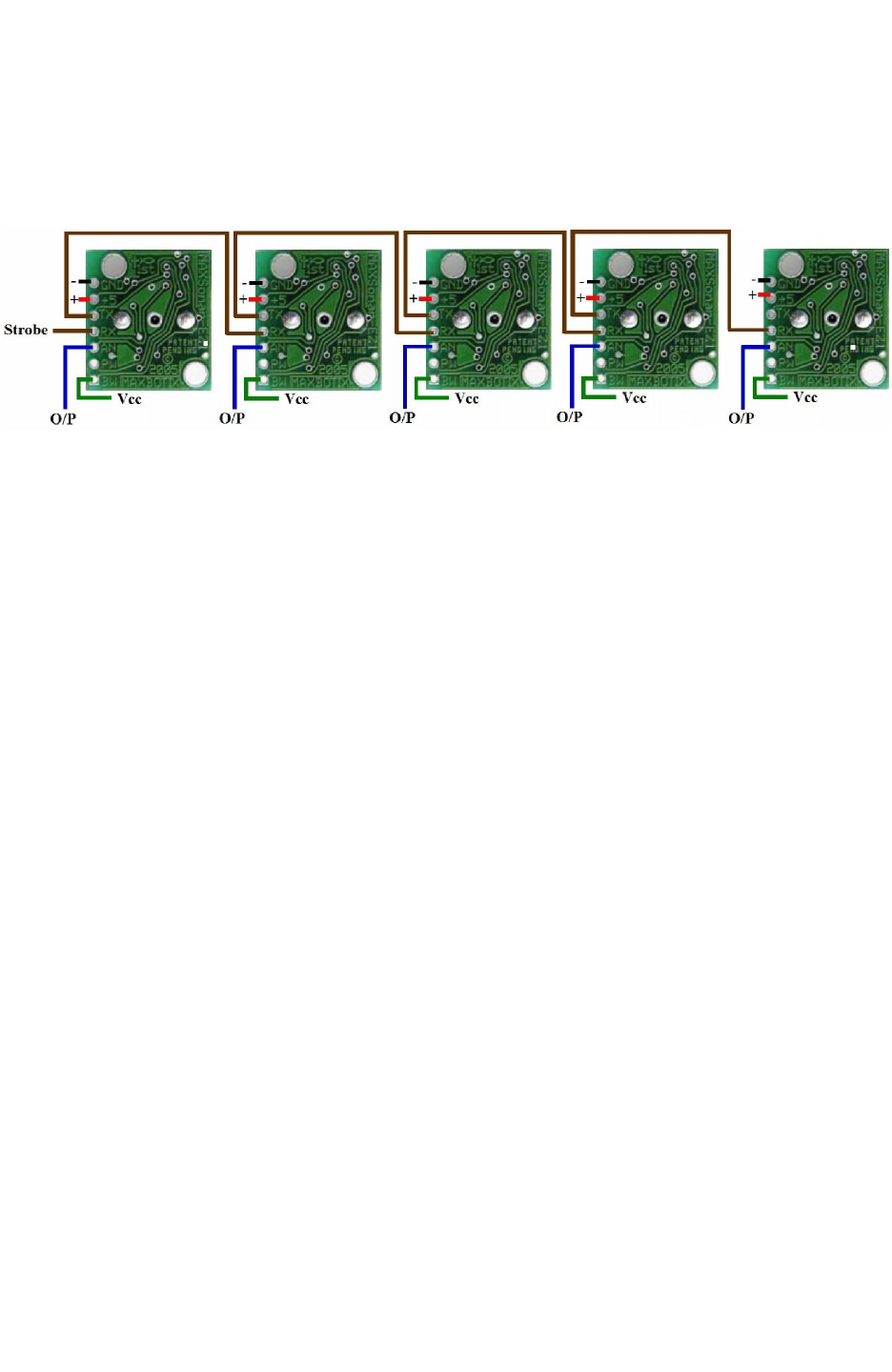
Figure 3.44b: Ultrasonic range sensor daisy chaining (courtesy: MaxBotix website)
If many of the sensors transmit ultrasound simultaneously their reading will get mixed-up. In
order to prevent this, all the ultrasonic sensors are connected in the daisy chain. Microcontroller
sends a trigger to the first ultrasonic sensor. First sensor takes the distance reading and sends
trigger to the second sensor. Second sensor follows the same process. This makes sure that at any
given time only one sensor transmits ultrasound.
Above figure shows sensor daisy chaining. Sensor 1’s TX pin is connected to the Sensor 2’s RX
pin and so on. In this way all 5 sensors are daisy chained. To enable the daisy chaining mode, pin
“BW” of the each ultrasonic sensor must be tied to Vcc. All sensors are powered at 3.3V sensor
supply.
To start taking reading a small trigger pules of more than 100uS needs to be given to the “RX”
pin of the first sensor. This pin is connected to the pin PH4 of the ATMEGA2560
microcontroller via pin 17B* of the main board socket. “RX” pin of the 5th ultrasonic range
sensor is left open. After triggering a Sensor 1, Sensor 1 transmits ultrasonic pulse and gives out
distance reading within 49mS. Sensor 1 triggers the Sensor 2 by transmitting a small pulse on its
TX pin to the RX pin of the second sensor. Now Sensor 2 takes reading. In this way sensor in the
daisy chain takes distance reading one at a time and triggers the next sensor connected. After all
5 sensors takes reading this process stops. You need to give trigger at the 1st sensor again.
You can trigger 1st sensor at the interval of 49ms x 5 sensors = 245ms if you want to insure that
only one sensor remains active at a time. This is the most recommended time interval. It is also
possible to keep more than one sensor preferably 90 degrees apart active by giving trigger at the
interval of 49ms x 2 sensors = 98mS for faster refresh rate but readings may get affected in small
room because of echos from other sensors. Figure 3.44c shows the schematics of the ultrasonic
ranges sensors.
*. We need to cut the track of 17B to PH4 pin at bottom side of microcontroller board, please refer the errata section
in this manual.
Important
1. You need to connect pin BW of the ultrasonic range sensor to the 3.3V manually.
2. If you want to install only one ultrasonic sensor, say sensor number 3 then you need to
short(hard wire) the pins “TX” and “RX” of the sensors which comes before this sensor
(in this case 1 and 2), so that trigger from microcontroller can reach the installed sensor.
© NEX Robotics Pvt. Ltd. and ERTS Lab, CSE, IIT Bombay, INDIA 55
Fire Bird V ATMEGA2560 Hardware Manual
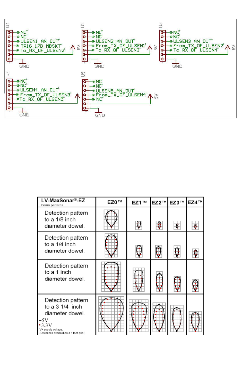
Figure 3.44c: Ultrasonic Range Sensor interfacing and jumper settings
Supported Ultrasonic range sensors
FireBird V robot mainly uses EZ0 to EZ4 sensors from MaxBotix. All these sensors are available
on NEX Robotics website. Other sensors from MaxBotix having compatible pin mapping can
also be used instead of these sensors. For more details on compatibility, refer to the respective
sensor’s datasheet.
EZ0 to EZ4 sensors have progressively more directionality. Refer to below figure to get rough
idea of the sensor characteristics.
Figure 3.44d: Range Shown on 1-foot grid to various diameter dowels (courtesy: MaxBotix
website)
© NEX Robotics Pvt. Ltd. and ERTS Lab, CSE, IIT Bombay, INDIA 56

Fire Bird V ATMEGA2560 Hardware Manual
Mounting Ultrasonic range sensors:
Fire Bird V robot's main board has empty slots for the ultrasonic range sensor mounting. You
can directly solder them using right angled male berg strip or you can solder flow solder (female
berg strip) on the main board and insert sensor which is already soldered to right angled male
berg stripe. Once you solder female berg strip on the main board, you can not insert Sharp IR
range sensor in to it.
Ultrasonic range sensors have wider beam angle. Even if they mounted in with sensor exactly
right angled to the main board it will see ground few meters ahead. It is good idea to solder them
directly on main board and slight bend them upward.
© NEX Robotics Pvt. Ltd. and ERTS Lab, CSE, IIT Bombay, INDIA 57
Fire Bird V ATMEGA2560 Hardware Manual
3.13 LCD Interfacing
LCD can be interfaced in 8bit or 4 bit interfacing mode. In 8 bit mode it requires 3 control line
and 8 data lines. To reduce number of I/Os required, Fire Bird V robot uses 4 bit interfacing
mode which requires 3 control lines and 4 data lines. In this mode upper and lower nibble of the
data/command byte needs to be sent separately. Figure 3.47 shows LCD interfacing in 4 bit
mode with three control lines EN (Enable), RS (Register Select), and RW (Read / Write).
The EN line is connected to PC2. This control line is used to tell the LCD that microcontroller
has sent data to it or microcontroller is ready to receive data from LCD. This is indicated by a
high-to-low transition on this line. To send data to the LCD, program should make sure that this
line is low (0) and then set the other two control lines as required and put data on the data bus.
When this is done, make EN high (1) and wait for the minimum amount of time as specified by
the LCD datasheet, and end by bringing it to low (0) again.
The RS line is connected to PC0. When RS is low (0), data is treated as a command or special
instruction by the LCD (such as clear screen, position cursor, etc.). When RS is high (1), data
being sent is treated as text data which should be displayed on the screen.
The RW line is connected to PC1. When RW is low (0), the information on the data bus is being
written to the LCD. When RW is high (1), the program is effectively querying (or reading from)
the LCD.
The data bus is bidirectional, 4 bit wide and is connected to PC4 to PC7 of the microcontroller.
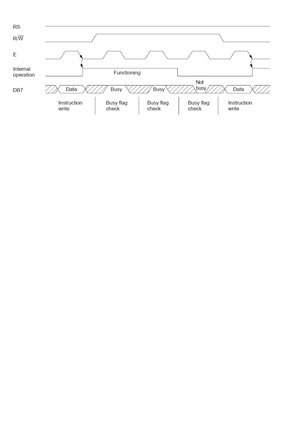
The MSB bit (DB7) of data bus is also used as a Busy flag. When the Busy flag is 1, the LCD is
in internal operation mode, and the next instruction will not be accepted. When RS = 0 and R/W
= 1, the Busy flag is output on DB7. The next instruction must be written after ensuring that the
busy flag is 0. Refer LCD datasheet provided in documentation CD for using Busy flag.
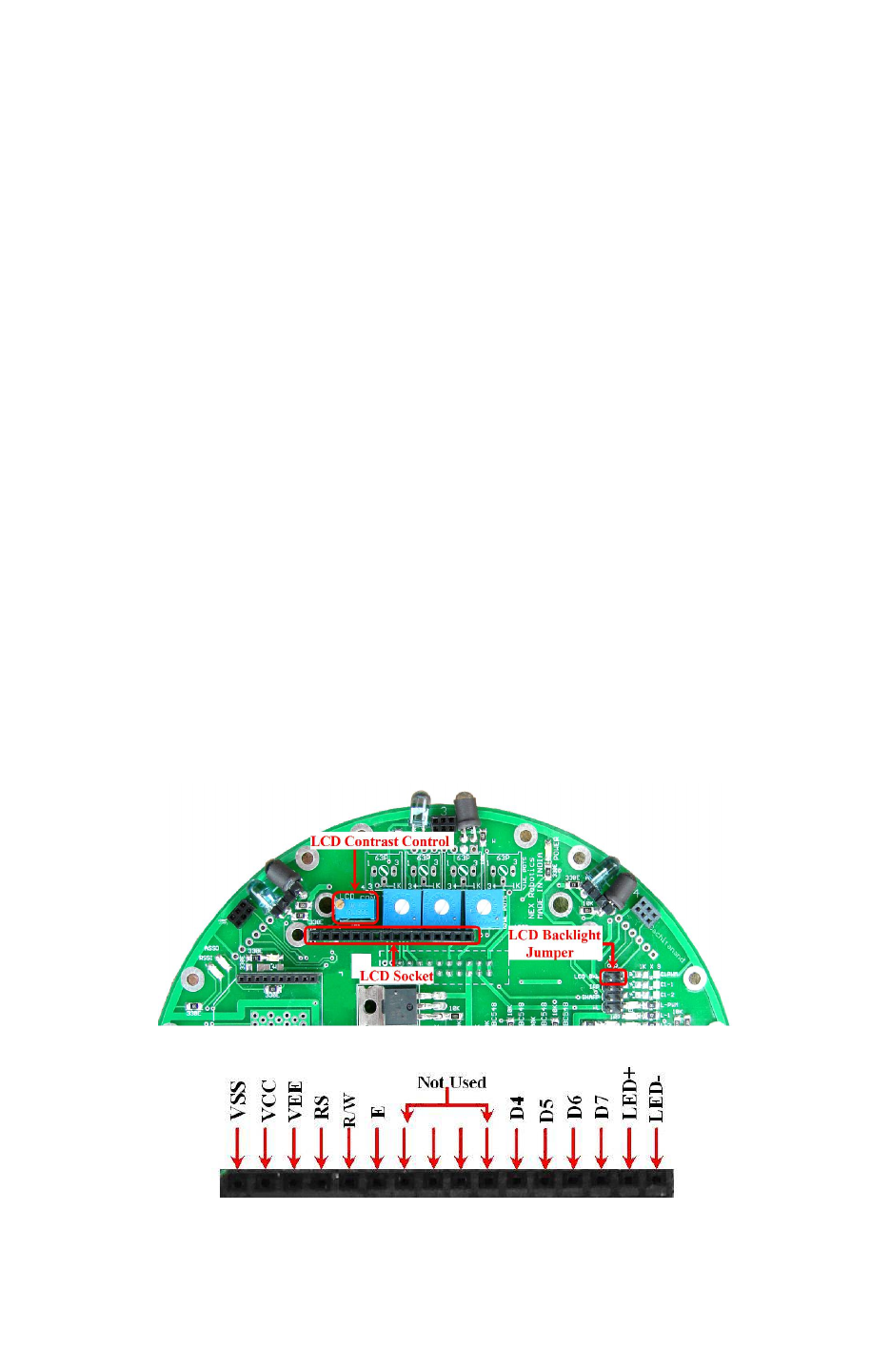
Figure 3.45: LCD socket and other settings
Figure 3.46: LCD socket pin connection
© NEX Robotics Pvt. Ltd. and ERTS Lab, CSE, IIT Bombay, INDIA 58
Fire Bird V ATMEGA2560 Hardware Manual
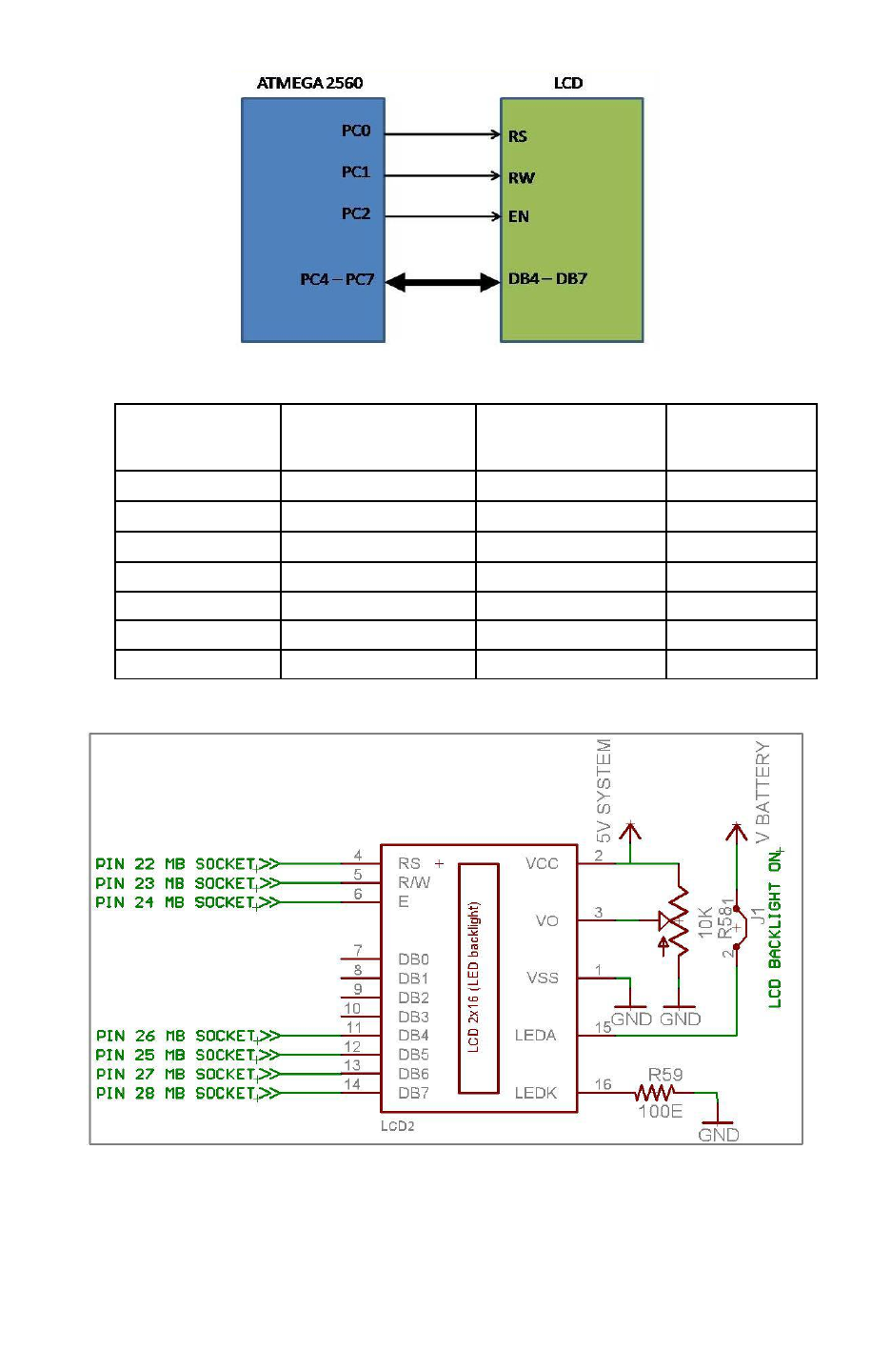
Figure 3.47 LCD interfacing with the microcontroller
ATMEGA2560
Microcontroller
Pins
LCD PINS Description Main Board
Pins Numbers
VCC VCC Supply voltage (5V). ----
GND GND Ground ----
PC0 RS (Control line) Register Select 22
PC1 R/W (Control line) READ /WRITE 23
PC2 EN (Control Line) Enable 24
PC4 to PC7 D4 to D7 (Data lines) Bidirectional data Bus 26 to 28
-- LED+, LED- Back light control ----
Table 3.18: LCD Pin mapping and functions
Figure 3.48: LCD display schematics
© NEX Robotics Pvt. Ltd. and ERTS Lab, CSE, IIT Bombay, INDIA 59
Fire Bird V ATMEGA2560 Hardware Manual
.
Figure 3.49: LCD Timing Diagram.
LCD is interfaced to the pins 22 to 28 of the main board socket. LCD uses 5V System supply for
its operation. For LCD backlight V Battery supply is used. Figure 8.45 shows LCD backlight
jumper and LCD contrast control potentiometer. In order to save power LCD backlight can be
turned off by removing LCD backlight jumper. LCD’s contrast can be adjusted by LCD contrast
control potentiometer.
© NEX Robotics Pvt. Ltd. and ERTS Lab, CSE, IIT Bombay, INDIA 60
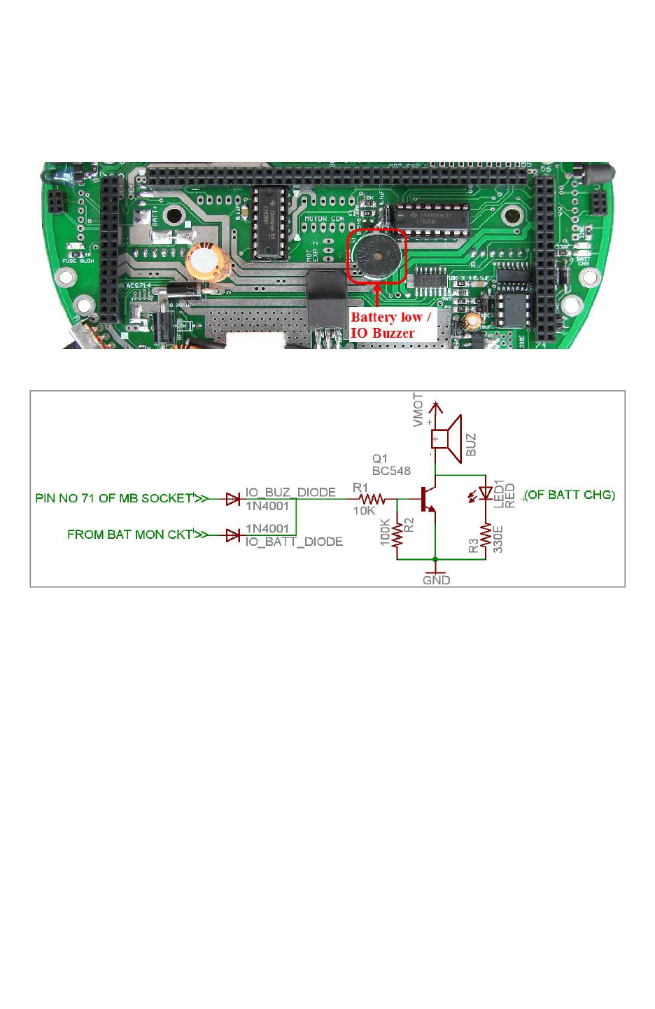
Fire Bird V ATMEGA2560 Hardware Manual
3.14 Buzzer
Robot has 3 KHz piezo buzzer. It can be used for debugging purpose or as attention seeker for a
particular event. The buzzer is connected to PC3 pin of the microcontroller. Also the same
buzzer is used in battery monitoring circuit to alert the battery low indication.
Figure 3.50: Buzzer
Figure 3.51: Buzzer Schematic
Buzzer is driven by BC548 transistor. Resistor 100K is used to keep transistor off, if the input
pin is floating. Buzzer will get turned on if input voltage is greater than 0.65V.
© NEX Robotics Pvt. Ltd. and ERTS Lab, CSE, IIT Bombay, INDIA 61
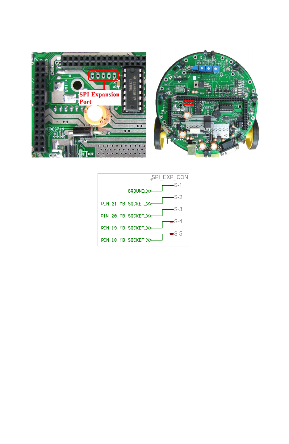
Fire Bird V ATMEGA2560 Hardware Manual
3.15 SPI expansion port on the main board
Main board has SPI connector for adding accessories such as robotic arm, color sensor etc.
Figure 3.52 shows its location on the main board and figure 3.52a shows its connections.
Figure 3.52: SPI expansion port pins
Figure 3.52a: SPI expansion port pins
© NEX Robotics Pvt. Ltd. and ERTS Lab, CSE, IIT Bombay, INDIA 62
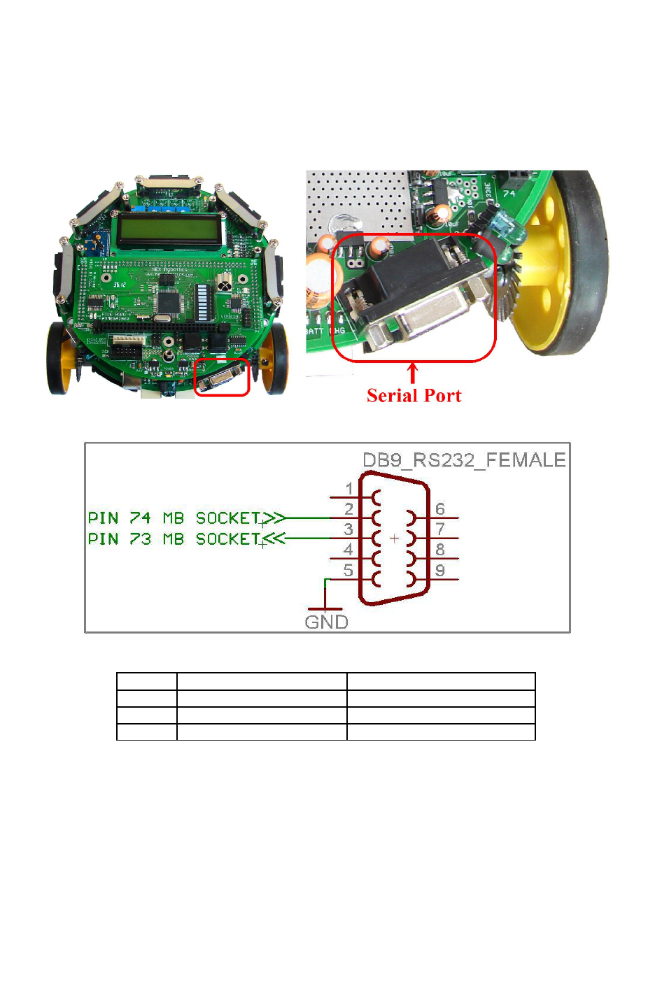
Fire Bird V ATMEGA2560 Hardware Manual
3.16 Serial Communication
Robot has 9pin female DB9 connector for serial communication. Out of these 9 pins only Tx (pin
3) Rx (pin 2) and ground (pin 5) are connected to the microcontroller via MAX202 RS232 to
serial TTL / CMOS logic converter. Figure 3.53 shows location of the serial on main board.
Figure 3.54 shows schematic. Table 3.19 shows the connections of the serial port.
Figure 3.53: Serial port pins
Figure 3.54: Serial port connections with the main board socket
Pin No. Description Main Board pin numbers
2 Receiver Data (RXD) Pin 74
3 Transmit Data (TXD) Pin 75
5 Signal Ground (GND) Ground
Table 3.19: Serial port pin out
© NEX Robotics Pvt. Ltd. and ERTS Lab, CSE, IIT Bombay, INDIA 63
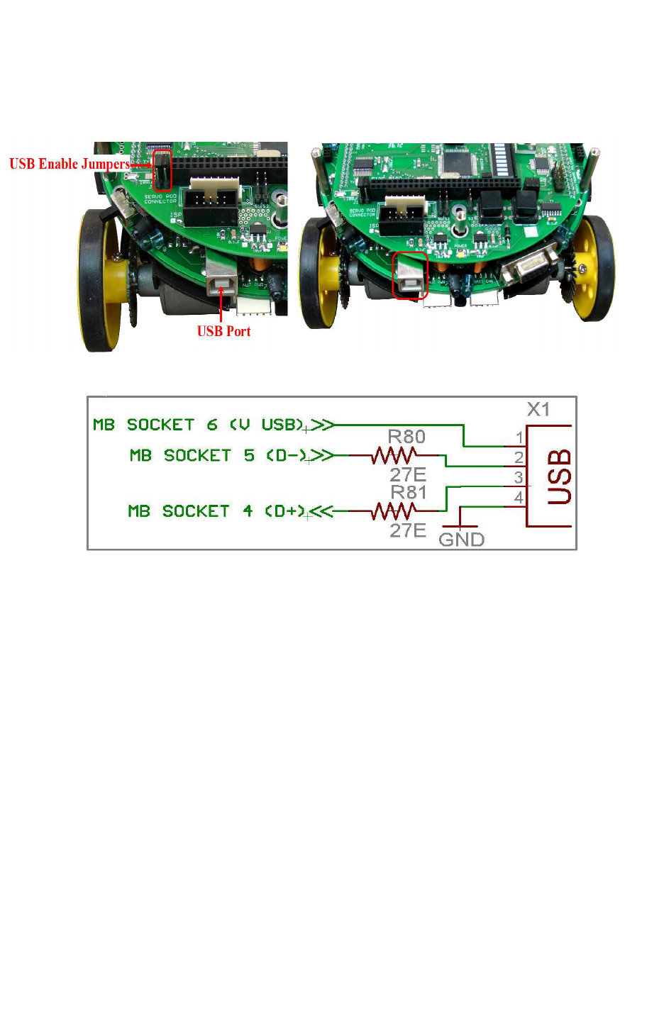
Fire Bird V ATMEGA2560 Hardware Manual
3.17 USB communication
Fire Bird V’s main board has USB port socket. Microcontroller accesses USB port via main
board socket. All its pins are connected to the microcontroller adapter board via main board's
socket connector.
Figure 3.55: USB port on the Fire Bird V main board
Figure 3.55a: USB port connections with the main board socket
© NEX Robotics Pvt. Ltd. and ERTS Lab, CSE, IIT Bombay, INDIA 64
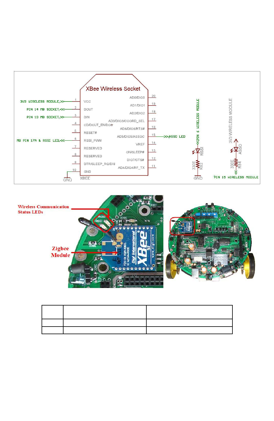
Fire Bird V ATMEGA2560 Hardware Manual
3.18 Wireless communication adaptor
Figure 3.57 shows location of the socket for the wireless module. It supports XBee and XBee Pro
series 1 and series 2 ZigBee wireless modules from digi international, RN-XV WiFi to serial
module and Bluetooth module. Table 3.20 shows the functions of the status indicator LEDs for
the XBee wireless modules.
Figure 3.56: ZigBee wireless module schematics
Figure 3.57: ZigBee wireless module and LED indicators
LED Connection to XBee Wireless
module Pin no. Description
ASSO 15 Associate LED
RSSI 6 RX Signal Strength Indicator
Table 3.20: XBee wireless module LED functions
Important:
You can change XBee wireless module’s frequency and Pan ID, so that multiple XBee wireless
modules can coexist at the same time. For more information on this, refer to “Application Notes”
folder which is located inside the “Manuals and Application notes” folder in the documentation
CD.
© NEX Robotics Pvt. Ltd. and ERTS Lab, CSE, IIT Bombay, INDIA 65
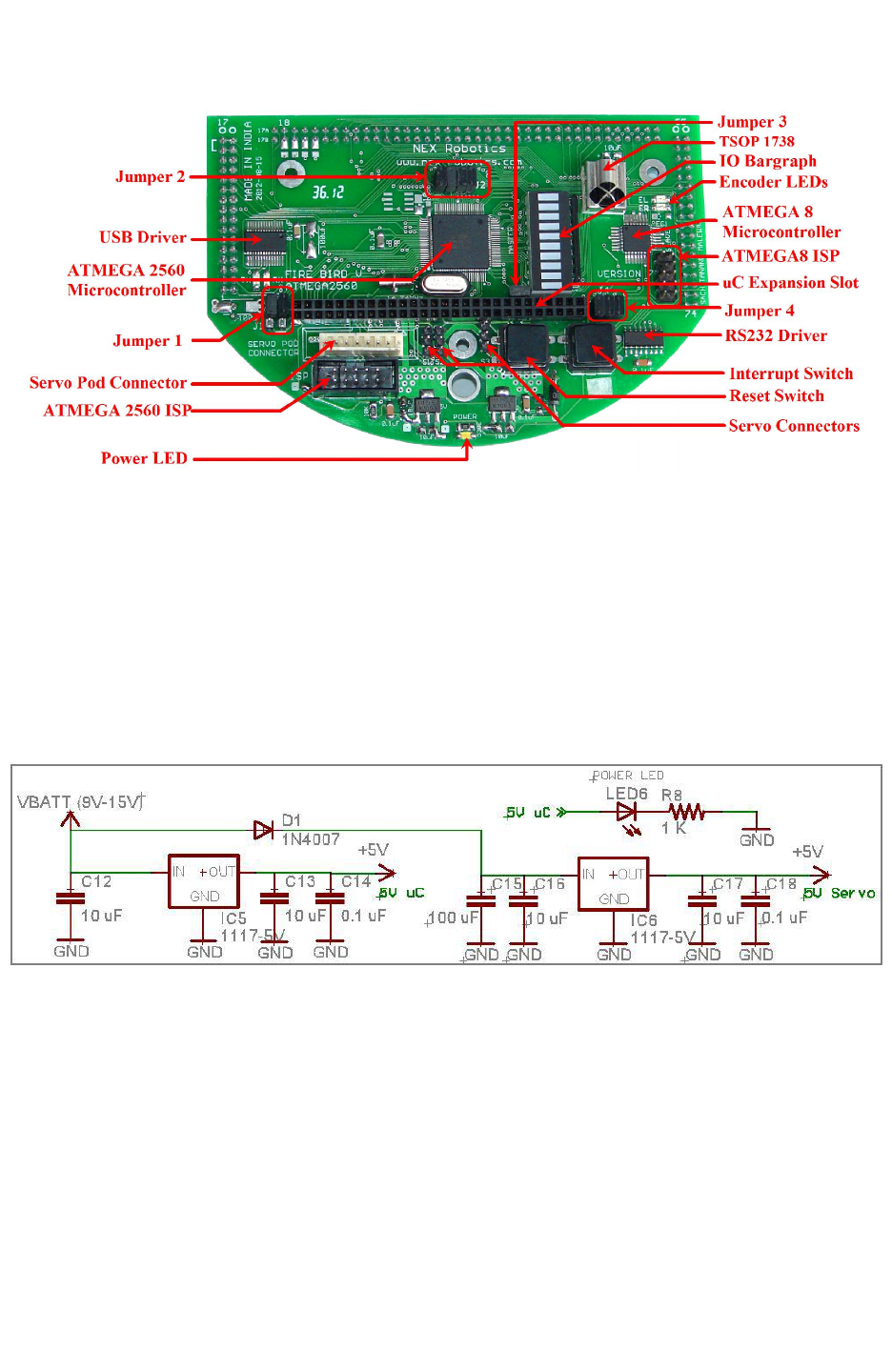
Fire Bird V ATMEGA2560 Hardware Manual
3.19 ATMEGA2560 microcontroller adapter board
Figure 3.58: ATMEGA2560 microcontroller adapter board
3.19.1 Power management
Power management block on the ATMEGA2560 microcontroller adapter board provides power
to the microcontroller, other devices and the power to the servo motor.
ATMEGA2560 microcontroller adapter board has two low drop voltage regulators:
1. “5V uC” supplies power to the microcontroller and its peripherals.
2. “5V servo” supplies power to the servo motor.
Figure 3.59: Power Supply Circuit
© NEX Robotics Pvt. Ltd. and ERTS Lab, CSE, IIT Bombay, INDIA 66
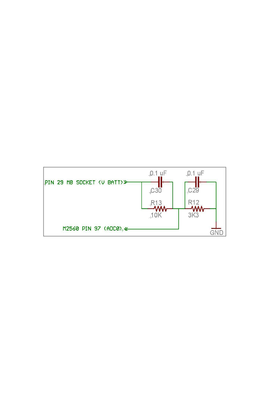
Fire Bird V ATMEGA2560 Hardware Manual
3.19.2 Battery voltage sensing
Filtered battery voltage is used for battery voltage sensing. Analog to Digital Converter (ADC)
can measure maximum voltage of 5V. Hence battery voltage is scaled down from 8-15V to less
than 5V using resistor divider network formed by R12 and R13. It scales down the voltage by
approximately 1/3 of the actual value.
ATMEGA2560 ADC can be used in 8 bit or 10 bit resolution. To calculate voltage from the
ADC’s acquired digital value in 8 bit resolution we use following formula:
V Battery = 0.7V + (ADC value * (5V/255) * ((10K + 3.3K) / 3.3K))
V Battery = 0.7V + (ADC value * 0.0790)
In the above formula:
•0.7V represents voltage drop across the diodes D7 and D9. for more details refer to figure
3.11.
•5V/255 represents the ADC step resolution
•(10K + 3.3K) / 3.3K is a voltage divider formula
Figure 3.60: Battery Voltage Divider Bias Circuit
Note: For 10 bit resolution replace 255 by 1024.
© NEX Robotics Pvt. Ltd. and ERTS Lab, CSE, IIT Bombay, INDIA 67
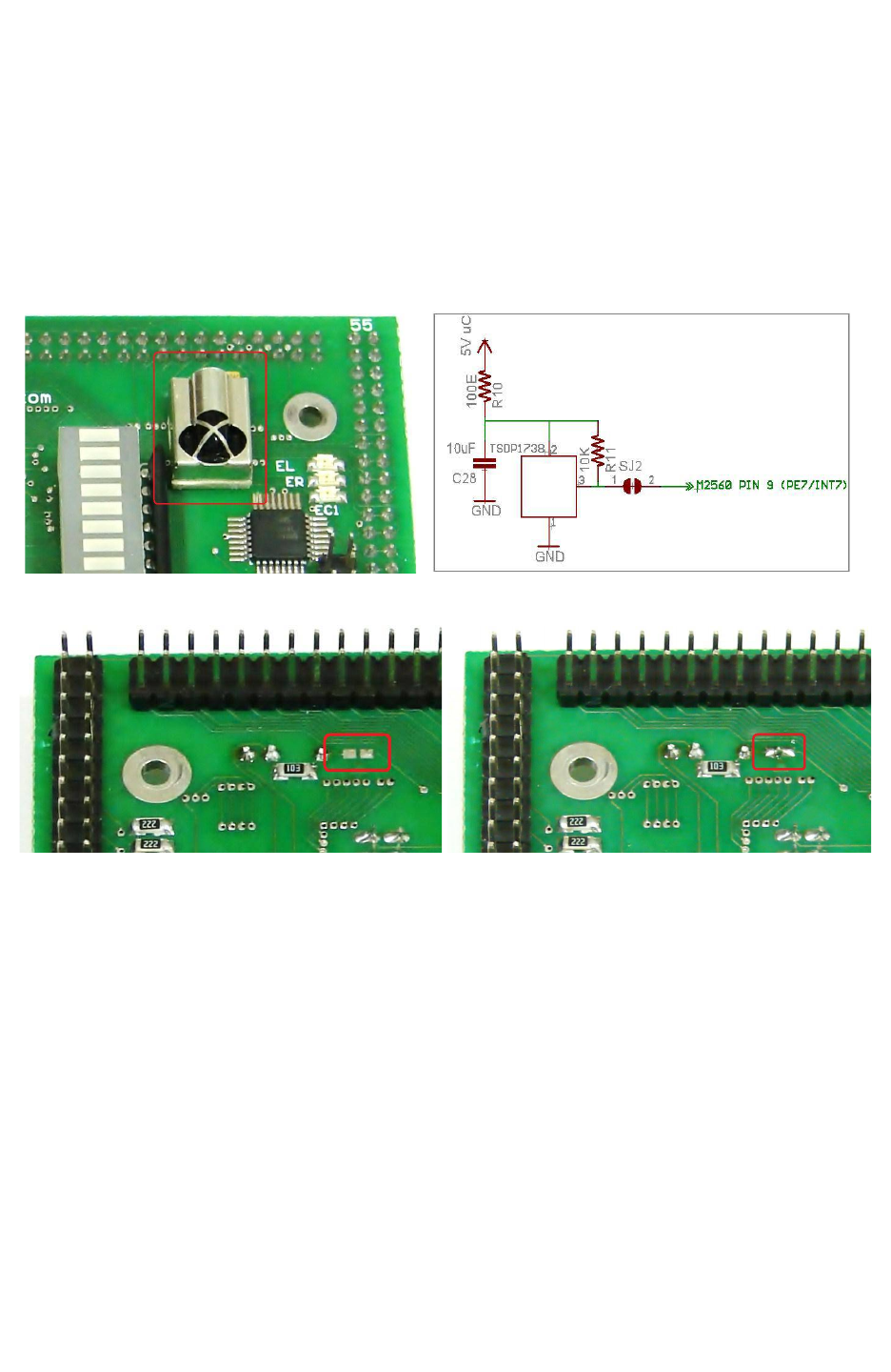
Fire Bird V ATMEGA2560 Hardware Manual
3.19.3 TSOP1738 RC5 IR receiver and decoder
TSOP1738 is an IR receiver based on RC5 decoder. It is very commonly used in televisions for
receiving commands from the remote control. It can be used to control robot using TV remote
control. Many robots can also be controlled simultaneously if you make your own TV remote
equivalent and interface it with the PC. Such type of setup can be used in the preliminary form of
robo-soccer. SJ2 solder pad needs to be connected by soldering for enabling the TSOP sensor.
Figure 3.62 shows the location of the SJ2 solder pad. It connects TSOP1738 with the INT7
(interrupt 7) pin of the microcontroller.
Figure 3.61: TSOP1738 RC5 decoder IR receiver
Figure 3.62: Jumper to be shorted to connect TSOP1738 with INT7 (shorted jumper is
shown in the right image)
Important:
Before using TSOP1738 insure that solder pad P1 on the main board is not shorted. For more
information refer to section 3.9 and figure 3.28.
© NEX Robotics Pvt. Ltd. and ERTS Lab, CSE, IIT Bombay, INDIA 68
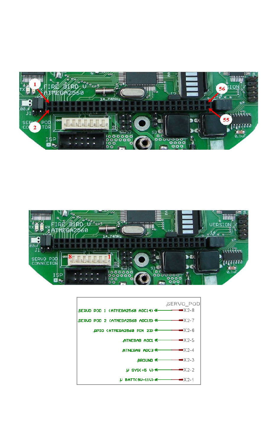
Fire Bird V ATMEGA2560 Hardware Manual
3.19.4 ATMEGA2560 Microcontroller Board Expansion Socket
ATMEGA2560 is a feature rich microcontroller with lots of available I/O ports. Many of the
ports are available for external use on the uC Expansion Socket. For Pin configuration of
expansion header refer section 4.3 from chapter 4.
Figure 3.63: uC Expansion Socket on the ATMEGA2560 Microcontroller Board
3.19.5 Servo Pod Sensor Socket
Servo pod sensor socket is used to connect external sensors / actuators which are mounted on pan
/ tilt servo pod. It is a 8 pin 2560 relimate connector. Table 3.22 gives its pin connections.
Fig 3.64: Servo Pod Sensor Socket
Figure 3.65: Servo pod sensor connector pin mapping
© NEX Robotics Pvt. Ltd. and ERTS Lab, CSE, IIT Bombay, INDIA 69
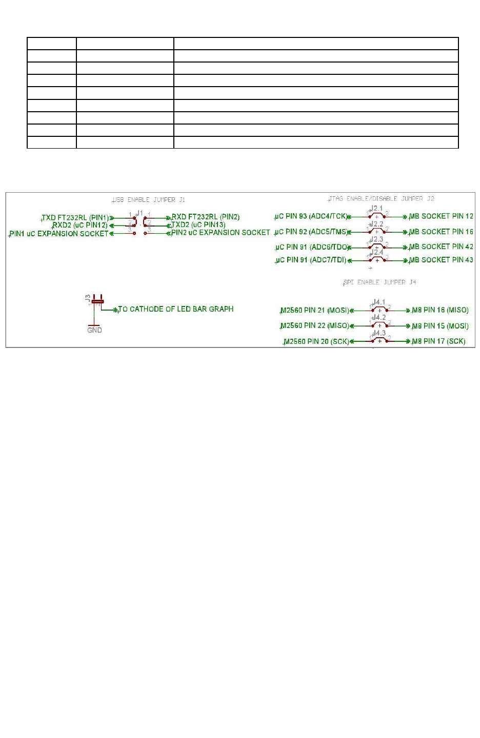
Fire Bird V ATMEGA2560 Hardware Manual
Pin No. Pin Name Description
1 Servo POD1 Connection with ATMEGA2560 ADC channel 14
2 Servo POD2 Connection with ATMEGA2560 ADC channel 15
3 GPIO Connection with ATMEGA2560 OC2A/PB4 pin (Pin no. 23)
4 Atmega8 ADC Connection with ATMEGA8 ADC channel 1
5 Atmega8 ADC Connection with ATMEGA8 ADC channel 3
6 Ground Ground
7 V SYS + 5V (VCC)
8 V BATT Battery Voltage(9V – 11V)
Table 3.22: Servo Pod socket pin description
3.19.6 Microcontroller Board Jumpers
Figure 3.66: Jumpers schematic
Microcontroller board has 4 jumpers labeled from J1 to J4 as shown in Figure 3.58 and figure
3.66.
J1: Jumper J1 is used to select between the UART2 pins connections of ATMEGA2560 on the
uC Expansion Socket and to the onboard FT232 USB to serial converter circuit. When jumper is
in position as shown in the figure 3.66, it enables the onboard USB communication through
UART2 (default state).
J2: When J2 is on IR Proximity sensors 1 to 4 are connected to the ADC pins of the
ATMEGA2560. When J2 is open, same ADC pins can be used for JTAG on the uC expansion
socket or as ADCs for external sensor interfacing. In the default state J2 is on.
J3: If J3 is on, all the pins of the PORT J are connected to the LED bargraph display. It can be
used for quick message display for debug purpose. If J3 is off, LED connection is disabled. All
the pins of the PORT J are available on the uC expansion socket for use as GPIOs. In the default
state J3 is kept on.
J4: When J4 is on, SPI bus between ATMEGA2560 (master) and ATMEGA8 (slave) is
connected and you can access date from the slave microcontroller. Since SPI lines are also used
for In System Programming (ISP) to load firmware on the master and slave microcontroller via
SPI port you need to remove all jumpers from J4 before attempting ISP. J4 is kept open as
default setting.
© NEX Robotics Pvt. Ltd. and ERTS Lab, CSE, IIT Bombay, INDIA 70
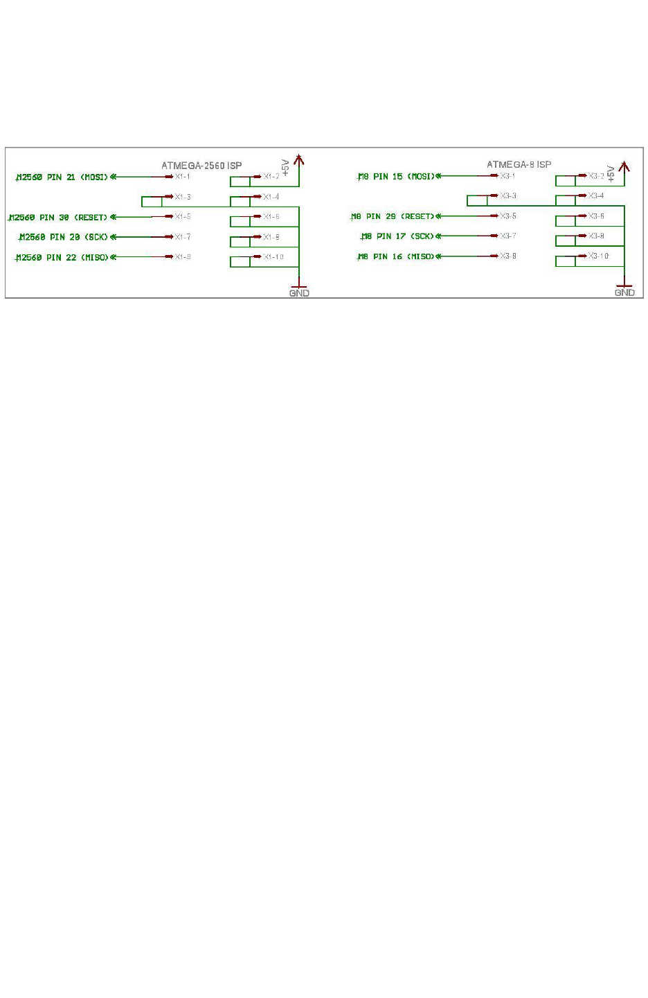
Fire Bird V ATMEGA2560 Hardware Manual
You can also program robot using boot loader utility via USB port. This will remove the need for
frequent removal of jumpers on J4 for loading new firmware.
In System Programming (ISP) sockets
Figure 3.67 ISP Schematic
ATMEGA2560 microcontroller adapter board has ISP sockets for the ATMEGA2560 and
ATMEGA8 microcontrollers.
Note: To do In System Programming of ATMEGA2560 and ATMEGA8 microcontrollers
jumper J4 must be absent. For more details refer to section 3.19.6 for the J4.
© NEX Robotics Pvt. Ltd. and ERTS Lab, CSE, IIT Bombay, INDIA 71
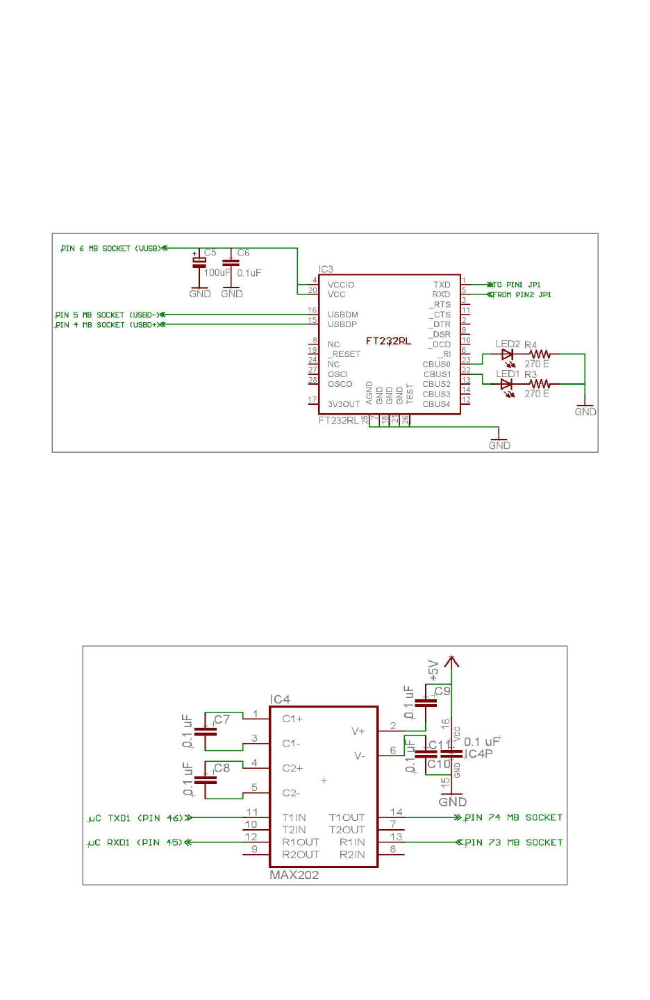
Fire Bird V ATMEGA2560 Hardware Manual
3.19.7 FT232 USB to serial converter on UART 2 of the ATMEGA2560 microcontroller
FT232 is a USB to TTL level serial converter. It is used for adding USB connectivity to the
microcontroller adapter board. With onboard USB circuit Fire Bird V can communicate serially
with the PC through USB port without the use of any external USB to Serial converter.
Microcontroller socket uses USB port from the main board. Data transmission and reception is
indicated suing TX and RX LEDs which are located near the FT232 IC. Refer to figure 3.58 for
LED's locations. To enable USB to serial communication, jumper J1 should be configured in a
particular way. Refer to section 3.19.6 for correct jumper settings.
Figure 3.68: FT232 Schematic
Note: Using bootloader from NEX Robotics, Robot can be programmed directly via USB port
without any need of external ISP programmer. How to use Bootloader GUI is covered in the
software manual.
3.19.8 TTL to RS232 converter on UART 1 of the ATMEGA2560 microcontroller
MAX202 IC is used for conversion of the TTL level signal of the UART 1 to the RS232 level. It
is connected to the DB9 female serial connector on the main board. For more details on the
hardware connections refer to section 3.16.
Figure 3.69: MAX202 TTL to RS232 converter
© NEX Robotics Pvt. Ltd. and ERTS Lab, CSE, IIT Bombay, INDIA 72
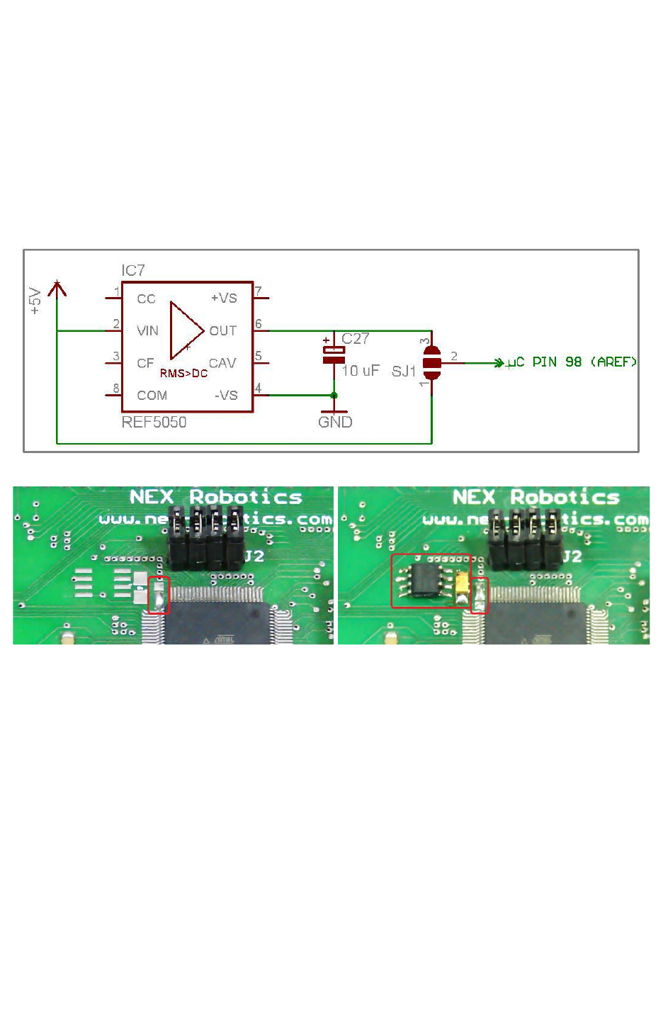
Fire Bird V ATMEGA2560 Hardware Manual
3.19.9 REF5050 precision reference voltage generator
ATMEGA2560 microcontroller’s ADC channels require external stable voltage reference. In the
default state microcontroller uses “5V uC Supply” as a external reference voltage. In case if you
want to interface microcontroller with the sensors where precision is very important then
REF5050 external reference voltage generator can be added on the microcontroller board. In the
default state voltage reference is directly taken from “5V uC supply” by connecting pins 2 and 1
of the pads of SJ1 which is located just below the J2 on the microcontroller board. Figure 3.71
shows mounting of REF5050 and change in the solder pad shorting.
Figure 3.70: REF5050 Schematic
Figure 3.71: Left- Jumper shorted to use 5V uC as A Ref. Right- REF5050 is installed and
jumper shorted to use its 5V output as reference.
© NEX Robotics Pvt. Ltd. and ERTS Lab, CSE, IIT Bombay, INDIA 73
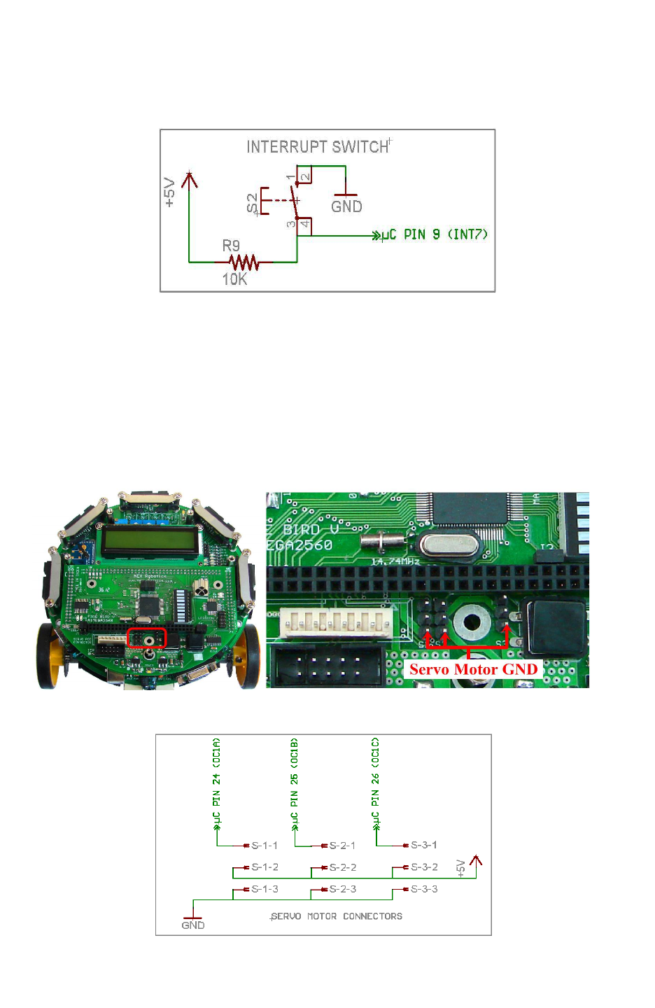
Fire Bird V ATMEGA2560 Hardware Manual
3.19.10 Interrupt Switch
Interrupt switch on the microcontroller adapter board is connected to PE7 (INT7) pin of the
microcontroller. It has external 10K pull-up resistor. When switch is pressed, PE7 becomes logic
low. Location of the interrupt switch is shown in figure 3.58.
Figure 3.72: Interrupt switch
Important:
Before using interrupt switch, ensure that soldering pad P1 on the main board is open. For more
information refer to figure 3.28 and section 3.9.
3.19.11 Servo Connectors
The microcontroller board has three Servo connectors as shown in figure 3.58. It can be used for
driving servo motors of camera pod or any other attachment. Power for the servo connector is
provided by the “5V servo supply” voltage regulator. Figure 3.73 shows correct orientation of
the servo motor's connector.
Figure: 3.73: Servo Connectors Schematic.
Figure: 3.73a: Servo Connectors Schematic
© NEX Robotics Pvt. Ltd. and ERTS Lab, CSE, IIT Bombay, INDIA 74
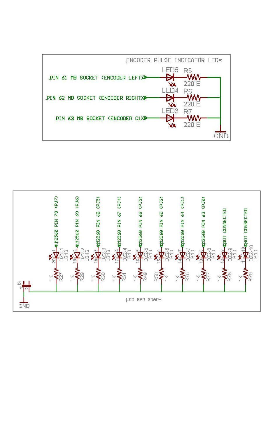
Fire Bird V ATMEGA2560 Hardware Manual
3.19.12 Position Encoder LEDs
These LEDs are used to display the pulses coming from the left, right and C2 motor connectors.
In the default configuration Motor C2 is not used hence LED corresponding to C2 is not soldered
on the microcontroller adaptor board.
Figure 3.74: Encoder LEDs Schematic
3.19.13 Bargraph LED display
Bargraph LED display is used for quick debugging purpose. It is connected to the PORTJ of the
ATMEGA2560 microcontroller. To enable bargraph jumper J3 needs to be connected. For more
details refer to the section 3.19.6.
Figure 3.75: LED BAR GRAPH Schematic
© NEX Robotics Pvt. Ltd. and ERTS Lab, CSE, IIT Bombay, INDIA 75
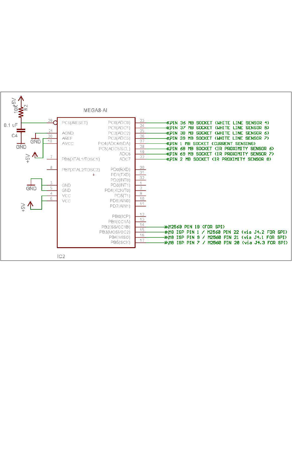
Fire Bird V ATMEGA2560 Hardware Manual
3.19.14 ATMEGA8 Slave Microcontroller
Fire Bird V robot can be interfaced with more than 30 sensors at the same time. ATMEGA2560
does not have sufficient number of ADC available of sensor interfacing. Hence ATMEGA8
microcontroller is connected with ATMEGA2560 microcontroller over the SPI port. Jumper J4
needs to be removed before attempting to do ISP with ATMEGA2560 and ATMEGA8 as there
SPI lines are connected with the jumper J4. For more details on the jumpers, refer to the section
3.19.6.
Figure 3.76: ATMEGA8 SCHEMATIC
Note: Firmware (ATMEGA8.hex ) for the ATMEGA8 microcontroller is located in the GUI and
Related Firmware folder in the documentation CD.
© NEX Robotics Pvt. Ltd. and ERTS Lab, CSE, IIT Bombay, INDIA 76
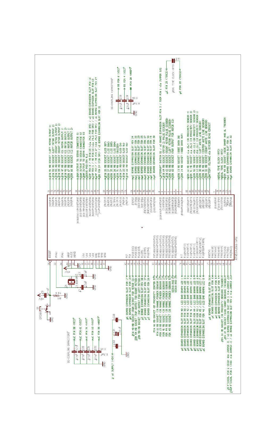
Fire Bird V ATMEGA2560 Hardware Manual
3.19.15 ATMEGA2560 Microcontroller
ATMEGA2560 is interfaced directly to most of the onboard peripherals. Its schematic is shown
in the figure 3.78.
Figure 3.78: ATMEGA2560 microcontroller schematic
© NEX Robotics Pvt. Ltd. and ERTS Lab, CSE, IIT Bombay, INDIA 77

Fire Bird V ATMEGA2560 Hardware Manual
4. Pin Functionality
Fire Bird V ATMEGA2560 microcontroller adapter board has two microcontrollers.
ATMEGA2560 (master microcontroller) and ATMEGA8 (slave) microcontroller.
ATMEGA2560 communicates with ATMEGA8 using SPI bus.
ATMEGA2560 is interfaced to all the important modules for the robot while ATMEGA8
microcontroller is interfaced with non critical modules such as IR proximity sensors 6, 7, 8,
Robot current sensing (if ACS712 current sensor is installed), extended white line sensor
channels 4, 5, 6, 7 and pin on the servo sensor socket etc.
4.1 ATMEGA2560 (master) microcontroller pin configuration
Pin
No
Pin name USED FOR Status
1 (OC0B)PG5 Slave Select (SS) of the SPI expansion port on the main board
(refer to figure 3.5) --
2 RXD0/PCINT8/PE0 UART 0 receive for XBee wireless module (if installed) Default
3 TXD0/PE1 UART 0 transmit for XBee wireless module (if installed) Default
4 XCK0/AIN0/PE2 GPIO* (Available on expansion slot of the microcontroller
socket)
5 OC3A/AIN1/PE3 PWM output for C2 motor drive Output
6 OC3B/INT4/PE4 External Interrupt for the left motor’s position encoder Input
7 OC3C/INT5/PE5 External Interrupt for the right motor’s position encoder Input
8 T3/INT6/PE6 External Interrupt for the C2 motor’s position encoder Input
9 CLK0/ICP3/INT7/ PE7
External Interrupt for Interrupt switch on the microcontroller
board, External Interrupt for the C1 motor’s position encoder,
Connection to TSOP1738 if pad is shorted, can also be used
as Boot loading switch ********
Input
10 VCC 5V
11 GND Ground
12 RXD2/PH0 UART 2 receives for USB Communication.
For more details refer to section 3.19.7 Default
13 TXD2/PH1 UART 2 transmit for USB Communication.
For more details refer to section 3.19.7 Default
14 XCK2/PH2 IR proximity sensors 1 to 8 enable / disable.
Turns off these sensors when output is logic 1 ******* Output
15 OC4A / PH3 Sharp IR ranges sensor 1and 5 enable / disable.
Turns off these sensors when output is logic 1 ******* Output
16 OC4B / PH4
Connected to Rx pin of 1st Ultrasonic range sensor to trigger
the ultrasonic sensor if sensor is mounted. Also Available on
expansion slot of the microcontroller socket*********
--
17 OC4C / PH5 Available on expansion slot of the microcontroller socket --
18 OC2B / PH6 Available on expansion slot of the microcontroller socket --
19 SS/PCINT0/PB0 ISP (In System Programming), SPI Communication with
ATMEGA8 **, Connection to the SPI port on the main board.
Also available on expansion slot of the microcontroller socket
20 SCK/PCINT1/PB1 Output
21 MOSI/PCINT2/PB2 Output
22 MISO/PCINT3/PB3 Input
23 OC2A/PCINT4/PB4 Servo Pod GPIO --
24 OC1A/PCINT5/PB5 PWM for Servo motor 1. *** Output
25 OC1B/PCINT6/PB6 PWM for Servo motor 2. *** Output
26 OC0A/OC1C/PCINT7/PB7 PWM for Servo motor 3. *** Output
© NEX Robotics Pvt. Ltd. and ERTS Lab, CSE, IIT Bombay, INDIA 78

Fire Bird V ATMEGA2560 Hardware Manual
27 T4/PH7 GPIO (Available On Expansion Slot) --
28 TOSC2/PG3 RTC (Real Time Clock)****
29 TOSC1/PG4
30 RESET Microcontroller reset
31 VCC 5V
32 GND Ground
33 XTAL2 Crystal 14.7456 MHz
34 XTAL1
35 ICP4/PL0 Connected to RSSI pin of XBee module. Also Available on
expansion slot of the microcontroller socket. --
36 ICP5/PL1 Available on expansion slot of the microcontroller socket. --
37 TS/PL2 Available on expansion slot of the microcontroller socket. --
38 OC5A/PL3 PWM for left motor. Output
39 OC5B/PL4 PWM for right motor. Output
40 OC5C/PL5 PWM for C1 motor. Output
41 PL6 GPIO* (Available on expansion slot of the microcontroller
socket)
--
42 PL7 --
43 SCL/INT0/PD0 I2C bus / GPIOs (Available on expansion slot of the
microcontroller socket)
--
44 SDA/INT1/PD1 --
45 RXD1/INT2/PD2 UART1 receive for RS232 serial communication Default
46 TXD1/INT3/PD3 UART1 transmit for RS232 serial communication Default
47 ICP1/PD4
GPIO* (Available on expansion slot of the microcontroller
socket)
--
48 XCK1/PD5 --
49 T1/PD6 --
50 T0/PD7 --
51 PG0/WR GPIO* (Available on expansion slot of the microcontroller
socket)
--
52 PG1/RD --
53 PC0 LCD control line RS (Register Select) Output
54 PC1 LCD control line RW(Read/Write Select) Output
55 PC2 LCD control line EN(Enable Signal) Output
56 PC3 Buzzer Output
57 PC4
LCD data lines (4-bit mode) Output
58 PC5
59 PC6
60 PC7
61 VCC 5V
62 GND Ground
63 PJ0/RXD3/PCINT9
LED bargraph display and GPIO* (Available on expansion
slot of the microcontroller socket) Output
64 PJ1/TXD3/PCINT10
65 PJ2/XCK3/PCINT11
66 PJ3/PCINT12
67 PJ4/PCINT13
68 PJ5/PCINT14
69 PJ6/PCINT15
70 PG2/ALE Red LEDs of white line sensor enable/disable. *******
Turns off these sensors when output is logic 1 Output
71 PA7 C2-2 Logic input 2 for C2 motor drive Output
© NEX Robotics Pvt. Ltd. and ERTS Lab, CSE, IIT Bombay, INDIA 79

Fire Bird V ATMEGA2560 Hardware Manual
72 PA6 C2-1 Logic input 1 for C2 motor drive Output
73 PA5 C1-2 Logic input 2 for C1 motor drive Output
74 PA4 C1-1 Logic input 1 for C1 motor drive Output
75 PA3 Logic input 1 for Right motor (Right back) Output
76 PA2 Logic input 2 for Right motor (Right forward) Output
77 PA1 Logic input 2 for Left motor (Left forward) Output
78 PA0 Logic input 1 for Left motor (Left back) Output
79 PJ7 LED Bar Graph and GPIO* (Available on expansion slot of
the microcontroller socket)
80 VCC 5V
81 GND Ground
82 PK7/ADC15/PCINT23 ADC Input For Servo Pod 2 Input
(Floating)
83 PK6/ADC14/PCINT22 ADC Input For Servo Pod 1 Input
(Floating)
84 PK5/ADC13/PCINT21 ADC input for Sharp IR range sensor 5 Input
(Floating)
85 PK4/ADC12/PCINT20 ADC input for Sharp IR range sensor 4 Input
(Floating)
86 PK3/ADC11/PCINT19 ADC input for Sharp IR range sensor 3 Input
(Floating)
87 PK2/ADC10/PCINT18 ADC input for Sharp IR range sensor 2 Input
(Floating)
88 PK1/ADC9/PCINT17 ADC input for Sharp IR range sensor 1 Input
(Floating)
89 PK0/ADC8/PCINT16 ADC input for IR proximity analog sensor 5 Input
(Floating)
90 PF7(ADC7/TDI) ADC input for IR proximity analog sensor 4***** Input
(Floating)
91 PF6/(ADC6/TD0) ADC input for IR proximity analog sensor 3***** Input
(Floating)
92 PF5(ADC5/TMS) ADC input for IR proximity analog sensor 2***** Input
(Floating)
93 PF4/ADC4/TCK ADC input for IR proximity analog sensor 1***** Input
(Floating)
94 PF3/ADC3 ADC input for white line sensor 1 Input
(Floating)
95 PF2/ADC2 ADC input for white line sensor 2 Input
(Floating)
96 PF1/ADC1 ADC input for white line sensor 3 Input
(Floating)
97 PF0/ADC0 ADC input for battery voltage monitoring Input
(Floating)
98 AREF ADC reference voltage pin (5V external) ******
99 GND Ground
100 AVCC 5V
Table 4.1: ATMEGA2560 microcontroller pin connections
* Not used pins are by default initialized to input and kept floating. These pins are available on
the expansion slot of the ATMEGA2560 microcontroller adapter board. Some pins are especially
reserved for servo motor interfacing for the Fire Bird V Hexapod robot.
© NEX Robotics Pvt. Ltd. and ERTS Lab, CSE, IIT Bombay, INDIA 80

Fire Bird V ATMEGA2560 Hardware Manual
** MOSI, MISO, SCK and SS pins of ATMEGA2560 are associated to the ISP (In System
programming) port as well as the SPI interface to ATMEGA8. J4 needs to be disconnected
before doing ISP. To communicate with ATMEGA8 jumper J4 needs to be in place. For more
details refer to section 3.19.6.
*** PORTB pin5, 6, 7 are OC1A, OC1B, OC1C of the Timer1. These pins are connected to the
servo motor sockets S1, S2, S3 on the microcontroller adapter board.
**** External Crystal of 32 KHz is connected to the pins PG3 and PG4 to generate clock for
RTC (Real Time Clock).
***** For using Analog IR proximity (1, 2, 3 and 4) sensors short the jumper J2. To use JTAG
or interface external analog sensors via expansion slot of the microcontroller socket remove
these jumpers.
****** AREF can be obtained from the 5V microcontroller or 5V analog reference generator IC
REF5050 (optional). For more details refer to section 3.19.9.
******* Sensor’s switching can be controlled only is if corresponding jumpers are open. For
more details refer to section 3.11 and 3.12.
******** External interrupt from the position encoder C1 is disabled by removing short on pad
P1 near CD40106 Schmitt trigger inverter buffer to avoid its wire ANDing with the interrupt
switch. Refer section 3.9 and 3.19.3 for details.
********* Refer the errata section for more details, where modification required for using PH4
port pin of microcontroller.
© NEX Robotics Pvt. Ltd. and ERTS Lab, CSE, IIT Bombay, INDIA 81

Fire Bird V ATMEGA2560 Hardware Manual
4.2 ATMEGA8 (slave) microcontroller pin configuration
Pin No. Pin name USED FOR
1 INT1/PD3 Not Used
2 XCK/TOSC1/PB6 Not Used
3 GND Ground
4 VCC 5V
5 GND Ground
6 VCC 5V
7 XTAL1/TOSC1/PB6 Not Used
8 XTAL2/TOSC1/PB7 Not Used
9 (T1) PD5 Not Used
10 (AIN0) PD6 Not Used
11 (AIN1) PD7 Not Used
12 (ICP) PB0 Not Used
13 (OC1A) PB1 Not Used
14 (SS/OC1B) PB2
ISP (In System Programming) and SPI Communication
with ATMEGA2560. *
15 (MOSI/OC2) PB3
16 (MISO) PB4
17 PB5 (SCK)
18 AVCC 5V
19 ADC6 ADC input for IR proximity analog sensor 7
20 AREF 5V
21 GND Ground
22 ADC7 ADC input for IR proximity analog sensor 8
23 PC0 (ADC0) ADC input for white line sensor 4
24 PC1 (ADC1) ADC input for white line sensor 5/Servo pod
25 PC2 (ADC2) ADC input for white line sensor 6
26 PC3 (ADC3) ADC input for white line sensor 7/Servo pod
27 PC4 (ADC4/SDA) ADC input for Current Sensing IC ACS712
28 PC5 (ADC5/SCL) ADC input for IR proximity analog sensor 6
29 PC6 (RESET) Microcontroller reset
30 PD0 (RXD) Not Used
31 PD1 (TXD) Not Used
32 PD2 (INT0) Not Used
Table 4.2: ATMEGA8 microcontroller pin connections
* MOSI, MISO, SCK and SS pins of ATMEGA2560 are associated to the ISP (In System
programming) port as well as the SPI interface to ATMEGA8. J4 needs to be disconnected
before doing ISP. To communicate with ATMEGA8 jumper J4 needs to be in place. For more
details refer to section 3.19.6 J4.
© NEX Robotics Pvt. Ltd. and ERTS Lab, CSE, IIT Bombay, INDIA 82
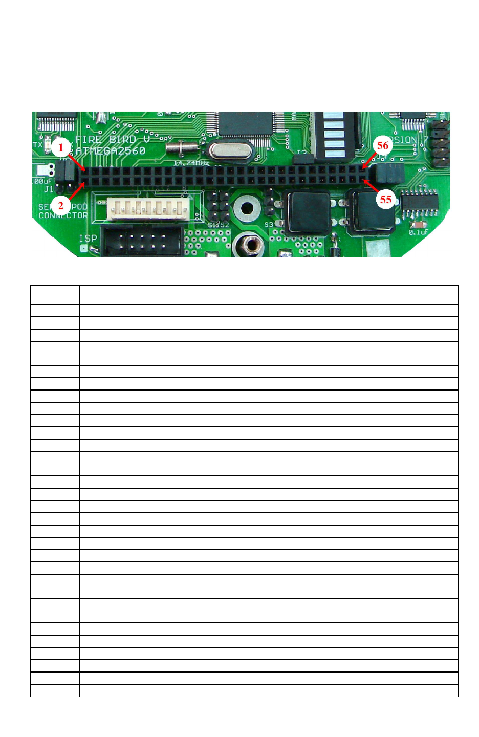
Fire Bird V ATMEGA2560 Hardware Manual
4.3 ATMEGA2560 Microcontroller Board Expansion Socket
ATMEGA2560 is a feature rich microcontroller with lots of available I/O ports. Many of the
ports are available on the uC Expansion Socket. Table 4.3 lists the connection details of all the
pins of the socket.
Figure 4.1: Expansion Header on Microcontroller Board
Pin No. Function
1 UART2 TXD pin of ATMEGA2560 via Jumper 1 (uC pin 13)
2 UART2 RXD pin of ATMEGA2560 via Jumper 1 (uC pin 12)
3 ATMEGA2560 interrupt 7 pin / CLKO / ICP3 (uC pin9)
4 OC4B / PH4 / GPIO (uC pin 16), Also connected to RX pin of 1st ultrasonic sensor
triggering.
5 OC4C / PH5 / GPIO (uC pin 17)
6 OC2B / PH6 / GPIO (uC pin 18)
7 TDO (JTAG)* / ADC6* / IR proximity sensor 3 (uC pin 91)
8 TDI (JTAG)* / ADC7* / IR Proximity sensor 4 (uC pin 90)
9 TMS (JTAG) */ ADC5* / IR Proximity sensor 2 (uC pin 92)
10 TCK (JTAG)* / ADC4* / IR Proximity sensor 1 (uC pin 93)
11 ATMEGA2560 Slave Select (SS) pin PB0 (uC pin 19) **
12 No Connection till the version 2009-12-08. Connected to V Batt supply in version 2010-
11-25 onwards.
13 MOSI / PB2 (uC pin 21)**
14 SCK / PB1 (uC pin 20)**
15 RESET (uC pin 30)
16 MISO / PB3 (uC pin 22)**
17 PL7 / GPIO (uC pin 42)
18 PL6 / GPIO (uC pin 41)
19 SDA / PD1 / INT1 / GPIO (uC pin 44)
20 SCL / PD0 / INT0 / GPIO (uC pin 43)
21 5V System Voltage. Can be used for powering up any digital device. Current Limit:
400mA.
22 5V System Voltage. Can be used for powering up any digital device. Current Limit:
400mA.
23 Ground
24 Ground
25 ICP1 / PD4 / GPIO (uC pin 47)
26 T4 / PH7 / GPIO (uC pin 27)
27 ICP5 / PL1 / GPIO (uC pin 36)
28 ICP4 / PL0 / GPIO (uC pin 35), Also connected to RSSI pin of XBee module
© NEX Robotics Pvt. Ltd. and ERTS Lab, CSE, IIT Bombay, INDIA 83

Fire Bird V ATMEGA2560 Hardware Manual
29 XCK1 / PD5 / GPIO (uC pin 48)
30 T5 / PL2 / GPIO (uC pin 37)
31 PG1 / GPIO (uC pin 52)
32 PG0 (uC pin 51)
33 T1 / PD6 / GPIO (uC pin 49)
34 T0 / PD7 (uC pin 50)
35 No Connections
36
37 TXD1 / INT3 / PD3: Connected to the MAX 202 for RS232 communication. Do not use
for other purpose unless connection with MAX 202 is removed. (uC pin 46)
38 RXD1 / INT2 / PD2: Connected to the MAX 202 for RS232 communication. Do not use
for other purpose unless connection with MAX 202 is removed. (uC pin 45)
39 PJ6 / GPIO (uC pin 69)***
40 PJ7 / GPIO (uC pin 79) ***
41 PJ4 / GPIO (uC pin 67) ***
42 PJ5 / GPIO (uC pin 68) ***
43 PJ2 / GPIO (uC pin 65) ***
44 PJ3 / GPIO (uC pin 66) ***
45 RXD3 / PJ0 / GPIO (uC pin 63)****
46 TXD3 / PJ1 / GPIO (uC pin 64)****
47
No Connections
48
49
50
51
52
53
54
55
56
Table 4.3: ATMEGA2560 microcontroller board expansion header table
Note:
* In order to use these pins as JTAG or as ADC for external sensor interfacing, remove all 4
connectors for the jumper 2 of the microcontroller board. When jumpers are removed IR
Proximity sensor 1 to 4 will be disconnected from the robot.
** Pins can be used as SPI bus. These pins are already connected to slave ATMEGA8
microcontroller via J4 of the microcontroller board. Before using it as a SPI bus for external
device interfacing, remove J4 to disconnect ATMEGA8 slave microcontroller or use different
pin of the microcontroller as SS (slave select).
*** All the pins of the PORTJ are connected to the bargraph LED display. While using these
pins as GPIO to turnoff this bargraph LED display, remove jumper J3 of the microcontroller
board.
**** PJ0 and PJ1 can be used as GPIO as well as TXD and RXD for UART 3. These pins are
also connected to bargraph LED display. While using these pins as UART 3, jumper J3 must be
removed to disable bargraph LED display in order to avoid loading on the TXD and RXD lines
of the device which is connected with the ATMEGA2560 microcontroller.
© NEX Robotics Pvt. Ltd. and ERTS Lab, CSE, IIT Bombay, INDIA 84
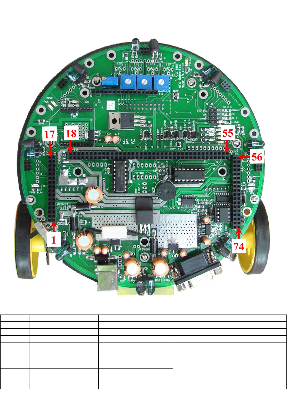
Fire Bird V ATMEGA2560 Hardware Manual
4.4 Microcontroller adapter board socket connections on the main board
Figure 4.2: Microcontroller adapter board socket connections on the main board
Pin No. Pin Name uC Board Connection Function
1 CS* ATMEGA8 ADC4 Current sense analog value
2 IR Proximity sensor 8 ATMEGA8 ADC7 IR Proximity sensor 8 analog value
3 Ground Ground Ground
4 USB Data+ Pin 15 of FT232 USB to
serial converter going to
UART 2 of ATMEGA2560
via jumper J1
USB connection going to the ATMEGA2560
microcontroller via FT232 USB to serial
converter.
To enable USB communication, set Jumper 1
as shown in the figure 6.2
5 USB Data- Pin 16 of FT232 USB to
serial converter going to
UART 2 of ATMEGA2560
© NEX Robotics Pvt. Ltd. and ERTS Lab, CSE, IIT Bombay, INDIA 85

Fire Bird V ATMEGA2560 Hardware Manual
via jumper J1
6 VUSB FT232 pin20 and pin4 (5V to
the FT232 USB to serial
converter)
7 5V System Not connected 5V System Voltage. Can be used for powering
up any digital device with current limit of
400mA.
8 5V Sensor Not connected 5V Sensor voltage. Can be used for additional
sensor interfacing with
current limit: 300mA
9 5V Sensor Not connected 5V Sensor voltage. Can be used for additional
sensor interfacing with
current limit: 300mA
10 5V System Not connected 5V System voltage. Can be used for powering
up any digital device with
Current Limit: 400mA
11 SHARP IR Range Sensor 1 ATMEGA2560 ADC9 Analog output of Sharp IR range Sensor 1
12 IR Proximity Sensor 1 ATMEGA2560 ADC4 Analog output of IR Proximity sensor 1
13 XBee RXD UART0 of ATMEGA2560 XBee wireless module Serial data in
14 XBee TXD UART0 of ATMEGA2560 XBee wireless module Serial data out
15 SHARP IR Range Sensor 2 ATMEGA2560 ADC10 Analog output of Sharp IR range sensor 2
16 IR Proximity Sensor 2 ATMEGA2560 ADC5 Analog output of IR Proximity sensor 2
17A RSSI ATMEGA2560 INT7 To capture the RSSI signal
17B Ultrasonic Trigger ATMEGA2560 PH4** To give the Trigger for 1st Ultrasonic Sensor
18 MOSI ATMEGA2560 Pin 21 SPI Communication lines for communication
with ATMEGA8 via Jumper 4 and for
programming ATMEGA2560 in ISP mode
19 MISO ATMEGA2560 Pin 22
20 SCK ATMEGA2560 Pin 20
21 SSI ATMEGA2560 Pin 19
22 RS ATMEGA2560 PC0 LCD Register Select pin (Command)
23 RW ATMEGA2560 PC1 LCD Read Write pin (Command)
24 EN ATMEGA2560 PC2 LCD Enable pin (Command)
25 DB5 ATMEGA2560 PC5 LCD data bit 5
26 DB4 ATMEGA2560 PC4 LCD data bit 4
27 DB6 ATMEGA2560 PC6 LCD data bit 6
28 DB7 ATMEGA2560 PC7 LCD data bit 7
29 V Battery System ATMEGA2560 ADC0 V Battery System (9V to 11.4V depending on
battery status). Unregulated Supply for
additional module interfacing. Maximum
current capacity: 1Amp
32 White Line Sensor 1 ATMEGA2560 ADC3 Analog output of white line sensor 1
31 White Line Sensor 2 ATMEGA2560 ADC2 Analog output of white line sensor 2
32 White Line Sensor 3 ATMEGA2560 ADC1 Analog output of white line sensor 3
33 Sharp IR Sensors 1and 5
Disable
ATMEGA2560 PH3 TTL/CMOS input. Disable Sharp IR range
sensors, when V>2 is applied. When V<0.65
Sharp IR range sensors are turned on.
34 IR Proximity Sensor
Disable
ATMEGA2560 PH2 TTL/CMOS input. Disable IR proximity
sensors 1 and 8 when V>2 is applied. When
V<0.65 IR proximity sensors are turned on.
35 5V System Not connected 5V system Voltage. Can be used for powering
up any digital device. Current Limit: 400mA.
36 White Line 4 ATMEGA8 ADC0 Analog output of white line sensor 4
37 White Line 5 ATMEGA8 ADC1 Analog output of white line sensor 5
38 White Line 6 ATMEGA8 ADC2 Analog output of white line sensor 6
39 White Line 7 ATMEGA8 ADC3 Analog output of white line sensor 7
© NEX Robotics Pvt. Ltd. and ERTS Lab, CSE, IIT Bombay, INDIA 86

Fire Bird V ATMEGA2560 Hardware Manual
40 White Line Sensors
Disable
ATMEGA2560 PG2 TTL/CMOS input. Disable White line sensors
when V>2 is applied. When V<0.65 white line
sensors are turned on.
41 Sharp IR Range Finder 3 ATMEGA2560 ADC11 Analog output of Sharp IR range sensor 3
42 IR Proximity Sensor 3 ATMEGA2560 ADC6 Analog output of IR Proximity sensor 3
43 IR Proximity Sensor 4 ATMEGA2560 ADC7 Analog output of IR Proximity sensor 4
44 Sharp IR Range Finder 4 ATMEGA2560 ADC12 Analog output of Sharp IR Range sensor 4
45 Sharp IR Range Finder 5 ATMEGA2560 ADC13 Analog output of Sharp IR Range sensor 5
46 IR Proximity Sensor 5 ATMEGA2560 ADC8 Analog output of IR Proximity sensor 5
47 C1 1 ATMEGA2560 PA4 Logic input 1 for C1 motor drive
48 C1 PWM ATMEGA2560 OC5C PWM input for C1 motor drive
49 C1 2 ATMEGA2560 PA45 Logic input 2 for C1 motor drive
50 PWM L ATMEGA2560 OC5A PWM input for Left motor drive
51 L1 ATMEGA2560 PA0 Logic input 1 for Left motor drive
52 L2 ATMEGA2560 PA1 Logic input 2 for Left motor drive
53 R1 ATMEGA2560 PA2 Logic input 1 for Right motor drive
54 PWM R ATMEGA2560 OC5B PWM input for Right motor drive
55 R2 ATMEGA2560 PA3 Logic input 2 for Right motor drive
56 Not connected Not Used
57 Not connected Not Used
58 Not connected Not Used
59 Not connected Not Used
60 Not connected Not Used
61 Not connected Not Used
62 Position Encoder Left ATMEGA2560 PE4(INT4) Output of Left position encoder (0-5V)
63 Position Encoder Right ATMEGA2560 PE5(INT5) Output of Right position encoder (0-5V)
64 Position Encoder C2 ATMEGA2560 PE6(INT6) Output of C2 position encoder (0-5V)
65 Position Encoder C1 ATMEGA2560 PE7(INT7) Output of C1 position encoder (0-5V)
66 C2 2 ATMEGA2560 PA7 Logic input 2 for C2 motor drive
67 C2 1 ATMEGA2560 PA6 Logic input 1 for C2 motor drive
68 C2 PWM ATMEGA2560 OC3A PWM input for C2 motor drive
69 IR Proximity Sensor 6 ATMEGA8 ADC5 Analog output of IR Proximity sensor 6
70 IR Proximity Sensor 7 ATMEGA8 ADC6 Analog output of IR Proximity sensor 7
71 BUZZER ATMEGA2560 PC3 Input, V>0.65V turns on the Buzzer
72 DAC OUT Not connected Not connected
73 RS232 TXD UART1(RXD) of
ATMEGA2560 via
MAX202, TTL to RS232
Converter
RS232 Transmit, connected to DB9 serial
connector on main board.
74 RS232 RXD UART1(TXD) of
ATMEGA2560 via
MAX202, TTL to RS232
Converter
RS232 Receive, connected to DB9 serial
connector on main board.
Table 4.4: ATMEGA2560 Microcontroller adapter board socket connections with the main
board
Note:
* CS will give output only if ACS712 hall effect current sensor is soldered on the main board
** refer errata section of this manual
© NEX Robotics Pvt. Ltd. and ERTS Lab, CSE, IIT Bombay, INDIA 87
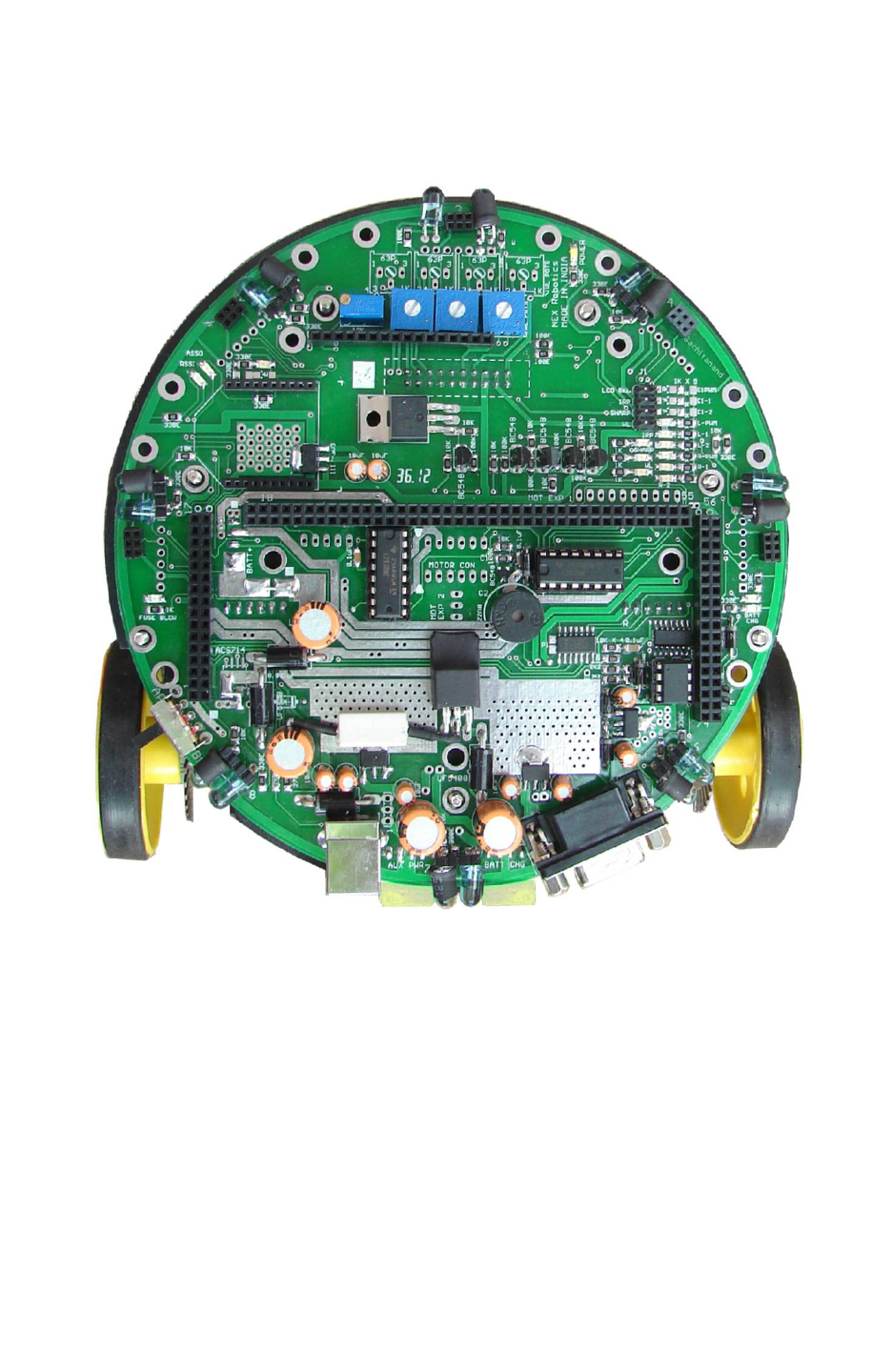
Fire Bird V ATMEGA2560 Hardware Manual
5. Upgrading Robot’s Hardware
In this chapter mounting of various modules of the robot are covered in pictorial way.
Figure 5.1: Fire Bird V main board
© NEX Robotics Pvt. Ltd. and ERTS Lab, CSE, IIT Bombay, INDIA 88
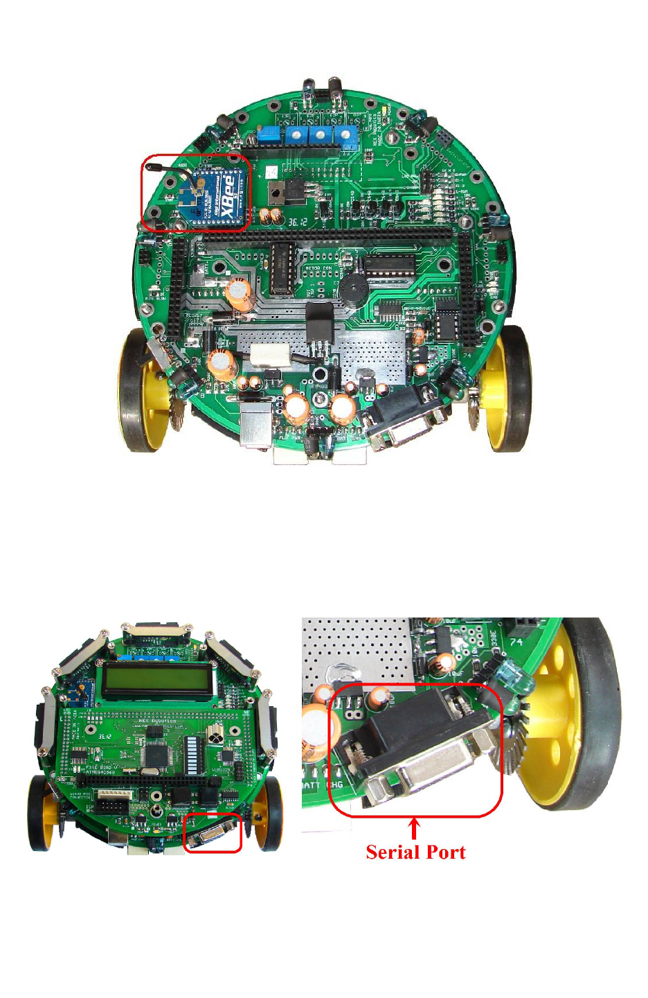
Fire Bird V ATMEGA2560 Hardware Manual
5.1 Installing XBee wireless module
Figure 5.2: Mounting the XBee wireless module
•Mount the ZigBee wireless module in the proper orientation.
•You might have to configure ZigBee wireless module to the appropriate settings using
XBee USB wireless module and X-CTU software. For more details refer to Application
notes.
5.2 Setting correct jumper settings on the main board
Figure 5.3: Set jumpers as per the requirements (for more details refer to chapter 3)
© NEX Robotics Pvt. Ltd. and ERTS Lab, CSE, IIT Bombay, INDIA 89
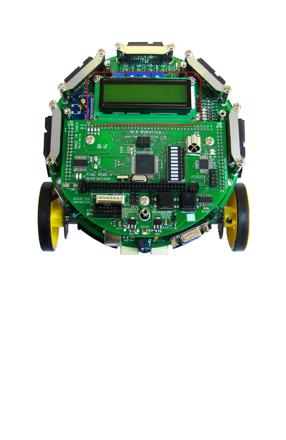
Fire Bird V ATMEGA2560 Hardware Manual
5.3 LCD mounting
Figure 5.4: LCD mounting
•Be careful while inserting LCD connector pins into the socket on the main board. Screw in
the LCD firmly on the studs.
© NEX Robotics Pvt. Ltd. and ERTS Lab, CSE, IIT Bombay, INDIA 90
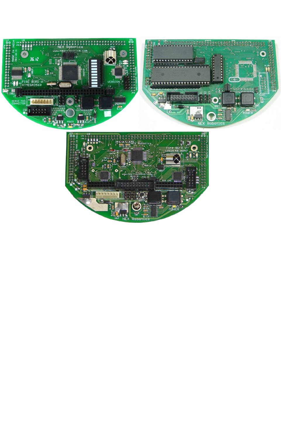
Fire Bird V ATMEGA2560 Hardware Manual
5.4 Microcontroller adapter board mounting
Figure 5.5: ATMEGA2560 (AVR), P89V51RD2 (8051) and LPC2148 ARM7
microcontroller adapter boards for Fire Bird V
© NEX Robotics Pvt. Ltd. and ERTS Lab, CSE, IIT Bombay, INDIA 91
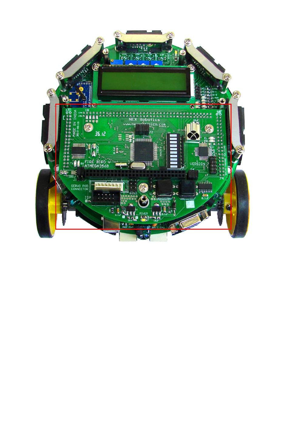
Fire Bird V ATMEGA2560 Hardware Manual
Figure 5.6: Microcontroller adapter board mounting
•Do not apply unnecessary pressure onto the PCB while inserting into the connectors on
the main board. Check for any bent pins before inserting the PCB. Mount 3 screws on the
microcontroller board.
© NEX Robotics Pvt. Ltd. and ERTS Lab, CSE, IIT Bombay, INDIA 92
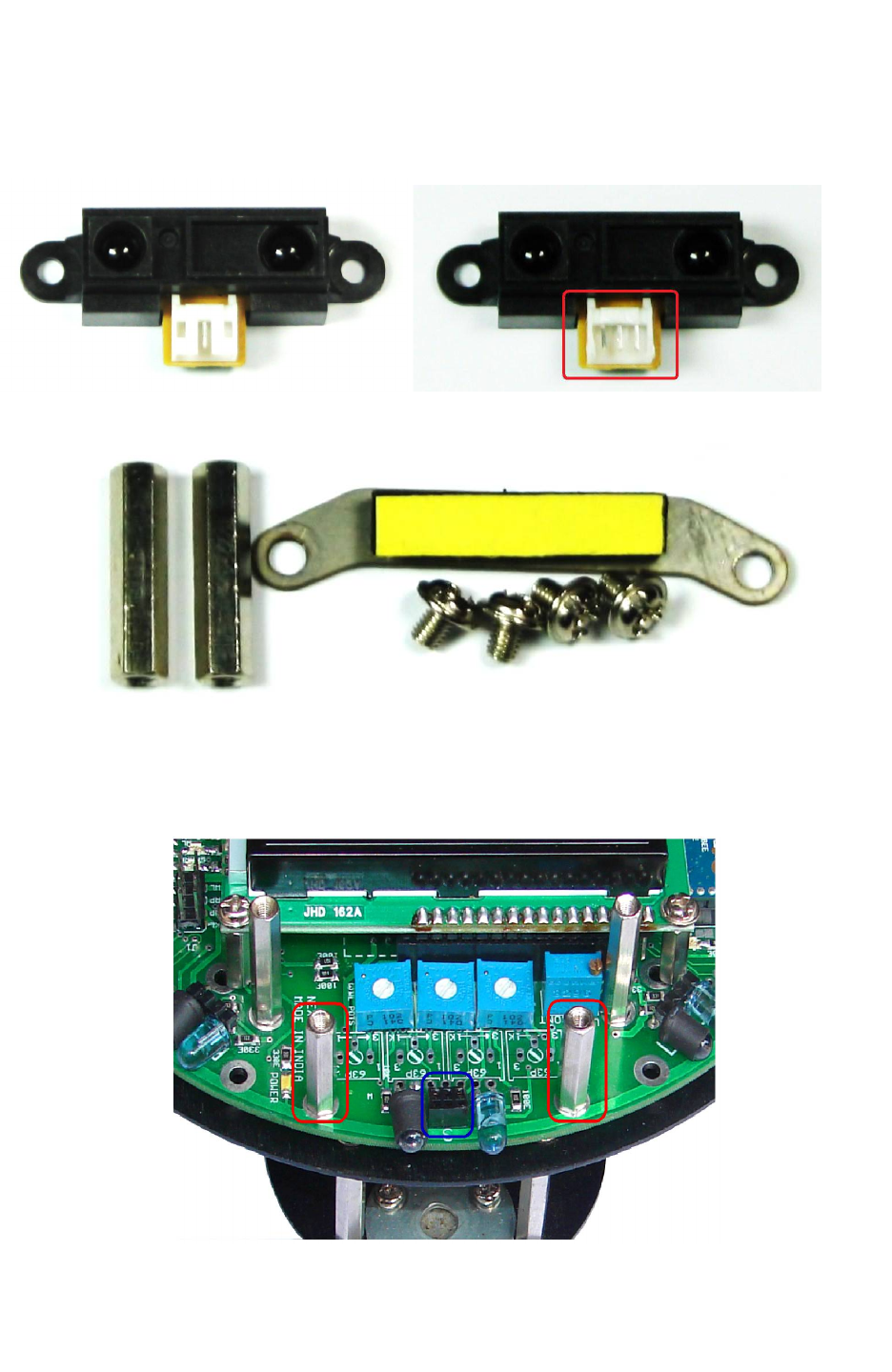
Fire Bird V ATMEGA2560 Hardware Manual
5.5 Sharp IR Range sensor mounting
Step 1: Cut the front section of white connector of the Sharp IR range sensor
Figure 5.7: Remove front cover of the white connector of the Sharp IR range sensor
Figure 5.8: Sharp IR range sensor mounting kit
Step 2: Mount the 20mm studs on the main board, where sharp sensor is to be fitted. In figure
5.9, area highlighted with the red border shows the mounted studs from the Sharp IR range
sensor mounting kit.
Figure 5.9: Mount 20mm studs from the Sharp sensor mounting kit
© NEX Robotics Pvt. Ltd. and ERTS Lab, CSE, IIT Bombay, INDIA 93
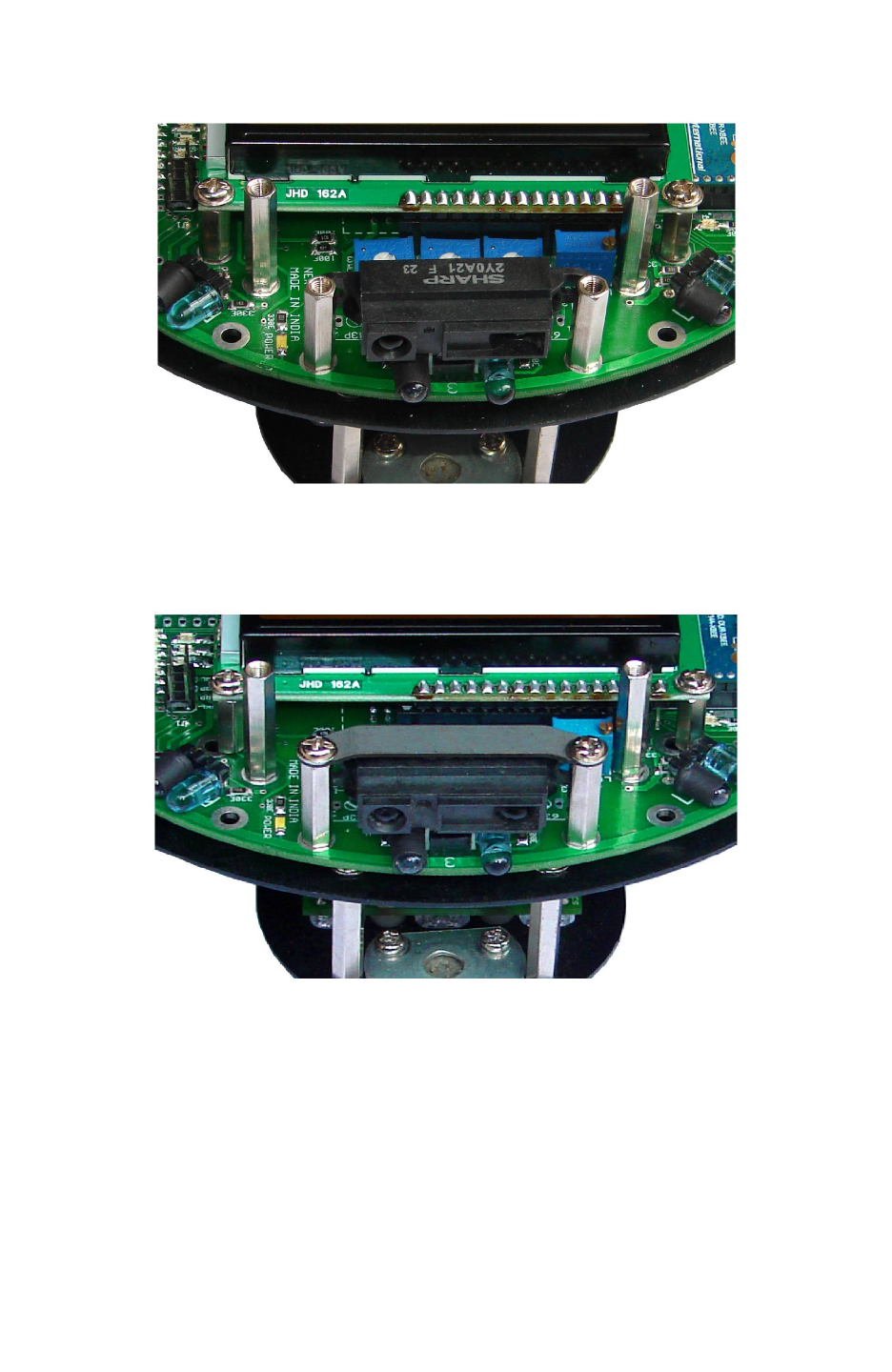
Fire Bird V ATMEGA2560 Hardware Manual
Step 3: Fix the Sharp IR range sensor on its holder.
Holder for the Sharp IR range sensor is highlighted in the figure 5.10 by blue border.
Figure 5.10: Mounting of the Sharp IR range sensor
Step 4: Remove the yellow colored paper stripe from the adhesive tape from the metal plate
which is shown in figure 5.8.
Fix the metal plate on top of the Sharp sensor and fit the screws.
Figure 5.11: Fitting metal plate on top of the Sharp IR range sensor
•Do not apply extreme pressure while pressing down the sharp sensors to fit into the
socket.
•Make sure that you remove yellow paper before mounting the metal plate on the Sharp IR
range sensor.
© NEX Robotics Pvt. Ltd. and ERTS Lab, CSE, IIT Bombay, INDIA 94
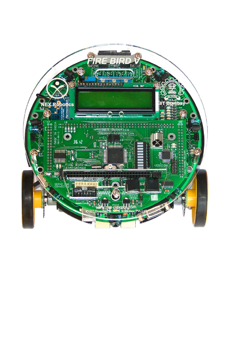
Fire Bird V ATMEGA2560 Hardware Manual
5.6 Mount top Acrylic plate on the robot
Figure 5.12: Install top acrylic plate
© NEX Robotics Pvt. Ltd. and ERTS Lab, CSE, IIT Bombay, INDIA 95

Fire Bird V ATMEGA2560 Hardware Manual
6. PC Based Control Using Serial Communication
In this chapter, simple robot control over wired (USB / serial) or wireless medium (XBee
wireless module) is covered. User can expand this protocol further to write his own applications.
Using good packet based protocol, user can design applications involving complex multi robot
communication scheme with robots to robots and robots to PCs simultaneous communication. A
more bit advanced communication protocol for the robot control and sensor data acquisition is
covered in the chapter 7.
6.1: Communication protocol for simple robot control
Character ASCII value Action
8 0x38 Forward
2 0x32 Backward
4 0x34 Left
6 0x36 Right
5 0x35 Stop
7 0x37 Buzzer On
9 0x39 Buzzer Off
Table 6.1: Control commands for the simple robot control protocol
Table 6.1 shows the simple robot control protocol. Using this, robot can be moved in forward,
backward, left or right directions and its buzzer can be turned on or off. You can use any serial
port control software such as hyper terminal or terminal.exe etc. For user friendliness keys of the
numerical pad of standard 104 keys “querty” keyboards are used. When a particular number key
is pressed, its ASCII character value is transmitted over serial / USB port. Robot receives this
ASCII values and based on its value it actuates its motors, buzzer etc. Keys are mapped in the
intuitive way on the Numerical pad of the keyboard.
This communication protocol is covered in the following experiments which are located in the
“Experiments” folder in the documentation CD. All these experiments are exactly same only
UART port number is different.
1. 13A_Serial_Communication: Serial communication via RS232 serial port.
2. 13B_Serial_Communication_USB-RS232: Serial communication via onboard FT232
USB to Serial Converter
3. 13C_Serial_Communication_ZigBee_wireless: Serial communication via XBee wireless
module (if installed).
Section 6.2 and 6.3 covers robot control using PC’s USB port and XBee wireless module.
Important:
While using “Numerical Pad” of the key board, make sure that “Num Lock” is on.
© NEX Robotics Pvt. Ltd. and ERTS Lab, CSE, IIT Bombay, INDIA 96
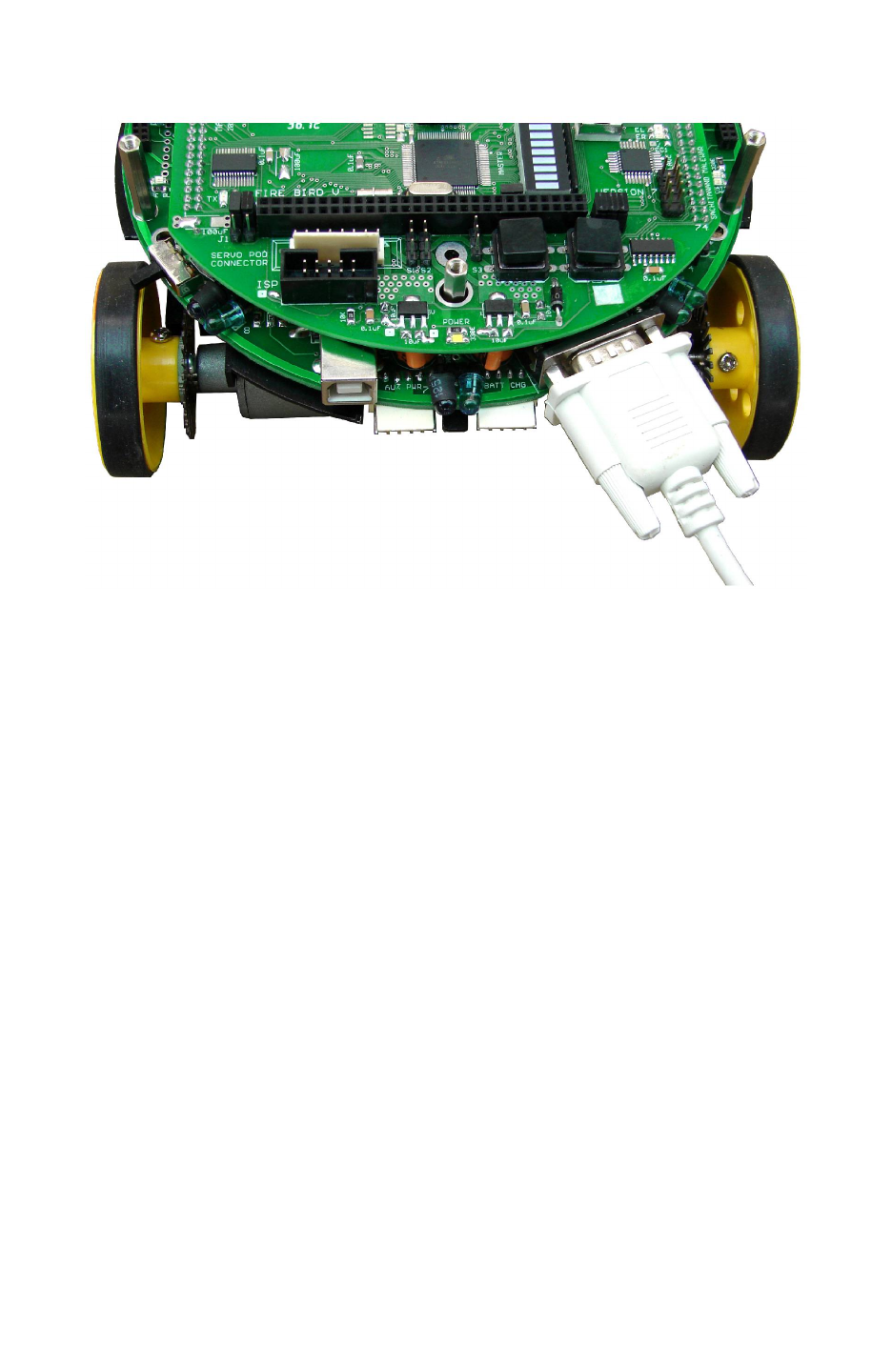
Fire Bird V ATMEGA2560 Hardware Manual
6.2 Robot control using RS232 serial port
Figure 6.1: Connecting RS232 serial port with the PC
UART1 of the ATMEGA2560 microcontroller is connected to the serial port via MAX202
UART to RS232 converter. For robot control over RS232 serial port application example we
need to load “13A_Serial_Communication.hex” on the robot which is located in the
“Experiments” folder in the documentation CD.
For robot control over serial port we use Terminal software from NEX Robotics. It is located in
the “Software” folder in the documentation CD. Installation and the use of the terminal software
from NEX Robotics is covered in the section 6.7.
© NEX Robotics Pvt. Ltd. and ERTS Lab, CSE, IIT Bombay, INDIA 97
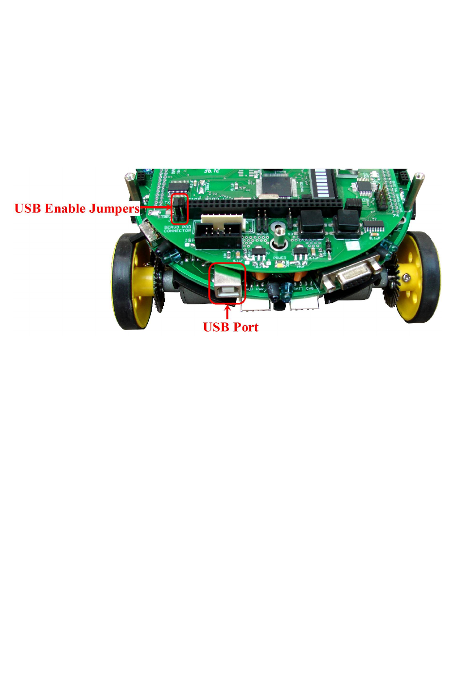
Fire Bird V ATMEGA2560 Hardware Manual
6.3 Robot control using USB port
Fire Bird V ATMEGA2560 has onboard USB port for direct interface with PC. USB interfacing
is based on FT232 USB to serial converter. For robot control over USB port application, we need
to load “13B_Serial_Communication_USB-RS232.hex” on the robot which is located in the
“Experiments” folder in the documentation CD.
FT232 USB to serial converter can be connected with UART 2 of the ATMEGA2560
microcontroller via Jumper J1. Figure 6.2 shows the correct jumper setting for connecting FT232
with the microcontroller.
Figure 6.2: Jumper setting to enable USB communication
Before using USB port we need to install the driver software for FT232 USB to serial converter.
The software is located in the “Software and Drivers \ CDM 2.06.00 WHQL Certified” folder.
For driver installation process refer to section 6.5.
For robot control over serial port we use Terminal software from NEX Robotics. It is located in
the “Software” folder in the documentation CD. Installation and the use of the terminal software
from NEX Robotics is covered in the section 6.7.
Important:
•When using USB port for the communication, for proper operation first turn on the robot
then insert the USB cable in the robot. We have to follow this sequence because USB to
serial converter chip is powered by USB. If any fault occurs then turn off the robot and
remove the USB cable and repeat the same procedure.
•Make sure that jumper is configured to enable USB communication. Jumpers should be
in the position as shown in the Figure 6.2.
© NEX Robotics Pvt. Ltd. and ERTS Lab, CSE, IIT Bombay, INDIA 98
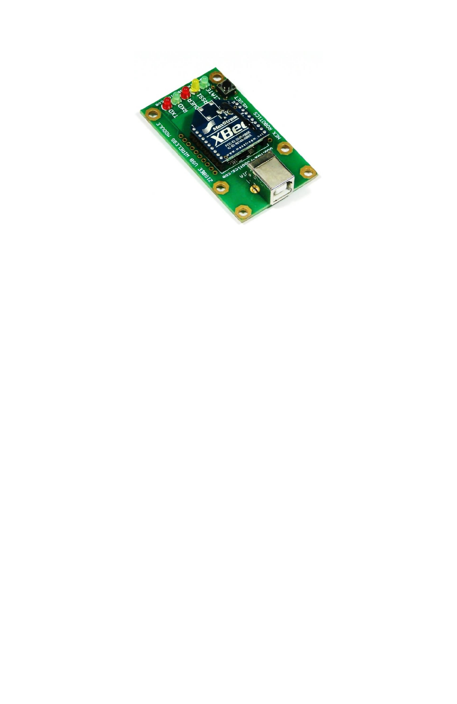
Fire Bird V ATMEGA2560 Hardware Manual
6.4 Robot control using XBee wireless communication module
Figure 6.3: XBee Wireless USB Module from NEX Robotics
Fire Bird V ATMEGA2560 has onboard socket for XBee and XBee Pro modules from Digi
International. For robot to PC communication we need to install XBee wireless module on the
robot and XBee USB wireless module for connection with the PC. XBee wireless module is
connected to the UART 0 of the ATMEGA2560 microcontroller. For Robot control over
wireless link we need to load “13C_Serial_Communication_ZigBee_wireless.hex” on the robot
which is located in the “Experiments” folder in the documentation CD. For XBee wireless
module installation on the robot, refer to chapter 5.
XBee USB wireless module has onboard FT232 USB to serial converter. You need to install
drivers for FT232 USB to serial converter before starting communication. software is located in
the “Software and Drivers \ CDM 2.06.00 WHQL Certified” folder. For driver installation
process refer to section 6.5.
For robot control over serial port we use Terminal software from NEX Robotics. It is located in
the “Software” folder in the documentation CD. Installation and the use of the terminal software
from NEX Robotics is covered in the section 6.7.
Important:
•XBee wireless modules are factory set at the 9600 bps. While shipping with the robot
they are set at 115200 bps by NEX Robotics using XCTU software. Application example
“13C_Serial_Communication_ZigBee_wireless.hex” requires 9600 bps. For this
application you need to set baud rate at 9600 bps. How to change the baud rate of the
XBee wireless module using XCTU software is covered in the application note which is
located in the “Manuals and Application notes” folder in the documentation CD.
•Wait for at least 8 seconds to start the wireless communication after turning on the robot
and the USB wireless module.
© NEX Robotics Pvt. Ltd. and ERTS Lab, CSE, IIT Bombay, INDIA 99
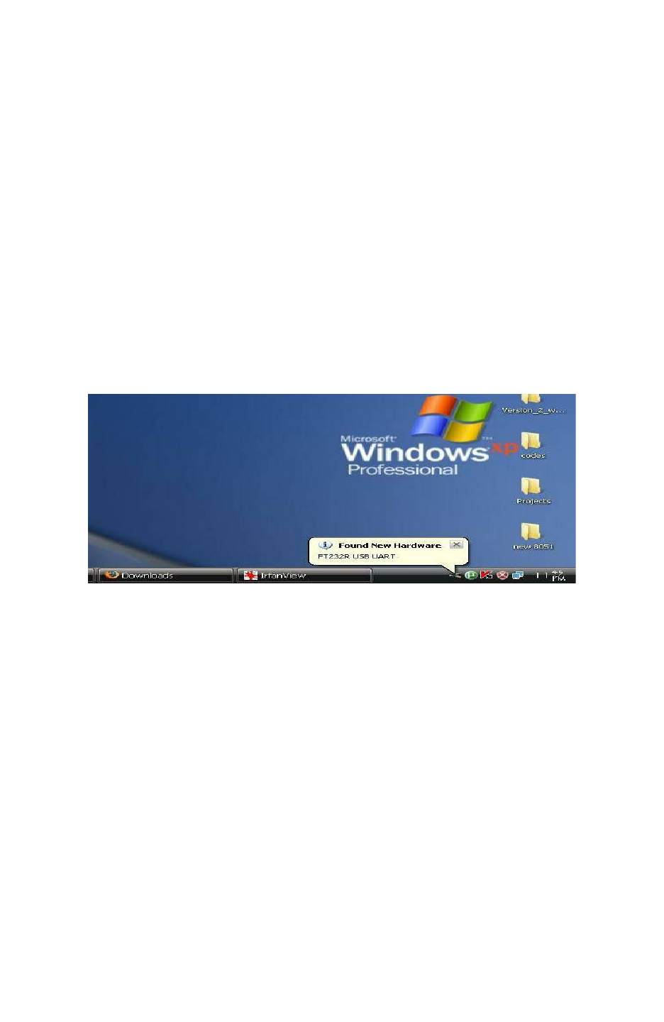
Fire Bird V ATMEGA2560 Hardware Manual
6.5 Installing drivers of FT232 USB to Serial Converter
FT232 USB to serial converter is present on the ATMEGA2560 microcontroller adaptor board
and XBee USB wireless module. Before using these devices you need to install drivers for the
FT232 USB to serial converter.
Steps to install the drivers for FT232 USB to serial converter:
Step 1:
Copy the driver installation folder on your PC from “Software and Drivers \ CDM 2.06.00
WHQL Certified” Folder which is located in the documentation CD.
Step 2:
Connect the USB to serial converter cable between robot and the PC
Step 3:
On connecting the device “Found New Hardware” message will appear in the task bar tray and
the following window opens.
Figure 6.4
Step 4:
Check on the radio button “No, not this time” and then click on the next button.
© NEX Robotics Pvt. Ltd. and ERTS Lab, CSE, IIT Bombay, INDIA 100
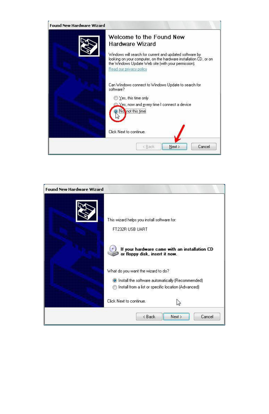
Fire Bird V ATMEGA2560 Hardware Manual
Figure 6.5
The following window will appear.
Figure 6.6
Select the second option manually to install the drivers and click on next button.
© NEX Robotics Pvt. Ltd. and ERTS Lab, CSE, IIT Bombay, INDIA 101
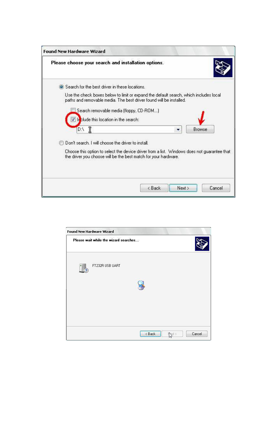
Fire Bird V ATMEGA2560 Hardware Manual
Step 5:
Now check the second option and set the location of folder containing drivers
E.g.(C:\CDM 2.06.00 WHQL Certified).
Figure 6.7
Step 6:
On clicking next driver installation will begin.
Figure 6.8
© NEX Robotics Pvt. Ltd. and ERTS Lab, CSE, IIT Bombay, INDIA 102
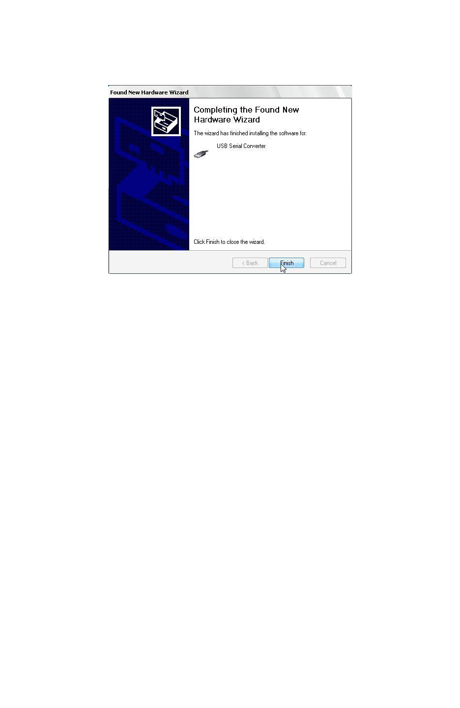
Fire Bird V ATMEGA2560 Hardware Manual
Step 7:
On successfully installing the driver following window will appear. Click Finish to complete the
installation.
Figure 6.9
After installation of FT232 USB UART software, PC may ask for USB serial port software. To
install this software follow steps 1 to 7 of USB serial converter software installation.
© NEX Robotics Pvt. Ltd. and ERTS Lab, CSE, IIT Bombay, INDIA 103
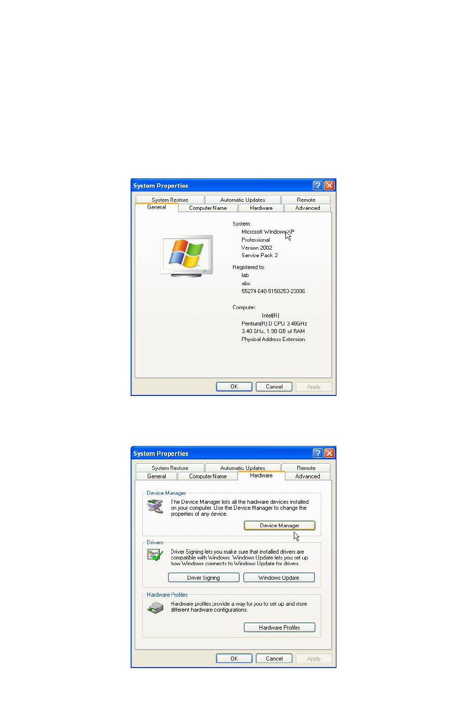
Fire Bird V ATMEGA2560 Hardware Manual
6.6 Identifying and changing COM Port number of the USB to serial
converter or XBee USB wireless module
In some software you may need to tell the COM port number before establishing
communication. Follow these steps to identify or change the COM port number. Don’t change
the COM port number unless it is absolutely necessary. It may result in making some of your
software unstable.
Step 1:
Right Click My Computer and click on properties. System properties window will appear.
Figure 6.10
Step 2:
Click on the Device manager in the Hardware tab.
Figure 6.11
© NEX Robotics Pvt. Ltd. and ERTS Lab, CSE, IIT Bombay, INDIA 104
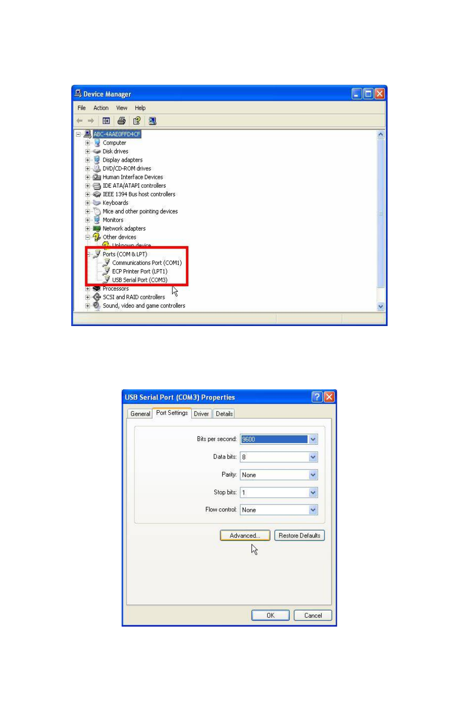
Fire Bird V ATMEGA2560 Hardware Manual
Step 3:
Expand Ports (Com & LPT) tree. COM Port number is mentioned in the parenthesis next to USB
Serial Port.
Figure 6.12
Step 4:
You can change the port number by right clicking on “USB serial Port” and select properties.
Figure 6.13
In the Port settings tab click on the Advanced button, the following window will appear.
© NEX Robotics Pvt. Ltd. and ERTS Lab, CSE, IIT Bombay, INDIA 105
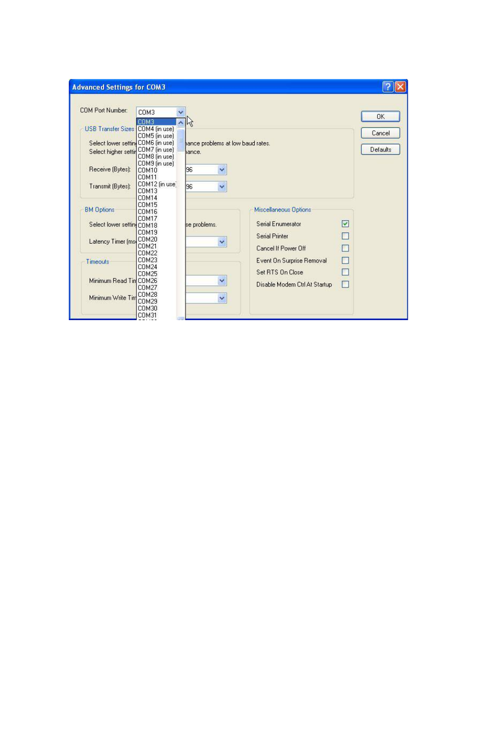
Fire Bird V ATMEGA2560 Hardware Manual
Step 5:
Select the new COM port number and click ok.
Figure 6.14
6.7 Use of Terminal software from NEX Robotics for Robot control
Terminal is easy to use free software for serial communication written by NEX Robotics. It is
located in the “Software and Drivers” folder in the documentation CD. In the following example
we will be using Serial communication protocol covered in the section 6.
Connect Serial / USB cable between robot and PC or connect XBee wireless module on the robot
and connect XBee USB wireless module on the PC and load correct .hex file on the robot as
mentioned in the sections 6.2, 6.3 and 6.4. Pay special attention to the text highlighted as
“important”.
6.7.1 Terminal Software Installation
Step 1:
Copy Terminal software setup from the “Software” folder of the documentation CD to PC. To
start installation process click on the “Setup” thumbnail (not “Terminal Setup” thumbnail).
Step 2:
Go through the installation process and select correct options to complete the installation.
© NEX Robotics Pvt. Ltd. and ERTS Lab, CSE, IIT Bombay, INDIA 106
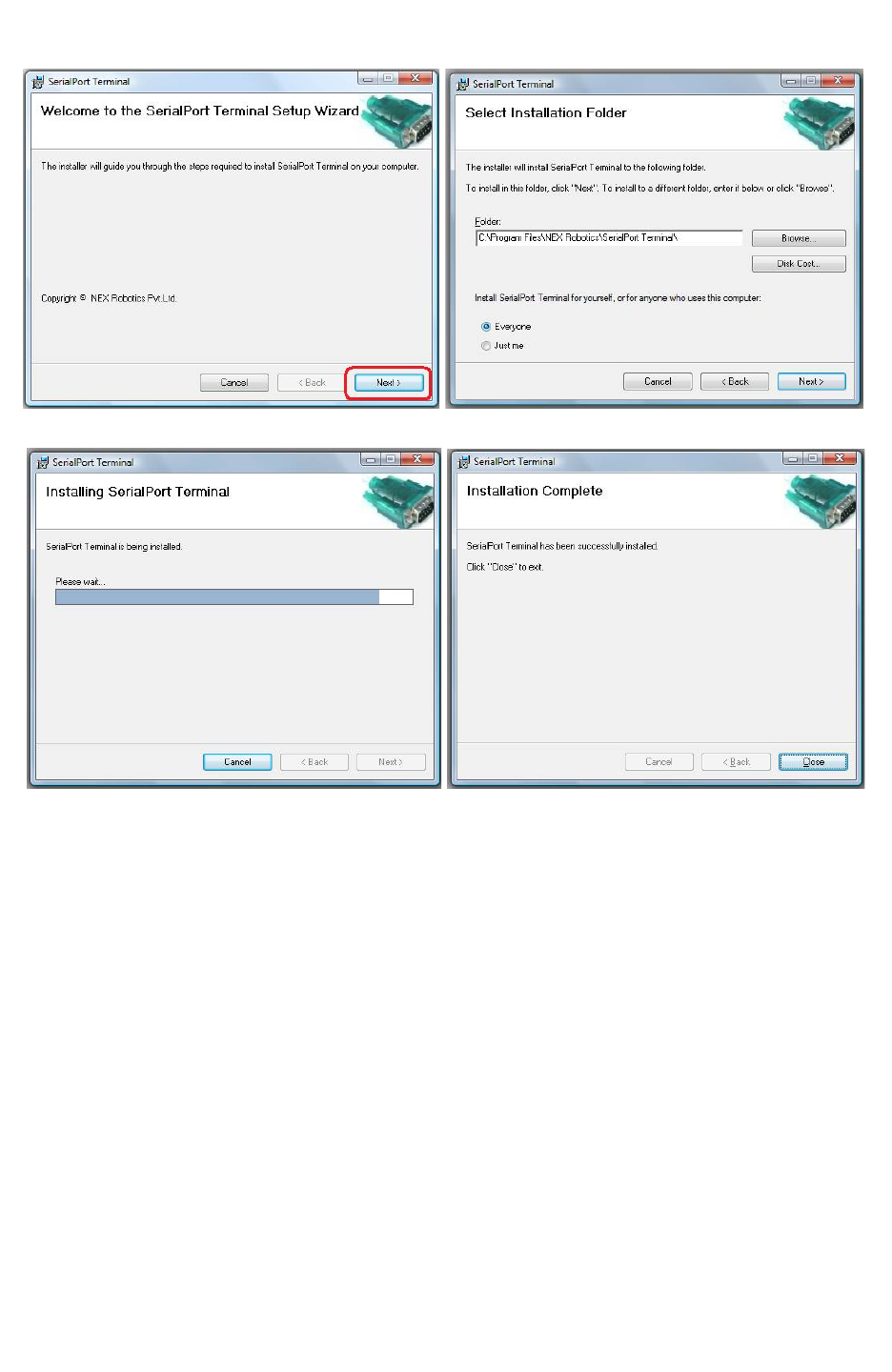
Fire Bird V ATMEGA2560 Hardware Manual
Figure 6.15
Figure 6.16
© NEX Robotics Pvt. Ltd. and ERTS Lab, CSE, IIT Bombay, INDIA 107
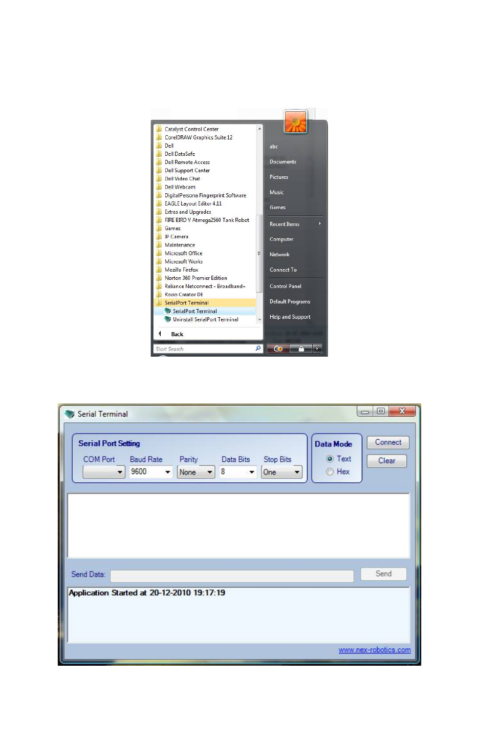
Fire Bird V ATMEGA2560 Hardware Manual
6.7.2 Using Terminal Software
Step 1:
Connect any device which is to be used to USB / serial port. Install its driver.
Go to Start menu and click on the Serial Terminal.
Figure 6.17
Terminal software will open.
Figure 6.18
© NEX Robotics Pvt. Ltd. and ERTS Lab, CSE, IIT Bombay, INDIA 108
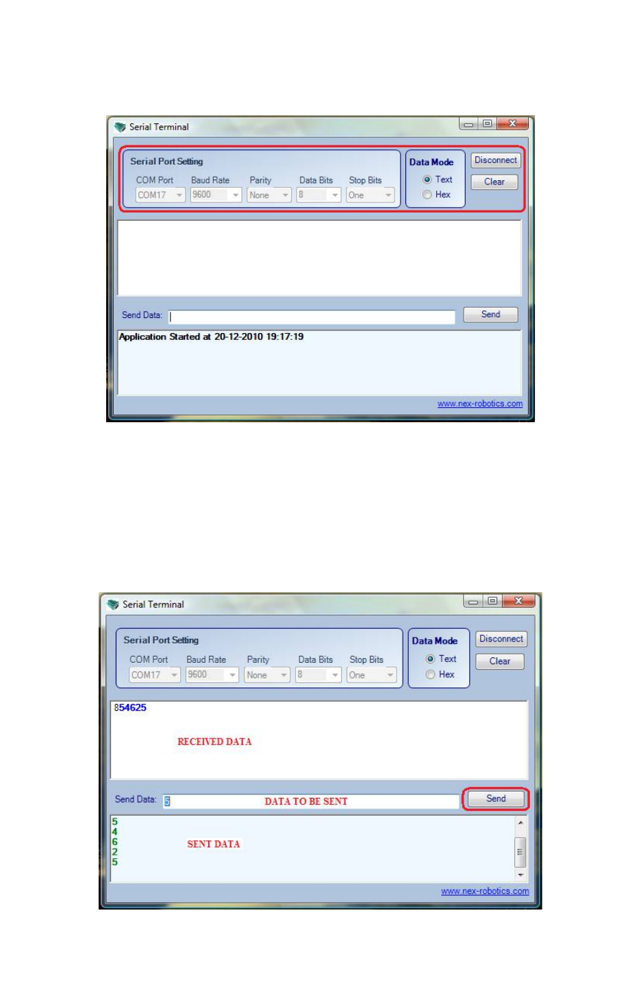
Fire Bird V ATMEGA2560 Hardware Manual
Step 2:
Select the COM port. If required, identify the COM port (refer to section 6.6)
Set the baud rate at 9600bps, Data Mode as text and press connect.
Figure 6.19
Step 3:
Make the Num lock on for the keyboard.
Load proper firmware (.hex file) on the robot as per the mode of communication (refer to section
6.2, 6.3 and 6.4).
Turn on the robot. Connect the Serial / USB wire or XBee wireless link between robot and PC
Use number keys of the key pad to control the robot.
For control commands refer to table 6.1.
Figure 6.20
© NEX Robotics Pvt. Ltd. and ERTS Lab, CSE, IIT Bombay, INDIA 109

Fire Bird V ATMEGA2560 Hardware Manual
Refer to figure 6.20. Serial Terminal software has 3 windows. In the middle window you can
type data to be sent. You can also send a single number of the strings of numbers
To send the ASCII value of the character typed select Data Mode as text. It you want to send
HEX data then select hex button in the Data Mode frame.
Sent data is displayed in the bottom window.
Received data is displayed in the top window.
In all three application examples mentioned in section 6.2, 6.3 and 6.4 robot sends back echo of
the received data apart from executing the motion commands.
© NEX Robotics Pvt. Ltd. and ERTS Lab, CSE, IIT Bombay, INDIA 110

Fire Bird V ATMEGA2560 Hardware Manual
7. Robot Control using ‘GUI’ for Fire Bird V
ATMEGA2560
Fire Bird V ATMEGA2560 robot can be controlled by GUI via serial / USB cable or in wireless
mode using XBee wireless module. To control the robot using GUI via appropriate mode of
communication, load appropriate hex file on the robot. GUI works on at the 115200 baud rate.
7.1 Loading firmware on the robot
Step 1:
Following firmware (.hex file) needs to be loaded on the robot depending on the mode of
communication used.
RS232 serial communication: “GUI_ control_serial.hex”
USB communication: “GUI control USB.hex”
ZigBee wireless module based communication: “GUI_control_wireless.hex”
All these hex files are located in the “GUI and Related Firmware” folder.
For information on how to load hex file, refer to software manual.
Step 2: Connect serial / USB to serial converter cable between robot and PC or install ZigBee
wireless module on the robot and connect wireless ZigBee USB module to the PC. For
connections refer to section 6.2 to 6.6.
Step 3: Install GUI software
7.2 Installing GUI
Step1: Copy “FIRE BIRD V ATMEGA2560 setup” folder which is located inside the folder
“GUI and Related Firmware” from the documentation CD on the PC.
Click on “setup.exe” which is located in the “FIRE BIRD V ATMEGA2560 setup” folder.
Step 2: Click Next Button to continue.
Step 3: Browse the location where set up will install or set the default location and click Next
Button to start the installation.
Step 4: When installation is successfully completed, Click Close to exit.
© NEX Robotics Pvt. Ltd. and ERTS Lab, CSE, IIT Bombay, INDIA 111
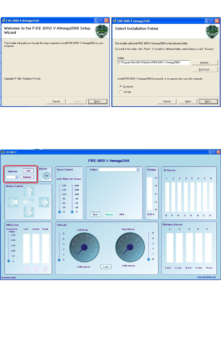
Fire Bird V ATMEGA2560 Hardware Manual
Figure 7.1
7.3 Using GUI
Step 1: After successful installation go to Start -> All Programs -> FIRE BIRD V Amega2560
-> FIRE BIRD V Amega2560 or click on Fire Bird V Amega2560 on your desktop location,
GUI will open.
Figure 7.2: Selecting correct com port
Step 2: Connect Robot with the PC using serial cable / NEX Robotics USB to serial converter or
with the XBee wireless module. For connections refer to section 6.2 to 6.6.
© NEX Robotics Pvt. Ltd. and ERTS Lab, CSE, IIT Bombay, INDIA 112
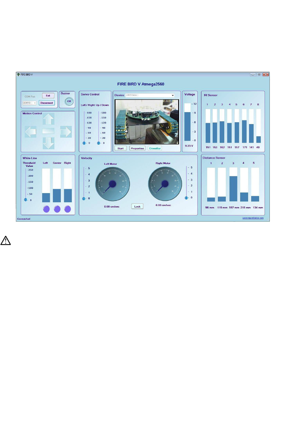
Fire Bird V ATMEGA2560 Hardware Manual
Step 3: If serial port is used then select COM Port as 1. If USB to serial converter module from
NEX Robotics or USB ZigBee wireless module is used then GUI automatically identifies the
COM port number. To manually identify the COM port, refer to section 6.6. Select the correct
COM port number and click on connect.
Now robot can be controlled using GUI
Figure 7.3: GUI showing robot’s data
Warning:
While using USB communication, ensure that the appropriate jumpers are in place. For more
details refer section 6.3 USB based communication.
© NEX Robotics Pvt. Ltd. and ERTS Lab, CSE, IIT Bombay, INDIA 113
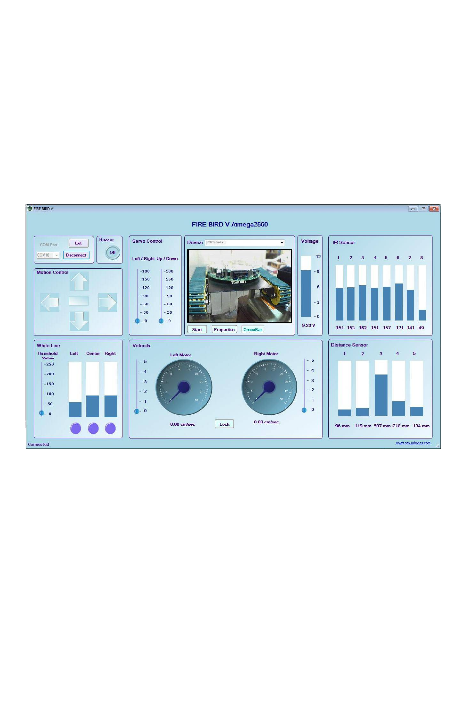
Fire Bird V ATMEGA2560 Hardware Manual
Step 4:
If you have Wireless camera pod from NEX Robotics and USB TV Tuner card then you can also
see the video on the GUI.
For more information on the installation and usage process, refer to documentation of the
wireless camera pod.
Follow these steps for video acquisition:
1. Connect USB TV Tuner card with PC and wait for 5 seconds.
2. Start the Fire Bird V robot’s GUI
3. In the video window, select devices as USB TV Device. This option will be visible only
if USB TV Tuner card is installed and connected.
4. Press start button to acquire the video.
Figure 7.4 : Video display on the Fire Bird V robot’s GUI
© NEX Robotics Pvt. Ltd. and ERTS Lab, CSE, IIT Bombay, INDIA 114

Fire Bird V ATMEGA2560 Hardware Manual
7.4 Robot control using ZigBee wireless module
To control robot using ZigBee wireless module refer to section 6.4. All the process remains the
same as mentioned in the section 7.1, 7.2 and 7.3. Only difference is that instead of USB to serial
converter, NEX Robotics wireless XBee USB module needs to be connected to the PC and XBee
wireless module needs to be installed on the robot. Make sure that XBee module on the robot and
XBee module on the XBee USB module are configured at 115200bps.
Important:
•If you want to see data on the IR proximity sensors 6, 7, 8 then connect jumper J4 on the
ATMEGA2560 microcontroller adaptor board. For more details refer to section 3.19.6.
•When using USB port for the communication, for proper operation first turn on the robot
then insert the USB cable in the robot. We have to follow this sequence because USB to
serial converter chip is powered by USB. If any fault occurs then turn off the robot and
remove the USB cable and repeat the same procedure.
•In case of XBee wireless module wait for at least 8 seconds to establish the
communication after turning on the robot and connecting XBee USB wireless module
with the PC.
7.5 Serial communication protocol used in robot control GUI
All the firmware used for Fire Bird V ATMEGA2560 robot control over wired USB / RS232
link or XBee wireless module are exactly the same. Only difference is that they use different
UARTs of the ATMEGA2560 microcontroller. All the firmware uses 115200bps baud rate. It’s a
simple byte based protocol in which upper nibble is command and lower nibble can be data or
command. You can use these firmware for controlling your robot using any software such as
Matlab, Scilab or Lab View etc.
To control robot in wired or wireless mode load the respective firmware on the robot which are
located in the “GUI and Related Firmware” folder inside the documentation CD.
GUI control USB.hex: Controls robot over USB port.
GUI_ control_serial.hex: Controls robot over RS232 port
GUI_control_wireless.hex: Controls robot over wireless link using XBee wireless modules.
Read chapter 6 carefully for configuring the ports, setting correct jumpers, installing devices and
their device drivers.
This is a simple byte based protocol. Fire Bird V ATMEGA2560 robot uses more complex
packet based protocol which can also be used for efficient robot control.
© NEX Robotics Pvt. Ltd. and ERTS Lab, CSE, IIT Bombay, INDIA 115

Fire Bird V ATMEGA2560 Hardware Manual
7.5.1 Commands to set velocity of the left and right motor:
Motor’s velocity can be varied by writing the proper byte into the particular register which
generates a pulse width modulation (PWM) signal with 8 bit resolution. The value of the velocity
control register can be set between 00 to FF hex, where a value 0 indicates that the motor is
stopped and 0xFF indicates motor is running at full speed.
Command
(HEX)
Function
1 Load the lower nibble of the left motor velocity control byte into
the robot.
2 Load the upper nibble of the left motor velocity control byte into
the robot and execute the command.
3 Load the lower nibble of the right motor velocity control byte
into the robot.
4 Load the upper nibble of the right motor velocity control byte
into the robot and execute the command.
Table 7.1
Example: Set left motor’s speed control byte to 0xAB
To set the speed of the left motor to 0xAB, follow the sequence of commands below. Attach
lower nibble “B” with command 1 and upper nibble A with command 2.
Step1: Send 0x1B Load the lower nibble of the left motor speed in the robot.
Step2: Delay of at least 3 milliseconds
Step3: Send 0x2A Load the upper nibble of the left motor speed in the robot and execute the
command
Step4: Delay of at least 3 milliseconds before loading next command
Note: It is very important that you send the byte containing command 1 first and then send the
byte containing command 2 for proper operation. The same rule is applicable for commands 3
and 4.
© NEX Robotics Pvt. Ltd. and ERTS Lab, CSE, IIT Bombay, INDIA 116

Fire Bird V ATMEGA2560 Hardware Manual
7.5.2 Commands to set direction of the robot:
Command
( HEX ) DIRECTION
LEFT
BWD
(LB)
PA0
LEFT
FWD(LF)
PA1
RIGHT
FWD(RF)
PA2
RIGHT
BWD(RB)
PA3
51 FORWARD 0 1 1 0
52 REVERSE 1 0 0 1
53
RIGHT (Left wheel
forward, Right
wheel backward) 0 1 0 1
54
LEFT(Left wheel
backward, Right
wheel forward,) 1 0 1 0
55
SOFT RIGHT(Left
wheel forward,,
Right wheel stop) 0 1 0 0
56
SOFT LEFT(Left
wheel stop, Right
wheel forward,) 0 0 1 0
57
SOFT RIGHT 2
(Left wheel stop,
Right wheel
backward)
0 0 0 1
58
SOFT LEFT 2 (Left
wheel backward,
Right wheel stop) 1 0 0 0
59 HARD STOP 0 0 0 0
Table 7.2
Example: To set left motor velocity to 0x84, right motor velocity to 0x65, and move
backward.
Step1: 0x14 Load the lower nibble ‘4’ of the left motor speed into the robot
Step2: Delay of at least 3 milliseconds
Step3: 0x28 Load the upper nibble ‘8’ of the left motor speed into the robot and execute the
command
Step4: Delay of at least 3 milliseconds
Step5: 0x35 Load the lower nibble ‘5’ of the right motor speed into the robot
Step6: Delay of at least 3 milliseconds
Step7: 0x46 Load the upper nibble ‘6’ of the right motor speed into the robot and execute the
command
Step8: Delay of at least 3 milliseconds
Step9: 0x52 move backward
Step10: Delay of at least 3 milliseconds before loading next command
© NEX Robotics Pvt. Ltd. and ERTS Lab, CSE, IIT Bombay, INDIA 117

Fire Bird V ATMEGA2560 Hardware Manual
7.5.3 Commands to access the Analog sensor data:
Command
(HEX)
Data
60 Battery voltage
Robot sends back 8 bit battery voltage value. To convert this
value in to volts use the following conversion formula for 8 bit
ADC resolution: Battery Voltage = ADC data x 0.069
62 Front Sharp IR range sensor data (Front distance)
The Robot will return 8 bit value which indicates distance
between the obstacle and front Sharp sensor.
63 Sharp IR range sensor 2 data
The Robot will return 8 bit value which indicates distance
between the obstacle and Sharp sensor.
64 White line sensor 1 (Left)
The Robot will return an 8 bit analog value of the left white line
sensor
65 White line sensor 2 (Center)
The Robot will return an 8 bit analog value of the center white
line sensor
66 White line sensor 3 (Right)
The Robot will return an 8 bit analog value of the right white
line sensor
67 Sharp IR range sensor 4 data
The Robot will return 8 bit value which indicates distance
between the obstacle and Sharp sensor.
C1 IR Proximity sensor 1
The Robot will return an 8 bit analog value of the IR Proximity
sensor 1
C2 IR Proximity sensor 2
The Robot will return an 8 bit analog value of the IR Proximity
sensor 2
C3 IR Proximity sensor 3
The Robot will return an 8 bit analog value of the IR Proximity
sensor 3
C4 IR Proximity sensor 4
The Robot will return an 8 bit analog value of the IR Proximity
sensor 4
C5 IR Proximity sensor 5
The Robot will return an 8 bit analog value of the IR Proximity
sensor 5
C6 IR Proximity sensor 6
The Robot will return an 8 bit analog value of the IR Proximity
sensor 6
© NEX Robotics Pvt. Ltd. and ERTS Lab, CSE, IIT Bombay, INDIA 118
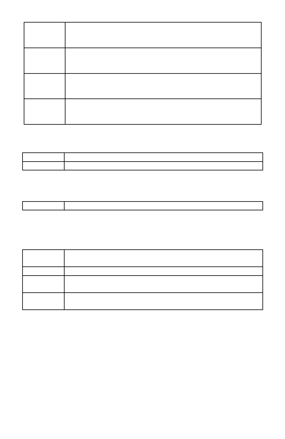
Fire Bird V ATMEGA2560 Hardware Manual
C7 IR Proximity sensor 7
The Robot will return an 8 bit analog value of the IR Proximity
sensor 7
C8 IR Proximity sensor 8
The Robot will return an 8 bit analog value of the IR Proximity
sensor 8
C9 Sharp IR range sensor 1 data
The Robot will return 8 bit value which indicates distance
between the obstacle and Sharp sensor.
CA Sharp IR range sensor 5 data
The Robot will return 8 bit value which indicates distance
between the obstacle and Sharp sensor.
Table 7.3
7.5.4 Commands to turn on / off the buzzer:
69 Turn on the buzzer.
6A Turn off the buzzer.
Table 7.4
7.5.5 Robot Version Signature
6B If 6B is sent to the robot will send back its ID
Table 7.5
7.5.6 Position encoder data:
Position encoder pulse count for the position tracking:
72 The robot will return lower byte of the pulse count for the left
motor.
73 The robot will return upper byte of the pulse count for left motor.
79 The robot will return lower byte of the pulse count for the right
motor.
7 A The robot will return upper byte of the pulse count for right
motor.
Table 7.6
Note: To get an actual pulse count, combine the lower byte and upper byte to get a 16 bit value.
For more information on the position encoder resolution refer to the section 3.9.
© NEX Robotics Pvt. Ltd. and ERTS Lab, CSE, IIT Bombay, INDIA 119

Fire Bird V ATMEGA2560 Hardware Manual
7.5.7 Commands for servo motor control:
ATMEGA2560 microcontroller adaptor board can drive three servo motors. Out of which S1 and
S2 servo motors can be controlled with serial control protocol. These motors are used to move
the camera or sensor pod in pan and tilt direction.
8 Data Load servo angle lower nibble
9 Data Load servo angle upper nibble and move the servo motor.
A Data Load servo angle lower nibble
B Data Load servo angle upper nibble and move the servo motor.
Table 7.7
The servo motor will move between 0° to180° given an 8 bit value between 0x15 and 0x65 (in
hex)
The Servo motion resolution is = 180 / (0x65 – 0x15) = 2.25 degrees / step.
Example: Move servo motor1 by 90 degrees.
Numbers of steps required = 90°/2.25 = 40steps = 0x28 hex
Byte to send = 0x15 + 0x28 = 0x3D
Lower nibble = D hex
Upper nibble = 3 hex
Combining these nibbles with the commands:
Step1: send 0x8D through the serial port
Step2: delay by 3 milliseconds
Step3: send 0x93 through the serial port
© NEX Robotics Pvt. Ltd. and ERTS Lab, CSE, IIT Bombay, INDIA 120
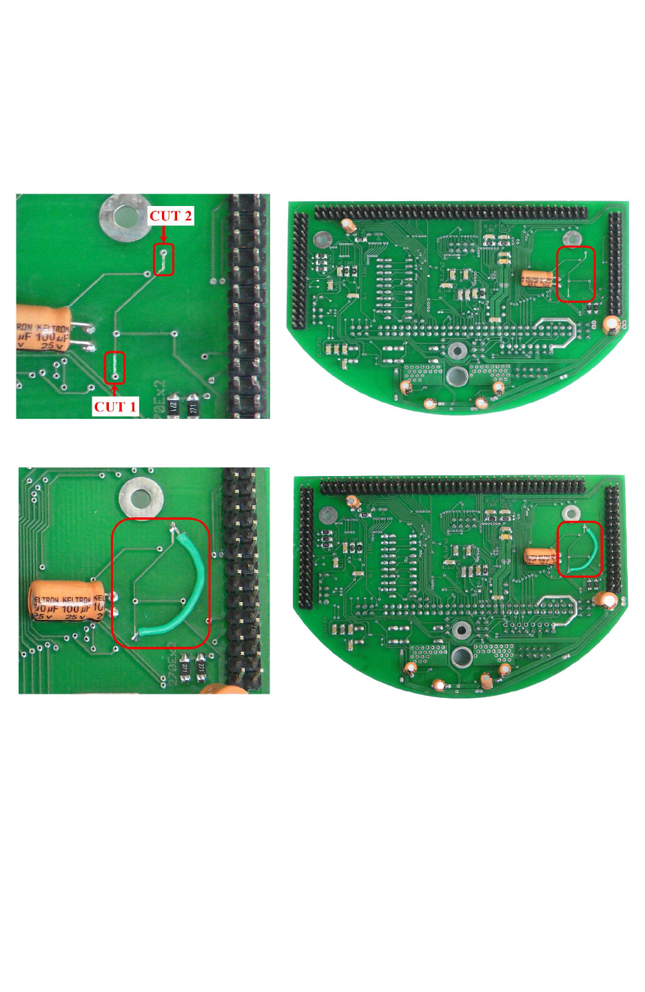
Fire Bird V ATMEGA2560 Hardware Manual
8. Errata
1. 17B pin on the Atmga2560 microcontroller adaptor socket is actually connected to PH4 pin of
microcontroller and also connected to ground. To utilize 17B pin and PH4 pin for user
application such as onboard ultrasonic triggering, it is recommended to cut the below shown
track at 2 places in figure (A) and solder the wire as shown in figure(B).
Figure(A)
Figure(B)
Important: It is also recommended to put some glue on both solder point, where you soldered
the wire to give the strengthen the soldering point.
© NEX Robotics Pvt. Ltd. and ERTS Lab, CSE, IIT Bombay, INDIA 121
