102370_K Isotemp 210 Manual Fisher Water Bath
Fisher_Water_Bath_Manual Fisher_Water_Bath_Manual
User Manual: Isotemp 210 Manual
Open the PDF directly: View PDF ![]() .
.
Page Count: 4
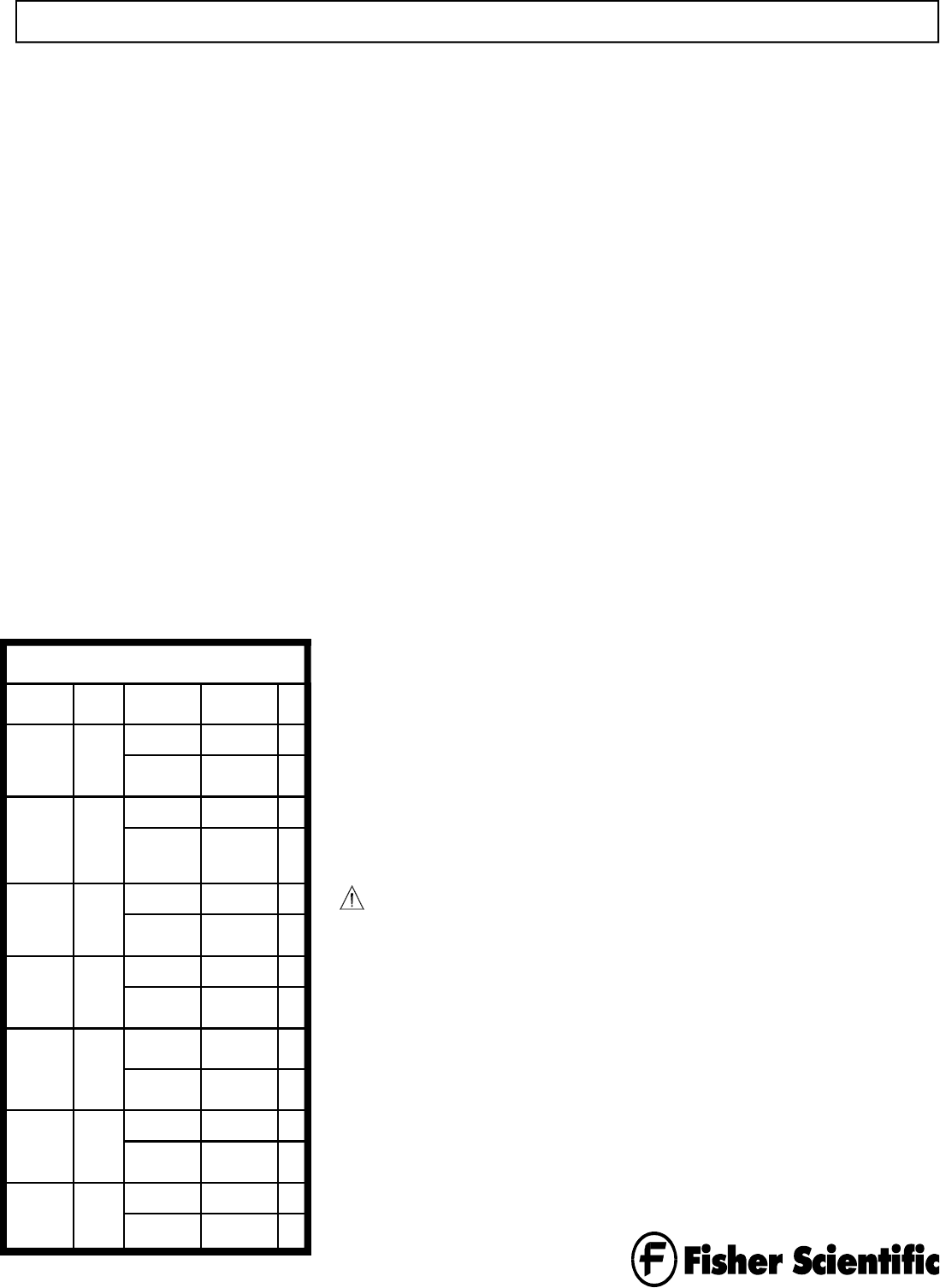
Capacity/
Type
Model 120 VAC 230 VAC
2 liter 202 15-462-2 15-462-3
Single
chamber
15-462-S2 15-462-S3 SS
Lid
2 liter 202S 15-462-2S 15-462-3S
Single
chamber,
shallow
15-462-S2S 15-462-S3S SS
Lid
5 liter 205 15-462-5 15-462-6
Single
chamber
15-462-S5 15-462-S6 SS
Lid
10 liter 210 15-462-10 15-462-11
Single
chamber
15-462-S10 15-462-S11 SS
Lid
5 and 10
liter
215 15-462-15 15-462-16
Dual
chamber
15-462-S15 15-462-S16 SS
Lid
20 liter 220 15-462-20 15-462-21
Single
chamber
15-462-S20 15-462-S21 SS
Lid
28 liter 228 15-462-28 15-462-29
Single
chamber
15-462-S28 15-462-S29 SS
Lid
Water Bath Models Available
Instructions
Fisher Isotemp Water Baths
Congratulations on your new Fisher Isotemp
Water Bath.
Isotemp Water Baths offer the versatility
needed to handle virtually any clinical
laboratory procedure — incubation,
inactivation, agglutination — as well as most
serological, pharmaceutical, biomedical, and
industrial procedures.
These water baths are available with chamber
capacities of 2, 5, 10, 20, and 28 liters. The 2
liter unit is available configured with either a
standard or shallow chamber. Also, a dual
chamber unit is available with 5 and 10 liter
chambers, with independent controls for each.
All units are available to operate from either
120 or 230 volts.
The baths work equally well with water or bath
oil as the medium. All models offer the same
temperature ranges: ambient to 60°C without
the supplied cover, and ambient to 100°C with
the cover in place (within physical limitations).
These baths are microprocessor controlled for
precise temperatures and reliable, trouble-free
operation. Dual thermostats — one controlling
the set point temperature and the other
operating as a safety — virtually eliminate the
possibility of overheating. Although not
designed to operate dry, the bath will not be
damaged if it is allowed to run dry.
Safety information
These instructions contain important
operating and safety information. The user
must carefully read and understand these
instructions before using the water bath.
Your unit has been designed to optimize
function, reliability, safety, and ease of use. It
is the user’s responsibility to install the bath
in conformance with local electrical codes.
To avoid electrical shock, always:
• Connect the water bath to a properly
grounded electrical outlet of the correct
voltage and current handling capacity.
Check the nameplate on the back of the
unit for the voltage and current rating.
• Disconnect the unit from the power outlet
prior to maintenance and servicing.
Note: 230V units are double pole,
neutral fusing.
To avoid personal injury:
• Do not use in the presence of flammable or
combustible materials; fire or explosion may
result. This device contains components which
may ignite such materials.
• Do not remove or modify the grounded power
plug. Use only properly grounded outlets to
avoid a shock hazard. This unit is not rated for
use in hazardous atmospheres.
• Do not continue to operate the bath if the
temperature control fails (displays an “E” code
or controls erratically) or the backup control
fails (red safety light glows continuously when
turned completely clockwise or fails to light
when turned completely counterclockwise).
• Select a fluid that is not corrosive and is not
flammable. The following fluids are not
recommended and may damage the unit:
− Chlorides or bleach.
− Strong concentrations of any acid.
− Strong concentrations of any salt.
− Weak concentrations of hydrochloric acid,
hydrofluoric acid, hydrobromic acid,
hydroiodic acid, sulfuric acid, or chromic
acid.
− Weak salt solutions containing sodium
chloride, calcium chloride, chromate or
chromium compounds.
− Deionized water.
− Most photographic solutions.
• Do not use a flammable liquid. A fire hazard
may result. This unit is not explosion proof.
Unit contains components which may ignite
such materials.
• Use appropriate hand and eye protection when
handling hazardous chemicals.
• The interior of the unit can reach temperatures
that can cause burns. Avoid contact. The unit
can remain hot without visual indication for
some time after power is turned off.
• If you will use the water bath with any liquid
that will give off fumes, be sure to operate the
water bath in a fume hood or with proper
ventilation.
• Use the cover to reduce evaporation and to
permit reaching higher temperatures.
• Hot liquids pose a burn hazard. Be careful not
to reach into the bath when it contains hot
liquids. Also be careful of steam rising from
hot liquids.
• The unit is intended to be operated with liquid
in the chamber. However, it will not be
damaged if it temporarily runs dry.
• Do not use in highly corrosive atmospheres;
corrosive fumes and spillage may damage the
unit and its internal components, creating a
shock hazard.
• Fumes from acidic solutions cause corrosion
of the stainless steel reservoir. Care should be
taken to maintain a neutral pH at all times.
• Refer servicing to qualified personnel.
• Do not place containers directly on bottom of
chamber. Bottom can get extremely hot if no
liquid is in the chamber. Always use the
diffuser tray
An energy-saving removable cover helps to
reduce evaporation while helping to
maintain a uniform, constant temperature.
The cover also allows the water bath to
reach higher temperatures. The hinged, see-
through gable cover features unique “fins”
that keep hands away from hot vapors for
easier, safer opening. The cover stays open
at the 90° position or, because of its quick-
attach hinge, can be lifted off completely to
accommodate large glassware.
A plastic rim remains cool to the touch
even when operating the bath at maximum
temperature.
The unit features a power-on self-test of
vital circuitry. This test will automatically
be performed each time you turn on the
unit. If problems are detected, the system
will indicate a warning message on the
display.
The calibration of the water bath can be
adjusted to optimize its accuracy for the
temperature that is used most often in your
application. This can be accomplished
through a simple procedure accessed from
the front panel.
As a convenience, a drain pump is supplied
with 10, 20, 28, and dual 5/10 liter models.
All controls are conveniently located on the
front panel for easy access. To assure set
point security, the temperature can only be
changed by entering a specific set menu
first. This ensures that the set point cannot
be accidentally altered during extended or
unattended operation.
To allow you to change the configuration
of some units, and to permit easy servicing,
your water bath provides front service
access to the controller without having to
empty the bath.
The water bath features corrosion resistant
construction throughout to withstand the
rigors of daily lab use.
Unpacking
The water bath is shipped in a single carton.
When unpacking the unit, check each loose item
against the packing list below. Should a shortage
exist, notify your Fisher branch or representative,
identifying the part by name and catalog number.
Note: If there is shipping damage, keep the entire
shipment intact — retaining the carton and all
packing material — and file a claim with the final
carrier. Usually the firm will send an investigator
to ascertain liability.
Assembly and installation
Follow these steps to assemble and install the
water bath before operation:
1. The location must:
− Be indoors.
− Provide an adequate source of power.
Check the label on the back of the unit for
voltage and current requirements.
− Provide adequate clearance to insert
samples.
− Be level, fixed, and capable of supporting
the weight of the unit when filled with
liquid and samples.
− Be free of drafts and wide ambient
temperature variations such as near a heater
or air conditioning vents.
− Provide a fume hood if hazardous fumes
are anticipated when using the water bath.
− Be convenient to a sink for filling and
draining the water bath.
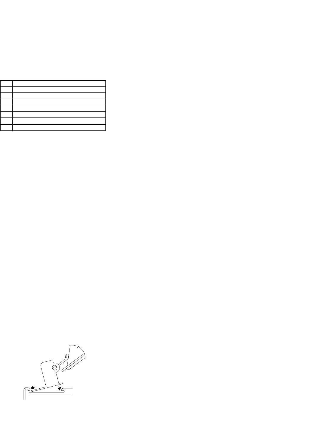
2. Install the cover by inserting the hinge into the
lip at the rear of the bath. Angle the cover up
while pushing down to lock the hinge in place
under the stainless steel tank lip. Remove the
cover by lifting the lid and pushing the hinge
towards the back to release it from under the
tank lip. Covers on the 2 liter shallow, 5 liter,
and 10 liter model baths can also be installed
and removed by sliding the hinge into place
under the rim and tank lips from either side.
3. Connect the line cord to a suitable grounded
electrical outlet.
Repositioning the control
panel
Note: This procedure applies to 20 and 28
liter units only.
With 20 and 28 liter units, the control panel
can be positioned on the side or the front of
the unit in order to achieve the best use of
available bench space. To change the position
of the control panel, follow these steps:
1. Turn off the unit and disconnect from
power source.
2. Allow to cool.
3. Remove thermometer and clip. Remove
the cover.
4. Assuming that the water bath is empty,
turn it over on a protected surface.
5. Remove two screws retaining the control
panel and two screws retaining the blank
panel.
Note: Do not disconnect internal wiring or
sensors from control panel.
6. Remove the blank panel.
7. Carefully move the control panel to the
new location and reinstall.
8. Install the blank panel at the other
location.
9. Return unit to location of use.
10.Reconnect power, turn on and test unit.
Filling the unit
Follow these steps to fill the unit in
preparation for use:
Note: If the bath has been used previously,
the tank should be thoroughly cleaned before
refilling.
1. Fill the water bath with tap water or oil so
that the liquid level is approximately 1½
inches (¾ inch with 2 liter shallow model)
from the top of the tank when full
anticipated load is placed in bath.
2. If a thermometer is used, use the clip
provided to hold the thermometer to the
side of the bath. Slide the O-ring on the
thermometer to position the thermometer
to the proper depth.
3. When closing the cover, place the
thermometer along the front edge. A notch
along the front of the cover clears the
thermometer and clip with the cover
closed.
4. For optimum results, the same fluid level
should be maintained throughout the
operating period.
5. If using water, algicide may be added to
reduce algae formation. Follow the
instructions supplied with the algicide.
Controls and indicators
All controls and indicators are located on the
front panel for ease of operation.
Power on/off
Controls line power to unit. Set to 1 position to
turn on power, 0 position to turn off power.
°F or °C
Shows whether temperature is being displayed in
Fahrenheit or Centigrade.
Display
During standby shows actual temperature; during
setups, shows menu modes and values being
selected.
Alarm
Lights to show that the backup controller is
regulating the temperature rather than the primary
controller.
Program
Lights to show that unit is in program mode
rather than run mode; see menu below.
Heat
Lights to show when heat is being supplied to the
chamber; cycles on and off as heat is requested
by the controller.
Menu
Allows you to select the mode of operation. Each
time you press the Menu button, the mode
changes in this sequence:
− Select temperature units in °F or °C
(display shows _C_F).
− Calibrate the unit (display shows CAL).
− Display the actual temperature of the
chamber (normal mode of operation).
− The unit will return to normal operation,
displaying the actual temperature, if you do
not touch any control for a few seconds.
Set
When in the normal mode of operation, allows
you to change the temperature setpoint. When in
the _C_F mode, allows you to change the
temperature units displayed. When in the
CALibration mode, allows you to set the
temperature offset to calibrate the unit.
Increase (∧)
After entering other than normal mode, increases
the displayed value.
Decrease (∨)
After entering other than normal mode, decreases
the displayed value.
Safety controller
Sets the Limit temperature above to the primary
setpoint; should be set at a higher temperature
than the setpoint to give the safety, control in the
event that the primary control fails.
Note: The safety control is not as accurate a
control as the digital control.
Packing List
Qty Item Supplied
1 Water Bath
1 Cover Assembly
1 Diffuser Tray
1 Thermometer Clip and Grommet
1 Siphon Pump (10, 20, 28, & dual 5/10 only)
1 Instructions
1 Warranty Card
2

Alarm Light
Operation
Follow these procedures for the operation of the
unit, including:
• Power up and initial indications.
• Setting the temperature units in °F or °C.
• Setting the temperature setpoint.
• Setting the backup temperature.
• Calibrating the unit.
• Emptying and cleaning the unit.
Power up
Follow these steps to turn on the unit to prepare it
for use:
1. Set the power switch to the ON position. The
unit will go through a power-on self test that
will take several seconds. During this time the
display will show the unit’s capacity in liters.
2. When the unit has completed its self-test, it
will maintain the bath at the last setpoint
temperature. The Heat indicator will light
when the unit is applying heat to the bath. This
indicator will cycle on and off during normal
operation.
3. When the display shows normal operation
after completing the self-test, continue by
setting the temperature setpoint and backup
temperature.
4. If the display shows any message after
completing the self-test, do not use the unit.
Refer to the Troubleshooting section to
determine what is causing the message to
appear on the display.
Setting the temperature units to °F
or °C
Note which indicator is lit to the left of the
display, either F for Fahrenheit or C for
Centigrade. If the desired indicator is lit, omit this
procedure. To change the temperature units,
follow this procedure:
1. Press Menu button so display shows _C_F.
Press and hold the Set while simultaneously
pressing the Increase (∧) or Decrease (∨)
button until the display shows the desired
temperature units, C for Centigrade or F for
Fahrenheit.
2. Release all controls. Within a few seconds, the
display will return to normal operation. The
desired indicator (F or C) should be lit to the
left of the display.
Setting the temperature
setpoint
Follow these steps to set the controller so that
it maintains the desired temperature:
1. Turn Safety controller knob fully
clockwise.
2. Press and hold the Set button to see the
current setpoint. The Program indicator
lights to show that this is the setpoint. If
this setpoint is correct, there is no need to
change the setting. The display will return
to normal operation when the Set button is
released, displaying the actual
temperature.
3. To change the setpoint, press and hold the
Set button while simultaneously pressing
the Increase (∧) or Decrease (∨) button.
The display shows the temperature
setpoint as you change it. Release the Set
button when you have achieved the
desired setting. The display will return to
normal operation within a few seconds,
displaying the actual temperature.
4. To check the setpoint without affecting
normal operation, press the Set button at
any time. To change the setpoint, repeat
step 3 above.
5. Set the Safety temperature according to
the procedure below.
Setting the Safety temperature
Follow these steps to set the water bath’s
Safety temperature controller.
1. Set the Temperature set point 2 to 5
degrees higher than desired temperature.
Wait until bath temperature stabilizes as
shown by displayed actual temperature.
2. Turn backup controller knob
counterclockwise until Alarm light just
comes on. Turn the knob clockwise
slightly until the light goes off.
3. Set the Temperature set point 5 degrees
higher and verify the Safety is controlling
2 to 5 degrees above desired set point.
4. Set the Temperature control to desired
temperature, allow the temperature to drift
down, and verify the alarm light does not
come on. If the light does come on, go
back to step 1 setting the Safety higher.
Calibrating the unit
To check the accuracy of the unit, clip a certified
thermometer, such as Fisher Cat. No. 15-166A (not
supplied with water bath), to the side of the bath as
described in the installation instructions. After
allowing sufficient time for the temperature to
stabilize, compare the thermometer reading to the
actual temperature displayed on the unit.
If the displayed temperature does not agree with the
thermometer, you can calibrate the controller as
follows:
1. Note the difference between the displayed
temperature and the thermometer.
For example: If the displayed temperature is 37
and the thermometer reads 36, the difference is
-1, meaning that the display should read 1 lower
than it now shows.
2. Press Menu button until display shows CAL.
3. Press and hold the Set button while
simultaneously pressing the Increase (∧) or
Decrease (∨) button to set the desired
temperature offset. Release the Set button when
you have achieved the desired setting. The
display will return to normal operation within a
few seconds, displaying the actual temperature.
In the example above, you would set the display
to read -1.
Note: The temperature offset can be set up to a
range of 5.5°C or 10.0°F.
Emptying and cleaning the unit
Please be advised that stainless steel can and will
rust if not regularly cleaned and properly
maintained. It is recommended that the bath be
cleaned at least on a monthly basis for moderate or
continuous use applications. Follow these steps to
empty and clean the unit after using it:
1. Turn off power, unplug the unit, and allow to
cool completely.
2. If you have a water bath of 2 or 5 liter capacity,
pour the liquid from the unit into an appropriate
disposal container.
3. If you have any other size water bath, allow the
unit to cool and use the hand pump to empty the
unit into an appropriate disposal container.
4. Clean the inside of the water bath with mild
detergent (such as Joy dishwashing detergent)
and warm water. Do not scrub any surface with
steel wool. (Steel wool leaves small metal
particles behind that will rust, causing the pan to
look rusty). In instances where a heavy coating
of residue has accumulated inside the tank or
where there is evidence that corrosion is
beginning, the use of a stainless steel cleaner
(such as 3M Stainless Steel Cleaner and Polish)
is recommended.
5. Rinse and wipe all tank surfaces with clean
water.
6. Unit is now ready for next use.
3
Note; If Alarm Light comes on during
normal cycling, turn backup controller
knob slighly clockwise and monitor. (If
backup and digital controls overlap, the
bath will have a wider temperature con-
trol band.)
Specifications
These are nominal specifications. Fisher
reserves the right to change specifications or
designs at any time without incurring
obligation.
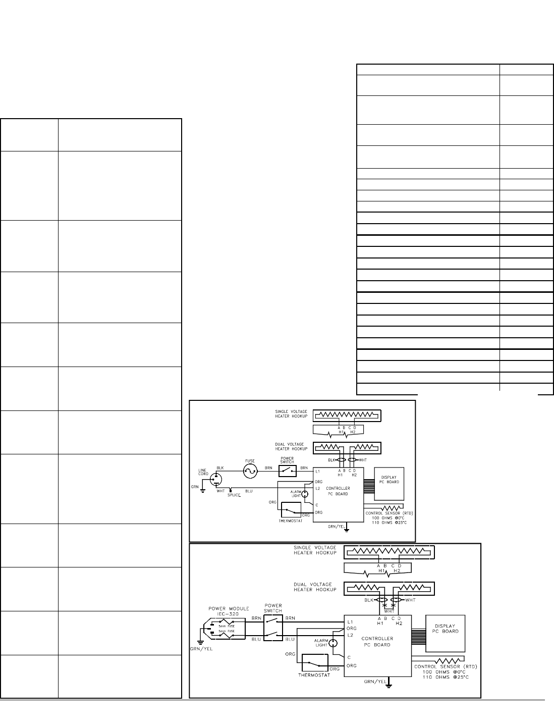
Replacement Parts
WARNING: To avoid electrical shock, always
disconnect from power supply before
maintenance and servicing. Refer servicing to
qualified personnel.
Item Part No.
Cover, 2 liter Plastic Lid
Stainless Steel Lid
SPN102304
15-462-32
Cover, 2 liter shallow and 5 liter
Plastic Lid
Stainless Steel Lid
SPN102305
15-462-33
Cover, 10 liter Plastic Lid
Stainless Steel Lid
SPN102306
15-462-34
Cover, 20 and 28 liter Plastic Lid
Stainless Steel Lid
SPN102307
15-462-35
Hinge, lid (for 2 liter) SPN102383
Hinge, rim (for 2 liter) SPN102384
Hinge, lid (for all except 2 liter) SPN102386
Hinge, rim 28L and Dual Models) SPN102387
Hinge, rim (for 2S, 5, 10 & 20 liter) SPN102459
Clip, thermometer (for 2L shallow) SPN102423
Clip, thermometer (all except 2LS) SPN102424
Microbicide, 8 oz. Bottle 13-641-337
Pump, Siphon SPN102391
Controller PC board (120V) SPN102419
Controller PC Board (230V) SPN104068
Display PC board SPN102420
Controller, safety SPN102499
Sensor, RTD SPN102331
Diffuser Tray, 2 liter SPN102352
Diffuser Tray, 2L shallow or 5 liter SPN102353
Diffuser Tray, 10 liter SPN102354
Diffuser Tray, 20 or 28 liter SPN102355
Fuse, Type 3AG 1.25x.25, 10 Amp SPN45920
Fuse, 5x20mm, F5A, 250V SPN102487
Part No. 102370 Rev. K Printed in U.S.A.
Published 01/04
If you have problems
If you have problems using the unit, follow these
general procedures to track down the cause from
the symptoms you are experiencing. If an error
message appears on the display, refer to the
specific error in this chart.
If the problem is not resolved using the table
below, Contact technical support at
1-800-926-0505 .
If you are
having this
This might be the cause
No power
indication
Unit not plugged in; no power at the
outlet; incorrect power (make sure
outlet matches label on back of
unit); defective power cord;
defective power switch or fuse (s).
(call Technical Support).
No heating Setpoint or backup not set properly;
defective heater or controller (call
Technical Support).
Always
heating;
temperature
greater than
Defective controller (call Technical
Support).
Very slow
heating of
samples
Empty tank or extremely low liquid
level in tank (add liquid to the tank
to improve heating).
Unit heating up
slower than
normal
Defective controller (call Technical
Support).
Alarm light on
constantly
Setpoint or backup not set properly;
defective primary controller (call
Technical Support).
Display not
correct
Temperature F or C set in error;
temperature not calibrated (perform
calibration procedure with
thermometer); defective controller
(call Technical Support).
Erratic
operation
Broken internal electrical
connection; defective heater or
controller (call Technical Support).
Error message:
E1
Failure of temperature sensor or
controller (call Technical Support).
Error message:
E2
Failure of controller (call Technical
Support).
Display shows
LLLL at
power-up.
Wrong voltage, Controller not set
up properly (call Technical Sup-
port).
Power requirements 120 VAC or 230 VAC ±
10%,
50 or 60 Hz
Ambient conditions +4°C to +35°C,
up to 75% relative humidity
Temperature range Cover open: Ambient to 60
°C Cover closed: Ambient
to 100°C
Control ±0.1°C between ambient
and 100°C
Uniformity ±0.24°C at 37°C
Stability ±0.5°C at 37°C
*Max. Altitude 2000m
*Over Voltage
Category
II (IEC 664)
*Pollution Degree 2 (IEC 664)
*CE Products meet the relevant EC harmonized
standards for safety (IEC1010-1/EN61010 and
EMC (EN55014, EN55104, EN61000-4-2, -4-4,
-4-6, -4-11and ENV50140)
*Applies to 230V units only
Schematic
230 VAC Unit
Schematic
120 VAC Unit
Note: The Stainless steel water
bath cover was designed as an
alternate to the see through
Plastic (polycarbonate) cover.
No material is impervious to
attack by all chemicals. The
Stainless lids are made of a
good quality 304 stainless steel
which is the same as the tank.
Clean with mild soap and wa-
ter. Rinse with clear tap water.
