_TS02_TS06_TS09_Mining Flex Line_Mining Manual_V1.0_English Line Mining Manual V1.0 English
User Manual: FlexLine_MiningManual_V1.0_English
Open the PDF directly: View PDF ![]() .
.
Page Count: 46

Leica FlexLine
TS02 TS06 TS09
Mining Application
Version 1.0
English
FlexLine, 2
Introduction
Introduction
To use equipment in the permitted manner, please refer to the detailed safety
instructions in the FlexLine TS02 TS06 TS09 User Manual.
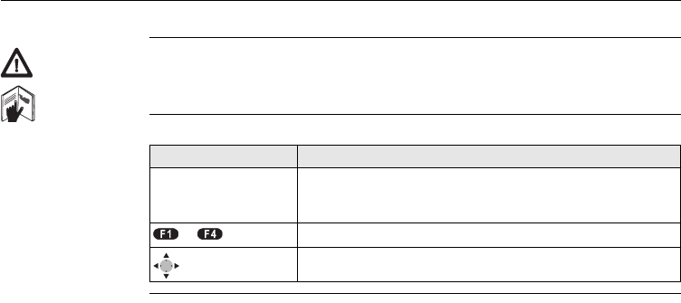
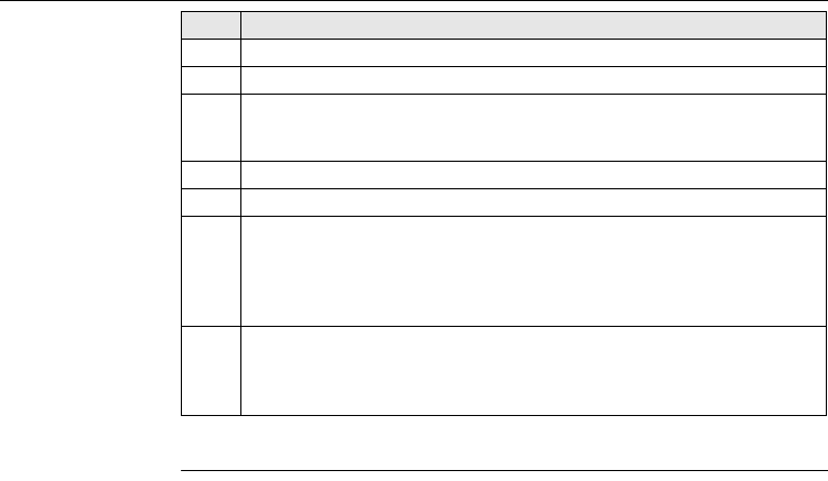
Symbols The symbols used in this manual have the following meanings:
Type Description
)Important paragraphs which must be adhered to in practice
as they enable the product to be used in a technically
correct and efficient manner.
- Press the function button F1 to F4.
Navigation keys.
Table of Contents FlexLine, 3
Table of Contents
In this manual Chapter Page
1 Tolerances 5
1.1 Defining Tolerances 5
1.2 Selecting Tolerance Profiles 7
1.3 PIN (Personal Identification Number) 8
2 Peg Survey 9
2.1 Overview 9
2.2 Starting Peg Survey 11
2.3 Measuring Peg Survey 15
2.4 Peg Survey Results 19
3Line Peg 22
4 Grades 23
4.1 Overview 23
4.2 Starting Grades 25
4.3 Gradeline Marking 27
4.4 Grade Results 30
5 Offset 32
5.1 Overview 32

Tolerances FlexLine, 5
1 Tolerances
1.1 Defining Tolerances
Description Before use of the mining applications, tolerance profiles have to be defined and
selected. The definition of tolerances can be done either via the Mining Editor
software or manually on the instrument. This chapter describes defining and
selecting tolerances manually. Refer to "6 Mining Editor" for details on using the
Mining Editor software.
Access 1. Select Prog from the MAIN MENU.
2. Select Define Tolerances from the PROGRAMS menu.
3. Enter the current PIN.
4. Press OK to proceed to the tolerance profile screen.
)If a wrong PIN has been typed in 5 times, a Personal UnblocKing code (PUK) is
required, which can be found on the instrument delivery papers. If the entered PUK
code is correct, then the PIN code is reset to default value "123456".
Define tolerances
step-by-step Step Description
1. Select the tolerance profile to define. Primary, Secondary or Tertiary.
2. Enter the limits for horizontal direction, horizontal distance and height.
3. Select the preferred sequence BFFB, BFBF, or BBFF, and number of sets.
)B = Backsight point. F = Foresight point.
FlexLine, 6
Tolerances
4. Repeat steps 1 to 3 for each of the three tolerance profiles.
5. Set the defined tolerances by pressing SET.
Step Description
Tolerances FlexLine, 7
1.2 Selecting Tolerance Profiles
Select tolerances
step-by-step
)• Tolerances themselves can be changed by using the PIN-protected Define
Tolerance application. Refer to "1.1 Defining Tolerances".
• If a tolerance was uploaded by the Mining Editor software, this tolerance will
appear as "Uploaded" and cannot be changed on the instrument.
Step Description
1. Start a mining application.
2. Select Set Tolerances.
3. Select Select Tolerances.
4. Select either a Primary, Secondary or Tertiary tolerance profile to be
applied.
5. Press SET to set the selected profile.
6. Press:
ACCEPT to accept the profile in the tolerances summary screen.
OR
REJECT to reject the profile and return to the define tolerance profile
screen.
FlexLine, 8
Tolerances
1.3 PIN (Personal Identification Number)
Description The definition of tolerances is PIN protected to prevent unauthorised changes. The
PIN is definable by the user. If a wrong PIN has been typed in 5 times, a Personal
UnblocKing code (PUK) is required, which can be found on the instrument delivery
papers. If the entered PUK code is correct, then the PIN code is reset to default value
"123456".
Set PIN code step-
by-step
)The default PIN is "123456".
Step Description
1. Select Setting from the MAIN MENU.
2. Select Mining from the SETTINGS MENU.
3. Enter the current PIN in PIN-CODE:.
4. Press OK.
5. Enter a personal PIN Code (max. 6 characters numeric) in New PIN-Code:.
6. Accept with OK.
Peg Survey FlexLine, 9
2 Peg Survey
2.1 Overview
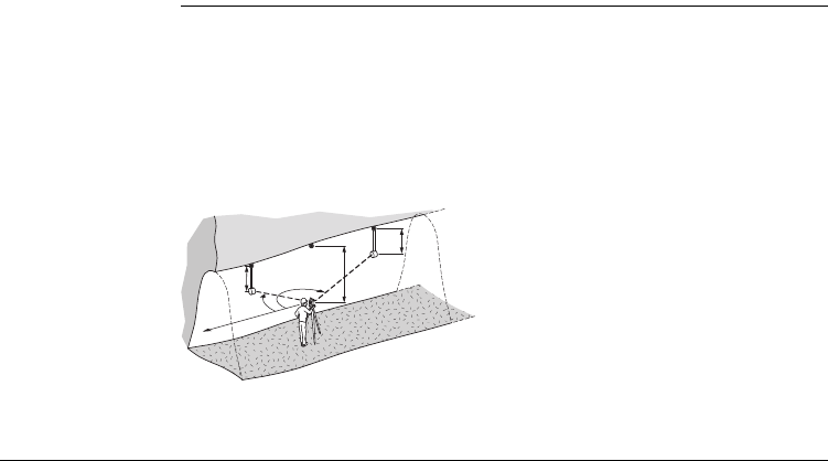
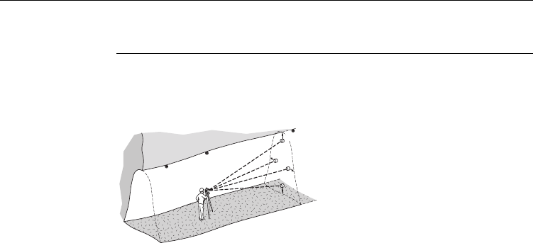
Description The application Peg Survey is used:
• to establish a forward peg (point).
• to control the intermediate horizontal angle between backsight and foresight
points.
• to check the horizontal distances and heights of the backsight and foresight
points.
• to compute the coordinates of the foresight point.
Users can measure several sets in different sequences. The quality of measurement
is controlled by the tolerances which are set before starting Peg Survey.
P0 Station
P1 Backsight point
P2 Foresight point
h1 Height of the reflector
h2 Height of the instrument
d1 Distance to backsight point
d2 Distance to foresight point
HZ1 Horizontal direction to backsight
point
HZ2 Horizontal direction to foresight
point
P0
P1
P2
d1
h1- h2+
h1-
Hz1
TSOX_Mining_001
Hz2 d2

FlexLine, 10
Peg Survey
Known
• Coordinates of station
• Coordinates of backsight point
Unknown
• Coordinates of foresight point
Peg Survey FlexLine, 11
2.2 Starting Peg Survey
Access 1. Select Prog from the MAIN MENU.
2. Select Peg Survey from the PROGRAMS menu.
3. Complete the application pre-settings by:
• Selecting a job, and
• Confirming the set of tolerances. Refer to "1.2 Selecting Tolerance Profiles".
4. Select Start to proceed to Input Station.
Input station step-
by-step Step Description
1. Enter the point ID (PtID:).
2. For manual entry of instrument height:
• Enter instrument height (hi:) of the station.
For measuring the instrument height:
• Turn the telescope to the azimuth with the help of the displayed
vertical angle (V:).
• Press DIST to measure distance to the peg.
)The sign for the instrument height is normally negative.
3. Press SET to set the point ID and instrument height.
FlexLine, 12
Peg Survey
Messages The following are important messages or warnings that may appear.
Next step
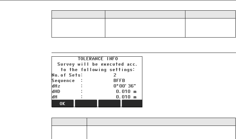
Press SET to proceed to the TOLERANCE INFO screen.
TOLERANCE INFO
Description of fields
Messages Description Measures
Station or BS point
has no valid coords !
The point ID entered is not available
in the internal memory or it has
invalid coordinates.
Re-enter point ID
(Step 1.).
OK
To continue with Peg Survey.
Field Description
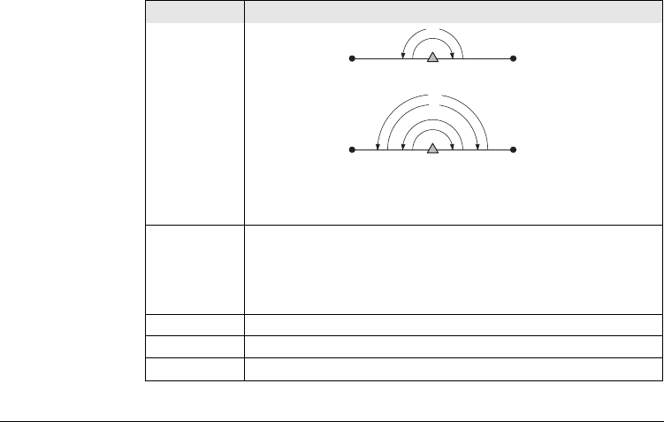
No. of Sets One set means to measure the backsight point (P1) twice and the
foresight point (P2) twice, in both faces.
Peg Survey FlexLine, 13
One Set a) I Set
Two Sets a) I Set
b) II Set
)The user must complete the number of sets as preset in
the tolerance settings. A maximum number of 20 sets is
supported by the application.
Sequence Displays the measuring sequence.
BFFB Backsight-Foresight-Foresight-Backsight.
BFBF Backsight-Foresight-Backsight-Foresight.
BBFF Backsight-Backsight-Foresight-Foresight.
dHz Tolerated residual in horizontal direction.
dHD Tolerated residual in horizontal distance.
dH Tolerated residual in height.
Field Description
P1 P2
TSOX_Mining_002
a
P1 P2
TSOX_Mining_003
b
a
FlexLine, 14
Peg Survey
Next step
Step Description
1. Press OK to proceed to the number of sets screen.
The number of sets screen displays which set is about to be measured out
of the total number of sets remaining. For example, Set 1 of total 3 means
the measurement will be the first set of three.
2. Press OK to proceed to the Measure Backsight Point screen.
The Measure Backsight Point screen displays information about which
backsight point the user has to measure.
3. Press OK to proceed to the backsight point measurement screen.
Peg Survey FlexLine, 15
2.3 Measuring Peg Survey
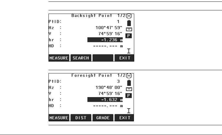
Access Press OK from the Measure Backsight Point screen.
Backsight Point
Foresight Point
MEASURE
To start angle and distance measure-
ments and save the measured
values.
SEARCH
To search for a different backsight
point.
EXIT
To exit the application and return to
the PEG SURVEY settings screen.
DIST
To start distance and angle measure-
ments without saving the measured
values.
GRADE
To edit current grades. Refer to "4
Grades".
FlexLine, 16
Peg Survey
Measure points
step-by-step
Next step
After each set the TOLERANCES MET, or the Out of tolerance screen displays.
Step Description
1. Enter the reflector height (hr:) for the backsight point, if required.
2. Aim at backsight point and press MEASURE.
3. Depending on the measurement sequence selected, enter a desired
backsight or foresight point ID (PtID:). OK saves the point ID and proceeds
to the measurement screen.
4. Enter the reflector height (hr:) for the point, if required.
5. Aim at target point and press MEASURE.
6. Decide whether to measure an additional point:
•NO Repeat steps 2. and 5. until all sets are measured.
•YES Repeat steps 3. to 5. with a new point.
)A maximum of 7 additional points can be measured.
7. If the tolerances after a set are not met, the user has the option to continue
with the measurements or reject the data.
•REJECT to reject the measurements and remeasure the set again.
•ACCEPT to accept the result and continue with the next set.
Peg Survey FlexLine, 17
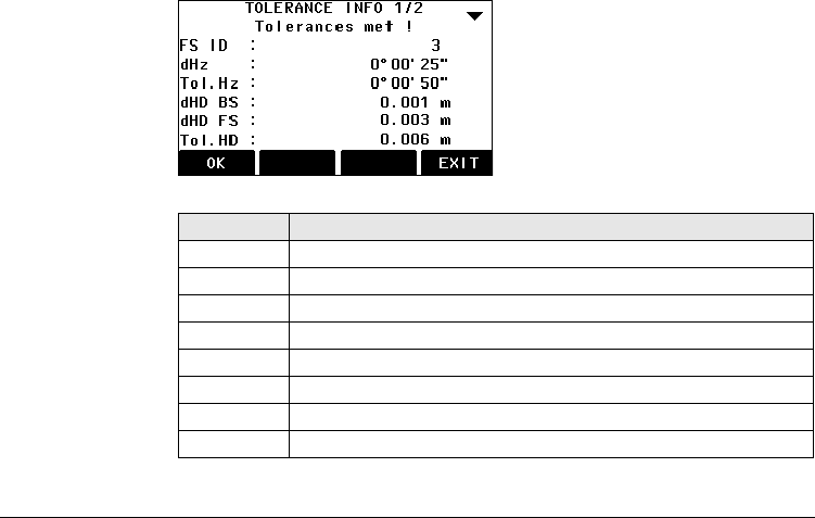
TOLERANCES MET
Description of fields
OK
To proceed to the results screen.
EXIT
To exit the application and return to
the PEG SURVEY settings screen.
Field Description
BS/FS ID Point ID for backsight and foresight points.
dHz Horizontal angle residual.
Tol.Hz Horizontal angle tolerance.
dHD BS/FS Horizontal distance residual for the backsight and foresight points.
Tol.HD Horizontal distance tolerance.
dH BS/FS Height residual for the backsight and foresight points.
Tol.H Height tolerance.
Set No Set number.

FlexLine, 18
Peg Survey
Next step
Press OK to proceed to the results screen.
Peg Survey FlexLine, 19
2.4 Peg Survey Results
Access Press OK from the TOLERANCES MET screen.
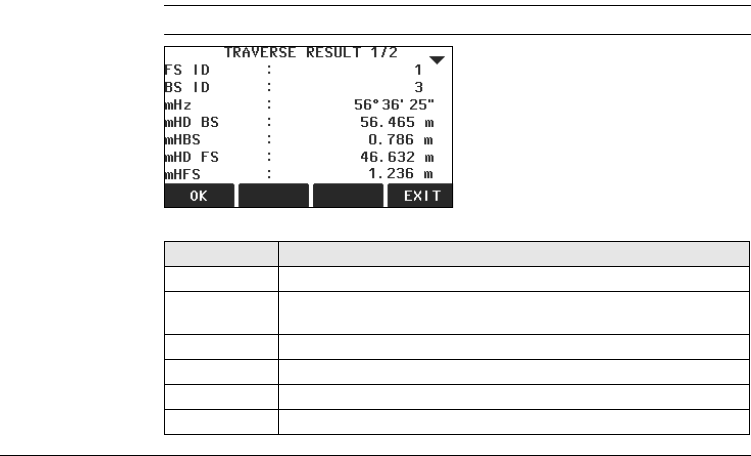
TRAVERSE RESULT
Description of fields
OK
To save the data and exit the appli-
cation.
EXIT
To exit the application and return to
the PEG SURVEY settings screen.
Field Description
BS/FS ID Point ID for backsight and foresight points.
mHz Average horizontal angle between backsight point and foresight
point.
mHD BS/FS Average horizontal distance to backsight and foresight points.
mH BS/FS Average height to backsight and foresight points.
Sequence Sequence of measurements.
No. of Sets Number of sets.
FlexLine, 20
Peg Survey
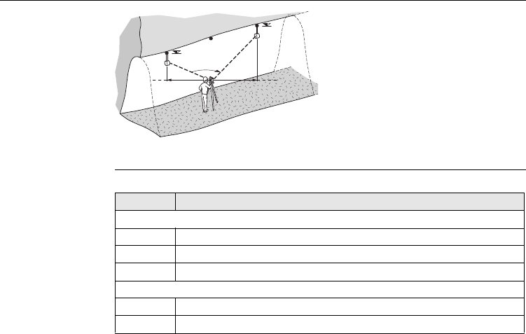
Saving the data The following results are stored in the internal memory.
P0 Station
P1 Backsight point
P2 Foresight point
αmHz: Averaged horizontal angle
d1 mHDBS: Average horizontal
distance to the backsight point
d2 mHDFS: Average horizontal
distance to the foresight point
h1 mHBS: Average height of the back-
sight point
h2 mHFS: Average height of the fore-
sight point
h1
h2
TSOX_Mining_004
d2
d1
P0
P1
P2
α
Field Description
Result
mHz Average horizontal angle between backsight point and foresight point.
mHD Average horizontal distance to backsight and foresight points.
mH Average height to backsight and foresight points.
Residual
dHz Horizontal angle residual.
dHD Horizontal distance residual.
Peg Survey FlexLine, 21
Next step Press OK to save the data and exit the application. The CONTINUE WITH... screen
appears for access to the GRADES or OFFSET applications. Refer to "4.2 Starting
Grades" and "5.2 Starting Offset".
dH Height residual.
Coordinates foresight point
E Easting.
NNorthing.
H Height point.
GrEl Grade elevation.
Field Description

Grades FlexLine, 23
4 Grades
4.1 Overview
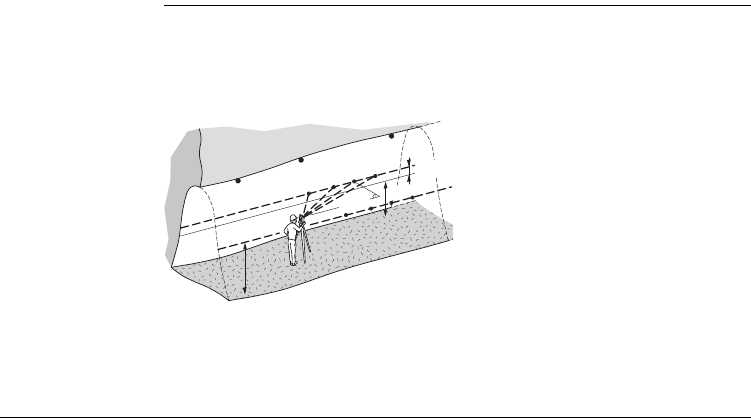
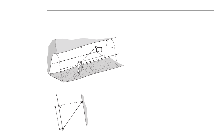
Description The Grades application is used:
• to mark gradelines along the side walls of the mines or tunnels.
• to input the slope gradient and an offset concerning the grade point.
• to compute the stake out height difference.
• to map the positions of the grade points along the gradelines.
P0 Station
P1 Backsight point
P2 Foresight point
a New gradeline
P3a - P6a Measured points
P3b - P6b New gradeline points
dHD Horizontal distance along
the foresight line.
H Current height of gradeline
above mine floor.
dH Height difference to new
gradeline.
TSOX_Mining_005
a
P0
P1 dH
H
H
dHD
P3a P4aP5a P6a
P3b P4bP5bP6b
P2
FlexLine, 24
Grades
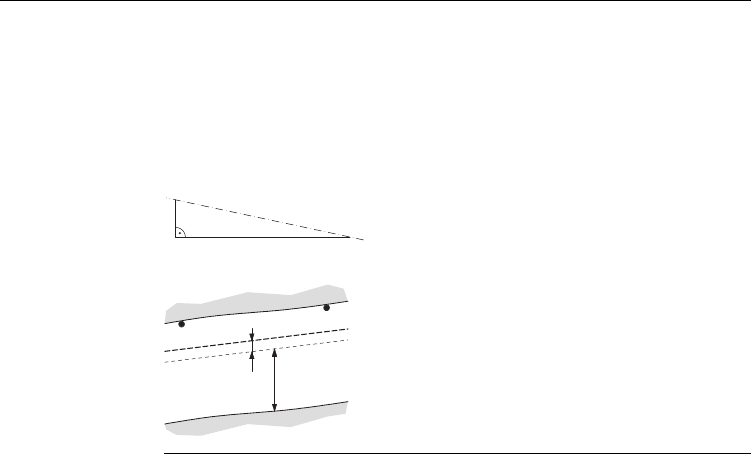
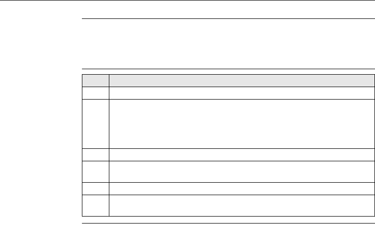
Slope gradient
Height difference
Known
• Coordinates and grade elevation of station
• Coordinates and grade elevation of backsight point
• Slope gradient, station to foresight point
• Height difference (dH) between current gradeline and new gradeline
Unknown
• Stake out height difference (dHgt) between measured point and gradeline point
• Horizontal distance (dHD) along the foresight line
aGradeline
hHeight
d Vertical distance
P0 Station
P1 Foresight point
a New gradeline
b Current gradeline
H Current height of gradeline above mine floor
dH Height difference between current gradeline
and new gradeline
TSOX_Mining_006
a
h
d
TSOX Mining 007
a
b
H
dH
P0
P1
Grades FlexLine, 25
4.2 Starting Grades
Access The Grades application is started by either selecting it in the PROGRAMS menu or
after measuring in the applications PEG SURVEY and LINE PEG.
When started from the PROGRAMS menu, station data must be entered and a
measurement made to backsight and foresight points first, before the Grade
application can be used.
Starting grades
step-by-step Step Description
1. Select Prog from the MAIN MENU.
2. Select GRADES & OFFSET from the PROGRAMS menu, and complete the
application pre-settings by:
• Selecting a job, and
• Confirming the set of tolerances. Refer to "1.2 Selecting Tolerance
Profiles".
3. Select Start to proceed to the Input Station screen.
4. Input station data and measure to the backsight and foresight points. Refer
to "2 Peg Survey" for details on this process.
5. Accept the tolerances from the measurements.
6. In the CONTINUE WITH screen, press GRADES to start the Grade
application.
FlexLine, 26
Grades
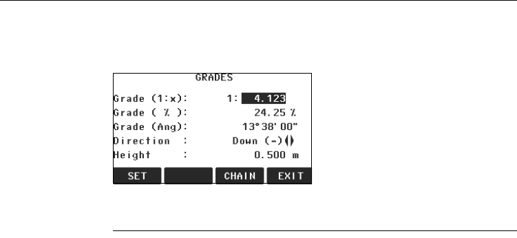
GRADES Enter the slope gradient as a proportion, for example 1:150, and the height
difference.
If the slope gradient from the station to the foresight point is the same as the slope
gradient from the backsight point to the station then no gradient needs to be
entered.
Next Step
Press SET to set the entered values and proceed to the GRADELINE MARKING
screen.
SET
To save the current values.
CHAIN
To enter a chain length instead of a
gradient.
EXIT
To exit the application and return to
the CONTINUE WITH screen.
Grades FlexLine, 27
4.3 Gradeline Marking
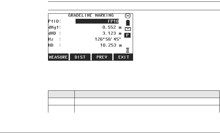
Access Press SET from the GRADES screen.
GRADELINE
MARKING
Description of fields
MEASURE
To start angle and distance measure-
ments and save the measured
values.
DIST
To start distance and angle measure-
ments without saving the measured
values.
PREV
To return to the previous screen.
EXIT
To exit the application and return to
the GRADES screen.
Field Description
PtID Point ID of the measured point.
dHgt Difference in height between the measured point and the grade point.
FlexLine, 28
Grades
Gradeline marking
step-by-step
)If the sign is negative the stake out point is above the meas-
ured point. If the sign is positive the stake out point is below
the measured point.
dHD Difference in horizontal distance between the measured point and the
grade point.
)If the sign is negative the stake out point is further away
than the measured point. If the sign is positive the stake out
point is closer than the measured point.
Hz Current horizontal angle.
HD Measured horizontal distance.
Field Description
Step Description
1. Enter a desired point ID (PtID:).
2. Aim at the target point and press MEASURE. The height difference (dHgt:)
and horizontal distance difference (dHD:) will display.
3. Turn the telescope until the height difference (dHgt:) is zero, then repeat
the measurement.

Grades FlexLine, 29
Next step
Press MEASURE to measure and record data for the current point and proceed
to measure another point.
FlexLine, 30
Grades
4.4 Grade Results
Description The Grades application computes the height difference (dHgt) between the
measured point and the stake out point, and the difference in horizontal distance
(dHD) along the foresight line.
Profile view
Top view
P0 Station
P1 Foresight point
aGradeline
dHgt Difference in height
dHD Difference in horizontal
distance
P0 Station
P1 Foresight point
a New gradeline point
dHD Difference in horizontal distance
TSOX_Mining_008
a
dHgt
dHD
P0
P1
TSOX Mining 009
a
dHD
P0
P1
Grades FlexLine, 31
Saving the data The following results are stored in the internal memory.
Field Description
Measurement data
PtID Point ID.
Hz Horizontal angle.
VVertical angle.
HD Horizontal distance.
SD Slope distance.
dH Height difference.
Coordinates of new gradeline point
E Easting.
NNorthing.
HHeight.
Grades Result
daH Stake out height difference.
daHD Horizontal distance along the foresight line.
Grd Slope gradient.
GE Grade elevation.
FlexLine, 32
Offset
5Offset
5.1 Overview
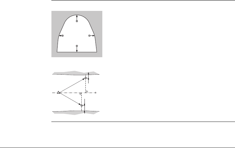
Description The Offset application is used:
• to record sections of the tunnels for volume computation and mapping.
• to input an offset value, left, right, up or down.
• to compute, after measurement, the actual coordinates of the tunnel walls.
P0 Station
P1 Backsight point
P2 Foresight point
aUp
bLeft
cRight
dDown
Known
• Coordinates of station
• Coordinates of backsight point
• Offset value
Unknown
• Point coordinates of the tunnel walls
TSOX Mining 010
a
b
c
P0
P2
P1
d
Offset FlexLine, 33
Offset Profile view
Top view
aUp
bLeft
cRight
dDown
P0 Station
P1 Foresight point
a Offset left
b Offset right
TSOX_Mining_011
a
bc
d
TSOX_Mining_012
a
b
P0 P1
FlexLine, 34
Offset
5.2 Starting Offset
Access The Offset application is started by either selecting it in the PROGRAMS menu or
after measuring in the applications PEG SURVEY and LINE PEG.
When started from the PROGRAMS menu, station data must be entered and a
measurement made to backsight and foresight points first, before the Offset
application can be used.
Starting offset
step-by-step Step Description
1. Select Prog from the MAIN MENU.
2. Select GRADES & OFFSET from the PROGRAMS menu, and complete the
application pre-settings by:
• Selecting a job, and
• Confirming the set of tolerances. Refer to "1.2 Selecting Tolerance
Profiles".
3. Select Start to proceed to the Input Station screen.
4. Input station data and measure to the backsight and foresight points. Refer
to "2 Peg Survey" for details on this process.
5. Accept the tolerances from the measurements.
6. In the CONTINUE WITH screen, press OFFSET to start the Offset
application.

Offset FlexLine, 35
OFFSET
Offset step-by-
step
MEASURE
To start angle and distance measure-
ments and save the measured
values.
DIST
To start distance and angle measure-
ments without saving the measured
values.
EXIT
To exit the application and return to
the CONTINUE WITH screen.
Step Description
1. Enter a desired point ID (PtID:) and the offset value.
2. Select the offset definition, Left, Right, Up or Down.
3. Aim at the target point and press MEASURE. The measurement is triggered
and stored.
)After storing, the application returns to the OFFSET screen.
4. To measure a new point, repeat steps 1. to 3.
FlexLine, 36
Offset
Next step
Press MEASURE to measure and record data for the current point and proceed
to measure another point.
Offset FlexLine, 37
5.3 Offset Results
) The measurement data is already corrected according to the offset values.
Saving the data The following results are stored in the internal memory.
Field Description
Measurement data
PtID Point ID.
Hz Horizontal angle.
V Vertical angle.
HD Horizontal distance.
SD Slope distance.
Offset information
Offset Offset value.
OffsetDir Offset direction (left, up, right, down).
Coordinates of new offset point
E Easting.
NNorthing.
HHeight.
FlexLine, 38
Mining Editor
6 Mining Editor
6.1 Overview
Description The Mining Editor is a Windows-based program used for the data exchange between
the instrument and a computer.
Installation on the
computer
The installation program for the Mining Editor can be found on the CD-ROM supplied.
Please note that the Mining Editor can only be installed under the operating systems
MS Windows 95, 98, ME, NT4.0, WINDOWS2000, or WINDOWSXP.
For the installation, select "setup.exe" in the directory "MiningEditor\Disk1" on the
CD-ROM and follow the onscreen instructions to complete the installation.
Program content The Mining Editor can be used for the following purposes:
Creating fixpoint files
Creating and editing of fixpoint files such as coordinates.
Defining and uploading tolerances
Defining, editing (password protected), and uploading tolerances.
Data import and export
Importing and exporting fixpoint files (ASCII format).
Data transfer between computer and instrument
Uploading of fixpoint files and tolerances, downloading of fixpoint files and
measurement data, and conversion of measurement data to various formats for
peg calculation and archiving.
Mining Editor FlexLine, 39
6.2 Functionality
Creating fixpoint
files step-by-step
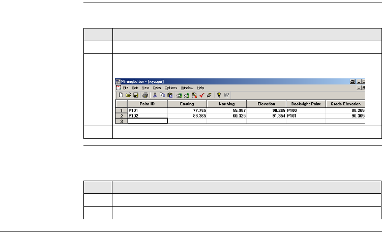
In the fixpoint entry module, the Mining Editor allows users to create, view, modify
and save coordinate lists.
Define tolerances
step-by-step
For defining tolerances ensure that the unit setting on the instrument, select
Settings -> General, is identical to the units set in the Mining Editor, select Options
-> Settings.
Step Description
1. Open a new file: File -> New.
2. Enter point IDs, and for each one: coordinates, a backsight reference point,
and a grade elevation.
3. Save the created coordinate list: File -> Save As.
Step Description
1. Open tolerances: Options -> Tolerances -> Edit.
2. Enter the password.
FlexLine, 40
Mining Editor
)To create a new password: Options -> Password.
3. Select a measuring sequence: BFFB, BFBF or BBFF.
)B = Backsight point. F= Foresight point.
4. Enter the number of sets.
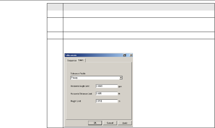
5. On the Limits tab, select a tolerance type. Primary, Secondary, or
Tertiary.
Step Description
Mining Editor FlexLine, 41
Uploading step-by-
step
6. Enter the values for:
• Horizontal Angle Limit:
• Horizontal Distance Limit:
• Height Limit:
7. Press OK to save the tolerances.
8. Refer to "Uploading step-by-step" to upload tolerances to the instrument.
Step Description
Step Description
1. Connect the instrument via the serial interface RS232 to the computer. The
instrument communication settings must be set to Port: RS232 and
Baudrate: 19200.
)To enable a higher data transfer speed at 19200 bauds, the
baudrate must be entered manually in the Com-Port settings.
2. In Mining Editor, open a fixpoint file: File -> Open.
3. Choose Upload: Data -> Upload.
4. Select a job folder on the instrument to save the data into.
)If the selected job already has data, all existing data will be over-
written by the new file being uploaded.
FlexLine, 42
Mining Editor
Process imported
fixpoint files step-
by-step
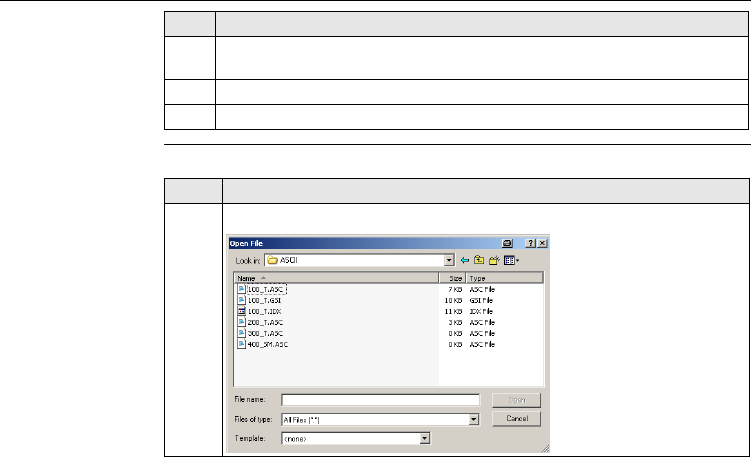
The Mining Editor allows import of fixpoint files in ASCII format.
5. Enter a jobname, operator and comments. Operator and comments are
optional.
6. Select a tolerance type and select OK.
7. The file uploading will begin and a status bar will indicate the progress.
Step Description
Step Description
1. Open an ASCII formatted file: File -> Open.
Mining Editor FlexLine, 43
2. Search and select the ASCII-File.
3. Open the selected file.
4. Follow the wizard onscreen instructions to convert the ASCII file into the
correct format.
5. Save the created file: File -> Save as.
Step Description

FlexLine, 44
Index
Index
A
Applications
Grades ........................................................... 23
Line peg ......................................................... 22
Offset ............................................................ 32
Peg survey ....................................................... 9
H
Height difference, description ............................. 24
I
Installation, of mining editor ............................... 38
M
Mining editor
Creating fixpoint files ..................................... 39
Defining tolerances ........................................ 39
Functionality .................................................. 39
Installation ..................................................... 38
Process imported files .................................... 42
Software ........................................................ 38
Uploading ...................................................... 41
O
Offset, description of ..........................................33
P
PIN code, set .........................................................8
S
Sequence, description .........................................13
Sets, description .................................................12
Slope gradient, description ..................................24
Symbols, used in this manual ................................2
T
Tolerances
Defining ...........................................................5
Met ................................................................17
Select profile ....................................................7

Index FlexLine, 45

Total Quality Management: Our commitment to total customer satisfaction.
Leica Geosystems AG, Heerbrugg, Switzerland, has been
certified as being equipped with a quality system which
meets the International Standards of Quality Management
and Quality Systems (ISO standard 9001) and Environmental
Management Systems (ISO standard 14001).
Ask your local Leica dealer for more information about our TQM program.
767508-1.0.0en
Original text
Printed in Switzerland © 2008 Leica Geosystems AG, Heerbrugg, Switzerland
Leica Geosystems AG
Heinrich-Wild-Strasse
CH-9435 Heerbrugg
Switzerland
Phone +41 71 727 31 31
www.leica-geosystems.com
