Four10sc_Manual Four10sc Manual
User Manual: Four10sc_Manual
Open the PDF directly: View PDF ![]() .
.
Page Count: 42

Owner’s Manual &
Technical Information
HLNS1001

2
Legal
Entire contents ©2015 Helion RC
Before using your product, review all documentation and inspect the product
carefully. If for some reason you decide it is not what you wanted, then do
not continue with unpacking, setup or operation of your product. Your local
hobby dealer cannot accept a product for return or exchange after partaking
in actions that produce wear and tear.
Read, understand and follow all instructions and accompanying material
carefully before operating or assembling your product to prevent serious
damage. Failure to complete these tasks properly or intentional aversion to
the content will be considered abuse and/or neglect.
Product specications are subject to change without notice. Due to ongoing
development, the actual product may vary from images shown.
This product contains chemicals known to the State of California to cause
cancer, birth defects and other reproductive harm.
This product is not a toy! (14+) Recommended for ages 14 and up. Adult
supervision required for ages under 18 years old. Contains small parts, keep
out of reach of children 3 years of age and younger.
Important Information
Throughout this manual you will see different notes, cautions and warnings
to help alert you to important information about the section you are reading.
Please see below for the descriptions and what to look for to identify each
type.
WARNING: THIS INFORMATION IS IMPERATIVE FOR YOU TO UNDERSTAND AND
FOLLOW AS LACK OF COMPLIANCE WITH THE CONTENTS OF THE WARNING
COULD CAUSE PERSONAL INJURY OR PROPERTY DAMAGE.
CAUTION: THIS INFORMATION IS IMPORTANT FOR YOU TO UNDERSTAND AND
FOLLOW AS LACK OF COMPLIANCE WITH THE CONTENTS OF THE CAUTION COULD
CAUSE DAMAGE TO YOUR PRODUCT THAT IS NOT COVERED UNDER WARRANTY.
Note/Tip: This information is important for you to keep in mind, most commonly
used to recall previously given information or to direct you to or provide you with
additional information on a subject.

3
Contents
Notice .......................................................................................... 4
Precautions................................................................................. 4
Package Contents ...................................................................... 5
Items Needed to Complete ........................................................ 5
Introduction ................................................................................ 6
Features ...................................................................................... 6
Getting Started ........................................................................... 7
Ikonnik ET4 Radio Sysytem ...................................................... 8
Radient Reaktor60-4T Overview ............................................... 9
Adjusting and Tuning Your Vehicle .......................................... 17
General Care & Maintenance .................................................. 18
Storage and Disposal ..............................................................22
Troubleshooting Problems .......................................................22
Appendix A: Troubleshooting for Reaktor Power System .......24
Appendix B: Troubleshooting Guide ........................................25
Appendix C: Differential Exploded Views ................................26
Appendix D: Shock Exploded Views ........................................27
Appendix E: Front Suspension Removal .................................28
Appendix F: Front Suspension Exploded View ........................29
Appendix G: Rear Suspension Removal View .........................30
Appendix H: Rear Suspension Exploded View ........................31
Appendix I: Main Chassis Exploded View ...............................32
Appendix J: Spare Parts List .................................................... 33
Warranties ................................................................................39
Declaration of Conformity ........................................................ 41

4
Notice
Your product is calibrated and tested at the factory prior to nal packaging,
some issues may arise during shipping and handling that can be easily
resolved at home. For other adjustments it should be known that hobby
grade radio controlled products such as this differ from toy grade, in that they
are intended to be user-serviceable products where the user can program,
disassemble and maintain their own product. We try our best to ensure the
information you need to introduce you to this form of product ownership is
available to you though this manual. Please see the troubleshooting guide at
the back of this manual for assistance in resolving issues, either as they are
experienced out of the box or as found after regular use.
Note: Assuming your product functions properly as intended out of the box, the
best thing you can do is pay close attention to how it feels, sounds and functions.
This will help you identify problems later since you will have a reference of how the
product is supposed to perform.
If you require further information or assistance resolving a possible issue,
please consult the warranty card included with your product.
Precautions
Although great for rst time users, Helion RC products are indeed advanced
radio controlled vehicles with sensitive electronics and moving parts capable
of causing injury if used improperly. Always use caution and common sense
as failure to operate your product in a safe and responsible manner can
result in damage to the product or other properties. Therefore this product
is not intended for use or maintenance by children without direct adult
supervision. Helion RC and your hobby dealer shall not be liable for any loss
or damages, whether direct, indirect, special, incidental, or consequential,
arising from the use, misuse, or abuse of this product or any product required
to operate or maintain it.
WARNING: ALWAYS KEEP LOOSE CLOTHING, HAIR, TOOLS OR OTHER MOVABLE
OBJECTS AWAY FROM MOVING PARTS OF YOUR VEHICLE DURING SETUP AND
CONFIGURATION. SPINNING TIRES CAN EXPAND AND MAKE CONTACT WITH SMALL
TOOLS, OR HARDWARE AND SEND THEM FLYING AT HIGH SPEEDS RISKING
INJURY TO YOU OR OTHERS AROUND YOU.
• Your model can cause serious damage or injury so please use caution
and courtesy when operating your model.
• As a safety precaution, perform all transmitter and receiver adjustments
with all parts of the vehicle off the ground. This ensures the complete
control over the vehicle at all times during adjustments.
• Do not operate your model near trafc, bystanders, parking areas, or any
other area that could result in injury to people or damage to property.
• If at any time during the operation of your model you observe any erratic
or abnormal behavior of your model, immediately stop operation and
bring the mode to a safe stop in a safe location to diagnose the problem.
• Always power on your transmitter before turning your vehicle on.

5
• If you have little or no experience operating R/C models, we strongly
recommend you seek the assistance of your local hobby dealer.
• Do not expose the transmitter to water or excessive moisture.
• Do not operate radio controlled products in a lightning or thunder storm.
• Ensure your batteries (both Tx and vehicle) are charged before each use.
• Check all servos and electrical connections prior to each use.
• Use caution when handling your vehicle after use as electronics may get
HOT and could cause a burn if handled carelessly.
• Always allow the motor in your vehicle to cool completely before using it
again.
R/C models are an extremely fun hobby, but safety should never be ignored
or taken lightly. Always take caution when operating your model as damage
to property and injury can result from careless operation. Please consult
your local hobby dealer with any questions or troubleshooting issues. And
of course don’t forget to have fun, you deserve it after reading through all of
these safety tips!
Package Contents
• 1x Four 10SC Short Course Vehicle
• 1x Ikonnik ET4 Xenon 2.4GHz 4-Channel Transmitter with Grips
• 1x 1.5mm Hex Wrench
• 1x 2.0mm Hex Wrench
• 1x 2.5mm Hex Wrench
• 1x Documentation package with decals
Items Needed to Complete and Enjoy
• 4 x size AA 1.5V Alkaline batteries for the transmitter
• 1 x 2-3S LiPo Battery and suitable charger
• 1 x Bib to catch the drool of on-lookers

6
Introduction
Select by Helion was born from the quest for the ultimate marriage of
performance, value and innovation. It’s not an easy task compromising so
we have done our best not to. We’ve included what we believe to be the
best radio system in its class; the most durable and robust brushless power
plant that includes proprietary technology; high performance engineering
grade composite plastics with aircraft grade aluminum and high carbon
steel components. We’ve taken a chassis platform that could have been
ok and made it great. The components by themselves can be seen as
capable, over engineered, rened and optimized, but their specs weren’t
chosen because of how they perform when their independent, we’ve put
them all together where each component complements each other with
perfect synergy into the product that best ts our customers’ needs and
expectations. It’s not just about being good, it’s about being Select.
Features
• Radient Reaktor 60T LiPo-Ready brushless all
weather sensorless ESC with TSP
• 4 Pole sensorless Radient Reaktor4T 3500kV
brushless motor with TSP
• Ikonnik ET4 2.4 GHz 4-Channel radio system
with 10 model memory and beginner mode
• All weather 6kg High Torque servo
• Mid CG chassis design optimizes stability and
ground clearance for all-terrain versatility
• Four wheel independent suspension
• Robust shaft based 4 wheel drive
• All metal gear transmission with quite running
composite spur gear
• Included center differential
• Planetary metal gear differential front and rear
• Rubber sealed ball bearings throughout
• Adjustable, oil lled, threaded aluminum body,
coil-over shock absorbers
• Dual bell crank ball bearing steering with
adjustable servo saver
• Durable, rugged engineering grade composite
chassis components
• 24mm Offset Hex drive wheels,
compatible with TRX and KYO
• High grip long wear racing lug tires with
12mm wheels
• Heavy duty telescoping drive hafts
• Aluminum bulkheads, steering spindles,
suspension pivots and wheel hexes
• Chassis guard/net
• 2-3S LiPo Ready (Not Included)

7
Getting Started
Below are some steps to help get you going right away and most applicable
to those who have used RC products before. If you are new to the hobby or
it has been a while since you’ve worked with the latest technology, please
read through the manual to acquaint yourself with the latest procedures,
Warnings, Cautions and Tips.
Charging
Although this information should be included with your batteries and charger,
we have included it here again to ensure you have seen it and are aware
of the most common things to be aware of with regards to charging our
batteries.
• Never leave the battery unattended while charging and never operate the
charger without adult supervision.
• Never charge a warm battery, always allow the battery to cool to room
temperature before charging.
• Never drop the charger or battery and do not attempt to charge a
damaged battery.
• Inspect the battery and charger before use. Never use a battery or
charger if the wire or connector has been damaged or if the battery has
experienced a short.
• Incorrect use of the battery, connections, or charging equipment can
cause personal injury or property damage.
• Never allow batteries or charger to come in contact with moisture at any
time.
• Stop charging immediately if the battery or charger becomes hot or
changes form during use.
WARNING: WHEN USING LIPO BATTERIES, ONLY USE CHARGERS DESIGNED
FOR USE WITH LIPO BATTERIES FOR THE RC INDUSTRY THAT ENABLE BALANCE
CHARGING AND USE THE SUPPLIED CONNECTOR. USE OF OTHER (NON-RC
SPECIFIC) CHARGERS OR CONNECTORS CAN CAUSE CATASTROPHIC FALURES AND
CAUSE PERMANENTLY DAMAGE YOUR BATTERY AND/OR CONNECTED EQUIPMENT.
THIS PRODUCT IS NOT A TOY AND SHOULD NOT BE CHARGED, OPERATED, OR
MAINTAINED WITHOUT SUPERVISION OF AN ADULT.
Fully balance charge your chosen 2S or 3S LiPo battery in accordance with
charging and safety guidelines supplied with the battery. LiPo batteries are
sensitive to the charge current and as such, it should be chosen with care.
• The battery pack must have a compatible HCT plug, never use plug
adapters that include a non-high-current connector.
• You can use a suitable NiMH battery pack, however you must change
the LVC (low voltage cut-off) on the ESC (see Appendix at the back of this
manual for ESC settings)

8
Preparing to Drive
1. Remove the body from vehicle.
2. Loosen the hook-and-loop battery straps.
3. Install the fully charged battery into the vehicle, be sure to secure the
battery straps to keep the battery in.
Note/Tip: If you are you using a tall high capacity battery, optional long straps are
available to suit your conguration.
4. Ensure the motor is plugged into the ESC.
5. Ensure the vehicle power switch is in the OFF position and connect the
battery to the ESC.
6. Read and understand the manual supplied with the Ikonnik ET4 radio
system.
CAUTION: NOTE TRANSMITTER CAUTIONS AND SETTING INSTRUCTIONS BEFORE
USE.
7. Install the [4] AA type alkaline batteries into the transmitter.
8. Conrm settings for steering/throttle trim and motor direction (update
connection if necessary)
9. Conrm ESC settings for the battery you will use (check LVC program
mode and ensure it is properly set to 5 if using a LiPo or 1 if you are
using a NiMH battery pack.)
10. Re-install body with 4 supplied clips; turn your equipment ON (transmitter
rst!) and enjoy!
The IKONNIK ET4 Radio System
Your Select Four 10SC comes equipped with one of the most advanced
2.4GHz radios in its class. It is feature packed and incorporates technology
normally reserved for only the upper echelon of radio systems and some
completely unique to IKONNIK.
Familiarize yourself with the usage and features presented in the IKONNIK
ET4 Owner’s Manual and quick start guide to enhance your experience:
Most importantly we recommend you become familiar with the following
features of the system.
• Pairing the transmitter and receiver.
• Setting Steering and Throttle trims.
• Using the 10 Model memory
• Utilizing the Beginner Modes to share and enhance the fun.
• Conguring the ergonomics to t you

9
Radient Reaktor60-4T Brushless System Overview
The Radient Reaktor series brushless motor and ESC is a great power plant
to satisfy your need for speed and performance, not just an entry level
brushless system, your Reaktor system has some of the most advanced
technology in ESC and motor development in the industry today. Here are
some great features we included that help keep your system running in top
shape ensuring maximum enjoyment potential.
CAUTION: ALWAYS ALLOW YOUR MOTOR TO COOL BETWEEN RUNS. EXCESSIVE
ACCELERATION AND AGGRESSIVE DRIVING WILL CAUSE YOUR SYSTEM TO GET
HOT. EXCERCISE GREAT CARE WHEN HANDLING YOUR VEHICLE AFTER RUNNING
TO AVOID GETTING BURNED.
Some Great Features of your ESC
• Total System Protection (TSP) is an exclusive technology which protects
your entire system against typical failures experienced and sometimes
caused by by new users.
CAUTION: ALTHOUGH TSP HAS BEEN ENGINEERED TO PROVIDE THE MAXIMUM
PROTECTION AVAILABLE TODAY, IT IN NO WAY MAKES FAILING PRODUCT
IMPOSSIBLE. TSP PROVIDES ADDED PROTECTION AGAINST THE MOST COMMON
TYPES OF FAILURES EXPERIENCED AND SOMETIMES INDUCED BY NEW USERS.
• Ready for all weather conditions allowing you to experience the fun of
rain, puddles and snow.
CAUTION: REMOVE THE COOLING FAN WHEN RUNNING IN WATER TO PREVENT
FAN OVERLOAD AND FAILURE. AFTER RUNNING, CLEAN AND THEN DRY THE ESC
AND FAN TO AVOID OXIDATION OF THE COPPER CONNECTORS.
• Specially designed for RC car and truck, with excellent start-up,
acceleration and linearity features.
• Compatible with sensorless brushless motors.
• 2 running modes suitable for different applications (“Forward with brake”
mode, “Forward/Backward with brake” mode).
• Proportional ABS brake function with 4 steps of maximum brake force
adjustment, 8 steps of drag-brake force adjustment.
• 4 start modes (“Punch”) from “Soft” to “Very aggressive” to be suitable
for different chassis, tires and tracks.
• Multiple protection features: Low voltage cut-off protection for LiPo or
NiMH battery / Over-heat protection / Throttle signal loss protection /
Motor blocked protection.
• Easily programmed with the “SET” button on the ESC or with the LED
Program Card.
Your ESC has been pre-installed at the factory but before using your
vehicle each time it is good to double check the wiring for damage or loose
connections to ensure everything is in working order before use. Refer to the
diagram below to check the connections of your electronics system. Some
brushless motors such as the Reaktor included with your vehicle use only
10
black wires, this is okay. On sensorless brushless systems the motor will change
operating direction when any two of the motor wires are swapped.
Total System Protection (TSP)
The Reaktor “T” series ESC’s and Motors incorporate the TSP technology. The
TSP system protects against the following failure modes.
• Over-current: Operating your product in very tall grass or in environments
that create a lot of drag in the drivetrain can cause the motor to draw
more current than the ESC is rated to maintain. This incredibly advanced
circuitry is calibrated to sense the current state and predicted state of the
electronics and will shut down the power to the motor to prevent an over-
load condition. The most common causes of an over-current condition are
improper gearing or running in very high drag environments such as tall
grass, wet heavy mud or in situations where damage has occurred to the
drivetrain but gone un-noticed.
• Over-temperature: Exclusive to the Radient Reaktor “T” Series is the
integrated temperature monitoring of both the ESC and the motor. Never
before has a sensorless brushless combo had the technology incorporated
which allows the ESC to monitor the temperature of the motor and enables
the cutting of power to prevent an over-heat melt down of the motor and the
ESC.
CAUTION: RMONITORING THE MOTOR TEMPERATURE AND PROPER FUNCTION
OF THE TSP SYSTEM REQUIRES PROPER CONNECTION OF THE SENSOR PORT
LOCATED IN THE BACK OF THE MOTOR AND THE SENSOR INPUT ON THE ESC.
The Reaktor ESC is Engineered to Communicate With You
LED Status:
• In normal use, if the throttle trigger is in the neutral range, neither the red
LED nor the green LED light up.
• The red LED lights when the car is run forward or backward and it will ash
quickly when the car is braking.
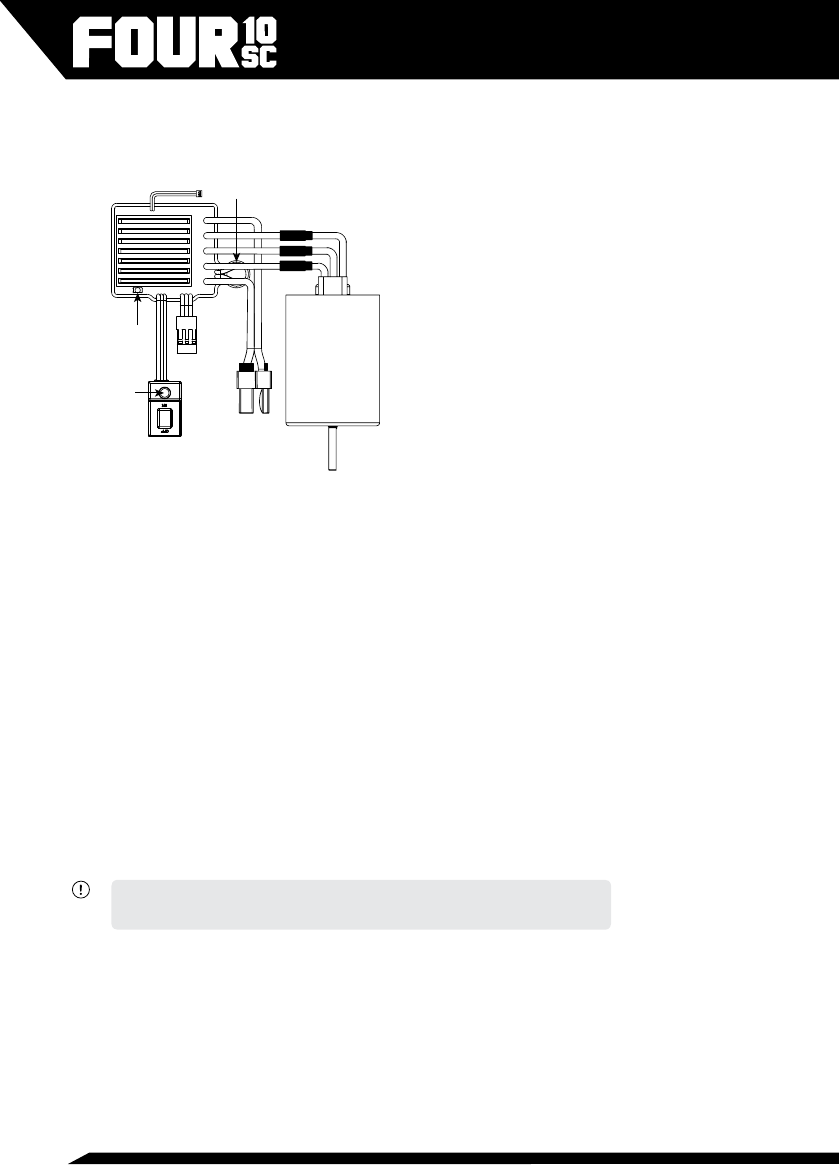
TO BATTERY
(THIS CONNECTOR IS
COMPATIBLE WITH
BATTERIES HAVING
WSD1300 PLUGS INSTALLED)
PLUG FOR
COOLING FAN
SETUP
BUTTON
ON/OFF
SWITCH
TO
RECEIVER
INDICATOR
LED
POWER
CAPACITOR
GOLD BULLET
CONNECTORS
MOTOR
ESC

11
• The green LED lights when the throttle trigger is moved to the full throttle
position.
Alert Tones:
• Input voltage abnormal alert tone: The ESC begins to check the input
voltage when power on, if it is out of the normal range, such an alert tone
will be emitted: “beep-beep-, beep-beep-, beep-beep-” (There is 1 second
time interval between every “beep-beep-” tone).
• Throttle signal abnormal alert tone: When the ESC can’t detect the normal
throttle signal, such an alert tone will be emitted: “beep-, beep-, beep-”
(There is 2 seconds time interval between every “beep-” tone).
Protection Functions:
• Low voltage cut-off protection: If the voltage of a LiPo battery pack is lower
than the selected threshold for 2 seconds, the ESC will cut of the output
power. Please note that the ESC cannot be restarted if the voltage of each
LiPo cell is lower than the set threshold.
• Over-heat protection: When the temperature of the ESC is over 105 degrees
Celsius for 5 seconds, the ESC will cut off the output power.
• Throttle signal loss protection: The ESC will cut off the output power if the
throttle signal is lost for 0.2 second.
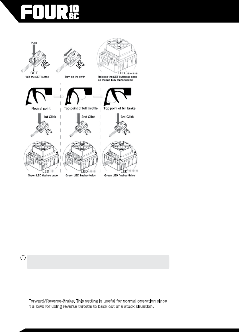
Throttle Range Calibration
1. Hold your transmitter approximately 1ft away while calibrating the ESC.
2. Turn Transmitter ON rst (transmitter should ALWAYS be ON if the ESC is
ON.
3. Ensure your Throttle channel (Ch. 2) on your transmitter is set to “Reverse”.
4. Adjust both Throttle and Reverse/Brake EPA settings to 100%.
5. With the ESC OFF, press and hold the Set button near the switch and turn
the ESC ON to enter setup mode. Release the button as soon as the LED
begins to ash.
6. Without touching the trigger, press the button to set the neutral position,
the GREEN LED will ash 1 time.
7. Pull/hold full throttle, press the button again, release the trigger, the
GREEN LED will ash 2 times.
8. Push/hold full brake/reverse, press the button again, the GREEN LED will
ash 3 times. Release trigger.
9. Switch the ESC OFF and back ON to complete setup.
10. Check the ESC operation to ensure forward throttle is actually forward, if
not, switch any two of the motor wires and re-check. Then repeat steps 3-8
if you experience odd behavior.
12
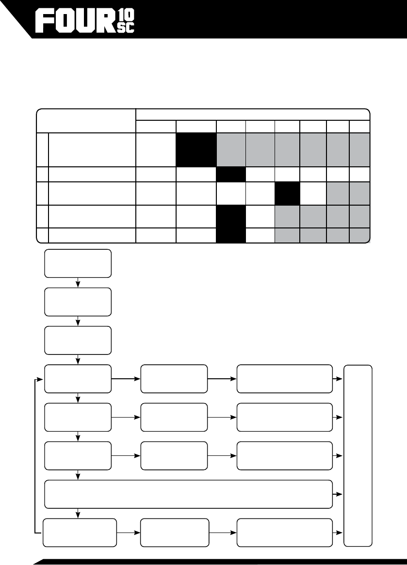
Programming your ESC
The Radient Reaktor is a programmable ESC. Although the default settings
should work well for most users, these settings exist so that you can ne tune
the performance of your ESC to your experience and components. Its various
programmable parameters can be adjusted either by interfacing with the
ESC directly (button presses and counting LED ashes), or via the optional
Reaktor Program Box (RDNA0031) which includes a digital readout of the
settings for easier interpretation and faster setup. There are 6 programmable
parameters for your consideration, below are descriptions of each Item and
following is the table and programming instructions for choosing your settings
should you choose to change from the defaults (highlighted in BOLD text).
CAUTION:THE MOST IMPORTANT OF THESE SETTINGS IS THE LOW VOLTAGE
CUT-OFF THRESHOLD (ITEM 3). PLEASE READ THE DESCRIPTION AND USAGE
SCENARIOS BELOW TO BETTER UNDERSTAND HOW TO USE THIS FEATURE.
Item 1: Running Mode:
1. Forward/Brake: This setting is considered as “Race” mode where the
reverse function is disabled.
2. Forward/Reverse-Brake: This setting is useful for normal operation since
it allows for using reverse throttle to back out of a stuck situation.
13
CAUTION: SWITCHING FROM REVERSE TO FORWARD THROTTLE POSITION
QUICKLY WILL CAUSE EXCESS LOAD ON THE ELECTRONICS AND DRIVETRAIN OF
YOUR VEHICLE. IT IS RECOMMENDED TO COME TO A STOP BEFORE CHANGING
REVERSE/FORWARD DIRECTION.
Item 2: Drag Brake Force (Automatic Brake):
1. 0%: This setting allows the vehicle to continue to roll after letting off
throttle without applying automatic-brake
2. 5%: Adding some drag brake will make the vehicle a little easier to
control, especially when driving on a closed circuit type course, helping
you to slow down and make turns easier.
3. 10%: Add more until you nd the right balance of assistance with slowing
down while still being able to maintain good corner speed without
upsetting the vehicle.
4. 15%
5. 20%
6. 25%
7. 30%
8. 40%
Item 3: Low Voltage Cut-Off (LVC) Threshold:
The Reaktor ESC has 6 built in LVC options. It is essential that you use the
proper LVC setting for the type of battery that you are using to achieve the
optimal performance and safest operation from your ESC/Motor/Battery.
This setting should be chosen based on the number and type of cells you are
using. For LiPo batteries we recommend setting the LVC to #5.
WARNING: USING A SETTING LOWER THAN 5 THIS MAY CAUSE OVER DISCHARGE
OF SOME BATTERIES AND CAUSE DAMAGE TO YOUR BATTERY, WHICH COULD
LEAD TO A FIRE.
1. No Protection: ONLY to be used with NiMH or NiCd type batteries. The
ESC will run as long as possible, draining all possible energy from the
batteries and eventually your vehicle will cease to function properly.
CAUTION: IF YOU ARE RUNNING YOUR VEHICLE AND NOTICE A SUDDEN DECREASE
IN POWER, YOUR ESC HAS DETECTED BATTERY VOLTAGE THAT IS LOWER THAN
WHAT SHOULD BE SAFELY RUN WITHOUT CAUSING DAMAGE TO YOUR BATTERY
OR ELECTRONIC EQUIPMENT. IF YOU ARE USING NIMH BATTERIES WHILE THIS
HAPPENS AND YOU HAVE ONLY BEEN RUNNING FOR A VERY SHORT TIME, IT IS
VERY LIKELY THAT YOU ARE MISTAKENLY USING ONE OF THE BELOW LVC MODES.
NOTE/TIP: When you notice the operation of your vehicle change, it is time to STOP
running and re-charge your battery.
2. 2.6V/Cell: This setting will cause the ESC to enter LVC protection mode
when the battery voltage is calculated at the selected voltage or less for
more than 2 seconds. Since the setting is “per cell” this means that if you
are running a 2 cell battery, the voltage protection will activate relative to

14
2 x 2.6V = 5.2V. This setting is primarily for use with LiFe type batteries
as the lower end of LVC settings. DO NOT USE THIS SETTING WITH LIPO
BATTERIES.
3. 2.8V/Cell: This setting would be the starting point for using LiFe type
batteries and is not recommended for LiPo batteries.
4. 3.0V/Cell: This setting is only recommended for use with extremely high
quality and highly durable LiPo batteries suitable for competition racing.
Using a setting this low with a LiPo battery may cause excessive “wear
and tear” on your batteries, shortening their lifespan.
5. 3.2V/Cell: This setting is recommended as the default for running
average grade LiPo batteries. If your batteries are relatively old it is
recommended to use setting 6 instead.
6. 3.4V/Cell: This setting can be used with any LiPo battery and will provide
the “safest” discharge level for your batteries however some lower quality
batteries do not sustain their voltage under heavy load and will cause
premature LVC activation. Starting here is a good choice if you are unsure
or just want to be extra cautious.
Item 4: Start Mode/Punch (Higher value is more aggressive):
The Reaktor ESC has 4 “punch” proles that allow you to tune the initial
power output of the ESC to suit your driving, vehicle, and the surface. You will
typically want a lower punch setting when the surface has less traction. To
get the optimal performance out of LiPo batteries, on high traction surfaces,
setting 4 is recommended.
1. Level 1 (70%): This setting will provide the smoothest throttle feel and
least wheel spin.
2. Level 2 (80%)
3. Level 3 (90%): This is the highest setting that should be used with high
performance NiMH batteries such as those included with your vehicle.
4. Level 4 (100%): This setting is recommended for use with LiPo batteries
only and allows you to get the maximum acceleration from your power
system. Choosing a setting higher than #3 for use with NiMH batteries
will cause inconsistent operation of your ESC, including possible
momentary power loss.
Item 5: Maximum Brake Force:
The Reaktor ESC has 4 maximum brake force settings allowing you to tune
your brakes for different driving surfaces. This setting works in conjunction
with the brake EPA setting on your transmitter which can still be used to ne
tune the braking force, however this setting affects the initial brake force
also. Since your vehicle is using a high performance brushless motor which
has great braking efciency already, we have reduced the setting to #3. On
some surfaces you may still nd this setting to be too high and nd that under
heavy braking with 4wd vehicles the rear tires may come off the ground.
This is a very unstable situation and should be avoided at all costs. If this

15
happens, reduce the maximum braking force to a lower setting. If however
you are unable to stop and the lack of deceleration is not due to wheel
slipping, you can increase the braking force.
CAUTION: BE SURE TO CHECK YOUR MAXIMUM BRAKE SETTINGS BY DRIVING
FROM FULL THROTTLE TO FULL HARD BRAKE IN AN OPEN AREA. IF THE REAR
TIRES COME OFF THE GROUND CAUSING A FRONT FLIP, THE VEHICLE WILL
TUMBLE OUT OF CONTROL AND COULD CAUSE PERSONAL OR PROPERTY
DAMAGE.
1. 25%: This is the lowest setting and should only be used when driving with
slow motors and on loose (low traction) surfaces.
2. 50%: It is not recommended to go below this setting on asphalt surfaces
as the stopping power may not be enough to safely slow your vehicle.
3. 75%: This is the default setting we feel will provide you the best starting
point for many different levels of traction on various surfaces. Remember
it is extremely important to only drive a vehicle as fast as you can safely
stop it. If the vehicle hits something or someone it can cause serious
injury.
4. 100%: This setting is only recommended if you are running a slotted
type motor, running this with a slotless style motor combined with a 4wd
vehicle will likely cause front ips thus a loss of control of your vehicle.
Reset to Factory Defaults:
• At any time when the throttle is located in neutral zone (except in the
throttle calibration or programming mode), hold the “SET” key for over 3
seconds, the red LED and green LED will ash at the same time , which
means each programmable item has be reset to its default value.
Audible/Visual Programming Alerts:
In dirty conditions or with various installations scenarios, visibility of the
LED’s may be obstructed. To assist with setting the ESC parameters you will
also be able to hear audible beeps from the motor that will indicate the value
of ashes the LED is transmitting.
To help interpret the beeps and ashes we use a long time ash and long
“Beep---” tone to represent number “5”, so it is easy to identify the higher
quantity of ashes/beeps. This applies to both the programming parameter
selection and also the value of each programmable item.
For example, if the LED ashes as the following:
• “A long time ash” (Motor sounds “B---”) = the No. 5 item
• “A long time ash + a short time ash” (Motor sounds “B---B”) = the No.
6 item
• “A long time ash + 2 short times ash” (Motor sounds “B---BB”) = the
No. 7 item
• “A long time ash + 3 short times ash” (Motor sounds “B---BBB”) = the
No. 8 item
• “A long time ash + 4 short times ash” (Motor sounds “B---BBBB”) =
the No. 9 item.
16
Programming Table and Default Settings:
Use the table below to better understand the programming process. This should help you navigate
thorugh the programming menu. A longer blink of the LED and Beep tone is used to represent number
5. So, a long Beep plus a short Beep is 6, a long Beep and two short Beeps is 7 etc.
Programmable Items
(Blinks of GREEN LED)
Programmable Value (Blinks of RED LED), Black background indicates default settings
1 2 3 4 5 6 7 8
1. Running Mode Forward
with Brake
Forward/
Reverse
with Brake
2. Drag Brake Force 0% 5% 10% 15% 20% 25% 30% 40%
3. Low Voltage Cut-Off
Threshold
No
Protection
2.6V/
Cell
2.8V/
Cell
3.0V/
Cell
3.2V/
Cell
3.4V/
Cell
4. Start Mode/Punch: Higher
value is more aggressive
Level 1
(70%)
Level 2
(80%)
Level 3
(90%)
Level 4
(100%)
5. Maximum Brake Force 25% 50% 75% 100%
Turn OFF ESC and
Transmitter
Press and hold the
SET button then
Turn ON the ESC
RED LED ashes
indicating you are in
program mode
GREEN LED ashes
1 time to set Item 1
Program Item 1:
Running Mode
RED LED ashes to indicate
set value: 1-2, press button to
cycle through available values
GREEN LED ashes
2 times to set Item 2
Program Item 2:
Drag Brake Force
Program Item 3:
LVC Threshold
Program Item N:
“Programmable
Item”
RED LED ashes to indicate
set value 1-8, press button to
cycle through available values
RED LED ashes to indicate
set value 1-6, press button to
cycle through available values
RED LED ashes to indicate
set value 1-X, press button to
cycle through available values
GREEN LED ashes
3 times to set Item 3
Continue to cycle through available Programmable Items and set values as desired. We
recommend you start with the default values and adjust only one value at a time to be sure
the change has made the desired effect.
GREEN LED ashes
“N” times to set Item N
HOLD SET BUTTON
HOLD SET BUTTON (3 Seconds)
HOLD SET BUTTON (3 Seconds)
HOLD SET BUTTON (3 Seconds)
HOLD SET BUTTON (3 Seconds)
Turn OFF ESC at any time to conrm setting, turn ON
again to begin using the new settings.

17
Adjusting and Tuning Your Vehicle
The Select Four 10SC has been engineered with some available tuning
options listed here for reference. The default conguration has been chosen
to provide what we feel is the most enjoyable experience for most operating
conditions. However we do encourage experimentation and testing as that’s
where the real fun begins!
Ride Height Adjustment
It is ideal to have the drive shafts above level but still allow the shocks to
extend when you lift the vehicle while the vehicle is sitting on a at surface
with the body installed. Use the threaded adjustment collars to achieve the
desired ride height.
• Lowering the collar will raise the ride height of the vehicle and if done
excessively may decrease stability.
• Raising the collar will lower the ride height and may cause the chassis to
drag on the ground.
Upper Shock Position
There are multiple shock installation locations for the top mounting location
of the shock towers. The default positions have been chosen as a good
starting point. Moving the shock mounting location inward will result in a
slightly less responsive feel on the front or rear of the vehicle but it will be a
little more stable. Moving the shock mounting location outward will make the
truck more responsive but less stable in some conditions.
Lower Shock Position
There are multiple shock installation locations for the lower mounting
location of the shocks in the suspension arm. The default location is ideal for
the included shock length. However you can play a little.
• Moving the shocks to the inside location will result in a slightly more
responsive feel on the front or rear of the vehicle but become a little less
stable. This change will also increase the vehicle’s articulation and you
will notice more body roll. Always check and adjust, if necessary, the ride
height of your vehicle after moving the shock mounting locations.
Battery Mounting
Your vehicle comes equipped with foam blocks used to position the battery.
Centered is the default location.
• Moving the battery forward will generally give the vehicle more steering
while exiting a turn, but less while entering a turn.
• Moving the battery backwards will generally give the vehicle a little more
traction but less steering while on power.
• Ensure the foam blocks are in place to keep the battery pack from

18
changing position in the battery tray.
• It may be necessary to reset the ride height after changing to a heavier/
lighter battery or making a setup change.
General Care
• Always use clean, dry cloth or soft bristle brush to clean your equipment.
• Never use chemical cleansers to avoid damage to the sensitive
electronics and plastics.
Maintenance
We want you to enjoy your product to its fullest potential. For this to happen
it is important to keep your product clean and properly maintained. Lack
of cleaning and maintenance can cause component failure. For best and
continued performance from your product it is recommended to briey
inspect your product for damage every few uses. Typically, a good time to
do this is when changing the battery in your vehicle or while it is charging.
If a problem is discovered, stop use immediately and perform repairs or
seek assistance. Continued use of failed components can cause more
unnecessary damage to your product.
ESC and Servo
The ESC and servo included in your vehicle are rated for all weather use. It
is recommended that you avoid submersion of the vehicle however running
in puddles, rain and snow should not be damaging. If you will be running in
a lot of water it is recommended to un-plug the fan from the ESC to prevent
the fan from being over-loaded from the water. Be sure to re-connect the fan
immediately after use and drying the terminals. Always remove excess water/
snow from your vehicle after running to help prevent corrosion. Using an air
compressor is effective but please use eye protection.
Transmitter
Although the receiver included with your radio system is rated for all weather
use, the transmitter is not. The transmitter should not be used in the rain or
other wet environment to avoid damage to the sensitive electronics.
• Clean dirt and debris off of your transmitter regularly to avoid the
consequences of these getting into the sensitive electronics where they
can cause short circuits and/or restrict motion of the internal steering
and throttle mechanisms.
• Ensure the antenna is kept in proper working order. The transmitter is not
safe to use with a broken or missing antenna.

19
Receiver
Although the receiver included with your radio system is rated for all weather
use, it is recommended that you avoid submersion of the receiver, however
running in puddles, rain, and snow is okay.
CAUTION: ALTHOUGH THE ELECTRONICS ARE PROTECTED FROM THE WEATHER,
THE CONNECTIONS ARE NOT. ELECTRICAL CONNECTIONS WILL CORRODE WHEN
EXPOSED TO MOISTURE WHEN IN USE AND IF LEFT IN A WET CONDITION. IT IS
CRITICAL THAT YOU UNPLUG AND DRY ALL EXPOSED ELECTRICAL CONNECTIONS
AFTER EACH USE IN WET CONDITIONS TO AVOID DAMAGE TO YOUR EQUIPMENT.
• To achieve full operating range with your radio system, it is critical that
the receiver antenna be installed properly and undamaged.
• Inspect any exposed antenna for cuts or abrasions.
• Ensure there are no kinks in the antenna or antenna tube.
• Never fold the end of the antenna over the tube, this will reduce the
range and damage the antenna.
• Ensure the antenna is not being pinched by the set screw that holds the
antenna tube in place.
Gears
Periodically remove the gear cover to clearly inspect the gears and ensure
there is no debris in the gear compartment.
Proper gear mesh setting is crucial for proper operation and life of gears in
your product. It is important to have the pinion gear (attached to motor) as
close to the spur gear (attached to drive shaft) as possible yet while providing
a minimal amount of backlash. Backlash is the rotation one gear has to make
before contacting the other. Having the gear mesh set too tight will cause
excess load on the electrical components and may cause premature failure.
Having gear mesh set too loose will cause excess wear and possible skipping
of teeth during operation thus causing excess wear and premature failure.
Checking the gear mesh and setting proper backlash.
1. Remove the spur gear cover.
2. Check how much movement is allowed (backlash) of the spur gear
before the pinion gear moves (this is mostly feel, not visual). Check this
movement in multiple places by rotating the spur gear approximately 1/6
rotation and rechecking.
3. If the spur gear is allowed to move more than a very small amount, or if it
there is no backlash, the gear mesh must be adjusted. If there is a lot of
movement, it is recommended to attempt to tighten the mesh. Attempted
adjustment should only improve the situation; if the mesh was correct to
begin with, you will know what that feels like, and if it wasn’t correct, it
will be when you are done after following these procedures.

20
Setting the Gear Mesh
1. Loosen the clamping screw securing the motor plate’s rotation in the
motor mount, only enough to allow the motor to rotate in the mount.
Check and ensure there is no debris in the gears affecting the mesh.
2. Rotate the top of the motor away from the center of the chassis, insert
a strip of notebook paper between the pinion and spur gear, then rotate
the motor plate back until there is no backlash. You will have to push/
twist relatively hard to ensure the paper is pressed all the way into the
teeth.
3. Hold the motor snugly in position while retightening the screw. Only
tighten the screw until the motor won’t move. There should be a slight
gap between the coils of the spring.
4. Rotate the spur gear (turn the tires) to feed the paper out of the mesh,
re-check the gear mesh and adjust again if necessary.
5. Re-install the spur gear cover when the mesh is properly set.
WARNING: NEVER OPERATE YOUR VEHICLE WITH THE SPUR GEAR COVER
REMOVED. SEVERE INJURY, DAMAGE TO ELECTRICAL COMPONENTS, AND
EXCESSIVE WEAR AND TEAR ON DRIVETRAIN MAY RESULT.
Shocks
Periodically inspect the shocks for smooth motion, leaking oil and dirt residue
build up around the shaft or caps. Do not allow dirt to build up around the
shock shaft and bottom of the shock. Doing so will reduce the life of the
shock and cause a shock to leak oil. Be sure to clean the shocks regularly
with a clean and dry soft bristle brush and/or rag.
CAUTION: NEVER USE SPRAY CLEANERS TO CLEAN YOUR SHOCKS, DOING SO CAN
CAUSE DAMAGE TO THE SEALS, CAUSING THEM TO LEAK MORE AND REDUCE THE
LIEF AND PERFORMANCE OF YOUR SHOCKS.
Signs to look out for determining if your shock needs to be maintained or
rebuilt.
• Oil around the shaft means the oil leaked from inside and needs to be
replaced.
• Persistent oil around the shock shaft or lower portion of the shock
typically points to damaged O-rings which will need replacing. See your
local hobby dealer for replacement parts.
Relling your shocks:
1. Remove shock from vehicle, remove spring and top cap. Remove the
bleed screw from the cap.
2. With shock shaft extended, add oil to top of body (use only 100% silicone
oil) and reinstall the shock cap. Be sure the o-ring stays “seated” and
does not squeeze out.
Turn right to tighten
and left to loosen
Clamping
Screw

21
3. Slowly compress the shock shaft 100% of travel using a towel or paper
napkin to clean up overowed oil, then reinstall the bleed screw. Do not
over-tighten.
4. Check for free motion of shock. If the shock feels like it gets stiffer at the
end of compression, there is too much oil or air. Compress the shaft and
remove the bleed screw slowly to allow excess air/oil to come out, then
reinstall the screw.
5. It is normal for the shock to rebound (with the spring removed) after full
compression and release.
Replacing the O-rings:
• Disassemble shock and remove shock end and shaft from the body.
• Carefully remove lower cap by unscrewing from the shock body.
• Remove the O-ring and spacer and replace with genuine replacement
parts.
• Re-assemble the shock following the relling instructions above.
Tires and Wheels
Inspect the tires to ensure they have adequate tread and they are properly
glued to the wheels. The tires on your vehicle come pre-glued from the
factory; however after running your vehicle it is possible for the glue to come
loose in some areas.
• To reattach the tire to the wheel, use hobby grade Cyanoacrylate (CA)
glue and apply small amounts (one drop at a time) between the tire and
wheel. Allow the glue to fully dry before operating your vehicle.
• When reinstalling tires, use caution when tightening the nuts that secure
the wheels to the vehicle. Ensure the wheels rotate freely but don’t
wobble excessively. Over tightening the wheels may cause excess strain
on the electrical and mechanical components of your vehicle. Operating
your vehicle under these conditions will void your warranty.
• Taking the above into consideration, leaving wheels too loose can cause
them to strip. It is recommended to check that the wheel nuts are tight
every time you run your vehicle.
• Consequently running your vehicle will cause the tires to eventually wear
out. Be sure to obtain and use genuine replacement parts from your local
hobby dealer when necessary.
General Wear and Tear
Using your vehicle will cause general wear and tear which is not covered
under warranty yet may necessitate replacement of components. Continued
operation of your product with worn components may cause continued
damage to other components.
Be sure to regularly inspect your vehicle and accessories for excess wear and
damaged components.

22
Storage and Disposal
Storage
• Always store all equipment in a cool dry place when not in use.
• Always disconnect the batteries before storage.
• Never store the transmitter or receiver in direct sunlight for extended
periods of time.
• Never store the transmitter with batteries installed for extended periods
of time. Doing so may allow the batteries to leak and cause permanent
damage to the transmitter.
• Always disconnect electrical connections after use in wet environments.
Allowing the contacts to dry will reduce corrosion.
Disposal
Your product is considered electronic waste and should never be discarded
in standard garbage containers. Please visit your local hobby dealer (and
some home improvement centers) and use the FREE battery disposal center
for proper disposal/recycling. Consult your local city hall for information on
recycling other electronic waste.
Troubleshooting Problems
Before contacting customer support, recall that this is a hobby grade product
intended to be user serviceable. Please take the time to fully inspect your
product for any obvious causes to the issues you are experiencing. Below are
some of the most common issues experienced. Scan the QR code to the right
with your smart phone for quick access to the product support content on our
website.
• Many control issues can be resolved by simply re-pairing the transmitter
and receiver, always start here.
• Dead transmitter or vehicle batteries will cause the product to malfunction
and not work properly. As with TV remote controls in your home, if the
batteries are dead, they don’t work. Start power related troubleshooting
with fresh batteries in the transmitter and recharged batteries in the
vehicle.
• Power connections between the Battery, ESC and receiver are critical to
the performance of the product. Running in various debris may cause
foreign objects to snag on wires, causing connections to come loose. It is
a good idea to unplug and reconnect motor and battery connections when
beginning power related troubleshooting. Also inspect for any damage
caused to the antenna.
• Drivetrain issues can mask themselves as power related. Fully inspect
the wheels, driveshafts, and motor for foreign objects that may have

23
become tangled or wrapped around the spinning parts of the drivetrain.
Small objects like shing line for example, can wrap around a drive shaft,
overheat and melt due to the friction and cause the entire drivetrain to
lock up. Although a big problem, it can be difcult to see when inspecting.
Always remove the wheels from your vehicle when troubleshooting
drivetrain related issues.
• The drivetrain in your vehicle has a covered shaft to protect from debris.
We encourage you to remove it and inspect under the cover to ensure that
items have not been entangled around the shaft causing drag and possible
failure. Inspect around the steering components to ensure no debris are
preventing normal steering operation.
• Steering can become sluggish once components get dirty or “take a set”
after running. Inspect the rod ends of the turnbuckles to ensure they are
properly aligned and not binding. You should be able to grab a turnbuckle
with your ngers and rotate it easily.
• Healthy gears are crucial to a properly functioning vehicle. If you hear your
vehicle making very loud noises, you should immediately stop and check
the gears for foreign debris. Even a small pebble can get lodged into the
teeth of the pinion gear, which would practically destroy the spur gear in a
very short period of time.

24
Appendix A: Troubleshooting Guide for the Reaktor Power System
Problem / Symptom Possible Cause Possible Solution
ESC will not set to
transmitter
Receiver and transmitter not bound Try re-pairing
Throttle Channel not set to Reverse Unless using Futaba radio, set Th channel to Re-
verse
Batteries dead in car or transmitter Replace batteries
Transmitter is too close to vehicle Hold transmitter farther away from vehicle
After turning ON, the
motor won’t work and
no sound comes from
motor
The connections between the bat-
tery and the ESC are not correct
Check the power connections. Replace the connec-
tors if they are worn or damaged
Car slowed down or
stopped drastically
during run
Battery voltage too low, LVC active Charge or change batteries
ESC over-temp protection active Turn off ESC and allow ESC and motor to cool before
running again
ESC Over current protection active
Change operating conditions to ones that are not
as hard on the electronics, i.e. move from grass to
asphalt.
Reduce pinion gear size on the motor to reduce load
on the ESC
Car doesn’t accelerate Ensure the proper punch mode is
used Change punch mode based on battery you are using
Reverse not working
Reverse mode has been disabled
in ESC Follow setup instructions to turn back on
ESC was improperly set to trans-
mitter
Re-set to transmitter, ensure Th channel is set to
Reverse for non Futaba transmitters
EPA on transmitter has been turned
down for reverse
Adjust EPA’s to 100% and recalibrate ESC to trans-
mitter
Motor only goes in
reverse or goes in
reverse when I pull
trigger to go forward
Throttle Channel not set to Reverse Unless using Futaba radio, set Th channel to Re-
verse and reset ESC to transmitter
Motor connected to ESC improperly Switch any two motor wires
EPA on transmitter has been turned
down for reverse Adjust EPA’s to 100% and reset ESC to transmitter

25
Appendix B: Troubleshooting Guide
Problem / Symptom Possible Cause Possible Solution
Vehicle will not turn on
Battery voltage too low Charge battery
Battery not connected Re/connect battery
Damaged battery Replace battery
Transmitter will not
turn on
Battery voltage too low Charge or change batteries
Battery/ies installed improperly Correct installation
Short radio range (Ve-
hicle stops responding
to transmitter at short
distances)
Damaged or improperly installed
receiver and antenna
Check receiver antenna for damage. Ensure antenna
is properly installed in tube and mount, extending
perpendicular from the ground. Ensure all connec-
tions are secure
Receiver is malfunctioning Replace receiver
Battery voltage too low Replace or recharge batteries in transmitter and
vehicle
Steering not respond-
ing as expected
Trim not set properly Adjust steering trim
Screws too tight on steering parts Adjust screws to allow for free motion
Fasteners have become loose Check and tighten all fasteners to as-new condition,
be careful to not over tighten
Vehicle not respond-
ing as expected to
transmitter
Trims not set properly Adjust throttle and/or steering trim
Radio system lost pair Re-pair radio system
Bad electrical connections Check motor and battery plugs to ensure they are fully
connected
Wheels twitch while
vehicle is idle (con-
trols at neutral)
Transmitter too close to receiver
(<1m) Increase distance between the units
Receiver wire damaged Inspect antenna for damage and replace if necessary
Receiver antenna not installed in
vertical position Install in mount with care to not damage antenna wire
Steering will not trim
straight, always has
right or left bias
Binding in steering system Inspect and correct any binding components or loosen
screws if over tight
Front wheels too tight Check and adjust wheel nuts to ensure the wheels
are not too tight
Vehicle top speed and
acceleration is slow
Battery voltage too low Charge battery
Drivetrain has too much friction Check for debris/excessive wear on gears, inspect
bearings
Gear mesh too tight Loosen gear mesh
Pinion gear is loose Check and tighten set screw on motor pinion
Broken Differential
Check differential and ensure the outdrives are
secured and gears intact. You should not be able to
pull them out
Drive pin missing Check for missing wheel pins (behind wheel hexes), or
dogbone pins
ESC not set to transmitter Follow ESC instructions to set to transmitter
Wheels not spinning
freely
Wheels too tight Check and adjust wheel nuts
Differentials stripped Check differentials and replace/repair if necessary
Battery charge stops
lasting as long as it
used to
The battery has become old Replace battery
Battery not charged completely due
to insufcient charge time
Charge for longer period of time or try a peak de-
tection charger. We recommend the Radient Primal
(RDNA0001)
Gear mesh too tight Check and reset gear mesh setting
Charger, battery, wires, or plug has
malfunctioned
Check all connections and wires for damage or exces-
sive wear and replace if necessary
Shocks and/or arms
covered in oil
Shock O-ring seals are worn Replace O-rings and rell shock with oil
Top shock cap too loose or over
tightened Check tightness (nger tight), rell shock oil
Bottom shock cap dislodged Check installation, rell shock oil
Spur gears stripping
Gear mesh too loose Tighten gear mesh for proper backlash
Fasteners loose or missing Check for loose fasteners and bad bearings.
Pinion gear too worn out Replace pinion gear
26
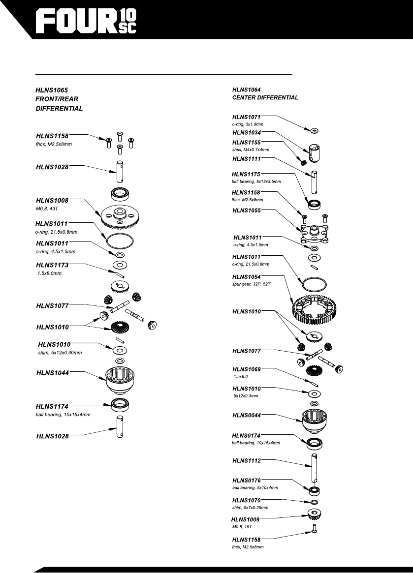
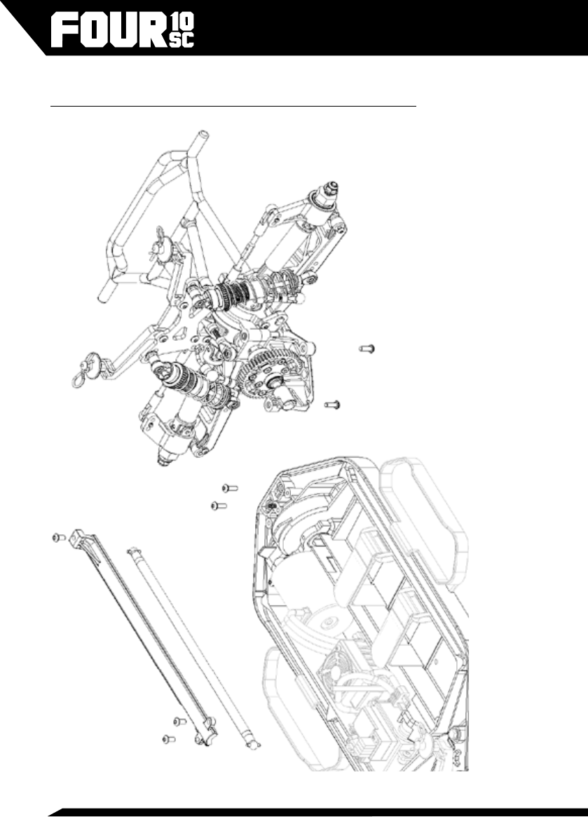
Appendix C: Differential Exploded Views
27
o-ring, 3x1.9mm
HLNS1071
HLNS1114
HLNS1063
o-ring, 7x1.0mm
HLNS1095
o-ring, 12x1.5mm
HLNS1071
HLNS1114
HLNS1073
HLNS1076
HLNS1163
bhcs, M2x4mm
HLNS1073
HLNS1073
HLNS1073
HLNS1073
REAR SHOCK
HLNS1071
HLNS1073
HLNS1072
HLNS1071
o-ring, 7x1.0mm
FRONT SHOCK
HLNS1073
HLNS1075
HLNS1071
o-ring, 7x1.0mm
HLNS1071
HLNS1072
HLNS1073
HLNS1073
HLNS1073
bhcs, M2x4mm
HLNS1163
HLNS1090
HLNS1062
HLNS1073
o-ring, 3x1.9mm
HLNS1071
HLNS1073
HLNS1113
HLNS1113
o-ring, 7x1.0mm
HLNS1071
o-ring, 12x1.5mm
Appendix D: Shock Exploded Views
28
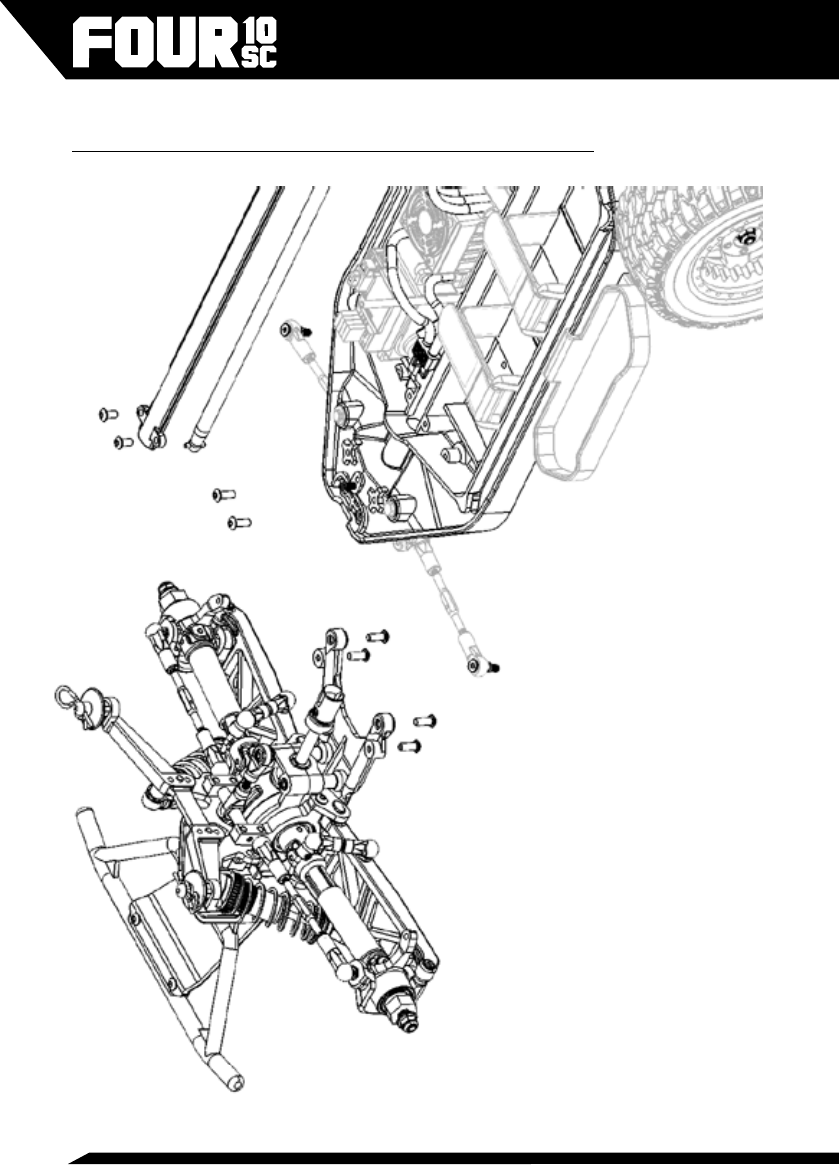
Appendix E: Front Suspension Removal
29
Appendix F: Front Suspension Exploded View
HLNS1041
HLNS1021
HLNS1014
HLNS1164
HLNS1160
HLNS1006
HLNS1164
HLNS1162
bhcs, M3x10mm
HLNS1157
bhcs, M3x8mm
flanged locknut,
HLNS1160
HLNS1159
bhcs, M3x16mm
HLNS1164
HLNS1023
bhcs, M3x8mm
HLNS1168
bhcs, M3x8mm
HLNS1039
HLNS1043
HLNS1045
M3X3mm
HLNS1025
HLNS1002
HLNS1061
HLNS1159
HLNS1021
HLNS1157
HLNS1167
flanged, M3X0.5mm
HLNS1100
M4X0.7
HLNS1021
bhcs, M3x8mm
M3X0.5mm
M3X3mm
HLNS1068
M3X20mm
ball bearing, 10x15x4mm
HLNS0174
M3X12mm
bhcs, M3x8mm
HLNS1030
fhcs, M4x8mm
HLNS1164
HLNS1015
HLNS1043
HLNS1047
HLNS1161
HLNS1058
HLNS1041
HLNS1033
,
M3X12mm
HLNS1023
HLNS1038
HLNS1026
HLNS1156
HLNS1102
HLNS1006
HLNS1045
HLNS1049
HLNS1164
bhcs, M2.5x4mm
fhcs, M4x8mm
HLNS1165
HLNS1078
HLNS1164
bhcs, M3x8mm
HLNS1164
bhcs, M3x8mm
HLNS1166
HLNS1073
30
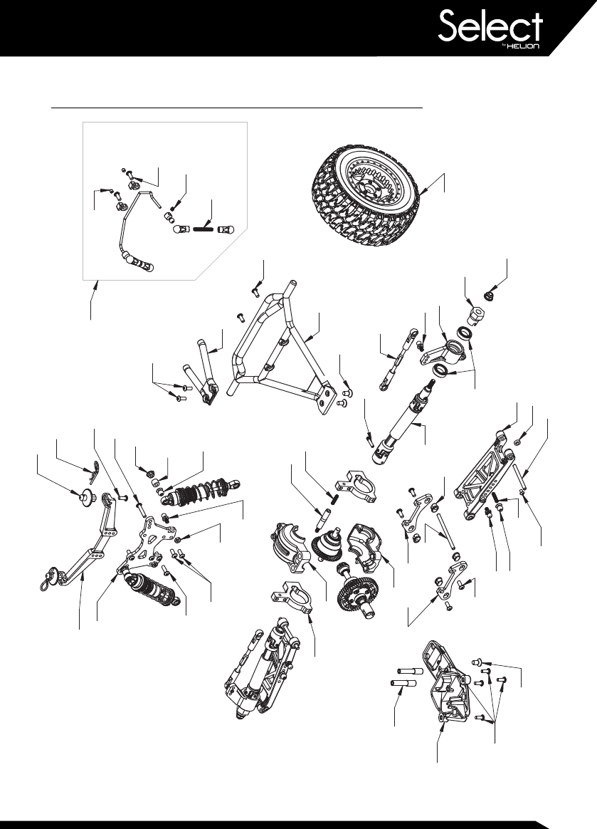
Appendix G: Rear Suspension Removal View
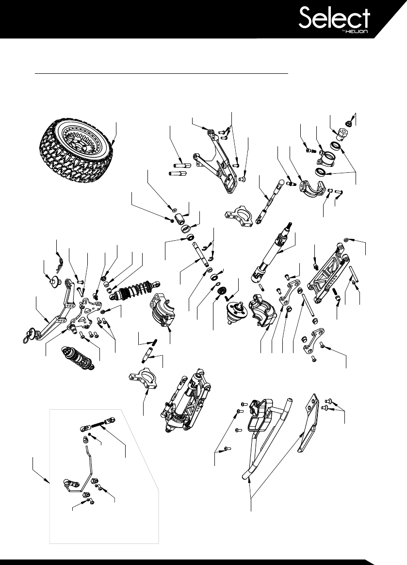
31
Appendix H: Rear Suspension Exploded View
HLNS1166
HLNS1015
M3X.05
HLNS1034
HLNS1022
HLNS1164
bhcs, M3x16mm
bhcs, M3x8mm
5x7x0.25mm
HLNS1164
HLNS1102
HLNS1167
M3x20mm
HLNS1157
fhcs, M4x8mm
HLNS1029
HLNS1164
bhcs, M3x8mm
HLNS1029
HLNS1164
HLNS1026
HLNS1023
HLNS1159
HLNS1023
ball bearing, 5x10x4mm
HLNS1156
flanged locknut, M4x0.7mm
M3x0.5x3mm
HLNS1009
bhcs, M3x10mm
HLNS1049
HLNS1165
bhcs, M3x8mm
HLNS1030
HLNS1005
HLNS1006
HLNS1066
HLNS1060
HLNS1024
bhcs, M3x8mm
HLNS1165
HLNS1021
HLNS1161
HLNS1073
FHCS, M2.5X0.4MM
HLNS1058
bhcs, M3x10mm
HLNS1048
HLNS1045
flanged, M3x0.5
HLNS1164
bhcs, M3x8mm
M3X12
HLNS1100
HLNS1070
bhcs, M2.5x4mm
HLNS1078
HLNS1025
HLNS1039
HLNS1013
HLNS1160
M4X0.7X4mm
HLNS1159
HLNS1040
M3x0.5x3mm
HLNS1002
fhcs, M4x8mm
HLNS1024
HLNS1176
ball bearing, 5x10x4mm
HLNS1162
HLNS1071
HLNS1158
HLNS1176
pinion gear, M0.8, 15T
HLNS1048
HLNS1021
ball bearing, 10x15x4mm
HLNS1155
HLNS1029
HLNS1038
HLNS1006
HLNS1168
HLNS1045
HLNS1157
HLNS1164
bhcs, M3x8mm
HLNS1174
HLNS1169
HLNS1164
bhcs, M3x8mm
32
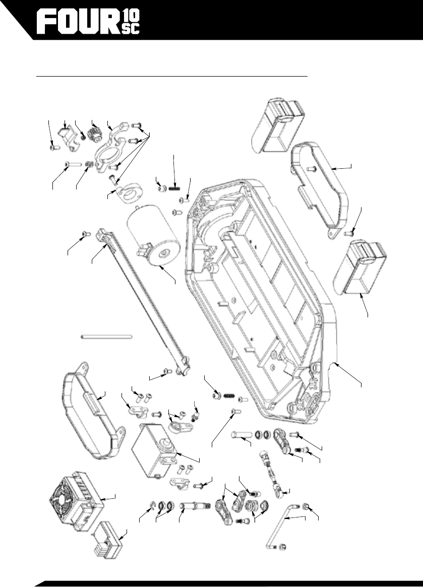
Appendix I: Main Chassis Exploded View
HLNS0154
bhcs, M3x6mm
HLNS1160
HLNS1167
HLNS1164
bhcs, M3x8mm
HLNS1079
HLNS1036
HLNS1164
HLNS1032
HLNS1042
bhcs, M3x8mm
M3x0.5x3mm
HLNS1032
HLNS1012
bhcs, M3x8mm
HLNS1159
HLNS1022
HLNS1074
bhcs, M3x8mm
bhcs, M3x16mm
KNNS0008
HLNS1177
HLNS1164
HLNS1050
HLNS1042
HLNS1003
bhcs, M3x6mm
HLNS1023
HLNS1021
HLNS1004
HLNS1023
HLNS1035 HLNS1164
HLNS1019
HLNS0169
HLNS1166
RDNA0197
HLNS1057
HLNS1056
HLNS1052
HLNS1164
bhcs, M3x8mm
M3x0.5x12mm,
HLNS1164
RDNA0055
HLNS1021
bhcs, M3x8mm
HLNS1046
HLNS1050
HLNS1164
bhcs, M3x8mm
HLNS1016
HLNS1154
RDNA0057

33
Appendix J: Spare Parts List
HLNS1001 Four 10SC, 4wd Brushless Short Course Truck
HLNS1002 Bulkhead, Aluminum (2) (410SC)
HLNS1003 Motor Mount (410SC)
HLNS1004 Motor Mount Cam (410SC)
HLNS1005 Steering Spindle, L-R (410SC)
HLNS1006 Hinge Pin Set (410SC)
HLNS1008 Ring Gear, 43T (410SC)
HLNS1009 Pinion Gear, Bevel, 15T (410SC)
HLNS1010 Gear Set and Pins, Internal Differential (410SC)
HLNS1011 Seal Kit, Differential (410SC)
HLNS1012 Pinion Gear, 32P, 15T x 0.125” (410SC)
HLNS1013 Shock Tower, Front (410SC)
HLNS1014 Shock Tower, Rear (410SC)
HLNS1015 Arm Holders (2) (410SC)
HLNS1016 Spring and Seat, Servo Saver (410SC)
HLNS1019 Link, Steering (410SC)
HLNS1020 Ball Stud, Pinned 4.8mm, Steering (410SC)
HLNS1021 Ball Stud, 4.8mm (410SC)
HLNS1023 Pivot Ball, 2.5mm Broached, M3, 5.8mm (410SC)
HLNS1024 King Pin Set (410SC)
HLNS1025 Ball Post, Bulkhead (410SC)
HLNS1026 Chassis Post, Lower (410SC)
HLNS1027 Shaft, Center (410SC)
HLNS1028 Shaft, Output, Diff (410SC)
HLNS1029 Driveshaft Set, Center, Front (410SC)
HLNS1030 Wheel Hex, 12mm (410SC)
HLNS1031 Turnbuckles, M3x58mm (2) (410SC)
HLNS1032 Steering Post Set (410SC)
HLNS1033 Screw Pin, Diff Outdrive (410SC)
HLNS1034 Outdrive, Center (410SC)
HLNS1035 Chassis (410SC)
HLNS1036 Gear Cover, Pinion (410SC)
HLNS1037 Ball Cup Set (410SC)
HLNS1038 Arm Bushing (410SC)
HLNS1039 Body Mount Set, F-R (410SC)

34
HLNS1040 Bumper Set, Front (410SC)
HLNS1041 Bumper Set, Rear (410SC)
HLNS1042 Bumper Set, Side (410SC)
HLNS1043 Hub Carrier Set, Rear (410SC)
HLNS1044 Differential Case, F-R-C (410SC)
HLNS1045 Differential Housing (410SC)
HLNS1046 Servo Mounts (410SC)
HLNS1047 Suspension Arm Set, F-R (410SC)
HLNS1048 Spindle Carrier, L-R (410SC)
HLNS1049 Lower Kick Plates, F-R (410SC)
HLNS1050 Steering Bellcranks (410SC)
HLNS1051 Dust Cover, Black (410SC)
HLNS1052 Battery Straps, 2S (410SC)
HLNS1053 Turnbuckles, M3x53mm (410SC)
HLNS1054 Spur Gear, Center Differential, 32P, 52T (410SC)
HLNS1055 Spur Gear Adapter, Center Differential (410SC)
HLNS1056 Center Shaft Cover (410SC)
HLNS1057 Servo Horn, 25T (410SC)
HLNS1058 Telescoping Universal Driveshaft Set (410SC)
HLNS1059 Tie Rod Set, Bulkhead, F-R (410SC)
HLNS1060 Swaybar Set, Front (410SC)
HLNS1061 Swaybar Set, Rear (410SC)
HLNS1062 Shock Set, Front (410SC)
HLNS1063 Shock Set, Rear (410SC)
HLNS1064 Differential, Center, Complete (410SC)
HLNS1065 Differential, Front-Rear, Complete (410SC)
HLNS1066 Tierod Set, Front Camber, 58mm (410SC)
HLNS1067 Tierod Set, Steering, 58mm (410SC)
HLNS1068 Tierod Set, Rear Camber, 53mm (410SC)
HLNS1069 Decal Sheet (410SC)
HLNS1070 Shims, 5x7x0.25mm (10)
HLNS1071 O-rings, Shock (410SC)
HLNS1072 E-clips, 2.5mm (410SC)
HLNS1073 Shock Plastic Rebuild Kit (410SC)
HLNS1074 Motor Mount Cam Spring Kit (410SC)
HLNS1075 Shock Shafts, Front, 39mm (2) (410SC)

35
HLNS1076 Shock Shafts, Rear, 45mm (2) (410SC)
HLNS1077 Cross Pins, Differential (410SC)
HLNS1078 Body Clips (410SC)
HLNS1079 Tierod Assembly, Servo Link (410SC)
HLNS1090 Spring, Shock, Front, White (410SC)
HLNS1095 Spring, Shock, Rear, White (410SC)
HLNS1098 Wheels, Black, 12mm Hex (410SC)
HLNS1100 Body Posts (410SC)
HLNS1101 Tires and Foam Inserts (410SC)
HLNS1102 Tires and Wheels, Assembled, Black (410SC)
HLNS1104 Battery Straps, XL 3S (410SC)
HLNS1105 Center Front Shaft Assembly (410SC)
HLNS1106 Body, Lava, Pre-mounted (410SC)
HLNS1108 Body, Cobalt, Pre-mounted (410SC)
HLNS1111 Center Differential Forward Output Shaft (410SC)
HLNS1112 Center Differential Rear Output Shaft (410SC)
HLNS1113 Shock Bodies, Front and Adjustment Nuts (410SC)
HLNS1114 Shock Bodies, Rear and Adjustment Nuts (410SC)
HLNS1154 Button Head Cap Screws (BHCS) M3x6mm (10)
HLNS1156 Flanged Locknuts, Serrated, M4x0.7mm (10)
HLNS1157 Flat Head Cap Screws (FHCS) M4x8mm (10)
HLNS1158 Flat Head Cap Screws (FHCS) M2.5x8mm (10)
HLNS1159 Socket Head Set Screws (SHSS) M3x3mm (10)
HLNS1160 Socket Head Set Screws (SHSS) M3x12mm (10)
HLNS1161 Socket Head Set Screws (SHSS) M3x20mm (10)
HLNS1162 Button Head Cap Screws (BHCS) M2.5x4mm (10)
HLNS1163 Button Head Cap Screws (BHCS) M2x4mm (10)
HLNS1164 Button Head Cap Screws (BHCS) M3x8mm (10)
HLNS1165 Button Head Cap Screws (BHCS) M3x10mm (10)
HLNS1166 Button Head Cap Screws (BHCS) M3x16mm (10)
HLNS1167 Nylon Locknuts M3 (10)
HLNS1168 Flanged Serrated Locknuts M3 (10)
HLNS1169 E-clips, 4.5mm (410SC)
HLNS1170 Shims, 5x10x0.3mm (10)
HLNS1171 Solid Pin, 3x10mm (10)
HLNS1172 Solid Pin, 2x10mm (10)

36
HLNS1173 Solid Pin, 1.5x8mm (10)
HLNS1174 Ball Bearings, Rubber Sealed 10x15x4mm (4)
HLNS1175 Ball Bearings, Rubber Sealed 8x12x3.5mm (4)
HLNS1176 Ball Bearings, Rubber Sealed 5x10x4mm (4)
HLNS1177 Ball Bearings, Rubber Sealed 5x8x2.5mm (4)
HLNS1178 Quick-Start Guide, Four 10SC
HLNS1179 Owner’s Manual, Four 10SC
KNNS0001 ET4 4Ch 2.4GHz Xenon (Xe) AW Radio System
KNNS0008 4Ch 2.4GHz Xenon (Xe) Receiver, AW
KNNS0012 Battery Holder, 4xAA
KNNS0013 ET4 Grips, S-M-L, Black
KNNS0014 ET4 Model Decal Set
KNNS0015 Wall Charger
KNNS0016 ET4 Quick Start Guide
KNNS0017 ET4 Owner’s Manual
KNNS0018 Battery Pack, 5-Cell NiMH AA, RX
KNNS0019 ET4 Grips, S-M-L, Blue
KNNS0020 ET4 Grips, S-M-L, White
RDNA0055 Reaktor Brushless ESC NS-60A WP-TSP
RDNA0057 Reaktor BL Motor NS 3500kV 4-Pole, TSP
RDNA0060 Reaktor BL Combo, NS-60A, 3500kV, TSP
RDNA0174 Fan Kit, Reaktor 50, 60T
Optional Parts
HLNS1080 Metal Universal Driveshaft Set, 77mm (410SC)
HLNS1081 Outdrive Cup Set, F-R (410SC)
HLNS1082 Aluminum Suspension Arm Set, L-R (410SC)
HLNS1083 Shock Set, Big Bore, Front (410SC)
HLNS1084 Shock Set, Big Bore, Rear (410SC)
HLNS1085 Aluminum Bulkhead Set, 2-Piece (410SC)
HLNS1088 Spring, Shock, Front, Ultra Soft (410SC)
HLNS1089 Spring, Shock, Front, Soft (410SC)
HLNS1091 Spring, Shock, Front, Hard (410SC)
HLNS1092 Spring, Shock, Front, Ultra Hard (410SC)
HLNS1093 Spring, Shock, Rear, Ultra Soft (410SC)
HLNS1094 Spring, Shock, Rear, Soft (410SC)

37
HLNS1096 Spring, Shock, Rear, Hard (410SC)
HLNS1097 Spring, Shock, Rear, Ultra Hard (410SC)
HLNS1099 Wheels, Black Chrome, 12mm Hex (410SC)
HLNS1103 Tires and Wheels, Assembled, Black Chrome (410SC)
HLNS1107 Body, Emerald, Pre-mounted (410SC)
HLNS1109 Body, Clear (410SC)
Accessories
RDNA0044 Ascend LCD Multi-Chem 6A Charger (US)
RDNA0045 Ascend LCD Multi-Chem 6A Charger (UK)
RDNA0046 Ascend LCD Multi-Chem 6A Charger (EU)
RDNA0098 Superpax Battery, SC 8.4V 7-Cell 3000mAh NiMH, 6-1 Hump, HCT
RDNA0100 Superpax Battery, SC 8.4V 7-Cell 4200mAh NiMH, 6-1 Stick, HCT
RDNA0101 Superpax Battery, SC 8.4V 7-Cell 4200mAh NiMH, 6-1 Hump, HCT
RDNA0103 Superpax Battery, SC 8.4V 7-Cell 5000mAh NiMH, 6-1 Stick, HCT
RDNA0104 Superpax Battery, SC 8.4V 7-Cell 5000mAh NiMH, 6-1 Hump, HCT
RDNA0105 Superpax Battery, SC 9.6V 8-Cell 5000mAh NiMH, 6-2 Hump, HCT
RDNA0110 Silicone Shock Fluid, 10wt, 100cSt
RDNA0111 Silicone Shock Fluid, 15wt, 150cSt
RDNA0112 Silicone Shock Fluid, 17.5wt, 175cSt
RDNA0113 Silicone Shock Fluid, 20wt, 200cSt
RDNA0114 Silicone Shock Fluid, 22.5wt, 238cSt
RDNA0115 Silicone Shock Fluid, 25wt, 275cSt
RDNA0116 Silicone Shock Fluid, 27.5wt, 313cSt
RDNA0117 Silicone Shock Fluid, 30wt, 350cSt
RDNA0118 Silicone Shock Fluid, 32.5wt, 388cSt
RDNA0119 Silicone Shock Fluid, 35wt, 425cSt
RDNA0120 Silicone Shock Fluid, 37.5wt, 463cSt
RDNA0121 Silicone Shock Fluid, 40wt, 500cSt
RDNA0122 Silicone Shock Fluid, 42.5wt, 538cSt
RDNA0123 Silicone Shock Fluid, 45wt, 575cSt
RDNA0124 Silicone Shock Fluid, 47.5wt, 613cSt
RDNA0125 Silicone Shock Fluid, 50wt, 650cSt
RDNA0126 Silicone Shock Fluid, 60wt, 800cSt
RDNA0127 Silicone Shock Fluid, 70wt, 900cSt
RDNA0128 Silicone Shock Fluid, 80wt, 1000cSt

38
RDNA0131 Superpax Battery, SC 9.6V 8-C 3000mAh NiMH, 6-2 Hump, HCT
RDNA0132 Superpax Battery, SC 9.6V 8-C 4200mAh NiMH, 6-2 Hump, HCT
RDNA0309 Pinion Gear, 32P, Steel 9T
RDNA0310 Pinion Gear, 32P, Steel 10T
RDNA0311 Pinion Gear, 32P, Steel 11T
RDNA0312 Pinion Gear, 32P, Steel 12T
RDNA0313 Pinion Gear, 32P, Steel 13T
RDNA0314 Pinion Gear, 32P, Steel 14T
RDNA0315 Pinion Gear, 32P, Steel 15T
RDNA0316 Pinion Gear, 32P, Steel 16T
RDNA0317 Pinion Gear, 32P, Steel 17T
RDNA0318 Pinion Gear, 32P, Steel 18T
RDNA0319 Pinion Gear, 32P, Steel 19T
RDNA0320 Pinion Gear, 32P, Steel 20T
RDNA0321 Pinion Gear, 32P, Steel 21T
RDNA0322 Pinion Gear, 32P, Steel 22T
RDNA0323 Pinion Gear, 32P, Steel 23T
RDNA0340 Charge Adapter Squid, 11-Way
RDNA0370 Ascert 80W LCD Charger, US
RDNA0371 Ascert 80W LCD Charger, UK
RDNA0372 Ascert 80W LCD Charger, EU
RDNA0373 Ascert 80W LCD Charger, AU

39
HobbyTown Warranty Information
30 DAY LIMITED WARRANTY
General Disclaimer: This item is to be free of manufacture defects at time
of purchase. This warranty does not cover breakage due to abuse, improper
break-in, improper setup, or improper operation.
We at Helion RC have made every effort in component design, material
selection and assembly to make our products as durable as possible. Helion
products are covered under warranty only against manufacturer’s defect in
materials, workmanship or assembly when it is new (before being used).
If you believe a defect in materials, workmanship or assembly was not
apparent when the product was new and only became evident after the
product was used, then please contact your local HobbyTown® to apply for
warranty service. You must provide your original sales receipt verifying the
proof-of purchase and date thereof.
Provided warranty conditions have been met, the components that are
found to be defective, incorrectly made, or incorrectly assembled within the
warranty coverage time period may be repaired or replaced under the sole
discretion of HobbyTown®. In the event that your product needs a repair or a
replacement part that is not covered by this warranty, your local HobbyTown®
dealer can assist you with obtaining the genuine replacement parts and/or
accessories to service your Helion RC product.
If you purchased your Helion RC product from a HobbyTown® internet site not
afliated with a local store, please consult that site for its service policies.
JPerkins Distribution Warranty Information
Guarantee
This product is covered by the current statutory guarantee regulations. If you
wish to make a warranty claim, please contact the model shop where you
originally purchased the product from. You should also present your proof of
purchase.
• The guarantee does not cover faults or damage caused by:
• Incorrect handling or operation
• The use of incompatible accessories
• Modication or unauthorised repairs
• Accidental or deliberate damage
• Normal wear and tear
• Using the product outside of its stated specication
Firelands Group LLC accepts no liability for loss, damage or costs which are
incurred due to the incorrect or incompetent use of the product.

40
Model Engines Warranty Information
HELION RC 60 DAY WARRANTY
Model Engines (Aust.) Pty. Ltd. warrants this product to be free from defects
in materials or workmanship for 60 days from the date of purchase and
will repair, replace or refund the purchase should the product prove to be
defective.
This warranty does not apply to any unit or system or component which has
been dropped, damaged in a crash, improperly installed, assembled, handled
or abused.
Model Engines (Aust.) Pty. Ltd. reserves the right to void the warranty if the
product has been altered or modied, has had a foreign part added, has
been misused or not used for the purpose for which it was designed, has
been used near or in salt water, has been water damaged, or if the damage
has been caused by the customer’s use of the product.
Under no circumstances does Model Engines (Aust.) Pty. Ltd. warrant nor will
the consumer be entitled to consequential or incidental damages. Model
Engines (Aust.) Pty. Ltd. assumes no responsibility for any other damage,
inconvenience or other claims whatsoever.
LODGING A CLAIM
To lodge a claim, present the goods to your place of purchase (retailer where
you bought the product) with your original purchase receipt and a written
explanation of the defect.
The place of purchase (retailer where you bought the product) will then
contact Model Engines (Aust.) Pty. Ltd. for a Return Authority number and will
return the item for warranty assessment to Model Engines (Aust.) Pty. Ltd..
Items delivered to Model Engines (Aust.) Pty. Ltd. for warranty assessment
without a Return Authority number will be returned to sender.
The warranty process may take up to 14 business days from the date of
receipt. Model Engines (Aust.) Pty. Ltd. must assess each item and if
warranty applies must repair or replace the item at its discretion and return it
to the place of purchase (retailer where you bought the product).
Goods presented for warranty may be replaced by refurbished goods of the
same type rather than being repaired. Refurbished parts may be used to
repair the goods.
If the product is proved to be defective the cost and expenses relating to the
delivery of the goods to Model Engines (Aust.) Pty. Ltd., will be borne by Model
Engines (Aust.) Pty. Ltd..
The benets of this warranty are in addition to other rights and remedies of
the customer under any law to which this warranty relates.
Our goods come with guarantees that cannot be excluded under the
Australian consumer Law. You are entitled to a replacement or refund for a
major failure and for compensation for any other reasonably foreseeable loss
or damage. You are also entitled to have the goods repaired or replaced if

41
the goods fail to be of acceptable quality and the failure does not amount to
a major failure.
Model Engines (Aust.) Pty. Ltd., Unit 1, 158-168 Browns Road, Noble Park,
Victoria, 3174, Australia.
www.modelengines.com.au Ph (03) 8793 5555 warranties@modelengines.
com.au
This warranty information relates to goods supplied on a wholesale basis by
Model Engines (Aust.) Pty. Ltd. to Australian Retailers. The warranty complies
with Australian regulatory requirements and supersedes all warranty
information from the original manufacturer.
Declaration of Conformity
CE Conformity Declaration
This device has been tested in accordance with the relevant harmonised
European directives. This product’s design fulls the protective aims of the
European Community relating to the safe operation of this equipment.
For a copy of the Declaration of Conformity, please visit:
www.ikonnik-rc.com/support
Disposal
Electrical equipment marked with the crossed out wheelie bin symbol must
not be disposed of in household waste, but must be taken to a specialist
disposal or recycling system. In EU member countries, electrical equipment
must not be discarded via the normal domestic refuse channels (WEEE
- Waste Electrical and Electronic Equipment Directive 2002/96/EG). You
should take unwanted electrical equipment to your nearest local authority
waste collection point or recycling centre.
Distributed in the UK by:
J Perkins Distribution Ltd,
Lenham,
Kent,
UK
ME17 2DL.
www.jperkins.com

Scan this QR code with your
smartphone for more information
www. Helion-RC.com 000567-001 (REV C)
