PDF Fujitsu Omni SI (GTE) Database & Maintenence
Omni SI (GTE) Database & Maintenence Omni SI (GTE) Database & Maintenence
User Manual: PDF T E X T F I L E S
Open the PDF directly: View PDF ![]() .
.
Page Count: 950 [warning: Documents this large are best viewed by clicking the View PDF Link!]
- Database Prog. Table of Contents
- General
- Data Sheet Prep
- System Parameters
- Digit Analysis
- Class of Service
- Line Features
- Line Assignment
- Attendant Console Features
- Trunk Features
- Most Economical Route Sel.
- Networking
- Message Detail Recorder
- Terminal Features
- Health Care/Hotel Features
- Centralized Answering Svc. Branch/Main
- PD-200 Packet Data
- Integrated Featurephone Usage Forms
- References
- Cross Reference
- Error Messages
- Index
- Maintenence Table of Contents
- General Info
- Maintenance Commands and displays
- On-Line Maintenance
- Sys Maint. General Principles
- Troubleshooting
- Call Tracing
- PD-200 Maintenance
- Recent Change
- Off-Line Diagnostics
- Index Maintenance
“:!
:
‘I
.I
FUJITSU GTE
SECTION TL-130400-1001 ISSUE 1
BUSINESS SYSTEMS, INC. AUGUST 1987
TECHNICAL PRACTICES
Data Base

:._.
Purpose
This Technical Practice has been prepared for FGBS Employees
who operate and maintain the equipment manufactured and sold
by Fujitsu GTE Business Systems, Inc. The information in this
practice is subject to change and may not be suitable in all
situations. Fujitsu GTE Business Systems, Inc. acknowledges
that a customer’s special requirements or practices may take
precedence over those supplied in this practice if a conflict
develops during installation or ongoing operation. Fujitsu GTE
Business Systems, Inc. hereby disclaims any responsibility or
32
liability for any consequential or inconsequential damages that
.1
*
may result from the use of this practice.
This document is provided with the understanding that it shall not
be copied or reproduced in whole or in part or disclosed to
‘*others
without the prior written permission of Fujitsu GTE
Business Systems, Inc.
Copyright
Q1987
by FGBS, Inc.
OMNI
SI@
is a trademark of Fujitsu GTE Business Systems, Inc.
Comm I” is a trademark of Fujitsu GTE Business Systems, Inc.
FlashComm
Plus’” is a trademark of Fujitsu GTE Business
Systems, Inc.
FeatureComm
Systems, Inc.
FeatureComm
Systems, Inc.
‘I1
is a trademark of Fujitsu GTE Business
I’”
is a trademark of Fujitsu GTE Business
FeatureComm Ill’” is a trademark of Fujitsu GTE Business
Systems, Inc.
FeatureComm IV’” is a trademark of Fujitsu GTE Business
Systems, Inc.
FeatureComm
V’”
is a trademark of Fujitsu GTE Business
Systems, Inc.
FeatureComm VI’” is a trademark of Fujitsu GTE Business
Systems, Inc.
AnswerComm I’” is a trademark of Fujitsu GTE Business
Systems, Inc.
AnswerComm II’” is a trademark of Fujitsu GTE Business
Systems, Inc.
OMNI
IVMS’”
is a trademark of Fujitsu GTE Business Systems,
Inc.
OMNI
ESP”
is a trademark of Fujitsu GTE Business Systems,
Inc.
APM”
is a trademark of Fujitsu GTE Business Systems, inc.
SPM’” is a trademark of Fujitsu GTE Business Systems, Inc.
PD-200’” is a trademark of Fujitsu GTE Business Systems, Inc.
CD-100’” is a trademark of Fujitsu GTE Business Systems,lnc.
~MNI
SWSVR
5216
This FGBS practice is part of a series of practices for the
Technical Practices
FGBS
OMNI
SI, System Version Release 5.2.1
.O.
The series
includes the following:
TL-130000-1001 System Description/Features
TL-130100-1001 Operation
TL-130200-1001 Maintenance
TL-130300-1001 Installation
TL-130400-1001 Data Base
TL-130500-1001 System Configuration
TL-130600-1001 5120 to 5210 Upgrade
TL-100000-1001 ADMP User’s Guide
TL-130700-1001 Index

THIS PAGE IS INTENTIONALLY LEFT BLANK.
.
.

USER RESPONSE/REQUEST FORM
Send To: Fujitsu GTE Business Systems Date Submitted:
Publications Manager, Dept. 443
2411 West 14th Street
Tempe, Arizona 85281-9904
0
0
e
q
q
0
0
Document Number: TL-130400-4001
Do.cument
Title:
OMNI
SI
Data Base
,”
&sue
Number: 1Date: August 1987
General Comments. Enter Comments concerning overall organization, presentation, or
content of this document in the space below.
Suggested Revisions. Enter specific additions deletions or changes to this document in the
space below, or provide a marked up copy of the original document.
Paragraph, Figure, or Table Number Comment
Revision Priority
0
1: Service Affecting Problem
I-J
2: Potentially Service Affecting Problem
0
3: Administrative, Documentation, and Other Maintenance Problems
Please attach a copy of your marked up pages.
May we contact you concerning your comments?
c]
YES
q
NO
May we send you information on other
available publications?
0
YES
q
NO
Please enter your: Name:
Title:
Company/Department:
Address:
Area Code/Tel.
No./Ext.:
Thank you for your cooperation and comments.
.
.
.
.
.
.
.
.
:
F
T.
.I
*
:O
. L
:
D
:0
:
R
.
:T
:
E
. A
:
R
.
:
H
. E
:
R
. E
.
:c
:A
.
R
.
.
FOLD HERE CAREFULLY. DOCUMENT WILL BE SCANNED BY 0
-1-1-1-1----1-111---------------
(BUSINESS REPLY MAIL
j
I
FIRST CLASS PERMIT NO. 216 TEMPE, AZ
1
I
POSTAGE WILL
BE
PAID
BY
ADDRESSEE
I
FUJITSU GTE BUSINESS SYSTEMS
PUBLICATIONS DEPARTMENT
2411 WEST 14TH STREET
TEMPE AZ 85281-9904
CR EQ
8-I
!UIPMENT
:
E
:
u
*
L
:
L
. Y
.
:
D
:o
. c
:
u
m M
:
E
. N
:
T
.
:W
-
I
:
L
*
L
.
:B
:
E
.
:s
:c
. A
:
N
. N
:
E
. D
-1--1-11--111--11-11--------------------------,
FOLD HERE CAREFULLY. DOCUMENT WILL BE SCANNED BY OCR EQUIPMENT : B
:
y
.
:0
.
c
:
R
.
:
E
. cl
:
u
. I
:
p
. M
:
E
.
N
:T
.

TL-130400-1001
PARA-
PAGE GRAPH TOPIC
D-19
-
1.0
D-1-9
1
.l
.-=l
~. .
.
.
.
D-19--
1.2
D-l 9
D-20
1.2.1
1.2.2
‘-
D-21
D-21
D-21
D-21
D-22
D-22
D-22
D-23
D-25
D-26
D-41
D-42
D-43
D-44
D-48
D-55
D-60
D-63
D-65
D-66
D-68
D-70
2.0
2.1
2.2
2.2.1
2.2.2
2.2.3
2.2.4
2.2.5
3.0
3.1
4.0
4.1
4.2
4.3
4.4
4.5
4.6
4.7
4.8
4.9
4.10
4.11
SW
5210
GENERAL
Generic Program
Customer Data Base Program
Custom Engineered Data Base
Pre-Engineered Data Base
DATA SHEET PREPARATION
Data Sheet Design
Coding Conventions
Alphabetic, Numeric, and Characters Rules
Record Code Entries
Directory Number
Card Slot
Suggested Preparation Order
FRAME IMAGE
Record Code FR: Frame Image Card
SYSTEM PARAMETERS AND MISCELLANEOUS FEATURES
Record Code DT: DTMF Receiver
Record Code OC: Office Features Circuits
Record Code OE: Office Equipment
Record Code OF: Office Features
Record Code OT: Office Timeout Values
Record Code OV: Office Timing Values
Record Code OD: Other Directory Numbers
Record Code PN: Predetermined Night Answer Pilot Numbers
Record Code PZ: Paging Zones
Record Code SL: User Security Level Password
Record Code TF: Traffic Data Facilities
8187
D-l

TL-130400-1001
TABLE OF CONTENTS
PARA-
PAGE GRAPH TOPIC
D-72
4.12
D-74
-.4&l
3
D-75
4;14
D-77 4.15
D-79 5.0
D-80 5.1
D-104 5.2
D-106 5.3
D-109 5.4
D-112 5.5
D-113 6.0
D-114
6.1
D-116 6.2
D-120 6.3
D-129
7.0
D-130 7.1
D-132 7.2
D-134
7.3
D-136
7.4
D-138 7.5
D-140 7.6
D-142 7.7
D-143
8.0
D-144 8.1
D-153 8.2
D-158 8.3
D-160
8.4
D-2
Record Code CD: Code Call
Record Code CB: Code Blocked Numbers
./
,” ’
Record Code AU: Remote Access Authorization Code
Record Code FA: Facility Restriction Level Authorization Code
.I
DIGIT ANALYSIS
Record Code AC: Access Code Translation
Record Code HD: Hundreds Groups
Record Code IR: Intercept Routing Numbers
Record Code SA: Specialized Common Carrier
Record Code
II:
International Country Code
CLASS OF SERVICE
Record Code DC: Displayable Class of Service
Record Code DD: Displayable Class of Service
Record Code NC: N-Displayable Class of Service
LINE FEATURES
Record Code HG: Hunt Group
Record Code MH: Hunt Group Members
Record Code GC: Group Speed Calling
Record Code GS: Group Speed Calling List Numbers
Record Code ED: Extended Dial Call Pickup Numbers
Record Code CH: Change Feature by Access Code
Record Code DF: CPG Default
LINE ASSIGNMENT
Record Code LD: Line Data
Record Code LM: Line Miscellaneous
Record Code LA: Line Appearances
Record Code LI: Line Identities
8187
SVR 5210

TL-130400-1001
PARA-
PAGE GRAPH TOPIC
D-161
-
9.0
D-162. 9.1
%-
./
*
D-166
9.2
D-168
-.
9.3
D-169 ..9.4
-
D-174 9.5
D-l 75
10.0
D-l 76
10.1
D-l 86
10.2
D-203 10.3
D-206 10.4
D-208 10.5
D-21 010.6
D-21 510.7
D-21 710.8
ATTENDANT CONSOLE FEATURES
Record Code AT: Attendant Console
Record Code BD: Busy Lamp Display Unit
Record Code BK: Busy Lamp Key
Record Code CA: Common Attendant
Record Code CN: Common Attendant Directory Numbers
TRUNK FEATURES
Record Code
Tl:
Trunk Group Part 1
Record Code T2: Trunk Group Part 2
Record Code CR: Code Restriction Numbers
Record Code EC: Expanded or Conflicting Code Check Tables
Record Code AS: Allowable Service Codes
Record Code TC: Trunk Circuit
Record Code NA: Nailed Trunk Connection
Record Code DA: Trunk Group Digit Absorption
D-21 9
D-220
D-227
D-231
D-234
D-239
D-242
D-243
D-245
D-247
D-248
11 .o
11.1
11.2
11.3
11.4
11.5
11.6
11.7
11.8
11.9
11.10
MOST ECONOMICAL ROUTE SELECTION
Record Code MR: MERS Six-Digit Translated NPA
Record Code RP: MERS Routing List
Record Code SI: MERS Sending Instruction
Record Code TR: MERS Numbering Plan Area/ABC Translation
Record Code NR: MERS Three-Digit Translated NPA
Record Code TP: MERS Time Period
Record Code ST: Service Code MERS Translation
Record Code PC: Prefix Code Digits
Record Code TN: Tone Detector
Record Code MS: Specialized Common Carrier Authorization Codes
SVR 5210
8187 D-3

TL-4 30400-l 001
PARA-
PAGE GRAPH TOPIC
D-249
11 .-I 1
D-250
11
..12
D-253 12.0
D-254 12.1
D-256 12.2
D-259 13.0
D-260 13.1
D-262 13.2
D-263 13.3
D-264 13.4
D-267 14.0
D-268 14.7
D-271 14.2
D-273 15.0
D-274 15.1
D-277 15.2
D-279 15.3
D-281 15.4
D-284 15.5
D-286 15.6
D-288 15.7
D-290 15.8
D-296 15.9
D-301 15.10
Record Code LP: Prefix Code Digits for Listed Directory Numbers and Other
Applications
Record Code MO: MERS On-Net Station Numbers and Sending Instruction
Values
NETWORKING
Record Code NT: Private Network Translation
Record Code TD: Private Network
Dl/D2
MESSAGE DETAIL RECORDER
Record Code MD: Message Detail Recorder
Record Code MT: Message Detail Recorder Port
Record Code Sl: Message Detail Recorder Screening Option 1
Record Code S2: Message Detail Recorder Screening Option 2
TERMINAL FEATURES
Record Code CT: Customer Defined Terminal
Record Code TT: Serial Device
HEALTH CARE/HOTEL FEATURES
Record Code HM: Health Care/Motel Miscellaneous
Record Code KD: Key Entry Display Unit Assignment
Record Code KS: Key Entry Display Unit Special Function Access
Record Code MK: Master Key Entry Display Unit
Record Code PD: Printer Assignment
Record Code RN: Room Number First Digit Translation
Record Code CL: Class of Call-Controlled Routing
Record Code TL: Transaction Record Control
Record Code AL: Audit Record Control
Record Code WT: Ward Control
D-303
-
16.0 CENTRALIZED ANSWERING SERVICE BRANCH/MAIN
D-304. 16.1
-=-
Record Code CF: CAS Branch Features
.1
*
D-306:
16.2
D-308
-
16.3
D-31 0.16.4
D-31 516.5
D-31 716.6
D-31 916.7
D-320 16.8
D-321 16.9
D-323 16.10
D-326 16.11
Record Code AD: Agent Position
Record Code AF: Limited Automatic Call Distribution Feature
Record
Code
AG: Agent Group
Record Code DK: Repertory Dial Key Code
Record Code RC: Release Link Trunk Circuit
Record Code SM: Source Messages
Record Code SP: Special Messages
Record Code TM: Supervisor Talk/Monitor Repertory Dial Key Code
Record Code RA: Recorder Announcer
Record Code SD: CAS Secondary Directory Numbers
PD-200 PACKET DATA
Record Code RT: Data System Routing
Record Code CP: Data System Common Port
Record Code AP: Data System Asynchronous Port
Record Code AQ: Data System Asynchronous Port Set/Read List
Record Code XP: Data System X.25 Port
Record Code
Pl:
Data System
Gobal
Parameter
-
Part 1
Record Code P2: Data System
Gobal
Parameter
-
Part 2
Record Code Cl: Data System Call Processing
-
Part 1
Record Code C2: Data System Call Processing
-
Part 2
Record Code SR: Data System Symbolic Replacement Word/String
INTEGRATED FEATUREPHONE USAGE FORMS
SVR 5210
8187
D-5
TL-130400-1001
TABLE OF CONTENTS
PARA-
PAGE GRAPH TOPIC
D-329 17.0
D-330 17.1
D-334 17.2
D-340 17.3
D-359 17.4
D-366 17.5
D-372 17.6
D-375 17.7
D-379 17.8
D-383 17.9
D-385 17.10
D-389 18.0

TL-130400-1001
TABLE OF CONTENTS
PARA-
PAGE GRAPH TOPIC
D-401
19.0
'-.'
D-403
20.0
D-404
2o.A
D-411 20.i
D-412 20.3
D-415 21.0
D-416
21.1
REFERENCES
-=-
.
.”
CROSS-REFERENCE
Record Code/Recent Change
Record Cod&/Form Sequence Number
Record Code/T Table Number
ERROR MESSAGES
CPG Error Messages

TL-130400-1001
PAGE
FIGURE
NUMBER TOPIC
D-26
3.1
%-
.j
,.
D-42
4.1
D-43
-
4.2
D-44
4.3
‘.
D-48
4.4
D-55 4.5
D-60 4.6
D-63 4.7
D-65 4.8
D-66 4.9
D-68 4.10
D-70 4.11
D-72 4.12
D-74 4.13
D-75
4.14
D-77 4.15
D-80
5.1
D-l 04
5.2
D-l 06 5.3
D-l 09 5.4
D-112 5.5
D-l 14
6.1
D-116 6.2
D-l 20 6.3
D-l 30
7.1
D-l 32 7.2
Record Code FR: Frame Image Card Data Sheet
Record Code DT: DTMF Receiver Data Sheet
Record Code OC: Office Features Circuits Data Sheet
. .
Record Code OE: Office Equipment Data Sheet
Record Code OF: Office Features Data Sheet
Record Code OT: Office Timeout Values Data Sheet
Record Code OV: Office Timing Values Data Sheet
Record Code OD: Other Directory Numbers Data Sheet
Record Code PN: Predetermined Night Answer Pilot Numbers Data Sheet
Record Code PZ: Paging Zones Data Sheet
Record Code SL: User Security Level Password Data Sheet
Record Code TF: Traffic Data Facilities Data Sheet
Record Code CD: Code Call Data Sheet
Record Code CB: Code Blocked Numbers Data Sheet
Record Code AU: Remote Access Authorization Code Data Sheet
Record Code FA: Facility Restriction Level Authorization Code Data Sheet
Record Code AC: Access Code Translation Data Sheet
Record Code HD: Hundreds Groups Data Sheet
Record Code IR: Intercept Routing Numbers Data Sheet
Record Code SA: Specialized Common Carrier Data Sheet
Record Code
II:
International Country Code Data Sheet
Record Code DC: Displayable Class-of-Service Data Sheet
Record Code DD: Displayable Class-of-Service Data Sheet
Record Code NC: N-Displayable Class-of-Service Data Sheet
Record Code HG: Hunt Group Data Sheet
Record Code MH: Hunt Group Members Data Sheet
SVR 5210
TL-130400-1001
LIST OF FIGURES
FIGURE
PAGE NUMBER TOPIC
D-l 34
7.3.
D-136
7:4
D-l 38
7-5
D-140
7.6
D-142 7.7’
D-144 8.1
D-153 8.2
D-158 8.3
D-162 9.1
D-166 9.2
D-168 9.3
D-169 9.4
D-174 9.5
D-l 76
10.1
D-l 87
10.2A
D-l 95
10.2B
D-l 97
10.2c
D-l 97
10.2D
D-l 98
10.2E
D-200
10.2F
D-201 10.2G
D-204
10.3
D-206 10.4
D-208
10.5
D-21 010.6
D-21 510.7
D-21 810.8
Record Code GC: Group Speed Calling Data Sheet
Record Code GS: Group Speed Calling List Data Sheet
Record Code ED: Extended
Dial
Call Pickup Numbers Data Sheet
Record Code
Cl-l:
Change Feature by Access Code Data Sheet
Record Code’ DF: CPG Default Data Sheet
Record Code LD: Line Data Sheet
Record Code LM: Line Miscellaneous Data Sheet
Record Code LA: Line Appearances Data Sheet
Record Code AT: Attendant Console Data Sheet
Record Code BD: Busy Lamp Display Unit Data Sheet
Record Code BK: Busy Lamp Key Data Sheet
Record Code CA: Common Attendant Data Sheet
Record Code CN: Common Attendant Directory Numbers Data Sheet
Record Code
Tl:
Trunk Group Part 1 Data Sheet
Record Code T2: Trunk Group Part 2 Data Sheet
Trunk Group Toll Restriction Flowchart
Three-Digit Analysis
Six-Digit Analysis
Samples of Toll Restriction for Areas with Toll Access Codes
Samples of Toll Restriction for Areas with 0 + Dialing Alone
Toll Restriction Flowchart
Record Code CR: Code Restriction Numbers Data Sheet
Record Code EC: Expanded or Conflicting Code Check Tables Data Sheet
Record Code AS: Allowable Service Codes Data Sheet
Record Code TC: Trunk Circuit Data Sheet
Record Code NA: Nailed Trunk Connection Data Sheet
Record Code DA: Trunk Group Digit Absorption Data Sheet

TL-130400-1001
FIGURE
PAGE NUMBER TOPIC
D-220
-
ll.lA
D-222
ll.lB
D-223
ll.lC
D-224
-
11.1 D
D-225
-.
ll.lE-
D-227 11.2
D-231 11.3
D-235 11.4
D-239 11.5
D-242 11.6
D-243 11.7
D-245 11.8
D-247 11.9
D-248 11.10
D-249 11.11
D-250 11.12
D-254 12.1
D-256 12.2
D-260 13.1
D-262 13.2
D-263 13.3
D-264
13.4
D-268 14.1
D-271 14.1
Record Code MR: MERS Six-Digit Translated NPA Data Sheet
Non-MERS Application
Off-Network MERS Record Code Association
On-Network MERS Record Code Association
On/Off-Network MERS Record Code Association
Record Code RP: MERS Routing List Data Sheet
Record Code SI: MERS Sending Instruction Data Sheet
Record Code TR: MERS Numbering Plan Area/ABC Translation Data Sheet
Record Code NR: MERS Three-Digit Translated NPA Data Sheet
Record Code TP: MERS Time Period Data Sheet
Record Code ST: Service Code MERS Translation Data Sheet
Record Code PC: Prefix Code Digits Data Sheet
Record Code TN: Tone Detector Data Sheet
Record Code MS: Specialized Common Carrier Authorization Codes Data
Sheet
Record Code LP: Prefix Code Digits for Listed Directory Numbers and Other
Applications Data Sheet
Record Code MO: MERS On-Net Station Numbers and Sending Instruction
Values Data Sheet
Record Code NT: Private Network Translation Data Sheet
Record Code TD: Private Network
Dl/D2
Data Sheet
Record Code MD: Message Detail Recorder Data Sheet
Record Code MT: Message Detail Recorder Port Data Sheet
Record Code
Sl:
Message Detail Recorder Screening Option 1 Data Sheet
Record Code S2: Message Detail Recorder Screening Option 2 Data Sheet
Record Code CT: Customer Defined Terminal Data Sheet
Record Code TT: Serial Device Data Sheet

TL-130400-1001
LIST OF FIGURES
FIGURE
PAGE NUMBER TOPIC
D-274
15.1
D-277
--
15.2
. . . .
D-279
15.3
D-281 15.4
D-284
15.5
D-286 15.6
D-288 15.7
D-291 15.8
D-297 15.9
D-301 15.10
D-304
16.1
D-306 16.2
D-308 16.3
D-31 016.4
D-31 516.5
D-31 716.6
D-31 916.7
D-320 16.8
D-321 16.9
D-323 16.10
D-326
16.11
D-330 17.1
D-334
17.2
D-341 17.3
D-359 17.4
D-366 17.5
D-372
17.6
Record Code HM: Health Care/Motel Miscellaneous Data Sheet
Y.
Record Code KD: Key Entry Display Unit Assignment Data Sheet
Record Code KS: Key Entry Display Unit Special Function Access Data
Sheet
Record Code MK: Master Key Entry Display Unit Data Sheet
Record Code PD: Printer Assignment Data Sheet
Record Code RN: Room Number First Digit Translation Data Sheet
Record Code CL: Class of Call-Controlled Routing Data Sheet
Record Code TL: Transaction Record Control Data Sheet
Record Code AL: Audit Record Control Data Sheet
Record Code WT: Ward Control Data Sheet
Record Code CF: CAS Branch Features Data Sheet
Record Code AD: Agent Position Data Sheet
Record Code AF: Limited Automatic Call Distribution Feature Data Sheet
Record Code AG: Agent Group Data Sheet
Record Code DK: Repertory Dial Key Code Data Sheet
Record Code RC: Release Link Trunk Circuit Data Sheet
Record Code SM: Source Messages Data Sheet
Record Code SP: Special Messages Data Sheet
Record Code TM: Supervisor Talk/Monitor Repertory Dial Key Code Data
Sheet
Record Code RA: Recorder Announcer Data Sheet
Record Code SD: CAS Secondary Directory Numbers Data Sheet
Record Code RT: Data System Routing Data Sheet
Record Code CP: Data System Common Port Data Sheet
Record Code AP: Data System Asynchronous Port Data Sheet
Record Code AQ: Data System Asynchronous Port Set/Read List Data Sheet
Record Code XP: Data System X.25 Port Data Sheet
Record Code
Pl:
Data System Global Parameter Data Sheet
-
Part 1

TL-130400-1001
LIST OF FIGURES
FIGURE
PAGE
NUMBER TOPIC
D-376
-
17.7
Record Code P2: Data System Global Parameter Data Sheet
-
Part 2
D-379
‘.
17.8
-1
‘1
*..
Record Code Cl: Data System Call Processing Data Sheet
-
Part 1
D-383
17.9
Record Code C2: Data System Call Processing Data Sheet
-
Part 2
D-385
-
17.10
Record Code SR: Data System Symbolic Replacement Word/String Data
‘-
Sheet
‘.
D-390
18.1
FeatureComm III/IV Key Plan
D-394 18.2
Multi-Line FeatureComm III/IV Feature Button Assignment.
D-398 18.3 Single-Line FeatureComm III/IV Feature Button Assignment.

TL-130400-1001
THIS PAGE IS INTENTIONALLY LEFT BLANK.
*
.
.

LIST OF TABLES
TL-130400-1001
TABLE
PAGE NUMBER TOPIC
D-22
2.1 Directory Numbers
D-R
2.2
..=I.
Universal Card Slot
D-27
D-33
D-35
D-37
D-39
D-40
D-42
D-43
D-45
D-49
D-56
D-61
D-64
D-65
D-67
D-69
D-71
D-73
D-74
D-76
D-78
D-81
D-83
D-85
D-89
3.1
3.2
3.3
3.4
3.5
3.6
4.1
4.2
4.3
4.4
4.5
4.6
4.7
4.8
4.9
4.10
4.11
4.12
4.13
4.14
4.15
5.1A
5.1B
5.1c
5.10
SVR
5210
Entry Fields for Record Code FR
. .
FR Rules
Card Types Versus Identifiers and Status
Card Types Versus Identifiers Check
Card Types Versus Slot Restriction
PD-200 Data Option Maximum Card Number
Entry Fields for Record Code DT
Entry Fields for Record Code OC
Entry Fields for Record Code OE
Entry Fields for Record Code OF
Entry Fields for Record Code OT
Entry Fields for Record Code OV
Entry Fields for Record Code OD
Entry Fields for Record Code PN
Entry Fields for Record Code PZ
Entry Fields for Record Code SL
Entry Fields for Record Code TF
Entry Fields for Record Code CD
Entry Fields for Record Code CB
Entry Fields for Record Code AU
Entry Fields for Record Code FA
Entry Fields for Record Code AC
Standard Access Codes
AC Rules
Code Type/Code Type Identifiers Definition and Description
8187
D-l 3
TL-130400-1001
LIST
OF TABLES
PAGE
D-l 05
D-l 06
D-110
D-l 12
D-115
6.1
D-117 6.2
D-l 21 6.3A
D-l 27 6.38
D-l 28 6.3C
D-l 31
7.1
D-l 33 7.2
D-l 35 7.3
D-l 37 7.4
D-l 39 7.5
D-l 41 7.6
D-l 42 7.7
D-l 45
8.1
D-l 54 8.2
D-l 59 8.3
D-l 63
D-l 67
D-l 68
D-l 70
D-l 74
D-l 77
D-l 88
TABLE
PARA
5.2.
5..3’
5Y.4
5s
9.1
9.2
9.3
9.4
9.5
10.1
10.2
TOPIC
Entry Fields for Record Code HD
Eetry
Fields for Record Code
IR
Entry Fields for Record Code SA
Entry Fields for Record Code
I1
. .
Entry Fields for Record Code DC
Entry Fields for Record Code DD
Entry Fields for Record Code NC
N-Displayable Class of Service Conflicts and Violations
Abbreviations
Entry Fields for Record Code HG
Entry Fields for Record Code MH
Entry Fields for Record Code GC
Entry Fields for Record Code GS
Entry Fields for Record Code ED
Entry Fields for Record Code CH
Entry Fields for Record Code DF
Entry Fields for Record Code LD
Entry Fields for Record Code LM
Entry Fields for Record Code LA
Entry Fields for Record Code AT
Entry Fields for Record Code BD
Entry Fields for Record Code BK
Entry Fields for Record Code CA
Entry Fields for Record Code CN
Entry Fields for Record Code
Tl
Entry Fields for Record Code T2

LIST
0r LIST OF TABLES
PAGE
TABLE
PAGE
PARA
D-360 _
D-367
_
D-373
‘j
*
D-377
_
D-380
,_
D-384
D-386
D-401
D-404
D-41 1
D-412
J.L
D-41 6
D-205
10.3
Entry Fields for Record Code CR
D-207
10.4
Entry Fields for Record Code EC
D-209
10.5
Entry Fields for Record Code AS
D-21 1 10.6
Entry Fields for Record Code TC
D-216
10.1
Entry Fields for Record Code NA
D-21 810.2
Entry Fields for Record Code DA
D-221 11.1
D-228
11.2
D-232
11.3
D-236
11.4
D-240
11.5
D-242
11.6
D-244
11.7
D-246
11.8
D-247
11.9
D-248
11.10
D-249
11.11
D-250
11.12
D-254
12.1
D-257
12.2
D-261 13.1
D-262
13.2
D-263
13.3
D-265 13.4
D-269
14.1
D-272
14.2
TOPIC
Entry Fields for Record Code MR
Entry Fields for Record Code RP
Entry Fields for Record Code SI
Entry Fields for Record Code TR
Entry Fields for Record Code NR
Entry Fields for Record Code TP
Entry Fields for Record Code ST
Entry Fields for Record Code PC
Entry Fields for Record Code TN
Entry Fields for Record Code MS
Entry Fields for Record Code LP
Entry Fields for Record Code MO
Entry Fields for Record Code NT
Entry Fields for Record Code TD
Entry Fields for Record Code MD
Entry Fields for Record Code MT
Entry Fields for Record Code
Sl
Entry Fields for Record Code S2
Entry Fields for Record Code CT
Entry Fields for Record Code TT
TL-130400-10 TL-130400-1001
TABLE
PAGE
PARA
--
THIS PAGE IS INTENTIONALLY LEFT BLANK.
D-275
I,%.1
D-278 15.2
_
D-279
D-280
D-282
D-285
D-287
D-289
D-290
D-292
D-296
D-297
D-302
15.36
154
.I
15.5
15.6
15.7
15.8A
15.88
15.9A
15.9B
15.10
D-305
16.1
D-306
16.2
D-309
16.3
D-31 1
16.4
D-31 6 16.5
D-31 8 16.6
D-31 916.7
D-320
16.8
D-322 16.9
D-324
16.10
D-327
16.11
D-331 17.1
D-335 17.2
D-342
17.3A
D-356 17.3B
,
D-358
17.3c
.
TL-130400-1001
GENERAL
Generic Program
. . . .
-. CuSltgmer
Data
Base
Program
.I
Custom Engineered
Data Base
1.0 The Fujitsu GTE Business Systems’
OMNI
SI
is controlled by
system software composed of the generic and customer data
base programs. The initial and update programming of the data
base is performed by the system.
1.1 The generic program contains the software instructions for
all of the features in the system. It is ordered by SVR (System
Version Release) along with the system hardware, and its
contents are the same at all sites using the same SVR.
1.2 The customer data base program contains all of the,
equipment, feature, and service parameters for the site. It is
programmed for each site before the site is placed in service.
Changes to an existing site configuration are made via data base
updates, Recent Change, and Manual Recent Change.
There are two ways of configuring the customer data base,
custom engineering or pre-engineering.
1.2.1 Information to be programmed into the custom data base
can be sent to FGBS Manufacturing Engineering six weeks
before system installation. It is checked, converted into loading
format, put onto a floppy disk, and returned to the job site. Once
the data is put on the disk, any changes must be entered on site
after loading.
Manufacturing Engineering uses CPG
(Cust6mer
Programming
Generator) computer programming to process customer data,
i.e., data specific to a job site. The data is entered on data
sheets and then processed by the CPG. This document
describes the format for all of the software programming data
sheets and gives instructions for completing them. Data sheets
are divided into related groups of data by record codes. Record
codes exist for lines, trunks, Attendant Console(s), features, and
the PD-200’” Data Option, as well as other categories.

TL-130400-1001
.
.
.
The CPG produces an error message for all data that is
incomplete. It checks for improper data format, invalid data
ranges, and data inconsistencies between fields. An engineer
from Manufacturing Engineering reviews the CPG program
print-outs after each program run. An error message guide
describes each error print-out in detail, and the engineer
decides on the corrective action to take. If clarification is
needed, Marketing Engineering or the site is contacted. The
engineer then inputs any changes to the stored data sheet record
x-
code
infor
lation
and returns it through the CPG program to
L
*
recheck
fi
errors. This procedure is repeated until no errors
are found. The data is then converted into system memory
format, placed onto a floppy disk, and returned to the job site for
loading into the system.
. .
Additional
In addition to the floppy disk, the customer is provided with
Documentation
several documentation listings for the site.
@
Error Summary Listing. This listing summarizes the errors
found in the input data base.
8
Customer Programming Records Listing. This listing
documents all of the data base programming values contained
in the CPG program input. It has approximately the same
format as the software data sheets.
9
Statistical Summary Listing. This listing summarizes the
results of the CPG processing for the site.
@
Alternate Sorts Listing. The line, trunk, and common port data
record codes from the CPG listing are printed in several
different orders.
0
Cable Pairs Listing. Wire pair color code and cable
designations are associated with physical locations for all lines
and trunks in the system.
0
Customer Memory Tables Listing. This listing shows a
formatted print-out of all of the site dependent memory tables
and their hexadecimal values.
Pre-Engineered
1.2.2 An alternative to a custom engineered data base is a
Data Base
standard (pre-engineered) data base. The standard data base
comes in several sizes with pre-programed values. Loading the
standard data base into the system is done at installation.
Modifications to the data base can be made on site via Recent
Change.
The same type of CPG produced documentation is sent with a
pre-engineered data base as is sent with a custom engineered
data base. Any data base changes made on site must be added
to the CPG.
DATA SHEET
PREPARATION
Data Sheet
x-
.1
*
Design
Coding Conventions
Alphabetic, Numeric,
And Characters Rules
TL-130400-I 00-l
2.0 This section contains instructions for providing data base
information. Software programming data sheets are required.
Data sheets are ordered under part number Fm-41395. A
single sheet for each record code is provided, with a maximum
of 64 entries per sheet. Because some record codes, such as
those for line or trunk circuits, require more entries than can be
provided for by one data sheet, copies of the data sheet must be
made.
2.1 The data sheets are designed as keypunch input forms, with
each line relating to an 80-column tab card image. If a record
code data sheet is not used for a given site, it must be marked
“N/A” and sent in as part of the total package of forms.
2.2 This paragraph provides information for filling in the data
sheets. The completed data sheets used for the
OMNI
SI are
referred to as record codes.
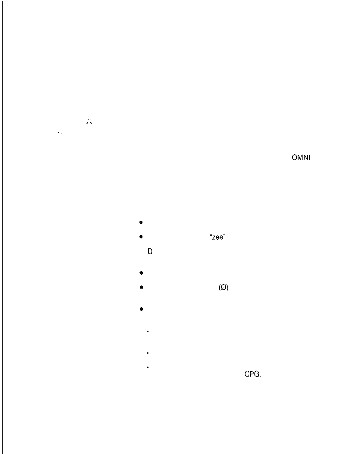
2.2.1 The following rules apply when filling out the data sheets:
l 1 denotes the numeral “one”
l i denotes the letter “eye”
e
2 denotes the numeral “two”
0
Z denotes the letter
“zee”
l
D
denotes the letter “dee” (it should not be rounded to look like
the numeral 0)
e
U denotes the letter “you”
*
Zeros must be slashed
(0)
to prevent keypunch errors due to
confusing zeros with the letter 0.
0
A dash (-) is used within the text to indicate a not applicable
condition.
-
A blank entry is interpreted by the keypunch operator as an
overlooked field, and you will be contacted for an entry. This
will delay completion of the data base.
-
A dash indicates that the field was not overlooked, but
requires no entry.
-
When a dash is entered and the field has a default value,
that value is assigned by the
CPG.
TL-130400-1001
Record Code
2.2.2 The following entries are found on the record code sheets:
Entries
0
Job Drawing Serial Number. This preprinted entry refers to a
prefix ID and the base number for an installation identity
number assigned by Manufacturing Engineering.
e
Sequence Number. This preprinted entry, located in columns
7, 8, and 9, is used by the CPG to incorporate data sheet
information to generate the site data disk.
x-
.1
*
l Record Code. This preprinted entry, located in columns 10
and 11, refers to the type of features referenced on each data
sheet.
Directory Number
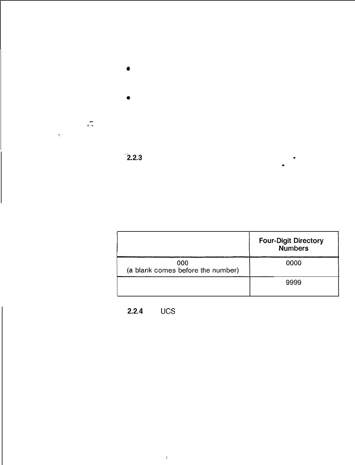
‘2.2.3
When a four-digit number is used, enter (0000
-
9999).
A three-digit directory number is entered as (000
-
999).
These entries are to be right justified in the four columns
provided. An example of a right justified three- and four-digit
numbering plan is shown in Table 2.1. Defining a three-digit
number requires a blank before the first digit. This is the only
application in which a blank is used in completing the record
‘codes.
Table 2.1 Directory Numbers
Three-Digit Directory Numbers
999
(a blank comes before the number)
Card Slot
2.24
The
KS
(Universal Card Slot) to PCS (Physical Card Slot)
numbering convention and comparison are given in Table 2.2.
I
Universal
Card Slot
Expansion
File
Group C
(File C)
Y.
Groub
D
(File D)
Get Started
File
-
~-
Group A
(File A)
Group B
(File
8)
TL-130400-1001
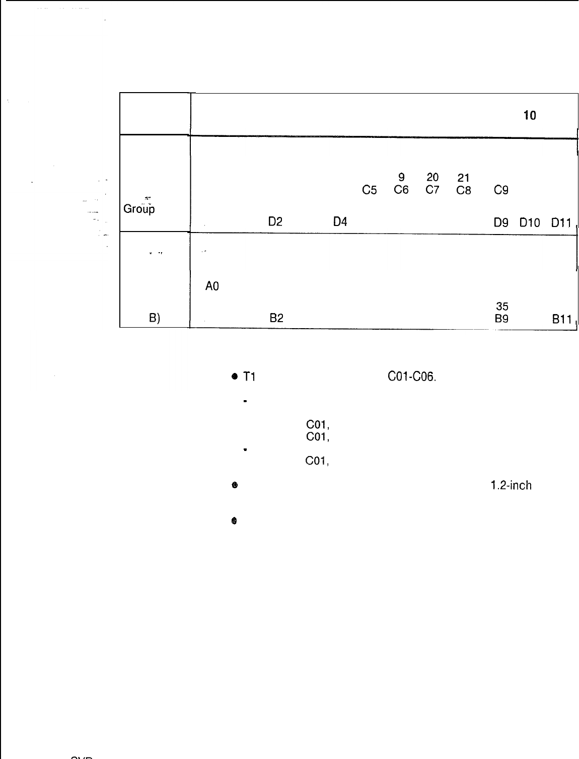
Table 2.2 Universal Card Slots
00
01
02 03
04 05 06 07 08
09 40
11
19 17 15 13
11
c4
c5
c”G
EY
2
22
23 24
Cl c2 c3
c9
Cl0 Cl1
25 26 27 28 29 30
31
32 33 34 35 36
DO Dl
82
D3
04
D5
D6 D7 D8 D9
DlO
Dll
18 19 20
21
22 23
24
25 26
A0
A2 A4 A6 A7 A8 A9 A10 All
28 29 30
31
32 33 34 36
BO
B2
B3 B5 B6 B7 B8
Ii: Bll
NOTE: Special physical location rules:
6
Tl
uses group C card slots
COl-C06.
-
Minimally implemented:
12 circuits CO1 , C02, CO3
16 circuits
COl,
C02, C03, CO4
20 circuits
COl,
C02, C03, C04, CO5
-
Fully implemented:
24 circuits
COl,
C02, C03, C04, C05, CO6
@
Off-premises line cards must be engineered as
1.2-inch
cards.
@
Group A card slot 00 can only be used by a DTMF card, a
conference card, or cards used to terminate an LPB (Local
Packet Bus).
Suggested
Preparation Order
2.2.5 The arrangement of the record codes for this SVR allows
them to be filled out in their existing order.
SW
5210
8187
D-23

TL-130400-1001
THIS PAGE IS INTENTIONALLY LEFT BLANK.
.
.

--
.I
*
.
_
SW
5210
TL-130400-1001
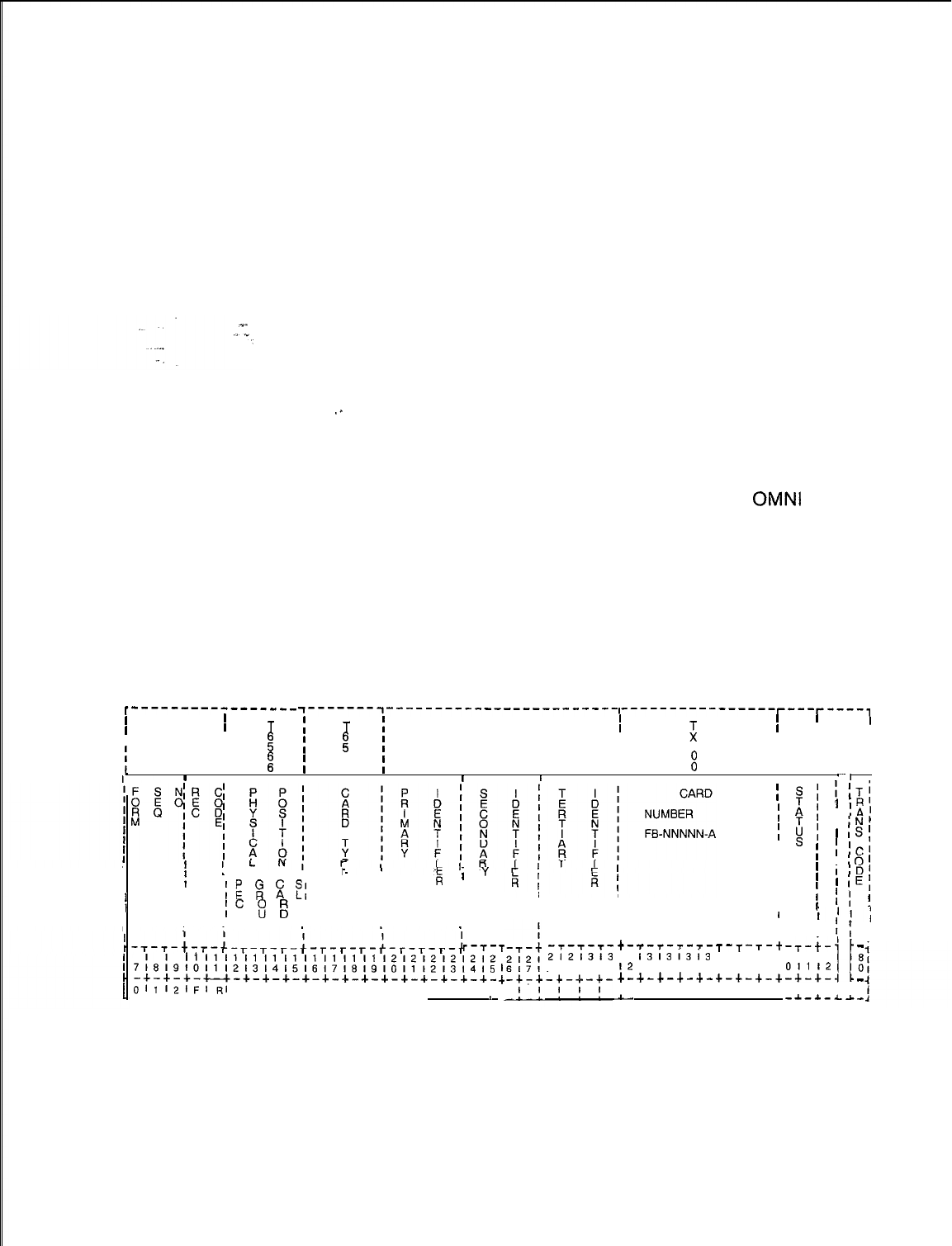
FRAME IMAGE 3.0 This section describes Record Code FR. Record Code FR
lists the cards that are located in the universal cards slots of a
given system.
‘.
TL-130400-1001
Record Code FR:
3.1
Record Code FR, Figure 3.1, lists the types of cards and the
Frame Image
FB (Functional Board) numbers of every occupied universal card
Card
slot in the system. Certain data parameters are specified in this
record code, depending on the type of card. From one to three
data parameters can be required per card. The parameters are
coded in three different identifier fields; however, some cards do
not require an entry in any of the three fields.
This record code provides a listing of all voice and data cards
used in the system. If the PD-200 Data Option is used in the
system, cards supporting that feature must be included on this
record code. The order in which the cards are listed on the
record code does not matter. All cards of a certain FB number
can be put together, or the cards can be listed as they appear in
‘*
the system. When the information from this record code is
processed and returned as part of the CPG, all cards will be
listed as they appear within the system.
Since the maximum number of card slots in the
OMNI
SI is 41,
the maximum number of entries on this record code is 41. The T
tables used for storing the physical location of a card depend on
the card type. The various T tables affected for a given card type
are listed with the card type descriptions. The physical location
is used as an index into Table T6566. Table 3.6 provides
information on the maximum number of PD-200 Data Option
cards allowed in the system.
~----------------- ~-------~------------------------,----------------~---~----,
II
T
!
I I I I
II
II
I
I
fz
I
T
;
:
I
I I
II
I
;
1III
I
II I I
I
1
I
1
I
8
I
I I I
I
:
I I
I0III
II
I I I
I
‘I
I
I
I
t
II
k
I
i
y
I
1
r-------i
f
I
IF=
8
E
@I
III
II
IC
s
El
PI
I
IIII
I I II
III PI I I
;
s;
:;Ti
I
$I
1
IR
I
lA’
I
!I
I
lN’
1
1s;
II
;
I;c’
I
I
I
10’
I
I
I,D’
I
I
II
1
IE;
II
I
II
;
I
IIll
I
I1
I1
I1
I1
I1
I1
I1
I1
I1
I1
I2 I2 I2 I2
12:;
71*19101112l3141516171819101112131415
-+-+-+-u-+-+-+-+-+-+-+-+-+-+-+-+-+-
Ol1l2lFI~I
I I I I I I I I I I I I I
-&--i--1- -~-*-~--L-~-~--L-~-~-~- ’
L
T
I
:
I
-7--r-l--
t-
2i2i3i3
8191011
T-T-T-T-
i3
12
+-
I
-
i3i3i3i3
13141516
+-+-+-+-
I I I I
iI
T-T
-T-t
1313131
1718191
+-+-+-+
I I I I
i
I;
I
-T-+-’
-
41414
011
I2
11
i
-+-+-.I
-
I I II
-*-*-LA-
Figure 3.1 Record Code FR: Frame Image Card Data Sheet
TL-130400-1001
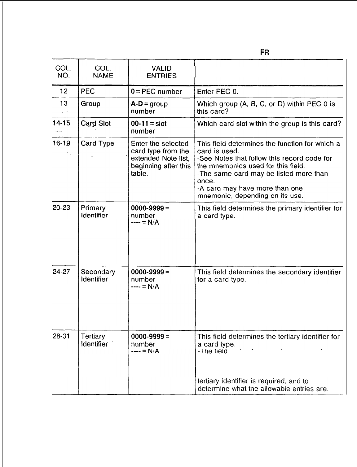
Table 3.1 Entry Fields for Record Code
FW
COMMENTS
-The field varies from card type to card
type, and not all card types require an entry.
-Refer to the extended card list that follows
this table to determine whether or not a
primary identifier is required, and to
determine what the allowable entries are.
-The field varies from card type to card
type, and not all card types require an entry.
-Refer to the extended card list that follows
this table to determine whether or not a
secondary identifier is required, and to
determine what the allowable entries are.
varies from card type to card
type, and not all card types require an entry.
-Refer to the extended card list that follows
this table to determine whether or not a
TL-130400-1001
COL.
NO.
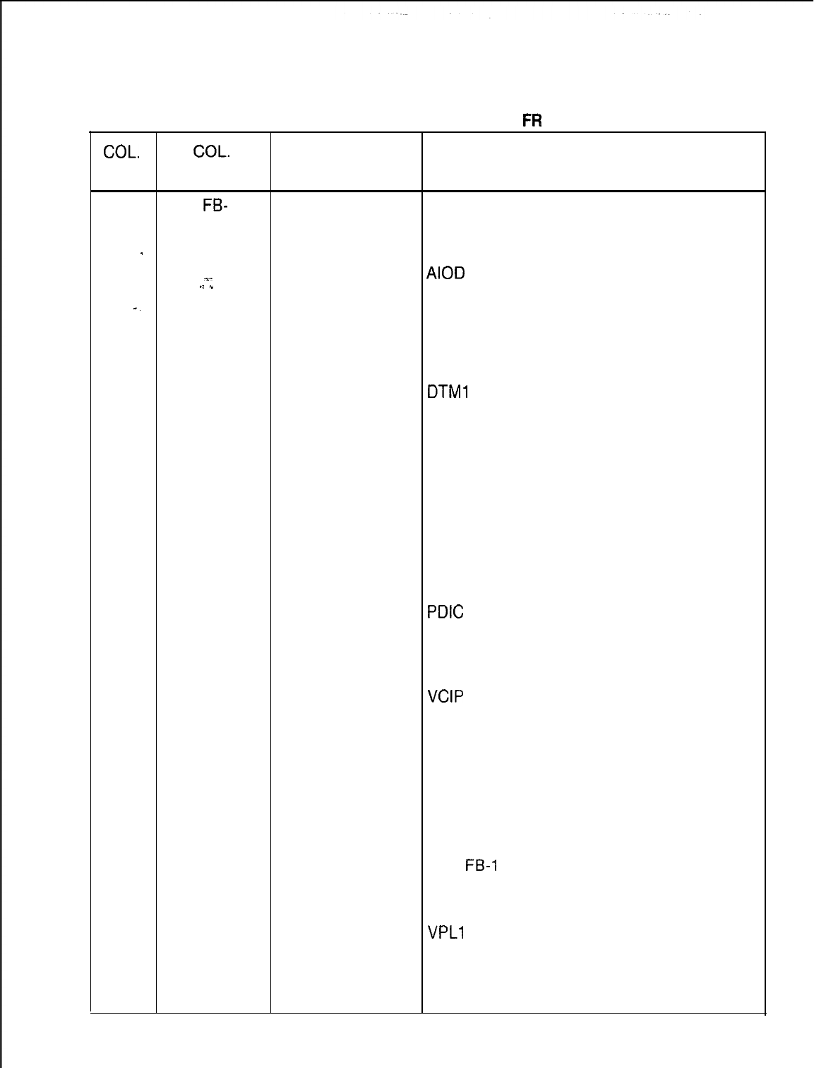
Table 3.1 Entry Fields for Record Code
FR
(Continued)
COL.
VALID
NAME ENTRIES COMMENTS
32-39
Card
FB-
This field entry is This field determines the FB number of the
Number the FB number of card type listed in columns 16-l 9:
the card.
Voice cards:
-
See comments AGNT = FB-17209
-2
following Table
AIOD
= FB-17276
.j
,”
3.1.
ART = FB-17208
-.
Any ASCII ATTN = FB-17208
characters are CIP = FB-17225
allowed. CONF = FB-51279
. .
COT = FB-17202
DTMF = FB-17203
DTMl
= FB-17203
DTRK = FB-15278, FB-15280, FB-17277
or FB-15277, FB-20718 or FB-17192
DVC = FB-17236
EMT = FB-17201
EMT4 = FB-51267
ERLT = FB-17251
FP = FB-17254
FPOP = FB-17250
ILT = FB-51280
KEDU = FB-17209
OFFP = FB-17250
OPI = TR-100119
PDIC
= FB-17210
POTS = FB-17254
RLT = FB-17251
SM = FB-51279
TDET = FB-17280
VCIP
= FB-17235
Data cards:
ADMP(-A) = FB-17229 and
ADMP(-C) = FB-17230
BT = FB-17227
DCP = FB-17231
DCPB = FB-17231
NIC = FB-17242
PBE = FB-17227
PR =
FB-4
7228
VP20 = FB-17246
VP21 = FB-17246
VPLO = FB-17226
VPLl
= FB-17226
NOTE: FB numbers are repeated for different
card types, because the same card can be
used for different applications. The card
types identify the various uses of the cards.
D-28
COL.
NO.
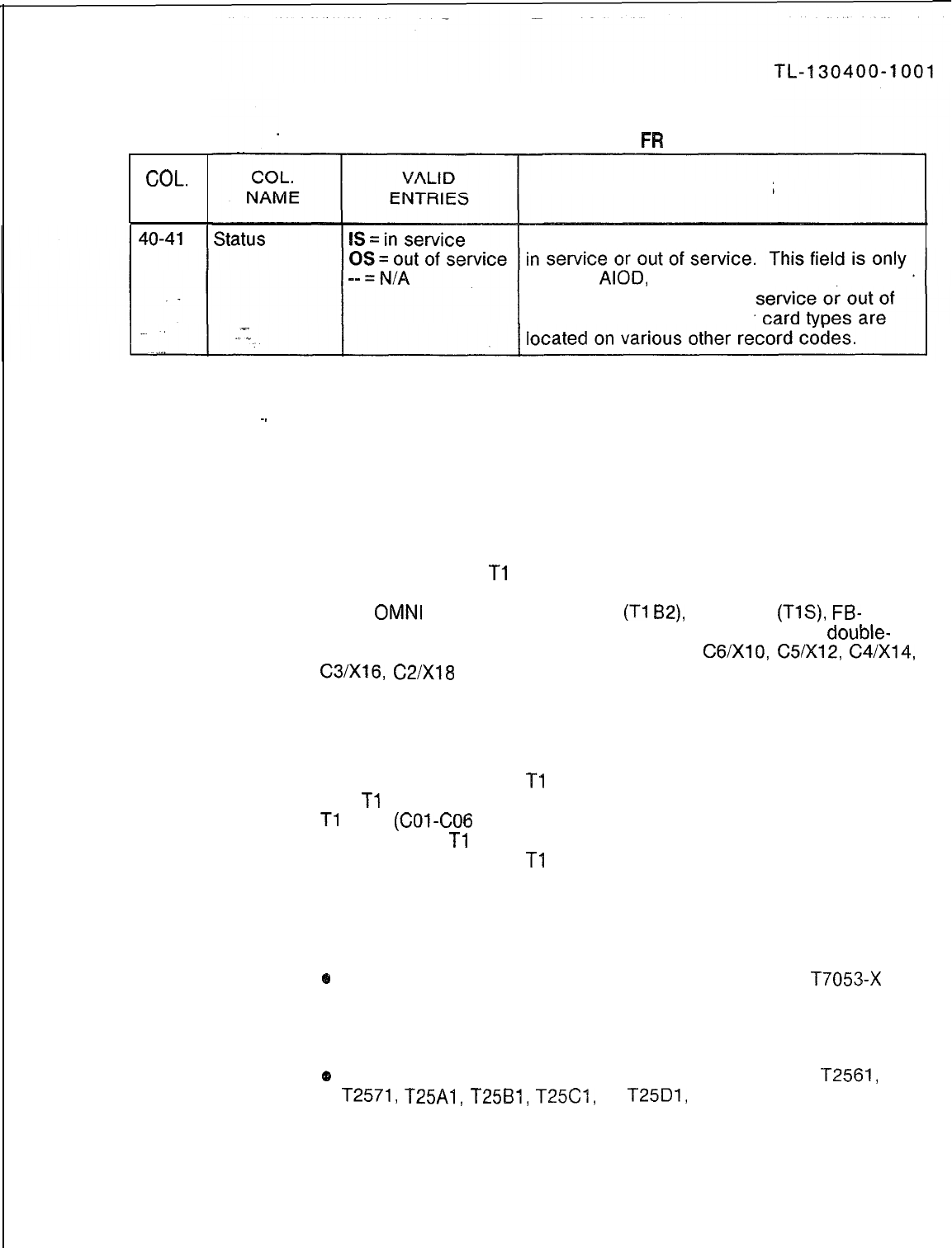
Table 3.1 Entry Fields for Record Code
FW
(Continued)
COMMENTS
This field determines whether or not a card is
used for
AlOD,
ART, or CONF cards. all other
card types are dashed. In
service conditions for other
NOTES:
~.
1. The tables in which the physical location information is stored depend
on the card type. For tables initialized, see Note 2. The physical
location is used as an index into Table T6566.
2. The maximum number of records is 41.
3.
PD-200 cards are in bold print (see Table 3.6 for system maximum).
4. The specification of
Tl
spans on Record Code FR requires some
explanation. The actual printed circuit boards that make up a Tl span
in the
OMNI
SI consist of FB-17192
(Tl
B2),
FB-20718
(TlS),
FB-
17277 (SIL), FB-15280 (LCM), and FB-15278 (FDC). These
double-
width cards are placed in physical card slots
C6/XlO,
C5IX12,
C4/X14,
C3/X16,
C2/X18
of the Expansion File. None of these card slots
corresponds to a universal card slot. An X denotes slots with no
connection to the backplane.
The DTRK (Digital Trunk) card types specified on Record Code FR
reserve the universal card slots that correspond to the hardware
addresses used by the
Tl
span. Each universal card slot represents
four
Tl
channels. A total of six universal card slots represent the entire
Tl
span
(COl-CO6
for the OMNI SI). The last 3 universal card slots
representing a
Tl
span may be used for cards types other than DTRK
card types if the full 24
Tl
channel capability is not required.
5.
Several card types in the following list of cards are referred to by
relative controlling card number and relative line card number. The
following information explains how these numbers are derived.
@
Relative controlling card number is derived from tables
T7053-X
(where X = PEC number). Each table contains 16 bytes which are
numbered 0 to 15. When assigning a relative controlling card
number, select an unused entry from one of these tables.
e
Relative line card number is derived from T2541, 12551,
12561,
T2571,
T25A1,
T2581,
T25C4,
or
T25D1,
depending on the PEC
number. Each table contains 32 bytes which are numbered O-31.
When assigning a relative line card number, select an unused entry
from one of these tables.
TL-130400-1001
Valid card types are as follows:
ADMP
*-
AGNT
.j
*
AIOD
ART
ATTN
BT
CIP
CONF
COT
DCP
Denotes the data system administrative processor cards (one set
maximum). The primary identifier is the ADMP number
-
0000.
The secondary identifier is the ADMP card number
-
0000
(ADMP-A) to 0001 (ADMP-C). The tertiary identifier is the
controlling UCBIDCP number 0000-0009. Entries are made in
T6563,
T705A,
and T6566.
Denotes the agent Programmable Attendant Console Electronic
Telephone (PACET) data link card (32 maximum). No identifiers
are required.
Denotes the
AIOD
card (1 maximum). Entries are made in
T6111,
T6131,
and T2701. No identifiers are required.
Denotes asynchronous receiver/transmitter cards (3 maximum).
The primary identifier is ART card type
-
0009, 0010, or 0011. No
other identifier is required. Entries are made in
T6111,
T6134,
T6394, and
T639B.
Unless the
FB-17208-BO
card is used, the
card may overhang into the next slot.
Denotes attendant BLDU card (3 maximum). No identifiers are
required. Unless the
FB-17208-BO
card is used, the card may
overhang into the next slot.
Denotes bus terminator card (for local packet buses associated
with packet routers and packet bus extender cards). The primary
identifier is packet router number
-
0000 to 0001. The secondary
identifier is local packet bus/ bus segment combination
-
0000 to
0003 is local packet bus 0, bus segments 0 to 3; 0004 to 0007 is
local packet bus 1, bus segments 0 to 3. Entries are made in
T6562 and T6567. See Table 3.6 for maximum cards allowed.
Denotes Featurephone data link card (16 maximum of all
Featurephone/Digital
Phone data link cards). The primary identifier
is relative controlling card number
-
0000 to 0015 (see Note 5).
No other identifier is required. Entries are made in
T7053-0
and
T7057-0.
Denotes conference card (2 maximum). The primary identifier is
conference circuit number
-
0000 to 0001. No other identifier is
required. Entries are made in
T6111,
T6131,
T2741,
and T2742.
Denotes CO trunk card (16 maximum of all trunk cards). No other
identifier is required.
Denotes data device controlling data UCB card (4 maximum with
this SVR). The primary identifier is DCP number
-
0000. No other
identifier is required. Entries are made in T6565.
DCPB
DTMF
x-
DTRK
DVC‘.
EMT
EMT4
ERLT
FP
FPOP
ILT
KEDU
NIC
TL-130400-1001
Denotes data device controlling data UCB card with a bus
terminator (4 maximum). The primary identifier is DCP number
-
0000 to 0003. The secondary identifier is packet router number
-
0000 to 0004. The tertiary identifier is the LPB (Local Packet Bus)
bus segment. Entries are made in T6562 and T6567.
Denotes DTMF receiver card with four circuits (8 maximum). No
identifiers are required.
Denotes digital trunk card
(Tl
spans). The engineering of digital
trunks requires that physical locations corresponding to the
hardware addresses used for
Tl
spans be specified (6 maximum).
No identifiers are required.
Denotes data voice control interface processor card (16 maximum
of all
FeaturephoneIDigital
Phone data link cards, 32 maximum of
all line cards). The primary identifier is relative line card number
-
0000 to 0031; the secondary identifier is relative controlling card
number
-
0000 to 0015 (see Note 5). No other identifier is
required. Entries are made in T2541,
T6561,
T7053-0,
and
T7057-0.
Denotes 2-wire E&M trunk card (23 maximum of all trunk cards).
No identifiers are required.
Denotes 4-wire E&M trunk card (23 maximum of all trunk cards).
No identifiers are required. (Cable pairs listing must show second
cable.)
Denotes E&M trunk card used as release link trunk card (4
maximum). No identifiers are required.
Denotes Featurephone line card (32 maximum of all line cards).
The primary identifier is relative line card number
-
0000 to 0031
(see Note 5). No other identifier is required. Entries are made in
T2541 and T6561.
Denotes Featurephone off-premises line card (16 maximum of all
line cards). The primary identifier is relative line card number
-
0000 to 0031 (see Note 5). No other identifier is required. Entries
are made in T2541 and
T6.561.
Denotes incoming loop trunk card (23 maximum of all trunk cards).
No identifiers are required.
Denotes
KEDU/printer
card (2 maximum). No identifiers are
required.
Denotes network interface card (16 maximum). The primary
identifier is controlling DCP number (0000 this SVR). No other
identifier is required. Entries are made in T6566.
TL-130400-1001
OFFP
OPI
PBE
*
.1
*
PDIC
POTS
PR
RLT
SM
TDET
VCIP
VP20
Denotes off-premises line card (32 maximum of all line cards).
The primary identifier is relative line card number
-
0000 to 0031
(see Note 5). No other identifier is required. Entries are made in
T2541
and
T6561.
Denotes the
OMNI
PMS interface card (1 maximum). No identifiers
are required.
Denotes packet bus extender card (2 maximum). The primary
identifier is packet router number
-
0000 to 0001. No other
identifier is required. Entries are made in T6562 and T6567.
Denotes paging and dictation trunk card (23 maximum of all trunk
cards). No identifiers are required.
.
Denotes regular line card (32 maximum of all line cards). The
primary identifier is relative line card number
-
0000 to 0031 (see
Note 5). No other identifier is required. Entries are made in T2541
and T6561.
Denotes packet router card (2 maximum with this
SW).
The
primary identifier is packet router number
-
0000 to 0001. No
other identifier is required. Entries are made in T6562 and
T7058-0.
Denotes release link trunk card (4 maximum). No identifiers are
required.
Denotes silent monitor card (8 maximum). The primary identifier is
silent monitor card number
-
0000 to 0007. No other identifier is
required. Entries are made in T5344.
Denotes SCC tone detector card (8 maximum). No identifiers are
required.
Denotes voice control interface processor card (16 maximum of all
Featurephone/Digital Phone data link cards (16 maximum of all line
cards). The primary identifier is relative line card number
-
0000
to 0031 (see Note 5). The secondary identifier is relative controlling
card number
-
0000 to 0015 (see Note 5). No other identifier is
required. Entries are made in T2541,
T7053-0,
and
T7057-0.
Denotes Voice Packet Line Cards VPLC Mark 2 or VPLC2, type 0,
eight circuit (32 maximum of all line cards). The primary identifier
is relative line card number
-
0000 to 0031 (see Note 5). The
secondary identifier depends on card usage as follows:
0
Voice only
-
relative controller card number 0000 to 0015 (see
Note 5)
0
Voice and data
-
relative controller card number 0000 to 0015
(see Note 5)
TL-130400-1001
0
Data only
-
always ----
The tertiary identifier depends on card usage as follows:
0
Voice only
-
always 0000
0
Voice and data
-
always 0001
l Data only
-
always ----
5.
.I
*
Entries are made in
T2541,
T6561,
T7053-0,
and T7057.
VP21
Denotes VPLC2, type 1, two circuit (32 maximum of all line cards).
The primary identifier is relative line card number
-
0000 to 0031
‘-
(see Note 5). No other identifier is required. Entries are made in
T2541 and
T6561.
VPLO
Denotes VPLC, type 0, eight circuit (32 maximum of all line cards).
The primary identifier is relative line card number
-
0000 to 0031
(see Note 5). No other identifier is required. Entries are made in
T2541 and
T6564.
VPLl
Denotes VPLC, type 1, two circuit (32 maximum of all line cards).
The primary identifier is relative line card number
-
0000 to 0031
(see Note 5). No other identifier is required. Entries are made in
T2541 and
T6561.
Table 3.2 FR
Rules
._-
._._
-.-
-
--
---_--
=R-01 CARD TYPE
-
PRIMARY, SECONDARY, AND TERTIARY IDENTIFIERS
Consult Table 3.3, Card Types Versus Identifiers and Status, to determine approximate values
to specify for each particular card type. This table specifies the valid ranges of the three
identifiers and the status given a particular card type.
FR-02 CARD TYPE
-
PHYSICAL LOCATION
If the card type is DTRK, then the group field must be C since Tl spans can only be installed
in this group. Specific card placement restrictions are in effect for the following card types:
. BT . PBE
. DCPB . PR
These cards can only be placed in the following group/slots:
. AOO,
AlO,
BOO,
B09
@
COO, CO9, DOO, DO1 ,
DlO
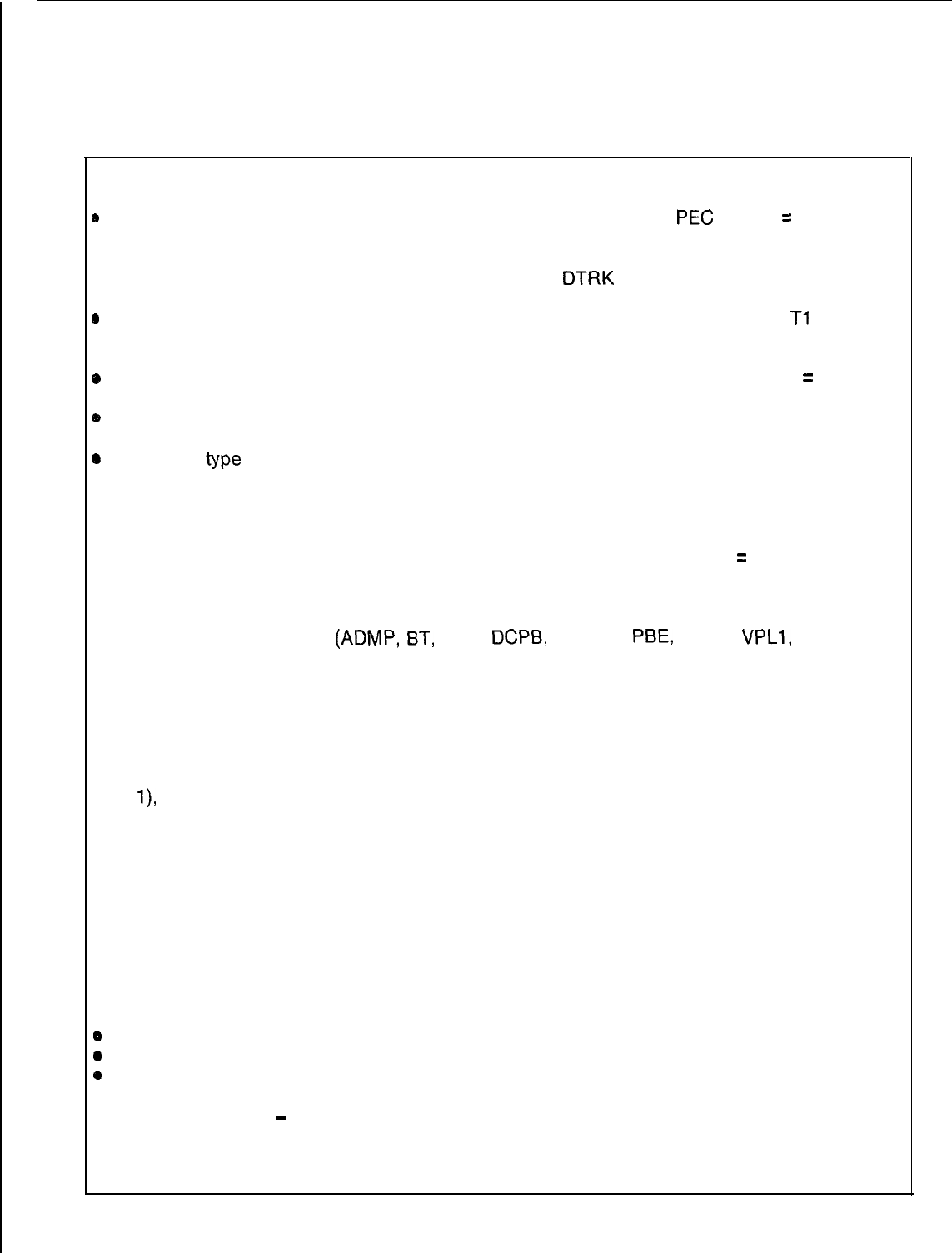
FR-50 CARD TYPE
-
PEC
-
PRIMARY, SECONDARY, TERTIARY IDENTIFIERS
Consult Table 3.4, Card Types Versus Identifiers Checks, to determine the appropriate values
to specify for each particular card type. The table shows the meaning of the primary,
secondary, and tertiary identifiers on the FR record and checks that are applicable for each
set of card types. Also shown is Table 3.5, Card Types Versus Card Slot Restriction.
TL-130400-1001
Table 3.2 FR Rules (Continued)
FR-51 PHYSICAL LOCATION
e
The PEC, group, and slot specified for this card must be unique.
PEG
always
=
0.
l
The DTRK cards must always be assigned from the lowest to the highest slot number
without any other type of card residing between the
DTRK
cards.
e
No other type of card can reside in one of the slots required to implement the
Tl
span
which is implied by the input of a DTRK card.
@
The-PEC, group, and slot specified must be valid for the PEC type. PEC always
=
0.
@
A previous FR-record cannot define a wide card which overhangs into a specified slot.
e
The card
type
specified must not be assigned a physical location to which it is not
allowed.
FR-52 PHYSICAL LOCATION
The PEC, group, and slot specified for a card must be unique. PEC always
=
0.
FR-53 CARD TYPE
The data system card types
(ADMP,
BT,
DCP,
DCPB,
NIC, PR,
PBE,
VPLO,
VPLl,
VP20 and
VP21) are only allowed in systems with the PD-200 Data Option.
FR-56 LOCAL PACKET BUS
The minimum local packet bus configuration is a packet router (card type PR) and a bus ,
terminator (card types BT and DCPB) in the primary file (bus 0). A second local packet bus
may be added by using a packet bus extender (card type PBE). If the second file is used
(bus
l),
it must contain a bus extender card and terminator card.
FR-57 LOCAL PACKET BUS
All data cards must be placed on a local packet bus segment. The ends of a local packet
bus segment are defined by the placement of PR, PBE, and bus terminator cards. All data
cards must be placed between a PR or PBE and a bus terminator.
FR-59 DATA SYSTEM CARD TYPES
If the data option is specified on Record Code OE, then at least one each of the following
cards must be defined:
0
ADMP
0
PR
0
BT (DCPB)
FR-60 CARD TYPE
-
PRIMARY IDENTIFIER
The primary index for SM (Silent Monitor) cards must be continuous (i.e., the SM card
numbers must be assigned from 0 to 7 corresponding to the number of SM cards 1 to 8).
TL-130400-1001
Table 3.2 FR Rules (Continued)
FR-61 PHYSICAL LOCATION
If a controlling DCP (UCB) number is used as the primary identifier for a
NfC
card, the same
number must be used as the primary identifier on a DCP or DCPB card.
FR-62 EXPANSION FILE STATUS
If group C or D is listed in the physical location, Expansion File status on record code OE
must be
ma&d
equipped.
Table 3.3 Card Types Versus Identifiers and Status
VALUE OF ALLOWABLE PRIMARY
ALLOWABLE SECONDARY
CARD TYPE IDENTIFIER RANGE IDENTIFIER RANGE
ADMP
AGNT
AIOD
ART
ATTN ----
BT
0000-0001
CIP 0000-0015
CONF 0000-0001
COT
----
DCP
0000-0003
DCPB
0000-0003
DTMF
----
DTRK
----
DVC
0000-0031
EMT
----
EMT4
----
EMT
----
FP
0000-0031
FPOP 0000-0031
0000-0001
----
0000 or 0004
we--
0000-0001
-w-e
ALLOWABLE
TERTIARY IDEN-
TIFIER RANGE
STATUS
FIELD
----
----
IS,
OS
0000 or 0004
0000-0015
--
ILT
---_
----
-w-w
TL-130400-1001
Table 3.3 Card Types Versus Identifiers and Status (Continued)
VALUE OF ALLOWABLE PRIMARY ALLOWABLE SECONDARY ALLOWABLE
CARD TYPE STATUS
IDENTIFIER RANGE IDENTIFIER RANGE TERTIARY IDEN-
TIFIER RANGE FIELD
KEDU
---_
___- -___
--
-
NC
0000-0003
__--
-_-- --
WFP
.--Tl
~0000-0031
____
----
--
OPi
----
-_-- _---
-_
PBE
._
oooo-ooqj
-___ ___-
__
PDIC
--__
----
-___
--
POTS
0000-0031
----
____
_-
PR 0000-0001
-___
---- --
RLT
----
____
_--- --
SM
0000-0007
_-__
-_--
-_
TDET
---- -_--
___- -_
VCIP
0000-0031
0000-0015
_--_
--
VP20
0000-0031
0000-0015
0000-0001
--
or
--__
or
____
VP21 0000-0031
----
___-
--
VPLO 0000-0031
_--- --_- --
VPLl
0000-0031
__--
----
--
Table 3.4
Card Types Versus Identifiers Checks (Continue1
CARD TYPE
PRIMARY IDENTIFIER
ADMP ADMP number
AIOD
N/A
ART ART card number
BT
Packet router number
CIP
Relative controller card
number
CONF
($$erFnce
circuit
SECONDARY IDENTIFIER
AnlX$le~ard
N/A
N/A
Local packet bus/ bus
segment
N/A
N/A
DCP
DCPB
DVC
FP
FPOP
OFFP
OPI
NIC
PBE
POTS
PR
SM
VCIP
VP20
DCP number
DCP number
Relative line card
number
Relative line card
number
lariat&
line card
Relative line card
number
N/A
Controlling DCP number
Packet router number
Relative line card
number
Packet router number
Etil;eyonitor
card
Relative line card
number
Relative line card
number
VP21
Relative line card
number
VPLO
Relative line card
number
VPLl
Relative line card
number
N/A
Packet router number
Relative controller card
number
N/A
N/A
N/A
N/A
NIA
N/A
N/A
N/A
N/A
Relative controller card
number
Relative controller card
number
N/A
N/A
N/A
TERTIAR
IDENTIFII
Local
bus/
bus
segment
-
TL-130400-1001 TL-130400-1001
NOTES:
Check 1.
For card type
ADMP.
The
card number combination
For card type ART. The
P
duplicated.
Check 2.
Check 3.
v-
.I
*
-.
-
Check 4.
Check 5.
Check 6.
Check
7.
Check 8.
Check 9.
Check 10.
Check 11.
For card types containing
packet bus/ bus segment i
DCPB),
the packet router r
bus/bus segment identifier
across any of the card
type
For card types containing r
information (CIP, DVC,
VCI,
relative controller card nurr
duplicated across any of th
For card type CONF, the cc
be duplicated.
For card types containing
0
and DCPB), the DCP numbs
either of the card types.
For card types containing re
information (DVC, FP, FPOP
VP21, VPLO, and
VPLl),
the
number cannot be
duplicate{
For card type PBE, the pack
duplicated.
For card type PR, the packet
duplicated.
For card type SM, the silent
I
duplicated.
For card types
AIOD
and OPI
system is allowed. For card 1
must appear as the DCP num
DCPB.
Table 3.6
PD-200 Data
Card Type

.
.
-
TL-130400-1001
SYSTEM 4.0 This section describes the record codes required to define
PARAMETERS AND the various system parameters and miscellaneous features. The
MISCELLANEOUS following record codes are required:
FEATURES
l Record Code DT defines the location of the system’s DTMF
cards.
l Record Code OC defines the location of the conference, AIOD,
and Music-On-Hold circuit cards.
.
l Record Code OE defines miscellaneous system data.
l Record Code OF defines additional miscellaneous system
data.
0
Record Code OT defines timeout intervals.
l Record Code OV defines additional timeout intervals.
l Record Code OD defines non-line circuit directory numbers.
l Record Code PN defines predetermined night answer pilot
numbers.
l Record Code PZ defines paging zones.
l Record Code SL defines voice and data passwords.
0
Record Code TF defines traffic study parameters.
l Record Code CD defines code calling parameters.
0
Record Code
CB
defines seven- and ten-digit numbers
screened by MERS.
l Record Code AU defines remote access authorization codes.
l Record Code FA defines FRL (Facility Restriction Level)
authorization codes.
TL-130400-I 001
Record Code DT:
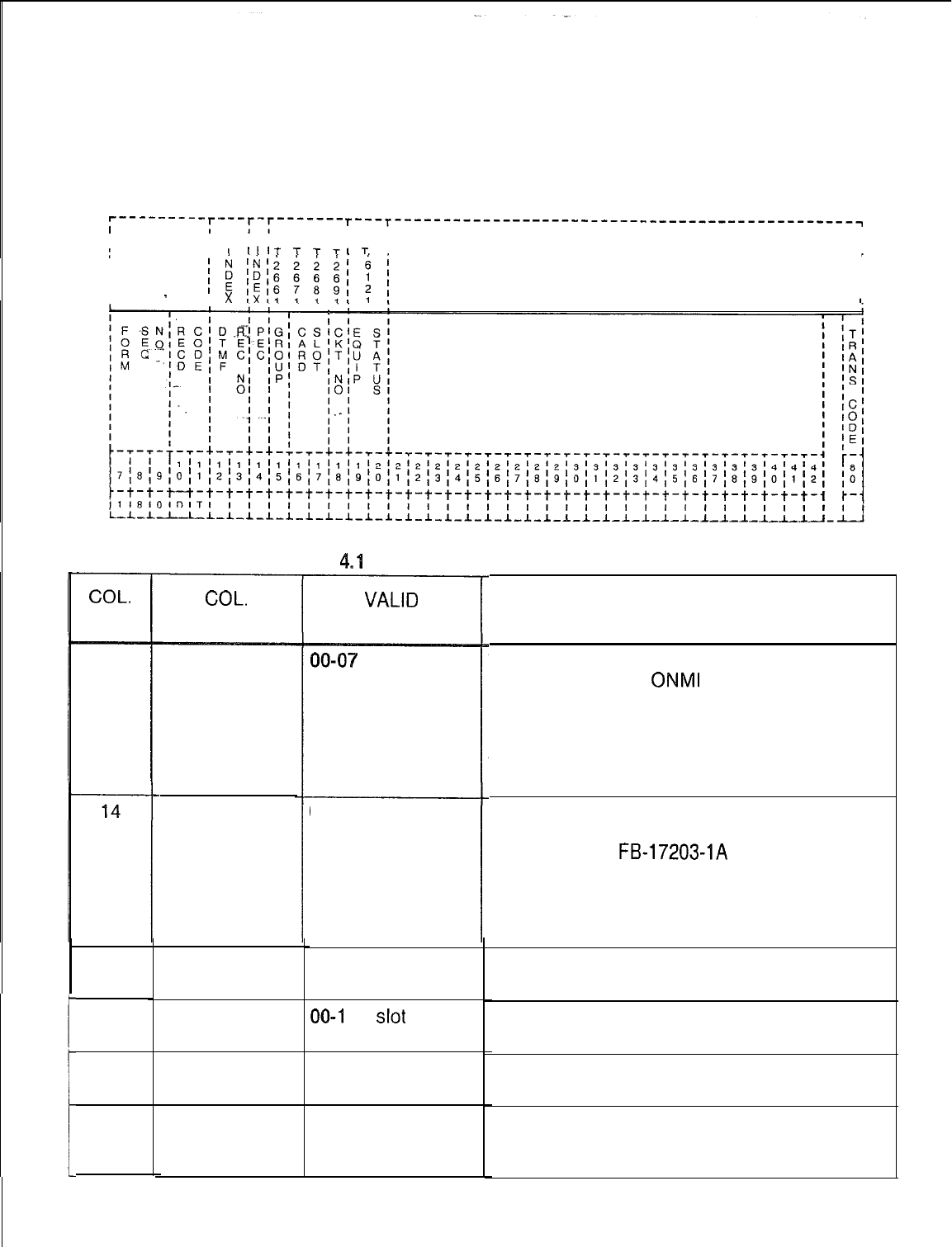
4.1 Record Code DT, Figure 4.1, defines the location and
DTMF Receiver
status of the system’s DTMF (FB-17203) receiver card(s).
The system can support a maximum of two DTMF receiver
cards with four circuits per card.
r---------r---r-r------- T---T-----------------------------------------------~
I
I I
IIII
I
I I
IIII
I I
"IT
T
T
TI
T
I
I
I
I
I
II
II
II
-
I
x
Figure 4.1 Record Code DT: DTMF Receiver Data Sheet
Table
4.1
Entry Fields for Record Code DT
COL.
NO.
12-13
15
16-17
18
19-20
COL.
NAME
DTMF
Receiver
Number
PEC
Group
Card Slot
Circuit
Number
Equipped
Status
VALID
ENTRIES
00-07
= number
0 = PEC number
A-D = group
number
00-l 1 =
slot
number
O-3 = assigned
circuit number
IS = in service
OS = out of service
COMMENTS
There can be a maximum of two DTMF
receiver cards per
ONMI
SI.
-If one DTMF receiver card is used, receiver
numbers 00-03 can be used.
-If a second DTMF receiver card is needed,
that card can use receiver numbers 04-07.
-Each number must be unique.
Enter PEC 0.
-A
DTMF receiver circuit must appear on an
FB-17203-A or
FB-17203-IA
card.
-This card must be defined on Record Code
FR.
-The
physical location for each circuit must
be unique.
Which group (A, B, C, or D) within PEC 0 is
this card?
Which card slot within the group is this card?
Which circuit on the card is being used?
Is the card in service or out of service?
-A slot can be reserved for a card by listing
the location and marking it out of service.
TL-130400-1001
Record Code OC:
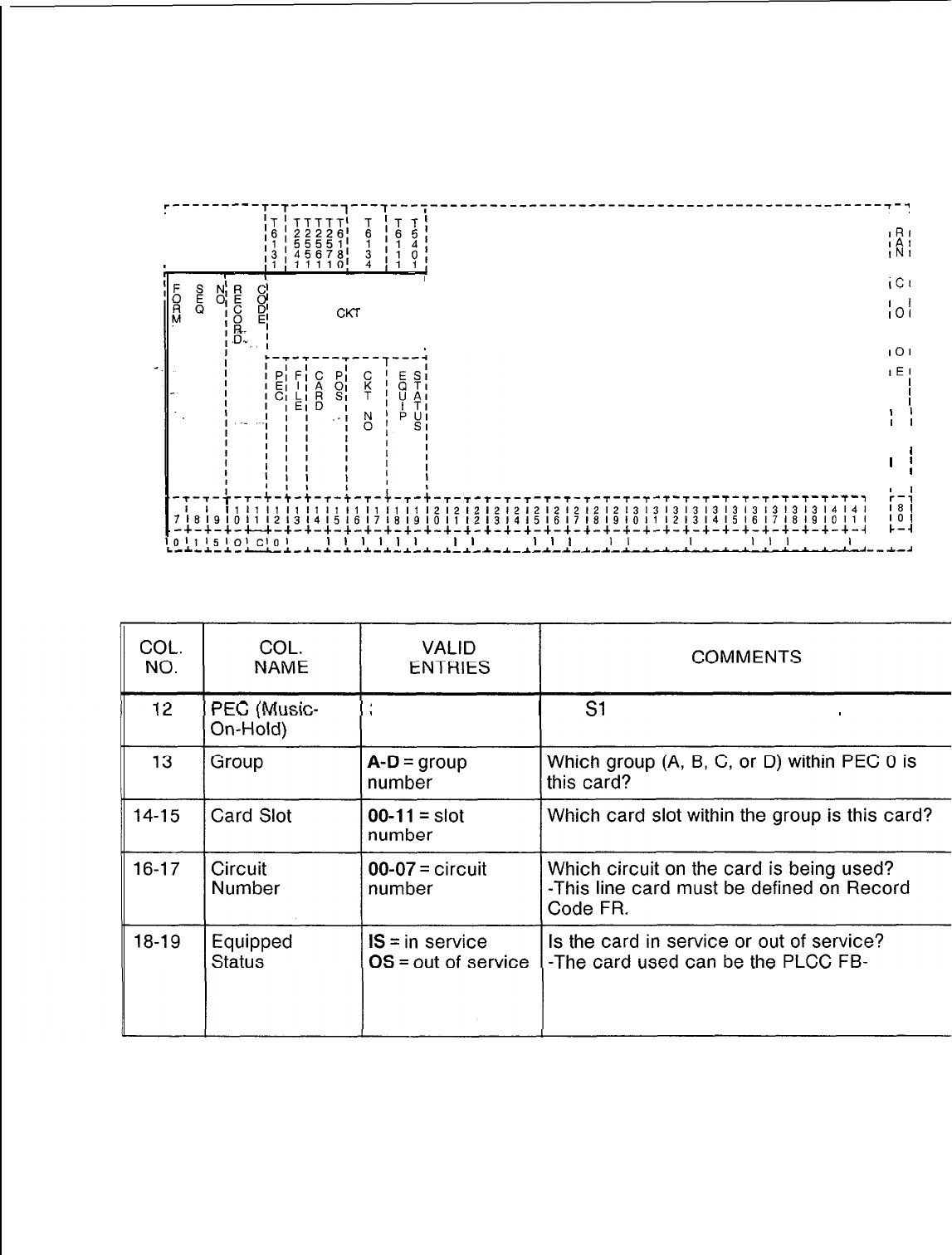
4.2
Record Code
OC, Figure 4.2, defines the location and status
Office Features Circuits
of the Music-On-Hold circuit cards.
r---------T-T-----,---7-
I
--;----------------‘-----------------------------~-~
I ,
I
IT,
I
IR'
I
IA,
I
INI
I
IS'
I
IA,
I
IC,
IT,
MUSIC ON
II
I
I
HOLD CKT
I
I
IO1
I
IN,
II
II
ICI
L--,-l---
IO1
-.
ID,
IE,
I
'
I
’
I
l
I
I
I ,
I ,
I 1
’
I
I
I ,
-T-T-t-t-T-T-T-t-T-T-T--r-T-,
11111111111111111111,2,212,2,2:;:;:;:2121313131313131313l3l3l4l4l
i-4
181
7181910111213141516171819101112131415161718191011121314151617181910,1,
‘01
-+-+-+-u-+-+-+-+-+-+-+-+-+-+-+-+-+-+-+-+-+-+-+-+-+-+-+-+-+-+-+-+-+-~
C-4
1011151()1cl01
I
I
I
I
I
I
1
I
I
I
I I
I
I
I
I
1
I
I I
I
I I
I
1
1
I I
I
I I
i-A-.l.-a--LI-A
-~--L-~-~-_C-~--L-~-~-~--L-~-~-~-~-'~--~-~
Figure 4.2 Record Code OC: Office Features Circuits Data Sheet
Table 4.2 Entry Fields for Record Code OC
0 = PEC number
The
SI
has two files called PEC 0.
17524-A or the POPS FB-17250-A.
-It is recommended to mark this field OS
whether or not the feature is used.
TL-130400-1001
Record Code OE:
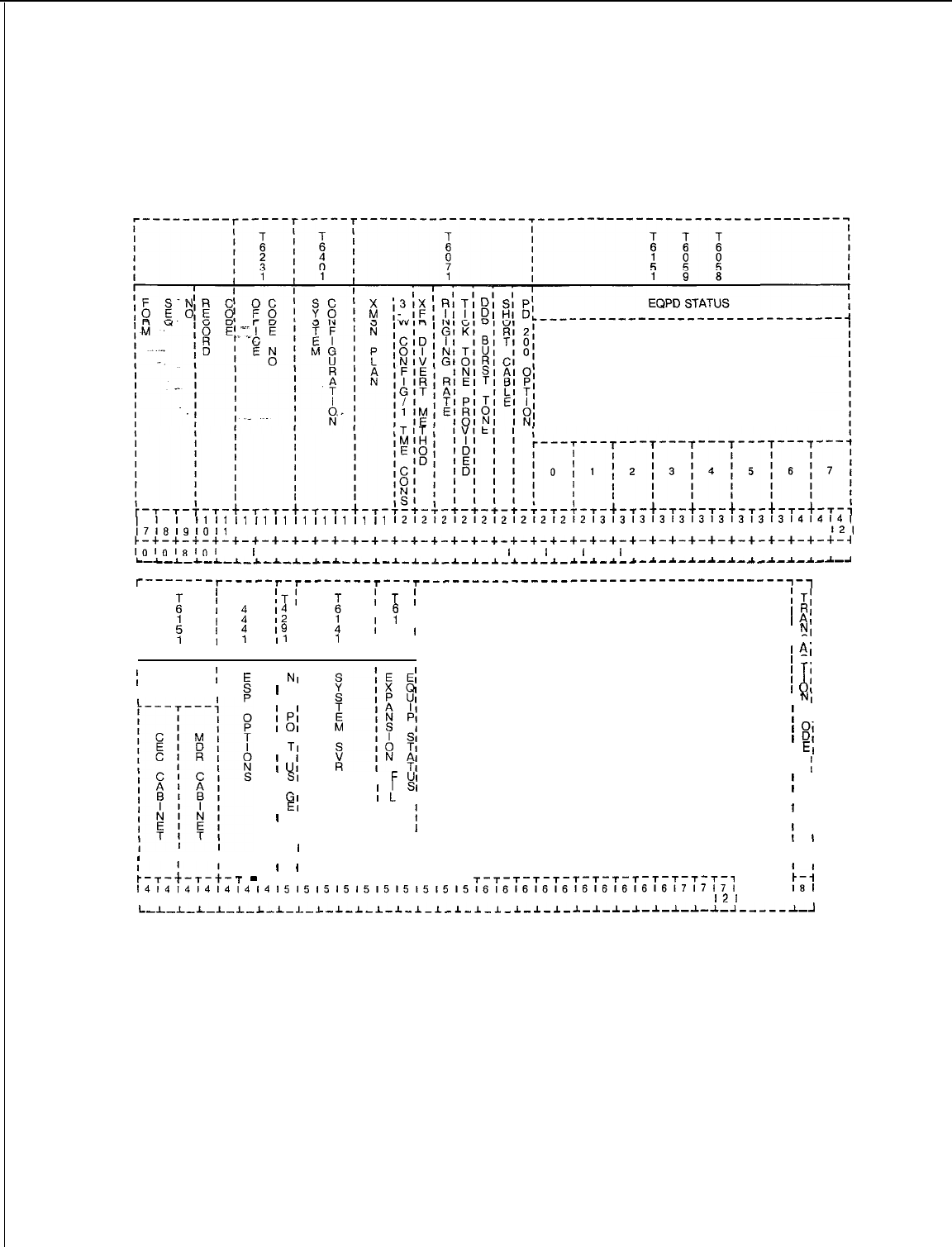
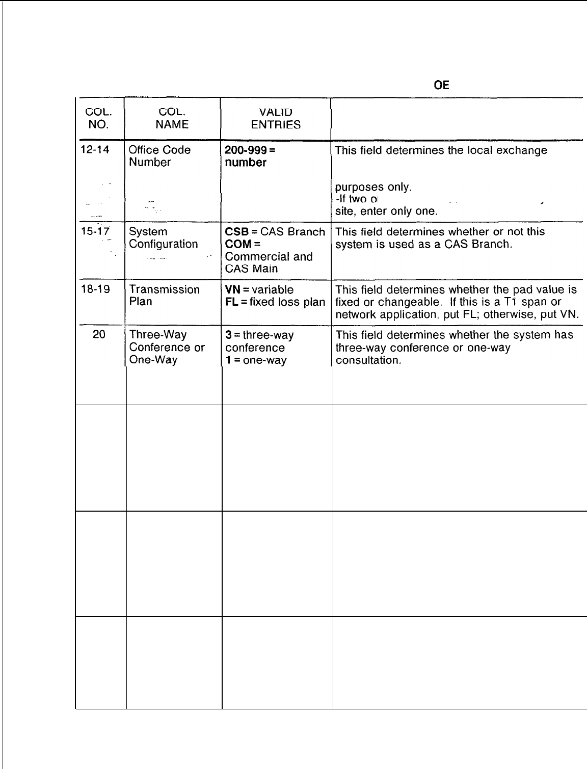
4.3 Record Code OE, Figure 4.3, defines miscellaneous office
Office Equipment
and equipment data.
PEC
I
’
I1
I1
I1
I1
I1
I1
I1
I1
I1
I1
1212121212121212121213131313131313131313l4l4l4I
,7l819lO11
12131415161718191011 12131415161718191011 12131415161716191011
121
~-+-+-+-+-+-+-+-+-+-+-+-+-+-+-+-+-+-+-+-+-+-+-+-+-+-+-+-+-+-+-+-+-+-+-+-~
,,)lolg,ol
I
I
I I I I I I I I I I I I
I
I
I
I
I
I
I
I I I I I I I I I I I
L_L-L-L-L-~_~-*_*-~-~-~-~-~-~-~-~-~-~-*-~-~-~-~-*-~-~-*-~-~-~-~-~-~-~-~-~
l-------
-r-----r-r-------r---r----------------------------------------~-~
I
I’
T
IT:
I
B
I
:
I4
I
i
1
T
:;
T;
I
RI
I
I
12
I
A
I
y
I
)
;’ 19
I
I
I
5
I
1
AI
I
11
I
1
I 7 II
NI
I
I Sl
II
I I
I I
1
AI
II
1 Cl
;
EQUIPPED
;
I I
I
TI
, STATUS II
NI
I
Cl 1
II
I Cl 1
01
I
NI
!
cl
I RI1
01
I
TI
1
b
I
EI
I
ul
I
I
I
SI
I
F
UI
t
I AI
;
;
SI
I
I
GI
I
I
I
I I
I
EI
I E
1
I
I
I
II
I I
I I
III
I I
I I I
!
I
II I
I I
III
I I
I I
I I
:-,-i-,-i-
-
’
’I I
T
r-+-+-r-r-r-+-r-t-r-r-
r-r-T-T-T-T-T-T-T-T-r-r-r-,
~~~~~~~~~~~~~~~~~~~~~~~~~~~~~~~~~~~~~~~~~~~~~~~~~~~~~~~~~~~~~
131415161718191011 12131415161716191011 12131415161718191011
121
IO I
L-L-L_L-L_L-L-I-L-L-I-L-l-l-l_l-l-l_l_l-~-~-~-~-~-~-~-~-~-~-~-----~-~
Figure 4.3 Record Code OE: Office Equipment Data Sheet
TL-130400-1001
Table 4.3 Entry Fields for Record Code
QE
COMMENTS
assigned to this system.
-This number is used for identification
r
more office codes are used by
a
Consultation consultation -The recommended value for this field is 3.
-If 1 is entered, a three-way conference
cannot be held by any line in the system.
21
Transfer Divert
P =
divert to
If a call is transferred to a busy or no answer
Back Method on transferring party station, this field determines whether the call
Busy or No A = divert to will go back to the attendant or go to the
Answer attendant station that forwarded the call.
-For normal applications, it is recommended
to enter P in this field. This prevents the
attendant operator from being overloaded with
calls.
22
Ringing Rate D = distinctive
R
= regular
This field determines whether the system has
distinctive or regular ringing.
-If distinctive ringing is used, the station user
can tell the difference between station (inside
calls) and trunk (outside calls).
-A station call rings 1 second on, 3 seconds
off, while a trunk call rings 1 second on, 1
second off.
23
Tick Tone Y = provided
Provided N = not provided This field determines whether or not a tick
tone is provided.
-The tick tone is an audible indication that the
system has recognized the access code
dialed and is waiting for more digits to be
dialed.
-This is an older feature not normally used.
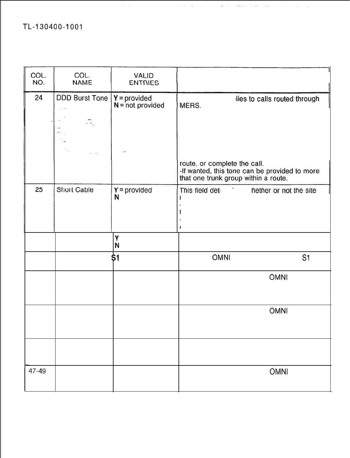
TL-130400-1004
Table 4.3 Entry Fields for Record Code OE (Continued)
COMMENTS
This field only app
-This field determines whether or not a burst
of tone is heard by the station user if the call is
to go out over a route marked for burst tone.
-Normally the burst tone is put on the last
and most expensive trunk group in a route.
-This feature lets the station user decide
whether to hang up and try later on a cheaper
N
= not provided ermines w
requires a short cable application.
-If the site is located less than 6000 feet from
the CO, this field can be used.
-The CO can provide information on whether
or not this is required.
26
PD-200 Option
Y
= provided If the PD-200 Data Option is used, enter Y.
N
= not provided
27-28
Equipped Status
S1
= only allowed Since the
OMNI
SI has only one PEC,
Sl
is
for PEC 0 entry the only allowed entry.
29-42
Equipped Status -- = only allowed This field is not used for the
OMNI
SI and
for Peripheral entry should contain dashes only.
Equipment
Complex
43-44 Equipped Status -- = only allowed This field is not used for the
OMNI
SI and
for Common entry should contain dashes only.
Equipment
Complex
45-46
Equipped Status MD = in service If the MDR option is used, enter MD.
for Message -- = out of
Detail Recorder service
Electronic
Services
Processor
-- = only allowed
entry This field is not used for the
OMNI
SI and
should contain dashes only.
-
TL-130400-1001
COL.
NO.
Table 4.3 Entry Fields for Record Code OE (Continued)
COL.
VALID
NAME ENTRIES COMMENTS
50
-.
Network Control
-
= not equipped Enter Y If a CEC port is used for the NCC
Center Port Y = equipped (Network Control Center).
Usage -The network control center provides network
x-
administration control and maintenance
.j
*
functions.
-MDR
output for a network can be sent to an
NCC via an MDR port.
51-54
-.
Systems
‘I
5210 = SVR for this The SVR for the system being installed is
System Version release entered here.
Release
55-56
Expansion File
EX
= equipped
Enter EX in this field.
Equipped Status -- = not
-SVR
5210 is to be configured only as an
equipped Expansion File system.
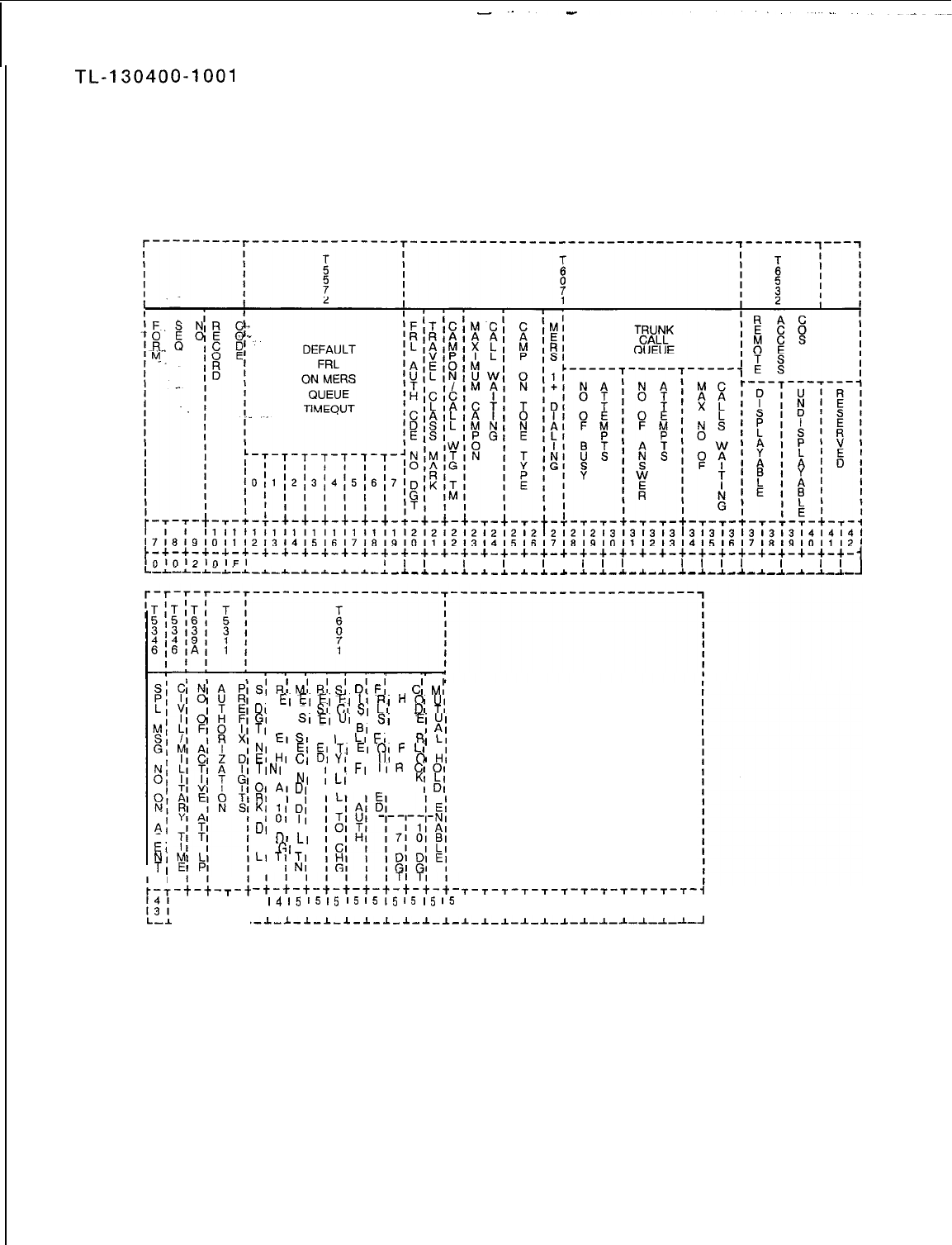
TL-130400-1001
Record Code OF:
4.4 Record Code OF, Figure 4.4, provides information about
Office Features
miscellaneous system features.
~-+-+-+-+-+-+-+-+-+-+-+-+-+-+-+-+-+-+-+-+-+-+-+-+-+-+-+-+-+-+-+-+-+-+-+-
1010121OlFl
I I I I I I
I
f
l
I
l
I
l
I
l
I
I
11
I I
l
l
l
l
I
l
I
I
l
L-L-L-~-i-*-~-~-~-~-~-~-~
-~-~-~-~-~-~-~-*-~-~-~-~-*-~-~-~-~-~-~-~-~-~-~-
Al
Gl
EI
NI
TI
I
41414141
41516171
.-l-L.-L-l
S:
RI
M;
Ri
S;
Di
Fi
C
Cl
Mj
I
EI
Ei
EI
EI
11
RI
H
ol
UI
DI
MI RI
SI
CI
SI
LI
E
DI
TI
GI
01
SI
EI
UI
AI
SI
C
El
)I;
TI
VI I RI RI
61
I K
I
EI
SI
VI 1 I
LI
EI
NI BI
LI
I
EI
EI
TI
EI
QI
F
LI
EI
HI
CI
DI
YI
TI
NI
01 I
UI
0
01
HI
WI PI
NI
IFI
IIR
Cl01
:I,
A;
DI
:
LI
RI PI
I VI Ll PI
KI
bl
K;
;I
$
DI
I AI
II
DI
LI
AI
GI
I
LI
T;
;I
I
-~-~-~-~-~-~-~-T;_‘-E_I_
4
I4
I5
I5
I5
I5
I5
I5
I5
I5
I5
8191011 12131415161718
.-1-1-1-1-1-1-1-~-1-I-
T-T-T-T-T-T-r-r-T-T-T-T-1
1516161616161616181616171
191011 121314151617181910~
S-S-l-l-~-J-l-l-l-l-~-~-~
Figure 4.4 Record Code OF: Office Features Data Sheet
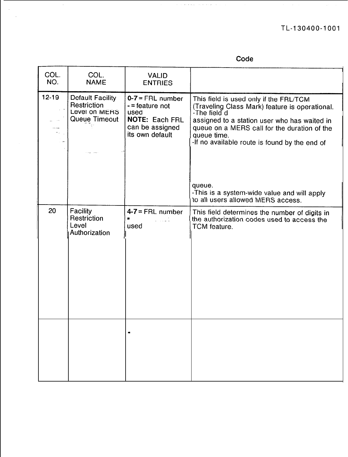
Table 4.4 Entry Fields for Record Code
OF
COMMENTS
etermines the FRL default value
timeout value. the queue time, the FRL assigned here will
temporarily be assigned to the station.
-This value should be set up to allow the call
to be routed over a more expensive route as a
reward to the station user for having stayed
in
-
= feature not
Code Number
of Digits
-This number must be consistent throughout
the network.
-If one switch in the network has 4-digit
authorization codes, then all other switches in
the network must have 4-digit authorization
codes.
-The more digits used in the authorization
code, the better the security that is provided.
-A total of 10,000 authorization codes can be
used. If all 10,000 are used the number of
digits must be over 4; if not, any number
dialed will work as an access code.
21
Traveling Class Y = used This field determines whether or not the TCM
Mark Provided
-
= feature not feature is used.
used -A TCM is only used for on-network MERS
calls.
-A TCM is assigned to a station user when a
valid authorization code is dialed.
-The TCM allows the call to be completed
over the network.
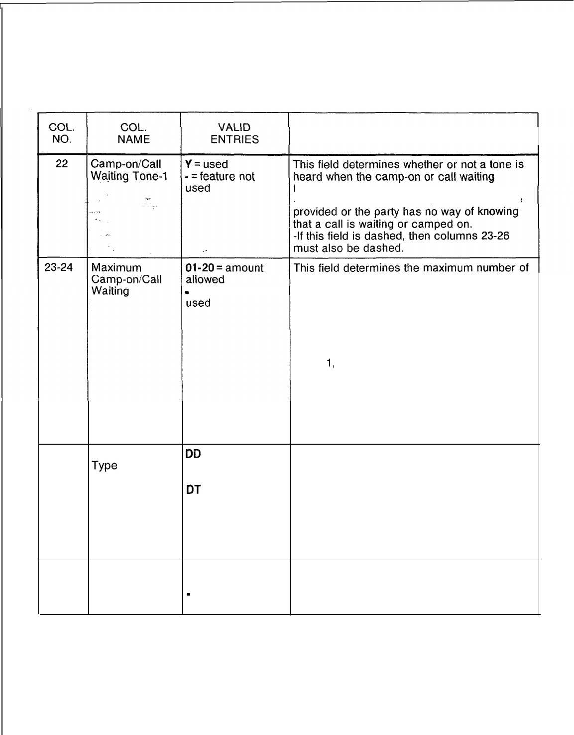
TL-130400-1001
Table 4.4 Entry Fields for Record Code O
F
(Continued)
COMMENTS
feature is activated.
-For these features to work, the tone must be
camp-on/call waiting calls that can be in
-
= feature
not
effect at the same time per station.
-A station that has calls camped on must
complete the call-back sequence before
calls can be placed. Therefore this number
must be kept low, or making calls could be a
problem. However, if this field is too low or is
set at
1,
the attendant could be flooded with
calls; 2 or 3 is recommended for this field.
-If an entry is made in this field, column 22
must be marked Y.
MOTE: If stations cannot process calls
because of this feature, then the site is a good
application for the message center feature.
25-26
Camp-on Tone
DD
= distinctive This field determines the type of tone heard
We
dial tone when the camp-on/call waiting feature is
40 = 440 Hz tone used.
DT
= dial tone -If an entry is made in this field, column 22
80 = 480 Hz tone must be marked Y.
-- = feature not -The recommended value for this field is DD.
used -If DT is used, the tone heard is the same as
the tone heard when the attendant breaks into
a conversation.
27
Most Y = 1 + dialing is in This field determines whether or not 1 +
Economical effect dialing is in effect.
Route Selection
-
= 1 + dialing is -If an NPA (Numbering Plan Area) has
1 + Dialing not in effect conflicting codes, then 1 + dialing is required.
I
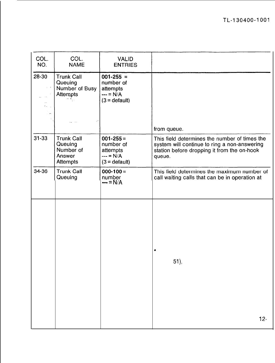
-
TL-130400-1001
Table 4.4 Entry Fields for Record Code
OF
(Continued)
COMMENTS
This field determines the number of times the
system will try calling a busy station before
dropping it from the on-hook queue.
-Trunk call queuing, defined in columns 28-
36, and MERS list queuing, defined on Record
Code OV, columns 12-17, are mutually
exclusive features.
-When the station is called back by the
system and it does not answer, it is dropped
Maximum
se-
=
N/A
the same time for the entire system.
Number of Calls
(default = 15)
Waiting
37-38
Remote Access
00-l 5 = COS
This field determines the displayable class of
Directory number service assigned to the remote access
Number -- = feature not feature.
Displayable used -This remote access feature does not require
Class of Service an access code.
-There is only one remote access number; it
is given to all system users who are allowed to
access the remote access feature.
-
When assigning the COS for a station
allowed remote access (Record Code LD,
column
51),
do not assign a COS for remote
access that allows more privileges than the
COS of the station. If this occurs, the station
user can use the remote access feature to
bypass restrictions placed on the station.
-Remote access is assigned on Record
Code LD, column 51.
-If an entry is made in this field, then columns
39-40 must also have an entry.
-The remote access directory number must
be defined on Record Code OD, columns
12-
15.
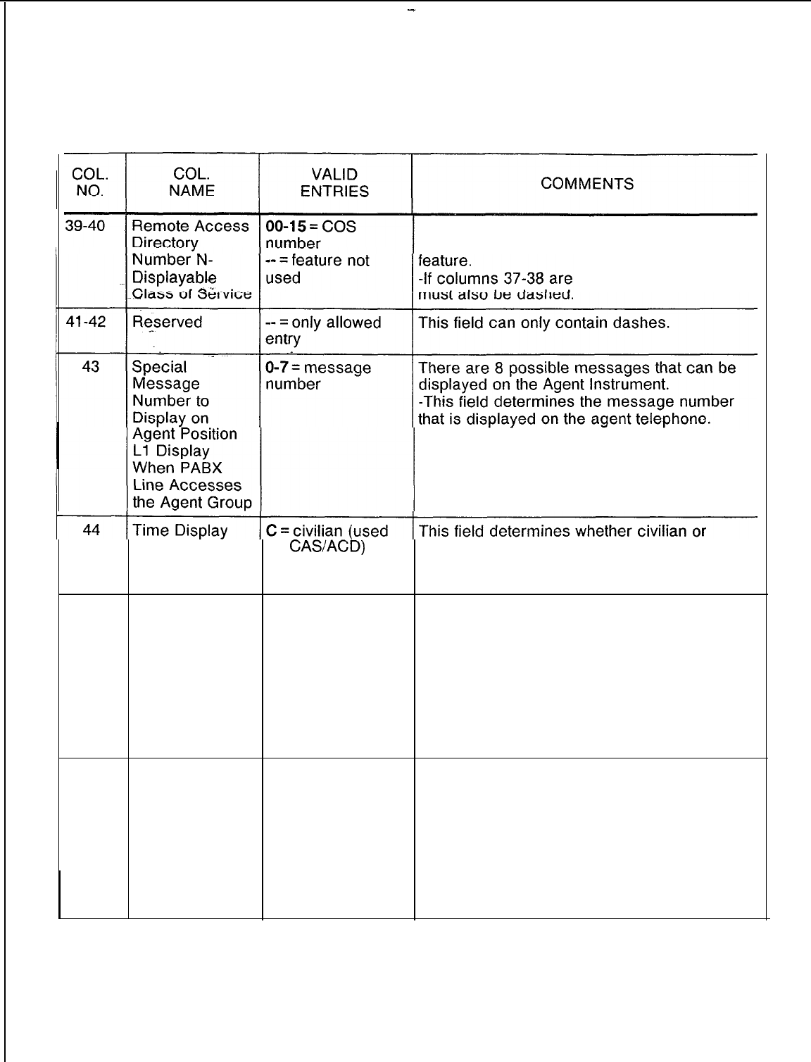
-
TL-130400-1001
Table 4.4 Entry Fields for Record Code OF (Continued)
r
L
This field determines the n-displayable class
of service assigned to the remote access
dashed, this field
-These messages are defined on Record
Code SM, columns 14-29.
for
CASACD)
M = military military time is displayed at the Agent
Instrument and on FADS (Force Administration
Data System) reports.
45
Number of 1-4 = number This field determines the number of attendant
Active Attendant 2 = default loops on which incoming calls can appear.
Loops -If all loops are activated, the attendant may
have difficultly accessing an outside line.
-When all loops are not activated, the
attendant has the call waiting light to assist in
determining the number of calls.
-If the enhanced Attendant Console is used,
activating loop 4 is not recommended.
46-47
Authorization 00-99 = prefix This field determines the authorization prefix
Prefix Digits digits digits used to access MERS off-network
-- = feature not dialing after making a MERS on-network call.
used -If the trunks are busy when making a MERS
on-network call, the user may decide to
continue the call over off-network facilities.
NOTE: The authorization code used to
access this feature is assigned on Record
Code AU, columns 12-13.
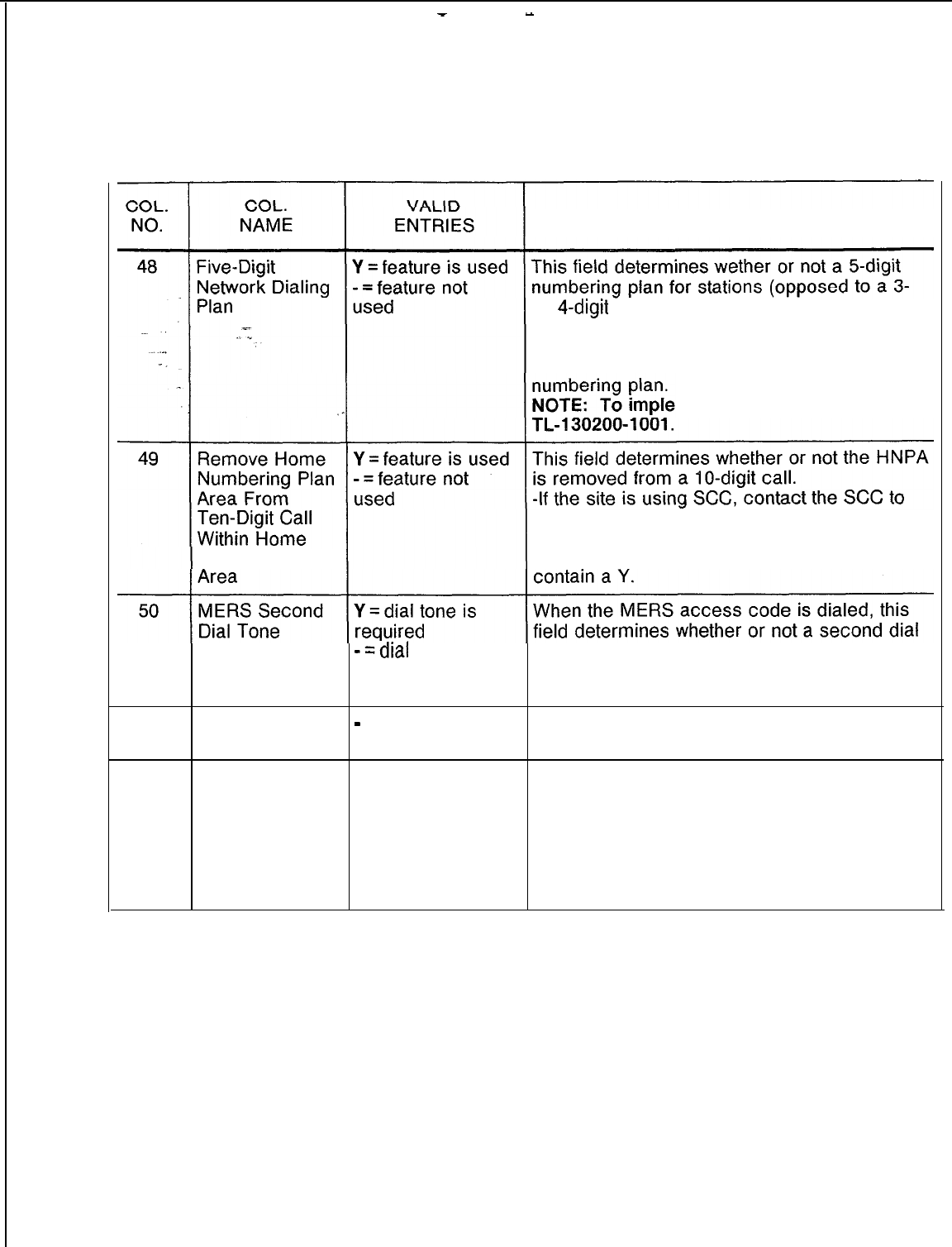
-
-
TL-130400-1001
Table 4.4 Entry Fields for Record Code
OF
(Continued)
COMMENTS
or
4-digit
numbering plan) is used at the site.
-This feature can be used to provide a
uniform numbering plan to a private network.
-Record Code NT determines the network
ment this feature refer to
Numbering Plan
determine if the HNPA needs to be deleted or
if it must be left on.
-If the routing is over ATT, the field must
-=dial
tone is not tone is heard.
required -The customer determines whether or not
this field should be activated or not.
51
Reserved
-
= only allowed
entry This field can only be dashed.
52
Recent Change l-6 = number This field determines the minimum security
Save Data Base level required to save the data base, entered
Security Level via recent change, to disk.
-Record Code SL, columns 13-14, defines
security levels.
-This feature allows the customer to write to
disk.
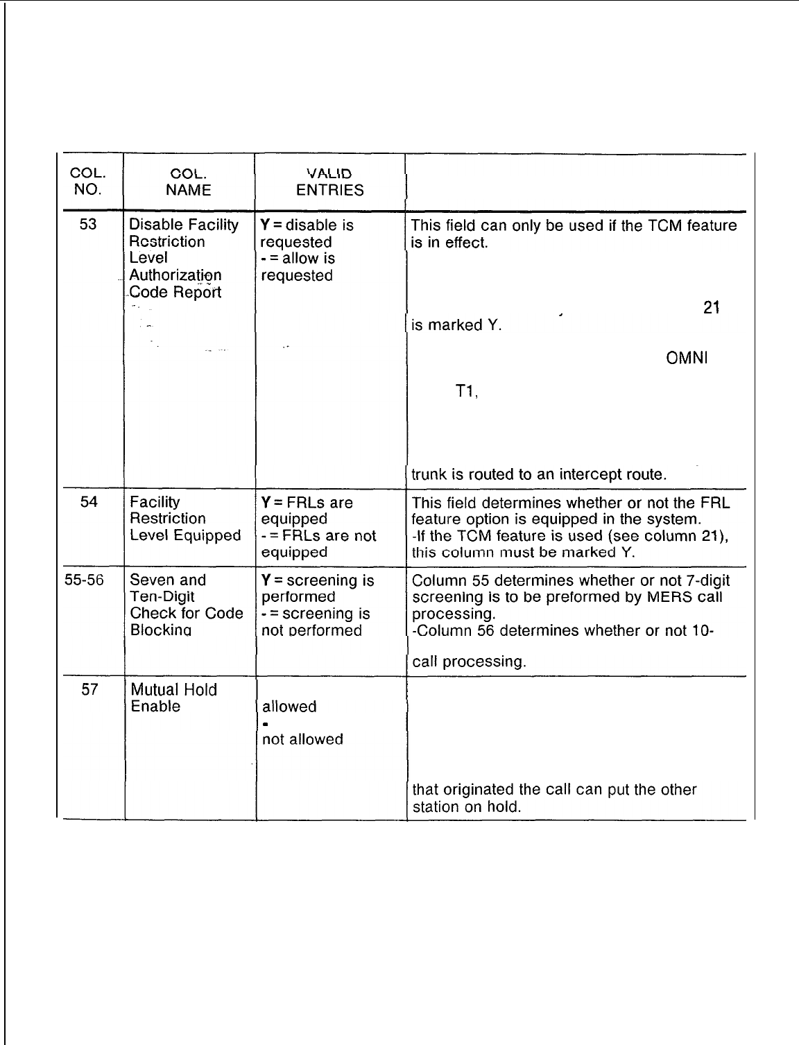
TL-130400-1001
Table 4.4 Entry Fields for Record Code
OF
(Continued)
COMMENTS
-The field determines whether or not an
incoming network trunk is required to have an
FRL value assigned to it.
-This feature can only be used if column
21
NOTE: If a remote switch cannot assign an
FRL value to an outgoing trunk, the
OMNI
SI
can assign one. This is done on Record
Code
Tl,
column 69.
-If an incoming default FRL is not assigned
by this switch and this field is dashed, the call
will still come through.
-If the column is marked Y, the incoming
digit screening is to be preformed by MERS
Y = mutual hold is This field determines whether or not the
system allows the mutual hold feature.
-
= mutual hold is -If this feature is activated when two stations
are connected, both parties can place each
other on hold.
-If this feature is not in effect, only the station
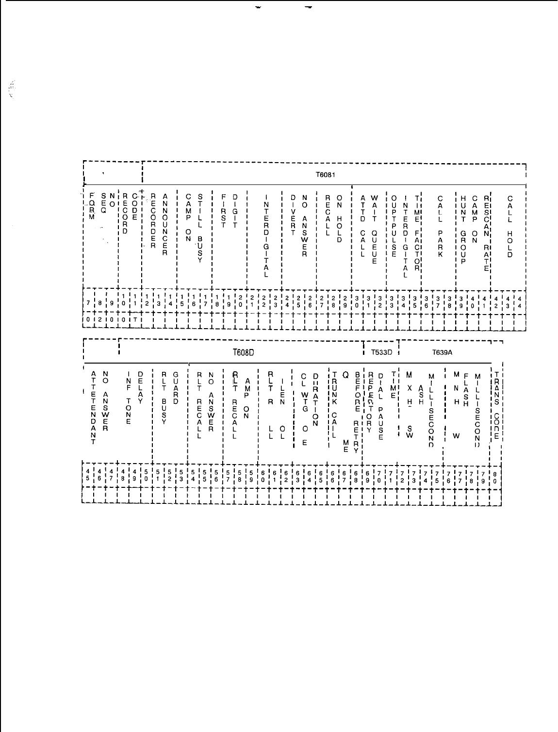
-
-
TL-130400-1001
Record Code OT:
Off ice Timeout Values
4.5 Record Code OT, Figure 4.5, defines the timeout intervals
required for the various call conditions.
r---------
I
-
r-----------------------------------------------------------------~
I
II
T6081
i
r
,
I
tI
r-----
j
T6081
r-----------------------------------------~-----
I
~---------------~-~
T608D
i
T533D
:
I I
I
T639A
I I
I-
I I
I I
I
II,I
I
I
*
T:
M
F
I
R
C
:i
I
R
S
:
:
Rk
E T
C
A H
bf
D
I
Iw
I
‘z
i
T
I
O
N
I
E
I
I
tT
Q
IR
U
‘U
E
‘N
U
;K
I
N
i;
G
‘L
T
IL
I
I
z
I
BIR
EIE
FlP
OlE
RlR
E(T
Ii
A L
z
x
A
;H:
0
I
0
I K
i
s
I
w
i
M
I I
I
N
I
H
0
I
0
I K
’
s
fw
ITI
IRl
IAl
INI
ISI
ICl
‘01
ID’
IEl
Figure 4.5 Record Code OT: Office Timeout Values Data Sheet
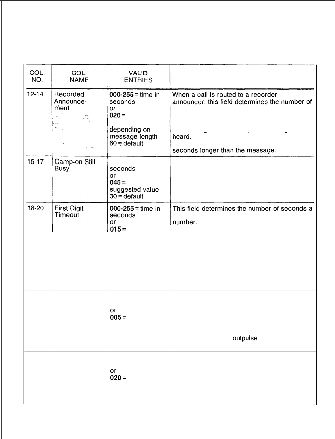
TL-130400-1001
Table 4.5 Entry Fields for Record Code OT
COMMENTS
seconds before the call is automatically
disconnected after message completion.
suggested value, -The timing value must exceed the length of
the message for the complete message to be
-It is recommended that this field be made 3
000-255 = time in When the attendant camps on to a busy
station and the station remains busy, this field
determines the number of seconds that pass
before the call is returned to the console.
station user has to dial the first digit of a
-If a digit is not dialed in this amount of time,
suggested value the station user is disconnected.
-If a station user takes too long to dial,
, system traffic could be affected and resulting
in delays getting system dial tone.
-This field is used in conjunction with
columns 21-23 (interdigital time) which gives
the timeout factor for all remaining digits.
-This does not apply to the consoles.
21-23
Interdigital 000-255 = time in This field determines the maximum number of
Timeout seconds seconds a station user can take between
%5=
dialing station or telephone number digits
before system disconnect.
suggested value -In a MERS application, it is recommended
that this value be kept at 005, or the system
will take too long to
outpulse
a call.
-This does not apply to the consoles.
24-26
Divert No 000-255 = time in This field determines the number of seconds a
Answer Time seconds call to a POTS telephone will ring before being
E&o=
forwarded to a no-answer divert destination.
-This field should always be less than
suggested value attendant no- answer time (columns 45-47).
30 = default -This value is programmable on an individual
basis for Integrated Featurephones.
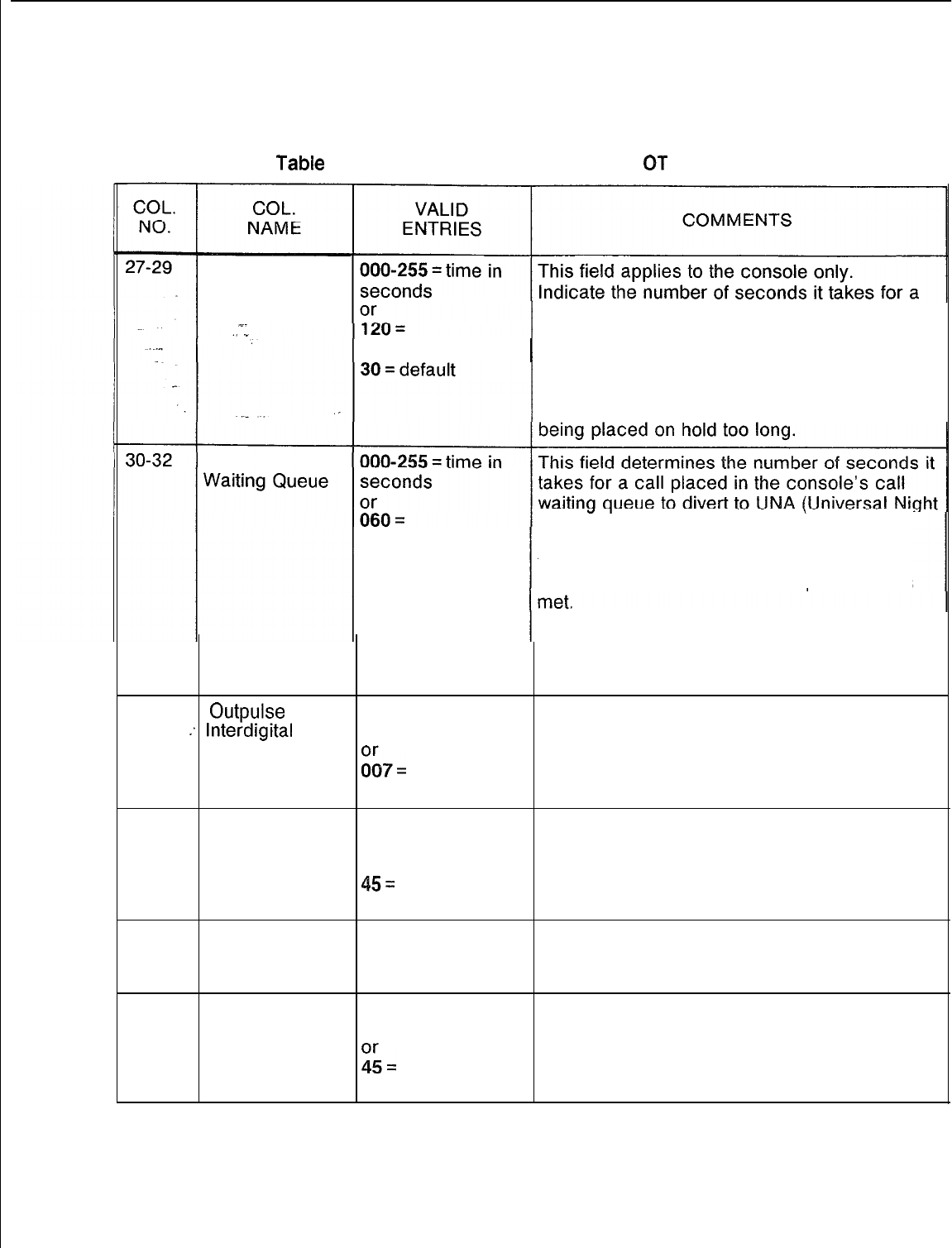
TL-130400-1001
Tabie
4.5
Entry Fields for Record Code
0T
(Continued)
Recall on Hold
suggested value
call put on hold and not retrieved to recall to
the attendant.
-Depending on how busy the attendant is, the
recommended value may prove too long for
some sites. A shorter value of 045 may work
better at sites where there are complaints of
Attendant Call
suggested value Answer) service.
-If the attendant is busy when an incoming
trunk call comes in, the call is automatically
routed to UNA when this timing parameter is
-The calling party hears ringing until
connected to the UNA destination.
-The UNA feature is assigned on Record
Code CA, columns 27-30 and 43.
33-35
Outpulse
003-015
= time in
This field determines the amount of time, in
:Interdigital
Time tenths of a second tenths of a second, between successive dial
Factor
&=
pulse digits being sent from the sender.
suggested value
36-38
Call Park 000-255 = time in This field determines the amount of seconds
seconds before a call that is parked or not retrieved will
or recall or ring back to the station that parked
45=
the call, to the attendant, or to another
suggested value destination if calls are forwarded.
39-41
Hunt Group 005 = only allowed The suggested value is 005.
Camp-on entry
Rescan Rate
42-44 Call Hold 000-255 = time in This field determines the number of seconds
seconds before a call that was put on hold by a station
&
automatically rings back to that station.
-If the station is busy or does not answer, the
suggested value call goes to the console.
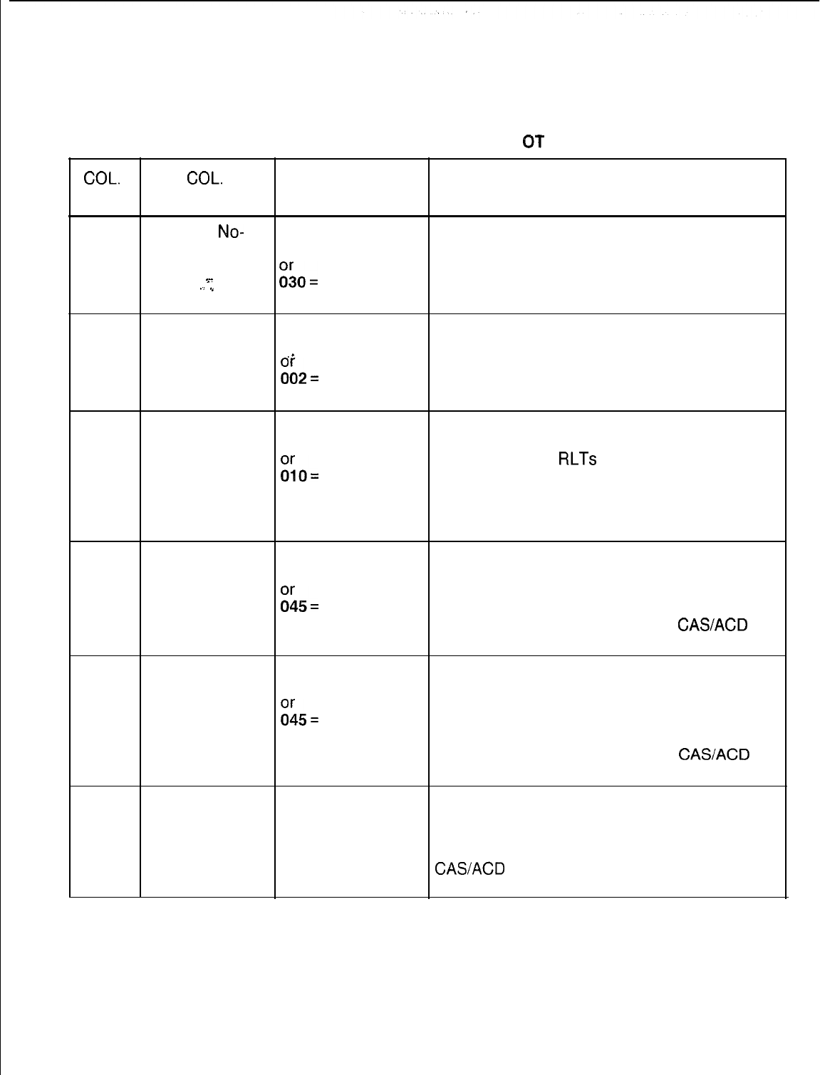
TL-130400-1001
COL.
NO.
Table 4.5 Entry Fields for Record Code
CT
(Continued)
COL.
VALID
NAME ENTRIES COMMENTS
45-47
Attendant
No-
000-255 = time in This field determines the number of seconds it
Answer Time seconds takes for a trunk-originated call to return to
the console if the attendant extended the call
%-
./
.”
Go=
to a station that did not answer.
suggested value
48-50
Information 000-255 = time in For a CAS Branch application, indicate the
Tone Delay
,_
milliseconds amount of time between the detection of an
:;2=
RLT (Release Link Trunk) being answered (by
an ACD agent or CAS) and the start of
suggested value information tone sending.
51-53
Release Link 000-255 = time in
Trunk Busy In a CAS Branch application, this field
milliseconds
Guard determines the amount of time for the busy
Go=
guard feature on
RLTs
to go into effect.
-The busy guard interval prevents a
suggested value reseizure of an RLT by the CAS Branch
system for a new call after a disconnect
(attendant release) is recognized.
54-56
Release Link 000-255 = time in In a CAS Branch application, this field
Trunk Recall on seconds determines the number of seconds allowed for
No Answer
G5=
a call extended by an RLT to ring.
-If the call is not answered before this timer
suggested value is up, the call is routed back to a
CASACD
agent.
57-59
Release Link 000-255 = time in In a CAS Branch application, this field
Trunk Recall seconds determines the number of seconds a call
Camp-on
:;5=
extended by an RLT can be camped on to a
busy station.
suggested value -If the call is not answered before this timer
is up, the call is routed back to a
CASACD
agent.
60-62
Release Link 000-255 = time in In a CAS Branch application, this field
Trunk Recall seconds determines the number of seconds a call can
Silent Hold or wait in the silent hold queue.
030 =
-When this timer is up, the call is routed to a
suggested value
CASACD
agent.
127 = default
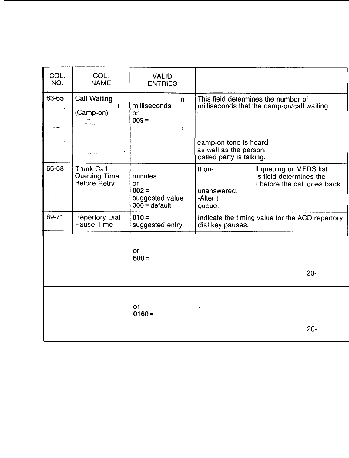
TL-130400-1001
Table 4.5 Entry Fields for Record Code OT (Continued)
COMMENTS
Tone Duration 000-255 = time
suggested value
tone is heard.
-The camp-on tone alerts a called party that
a call is camped on.
-This time is in tenths of a second and the
d
by the called party
/persons to whom the
000-255 = time
in
hook trunk cal
queuing is used, thi
number of seconds
his time, the call is again placed in
72-75
Maximum 0160-2000 = time This field determines the maximum time
Hookswitch in milliseconds allowed for a hookswitch flash.
Flash
iGo=
-The maximum hookswitch timing value must
be greater than the minimum hookswitch
suggested value timing value.
2000 = default -The timing value is in multiples of
20-
millisecond increments.
76-79 Minimum
0160-2000
= time
This field determines the minimum time
Hookswitch in milliseconds allowed for a hookswitch flash.
Flash
:;60=
-
Always make the minimum hookswitch flash
timing less than the maximum hookswitch
suggested value flash timing.
-The timing value is in multiples of
20-
millisecond increments.
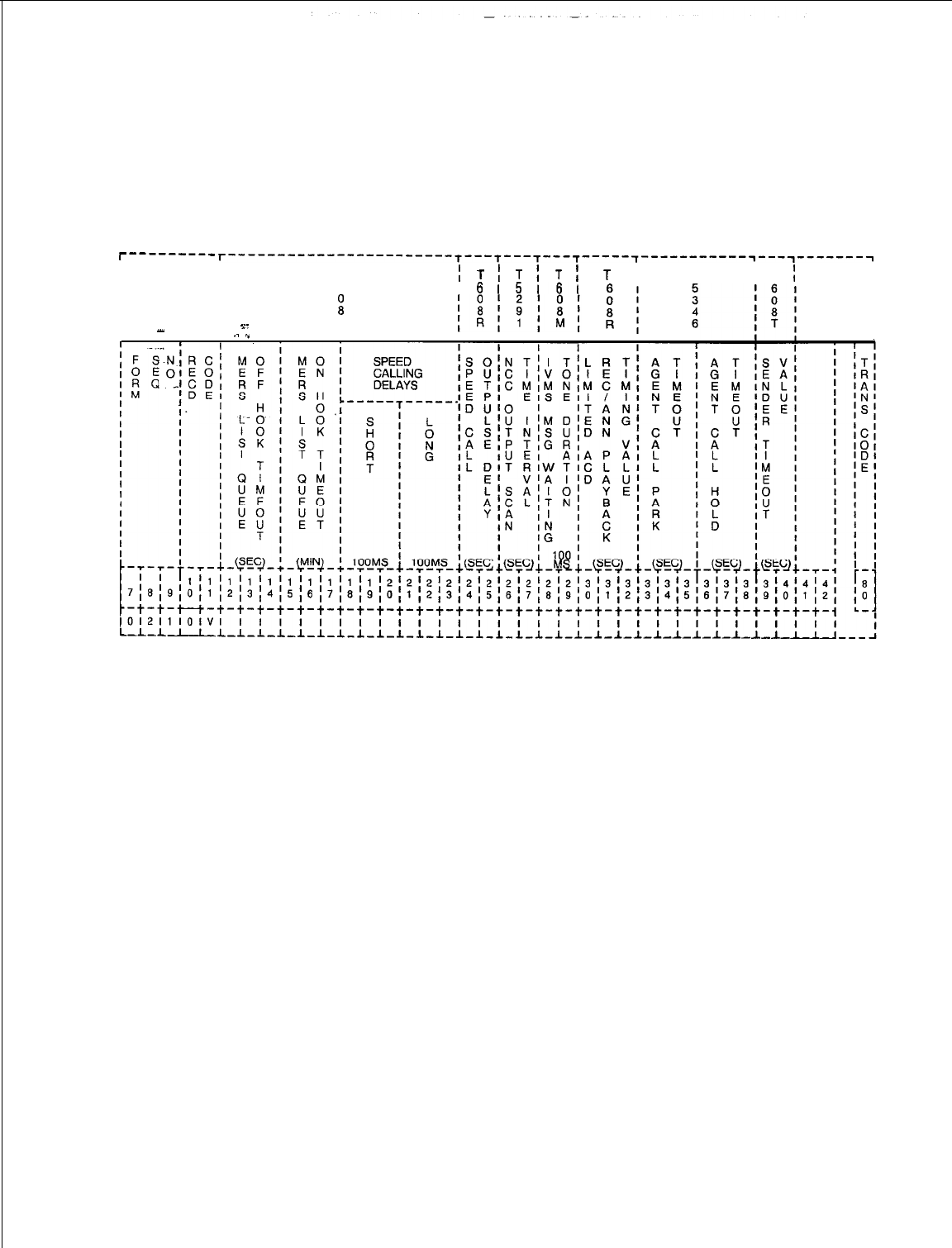
TL-130400-1001
Record Code OV:
Office Timing Values
4.6 Record Code OV, Figure 4.6, defines the timing intervals
required for the call conditions. This data sheet is basically an
extension of the office timing values data sheet, Record Code OT
(Figure 4.5).
r---------
I
r-----------------------T---T---T---T---T-----~-----------~---~-------~
I
II
T
I
6
1
T
i
T
1
T
I
t
T
I
I
I T
;I
T
I
II
615161
I
II
II
II
ii
I
I
I
Y. M
I
I
-
I
.1
.” I I I I I I
Figure 4.6 Record Code OV: Office Timing Values Data Sheet
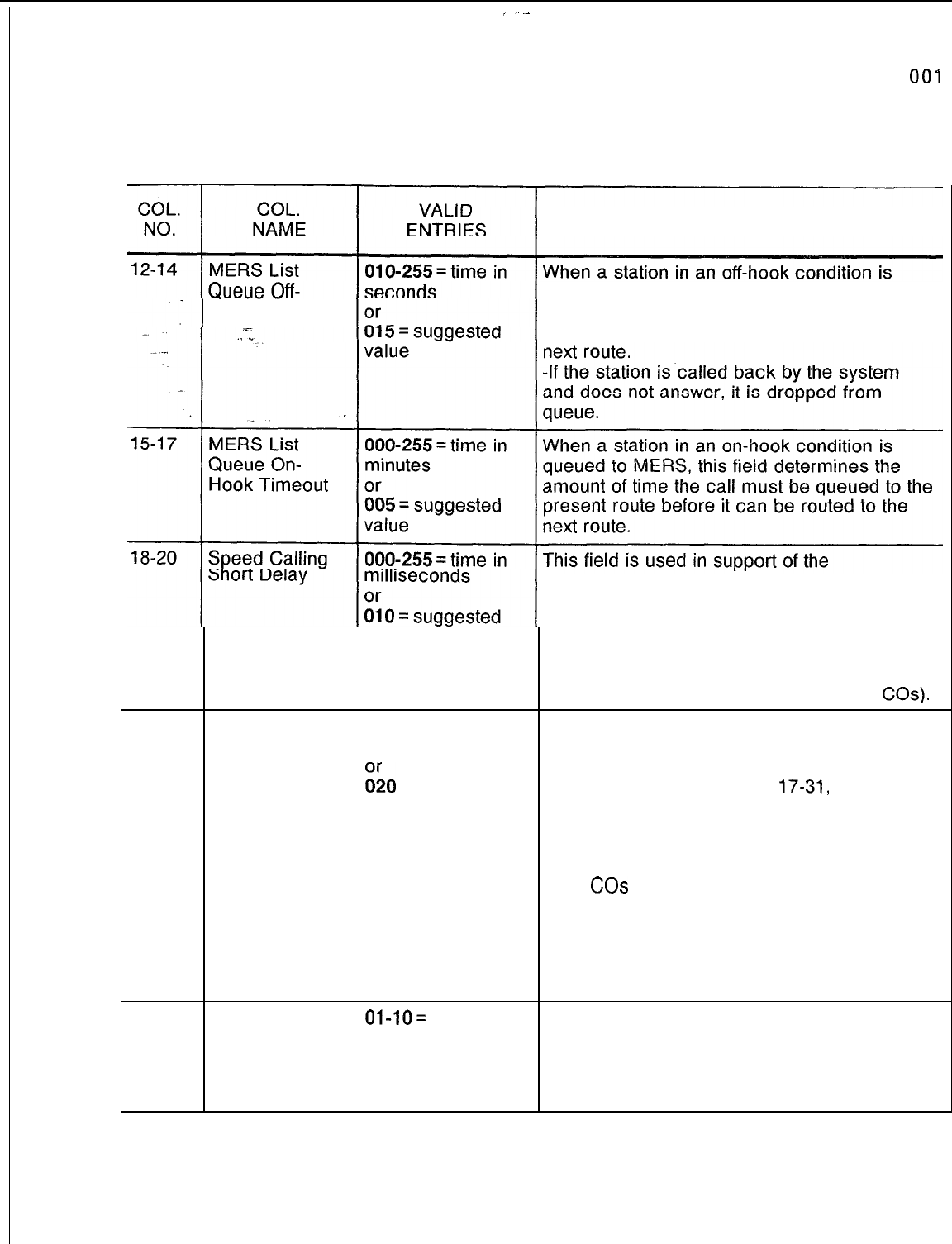
l-L-1 30400-l
00-l
Table 4.6 Entry Fields for Record Code OV
COMMENTS
Hook Timeout queued to MERS, this field determines the
amount of time the call must be queued to the
present route before it can be routed to the
value
group/individual speed calling feature.
-If a speed calling short delay is given on
Record Code GS, columns 17-31, this field
determines the length of the delay.
-This feature provides a short delay between
the dialing of the number and the CO sending
dial tone (this is often required for older
COs).
21-23 Speed Calling
Long Delay 000-255 = time in
seconds
&I
= suggested
value
100 = default
This field is used in support of the
group/individual speed calling feature.
-If a speed calling long delay is given on
Record Code GS, columns
17-31,
this field
determines the length of the delay.
-The feature provides a long delay between
the dialing of the number and the CO sending
dial tone (this is often required for older or
busy
COs
if the site SCC dialer outpulses
digits faster than the CO can accept them).
-If speed calling is used over MERS routing,
it is not recommended to use a long delay
NOTE: The long timing value must exceed the
short timing value.
24-25
Speed Calling
Outpulsing
Delay
Ol-lO=
time in When processing a call using the speed
seconds calling feature, this field determines the
or number of seconds the system waits before
03 = suggested outpulsing the first digit of a number to the
value trunk.
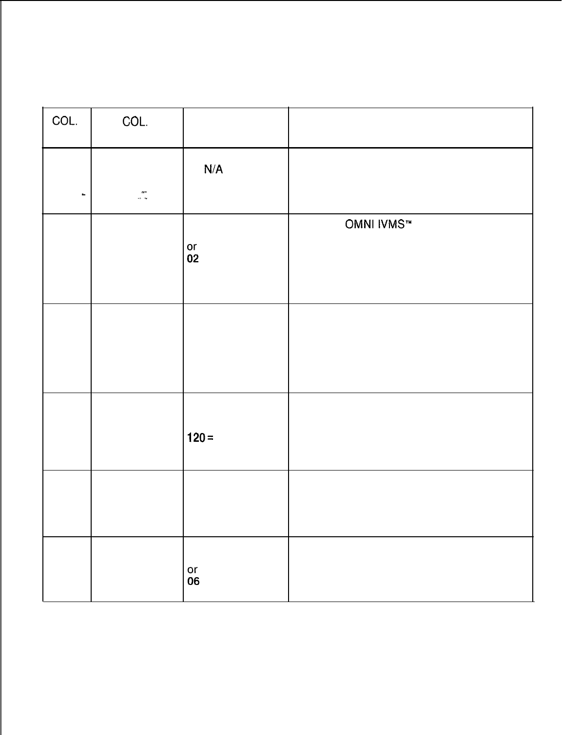
TL-130400-1001
COL.
NO.
Table 4.6 Entry Fields for Record Code OV (Continued)
COL.
VALID
NAME ENTRIES COMMENTS
26-27 Network Control 5-15 = seconds
Center Output If the system scans the NCC (Network Control
-- =
N/A
Scan Time Center) for any output, this field determines the
time between the scans.
-
Interval
.,x1
-This field only applies to a system that is
used as an NCC.
28-29
Integrating 00-20 = time in When the
OMNI
IVMS”
message waiting
Voice milliseconds feature is accessed, this field determines how
Messaging
. .
System
i;
= suggested long the tone will be heard.
Message -This tone indicates that the system is ready
value to accept the message.
Waiting Tone
Duration
30-32 Limited ACD 000-255 = time in
Recorder This field determines the length of time
seconds provided for the recorder announcer
Announcer or
Playback message.
016 = suggested
Timing Value -This timing value should be set at a greater
value, depending value than the message (3 seconds longer is
on the length of the sufficient).
message.
33-35
Agent Call Park 000-255 = time in If an ACD agent parks an incoming trunk call
Timeout seconds on a busy agent or an agent group, this field
or determines the amount of seconds that the
120= N/A
call can be parked before it times out and
120 seconds = recalls.
default
36-38
Agent Call Hold 000-255 = time in If an ACD agent puts a call on hold, this field
Timeout seconds determines how long the call can be held
or before it recalls to the agent.
120 = suggested
value
39-40 Sender Timeout 03-30 = time in This field determines the amount of seconds a
Value seconds trunk has to recognize a wink from a remote
g;
= suggested system or CO to seize a trunk.
-This field applies to all trunks in the system.
value
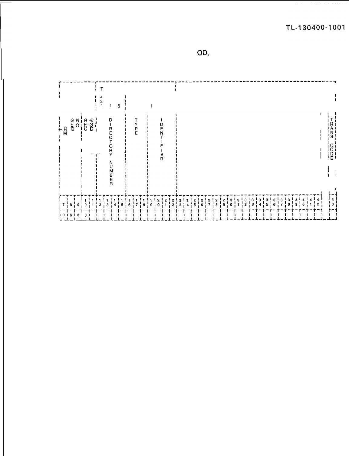
r
Record Code OD:
4.7 Record Code
00,
Figure 4.7, defines certain types of
Other Directory Numbers
directory numbers that are not associated with a line circuit.
I
II
I
IT
T T
T
II
I
I 6 6 61
6
II
1;
4 1
4 0
;
4
I
I
4
II
I
I
11
15;
I
1II
I
I I I I
III
r
I
;
F
SN;R-G;
I
ITI
l
0
EoIE-O.,
I
IRI
+R
0
;c
DI
I
lAt
I
M
E I
I
‘NI
IIII
isI
I
II
II
IIII
ICi
1 . .
III
101
1
IDI
I
‘El
I I I
I I I
I
I
I
I
I
;I
I I
I I I
I I I
I I I
Figure 4.7 Record Code OD: Other Directory Numbers Data Sheet
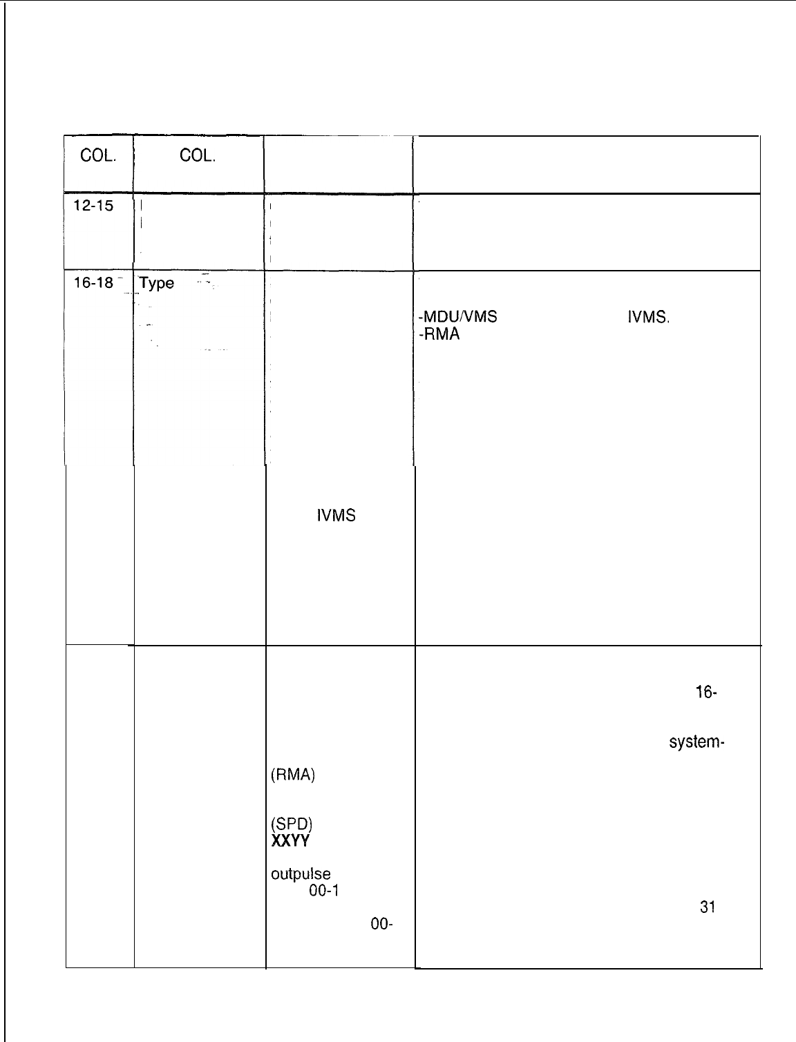
TL-130400-1001
Table 4.7 Entry Fields for Record Code OD
COL.
NO.
19-22
COL.
NAME
Directory
Number
Code Type
Identifier
VALID
ENTRIES
0000-9999 or
000-999 for
three-digit
numbers
MDU =
message
deskunattended
RMA =
remote
access directory
number
SPD = call forward
to individual speed
call list entry
TGO = satellite
access-trunk
group outplusing
TGS
= satellite
access-trunk
group select
VMS
=
IVMS
(Integrated Voice
Messaging
System) directory
number
0000-0063 =
trunk group
number (MDU,
TGS, and VMS)
0000 =
remote access
directory number
(RMA)
0001-0008 =
entry number
(SW
XXW
= (TGO)
number of digits to
outpulse
(XX =
00-l
5);
trunk group
number (W =
OO-
63)
COMMENTS
This field determines the directory number to
be
used to access the feature defined in
columns 16-l 8.
This field determines the type of directory
number.
-MDUNMS
are both used for
IVMS.
-RMA
assigns the directory number as a
remote access number.
-SPD is used to define a directory number
that is used to access the remote call
forwarding feature. The directory number
defined here is used to access an individual
speed call list. The individual speed calling
list stores directory numbers for the remote
call forwarding feature. Up to 8 directory
numbers can be created to access all 8 of the
individual speed calling numbers.
NOTE: If the line is a DID line and is allowed
remote call forwarding, billing to the calling
party begins as soon as the call rings at the
on-site station whether or not the call is
answered at the remote forwarded location.
For this reason; it is not recommended to
assign the remote call forwarding features to
DID lines.
This field determines the code type identifier
for the directory number.
-If the directory number type, columns
l6-
18, is marked SPD, the numbers 0001-0008
are pointers to the 8 individual speed calling
entries. There are only 8 possible
system-
wide directory numbers for the remote call
forwarding feature. However, each user
allowed this feature can have up to 8 remote
call forwarding numbers stored in an individual
speed calling list. Since the external call
forward feature works in conjunction with the
individual speed calling feature, the number of
users who can access the feature is limited by
the number of individual speed calling lists.
The system will support a maximum of
31
individual speed calling lists. If the external
call forward feature is used, code type number
110 on Record Code AC must be defined.
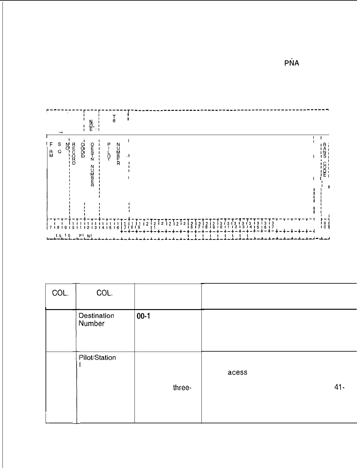
‘-----.----T---T-------r- ____________-----------------------------------------
I
II
I
I
;5
II
I
I
I
KI
;
.p..;
0
II
I
-
I
I
2
I
II
I
--..
1I
I
I x I
I
-
II I I
I
I
’
I
‘F
S
I
!
IT,
0 E
I
1
IRI
R
Q
I
M
.I
I
$1
II
’
iSI
I I
I
I
ICI
I
I
I
18;
I
I
lEl
’
’
I
I
I
:
i
’
’
I
’
’
I
’
’
I
’
’
I
Predetermined
hunt group or a station number required for
P$A
(Predetermined
Night Answer
Night Answer) service. A maximum number of 16 hunt
Pilot Numbers
groups or station numbers can be assigned for PNA service.
II
’
i
I
1
’
I
I I
T-T-T-T-T-I p-:
13131414141
‘8
1
18191011121
‘0
I
+-+-+-+-+-4
t-i
I I I I I I I I
A-A-A--L--A
-
-
I
T-t-T-T-
I1
I1
I1
I2
I7
I8
I9
IO
+-+-+-+-
I I I I
.I-A--L-A-
t-c-+-+--t--t-+-+-+-+-
10
19
I6
I
PI
NI
I I I I
L-A-I-L-L-LA-A-A-&-
T-T-T-T-T-
I2
I2
I2
I2
I2
I1
12131415
+-+-+-+-+-
I I I I I
.A.-.&.-*-*-&-
T-T-T--r-t-T-T-T-T-
I2
12
12
I2
I3
I3
I3
I3
13
i61718191011121314
yyy+-+-t-+-y+-
I I
II
A-~-~-*-&-A-~-A-A-
T-T-T-
131313
151617
+-+-+-
I I I
L--L-A.-
Figure 4.8 Record Code PN: Predetermined Night Answer Pilot Numbers Data Sheet
Table 4.8 Entry Fields For Record Code PN
COL.
NO.
12-13
14-17
1
I
1
I
I
COL.
NAME
Iestination
Vumber
Pilot/Station
Number
VALID
ENTRIES
00-l
5 = number
0000-9999 or
000-999 for
three-digit
numbers
right justify
three-
digit numbers
COMMENTS
This field determines the number used to
represent the pilot/station number.
-The attendant can change the PDN number
from the console by entering a number
defined here.
This field determines the pilot number used.
-Any valid directory number (pilot, station, or
remote
acess
number, etc.) can be entered.
-This number must also be defined on
Record Code TC, columns 37-40 and/or
41-
44.
-This number must also be defined on
Record Code CA, columns 12-15 and/or
16-19.
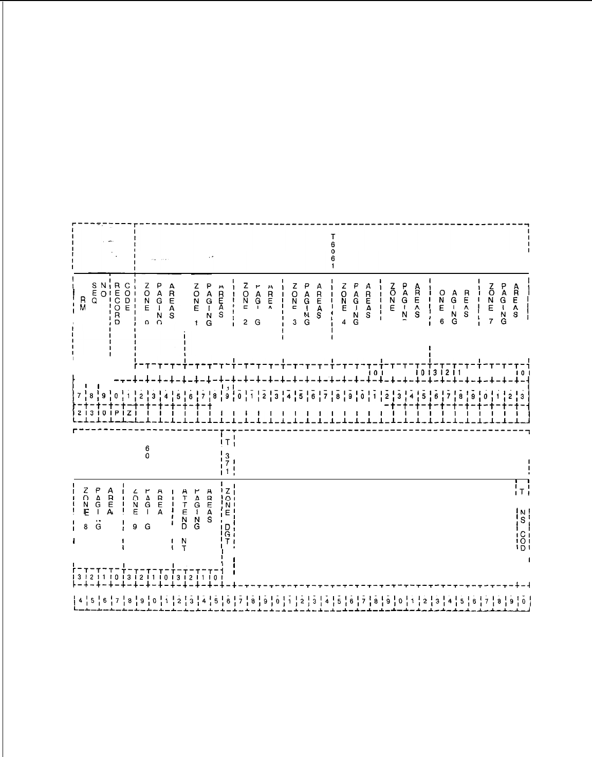
TL-130400-1001
Record Code PZ:
Paging Zones
4.9 Record Code PZ, Figure 4.9, defines the paging zones for
the system. The attendant and certain system stations can be
allowed to access the paging equipment. A station user can
access the paging system by dialing an access code and zone
number. The attendant can access the paging system by the
above method or by depressing.the console PAGE button. The
card used to support this feature is the FB-17210 card and
paging is assigned to circuit 2.
:
F
’
0
iR
IM
I
I
I
II
II
II
13121110’312’
i
--r-1--+
-,-+-a-+-+-i-a--b
I
'
'1'1'1'1'1'1'1'1'
718;9;O;1 ;2;3;4;5;6;7;
,;t,t,t,t~-t-t-t-t-t-t
L-L-L-I-LLL-LI-I-:-I
A
I
2
P A
I
ZPA’ZPA
I
R’OARlOAR~OARt
ElNGElNGElNGE;
:;
NS
E I A
;
E
IA;EIA
I~G
NS,
NS;
:3G
I~G
I
III
III
I I I I
I
i i i
II I I
-T-~-T-T-T-~-T-T-T-:-T-T-T-~
110’31211 10131211 10131211
IO1
-+-.+-a-4-+-+-+-+-+-+-4-+-+-+
1
‘I
’
2'2'2'2'2'2'2'2'2'2'313:
81910111213141516171819~0111
-t-t-t-t-t-t-t-t-t-t-t-t-t-t
ZPA:
Z P A
;ZPA;
OARlOARlOARl
zcH;EU;NGE;
NS;
NS;
E I A
5 G
I6G
NS;
,7G
I
I I
III
I I
II I
II
-T-T-T-~‘T-T-T-:-T-T-T-,
3’2’1
10’31211
10131211
IO’
-4-4-4-4-+-4-4-4-4-4-d.-
3'3'3'3'3'3'3'3'4'4'4'4
213141516171819(0111213
-t-t-t-t-t-t-t-t-t-t-t-
i
r-----------------------r-r-----------------------------------------------------~
I
I
T
:T;
I
I
I
I
:
‘6 I
!3
I
I
I
6
1
I
I
:ZPA’
ZPA’ A P A
iZl
lOAR!OAR!TAR’O!
ITI
;NGE;;Q;‘TGE;N’
‘RI
‘Al
I
E
’
A
I
N SN S
;
E I A
‘El ‘N’
I8G
;
9G
,NNS
I
I
DG
ID;
Is:
I I
I A
‘GI ICl
I
II
III
7
iTi
‘01
I
I’
I
IDI
II I
:-T-T-T-
Ii
I
‘El
I
’
T-T-T-T-+-T-T-T-t
I
I I
I I
l3l2l1lOl3l2l1lOl3l2l1lOl
II I
L-+-+-+-+-+--l-+-+-+-+-+-+-+-T-T-T -T-T-T-T-T-T-T-T-T-T-T-T-T-T-T-T-T--r--r--r-+-4
~4~4~4~4~4~4~5'5'5'5'5'5'5'5~6'5'6'6'6'6'6'6'6'6'6'6'7'7~7'7'7'7'7'7'7'7'8~
,4l5l6,7l8,9lO~1~2~3~4~5~6~7~8~9~O~1~2~3~4~5~6~7~8)9~O~~l2~3~4~5~6~7~8~9~O,
L-L-L-L-L-*-L-r-r-~-*-~-~-~-~-~-~-~-~-~
-~-~-~-~-~-~-~-~-~-i-~-~-~-~-1
Figure 4.8
Record Code PZ: Paging Zones Data Sheet
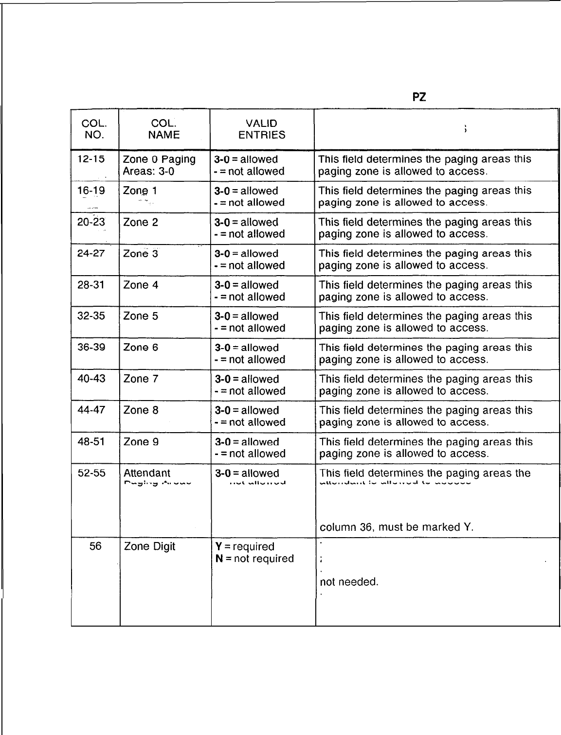
TL-130400-1001
Table 4.9 Entry Fields for Record Code
PZ
COMMENTS
-The attendant paging area is normally an all
call for all zones.
-If this feature is allowed, Record Code CA,
This field determines whether or not the 0
zone digit must be dialed to access the zone.
-If the site only has one zone, a zone digit is
-If the site has more than one zone, a digit
must be dialed to identify what zone is to be
paged.
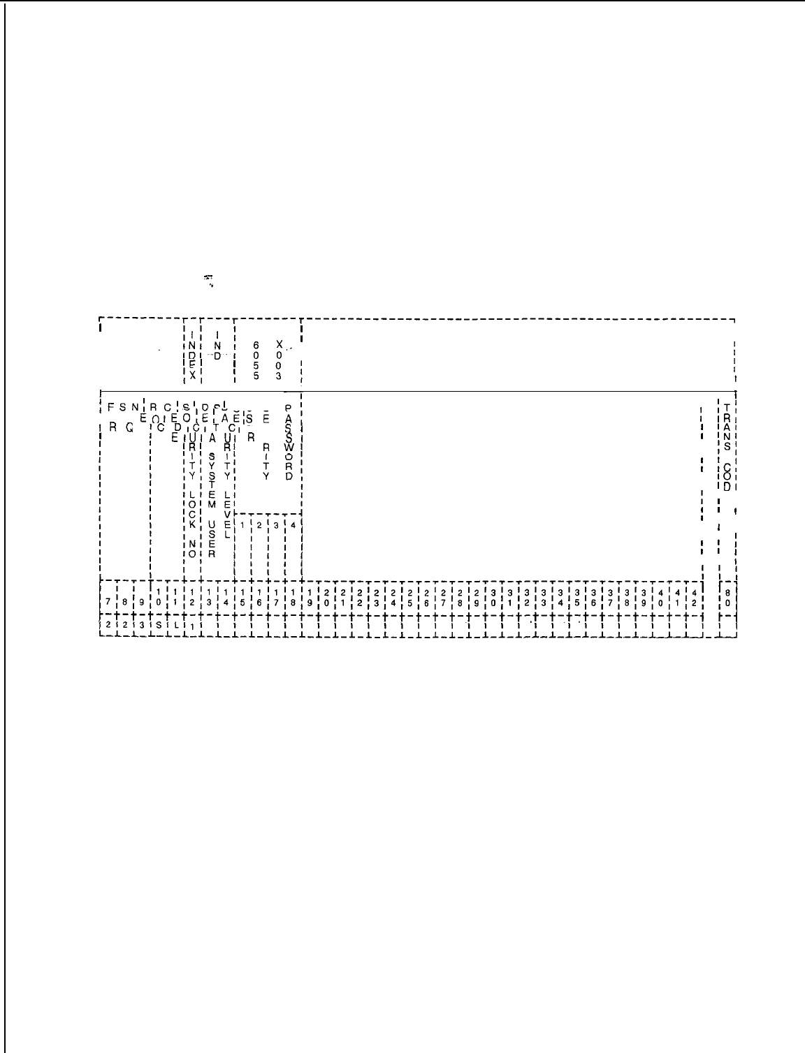
TL-130400-1001
Record Code SL:
User Security 4.10 Record
Code SL, Figure 4.10, defines passwords to access
Level Password
both the voice and data software of the system. If the system is
equipped with the PD-200 Data Option, this record code must
be completed for the data security level. To date, eight security
levels for voice and six security levels for data have been
defined. The user can perform the functions associated with the
level accessed, including the functions associated with all lower
levels. Use one row per password for the system. Assign to
each password the appropriate voice and/or data security level.
%-
.I
.”
r---------r-r---r-------T------------------------------------------------------~
I
I
T T
;II
I
I
I
:
I
$-
I
I
I
‘E’
E
’I
I
;x;
x
;I
I
I
I I
II I I
I I
I
I I
I
;
F
SN;RClS’D
S’
U S
I
I 0
EOIE
O;E;A
El
i
IT1
rRG
IRI
1 M
;C
DIGIT
C,
E C
S
l
EIUIAUI
R
U
SI
I
,AI
I
‘NI
I
ISI
I
fCl
I
IO,
I
,DI
I
‘El
I
I
I
I
I I
I
I
I
I I
III
I I
I
)212131SlL,~,
I I I I I I I I I I I
I
I I I
I
I I I
I
1
I
1 I I I I I I I I
L-L-L-L-L-L-L-L-L-L-L_I-I-I-L-L-L-L-L-L-~-L-~-~-~-~-~-*-~-~-~-~-~-~-~-~-~---~
Figure 4.10 Record Code SL: User Security Level Password Data Sheet
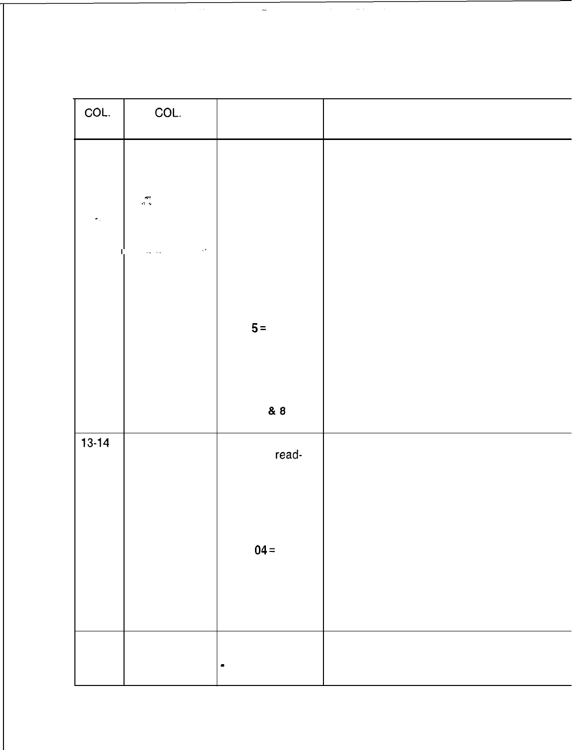
TL-130400-1001
Table 4.10 Entry
Fields
for Record Code SL
COL. COL.
VALID
NO. NAME ENTRIES COMMENTS
12
Voice Security 1-8 where: This field determines the voice security level
Level Number
Level 1
= traffic
number (l-6) associated with the password
studies, system defined in columns 15-l 8.
status, and recent -The value level given here defines what
x-
.j
,”
change display functions the user’s password accesses.
Level
2 = recent
-Column 12 is preprinted on the record code
-.
change of line forms.
functions
,.
Level
3 = feature
changes of minor
impact
Level 4 = all recent
change of all
features of major
impact
Level
5=
maintenance
request
Level
6 = generic
program changes
and manual data
base changes
Levels 7
818
= reserved
13-14
Data System 00-05 where: This field determines the data security level
Security Level
Level
00 =
read-
number (l-6) associated with the password
only access defined in columns 15-18.
Level 01 =
-Each of these levels can be assigned as
reserved often as needed to the various voice values
Level 02 =
(e.g. data level 00 could be assigned to voice
reserved levels l-6).
Level 03 =
NOTE: Enter -- for N/A if the PD-200 Data
reserved Option is not equipped.
Level
04=
ability to
change the
majority of fields
Level
05 = ability to
change most
fields, but files
cannot be deleted
15-18
User Security
O-9 or
A-Z
= four
This field determines the password used to
Password characters access the system.
Characters:
-
= N/A -Numbers and letters cannot be mixed in this
l-4 field.
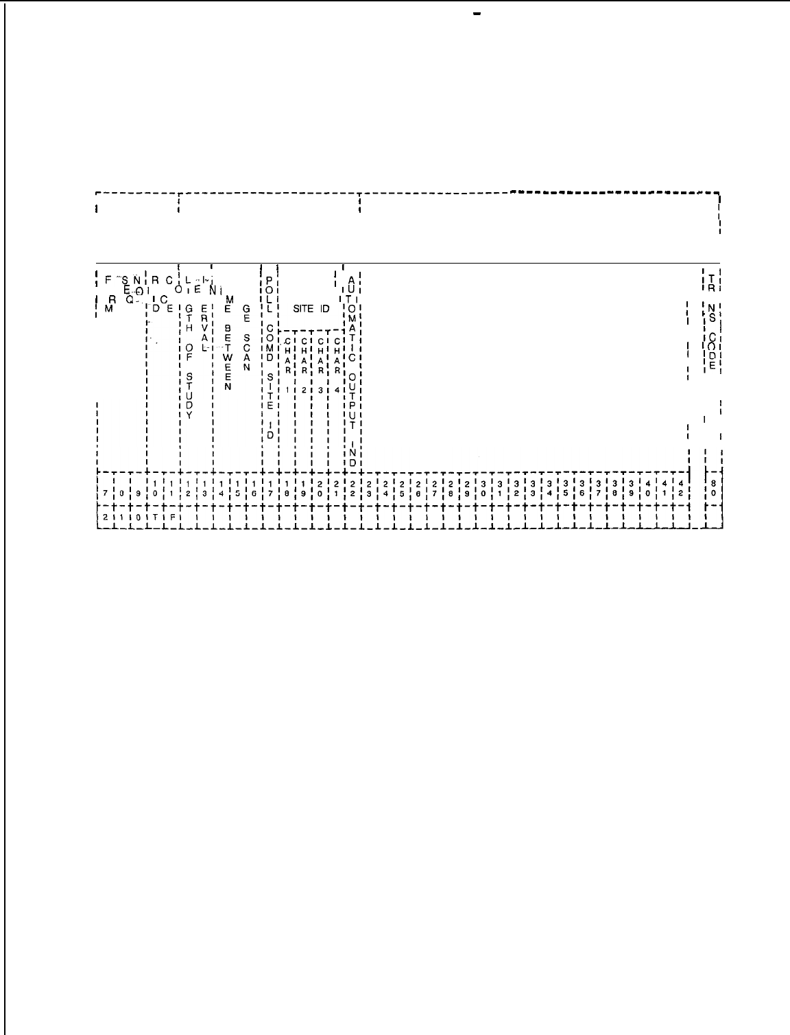
-
TL-130400-1001
Record Code TF:
4.11 Record Code TF, Figure 4.11, defines the system
Traffic Data Facilities
parameter requirements for a traffic data study.
r---------r---------------------I---------------------
--------------------___c__
I
f
I
I
T
I
II
I
6
II
I
0
I
II
II
4
II
1
II
I I I I
I I I
I I III
I I
,
;
F-Sk&C;
-- I
L..bl
T U
;Pf
I 0
LOI
E
OIE
NI
I S
101
DATA
;
A;
DUMP
IUI
1
R
Q-.
lC
DIN Tl
M
A
ILI
HEADER
ITI
IM
I
I
I
I
I
I
I
I
I
I
I
I
I I
I
IT;
I
lRl
I
‘Al
I
INI
1
ISI
I I
I
ICl
1
‘01
I
‘D’
I
‘IEl
I
I ,
I I I
I I I
I I
I I
f
I 1 I
I I
I
I
I
I I I
Figure 4.11 Record Code TF: Traffic Data Facilities Data Sheet
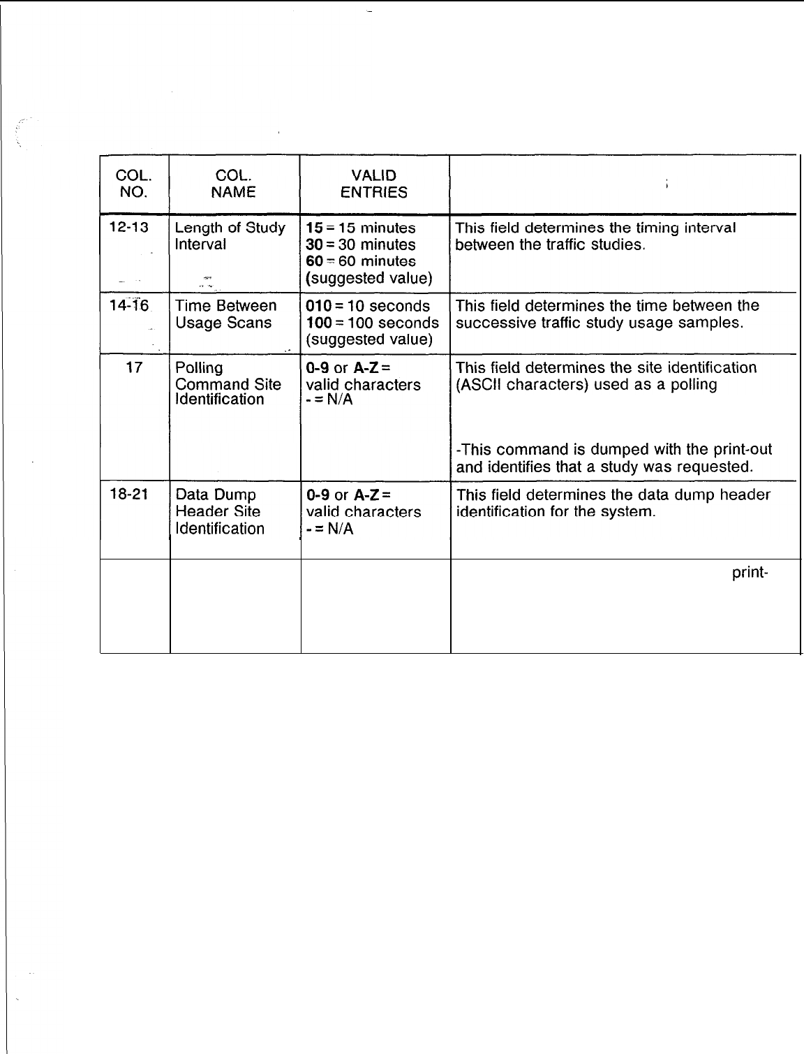
TL-130400-1001
Table 4.11 Entry Fields for Record Code TF
COMMENTS
command to retrieve a traffic study.
-This is required if the data is processed by
a centralized polling message system.
Characters l-4
22
Automatic Y = provided This field determines whether or not a
print-
Output indicator N = not provided out of the traffic study is automatically given.
-This is done by using the specified intervals
along with the data dump header site
identification.
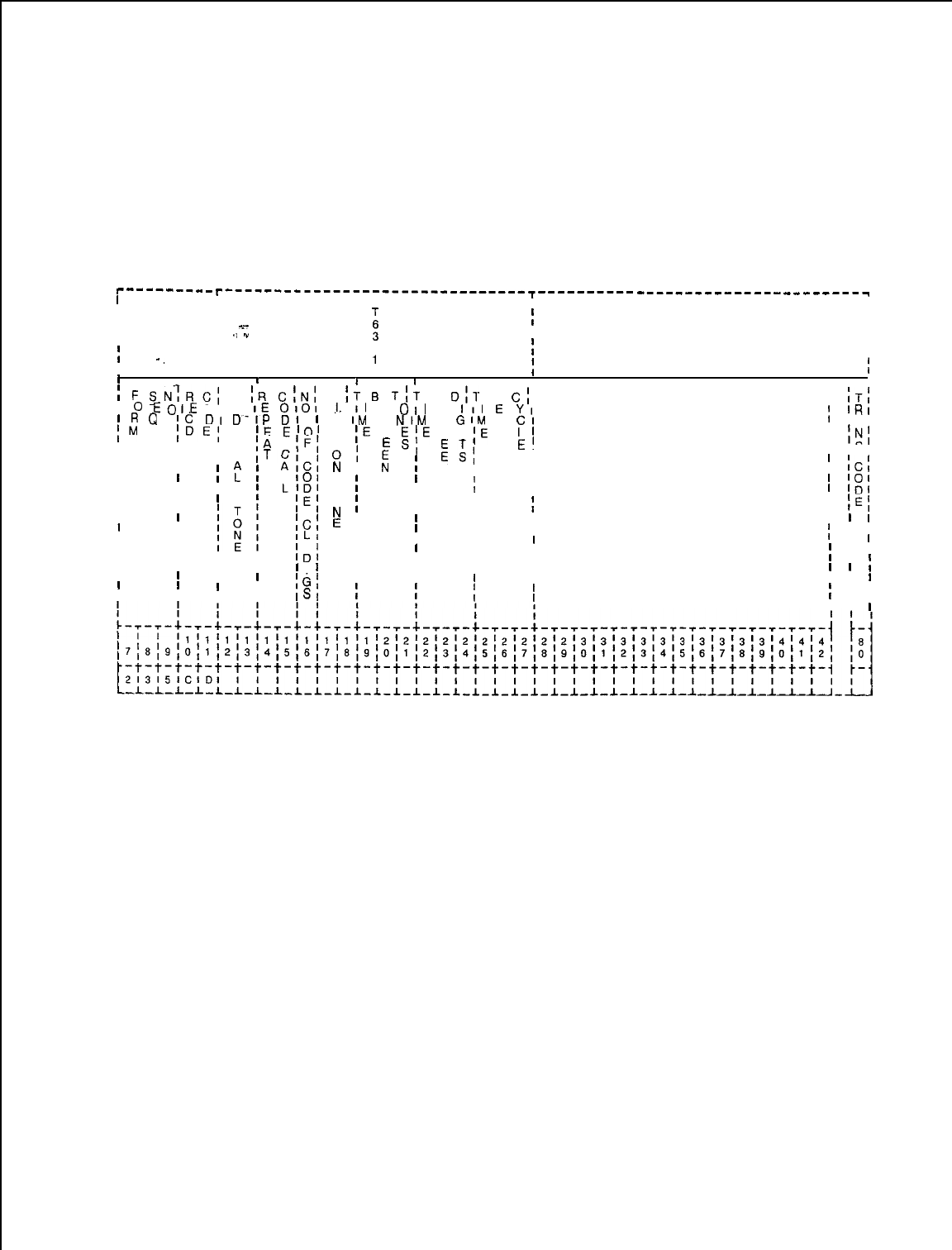
TL-130400-1001
Record Code CD:
Code Call 4.12
Record Code CD, Figure 4.12, defines the parameters for
the code calling option. For this feature to work, at least one
class of service defined on Record Code DD, columns 26-27,
must allow code call access. The card used to support this
feature is the FB-17210 card.
r--------- r-------------------------------
I
-r---------- ----_-___---------------
I
III
I
T
II
I
I
I --
x-
i
II
I
.(
w
I
i
I
-.
I
7
I1I
II
II
III
I I
I I II
!
F
SN:RC;
C
(R
C:N:
T
;T
0
TIT
B
1311.
B
C;
I
0
EOIE
01 0
IE
0101
!.
II
E
011
E
III
E
YI
1
R
Q
,C
DI
D-IP
Dl
IM IDE,
E1 M
IM
T
NIM
T
GIM
T
Cl
lE
El01
E
;E
W
E;E
W I
;E
W
L’
I
I
I
I
1
I I
I
ITI
I
IRI
I
‘Al
I I I
IA IFI
E
Sl
E
E’
I
INI
I IS,
I I
I C
ITCI
0;
::I
ES;
I
I
I I
AIC:
N
I
:
I
,cl
II
?
I
L
101
;
N , N ,
I
LlDl
T
iI
I
I
I L
;III
1
101
I
I I
1
lDI
IIII
I I
;E;
0
;
N
I
I I iI
IEI
IIIII
I
I
I
II
;C:
E
I
IL1
III
I ,
I I I I I I
I
l
I I I
IDI
III
I I I
I I
I I I I I II
I
I I I I I
I
III I II
II
IIII
IGt
I I II
I I
I
I I II
ISI
I I II
I I
, I IIII
I ,
I I
l
Figure
4.12 Record Code CD: Code Call Data Sheet
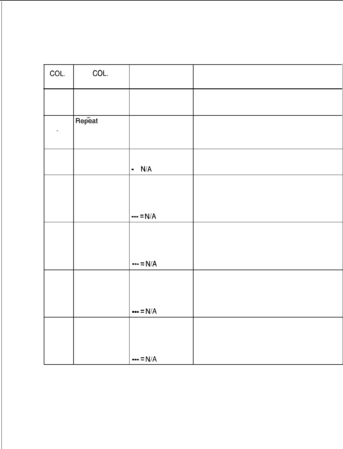
TL-130400-1001
COL.
NO.
Table 4.12 Entry Fields for Record Code CD
COL.
VALID
NAME ENTRIES COMMENTS
12-13
Code Call Tone
DD
= distinctive
This field determines the type of tone to be
dial tone used for the code calling feature.
HZ = 440-Hz
tone
14-15
Repeat
Code
-.
Call 00-l 5 = number
or
-- = N/A
This field determines the number of times the
code call cycle is outpulsed after the initial
cycle is repeated (number of times overhead
ringing is heard).
16
Number of O-3 = number of This field determines the digits outpulsed in a
Code Call Digits rings or code call code.
-
=
N/A
17-19
Time on Tone 000-255 = interval This field determines the time for tone pulses
in tenths of a which make up the code call digits.
second
3 = suggested
value
m-v
=
N/A
20-22 Time Between 000-255 = interval This field determines the time between the
Tones in tenths of a successive tone pulses that make up code
second call digits.
3 = suggested
value
s-m
=
N/A
23-25 Time Between 000-255 = interval This field determines the amount of time
Digits in tenths of a between each code call digit.
second
7 = suggested
value
mm-
=
N/A
26-28
Time Between 000-255 = interval This field determines the amount of time
Cycles in tenths of a between each code call cycle.
second
15 = suggested
value
mm-
=
N/A

130400-l 001
Record Code
CB:
Code Blocked 4.13 Record Code CB, Figure 4.13, defines the
i’-and
lo-digit
numbers that are screened by MERS call processing.
Numbers
r---------
~-------------------~---------------------------------------------,
III
III
II
I
I
II
T63Xl
I I
I
I
I
I
I I
III
II I I
DIGITS
I
N”&R
I
I
TO BLOCK
I
I
II I
I-
I
I
II
Figure 4.13 Record Code CB: Code Blocked Numbers Data Sheet
Table 4.13 Entry Fields For Record Code CB
COL.
NAME
Code Blocked
Number Digit
11
to 10
Code Blocked
Number Digit
4
to 10
Code Blocked
Number Digit 1
to 10
VALID
ENTRIES
2-9 and F (wild
card value of all
digits)
O-9 and F (wild
card)
O-9 and
F
(wild
card)
or
-
= N/A
COMMENTS
This field determines digit 1
This field determines digits 2-7.
Dashes are coded for 7-digit numbers. If a
dash is placed anywhere in columns 19-21,
then the rest of the columns in this field must
be dashed.
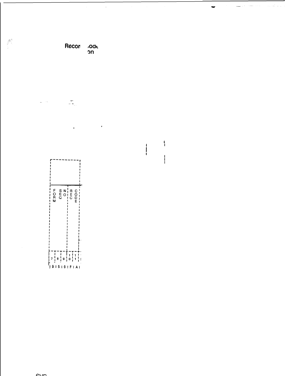
Recori
,oat
Facility Restri
m
L
Authoriz
.
.
_
-t-t-t-t-t-
)915101FIAI
L-L-L-L-L-L.
Figure 4.15 F
SW
5210
i
I
II
I
fI
I
II
II
II
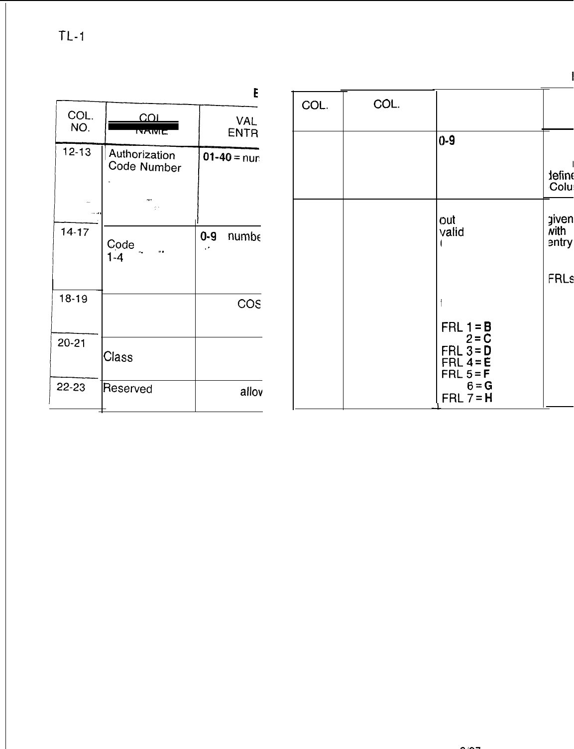
TL-I
30400-l 001 TL-130400-1001
Table 4.13
E
D-76
.
.
(
I
Authorization 0-9
=
numbe
Cpde
Digits
,.
l-4
‘-
.-
Displayable 00-l 5 =
cos
Class of Service -- = N/A
N-Displayable
00-l 5 = cos
Slass
of Service -- = N/A
qeserved
-- = only
allov
entry
Table 4.15 Entry Fields for
Wecor
COL.
NO.
12-18
19
COL.
NAME
Authorization
Code Digits
Facility
Restriction
Level
(
I
(
\
l
I
I
I
I
1
I
VALID
ENTRIES
I-9 = digits
= not selected
f this field is filled
xrt
by the coder,
Jalid
entries are:
D-7
If this record code
is to be generated
by the FAREC
utility program, use
the following:
FRL
O=A
FRLl=B
FRL
2=C
FRL3=D
FRL4=E
FRLS=F
FRL
6=G
FRL7=H
D-78
8187
This field
lumber.
The
numbs
defined
,Columns
This field
liven
to
Nith
values
sntry
for
-The space
can be use
FRLs
NOTE: If a
used, they
any digit
-The digit
column 20.

TL-130400-1001
DIGIT 5.0 This section describes the record codes required to define
ANALYSIS the various digits used by the system. The following record
codes are required:
l Record Code AC defines the system dialing plan and access
codes.
%-
./
.”
l Record Code HD defines the hundreds groups used as system
directory numbers.
l Record Code
IR
defines the system intercept conditions.
l Record Code SA defines non-SCC (Specialized Common
,I
Carrier) codes.
*
Record Code
I1
defines international country codes for
international dialing.
SVR 5210
8187
D-79
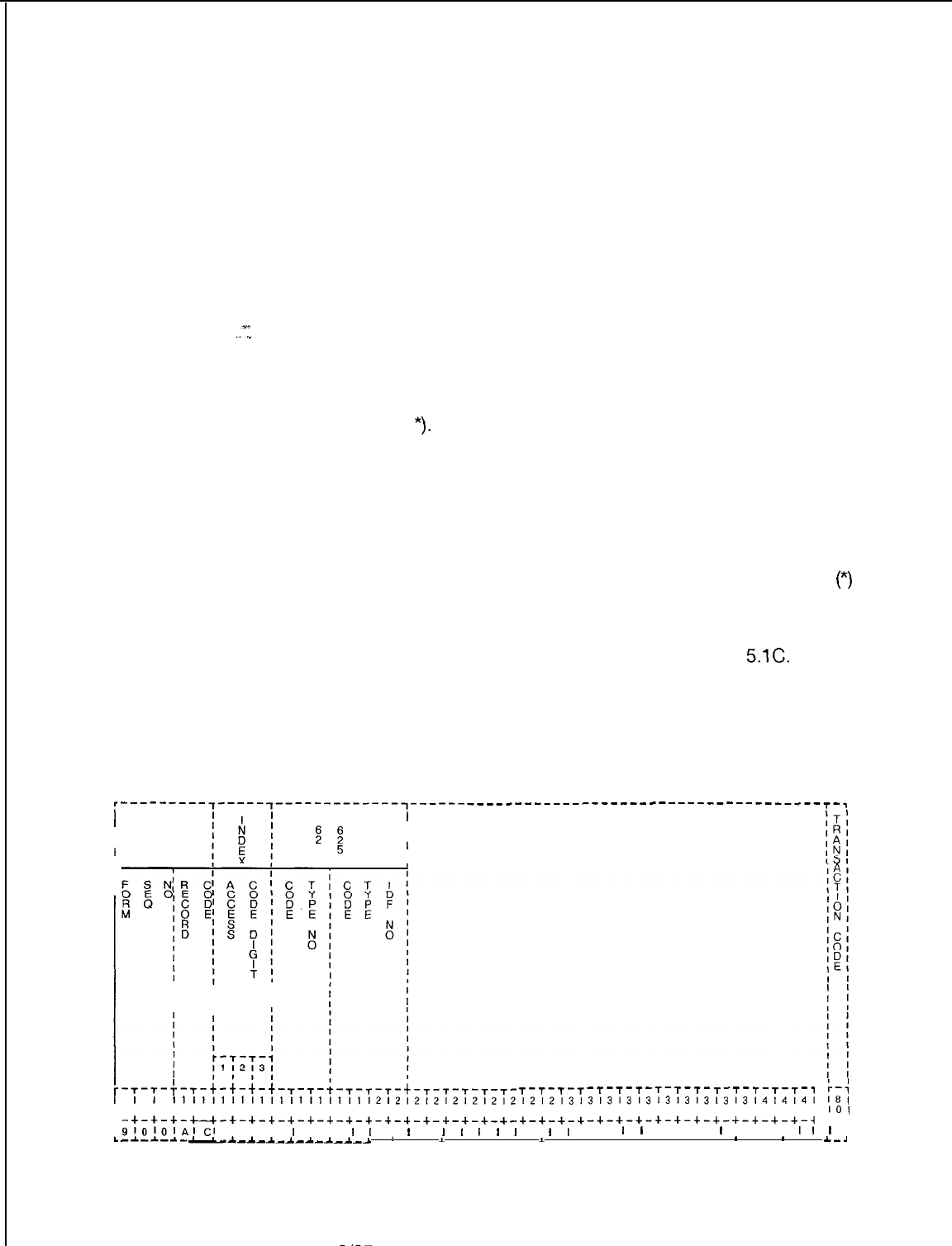
TL-130400-1001
Record Code AC:
Access Code Translation 5.1 Record Code AC, Figure 5.1, defines the dialing plan and
access codes used by the system. Any digit can be assigned as
a single digit access code, the first digit of a two- or three-digit
access code or the first digit of the three- or four-digit station
number.
l Once a number is assigned as a single digit access code or
the first digit of a station number, it cannot be assigned as
the first digit of a two- or three-digit code.
l The last two digits of a three-digit access code cannot be
the same as an existing two-digit access code.
For example, if a two-digit access of 32 exists, there
.I
cannot be a three-digit access code of X32 (X = O-9, #
or
*).
l The last two digits of one three-digit access code cannot
be the same as the last two digits of another three-digit
access code.
For example, only one three-digit access code ending in
32 can exist.
Stations equipped with DTMF keypads can use the asterisk
(*)
and the octothorpe (#) characters for access codes. Access
codes and the system numbering plan supported by standard
user guides are listed in Table 5.1 B (maximum entries, 156).
Additional information can also be found in Table
5.1C.
One or more access codes can be used to precede station
numbers for station-to-station calling thus allowing the use of
more single digit access codes for special service functions.
Refer to Record Code RN, Figure 15.6.
‘---------,-----,-------------~------ -------------------------------------T-,
II
I
T T
I
I
z
B
I
I
I
I
4
5
I
1 1
I
r
I
L.
II
II
III
I I
T-T-T-T-T-T-T-T-T-T- T-T-T-T-T-,
r-;
111111111111111111111212121212121212121213131313131313131313l4l4l4l
181
718191011121314151617181910111213141516171819101112131415161718191011121
101
-+-+-+-c-+-+-+-+-~-+-+-+-+-+-+-~-+-+-~-+-+-+-+-~-+-+-+-+-+-+-+-+-+-+-+-~
L-4
9lOlOlAICI
I I I
I
I I
I
I
,
I
I
I
I
I
I
I
I
I
I
I I
I
I
I I I
I
I I I
II
I
-A.--c-a-
-a.-*-A.-A-~-~_*_~
1 .
I
. . .
I
. . . . . I .
*
.
*
I
a._.4
Figure 5.1
Record Code AC: Access Code Translation Data Sheet
D-80
8187
SVR 5210
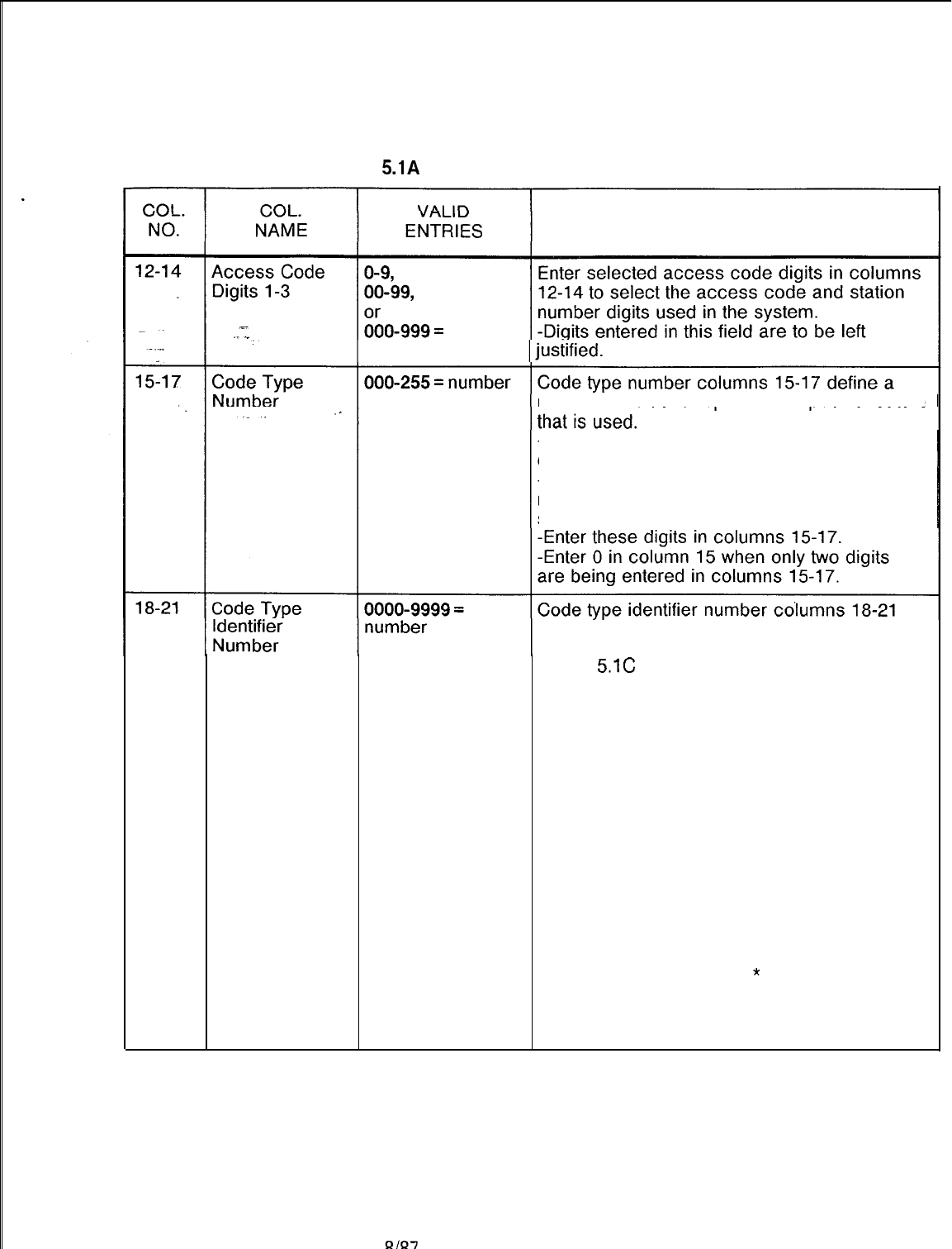
TL-130400-1001
Table
5.1A
Entry Fields for Record Code AC
COMMENTS
access code
numerical value to represent a specific feature
-All code type numbers, range 000-255, are
defined in Table 5.1 D.
-To fill in this field, find the code type
numbers associated with the first digit of the
station numbering plan.
further identify the code type in relation to
termination information.
-Table
5.1C
defines the code type identifier
numbers.
Access Code
-When defining an access code, do the
following:
-To fill in this field, find the code type
identifier number associated with the first digit
of the chosen access codes in Tables 5.1 B or
5.1 D.
-Enter digits from right to left (right justified,
zero filled) in columns 18-21.
-Enter the same number in column 21 that
was used in column 12, which represents the
first digit of the access code using code type
number 10 or 11.
-When * or # is used as the first digit of an
access code, enter 11 for
*
and 12 for # in
columns 20 and 21.
-Enter zeros in unused columns (right
justified, zero filled).
SVR 5210
8187
D-81
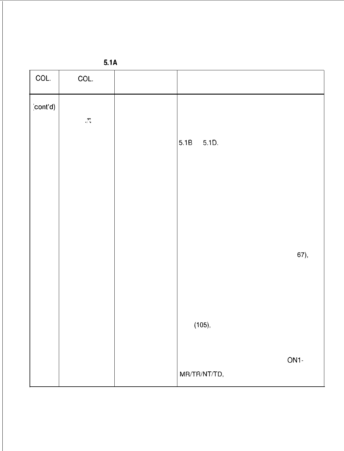
TL-130400-1001
COL.
NO.
Table 5.1A Entry Fields for Record Code AC
(Continued)
COL.
VALID
NAME ENTRIES COMMENTS
18-21
Code Type
cont’d)
Identifier
Number
x-
./
1
0000-9999 =
number
. .
Station Numbering Plan
When defining a station numbering plan ,do
the following:
-To fill in this field, find the code type
identifier number associated with the first digit
of the chosen station numbering plan in Table
5.1B
or
5.1D.
-For a three-digit station numbering plan,
enter in column 21 the first missing terminal
digit that normally would be dialed for DID
applications.
-Example:
ABC xxxx
Office Missing Station
Code Terminal Number
Digit
If the missing terminal digit cannot be
determined, a zero can be used in its place.
-Once a terminal digit is assigned, it must be
used in all applicable areas of the data
sheets.
-If there is no missing terminal digit (e.g.,
code type identifier is 12 for code type
67),
the
station numbers are entered as a blank and
the three-digit number is entered on the input
sheets. This is the only case where a blank is
valid.
-The CTI range of 0000-0063 is the trunk
group number, and the CTI range of 0000 to
9999 is the station or pilot number as
indicated in Table 5.16 or 5.1 D.
-For the MERS on-network access code
type
(105),
the first digit of the code type
identifier must be a 0 (lo-digit dialing) or a 7
(7-digit dialing), and the last three digits must
match an NPA or on-network access code
on Record Code MR and be defined on
Record Code TR (check type 9). If
ONl-
ON4 is defined on Record Codes
MRTTR/NT/TD,
then one of code types 105,
94, 96, 126, or 127 must be defined.
8187
SVR 5210
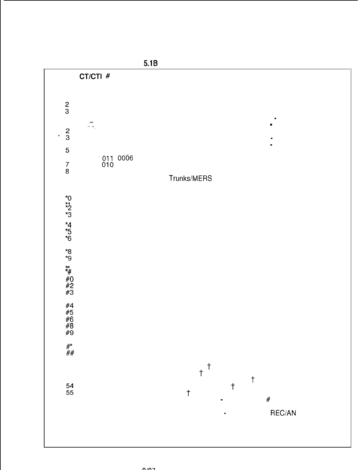
TL-130400-1001
Table
5.18)
Standard Access Codes
Code
CT/CT1
#
DESCRIPTION
0
009 0128
Attendant Access
1
067 0012
:
067 067
Three-digit station numbering system
0012 0012
Three-digit station numbering system
station
4
067 0012
Three-digit numbering system
Three-digit station numbering system
-
spare
--
1
..=I.
067 0015
Four-digit station numbering system spare
-
067 0015
-
:
067 0015
Four-digit station numbering system
Four-digit station numbering system
-
spare
4
067 0015
Four-digit station numbering system
-
spare
5.
010 0005
1 st digit of two-digit feature access
6
.Oll
0006
Three-digit attendant access codes
i
01q
0007 Two-digit trunk access
010 0008 Additional Trunk Groups (FX, WATS, TIE, SCC, etc.)
9
001 0001
*CO
Trunks/MERS
(Trunk Group 1)
010 0011
1st digit of two-digit access codes for station features
#
010 0012
*0
1st digit of two-digit access codes for station features
117 0000
*1
Individual Speed Access
040 0000
Call Hold
:;
079 021 0000 0000
Executive Reminder Entered
*4
Call Forward Variable (Flexible)
024
0000
“5
Group Dial Call Pickup
025 0000
“6
Extended Group Dial Call Pickup
033 0000
Conference
7
057 0000
1;
Trunk Call On Hook (Queuing)
032 0000
Meet Me Conference
039 0000
Call Park
9&
028 0000
*#
Station Camp-On
031
0000
Night Answer
#O 118 0000
#l
Individual Speed Change
044 0000
Call Hold Answer
z:
080 020 0000 0000
Call Executive Forward Reminder Fixed Canceled
#4
026 0000
Station Dial Call Pickup
#5
019 0000
Executive Override
#6 013 0000
Call Waiting Answer
#7
058 0000 Trunk Call On-Hook (Queuing) Cancel
Ei
014 043 0000 0000
Call Call Waiting Park Answer Originating
P
029 0000
Camp-On Cancel
##
012 0000
Group Speed Calling
50 000 0004
51
Automatic Call Distribution Feature Access (Future)
121
0000
Unstaff Position
T
52 125 0000
Staff Position
T
53 122 0000
zz
Call Supervisory ACD (Agent)
T
123 0000
Emergency Assistance
T
124 0000
Bad Line
T
56 047 0000
57
MDR Account Code
-
CTI must be
#
of digits used (l-8)
088 0000
58
Priority Call
049 0000
Recorder Announcer
-
CTI requires
REC/AN
TRK #
XYYY where X = PEC and YYY = PABX TRK *
59 000 0004
Spare
SVR 5210
8187
D-83
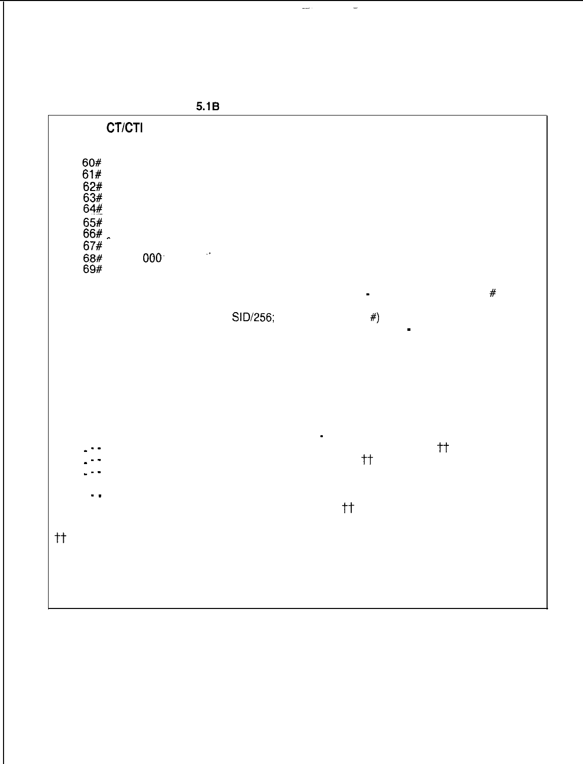
TL-130400-1001
Table
5.1B
Standard Access Codes (Continued)
Code
CT/CT1
# DESCRIPTION
60#
106 0000
Real-Time Clock Update
61#
030 0000
Flexible Night Connection
62#
017 0000
Attendant Control of Trunk Group Off
63#
046 0000 Attendant Force Release of Trunk
W%
055 0000
RLT Day Mode
65#
056 0000
RLT Silent Mode
66#
_
082 0000 Executive Reminder Deactivate (Attendant)
67#
090 0000
MERS Time of Day Change (Cancel)
68#
000. 0000 ‘I
Spare
69#
075 0000 Message Waiting Deactivate (Attendant Administrator)
680 102 0000
MERS Time Zone Display
690 083 0000
Message Waiting Process
-
CTI requires a station
#
699
119 0000 Group Speed Calling Update (CTI is a remainder of
SID/256;
enter A STATION
#)
688 000
0004 Attendant Access Two-Way Trunk
-
Spare
71
001 0002
Trunk Group 2 Access
72 001 0003
Trunk Group 3 Access
73 001 0004
Trunk Group 4 Access
74 001 0005
Trunk Group 5 Access
75 022 0000
Code Call Originating
76 023 0000
Code Call Answer
77 034 0000
Paging Access
78 035 0000
Page Answer
79 036 0000
Dictation Access
-
CTI requires a trunk group number
-- -
084 0000
Maid Service in Progress Access Code
Tt
-- -
085 0000
Maid Service Completed
7-t
-- -
086 0000
Room Restriction Activation from Administrative Phone or
Attendant Console j-j-
-- -
087 0000
Room Restriction Deactivation from Administrative Phone
or Attendant Console
tt
tACD Station User End
j-T
Access codes are custom designed in accordance with the customer data base.
(The above access codes are examples. They can be used as is, modified, or added to if
desired.)
8187
SVR 5210
TL-130400-1001
Table
5.1C
AC Rules
AC-02 CODE TYPE
A code type must be one of the valid code types shown in Tables 3.1 and
3.3, and must be appropriate for SVR 5210.
AC-03 ACCESS CODE
When defining the access code digits.,
the
use of dashes must be
consistent. If digit 2 equals
-,
then
drgrt
3 must be
-.
Examoles:
Ret
Access
Code
‘-
AC Code
1
-- Allowed
AC l-l Incorrect specification
AC-04 ACCESS CODE
-
CODE TYPE
Code type 10 indicates the first digit of a two-digit access code. If this
code type is used, then digits 2 and 3 must be
-.
Only digit 1 can be
specified.
Examples:
Ret
Access Code
Code Code
E
1
--
%
Allowed
111
10
Incorrect specification
AC
ll-
10
Incorrect specification
AC-05 ACCESS CODE
-
CODE TYPE
Code type 11 indicates the first digit of a three-digit access code. If this
code type is used, then digits 2 and 3 must be
-.
Only digit 1 can be
specified.
Examples:
Ret
Access Code
Code
AC Code
2--
9
Allowed
AC
AC 222
11
Incorrect specification
22-
11
Incorrect specification
AC-51 ACCESS CODE
The access codes must be unique across the AC forms. This also applies
to any two-digit combinations.
Examples:
Ret
Access
Code Code
AC 1
o-
AC 210 Access code duplication
AC 1
o-
Access code duplication
SVR 5210
8187
D-85
TL-130400-1001
Table
5.1C
AC Rules (Continued)
AC-52 ACCESS CODE
The listed record code is required for the code types specified
Record Codes Code Types
AD
113
AT
,-.g)
GS
MK
PN
RC
WT
15, 16, 17, 18, 45, 46, 89, 90, 102, 106, 107
76 25
12,119
;“o
,,
53, 55, 56
98, 99, 100, 115
AC-52 CODE TYPE IDENTIFIER
(a)
The attendant number(s) specified in the code type ID field for code
type 9 must be defined on Record Code AT.
(b)
The pilot number specified in the code type ID field for code type 37,
38, 41, 42, 61, 62, 138, or 139 must be defined as the pilot number of
the corresponding hunt group on Record Code HG.
(c)
The intercept routing code specified in the code type ID field for code
type 0 must be defined on Record Code IR.
(d)
The SCC number specified in the code type ID field for code type 120
must be defined on Record Code SA.
(e)
The SA access code specified on Record Code SA must appear on
an AC record code with a code type of 1, 2, 3, 4, or 8.
(0
The on-net code specified in the code type ID field for code type
105 must be defined on Record Code TR.
(g)
The trunk group number specified in the code type ID field for code
types
1,
2, 3, 4, 7, 8, 27, 36, 69, 97, and 141 must be defined on
Record Code
Tl.
AC-52 CODE TYPE
-
OTHER RECORD CODES
The listed class of service mark on Record Code DC, DD, or NC is required for the specified
code types. Class of Service Mark
CC (Record Code DC,
DD)
CF (Record Code NC)
’
CV (Record Code NC)
CO (Record Code NC)
EX (Record Code NC)
HD (Record Code NC)
MC (Record Code DC, DD)
PA (Record Code DC, DD)
PC (Record Code DC, DD)
PK (Record Code NC)
RL (Record Code DC, DD)
SA (Record Code NC)
UN (Record Code NC)
Code Type
22. 23
20’
21
28, 29
19
40, 44
32, 33
34, 35
33. 32
39; 43
53
120
31
D-86
8187
SVR 5210
TL-130400-1001
Table
5.1C AC Rules (Continued)
AC-53 ACCESS CODE
-
OTHER RECORD CODES
A feature was specified in the class of service record codes (DC, DD, NC), but an access
code for the feature was not defined.
N-Displayable Access Code
Class of Service Type
cc 22, 23
x-
./ ,”
ii
it
33
ME
48’
FAC
34, 32, 35 33
RL
.
.
53, 55, 56
::
20 28, 29
cv
DC
2l
K
71, 19 72
HD 40, 44
FIi
83
13,14
Et
39, 120 43
SC 119
i/t
i:,
82
AC-54 ACCESS CODE
-
TRUNK GROUP
Access codes should be defined on a
Tl
form for all trunk groups having an outgoing or
two-way direction. If a trunk group does not have an access code, access to the code must
be provided on another record code such as T, TD, OD (code types TGO and TGS), or RP.
AC-55 ACCESS CODE
If two-and/or three-digit access codes are defined, then the first digit of the two-and /or
three-digit access code must be defined on an AC form.
Examples:
Ret
Access Code Code Type
CodeCode Type Identifier
AC
l--
10
0001
First digit of a two-digit
accesscode
AC
12-
00 0000 Two digit access code
AC
2--
11
0002
First digit of a three-digit
access code
AC 211 02 0010 Three-digit access code
AC-56 CODE TYPE
If the ward control was specified on Record Code AT, then code types 98 and 99 are
required, and if the time period control was specified on Record Code AT, then code type 100
is required.
SVR 5210
8187
D-87
TL-130400-1001
Table
5.1C
AC Rules (Continued)
AC-57 CODE TYPE
Code type 007 requires the members of the specified trunk group to have a supervisory
outgoing signal value of SO (Seize Out) on Record Code TC.
AC-58 ACCESS CODE
-
RECORD CODE
An access code used on Record Code SA was not found on Record Code AC.
AC-59 ‘CODE
TvP.E
Code type 066 is the required input on Record Code AC whenever there are RN Record
Codes with a code type of 3DG or 4DG.
AC-66
CGDE
TYPE
-
MERS
An access code must be provided with either code type 094, 096, 105, 126, or 127 for the
MERS on-network dialing feature to work properly on Record Code AC-53
TL-130400-1001
Table 5.1 D Code Type/Code Type identifiers Definition and Description
Code
Type
No.
Description of
Code Type Applicable Applicable
CPG Record SVR
Code
000
Inter.cept
Roding
Code
001
002
003
004
005
006
007
008
009
.
_
CO Access
Code
Foreign
Exchange (FX)
Access Code
CCSA Access
Code
WATS Access
Code
1st Digit of
Directory
Number Dialed
Station Code
-
Four Digit
Termination
Processing
Tie Line- Ring
Down. Number
Digit Sending
Access Code.
Tie Line Digit
Outpulsing
needed Access
Code
Attendant
Access Code
ACu(nU$se?for
access
All
T
LD (Line
w3
e = NW)
N (Code
=SE).
AC All
AC All
AC All
AC All
AC 2.2.x.x
LC
2.2.x.x
‘o~;o,jt
AC All
AC All
AC
AT
CL
(Destination
Type = ATTN)
CN
All
DB Table
-
Code
Type Identifier
Values in Decimal
(Hex Values in
Parenthesis)
Values
0 -15 (0 -F) as
defined in T6031
CPG Record
Code Type
Identifier
Values
AC:
OOO-
0015 as
defined on
00-63 (00-3F)
Trunk Group No.
00-63 (00-3F)
Trunk Group No.
00-63 (00-3F)
Trunk Group No.
00-63 (00-3F)
Trunk Group No.
O-9
6
O-9) for 3-
i
15 (F7
it Dialing
for 4-Digit
Dialing
Remainder of Line
Software ID Divided
by 256
00-63 (00-3F)
Trunk Group No.
00-63 (00-3F)
Trunk Group No.
Attendant Consoles:
128 (80) Console 0
064 (40 Console 1
or an
Y
J
ombination
0 Consoles
IR record.
CL, IR, RN:
CT/CT1
are
Internally
Generated.
0000-0063
0000-0063
0000-0063
0000-0063
0000-0009
for 3 Digit
0015 for 4
Digit
CT/CT1
are
Internally
Generated
0000-0063
0000-0063
0000-0255
Examples:
CitLt?et
0
SVR 5210
8187
D-89
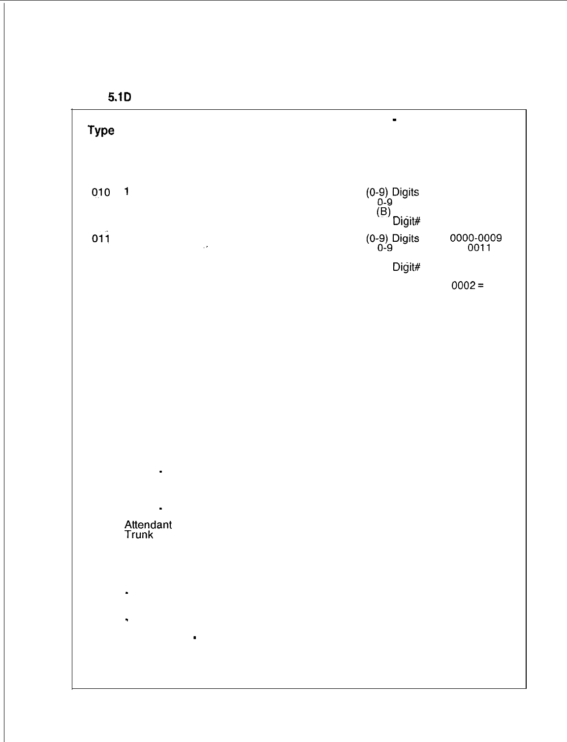
TL-130400-1001
Table
5.1D
Code Type/Code Type identifiers Definition and Description (Continued)
Code Description of
Type
Code Type
No.
Applicable Applicable DB Table
-
Code
CPG Record SVR Type Identifier
Code Values in Decimal
(Hex Values in
Parenthesis)
Values
AC All
O-9 (0-!$)9Digits
CPG Record
Code Type
Identifier
Values
010
1
st Digit of Two
Digit-Access
Code
0000-0009
0011
0012
11
(B)
Digit*
12 (C)
Digit#
Oli
1st Digit of
Three Digit
”
Access Code
AC All
O-9
(O;JgDigits
11 (B) Digit”
12 (C)
Digit#
AC All 0 (0) Unassigned
oooEotog
0012
012 Group Speed
Calling Access
0002=
100
Speed Call
Nos.
0003 = 1000
Speed Call
Nos.
0000013
014
015
Call Waiting
Answer Code
Call Waiting
Originating
Access Code
for Conference
Bridge 2
Attendant
Control of Trunk
Group
-
On
Attendant
Control of Trunk
Group
-
Off
$;;;fant
Direct
Executive
Override
Call Forwarding
-
Fixed
Call Forwarding
-
Variable
Code Calling
-
Origination
Code Calling
Answer
AC All 0 (0) Unassigned
AC All 0 (0) Unassigned 0000
AC All 0 (0) Unassigned
0000
016
AC All 0 (0) Unassigned
0000
017 AC All 0 (0) Unassigned
0000
018
019
AC All 0 (0) Unassigned
0000
AC All 0 (0) Unassigned 0000
020
021
022
023
AC All 0 (0) Unassigned
0000
AC All 0 (0) Unassigned
0000
AC All 0 (0) Unassigned
0000
AC All 0 (0) Unassigned
0000
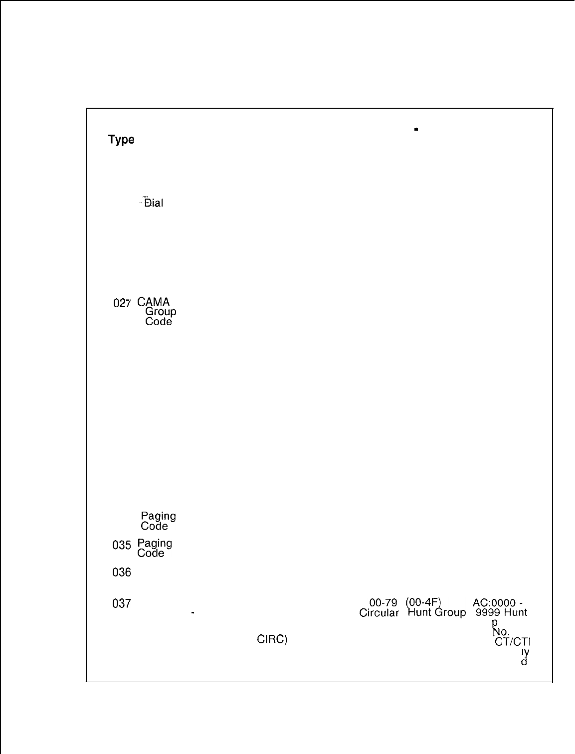
TL-130400-1001
Table 5.1 D
Code Type/Code Type Identifiers Definition and Description (Continued)
Code Description of
Applicable Applicable DB Table
-
Code CPG Record
Type Code Type CPG Record
SVR
Type Identifier Code Type
No. Code
Values in Decimal Identifier
(Hex Values in Values
Parenthesis)
Values
024
.&al
Call Pick- AC All 0 (0) Unassigned
0000
up, First Group
025 Dial Call
Pickup,
Extended Group
AC All 0 (0) Unassigned
0000
026 Directed Dial
Call Pickup
027
CAMA
Trunk
g~~uep
Access
AC
AC
All
All
0 (0) Unassigned
0000
00-63 (00-3F)
0000-0063
Trunk Group No.
028 Camp-On
Origination AC All 0 (0) Unassigned 0000
029 Camp-on AC All
Cancellation 0 (0) Unassigned
0000
030 Flexible Night AC All
Connection 0 (0) Unassigned 0000
Changes
031
Universal Night AC All
0000
Answer Pickup 0 (0) Unassigned
032 Meet Me AC All 0 (0) Unassigned
0000
Conference
033 Progressive
Conference AC All 0 (0) Unassigned
0000
034
,PP~~g
Access AC All 0 (0) Unassigned
0000
035
F’a,$terg
Answer AC All 0 (0) Unassigned
0000
036
Dictation AC All
Access Code
00-63 (00-3F)
0000-0063
Trunk Group No.
037
Station Hunting AC
Pilot No.
-
All
Circular HG (Hunt
CiZZ?r
~oUZ&oup
?$ZEilnt
Group Type Number Gr Pilot
=
CIRC)
R
HG:
&CT1
is Internal1
Generate
cr
SVR 5210
8187
D-91
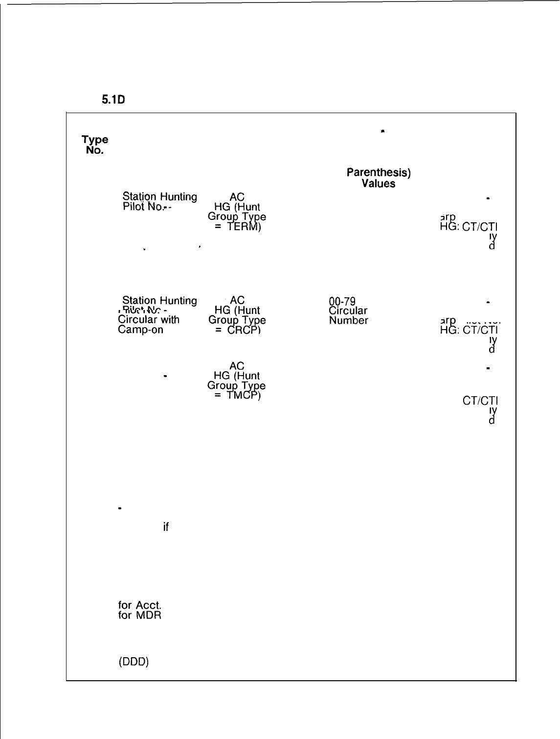
TL-130400-1001
Table
5.1D
Code Type/Code Type Identifiers Definition and Description (Continued)
Code Description of
TNyope
Code Type
,
038
$:$o{oHunting
Terminal
-
_
039 Call Park
.
.
040 Call Hold
041
S$$;oHunting
E%&my;>ith
042 Station Hunting
Pilot No.
-
Terminal with
Camp-on
043 Call Park
Answer
044 Call Hold
Answer
045 Attendant Busy
-
Idle Check
and Setup for
Break-in
If
Trunk is Busy
046 Attendant Force
Release a
Trunk
047 Access Code
;cg
$c&
Code
048 MERS Access
Code for Off
Network Dialing
ODD)
Applicable Applicable DB Table
-
Code
CPG Record SVR
Code Type Identifier
Values in Decimal
All
(Hex Values in
Pare;Lysis)
Remainder of the
First Line Software
ID of the Terminal
Hunt Group Divided
by 256
AC All 0 (0) Unassigned
AC All 0 (0) Unassigned
G!?!!!!$e
All
00-79
(00-4F)
i:rc,udae;
Hunt Group
= RC)
All Remainder of the
First Line Software
ID of the Terminal
Hunt Group Divided
by 256
AC All 0 (0) Unassigned
AC All 0 (0) Unassigned
AC All 0 (0) Unassigned
AC All 0 (0) Unassigned
AC All l-8 (l-8) No. of
Digits Used
AC All 0 (0) Unassigned
CPG Record
Code
Type
identifier
Values
AC:0000
-
9999 Hunt
Gr Pilot No.
HE:
CT/CT1
is Internal1
Generate
J
0000
0000
AC:0000
-
9999 Hunt
Gr Pilot No
H&
CTCTI’
is Internal1
Generate
J
AC:0000
-
9999 Hunt
Grp Pilot No.
HG:
CT/CT1
is Internal1
Generate
J
0000
0000
0000
0000
0001-0008
0000
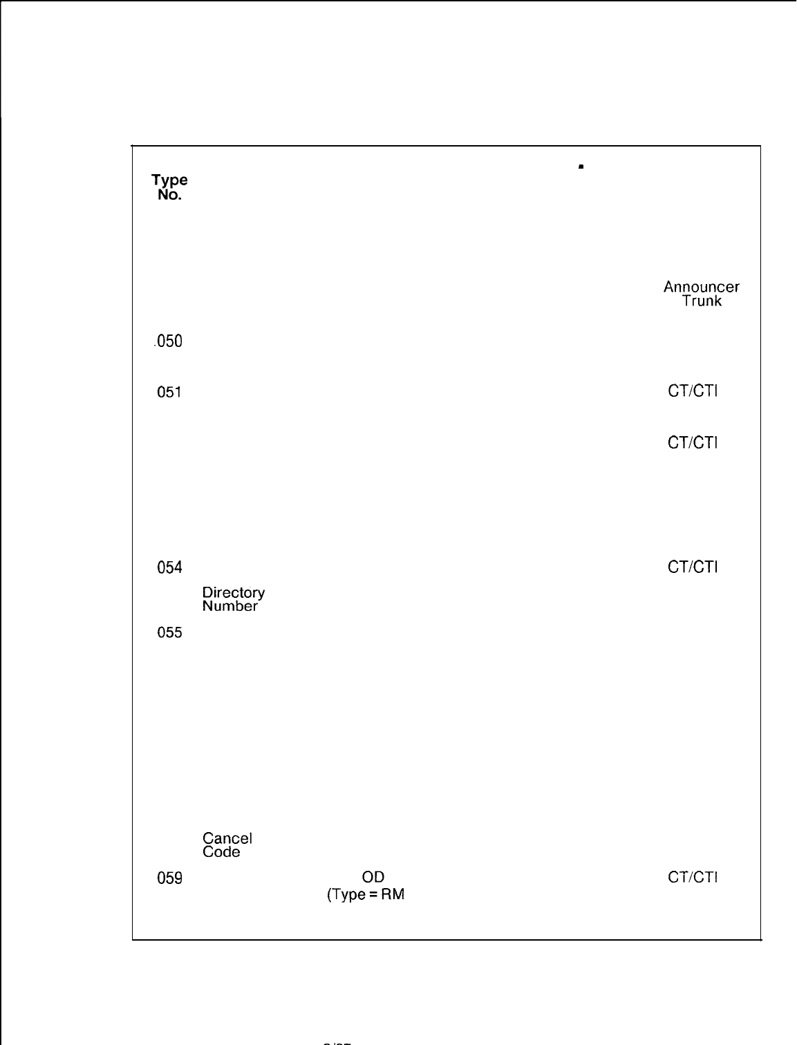
TL-130400-1001
Table 5.1 D
Code Type/Code Type Identifiers Definition and Description (Continued)
Code Description of Applicable Applicable DB Table
-
Code
TN’ope
Code Type
CPG Record SVR Type Identifier
.
Code Values in Decimal
(Hex Values in
Parenthesis)
Values
049 Recorder AC All
-Announcer
00-63 (00-3F)
Trunk Number
“Access Code
.05o
Change/F&store
Feature by
Access Code
051
Change/Restore
Feature Routing
052 Secondary
Directory
Number for a
Station
053 Release Link
Trunk (RLT)
Access Code
054
Release Link
Trunk (RLT)
p$;g;Y
AC All from
2.3.X.X 0 (0) Unassigned
CH SI from
5.2.1 .O
0 (0) Unassigned
SD
All Remainder of Line
Software ID is
Divided by 256
AC All 0 (0) Unassigned
RC
All
00-15 (O-F) RLT
Number
CPG Record
Code Type
Identifier
Values
0000-0063
Recorder
Anrq;;;;er
Number
0000
CT/CT1
is
Internally
Generated
CT/CT1
is
Internally
Generated
0000
CT/CT1
is
Internally
Generated
055
Release Link
Trunk (RLT)
Night Mode
Access Code
AC All 0 (0) For Day Mode 0000-0001
l(1) For Night Mode
056 Release Link
Trunk (RLT)
Silent Hold
Access Code
AC All 0 (0) Unassigned
0000
057 On-HookTrunk
Call Queuin
Access Co8
e
058 On-HookTrunk
Call Queuing
&;;el
Access
AC
AC
All
All
0 (0) Unassigned
0 (0) Unassigned
0000
0000
059
Remote Access All
CT/CT1
is
Feature/
(TypezDRM A)
0 (0) Unassigned
Code Directory Internally
Generated
Access Code
SVR 5210
8187
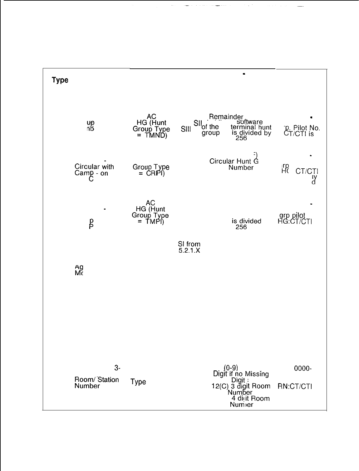
TL-130400-1001
Table 5.1 D
Code Type/Code Type Identifiers Definition and Description (Continued)
Code
Type
No.
Description of
Code Type
060 Terminal Hunt
Gro
-
with
Num ‘er Display
3)
061
062
063
064
065
066
067
Station Hunting . .
Pilot No.
-.
~gr~laro~th
and all
8
Pressure
Indicator
Station Hunting
Pilot No.
-
Terminal with
Cam -on and
Call ressure
P
Indicator
Station Silent
Monitor Access
Code
A
Ii?
ent Silent
onitor Access
Code
Room
Termination by
Access Code
3-or 4-Digit
Room Number
Access Code
(To use, Dial
Access Code
Followed by
Room/ Station
Number
First Digit of
3-
or 4-Digit
t;;Te%ation
Applicable Applicable DB Table
-
Code
CPG Record SVR
Code Type Identifier
Values in Decimal
(Hex Values in
Parenthesis)
Values
HGqEunt
for Sl,
Sll,
flrst line
Software
ID
Obsolete
.Remainder
of the
G~o~~ge.
Sill
“,;;f$
t~;$$$r”
AC
HG (Hunt All
00-79 (00-4F
Gr=o”
i!-
I
L
6
$7
e
CirculaNJlu&
roup
All Remainder of the
first line software ID
of the terminal hunt
group
is2g;rded
by
AC
E!%
. . 0 (0) Unassigned
AC All 0 (0) Unassigned
AC All Remainder of
Room Software ID
Divided by 256
AC All 0 (0) Unassigned
AC All
RN (Code O-9
(0:9)
Missing
Type
= 3DG
Drgrt
r~~tMrssrng
or 4DG)
1
2(C)N3uz
8
itrRoom
15(F)
Nudm
ikPoom
%
CPG Record
Code Type
Identifier
Values
AC:0000
-
9999. Hunt
Gr
e
Tipdylf
i;o.
Internally
Generated
AC:0000
-
9999 Hunt
Gr . Pilot No.
I-P
G:
CT/CT1
is Internal1
Generate
J
AC:0000
-
9999 hunt
r
14&c!!
ilot
No.
:
T/CT1
is
Internally
Generated
0000
0000
0000-9999
Directory
Number
0000
AC:
OOOO-
0009 or 0012
or 0015
RN:CT/CTI
is
Internally
Generated
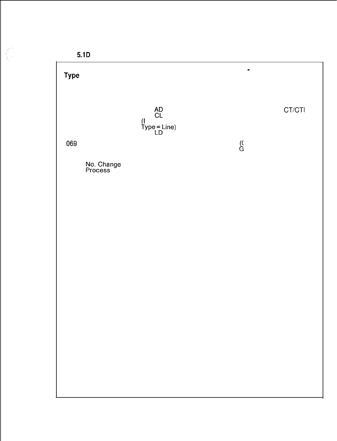
TL-130400-1001
Table
5.1D
Code Type/Code Type Identifiers Definition and Description (Continued)
Code
Type
No.
068
,069
070
071
072
073
074
075
076
077
078
Description of
Code Type
Line (Room/
Station)
“Termination
CLR Trunk
Access Code
Master KEDU
p.$-gnw
Access Code
Do Not Disturb
Activation
Access Code
Do Not Disturb
Deactivation
Access Code
Do Not Disturb
Override
Access Code
Message
Waiting
Activation
Access Code
Message
Waiting
Deactivation
Access Code
Class of Call
Controlled
Routing Access
Code
Do Not Disturb
Activation by
Occupied
Room Access
Code
Do Not Disturb
Deactivation by
Occupied
Room Access
Code
Applicable Applicable
CPG Record SVR
Code
ACF
All
f
Destinafion
YPeL’DL’ne)
AC All
AC All H/M
AC All H/M
AC All H/M
AC All H/M
AC All
AC All
AC All H/M
AC All H/M
DB Table
-
Code
Type Identifier
Values in Decimal
(Hex Values in
Parenthesis)
Values
Remainder of
Room Software ID
Divided by 256
00-63 00-3F)
L
Trunk roup No.
0 (0) Unassigned
0 (0) Unassigned
0 (0) Unassigned
0 (0) Unassigned
0 (0) Unassigned
0 (0) Unassigned
0 (0) Unassigned
0 (0) Unassigned
CPG Record
Code Type
Identifier
Values
CT/CT1
is
Internally
Generated
0000-0063
0000
0000
0000
0000
0000
0000
0000
0000
AC All H/M 0 (0) Unassigned 0000
SVR 5210
8187
D-95
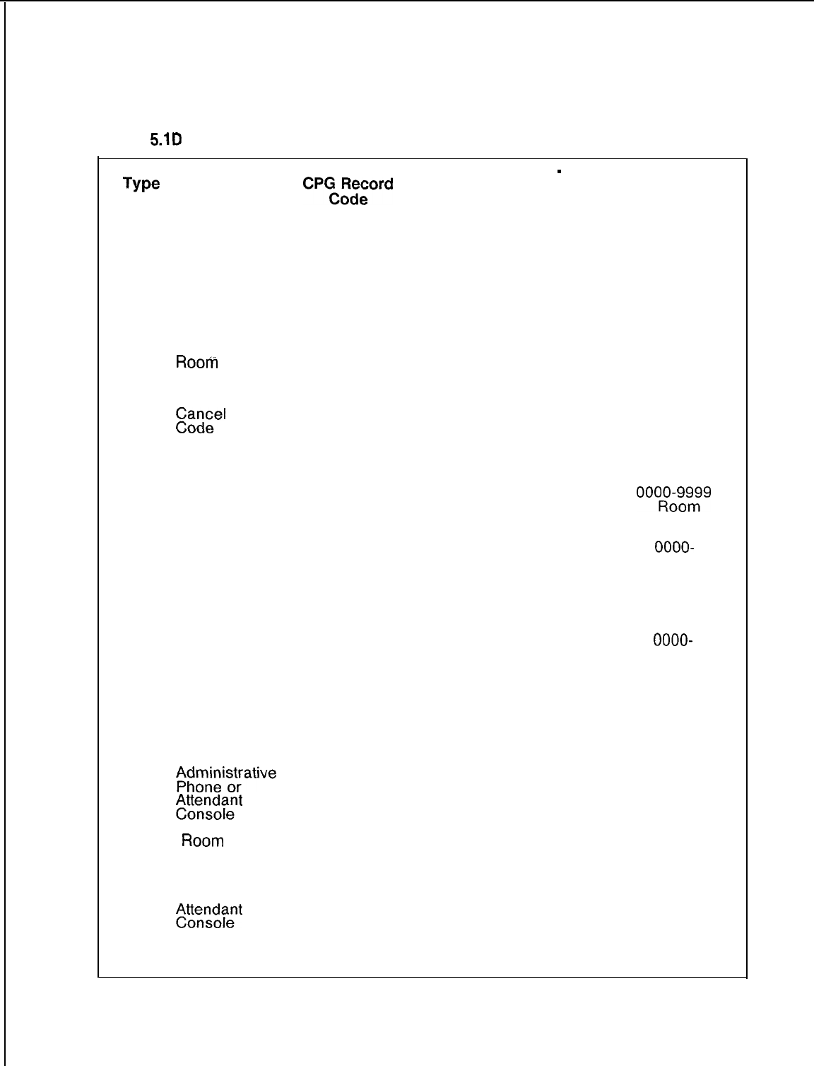
TL-130400-1001
Table
5.1D
Code Type/Code Type Identifiers Definition and Description (Continued)
Code Description of
Applicable Applicable DB Table
-
Code CPG Record
Type Code Type
SVR
No.
cp%Yd
Type Identifier
Values in Decimal Code Type
Identifier
(Hex Values in
Values
Parenthesis)
Values
079 Wake up Time
Entered by AC All 0 (0) Unassigned
0000
Room Access
Code
080 Wake up Time
Cancellation by . .
Room
Access
Code
AC All 0 (0) Unassigned
0000
081
Wake up Time
G&III
Access AC All 0 (0) Unassigned
0000
082 Wake up Time
Access Code AC All 0 (0) Unassigned
0000
083 Message
Waiting
Processing
084 Maid Service in
Progress
Access Code
085 Maid Service
Completed
Access Code
AC
AC
AC
All
All H/M
All H/M
Remainder of
Room Software ID
oooRo;Eg
Divided by 256 Number
0 (0) Unassigned
oooo-
0006 = No.
of Maid ID
Digits (used
with PMS)
0 (0) Unassigned
oooo-
0006 = NO.
of Maid ID
Digits (used
with PMS)
086 Room
Restriction
Activation from
bcix;r;t;atrve
i2!E$lt
AC All H/M 0 (0) Unassigned
0000
087
&m-n
Restriction
Deactivation
from Adminis-
trative Phone or
CEiZknt
AC All H/M 0 (0) Unassigned
0000
088 Priority Call
Access Code AC All H/M 0 (0) Unassigned
0000
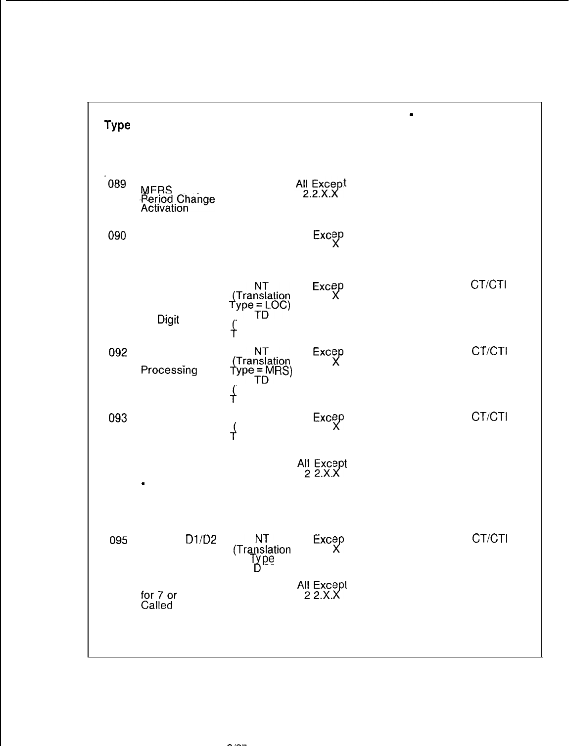
TL-130400-1001
Table 5.1 D
Code Type/Code Type Identifiers Definition and Description (Continued)
Code Description of
Type Code Type Applicable Applicable
CPG Record
SVR
No. Code
-089
Attendant
MERS
Time
. .
fg;f$.pnge
Access Code
AC
t
090
Attendant
MERS Time.
Period Change
Cancellation
Access Code
AC All
Exce
t
2.2.x.
>p
091
Local
Termination by All
Exce
t
the Last Four
Digits of a 7 or
4TracTation
2.2.X.
>p
10
Dtgrt
Call
ype;pC)
Translation
i
ype = LOC)
092
MERS Off Net 7 All
Exce
t
or 10 Digit
Trat!%ation
2.2.X.
f
>p
Processrng weTDM
W
Translation
J
ype = MRS)
093
Trunk Group
t
Selection and NT, TD, OD All
Exce
Translation 2.2.X.
4
>p
Outpulsing of all
Received Digits ype =TGS)
094 First Digit 7-or
1 O-Digit Call
-
NPA and/or
ABC Code
Translation
t
AC
Ai
Exge
. .
.
>p
needed before
Routing
095
Analyze
Dl/D2
All
Exce
or Terminal
Digit before
(Trar!%ation
2.2.X.
>p
t
Routing T
pe
= GT)
4;
096 Access Code AC
Al
2ExXce t
fo&“r
10 Digit . .
.
>p
Number-NPA
Translation
needed before
Routing
DB Table
-
Code
Type Identifier
Values in Decimal
(Hex Values in
Parenthesis)
Values
0 (0) Unassigned
0 (0) Unassigned
0 (0) Unassigned
0 (0) Unassigned
00-63 (00-3F)
Trunk Group No.
0 (0) Unassigned
0 (0) Unassigned
0 (0) Unassigned
CPG Record
Code Type
Identifier
Values
0000
0000
CT/CT1
is
Internally
Generated
CT/CT1
is
Internally
Generated
CT/CT1
is
Internally
Generated
0000
CT/CT1
is
Internally
Generated
0000
SVR 5210
8187
D-97
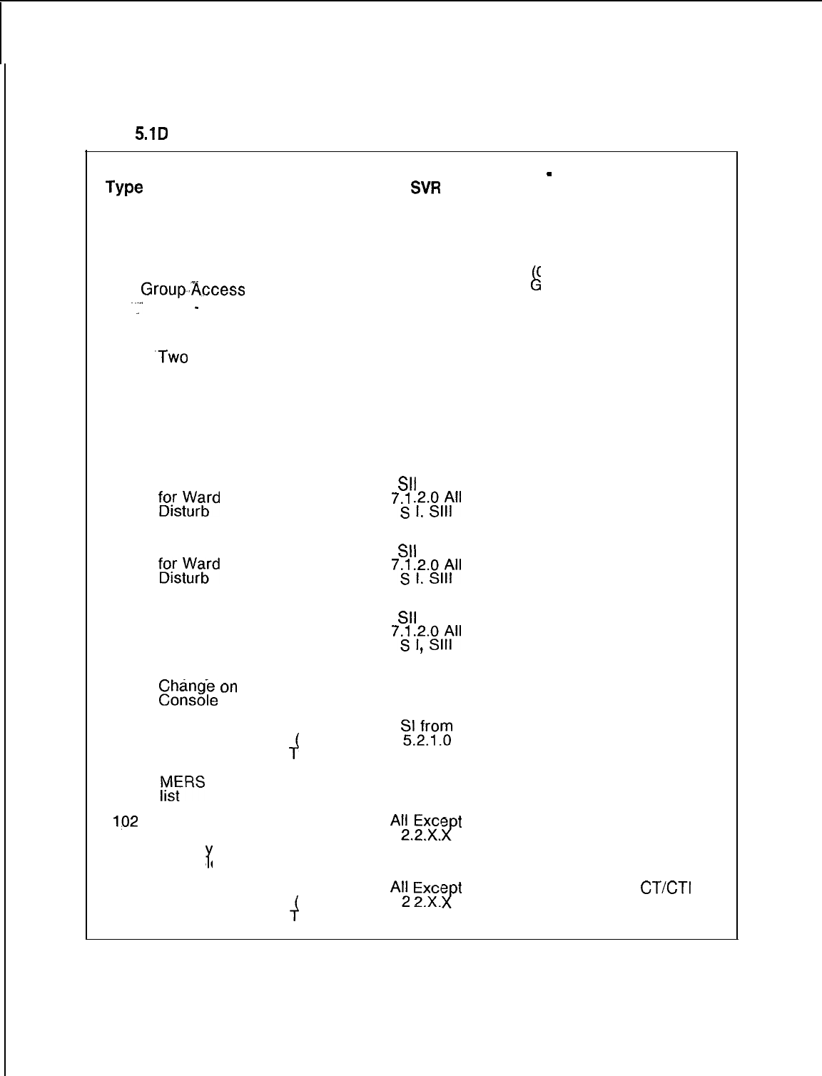
TL-130400-1001
Table
5.1D
Code Type/Code Type Identifiers Definition and Description (Continued)
Code
Type
No.
Description of
Code Type
097 Special Trunk
Group,.Access
-1
Code
-
1 or 2
Digit Access
-Code or Last
.Two
Digits of a
Three-Digit
Access Code,
plus Remaining
Dialed Digits
are Repeated
out to Trunk
Applicable Applicable DB Table
-
Code CPG Record
CPG Record
SW
Code Type Identifier
Code Type
Values in Decimal Identifier
(Hex Values in Values
Parenthesis)
Values
AC All Except 00-63 00-3F)
k
0000-0063
2.2.x.x Trunk roup No.
098 Access Code
fD”i’s;;;d
Do Not
Activation
AC
SII
from 0 (0) Unassigned 0000
7.-S
.12.~l;ll
099 Access Code
fD”i’scrazbrd
Do Not
Deactivation
AC
SII
from 0 (0) Unassigned
0000
7.J
.12.;l;ll
,
100 Access Code
for Ward Do Not
Disturb Time
Period Time
Display/
E,ni%
On
AC
SII
from
0000
72
.12.;16”
0 (0) Unassigned
9
101
Termination NT
2-z
Sending CTI is
directly via Translation . . instruction/route list
MERS sending
f
= MER) Internally
ype Generated
instruction/
rsFRS
routing
162
Access Code AC
for Time Period
“Ex,ce
t
. .
.
>p
0 (0) Unassigned
0000
Displa on
Cons0 e
Y
103 Analyze ABC NT
Code before Translation
JAl
Exxc.e
. .
f
t
0 (0) Unassigned
CT/CT1
is
Routing ype =ABC) Internally
Generated
D-98
8187
SVR 5210
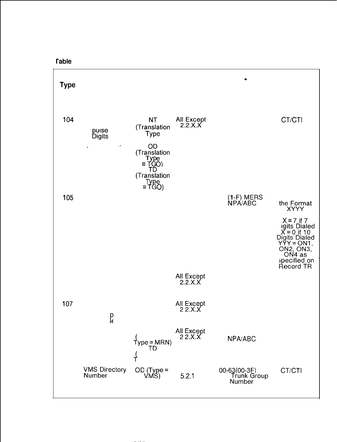
TL-130400-1001
rable 5.1 D Code Type/Code Type identifiers Definition and Description (Continued)
Code Description of
Type Code Type
No.
104
Trunk Group
. .
Selection and
Out ulse Last
‘X’
Kigits
,.
_
105
MERS Access
Code for On
Network Dialing
(Non DDD)
106 Access Code
for Real Time
Clock Update
from Console
lo7
Access Code
for Real Time
Clock Dis
lay
on Cons0 e
P
108 MERS On Net
7 or 10 Digit
Processing
109
;kJzbf;ectory
Direct Access
by Station User
Applicable
CPG Record
Code
(Trat!Tation
Type
= TGO)
(TraTt!?;tion
=
lE
0)
(Tra$?;tion
=
i%
0)
AC
AC
AC
NT
Translation
J
we;pW
Translation
+
ype = MRN)
OD
T
dlvi!~
,“=
Applicable DB Table
-
Code CPG Record
SVR
Type Identifier Code Type
Values in Decimal Identifier
(Hex Values in Values
Parenthesis)
Values
Trunk Group 00-63
CT/CT1
is
Internally
Generated
All Except
2.2.x.x.
AEF.e
t
>p
“i
Exxce>p
t
. .
.
Ai
2ExXce t
. .
.
>p
SI from
52.1
.o
l-l 5
lPF&fvlBE$S
L
AC: CTI in
Translation Table
theX:oyrymat
Numbers l-l 5Where:
52.1.X.18.2.2.X.
X=7if7
Di
iJso~fi~l;d
2
S
e&f;$dToR”
F?
0 (0) Unassigned
0000
0 (0) Unassigned
0000
1-4 MERS
NPAABC
Translation Table
1-15
5.2.1.X.18.2.2.X
0000
00-63(00-3F)
VMS
NT:U,nbeFroup CT/CT1
is
Internally
Generated
SVR 5210
8187
D-99
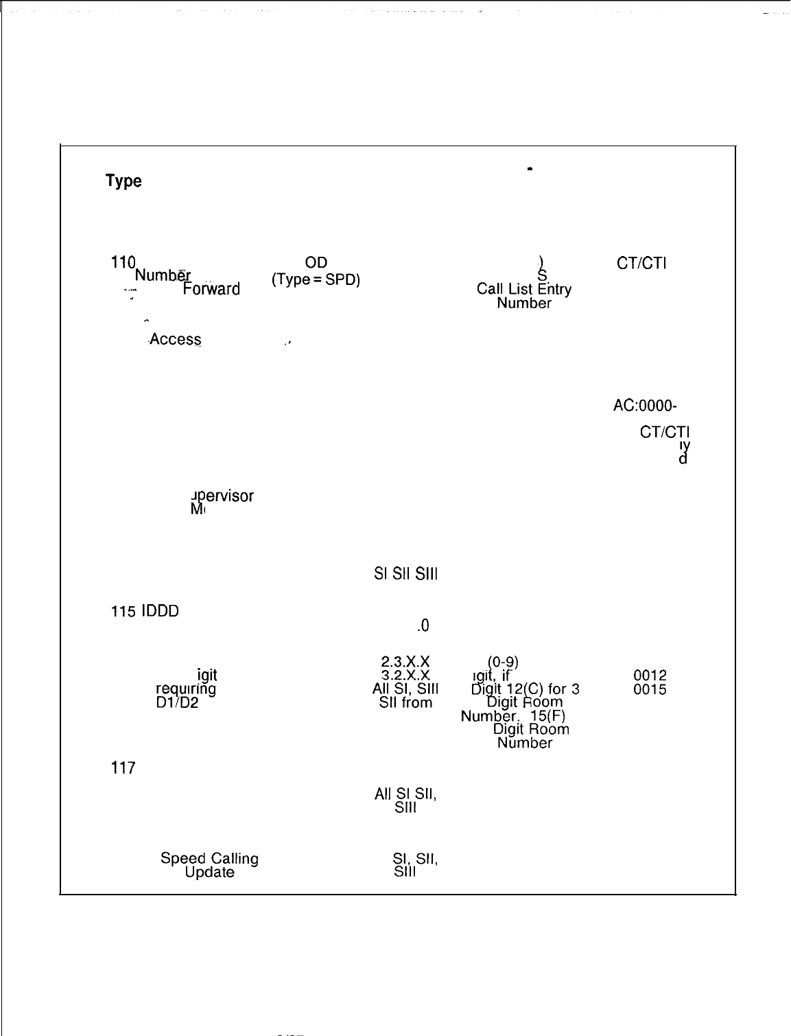
TL-130400-1001
Table 5.1 D
Code Type/Code Typeldentifiers Definition and Description (Continued)
Code Description of
Type Code Type Applicable Applicable DB Table
-
Code CPG Record
CPG Record
SVR
NO.
Code
Type Identifier
Values in Decimal Code Type
Identifier
(Hex Values in Values
Parenthesis)
Values
110
Directory
(TyptFSPD)
SI from
Numb,er
for
5.2.1 .o
l-8 (l-8
CT/CT1
is
----.
Call
Fotiard
to
L
Individual peed
-
Individual
-
Speed Call List
Cak,‘;tE:try
Internally
Generated
111
.Access
Code
,.
AC
to Activate All H/M 0 (0) Unassigned
0000
Room to Room
Blocking
112 Access Code
for Agent
Group Access
113 Access Code
for Su
&
et-visor
Talk onitor
AC
AG
AC
All CAS
All CAS
O-7 (O-7) Agent AC:OOOO-
Group Number
0007
AG:
CT/CT1
is Internal1
Generate
cr
0 (0) Unassigned
0000
114 Access Code
to Deactivate
Room to Room
Blocking
AC 2.2.x.x
2.3.X.X 0 (0) Unassigned
0000
3.2.X.X. All
SI
SII
Sill
from 7.1.2.0
115
IDDD
variable
numbering
plan
AC SI from
5.2.1 .o
0 (0) Unassigned
0000
116
1st di it of 3-
8
or 4-. !git
No. AC
SE
O-9
(O-9)
Missing 0000-0009
Di
‘Delqi”d;ng
,rt,.
If
no Missing
A.l~),&II
. .
8
I
ttl2C)for3
8
k
E
translation
6.1 .l .O Numdge:‘.
before routing
?t(?)
for
4
Ddgui;tfg;rn
117
Access Code
for Individual
Speed Calling
118
Access Code
for Individual
Spe;gd(Zgling
AC
AC
All CAS
from 3.3.1 .O
0 (0) Unassigned 0000
All
ss(llS”’
All CAS
from 3.3.1 .O
0 (0) Unassigned
0000
all
!$Sll,
8187
SVR 5210
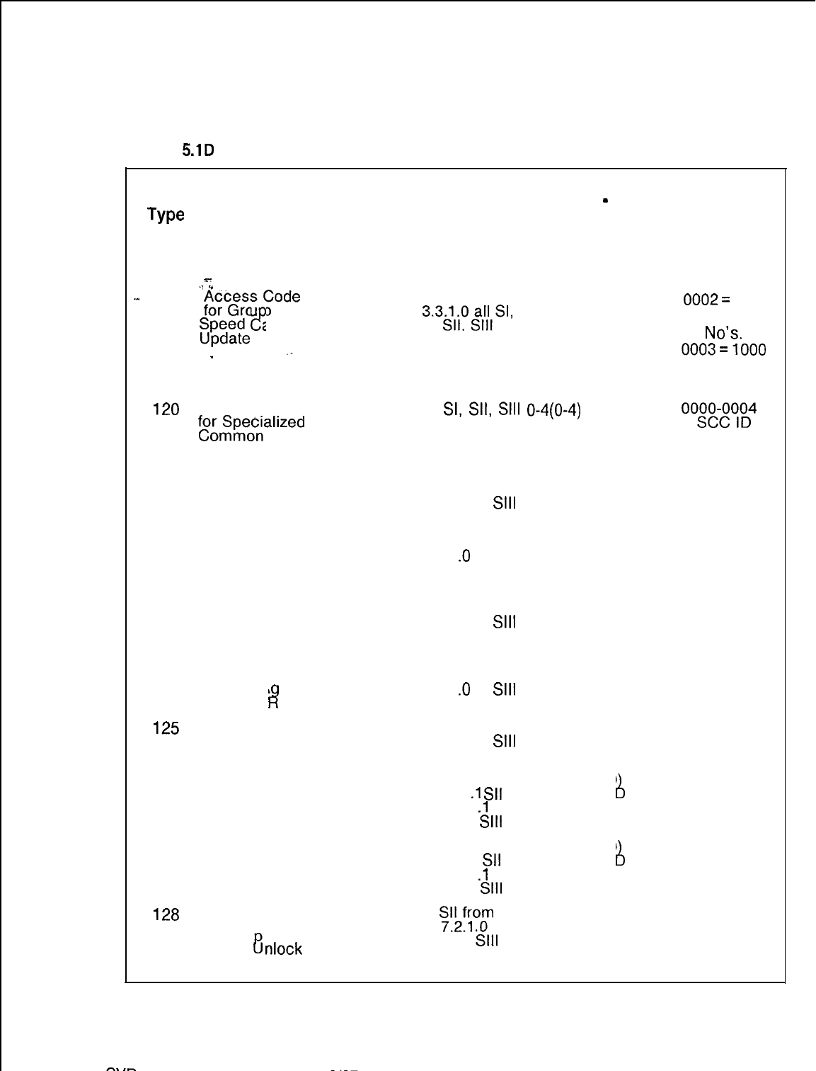
TL-130400-1001
Table
5.1D
Code Type/Code Type Identifiers Definition and Description (Continued)
Code Description of
Applicable Applicable DB Table
-
Code CPG Record
Type Code Type CPG Record
SVR
Type Identifier
No. Code
Code Type
Values in Decimal Identifier
(Hex Values in Values
Parenthesis)
s-
Values
.1
.”
.^
119
&yx3;;uCode
AC All CAS from
0002=
100
c?
3.3~l;ogllsI,
2 (3) Unassigned
$21;~
alling Speed Call
No’s
_
0003=1000
Speed Call
No’s.
120
Access Code
foozgzzzalized
Carrier
Processing
121
Access Code
for ACD Agent
Unstaff Position
AC
AC
All
SI,
SII,
Sill
O-4(0-4)
SCC ID
Number
oogm&oD"
Number as
Defined on
SA Record
CAS from 0 (0) Unassigned 0000
3.4.1 .O All
Sill
122 Access Code
for ACD Agent
Supervisor
Assist
AC CAS from 0 (0) Unassigned
0000
3.4.1
.O
All Sill
123 Access Code
for ACD Agent
Emergency
Request
124 Access Code
for ACD A
w
ent
Bad Line eport
125
Access Code
for ACD Agent
Staff Positron
AC
AC
AC
CAS from 0 (0) Unassigned
0000
3.4.1 .O All
Sill
CAS from 0000
3.4.1
.O
All
Sill
0 (0) Unassigned
CAS from
3.4.1 .O All
Sill
0 (0) Unassigned
0000
126
First Digit of a AC CAS from
Flexible 3.3.1
.l
SII
5-10 (5-10
Number of
A
0005-0010
Numbering Plan
from 6.1
.l
.O
igits
All SI,
Sill
127 Access Code
for Flexible
Numbering Plan
128
Access Code
for integrated
Feature hone
Station
nlock8
AC
AC
CAS from
3.3.1.1
Sll
5-10 (5-10A
0005-0010
Number of
from 6.1
.l
.O
igits
All SI,
Sill
S!L!Y?
0 (0) Unassigned
0000
All SI
Sill
SVR
5210
8187
D-l 01
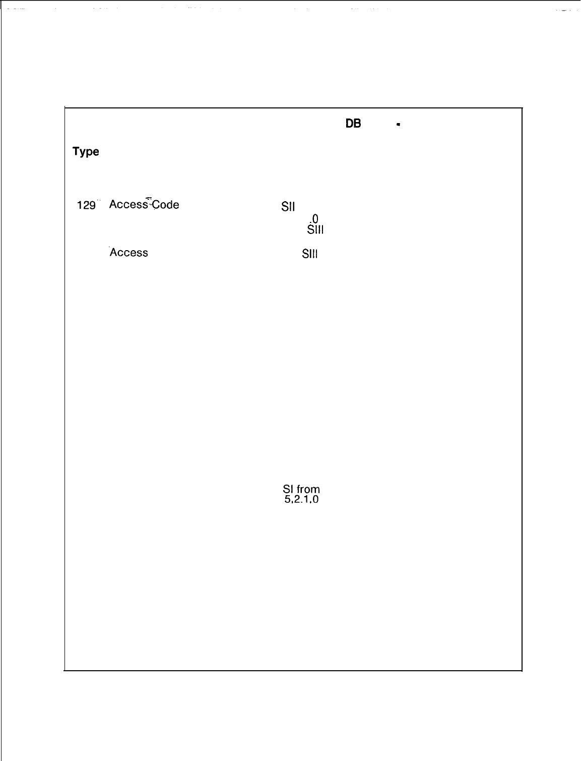
TL-130400-1001
Table 5.1 D Code Type/Code Type Identifiers Definition and Description (Continued)
Code
Type
Description of
No.
Code Type
129.
130
131
132
133
134
135
136
s-
AccessCode
for IFP
Message
-Leaving
.Access
-Code
for Agent Group
Night/Day
Mode
Internal Code
Type for FRL
Authorization
Codes
Access Code
Issued by VMS
to Turn
Message
Waiting On
Access Code
Issued by VMS
to Turn
Message
Waiting Off
Access Code
Issued by VMS
for Outgoing
Call to Remote
VMS
Access Code’
Issued by VMS
for Outgoing
Call to Remote
VMS
Access Code
Issued by VMS
for Outgoing
Call to User
Applicable
CPG Record
Code
AC
. .
AC
N/A
AC
AC
AC
AC
AC
Applicable
SVR
SII
from
7.2.1
.O
All SI
Sill
All
Sill
SI from
52.1 .o
SI from
5.2.1 .O
SI from
52.1 .o
E-E
.
.
SI from
5.2.1 .O
SI from
5.2.1 .O
DB
Table
-
Code
Type Identifier
Values in Decimal
(Hex Values in
Parenthesis)
Values
0 (0) Unassigned
O(0) for Day Mode
l(1) for Night Mode
0 (0) Unassigned
0 (0) Unassigned
0 (0) Unassigned
0 (0) Unassigned
0 (0) Unassigned
0 (0) Unassigned
CPG Record
Code Type
Identifier
Values
0000
0000-0001
CPG does
not collect
data for this
code type
0000
0000
0000
0000
0000
D-l 02
8187
SVR 5210
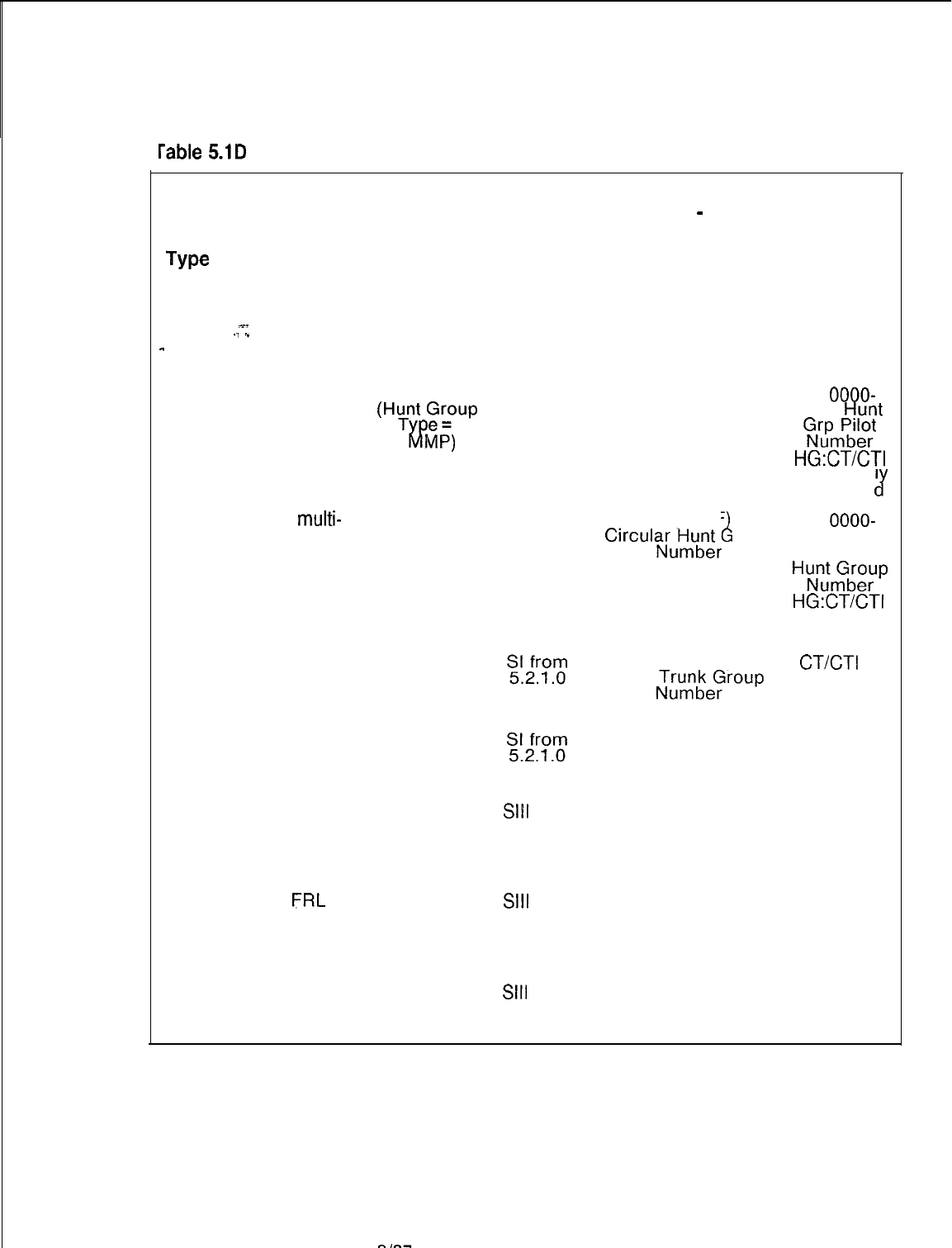
TL-130400-1001
1
rable
5.1D
Code Type/Code Type ldentifiers Definition and Description (Continued)
Code
Type
NO.
Description of
Code Type
Applicable
CPG Record
Code
-
137
i38
139
140
141
142
143
144
%-
.1 .”
Reserved for
Future Feature
Terminal
multi--pilot hunt
group
Circular
multi-
pilot hunt group
AC
AC, HG
(HuTnt
Foup
T
MP=)
iv?
AC, HG
(Hunt Group
Type =
CRMP)
VMS Directory
Number for
Message Desk
Unattended
OD (Type =
MDU)
Access Code
for VMS for
Message Desk
Attended
AC
Display FRL
Assignment
MAP Access
Code
Update
FRL
Assignment
MAP Access
Code
Second Paging
Answer Code
AC
AC
AC
Applicable
SVR
SI from
5.2.1 .o
SI from
5.2.1 .O
SI from
5.2.1 .o
Sill
from
8.2.2.2
Sill
from
8.2.2.2
Sill
from
8.2.2.2
DB Table
-
Code
Type Identifier
Values in Decimal
(Hex Values in
Parenthesis)
Values
0 (0) Unassigned
Remainder of the
First Line Software
ID of the Terminal
Hunt Group Divided
by 256
00-79 (00-4F
L
Circul~J-lu&
roup
00-63 (00-3F)
VMS
;T$keFroup
00-63 (00-3F)
VMS Trunk Group
Number
0 (0) Unassigned
0 (0) Unassigned
0 (0) Unassigned
CPG Record
Code Type
Identifier
Values
0000
AC:
OOOO-
9999
Hunt
GN’UP,;;;
HG:CT/CTI
is Internal1
Generate
J
AC:
OOOO-
9999
Circular
HuN”,‘,Gb’,“,“P
HG:CT/CTI
is Internally
Generated
CT/CT1
is
Internally
Generated
0000-0063
0000
0000
0000
SVR 5210
8187
D-l 03
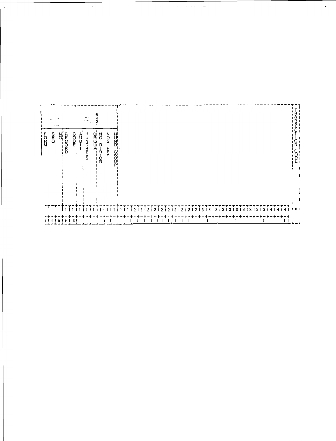
TL-130400-1001
Record Code HD: 5.2 Record Code HD (Figure 5.2) defines the hundreds groups
Hundreds Groups
used as directory numbers by the system. The number of
directory numbers in each hundreds group is also defined. The
audit field is used in support of the Hotel/Motel feature that allows
hotel staff telephones to be audited while guest telephones are
normally not audited.
,---------,-----------
II
II
T
1’
----T-~
ITI
IRI
$;
ISI
IAI
ICI
ITI
1
I
lOI
INI
ICl
101
IDI
IEl
I
I
I
II
I
l
I I
I 1
II
I
I
I
I I
I
1
I
I
I
I
--r-
T-;-T-t-+-t-+-T-T-t-T-T-T-T-T-T-t-T-T-T-~-~-~-~-~-~-~-~-~-~-~-~-~-~-,
r-7
111111111111111111111212121212121212121213131313131313131313l4l4l4l
181
1~8~9101112131415181718191011121314151617181910111213141516171819101112110~
-+-+-+-LJ-+-+-+-+-+-+-+-+-+-+-+-+-+-+-+-+-+-+-+-+-+-+-+-+-+-+-+-+-+-+-~
c-4
,l,1OIHIlJI
I I I
I
I
I I
III,
t
I
I,,,
I
I
I
I I I
t
I I I
I
I I
II
I
-*--L-~--~-~-~-_L-~---~--L
. . . , .
-
. . . . . .
1
.
.-A-.3
Figure 5.2
Record Code HD: Hundreds Groups Data Sheet
D-l 04
8187
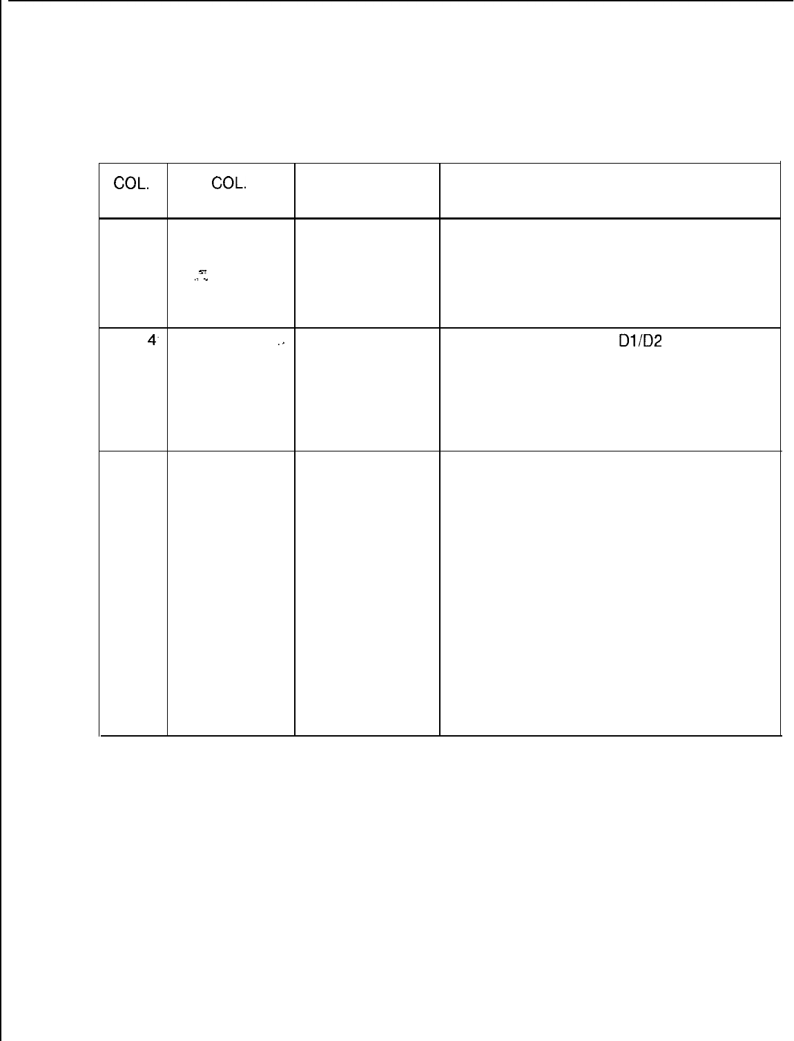
TL-130400-1001
CQL.
NO.
Table 5.2
Entry Fields for Record Code HD
COL.
VALID
NAME ENTRIES COMMENTS
12
Selected Audit
A
= audit
This field determines whether or not this
Condition N = not audited hundreds group can be audited.
%-
NOTE: In a motel application, auditing is
./
.”
provided to guest room telephones.
-It is not provided to management and motel
operations telephones.
13-l
4.
Hundreds
Group
.,
00-99 = number This field determines the
Dl/D2
(00-99)
combination.
-One entry must be made for each hundreds
group in the system.
NOTE: If three-digit numbers are used,
column 13 must be dashed and column 14
must contain O-9.
15-17
Number of
005-l 00 = number Assign the number of directory numbers,
Directory reserved for this hundreds group.
Numbers per
-Because Recent Change cannot be used for
Hundreds this field, it is recommended to always set this
Group value at 100. Setting this value at 100 allows
for future growth.
-It is recommended to build spare numbers
into the system. Spare numbers can be used
for pilot/phantom numbers. Spare numbers
should also be built into the hundreds group
numbers to allow for the addition of station
lines in the future.
-Each hundreds group should reserve 100
directory numbers when 25 or less hundreds
groups are used: If this number is not a
multiple of five, the amount allocated is the
next higher multiple of five.
SVR 5210
8f87
D-l 05
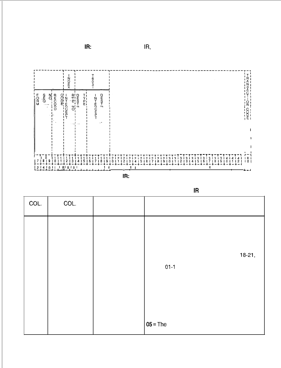
TL-130400-1001
Record Code
IR:
Intercept Routing
5.3 Record Code
IR,
Figure 5.3, assigns, intercept conditions for
the various call configurations.
Numbers
IC:
101
IDI
IEI
I I
II
I I
I
l
I I
I I
I
I
I I
II
I
I
-T-~-T-T-T-T-T-T-T-T-T-T-T-
I I
I
'
'
T-T-T-T-T-T-T-T-t-T-~-,
r-4
11111111111111,1,11112121212121212121212131313l3l3,3l3l3l3l3l4,4l4l18(
~7181910111213141516171819101112l314t51617181910111213141516171819101112110(
t-+-+-+-c--c-+-+-+-+-+-+-+-+-+-+-+-+-+-+-+-+-+-+-+-+-+-+-+-+-+-+-+-+-+-+-~
c-4
1214101~
IRIOl,,l
I I I I
I
1
I I I
I
I
I I I I I I I I I I I I
I
I I I I I I I
L-A-A-A-
-*-1_&-&-A_~--_~
.
A
*
. . . . .
*
. . . . . . . .
*
.
__a
Figure 5.3 Record Code
IR:
Intercept Routing Numbers Data Sheet
COL.
NO.
Table 5.3 Entry Fields For Record Code
IR
COL.
VALID
NAME ENTRIES COMMENTS
12-13
Intercept
00-15
= number
This field determines the type of call to be
Routing Number intercepted.
Routes 00 and 12-l 5 are available for
special applications and are defined by the
user. They can be routed to a station line,
attendant, recorder announcer, or 120 IPM
tone (e.g., Record Code CL, columns
18-21,
AG, columns 25-26, 31-32).
Routes
01-l
1 are predefined as listed below:
01 =The call is toll restricted. It is not
recommended to send these calls to the
console because the attendant may not be
able to answer all of them. It is preferred to
send these calls to tone.
02 = The feature dialed is not allowed for the
station line or the system.
03 = The call was made to a vacant number.
04 = The call was made to an invalid number
05=The
call was a DID (Direct Inward Dialing)
to a restricted station.
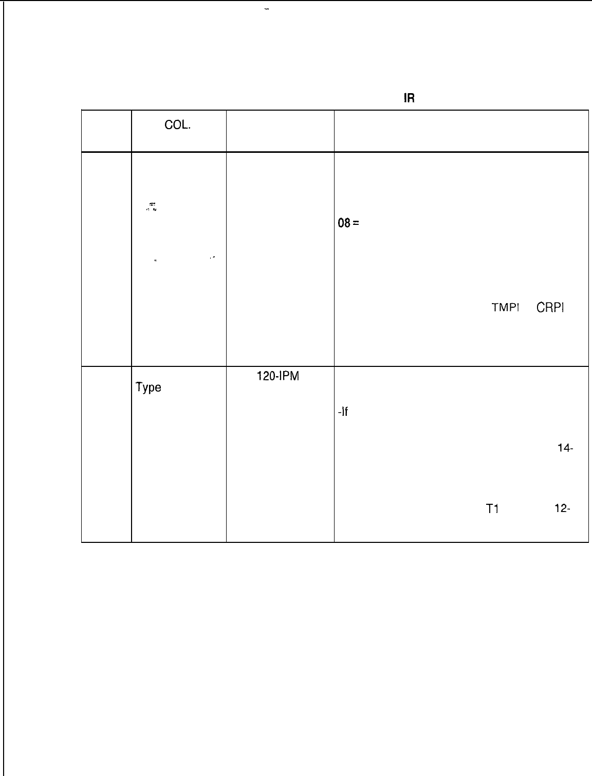
TL-130400-1001
COL.
NO.
Table 5.3 Entry Fields for Record Code
IR
(Continued)
COL.
VALID
NAME ENTRIES COMMENTS
12-13
Intercept 00-l 5 = number
(cont’d) Routing Number 06 = The call cannot be completed due to
present call configuration (e.g., the call is in
DND (Do Not Disturb).
%-
.1
I
_
07 = The trunk group is restricted by ACOF
(Attendant Control Of Facilities).
08=
Digit timeout /no dial alarm calls should
be routed to the console or a security station.
If routed to the console once the key is
released, the station number that is causing
the alarm is no longer visible on the LCD.
09 = Wake-up or appointment reminder
answer routing.
10 = Recorder announcer for
TMPI
or
CRPI
type hunt groups (see Record Code HG).
11 = The number called has been changed.
NOTE: The intercept routing number must be
unique across this record code.
14-15
Destination
TO
=
120-IPM
This field determines whether the call will
Type
tone intercept to a line, trunk, attendant, tone, or
LN
= line
recorder announcer.
AT
= attendant
-If
the destination type is AT, it must be
RA
= recorder
defined on Record Code AT, column 12.
announcer -If the destination type is RA, the trunk must
TI
= Tie trunk
be defined on Record Code TC, columns
14-
RL
= release link
16, and marked G in column 45.
trunk -If the destination type is LN, it must be
defined on Record Code LD, columns 12-15.
-If the destination type is TI, the trunk must
be defined on Record Code
Tl
, columns
12-
13, and must be marked TIE in columns 14-
16.
SVR 5210
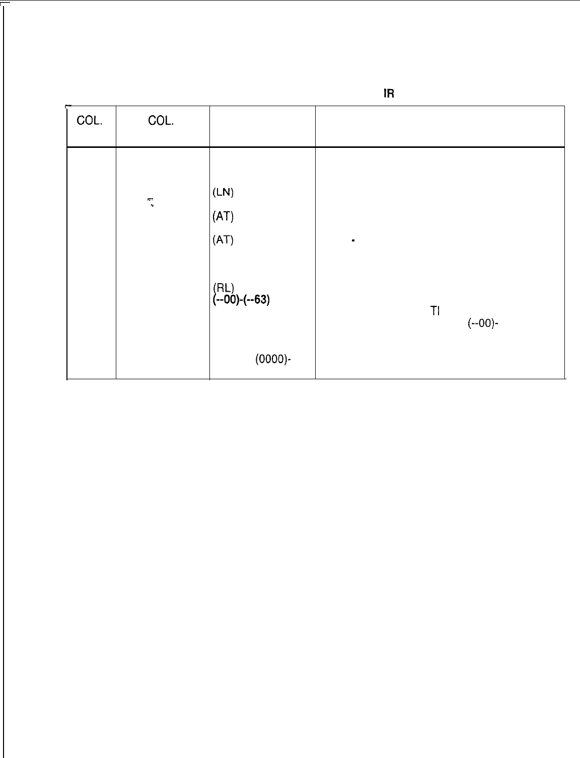
TL-130400-1001
Table 5.3 Entry Fields for Record Code
IR
(Continued)
c
COL. COL.
VALID
NO.
NAME ENTRIES COMMENTS
16-19
Intercept 0000 = tone
(TO)
This field determines the intercept destination
Destination
0000-9999 =
of the destination type.
directory number -A destination type of TO must have an
U’J)
s-
intercept destination value of 0000.
.I
1
0128 = console 0 -A destination type of LN must have an
(AT)
intercept destination value of 0000-9999 or if
0064 = console 1 three-digit station numbers are used
(AT)
(-000)
-
(-999).
0192 = either of the -A destination type of AT must have an
two consoles intercept destination value of 0128, 0064 or
0000 = to an RLT
0192.
W-1
-A destination type of RL must have an
(--OO)-(--63)
intercept destination value of 0000:
=Tie trunk (TI) -A destination type of
TI
must have an
XXXX = recorder intercept destination value of
(--OO)-
announcer (RA)
(--63).
XXXX = the trunk -A destination type of RA must have an
number
(OOOO)-
intercept destination value of (OOOO)-(0063).
(0063)
D-l 08
8/87
SVR 5210
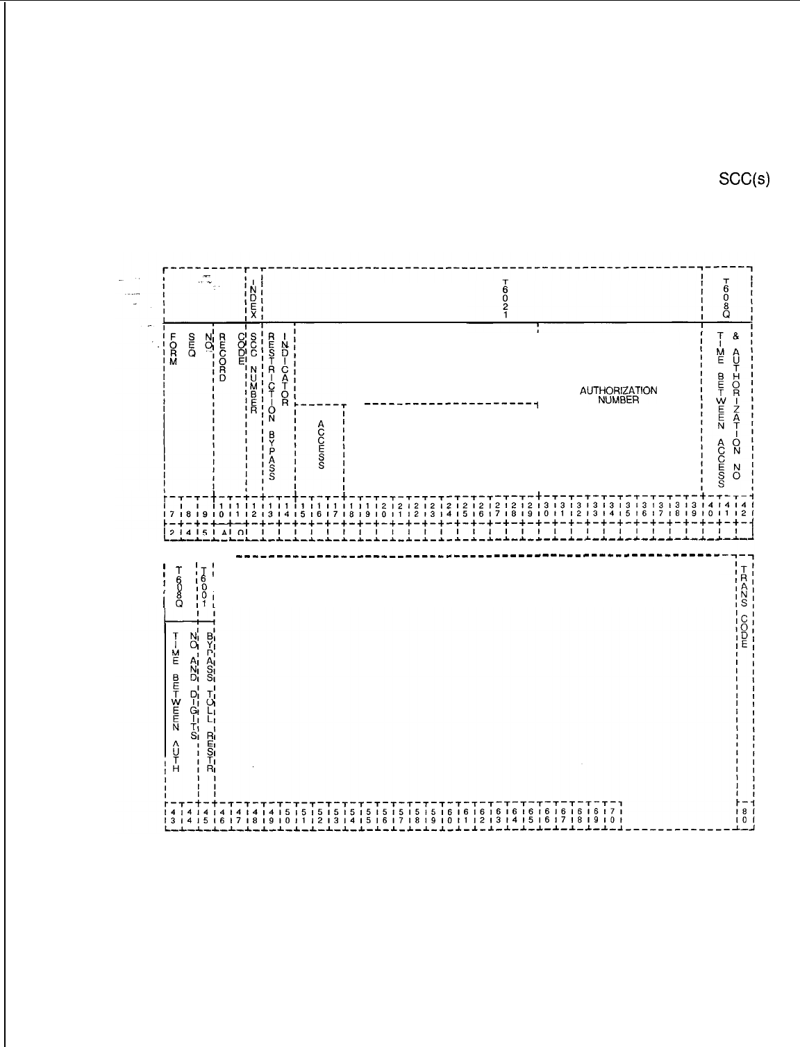
TL-130400-I 001
Record Code SA:
5.4 Record Code SA, Figure 5.4, defines the access codes,
Specialized
directory numbers, and authorization codes for up to five SCC
Common Carrier
(Specialized Common Carrier) networks. When the MERS option
is in effect, this record code is not normally used as the
SCC(s)
will be in the MERS routing. This record code provides SCC
information when the SCC is not routed through MERS.
I
GATEWAY NUMBER
I
II
I
I
I
---------------------,
AUT;liRZ3~ION
I
I
I
DIRECTORY
r---r-r--
---------------_-_________r_____________--------------------
I
;
ITI
1
0
16
I
IO
I
I8
IPI
SVR 5210
Figure 5.4 Record Code SA: Specialized Common Carrier Data Sheet
8187
D-109
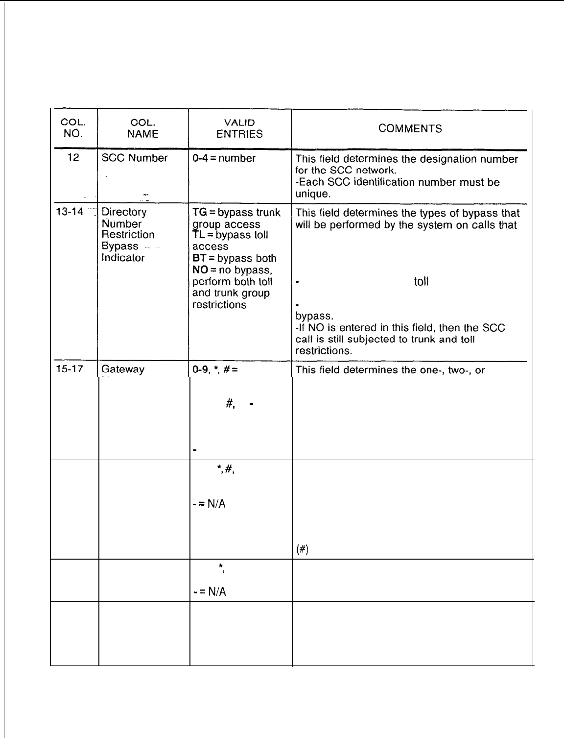
TL-130400-1001
Table 5.4 Entry Fields for Record Code SA
COMMENTS
are placed over an SCC.
-If a trunk is normally restricted from a
station user, an entry of TG allows SCC calls
to use the restricted trunk.
-
If a station is normally
toll
restricted, an
entry of TL allows SCC calls to be made.
-
An entry of BT allows for both types
of
Number/Access allowable entries three-digit access code of the SCC.
Code for column 15 -This code tells the system that the user
O-9, *,
#,
or
-
wants to access the SCC.
= allowable entries -Column 15 cannot be dashed.
for columns 16
and 17
-
= N/A
18-29
Gateway O-9,
*,
#,
L (long This field gives the directory number that
Number/ pause), S (short accesses the SCC.
Directory pause), or -Column 18 cannot be dashed.
Number
-=N/A
-This number must be left justified.
NOTE: If the SCC feature is used for
applications other than SCC where no
authorization code is necessary, a pound sign
(#)
should be entered in column 29.
30-39
Authorization O-9,
*,
#= allowed This field gives the authorization code number.
Number codes -Column 30 cannot be dashed.
-=
N/A
40-42 Time Between 000-254 = time in This field determines the maximum time
Access and seconds between the end of sending an SCC gateway
Authorization or directory number and the start of authorization
Number 045 = suggested code.
value
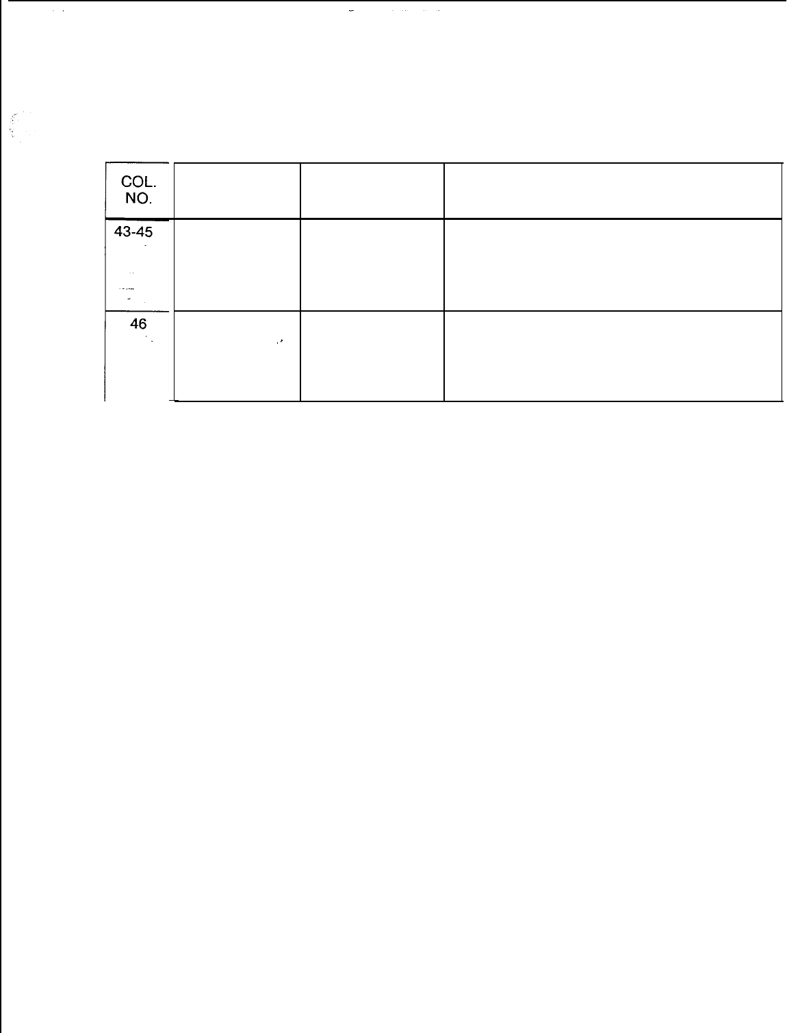
SW
5210
TL-130400-1001
Table 5.4 Entry Fields for Record Code SA
COL.
VALID
NAME ENTRIES COMMENTS
Time Between 000-254 = time in
Authorization This field determines the selected elapsed
seconds
Number and or seconds required between sending the
Digits authorization number and the digits.
015 = suggested
value
Bypass Toil Y = required
Restriction
‘,
N = not required This field determines whether or not a bypass
of toll restriction is allowed when the final
Check on Final
Directory
Number
directory number is entered.
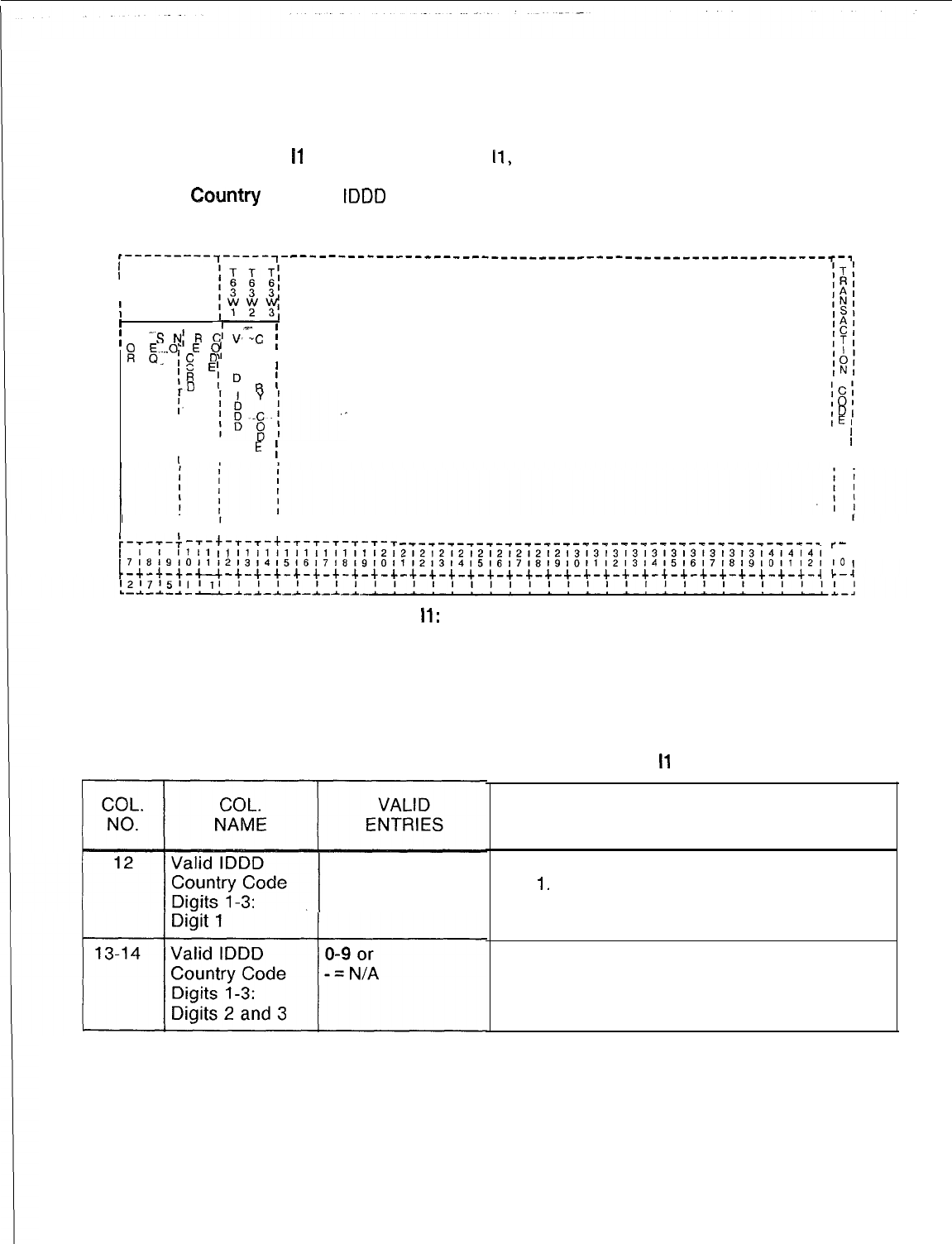
TL-130400-1001
Record Code
I1
: 5.5 Record Code
11,
Figure 5.5, defines the valid international
International
country codes for MERS (Most Economical Route Selection)
Cohlntry
Code
IDDD
(International Direct Distant Dialing) processing.
,---------7-----7- --------------------------------------------------------~-~
I
I
I
I
I
1I
;
F
-S
N;
R
Cl
V,-:C
g
i
M
.$..“I
E
0,
A 0 ,
,c
D
L u
0
E’
I N
’
IR
rD
;
D
T
;
R
IC’l
I.
101
IDI
I
IEl
I
I
I
II
I
E
I
I
’
II I
I
,
,
I I
I
I
I
I
:-T-T-: --r-t-T-T-+-T-T-T-T-T-T
-T-T-T-T-T-T-T-T-T-T-T-T-T-T-T-T-T-T-T-T--r--r--r--r-*-,
r-
[7~~~9t0111213,4151617181910111213141516171819101112131415161718191011121
IO
ilti
11
~iii~i~i~i~i;ii2~2;2~2~2i2i2~2i2~2;3;3;313;313;313;313~414141
18
t-+-+-+-c--+-+-+-+-+-+-+-+-+-+-+-+-+-+-+-+-+-+-+-+-+-+-+-+-+-+-+-+-+-+-+-~
c-
Figure 5.5
Record Code
II:
International Country Code Data Sheet
Table 5.5 Entry Fields for Record Code
I1
O-9 = number
COMMENTS
This field determines the valid values for
digit
1.
This field determines the valid values for
digits 2 and 3.

--
TL-130400-1001
CLASS OF SERVICE 6.0 This section describes the record codes required to define
the system classes of service. The following record codes are
required:
l Record Code DC defines the trunk groups allowed for the
various classes of service.
l Record Code DD defines the system features allowed for the
various classes of service.
SVR 5210
l Record Code NC defines additional system features allowed
for the various classes of service.
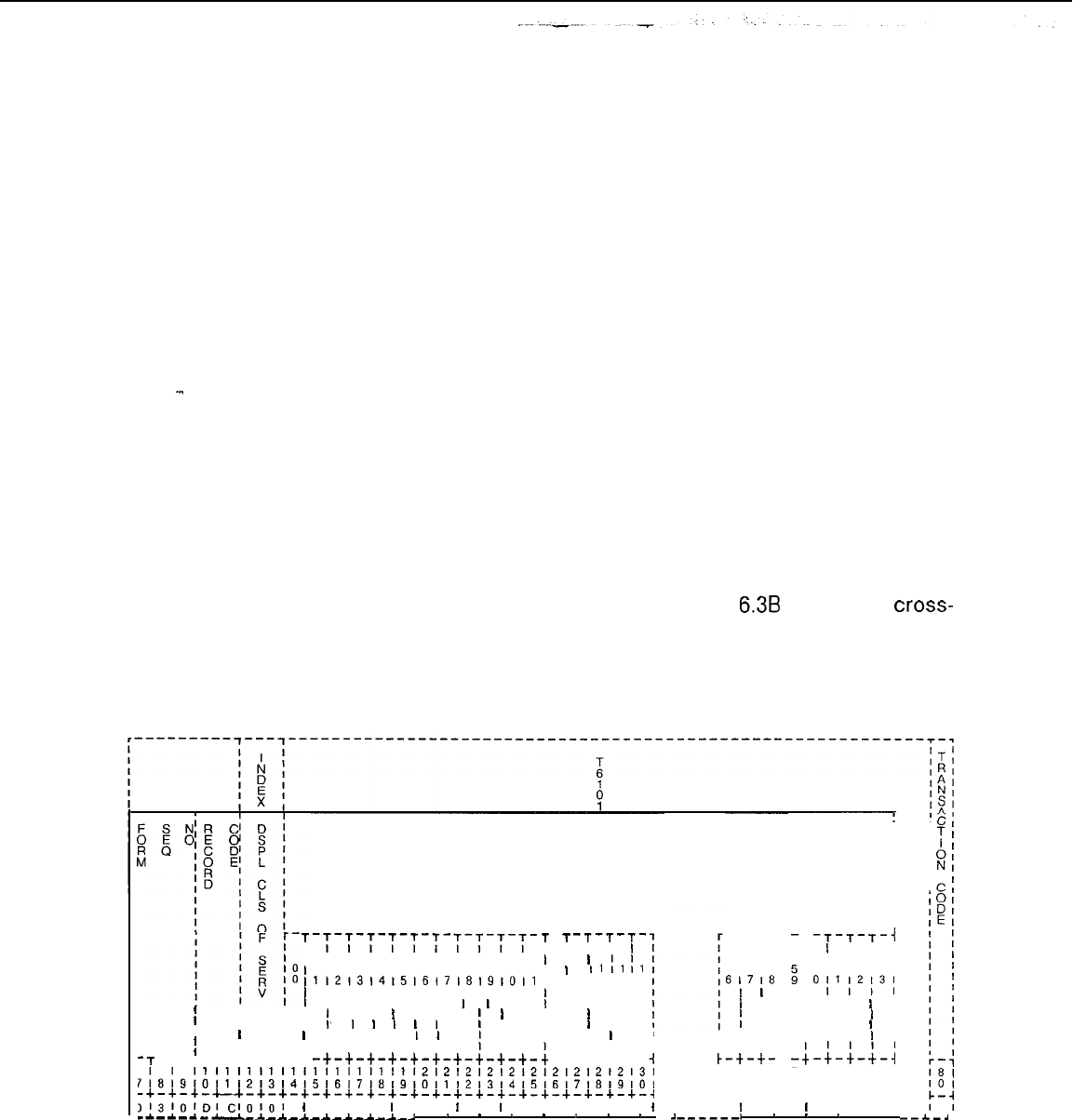
TL-130400-1001
Record Code DC: 6.1 Record Code DC, Figure 6.1, allows system users access
Displayable
to the various trunk groups (00-63) within the system. Sixteen
Class of Service
different displayable classes of service are possible.
-..
A COS provide access to certain trunk features or allows certain
types of calls to be made. The classes of service assigned in
the system are defined by three different record codes: DC, DD,
and NC. Record Code NC defines the n-displayable classes of
service. Record Codes DC and DD together define the
displayable classes of service. Since there is only one entry field
for displayable COS on line, trunk, and feature record codes,
Record Codes DC and DD must be used in conjunction with one
another. The displayable COS value assigned on Record Code
DC also applies to Record Code DD.
On a per-station basis, each station is marked with a
displayable COS number and an n-displayable COS (refer to
Record Code NC). The displayable and n-displayable COS
numbers are displayed at the Attendant Console every time a
station accesses the attendant. Table
6.3B
provides a
cross-
reference for compatible and noncompatible station features. If
remote access authorization codes are used, the COS required
must be included in Record Codes DC and NC.
-~-~-~-~-~-T-T-T-T-T-
I I I I I
0101010~0101010101111
11213141516,718191011
T
I
I
I
I
I
I
8
I
I
I I
I
I
I I
II
I
I
II
I I
I I I I I I I I I I
I I I I I
I
I
II,
I
I I
I
I I I
I
I
I’
I
I
I
I
I
I
I
I I
I I I I
I
I
, I I
I I I I I I I
I
I I
-t-t-t-t-t-t-t-t-t-t-
-7
-r-+-r-t-r-t-t
T
I
I
I
I
I
I
I
I
I
;
1
2
T
I
I
I
I
I
I
I
I
I
I
t
-T-T-T-
I I
I
I
1
I1
II
II
3141516
I I I
I I I
I
I I
I
I I
I
I
I
I I I
-t-t-t-
-T-T-
I I
51515
61718
I
I
I
I
I
I
,
I
I I I
I
I I I
T
I
I
I
I
I
I
I
I
I
I
t
i
t-t-t-
TRUNK GROUP ACCESS
T
-T-T-T-i
II
I I I
I
I61616161
I
I
011’2’3’
I , I
II I
I
I
II I
I
I
II I
I
I
II I
I
I
4
-;-;-i-j
II
II
II
,I
,I
II
II
II
,I
II
12121212121212121212131
7~8~9,Ol1121314151617,8l91O1112131415,6,7l8191O1
17171717171717171
10111213141516171
-+-+-+-+--+-+-+-+-+-+-+-+-+-+-+-+-+-+-+-+-+-+-+-q
t-+-+-+-+-+-+-+-4
,‘zj’OI,jI~IOIOl
1
I I I
I
I I
I
I
I
I I I I I I
I
I
I
I I
I
I I I I
--------___-------------.
.
.
.
.
1
.
.
J-_----,
.
.
.
I
--.&.-a
Figure 6.1
Record Code DC: Displayable Class-of-Service Data Sheet
TL-130400-1001
COL.
NO.
Table 6.1
Entry Fields for Record Code DC
COL.
VALID
NAME ENTRIES COMMENTS
12-13
Displayable
00-l
5 = number
This field determines the number used to refer
Class of Service to this displayable class of service.
%-
-It is recommended to use 00 as a default for
./
.”
trunks.
-The displayable class-of-service number
must be unique across the DC forms.
NOTE: COS 15 is normally reserved as the
COS for maintenance and is allowed access
to all trunk groups.
14-77
Trunk Group Y = selected This field determines what trunk groups this
Access
-
= not selected displayable COS is allowed to access.
-If a large number of CO lines are not
allowed to access one another, they can be
put in one group. Since access to these lines
is through a divert condition and each CO
requires its own trunk, the different CO users
cannot use each other’s CO.
-If toll access is indicated on Record Code
DD, columns 14-15, then at least one trunk
group in the trunk group access field must be
marked Y.
NOTE: The trunk group access must be
compared to Record Code
Tl
to ensure that
each trunk group with outgoing or two-way
direction can be accessed.
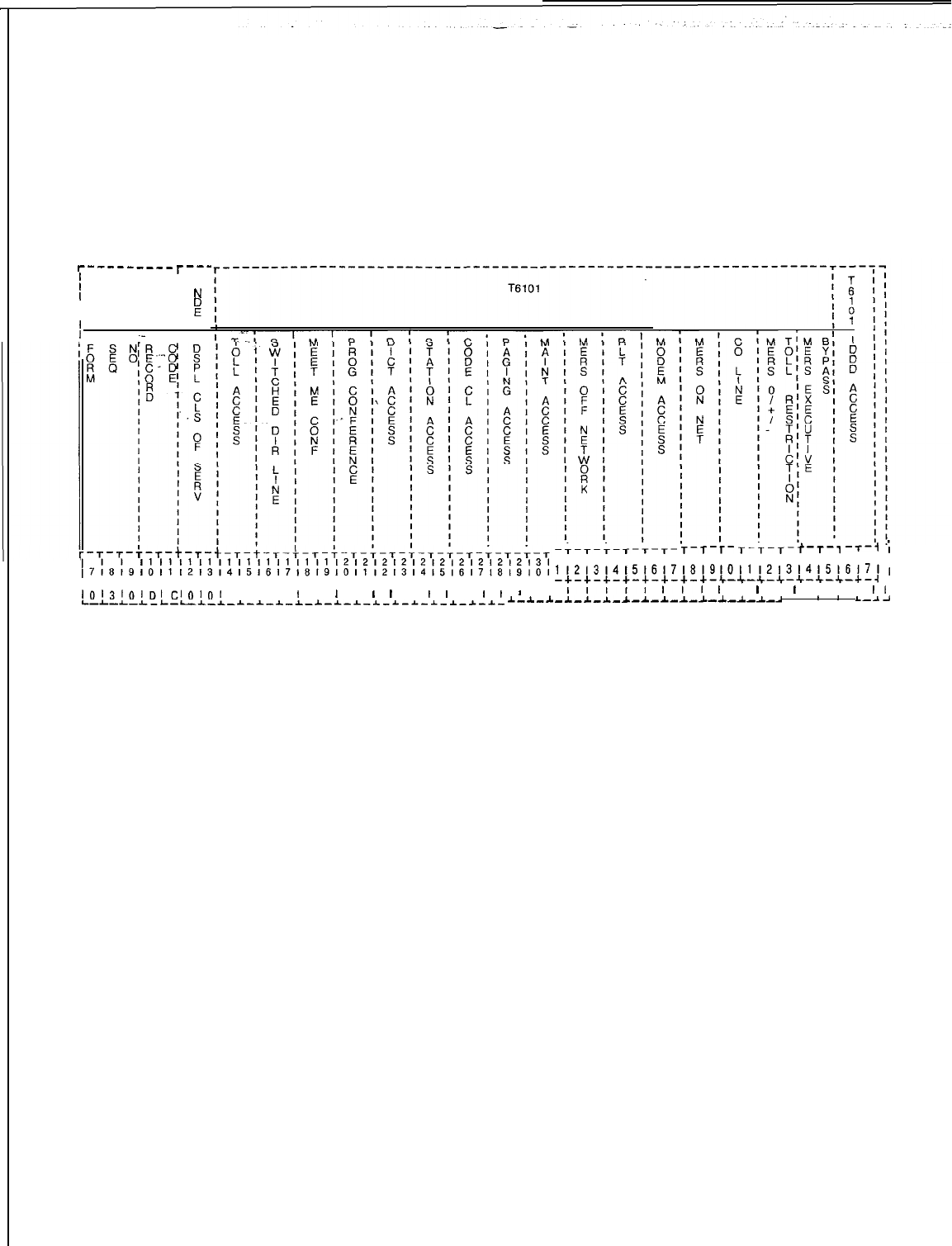
Record Code DD: 6.2 Record Code DD, Figure 6.2, allows access to certain
Displayable
system features. This record code is a continuation of record
Class Of Service code DC.
#----------
l
l----
I
I ’
I
,
N
I
I
I
F
I
I x
II
.-
I
I
I1
I1
I1
I1
I1
I1
I1
I1
I1
I1
l2l2l2l2l2l212l2l212l3l
~7~8~9,0,11213,41516171819,0,1,2,3,415,6171819,0,
c-+-+-+-u-+-+-+-+-+-+-+-+-+-+-+-+-+-+-+-+-+-+-+
lOl3lOl~I~IOlOI
I I I
I
I 1 I
I
I
I
I
I
I
I
I
I
I
L-L-L-I-L-I-~-~-~-~-~-~-~-~-~-~-~-*-~-*-*-~-
I-.L--L
-+-T-+-T-T-T- T-T-T- T-T-T-t-T-1
-T-i
;
3131313131313131314141114141414141,
1121314151617181910l11213141516171,
-+-+-+-+-+-+-+-+-c-+-~-Jr-~-~-+-+-4
I
,,,,I
III
I
I
I
I
I
I I I
II
_~_~_*_~-~-~-~-~-~-I-~-.
-
*
8
L-2-l
Figure 6.2
Record Code DD: Displayable Class-of-Service Data Sheet
TL-130400-1001
TL-130400-1001
Table 6.2
Entry Fields for Record Code DD
COL.
COL.
VALID
NO. NAME ENTRIES COMMENTS
12-13
Displayable
00-l
5 = number This field determines the number given to
Class of Service each of the 16 possible displayable
COSs
NOTE: COS 15 is normally reserved for
_-
maintenance and is allowed access to all
.”
features.
14-15
Toll Access TA = allowed If toll restriction is in effect for the trunk group
-- = not allowed accessed, this field determines whether or not
.the toll restriction can be overridden.
-An entry of TA allows the toll restriction
feature to be overridden.
-An entry of -- disallows toll restriction to
be overridden.
-Speed call numbers and numbers
accessing a non-MERS SCC route can
override toll restrictions if programmed to do
so. Speed calling is programmed on Record
Code GS, columns 15-l 6.
-SCC is programmed on Record Code SA,
columns 13-l 4.
-If this field is marked TA, Record Code NC,
columns 40-41, must be dashed.
16-17
Switch Direct SL = allowed This field determines whether or not access to
Line
-- = not allowed a switched direct line is allowed.
-SL must be indicated for a hot-line service
or a CO line.
-A CO line requires its own trunk group.
-It is not recommended to terminate a hot
line to a console.
-A COS used by a hunt group that does not
divert must not be marked SL.
-If this field is marked SL, the divert
destination (Record Code LM, columns 30-
31) can be a line, console, recorder
announcer, or tone. A hunt group pilot number
is allowed only if it does not have the
camp-
on feature.
18-19
Meet-Me MC = allowed MC allows access to the progressive
Conference -- = not allowed conference feature.
-For this feature to work, the system must
have an (FB-51279) eight-party conference
card.
-With this feature, the user can join a
conference.
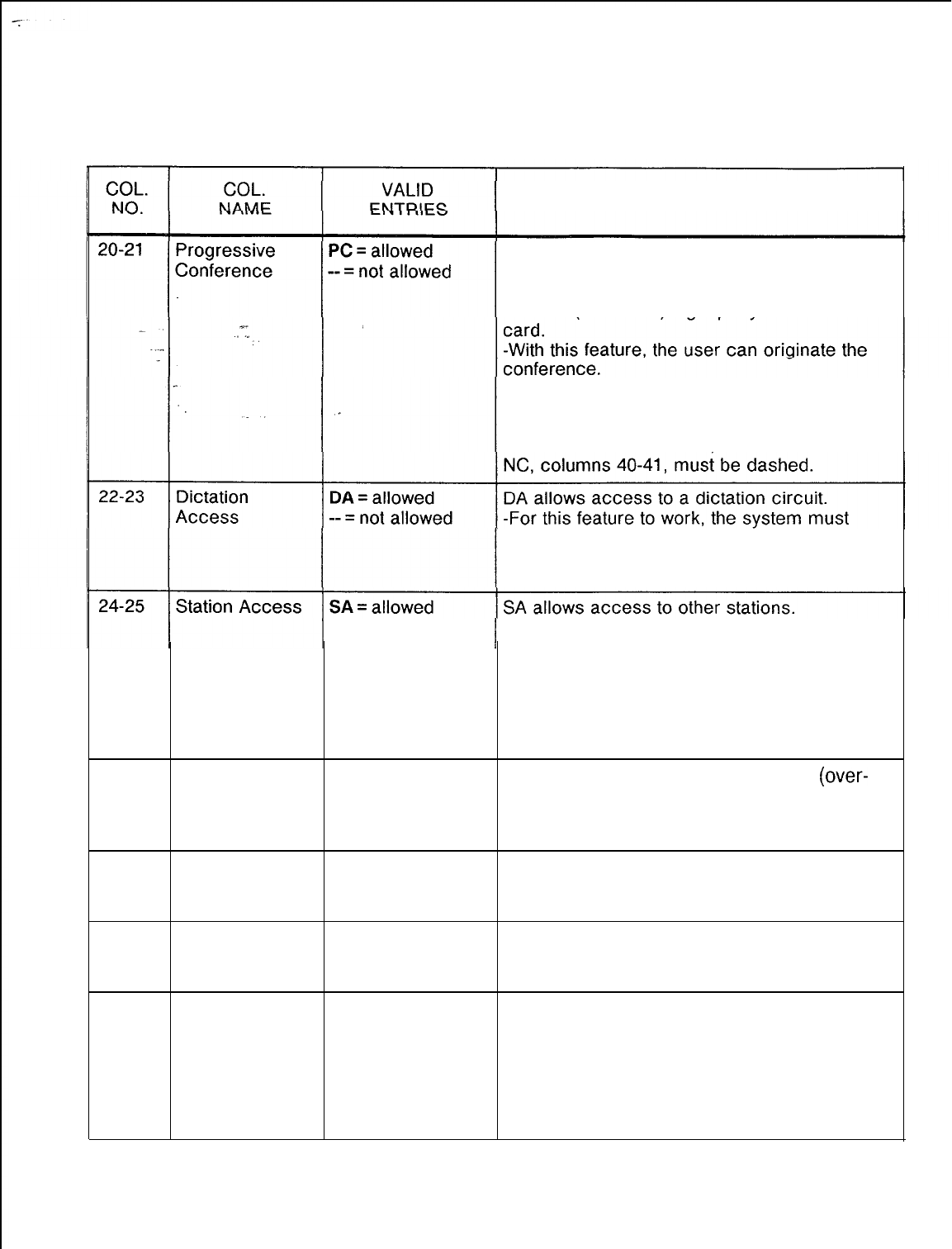
TL-130400-1001
Table 6.2
Entry Fields for Record Code DD (Continued)
COMMENTS
PC allows access to the progressive
conference feature.
-For this feature to work, the system must
have an (FB-51279) eight-party conference
-If this field is marked PC, then Record Code
NC, columns 30-31, must be marked HS for
proper operation of the feature.
-If this field is marked TA
then
Record Code
have an FB-17210 card.
-If this field is marked TA, then Record Code
NC, columns 40-41, must be dashed.
-- = not allowed -If this field is dashed, the line cannot call
other stations; it can only receive calls.
-A CO line does not need station access.
-When defining a trunk COS, it is important to
give the trunk station access.
-If Record Code LM, columns 30-31, is
marked LN, this field must be marked SA.
26-27
Code Call CC = allowed CC allows access to the code calling
(over-
Access -- = not allowed head ringing) feature.
-For this feature to work, the system must
have an FB-17210 card.
28-29
Paging Access PA = allowed PA allows access to the paging feature.
-- = not allowed -For this feature to work, the system must
have an FB-17240 card.
30-31
Maintenance
Access MA = allowed
-- = not allowed MA allows access to the maintenance feature.
-The switch room telephone is always given
MA.
32-33
MERS Off
ME
= allowed
ME allows access to MERS off-network
Network -- = not allowed trunks.
-See Record Codes MR, TR, SI, and RP for
requirements.
-This field can be used to allow overflow
calls on the network to overflow to the DDD
(Direct Distance Dial) trunks.
D-118
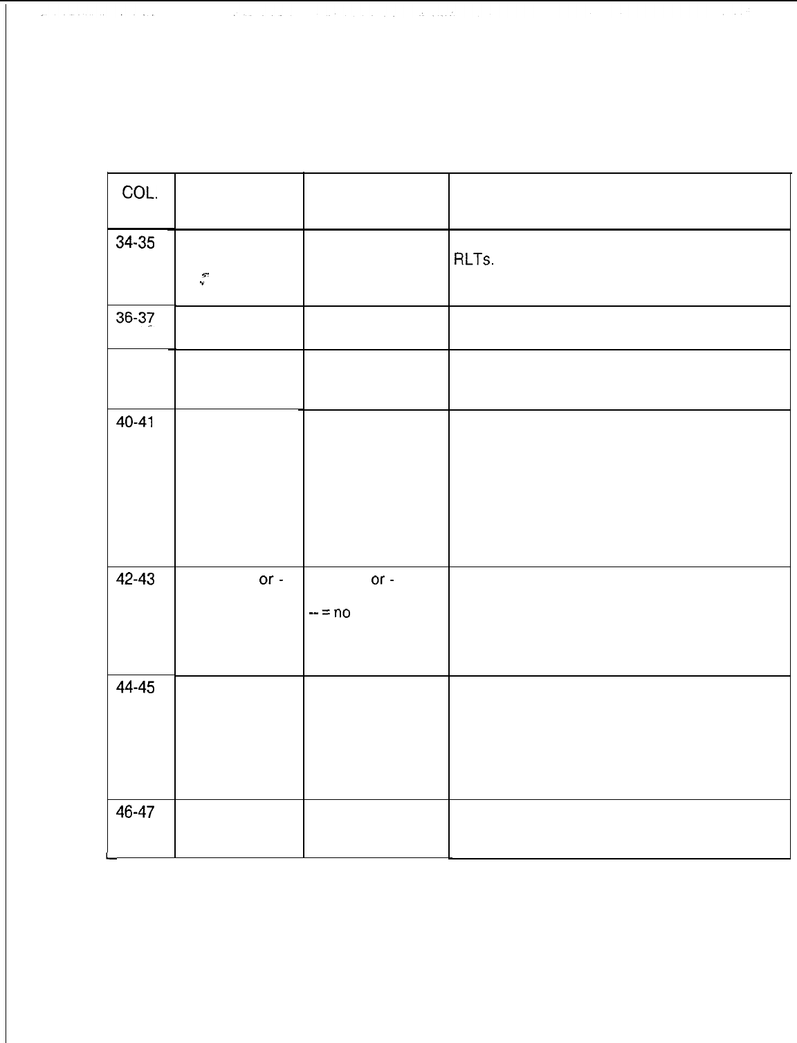
COL.
NO.
34-35
36-37
38-39
40-41
42-43
44-45
46-47
TL-130400-1001
Table 6.2 Entry Fields for Record Code DD (Continued)
COL.
NAME
Release
Link
Trunks Access
*-
.”
Modem Access
MERS On
Network
CO Line
MERSO+
or-
Toll Restriction
MERS
Executive
Bypass
International
Direct Distant
Dialing Access
VALID
ENTRIES
RL
= allowed
-- = not allowed
MD
= allowed
-- = not allowed
MN
= allowed
-- = not allowed
CL
= allowed
-- = not allowed
TR=O+
or-
restriction
--Z”O
restriction
EB
= searches all
routes
-- = call is
placed into queue
before being sent
out over the most
expensive route
ID = allowed
-- = not allowed
COMMENTS
RL allows access to the CAS attendant via the
RLTs.
-In a CAS application, this field should be
given at least one line for testing purposes.
This field is no longer used.
MN allows access to MERS private network
trunks.
-See MR, TR, SI, and RP for requirements.
CL allows access to a CO line.
-The CO is normally given an unpublished
DN (Directory Number).
-If this field is marked CL for access to a CO
line, then the switched direct line (SL) must be
marked in columns 16-17.
-A CO line can only appear on an IFP.
-A COS used by a hunt group that does not
divert must not be marked CL.
TR permits credit card, outside operator, or
international calls. This only applies if toll
restriction is in effect for MERS calls and the
call is routed over MERS.
-This field is only used if toll restriction is in
effect.
EB allows access to the MERS executive
bypass feature.
-With this feature, the system searches all
MERS routes before queuing an outgoing call.
NOTE: If the trunk group is busy, the call will
not route to another trunk group.
ID allows access to international dialing for
calls outside the USA.
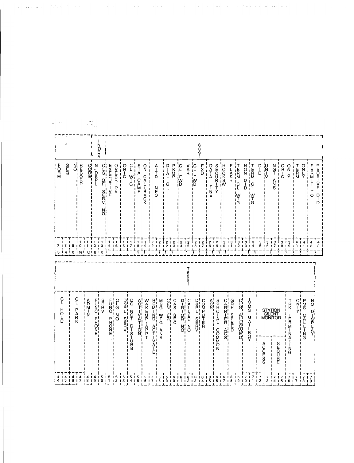
TL-130400-1001
Record Code NC:
6.3 Record Code NC, Figure 6.3, defines the n-displayable
N-Displayable
COS used to allow or restrict station access to the system
Class of Service
features. If remote access authorization codes are used, make
sure that Record Codes DC and DD have a field that meets the
requirements of that code. Since a class of service is assigned
on a line basis not a station basis, the term line user is used as
opposed to station user when defining class-of-service
features.
T”-------T---r-----------------------------------------------------------~
I I I
I
-
I
;
I:
I
T
I
I
I
D
’
I
I
,
1.
E
’
. .
I
I
I
,
n
I
1!
~O!4~0lNICIOIOI
I I I
I
I
I
1
I
I
,
I
I
I
I
I
I
I
I I
I
I
I
I
I
r-----------------------------------------------------------------------~
I I
I
L
I
$
I
I
,
I
Figure 6.3 Record Code NC: N-Displayable Class-of-Service Data Sheet

TL-130400-1001
Table
6.3A
Entry Fields for Record Code NC
COL.
COL.
VALID
NO.
NAME ENTRIES COMMENTS
12-13
N-Displayable 00-l 5 = number This field determines the number assigned to
Class-of-
the COS defined in this row.
Service Number -It is recommended not to assign 00 as a
z-
,
.”
station COS. COS 15 is normally reserved for
maintenance and is allowed access to all
features.
14-S Executive EX = allowed This feature allows a third party to break in to
Override
‘-
-- = not allowed a two-party connection.
-This feature cannot be enabled if the station
has call waiting non-DID (Direct Inward Dial).
16-17
Originating Call OC = allowed This feature allows a line user to send a call
Waiting
--
= not allowed waiting tone to a busy station. The tone
indicates that another call is waiting to be
answered. This feature causes a call waiting
tone to be heard by the called party.
-With this feature, the originating party must
remain off-hook.
NOTE: If this field is marked OC, then Record
Code OF, column 22, must be marked Y and
columns 25-26 (of Record Code OC) cannot
be dashed.
18-19
Station
Camp-
CO = allowed This feature allows a line user to camp on to a
on Call Back -- = not allowed busy station.
-Once a user has activated this feature, the
telephone can be hung up. When the calling
and called stations are both idle, the calling
station is rung. If the calling station answers,
the called station is also rung.
-If this field is marked CO, then Record Code
OF, column 22, must be marked Y and
columns 25-26 cannot be dashed.
-It is recommended that this feature be given
to the console.
20-21
Attendant
Information Al = allowed
-- = not allowed This feature allows access to the console by
dialing the attendant access code.
-If this feature is not allowed, the line cannot
call the attendant.
-If Record Code LM, columns
30-31,
are
marked AT, this field must be marked AL.
22-23
Dial Call Pickup DC = allowed This feature allows a line user in a dial call
-- = not allowed pickup group to answer a call placed to
another station within the same group.
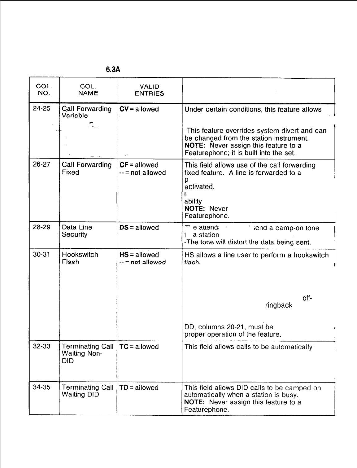
TL-130400-1001
Table 6.3A Entry Fields for Record Code NC (Continued)
COMMENTS
-- = not
allowed call forwarding automatically to any destination
within the system.
redetermined location when this feature is
ctivated.
If the call forwarding variable
eature is allowed, that feature provides the
to
override the forwarding condition.
assign this feature to a
-- = not allowed to
z
ztation
with a COS marked
DS.
-A hookswitch flash is used to access
system features. For normal applications, this
feature is not required for hot-line service
telephones or motel guest room telephones.
-When a hot-line service station goes
off-
hook, the party hears the
ringback
tone from
the station or trunk at the far end being rung.
-If this field is marked HS
then
Record Code
marked PC for
-- = not allowed camped on when the station is busy.
-This feature applies to internal calls,
console extended calls, and station
transferred calls
-- = not allowed
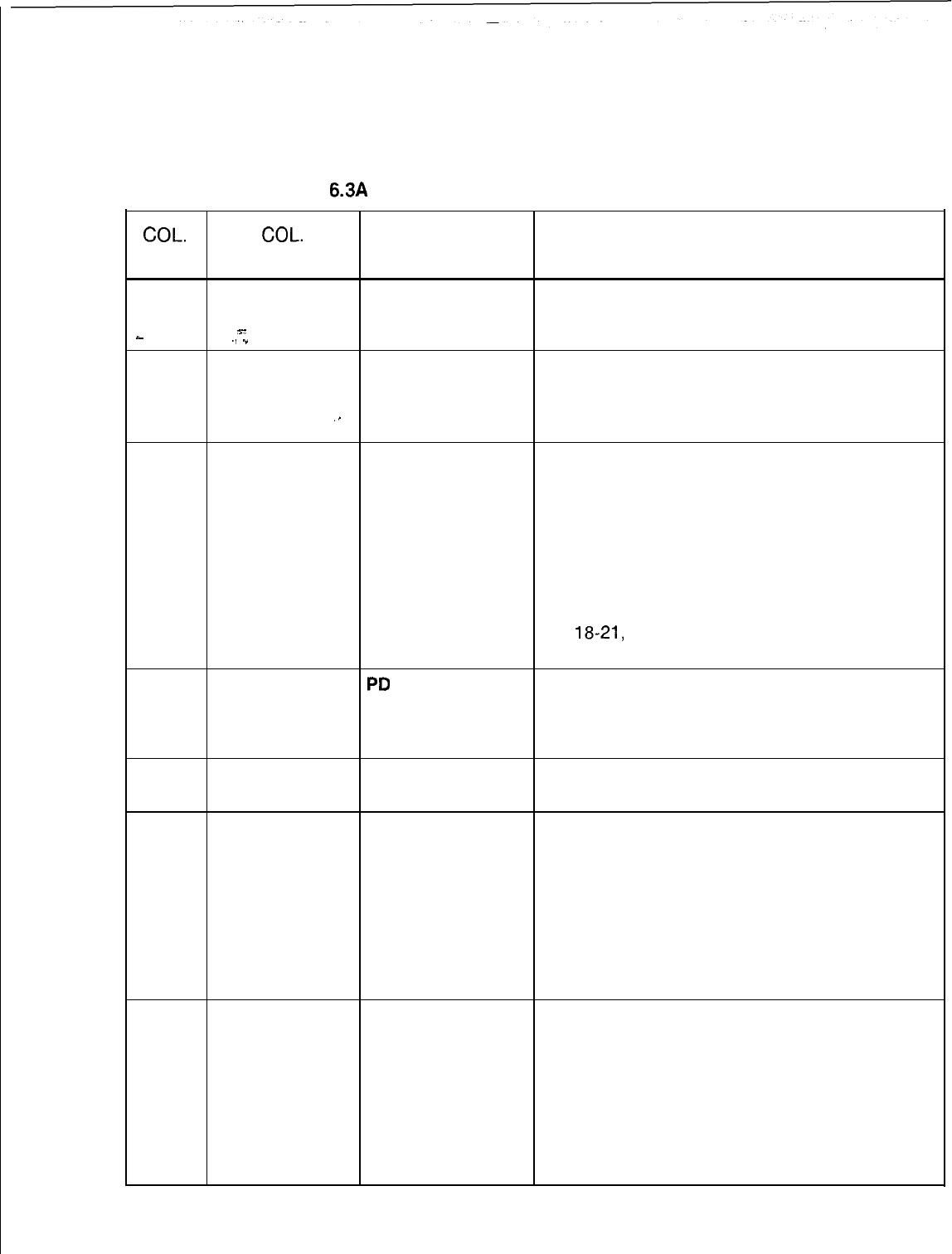
TL-130400-1001
Table
6.3A
Entry Fields for Record Code NC (Continued)
COL.
COL.
VALID
NO. NAME ENTRIES COMMENTS
36-37
Universal Night
UN = allowed
UN allows retrieval of UNA calls at this line.
Answer -- = not allowed -The universal night answer feature is either
s-
.-
.I
.”
a bell or light that indicates an incoming call.
38-39
Originating Only OR = allowed OR allows a line user to make calls only, not
-- = not allowed receive them.
-Hot line telephones are normally configured
.I
as originating only.
40-41
Terminating
Only TM = allowed
-- = not allowed TM allows a line user to receive calls but not
make them.
-This field is normally applied to an ACD
group.
-If a station with TM marked goes off-hook
to place a call, reorder tone is heard.
-Originating only and terminating only are
mutually exclusive features.
-If this field is marked TM, thencolumns 14-
15,
18-21,
and 22-23 of Record Code DD
must be dashed.
42-43
Permit to
PD
= allowed PD allows a line user to receive DID calls.
Receive DID -- = not allowed -If the site has DID and non-DID stations,
assign PD to all stations that are to receive
DID or DID transferred calls.
44-45
Call Hold HD = allowed HD allows a line user to put a call on hold.
-- = not allowed
46-47
Call Park PK = allowed PK allows a line user to put a call into a call
-- = not allowed park queue.
-This feature allows a call put into the park
queue to be retrieved from any station in the
system.
-For a station to retrieve a parked call, it
must have the hookswitch flash feature.
-The timeout factor is set on Record Code
OT, columns 36-38.
48-49
Administrative AF = allowed This field determines whether or not the
Function Phone -- = not allowed administration feature is allowed.
-This feature allows a station to activate or
cancel features such as reminder
service/message waiting on another
telephone.
-This is given to a message waiting
telephone and to the telephone that is used to
turn on/off hotel features.

TL-130400-1001
COL.
NO.
Table
6.3A
Entry Fields for Record Code NC (Continued)
COL.
VALID
NAME ENTRIES COMMENTS
50-51
Service
SF = allowed
This field determines whether or not the
Function Phone -- = not allowed service feature is allowed.
%-
-
A station marked SF will not be blocked if
.I
1
the motel room block feature is in effect.
-Room blocking is used in a motel
application. Room blocking prevents rooms
from calling one another directly. Motel
service telephones such as the valet, maid, or
food service telephones should not be blocked
when room blocking is in effect. These
telephones should be marked SF.
52-53
Calling Number CN = allowed This field determines whether or not the calling
On Display -- = not allowed number (number of the station placing the call)
Phone is displayed on the LCD (Liquid Crystal
Display).
-Message waiting cannot be activated on
calling number display telephones.
-This feature is only used for a display
telephone.
-This feature is normally used in a motel
application to indicate what room number is
calling.
-This telephone can be used as a message
center if required.
-Called number display service and calling
number display phone are mutually exclusive.
-If this field is marked CN, then columns 62-
63 must be dashed.
NOTE: Never assign this feature to an IFP.
54-55
Do Not Disturb DD = allowed DD allows the DND (Do Not Disturb) feature to
Activation -- = not allowed be turned off/on from the telephone.
-This feature is normally assigned to a POTS
telephone in a motel/hospital application for
use by guests/patients who want quiet.
-In an ACD group, this feature can be
assigned to the agent; or the supervisor can
put the agent into a work state.
-When a telephone is in DND, the calling
party hears busy.
-On an IFP, this feature can be activated by
a button on the telephone or by an access
code.
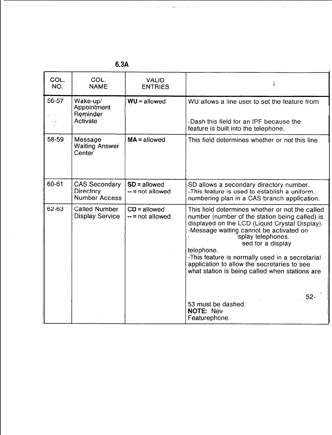
TL-130400-1001
Table 6.3A Entry Fields for Record Code NC (Continued)
COMMENTS
-- = not
allowed the user telephone. The feature works much
like an alarm clock.
-- = not allowed appears at a message waiting answer center.
-If a message waiting answer center
telephone answers a call from a station that
has message waiting activated, the message
waiting feature is automatically canceled.
calling number di
-This field is only u
forwarded to them.
-Called number display service and calling
number display phone are mutually exclusive.
If this field
is
marked
CD, then
columns
52-
er assign this feature to a
TL-130400-1001
COL.
NO.
Table
6.3A
Entry Fields for Record Code NC (Continued)
COL.
VALID
NAME ENTRIES COMMENTS
64-65
Computer
CA = allowed
CA allows computer access.
Access -- = not allowed -This feature interfaces with compatible
equipment and is designed to interface with
%-
.”
. .
Wavetech.
Wavetech
is a system used in
credit card checking. It determines whether
or not the card holder is over the credit
amount allowed. A dial tone is sent to the
called station (Wavetech equipment) when the
originating station disconnects. A short
across the tip and ring will exist until the dial
tone detector, which is built into the
Wavetech
equipment, detects the tone and causes the
shorted circuit to open. The
Wavetech
equipment is then released.
66-67
SCC Access SA = allowed SA allows access to non-MERS SCC.
-- = not allowed -If the MERS option is equipped, the SCC will
normally be placed into the MERS routing.
68-69
Group Speed SC = allowed SC allows access to group speed calling.
Calling Allowed -- = not allowed -The group speed calling feature must be set
up on Record Codes GC and GS.
70-71
VMS Mailbox VM = allowed VM allows access to a VMS (voice mail)
-- = not allowed mailbox.
72-73
Station Silent SM = allowed SM allows access to the silent monitor feature.
Monitor Access -- = not allowed -This feature allows a station to monitor other
station lines without being detected.
-This feature will not work on a
nonprime
control line or Attendant Consloes.
74-75
Station Silent SS = allowed SS secures a line from the silent monitor
Monitor Secure -- = not allowed
feature.
-If SS is entered, the silent monitor feature
cannot be used on lines with this COS.
-In a conference call, a line marked SS can
be monitored.
76-77
Trunk TT = allowed This field determines whether or not only
Terminating -- = not allowed incoming calls are allowed. If this field is
Only marked TT, the line cannot make outgoing
calls.
78-79
PMS Calling PM = allowed This field determines whether or not PMS
Number Display -- = not allowed (Property Management System) calling
number display is allowed.
-PMS (Property Management System) is
used in motel applications to provide extensive
management features.
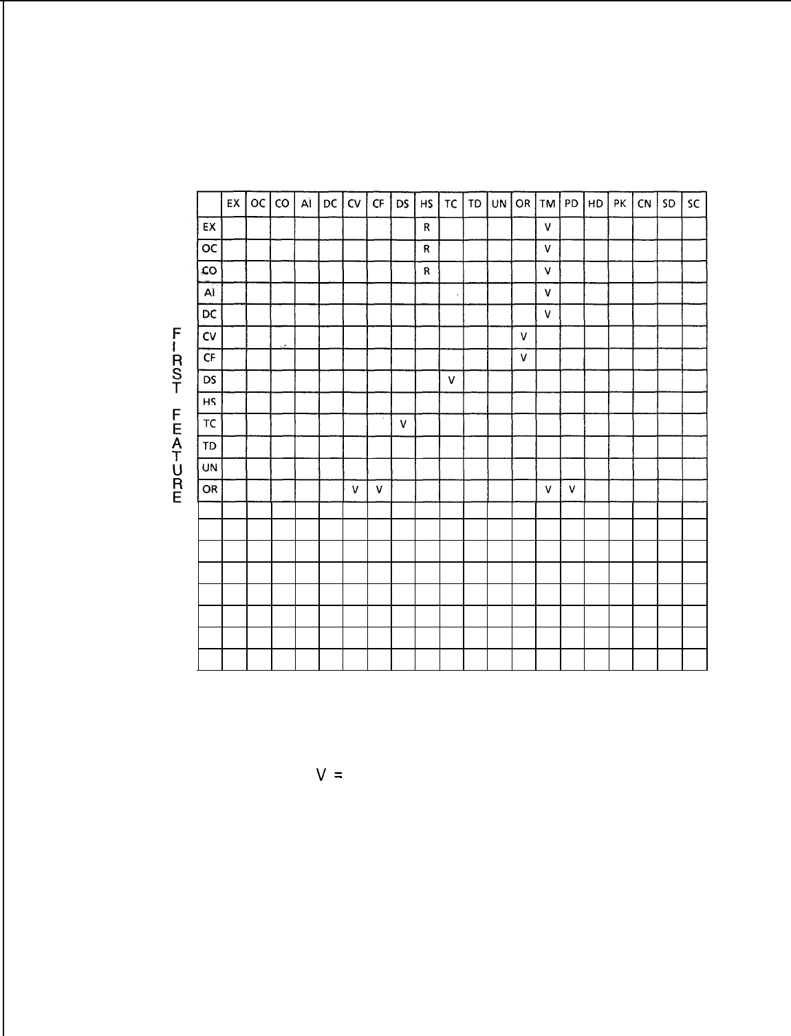
TL-130400-1001
Table 6.38 N-Displayable Class of Service Conflicts and Violations
SECOND FEATURE
TM V V V V V
PD
HD
PK
SD
CD
CA
SC
V
V
R
R
V
R
V
KEY:
R= The second feature is required for the first feature to
operate properly. (Example: EX requires HS.)
v=
Only one or the other of the two features can be specified
within the same class of service. (Example: EX conflicts with
TM.)
TL-130400-1001
Table
6.3C
Abbreviations
I
AF
-
Administrative Function Phone
I
MA
-
Message Waiting Answer Center
I
I
Al
-
Attendant Information Calls 1 OC
-
Originating Call Waiting
CA
-
Computer Access
v-
OR
-
Originating Only
CD
-
Catled
Number Display
CF
-
Call
Forwarding
-
Fixed
CN
-
Calling Number
Display,Service
PD
-
Permit to Receive DID
PK
-
Call Park
SA
-
Special Common Carrier Access
CO
-
Camp-on/Automatic Recall
CV
-
Call Forwarding
-
Variable
DC
-
Dial Call Pickup
SC
-
Group Speed Calling Allowed
SD
-
Secondary Directory Number Access
SF
-
Service Function Phone
1 DD
-
Do Not Disturb Activation 1 TC
-
Terminating Call Waiting Non-DID
1 DS
-
Data Line Security 1 TD
-
Terminating Call Waiting DID
EX
-
Executive Override
I
TM
-
Terminating Only
I
1 HD
-
Call Hold
I
UN
-
Universal Night Answer
I
HS
-
Hookswitch Flash
-I-
WU
-
Wake-up Appointment Reminder

TL-130400-1001
LINE 7.0 This section describes the record codes required to
FEATURES define the various system line features. The following record
codes are required:
l Record Code HG defines the station hunt groups.
0
Record Code MH defines the station hunt group members.
l Record Code GC defines the system speed calling groups.
l Record Code GS defines the system speed calling numbers.
l Record Code ED defines the system pickup groups.
l Record Code CH defines the “change feature by access
code” feature.
l Record Code DF defines the system default divert condition
value.
.
SVR 5210
D-129
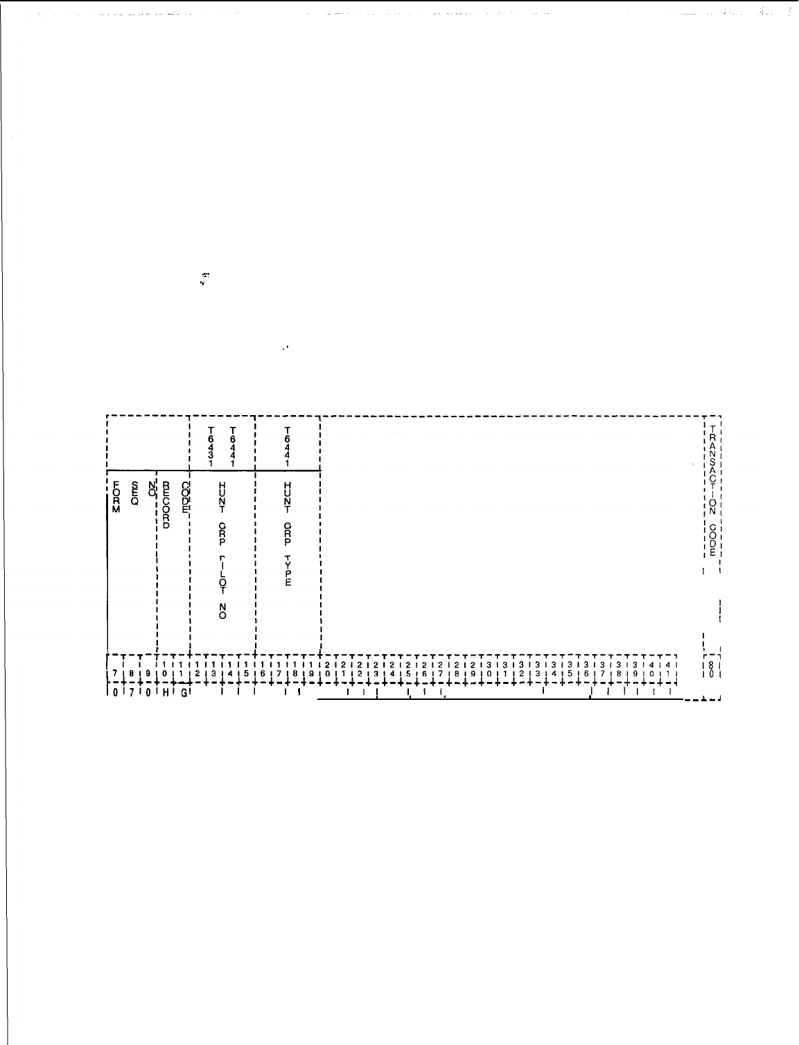
TL-130400-1001
Record Code HG:
7.1 Record Code HG, Figure 7.1, defines the station hunt group
Hunt Group
data requirements. The station hunting feature provides for a call
to route to an idle station of a prearranged group of stations. The
group of stations is defined by a pilot number. If the PNA
(Predetermined Night Answer) and ACD (Automatic Call
Distribution) station hunt groups are selected, they must be
assigned here.
__
.”
The system supports a maximum of 256 hunt groups. Of the total
hunt groups supported, no more than 80 can be circular hunt
groups. The number of hunt groups remaining for terminal hunt
groups is determined by subtracting the number of circular hunt
groups used from the allowed total- (e.g., if 80 circular hunt
‘*
groups are in use, the system can support 136 terminal hunt
groups, 256-80 = 136).
I
1
I
1
I 1
I 1
I I
I
1
I
1
,
f
I I
I
I
'
1
-T-T -T-T-+-T-T-T-+-T-T-T-t-~-~-~-~-~-~-~-~-~-~-~-~-~-~-~-~-~-~-~-~-~-,
k-4
I1I1I1I1I1I1I1I111111212121212121212121213131313131313131313l414l
,,~8:9,0,1,2,3,4,516171819101112131415161718191011121314151617181910111
181
101
c-+-+-+-u-+-+-+-+-+-+-+-+-+-+-+-+-+-+-+-+-+-+-+-+-+-+-+-+-+-+-+-+-+-~
L-4
10171O~Hl~I
I
III
I
I
I
I I
Ii
I
I
III
I I I I I
I
I I
III
,,I
I I
L--c--L-A- -A-*-A.-A.-*-A-A-&L . . . . .
*
.
*
.
8
. . . . . . .
*
. . . .
--A_.8
Figure 7.1
Record Code HG: Hunt Group Data Sheet
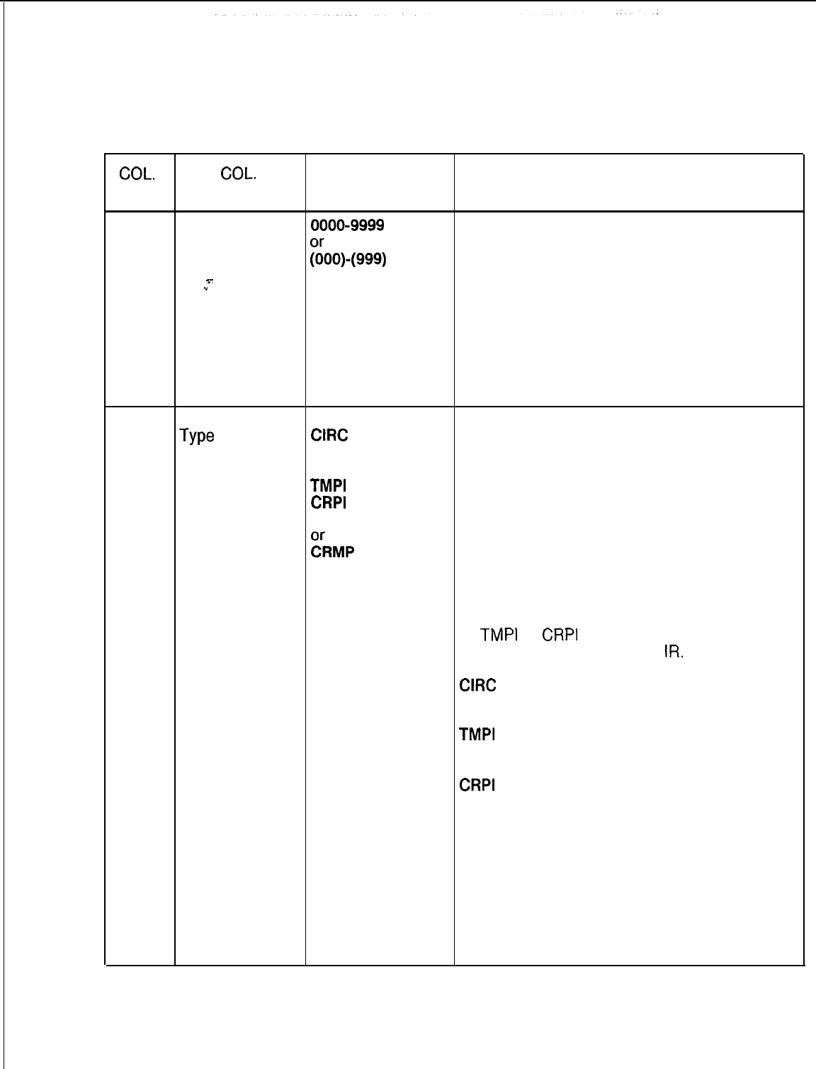
TL-130400-1001
Table 7.1 Entry Field for Record Code HG
COL. COL.
VALID
NO.
NAME ENTRIES COMMENTS
12-15
Hunt Group Pilot
0000-9999
This field assigns the pilot number that is used
Number
;00)-(999)
=
to access the hunt group.
-When a pilot number is dialed, the hunt
x-
.”
number begins for stations assigned on Record Code
A three-digit MH. When the normally assigned directory
number must have number of a station in a hunt group is dialed,
a blank before it. hunting occurs only for hunt group types
TMMP and CRMP.
.-Every hunt group pilot number on this record
code must have at least one member listed on
Record Code MH.
16-19
Hunt Group
TERM
This field determines the type of station hunt
Type
CIRC
(terminal or circular).
TMCP -If terminal hunting is used, the hunt always
CRCP begins at the first station in the group and
TMPI
terminates at the last station in the group (if all
CRPI
stations are busy).
TMMP
-If circular hunting is used, the hunt begins at
~RMP
the next station following the station that
answered the previous hunt call.
-True ACD requires circular hunting.
-Limited ACD groups can be assigned
terminal hunting or terminal hunting with group
camp-on.
-If
TMPI
or
CRPI
is used, enter the recorder
announcer on Record Code
IR.
TERM = terminal hunt
CIRC
= circular hunt
TMCP = terminal hunt with group camp-on
CRCP = circular hunt with group camp-on
TMPI
= terminal hunt with camp-on and
pressure indicator with divert to a recorder
announcer
CRPI
= circular hunt with camp-on and
pressure indicator with divert to a recorder
announcer
TMMP = terminal hunt group with camp-on
and pressure indicator with no divert to a
recorder announcer
CRMP = circular hunt group with camp-on
and pressure indicator with no divert to a
recorder announcer
-The maximum number of circular hunt
groups is 80.
SVR 5210
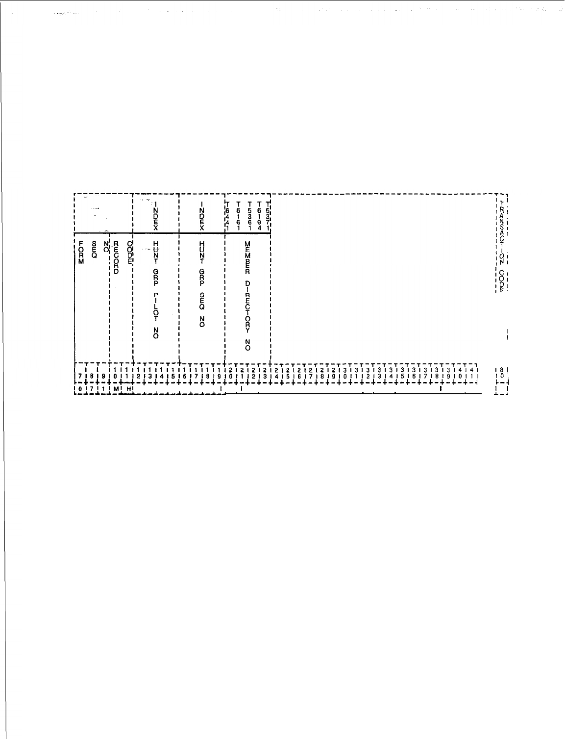
TL-130400-1001
Record Code MH:
7.2 Record Code MH, Figure 7.2, defines the station member
Hunt Group
directory numbers for the various hunt group pilot numbers.
Members
The order for call attempts to the hunt group members is also
defined on this record code. This record code is used in
conjunction with Record Code HG.
-T-T-T-t-T-T-T-t-T-T-T-T-T-T-T-T-T-T-T-T-~-~-~-~-~-,
I1
I1
I1
I1
II
It
I1
I1
I1
I1
1212121212121212121213131313131313131313l4l4l
~~~~~~~~~~~~~~~~~~~~~~~~~~~~~~~~~~~~~~~~~~~~~~~~~~~~~~~~~~~~~~~~~~~~~~
-+-+-+-~-c-+-+-+-+-+-+-+-+-+-+-+-+-+-+-+-+-+-+-+-+-+-+-+-+-+-+-+-+-~
1017111~I~I
I I I I I I I
I
I
I
I I I I I I I I I I I I I I I I I
I
I I
L-~-*-~--~-~-~-~-*-~-~-~
*
. 9 . . . . . . . .
*
*
.
*
. . . . .
*
. --
Figure 7.2 Record Code MH: Hunt Group Members Data Sheet
-.
-1
I
11
’
I
1,
$1
!I
?
I
I
I
)I
JI
IC
I
:I
IC
)I
I[
?I
IE
-
I
I
I
I
I
I
I
I
I
I
I
I
r-7
18
I
IO
I
c-i
I
I
A--.8
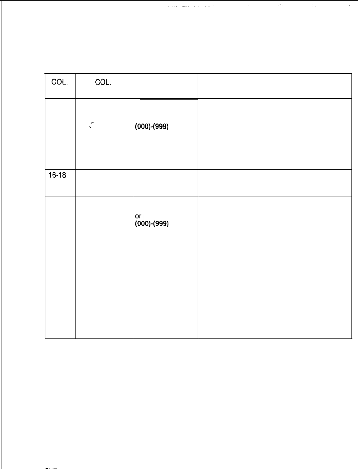
COL.
NO.
12-15
16-18
IHunt Sequence
INumber
19-22
IMember
I
Directory
INumber
I
Hunt Group Pilot
I
Number
s-
.”
SVR
5210
TL-130400-1001
Table 7.2 Entry Fields for Record Code MH
COL.
NAME VALID
ENTRIES
0000-9999 =
number
or
(000)(999)
=
number
A three-digit
number must have
a blank before it.
000-255 = number
0000-9999 =
number
goo)-(999)
=
number
A three-digit
number must have
a blank before it.
COMMENTS
This field assigns the pilot number of the hunt
group.
-Use phantom numbers for the pilot numbers;
this saves the numbering plan for station
numbers,
-Phantom numbers can be defined on
Record Code HD.
-The hunt group pilot number must have
been defined on Record Code HG.
Start the sequence number within a hunt group
with zero and continue in ascending order; no
gaps are allowed.
Make the member directory number a valid
line or room number.
-A directory number can only be in one hunt
group.
-A hunt group member cannot be an agent
position.
-Lines with the following class-of-service
features should not be members of a hunt
group:
from COS Record Code DD, SL (Switched
Direct Line)
from COS Record Code NC, OR
(Originating Only)
-Members of a hunt group should not be
given a divert condition, with the possible
exception of the last member of the hunt
group.
-Divert conditions are defined on Record
Codes LD and LM.
8187
D-133
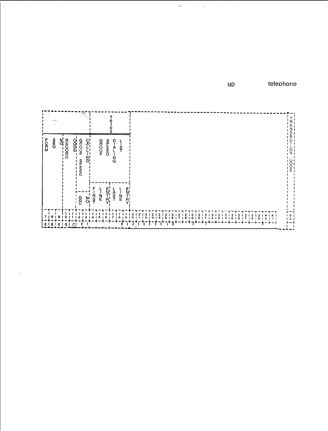
TL-130400-1001
Record Code GC:
Group Speed
7.3 Record Code GC, Figure 7.3, defines the speed calling
Calling
groups used by the system’. The directory numbers that make up
this group or groups are listed on Record Code GS. This record
code allows access to portions of or all of the system’s group
speed calling list. This release allows
up
to a 1000
teleohone
numbers in the group speed calling list. .
,-----e-e
----
---,-----------
~-----------------------------------------------
I
I
iI
r-s-r-T-T-t-s-t-T-T-+-~-~-t-~-~-~-~-~-~-~-~-~-~-~-~-~-~-~-~-~-~-~-~-
~7~9~9,0,1121314151617181910,112,31415,6,718191011121314151617181910111
,1,1,111,1,1,111,111,2,2,212,2,2,2,212,2~3,3l3~3~3~3~3~3~3~3,4~~~
c-+-+-+-u-,.-+-+-+-+-+-+-+-+-+-+-+-+-+-+-+-+-+-+-+-+-+-+-+-+-+-+-+-+-~
lO,~lOlGlCI
I
I
, I I I
I
I
I
I
I
I
I
I,
I
I I
I
I
I
I I I I I I I
!
I
I.-*-A.-a-
-d-A.-A.-A-A-_L-A--
*
.
*
--A-.4
Figure 7.3 Record Code GC: Group Speed Calling Data Sheet
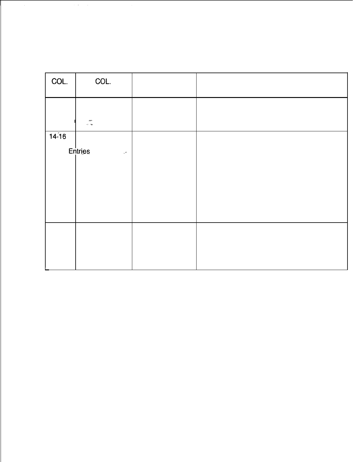
L
TL-130400-1001
Table 7.3 Entry Fields for Record Code GC
COL.
COL.
VALID
NO. NAME ENTRIES COMMENTS
12-13
Group Number 01-48 = number This field determines the group number for the
list.
-This number is used on Record Code LD
when assigning the speed call list to users.
14-16
Group
Speed
000-999 = number
Calling List Columns 14-l 9 determine the range of
Entri-es
entries in the group speed calling list that a
(first entry)
‘-
station user is allowed to access. Columns
14-16 are used to list the first entry, and
columns 17-l 9 are used to list the last entry.
-The range can be as small as a single entry
or as large as the whole list.
-If needed, several ranges can be listed for
the same group. This is done by using the
same group number on multiple records.
-Ranges must be listed in multiples of four
(e.g., 000-003 or 000-175).
17-19
Group
Speed
000-999 = number
Calling List Columns 14-l 9 determine the range of
entries in the group speed calling list that a
Entries station user is allowed to access. Columns
(last entry) 14-16 are used to list the first entry, and
columns 17-l 9 are used to list the last entry.
SVR 5210
8187
D-l 35
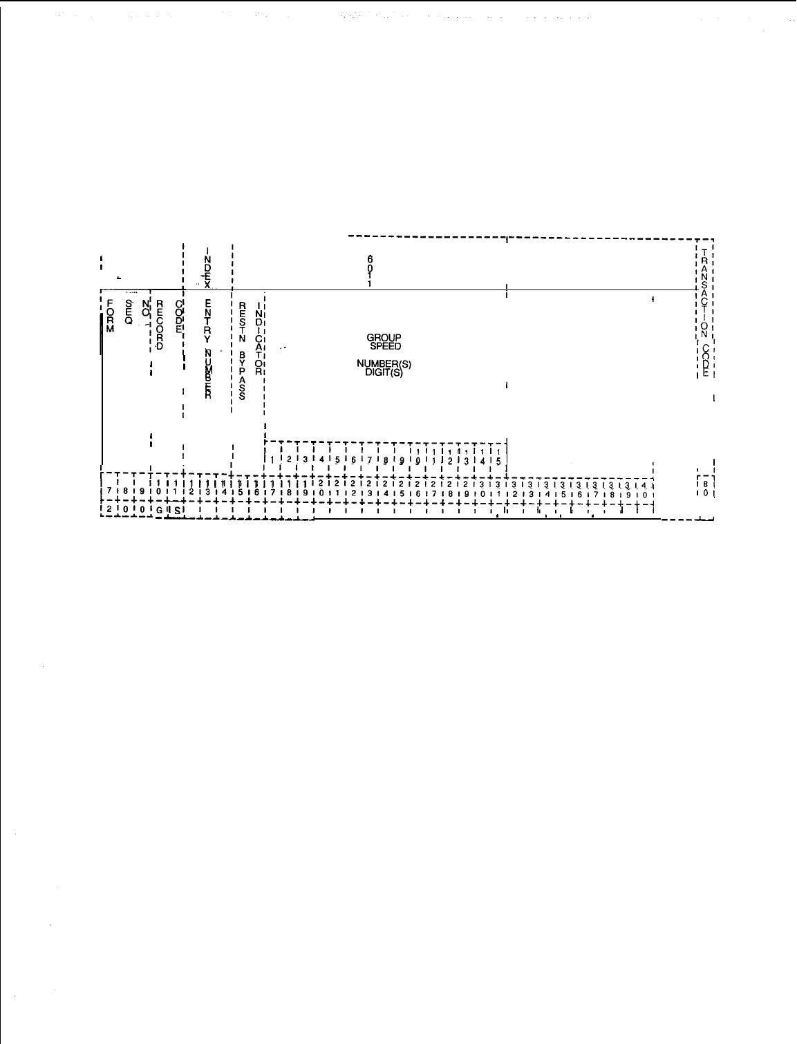
TL-130400-1001
Record Code GS:
Group Speed
7.4 Record Code GS, Figure 7.4, defines the speed call
Calling List
numbers that make up the group speed calling list. The list can
contain a maximum of 1,000 different numbers.
Numbers
r---------,--e--
I
~----^---------
--------------------,-----------------------~-~
I
T
I
I
x
I
I
I
-
I
1
I
I
I
I5
II
II
II
II
%a
II
I
I
II
M
t:
CALLING
II
II
ICl
I
101
II
I
IDI
II
!G
I
I
IEI
II
1
I
I I
I
’
R
II
I I
I
I
I
III
I
II
I I
I
IIIII
III
I I
I
I I
iII
III
I
:-;-;-;-T-T-T-~-T-~-~-~-~-~-~-~
I
I I
II
1
I
I I
I
I1
I1
I1
I1
Ill1
I
I I
I
I I
I
‘1
‘2’~‘4~5~~~7~8~~‘,,‘,
121314151
I
r-T-T-+-T-t-T-T-
I
I
~~~~~~~~~~~~~~~~~~~~~~~~~~~~~~~~~~~~~~~~~~~~~~~~~~~~~~~~~~~~~~~~~~~~~
I1
Ii
I1
I1
I1
I1
I1
I1
I1
I1
~~~~~~~~~~~~~~~~~~~~~~~~~~~~~~~~~~~~~~~~~~~
:-:
181
~-'-'-'-U-~-t-t-t-t-t-t-t-t-t-:-'-'-'-'-'-"-'-'-+-+-+-+-+-+-+-+-+-~
'0
t
;z;U;o;
G
'
SI
I I I I II I I
I
I
I
I
I
I I
I
I,
--*-A-A.--L-A-A-A-~
. . . . . . . . . .
*
. .
*
*
.
*
. . .I I
---m-u
Figure 7.4 Record Code GS: Group Speed Calling List Numbers Data Sheet
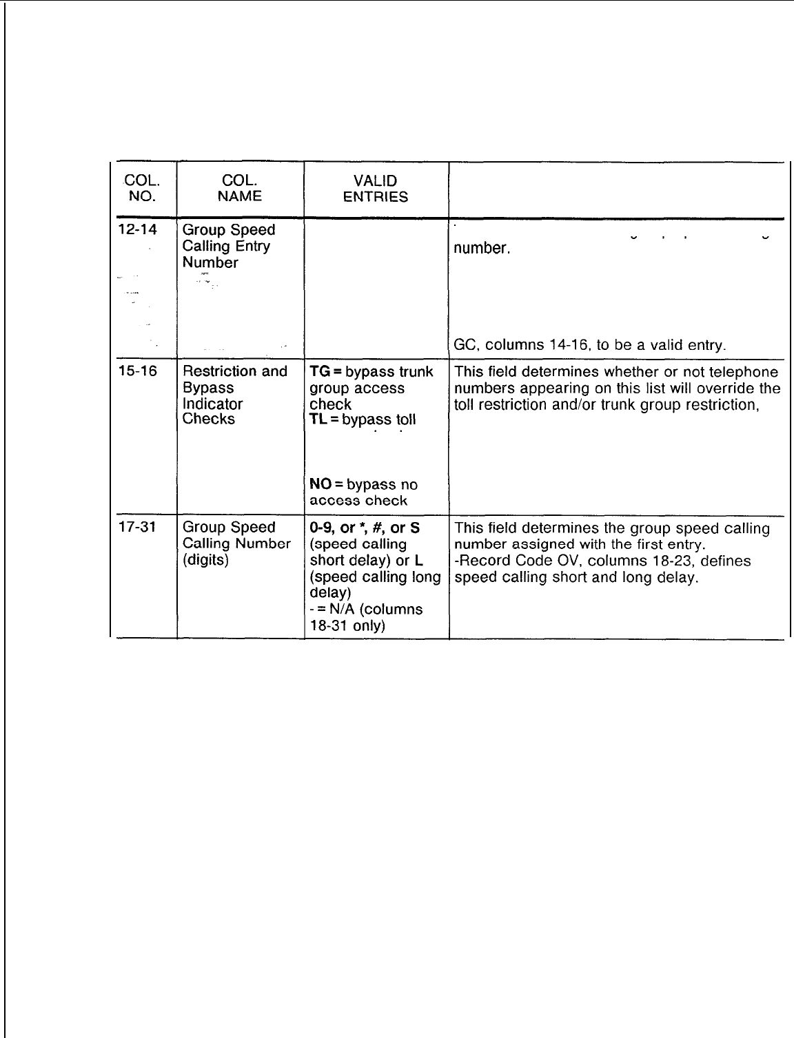
TL-130400-1001
Table 7.4 Entry Fields for Record Code GS
COMMENTS
000-999 = number This field determines the group speed calling
-These digits should be filled in from left to
right with no imbedded dashes.
-This number must be unique across this
record code.
-This number must be listed on Record Code
should these restrictions be in effect.
accesscheck
BT = bypass both
access checks
SVR 5210
8187
D-l 37
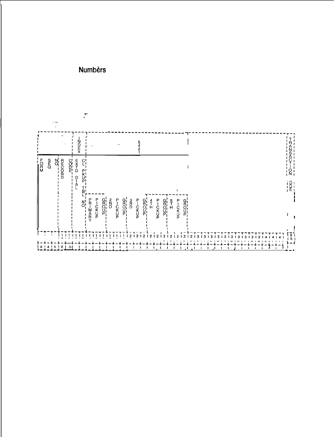
TL-130400-1001
Record Code ED:
Extended Dial Call
7.5 Record Code ED, Figure 7.5, assigns pickup groups to
Pickup
Numb&s
extended dial call pickup groups. The pickup groups that make
up the extended dial call pickup groups are set up on this record
code. Because the pickup groups are created on this record
code, they are not redefined on Record Code LD. If a user is a
member of an extended dial call pickup group, Record Code LD
only lists the extended dial call pickup group to which the user
belongs, not the dial call pickup group. The dial call pickup
s-
.”
numbers should be filled in from left to right.
;---------,---,------
----------------_---___ ~-----------------------------~-~
T
I
I
f
I
I
I
I
I
I
1
PICKUP
I
GROUP(S)
I
I
I
ICI
I
101
I
IDI
’
I
IEI
T-----T----- I
I
I
I
I
l
I I
I I
I I
I
I
I
I
I I
I I
r-T-T-~-T-t-T-t-T-T-t-T-T-t-~-~-t-~-r-+-r-~-t-r-r-~-~-~-~-~-~-~-~
I
I
;-:
~7~8~91011121314151617181910111213141516171819101112131415161718191011111
101
1111111111111111111112121212121212121212l3l3l3i3l3l3l3l3~3l~~~~~~~~
181
t,t;t;t;;--t-~-t-t-:-t-:-t-:-t-:-t-:-t-t-’-’-’-t-‘-~
k-4
L-A-A.-~_
I I II I I I I I I I I
I
I
II
I
~A-A-A-A-A_A_~-A
. . .
*
. . . 8
*
. .
*
. .
*
. . . . . .
~-~
Figure 7.5
Record Code ED: Extended Dial Call Pickup Numbers Data Sheet
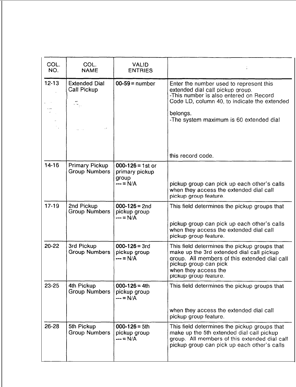
TL-130400-1001
Table 7.5 Entry Fields for Record Code ED
COMMENTS
Table Numbers
dial call pickup group to which that line
call pickup groups, each containing a
maximum of 5 pickup groups.
-There is no limitation to the number of
stations that make up a pickup group.
-The table number must be unique across
This field determines the pickup groups that
make up the primary extended dial call pickup
group. All members of this extended dial call
make up the 2nd extended dial call pickup
group.
All members of this extended dial call
up each other’s calls
extended dial call
make up the 4th extended dial call pickup
group. All members of this extended dial call
pickup group can pick up each other’s calls
when they access the extended dial call
pickup group feature.
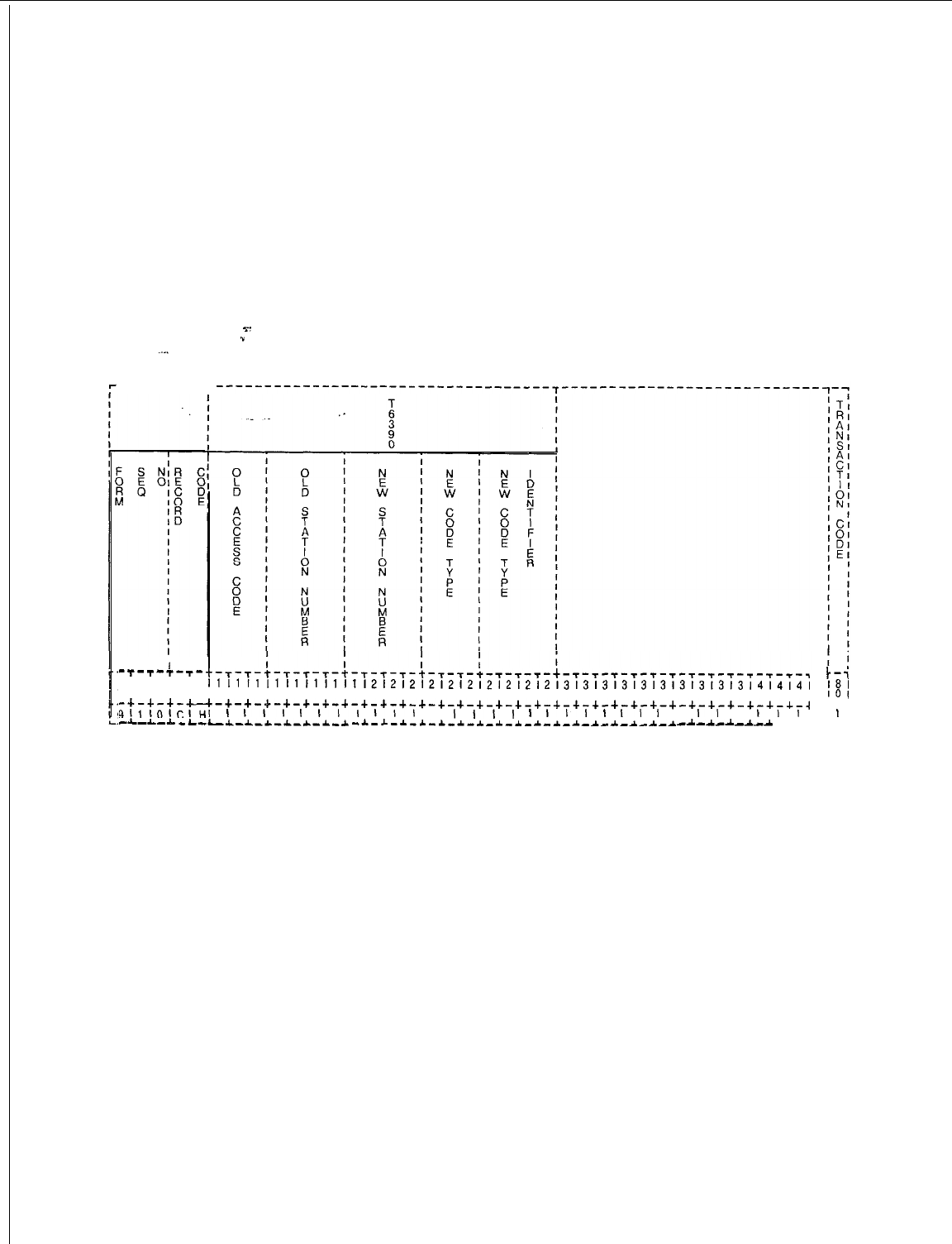
TL-130400-1001
Record Code CH:
7.6 Record Code Cl-l, Figure 7.6, determines the feature or
Change Feature
by Access Code
destination that will be temporarily changed by the use of an
access code. The line always diverts to the alternate destination
whenever that route is accessed. What the feature or destination
is temporarily changed to is also defined. The access code
used to indicate this feature is set up on Record Code AC under
code type numbers 50 (change/restore feature by access code)
and 51 (change/restore feature routing). This feature is limited to
one access code or one directory number per system.
Y.
.”
------r--r
I
-t-T-T-T-
i iii ii
r-r-T-t-t-T-T-t-T-T-s-+-T-t-T-T-t-T-T-T-t-T-T-~-~-~-~-~-~-~-~-~-~-,
t-'
718191011
11111111111111111212121212121212121213131313131313131313l4l4,4,
7
121314~516171819101112131415~617~819101112131415161718191011121
181
-+-+-+-c
~-+-+-+-+-+-+-+-+-+-+-+-+-+-+-+-+-+-+-+-+-+-+-+-+-+-+-+-+-+-+-~
101
C-4
gl,IoIcIHI
I
III
I
III
\,I
I
I,,,
1
III
I
II
I
I
II
I
I,,
I
I
-L-L-~-L---L-~-*--L-~-*-~ -*-~-~-~-~-~-*_~_~-~-~-~-*-~-~-*-*
-A-A.-A.-A-A
---
Figure 7.6 Record Code CH: Change Feature by Access Code Data Sheet
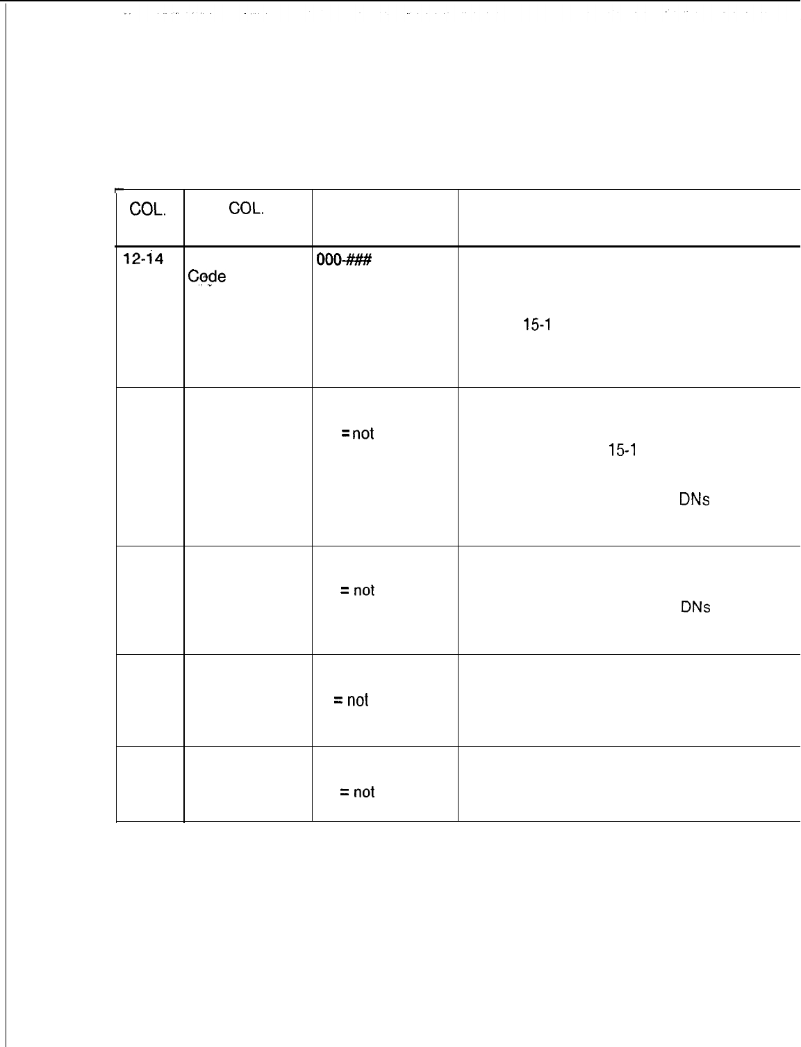
TL-130400-1001
Table 7.6 Entry Fields for Record Code CH
COL.
COL.
VALID
NO. NAME ENTRIES COMMENTS
12-i4
Old Access
OOO-###
= number Enter the access code that is to be
Code
temporarily changed.
-Columns 12-14 and 15-l 8 are mutually
exclusive. If you mark this field, do not mark
columns
15-l
8.
. .
-This feature can only be used for intercept,
Attendant Console(s), hunt group, or agent
group.
15-18
Old Station
0000-9999 =
This field defines the station number that is to
Number number be temporarily changed.
----
=
not
-Right justifiy three-digit numbers.
selected -Columns 12-l 4 and
15-l
8 are mutually
exclusive. If you mark this field, do not mark
columns 12-l 4.
-This number can only refer to
DNs
for lines,
Attendant Console(s), hunt groups, or agent
groups.
19-22
New Station
Number
0000-9999 =
number
---
=
not
selected
Enter the station number of the new
(temporary) destination.
-Right justify three digit numbers.
-This number can only refer to
DNs
for lines,
Attendant Console(s), hunt groups, or agent
group.
23-25 New Code Type
000-225 =
Enter the new code type to be temporarily
number
used.
--
=
not
-This number can only define an intercept
selected route, Attendant Console(s), recorder
announcer, or agent group.
26-29
New Code Type
0000-9999 =
Enter the new code type identifier to be
Identifier number temporarily used.
---
=
not
-Right justify three-digit numbers.
selected
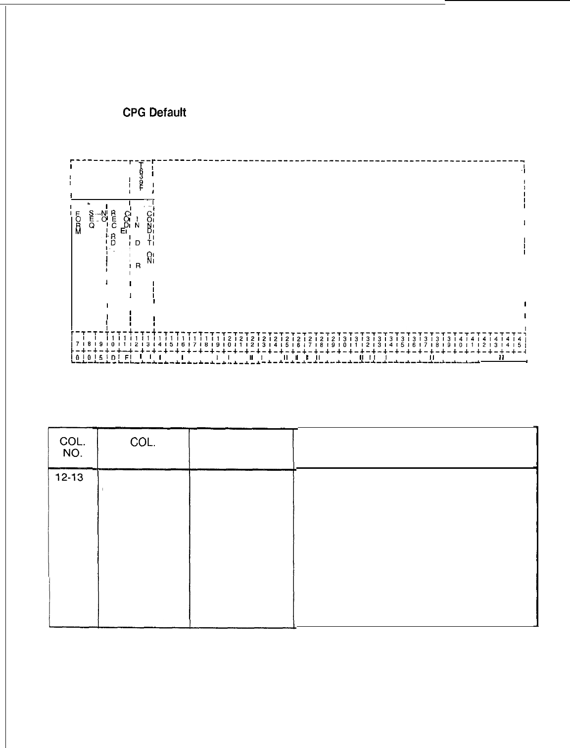
TL-130400-1001
Record Code DF: 7.7 Record Code DF, Figure 7.7, defines the default line divert
CPG
5efault
condition for lines assigned a divert destination on Record Code
LD,
columns 45-48.
Record Code DF: 7.7 Record Code DF, Figure 7.7, defines the default line divert
CPG
5efault
condition for lines assigned a divert destination on Record Code
LD, columns 45-48.
‘---------r---r
I
I
,
T
I
6
,---------------------------------------------------------------~
I
I
;
I
.I
iI
I
:
FI
I
5
I
I
I
I
I
I
I
I
I
I
_
II
_
I
’
/-.“I
’
/-.“I
I
I
1F
1F
I
I
C;
L
Ct
C;
L
Ct
II
S---N
R
S---N
R
II
::
5-q
81:
:;
II
II
M
‘0
EI
E
y;
II
1.3
ID
TI
II
II
II II
II
I..
I
I
I
I v
01
I E
NI
II
I
IR
I
II
I
IT ,II
I
III
II II
II
II
II II II
II II II II
II
II II II
II II II
II II II II
II II
I
I
I
I
I
I
I
I
I
I
I
I
I
I
I
I
I
I
I
I
r-T-r-C-T-t-r-t-r-~-T-T-T-T-T-T-T-T-T-T-~-~-~-~-~-~-~-~-~-~-~-~-~-~-~-~-~-~-~-~
r-T-r-C-T-+-r-t-r-~-T-T-T-T-T-T-T-T-T-T-~-~-~-~-~-~-~-~-~-~-~-~-~-~-~-~-~-~-~-~
~7~8~9~0~1~2131415161718~910111213l415l6l7l8l9l0l1~2~31415161718l910~112131415,~7~8~91011121314151617181910111213141516171819101112131415161718l9101112131415,
111111111111111111111212121212121212121213131313131313131313l4i4l4l4l4l4~111111111111111111111212121212121212121213131313131313131313l4i4l4l4l4l4~
t-+-+-+-u-+-~-+-+-+-+-+-+-+-+-+-+-+-+-+-+-~-+-+-~-+-+-+-+-+-+-+-+-+-+-+-+-+-~t-+-+-+-u-+-~-+-+-+-+-+-+-+-+-+-+-+-+-+-+-~-+-+-~-+-+-+-+-+-+-+-+-+-+-+-+-+-~
1010,51~!FI
I
I
I
I
I
I I
,I
I
,I
I
I,,,
I I I
,,I
I I I
I
I I I I I
I
I
1010'51D!FI
I
I
I
I
I
I I
I
I I
I
I I
I
I
I
I
I I I
I
I
I I I I
I
I I I I I
I
I
L-L-L-~-L-L-_~--L-L-~-L-~-~-~.-~-~-~L-L-L-~-L-L-_~--L-L-~-L-~-~-~.-~-~-~ -~-~-i-I-~-~-~-~-~-~-~-~-~-~-~-~---~--
. . .
8
-~-~-i-I-~-~-~-~-~-~-~-~-~-~-~-~---~--
. . .
8
I!
F
!I
‘---------r---r
I
I
,
T
,---------------------------------------------------------------~
i
I
6
I
I
;
I
.I
I
Figure 7.7
Record Code DF: CPG Default Data Sheet
Table 7.7
Entry Fields for Record Code DF
COL.
NO.
12-13
I
COL.
NAME
Line Divert
Condition
VALID
ENTRIES‘
BY = divert if busy
NA = divert if no
answer
BN = divert if
busy or no answer
COMMENTS
Mark this field with the system default divert
condition.
-This record code makes it unnecessary to
program a divert condition for each line
(Record Code LM, columns 28-29) if all
system stations have the same divert
condition.
If the majority of lines have the same divert
condition, then that condition can be given
here.
-Divert conditions that are different from the
default value given here can be assigned to
the various lines on Record Code LM.

TL-130400-1001
LINE
8.0 This section describes the record codes required to
ASSIGNMENT define the various system lines. The following record codes are
required:
l Record Code LD defines the primary directory number for all
lines in the system and provides additional line information.
l Record Code LM is an extension of Record Code LD.
-=-
.”
.
.
l Record Code LA defines the various line or DSS (Direct Station
Select) appearances.
l Record Code LI is not input by the customer
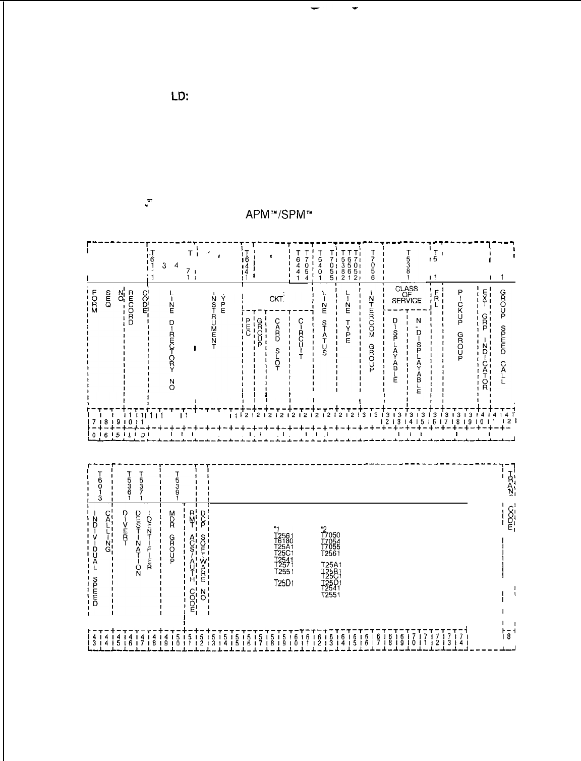
TL-130400-1007
Record Code
LB:
8.1 Record Code LD, Figure 8.1, defines the primary directory
Line Data
number for every line in the system. If an Analog/Digital
Featurephone has additional appearances of control lines such
as CO (Central Office), non-primary control, or data lines, an
entry on this record code is needed for each line type. Use this
record code to route non-working lines to a changed number
intercept. Line circuits programmed on the Attendant Console
(Record Code AT) or office features circuit (Record Code OC) do
not require an entry on Record Code LD. If the sytstem is
s-
1
equipped with the PD-200 Data Option, this record code must
list the
APM’“/SPM”
physical location.
T---------T----- --r---__--_- T-----T---T--- _---_--___--------_------------
I
;T
T T
T:
‘.
*
’
i .
I
I
,6
6 6
61
IT,
a
I
,4
4 4
4,
1
14
’
I4
;
2
I
I’
3 4
I
,I
1 1
:I
I1
,
I
1
I
I
I
TI
T
!
T
;
I5
I
5
I
5
i3 I
4
I
4
16
I
1I
3
II
I 1
I1
I T I
I
LINE
I
CKI-.
I
/
1 1
I
I
I
-,-t-,-;-,-$-$-,-,-t-t-~-~
I1
I1
I1
I1
11
11
II 11 11
I1
1212121212121212121213131313131313131313l4l4l4l
:7;8;9,0,1
12131415161718191011 12131415161718191011
1213l415161718191011
121
~-+-+-u-+-+-+-+-~-~-~-+-+-+-~-+-+-+-+-+-+-+-+-+-+-+-+-+-+-+-+-+-+-+-+-
!,-l~.55iLlDl
I
I
I
I
I I I I
I
I
I
I
I
I
I
1 I I I I I
II
I
I I
I
I I
l
i
L
--L--C-L-L-L-*-~-~-~-*-~-~-~-*-~_~-~-*-~-~--L-~-~-*-~-~-~-~-~-~---J
r---r-------p-----r-r----------------------------------------------------~-~
;
T;
I
RI
I
A,
I
N,
I Sl
,
I
II
Gf
I
1
0,
x561
*z
I
1
DI
II
E,
T22
i%%
II I
’
I
w:
ZE
I
I
1 I
I
1 I
T257 1
m
E%
I
1 I
1 I
I
T2581
ES1
II
I
I
1 I
T25Dl
I I
T%z
II
II
I
I
I
1 I
I I
I1 I
II
I1 I I
I
I I
II I
1 I I
I
k-T-t-T-T-T-t-T-t-t-t-T-T--r-T-T-T--r-
T-T-T-T-T-T-T-T-T-T-T-T-r-T-i
L-4
1414141414141415151515151515151515161616,6i6l61616l6l6l7l7l7l7i7l
I8
I
1314151617,819,0,112,3,415,6,718191011121314151617181910111213141
IO I
L-L-L-L-L-L-L-I-L-I-~_~-~-~-~-~-~-~-~-~-~-~-~-~-~-~-~-~-~-~-~-~-~-----~-J
Figure 8.1
Record Code LB: Line Data Sheet
D-l 44
SVR 5210
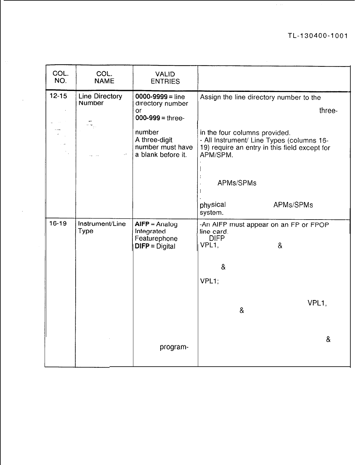
Table 8.1 Entry Fields for Record Code LD
COMMENTS
equipped line circuits in the system.
-Directory numbers can be chosen in
three-
and/or four-digit patterns.
digit line directory -Three-digit numbers must be right justified
-Dashes must be entered in this field if the
line is used for an APM or SPM that is used in
support of the PD-200 Data Option.
-The
APMs/SPMs
are not accessed by a line
number, but by an X.121 address.
-This record code is only used to provide the
sical
location of the
APMsSPMs
within the
-A
DIFP
must appear on a VCIP, VPLO,
VPLl,
VP20 (voice/voice
&
data), or DVC line
integrated
Featurephone
APM =
Asynchronous
Packet Manager
card.
-An APM must appear on a VPLO, VP20
(voice
&
data or data only), or VP21 line card.
-If necessary, an APM can be assigned to a
VPLl;
however, it is recommended to use the
SPM =
Synchronous VPLO card, which is designed to support the
low-speed APM.
Packet Manager -An SPM must appear on a VPLO,
VPLl,
DFPA = Digital
VP20 (voice
&
data or data only), or VP21 line
Integrated card.
Featurephone with -APM and SPM should be left justified in the
Asynchronous four columns; e.g., APM- and SPM-.
Packet Manager -A DFPA must appear on a VP20 (voice
&
PACT =
program-
data) line card.
mable Attendant -A PACT or POTS must appear on a POTS
Console or OFFP line card.
SVR 5210
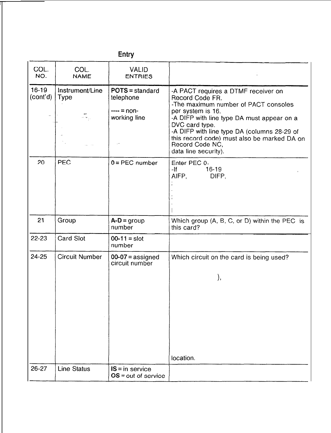
TL-130400-1001
Table 8.1 Entry Fields for Record Code LD (Continued)
COMMENTS
instrument line
columns 28-29 (this allows
-If
columns
;6-19
are marked
POTS,
PACT,
AlFP,
DFPA,
DIFP,
APM, or SPM, columns
20-25 must not be dashed.
-If columns 16-l 9 are dashed, columns
20-25 must be dashed.
-All card locations must be defined on
Record Code FR.
Which card slot within the group is this card?
-In
order to provided
a
sequential
appearance of line numbers on the CPG (in
groups of eight
),
list all eight circuits of a line
card for each group and card slot in the
following order: 4, 0, 5, 1, 6, 2, 7, 3.
-The reason for this order is that this is the
order in which the circuits are connected on
the backplane of the system.
-The circuit numbers assigned to a digital
IFP used for (CD-100 data) voice transfer
can only be circuits O-3. Circuits 4-7 are
assigned to data connections.
-This number must match the limits given to
the card type at the specified physical
Is the line in service or out of service?
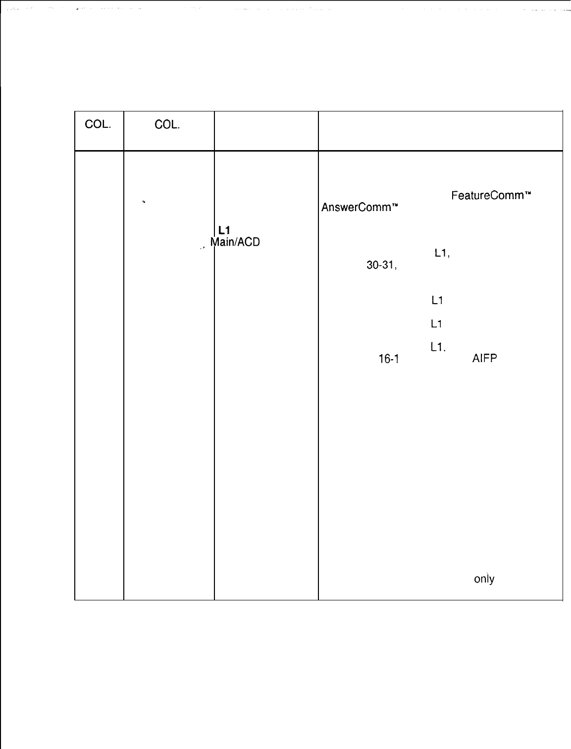
TL-130400-1001
Table 8.1 Entry Fields for Record Code LD (Continued)
COL.
COL.
VALID
NO. NAME ENTRIES COMMENTS
28-29
. . . .
Line Type
--
1
CO = central office NP is used for a logical line, which appears in
line, as in key software only and needs no line card.
system CO line -- (a double dash) is used for all tip and ring
(Featurephone) type telephones (e.g., the
FeatureComm”
and
DA
= data line
AnswerComm”
1 and 2).
(DIFP)
When defining line 2 on a PACET
Li
= CAS (Programmable Attendant/Agent Console
,_
Main/ACD
agent Electronic Telephone), mark this field --.
line -If this field is marked
Ll,
Record Code NC,
NP
= non-primary
columns
30-31,
must be marked HS (this
control line allows hookswitch flash in COS).
(Featurephone) -If columns 16-l 9 are marked POTS, this
NW
= nonworking
field must be marked
Ll
or dashed.
line -If columns 16-l 9 are marked POTS, this
PC
= primary
field must be marked
Ll
or dashed.
control line -If columns 16-19 are marked PACT, this
-- = none of the field must be marked
Ll.
above, e.g., POTS -If columns
16-l
9 are marked
AIFP
or
telephone DFPA, this field must be marked CO, NP, or
PC.
-If columns 16-19 are marked DIFP, this
field must be marked CO, DA, NP, or PC.
-If columns 16-19 are marked APM or SPM,
this field must be marked DA.
-If columns 16-l 9 are dashed, this field
must be marked NW.
-The physical location fields for a line
marked NP must match that of the controlling
IFP.
-If an entry of NP or CO is made, there must
be available space in the system tables to
assign a line software ID. A maximum of 256
lines of all kinds is allowed.
-If this field is marked NP, station silent
monitor (Record Code NC, columns 72-73)
will not work.
-Each IFP must have one and
only
one
primary control line.
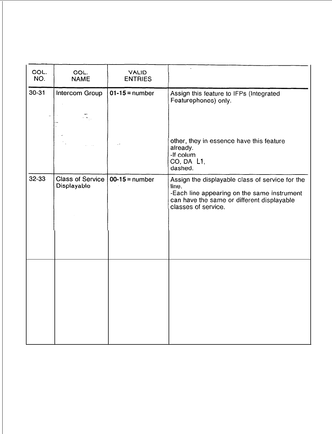
TL-130400-1001
Table 8.1 Entry Fields for Record Code
LD (Continued)
COMMENTS
-If this line is to belong to an intercom group,
this field determines which group it belongs to.
-Each line appearing on the same IFP can
be in the same or different intercom groups.
-If two lines have a DSS appearance of each
ns 28-29 (line type) are marked
,
Ll,
-- or NW, this field must be
-The number entered here must be defined
on Record Codes DC and DD.
-If columns 16-19 are marked POTS, PACT,
AIFP, DFPA, or DIFP, these columns must not
be dashed.
-If columns 16-l 9 are marked APM, SPM,
or dashed, these columns must be dashed.
34-35
Class of Service
00-l
5 = number
Assign the n-displayable class of service for
N-Displayable the line.
-Each line appearing on the same instrument
can have the same or different n-displayable
classes of service.
-The number entered here must be defined
on Record Code NC.
-If columns 16-19 are marked POTS, PACT,
AIFP, DFPA, or DIFP, these columns must not
be dashed.
-If columns 16-l 9 are marked APM, SPM,
or dashed, these columns must be dashed.
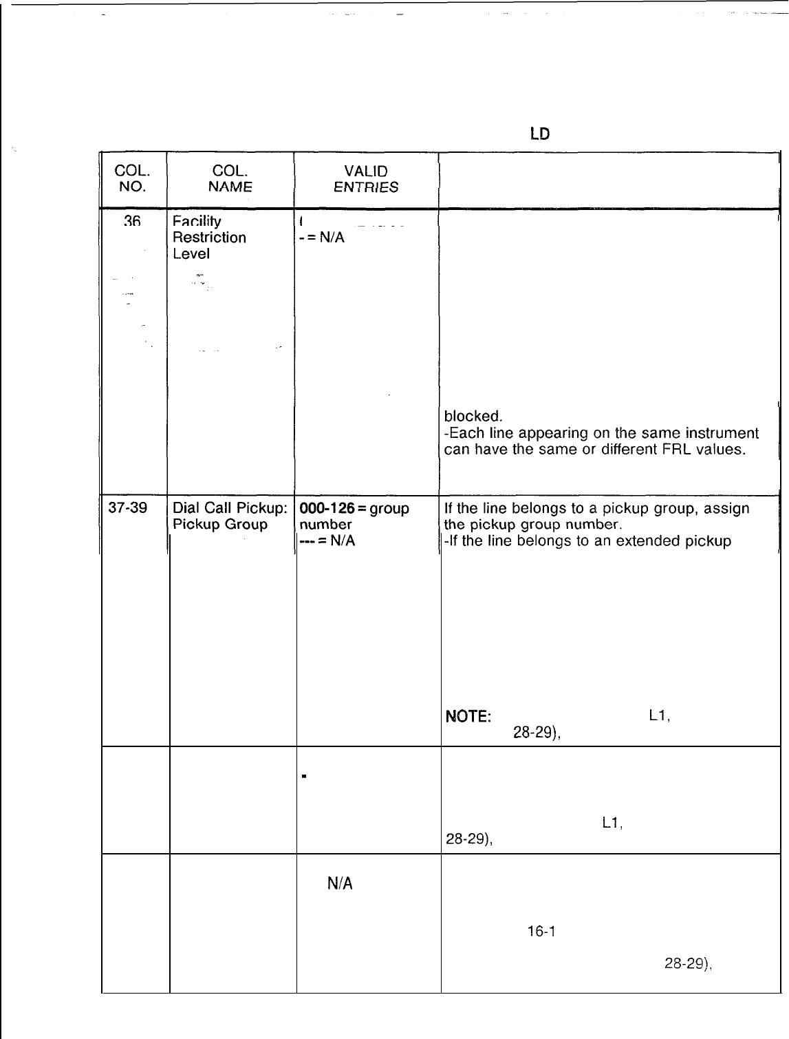
TL-130400-1001
Table 8.1 Entry Fields for Record Code
bD
(Continued)
COMMENTS
O-7
=
FRL
value Assign the FRL value given to this line.
-This can only be assigned if the FRL feature
is in effect (see Record Code OF, column 54).
-A value of 0 is the most restrictive; a value
of 7 is the least restrictive.
-This value is compared to the FRL value of
the trunk that the user is trying to access.
-If the FRL value of the user is the same as
or greater than the FRL value given to the
trunk, the call can be made.
-If the FRL value of the user is less than the
FRL value given to the trunk, the call will be
-If columns 16-19 are marked APM, SPM,
or dashed, these columns must be dashed.
group, this field is the primary group.
-The pickup group to which a member of an
extended pickup group belongs is defined on
Record Code ED.
-The Attendant Console cannot be in a
pickup group. The system maximum is 127
pickup groups, with no limit to the number of
members in each group.
-If a station line appears on the DSS, having
this feature is redundant.
MITE:
If the line type is DA,
Ll,
or NW
(columns
28-29),
this field must be dashed.
40
Dial Call Pickup: E = extended group If the line belongs to an extended pickup
Extended
-
= dial call group, enter an E.
Pickup Group pickup group -Record Code ED must be completed before
this entry can be made.
-If the line type is DA,
Ll,
or NW (columns
28-29),
this field must be dashed.
41-42
Group Speed
01-48 = number This field determines the speed calling group
Calling
-- =
N/A
number assigned to this station.
-Record Code GC must be completed before
this entry can be made.
-If columns
16-l
9 are marked APM, SPM,
or dashed, these columns must be dashed.
-If the line type is DA (columns
28-29),
this
field must be dashed.
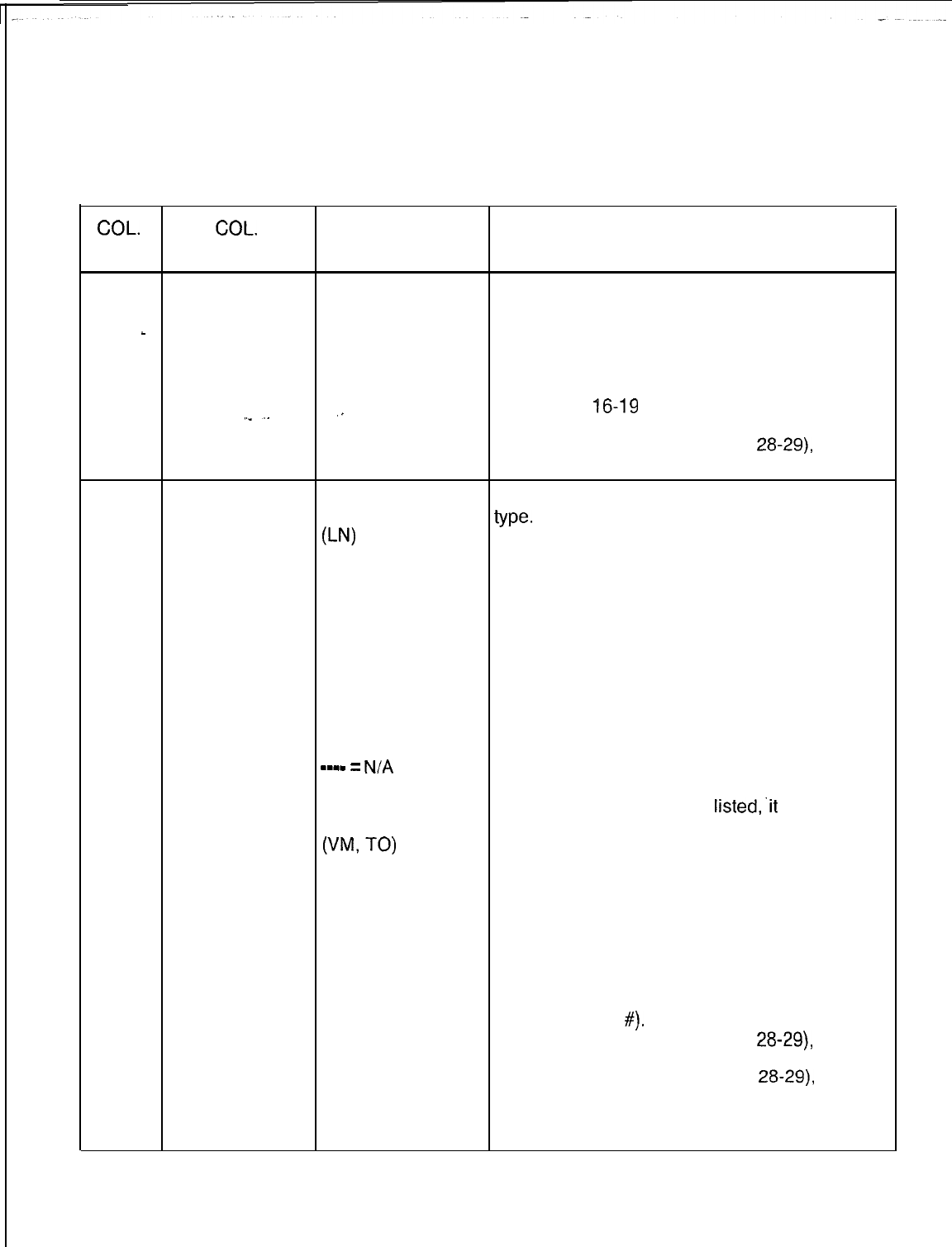
TL-130400-1001
COL.
NO.
Table 8.1 Entry Fields for Record Code LD (Continued)
COL.
VALID
NAME ENTRIES COMMENTS
43-44 Individual 00-30 = number
Speed Calling If the line is a member of an individual speed
-- = N/A calling list, assign the list it belongs to.
_
List Number
.
-Only one station can be assigned to each
individual speed calling list.
-A system maximum of 31 stations can have
this feature.
,.
-If columns
16-19
are marked APM, SPM,
or dashed, these columns must be dashed.
-If the line type is DA (columns
28-29),
this
field must be dashed.
45-48 Divert
0000-9999 =
Assign the divert destination (call forwarding)
Destination station number
type.
Identifier
0-N)
-It can be a line, pilot number, trunk group,
or
intercept route, VMX mailbox, or external
pilot number (PN) directory number.
of a hunt group -If the entry is SC, then the speed calling list
(right justify must not contain dashes because the remote
three-digit call forward feature is accessed through an
numbers) entry in the individual speed call list that stores
0000, 0064, 0128, the remote number.
or 0192 = console -A line cannot divert to itself.
number (AT) -If a station number is listed, it must be
0000-0063 =defined in columns 12-15 of this record code.
trunk number -If a pilot number of a hunt group is listed, it
m-w-
=
N/A
must be defined on Record Code HG,
directory number columns 12-l 5.
and individual -If an attendant number is
listed,.it
must be
speed call list defined on Record Code AT.
(VW
TO)
-If a trunk number is listed, it must be defined
0001-0008 =on Record Code TC.
speed call list -The additional information needed to
entry number (SC) implement this feature is found on Record
Code LM, columns 28-31.
-If columns 16-19 are marked APM or SPM,
these columns must be dashed.
-If columns 16-l 9 are dashed, these
columns must be either 0003 (vacant #) or
0011 (changed
~7).
-If the line type is DA (columns
28-29),
this
field must be dashed.
-If the line type is CO (columns
28-29),
this
field must be marked with a trunk number and
Record Code LM, columns 28-29, must be
marked DA.
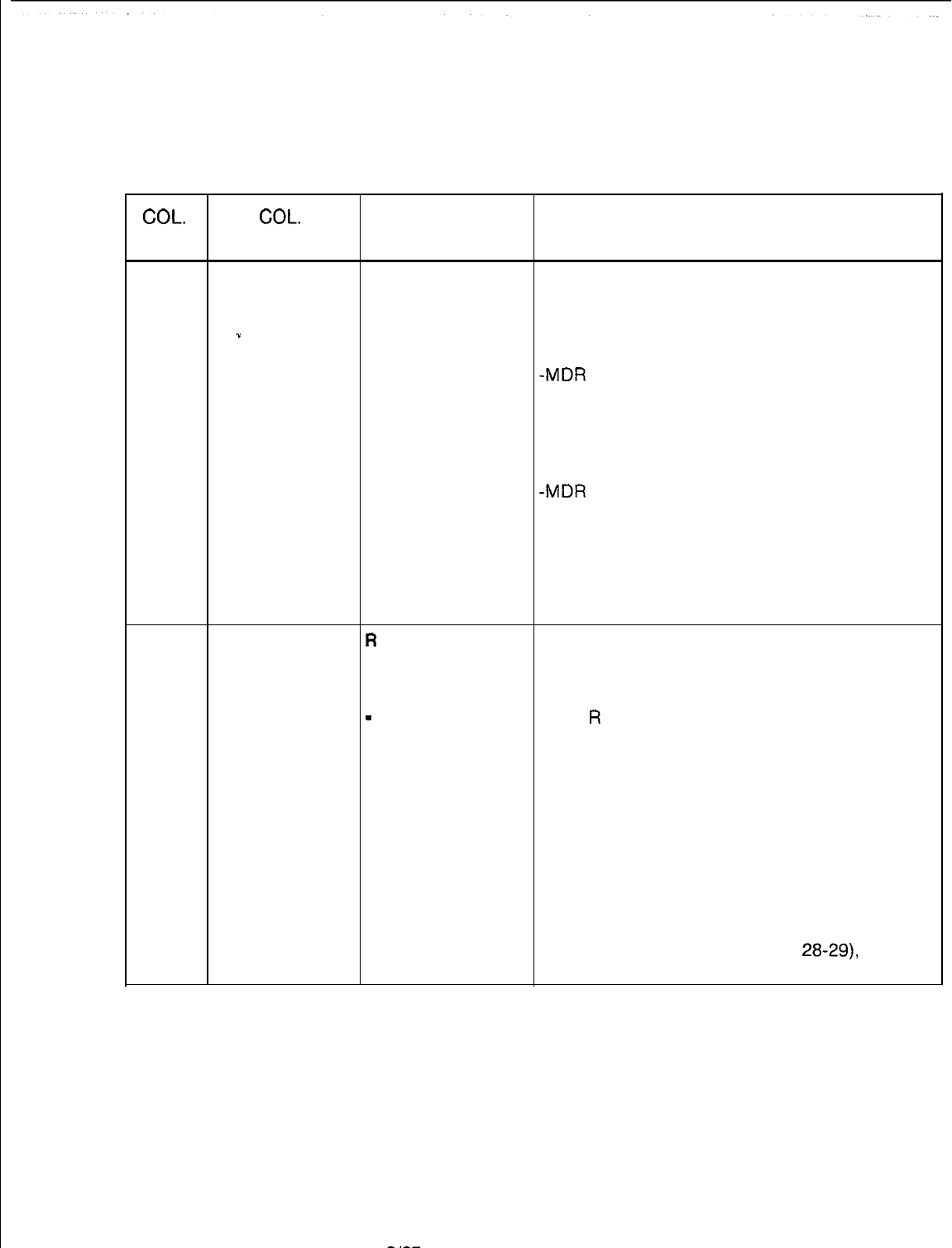
TL-130400-1001
COL.
NO.
Table 8.1 Entry Fields for Record Code LD (Continued)
COL.
VALID
NAME ENTRIES COMMENTS
49-50
Message Detail
00-63 = group
Assign the MDR work group number to the
Recorder Work number station.
Group Numbers -- = N/A -The stations are divided into groups
.”
default = 00
according to the information output required
. . . .
for each group.
.
-MDR
work groups are normally arranged in
groups of like users for billing purposes (e.g.,
all accounting department telephones can be
in the same group).
-The MDR print-out gives the PDN (Prime
Directory Number) of the station.
-MDR
group 00 is used as the default value
and should not be assigned to stations.
-If columns 16-19 are marked POTS, PACT,
AIFP, DFPA, or DIFP, these columns must not
be dashed.
-If columns 16-19 are marked APM, SPM,
or dashed, these columns must be dashed.
51
Remote Access
R
= remote access This field determines whether or not the
and A = authorization remote access (or remote access requiring
Authorization code required with an authorization code) feature can be used
Code remote access from this line.
-
= N/A -If an
R
is entered in this field, then the line
can be used for remote access.
-If this field is marked with an A, the line can
be used for remote access. However, an
authorization code is required.
-By giving either of these features to a line,
the COS normally assigned to this line can be
temporarily overridden (e.g., a roving manager
could make a toll call from a toll restricted
line).
-If columns 16-l 9 are dashed, this column
must also be dashed.
-If the line type is DA (columns
28-29)
this
field must be dashed.
SVR 5210
8187
D-l 51
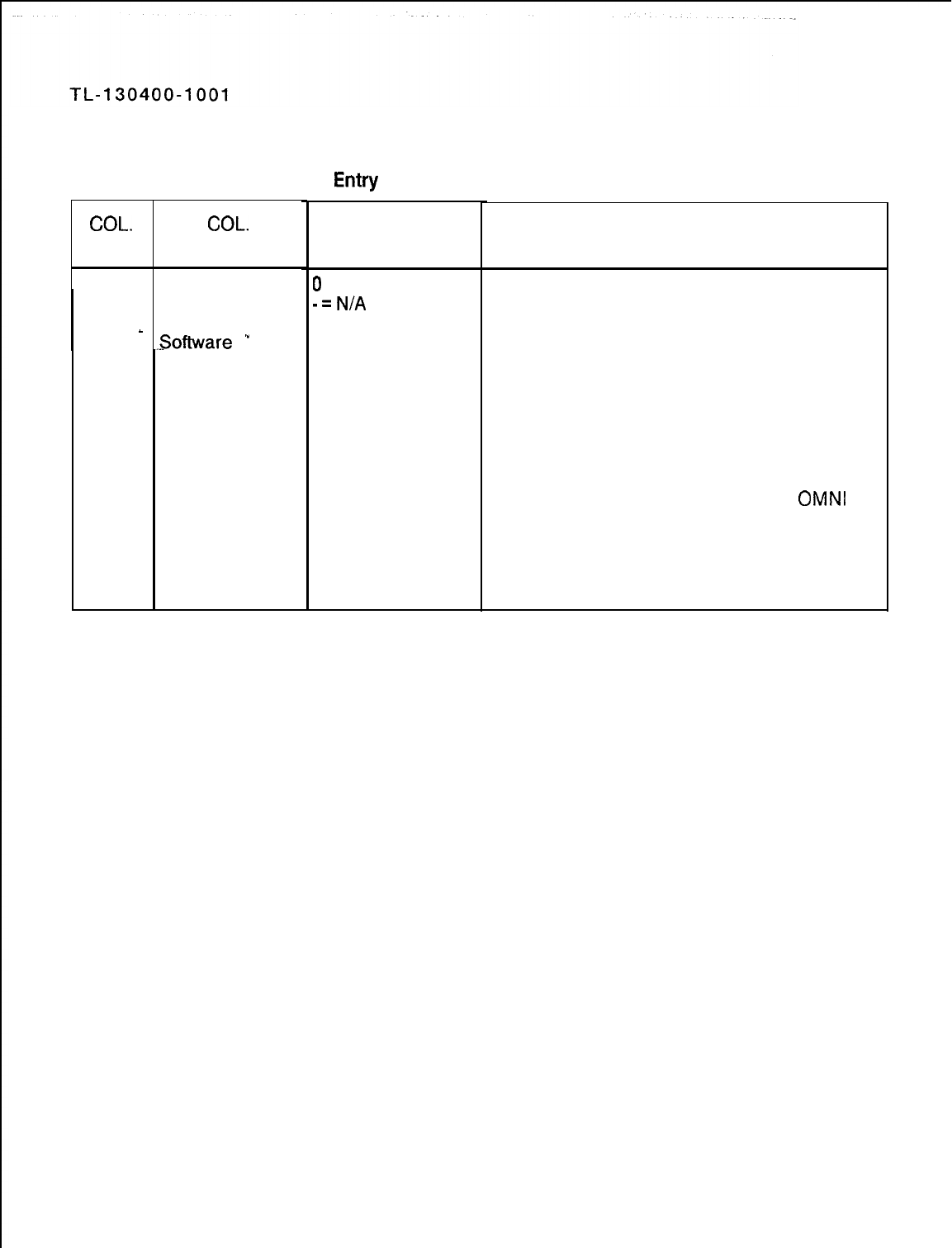
Table 8.1
Entry
Fields for Record Code LD (Continued)
COL.
COL.
NO. NAME
52
Controlling Data
Control
_
Processor
.-Software
‘”
VALID
ENTRIES
0
= number
-=N/A
COMMENTS
This field determines the controlling DCP
(Data Control Processor) software number
assigned to this Digital Featurephone.
-The DCP is otherwise known as the UCB
(Universal Control Board)
-This field only applies to a Digital
Featurephone used with the PD-200 Data
Option.
-If the PD-200 Data Option is in use, enter
0.
-Because one UCB can support up to 240
data ports, only one is needed in the
OMNI
SI.
-The UCB must be defined on Record Code
FR.
-This field is new to SVR 5210.
NOTE: UCB is the card; DCP is the software
on the card.
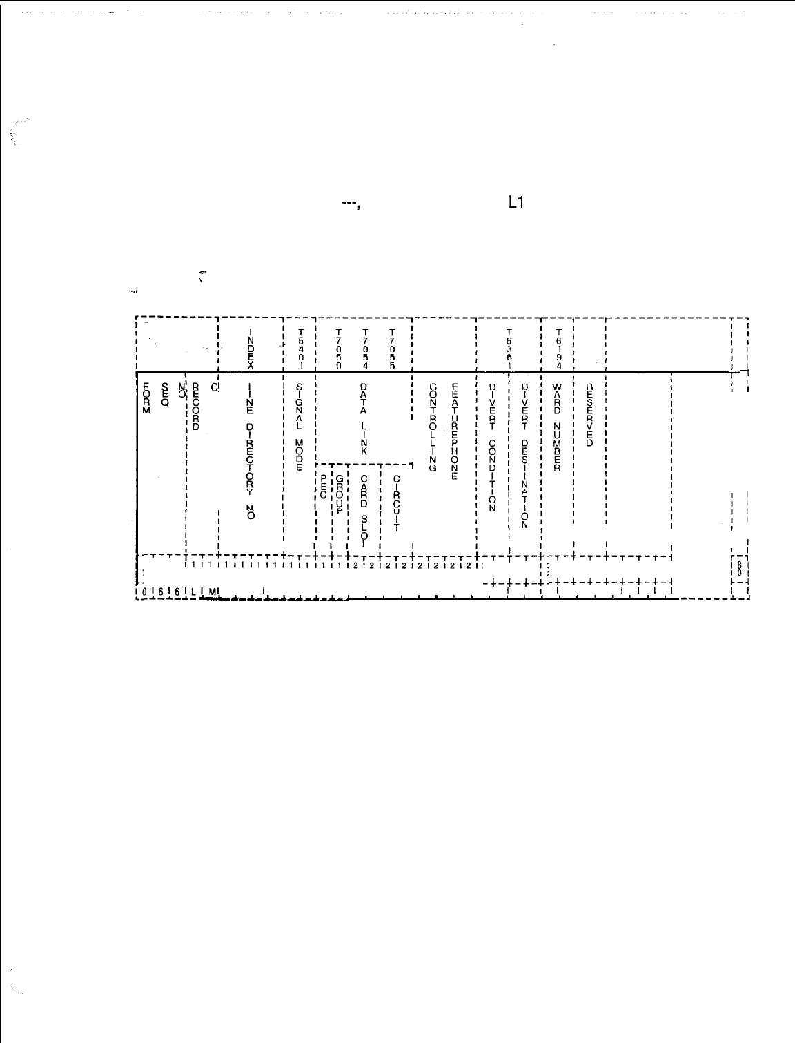
TL-130400-1001
Record Code LM:
Line Miscellaneous
%-
.”
-..
8.2 Record Code LM, Figure 8.2, is an extension of Record
Code LD and provides additional data for lines. Any directory
number that appears on this record code must appear on
Record Code LD as well. Instrument types APM, SPM, PACET,
or
---,
as well as line types
Ll
and NW, never have an LM
entry. LM is required for Analog Featurephones (instrument type
AIFP). LM is used whenever the signal mode is something other
than MX. It is also used if a field on LM is needed to complete
the description of a line.
III
-I
I
I
I
I
I
I
I
I
I
I
I
II
I
I
I
I
I
I
I
I
I
I
I
I
I
I
I
I
I
I
‘1
I
I
I
I
I
I
I
-T-T-f-T-t-T-T-T-t -T-t-t-t-T-t-T-+-T-T-T-t~
I I
-,--;-T-
I1I1I1I1I1I111I1111112121212121212121:
2121313
718191011121314151617181910111213141516171~ 8191011
-+-+-+-u-+-+-+-+-+-+-+-+-+--c-+-+-+-+-+-+.
-+-+-+-
31I31lj1LI~I
I I
I
I I I I I I I I I I I I I I
I
I
I I I
I
I I I
I
I I
-,-;-,-l-,-,-,-4
I
1
r-:
1131313131313131
181
1131415161718191
101
-+-+-+-+-+-+-+-A
c-4
I
I I I
I
I
I
I I
I
m--e--- _LA_A_A_A_A_A_A_*
.
*
.
.
.
.
.
*
*
*
.
*
*
.
,
.
.
.
------a.-~
Figure 8.2 Record Code LM: Line Miscellaneous Data Sheet
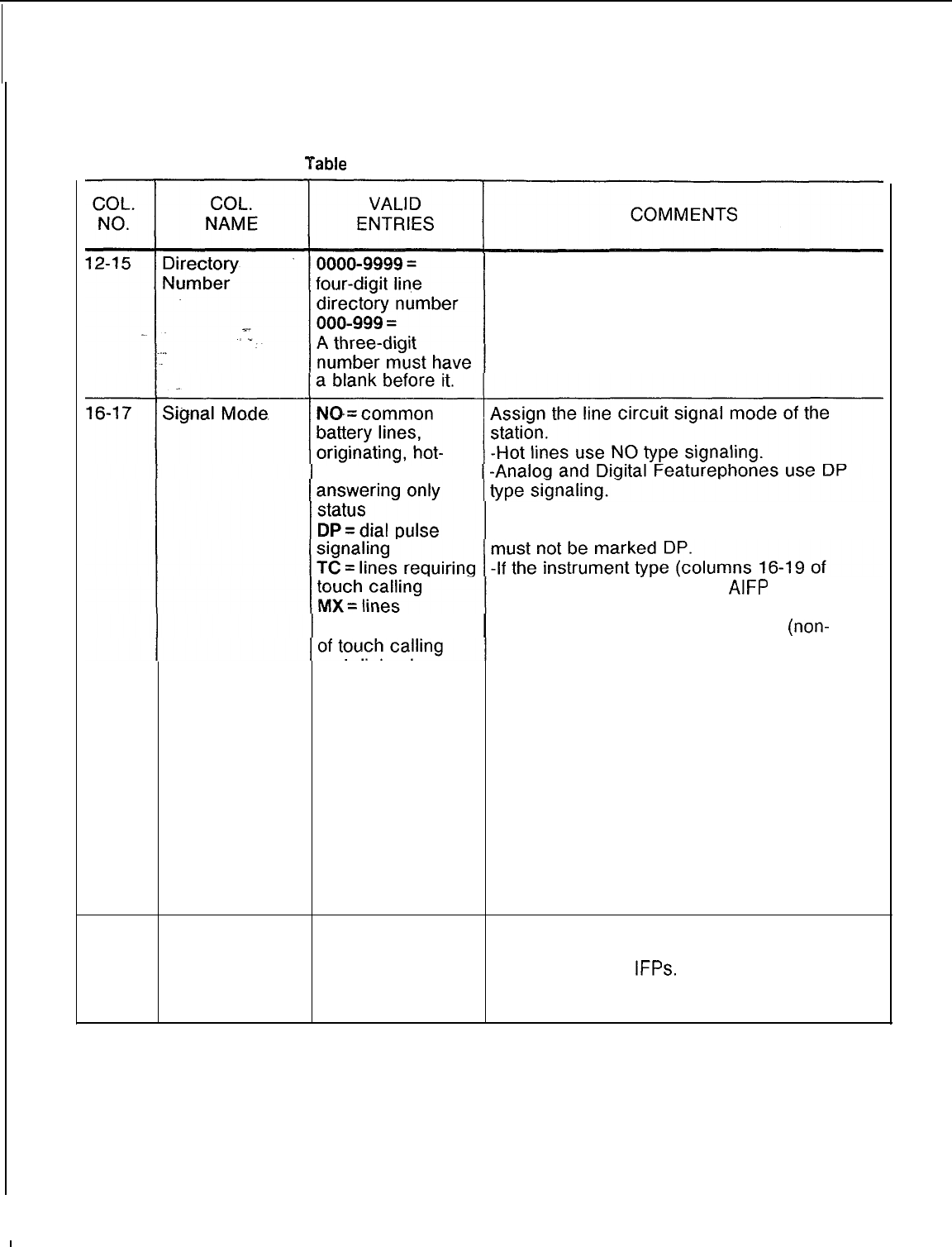
TL-130400-1001
Yable
8.2 Entry Fields for Record Code LM
Assign the line directory number to the
equipped line circuits in the system.
-Three-digit numbers must be right justified.
line service,
or
-If the instrument type (columns
16-19 of
Record Code LD) is marked POTS, this field
Record Code LD) is marked
AIFP
or DFPA,
this field must be marked DP.
requiring a mixture -If this field is marked NO, the SCC
(non-
MERS) access allowed in COS (Record Code
and dial pulse; or NC, columns 66-67) will not work.
MX can be used in -If this field is marked NO, the following COS
place of DP and features defined by Record Code DD will not
TC (MX is used for work: toll access, meet-me conference,
POTS,
progressive conference, dictation, paging,
Featurephones, maintenance access, modem access, MERS
and default.)
on-net.
-If this field is marked NO, the following COS
features defined by Record Code NC will not
work: executive override, originating call
waiting, camp-on/auto recall, attendant
information, dial call pickup, call forwarding
variable, speed call, universal night answer.
18
Data Link Card 0 = PEC number -Enter PEC 0.
Location: PEC This is the PEC entry for the FB-17225 card
that supports the
IFPs.
-Data link cards are defined for Agent
Instruments on Record Code AD.
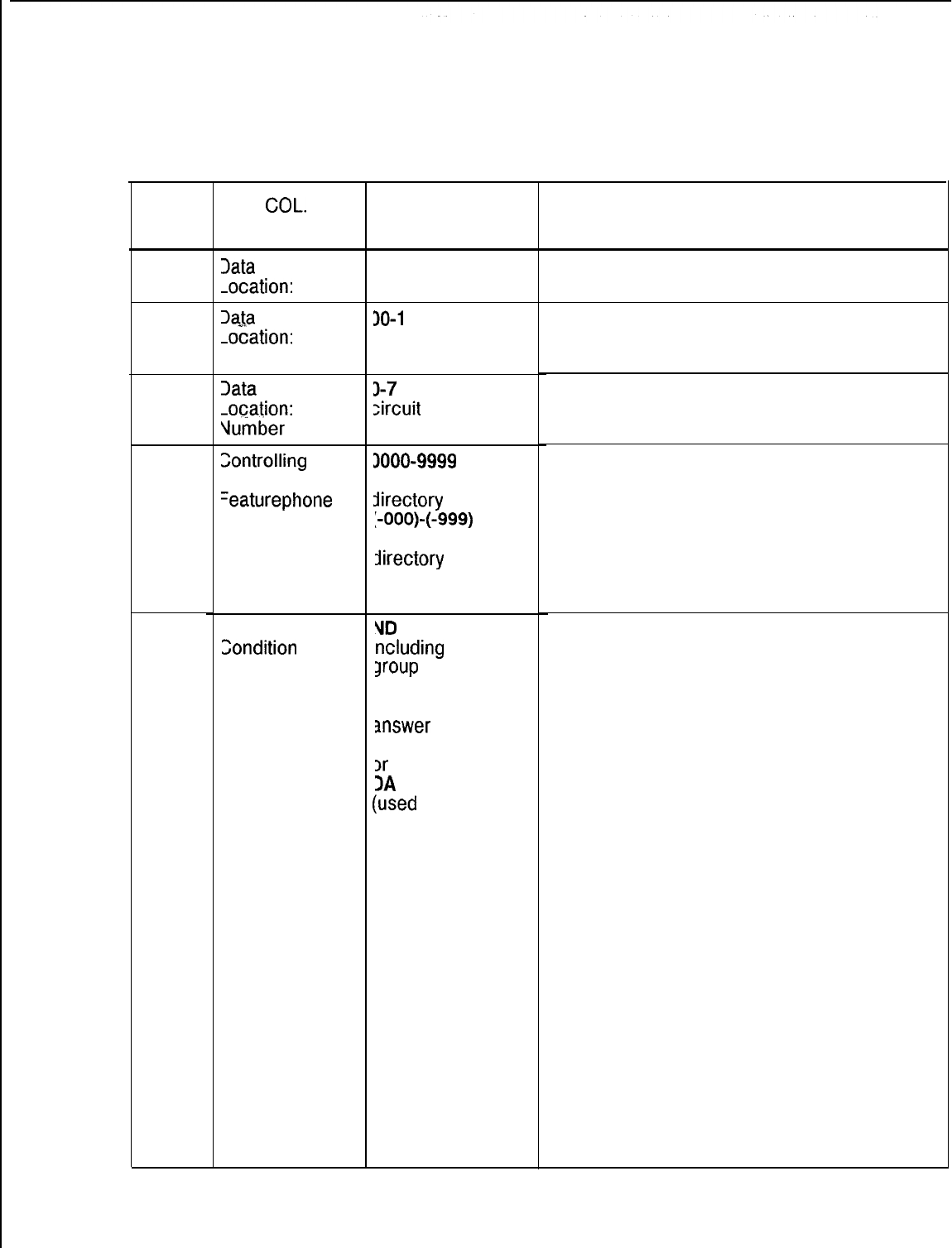
COL.
NO.
19
20-21
22-23
24-27
28-29
TL-130400-1001
Table 8.2 Entry Fields for Record Code LM (Continued)
COL.
NAME
Data
Link Card
-ocation:
Group
Xtta
Link Card
-ocation:
Card
Slot
Data
Link Card
-0cation:
Circuit
Vumber
Zontrolling
ntegrated
=eaturephone
Call Divert
Condition
VALID
ENTRIES
4-D = group
lumber
30-l
1 = slot
lumber
J-7
= assigned
circuit
number
1000-9999 =
‘our-digit line
directory
number
:-OOO)-(-999) =
:hree-digit line
Directory
number
VD
= no divert,
ncluding
hunt
Jroup
members
3Y = divert if busy
VA = divert if no
answer
3N = divert if busy
)r
no answer
DA
= divert always
(used
for CO lines
and hot lines)
COMMENTS
Which group (A, B, C, or D) within the PEC is
this card?
Which card slot within the group is this card?
Which circuit on the card is being used?
This field determines the primary line directory
number for non-prime and CO lines.
-If the instrument type (columns 16-19 of
Record Code LD) is marked POTS, this field
must be dashed.
-When defining the PDN (Prime Directory
Number), this number will be the same as the
directory number.
Columns 28-31 are used to define divert
conditions. Assign the conditions under which
a call will divert. Columns 30-31 define what
type of destination the call diverts to. The
destination itself is defined on Record Code
LD, columns 45-48.
-The call divert fields are used to implement
the following features: fixed call forwarding, hot
line switched direct line service, diversion of
one hunt group to another (via last member).
-Use Record Code MH to program hunt
group member searches and LD to specify the
divert destination identification for call diverts.
-The divert always condition will allow a call
to be forwarded twice only. The third attempt
rings busy.
-Columns 28-29 define the conditions that
cause a call to forward from the called station
to another location.
-If this value is set at ND, the allowable value
of columns 30-31 is --, TO, LN, AT, TR, or
PN.
-If this value is set at BT, NA, BN, or DA, the
allowable value of columns 30-31 is TO, LN,
AT, TR, or PN.
-If Record Code NC, columns 38-39, is
marked OR (for COS originating only), this
field should be marked ND.
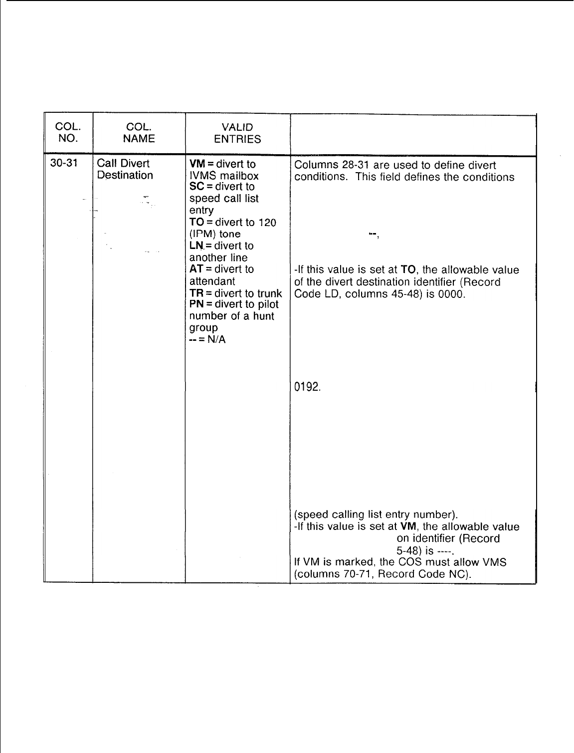
r
TL-130400-1001
Table 8.2
Entry Fields for Record Code LM (Continued)
COMMENTS
under which a call will divert. Columns 30-31
define the type of destination to which the call
diverts. The destination itself is defined on
Record Code LD, columns 45-48.
-If this value is
--,
the allowable value of
the divert destination identifier (Record Code
LD, columns 45-48) is ---- .
-If this value
is
set at
LN,
the
allowable value
of the divert destination identifier (Record
Code LD, columns 45-48) is 0000-9999
(station number).
-If this value is set at AT, the allowable value
of the divert destination identifier (Record
Code LD, columns 45-48) is 0064, 0128, or
-If this value is set at TR, the allowable value
of the divert destination identifier (Record
Code LD, columns 45-48) is 0000-0063.
-If this value is set at PN, the allowable value
of the divert destination identifier (Record
Code LD, columns 45-48) is 0000-9999
(hunt group pilot number).
-If this value is set at SC, the allowable value
.of the divert destination identifier (Record
Code LD, columns 45-48) is 0001-0008
of the divert destinati
Code LD, columns 4
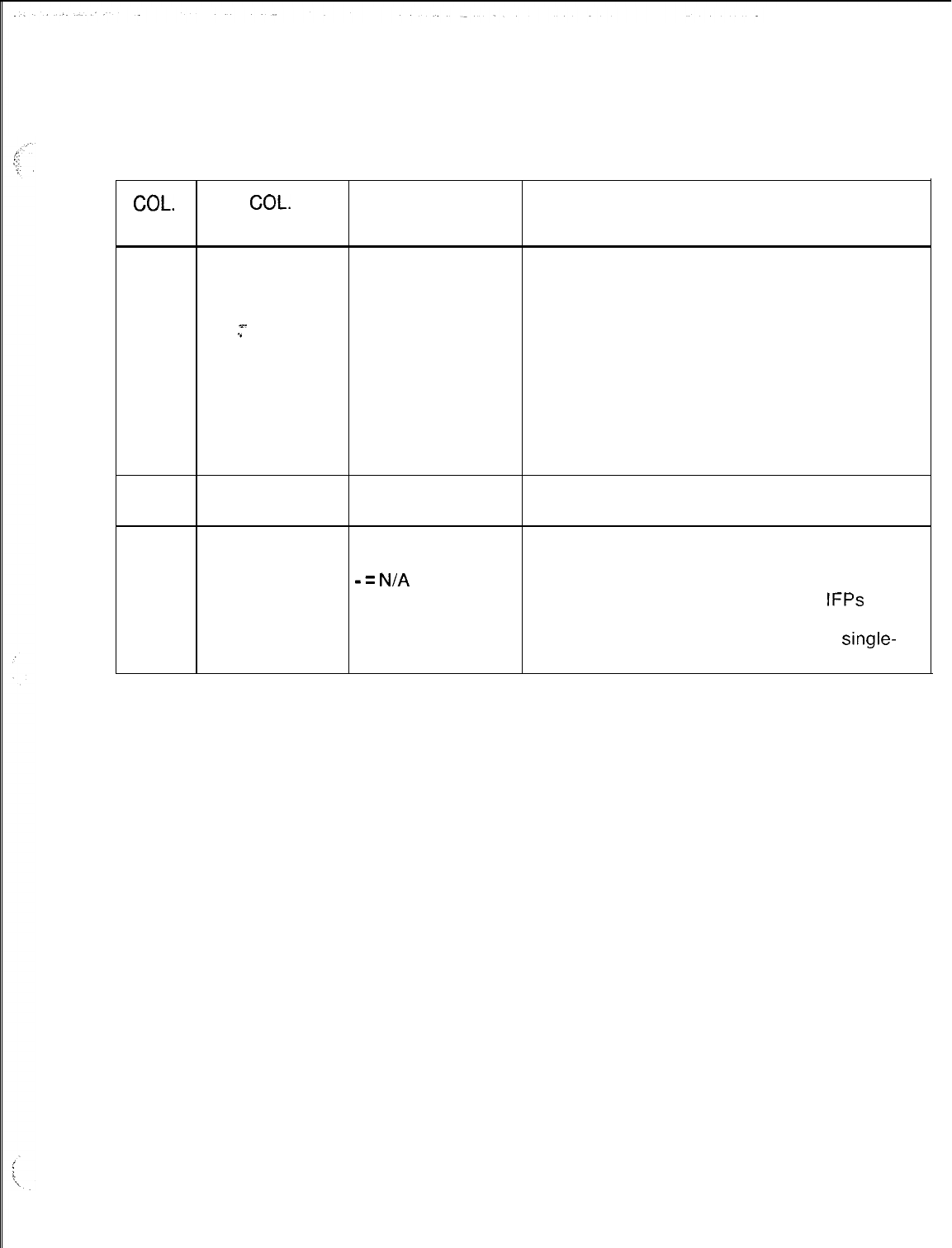
TL-130400-1001
COL.
NO.
Table 8.2
Entry Fields for Record Code LM (Continued)
COL.
VALID
NAME ENTRIES COMMENTS
32-33
Ward Number 00-31 = This hospital feature is used to provide quiet
ward number hours to patient room telephones.
-- = N/A -The system supports a maximum of 32 ward
x-
numbers.
.”
-The field determines which ward number is
assigned to a station.
.
-Ward numbers are created on Record Code
WT, columns 21-52.
-If an entry is made in this field, then at least
one entry on Record Code WT, columns 21-
52, must be marked A.
34-35
Reserved -- = only allowed This field is reserved for future use and is only
entry
to be dashed.
36
Multiline Y = Multiline If the instrument type is an IFP, this field
Featurephone Featurephone determines if it is used as a multiline
-=
N/A
telephone.
-It is recommended to configure all
IFPs
as
multiline (whether or not they are) because a
multiline IFP has a hold button and a
single-
line IFP does not.
SVR 5210
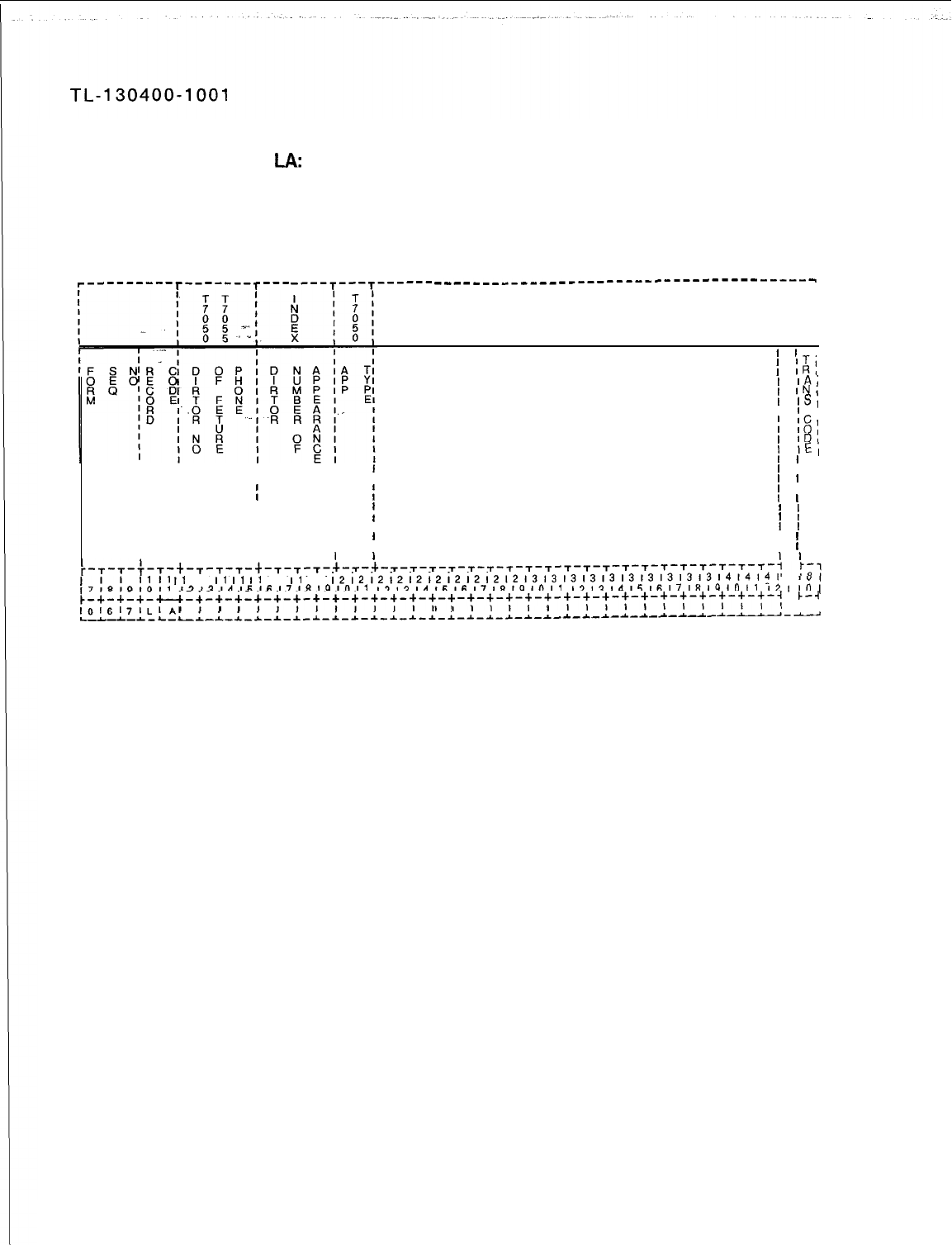
Record Code
LA:
8.3 Record Code LA, Figure 8.3, defines all the directory
Line Appearances numbers that appear as either a line or a DSS (Direct Station
Select) on the multiline Integrated Featurephones.
‘---------T-------T---
----T---T------
___-___________--_----------------
-----_
I
II
I
I
I
,
’
’
I
1
ITI
’
‘RI
I
‘AI
1
INI
’
,Sl
IC
I
I
10;
’
,Dl
1
,EI
I
’
’
I
IIII
I
’
’ I
III I
I
’
’
I
II
I
1
f
’
’ I
I I
I
’
’
I
III
II
’
’
I
I I
II
’
’
I
IIII
I
’
1 I
IIII
I
’
’
I
II I I
I
’
’
I
I I I
1
’
’
I
I1
I1
I1
11
II
II
II
11
II
11
1212121212121212121213131313131313131313l4l4l4l
f7%9,0,1
,2,3,4,6,6,7,81910,1
,2,3,41516,7,8,9,011
12,3,415161718191011
I21
IO1
~-+-+-+-u-+-+-+-~-:-+-+-:-+-+-+-+-+-+-+-+-+-+-+-:-:-:-:-:-:-:-:-:-:-:-:
k-4
1016l7l~l~l
I
l
l
I 1I I I I
I
I,,
I
I1
I I
L-L-L-~-L--~-~-~--L-~-~-~-~-~-~-~-*-*-*-*-*--L-~-~--C-~-~-~-~-~-~-~-~-~-~
Figure 8.3
Record Code LA: Line Appearances Data Sheet
SVR 5210
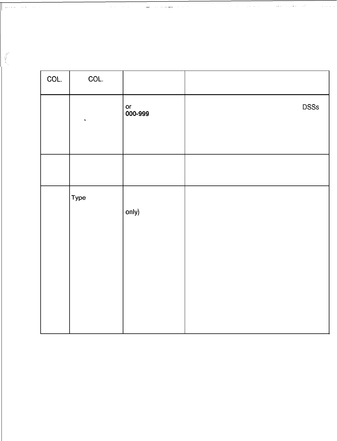
TL-130400-1001
Table 8.3 Entry Fields for Record Code LA
COL.
COL.
VALID
NO. NAME ENTRIES COMMENTS
12-15
Line Number of 0000-9999 This field determines the multiline IFP line
the Integrated directory number on which the lines or
DSSs
Featurephone
~~0-999 =
appear. Right justify three-digit numbers.
.”
number -Any line appearing in this field must be
A three-digit marked as a multiline IFP on Record Code LM
number must have (Y in column 36).
a blank before it. -If a line appears on Record Code LA, the
.CPG defaults to multiline.
16-19
Line Number of 0000-9999 This field determines the line number of the
Appearance or appearance.
000-999 =
Right justify three-digit numbers.
number
20-21
Appearance
We
LA = line
appearance
(Featurephone
only
1
DS =
DSS
appearance
This field determines whether or not the
appearance is a line or DSS.
-Controlling numbers and logical lines are
not to appear on this record code.
-A POTS telephone can only appear as a DS
(DSS) because a POTS line cannot appear on
another phone.
-An LA (line appearance) on this record code
can only be an Analog or Digital
Featurephone.
-If a line is defined as a CO line on Record
Code LD, it cannot appear as a DS (DSS) on
this record code.
-A line directory number listed as an
appearance must be defined on Record Code
LD, columns 12-l 5.
-The system supports a maximum of eight
appearances (line or DSS) of the same line.
-A single-line Featurephone (see Record
Code LM, column 36) cannot be a line
appearance.
SVR
5210

TL-130400-1001
Record Code
LI:
8.3 Record Code
LI,
is not input by the customer. It is
Line Identities
generated by the reverse CPG to preserve the assignments of
internal system identities for re-engineering or documentation
purposes.
s-
.”
.
.
.
.
SVR 5210

TL-130400-1001
‘,--
ATTENDANT 9.0 This section describes the record codes required to
CONSOLE define the system Attendant Console(s). The following
FEATURES record codes are required:
l Record Code AT defines the Attendant Console(s).
l Record Code BD defines the location of the BLDU cards.
l Record Code BK defines the KEDU unit number and the keys.
l Record Code CA defines common data for the Attendant
Console position(s).
.r
l Record Code CN defines common
DNs
(Directory Numbers).
SVR 5210
8h37
D-161
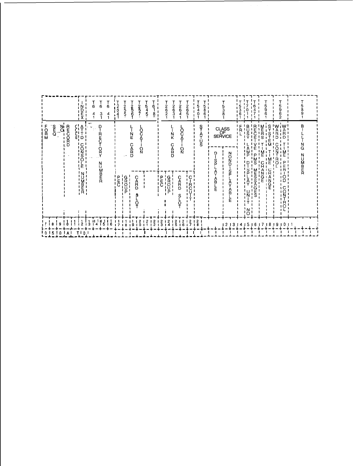
TL-130400-1001
I..
:!
Record Code AT:
9.1 Record Code AT, Figure 9.1, describes the Attendant
Attendant Console
Consoles in the system. The system will support a maximum of
two Attendant Consoles .
------___
T-T-------T-----------
;;;;TTTTTT
,2
222
5 6
4 4 4
;’ ::
!
,I
111
10
II
0
I
I I
I
I I
I
I I
I
I I
-+~T~-+-‘-
1
I1
I1
I1
716191011l21314l516
-+-+-+-+-a-+-+-+-+-
,151lJl~l
TlO,
I I I
-.L-Ad-l-L-
.I.-.L-A-.&.-
I
T-T-T
‘P’G’
‘E’R’
;c;o,
I
“l
I
IPI
‘PIG’
‘E’R’
icfo’
“‘,
!
IPI
I I
I
I
I
I I
.-,-;-,-;-;-;-,-;j-
1121212121212121212T
9,011
1213,415161716,
,--b-+-A.-+-+-+-+-+-+-+
I
I
I I
I
I
I
I
I,
,-*-~-~-1-~-~-~-~-*-~
21313131313131313131314141414141
9,011
,2131415161716191011
1213141
-4-+-a-+-+-+-+-+-+-+-+-+-+-+-+-4
D-l 62
8437
SVR 5210
Figure 9.1 Record Code AT: Attendant Console Data Sheet
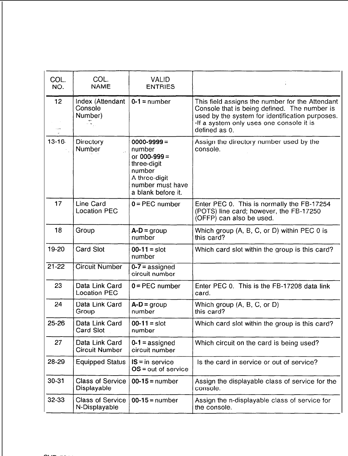
TL-130400-1001
Table 9.1 Entry Fields for Record Code AT
COMMENTS
Which circuit on the card is being used?
within PEC 0 is
8187
D-l 63
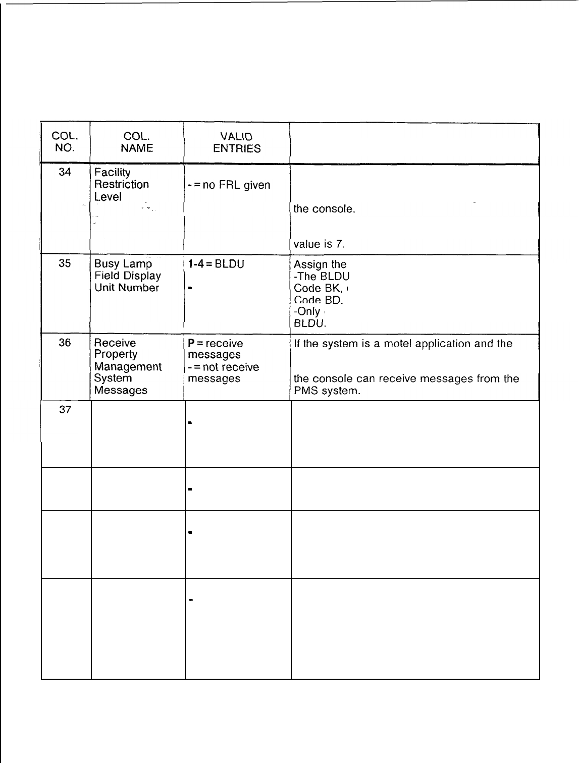
TL-130400-1001
Table 9.1 Entry Fields for Record Code AT (Continued)
COMMENTS
O-7 = FRL value
If the system has the FRL option, the console
must have an FRL value.
-This field determines the FRL assigned to
-Unless the console
is
not allowed to access
all trunks (e.g., CO line), the recommended
number selected
-
= not selected
BLDU associated with the console.
number is assigned on Record
column 13, and listed on Record
one console can use a particular
PMS (Property Management System) option is
equipped, this field determines whether or not
MERS Time
Change M
= allowed
-
= not allowed This field determines whether or not the
console is allowed to change the MERS time
period feature.
-It is recommended to give this feature to
only one console.
38
System Time
Change S = allowed
-
= not allowed This field determines whether or not the
console is allowed to change the time setting
for the system time clock.
39
Ward Control C = allowed
-
= not allowed This field determines whether or not the
console is allowed to activate the ward control
feature.
-Access to this feature is via a button on the
console.
40
Ward Time T = allowed This field determines whether or not the
Period Control
-
= not allowed console is allowed to change the automatic
ward control timer (e.g. the time is set to block
calls at a ward from 8:00 to 12:OO and the user
wants to change it to 9:00 to 12:OO).
-With this feature, the attendant can change
the timing parameter without going into Recent
Change.
SVR 5210
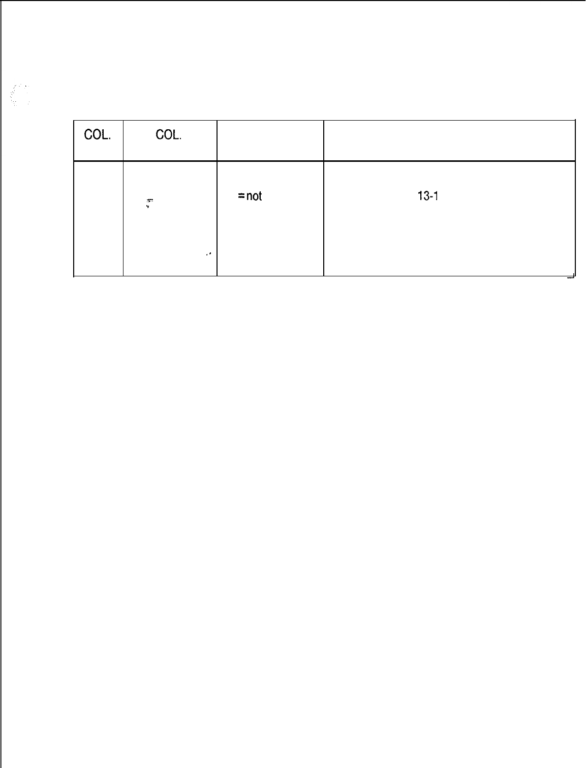
TL-130400-1001
Table 9.1 Entry Fields for Record Code AT (Continued)
COL.
COL.
VALID
NO. NAME ENTRIES COMMENTS
41-44
. . . .
Billing Number
0000-9999 =
Assign the billing number used by the console.
billing number -If the directory numbers assigned to each
s-
----
=
not
console (columns
13-l
6) are different and all
.”
selected consoles are to be billed as one, enter the
same billing number for both console 0 and 1.
-The MDR records will have this number
printed for calls that involve the console.
.-
-If required, the system will support different
billing numbers for the two consoles.
SVR 5210
8187
D-l 65
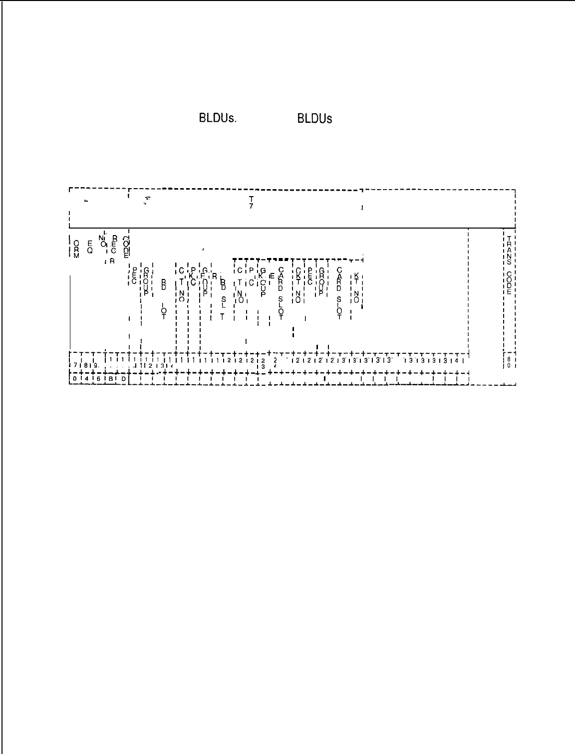
TL-130400-1001
Record Code BD:
Busy Lamp Display Unit 9.2 Record Code BD, Figure 9.2, defines the physical location of
the BLDU cards. The system will support a maximum of four
BLDUs.
Up to four
BLDUs
can be daisy-chained off the same
circuit. The card used to support the BLDU is the FB-17208
card, which is a double-width card. The BLDU parameters
cannot be altered by Recent Change.
T---------r----- ---------------------------------- +-------------------------~
II
s-
I
I
-
I.”
:
I
I I I
I
. . . .
8
I I
II
II
0
I
’
F S
N:
R
Ci
II
I
I::
:
7;
g
BLDU DATA LINK LINES
I
I
_
1M
I
IO
E’
IR
p--s--s----s--s--s--s---
T-T-T
--- .--
‘T-T-T-T-
T-i
I
ID
I
;P!Gf
C
;C;P:G;
C
;C;P;t
,EIRI
A
IKIEIRI
A
IK,EII
E
tC!P!G!
I
,CIOI
R
IKIEIRI
E
I I
ICI
IKI
I
II
IUI
D
ITICIOI
R
I-I-ICI,
IUI
D
I
I I’
i
ITICIOI
IUI
E
ITI
II
IPI
I
, 1 I s
IPI
IN,
I
I
I
I
I 1 I
F
101
I
INI
IPI
101
I I
INI
101
I
0
I
I I
t
I I I I
F
I
I
II
II
fI
IT,
1;
B
I I I I
I
I
I I
P
I
I
I
I
I
I
I
I
I I I II I
I
I I I
I
I I
I
I I
II
I I
I
I
I I II I
I
I
I
I
I
I I I I
I
1 I
I
I I
I I
I I
I
I
I I
-I--
l
I
1;
I
I
II
I
II
I
I
I
t-
I
;
I
1
+-
I
.I.-
I I
I
I
I I
I I
/-y-T-f-T-t-t-t-
I
~111111111
I7
I8
I9
IO
II
1213
Id
-T-t-t-t-t-T-t-t-
I
I1
I1
I1
I1
I1
121212
11516171819101112
-+-+-+-+-+-+-+-+-
-T-t-t-t-t-r-t-t-T-T-T-T-T-T-T-T-j
!
12
12
12
I2
12
I3
13
13
13
I3
13
I3
I3
I3
I3
I4
I
i-1
1151617181910111213141516171619101
-+-+-+-+-+-+-+-+-+-+-+-+-+-+-+-+-4 I:
I
C-i
I,,,, I
I
I
III,
I
I,,,
I I
-.I.-A-*-A-A-A-A-A.-A-A,
-~-.A-d.--L-.A-A-------
Figure 9.2
Record Code BD: Busy Lamp Display Unit Data Sheet
8187
SVR 5210
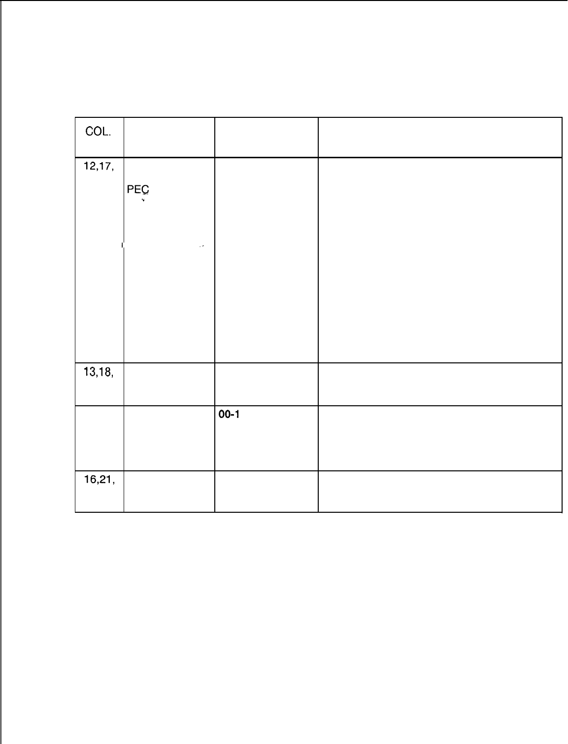
TL-130400-1001
COL.
NO.
Table 9.2
Entry Fields for Record Code BD
COL.
VALID
NAME ENTRIES COMMENTS
12,17,
BLDU Data Link 0= PEC number
22 and Lines
27 PEG
.”
Enter PEC 0. This is the FB-17208 card.
-If column 12 is dashed, columns 13-l 6
must be dashed.
-If column 12 is marked 0, columns 13-l 6
cannot be dashed.
-If column 17 is dashed, columns 18-21
must be dashed.
-If column 17 is marked 0, columns 18-21
cannot be dashed.
-If column 22 is dashed, columns 23-26
must be dashed.
-If column 22 is marked 0, columns 23-26
cannot be dashed.
-If column 27 is dashed, columns 28-31
must be dashed.
-If column 27 is marked 0, columns 28-31
cannot be dashed.
13,18,
Group A-D = group Which group (A, B, C, or D) within PEC 0 is
23 and number this card?
28
14-15,
Card Slot
00-l
1 = slot
19-20,
Which card slot within the group is this card?
number
25-26
and
29-30
16,21,
Circuit Number 0 or 1 = assigned
26 and Which circuit on the card is being used?
circuit number
31
SVR
5210
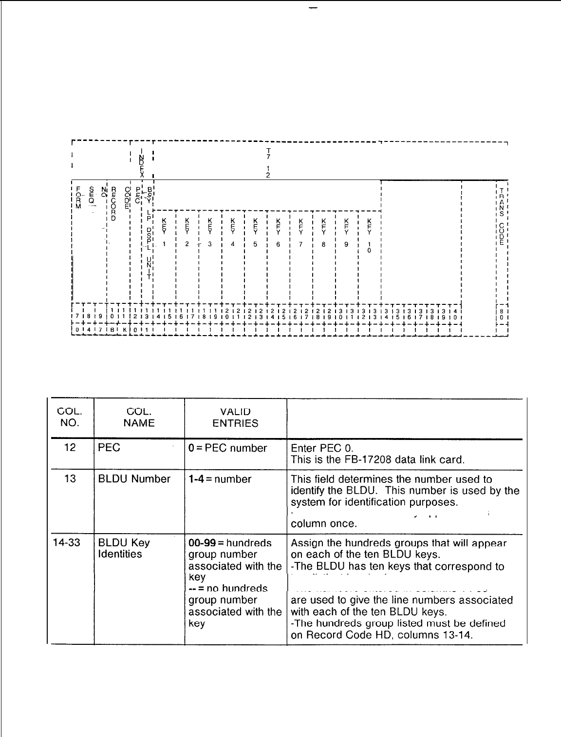
-
TL-130400-1001
Record Code BK: 9.3 Record Code BK, Figure 9.3, defines the unit number and
Busy Lamp Key key identification for each BLDU.
r---------r----r--- -----------------_------------------
I I
;
r:
I
T---------------------q
:
II
1I
I
I
I
I
D
;
II
I
I
E
I
0
I
I
I
x
1
:
I
I
I
III
BLDU KEY IDENTITIES
Figure 9.3
Record Code BK: Busy Lamp Key Data Sheet
Table 9.3
Entry Fields for Record Code BK
COMMENTS
-A
BLDU number can only appear in this
ten
distinct hundred groups.
-The numbers entered in columns
14-33
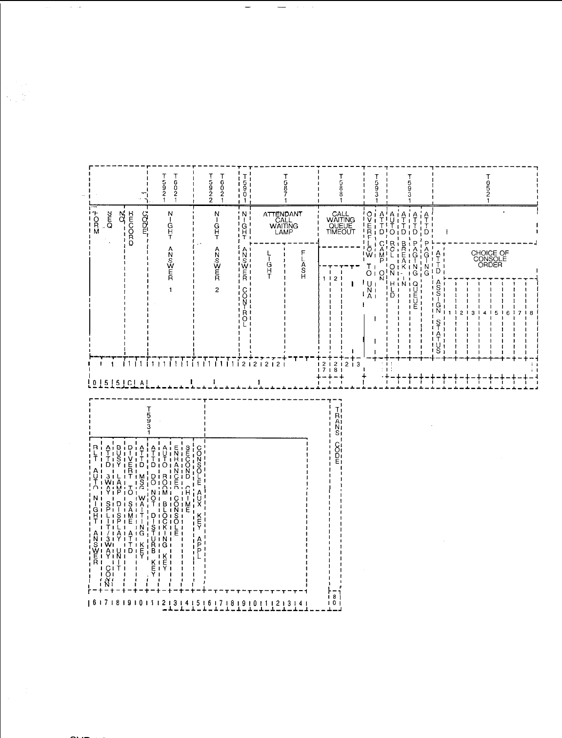
TL-130400-1001
Record Code CA:
9.4 Record Code CA, Figure 9.4, defines the common data for
Common Attendant
the attendant positions. There must be at least one entry on
Record Code AT before completion of this record code is
required.
ATTENDANT I
ASSIGNMENT I
FOR ROOM TO ROOM
;
BLOCKING FUNCTIONS ,
-I
I
I
I
I
;
3131313131313141414141414
3141516171819101112131415
-+-+-+-+-+-+-+-+-+-c-+-+-
Li
I
2
I
8:
I
I
I
I
I
I
I
I
I
-;-
313
112
-+-
,
UNA
ZONES
-T-
I
314II
II
II
I
I
II
I
I
II
II
,I
II
II
I
I
-;-
I
t
213
I
9 IO
-+-
L
,
I
i
1111
i11I
IlIt
il
tl
illI
i212,2,2i
-T-T-
I
I
I
21212
17161910111213141516171819101112131 41516
c-+-+-+-+-c-+-+-+-c-+-+-+-+-+-+-+-+ -4--h-
101515,C,,,,
I I I
I
I
I
I I I
I
I I, I
L-~-~-_--L-*-~-~-~-*-_C-~-~-I-~-~-~-~-~-~-
,
I
NI
:-+-+-~-~-~-:-:-~-~-+-~-~-~-~-~-~-~-~-;
~4141414151515151515151515151616161616)
1-i
~617181910,112~3,4~516i718,9~0~1,2l3l4,
181
101
L-L-I-L-L-L-I
-~-L-l-l-l-l-l-l-l-l-~-~-~---~-,
Figure 9.4 Record Code CA: Common Attendant Data Sheet
8l87
D-169
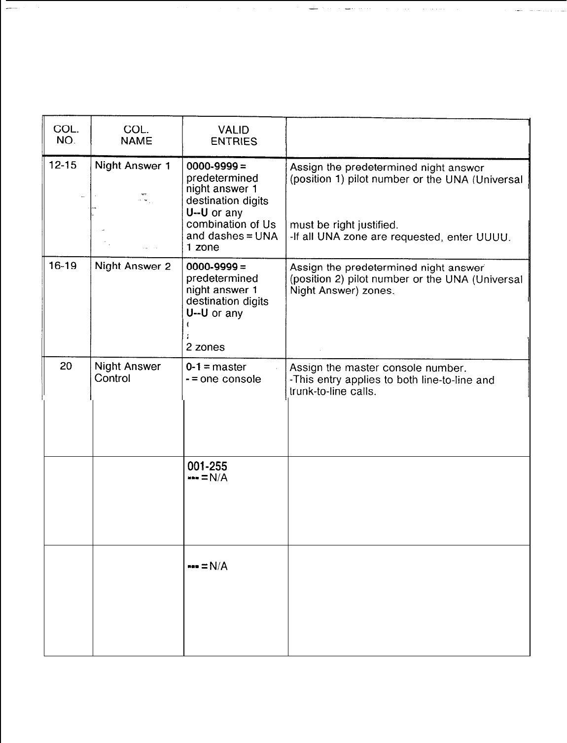
r
TL-130400-1001
Table 9.4
Entry Fields for Record Code
C
A
COMMENTS
Night Answer) zones.
-The UNA zones can be in any combination.
If three-digit pilot numbers are used, they
-The UNA zones can be in any combination.
If three-digit pilot numbers are used, they
combination of Us must be right justified.
and dashes = UNA
-The console listed here must be defined on
Record Code AT, column 12.
-The console number 0 or 1 marked in this
column, must be defined on Record Code AT,
column 12.
21-23
Attendant Call
001-255
= number This field determines the number of calls
Waiting Lamp
m-w
=
N/A
allowed in the call waiting queue.
Light
(default = 1)
-When the number of calls entered in this
field is reached, the CALL WTG pushbutton on
the console lights.
-This lets the attendant know the number of
calls waiting to be answered.
24-26
Attendant Call 001-255 = number This field determines the number of calls
Waiting Lamp
-mm
=
N/A
waiting in queue before the CALL WTG
Flash
(default = 8)
pushbutton on the console flashes.
-This field must be set at a greater number
than the waiting lamp light field, columns 21-
23.
-The flashing lamp is designed as a warning
to let the attendant know that there are a large
number of unanswered calls.
8187
SVR 5210
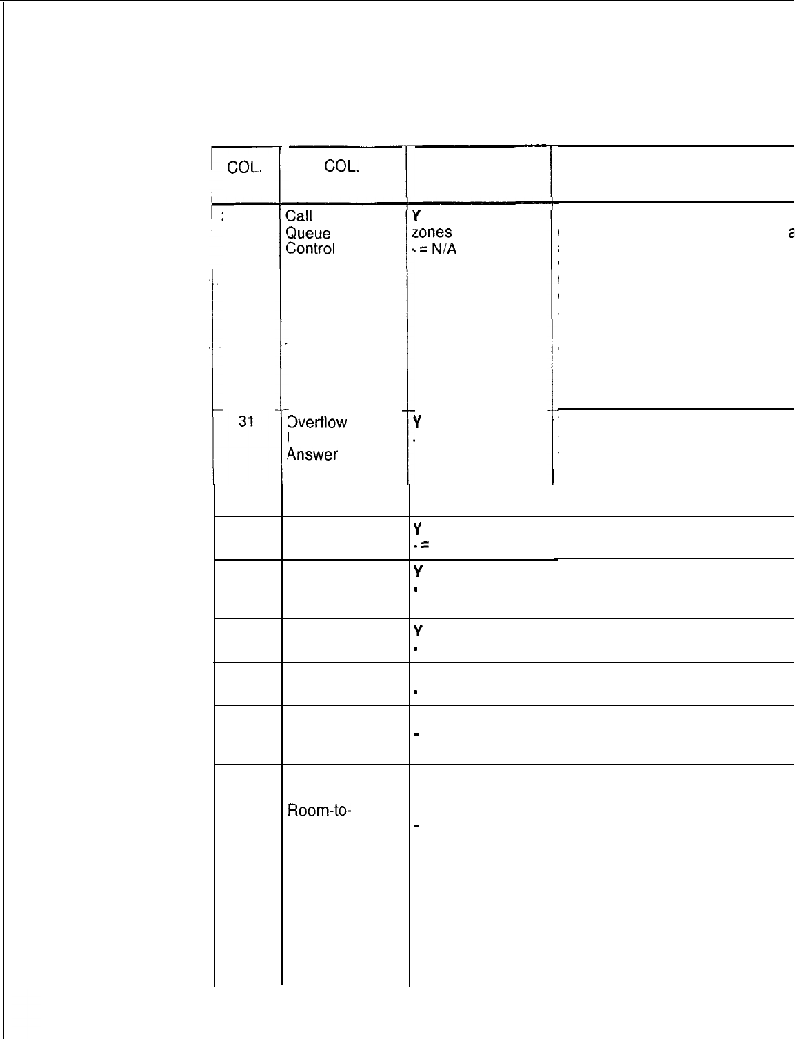
-
55
COL.
NO.
27-30
32
33
34
35
36
37
TL-130401
Table 9.4 Entry Fields for Record Code CA (Continued)
COL.
NAME
3all
Waiting
3ueue
Timeout
Zontrol
3verflow
to
Universal Night
Answer
Attendant
Y
= allowed
Camp-on
.=
not allowed
Attendant Recall
on Hold
Attendant
Break-In
Attendant
Y = allowed
Paging Queue
-
= not allowed
Attendant
Paging
Attendant
Assignment for
Room-to-
Room Blocking
Function
(Attendant
Assignment
Status)
VALID
ENTRIES
f
= UNA zone or
cones
(l-4)
.=N/A
Y
= allowed
. = not allowed
Y
= allowed
-
= not allowed
Y
= allowed
-
= not allowed
Y = allowed
-
= not allowed
A = console
assignment
required,
-
= all consoles
can activate
room-to-room
blocking feature.
8187
COMMENTS
This field determines whether or not a
(Universal Night Answer) zone is
alertec
a call has been waiting in the attendant
waiting queue for a longer time than
the attendant call waiting queue on
Code OT, columns 30-32.
-If this field is used and the console has
more calls presented to it than are
answered, the calls automatically divert
UNA zone defined here. The UNA
indicator is a bell or light that alerts
users to calls that need to be answered
This field determines whether or not cal
the call waiting queue are allowed to
to the UNA.
-If an entry is made in this field, then an
must be made in columns 27-30 to defir
UNA to which the calls will overflow.
If the attendant is allowed to camp on to
busy line, enter Y.
If a call put on hold by the attendant is
automatically recall to the console after
predetermined amount of time, enter Y.
If the attendant is allowed to break in on
ongoing station call, enter Y.
If the attendant is allowed to put a call ir
page queue, enter Y.
If the attendant is allowed to access the
paging system equipment via the PAGE
pushbutton, enter Y.
This field determines whether or not
both consoles are allowed to activate th
room-to-room blocking feature.
-If a first choice console is given, then c
the first choice console can activate the
feature.
-If the first choice console is in the night
mode, then the second choice console
automatically assumes the function.
-If A is entered, then only one console c
access the feature.
-If the field is dashed, then both console
allowed to access the feature.
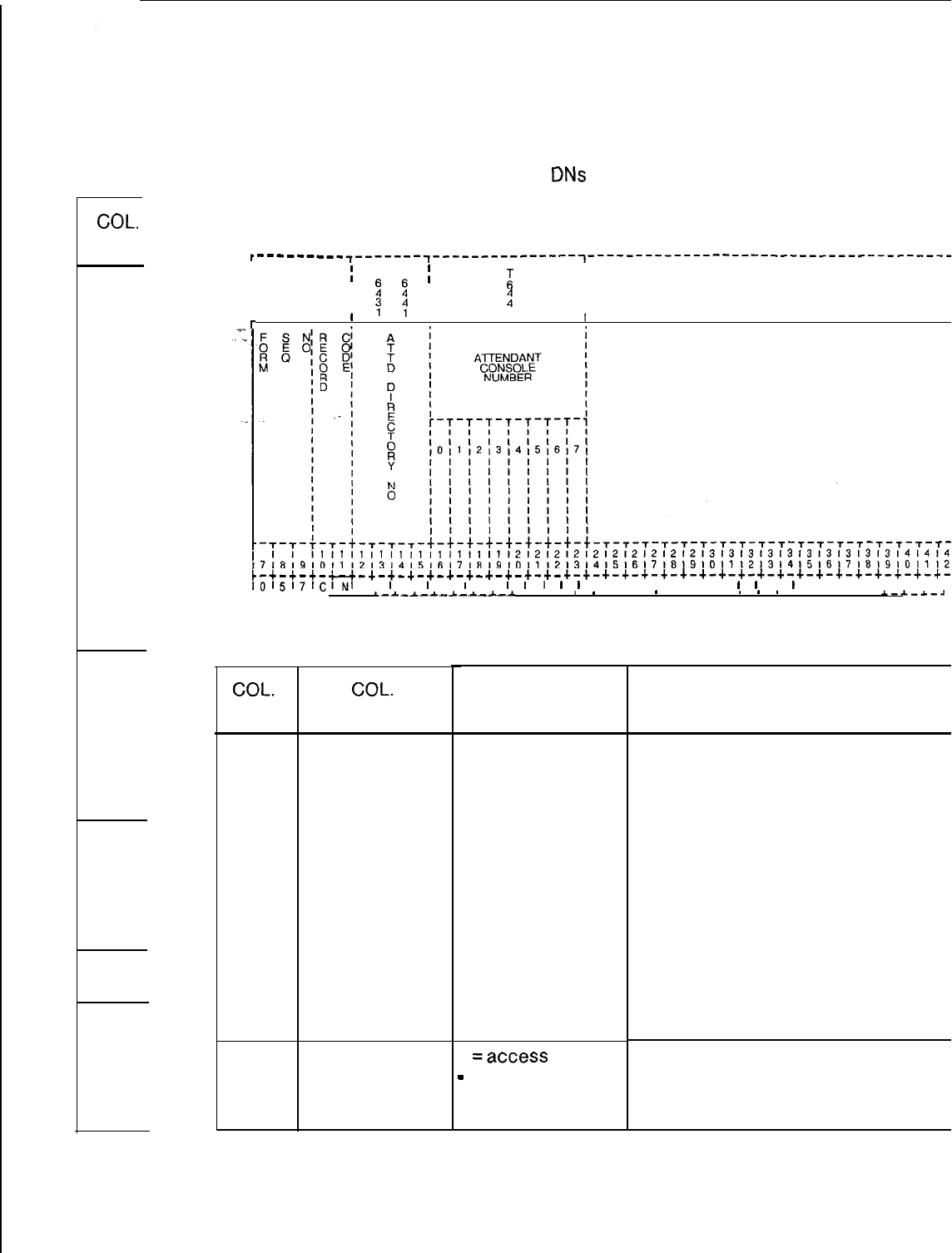
TL-13C
COL.
NO.
38-45
46
47
48
49
TL-130400-1001
Record Code CN:
9.5 Record Code CN, Figure 9.5, allows the system to have
Common Attendant
common
DNs
(Directory Numbers) for a variety of Attendant
Directory Numbers
Console configurations.
,---
---___
~-------,---------------~---------------------------------------~-
I
I;
T T
;I
I
2
2
I
B
I
II
II I
I
I
q
;’
I
!
I
I
III1
1
r
I
11,11,~1,,,,,,11,,,,~2,2~21212121212121213131313131313131313~4~4~4~
~7181910,1121314151617161910111213,41516171819101112131415161718191011121
t-+-+-+-u-+-+-+-+-+-+-*-+-+-+-+-+-+-+-+-+-+-+-+-+-+-+-+-+-+-+-+-+-+-+-~
,01517,~lN,
I
I
I
I
I
I
I,
I
I1
I
I
I I I I I I I
I
I
I
I
I I I I I I I
L-A-A-A- -, .
L-A-A-A-&-A-&-*
. . a
*
. .
*
. . .
*
*
*
. . . .
A.-*_*-.I
Figure 9.5
Record Code CN: Common Attendant Directory Numbers Data Sheet
Table 9.5 Entry Fields for Record Code CN
COL.
NO.
12-15
16-23
COL.
NAME
Attendant
Directory
Number
Attendant
Console
Number
VALID
ENTRIES
0000-9999
= number
or 000-999
Y =access
-
= no access
COMMENTS
If a directory number used is other than the
number defined on Record Code AT, this fie
determines the attendant directory number.
-If three-digit numbers are used, they
should be right justified.
-This number provides for a unique or
standard calling number for the Attendant
Console that allows the same DN to be used
for different consoles.
-With this number, a user can dial 2000 and
be connected to either attendant 0 or 1.
NOTE:
Each Attendant Console number
assigned to answer calls via the common
attendant directory number must be listed on
Record Code AT, column 12.
For each Attendant Console number listed,
this field determines whether or not access
an attendant via the specified attendant
directory number is allowed.
D-l 74
SVR 52

TL-130400-1001
TRUNK 10.0 This section describes the record codes required to
FEATURES define the various system trunks and their features. The following
record codes are required:
l Record Code
Tl
defines the system trunk group parameters.
l Record Code T2 defines additional system trunk group
parameters.
x-
.
.
l Record Code CR defines system toll restriction.
l Record Code EC defines system expanded toll restriction.
l Record Code AS defines service codes allowed with toll
restriction.
l Record Code TC defines the system trunk group members.
l Record Code NA defines permanent connection trunks.
0
Record Code DA defines CO digit absorption.
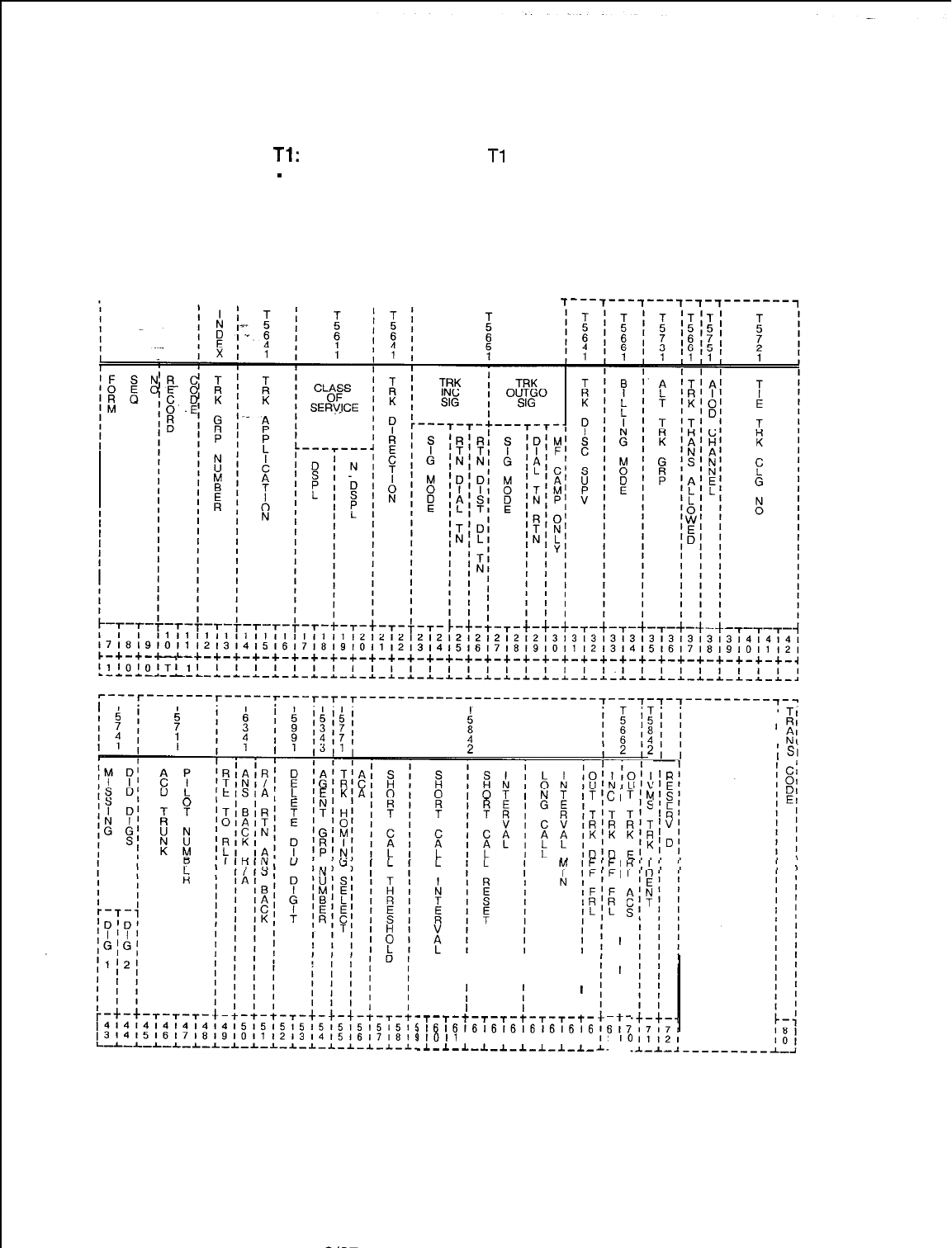
TL-130400-1001
Record Code
Tl:
Trunk Group Part
-
1 10.1 Record Code
Tl
, Figure 10.1, provides parameters that are
used to define trunk groups within the system. Record Code T2
also provides parameters for defining trunk groups. Individual
trunks that make up the trunk groups are defined on Record
Code TC.
r---------r---r-----r-------r---T---------------
7---7---f---7-~-7-------~
(SEC)
;
(SEC)
(I
I
I 1
I
-T-T-t-T-T-t-T-T-t-
i1616161616161616'6
I1011
12131415161718
.I-l-L-.J.~l-l-l~l-l-
Ci
I
I
I
I
I
I
I
I
I
I
I 1
I
I
I
I
I
I
I
I
I
I
I
,:7
9
IO
-I-
I
‘R
;ii
“R
‘V
;
’
E
ID
Figure 10.1
Record Code Tl: Trunk Group Data 1 Data Sheet
D-l 76
8187
SVR 5210
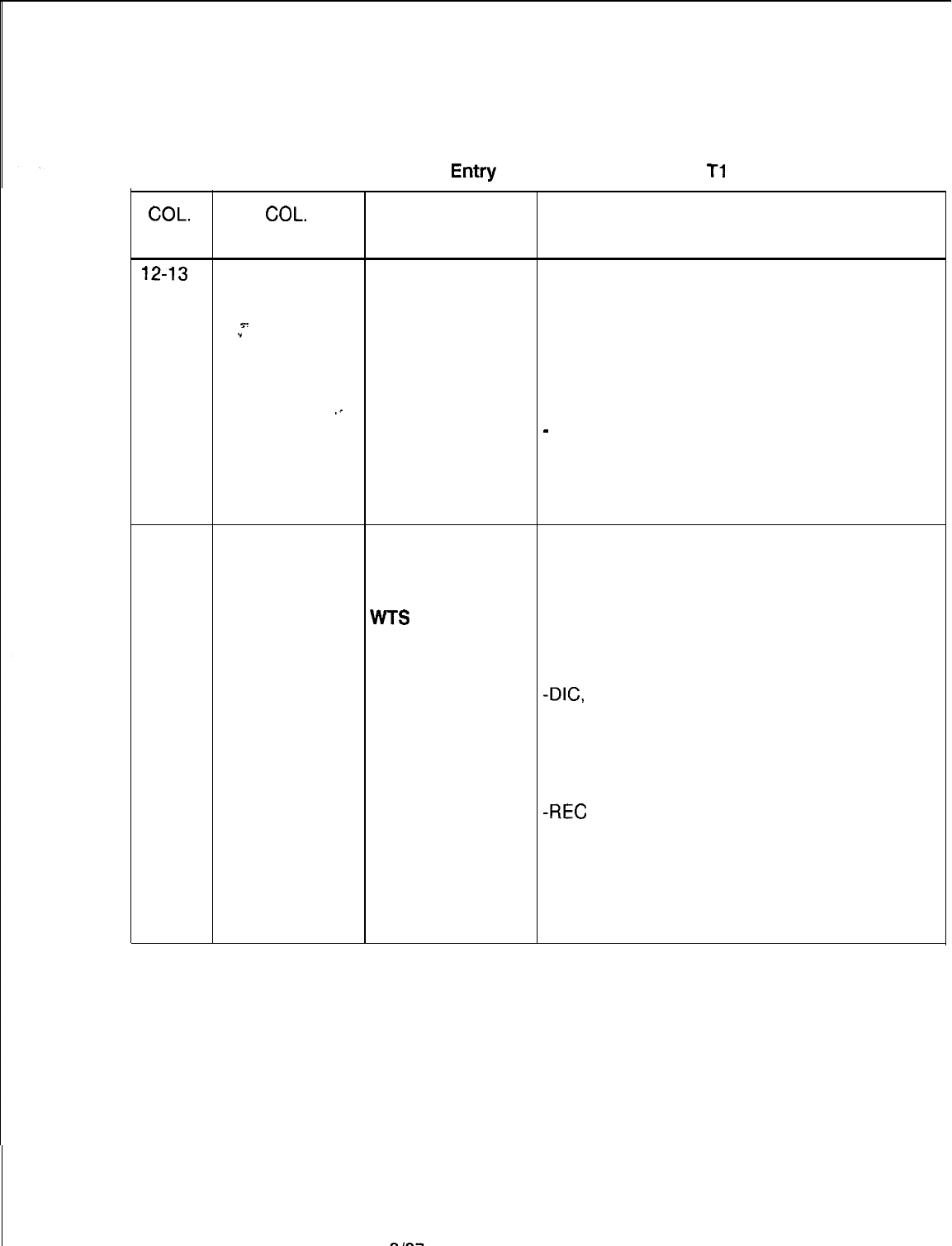
TL-130400-I 001
COL.
NO.
Table 10.1 Entry
Fields for Record Code
Tl
COL.
VALID
NAME ENTRIES COMMENTS
12-13
Trunk Group 00-63 = number
Number This field determines the trunk group number.
-An RLT (Release Link Trunk) group does
s-
not need trunk group assignment. The
.”
combined line and recording trunks are
. . .
allowed access to the distant toll operator if
seizure (loop or E&M) capability is allowed.
-The trunk group number must be unique
.-
across this record code.
-
Any trunk group defined here must also be
defined on Record Code T2 and have at least
one member on Record Code TC.
-An incoming RLT from a CAS Branch is not
configured as a trunk group.
14-16
Trunk COT = DID/CO/
Application Assign the type of trunk usage allowed to the
DOD
trunk group.
FXT =
FX
-The following rules apply to trunk
TIE =
Tie
applications:
WTS
= WATS -COS: TIE, COT, FXT, and WTS trunks can
DIC = dictation be assigned a COS (columns 17-20) if their
access trunk direction is marked IN or TW (columns
PAG = paging
21-22).
access
-DIG,
PAG, REC, CAS, and CLR trunks
NIC = network cannot be assigned a COS.
interface -If this field is marked DIC, NIC, PAG, or
REC = recorder REC, columns 21-50 must be dashed.
announcer access -The recommended ratio of DID trunks to
CAS = centralized DID stations is 1 trunk to 10 stations.
attendant service
-REC
uses a 2-wire E&M trunk.
CLR = combined
line and recording
trunks (sometimes
used for billing of
motel guest
rooms)
SVR 5210
6167
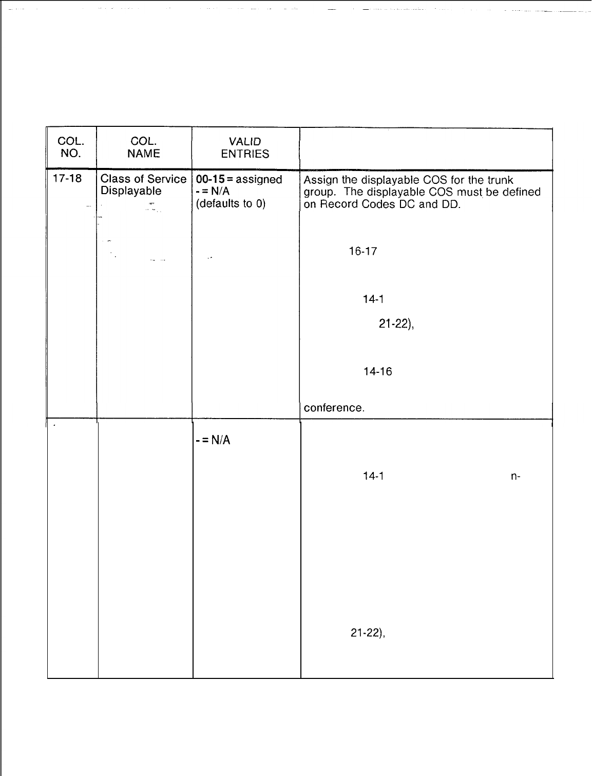
TL-130400-1001
Table 10.1
Entry Fields for Record Code Tl (Continued)
COMMENTS
-If columns 14-16 are marked CAS, the
displayable COS (Record Code DD) assigned
to the trunk group must be marked -- in
columns
16-17
and 36-37, and SA in
columns 24-25. The dashes disallow
switched direct line and modem access, and
SA allows station access.
-If columns
14-l
6 are marked COT, FXT, or
WTS and these are incoming trunks (marked
IN in columns
21-22)
the only allowed
features for the trunk group are trunk group
access, dictation equipment access, station
access, and RLT access.
-If columns
14-16
are marked TIE, the only
features restricted from the trunk group are
switched direct line and progressive
19-20
Class of Service
00-l
5 = assigned
Assign the n-displayable COS for the trunk
N-Displayable
-=N/A
group.
(defaults to 0) -The n-displayable COS must be defined on
Record Code NC.
-If columns
14-l
6 are marked WTS, the
n-
displayable COS (Record Code NC) assigned
to the trunk group must be marked DS in
columns 28-29. DS provides the trunk group
with data line security. All other
n-displayable COS fields must be dashed.
-If columns 14-16 are marked TIE, the only
allowed features for the trunk group are
attendant information, data line security,
universal night answer, computer access,
special common carrier, and speed calling.
-If columns 14-16 are marked COT or FXT
and the trunks are incoming (marked IN in
columns
21-22),
the only allowed features for
the trunk group are attendant information, data
line security, universal night answer, and
computer access.
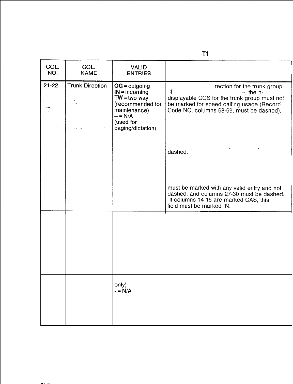
TL-130400-1001
Table 10.1 Entry Fields for Record Code
Tl
(Continued)
COMMENTS
Assign the trunk di
-If
this field is marked OG or
-If this field is marked OG or --, columns
17-20 must be dashed. If this field is marked
IN or TW, columns 17-20 can be dashed or
marked with any allowable digit.
-If this field is marked TW, columns 23-30
must be marked with any valid entry and not
-If this field is marked OG, columns 23-26
must be marked with dashes, and columns
27-30 can be marked with any valid entry but
must not be dashed.
-If this field is marked IN, columns 23-26
23-24 Trunk Incoming DP
Signal: Assign the incoming signaling mode for the
TC
trunk group.
Signaling Mode MX DP = lines that use dial pulse signaling (used
or
for DID and Tie lines)
-- = incoming TC = lines that use touch calling signaling
signaling mode MX= lines that can use DP or TC type
signaling
-- = N/A (used for paging/dictation, hot-line
service, recorder announcer, traffic to the
attendant, or any answer-only trunk)
25
Trunk Incoming Y = allowed (Tie This field determines whether or not the trunk
Signal:
only)
group is allowed incoming return of dial tone.
Return Dial
-=N/A
Tone -This field is used by Tie trunk groups only.
-When this field is allowed, the incoming
trunk receives dial tone from the remote end,
indicating that dial tone is coming from the
switch.
-Columns 25 and 26 are mutually exclusive.
SW
5210
8187
D-l 79
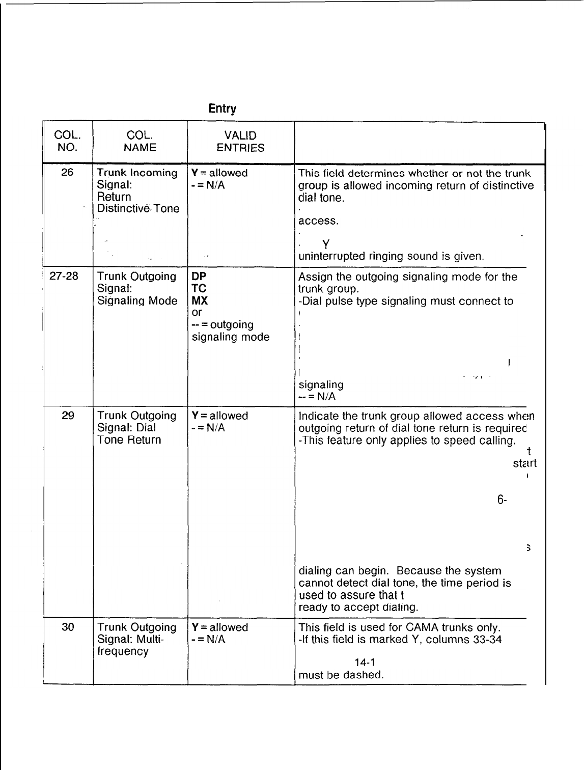
TL-130400-1001
Table 10.1 Entry
Fields for Record Code Tl (Continued)
COMMENTS
-This field is sometimes used for remote
-Columns 25 and 26 are mutually exclusive.
-If a
Y
is entered in this field, an
dial pulse type signaling.
-Touch calling signaling can connect to
touch calling type signaling.
DP = lines that use dial pulse signaling
TC = lines that use touch calling signaling
MX = lines that can
use DP
or TC type
-Return dial tone is used when a ground star
signal cannot be used as an indication to
st2
outpulsing to a CO. This is normally for loop
trunk applications. When the dial tone
returned bit is implemented, there is a
6-
second delay between the trunk seizure and
the start of outpulsing on speed calls (no
matter what trunk type). The dial tone return
bit does not indicate that return of dial tone i:
the only valid indication from the CO that
he CO will normally be
must be marked CM.
If columns
14-l
6 are marked CAS, this field
rn
I.
t
u-t
1
ed
5
8187
SVR 5210
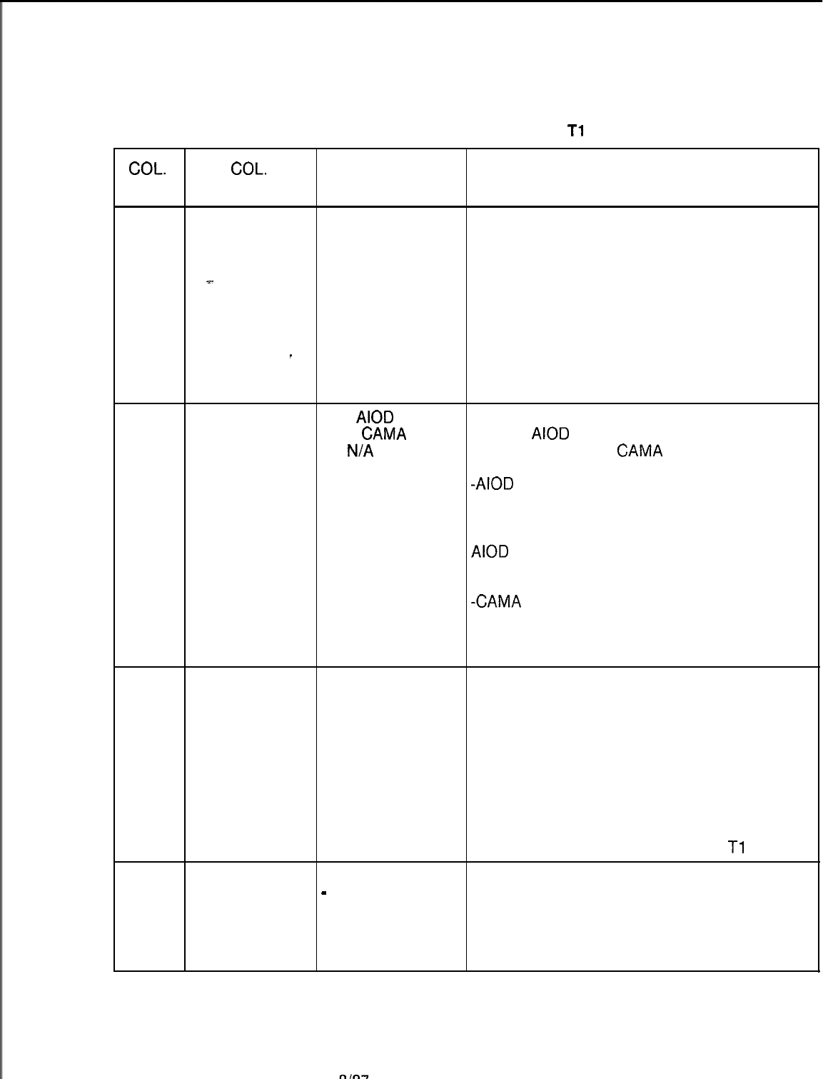
TL-130400-1001
Table 10.1 Entry Fields for Record Code
Tl
(Continued)
COL.
COL.
VALID
NO. NAME ENTRIES COMMENTS
3i -32 Trunk
CA
= incoming
Assign the type of trunk disconnect
Disconnect
CD
= outgoing
supervision for the trunk group.
Supervision BT = incoming and -All references to the incoming or outgoing
outgoing (Tie) trunk calls are from the system point of view.
x-
.
-- = N/A -Disconnect is defined as an on-hook
condition for 300 milliseconds after the answer
condition has been received.
-Loop start trunks usually do not guarantee
_disconnect supervision.
-E&M and ground start trunks, however, will
usually guarantee disconnect supervision.
33-34 Billing Mode
AL =
AIOD
This field determines whether the billing mode
CM
=
CAMA
used is
AIOD
(Automatic Identification of
-- =
N/A
Outward Dialing) or
CAMA
(Centralized
Automatic Message Accounting).
-AIOD
is used for billing information that is
provided by the CO. This feature provides the
DN of stations placing outside calls. This
feature can be used only if the CO supports
AIOD
trunks.
-If this field is marked AL, column 38 must be
marked 1, 2, 3, or 4.
-CAMA
is used only on outgoing toll trunk
groups.
-If this field is marked CM, columns 21-22
must be marked OG.
35-36
Alternate Trunk
00-63 = trunk
Assign the alternate trunk group to be used if
Group group number the trunk group is busy when a user places a
-- = N/A call.
-Only one alternate trunk group is allowed
per trunk group.
-If no alternate trunk group is to be used, the
field is dashed.
-If an alternate trunk group is not used, the
potential for calls to be blocked exists.
-The alternate trunk group must be defined
as a trunk group on Record Codes
Tl
and T2.
37
Trunk Transfer Y = allowed Y allows a call to be transferred.
Allowed
-
= N/A (REC or -Transfer should not be allowed for recorder
MERS trunk group) announcer trunks. However, when trunk
transfer is not allowed, the attendant can
transfer a call to a station, but the station
cannot transfer the call elsewhere.
SVR
5210
8187
D-l 81
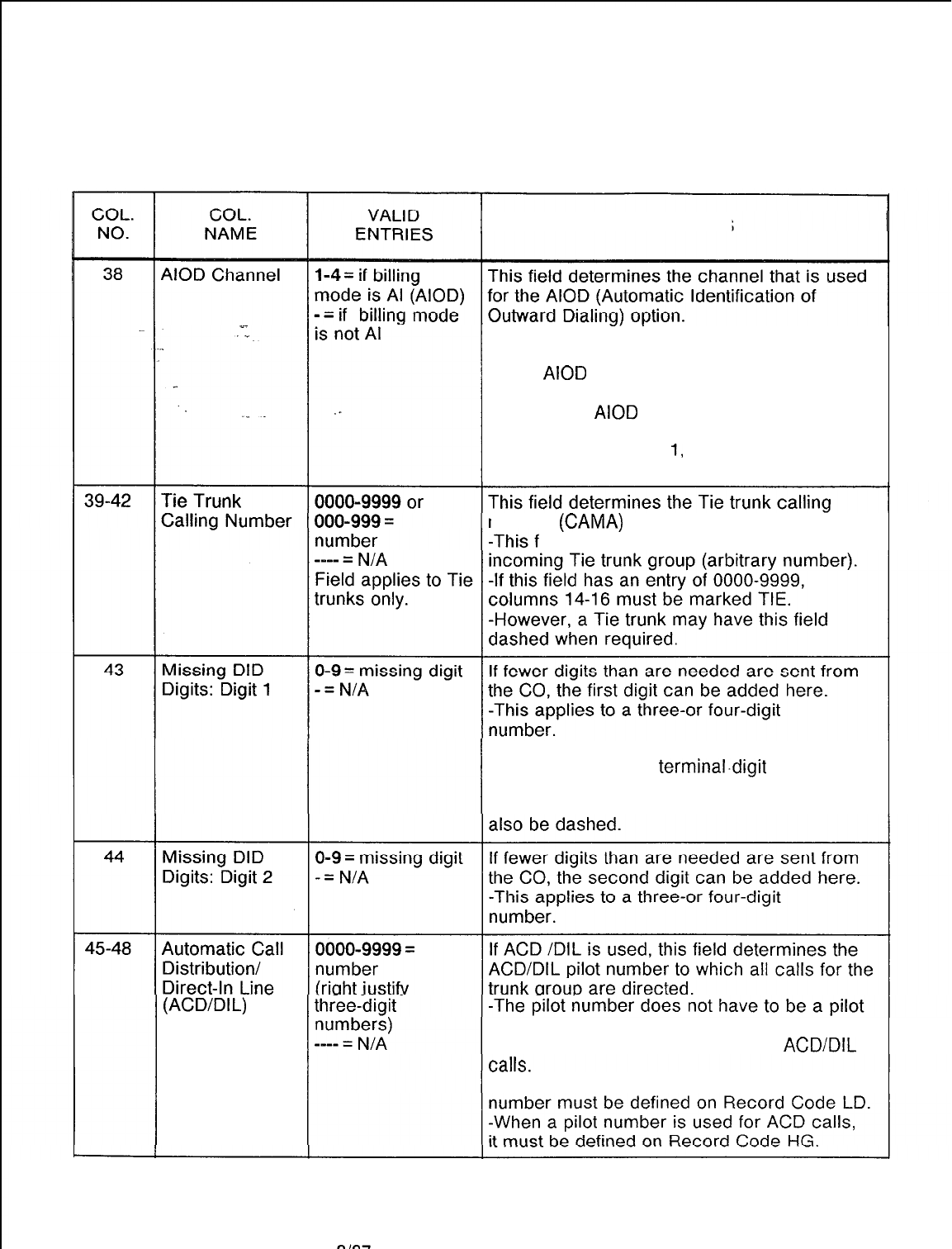
TL-130400-1001
Table 10.1 Entry Fields for Record Code Tl (Continued)
COMMENTS
-The FB-17276 card has 4 circuits. Circuits
1 and 2 are loop; circuits 3 and 4 are E&M.
-If the
AIOD
option is used and no circuit is
defined, the default value is circuit 1.
-If used, the
AIOD
card must be defined on
Record Code FR.
-If this field is marked
1,
2, 3, or 4, columns
33-34 must be marked AL.
number
(CAMA)
sending requirements.
ield allows billing identification to the
-When a three-digit station numbering plan
is used, the missing
terminal.digit
is the first
missing digit and must be specified.
NOTE: If this field is dashed, column 44 must
(ACD/DIL)
Trunk
Pilot Number number of a station hunting group. If needed
a single station can receive limited
ACD/DIL
-If a single station number is used, the
D-l 82
8187
SVR 5210
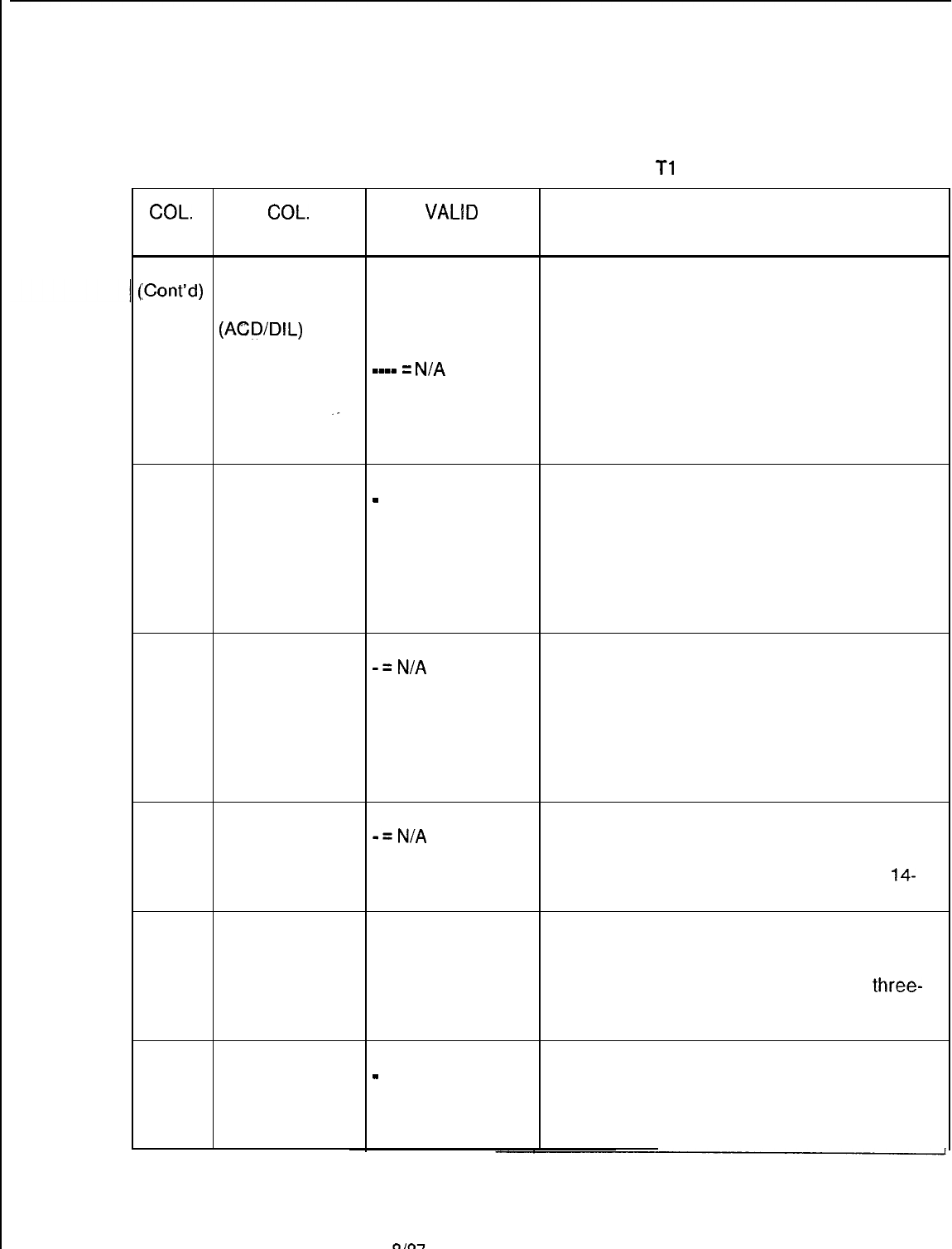
TL-130400-1001
Table 10.1 Entry Fields for Record
Code
Tl
(Continued)
COL.
COL.
VALID
NO. NAME ENTRIES COMMENTS
45-48 Automatic Call 0000-9999 =
ICont’d)
Distribution/ number
Direct-In Line (right justify
(ACD/DIL)
Trunk three-digit
Pilot Number numbers)
mm-m
=
N/A
For the limited ACD feature to work properly, it
is recommended to use a pilot number from a
circular hunt group.
-If an entry (other than dashes) is made in
this field, columns 23-26 must be dashed.
-If an entry (other than dashes) is made in
this field, columns 14-16 must be marked
CAS, CLR, COT, FXT, TIE, or WTS.
-The direction for any of those trunk groups,
must be marked IN or TW (columns 21-22).
49
Route to RLT
(Release Link
Trunk)
Y = connect to RLT This field determines whether or not incoming
-
= connect to seizure is assigned to a trunk group when no
local attendant incoming signaling (ringdown) is allowed to
connect to the RLT (CAS) or to the local
Attendant Console.
NOTE: If the site is a CAS Branch and calls
are to be routed to the CAS Main location, this
field must be marked Y.
50
Answer Back
Recorder
Announcer
Y = allowed
-=N/A
This field determines whether or not the trunk
group is allowed an answer back signal when
any trunk group is routed to a recorder
announcer.
51
-This field should be allowed if the trunk
group is routed to a recorder announcer. This
allows the CO to bill for the time that the
calling party is connected to the recording.
Recorder Y = allowed This field determines the recorder announcer
Announcer
-=N/A
trunk group that is to return an answer back
Return Answer
Back signal when connected to an incoming trunk.
NOTE: If this field is marked Y, columns
14-
16 must be marked REC.
52-53
Delete DID
01-10
= number
In a DID application, this field determines the
Digits -- = N/A number of digits sent from the CO that are to
be deleted. This field is used when the CO is
sending more digits than needed (e.g.,
three-
digit numbering plan in effect and the CO is
sending four digits).
54 Agent Group
Number
O-7 = number
-
= not assigned Assign the agent group number for the trunk
group.
-This field is used only for CAS or full ACD.
-If columns 14-16 are marked CAS, this
field must specify an agent group O-7.
SVR 5210
8187
D-l 83
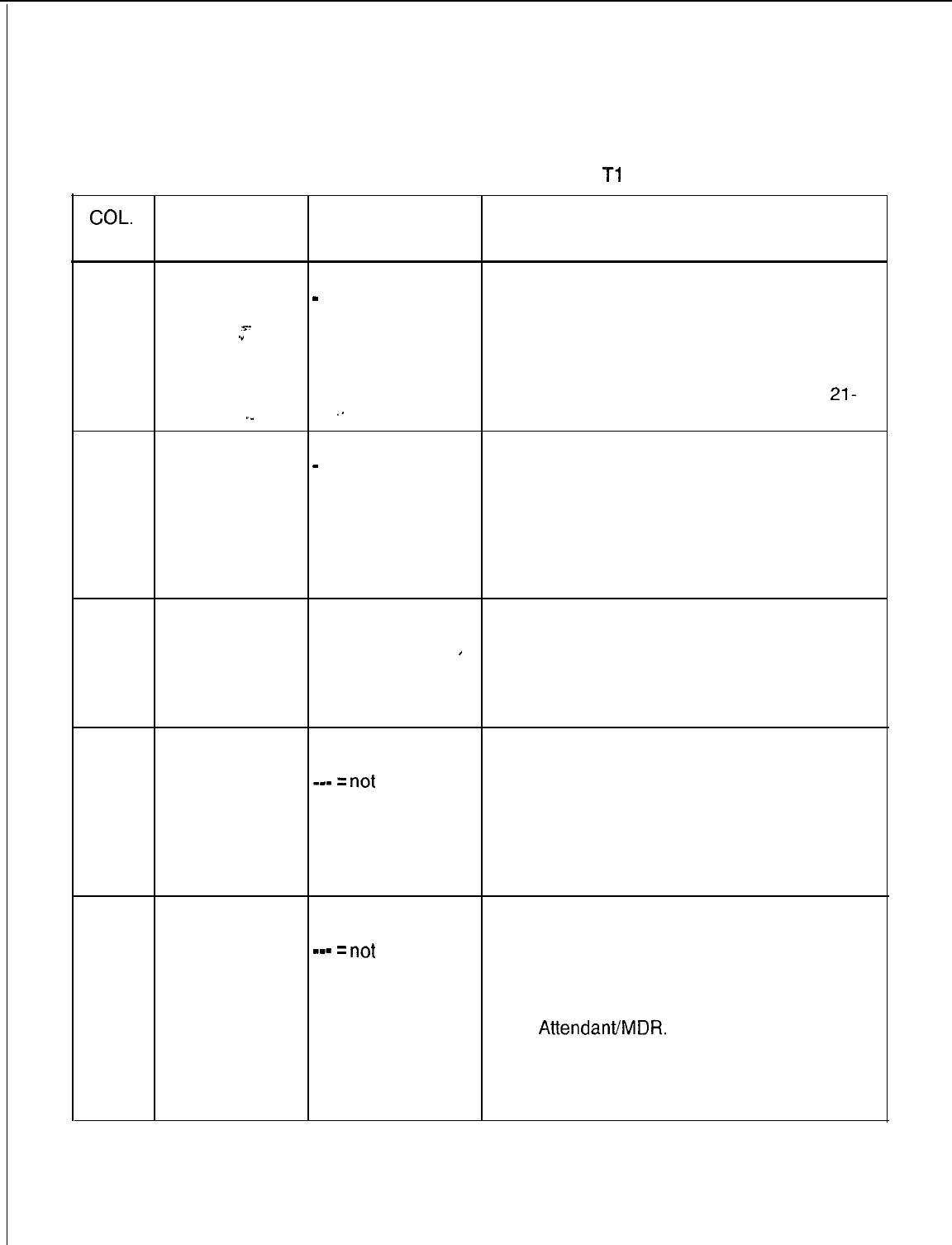
TL-130400-1001
COL.
NO.
Table 10.1
Entry Fields for Record Code
Tl
(Continued)
COL.
VALID
NAME ENTRIES COMMENTS
55
56
Trunk Homing
Selection
s-
.”
. . . .
._
Automatic
Circuit
Assurance
H = allowed
-
= not allowed
.-
Y = selected
-
= not selected
This field determines whether or not the trunk
group is allowed homing.
-Entering an H in this field provides trunk
homing, which acts like a terminal hunt group.
-Normally a dash is recommended in this
field. This provides circular hunting.
NOTE: If this field is marked H, columns
21-
22 must be marked OG or TW.
Enter Y if the ACA (Automatic Circuit
Assurance) feature option is used by the trunk
group.
-By monitoring the holding time for both long
and short calls, this feature gives an indication
of possible trunk problems.
-The definition of a long and short call is
determined by the following parameters.
57-58
Automatic 01-15 = number Enter the number of call attempts that must fall
Circuit of calls in the short below the seconds listed in columns 59-60
Assurance call
’
before a short call report is made.
Short Call -- = not selected -A default value is not provided for this field.
Threshold -This feature is also used for remote
maintenance.
59-61
Automatic
Circuit
Assurance
Short Call
Interval
001-255 =
seconds
_-
=
not
selected
1-3 = suggested
value
Enter the number of seconds that a trunk must
be seized before it is seen by the system as a
short call.
-This value should be set lower than the
normal amount of time the site spends on a
call (e.g., a telemarketing group may average
calls that are very short in length).
-A default value is not provided for this field.
62-64 Automatic
001-255 =
Enter the number of minutes that must pass
Circuit seconds before the short call threshold is reset.
Assurance
_-
=
not
-The above listed short call parameters are
Short Call Reset selected monitored for the amount of time set here.
Interval -If the above parameters are reached within
the time frame, then a short call report is sent
to the
Attendant/MDR.
-If the parameters are not met, the timer is
reset to zero and the short call parameters are
set back to zero.
-A default value is not provided for this field.
D-l 84
8187
SVR 5210
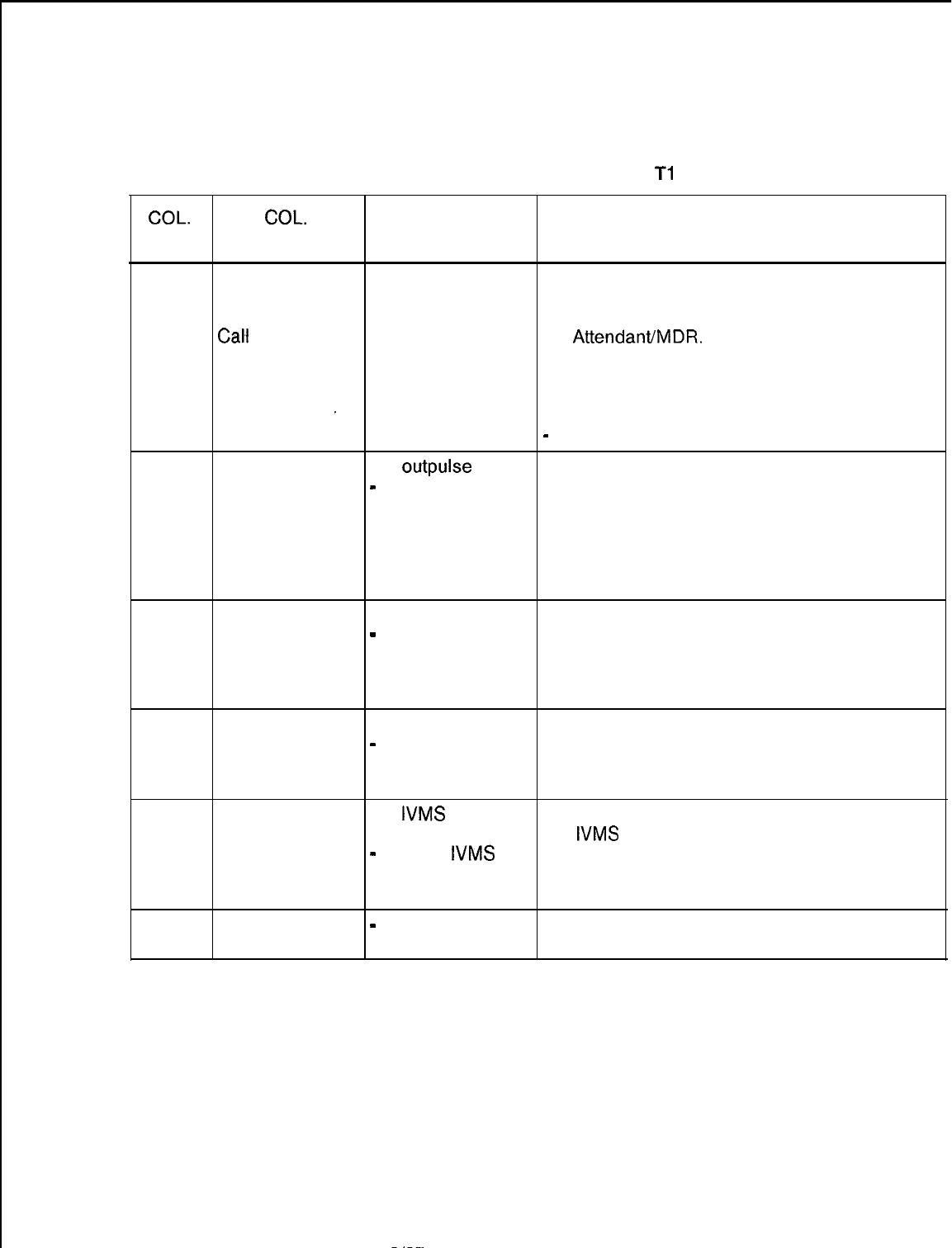
TL-130400-1001
Table 10.1
Entry Fields for Record Code
Tl
(Continued)
CQL. COL.
VALID
NO. NAME ENTRIES COMMENTS
65-67
Automatic
001-255 =
Enter the number of minutes that a trunk must
Circuit minutes be seized before a report is made.
Assurance Long --- = not -If this value is reached, a report is sent to
Calf
Interval selected the
AttendantIMDR.
45 = suggested This value should be set higher than the
value normal amount of time the site spends on a
call (e.g., a site that has the data option may
_be making long data calls).
-
A default value is not provided for this field.
68
Outgoing Trunk Y =
outpulse
FRL If the trunk group has been given an FRL
Group Facility
-
= not selected value, this field determines whether or not the
Restriction FRL value is outpulsed when an outgoing trunk
Level Outpulsed call is made.
NOTE: If the FRL option is used, this field will
normally be marked Y for Tie trunks
connecting two switches in a network.
69
70
71
Incoming Trunk
O-7 = number
This field determines the incoming FRL value
Group Default
-
= N/A (TCM not for the trunk group.
Facility equipped) NOTE: If a remote network system does not
Restriction have the capability to send an FRL, an FRL
Level value can be given to that incoming trunk.
Outgoing Trunk
O-7 = number
This field determines the FRL value to be
Group Facility
-
= N/A (TCM not outpulsed for the trunk group.
Restriction equipped) -The FRL value should only be outpulsed for
Level to Access a MERS networking environment.
Integrating Y =
IVMS
trunk Enter Y if the trunk group is used to support
Voice group the
IVMS
option.
Messaging
-
= not an
IVMS
System Trunk trunk group
Identifier
72
Reserved
-
= only allowed
entry
This field is not used for this SVR.
SVR 5210
8187
D-l 85

TL-130400-1001
Record Code T2:
Trunk Group Part
-
2
10.2 Record Code T2, Figure
10.2A,
provides parameters that
define trunk groups. This record code is used along with Record
Code
Tl
in defining trunk groups.
Columns 14-28 are only used if toll restriction is in effect. If the
trunk group does not have toll restriction, dash columns 14-28.
Figures containing flowcharts and examples for toll restriction
configurations are included at the end of this record code.
Programming information is as follows:
D-l 86
8187
s-
.”
.
.
.
.
l A flowchart (Figure
10.2B)
is included to explain toll restriction.
The flowchart assumes that a station classed as toll restricted
has dialed the trunk group access code. When toll restriction
. .
is placed on a trunk group, the flowchart explains the
checkpoints that the system uses to determine the type of toll
restriction that is to be used.
l Figures
10.2C
and
10.2D
explain three-digit and six-digit
analysis as applied to the system.
l Figures
10.2E
and
10.2F
show a cross-section of the
columns on Record Code T2 that apply to toll and code
restriction. The three types of toll and code restriction are
categorized and shown in examples.
l Figure
10.2G
is a flowchart that shows how to fill out the
various record codes that can be used for toll and code
restriction. These record codes are T2, CR, EC, AS, and DA.
It is recommended to read the flowchart before completing
these record codes.
SVR 5210
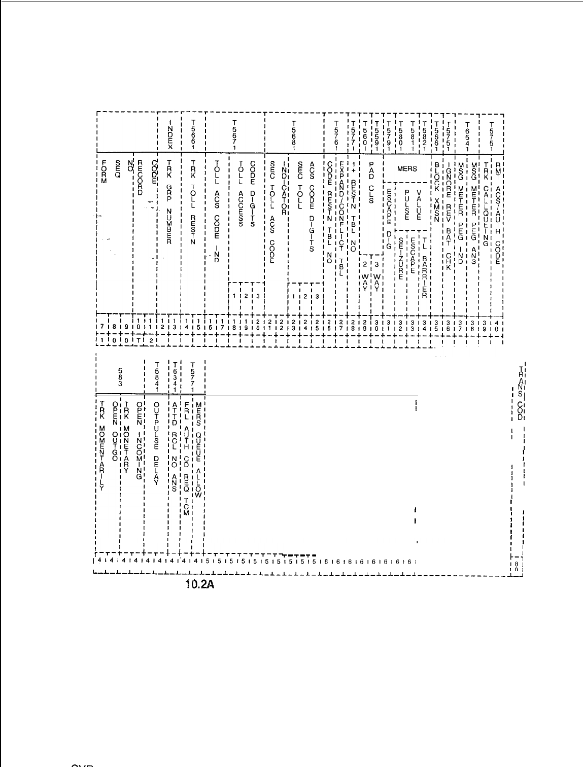
TL-130400-1001
----------1--
;
T;
I
RI
I
A’
;
.!I
;
CI
;
81
I E’
;
I
;
I
;
;
f
i
;
i
;
I
;
I
;
I
f
I
;
I
I
-
-
-
T
T
T
l--r--r--r--r--r--r--r-i
~414141414~4,41’4~4’515151515151515151516l6’6l6,6l6’6~6~
;-I
~11213141516171819101112131415161718~910111213141516171
18:
I-L-I-L-I-L-L-I-L-*-L_L
101
-L-I-L-L-I-I-L-I-I-I-~-~-~-~-~-~---------------~-~
Figure 10.2A Record Code T2: Trunk Group Data 2 Data Sheet
v-------r---
I
r-r---r---------------------------------------
I
T
I
I
I
I
1
I
/
I
I
I
I
I
I
I
I
I
I
I
I
I
I
I
I
/
I
I
I
I
I
SW
5210
8h37
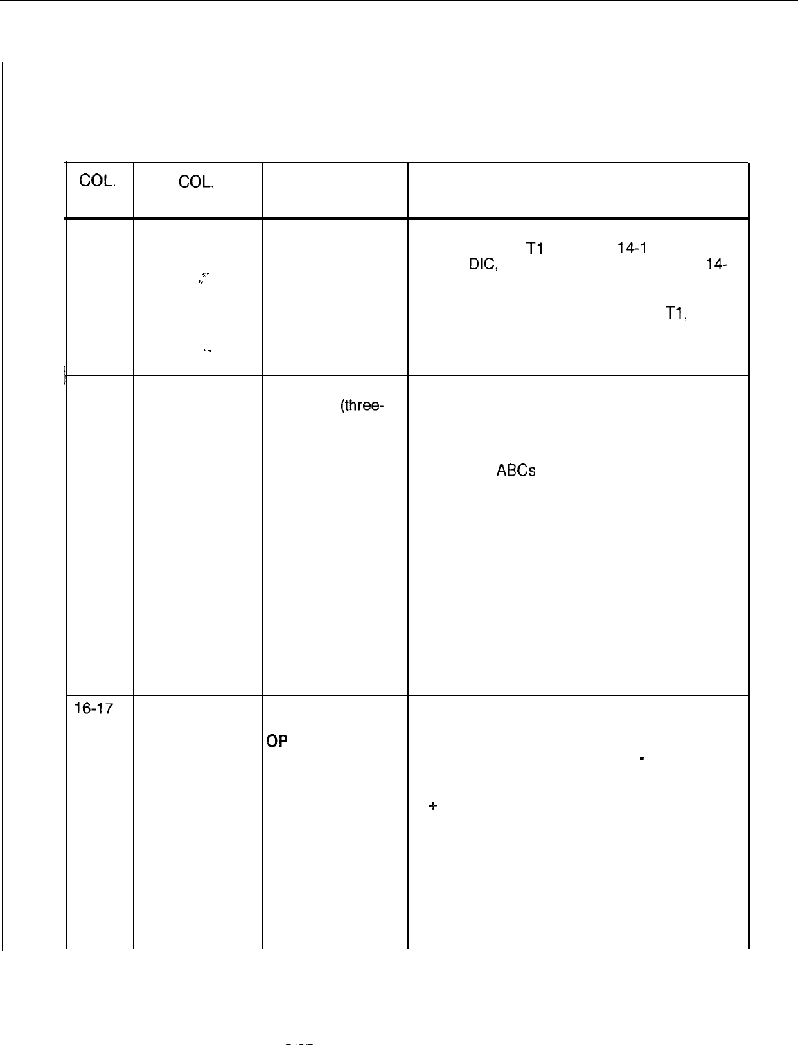
TL-130400-1001
Table 10.2 Entry Fields for Record Code T2
COL.
COL.
VALID
NO. NAME ENTRIES COMMENTS
12-13
Trunk Group 00-63 = number This field determines the trunk group number.
Number -If Record Code
Tl
, columns
14-l
6, are
marked
DIG,
PAG, REC, or NIC, columns
14-
Y.
.e
40 and 45-46 must be dashed.
.-Each trunk group number on this record
code must appear on Record Code
Tl,
columns 12-l 3.
. .
._
-Trunk group numbers must be unique
’
14-15
across this record code.
Trunk Toll TL = simple toll Assign the type of toll restriction placed on a
Restriction restriction
(three-
trunk group.
digit analysis) -TL is used for trunk groups required to
ET = expanded toll analyze the NPA dialed.
toll restriction -ET is used for trunk groups required to
(six-digit analysis) analyze the
ABCs
of the NPA dialed.
-- = N/A -If this field is marked ET, column 27 must
have an entry.
-If this field is marked TL, column 26 must
have an entry and columns 27-28 must be
dashed.
-If this field is marked --, columns 16-28
must be dashed.
-If a station has a displayable COS that
allows toll access, the call will bypass the toll
restriction placed on the trunk group.
-Toll access is assigned to stations on
Record Code DD, columns 14-15, by
marking the columns TA.
16-17
Toll Access NM = number Fields in columns 16-25 determine the
Code Digits: allowed access codes allowed to the toll restricted
Code Indicator
QP
= operator trunk group. The access codes determined
permitted by these fields are 1 + , 0 + or 0
-
. An
NR = number access code of 1 + is normally used to access
restricted toll trunks. In an NPA with conflicting codes,
OR = operator 1
+
is always dialed. An access code of 0 +
restricted is used to make an operator assisted toll call.
-- = allowed An access code of 0- is used to make a
credit card call (or a call that is dialed after
the digit 0 is dialed).
-Columns 16-20 determine whether or not
1 + dialing is allowed.
-Columns 21-25 determine whether or not
0+ or 0- dialing is allowed.
D-l 88
8187
SVR 5210
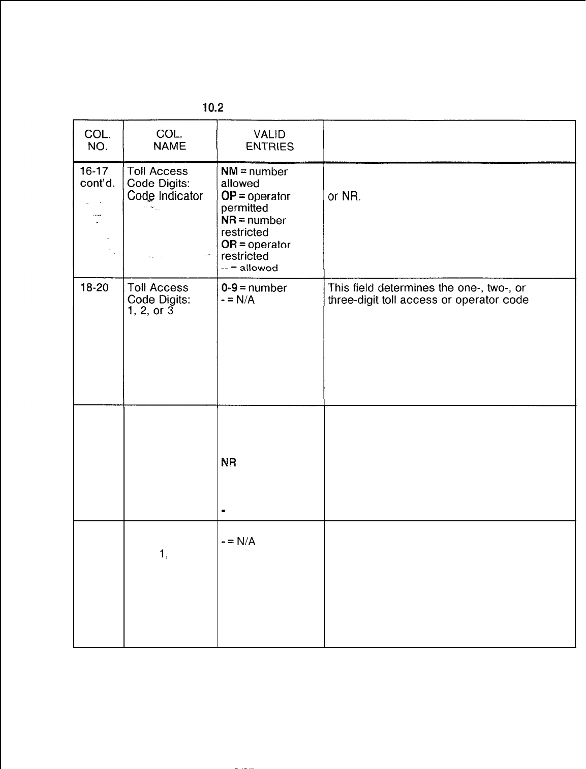
TL-130400-1001
Table
10.2 Entry Fields for Record Code T2 (Continued)
COMMENTS
-If toll restriction is
in
effect, for normal
applications this field will only be marked NM
-If this field is dashed, columns 18-20 and
23-25 must be dashed.
-If this field is not dashed, columns 18-20
and 23-25 must be marked 0-- to 999.
required for the trunk group.
-For normal applications, column 18 is
marked 1 and columns 19-20 are dashed.
-Columns 18-20 determine the digit while
columns 16-l 7 determine whether or not the
system allows access to that digit.
-If digit 1 is dashed, then digits 2 and 3 must
also be dashed.
21-22
Second Toll NM = number -Columns 21-25 are normally used to
Access: Code allowed determine whether 0 + or 0- dialing is
Indicator OP = operator allowed.
permitted -If toll restriction is in effect, for normal
NR
= number applications this field will only be marked OP
restricted or OR.
OR = operator NOTE: The entry for the toll access code and
restricted the second toll access code cannot be the
-
= allowed same.
23-25
Second Toll
O-9 = number
This field determines the one-, two-, or
Access Code
-=N/A
three-digit toll access or operator code
Digits
1,
2, or 3 required for the trunk group.
-For normal applications, column 18 is
marked 1 and columns 19-20 are dashed.
-Columns 18-20 determine the digit while
columns 16-17 determine whether or not the
system allows access to that digit.
-If digit 1 is dashed, then digits 2 and 3 must
also be dashed.
SVR 5210
8187
D-l 89
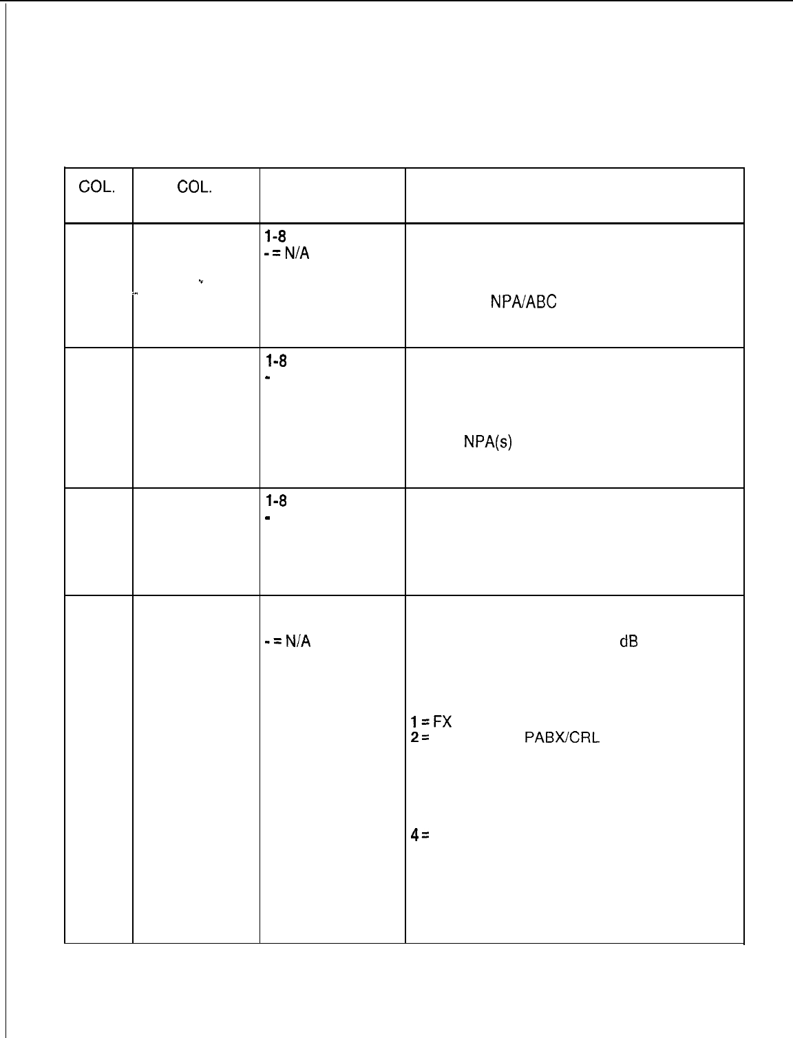
TL-130400-1001
COL.
NO.
Table 10.2 Entry Fields for Record
Code T2 (Continued)
COL.
VALID
NAME ENTRIES COMMENTS
26
Code
l-8
= number This field determines the code restriction table
Restriction
-=N/A
number used by the trunk group.
Table Number -This field points to Record Code CR,
.”
column 12. Column 12 is a table number for
-..
the allowed
NPAIABC
of that table.
-If an entry is made in this column, Record
Code CR must be completed.
. .
27
Expanded or
l-8
= number This field determines the expanded or
Conflicting
-
= N/A conflicting table number used for the trunk
Table Number
group.
-This field points to Record Code EC, column
12. Column 12 is a table number for the
allowed
NPA(s)
of that table.
-If an entry is made in this column, Record
Codes CR and EC must be completed.
28
1+ Code
l-8
= number Assign the code restriction table number used
Restriction
-
= N/A by the trunk group.
Table Number -This number is used when conflicting NPA
and ABC codes exist.
-If an entry is made in this column, Record
Code CR must be completed.
29
Pad Class
(two-way)
1-9
= number
or
-=N/A
Assign pad two-way trunk application for a
trunk group.
-This is used to put additional
dB
pads
(decimal level) on a trunk. This is used for
volume control.
-Two-way pertains to a two-way
connection.
l=FX
2=
PABWCO or
PABXICRL
trunks
3 = non-tandem PABX Tie trunks (This is
used in a tandem network, allowing the PABX
to access CO trunks from a remote PABX, but
not access Tie trunks that connect the remote
PABX to other PABXs in the network.
4=
satellite Tie trunks (This PABX only has Tie
trunks that connect it to a main switch. Other
trunks are accessed at the main switch.)
5 = inter-tandem PABX Tie trunks (This is
used in a tandem network, allowing incoming
PABX trunks to access CO lines, but not
access Tie lines to network PABXs.)
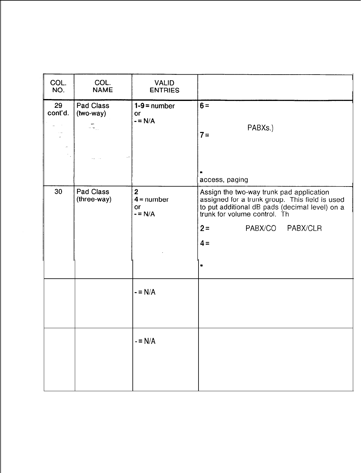
TL-130400-1001
Table 10.2 Entry Fields for Record Code T2 (Continued)
COMMENTS
6=
tandem PABX Tie trunks (This is used in a
tandem network, allowing incoming PABX
trunks to access CO lines as well as Tie
trunks to other
PABXs.)
7=
class 4 WATS trunks (normally a small CO
with limited capabilities)
8 = class 5 WATS trunks (This type of CO can
provide toll switching.)
9 = conference port
-
= dictation access, recorder announcer
access, or N/A
ree-way pertains
to a three-way connection.
2=
FX trunks,
PABXCO
or
PABXCLR
trunks,
class 5 WATS trunks
4=
non-tandem PABX Tie trunks, satellite Tie
trunks, inter-tandem PABX Tie trunks,
tandem PABX Tie trunks, class 4 WATS trunks
-
= dictation access, recorder announcer
access, paging access, or N/A.
31
MERS Escape
O-9 = digit
Assign the code used (number dialed) to
Digit
-=N/A
access off-network facilities after placing an
on-network MERS call.
NOTE: If an entry is made in this field, Record
Code Sl, columns 19 and 23, may require
entries.
32
MERS Pause
Value/Seizure l-5 = seconds
-=N/A
After a trunk is seized, this field determines the
amount of seconds the system waits before
sending the first digit.
-This is the pause applied after the escape
digit and allows a second dial tone on the
homing switch.
NOTE: If an entry is made in this field, Record
Code SI, column 18, may require an entry.
SVR 5210
8187
D-l 91
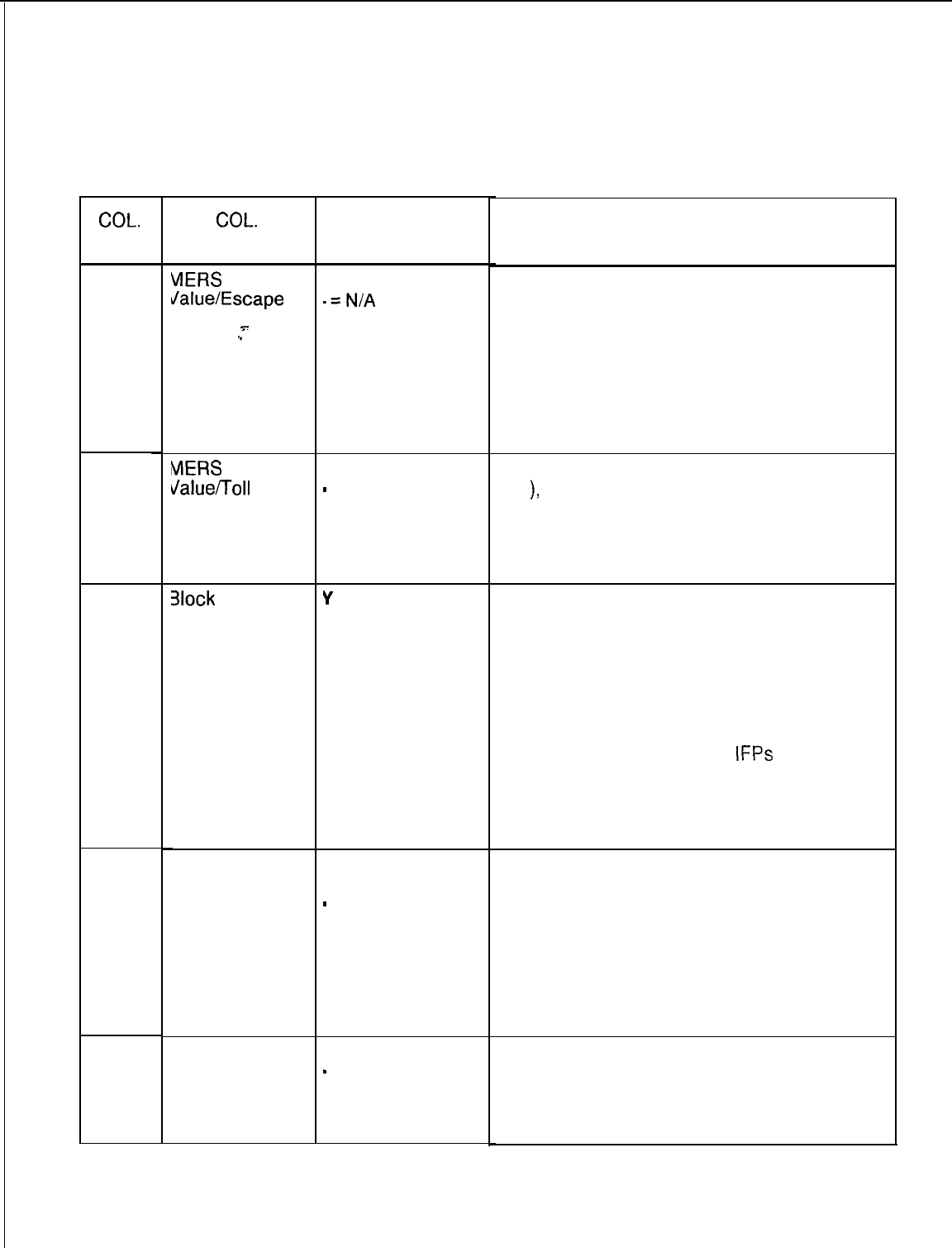
TL-130400-1001
Table 10.2 Entry Fields for Record Code T2
(Continued)
COL. COL.
VALID
NO. NAME ENTRIES
33
34
35
VlERS
Pause l-5 = seconds
Jalue/Escape
.=N/A
s-
.”
MERS
Pause
dalue/Toll
3arrier Code
3lock
Y
= blocked
Transmission N = not blocked
Ignore Reverse
Battery Check
Message Meter Y = allowed
Pegs Indicator
-
= not allowed
1-5 = seconds
-
= N/A
36
37
8/87
SVR 5210
I = ignore battery
check
-
= perform
battery check
COMMENTS
After the escape digit is sent, this field
determines the amount of seconds the system
waits before sending the next digits.
-Normally this field is only used for
applications involving an older CO. It provides
a pause after the first digit is dialed.
NOTE: If an entry is made in this field, Record
Code SI, columns 19 and 23, may require
entries.
After the toll barrier code is sent (type 1 + or
0 +
),
this field determines the amount of
seconds the system waits before sending the
next digit.
NOTE: If an entry is made in this field, Record
Code SI, column 20, must be marked B.
Enter Y if blocked transmission is to be
applied during outpulsing before dialing is
completed.
-This is used in applications where a DTMF
station accesses a trunk group with outgoing
DP signaling and is then fed to a CO that has
combined DP and DTMF receivers.
-It is recommended to apply block
transmission to systems with
IFPs
on Tie
trunks.
-If block transmission is required and not
performed, the result is a transmission of
double digits.
Enter Y if the reverse battery check is ignored
by the system that acknowledges disconnect
supervision.
-An area serviced by a Bell CO should be
marked I. If an FGBS pay phone is used, it is
recommended to dash this field.
-If ignore battery check is required and not
performed, the system will see it as a
disconnect.
Enter Y if the message meter pegs indicator
for calls terminating to a trunk group is used.
-This field is only used for motel applications
that use the message meter pegs feature on
the KEDU.
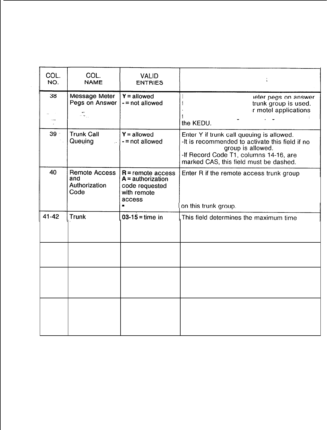
TL-130400-1001
Table 10.2 Entry Fields for Record Code T2 (Continued)
COMMENTS
Enter Y if the message m
for calls terminating to a
-This field is only used fo
that use the message meter pegs feature
on
alternate trunk
feature
is
allowed for 24-hour a day service
on this trunk group.
Enter A if an authorization code is needed to
access the remote access trunk group feature
-
= not
allowed
Momentarily hundreds of
Open Outgoing allowed for a loop to remain open on an
milliseconds outgoing trunk before the call is dropped.
-It is recommended to enter 03 in this field.
43-44 Trunk 02-l 5 = time in This field determines the maximum time for a
Momentarily hundreds of
Open Incoming milliseconds loop to remain open on an incoming trunk call
before the call is dropped.
45-46 Outpulsing 02-l 5 = time in Assign the time the system waits before
Delay 100 ms intervals or beginning to send digits on an outgoing trunk.
10 = suggested
value
47
Attendant Recall T = allowed
After No Answer N = not allowed
Timeout
Enter T if trunk calls recall to the attendant
after the no answer timeout parameter is
reached.
-This timing parameter is set on Record
Code OT, columns 45-47.
SVR 5210
8187
D-l 93
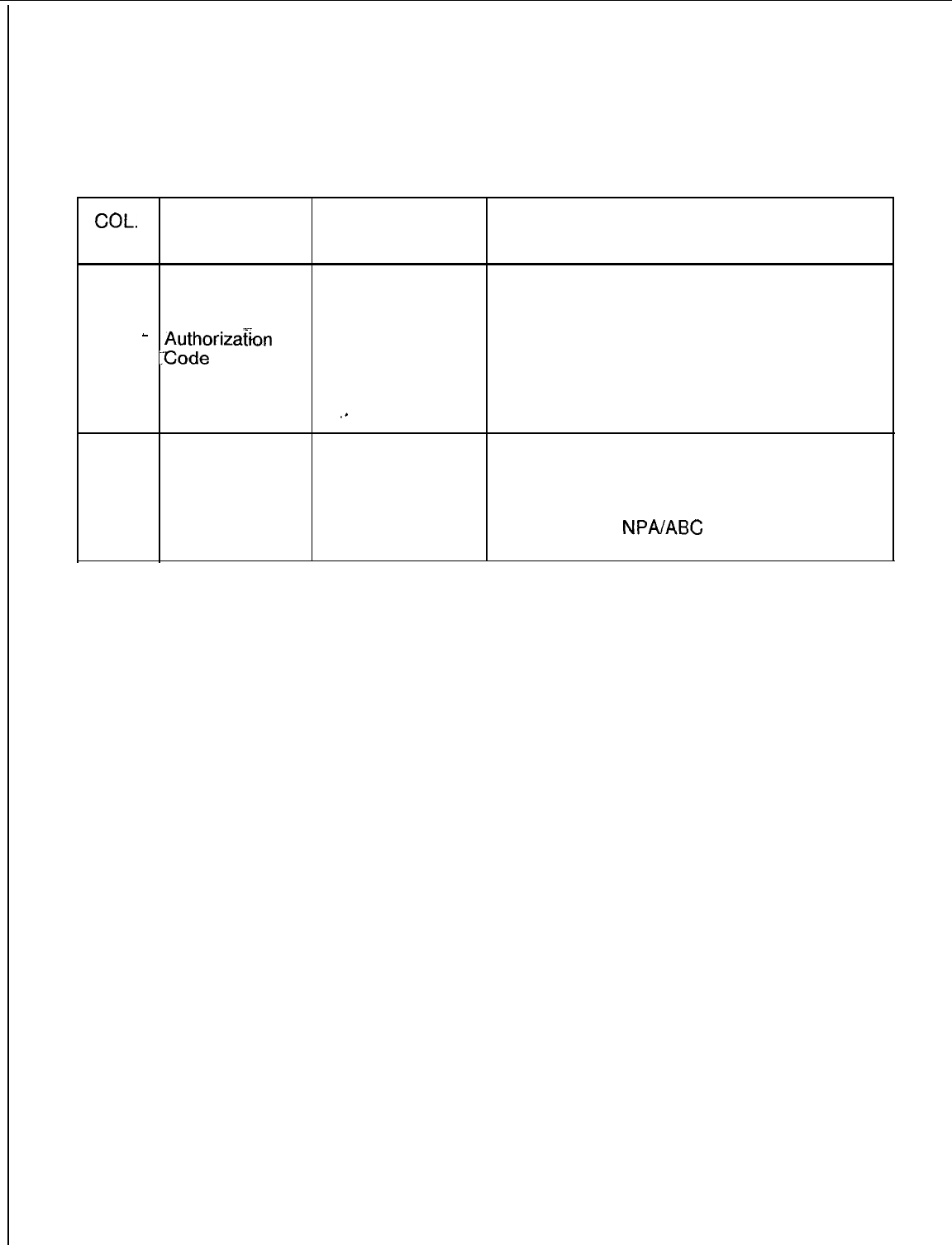
TL-130400-1001
Table 10.2 Entry Fields for Record Code T2 (Continued)
COL.
COL.
VALID
NO. NAME ENTRIES COMMENTS
48 Facility T = allow request Enter T if this trunk group requests an
Restriction N = disallow authorization code even if a TCM (Traveling,
Level
-
Authorizatkm
request Class Mark) digit is received.
:%ode
Request
When Traveling
Class Mark Has
Been Received
‘*
49
MERS Queue
Allow T = allowed MERS Enter T if MERS queuing is allowed for the
queuing trunk group.
N = disallowed NOTE: When this feature is activated, the
MERS queuing queuing begins with the first MERS route
allowed for the
NPAIABC
dialed and continues
to the other routes.
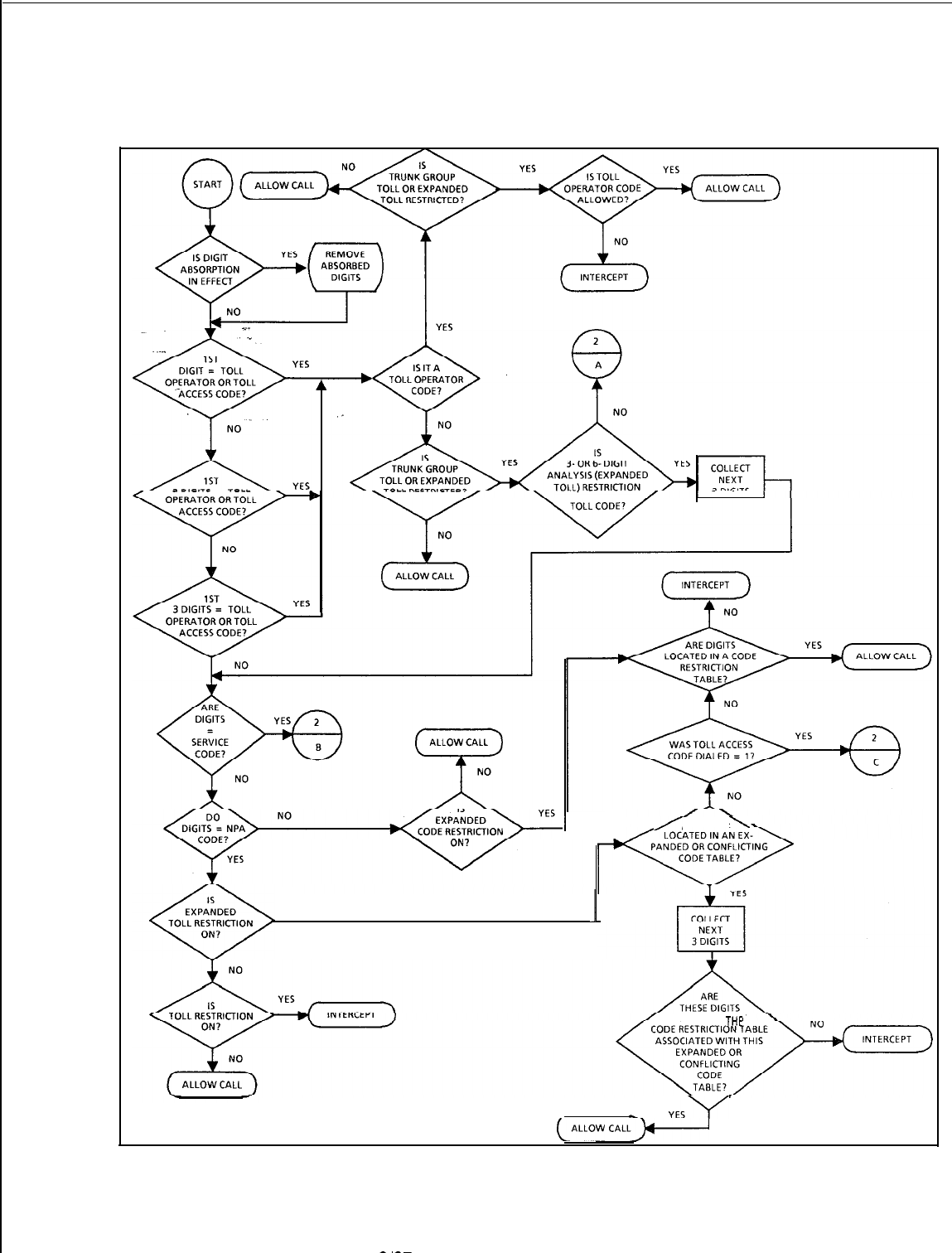
TL-130400-1001
NEEDED AFTER
J
I
/
\
ARE DIGITS
YES
1
LOCATED IN
TV=
-
YES\/
(ALLOW
CALL)-1
Figure 10.28 Trunk Group Toll Restriction Flowchart
SVR
5210
8187
D-195
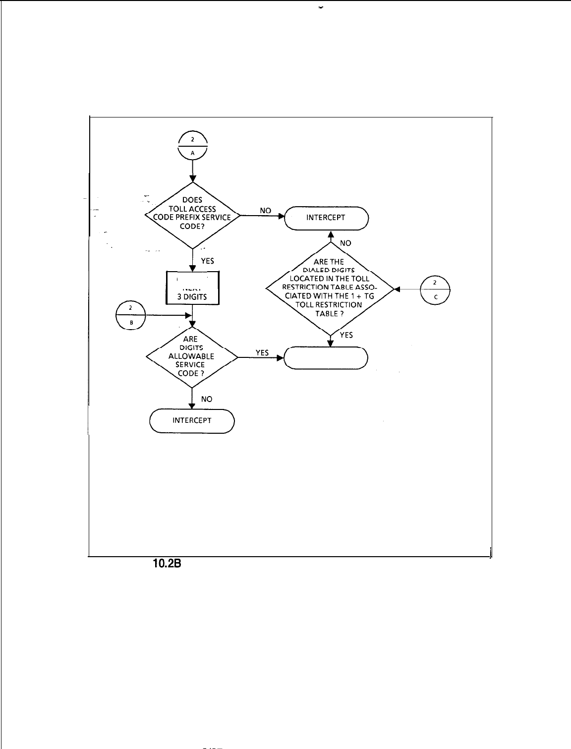
-
TL-130400-1001
D-l 96
A
Y
COLLECT
NEXT
ALLOW CALL
I
Figure
10.2B
Trunk Group Toll Restriction Flowchart (Continued)
8/87
SVR 5210
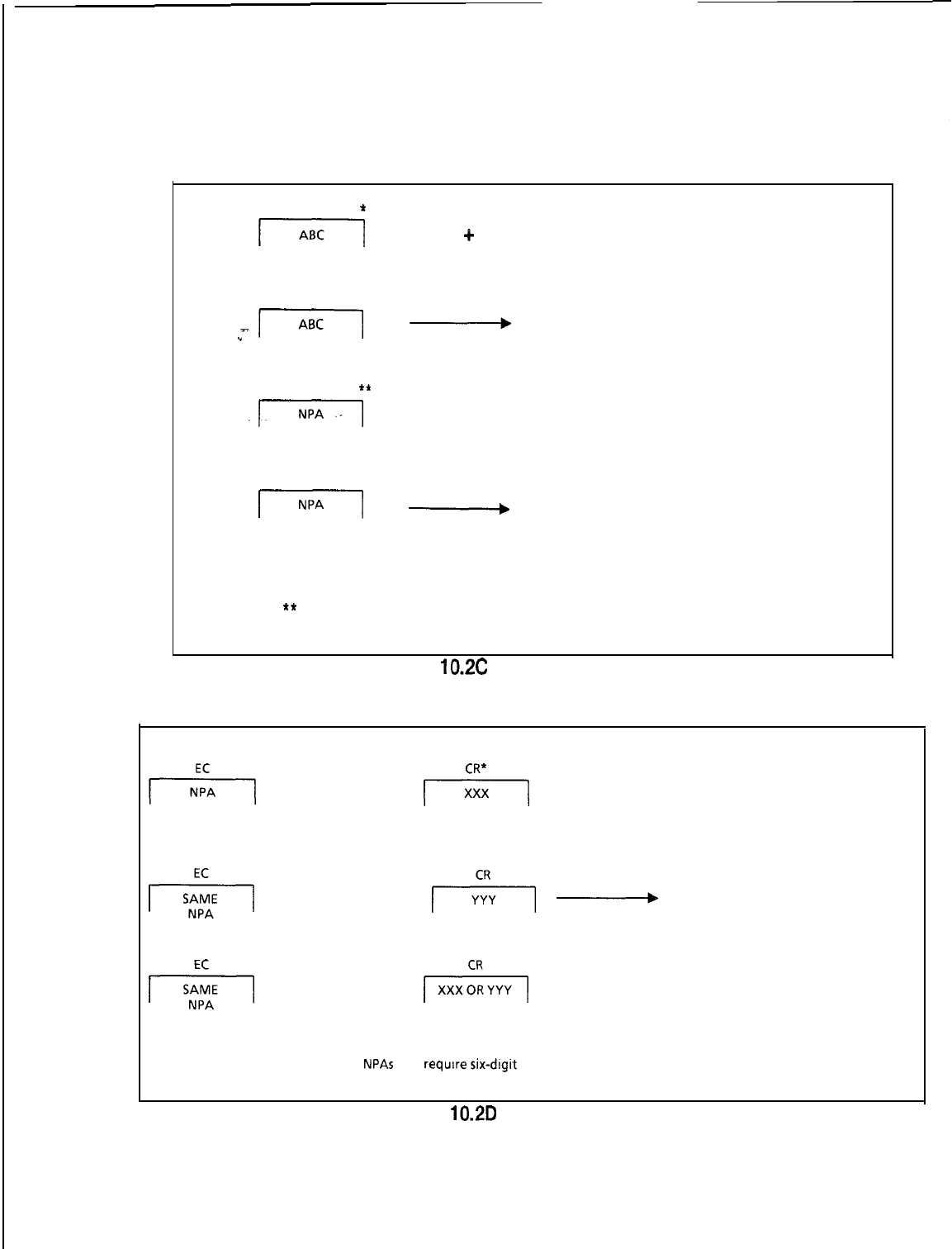
TL-130400-1001
ASSIGNED ON
RECORD CODE CR
*
l-7G-j
+
XXXX = LOCAL CALLS
ALLOWED
NOT
ASSIGNED ON
RECORD CODE CR
J-Tiq
A
INTERCEPT = LOCAL CALLS
.”
BLOCKED
ASSIGNED ON
RECORD CODE CR
**
.ITl
+
XXX + XXXX = LONG DISTANCE CALL
ALLOWED
NOT
ASSIGNED ON
RECORD CODE CR
1-1
-
INTERCEPT = LONG DISTANCE CALL
BLOCKED
NOTES: *Table 10.3 of Record Code CR should contain the allowed ABC codes of
the HNPA.
**
When three-digit analysis is required for an NPA code, it also should be
placed in Table 10.3 of Record Code CR.
Figure
10.2C
Three-Digit Analysis
ASSIGNED ON ASSIGNED ON
RECORD CODE RECORD CODE
+I
+
+I
+
XXXX = LONG DISTANCE CALL
ALLOWED
NOT
ASSIGNED ON ASSIGNED ON
RECORD CODE RECORD CODE
+J
+
*i-d
INTERCEPT= LONG DISTANCE CALL
BLOCKED
ASSIGNED ON ASSIGNED ON
RECORD CODE RECORD CODE
+I
+
pi%q
+
XXXX = LONG DISTANCE CALL
ALLOWED
NOTE: lA separate code restriction table is assigned for each NPA or group of
NPAs
that
require
six-dlgit
analysis.
Figure
10.2D
Six-Digit Analysis
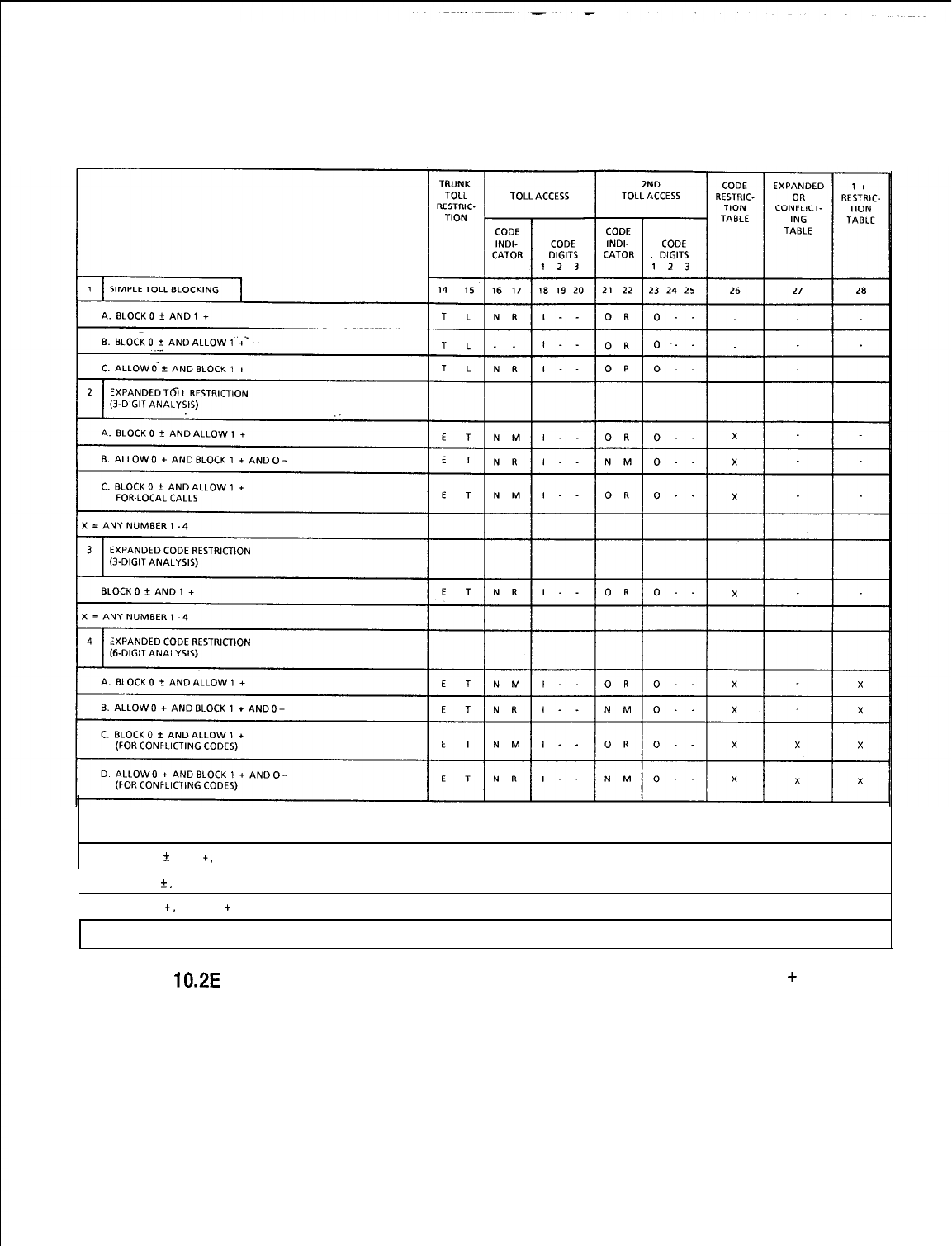
TL-130400-1001
NOTE: THESE EXAMPLES ARE JUST A FEW OF THE POSSIBLE COMBINATIONS.
1
SIMPLE TOLL BLOCKING
A. BLOCKS 0
C
AND 1
+,
ALLOWS ALL LOCAL CALLS
B BLOCKS 0
k,
ALLOWS 1 + AND ALL LOCAL CALLS
1C. BLOCKS 1
+,
ALLOWS 0
+
AND ALL LOCAL CALLS
Figure 10.2E
Samples of Toll Restriction for Areas with Toll Access Codes (1
+
Most
Common) and 0+ Dialing
D-l 98
8187
SVR 5210
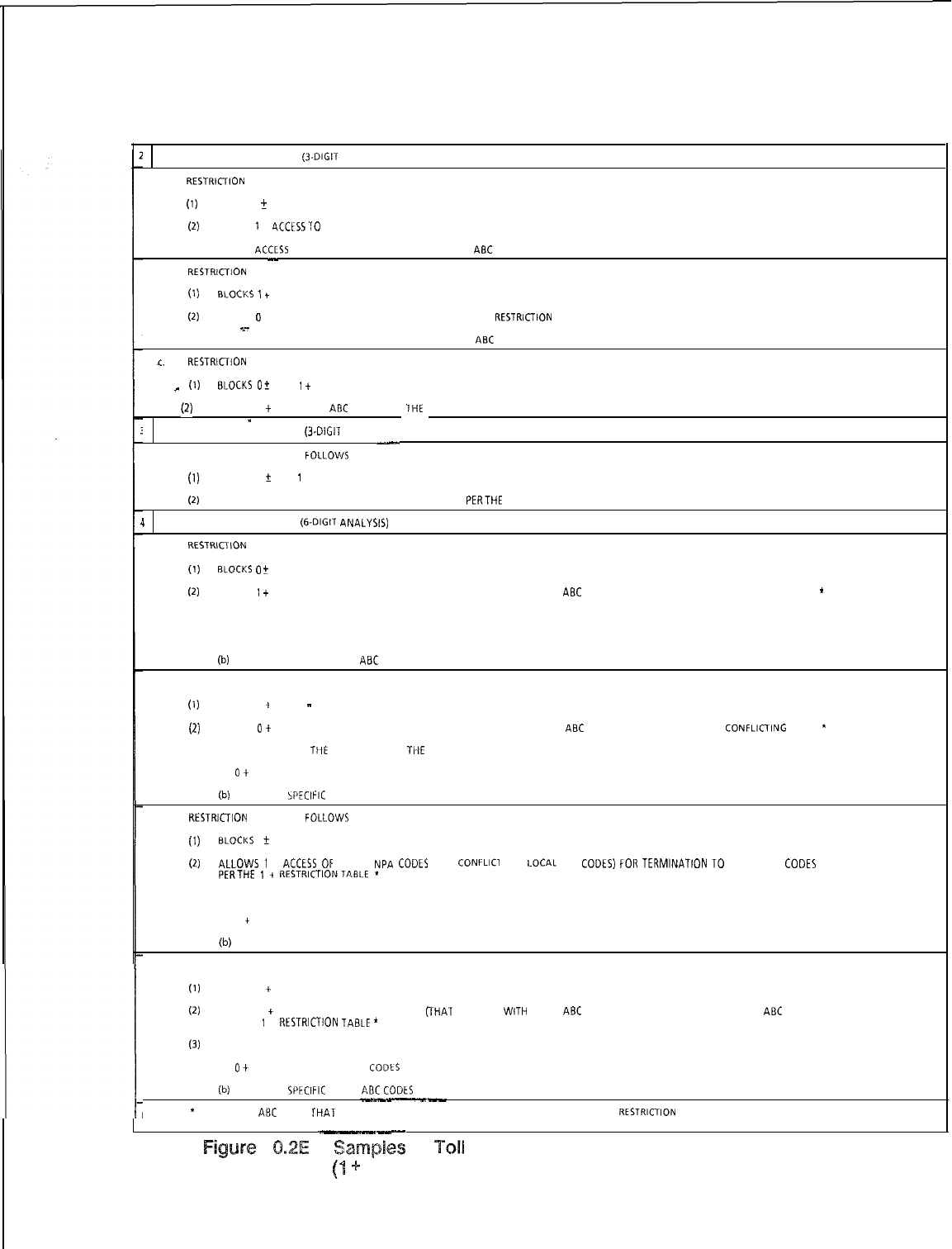
TL-130400-1001
EXPANDED TOLL RESTRICTION
(3.DIGIT
ANALYSIS)
A.
RESTRlCllON
DIVIDED AS FOLLOWS:
(1)
BLOCKS 0
f
(2)
ALLOWS 1 +
4CCESS?O
SPECIFIC NPA CODES pt” THE CODE RESTRICTION TABLE.
(3) ALLOWS
ACCLSS
EITHER TO ALL OR ONLY SPECIFIC LOCAL
AaC
CODES PER THE CODE RESTRICTION TABLE.
-
a.
RESTRlCllON
DIVIDED AS FOLLOWS:
(1) aLocKs
7
+
AND 0
(2)
ALLOWS
0
+ ACCESS TO SPECIFIC NPA CODES PLR THE CODE
RESTRIcTION
TABLE.
x-
(3) ALLOWS ACCESS EITHER TO ALL OR ONLY SPECIFIC LOCAL
ABC
CODES PER THE CODE RESTRICTION TABLE.
1c.
RESTRIcTION
DIVIDED AS FOLLOWS:
_
(1) aI.OCKS
O+
AND 1
+
NPA.
p)
ALLOWS 1
+
FOR LOCAL
ABC
CODES PER
1HE
CODE RESTRICTION TABLE.
--
_
I
EXPANDED CODE RESTRICTION
(3~DIGIT
ANALYSIS)
-
RESTRICTION DIVIDED AS
FOLL.OWS
(1)
BLOCKS 0
f
AND 1 +
(2)
ALLOWS ACCESS ONLY TO SPECIFIC LOCAL ABC CODES
PERTHE
CODE RESTRICTION TABLE.
I
EXPANDED CODE RESTRICTION
(&DIGIT
ANAI.YSIS)
A.
“ESTKlCllON
DIVIDED AS FOLLOWS:
(1) RLOCKS
0
f
(2)
ALLOWS 1
+
ACCESS OF CERTAIN NPA CODES FOR TERMINATION TO SPECIFIC
ABC
CODES PER THE EXPANDED 0” CONFLICTING TABLE.
*
(3) ALLOWS ACCESS TO THE FOLLOWING PER THE CODE RESTRICTION TABLE:
(a) 1 + ACCESS OF SPECIFIC NPA CODES.
(b)
ACCESS OF SPECIFIC LOCAL
ABC
CODES.
a.
RESTRICTION DIVIDED AS FOLLOWS.
(1)
BLOCKS 1
+
AND 0
-
(2)
ALLOWS
0
+
ACCESS OF CERTAIN NPA CODES FOR TERMINATION TO SPECIFIC
ABC
CODES PER THE EXPANDED 0”
CONFLlCllNG
TABLE.
*
(3) ALLOWS ACCESS TO
TIIE
FOLLOWING PER
TI-IE
CODE RESTRICTION TABLE:
(a)
0
+
ACCESS OF SPECIFIC NPA CODES
(b)
ACCESS OF
5PECIFIC
LOCAI. ABC CODLS
C.
RESTRlCllON
DIVIDED AS
FOLLOwS
(1) BLCCKS
0
r
(2)
ALLOWS
i
+
ACCESS
0~
CERTAIN
NPA
CODES
(THAT
CONFLICT
WITH
LOCAL
Aac
CODES)
fo”
TERMINATION
~0
SPECIFIC Aac
CODES
PERTHE
1
+
RESTRICTIONTABLE
*
(3) ALLOWS ACCESS TO THE FOLLOWING PER THE CODE RESTRICTION TABLE:
(a) 1
+
ACCESS OF SPECIFIC NPA CODES
(b)
ACCESS OF SPECIFIC LOCAL ABC CODES
D. RESTRICTION DIVIDED AS FOLLOWS’
(1)
BLOCKS 1
+
AND 0 --
(2)
ALLOWS 0
+
ACCESS OF CERTAIN NPA CODES
VHAT
CONFLICT
WITH
LOCAL
ABC
CODES) FOR TERMINATION TO SPECIFIC
ABC
CODES
PER THE 1 +
RESTRICUON
TABLE
’
(3)
ALLOWS ACCESS TO THC FOLLOWING PER THE CODE RESTRICTION TABLE:
(a)
0
+
ACCESS OF SPECIFIC NPA
CODtS
(b)
ACCESS OF
SPFCIFIC
LOCAL
AaC
CODtS
--~-
NOTE:
*
THE
ABC
CODE5
THAT
ARE LINKED TO THE NPA CODES ARE PLACED IN ANOTHER CODE
“ESTRI‘UON
TABLE ON RECORD CODE CR.
.--
Figure 4 0.2E Ssmpilss
of
Tall
Restriction for Areas With Toll Access Codes
(I
+
Most Common) and 0+ Dialing (Continued)
SVR 5210
8187
D-l 99
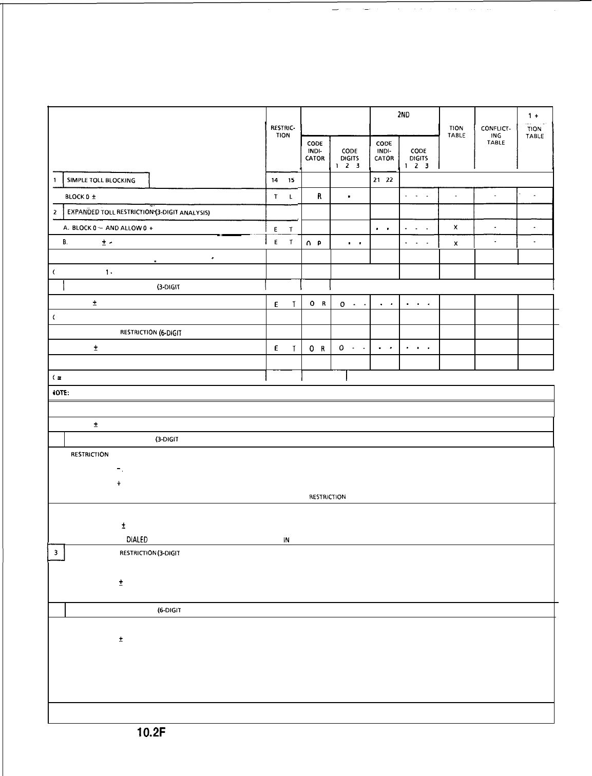
TL-130400-1001
TRUNK 2ND CODE EXPANDED
1+
TOLL TOLL ACCESS TOLL ACCESS RESTRIC- OR RESTRIC-
17
EXPANbED
TOLL
RESTRICIIONO-DIGIT
ANALYSIS)
B.
ALLOW0
f
-~______
--1
16 17
0
R
N M
n
P
18 19 20
0
-
0 . .
0
-
-
.
.
I
I
I
23 24 25 26 27 28
.
.
_
(
= ANY NUMBER
I-
4
II
3
1
EXPANDED CODE RESTRICTION (3-DIGIT ANALYSIS)
I
-17
I I I II
I
BLOCK 0
f
E
T
OR
0..
_.
__.
X
(
= ANY NUMBER l-4
4
EXPANDED CODE RESTRI~~ON (~-DIGIT AN
A
LYS
I
S)
BLOCK 0
CE
T
OR
0..
_.
.-.
X
X
(
=
ANY NUMBER l-4
I--I
---I-
I I I II I
(OTE: THESE EXAMPLES ARE JUST A FEW OF THE POSSIBLE COMBINATIONS.
1
SIMPLE TOLL BLOCKING
BLOCK 0
f
AND FOREIGN NPA CALLS, ALLOWS ALL LOCAL.
2EXPANDED TOLL RESTRICTION (3-DIGIT ANALYSIS)
A.
RESTRlCllON
DIVIDED AS FOLLOWS:
(1) BLOCKS 0
-.
(2) ALLOWS 0 + CALLS TO NPA OR LOCAL ABC CODES PROGRAMMED IN THE CODE RESTRICTION TABLE.
(3) BLOCKS ANY DIALED NPA OR LOCAL ABC CODES NOT PROGRAMMED IN CODE RESTRlClLON TABLE
B. RESTRICTION DIVIDED AS FOLLOWS:
(1) ALLOWS 0
?r
(2) BLOCKS ANY DlALED NPA OR LOCAL ABC CODES NOT PROGRAMMED IN CODE RESTRICTION TABLE
EXPANDED CODE RESTRltrlON (3-DIGIT ANALYSIS)
RESTRICTION DIVIDED AS FOLLOWS:
(1) BLOCKS 0
+
(2) ALLOWS ANY DIALED NPA OR LOCAL ABC CODES PROGRAMMED IN CODE RESTRICTION TABLE
4EXPANDED CODE RESTRICTION (6.DIGIT ANALYSIS)
A. RESTRICTION DIVIDED AS FOLLOWS:
(1) BLOCKS 0
f
(2) ALLOWS ACCESS OF CERTAIN NPA CODES FOR TERMINATION TO SPECIFIC ABC CODES PER THE EXPANDED OR CONFLICTING TABLE.’
(3) ALLOWS ACCESS TO THE FOLLOWING PER THE CODE RESTRICTION TABLE:
(a) ACCESS OF SPECIFIC NPA CODES.
(b) ACCESS OF SPECIFIC LOCAL ABC CODES.
YOTE:
l
THE ABC CODES THAT ARE LINKED TO THE NPA CODES ARE PLACED IN ANOTHER CODE RESTRICTION TABLE ON RECORD CODE CR.
Figure
10.2F
Samples of Toll Restriction for Areas with 0 + Dialing Alone
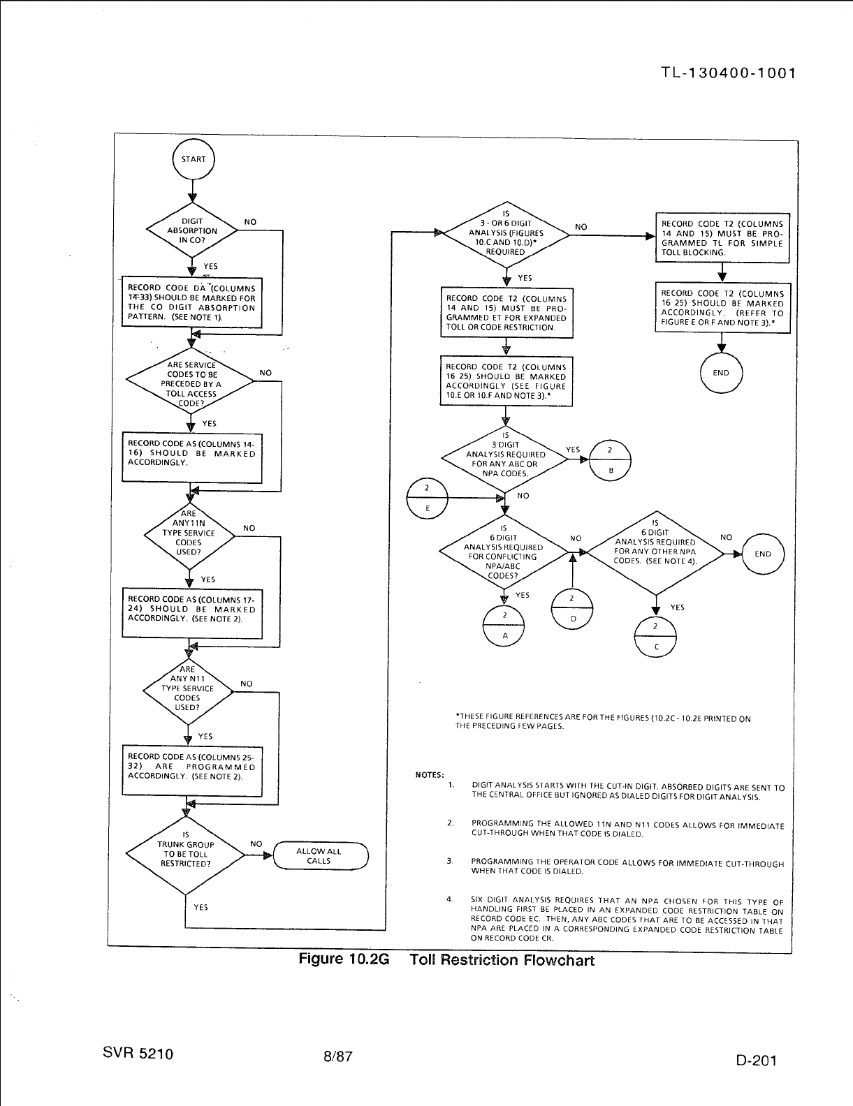
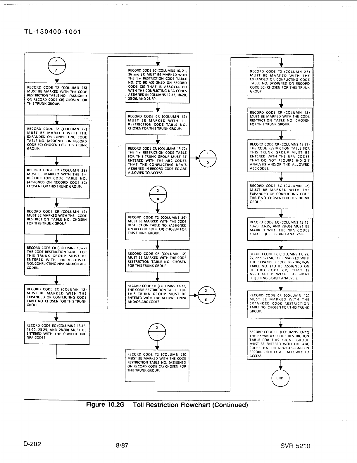
TL-130400-1001
Record Code CR:
Code Restriction
10.3 Record Code CR, Figure 40.3, gives toll restricted stations
limited DDD (Direct Distance Dialing) access. A maximum of
Numbers
eight code restriction tables are provided in the system’s data
base. Each code restriction table can contain up to 1,000
NPA/ABC
codes.
x-
.”
.
.
.
.
SVR 5210
For normal applications, one code restriction table is all that is
required, and it is assigned to all applicable trunk groups. This
table includes all the allowed ABC codes of the HNPA (Home
Numbering Plan Area) and all the FNPA (Foreign Numbering
Plan Area) codes. Toll restriction stations accessing a trunk
group assigned to this table are allowed to make calls to the
NPAs/ABCs
that are listed.
.
.
NOTE: When a code restriction table is assigned to a trunk
group, normal
toll
restriction checks are expanded. The system
allows only toll restricted stations accessing the trunk group to
complete calls to codes entered in this table. These can be
assigned per trunk group.
If greater flexibility is needed, up to eight tables can be defined
with NPA /ABC codes. These tables can be assigned to different
trunk groups. Toll restricted stations can be assigned to access
only certain trunk groups. Since these trunk groups are only
allowed to access certain
NPAs/ABCs,
the stations are restricted
from calling unlisted
NPAs/ABCs.
If six-digit analysis is needed for any
NPA(s),
Record Code EC
must also be completed. Six-digit analysis is required for the
following reasons:
Q
An NPA has ABC(s) that are conflicting codes. That is, the
ABC has a 0 or
1
as the middle (B) digit.
@
Cross boundary dialing is in effect (e.g., calls to certain
ABCs
within an NPA other than the HNPA are dialed/billed as local
calls).
o
Certain ABC(s) within the NPA will be treated in a different
manner than other
ABCs.
That is, they will be routed differently
because some
ABCs
are local calls while others are toll calls
(e.g., an
FX
line or toll
ABCs
for the HNPA).
8187
D-203
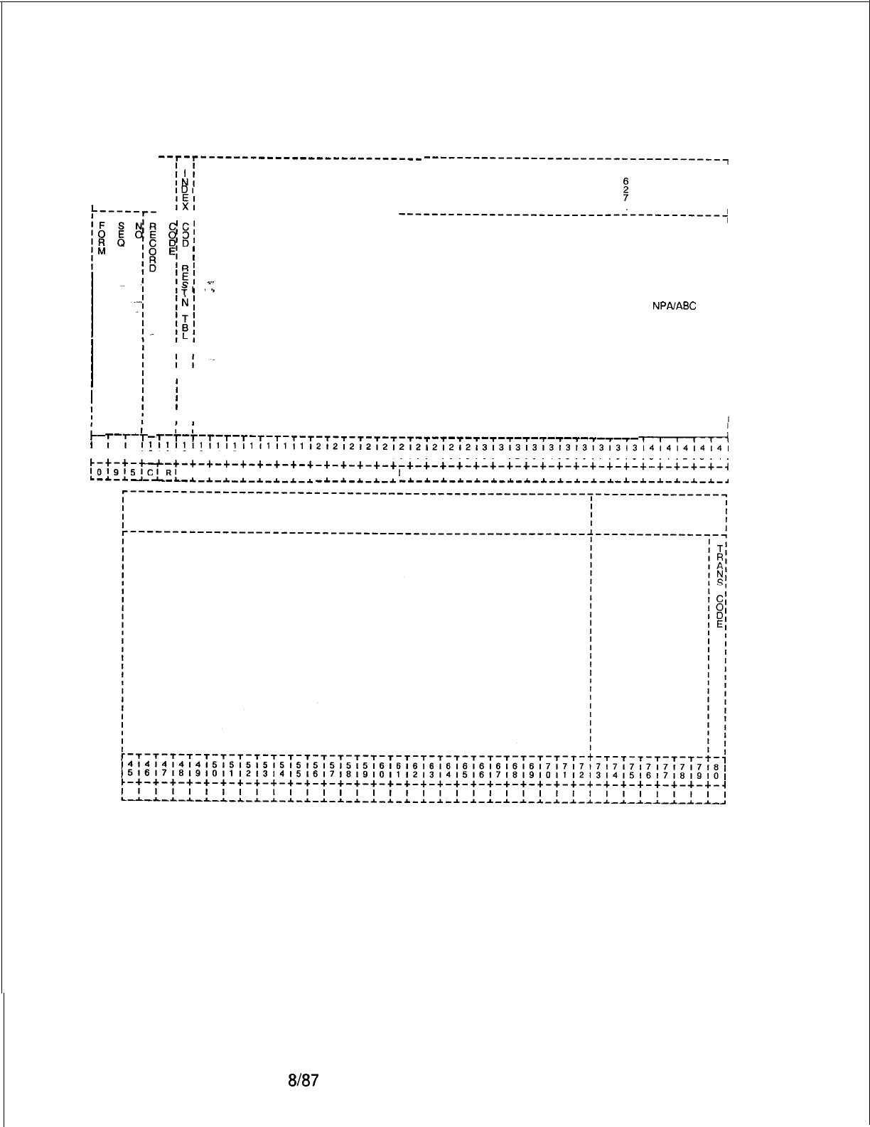
TL-130400-1001
r-------
--r-r---------------------------
hi
------------------------------------~
TI
IDI
IEI
s
I
I
I
IX1
I
--r-r---------------------~--
1
pi
---------------------------------------t
I
I
El
E
;
I
I
‘RI
I
;$I
r-
I
I
Tl
(‘I
I
1NI
I
ALLOWABLE 3-DIGIT
NPAIABC
I
‘Ti
CODENUMBERS I
!?I
I
I
I
IL1
I I
I
II’
I I
I
I
I
I
I
I
I I
;
I-ii
l
7-7-r
r-r-r-r-r-r-r-r-r-T-T-T-r-s-T-T-s-T-r-T--
l-n-r-i
~~~~~~~~~~~~~~~~~~~~~~~~~~~~~~~~~~~~~~~~~~~~~~~~~~~~~~~~~~~~~~~~~~~~~~~
17181910111213141516171819101112131415161718191011121314151617181910111213141
c-+-+-u-+-+-+-+-+-+-+-+-+-+-+-+-+-+-+-+-+-+-+-+-+-+-+-+-+-+-+-+-+-+-+-+-+-i
IOl9l5lCIRI
I I I I I I I I I I I I I
I
I I I I I I I I I I I I I I I I I I I
L-~-*----L--C-~-~-~-~-~-~-~
-.&.-A-L-A.-&
-~-*-~-~-~-~-~-~-~-*-~-~-~
-&-&-.&-4.-A-*-d
D-204
Figure 10.3
Record Code CR: Code Restriction Numbers Data Sheet
8f87
SVR 5210
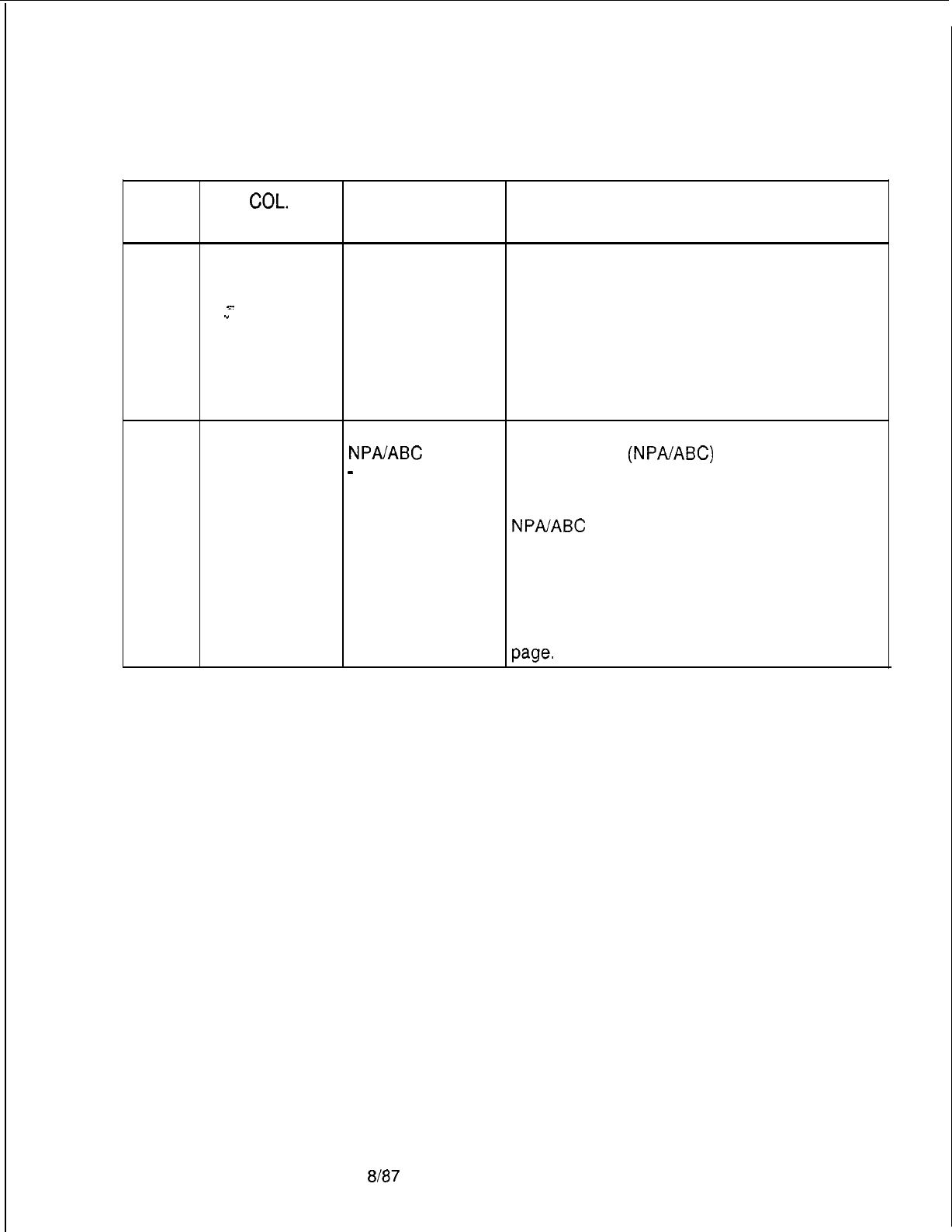
TL-130400-1001
Table 10.3 Entry Fields for Record Code
CR
COL.
COL.
VALID
NO. NAME ENTRIES COMMENTS
12
. . .
Code
Restriction
Table
x-
.”
l-8 = number This field determines the table number
assigned to the allowable codes listed in
columns 13-72.
-This number is used by the system for
identification purposes.
.
-A code restriction table with no codes
allowed is programmed by entering the code
restriction table number in column 12 and
dashes for the first entry in columns 13-15.
13-72
Allowable
000-999 =
This field determines the allowable three-digit
Three-Digit
NPAIABC
number code numbers
(NPAABC)
that can be
Numbering Plan
-
= range marker assigned for the possible eight different code
Area/ABC Code , = end of range restriction tables.
Numbers marker -Commas are entered between individual
NPA/ABC
codes (e.g., 220,474).
-Dashes are entered to indicate a series of
codes (e.g., 220-229).
-Column 72 can only contain a comma.
-When a code restriction table is assigned in
column 12, the codes are entered in
sequence going from left to right across the
page.
SVR 5210
8187 D-205
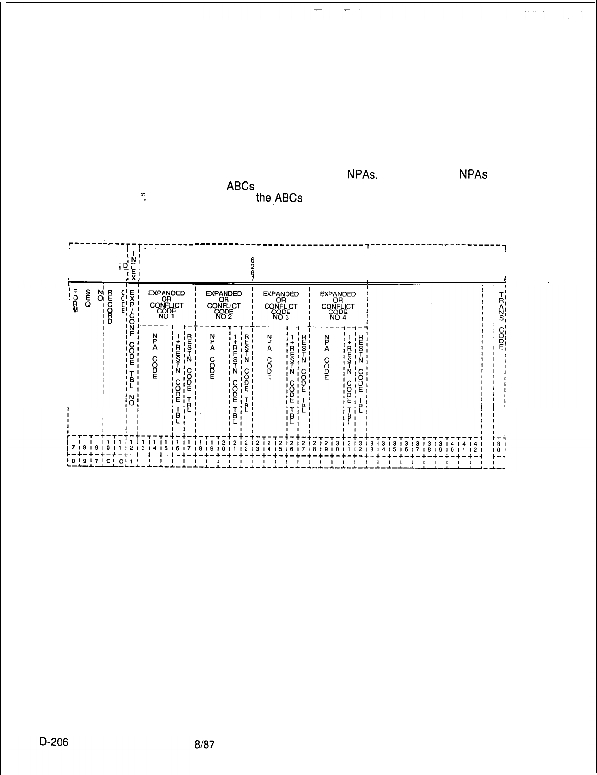
TL-130400-1001
Record Code EC:
Expanded or
Conflicting Code
Check Tables
-=_
.”
10.4 Record Code EC, Figure 10.4, is used in conjunction
with expanded code restriction capabilities. This record code
must be set up along with Record Code CR. Expanded code
restriction is used to allow access to certain ABC codes within an
NPA or for an NPA that has conflicting ABC codes. An ABC
code is a conflicting code if it has a 0 or 1 as the middle digit
(e.g., ABC = 212). 212 is an NPA in New York. A 0 or 1 as the
middle digit is only applied to
NPAs.
However, some
NPAs
have
more
ABCs
than they have numbers to accommodate. In these
NPA areas,
the,ABCs
are allowed a 0 or 1 as the middle digit,
thereby causing a conflict between the ABC and NPA codes.
‘------‘--r-r7--------
I
I
II
I
I
I
IN,
I
IDI
I
!E!
Tc------------_---------------
7------------------------
T
I
I
i
II
II
II
1II
I
i
11
I
I
Figure 10.4 Record Code EC: Expanded or Conflicting Code Check Tables Data Sheet
SVR 5210
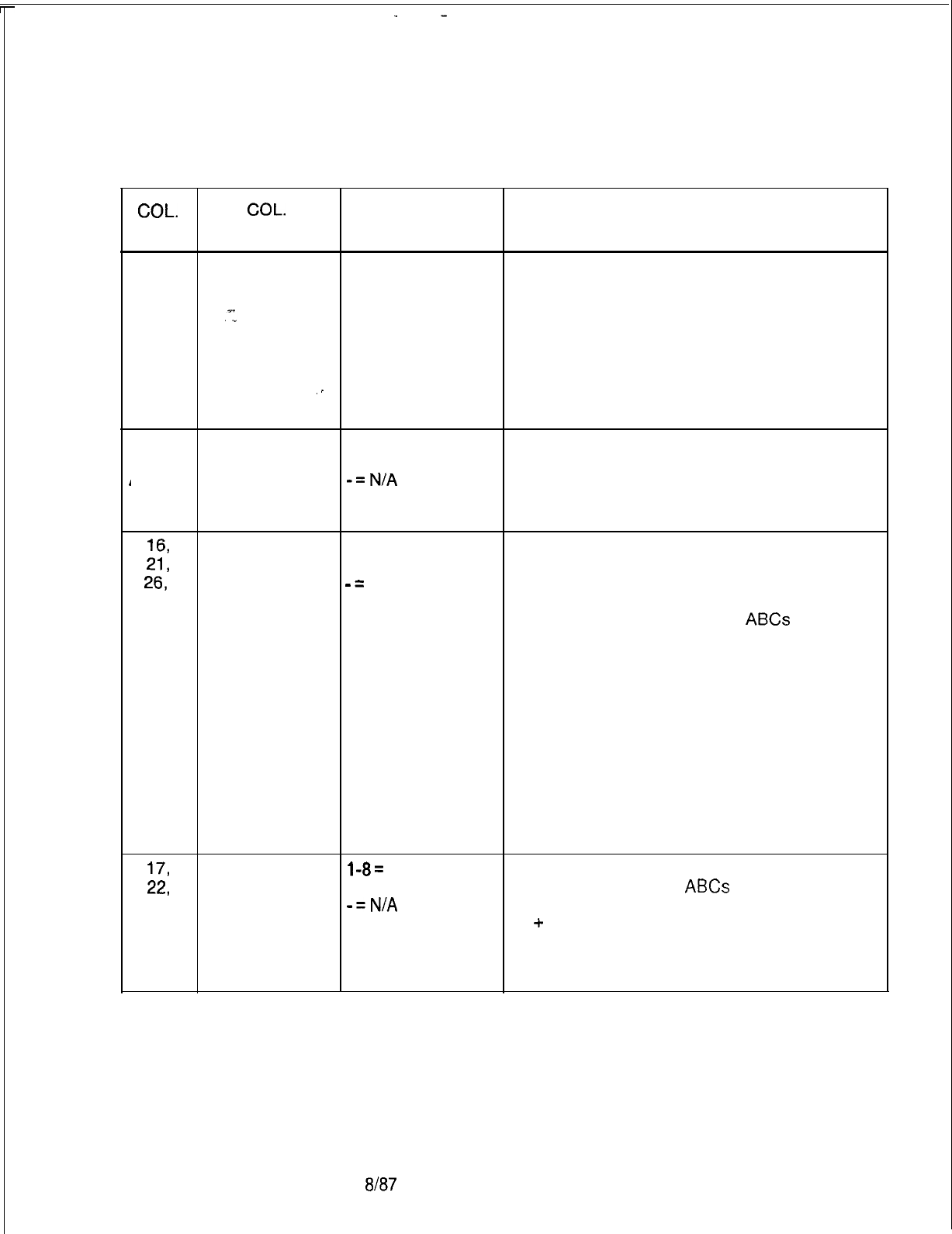
,
TL-130400-1001
Table 10.4
Entry Fields for Record Code EC
COL.
COL.
VALID
NO.
NAME ENTRIES COMMENTS
12
Table Number 1-8 = number This field defines the table number of the
expanded or conflicting code or codes that
are allowed in the system. The table number
is used by the system for identification
purposes.
-This number must be defined on Record
Code CR, column 12.
-The table number must be unique across
this record code.
13-15,
Expanded or
000-999 = N PA
Enter the NPA requiring expanded toll
18-20,
Conflicting Code number restriction.
23-25,
Numbers l-8
-=N/A
-The NPA codes must be unique on a per
and table (one EC form) basis.
28-30
-This field can only contain an NPA.
16,
1 + Restriction
1-8 =
This field determines whether or not the NPA
21,
Code Table table number listed in preceding columns has conflicting
26,
-=
N/A codes.
and -This field points to Record Code CR,
31
column 12, where the allowed
ABCs
for the
NPA requiring six-digit analysis are listed.
-For normal applications, either the
1 + restriction code table or the restriction
code table will have an entry, not both. There
are, however, applications that require an
entry in both of these fields (e.g., conflicting
codes in an NPA with cross boundary dialing).
-If this application exists, fields for 1 +
restriction (16, 21, 26, and/or 31) define the
NPA with conflicting codes, and fields 17, 22,
27, and/or 32 point to Record Code CR for the
ABC listing.
17,
Restriction
l-8=
This field points to Record Code CR, column
22,
Code Table table number 12, where the allowed
ABCs
for the NPA
27,
-=NlA
requiring six-digit analysis are listed.
and
-1
+
restriction code tables and restriction
32
code tables for normal applications are
mutually exclusive; however, an entry can be
made in each of these fields when required.
SVR 5210
8187
D-207
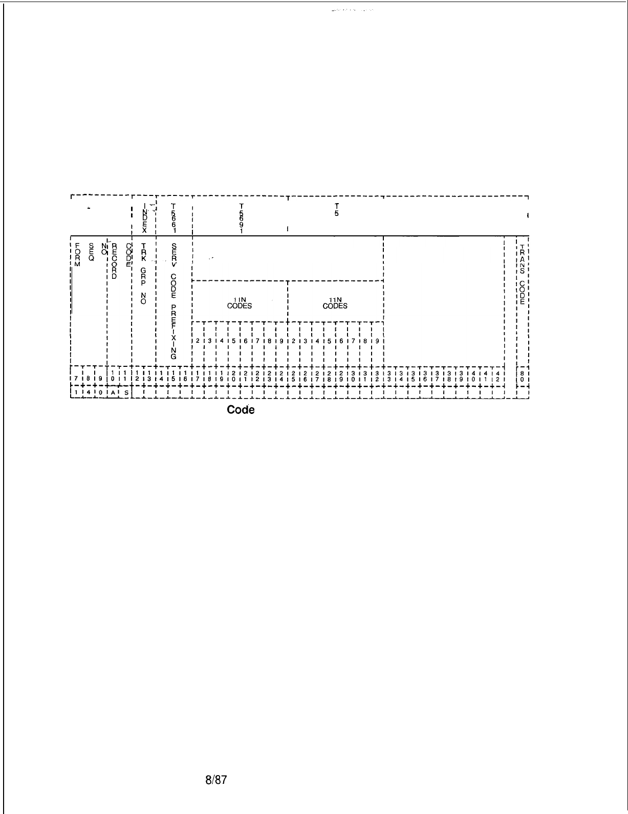
TL-130400-1001
Record Code AS: 10.5 Record Code AS, Figure 10.5, defines the service codes
Allowable Service Codes such as 411, 611, and 911, that the system is allowed to dial.
This record code is used in conjunction with the toll restriction
feature and is applied on a trunk-group by trunk-group basis.
If service codes are accessed through MERS, Record Code ST
must be used.
T---------r---r-----r------------------~---------------~-----------------------~
I I
I
-
’
-j’
IIII
;
N”,
:
:
ii
I
I
El
ii
II
I
,
I
I
4
I
I
I
. .
fIII
IIII
I
Ix,
1
IIII
VALID SERVICE CODE VALUES
OF N ALLOWED
Figure 10.5
Record
Codk
AS: Allowable Service Codes Data Sheet
8187
SVR 5210
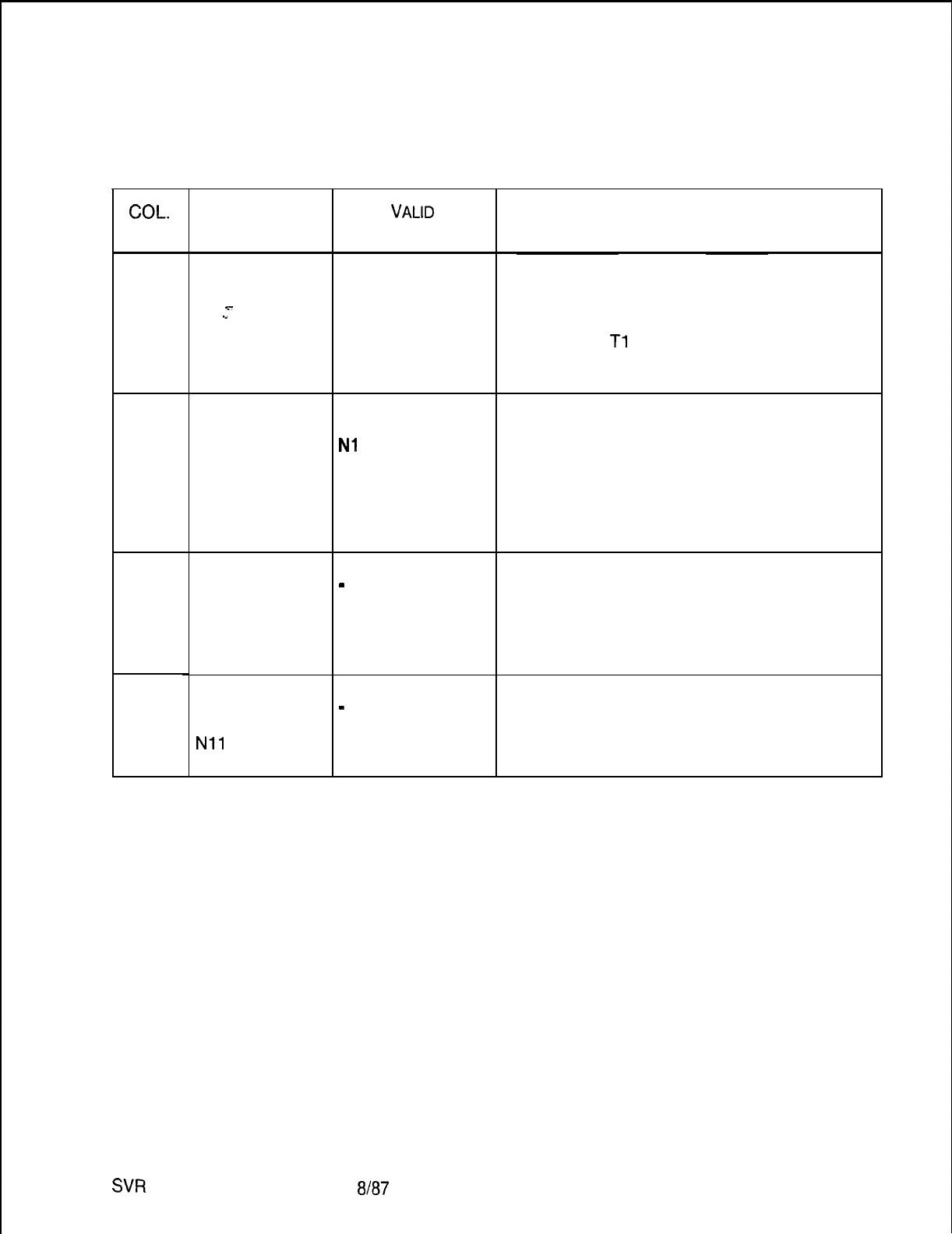
COL.
NO.
12-13
14-16
17-24
25-32
TL-130400-1001
Table 10.5 Entry Fields for
Record Code
AS
COL.
NAME
Trunk Group
Number
x-
.I
Service Code
Prefixing
Valid Service
Code Values of
N Allowable
11 N codes 2-
9
Valid Service
Code Values of
N Allowable
Nil
codes 2-
9
VALID
ENTRIES
00-63 = trunk
group
NON = no prefixing
required
Nl
1 = format
prefixed
11
N = format
prefixed
BTH
= both formats
prefixed
Y = allowed
-
= not allowed
Y = allowed
-
= not allowed
COMMENTS
This field determines the trunk groups allowed
to access the service codes listed in columns
17-32.
-The trunk group listed must be defined on
Record Code
Tl
, column 12-l 3.
-Each trunk group number defined in
columns 12-l 3 must be unique.
Assign the service code prefixing method
applied to a toll access code (1 + etc.) dialed
before a service code number.
This field determines the allowed dialed digits
that follow the digits 11 (e.g., if 112, 113, and
114 are allowed, enter a Y in fields 17, 18, and
19).
-The 11 N format is seldom found in use
today.
This field determines the allowed leading digits
that precede the digits 11 (e.g., if 411, 611,
and 911 are allowed, enter a Y in fields 27, 29,
and 32).
SW
5210
8187
D-209
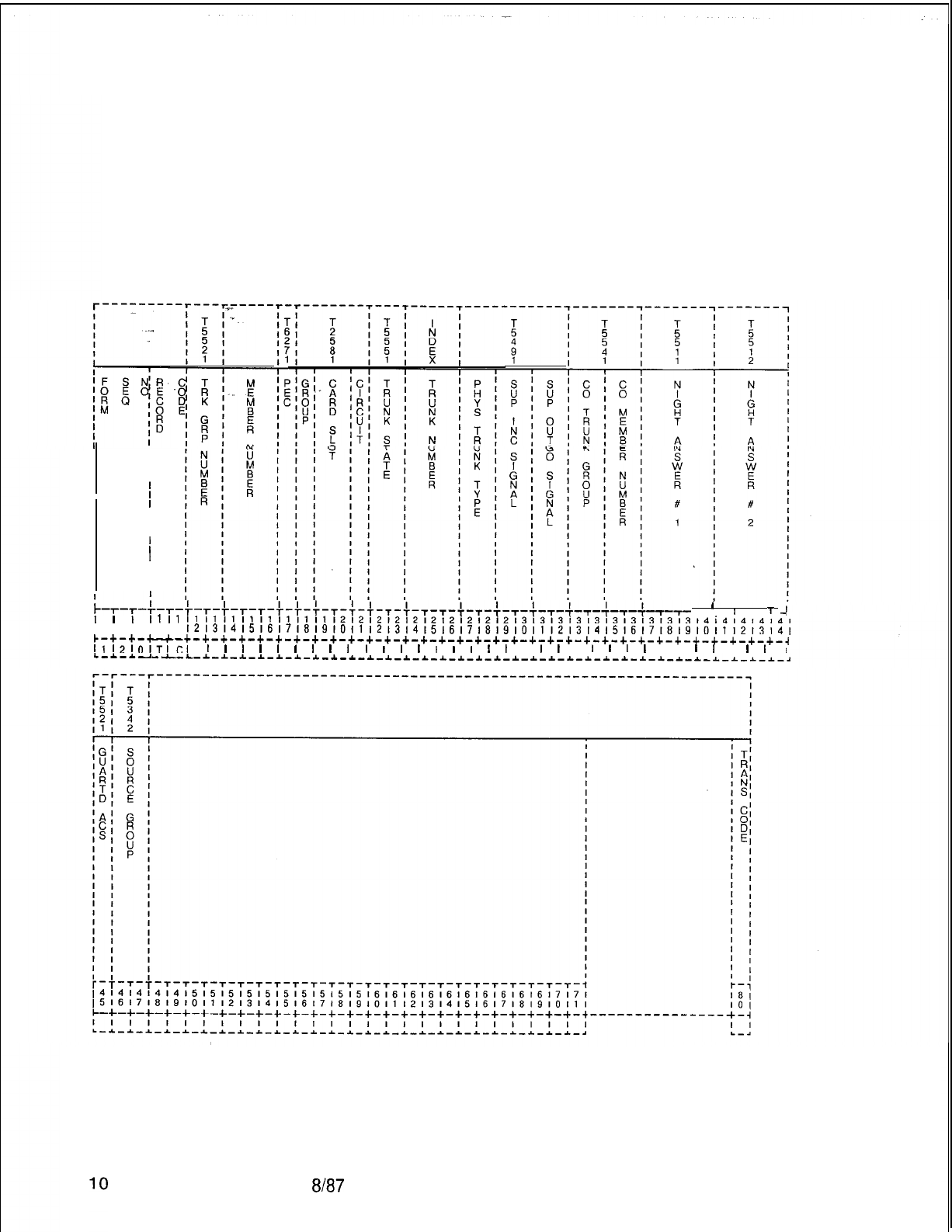
TL-130400-1001
Record Code TC:
10.6 Record Code TC, Figure 10.6, defines the trunk circuit data
Trunk Circuit
required and its related assignment. Dictation/paging, recorder
announcer, and NIC (Network Interface Card) circuits require an
entry in columns 12-28. All other columns for these cards must
contain dashes except when recorder announcer access is
required.
I
I
I
I
I
I
I
I
I
I
1
I
II
I
I
;-,-,-;-,-
I
I
I
Ill1
1718191011
t-r-f-r-r-t-t-$-T-$-f-T-t-T-T-$-T-f-T-f--~-
’
,
T
111111111111111112l2121212121212121213131313131313131313l4i4l414141
,2,3,415,6,71819101112l314151617~819101112,3,415161718,910111213141
c-+-+-u-+-+-+-+-+-+-+-+-+-+-+-+-+-+-+-+-+-+-+-+-+-+-+-+-+-+-+-+-+-+-+-+-+-~
1,12101TI~I
I
I
I
I
I
I
I
I
I
I
I
I
I
I
I
I
I
I
I
I
I
I
I
I
I
I
I I
I
I
I
I
I
L-*-~----L-~-I-_C-*-~-~-_C--L-~-~_~-*-*-~_*-~-*-*-~-~-I-~-~-~-~-~-~-~-_L-I-~-*-.
D-2
Figure 10.6 Record Code TC: Trunk Circuit Data Sheet
8187
SVR 5210
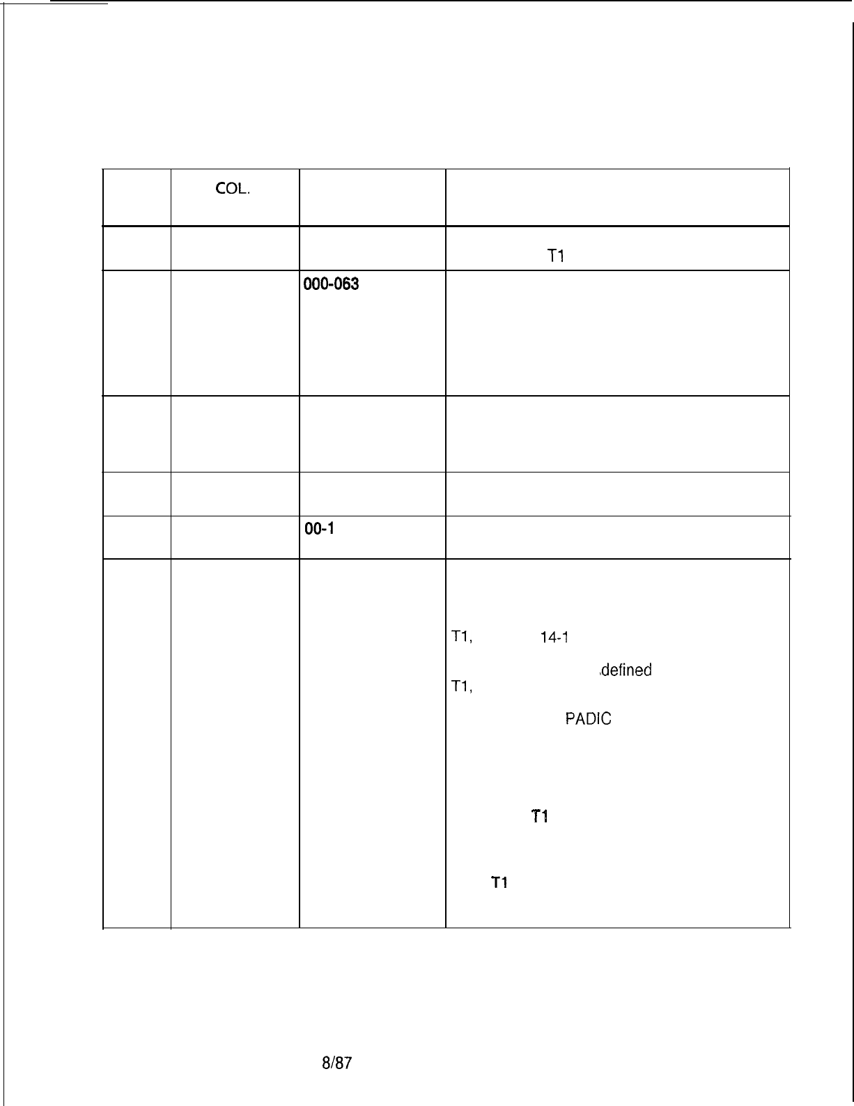
I
TL-130400-1001
Table 10.6 Entry Fields for Record Code TC
CCL.
COL.
VALID
NO. NAME ENTRIES COMMENTS
12-13
Trunk Group
00-63 = trunk
This number must be a trunk group defined on
Number group number Record Code
Tl
, columns 12-l 3.
14-l 6 Member
000-063 = trunk
This’field determines the outgoing order of the
. . .
Number group member trunks.
number -The member numbers for each trunk group
must be in sequential order beginning with
member zero.
-No gaps or duplications are allowed in the
number order.
17
PEC 0 = PEC number Enter PEC 0.
-This card must be defined on Record Code
FR and must be valid for that trunk type.
-Each location for a trunk must be unique.
18
Group A-D = group Which group (A, B, C, or D) within PEC 0 is
number this card?
19-20
Card Slot
00-l
1 = slot
Which card slot within the group is this card?
number
21
Circuit Number
O-3 = assigned
Which circuit on the card is being used?
circuit number -There must be at least one trunk circuit
defined for each trunk group.
-If the trunk group is defined on Record Code
Tl,
columns
14-I
6, as DIC, only circuit
position 0 or 1 can be used.
-If the trunk group is
.defined
on Record Code
Tl,
columns 14-16, as PAG, only circuit
position 2 can be used.
-Circuits on the
PADIC
(Public Address and
Dictation) card are assigned as required. This
is a wiring option only; no software is needed.
The circuits on the dictation/paging card are
assigned as follows: circuit 0 dictation, circuit
1 dictation, circuit 2 paging.
-CAUTION:
Tl
span cards are programmed
in universal card slots in the CPG and not in
Recent Change, but they are not physically
mounted in these slots.
-The
Tl
cards must be mounted in the PEC
files in dedicated card slots as indicated on
the file designation strip.
SVR 5210
8187
D-21 1
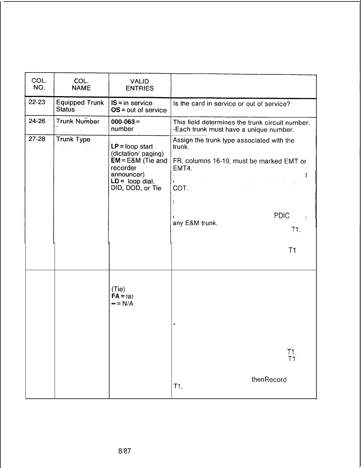
TL-130400-1001
Table 10.6 Entry Fields for Record Code TC
(Continued)
COMMENTS
GS = ground start
-If this field is marked EM, then Record Code
-If this field is marked GS or LD, then Record
Code
FR,
columns
16-l 9,
must be marked
-If this field is marked LD, then Record Code
FR, columns 16-19, must be defined as ILT.
-If this field is marked LP, the trunk must be
defined on Record Code FR as a
PDIC
or as
-If the trunk is defined on Record Code
Tl,
columns 14-16, as DIC or PAG, this field
must be marked LP.
-If the trunk is defined on Record Code
Tl
,
columns 14-16, as REC, this field must be
marked EM.
29-30
Incoming Signal
WS
= wink start
This field determines the incoming start dial
DD
= delay dialing
method used for the incoming trunk
IZ?)
fast access requirements in a trunk group.
mm
=;/A
-Fast access is used by dial trunk groups
from non-delay dial offices or systems.
-WS is normally used for E&M, CCSA, or DID
trunks that are sent from a stepper CO.
-
(--) will normally apply to DOD, ground,
and loop start trunks.
-FA is sometimes used by DID trunks.
-If FA is marked, the trunk must be marked
IN in columns 21-22 on Record Code
Tl.
-If the trunk is defined on Record Code
Tl
,
columns 14-16, as DIC, PAG, or REC, this
field must be dashed.
-If this field is marked FA,
thenRecord
Code
Tl,
columns 23-24, can only be dashed or
marked DP.
8187
SVR 5210
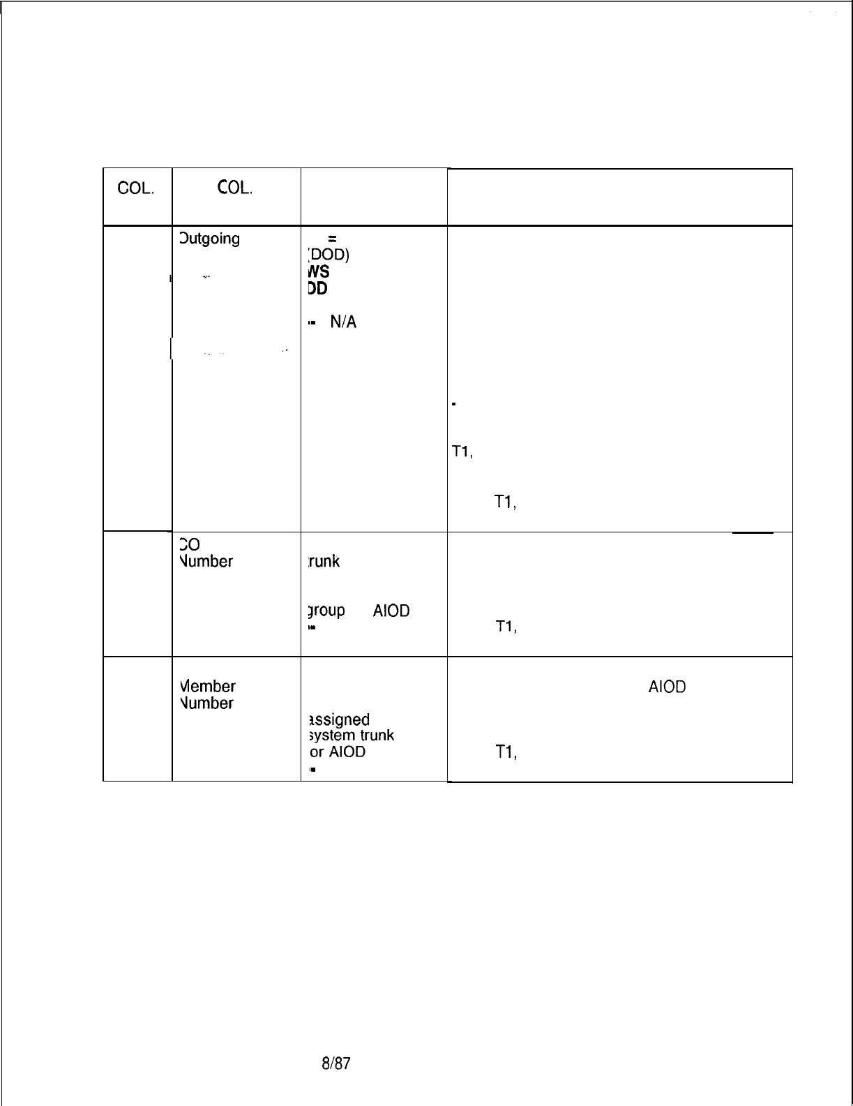
COL.
NO.
31-32
. . . .
33-34
35-36
TL-130400-1001
Table 10.6 Entry Fields for Record Code TC (Continued)
COL.
NAME
Dutgoing
Signal
20
Trunk Group
Vumber
30 Trunk Group
Vlember
lumber
VALID
ENTRIES
ID
=
immediate dial
:DOD)
JllS
= wink start
DD
= delay dialing
SO = seize out
.-
=
N/A
IO-99 = the CO
:runk
group
lumber assigned
o a system trunk
Jroup
for
AIOD
a-
= N/A
IO-99 = the CO
runk group
nember number
Issigned
to a
;yrs;lterunk
group
I-
= N/A
SVR 5210
8187
COMMENTS
This field determines the outgoing start dial
signal method used for outgoing trunk
requirements.
-WS is used for Tie trunks that have
supervision.
-DD is used for Tie trunks that do not have
supervision.
-SO is used for E&M and CO line trunks.
-SO must be marked if the trunk is used as a
CO line.
-
(--) is used for DID, ground, or loop start
trunks.
-If the trunk group is defined on Record Code
Tl,
columns 14-l 6, as DIC, PAG, or REC,
this field must be dashed.
-If this field is marked ID or SO, then Record
Code
Tl,
column 25, must be marked Y to
return dial tone.
Assign the CO trunk group number assigned
to a system trunk group for AIOD.
NOTES: If an entry is made in this field, an
entry must be made in columns 35-36.
-If any entry is made in this field, then Record
Code
Tl,
columns 33-34, must be marked Al
and column 38 must be marked 1, 2, 3, or 4.
Enter the CO trunk member number assigned
to a system trunk circuit for
AIOD
here.
NOTES: If an entry is made in this field, an
entry must be made in columns 33-34.
-If any entry is made in this field, then Record
Code
Tl,
columns 33-34, must be marked Al
and column 38 must be marked 1, 2, 3, or 4.
D-21 3
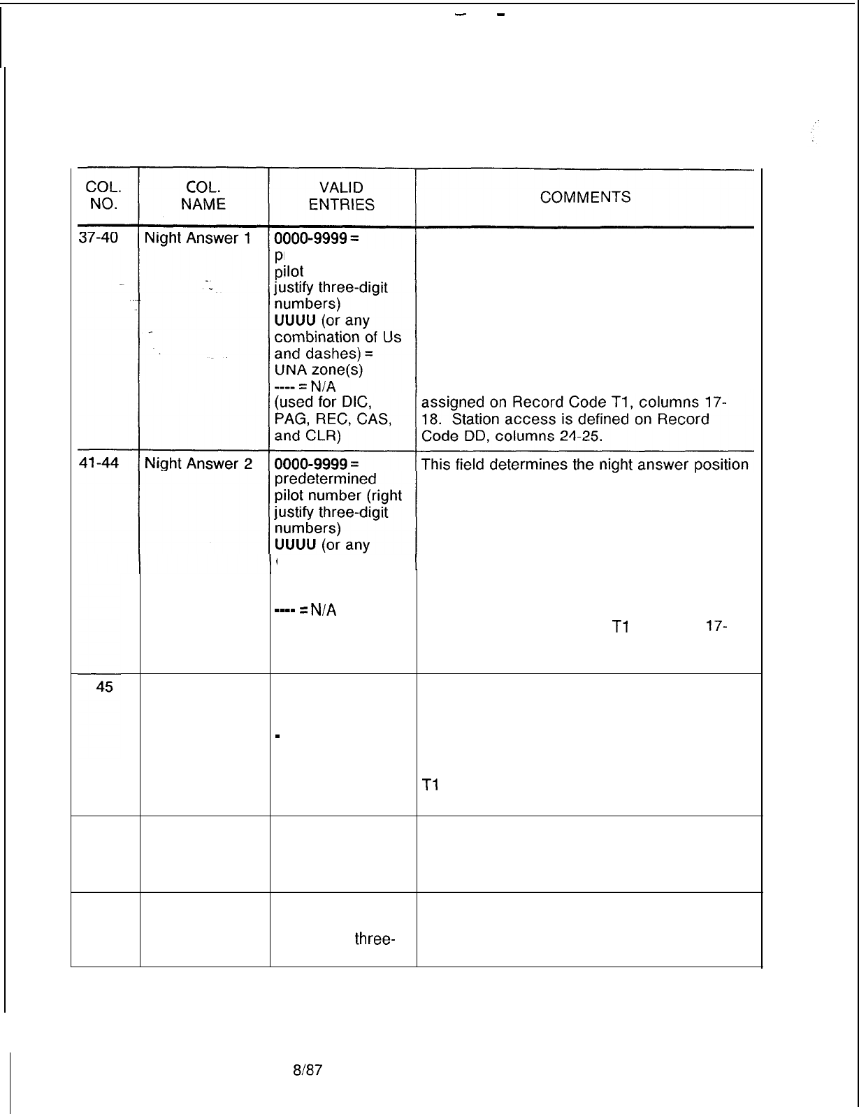
-
-
TL-130400-1001
Table 10.6 Entry Fields for Record Code TC (Continued)
This field determines the night answer position
redetermined 1 destination.
ilot
number (right -The destination can be a predetermined
pilot number or a universal night answer
position. If a UNA is used, it can be any
combination of the four UNA zones.
-If an entry of 0000-9999 is made, the
displayable COS assigned to the trunk group
(of which this trunk is a member) must allow
station access. COS for trunk groups is
2 destination.
Guaranteed
Access
-The destination can be a predetermined
pilot number or a universal night answer
position. If a UNA is used, it can be any
combination of the four UNA zones.
combination of Us -If an entry of 0000-9999 is made, the
and dashes) = displayable COS assigned to the trunk group
UNA zone(s) (of which this trunk is a member) must allow
--mm
=
N/A
station access. COS for trunk groups is
(used for DIC, assigned on Record Code
Tl
, columns
17-
PAG, REC, CAS, 18. Station access is defined on Record
and CLR) Code DD, columns 24-25.
G = used for RA When this field is marked G, the trunk is given
access or nailed a dedicated time slot or talk path.
connections -Guaranteed access is always used for
-
= not required recorder announcer trunks or a nailed
connection.
-If this field is marked G, then Record Code
Tl
, columns 14-16, must be marked DIC or
PAG.
46-47 Source Group 00-31= number This field determines the source group
or assigned to the trunk circuit. A source group
--= not is used to identify the branch trunk that is
assigned coming into the CAS Main or ACD group.
48-51
Central Office 0000-9999 or This field determines the CO line directory
Line Directory 000-999 number.
right justify
three-
digit numbers
D-21 48187
SVR 5210
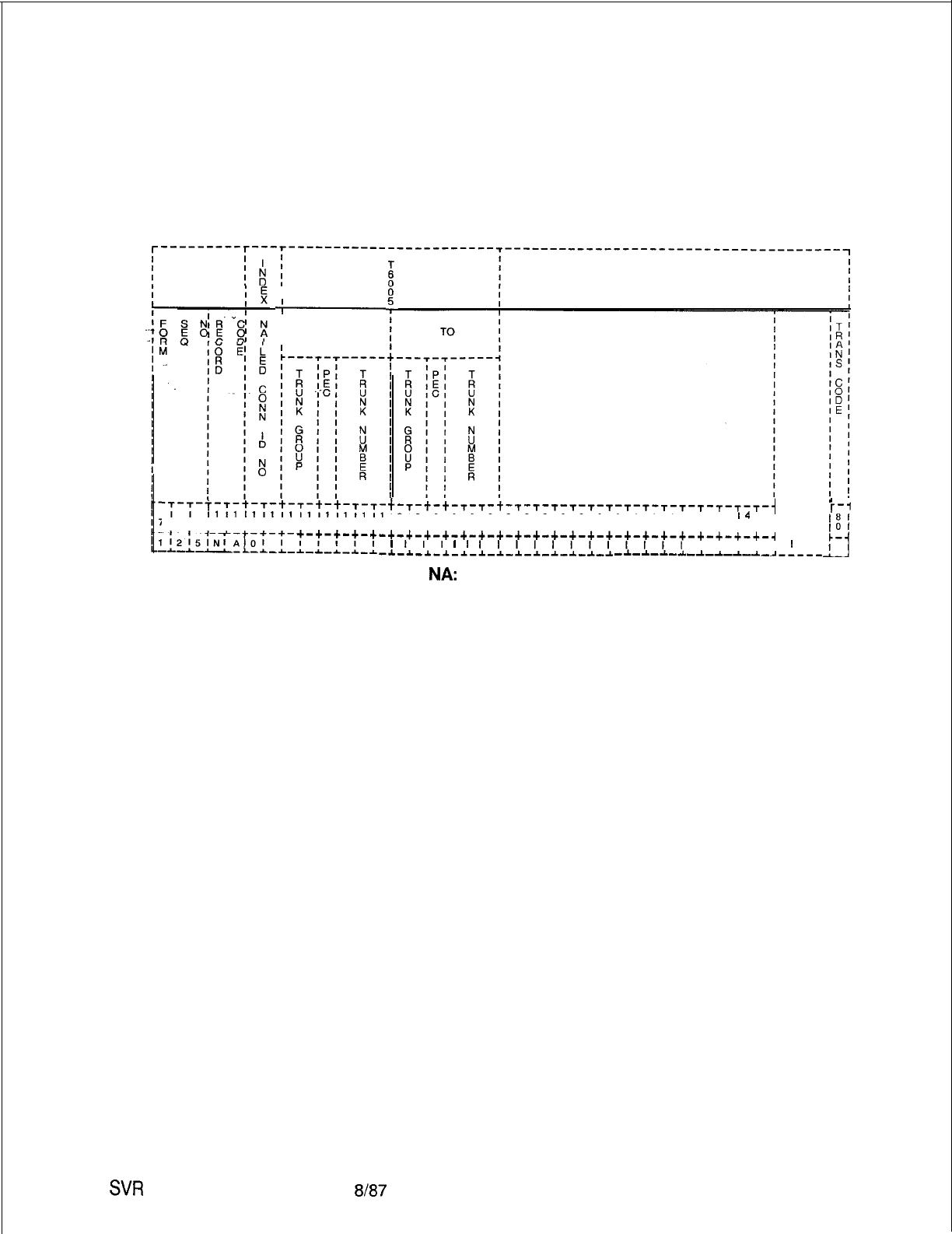
TL-130400-1001
Record Code NA:
Nailed Trunk
10.7 Record Code NA, Figure 10.7, defines the permanent
connection data between trunk circuits. Information selected
Connection
includes to and from nailed connection data.
-
I
I
FROM
I
-:-;-T-T-t-T-t-T-t-t-T-T-
~1111111111111111111
'1819~0111213141516171819
, . . . I
t-T-t-t-T-s-t-T-s-s-T-T-T-T-T-T-T-T-T-T-T-{
1212121212121212121213131313131313131313
14
I
i-1
1011121314151617181910111213141516171819101
+-+-+-+-+-+-+-+-+-+-+-+-+-+-+-+-+-+-+-+-+-+-+-+-+-+-~
I
III
I
I
IIIIIIIIIIII
II I
!
-~-~-*-1-~-*-~-*-~-~-~-*-* -~-~-~-~-~-~-~--L-~-----
Figure 10.7 Record Code
NA:
Nailed Trunk Connection Data Sheet
SW
5210
8187 D-21 5
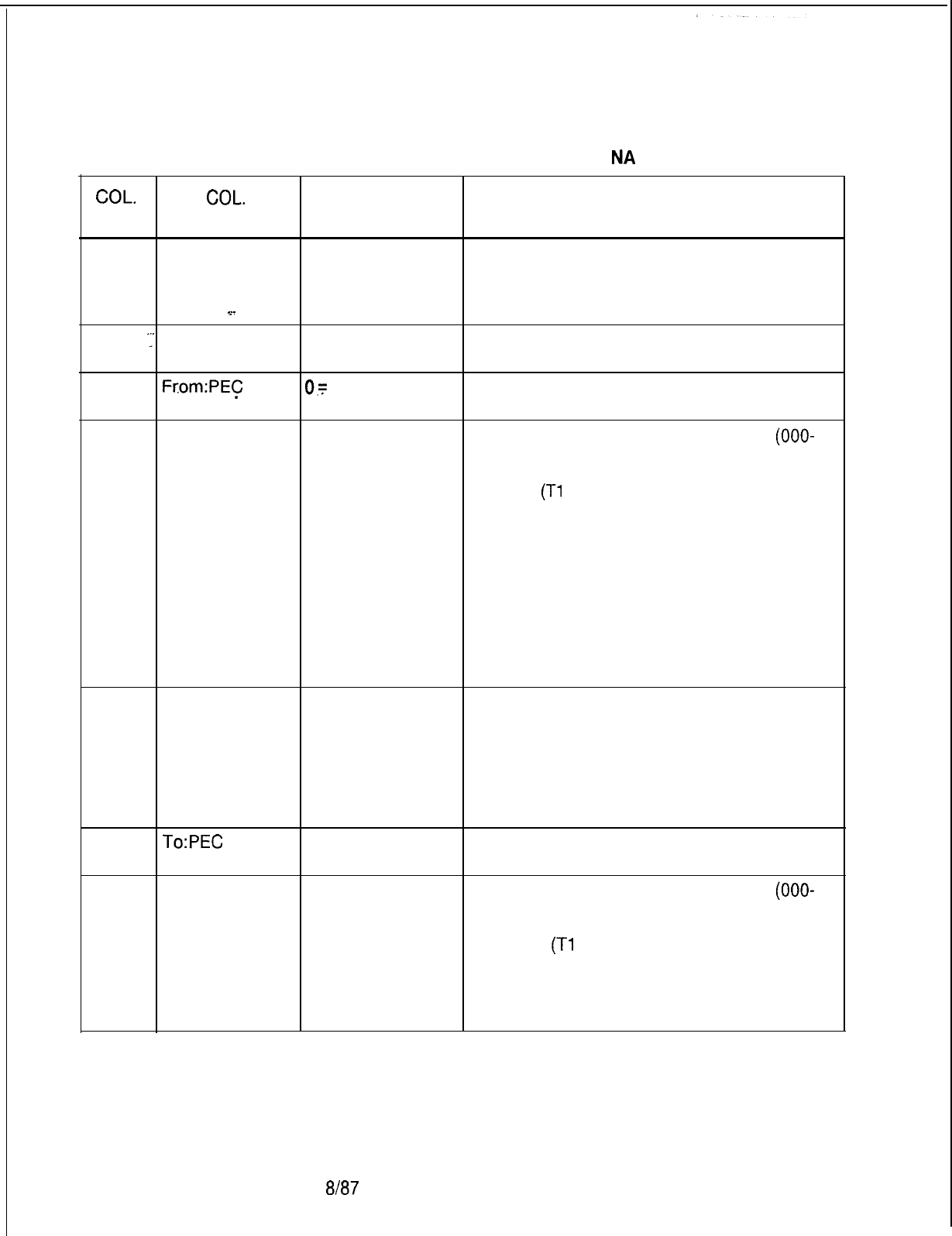
TL-130400-1001
Table 10.7 Entry Fields for Record Code
NA
COL.
COL.
VALID
NO. NAME ENTRIES COMMENTS
12-13
Nailed 00-47 = number Assign the nailed connection trunk software
Connection identification number.
Identification
number
21
14-15
.:
From:Trunk
00-63 = trunk
This field determines the trunk group (00-63)
Group group number number of the from trunk.
16
Fcom:PEC
0.~
PEC number
_
This field determines the PEC number (always
0) of the from trunk.
17-19
From:Trunk
000-063 = trunk
This field determines the trunk number
(OOO-
Number group member 063) of the from trunk.
number -If one of the trunks in the nailed connection
is a NIC
(Tl
Network Interface) used by the
PD-200 Data Option, the other trunk must be
a DTRK (digital trunk).
-This trunk must have guaranteed access
marked on Record Code TC, column 45.
-The from trunk cannot have been used on a
previous NA record.
-The from trunk number must be listed on a
TC record.
-This trunk must be engineered in the trunk
group on a TC record.
20-21
To:Trunk Group
00-63 = trunk
This field determines the trunk group (00-63)
group number number of the to trunk.
-The to trunk number must be listed on a TC
record. This trunk must be engineered in the
trunk group on a TC record.
-The to trunk cannot have been used on a
previous NA record.
23-25
To:PEC
0 = PEC number This field determines the PEC number (always
0) of the to trunk.
22-24 To:Trunk
000-063 = trunk
This field determines the trunk number
(OOO-
Number group member 063) of the to trunk.
number -If one of the trunks in the nailed connection
is an NIC
(Tl
Network Interface) used by the
PD-200 Data Option, the other trunk must be
a DTRK (digital trunk).
-This trunk must have guaranteed access
marked on Record Code TC, column 45.
D-21 68187
SVR 5210

TL-130400-1001
Record Code DA:
10.8 Record Code DA, Figure 10.8, provides for the absorption
Trunk Group
of digits by the CO on a per trunk group basis. Digits are not
Digit Absorption
absorbed but are passed over to the end office and are only
monitored by the system. These digits are used by the system to
determine the start of an NPA or toll code, which is used to
perform code restriction. The NPA or toll code must be sent
from a non-common control end office. If the end office has no
digit absorption characteristics, this record code need not be
used. However, if digit absorption is required, the absorption
pattern must be obtained.
SW
5210
8187
_
NOTE: This record code is only required when toll restriction is
used. Use the following guidelines when completing this record
code.
l If a cut-in digit is used, it and all following digits are used
for routing information.
l If an absorbed digit is used, it is ignored and all the following
digits are used in routing.
l If absorbed repeatedly, it is repeatedly ignored.
The two types of switches used are the single MDA (Marking
Digit Absorption) and the dual MDA-l marking switch.
When a single marking switch is used, two duplicate entries are
always needed for a digit code. When a dual marking switch is
used, each digit must be analyzed for its absorbed markings.
Entries are based on first digit markings and second plus digits.
0
Single Marking Switch
-
Two duplicate entries are always required for a dialed
digit.
-
Under the appropriate digit value, enter the absorption
markings (C, A, or R) in both the first digit action and
second plus digits. Refer to first digit action digit value.
e
Double Marking Switch
-
Each digit must be analyzed for its absorbed markings.
-
The analysis is based on the entries (C, A, or R) in the first
digit action and second plus digits. Refer to first digit
action digit value.
D-217
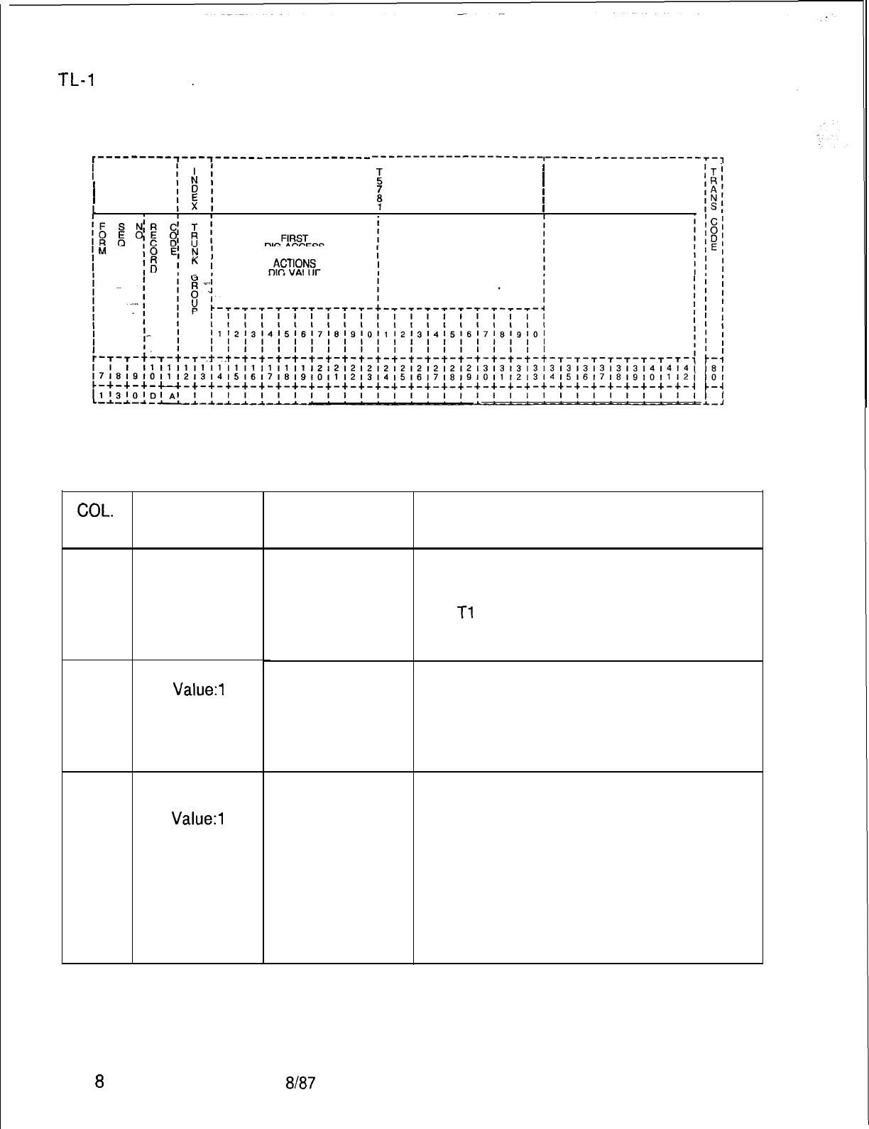
r
TL-I
30400-l 001
t---------,---~------------------- ---‘-------‘---------I---------------------~-,
I
II
5
I
I
I
II
I I
1
I
DIG ACCESS SECOND PLUS
DIG ACCESS
DIG VALUE
Figure 10.8
Record Code DA: Trunk Group Digit Absorption Data Sheet
Table 10.8
Entry Fields for Record Code DA
COL.
NO.
12-13
14-23
24-33
COL.
NAME
Trunk Group
First Digit Action
Digit
Value:1
-0
Second
Plus
Digits Action
Digit Value:1 -0
VALID
ENTRIES
00-63 = trunk
group number
C = cut in
A = absorb and
unlock
R
= absorb
repeatedly
C = cut in
A = absorb and
unlock
F? = absorb
repeatedly
COMMENTS
Enter the trunk group number (00-63) that
needs digit absorption.
-This number must be defined on Record
Code
Tl
.
-A trunk group number can only appear once
on this record code.
This field determines the first digit action digit
value needing digit absorption.
-There must be at least one C marked in
either the first digit action digit value or second
plus digits action digit value fields.
-The first digit actions cannot all be R.
This field determines the second plus digit
action digit value needing digit absorption.
-The second plus digit action digit value
applies to the first digit received following a
legitimate cut-in action.
-There must be at least one C marked in
either the first digit action digit value or second
plus digits action digit value fields.
-If there is an A anywhere in the first digit
action, there must be at least one in the
second plus digit.
D-21 68187
SVR 5210
TL-130400-1001
MOST 11.0 This section describes the record codes required to
ECONOMICAL define the MERS features. The following record codes
ROUTE are required:
SELECTION
l Record Code MR defines the
NPA(s)
requiring six-digit
analysis.
l Record Code RP defines the routing list.
.
.
.
.
SVR 5210
l Record Code
SI
defines the trunks allowed by a specific
NPA/ABC.
l Record Code TR defines the ABC codes for an NPA that
requires six-digit analysis.
l Record Code NR defines the ABC codes for an NPA that does
not requires six-digit analysis.
l Record Code TP defines MERS time periods.
l Record Code ST defines the service codes allowed through
MERS.
l Record Code PC defines SCC (Specialized Common Carrier)
prefix code digits.
l Record Code TN defines the tone detector circuit.
l Record Code MS defines the SCC (Specialized Common
Carrier) authorization codes.
l Record Code LP defines the prefix digits for MERS LDN
(Listed Directory Number).
l Record Code MO defines station codes requiring a second
sending instruction.
8/87 D-21 9
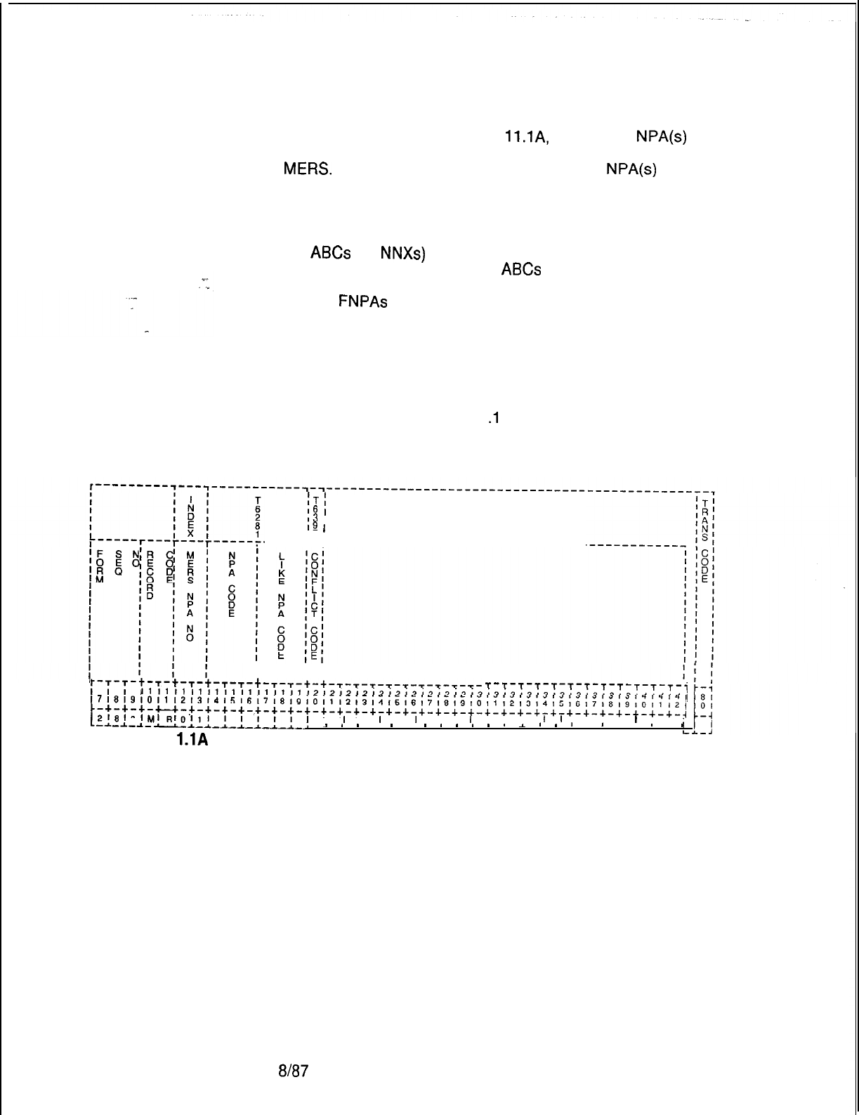
TL-130400-1001
Record Code MR:
MERS Six-Digit
11.1 Record Code MR, Figure
ll.lA,
defines the
NPA(s)
Translated NPA
(Number Plan Area) that is given six-digit analysis through
MEW.
This is done before calls going to the
NPA(s)
are routed
to outgoing trunks.
The HNPA (Home Number Plan Area) of the site must
also be included on this record code. This is because some of
the
ABCs
(or
NNXs)
within the HNPA will be local and will not
have a toll charge, while other
ABCs
within the HNPA will be
foreign and will have a toll charge. Six-digit analysis is used for
calls to
FNPAs
(Foreign Number Plan Areas) that have different
rates for calls within that NPA depending on their ABC.
After completing Record Code MR, complete Record Codes RP,
SI, and TR. Other record codes for six-digit analysis are
optional.
Diagrams following Table 11
.l
provide information for MERS
record code completion.
iTI
16
I
I3
I
19
I
IF I
-----T-T--------------------------------
I I
I I
;-~-~-t-T-t-T-t-s-T-t-T-t-t-T-t-t-T-T-T-T-T-T-T-T-T-
T-T-T-T-T-T-t-T-T-T-T-T-i
~~~~~~~~~~~~~~~~~~~~~~~~~~~~~~~~~~~~~~~~~~~~~~~~~~~~~~~~~~~~~~~~~~~
~~~~~~~~~~~~~~~~~~~~~~~~~~~~~~~~~~~~~~~~~~~~~~~~~~~~~~~~~~~~~~~~~~~~~~~~~
c-+-+-+-u-+-+-+-+-+-+-+-+-+-+-+-+-+-+-+-+-+-+-+-+-+-+-+-+-+-+-+-+-+-+-~
[2;8
’
0
’
hl’
RI
0
’
1
l
I I
-A.--L-
-*-ALLL-LLJ
x
*
-
.
-
.
-
*
s
-
n
*
I
’
-
n ’ 3 . ’
’
-
t
I
I
I
I
I
I
I
I I
I
I I I
I
I
I I I
I
III II
Figure 1
l.lA
Record Code MR: Most Economical Route Selection Six-Digit
Translated NPA Data Sheet
D-220
%I87
SVR 5210
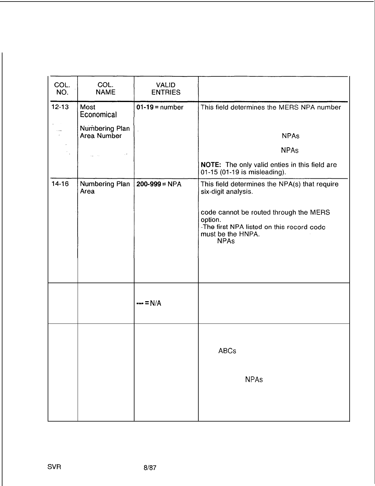
TL-130400-I 001
Table 11.1 Entry Fields for Record Code MR
COMMENTS
Route Selection code. This number is used by the system for
identification purposes.
-The entry for 01 must be the HNPA.
Entries 02-19 are used by
NPAs
that need
six-digit analysis.
-It is recommended to list
NPAs
used in
ascending order from 2-9.
-Any NPA that requires six-digit analysis
through MERS and is not listed on this record
-The
NPAs
must be in order. Gaps are not
allowed in the NPA numbers.
-After listing the HNPA, start with the lowest
value FNPA and continue to the highest.
-This number must be unique across the
record code.
17-19
Like Numbering
200-999 = like
This field determines the like NPA codes
Plan Area Code NPA code
(200-999).
s-w
=
N/A
-A like NPA code is entered if the NPA code
given is translated using the ABC codes that
are defined on Record Code TR.
20
Conflicting Code Y = six-digit
conflict exists
N = no six-digit
conflict exists
This field determines whether or not a
conflicting code exists within this NPA.
-A conflicting code condition exists if one or
more
ABCs
within the NPA looks like an NPA.
-To look like an NPA, an ABC will have a 0
(zero) or a 1 as the center digit (e.g., an ABC
of 202 or 212 is a conflicting code because
there are also
NPAs
of 202 and 212. NPA 202
is the NPA for Washington D.C., and 212 is an
NPA in New York.
NOTE: If an MR record has a conflicting
code, then Record Code OF must be marked
Y in column 27 for MERS 1 + dialing.
SVR
5210
8187
D-221
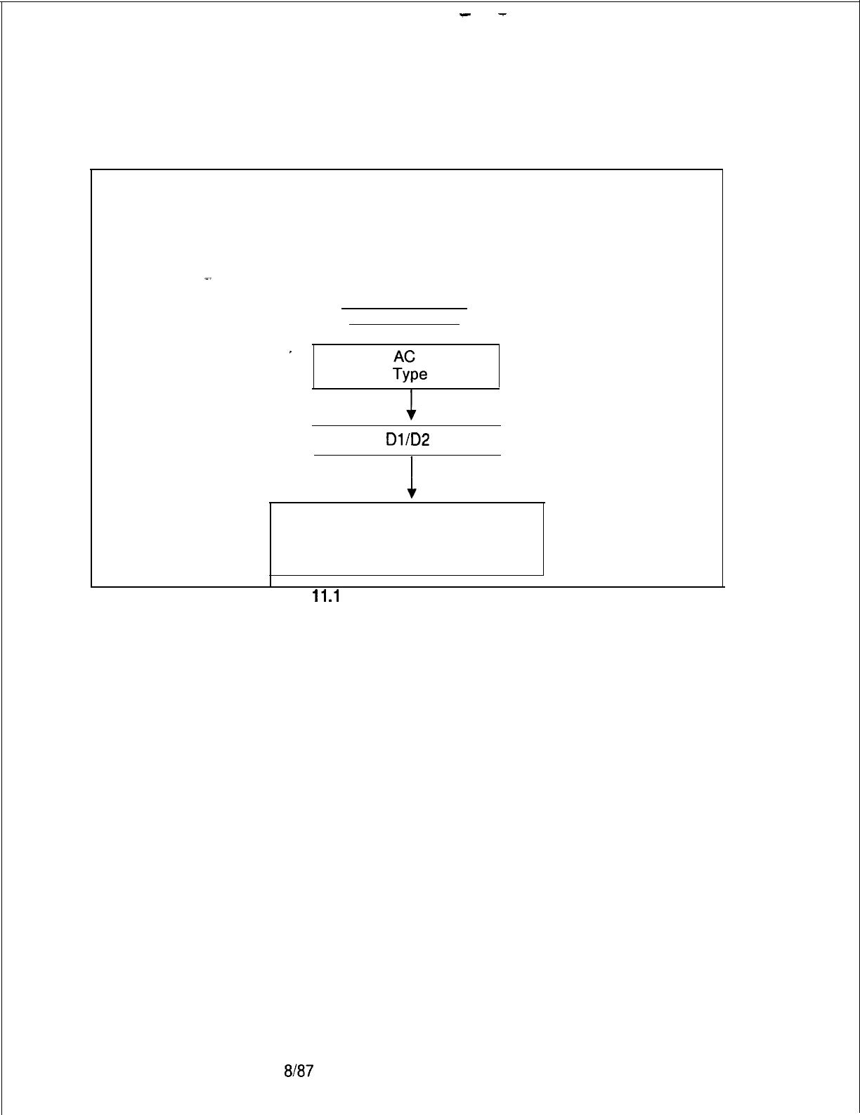
-
-
TL-130400-1001
This diagram represents an application which can never
be used to initiate the MERS On-Net and MERS Off-Net features.
Dialed 1st Diqit of
Station Number
.
.
(Code
?fpe
116)
Dialed
Dl/D2
Digits
TD
NOTE: Translation Type must never
specify MRN or MRS.
Figure
11
.l
B Non-MERS Application
D-222
at87
SVR 5210
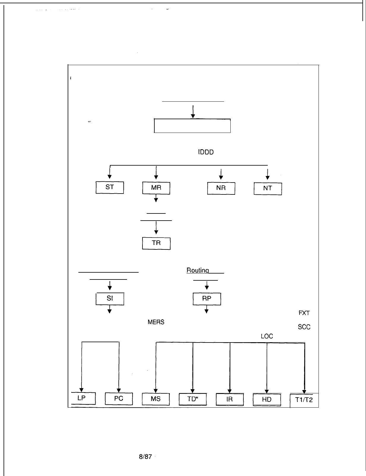
TL-130400-I 001
This diagram represents an application of MERS Off-Network using an access
code defined with the MERS Off-Network code type to initiate the feature.
Dialed Access Code
AC (Code Type 48)
1
Dialed Service Code or NPA or
IDDD
Code/Country Code
(or Undialed Home NPA)
I
,
Dialed
ABC Code
I
Sending Instruction
List Number
4
SI
Li
Routine
List
Number
4
Dest.
Type =
COT
LDN
Prefix
Index
Prefix
MEW
lndex SCC ID Dest.
Type =
DGT
Dest.
Type =
INT
Dest.
Type =
LOC
TIE
see
WTS
Figure 11.1 C
Off-Network MERS Record Code Association
SVR 5210 D-223
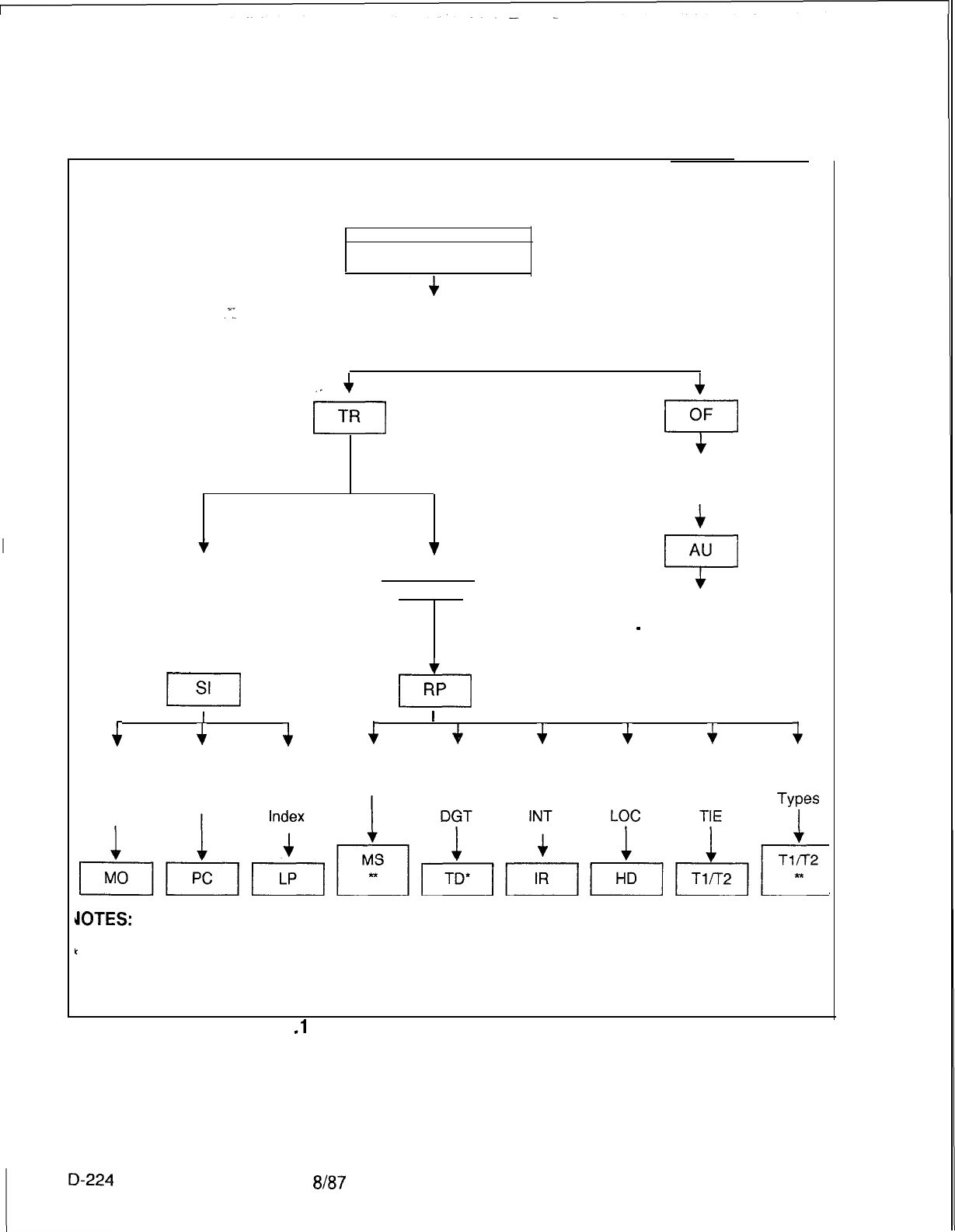
TL-130400-1001
This diagram represents an application of MERS On-Net using an access code defined with
the MERS On-Net code type to initiate the feature.
Dialed Access Code
AC (Code Type 105)
Dialed On-Network ABC Code
or Authorization Prefix Digits
+
/
TR
.
.
4
OF
7
Authorization
Code
4
v
Routing List
Number
AU
7
(switches to MERS Off-Net
process
-
See code type 48)
I
11
RP
t
I
t
I
+
4
+++
4
MERS
Other
Digits Prefix LDN SCC ID Dest. Dest. Dest. Dest. Dest.
Deleted Index Prefix
1
Type = Type = Type = Type =
Types
1
p&&$-&&&&,,-
JOTES:
Translation type must never specify MRN or MRS.
*
The MERS SCC ID and the other destination types (COT, FXT, SCC, WTS) may be
specified for On-Net MERS but the DDD network will be used to complete On-Net
MERS calls.
Figure 11
.l
D
On-Net MERS Record Code Association
8187
SVR 5210
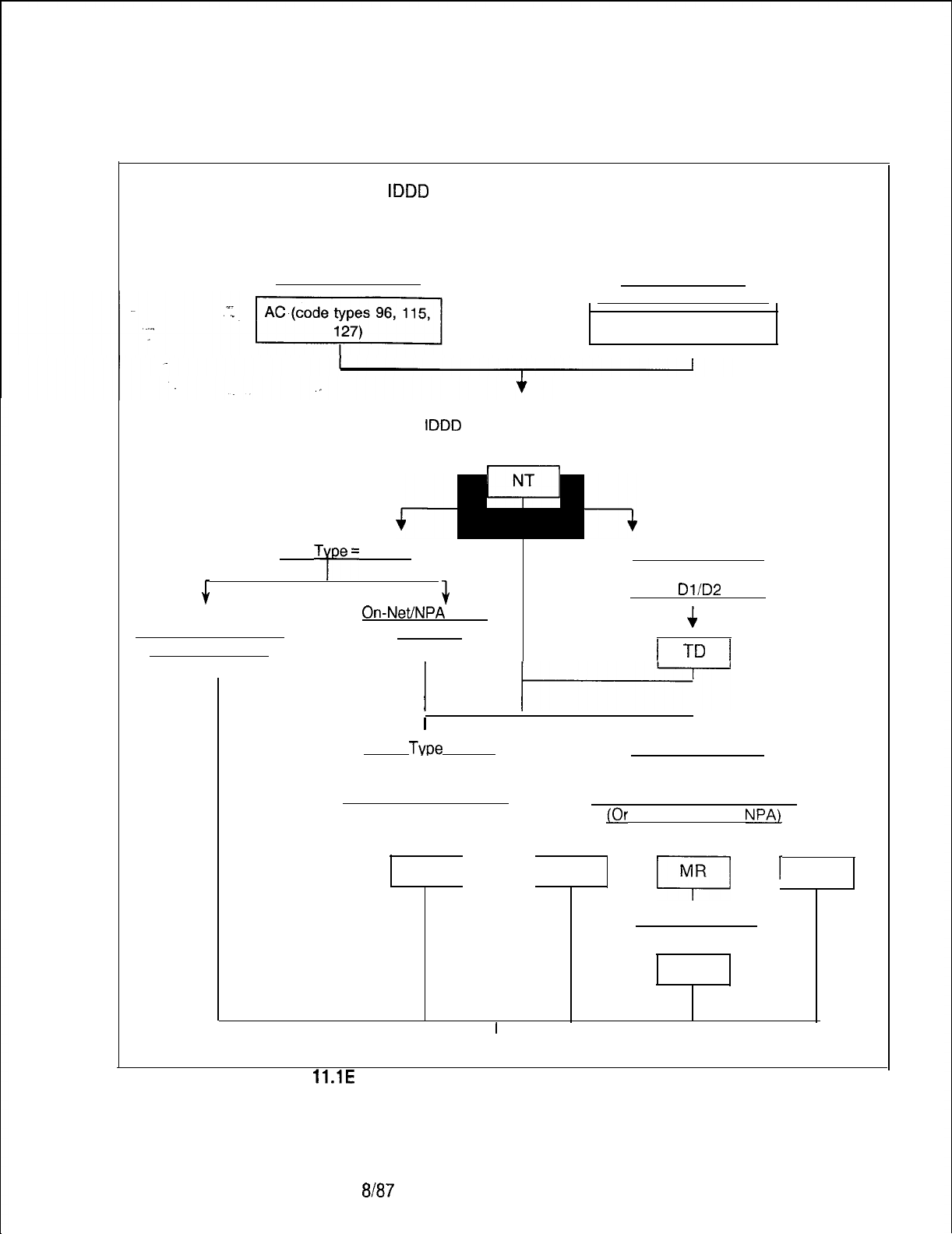
TL-130400-1001
This diagram represents an application of MERS On-Net and/or MERS Off-Net.
An access code defined with the
IDDD
variable numbering plan, the flexible numbering plan, or
the 7-l 0 digit called number can initiate the feature. The 1 st digit of either the flexible
numbering plan or the 7-10 digit called number can also initiate the feature.
Dialed Access Code
Dialed 1st Diqit
of
Network Numberinq Plan
AC (code types 96, 126)
I
Dialed 1st 3 Digits of Network Dialing Plan or
IDDD
Code/Country Code
/
Trans.
T;pe=
MER
+
+
On-Net/NPA
Code
Sendinq Inst./Routing
Specified
Pattern Specified
I
Trans. Type = DGT
Dialed
Dl/D2
Diqits
t
I
-l-D
I
I
-
I
Trans.
Type
= MRN
I
Trans. Type = MRS
I
Dialed on-net ABC code
I
TR
I
Dialed Service Code Or NPA
IOr
Undialed Home
NPA)
I
ST
MR
I
1
NR
Dialed ABC Code
I
TR
I
Continued on the Next Page
Figure
ll.lE
On/Off-Net MERS Record Code Association
SVR 5210
8187 D-225
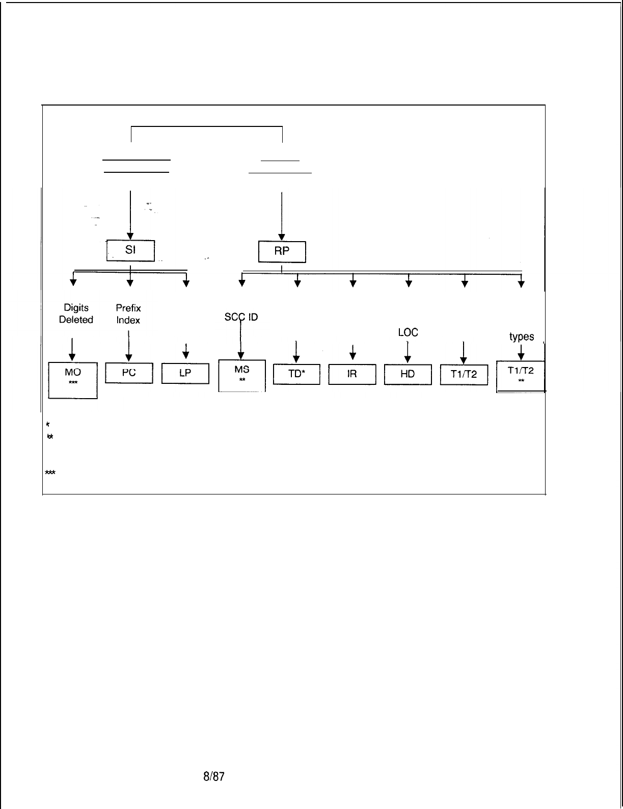
TL-130400-1001
Sending Inst.
List Number Routinq
List Number
LDN
Prefix
Index
MERS
Dest.
Type =
DGT
Dest.
Type =
INT
Dest.
Type =
LOC
Dest.
Type =
TIE
Other
Dest.
types
NOTES:
c
Translation type must never specify MRN or MRS.
te
The MERS SCC ID and the other destination types (COT, FXT, SCC, WTS) may be
specified for On-Net MERS but the DDD network will be used to complete On-Net
MERS calls.
ltld
Record Code MO is only applicable to On-Net MERS.
Figure 11.1 E
On/Off-Net MERS Record Code Association (Continued)
8187
SVR 5210
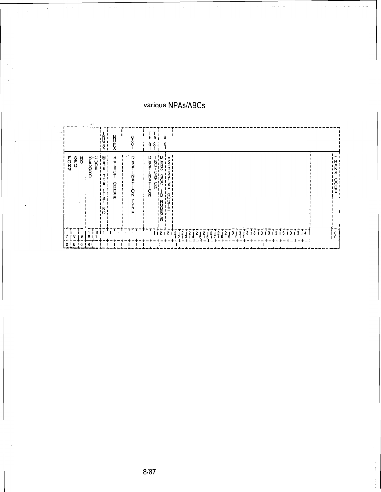
TL-130400-1001
Record Code RP:
11.2 Record Code RP, Figure 11.2, defines the routing list data,
MERS Routing List
including the trunks to be used by the MERS feature. Any trunks
not listed on this record code cannot be accessed by calls using
the MERS feature. In addition to listing all trunks to be used for
MERS, this record code also lists the trunk order in which calls
will go out. The routing list(s) is defined here and assigned to the
variqus
NPAs/ABCs
on Record Codes TR and NR.
;I;
I
;
T
,NI
N
OTT!
T
I
I
IDI
g
I
:
I
651
6
I
IEI
,341 3
I
IXI
x
I
‘:
,081
‘:
I
1111
I
. I
I I
I
’
I
-.).--$.-
T
-r-t-t-r-t-r-r-t-r-t-t-t-r-r-r-r-r-r-r-r-r-r-r-r-r-r-r-r-r-r-~
1
I1
I1
I1
11 11 11 11 11
II
1212121212121212121213131313131313131313l41
7!8!9,Oll
12131415161718191011
12,3i41516,718191011
121314151617181910,
-+-+-u-
-+-+-+-+-+-+-+-+-+-+-+-+-+-+-+-+-+-+-+-+-+-+-+-+-+-+-+-+-~
C-
216lOlRI
P
t
I I I
l
-Ad-l--L-
-L,d,1,,,1
I
I
I
I
I I I I I I I I I
I
I III I III,
I
-*-~-*-*-*-~-~-~-i-*-~-*-~-*-~-~-~-~-~-~-~-~-~------
I
I
I
1
I
I
I
:
I
1
Figure 11.2 Record Code RP: Most Economical Route Selection Routing List Data Sheet
SVR 5210
8187
D-227
TL-130400-1001
Table 11.2 Entry Fields for Record Code RP
COL.
COL.
VALID
NO. NAME ENTRIES COMMENTS
12
MERS Routing
O-7 = number
This field defines the identification number
List Number given to a route.
__
-For most applications, only one routing
pattern list number is required.
-If only one routing pattern is used, enter 0
down the row 12 times in column 12.
-The 12 entries coincide with the 12 possible
sending instructions found on Record Code SI,
columns 12-l 3.
-
All 12 entries must be made whether used
or not used. If they are not used, they will be
sent to intercept.
-When off-network MERS is used, it is
normally recommended to use a separate
routing pattern list number.
-A separate routing pattern list number can
be used for local calls.
-This number is referred on the following
record codes:
TR, columns 23, 26, 29 and/or 32
NR, columns 20, 23, 26 and/or 29
ST, column 19
NT, column 30
13-14
Select Order
1-12
= number
This field identifies the trunks that can be used
and the order of these trunks for calls placed
using this route.
-Each routing list/select order combination
must be unique across this record code.
-The select order must be continuous with no
gaps for each routing list.
8187
SVR 5210
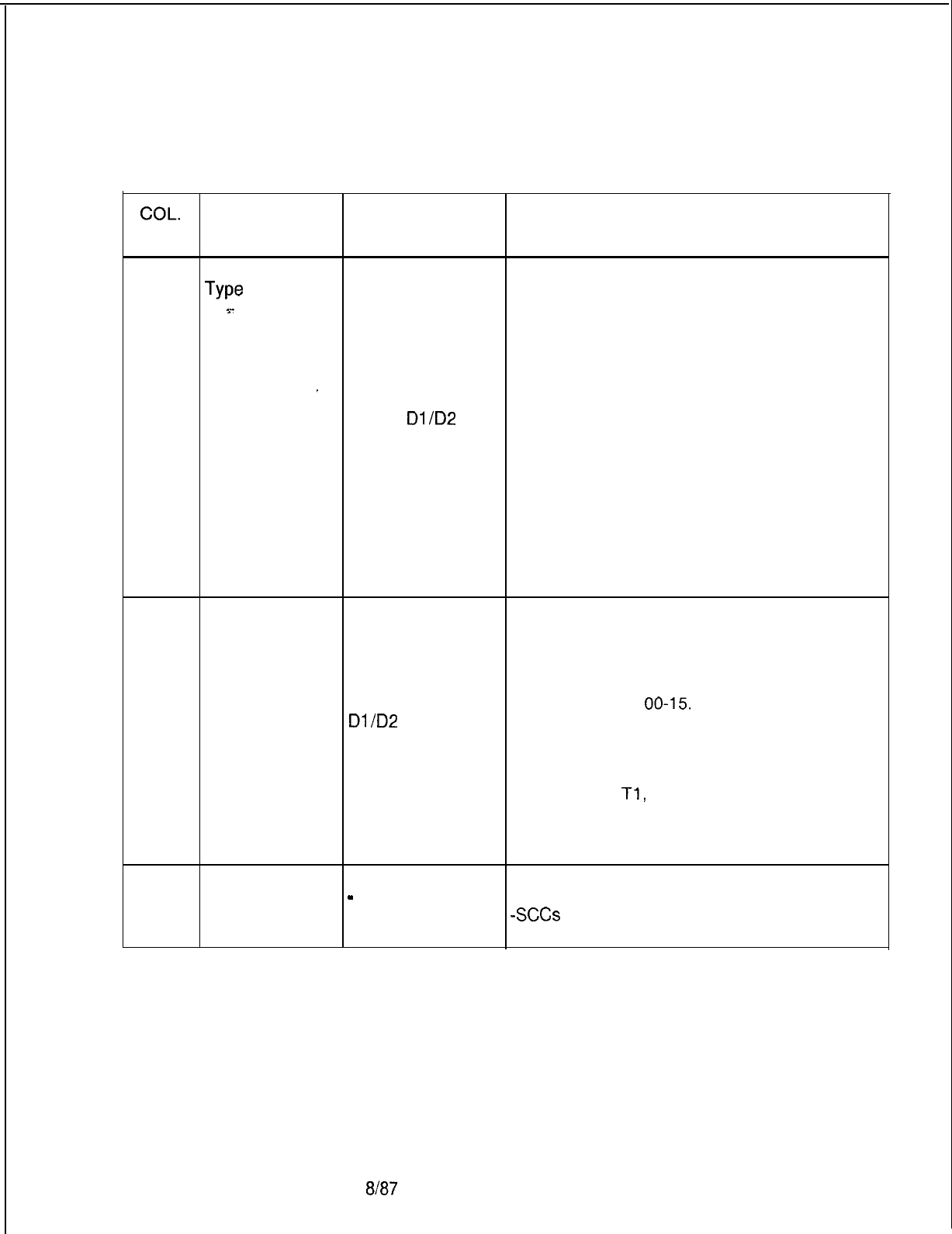
TL-130400-1001
COL.
NO.
Table 11.2 Entry Fields for Record Code RP
(Continued)
COL.
VALID
NAME ENTRIES COMMENTS
15-17
. . . .
Destination
COT
= CO trunks
This field determines how the trunk group is
Type
FXT
= FX trunks
treated (see columns 17-18).
3-
TIE
= Tie trunks
-LOC (Local Termination) is used in a
WTS = WATS network environment when the system is only
trunks to look at the last four digits dialed. Since the
INT
= intercept
first three digits (leading network digits) are all
LOC =
local
_the same, the last four digits dialed determine
termination the network switch to which the call is routed.
DGT
=
Dl
/D2
digit
-If an SCC is used, access to more than one
SCC = specialized local trunk group can be allowed. By allowing
common carrier access to more than one local trunk group,
the probability of accessing the SCC is
greater.
-If COT, FXT, WTS, or SCC is entered in this
field, then Record Code T2, columns 32, 33
and 34, cannot be dashed. It is
recommended to set these fields at the lowest
possible value.
18-19
Destination
00-63 = trunk
This field determines the trunk group number,
Identifier group number for the trunk type defined in columns 14-l 6.
00-l
5 = intercept
-If columns 14-16 are marked LOC or DGT,
routing number this field must be dashed.
-- = N/A or local -If columns 14-l 6 are marked INT, this field
termination or must be marked
00-15.
Dl
/D2
digit -If columns 14-16 are marked COT, FXT,
translation SCC, TIE, or WTS, this field must be marked
00-63.
-Trunk group numbers must be defined on
Record Code
Tl,
columns 12-l 3.
-The destination identifier can also be an
intercept routing number. This must be
defined on Record Code IR, columns 12-13.
20
MERS SCC
Identification
Number
O-7 = number
-
= not selected If an SCC is included in this route, this field
determines which SCC is to be used.
-SCCs
are identified on Record Code MS,
column 12.
SVR 5210
8187
D-229
TL-130400-1001
Table 11.2 Entry Fields for Record Code RP (Continued)
Expensive
Route
s-
.
.
_
VALID
ENTRIES
I=
tone
U
= not selected
COMMENTS
Mark this field Y if a burst tone is to be heard
when the call goes out over this route.
-A burst tone is normally used to notify a
caller that the call is going out over the most
expensive route.
-The most expensive route should be the last
trunk group of the route.
-With this feature, the caller has the option of
hanging up and trying later or continuing the
call over the most expensive route.
-A tone can be assigned to as many trunk
groups within a route as wanted.
8187
SVR 5210
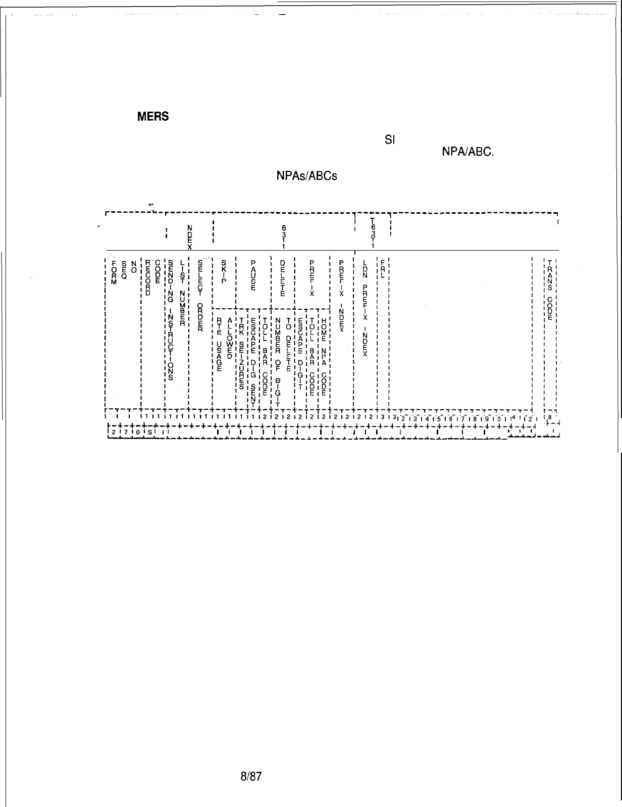
TL-130400-1001
Record Code SI:
11.3 Record Code SI, Figure 11.3, defines the special handling
MEW
Sending
requirements for a trunk group and the trunk group’s assigned
Instruction
destination number. Record Code RP defines the routes for
MERS usage. Record Code
SI
determines what facilities, within
a route, can be accessed by a specific
NPAIABC.
The sending
instructions are defined on this record code and assigned to the
various
NPAs/ABCs
on Record Codes TR and NR.
3-
r------iL-r-------r-----------------------~-----~---------------------------~
IIII
_
I
III
T
I
I
If
!
T
;
5
:
d
I
I
!
t
I
I
I-
I
I I I
;
I
‘;
I
I
I
II
I
III
I ,
1718191011 1213141516171819101112131415161718191011
1213141516171819l011
I21
IO I
c-+-+-u-+-+-+-+-+-+-+-+-+-+-+-+-+-+-+-+-+-+-+-+-+-+-+-+-+-+-+-+-+-+-+-~
C-4
l2171Olsl~l
I I I
l
I
l
l
1
l
1
l
I
I
1 l 1
I
1 I
I
I I
I
I
I
I 1 I
I
1
I
I
I
LLL
--L-L-~-~-~-~-*-~-~-~-~-~-~-*-~-~-*-*-~-~-~-*-~-~-~-~-~-~-~-
u-u
Figure 11.3 Record Code SI: Most Economical Route
Selection
Sending Instruction Data Sheet
SVR
5210
8187
D-231
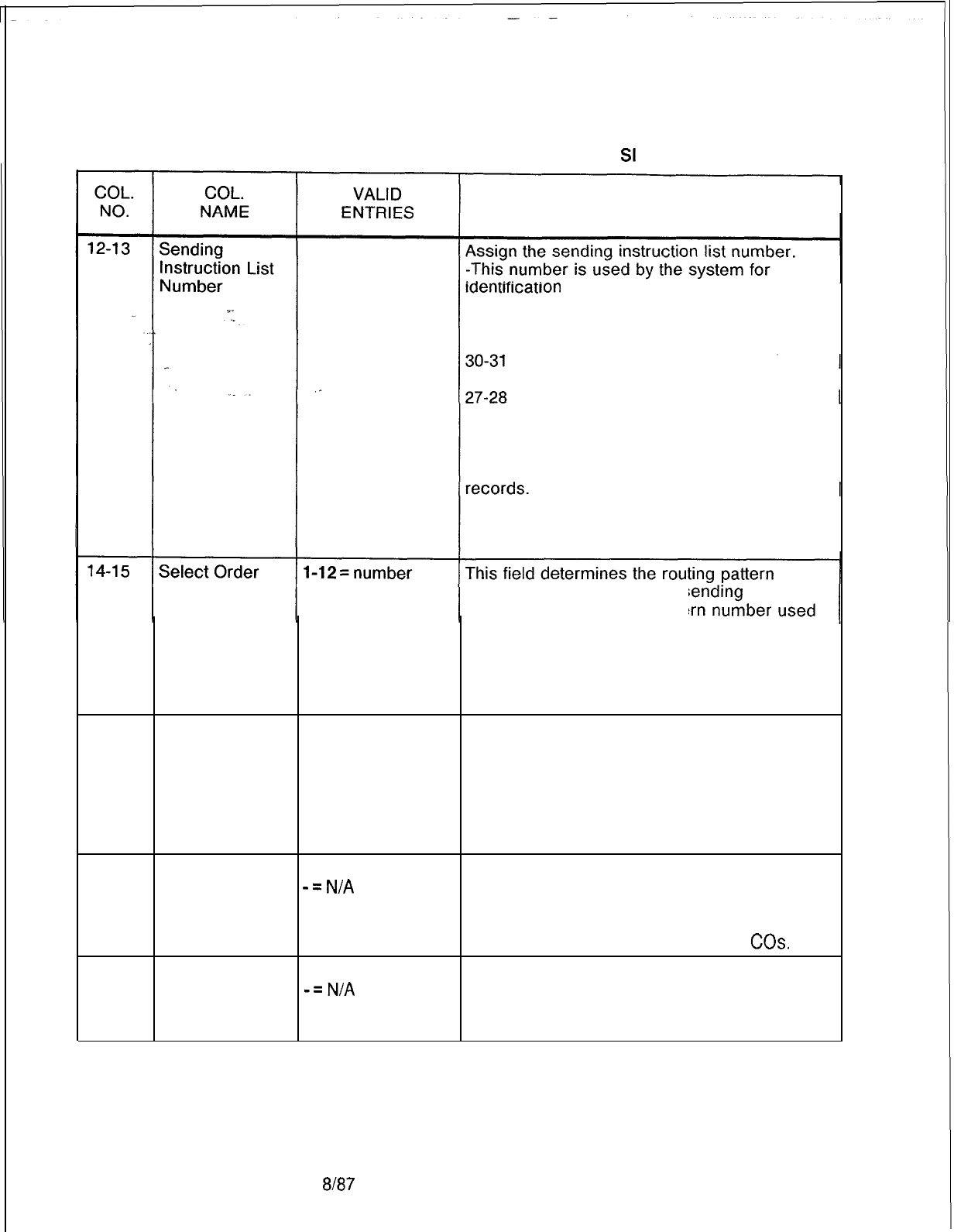
TL-130400-1001
Table 11.3 Entry Fields for Record Code
St
COMMENTS
00-31 = number
Ion
purposes.
-This number is referred to on the following
Record Codes:
TR, columns 21-22, 24-25, 27-28, and
NR, columns 18-l 9, 21-22, 24-25, and
NT, columns 28-29
ST, columns 17-18
-The sending instruction/select order
combination must be unique across all
NOTE: Sending instruction list number 00 is a
valid CPG entry; however, 00 should never be
used on this record code.
number that is used for this s
instruction. The routing patte
for this sending instruction is chosen from the
list of routing patterns on Record Code RP,
column 12.
-This field must be continuous with no gaps
for each sending instruction list.
16-17
Skip/Route AL = allowed This field determines whether or not this
Usage Allowed SK = skipped sending instruction is allowed access to this
trunk group.
-The trunk groups are defined for each route
on Record Code RP, and must be listed in the
order in which they appear on that record
code.
18
Pause After T = required Enter T if a pause is required after a trunk is
Trunk Seizure
-=N/A
seized.
-See Record Code T2, column 32, for the
timing value required for this field.
-This field is normally used for older
COs.
19
Pause After
E
= equipped
Enter E if a pause is required after an escape
Escape Digit
-=N/A
digit (trunk group access code) is sent.
Sent -See Record Code T2, columns 31 and 33,
for the timing value required for this field.
D-232 8187
SVR 5210
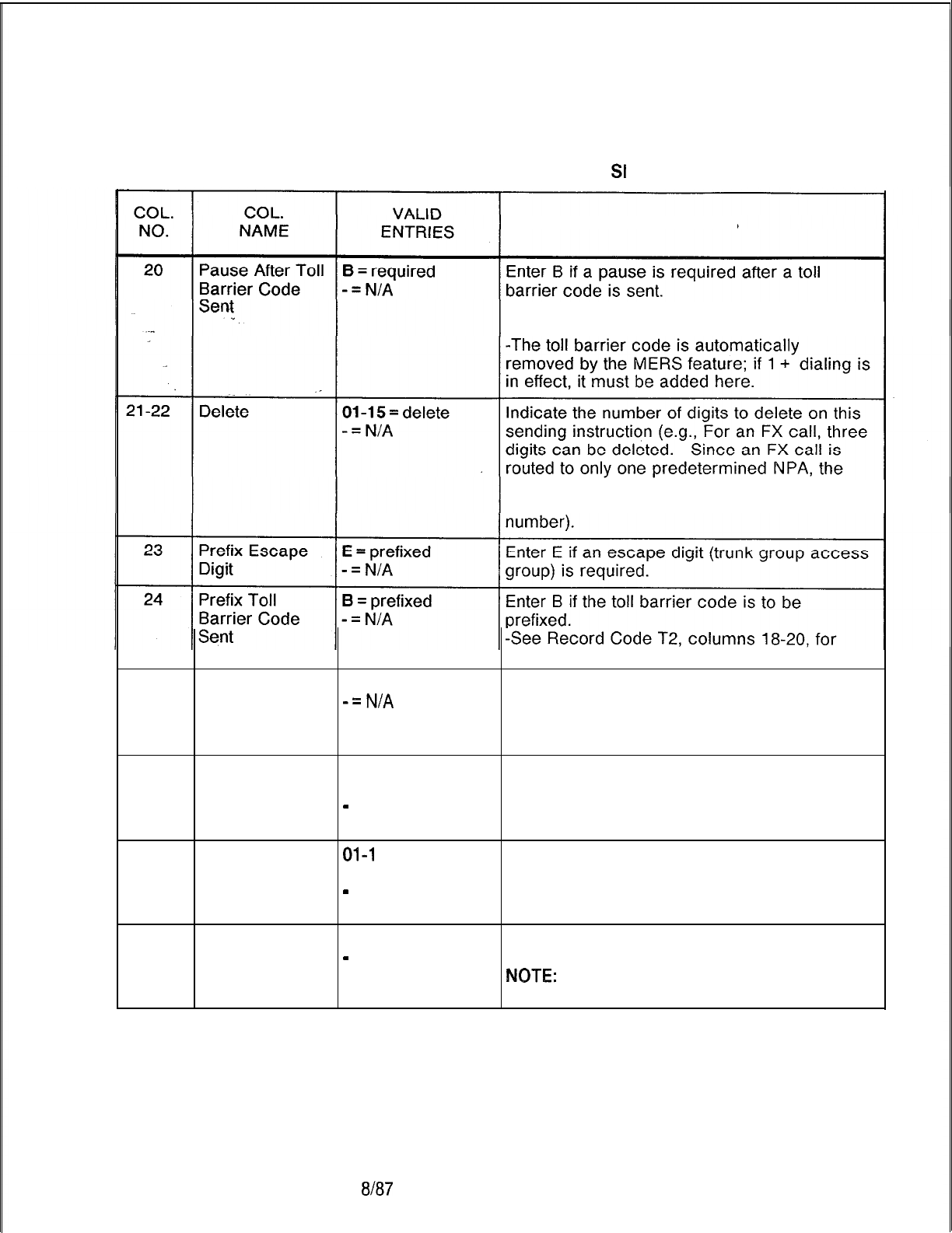
TL-130400-1001
Table 11.3 Entry Fields for Record Code
SI
(Continued)
COMMENTS
-See Record Code T2, column 34, for the
timing value required for this field.
three digits that make up the NPA are not
needed and can be removed from the
the toll barrier code per trunk group.
25
Prefix Home
Number Plan
Area (HNPA)
Code
H
= prefixed
-=N/A
Enter H if the HNPA code is to be prefixed.
26-27
Prefix Index
01-15
= prefix
This field determines whether or not a prefix
index index is used. Up to l-1 5 prefix index can
-
= not selected used. A prefix index is defined on Record
Code PC.
28-29
Listed Directory
01-l
5 = prefix
Example: This field determines the LDN
Number Prefix index (Listed Directory Number) prefix index (for
-
= not selected other examples, see Record Code LP).
-This is defined on Record Code LP.
30
Facility
Restriction
Level
O-7 = FRL
-
= not selected If this field is used, it determines the FRL
value placed on this sending instruction.
NOTE:
An application for this field is to block
calls, thereby forcing MERS call queuing.
SVR 5210
8187
D-233
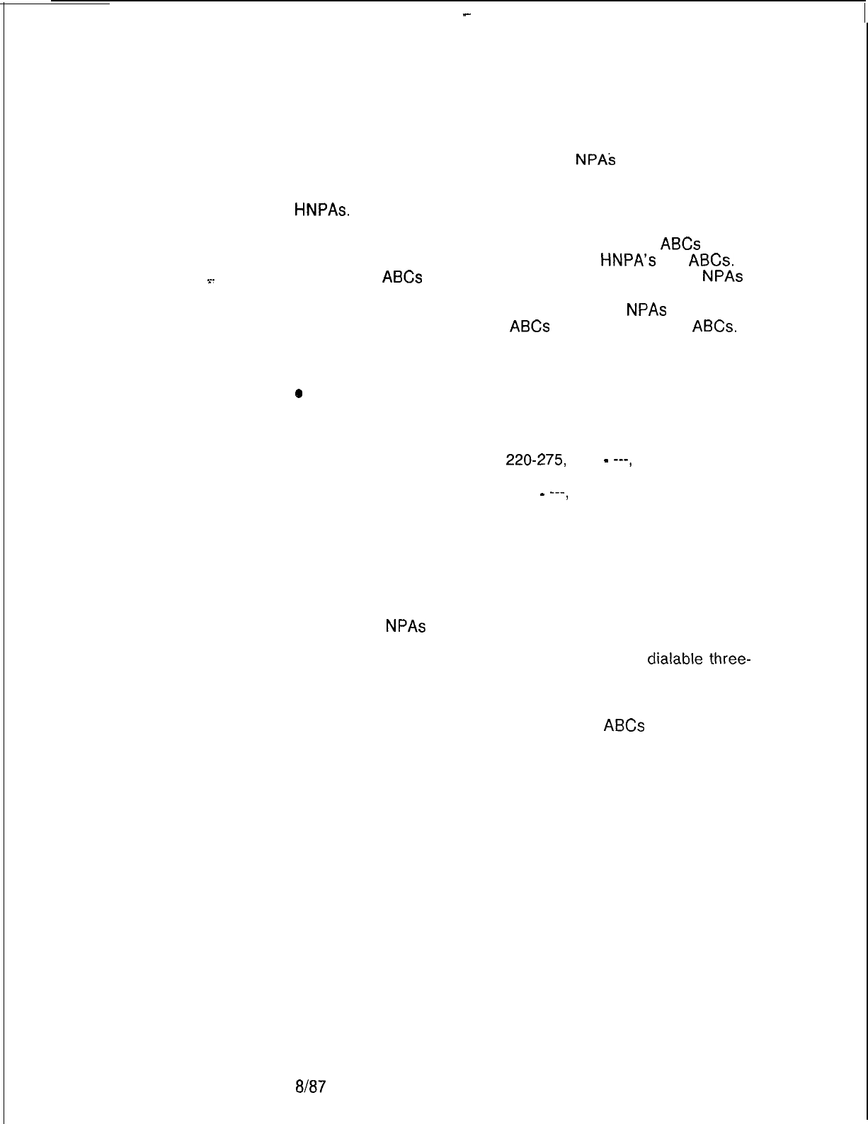
-
TL-130400-1001
Record Code TR:
11.4 Record Code TR, Figure 11.4, lists all of the ABC codes for
MERS Numbering Plan
an NPA that requires six-digit analysis.
NPAs
that require
Area/ABC Translation
six-digit analysis are defined on Record Code MR. Any NPA
listed on Record Code MR must be listed on this form, including
HNPAs.
. . . .
The first entry on this form must be the HNPA. The
ABCs
local to
the HNPA must be listed first. Next list the
HNPA’s
toll
ABCs.
After all the
ABCs
for the HNPA are listed, enter all other
NPAs
appearing on Record Code MR. Begin with the lowest number
and work upward (e.g., 212, 401, 813). For all
NPAs
listed on this
record code, first list the local
ABCs
followed by the toll
ABCs.
.
“NOTES:
e
An ABC for an NPA can only be listed once, as either a local
ABC or a toll ABC.
l ABC codes can be entered either singularly or by groups of
consecutive numbers (e.g.,
220-275,
277
-
---,
280-
299). Numbers should be entered singularly when they must
stand alone (e.g., 220-275, 277
-
---,
280-299). In this
example, the numbers 276, 278, and 279 do not exist. Only
numbers that contain conflicting codes can jump hundreds
groups (e.g., 220-399).
l Both MERS off-network DDD (Direct Distant Dialing) and
MERS on-network ABC codes can be listed. When MERS
off-network dialing is used, this record code lists the ABC
codes for
NPAs
that require six-digit analysis. When MERS
on-network dialing is used, this record code lists the RNX
(Remote Numbering Exchange) codes that are
dialable
three-
digit network codes.
l Any ABC for an NPA not listed on this record code cannot be
called over the MERS option. Include all
ABCs
for a given
NPA. If denial to a certain ABC is required, that must be done
by means of toll restriction.
l Record Code TR allows for three time periods. Time periods
1, 2, and 3 are defined on Record Code TP. Any time not
within the ranges defined by time period l-2 or l-3 is
considered to be time period 0.
D-234
8187
SVR 5210
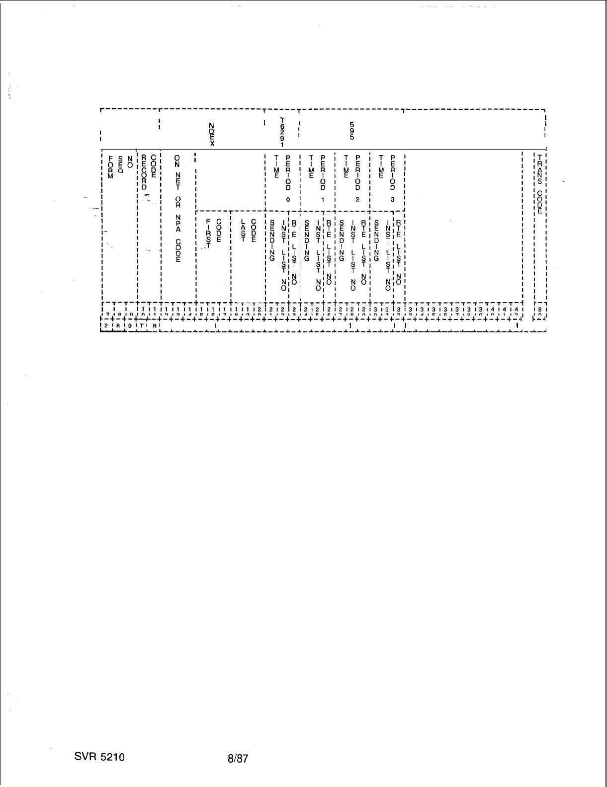
TL-130400-1001
T---------r-----------------T-----T----T-----------------,-----------------------~
II
III I
I
T
II
I
II
2
’
i
’
II
E
II
I
$
I
It
I1II
III I II
IIII I I
f:
I
ABC
I
CODE
RANGE
c-+-+-u-+-+-+-+-+-+-+-+-+-+-+-+-+-+-+-+-+-+-+-+-+-+-+-+-+-+-+-+-+-+-+-~
I..-4
l218191Tt~l
I I I I 1 I I I I I I I I I I I
I
I I I
I
I
I I I I I I I I I
I
I
L-*-L
--L-~-L-~-~-~-~-~-~-~-~-~-*-~-~-~-~-~-~-~-~-~-~-~-~---~--------
Figure 11.4 Record Code TR: Most Economical Route Selection
Numbering Plan Area/ABC Translation Data Sheet
8187
D-235
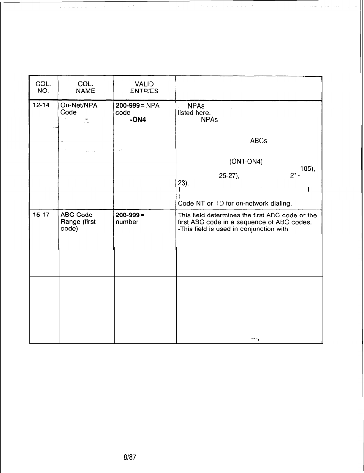
TL-130400-1001
Table 11.4 Entry Fields for Record Code TR
COMMENTS
ON1 -ON4 =
on-
network code
All
NPAs
requiring six-digit analysis must be
-These
NPAs
must first be identified on
Record Code MR, which points to TR for the
routing patterns and sending instructions
needed for the different
ABCs
of this NPA.
-The HNPA must be the first entry.
-For MERS on-network dialing, enter the
on-network code
(ONl-ON4)
that is defined
on Record Code AC (code type number
105)
NT (columns
25-27),
or TD (columns
21-
NOTE:
This entry must be listed on Record
Code MR for six-digit analysis or Record
columns 18-20.
NOTE: If an ABC code on this record code is
the same as an NPA code or an RNX code for
on-network dialing, the conflicting code field
on Record Code MR, column 20, must be
marked Y.
18-20
ABC Code
200-999 =
This field determines the last ABC code in a
Range (last number sequence of ABC codes.
code) --- = N/A or -The last ABC code (columns 18-20) must
single code be greater than the first ABC code (columns
15-17).
-If only one number is represented, columns
18-20 must be dashed (e.g., 221 is the only
number not used; in a sequence that ranges
from 220-299, enter 212
---,
214-299).
8187
SVR 5210
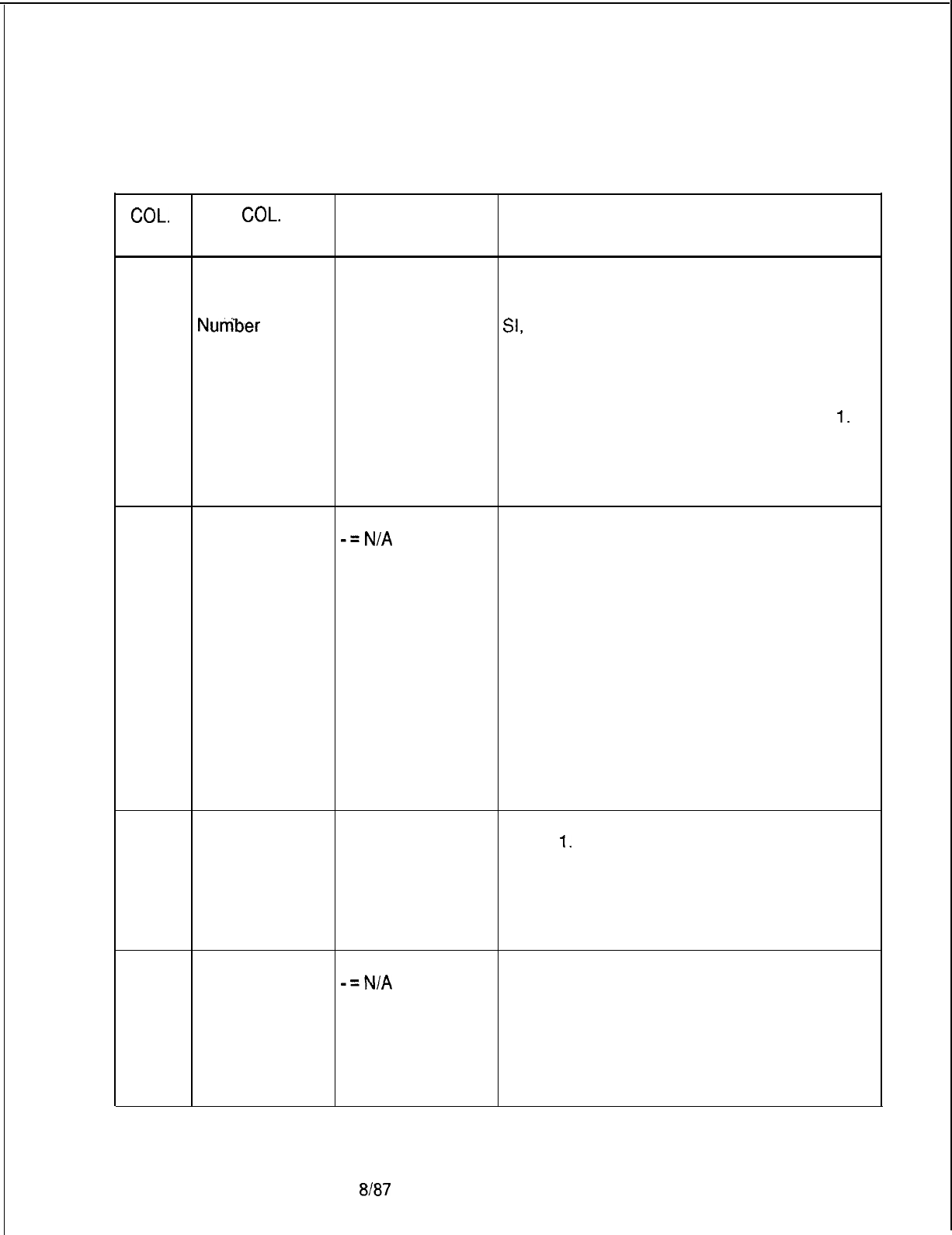
TL-130400-1001
Table 11.4 Entry Fields for Record Code TR (Continued)
COL. COL.
VALID
NO. NAME ENTRIES COMMENTS
21-22
Time Period 0
01-31 =
list
Assign the sending instruction used for time
Sending number period 0. The sending instruction list number
Instruction List -- = N/A used here must be defined on Record Code
. .
Nurriber
SI,
columns 12-l 3.
-Use only this field if no time changes are
required for entries on Record Code TR or
NR.
.NOTE: When time changes are required,
begin the first time period with time period
1.
Enter routing information for the remainder of
the day in time period 0. If all time periods are
defined, time period 0 serves as a default
value.
23
Time Period 0
O-7 = list number
Assign the route list number for time period 0.
Route List
-=N/A
-This field defines the time period not
Number
covered by time periods l-3. If no time
changes are required for any entries on
Record Code TR or NR, this is the only field
that requires an entry.
-When time changes are needed, begin the
first time period with time period 1 and put a
default value in columns 21-23. If the time
periods defined on TP cover the entire day,
the default value will not affect the routing
because the default will never be used.
-If an entry is made in columns 21-22, then
an entry must be made in this field.
-The route list number used here must be
defined on Record Code RP, column 12.
24-25
Time Period 1
01-31
= list
Assign the sending instruction used for time
Sending number period
1.
Instruction, List -- = N/A -The sending instruction list number used
Number
here must be defined on Record Code SI,
columns 12-l 3.
-If this field is used, then Record Code TP
must be filled out.
26
Time Period 1
Route List
Number
O-7 = list number
Assign the route list number used for time
-=N/A
period 1.
-If an entry is made in columns 24-25, then
an entry must be made in this field.
-The route list number used here must be
defined on Record Code RP, column 12.
-If this field is used, then Record Code TP
must be filled out.
SVR 5210
8187
D-237
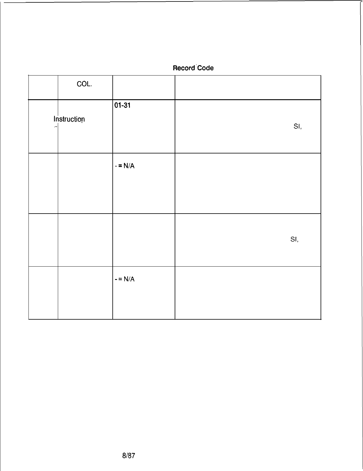
TL-130400-1001
COL.
NO.
Table 11.4 Entry Fields for Record’Code TR (Continued)
COL.
VALID
NAME ENTRIES COMMENTS
27-28
Time Period 2
Sending
-
lnstructi0.n
List
.-.
Number
01-31
= list
number
-- = N/A
Assign the sending instruction for time period
2.
-The sending instruction list number used
here must be defined on Record Code
SI,
columns 12-l 3.
-If this field is used, then Record Code TP
must be filled out.
29
Time Period 2
O-7 = list number
Assign the route list number used for time
Route List
-=N/A
period 2.
Number -If an entry is made in columns 27-28, then
an entry must be made in this field.
-The route list number used here must be
defined on Record Code RP, column 12.
-If this field is used, then Record Code TP
must be filled out.
30-31
Time Period 3
Sending
Instruction List
Number
01-31
= list
number
-- = N/A
Assign the sending instruction for time period
3.
-The sending instruction list number used
here must be defined on record code
SI,
columns 12-l 3.
-If this field is used, then Record Code TP
must be filled out.
32
Time Period 3
O-7 = list number
Assign the route list number for time period 3.
Route List
-=N/A
-If an entry is made in columns 30-31, then
Number an entry must be made in this field.
-The route list number used here must be
defined on record code RP, column 12.
-If this field is used, then Record Code TP
must be filled out.
D-238 8187
SVR 52’0
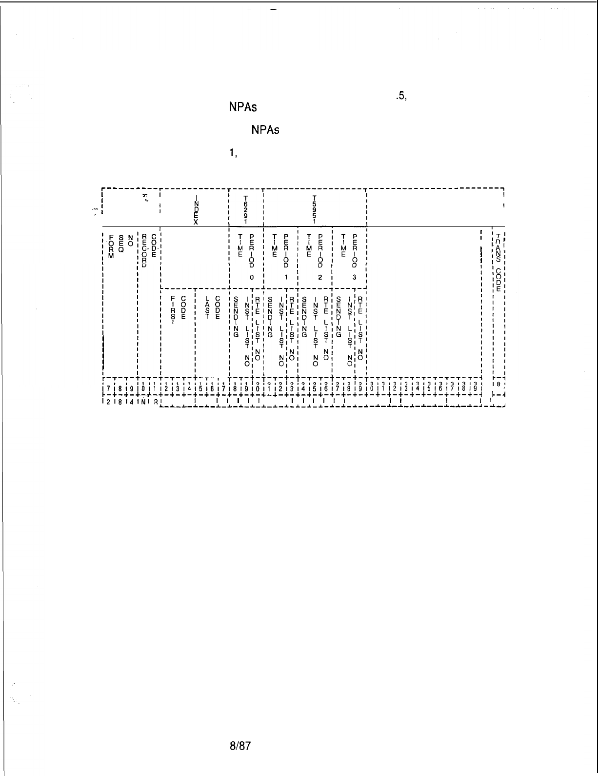
TL-130400-1001
Record Code NR
11.5 Record Code NR, Figure 11
S,
lists all of the ABC codes for
MERS Three-Digit
NPAs
that do not require six-digit analysis. This sheet defines
Translated NPA
the off-network routing for each time period used. The HNPA
and
NPAs
requiring six-digit analysis are listed on Record Code
TR and must not be listed on this record code. Time periods 0,
1,
2, and 3 are defined on Record Code TP.
r-----‘---r-----------r-----I-------------------------~-----------------------~
I
--
I
I
I
‘I
I
I
I
If
!
I
.-..
I
-
I
II
II
x’
I
III
,
NPA
CODE
1
IT’
RANGE
1
R’
1
IAl
’
IN,
’
IS,
17181910111213141516171819101112l3141516171819101112131415161718191
IO I
c-+-+-c-c-+-+-+-+-+-+-+-+-+-+-+-+-+-+-+-+-+-+-+-+-+-+-+-+-+-+-+-+-~
k-4
l2161411;11,?I
I ,
I
I
I
I
I
I
I
, I
I
I
I
I
I
I
I I I
I
I
I I I
I
I I
I
l
L-a----
L---L-*-~-~-~-~-~-~-~-~-~-~-~-*-~-~-~-~-~-*-~-~-~-~-~-~-~---~
Figure 11.5 Record Code NR: Most Economical Route Selection
Three-Digit Translated NPA Data Sheet
SVR 5210
8187
D-239
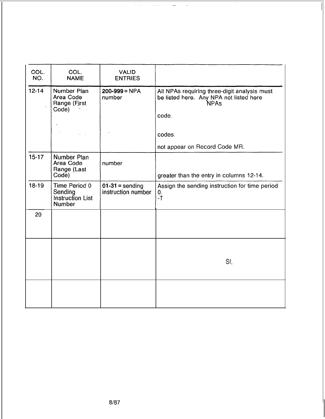
TL-130400-1001
Table 11.5 Entry Fields for Record Code NR
COMMENTS
cannot be called.
NPAs
needing six-digit
analysis are not to appear on this record
-This field determines either the NPA code or
the first NPA code in a sequence of NPA
-Any NPA listed in in columns 12-l 7 must
200-999 = N PA
This field determines the last NPA code in a
sequence of NPA codes.
-The number entered in this field must be
Time Period 0
Routing List
Number
O-7 = routing list
number
he sending instruction list number must be
defined on Record Code SI, columns 12-l 3.
Assign the routing list number for time period
0.
-The routing pattern list number must be
defined on Record Code RP, column 12.
21-22 Time Period 1
01-31 =
= sending Assign the sending instruction for time period
Sending instruction number 1.
Instruction List -The sending instruction list number must be
Number defined on Record Code
SI,
columns 12-13.
-Time periods are defined on Record Code
TP.
23
Time Period 1
O-7 = routing list
Routing List number
Number
Assign the routing list number for time period
1.
-The routing pattern list number must be
defined on Record Code RP, column 12.
D-240
8B7
SVR 5210
COL.
NO.
24-25
.
.
.
26
27-28
I-
29
TL-130400-1001
Table 11.5 Entry Fields for Record Code NR (Continued)
COL.
VALID
NAME ENTRIES
Time Period 2
01-31 = sending
Sending instruction number
Instwction
List
Number
Time Period 2
O-7 = routing list
Routing List number
Number
‘.
Time Period 3
Ol-31=
sending
Sending instruction number
Instruction List
Number
Time Period 3
Routing List
Number
O-7 = routing list
number
COMMENTS
Assign the sending instruction for time period
2.
-The sending instruction list number must be
defined on Record Code SI, columns 12-13.
Assign the routing list number for time period
2.
-The routing pattern list number must be
defined on Record Code RP, column 12.
Assign the sending instruction for time period
3.
-The sending instruction list number must be
defined on Record Code SI, columns 12-l 3.
Assign the routing list number for time period
3.
-The routing pattern list number must be
defined on Record Code RP, column 12.
SVR
5210
8187
D-241
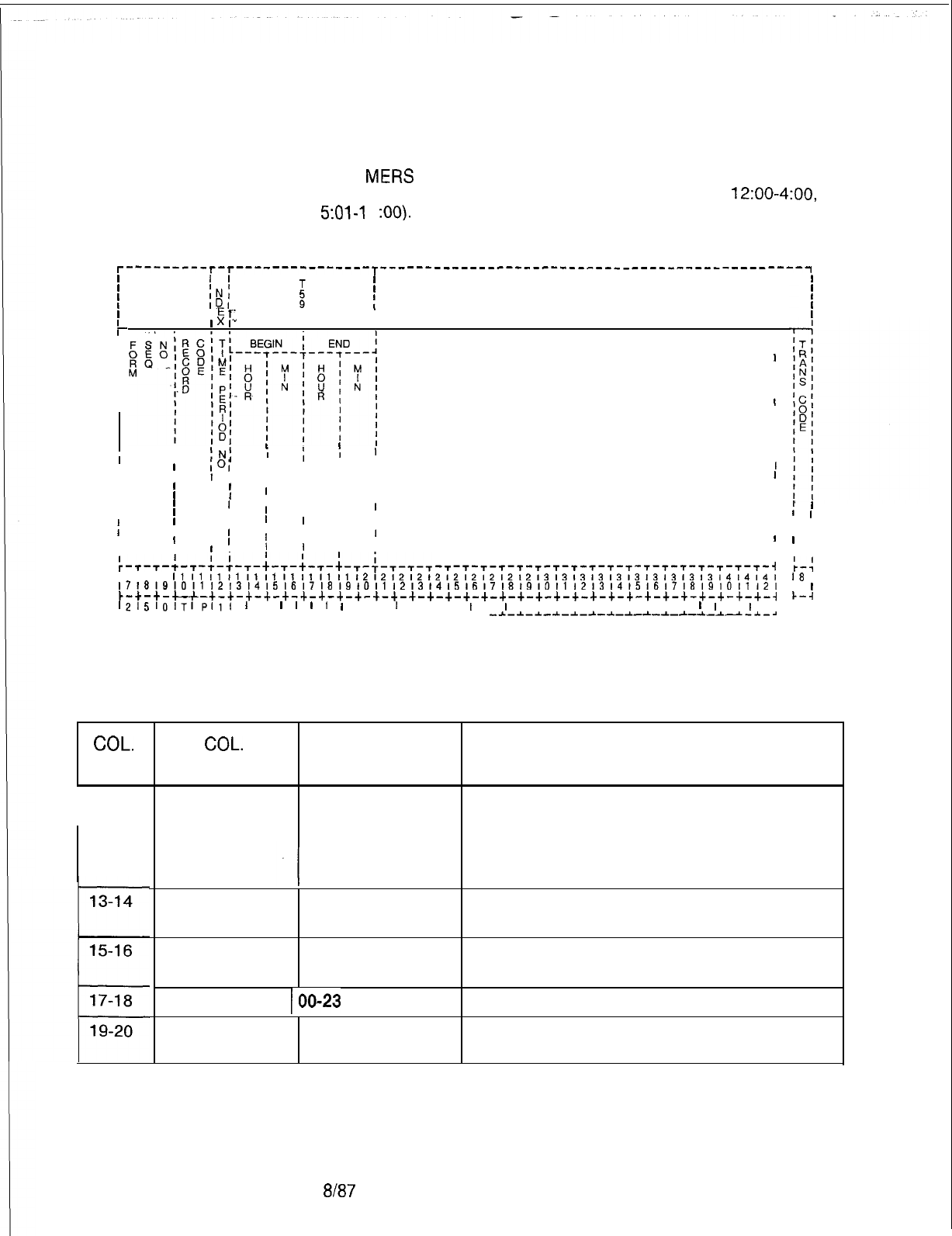
TL-130400-1001
Record Code TP
11.6 Record Code TP, Figure 11.6, defines the time of day when
MERS Time Period
each
MEW
time period is in effect. Time periods entered on
this record code must not overlap one another (e.g.,
12:00-4:00,
5:01-l
1
:OO).
r---------
r--r---------------T
-----------------------------------------------~
I I
I I
II
I I
I I
t
I
I
I
I
I
I
I
I
1
I
I
IN’
I
ID’
I
E
T-
4
I
I
x
I'"
1I
I
. . .
I I
I
I
I
I
I
I
I
I
I
I
I
I
I
I
II
IN;
i
;
iI
III
I
I
IO1
IIIII
III
I
II
I
I
II
II
I
IIIIII
I
I
IIII
IIIII
II
I
III
II
I I
I
II,I
f
I
I I
II
II
I,
I
IIII
I
II
I
IIII
I
I
III
I
IIIII
,-T-T-i-T
II
-:-:-,-;-,-;-,-+-,-;-,-,-,
I
-T-T-T-T-T-T-T-T-T-T-T-T-T-T-T--r--r-T-i
I I I
111111111111111111111212121212121212121213131313131313131313l4l4l4l
~~~~~~~~~~~~~~~~~~~~~~~~~~~~~~~~~~~~~~~~~~~~~~~~~~~~~~~~~~~~~~~~~~~~~~~~~
~-+-+-u-+-+-+-+-+-+-+-+-+-+-+-+-+-+-+-+-+-+-+-+-+-~-+-+-+-+-~-+-+-+-+-~
1215101TIP,,,
1
I
I
I
I
I
I
I I
I
I I I
I
I
I
I , I I I , I I I
I
I
I
I
I
L-L&A-L-~-L-~-~-~-~-*-~-~-~-~-~-~-~-*
-~-*-~-~-~-~-~-~-~-~-~-~-*--~-~
COL.
NO.
I
12
Figure 11.6 Record Code TP: Most Economical Route Selection
Time Period Data Sheet
Table 11.6 Entry Fields for Record Code TP
I
I
I
II
I I
I
I
I I
I
r-4
18 I
IO
I
k-4
I I
COL.
NAME
Time Period
Number
VALID
ENTRIES
l-3 = number
Begin Time
Hours
00-23 = hour
Begin Time
Minutes 00-59 = minute
End Time Hours
100-23
= hour
End Time
Minutes 00-59 = minute
COMMENTS
This field represents one of the four possible
time periods allowed for the MERS feature.
-This field is used by the system for
identification purposes.
-Each time period number must be unique.
Enter the hour that the time period is activated.
Enter the minute that the time period is
activated.
Enter the hour that the time period ends.
Enter the minute that the time period ends.
D-242
8187
SVR 5210
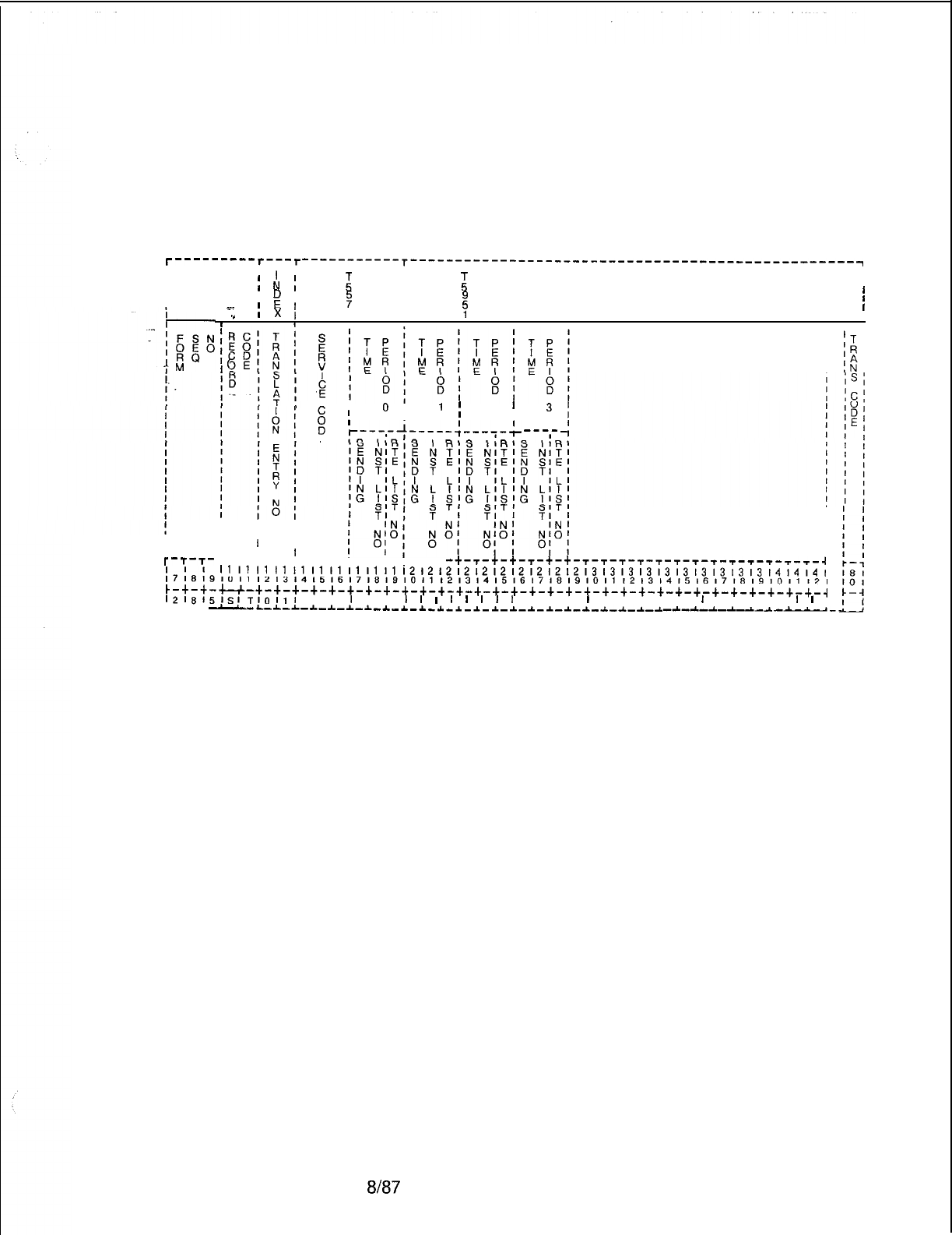
TL-130400-1001
Record Code ST:
11.7 Record Code ST, Figure 11.7, defines the service code
Service Code
MERS Translation
translation data for MERS routing, correlating the sending
instruction and routing list numbers to the service codes listed.
I I
I I
1
I
I
1
I
T-T-T-
t-T-T-T-t-t-T-t-T-+-T-T-T
-t-r-t-t-T-t-t-T-T-T-T-T-T-T-T-T-T--r-T-T-T--r-i
;7i8fSIOll
121314151617181910111213141516171819101112l31415161718191011121
11111111111111111111121212121212121212l213131313131313131313l4l4l4l
c-+-+-u-+-+-+-+-+-+-+-+-+-+-+-+-+-+-+-+-+-+-+-+-+-+-+-+-+-+-+-+-+-+-+--i
12l8l5I~ITlOllI
I I
I
I I
I
I
I
I
I
I
I
I
I I I
I
I I I I I
I
I I I I
I
I
L-L-L
--L-~-L-*--L-~-~-~-~-~-*-~-~-*-~-~-*-*--L-~._-C-~--L
-A-A.-A-A--L--L
---_
Figure 11.7 Record Code ST: Service Code MERS Translation Data Sheet
r---------r---r-----------T-------------------------------------------------~
I I
;
ti
III
I
I;
i
I
I
E
I
I
:
I
7
I
III
I
s-
I
I
x
I
1II
.”
I
Y
I
II
;j
I ,
Jr
I
(
I
.
I
g
I
0
i
I
’
I
2
’
3
I
E
,.--,-+----&--,-$
---,-
4
I
SVR 5210
Em7
D-243
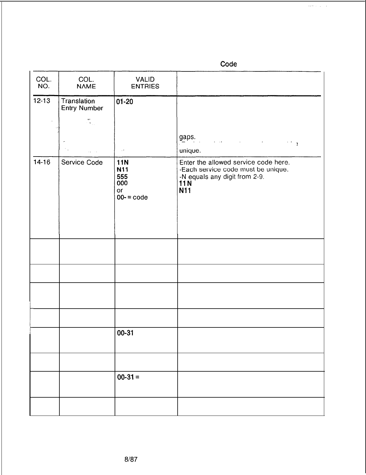
TL-130400-1001
Table 11.7 Entry Fields for Record
Code
ST
COMMENTS
04-20
= number This field determines the number given to the
translation entry.
-This number is used by the system for
identification purposes.
-This number must be consecutive with no
-Each translation
entry
number must be
11
N
= suffixed service calls allowed
Nil
= prefixed service calls allowed
555 = long distance, directory, directory
assisted calls allowed
000 = local, operator assisted calls allowed
00- = toll operator, operator assistance
allowed when using equal access (MERS -0
and + 0 dialing allowed)
17-18
Sending 00-31 = number Assign the sending instruction list number for
Instruction List time period 0 here. This must be defined on
Number (0) Record Code SI, columns 17-18.
19
Route List
O-7 = number
Assign the list number for time period 0 here
Number (0) and define it on Record Code RP, columns 19.
20-21
Sending 00-31 = number Assign the sending instruction list number for
Instruction List time period 1 here. This must be defined on
Number (1) Record Code SI, columns 17-18.
22
Route List
O-7 = number
Assign the list number for time period 1 here
Number (1) and define it on Record Code RP, columns 19.
23-24
Sending
00-34
= number Assign the sending instruction list number for
Instruction List time period 2 here. This must be defined on
Number (2) Record Code SI, columns 17-l 8.
25
Route List
O-7 = number
Assign the list number for time period 2 here
Number (2) and define it on Record Code RP, columns 19.
26-27
Sending
00-31=
number Assign the sending instruction list number for
Instruction List time period 3 here. This must be defined on
Number (3) Record Code SI, columns 17-l 8.
28
Route List
O-7 = number
Assign the list number for time period 3 here
Number (3) and define it on Record Code RP, columns 19.
D-244
8187
SVR 5210
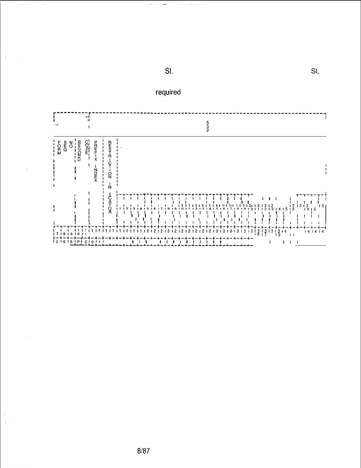
TL-130400-1001
Record Code PC:
11.8 Record Code PC, Figure 11.8, defines the MERS prefix
Prefix Code Digits
digits referenced by the prefix index defined on Record Codes
MO and
SI.
If Record Code RP (associated with MO and
SI,
which reference the prefix index) specifies SCC identification,
Record Code PC must provide the restriction indicator value and
digits
,required
to access the SCC.
l----------r
---------------------------^-----------------------------------------~
I
--,
I
,-I
T
I
I
I ..^
I
I
II
I-
I
,
i
I
;FSN:R
C;
,gpE
0
IM
c
d
;O
El
I
IR
I
ID
I
i
I
II
I
II
I
II
II
I
PREFIX DIGITS
III;
N
I
III
D
IIII
’
:-r-r,-
T-T-T-t-T-T-T-T-T-T-T-T-T-T-T-T-
II
CIIII,,,,,,,,,
I
I
I
I
I
III
;AI
I I I
I
I
I I
I
I
I
I I
;I
I
I
I
I
I
III;
I1
I1
I1
I1
I1
I1
I1
I1
I1
I1
12
II
III
,Rllll,,,l,,,lll,,,,,,
III
IIIf
I
I
I
I
I
I
I
I,
I
I
I
I
I
I
I
I
I,
!
III
I
I
I
I
I
I
I I
I
II
I
I
I
I
I
11111111111111111111121212121212121212,2131313131313
;7;8;910,1
12131415161718191011 12131415161718191011 12131415
C-+-+-u.-+-+-+-+-+-+-+-+-+-+-+-+-+-+-+-+-+-+-+-+-+-+-+-+-
1216151PlC1011I
I I I
I
1
I
I
I
I
I
I
I
I
1
I
I
I
, I I I
L-L-A
--LL-L--c-~-*-~-~-~-~-~~~~~~~-~-~-~-*-*-*-~-~-~-~-~-~-
T-T-T- -r--r--r-
I
I
I
I
I
I
I I I I I
I
12
12
12
12 12
12
;I
;2;3141516
I
I
I
I
I
I
I
I
I
I
I
I
I
I
I
;-;-;-;-;-;-
I3
I3
13
13
I4
14
16
17
18
I9
10
11
+-+-+-+-+-+-
, I
I
I
I
I
A--L-4.-A--c-A-
,
T-T-T-T-
I I I
I
1
I
I
I
I
,
12
I2
12
13
17
18
‘9
10
I I
I
I
I
I
I
I
I
I I I
;--;-;-;-
-I
14
14,414
I
12131415,
+-+-+-+--I
I
I I I I
Figure 11.8 Record Code PC: Prefix Code Digits Data Sheet
SVR 5210
8187
D-245
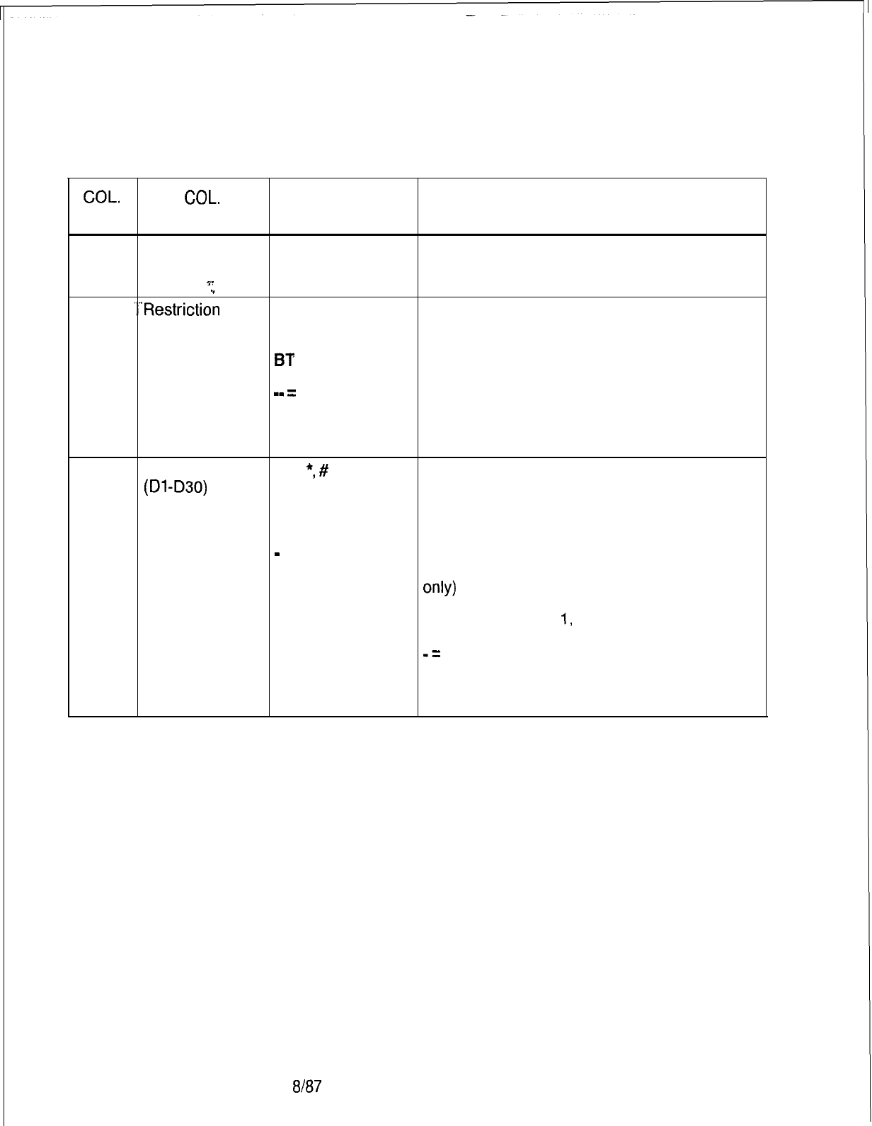
TL-130400-1001
Table 11.8
Entry Fields for Record Code PC
COL.
COL.
VALID
NO.
NAME ENTRIES COMMENTS
12-13
Prefix Index 01-l 5 = number Indicate the prefix index.
-This number is used by the system for
T.
identification purposes.
.”
14-15 ‘..‘Restriction
NO Assign the restriction indicator.
Indicator TL -This field is applied only to an SCC dialing
TG
pattern.
BT
NO = perform all checks
or
TL = bypass toll restrictions
mm
=
indicator TG = bypass trunk group access restrictions
BT = bypass toll and trunk group access
restrictions
-- = not applicable
16-45
Prefix Digits o-9,
*,
#
Assign the prefix digits not tied to a trunk
(Dl
-D30)
A
group.
D
-Column 16 cannot be dashed.
E
O-9, *, #= telephone digits
or A = obtain authorization code (SCC only)
-
= digits D = pause. The next two digits specify a
pause in increments of 0.5 seconds (SCC
only)
E = switch to DTMF and recognize tone from
SCC if next digit is
1,
or switch to DTMF if next
digit is 0 (SCC only)
-=
unused
-If the application is not an SCC:
D = a short pause
E = a long pause
8187
SVR 5210
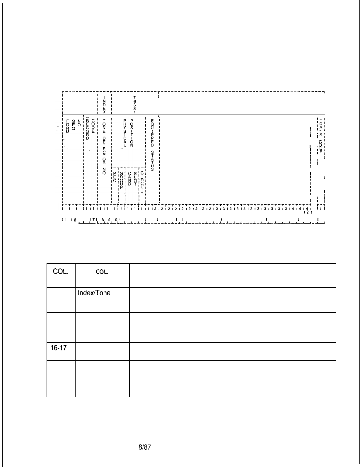
TL-130400-1001
Record Code TN: 11.9 Record Code TN, Figure 11.9, defines the tone detector
Tone Detector
circuit. The tone detector is used to detect and recognize tones
issued by an SCC (Specialized Common Carrier) when used as
a MERS route.
T---------T---~-------------T-----------------------------------------------~
I I
I
i
III
III
I
II
III
III
IIII
I ,
I
I
I;r;l
1
IAl
1IN,
’
IS,
I
:c;
’
IO,
’
ID,
’
IEI
’
I
I
’
1 I
f
, ,
I
I
I , ,
1 I ,
’
I
I
I ,
I
I ,
I
I
I
I I
’
I
I
1
fI
F-4
I8
I
1718191011 12131415161718191011 12131415161718191011 12131415161718191011
121
10 I
c-+-+-u-+-+-+-t-t-t-t-+-+-+-+-+- C-4
il
I8
15
ITI
NIOIOI
I I I
I
I
I
I I
I
I
I I I I I
I
I I I I I I
I
I I I I
I
I I 1
L-L-L
-LL-
L--L-L--L-A
-~-~-~-~-~-~-~-~-~-*-~-*-~-~-~-~-~-~-~-~-~-~---~-
u-u
Figure 11.9
Record Code TN: Tone Detector Data Sheet
I
Table 11.9 Entry Fields for Record Code TN
COL.
COL.
VALID
NO. NAME ENTRIES COMMENTS
12-13
Index/Tone
00-31 = number This field determines the number assigned to
Detector the tone detector. This number is used by the
Number system for identification purposes.
14 PEC 0 = PEC number Enter PEC 0.
15
Group A-D = group Which group (A, B, C, or D) within PEC 0 is
number the card?
16-17
Card Slot
00-l
1 = slot
Which card slot within the group is the card?
number
18
Circuit
O-3 = assigned
Which circuit on the card is being used?
circuit number
19-20
Equipped Status IS = in service Is the card in service or out of service?
OS = out of service
SVR 5210
8187
D-247
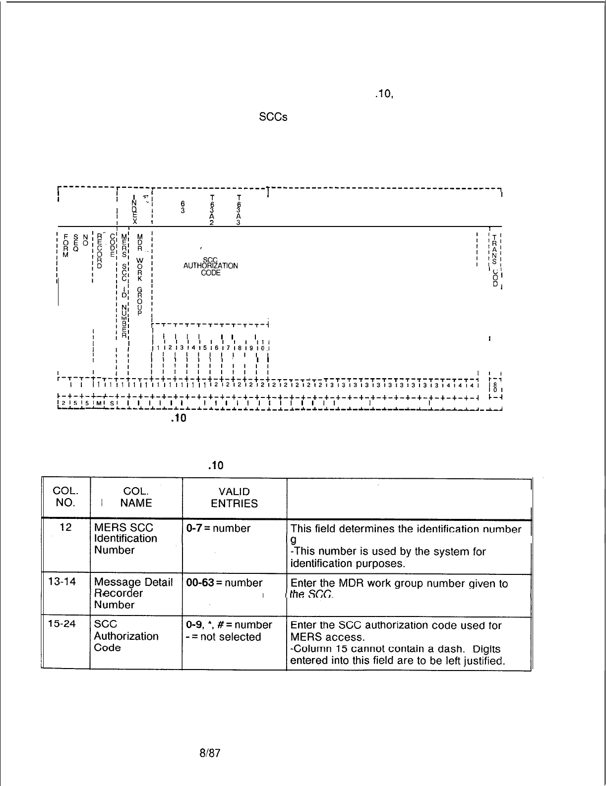
TL-130400-1001
Record Code MS:
11.10 Record Code MS, Figure 11
.lO,
defines the SCC
Specialized
Common Carrier
(Specialized Common Carrier) authorization codes required to
access the
SCCs
through MERS. Different SCC authorization
Authorization Codes
codes can be given for each MERS SCC identification or for
each MERS SCC identification and MDR (Message Detailed
Recorder) work group combination.
T---------T-----r-------------------
I I
II
I=- f
T---------------------------------------~
T1
I
I I
I
:
‘“1 1
i i
II
II
I. . . .
I
II
E
:
A
II
1II
I
II
1 bI
I
, 1 ,
II
_
I
I
see
I
AUTH~~~~TION
I
I
l-1
I
I I
II
I I
I I
$
II
E
I
I
I I
II
I I
I I
III
III
I I
III
I I
II
:-T-T-T-T-T-T-T-T-T-i
I I
I
If
I I I I I I I I I
I
I
IIll
I
I
I
I
I
I I I
I I
II
I
II
I
I
I
1
I1
12131415161718191A1
I I
I
II
I I
I I
I
I
I I
I I
II
;-,-,-;-
I I
I
I
I
1
I
I
I
I
I
I
I
I
I
I
I
I
I
I
I
I
I
T-T-T-T-T-T-T-T-T-T-T-T-T-:
r-:
I1
I1
I1
I1
I1
I1
I1
I1
I1
I1
1212121212121212121213131313131313131313l4l4l4l
1718191011121314151617181910111213141516171819101112131415161718191011121
I8
I
c-+-+-u-+-+-+-+-+-+-+-+-+-+-+-+-+-+-+-+-+-+-+-+-+-+-+-+-+-+-+-+-+-+-+-~
2:
l215151~IsI
I
I
I
I
I
I
I
I
I
I
I
I
I
I
I
I
I
I
I
I
I I
I
I I I I
I
I I I I I
L-L-*
--L-~-_c-~-~-~-~-~-~-~-*-~.-~-~--L-*
-~-~-~-i-~-*-~-~-~-~-~-~-~~--
Figure 11 .lO Record Code MS: Specialized Common Carrier
Authorization Codes Data Sheet
Table 11 .lO Entry Fields for Record Code MS
COMMENTS
iven to the SCC.
ecorder
Work -- = not selected
8187
SVR 5210
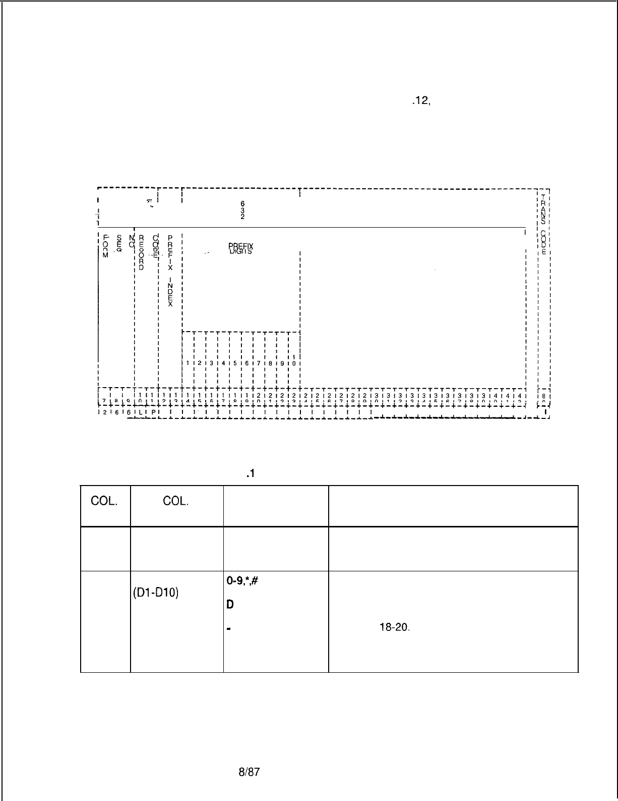
TL-130400-1001
Record Code LP: 11.11 Record Code LP, Figure 11
.12,
specifies up to ten prefix
Prefix Code Digits
digits for MERS LDN (Listed Directory Number) processing and
for Listed Directory for other prefixing applications.
Numbers and
Other Applications
‘---------r---r-------------------T------------------------------------------~--
I
I I
T
I
I
s-
II
I
IT;
I
‘I
I
I I
IRI
.-It
I
I I
IAl
I I I
INI
7
I I
1
I
ISI
,II I I
I
I
'
ICI
I
'
101
I
'
IDI
c-+-~-c-c-+-+-+-+-+-+-+-+-+-+-+-+-+-+-+-+-+-+-+-+-+-+-+-+-+-+-+-+-+-+-+-~
b-4
12161~ILIPl
I
I I I
I
I I I
L-i-L
--L-*-L-L-L-~-*-*-~-I-1_1-1-1-1-1-1-1-1
I I I I I I I I I I I I I I
I
-~-~-~-~-~-~-~-~-~‘-~-~-~
Figure 11.11
Record Code LP: Prefix Code Digits for Listed Directory Numbers and
Other Applications Data Sheet
COL.
NO.
Table 11
.l
1
Entry Fields for Record Code LP
COL.
VALID
NAME ENTRIES COMMENTS
12-13
Prefix Index 01-l 5 = number This field determines the prefix index number.
-This number is used by the system for
identification purposes.
14-23
Prefix Digits
o-9,“,#
= This field determines the selected prefix digits.
(Dl
-DlO)
telephone digits -Column 14 cannot contain a dash.
D
= short pause -If this field has an entry of D, the short
E = long pause pause must be defined on Record Code OV,
-
= unused (digits columns
18-20.
2-9 only)
-If this field has an entry of E, the long pause
must be defined on Record Code OV,
columns 21-23.
SVR 5210
8187
D-249
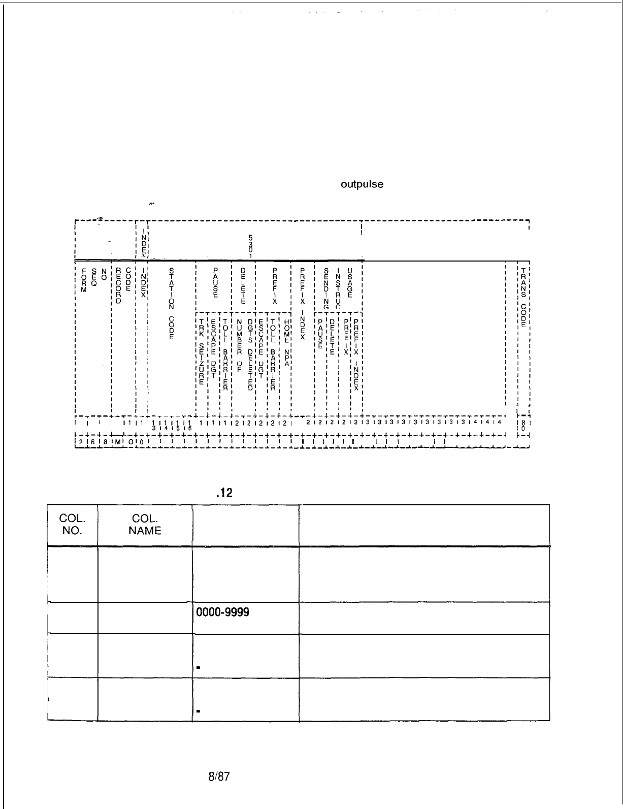
TL-130400-1001
Record Code MO:
11.12 Record Code MO, Figure 11.12, lists a set of four-digit
MERS On-Net station codes that require a second (replacement) sending
Station Numbers and
instruction application. The station codes are only impacted
Sending Instruction
if the MERS on-net process selects a sending instruction that
Values
deletes one or more digits. If the last four dialed digits match
a station code defined on Record Code MO, the associated
sending information will be applied. This allows a MERS on-net
trunk group to be used to
outpulse
a different number of digits
based on the station code dialed.
w-
.
.
.
.
T---------T-T-
--------------------------------------------------------------~
I
T
I
I
2
I
II
I
?
I
I
I
I
.-s-s-+-s-+-l-s-s-s-+-+-+-+
’
i
;
-s-+-+-+-+-5-+-+-+-+-+-s-T-s-s-s-s-s-s-s-7-~-4
v--l
i
i
i
ii
iii1
171619101112
lililil
3141516 1;1i1;2i2;2;2;2; 2;2;2i2;3;3i3i3i3;3i3;3;3;3;4;4;4;
i8i
7181910111213141 6171819101112131415161718191011121
IO I
c-+-+-u-+-+-+-+-+-+-+-+-+-+-+-+-+-+-+-+-+-+-+-+-+-+-+-+-+-+-+-+-+-+-+--l
c--l
I2tgl81~l~lO1
I
I I I I
I
I
I
I
I
-J---L-L-~-*-I-*-~-L-*-~--L-*-L-~-l
I
I
I
I
I
I
I
I
I,
I I
I
I
I I I I I I
L-L-A
-~-*-~-~-*-~-~-~-~-~-~-~---~-~~--
Figure 11.12 Record Code
MO:
MERS On-Net Station Numbers and Sending
instruction Values Data Sheet
Table 11
.12
Entry Fields for Record Code
MO
12
Index
13-16
Station Code
17
Pause After
Trunk Seizure
18
Pause After
Escape Digit
Sent
VALID
ENTRIES
O-9 = number
0000-9999 =
number
T = trunk seizure
pause
-
= no pause
E = escape digit
pause
-
= no pause
COMMENTS
This field determines the index number for the
station code.
-This number is used for identification
purposes by the system.
Enter the station code.
-This must be a four-digit number.
Enter a T here if a pause is placed after trunk
seizure.
Enter an E here if a pause is entered after the
escape digit is sent.
D-250 8187
SVR 5210
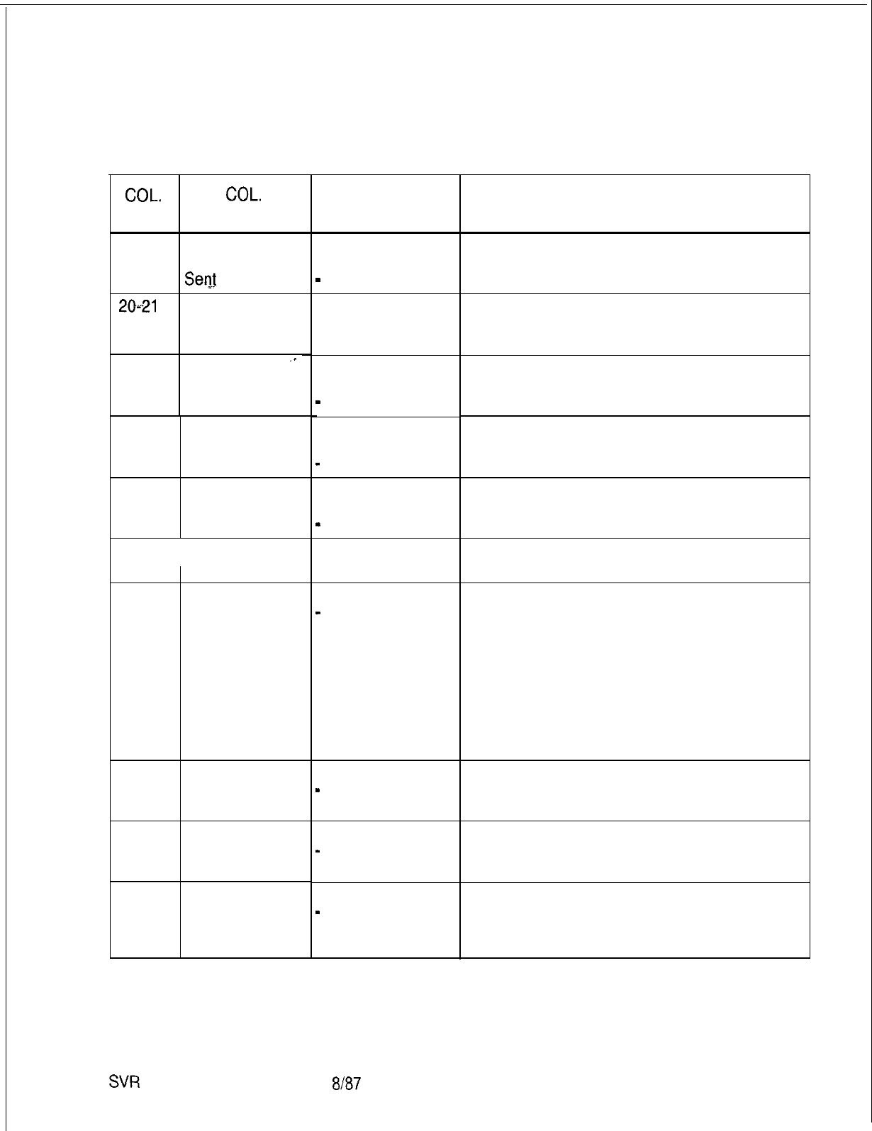
TL-130400-1001
Table 11.12 Entry Fields for Record Code MO (Continued)
COL.
COL.
NO. NAME
19
Pause After Toll
B
= toll barrier
Barrier Code code pause
Serg
-
= not selected
2061
Delete/Number
of Digits to
Delete
00-l
5 = number
-- = N/A
22 Prefix
‘-
Escape Digit E = escape digit
prefix
-
= no prefix
23
Prefix Toll
Barrier Code
24
Prefix Home
Numbering Plan
Area Code
25-26
I
Prefix Index
27
Sending
Instruction
Pause Usage
28
Sending
Instruction’
Delete Usage
29
30
Sending
Instruction
Prefix Usage
Sending
Instruction
Prefix Index
Usage
VALID
ENTRIES
B
= toll barrier
code prefix
-
= no prefix
H = HNPA code
prefix
-
= no prefix
01-15
= number
-- = no prefix
Y = selected
-
= not selected
Y = selected
-
= not selected
Y = selected
-
= not selected
Y = selected
-
= not selected
SVR
5210
8187
COMMENTS
Enter a B if a pause is entered after the toll
barrier code is sent.
Indicate the number of digits to delete.
Enter an E if prefixing is required on the
escape digit.
Enter a B if prefixing is required on the toll
barrier code.
Enter an H if prefixing is required on the HNPA
(Home Numbering Plan Area).
If a prefix index is used, assign the index
number here.
The sending instruction usage defines which
of the fields specified on this record code will
be used instead of the original sending
instruction pause value.
-Sending instructions are defined in columns
27-30 of this record code.
-The original sending instruction values are
defined on Record Code SI.
-This field determines whether or not a pause
is applied.
Enter a Y if a delete instruction is applied.
Enter a Y if a prefix instruction is applied.
Enter a Y if a prefix index instruction is
applied.
D-251

TL-130400-
1001
THIS PAGE IS INTENTIONALLY LEFT BLANK.
SVR 5210

-
.--
TL-130400-1001
NETWORKING 12.0 This section describes the record codes required to
define the various networking features. The following record
codes are required:
.
.
SVR 5210
l Record Code NT defines the routing for private tandem
switching networks.
l Record Code TD defines the translation of the digits for a
tandem network.
8187
D-253
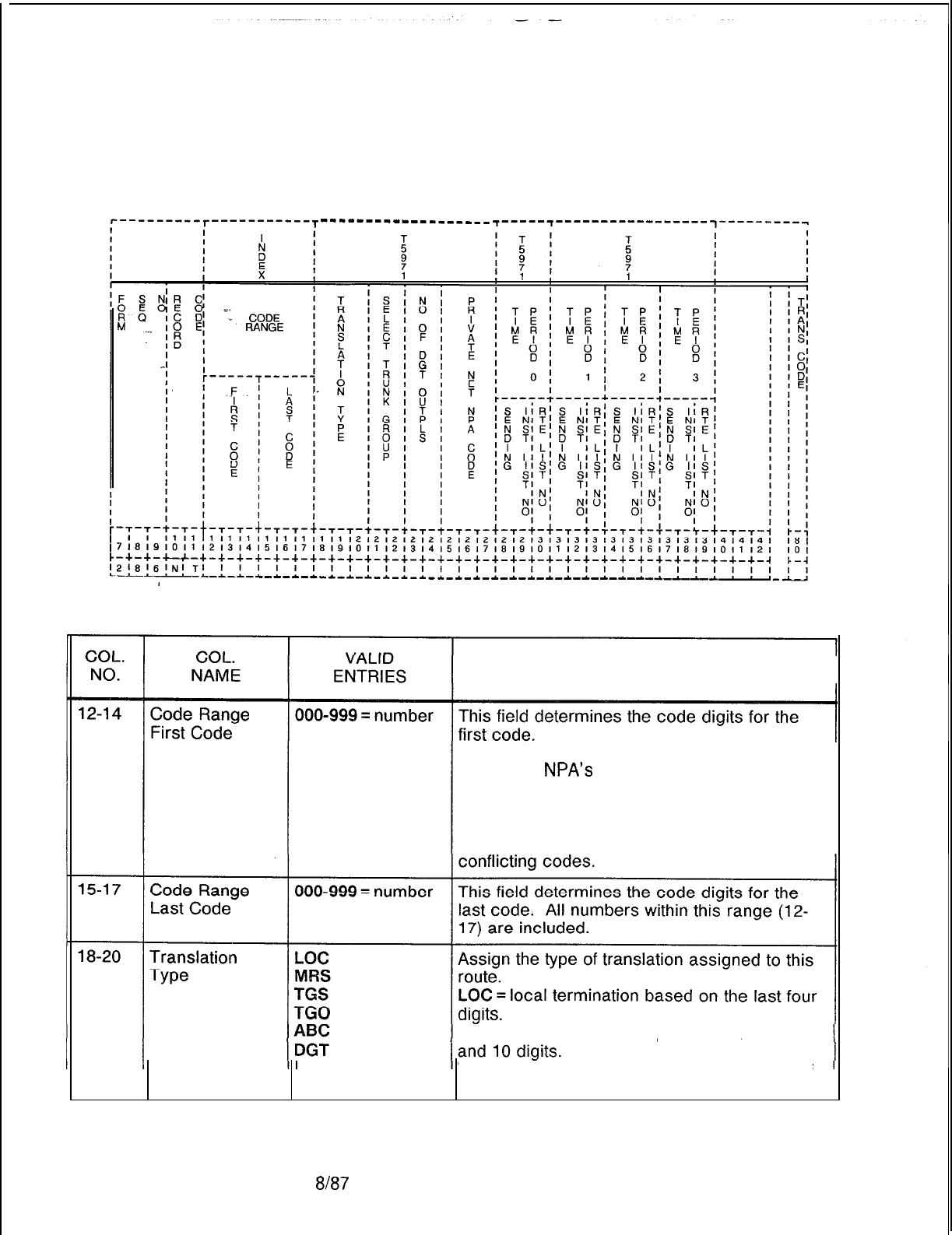
TL-130400-1001
D-254
Record Code NT:
Private Network
12.1 Record Code NT, Figure 12.1, defines the first level call
routing for private tandem switching networks. Use one record
Translation
for each RNX (or RNX range) with the same routing
characteristics in the RNX numbering plan.
‘---------r-----------T
---------------____ ~-----~-----------------
1----------
Record Code NT:
Private Network
12.1 Record Code NT, Figure 12.1, defines the first level call
routing for private tandem switching networks. Use one record
Translation
for each RNX (or RNX range) with the same routing
characteristics in the RNX numbering plan.
‘---------r-----------T
---------------____
-r------r----- ------------1----------
Figure 12.1
Record Code NT: Private Network Translation Data Sheet
Table 12.1 Entry Fields for Record Code NT
COMMENTS
Note: A conflict exists with the three-digit
translated
NPA’s
warning message. The
private network digit analysis is combined with
the three-digit translation (Record Code NR)
on the same data base table. A problem may
occur if the private network digits contain
MRN
or
MER =
type
MRS
= off-network
MERS processing
on 7
TGS = trunk group selection and outpulsing of
received digits (see columns 21-24)
8187
SVR 5210
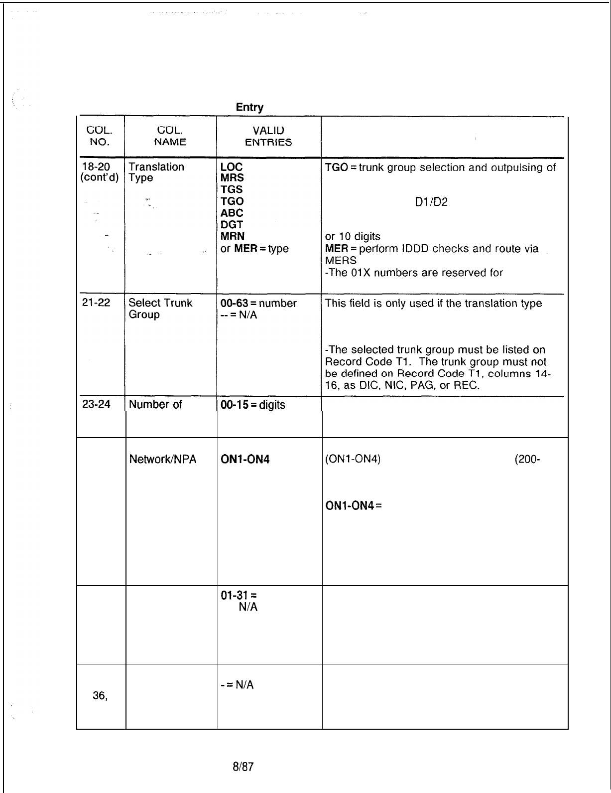
TL-130400-1001
Table 12.1 Entry
Fields for Record Code NT (Continued)
COMMENTS
N digits (see columns 21-22)
ABC = analysis of the ABC code before routing
DGT = analysis of
Dl
/D2
(digit 1, digit 2) of the
last four terminal digits before sending
MRN = private network MERS processing on 7
international dialing.
given in columns 18-20 is either TGO or
TGS. Indicate the trunk group used for
outpulsing the digits.
Digits Outpulsed -- = N/A This field
is
only used if the translation type
given in columns 18-20 is TGS.
-Enter the number of digits outpulsed.
25-27 Private
NetworklNPA
Code
200-999,
ONl-ON4
or
---
This field determines the private network code
(ONl-ON4)
or the NPA code number
(200-
999).
200-999 = NPA code as defined on Record
Codes MR and TR
QNl-ON4=
private network code as defined
on Record Codes AC and TR
-Record Code TR defines the phantom
number used for on-network dialing.
-This field must be used if columns 18-20
are marked MRN. For all other entries in
columns 18-20, this field is dashed.
28-29,
Sending
Ol-31=
number These fields can be used only if the translation
31-32,
Instruction List -- =
N/A
type given in columns 18-20 is MER. Assign
34-35, Number
the sending instruction list number to be used
37-38.
for the various time periods. The sending
instruction list numbers are defined on Record
Code SI, columns 12-13.
30,
33,
38,
39.
Route List
O-7 = number
Number
-=N/A
These fields can be used only if the translation
type given in columns 18-20 is MER. Assign
the routing list number to be used for the
various time periods. The routing list numbers
are defined on Record Code RP, column 12.
SVR
5210 8187 D-255
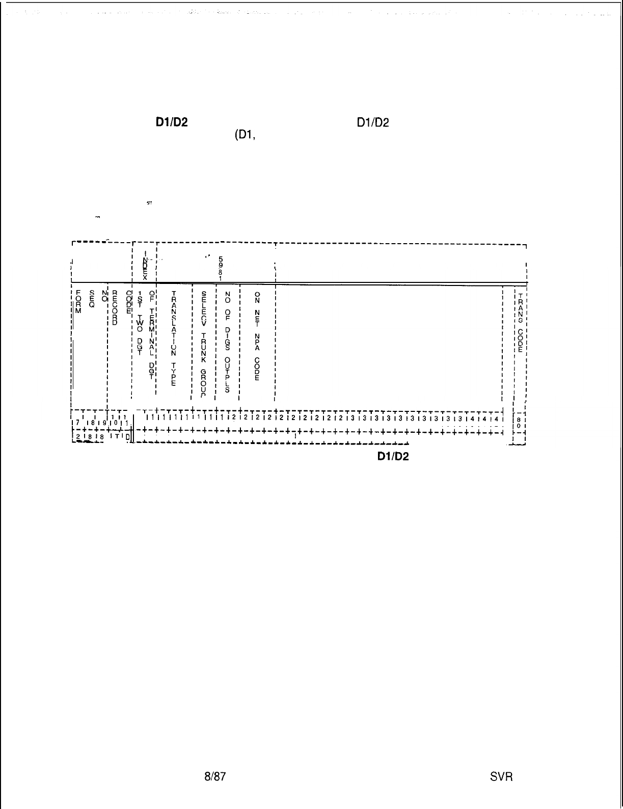
TL-130400-1001
Record Code TD:
Private Network
12.2 Record Code TD, Figure 12.2, defines, in a seven- or
Dl/D2
ten-digit, format, the translation of the digits for a tandem
network. These digits are the
Dl/D2
digits of the four terminal
digits
(Dl,
D2, D3, D4).
-..
__
NOTE: There is a conflict with the three-digit translated NPA
warning message. The private network digit analysis was
combined with the three-digit translation (Record Code NR) in
the same data base table. A possible problem exists if the
private network digits contain conflicting codes.
D-256
(-
-----
-----
r----r----------
I
---------T-----------------------------------------~
I
II
.-
T
1
I
i
I
II
17
18
I9
10
I1
c-+-+-+-+-
!2;8;8
ITI
0
-
-
--
t
I
-T-t-T-T-t-T-t-T-t-T-T-t-
T-T-T-T-T-T-T-T-T-T-T-T-T-T-T-T-f-T-T-T-i
1
I1
I1
I1
I1
I1
I1
I1
1212121212121212121213131313131313131313l4l4l4l
21314151617181910111213141516171819101112131415161718191011121
-+-+-+-+-+-+-+-+-+-+-+-+-+-+-+-+-+-+-+-+-+-+-+-+-+-+-+-+-+-+-~
I I I I I I I I I I I I I
I
I I I I I I I I I I I I I I I I I
-.L-*-A-.L-
~-*-*-*-*-~-*-~-*-i-*-~-*-*-~-~-~-~-~
-A-.&--L-A.-A--
I
IIII I
Figure 12.2 Record Code TD: Private Network Dl/D2 Data Sheet
8187
SW
5210
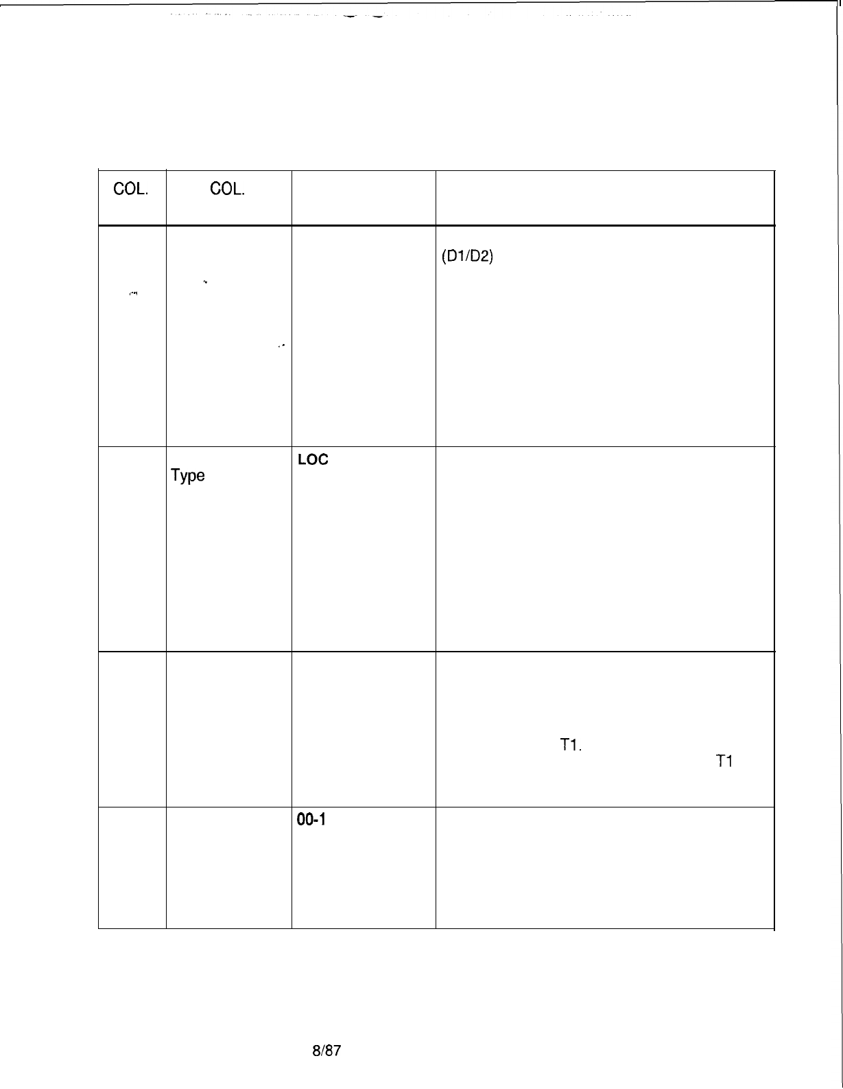
TL-130400-1001
COL.
NO.
Table 12.2 Entry Fields for Record Code TD
COL.
VALID
NAME ENTRIES COMMENTS
12-13
First Two Digits 00-99 = number This field determines the first two digits
of Terminal
(Dl/D2)
of the four terminal digits that require
Digits local termination or outpulsing.
.”
.-..
-The first two digits of the terminal digits must
be unique across all TD records.
-These digits must correspond to a hundreds
,.
group engineered on Record Code HD.
-If the first two digits are OX, then both OX
and X hundreds groups must not be specified
on Record Code HD.
-If a number is listed here, the system will
process both hundreds groups with the first
two digits of OX for this application.
14-16
Translation
LOC
Indicate the type of translation assigned to the
Type
MRS
route.
TGS LOC = local termination based on the last four
TGO digits
or
MRS = off-network MERS processing on 7
MRN
and 10 digits
TGS = trunk group selection and outpulsing of
all received digits (see columns 17-18)
TGO = trunk group selection and outpulsing of
last N digits (see columns 17-20)
MRN = on-network MERS processing on 7
and 10 digits (see columns 21-23)
17-18
Select Trunk 00-63 = number This field is only used if the translation type
Group -- = N/A defined in columns 14-l 6 is TGO or TGS.
-Assign the trunk group used for outpulsing
the digits.
-The selected trunk group must be defined
on Record Code
Tl.
-The trunk application on Record Code
Tl
for this trunk group cannot have values of DIC,
PAG, or REC.
19-20
Number of
00-l
5 = number
This field is only used if the translation type
Digits Outplused -- = N/A defined in columns 14-16 is TGO.
-The field determines the number of digits
outpulsed.
-If a five-digit numbering plan is in effect,
the number of outpulsed digits must be
indicated here.
SVR 5210
8187 D-257
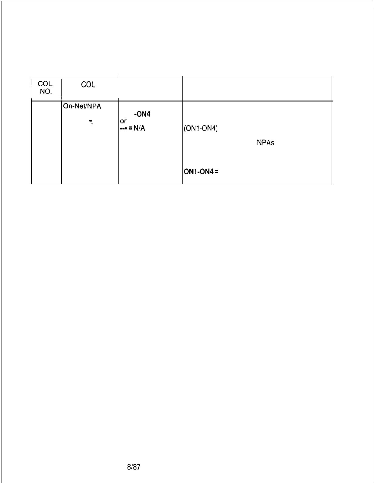
I
TL-130400-1001
Table 12.2 Entry Fields for Record Code TD (Continued)
COL.
VALID
NAME ENTRIES
I
21-23
On-Net/NPA
200-999
Code
ON1 -ON4 = code
s-
Or
.”
. . m-s
=
N/A
.
COMMENTS
This field is only used if the translation type
defined in columns 14-16 is MRN.
-This field determines the on-network code
(ONl-ON4)
or the NPA code number (200-
999).
Note: Only four unique
NPAs
are allowed
between the MR, NT, and TD record codes.
200-999 = NPA code as defined on Record
Codes MR and TR
ONl-ON4=
on-net code as defined on
Record Codes AC and TR
D-258 8187
SVR 5210

-
-
TL-130400-1001
MESSAGE 13.0 This section describes the record codes required to
DETAIL RECORDER define the system MDR (Message Detail Recorder) feature. The
following record codes are required:
l Record Code MD defines the requirements for the MDR
devices,
__
l Record Code MT defines the TTY requirements.
.-..
l Record Code
Sl
defines the screening options.
l Record Code S2 defines additional screening options.
SVR 5210
8187 D-259
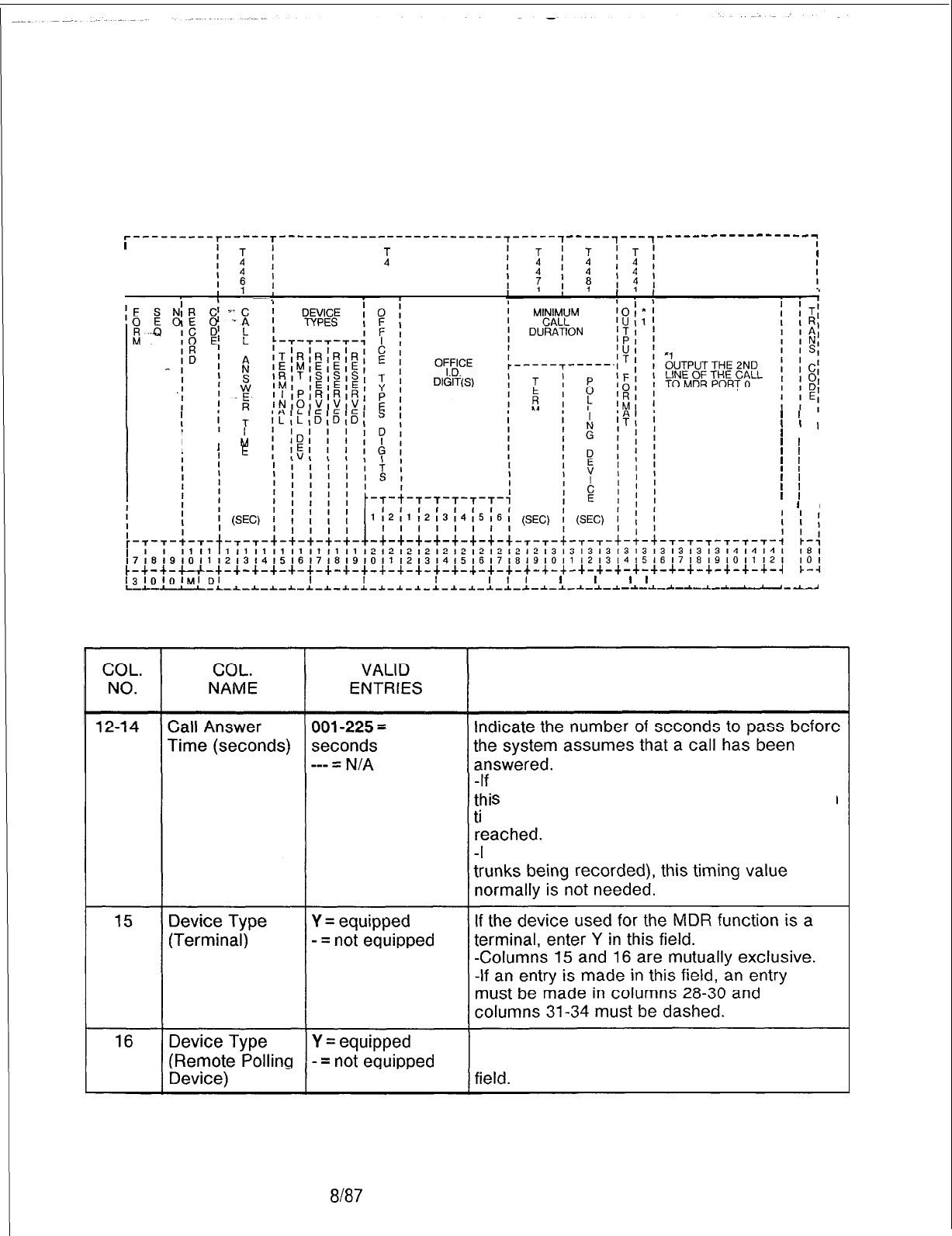
TL-130400-1001
Record Code MD:
13.1 Record Code MD, Figure 13.1, defines the requirements for
Message Detail
the MDR devices.
Recorder
‘---------T-----T-------------------------~-----~ -----7---,-----
__--------___
I
I
I
T
I
II
I
4
I
I
4
I
I1I
I
’
’
I
’
’
I
I
’
’ I
I
I
h
I
’
E
’
’
I
’
’
I
’
’
I
’
’
I
’
’
I
’
’
I
’
’
I
’
’
I
c-+-+-u-+-+-+-+-+-+-+-+-+-+-+-+-+-+-+-+-+-+-+-+-+-+-+-+-+-+-+-+-+-+-+-~
l3lOlOI,,,,,i,I
I I I I
I
I I
I
I I I
I
I I
I,,
I
I
I
I
I
l
I
I I I I I I I I I
L-*-L
--U--L-~-I-~--C--C-~-I-~-~-~--L-~-I--L-I-*-*-~-I-*-~-~-~-~-~-~-~-~--l--U
Figure 13.1
Record Code MD: Message Detail Recorder Data Sheet
Table 13.1 Entry Fields for Record Code MD
COMMENTS
a trunk does not have answer supervision,
s
timing value is used to estimate how much
me it takes for a two-way connection to be
If answer supervision is provided (for all
If the device used for the MDR function is a
remote polling device (CRT), enter Y in this
D-260 8167
SVR 5210
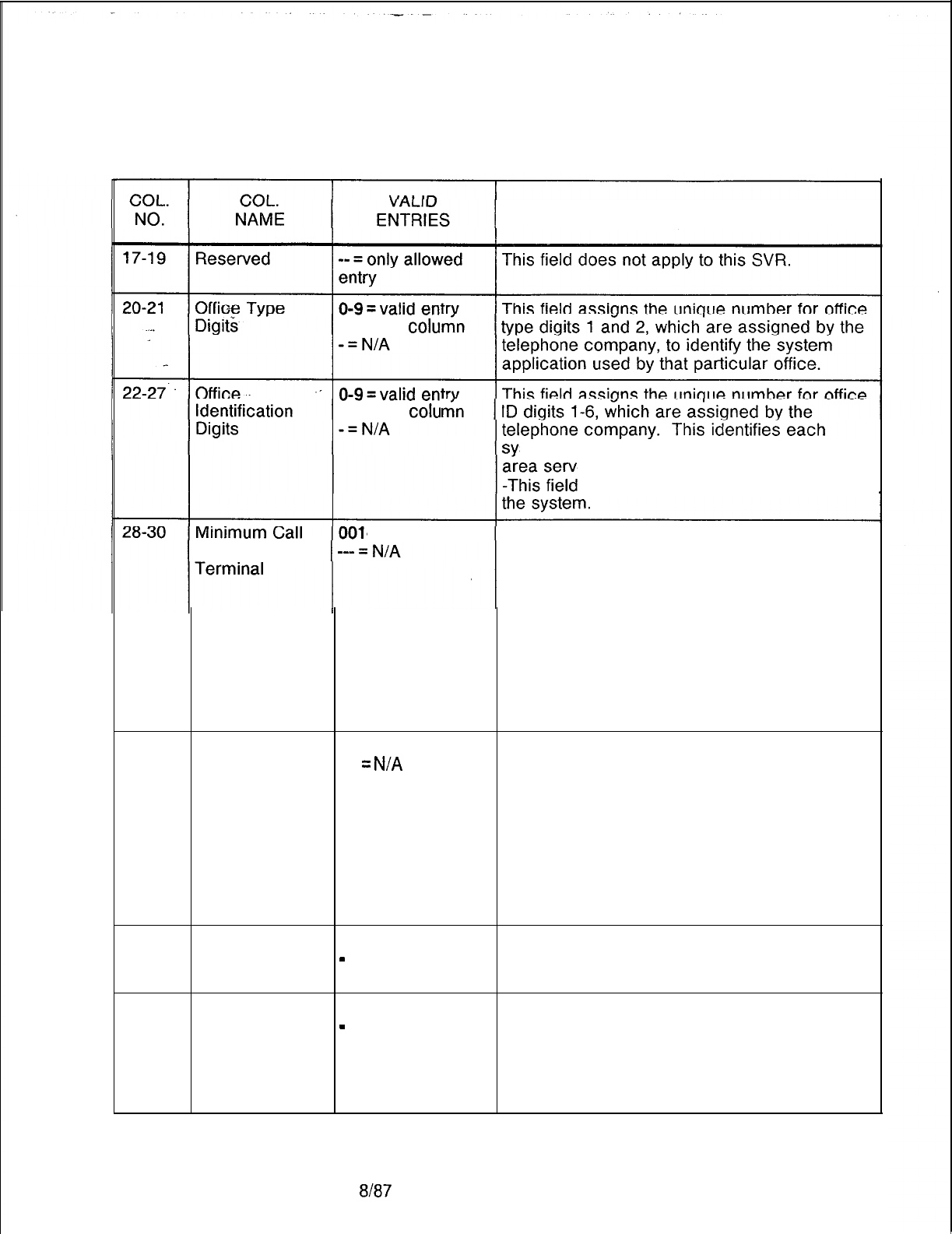
TL-130400-1001
Table 13.1 Entry Fields for Record Code MD (Continued)
COMMENTS
for each
colu
for each
colu
stem and its physical location within the
ed by the telephone company.
represents the billing number of
Duration for a
-255 =
number Indicate the minimum number of seconds that
a call must be connected before a call record
is produced at the MDR terminal.
-Calls that last less than this amount of time
are not recorded.
-If this timing parameter is met, a record of
the call is made whether or not the call was
actually answered.
-The value of this field is added to the value
given in columns 12-14 when listing the
length of the call.
31-33
Minimum Call 001-255 = number Indicate the minimum number of seconds that
Duration for a ---
=
N/A
a call must be connected before a call record
Remote Polling is produced at the remote polling device.
Device -Calls that last less than this amount of time
are not recorded.
-If this timing parameter is met, a record of
the call is made whether or not the call was
actually answered. The value of this field is
added to the value given in columns 12-14
when listing the length of the call.
34 Output Format Y = EBCDIC format This field determines the format of the MDR
-
= TTY format
output.
-For normal applications, the entry is TTY.
35
Output the Y = allowed Enter Y if a second line output of the call
Second Line of
-
= not allowed record to MDR port 0 is allowed.
the Call Record -Do not specify this if the MDR data is
to MDR Port 0 transmitted to a remote processor (COMDEV
or other) that requires single line output
format.
SVR 5210
8187 D-261
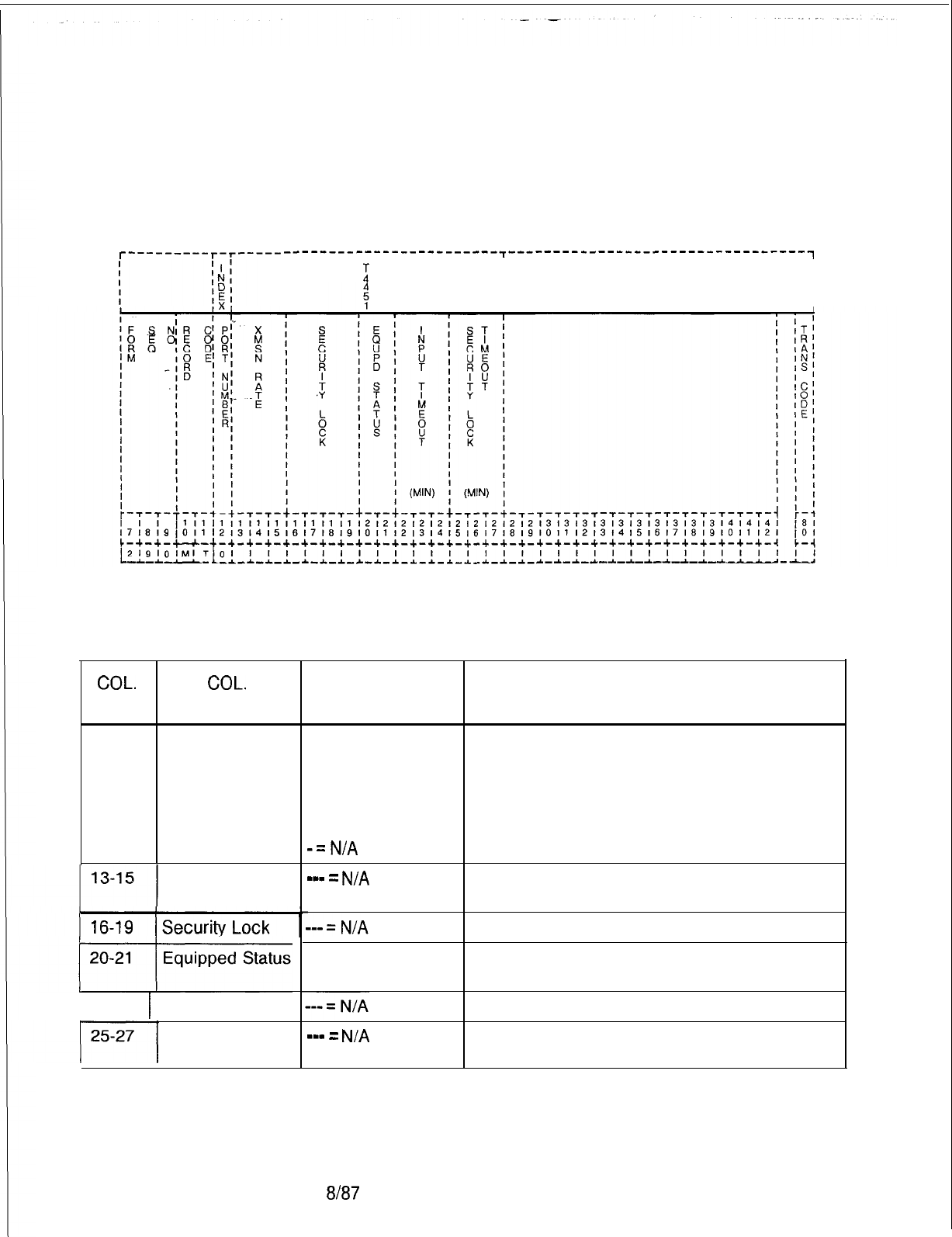
TL-130400-1001
Record Code MT: 13.2 Record Code MT, Figure 13.2, defines the requirements for
Message Detail
the MDR (Message Detail Recorder) TTY unit interfacing
Recorder Port the system.
r---------r-r-----
------------------------~---------------------------------~
I;
I I
I I
I
I
I
I
I
I
I I
Figure 13.2 Record Code MT: Message Detail Recorder Port Data Sheet
Table 13.2
Entry Fields for Record Code MT
COL. COL.
NO. NAME
12
Port Number
Transmission
Rate
1 22-24 1 Input Timeout
Security Lock
Timeout
VALID
ENTRIES
0= MDR call
records (ASCII)
1 = MDR call
record blocks
(GTE-modified
EBCDIC)
-=N/A
m-v
=
N/A
IS = in service
OS = out of service
m-w
=
N/A
COMMENTS
This field determines the MDR format output.
This field can only be dashed.
This field can only be dashed.
Is the card in service or out of service?
This field can only be dashed.
This field can only be dashed.
D-262 8187
SVR 5210
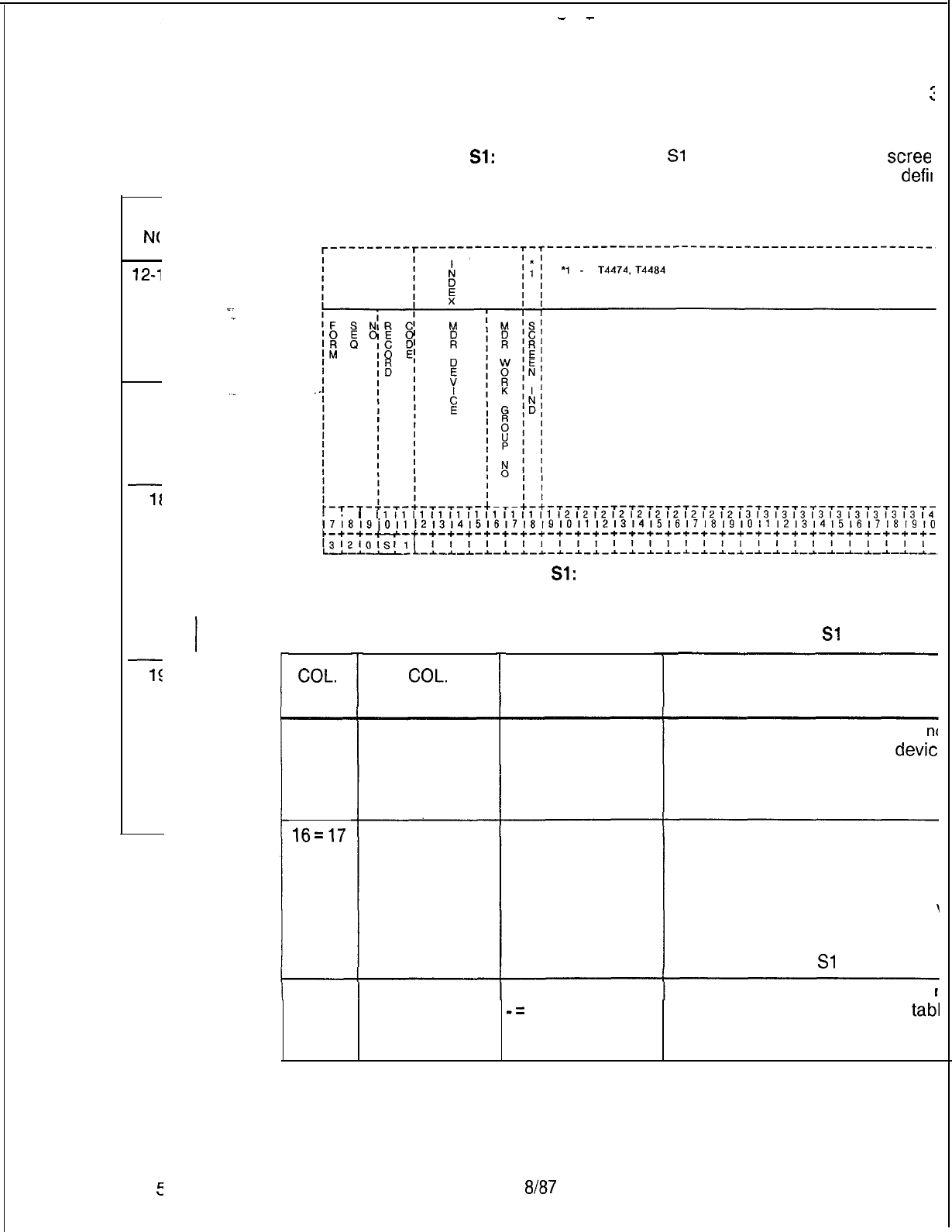
-
-
cc
N(
16-1
TL-1
E
Record Code Sl:
13.3 Record Code
Sl
, Figure 13.3, defines the
scree
Message Detail Recorder
available with the system. A screening option is
defit
Screening Option 1
as the ability to select the type of calls that are to be
l
~11111111111111111111212121212121212121213131313131313131313l4
171819)01112131415161718191011l2l3l4l5l6l7l8l9l0l1121314151617181910
Figure 13.3 Record Code Sl: Message Detail Recorder Screening Option
Sheet
Table 13.3 Entry Fields for Record Code Sl
COL.
NO.
12-15
16=17
18
COL.
NAME
Message Detail
Recorder
Device
Message Detail
Recorder Work
Group
Number
Screening
Indicator
VALID
ENTRIES
TERM
= terminal
required
CART
= remote
polling device
required
00-63 = number
Y = required
-=
not required
COMMENTS
This field determines whether or
nc
device listed here must be a
devic
engineered on Record Code MD.
Indicate the MDR work group nun
numbers assigned to this device.
-MDR work groups are assigned tc
lines on Record Code LD, column!
-There
must be at least one MDR
\
assigned on Record Code LD.
NOTE:
The MDR work group num
unique across the
Sl
record code
Enter Y if a screening indicator is
I
-The combination of screening
tab1
MDR work group number must be
across this record code.
SVR
5
SVR 5210
8187
TL-130400-l
Recc
Message
Del
Screen
D-264
TL-130400-1001
r--------
l
I
I
II
Figure
I
3.r
D-266
THIS PAGE IS INTENTIONALLY LEFT BLANK
8f87

SVR
5210
-
TL-130400-1001
TERMINAL 14.0 This section describes the record codes required to
FEATURES define the various system miscellaneous terminal features.
The
follotiing
record codes are required:
l Record Code CT defines the terminal parameters.
l Record Code TT defines the TTY requirements.
8187 D-267
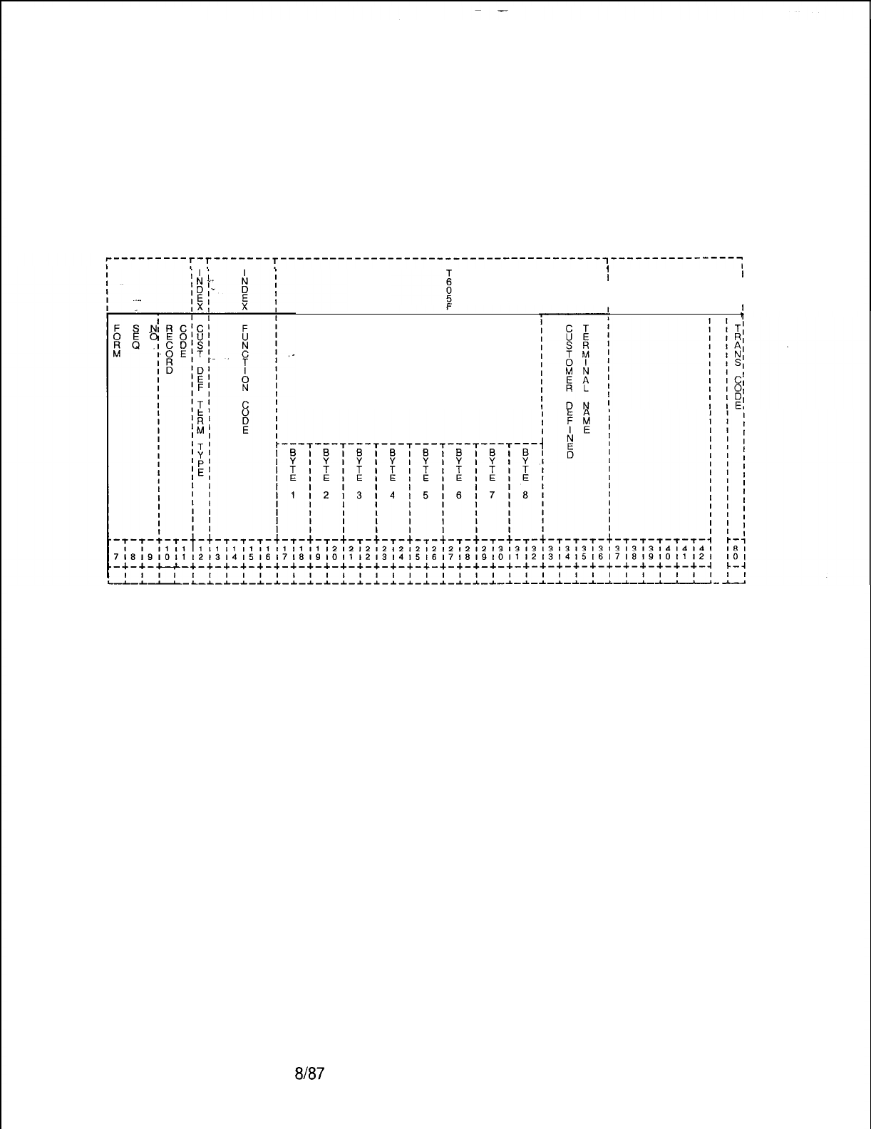
TL-130400-1001
Record Code CT:
14.1 Record Code CT, Figure 14.1, allows parameters to be set
Customer Defined
for up to two customer defined terminal types. Record Code CT
Terminal
is used when none of the standard terminal types in Record
Code TT (Terminal Type), field 0, meets the needs of the
application. The various terminal characteristics of the customer
defined terminal types are specified in this record code.
D-268
---------r-r-------r---------------------------------------~---------------~
1
II
I
I
I
I
II
1
I
HEXADECIMAL EQUIVALENT OF
THE BIT STRINGS FOR THE
FUNCTION
Figure 14.1
Record Code CT: Customer Defined Terminal Data Sheet
8187
SVR 5210
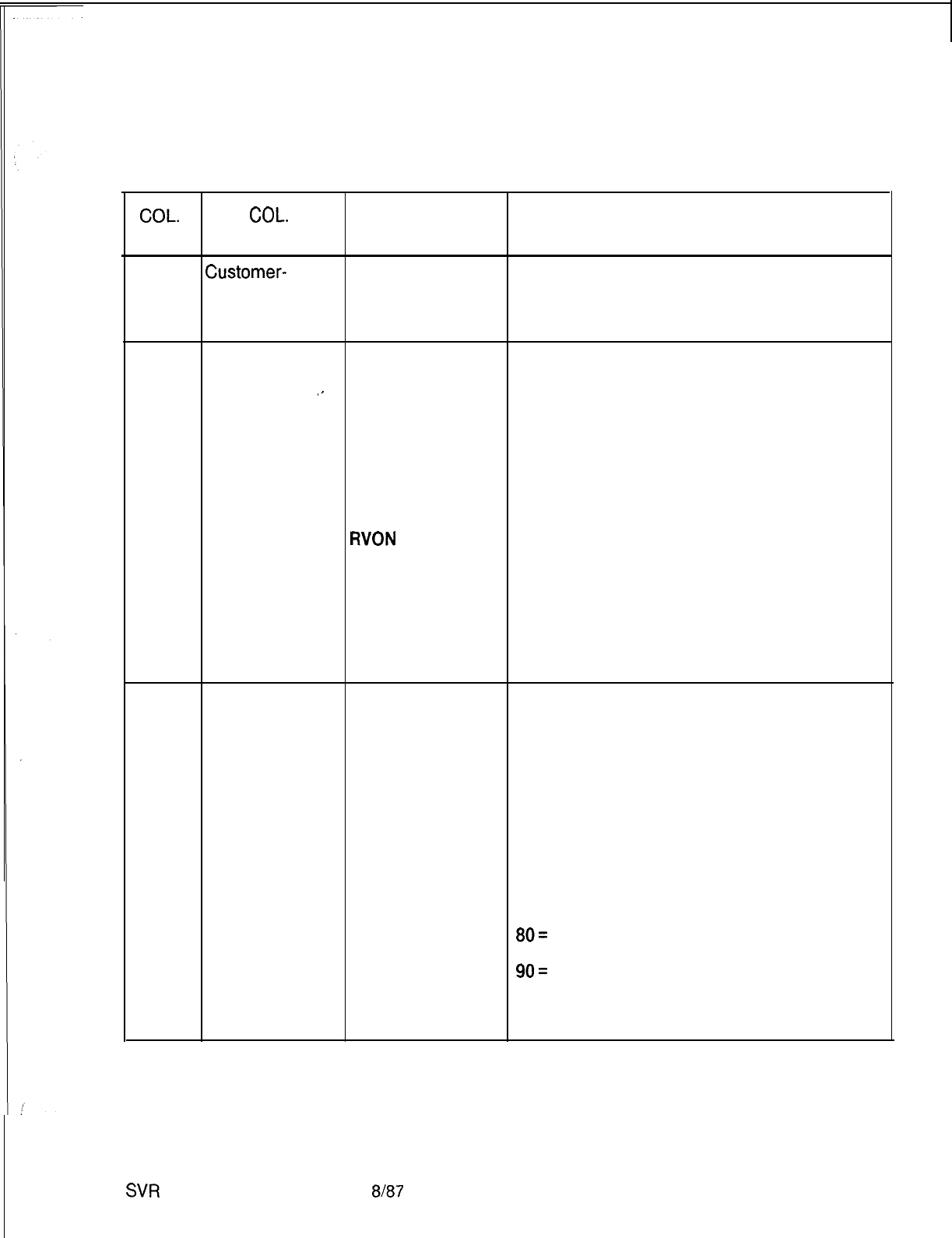
TL-130400-1001
Table 14.1 Entry Fields for Record Code CT
COL.
COL.
VALID
NO. NAME ENTRIES
COMMENTS
12
Customer-
1-2 = number This field represents the customer defined
Defined terminal that is being defined.
Terminal Type -This field is used by the system for
Number
. . .
identification purposes.
13-16
Function Code TNAM = terminal Indicate the function code of the customer
type mnemonic defined terminal.
.-
CLSC = clear
screen characters
ABCC = absolute
cursor control
EEOL = erase to
end of line
EEOP = erase to
end of page
WON
= reverse
video on
RVOF = reverse
video off
APON = auxiliary
port on
APOF = auxiliary
pot-t off
17-32
Hexadecimal
00-FF = code
This field determines the hexadecimal
Equivalent of the -- = not selected equivalent codes, which represent the one to
Bit Strings for eight ASCII characters. These characters
the Function make up the control sequence or directive that
(Bytes 1-8) performs the selected function code.
-The ABCC function code includes the
specification of row and column number
position.
-Since these values are dynamically
provided when needed, non-ASCII
placeholder notation indicators are to be used
in defining the ABCC function code bytes.
These codes are as follows:
80=
row number in ASCII notation
81 = column number in ASCII notation
90=
row number in decimal notion
91 = column number in decimal notion
-The TNAM function code never specifies the
hexadecimal equivalent code bytes.
SVR
5210
8187
D-269
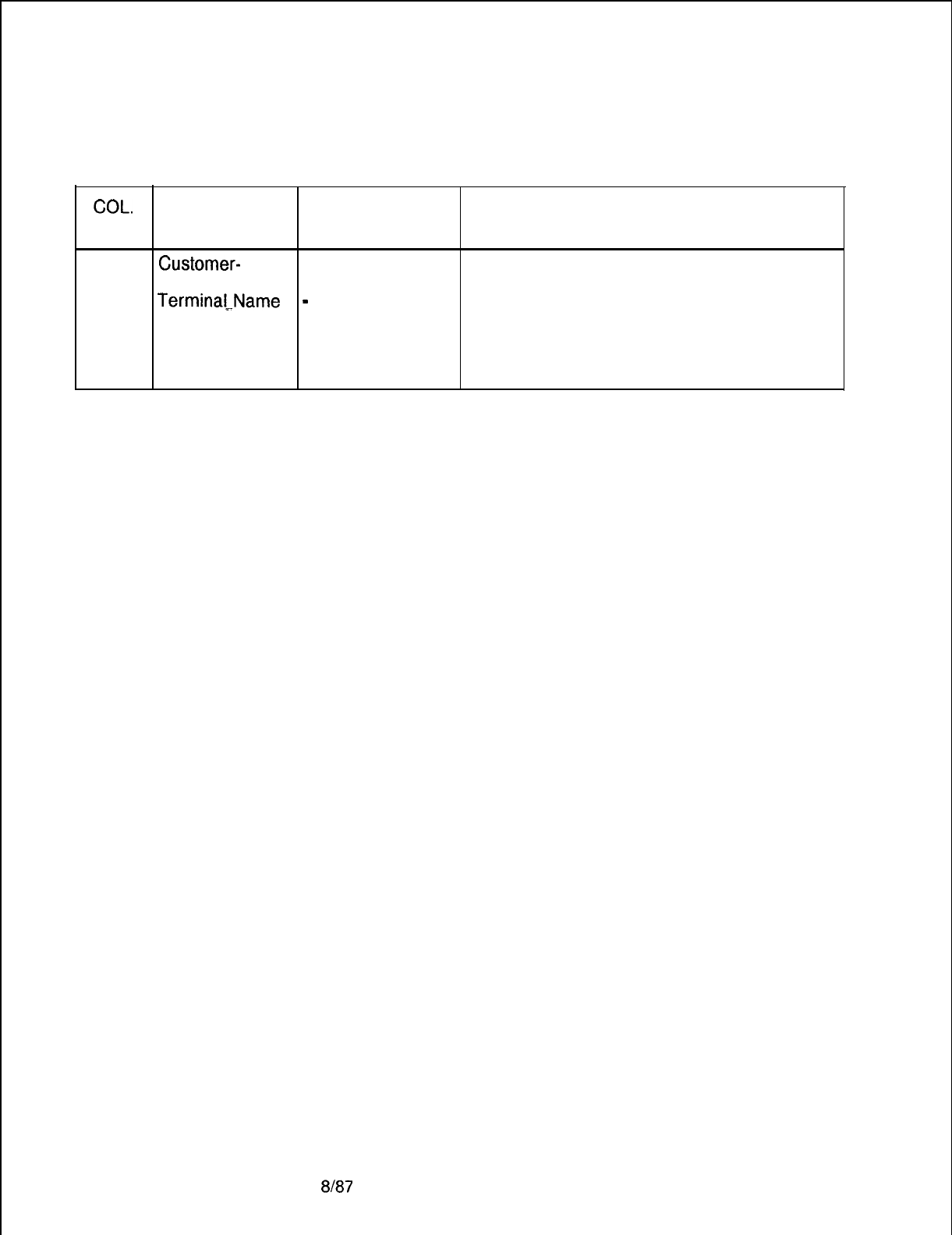
TL-130400-1001
COL.
NO.
Table14.1 Entry Fields for Record Code CT (Continued)
COL. VALID
NAME
ENTRIES
COMMENTS
33-36
Customer-
(O-9) to
(A-Z) =
Assign the name given to the customer
Defined name defined terminal.
Termina[-Name
-
= not selected -This is the one-to-four-character name
associated with this terminal type (referenced
on Record Code TT).
-This field is only supplied if the function
code is TNAM.
D-270
8187
SVR 5210
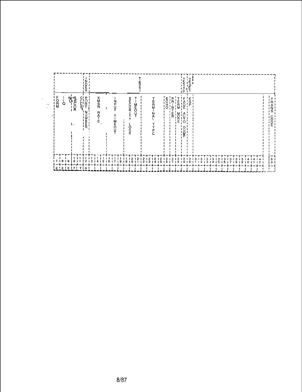
TL-130400-1001
Record Code TT:
Serial Device
14.2 Record Code TT, Figure 14.2, defines the requirements for
a TTY unit to interface with the system.
S
N1-R
I
CfPl
E
01-E
C’O;
Q
;g
$?I
IR
’
’
ID
‘N’
I
‘U’
I
‘M’
I
‘B’
I._
‘E’
II
IRI
I I
I
!!
T
IIII
I
IIIIIIIII
i
fT
jT
’
I
I5
16
II
I3
IO
I I
I4
I5
I
1
IO
11
I II
I
I
I
I
I
I
-*-.l.-a.-~-.L-~-a.-A
-~-~-~-~-*-~-~-~-~-~-~
--L-A.--I.--L-
-
Figure 14.2 Record Code TT: Serial Device Data Sheet
SVR 5210
8J87
D-271
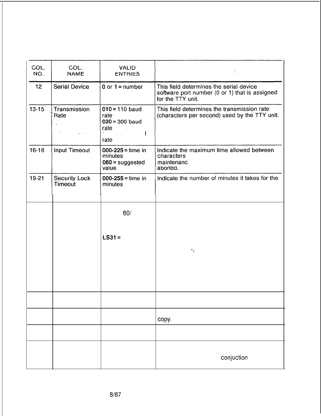
TL-130400-1001
Table 14.2 Entry Fields for Record Code TT
COMMENTS
120 =1,200 baud
inputted via the system
e terminals before a command is
005 = suggested
value
system maintenance terminal to lock after the
last entry is made from the TTY.
22-25
Terminal Type
ADDS =
ADDS
Assign the type of terminal to be connected to
Regent
60/
the output port.
Viewpoint 60 -In addition, the customer can define up to
DECV =
DEC
two other terminal types (using Record Code
VT1 00 series CT).
LS31=
Lear -The customer-defined terminal type must
Sieglar ADM31 or consist of characters as follows: A through Z,
ADM32 0 through 9,
-,
or blank.
TELE
= Televideo
900 series
XT 30 = GTE
XT300
TTY=
teletypewriter
26
Echo
Y
= selected
N = not selected Enter Y if an echo is used.
27
28
Printer Y = selected Enter Y if a printer is used to provide a hard
N = not selected
copy.
Terminal Mode Y = selected (CRT) Enter Y if the terminal mode is a CRT.
N = not selected
29
FADS System Y = selected Enter Y if if the FADS (Force Administration
Auto Dump Port N = not selected Data System) is in effect.
-This feature is used in
conjuction
with CAS
and provides historical data.
D-272 8187
SVR 5210

TL-130400-1001
HEALTH CARE/ 15.0 This section describes the record codes
r
?ed
to
HOTEL FEATURES define the various system health care and hotel features. The
following record codes are required:
l Record Code HM defines the miscellaneous hotel features.
l Record Code KD defines the KEDU card location.
-..
l Record Code KS defines the KEDU audit feature.
l Record Code MK defines KEDU special functions.
l Record Code PD defines the KEDU printer card location.
l Record Code RN defines room station access codes.
l Record Code CL defines routing information.
l Record Code TL defines printer information.
l Record Code AL defines additional printer information.
l Record Code WT defines health care ward groups.
SVR 5210
8187
D-273
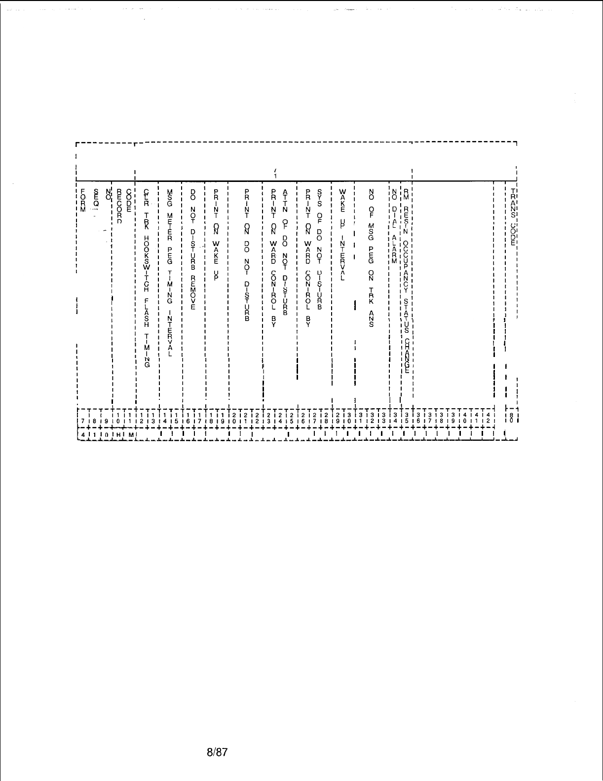
TL-130400-1001
Record Code HM:
15.1 Record Code HM, Figure 15.1, defines the miscellaneous
Health Care/Motel
system functions of the hotel option.
Miscellaneous
r---------r-
----------------------------------------------~-----------------~
IIII
II
T
I
II
II
9
II
I
I
I
I
I
II
II
1
I
II
II
II
II
II
II
II
IIII
III I
I
I I I
II I I
III I
II I I
III I
I I I I
I
I
Icl
1
IHI
1
IA,
1
INI
I
IGI
I
IEI
’
’
I
’
’
I
’
’
I
I
I ,
I I ,
’ ’
I
’
’ I
’
’
1
I
I
;
’ ’
I
1
’
I
III:I
I
I I I
i
t-,-,-t-,-t-,-~-,-,-~-~-~-~-~-~-~-~-~-~-~-~-~-~-~-~-~-~-~-t-~-~-~-~-~-~-~
!,:
I1
I1
I1
I1
I1
11
I1
I1
I1
I1
1212121212121212121213131313131313131313l4l4l4l
~~~~~~~~~~~~~~~~~~~~~~~~~~~~~~~~~~~~~~~~~~~~~~~~~~~~~~~~~~~~~~~~~~~~~~~~~
IO
I
t
-+-+-c-c-+-+-+-+-+-+-+-+-+-+-+-+-+-+-+-+-+-+-+-+-+-+-+-+-+-+-+-+-+-+-+-~
c-4
4,l,O,l.l,M,
I
I
I
I
I
I
I
I
I
I
I I
I
I,
I
I,
I
I
I
I
I
I
I
I
I
I
I
I
I
I
(
--L-l--L-~--L-~-~-~-~-~-~-~-~-~-~-~-~-~-*-~-~-~-~-~-~-~-~-~-~-~-~--‘-J
p
I
I
I
I
I
I
I
II
I
I
I
I
I
I
I
I
I
I
I
I
I
’
’
I
’
’
I
’
’
I
Figure 15.1
Record Code HM: Health Care/Motel Miscellaneous Data Sheet
D-274 8187
SVR 5210
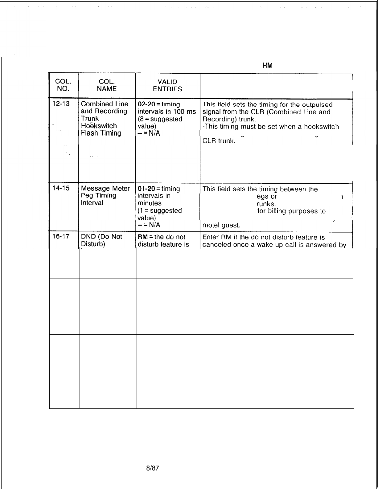
TL-130400-1001
Table 15.1 Entry Fields for Record Code
#M
COMMENTS
flash
is
recognized on the line calling via the
-The field is used to keep track of local calls
for billing purposes.
-Another option with this feature is to disallow
a hookswitch flash on Record Code NC,
columns 30-31.
message meter pcounts on calls from
lines to outgoing t
-The field is used
tabulate the number of local calls made by a
Remove deactivated when the guest room telephone.
a wake-up call is -The wake-up call feature overrides the do
answered not disturb feature.
-- = N/A
18-19
Print on Wake
WU
= output is
Enter WU if a print-out is output by the printer
UP printed
when the wake-up call feature is activated or
-- = N/A deactivated by a station user from the guest
room telephone.
-It is recommended to always have a print-
out to provide proof that the wake-up call was
received by the guest.
20-22
Print on DND DND = output is Enter DND if a print-out is output to the
(Do Not Disturb) printed printer when the ward control of the DND
-- = N/A feature is activated or deactivated by a station
user from a guest room telephone.
23-25 Print on Ward ATT = output is Enter ATT if a print-out is output to the printer
Control by
printed
when the ward control of the DND feature is
Attendant of -- = N/A activated or deactivated by the attendant.
DND (Do Not -The system may have an automatic timer
Disturb) that controls this feature.
SVR 5210
8187
D-275
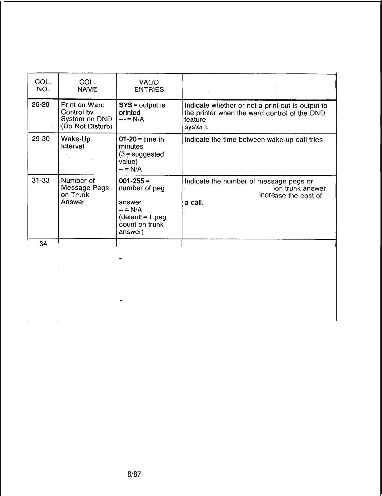
TL-130400-1001
Table 15.1 Entry Fields for Record Code HM (Continued)
COMMENTS
is activated or deactivated by the
when a wake-up call is placed to a busy or
no answer station.
counts on trunk counts that are registered up
-This feature
is
used to
incre
No Dial Alarm Y = no dial alarm Enter Y if the no dial alarm feature is
activated activated.
-
= no dial alarm
not activated
35
Room Y = room station Enter Y if the system is to automatically
Restriction on restriction
Occupancy restrict a room station from making outside
activated
Status Change
calls when the room status is changed to
-
= room station unoccupied.
restriction not -This prevents unauthorized use of the
activated telephone.
D-276 8187
SVR 5210
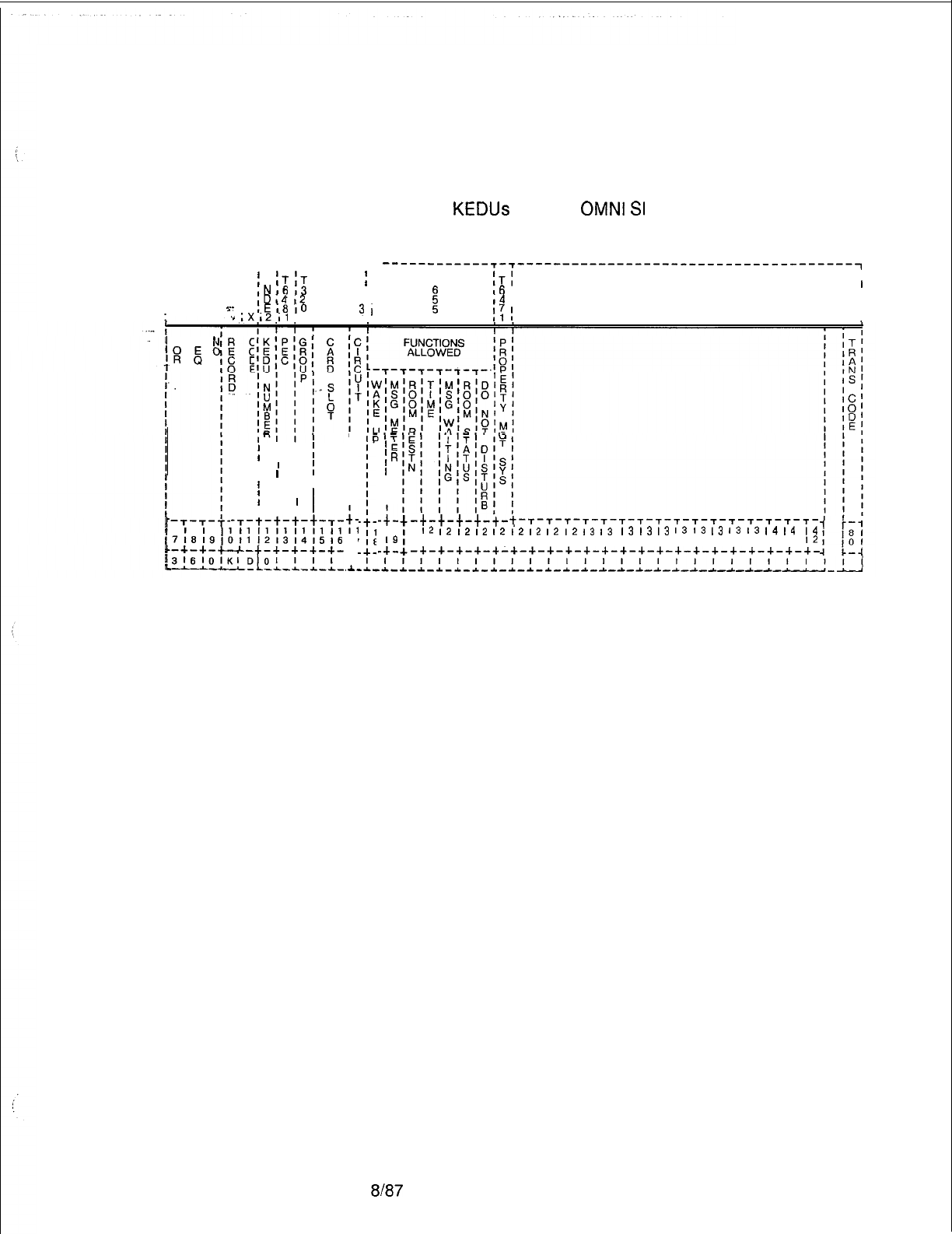
TL-130400-1001
Record Code KD:
15.2 Record Code KD, Figure 15.2, defines the physical location
Key Entry Display Unit
of the KEDU circuit card(s) and the features that can be
Assignment
activated or deactivated at each KEDU. Because the maximum
number of
KEDUs
that the
OMNI
SI
will support is two, the
maximum number of entries for this record code is two.
r--------- r--r--r-------r-
------------T-~-------------------------------------~
I
I
;
I
;T
;T
T T T T
f
T
ITI
I
,N,6
,3
3 6 3 3,
i
16
I1
I
,D,4
,2
2 4 2 2,
I4
I
I
I
I
I
7.
,E18
10
18 2
3,
‘”
,Xl2Il
1211,
1
::
!I
I
F S
f
I
w
5’
M
f
,I
I1
,I
I1
I1
I1
I1
7~8~9,9111213141516
I
I I
I I
;
I
’
I
;
I
I
I
i
I
I I 1
I
I
I
1
, I I
’
--r-t-t-t-t-r-
i
I
I
I
I
I
I
I
I
$;
I i
+-
’
,.I.-
‘C
IR
I
I
I
I
-;-
I 1
I
I9
-+-
-t-t-t-t-t-.
+-T-T-T-T-T-T-T-T-T-T-T-T-T-T-T-T-T-
2
I2
12
12
12
I2
I2
12
12
I2
13
13 13
13
13
I3
13
13
I3
I3
14
14
I4
011 12131415161718191011 12131415161718191011
12
-+-+-+-+-+-+-+-+-+-+-+-+-+-+-+-+-+-+-+-+-+-+-
Figure 15.2 Record Code KD: Key Entry Display Unit Assignment Data Sheet
SVR 5210
8187
D-277
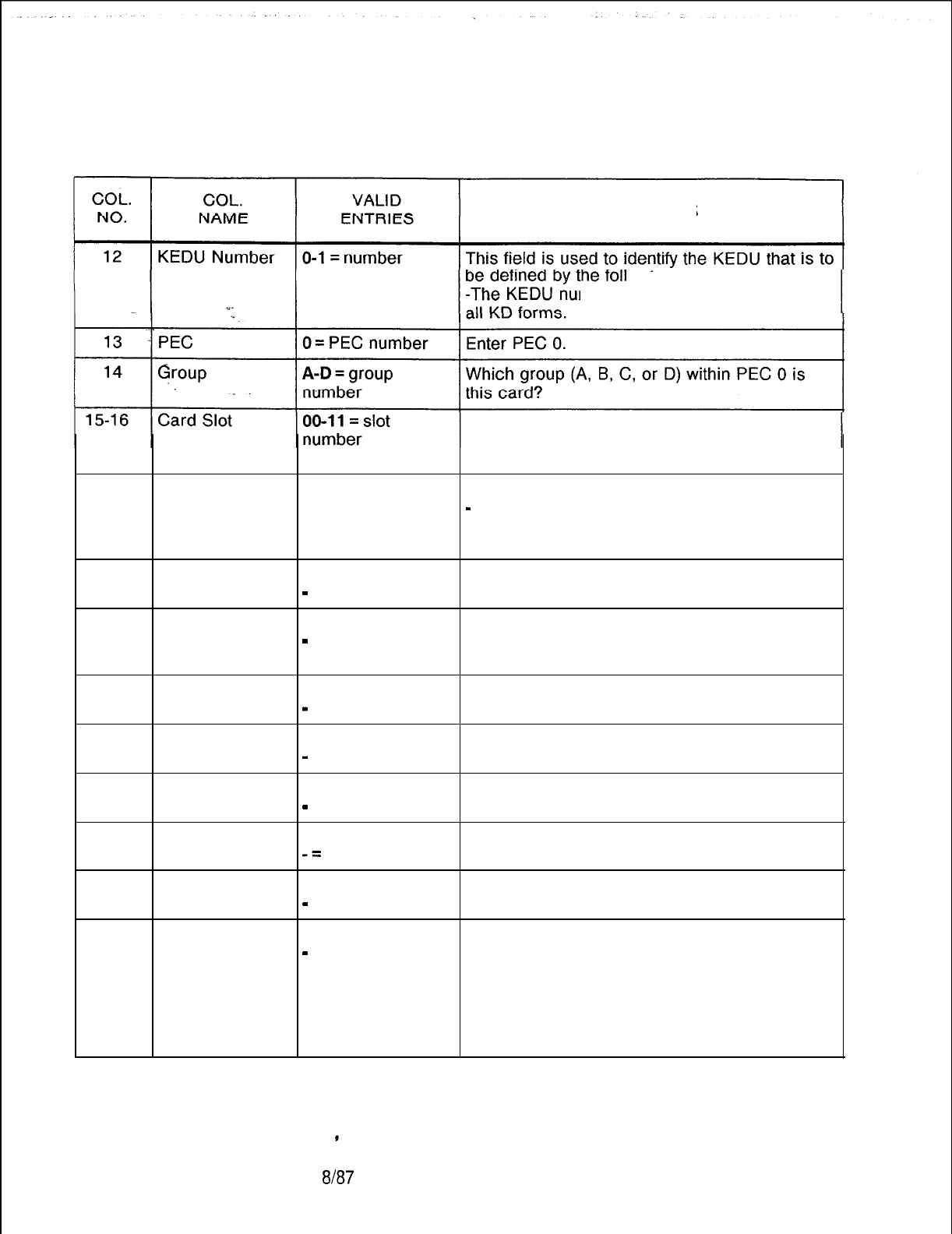
TL-130400-1001
Table 15.2 Entry Fields for Record Code KD
COMMENTS
owing parameters.
mber must be unique across
Which card slot within the group is this card?
-The FB-17209 card used to support the
KEDU is a double width card.
17
Circuit O-l = circuit Which circuit on the card is being used?
number
-
A maximum of two KEDU circuits or one
KEDU circuit and one printer circuit can be
used on the same card.
18
19
20
21
22
23
24
25
Wake Up Y = allowed Enter Y if access to the wake-up feature is
-
= not allowed allowed.
Message Meter Y = allowed Enter Y if access to the message meter
-
= not allowed feature is allowed.
-This feature requires a printer.
Room Y = allowed Enter Y if access to the room restriction
Restriction
-
= not allowed feature is allowed.
Time Y = allowed Enter Y if access to the time feature is
-
= not allowed allowed.
Message Y = allowed Enter Y if access to the message waiting
Waiting
-
= not allowed feature is allowed.
Room Status Y = allowed Enter Y if access to the room status feature is
-=
not allowed allowed.
Do Not Disturb Y = allowed Enter Y if access to the do not disturb feature
-
= not allowed is allowed.
Property P = PMS equipped Enter Y if the PMS (Property Management
Management
-
= PMS not System) is equipped in place of this KEDU.
System equipped -If this field is marked P, OPI must be
equipped on Record Code FR.
-For this feature to work properly, an OPI
card, a KEDU with PMS, and a KEDU printer
must be equipped.
D-278
8187
SVR 5210
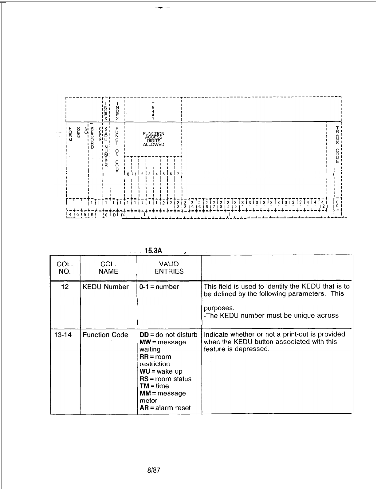
--
TL-130400-1001
Record Code KS:
15.3 Record Code KS, Figure 15.3, defines the special functions
Key Entry Display Unit
performed by the KEDU for the audit feature.
Special Function Access
;
I
=
II
1011
121314l5~617l
I I I
l
I II
I
r-t-~-r-~-$-~-~-~-~-~-~-~-r-~-~-~-~-~-~-~-~-~-~-~-~-~-~-~-~-~-~
~11111111111111111111212121212121212121213131313131313131313l4l4l4l
171619,011 12131415161718191011
l2131415161718191011
12131415161718191011
I21
L-+-+-c-c-
t
-~+-+-~-+-+-+-+-+-+-+-+-+-+-+-+-+-+-+-+-+-+-+-+-+-+-+-+-+-~
/4!0!5lKI
D
OIDIDI
I I I I I I I I
I
I I I I
I
I I I
I
I I I I I I I I I I
--
--~-~-~_I_~c-*-l-~--L-~-~-I-I-*-~-*-~-~-~-~-~-~-~-~-~---
Figure 15.3 Record Code KS: Key Entry Display Unit Special Function Access Data
Sheet
Table
15.3A
Entrv Fields for Record Code KS
COMMENTS
number is used by the system for identification
all
KD forms.
SVR 5210
8187 D-279
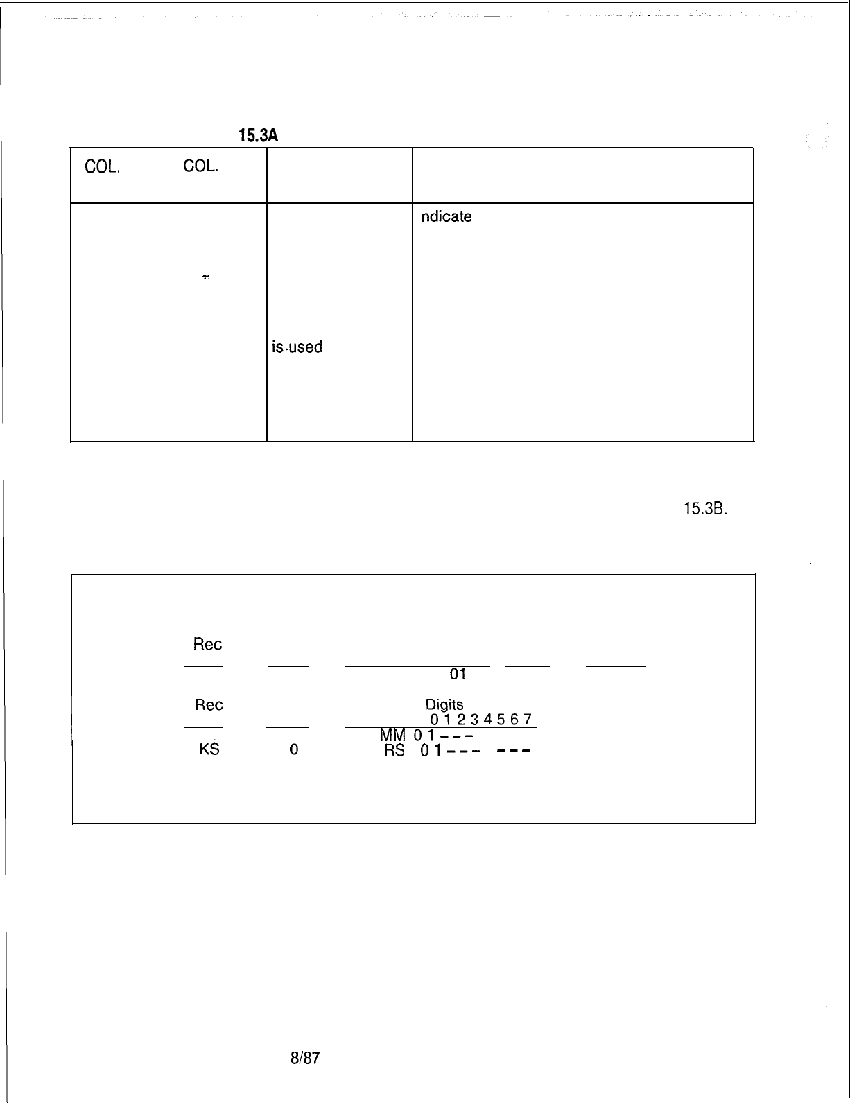
TL-130400-1001
Table 15.3A Entry Fields for Record Code KS (Continued)
COL.
NO.
15-22
COL.
NAME
Function
Access Digits
Allowed
__
VALID
ENTRIES
0 = print function
without clearing
the memory
1
= function
canceled
2 = print function,
then clear the
memory (this value
isused
for the
message meter
feature only)
3-7 = not defined
at this time; do not
use
COMMENTS
ndicate
the action taken by the system when
a particular function button is depressed from
:he KEDU.
NOTE: If an access digit is indicated for a specific function code,
one or more printers must be defined for that function on Record
Code AL associated with the KEDU number. See Table
153B.
Table 15.38 KS Rules
Example:
Ret
KEDU
Code .No
AL
0
Meter Status
Message Printer Room Printer
Status ID Status ID
AL
01
-- --
KEDU Function
Diaits
Allowed
Code .
No
KS 0
Code
Oi234567
MM
()I---
___ Allowed
RS
01-v-
--a
Incorrect
D-280
8187
SVR 5210
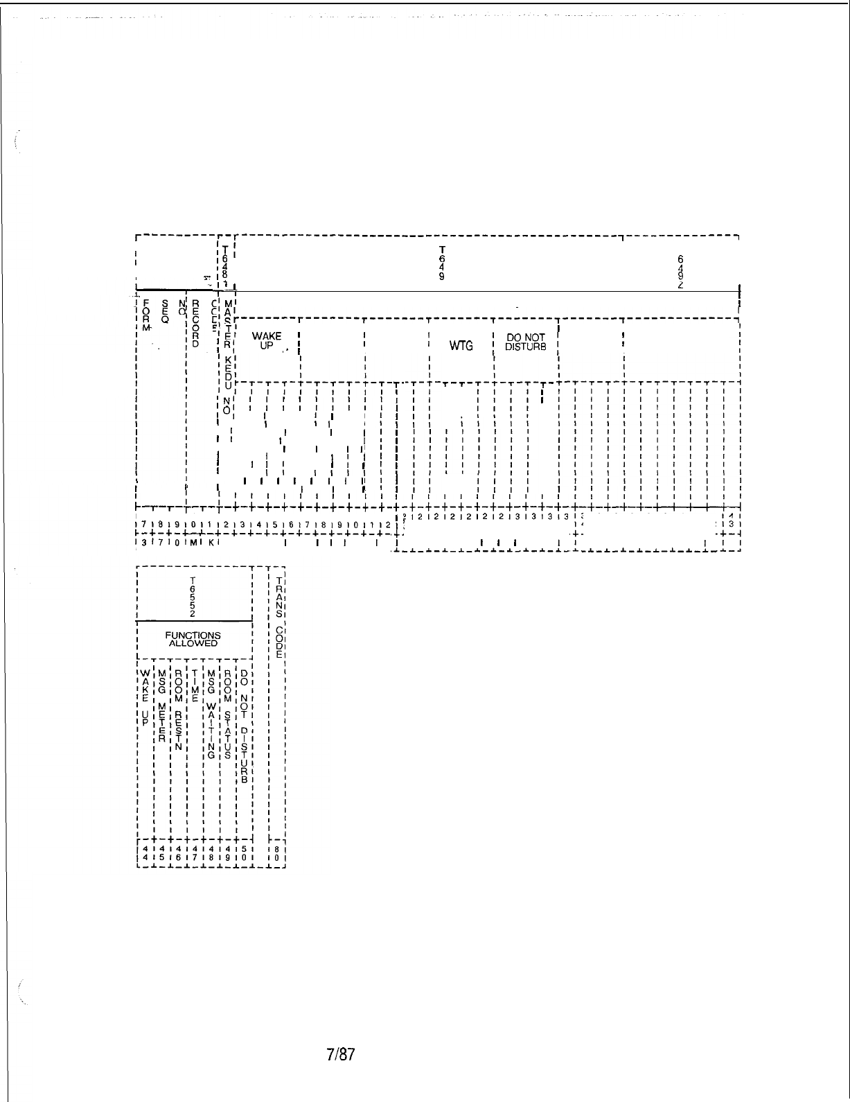
TL-130400-1001
Record Code MK:
15.4 Record Code MK, Figure 15.4, defines the special functions
Master Key Entry
that are assigned to the KEDU. If more than one KEDU is in use,
Display Unit
one must be assigned as a master for control of the features. If
only one KEDU is in use, it is assigned as the master KEDU.
T---------r-r-----------------------------------------------
,-------------~
I
t
ITi
I I
I
T
16
I
B
I
I
‘4
I
i
I
2
I
I’$
I I
9
I
I
>-
II
c
’
I
II
L
I
I
MASTER KEDU SECURITY CODES CLEAR MEMORY
I
sT-----‘-T---‘---T-------T--------~-------~-------~-------------~
IIIIII
=I
El
i
RI
“u”p”’
I
MSG
;
ROOM
)
MSG
ROOM
;
ALL
,-
I
METER ,RESTN ,
WTG
i
ANT!%
j
STATUS FUNCTIONS
;N;
;
;
; ;
loI
I
I
I I
I
I
I
’
I I
I
, I
I
I
I I
I I
I
I I
I
I
I
1
I
I I
I
I I I I
I
’ I I I
I
I
I
I
I
I
’
I I
I
I I I
II
’
I
I
I
I I
II
I
’
I I
I I
I
,,I,
'I
I
I
I
I
I
I
I
I
II'
I I I I
I
I
I
I
I
c
I I I 11111111111111111111121212
l7,a,9io,i,2,314,5,6,7,8,9,01112
c-+-+-+-+-+-+-+-+-+-+-+-+-+-+-+-
r3171o,MIK,
I , I
I
I
I
I
I
I
I
L-~-~----L-~-*-*-*-~-*-*-~-~-L-
T-
I
;
I
I
I
I
I
I
I
I
I
I
I
i-
I
;
I
:
,C.
I
.A..
T-
T-
I
T-
I
I
I
-~-~-~-~-~-~-~-~-~-~-
'121212,2121213131313
~14151617181910111213
-+-+-+-+-+-+-+-+-+-c-
, I I,
I
I
I
I,
1
-~-~-~-~-*-~-~-*-~-~-
31313131313141414
~1516171819101112
-+-+-+-+-+-+-+-+-
, I I I I I I
I
-.L-*-*-A-L-l-*-*-
D-281
Figure 15.4 Record Code MK: Master Key Entry Display Unit Data Sheet
SVR 5210
7187
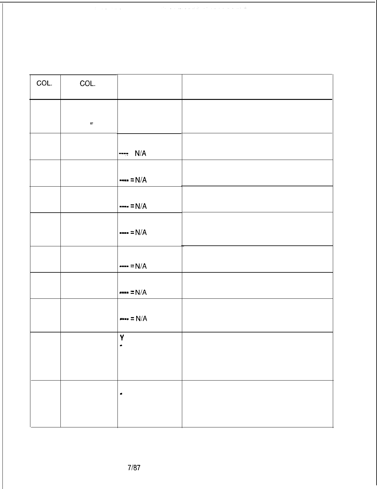
TL-130400-1001
Table 15.4 Entry Fields for Record Code MK
COL. COL.
VALID
NO. NAME ENTRIES
12
13-16
17-20
21-24
25-28
29-32
33-36
37-43
44
45
Master KEDU
Number
Clear Memory
0000-9999 =
Code for Wake clears memory
UP
--::
=
N/A
Clear Memory
0000-9999 =
Code for clears memory
Message Meter
-mm-
=
N/A
Clear Memory
Code for Room
Restriction
Clear Memory
Code for
Message
Waiting
Clear Memory
Code for Do Not
Disturb
Clear Memory
Code for Room
Status
Clear Memory
Code for All
Functions
Allowed
Wake-Up
Function
Allowed
Message Meter
Function
Allowed
O-l = number
0000-9999 =
clears memory
-m-m
=
N/A
0000-9999 =
clears memory
w-mm
=
N/A
0000-9999 =
clears memory
mm-m
=
N/A
0000-9999 =
clears memory
w-mm
=
N/A
0000-9999 =
Assign the security code used by the master
clears memory KEDU to clear the memory for the all functions
m--w
=
N/A
allowed feature.
Y
= allowed
-
= not allowed
Y = allowed
-
= not allowed
D-282
7187
SVR 5210
COMMENTS
This field is used to identify the master KEDU,
which is defined by the following parameters.
The KEDU number must be unique across all
KD forms.
Assign the security code used by the master
KEDU to clear the memory for the wake-up
feature.
Assign the security code used by the master
KEDU to clear the memory for the message
meter feature.
Assign the security code used by the master
KEDU to clear the memory for the room
restriction feature.
Assign the security code used by the master
KEDU to clear the memory for the message
waiting feature.
Assign the security code used by the master
KEDU to clear the memory for the do not
disturb feature.
Assign the security code used by the master
KEDU to clear the memory for the room status
feature.
Enter Y if the master KEDU is allowed access
to the wake-up feature through its control
buttons.
NOTE: If this field is dashed, the security
code corresponding to this feature must also
be dashed.
Enter Y if the master KEDU is allowed access
to the message meter feature through its
control buttons.
NOTE: If this field is dashed, the security
code corresponding to this feature must also
be dashed.
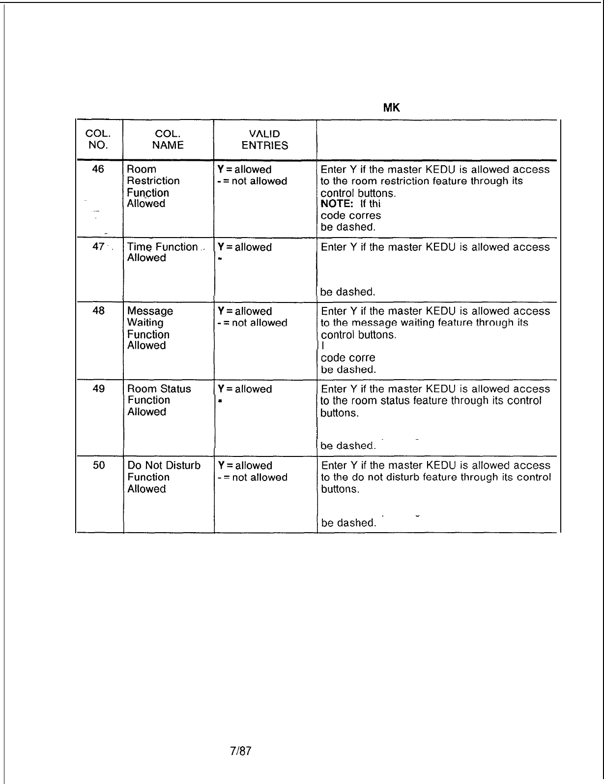
TL-130400-1001
Table 15.4 Entry Fields for Record Code
MK
(Continued)
COMMENTS
s field is dashed, the security
ponding to this feature must also
-
= not allowed to the time feature through its control buttons.
NOTE: If this field is dashed, the security
code corresponding to this feature must also
NOTE:
If this field is dashed, the security
sponding to this feature must also
-
= not allowed
NOTE: If this field is dashed, the security
code corresponding to this feature must also
NOTE: If this field is dashed, the security
code corresponding to this feature must also
SVR 5210
7187 D-283
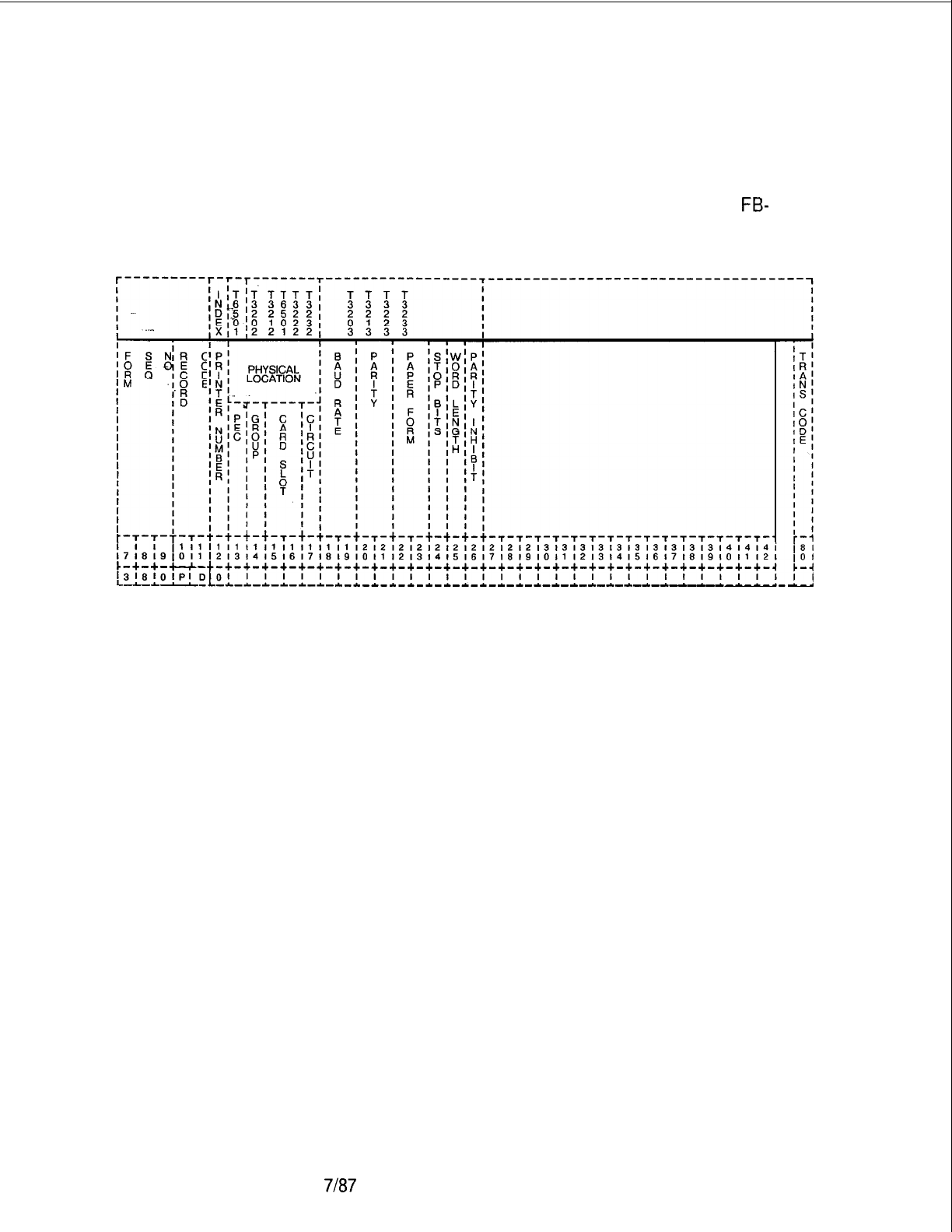
TL-130400-1001
Record Code PD:
15.5 Record Code PD, Figure 15.5, defines the physical location
Printer Assignment
of the printer card circuit(s). It also gives the speed, format, and
data transfer information for the printer assigned to support the
KEDU. The card used in support of this feature is the
FB-
17209-A card.
Figure 15.5 Record Code PD: Printer Assignment Data Sheet
D-284
7187
SVR 5210
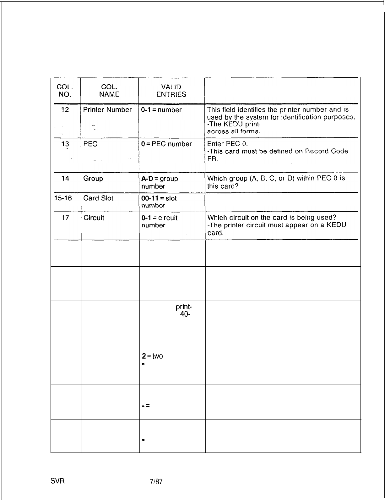
TL-130400-1001
Table 15.5
Entry Fields for Record Code PD
COMMENTS
er number must be unique
-Each location must be unique.
Which card slot within the group is this card?
18-19
Baud Rate
03 = 300 baud
Indicate the baud rate or speed of the printer.
-- = 1,200 baud
-If an Axiom printer is used, this field can be
defaulted.
20-21
Parity OD = odd parity
-- = even parity Indicate the parity (used for error detection) of
the printer.
-If an Axiom printer is used, this field can be
defaulted.
22-23
Paper Form WD = wide
print-
Indicate the paper form by checking the
out (at least
40-
number of characters that are typed by the
80 columns wide) printer on a per line basis.
-- = narrow -If an Axiom printer is used, this field can be
print-out (40-80
defaulted.
columns wide)
24
Stop Bit
2=two
stop bits
-
= one stop bit Indicate the number of stop bits needed to
stop the data flow.
-If an Axiom printer is used, this field can be
defaulted.
25
26
Word Length in
8 = eight-bit
Indicate the word length that is sent to the
Bits words
printer.
-=
seven-bit -If an Axiom printer is used, this field can be
words defaulted.
Parity Inhibit Y = printer does not Enter Y if the printer needs a parity inhibit bit.
require a parity bit -If an Axiom printer is used, this field can be
-
= printer does defaulted.
require a parity bit
SVR
5210
7187
D-285
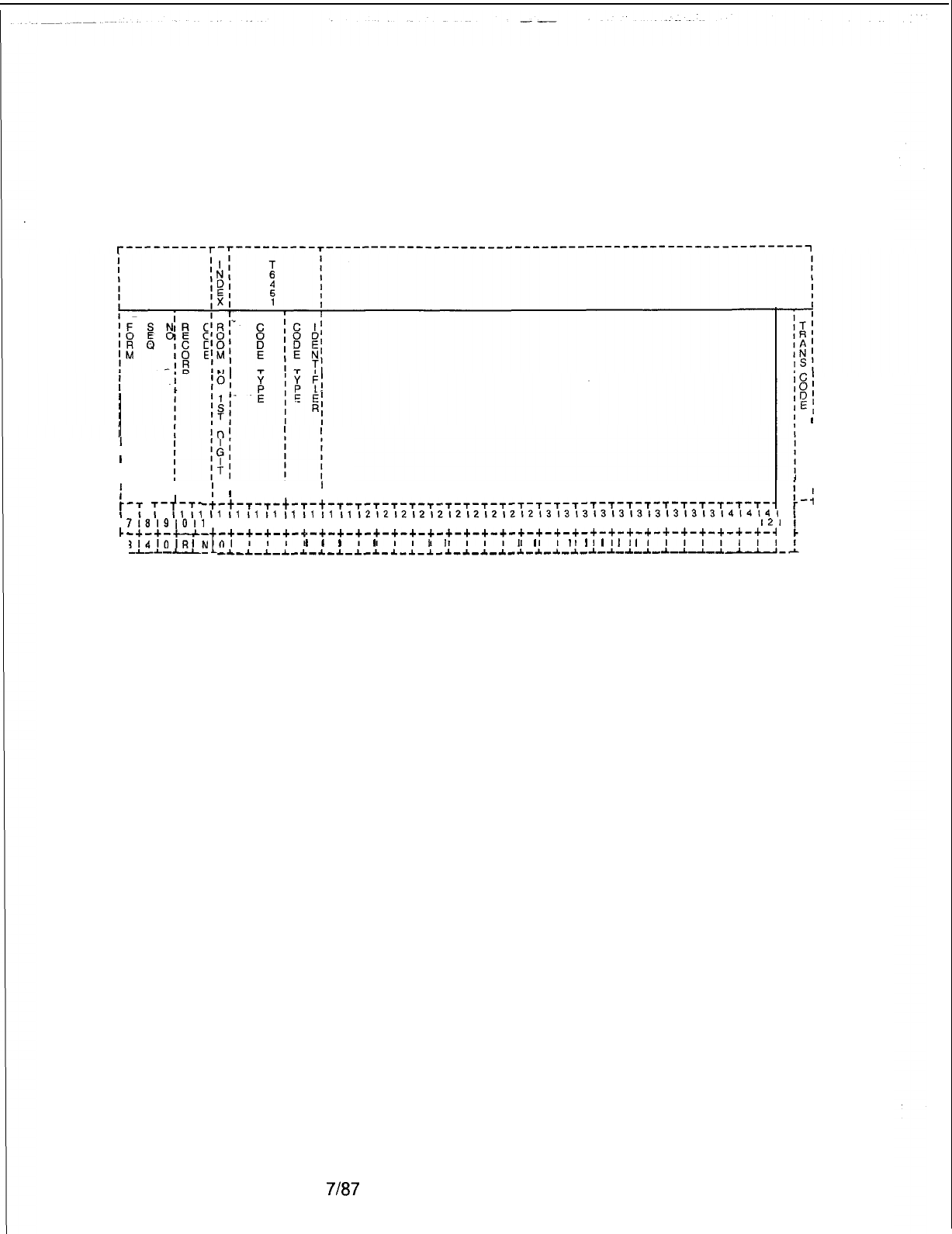
TL-130400-1001
Record Code RN:
15.6 Record Code RN, Figure 15.6, indicates when it is
Room Number
necessary to precede a room station number with an access
First Digit Translation
code for room-to-room calling.
r---------r-r---------+--------------------------------------------------------~
I
I
I
I
I
f
r
I
;
C.
I :
L.
D-286
II
I
1
II
II
’
-t-t-r-s-t-T-t-T-T-t-T-T-T-T-T-T-T-T-T-T-~-~-~-~-~-~-~-~-~-~-~-
-:
:-:;:I
I1
I1
I1
I1
I1
I1
I1
II
1212121212121212121213131313131313131313l4l4l4~
718191011
12131415161718191011 12131415161718191011 12131415161718191011
I21
-+-+-+-+-
t
-+-+-+-+-+-+-+-+-+-+-+-+-+-+-+-+-+-+-+-+-+-+-+-+-~-+-+-+-+-+-~
314lOlRlN
01
I I I
I
l
I
I
l
I I
I
I
I I I
I
l
I
I
1
l
1 1I I I I I I
-L-L
J-L-
--C-l-~-~-*-~-l-l-~-~-*-~-~-~-~-*-~-~-~-*-~-~-*-~-~-~--~--’.
8;
EI
I
II
I
I
I
I
I
-4
8 I
0 I
-1
Figure 15.6 Record Code RN: Room Number First Digit Translation Data Sheet
7187
SVR 5210
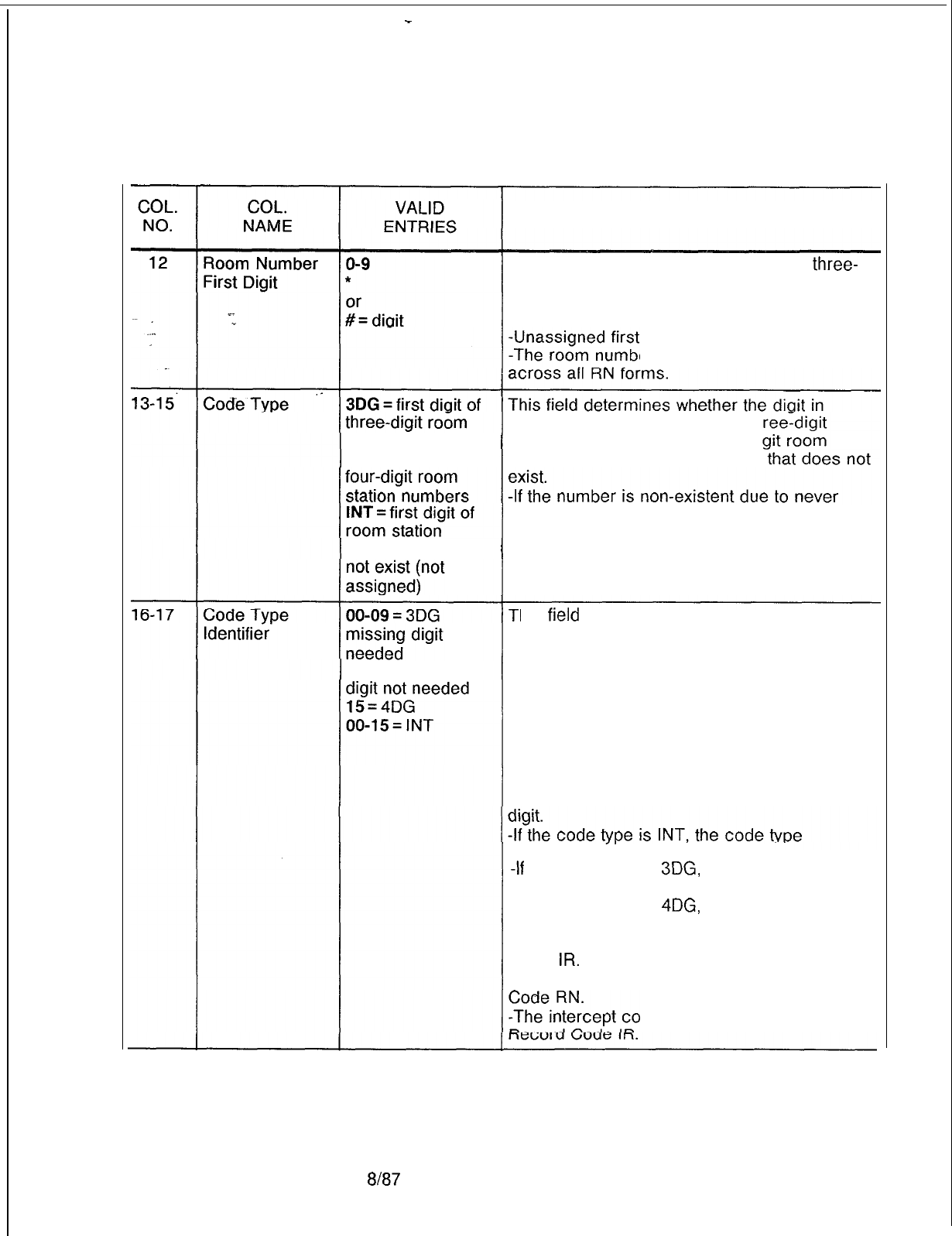
-
TL-130400-1001
Table 15.6 Entry Fields for Record Code RN
COMMENTS
This field determines the first digit of a
three-
or four-digit room directory number.
-This number is preceded by an access
code for room-to-room calling.
digits must also be entered.
er first digit must be unique
column 12 is the first digit of a th
station numbers room directory number, a four-di
4DG = first
digit
of
directory number, or the number
numbers that do
being defined, a move or a change call to that
number is routed to an intercept condition.
-Intercept conditions must be defined on
Record Code IR.
his
field
determines the missing digit required
for three-or four-digit room station numbers
or specifies the intercept routing number
12 = 3DG missing assigned to an intercept condition.
-If a missing digit is required, this field also
selects the missing digit.
If a missing digit is not specified, the console
station number display will display L followed
by a three-digit station number.
-If the missing digit is specified, the console
station number display will display the missing
identifier must be O-15.
-If
the code type is
3DG,
the code type
identifier must be O-9 or 12.
-If the code type is
4DG,
the code type
identifier must be 15. The numbers O-15 are
the intercept conditions defined or Record
Code
IR.
Only one of these intercept
conditions can be used in support of Record
ndition must be defined on
SVR 5210
8187 D-287
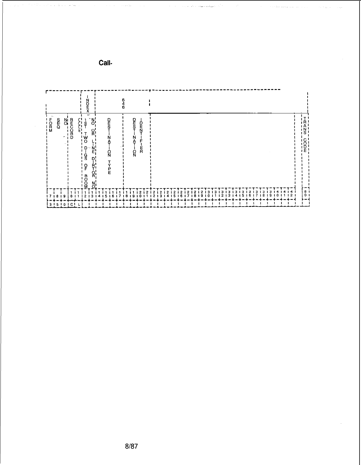
TL-130400-1001
Record Code CL:
15.7 Record Code CL, Figure 15.7, defines routing information
Class of
Call-
based on the first two digits (00-99) of the calling station’s
Controlled Routing
assigned directory number or room number.
T---------T---‘---------------I--------’-----------------------------
-------1
I
T
I
I
III
III
II
I
I
1
II
Figure 15.7 Record Code CL: Class of Call-Controlled Routing Data Sheet
D-288 8187
SVR 5210
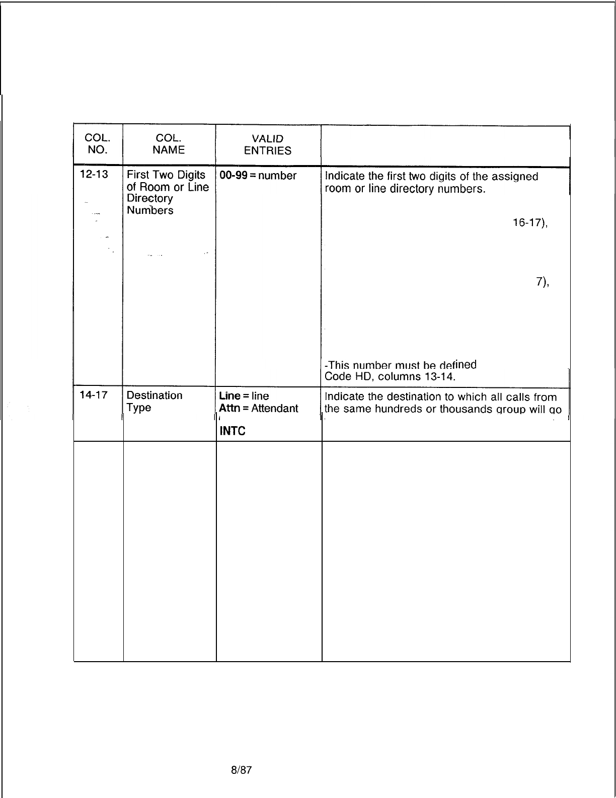
TL-130400-1001
Table 15.7 Entry Fields for Record Code CL
COMMENTS
-If the room or line directory numbers are
three-digit numbers and a missing digit is
listed on Record Code RN (columns
16-17),
enter the missing digit in column 12. Enter the
first digit of the three numbers in column 13.
-If the room or line directory numbers are
three-digit numbers and no missing digit is
listed on Record Code RN (columns 16-l
7)
enter 0 in column 12. Enter the first digit of the
three numbers in column 13.
-If the room or line directory numbers are
four-digit numbers, enter the first two-digits
of the room or line directory numbers in
columns 12-l 3.
ined
on Record
Console
INTC
= intercept when the access code for call control routing
is activated.
18-21
Destination
Identifier 0000-9999 or Indicate the destination to which all calls from
000-999 = the line
the same hundreds group will terminate when
directory number if the access code for call control routing is
the destination is a activated.
line
-The destination can be any of the following:
A three-digit a room station number, a line directory
number must have number, an Attendant Console, or an intercept
a blank before it. routing number.
0128
= Attendant
-If the destination is a line directory number,
Console 0 that number must be defined on Record Code
0064 = Attendant LD.
Console 1 -If the destination is an Attendant Console
0192
= either of the
circuit, that console circuit must be defined on
two Attendant Record Code AT.
Consoles -If the destination is an intercept condition,
0000-0015 =
that condition must be defined on Record
intercept routing Code IR.
number
SVR 5210
8187
D-289
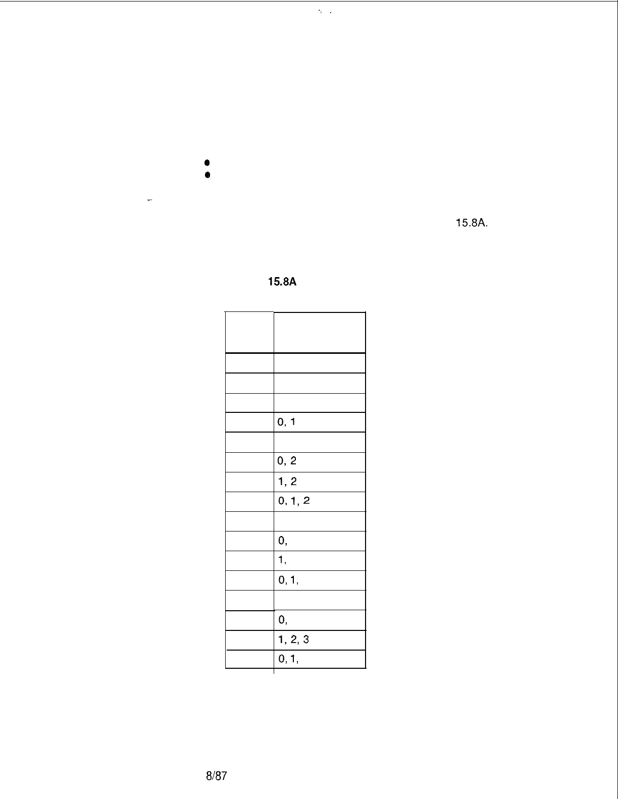
_
-,
.
TL-130400-1001
Record Code TL:
15.8 Record Code TL, Figure 15.8, assigns printers to the
Transaction Record
function of the transaction record. All printer numbers indicated
Control
by the printer identification number must be valid printer numbers
on a PD form. The four printers are given the following values:
*
Printer No. 0 is assigned value 01.
e
Printer No. 1 is assigned value 02.
l Printer No. 2 is assigned value 04.
l Printer No. 3 is assigned value 08.
If more than one printer is designated, use Table
15.8A.
Table
15.8A
Printer ID
Number
Printer
ID
00
01
02
03
04
05
06
07
08
09
10
11
12
13
14
15
Printer
Number(s)
None
0
1
0,
1
2
0,
2
1,2
0,
1,
2
3
0,
3
1,
3
0,
1,
3
2, 3
0,
2, 3
1,293
0,
1,
2, 3
D-290
8187
SVR 5210
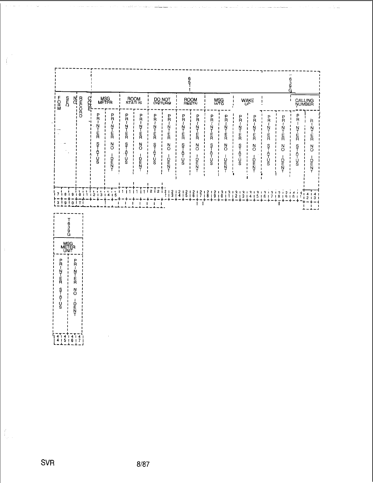
TL-130400-1001
i
T
I
I
E
I
I1
I
I
T
I
I3”
I
I
Ei
MAID
;
I STATUS ,
I I I
‘T---r---
1716191011121314,5
c-+-+-+-+-+-+-+-+-
1319101Tl
LI I
I
I
L-A-A.-A--L-L-A-A-A._
141414141
141516171
I.-A.-J.-l-,
III
IIII
IIII
;-T-;-T-;-T-;.
I1
I1
I1
I1
12121;
161718191011 I:
+-+-+-+-+-+-+-
DISPLAY I
--7---J
’
!
;
I
P
I
I
I
I
’
I
i
III
ii
;II
IIIIIIII
-T-~-T-~-T-~-,-~-,-~-~-~-~-~-~-~-
I
!
!12121212121212131313131313131313131414
!13141516171819101112131415161718191011
-+-+-+-+-+-+-+-c-+-+-+-+-+-+-+-+-+-+-+-
I I I I
I
I
I I I I I I I I I I
I
I I
-~-~-~-~-I-*-~-~-~-~-~-~-*-~-~-~-~-~-~-
Figure 15.8 Record Code TL: Transaction Record Control Data Sheet
SW
5210
8187
D-291
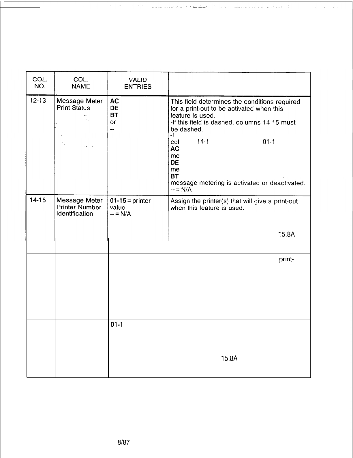
r
TL-I 30400-l 001
Table 15.88
Entry Fields for Record Code TL
COMMENTS
If this field
is
marked AC,
DE,
or BT,
umns
14-l
5 must be marked
01-l
5.
= transaction record is printed when
ssage metering is activated.
= transaction record is printed when
ssage metering is deactivated.
= transaction record is printed when
-If only one printer is used, enter the printer
value 01, 02, 04, or 08.
-If more than one printer is used, enter the
sum of the printer values from Table
15.8A
(e.g., if printers 0 and 1 are used, enter 3; if
printers 2 and 3 are used, enter 12).
16-17
Room Status AC
Print Status Indicate the conditions required for a
print-
DE
out to be activated when this feature is used.
BT
AC = transaction record is printed when
or message metering is activated.
--
DE = transaction record is printed when
message metering is deactivated.
BT = transaction record is printed when
message metering is activated or deactivated.
-- = N/A
18-19
Room Status
01-l
5
= printer
Printer Number value Assign the printer(s) that will give a print-out
when this feature is used.
Identification -- = N/A -If only one printer is used, enter the printer
value 01, 02, 04, or 08.
-If more than one printer is used, enter the
value from Table
15.8A
(e.g., if printers 0 and
1 are used, enter 3; if printers 2 and 3 are
used, enter 12).
D-292 8187
SVR 5210
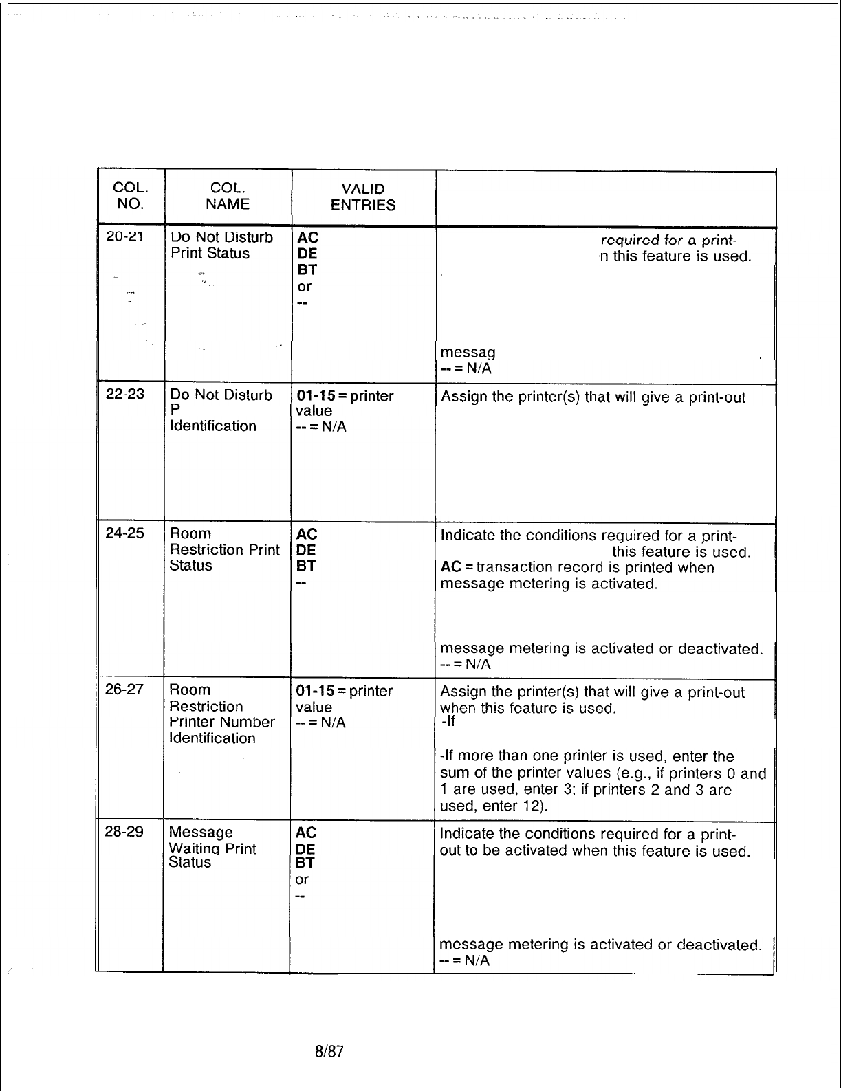
TL-130400-1001
Table 15.88 Entry Fields for Record Code TL (Continued)
COMMENTS
Indicate the conditions
out to be activated whe
AC
= transaction
record
is
printed when
message metering is activated.
DE = transaction record is printed when
message metering is deactivated.
BT
= transaction
record is printed when
e metering is activated or deactivated.
rinter Number when this feature is used.
-If only one printer is used, enter the printer
value 01, 02, 04, or 08.
-If more than one printer is used, enter the
sum of the printer values (e.g., if printers 0 and
1 are used, enter 3; if printers 2 and 3 are
used, enter 12).
out to be activated when
DE = transaction record is printed when
message metering is deactivated.
BT= transaction record is printed when
-If
only one printer is used, enter the printer
value 01, 02, 04, or 08.
AC = transaction record is printed when
message metering is activated.
DE = transaction record is printed when
message metering is deactivated.
BT= transaction record is printed when
SVR 5210
8187
D-293
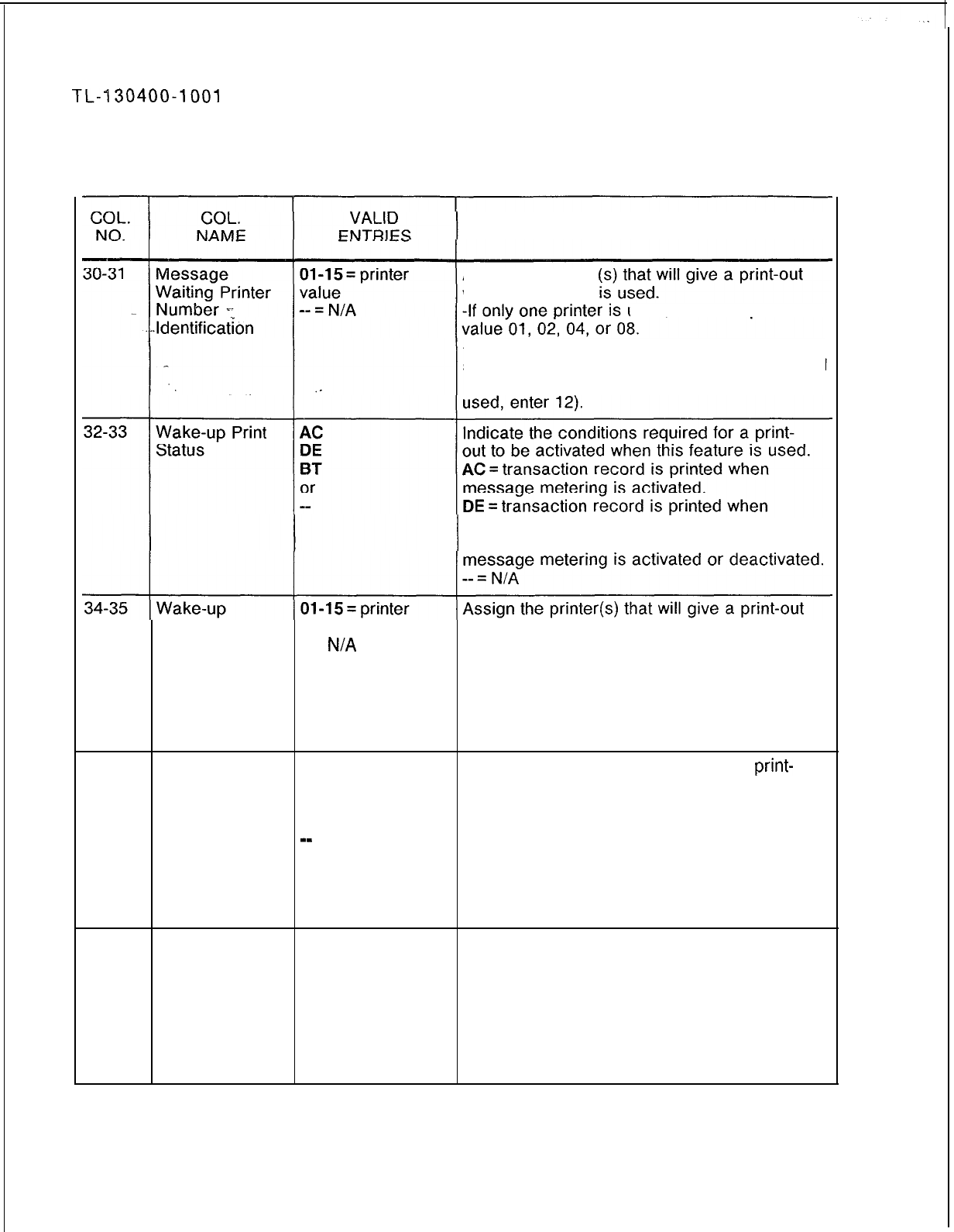
TL-l30400-1001
Table 15.85 Entry Field for Record Code TL (Continued)
COMMENTS
Assign the printer
when this feature
used,
enter the printer
-If more than one printer is used, enter the
sum of the printer values (e.g., if printers 0 and
1 are used, enter 3; if printers 2 and 3 are
message metering is deactivated.
BT = transaction record is printed when
Printer Number value when this feature is used.
Identification
-- =
N/A
-If only one printer is used, enter the printer
value 01, 02, 04, or 08.
-If more than one printer is used, enter the
sum of the printer values (e.g., if printers 0 and
1 are used, enter 3; if printers 2 and 3 are
used, enter 12).
36-37
Maid Status
Print Status
AC
DE
BT
or
mm
Indicate the conditions required for a
print-
out to be activated when this feature is used.
AC = transaction record is printed when
message metering is activated.
DE = transaction record is printed when
message metering is deactivated.
BT = transaction record is printed when
message metering is activated or deactivated.
-- = N/A
38-39
Maid Status
01-l
5 = printer
Assign the printer(s) that will give a print-out
Printer Number value when this feature is used.
Identification -- = N/A -If only one printer is used, enter the printer
value 01, 02, 04, or 08.
-If more than one printer is used, enter the
sum of the printer values (e.g., if printers 0 and
1 are used, enter 3; if printers 2 and 3 are
used, enter 12).
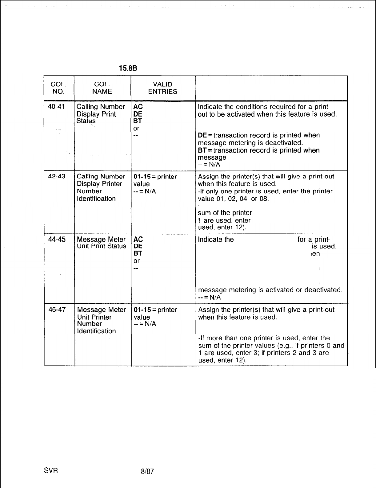
TL-130400-1001
Table
15.8B
Entry Fields for Record Code TL (Continued)
COMMENTS
AC = transaction record is printed when
message metering is activated.
metering is activated or deactivated.
-If more than one printer is used, enter the
values (e.g., if printers 0 and
3; if printers 2 and 3 are
conditions required
out to be activated when this feature
AC = transaction record is printed wh
message metering is activated.
DE = transaction record is printed when
message metering is deactivated.
BT= transaction record is printed when
-If only one printer is used, enter the printer
value 01, 02, 04, or 08.
SW
5210
8187
D-295
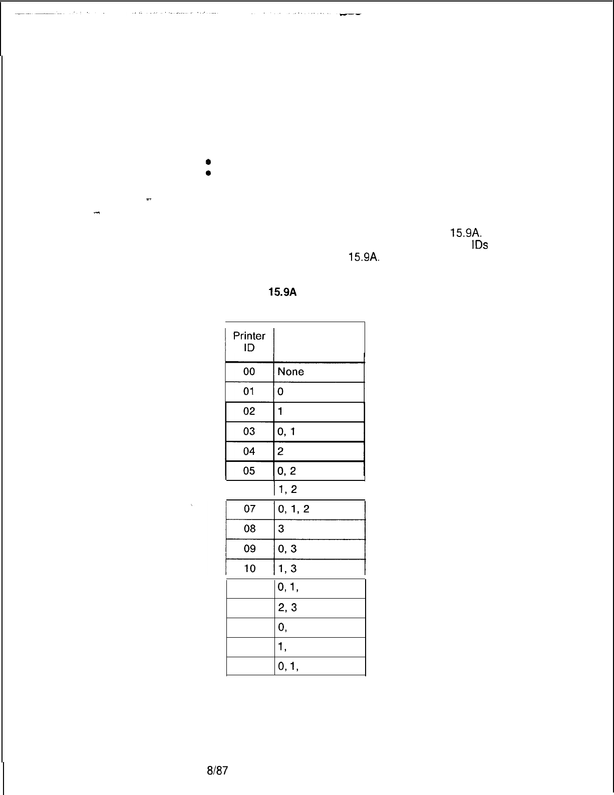
TL-130400-1001
Record Code AL:
15.9 Record Code AL, Figure 15.9, assigns a printer to a KEDU
Audit Record
for the audit functions associated with that KEDU. The printer is
Control
assigned the following values:
l Printer No. 0 is assigned the value 01.
*
Printer No. 1 is assigned the value 02.
o
Printer No. 2 is assigned the value 04.
l Printer No. 3 is assigned the value 08.
.
.
.
.
D-296
The printer ID identifies a specific printer number or several
printer numbers, depending on the value range entered. If more
than one printer is to be designated, use Table
15.9A.
Example:
printer numbers 0 and 3 have the value of 9. Printer
IDS
and
‘numbers are found in Table
15.9A.
Table
15.9A
Printer ID
Number
Printer
Number(s)
I
112
06
I
11
0,
1,
3
12
2,3
13 0,
2, 3
14
1,
2, 3
15 0,
1,
2, 3
8187
SVR 5210
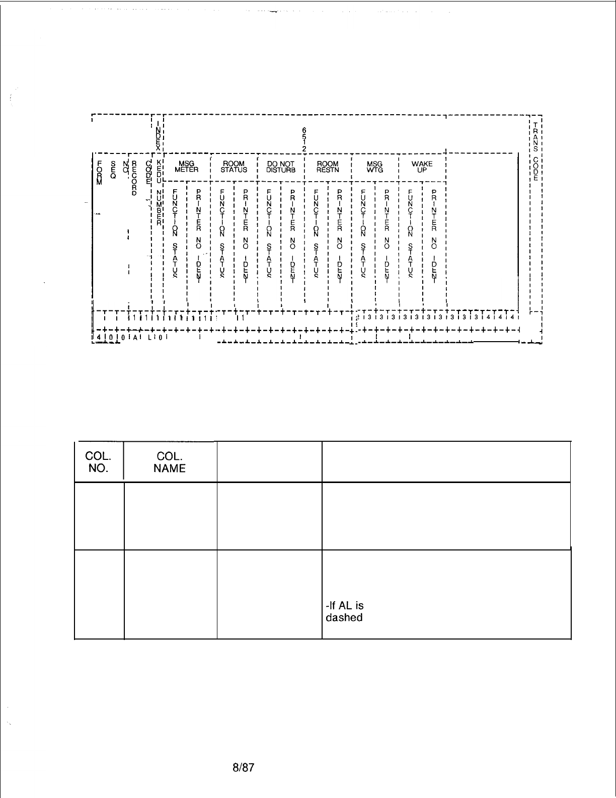
TL-130400-1001
I
II
T
I
I
NI
I
I
DI
:
I
I EI
I
I XI :
I
.-----r---r-r-------r-------r--------------------------------------
A-----------
xJ(
M
I
I
I
I
I
I
-.. I
I
I
t
I
I
I
I
t
I
I
I
I
I
I
t
I
-+-T-f-T-T-;-T-+-
I1
I1
I1
I1
I1
I1
I1
I.
71819101112131415161;
-+-+-u-+-+-+-+-+-+.
4,OlOlAl
LlOl
I I
I
I
--A
--L-A-L-L-L-*-
I
-T-f--r-t-T-+-T-t-r-+-T-
I
I1
11121212121212121212
718191011 12131415161718
-+-c-+-+-+-+-+-+-+-+-+-
I I I, I, I
I
I I I
-~-~-~-~-*-~-*-~-*-*-*-
-T-f-T-t-T-f-T-&
T-T-T-T-T-
I
!131313131313131313131414141
i8
110111213141516171819101112, IO
-+-c-+-+-+-+-+-+-+-c-+-+-+-4
c-
l
I
I I
I
I I I I I I I I I I
-A-*-A-A.-A-*-A-A--L-A
. . .
4-L
Table 15.98 Entry Fields for Record Code AL
F-pi-
VALID
ENTRIES COMMENTS
12
KEDU Number
13-14
Message Meter
Function Status
Figure 15.9 Record Code AL: Audit Record Control Data Sheet
O-3 = number
This field determines the selected KEDU
number and is used by the system for
identification purposes.
-This number must be defined on Record
Code KD.
AL = message
metering
information is to be
printed
-- = metering
information is not
to be printed
Enter AL if the printer(s) can accept message
metering information associated with a KEDU.
-Columns 15-l 6 indicate which printer(s)
will print this information.
-l’,lke;
entered, columns 15-16 cannot be
SVR 5210
8187 D-297
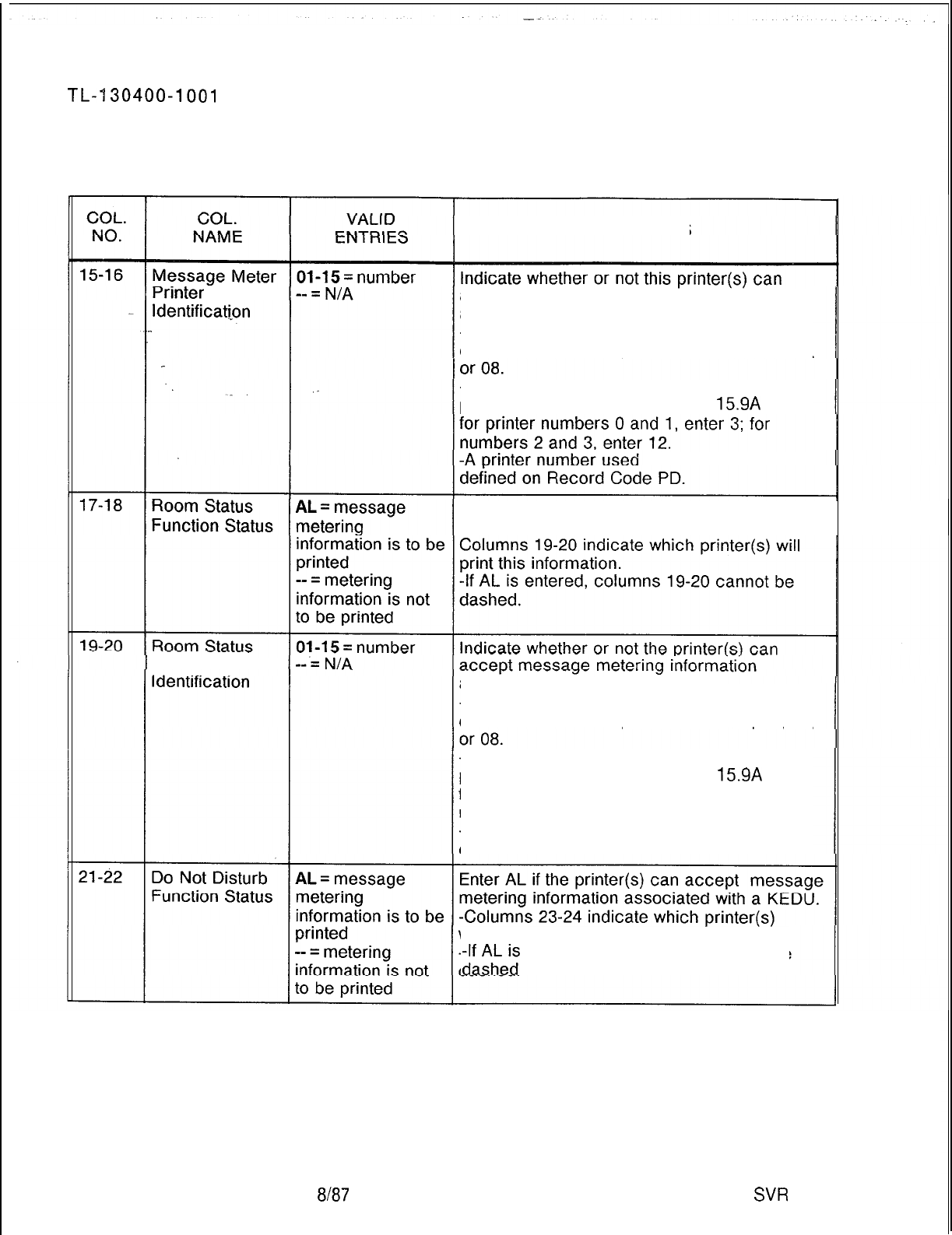
r
TL--l30400-1001
Table 15.95
Entry Fields for Record Code AL (Continued)
COMMENTS
rrnter
Number accept message metering. information
associated with a KEDU.
-When only one printer is selected to print,
enter the sum of the printer values
01, 02, 04,
-When
more than one printer is selected to
print, enter the value from Table
15.9A
(e.g.,
in this field must be
Enter AL if the printer(s) can accept message
metering information associated with a KEDU.
Printer Number associated with
a
KEDU.
-When only one printer is selected to print,
enter the sum
of the
printer values
01, 02, 04,
-When more than one printer is selected to
print, enter the value from Table
15.9A
(e.g.,
for printer numbers 0 and 1, enter 3; for
numbers 2 and 3, enter 12.
-A printer number used in this field must be
defined on Record Code PD.
will print this information.
-ll;;ez
entered, columns 23-24 cannot be
8187
SW
5210
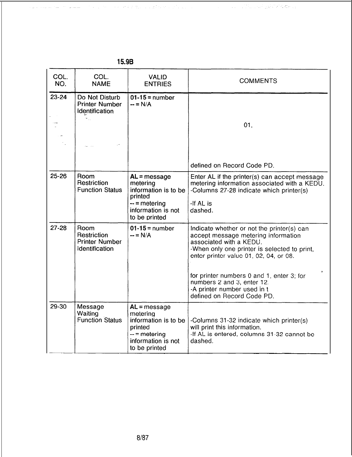
TL-130400-1001
Table 15.96 Entry Fields for Record Code AL
(Continued)
Indicate whether or not the printer(s) can
accept message metering information
associated with a KEDU.
-When only one printer is selected to print,
enter printer value
01,
02, 04, or 08.
-When more than one printer is selected to
print, enter the sum of the printer value (e.g.,
for printer numbers 0 and 1, enter 3; for
numbers 2 and 3, enter 12).
-A printer number used in this field, must be
will print this information.
-lgl;ez
entered, columns 27-28 cannot be
-When more than one printer is selected to
print, enter the sum of the printer values
(e.g.,
his field must be
Enter AL if the printer(s) can accept message
metering information associated with a KEDU.
SVR 5210
8187
D-299

TL-130400-1001
Table 15.98
Entry Fields for Record Code AL (Continued)
COL.
NO.
D-300
31-32
33-34
35-36
COL.
NAME
Message
Waiting Printer
Number,
Identification
Wake Up
Function Status
VALID
ENTRIES
01-l 5 = number
-- = N/A
AL = message
metering
information is to be
printed
-- = metering
information is not
to be printed
01-l 5 = number
-- = N/A
Wake Up Printer
Number
Identification
8187
COMMENTS
Indicate whehter or not the printer(s) can
accept message metering information
associated with a KEDU.
-When only one printer is selected to print,
enter printer value 01, 02, 04, or 08.
-When more than one printer is selected to
print, enter the sum of the printer values (e.g.,
for printer numbers 0 and 1, enter 3; for
numbers 2 and 3, enter 12).
-A printer number used in this field must be
defined on Record Code PD.
Enter AL if the printer(s) can accept message
metering information associated with a KEDU.
-Columns 35-36 indicate which printer(s)
will print this information.
-If AL is entered, columns 35-36 cannot be
dashed.
Indicate whether or not the printer(s) can
accept message metering associated with a
KEDU.
-When only one printer is selected to print,
enter printer value 01, 02, 04, or 08.
-When more than one printer is selected to
print, enter the sum of the printer values (e.g.,
for printer numbers 0 and
1,
enter 3; for
numbers 2 and 3, enter 12).
-A printer number used in this field must be
defined on Record Code PD.
SVR 5210
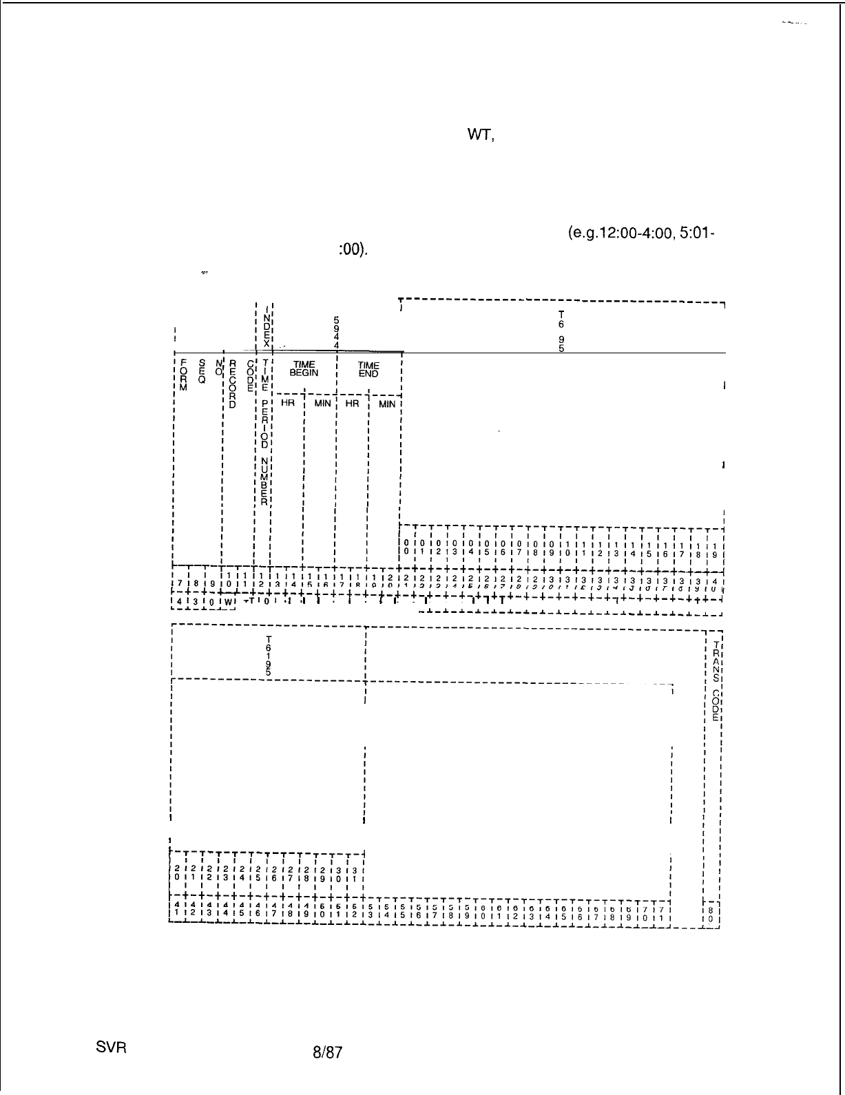
TL-130400-1001
Record Code WT:
Ward Control
15.10 Record Code
WT,
Figure 15.10, defines the ward
groupings for the system. The beginning and ending times that
the system will automatically impose the do not disturb feature
are also defined. This feature provides quiet time for hospital
patient rooms. A maximum of eight time periods can be used for
up to 32 ward numbers. Time periods entered on this record
code must not overlap one another
(e.g.12:00-4:00,
5:01-
11
:OO).
. . .
T---------r-r--- ---------___
T---------------
I
T
I
------------------------~
I
z!
I
I
;
I
II
I
:
I1I
II
II
:
I
I
I
I
WARD NUMBER(S)
I
I
I
I
I
I
I
I
I
I
I
I
I
I
I
I
I
~-+-~-u-+-+-+-+-+-+-+-+-+-+-+-+-+-+-+-+-+-~-+-+-+-+-+-+-+-+-+-+-+--l
~413lOlWI
TIOI
I
I
I
I
I
I
I
I
I
I
I I
I
I
I
I I I I I I
I
I I I I
I
I
A-J.-A- -L-L-~-~-I-~-I-*-~-I-*-~
-1-1-~-~-~-1-*-~-1-1-~-~-~
-*-J.-A.-A-*-A
WARD
NUMBER(S)
I
I
I
I
I
I I
II I
;
I
I
II
-r--r--r-T-T-T-T-T-r-r-T-i
I
Figure 15.10 Record Code WT: Ward
Control
Data Sheet
SW
5210
8187 D-301
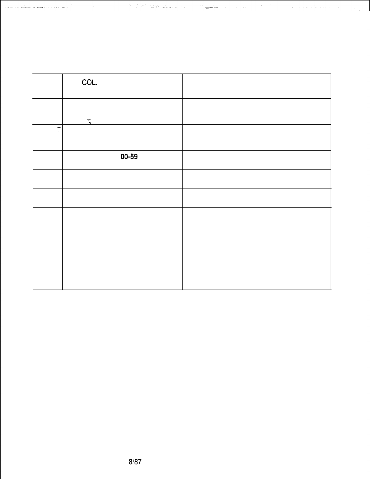
TL-130400-1001
Table 15.10 Entry Fields for Record Code WT
COL. COL.
VALID
NO. NAME ENTRIES COMMENTS
12
Time Period
O-7 = number
This field determines which time period this
Number field is. Up to eight time periods are allowed.
s-
-Each time period number must be unique.
.”
13-14
‘Y’
Begin Time by 00-23 = number Indicate the hour that this feature, which
Hour prevents rooms from being rung, goes into
effect.
15-16
Begin Time by
00-59
= number Indicate the minute of the hour that this feature
Minute goes into effect.
17-18
End Time by 00-23 = number Indicate the hour that the feature is no longer
Hour in effect.
19-20
End Time by 00-59 = number Indicate the minute of the hour that this feature
Minute is no longer in effect.
21-52
Ward Number
A
= allowed
Enter A if the time periods created in columns
D = disallowed 12-20 are in effect for this ward number.
-Ward numbers are assigned to stations on
Record Code LM, columns 32-33.
-Ward control is assigned to attendants on
Record Code AT, columns 39-40.
-If allowed, the attendant can change these
timing parameters from the console.
NOTE: If a ward number is listed on Record
Code LM, it must also be listed on this record
code.
D-302 8187
SVR 5210

TL-130400-1001
CENTRALIZED 16.0 This section describes the record codes required to
ANSWERING define the various system CAS (Centralized Answering Service)
SERVICE features. The following record codes are required:
BRANCH/MAIN
l Record Code CF defines the system CAS Branch features.
l Record Code AD defines the CAS Main agent position.
l Record Code AF defines ACD recorder announcer access.
Y.
.”
.
.
SVR 5210
l Record Code AG defines agent group characteristics.
l Record Code DK defines repertory dial numbers.
l Record Code RC defines RLT (Release Link Trunks)
characteristics.
l Record Code SM defines LCD (Liquid Crystal Display)
messages.
l Record Code SP defines supervisor messages.
l Record Code TM defines supervisor repertory dial key.
l Record Code RA defines CAS
Main/ACD
recorder
announcers.
l Record Code SD defines secondary directory numbers.
$187 D-303
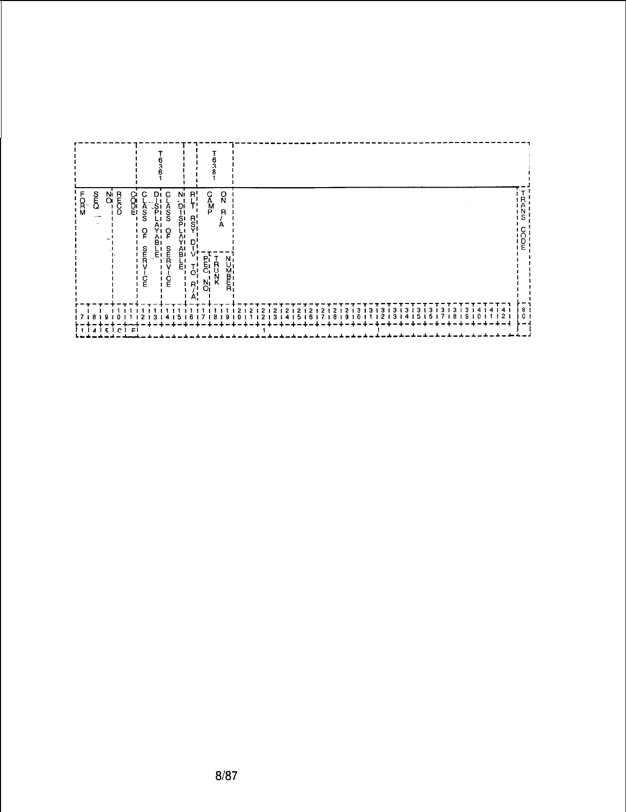
TL-130400-1001
Record Code CF:
16.1 Record Code CF, Figure 16.1, defines the CAS Branch
CAS Branch Features
features used by the system.
-------------------------------------------------,
I
I
I
I
1114151ClFl
I I I I I I I I I I
I
I I I I I I I I I
I
I I I I I I I I I I
L-*-*-~--~_I-~-~-~-~-i-~-~-~-*-~-~-~-~-~-~-~-~-~-~-~-*-~-~-~-*-~-~-~-~~-,
Figure 16.1
Record Code CF: CAS Branch Features Data Sheet
D-304
8187
SVR 5210
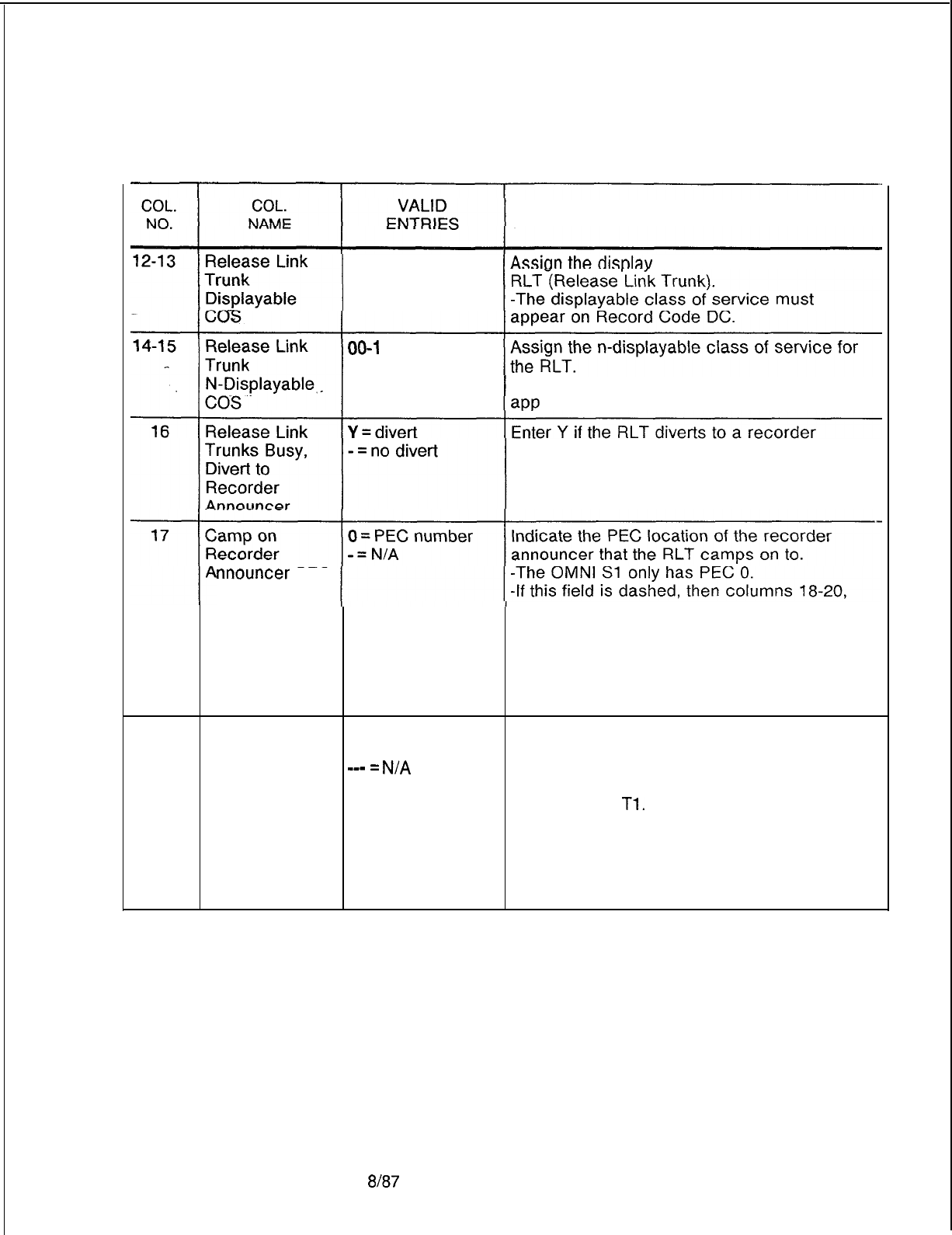
TL-130400-I 001
Table 16.1 Entry Field for Record Code CF
COMMENTS
00-15
= number
able class of service for the
00-l
5 = number
-The n-displayable class of service must
ear on Record Code NC.
announcer.
nnouncer
PEC
must also be dashed.
-If an entry is made in this field, columns
18-20 must have an entry.
NOTE: If column 16 is dashed, this field must
be dashed. If column 16 is Y, this field must
not be dashed.
18-20
Camp on
000-063 = trunk
Indicate the trunk number that the RLT camps
Recorder number
on to.
Announcer
-mm
=
N/A
-The trunk listed should be a member of a
Group trunk group marked for recorder announcer on
Record Code
Tl.
-The trunk number field must correspond to a
TC form defining a recorder announcer.
-In order to work properly, the recorder
announcer indicated must be used for this
feature only.
SVR 5210
8187
D-305
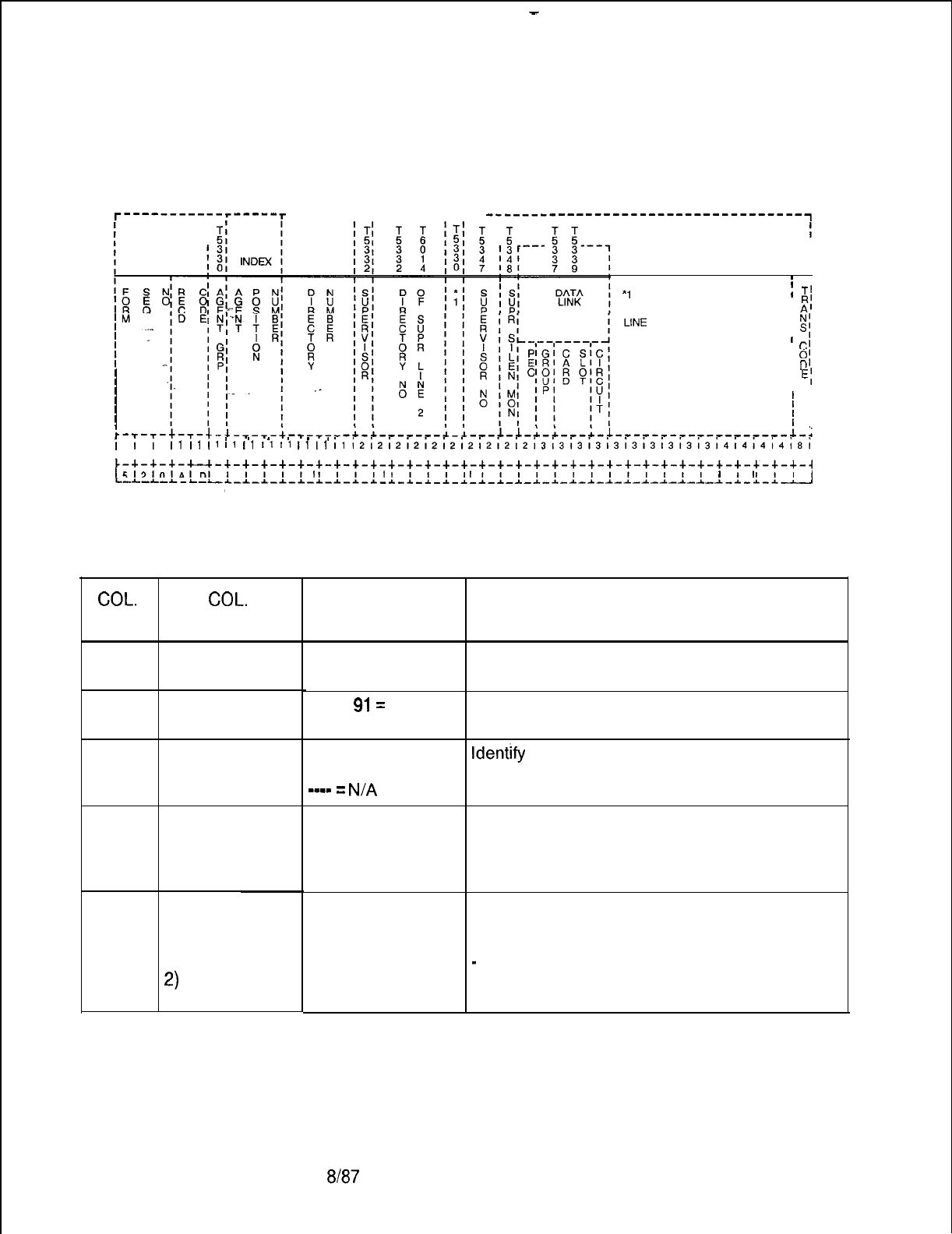
-
TL-130400-1001
Record Code AD:
16.2 Record Code AD, Figure 16.2, defines the agent position
Agent Position
data required for the CAS Main and ACD operations. The system
supports a maximum of 192 agents.
r-~~~--------r-~~~~-r
-------T-T------- -r--r--
-----------------------------------~
I
I
I
I
I
m I
*l
= ALLOW AGENT
;
T’
CALL ORIGINATION ON
I
R’
I
A’
I
N’
I
s;
I
I
C’
I
0’
I
D’
I
E;
’ I
’
I
’
I
’
I
’
I
iii’.. . . . . . . . . . . . .
I1
I1
I1
il
I1
1111
ill1
~~~~~~~~~~~~~~~~~~~~~~~~~~~~~~~~~~~~~~~~~~~~~~~~~~~~~
17181910111213141516171819101112131415161718191011121314151617181910111213101
~-+-+-+-u-+-+-+-+-+-+-+-+-+-+-+-+-+-+-+-+-+-+-+-+-+-+-+-+-+-+-+-+-+-+-+-+-~
1~131nlAlnl
I I I I I
I
I I I
t
I I I I
I
I I I I I I I I I I I I I
I
I
I
I
Figure 16.2 Record Code AD: Agent Position Data Sheet
Table 16.2 Entry Fields For Record Code AD
COL.
NO.
12
13-15
16-19
20
21-24
D-306
COL.
NAME
Agent Group
Agent Position
Number
Line Number
Supervisory
Position
(Supervisor)
Supervisor
Position
(Line Number of
Supervisor Line
2)
VALID
ENTRIES
O-7 = number
000-l
91=
number
0000-9999 =
number
--mm
=
N/A
Y = supervisory
position
N = agent position
0000-9999 =
number (right
justify 3-digit
numbers)
---- = agent
position
8187
COMMENTS
Select the agent group number for each of the
agent positions.
Select the agent position number. This field
cannot be dashed.
ldentjfy
the line number associated with the
line 1 pushbutton on all Agent Instrument
positions.
Enter Y if this Agent Instrument is used as a
supervisor position.
-The system supports a maximum of 8
supervisors.
Identify the line number for line 2 of an Agent
Instrument being used as a supervisor
position.
-
All supervisor positions are allowed a
maximum of two directory numbers.
SVR 5210
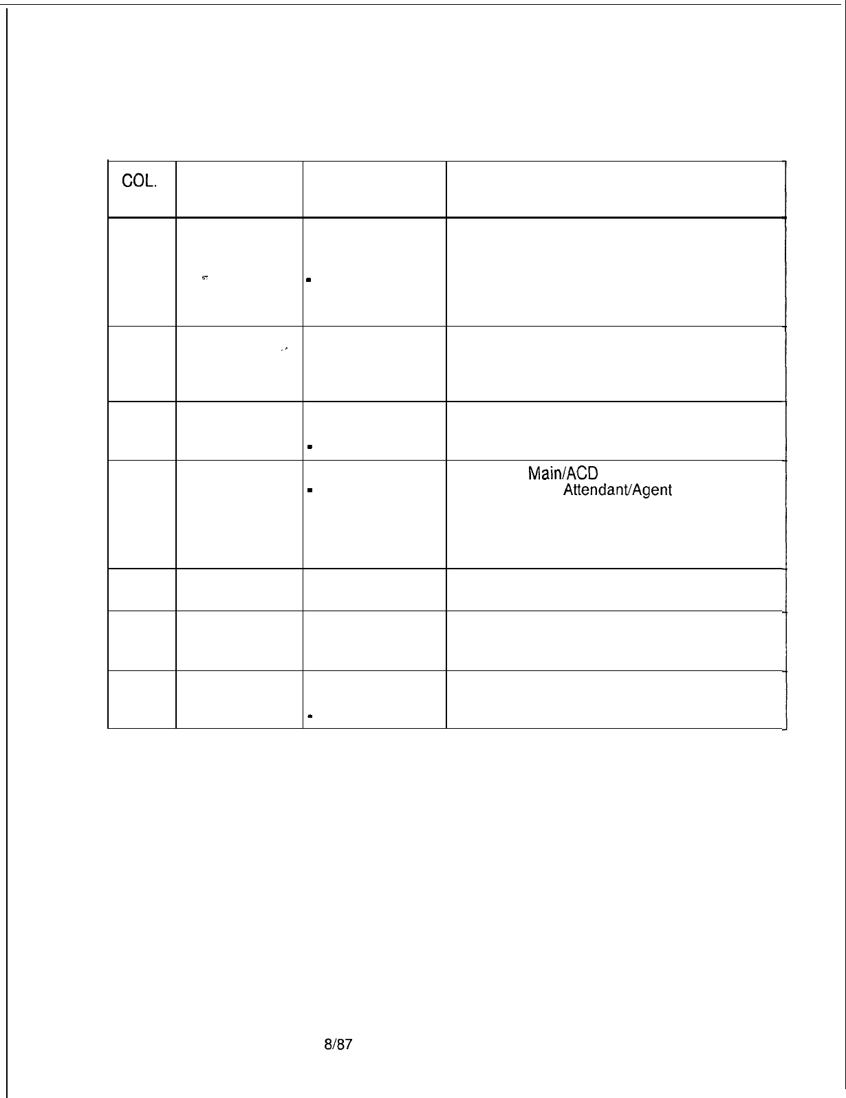
TL-130400-1001
COL.
NO.
Table 16.2 Entry Fields for Record Code AD (Continued)
COL.
VALID
NAME ENTRIES COMMENTS
25
Allow Agent to
A
= originating
Enter A if the Agent Instrument can make calls
Originate Calls calls is allowed on on line 1.
on Line 1
line 1
NOTE: An Agent Instrument can be assigned
s-
-
= originating up to two directory numbers. If two directory
. . . .
calls is not allowed numbers are assigned, it is recommended to
on line 1
disallow outgoing calls on line 1.
26-27 Supervisor
01-08 =
Indicate what supervisor number is given to
Number
‘-
supervisor number this agent.
-The system supports a maximum of 8
supervisors per system.
28
29
Supervisor
Silent Monitor
Link Card
Location:
PEC
Y = silent monitor Enter Y if the silent monitor feature can be
allowed
used.
-
= not selected -This feature is used by supervisors only.
0 = PEC number If the CAS
Main/ACD
instrument is a PACET
-
= no selection (Programmable
AttendanvAgent
Console
NOTE: Enter PEC Electronic Telephone), use an unused circuit
0.
on FB-17209 card.
-Fill in the card location here and in columns
30-33.
30
Link Card
A-D
= group
Which group (A, B, C, or D) within PEC 0 is
Location: Group number this card?
31-32
Link Card
00-l 1 =
slot
Which card slot within the group is this card?
Location: Card number
Slot
33
Link Card
O-1 = circuit
Location: Circuit number
Number
-
= no selection
Which circuit on the card is being used?
SVR 5210
8187
D-307
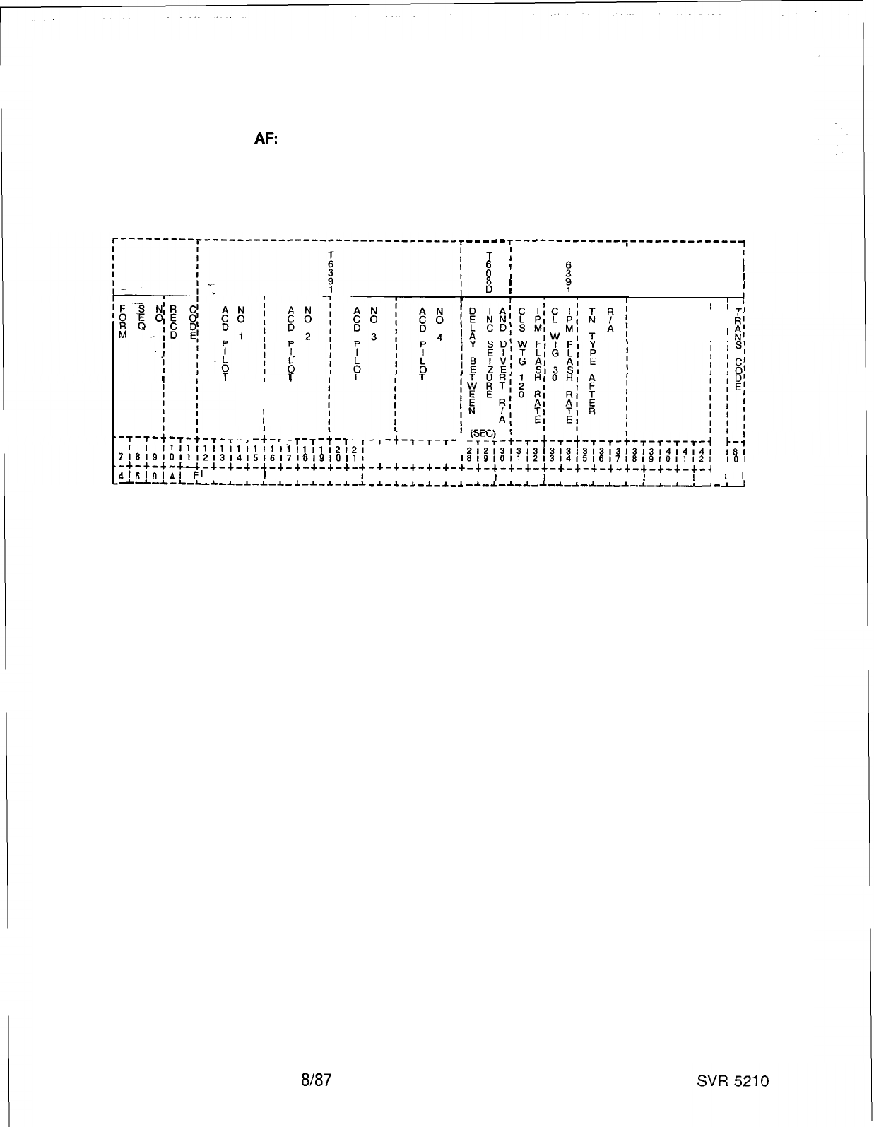
TL-130400-1001
Record Code
AF:
Limited Automatic
16.3 Record Code AF, Figure 16.3, defines the ACD trunk group
pilot number or numbers allowed access to the recorder
Call Distribution
announcer when all stations are busy. The system supports a
Feature
maximum of four ACD trunk group pilot numbers.
I
i
I
I
’
I
I
I
I
T-T-L-
II
II
11
ii
ii
il
ii
it
T
7~8~9,011121314151617
I
-+-+-+-u-+-+-+-+-+-
1
.$16lOlAl
FI
I I I
I
I
I
-L-A-&-L-LA-L-I-A-L-
.I.
8'9iOll
-+-+-+-
I I I
-a.-*-*-
Figure 16.3 Record Code AF:
-,-i-,-,-,-
21212121212
I
21314151617
-+-+-+-+-+-
:
I I I I I
I
-A.-a-A.-I-*-
.I.
--me-
r-------------,-------------~
T
:
T
II
d
III
II
B
III
1II
II
’
I
’
‘TI
I I
I I
I
I
I I
819,0,112131415161718191011121
IO1
-+-+-+-+-+-+-+-+-+-+-+-+-+-+-4
c-4
I
I
I I
I
I I I I I
I
I I
I
I
,I
-*-A-*-A-L-A.-A-A-a-A
--L--A.-
-
-
Limited Automatic Call Distribution Feature Data
Sheet
D-308 8187
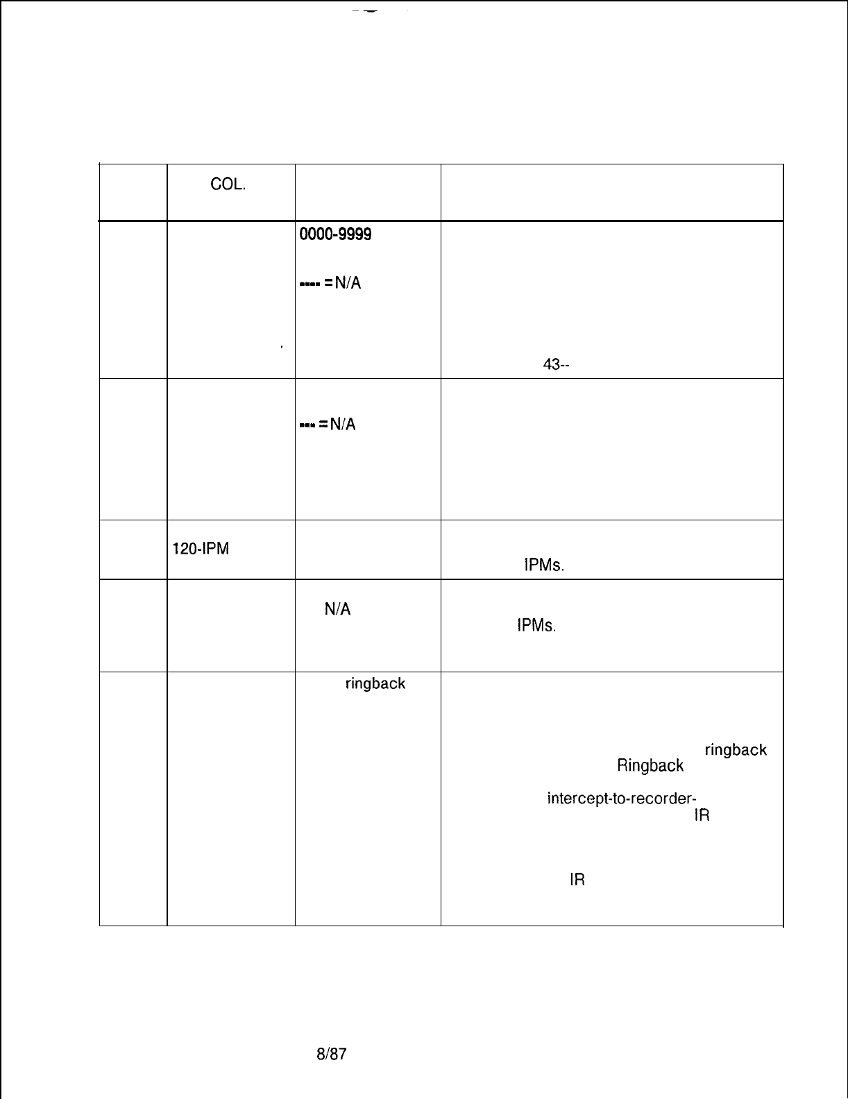
TL-130400-1001
Table 16.3
Entry Fields for Record Code AF
COL.
COL.
VALID
NO. NAME ENTRIES COMMENTS
a
12-27 Automatic Call 0000-9999 = pilot
This field determines the ACD trunk group pilot
Distribution Pilot number number (l-4) that diverts to a recorder
Numbers l-4 or 000-999 announcer message when all stations in the
m-mm
=
N/A
hunt group are busy.
. . . .
-All ACD pilot numbers must appear as a
pilot number on Record Code HG.
NOTE: The ACD pilot number fields must use
_dashes consistently (e.g., 4321 = allowed;
---- = allowed;
43--
= not allowed).
28-30
Delay Between 001-255 = When a call is in queue for the ACD group,
Incoming seconds this field determines the number of seconds a
Seizure and
m-m
=
N/A
call will wait in that queue before it is sent to
Divert to the recorder announcer message.
Recorder -If the agent does not answer the queued call
Announcer within this timing parameter, the call is
forwarded to the recorder announcer
message.
31-32
Calls Waiting 01-l 5 = number Indicate the number of calls waiting in queue
120-IPM
Flash -- = N/A before the call pressure indicator flashes at a
Rate
rate of 120
IPMs.
33-34
Calls Waiting
01-l 5 = number Indicate the number of calls waiting in queue
30-IPM Flash
-- =
N/A
before the call pressure indicator flashes at a
Rate
rate of 30
IPMs.
-This number should be less than the
number entered in columns 31-32.
35-37 Tone Type After
RBT =
ringback
Enter MQC if a caller who has heard the
Recorder tone recorder announcer message hears music on
Announcer MQC = music on hold after the message.
hold
Enter RBT if a caller who has heard the
recorder announcer message hears
ringback
tone after the message.
Ringback
tone is the
sound heard when the phone is ringing.
-To set up the
intercept-to-recorder-
announcer condition, Record Code
IR
must be
used. One predefined condition for this
application is found on Record Code IR; it is
route number 10. For intercept route number
10, Record Code
IR
must be used.
NOTE: It is recommended to send the call to
music on hold.
SVR 5210
8187
D-309
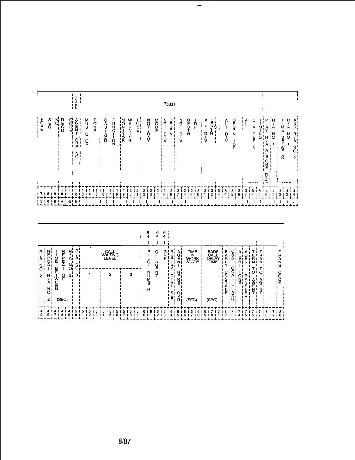
--
TL-130400-1001
Record Code AG:
16.4 Record Code AG, Figure 16.4, defines the characteristics of
Agent Group
the agent groups. The system supports a maximum of eight
agent groups.
1
I,
I.
I I I
$I;
Dl
IE
I
T5331
Ii
I
I
T5341
I
I
I
‘F
1::
IM
I
I
I
I
I
I
I
I
I
II
'G'
0
'R'
R
Ipl
I I
‘N’
i”:
I
I
I I
I I
Tf
0,
Nl
El
I
1
1~01
;
ILEI
IT
SI
ID
:I
$
f
I I
I I
I I
I I
I I
I I
I I
II
IA
;t
III I I I III I
III
I
I
I I
I I I I I I I I
‘RI
;
I
II
I I
I I I I I I I
tTl
I
L-,-t
II I I I I I
;
(SEC) E ,
;
(SEC)
’
-T-~-:-,-,-t-,-,-+-,-~-t-~-~-t-~-t-~-~-~-t-~-t-~-~-~-t-~-~-~-t-t-~-~-~
I I I
11111111l1111111111112121212121212121212131313131313131313i3t4141414141
~~~~~~~~~~~~~~~~~~~~~~~~~~~~~~~~~~~~~~~~~~~~~~~~~~~~~~~~~~~~~~~~~~~~~~~~~~~~~~
c-+-+-*-+-+-+-+-+-+-+-+-+-+-+-+-+-+-+-+-+-+-+-+-+-+-+-+-+-+-+-+-+-+-+-+-+-~
15l0l0lAi~,Oi
I I
l
l
l
I
I
l
l
l
1
I
l
l
I
I
I
I
I I I I I
I
I
I
I
,
l
I
I
I
L-*-*---L-L-~--C--C-*-~-*-~-~
-*-~-*-*-~-~-*-L-~-~-~-~-~-~-*-~-~-~-~-*-~-*-~-~-~
II
I
I T
II
TT,
I
I I
I I
I
T5341
I
II
2 2
2;
I
I I
T5331
I
I
I I
I
I2 34, I I
Figure 16.4 Record Code AG: Agent Group Data Sheet
D-31 0
8187
SVR 5210
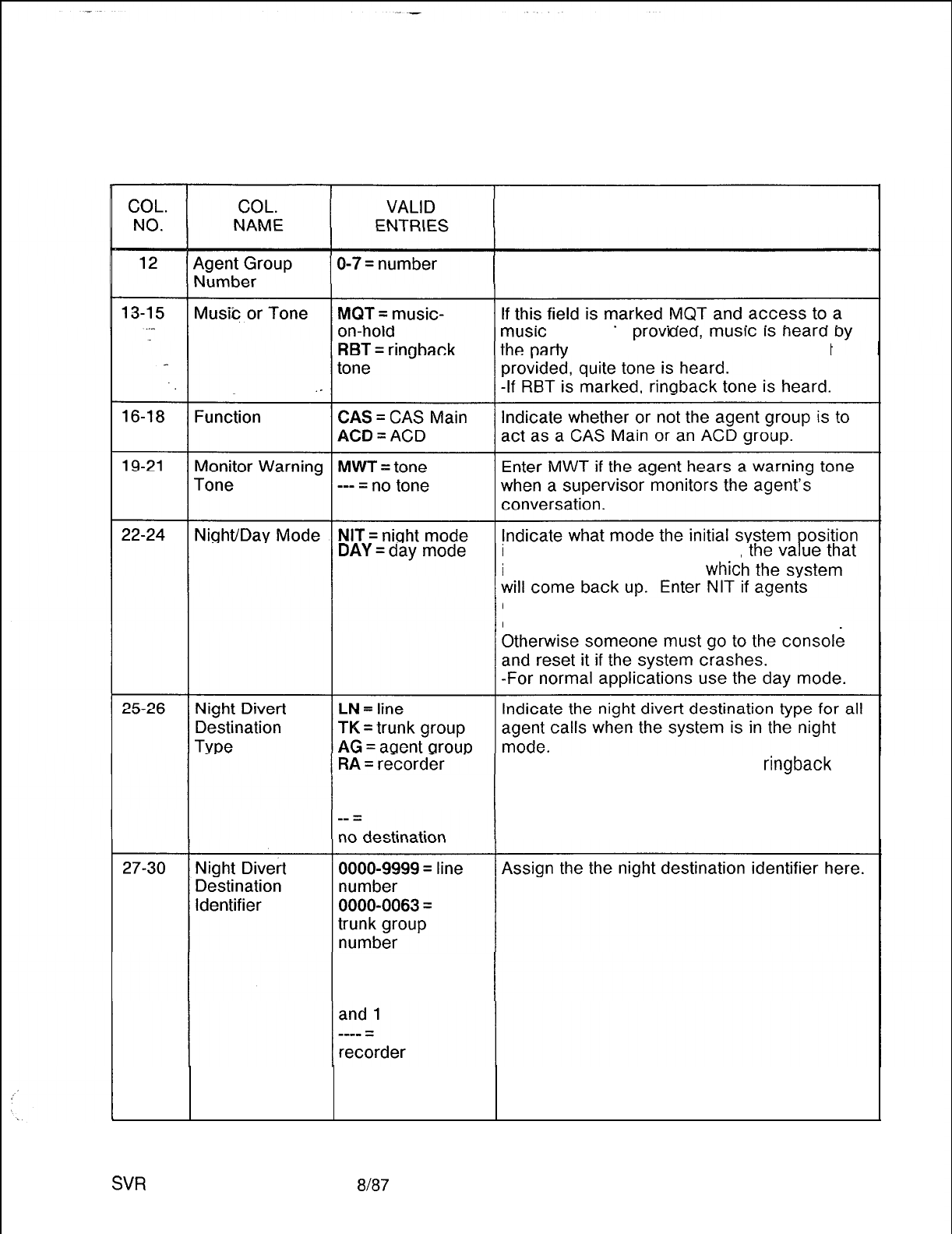
TL-130400-1001
Table 16.4
Entry Fields for Record Code AG
COMMENTS
This field determines the agent group number.
musrc
source IS
prove
on hold. If a music source is not
is in. If the system goes down,
is set here is the mode in
whit
operate 24 hours a day with no operator to
change day/mode
if the
system goes down.
announcer
AT = attendant
If -- (no destination) is used, then
ringback
tone is heard.
0128 = console
0
0064 = console 1
0192 = console
0
announcer
message played
or no divert
SW
5210
8187
D-31 1
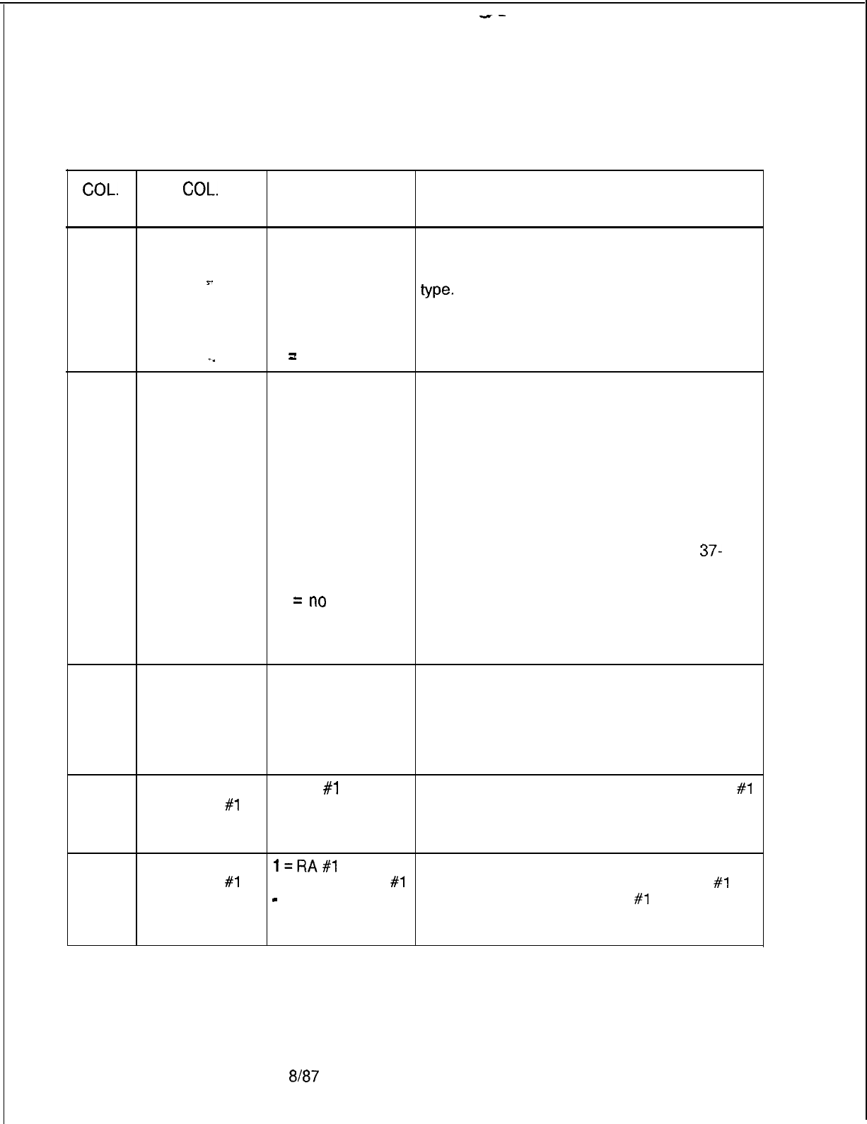
--
TL-130 400-l 001
Table 16.4
Entry Fields for Record Code AG (Continued)
COL.
COL.
VALID
NO.
NAME ENTRIES COMMENTS
31-32
Alternate Divert LN = line
If a call remains in an agent queue longer than
Destination TK = trunk group the time selected in columns 37-39, this field
AG = agent group determines the alternate divert destination
=.
RA = recorder
type.
. .
announcer -Columns 33-36 define what line, trunk or
AT = Attendant agent group, etc. the destination is.
Console NOTE: If an entry is made in this field, then an
._
--
=
no alternate entry is required in columns 33-39.
33-36
Alternate Divert
0000-9999 = line
Assign the alternate divert destination here.
Destination
number -If a line is used and three-digit numbers
Identifier
0000-0063 =
are in effect, the numbers must be right
trunk group justified.
number -If ---- (for no divert recorder announcer
0000-0007 =
message played) is used, it defaults to
agent group number 3, which is the night recording.
number -The night recording indicates that the office
0, 64, 128, or is closed.
192 = Attendant NOTE: If an entry is made in this field, then an
Console entry is required in columns 31-32 and
37-
combination
39.
number
--
zt
no
divert recorder
announcer
message played
37-39
Alternate Divert
000-225 =
Assign the number of seconds a call must wait
Destination seconds in queue before it is forwarded to the alternate
Tlming
--- = not used
divert destination.
Note: If an entry is made in this field, then an
entry is required in columns 31-32 and 33-
39.
40
Play Recorder Y = RA
#1
Indicate whether or not recorder announcer
#l
Announcer
#l
N = not used is played before the call is routed to an agent.
Before Routing -The recording will play only once.
to Agent Group
41
Recorder
Announcer
#l
l=RA#l
If a recorder announcer is played, this field
A = alternate RA
#l
determines whether recorder announcer
#I
or
-
= not used alternate recorder announcer
#1
will be
played.
-The recording will play only once.
D-31 28187
SVR 5210
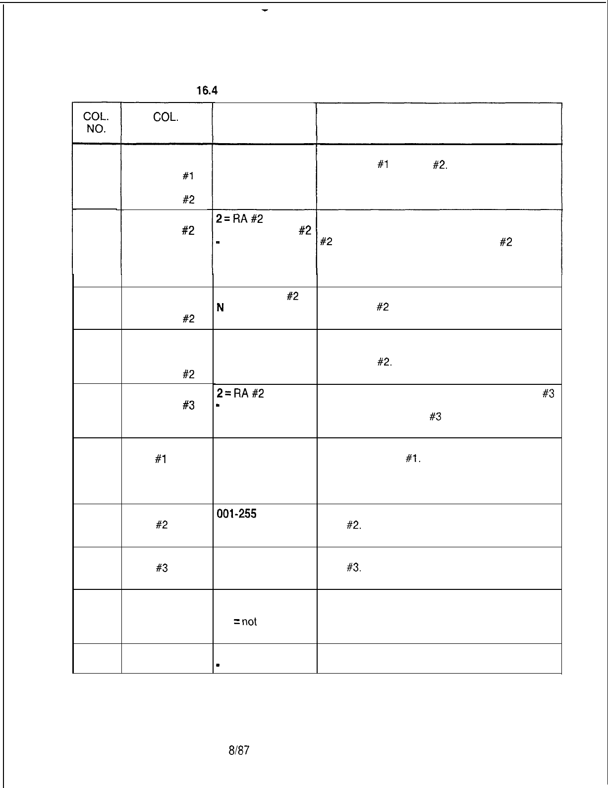
-
TL-130400-1001
Table
16.% Entry Fields for Record Code AG (Continued)
COL.
NAME VALID
ENTRIES COMMENTS
42-44
. . .
45
Time Between
Recorder
Announcer
#I
and Recorder
Announcer
#2
Recorder
Announcer
#2
001-255 =
seconds
--- = not used
Assign the number of seconds between
playing RA
#1
and RA
#2.
2=RA#2
A = alternate RA
#2
-
= not used
If a recorder announcer is to be played, this
field determines whether recorder announcer
#2
or alternate recorder announcer
#2
is
played.
-The recording is played only once unless
column 46 is marked Y.
This field determines whether or not recorder
announcer
#2
is to be repeated.
46
47-49
Repeat
Recorder
Announcer
#2
Time Between
Repeats of
Recorder
Announcer
#2
Y = repeat RA
#2
N
= not used
001-255 =
seconds
--- = not used
This field determines the number of seconds
between playing the repeats of recorder
announcer
#2.
Recorder
Announcer
#3
50
51-53
2=RA#2
Indicate whether or not recorder announcer
#3
-
= not used is played.
-Recorder announcer
#3
is used for the night
recording.
Call Waiting
Level
#l
001-255 = number
of calls
--- = not used
This field determines the number of calls for
call waiting level
#l.
-This feature is the light on the Agent
Instrument that indicates the number of calls in
queue.
Assign the number of calls for call waiting
level
#2.
54-56
Call Waiting
Level
#2 001-255
= number
of calls
--- = not used
57-59
Call Waiting
Level
#3
Assign the number of calls for call waiting
level
#3.
001-255 = number
of calls
--- = not used
0000-9999 = line
number
----
=
not
used
60-63
Pilot Number of
Agent Group Identify the pilot number of the agent group.
-Three-digit numbers should be right
justified.
64
Repertory Dial
O-3 = number
The system can support only four instruments,
Set
-
= not used with this feature.
SVR 5210
8167 D-31 3
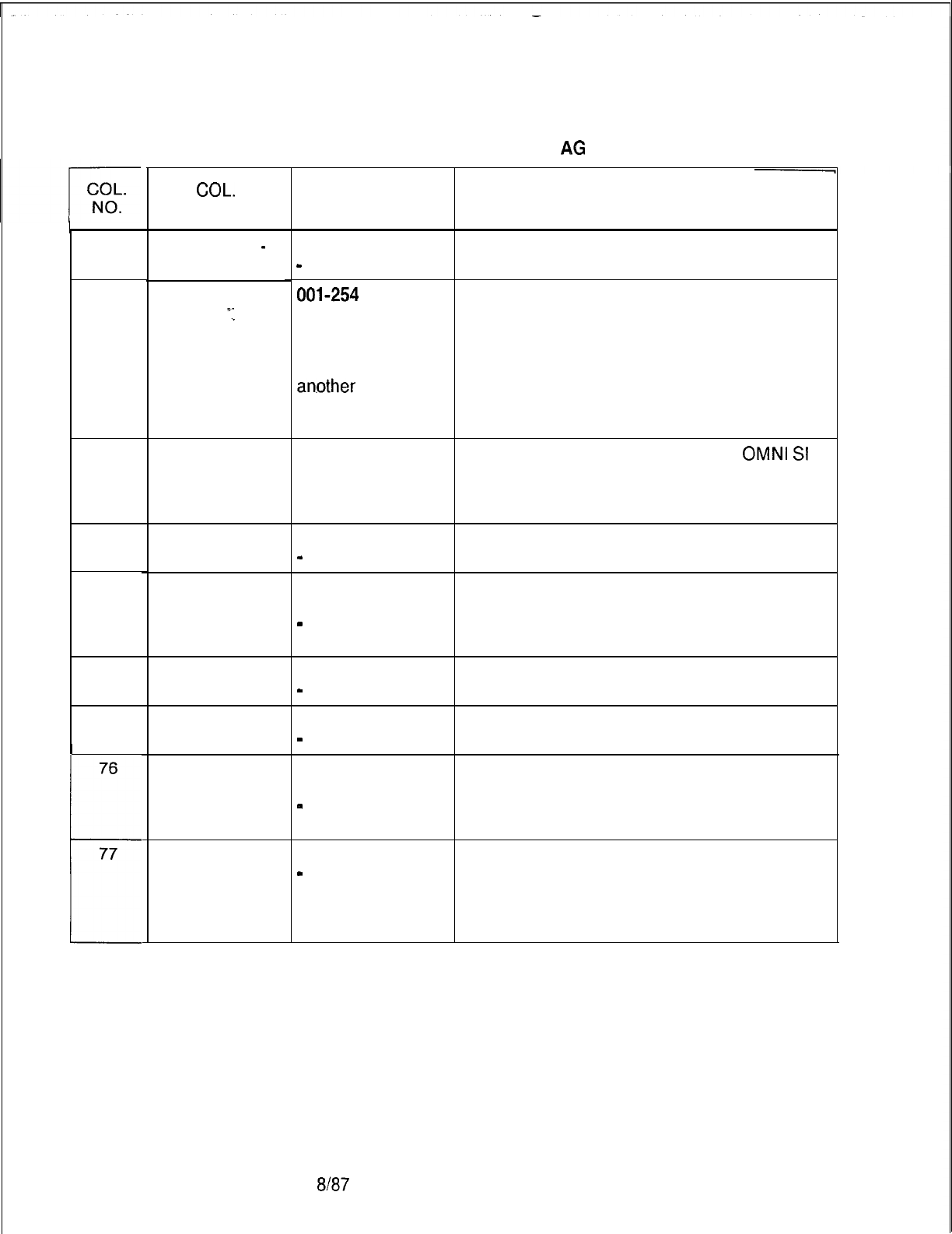
TL-130400-1001
65
66-68
69-71
72
73
74
75
76
b
77
D-31 4
Table 16.4 Entry Fields for Record Code
AG
(Continued)
COL.
NAME
Agent Hands
-
Free Operation
Time in Work
State
‘I
Force
Administration
Data System
Call Delay Time
Early Unstaff
CAS Local
Flash
Alert Tone
Agent Transfer
Terminate to
Agent
Line/Attendant
Transfer to
Agent Line 1
VALID
ENTRIES
Y = used
-
= not used
001-254 =
seconds
INF = infinite time
(as much time as
is needed before
an.other
call
comes in)
--- = not used
--- = only
allowed entry
E = early unstaffed
-
= not allowed
M = CAS Main or
ACD
-
= CAS Branch
(default)
M = CAS Main
-
= CAS Branch
X = agent transfer
-
= not allowed
T = terminate to
agent
-
= not allowed
X = allowed
-
= not allowed
COMMENTS
This field determines whether or not the agent
is allowed hands-free operation.
Enter the time allowed for the agent to be in
the work state.
-When the agent is in the work’state, calls
are not sent to the agent’s telephone.
-This gives the agent time to complete
necessary paper work before another call
comes in.
This feature is not supported by the
OMNI
Sl
and must be dashed.
If an IFP is used, the feature is built in.
-This feature acts like forward busy.
Enter M if a relay flash is allowed to the CAS
Main or the CAS Branch.
Enter M if a alerting tone is provided by the
CAS Main or the CAS Branch.
Enter X if the agent is allowed to transfer calls.
This field determines whether or not the agent
is allowed to receive transferred calls.
-If a T is marked, then the agent is allowed to
receive in-house calls.
This field determines whether or not the agent
is allowed to receive transferred attendant or
line calls on line 1.
-If an X is marked, then the agent is allowed
to receive transferred external calls.
8187
SVR 5210
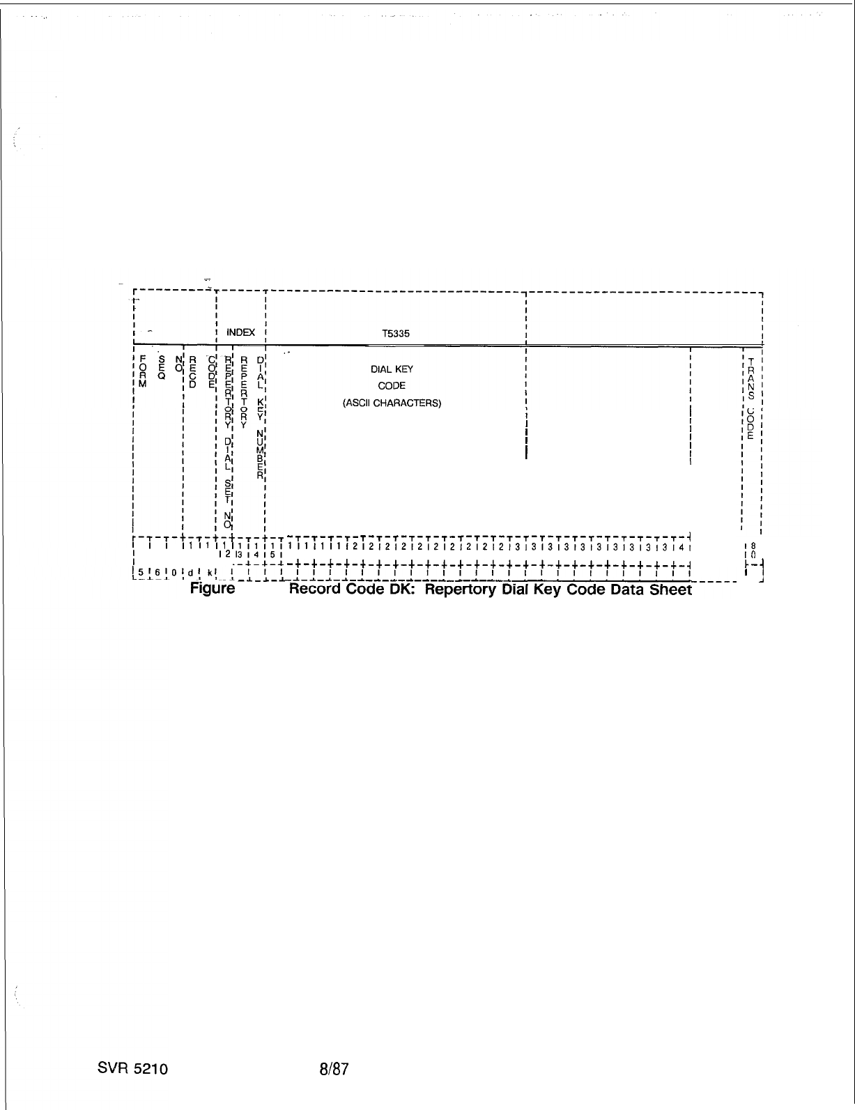
TL-130400-1001
Record Code DK:
Repertory Dial Key Code
16.5 Record Code DK, Figure 16.5, defines the set of repertory
dial numbers that can be assigned to agent groups. The
maximum number of entries for each repertory dial set is 17,
corresponding to the repertory dial keys on the CAS Main
instrument. If the agent group is ACD, the maximum number of
code entries is 16. One entry should be made for each agent
group. Use one record for each repertory dial number in each of
the sets.
I1
I1
I1
I
1718191011
I21
c-+-+-+-u-+
-.I._*-.A
16.5
i
I
II
II
I1
II
II
II
I
I
II
II
II
I
I
II
II
I
I
-T-T-T-T- T-T-T-T-T-T-
T-T-T-T-T-T-T-T-T-T-~-~-~-~-i
11111111212121212121212121213131313131313131313l41
6171819101112131415161718191011121314151617181910,
-+-+-+-+-+-+-+-+-+-+-+-+-+-+-+-+-+-+-+-+-+-+-+-+-~
8l87
r-1
18
I
IO
I
k-i
’
J
.A-
D-315
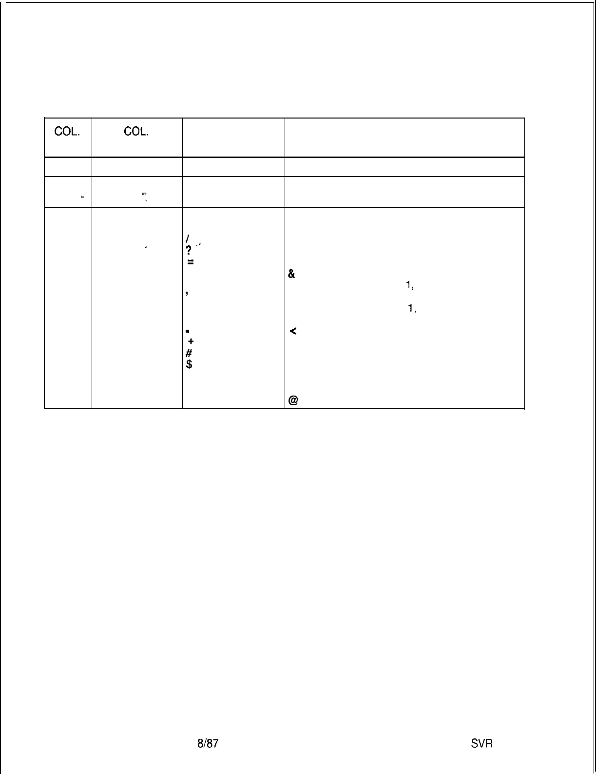
TL-130400-1001
COL.
NO.
Table 16.5 Entry Field for Record Code
DK
COL.
VALID
NAME ENTRIES COMMENTS
12
Set Number
O-3 = number
This field determines the set used.
13-14
Repeat Dial Key 00-l 6 = number
-
Number
“I
This field determines the repertory dial key.
15-30
Dial Key Code
A-Z
Indicate the repertory dial key characters
o-9
assigned to the indicated dial key.
I
-Each dial key code can be 16 characters.
_
?
‘-
NOTE: The following seven ASCII characters
=
can also be entered in the dial key code:
.
&
= pause
*
9
(= in character position
1,
repertory dial key
applies to line 1
.
.
.
,
w
#’
) = in character position
1,
repertory dial key
applies to line 2
<
= in character position 1, auto connect to
line 2 auto disconnect line 2; if active, enter
line 1 on hold
$
>=in character position 1, auto connect to
and
blank=
line 2 and enter line 1 on hold
allowable entries % = hookswitch flash
@
= release
8187
SW
5210
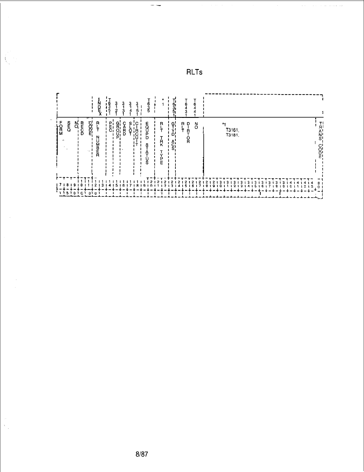
TL-130400-1001
Record Code RC:
Release
Link
16.6 Record Code RC, Figure 16.6, defines the trunk
Trunk Circuit
characteristics associated with the CAS (Centralized Answering
Service) Branch
RLTs
(Release Link Trunks).
---------r---r-------------~--- T-T-------T
. .
---------------------------------~
I-
fI
1
;T
T T T T
I
Ti;
i
I
I
1;163333
11
I
II
E
$
:
;
II
;I
5
II
I
I
x
11
11111
1,
I
II
I
’
I
*1
)
T'
f
T3161,
T3171, I
R’
I
T3181,
T3191
I
I
II
I
I
I
:-T-T-t-T-t-
T-t-t-t-T-t-t-
I
I I I
T-t-T-t-t-T-T-T-t-T-T-T-T-f-T-T-T-T-T-T-T-T-T-T-T-
~~~~~~~~~~~~~~~~~~~~~~~~~~~~~~~~~~~~~~~~~~~~~~~~~~~~~~~~~~~~~~~~~~~~
t
171819101112131415161718191011,2131415161718191011121314151617181910111213
I
~-+-+-+-c-c-+-+-+-+-+-+-+-+-+-+-+-+-+-+-+-+-+-+-+-+-+-+-+-+-+-+-+-+-+-+-+-
I
L
115lOlcIOIOI
I I I I I I I I
I
I I I I
+
-L-L-I-~-L-*-~-~-I-~-~-~-~-~-*-~-~-~-*-~-~
I I I I I I I
I
I I
I
I I I I
-~^*-~-~-*-~-~-~-I-~-~-~-~-~-~-
I
Figure 16.6 Record Code RC: Release Link Trunk Circuit Data Sheet
SVR 5210
8l87 D-31 7
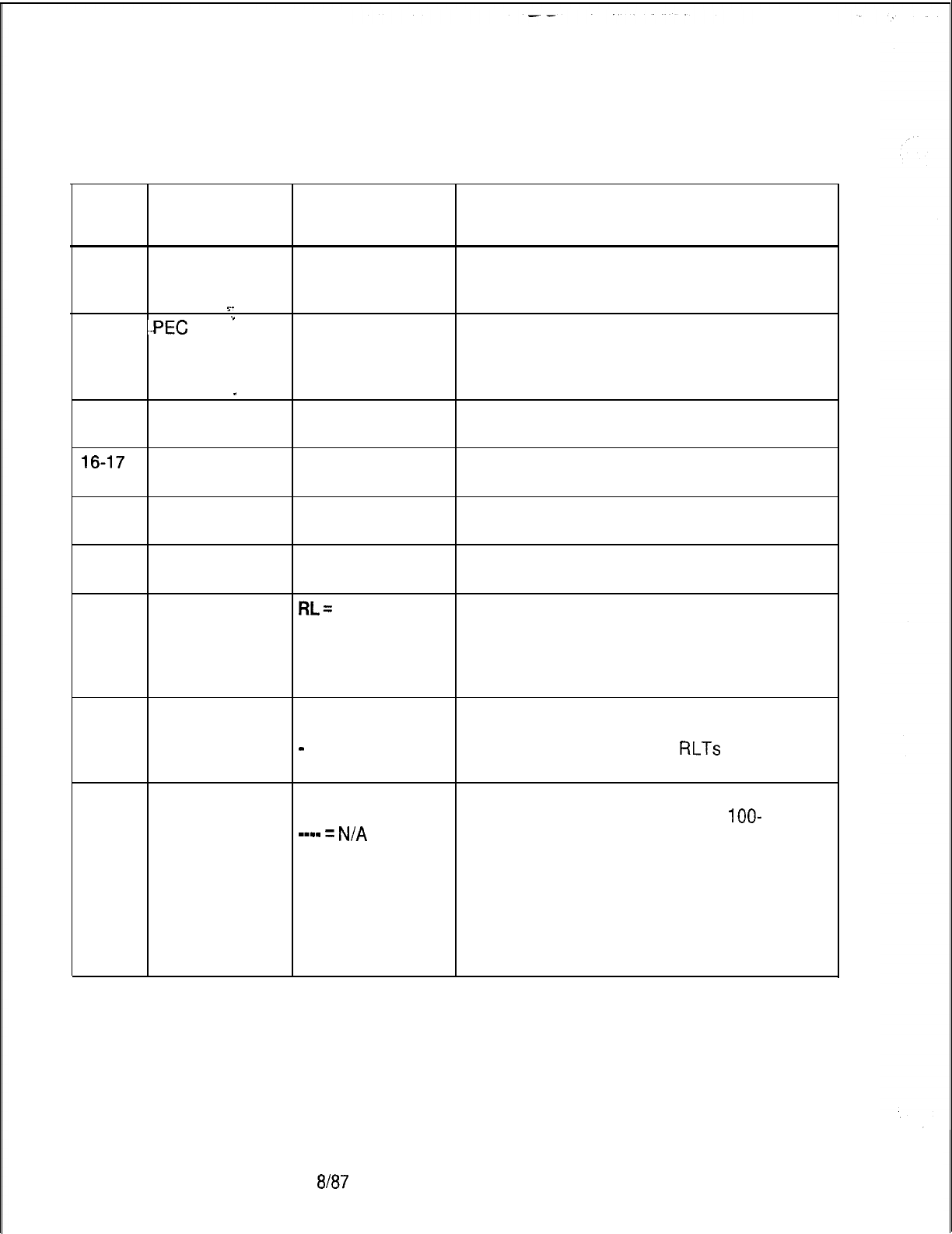
TL-130400-1001
COL.
NO.
Table 16.6 Entry Field for Record Code RC
COL.
VALID
NAME ENTRIES COMMENTS
12-13
Release Link
00-l
5 = number
Trunk Number The release link trunk number must be unique
across this record code. Each RLT number
.=_
must be unique across this form.
14 --PEC
.*
0 = PEC number Enter PEC 0.
-The physical location for each RLT must be
unique.
.-The card used is a double-width card.
_
15
Group
A-D
= group
Which group (A, B, C, or D) within PEC 0 is
number this card?
16-17
Card Slot
00-l 1 =
slot
Which card slot within the group is this card?
number
18
Circuit Number
O-3 = assigned
Which circuit on the card is being used?
circuit number
19-20
Equipped Status IS = in service Is the card in service or out of service?
OS = out of service
21-22
Release Link
RL=
RLT card type Assign the card type used to support this
Trunk Type on Record Code
trunk.
FR
-If an FB-17251 card is used, enter RL.
EM
= ERLT type on
-If an FB-17201 card is used, enter EM.
Record Code FR
23
Guaranteed
Access Y = required (CAS Enter Y if the system guarantees a time slot
Main) for the RLT circuits.
-
= not required -It is recommended to give
RLTs
guaranteed
access.
24-27
Release Link
0000-9999 =
Indicate the directory number assigned for
Trunk Directory number each RLT that provides a special
lOO-
Test Number
-m-e
=
N/A
millisecond tone to alert the agent that this is a
test call.
-When entering three-digit numbers, leave
column 24 blank before entering the digits.
NOTE: It is recommended that each branch
have a test line. Due to the high cost of the
RLT, this trunk should be tested daily for
malfunctions.
D-31 8
8187
SVR 5210
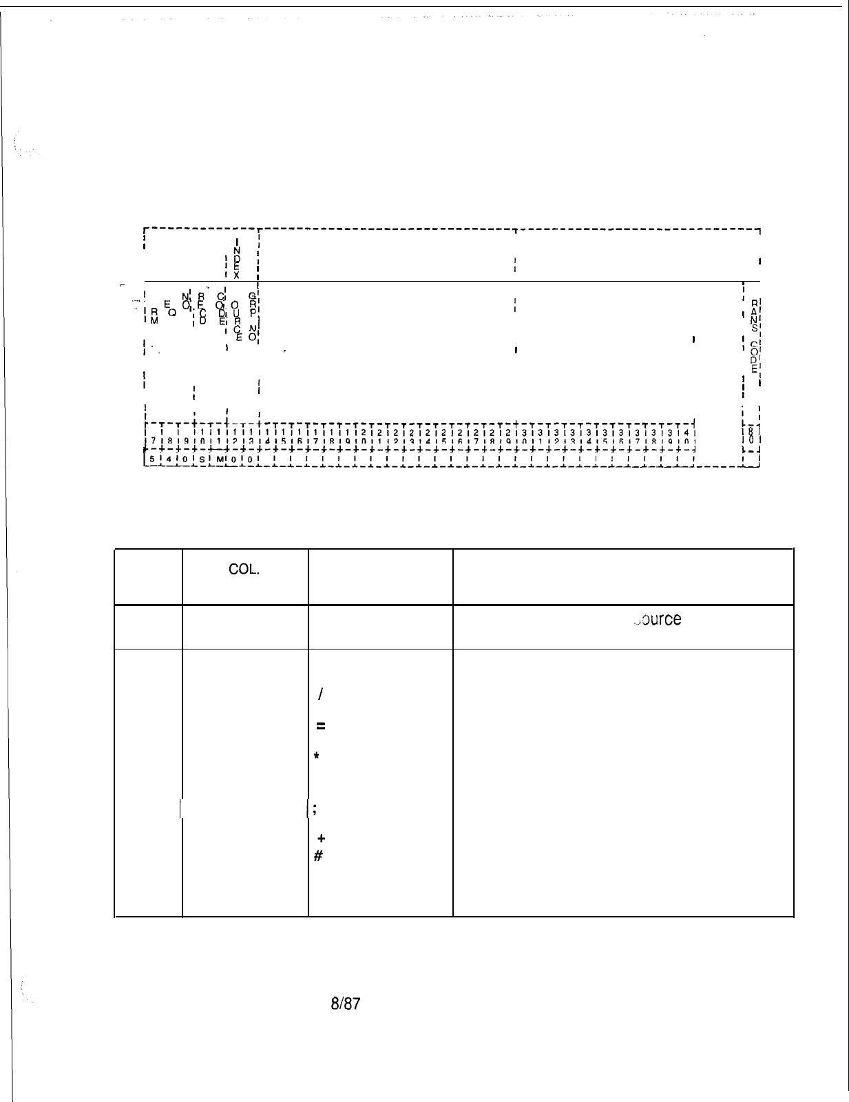
TL-130400-1001
Record Code SM:
16.7 Record Code SM, Figure 16.7, defines the message that
Source Messages
appears in the LCD (Liquid Crystal Display) of the agent’s
instrument. These messages are displayed when a call from a
source group is routed to an agent.
T----------‘--r-------------------------------~-----------------------------~
I
’
II I
I I
I
12
;I I
I
r:
;
T5333
III
I
I
__
I I
-
I
I
.._.I
F S
N;
R’”
C;
S
G’
II
m I
‘0
E
O’E
010
RI MESSAGE
I
I
I
;
T’
-1;
0
\C
DIU
P,
(ASCII CHARACTERS)
I
I
R’
,D
EIR
III
A’
I-
IC
N’
I
II
N’
I
I
..
I
I
E
0;
II
I
s;
III
III
C’
I
I I
I_I
I I I
I
0’
IIIII
I
D’
fIIIII
II I
I
El
IIII
III
’
I
I I
’
I
III
’
I
IIIIIII
I
r-T-T-t-T-+-L
II
‘T-s-r-T-T-T-T-T-r-T-T-T-T-T-T-t-T-T-T-T-T-T-T-T-T-T-i
I1
I1
II
I1
I1
I1
11
I1
I1
I1
1212121212121212121213131313131313131313l4l
~7:8~9,0,112,31415,6171819101112,314151617181910111213141516171819101
I81
IO1
c-+-+-+-u-+-+-+-+-+-+-+-+-+-+-+-+-+-+-+-+-+-+-+-+-+-+-+-+-+-+-+-+-~
Figure 16.7 Record Code SM: Source Messages
Data
Sheet
Table 16.7 Entry Field for Record Code SM
COL. COL. VALID
NO. NAME ENTRIES COMMENTS
12-13
Source Group 00-31 = number This field determines the
..5xxce
group
Number number.
14-29 Message A-Z This field determines the source message up
o-9
to 16 characters long.
I
?
=
.
*
,
#’
&
and
blank=
allowable entries
SVR 5210
8187
D-31 9
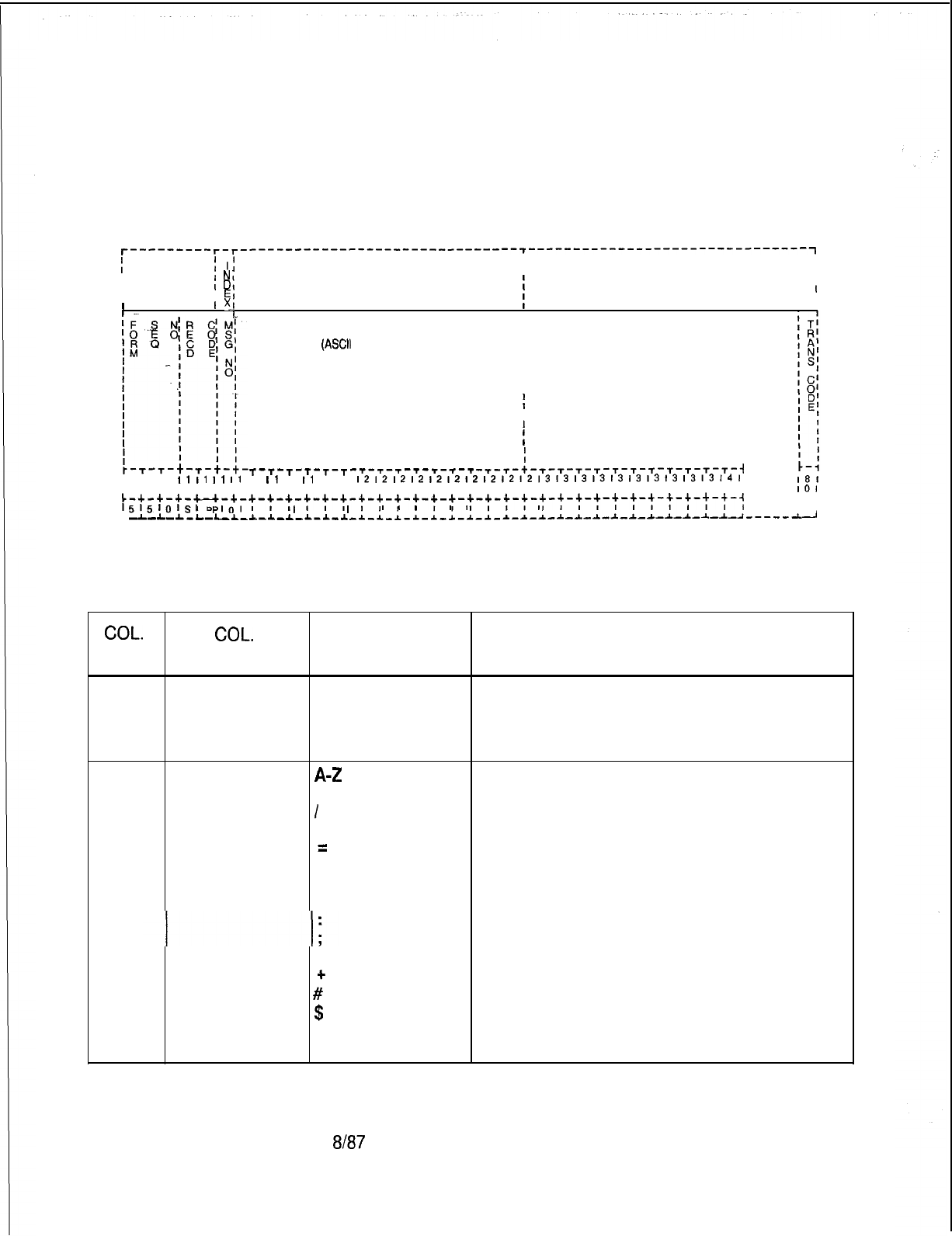
TL-130400-1001
Record Code SP:
16.8 Record Code SP, Figure 16.8, defines selected messages
Special Messages
that a supervisor can send to an agent. The system supports a
maximum of eight messages.
r---------r-r------‘------------------------~-------------------------------~
fI
1:
II
I
Nl
II
t
Dl
I
I
I
T5334
I
I
EI
I
I’
?.!
II
I
I
III
MESSAGE
I
II
(ASCtl
CHARACTERS)
II
II
II
II
II
II
II
I
II
1
I
II
I
II
I
T-t-T-T-T-T-T-T-T-T-T-T-T
-r-r-t-r-T-T-T-T-T-T-T-T-T-T-i
I1
I1
I1
I1
11
I1
11
I1
11 11
1212121212121212121213131313131313131313l4l
~7~6~9101112131415161718191011121314151617181910111213141516171819101
181
101
c-+-+-+-u-+-+-+-+-+-+-+-+-+-+-+-+-+-+-+-+-+-+-+-+-+-+-+-+-~-+-+-+-~
C-4
L
51510151
PI01
I I
I
I I
I
I
I
I
I
I
I
I
I I I
I
I I I I I I
I
I I II I
--L-L-~-L-L-*-~-I-~-~-~ -1-~-1-1-~-~-1-*-~-~-*-~-*-~-~-*-~-~-~-~-*-~-----~
Figure 16.8 Record Code SP: Special Messages Data Sheet
COL.
NO.
Table 16.8 Entry Fields for Record Code SP
COL.
VALID
NAME ENTRIES COMMENTS
12
Message
O-7 = number
This field determines the number assigned to
Number the message.
-This number is used by the system for
identification purposes.
13-28
Message
A-Z
This field determines the special message that
o-9
will appear on the agent’s instrument.
I
-This message can be up to 16 characters
?long.
=
.
*
,
#’
$
and
blank=
allowable entries
D-320 8187
SVR 5210
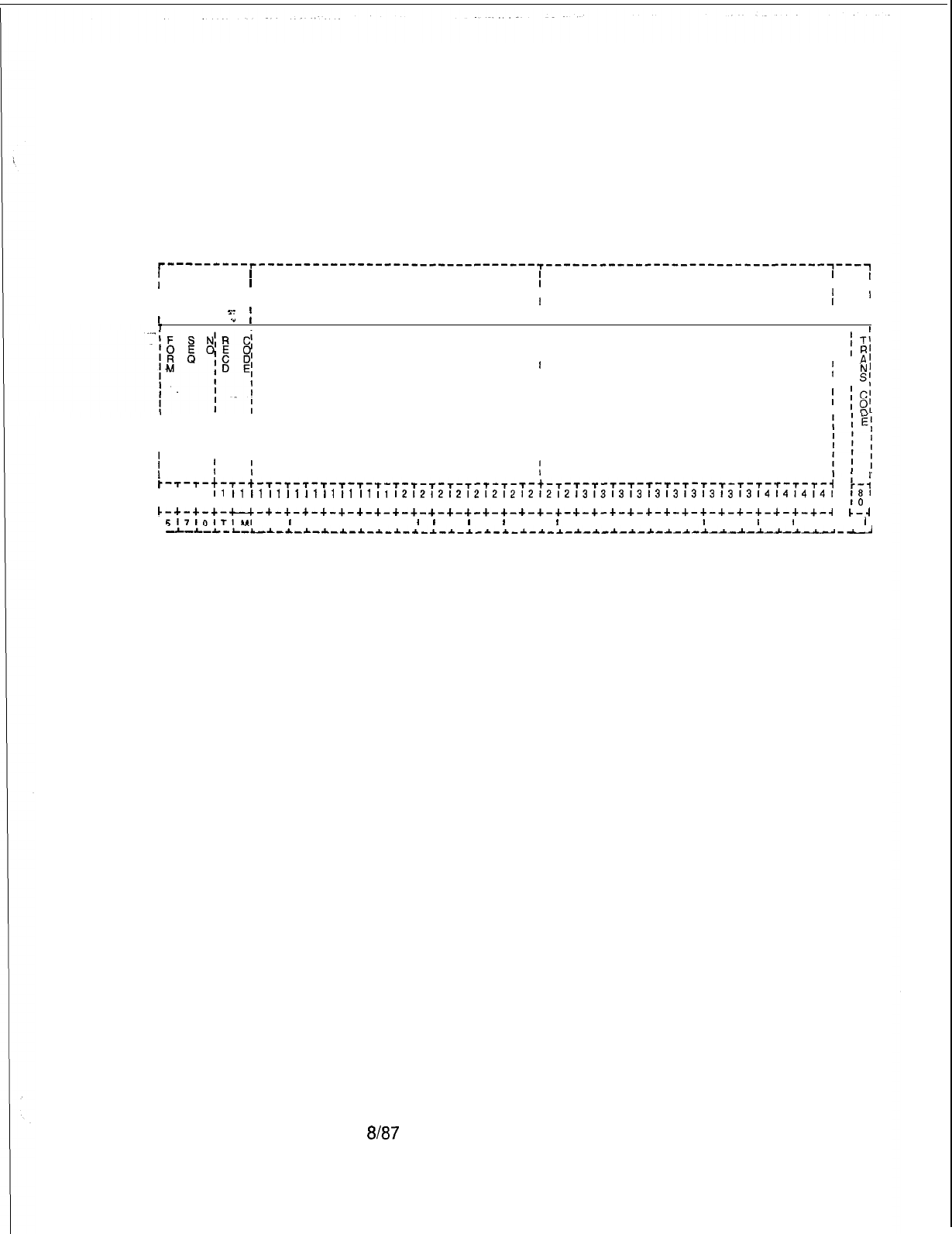
TL-130400-1001
Record Code TM:
16.9 Record Code TM, Figure 16.9, defines the supervisor’s
Supervisor Talk/Monitor
repertory dial key code (one maximum). This table has been
Repertory Dial
expanded to collect key codes for the silent monitor feature.
Key Code
T-----‘---r-------------------------------~-------------------------------~---~
i
I I I I
I I
II
IIII
I
II
T5336
t
T5349
I
I
I
s-
fI I I
L
.”
I I I
I I
I .
I
SUPERVISOR’S DIAL
KEY CODE
(ASCII CHARACTERS)
i
I
SUPERVISOR’S SILENT
i
IT;
I
I;
R’
I
MONITOR DIAL KEY CODE
I
A’
II
I
N’
I
(ASCII CHARACTERS)
I
I
s;
I
I
;
IC’
I
I
Is?1
i
III
III I
III I
III
III I
III I
~-r-T-t-T-t-T-T-T-T-r-T-t-T-T-T-T-T-T-T-T-t-r-r-T-r-r-~-r-r-r-~-r-r-T-r-r-i
:-:
I1
I1
I1
I1
I1
I1
I1
11
I1
II
1212121212121212121213131313131313131313l4l4l4l4l
~7~8~9~0~11213141516~7181910~1121314151617181910111213141516171819101112131
I81
IO
I
c-~-+-+-u-+-+-~-+-+-+-+-+-+-+-+-+-+-+-+-+-+-+-+-+-+-+-+-+-+-+-+-+-+-+-+-~
&-.I
L
517lOlTI~I
I
I
I I I I I I
I
I
I
I
I
I
I I
I
I I I I I I : 1 I I
I
I
I
I I I
i
-L-L-L-L--*-*-~-~^-~-~-~-~-~-~-~_~-~--C-*-~-*-*-~-*-~-~-~-~-~-~-~-~-~-~--~
Figure 16.9 Record Code TM: Supervisor Talk/Monitor Repertory Dial Key Code Data
Sheet
SVR 5210
8187
D-321
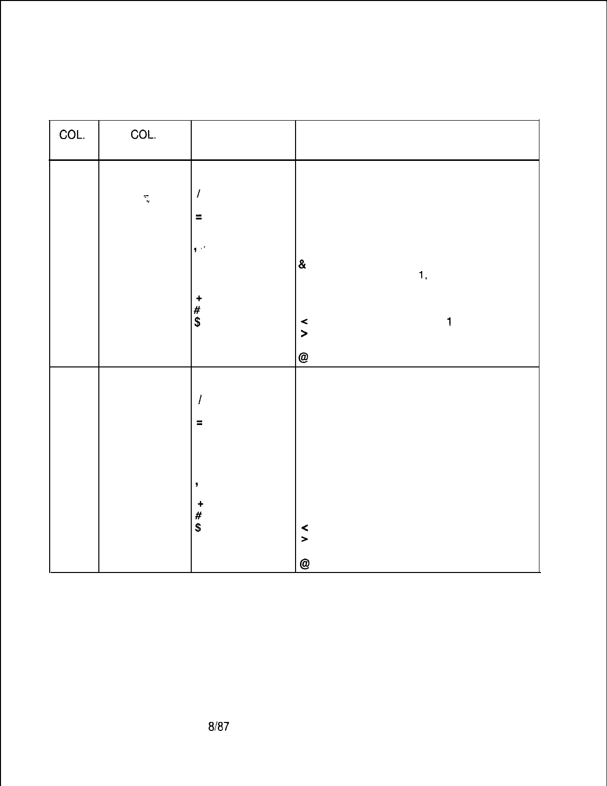
TL-130400-1001
Table 16.9
Entry Fields for Record Code TM
COL.
COL.
VALID
NO.
NAME ENTRIES COMMENTS
12-27
Supervisor’s A-Z This field determines the supervisor’s dial
Dial Key Code
O-9
repertory key code assigned to the
x-
I
supervisor’s talk monitor dial key. The dial
.”
?
key code can be a maximum of 16
=
characters.
.
NOTE: The following special ASCII characters
*
can also be used as entries in the
I
‘.
supervisor’s dial key code:
.
.
&
= pause
.
,
(= in character position
1,
repertory dial key
applies to line 1
?i
) = in character position 1, repertory dial key
applies to line 1
$
-z
= in character position line
1
and blank=
>
= in character position line 2
allowable entries % = hookswitch flash
@
= release
28-43
Supervisor’s A-Z This field determines the supervisor’s dial
Silent Monitor O-9 repertory key code assigned to the
Dial Key Code
/
supervisor’s silent monitor dial key. The dial
?
key code can be a maximum of 16
=
characters.
.
NOTE: The following special ASCII characters
*can also be used as entries in the
,
supervisor’s dial key code:
..
& = pause
.
I
(= in character position 1, repertory dial key
applies to line 1
#’
) = in character position 1, repertory dial key
applies to line 1
$
<
= in character position line 1
and blank=
>
= in character position line 2
allowable entries % = hookswitch flash
@
= release
D-322
8187
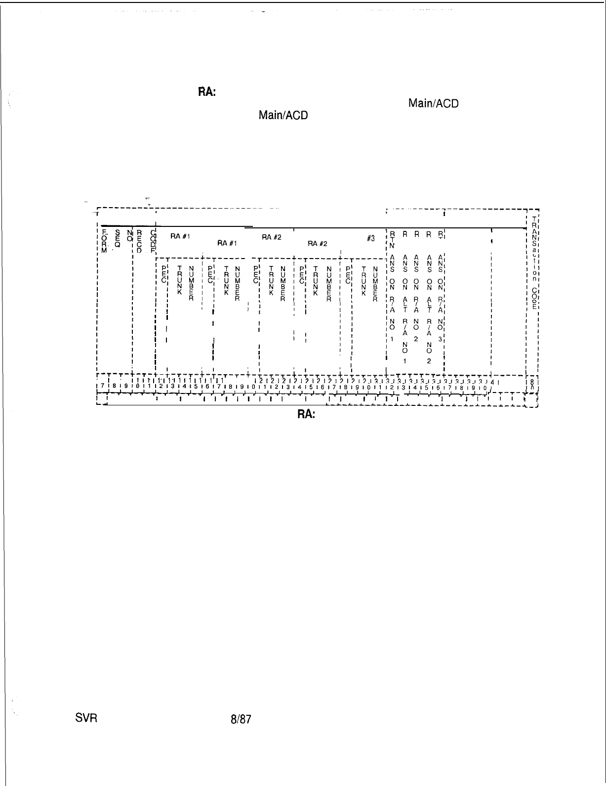
TL-130400-1001
Record Code
FM:
Recorder Announcer
16.10 Record Code RA, Figure 16.10, defines the recorder
announcer locations used for CAS
Main/ACD
functions. The
CAS
Main/ACD
feature supports up to five dedicated recorder
announcers; however, only three recorder announcers can be
used per agent group. One of these is used as a night
recording. The night recording advises that the “office is closed,
please call again.”
.-i.
I
-I
I
RA#l
;ALT
,
Fa#l
t
I
’
I
I
I
I ’ I
’
I
’ I ’ I
’ I ’
I
’ I
’
I
’ I ’ I ’ I
1 I
1
I
’ 1
I
I
I ’
I
; I
I
;
’
I
’ 1’
I
’ I
’ I
1 I
iI
1 I ’ I ’ I
’ I ;
;
’
1
I
2
f
1;
I
I
r’T-,-t-,-+-:-,-,-t-~-~-~-t-~-~-~-t-~-~-~-t-~-~-~-
L
’
I
I
l
I
T-T-T-T
-+-T-T-T-j
-----I,-;
I1
I1
I1
II
I1
I1
I1
I1
I1
11
l212121212121212121213131313131313131313l41
~~~~~~~~~~~~~~~~~~~~~~~~~~~~~~~~~~~~~~~~~~~~~~~~~~~~~~~~~~~~~~~~~~~~~
18,
L4-&-~
.’
.’
*’
,’
.’
w
>I
,I
.I
.I
.I
&
,I
.I
,I
,I
.I
*
IO,
;I
I I I
I
I
I
I
I
I
I
I
I
I
I
I
I
I
I
I
I
,
I
I
I
I
I I I
I
I
I
1
I-;-;-t-j
.
C-~-~-L-~-L-~-L-~-~-~-~-~-~-~-~-~-~-,
Figure
16.10
Record Code
RA:
Recorder Announcer Data Sheet
T5345
I
I
I
T5345
I
I
II
III
/
RA#2
1ALT /RA
#3
;R
R
R
R
R;
,T
T T T T,
I
I,
RA#2
,
I
,N
N N N N, 1
I
I
i
I
SW
5210
8187
D-323
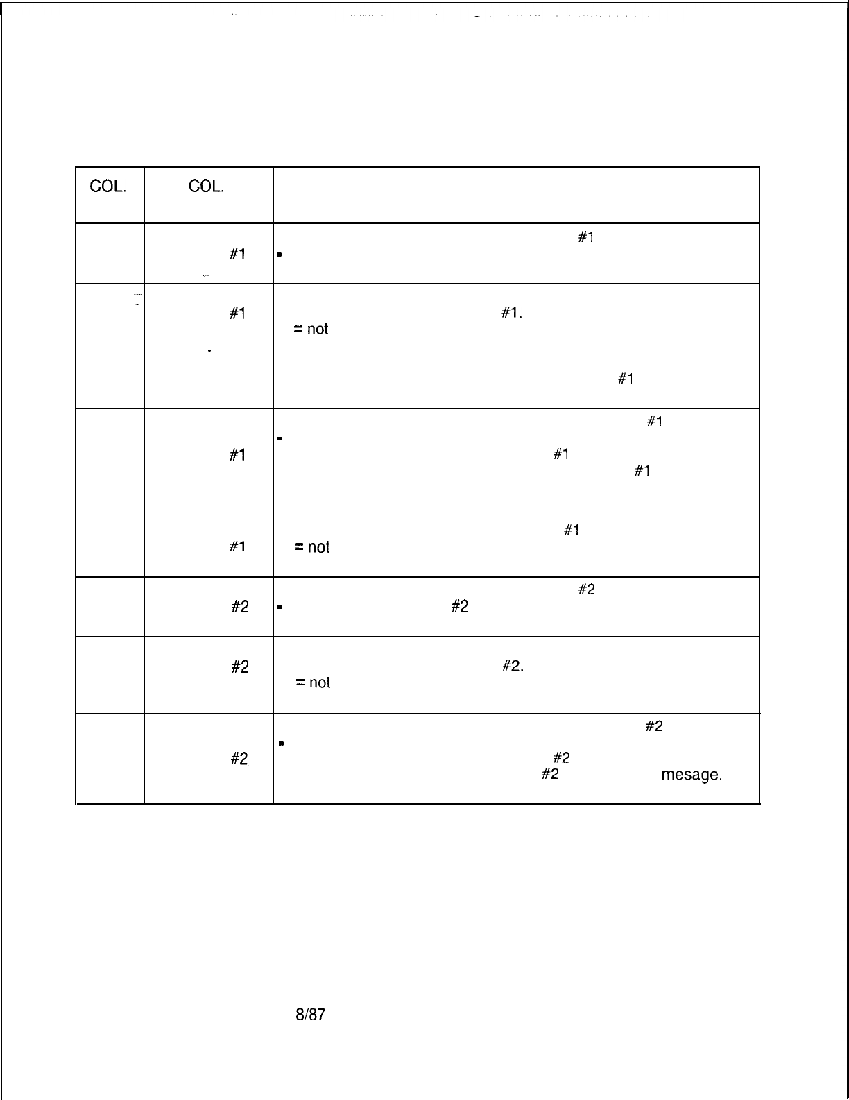
TL-130400-1001
COL.
NO.
Table 16.10
Entry Fields For Record Code RA
COL.
VALID
NAME ENTRIES COMMENTS
12
Recorder O=PECO If recorder announcer
#1
is used, enter 0.
Announcer
#l
-
= not selected
PEC
~.
13-15
_’
Recorder
000-063 = trunk
Identify the trunk used in support of recorder
Announcer
#l
number announcer
#l.
-Trunk Number --
=
not
-This recording is normally used to inform
_
selected incoming calls that no agents are available to
answer the call because all agents are busy.
-Some applications use RA
#l
to provide
other information as well.
16
Alternate O=PECO If alternate recorder announcer
#1
is used,
Recorder
-
= not selected
enter 0.
Announcer
#l
-The alternate RA
#l
can provide the same
PEC or a different message as RA
#1
and provide
additional access.
17-19
Alternate 000-063 = trunk Identify the trunk used in support of alternate
Recorder number recorder announcer
#l
.
Announcer
#l
--
=
not
Trunk Number selected
20
Recorder O=PEC 0If recorder announcer
#2
is used, enter 0.
Announcer
#2
-
= not selected RA
#2
can provide a second recording when
PEC agents are still busy.
21-23
Recorder 000-063 = trunk Identify the trunk used in support of recorder
Announcer
#2
number announcer
#2.
Trunk Number --
=
not
selected
24
Alternate O=PECO If alternate recorder announcer
#2
is used,
Recorder
-
= not selected
enter 0.
Announcer
#2,
-The alternate RA
#2
can provide the same
PEC message as RA
#2
or a different
mesage.
It
also provides additional access.
D-324 6167
SVR 5210

TL-130400-1001
Table 16.10 Entry Fields for Record Code RA (Continued)
000-l 27 = trunk Identify the trunk used in support of alternate
recorder announcer
#2.
-
= not selected er announcer
#3
is used, enter 0.
order announcer is used for the night
Announcer
#3
Announcer
#l
N = not selected -A trunk must be answered before an RA
message can be heard (a
ringdown
central
to an RA without answer supervision being
returned.
33
Return Answer Y = return answer Enter Y if alternate RA
#l
has message return
on Alternate N = not selected answer supervision.
Recorder
Announcer
#l
34 Return Answer Y = return answer Enter Y if RA
#2
has message return answer
on Recorder N = not selected supervision.
Announcer
#2
35
Return Answer Y = return answer Enter Y if alternate RA
#2
has message return
on Alternate N = not selected answer supervision.
Recorder
Announcer
#2
36
Return Answer Y = return answer Enter Y if RA
#3
has message return answer
on Recorder N = not selected supervision.
Announcer
#3
SVR 5210
8187
D-325
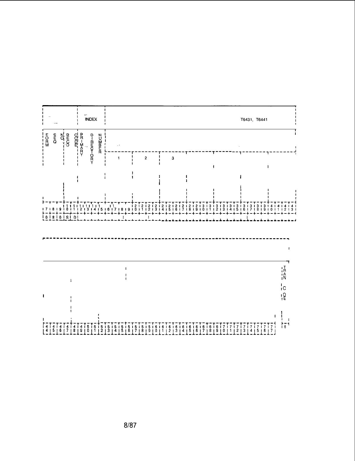
TL-130400-1001
Record Code SD:
16.11 Record Code SD, Figure 16.11, defines the secondary
CAS Secondary
directory numbers of a branch that are directed to the primary
Directory Numbers
directory numbers of that branch. All secondary directory
numbers must be unique and cannot be a primary directory
number or a pilot number of a station hunt group.
CAS SECONDARY DIRECTORY NUMBERS
I
I
I
T-------T----- --7-------T-------;
I
4
IIII
I I
5
I
6
I
7
I
III I
I
III
IIIIIIII
IIIIIIIII I
II
IIItIIIII I I
II I II
IIIIII I IIII
IIIIIII I I I I
I
IIIIIIII
1
I
I;IIII
I
III
II
5-T-L-T-T-+-T-T-T-+
I I I
I1
I1
I1
I1
I1
I1
11
I1
11 11
1212121212121212121213131313131313131313l4l4l4l4l
171819101112131415161718~9~0i1~2t314i51617181910111213141516171819101112131
c-+-+-*-+-+-+-+-+-+-+-+-+-+-+-+-+-+-+-+-+-+-+-+-+-+-+-+-+-+-+-+-+-+-+-+-~
lOl8lOl~l~I
I I I I I I
I
I I I 1 I I I I I I I I I I I I I I
I
I I I I I I
L-*-~---L-L-*-~-~-~--C-~-~-*-*-~-L-~ -~-*-~-~-~-~-*-~-~-~-~-~-~-~-~-~-~-~-~-~
r-------------------____r_______________---------------------------------
I I I
II I
I I I
I I
II
I I
II
II
c--e----
I
T-------T-------,
I
a
I
9
I
II
10
I
I I
II I
IIII
III
I
IIII
I
III
III
IIII
;II
II
III
i i
I
IT
I
IR
I
IA
I
IN
I IS
I
I
Ic
I IO
I
ID
I
IE
I I
I I
I I
I
I
I
I
I
II;I
1 1 I
:-T-T-T-+-T-T-T-+
I
I I
-T-T-T-t-T-T-T-T-T-T-T-T-T-T-T-T-T-
+-T-T-t-T-T-T-T-T-T-i
b-:
~~~~~~~~~~~~~~~~~~~~~~~~~~~~~~~~~~~~~~~~~~~~~~~~~~~~~~~~~~~~~~~~~~~~~
18
I
141516171819101112131415l6l7l8l9l011121314151617l81910111213141516171
IO I
L-*-l-*-*-~-l-l-l-*-*-*-~-~-~-~-~-~-~-*-~-~-~-~-~-~-*-*-~-~-~-~-~-~-,
L-J
-l
I
Figure 16.11
Record Code SD: CAS Secondary Directory Numbers Data Sheet
D-326 8187
SVR 5210
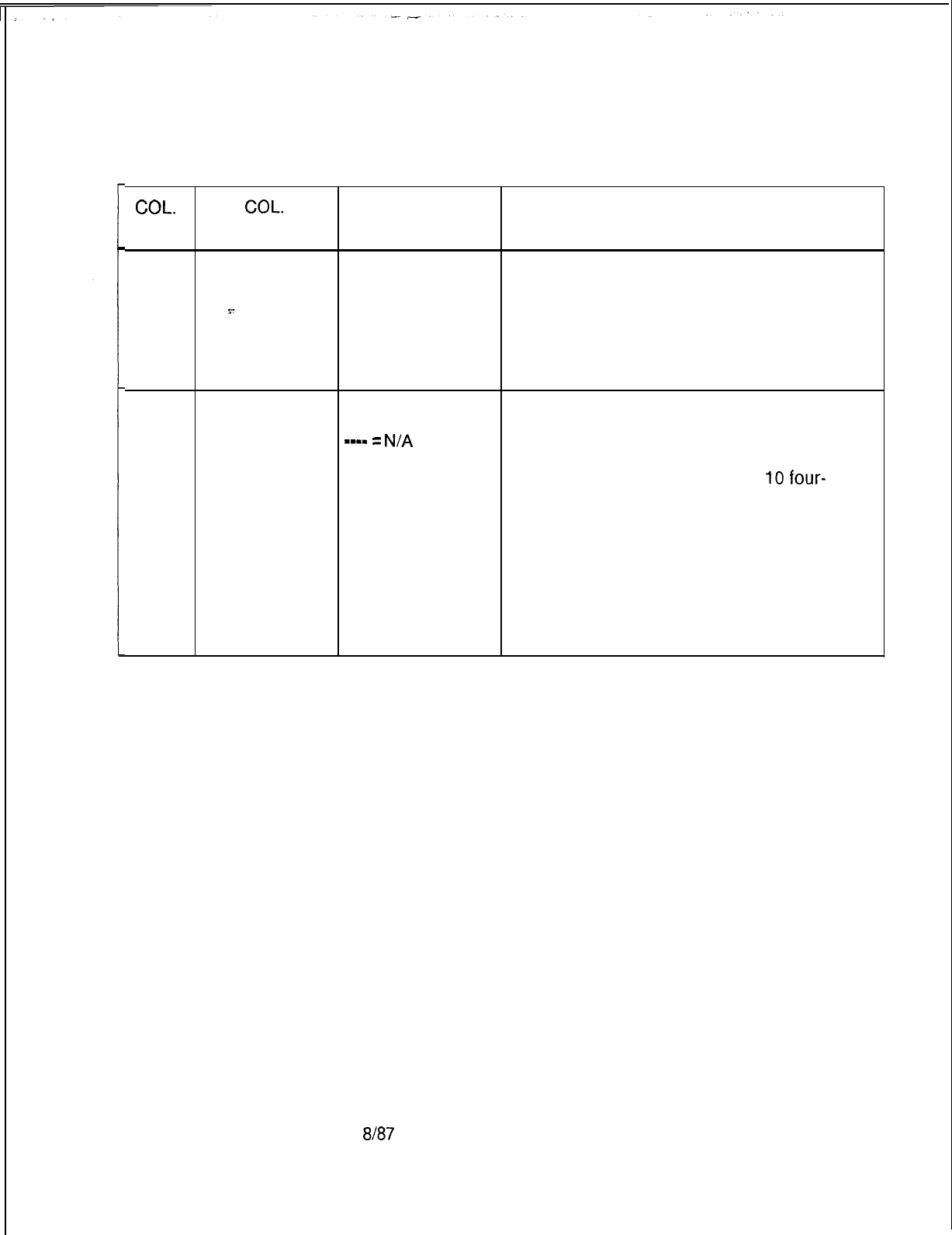
TL-130400-1001
COL.
NO.
Table 16.11 Entry Fields for Record Code SD
COL.
VALID
NAME ENTRIES COMMENTS
12-15
. . . .
Primary
Directory
Numbers
s-
0000-9999 =
number Assign the primary directory number of a line
that is to have secondary directory numbers.
-The primary directory number must have an
n-displayable class of service with SD (CAS
secondary number) specified.
-This number must be a valid directory
number appearing on Record Code LD.
16-55
CAS Secondary 0000-9999 =This field determines the CAS Branch
Numbers number secondary directory numbers.
-m-w
=
N/A
-Enter the secondary directory numbers
NOTE: The associated with a primary directory number.
numbers must be -These numbers are divided into
IO
four-
filled in from right digit number groups.
to left; -Columns 16-l 9 cannot be dashed.
if dashes are -If three-digit numbers are used, they must
used, they must be be right justified.
consistent, NOTE: A line number defined on Record
Code LD, with a class of service specifying a
secondary directory number, must appear as
the primary directory number on Record Code
SD.
SVR 5210
ah37
D-327

TL-130400-1001
THIS PAGE IS INTENTIONALLY LEFT BLANK.
D-328 8187
SVR 5210
SVR
5210
PD-200 17.0 This section describes the record codes required to
PACKET DATA define the various system packet data features. The following
record codes are required:
l Record Code RT defines the data system routing patterns.
l Record Code CP defines additional call routing information.
l Record Code AP defines the system’s
APMs
(Asynchronous
Packet Managers).
e
Record Code AQ defines port parameters that can be
modifiec’
by another device.
o
Record Code XP defines the system’s
SPMs
(Synchronous
Packet Managers).
l Record Code
Pl
defines the ADMP parameters.
l Record Code P2 defines additional ADMP parameters.
l Record Code Cl defines global information.
l Record Code C2 defines additional global information.
e
Record Code SR defines PD-200 speed call numbers.
In addition to the above record codes, FR, LD, and SL must be
completed for a data system.
8187
D-329
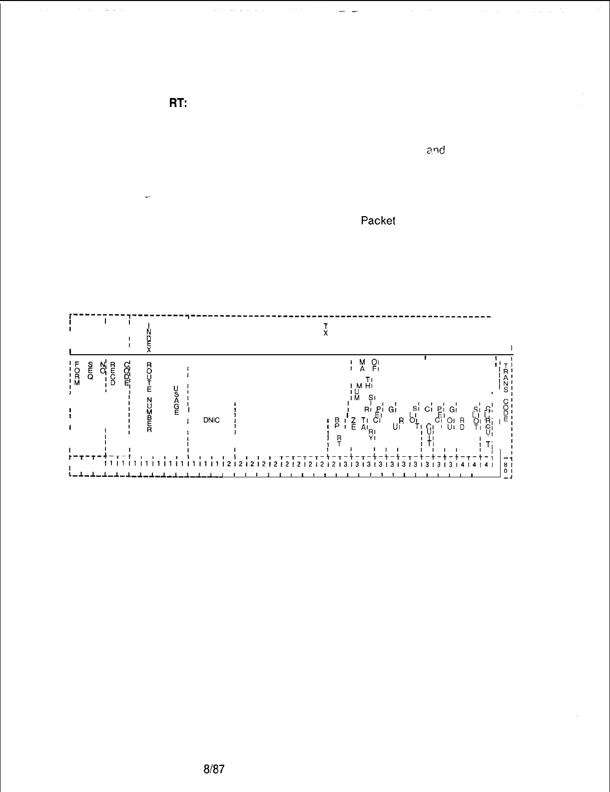
TL-130400-I 001
Record Code
RT:
Data System
17.1 Record Code RT, Figure 17.1 defines the system
Routing
numbering plan by groups according to the type of usage. Since
each server number represents one type of usage, one entry is
required per server number. The sub-port field (columns 29-
30) must be dashed for both asynchronous
a.rld
synchronous
(X.25) groups. Primary and secondary destination fields
(columns 33-42) are only used if the usage type defined in
columns 15-16 is 01 or 02. The primary and secondary
destination fields define the VPLC (Voice Packet Line Card)
location and the VPLC circuit, which is connected to the
associated SPM (Synchronous
Packef
Manager). Any X.121
address defined on this record code must also be defined on
Record Code CP.
NOTE: A NIC (Network Interface Card) is treated the same as an
SPM (X.25).
r---------~---------~----------------------------------------------------
I
II
r--i
IIII
I
z
I I
II
E
I
I
I I I
II
IIf
I
E
II I
I
III
8
I
I
1
II I
II
I
;
f
$
PRIMARY ,
I
SECONDARY
;
’
1-r’
f
X. 121 ADDRESS IX II
’
I
I I
I
’
I
’
!A
fI
M
;I
X.25 ROUTE
IU
, , DESTINATION
I
’
I
I
I
I
I
I
I
I
I
I
:
I
:
I
x
f
IM
SI
II
I
II
I
I
E
’
S
;
S
RI
Pi
Gi
C
Si
C;
P;
G;
C
Si
C’
I
I
I U
I
I 01
EI
RI A
LI
I I
EI
RI A
LI
I;
I
DNIC
t
SERVER
IIt
;
;
;
‘E
A;
CI
01
R
01
RI
C;
$1
fj
,
UI
D
TI
CI
I
p;
El
fI
0 II PI
I I
BI
I PI
I I
I
YI
I
u;
I I
II
IfIi
B
I I I I
ITI
I I
’
‘I
1
TI
-T-t-t-
T-t-T-T-T-T-t-T-T-T-;-
T-T-T-T-T-T-
7~8~91011121314151617181910111213141516171819101112131415161718191011121
~~~~~~~~~~~~~~~~~~~~~~~~~~~~~~~~~~~~~~~~~~~~~~~~~~~~~~~~~~~~~~~~~~~
-1-~-1-1-1-1-1-~-1-1-1-1-1
1 1 1
1
I
8
I
1
I
I
I
I
1 1 1
I
I
a
I
1
I
8 I
I
I
I
I
1
I
I
I
I
I
i
Figure 17.1
Record Code RT: Data System Routing Data Sheet
D-330 6167
SVR 5210
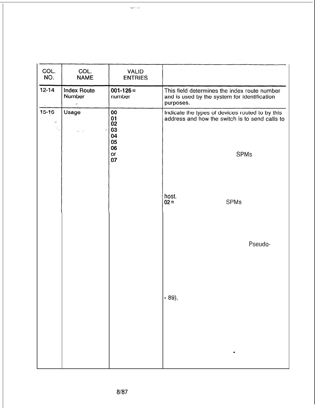
T-L-1 30400-l 001
Table 17.1 Entry Fields for Record Code RT
COMMENTS
them. This field is generally set to 5 for
asynchronous devices. The types are:
00= X.25 single line. The device routed to is
an X.25 SPM, and only one device can
receive calls to this address.
01 = X.25 load share. Two
SPMs
can receive
calls to this address, and the one with the
most current LCN (Logical Channel Number)
capacity receives the call. This feature is
often used to double the LCN capacity into a
single X.25 host or to provide connections into
two physical hosts that act as a single virtual
02=
X.25 backup. Two
SPMs
are also
addressed by this type, but the secondary
device is used only in cases where the
primary cannot be used (either the line is
down or it is at LCN capacity). This provides
an emergency route to a host via another
PD-200 or a PDN (Public Data Network).
03 = ADMP. The Administrative
Pseudo-
Packet Device Handler can be specified in the
routing tables. Calls to it are treated like a
single line X.25 route, but are sent to the
ADMP.
04 = asynchronous direct ordered non-rotary
groups. Asynchronous devices can be
directly addressed by sub-address (digits 13
and 14 of the X.121 address can be from 01
-
89),
the group is built in incrementally
increasing sub-address order. Terminals
are normally put into this category.
05 = Asynchronous, direct-ordered rotary
hunt groups. Asynchronous devices can be
called directly as above or can be addressed
as a group with sub-address 00. When a
sub-address is used, the first device
available and usable in the group is selected;
if it does not answer (e.g.,
-
host ringing
timeout), the next available usable device is
tried, and so on.
SVR 5210
8187 D-331
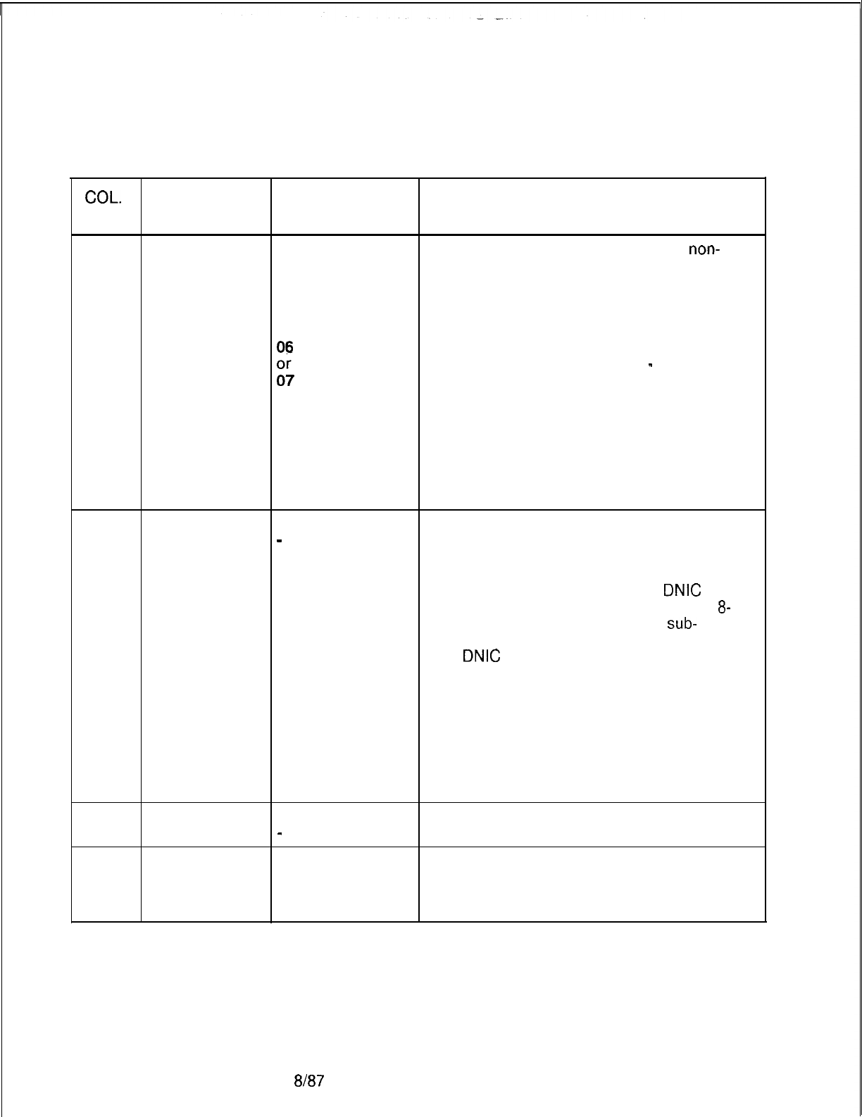
TL-130400-1001
COL.
NO.
Table 17.1 Entry Fields for Record Code RT (Continued)
COL. VALID
NAME
ENTRIES COMMENTS
15-16
Usage
00
06 = asynchronous, random-ordered
non-
cont’d
01
rotary groups. Asynchronous devices are
__
02
addressed directly by sub-address 01-89,
03
but the actual order in which the group is built
04
depends only on the order in which the
05
devices are loaded and initialized. Unlike the
06
direct-ordered variety, these groups can
:;
have any sub-address (from 01
-
89) no
matter what the group size. Direct-ordered
groups are limited in sub-address from 01 to
size-of-group. Terminals can be configured
in this type of group.
07 = asynchronous, random-ordered rotary
hunt groups. Asynchronous devices are
addressable with sub-address 00 or (directly)
with any sub-address allowed in the group.
17-20
X.1 21 Address
O-9 = select
This field contains the Data Network Identifier
(DNIC)
-
= not selected Code (DNIC: first 4 digits of the X.121
address), the main server address (next 8
digits), and port number (last 2 digits).
-The full address is structured as
DNIC
SSSSSSSS PP, where SSSSSSSS is the
8-
digit server number and PP is the
sub-
address number of the port.
-The
DNIC
will usually be 3110. The server
number will identify the PD-200 network end
routing group (when data calls are made
outside this network e.g., to Telenet).
-The network assigns the X.121 sever ID
number. The port number is the portion of the
address that is used to sequence “ordered”
type asynchronous device groups.
-Column 17 cannot be dashed.
21-28
X.121 Address O-9 Indicate the server number of the X.121
(server)
-
= not selected address used for this route.
29-30
X.1 21 Address
-- = not
Indicate the sub-port number of the X.121
(sub-port) selected, address used for this route.
this is the only -This field must be dashed.
allowed entry
D-332 8187
SVR 5210
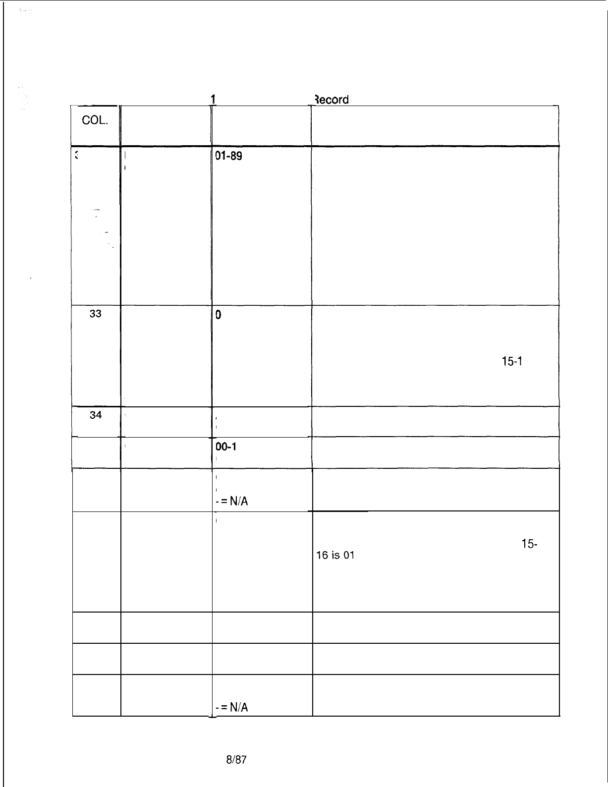
TL-130400-1001
Table 17.
a
Entry Fields for 3ecord
Code RT (Continued)
L
COL.
NO.
COL.
NAME VALID
ENTRIES COMMENTS
31-32
Maximum Size
of This Rotary
01-89
= number Identify the number of asynchronous devices
that make up this rotary group.
-This is the number of ports actually defined
for this group of devices.
-The field must be less than or equal to the
Maximum Number To Configure field.
-This field applies only if columns 15-16 are
marked 05 or 07.
-If columns 15-l 6 are marked 00, 01, 02,
03, 04, or 06, this field must be dashed.
-Since each number defined here requires a
software address, it is not recommended to
overbuild for possible growth.
Primary X.25
Route
Destination PEC
0
= PEC number This field determines the location of the first
route used by an SPM (X.25) or NIC when the
usage type defined in columns 15-16 is 01 or
02.
-If the usage type defined in columns
15-l
6
is 00, 03, 04, 05, 06, or 07, this field must be
dashed.
Enter PEC 0.
35-36
Which group (A, B, C, or D) within PEC 0 is
this card?
Group
Card Slot
A-D
= group
number
00-l
0 =
slot
number Which card slot within the group is this card?
37
Circuit Number Which circuit on the card is being used?
38
39
40-41
O-7 = assigned
circuit number
-=N/A
0 = PEC numberSecondary X.25
Route
Destination. PEC
This field determines the location of the
second route used by an SPM (X.25) or NIC
when the usage type defined in columns
15-
16isOl
or02.
-If the usage type defined in columns 15-16
is 00, 03, 04, 05, 06, or 07, this field must be
dashed.
Enter PEC 0.
Group
Card Slot
A-D
= group
Which group (A, B, C, or D) within PEC 0 is
number this card?
00-l 0 =
slot
number Which card slot within the group is this card?
42
Circuit Number
O-7 = assigned
circuit number
-=N/A
Which circuit on the card is being used?
SVR 5210
8187
D-333
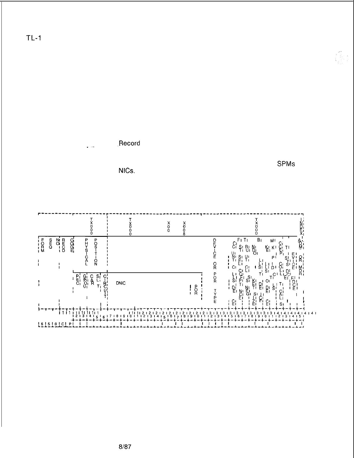
TL-I
30400-l 001
Record Code CP:
17.2 Record Code CP, Figure 17.2, defines the parameters for
Data System
the common asynchronous and synchronous (X.25) port
Common Port
attributes. The parameters required by the data system ADMP
processor are also defined. The X.121 address is used for data
call setup and verification. The system requires an entry in this
record code for each of the following:
I
II
NI
DI
El
Xl
r----^----r---------~---------------------------~------------------------------
II
I I
z
T T
I
ii
I
I I I
II I
I I
I I
f
1
0
I
I
I1
I
1
I
E
I AI
FI
TI
WI
BI
MI
MI
A, Dl , ,
A;
X. 121 ADDRESS
I
I
CI
AI HI II AI AI Al
C,
Al S,
D,
I
I
Cl
St
RI
NI
RI
KI
Kl
c,
Tl
I
MI
I
Y
I 01
TI
UI
DI
I
EI
El
EI
A, Dl PI
III I
E
I
UI
I PI
01
Cl I
’
PI
III I
I I
;
y;
2;
y;
WI AI C,
pt
T,
Si
5;
0:
Fi
I
LI
I
LI
AI Al
I I
I &I I
Yl
IlRl
:
CI
AI
CI Ll
Ll
I
I
Cl
I
I
L
I
I AI
CI
LI
’
7
kI
D’
O’
SI
Cl
PI
I
E,M;
I
LI
DI
I
DI
I
I
I I
I
I
;I
El
“A
?I
7;
I
I
LI
CI
A, AI
TI
I
I
Cl
Ll
C,
Al
RI
Cl
0;
R
Of
Rf
I s
;
I
I uI
Ll
EI
SI
Cl 01
TI
Al
EI
El
I
,
I
I
DNIC
I
SERVER
I B
;
T
’
7
7;
s’
K’
IO1
Ll Cl
,DI
I
f
I
UI
D
I
p
I PI
T;
5,
II
1s
i
I
EI
DI
DI
AI
NI
TI
EI
I
LI
TI
ICI
I
II
II
II
II
II
f
II
II
II
II
II
I
;
I
-T-T-+-T-
I I I
I1
I1
1718191011
c-+-+-+-t-
I
I II
1’
I
I
T;
I
I T
;
;
I
EI
NI
EI DI
S’
I VI
El
IEI
,
I VI
CI
GI
St
11
VI
Id
I I
I
I
I
1
II
F
I II
El
I
IICI
II
IAI
I
I
,
ILI
I I
I
I
I II I
II
IL,
I
I
I
I
I I
1
iIII
t-t-t-T-t-t-T-T-T-t-
T-r-T-r-r-T-r-r-r-t-T-T-
I1
11
I1
I1
11
11
I1
I1
,212,21212,21212,2,213131313131313131313l4,4,4l4l4l4l
12131415,6,718191Ot112,3141~16l~l6191O1112,31415161716l9,O1112,314151
.+-+-+-+-+-+-+-+-+-+-+-+-+-+-+-+-+-+-+-+-+-+-+-+-+-+-+-+-+-+-+-+-+-+-~
1615101~Ipl
I,
I I I I
I
I I I I I
I
I
I
I
I I
I
I
I
I
I
I I I
I
I
I
I I I
I
I
L-~-~----L-~-~-*-~-~-~-~-~-~-~-*-*-~-~-~-~-~ -*-*-~-~-~-~-~-~-~-~-~-*-*-~-~-*-~
* SPM (Synchronous Packet Manager)
l APM (Asynchronous Packet Manager)
l ADMP (each two-card set)
l NIC (Network Interface Card)
,Record
Code RT establishes groups of lines by usage; Record
Code CP identifies each member of each group. The sub-ports
for the asynchronous groups (established on Record Code RT)
must be defined here. Sub-ports are never defined for
SPMs
or
NICs.
A synchronous (X.25) group can have a maximum of two
synchronous members. If a synchronous (X.25) group has two
members, both members must have the same X.121
address.
D-334
8187
Figure 17.2 Record Code CP: Data System Common Port Data Sheet
SVR 5210
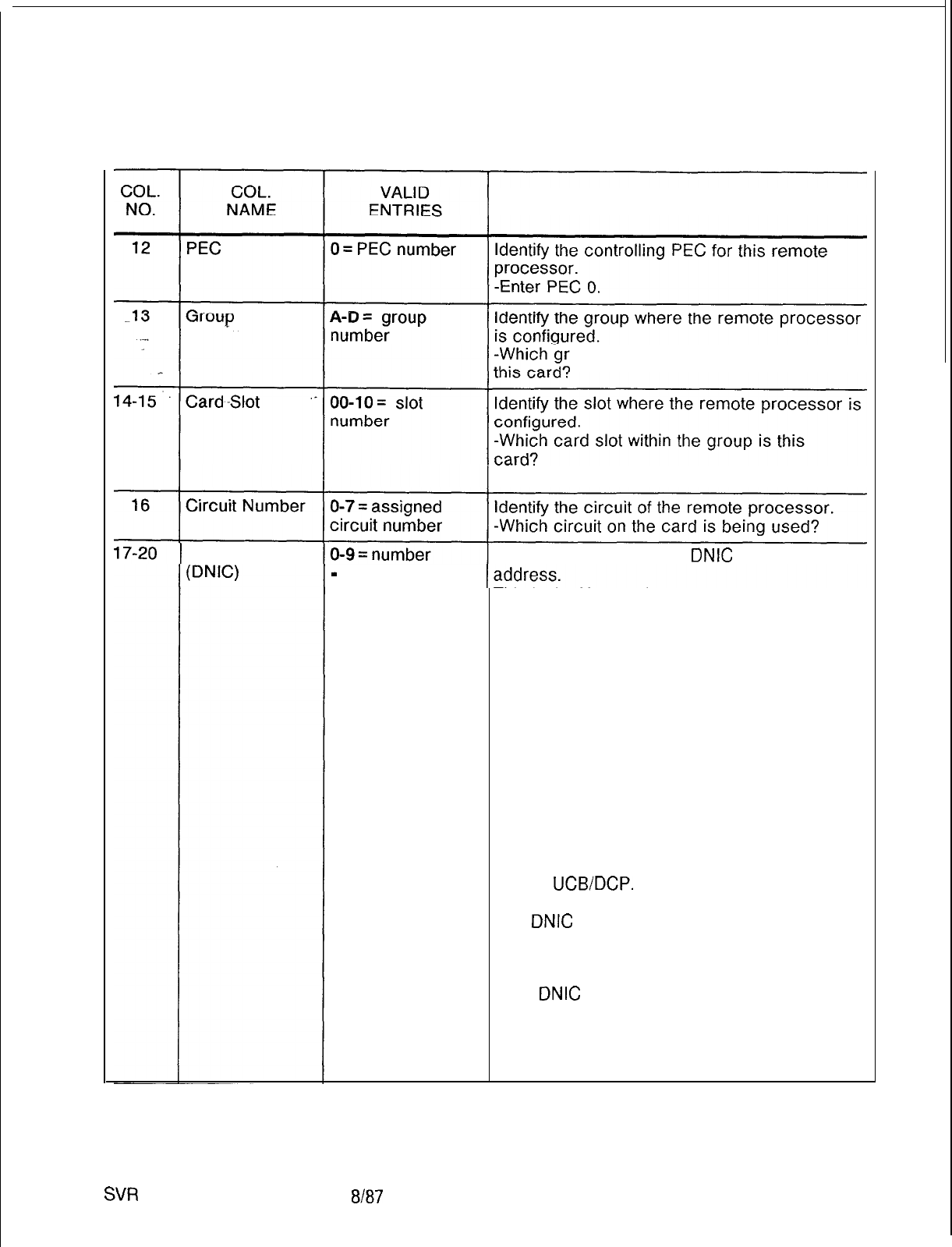
TL-130400-1001
Table 17.2 Entry Fields for Record Code CP
COMMENTS
oup (A, B, C, or D) within PEC 0 is
-Card slot 11 cannot be used.
X.1 21 Address This field determines the
DNIC
of the X.121
-
= not selected This is the X.121 address for the device as the
network sees it. This address is like a phone
number for a data network.
-The X.121 addresses are gotten from a
network just as DID numbers are gotten from
a CO.
-The PD-200 system requires X.121
addresses.
-This address is used in the processing of
X.25 call setup and verification.
-If the device is asynchronous, this address
must be 14 digits.
-If the device is a synchronous X.25 or if the
device is an ADMP, this address can contain
O-l 4 digits.
-X.121 addresses are checked by data base
or the
UCB/DCP.
All X.121 addresses must
be different.
The
DNIC
is the first four digits of the X.121
address and will usually be 3110.
-311 = USA or country number: 0 = Telenet or
newtork number.
-The
DNIC
identifies the PD-200 network.
-If data calls will be made outside this
network (e. g., to Telenet), server numbers are
assigned by the network.
-Dashes cannot be entered in column 17.
SVR
5210
8187
D-335
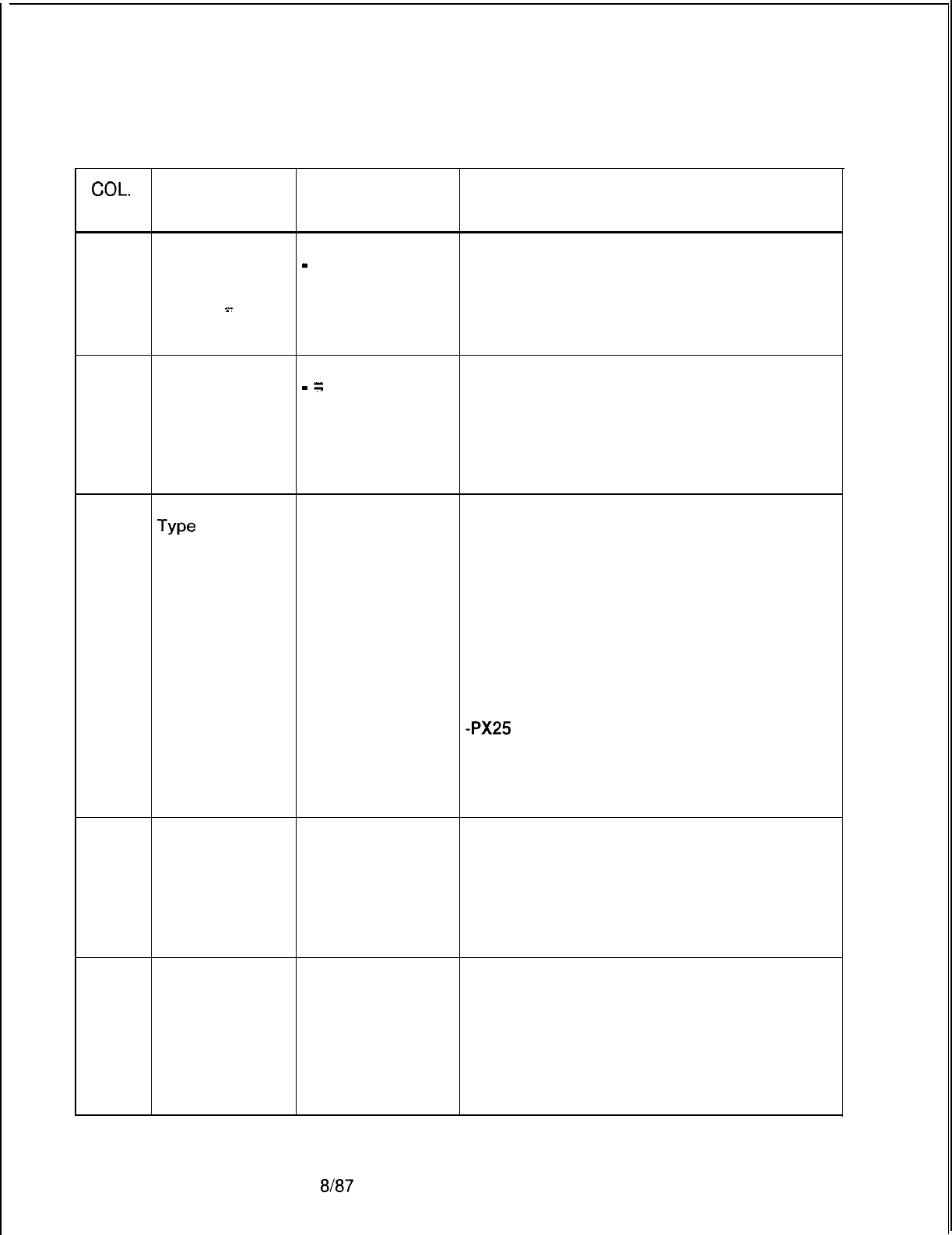
r
TL-130400-1001
COL.
NO.
Table 17.2 Entry Fields for Record
Code
CP
(Continued)
COL. VALID
NAME ENTRIES COMMENTS
21-28
X.1 21 Address
O-9 = number
(sever number) identify the sever number of the X.121
-
= not selected address.
-The sever number is the next eight digits
29-30
9.
after the DNIC.
-The sever number identifies the PD-200
routing group.
X.1 21 Address
O-9 = number
(sub-port) Identify the sub-port number of the X.121
-
=
not selected address.
-Only asynchronous devices require an entry
in this field.
-These last two digits of the X.121 address
are the port number and specify the specific
device.
31-34 Device or Port
Term
Type
This field determines the type of endpoint
Host
device to which the APM or SPM is
X.25 connected.
or -If this field is defined as an asynchronous
PX25
terminal or host, the asynchronous
configuration tables will be used. Otherwise,
use the X.25 tables.
-Term = APM is attached to an asynchronous
terminal or modem.
-Host =APM is attached to an asynchronous
host.
-X.25 = SPM is attached to any X.25 device.
-PX25
= device is an ADMP.
NOTE: If columns 31-34 = PX25, columns
14-15 must contain the slot number of the
ADMP A card and column 16 must be marked
0.
35
Account Calls
From/To This
Device
Y = collected
N = not collected
(always N for
ADMP)
Enter Y if accounting of calls to/from this
device is collected.
-If this parameter is enabled, an accounting
record will be generated.
-If both devices involved in a call have this
field disabled, no account record will be
generated.
36
Fast Selected
Acceptance
Supported
Y = selected
N = not selected
(always N for
asynchronous)
Enter Y if the connected device supports
accepting of fast select.
-If this is enabled and a fast select call is
directed toward this device, that call will be
allowed to connect as long as there are no
other facility conflicts. Otherwise, the call is
cleared.
-This field is only used with SPM ports.
D-336 8187
SVR 5210
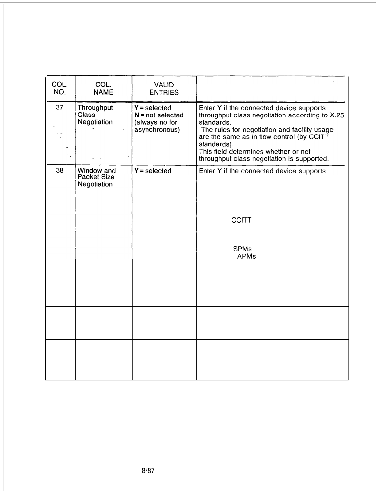
TL-130400-1001
Table 17.2 Entry Fields for Record Code CP (Continued)
COMMENTS
N = not
selected window and packet size negotiation that is
according to X.25 standards.
-If enabled, the window and packet size
facilities will always be placed in call request
packets to the device and checked in any call
or accept packets from the device.
-Standard
CCITT
X.25 negotiation rules will
be enforced. If not enabled, the facilities will
not be allowed from the device and will not be
sent to that device.
-Only X.25
SPMs
can negotiate these
parameters;
APMs
should be set to N.
-This field determines whether or not window
and packet size negotiation is supported.
-This field is only used with SPM ports (X.25
in columns 31-34).
-If columns 31-34 are marked Term, Host
or PX25, mark this field N.
39
Bar Calls From
Y = barred
Enter Y if the call processor allows outgoing
Device N = not barred calls to the device through the network.
-If calls cannot be placed from the device, it
becomes a terminate-only device.
40
Bar Calls To
Y = barred
Device N = not barred Enter Y if the call processor can allow any
ingoing calls to the device through the
network.
-If calls cannot be placed to the device, it
becomes an originate-only device.
SVR 5210
8187
D-337
TL-130400-1001
COL.
NO.
Table 17.2
Entry Fields for Record Code CP (Continued)
COL.
VALID
NAME ENTRIES COMMENTS
41
Make Paid Calls Y = selected
(always Y for
.~.
ADMP)
-..
N = not selected
. .
_
This field is only valid for asynchronous
terminals/modems connected to
APMs.
-The field specifies the charging default for
the connect command from this device.
-The default is either to make caller paid
calls or collect (reverse charge) calls.
-This is part of the facility field of the call
packet.
-If this field is enabled (Y), the default will be
the placement of paid calls. This port is billed
by the network for calls it originates.
-If disabled (N), the default will be collect
calls from this device.
-The terminal user may enter an
R
(requesting reverse charging) or a P
(requesting paid call) at the end of the connect
command and this will always override the
default.
-If
this column is marked Y and column 42 is
marked N, the normal connect command will
fail to work properly.
-Since the host usually pays a call charge,
most terminals do not make paid calls.
42 Accept Collect
Y = selected This field specifies whether or not this device
Calls
(always Y for
is billable.
ADMP) , -Billable devices may initiate paid calls (or
N = not selected collect calls) and should accept a call that has
the collect facility specified in the call packet.
-If this field is enabled (Y), the call processor
will allow such calls to the device and this
device will have to pay for the call.
-Otherwise, calls having the collect (reverse
charging) facility are not be able to connect to
this device (the call will be cleared).
-If this field is marked N, this device may
initiate only collect calls.
-If this column is marked Y and column 42 is
marked N, accounting information will be lost
for collect calls.
-Y is normally selected.
43
Is the Data
System
Configured as
DCE?
Y = selected
(always Y )
N = not selected
Enter Y if the system is configured as a DCE.
-Always enter Y for ADMP and NIC.
D-338
8187
SVR 5210
TL-130400-I 001
COL.
NO.
44
Table 17.2 Entry Fields for Record Code CP (Continued)
COL.
NAME
Is the Data
System a DCE?
Y-
ADMP or MDR
VALID
ENTRIES
Y = selected
NOTE: Enter Y if
SPM is connected
to a PDN (Public
Data Network)
N = not selected
(usually N)
M=MDR
-
= not connected
MDA = PX25
device
COMMENTS
This field determines if this device is
configured as a DCE.
Enter M if the port is connected to an MDR.
-If columns 31-34 are marked PX25, enter
A in this field.
SVR 5210
8187 D-339

TL-130400-1001
Record Code AP:
17.3 Record Code AP, Figure 17.3, defines the common
Data System
interface parameters for each APM (Asynchronous Packet
Asynchrouous Port
Manager). This record code is only used for
asynchrouous
ports, and an entry for each APM must be found here.
There are three types of parameters that are defined for each of
the terminals or groups of terminals. They are:
.=.
.
.
.
.
l X.3 parameters
l Local parameters
l Optional subscription parameters
For normal applications, all terminals within the same group
(having the same
DNIC
and server number) have the same
parameters, depending on the terminal types.
8187
SVR 5210
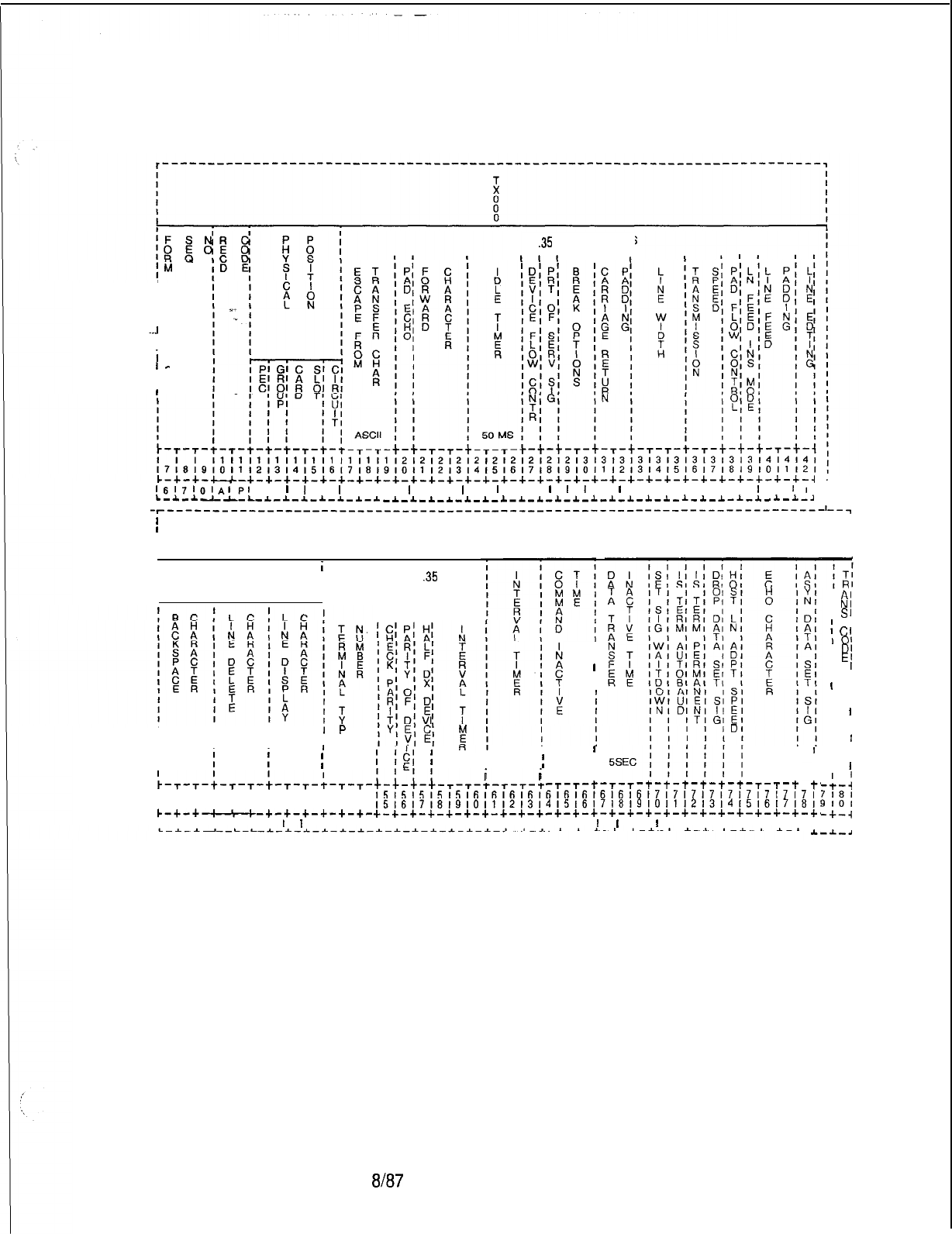
TL-130400-1001
X
.35
PARAMETERS
III
I
I
IIIII
.
..J
-I
i
I
-
II
I
c-+-+-l-+-+-+-+-+-+-+-+-+-+-+-+-+-+-~-+-+-+-+-+-+-+-+-+-+-+-+-+-+-+-+-~
,
1fj171,,1A#p,
,
I
I
,
I
I , I
I
I I
I
I
I
, ,
1
I
t
,
1
, , 1 , , , 1
i
,
1,
L-~-I--L-L--L-I--L-*-~-*-~
-1-~-1-*-1-~-~-~-~-1-~-~-~-~-~-~-~-~-~-~-~-~-~-~
,
-r-------------------------------------------------------------------------I--~
I
I
i
ILOCAL X
.35
I
PARAMETERS
I
I
Al
I
N’
I
s,
I
Cl
I
01
I
DI
I
El
I 1
I I
I
I
I ’
I ,
I
I
I ’
I I
I
’
I I
I 1
I
1
-+-;
7181
9101
-c-4
I I
-.I.-.4
I I I I
I
I
El
$I
;II
, 50 MS
;
5SEC I I
;-/-/-/-T-T-+-T-T-+
I I
I I
II
-T-T-t-T-T-t-t-t-t-t-t-t--r-t
I-’
,515151515,6,61616,616161616161717171717,7l7l7l7,
,5,617,8,910,112131415161718191011121314l51617181!
+-+-+-+-+-+-+-+-+-+-+-+-+-+-+-+-+-+-+-+-+-+-+-+-+~
I I I I, I I I I I II I
I
I
I
I
I I I I I I I I
A.
III
IIII E
I I I I
II ASCII
j
ASCII
i
ASCII
;
I I
~-r-T-~-t-T-+-T-t-~-r-T-
141414141414141515151515
131415161718191011121314
c-+-+-+-+-l--+-+-+-+-+-+-
I I I I I I I
I
I
I I I
Figure 17.3 Record Code AP: Data System Asynchronous Port Data Sheet
SVR 5210
t-v87
D-341
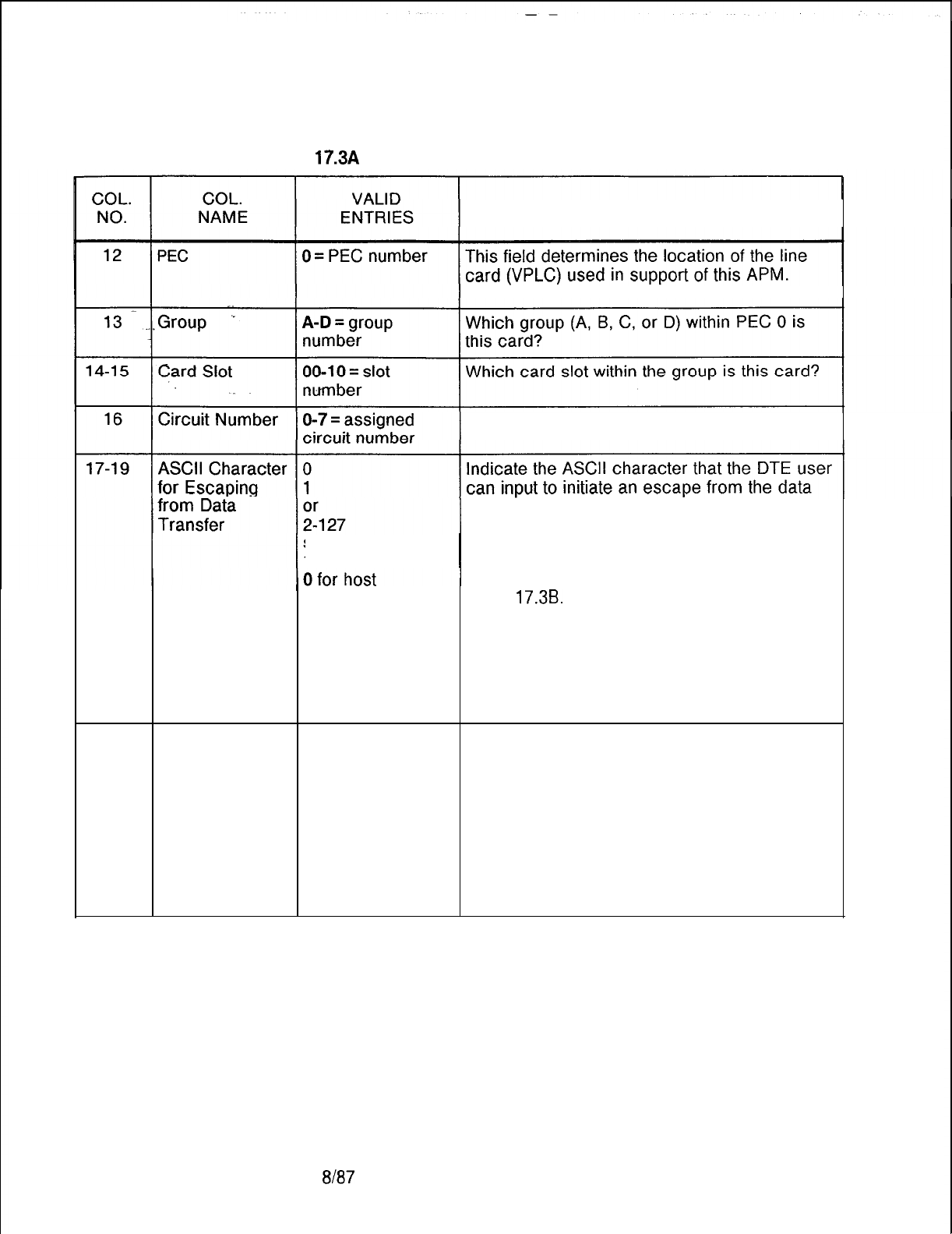
TL-130400-1001
Table 17.3A Entry Fields for Record Code AP
COMMENTS
-Enter PEC 0.
Which circuit on the card is being used?
transfer mode.
0 = escape not possible
suggested value = 1 = DLE character initiates escape
1 for terminals 2-127 = selected character initiates escape
-If another ASCII character is required, see
Table
17.3B.
-This parameter specifies the character used
to indicate to the terminal that the user wants
to enter command mode.
-The value is the decimal equivalent of the
ASCII character to be typed.
-This is X.3 parameter 1.
20
Pad Echo 0 = no echo This field specifies the default value of ECHO.
1 = echo
-If this parameter is enabled, then ECHO will
suggested value = occur in data transfer mode; otherwise, no
1 for terminals echoing will occur in data transfer mode.
0 for host -This field is normally set at 0 for full duplex
and 1 for half duplex.
If station equipment does not display
information that is keyed in, then try setting this
field to 1.
-This is X.3 parameter 2.
8187
SVR 5210
1
COL.
NO.
21-23
24-26
TL-130400-1001
Table
17.3A
Entry Fields for Record Code AP (Continued)
COL.
NAME
3ata
Forwarding
Zhalacters
,dle
Timer
VALID
ENTRIES
0
1
2
4
8
16
32
64
128
suggested value =
2 for terminals
0 for host
0 = data will not be
forwarded in the
timeout.
l-255 = length of
delay in
50-ms
increments
suggested value =
20 for terminals
0 for host
COMMENTS
Indicate a predefined character or set of
characters that are typed by the user (DTE) to
tell the terminal to transmit/forward a packet.
0
=
user cannot initiate data forwarding
1 = alphanumeric characters (A-Z, a-z,
O-
9)
2 = carriage return
4=
characters ESC, BEL, ENQ, ACK
8 = characters DEL, CAN, DC2
16 = characters ETX, EOT
32=
characters HT, LF, VT, FF
64=
a character inserted by the user in user
text column 0 or 1 which is not any of the
characters listed in O-32 above
128 = all other characters not mentioned
above
-This is X.3 parameter 3.
Indicate the allowed interval between input
(DTE) characters.
-When this interval is exceeded, the timeout
causes the forwarding of a packet.
-The time is selected in 50-ms increments,
so a selection of 2 = 100 ms.
-This field specifies the default value of the
idle timer.
-This timer clocks the time between
characters.
-If this timer expires, all of the characters
buffered up to that point will be forwarded in a
packet.
-This is X.3 parameter 4.
SVR 5210
8187 D-343
TL-130400-1001
COL.
NO.
Table 17.3A Entry Fields for Record Code AP
(Continued)
COL.
VALID
NAME ENTRIES COMMENTS
27
Device Flow 0
Control This field allows the PAD (remote end) to
or temporarily slow the output from this device
>-
1
when the PAD is momentarily unable to
. . .
suggested value = receive more data .
0 for terminals This parameter determines the default value of
1 for host device flow control.
.-
-If this parameter is enabled, the PAD will be
_
able to flow control the device when the PAD
falls behind in processing or if the amount of
characters buffered becomes too great due to
transmission condition or network slow-down.
-When the PAD sends a control-S, the
device stops transmission to the PAD. If the
device continues to transmit and overruns the
buffer, data is lost.
-When the PAD becomes unblocked, it
transmits a control-Q. It continues to
transmit this character until the device starts
sending data. Then the PAD sends an
indication to the connected device that it can
continue.
0 = disable use of flow control
1 = enable use of flow control
-This is X.3 parameter 5.
28
Printing of
0
Indicate wehther or not this device prints
Service Signals 1network service signals.
or
-Example: Network tells you “connected”
5
upon completing a connection.
suggested value = 0 = no service signals sent to DTE
5 for terminals 1 = all service signals except PAD prompt are
0 for host sent
5 = all service signals sent including PAD
prompt
-This is X.3 parameter 6.
-This parameter sets the default value for
control of PAD service signals.
-This parameter controls the sending of the
PAD generated messages and disallows or
allows different classes of messages.
-These message classes are user
acknowledgments and prompts.
D-344
8187
SVR 5210
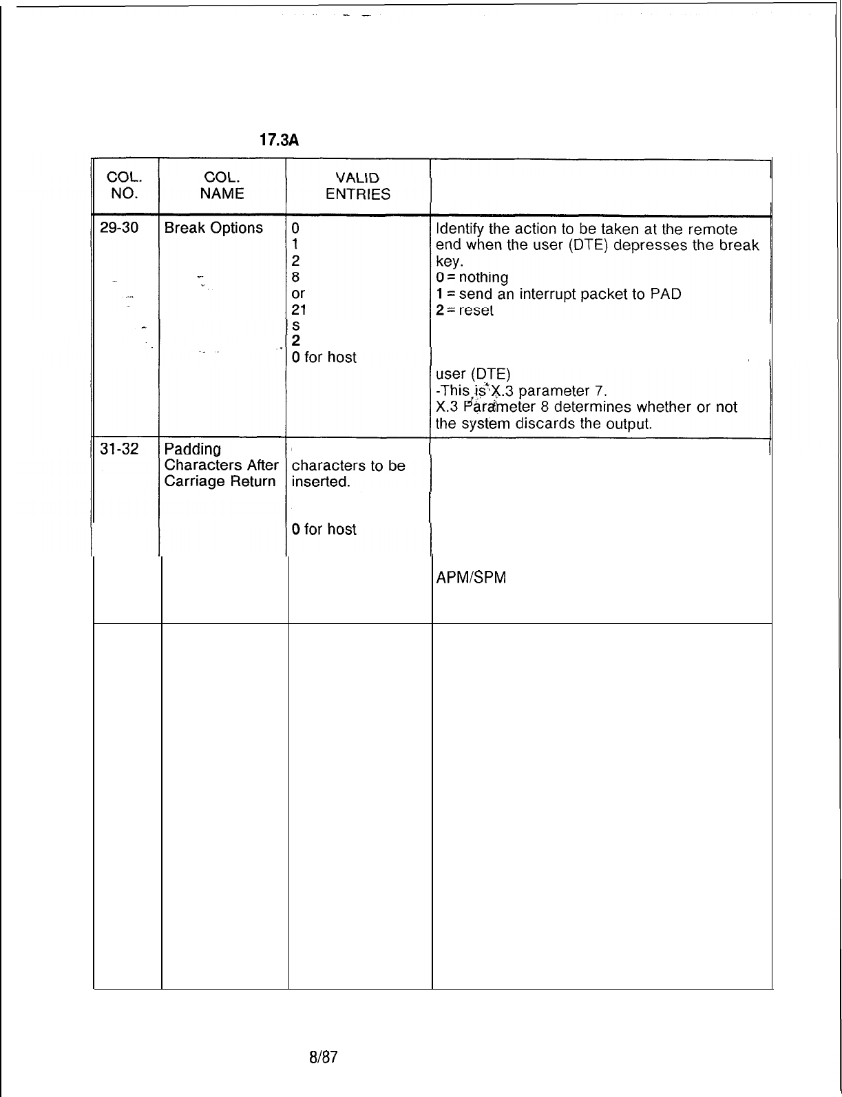
TL-130400-1001
Table 17.3A Entry Fields for Record Code AP
(Continued)
COMMENTS
uggested value = 8 = escape from the data transfer mode
1 for terminals_21 = send an interrupt plus an indication of a
break message to PAD and discard output to
O-31
= number
of
Indicate how many padding characters are to
be inserted after a carriage return.
-Printing devices need sufficient time for the
suggested
value =
mechanism to perform the carriage return.
7 for terminals -This parameter determines the number of
null characters to wait before continuing to
send any other characters.
-There are no real characters sent. The
APM/SPM
waits the amount of time it would
take to transmit those characters.
-This is X.3 parameter 9.
33-35
Line Width
0
Indicate the maximum number of output
or
characters printed per line at the user (DTE)
1-255
device.
suggested value = 0 = this function will not be performed
80 for terminals automatically
0 for host l-255 = number of characters per line
-This parameter specifies the default value of
line folding.
-This parameter determines the number of
characters to transmit before an automatic
carriage return/line feed is sent. This causes
long lines to fold or wrap onto the next line.
-If this parameter is 0, the function is
disabled. A backspace will cause the internal
counter to be decremented by one for each
backspace character received. A carriage
return will reset the counter.
-This parameter is normally set at 0 since
most station equipment performs this function
automatically. Otherwise, standard line
lengths are 80 or 132 characters.
-This is X.3 parameter 10.
SVR 5210
8187
D-345
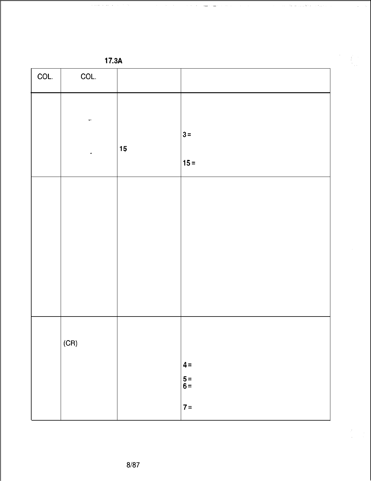
TL-130400-1001
COL.
NO.
Table 17.3A Entry Fields for Record Code AP
(Continued)
COL.
VALID
NAME ENTRIES COMMENTS
36-37
Transmission 0
Speed identify the transmission rate at which data is
2sent.
3
-This is a read-only parameter.
.=.
12
0= 110 bps (uses 2 stop bits)
.
13
2 = 300 bps
(uses 1 stop bit)
14
3=
1.2 kbps (uses 1 stop bit)
or 12 = 2.4 kbps
(uses 1 stop bit)
15 13 = 4.8 kbps
(uses 1 stop bit)
_
14 = 9.6 kbps
(uses 1 stop bit)
15=
19.2 kbps (uses 1 stop bit)
This is X.3 parameter 11.
38
Flow Control of 0 = PAD flow This field determines whether or not a signal is
PAD control not sent by the user terminal (DTE) to warn the
allowed. remote end that this terminal is temporarily
1 = PAD flow unable to receive more data.
control allowed -This field specifies the default value of flow
suggested value = control.
1 for terminals -If this parameter is enabled (Y), then the
1 for host device and/or user of the device can flow
control the PAD.
-This will disallow transmission of control-S
and control-Q. However, if this parameter is
disabled (N), the device cannot flow control
the PAD, but the device can transmit the flow
control characters through the network.
-Control-S stops the PAD and control-Q
ends flow control. This is commonly done by
printers and users that get behind in some
type of listing and wish to catch up.
-This is X.3 parameter 12.
39
Line Feed
0
Indicate whether or not an automatic insertion
Insertion After 1of a line feed after any carriage return is
Carriage Return 4transmitted.
(CR) 5
0 = no line feed inserted
6
1 = insert line feed after each carriage return
or sent to the user terminal (DTE) as data
7
4=
insert line feed after each carriage return
suggested value = sent to user terminal (DTE) as an echo
4 for terminals
5=
combination of 1 and 4
0 for host
6=
insert line feed after each carriage return
sent from the user terminal as data and to the
user terminal as an echo
7=
combination of 1 and 6
-This is X.3 parameter 13.
D-346 8187
SVR 5210
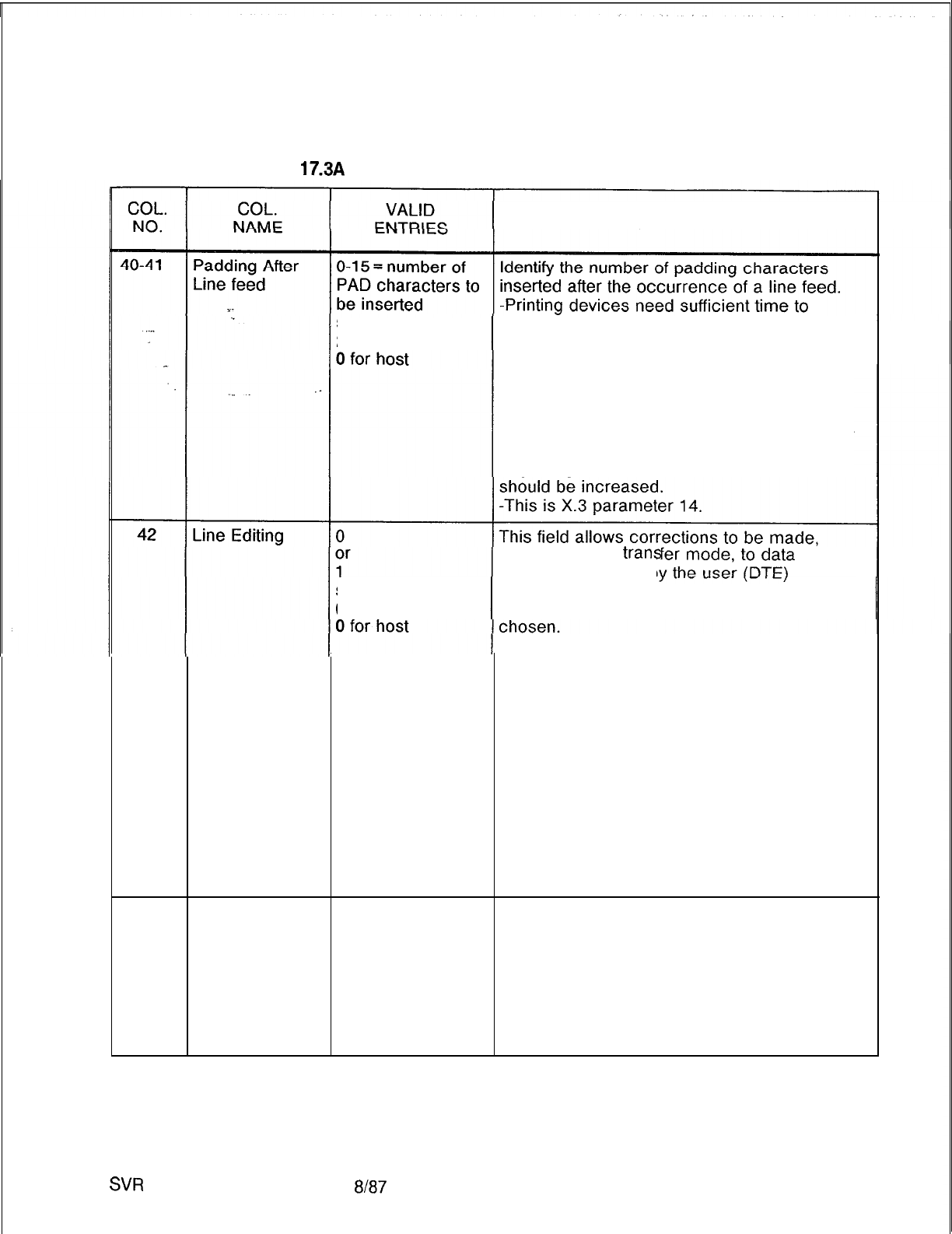
TL-130400-1001
Table
17.3A
Entry Fields for Record Code AP (Continued)
COMMENTS
suggested value = perform the line feed.
2 for terminals
-This parameter determines the default value
of line feed padding.
-This is the number of null characters after a
line feed is sent to a device that the system
will pause before sending additional data.
-The carriage return padding field is normally
assigned. If terminals lose information at the
beginning of each line, the value in this field
during the data
Vans
previously inputted b
suggested value = -The next three parameters determine the
0 for terminals control characters to be used if editing is
0 = editing not enabled during data transfer
1 = editing enabled during data transfer
-This parameter sets the default mode of the
editing function that the PAD performs. If this
parameter is enabled, the PAD will process
editing characters. This only applies to data
transfer mode. Editing will always be enabled
(Y) for command mode on terminals. If this
field is enabled, timers should be turned off
and the forwarding condition should be set to
transmit on carriage return. If this field is
disabled (N), all editing characters (LF, BS,
etc.) are lost in data transfer mode.
-This is X.3 parameter 15.
43-45
Backspace
O-l 27 = character
Identify the editing character that will delete
Character suggested value = the previous character entered (backspace
8 (Control H) for function).
terminals -See the previous ASCII character set to
0 for host select another character.
O-l 27 = ASCII character to be used for
character delete
-This is X.3 parameter 16.
SW
5210
8187 D-347
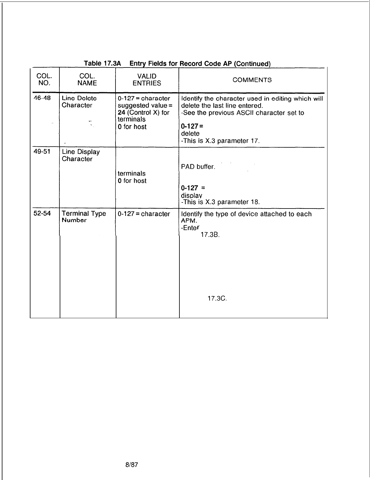
TL-130400-1001
select another character.
O-127=
ASCII character to be used for line
O-l 27 = character
Identify the character to be used in editing
suggested value = which will display the current contents of the
18 (Control R) for -See the previous ASCII character set to
select another character.
ASCII character to be used for line
r
the appropriate value (O-127) from
Table
17.3B.
-This option selects local (not CCITT
standardized) parameter number 1.
-Asynchronous host = 127
-Each APM user can specify the device type
while connecting a call.
-The terminal type in this field will be used if
no other is specified by the user.
-The terminal type number choices are listed
in Table
17.3C.
-This option selects local (not CCITT
standardized) parameter number 1.
8187
SVR 5210
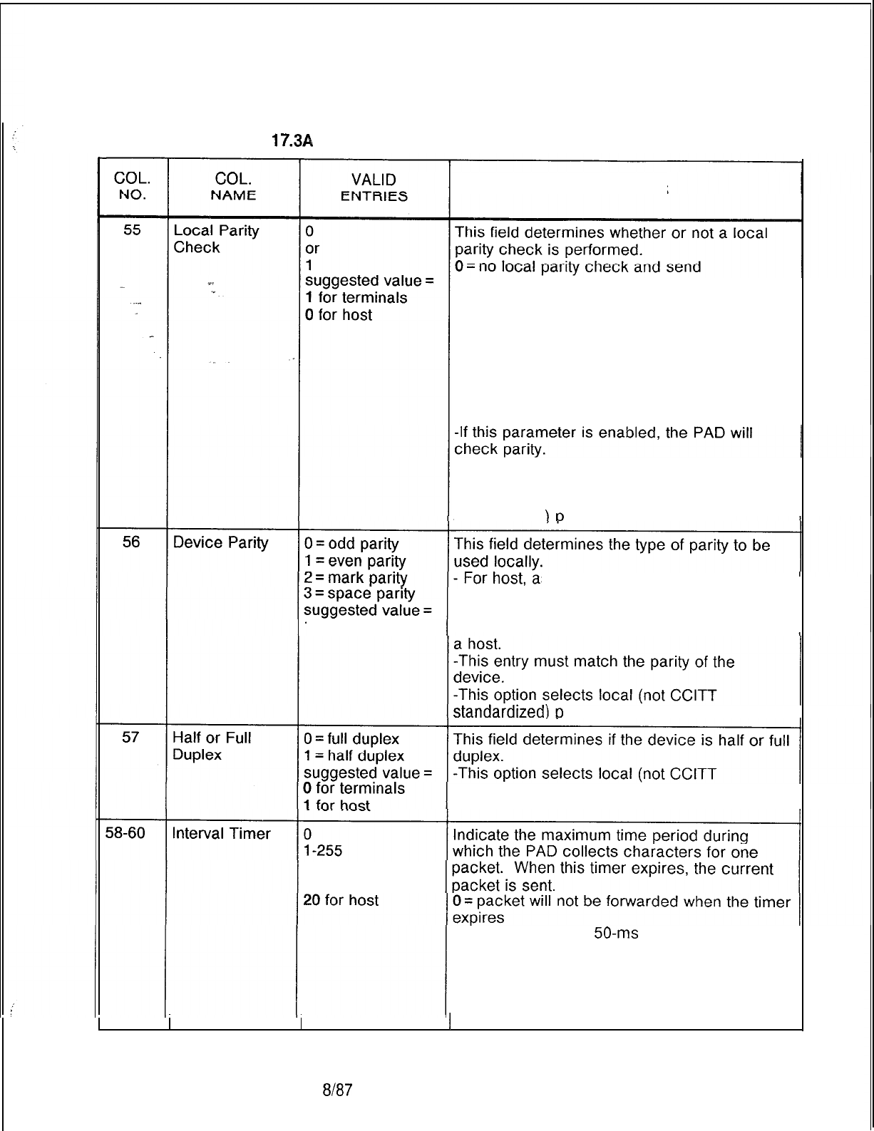
TL-130400-1001
Table
17.314
Entry Fields for Record Code AP (Continued)
COMMENTS
transparently through network (transmit parity
received through network)
1 = check local parity and send space parity
through network (ignore parity received
through network)
-This parameter determines the default value
of eighth bit transparency.
-This function specifies that the PAD should
or should not check parity.
-This field is normally set to N for
asynchronous devices.
-This field selects local (not CCITT
standardized arameter number 2.
sk the site if the host is
configured for odd or even parity.
-This parameter determines the parity of the
1
for terminals device if the device is a permanent terminal or
arameter number 3.
standardized) parameter number 4.
suggested
value =
0 for terminals
l-255 = number of
50-ms
increments before
the timer expires
-The selection must be made in increments
of 50 ms, so a selection of 2 = 100 ms.
-This option selects local (not CCITT
1 standardized) parameter number 5.
SVR 5210
8187 D-349

TL-130400-1001
COL. COL.
VALID
NO. NAME ENTRIES COMMENTS
61-63
Break Signal 002-006 = number Assign the length of the break signal to the
Timing of increments asynchronous device.
%
suggested value = -The selection must be made in increments
. . . .
5 (250 ms) for of 50 ms, so a selection of 2 = 100 ms.
terminals
5 (250 ms) for host
64-66
Command
O-255 = number
If this timer is enabled, it drops the
Inactivity Timer of increments connection when no user commands are sent
suggested value = within the time period specified.
12 (60
seconds)
-The user may disable this timer by the user
for terminals command signal “Test No-Disconnect.”
0 for host -The selection must be made in increments
of 5 seconds each, so a selection of 2 = 10
seconds.
67-69
Data Transfer 0If this timer is enabled, it drops the
Inactivity Timer or connection when data is not transmitted or
l-255 received within the time period specified.
suggested value = 0 = timer disabled.
0 for terminals
l-255=
number of increments (5 minutes
0 for host each)
-The selection must be made in increments
of 5 minutes, so a selection of 2 = 10 minutes.
Table
17.3A
Entry Fields for Record Code AP (Continued)
SVR 5210
D-350 6187
TL-130400-1001
Table 17.3A Entry Fields for Record Code AP
(Continued)
COL. COL.
VALID
NO. NAME ENTRIES COMMENTS
70
. . .
Data Set Signal Y = timer enabled This field determines whether or not this timer
Wait-Down N = timer disabled is enabled or disabled.
Timer suggested value = -The timer controls the delay between the
.”
Y for terminals time when the user disconnects (goes on-
N for host hook) and the time when the connection is
actually dropped.
-If Y is selected (enable), mark Record
Code Cl, columns 46-48, with the actual
delay time.
-This configuration parameter determines
whether or not the port is configured to use
the DSS wait-down option.
-This option specifies the use of the
disconnect delay timer.
-This timer comes into effect any time the
PAD disconnects the device (terminal or
host). When a PAD drops its DSS, it begins
running this timer. When the timer expires,
the PAD can continue on to its next DSS
state.
-This parameter specifies whether or not
this timer value can be used.
=lf
this field is enabled, the PAD will use the
timer that is defined on Record Code AP,
columns 24-26, for
APMs
or XP, columns
60-62, for
SPMs;
otherwise, no timer will be
run. This allows hosts that do not scan their
DSS very quickly to catch ports that were
remotely disconnected.
SVR 5210
8187
D-351
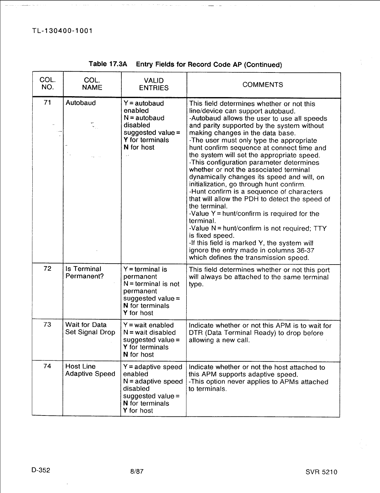
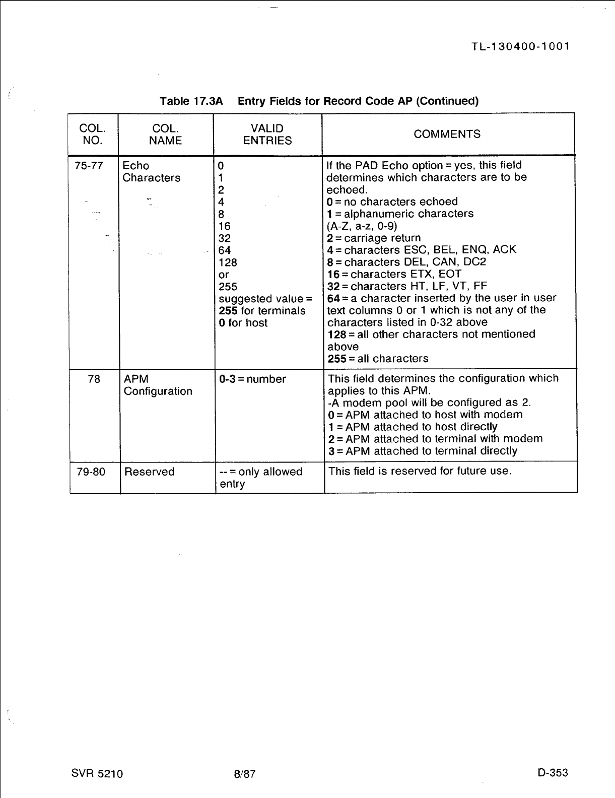
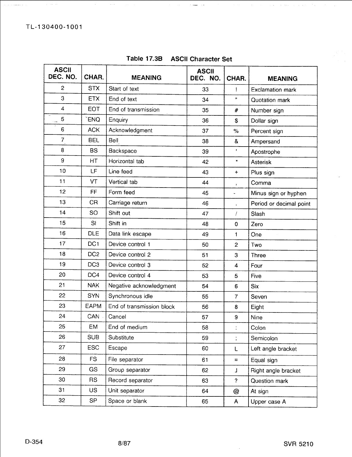
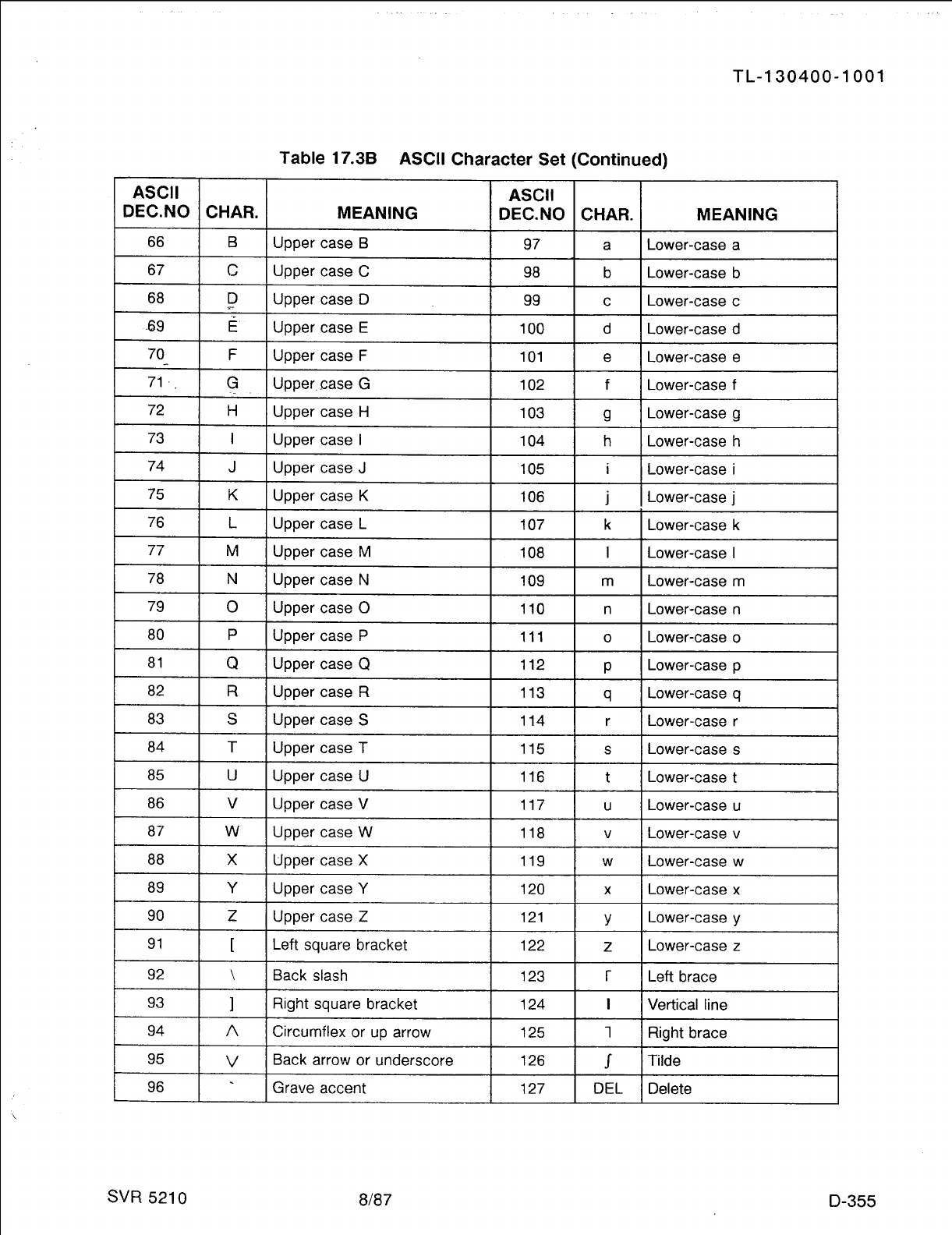
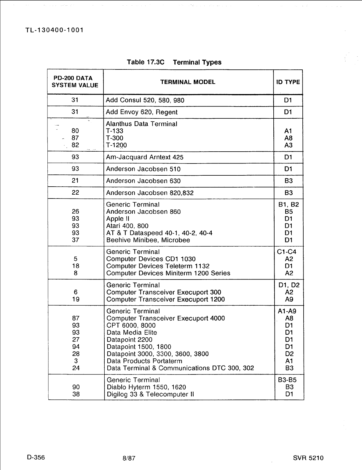
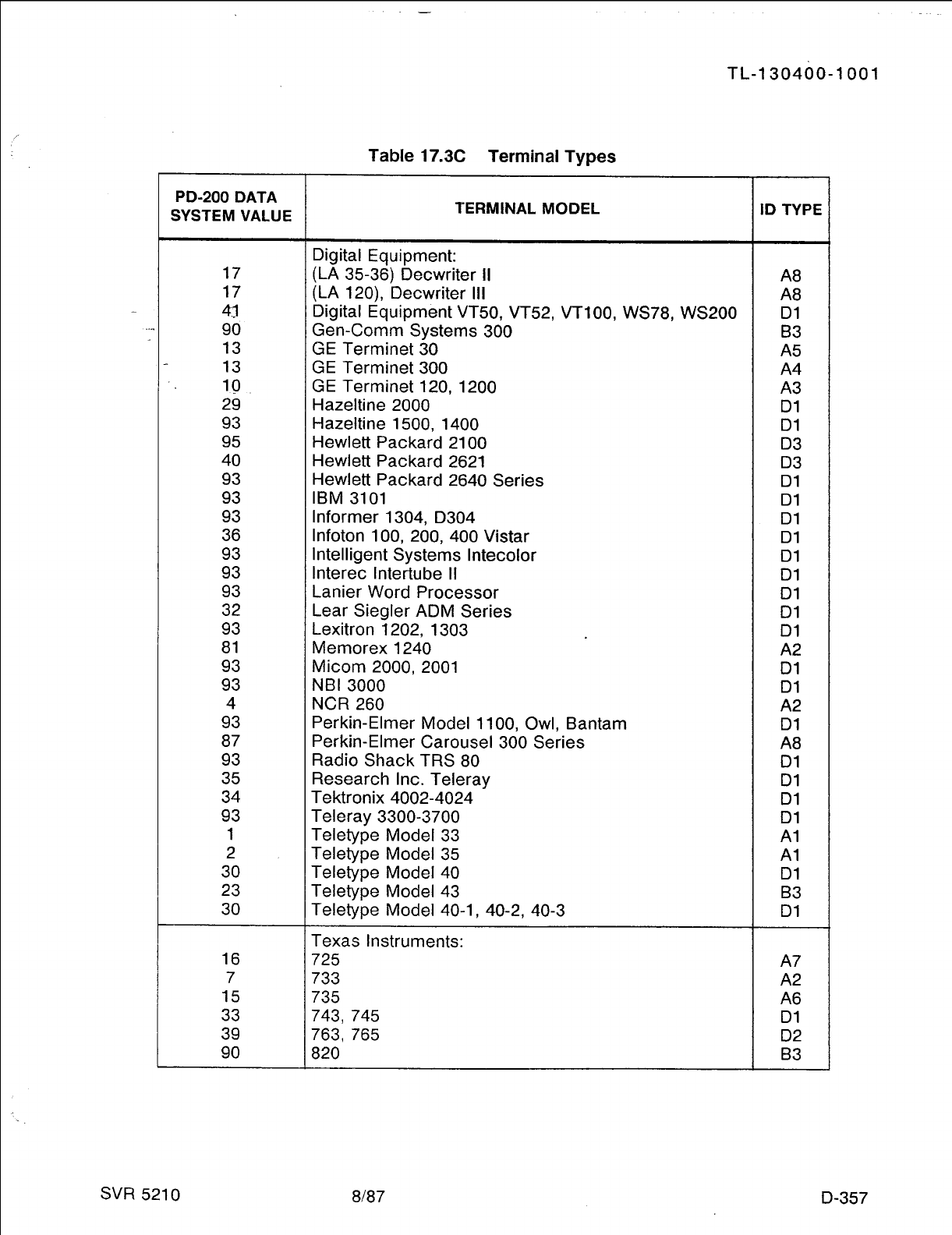
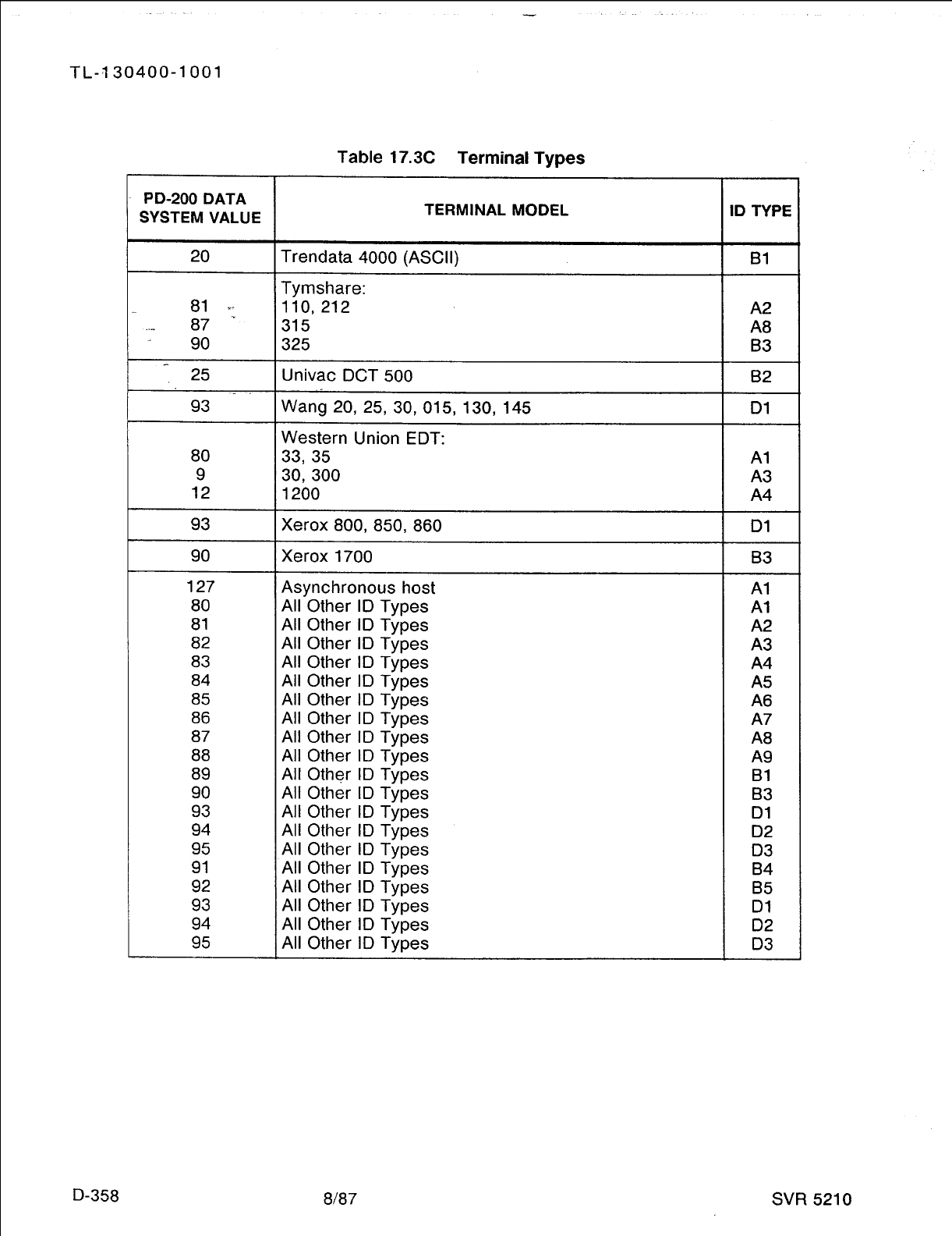
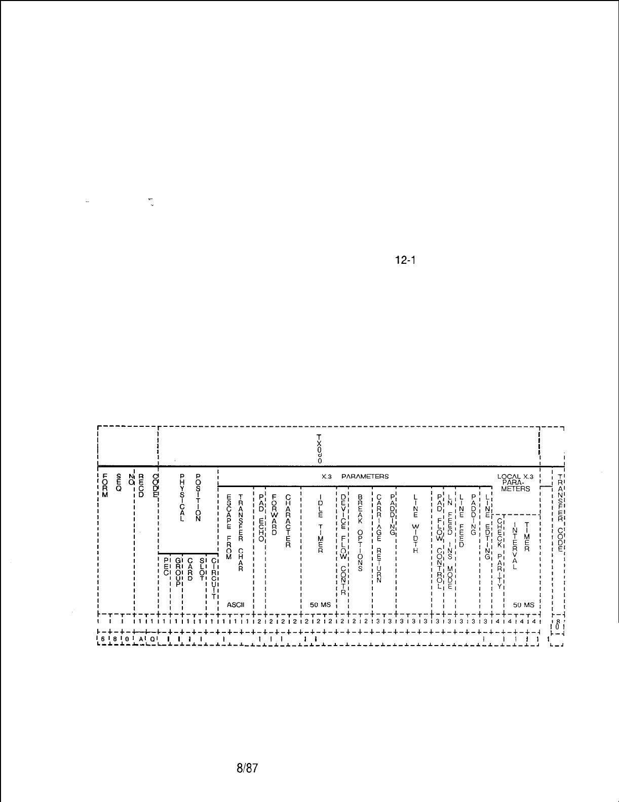
TL-130400-1001
Record Code AQ:
17.4 Record Code AQ, Figure 17.4, provides a list of parameters
Data System
applied to the remote end of a data call. These parameters
Asynchronous Port
temporarily override the pre-existing parameters of the remote
Set/Read List
end of a data call while a data call is connected to/from the port
specified on this record code. This allows the port specified in
this record code to control the configuration of its call partner on
both incoming and outgoing data calls. The remote port may be
reconfigured while the call is set up. It is restored to the original
configuration when the call is disconnected.
This option is normally implemented for host ports; however, any
asynchronous or synchronous (X.25) port can be assigned this
record code. The following rules apply for this record code:
l Any port defined in columns
12-l
6 of this record code must
have an entry on Record Code CP.
l If the port is asynchronous, it requires an entry on Record
Code AP.
l If the port does not reconfigure the port at the remote end, an
entry on this record code is not needed.
The values assigned to the options defined on this record code
depend on the requirements of the device which is attached to
the port. For parameters that do not need reconfiguration
at call setup, enter a dash in the field.
T---------T---------------------------------------------------------------~---~
I I
i
I
I
I I I
I
I I I
I
I I
9
I
I
171819101112131416161718191011121314151617181910111213141516171819101112131
10’
c-+-+-c-c-+-+-+-+-+-+-+-+-+-+-+-+-+-+-+-+-+-+-+-+-+-+-+-+-+-+-+-+-+-+-+-+-~
L--I
1618101~l~l
I
I
I
l
I
I
I I
I
I
I
I
I
I
I I I I I I I I I I I I I
I
I
I1
f
I
I
L-~-I-~-L-L-I-I-I-~-~-~-~ -*-1-1-1-1-~-*-1-~-*-~-*-~-~-*-*-~-~-~-~-~-~-*-*-~
L-2
Figure 17.4
Record Code AQ: Data System Asynchronous Port Set/Read List Data
Sheet
SVR 5210
8167 D-359
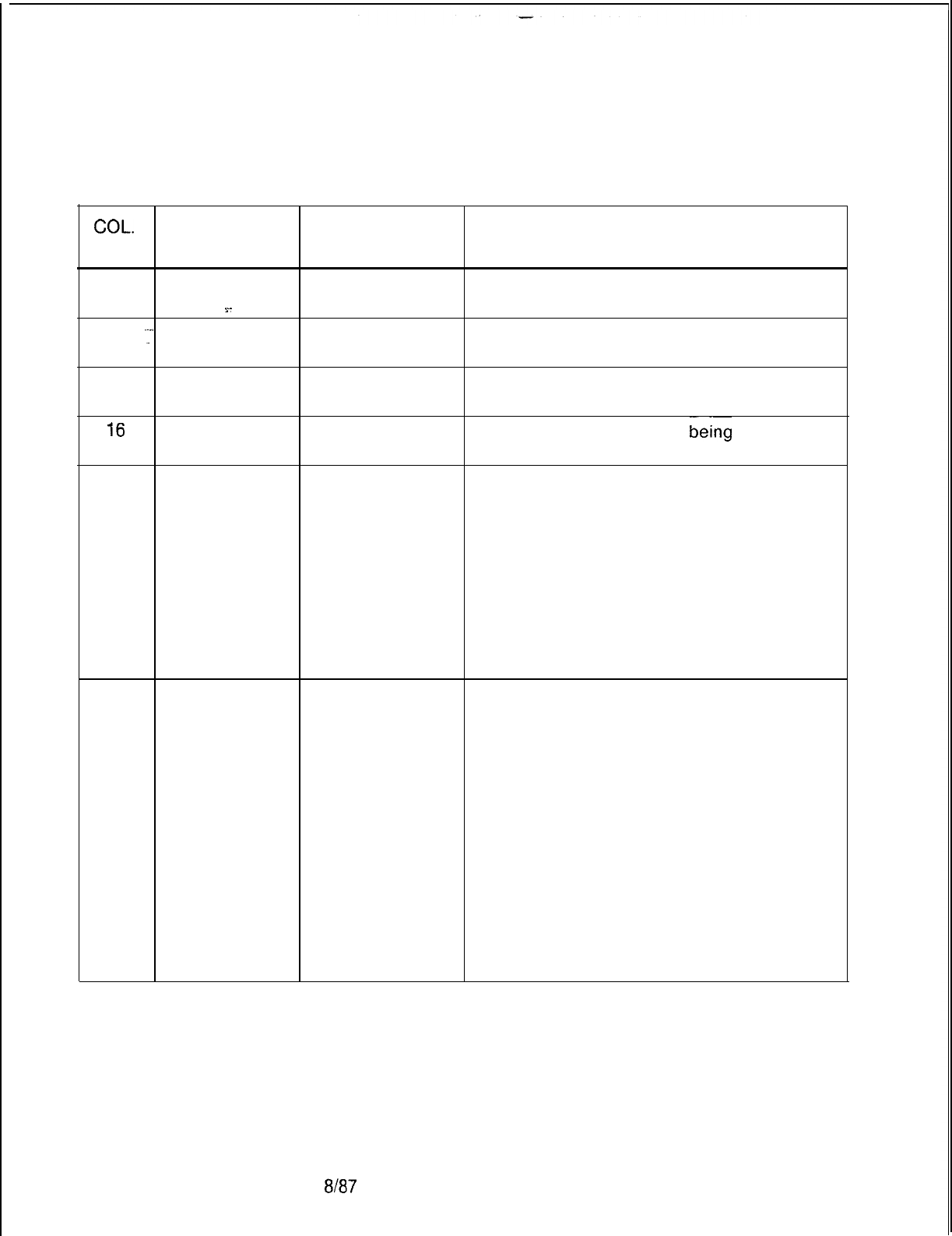
TL-130400-1001
Table 17.4 Entry Fields for Record Code AQ
COL.
COL. VALID
NO. NAME ENTRIES COMMENTS
12
PEC 0 = PEC number This field determines the location of the port.
.~.
What PEC is this card located in?
13
.r
Group A-D = group Which group (A, B, C, or D) within the PEC is
number this card?
14-15
Card Slot
00-l 0 = slot
number Which card slot within the group is this card?
16
Circuit Number
O-7 = assigned
Which circuit on the card is
being
used?
circuit number
17-19
Escape from
O-l 27
Data Transfer Assign the ASCII character that allows a user
Character to stop the flow of data.
(ASCII Value) -This parameter specifies the character that
will be received to indicate that the terminal
user wants to enter command mode.
0 = escape not allowed
1 = DLE character initiates escape
2-l 27 = decimal representation of selected
ASCII character (see ASCII character set
table )
-This is X.3 parameter 1.
20
PAD Echo 0 = no echo Enter 1 if PAD echo is provided.
1 = echo allowed -This field determines the default value of
echo. If this parameter is enabled, then echo
will occur in data transfer mode; otherwise, no
echoing will occur in data transfer mode.
Generally, this field should be set to N for full
duplex and Y for half duplex. If station
equipment displays two of each character, set
this field to N. If station equipment does not
display information that is keyed in, then try
setting this field to Y.
-PAD echo provides for all input characters
to be echoed back to the device attached
during the data transfer mode
-This is applied only to full-duplex devices.
-This is X.3 parameter 2.
D-360 8187
SVR 5210
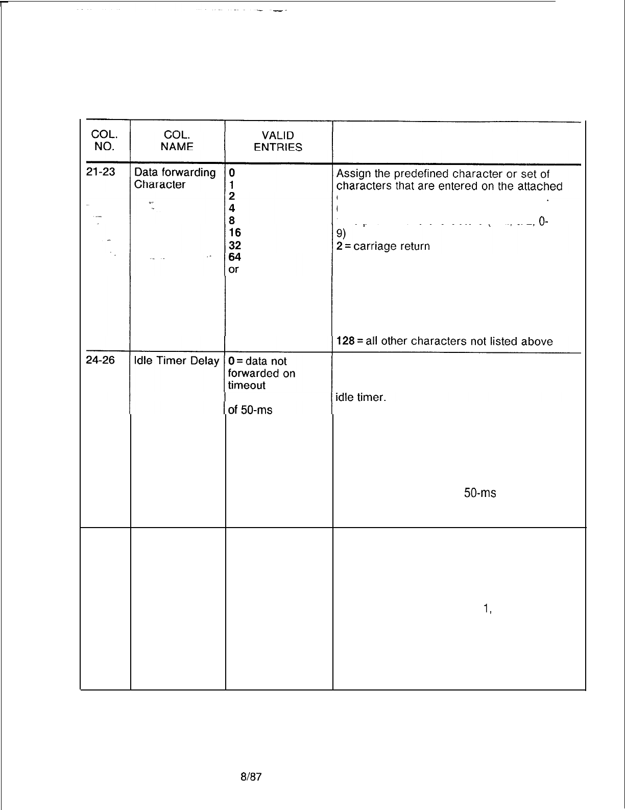
TL-130400-1001
Table 17.4 Entry Fields for Record Code
AQ (Continued)
COMMENTS
device to begin transmission of a packet.
0 = user cannot initate data forwarding
1 = alphanumeric characters
(A-Z,
a-z,
O-
128 = number
4 = characters
ESC,
BEL, ENQ, ACK
8 = characters
16 = characters
32 = characters
64 = a character inserted by the user in text
column 0 or 1, which is not any of the
characters listed in O-32 above
Indicate the allowed intervals between the user
input characters.
l-255 = number
-This field specifies the default value of the
increments -This timer clocks the time between
characters. If this timer expires, all of the
characters buffered up to that point will be
forwarded in a packet.
-Zero disables this timer.
-If this interval is exceeded, the timeout
causes the forwarding of a data packet.
-The time is selected in
50-ms
increments,
so a selection of 2 = 100 ms.
-This is X.3 parameter 4.
27 Ancillary Device 0 = disables flow
Indicate whether or not the PAD (Packet
Flow
Control control
Assembler Disassembler) can temporarily
1
= enables flow
slow the output from this device when the PAD
control is unable to receive more data.
-This parameter sets the default value of
device flow control.
-If this parameter is marked
1,
the PAD can
flow control the device.
-Flow control is used when the PAD cannot
process data fast enough or when the amount
of characters buffered is too great (due to the
transmission condition or network slow-
down).
SVR 5210
8187
D-361
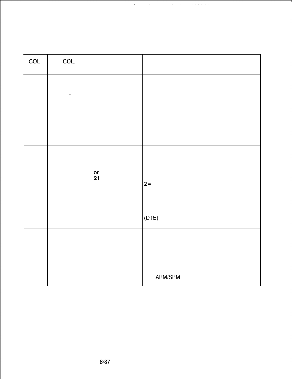
TL-130400-1001
Table 17.4 Entry Fields for Record Code AQ (Continued)
COL.
COL.
VALID
NO. NAME ENTRIES COMMENTS
27
Ancillary Device 0 = disables flow -The PAD sends a control-S, signaling the
(cont’d) Flow Control control device to stop transmission to the PAD.
1 = enables flow Should the device continue to transmit and
%. control overrun the buffer, data will be lost. When the
PAD becomes unblocked, it transmits a
control-Q. Transmission of this character
continues until the device starts sending data.
. .
The PAD then signals the connected device to
continue data flow.
-This field is dependent upon column 35
being set to Y.
-This is X.3 parameter 5.
28-29
Break Options 0This field determines the action to be taken by
1
an APM when a user depresses the break key
2
at the device attached to the APM.
80 = nothing
;i
1 = send an interrupt packet (X.25 special
packet) to the PAD
2=
send a reset packet (X.25 special packet);
this can cause data to be lost.
8 = escape from data transfer mode
21 = send an interrupt packet (X.25 special
packet) plus indication of the break message
to the PAD; also discard the output to the user
U-E)
-This is X.3 parameter 7.
30-31
Padding
O-31 = number of
Assign the amount of padding characters,
Characters After characters inserted after a carriage return is depressed.
Carriage Return inserted -Printing devices need sufficient time for the
mechanism to perform the carriage return.
-This parameter sets the number of null
characters to wait before continuing to send
any other characters.
NOTE: There are no real characters sent.
The
APMSPM
waits the amount of time it
would take to transmit those characters.
8187
SVR 5210
TL-130400-1001
CQL.
NO.
Table 17.4 Entry Fields for Record Code AQ
(Continued)
COL.
VALID
NAME ENTRIES COMMENTS
32-34 Line Width
0 = function
Assign the the number of output characters to
performed be printed per line at the user device.
.=.
automatically -This parameter sets the default value of line
l-255 = number
. . .
folding. This determines the number of
of characters per characters to transmit before an automatic
line carriage return/line feed is sent. This causes
long lines to fold or wrap to the next line. If
. .
_
this field is set at 0, this function is disabled.
A backspace will cause the internal counter to
be decremented by one for each backspace
character received, and carriage return will
reset the counter. This field is normally set to
0 because most station equipment does this
automatically. Otherwise, standard line
lengths are 80 or 132 characters.
-This is X.3 parameter 10.
35
Pad Flow
Control 0 = PAD flow If selected, this field determines that the APM
control not allowed will send a signal when the device attached to
1 = PAD flow it is temporarily unable to receive more data.
control allowed -This field sets the default value of flow
control.
-If this field is marked
1,
the device and/or
user of the device can flow control the PAD.
This disallows transmission of control-S and
control-Q.
-If this field is marked 0, the device cannot
flow control the PAD. However, the device
can transmit flow control characters through
the network.
-Control-S stops the PAD and control-Q
ends flow control.
This is commonly done by printers and users
that get behind and need to catch up.
-This is X.3 parameter 12.
36 Line Feed After 0This option allows automatic insertion of a line
Carriage Return 1feed after any carriage return is transmitted.
(CR) 4
-This parameter sets the default LF (Line
5
Feed) insertion. This causes the PAD to insert
6
an LF character into the transmission stream.
or 0 = no line feed inserted
7 = number 1 = insert line feed after each carriage return
sent to the user terminal (DTE) as data
SW
5210
8187 D-363
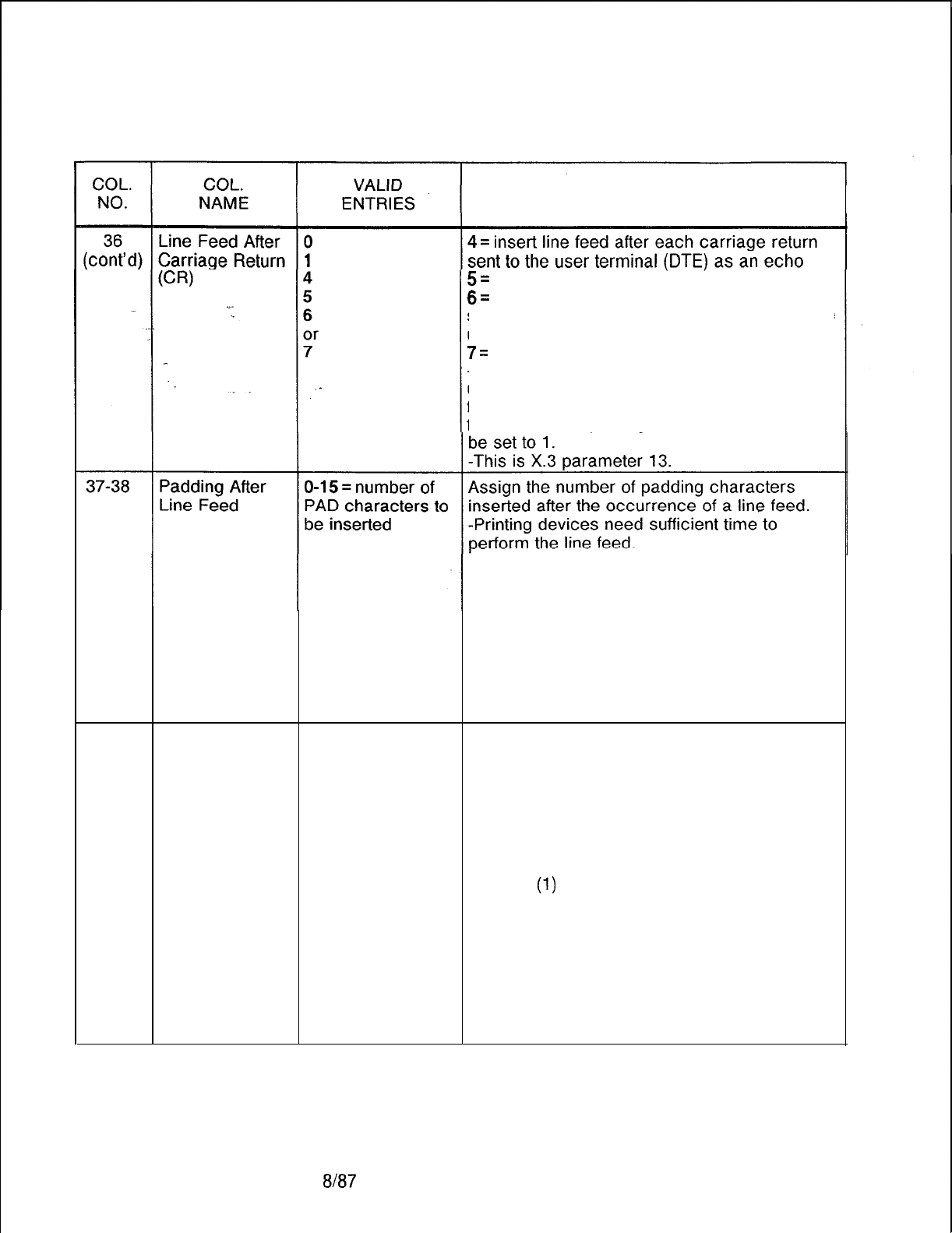
TL-130400-1001
Table 17.4 Entry Fields for Record Code AQ (Continued)
COMMENTS
5=
combination of (1) and (4)
6=
insert line feed after each carriage return
sent from the user terminal as data, plus to the
user terminal as an echo
7=
combination of (1) and (6)
-This field will usually be set to 0 or 1. If the
user’s terminal is double spacing lines, this
field should be changed to 0. If the user’s
terminal is overprinting lines, this field should
-This parameter sets the default value
of
line
feed padding. It is the amount of null
characters after a line feed is sent to a device
that the switch will pause before sending
additional data. Normally, the carriage return
padding field is put in first. If terminals are still
losing information at the beginning of each
line, the value in this field is increased.
-This is X.3 parameter 14.
39
Line Editing 0
or
1
This option allows corrections to be made,
during the data transfer mode, to data
previously inputted by the user.
-The parameter specifies the default mode of
the editing function that the PAD performs.
-If this parameter is enabled, the PAD will
process editing characters. This only applies
to data transfer mode. Editing will always be
enabled
(1)
for command mode on terminals.
If this field is enabled, timers should be turned
off and the forwarding condition should be set
to transmit on carriage return. If this field is
disabled, all editing characters (LF, BS, etc.)
are lost in data transfer mode.
0= editing not enabled during data transfer
1 = editing enabled during data transfer
-This is X.3 parameter 15.
8187
SVR 5210
TL-130400-I 001
Table 17.4 Entry Fields for Record Code AQ (Continued)
COL. COL. VALID
NO. NAME ENTRIES
COMMENTS
40
. . . .
Local Parity
0
Indicate whether or not a local parity check is
Check
Ot-
performed.
Y-
1 = number -This parameter sets the default value of
eighth bit transparency. This determines if the
PAD checks the parity bit. If enabled, the PAD
will check parity. Normally, this field is set at 0
for asynchronous devices.
_
_
0 = no local parity check and send
transparently through the network (transmit
parity received through the network)
1 = check local parity and send space parity
through the network (ignore parity received
through the network)
-This is local parameter 2.
41-43 Interval Timer 0
or
l-255 = number
Indicate the maximum time period during
which the PAD collects characters for one
packet.
-When this timer expires, the current packet
is sent.
-
The selection must be made in increments
of 50 ms, so a selection of 2 = 100 ms.
0 = packet will not be forwarded when timer
expires
l-255 = number of
50-ms
increments before
timer expires
SVR 5210
8187 D-365
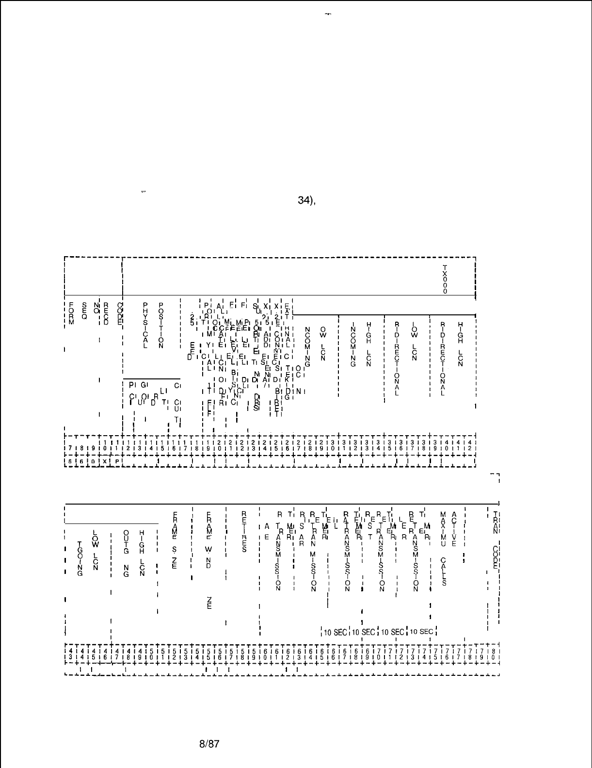
TL-130400-1001
Record Code XP:
17.5 Record Code XP, Figure 17.5, defines the parameters
Data System
required to describe the X.25 port attributes. An XP record is
x.25 Port required for every SPM (Synchronous Packet Manager) on the
system. One is also required for the ADMP. The parameters
below specify situations where the SPM ports must be configured
differently than the ADMP ports. If this is not specified, configure
the ADMP ports the same as SPM ports.
NOTE: For an ADMP (defined as PX25 in Record Code CP,
. . . .
columns 31 through
34),
enter the PEC and slot position of the
ADMP-A card. For an SPM, enter the slot position of
the associated line card.
r---------r-------------------------------------------------------------~
II
I I
I I is I
I
I
II I
II I
II I
x
(PI
AI
FI
FI
SI
xIxl~l
,
101
LI
RI RI
Ul
.I
.1x
LOGICAL CHANNEL NUMBER ASSIGN- I
IIII
fM
ID
E;
i
IRI
LI
AI AI PI
2,
2,Ti
III
5
;T,OIMIMI
p1515;;;
, L
1
CI
EI EI
Ch
II
I
S
IMIAI
I
W
AICINI
II
III
P I A,
TI
L;
LI
T;
g;
‘&y
II
II
II
I
E
;
Y;
EI
EI
EI
I
VI
VI
t
RI
NI
I
D
ICI
LI
EI
EI
XI
EI
ElCt
II
LI
LI
TI
SI
CI
L I
III
;
f;
$;
IIIII
L, I
BI
HI
NI
I I
E,S;;;g;
IIII
I
101
II’
PI
GI
C S,
CI
’
E, RI A
Ll
I I
I
II
RI
SI
LI
1,
DI
“t
3;
D;
‘:
1
II
II
I
;
Cl
01
R
0, RI
ITIDI
YI
Cl
A I
BIDIN,
I S,
EI
NI
I
Ci
I
IIGI
I
III
I
lJ’
D
TI
5:
IE,RICI
IR
IRI
I
III I
I
I P,
IL1
I I
I
SI
IEI
I
I I I I
II
1
I
I
I II
IF;
I
I
I I
ITI
I
I I I I
II
I
TI
II
I
I
I I
I
I
, I I I ,
II
I
I I
II
1
I
I
I
I
I
I
I
1
I I
I
I I I I
I I I I
;-
I’
I
I
I
I
,I
T-r-t-r-t-t-t-r-t-t-r-t-t-t-t-t-t-t-t-t-r-~-T-t-~-r-~-t-r-~-r-t-T-~-T-i
I
I I
11
I1
I1
I1
I1
I1
I1
I1
It
I1
l212121212121212121213131313131313131313,4l4l4l
1718191011121314151617l8l9l01112,3,4,5,6l71819101112131415161718~9~0l1121
c-+-+-u-+-+-+-+-+-+-+-+-+-+-+-+-+-+-+-+-+-+-t-+-+-+-+-+-+-+-+-+-+-+-+-~
I~lfil,,lXlPl
I I
I
I I
I
I
I,
I
I
I I I
I
I I I
I
I
I
I I
l
I
I
I
I
I I
I
L-I-I-J-I-I-~-I-*-I-I-
1-1-1-1-1-1-~-*-1-*-1-1-1-1 -1-~-1-1-1-~-~-1-~-1-~-~
----------------------------------------------------------------------------
I
!
MENT
I
I
F!
F;
R’
I F
R
T;
R
R
T;
C
R
T:
R
R
T;
C
R
T:
I
;
TI
II
IRE
IIEE
IIAE
IIEE
IILE
I II
RI
I
0
I
u
b
I
I
;
I
2
I
?
IATMIST~V~LTUSTUETU
‘::
I
I
Ai
“7;
z
I
E
I
il
I M
R
E,
T
R
EI
L
R
EI
E
R
EI
A
R
EI
I
Nf
I s,
I
;
l
TWI
IE
b
R;i
i
R
I
iFOTANWR(jW
;A;
I I
I I
1
I
1
8
I
y$IsIwIEI
8
ITS I
I
1
I M
I
I
Cl
;
;
I I
I
I
I
I
01
II
z
II
’
:
;
E
i
I
E
I
,?I
“:I
f,
$1
I
I
z
III I
4
I
II
2
I
I
DI
I
I
El
I 0
1
I
I
L
:
I
z
I
I
:I
I
I
II
1
IIII
w
III I I
I
k
I
I
1
IIII I
I,
I s I
18,
iI
;I
;I
iIS
I
IIIIIII
1;
I
III
I I I
I
I
IIII
I I
1
I
I
III
I
z
I
I
I
IIII
I I
1
I I IIII
I
I
I
II
IIIIIIII I
I
I
i
I
IIIII
II I I
f
III
I
I
I
I
III I
I
I
I
IIII
I
I
I
1
IIII
;
200MS
;
10SEC
1
10SEC
;
10SEC
(
10SEC
;
II 1
I
II I I
I
III
t-T-T-T-t-T-T-T-+-T-T-t-T-T-t-T-T-t-T-T-t-
I
T-T-t-T-T-t-T-T-t-T-i--k-
I I
T-t-i
~~~~~~~~~~~~~~~~~~~~~~~~~~~~~~~~~~~~~~~~~~~~~~~~~~~~~~~~~~~~~~~~~~~~~~~~~~~~~
13141516~7~8~9~O,,~2~3~4~5~6~7~8~9,O,,12,314151617~8191O1112~314~5~6,7~8~9~O~
c-+-+--+-+-+-+-+-+-+-+-+-+-+-+-+-+-+-+-+-+-+-+-+-+-+-+-+-t-t-t-t-t-t-+-~
III
I
I
I I
I
I I I I I I
I
I
I
I I I I
I
I
I I I I I I I I I I I I I I I I
L-~-~II--L-L-I-I-~-I-~-~-~-*-~-*-~-~-*-~-~-~-~-~-~-~-~-~-~-~-~-~-~-~-~-~-~-~-~
Figure 17.5
Record Code XP: Data System X.25 Port Data Sheet
D-366
8187
SVR 5210
-
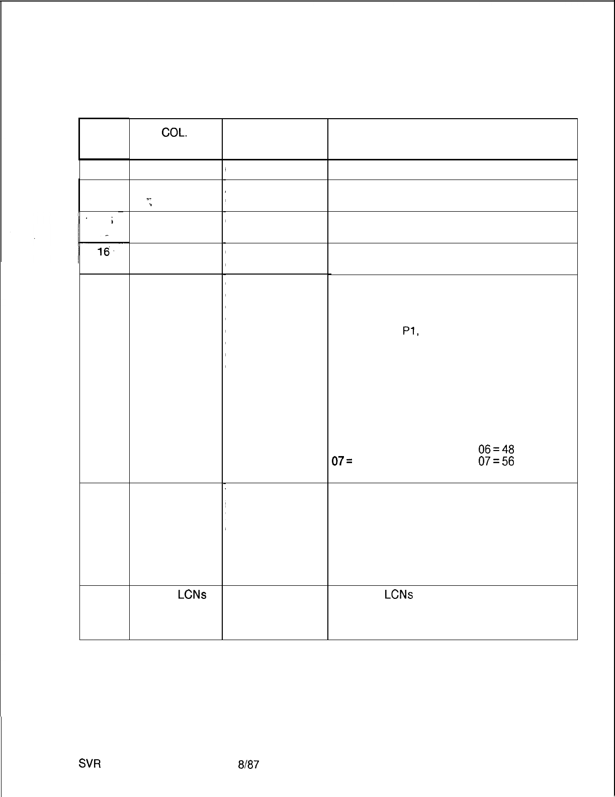
I
12
COL.COL.
NO.NO.
12
13
13
. . .
14-15
16.
17-18
19
20
SW
5210
TL-130400-1001
Table 17.5 Entry Fields for Record Code XP
COL.
NAME
PEC
Group
s-
.”
Card Slot
Circuit Number
X.25 Speed
Port May Call
Itself
Allocate
LCNs
in Ascending
Order
VALID
ENTRIES
0 = PEC number
A-D
= group
number
00-l 0 =
slot
number
O-7 = assigned
circuit number
01
=
1,200 baud
02=
2,400 baud
03=
4,800 baud
04=
9,600 baud
05=
19.2 kbps
06=
48 kbps
07=
56 kbps
08=
64 kbps
Y = port may call
itself
N = port may not
call itself
ADMP = N
SPM=Y
Y=yes
N=no
8187
COMMENTS
What PEC is this card located in?
Which group (A, B, C, or D) within the PEC is
this card?
Which card slot within the group is this card?
Which circuit on the card is being used?
This field determines the X.25 speed of the
device.
-For ADMP, enter the speed of the device
used for remote access to the ADMP (see
Record Code
Pl,
column 12).
-The speed for the value 5 is different when
used for a NIC. If NIC, then the X.25 speed
must be 05-07 as follows:
ADMP NIC
01 = 1,200 baud
02 = 2,400 baud
03 = 4,800 baud
04 = 9,600 baud
05 = 19.2 kbps 05 = 32 kbps
06 = 48 kbps
06=48
kbps
07=
56 kbps
07=56
kbps
08 = 64 kbps
Enter Y if this port or ADMP is allowed to call
itself. This field allows the X.25 device to
route a call to itself.
-This is a special bit intended for network
programmers who are experienced with
routing. This will enable testing of a single
device. No external routing loop detection will
be made by the switch while this field = Y.
Enter Y if
LCNs
are allocated in ascending
order.
-Enter Y for ADMP and all ports except the
port connected to a public data network.
D-367
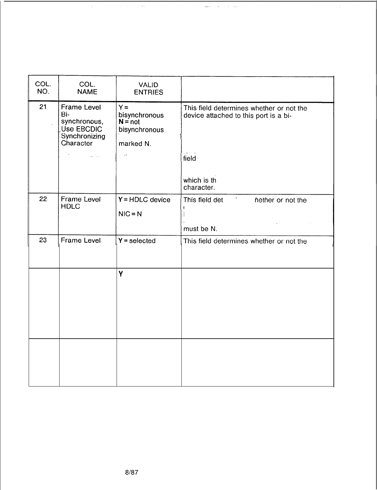
TL-130400-1001
Table 17.5
Entry Fields for Record Code XP (Continued)
COMMENTS
synchronous device.
-This field must be marked N because
This field must be bisynchronization is not supported in this SVR.
-This field specifies the frame sync character
for the bisynchronous protocol only. If this
= 1, the character will be hex 32, which is
the EBCDIC equivalent of the sync character.
Otherwise the sync character will be hex 16,
e ASCII equivalent of the sync
N = not HDLC ermines w
device attached to this port uses frame level
HDLC format.
-Enter Y for all devices except NIC which
24
supports N = not selected device attached to this port supports frame
Extended level extended addressing.
Addressing -Enter N for all devices.
Is X.25 Frame
Y
= address A This field determines whether or not this
Level Address A N = address B device uses X.25 frame level address A or
or B? address B.
-Enter Y (address A) for all ports connected
to a PDN (Public Data Network).
-Enter N for all other devices.
-When programing two NIC cards on different
systems that are used together, one should be
marked Y and the other N.
25
Is X.25 Device
Directly
Connected?
Y = direct connect This field determines whether the SPM is
N = not direct directly connected to the X.25 device or to a
connect modem.
-Enter Y for all devices not connected to
modems.
-Enter N for devices connected by modems.
SVR 5210

-
TL-130400-1001
COL.
NO.
Table 17.5 Entry Fields for Record Code XP (Continued)
COL.
VALID
NAME ENTRIES COMMENTS
26
. . .
External
Clocking
_.
Y = externally Indicate whether or not this device is clocked
clocked from an external source.
N = not externally -Enter N for all devices except NIC which
clocked must be marked Y.
-If this field = Y, the SPM will be clocked via
pins 15 and 17 of the RS-232 or V35
connector connected to the X.25 SPM. If N,
. .
the SPM provides clocking to the line (must
not be a modem).
-If this field is marked Y, column 25 must be
marked N.
-If this field is marked N, column 25 must be
marked Y.
-This field is not used for the NIC.
27-30 Incoming Low
LCN 0000-255 = LCN Identify the the lower limit of the LCN (Logical
range Channel Number) range to be used only for
Enter 0000 in this incoming calls. a
field.
31-34 Incoming High 0000-255 = LCN
L6N
Identify the the upper limit of the LCN range to
range be used only for incoming calls.
Enter 255 in this
field.
35-38
Bidirectional
Low LCN 0000-255 = LCN Identify the lower limit of the LCN range to be
range used for both incoming and outgoing calls.
Enter 0000 in this
field.
39-42 Bidirectional 0000-255 = LCN Identify the upper limit of the LCN range
High LCN range (0000-4095) to be used for both incoming
Enter 255in this and outgoing calls.
field.
43-46 Outgoing Low 0000-255 = LCN Identify the lower limit of the LCN range
LCN range (0000-4095) to be used only for outgoing
Enter 0000 in this calls.
field.
47-50 Outgoing High 0000-255 = LCN Identify the upper limit of the LCN range
LCN range (0000-4095) to be used only for outgoing
Enter 0000 in this calls.
field.
SVR 5210
8187 D-369
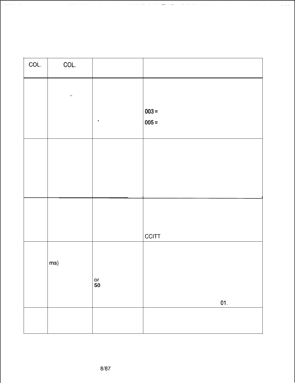
TL-130400-1001
Table 17.5 Entry Fields for Record Code XP (Continued)
COL.
COL.
VALID
NO. NAME ENTRIES COMMENTS
51-53
Frame Size
000-007
This field determines the frame size or number
suggested value = of bits per packet.
w-
005
000= 16
001 = 32
002 = 64
003=
128
004 = 256
_
005=
512
006 = 1,024
007 = 2,048
54-56
Frame Window 001-l 27 = window Identify the maximum number of
Size size unacknowledged frames that can be sent or
suggested received at one time. This can range from 1
value = 007 to 7 (module 8) if extended addressing is not
used.
-If extended addressing is used, then this
field could range from 1 to 127 (module 128).
-Extended addressing is not supported in this
release, so only values from l-7 should be
used in this field.
57-59
Retries
000-031
This field determines the number of frame
suggested value = level retransmissions of any packet type
10 for all ports before that packet is considered
untransmittable.
-This causes an error condition that is dealt
with by the X.25 SPM. This corresponds to
CCITT
X.25 N2 parameter.
60-62
Frame
01
Indicate the time for frame retransmission
Retransmission 02 (002-255) (multiples of 200 ms).
Timer (200- 04 -The X.25 speed is set in columns 17-18.
ms)
10
-If X.25 speed = 1,200 baud, enter 50.
20
-If X.25 speed = 2,400 baud, enter 30.
30
-If X.25 speed = 4,800 baud, enter 20.
&
-If X.25 speed = 9,600 baud, enter 10.
-If X.25 speed = 19.2 kbps,enter 04.
-If X.25 speed = 48 kbps,enter 02.
-If X.25 speed = 56 kbps, enter 01.
-If X.25 speed = 64 kbps, enter
01.
63-65
Restart 002-063 = timer This field determines the time limit between a
Retransmission range restart indication and a restart confirmation.
Timer Enter 006 for all This value is specified in increments of 10
(1 O-second)
devices. seconds.
8187
SVR 5210

TL-130400-1001
Table 17.5 Entry Fields for Record Code XP (Continued)
COL.
COL.
VALID
NO. NAME ENTRIES COMMENTS
66-68
Call 002-063 = timer This field determines the timing factor for
Retransmission range retransmitting calls.
Timer Enter 018 for all
(1 &Second) -This value is specified in increments of 10
devices. seconds.
. . . .
69-71
Reset 002-063 = timer This field determines the timing factor for
Retransmission range sending resets.
Timer Enter 006 for all
(1 O-Second)
‘-
devices. -This value is specified in increments of 10
seconds.
-When a reset is sent, an acknowledgment
must be received before the timer runes out.
72-74 Clear 002-063 = timer This field determines the timing factor for
Retransmission range retransmitting clear signals.
Timer Enter 006 for all -This value is specified in increments of 10
(1 O-Second)
devices. seconds.
75-77
Maximum Calls 000-063 =This field determines the maximum number of
Active maximum calls active calls.
Enter 005 for
ADMP
Enter 255 for all
other devices.
SVR 5210
8187
D-371
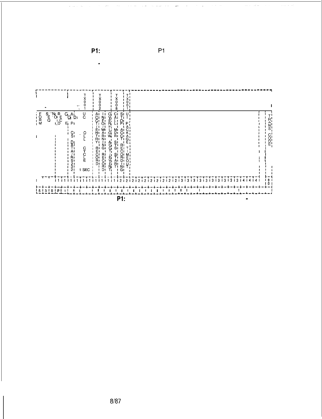
TL-130400-1001
Record Code Pl:
17.6 Record Code
Pl
, Figure 17.6, defines the parameters
Data System
required by the data system ADMP processor. The PI Record
Global Parameter
-
Code will contain only one record.
Part 1
r---------r-------r-----r---r-T---------------------------------------------~
I1
,
II
I
I I I
I I I
I
1
I
-
II
I
I
I
,F
S’-NIR
C,Ai
$
&YE
QDI
:
1
1
1
III
I
I
;
AI
P
I
I
ICI
.o
I
I SI
II
I
:
II
;
DI
I
I
I
1
I
I
I
1 I
I
I 1 I
II
’
I
II
1 I
I
I
’
I
I
I
I-
I
I I
111111111111111111111212121212121212121213131313131313131313l4i4l4l
181
1718191011121314151617181910111213141516171819101112131415161718191011121
101
~-+-+-*-+-+-+-+-+-+-+-+-+-+-+-+-+-+-+-+-+-+-+-+-+-+-+-+-+-+-+-+-+-+-+-+-+-~
l,j13tOipl~I
I
I
,
I
I
I
I
I
I
I
I
I
I
I
I
I
I
I
I
I
I
I
I I I I I 1 I I I I
I
L-A.-Ad-_L-
L-*-~-~-~_*-~_~-~_~_~-~-~-~-~-~-*-~-~-~-~-~-~-~-~-*-*-~-*-*-~-*-*-~
Figure 17.6 Record Code Pl: Data System Global Parameter Data Sheet
-
Part 1
D-372
8187
SVR 5210
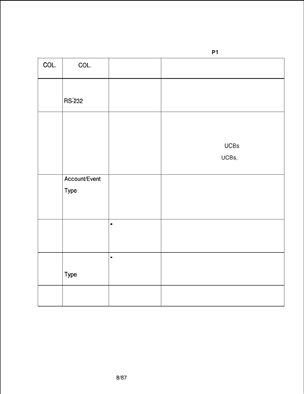
TL-130400-1001
COL.
NO.
Table 17.6 Entry Fields for Record Code Pl
COL. VALID
NAME
ENTRIES COMMENTS
12
. . .
ADM P Access Y=yes This field determines whether or not the ADMP
from Data N=no user interface can be accessed from ports
Network and other than the ADMP maintenance terminal.
RSr232
-This field allows or disallows access to the
ADMP from the data network.
13-15
Universal 000-255 = number This field determines how often the ADMP
Controller Board of seconds for should poll the UCB to check its operation.
Polling Cycle polling -The selection must be made in increments
suggested value = of 1 second, so 005 = 5 seconds.
10 to 15 seconds -This field is the number of seconds which
-suggested entry elapse before polling all
UCBs
again.
is 5 seconds -If this value is 20, the ADMP UCB poller
runs through the list of
UCBs,
polling each of
them. This is repeated after waiting 20
seconds.
16
AccounWEvent
0 = accounts Identify what type of report is printed.
Record Report
1 =
events
-“Event” reports relate to malfunctions of the
Type
2 = events/
system and “account” reports relate to has to
accounts separate do with call acounting.
3 = events/
-Because there are two types of reports, they
accounts are normally sent to different locations (2).
combined
17
Information/
-
= only allowed Not used in this SVR.
Warning Record entry 0 = warning
Report Type 1 = information
2 = information/ warning separate
3 = information/ warning combined
18
Overflow
-
= only allowed Not used in this SVR.
Account/Event entry 0 = overflow accounts
Record Report 1 = overflow events/accounts
Type
2 = overflow events/accounts separate
3 = overflow events/accounts combined
19
Call MDR on Y = selected The suggested entry is Y if MDR is to report
System Startup N = not selected account/events/information/warning to the
ADMP.
SVR 5210
8187 D-373
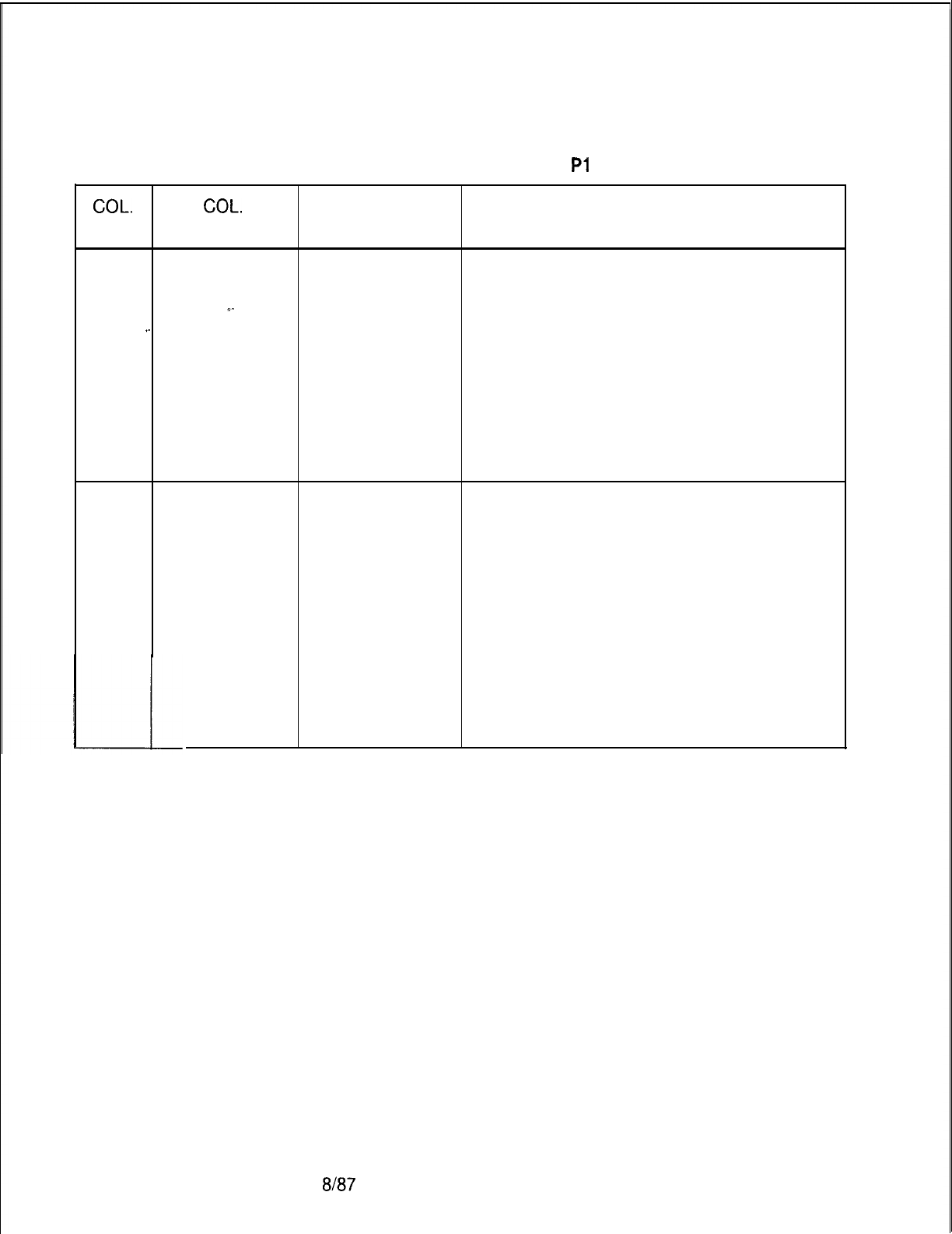
TL-130400-1001
COL.
NO.
Table 17.6 Entry Fields for Record Code Pl (Continued)
COL.
VALID
NAME ENTRIES COMMENTS
20
Stop Account Y = stop recording This field determines the action that is taken
Recording on N = overwrite old when the file is full.
File Full
__-
accounting Y = recording is stopped when the event file is
records
full
.-
.
.
N = overwrite the oldest event record
-This currently impacts systems where event
reports are saved until a device calls the
ADMP.
-Up to 4,000 event reports can be saved
simultaneously.
-It is recommended to enter an N in this field;
this keeps the most recent information.
21
User Inter-face Y = timeout This field determines whether or not the user
Package N = no timeout interface package timeout is used.
Timeout -The user interface package timeout is the
timeout applied when the ADMP terminal is in
the UI (User Interface) mode. The UI mode is
listed within the system table which is listed
within the table edit.
-If no entry is made from the ADMP terminal
keyboard within 10 minutes, the system
automatically cancels the UI mode and returns
to the diagnostic mode.
-The timeout value for this field is a
predetermined 10 minutes and cannot be
changed.
8187
SVR 5210

TL-130400-1001
Record Code P2:
17.7 Record Code P2, Figure 17.7, defines the parameters
Data System
required by the data system ADMP processor. Record Codes
Global Parameter
-
Pl
and P2 define the type of report the ADMP generates
Part 2
and the destination for sending these reports. The ADMP
can generate accounting records and event records.
Accounting and events are stored in files.
s
.
.
.
.
SVR 5210
Only one P2 record will exist for each ADMP report type;
therefore, this record code will contain a maximum of two
records. The two types are account and event. If a P2 record
is missing for either of the two types, that particular type of
report is not generated by ADMP.
The ADMP records can be reported to an RS-232C connection
that is linked to the ADMP maintenance console or a specified
X.121 incoming or outgoing address (columns 27 through 42).
If the destination is an outgoing X.121, the ADMP maintains
a permanent connection to this port, which is specified in the
following’ X.121 address. That port can never be assigned to
a user. The recommended configuration is outgoing to an
X.121 address and use a dedicated device.
If the destination is incoming, the ADMP waits for a call from
the port specified in the following X.121 address (and reports
only to that port). Since the ADMP cannot initiate a disconnect,
the originating end controls this call. It is suggested that the
incoming X.121 address be assigned only for this purpose.
8l87 D-375
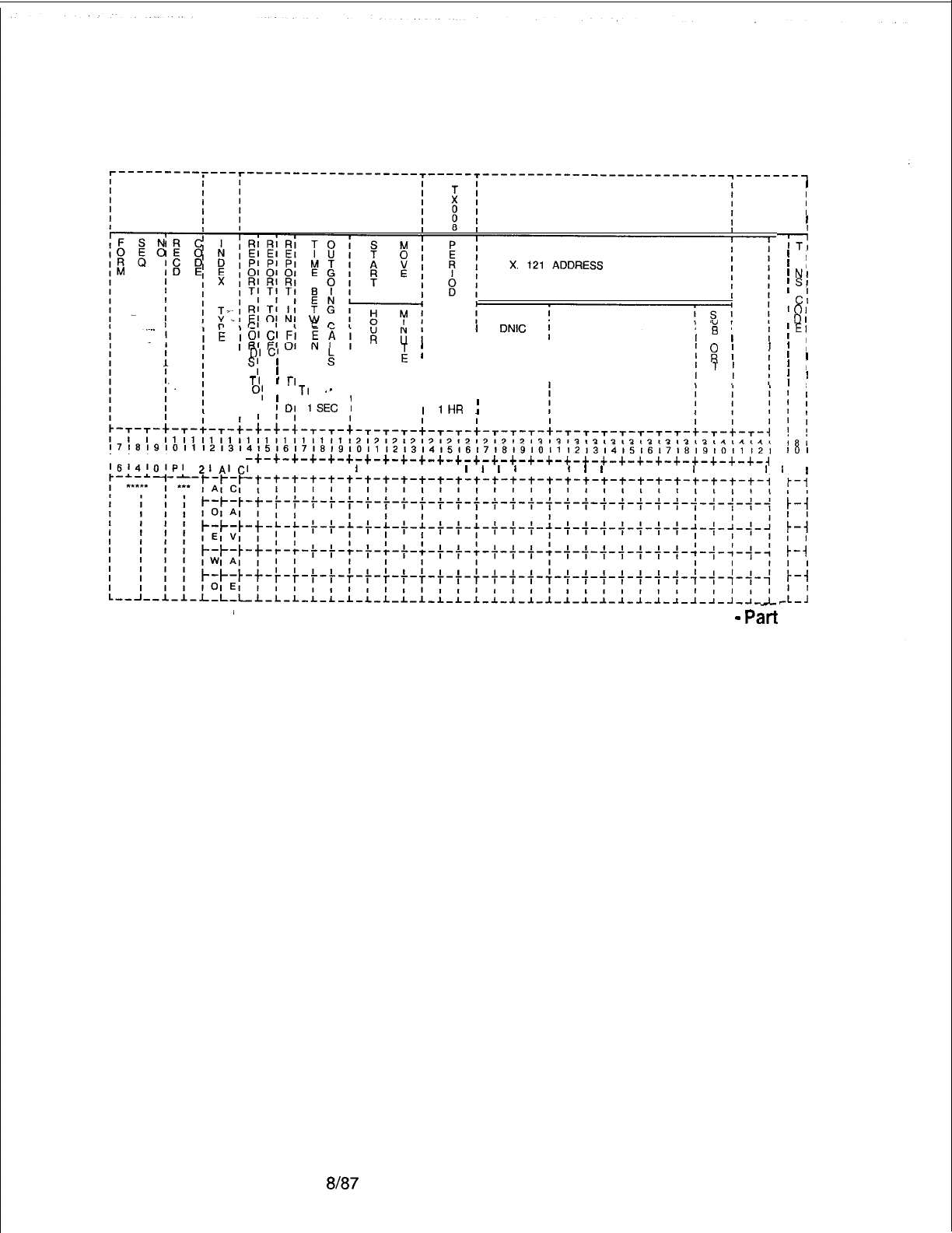
TL-130400-1001
I
I
I
I
1
--Fi
’
RI
1AI
1
NI
;
SI
1
c:
’
01
’
DI
;
EI
I
1
I
1 1
1
I
’
!
’
I
1
DNIC
j
SERVER i
g
;
I
’
P
lI
,
DI
Cl
RI
k
I
g
II I I
I
s;
1 Ml
I I ;
g
II
1 AI
I I I I
II
-.
.-
II I I
T
II
I
1’
1
II
I
.I
0;
I
TI
.m
I
I
’
El
I !
!DI
1SEC
1
II
II
I
I
1HR
;
~~~~~~~~~~~~~~~~~~~~~~~~~~~~~~~~~~~~~~~~~~~~~~~~~~~~~~~~~~~~~~~~~~~~~~~~~
c-+-+-t-+--c--c--+
101
-+-+-+-+-+-+-+-+-+-t-+-+-+-+-+-+-+-+-+-+-+-+-+-+-+-+-+-+-~
c-4
l6141OlPl
21AICI
I I I I I
I
I I , I I
I
I
I
I
I I
I
I
I
I I I I
I
I I I
I
II
i-i
;-;
;-;
1-i
A-:
Figure 17.7 Record Code P2: Data System Global Parameter Data Sheet
-
Part
2
D-376
8187
SVR 5210
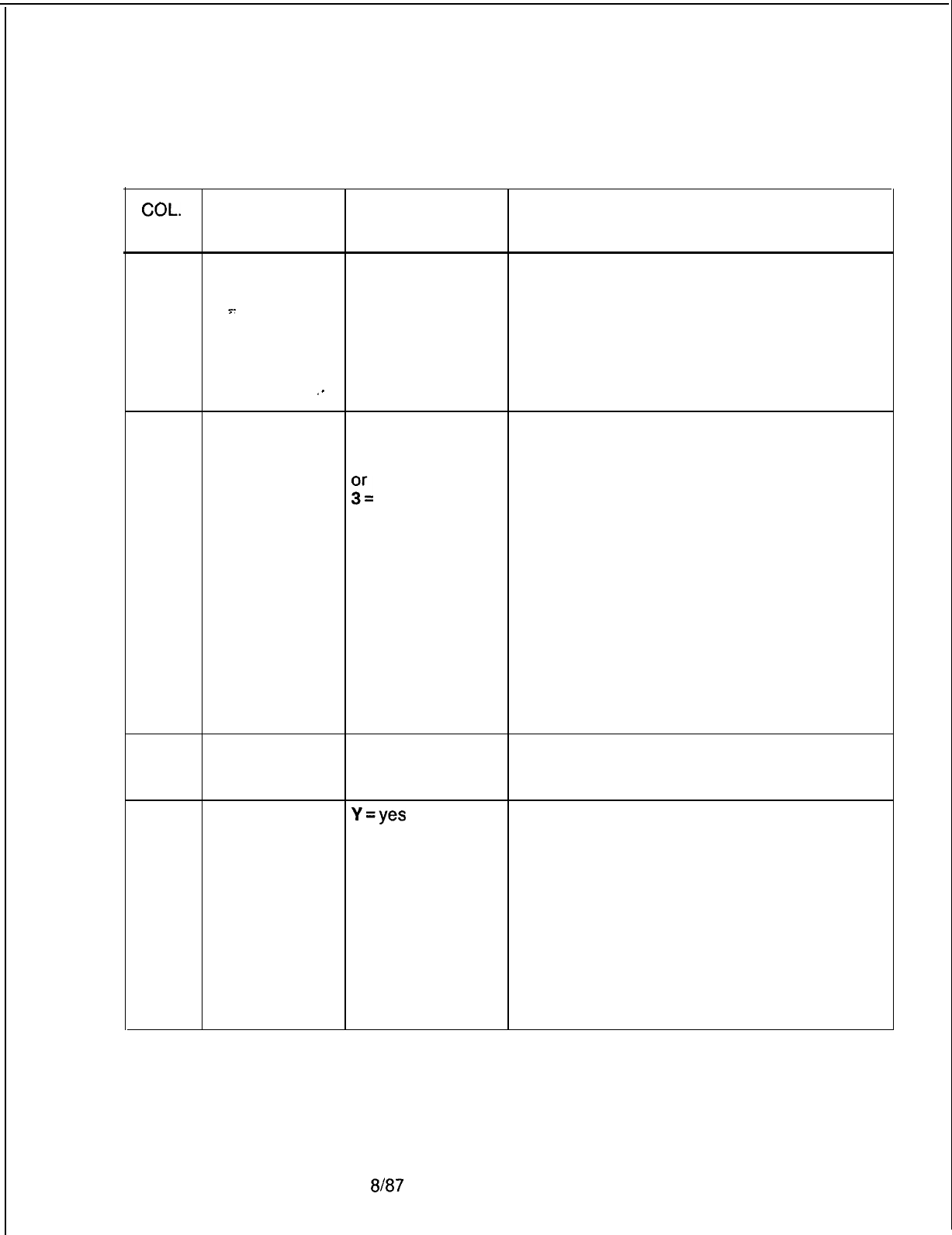
TL-130400-1001
COL.
NO.
Table 17.7 Entry Fields for Record Code P2
COL. VALID
NAME
ENTRIES COMMENTS
12-13
Report Type AC = accounts This field determines the type of report
EV = events
generated.
IN = information
s-
OA = overflow
. . .
account
OE = overflow
event
,-
WA = warning
14
Report Records 0This field determines where the system will
to Destination 1send the report(s) listed in columns
212-13.
:L
number 0 = nowhere, reports are discarded
1 = RS-232C (ADMP maintenance console),
the reports appear on the ADMP terminal
2 = outgoing to specified X.1 21 address
(recommended), the reports are to be sent to
another device
3 = incoming from specified X.1 21 address,
the reports are stored until a device calls in
requesting the reports
-If account and event reports are to be sent to
separate devices, this field will appear once
for each report.
-It is recommend to send reports to a
dedicated outgoing hard-copy terminal.
15
Report to CEC N=no This field determines whether or not reports
are sent to the CEC.
-This field must be marked N.
16
Format
Y=yes
This field determines whether or not the
N=no records are reported in formatted ASCII or
Binary.
-Enter Y if records are reported to the ASCII
device.
-This field only applies to incoming or
outgoing reports.
-Reports sent to the ADMP terminal
(RS-232) will always be in ASCII format.
-This field is normally set to 1 (ASCII).
-All report examples given earlier are in
ASCII format.
SVR 5210
8187 D-377
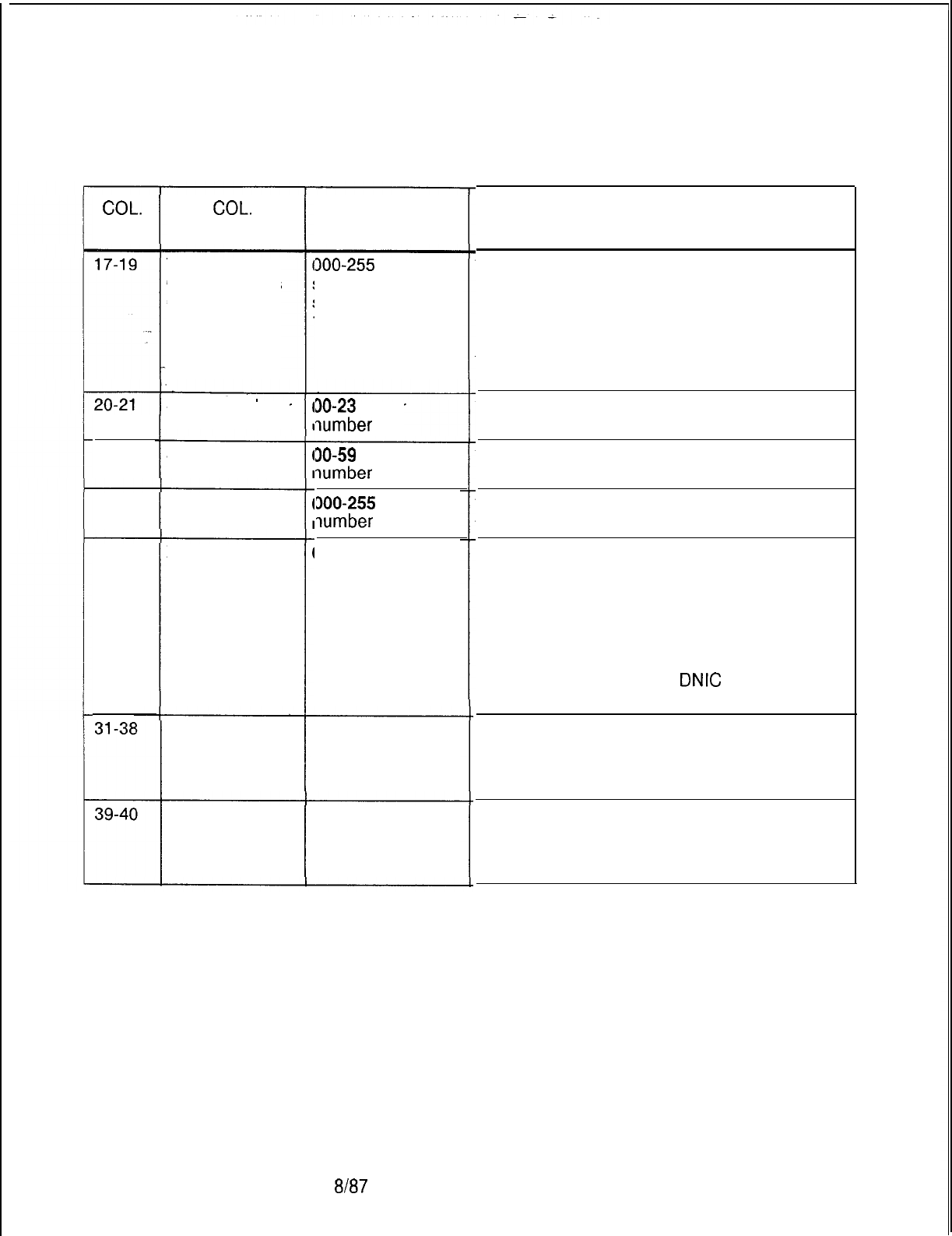
TL-130400-1001
Table 17.7 Entry Fields for Record Code P2 (Continued)
COL.
NO.
22-23
24-26
27-30
COL.
NAME
Time Between
Outgoing Calls
(1 Second)
Start Time Hour
Start Time
Minute
Period (1 Hour)
X.1 21 Address
(DNIC)
X.1 21 Address
(server number)
X.1 21 Address
(sub-port)
VALID
ENTRIES
300-255 =
seconds
suggested value =
10 (010) seconds
30-23 = hour
qumber
30-59
= minute
7umber
300-255 = hour
7umber
3-9 = number
O-9
= number
O-9
= number
D-378 8187
COMMENTS
This field determines the time (in seconds)
between outgoing calls.
-This field is only for outgoing reports or
reports to the ADMP terminal.
-The field determines the number of seconds
the system will wait before retrying an outgoing
call.
This field determines the hour for the start time
(00-23)
for the 24-hour clock.
This field determines starting time in minutes
(00-59) to make an outgoing account call.
This field determines the number of hours to
wait between outgoing account calls.
If the system is configured for incoming or
outgoing call reports, this is the only X.121
address that can send or receive a data call.
-Calls from or to other incoming or outgoing
addresses will not be accepted.
-This field is only used if column 14 is
marked 2 or 3.
-This field determines the
DNIC
of the X.121
address.
This field determines the server number of the
X.1 21 address.
-This field is only used if column 14 is
marked 2 or 3.
This field determines the sub-port number of
the X.121 address.
-This field is only used if column 14 is
marked 2 or 3.
SVR 5210
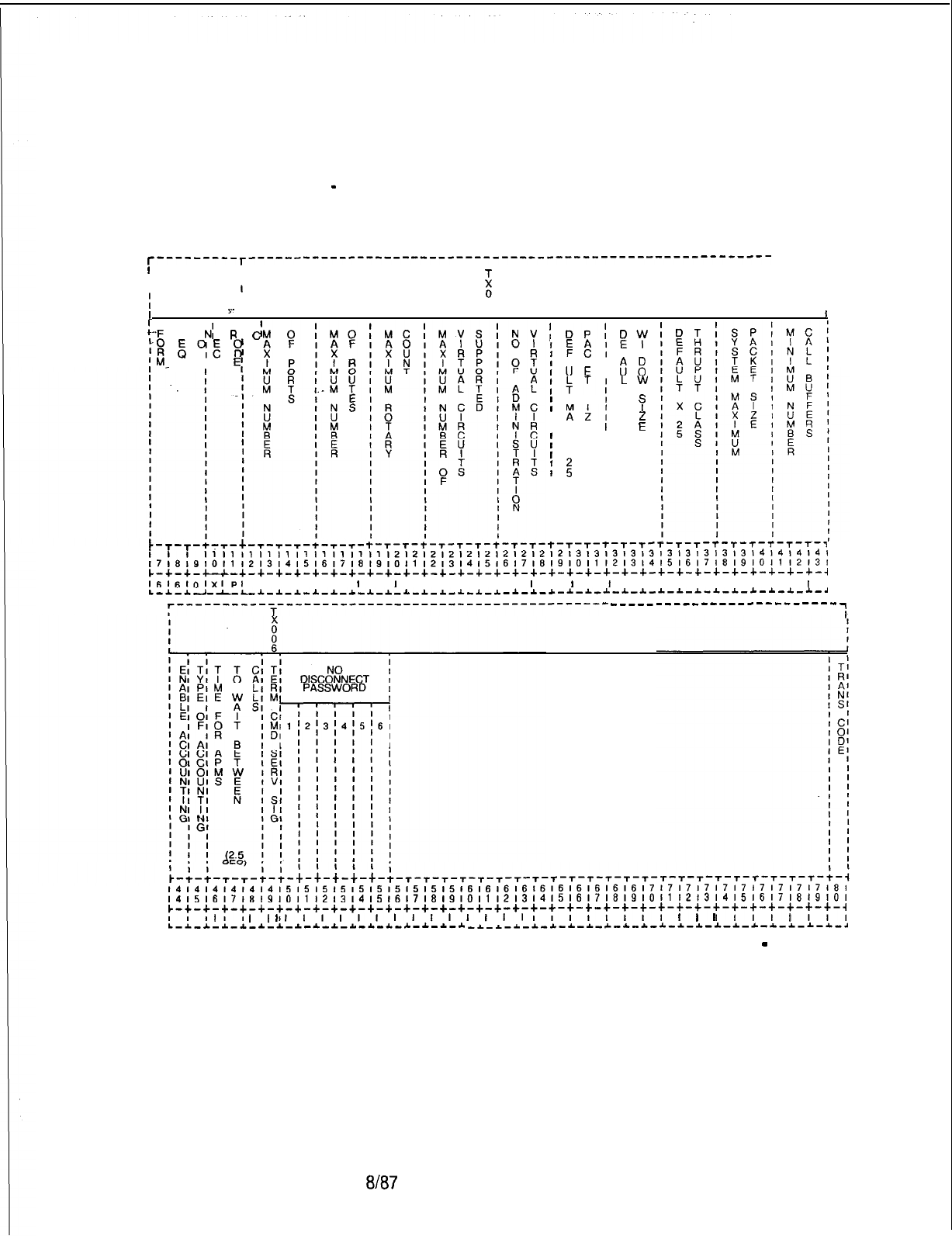
TL-130400-1001
Record Code Cl:
17.8 Record Code Cl, Figure 17.8, defines the global
Data System
information for call processing. One record is required per
Call Processing
-
system.
Data Part 1
T---------T-----------‘------------------------------------------------
-----1
I
II
I I I
III
II
i
I
8
I
I
IY-
I
:-.F
S
N;
R
d
k::
E”IE
g
I”-
I
ID
E(
)
DP;
‘ES
f
AK I
,lJE
I
ST’
I
MS
I
I
AZ;
I XE
I
I
x
I
I
I
I
<
I
I
I I
I I
II
II
II
I I
I I
‘FY
F N
38
LW
T
x
s
2
E
5
t-
r-r-t-r-+-r-r-r-t-r-r-
t-T-T-t-T-T-T-t-T-T-t-T-T-T-T-T’T-T-T-T-r-r-r-r-r-~
1111111111,11111,1,112,21212,21212l2,2,21313l3,3,313l313l3l3l4l4l4l4l
~~~~~~~~~~~~~~~~~~~~~~~~~~~~~~~~~~~~~~~~~~~~~~~~~~~~~~~~~~~~~~~~~~~~~~~~~~~
c-+-+-u-+-+-+-+-+-+-+-+-+-+-+-+-+-+-+-+-+-+-+-+-+-+-+-+-+-+-+-+-+-+-+-+-~
l6l6,OlxIpl
I I I I I
I
I
I
I I I I I I
I
I,
I
I
I
I I , I, I I I I I
I
I
L-*-~----L-*-*-~-I-*-*--L-~-*-*_~-~-*-~-*-~-~-~-~-~-l-*-~-~-~-~-~-~-*--L--L-~
‘----------T--------‘------------------------------
-------------------------~
II
~~~~~~~~~~~~~~~~~~~~~~~~~~~~~~~~~~~~~~~~~~~~~~~~~~~~~~~~~~~~~~~~~~~~~~~~~~~
141516,71819,011,2,3,4,5,6,7,819,0,,,2,3141516171819101112,3141516171819101
c-+-+-+-+-+-+-+-+-+-+-+-+-+-+-+-+-+-+-+-+-+-+-+-+-+-+-~-+-+-+-+-+-~-+-+-+-~
I
I
I
I
I,
I
,I,,,,,,,,,,,,
I II III
I
I
I
I I
I
I I
I
L-~-L-~-*-L-~-*-~-~-*-~-~-*-~-~-~ _*_~-~-~^~-~-~-L-~-~-~-*-~-~-*-~-*-*-~-~-~
Figure 17.8 Record Code Cl: Data System Call Processing Data Sheet
-
Part 1
SVR 5210
8t87
o-379
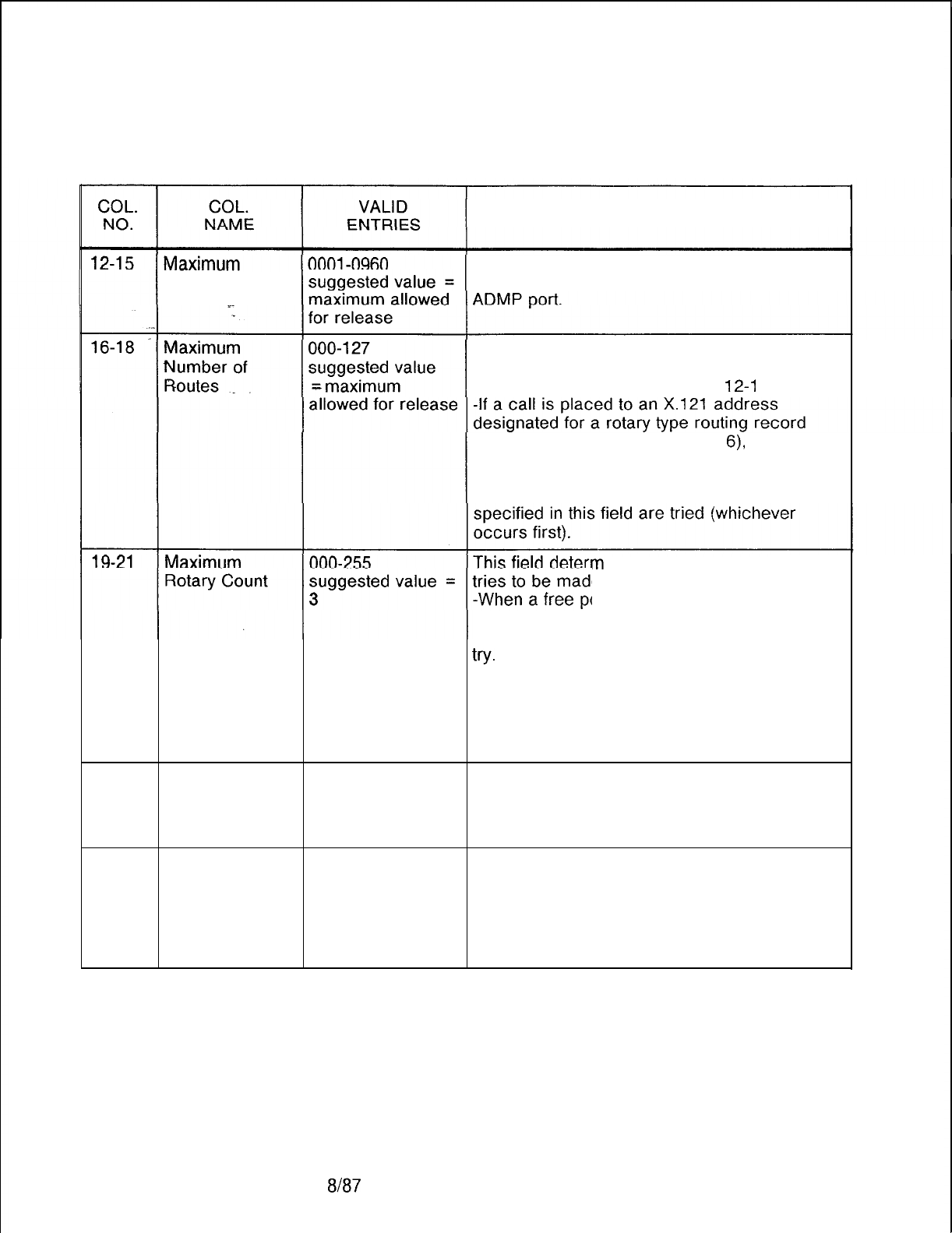
TL-130400-1001
Table 17.8 Entry Fields for Record Code Cl
COMMENTS
Number of Ports This field determines the maximum number of
ports configured in the system including the
Indicate the maximum number of routing
records entered in the system.
-See Record Code RT, columns
12-l
4.
(Record Code RT, columns 15-l
6)
it will try
devices in this routing group until either an idle
device is found, all devices in this routing
record are tried, or the number of devices
ines the maximum number of
e to a rotary hunt group.
ort in a rotary is allocated to a
call and there is no answer, the call
processing will allocate another free port to
try.
-This option defines the number of free ports
the call is tried on before the call is rejected.
This is to avoid unnecessary repetition of tries
when a device connected to the rotary hunt
group cannot be reached.
22-25
Maximum 0005-l 000 This field determines the the maximum
Number of suggested value = number of virtual circuits (i.e., active calls) that
Virtual Circuits
1000
can be supported by the system at any one
Supported time
26-28
Number of suggested value = This field determines the number of virtual
Administrative 5circuits to be allocated to exclusive
Virtual Circuits administrative.
-This field allows the system administrator to
reserve virtual circuits for ADMP usage (no
restriction on incoming or outgoing).
8187
SVR 5210
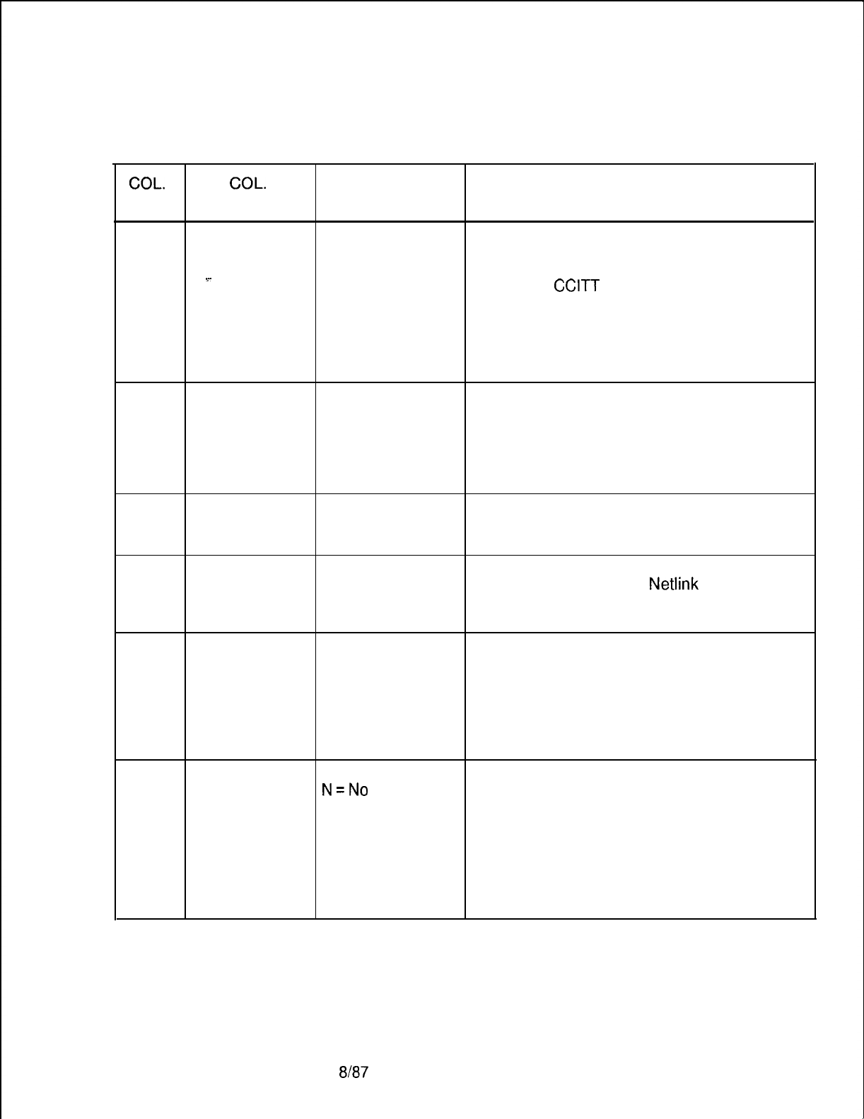
TL-130400-1001
Table 17.8 Entry Fields for Record Code Cl (Continued)
COL. COL.
VALID
NO. NAME ENTRIES COMMENTS
29-31
. . . .
Default
004 = 16 bytes
This is the default X.25 data packet maximum
Maximum X.25 005 = 32 bytes size to be used when packet size negotiation
Packet Size
006 = 64 bytes
is not in effect.
s-
. .
007 = 128 bytes
-Codes are
CCITT
standard.
008 = 256 bytes -This value is used when packet size
009 = 512 bytes negotiation is not in effect (see Record Code
010 = 1024 bytes CP, column 38).
. .
suggested value =
007
32-34 Default X.25
001-007
= number
This field determines the default window size
Window Size used for X.25 calls that do not use window
size negotiation.
-This is the window size used when the
window size negotiation is not in effect (see
Record Code CP, column 38).
35-37
Default X.25
003-015
This field allows X.25 throughput class
Throughput suggested value = negotiation.
Class
8
38-40 System
004-015
This field determines the maximum valid X.25
Maximum
This value should data packet size that the
Netlink
can support.
Packet Size always be 10. -The default is 10 and should be treated as a
constant.
41-43 Minimum
000-255
This field determines the minimum number of
Number Of Call suggested value = call buffers to be maintained by the system.
Buffers
25
-This field is used by the switch to self-limit
the number of calls active at any one time.
-It is only checked for new,
non-administrative calls in order to limit
typing up system resources.
44 Enable Y=Yes This field determines whether or not
Accounting
N=No
accounting is enabled.
suggested value = -This field is set in the switch version of the
Y
table by messages sent from the Account
Administrator table.
-If delays are being experienced, or for some
other reason accounting is to be temporarily
suspended, this bit is reset and the type of
accounting field (column 45) remains intact.
SVR 5210
8187 D-381
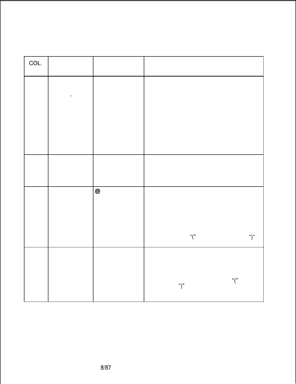
TL-130400-1001
COL.
NO.
Table 17.8 Entry Fields for Record Code Cl (Continued)
COL.
VALID
NAME ENTRIES COMMENTS
45
Type of
Accounting to
Perform
.~.
o-2
This field determines the type of data call
suggested value =
accounting performed by the system.
2
-This field is only valid when column 44 is Y.
0= no accounting, statistics are kept only on a
per-port basis
. .
1 = X.25 accounting, APM-to-APM calls are
not accounted for
2 = full accounting, all calls are to be
accounted for
-For values 1 or 2, column 35 on Record
Code CP is checked for each device, and if
both devices indicate “no accounting” for that
port, then no accounting record is generated.
46-48 Time of
002-255
This field determines the time for an APM to
Accounting to
suggested value = wait between calls.
Perform
8 (i.e., 20 -The value is in 2.5second increments.
seconds) -This value is used when the value in column
73 of Record Code AP is Y.
49
Terminal @ = Suggested
Command This character is displayed as a prompt by the
character
terminal when in the command mode.
Service Signal -This character will tell the user to enter a
Prompt command.
-The valid character set includes all ASCII
characters with a decimal value from 33 to
127.
-This prompt should be a printable ASCII
character, except
“(”
(ASCII 5B Hex) and
“)‘I
(ASCII 5D Hex).
50-55
No Disconnect see comments
This password allows a terminal user to
Password
remain in command mode indefinitely without
timeout disconnect.
-The password should be a printable ASCII
character string.
-The password should not contain
“(”
(ASCII
5B Hex) and
“)”
(ASCII 5D Hex).
-This password is used with the terminal user
command “Test No Disconnect.”
D-382 8187
SVR 5210
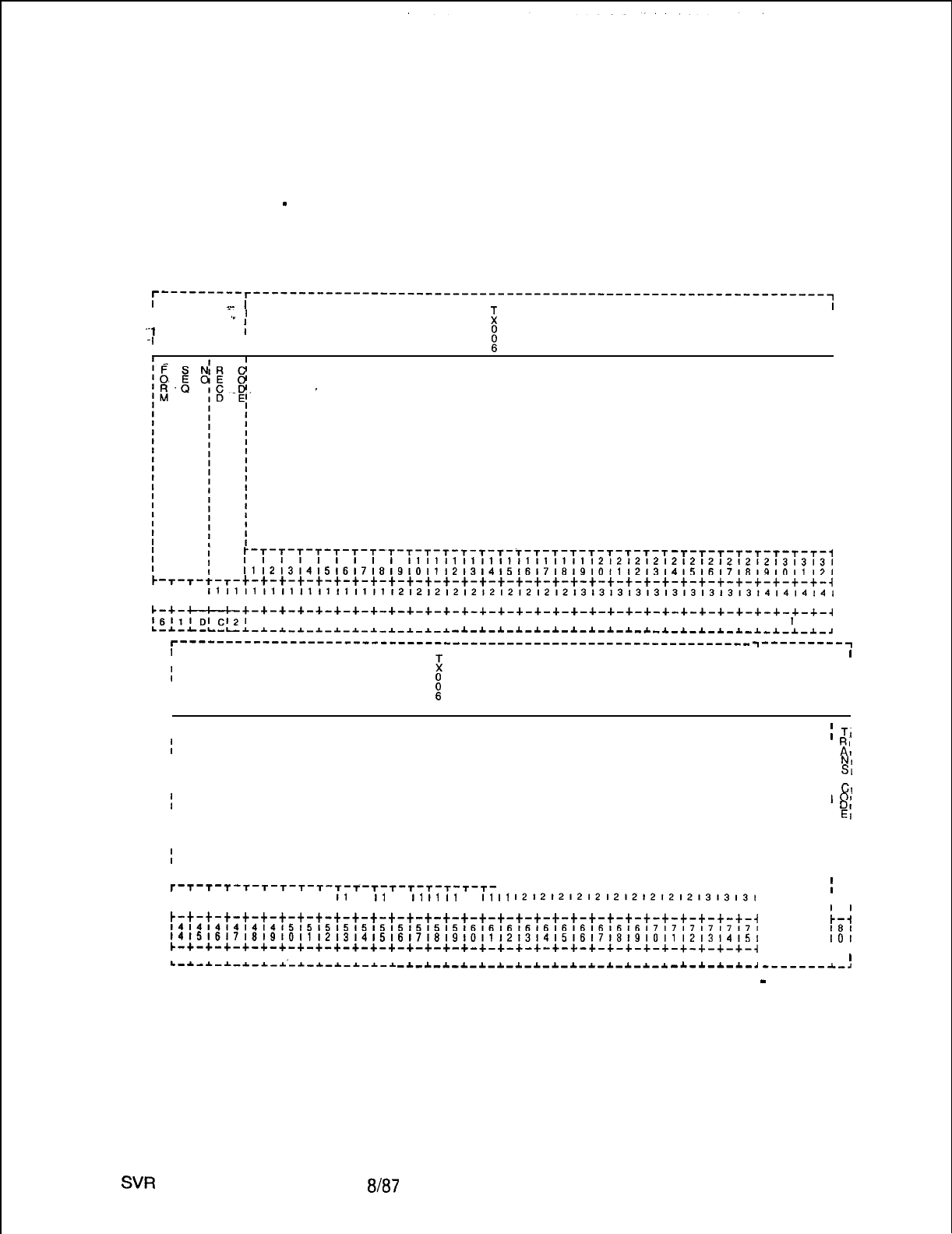
TL-130400-1001
Record Code C2:
Data System
17.9 Record Code C2, Figure 17.9, provides the global
Call Processing
information for data call processing. The “Private Herald” is
displayed when an asynchronous terminal is connected to its
Data
-
Part 2
local APM. The “Profile Identifier” is displayed to request
terminal characteristics identification. One ‘record is required per
system.
T---------T---------------------------------------------------------------~
I
s-
’
I.”
I
II
;
I
I
I
‘-I
I
-I
I
II
II
I
I
PRIVATE HERALD
I
_
I
I
I
I
I
I
I
I
I
I
I
I
I
I
I
I
I
I
:-:-:-:-:-T-T-T-T-T-T-T-T-T-T-T-T-T-T-T-T-T-T-T -T-T-T-T-T-T-T-T-l
,111,,,111,111111111121212121212121212121313131
111213,415~6~7~8~910111213141516171819101112131415161718191011121
-r-r-t-T-t-t-t-t-t-t-t-t-t-t-t-t-t-t-t-t-t-t-t-t-t-t-t-t-t-t-t-t-t-t-t-t-i
I I I
1111111111111111111112121212121212121212131313131313131313l3l4l4l4141
171819101112131415161718191011121314151617191910111213141516171819101112131
c-+--+-+-+-+-+-+-+-+-+-+-+-+-+-+-+-+-+-+-+-+-+-+-+-+-+-+-+-+-+-+-+-+-~
l6l~l~I~l2l
I I I I I I I I I I I I I I I I I I I I I I I I I I I I I I
I
I
L-~-L-L-L-I-I-~-~-I-~-~-~-~-~-~-~ -1-*-1-1-*-*-1-*-*-~-~-*-~-~-~-~-~-~-*-~-,
r---------------------------------------------------------------
T---------T
I
i
I
I
I I I
I
H
II
I I
II I
II I
II I
II
III
II
I
PROFILE IDENTIFIER
:
TI
I
I
RI
I
I
At
II
I
NI
II
I
SI
II
I I
II
I
Cl
III
01
I
I
DI
II
I
EI
II
I I
II
I I
II
I I
II
I I
I
I I
II
I I
III
T-T-T-T
-T-T-T-T-T-T-T-t-T-T-T-T-T-T-
T-T-T-T-T-T-T-T-T-T-T-T-T-T-,
I I I I I I I I I
I1
11
11
11
II
II
I1
11
I1
I1
1212121212121212l2l21313131
I
I
1112131415161718191011121314151617181910111213141516171819101112, I I
~-t-t-t-t-t-t-t-t-t-t-t-t-t-t-t-t-t-t-t-t-t-t-t-t-t-t-t-t-t-t-t-i
~~~~~~~~~~~~~~~~~~~~~~~~~~~~~~~~~~~~~~~~~~~~~~~~~~~~~~~~~~~~~~~~~
;--I
141516171819101112l3141516171819101112131415161718(91011121314151
I81
IO1
c-+-+-+-+-+-+-+-+-+-+-+-+-+-+-+-+-+-+-+-+-+-+-+-+-+-+-+-+-+-+-+-~
C-4
I I I I I I I I I I I I I I I I I I I I I I I I I I I I I I I I I
L-~-~-~-~-~-i-~-~-~-~-*-~
I
I
-~-*-~-~-~-~-~-~-~-~-*-~-~-~-~
-A.-*-A.-A.-d
-------A-,
Figure 17.9 Record Code C2: Data System Call-Processing Data Sheet
-
Part 2
SW
5210
8187
D-383
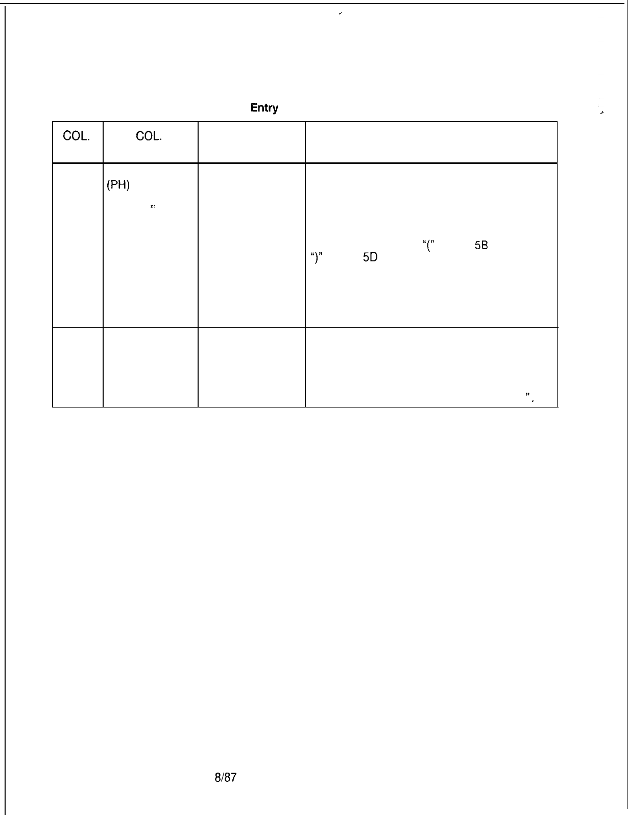
TL-130400-1001
Table 17.9
Entry
Fields for Record Code C2
COL.
COL.
VALID
NO. NAME ENTRIES COMMENTS
12-43
Private Herald
A-Z =
letter
This field determines the printable ASCII string
W-V
for private herald.
-This is the actual private herald displayed
=-
when a terminal comes up and has gone
through hunt-confirm sequence.
-Any ASCII characters are valid.
-It should not contain
“(”
(ASCII
56
Hex) or
“)”
(ASCII
5D
Hex). For example,” FGBS Data
Network” would be a valid entry to notify that a
user is now connected to the particular data
network.
-Other than the above exception, any ASCII
characters are valid.
44-75 Profile Identifier
A-Z =
letter
This field determines the printable ASCII string
for profile identifier.
-This is a prompt for a user at an
asynchronous terminal to specify terminal
characteristics identifier.
-An example would be “Terminal Type =
“.
D-384
8187
SVR 5210
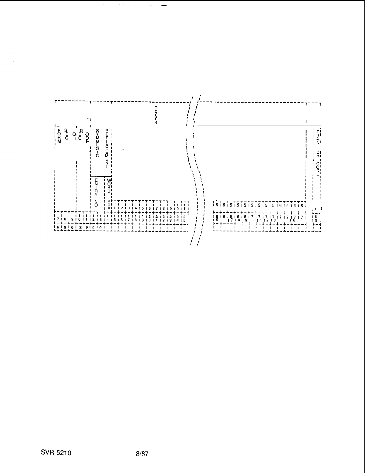
-
TL-130400-1001
Record Code SR:
Data System 17.10 Record Code SR, Figure 17.10, provides mapping of
Symbolic Replacement
symbolic user terminal input to actual terminal commands. A
Word/String
maximum of 8 records are allowed. This is the only optional
record code for the PD-200 data feature.
J
,*
T---------T-----T--- -------------------,
II I
,----------------------em-----w7--w7
III
III
z
1
I
I
1
:
I I
I I
II I I I
I
‘I
I
:
:
I
I
III
$
II
I....
I
’
II’
:
I I
I : #
I-F
S
N;
R
c
I:
&
“IE
g9
21
;hA-
ID
E
::
;r
I
’
. . ,
I
II
SYMBOLIC
I
I
REPLACEMENT
II
WORD/STRING
II
CHAR ACTERS
I
.
I
I
I !
Ii
’
I
1 I
’
I
I
I
\
i
\
,
\
\
\
\
\
\
’
;Ti
’
IR’
’
IA’
’
TN’
’
IS’
’
IF’
’
IE’
’
IR;
I
I
r--r--r--r-T-T-T-T-T-T-r-T-T-T-l
, I
l51515151515151515161616161
, I
I11213141516171819101112131
I
I
c-+-+-+-+-+-+-+-+-A-+-+-&-J
L-J
I
I
I
I
i6i6i6i6i6i7i7i7;7i7171717,
I
I
I5
16
I7
I8
I9
IO
I1
12
13
1415
I6
17 I
I8
I
IO
I
Figure 17.10 Record Code SR: Data System Symbolic Replacement Word/String
Data
Sheet
8187 D-385
TL-130400-1001
COL.
NO.
Table 17.10 Entry Fields for Record Code SR
COL.
VALID
NAME ENTRIES COMMENTS
12-13 Symbolic 00-8 = number This field defines a unique number that is
Replacement
Entry Number associated with the symbolic replacement
data entry found in columns 15-77.
14
Symbolic
0
Replacement or This field determines the type of symbolic
replacement that is to be used.
Word Type
1
-0 = normal replacement. When this field is
,.
marked with a 0, the symbolic character string
is taken as equivalent to a command. The
replacement string and the command are
defined in columns 15-77. The system
replaces the word with the specified character
string when the word is encountered in a user
input. Normal replacement is used to define
commands other than X.1 21 addresses.
These commands are input by the user to the
terminal and are used to perform certain
functions (e.g., S = Stat, user’s name =
Help).
-1 = address replacement. When this field is
marked with a 1, the symbolic character string
is taken as equivalent to an X.121 address.
The replacement string and the X.121 address
are defined in columns 15-77. The data
system replaces the word with the X.121
address specified in this record. It also
replaces the X.121 address with the specified
word whenever it has to output a message
containing the particular address. For
example, “Computer 70300271
I’.
When a
user types
“C
Computer” at a terminal during
the command mode, the system replaces
“Computer” with “70300271” and the
command will actually be “C 70300271”.
Also, the system output “70300271
Disconnected” is printed to terminal as
“Computer Disconnected”.
D-386
8187
SVR 5210
TL-130400-1001
Table 17.10 Entry Fields for Record Code SR (Continued)
COL.
COL.
VALID
NO. NAME ENTRIES COMMENTS
15-77
Symbolic
A-Z =
letter
This field determines the symbolic
Replacement replacement word and the symbolic
Word/String
Chkacters
replacement string.
-The format of this field is as follows:
. . .
-First, enter the symbolic replacement word
in ASCII characters. This
enrty
must start in
the first open field and can contain any
printable characters (no control or space
characters). The entry is followed by a single
space. The space informs the Call Handler
CH where the symbolic replacement word
ends and the symbolic replacement string
starts.
-Second, leave a blank space and then enter
the symbolic replacement string. The
symbolic replacement string can contain any
character sequence at all including spaces
and commas, but cannot contain any control
characters. For example, COMP C 30100123,
COMP is the keyword that the CH would look
for in the user’s command line and, if found,
would be replaced by C 30100123.
NOTES: The symbolic replacement word
must be entered first.
-The symbolic replacement word cannot
contain any space.
-Enter one space after the symbolic
replacement word; then enter the actual
command string. For example: If the string is
MAIL C 70300442, then the word MAIL can be
used instead of the string C 70300442.
-In this example, 70300442 is the server
number of the X.121 address.
SVR 5210
8187
D-387

TL-130400-1001
THIS PAGE IS INTENTIONALLY LEFT BLANK.
D-388
8187
SVR 5210

INTEGRATED
FEATUREPHONE
USAGE FORMS
FeatureComm
_
Key Plan
Instructions
Company Name
Location
Telephone Number
Originator
Sales Order Number
s.w.o./c.w.o.
(Service Work Order/
ChangeWork Order)
Dbte
Key Plan Number
Rev. (Revision)
Page- Of
_
Location
SVR 5210
TL-130400-1001
18.0 This section provides detailed instructions for completing
three customer-specific usage forms. Each of the following
forms is to be completed by the customer:
l FeatureComm Key Plan ( Figure 18.1)
l Multi-Line FeatureComm Control Programming and Feature
Button Assignments (Figure 18.2)
l Single Line FeatureComm Control Programming and Feature
Button Assignments (Figure 18.3)
18.1 The Feature Comm Key Plan will include information
on station designation, instrument type, directory number, and
line appearance designation. Changes to this form must be
provided for in the data base prior to station(s) implementation.
18.2
18.2.1 Enter name of customer (company).
18.2.2 Enter customer’s address or other appropriate major
building designation.
18.2.3 Enter the customer’s main (listed) telephone number
-
not
the telephone numbers used on the Key Plan.
18.2.4 Enter the name of the person responsible for collecting
information shown on the Key Plan and related forms.
18.2.5 Enter the appropriate sales order number for this
customer and for this job.
18.2.6 Enter, if applicable, the appropriate work order number
18.2.7 Enter the date of the issuance form.
18.2.8 Enter the Key Plan number that is consistent with the
number plan accepted or developed for this account.
18.2.9 Enter, when applicable, a revision number each time a
change to the previous Key Plan is requested. If new, enter 0.
18.2.10 If more than one page is needed to diagram the basic
Key Plan, enter the page number in the space indicated for each
page, followed by the number of pages included in the full
diagram.
18.2.11
Enter a brief description of the specific location within
the customer’s site where the Key Plan exists.
8187
D-389
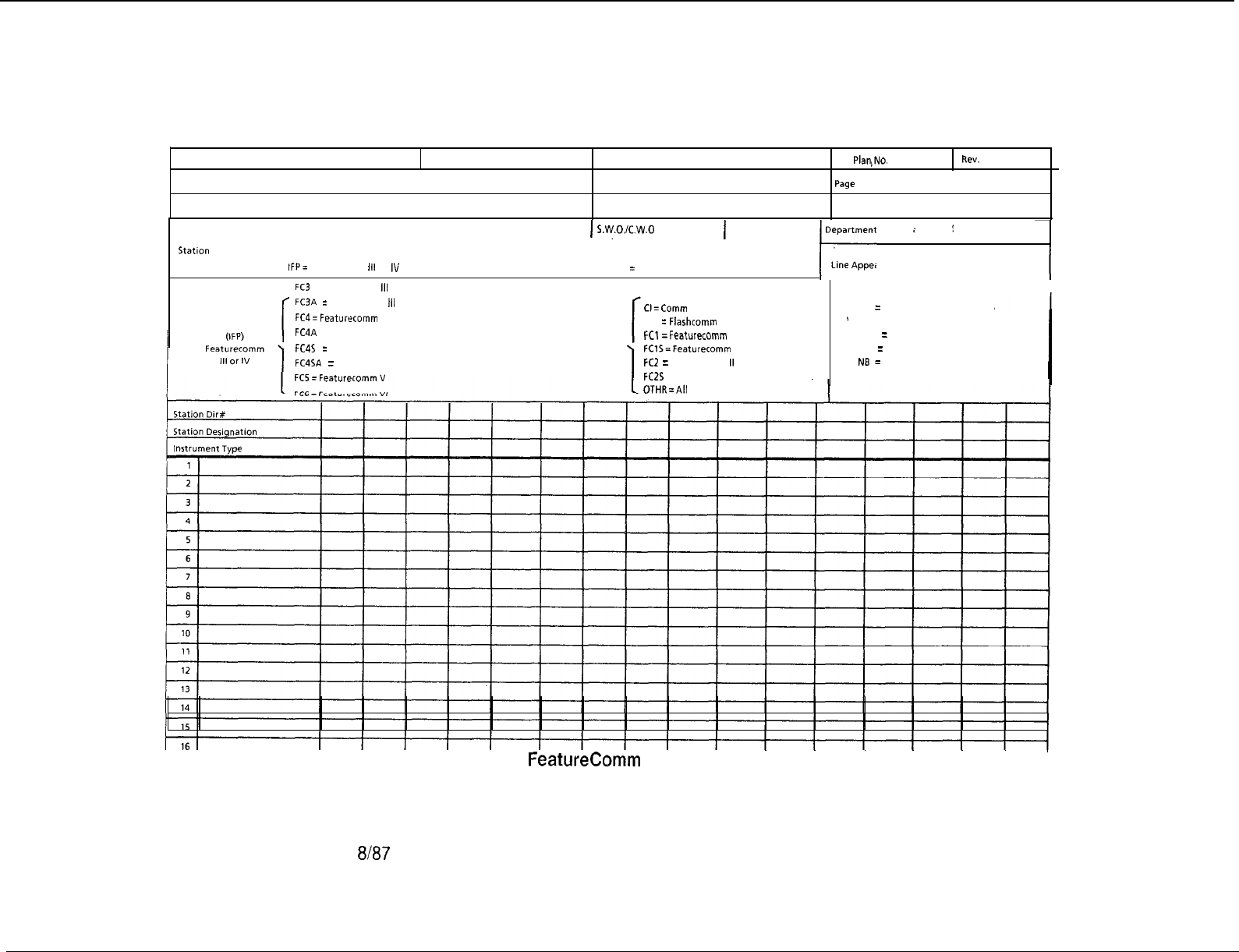
TL-130400-1001
D-390
8187
5210
Company Name
Originator
Comments
Location Telephone Number Key
PlqNO.
Sates Order Number Page
Customer Signature Location
Rev.
Of
Statlon Designation IFP= Featurecomm
Ill
or IV
1
Date
1
s.viy0./c.w.0
POTS
=
All Other
rrtrnent
i
‘i
~
/
Line Appearance Designation
Instrument Type
FC3
= Featurecomm
Ill
FC3A
=
Featurecomm
III
W/Add on Module
FC4=
Featurrcomm
IV
FC4A = Featurecomm IV W/Add on Module
FC4S
=
Featurecomm IV W/Speakerphone
FC4SA = Featurecomm IV W/Speakerphone &Add on Module
(POTS)
All Other
CI=Comm I
FLC
=
Flashcomm Plus
FCl
=Featurecomm
\
FClS=Featurecomm
I
W/Speakerphone
FCZ
= Featurecomm
II
FCZS = Featurecomm II W/Speakerphone
OTHR=AII
Other
C = Control Appearance
I
LC = Logical Control Appearance
’
NC = Non-Control Appearance
LNC = Logical Non-Control Appearance
DSS
=
DSS Appearance
NB = No Button Appearance
Figure 18.1
FeatureComm
Key Plan (Form 1)

Department
Station Dir # (Station
Directory Number)
Station Designation
s-
. .
Instrument Type
Line Appearance
Designation
SVR 5210
TL-130400-1001
18.2.12 Enter, if known, the specific name of the customer’s
department where the Key Plan exists.
18.2.13 As the first entry in each of the vertical columns on the
diagram, enter the PABX directory number specifically assigned
to that station and considered the prime directory number for that
station
18.2.14 As the second entry in each vertical column on the
diagram, enter either:
l POTS (non-integrated and all other telephones)
l
AIFP
(Analog Integrated Featurephone)
l
DIFP
(Digital Integrated Featurephone)
l DFP/APM (Digital Integrated Featurephone with APM)
This properly designates the type of station hardware to be used.
It also indicates the type of line equipment and software needed
in the PABX to implement the line appearance.
18.2.15 As the third entry in each vertical column on the
diagram, enter a specific destination from the list (as shown in
Figure 18.1) to indicate the kind of station equipment involved.
If the previous entry in Station Designation was IFP, only those
equipment codes shown for IFP should be entered. If the
previous entry in Station Designation was POTS, only those
equipment codes shown for POTS should be entered.
Instruments not specifically represented for POTS should be
shown as Other.
18.2.16 The horizontal entries on the Key Plan diagram are
used to individually show the relationship of each directory
number to each instrument involved in the Key Plan. In the Line
Appearance Designation list, several different mnemonics or
codes are used to describe how and why each line or directory
number appears at each station. There are six different codes.
These codes are as follows:
e
C (Control Appearance). The use of code C indicates a
programmed line button appearance of the directory number at
a station that has the right to privacy or control of that
directory number.
l LC (Logical Control Appearance). The use of code LC
indicates a programmed line button appearance of a software
only or logical directory number at a station that has the right to
privacy or control of that logical directory number.
l NC
(NonControl
Appearance). The use of code NC indicates
a programmed line button appearance of the directory number
at a station that does not have the right to privacy or control of
that directory number.
8187 D-391

-
-
TL-130400-1001
l LNC (Logical Non-Control Appearance). The use of code
LNC indicates a programmed line button appearance of a
software only or logical directory number at a station that does
not have the right to privacy or control of that logical directory
number.
NOTE: The use of the four previous codes (C, LC, NC, and LNC)
is limited to appearances of directory numbers under the control
of IFP (FeatureComm) only.
l DSS (Dialing Station Select). The use of code DSS indicates
a programmed DSS button appearance of the directory
number that is under control of a POTS telephone or IFP. This
is the only way a standard POTS line circuit can appear on an
IFP. A DSS button is used to answer calls and automatically
dial the directory number only. The LED (Light Emitting Diode)
associated with the DSS button also provides line status.
Outgoing calls cannot be originated via a DSS button.
l NB (No Button Appearance). The use of code NB indicates
the termination of a directory number at a single-line
telephone where no button is allowed or provided. When the
code is used in conjunction with an IFP station, control for the
directory number is assumed to be at that station.
NOTES:
o
An IFP controlled line is limited to a maximum of eight line
button and DSS button appearances.
0
Only one control appearance is allowed per directory
number.
0
The prime directory number for a multi-line IFP will
automatically be downloaded from the PABX software to the
IFP when the telephone is initialized (plugged in) and will
appear on feature button number 8 (bottom button, first row
nearest keypad).
o
Feature button number 5 on a multi-line IFP will
automatically be downloaded for hold when the telephone is
initialized.
l Any changes on the Key Plan must be provided for in the
PABX data base prior to implementation at the station(s).
Multi-Line Feature-
18.3 The Multi-line FeatureComm Feature Button
Comm III/IV Feature
Assignments (Figure 18.2) include information on line selection
Button Assignments
preference (incoming and outgoing), feature button number and
functional assignment, and button label information.
D-392 8f87
SVR 5210

Instructions
Key Plan Number
Prime Directory Number
Instrument Type
18.4.3 Enter the appropriate code for this telephone as shown on
w-
the Key Plan.
.
.
.
User Name
-
User Location
Intercom Group
Call Pickup Group
Line Selection
Preference
SIR
5210
TL-130400-1001
18.4
18.4.1 Enter the number on the associated Key Plan (Figure
18.1).
18.4.2
Enter the assigned or prime directory number for this
specific telephone.
18.4.4 Enter the user’s name using the last name only, if known.
If unknown, leave blank.
18.4.5 Enter a brief description of the user’s location, i.e., room
number, post number, or grid location or floor.
18.4.6 Enter S.A.K.P. (Same As Key Plan) since all
IFPs
on this
Key Plan should be in the same intercom group. If more than
one intercom group is desired per Key Plan, enter S.A. (Same
As) followed by the directory numbers to be included in the
specific group.
18.4.7 Enter the number of the call pickup group assigned on the
basis of overall station reviews, typically by user department,
functional group, or physical layout. If assignment has not been
made or is unknown, enter S.A. (Same As) followed by the
directory numbers to be in the group.
18.4.8 Select and enter one of four codes to designate
user-
specific incoming preference. The codes are as follows:
0
Ringing line (10)
e
Flashing line (01)
0
Either line (11)
0
No preference (00)
Select and enter one of four codes to designate user-specific
outgoing preference. The codes are as follows:
0
Prime line (100)
l Last line used (010)
l Any idle line (001)
l No preference (000)
NOTE: No entry in the area will cause the use of the default
code for preference. The default code is l-O-1 -0-O.
8187
D-393
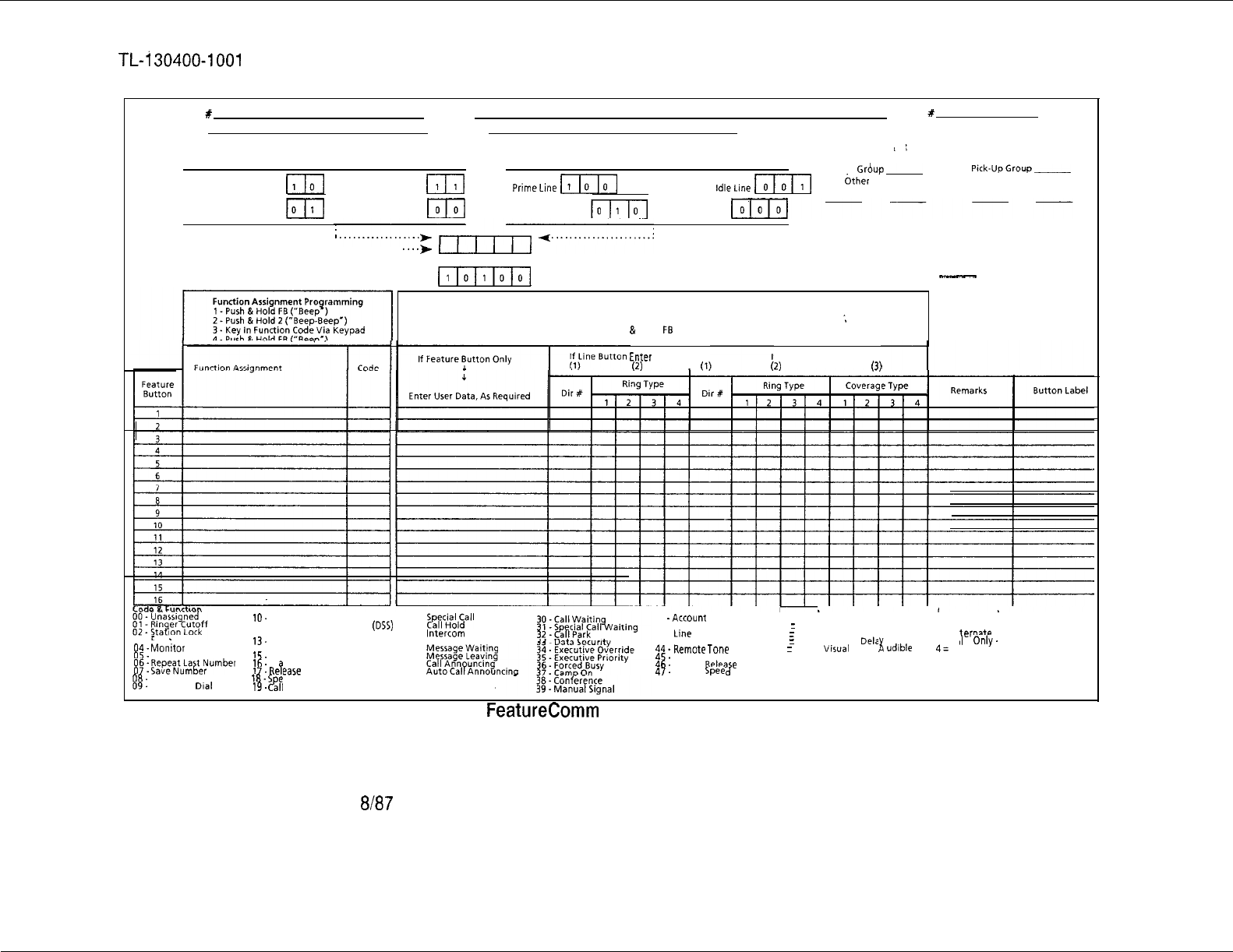
TL-i30400-1001
Prime Directory #User Name
Instrument Type User Location
Key Plan #
/
Line Selection Preference
Incoming
Ringing Line
11101
Either Line
[II
Outgoing
PrimeLine
[I
Any
IdleLine
m[
Intercom
Grbup-
&her
X’s in Group Call
Pick-UpGroup-
Other #‘sin Group
Flashing Line
10
No Preference Last Line Used No Preference
Input Via “Instrument Control’ Programming
“‘.*
Preference Code
Default =
(,
__
-
Button Data Entry Programming
1 -Push &Hold FB (“Beep’)
2 -Key in Data Via Keypad
3 -Push
&
Hold FB (“Beep’)
;
Enter
(2)
(1)
If DSS Button Enter
(2)
(3)
03
Flash
04.
Monitor
05.
New Call
85:
EyPeeaNt;;t$umber
08.
Station Speed Call
09.
Repertory Dial
10.
Dual Access
11 . Direct Station Selection (DSS)
12 -Extended Group
13.
Reminder
14 -Time/Alarm
15.
Time and Date
16.
Di I Display
17.
Re
eaw
B
18.5
eakerphone (Optional)
19.
&II
Forward
S#aia,all
Forward
Intercom
Auto Intercom
Group Pickup
Extended Pickup
40 -Account Code
41 -Unassigned
42. Line Buttons
43 -Shift
44.
Remote
TOW?
45.
Bad Line
46.
Privacy
R&a
e
47.
System Spee
d
Calling
Ring Type
1
=
Immed. Visual
2
=
Immed. Visual. No Audible
3
=
Immed. Visual. Dela Audible
4
=
Delay
Visual
Delay
1
udlble
Enter “X’ Under Type Selected
Coverage Type
1 = Always
2 = Al ernate
3 = Ca I Only. No Status
I
4=
Enter “X’ Under Type Selected
Figure 18.2
Multi-Line
FeatureComm
Feature Button Assignments (Form 2)
D-394
8187
5210

TL-130400-1001
Feature Button
18.4.9 The number shown in this column designates the feature
button to be used to assign and program the desired functions on
this specific IFP. Physically, the buttons are numbered starting
with the row of buttons nearest the keypad, starting at the top of
the row and proceeding downward in order, i.e., button number 1
is the top button in the first row; button number 9 is the top button
in the second row.
. . .
NOTE: A FeatureComm II has one row of buttons (8) and the
FeatureComm IV has two rows of buttons (16).
Function Assignment 18.4.10 Enter the name of the function or feature to be assigned
to the designated button. Examples of 47 feature and function
. .
descriptions are shown at the bottom of Figure 18-2.
Code
18.4.11
Enter the two-digit code corresponding to the feature or
function shown in the previous column. Examples of 47 codes
are shown at the bottom of Figure 18-2.
Feature Button Data
18.4.12 If the following functions or features have been selected,
additional information about the feature button needs to be
entered:
l Station speed calling
l Repertory dial
l Dual access
l Reminder
0
Time and date
l Call forward
l Special call forward
l Auto intercom
l Message waiting
l Special call waiting
l Manual signal
If the information is known at the time of form preparation, enter it
in the column under the heading “If Feature Button Only”. If the
information is not available, the user must be alerted at the time
of user training and/or telephone installation to add the
appropriate information. Consult the User’s Manual or
Programming Manual as necessary.
If the feature button has been designated a line button, enter the
directory number and ring type of the line in the column under “If
Line Button Enter”. If the feature button has been designated a
DSS button, enter the directory number, ring type, and coverage
type of the line in the column under the heading of “If DSS Button
Enter”. Examples of the ring and coverage types are
summarized at the bottom of Figure 18.2. Consult the User’s
Manual or Programming Manual for detailed input directions as
necessary.
SVR 5210
8187
D-395
TL-130400-1001
Remarks
Button Label
.
.
.
.
Single-Line Feature-
Comm Feature
Button Assignments
Instructions
Key Plan Number
Prime Directory Number
Instrument Type
18.4.13 At the originator’s discretion, enter any note or comment
to further clarify the programmable information.
18.4.14 Enter, if known, the description that should appear on the
button label when the telephone is installed. Preprinted labels
are available for most features and are packaged with the
instrument at the factory. Blank labels are also provided to allow
the user discretion in button labeling.
For stations to be equipped with add-on modules, the reverse
side of the form can be used in a similar fashion to describe
feature button assignments on the add-on module. The button
numbering on the add-on module begins with the top-left
button (row number 1, button number 1) and ends with the
bottom-right button (row number 3, button number 30).
18.5 The Single-Line FeatureComm Feature Button
Assignments (Figure 18.3) include information on intercom
group, call pickup group, feature button number and functional
assignment, feature/function code, feature button data, and button
label information.
18.6
18.6.1
If the instrument is associated with a Key Plan, enter the
number of the Key Plan as shown on Key Plan (Figure 18.1). If it
is not associated with the Key Plan, enter “None”.
18.6.2 Enter the assigned or prime directory number for this
specific telephone.
18.6.3 Enter one of the following codes to properly describe the
instrument to be used:
e
FC3 = FeatureComm III
.
FC3A=
FeatureComm III w/Add-on Module
. FC4 = FeatureComm IV
e
FC4A=
FeatureComm IV w/Add-on Module
0
FC3S=
FeatureComm IV w/Speakerphone
8
C4AS=
FeatureComm IV w/Add-on Module
&
Speakerphone
0
FCV = FeatureComm V
Q
FCVI
= FeatureComm VI
D-396
8187
SVR 5210

User Name
User Location
Intercom Group
s-
. . .
-
Call Pickup Group
Feature Button
Function Assignment
Code
SVR 5210
TL-130400-1001
18.6.4 Enter user’s name using last name only, if known. If
unknown, leave blank.
18.6.5 Enter a brief description of user’s location, i.e., room
number, post number, or grid location or floor.
18.6.6 Enter S.A.K.P. (Same As Key Plan) since all
IFPs
on this
Key Plan should be in the same intercom group. If more than
one intercom group is desired per Key Plan, enter S.A. (Same
As) followed by the directory numbers to be included in the
specific group.
18.6.7 Enter the number of the call pickup group assigned on the
basis of overall station reviews, typically by user department,
functional group, or physical layout. If assignment has not been
made or is unknown, enter S.A. (Same As) followed by the
directory numbers to be in the group
18.6.8 The number shown in this column designates the feature
button to be used to assign and program the desired functions on
this specific IFP. Physically, the buttons are numbered in order,
starting at the top-left button (row number
1,
button number 1)
and ending with the bottom-right button (row number 2, button
number 16).
18.6.9 Enter the name of the function or feature to be assigned
to the designated button. Examples of 47 feature and function
descriptions are shown at the bottom of Figure 18 3.
18.6.10 Enter the two-digit code corresponding to the feature or
function shown in the previous column. Examples of 47 codes
are shown at the bottom of Figure 18 3.
8187
D-397
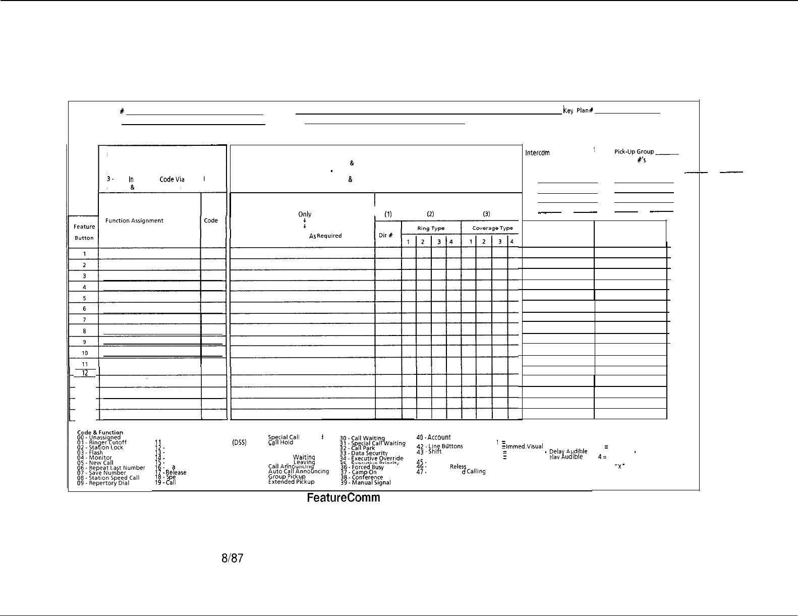
TL-130400-1001
i
Prime Directory #User Name
key
plan #
Instrument Type User Location
12
13
14
15
16
Function Assignment Programming
1 Push &
Hold FB (“Beep’)
2. Push &Hold 2 (“Beep-Beep’)
3.
Key
In
Function CodeVia Keypad
4. Push
&
Hold FB (“Beep’)
D-398 8187
Button Data Entry Programming
1 . Push & Hold FB (“Beep’)
2
-
Key in Data Via Keypad
3. Push
&
Hold FB (“Beep’)
II
If DSS Button Enter
I
If Feature Button
0nlv
I
(1)
(2)
(3)
Enter User Data, As Required
10 -Dual Access
11 Direct Station Selection (DSS)
12.
Extended Group
13.
Reminder
14.
Time/Alarm
15.
Time and Date
16.
Di I Display
17.
Re
P
ease
19.
&II
Forward
18.5
eakerphone (Optional)
‘:
IntercOrn
Group ___
Call
Pick-UpGroup-
Other x’s in
Group Other b’s in Group
--
____
Remarks Button Label
P
S,~;ci$&ll
Forward
Intercom
Auto Intercom
Message Wait,ing
Message Leavmg
40.
Acco”“~ Code
41 -Unassigned
$$
:
QF;Buttons
44 Remote Tone
45.
Bad Line
46.
Privacy
Relea
e
47.
System Spee
d
Calling
Ring Type
1
= Immed. Visual
2
=
immed.
Visual
. No Audible
3 = Immed. Visual
-
Delat;Au,dlble
4 = Delay Visual. Delay udlble
Enter “X’ Under Type Selected
Figure 18.3 Single-Line FeatureComm Feature Button Assignments (Form 3)
Coverage Type
1 = Always
2
:
Alternate
3 = Call Only
-
No Status
4=
Enter
“X’
Under Type Selected
5210

TL-130400-1001
Feature Button Data
18.6.11
If the following functions or features have
.been
selected,
additional information about the feature button needs to be
entered:
0
Station speed calling
l Repertory dial
l Dual access
l Reminder
l Time and date
l Call forward
. . .
l Special call forward
l Auto
inercom
l Message waiting
. .
l Special call waiting
l Manual signal
If the information is known at the time of form preparation, enter it
in the column under the heading “If Feature Button Only”. If the
information is not available, the user must be alerted at the time
of user training and/or telephone installation to add the
appropriate information. Consult the User’s Manual or
Programming Manual as necessary.
If the feature button has been designated a DSS button, enter the
directory number, ring type, and coverage type of the line in the
column under the heading of “If DSS Button Enter”. As a
reminder, line buttons are not allowed on single-line configured
FeatureComm
III/IV telephones. Examples of the ring and
coverage types are summarized at the bottom of Figure 18.3.
Consult the User’s Manual or Programming Manual for detailed
input directions as necessary.
For stations to be equipped with add-on modules, the reverse
side of the form may be used in a similar fashion to describe
feature button assignments on the add-on module. The button
numbering on the add-on module begins with the top-left
button (row number 1, button number 1) and ends with the
bottom-right button (row number 3, button number 30). Also,
line buttons cannot be assigned or programmed on the add-on
module.
Remarks
18.6.12 At the originator’s discretion, enter any note or comment
to further clarify the programmable information.
SVR 5210
8187
D-399

-
-
TL-130400-1001
Button Label
18.6.13 Enter, if known, the description that should appear on the
button label when the telephone is installed.
Preprinted labels are available for most features and are
packaged with the instrument at the factory. Blank labels are
also provided to allow user discretion in button labeling.
. . .
Upon completion, this form, along with the Key Plan and
Multi-
Line Feature Button Assignments, if applicable, must be sent to
the persons responsible for the following tasks:
l PABX Data Base Generation and Maintenance
0
Station Installation
,-*
Customer Training
D-400 8187
SVR 5210
TL-130400-1001
REFERENCES 19.0 The following reference documents (Table 19.1)
complement/supplement the information provided in this practice:
Table 19.1 References
DOCUMENT
Fujitsu
GTEPractices:
Hardware
Ordering
Guide:
Data Base
Sheets:
Configuration
Management:
Customer
Instructions:
NUMBER
ISSUE DESCRIPTION
TL-130000-1001 3Introduction/Features
TL-130500-1001 3System Configuration
TL-130100-1001
13
Operation
278-904-l 80
I
3
I
PD-200 Packet Data System
I
TL-130300-1001 3
TL-130200-1001 3
FM-41 444
Hardware/Software Installation
Maintenance
Ordering Guide
FM-41 444-A,
-B, or -C
FM-41 479 4186
Ordering Sheets
Software Programming Data
Sheets (Instructions for
completing the software
programming data sheets are
contained in Technical Practice
TL-130400-1001.)
CM-638202-SV
-
I
I
System Version Stocklist
I
CM-638202-
-
I
I
System Version Release
52.1
.O
SVR
Cl-278-248
2
I
I
Executive Features Insert
Cl-278-294
12
Busy Lamp Display Unit
Cl-278-401
1
Attendant Manual Hotel/Motel
Health-Care Features Insert
Cl-278-402
1
Key Entry Display Unit
Instructions
SVR 5210
8187 D-401

TL-130400-1001
Table 19.1 References (Continued)
BESCRlPTlQN
Cl-278-41 0
Cl-278-41 1
Cl-278-41 2
Cl-278-41 7
1
OMNI
Series Attendant Manual
1
Maid Service Features Insert
1
OMNI
Series Generic Station
User’s Guide (No Access Codes
Included)
1
Asynchronous Packet Manager
User’s Guide
Cl-278-41 8
Cl-473-365
1
Integrated Voice Messaging
System User’s Guide
1
FeatureComm
V/VI
Handbook
for CD-100 Data
Cl-473-366
Cl-473-395
1
FeatureComm
V/VI
User’s
Manual (Voice Features Only)
1
FeatureComm V/VI Handbook
for PD-200 Data
Cl-473-396
1
FeatureComm
VNI
User’s
Manual for PD-200 Data
Cl-473-397
1
OMNI
FeatureComm Handbook
(Voice Features Only)
Cl-473-398
1
OMNI
FeatureComm User’s
Manual (Voice Features Only)
Cl-473-51 9
1
FeatureComm Quick Reference
Guide
D-402 8187
SVR 5210

TL-130400-1001
CROSS REFERENCE
Record Code
Number to
Recent Change
Number
-..
Record Code
=:
Number to
Form Sequence
Number
Record
Co,de
Number to
T Table Number
SW
5210
20.0 This section provides cross-references to other
documents which may prove useful in configuring the data base.
20.1 Table 20.1 provides a cross-reference of the record code
numbers to Recent Change numbers. When the Recent Change
number pertains to a specific record code column number, the
column number is included.
20.2 Table 20.2 provides a cross-reference of the record code
numbers to the form sequence numbers.
20.3 Table 20.2 provides a cross-reference of the record code
numbers to the T table numbers.
8i87
D-403
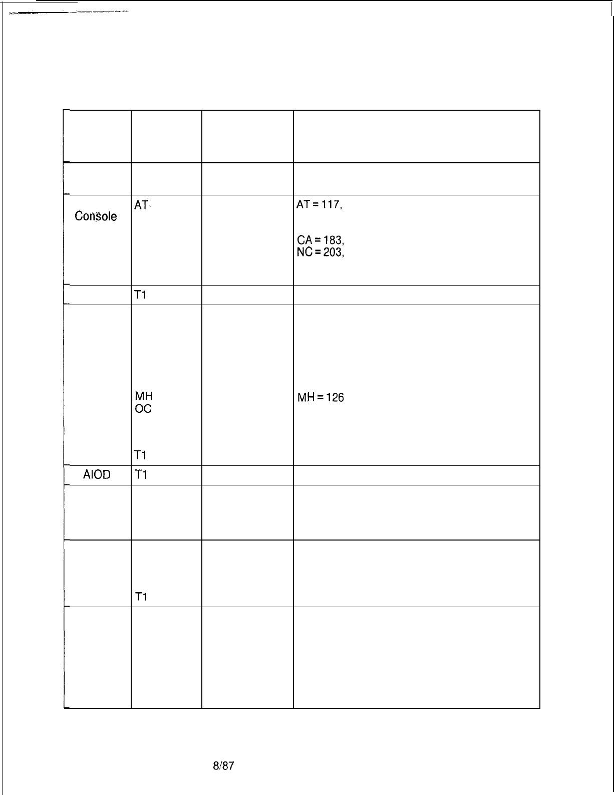
r
TL-130400-1001
Table 20.1 Cross Reference of Features to Record Codes and Recent Change
Record Record Code
Feature Codes Column(s) Recent Change Numbers Used in
Used Numbers Support of Feature
Access AC
Code
all
.
Attendant AT,.
ConSole
CA
DC
DD
NC.
OF
OT
ACA
Tl
ACD AD
AF
AG
DK
DT
HG
LD
z:
OF
RA
SD
Tl
AIOD
Tl
BLDU
AT
BD
BK
CA
CAS CF
Branch OE
OT
SD
Tl
CAS Main AD
AF
AG
AL
DK
HG
MH
TM
all
AT=117,
181, 184, 188, 218
all
BD= 189
all
BK= 190
all
CA=183,
185,
186, 187
-all
NC=203,
211,
213
all
OF = 89, 209
30-32, 45-47
56-67
all
all
all
all
all
all
HG= 125, 127,
128
16-18
all
MH=126
all
42 OF = 89, 209
all
all
45-48
38
37 189
all 190
all
61
all
218
15-17
51-62
all
49
all
46, 61, 65, 66, 45, 142, 218
all
all
all
all
all
all
all
D-404
8187
SVR 5210
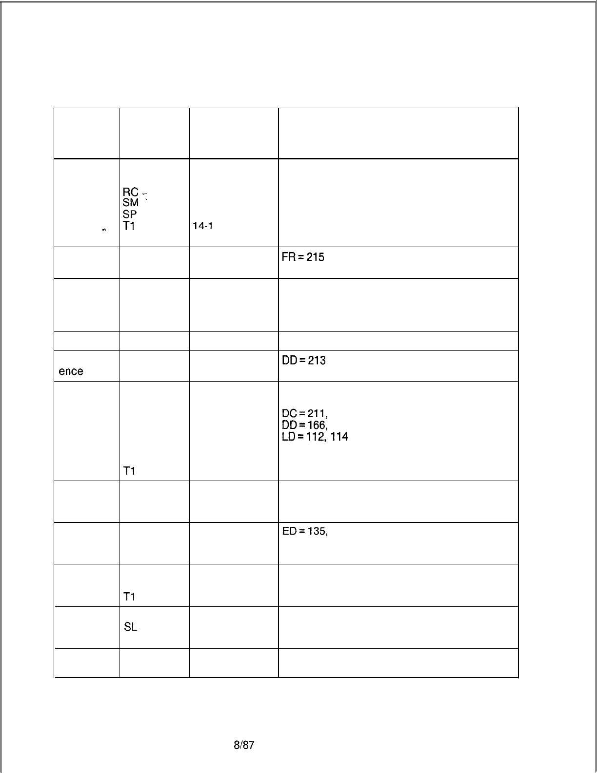
TL-130400-1001
Table 20.1 Cross Reference of Features to Record Codes and Recent Change
Record Record Code
Feature Codes Column(s) Recent Change Numbers Used in
Used Numbers Support of Feature
CAS Main
OE
14, 15, 17
(Cont’d)
OT 48-62
RC
_i.
all
‘.
. . .
zr
all
all
-
Tl
TM
CD-100 FR
LD
CO line
DD
LD
LM
TC
Code Call CD
Confer-
DD
ence
Calls
14-l
6, 49
all
all
all
16-l 7, 40-41
45-48
28-29, 30-31
31-32
all
18-l 9, 20-21
FR=215
DD=213
COS AT
AU
DC
DD
LD
NC
OF
Tl
Customer CT
Defined
Terminal
33-36
18-21
all
DC=211,
213
all
DD=166,
211,
213
32-35
LD=112,114
all
NC= 167, 212,
214
38-41 OF = 89, 209
17-20
all
Dial Call
ED
Pickup
LD
NC
Dictation DC
Access
DD
Tl
FADS
OE
SL
TT
Five-Digit
OE
Dialing NT
22-23
ED=135,
136,
137, 138, 139, 140
37-39, 40
22-23
allowed trunks
22-23
14-16
47-49
12, 15-18
29
48
23-24
SVR 5210
8187 D-405
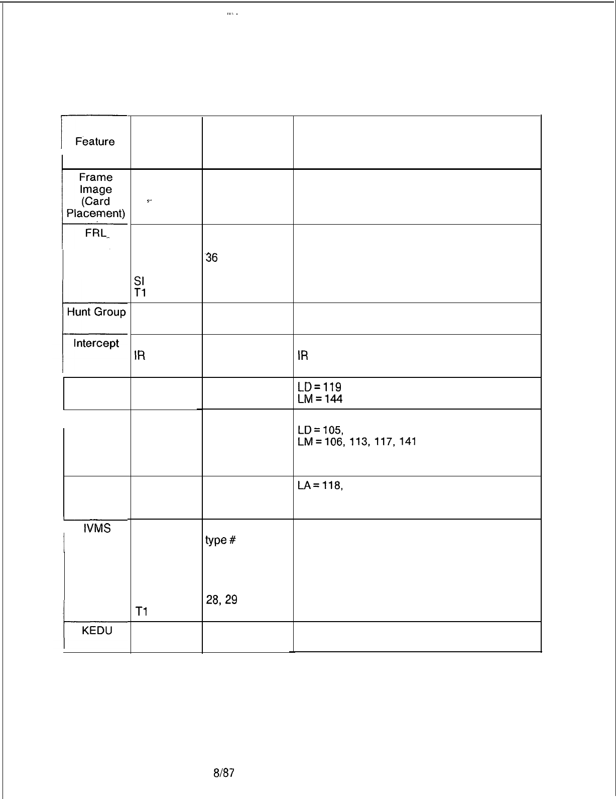
..~
TL-130400-1001
Table 20.1 Cross Reference of Features to Record Codes and Recent Change
r
Feature Record Record Code
Codes Column(s)
Used Numbers
Recent Change Numbers Used in
Support of Feature
FR all FR = 221
AT 43
FA
all
LD-
.36
OF 12-21, 54
SI 30
Tl
68-70
215
219
i-
Hunt Group HG all
127
MH
all 126
CL 14-17
IR
all
RN
14-16
CL = 205, 206
IR
= 205, 206
Intercom
LD all
LD=119
Groups LM all
LM=144
LA
LD
LM
IIFP
all
LD=105,
107, 108, 109, 117, 121,
141
LM=106,113,117,141
110, 112, 114, 118, 119, 132-134, 136, 144-
145
LA all
LA=118,
145IFP Line
Appear-
ances
I
IVMS
AC
LD
LM
NC
OD
ov
Tl
140,141 =
code
type
#
45-48
30-31
70, 71
all
28,29
71
KD all
KS all
D-406
8187
SVR 5210
TL-130400-1001
Table 20.1
Cross
Reference of Features to Record Codes and Recent Change
Record Record Code
Feature
Codes
Column(s) Recent Change Numbers Used in
Used Numbers Support of Feature
MERS AC 48, 89, 90,
94,
on/off-net AC 96, 102, 105,
AC
~.
115, 116, 126
AC
‘.
and 127 = code
. .
AC
type
#
AT
37
“c;..
14-17
1 f-21
DD 32-33, 38-39,
DD 42-47
IR all
LP
all
MO all
MR
all
MS
all
NR
all
:‘E
24 18-20, 28-30
OF
27, 45-47, 50
OF
and 55-56
OV
12-17
PC
all
s”p
all
all
ST all
MDR
T2
TD
TP
TR
TN
NT
LD
MD
MS
MT
OE
Sl
s2
TF
TT
28, 31-34, 49
12-16
all
all
all
18-20
49-50
all
all
all
15-l 7, 45-46
all
all
all
13-28
SVR 5210
8187
D-407
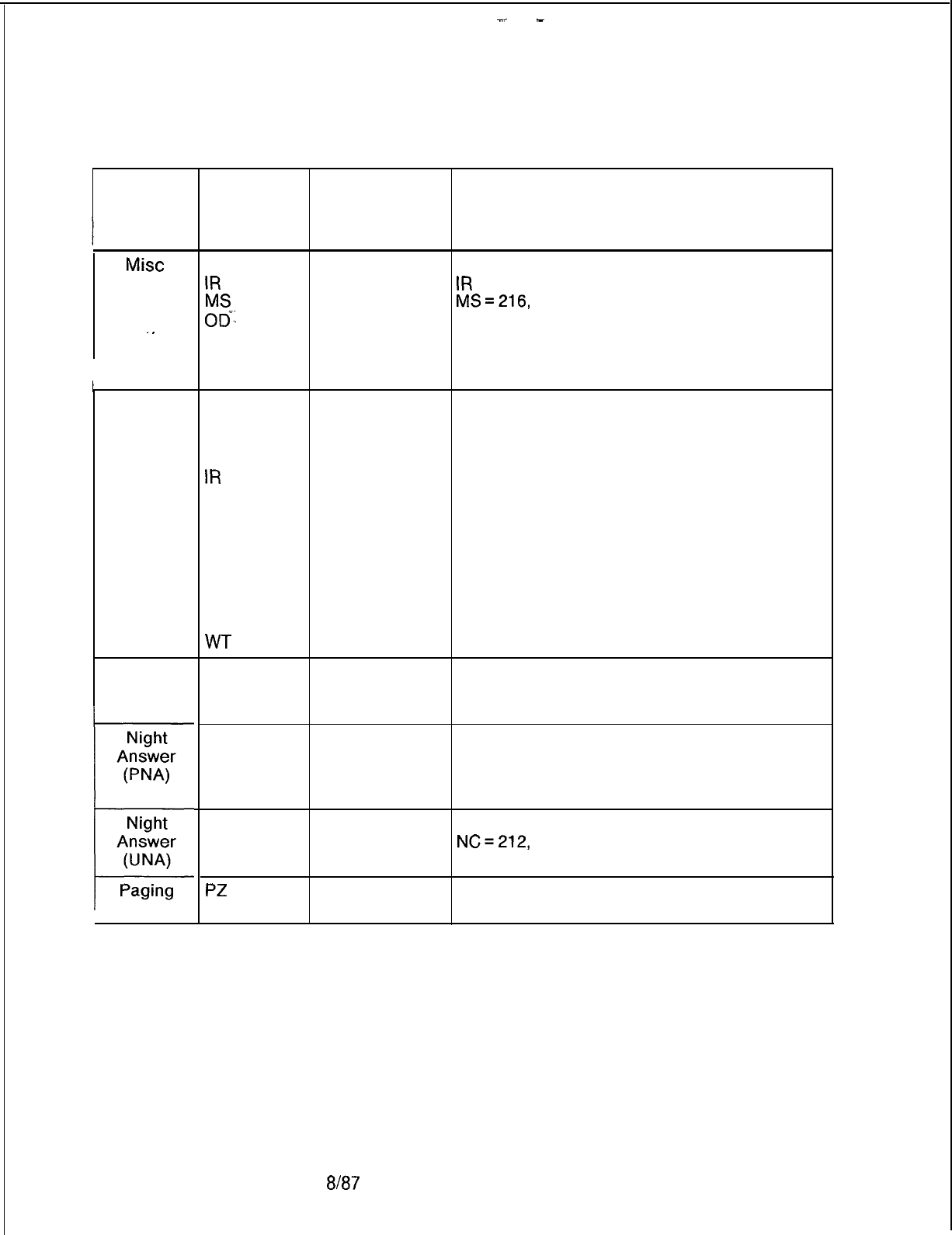
-..
-
TL-130400-i ooi
Table 20.1 Cross Reference of Features to Record Codes and Recent Change
Feature
Mist
System
Features
.
.
Motel
Health
Care
Music on
Hold
Record
Codes
Used
Record Code
Column(s)
Numbers
CA
IR
;g
OF
OF
OT
12-19 CA = 203
all
IR
= 205, 206
all
MS=216,
217
all
OD = 218, 221, 222
52
OF=89
all OF = 209
all OT = 201
AC-
AL
CL
HM
IR
KD
KS
LM
MK
PD
RN
T2
TL
all
all
all
all
all
all
all
32-33
all
all
all
all
all
all
AF
AG
oc
35-37
13-15
all
CA
20-31
NC
36-37
PN
all
TC
39-44
CA
12-I 9, 27-30
NC
36-37
TC
37-44
PZ
all
Tl
14-16
Recent Change Numbers Used in
Support of Feature
KD = 206
203
NC=212,
214
D-408 8187
SVR 5210
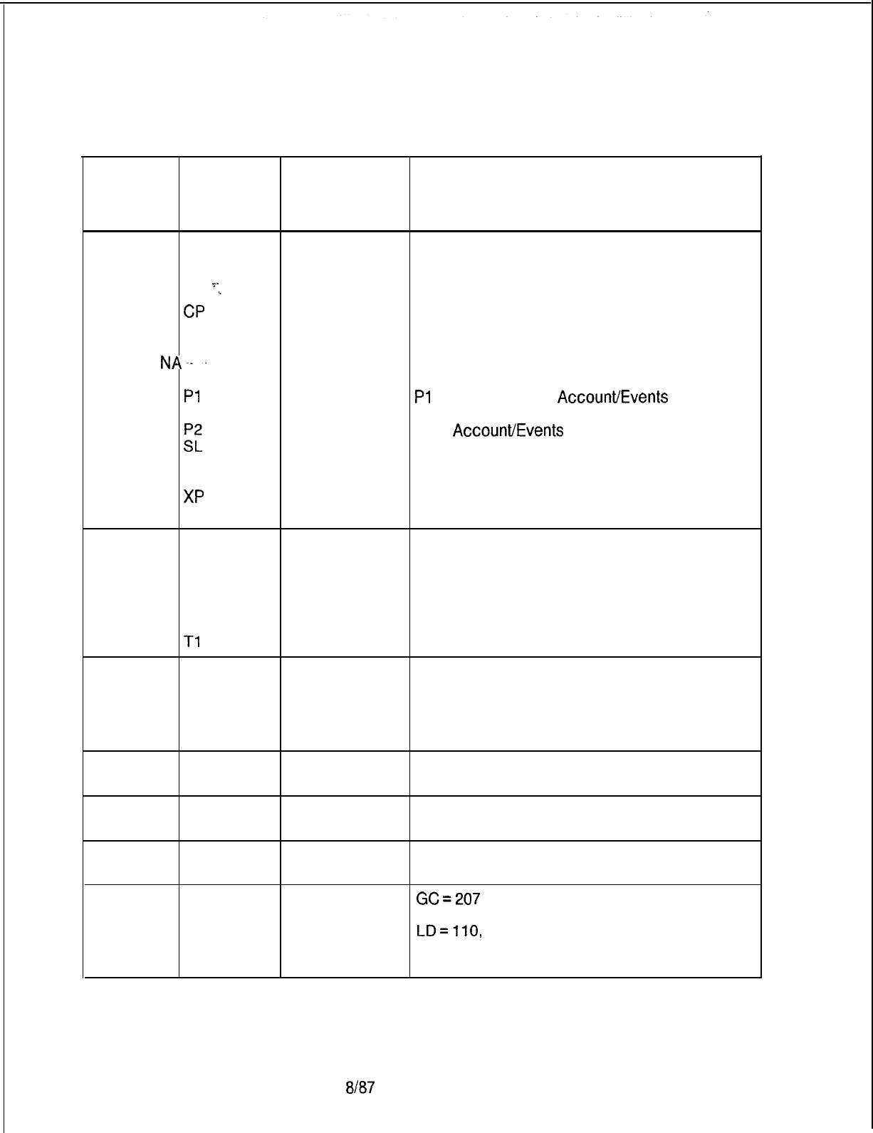
TL-130400-1001
Table 20.1 Cross Reference of Features to Record Codes and Recent Change
Feature Record
Codes
Used
Record Code
Column(s)
Numbers
Recent Change Numbers Used in
Support of Feature
PD-200 AP
AQ
Cl
~.
c2
‘-
. . . .
CP
FR
LD
NA--
OE
Pl
:‘L
SR
RT
XP
all
all
all
all
all
all
12-15
all
all
all
all
13-14, 15-18
all
all
all
Cl = Call Processing Information,
C2 = X.25 and ASYN. Characteristics
Common Port Information
FR = 221
NA= 168
Pl
= System Table,
AccourWEvents
Report
option, Account Administration
P2 =
AccouWEvents
Report
SL = System Access Password Table
SR = Symbolic Replacement Table
RT = Routing Table
XP = X.25 Frame Level Information, Packet
Level
Recorder AF
Announcer AG
CF
IR
OT
RA
Tl
Remote AU
Access LD
OD
OF
T2
SCC MS
TD
Security SL
Lock
28-30, 35-37
25-26, 31-32
17
65-66
all
14-16
12-14
all
51
all
38-40
40
all
all
all
OT = 201, 204
OD = 218, 221, 222
OF = 89, 209
216
217
Silent NC
Monitor
72-73, 74-75
Speed Call GC all
GS all
LD 41-44
NC
68-69
ov
18-23
GC=207
GS = 202
LD=llO,
113
SVR 5210
8187
D-409
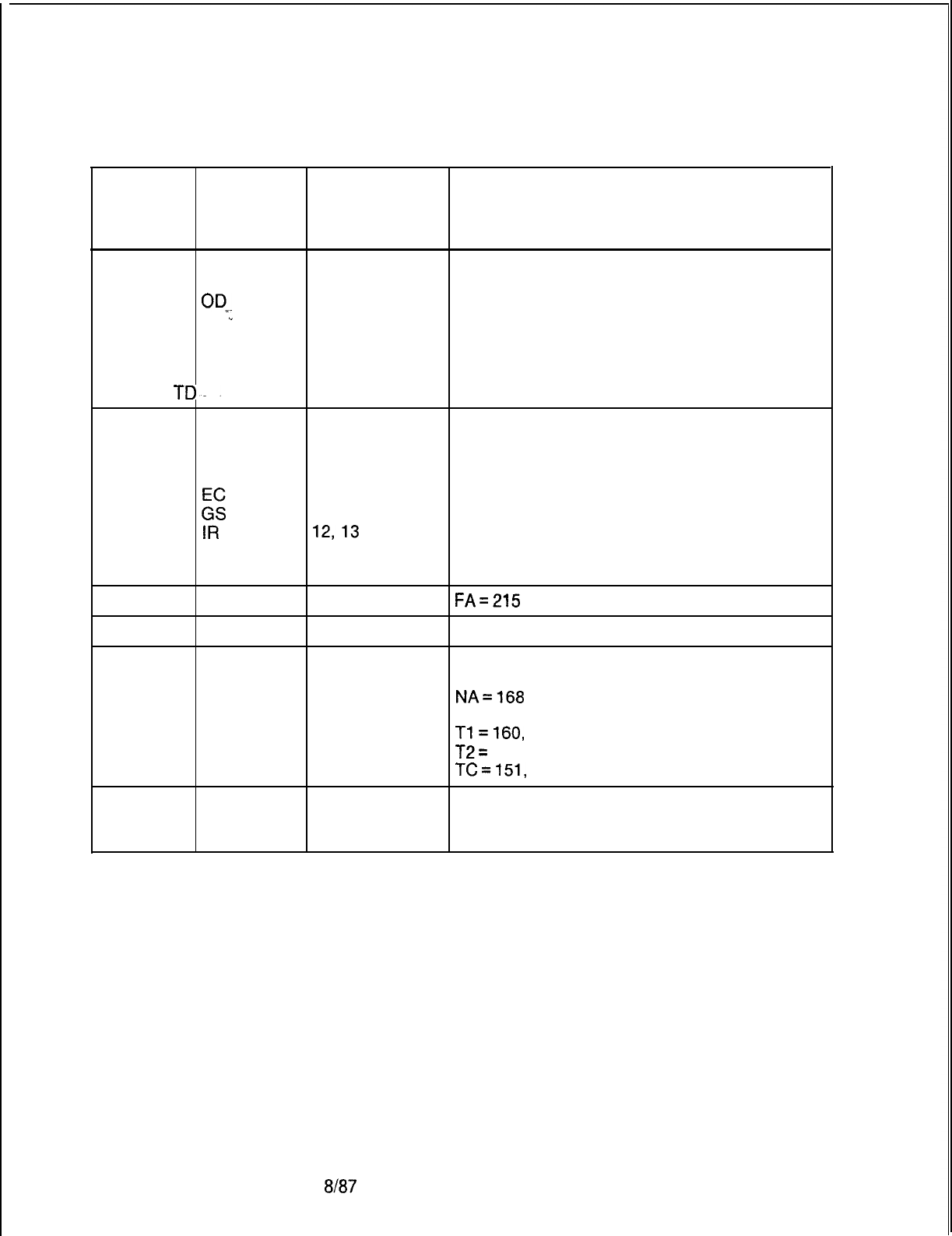
TL-130400-1001
Table 20.1 Cross Reference of Features to Record Codes and Recent Change
Feature Record
Codes
Used
Record Code
Column(s)
Numbers
Recent Change Numbers Used in
Support of Feature
Tandem MO all
Network NT all
OR
all
OE
‘.
50
. .
OV
26, 27
Tl
68-70
T2
TD--
all
Toll AS
all
Restriction CR
all
DA
all
DD 14-15
K
all
14-15
IR 12,13
SA
13-14
T2 14-28
TCM FA
all
FA=215
Traffic TF
all
Trunk CR all
CR = none
Group and EC
all EC = none
Member NA all
NA=l68
Features OE
18-19 OE = none
Tl all
Tl=l60,
161, 169
T2
all
T2=
160, 161
TC all
TC=151,
153, 154, 156, 157, 158, 159
Ward AT
39
Control LM
32-33
WT
all
D-41 08187
SVR 5210
r
TL-130400-1001
Table 20.2 Form Sequence Number for the Various Record Codes
Record
Form Sequence
Record
Form Sequence
Code Number Code
Number
AC
900
MK
370
AD
520
MO
268
AF 460
MR
280
AG 500
MS
255
AL 400 MT
290
;;
‘:
670 680 NA NC 040 125
AS
140
NR
284
AT
050 286
AU
310
K
015
BD’ -046
‘-
OD 068
Et
047 055 OE OF 001 002
CB
272 OT 020
CD
235
ov
021
CF 145
Pl
630
CH
910 P2 640
CL
350 PC 265
CN
057 PD 380
CP
650
PZ
230
CR
095 RA 495
CT 215 RC 150
Cl
600
RN
340
c2
610 RP 260
i”c
030 130
s”:
620 320
DD
031
::
330
DF 005 245
DK
560
SD
080
DT 180
Si
270
EC 097
SL
223
ED 045
SM
540
FA 950
SP
550
E
012 060 SR ST 690 285
GS
200
Tl
100
HD
010 T2 110
HG
070 TC 120
HM
410 TD 288
IR
240
-T-F
210
KD
360 TL 390
KS
405
TM
570
LA
067
TN
185
LD 065 TP 250
LI 013 TR 289
LM
066 TT 220
LP 266 43
MD
300
XP
660
MH
071
SVR 5210
8187
D-41 1
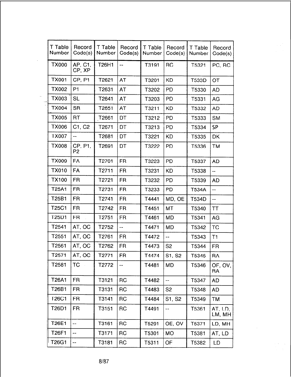
TL-130400-1001
D-41 2
Table 20.3 Record Code/T Table Cross-Reference
8/87
SVR 5210
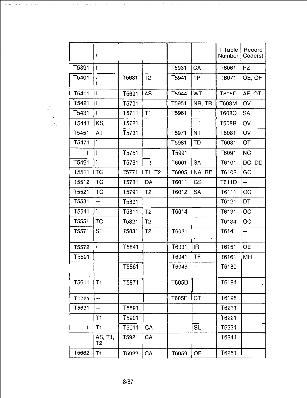
TL-130400-1001
Record T Table Record
I I
Code(s) Number Code(s)
Table 20.3 Record Code/T Table Cross-Reference
T Table Record
Number Code(s)
T5931
CA
---I--
T5941
TP
LD T5671
1 T2
AT, LD,
LM, OC
LD T5691
ED T5701
1 AS
LD
1
T5711
IT1
KS
T5721
1 Tl
T5961’
1 AT
T5962
1 AT
T5731
1 Tl
T5991
1 Tl
TC T5741
1 Tl
RP T5751
1 Tl, T2
TC T5761
1 T2
TC
1
T5811
IT2
I
I
OF T5841
1 T2
T2
T2
T5801
1 T2
T6013
1 LD
T6014
1 AD
T6015
1 OD
T6021
CA, DT,
PN, SA
T6031
1
IR
T5842
1 Tl T6041 TF
T5861
AT
I
I
---I--
T6046 --
T6180
AT, LD,
oc
T5871
CA
I
I
T605D
--
T6194
LD, LM,
MH
T6195
WT
T5891
1 AT
T6051
1 TT
T6211
--
T5901
1 CA
T6053
j
--
T6221
--
1
T5911
ICA
T6055
1
SL
T6231
OE
T6058 OE
T6241
AC
T6251
AC
I
I
--
T5881 CA
T Table
Number
T5391
T5401
1
T5431
1 T5481
1
T5491
T5511
j
T5541
T5551
T5571
t
T5572
T5591
T5601
T5611
T5641
T5651
T5661
j
SVR 5210
8187
D-41 3
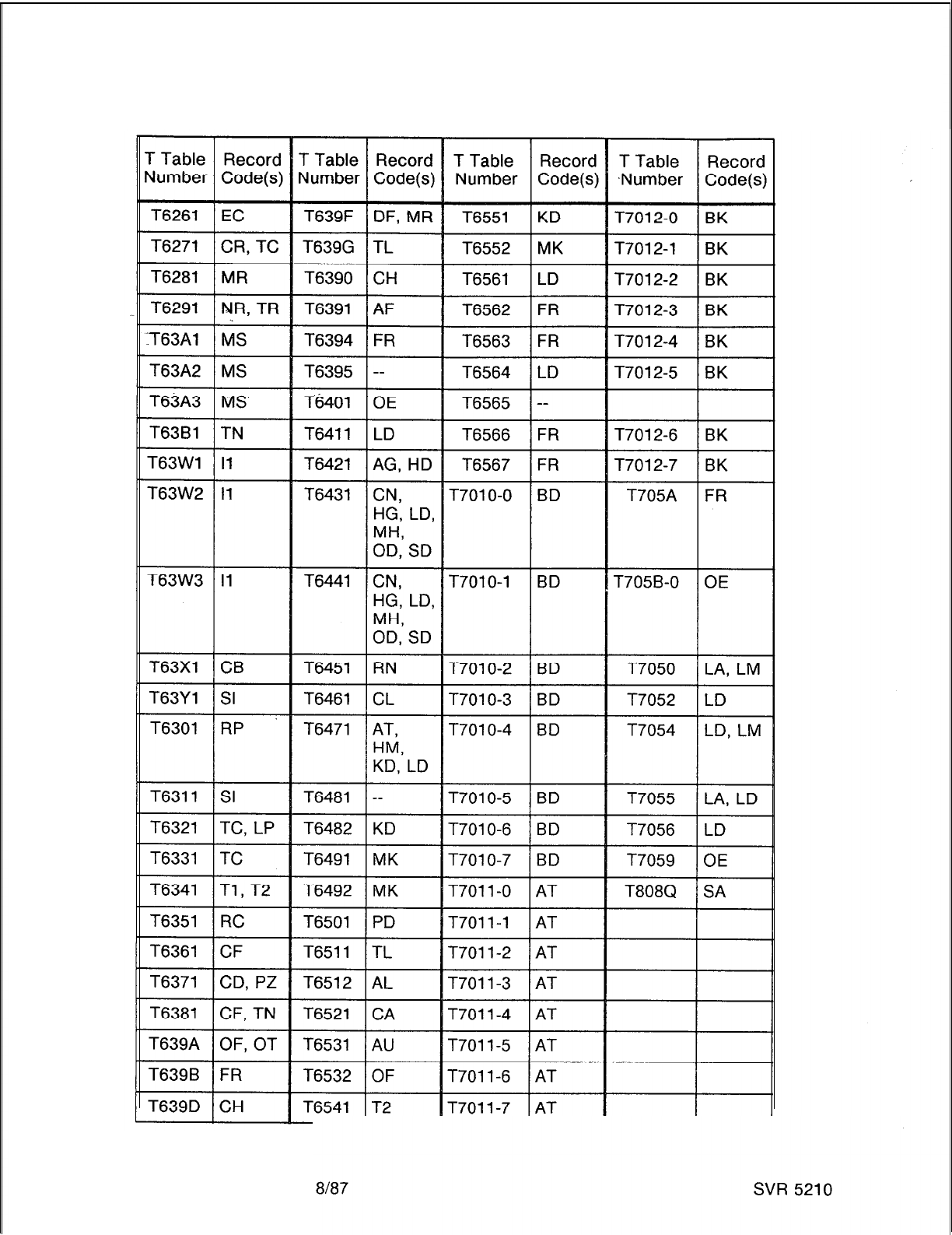
TL-130400-1001
Table 20.3 Record Code/T Table Cross-Reference
D-41 4

SVR 5210
TL-130400-1001
CPG ERROR
MESSAGES 21.0 Table 21
.l
describes the error messages that are
detected by the CPG program. These massages are used to
correct the errors that are generated in a CPG run.
.
.
8187
D-415
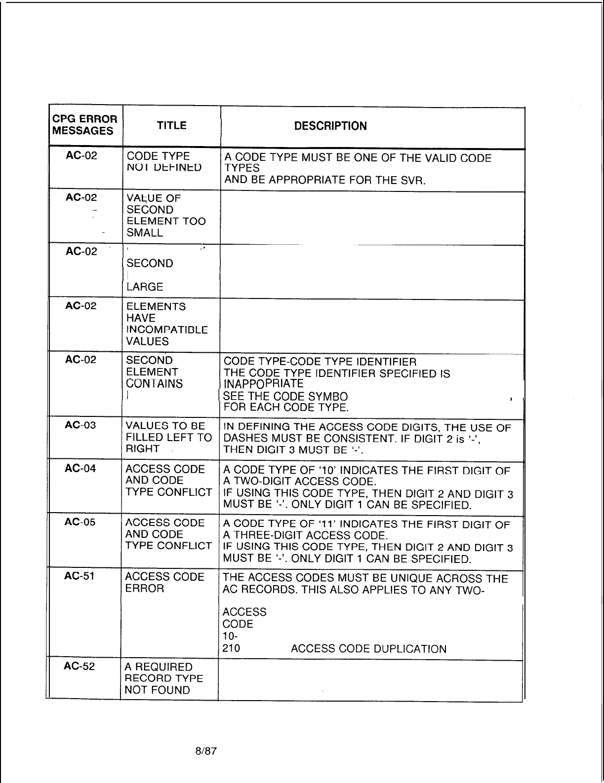
Table 21.1 CPG Error Messages
TL-130400-1001
DESCRlPTlON
OF MESSAGES
AS SHOWN IN THE CODE SYMBOL MODULE
VALUE OF
‘-
ELEMENT TOO
PRIATE
FOR THE CODE TYPE.
INVALID VALUE L MODULE FOR VALID VALUES
DIGIT COMBINATIONS.
D-41 6
SVR 5210
CPG ERROR
MESSAGES
AC-52
. . . .
AC-52
AC-52
AC-52
AC-52
AC-52
TITLE
FEATURE NOT
USABLE
WITHOUT
INDICATED
. .
RECORDCODE
.
.
AGENT GROUP
NUMBER NOT
FOUND
ATTENDANT
NOT FOUND
CLASS OF
SERVICE
REQUIRED
FEATURE NOT
USABLE’
WITHOUT
CLASS OF
SERVICE MARK
SODE
TYPE
IDENTIFIER
-
DN-NET
CODE
3N
TR
Table 21.1 CPG Error Messages
DESCRIPTION OF MESSAGES
THE LISTED RECORD CODE IS REQUIRED FOR THE
CODE TYPE SPECIFIED.
RECORD CODES CODE TYPES
AD
113
AT 5-18, 45-46, 89-90,
102, 106-l 07
CL
76
:“s
225
12,119
MK
70
PN 30
RC
53, 55-56
WT 98-l 00,
115
THE AGENT GROUP NUMBER SPECIFIED IN THE CODE
TYPE IDENTIFIER FIELD FOR CODE TYPE 112 MUST
BE DEFINED ON AN AG RECORD.
THE ATTENDANT NUMBER/S SPECIFIED IN THE CODE
TYPE IDENTIFIER FIELD FOR CODE TYPE 9 MUST BE
DEFINED ON AN AT RECORD.
THE LISTED CLASS OF SERVICE MARK ON RECORDS
DC, DD OR NC IS REQUIRED FOR THE SPECIFIED
CODE TYPES TO WORK.
CLASS OF SERVICE MARK CODE TYPE
CC (RECODE CODE DC, DD)
22,23
CF (RECODE CODE NC)
20
CV RECODE CODE NC)
21
CO (RECODE CODE NC)
28,29
EX (RECODE CODE NC)
19
HD (RECODE CODE NC)
40,44
MC (RECODE CODE NC)
32,33
PA (RECODE CODE DC, DD)
34,35
PC (RECODE CODE DC, DD)
33,32
PK (RECODE CODE NC)
39,43
RL (RECODE CODE DC, DD)
53
SA (RECODE CODE NC)
120
UN (RECODE CODE NC)
31
(ENDCHK)
THE ON-NET CODE SPECIFIED IN THE CODE TYPE
IDENTIFIER FIELD FOR CODE TYPE 105 MUST BE
DEFINED ON A TR RECORD.
SVR 5210
TL-130400-1001
8187
D-41 7
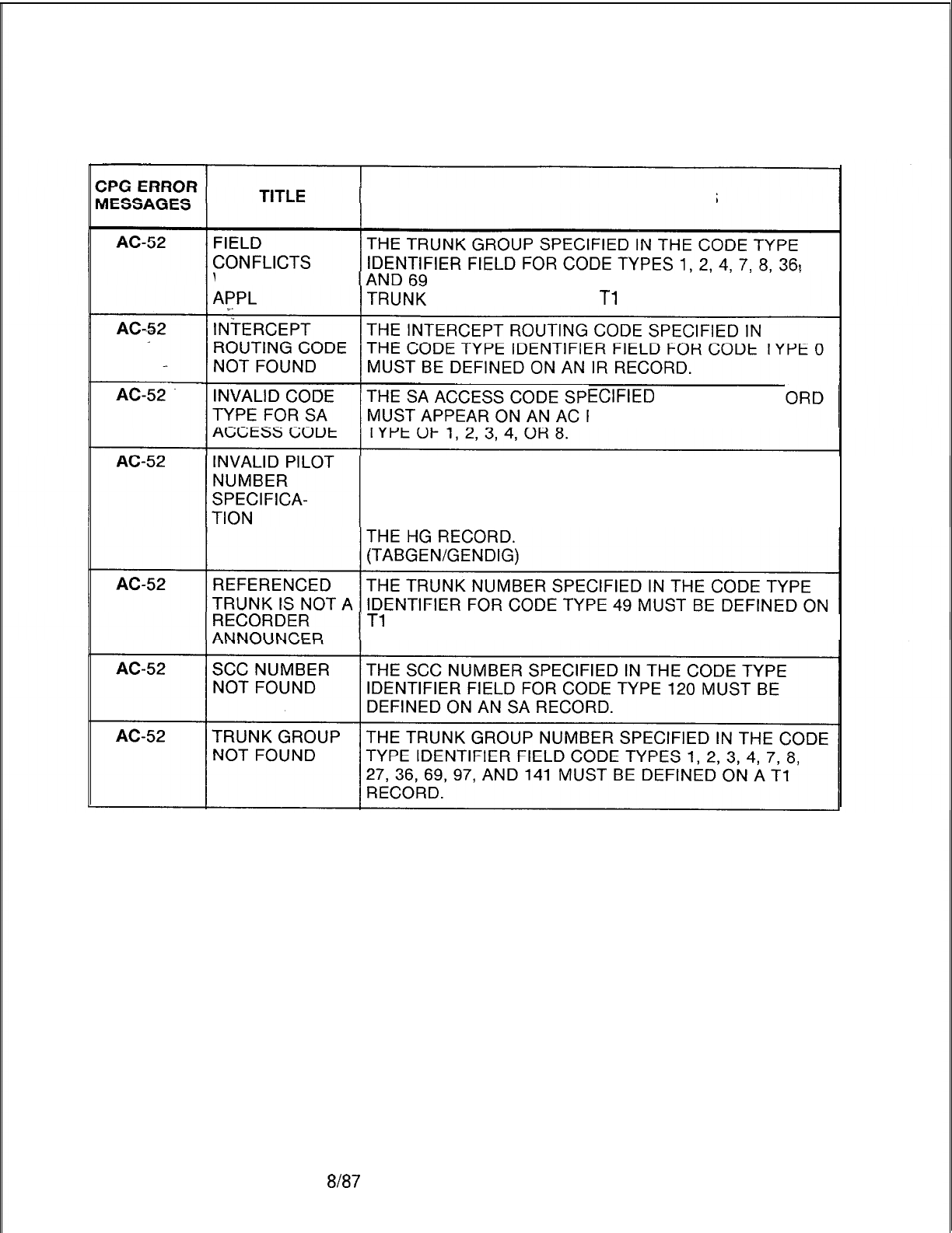
TL-130400-1001
Table 21.1 CPG Error Messages
DESCRIPTION OF MESSAGES
’
WITH TRUNK MUST BE DEFINED WITH A COMPATIBLE
APPLICATION ON A
Tl
RECORD.
ECIFIED
ON AN SA REC
RECORD WITH A CODE
THE PILOT NUMBER SPECIFIED IN THE CODE TYPE
IDENTIFIER FIELD FOR CODE TYPES 37, 38, 41, 42, 61,
62 ,138, OR 139 MUST BE DEFINED AS THE PILOT
NUMBER OF THE CORRESPONDING HUNT GROUP ON
Tl
AND TC RECORDS AS A RECORDER ANNOUNCER.
D-41 88187
SVR 5210
Table 21.1 CPG Error Messages (Continued)
TL-130400-1001
CPG ERROR
MESSAGES TITLE DESCRIPTION OF MESSAGES
AC-53 CLASS OF A FEATURE WAS SPECIFIED IN THE CLASS OF
SERVICE/ SERVICE RECORD CODES (DC, DD, NC),
ACCESS CODE BUT AN ACCESS CODE FOR THE FEATURE WAS NOT
.i_
ERROR DEFINED.
DISPLAYABLE ACCESS CODE
CLASS OF SERVICE TYPE
cc
22,23
DA 36
MC
32,33
ME
48
PA 34,35
PC 32,33
RL 53,55,56
N-DISPLAYABLE ACCESS CODE
CLASS OF SERVICE TYPE
EL
20
28,29
cv
21
DC 24
DD 71,72
EX
19
HD
40,44
MA
83
oc
13,14
ri:
39,43
120
SC 119
UN
31
wu
81,82
(ENDCHK)
AC-54 NO ACCESS ACCESS CODES SHOULD BE DEFINED FOR ALL
CODE FOUND TRUNK GROUPS HAVING A DIRECTION OF OUTGOING
FOR TRUNK OR TWO-WAY ON A
Tl
RECORD.
GROUP. NO IF A TRUNK GROUP DOES NOT HAVE AN ACCESS
ACCESS FOUND CODE, ACCESS TO IT MUST BE PROVIDED ON
FOR TRUNK ANOTHER RECORD CODE SUCH AS NT, TD, LS, OR
GROUP
SVR 5210
Em7 D-419
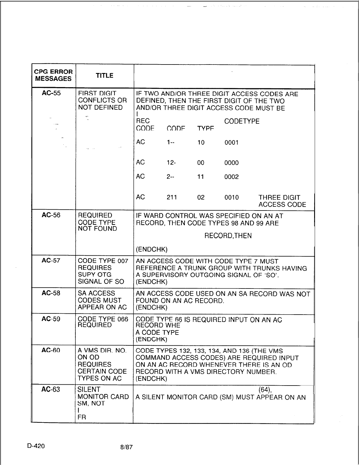
Table 21.1 CPG Error Messages (Continued)
TL-130400-1001
DESCRIPTION OF MESSAGES
DEFINED ON AN AC RECORD.
ACCESS CODE
CODETYPE
IDENTIFIER
FIRST DIGIT OF
A TWO DIGIT
ACCESS CODE
TWO DIGIT
ACCESS CODE
FIRST DIGIT OF
A THREE DIGIT
ACCESS CODE
REQUIRED, AND IF TIME PERIOD CONTROL WAS
SPECIFIED ON AN AT
RECORD,THEN
CODE TYPE 100
IS REQUIRED.
NEVER THERE-ARE RN RECORDS WITH
OF 3DG OR 4DG.
FOR SILENT MONITOR ACCESS CODE
(64),
FR RECORD.
EQUIPPED ON
SVR 5210
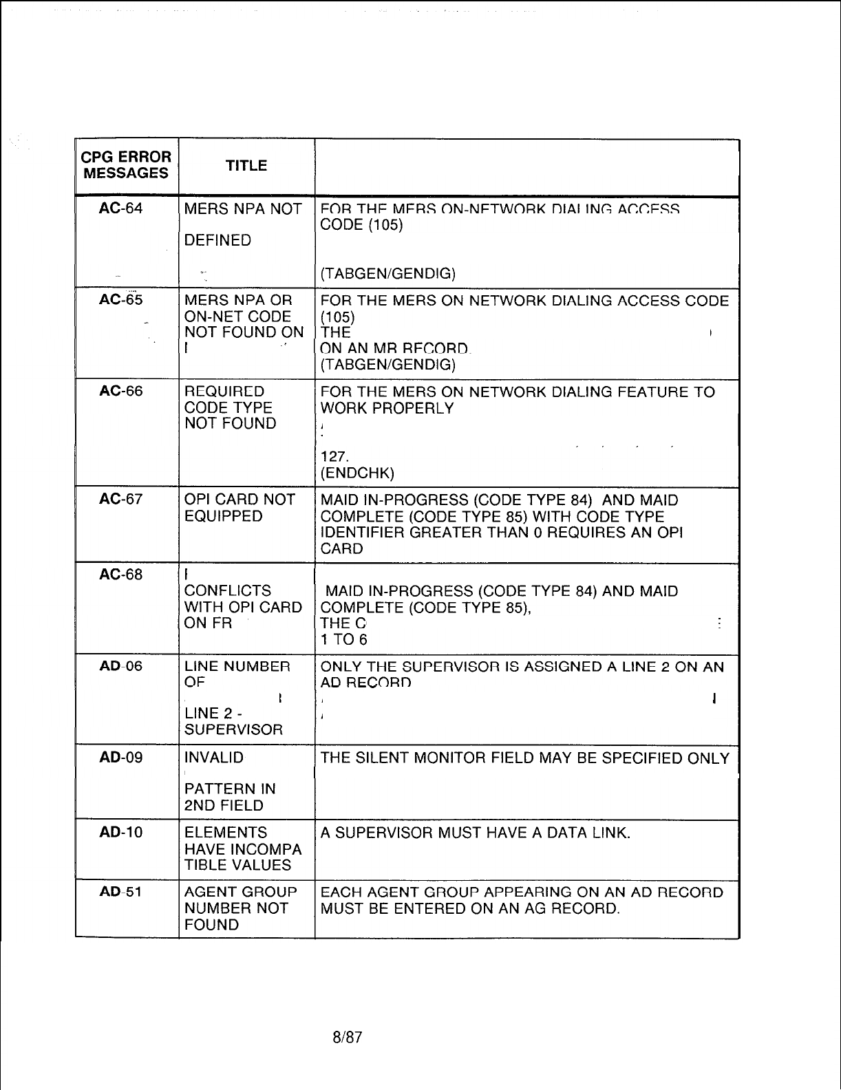
Table 21.1 CPG Error Messages (Continued)
TL-130400-1001
DESCRIPTION OF MESSAGES
PREVIOUSLY THE MERS ON-NET NPA MUST HAVE BEEN DEFINED
ON A TR RECORD.
MERS ON-NET NPA MUST HAVE BEEN DEFINED
MR FORM
.v
AN ACCESS CODE MUST BE PROVIDED WITH ONE OF
THE FOLLOWING CODE TYPES: 94, 96,
105, 126, OR
FIELD VALUE IF THE OPI CARD IS EQUIPPED ON FR,
ODE TYPE IDENTIFIER MUST BE IN THE RANGE
SUPERVISOR AGENT LINE’2 FOR OTHER AGENTS IS ASSIGNED ON
AN LD RECORD.
CHARACTER IF THE SUPERVISOR FIELD IS SPECIFIED.
SVR 5210
8187 D-421
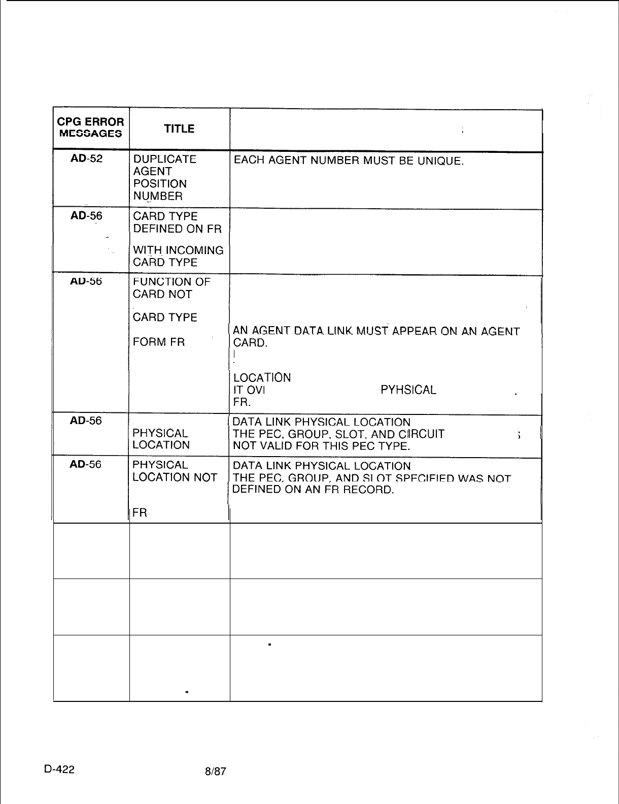
TL-130400-1001
Table 21.1 CPG Error Messages (Continued)
DESCRIPTION OF MESSAGES
INCOMPATIBLE
DATA LINK PHYSICAL LOCATION
THE PEC, GROUP, SLOT, AND CIRCUIT FUNCTION
ALLOWED FOR SPECIFIED IS INVALID FOR THE CARD TYPE DEFINED
ON FR (FOR THIS PEC TYPE).
DEFINED ON
IF THE CARD TYPE IN THE MESSAGE IS “OVER”,
THAT INDICATES THAT A CARD IN THE PREVIOUS
TION
IS A WIDE CARD AND
ERHANGS INTO THIS
PYHSICAL
LOCATION ON
NONEXISTENT
IRCUIT
SPECIFIED IS
DEFINED ON
RECORD CODE
AD-56 PHYSICAL
LOCATION
PREVIOUSLY
FILLED
DATA LINK PHYSICAL LOCATION
THE PEC, GROUP, SLOT, AND CIRCUIT SPECIFIED FOR
THE AGENT DATA LINK MUST BE UNIQUE.
AD-58 REQUIRED THE LINE NUMBER OF SUPERVISOR LINE 2 MUST BE
VALUE NOT A VALID ENTRY ON AN LD RECORD.
FOUND ON
LISTED FORM
AD-59 FUNCTION OF SELF
-
EXPLANATORY
AGENT GROUP
MUST BE ACD IF
DATA LINK
EQUIP IS
-
SVR 5210
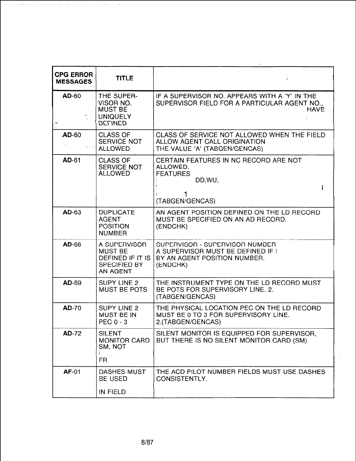
TL-130400-1001
Table 21.1 CPG Error Messages (Continued)
DESCRIPTION OF MESSAGES
THEN ANOTHER AGENT SUPERVISOR CANNOT
THE ALREADY DEFINED SUPERVISOR NUMBER.
-..
ON LINE 1 HAS
FEATUREi
OC, CO, DC, CV, CF,TC, TD, UN, TM, PD,
HD, PK, CN,
DD,WU,
MA AND SD ARE NOT ALLOWED
WHEN THE FIELD ALLOW AGENT CALL ORIGINATION
ON LINE
1
HAS THE VALUE ‘A’.
IT IS SPECIFIED
PROVIDED ON FR RECORD.
EQUIPPED ON
CONSISTENTLY
SVR 5210
8187
D-423
r
TL-130400-1001
CPG ERROR
MESSAGES
AF-02
AF-51
AF-51
AF-51
AF-51
D-424
AF-52
AF-53
AG-01
Table 21.1
TITLE
DASHES MUST
BE USED
CONSISTENTLY
IN FIELD
ELEMENTS
HAVE
INCOMPATIBLE
VALUES
PHYSICAL
LOCATION
PREVIOUSLY
FILLED
NONEXISTENT
PHYSICAL
LOCATION
CARD OVER-
HANGS INTO A
PREVIOUSLY
FILLED SLOT
PREVIOUS
CARD
OVERHANGS
INTO
TH,lS
SLOT
INVALID PILOT
NUMBER
SPECIFICATION
PEC NUMBER IS
NOT EQUIPPED
NIGHT DAY
MODE
-
NIGHT
DIVERT
DESTINATION
CPG Error Messages (Continued)
DESCRIPTION OF MESSAGES
THE
9TH
ART CARD MUST USE DASHES
CONSISTENTLY.
CHECK ON EQUIPPED STATUS
IF PEC, GROUP, AND CARD SLOT FIELDS ARE
DASHES, THEN THE EQUIPPED STATUS MUST BE ‘N’.
THE
9TH
ART CARD MUST CONTAIN A UNIQUE
PHYSICAL LOCATION.
THE CARD WAS ASSIGNED TO A NONEXISTENT
PHYSICAL LOCATION.
THIS CARD IS AN OVERSIZED CARD AND IS TRYING
TO FILL TWO SLOTS.
OF THE TWO SLOTS IT FILLS,
THE RIGHT HAND ONE HAS ALREADY BEEN FILLED.
THE CARD TO THE LEFT OF THIS SLOT IS AN
OVERSIZED CARD1
THE RIGHT HALF
6F
THAT CARD FILLS THIS SLOT.
THE PILOT NUMBER SPECIFIED IN THE ACD PILOT
NUMBERS 1 THRU 4 MUST APPEAR AS A PILOT
NUMBER ON AN HG RECORD.
THE PEC NUMBER SPECIFIED MUST BE MARKED
EQUIPPED ON THE OF RECORD.
IF NIGHT MODE IS SPECIFIED,
THEN A NIGHT DIVERT DESTINATION MUST BE
SPECIFIED.
8187
SVR 5210
TL-130400-1001
Table 21.1 CPG Error Messaaes (Continued)
CPG ERROR
MESSAGES
we
.I
TITLE DESCRIPTION OF MESSAGES
AG-02
. . .
AG-03
AG-04
NIGHT DIVERT A NIGHT DIVERT DESTINATION ID MUST CONTAIN
DESTINATION
-
ONLY THE ALLOWABLE VALUES ASSIGNED TO THE
NIGHT DIVERT CORRESPONDING NIGHT DIVERT DESTINATION TYPE
DESTINATION ID AS FOLLOWS:
.,-
ALLOWABLE VALUE:
NIGHT DIVERT NIGHT DIVERT
DESTINATION DESTINATION ID
LN (LINE) 0000 TO 9999
TK (TRUNK GROUP) 0000 TO 0063
DEPENDING ON SVR
AG (AGENT GROUP) 0000 TO 0007
DEPENDING ON SVR
RA (REC. ANN.
#3) ----
AT (ATTENDANT) 0000 TO 0128
ALTERNATE AN ALTERNATE DIVERT DESTINATION ID MUST
DIVERT CONTAIN ONLY THE ALLOWABLE VALUES ASSIGNED
DESTINATION
-
TO THE CORRESPONDING ALTERNATE DIVERT
ALTERNATE DESTINATION TYPE AS FOLLOWS:
DIVERT ALLOWABLE VALUE:
DESTINATION ID ALTERNATE DIVERT ALTERNATE NIGHT
DESTINATION DIVERT DESTINATION ID
LN (LINE) 0000 TO 9999
TK (TRUNK GROUP) 0000 TO 0063
AG (AGENT GROUP) 0000 TO 0007
RA (RECORDER ANNOUNCER) PXXX WHERE
P= PEC NUMBER
XXX=TRUNK NUMBER
AT (ATTENDANT) 0000 TO 0128
NIGHT/ALTER-
IF A CAS
MAIN/ACD
GROUP IS SPECIFIED AS THE
NATE DIVERT NIGHT/ALTERNATE DIVERT DESTINATION,
DESTINATION
-
IT CANNOT BE THE SAME GROUP.
AGENT GROUP
AG-05 ALTERNATE
DIVERT
DESTINATION
TIMING
THE ALTERNATE DIVERT DESTINATION TIMING IS
REQUIRED IF AN ALTERNATE DIVERT DESTINATION IS
SPECIFIED.
AG-06 PLAY RA
#I
RECORDER ANNOUNCER
#l
MUST BE PLAYED IF
BEFORE PLAY RA
#1
BEFORE ROUTING TO AGENT GROUP IS
ROUTING
-
RA SPECIFIED AS ‘Y’.
#l
AG-07 TIME BETWEEN THE TIME BETWEEN RA
#l
AND RA
#2
IS REQUIRED IF
RA
#l
AND RA BOTH RECORDER ANNOUNCERS ARE TO BE PLAYED.
#2
SVR 5210
8187
D-425
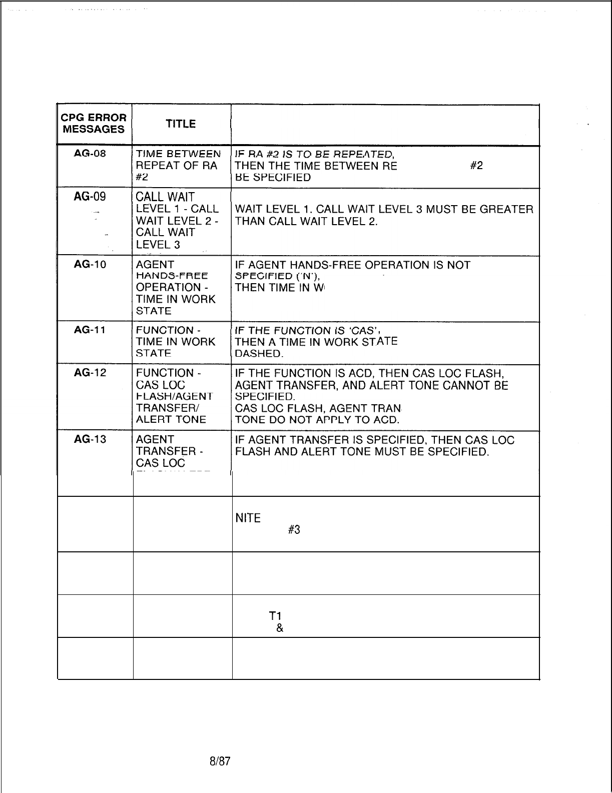
TL-130400-1001
Table 21.1 CPG Error Messages (Continued)
DESCRIPTION OF MESSAGES
PEAT OF RA
#2
MUST
CALL WAIT LEVEL 2 MUST BE GREATER THAN CALL
ORK STATE VALUE MUST BE DASHED.
ATE
VALUE MUST BE
SFER, AND ALERT
FLASH/ALERT
TONE
AG-14 ELEMENTS IF RECORDER ANNOUNCER (‘RA’) IS SPECIFIED AS
HAVE
NITE
DIVERT DESTINATION,
INCOMPATIBLE THEN RA
#3
MUST NOT BE DASHED.
VALUES
AG-51
RECORDCODE
TYPE NOT
FOUND
AG-51
AG-52
AGENT GROUP EACH AGENT GROUP ASSIGNED TO A TRUNK GROUP
NUMBER NOT ON A
Tl
RECORD MUST APPEAR ON AN AG RECORD.
FOUND (INTER
&
ENDCHK)
DUPLICATE THE AGENT GROUP NUMBER ON EACH AG RECORD
AGENT GROUP MUST BE UNIQUE.
NUMBER
D-426
8187
SVR 5210
TL-130400-1001
CPG ERROR
MESSAGES
Table 21.1 CPG Error Messages (Continued)
TITLE DESCRIPTION OF MESSAGES
AG-53 NIGHT DIVERT IF A NIGHT DIVERT DESTINATION ID IS SPECIFIED, IT
DESTINATION ID MUST EXIST;
I.E., IT MUST ALSO BE ENTERED ON AN APPROPRIATE
%-
RECORD AS FOLLOWS:
. . .
NIGHT DIVERT CORRESPONDING
DESTINATION ID REQUIRED RECORD
_LN LINE NUMBER
LD
TK TRUNK GROUP NUMBER
Tl
AND T2
AG AGENT GROUP NUMBER AG
RA ---- (REC. ANN.
#3)
RA
AT ATTENDANT MASK AT
--
----
NONE
AG-54 ALTERNATE IF AN ALTERNATE DIVERT DESTINATION ID IS
DIVERT SPECIFIED, IT MUST EXIST;
DESTINATION ID I.E., IT MUST ALSO BE ENTERED ON AN
APPROPRIATE RECORD AS FOLLOWS:
AG-55
ALTERNATE DIVERT CORRESPONDING
DESTINATION ID REQUIRED RECORD
LN LINE NUMBER
LD
TK TRUNK GROUP NUMBER
Tl
AND T2
AG AGENT GROUP NUMBER
AG
RA PEC AND TRUCK NUMBER
TC
OF RECORDER/ANN
AT ATTENDANT MASK AT
--
----
NONE
FUNCTION NOT IF A CAS
MAIN/ACD
GROUP IS SPECIFIED AS THE
SAME AS THE NIGHT/ALTERNATE DIVERT DESTINATION,
DIVERTING IT MUST HAVE THE SAME FUNCTION AS THE
GROUP DIVERTING GROUP;
I.E. BOTH MUST BE CAS OR BOTH MUST BE ACD.
(ENDCHK)
SVR 5210
8/W
D-427
TL-130400-1001
CPG ERROR
MESSAGES
Table 21.1 CPG Error Messages (Continued)
TITLE DESCRIPTION OF MESSAGES
AG-56 FIELD DOES RA
#l,
RA
#2
AND RA
#3
FIELDS IF SPECIFIED ON AN
NOT HAVE AG RECORD REQUIRE CERTAIN FIELDS TO BE
REQUIRED EQUIPPED ON AN RA RECORD, DEPENDING ON THE
VALUE VALUE SPECIFIED:
._
THE REQUIREMENTS ARE AS FOLLOWS:
. . .
FIELD AND VALUE VALUES REQUIRED
ON AG RECORD ON RA RECORD
,-
RA
#l:
1
RA
#1
AALT RA
#l
RA
#2:
2 RA
#2
AALT RA
#2
RA
#3:
3 RA
#3
AALT RA
#3
AL-01
ELEMENTS
HAVE
INCOMPATIBLE
VALUES
AL-01
ELEMENT 2 IS
MEANINGLESS
SPECIFICATION
AL-01
AL-51
2ND FEATURE FUNCTION STATUS
-
PRINTER ID
REQUIRED IF THERE ARE CERTAIN VALUES REQUIRED IN THE
FIRST PRINTER ID FIELD DEPENDING ON THE FUNCTIONS
SPECIFIED STATUS VALUE:
FUNCTION ALLOWABLE VALUES OF
STATUS PRINTER NUMBER ID
AL
01-15
-- --
KEDU NUMBER THE SPECIFIED KEDU NUMBER MUST BE A VALID
NOT FOUND KEDU NUMBER ON A KD RECORD.
D-428
8187
SVR 5210
TL-130400-1001
CPG ERROR
MESSAGES
Table 21.1 CPG Error Messages (Continued)
TITLE DESCRIPTION OF MESSAGES
AL-52
. . . .
PRINTER THE PRINTER ID IDENTIFIES A SPECIFIC PRINTER
NUMBER NOT NUMBER OR SEVERAL PRINTER NUMBERS
FOUND DEPENDING ON THE VALUE RANGE ENTERED.
ALL PRINTER NUMBERS INDICATED BY THE PRINTER
._-
ID MUST BE VALID PRINTER NUMBERS ON A PD
RECORD.
AP-52
PRINTER PRINTER
ID
NUMBER(S)
0
NONE
1
0
2
1
3
0,1
42
5
02
6
12
70,1,2
8
3
90,3
10 1,3
11
0,1,3
12
23
13
023
14 1,2,3
15
0,123
CARD TYPE
DEFINED ON FR
INCOMPATIBLE
WITH FCN OF
INCOMING
CARD
AP-52 CARD TYPE
DEFINED ON FR
INCOMPATIBLE
WITH INCOMING
CARD TYPE
AP-52 FUNCTION OF PHYSICAL LOCATION
CARD NOT THE PEC, GROUP, SLOT AND CIRCUIT FUNCTION
ALLOWED FOR SPECIFIED IS INVALID FOR THE CARD TYPE DEFINED
CARD TYPE ON FR (FOR THIS PEC TYPE). ASYNCHRONOUS PORT
DEFINED ON MUST APPEAR ON A VPLO,
VPLl,
VP20 (VOICE OR
FORM FR VOICE AND DATA) OR VP21 CARD. (PHYLOC)
IF THE CARD TYPE IN THE MESSAGE IS “OVER”
THAT INDICATES THAT A CARD IN THE PREVIOUS
LOCATION IS A WIDE CARD AND IT OVERHANGS INTO
THIS PHYSICAL LOCATION ON FR.
SVR 5210
8187 D-429

-
TL-130400-1001
ZPG
ERROR
MESSAGES
Table 21.1 CPG Error Messages (Continued)
TITLE DESCRIPTION OF MESSAGES
AP-53
. .
AP-53
PHYSICAL
LOCATION NOT
DEFINED ON
RECORD CODE
LD:
PHYSICAL PHYSICAL LOCATION
LOCATION NOT THE PEC, GROUP, SLOT, AND CIRCUIT OF AN
DEFINED ASYNCHRONOUS PORT MUST BE DEFINED ON AN LD
. .
RECORD.
AP-53 USE OF PHYSICAL LOCATION
PHYSICAL LOC THE PEC, GROUP, SLOT, AND CIRCUIT OF AN
CONFLICTS ASYNCHRONOUS PORT MUST BE DEFINED ON AN LD
WITH INSTR. RECORD WITH AN INSTRUMENT TYPE OF ‘DFPA’ OR
TYPE SPECIFIED ‘APM’ (DEPENDING ON THE SVR).
ON LD
AP-54
AP-56
AP-56
DUPLICATE PHYSICAL LOCATION
PHYSICAL THE PEC, GROUP, SLOT, AND CIRCUIT SPECIFIED
LOCATION MUST BE UNIQUE ACROSS ALL AP RECORDS.
PHYSICAL PHYSICAL LOCATION
LOCATION NOT THE PEC, GROUP, SLOT, AND CIRCUIT OF AN
FOUND ON ASYNCHRONOUS PORT MUST BE DEFINED ON A CP
RECORD CODE RECORD WITH A DEVICE TYPE OF EITHER ‘TERM’ OR
CP
‘HOST’.
HOST LINE PHYSICAL LOCATION
-
HOST LINE ADAPTIVE SPEED
ADAPT. SPEED THE PEC, GROUP, SLOT, AND CIRCUIT OF AN
IS VALID ONLY ASYNCHRONOUS PORT MUST BE DEFINED ON A CP
FOR DEVICE RECORD WITH A DEVICE TYPE ‘HOST’ IF HOST LINE
TYPE ADAPTIVE SPEED IS SPECIFIED AS ‘Y’.
HOST ON CP
AP-82 PHYSICAL PHYSICAL LOCATION
LOCATION IS THE COMPLETE DEFINITION ON AN ASYNCHRONOUS
MISSING ON PORT INCLUDES AN LD, CP AND AP RECORD.
NAMED (ENDCHK)
RECORDCODE
AQ-52 CARD TYPE
DEFINED ON FR
INCOMPATIBLE
WITH FCN OF
INCOMING
CARD
D-430
8187
TL-130400-1001
CPG
ERROR
MESSAGES
Table 21.1 CPG Error Messages (Continued)
TITLE DESCRIPTION OF MESSAGES
AQ-52 FUNCTION OF PHYSICAL LOCATION
CARD NOT THE PEC, GROUP, SLOT, AND CIRCUIT FUNCTION
ALLOWED FOR SPECIFIED IS INVALID FOR THE CARD TYPE DEFINED
%
. CARD TYPE ON AN FR RECORD (FOR THIS PEC TYPE).
-..
DEFINED ON AN ASYNCHRONOUS PORT MUST APPEAR ON A VPLO,
FORM FR
VPLl,
VP20 (VOICE AND DATA OR DATA) OR VP21
CARD. (PHYLOC)
IF THE CARD TYPE IN THE MESSAGE IS
“
OVER
“,
THAT INDICATES THAT THE CARD IN THE PREVIOUS
LOCATION IS A WIDE CARD AND IT OVERHANGS INTO
THIS PHYSICAL LOCATION ON FR.
AQ-52
AQ-52
NONEXISTENT PHYSICAL LOCATION
PHYSICAL THE PEC, GROUP, SLOT, AND CIRCUIT SPECIFIED IS
LOCATION NOT VALID FOR THIS PEC TYPE. (PHYLOC)
PHYSICAL PHYSICAL LOCATION
LOCATION NOT THE PEC, GROUP, AND SLOT SPECIFIED WAS NOT
DEFINED ON DEFINED ON AN FR RECORD.
RECORD CODE (PHYLOC)
FR
AQ-53 USE OF PHYSICAL LOCATION
PHYSICAL LOC THE PEC, GROUP, SLOT, AND CIRCUIT OF AN
CONFLICTS ASYNCHRONOUS PORT MUST BE DEFINED ON AN LD
WITH INSTR. RECORD WITH AN INSTRUMENT TYPE OF ‘DFPA’ OR
TYPE SPECIFIED ‘APM’.
ON LD
AQ-54
AQ-55
DUPLICATE PHYSICAL LOCATION
PHYSICAL THE PEC, GROUP, SLOT, AND CIRCUIT SPECIFIED
LOCATION MUST BE UNIQUE ACROSS ALL AQ RECORDS.
SITE HAS AN INCONSISTENCY HAS BEEN DETECTED IN THE
INCONSISTENT SET/READ LIST OF THE LISTED PORT TABLE ENTRY.
DATA BASE
AS-51
AS-52
TRUNK GROUP THE TRUNK GROUP SPECIFIED MUST HAVE A
NOT FOUND CORRESPONDING
Tl
RECORD.
DUPLICATE THIS NUMBER MUST BE UNIQUE ACROSS AS
TRUNK GROUP RECORDS.
NUMBER
AT-01
ATTENDANT DASHES MUST BE USED CONSISTENTLY IN FIELD.
BILLING
NUMBER
SVR 5210
8187 D-431
TL-130400-1001
CPG ERROR
MESSAGES
Table 21.1 CPG Error Messages (Continued)
TITLE DESCRIPTION OF MESSAGES
AT-03 PEC
-
PEC THE ATTENDANT BILLING NUMBER MUST BE IN THE
INDICATED BY SAME PEC AS INDICATED BY THE CONSOLE.
THE CONSOLE
AT-04 SECOND FIELD
. . . .
PATTERN MUST
BE SPECIFIED IF
FIRST FIELD IS
Y
AT-04
SE&ND
ELEMENT
CONTAINS
INVALID VALUE
AT-04 INVALID PROGRAMMABLE ATTENDANT CONSOLE
-
CHARACTER PROGRAMMABLE SWITCHES ONLY ONE TYPE OF
PATTERN IN CONSOLE MAY BE USED ON THE SYSTEM
2ND FIELD (I.E., STANDARD AND PROGRAMMABLE SWITCHES
MAY NOT CO-EXIST).
AT-05 VALUE OF
SECOND
ELEMENT TOO
SMALL
AT-05
AT-06
AT-07
VALUE OF ATTENDANT NUMBER
-
PEC
SECOND THE PLACEMENTS OF ATTENDANTS IN THE PECS ARE
ELEMENT TOO AS FOLLOWS:
LARGE ATTENDANT NUMBER PEC
0 TO 1 0
2 TO 3
1
4 TO 5
2
6TO7
3
SECOND EQUIPPED STATUS
-
LINE STATUS
ELEMENT IF THE EQUIPPED STATUS OF THE DATA LINK IS
CONTAINS IS/OS, THE LINE STATUS OF LINE DATA MUST BE THE
INVALID VALUE SAME OR --.
CKT MUST BE 0 CIRCUIT
-
PROGRAMMABLE ATTENDANT CONSOLE
IF
PROGRAM-
IF PROGRAMMABLE ATTENDANT CONSOLE IS
MABLE DASHED,
ATTENDANT THEN THE CIRCUIT OF THE DATA LINK MUST BE 0.
CONSOLE IS
‘-’
AT-51
DUPLICATE
ATTENDANT
CONSOLE
NUMBER
THE ATTENDANT NUMBER MUST BE UNIQUE ACROSS
THE AT RECORDS.
D-432 8J87
SVR 5210
r
Table 21.1
CPG Error Messaoes
fContinued\
TL-130400-1001
ZPG
ERROR
MESSAGES
-~
_
-
.._.
.
..-
---=--
t-----------t
TITLE DESCRIPTION OF MESSAGES
AT-52
. . .
Ai-
CARD TYPE
DEFINED ON FR
INCOMPATIBLE
WITH FCN OF
JNCOMING
CARD
CARD TYPE
DEFINED ON FR
!NCOMPATIBLE
WITH INCOMING
CARD TYPE
AT-52 FUNCTION OF DATA LINK PHYSICAL LOCATION
CARD NOT THE PEC, GROUP, SLOT, AND CIRCUIT FUNCTION
ALLOWED FOR SPECIFIED IS INVALID FOR THE CARD TYPE DEFINED
CARD TYPE ON FR (FOR THIS PEC TYPE).
DEFINED ON ATTENDANT DATA LINK MUST APPEAR ON AN ATTN
FORM FR CARD.
(PHYLOC)
IF THE CARD TYPE IN THE MESSAGE IS “OVER” THAT
INDICATES THAT A CARD IN THE PREVIOUS LOCATION
IS A WIDE CARD AND IT OVERHANGS INTO THIS
PYHSICAL
LOCATION ON FR.
AT-52 NONEXISTENT DATA LINK PHYSICAL LOCATION
PHYSICAL THE PEC, GROUP, SLOT, AND CIRCUIT SPECIFIED IS
LOCATION NOT VALID FOR THIS PEC TYPE.
(PHYLOC)
AT-52 PHYSICAL DATA LINK PHYSICAL LOCATION
LOCATION NOT THE PEC, GROUP, AND SLOT SPECIFIED WAS NOT
DEFINED ON DEFINED ON AN FR RECORD.
RECORD CODE (PHYLOC)
FR
AT-52
AT-55
PHYSICAL DATA LINK PHYSICAL LOCATION
LOCATION THE PEC, GROUP, SLOT, AND CIRCUIT SPECIFIED FOR
PREVIOUSLY THE ATTENDANT DATA LINK MUST BE UNIQUE.
FILLED (PHYLOC)
PEC NUMBER IS PEC NUMBER
NOT EQUIPPED THE PEC SPECIFIED MUST BE MARKED EQUIPPED ON
THE OE RECORD.
AT-55 NONEXISTENT THE CARD WAS ASSIGNED TO A NONEXISTENT
PHYSICAL PHYSICAL LOCATION.
LOCATION
SVR 5210
8h37
D-433

TL-130400-1001
CPG ERROR
MESSAGES
Table 21.1 CPG Error Messages (Continued)
TITLE DESCRIPTION OF MESSAGES
AT-55 CARD
OVERHANGS
INTO A
PREVIOUSLY
FILLED SLOT
THIS CARD IS AN OVERSIZED CARD AND IS TRYING
TO FILL TWO SLOTS. OF THE TWO SLOTS IT FILLS,
THE RIGHT HAND ONE HAS ALREADY BEEN FILLED.
AT-55 PREVIOUS THE CARD TO THE LEFT OF THIS SLOT IS AN
CARD OVERSIZED CARD. THE RIGHT HALF OF THAT CARD
OVERHANGS FILLS THIS SLOT.
INTO THIS
SCOT
AT-56
AT-58
PEC/BLDU NOT THE PEC AND BLDU SPECIFIED DID NOT HAVE A
FOUND CORRESPONDING BK RECORD.
PEC NUMBER THE BLDU NUMBER SPECIFIED ON AN AT RECORD
NOT FOUND ON MUST HAVE AN EQUIPPED STATUS ON A BD RECORD.
BD
AT-59 DUPLICATE
PEC/BLDU
NUMBER
ONLY ONE ATTENDANT CONSOLE CAN USE A
PARTICULAR BLDU.
AT-60 ALL AT FORMS ONLY ONE TYPE OF CONSOLE MAY BE USED ACROSS
MUST HAVE ALL AT RECORDS.
ONLY ONE TYPE (ENDCHK)
OF CONSOLE
AT-61
CARD TYPE
DEFINED ON FR
INCOMPATIBLE
WITH FCN OF
INCOMING
CARD
AT-61
CARD TYPE
DEFINED ON FR
INCOMPATIBLE
WITH INCOMING
CARD TYPE
AT-61
FUNCTION OF LINE PHYSICAL LOCATION
CARD NOT THE PEC, GROUP, SLOT AND CIRCUIT FUNCTION
ALLOWED FOR SPECIFIED IS INVALID FOR THE CARD TYPE DEFINED
CARD TYPE ON FR (FOR THIS PEC TYPE).
DEFINED ON ATTENDANT LINE MUST APPEAR ON A POTS OR OFFP
FORM FR LINE CARD.
(PHYLOC)
D-434 8187
SVR 5210
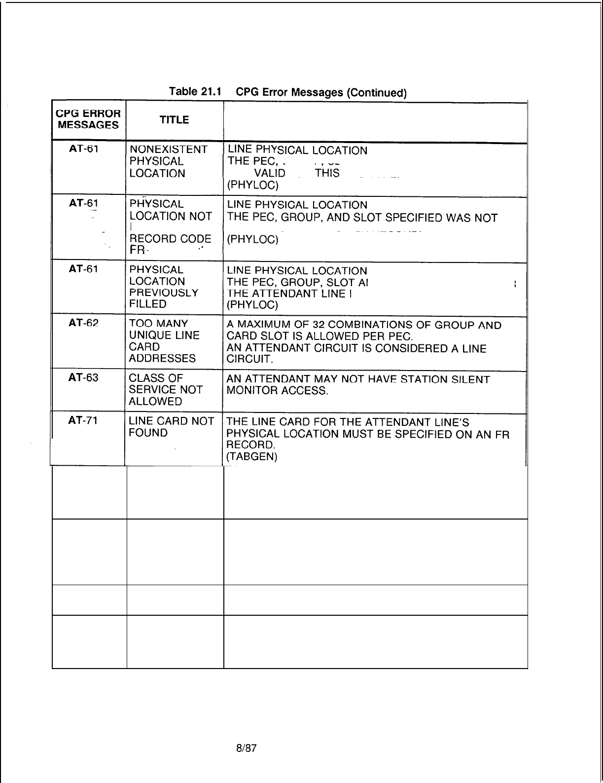
TL-130400-1001
DESCRIPTION OF MESSAGES
Tl!:PEC
GROUP SLOT AND CIRCUIT SPECIFIED IS
NOT
VALiD
FOR
Ti-lIS
PEC TYPE.
DEFINED ON DEFINED ON AN FR OR
LR
RECORD.
FR.
‘-
ND CIRCUIT SPECIFIED FOR
MUST BE UNIQUE.
AT-80 FRL MUST BE FRLS HAVE BEEN EQUIPPED FOR THIS SYSTEM ON
SPECIFIED RECORD CODE OF AND MUST THEREFORE BE
SPECIFIED FOR EVERY ATTENDANT ON RECORD
CODE AT.
AT-80 INCONSISTENT FRLS HAVE BEEN SPECIFIED FOR SOME PARTS OF
ENGINEERING THE SYSTEM AND NOT OTHERS.
OF FRLS ENSURE THAT ALL ATTENDANTS, LINES, TRUNK
GROUPS, MERS ROUTES, ETC. HAVE FRLS ENTIRELY
ENABLED OR DISABLED.
AT-82
AT-83
OPI CARD NOT RECEIVE PMS MESSAGES WAS INDICATED BUT OPI
EQUIPPED CARD WAS NOT EQUIPPED.
DTMF ATTENDANT CONSOLES REQUIRE USE OF A DTMF
RECEIVER NOT RECEIVER.
EQUIPPED ON
RECORD FR
SVR 5210
8187
D-435
TL-130400-1001
CPG ERROR
MESSAGES
Table 21.1 CPG Error Messages (Continued)
TITLE DESCRIPTION OF MESSAGES
AU-51
DUPLICATE THE AUTHORIZATION CODE NUMBER MUST BE
AUTHORIZATIO
UNIQUE ACROSS ALL AU RECORDS.
N CODE
NUMBER
AU-52
CLASS OF THE DISPLAYABLE CLASS OF SERVICE NUMBER MUST
SERVICE NOT BE DEFINED ON A DC RECORD.
DEFINED
AU-53 CLASS OF
‘m
THE N-DISPLAYABLE CLASS OF SERVICE NUMBER
SERVICE NOT MUST BE DEFINED ON AN NC RECORD.
DEFINED
BD-01
SECOND PEC
-
GROUP
-
CARD SLOT
-
CIRCUIT
ELEMENT DASHES MUST BE USED CONSISTENTLY ACROSS THE
CONTAINS ENTIRE PHYSICAL LOCATION (PEC, GROUP, CARD
INVALID VALUE SLOT, CIRCUIT).
IF ANY OF THE FIELDS CONTAIN DASHES, THEN ALL
MUST BE DASHED.
IF ONE OF THE FIELDS IS SPECIFIED (NONDASHED),
THEN ALL MUST BE SPECIFIED.
BD-51
CARD TYPE
DEFINED ON FR
INCOMPATIBLE
WITH FCN OF
INCOMING
CARD
BD-51
CARD TYPE
DEFINED ON FR
INCOMPATIBLE
WITH INCOMING
CARD TYPE
BD-51
NONEXISTENT PHYSICAL LOCATION
PHYSICAL THE PEC, GROUP, SLOT AND CIRCUIT SPECIFIED IS
LOCATION NOT VALID FOR THIS PEC TYPE.
(PHYLOC)
BD-51
PHYSICAL PHYSICAL LOCATION
LOCATION NOT THE PEC, GROUP, AND SLOT SPECIFIED WAS NOT
DEFINED ON DEFINED ON AN FR RECORD.
RECORD CODE (PHYLOC)
FR
D-436
8187
SVR 5210
-.
TL-130400-1001
CPG ERROR
MESSAGES
Table 21.1 CPG Error Messages (Continued)
TITLE DESCRIPTION OF MESSAGES
BD-51 FUNCTION OF PHYSICAL LOCATION
CARD NOT THE PEC, GROUP, SLOT AND CIRCUIT FUNCTION
ALLOWED FOR SPECIFIED IS INVALID FOR THE CARD TYPE DEFINED
.~_
CARD TYPE ON FR (FOR THIS PEC TYPE).
DEFINED ON A BLDU CIRCUIT MUST APPEAR ON AN ATTN CARD.
FORM FR (PHYLOC)
IF THE CARD TYPE IN THE
MESsAGE
IS “OVER” THAT
.
_
INDICATES THAT A CARD IN THE PREVIOUS LOCATION
IS A WIDE CARD AND IT OVERHANGS INTO THIS
PHYSICAL LOCATION ON FR.
BD-51
BD-51
PHYSICAL
LOCATION
PREVIOUSLY
FILLED
CARD
OVERHANGS
INTO A
PREVIOUSLY
FILLED SLOT
PHYSICAL LOCATION
THE PEC, GROUP, SLOT AND CIRCUIT SPECIFIED FOR
THE BLDU CIRCUIT MUST BE UNIQUE.
(PHYLOC)
THIS CARD IS AN OVERSIZED CARD AND IS TRYING
TO FILL TWO SLOTS. OF THE TWO SLOTS IT FILLS,
THE RIGHT HAND ONE HAS ALREADY BEEN FILLED.
BD-51
PREVIOUS THE CARD TO THE LEFT OF THIS SLOT IS AN
CARD OVERSIZED CARD.
OVERHANGS THE RIGHT HALF OF THAT CARD FILLS THIS SLOT.
INTO THIS SLOT
BD-55
PEC NUMBER PEC NUMBER
NOT EQUIPPED THE PEC SPECIFIED MUST BE EQUIPPED ON THE OE
RECORD.
BK-51 PEC NUMBER EACH PEC SPECIFIED ON A BK RECORD,
NOT FOUND ON MUST ALSO BE SPECIFIED IN THE BD RECORD.
BD
BK-52
BK-53
DUPLICATE
PECIBLDU
NUMBER
HUNDREDS
GROUP NOT
FOUND
THE COMBINATION OF PEC AND BUSY LAMP DISPLAY
UNIT NUMBER MUST BE UNIQUE ACROSS ALL BK
RECORDS.
THE SPECIFIED HUNDREDS GROUP WAS NOT
ENGINEERED ON AN HD RECORD.
CA-02 SECOND ATTENDANT CALL WAITING QUEUE SIZES QUEUE
l-
ELEMENT LESS QUEUE 2.
THAN FIRST ATTENDANT CALL WAITING QUEUE 2 MUST BE
ELEMENT LARGER THAN ATTENDANT CALL WAITING QUEUE 1.
SVR
5210
8187 D-437
TL-130400-1001
Table 21.1 CPG Error Messages (Continued)
CPG ERROR
MESSAGES
CA-04
CA-05
CA-51
CA-52
CA-56
CA-57
CA-57
CA-58
CB-01
CB-50
TITLE
ONLY ONE
FIELD CAN BE
SPECIFIED
DASHES MUST
BE USED
CONSISTENTLY
IN FIELD
ATTENDANT
NOT FOUND
HUNDREDS
GROUP NOT
FOUND
A REQUIRED
RECORD TYPE
NOT FOUND
PNA
DESTINATION
NUMBER
TOO MANY PNA
PILOT
NUMBERS
ATTENDANT
NOT FOUND
INVALID
RECORD CODE
-
DIGITS
INCONSISTENT
7/l
O-DIGIT
CHECKING NOT
SPECIFIED ON
RECORDCODE
OF
D-438
DESCRIPTION OF MESSAGES
NIGHT ANSWER POSITIONS 1 AND 2 PNA
DESTINATION NUMBER
-
UNA ZONES ONLY ONE OF
THESE FIELDS CAN BE SPECIFIED.
PNA
DEST UNA
NO ZONES
02
----
ALLOWED
--
uu--
ALLOWED
15
UUUU INCORRECT
IF THE ATTENDANT ASSIGNMENT STATUS IS DASH,
THEN THE CHOICE OF CONSOLE ORDER FIELDS
MUST ALL BE DASHES.
THE ATTENDANT MARKED FOR NIGHT ANSWER
CONTROL MUST APPEAR ON AN AT RECORD.
THE FIRST TWO DIGITS OF DIRECTORY NUMBER
FIELDS SHOULD BE VALID NUMBERS
CORRESPONDING TO THE DIRECTORY NUMBERS IN
USE.
IF A CA RECORD IS SUPPLIED AT LEAST ONE AT
RECORD MUST BE SUPPLIED ALSO.
THE PNA DESTINATION NUMBER SPECIFIED MUST BE
A VALID PNA DESTINATION NUMBER DEFINED ON A
PN RECORD.
MORE THAN THE SVR MAXIMUM NUMBER OF UNIQUE
PNA PILOT NUMBERS HAVE BEEN USED.
IF AN ATTENDANT NUMBER IS SPECIFIED IN ANY OF
THE EIGHT CHOICES OF CONSOLE FIELDS,
THAT NUMBER MUST BE A VALID ATTENDANT
CIRCUIT NUMBER DEFINED ON AN AT RECORD.
CODE BLOCKED DIGITS 8
-
10 MUST BE ENTIRELY
DASHED OR NOT DASHED AT ALL.
IF A
-/-DIGIT
CODE BLOCKED NUMBER IS SPECIFIED
THEN 7-DIGIT CHECKING MUST BE ENABLED ON
RECORD CODE OF.
IF A
lo-DIGIT
CODE BLOCKED NUMBER IS SPECIFIED
THEN
lo-DIGIT
CHECKING MUST BE ENABLED ON
RECORD CODE OF.
8187
SVR 5210

TL-130400-1001
Table 21.1 CPG Error Messages (Continued)
CPG ERROR
MESSAGES TITLE DESCRIPTION OF MESSAGES
CB-51
DUPLICATE
ENTRY A DUPLICATE CB RECORD HAS BEEN DETECTED.
CD-52
c
CLASS OF AT LEAST ONE DC OR DD RECORD SHOULD SPECIFY
SERVICE CODE CALL ACCESS (‘CC’).
REQUIRED
-CF-01
INVALID
CHARACTER
PATTERN IN
2ND FIELD
CF-01
DASHES MUST
BE USED
CONSISTENTLY
IN FIELD
CF-01
SECOND CAMP-ON RECORDER ANNOUNCER PEC NUMBER
-
ELEMENT PABX TRUNK NUMBER.
CONTAINS DASHES MUST BE CONSISTENT.
INVALID VALUE IF ONE FIELD IS DASHED THEN THE OTHER MUST BE
DASHED.
CF-02
INVALID
CHARACTER
PATTERN IN
2ND FIELD
CF-02
SECOND
ELEMENT
CONTAINS
INVALID VALUE
CF-02
SECOND
PATTERN MUST
BE SPECIFIED IF
FIRST FIELD IS
‘Y
CF-02
CF-02 DASHES IF RLT BUSY DIVERT TO RECORDER ANNOUNCER IS
MUST BE USED DASHED, CAMP-ON RECORDER ANNOUNCER MUST
CONSISTENTLY BE DASHED.
IN FIELD IF RLT BUSY DIVERT TO RECORDER ANNOUNCER IS
‘Y’, CAMP-ON RECORDER ANNOUNCER MUST BE
SPECIFIED (NOT DASHED).
CF-51
CLASS OF THE DISPLAYABLE CLASS OF SERVICE MUST APPEAR
SERVICE NOT ON A DD RECORD AND THE N-DISPLAYABLE CLASS
DEFINED OF SERVICE MUST APPEAR ON AN NC RECORD.
SVR 5210
8187 D-439
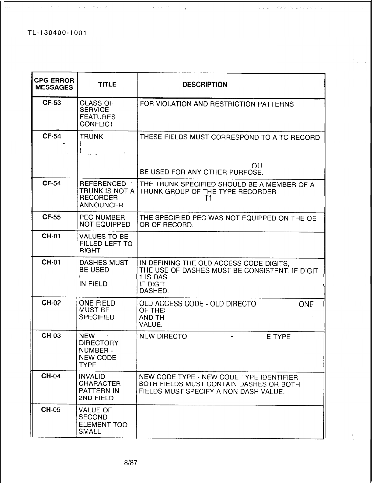
Table 21.1 CPG Error Messages (Continued)
DESCRlPTlON
OF MESSAGES
BETWEEN DISPLAYABLE AND N-DISPLAYABLE
CLASSES OF SERVICE, SEE APPENDIX 1.
NUMBER NOT DEFINING A RECORDER ANNOUNCER.
FOUND _THE RECORDER ANNOUNCER INDICATED MUST BE
USED FOR THIS FEATURE ONLY. IN ORDER TO WORK
PROPERLY THIS RECORDER ANN NCER CANNOT
ANNOUNCER ON A
Tl
RECORD.
CONSISTENTLY HED THEN DIGITS 2 AND 3 MUST BE DASHES.
2 IS DASHED THEN DIGIT 3 MUST BE
RY NUMBER
SE
FIELDS MUST BE FILLED WITH DASHES
E OTHER FIELD MUST SPECIFY A NON-DASH
RY
NUMBER
-
NEW COD
ONE OF THESE FIELDS MUST BE FILLED WITH
DASHES AND THE OTHER FIELD MUST SPECIFY A
NON-DASH VALUE.
D-440 8187
SVR 5210
TL-130400-1004
C’PG
ERROR
MESSAGES
Table 21.1 CPG Error Messages (Continued)
TITLE
DESCRlPTlON
OF MESSAGES
CH-05 VALUE OF
SECOND
*
ELEMENT TOO
LARGE
-..
CH-05 ELEMENTS
HAVE
INCOMPATIBLE
VALUES
CH-05 SECOND NEW CODE TYPE
-
NEW CODE TYPE IDENTIFIER
ELEMENT THE CODE TYPE IDENTIFIER SPECIFIED IS
CONTAINS INAPPROPRIATE FOR THE CODE TYPE.
INVALID VALUE SEE THE CODE SYMBOL MODULE FOR VALID VALUES
FOR EACH CODE TYPE.
CH-51
CH-52
ACCESS CODE THE OLD ACCESS CODE REFERENCED ON THE CH
NOT FOUND RECORD MUST BE DEFINED ON AN AC RECORD.
(TABGENIGENDIG)
A CH RECORD AN AC RECORD WITH A CODE TYPE OF 50
REQUIRES A
CODE TYPE OF (CHANGE/RESTORE ACCESS CODE) REQUIRES THAT
A CH RECORD BE SPECIFIED AND VICE VERSA.
50 ON AC AND (ENDCHK)
VICE VERSA
CH-53
CH-54
CH-54
INVALID CODE THE CODE TYPE OF THE OLD OR NEW STATION
TYPE FOR NUMBER OR THE OLD OR NEW CODE TYPE ITSELF IS
CHANGE/ NOT APPROPRIATE FOR USE WITH THE
RESTORE CHANGE/RESTORE FEATURE.
(TABGENIGENDIG)
AGENT GROUP THE AGENT GROUP NUMBER SPECIFIED IN THE CODE
NUMBER NOT TYPE IDENTIFIER FIELD FOR CODE TYPE 112 MUST
FOUND BE DEFINED ON AN AG RECORD.
ATTENDANT THE ATTENDANT NUMBER(S) SPECIFIED IN THE CODE
NOT FOUND TYPE IDENTIFIER FIELD FOR CODE TYPE 9 MUST BE
DEFINED ON AN AT RECORD.
CH-54 INTERCEPT IF THE CODE TYPE IS 000,
ROUTING CODE THEN THE CODE TYPE IDENTIFIER MUST BE A VALID
NOT FOUND INTERCEPT ROUTING NUMBER ON AN
IR
RECORD.
CH-54 REFERENCED THE TRUNK NUMBER SPECIFIED IN THE CODE TYPE
TRUNK IS NOT A IDENTIFIER FOR CODE TYPE 49 MUST BE DEFINED ON
RECORDER
Tl
AND TC RECORDS AS A RECORDER ANNOUNCER.
ANNOUNCE
SVR 5210
ah37
D-441
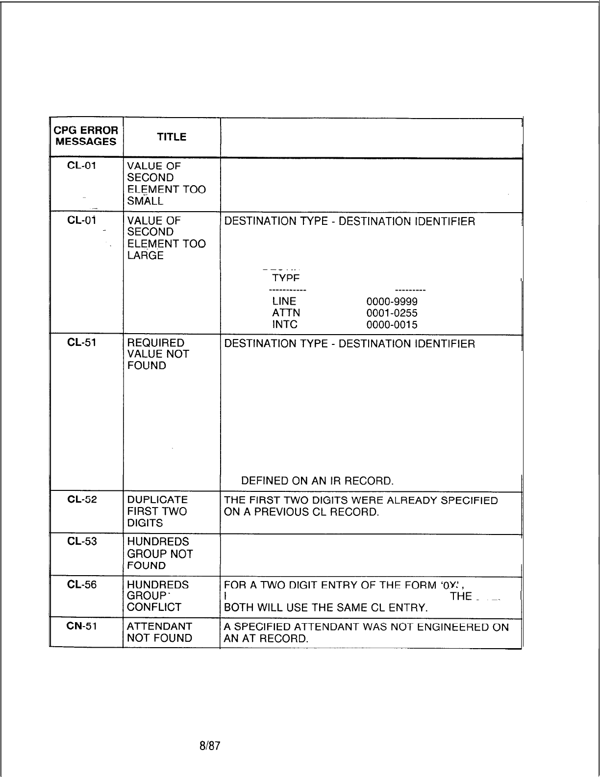
TL-130400-1001
Table 21.1 CPG Error Messages (Continued)
DESCRIPTION OF MESSAGES
CERTAIN VALUES IN THE DESTINATION TYPE FIELD
REQUIRE SPECIFIC VALUES OR RANGE OF VALUES IN
THE DESTINATION IDENTIFIER FIELD:
DESTINATION DESTINATION
IDENTIFIER
1.
IF THE DESTINATION TYPE IS ‘LINE’,
THE DESTINATION IDENTIFIER VALUE SPECIFIED
MUST BE A VALID LINE STATION NUMBER DEFINED
ON AN LD RECORD.
2. IF THE DESTINATION TYPE IS ‘ATTN’,
THE DESTINATION IDENTIFIER VALUE SPECIFIED
MUST BE A VALID ATTENDANT CIRCUIT DEFINED
ON AN AT RECORD.
3. IF THE DESTINATION TYPE IS ‘INTC’,
THE DESTINATION IDENTIFIER VALUE SPECIFIED
MUST BE A VALID INTERCEPT ROUTING NUMBER
THE SPECIFIED HUNDREDS GROUP WAS NOT
ENGINEERED ON AN HD RECORD.
HUNDREDS GROUP
‘OX’
AND ‘X’ EXIST AT
Tl-iE
SITE.
D-442 8187
SVR 5210
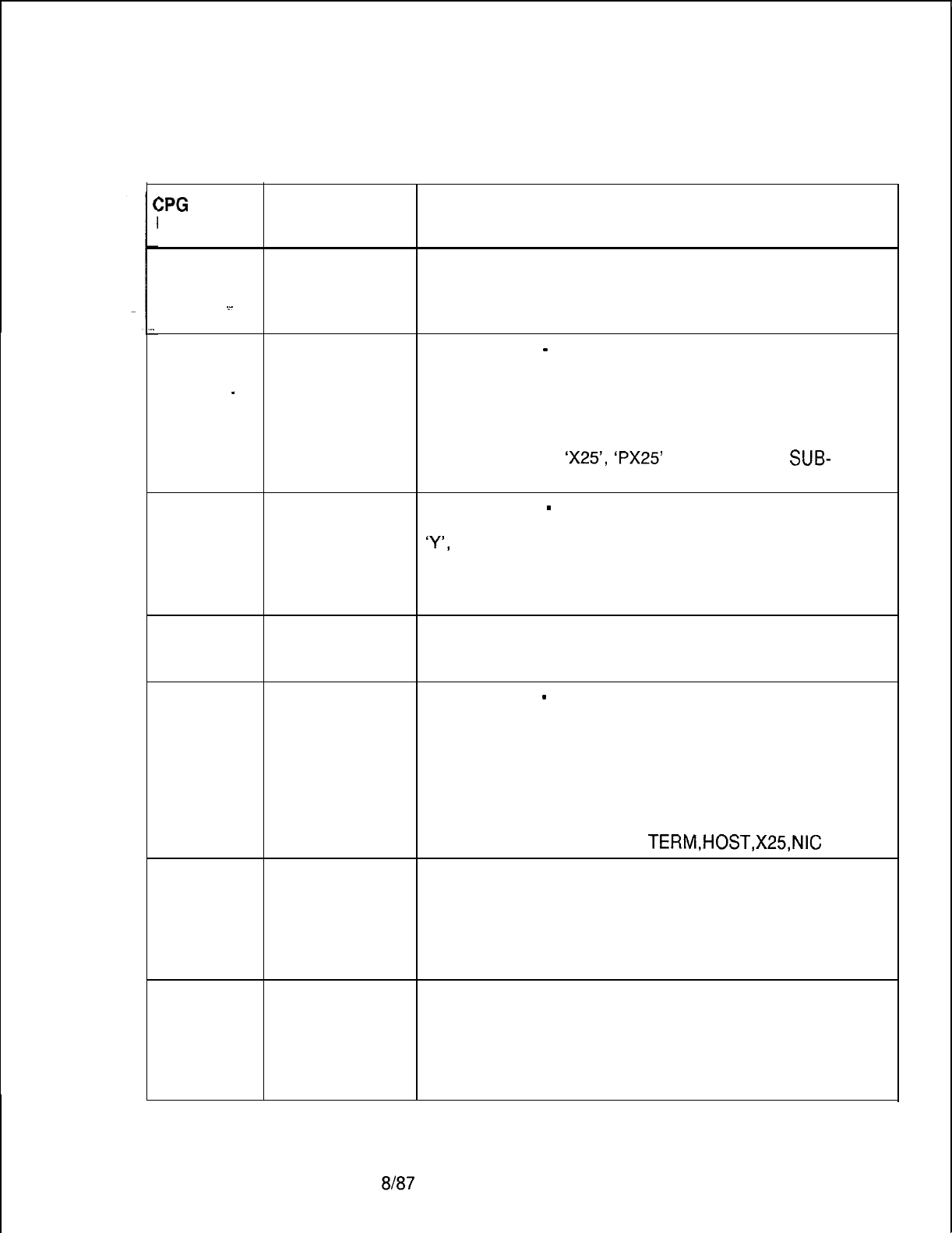
TL-130400-1001
Table 21.1 CPG Error Messages (Continued)
ZPG
ERROR
MESSAGES TITLE DESCRIPTION OF MESSAGES
CP-01
INVALID X.1 21 ADDRESS
CHARACTER THE X.121 ADDRESS MUST CONSIST OF FROM ONE
STRING TO FOURTEEN NUMERIC DIGITS FOLLOWED BY
*
DASHES.
CP-02 ELEMENTS DEVICE TYPE
-
X.121 ADDRESS
HAVE IF THE DEVICE TYPE IS ‘TERM’ OR ‘HOST’, THEN THE
INCOMPATIBLE X.121 ADDRESS MUST CONSIST OF FOURTEEN
_
VALUES NUMERIC DIGITS AND NO DASHES.
ASYNCHRONOUS DEVICES MUST SPECIFY A FULL
X.121 ADDRESS (DNIC, SERVER, SUBPORT). IF THE
DEVICE TYPE IS
‘X25’,
‘PX25’
OR ‘NIC’, THE
SUB-
PORT MAY BE DASHES.
CP-03 ELEMENTS DEVICE TYPE
-
WINDOW AND PACKET NEGOTIATION
HAVE IF THE WINDOW AND PACKET NEGOTIATION FIELD IS
INCOMPATIBLE
‘Y’,
VALUES THEN THE DEVICE OR PORT TYPE FIELD MUST BE
‘X25’ OR ‘NIC’. ONLY SYNCHRONOUS DEVICES MAY
PERFORM WINDOW AND PACKET NEGOTIATION.
CP-04 ELEMENT 2 IS A
MEANINGLESS
SPECIFICATION
CP-04 ELEMENTS DEVICE TYPE
-
ADMP OR MDR FIELD
HAVE CERTAIN VALUES IN THE ADMP OR MDR FIELD
INCOMPATIBLE REQUIRE SPECIFIC VALUES IN THE DEVICE TYPE OR
VALUES PORT TYPE FIELD:
ADMP OR MDR DEVICE TYPE
APX25
M
TERM
TERM,HOST,X25,NIC
CP-51
NO PACKET
ROUTER FOR
PORT
PHYSICAL LOCATION
THE PEC, GROUP, SLOT AND CIRCUIT SPECIFIED FOR
EVERY DATA PORT MUST APPEAR ON A LOCAL
PACKET BUS WHICH IS CONTROLLED BY A PACKET
ROUTER.
(TABGEN/GENDAT)
CP-52 CARD TYPE
DEFINED ON FR
INCOMPATIBLE
WITH FCN OF
INCOMING
CARD
SVR 5210
$187 D-443
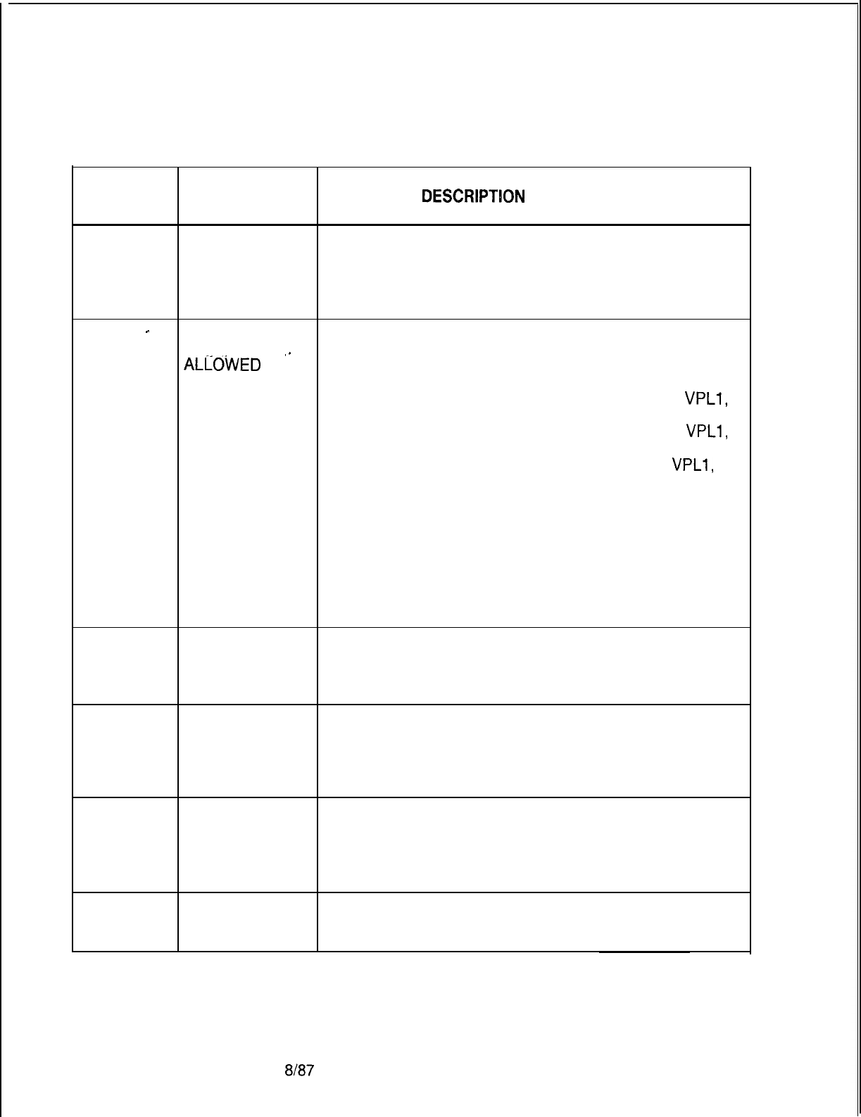
TL-130400-1001
CPG ERROR
MESSAGES
Table 21.1 CPG Error Messages (Continued)
TITLE
DESCRlPTlON
OF MESSAGES
CP-52
. . .
CARD TYPE
DEFINED ON FR
INCOMPATIBLE
.
WITH INCOMING
CARD TYPE
CP-52
-
FUNCTION OF PHYSICAL LOCATION
CARD NOT
,_
ALLOWED
FOR THE PEC, GROUP, SLOT AND CIRCUIT FUNCTION
SPECIFIED IS INVALID FOR THE CARD TYPE DEFINED
CARD TYPE
DEFINED ON ON FR (FOR THIS PEC TYPE).
FORM FR DEVICE TYPE TERM MUST APPEAR ON A VPLO,
VPLl,
VP20 (DATA OR VOICE AND DATA), OR VP21 CARD.
DEVICE TYPE HOST MUST APPEAR ON A VPLO,
VPLl,
VP20 (DATA OR VOICE AND DATA), OR VP21 CARD.
DEVICE TYPE X25 MUST APPEAR ON A VPLO,
VPLl,
VP20 (DATA OR VOICE AND DATA), OR VP21 CARD.
DEVICE TYPE PX25 MUST APPEAR ON AN ADMP
CARD.
DEVICE TYPE NIC MUST APPEAR ON A NIC CARD.
(PHYLOC)
IF THE CARD TYPE IN THE MESSAGE IS “OVER”, THAT
INDICATES THAT A CARD IN THE PREVIOUS LOCATION
IS A WIDE CARD AND IT OVERHANGS INTO THIS
PHYSICAL LOCATION ON FR.
CP-52 NONEXISTENT PHYSICAL LOCATION
PHYSICAL THE PEC, GROUP, SLOT AND CIRCUIT SPECIFIED IS
LOCATION NOT VALID FOR THIS PEC TYPE.
(PHYLOC)
CP-52 PHYSICAL PHYSICAL LOCATION
LOCATION NOT THE PEC, GROUP, AND SLOT SPECIFIED WAS NOT
DEFINED ON DEFINED ON AN FR RECORD.
RECORD CODE (PHYLOC)
FR
CP-53 PHYSICAL
LOCATION NOT
DEFINED ON
RECORD CODE
LD
CP-53 PHYSICAL
LOCATION NOT
DEFINED
D-444
8l87
SVR 5210
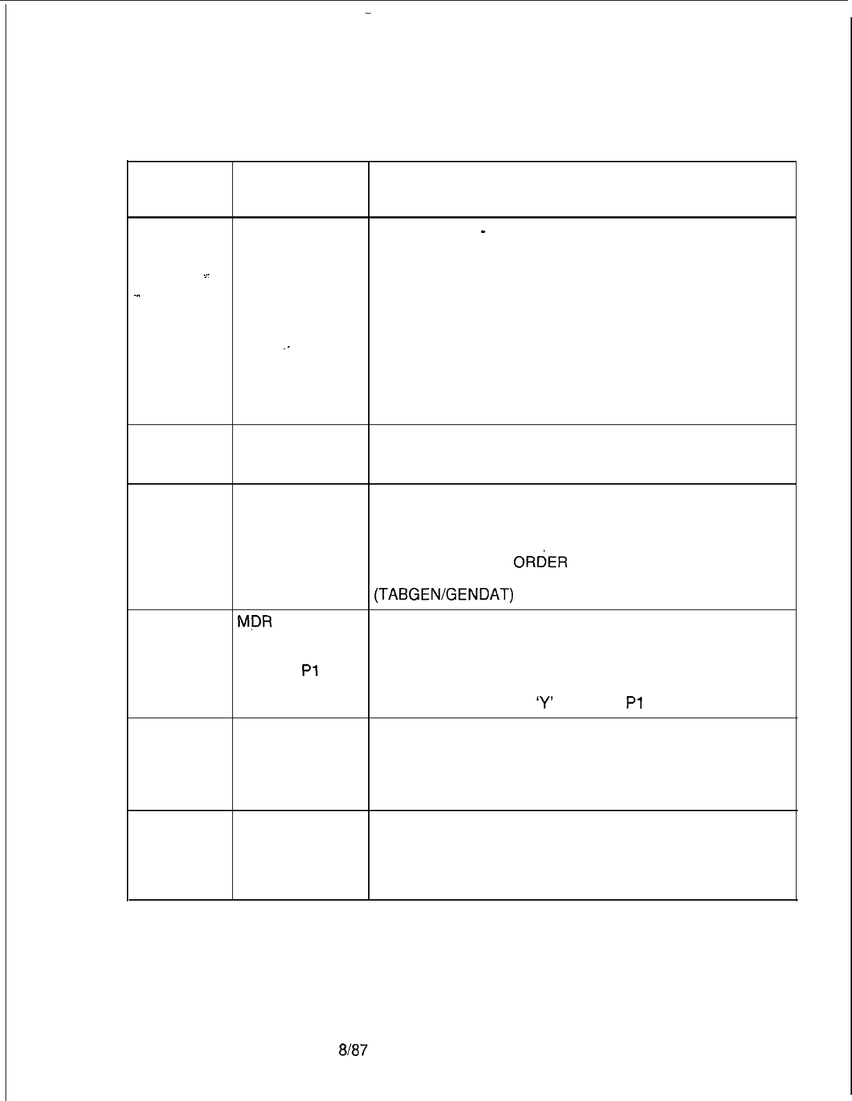
TL-130400-1001
CPG ERROR
MESSAGES
Table 21.1 CPG Error Messages (Continued)
TITLE DESCRIPTION OF MESSAGES
CP-53 USE OF DEVICE TYPE
-
PHYSICAL LOCATION THE PEC,
PHYSICAL LOC GROUP, SLOT AND CIRCUIT OF SOME DATA PORTS
CONFLICTS MUST BE DEFINED ON AN LD RECORD.
-r
WITH DEVICE TYPE TERM MUST APPEAR ON AN LD
-..
INSTRUMENT RECORD WITH INSTRUMENT TYPE ‘DFPA’ OR ‘APM’.
TYPE SPECIFIED DEVICE TYPE HOST MUST APPEAR ON AN LD
ON LD RECORD WITH
.-
INSTRUMENT TYPE ‘DFPA’ OR ‘APM’.
DEVICE TYPE X25 MUST APPEAR ON AN LD RECORD
WITH INSTRUMENT TYPE ‘SPM’.
DEVICE TYPE NIC MUST APPEAR ON A TC RECORD
AS A MEMBER OF A NIC TRUNK GROUP.
CP-54
CP-55
DUPLICATE PHYSICAL LOCATION
PHYSICAL THE PEC, GROUP, SLOT, AND CIRCUIT SPECIFIED
LOCATION MUST BE UNIQUE ACROSS ALL CP RECORDS.
X.121 ADDRESS X.121 ADDRESS
NOT IN ROTARY AN ASYNCHRONOUS PORT (DEVICE TYPE OF ‘TERM’
OR ‘HOST’) MUST BE PART OF AN ASYNCHRONOUS
GROUP
(ORDER ROTARY,
ORdER
DIRECT, RANDOM ROTARY,
RANDOM DIRECT) DEFINED ON AN RT RECORD.
(TABGENIGENDAT)
CP-57
MPR
MUST BE ADMP OR MDR FIELD
SPECIFIED ON IF THIS DATA PORT IS SPECIFIED AS INTERFACING TO
RECORD CODE THE MDR PROCESSOR THEN MDR MUST BE
OE AND
Pl
EQUIPPED ON THE OE RECORD.
THE MDR FIELD ON SYSTEM START-UP (MDR
EQUIPPED) MUST BE
‘Y’
ON THE
Pl
RECORD.
CP-58 ONLY ONE MDR ADMP OR MDR FIELD
AND ONE ADMP THE DATA PORT INTERFACING TO THE MDR
X.121 ADDRESS PROCESSOR AND THE PSEUDO DATA PORT
MAY BE INTERFACING TO THE ADMP MUST BE UNIQUE.
SPECIFIED
CP-59 AN ADMP CARD ADMP OR MDR FIELD
MUST BE IF THIS DATA PORT IS SPECIFIED AS INTERFACING TO
DEFINED ON THE PSEUDO DATA PORT, THEN AN ADMP CARD
RECORD CODE MUST BE DEFINED ON AN FR RECORD.
FR
(ADMPCK)
SVR 5210
8187
D-445
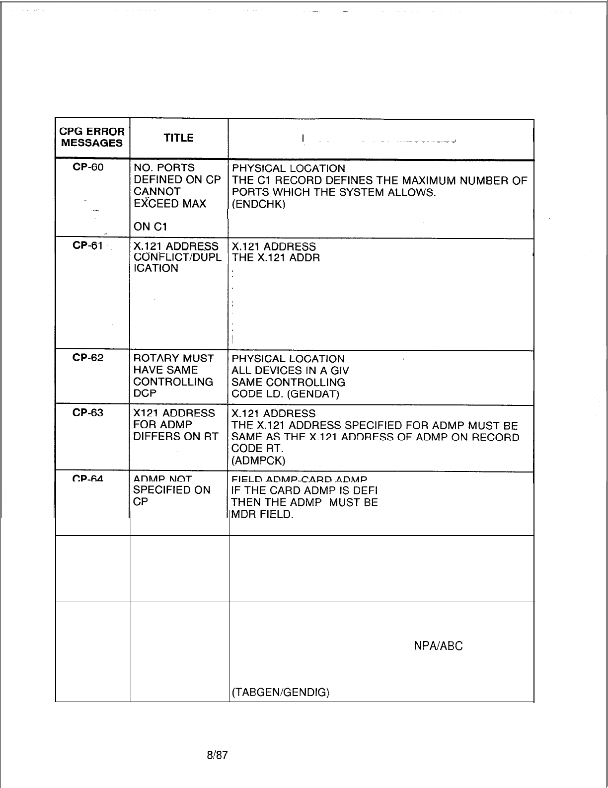
TL-130400-1001
D-446
Table 21.1 CPG Error Messages (Continued)
DESCRIPTION OF MESSAGES
PORTS DEFINED
ESS SPECIFIED MUST BE UNIQUE
ACROSS ALL CP RECORD. IN ADDITION,
THERE MUST BE NO CONFLICT BETWEEN THE
TWELVE NUMERIC DIGIT X.121 ADDRESSES FOR
SYNCHRONOUS DATA PORTS (DEVICE TYPES ‘X25’,
‘NIC’ AND ‘PX25’) AND THE FOURTEEN NUMERIC DIGIT
X.121 ADDRESSES FOR ASYNCHRONOUS DATA
PORTS (DEVICE TYPES ‘TERM’ AND ‘HOST’)
EN ROTARY MUST HAVE THE
DCP SPECIFIED ON RECORD
NED ON RECORD CODE FR
SPECIFIED IN ADMP OR
(ADMPCK)
CP-82 PHYSICAL PHYSICAL LOCATION
LOCATION IS EVERY DATA PORT APPEARING ON AN LD RECORD
MISSING ON MUST ALSO APPEAR ON A CP RECORD. EVERY NIC
NAMED APPEARING ON A TC RECORD MUST APPEAR ON A CP
RECORD CODE RECORD. (ENDCHK)
CR-01
ENTRY AN ENTRY INTO THE CODE RESTRICTION TABLES
ATTEMPTED IN HAD BEEN ATTEMPTED, BUT THAT LOCATION AND BIT
NONVACANT POSITION WAS ALREADY FULL. THE ENTRY WAS NOT
LOCATION MADE. CHECK THE THREE DIGIT
NPA/ABC
CODE
NUMBER IN THE DESIGNATED COLUMN AGAINST
CODES PREVIOUSLY ENTERED IN THAT CODE
RESTRICTION TABLE FOR A DUPLICATION.
(TABGEN/GENDIG)
8187
SVR 5210
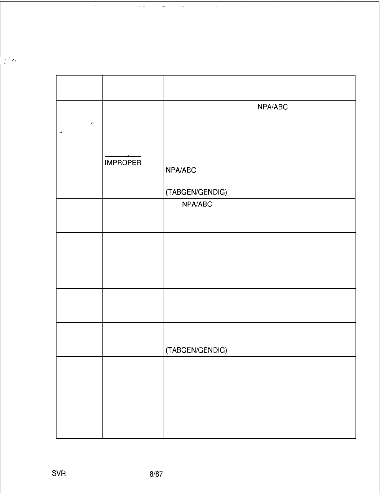
TL-130400-1001
CPG ERROR
MESSAGES
Table 21.1 CPG Error Messages (Continued)
TITLE DESCRIPTION OF MESSAGES
CR-02 INVALID AN INVALID SEQUENCE OF
NPA/ABC
CODES HAD
SEQUENCE BEEN SPECIFIED TO BE ENTERED.
Y-
NO ENTRIES WERE MADE.
-..
CHECK THE SEQUENCE CONTAINING THE
DESIGNATED COLUMN FOR A LOWER BOUND LESS
THAN OR EQUAL TO THE UPPER BOUND.
(TABGEN/GENDIG)
CR-03
IMPRObER
THE CPG HAS DETERMINED THAT THE FIRST
STARTING
NPA/ABC
CODE LISTED ON THE CODE RESTRICTION
COLUMN RECORD IS NOT IN THE PROPER COLUMNS.
PROPER TABLE GENERATION IS NOT GUARANTEED.
(TABGEN/GENDIG)
CR-04 INVALID THE
NPA/ABC
CODE TO BE ENTERED IS NOT
SYNTAX STRICTLY NUMERIC AND CONVERSION FROM THE
RECORD TO A VALUE HAD FAILED.
(TABGEN/GENDIG)
CR-05
LAST A DASH (SIGNIFYING A SEQUENCE) IS FOLLOWED
OPERATOR ONLY BY BLANKS.
INVALID CHECK FIRST TO VERIFY THAT A SEQUENCE WAS
MEANT INSTEAD OF A SINGLE ENTRY AND, IF IT WAS,
PROVIDE THE TERMINAL NUMBER OF THE SEQUENCE
ON THE SAME RECORD.
(TABGEN/GENDIG)
CR-06
INVALID A CHARACTER OTHER THAN COMMA, DASH, OR
OPERATOR BLANK HAD BEEN USED IN AN OPERATOR’S POSITION
IN THE DESIGNATED COLUMN.
(TABGEN/GENDIG)
CR-07
MISPLACED
BLANK A BLANK HAD BEEN USED IN AN OPERATOR’S
LOCATION.
A COMMA WAS ASSUMED.
(TABGENIGENDIG)
CT-01
VALUES TO BE HEXADECIMAL EQUIVALENT BYTES
FILLED LEFT TO HEXADECIMAL EQUIVALENT BYTES MUST BE FILLED
RIGHT IN FROM LEFT TO RIGHT,
WITH DASHED BYTES IN THE RIGHTMOST BYTES OF
THE HEXADECIMAL BYTE FIELDS.
CT-02 INVALID HEXADECIMAL EQUIVALENT BYTES
CHARACTER IF ONE DIGIT OF A HEXADECIMAL EQUIVALENT BYTE
PATTERN IN IS DASHED,
2ND FIELD THE THE OTHER DIGIT OF THE BYTE MUST BE
DASHED.
SVR
5210
8187 D-447
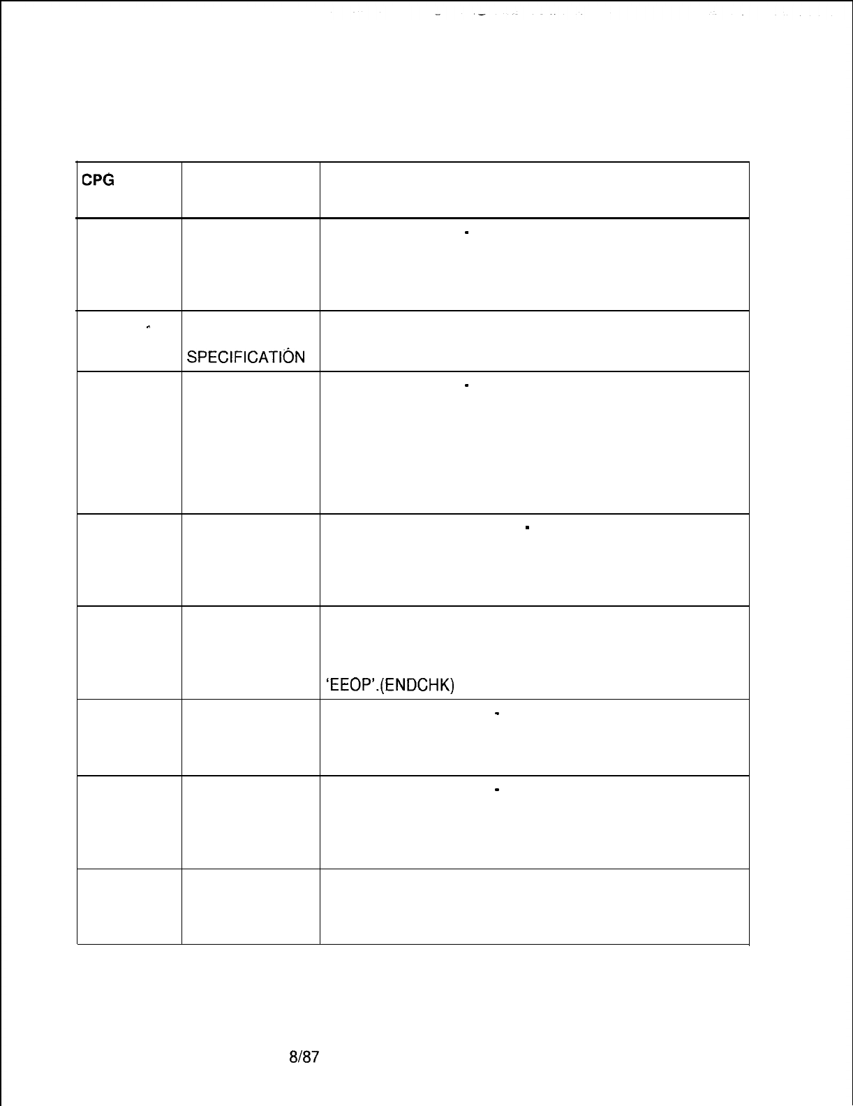
TL-130400-1001
Table 21.1 CPG Error Messages (Continued)
CPG
ERROR
MESSAGES TITLE DESCRIPTION OF MESSAGES
CT-03
. . .
CT-04
-
FOR FUNCTION FUNCTION CODE
-
HEXADECIMAL EQUIVALENT
CODE, TNAM, BYTES
BYTES l-8 IF THE FUNCTION CODE IS ‘TNAM’,
MAY NOT BE THEN THE HEXADECIMAL EQUIVALENT BYTES MAY
SPECIFIED NOT BE SPECIFIED.
ELEMENT 2 IS
MEANINGLESS
SPECIFICATItjN
CT-04 ELEMENTS FUNCTION CODE
-
HEXADECIMAL EQUIVALENT
HAVE BYTES
INCOMPATIBLE IF THE FUNCTION CODE IS ‘TNAM’,
VALUES THEN THE CUSTOMER DEFINED TERMINAL NAME
MUST BE SPECIFIED.
IF THE FUNCTION CODE IS NOT ‘TNAM’, THEN THE
CUSTOMER DEFINED TERMINAL NAME MUST BE
DASHED.
CT-50 DUPLICATE TTY TERMINAL TYPE NUMBER
-
FUNCTION CODE
NO. AND THE TERMINAL TYPE NUMBER AND FUNCTION CODE
FUNCTION COMBINATION CANNOT BE DUPLICATED.
CODE NOT
ALLOWED
CT-51
DA-01
FCN CODES OF FUNCTION CODE
CLSC , ABCC, THE FOLLOWING FUNCTION CODES ARE REQUIRED
EEOL, AND FOR COMPLETENESS OF A CUSTOMER-DEFINED
EEOP TERMINAL: ‘CLSC’, ‘ABCC’, ‘EEOL’, AND
REQUIRED
‘EEOP’.(ENDCHK)
INVALID FIRST DIGIT ACTIONS
-
SECOND PLUS DIGITS
CHARACTER THERE MUST BE AT LEAST ONE ‘C’ ACROSS BOTH OF
PATTERN IN THESE FIELDS.
2ND FIELD
DA-02 INVALID
CHARACTER
PATTERN IN
2ND FIELD
FIRST DIGIT ACTIONS
-
SECOND PLUS DIGITS
IF THERE IS AN ‘A’ ANYWHERE IN THE FIRST DIGIT
ACTIONS,
THERE MUST BE AT LEAST ONE ‘C’ IN THE SECOND
PLUS DIGITS.
DA-03 INVALID FIRST DIGIT ACTIONS CANNOT BE ALL ‘R’.
CHARACTER
PATTERN IN
2ND FIELD
D-448
8187
SVR 5210
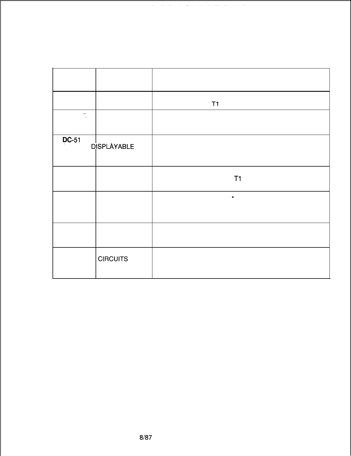
TL-130400-1001
CPG ERROR
MESSAGES
Table 21.1 CPG Error Messages (Continued)
TITLE DESCRIPTION OF MESSAGES
DA-51
TRUNK GROUP THE TRUNK GROUP SPECIFIED MUST HAVE A
NOT FOUND CORRESPONDING
Tl
RECORD.
DA-52
‘;I
DUPLICATE THIS NUMBER MUST BE UNIQUE ACROSS ALL DA
. .
TRUNK GROUP RECORDS.
NUMBER
y-51
DUPLICATE DISPLAYABLE CLASS OF SERVICE NUMBER MUST BE
DISPMYABLE
UNIQUE ACROSS THE DC RECORDS.
CLASS OF
SERVICE DATA
DC-53 TRUNKGROUP ATRUNKGROUPREFERENCEDONADCRECORD
NOT FOUND WAS NEVER INPUT ON A
Tl
RECORD.
(ENDCHK)
DD-02
DD-51
CLASS OF SWITCHED DIRECT LINE
-
CO LINE CONFLICT
SERVICE IF CO LINE INDICATED (‘CL’),
FEATURES THEN SWITCHED DIRECT LINE (‘SL’) SHOULD ALSO BE
CONFLICT INDICATED.
DUPLICATE DISPLAYABLE CLASS OF SERVICE NUMBER MUST BE
DISP. CLASS OF UNIQUE ACROSS THE DD RECORDS.
SERVICE DATA (ENDCHK)
DD-52
CONFERENCE MEET ME CONFERENCE OR PROGRESSIVE
ClRCUlTS
NOT CONFERENCE,
DEFINED IF INDICATED, NEEDS ONE OF THE CONFERENCE
CIRCUITS ON THE FR RECORD SPECIFIED.
SVR 5210
8187
D-449
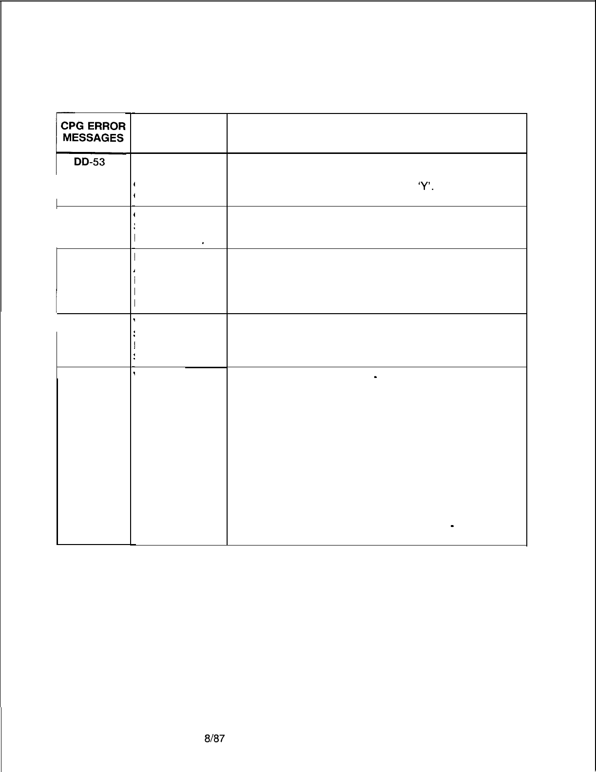
TL-130400-1001
Table 21.1 CPG Error Messages (Continued)
CPG ERROR
MESSAGES
C
DD-53
DD-54
DK-53
I
DT-01
DT-01
TITLE
TOLL ACCESS
-TRUNK
GROUP ACCESS
CONFLICT
CLASS OF
SERVICE NOT
DEFINED _
DUPLICATE
AGENT GROUP/
REPERTORY
DIAL KEY
NUMBER
VALUE OF
SECOND
ELEMENT TOO
SMALL
VALUE OF
SECOND
ELEMENT TOO
LARGE
DESCRIPTION OF MESSAGES
IF TOLL ACCESS IS INDICATED (‘TA’) THEN AT LEAST
ONE TRUNK GROUP IN THE TRUNK GROUP ACCESS
FIELD ON RECORD DC SHOULD BE
‘Y’.
A DISPLAYABLE CLASS OF SERVICE REFERENCED ON
THE DD RECORD MUST BE DEFINED ON A DC
RECORD.
EACH COMBINATION OF AGENT GROUP AND
REPERTORY DIAL KEY NUMBER MUST BE UNIQUE.
DTMF RECEIVER NUMBER
-
PEC REQUIREMENTS
VALUE OF VALUE OF
DTMF RECEIVER PEC
o-7
8 -15
16-23
24-31
32-39
40-47
48-55
56-63
0
1
2
3
4(SVR
8.2.X.X. ONLY)
5
(SVR
8.2.X.X. ONLY)
6
(SVR
8.2.X.X. ONLY)
7(SVR
8.2.X.X. ONLY)
RECEIVER NUMBER
-
PEC
REQUIREMENTS
D-450 8187
SVR 5210
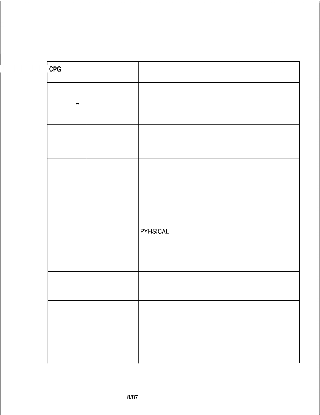
TL-130400-1001
Table 21.1 CPG Error Messages (Continued)
ZPG
ERROR
MESSAGES TITLE DESCRIPTION OF MESSAGES
DT-51
CARD TYPE
DEFINED ON FR
INCOMPATIBLE
Y-
WITH FCN OF
INCOMING
CARD
DT-51
CARD TYPE
DEFINED ON FR
INCOMPATIBLE
WITH INCOMING
CARD TYPE
DT-51
FUNCTION OF PHYSICAL LOCATION
CARD NOT THE PEC, GROUP, SLOT AND CIRCUIT FUNCTION
ALLOWED FOR SPECIFIED IS INVALID FOR THE CARD TYPE DEFINED
CARD TYPE ON FR (FOR THIS PEC TYPE).
DEFINED ON A DTMF RECEIVER CIRCUIT MUST APPEAR ON A
FORM FR DTMF CARD.
THE PEC, GROUP, SLOT AND CIRCUIT SPECIFIED IS
NOT VALID FOR THIS PEC TYPE. (PHYLOC)
IF THE CARD TYPE IN THE MESSAGE IS “OVER”, THAT
INDICATES THAT A CARD IN THE PREVIOUS LOCATION
IS A WIDE CARD AND IT OVERHANGS INTO THIS
PYHSICAL
LOCATION ON FR.
DT-51
PHYSICAL PHYSICAL LOCATION
LOCATION NOT THE PEC, GROUP AND SLOT SPECIFIED WAS NOT
DEFINED ON DEFINED ON FR.
RECORD CODE (PHYLOC)
FR
DT-51
DT-51
PHYSICAL
LOCATION
PREVIOUSLY
FILLED
CARD
OVERHANGS
INTO A
PREVIOUSLY
FILLED SLOT
PHYSICAL LOCATION
THE PEC, GROUP, SLOT AND CIRCUIT SPECIFIED FOR
THE DTMF RECEIVER CIRCUIT MUST BE UNIQUE.
(PHYLOC)
THIS CARD IS AN OVERSIZED CARD AND IS TRYING
TO FILL TWO SLOTS. OF THE TWO SLOTS IT FILLS,
THE RIGHT HAND ONE HAS ALREADY BEEN FILLED.
DT-51
DUPLICATE
DTMF
RECEIVER
NUMBER
THE DTMF RECEIVER NUMBER MUST BE UNIQUE
ACROSS ALL DT RECORDS.
SVR 5210
8187
D-451

r
TL-130400-1001
ZPG
ERROR
MESSAGES
Table 21.1 CPG Error Messages (Continued)
TITLE DESCRIPTION OF MESSAGES
DT-57
DUPLICATE
DTMF
RECEIVER
NUMBER
THE DTMF RECEIVER NUMBER MUST BE UNIQUE
ACROSS ALL DT RECORDS.
DT-58 PEC NUMBER THE PEC NUMBER SPECIFIED MUST BE MARKED
NOT EQUIPPED EQUIPPED ON THE OE RECORD.
EC-01 SECOND
‘-
NPA CODES MUST BE UNIQUE ON A PER TABLE
ELEMENT (ONE EC RECORD) BASIS
EQUALS FIRST
ELEMENT
(NPA CODES)
EC-03 ELEMENTS
HAVE
INCOMPATIBLE
VALUES
EC-03 ELEMENT 2 IS
MEANINGLESS
SPECIFICATION
EC-03 2ND FEATURE 1 + RESTRICTION TABLE
-
RESTRICTION CODE TABLE
REQUIRED IF ONLY ONE OR THE OTHER OF THESE MAY BE
FIRST SPECIFIED FOR EACH NPA CODE ENTERED.
SPECIFIED BOTH CANNOT BE SPECIFIED.
HOWEVER, BOTH MAY BE DASHED IF DESIRED
EC-51
DUPLICATE THE TABLE NUMBER MUST BE UNIQUE ACROSS THE
CODE CHECK EC RECORDS.
TABLE NUMBE
EC-53 CODE THESE TABLE NUMBERS MUST BE DEFINED ON A CR
RESTRICTION RECORD.
TABLE NOT
FOUND
ED-01
VALUES TO BE PICKUP GROUP NUMBERS SHOULD BE FILLED IN
FILLED LEFT TO FROM LEFT TO RIGHT.
RIGHT
ED-51
DUPLICATE THIS NUMBER MUST BE UNIQUE ACROSS THE ED
EXTENDED DIAL RECORDS.
CALL PICKUP
TABLE
D-452 8187
SVR 5210

TL-130400-1001
CPG ERROR
MESSAGES
Table 21.1 CPG Error Messages (Continued)
TITLE DESCRIPTION OF MESSAGES
ED-52
EXTENDED EXTENDED DIAL CALL PICKUP TABLE
PICKUP GROUP EACH TABLE NUMBER SHOULD APPEAR ON AN LD
NOT RECORD IN THE EXTENDED DIAL CALL PICKUP TABLE
s-
REFERENCED FIELD.
-..
ON LD FORM (ENDCHK)
-FA-50
DUPLICATE FRL AUTHORIZATION CODE DUPLICATE
AUTHORIZATIO FRL AUTHORIZATION CODES ARE NOT ALLOWED.
N CODE
NUMBER
FA-51
FRL
FRL AUTHORIZATION CODE
AUTHORIZATIO THE NUMBER OF FRL AUTHORIZATION CODE DIGITS
N CODE OUT OF ON FA RECORD MUST BE THE SAME,
RANGE AS THE NUMBER OF FRL AUTHORIZATION CODE
DIGITS SPECIFIED ON OF RECORD (FOUR TO SEVEN
DIGITS).
FA-51
THREE HASH FRL AUTHORIZATION CODE
BUCKET THE ALGORITHM USED TO GENERATE THE FRL
ENTRIES FILLED AUTHORIZATION CODE TABLE ENTRIES HAS
DETECTED THE OCCURRENCE OF A FOURTH (OR
FIFTH, SIXTH, SEVENTH, EIGHTH) CODE WITH THE
SAME HASH VALUE.
FOR INITIAL ENGINEERING THIS IS IN VIOLATION OF
ADVERTISED FRL AUTHORIZATION CODE
GENERATION REQUIREMENTS.
FOR RE-ENGINEERING, THIS IS A POSSIBLE
CONDITION.
THE OCCURRENCE OF A FIFTH CODE WITH THE SAVE
HASH VALUE WILL CAUSE AN ADDITION DISK ACCESS
BY CALL PROCESSING.
(FRLGEN)
FA-51
REACHED FRL AUTHORIZATION CODE
MAXIMUM THE ALGORITHM USED TO GENERATE THE FRL
BUCKET ENTRY, AUTHORIZATION CODE TABLE ENTRIES HAS
RECORD DETECTED THE OCCURRENCE OF A NINTH (OR
REJECTED MORE) CODE WITH THE SAME HASH VALUE. (FRLGEN)
FA-52
INVALID FA RECORDS WERE CODED FOR A SITE WITHOUT
RECORD CODE THE TRAVELING CLASS MARK (TCM) FEATURE,
I.E. THE TRAVELING CLASS MARK FIELD ON THE OF
RECORD WAS DASHED OUT.
FR-01
ELEMENTS
HAVE
INCOMPATIBLE
VALUES
SVR 5210
8187 D-453
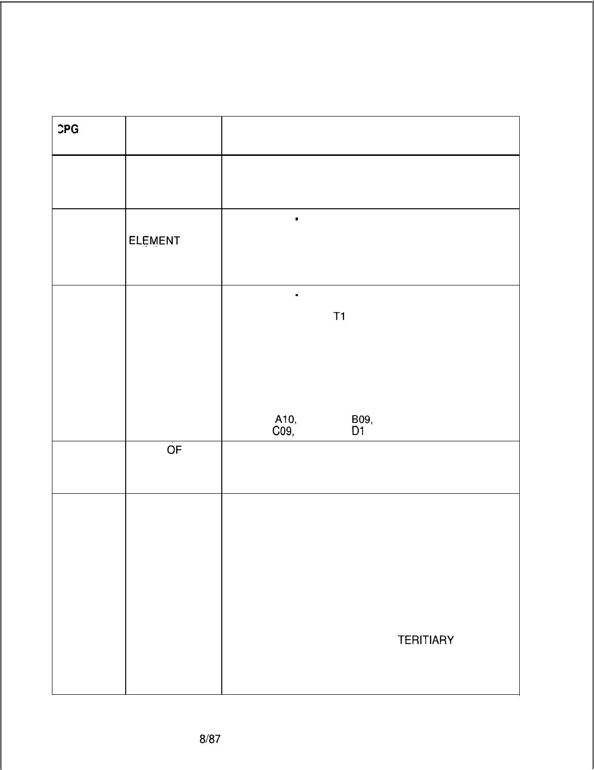
TL-130400-1001
ZPG
ERROR
MESSAGES
Table 21.1 CPG Error Messages (Continued)
TITLE DESCRIPTION OF MESSAGES
FR-01
. .
FR-Oi
VALUE OF
SECOND
ELEMENT TOO
LARGE
VALUE OF CARD TYPE
-
PRIMARY, SECONDARY, TERTIARY
SECOND IDENTIFIERS CONSULT THE CARD TYPES VS.
ELEMENT
TOO IDENTIFIERS,
SMALL AND STATUS CHART TO DETERMINE APPROPRIATE
VALUES TO SPECIFY FOR EACH PARTICULAR CARD
TYPE.
FR-02
ELEMENTS CARD TYPE
-
PHYSICAL LOCATION
HAVE IF THE CARD TYPE IS DTRK, THEN THE GROUP FIELD
INCOMPATIBLE MUST BE ‘C’, SINCE
Tl
SPANS CAN ONLY BE
VALUES INSTALLED IN THAT GROUP.
SPECIFIC CARD PLACEMENT RESTRICTIONS ARE IN
EFFECT FOR THE CARD TYPES OF BT, DCPB, PBE, PR
AND RPTR.
THESE CARDS MAY ONLY BE PLACED IN THE
FOLLOWING GROUP/SLOTS:
AOO, A02,
AlO,
BOO, B02, B09,
C06,
Cl 0, CO9, DOO, DO1 ,
Dl
0.
FR-03
VALUE
dF
SECOND
ELEMENT TOO
LARGE
FR-03
VALUE OF CARD TYPE-PEC
SECOND THE FOLLOWING CARD TYPE CAN APPEAR ONLY IN
ELEMENT TOO PECS O-3: AGNT, AIOD, ART, ATTN, CONF, ERLT,
SMALL KEDU, AND RLT.
THE FOLLOWING CARD TYPE SPECIFIES THE VALID
RANGE OF THE THREE IDENTIFIERS AND STATUS
GIVEN A PARTICULAR CARD.
CARD TYPES VS. IDENTIFIERS AND STATUS CHART
VALUE ALLOWED ALLOWED ALLOWED STATUS
OF
CARD PRIMARY SECONDARY
TERITIARY
FIELD
TYPE ID RANGE ID RANGE ID RANGE
ADMP 0000-0001 0000-0001 ---- --
AGNT ----
---- ----
--
D-454 8187
SVR 5210
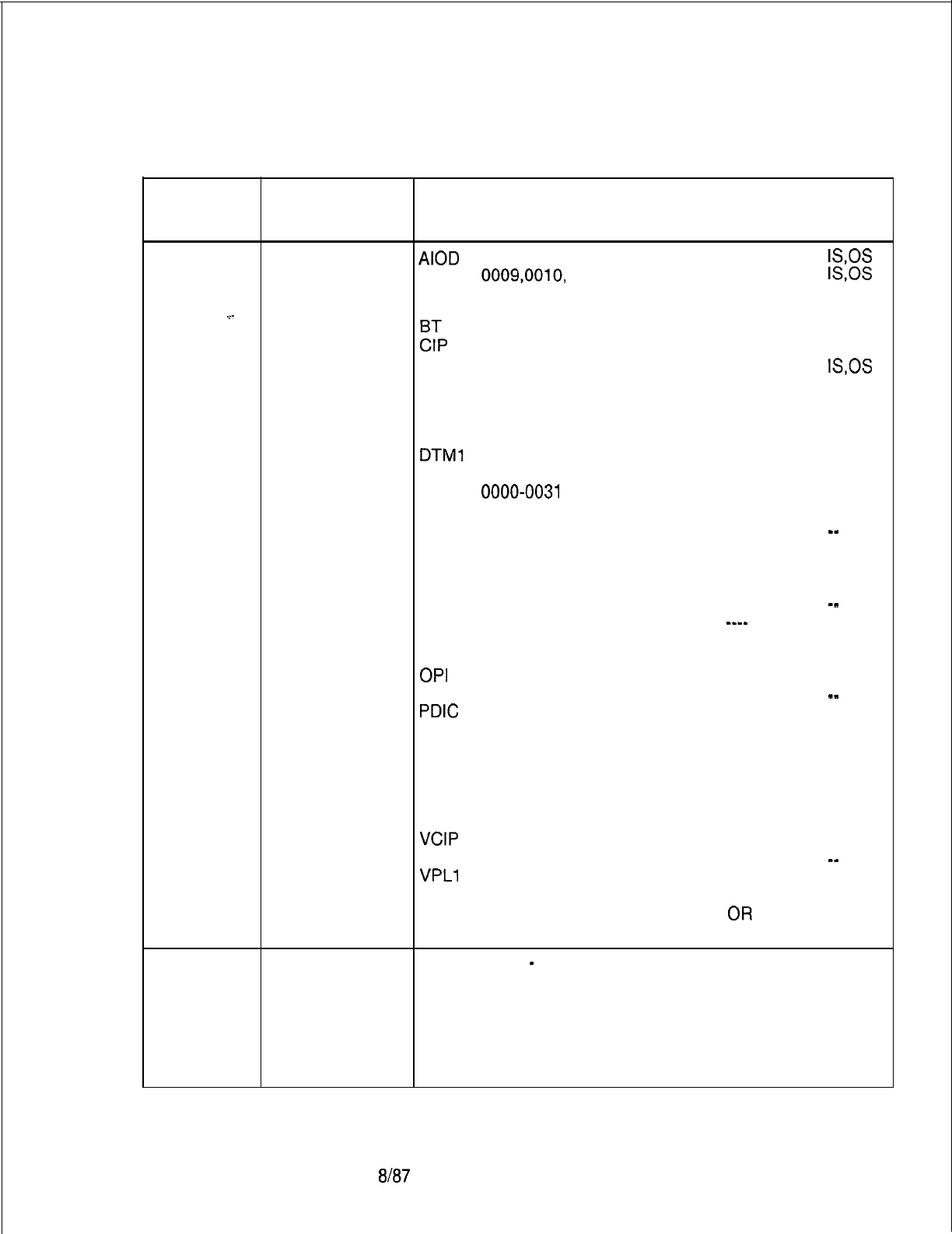
TL-130400-1001
CPG ERROR
MESSAGES
Table 21.1 CPG Error Messages (Continued)
TITLE DESCRIPTION OF MESSAGES
FR-03
VALUE OF
AIOD
---- ---- ----
IS,OS
(cont’d) SECOND ART
0009,0010, ---- ----
IS,OS
ELEMENT
TOO 0011
->-
SMALL ATTN
---- ---- ----
--
EL
0000-0001 0000-0015
0000-0007 ----
---- ---- -- --
CONF
0000-0001 ---- ----
IS,OS
COT ---- ---- ----
--
DCP
0000-0003 ---- ----
--
DCPB
0000-0003 0000-0001
0000-0007
--
DTMF
---- ---- ----
--
DTMl
---- ---- ----
--
DTRK
---- ---- ----
--
DVC
0000-0031 0000-0015 ----
--
EMT
---- ---- ----
--
EMT4
---- ---- ----
-_
ERLT
---- ---- ----
--
FP 0000-0031 ---- ----
--
FPOP 0000-0031 ---- ----
--
ILT
---- ---- ----
-_
KEDU
---- ----
_--- --
NIC
0000-0003 ---- ----
--
OFFP 0000-0031 ---- ----
--
OPI
---- ---- ----
--
PBE
0000-0001 ---- ----
_-
PDIC
---- ---- ----
--
POTS 0000-0031 ---- ----
--
PR 0000-0001 ---- ----
--
RLT ---- ---- ----
--
RPTR
0000-0001 0000-0007 ----
--
SM
0000-0007 ---- ----
--
TDET
---- ---- ----
--
VCIP
0000-0031 0000-0015 ----
--
VPLO 0000-0031 ---- ----
_-
VPLl
0000-0031 ----
--_- --
VP20
0000-0031 0000-0015 0000-0001
--
(-JR ____
OR
____
VP21 0000-0031 ---- ----
--
FR-50
FIELD DOESN’T CARD TYPE
-
PRIMARY, SECONDARY, TERTIARY
HAVE IDENTIFIERS FOR CARD TYPE VP20 THE TERTIARY
REQUIRED IDENTIFIER MUST BE DASHES IF THE SECONDARY
VALUE IDENTIFIER IS DASHES.
THE TERTIARY IDENTIFIER MUST NOT BE DASHES IF
THE SECONDARY IDENTIFIER IS NOT DASHES.
(FRCHKS)
SVR 5210
8187
D-455
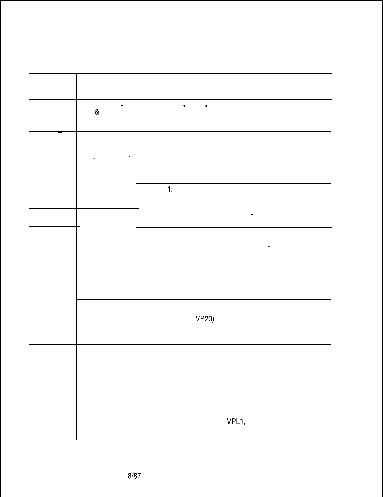
TL-130400-1001
Table 21.1 CPG Error Messages (Continued)
CPG ERROR
MESSAGES
I
FR-50
.
.
.
.
,
TITLE
CARD TYPE
-
PEC
&
IDENTIFIERS
CONFLICT
DESCRIPTION OF MESSAGES
CARD TYPE
-
PEC
-
PRIMARY, SECONDARY,
TERTIARY IDENTIFIERS.
CONSULT THE CARD TYPES VS. IDENTIFIERS CHECKS
CHART TO DETERMINE APPROPRIATE VALUES TO
SPECIFY FOR EACH PARTICULAR CARD TYPE.
THE CHART STATES THE MEANING OF THE PRIMARY,
SECONDARY AND TERTIARY IDENTIFIERS ON THE FR
RECORD AND THE CHECKS FOR EACH SET OF CARD
TYPES.
CHECK
1:
FOR CARD TYPE ADMP -THE ADMP
NUMBER AND THE ADMP CARD NUMBER
COMBINATION CANNOT BE DUPLICATED.
CHECK 2: FOR CARD TYPE ART
-
THE ART CARD
NUMBER CANNOT BE DUPLICATED.
CHECK 3: FOR CARD TYPES CONTAINING PACKET
ROUTER NUMBER AND LOCAL PACKET BUS NUMBER
INFORMATION (BT, DCPB AND RPTR)
-
THE PEC, THE
PACKET ROUTER NUMBER AND THE LOCAL PACKET
BUS NUMBER COMBINATION CANNOT BE
DUPLICATED ACROSS ANY OF THE CARD TYPES.
FOR THE REVISED CONFIGURATION, THE PACKET
ROUTER NUMBER AND BUS SEGMENT COMBINATION
CANNOT BE DUPLICATED ACROSS ANY OF THE CARD
TYPES.
CHECK 4: FOR CARD TYPES CONTAINING RELATIVE
CONTROLLER CARD NUMBER INFORMATION (CIP,
DVC, VCIP, AND
VP20)
THE PEC AND RELATIVE CONTROLLER CARD
NUMBER COMBINATION CANNOT BE DUPLICATED
ACROSS ANY OF THE CARD TYPES.
CHECK 5: FOR CARD TYPE CONF -THE
CONFERENCE CIRCUIT NUMBER CANNOT BE
DUPLICATED.
CHECK 6: FOR CARD TYPES CONTAINING DCP
NUMBER INFORMATION (DCP AND DCPB)
THE DCP CANNOT BE DUPLICATED ACROSS EITHER
OF THE CARD TYPES.
CHECK 7: FOR CARD TYPES CONTAINING RELATIVE
LINE CARD NUMBER INFORMATION (DVC, FP, FPOP,
OFFP, POTS, VCIP, VPLO,
VPLl,
VP20 AND VP21)
THE PEC AND RELATIVE LINE CARD NUMBER CANNOT
BE DUPLICATED ACROSS ANY OF THE CARD TYPES.
D-456 8187
SVR 5210
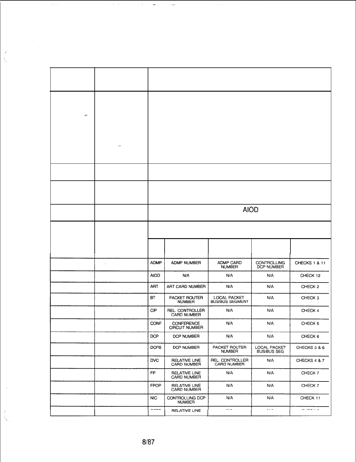
TL-130400-1001
Table 21.1 CPG Error Messages (Continued)
CPG ERROR
MESSAGES
FR-50
(Continued)
.~_
. .
TITLE
,.
DESCRIPTION OF MESSAGES
CHECK 8: FOR CARD TYPE PBE THE PEC AND THE
PACKET ROUTER NUMBER COMBINATION CANNOT BE
DUPLICATED. FOR THE REVISED CONFIGURATION,
THE PACKET ROUTER NUMBER CANNOT BE
DUPLICATED.
CHECK 9: FOR CARD TYPE PR THE PEC AND THE
PACKET ROUTER NUMBER COMBINATION CANNOT BE
DUPLICATED. FOR THE REVISED CONFIGURATION,
THE PACKET ROUTER NUMBER CANNOT BE
DUPLICATED.
CHECK 10: FOR CARD TYPE SM THE SILENT MONITOR
CARD NUMBER CANNOT BE DUPLICATED.
CHECK 11: FOR CARD TYPE NIC AND ADMP THE
CONTROLLING DCP MUST APPEAR AS THE DCP
NUMBER FOR CARD TYPE DCP OR DCPB.
CHECK 12: FOR CARD TYPE
AIOD
AND OPI ONLY ONE
CARD OF THIS TYPE IS ALLOWED.
CARD TYPES VS. IDENTIFIERS CHECKS CHART
CARD
TYPE PRIMARY
IDENTIFIER SECONDARY
IDENTIFIER TERTIARY
IDENTIFIER CHECKS
APPLICABLE
CARD NUMBER
SVR 5210
8187 D-457
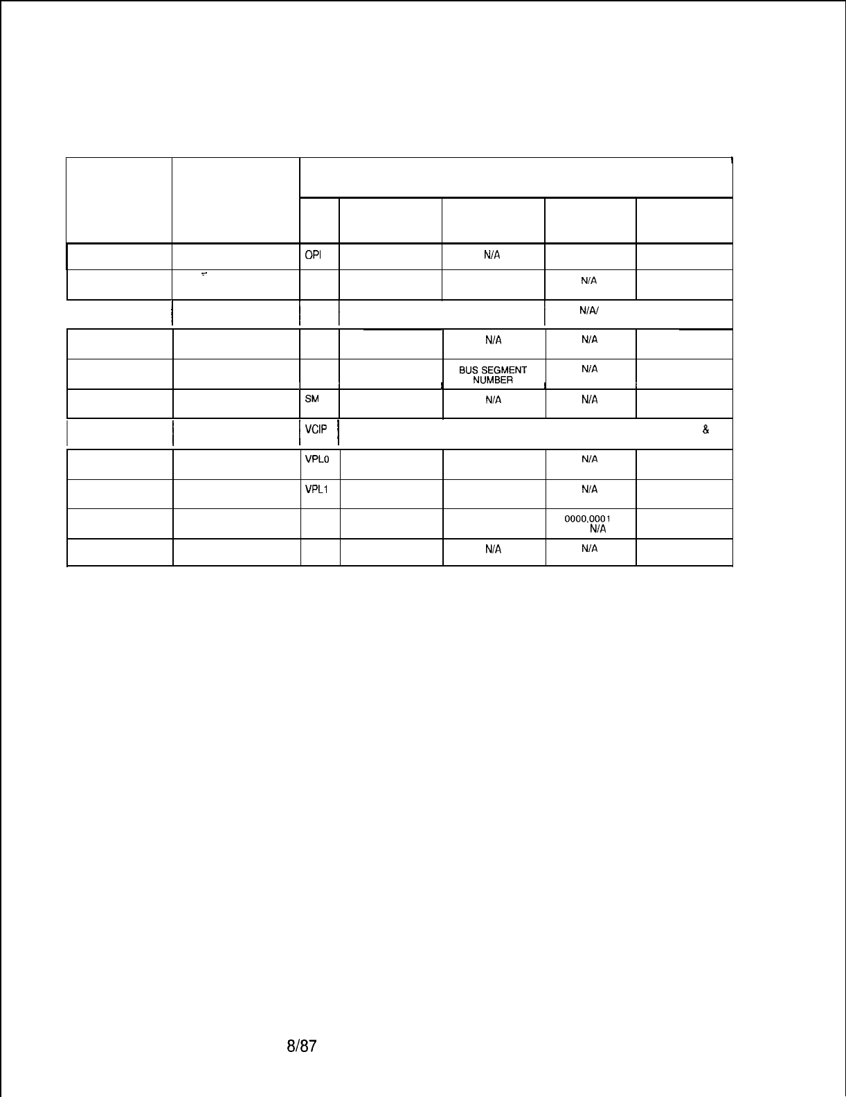
TL-130400-1001
Table 21.1 CPG Error Messages (Continued)
FR-50
(Continued)
I
CARD TYPES VS. IDENTIFIERS CHECKS CHART
CARD PRIMARY SECONDARY TERTIARY CHECKS
TYPE IDENTIFIER IDENTIFIER IDENTIFIER
APPLICABLE
OPI N/A N/A N/A CHECK 12
.r
PBE PACKET ROUTER N/A N/A CHECK 8
. . .
NUMBER
!
I I
I
POTS RELATIVE LINE N/A NIAI
I
CHECK 7
CARDNUMBER
PR PACKET ROUTER N/A N/A CHECK 9
.
NUMBER
RPTR PACKET ROUTER
BUS?X;A;NT
N/A CHECK 3
NUMBER
I
I1I I I
St.4
SILENT MONITOR N/A N/A CHECK 10
CARD NUMBER
VCIP
I
I
RELATIVE LINE REL. CONTROLLER N/A
CHECKS 4
&
7
CARD NUMBER CARD NUMBER
VPLO RELATIVE LINE N/A N/A CHECK 7
CARD NUMBER
VPLl
RELATIVE LINE NIA N/A CHECK 7
CARDNUMBER
VP20
RELATIVE LINE REL. CONTROLLER 0000,0001 CHECKS 4 & 7
CARD NUMBER CARD NUM OR NIA
OR
N/A
VP21 RELATIVE LINE N/A N/A CHECK 7
CARD NUMBER
D-458
8187
SVR 5210
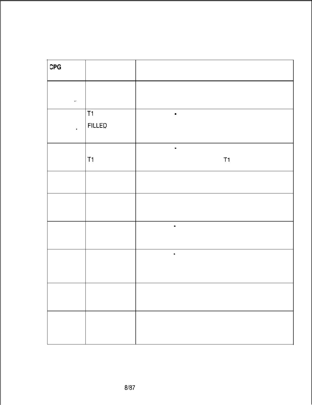
TL-130400-1001
CPG
ERROR
MESSAGES
Table 21.1 CPG Error Messages (Continued)
TITLE DESCRIPTION OF MESSAGES
FR-51
PHYSICAL PHYSICAL LOCATION
LOCATION THE PEC, GROUP, AND SLOT SPECIFIED FOR THIS
PREVIOUSLY CARD MUST BE UNIQUE
.~_
FILLED
FR-51
Tl
TRUNK CARD TYPE
-
PHYSICAL LOCATION
SLOTS NOT DTRK CARDS BLOCK THE INDICATED SLOTS FROM
FILLEP
IN THE LOWEST TO HIGHEST SLOT NUMBER WITHOUT
_
CORRECT ANY OTHER TYPE OF CARD ALLOWED RESIDING IN
ORDER DTRK BLOCKED SLOTS. (FRCHKS)
FR-51
SLOT CARD TYPE
-
PHYSICAL LOCATION
UNUSABLE BY NO OTHER TYPE OF CARD CAN RESIDE IN ONE OF
Tl
EQUIPMENT THE SLOTS BLOCKED BY THE
Tl
SPAN WHICH IS
IMPLIED BY THE INPUT OF A DTRK CARD. (FRCHKS)
FR-51
NONEXISTENT PHYSICAL LOCATION
PHYSICAL THE PEC, GROUP, AND SLOT SPECIFIED MUST BE
LOCATION VALID FOR THE PEC TYPE. (FRCHKS)
FR-51
PREVIOUS PHYSICAL LOCATION
CARD A PREVIOUS FR RECORD CANNOT DEFINE A WIDE
OVERHANGS CARD WHICH OVERHANGS INTO A SPECIFIED SLOT.
INTO THIS SLOT (FRCHKS)
FR-51 INVALID CARD CARD TYPE
-
PEC
TYPE FOR THIS THE CARD TYPE MUST BE ALLOWABLE FOR THE PEC
PEC TYPE TYPE (‘Sl’) SPECIFIED ON THE OE RECORD.
(FRCHKS)
FR-51
FR-51
PHYSICAL CARD TYPE
-
PHYSICAL LOCATION
LOCATION THE CARD TYPE SPECIFIED HAS BEEN ASSIGNED TO
INVALID FOR A PHYSICAL LOCATION TO WHICH IT IS NOT
SPECIFIED ALLOWED.
CARD TYPE (FRCHKS)
MAX NUMBER THE CARD TYPE LIMIT HAS BEEN EXCEEDED.
OF CARDS OF (FRCHKS)
THIS TYPE
EXCEEDED
FR-51
SLOT BLOCKED INFORMATIONAL MESSAGE WHICH SHOWS THAT
BY DTRK CARD. DTRK CARDS ARE NOT PHYSICALLY PLACED IN
NO CARD UNIVERSAL SLOTS, BUT RENDER THE SLOTS
PLACED IN THIS UNUSABLE BY OTHER CARD TYPES.
SLOT (FRCHKS)
SVR 5210
8187
D-459
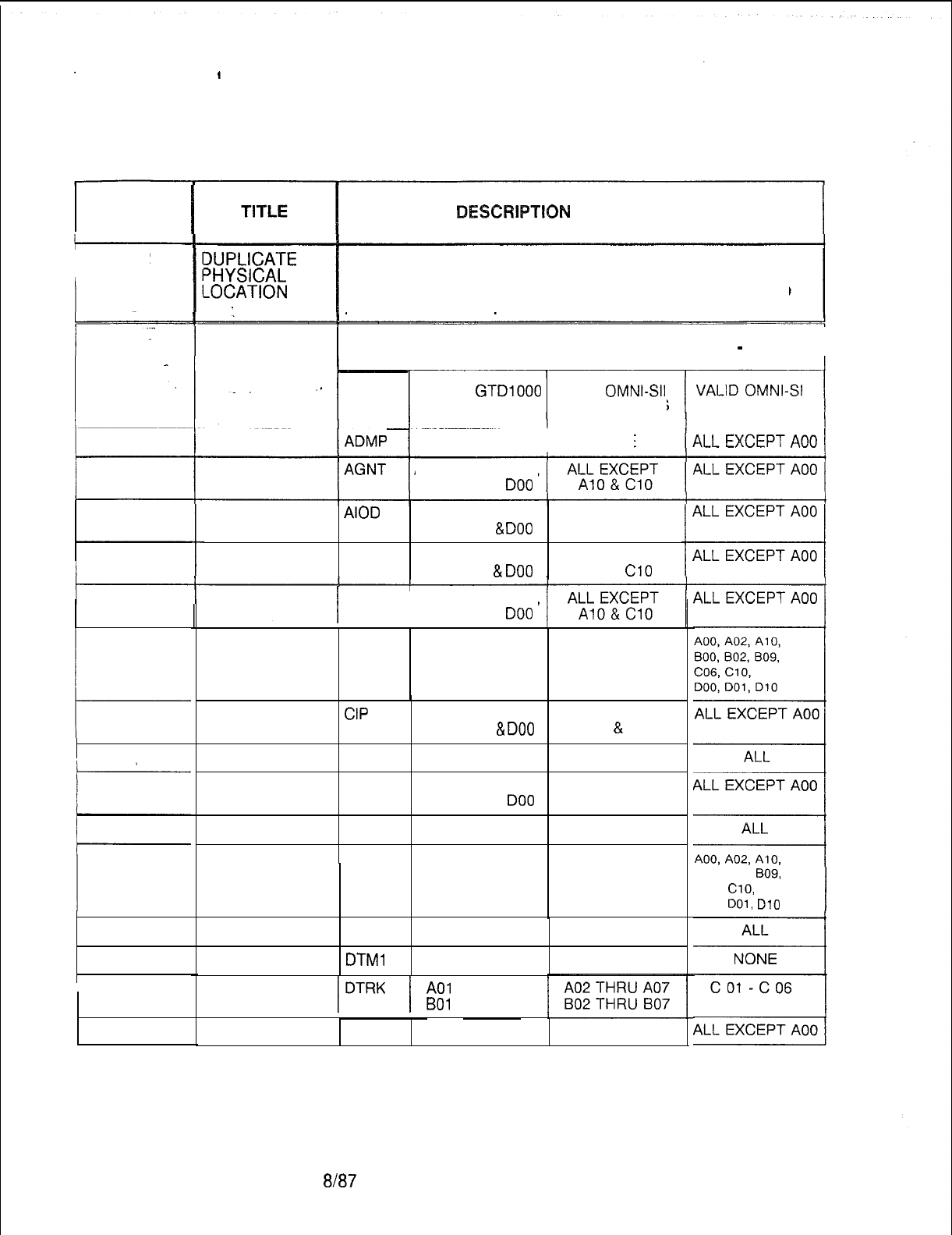
TL-130400-1001
Table 21.1 CPG Error Messages (Continued)
CPG ERROR
MESSAGES
I
FR-52
L
D-460
DES@RIPTION
OF MESSAGES
XJPLICATE
‘HYSICAL
-0CATION
. . -
PHYSICAL LOCATION
THE PEC, GROUP AND SLOT SPECIFIED FOR A CARD
MUST BE UNIQUE.
CARD TYPES VS. CARD SLOT RESTRICTION CHART
-
PART 1
.
.I
I
CARD
VALID
GTDlOOO
VALID
OMNI-SII
TYPE GROUP/SLOTS GROUP/SLOTS
~ADMP
1
NONE
I
NONE
ALL EXCEPT AOO,
BOO, COO & DO0
AIOD ALL EXCEPT AOO, ONLY A01 & CO1
BOO, COO
&
DO0
ART
ALL EXCEPT AOO,
ALL EXCEPT
BOO,
COO
&
DO0
Al0 &
Cl0
j
ATTN I
ALL EXCEPT AOO,
BOO, COO & DO0
BT NONE NONE
CIP ALL EXCEPT AOO,
ALL EXCEPT
BOO, COO
&
DO0
A10
&
Cl0
CONF ALL ALL
COT
ALL EXCEPT AOO,
ALL EXCEPT
BOO, COO & DO0
A10 & Cl0
DCP NONE NONE
DCPB NONE NONE
DTMF ALL ALL
DTMl
ALL ALL
lDTRK
/
A01
THRU 106
BOl
THRU B06
DVC NONE NONE
8l87
GROUP/SLOTS
BOO, B02,
BO9,
C06,
ClO,
DOO,
DOl,
D10
SVR 5210
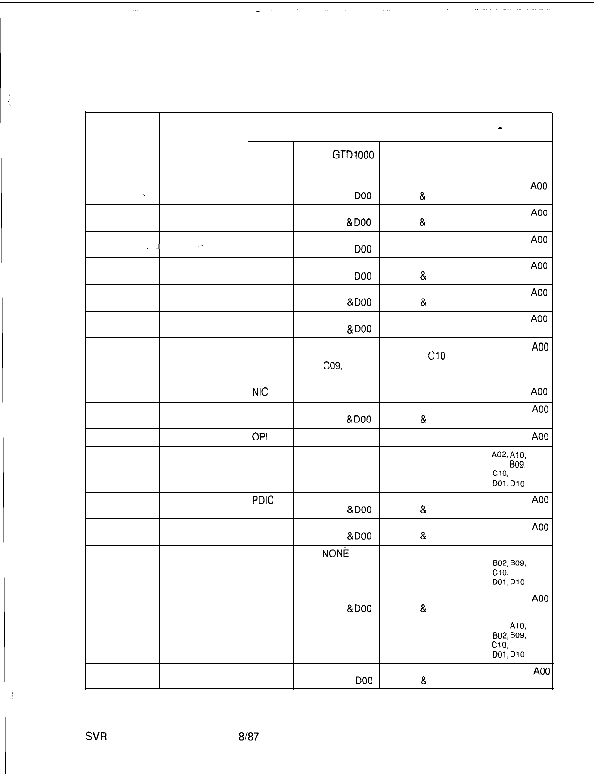
TL-130400-1001
Table 21.1 CPG Error Messages (Continued)
FR-52
(Continued)
.F
. . .
CARD TYPES VS. CARD SLOT RESTRICTION CHART
-
PART 2
CARD
VALID
GTDlOOO
VALID OMNI-SII VALID OMNI-SI
TYPE GROUP/SLOTS GROUP/SLOTS
GROUP/SLOTS
EMT ALL EXCEPT AOO,
ALL EXCEPT ALL EXCEPT
A00
BOO, COO, & DO0
A10
&
Cl0
EMT4 ALL EXCEPT AOO,
ALL EXCEPT ALL EXCEPT
A00
BOO, COO,
&
DO0
A10
&
Cl0
ERLT
ALL EXCEPT AOO,
ALL EXCEPT ALL EXCEPT
A00
BOO, COO, & DO0
A10 & Cl0
FP
ALL EXCEPT AOO,
ALL EXCEPT ALL EXCEPT
A00
BOO, COO, & DO0
A10
&
Cl0
FPOP ALL EXCEPT AOO,
ALL EXCEPT ALL EXCEPT
A00
BOO, COO,
&
DO0
A10
&
Cl0
ILT
ALL EXCEPT AOO,
ALL EXCEPT ALL EXCEPT
A00
BOO, COO,
&
DO0
A10 & Cl0
KEDU ALL EXCEPT AOO,
ALL EXCEPT ALL EXCEPT
A00
BOO, COO, C07,
A10 &
Cl0
C08, CO9, DOO,
D07, D08, DO9
NC
NONE NONE
ALL EXCEPT
A00
OFFP ALL EXCEPT AOO,
ALL EXCEPT ALL EXCEPT
A00
BOO, COO,
&
DO0
A10
&
Cl0
OPI NONE NONE
ALL EXCEPT
A00
PBE NONE NONE
AOO,
AOZ,
AlO,
BOO, B02,
BO9,
C06,
ClO,
DOO,
DOl,
D10
PDIC ALL EXCEPT AOO,
ALL EXCEPT ALL EXCEPT
A00
BOO, COO,
&
DO0
A10
&
Cl0
POTS ALL EXCEPT AOO,
ALL EXCEPT ALL EXCEPT
A00
BOO, COO,
&
DO0
A10
&
Cl0
PR NONE NONE
AOO, A02, Al 0,
BOO,
802,
B09,
C06,
ClO,
DOO,
DOl,
DlO
RLT
ALL EXCEPT AOO,
ALL EXCEPT ALL EXCEPT
A00
BOO, COO,
&
DO0
A10
&
Cl0
RPTR NONE NONE
AOO, A02,
AlO,
BOO,
802,
BO9,
C06,
ClO,
DOO,
DOl,
DlO
SM ALL EXCEPT AOO,
ALL EXCEPT ALL EXCEPT
A00
BOO, COO, & DO0
A10
&
Cl0
SVR
5210
a/t37
D-461
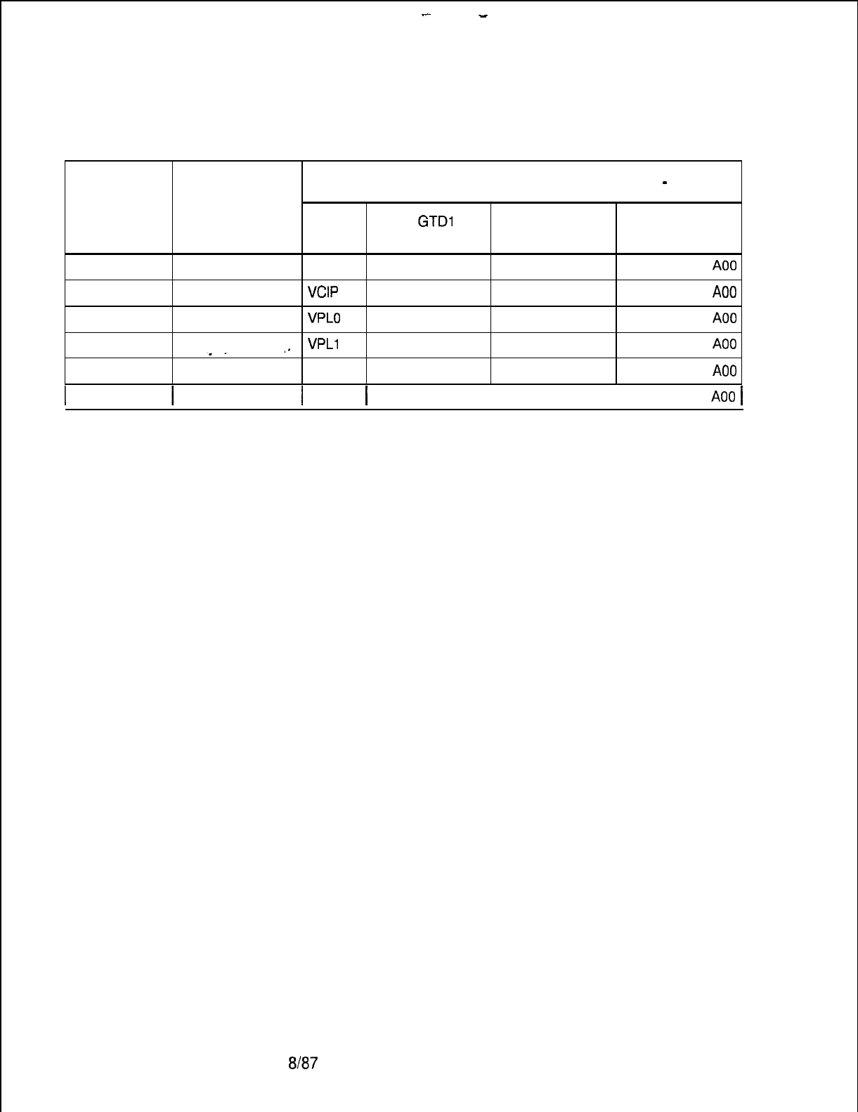
--
TL-130400-1001
Table 21.1 CPG Error Messages (Continued)
FR-52
(Continued)
CARD TYPES VS. CARD SLOT RESTRICTION CHART
-
PART 2
CARD VALID
GTDl
000 VALID OMNI-SII
VALID OMNI-SI
TYPE GROUP/SLOTS GROUP/SLOTS
GROUP/SLOTS
. . .
TDET
NONE NONE
ALL EXCEPT
A00
VCIP NONE NONE
ALL EXCEPT
A00
VPLO
,_
VPLl
VP20
NONE NONE
ALL EXCEPT
A00
NONE NONE
ALL EXCEPT
A00
NONE NONE
ALL EXCEPT
A00
I
I
VP21 NONE
I
NONE
1 ALL EXCEPT
A00
1
D-462
m7
SVR 5210
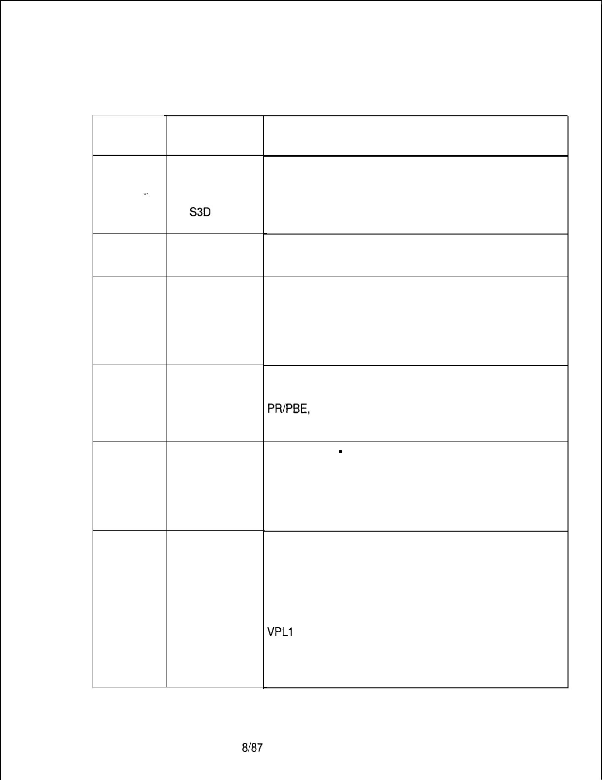
CPG ERROR
MESSAGES
FR-53
.FR-54
FR-56
FR-56
FR-57
FR-58
TL-130400-1001
Table 21.1 CPG Error Messages (Continued)
TITLE
DEFINING A
DATA CARD
REQUIRES
SPECIFICATION
OF
S3D
OPT ON
OE
PEC NUMBER IS
NOT EQUIPPED
THE LOCAL
PACKET BUS IS
NOT COMPLETE
THE LOCAL
PACKET BUS IS
INVALID
A‘DATA CARD IS
NOT ON A
LOCAL PACKET
BUS
THE NUMBER
OF DATA CKTS
ON A BUS
SEGMENT
CANNOT
EXCEED 64
SVR 5210
DESCRIPTION OF MESSAGES
CARD TYPE
THE DATA SYSTEM CARD TYPES (ADMP, BT, DCP,
DCPB, NIC, PR, PBT, RPTR, VP20
(DATA ONLY AND VOICE AND DATA).
PEC
THE PEC NUMBER SPECIFIED MUST BE MARKED
EQUIPPED ON THE OE RECORD.
A LOCAL PACKET BUS IS COMPLETELY DEFINED BY A
PACKET ROUTER (CARD TYPE, PR) AND A BUS
TERMINATOR (CARD TYPES BT, DCPB); OR A PAIR OF
LOCAL PACKET BUSES CAN BE DEFINED BY A
PACKET ROUTER,
TWO BUS TERMINATORS, AND A PACKET BUS
EXTENDER (CARD TYPE, PBE). (ENDCHK)
TEXT IDENTIFYING THE CAUSE OF THE ERROR
MESSAGE IS ALSO PRINTED.
THIS CHECK VERIFIES THE CONFIGURATION OF
PR/PBE,
BT, DCPB, AND RPTR CARDS FOR ALL BUS
SEGMENTS ENGINEERED. IT ALSO VERIFIES THE
COMBINATIONS OF PECS AND GROUPS. (FRCHKS)
CARD TYPE
-
PHYSICAL LOCATION
ALL DATA CARDS MUST BE PLACED ON A LOCAL
PACKET BUS. THE ENDS OF A LOCAL PACKET BUS
ARE DEFINED BY THE PLACEMENT OF PR, PBE, BUS
TERMINATOR AND RPTR CARDS. DATA CARDS MUST
BE PLACED BETWEEN A PR OR PBE AND A BUS
TERMINATOR OR RPTR. (ENDCHK OR FRCHKS)
CARD TYPE
THE NUMBER OF DATA CIRCUITS ON A LOCAL
PACKET BUS SEGMENT CANNOT EXCEED 64.
CIRCUITS ARE COUNTED AS FOLLOWS:
ADMP CARDS: 1 CIRCUIT.
DCP CARDS: 1 CIRCUIT.
NIC CARDS: 1 CIRCUIT.
VPLO CARDS: 8 CIRCUITS.
VPLl
CARDS: 2 CIRCUITS.
VP20 CARDS: 8 CIRCUITS (VOICE AND
DATA,DATA ONLY).
VP21 CARDS: 2 CIRCUITS.
(FRCHKS)
8187 D-463
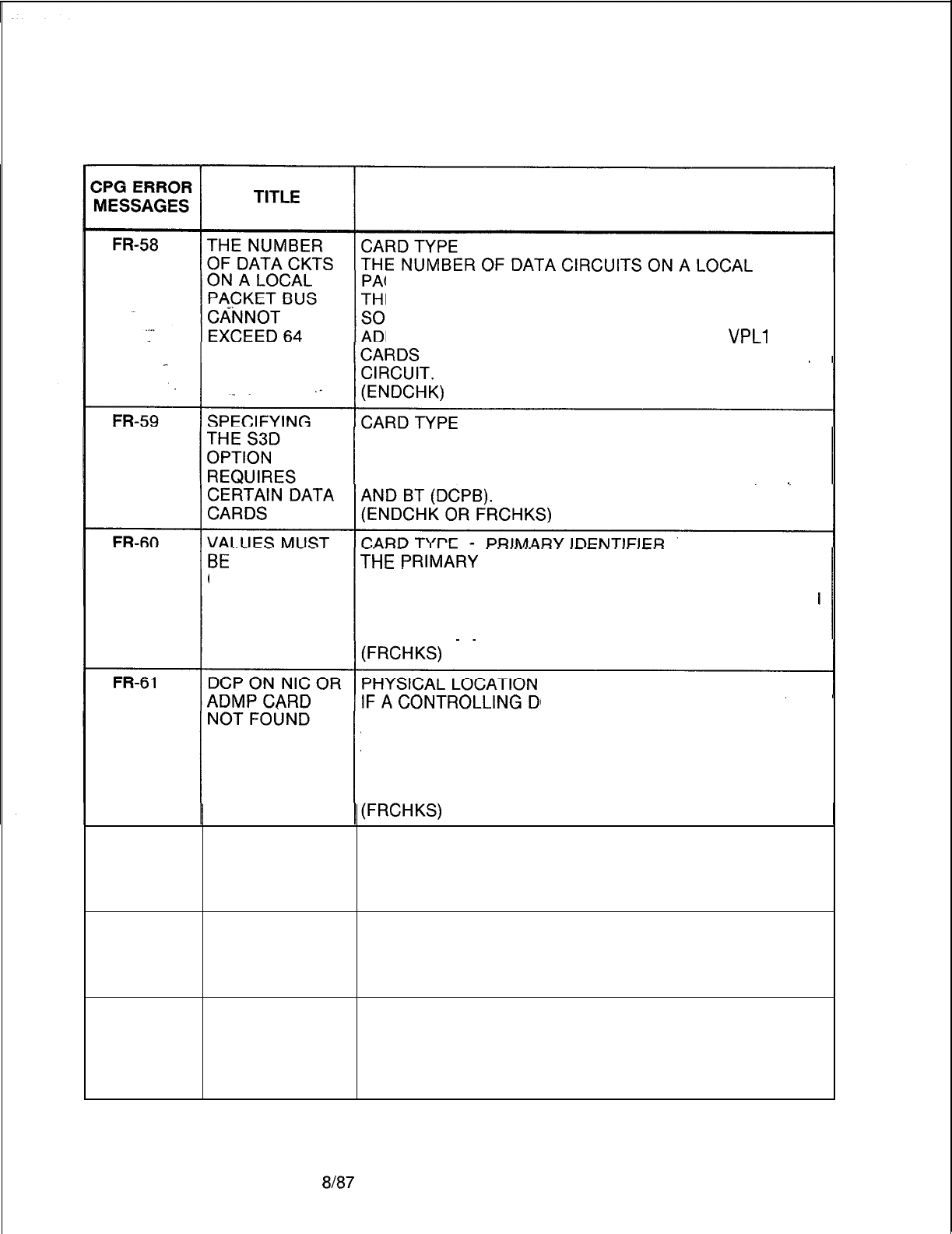
TL-130400-1001
Table 21.1 CPG Error Messages (Continued)
DESCRIPTION OF MESSAGES
CKET BUS CANNOT EXCEED 64.
IS LIMIT IS IMPOSED BY THE DATA SYSTEM
FTWARE DEFINITION OF THE PLA (PACKET LINE
DRESS). VPLO CARDS HAVE 8 CIRCUITS;
VPLl
HAVE 2 CIRCUITS; ADMP AND DCP HAVE ONE
IF THE DATA OPTION IS SPECIFIED ON THE OE
RECORD, THEN AT LEAST ONE EACH OF THE
FOLLOWING CARDS MUST BE DEFINED: ADMP,
PR,
PRIMAR;
INDEX FOR SILENT MONITOR (SM)
CONTINUOUS CARDS MUST BE CONTINUOUS (I.E., THE SILENT
MONITOR CARD NUMBERS MUST BE ASSIGNED FROM
0 TO 7 CORRESPONDING TO THE NUMBER OF SM
CARDS 1
TO 8.
CP NUMBER IS USED AS THE
PRIMARY IDENTIFIER FOR A NIC CARD OR THE
TERTIARY IDENTIFIER FOR AN ADMP CARD,
THE SAME CONTROLLING DCP NUMBER MUST BE
USED AS THE PRIMARY IDENTIFIER ON A DCP OR
DCPB CARD.
FR-62
FR-63
EXPAN. FILE EXPANSION FILE STATUS
UNEQUIPPED IF GROUP C OR D ARE SPECIFIED THEN THE
ON OE FOR GRP EXPANSION FILE STATUS OF RECORD CODE OE MUST
C/D BE EQUIPPED.
THE ADMP IS PRIMARY IDENTIFIER
NOT COMPLETE THE ADMP IS MADE UP OF MORE THAN ONE CARD
AND ALL CARDS NEEDED TO MAKE IT UP MUST BE
SPECIFIED.
FR-64
CONTROLLING PRIMARY IDENTIFIER/TERTIARY IDENTIFIER
DCPS ON AN THE ADMP IS MADE UP OF MORE THAN ONE CARD
ADMP CARD AND ALL CARDS OF THE SET MUST SPECIFY THE
SET MUST BE SAME CONTROLLING DCP.
EQUAL
D-464
8187
SVR 5210
TL-130400-1001
Table 21.1 CPG Error Messages (Continued)
CPG ERROR
MESSAGES TITLE DESCRIPTION OF MESSAGES
FR-65
G&l
ADMPIDCP ADMP AND DCP CARDS MUST BE ON A PRIMARY BUS
CARDS MUST SEGMENT.
BE ON PRIMARY (A PRIMARY BUS SEGMENT CONTAINS A PACKET
BUS
SEGMENT ROUTER OR A PACKET BUS EXTENDER).
DUPLICATE THE SPEED CALLING ACCESS CLASS MUST BE
SPEED CALLING UNIQUE ACROSS THE GC RECORDS.
ACCESS GROUP
GC-52 RANGE OF
SP.
THE SPEED CALLING LIST NUMBERS MUST BE
LIST NOS. OUT SPECIFIED IN SETS OF FOUR STARTING WITH 0. IF
OF ORDER. THEY ARE NOT SPECIFIED IN THE SAID ORDER, THE
NEAREST FIRST ENTRY NUMBER AND LAST ENTRY NUMBER
MULTIPLE OF 4
ALLOTTED WILL BE ADJUSTED ACCORDINGLY (PLUS OR MINUS)
TO THE NEAREST MULTIPLE OF FOUR. FOR
EXAMPLE, USER SPECIFIES AS FOLLOWS:
FIRST ENTRY NUMBER IS 2, LAST ENTRY NUMBER IS
6
FIRST ENTRY NUMBER IS 20, LAST ENTRY NUMBER IS
50
THE ENTRY NUMBERS ACTUALLY SHOULD HAVE
BEEN:
FIRST ENTRY NUMBER IS 0, LAST ENTRY NUMBER IS
7
FIRST ENTRY NUMBER IS 20, LAST ENTRY NUMBER IS
51
GC-53 ELEMENTS THE LAST ENTRY NUMBER CANNOT BE LESS THAN
HAVE THE FIRST ENTRY NUMBER.
INCOMPATIBLE (GCGEN)
VALUES
GS-01
GS-51
VALUES TO BE SPEED CALLING NUMBER DIGITS
FILLED LEFT TO DIGITS SHOULD BE FILLED IN FROM LEFT TO RIGHT
RIGHT WITH NO
IMBEDDED
DASHES.
DUPLICATE THE SPEED CALLING LIST NUMBER MUST BE UNIQUE
SPEED CALLING ACROSS THE GS RECORDS.
LIST NUMBER
HD-01
MAXIMUM
NUMBER OF
HUNDREDS
GROUPS
EXCEEDED
THE MAXIMUM NUMBER OF HUNDREDS GROUPS
SUPPORTEDBYTHESVRHASBEENEXCEEDED.
(GENLIN)
SVR 5210
8187
D-465
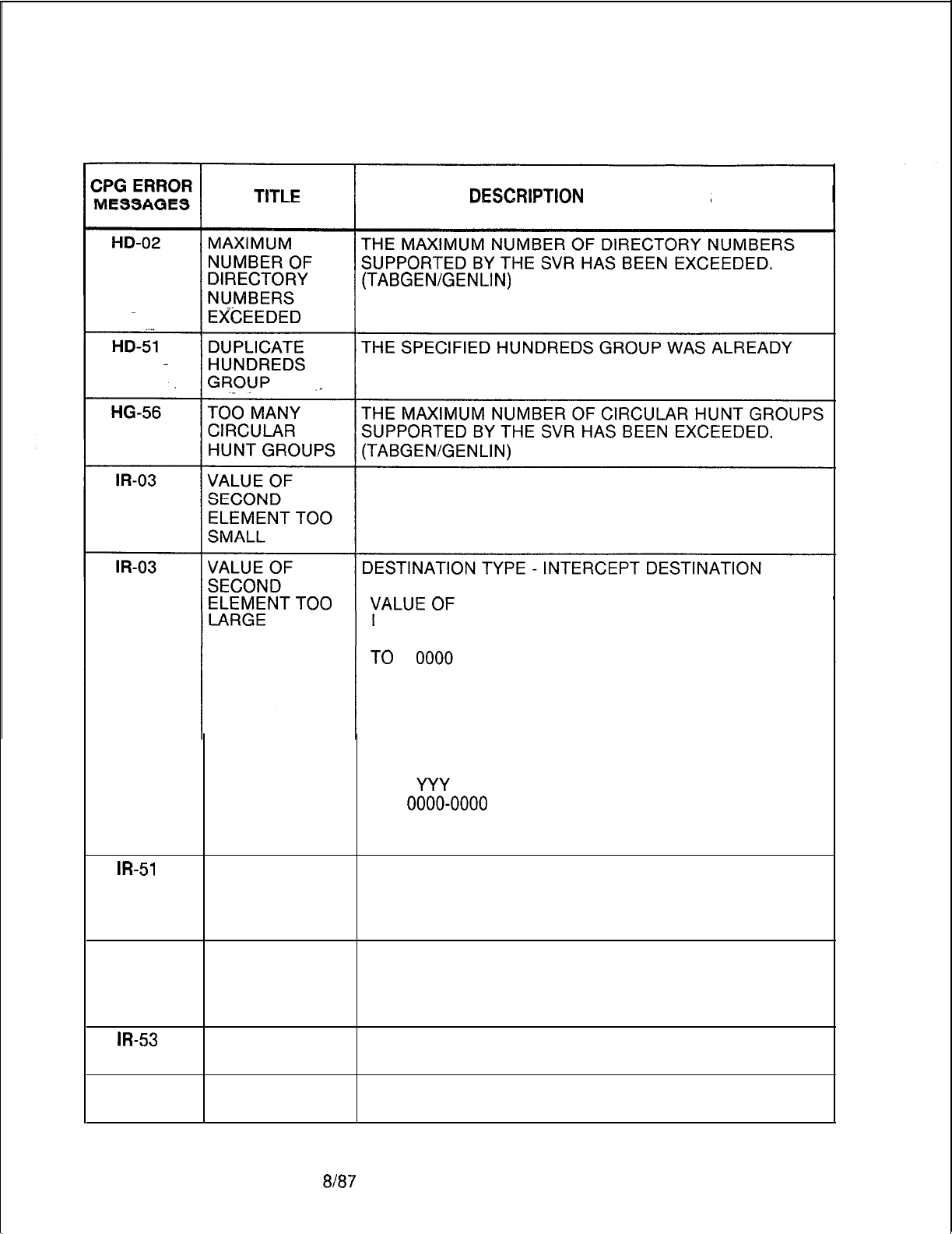
TL-130400-1001
Table 21.1 CPG Error Messages (Continued)
DESCRlPTlQl’l
OF MESSAGES
(TABGEN/GENLIN)
ENGINEERED ON A PREVIOUS HD RECORD.
ALLOWABLE VALUES OF
DESTINATION TYPE INTERCEPT DESTINATION
LN
0000-9999 (A ROOM NUMBER)
AT 0001-0255 (ANY COMBINATION OF
THE EIGHT ATTENDANTS)
RA 0000-0127
PEC AND TRUNK NUMBER,
XYW, WHERE X IS PEC AND
WY
IS TRUNK NUMBER
RL
0000-0000
(RLT NUMBER)
TI
0000-0031 OR 0063 (TIE TRUNK GROUP
NUMBER
m-51
DUPLICATE
INTERCEPT
ROUTING
NUMBER
INTERCEPT ROUTING NUMBER MUST BE UNIQUE
ACROSS THE IR RECORDS.
IR-53
REQUIRED
VALUE NOT
FOUND ON
LISTED FORM
m-53
ATTENDANT
NOT FOUND
IR-53
RLT NUMBER
NOT FOUND
D-466
8l87
SVR 5210
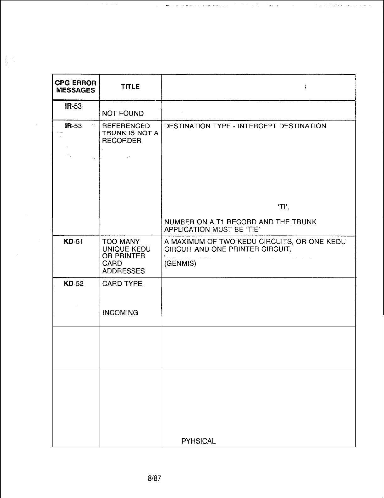
TL-130400-1001
Table 21.1 CPG Error Messages (Continued)
DESCRIPTION OF MESSAGES
TRUNK GROUP
A. IF THE DESTINATION TYPE IS ‘AT’, THE
ANNOUNCER DESTINATION MUST BE A VALID ATTENDANT CIRCUIT
ON AN AT RECORD.
B. IF THE DESTINATION TYPE IS ‘RA’, THE
DESTINATION MUST BE A VALID RECORDER
ANNOUNCERONATCRECORD
C. IF THE DESTINATION TYPE IS ‘LN’, THE
DESTINATION MUST BE A VALID LINE STATION
NUMBER ON AN LD RECORD.
D. IF THE DESTINATION TYPE IS
‘TI’,
THE
DESTINATION MUST BE A VALID TRUNK GROUP
CAN BE PLACED IN THE SAME CARD’SLOT.
DEFINED ON FR
INCOMPATIBLE
WITH FCN OF
CARD
KD-52
CARD TYPE
DEFINED ON FR
INCOMPATIBLE
WITH INCOMING
CARD TYPE
KD-52
FUNCTION OF PHYSICAL LOCATION
CARD NOT THE PEC, GROUP, SLOT AND CIRCUIT FUNCTION
ALLOWED FOR SPECIFIED MUST BE VALID FOR THE CARD TYPE
CARD TYPE DEFINED ON FR (FOR THIS PEC TYPE).
DEFINED ON KEDU CIRCUIT MUST APPEAR ON A KEDU CARD.
FORM FR (PHYLOC)
IF THE CARD TYPE IN THE MESSAGE IS “OVER”,
THAT INDICATES THAT A CARD IN THE PREVIOUS
LOCATION IS A WIDE CARD AND IT OVERHANGS INTO
THIS
PYHSICAL
LOCATION ON FR.
SVR 5210
8h37 D-467
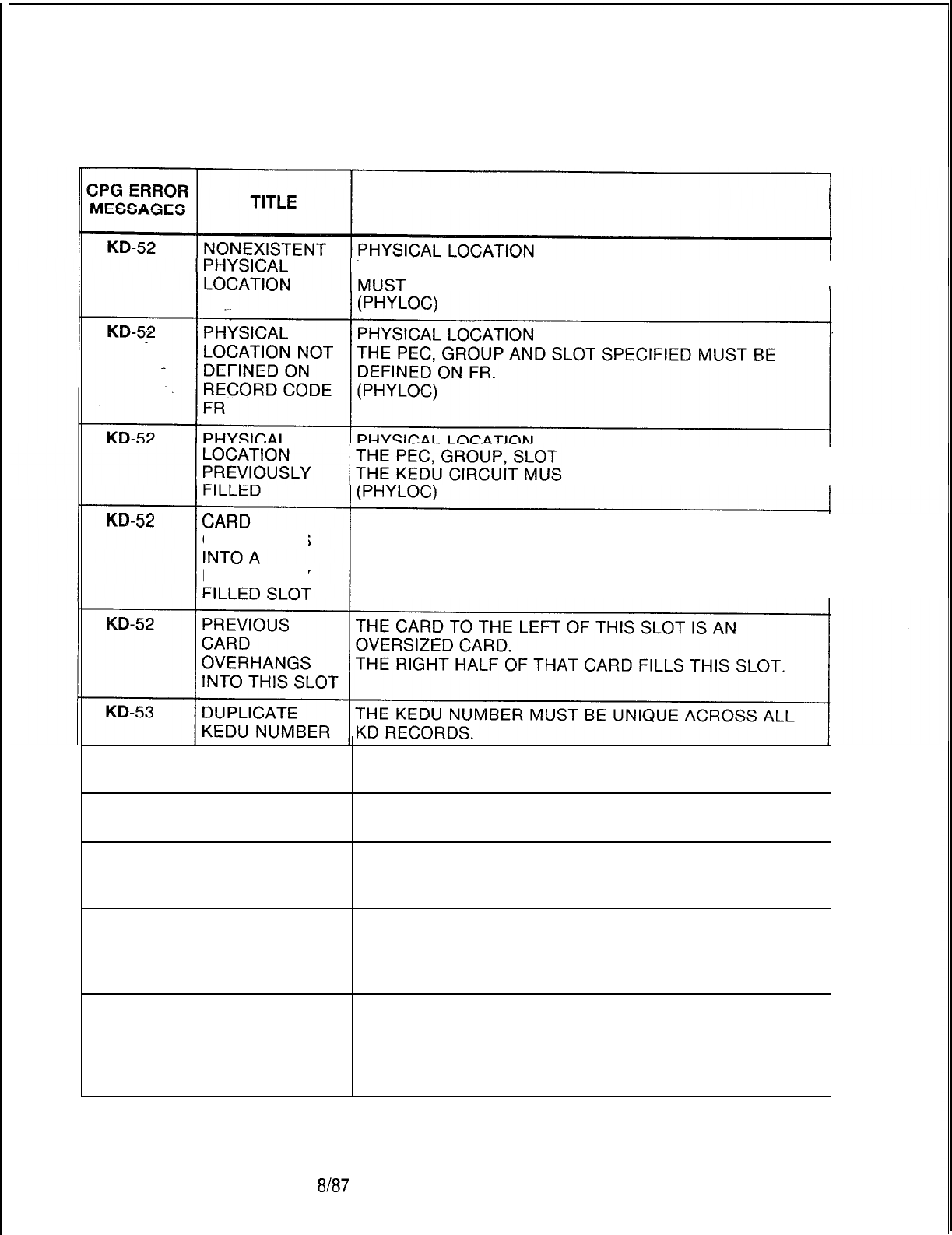
r
TL-130400-1001
Table 21.1 CPG Error Messages (Continued)
DESCRIPTION OF MESSAGES
THE
PEC,
GROUP, SLOT AND CIRCUIT SPECIFIED
BE VALID FOR THIS PEC TYPE.
AND CIRCUIT SPECIFIED FOR
T BE UNIQUE.
OVERHANGS
PREVIOUSLY
THIS CARD IS AN OVERSIZED CARD AND IS TRYING
TO FILL TWO SLOTS. OF THE TWO SLOTS IT FILLS,
THE RIGHT HAND ONE HAS ALREADY BEEN FILLED.
KD-54
KD-55
KD-56
PEC NUMBER IS THE PEC NUMBER SPECIFIED MUST BE MARKED
NOT EQUIPPED EQUIPPED ON THE OE OR OF RECORD.
OPI CARD NOT THE PMS EQUIPPED FIELD IS SPECIFIED FOR THE
EQUIPPED KEDU, BUT THE OPI CARD IS NOT EQUIPPED OF FR.
ONLY ONE THE PMS EQUIPPED FIELD IS SPECIFIED FOR THE
KEDU MAY MORE THAN ONE KEDU.
HAVE PMS
KD-57
OPI CARD ON FOR THE PMS FEATURE TO WORK PROPERLY, BOTH
FR REQUIRES AN OPI CARD AND A KEDU WITH PMS ARE REQUIRED.
KEDU WITH (ENDCHK)
PMS
KD-58
PMS KEDU
REQUIRES
PRINTER ON
THE SAME
CARD
FOR THE PMS FEATURE TO WORK PROPERLY, A
PRINTER MUST BE ENGINEERED WITH THE PMS
KEDU.
(ENDCHK)
D-468
8187
SVR 5210
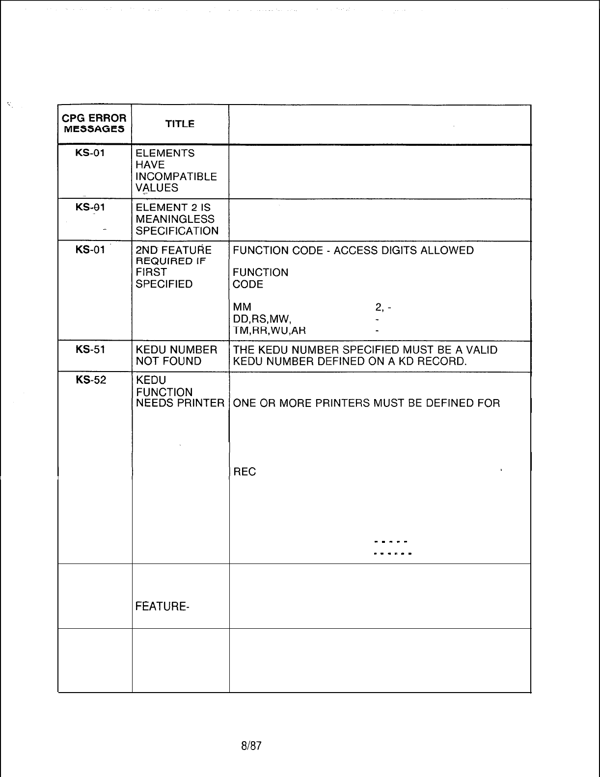
TL-130400-1001
Table 21.1 CPG Error Messages (Continued)
DESCRIPTION OF MESSAGES
ALLOWABLE VALUES OF
FUNCTION ACCESS DIGIT 2
IF AN ACCESS DIGIT IS INDICATED FOR A SPECIFIC
FUNCTION CODE,
ASSIGNMENT THAT FUNCTION ON THE AL RECORD ASSOCIATED
ON AL FORM WITH THE KEDU NUMBER.
MESSAGE METER ROOM STATUS
KEDU STATUS PRINTER STATUS PRINTER
CODE NO
ID ID
AL 0 AL
01
-- --
LA-51
REC
KEDU FUNCTION DIGITS ALLOWED
CODE NO CODE 01 234567
KS 0 MM 0 1
-
-
-
-
-
-ALLOWED
KS 0 RS 0 1
-
-
-
I
-
-
INCORRECT
LINE APP MUST THE LINE DIRECTORY NUMBER SPECIFIED AS THE
BE ON FEATUREPHONE WAS NOT SPECIFIED AS A
MULTILINE MULTILINE FEATUREPHONE ON AN LD RECORD.
FEATURE-
(GENLIN)
PHONE
LA-51
LINE APP MUST THE DIRECTORY NUMBER SPECIFIED AS THE
BE ON FEATUREPHONE IS NOT A FEATUREPHONE PRIME
FEATUREPHON CONTROL LINE.
E PRIME (GENLIN)
CONTROL LINE
SVR 5210
8187
D-469
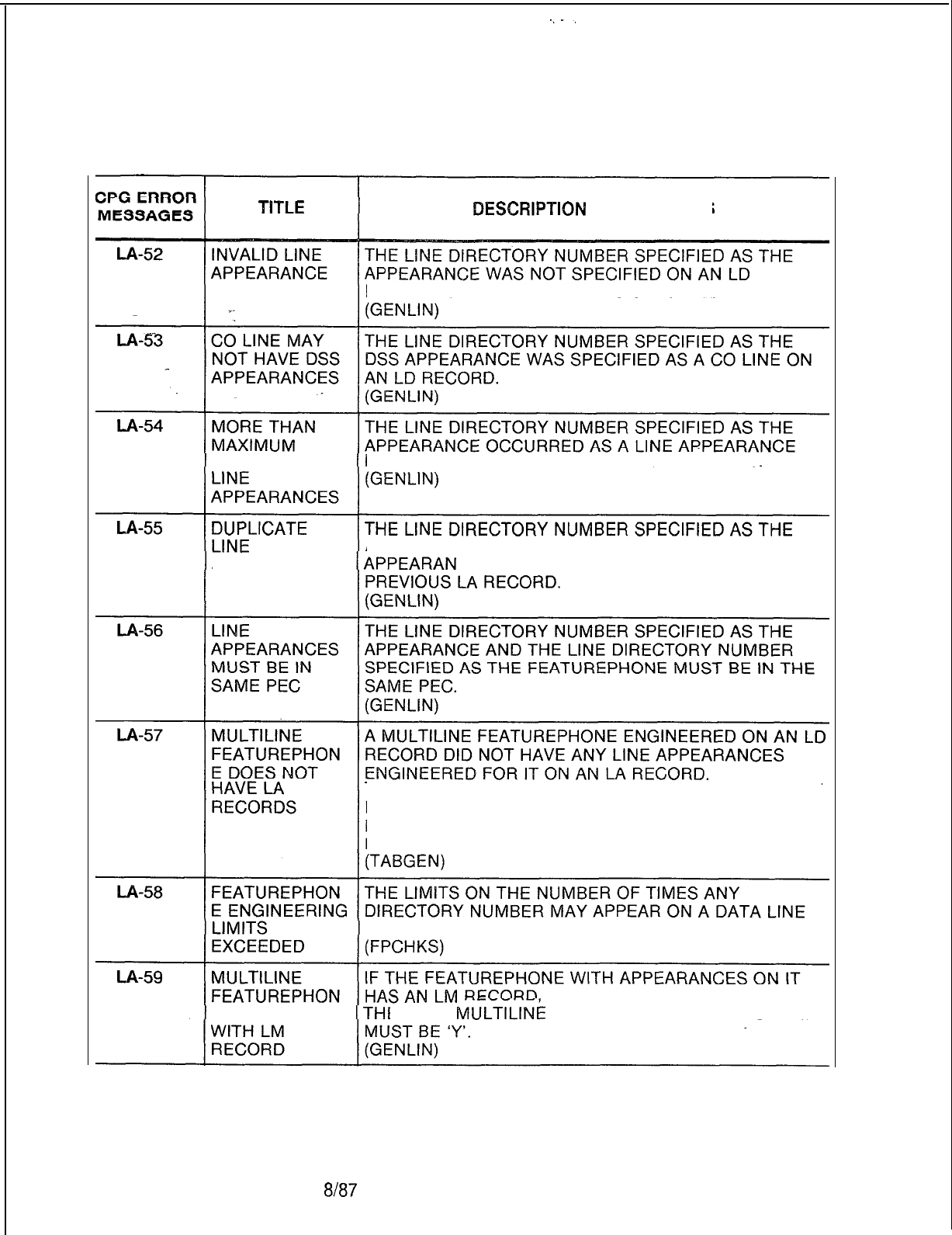
r
TL-130400-I 001
Table 21.1 CPG Error Messages (Continued)
DESCRIPTIQN
OF MESSAGES
RECORD OR A
POTS
LINE WAS SPECIFIED.
NUMBER OF MORE TIMES THAN THE SYSTEM SVR ALLOWS.
APPEARANCE WAS SPECIFIED AS AN IDENTICAL
APPREARANCE CE ON THE FEATUREPHONE ON A
THIS IS A WARNING MESSAGE SINCE SOME TYPES OF
LINE APPEARANCES ARE ENGINEERED ON LD
RECORDS AND AN LA RECORD IS A DUPLICATE
ENTRY FOR DOCUMENTATION PURPOSES.
CARD WERE EXCEEDED.
E CONFLICTS EN THE
MULTILINk
FEATUREPHONE FIELD ON LM
D-470 8187
SVR 5210

TL-130400-1001
Table 21.1 CPG Error Messages (Continued)
ZPG
ERROR
MESSAGES TITLE DESCRIPTION OF MESSAGES
l-A-60 SINGLE LINE IF THE MULTILINE FEATUREPHONE FIELD ON LM IS
FEATUREPHON DASHED
’
E CANNOT BE A (THE FEATUREPHONE IS A SINGLE LINE SET),
‘:
LINE THEN IT CANNOT BE A LINE APPEARANCE.
..^
APPEARANCE (GENLIN)
LA-61
A VISUAL CALL A VISUAL CALL PARK LINE (SPECIFIED ON RECORD
PARK LINE CODE LD AS LINE TYPE, ‘VP’, CANNOT BE A LINE
-CANNOT BE A APPEARANCE SINCE IT IS A SINGLE LINE).
LINE (GENLIN)
APPEARANCE
LA-70 FEATUREPHON THE LINE DIRECTORY NUMBER SPECIFIED AS THE
E LINE NOT FEATUREPHONE WAS NOT SPECIFIED ON AN LD
FOUND RECORD.
(GENLIN)
LA-99 SITE HAS T7050 ENTRY FOR LINE SOFTWARE ID
INCONSISTENT AN ENTRY IN T7050, LINE APPEARANCE TABLE, FOR
DATA BASE THE INDICATED LINE SOFTWARE ID REPRESENTS AN
INVALID LINE APPEARANCE.
CPG CROSS-CHECKS INSTRUMENT TYPE, LINE TYPE
AND MULTIPLE APPEARANCE BIT IN OTHER TABLES
TO DETERMINE VALID ENTRIES.
WHILE THIS MESSAGE WILL DETECT ISOLATED DATA
BASE ERRORS,
LD-02
LD-03
MULTIPLE MESSAGES CAN INDICATE A BAD DUMP
FROM THE SITE FOR PEC RESIDENT MEMORY FILES.
(REVLA)
.
SECOND FIELD PICKUP GROUP NUMBER - PICKUP GROUP TYPE
MUST BE A IF THE PICKUP GROUP NUMBER IS DASHED,
DASH THEN THE PICKUP GROUP TYPE MUST BE DASHED.
ELEMENTS
HAVE
INCOMPATIBLE
VALUES
LD-03 ELEMENT 2 IS
MEANINGLESS
SPECIFICATION
SVR 5210
8187 D-471
Table 21.1 CPG Error Messages (Continued)
CPG ERROR
MESSAGES
LD-04
LD-04
LD-04
LD-04
LD-04
TITLE
2ND FEATURE
IS
MEANINGLESS
SP>l$ClFlCATlON
ELEMENT
2 IS
MEANINGLESS
SPECIFICATION
ELEMENTS
HAVE
INCOMPATIBLE
VALUES
ELEMENTS
HAVE
INCOMPATIBLE
VALUES
2ND FEATURE
IS
MEANINGLESS
SPECIFICATION
SECOND
ELEMENT
CONTAINS
INVALID VALUE
VALUE OF
SECOND
ELEMENT TOO
LARGE
DESCRIPTION OF MESSAGES
DIVERT CONDITION
-
DIVERT DESTINATION
VALUE OF ALLOWABLE VALUE OF
DIVERT CONDITION DIVERT DESTINATION
ND
--,TO,LN,AT,RA/TR,RM,PN
BY,NA,BN,
OR DA
TO,LN,AT,RA/TR,RM,PN
D-472 8187
SVR 5210
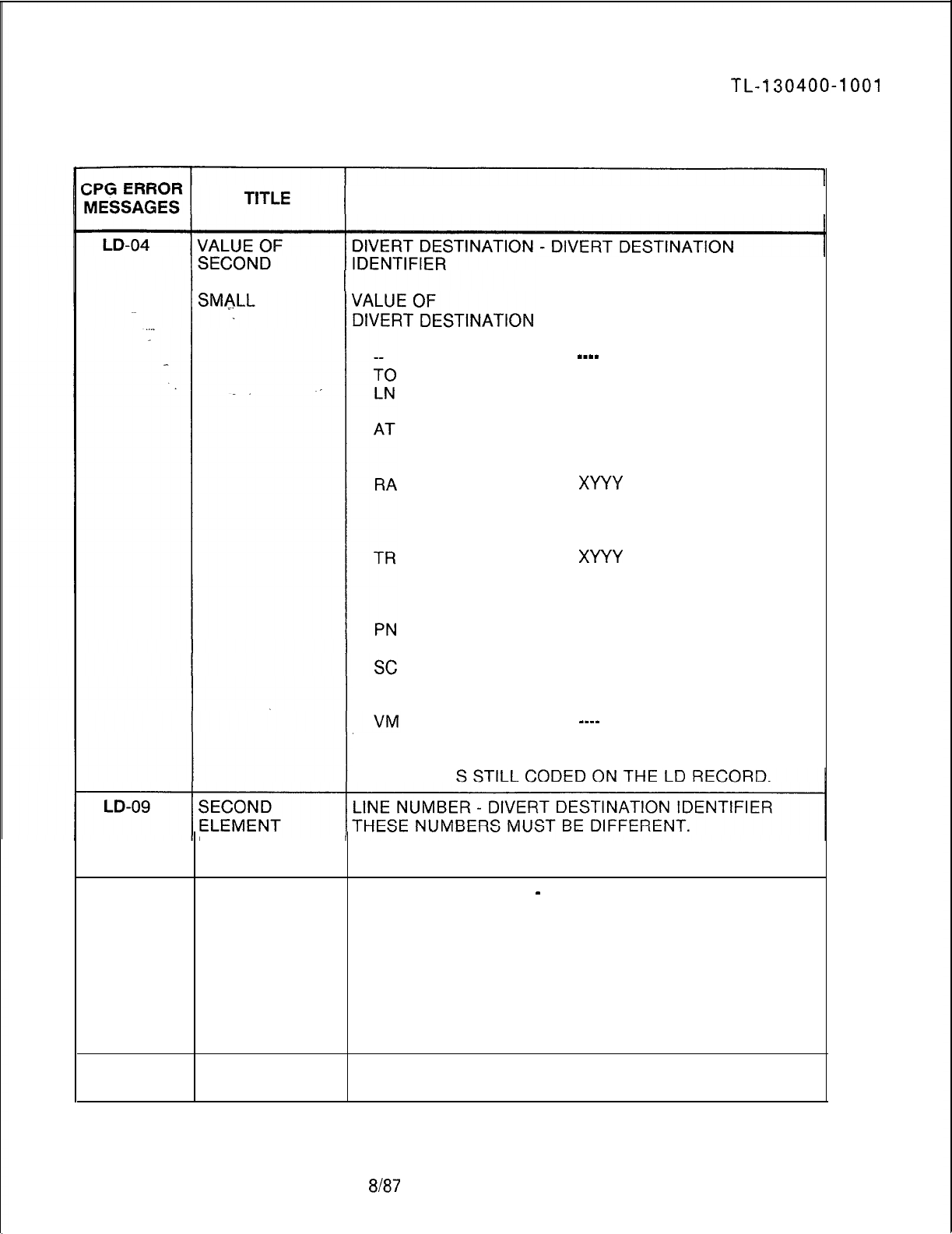
TL-l30400-1001
Table 21.1 CPG Error Messages (Continued)
DESCRIPTION OF MESSAGES
ELEMENT TOO ALLOWABLE VALUES OF
DIVERT DESTINATION
IDENTIFIER
-_--
0000
0000-9999 (A STATION
NUMBER)
0001-0255 (ANY
COMBINATION OF THE8
ATTENDANTS)
XYYY
(PEC NO. AND
TRUNK NO.) WHERE:X =
PEC NUMBER YYY =
TRUNK NUMBER
XYYY
(PEC NO. AND
TRUNK NO.) WHERE: X =
PEC NUMBER YYY =
TRUNK NUMBER
0000-9999 (HUNT GROUP
PILOT NUMBER)
0001-0008 (SPEED
CALLING LIST ENTRY
NUMBER)
--_-
THE DIVERT DESTINATION IS CODED ON THE LM
RECORD, WHILE THE DIVERT DESTINATION
IDENTIFIER I
EQUALS FIRST
ELEMENT
LD-12
THE TWO
ELEMENTS
MUST HAVE
THE SAME
VALUE
LINE LOCATION PEC
-
DATA LINK LOCATION PEC
THE PEC NUMBER OF THE DATA LINK AND THE PEC
NUMBER OF THE LINE’S PHYSICAL LOCATION MUST
MATCH.
THE DATA LINK PEC IS CODED ON THE LM RECORD
FOR AN ANALOG FEATUREPHONE AND ON THE AD
RECORD FOR AN AGENT PACET INSTRUMENT,
WHILE THE LINE LOCATION PEC IS STILL CODED ON
THE LD RECORD.
LD-13
ILLEGAL CARD FEATUREPHONE DATA LINK CARDS MAY NOT BE
SLOT PLACED IN UNIVERSAL SLOT 04 OF FILES C AND D.
SVR 5210
8187
D-473
TL-130400-1001
Table 21.1 CPG Error Messages (Continued)
CPG ERROR
MESSAGES TITLE DESCRIPTION OF MESSAGES
LD-14 DASHES MUST DESCRIPTION OF DATA LINK AND LINE LOCATION
BE USED THE DATA LINK AND LINE LOCATION FIELDS MUST BE
CONSISTENTLY ALL DASHES OR ALL FIELDS MUST BE SPECIFIED.
IN--FIELD
LD-15
ELEMENTS
HAVE
INCOMPATIBLE
VALUES
,e
LD-15 ELEMENT 2 IS AGENT POSITION NUMBER
-
INSTRUMENT TYPE
MEANINGLESS IF THE AGENT POSITION NUMBER IS DASHES THEN
SPECIFICATION THE INSTRUMENT TYPE CANNOT BE ‘PACT’;
IF THE AGENT POSITION NUMBER IS NOT DASHES
THEN THE INSTRUMENT TYPE MUST BE ‘POTS’ OR
‘PACT’.
LD-16 INSTRUMENT
-
INSTRUMENT TYPE = ‘POTS’:
TYPE
-
OTHER 1) THE LINE TYPE MUST BE
‘Ll’
OR
‘--I.
FIELDS (ON 2) THE CARD LOCATION AND CIRCUIT MUST NOT BE
RECORD CODES DASHED.
LD AND LM) 3) THE CLASS OF SERVICE FIELDS MUST NOT BE
DASHED.
4) THE MDR WORK GROUP FIELD MUST BE DASHED.
5) THE CONTROLLING DCP FIELD MUST BE DASHED.
6) THE
SIGNALLING
MODE MUST NOT BE ‘FP’ (LM
-
LD CHECK).
7) THE DATA LINK MUST BE DASHED (LM
-
LD
CHACK)
8) THE CONTROLLING FEATUREPHONE FIELD MUST
BE DASHED (LM
-
LD CHECK)
9) THE MULTILINE FEATUREPHONE FIELD MUST BE
DASHED (LM
-
LD CHECK).
D-474
8187
SVR 5210
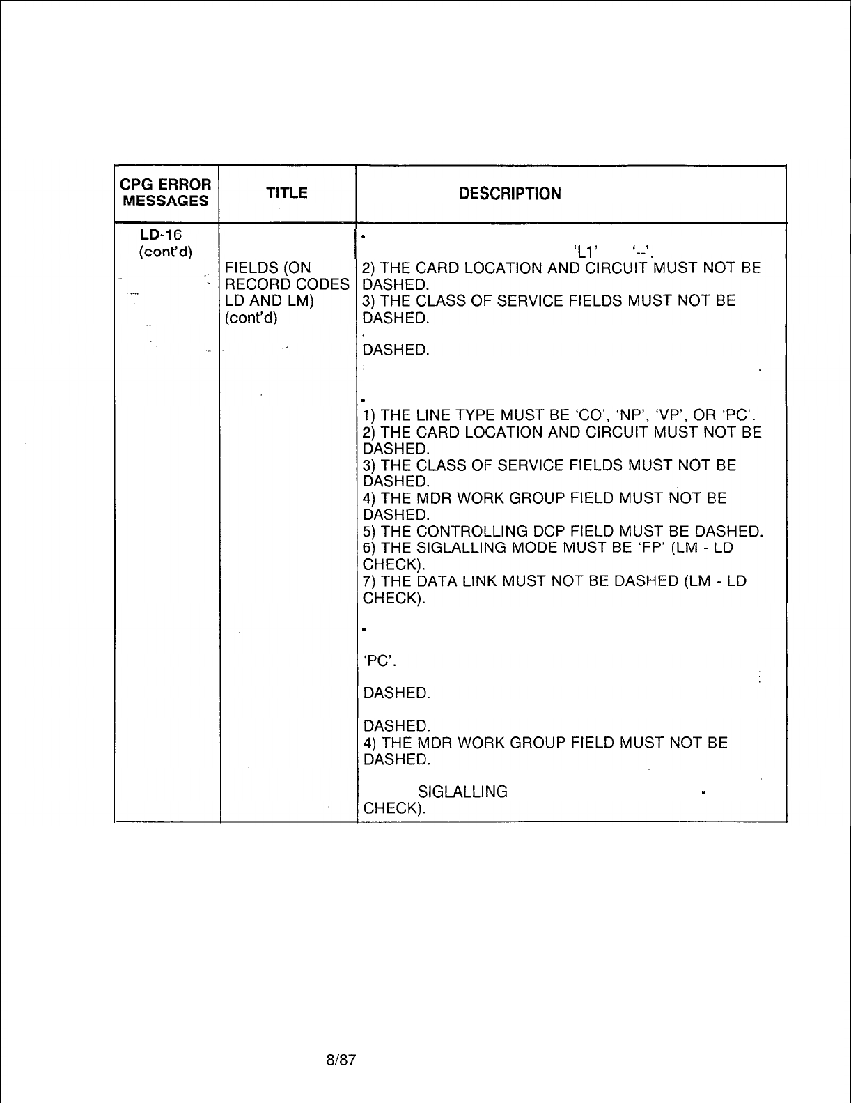
TL-130400-1001
Table 21.1 CPG Error Messages (Continued)
DESCRlPTlON
OF MESSAGES
INSTRUMENT
-
INSTRUMENT TYPE =‘PACT’:
TYPE -OTHER 1) THE LINE TYPE MUST BE
‘Ll’
OR
‘--‘.
4) THE MDR WORK GROUP FIELD MUST NOT BE
5) THE CONTROLLING DCP FIELD MUST BE DASHED.
-
INSTRUMENT TYPE = ‘AIFP’:
-
INSTRUMENT TYPE = ‘DIFP’:
1) THE LINE TYPE MUST BE ‘CO’, ‘DA’, ‘NP’, ‘VP’ OR
2) THE CARD LOCATION AND CIRCUIT MUST NOT BE
3) THE CLASS OF SERVICE FIELDS MUST NOT BE
5) THE CONTROLLING DCP FIELD MUST BE DASHED.
6) THE
SIGLALLING
MODE MUST BE ‘FP’ (LM
-
LD
SVR
5210 8187 D-475
TL-130400-1001
Table 21.1 CPG Error Messages (Continued)
CPG ERROR TITLE
INSTRUMENT
TYPE
-
OTHER
FIELDS (ON
RECORD CODES
LDAND
LM)
(cont’d)
DESCRIPTION OF MESSAGES
-
INSTRUMENT TYPE = ‘DFPA’:
1) THE LINE TYPE MUST BE ‘CO’, ‘NP’, ‘VP’ OR ‘PC’.
2) THE CARD LOCATION AND CIRCUIT MUST NOT BE
DASHED.
3) THE CLASS OF SERVICE FIELDS MUST NOT BE
DASHED.
4) THE MDR WORK GROUP FIELD MUST NOT BE
DASHED.
5) THE CONTROLLING DCP FIELD MUST BE DASHED.
6) THE
SIGLALLING
MODE MUST BE ‘FP’ (LM
-
LD
CHECK).
-
INSTRUMENT TYPE = ‘APM’:
1) THE LINE TYPE MUST BE ‘DA’.
2) THE DIRECTORY NUMBER MUST BE DASHED.
3) THE CARD LOCATION AND CIRCUIT MUST NOT BE
DASHED.
4) THE CLASS OF SERVICE FIELDS MUST BE DASHED.
5) THE MDR WORK GROUP FIELD MUST BE DASHED.
6) THE DIVERT DESTINATION IDENTIFIER MUST BE
DASHED.
7) THE FRL MUST BE DASHED.
8) THE GROUP AND INDIVIDUAL SPEED CALLING
FIELDS MUST BE DAZSHED.
9) THE REMOTE ACCESS AND AUTHORIZATION CODE
FIELD MUST BE DASHED.
10) THE CONTROLLING DCP FIELD MUST NOT BE
DASHED.
-
INSTRUMENT TYPE = ‘SPM’:
1) THE LINE TYPE MUST BE ‘DA’.
2) THE DIRECTORY NUMBER MUST BE DASHED.
3) THE CARD LOCATION AND CIRCUIT MUST NOT BE
DASHED.
4) THE CLASS OF SERVICE FIELDS MUST BE DASHED.
5) THE MDR WORK GROUP FIELD MUST BE DASHED.
6) THE DIVERT DESTINATION IDENTIFIER MUST BE
DASHED.
7) THE FRL MUST BE DASHED.
8) THE GROUP AND INDIVIDUAL SPEED CALLING
FIELDS MUST BE DAZSHED.
9) THE REMOTE ACCESS AND AUTHORIZATION CODE
FIELD MUST BE DASHED.
10) THE CONTROLLING DCP FIELD MUST NOT BE
DASHED.
D-476 8187
SVR 5210
TL-130400-1001
CPG ERROR
MESSAGES
Table 21.1 CPG Error Messages (Continued)
TITLE DESCRIPTION OF MESSAGES
LD-16
INSTRUMENT INSTRUMENT TYPE =
‘----I:
(cont’d) TYPE
-
OTHER 1) THE LINE TYPE MUST BE ‘NW’.
FIELDS (ON 2) THE CARD LOCATION AND CIRCUIT MUST NOT BE
_
RECORD CODES DASHED.
. . . .
LD AND LM) 3) THE CLASS OF SERVICE FIELDS MUST BE DASHED.
(cont’d) 4) THE MDR WORK GROUP FIELD MUST BE DASHED.
5) THE DIVERT DESTINATION IDENTIFIER MUST BE
EITHER ‘0003’ OR ‘0011’.
. .
6) THE FRL MUST BE DASHED.
7) THE GROUP AND INDIVIDUAL SPEED CALLING
FIELDS MUST BE DAZSHED.
8) THE REMOTE ACCESS AND AUTHORIZATION CODE
FIELD MUST BE DASHED.
-
LINE TYPE = ‘CO’:
1) THE INTERCOM GROUP MUST BE DASHED.
LINE TYPE
-
2) THE DIVERT DESTINATION
OTHER FIELDS
-
LINE TYPE = ‘DA’:
(ON RECORD 1) THE INTERCOM GROUP MUST BE DASHED.
CODES LD AND 2) THE PICKUP GROUP AND EXTENDED FIELDS MUST
LW
BE DASHED.
3) THE DIVERT DESTINATION IDENTIFIER MUST BE
DASHED.
4) THE GROUP AND INDIVIDUAL SPEED CALLING
FIELDS MUST BE A DASH.
-
LINE TYPE =
‘Ll’:
1) THE INTERCOM GROUP MUST BE DASHED.
2) THE PICKUP GROUP AND EXTENDED FIELDS MUST
BE DASHED.
3) THE DIVERT DESTINATION IDENTIFIER MUST BE
DASHED.
-
LINE TYPE = ‘NW’:
1) THE INTERCOM GROUP MUST BE DASHED.
2) THE PICKUP GROUP AND EXTENDED FIELDS MUST
BE DASHED.
3) THE DIVERT DESTINATION IDENTIFIER MUST NOT
BE DASHED.
-
LINE TYPE = ‘VP’:
1) THE INTERCOM GROUP MUST BE DASHED.
2) THE PICKUP GROUP AND EXTENDED FIELDS MUST
BE DASHED.
3) THE DIVERT DESTINATION IDENTIFIER MUST BE
DASHED.
4) THE MULTILINE FEATUREPHONE FIELD MUST BE
DASHED.
-
LINE TYPE =
I--‘:
1) THE INTERCOM GROUP MUST BE DASHED.
SVR 5210
8187
D-477
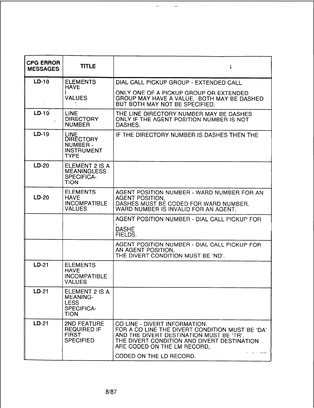
TL-130400-1001
Table 21.1 CPG Error Messages (Continued)
DESCRIPTION OF MESSAGES
PICKUP GROUP
INCOMPATIBLE
INSTRUMENT TYPE MUST BE EITHER ‘APM’ OR ‘SPM’.
AN AGENT POSITION,
S
MUST BE CODED FOR DIAL CALL PICKUP
WHILE THE DIVERT DESTINATION IDENTIFIER IS STILL
D-478 8187
SVR 5210
TL-130400-1001
Table 21.1 CPG Error Messages (Continued)
ZPG
ERROR
MESSAGES TITLE DESCRIPTION OF MESSAGES
LD-23 ELEMENT 2 IS A DATA LINK LOCATION
-
AGENT POSITION NUMBER.
MEANINGLESS IF THE AGENT POSITION IS SPECIFIED, THEN THE
SPECIFICA-
DATA LINK PEC MUST BE IN THE RANGE 0 TO 3.
‘:
TION
-LD-26
INDIVIDUAL DIVERT DESTINATION
-
INDIVIDUAL SPEED CALLING
SPEED CALLING LIST.
LIST MUST BE
SPECIFIED
IF THE DIVERT DESTINATION IS ‘SC’, THEN THE
INDIVIDUAL SPEED CALLING LIST MUST NOT CONTAIN
DASHES.
THE DIVERT DESTINATION IS CODED ON THE LM
RECORD, WHILE THE INDIVIDUAL SPEED CALLING
LIST IS STILL CODED ON THE LD RECORD.
LD-51
CARD TYPE
DEFINED ON FR
INCOMPATIBLE
WITH FCN OF
INCOMING
CARD
LD-51
CARD TYPE
DEFINED ON FR
INCOMPATIBLE
WITH INCOMING
CARD TYPE
SVR 5210
8h37
D-479
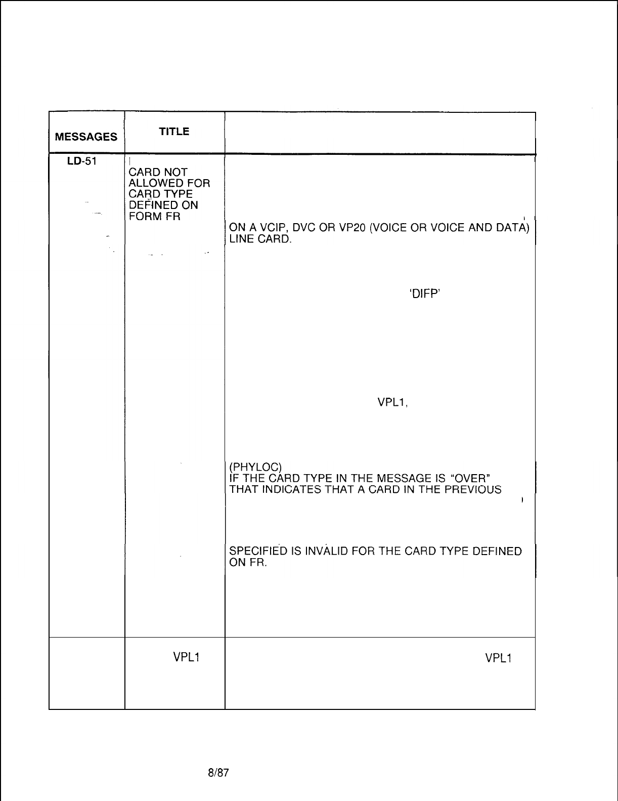
TL-130400-1001
Table 21.1 CPG Error Messages (Continued)
CPG ERROR DESCRIPTION OF MESSAGES
FUNCTION OF LINE LOCATION
THE PEC, GROUP, SLOT, AND CIRCUIT FUNCTION
SPECIFIED IS INVALID FOR THE CARD TYPE DEFINED
ON FR (FOR THIS PEC TYPE).
A LINE WITH INSTRUMENT TYPE ‘DIFP’ MUST APPEAR
A LINE WITH INSTRUMENT TYPE ‘DATD’ MUST
APPEAR ON A DVC LINE CARD.
A LINE WITH INSTRUMENT TYPE
‘DIFP’
AND LINE
TYPE OF ‘DA’ MUST APPEAR ON A DVC LINE CARD.
A LINE WITH INSTRUMENT TYPE ‘AIFP’ MUST APPEAR
ON A FP OR FPOP LINE CARD.
A LINE WITH INSTRUMENT TYPE ‘PACT’ OR ‘POTS’
MUST APPEAR ON A POTS OR OFFP LINE CARD.
A LINE WITH INSTRUMENT TYPE ‘APM’ OR ‘SPM’
MUST APPEAR ON A VPLO,
VPLl,
VP20 (VOICE AND
DATA OR DATA), OR VP21 LINE CARD.
A LINE WITH INSTRUMENT TYPE ‘DFPA’ MUST
APPEAR ON A VP20 (VOICE AND DATA) LINE CARD.
LOCATION IS A WIDE CARD AND IT OVERHANGS INTO
THIS PHYSICAL LOCATION ON FR.
LINE LOCATION
THE
PEC,
GROUP, SLOT AND CIRCUIT FUNCTION
A LINE WITH INSTRUMENT TYPE ‘DATD’ MUST
APPEAR ON A DVC LINE CARD.
A LINE WITH INSTRUMENT TYPE ‘POTS’ MUST
APPEAR ON A POTS OR OFFP LINE CARD.
LD-51
INEFFICIENT LINE LOCATION
USE OF
VPLl
INSTRUMENT TYPE ‘APM’ IS PERMITTED ON A
VPLl
CARD FOR LINE CARD,
INSTRUMENT HOWEVER IT IS A SLOW SPEED DEVICE WHICH
TYPE SPECIFIED NORMALLY IS ASSIGNED TO A VPLO LINE CARD.
(PHYLOC)
D-480
8187
SVR 5210
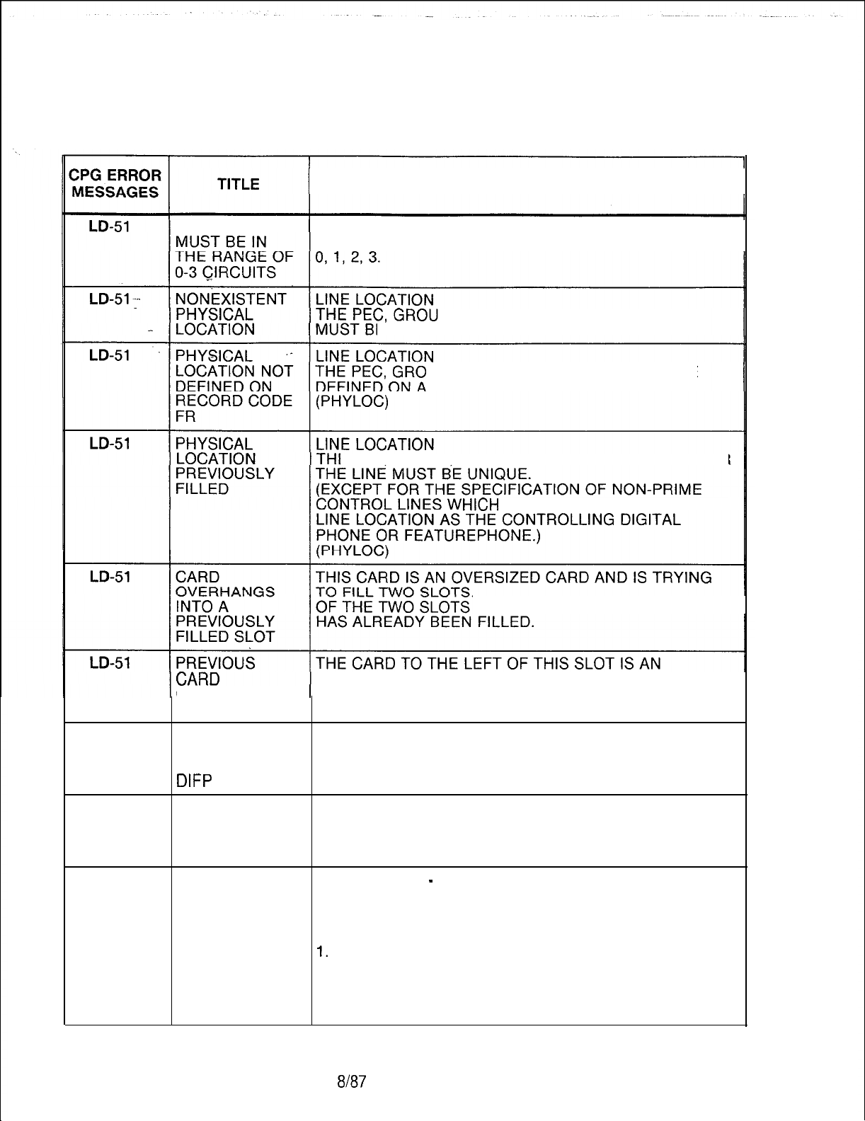
TL-130400-I 001
Table 21.1 CPG Error Messages (Continued)
DESCRIPTION OF MESSAGES
DVCIP CARD IF THE INSTRUMENT TYPE IS DATD, ON THE DVCIP
CARD, THEN THE CIRCUIT NUMBER MUST BE EITHER
P, SLOT, AND CIRCUIT SPECIFIED
E VALID FOR THIS PEC TYPE.
UP, AND SLOT SPECIFIED MUST BE
N FR RECORD.
E PEC GROUP SLOT AND CIRCUIT SPECIFIED FOR
HIGH
MUST SPECIFY THE SAME
‘IT
FILLS,
THE RIGHT HAND ONE
OVERSIZED CARD.
OVERHANGS THE RIGHT HALF OF THAT CARD FILLS THIS SLOT.
INTO THIS SLOT
LD-51
LD-51
LD-52
LINE TYPE DA IF THE INSTRUMENT TYPE IS ‘DIFP’ AND THE LINE
MUST BE ON TYPE IS ‘DA’, THEN THE CARD TYPE FOR THAT
DVC CARD FOR LOCATION MUST BE DVC.
DIFP
(PHYLOC)
CIRCUIT THE CIRCUIT NUMBER SPECIFIED DOES NOT MATCH
NUMBER TOO THE LIMITS OF THE CARD TYPE AT THE SPECIFIED
LARGE FOR PHYSICAL LOCATION.
CARD TYPE (PHYLOC)
CLASS OF SIGNAL MODE
-
CLASS OF SERVICE
SERVICE NOT IF SIGNAL MODE IS ‘NO’, THEN THE FOLLOWING
ALLOWED DISPLAYABLE CLASS OF SERVICE FEATURES WILL
NOT WORK:
1.
TOLL ACCESS 5. PAGING ACCESS
2. MEET-ME CONFERENCE 6. MAINTENANCE
ACCESS
3. PROGRESSIVE CONF. 7. MODEM ACCESS
4. DICTATION EQUIPMENT 8. MERS ON-NET
SVR 5210
8187
D-481
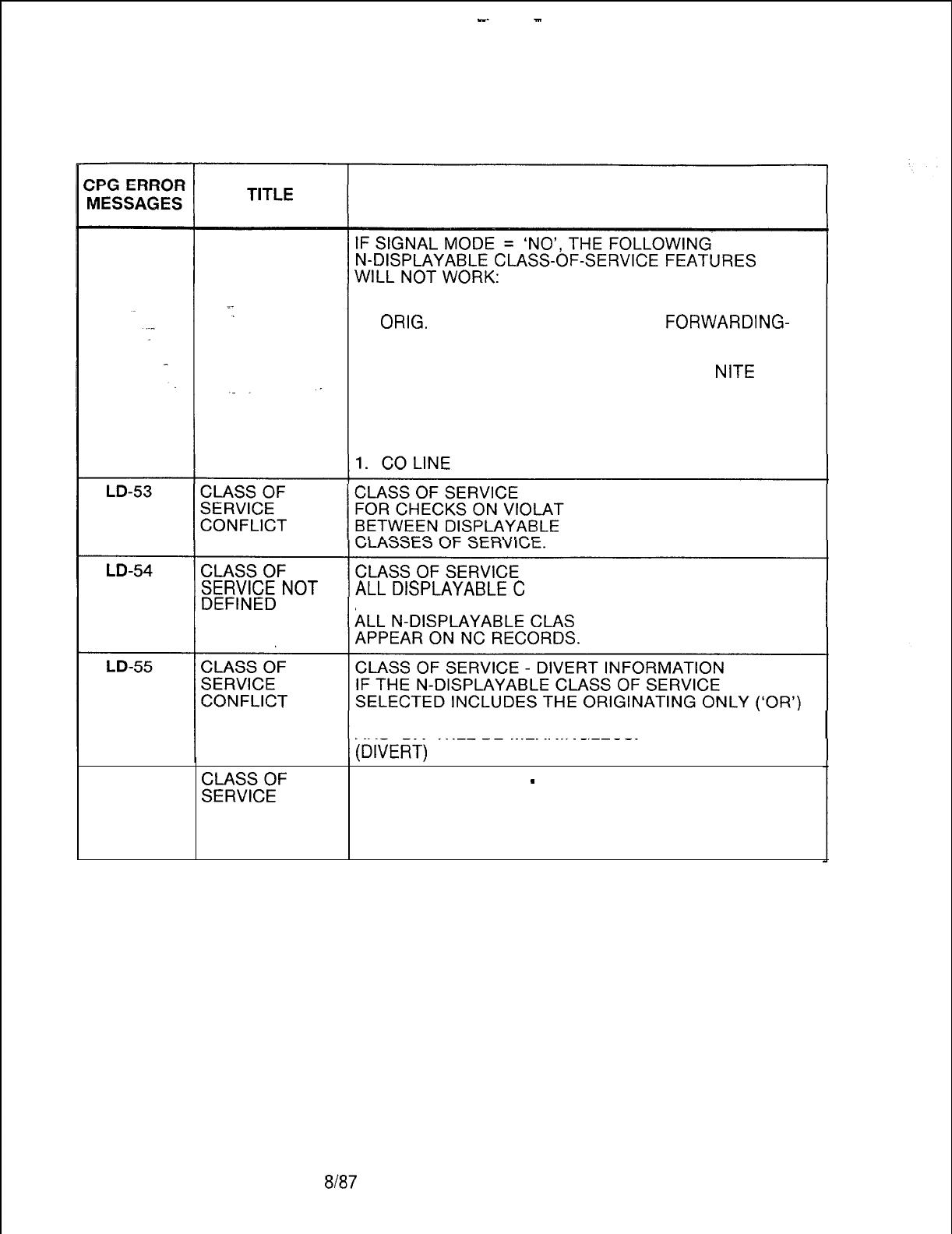
-.
-
TL-130400-1001
Table 21.1 CPG Error Messages (Continued)
DESCRIPTION OF MESSAGES
1. EXECUTIVE OVERRIDE 5. DIAL CALL PICKUP
2.
ORIG.
CALL WAITING 6. CALL
FORWARDING-
VAR
3. CAMP-ON/AUTO RECALL 7. SPEED CALLING
4. ATT. INFO CALLS 8. UNIVERSAL
NITE
ANS.
IF THE SIGNAL MODE IS SOMETHING OTHER THAN
‘FP’ THEN THE FOLLOWING DISPLAYABLE CLASS OF
SERVICE FEATURE WILL NOT WORK:
IONS AND REQUIREMENTS
AND N-DISPLAYABLE
LASSES OF SERVICE MUST
APPEAR ON DD RECORDS.SES OF SERVICE MUST
FEATURE, THE DIVERT CONDITIONS ‘BY’, ‘NA’, ‘BN’,
AND ‘DA’ WILL BE MEANINGLESS.
LD-57
::%:F
CLASS OF SERVICE
-
DIVERT INFORMATION
FOR LINES WHICH DO NOT DIVERT (BUT WHICH ARE
CONFLICT IF IN A HUNT GROUP) THE DISPLAYABLE CLASS OF
HUNT GROUP SERVICE MUST NOT INCLUDE SWITCH DIRECT LINE
(‘SL’) OR CO LINE (‘CL’).
D-482 8187
SVR 5210
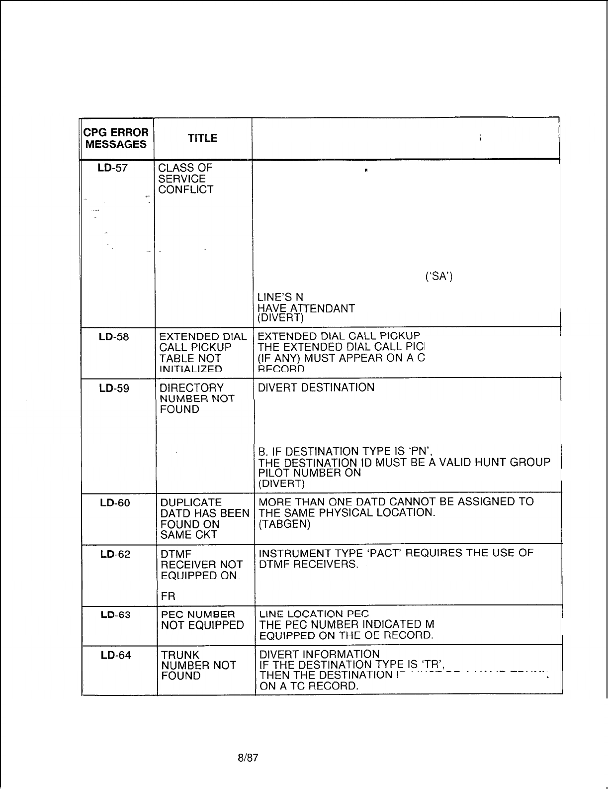
TL-130400-1001
Table 21.1 CPG Error Messages (Continued)
DESCRIPTION OF MESSAGES
CLASS OF SERVICE
-
DIVERT INFORMATION
FOR LINES WHOSE DISPLAYABLE CLASS OF SERVICE
INCLUDES SWITCHED DIRECT LINE (‘SL’),
THE DIVERT DESTINATION SPECIFIED MUST BE A
LINE (‘LN’), AN ATTENDANT (‘AT’), A RECORDED
ANNOUNCEMENT (‘TR’), OR A TONE (‘TO’). A HUNT
GROUP PILOT NUMBER (‘PN’) IS PERMISSIBLE ONLY
IF THE HUNT GROUP SPECIFIED DOES NOT HAVE
CAMP-ON. IF A LINE’S DIVERT CONDITION IS ‘LN’
THEN THAT LINE’S DISPLAYABLE CLASS OF SERVICE
MUST HAVE STATION ACCESS
(ISA’)
SPECIFIED.
IF A LINE’S DIVERT CONDITION IS ‘AT’ THEN THAT
-DISPLAYABLE CLASS OF SERVICE MUST
TENDANT
INFORMATION (‘Al’) SPECIFIED.
KUP TABLE SPECIFIED
ORRESPONDING ED
A. IF DESTINATION TYPE IS ‘LN’,
THE DESTINATION ID MUST BE A VALID STATION
NUMBER OR AN LD RECORD.
AN HG RECORD.
RECORDCODE
UST BE MARKED
ID
MUST
BE
A VALID TRUNK
SVR 5210
8h37
D-483
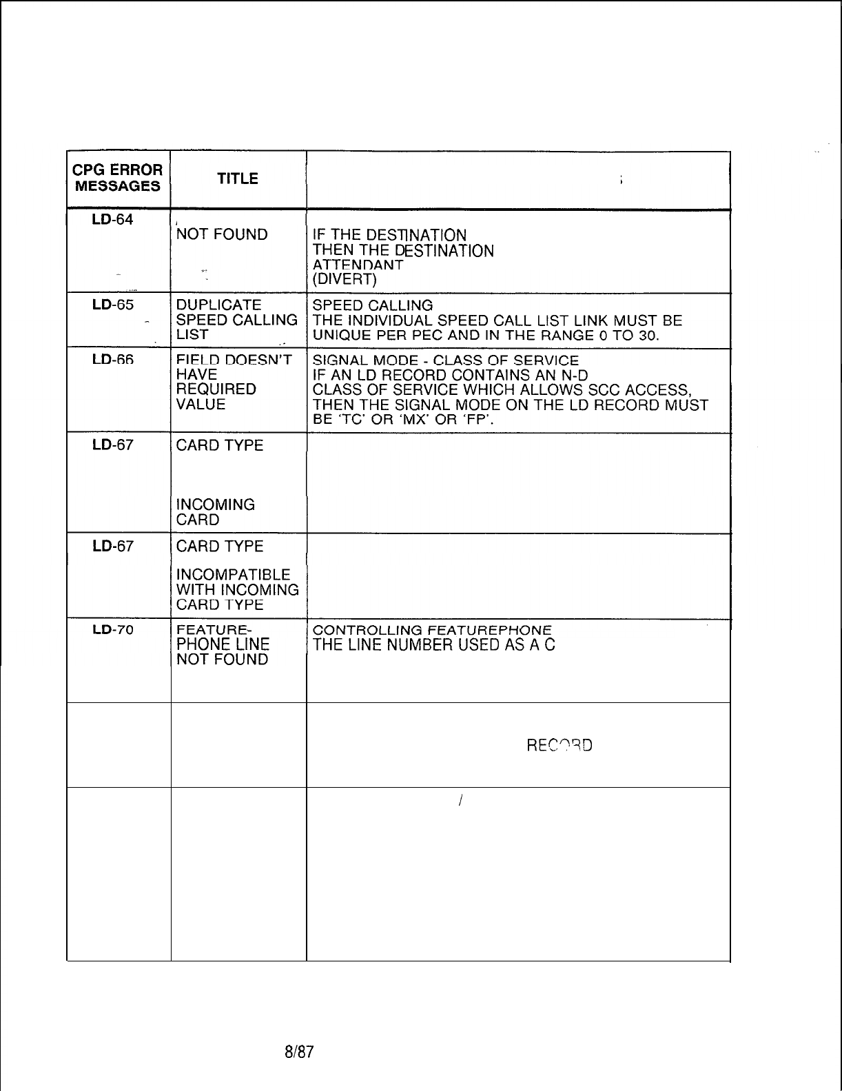
TL-130400-1001
Table 21.1 CPG Error Messages (Continued)
DESCRIPTION OF MESSAGES
ATTENDANT DIVERT INFORMATION
INATION
TYPE IS ‘AT’,
ESTINATION
ID MUST BE A VALID
OR ATTENDANTS ON AT RECORDS.
ISPLAYABLE
DEFINED ON FR
INCOMPATIBLE
WITH FCN OF
DEFINED ON
FR
ONTROLLING
FEATUREPHONE MUST BE ENGINEERED AS A LINE
ON AN LD RECORD.
(TABGEN)
LD-71
LINE CARD NOT LINE LOCATION
FOUND THE LINE CARD BEING ASSIGNED MUST BE
SPECIFIED ON AN FR OR LR
REC??D
(DEPENDENT ON THE SVR).
(GENLIN)
LD-72
CANNOT INSTRUMENT TYPE
/
LINE TYPE
ASSIGN LINE ID THERE MUST BE SPACE AVAILABLE IN THE SYSTEM
TABLES TO ASSIGN A LINE SOFTWARE ID IN THE
GIVEN PEC FOR ANY ‘BDML’, ‘DDML’, ‘DTML’, OR
‘FPML’ LINE CONTROLLED BY ANOTHER DIGITAL
PHONE OR FEATUREPHONE OR ANY LINES WITH A
LINE TYPE OF ‘NP’ OR ‘CO’.
A MAXIMUM OF 256 LINES OF ALL KINDS IS ALLOWED
PER PEC.
(GENLIN)
D-484
8187
SVR 5210
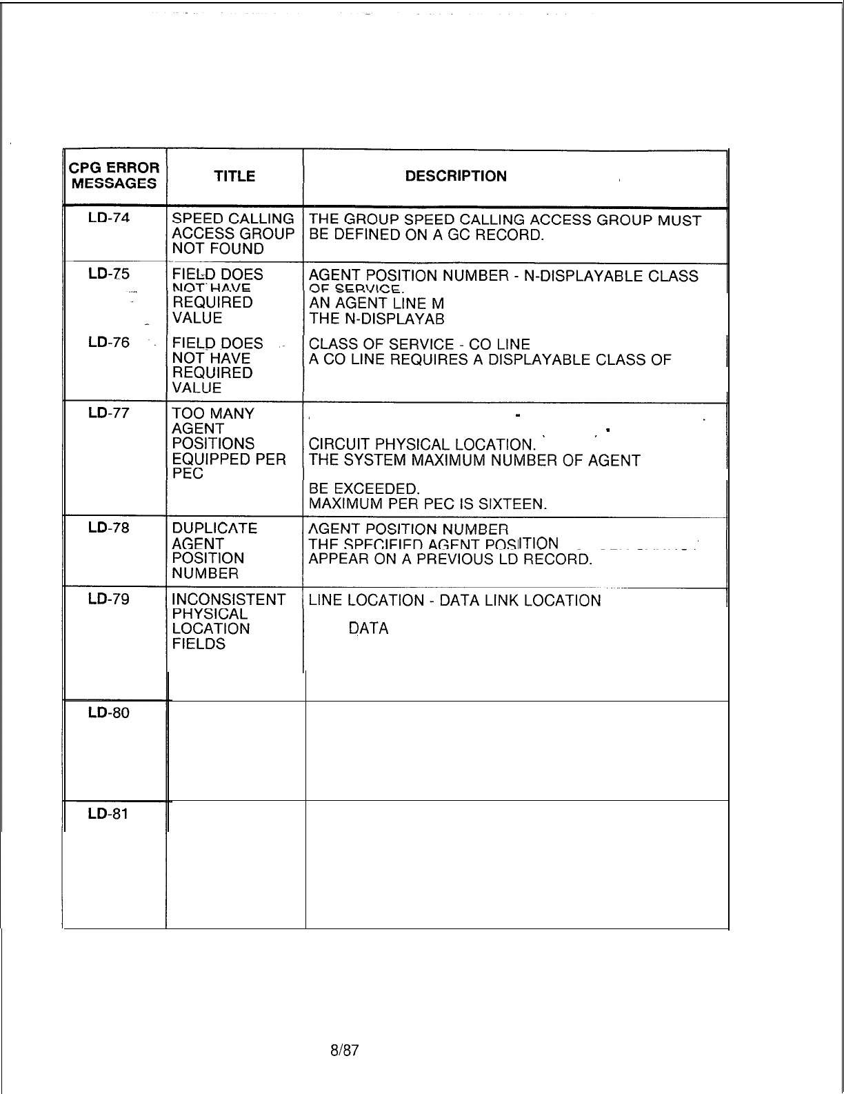
TL-130400-1001
Table 21.1
CPG
Error Messages (Continued)
DESCRlPTlON
OF MESSAGES
UST HAVE HOOKSWITCH FLASH IN
LE CLASS OF SERVICE.
SERVICE WITH SWITCHED DIRECT LINE AND CO LINE.
AGENT POSITION NUMBER
-
LINE CIRCUIT PHYSICAL
LOCATION INSTRUMENT TYPE (‘PACT’)
-
LINE
POSITIONS OR AGENT PACETS
PER
PEC MUST NOT
ITION
NUMBER CANNOT
THE PHYSICAL LOCATION FIELDS (BOTH LINE CIRCUIT
AND
DATA
LINK) FOR A FEATUREPHONE NON-PRIME
CONTROL LINE MUST MATCH THE PHYSICAL
LOCATION FIELDS OF THE CONTROLLING
FEATUREPHONE.
(FPCHKS)
CONTROLLING CONTROLLING FEATUREPHONE
FEATURE- A LINE DIRECTORY NUMBER USED IN A
PHONE MUST CONTROLLING FEATUREPHONE FIELD MUST BE
BE MULTILINE ENGINEERED AS A MULTILINE FEATUREPHONE OR
DIGITAL PHONE ON AN LD RECORD.
(TABGEN)
INVALID LINE LOCATION
FEATURE- A FEATUREPHONE OR DIGITAL PHONE MAY NOT BE
PHONE ASSIGNED TO CIRCUIT 7 OF A LINE CARD
PHYSICAL ENGINEERED AS RELATIVE LINE CARD NUMBER 31 IN
LOCATION A PEC ON AN FR RECORD.
REARRANGE CARD ASSIGNMENTS TO PLACE OTHER
TYPES OF LINES IN THIS LOCATION.
(GENLIN)
SVR 5210
8187
D-485
TL-130400-1001
Table 21.1 CPG Error Messages (Continued)
ZPG
ERROR
MESSAGES
LD-82
. . .
LD-83
-
LD-84
LD-87
LD-88
LD-89
LD-89
D-486
TITLE
PHYSICAL
LOCATION
DEFINED ON LD
IS MISSING ON
NAMED
RECORD CODE
CLASS OF
SERVICE NOT
ALLOWED
‘-
TRUNKS
DIVERTED TO
BY CO LINE
MUST HAVE
SUPY OTG =
so
A LINE CANNOT
DIVERT TO
ITSELF
CONTROLLING
DCP NUMBER
NOT DEFINED
ON RECORD
CODE FR
PC LINE TYPE
MISSING OR
EXTRA FOR
FEATURE-
PHONE
FEATURE-
PHONE
ENGINEERING
LIMITS
EXCEEDED
FRL MUST BE
SPECIFIED
INCONSISTENT
ENGINEERING
OF FRLS
DESCRIPTION OF MESSAGES
INSTRUMENT TYPE
IF THE INSTRUMENT TYPE ON AN LD RECORD IS A
DATA DEVICE (‘ARM’, ‘SPM’, OR ‘DFPA’), THE
APPROPRIATE CP AND AP, AQ OR XP RECORDS MUST
BE INPUT FOR THE SAME PORT.
(ENDCHK)
A FEATUREPHONE NON-PRIME CONTROL LINE MAY
NOT HAVE STATION SILENT MONITOR ACCESS.
A TC RECORD MUST SPECIFY SUPERVISORY
OUTGOING SIGNAL OF ‘SO’ FOR A TRUNK DIVERTED
TO BY A CO LINE.
(DIVERT)
THE DIVERT DESTINATION OF A LINE CANNOT BE
ITSELF.
(DIVERT)
DCP NUMBER
THE DCP NUMBER REFERENCED IN THE LD RECORD
MUST BE DEFINED ON AN FR RECORD.
EVERY FEATUREPHONE MUST HAVE ONE AND ONLY
ONE PRIME CONTROL LINE.
(FPCHKS)
THE LIMITS PER CARD OR PER PEC HAVE BEEN
EXCEEDED.
(FPCHKS)
FRLS HAVE BEEN EQUIPPED FOR THIS SYSTEM ON
RECORD CODE OF AND MUST THEREFORE BE
SPECIFIED FOR EVERY LINE ON RECORD CODE LD.
FRLS HAVE BEEN SPECIFIED FOR SOME PARTS OF
THE SYSTEM AND NOT OTHERS.
ENSURE THAT ALL ATTENDANTS, LINES, TRUNK
GROUPS, MERS ROUTES, ETC. HAVE FRLS ENTIRELY
ENABLED OR DISABLED.
8187
SVR 5210
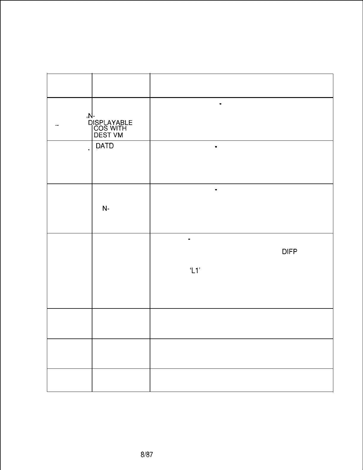
TL-130400-1001
CPG ERROR
MESSAGES
Table 21.1 CPG Error Messages (Continued)
TITLE DESCRIPTION OF MESSAGES
LD-91
NO ACCESS TO CLASS OF SERVICE
-
DIVERT INFORMATION
VMS IN THE VMS ACCESS FIELD, ‘VM’, SHOULD BE SPECIFIED
.i_
I&PLAYABLE
ON NC RECORD IF A LINE HAS A DIVERT
DESTINATION ‘VM’.
..”
;;zTW;;H
DIVT. (DIVERT)
LD.-92
_
DATD
. INSTRUMENT TYPE
-
CLASS OF SERVICE
REQUIRES INSTRUMENT TYPE DATD REQUIRES THAT THE
STATION DISPLAYABLE CLASS OF SERVICE SPECIFIES STATION
ACCESS IN ACCESS AS YES.
DISPLAYABLE
cos
LD-93 DATD INSTRUMENT TYPE
-
CLASS OF SERVICE
REQUIRES DATA
LINE SECURITY INSTRUMENT TYPE DATD REQUIRES THAT THE
IN
N-
N-DISPLAYABLE CLASS OF SERVICE SPECIFIES DATA
DISPLAYABLE LINE SECURITY AS YES.
CLASS OF
SERVICE
LD-93 FIELD DOESN’T LINE TYPE
-
CLASS OF SERVICE
HAVE
REQUIRED LINE TYPE DA WITH INSTRUMENT TYPE
DIFP
VALUE REQUIRES THAT THE N-DISPLAYABLE CLASS OF
SERVICE SPECIFIES DATA LINE SECURITY AS YES.
LINE TYPE
‘Ll’
REQUIRES THAT THE N-DISPLAYABLE
CLASS OF SERVICE SPECIFIES HOOKSWITCH FLASH
AS YES.
LINE TYPE ‘VP’ REQUIRES THAT THE N-DISPLAYABLE
CLASS OF SERVICE SPECIFIES ORIGINATING ONLY,
TERMINATING ONLY AND CALL PARK.
LD-94 NO. OF PORTS NUMBER OF PORTS PER CONTROLLING DCP ARE
EXCEEDED FOR LIMITED TO 240. ANY CONTROLLING DCP CAN
THIS DCP HANDLE UP TO 240 ENTRIES OF LD RECORDS.
(ADMPCK)
LI-52
DUPLICATE THE LINE DIRECTORY NUMBER MUST BE UNIQUE
LOGICAL LINE ACROSS ALL LI RECORDS.
DIRECTORY
NUMBER
LI-54 DUPLICATE THE SOFTWARE ID CANNOT BE DUPLICATED ACROSS
LOGICAL LINE THE LI RECORDS.
SOFTWARE ID
SVR 5210
8187
D-487
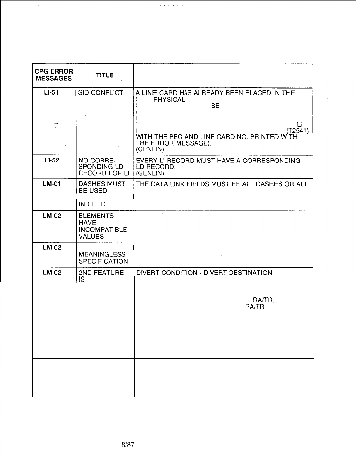
TL-130400-1001
Table 21.1 CPG Error Messages (Continued)
DESCRIPTION OF MESSAGES
SAID
PHt!!CAL
LOCATION THE LOGICAL LINE
SOFTWARE ID CANNOT
Bi
PRESERVED.
(NOTE: THE SOFTWARE ID OF A LINE NUMBER ON
LD RECORD CODE WHICH IS NOT A LOGICAL LINE, IS
THE SAME AS THAT GIVEN TO A LOGICAL LINE ON
Ll
RECORD. CHECK LINE CARD ADDRESS TABLE
(T2541)
FIELDS MUST BE SPECIFIED.
CONSISTENTLY
ELEMENT 2
IS
LM-51
VALUE OF ALLOWABLE VALUE
OF
MEANINGLESS DIVERT CONDITION DIVERT DESTINATION
SPECIFICATION ND --, TO, LN, AT,
RA/TR,
RM, PN
BY, NA, BN, OR DA TO, LN, AT,
RA/TR,
RM, PN
CARD TYPE
DEFINED ON FR
INCOMPATIBLE
WITH FCN OF
INCOMING
CARD
LM-51
CARD TYPE
DEFINED ON FR
INCOMPATIBLE
WITH INCOMING
CARD TYPE
D-488 8187
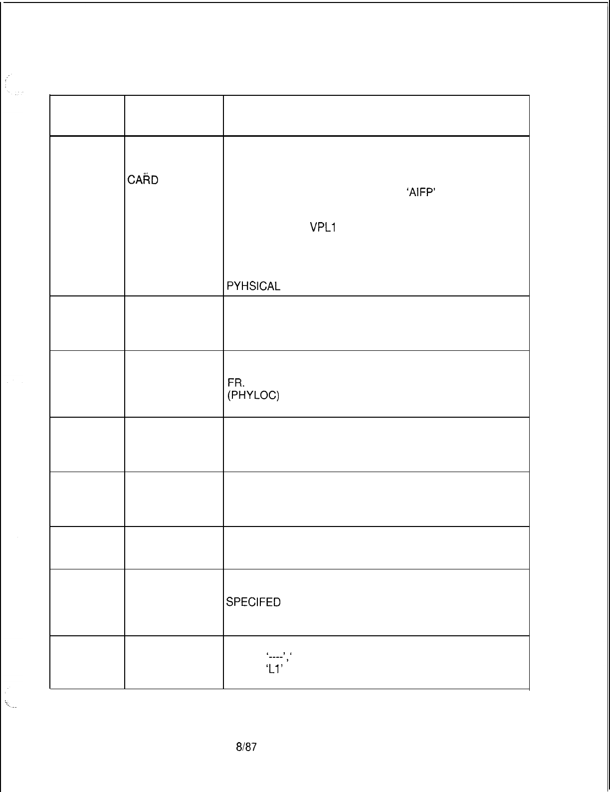
TL-130400-1001
CPG ERROR
MESSAGES
Table 21.1 CPG Error Messages (Continued)
TITLE DESCRIPTION OF MESSAGES
LM-51
. . . .
FUNCTION OF DATA LINK LOCATION
CARD NOT THE PEC, GROUP, SLOT, AND CIRCUIT FUNCTION
ALLOWED FOR
CAiiD
TYPE SPECIFIED IS INVALID FOR THE CARD TYPE DEFINED
DEFINED ON FR ON FR (FOR THIS PEC TYPE).
A LINE WITH INSTRUMENT TYPE
‘AIFP’
MUST APPEAR
ON A CIP DATA LINK CARD.
A LINE WITH INSTRUMENT TYPE ‘DIFP’ MUST APPEAR
. .
ON A VLPO OR
VPLl
DATA LINK CARD.
(PHYLOC)
IF THE CARD TYPE IN THE MESSAGE IS “OVER”, THAT
INDICATES THAT A CARD IN THE PREVIOUS LOCATION
IS A WIDE CARD AND IT OVERHANGS INTO THIS
PYHSICAL
LOCATION ON FR.
LM-51
NONEXISTENT DATA LINK LOCATION
PHYSICAL THE PEC, GROUP, SLOT, AND CIRCUIT FUNCTION
LOCATION SPECIFIED MUST BE VALID FOR THIS PEC TYPE.
(PHYLOC)
LM-51
PHYSICAL DATA LINK LOCATION
LOCATION NOT THE PEC, GROUP, AND SLOT MUST BE DEFINED ON
DEFINED ON
RECORD CODE
;YLOC)
FR
LM-51
PHYSICAL
LOCATION
PREVIOUSLY
FILLED
DATA LINK LOCATION
THE DATA LINK LOCATION MUST BE UNIQUE.
(PHYLOC)
LM-51
LM-52
CIRCUIT THE SPECIFIED CIRCUIT NUMBER IS NOT VALID FOR
NUMBER TOO THE TYPE OF CARD IN THE GIVEN PHYSICAL
LARGE FOR LOCATION.
CARD TYPE (PHYLOC)
PEC NUMBER IS DATA LINK LOCATION
NOT EQUIPPED THE PEC NUMBER INDICATED MUST BE MARKED AS
EQUIPPED ON THE OE RECORD.
LM-53 MAX THE MAX PRECEDENCE LEVEL FIELD MAY CONTAIN
PRECEDENCE VALUES OTHER THAN DASH ONLY IF AUTOVON IS
LEVEL APPLIES
SPECIFED
ON THE OF RECORD.
TO AUTOVON
ONLY
LM-54
INVALID LM RECORDS ARE NOT VALID FOR INSTRUMENT
RECORD CODE TYPES
‘----‘,I
APM’, AND ‘SPM’ AND THE LINE
TYPES
‘Ll’
AND ‘DA’.
(SPECIFIED ON AN LD RECORD)
SVR 5210
8187
D-489
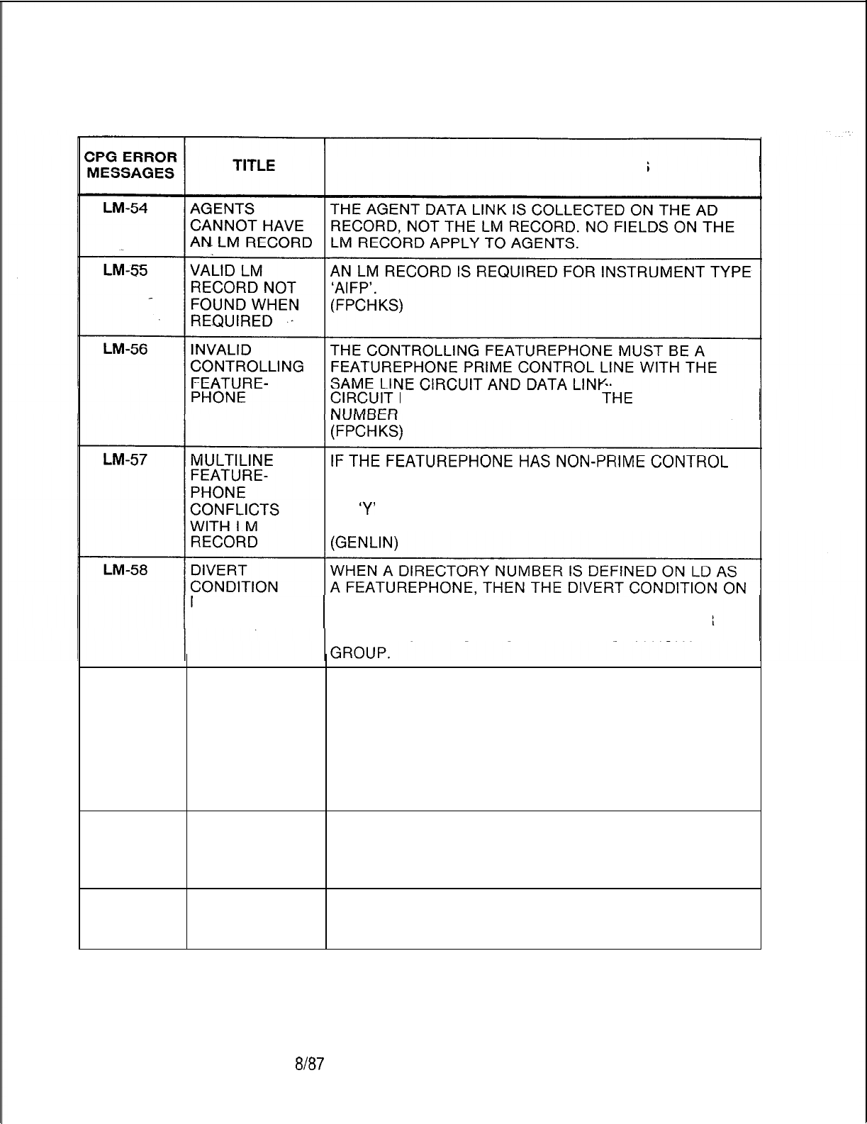
TL-130400-1001
Table 21.1 CPG Error Messages (Continued)
DESCRIPTION OF MESSAGES
PHYSICAL LOCATIONS AS
THE
DIRECTORY
ON THE LM RECORD BEING CONTROLLED.
OR CO LINES ON RECORD CODE LD, THE MULTILINE
FEATUREPHONE FIELD ON RECORD CODE LM MUST
BE
‘Y’
IF AN LM RECORD IS PROVIDED FOR THE
FEATUREPHONE PRIME CONTROL LINE.
MUST BE ND
LM
MUST BE ENTERED AS AN ‘ND’ (NO DIVERT)
EXCEPT WHEN THE LINE TYPE IS ‘CO’ (ON LD) OR
THE FEATUREPHONE IS A MEMBER OF A HUNT
Lrvl-59
DATA LINK OF A FEATUREPHONE’S OR DIGITAL FEATUREPHONE’S
127 NOT CONTROLLER MAY NOT BE ASSIGNED TO CIRCUIT 7
ALLOWED OF A CONTROLLING CARD (CIP) ENGINEERED AS
RELATIVE CONTROLLING CARD NUMBER 15 ON AN FR
RECORD, SINCE THIS WILL RESULT IN A DATA LINK
NUMBER OF 127.
THE VALID RANGE FOR DATA LINK NUMBERS IS 0 TO
126.
MD-01
ELEMENTS
HAVE
INCOMPATIBLE
VALUES
MD-01
ELEMENT 2 IS
MEANINGLESS
SPECIFICATION
D-490
8187
SVR 5210

.
.
ZPG
ERROR
MESSAGES
MD-01
>-
. . .
MH-51
MH-52
MH-53
MH-54
MH-55
MH-56
MH-57
MH-59
Table 21.1
TITLE
2ND FEATURE
REQUIRED IF
FIRST
SPECIFIED
INVALID PILOT
-NUMBER
SPECIFICATION
INVALID
SEQUENCE
NUMBER
DIRECTORY
NUMBER
ERROR
MEMBER
ALREADY IN
ANOTHER HUNT
GROUP
AGENT POS.
NOT ALLOWED
IN HUNT GROUP
PhEVlOUS
DIVERT DATA
IGNORED
CLASS OF
SERVICE NOT
ALLOWED
FIXED CALL
FORWARDING
-
FEATURE-
PHONES
-
HUNT GROUPS
TL-130400-1001
CPG Error Messages (Continued)
DESCRIPTION OF MESSAGES
MDR PORT 1
THE TERMINAL AND MDR PORT 1 FIELDS CANNOT
BOTH BE ‘Y’.
THE HUNT GROUP PILOT NUMBER MUST HAVE BEEN
DEFINED ON AN HG RECORD.
(GENLIN)
THE SEQUENCE NUMBERS WITHIN A HUNT GROUP
MUST START WITH ZERO AND BE IN ASCENDING
ORDER WITH NO GAPS.
(GENLIN)
THE DIRECTORY NUMBER MUST BE A VALID LINE
NUMBER.
(GENLIN)
A DIRECTORY NUMBER MAY BE IN ONLY ONE HUNT
GROUP.
(GENLIN)
A HUNT GROUP MEMBER MUST NOT BE AN AGENT
POSITION.
(GENLIN)
DIVERT DATA PREVIOUSLY SPECIFIED FOR THIS LINE
HAS BEEN OVERRIDDEN AND REPLACED BY A DIVERT
TO THE NEXT HUNT GROUP MEMBER.
(GENLIN)
LINES MARKED WITH SWITCH DIRECT LINE OR
ORIGINATING ONLY SHOULD NOT BE A MEMBER OF A
HUNT GROUP:
(GENLIN)
A FEATUREPHONE EQUIPPED WITH FIXED CALL
FORWARDING ON A LINE SHOULD BE THE LAST
MEMBER OF A TERMINAL HUNT GROUP.
(FPCHKS)
SVR 5210
8h37
D-491
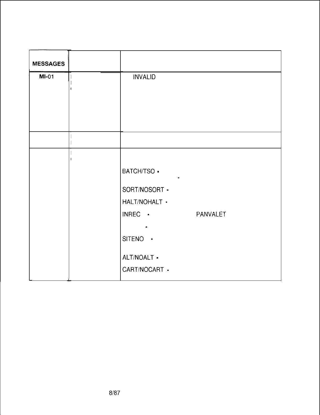
TL-130400-1001
Table 21.1
CPG ERROR
MI-01
MI-02
D-492
L
TITLE
INVALID
MONITOR MODE
COMMAND
END OF FILE
DETECTED
INVALID OPTION
COMMAND
8187
CPG Error Messages (Continued)
DESCRIPTION OF MESSAGES
AN
iNVALID
MONITOR MODE COMMAND HAS BEEN
SPECIFIED.
ONLY THE FOLLOWING MONITOR COMMANDS ARE
AVAILABLE:
OPTIONS
RUN
SAVE
PRINT
END
CPG WILL PRODUCE THIS ERROR MESSAGE IF NO
‘END’ MONITOR COMMAND IS ENTERED.
AN INVALID OPTION COMMAND HAS BEEN SPECIFIED.
THE FOLLOWING OPTIONS ARE AVAILABLE
(DEPENDING UPON SVR):
BATCH/TSO
-
MODE TO BE RUN UNDER.
TABLES/NOTABLES
-
SPECIFIES WHETHER THE
TABLE LISTING SHOULD BE PRINTED.
SORT/NOSORT
-
SORT THE INPUT FILE ON
RETRIEVAL FROM PANVALET.
HALTINOHALT
-
CONTROLS USER INTERACTION
DURING A FORWARD PROCESS.
INREC
=
-
SPECIFIES THE
PANVALET
SOURCE FOR
THE INPUT RECORD FILE.
TITLE =
-
SPECIFIES THE TITLE FOR THE OFFICE
RECORD LISTINGS.
SITENO
=
-
SPECIFIES THE SITE DRAWING NUMBER
FOR THE
OFFICE RECORD LISTINGS.
ALTINOALT
-
CONTROLS GENERATION OF ALL
ALTERNATE SORT LISTING.
CART/NOCART
-
CONTROLS WHETHER INPUT
RECORDS OR A DATA BASE ARE INPUT TO THE CPG.
SVR 5210
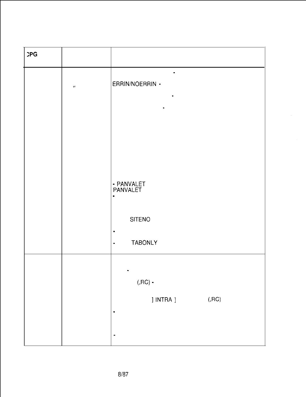
TL-130400-1001
Table 21.1 CPG Error Messages (Continued)
ZPG
ERROR
MESSAGES TITLE DESCRIPTION OF MESSAGES
MI-02
INVALID OPTION TABONLY/NOTABONLY
-
CONTROLS WHETHER OR
(cont’d)
COMMAND NOT BLANK TABLES SHOULD BE PRINTED.
ERRIN/NOERRIN
-
CONTROLS PLACEMENT OF
%-
ERROR MESSAGES IN THE MIRROR REPORT LISTING.
. . .
FULLTAB/NOFULLTAB
-
PRODUCES PARTIAL TABLE
OUTPUT FOR IMPLEMENTED PECS AND LINES ONLY.
PROTO/NOPROTO
-
PRODUCES ODDB LOAD MODULE
. .
IN FORMAT SUITABLE FOR DOWNLOADING TO THE
DECPROTOTYPE
UTILITY SYSTEM OR THE IBM-PC.
THE DEFAULT MODE IS BATCH.
THE DEFAULT BATCH OPTIONS ARE:
TABLES,NOHALT,SORT,ALT,NOCART,NOTABONLY,ERR
IN, NOFULLTAB,NOPROTO
THE DEFAULT TSO OPTIONS ARE:
NOTABLES,HALT,SORT,NOALT,NOCART,NOTABONLY,E
RRIN,
NOFULLTAB,NOPROTO
RESTRICTIONS :
-
PANVALET
FILE NAMES MUST FOLLOW ALL
PANVALET
NAMING CONVENTIONS.
-
THE HALT OPTION CANNOT BE SPECIFIED IN
BATCH MODE.
THE TITLE CANNOT EXCEED 50 ALPHANUMERIC
CHA RACTERS.
THE
SITENO
CANNOT
CHARA CTERS. EXCEED 6 NUMERIC
-
THE CART OPTION CANNOT BE SPECIFIED WITH
ANY OTHER OPTIONS.
-
THE
TABONLY
OPTION CANNOT BE SPECIFIED
WITH ANY OTHER OPTIONS.
MI-03
INVALID RUN AN INVALID RUN COMMAND HAS BEEN SPECIFIED.
COMMAND THE FOLLOWING COMMANDS ARE AVAILABLE:
RUN
-
RUN A FORWARD PROCESS ON THE ENTIRE
INPUT RECORD FILE.
RUN RC
(,RC)
-
RUN A FORWARD PROCESS ON THE
SELECTED RECORD CODES WHERE ‘RC’ IS THE
RECORD CODE MNEMONIC.
RUN (SYNTAX
]
INTRA
]
INTER) RC
(,RC)
RESTRICTIONS:
-
ALL RECORD CODES SPECIFIED MUST CONTAIN AT
LEAST ONE RECORD.
INTER CHECKS MUST BE SPECIFIED IF TABLES ARE
GENERATED.
-
INTER CHECKS MUST BE SPECIFIED IF ALTERNATE
SORTS ARE GENERATED.
SVR 5210
8187
D-493
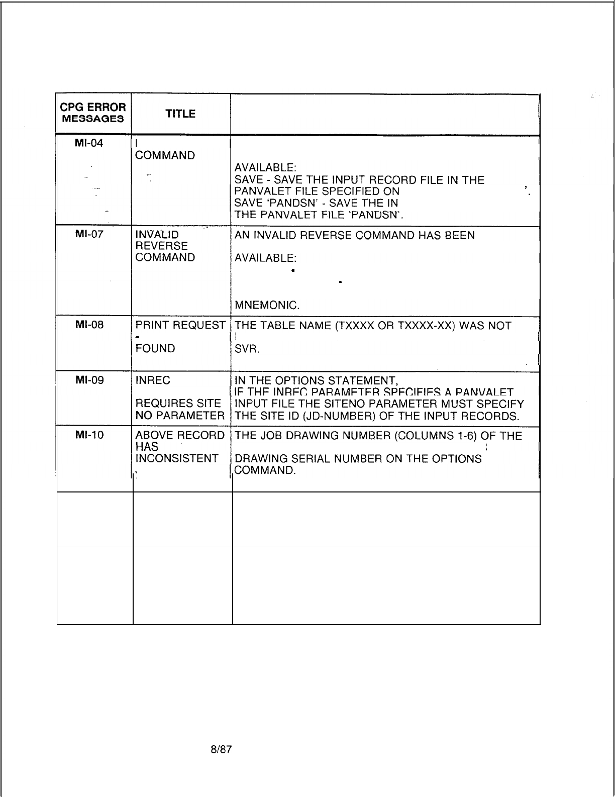
TL-130400-1001
Table 21.1 CPG Error Messages (Continued)
DESCRIPTION OF MESSAGES
INVALID SAVE AN INVALID SAVE COMMAND HAS BEEN SPECIFIED.
THE FOLLOWING COMMAND FORMATS ARE
THE OPTION ‘INREC =
‘.
PUT RECORD FILE IN
SPECIFIED. THE FOLLOWING COMMANDS ARE
REVERSE
-
REVERSE THE ENTIRE INPUT DATA BASE
REVERSE RC (RC)
-
REVERSE ONLY THE SELECTED
RECORD CODES WHERE ‘RC’ IS THE RECORD CODE
-
TABLE NOT FOUND IN THE
CPG
LIST OF VALID TABLES FOR THE
THE PRINT REQUEST FOR THE TABLE WAS IGNORED.
PARAMETER
ABOVE RECORD
IS
DIFFERENT THAN THE JOB
JOB ID. IT HAS
BEEN DELETED
Ml-l 1
ERROR IN SORT A SYSTEM ERROR OCCURRED WHEN TRYING TO
OF INPUT SORT THE INPUT RECORD FILE.
RECORD FILE CHECK LISTING FOR ANY JCL ERRORS.
BRING LISTING TO CPG SUPPORT GROUP.
Ml-l 2 DATA NOT TO PERFORM ALL INTER CHECKS AND TO GENERATE
SORTED, INTER TABLES, THE INPUT RECORDS MUST BE IN
CHECKS AND ASCENDING ORDER.
TABLE IF TABLES ARE TO BE GENERATED, CODE THE SORT
GENERATION OPTION ON THE OPTIONS COMMAND.
NOT COMPLETE
D-494
8187
SVR 5210
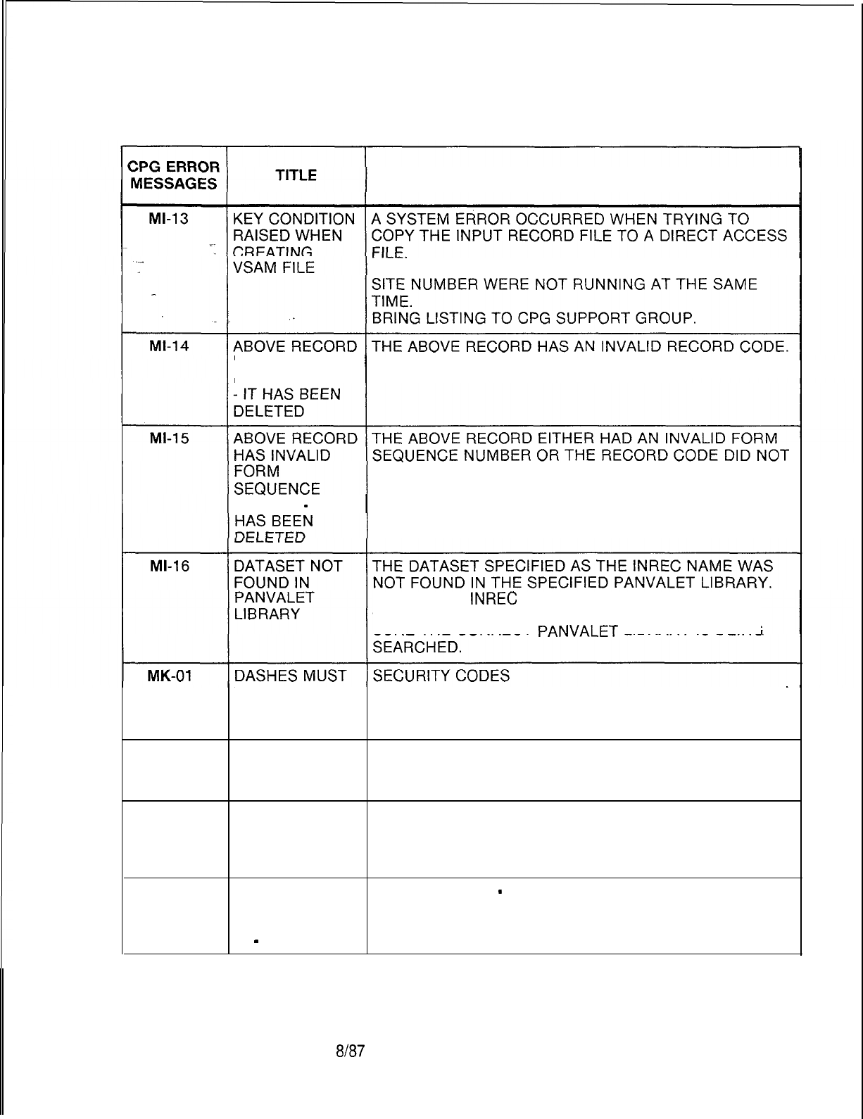
TL-130400-1001
Table 21.1 CPG Error Messages (Continued)
DESCRIPTION OF MESSAGES
CHECK TO MAKE SURE TWO JOBS WITH THE SAME
HAS INVALID IT WILL NOT BE CHECKED FOR ERRORS.
RECORDCODE
CORRESPOND TO THE FORM SEQUENCE NUMBER.
NUMBER
-
IT
CHECK THE
INREC
NAME FOR CORRECTNESS.
CHECK THE LIB PARAMETER IN THE JCL TO MAKE
SURE THE CORRECT
PANVALET
LIBRARY
IS
BEING
BE USED DASHES MUST BE CONSISTENT FOR EACH FUNCTION
CONSISTENTLY SECURITY CODE.
IN FIELD
MK-51
MASTER KEDU THE MASTER KEDU NUMBER SPECIFIED MUST BE A
NUMBER NOT VALID KEDU NUMBER DEFINED ON A KD RECORD.
FOUND
MO-01
INVALID
CHARACTER
PATTERN IN
2ND FIELD
MO-01
SECOND FIELD USAGE FIELDS
-
INSTRUCTION/INDEX FIELDS
MUST BE --- IF A PARTICULAR USAGE FIELD IS DASHED, THEN THE
IF FIRST FIELD CORRESPONDING INSTRUCTION/INDEX FIELD MUST
IS
-
BE DASHED.
SVR 5210
8/87 D-495
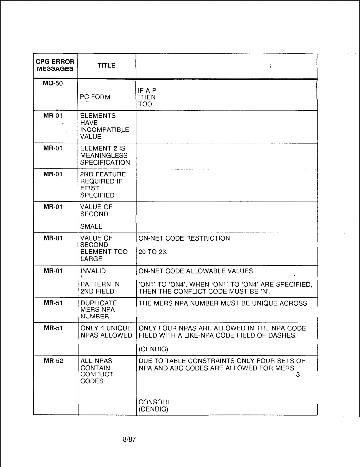
TL-130400-1001
Table 21.1 CPG Error Messages (Continued)
DESCRIPTION OF MESSAGES
PREFIX INDEX PREFIX INDEX
NOT FOUND ON REFIX INDEX IS SPECIFIED ON AN MO RECORD,
IT SHOULD BE SPECIFIED ON A PC RECORD
ELEMENT TOO
ON-NET MERS CODES MUST BE NUMBERED FROM
CHARACTER ALLOWABLE VALUES FOR AN ON-NET CODE ARE
ALL MR RECORDS.
CONSOLIDATE THE NPAS USING THE LIKE NPA.
ROUTING. ONE OF THESE TABLES IS USED FOR
3-
DIGIT NPA TRANSLATION, SO THE REMAINING THREE
TABLES MAY BE USED FOR 6-DIGIT TRANSLATION
CONTAINING CONFLICT CODES.
DATE THE NPAS USING THE LIKE NPA.
D-496 8h37
SVR 5210
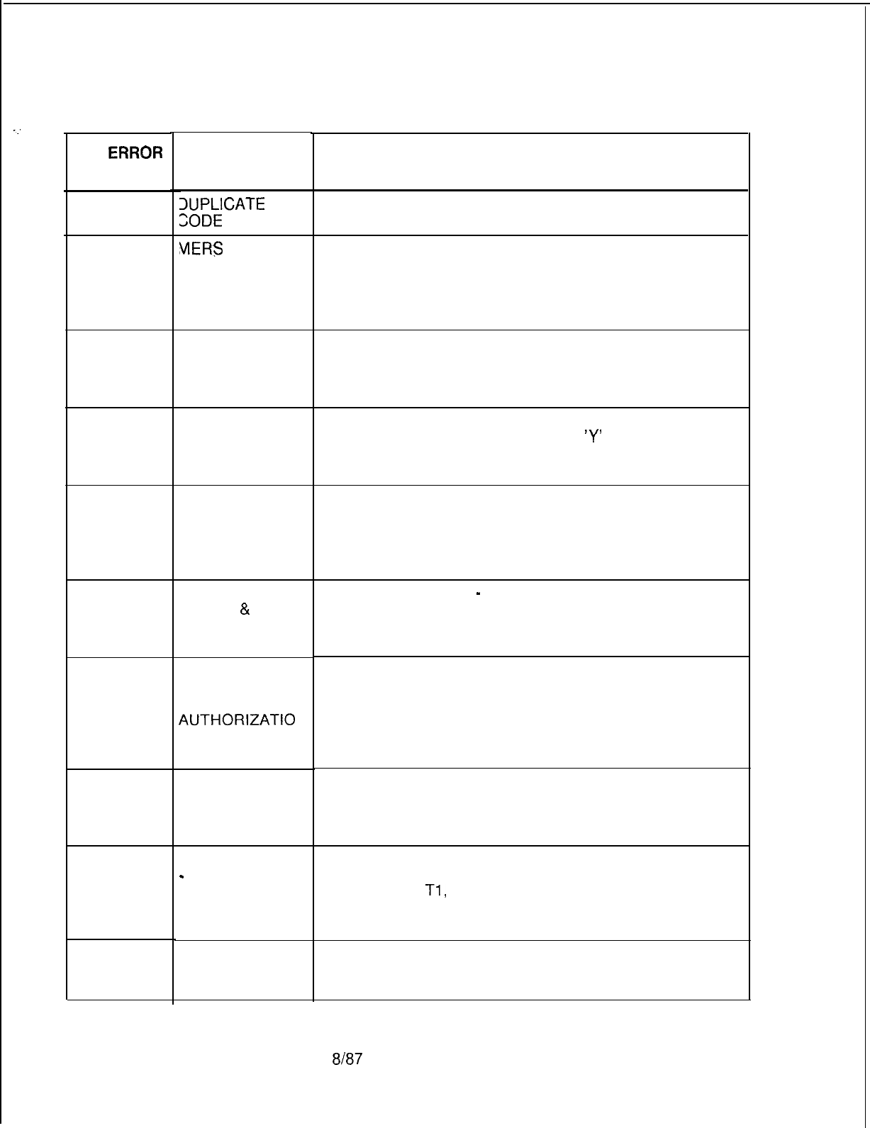
-:
CPG
ERRQR
MESSAGES
MR-53
MR-55
. . . .
MR-56
MR-57
MS-01
MS-50
MS-51
MS-51
NA-53
NA-54
SVR 5210
Table 21.1
TITLE
IUPLICATE
NPA
ZODE
blERS
NPA NOT
PREVIOUSLY
DEFINED
.
VALUES MUST
BE
CONTINUOUS
FIELD DOES
NOT HAVE
REQUIRED
VALUE
VALUES TO BE
FILLED LEFT TO
RIGHT
MDR WORK
GROUP
&
SCC
ID NUMBER
DUPLICATED
MAXIMUM
NUMBER OF
UNIQUE
AUTHORIZATIO
N CODES
EXCEEDED
MDR WORK
GROUP NO NOT
FOUND ON LD
FORM
TRUNK GROUP
-
HAS INVALID
N-DISP CLASS
OF SERVICE
MARK
DUPLICATE
TRUNK
NUMBER
TL-130400-1001
CPG Error Messages (Continued)
DESCRIPTION OF MESSAGES
THE MERS NPA NUMBER OCCURRED ON A PREVIOUS
MR RECORD.
THE LIKE NPA CODE HAS NOT BEEN SPECIFIED AS A
MERS NPA CODE ON A PREVIOUS MR RECORD.
THIS CHECK DOES NOT INVOLVE MERS NPAS ON THE
MR, NT, OR TD RECORDS.
(GENDIG)
MERS NPA INDEX
GAPS ARE NOT ALLOWED IN THE MERS NPA
NUMBER.
(ENDCHK)
IF AN MR RECORD INDICATES CONFLICT CODES,
THEN MERS 1 + DIALING MUST BE
‘Y’
ON THE OF
RECORD.
AUTHORIZATION CODE DIGITS
IF THE AUTHORIZATION CODE IS LESS THAN TEN
DIGITS,
THEN THE DIGITS MUST BE PACKED TO THE LEFT
WITH THE REMAINING FIELDS DASHED.
MDR WORK GROUP
-
SCC ID NUMBER
DUPLICATE MDR WORK GROUP AND SCC ID NUMBER
COMBINATION IS NOT ALLOWED.
THE TOTAL NUMBER OF SCC AUTHORIZATION CODES
MUST NOT BE GREATER THAN THE SYSTEM LIMIT OF
255.
(TABGEN/GENDIG)
MDR WORK GROUP NUMBER
IF A MDR WORK GROUP IS REFERENCED ON AN MS
RECORD, THEN THAT MDR WORK GROUP SHOULD BE
DEFINED ON AN LD RECORD.
THE TRUNK GROUP SPECIFIED ON RECORD NA
(FROM/TO) MUST CORRESPOND TO A TRUNK GROUP
ON RECORD
Tl,
HAVING AN N-DISPLAYABLE CLASS
OF SERVICE WHICH INDICATES DATA LINE SECURITY.
THE TO OR FROM TRUNK WAS SPECIFIED ON A
PREVIOUS NA RECORD.
8187 D-497
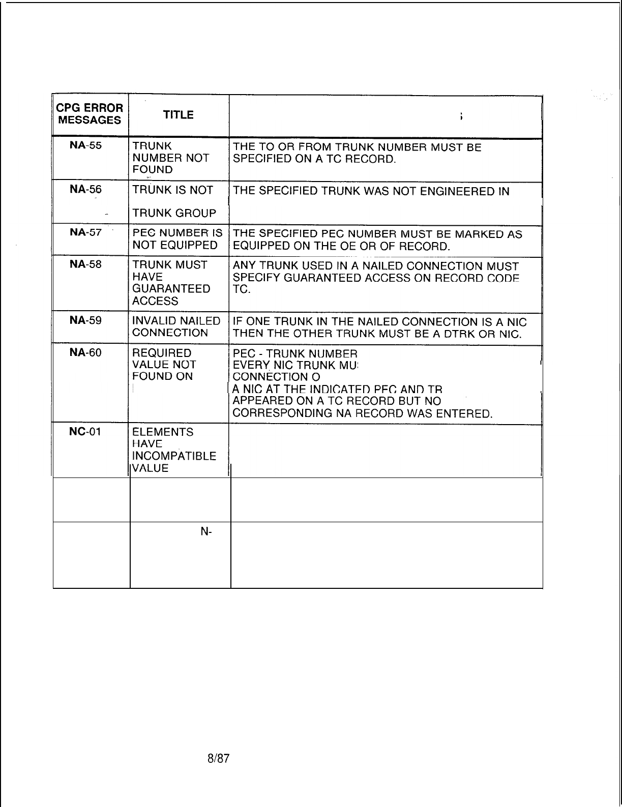
TL-130400-1001
Table 21.1 CPG Error Messages (Continued)
DESCRIPTION OF MESSAGES
IN SPECIFIED THE TRUNK GROUP ON A TC RECORD.
ST APPEAR IN A NAILED
N AN NA RECORD.
LISTED FORM UNK NUMBER
NC-01
ELEMENT 2 IS
MEANINGLESS
SPECIFICATION
NC-51
DUPLICATE
N-
N-DISPLAYABLE CLASS OF SERVICE NUMBER MUST
DISPLAYABLE BE UNIQUE ACROSS THE NC RECORDS. FOR
CLASS OF VIOLATION AND RESTRICTION PATTERNS BETWEEN
SERVICE DATA DISPLAYABLE AND N-DISPLAYABLE CLASSES OF
SERVICE, SEE APPENDIX 1.
D-498 8187
SVR 5210
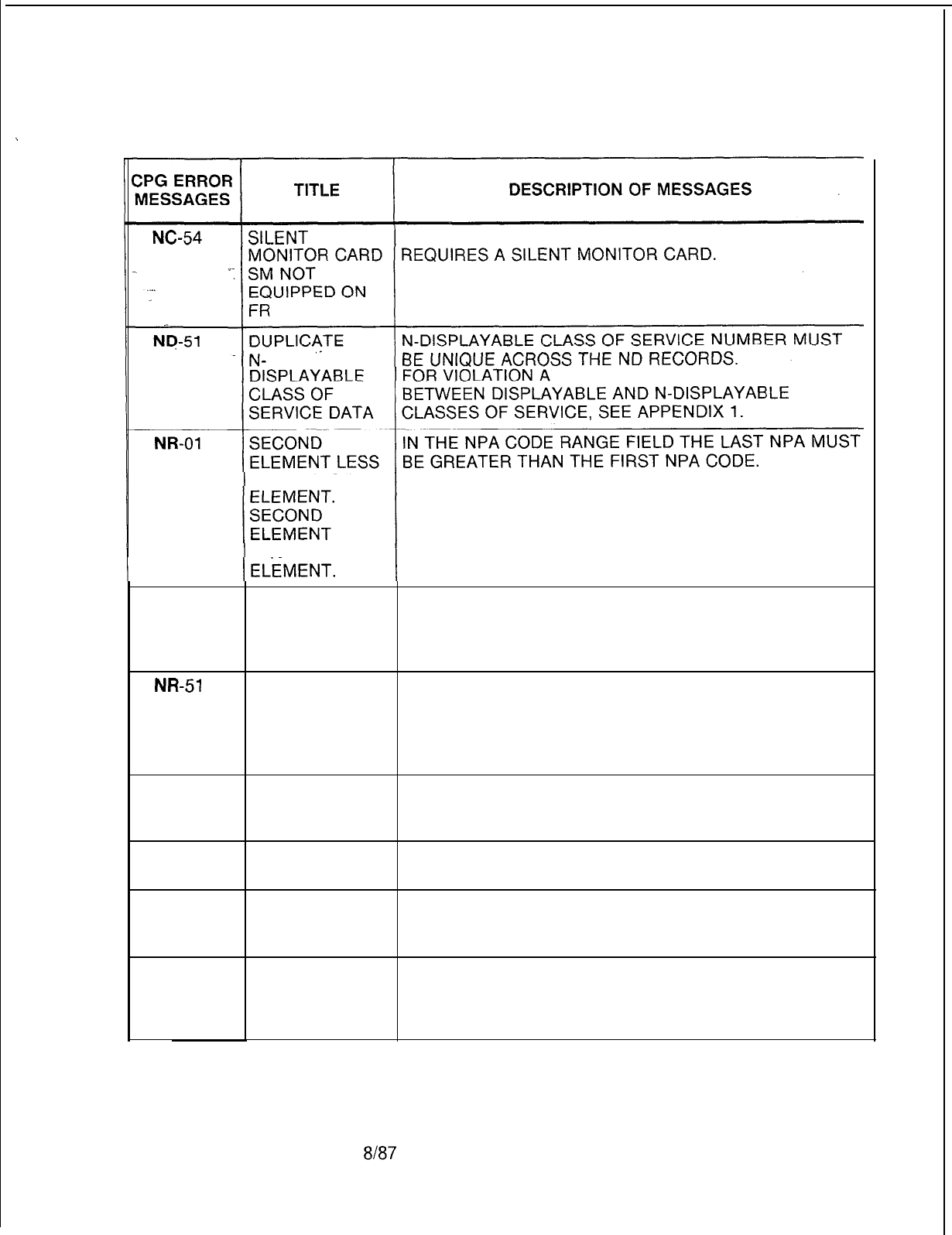
.
TL-130400-1001
Table 21.1 CPG Error Messages (Continued)
THE STATION SILENT MONITOR ACCESS FIELD
ND RESTRICTION PATTERNS
THAN FIRST
EQUAL FIRST
NR-02
DASHES MUST IN TIME PERIODS 1 TO 3, THE SENDING INSTRUCTION
BE USED LIST NUMBER AND THE ROUTING LIST NUMBER MUST
CONSISTENTLY BOTH BE DASHES OR BOTH CONTAIN VALID VALUES.
IN FIELD
NR-51
CODE RANGE THE NPA CODE RANGE FIELDS CONTAIN A THREE
INCLUDES DIGIT CODE THAT IS NOT AN NPA CODE.
INVALID NPA SPLIT THE NPA DATA INTO MULTIPLE NR RECORDS
TO AVOID THE INVALID NPA.
(GENDIG)
NR-52
SENDING A SENDING INSTRUCTION LIST NUMBER USED ON AN
INSTRUCTION NR RECORD WAS NOT DEFINED ON AN SI RECORD.
NOT DEFINED
NR-53
NR-54
ROUTING LIST A ROUTING LIST NUMBER USED ON AN NR RECORD
NOT DEFINED WAS NOT DEFINED ON AN RP RECORD.
DUPLICATE NPA AN NPA CODE SPECIFIED ON THE NR RECORD WAS
ENTRY ALREADY SPECIFIED.
(GENDIG
NR-55
NPA CODE AN NPA CODE ON THE NR RECORD WAS ALREADY
SPECIFIED ON SPECIFIED AS A 6-DIGIT TRANSLATED NPA CODE ON
MR FORM AN MR RECORD.
(GENDIG)
SVR 5210
$187 D-499
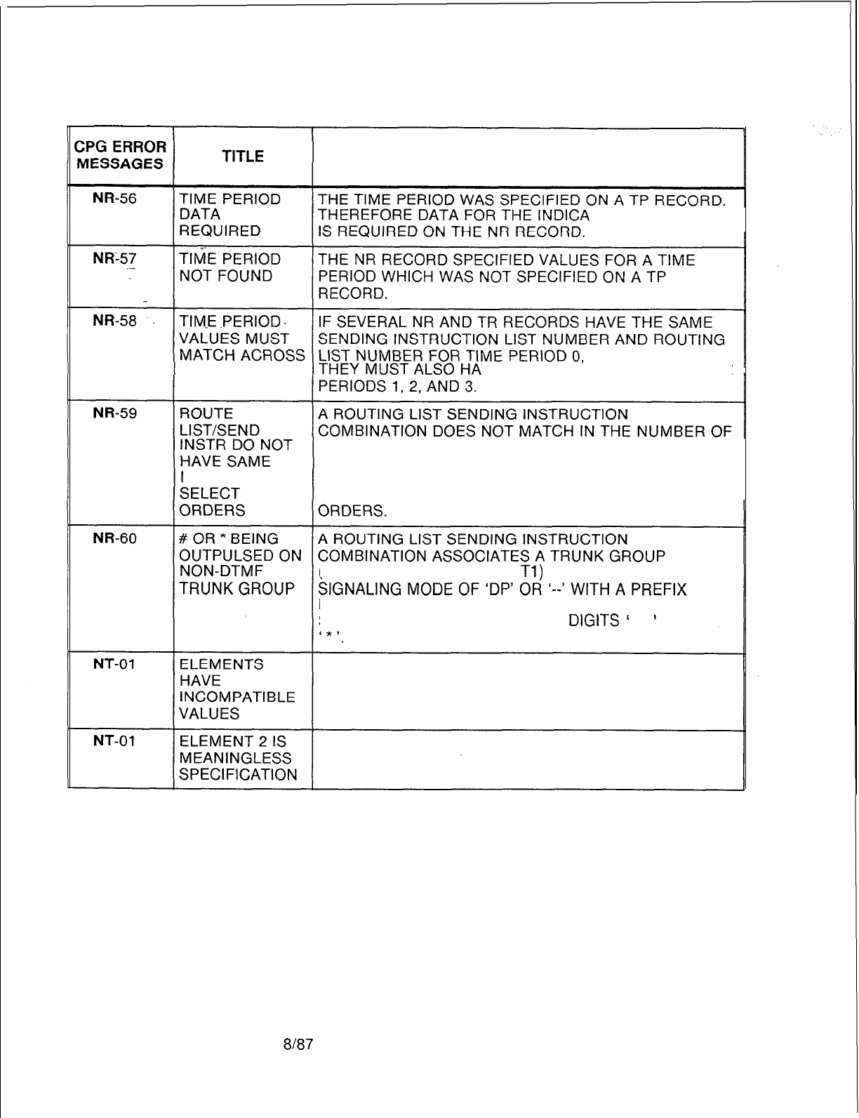
TL-130400-1001
Table 21.1 CPG Error Messages (Continued)
DESCRIPTION OF MESSAGES
TED TIME PERIOD
ALL RECORDS
VE
IDENTICAL VALUES FOR TIME
SELECT ORDER.
IT IS POSSIBLE TO HAVE ERRONEOUS VALUES IN THE
NUMBER OF ROUTING LIST OR SENDING INSTRUCTIONS IF THEY
DO
NOT HAVE THE SAME NUMBER OF SELECT
(RECORD CODES RP AND
Tl)
WITH AN OUTGOING
INDEX (RECORD CODES St, LP AND/ OR PC) THAT
SPECIFIES THE OUTPULSING OF
DlGlTS
’
#
’
AND/OR
D-500 8187
SVR 5210
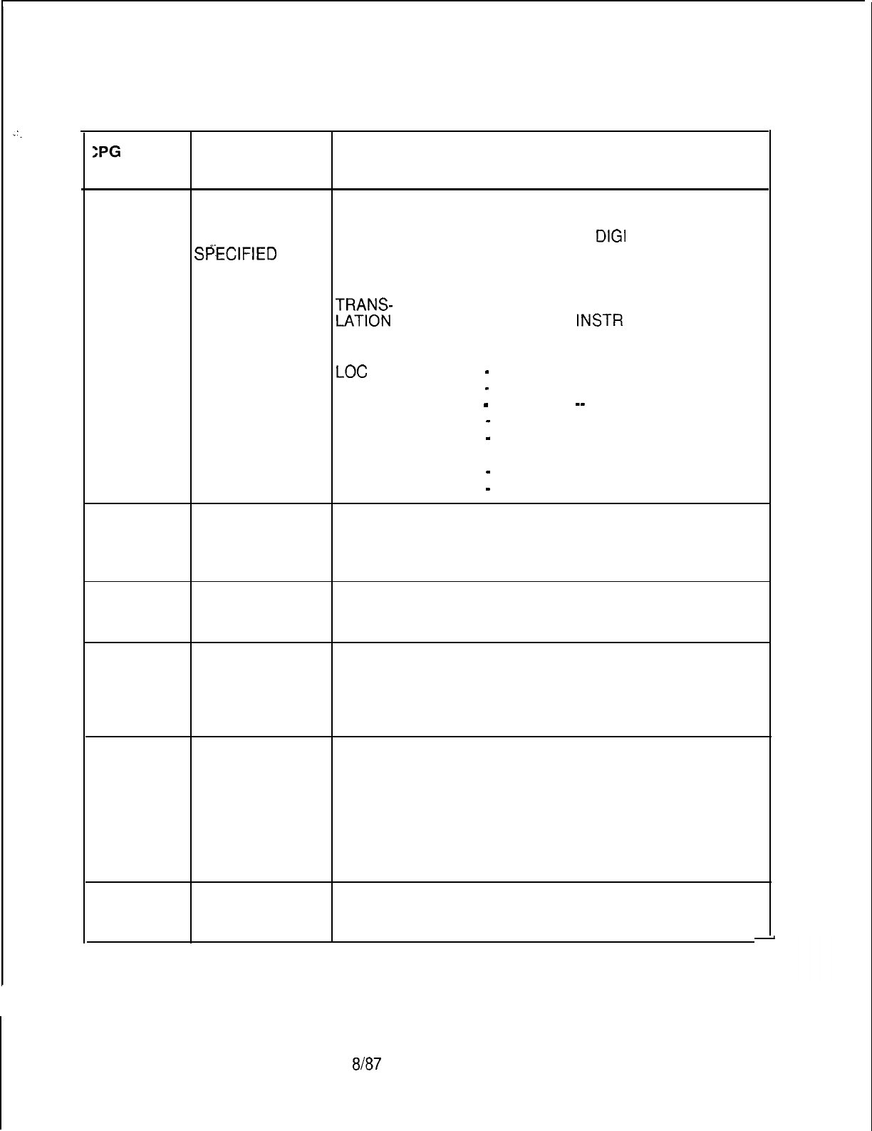
.
.
.
SVR 5210
8187
D-501
TL-130400-1001
Table 21.1 CPG Error Messages (Continued)
>PG
ERROR
MESSAGES TITLE DESCRIPTION OF MESSAGES
NT-01
2ND FEATURE TRANSLATION TYPE
REQUIRED IF GIVEN A CERTAIN TRANSLATION TYPE, THE SELECT
FIRST TRUNK GROUP, THE NUMBER OF
DIGI
TS
Sf%ClFlED
OUTPULSED, SENDING INSTRUCTION, AND ROUTING
. . .
LIST FIELDS MUST BE AS FOLLOWS:
TRANS-
SELECT NO. OF SENDING ROUTING
LATION
TRUNK DIGITS
INSTR
LIST
TYPE OUTPULSED
LOC
--
-
--
MRS --
-
--
TGS 00-63
-_-
DGT --
-
--
ABC --
-
--
TGO 00-63
1-15 --
MRN --
-
--
MER --
-
01-31 o-7
NT-02 ELEMENTS
HAVE
INCOMPATIBLE
VALUES
NT-02 ELEMENT 2 IS
MEANINGLESS
SPECIFICATION
NT-02 2ND FEATURE MERS ON-NET LIKE NPA
REQUIRED IF FOR ALL TRANSLATION TYPES EXCEPT MRN, THE
FIRST MERS LIKE NPA FIELD MUST BE DASHES.
SPECIFIED THE LIKE NPA FIELD MUST BE SPECIFIED FOR
TRANSLATION TYPE MRN.
NT-04 SECOND IN THE CODE RANGE FIELDS THE SECOND CODE IS
ELEMENT LESS LESS THAN OR EQUAL TO THE FIRST CODE.
THAN FIRST
ELEMENT.
SECOND
ELEMENT
EQUALS FIRST
ELEMENT.
NT-51
DUPLICATE THE TRANSLATION ENTRY NUMBER MUST BE
TRANSLATION UNIQUE.
ENTRY NUMBER
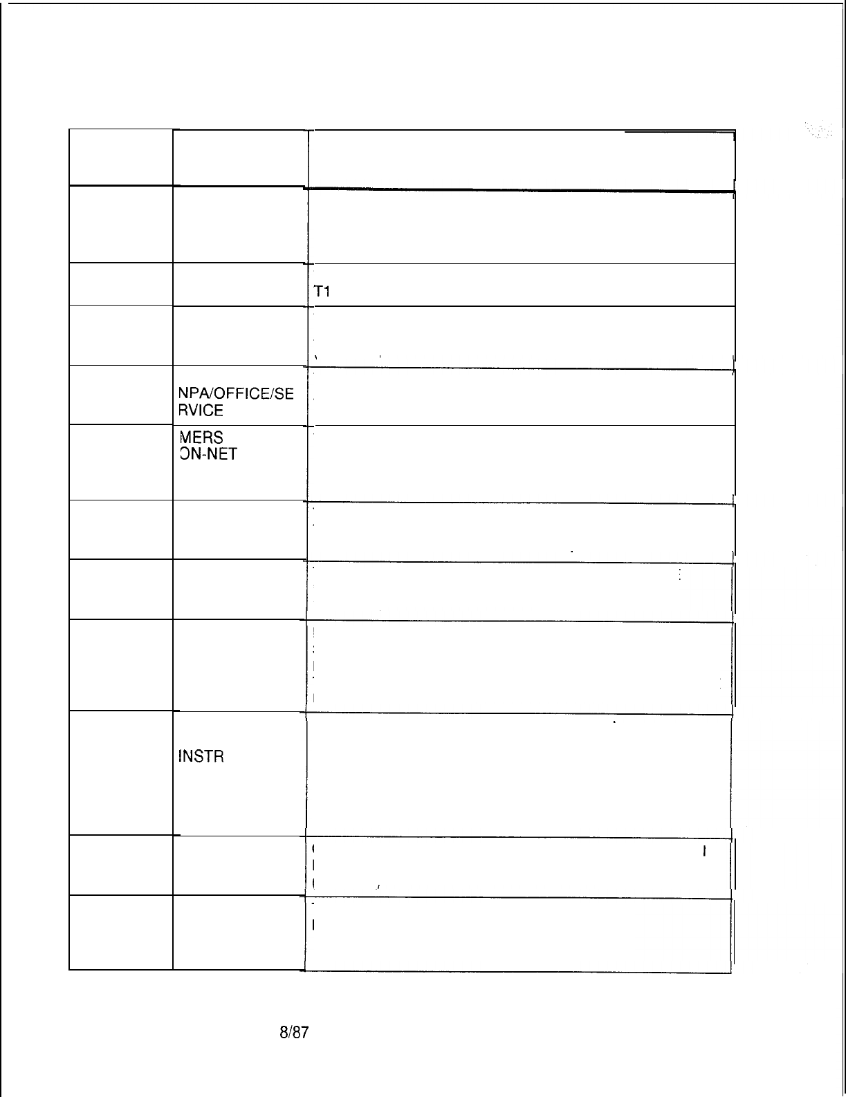
TL-130400-1001
CPG ERROR
MESSAGES
I
NT-52
. . .
NT-53
NT-54
NT-54
NT-55
NT-56
NT-57
NT-58
NT-59
NT-61
NT-62
D-502
Table 21.1 CPG Error Messages (Continued)
TITLE
FIELD
CONFLICTS
WITH TRUNK
APPLICATION
TRUNK GROUP
NOT FOUND
DUPLICATE ABC
ENTRY
DUPLICATE
NPA/OFFICE/SE
RVICE
CODE
MERS
NPA OR
3N-NET
CODE
NOT ON MR
FORM
TIME PERIOD
DATA
REQUIRED
TIME PERIOD
NOT FOUND
TIME PERIOD
VALUES MUST
MATCH ACROSS
ALL RECORDS
ROUTE
LIST/SEND
INSTR
DO NOT
HAVE SAME
NUMBER OF
SELECT
ORDERS
ONLY 4 UNIQUE
NPAS ALLOWED
SENDING
INSTRUCTION
LIST NOT
FOUND
DESCRIPTION OF MESSAGES
THE TRUNK APPLICATION CANNOT BE DIC, PAG, REC
OR NIC.
THE SELECT TRUNK GROUP MUST BE FOUND ON THE
Tl
RECORD.
THE CODE RANGES SPECIFIED MUST BE UNIQUE
ACROSS ALL NT RECORDS.
(GENDIG)
THE NPA OR OFFICE CODE MUST BE UNIQUE ACROSS
ALL NT RECORDS.
THE NPA SPECIFIED IN THE LIKE NPA MUST BE
FOUND ON THE MR RECORD.
(GENDIG)
THE TIME PERIOD WAS SPECIFIED ON A TP RECORD.
THEREFORE DATA FOR THE INDICATED TIME PERIOD
IS REQUIRED ON THE NT RECORD.
THE NT RECORD SPECIFIED VALUES FOR A TIME
PERIOD WHICH WAS NOT SPECIFIED ON A TP
RECORD.
IF SEVERAL NT, NR, AND TR RECORDS HAVE THE
SAME SENDING INSTRUCTION LIST NUMBER AND
ROUTING LIST NUMBER FOR TIME PERIOD 0,
THEY MUST ALSO HAVE IDENTICAL VALUES FOR TIME
PERIODS 1, 2, AND 3.
A ROUTING LIST SENDING INSTRUCTION
COMBINATION DOES NOT MATCH IN THE NUMBER OF
SELECT ORDER.
IT IS POSSIBLE TO HAVE ERRONEOUS VALUES IN THE
ROUTING LIST OR SENDING INSTRUCTIONS IF THEY
DO NOT HAVE THE SAME NUMBER OF SELECT
ORDERS.
ONLY FOUR UNIQUE NPAS ARE ALLOWED BETWEEN
MR, NT, AND TD RECORDS.
(GENDIG)
THE SENDING INSTRUCTION LIST MUST BE
ENGINEERED ON RECORD CODES.
8187
SVR 5210
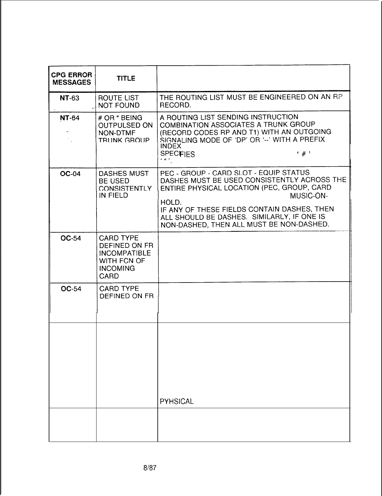
TL-130400-1004
Table 21.1 CPG Error Messages (Continued)
DESCRIPTION OF MESSAGES
(RECORD CODES SI, LP AND/ OR PC) THAT
FIES
THE OUTPULSING OF DIGITS
‘
#
’
AND/OR
SLOT, AND EQUIPMENT STATUS) FOR
MUSIC-ON-
INCOMPATIBLE
WITH INCOMING
CARD TYPE
oc-54 FUNCTION OF PHYSICAL LOCATION
CARD NOT THE PEC, GROUP, SLOT AND CIRCUIT FUNCTION
ALLOWED FOR SPECIFIED MUST BE VALID FOR THE CARD TYPE
CARD TYPE DEFINED ON FR (FOR THIS PEC TYPE).
DEFINED ON THE MUSIC ON HOLD CIRCUIT MUST APPEAR ON A
FORM FR POTS OR OFFP LINE CARD.
(PHYLOC)
IF THE CARD TYPE IN THE MESSAGE IS “OVER”, THAT
INDICATES THAT A CARD IN THE PREVIOUS LOCATION
IS A WIDE CARD AND IT OVERHANGS INTO THIS
PYHSICAL
LOCATION ON FR.
oc-54 NONEXISTENT PHYSICAL LOCATION
PHYSICAL THE PEC, GROUP, SLOT, AND CIRCUIT SPECIFIED
LOCATION MUST BE VALID FOR THIS PEC TYPE.
(PHYLOC)
SVR 5210
8187
D-503
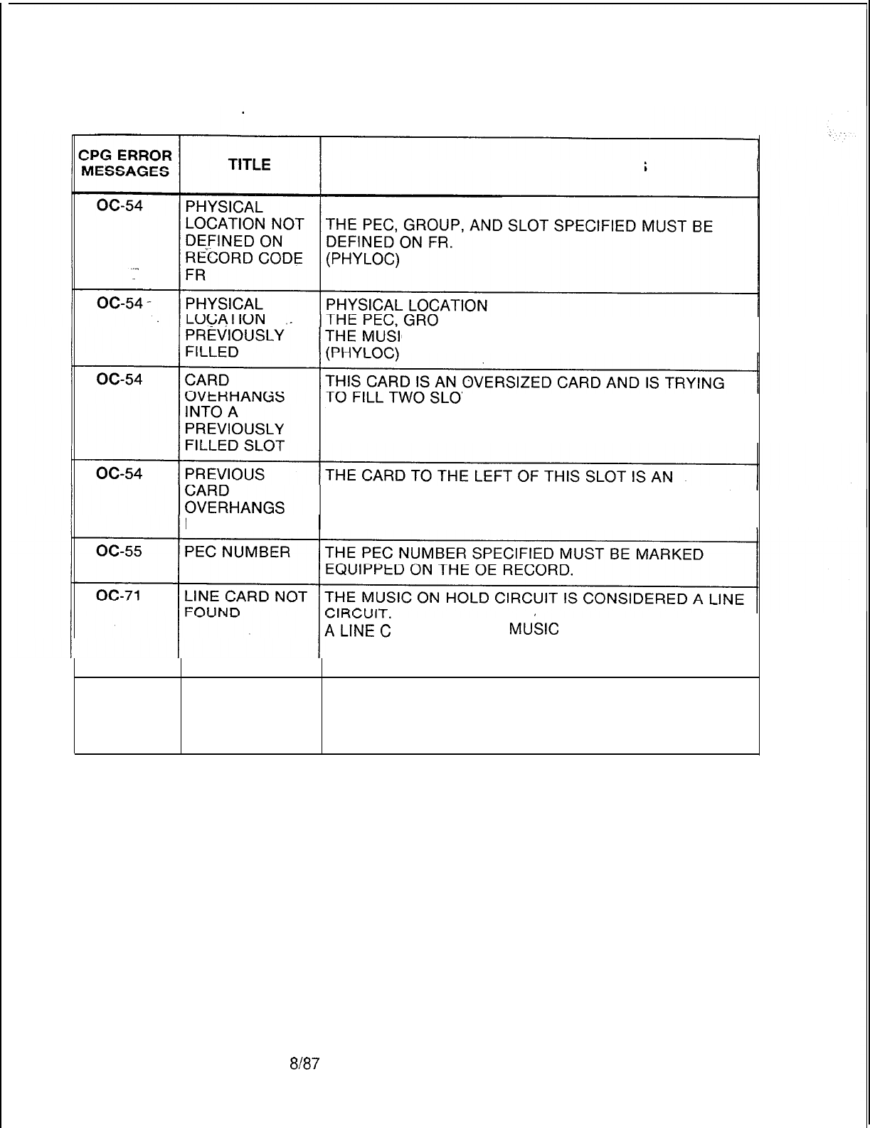
TL-130400-1001
Table 21.1 CPG Error Messages (Continued)
DESCRIPTION OF MESSAGES
PHYSICAL LOCATION
UP, SLOT AND CIRCUIT SPECIFIED FOR
C ON HOLD CIRCUIT MUST BE UNIQUE.
TS.
OF THE TWO SLOTS IT FILLS,
THE RIGHT HAND ONE HAS ALREADY BEEN FILLED.
OVERSIZED CARD. THE RIGHT HALF OF THAT CARD
FILLS THIS SLOT.
INTO THIS SLOT
ARD FOR THE
MU&C
ON HOLD CIRCUIT WAS
NOT SPECIFIED ON AN FR RECORD
(PHYLOC)
OD-01
VALUE OF
SECOND
ELEMENT TOO
LARGE
D-504 8187
SVR 5210
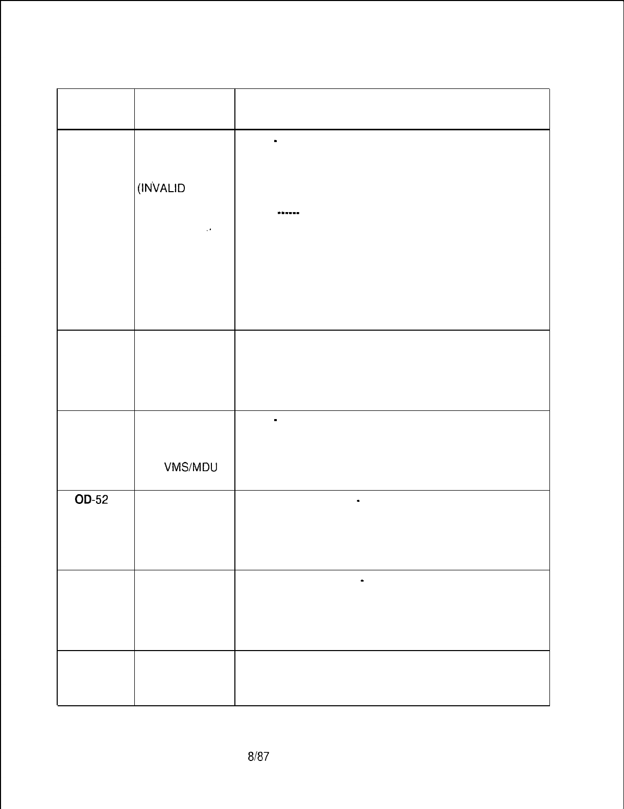
TL-130400-1001
Table 21.1 CPG Error Messages (Continued)
CPG ERROR
MESSAGES TITLE DESCRIPTION OF MESSAGES
OD-01
. . .
OD-50
OD-51
VALUE OF TYPE
-
IDENTIFIER
SECOND FOR EACH TYPE, THE IDENTIFIER MUST BE IN THE
ELEMENT TOO APPROPRIATE RANGE AS THE FOLLOWING CHART
SMALL INDICATES.
(INVALID
NUMBER OF TYPE IDENTIFIER RANGE
DIGITS TO
_-----
----------
OUTPULSE)
,_
RMA
0000
VMS 0000-0063 TRUNK GROUP
SPD 0001-0008 SPEED CALL LIST
ENTRY
MDU 0000-0063 TRUNK GROUP
TGS
0000-0063 TRUNK GROUP
TGO
XXW WHERE XX = 00-15
NUMBER OF DIGITS OUTPULSED,
YY =00-63 TRUNK GROUP
CLASS OF CLASS OF SERVICE
SERVICE NOT EITHER THE N-DISPLAYABLE CLASS OF SERVICE OR
SPECIFIED ON THE DISPLAYABLE CLASS OF SERVICE (OR BOTH)
OF FOR SHOULD BE SPECIFIED ON THE RECORD OF WHEN A
REMOTE REMOTE ACCESS DIRECTORY NUMBER IS SPECIFIED
ACCESS ON AN OD RECORD.
ONLY ONE TYPE
-
IDENTIFIER
TRUNK GRP TYPES ‘VMS’ AND ‘MDU’ MUST HAVE THE SAME
PER SYSTEM IS IDENTIFIER (TRUNK GROUP NUMBER).
ALLOWED FOR
THE
VMS/MDU
FEATURE
00-52
AN N-DISP. N-DISPLAYABLE COS
-
TYPE
COS OF VM IF ANY NC RECORD SPECIFIES A CLASS OF SERVICE
SPECIFIED ON OF VM,
NC REQUIRES ATHEN A VMS DIRECTORY NUMBER MUST BE DEFINED
VMS DIR. ON AN RECORD OD.
NUMBER (ENDCHK)
OD-53
A DIV. DEST. OF DIVERT DESTINATION
-
TYPE
VM SPECIFIED IF ANY LD RECORD SPECIFIES A DIVERT
ON LD DESTINATION OF ‘VM’,
REQUIRES ATHEN A VMS DIRECTORY NUMBER MUST BE DEFINED
VMS DIR. NO. ON AN OD RECORD. (ENDCHK)
ON OD
OE-02
REQUIRED PEC FIELDS
VALUE NOT AT LEAST ONE PEC MUST BE MARKED AS EQUIPPED.
FOUND ON (ENDCHK)
LISTED FORM
SVR 5210
8187 D-505

TL-130400-1001
Table 21.1 CPG Error Messages (Continued)
CPG ERROR
MESSAGES TITLE DESCRIPTION OF MESSAGES
OE-51
IF ESP IS
EQUIPPED ON
OE, PORT 1 ON
MTyMUST
BE
. . .
PRESENT
OE-5-l
_
REQUIRED IF THE ESP IS EQUIPPED ON THE OE RECORD, THEN
DATA NOT AN MT RECORD WITH PORT 1 MUST BE PRESENT.
FOUND .
(ENDCHK)
OE-52 IF ESP IS
EQUIPPED ON
OE, TRANS.
RATE ON MT
MUST BE 2400
OE-52
OE-53
FIELD DOESN’T IF THE ESP IS EQUIPPED ON THE OE RECORD, THEN
HAVE THE TRANSMISSION RATE FOR PORT 1 ON THE MT
REQUIRED RECORD MUST BE 2400 BAUD.
VALUE (ENDCHK)
IF ESP IS
EQUIPPED ON
OE, MDR PORT
1 ON MD MUST
BE SPECIFIED
OE-53
OF-09
OF-l 0
FIELD DOESN’T IF THE ESP IS EQUIPPED ON THE OE RECORD, THEN
HAVE THE MDR PORT 1 ON MD MUST BE SPECIFIED ON THE
REQUIRED MD RECORD.
VALUE (ENDCHK)
DASHES MUST CAMP-ON/CALL WAITING TONE
-
CAMP-ON TONE
BE USED TYPE
CONSISTENTLY IF CAMP-ON/CALL WAITING TONE IS DASHED,
IN FIELD THEN THE CAMP-ON TONE TYPE MUST BE DASHES.
REQUIRED AT LEAST ONE PEC MUST BE MARKED AS EQUIPPED.
VALUE NOT (ENDCHK)
FOUND ON
LISTED FORM
OF-l
1
SECOND TRAVELING CLASS MARK
-
FRL AUTHORIZATION
ELEMENT CODE NUMBER OF DIGITS.
CONTAINS IF THE TRAVELING CLASS MARK FIELD IS DASHED,
INVALID VALUE THEN THE FRL AUTHORIZATION CODE NUMBER OF
DIGITS MUST BE DASHED.
D-506 8187
SVR 5210
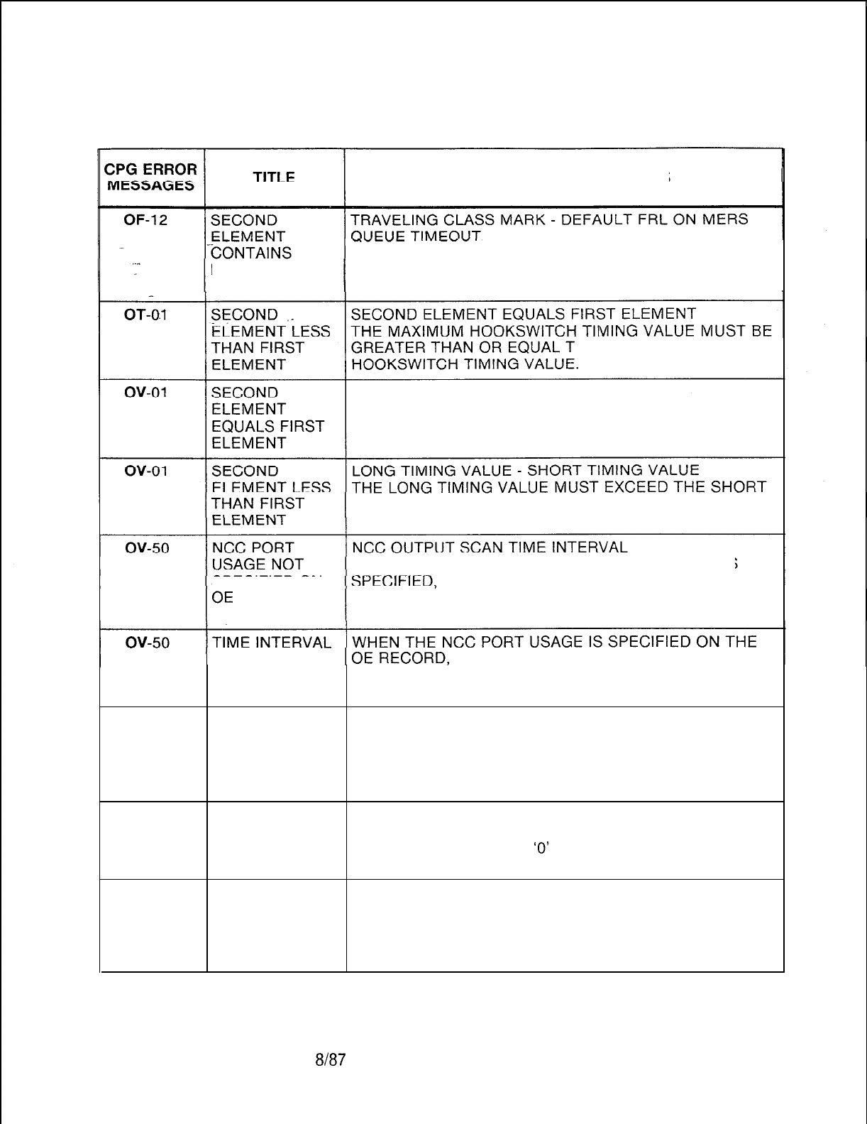
TL-130400-1001
Table 21.1 CPG Error Messages (Continued)
DESCRIPTION OF MESSAGES
IF THE TRAVELING CLASS MARK FIELD IS DASHED,
INVALID VALUE THEN THE DEFAULT FRL ON MERS QUEUE TIMEOUT
VALUES MUST BE DASHED.
0 THE MINIMUM
TIMING VALUE.
WHEN THE NCC OUTPUT SCAN TIME INTERVAL IS
SPECIFIED ON THEN THE NCC PORT USAGE SHOULD BE SPECIFIED
ON THE OE RECORD.
OUTPUT SCAN
NOT SPECIFIED THEN THE NCC OUTPUT SCAN TIME INTERVAL
SHOULD BE SPECIFIED ON THE OV RECORD.
PC-01
VALUES TO BE PREFIX DIGITS
FILLED LEFT TO IF THERE ARE LESS THAN THE MAXIMUM ALLOWED
RIGHT PREFIX DIGITS,
THEN THE DIGITS MUST PACKED TO THE LEFT WITH
THE REMAINING FIELDS DASHED.
PC-02
SECOND PREFIX DIGITS
ELEMENT IF ANY PREFIX DIGIT IS AN ‘E’, THEN THE NEXT
CONTAINS PREFIX DIGIT MUST BE
‘0’
OR ‘1’.
INVALID VALUE
PC-03
A CHAR D MUST PREFIX DIGITS
BE FOLLOWED IF ANY PREFIX DIGIT IS A ‘D’,
BY TWO DIGITS THEN THE NEXT TWO PREFIX DIGITS MUST BE IN THE
IN THE RANGE RANGE 00 TO 99.
00 TO 99
SVR
5210
8187
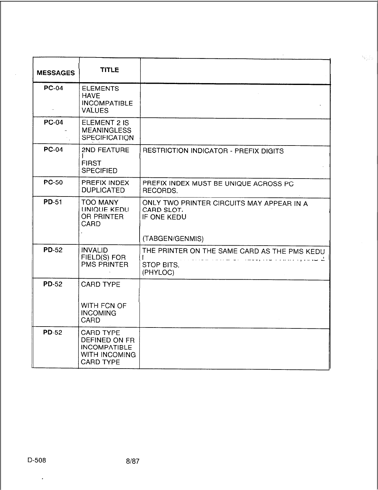
TL-130400-I 001
CPG ERROR
Table 21.1 CPG Error Messages (Continued)
DESCRIPTION OF MESSAGES
REQUIRED IF IF AT LEAST ONE PREFIX DIGIT IS AN ‘A’, ‘D’, OR ‘E’,
THEN RESTRICTION INDICATOR CANNOT BE DASHED.
iJ
CIRCUIT HAS BEEN PLACED IN THE
SAME CARD SLOT, THEN ONLY ONE PRINTER CIRCUIT
ADDRESSES MAY BE PLACED IN THAT CARD SLOT.
(TABGENiGENMIS)
MUST HAVE A BAUD RATE OF
1200,
NO PARITY, AND 2
DEFINED ON FR
INCOMPATIBLE
8187
SVR 5210

CPG ERROR
MESSAGES
PD-52
.
.
.
PD-52
PD-52
PD-52
PD-52
PD-52
PD-53
PD-54
SVR 5210
Table 21.1
TITLE
FUNCTION OF
CARD NOT
ALLOWED FOR
CARD
TYPE
DEFINED ON
FORM FR
NONEXISTENT
PHYSICAL
LOCATION
PHYSICAL
LOCATION NOT
DEFINED ON
RECORDCODE
FR
PHYSICAL
LOCATION
PREVIOUSLY
FILLED
CARD
OVERHANGS
INTO A
PREVIOUSLY
FILLED SLOT
PREVIOUS
CARD
OVERHANGS
INTO THIS SLOT
DUPLICATE
PRINTER
NUMBER
PEC NUMBER IS
NOT EQUIPPED
TL-130400-1001
CPG Error Messages (Continued)
DESCRIPTION OF MESSAGES
PHYSICAL LOCATION
THE PEC, GROUP, SLOT, AND CIRCUIT FUNCTION
SPECIFIED MUST BE VALID FOR THE CARD TYPE
DEFINED ON FR (FOR THIS PEC TYPE). PRINTER
CIRCUIT MUST APPEAR ON A KEDU CARD.
(PHYLOC)
IF THE CARD TYPE IN THE MESSAGE IS “OVER”, THAT
INDICATES THAT A CARD IN THE PREVIOUS LOCATION
IS A WIDE CARD AND IT OVERHANGS INTO THIS
PYHSICAL
LOCATION ON FR.
PHYSICAL LOCATION
THE PEC, GROUP, SLOT, AND CIRCUIT SPECIFIED
MUST BE VALID FOR THIS PEC TYPE.
(PYHLOC)
PHYSICAL LOCATION
THE PEC,GROUP AND SLOT SPECIFIED MUST BE
DEFINED ON FR.
(PHYLOC)
PHYSICAL LOCATION
THE PEC, GROUP, SLOT AND CIRCUIT SPECIFIED FOR
THE PRINTER CIRCUIT MUST BE UNIQUE.
(PHYLOC)
THIS CARD IS AN OVERSIZED CARD AND IS TRYING
TO FILL TWO SLOTS.
OF THE TWO SLOTS IT FILLS,
THE RIGHT-HAND ONE HAS ALREADY BEEN FILLED.
THE CARD TO THE LEFT OF THIS SLOT IS AN
OVERSIZED CARD.
THE RIGHT HALF OF THAT CARD FILLS THIS SLOT.
PRINTER NUMBER
THE PRINTER NUMBER MUST BE UNIQUE ACROSS
ALL PD RECORDS.
PEC NUMBER
THE PEC NUMBER SPECIFIED MUST BE MARKED
EQUIPPED ON THE OE RECORD.
8187
D-509

TL-130400-1001
Table 21.1 CPG Error Messages (Continued)
CPG ERROR
MESSAGES
I
PN-53
. . .
PN-54
PN-55
PZ-52
Pl-51
P2-51
RA-01
RA-01
D-51 0
TITLE
PNA PILOT
NUMBER NOT
PREVIOUSLY
ENTERED
DUPLICATE PNA
DESTINATION
NUMBER
AN MDU DIR.
NO. ON OD
MUST APPEAR
ON RECORD
CODE PN
FIELD
CONFLICTS
WITH LISTED
FIELD
IF ADMP PORT
TIMEOUT IS
SPECIFIED, AN
ADMP PORT
MUST BE
DEFINED ON CP
DUPLICATE
ADMP DUMP
TYPE
ELEMENTS
HAVE
INCOMPATIBLE
VALUES
ELEMENT 2 IS
MEANINGLESS
SPECIFICATION
DESCRIPTION OF MESSAGES
THE PNA PILOT NUMBER MUST BE DEFINED AS ONE
OF THE FOLLOWING:
1. A VALID LINE (ROOM) NUMBER ON AN LD RECORD.
2. A VALID REMOTE ACCESS DIRECTORY NUMBER ON
AN OD OR OF RECORD.
3. A VALID RLT DIRECTORY NUMBER ON AN RC
RECORD.
4. A VALID PILOT NUMBER ON AN HG RECORD.
5. A VALID MESSAGE DESK UNATTENDED DIRECTORY
NUMBER ON AN OD RECORD.
(ENDCHK)
THE PNA DESTINATION NUMBER MUST BE UNIQUE
ACROSS ALL PN RECORDS.
PILOT NUMBER
THE MDU DIRECTORY NUMBER ON AN OD RECORD IS
A SPECIAL APPLICATION OF A PREDETERMINED
NIGHT ANSWER PILOT NUMBER AND THEREFORE
MUST BE DEFINED ON A PN RECORD.
(ENDCHK)
IF THE ATTENDANT PAGING AREA FIELDS ARE NOT
DASHED, THEN ATTENDANT PAGING FIELD ON THE
CA RECORD MUST BE ‘Y’.
USER INTERFACE PACKAGE TIMEOUT IS SPECIFIED
ON
Pl,
AN ADMP PORT MUST BE DEFINED ON CP.
(ENDCHK)
ADMP DUMP TYPE
THE ADMP DUMP TYPE MUST BE UNIQUE ACROSS
ALL P2 RECORDS.
8187
SVR 5210
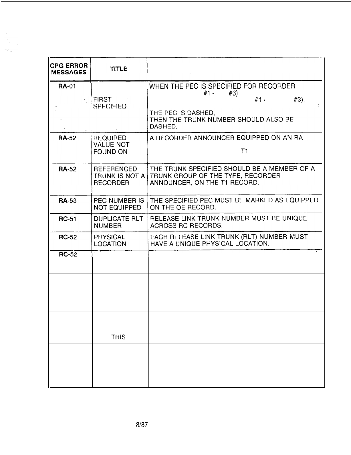
TL-130400-1001
Table 21.1 CPG Error Messages (Continued)
DESCRIPTION OF MESSAGES
2ND FEATURE
REQUIRED IF ANNOUNCER (RA
#1
-
RA
#3)
OR ALTERNATE
RECORDER ANNOUNCER (ALT RA
#l
-
ALT RA
#3),
.--
THE TRUNK NUMBER SHOULD ALSO BE SPECIFIED. IF
RECORD MUST APPEAR ON A TC RECORD WITH AN
APPLICATION OF ‘REC’ ON A
Tl
RECORD.
LISTED FORM
ANNOUNCER
NONEXISTENT THE CARD SLOT WAS ASSIGNED TO A NONEXISTENT
PHYSICAL PHYSICAL LOCATION.
LOCATION
RC-52
CARD
OVERHANGS
INTO A
PREVIOUSLY
FILLED SLOT
THIS CARD IS AN OVERSIZED CARD AND IS TRYING
TO FILL TWO SLOTS.
OF THE TWO SLOTS IT FILLS, THE RIGHT HAND ONE
HAS ALREADY BEEN FILLED.
RC-52 PREVIOUS THE CARD TO THE LEFT OF THIS SLOT IS AN
CARD OVERSIZED CARD.
OVERHANGS THE RIGHT HALF OF THAT CARD FILLS THIS SLOT.
INTO
THIS
SLOT
RC-54 CARD TYPE
DEFINED ON FR
INCOMPATIBLE
WITH FCN OF
INCOMING
CARD
SVR 5210
m37 D-51 1

TL-130400-1001
CPG ERROR
MESSAGES
Table 21.1 CPG Error Messages (Continued)
TITLE DESCRIPTION OF MESSAGES
RC-54
. . . .
CARD TYPE PHYSICAL LOCATION
DEFINED ON FR THE PEC, GROUP, SLOT, AND CIRCUIT FUNCTION
INCOMPATIBLE SPECIFIED MUST BE VALID FOR THE CARD TYPE
WITN
INCOMING DEFINED ON FR (FOR THIS PEC TYPE).
CARD TYPE AN RLT CIRCUIT MUST APPEAR ON AN RLT OR ERLT
CARD.
(PHYLOC)
RC-54 FUNCTION OF’ PHYSICAL LOCATION
CARD NOT THE PEC, GROUP, SLOT, AND CIRCUIT SPECIFIED
ALLOWED FOR MUST BE VALID FOR THE CARD TYPE DEFINED ON FR
CARD TYPE (FOR THIS PEC TYPE). AN RLT CIRCUIT MUST APPEAR
DEFINED ON ON AN RLT, ERLT, DTRK OR
TlIN
CARD.
FORM FR (PHYLOC)
IF THE CARD TYPE IN THE MESSAGE IS “OVER”, THAT
INDICATES THAT A CARD IN THE PREVIOUS LOCATION
IS A WIDE CARD AND IT OVERHANGS INTO THIS
PHYSICAL LOCATION ON FR.
RC-54 NONEXISTENT PHYSICAL LOCATION
PHYSICAL THE PEC, GROUP, SLOT, AND CIRCUIT SPECIFIED
LOCATION MUST BE VALID FOR THIS PEC TYPE.
(PHYLOC)
RC-54 PHYSICAL PHYSICAL LOCATION
LOCATION NOT THE PEC, GROUP, AND SLOT SPECIFIED MUST BE
DEFINEP
ON DEFINED ON AN FR RECORD.
RECORD CODE (PHYLOC)
FR
RC-54
RC-54
PHYSICAL PHYSICAL LOCATION
LOCATION THE PEC, GROUP, SLOT, AND CIRCUIT SPECIFIED FOR
PREVIOUSLY THE RLT CIRCUIT MUST BE UNIQUE.
FILLED (PHYLOC)
PEC NUM’BER IS THE PEC NUMBER SPECIFIED MUST BE MARKED
NOT EQUIPPED EQUIPPED ON THE OE RECORD.
ON THE OE
FORM
RC-55
RN-01
PEC NUMBER IS THE PEC NUMBER SPECIFIED MUST BE MARKED
NOT EQUIPPED EQUIPPED ON THE OE RECORD.
VALUE OF
SECOND
ELEMENT TOO
SMALL
D-51 2
8A37
SVR 5210
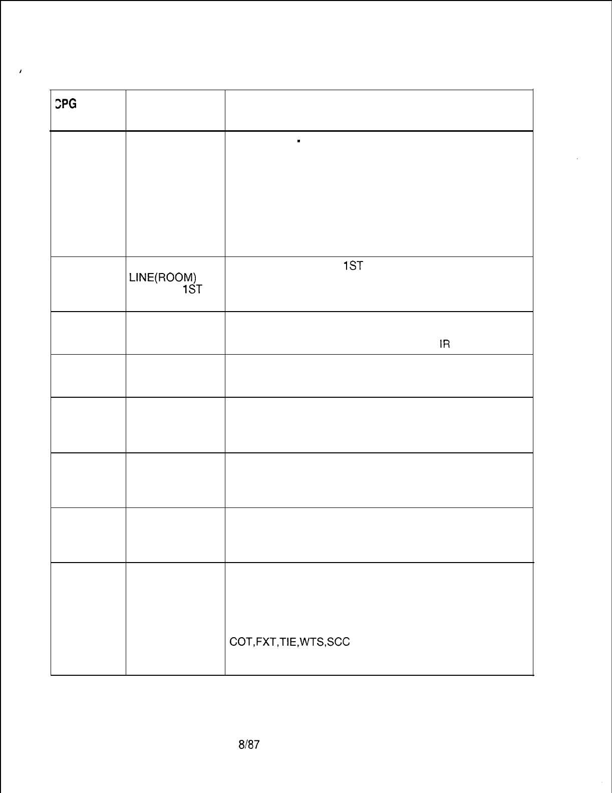
I
TL-130400-1001
SPG
ERROR
MESSAGES
Table 21.1 CPG Error Messages (Continued)
TITLE DESCRIPTION OF MESSAGES
RN-01
. . . .
RN-51
VALUE OF CODE TYPE
-
CODE TYPE IDENTIFIER
SECOND FOR EACH VALUE OF CODE TYPE, REQUIRED VALUES
ELEMENT TOO OR VALUE RANGES ARE INDICATED AS FOLLOWS:
LARGE CODE CODE TYPE
TYPE IDENTIFIER
---- ----------
. .
INT
o-1 5
3DG o-9, 12
4DG 15
DUPLICATE THE ROOM NUMBER
1ST
DIGIT MUST BE UNIQUE
LINE(ROOM)
ACROSS ALL RN RECORDS.
NUMBER
1ST
DIGIT
RN-52
RP-01
INTERCEPT IF THE CODE TYPE IS ‘INT’,
ROUTING CODE THEN THE CODE TYPE IDENTIFIER MUST BE A VALID
NOT FOUND INTERCEPT ROUTING NUMBER ON AN
IR
RECORD.
ELEMENT 2 IS
MEANINGLESS
SPECIFICATION
RP-01
ELEMENTS
HAVE
INCOMPATIBLE
VALUES’
RP-01
2ND FEATURE
REQUIRED IF
FIRST
SPECIFIED
RP-01
VALUE OF
SECOND
ELEMENT TOO
LARGE
RP-01
RP-01 VALUE VALUE OF TRUNK VALUE OF TRUNK
OF SECOND GROUP TYPE OR GROUP NUMBER OR
ELEMENT TOO INTERCEPT INTERCEPT ROUTING
SMALL NUMBER
INT
00-l 5
COT,FXT,TIE,WTS,SCC
00-31 OR 00-63 DEPENDS
ON SVR
LOC, DGT --
SVR 5210
8h37 D-51 3
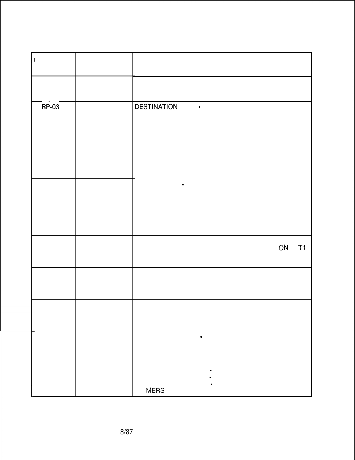
TL-130400-1001
Table 21.1
CPG ERROR
MESSAGES
RP-03
R6-03
RP-51
RP-52
RP-53
RP-53
RP-55
RP-60
RP-61
1
D-51 4
TITLE
ELEMENT 2 IS
MEANINGLESS
SPECIFICATION
ELEMENTS
HAVE
INCOMPATIBLE
VALUES
ROUTING LIST
NOT USED
DUPLICATE
ROUTING
LIST/SELECT
ORDER
INTERCEPT
ROUTING CODE
NOT FOUND
TRUNK GROUP
NOT FOUND
SCC NUMBER
MUST BE
ENGINEERED
ON MS RECORD
FOR GIVEN
DEST. TYPE,
MERS FIELDS
ON T2 CANNOT
BE DASHED
8187
CPG Error Messages (Continued)
DESCRIPTION OF MESSAGES
DESTlNATlOlj
TYPE
-
MERS SCC ID
IF THE DESTINATION TYPE IS ‘SCC’, THEN THE MERS
SCC ID FIELD CANNOT BE DASHED.
SIMILARILY, IF THE DESTINATION TYPE IS NOT ‘SCC’,
THEN THE MERS SCC ID FIELD MUST BE DASHED.
ROUTING LIST NUMBER
THE ROUTING LIST NUMBER DEFINED ON AN RP
RECORD SHOULD BE REFERENCED ON AN NR, NT, ST
OR TR RECORD.
(ENDCHK)
ROUTING LIST
-
SELECT ORDER
THE ROUTING LIST/SELECT ORDER COMBINATION
MUST BE UNIQUE ACROSS ALL RP RECORDS.
DESTINATION IDENTIFIER
ALL TRUNK GROUP NUMBERS MUST APPEAR
Oiu
A
Tl
RECORD. ALL INTERCEPT ROUTING NUMBERS MUST
APPEAR ON AN IR RECORD.
SELECT ORDER
SELECT ORDERS MUST BE CONTINUOUS WITH NO
GAPS FOR EACH ROUTING LIST.
(ENDCHK)
MERS SCC ID NUMBER
THE MERS SCC ID NUMBER MUST BE DEFINED ON AN
MS RECORD.
DESTINATION TYPE
-
DESTINATION IDENTIFIER
FOR DESTINATION TYPES ‘COT’, ‘FXT’, ‘TIE’, ‘WTS’,
AND ‘SCC’, THE FOLLOWING MERS FIELDS ON A T2
RECORDCANNOTBEDASHED:
1. MERS PAUSE VALUE
-
ESCAPE
2. MERS PAUSE VALUE
-
TOLL BARRIER CODE
3. MERS PAUSE VALUE
-
SEIZURE
4.
MERS
QUEUE ALLOWED
SVR 5210
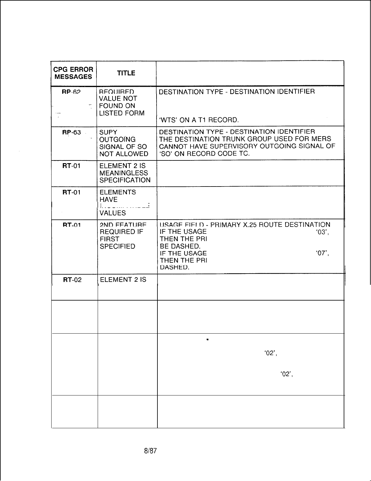
TL-130400-1001
Table 21.1 CPG Error Messages (Continued)
DESCRIPTION OF MESSAGES
FOR DESTINATION TYPE ‘SCC’, THE DESTINATION
TYPE IDENTIFIER MUST BE A VALID TRUNK GROUP
WITH AN APPLICATION TYPE OF ‘COT’, ‘FXT’, ‘TIE’, OR
INCOMPATIBLE
FIELD IS IN A RANGE OF ‘00’ TO
‘03’,
MARY DESTINATION FIELDS CANNOT
FIELD IS IN A RANGE OF ‘04’ TO
‘07’,
MARY DESTINATION FIELDS MUST BE
MEANINGLESS
SPECIFICATION
RT-02 ELEMENTS
HAVE
INCOMPATIBLE
VALUES
RT-02 2ND FEATURE USAGE FIELD
-
SECONDARY X.25 ROUTE
REQUIRED IF DESTINATION
FIRST IF THE USAGE FIELD IS ‘01’ OR
‘02’,
THEN THE
SPECIFIED SECONDARY DESTINATION FIELDS CANNOT BE
DASHED.
IF THE USAGE FIELD IS NOT ‘01’ OR
‘02’,
THEN THE SECONDARY DESTINATION FIELDS MUST
BE DASHED.
RT-03 INVALID X.1 21 ADDRESS
CHARACTER IF THE X.121 ADDRESS IS LESS THAN 14 DIGITS, THEN
STRING THE DIGITS MUST BE PACKED TO THE LEFT WITH THE
REMAINING FIELDS DASHED.
SVR 5210
8/87 D-51 5
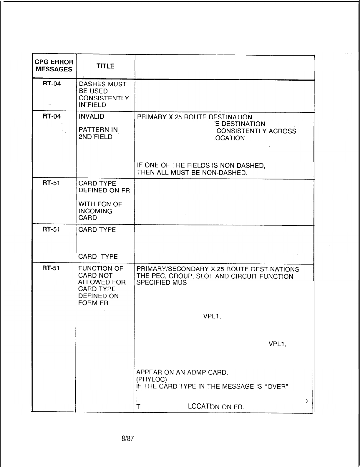
TL-130400-1001
Table 21.1 CPG Error Messages (Continued)
DESCRIPTION OF MESSAGES
CHARACTER SECONDARY X.25 ROUT
DASHES MUST BE USED
THE ENTIRE PHYSICAL L
(PEC, GROUP, CARD SLOT, AND CIRCUIT).
IF ANY OF THE FIELDS ARE DASHED,
THEN ALL MUST BE DASHED.
INCOMPATIBLE
DEFINED ON FR
INCOMPATIBLE
WITH INCOMING
TBE
VALID FOR THE CARD TYPE
DEFINED ON FR
(FOR THIS PEC TYPE).
FOR USAGE 00 AND 01,
THE PRIMARY X.25 ROUTE DESTINATION MUST
APPEAR ON A VPLO,
VPLl,
VP20 (VOICE AND DATA OR
DATA), VP21 OR NIC CARD.
FOR USAGE 02,
THE PRIMARY AND SECONDARY X.25 ROUTE
DESTINATION MUST APPEAR ON A VPLO,
VPLl,
VP20
(VOICE AND DATA OR DATA), VP21 OR NIC CARD.
FOR USAGE 03,
THE PRIMARY X.25 ROUTE DESTINATION MUST
THAT INDICATES THAT A CARD IN THE PREVIOUS
LOCATION IS A WIDE CARD AND IT OVERHANGS INTO
HIS PHYSICAL
LOCATI
D-51 6
8187
SVR 5210
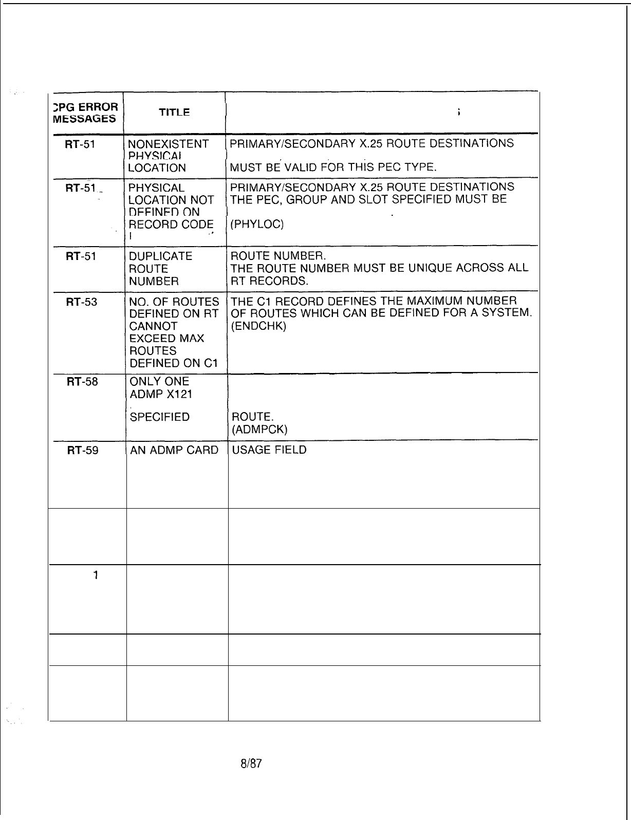
TL-130400-1001
Table 21.1 CPG Error Messages (Continued)
DESCRIPTION OF MESSAGES
THE PEC GROUP SLOT AND CIRCUIT SPECIFIED
DEFINED ON AN
FR
RECORD.
FR
X.1 21 ADDRESS
THE X.121 ADDRESS FOR THE ADMP MUST BE
ADDR MAY BE LIMITED TO ONE. ADMP CAN ONLY HAVE ONE
RT-64
MUST BE IF ADMP IS SPECIFIED FOR THE USAGE FIELD OF
DEFINED ON DATA SYSTEM ROUTING DATA, THEN AN ADMP CARD
RECORDCODE MUST BE DEFINED ON FR.
FR
(ADMPCK)
ADMP NOT USAGE FIELD-CARD TYPE
SPECIFIED ON IF THE CARD TYPE ADMP IS DEFINED ON RECORD
RT
CODE FR THEN AN ADMP MUST BE SPECIFIED ON
RT.
SA-5
1
DTMF SELF-EXPLANATORY
RECEIVERS NOT
EQUIPPED ON
RECORD CODE
FR
SA-51
DUPLICATE SCC THE SCC NUMBER WAS SPECIFIED ON A PREVIOUS
NUMBER SA RECORD.
SD-01
DASHES MUST SECONDARY DIRECTORY NUMBERS
BE USED THESE FIELDS MUST BE FILLED FROM LEFT TO
CONSISTENTLY RIGHT, WITH DASHES BEING CONSISTENT.
IN FIELD
SVR 5210
Em? D-5? 7
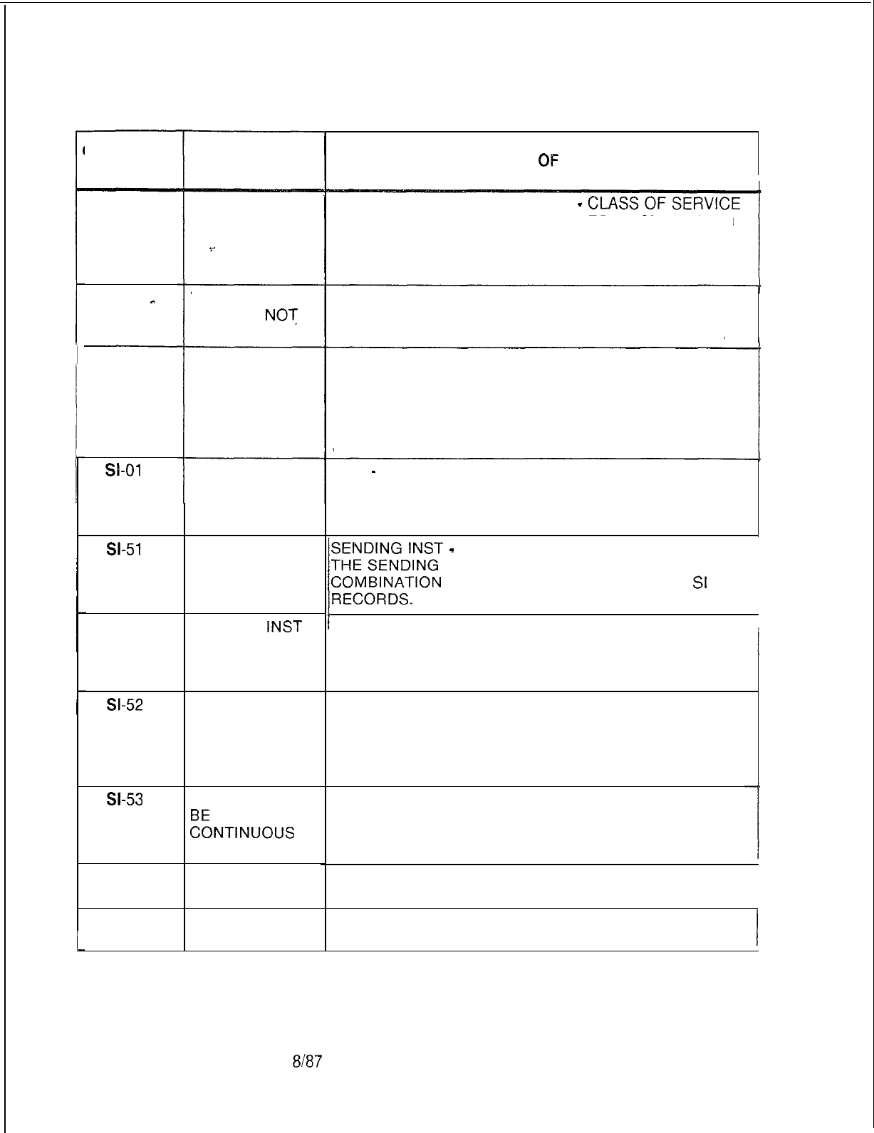
TL-130400-1001
Table 21.1 CPG Error Messages (Continued)
.
DESCRIPTION
OF
MESSAGES
CPG ERROR
MESSAGES
r
SD-54
a-01
s-51
SI-52
9-52
w-53
SI-60
SI-61
i
D-51 8
TITLE
CLASS OF
SERVICE NOT
DEFINED
.=.
PRIMARY DIRECTORY NUMBER
-
THE PRIMARY DIRECTORY NUMBER MUST HAVE AN
N-DISPLAYABLE CLASS OF SERVICE WITH ‘SD’ (CAS
SECONDARY NUMBER) SPECIFIED.
(GENLIN)
SD-51
. . .
SD-51
_
DIRECTORY
NUMBER
NO?
FOUND
PRIMARY DIRECTORY NUMBER
THIS NUMBER MUST BE A VALID DIRECTORY
NUMBER APPEARING ON AN LD RECORD. (GENLIN)
REQUIRED
DATA NOT
FOUND
A LINE NUMBER WAS FOUND ON AN LD RECORD
WITH A CLASS OF SERVICE SPECIFYING SECONDARY
DIRECTORY NUMBER,
BUT THE LINE NUMBER DID NOT APPEAR AS THE
PRIMARY DIRECTORY NUMBER ON AN SD RECORD.
(GENLIN)
ELEMENTS
HAVE
INCOMPATIBLE
VALUES
SKIP
-
OTHER FIELDS
IF THE VALUE ‘SK’ IS SPECIFIED FOR THE SKIP FIELD
THEN ALL FIELDS TO THE RIGHT OF THE SKIP FIELD
MUST CONTAIN DASHES.
DUPLICATE
SENDING
INST./SELECT
ORDER
THE SENDING INSTRUCTION/SELECT ORDER
1
;IllNG/T
-
SELECT ORDER
COMBINATION MUST BE UNIQUE ACROSS ALL
Sl
SENDING
INST
NOT USED ON
TR, NR, OR ST
FORM
SENDING INST.
NOT USED SENDING INSTRUCTION
A SENDING INSTRUCTION LIST NUMBER WHICH IS
SPECIFIED ON AN SI RECORD SHOULD BE
REFERENCED ON A NR, NT, ST OR TR RECORD.
(ENDCHK)
VALUES MUST
E~NTINU~US
SELECT ORDER
SELECT ORDERS MUST BE CONTINUOUS WITH NO
GAPS FOR EACH SENDING INSTRUCTION LIST.
(ENDCHK)
PREFIX INDEX THE PREFIX INDEX REFERENCED ON THE SI RECORD
NOT FOUND MUST BE DEFINED ON A PC RECORD.
PREFIX INDEX
NOT FOUND THE LDN PREFIX INDEX REFERENCED ON THE SI
RECORD MUST BE DEFINED ON AN LP RECORD. 1
8187
SVR 5210
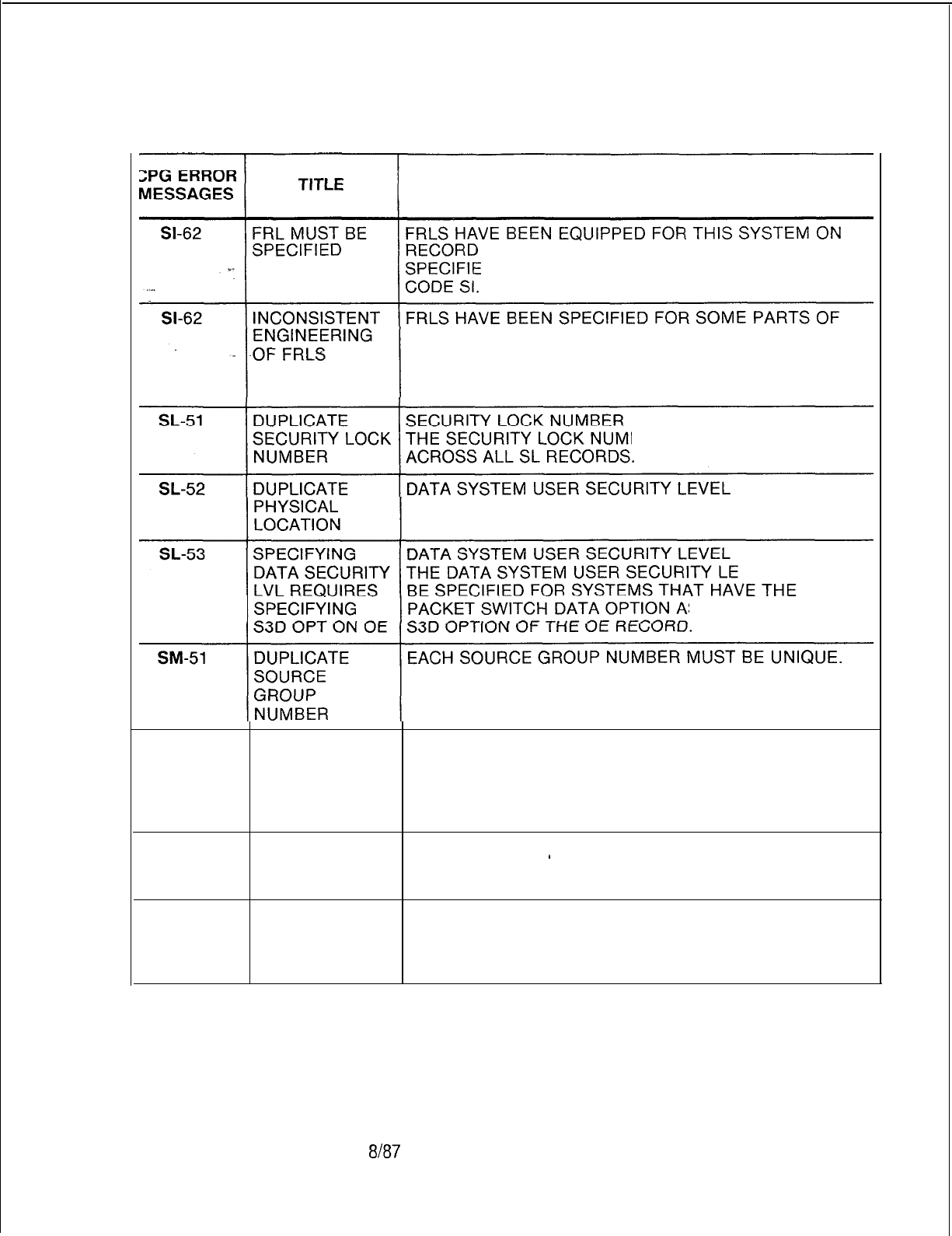
TL-130400-1001
Table 21.1 CPG Error Messages (Continued)
DESCRIPTION OF MESSAGES
CODE OF AND MUST THEREFORE BE
D FOR EVERY MERS ROUTE ON RECORD
THE SYSTEM AND NOT OTHERS.
ENSURE THAT ALL ATTENDANTS, LINES, TRUNK
GROUPS, MERS ROUTES, ETC. HAVE FRLS ENTIRELY
ENABLED OR DISABLED.
BER MUST BE UNIQUE
THE DATA SYSTEM USER SECURITY LEVEL MUST BE
UNIQUE ACROSS ALL SL RECORDS.
VEL CAN ONLY
S DEFINED BY THE
SM-52
REQUIRED SOURCE GROUP
VALUE NOT FOR EACH SOURCE GROUP APPEARING ON A TC
FOUND ON RECORD THERE SHOULD BE A CORRESPONDING
LISTED FORM SOURCE GROUP MESSAGE ON A SM RECORD.
(ENDCHK)
SP-51
DUPLICATE
MESSAGE
NUMBER
THE MESSAGE NUMBER APPEARED ON A PREVIOUS
SP RECORD.
’
SP-52 REQUIRED SOURCE GROUP NUMBER
VALUE NOT A SOURCE GROUP NUMBER USED ON A TC RECORD
FOUND ON WAS NOT DEFINED ON AN SP RECORD.
LISTED FORM (ENDCHK)
SVR 5210
8187
D-519

TL-130400-1001
CPG ERROR
MESSAGES
Table 21.1 CPG Error Messages (Continued)
TITLE DESCRIPTION OF MESSAGES
SR-01
. . .
INVALID
CHARACTER
STRING
.i_
SYMBOLIC REPLACEMENT WORD STRING
CHARACTERS
THE SYMBOLIC REPLACEMENT WORD/STRING
CHARACTER FIELDS ARE COMPOSED OF SYMBOLIC
REPLACEMENT WORD PLUS THE SYMBOLIC
REPLACEMENT STRING.
THE FIRST ‘N’ ASCII CHARACTERS BEFORE THE FIRST
BLANK CHARACTER WILL BE THE SR WORD. THE
NEXT ‘M’ ASCII CHARACTERS FOLLOWING THE FIRST
BLANK CHARACTER WILL BE THE SR STRING. ‘N’ +
‘M’ HAVE TO BE LESS THAN OR EQUAL TO THE TOTAL
OF 63 SYMBOLIC REPLACEMENT
WORDiSTRINGCHARACTERS.
SR-51
DUPLICATE SYMBOLIC
REPLACEMENi
ENTRY NUMBER
SYMBOLIC THE SYMBOLIC REPLACEMENT ENTRY NUMBER
REPLACEMENT MUST BE UNIQUE ACROSS ALL SR RECORDS.
ENTRY NUMBER
ST-01
ELEMENTS
HAVE
INCOMPATIBLE
VALUES
ST-01
ELEMENT 2 IS
MEANINGLESS
SPECIFICATION
ST-01
2ND FEATURE
REQUIRED IF
FIRST
SPECIFIED
ST-01
VALUE OF
SECOND
ELEMENT TOO
SMALL
ST-01
VALUE OF
SECOND
ELEMENT TOO
LARGE
ST-01
INVALID INVALID SERVICE CODE
SYNTAX THE SERVICE CODE MUST BE OF THE FORM
‘llN’,
‘Nil’,
‘555’,
‘00-l
OR ‘OOO’, WHERE ‘N’ IS A NUMBER
BETWEEN 2 AND 9.
D-520 6l87
SVR 5210
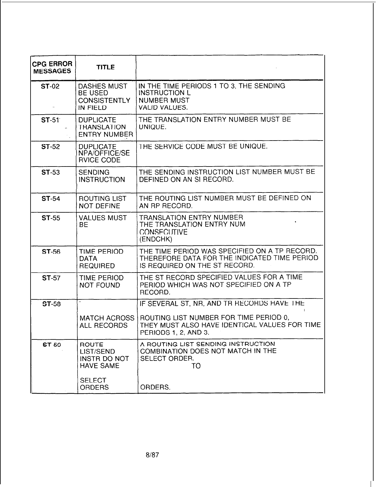
TL-130400-1001
Table 21.1 CPG Error Messages (Continued)
DESCRIPTION OF MESSAGES
IST NUMBER AND THE ROUTING LIST
BOTH BE DASHED OR BOTH CONTAIN
NPA/OFFICE/SE
NOT DEFINED
BERS MUST BE
CONTINUOUS
TIVE
WITH NO GAPS.
TIME PERIOD
VALUES MUST SAME SENDING INSTRUCTION LIST NUMBER AND
NUMBER OF
IT IS POSSIBLE
i0
HAVE ERRONEOUS VALUES IN THE
NUMBER OF ROUTING LIST OR SENDING INSTRUCTIONS IF THEY
DO NOT HAVE THE SAME NUMBER OF SELECT
SVR
5210 8187 D-521
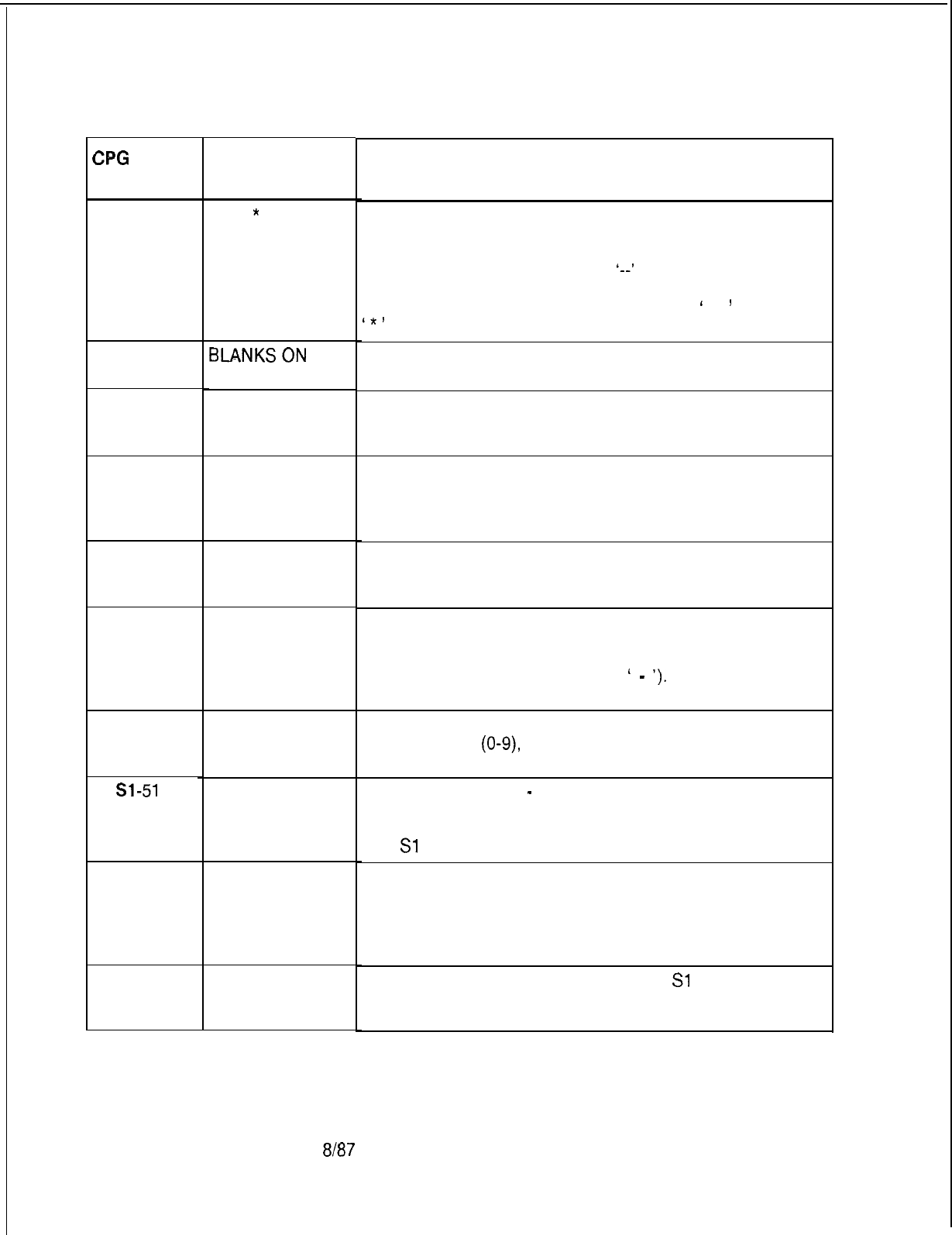
TL-130400-1001
Table 21.1 CPG Error Messages (Continued)
SPG
ERROR
MESSAGES
ST-60
. . .
SY-01
SY-02
SY-03
SY-04
SY-05
SY-06
Sl-51
Sl-52
Sl-53
D-522
TITLE
#OR
*
BEING
OUTPULSED ON
NON-DTMF
TRUNK GROUP
BLANKSON
.
INPUT RECORD
INVALID
CHARACTER
STRING
NUMERIC FIELD
CONTAINS
NON-NUMERIC
DATA
INVALID
CHARACTER
STRING OR
NUMERIC
VALUE
INVALID
CHARACTER
DUPLICATE
SCREENING
TABLES
MDR WORK
GROUP
NUMBER NOT
FOUND ON LD
FORM
MDR DEVICE
NOT ON MD
FORM
8187
DESCRIPTION OF MESSAGES
A ROUTING LIST SENDING INSTRUCTION
COMBINATION ASSOCIATES A TRUNK GROUP
(RECORD CODES RP AND Tl) WITH AN OUTGOING
SIGNALING MODE OF ‘DP’ OR
‘--I
WITH A PREFIX
INDEX (RECORD CODES SI, LP AND/ OR PC) THAT
SPECIFIES THE OUTPULSING OF DIGITS
‘
#
’
AND/OR
c*r
BLANKS WERE FOUND IN SOME FIELD (OTHER THAN
THE COMMENTS FIELD) ON THE INPUT RECORD.
THE FIELD BEGINNING IN THE LISTED COLUMN
CONTAINS AN INVALID STRING.
THE FIELD BEGINNING IN THE LISTED COLUMN IS TO
CONTAIN NUMERIC DATA (DIGITS O-9) ONLY.
NON-NUMERIC DATA WAS FOUND.
A NUMERIC FIELD CONTAINS A VALUE THAT IS NOT IN
THE ALLOWABLE RANGE OF VALUES FOR THAT
FIELD.
THE FIELD BEGINNING IN THE LISTED COLUMN
CONTAINS AN INVALID VALUE. THE FIELD CAN
CONTAIN EITHER A NUMERIC VALUE OR SOME
CHARACTER STRING (USUALLY L
-
‘).
THE COLUMN LISTED IS TO CONTAIN A CHARACTER
(A-Z), A DIGIT
(O-9),
OR A DASH. AN INVALID
CHARACTER WAS FOUND IN THE COLUMN.
SCREENING TABLE
-
MDR WORK GROUP NUMBER
THE COMBINATION OF SCREENING TABLE AND MDR
WORK GROUP NUMBER MUST BE UNIQUE ACROSS
ALL
Sl
RECORDS.
THE MDR WORK GROUP NUMBER MUST BE
SPECIFIED ON AT LEAST ONE LD RECORD.
THE MDR DEVICE SPECIFIED ON AN
Sl
RECORD
MUST BE A DEVICE ENGINEERED ON AN MD RECORD.
SVR 5210
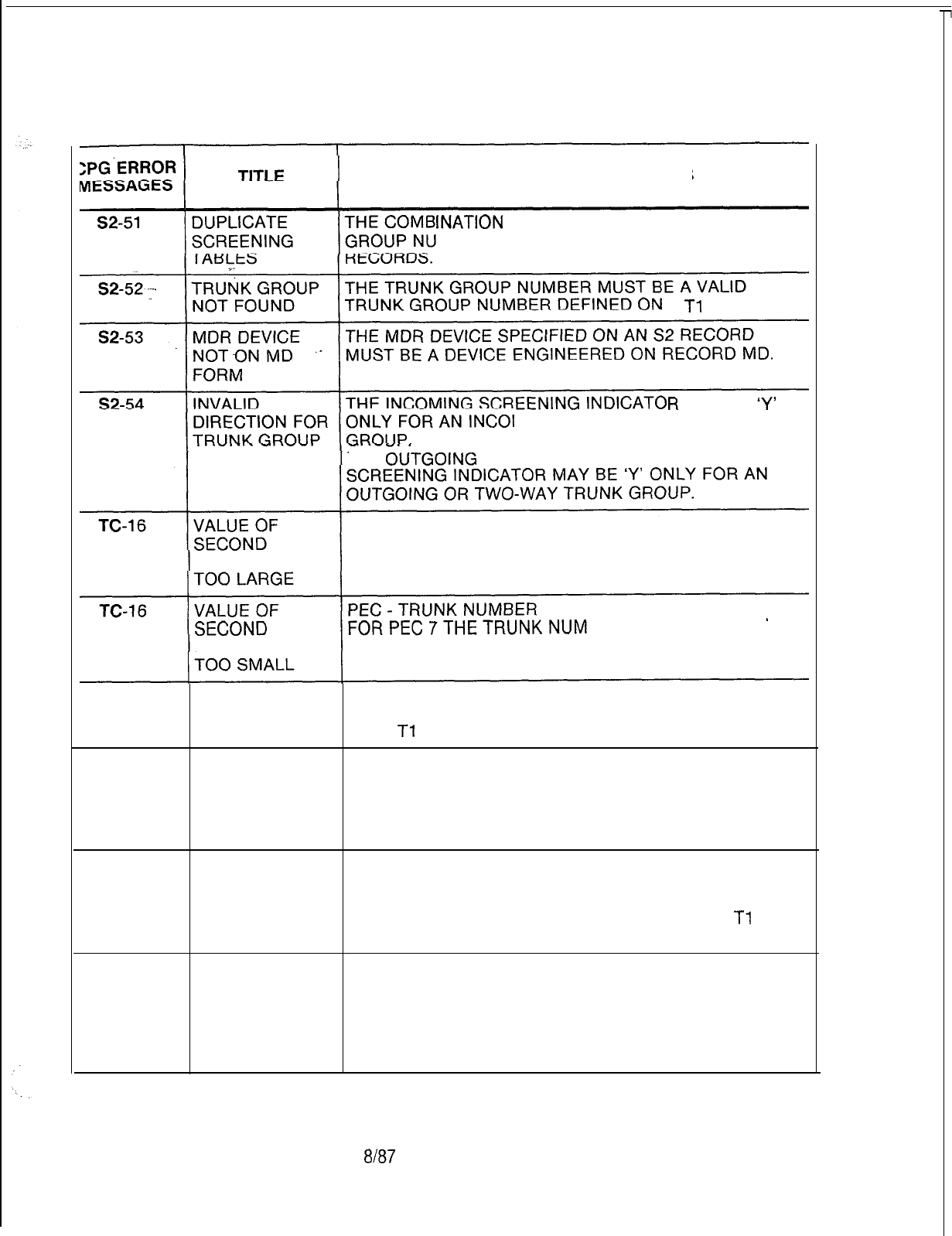
TL-130400-1001
Table 21.1 CPG Error Messages (Continued)
DESCRIPTION OF MESSAGES
INATION
OF MDR DEVICE AND TRUNK
MBER MUST BE UNIQUE ACROSS ALL S2
A
Tl
RECORD.
R
MAY BE
‘Y’
MING OR TWO-WAY TRUNK
THE
OtiTGOiNG
SCREENING THE OUTGOING
ELEMENT IS
BER MUST BE IN THE
ELEMENT IS RANGE 000 TO 103 ONLY.
TC-51
TRUNK GROUP TRUNK GROUP NUMBER
NOT FOUND THIS NUMBER MUST BE A TRUNK GROUP DEFINED
ON A
Tl
RECORD.
TC-52 TRUNK GROUP THERE SHOULD BE AT LEAST ONE TRUNK CIRCUIT
DOES NOT ON A TC RECORD FOR EACH TRUNK GROUP.
HAVE ANY (GENTRK)
TRUNK
CIRCUITS
TC-55 FIELD SUPERVISORY INCOMING SIGNAL
CONFLICTS TRUNKS MARKED FOR FAST ACCESS (‘FA’) IN THE
WITH TRUNK SUPERVISORY INCOMING SIGNAL MUST HAVE A
DIRECTION DIRECTION OF INCOMING ONLY (‘IN’) ON THE
Tl
RECORD FOR THE SPECIFIED TRUNK GROUP.
TC-56 CARD TYPE
DEFINED ON FR
INCOMPATIBLE
WITH FCN OF
INCOMING
CARD
SVR 5210
8187
D-523
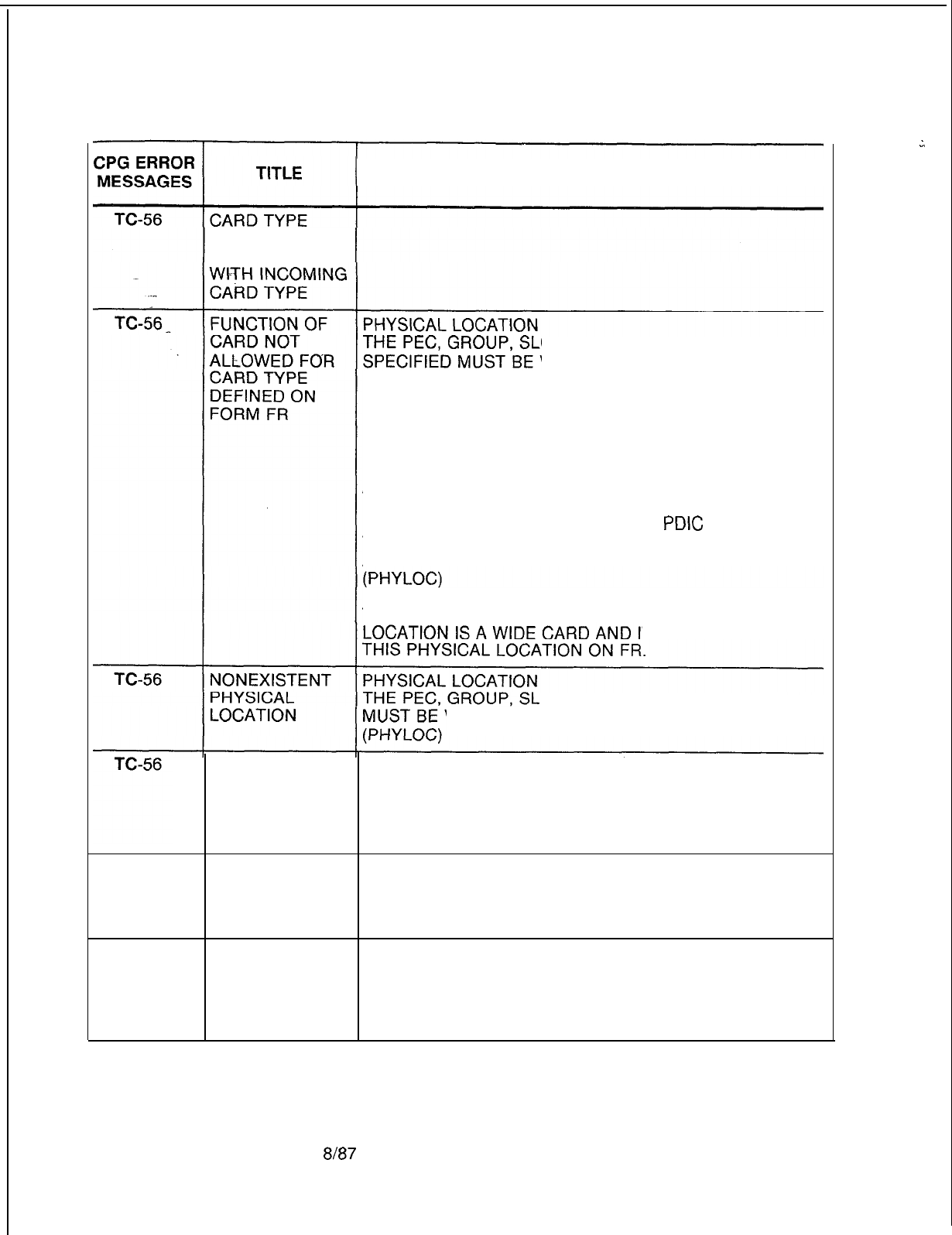
TL-130400-1001
Table 21.1 CPG Error Messages (Continued)
DESCRIPTION OF MESSAGES
DEFINED ON FR
INCOMPATIBLE
OT, AND CIRCUIT FUNCTION
VALID FOR THE CARD TYPE
DEFINED ON FR (FOR THIS PEC TYPE).
PHYSICAL TRUNK TYPE OF ‘EM’ MUST APPEAR ON AN
‘EMT OR ‘EMT4 TRUNK CARD.
PHYSICAL TRUNK TYPE OF ‘GS’, ‘LP’, AND ‘LD’
(OUTGOING) MUST APPEAR ON A COT TRUNK CARD.
PHYSICAL TRUNK TYPE OF ‘LD’ (INCOMING) MUST
APPEAR ON AN ILT TRUNK CARD.
PAGING/DICTATION CIRCUITS (TRUNK APPLICATION
‘DIC’ OR ‘PAG’ MUST APPEAR ON A
PDIC
CARD.
TRUNKS WITH TRUNK APPLICATION ‘NIC’ MUST
APPEAR ON A NIC CARD.
IF THE CARD TYPE IN THE MESSAGE IS “OVER”,
THAT INDICATES THAT A CARD IN THE PREVIOUS
T OVERHANGS INTO
OT, AND CIRCUIT SPECIFIED
VALID FOR THIS PEC TYPE.
PHYSICAL PHYSICAL LOCATION
LOCATION NOT THE PEC, GROUP, AND SLOT SPECIFIED MUST BE
DEFINED ON DEFINED ON AN FR RECORD.
RECORDCODE
FR
TC-56
TC-56
PHYSICAL
LOCATION
PREVIOUSLY
FILLED
CARD
OVERHANGS
INTO A
PREVIOUSLY
FILLED SLOT
PHYSICAL LOCATION
THE PEC, GROUP, SLOT, AND CIRCUIT SPECIFIED FOR
THE TRUNK CIRCUIT MUST BE UNIQUE.
(PHYLOC)
THIS CARD IS AN OVERSIZED CARD AND IS TRYING
TO FILL TWO SLOTS.
OF THE TWO SLOTS IT FILLS, THE RIGHT HAND ONE
HAS ALREADY BEEN FILLED.
D-524
8187
SVR 5210
z
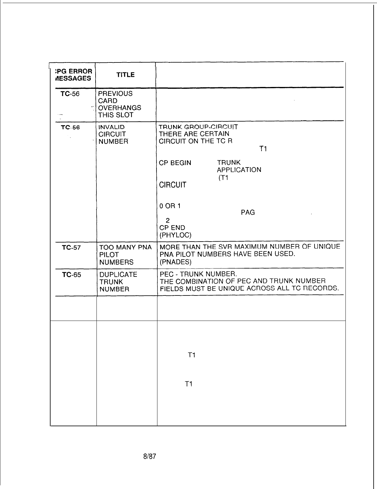
TL-130400-1001
Table 21.1 CPG Error Messages (Continued)
DESCRIPTION OF MESSAGES
THE CARD TO THE LEFT OF THIS SLOT IS AN
OVERSIZED CARD.
THE RIGHT HALF OF THAT CARD FILLS THIS SLOT.
REQUIRED VALUES FOR THE
ECORD DEPENDING ON THE
TRUNK APPLICATION ON THE
Tl
RECORD:
(Tl
RECORD)
DIC
TC-66
ILLEGAL VALUE
FOR DIC, PAG,
OR REC APPL
TC-66
ILLEGAL VALUE PHYSICAL TRUNK TYPE
FOR TRUNK THERE ARE CERTAIN REQUIRED VALUES FOR THE
APPLICATION PHYSICAL TRUNK TYPE FIELD ON A TC RECORD
DEPENDING ON THE TRUNK APPLICATION INDICATED
ON THE
Tl
RECORD:
TRUNK PHYSICAL
APPLICATION TRUNK
Tl
RECORD) TYPE
DIC
PAG
REC
NIC
LP
LP
EM
EM OR LP
SVR 5210
8l87 D-525
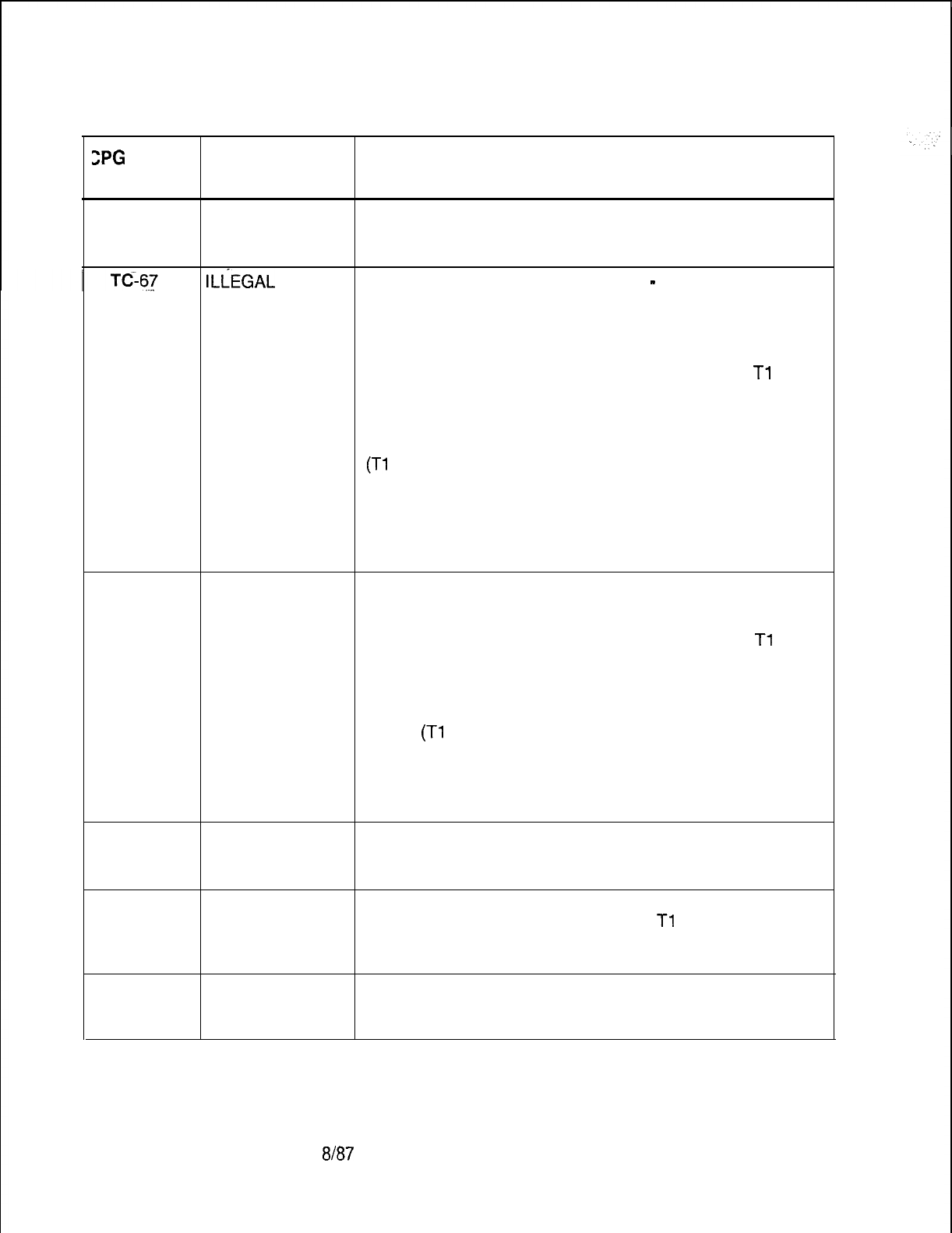
TL-130400-1001
ZPG
ERROR
MESSAGES
Table 21.1 CPG Error Messages (Continued)
TITLE DESCRIPTION OF MESSAGES
TC-67 ILLEGAL VALUE
FOR DIC, PAG
OR REC APPL
ILiEGAL
VALUE SUPERVISORY INCOMING SIGNAL
-
SUPERVISORY
FOR TRUNK OUTGOING SIGNAL
APPLICATION THERE ARE CERTAIN REQUIRED VALUES FOR THE
SUPERVISORY INCOMING SIGNAL AND THE
SUPERVISORY OUTGOING SIGNAL DEPENDING ON
THE TRUNK APPLICATION INDICATED ON THE
Tl
RECORD (DEPENDING ON SVR).
TC-68
TRUNK SUPERVISORY SUPERVISORY
APPLICATION INCOMING OUTGOING
(Tl
RECORD) SIGNAL SIGNAL
DIC -- ID OR --
PAG -- ID OR --
REC -- ID OR --
NIC -- ID OR --
ILLEGAL VALUE TRUNK CARRIER
FOR DIC, PAG THERE ARE CERTAIN REQUIRED VALUES FOR THE
OR REC APPL TRUNK CARRIER ON A TC RECORD DEPENDING ON
THE TRUNK APPLICATION INDICATED ON THE
Tl
RECORD (DEPENDING ON SVR):
TC-69 ILLEGAL VALUE
FOR DIC, PAG
OR REC APP
TRUNK
APPLICATION
(Tl
RECORD)
DIC
PAG
REC
TRUNK
CARRIER
AT OR --
AT OR --
AT OR --
TC-69 ILLEGAL VALUE CO TRUNK NUMBER
FOR TRUNK IF THE TRUNK APPLICATION ON A
Tl
RECORD IS
APPLICATION ‘DIC’, ‘PAG’, ‘REC’ OR ‘NIC’
THEN THE CO TRUNK NUMBER MUST BE DASHED.
TC-71
ILLEGAL VALUE
FOR DIC, PAG
OR REC APPL
D-526
8187
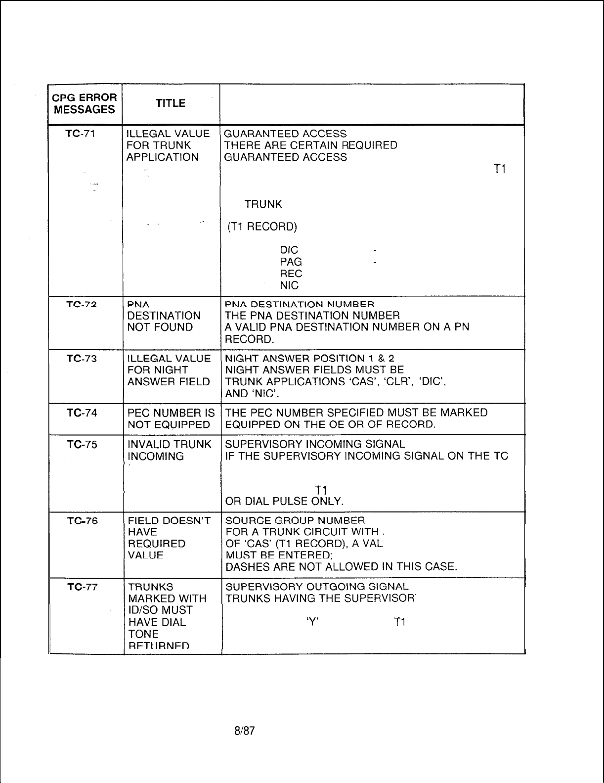
TL-130400-1001
Table 21.1 CPG Error Messages (Continued)
DESCRIPTION OF MESSAGES
EQUIRED
VALUES FOR THE
ON A TC RECORD DEPENDING
ON THE TRUNK APPLICATION INDICATED ON THE
Tl
RECORD (DEPENDING ON SVR):
APPLICATION GUARANTEED
ACCESS
SPECIFIED MUST BE
DASHES FOR
‘,
‘DIG’,
‘PAG’, ‘REC’
SIGNAL FOR RECORD IS ‘FA’ (FAST ACCESS TRUNK),
FAST ACCESS THEN THE TRUNK INCOMING SIGNAL FOR ITS TRUNK
GROUP ON THE
Tl
RECORD MUST BE ALL DASHED
A TRUNK APPLICATION
ID SOURCE GROUP
Y OUTGOING
SIGNAL OF ‘ID’, OR ‘SO’ MUST HAVE DIAL TONE
RETURNED AS
‘Y’
ON RECORD
Tl
SVR 5210
8187
D-527
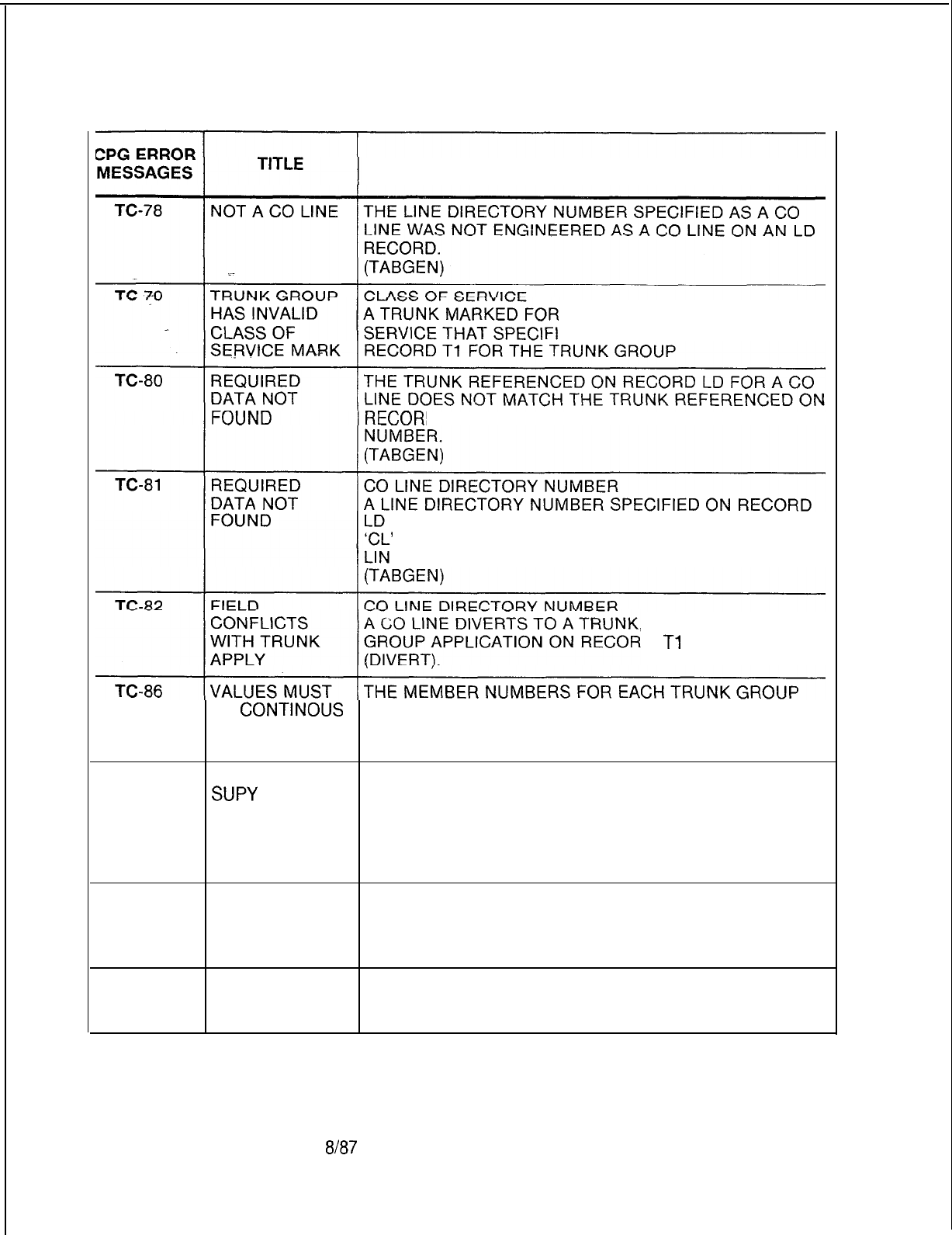
TL-130400-1001
Table 21.1 CPG Error Messages (Continued)
DESCRIPTION OF MESSAGES
PNA MUST HAVE A CLASS OF
ES STATION ACCESS ON
D TC
FOR THE SAME LINE DIRECTORY
HAVING A DISPLAYABLE CLASS OF SERVICE WITH
’
(CO LINE) SHOULD BE SPECIFIED ON TC AS A CO
E DIRECTORY NUMBER.
BUT THE TRUNK
D
Tl
WAS NOT ‘COT’
BE
CONTINOUS
MUST BE NUMBERED IN SEQUENTIAL ORDER
BEGINNING WITH MEMBER ZERO WITH NO GAPS OR
DUPLICATES ALLOWED.
TC-87 IF ONE TRK HAS SUPERVISORY OUTGOING SIGNAL ‘SO’ MUST BE
SUPY
USED FOR ALL MEMBERS OF A TRUNK GROUP IF
OUTGOING REQUIRED FOR ONE MEMBER.
SIGNAL SO
THEN ALL TRKS
IN GRP MUST
TC-99 SITE HAS THECPGREVERSEPROCESSHASDETECTEDA
INCONSISTENT PROBLEM IN THE CUSTOMER’S DATA BASE IN THE
DATA BASE TABLE INDICATED IN THE ERROR MESSAGE.
(TGLINK)
TD-01
ELEMENT 2 IS
MEANINGLESS
SPECIFICATION
D-528
8187
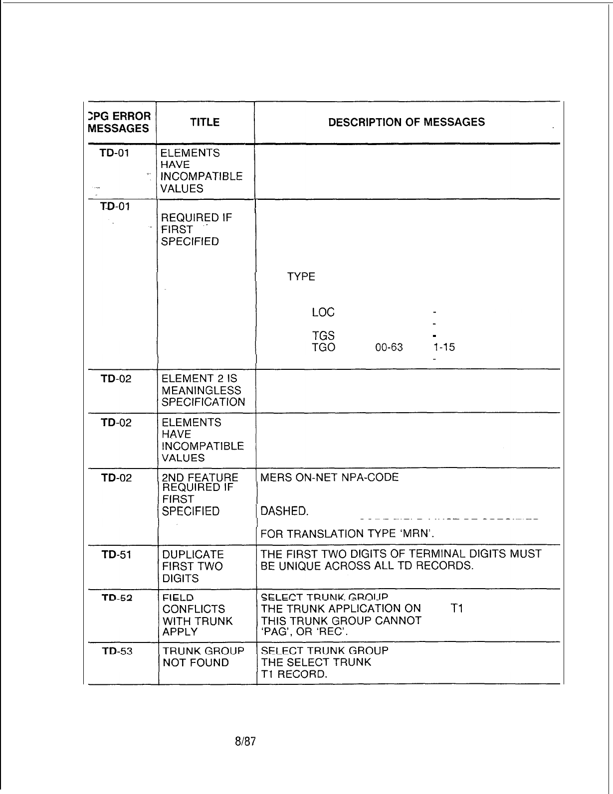
TL-130400-1001
Table 21.1 CPG Error Messages (Continued)
2ND FEATURE TRANSLATION TYPE
GIVEN THE TRANSLATION TYPE, THE SELECT GROUP
AND THE NUMBER OF DIGITS OUTPULSED MUST BE
ENTERED AS THE FOLLOWING:
TRANSLATION SELECT NO. OF
TRUNK DIGITS
GROUP OUTPULSED
LOC
--
MRS --
00-63
-
MRN --
FOR ALL TRANSLATION TYPES EXCEPT ‘MRN’,
THE MERS ON-NET NPA-CODE FIELD MUST BE
THE ON-NET NPA-CODE FIELD MUST BE SPECIFIED
THE
Tl
RECORD FOR
HAVE VALUES OF ‘DIC’,
GROUP MUST BE DEFINED ON A
SVR 5210
8187
D-529

TL-130400-1001
Table 21
.l
CPG Error Messages (Continued)
CPG ERROR
MESSAGES
D-530
TD-56
. . .
TD-57
TD-60
TD-61
TF-01
TL-01
TL-01
TL-01
TITLE
HUNDREDS
GROUP
CONFLICT
HUNDREDS .
GROUP NOT
FOUND
POSSIBLE
CONFLICT WITH
MERS 3-DIGIT
TRANSLATION
ONLY 4 UNIQUE
NPAS ALLOWED
DASHES MUST
BE USED
CONSISTENTLY
IN FIELD
ELEMENTS
HAVE
INCOMPATIBLE
VALUES
ELEMENT 2 IS
MEANINGLESS
SPECIFICATION
2ND FEATURE
REQUIRED IF
FIRST
SPECIFIED
DESCRIPTION OF MESSAGES
IF THE FIRST TWO DIGITS HAVE THE FORM ‘OX’, THEN
BOTH
‘OX’ AND ‘X’ HUNDREDS GROUPS MUST NOT BE
SPECIFIED ON HD RECORDS. IF PRESENT,
THE SYSTEM WILL PROCESS BOTH HUNDREDS
GROUPS WITH FIRST TWO DIGITS OF ‘OX’ FOR THIS
APPLICATION.
FIRST TWO DIGITS OF TERMINAL DIGITS
THE FIRST TWO DIGITS MUST CORRESPOND TO A
HUNDREDS GROUP ENGINEERED ON AN HD RECORD.
CONFLICT WITH 3-DIGIT TRANSLATED NPA’S
WARNING MESSAGE.
PRIVATE NETWORK DIGIT ANALYSIS WAS COMBINED
WITH 3-DIGIT
TRANSLATION (RECORD CODE NR) IN THE SAME
DATA BASE TABLE. POSSIBLE PROBLEM IF PRIVATE
NETWORK DIGITS CONTAIN CONFLICT CODES.
(GENDIG)
ONLY FOUR UNIQUE NPAS ARE ALLOWED BETWEEN
MR, NT, AND TD RECORDS.
(GENDIG)
DATA DUMP HEADER SITE ID
IF ONE CHARACTER IS DASHED IN THE DATA DUMP
HEADER SITE ID,
THEN ALL CHARACTERS MUST BE DASHED
PRINT STATUS
-
PRINTER ID
THE PRINTER STATUS AND PRINTER NUMBER FIELDS
MUST BOTH BE DASHED OR NONDASHED.
8187
SVR 5210
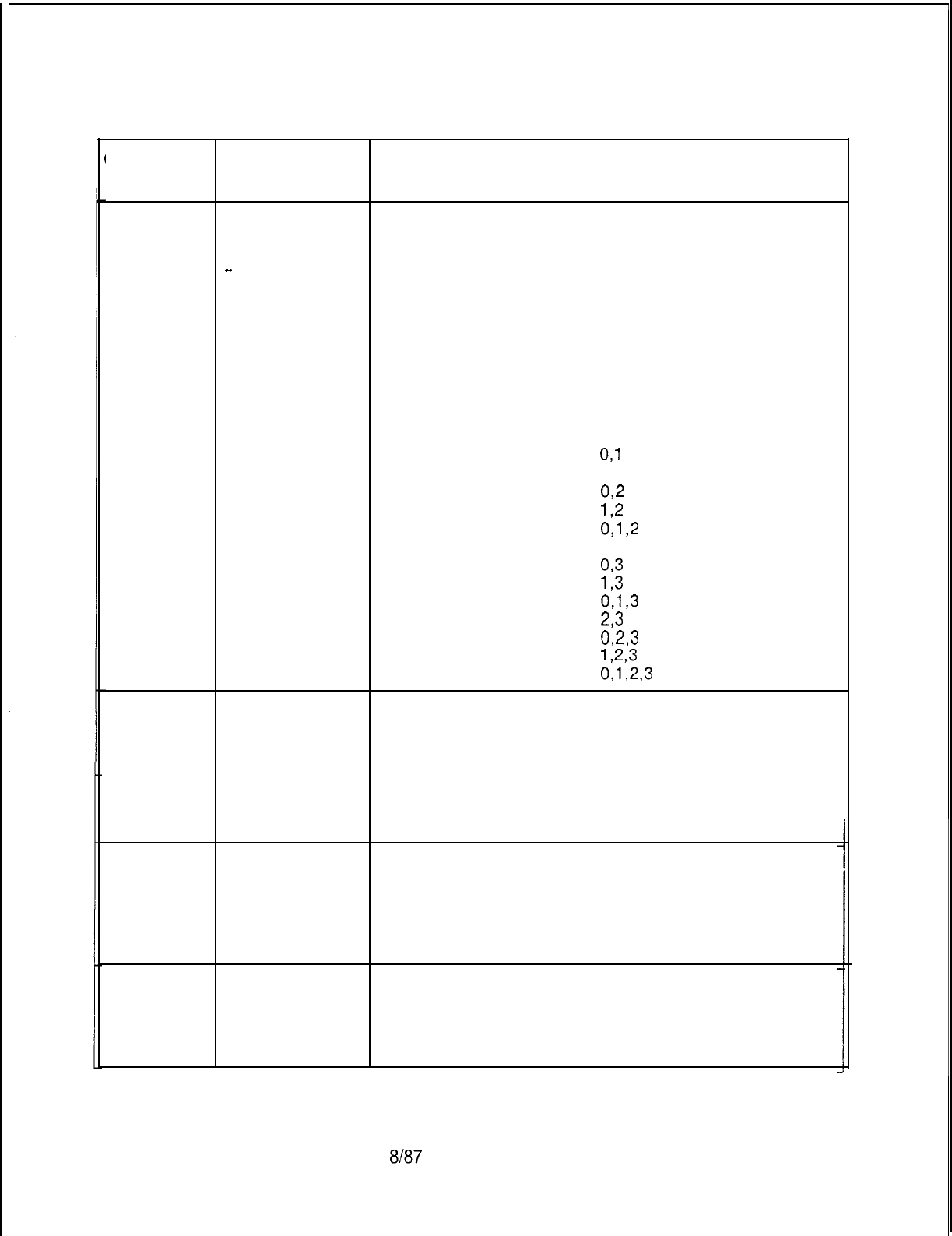
TL-130400-1001
Table
21.1 CPG Error Messages (Continued)
CPG ERROR
MESSAGES TITLE DESCRIPTION OF MESSAGES
TL-51
. . . .
PRINTER THE PRINTER ID IDENTIFIES A SPECIFIC PRINTER
NUMBER NOT NUMBER OR SEVERAL PRINTER NUMBERS
FOUND DEPENDING ON THE VALUE RANGE ENTERED.
>-
ALL PRINTER NUMBERS INDICATED BY THE PRINTER
ID MUST BE VALID PRINTER NUMBERS ON A PD
RECORD.
. .
PRINTER PRINTER
ID
NUMBER(S)
0
NONE
1
0
2
1
3
0,1
4 2
5
02
6
12
70912
8
3
9
093
10
I,3
11 0,1,3
12
23
13
023
14
1,2,3
15
0,1,2,3
TL-52 OPI CARD NOT PMS FIELDS ON TL REQUIRE AN OPI CARD TO BE
EQUIPPED ON EQUIPPED ON AN FR RECORD.
RECORDCODE
FR
TN-51
PEC NUMBER IS PEC NUMBER
NOT EQUIPPED THE PEC NUMBER MUST BE MARKED AS EQUIPPED
ON THE OE RECORD.
TN-52 CARD TYPE
DEFINED ON FR
INCOMPATIBLE
WITH FCN OF
INCOMING
CARD
TN-52 CARD TYPE
DEFINED ON FR
INCOMPATIBLE
WITH INCOMING
CARD TYPE
SVR 5210
8187
D-531
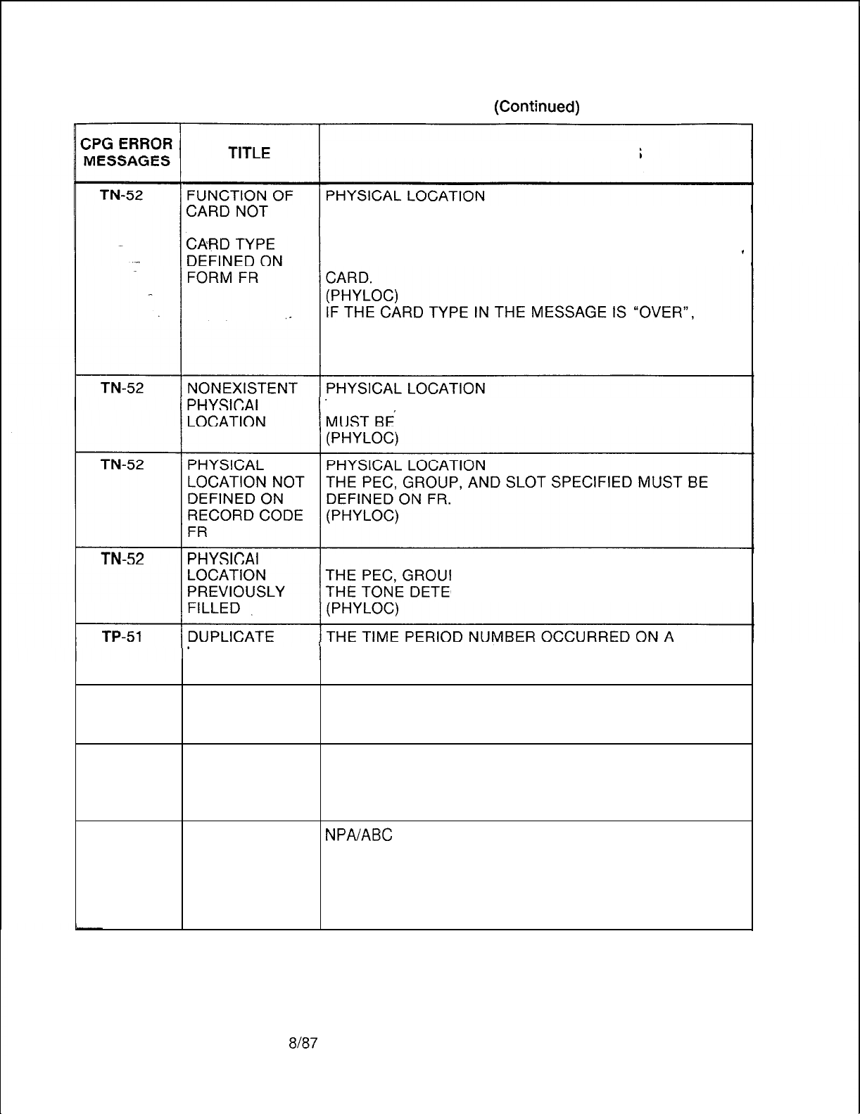
TL-130400-1001
Table 21.1 CPG Error Messages (Contjnued)
DESCRIPTION OF MESSAGES
THE PEC, GROUP, SLOT, AND CIRCUIT FUNCTION
ALLOWED FOR SPECIFIED MUST BE VALID FOR THE CARD TYPE
DEFINED ON FR (FOR THIS PEC TYPE).
TONE DETECTOR CIRCUIT MUST APPEAR ON A TDET 1
THAT INDICATES THAT A CARD IN THE PREVIOUS
LOCATION IS A WIDE CARD AND IT OVERHANGS INTO
THIS PHYSICAL LOCATION ON FR.
THE PEC GROUP, SLOT, AND CIRCUIT SPECIFIED
VALID FOR THIS PEC TYPE.
PHYSICAL LOCATION
P, SLOT, AND CIRCUIT SPECIFIED FOR
CTOR CIRCUIT MUST BE UNIQUE.
TIME PERIOD PREVIOUS TP RECORD.
NUMBER
TP-52
TIME PERIOD THE TIME OF DAY SPECIFIED ON THE CURRENT TP
OVERLAP RECORD OVERLAPS WITH THE TIME OF DAY ON A
PREVIOUS TP RECORD.
TR-01
SECOND
ELEMENT
EQUALS FIRST
ELEMENT
TR-01
SECOND
NPA/ABC
CODE RANGE
ELEMENT LESS IN THE ABC CODE RANGE FIELD THE SECOND ABC
THAN FIRST CODE MUST BE LESS THAN OR EQUAL TO THE FIRST
ELEMENT ABC CODE.
IF ONLY ONE NUMBER IS TO BE REPRESENTED THE
SECOND ABC CODE FIELD SHOULD BE DASHED.
D-532
8187
SVR 5210

TL-130400-1001
CPG ERROR
MESSAGES
TR-02
>-
.
.
.
.
TR-51
TR-52
I
~
TR-53
1 TR-54
TR-55
TR-56
1 TR-57
TR-58
TR-59
Table 21.1
TITLE
DASHES MUST
BE USED
CONSISTENTLY
IN FIELD
MERS NPA NOT
ON MR, NT, OR
TD FORM
SENDING INST.
NOT DEFINED
ROUTING LIST
NOT DEFINED
MERS NPA NOT
PREVIOUSLY
DEFINED
DUPLICATE ABC
ENTRY
TIME PERIOD
DATA
REQUIRED
TIME PERIOD
NOT FOUND
TIME PERIOD
VALUES MUST
MATCH ACROSS
ALL RECORDS
ROUTE
LIST/SEND
INSTR
DO NOT
HAVE SAME NO.
OF SELECT
ORDERS
CPG Error Messages (Continued)
DESCRIPTION OF MESSAGES
TIME PERIODS 1 TO 3
IN TIME PERIODS 1 TO 3 THE SENDING INSTRUCTION
LIST NUMBER AND THE ROUTING LIST NUMBER MUST
BOTH BE DASHED OR BOTH CONTAIN VALID VALUES.
THE NPA CODE ON THE TR RECORD MUST BE
SPECIFIED AS A 6-DIGIT TRANSLATED NPA ON AN
MR RECORD OR AS AN ON-NET CODE ON EITHER AN
NT OR TD RECORD.
(GENDIG)
SENDING INSTRUCTION LIST NUMBER
A SENDING INSTRUCTION LIST NUMBER USED ON A
TR RECORD MUST BE DEFINED ON AN
SI
RECORD.
ROUTING LIST NUMBER A ROUTING LIST NUMBER
USED ON A TR RECORD MUST BE DEFINED ON AN RP
RECORD.
TR RECORDS MUST BE PROVIDED FOR AN NPA CODE
SPECIFIED AS BEING 6-DIGIT TRANSLATED ON AN
MR RECORD, AND AN ON-NET CODE SPECIFIED ON
AN NT OR TD RECORD.
(ENDCHK)
AN ABC CODE SPECIFIED ON THE TR RECORD WAS
ALREADY SPECIFIED.
(GENDIG)
THE TIME PERIOD WAS SPECIFIED ON A TP RECORD.
THEREFORE DATA FOR THE INDICATED TIME PERIOD
IS REQUIRED ON THE TR RECORD.
THE TR RECORD SPECIFIED VALUES FOR A TIME
PERIOD WHICH WAS NOT SPECIFIED ON A TP
RECORD.
IF SEVERAL NR, NT, ST, AND TR RECORDS HAVE THE
SAME SENDING INSTRUCTION LIST NUMBER AND
ROUTING LIST NUMBER FOR TIME PERIOD 0
THEY MUST ALSO HAVE IDENTICAL VALUES FOR TIME
PERIODS 1, 2, AND 3.
A ROUTING LIST/SENDING INSTRUCTION
COMBINATION DOES NOT MATCH IN THE NUMBER OF
SELECT ORDER.
IT IS POSSIBLE TO HAVE ERRONEOUS VALUES IN THE
ROUTING LIST OR SENDING INSTRUCTION
IF THEY DO NOT HAVE THE SAME NUMBER OF
SELECT ORDERS.
SVR 5210
8187 D-533
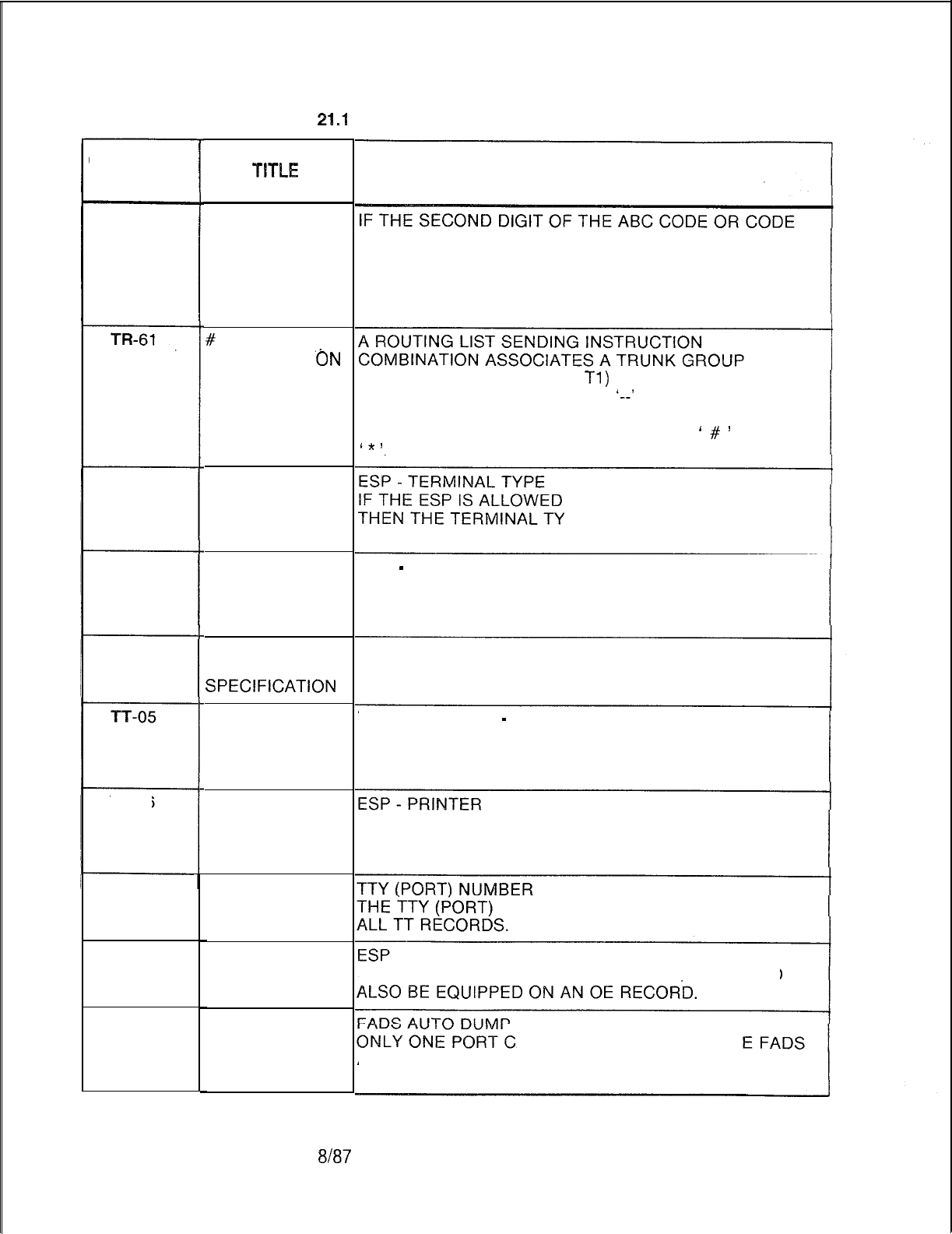
TL-130400-1001
Table
21.1 CPG Error Messages (Continued)
CPG ERROR
MESSAGES
TR-60
TT-03
TT-04
TT-05
TT-06
TT-51
TV-60
TT-61
D-534
TITLE
ABC CODE
CONFLICTS
WITH NPA,BUT
CONFLICT
CODE IS NOT Y
ON MR
#
OR * BEING
OUTPULSED
‘ON
NON-DTMF
TRUNK GROUP
SECOND
ELEMENT
CONTAINS
INVALID VALUE
SECOND
ELEMENT
CONTAINS
INVALID VALUE
ELEMENT 2 IS
MEANINGLESS
SPEClFlCATlON
ELEMENTS
HAVE
INCOMPATIBLE
VALUES
SECOND
ELEMENT
CONTAINS
INVALID VALUE
DUPLICATE TTY
NUMBER
ESP NOT
EQUIPPED ON
OE
FADS AUTO
DUMP CAN BE
‘Y’ FOR ONLY
ONE PORT
DESCRIPTION OF MESSAGES
RANGE SPECIFIED IS ZERO OR ONE,
THEN THE CONFLICT CODE ON THE MR RECORD
SHOULD BE ‘Y’.
(RECORD CODES RP AND
Tl)
WITH AN OUTGOING
SIGNALING MODE OF ‘DP’ OR
‘--’
WITH A PREFIX
INDEX (RECORD CODES SI, LP AND/ OR PC) THAT
SPECIFIES THE OUTPULSING OF DIGITS
‘
#
’
AND/OR
1x7
ON THE PORT,
PE MUST BE ‘ADDS’.
ESP
-
ECHO
IF THE ESP IS ALLOWED ON THE PORT, THEN THE
ECHO FIELD MUST BE ‘N’.
TERMINAL TYPE
-
PRINTER
IF THE TERMINAL TYPE IS ‘TTY’,
THEN THE PRINTER FIELD MUST BE ‘N’.
IF THE ESP IS ALLOWED ON THE PORT, THEN THE
PRINTER FIELD MUST BE ‘N’.
NUMBER MUST BE UNIQUE ACROSS
IF ESP IS EQUIPPED ON A TT RECORD IT SHOULD
AN BE DESIGNATED AS TH
AUTO DUMP PORT.
$I87
SVR 5210
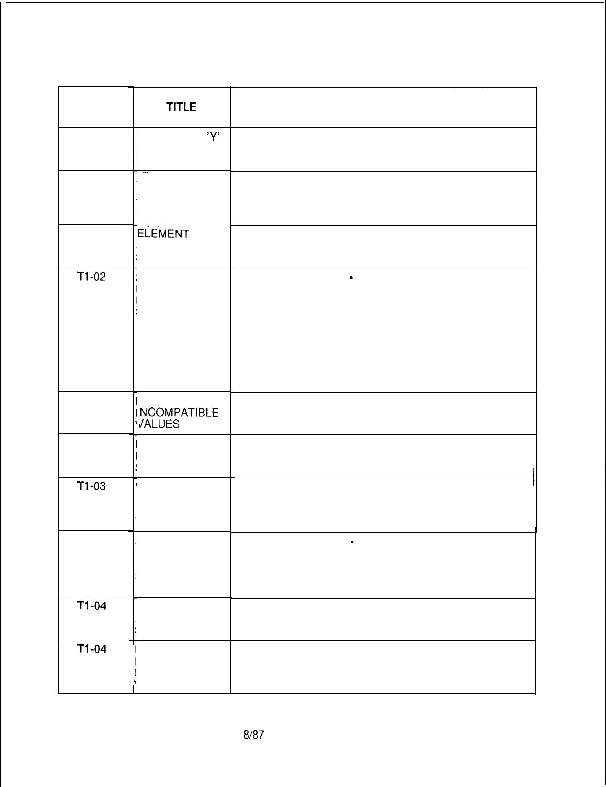
CPG ERROR
MESSAGES
TT-62
l-l
-01
. . .
Tl-02
Tl-02
Tl-02
Tl-03
Tl-03
Tl-03
Tl -04
Tl-04
SVR 5210
TL-130400-1001
Table 21.1 CPG Error Messages (Continued)
TITLE
ESP CAN BE
‘Y’
FOR ONLY ONE
PORT
.~.
SECOND
ELEMENT LESS
l-HEN FIRST
ELEMENT
ELEMENT
2 IS
MEANINGLESS
SPECIFICATION
2ND FEATURE
REQUIRED IF
FIRST
SPECIFIED
ELEMENT HAVE
NCOMPATIBLE
dALUES
ELEMENT 2 IS
MEANINGLESS
SPECIFICATION
ELEMENTS
HAVE
INCOMPATIBLE
VALUES
2ND FEATURE
REQUIRED IF
FIRST
SPECIFIED
ELEMENT 2 IS
MEANINGLESS
SPECIFICATION
DESCRIPTION OF MESSAGES
ESP
ONLY ONE PORT CAN BE DESIGNATED AS THE ESP
PORT.
TRUNK GROUP -ALTERNATE TRUNK GROUP
THESE TRUNK GROUP NUMBERS CANNOT BE EQUAL.
TRUNK APPLICATION
-
DISPLAYABLE CLASS OF
SERVICE, N-DISPLAYABLE CLASS OF SERVICE
A CLASS OF SERVICE IS MEANINGFUL ONLY WHEN
THE TRUNK APPLICATION IS ‘TIE’, ‘COT’, ‘FXT’, OR
‘WTS’, AND THE TRUNK DIRECTION IS ‘IN’ (INCOMING)
OR ‘TW’ (TWO-WAY).
THE CLASS OR SERVICE FIELDS FOR THESE TRUNK
APPLICATIONS, HOWEVER, CAN BE DASHED.
TRUNK APPLICATION ‘NIC’ MUST HAVE CLASS OF
SERVICE DATA.
TRUNK APPLICATION
-
TIE TRUNK CALLING NUMBER
A TIE TRUNK CALLING NUMBER IS MEANINGFUL ONLY
WHEN THE TRUNK APPLICATION IS ‘TIE’.
THE TIE TRUNK CALLING NUMBER, HOWEVER, CAN
BE DASHED.
ELEMENTS
HAVE
INCOMPATIBLE
VALUES
8187
D-535
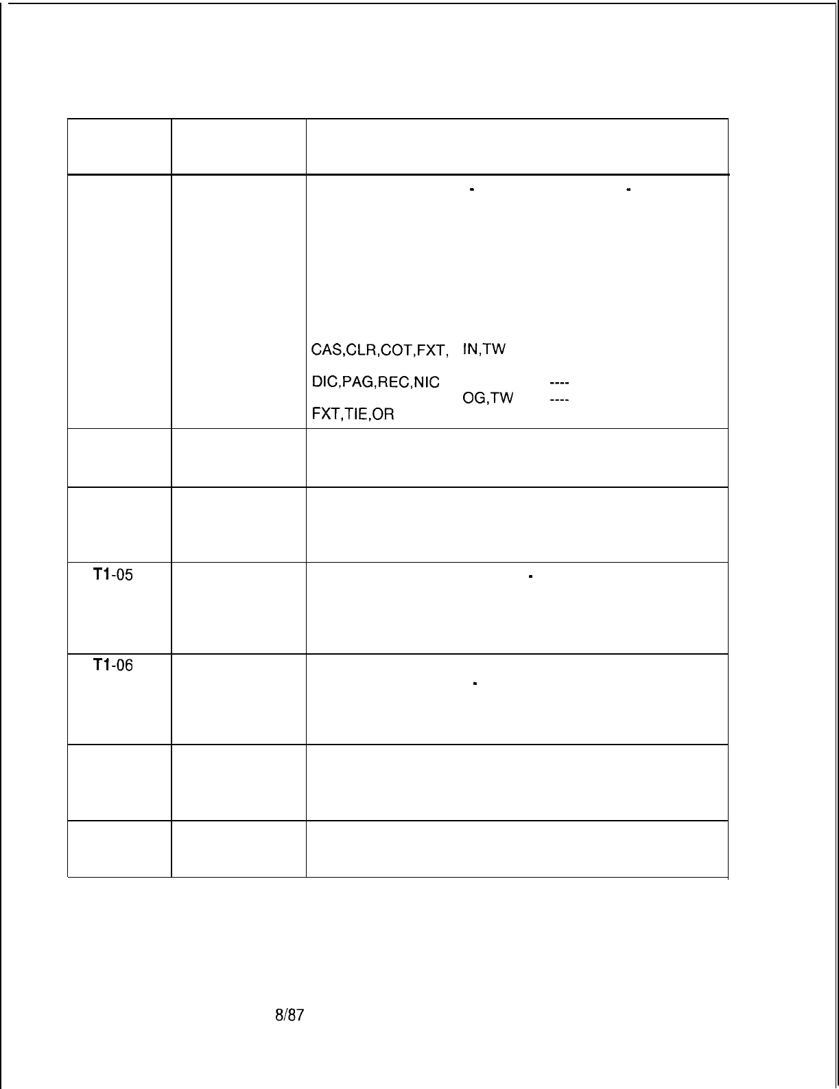
TL-130400-1001
CPG ERROR
MESSAGES
Table 21.1 CPG Error Messages (Continued)
TITLE DESCRIPTION OF MESSAGES
Tl-04
. . .
2ND FEATURE TRUNK APPLICATION
-
TRUNK DIRECTION
-
ACD
REQUIRED IF TRUNK PILOT NUMBER
FIRST ACD TRUNK PILOT NUMBER CAN BE USED WITH ANY
SPECIFIED TRUNK APPLICATION IF THE TRUNK DIRECTION IS
INCOMING OR TWO-WAY.
THE FOLLOWING IS A LIST OF REQUIREMENTS:
TRUNK ACD TRUNK
APPLICATION DIRECTION PILOT NUMBER
CAS,CLR,COT,FXT,
IN,TW
0000-9999
TIE OR WTS
DIC,PAG,REC,NIC
--
CAS,CLR,COT,
OG,TW
::::
FXT,TIE,OR
VVTS
Tl-05 ELEMENT 2 IS
MEANINGLESS
SPECIFICATION
Tl-05 ELEMENTS
HAVE
INCOMPATIBLE
VALUES
Tl-05
2ND FEATURE ACD TRUNK PILOT NUMBER
-
TRUNK INCOMING
REQUIRED IF SIGNAL
FIRST AN ACD TRUNK PILOT NUMBER CAN BE SPECIFIED
SPECIFIED ONLY IF THE INCOMING SIGNALING FIELDS ARE
DASHED.
Tl-06
INVALID TRUNK INCOMING SIGNAL
CHARACTER (RETURN DIAL TONE
-
RETURN DISTINCTIVE DIAL
PATTERN IN TONE)
2ND FIELD ONE OR THE OTHER OF THESE FIELDS CAN BE
SPECIFIED (‘Y’), BUT NOT BOTH.
Tl-08 ELEMENTS
HAVE
INCOMPATIBLE
VALUES
Tl-08 ELEMENT 2 IS
MEANINGLESS
SPECIFICATION
D-536 8187
SVR 5210
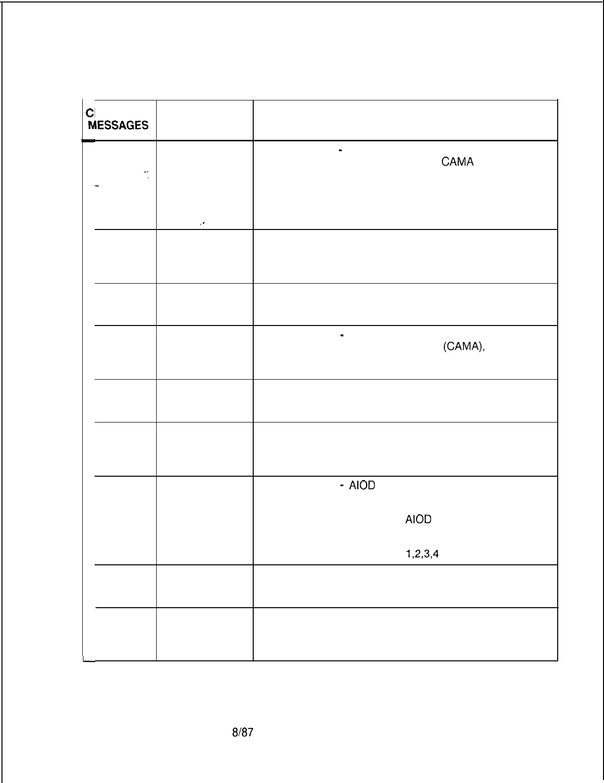
TL-130400-1001
Table 21.1 CPG Error Messages (Continued)
PG ERROR
IESSAGES
TITLE DESCRIPTION OF MESSAGES
Tl-08 2ND FEATURE BILLING MODE
-
TRUNK OUTGOING SIGNAL (MF)
REQUIRED IF MF SIGNALING APPLIES ONLY TO
CAMA
BILLING
‘-
FIRST MODE.
-..
SPECIFIED THUS, IF THE BILLING MODE IS SPECIFIED AS ‘CM’,
THEN THE MF OUTGOING SIGNAL FIELD MUST BE ‘Y’.
THE MF OUTGOING SIGNAL FIELD FOR ALL OTHER
,.
BILLING MODE SPECIFICATIONS MUST BE DASHED.
Tl-09 ELEMENTS
HAVE
INCOMPATIBLE
VALUES
Tl-09 ELEMENT 2 IS
MEANINGLESS
SPECIFICATION
Tl-09 2ND FEATURE BILLING MODE
-
TRUNK DIRECTION
REQUIRED IF WHEN THE BILLING MODE IS ‘CM’
(CAMA),
THE TRUNK
FIRST DIRECTION MUST BE ‘OG’ (OUTGOING ONLY).
SPECIFIED
Tl-10 ELEMENT 2 IS
MEANINGLESS
SPECIFICATION
Tl-10 ELEMENTS
HAVE
INCOMPATIBLE
VALUES
Tl-10
Tl-11
2ND FEATURE BILLING MODE
-
AIOD
CHANNEL
REQUIRED IF
FIRST VALUE OF ALLOWABLE VALUE OF
SPECIFIED BILLING MODE
AIOD
CHANNEL
CM OR --
Al
1,2,3,4
ELEMENT 2 IS
MEANINGLESS
SPECIFICATION
Tl-11 ELEMENTS
HAVE
INCOMPATIBLE
VALUES
SVR 5210
8187 D-537

TL-130400-1001
CPG ERROR
MESSAGES
Table 21.1 CPG Error Messages (Continued)
TITLE DESCRIPTION OF MESSAGES
Tl-11 2ND FEATURE TRUNK DIRECTION
-
REQUIRED IF DISPLAYABLE CLASS OF SERVICE,
FIRST N-DISPLAYABLE CLASS OF SERVICE
SPECIFIED CLASS OF SERVICE MUST BE DASHES FOR TRUNK
. . .
DIRECTION OF ‘OG’.
Tl-12
_
ELEMENT 2 IS
MEANINGLESS
SPECIFICATION
Tl-12
ELEMENTS
HAVE
INCOMPATIBLE
VALUES
Tl-12
2ND FEATURE TRUNK DIRECTION-TRUNK INCOMING
SIGNAL-
REQUIRED IF TRUNK OUTGOING SIGNAL
FIRST
SPECIFIED IF THE TRUNK DIRECTION IS ‘OG’ (OUTGOING ONLY),
THEN THE TRUNK OUTGOING SIGNALING FIELDS
MUST BE NONDASHED,
AND THE TRUNK INCOMING SIGNALING FIELDS MUST
BE DASHED.
IF THE TRUNK DIRECTION IS ‘IN’ (INCOMING ONLY),
THEN THE TRUNK INCOMING SIGNALING FIELDS
MUST BE NONDASHED,
AND THE TRUNK OUTGOING SIGNALING FIELDS MUST
BE DASHED.
IF THE TRUNK DIRECTION IS ‘TW’ (TWO WAY),
THEN THE TRUNK INCOMING SIGNALING FIELDS
MUST BE NONDASHED,
AND THE OUTGOING SIGNALING FIELDS MUST BE
NONDASHED.
Tl-13 INVALID MISSING DID DIGITS
CHARACTER IF DIGIT 1 IS DASHED, THEN DIGIT 2 MUST BE
PATTERN IN DASHED.
2ND FIELD
Tl-14 ELEMENT 2 IS
MEANINGLESS
SPECIFICATION
Tl-14 ELEMENTS
HAVE
INCOMPATIBLE
VALUES
D-538 8187
SVR 5210
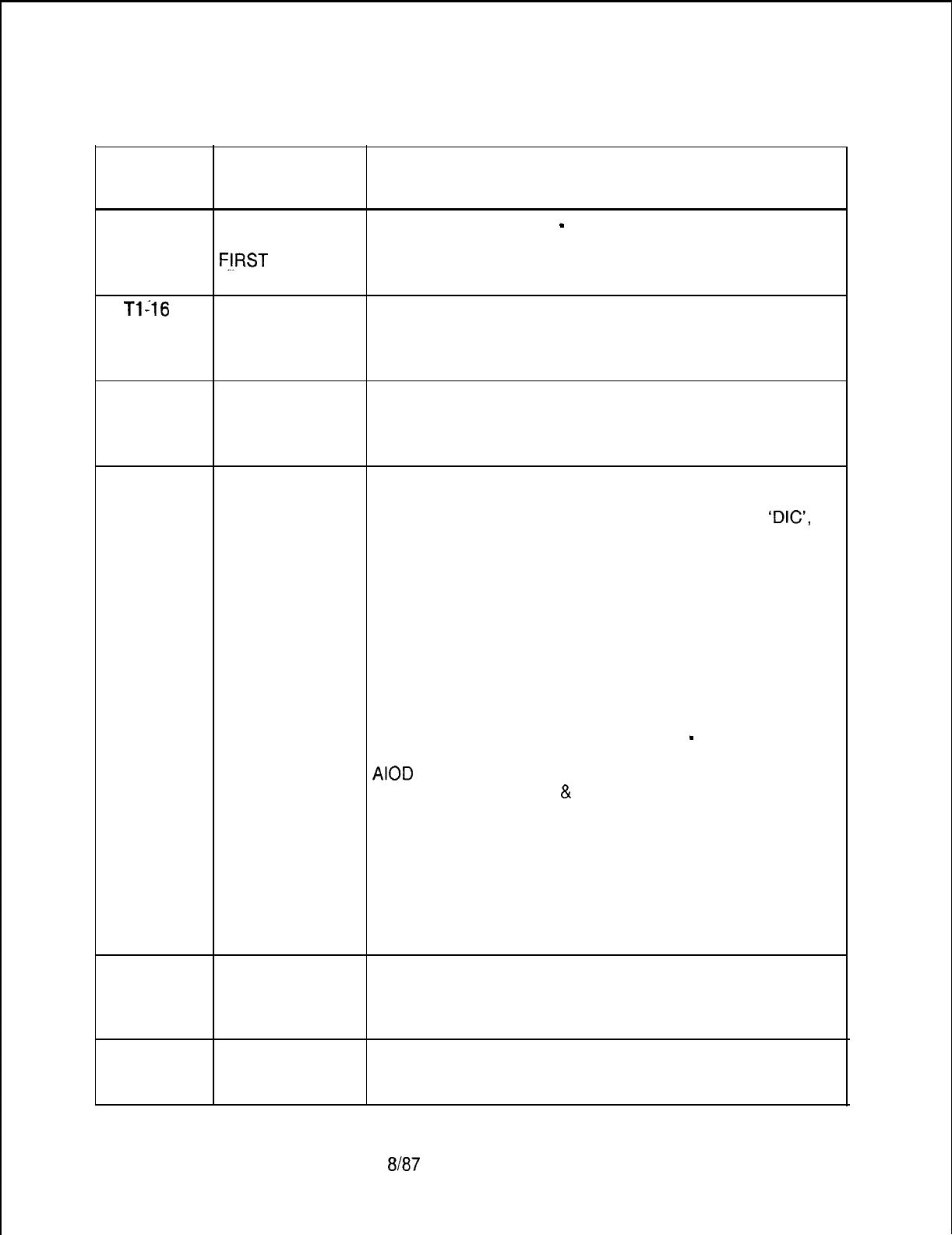
TL-130400-1001
CPG ERROR
MESSAGES
Table 21.1 CPG Error Messages (Continued)
TITLE DESCRIPTION OF MESSAGES
Tl-14 2ND FEATURE TRUNK APPLICATION
-
DISCONNECT SUPERVISION
REQUIRED IF IF THE TRUNK APPLICATION IS ‘TIE’,
F.!!RST
THEN DISCONNECT SUPERVISION MUST BE ‘BT’.
SPECIFIED
. . .
Tl-16
DASHES MUST TIE TRUNK CALLING NUMBER
BE USED DASHES MUST BE USED CONSISTENTLY.
CONSISTENTLY
IN FIELD
Tl-17 DASHES MUST ACD PILOT NUMBER
BE USED DASHES MUST BE USED CONSISTENTLY.
CONSISTENTLY
IN FIELD
Tl-20 ILLEGAL VALUE TRUNK APPLICATION
FOR TRUNK THE FOLLOWING FIELDS MUST HAVE CERTAIN
APPLICATION REQUIRED VALUES IF TRUNK APPLICATION IS
‘DIG’,
‘PAG’, ‘REC’ OR ‘NIC’:
FIELD NAME REQUIRED
VALUE
TRUNK DIRECTION
--
TRUNK INCOMING SIGNAL
----
TRUNK OUTGOING SIGNAL
----
TRUNK DISCONNECT SUPERVISION --
BILLING MODE
--
ALTERNATE TRUNK GROUP
--
TRUNK TRANSFER ALLOWED
-
TIE TRUNK CALLING NUMBER
----
AIOD
CHANNEL
MISSING DID DIGITS 1
&
2
--
ACD TRUNK PILOT NUMBER
----
ACD TRANSLATION INDICATOR
--
ROUTE TO RLT
ANSWER BACK R/A
ACA
OUTGOING TRUNK
GROUP FRL TO ACCESS
Tl-21 ELEMENTS
HAVE
INCOMPATIBLE
VALUE
Tl-21 ELEMENT 2 IS
MEANINGLESS
SPECIFICATION
SVR 5210
8187 D-539
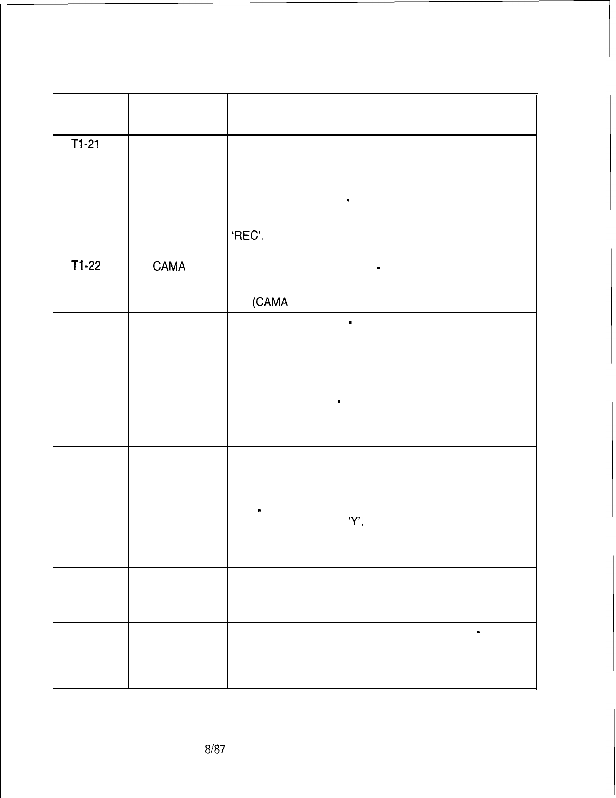
TL-130400-1001
CPG ERROR
MESSAGES
Table 21.1 CPG Error Messages (Continued)
TITLE DESCRIPTION OF MESSAGES
Tl-21
2ND FEATURE
REQUIRED IF
FIRST
SPECIFIED
Tl-21 RECORDER TRUNK APPLICATION
-
R/A RETURN ANSWER BACK
ANNOUNCER THE R/A RETURN ANSWER BACK FIELD CAN BE
NOT ALLOWED SPECIFIED (‘Y’) ONLY IF THE TRUNK APPLICATION IS
FOR TRUNK
‘REC.
APPLICATION
Tl-22
Tl-23
MF
CAMA
ONLY CAS TRUNK APPLICATION
-
TRUNK OUTGOING
IS NOT SIGNAL
ALLOWED FOR FOR TRUNK APPLICATION, ‘CAS’, OUTGOING SIGNAL
TRK APPL CAS MF
(CAMA
ONLY) IS NOT ALLOWED.
AGENT GROUP TRUNK APPLICATION
-
AGENT GROUP NUMBER
# MUST BE FOR TRUNK APPLICATION, ‘CAS’, AN AGENT GROUP
SPECIFIED FOR NUMBER MUST BE SPECIFIED.
TRUNK
APPLICATION
CAS
Tl-24 SECOND TRUNK DIRECTION
-
TRUNK HOMING SELECTION
ELEMENT IF TRUNK HOMING SELECTION IS SPECIFIED,
CONTAINS THE TRUNK DIRECTION MUST BE ‘OG’ OR ‘TW’.
INVALID VALUE
Tl-25 ELEMENTS
HAVE
INCOMPATIBLE
VALUES
Tl-25 ELEMENT 2 IS ACA
-
ACA TOLERANCES
MEANINGLESS IF THE ACA FIELD IS
‘Y’,
THEN THE ACA TOLERANCE
SPECIFICATION FIELDS (ACA SHORT CALL THRESHOLD, INTERVAL,
AND THE LONG CALL INTERVAL) MUST BE NOT BE
DASHED.
Tl-26 ELEMENTS
HAVE
INCOMPATIBLE
VALUES
Tl-26 ELEMENT 2 IS OUTGOING TRUNK GROUP FRL OUTPULSED
-
TRUNK
MEANINGLESS DIRECTION
SPECIFICATION IF THE OUTGOING TRUNK GROUP FRL OUTPULSED IS
‘Y’, THEN THE TRUNK DIRECTION MUST BE ‘OG’ OR
‘TW’.
D-540
8l87
SVR 5210
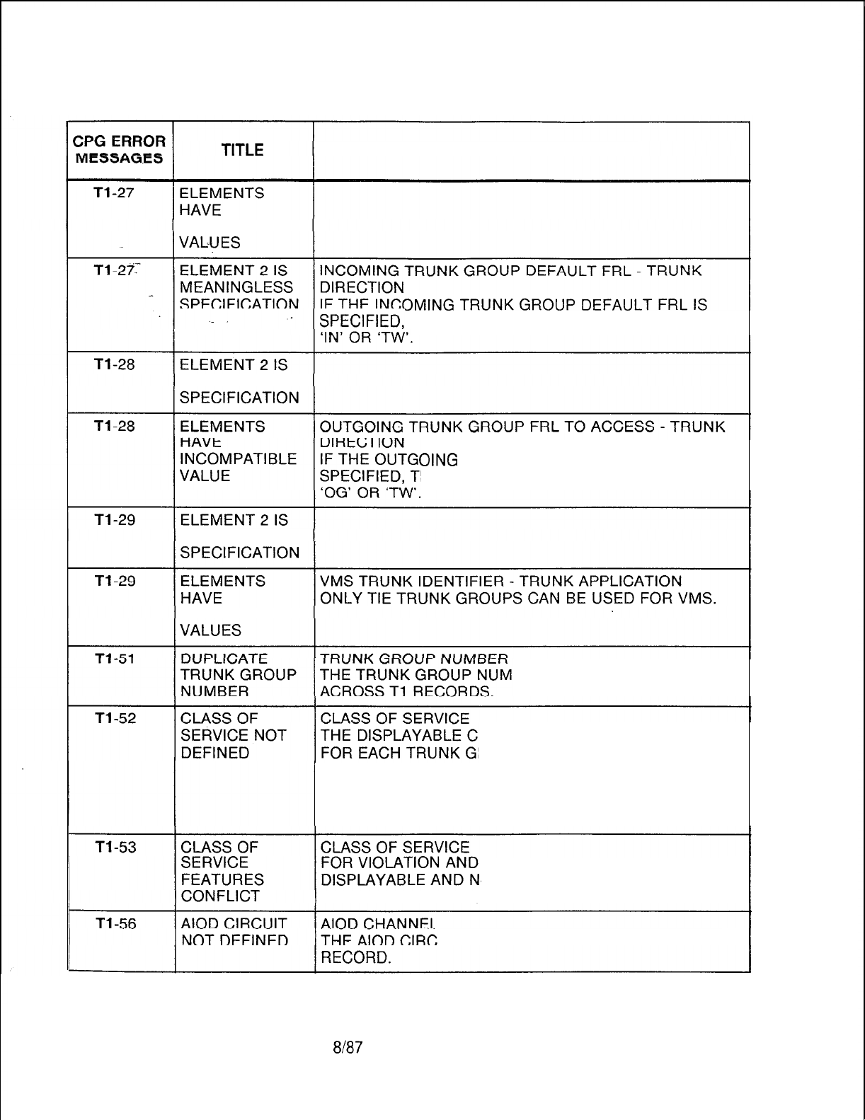
TL-130400-1001
Table 21.1 CPG Error Messages (Continued)
DESCRIPTION OF MESSAGES
INCOMPATIBLE
THEN THE TRUNK DIRECTION MUST BE
MEANINGLESS
OING
TRUNK GROUP FRL TO ACCESS IS
HEN THE TRUNK DIRECTION MUST BE
MEANINGLESS
INCOMPATIBLE
BER MUST BE UNIQUE
DD RECORD.
LASSES OF SERVICE SELECTED
ROUP MUST BE INITIALIZED BY A
THE N-DISPLAYABLE CLASSES OF SERVICE
SELECTED FOR EACH TRUNK GROUP MUST BE
INITIALIZED BY AN NC RECORD.
REQUIREMENT PATTERNS OF
-DISPLAYABLE CLASSES OF
SERVICE FEATURES SEE APPENDIX 1.
UIT SHOULD BE DEFINED ON THE FR
SVR
5210 8187 D-541

TL-130400-1001
CPG ERROR
MESSAGES
Table 21.1 CPG Error Messages (Continued)
TITLE DESCRIPTION OF MESSAGES
Tl-57
Tl-59
Tl-60
INVALID ALTERNATE TRUNK GROUP
ALTERNATE THE ALTERNATE TRUNK GROUP MUST BE DEFINED
TRUNK GROUP AS A TRUNK GROUP ON A
Tl
AND T2 RECORD.
i
(ENDCHK)
PILOT NO. IN ORDER FOR THE ACD FEATURE TO WORK
BELONGS TO PROPERLY, IT IS MORE DESIRABLE TO USE A PILOT
TERMINAL NUMBER FROM A CIRCULAR HUNT GROUP.
HUNT GRP
‘o
(GENTRK)
INVALID PILOT THE ACD PILOT NUMBER SHOULD BE A VALID PILOT
NUMBER NUMBER ON AN HG RECORD, AN ATTENDANT
CALLING NUMBER ON AN AT OR CN RECORD, OR A
STATION NUMBER ON AN LD RECORD.
(GENTRK)
Tl-61
TRUNK GROUP TRUNK GROUP NUMBER
ACCESS ERROR EACH TRUNK GROUP SHOULD BE MARKED FOR
TRUNK GROUP ACCESS ON A DC RECORD IF THE
TRUNK GROUP DIRECTION IS OUTGOING OR
TWO-
WAY.
(ENDCHK)
Tl-62
CLASS OF TRUNK GROUP
-
DISPLAYABLE CLASS OF SERVICE
SERVICE NOT CONFLICTS
ALLOWED AN INCOMING TRUNK GROUP IS RESTRICTED FROM
HAVING CERTAIN FEATURES. THE FOLLOWING ARE
THE ONLY FEATURES ALLOWED FOR TRUNK GROUPS
WITH AN APPLICATION TYPE OF ‘COT’, ‘FXT’, OR
‘WTS’:
1. TRUNK GROUP ACCESS
2. DICTATION EQUIPMENT ACCESS (‘DA’)
3. STATION ACCESS (‘SA’)
4. RLT ACCESS (‘RL’)
THE FOLLOWING ARE THE ONLY FEATURES
RESTRICTED FROM ‘TIE’ TRUNK APPLICATION TRUNK
GROUPS:
1. SWITCHED DIRECT LINE (‘SL’)
2. PROGRESSIVE CONFERENCE (‘PC’)
D-542
8187
SVR 5210
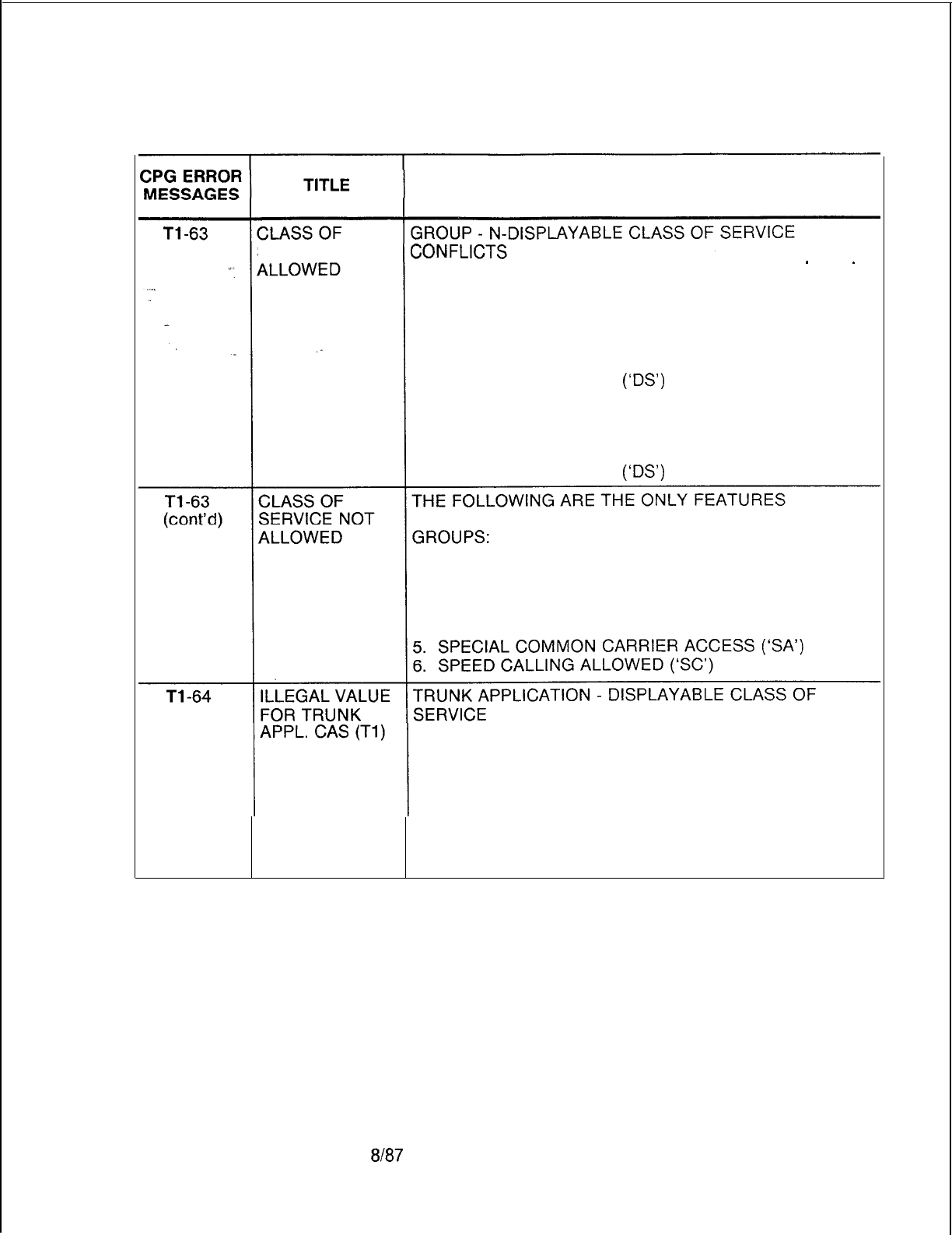
TL-130400-1001
Table 21.1 CPG Error Messages (Continued)
DESCRIPTION OF MESSAGES
SERVICE NOT AN INCOMING TRUNK GROUP
IS
RESTRICTED FROM
HAVING CERTAIN FEATURES.
THE FOLLOWING ARE THE ONLY FEATURES ALLOWED
FOR TRUNK GROUPS WITH AN APPLICATION TYPE OF
‘COT’ OR ‘FXT’:
1. ATTENDANT INFORMATION (‘Al’)
2. DATA LINE SECURITY
(‘OS’)
3. UNIVERSAL NIGHT ANSWER (‘UN’)
4. COMPUTER ACCESS (‘CA’)
THE FOLLOWING ARE THE ONLY FEATURES ALLOWED
FOR ‘WTS’ TRUNK APPLICATION TRUNK GROUPS:
1. DATA LINE SECURITY
(IDS’)
ALLOWED FOR ‘TIE’ TRUNK APPLICATION TRUNK
1. ATTENDANT INFORMATION (‘Al’)
2. DATA LINE SECURITY (‘DS’)
3. UNIVERSAL NIGHT ANSWER (‘UN’)
4. COMPUTER ACCESS (‘CA’)
FOR TRUNK APPLICATION, ‘CAS’, STATION ACCESS IS
REQUIRED IN THE TRUNK GROUP’S DISPLAYABLE
CLASS OF SERVICE.
THE FOLLOWING FEATURES ARE NOT ALLOWED IN
THE TRUNK GROUP’S DISPLAYABLE CLASS OF
SERVICE:
1. SWITCHED DIRECT LINE (‘SL’)
2. MODEM ACCESS (‘MD’)
SVR 5210
$I87
D-543
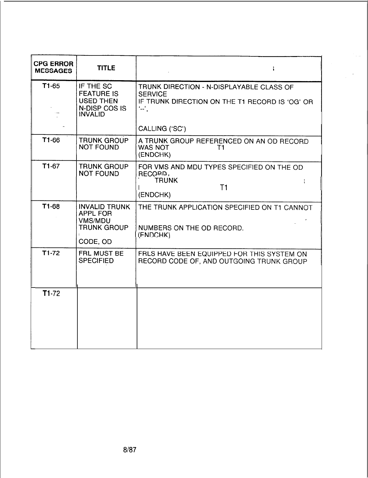
TL-130400-1001
Table 21.1 CPG Error Messages (Continued)
DESCRIPTION OF MESSAGES
THEN THE ASSOCIATED N-DISPLAYABLE CLASS OF
SERVICE MUST NOT BE MARKED FOR SPEED
FOUND ON A
Tl
RECORD.
THE
TRU’NK
GROUP SPECIFIED AS THE IDENTIFIER
MUST BE DEFINED ON A
Tl
RECORD.
BE ‘DIC’, ‘PAG’, ‘REC, OR ‘NIC’ FOR THE TRUNK
GROUP SPECIFIED FOR VMS AND MDU DIRECTORY
ON RECORD
FRL TO ACCESS MUST THEREFORE BE SPECIFIED
FOR EVERY OUTGOING OR TWO-WAY TRUNK GROUP
ON RECORD CODE Tl.
Tl-72
INCONSISTENT FRLS HAVE BEEN SPECIFIED FOR SOME PARTS OF
ENGINEERING THE SYSTEM AND NOT OTHERS.
OF FRLS ENSURE THAT ALL ATTENDANTS, LINES, TRUNK
GROUPS, MERS ROUTES, ETC. HAVE FRLS ENTIRELY
ENABLED OR DISABLED.
IN THE CASE OF TRUNK GROUPS, ALL OUTGOING OR
TWO-WAY TRUNK GROUPS REQUIRE OUTGOING FRL
TO ACCESS TO BE CONSISTENTLY ENGINEERED.
D-544
8187
SVR 5210
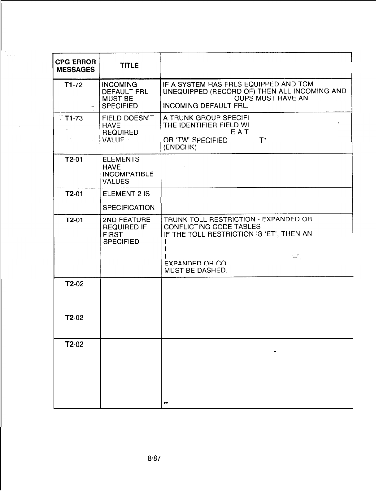
TL-130400-1001
Table 21.1 CPG Error Messages (Continued)
DESCRIPTION OF MESSAGES
TWO-WAY TRUNK
GR
ED ON AN OD RECORD IN
TH A CODE TYPE OF ‘TGO’
OR ‘TGS’ MUST HAV RUNK DIRECTION OF ‘OG’
PECIFIED
ON THE
Tl
RECORD.
MEANINGLESS
EXPANDED OR CONFLICTING CODE CHECK TABLE
MUST BE SPECIFIED.
IF THE TOLL RESTRICTION IS ‘TL’ OR
‘--I,
THEN AN
NFLICTING CODE CHECK TABLE
T2-02
ELEMENTS
HAVE
INCOMPATIBLE
VALUES
T2-02
ELEMENT 2 IS
MEANINGLESS
SPECIFICATION
T2-02
2ND FEATURE 2ND FEATURE REQUIRED IF FIRST SPECIFIED.
REQUIRED IF TOLL ACCESS CODE INDICATOR
-
TOLL ACCESS
FIRST CODE
SPECIFIED VALUE OF ALLOWABLE VALUES OF
ACCESS CODE TOLL ACCESS CODE
INDICATOR DIGITS
NM, OP, NR, OR 0-- TO 999
_-
---
8187
D-545
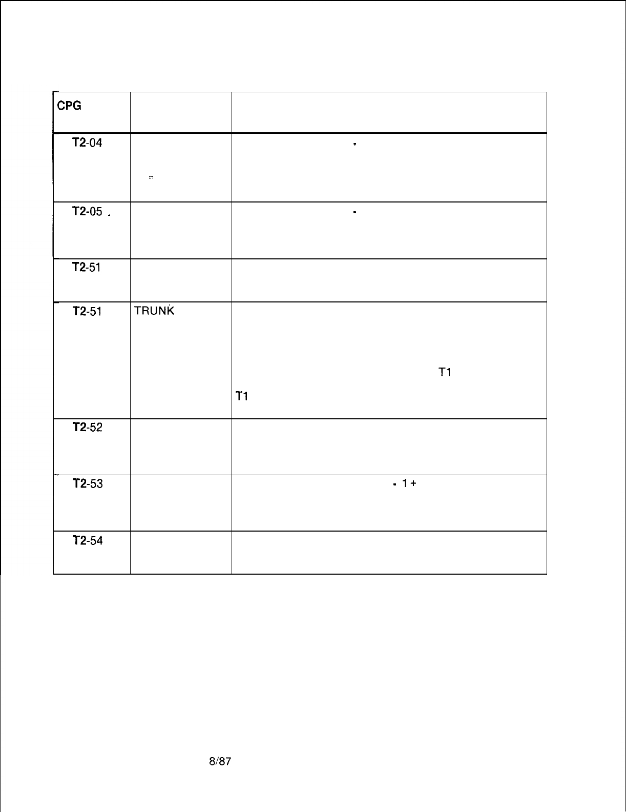
TL-130400-1001
ZPG
ERROR
MESSAGES
Table 21.1 CPG Error Messages (Continued)
TITLE DESCRIPTION OF MESSAGES
T2-04
VALUES TO BE TOLL ACCESS CODE
-
SECOND TOLL ACCESS CODE
FILLED LEFT TO IF DIGIT 1 IS DASHED,
RIGHT THEN DIGITS 2 AND 3 MUST BE DASHED.
.~_
IF DIGIT 2 IS DASHED,
. . .
THEN DIGIT 3 MUST BE DASHED.
T2-05
-
SECOND TOLL ACCESS CODE
-
SECOND TOLL ACCESS CODE
ELEMENT THESE FIELDS CANNOT BE THE SAME.
EQUALS FIRST
ELEMENT
T2-51
DUPLICATE
TRUNK GROUP
NUMBER
T2-51
TRUNK
GROUP TRUNK GROUP NUMBER
NOT FOUND A. TRUNK GROUP NUMBER MUST BE UNIQUE ACROSS
T2 RECORDS.
B. EACH TRUNK GROUP NUMBER APPEARING ON A T2
RECORD MUST ALSO APPEAR ON A
Tl
RECORD
C. EACH TRUNK GROUP NUMBER APPEARING ON A
Tl
RECORD MUST APPEAR ON A T2 RECORD.
(ENDCHK)
T2-52
CODE CHECK EXPANDED OR CONFLICTING CODE TABLE
TABLE NOT THE EXPANDED OR CONFLICTING TABLE SELECTED
FOUND MUST HAVE A CORRESPONDING EC RECORD TO
INITIALIZE THE TABLE.
T2-53
T2-54
CODE CODE RESTRICTION TABLE
-
1+
RESTRICTION
RESTRICTION TABLE NOT FOUND
TABLE NOT RESTRICTION TABLE NUMBERS MUST APPEAR ON A
FOUND CR RECORD.
ILLEGAL VALUE
FOR DIC, PAG
OR REC APPL
D-546 8187
SVR 5210
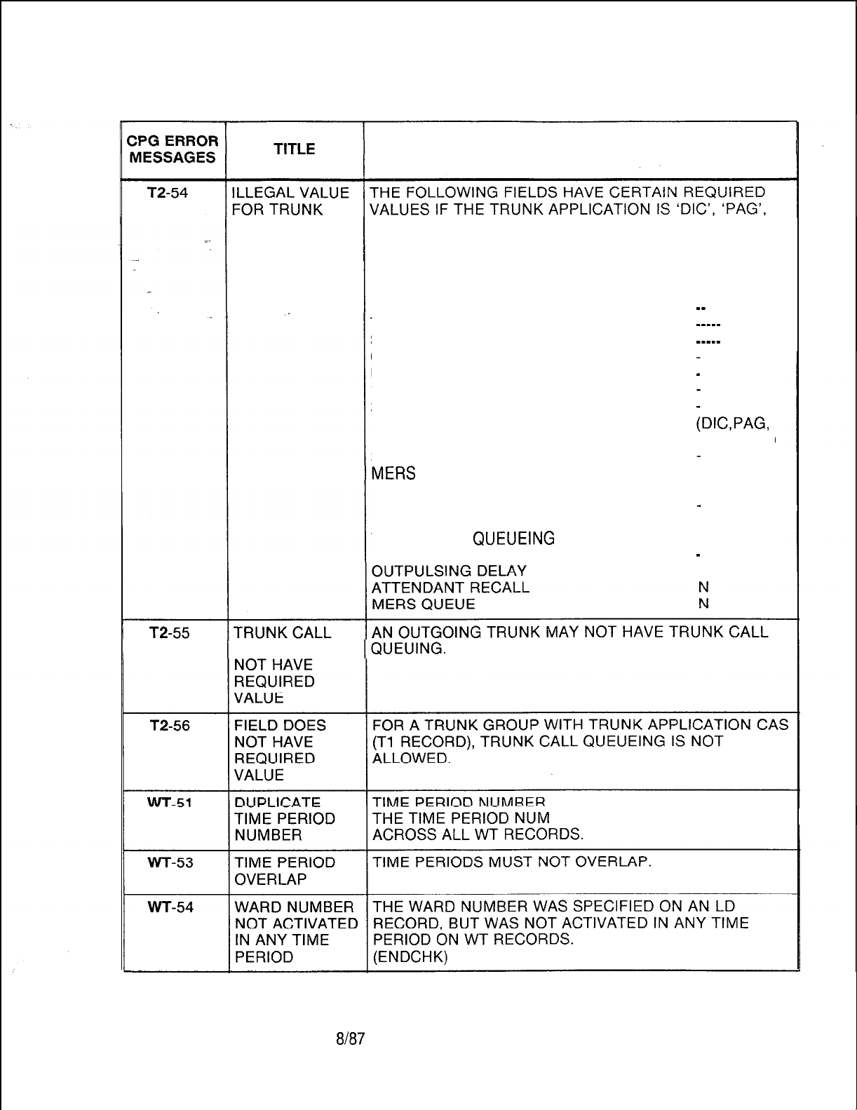
TL-130400-1001
Table 21.1 CPG Error Messages (Continued)
DESCRIPTION OF MESSAGES
APPLICATION ‘REC’ OR ‘NIC’:
FIELD NAME REQUIRED
VALUE
TRUNK TOLL RESTRICTION
_-
TOLL ACCESS CODE
_--__
SECOND TOLL ACCESS CODE
____-
CODE RESTRICTION TABLE
EXPANDED OR CONFLICTING TABLE
-
1 + RESTRICTION TABLE
2-WAY PAD CLASS
(DIC,PAG,
NIC ONLY)
3-WAY PAD CLASS
----
DTMF BLOCK TRANSMISSION
N
REVERSE BATTERY CHECK
MESSAGE METER PEG
--
TRUNK CALL
QUEUEING
N
REMOTE-ACCESS AUTHORIZATION CODE
-
--
QUEUE DOES
BERS MUST BE UNIQUE
SVR 5210
8h37
D-547

T-L-1 30400-l 001
Table 21.1 CPG Error Messages (Continued)
CPG ERROR
MESSAGES
XP-01
XP-o-1
XP-02
XP-03
XP-03
D-548
XP-04
XP-05
XP-52
TITLE
VALUE OF
SECOND
ELEMENT TOO
LARGE
VALUE OF
SECOND
ELEMENT TOO
SMALL .
SECOND
ELEMENT
EQUALS FIRST
ELEMENT
INVALID
CHARACTER
STRING
SECOND
ELEMENT
CONTAINS
INVALID VALUE.
VALUE OF
SECOND
ELEMENT TOO
SMALL
VALUE OF
SECOND
ELEMENT TOO
SMALL
CARD TYPE
DEFINED ON FR
INCOMPATIBLE
WITH FCN OF
INCOMING
CARD
DESCRIPTION OF MESSAGES
EXTENDED ADDRESSING
-
FRAME WINDOW SIZE
IF THE FRAME LEVEL SUPPORTS EXTENDED
ADDRESSING FIELD IS ‘N’,
THEN THE FRAME WINDOW SIZE FIELD MUST BE IN
THE RANGE 1 TO 7.
X.25 DEVICE DIRECTLY CONNECTED
-
EXTERNAL.
CLOCKING
THE FIELD, IS X.25 DEVICE DIRECTLY CONNECTED,
CANNOT CONTAIN THE SAME VALUE AS THE
EXTERNAL CLOCKING FIELD.
ONE OR THE OTHER OF THESE FIELDS CAN BE
SPECIFIED (‘Y’), BUT NOT BOTH.
LOGICAL CHANNEL NUMBER ASSIGNMENTS (LCNS)
ALL SIX LCN ASSIGNMENT FIELDS MUST NOT
CONTAIN ZEROS.
LOW LCN
-
HIGH LCN
IF ANY OF THE LOW LCN STARTS WITH ‘OOOO’,
THEN THE MATCHING SET
HIGN
LCN SHOULD BE
‘0000’.
HIGH LOGICAL CHANNEL ASSIGNMENT FIELDS
THE HIGH LCN MUST BE GREATER THAN OR EQUAL
THE LOW LOCN ON INCOMING,
BI-DIRECTIONAL AND OUTGOING CHANNELS.
LOGICAL CHANNEL NUMBER ASSIGNMENTS
THE BI-DIRECTIONAL FIELDS’ VALUES MUST
CONTAIN LARGER NUMBER VALUES THAN THE
INCOMING FIELDS’.
THE OUTGOING FIELDS’ VALUES MUST CONTAIN
LARGER NUMBER VALUES
THAN THE BI-DIRECTIONAL FIELDS’ VALUES.
8187
SVR 5210
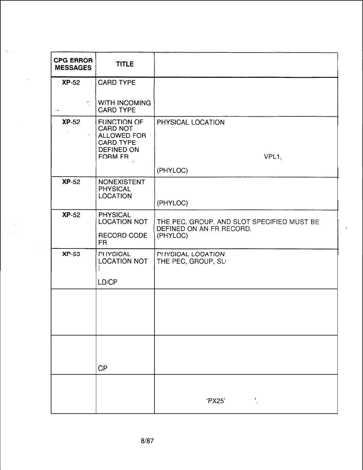
TL-130400-1001
Table 21.1 CPG Error Messages (Continued)
DESCRIPTION OF MESSAGES
DEFINED ON
FR
INCOMPATIBLE
THE PEC, GROUP, SLOT, AND CIRCUIT FUNCTION
SPECIFIED MUST BE VALID FOR THE CARD TYPE
DEFINED ON FR (FOR THIS PEC TYPE).
A SYNCHRONOUS DATA PORT MUST APPEAR ON AN
ADMP OR NIC CARD OR A VPLO,
VPLl,
VP20 (VOICE
AND DATA OR DATA) OR VP21 LINE CARD.
PHYSICAL LOCATION
THE PEC, GROUP, SLOT, AND CIRCUIT SPECIFIED
MUST BE VALID FOR THIS PEC TYPE.
PHYSICAL LOCATION
DEFINED ON
XP-53
OT, AND CIRCUIT SPECIFIED
DEFINED ON MUST BE DEFINED ON AN LD RECORD
RECORD CODE (EXCEPT FOR THE PX25 PORT WHICH MUST BE
LD/CP
DEFINED ON A CP RECORD).
USE OF PHYSICAL LOCATION
PHYSICAL LOC THE PEC, GROUP, SLOT, AND CIRCUIT SPECIFIED
CONFLICTS MUST BE DEFINED ON AN LD RECORD WITH AN
WITH INSTR. INSTRUMENT TYPE OF ‘SPM’.
TYPE SPECIFIED (EXCEPT FOR THE PX25 PORT).
ON LD
XP-53 PHYSICAL PHYSICAL LOCATION
LOCATION NOT THE PEC, GROUP, SLOT, AND CIRCUIT SPECIFIED
DEFINED ON MUST BE DEFINED ON A CP RECORD.
RECORD CODE (SVR 8220 AND BEYOND)
CP
XP-53 XP RECORD PHYSICAL LOCATION
APPLIES ONLY THE PEC, GROUP, SLOT, AND CIRCUIT SPECIFIED
TO SYNCH MUST BE DEFINED ON A CP RECORD WITH A DEVICE
DEVICE TYPES TYPE OF ‘X25’,
‘PX25’
OR ‘NIC
‘.
ON CP
SVR 5210
8187
D-549
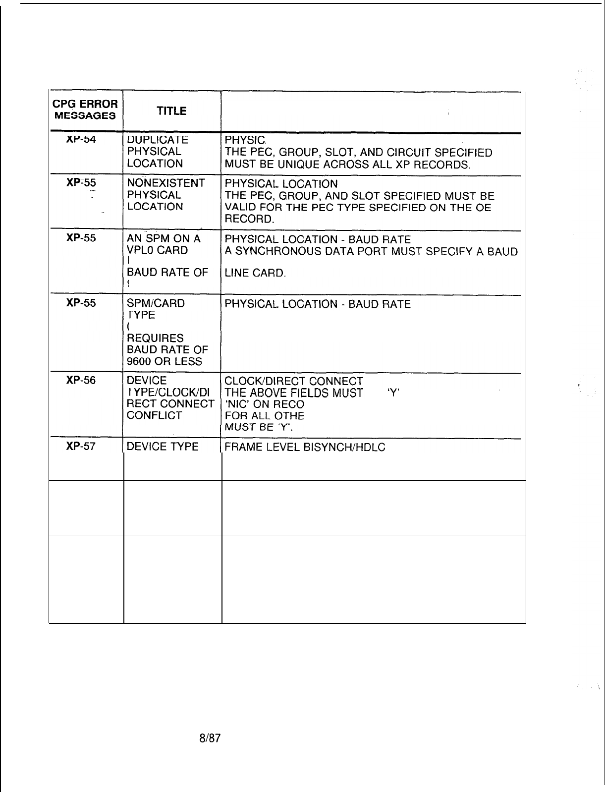
TL-130400-1001
Table 21.1 CPG Error Messages (Continued)
DESCRIPTION OF MESSAGES
AL LOCATION
MUST HAVE ARATE OF 9600 OR LESS IF IT CONNECTS TO A VPLO
9600 OR LESS
A SYNCHRONOUS DATA PORT MUST SPECIFY A BAUD
COMBINATION RATE OF 9600 OR LESS IF IT CONNECTS TO A VPLO
OR VP20 LINE CARD.
BE
‘Y’
FOR DEVICE TYPE
RD CODE CP.
R DEVICE TYPES, ONE OF THE FIELDS
XP-58
NIC REQUIRES THE ABOVE FIELDS MUST BE ‘N’ FOR DEVICE TYPE
FIELD TO BE N ‘NIC’ ON RECORD CODE CP.
DEVICE TYPE X.25 SPEED SELF-EXPLANATORY
NIC REQUIRES
X.25 SPEED TO
BE 5 TO 8
XP-82
PHYSICAL PHYSICAL LOCATION
LOCATION IS EVERY SYNCHRONOUS DATA PORT APPEARING ON
MISSING ON AN LD AND CP RECORD MUST APPEAR ON AN XP
NAMED RECORD.
RECORD CODE EVERY NIC APPEARING ON A TC AND CP RECORD
MUST APPEAR ON AN XP RECORD.
(ENDCHK)
D-550 8187
SVR 5210

TL-I
30400-l 001
ALPHABETICAL INDEX OF RECORD CODES
AC:
AD:
AF:
AG:
AL:
AP:
AQ:
AS:
AT;-
AU:
BD:
BK:
Cl:
c2:
CA:
CB:
CD:
CF:
CH:
CL:
CN:
CP:
CR:
CT:
DA:
DC:
DD:
DF:
DK:
DT:
EC:
ED:
FA:
FR:
GC:
GS:
HD:
HG:
HM:
II:
IR:
KD:
KS:
LA:
LD:
LI:
LM:
LP:
Access Code Translation, D-80
Agent Position, D-306
Limited Automatic Call Distribution Feature, D-308
Agent Group, D-310
Audit Record Control, D-296
Data System Asynchronous Port, D-340
Data System Asynchronous Port Set/Read List, D-359
Allowable Service Codes, D-208
Attendant Console, D-1 62
Remote Access Authorization Code, D-75
BLDU, D-l 66
Busy Lamp Key, D-168
Data System Call Processing
-
Part 1, D-379
Data System Call Processing
-
Part 2, D-383
Common Attendant, D-l 69
Code Blocked Numbers, D-74
Code Call, D-72
CAS Branch Features, D-304
Change Feature by Access Code, D-140
Class of Call-Controlled Routing, D-288
Common Attendant Directory Numbers, D-l 74
Data System Common Port, D-334
Code Restriction Numbers, D-203
Customer Defined Terminal, D-268
Trunk Group Digit Absorption, D-217
Displayable Class of Service, D-l 14
Displayable Class of Service, D-l 16
CPG Default, D-142
Repertory Dial Key Code, D-315
DTMF Receiver, D-42
Expanded or Conflicting Code Check Tables, D-206
Extended Dial-Call Pick up Numbers, D-138
FRL Auorization Code, D-77
Frame Image Card, D-25
Group Speed Calling, D-134
Group Speed Calling List Numbers, D-136
Hundreds Groups, D-l 04
Hunt Group, D-130
Health Care/Motel Miscellaneous, D-274
International Country Code, D-l 12
Intercept Routing Numbers, D-106
KEDU Assignment, D-277
KEDU Special Function Access, D-279
Line Appearances, D-l 58
Line Data, D-144
Line Identities, D-l 60
Line Miscellaneous, D-l 53
Prefix Code Digits for Listed Directory Numbers and Other Applications, D-249
F=TL-130000-1001
O=TL-130100-1001 M=TL-130200-1001 I=TL-130300-1001 D=TL-130400-1001 S=TL-130500-1001 A=TL-100000-1001
FeatWe
Operation Maintenance
Installation
Data Base System Configuration ADMP Users Guide
TL-130400-1001
MD:
MH:
MK:
MO:
MR:
MS:
MT:
NA:
NC:
NR:
g.
OD;
OE:
OF:
OT:
ov:
Pl:
P2:
PC:
PD:
PN:
PZ:
RA:
F-c:
RN:
RP:
RT:
Sl:
s2:
SA:
SD:
SI:
SL:
$’
SR:
ST:
Tl:
T2:
TC:
TD:
TF:
TL:
TM:
TN:
TP:
TR:
TT:
WT:
XP:
MDR, D-260
Hunt Group Members, D-l 32
Master KEDU, D-281
MERS On-Net Station Numbers and Sending Instruction Values, D-250
MERS Six-Digit Translated NPA, D-220
SCC Authorization Codes, D-248
MDR Port, D-262
Nailed Trunk Connection, D-21 5
N-Displayable COS, D-l 20
MERS Three-Digit Translated NPA, D-239
Private Network Translation, D-254
Office Features Circuits, D-43
Other Directory Numbers, D-63
Office
Equipment,
D-44
Office Features, D-48
Office Timeout Values, D-55
Office Timing Values, D-60
Data System Global Parameter
-
Part 1, D-372
Data System Global Parameter
-
Part 2, D-375
Prefix Code Digits, D-245
Printer Assignment, D-284
PNA Pilot Numbers, D-65
Paging Zones, D-66
Recorder Announcer, D-323
Release Link Trunk Circuit, D-317
Room Number First Digit Translation, D-286
MERS Routing List, D-227
Data System Routing, D-330
MDR Screening Option 1, D-263
MDR Screening Option 2, D-264
Specialized Common Carrier, D-l 09
CAS Secondary Directory Numbers, D-326
MERS Sending Instruction, D-231
User Security Level Password, D-68
Source Messages, D-31 9
Special Messages, D-320
Data System Symbolic Replacement Word/String, D-385
Service Code MERS Translation, D-243
Trunk Group Part 1, D-176
Trunk Group Part 2, D-186
Trunk Circuit, D-21 0
Private Network
Dl/D2,
D-256
Traffic Data Facilities, D-70
Translation Record Control, D-290
Supervisor Talk/Monitor Repertory Dial Key Code, D-321
Tone Detector, D-247
MERS Time Period, D-242
MERS Numbering Plan Area/ABC Translation, D-234
Serial Device, D-271
Ward Control, D-301
Data System X.25 Port, D-366
F=TL-130000-1001
O=TL-130100-1001 M
=TL-130200-1001
I=TL-130300-1001 D=TL-130400-1001 S=TL-130500-1001 A=TL-100000-1001
‘,
FeattIreS
Operation Maintenance Installation Data
Base
System Configuration
ADMP
Users Guide
TL-130400-1001
INDEX
A
ABC Code Range, D-236
Access
Code---Digits
l-3, D-81
Agent Call
Hoid
Timeout, D-62
Agent Call Park Timeout, D-62
Agent Group, D-302 _
Agent Group
Number
(Record Code AG), D-311
Agent Group Number (Record Code
Tl),
D-183
Agent Hands-Free Operation, D-314
Agent Position Number, D-302
Agent Transfer, D-31 4
AIOD
Channel, D-181
Alert Tone, D-314
Allow Agent to Originate Calls on Line
1,
D-307
Allowable Three-Digit Numbering Plan Area/ABC Code Numbers, D-205
Alternate Divert Destination, D-31 2
Alternate Divert Destination Identifier, D-31 2
Alternate Divert Destination Timing, D-31 2
Alternate Recorder Announcer
#l
, D-324
Alternate Recorder Announcer
#2,
D-324
Alternate Trunk Group, D-181
Answer Back Recorder Announcer, D-183
Appearance Type, D-l 59
Attendant Assignment for Room-to-Room Blocking Function, D-l 71
Attendant Break-In, D-171
Attendant Call Waiting Lamp Light and Flash, D-170
Attendant Call Waiting Queue, D-57
Attendant Camp-on, D-171
Attendant Console Number, D-l 74
Attendant Directory Number, D-l 74
Attendant Do Not Disturb Key, D-173
F=TL-130000-1001
O=TL-130100-1001 M=TL-130200-1001 I=TL-130300-1001 D=TL-130400-1001 S=TL-130500-1001 A=TL-100000-1001
Features Operation Maintenance
Installation Data Base
SyStem
Configuration ADMP Users Guide
TL-130400-1001
Attendant Message Waiting Key, D-173
Attendant No Answer Time, D-58
Attendant Paging, D-171
Attendant Paging Areas, D-67
Attendant-Paging Queue, D-l 71
Attendant-Recall After No Answer Timeout, D-l 93
Attendant Room Blocking Key, D-173
Attendant Three-Way
SplitiThree-Way
Connection, D-172
Authorization Code Digits, D-78
Authorization Code Digits 1-4, D-76
Authorization Code Number, D-76
Authorization Number, D-l 10
Authorization Prefix Digits, D-52
Automatic Call Distribution Pilot Numbers 1-4, D-309
Automatic Call Distribution/Direct In Line
(ACD/DIL)
Trunk Pilot Number, D-183
Automatic Circuit Assurance, D-184
Automatic Output Indicator, D-71
Automatic Recall on Hold, D-171
Baud Rate, D-285
Begin Time (Record Code TP), D-242
Begin Time (Record Code WT), D-302
Billing Mode, D-181
Billing Number, D-165
Block Transmission, D-l 92
BLDU Data Link Llnes, D-167
BLDU Key Identities, D-168
Busy Lamp Display Unit Number, D-164
Busy Lamp Display Units, D-172
Bypass Toll Restriction Checks on Final Directory Number, D-111
F =TL-130000-1001
O=TL-130100-1001 M=TL-130200-1001
I =TL-130300-1001
D=TL-130400-1001 S=TL-130500-1001 A=TL-100000-1001
Features Operation Maintenance Installation Data Base System Configuration ADMP Users Guide
TL-130400-1001
INDEX
C
Call Answer Time (Seconds), D-260
Call Diverts, D-155
Call Hold, D-57
Calf..Park,
D-57
Calf Waiting Level
#1,
D-31 3
Call Waiting Level
#2,
D-313
Call Waiting Level
#3,
D-313
Call Waiting Queue Timeout Control, D-171
Call Waiting Tone Duration (Camp-on), D-59
Calling Number Display, D-295
Calls Waiting
120-IPM
Flash Rate, D-309
Calls Waiting 30-IPM Flash Rate, D-309
Camp-on Call Waiting Tone-l, D-50
Camp-on Recorder Announcer, D-305
Camp-on Still Busy, D-56
Camp-on Tone Type, D-50
Card FB-Number, D-28
Card Location and
,Circuit
(Record Code LD), D-l 46
Card Location and Circuit (Record Code TC), D-211
Card
Slot,
D-27
Card Slot Position, D-278
Card Type, D-27
CAS Local Flash, D-314
CAS Secondary Directory Numbers, D-327
Circuit, D-278
Class of Service (Record Code AT), D-163
Class of Service (Record Code LD), D-148
Class of Service (Record Code
Tl),
D-178
Code Blocked Number Digits 1 to 10, D-75
Code Call Access, D-l 18
Code Call Tone, D-73
F=TL-I~OOOO-1001
O=TL-130100-1001 M=TL-130200-1001 I=TL-130300-1001 D=TL-130400-1001 S=TL-130500-1001 A=TL-100000-1001
Features Operation Maintenance
Installation
Data Base System Configuration ADMP Users Guide

TL-130400-1001
Code Range, D-254
Code Restriction Table, D-205
Code Restriction Table Number, D-190
Code Type, D-287
Code Type Identifier-(Record Code OD), D-64
-..
Code Type Identifier (Record Code RN), D-287
Code Type identifier Number, D-81
Code Type Number,.D-81
‘-
Coding Conventions, D-21
Combined Line and Recording Trunk Hookswitch Flash Timing, D-275
Conflict Code, D-221
Console Auxiliary Key Application, D-l 73
Controlling Data Control Processor Software, D-l 52
Controlling Integrated Featurephone, D-l 55
CO Line, D-l 19
CO Trunk Group and Member Number, D-213
Customer-Defined Terminal Name, D-270
Customer-Defined Terminal Type Number, D-269
Custom Engineered Data Base, D-19
Data Dump Header Site Identification Characters 1-4, D-71
Data Link Card Location and Circuit (Record Code AT), D-163
Data Link Card Location and Circuit (Record Code LM), D-154
Data Sheet Design, D-21
Data Sheet Preparation, D-21
Data System Security Level, D-69
DDD Burst Tone, D-46
Default Facility Restriction Level on MERS Queue Timeout, D-49
Delay Between Incoming Seizure and Divert to Recorder Announcer, D-309
Delete, D-233
Delete DID Digits, D-183
F=TL-130000-1001 O=TL-130100-1001 M=TL-130200-1001 I=TL-130300-1001 D=TL-130400-1001
S
=TL-130500-1001 A=TL-100000-1001
Features Operation Maintenance Installation Data Base System Configuration ADMP Users Guide

TL-130400-1001
INDEX
Delete/Number of Digits to Delete, D-251
Destination Identifier (Record Code CL), D-289
Destination Identifier (Record Code RP), D-229
Destination Type (Record Code CL), D-289
Destination Type (Record Code IR), D-107
. . .
Destination Type (Record Code RP), D-229
-Device Types, D-260
Dial Call Pickup, D-149
‘-
Dial Key Code, D-316
Dictation Access, D-l 18
Directory Number (Record Code AT), D-163
Directory Number (Record Code LM), D-154
Directory Number (Record Code OD), D-64
Directory Number Restriction Bypass Indicator, D-l 10
Disable Facility Restriction Level Authorization Code Report, D-54
Displayable Class of Service (Record Code AU), D-76
Displayable Class of Service (Record Code DC), D-l 15
Displayable Class of Service (Record Code DD), D-117
Divert Destination Identifier, D-150
Divert No Answer Time, D-56
Divert to Same Attendant, D-172
Do Not Disturb (Record Code AL), D-298
Do Not Disturb (Record Code TL), D-293
Double Marking Switch, D-217
Do Not Disturb Remove, D-275
DTMF Receiver Number, D-42
E
Early Unstaff, D-314
Echo, D-272
Electronic Services Processor, D-46
End Time (Record Code TP), D-242
F=TL-130000-1001
o=TL-130100-1001 M=TL-130200-1001 I=TL-130300-1001 D=TL-130400-1001 S=TL-130500-1001 A=TL-100000-1001
Features Operation Maintenance Installation Data Base System Configuration ADMP Users Guide

TL-130400-1001
End Time (Record Code WT), D-302
Enhanced Console, D-l 73
Enhanced Services Processor, D-272
Equipped Status (Record Code DT), D-42
Equipped Status (Record Code MT), D-262
Equipped -Status (Record Code RC), D-31 8
Equipped Sfatus (Record Code TN), D-247
Equipped Status for Common equipment Complex, D-46
Equipped Status for Message Detail Recorder, D-46
Equipped Status for Peripheral Equipment Complex, D-46
Expanded or Conflicting Code Numbers, D-207
Expanded or Conflicting Table Number, D-190
Expensive Route, D-230
Extended Dial Call Pickup Table Numbers, D-139
Facility Restriction Level (Record Code AT), D-164
Facility Restriction Level (Record Code FA), D-78
Facility Restriction Level (Record Code LD), D-149
Facility Restriction Level (Record Code SI), D-233
Facility Restriction Level Authorization Code Number of Digits, D-53
Facility Restriction Level Authorization Code Request When Traveling Class Mark Has Been
Received, D-l 94
Facility Restriction Level Equipped, D-54
FeatureComm
III/IV Key Plan, D-390
Features Available, D-l 21
First Digit Time, D-56
First Digit Actions Digit Value:
l-0,
D-21 8
First Two Digits of Room or Line Directory Number, D-289
First Two Digits of Terminal Digits, D-257
Five-Digit Network Dialing Plan, D-53
Force Administration Data System Auto Dump Port, D-272
F=TL-130000-1001 O=TL-130100-1001 M=TL-130200-1001 I=TL-130300-1001 D=TL-130400-1001 S=TL-130500-1001 A=TL-100000-1001
Features
ODeration
Maintenance Installation Data Base
System Contiguration
ADMPUsers
Guide

TL-130400-1001
Force Administration Data System Call Delay Time, D-314
From PEC, D-218
Function
(CAWACD),
D-31 1
Function Access Digits Allowed, D-280
Function Code (Record Code CT), D-269
. . .
Function Code (Record Code KS), D-279
Functions Allowed (Record Code KD), D-278
Functions Allowed (Record Code MK), D-282
Gateway Number/Access Code, D-l 10
Gateway Number/Directory Number, D-l 10
General, D-l 9
Group (Record Code FR), D-25
Group (Record Code KD), D-278
Group Number, D-135
Group Speed Calling Entry Number, D-137
Group Speed Calling List Entries, D-135
Group Speed Calling Number (Digits), D-137
Guaranteed Access (Record Code RC), D-318
Guaranteed Access (Record Code TC), D-214
Hexadecimal Equivalent of the Bit Strings for the Function (Bytes
l-8),
D-269
Hundreds Group, D-105
Hunt Group Camp-on Rescan Rate, D-57
Hunt Group Pilot Number (Record Code HG), D-131
Hunt Group Pilot Number (Record Code MH), D-133
Hunt Group Type, D-131
Hunt Sequence Number, D-133
F=TL-130000-1001 O=TL-130100-1001 M=TL-130200-1001 I=TL-130300-1001 D=TL-130400-1001 S=TL-130500-1001 A=TL-100000-1001
Features Operation Maintenance Installation
Data
Base
System
Configuration ADMP Users Guide

TL-130400-1001
INDEX
Ignore Reverse Battery Check, D-192
Incoming Signal, D-212
Incoming Trunk Group Default Facility Restriction Level, D-185
__
Incoming Trunk Group Screening Indicator, D-265
. .
Index, D-250
Index (Attendant Console Number), D-l 63
Index/Tone Detector Number, D-247
Information Tone Delay, D-58
Input Timeout (Record Code MT), D-262
Input Timeout (Record Code TT), D-272
Instructions (FeatureComm, Key Plan), D-389
Instructions (Multi-Line FeatureComm Feature Button Assignments), D-392
Instructions (Single Line FeatureComm Feature Button Assignments), D-396
Instrument/Line Type, D-l 45
Integrated Featurephone Usage Forms, D-389
Integrating Voice Messaging System Waiting Tone Duration, D-62
Integrating Voice Messaging System Trunk Identifier, D-185
Intercept Destination, D-197
Intercept Routing Number, D-107
intercom Group, D-l 48
Interdigital Time, D-56
International Direct Distant Dialing Access, D-l 19
KEDU Number (Record Code AL), D-297
KEDU Number (Record Code KD), D-278
KEDU Number (Record Code KS), D-279
F=TL-130000-1001 O=TL-130100-1001 M=TL-130200-1001 I-TL-130300-1001 D=TL-130400-1001 S=TL-130500-1001 A=TL-100000-1001
Features Operation Maintenance
Installation
Data Base System Configuration ADMP Users Guide

TL-130400-1001
L
Length of Study Interval, D-71
Like Numbering Plan Area Code, D-62
Limited ACD Recorder-Announcer Playback Timing Value, D-62
Line Card Location and Circuit, D-145
. . . .
Line Directory Number, D-145
Line Divert Condition, D-l 42
Line Number,
-D&306
‘-
Line Number of Appearance, D-159
Line Number of Integrated Featurephone, D-159
Line Status, D-146
Line Type, D-147
Link Card Location, D-306
Listed Directory Number Prefix Index, D-233
Long Call Interval, D-185
Maid Status, D-294
Maintenance Access, D-l 18
Master KEDU Number, D-282
Master KEDU Security Codes Clear Memory, D-282
Maximum Camp-on Call Waiting, D-50
Maximum Hookswitch Flash, D-59
Meet-Me Conference, D-l 18
Member Directory Number, D-l 33
Member Number, D-21 1
MERS 0 + or
-
Toll Restriction, D-19
MERS Executive Bypass, D-l 19
MERS List Queue Off-Hook Timeout, D-61
MERS List Queue On-Hook Timeout, D-61
MERS Off Network, D-l 18
MERS On Network, D-l 19
F=TL-130000-1001 O=TL-130100-1001 M=TL-130200-1001 I=TL-130300-1001 II
=TL-130400-1001 S=TL-130500.1001
A=TL-100000-1001
Features Operation Maintenance Installation Data Base System Configuration ADMP Users Guide
TL-130400-1001
INDEX
MERS Queue Allow, D-194
MERS Routing List Number, D-228
MERS Second Dial Tone, D-53
MERS Specialized Common Carrier Identification Number, D-248
Message., (Record Code SM), D-31 9
Message (Record Code SP), D-320
Message Detail Recorder Device (Record Code Sl), D-263
Message Detail Recorder
Device
(Record Code
S2),
D-265
Message Detail Recorder Work Group (Record Code MS), D-248
Message Detail Recorder Work Group Numbers (Record Code LD), D-151
Message Detail Recorder Work Group Number (Record Code
Sl),
D-263
Message Meter (Record Code AL), D-297
Message Meter (Record Code TL), D-292
Message Meter Peg Timing Interval, D-275
Message Meter Pegs Indicator, D-192
Message Meter Pegs on Answer, D-193
Message Meter Unit, D-295
Message Number, D-320
Message Waiting (Record Code AL), D-299
Message Waiting (Record Code TL), D-293
Minimum Call Duration, D-261
Minimum Hookswitch Flash, D-59
Missing DID Digits, D-182
Monitor Warning Tone, D-311
Most Economical Route Selection (MERS), D-191
Most Economical Route Selection 1
+
Dialing, D-50
Most Economical Route Selection Numbering Plan Area Number, D-221
Most Economical Route Selection Specialized Common Carrier Identification Number, D-230
Most Economical Route Selection Time Change, D-164
Multi-Line
FeatureComm
III/IV Feature Button Assignments, D-394
Music or Tone, D-31 1
F=TL-130000-1001
O=TL-130100-1001 M=TL-130200-1001 I=TL-130300-1001 D-TL-130400-1001 S=TL-130500-1001 A=TL-100000-1001
Features Operation Maintenance Installation Data
Base
System Configuration ADMP Users Guide

TL-130400-1001
Music-on-Hold Circuit, D-43
Mutual Hold Enable, D-54
Nailed Connection Identification Number, D-21 6
. . . .
Network Control Center Output Scan Time Interval, D-62
Network Control Center Port Usage, D-47
New Code Type; D-289 .
New Code Type Identifier, D-289
New Station Number, D-289
Night Answer 1 (Record Code CA), D-170
Night Answer 1 (Record Code TC), D-214
Night Answer 2 (Record Code CA), D-170
Night Answer 2 (Record Code TC), D-214
Night Answer Control, D-170
Night Divert Destination Identifier, D-31 1
Night Divert Destination Type, D-311
Night/Day Mode, D-31 1
No Dial Alarm, D-276
Number of Active Attendant Loops, D-52
Number of Code Call Digits, D-73
Number of Digits Outpulsed (Record Code NT), D-255
Number of Digits Outpulsed (Record Code TD), D-257
Number of Directory Numbers per Hundreds Group, D-105
Number of Message Pegs on Trunk Answer, D-276
Number Plan Area Code Range, D-240
Numbering
Ptan
Area, D-221
N-Displayable Class of Service, D-121
0
Office Code Number, D-45
Office Identification Digits, D-261
F=TL-130000-1001
O=TL-130100-1001 M=TL-130200-1001 I=TL-130300-1001 D=TL-130400-1001 S=TL-130500-1001 A=TL-100000-1001
Features Operation Maintenance Installation Data Base System Configuration ADMP Users Guide

TL-130400-1001
INDEX
Office Type Digits, D-261
Old Access Code, D-141
Old Station Number, D-141
On-NeffNPA
Code (Record Code TD), D-258
On-Net/NPA
Code (Record Code TR), D-236
Outgoing Signal, D-21 3
Outgoing Trunk Group Facility Restriction Level Outpulsed, D-185
Outgoing Trunk Group Facility Restriction Level to Access, D-185
Outgoing Trunk Group Screening Indicator, D-265
Outpulse
Interdigital Time Factor, D-57
Outpulsing Delay, D-l 93
Output Format, D-261
Output the Second Line of the Call Record to MDR Port 0, D-261
Overflow to Universal Night Answer, D-171
P
PAD Class, D-190
Paging Access, D-l 18
Paper Form, D-285
Parity, D-285
Parity Inhibit, D-285
Pause (Record Code MO), D-250
Pause (Record Code SI), D-232
Pickup Group Numbers, D-139
Pilot Number of Agent Group, D-313
Play Recorder Announcer
#l
Before Routing to Agent Group, D-312
Polling Command Site Identification, D-71
Port Number, D-262
Prefix (Record Code MO), D-251
Prefix (Record Code SI), D-232
Prefix Digits
(Dl
-DlO),
D-249
Prefix Digits
(Dl
-D30),
D-246
F=TL-130000-1001 O=TL-130100-1001 M=TL-130200-1001 I=TL-130300-1001 D=TL-130400-1001 S=TL-130500-1001 A=TL-100000-1001
FeatWeS
operation Maintenance
Installation
DataBase
System Configuration ADMP Users Guide

TL-130400-1001
Prefix Index (Record Code LP), D-249
Prefix Index (Record Code MO), D-251
Prefix Index (Record Code PC), D-246
Prefix Index (Record Code SI), D-233
Pre-Engineered Data Base, D-20
. . . .
Primary Directory Numbers, D-327
Primary Identifier, D-27
Print on Do Not-Disturb, ‘D-275
Print on Wake Up, D-275
Print on Ward Control by Attendant of DND, D-275
Print on Ward Control by System on DND, D-276
Printer, D-272
Printer Numbers, D-285
Private Network/N PA Code, D-255
Progressive Conferences, D-l 18
Property Management System, D-278
Recall on Hold, D-57
Receive Property Management System Messages, D-l 64
Recent Change Save Data Base Security Level, D-53
Record Code AC: Access Code Translation, D-80
Record Code AD: Agent Position, D-306
Record Code AF: Limited Automatic Call Distribution Feature, D-308
Record Code AG: Agent Group, D-310
Record Code AL: Audit Record Control, D-296
Record Code AP: Data System Asynchronous Port, D-340
Record Code AQ: Data System Asynchronous Port Set/Read List, D-359
Record Code AS: Allowable Service Codes, D-208
Record Code AT: Attendant Console, D-162
Record Code AU: Remote Access Authorization Code, D-75
Record Code BD: Busy Lamp Display Unit, D-166
F=TL-130000-1001 O=TL-130100-1001 M=TL-130200-1001 I=TL-130300-1001 D=TL-130400-1001 S=TL-130500-1001 A=TL-100000-1001
FeatIlK
Operation Maintenance
Installation
Data Base Systetn Configuration ADMP Users Guide
TL-130400-1001
INDEX
Record Code BK: Busy Lamp Key, D-168
Record Code Cl : Data System Call Processing
-
Part
1,
D-379
Record Code C2: Data System Call Processing
-
Part 2, D-383
Record Code CA: Common Attendant, D-169
RecordCode
CB: Code Blocked Numbers, D-74
. . . .
Record Code CD: Code Call, D-72
Record Code CF: CAS Branch Features, D-304
Record Code CH: Change Feature by Access Code, D-140
Record Code CL: Class of Call-Controlled Routing, D-288
Record Code CN: Common Attendant Directory Numbers, D-174
Record Code CP: Data System Common Port, D-334
Record Code CR: Code Restriction Numbers, D-203
Record Code CT: Customer-Defined Terminal, D-268
Record Code
DA:-
Trunk Group Digit Absorption, D-217
Record Code DC: Displayable Class of Service, D-l 14
Record Code DD: Displayable Class of Service, D-l 16
Record Code DF: CPG Default, D-142
Record Code DK: Repertory Dial Key Code, D-315
Record Code DT:
DTMF,Receiver,
D-42
Record Code EC: Expanded or Conflicting Code Check Tables, D-206
Record Code ED: Extended Dial Call Pickup Numbers, D-138
Record Code FA: Facility Restriction Level Authorization Code, D-77
Record Code FR: Frame
Image
Card, D-25
Record Code GC: Group Speed Calling, D-134
Record Code GS: Group Speed Calling List Numbers, D-136
Record Code HD: Hundreds Groups, D-104
Record Code HG: Hunt Group, D-130
Record Code HM: Health Care/Motel Miscellaneous, D-274
Record Code
I1
: International Country Code, D-l 12
Record Code IR: Intercept Routing Numbers, D-106
Record Code KD: Key Entry Display Unit Assignment, D-277
Record Code KS: Key Entry Display Unit Special Function Access, D-279
F=TL-1300001001
O=TL-130100-1001 M=TL-130200-1001 I=TL-130300-1001 D=TL-130400-1001 S-TL-130500-1001 A-TL-100000-1001
FeatWeS
Operation Maintenance
lnstallatlon
Data Base System Configuration
ADMP
UsersGuide

TL-130400-1001
INDEX
Record Code LA: Line Appearances, D-158
Record Code LD: Line Data, D-144
Record Code LI: Line Identities, D-160
Record Code LM: Line
Miscelianeous,
D-153
Record
Code*.LP:
Prefix Code Digits for Listed Directory Numbers and Other
Applications, D-250
Record Code MD: Message Detail Recorder, D-260
Record
C0de.M.H:
Hunt.Group Members, D-132
Record Code MK: Master Key Entry Display Unit, D-281
Record Code MO: MERS On-Net Station Numbers and Sending Instruction Values, D-250
Record Code MR: Most Economical Route Selection Six-Digit Translated NPA and On-Net
Code, D-220
Record Code MS: Specialized Common Carrier Authorization Codes, D-248
Record Code MT: Message Detail Recorder Port, D-266
Record Code NA: Nailed Trunk Connection, D-215
Record Code NC: N-Displayable Class of Service, D-120
Record Code NR: Most Economical Route Selection Three-Digit Translated
NPA, D-240
Record Code NT: Private Network Translation, D-254
Record Code OC: Office Features Circuits, D-43
Record Code OD: Other Directory Numbers, D-63
Record Code OE: Office Equipment, D-44
Record Code OF: Office Features, D-48
Record Code OT: Office Timeout Values, D-55
Record Code OV: Office Timing Values, D-60
Record Code
Pl:
Data System Global Parameter
-
Part 1, D-372
Record Code P2: Data System Global Parameter
-
Part 2, D-375
Record Code PC: Prefix Code Digits, D-245
Record Code PD: Printer Assignment, D-284
Record Code PN: Predetermined Night Answer Pilot Numbers, D-65
Record Code PZ: Paging Zones, D-66
Record Code RA: Recorder Announcer, D-323
Record Code RC: Release Link Trunk Circuit, D-317
F=TL-130000-1001 O=TL-130100-1001 M
=TL-130200-1001
I =TL-130300-1001
D=TL-130400-1001 S=TL-130500-1001 A=TL-100000-1001
Features Operation Maintenance Installation Data Base System Configuration ADMP Users Guide
TL-130400-1001
Record Code RN: Room Number First Digit Translation, D-286
Record Code RP: Most Economical Route Selection Routing List, D-227
Record Code RT: Data System Routing, D-330
Record Code
Sl:
Message Detail Recorder Screening Option
1,
D-263
Record-Code S2: Message Detail Recorder Screening Option 2, D-264
Record
Code
SA: Specialized Common Carrier, D-109
Record Code SD: CAS Secondary Directory Numbers, D-326
Record Code SI: Most Economical Route Selection Sending Instruction, D-231
Record Code SL: User Security Level Password (ASCII), D-68
Record Code SM: Source Messages, D-319
Record Code SP: Special Messages, D-320
Record Code SR: Data System Symbolic Replacement Word/String, D-385
Record Code ST: Service Code MERS Translation , D-243
Record Code
Tl
: Trunk Group Part 1, D-176
Record Code T2: Trunk Group Part 2, D-187
Record Code TC: Trunk Circuit, D-210
Record Code TD: Private Network
Dl/D2,
D-256
Record Code TF: Traffic Data Facilities, D-70
Record Code TL: Transaction Record Control, D-290
Record Code TM: Supervisor Talk/Monitor Repertory Dial Key Code, D-321
Record Code TN: Tone Detector, D-247
Record Code TP: Most Economical Route Selection Time Period, D-242
Record Code TR: Most Economical Route Selection Numbering Plan Area/ABC
Translation, D-235
Record Code TT: Serial Device, D-271
Record Code WT: Ward Control, D-301
Record Code XP: Data System X.25 Port, D-366
Recorded Announcement, D-56
Recorder Announcer
#l
(Record Code AG), D-312
Recorder Announcer
#l
(Record Code RA), D-324
Recorder Announcer
#2
(Record Code AG), D-313
Recorder Announcer
#2
(Record Code RA), D-324
F=TL-130000-1001
O=TL-130100-1001 M=TL-130200-1001 I=TL-130300-1001 D=TL-130400-1001
S =TL-130500-1001
A=TL-100000-1001
Features
Operation Maintenance Installation Data Base System Configuration ADMP Users Guide

TL-130400-1001
Recorder Announcer
#3
(Record Code AG), D-313
Recorder Announcer
#3
(Record Code RA), D-325
Recorder Announcer Return Answer Back, D-183
References, D-401
Release Link-Trunk Automatic Night Answer, D-172
Release Link Trunk Busy Guard, D-58
Release Link Trunk Directory Test Number, D-318
Release Link Trunk Displayable Class of Service, D-305
Release Link Trunk Number, D-318
Release Link Trunk N-Displayable Class of Service, D-305
Release Link Trunk Recall Camp-on, D-58
Release Link Trunk Recall on No Answer, D-58
Release Link Trunk Recall Silent Hold, D-58
Release Link Trunk Type, D-31 8
Release Link Trunks Access, D-l 19
Release Link Trunks Busy, Divert to Recorder Announcer, D-305
Remote Access and Authorization Code (Record Code LD), D-151
Remote Access and Authorization Code (Record Code
T2),
D-193
Remote Access Directory Number Class-of-Service Authorization Code, D-51
Remove Home Numbering Plan Area From Ten-Digit Call Within Home Numbering
Plan Area, D-53
Repeat Code Call, D-73
Repeat Dial Set Number, D-316
Repeat Recorder Announcer
#2,
D-313
Repertory Dial Pause Time, D-313
Repertory Dial Set, D-313
Reserved (Record Code LM), D-157
Reserved (Record Code MD), D-261
Reserved (Record Code OF), D-52
Reserved (Record Code
Tl),
D-186
Restriction and Bypass Indicator Checks, D-137
Restriction Indicator, D-246
F =TL-130000-1001
O=TL-130100-1001
M
=TL-130200-1001
I=TL-130300-1001 D=TL-130400-1001 S=TL-130500-1001 A=TL-100000-1001
Features operation Maintenance Installation Data Base System Configuration ADMP Users Guide

TL-130400-1001
INDEX
Return Answer on Alternate Recorder Announcer
#1
, D-325
Return Answer on Alternate Recorder Announcer
#2,
D-325
Return Answer on Recorder Announcer
#l,
D-325
Return Answer on Recorder Announcer
#2,
D-325
Return Answer on Recorder Announcer
#3,
D-325
Ringing Rate, D-45
Room Number First Digit, D-287
Room Restriction (Record Code AL), D-299
Room Restriction (Record Code TL), D-293
Room Restriction on Occupancy Status Change, D-276
Room Status (Record Code AL), D-298
Room Status (Record Code TL), D-292
Route to Release Link Trunk, D-183
Routing List Number (Record Code NT), D-255
Routing List Number (Record Code ST), D-244
S3D
Option, D-46
SCC Number, D-l 10
Screening Indicator, D-263
Second Chime, D-173
Second Plus Digits Actions Digit Value: l-0, D-218
Second Toll Access, D-189
Secondary Identifier, D-27
Security Lock/Security Lock Timeout (Record Code MT), D-262
Security Lock Timeout (Record Code TT), D-272
Select Order (Record Code RP), D-228
Select Order (Record Code SI), D-232
Select Trunk Group (Record Code NT), D-255
Select Trunk Group (Record Code TD), D-257
Selected Audit Condition, D-l 05
Sender Timeout Value, D-62
F=TL-130000-1001
O=TL-130100-1001 M=TL-130200-1001 l=TL-130300-1001 D=TL-130400-1001
s=n-130500~1001
A=TL-100000-1001
Features
Operation
Maintenance Installation Data Base System Configuration ADMP Users Guide

TL-130400-1001
Sending instruction List Number (Record Code NT), D-255
Sending Instruction List Number (Record Code SI), D-232
Sending Instruction List Number (Record Code ST), D-244
Sending Instruction Usage, D-251
Serial Device, D-277
. . .
Service Code, D-244
Service Code Prefixing, D-209
Set Number, D-316
‘-
Seven- and Ten-Digit Check for Code Blocking, D-54
Short Cable, D-46
Short Call Interval, D-184
Short Call Reset Interval, D-184
Short Call Threshold, D-l 84
Signal Mode, D-154
Single Line
FeatureComm
III/IV Feature Button Assignments, D-298
Single Marking Switch, D-218
Skip/Route Usage Allowed, D-232
Source Group, D-214
Source Group Number, D-319
Specialized Common Carrier Authorization Code, D-248
Special Message Number to Display on Agent Position
Ll
Display When PABX Line
Accesses the Agent Group, D-52
Speed Call Outpulsing Delay, D-61
Speed Calling, D-149
Speed Calling Delay Long, D-61
Speed Calling Delay Short, D-61
Station Access, D-l 18
Station Code, D-250
Status (Record Code AT), D-163
Status (Record Code FR), D-29
Stop Bits, D-285
Suggested Preparation Order, D-23
F=TL-130000-1001 O=TL-130100-1001 M
=TL-130200-1001 I=TL-130300-1001 D=TL-130400-1001 S=TL-130500-1001 A=TL-100000-1001
Features Operation Maintenance Installation Data Base System Configuration ADMP Users Guide

TL-130400-1001
INDEX
Supervisor Number, D-307
Supervisor Silent Monitor, D-307
Supervisor’s Dial Key Code, D-322
Supervisor’s Silent Monitor Dial Key Code, D-322
Supervisory Position, D-306
Switch Dire& Line, D-117
.
System Configuration,
-D-45
System’s System Version Release, D-47
System Time Change, D-164
T
Table Number, D-207
Terminal Mode, D-272
Terminal Type, D-272
Terminate to Agent, D-314
Tertiary Identifier, D-27
Three-Way Conference or One-Way Consultation, D-45
Tick Tone Provided, D-45
Tie Trunk Calling Number, D-182
Time Between Access and Authorization Number, D-l 10
Time Between Authorization Number and Digits, D-l 11
Time Between Cycles, D-73
Time Between Digits, D-73
Time Between Recorder Announcer
#l
and Recorder Announcer
#2,
D-313
Time Between Repeats of Recorder Announcer
#2,
D-313
Time Between Tones, D-73
Time Between Usage Scans, D-71
Time Display, D-52
Time in Work State, D-314
Time on Tone. D-73
F=TL-130000-1001 O=TL-130100-1001 h4=TL-130200-1001 I-TL-130300-1001 D=TL-130400-1001 S=TL-130500-1001 A=TL-100000-1001
FeatlltIX Operation Maintenance
Installation
Data Base System Configuration ADMP Users Guide

TL-130400-1001
INDEX
Time Period 0 (Record Code NR), D-240
Time Period 0 (Record Code TR), D-237
Time Period 1 (Record Code NR), D-240
Time Period 1 (Record Code TR), D-237
Time Period
2
(Record Code NR), D-241
-..
Time Period 2 (Record Code TR), D-238
Time-Period 3 (Record Code NR), D-241
Time Period 3 (Record Code TR), D-238
Time Period Number (Record Code TP), D-242
Time Period Number (Record Code WT), D-302
Toll Access, D-l
17
Toll Access Code Digits, D-189
Tone Type After Recorder Announcer, D-309
Transfer Divert Back Method on Busy or No Answer, D-45
Translation Entry Number, D-244
Translation Type (Record Code NT), D-254
Translation Type (Record Code TD), D-257
Transmission Plan, D-45
Transmission Rate (Record Code MT), D-262
Transmission Rate (Record Code TT), D-272
Traveling Class Mark Provided, D-49
Trunk Application, D-l 76
Trunk Call Queuing (Record Code OF), D-51
Trunk Call Queuing (Record Code
T2),
D-193
Trunk Call Queuing Time Before Retry, D-59
Trunk Direction, D-179
Trunk Disconnect Supervision, D-l 81
Trunk Group, D-218
Trunk Group Access, D-l 15
Trunk Group Number (Record Code AS), D-209
Trunk Group Number (Record Code
S2),
D-265
F=TL-130000-1001 O=TL-130100-1001 M
=TL-130200-1001 I=TL-130300-1001 D=TL-130400-1001 S=TL-130500-1001 A=TL-100000-1001
Features Operation Maintenance Installation Data Base System Configuration ADMP Users Guide
TL-130400-1001
INDEX
Trunk Group Number (Record Code
Tl),
D-177
Trunk Group Number (Record Code
T2),
D-188
Trunk Group Number (Record Code TC), D-211
Trunk Homing Selection, D-184
Trunk
Incoming
Signal, D-l 83
Trunk Momentarily Open Incoming, D-l 93
Trunk Momentarily Open Outgoing, D-193
. .
Trunk Number,
D-21i
Trunk Outgoing Signal, D-180
Trunk State, D-212
Trunk Toll Restriction, D-188
Trunk Transfer Allowed, D-l 81
Trunk Type, D-212
Type, D-64
User Security Password Characters: 1-4, D-69
Valid
IDDD
Country Code Digits
l-3,
D-l 12
Valid Service Code Values of N Allowable, D-209
Voice Security Level Number, D-69
W
Wake Up (Record Code AL), D-300
Wake Up (Record Code TL), D-294
Wake-Up Interval, D-276
Ward Control, D-164
Ward Number (Record Code LM), D-157
Ward Number (Record Code WT), D-302
Ward Time Period Control, D-164
Word Length in Bits, D-285
F=TL-130000-1001 O=TL-130100-1001 M=TL-130200-1001 I=TL-130300-1001 D=TL-130400-1001 S=TL-130500-1001 A=TL-100000-1001
FeattIreS
Operation Maintenance Installation
DataBase
System Configuration ADMP Users Guide

TL-130400-1001
INDEX
X
X.1 21
Address(ing),
D-332
Z
__
Z&e
0
Paging
Areas: 3-0, D-67
Zone
_1,
D-67
Zone 2, D-67
. .
Zone 3, D-67
Zone 4, D-67
Zone 5, D-67
Zone 6, D-67
Zone 7, D-67
Zone 8, D-67
Zone 9, D-67
Zone Digit, D-67
F=TL-130000-1001
O=TL-130100-1001
M
=TL-130200-1001 I =TL-130300-1001
D=TL-130400-1001 S-TL-130500-1001 A=TL-100000-1001
Features operation Maintenance Installation Data Base System Configuration ADMP Users Guide


TL-130200-1001
TABLE OF CONTENTS
PAGE
PARA-
GRAPH TOPIC
M-13
M-13
M-lj
M-13
M-14
M-14
M-14
M-15
M-15
M-15
M-15
M-17
M-20
M-20
M-20
1.0
_
1.1
1
.l.l
1
.1.2
1 .1.3
1.2
1.2.1
1.2.2
1.3
1.4
1.4.1
1.4.2
1.4.3
1.4.4
1.4.5
GENERAL
System Software and Maintenance Applications
Maintenance Terminals
Security Levels
Security Codes
System Diagnostics
Self-Testing Diagnostics
Manual Hardware Testing
Reference Documents
System Configuration
Frame image
Card List
Power Restrictions
Handling Cards
Card Removal and Replacement
M-23 2.0
M-23
2.1
M-23 2.1.1
M-24 2.1.2
M-28 2.4
M-36 2.1.3
M-43 2.1.4
M-44 2.1.5
M-45 2.1.6
M-50 2.1.7
M-55 2.2
M-57
2.2.1
M-57 2.2.1
.l
M-59 2.2.1.2
MAINTENANCE COMMANDS AND DISPLAYS
Maintenance Displays
System Status
Fault Log Request Commands
Software Identity Calculations (Lines)
TTY Response Log Display
Automatic Circuit Assurance Log Request Commands
Traffic Data Polling Command
Time of Day/Traffic Study Command
Display Command
Maintenance Command
Force In Service Out of Service Command
Featurephones
Line Cards with Featurephones
5210
8187
M-l

TL-130200-1001
TABLE OF CONTENTS
PAGE
PARA-
GRAPH TOPIC
M-59
M-60
M-60
M-61
M-63
M-65
M-66
M-66
M-68
M-69
M-72
M-73
M-73
M-73
M-77
M-78
M-79
M-79
M-80
M-81
M-83
2.2.1.3 Trunks
.
2.2.1.4 Attendant and Busy Lamp Display Unit
2.2. t.5 Agent Instruments
2.2.1.6 Force Download
2.2.1.7
2.2.1.8
2.2.1.9
2.2.1.10
2.2.2
2.2.3
2.2.4
2.2.5
2.3
2.3.1
2.3.2
2.3.3
2.3.4
2.4
2.4.1
2.4.2
2.4.3
Downloading Featurephones
Downloading VCIP, DVCIP, and VPLC Cards
Downloading, ADMP, UCB (DCP), and NIC Card
Bulk Downloading Commands
Memory Watch Command
PUT Command Entry
Test Command (Featurephone)
Unlock Command
Memory Access Commands
General Read and Data General Read Commands
General Write Command
Bulk Input Command
Hardware Write Command
Maintenance Request Command
Alarm Command Codes
MR Data Base for Peripheral Circuits
Disk Backup of Room Status
M-85
3.0
ON-LINE MAINTENANCE
M-85
3.1
Access On-Line Maintenance
M-87
3.2
Maintenance Options
M-88
3.2.1
System Status Display
M-89 3.2.2 Touch Call Receiver Test
M-90
3.2.3
Network Test
M-91
3.2.4 Traffic Data Menu Options Menu
M-91 3.2.4.1
Current Collection Parameter Settings
M-2
8187
5210

-.
TL-130200-1001
TABLE OF CONTENTS
PARA-
PAGE GRAPH TOPIC
M-92
M-96
M-97-
M-98
M-98
M-99
M-99
M-l 00
M-l
90
M-l 01
M-l 02
M-l 07
4.0
M-l 07
4.1
M-l 07
4.2
M-l 07
4.3
M-l 07 4.4
M-l 07 4.5
M-l 08
4.6
M-l 55
5.0
M-l 55
5.1
M-155
5.2
M-l 55
5.2.1
M-l 60 5.2.2
M-l 62
5.3
M-l 76 5.4
M-l 77
5.5
M-l 78
5.6
M-l 79
5.7
5210
3.2.4.2 Traffic Meters Menu
3.2.4.3 Return to Maintenance Options
3.2.5 Memory Test Results
3.2.6 Trunk Sequence State Display
3.2.7 Touch Call Receiver Status
3.2.8
Data Switch Device Status Display
3.2.8.1
Packet Line Cards Status
3.2.8.2 Remote Processors Status
3.2.9 Mass Storage Utility Menu
3.2.9.1
Disk Backup Option
3.2.9.2 Device Catalog Display Option
SYSTEM MAINTENANCE GENERAL PRINCIPLES
Preventive Maintenance
System Voltage Checks
System Operation Checks
Spare Cards
Quick Reference Chart
Attendant Console Code Display Fault
TROUBLESHOOTING
Fault Isolation
Fault Code Procedures and Flowcharts
Attendant Console
BLDU Unit Troubleshooting Procedure
Featurephone Self-Test Diagnostics
Tl
-Type Trunk Maintenance
Channel Unit Removal
Alarms
Testing
8/87
M-3

TL-130200-1001
TABLE OF CONTENTS
PARA-
TOPICPAGE GRAPH
M-180 5.8
M-21 1
6.0-
M-216 6.1
M-216 6.2
M-217
6.3
M-21 76.3.1
M-21 7
6.3.2
M-21 8
6.3.3
M-21 8
6.3.4
M-21 9
6.3.5
M-230 6.4
M-236
6.5
M-247
7.0
M-248
7.1
M-248
7.2
M-249
7.3
M-249 7.4
M-250 7.5
M-253
7.6
M-254
7.7
M-255
7.8
M-255
7.8.1
M-256 7.8.2
M-256 7.8.3
M-258
7.9
M-261 7.9.1
M-263 7.10
M-263
7.10.1
M-4
71.Trunk
Trouble
CALL TRACING
Memory Dumps
Memory Dump Contents
Call Tracing Examples
Two-Party Connection
Three-Party Connection
Connection to a TCR
Dedicated Time Slot
Connection Between Files
Digit Store
Call Store
PD-200 MAINTENANCE
Data System Administrative and Maintenance Features
Accounting Reports
Event Reports
Maintenance Commands and Displays
Data System Troubleshooting
PD-200 Data System Devices
Display Software Version Command
Force In Service/Out of Service Command
Featurephones
Line Cards with Featurephones
Trunks
Load Commands
Load Command Responses
PD-200 Maintenance Tools and Fault Isolation
Maintenance Tools
8187
5210
TL-130200-1001
TABLE OF CONTENTS
PARA-
PAGE GRAPH TOPIC
M-277
.
.
M-281
M-281
M-282
M-284
M-285
M-287
M-287
M-288
M-288
M-289
M-289
M-291
M-293
M-294
M-295
M-295
M-296
M-296
M-296
M-297
M-297
M-298
M-298
M-299
M-299
M-300
M-300
M-302
5210
7.10,2
8.0
8.1
L
8.2
8.2.1
8.2.2
8.3
8.4
8.5
8.51
8.5.2
8.5.3
8.5.4
8.5.5
8.5.6
8.5.7
8.5.8
8.6
8.6.1
8.6.2
8.6.3
8.6.4
8.6.5
8.6.6
8.6.7
8.6.8
8.7
8.7.1
8.7.2
Fault Resolution
RECENT CHANGE
Access Recent Change
CAS
Main/ACD
Supervisor Options
CAS
Main/ACD
Help
FADS, CAS
MainlACD
Transactions
FADS Recent Change
FADS Display Options Menu
FADS Display Transactions
Real-Time Agent Status Display
Real-Time System Status Display
System Status Report
CASACD
Source Group Report
Agent Status Report
Trend Report
CAS
MAINIACD
Source
FADS Control Data Menu
FADS Control Transactions
Display All FADS Options
Change FADS Periodic Data Collection Period
Change FADS Automatic Dump Period
Change the FADS Automatic Dump Selections
Change FADS Data Collection Start Time
Initiate a Trend Report
Cancel a Trend Report
CAS
Main/ACD
Supervisory Recent Change
Agent Data Displays and Changes
Agent Position Status Display
Agent Group Status Display
8187
M-5
TL-130200-1001
TABLE OF CONTENTS
PARA-
PAGE
GRAPH TOPIC
M-303 8.7.3
M-304 3.7.4
M-304 8.7.5
M-305 8.7.6
M-305 8.7.7
M-306 8.7.8
M-306 8.7.9
M-306 8.7.10
M-307 8.8
M-307 8.8.1
M-308 8.8.2
M-309 8.8.3
M-309 8.8.4
M-31 0
8.8.5
M-31 0
8.8.6
M-311
8.9
M-31 18.9.1
M-31 2
8.9.2
M-313 8.10
M-313 8.10.1
_
M-31 3
8.10.2
M-314 8.10.3
M-315 8.10.4
M-31 5
8.10.5
M-31 6
8.10.6
M-31 6
8.10.7
M-317 8.10.8
M-31 7
8.10.9
Night Destination of All Agent Groups
Change the Group/Supervisor of an Agent Position
Change the State of an Agent Position
Change Night Destination of an Agent Group
Add a CAS Main/ACD Agent Group
Delete a CAS Main/ACD
Display/change FADS Delay Timing
CAS Main/ACD Trunk Data Menu
CAS Main/ACD Trunk Data Transactions
Display Trunks by Trunk Number
Display CAS Main/ACD Trunks by Agent Group Number
Display Trunks with a Specific Source Group
Change the State of a CAS Main/ACD Trunk
Change the Source Group of a Trunk
Change the Primary Destination of a Trunk Group
Source Message Data Menu
Source Message Display
Change a Source Message
Call Waiting Data Menu Access
Call Waiting Data Menu
Display R/A Trunk Number and State
Agent Group Delay Routing Display
Agent Group Call Waiting Levels
Change Delay Routing of an Agent Group
Change First Recorded Announcement
Change Second Recorded Announcement
Change Recorded Announcement Delay or Repetition Timing
Change Alternate Destination of an Agent Group
M-31 8
8.10.10 Change Call Waiting Indicator Levels
M-318 8.11
CAS Main/ACD Data Menu Instrument Control
M-6
8187
5210

TL-130200-1001
TABLE OF CONTENTS
PAGE
M-31 9
M-31-9
M-320
M-321
M-321
M-321
M-322
M-322
M-323
M-323
M-324
M-324
M-333
M-337 9.0 OFF-LINE DIAGNOSTICS
M-337
9.1
Physical Locations
M-337
9.2
Test Options Menu
M-338
9.3
Loading the Program
M-339
9.4
Manual Testing
M-340
9.5
Automatic Testing
M-341 9.6
Fast Test Option
M-341 9.7
Retest Option
M-341 9.8
System Memory Test
M-343
9.8.1
System Memory Testing Procedures
M-344
9.8.2
Test Results
M-345
9.9
Channel Memory Test
M-345
9.9.1
Channel Memory Testing Procedures
M-346
9.9.2
Test Results
M-346
9.10
Paging Card Test
M-346
9.10.1
Paging Card Testing Procedures
PARA-
GRAPH
8.11.1.
8.11.2
8.12
8.12.1.
8.12.2
8.13
48.13.1
8.13.2
8.13.3
8.13.4
8.13.5
8.14
8.15
TOPIC
Display a Repertory Dial key Set
Change a Repertory Dial Key Set
Day/Night Mode Data Menu
Display-Day/Night Mode (86)
Change Day/Night Mode (87)
Supervisor Message Handler
Supervisor Message Options Menu (85)
Send a Special Message (49)
Send a Unique Message (97)
Special Message Display (84)
Change Special Message (88)
Manual Changes and Recent Change Summary (Voice Configuration)
Typical Recent Change Sequences
5210 8187
M-7

TL-130200-1001
TABLE OF CONTENTS
PARA-
PAGE GRAPH TOPIC
M-347 9.10.2
M-347
9.11
M-347 9.i 1 .l
M-347
9.1 l-.2
M-349 9.11.3
M-349 9.12
M-349
9.12.1
M-350 9.12.2
M-351
9.12.3
M-353 9.12.4
M-354 9.12.5
M-354
9.13
M-355
9.13.1
M-355 9.13.2
M-355 9.14
M-356
9.14.1
M-356 9.14.2
M-359 9.14.3
M-359
9.15
M-360
9.15.1
M-360
9.15.2
M-361
9.15.3
M-361 9.16
M-362
9.16.1
M-363 9.16.2
M-364 9.16.3
M-365
9.17
M-365
9.17.1
M-365 9.17.2
M-366 9.17.3
M-8
Test Results
__
Network Test
Network Testing Procedures
Test Results
._
Fault correction
Disk Device Tests
Disk Device Testing Procedures
Repeat FMS Test
Test Device
#O
Test Device
#2
Return to Main Menu
Serial Device Controller Test
Serial Device Controller Testing Procedures
Fault Correction
Tone Test
Tone Test Testing Procedures
Test Results
Fault Correction
Attendant Interface Card
Attendant Interface Card Test Testing Procedures
Test Results
Fault Correction
Line/Trunk Test
Line/Trunk Test Testing Procedures
Test Results
Fault Correction
Touch Calling Receiver Test
Automatic Testing Procedures
Automatic Test Results
Manual Testing Procedures
8187
5210
TL-130200-1001
LIST
OF
FIG
FIGURE
PAGE NUMBER TOPIC
M-16
1.1
‘:
. .
M-25
-
2.1
M-27 2.2
M-36 2.3
M-37 2.4
M-46 2.5
M-156
5.1
M-157
5.2
M-159
5.3
M-165
5.4
M-168
5.5
M-169
5.6
M-171 5.7
M-174
5.8
M-175
5.9
M-181 5.10
M-188
5.11
M-194 5.12
M-204
5.13
M-206 5.14
M-21 1 6.1
M-215 6.2
M-228
6.3
M-230
6.4
M-237
6.5
M-240
6.6
M-263 7.1
M-264 7.2
M-265 7.3
SVR
5210
Frame Image Card Locations for a Fully Configured System
Fault Reporting Format on TTY
Fault Code Quick Reference Guide
Response Reporting Format on TTY
Response Code Quick Reference Guide
Traffic Register Layout
Attendant Console and Indicator Troubleshooting Flowchart
Attendant Console Troubleshooting Flowchart
Attendant Console Operation Troubleshooting Flowchart
Featurephone Troubleshooting Flowchart
Featurephone Control and Indicator Troubleshooting Flowchart
Station DTMF Troubleshooting Flowchart
Ringing Operation Troubleshooting Flowchart
Analog Line Operation Troubleshooting Flowchart
Trunk Operation Troubleshooting Flowchart
Tl -Type Trunk Loss of
Supe’rvision
Troubleshooting Flowchart
Tl -Type Trunk Loss of Transmission Troubleshooting Flowchart
Tl -Type Trunk Loss of Frame Synchronization Troubleshooting Flowchart
Tl
-Type Trunk Loss of Network Synchronization Troubleshooting Flowchart
System Loading Troubleshooting Flowchart
Time Switch Network Memories
Time-Switch Memory Setup (Channel 16)
Call State Definitions
Digit Store Layout
Call Store Layout
Sense and Control Address Words
Visual Fault Indicator
-
VPLC
(INS/OOS
LED)
Visual Fault Indicator
-
ADMP-A
(lNS/OOS
LED and RESET BUTTON)
Visual Fault Indicator
-
UCB (DCP)
(lNS/OOS
LED and RESET BUTTON)
7187
M-9

TL-130200-1001
M-266 7.4
Visual Lamp Indicators and Switches
-
Asynchronous Packet Manager
M-267 7.5
Visual Lamp Indicators and Switches
-
Synchronous Packet Manager
M-10
7187
SVR 5210

TL-130200-1001
LIST OF TABLES
TABLE
PAGE NUMBER TOPIC
M-17 1.1
=:
. . .
M-21. 1.2
OMNI
SI
Cards
Power Restriction Status
M-26
2.1
M-48
2.2
M-51 2.3
M-53 2.4
M-54
2.5
M-63
2.6
M-76
2.7
M-81 2.8
Attendant Console Fault Log Decoding Summary
Traffic Data Commands Input and Output Formats
Display Command Input and Output Format
CEC Line State Codes
CEC Trunk State Codes
Download Commands for Featurephones
Status of the GR or DGR Command
Circuit-Type Codes for Maintenance Busy Functions
M-105 3.1 FMS Status Code and Explanation
M-160
5.1
M-160
5.2
M-160
5.3
M-162
5.4
M-176
5.5
M-177
5.6
BLDU Station 100’s Group Key Test
BLDU
LCDs
and
LEDs
Test
BLDU Self-Diagnostics
Featurephone Self Test Diagnostics
Sense and Control Words for Digital Trunks
Trunk to Digital Span: Channel Correlation
M-212 6.1
M-216 6.2
M-220 6.3
M-220 6.4
M-221 6.5
M-222 6.6
M-223 6.7
Memory Cross Reference Fujitsu GTE
OMNI
SI: Get Started File Channel
Memory Dump General Read Commands
Channel Memory Get Started File
Channel Memory Expansion File
Control Memory A
Control Memory B
Pad Memory
SVR 5210
7187
M-l 1

TL-130200-1001
M-226 6.8
M-227 6.9
M-244 ‘6.10
M-244 6.11
M-245 6.12
M-246 6.13
M-246
6.14
-..
M-253
7.1
M-260 7.2
M-261 7.3
M-271 7.4
M-334
8.1
M-338
9.1
M-342 9.2
M-345 9.3
M-357 9.4
M-362 9.5
M-362 9.6
M-12
Get Started File
Expansion File
Call-Type Codes
Port-Type Codes
CEC Trunk State Codes
CEC Line State Codes
Call-State Codes
Responses for Force Commands at Terminal
Responses for Load Data Commands at Terminal
Responses for Load Commands at Terminal
Fault Code Listings
Recent Change Sequences
Menu of Test Options
System Memory Test Card and Address Range Correlation
Channel Memory Test-Card and Address Range Correlation
Tone Test Outputs
Line/Trunk Pair to Point Conversion
Line/Trunk Pair to CDF Point Conversion
7187
SVR
5210

TL-130200-1001
GENERAL
1
.Q
This technical practice document provides maintenance
procedures for the Fujitsu GTE Business Systems’
OMNI
SI
Digital PABX (Private Automatic Branch Exchange), System
Version Release 52.1 .X. This document contains basic
information and step by step procedures for:
0
Locating and correcting system failures caused by problems
with system power, hardware, software, or peripheral
equipment.
l Making modifications or changes to system hardware,
software, and peripheral equipment.
.
.
l Monitoring the status of system hardware, software, and
peripheral equipment by using self-testing diagnostics.
System Software
1.1 The following system maintenance software features and
Maintenance and
their applications are covered:
Applications
-
Maintenance Commands
-
On-Line maintenance
-
System Maintenance General Principles
-
Troubleshooting
-
Call Tracing
-
PD-200 Maintenance
-
Recent Change
-
Off-Line Diagnostics
Maintenance
1.1.1 A maintenance terminal interacts with system
Terminals
maintenance features. As the system responds to user keyboard
commands to provide information or perform certain functions,
information is printed on the terminal display screen. The system
will support a printer connected to a maintenance terminal. The
printer provides a permanent record of maintenance operations.
Security Levels
1.1.2 The use of system maintenance software requires the
technician to directly access the system data base. The level of
data base access is determined by the maintenance feature
used and the task. The following security levels apply:
0
Security Level 0: lock not open
8
Security Level 1: display capability traffic studies and system
status
5210
8187
M-13

TL-130200-1001
__
M-14
l Security Level 2: line changes and other rearrangements of
existing facilities
l Security Level 3: feature changes not requiring hardware
changes
0
Security Level 4: complete Recent Change capabilities
0
Security Level 5:
~Iata
Base changes and Maintenance
Requests.
0
security Level 6: generic changes
0
Security Level 7: spare
l
. Security Level 8: spare
Security Codes
1.1.3 Security codes prevent unauthorized access to the data
base. Security codes are four-character passwords made up
of letters, numbers, or a combination of both. They are used to
unlock the data base security lock. The security code which
opens the lock at one security level will allow access at that level
or to those below it.
The use of an incorrect security code, or the incorrect level of
security code, will result in the following on-screen message:
INVALID SECURITY ACCESS
If this prompt appears, check the security code as well as the
nature of the task being done. This prompt will also appear if an
attempt is made to work at a Security Level higher than the one
authorized.
The following procedure unlocks the security lock:
1. Type SL OL
The system responds: SECURITY CODE
>
2. Type four-character security code
The System responds: OPEN AT LEVEL X
where X is the security level open
System Diagnostics
1.2 Self-testing diagnostics and manual hardware testing
determine system fault conditions.
Self-Testing
1.2.1 As part of normal operations, the system automatically
Diagnostics
conducts diagnostic self-tests on a periodic basis. Failures
detected by the system are recorded as Fault Codes listed in the
Fault Log. The Fault Log is accessed using the maintenance
terminal as part of the routine troubleshooting process (see
Section 5.0 Troubleshooting).
8187
5210
TL-130200-1001
Manual Hardware
.=_
Testing
Reference Documents
System Configuration
Frame Image
5210
The Smart Loader program occurs at the beginning of the
generic diskette. After loading this program the system conducts
memory tests and self-testing diagnostics for about 20 seconds.
Diagnostic self-tests are performed on Attendant Consoles,
agent instruments, and Featurephones. These self-tests are
conducted at each instrument in order to check equipment
performance without affecting system operations.
1.22
Maintenance commands place system
hardware in an out-of-service condition for maintenance
-
purposes. The “maintenance busy” status tells system software
that this particular piece of hardware is not available for service
(see Section 2 0 Maintenance Commands).
The system conducts tests while the hardware is in the
out-of-
service condition. Response Codes show whether or not the
equipment passed system tests and was allowed to be placed in
service, or failed system tests and was not placed in service (see
Section 5.0 Troubleshooting).
1.3 Maintenance personnel should become familiar with
OMNI
SI information contained in the following Technical Practices
before performing maintenance tasks:
l TL-130000-1001 System Description/Features
o
TL-130100-1001 Operation
o
TL-130300-1001 Installation- Appendix 1 Printed Circuit
Board Strapping Options
o
TL-130400-1001 Data Base Programming
o
PD-200 Packet Data System 278-922-180
-
Appendix 1
PD-200 Packet Data System, Administration and Maintenance
1.4 The following paragraphs contain the frame image listing, the
power restriction categories for removal and replacement of
cards, and the procedure for handling the cards.
1.4.1 The frame image card locations for a fully configured
OMNI
SI system appear in Figure 1
.l.
The frame image includes
the Expansion File, the Get Started File, and the Power File. The
location of Groups A,
8,
C and D are shown as well as the
location of Tl-Span cards.
8187
M-15
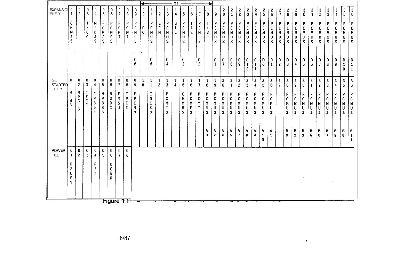
Hgure
i
.i
Frame Image Card Locations for a Fully Configured System
M-16
8l87
n
TL-130200-1001
5210
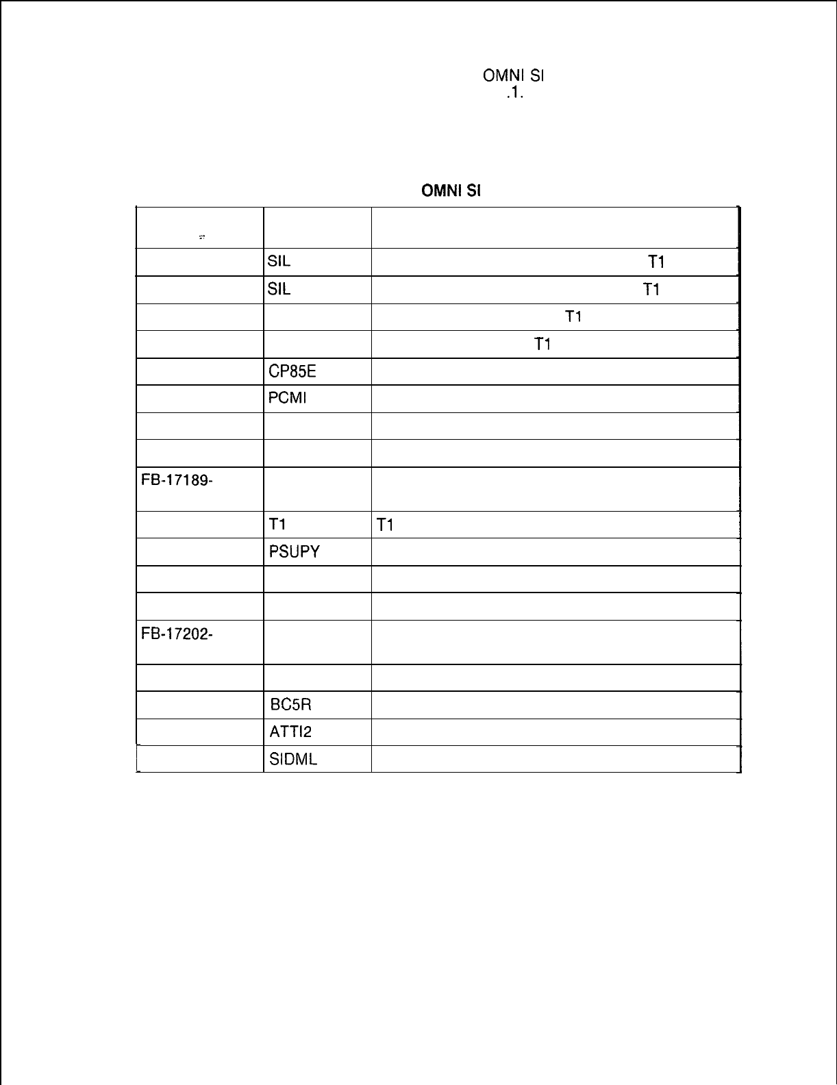
5210
8187
M-17
TL-130200-1001
Card List 1.4.2 A complete list of
OMNI
SI
cards according to card
number appears in Table 1
.l.
Cards used for the PD-200
Option are also included in the list. Information about removal
and replacement is noted with the card and explained at the end
of the table.
CARD NO.
.~_
FB-15277-A
FB-15277-l A
FB-15278-A
FB-15280-A
FB-17288-A
FB-17187-A
FB-17188-A
FB-17189-A
FB-17189-
BOA
FB-17192-A
FB-17197-A
FB-17201 -A
FB-17202-A
FB-17202-
BOA
FB-17203-A
FB-17204-A
FB-17208-A
FB-17209-A
Table 1.1
OMNI
SI
Cards
MNEMONIC DESCRIPTION
SIL
Span Interface and Output Format for
Tl
SIL
Span Interface and Output format for
Tl
FDC
Frame Detector Circuit for
Tl
LCM Line Compensator for
Tl
CP85E
Central Processor Unit Enhanced (8085) (Note 1)
PCMI
PCM Interface
TP12
Test Panel Interface Version 2 (Notes 1, 3)
PCMFS PCM Frame Synchronization
PCMFS PCM Frame Synchronization
Tl
B2
Tl
Buffer Circuit 2
PSUPY
Power Supervisory (Note 1)
PEMT PCM Two-Wire E&M Trunk (Note 2)
PCOT PCM Central Office Trunk (Note 2)
PCOT PCM Central Office Trunk (Note 2)
PDTMF PCM Dual Tone Multi-frequency
BCSR
Battery Charger 5 volt Regulator (Note 1)
ATT12
Attendant Interface, Number 2 (Note 2)
SIDML
SI Dual Modem and Current Loop (Note 2)
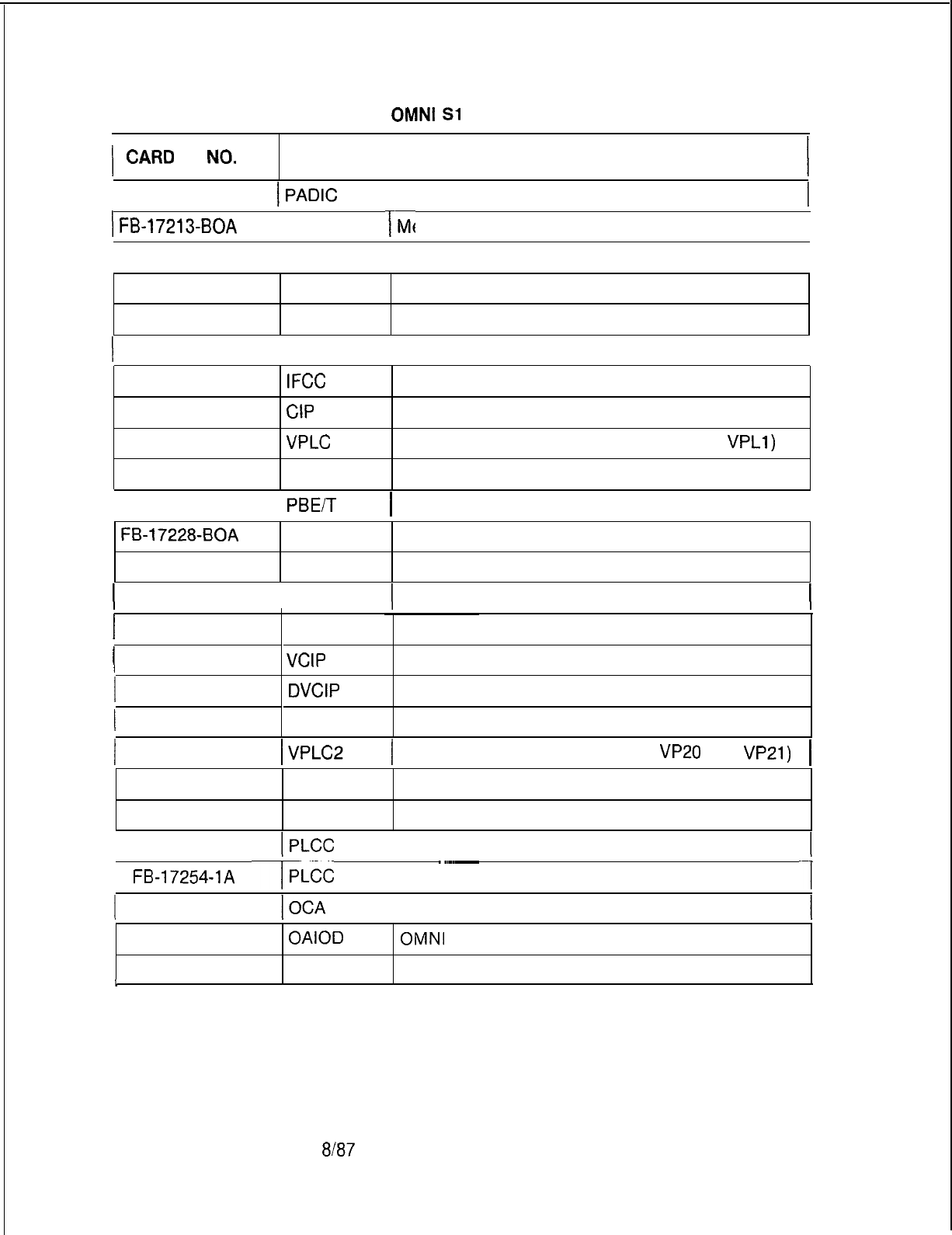
TL-130200-1001
I
CARD
NO.
1
FB-1721 O-A
Table 1.1 OMNI
Sl
Cards (Continued)
MNEMONIC
I
DESCRIPTION
I
I
Public Address and Dictation
)
FB-17213-BOA
rMPG16
T-
Memory Paging 16 Page (Note 1) I
1 FB-17215-A
I
MPB85
I
Multiprocessor Buffer 8085 (Notes 1, 3)
I
FBI.721 7-A
FB-17218-A
EPCMN
CHM85
Expandable PCM Network (Notes 1, 3)
Channel Memory 8085 (Notes 1, 3)
1 FB-17220-BOA
I
FMSD
I
File Management System Card (Notes 1, 2, 3)
I
FB-17224-A
FB-17225-A
IFCC
CIP
Inter-file Connector Card
Control Interface to Periphery (Note 2)
FB-17226-A
FB-17226-l A
VPLC
VPLCD
Voice Packet Line Card (Type VPLO and
VPLl)
Voice Packet Line Card Derived
1 FB-17227-A
I
PBE/T
1 Packet Bus Extender/Terminator (Note 3)
I
FB-17228-BOA
FB-17229-A
PRE
ADM P-A
Packet Router Extender (Note 3)
Administrative Maintenance Processor A (Note 3)
(
FB-17230-BOA
I
ADMP-C 1 Administrative Maintenance Processor C (Note 31
1
FB-17231 -A
(
FB-17235-A
UCB
VCIP
Universal Controller Board
Voice Control Interface Processor
1 FB-17236-A
(
FB-17242-A
DVCIP
NIC
Data Voice Control Interface Process. (Notes 1, 2)
Network Interface Card
1 FB-17246-A
I
Voice Packet Line Card 2 (Type
VP20
and
~~21)
I
FB-17250-A
FB-17251 -A
POPS
PRLT
PCM Off-Premises Station Line Card (Note 2)
PCM Release Link Trunk (Note 2)
1 FB-17254-A
I
PCM Line Circuit Card (Note 2)
1
FB-17254-1A
TLCC
r
~~~~___
PCM Line Circuit Card (Note 2)
~1
1 FB-17265-A Outrigger Cable Adapter
FB-17276-A
OAIOD OMNI
Automatic Identification of Outward Dialing
FB-17280-A PPTR PCM Progress Tone Repeater
I
M-l 8
8187
5210
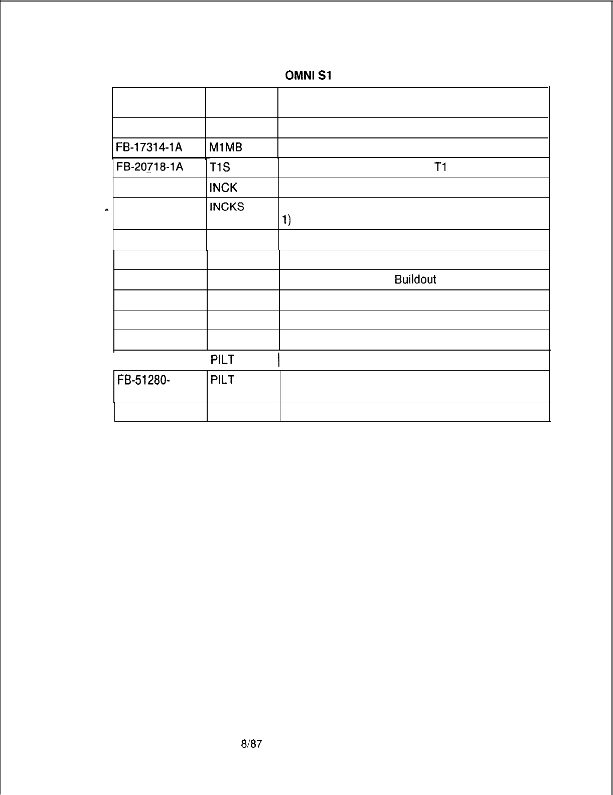
TL-130200-1001
CARD NO.
FB-17312-A
FB-17314-1A
Table 1.1
OMNI
Sl
Cards (Continued)
MNEMONIC DESCRIPTION
RPTR Repeater Card (Note 3)
MlMB
Memory 1 Megabyte (Note 1)
FB-20718-1A
TlS
Supervisory Alarm Circuit for
Tl
. . .
FB-20771-l A
INCK
Intermediate Network Clock (Note 1)
-
FB-20922-A
INCKS
FB-20974-A
FB-20992-A
FB-20996-A
FB-51051 -A
FB-51267-A
FB-51279-A
PCMTS
NSDC
RABR
PFT
PFWTA
PCONF
Synchronized Intermediate Network Clock (Note
1)
PCM Tone Source Card (Note 1)
Narrow Serial Device Controller (Notes 1, 3)
Recorder Announcer
Buildout
Resistor
Power Fail Transfer
PCM Four-Wire E&M Trunk (Note 2)
PCM Conference Card
1 FB-51280-A
I
PILT
1 PCM Incoming Loop Trunk DID (Note 2)
PCM Incoming Loop Trunk DID (Note 2)
FB-51280-
BOA
PILT
5210
FB-100119-l PMI Property Management System Interface (Note 1)
NOTES:
1. Power to cabinet must be turned OFF before card can be
removed or replaced
2. Card position must be placed in MAINTENANCE BUSY state
before card can be removed
3. Cables must be disconnected from the front of the card before
removing from the cabinet.
8187
M-19

TL-130200-1001
Power Restrictions
1.4.3 There are three power restriction categories for the
removal and replacement of
OMNI
SI
printed circuit boards.
PABX service may be affected as follows:
l AC power ON
-
No interruption to PABX service
l AC power OFF
-
Warm start required (about a 15 second
system outage)
lAC power off and battery pack fuse removed
-
Cold start
required (about a ten minute system outage)
Cards with peripheral service circuits (lines and trunks) may be
removed and replaced while the PABX is operating. The removal
and replacement of common control cards may require AC
power down or AC power down with the battery pack fuse
removed. Table 1.2 provides a reference between cards and the
power restrictions for removal and replacement.
Handling Cards
1.4.4
(PCBs)
Printed circuit boards require special handling
during removal and storage because of their sensitivity to static
electrical charges. A static discharge as low as 40 volts can
damage the PCB metal-oxide semiconductor integrated and
hybrid circuitry. The following procedures are used when
handling a PCB:
1. A wrist strap must be worn, and it must be connected to a bare
metal or plated part of the frame (screw, card guide support,
etc.) when performing the following procedures:
l Removing the static-sensitive PCB from the SI frame and
placing it in an anti-static plastic bag.
l Removing a static sensitive PCB from an anti-static plastic
bag and inserting it into the frame.
l Repairing static sensitive cards or handling static sensitive
components. Because the human body can hold static
electricity, cards should never come in contact with skin or
clothing.
2. Remove static sensitive cards from anti-static packaging
immediately before placing into the
OMNI
SI frame.
3. Static sensitive cards are stored in anti-static packaging.
Card Removal and
1.4.5
OMNI
SI
PCBs
fall into the three power restrictions
Replacement
shown in paragraph 1.9. When removal or replacement are
required, refer to Table 1.2.
M-20
8l87
5210
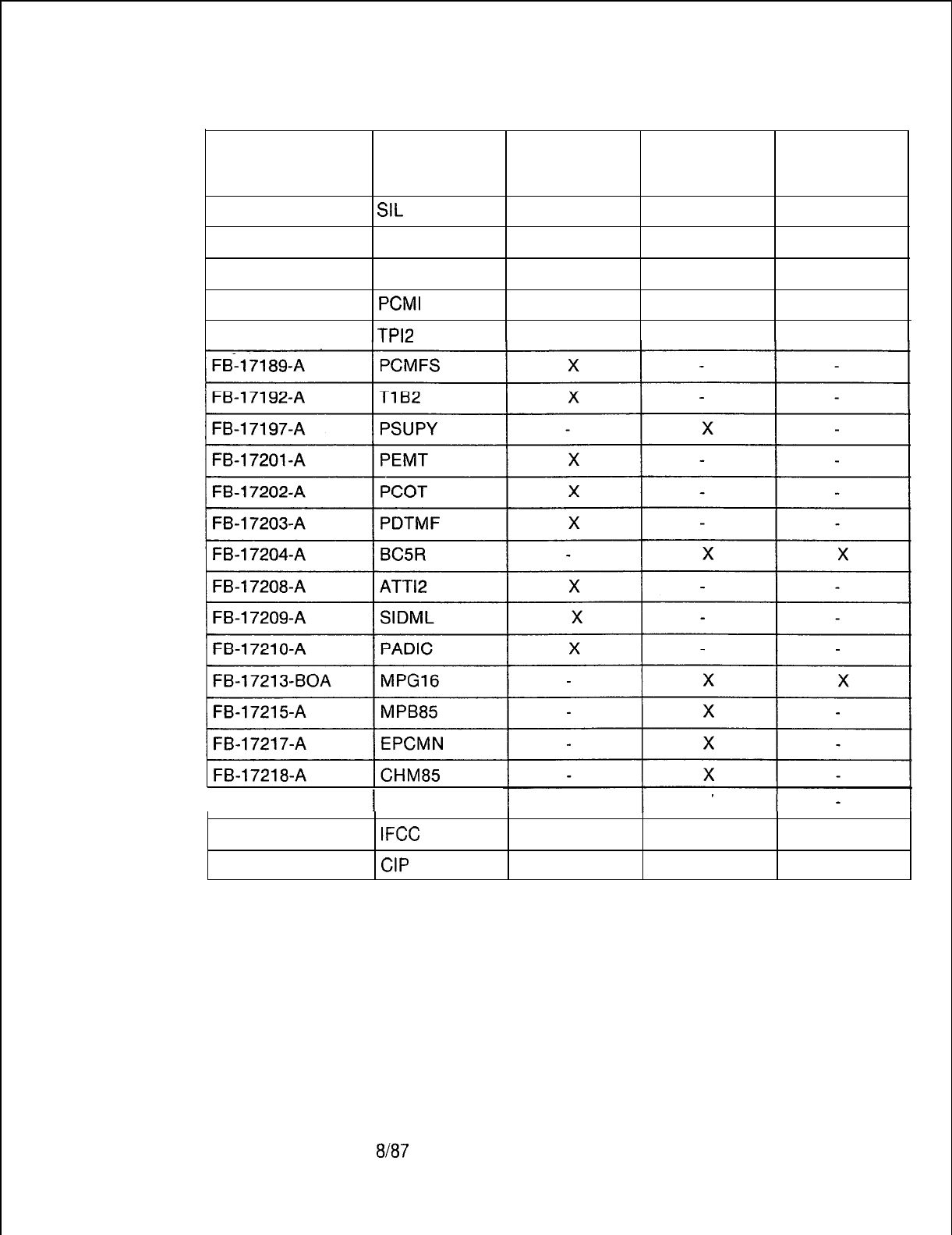
TL-130200-1001
Table 1.2 Power Restriction Status
Card No.
Mnemonic
AC ON AC OFF
Remove
Battery Fuse
. .
FB-15277-l A
FB-15278-A
FB-15280-A
FB-17187-A
FB-17188-A
SIL
FDC
LCM
PCMI
TPl2
X
X
X
X
X
5210
1 FB-17220-BOA 1 FMSD
FB-17224-A
FB-17225-A
IFCC
CIP
X
X
X
8187
M-21
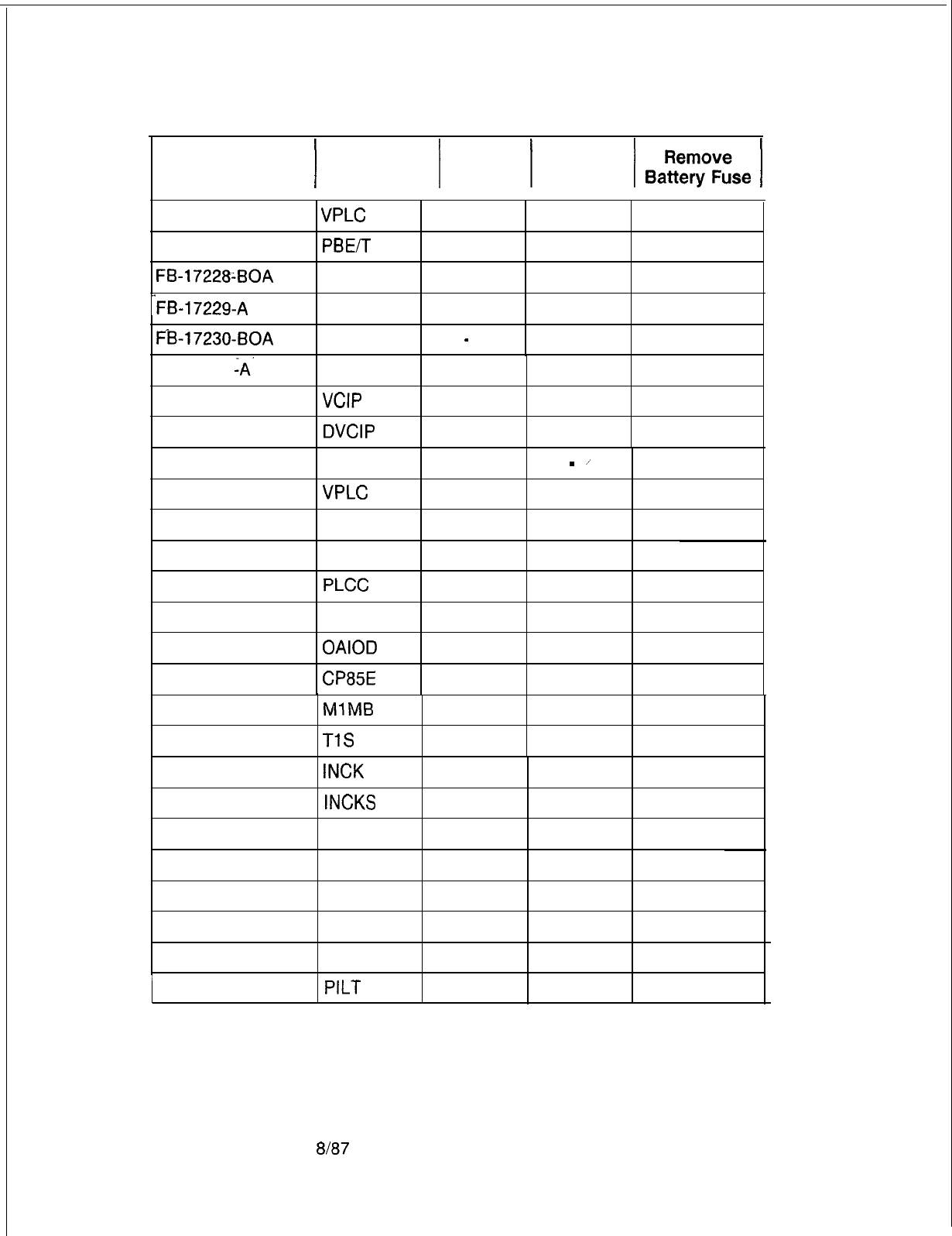
TL-130200-1001
Table 1.2 Power Restriction Status (Continued)
Card No.
1 Mnemonic
/
AC ON 1 AC OFF
/
BgyT&e
1
FB-17226-A
FB-17227-A
FB-17228~BOA
VPLC
PBEiT
PRE
X
X
X
-FB-17229-A
ADMP-A X
FB-17230-BOA
ADMP-C
-
X
FB-17231 iA-
FB-17235-A
FB-17236-A
UCB
VCIP
DVCIP
X
X
X
FB-17242-A
FB-17246-A
FB-17250-A
FB-17251 -A
FB-17254-A
NIC
VPLC
2
POPS
PRLT
PLCC
X
-
/
X
X
X
X
FB-17265-A OCA X
FB-17276-A
OAIOD
X
FB-17288-A
CP85E
X
FB-17314-l A
MlMB
X X
FB-20718-l A
TlS
X
FB-20771-1 A
FB-20922-A
FB-20974-A
INCK
INCKS
PCMTS
X
X
X
FB-20992-A
FB-51051 -A
FB-51267-A
FB-51279-A
FB-51280-A
NSDC
PFT
PFWTA
PCONF
PILT
X
X
X
X
X
8187
5210
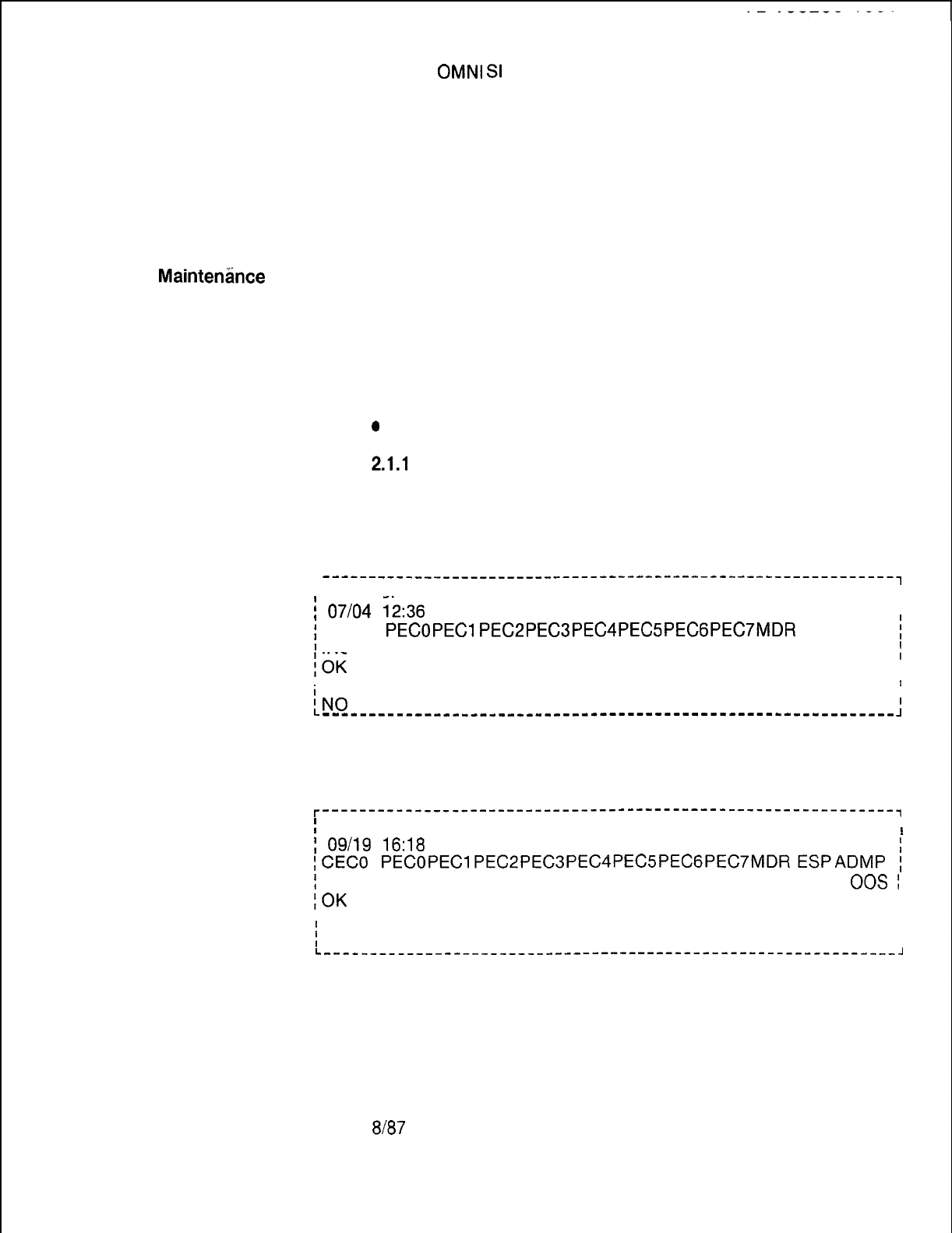
MAINTENANCE
2.0 The
OMNI
SI
system provides software support and
COMMANDS
status display programs that aid in system maintenance
AND DISPLAYS
and fault isolation. The system provides maintenance displays,
maintenance commands and maintenance request commands .
Maintenance displays provide records of system operations and
records of automatic fault detection. Maintenance commands,
memory access commands, and maintenance requests permit
testing of devices and/or circuits and the removal of defective
devices and/or circuits from operation without affecting the
operation of the system.
Maintenhce
Displays
2.1 Maintenance displays provide both general and specific
--
information on system operations. The displays are:
.
l
System
Status
l
Fault Log
l
Response Codes
l
ACA (Automatic Circuit Assurance Requests Log)
l
Traffic Study
0
Display Condition
System Status
2.1.1
System status can be displayed on the system
maintenance terminal by entering the status command. The
STATUS (or “ST.“) command is used. The system will respond
by causing the maintenance terminal to print out the following:
--------------------------------------------------------------,
[STATUS
I
!
07104
1236
I
I
)
CECO
i
INS
PECOPECl
PEC2PEC3PEC4PEC5PECGPEC7MDR
ESPADMP
i
;OK
INS UNE UNE UNE UNE UNE UNE UNE INS INS INS
;
OK OK OK OK OK OK OK OK OK
I
I
II
iN0
ALARMS PRESENT
I
----_--__-_-________------------------------------------------
:
With an ADMP out of service:
r--------------------------------------------------------------,
1
STATUS.
I
I
;
09/19
16:18
;CECO
PECOPEClPEC2PEC3PEClPEC5PECGPEC7MDRESPADMP
;
;
INS INS UNE UNE UNE UNE UNE UNE UNE INS UNE
00s
;
;OK
OK OK OK OK OK OK OK OK OK
I
I
I
I
i
ALARMS PRESENT
I
I
I
L--------------------------------------------------------------,
5210
8187
M-23
Tb-130200-1001
Fault Log
2.1.2 The
status
printout wilt show NO ALARMS PRESENT when
Request Commands
there are no faults in the system. If the printout shows that
alarms are present, a printout of the fault log should be requested
by executing the appropriate fault log command. The fault log is
a record of the last 32 faults that were detected by the CEC. A
printout of these faults is arranged in the same order that the
faults occurred (earliest is first entry on the list; most recent is
the last entry on the list). The commands for
,executing
a fault log
report are as follows:
(a)
To dump a fault
iog,
enter the following:
r---m
---------------------------------------------~
I
FLOG INS DUMP. or
I
I
I
I
FL INS. or
I
I
I I
I
FL INS DU.
I
L-------------------------------------------------~
(b)
To clear a fault log, enter the following:
r-------------------------------------------------~
I I
I
FLOG INS CLEAR. or
I
I
I
I
FL INS CLEAR.or
I
i
FL INS
CL.
or
I
I
L-------------------------------------------------~
(c)
To dump and clear a fault log, enter the
following:
r-------------------------------------------------~
I I
I
I
FL INS DUMP CLEAR. or
II
I I
I I
IFL INS DU CL. I
I
I
II
_---____________---_------------------------------~
Fault Log Display
When a system fault occurs, a message is printed on the
maintenance terminal connected to the CEC. The fault is also
logged in memory so that maintenance personnel can later
retrieve a recent, operational history of the system. This fault log
may be displayed and/or cleared at any time via maintenance
commands.
The format of a fault message as printed on the terminal is
shown in Figure 2.1. A key item in the fault message is the
two-
digit fault code. Table 2.1 lists the fault codes and their functions.
M-24
a/a7
5210
5210
Fault codes and their associated fault message printouts form
the basis for system troubleshooting as described in section 5.0
of this practice. A fault code quick reference chart is given in
Figure 2.3. For each code, the fault title and the meaning of data
stored in the CEC CPU registers are given.
MONTH/DAY
.~_
HOUR/MINUTE
.ON-LINE CEC (0)
(CONTROLS ON-LINE l-l-Y)
CEC REPORTING
FAULT (0) (REPORTS
FAULT)
FAULT CODE
di-d?
CECX
&i--6b
B C D E H L
xx xx xx xxxx xx
I
c
XX = TWO
HEXAIDECIMAL
DIGITS REGISTER STORED
--I
NN = TWO-DIGIT FAULT CODE DATA VALUE AT TIME
OF FAULT
Figure 2.1 Fault Reporting Format on TTY
8f87
M-25
I L-l
3uzuu-
I
vu
I
Table 2.1 Fault Codes and Functions
CODE FUNCTION
00
BLOCK PARITY FAILURE
01
DYNAMIC RAM MEMORY FAILURE
02
CONTROL MEMORY READ-AFTER-WRITE FAILURE
06
=-
SYSTEM NETWORK TEST FAILURE
. . .
-
08 NETWORK TEST MALFUNCTION
09
DIRECTIVE TEST MALFUNCTION
M-26
10
.DlRECTlVE
HOPPER FULL MALFUNCTION
11
ILLEGAL EVENT ERROR MALFUNCTION
12
READ-AFTER-WRITE FAILURE IN CHANNEL MEMORY
15
Tl
ALARM
16
10 MS STOPPED
17
ALARM FAULT
19
PRE-LOADING MEMORY TEST FAILURE
20
EVENTHOPPERERROR
21
DIRECTIVE HOPPER ERROR
22
MDR SDC FAULT
25
REAL TIME CLOCK FAILURE
I
27
1 HOTEL /HEALTH CARE DISK BACKUP FAILURE
I
28
1 CAS
MAIN/ACD
AGENT DATA LINK ERROR
29
CAS
MAIN/ACD
MESSAGE QUEUE ERROR
30
ATTENDANT CONSOLE DATA CHECK ERROR
32
CIP/VCIP/DVCIP
CARD FAILURE
33
CIP/VCIP/DVCIP
PORT FAILURE
36
CHANGE MDR SYSTEM CLOCK FAILURE
37
SYSTEM WARM START
39
ADMP INITIALIZATION AND ASSOCIATED ERRORS
40 DISK FILES GV
TX009/GVTXOlO
(TCM/FRL)
AND
I/O
ERRORS
41
FMS DISK ERROR
42
TIME SLOT LOCKUP
8187
5210
.-
.-..---
.--.
II
I
I
REGISTER STORED DATA VALUE
I
I
II
I I
II
I
I
I
I
FAULT CODE
I
I
II
B
I
C’
I
D2
I
E3
I
H
I
L
I
I
II
!
00-CEC I
IIf
02 = Test
I
Pageonwhich
I
Address of Faulty Byte
I
I
Block Parity
I I
I
Failure
I Failure
I
I
I
I
failureoccurred
I
I
I
I
II I I
I 00 IO 08
I4
I I
II I
=
I
I
I
1
III
I
II I
;
o,:,,
09=15
;
I
I
.;.
;I I I
II I
1
02=DOOA=D4
;
I
II
I
03=DlOB=D5
I
I
I. . . I
I
II
I
I
III
;
04=12
OC=l6
;
I
I
I
I
III I
I
I I
I
;
05=13
OD=17
;
I
I I
II
I 06
DZOE
D6
I
==
I I
t
I I
II
;
07=D3OF=D7
;I
I
I
I,
I
I
Ol-CEC
I-
I
III I
I
I
II
I
Dynamic I I
I
1 02 = Test , Pageonwhich
;
I
failureoccurred ,Address of Faulty Byte
I I
II
Failure
;
I
I
Memory I
II
I Failure
I
IIIII
I
I
I I
I
00=1008=14
;
I
I
I I
II
1 01
I1
09
I5
,
I
I I I
II
t
II;
&l)OA==D4
;I
I I I
II
III
,
03=DlOB=D5
;
I
I
I
II
I
Ii
=
I6
’
I
I
I I
III
I
I
II I
I
05
=I3
OD:l7
I
1
06=DZOE=D6
II
I I
I
I
I
I
I
I
II
,
07=D3OF=D7
:I
I
I I
II
:
02-
CEC
I
I
I
I
I
I
I
Data
I
Data Read
I
Address of Faulty Byte
i
t
Control Memory
I
f
II
I
I
I
(
Written
II
;
Read-After-
II
II I
, Write Failure I I
II I I I
I I
,III
;
03
-CEUPEC
I
I
PEC No.
IIII I
I
;
CommonMemory
I
I .
I
I
Data
I
Written
I
Data Read
I
Address of Faulty Byte
I
I
Read-After-
I
II I II
I I
III I I
1 Write Failure
:
I
II
I I II
f
OCCEC
I
I
Channel No.
i
00 = Cannot
IIII
II
I
I
Total
I I
I
Communication
I
l
that failed
i
Allocate
II:I
I
I
;
Message
I I I I
;
Failure
!
f
, Buffer I I
I I
II I I
I
I
I
I
II
I
I
I
II
II
I
I
1 01
=Test
I
II
I
And I I
I
I I
I
Message
I I I
I
II
II
II
I
II
I
;
Timeout
II I I
I
I I I
;
OS-CEC
I
I
02=MPB85
;I
I
I
Single
I I I
I
I
I
Channel
I
I!
Timeout
III
,I
I
I
Communication
i
II
(While II
:
I
;
Un-Loading) 1I
II
;
Failure I I I I
I
I
IIII
I
I I
II I I
I
I I
I
03=Check
I
I
I I
II IIII I
I
I I
I
Allocate
I I
II
I
I I 1 Message
II
II
I
I I
I
Buffer
I
I
I
I
I
I
1
I
I
I
I
I
fIII I
I
II I
II
II I
I
04=MPB85
;I I I
II
III I
II
II
Timeout
III I
I
I
I
I;
(Single Byte)
;I
I
I
I
1I
II I
IIII
1
Figure 2.2 Fault Code Quick Reference Guide
5210
a/a7
M-27
.-
.-----
.W”.
I
II
II
I
REGISTER STORED DATA VALUE
I
I
II
I
II
I
FAULT CODE
I
8
C’
I
II
I
D2
I
I
Es
H
I
L
I
I
I I
II
I
II
I
’
05=Read
i
’
Data
After Write
f
Written
]
Data Read
;
I
I
Address of Faulty
Byte
II
I
i
ErrorinCEC
II
I
1
I
I
I
i
I
I
I
I
I I
;
Memory
IIII
II I I
I I
II I I
’
=-.
I I
I I
1
I
I
I I
:
II
I
‘I- I I
;
06=
MPB85
;
r
Timeout
I
II
I I
IIII
I
I I
III
I
!
(While
I
I
III
i
Loading)
II
I
III
I
I I
I I I
-I
III
I
07 = Cannot
III
I
I
II
I
I
I
III
IIII
II
Ii
Bring Up
I
I
II
I I I Channel on
I
I
I I
i
Startup
I
I
I
1
II
III,I
I
fI
;I
I
08=
First
II I I
I
III I I
I
i
Faulty
Byte
;
I I I
II
I
I in Message
II
I
I
I
I
I
I
I
fiI
II
IIII
f
06-CEC
Ii
1 PEC X
I
I
System Network
I
Ii
Timeslot
in 1
OO=PEC(s)did
iI
I
Test Failure
I
I
;
PEC X
;
not respond
;;
PEC Y
r
Timeslot
i
II
in
II
I
II
I
I
I
01 = Only one
!
PEC No. not
I
;
PEC Y
I
I
I
II
i
PECresponded
)
responding
I
I
I
I
I
III
IIII
I
II
I
02
=Test
f
III
I
I
I Failure
IIII
I
I I
I
III
I
I
ObPEC
I
1 Network
i
i
PEC No.
II
I
I
)
Channel No.
;
OO=PEC(s)
;
I
I
Ir
did not
III
I Test Failure I I
IIII
I
I I
I
i
respond
I
I1
I
IIIIII
I
I
II
i
02=Test
I
III
II
III
I
I
I I
I
I Failure
I
II
IIII
I
I I
II
i
03=Network
I
II
Ii
III
I
f
Detected Off-
iI
I
I:
;t
i
line
II
II I I
I
;
09-PEC
1
I
, , PEC No.
I
Channel No.
I
f
II
r
Directive
I
I:I
OO=PEC(s)did
I
I
not respond
iI
I
t
Test Failure
II
I I
IIII
I
II
IIII
II
III
II
I
II
02 = Test
I
I
i
I Failure
I
II
I
iI
fI
II
III
r
IO-PEC
;
;
PEC No.
II
II I I
IIIII
I
Directive I I
II I
I
I
I
I Hopper Full
I
i
I
II
II
III
I
I
I
IIII
I
I 11 PEC
II,
I
i
I
I
PEC No.
Illegal Event
I I
i
Parameter 1
I
Parameter 2
f
Parameter 3
i
Event No.
i
I
I
I
I Error
t
I
I
II
I
I
I
I
IIII
Figure 2.2 Fault Code Quick Reference Guide (Continued)
M-28 8187
5210
I
II
Ii
I
REGISTER STORED DATA VALUE
I
I
,
I
i
II
I
i
FAULTCODE
II
BI
C’
I
02
IE3 IHI
I
I
L
I
II
III
;
12-PEC
;
:
PEC No. I Channel No. I Data I Data Read
I
Address of Faulty Byte
I
Read After
I
I
I I
II
Written
II
1
I
I
I
I
WriteChannel
I I
I
I
Memory Failure
\
%L I I
II
I
II
III
I
IIIII
I
I
i
13-PEC
!
Self Test
I
Error
-
i
;
PEC No.
I I
I I
I
I
I
I
I I
Il.
I I
I I
I I
I I
I I
I I
I I
I
I
I
I
,I
I I
I I
I I
I I
I
I
I
I
I I
I I
I I
I
I
;
00 = PEC-CEC
1 Data
I
i
Data Read
:
I
;
Written
I
Address of Faulty Byte
I
Common
I
III
I
Memory
I
;
Read-and-
t
II
I
I
I
l
Write
III
III:
II,
!
OI=PEC
!
II
I
I
Address of Faulty Byte
I
\
Block Parity
i
III
III
I
5210
I
I
I I
I I
I I
I I
I I
II
I I
I I
I
I
14-PEC
,
I
I
I
II
I
I
I
I
I
I
I
I
;07=MDR
i
I
Checksum on
I
Call Info
I
;
I
Buffer
I
I
II
II
I
II
I
II
III
I
!
OS=PEC
i
Directive No.
I
r
Parameter
1i
Parameter 2
t
Parameter 3
i
:
Illegal PEC
I!I
IIII
I Directive
I
III
II
III
III
i
10 MS Error
;
;
PEC No.
I
1
02=Test
I!
I\
Failure
;
CECCount
II
PECCount
I
I
IIIII
I
I
I I
II
fII
I!
I I
I
1
I
1 15
Tl
Alarm
:
;
PEC No.
;
OO=TlA
!
OO=System
II,
I
I I
I I I
I
I I
I;
Alarm
II
I
I I
III
I
I I
II
I
I
I
1 01
=
Remote
II
I
I I
;
Ol=TlB
I Alarm
I
,I
I
II
,
I
I I
I
I
I I
II
02
=Cutoff
If
I
I I
I
I
I I
I\
Alarm
II
I,
II
I
IIII
I
I I
I I I
I
I I
II
03=Local
I
r
Alarm
,,
I
I I
II
I
16CEC
I
I I
II
, I
I
)
10 MS Stopped
!
!I
1
;
02=PEC
Ii
I
r
Address of Faulty Byte
I
I
I
Dynamic
I
III
;
Memory
IIII
III
III
I
;
03=PEC
i
Directive NO.
I
Parameter 1
t
Parameter 2
.
1 Parameter3
I
i
Illegal
,I
II
I
Directive
I
I
I
I!
II
I
II
I
I
04zMPB85
I
Counter
I
II
Addressof Attempted Write
I
;
Timeout
II
II
II
f
06
=
Invalid
!
Test No.
I
I
I
Test No.
II
I
II
TL-130200-l uu I
Figure 2.2 Fault Code Quick Reference Guide (Continued)
8/87
M-29
TL-130200-1001
I
I
i
I
REGISTER STORED DATA VALUE
1
I
I
I
I
I
II
I
1
I
FAULT CODE
I
I
II
B
I
C’
I
D2
I
E3 H
I
L
I
I
1
17-CEC
I Alarm Fault
i
I
Attendant
;
OO=ArtCard
i
I
I
I
I I Console No.
II
I
I I , Alarm
I
Ol-lO=Tl
Line
III
!
I
I I
I I
IiI
I
I.~_ I
I
i
Numberl-16
;
II
II
I
I I
i
11-tB=Attend-
III
I I
I
I. . . I
I I
:
ant
I
I I
Ir
00-07 =
Trans-
i
mission Fault
I!I
I
I
I I
I I
I
i
II
II
I
I
III
i
18-Common
i-1
PEC No. .
It
I
I
II
i
Memory Block
i
;II
End Address of Block
I
Address of Block That
I
I Parity Error
II
I
I I
I
I
Failed
I
I I
IIII
III
I
IQCEC
;
Preloading
r
r
OO=
Instruction
i
I
, Memory Test 1 1 Page0
i
Address of Block That
I
I
II
1 Failed
I
I
I
i
:
01
=Instruction
i
II
I
I
I
I
I Page 1
II
I
II
I
I
I
I
I
;
;
02=Data
I
II
I
I I
Page0
III
I I
III
IfI
I
I I
03=Data
I
J
;
1 Page 1
III
I
II
III
4
Figure 2.2 Fault Code Quick Reference Guide .(Continued)
M-30
8l87
5210
FUJITSU GTE
SECTION TL-130200-1001 ISSUE
1
BUSINESS SYSTEMS, INC. AUGUST 1987
MAINTENANCE
OMNI
SI@’
TECHNICAL PRACTICES
5.2.1.0

Purpose
This Technical Practice has been prepared for FGBS Employees
who operate and maintain the equipment manufactured and sold
by Fujitsu GTE Business Systems, Inc. The information in this
practice is subject to change and may not be suitable in all
situations. Fujitsu GTE Business Systems, Inc. acknowledges
that a customer’s special requirements or practices may take
precedence over those supplied in this practice if a conflict
develops during installation or ongoing operation. Fujitsu GTE
Business Systems, Inc. hereby disclaims any responsibility or
.-liability
for any consequential or inconsequential damages that
may result from the use of this practice.
This document is provided with the understanding that it shall not
be copied or reproduced in whole or in part or disclosed to
-others with-out the prior written permission of Fujitsu GTE
Business Systems, Inc.
Copyright
a1987
by FGBS, Inc.
OMNI
SI@
is a trademark of Fujitsu GTE Business Systems, Inc.
Comm
I’”
is a trademark of Fujitsu GTE Business Systems, Inc.
FlashComm
Plus’” is a trademark of Fujitsu GTE Business
Systems, Inc.
FeatureComm I’” is a trademark of Fujitsu GTE Business
Systems, Inc.
FeatureComm II’” is a trademark of Fujitsu GTE Business
Systems, Inc.
FeatureComm
Ill’”
is a trademark of Fujitsu GTE Business
Systems, Inc.
FeatureComm
IV’”
is a trademark of Fujitsu GTE Business
Systems, Inc.
FeatureComm
V’”
is a trademark of Fujitsu GTE Business
Systems, Inc.
FeatureComm VI’” is a trademark of Fujitsu GTE Business
Systems, Inc.
AnswerComm
IT,
is a trademark of Fujitsu GTE Business
Systems, Inc.
AnswerComm II’” is a trademark of Fujitsu GTE Business
Systems, Inc.
OMNI
IVMS’”
is a trademark of Fujitsu GTE Business Systems,
Inc.
II
I
REGISTER STORED DATAVALUE
I
II
I
I
FAULT CODE
II
II I I
I
I
B
C’
Dz
I
Es
HL
II
I
I I
II
I
I I
;
80 = Illegal Di-
i
i
rectiveNo.lnto
;I
II
I
I I
II
I
I I
I
I
I
I I
I
I I
I
Target Routine
II
II
II
I
I I
r
FF=PEDTest
1
I
I I
I
Failed
III
i
22-24Spare I
I
I
I
25 Real Time
I
III
II
I I
II
1Clock Failure I I
I
I
II
I
I
‘1”
I
III
I
III
IIII
II
I I
f
II
I:III
I
II
II
IfII
I
c
I-
.I
I I I
I I ,I
I
I I
II
I
27 H/M Data not
I
i
DiskOperation
I
i
Failure Mode
II
II
r
Backed up
r
r
Failure
I
I
I I
I I
I
I I
III
i
28-CAS Main/
i
!
PEC No.
II
I
I
I
I
;
ACDAgent
I
I(
Data Link No.
I
A=Time-out
i
Agent I.D.
I
NO Meaning
I
I I I
Data Link
II
i
Error
I
II
;9=2ndNack
i
II
I I
II
II
II I II
III
I
II
II
I
II
i
8=DataNot
1
I
I
r
Expected
I I
I
II
I
I
;
;
PEC No.
i
Data Link No. 1 FF = Request
I
I
for
i
Agent I.D.
I
I
I
I
I
II
I
I
NO Meaning
I
I
I
I I
I
1 Initialization
I
I I I
I
;
;
PEC No.
II I I
I
I
r
r
Buffer
i
No Meaning
;
C=NoPEC
1
NoMeaning
i
NO Meaning
I
I
I
f
)
Destination
I
I
I Message Buffer I
II
I
Available
I I
I I
III
I
!
29-CAS
Main/
I
IfII
III
III
I
;
;
PEC No.
I
I
r
B = Failure
II
i
ACD Message
I Queue Error I
I
II
Whena
PEC’s
ii
I
I
I
I
I
I
II
QueueCleared
I
II
I
I
II
;
All PEC
,I,
If
II
I
I
II
I I
i
I
Queue Were
i
II
I
I I I Cleared
II
I
II
IIIIII
II
I
I
i
No.of
Times
I
00 = Message 1
C=No
III
I
I
I
That No
I
i
i
Message I Buffer Queue
i
Not Cleared 1 Message
III
I
II
I
r
Buffers Were I
I
I
Ir
r
BuffersWere
III
Ii
i
Available 1 Available
i
FF=Message I
I
I
I
I
I
I I
I
I
I
i
Buffer Queue
I
I
,
I
I
I
III
I
I I
I
Cleared
IIII
i
30-Attendant
I
f
I
I
I
[
Console I 1 Console No.
I
I I
i
Console No.
;i
Typeof
Error
i
I
I
8=Checksum
I
I
I Data
I
I
I
I
II
i
Check
I
II
I
i
9=DataLink
iI
III A=Time-out I
I
I
Error II
II
I
I I
II
1 Occurred
I
I
I
I
I
I I
I
1I
II
I
II
FF=Data Link
II
;
,
I
I
i
I
I
II
1 Check Failure
II
31PEC ODDB
; ; I
I
PEC No.
I
I
ti
BackupFailure
I
lIi
Figure 2.2 Fault Code Quick Reference Guide (Continued)
5210
8187 M-31
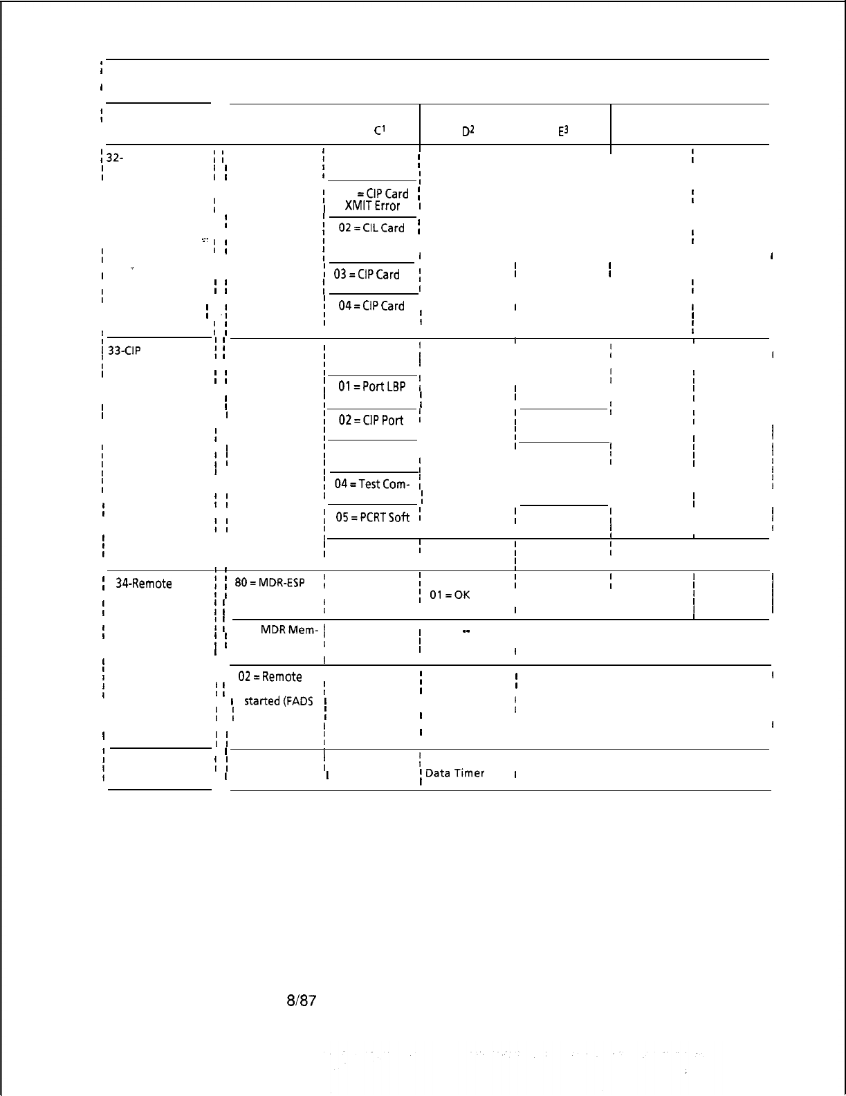
;I
II
I
REGISTER STORED DATAVALUE
I
II
II
I
I
FAULT CODE
I
II
B
I
C’
Dz
I
I
Es H
I
I
I
L
I
I
I
1
32-
CIP Card
i
;
PEC No.
i
00 = CLP Card
III
Card No.
I I I
I
Failure
I
If
Test Failure
i
I I
;
II
I I II
I
I I
II I I
I
;
01
=CIPCard
[I
I I
I I I
II I
:
I
II
I
I
XMlTError
I
I I I I
III I
I
I
I
I
I
I
02=CILCard
iI I I
I
I
I I
I
-
.~_
I
II
Watchdog
I I
III
II
I
I
;IIII
. . .
I I
I
Timer Error
II I I
I
-
I I
i
03=CIPCard
II
I I II
I
I I
iI I II
I
I
I
I
1Hardware Error
I
I I I
I I II
I I
I
!
04=CIPCard
,
I I
I
I
I;
.;
I
II
I
I
Initialization
II
IIII
II
II
I!
I
i
I Error
I
II
II I I
I
33-CIP
Port
I
I
I
]
Failure
;
i
PEC No.
I
00= Data Link
i
Port No.
II
I
I
I I
;
Test Failure
II I
III
III
II
I
;
Ol=PortLBP
t
I
1
fI
I
I I
II
I
I
I
I
I
I
I;
Protocol Error
IIIII
III
I
I
I
II
I
I I
t
!
Total #of Sync I
II
I
I
I
I
02=CIPPort
,
I
Sync Error
I
Change
I
III
III
I
I
II
I
03 = Port Initial- ,
I I I
i
II
If
I
1 ization Error
i
I
I
I
I
I
I
I I I
1
I
I I
I I I
I I
i
04=TestCom-
i
I I Ii
I
I
I
II
mand Failure
I
I I II
I I I II
I I
II
I
;
05=PCRTSoft
; I
Total #of Soft
I
I
II
I
;
Protocol
I
, Protocol
I
II
I
I
I I
I I I
I
I I
I
06 = Down
;
SID
I
Block Number
i
DN = Directory Number
I
I I
I
I
I I , Load Failure
,I
II
I
i
3CRemote
’
’
BO=MDR-ESP
II I
1 Number of
I
Current Status
I
*See Below
iI I
I I
I FADS
I !
Communications, Communications
I I I I
I
Transmission
i
(
Status Change
t
Status Change
;
Ol=OK
I OO=BAD
I I I I
II
I
I
I Error
II
I
i
1
I
01 =
MDRMem-
’
Number of
II
_-
I
1 1 ory Allocation 1 Figures
II
No Meaning
I
I
II
I
’
, Failure
IIII
I
I I
IIII
I
I I
III
I I
02=Remote
, Previous ESP
fI
I
FADS must be
(
State
i
New ESP State 1No Meaning
I
I
I
II
I
I
I
started(FADS
I
II
I
I
(
periodicdata
I
I
1
I
IIII
,
I I collection in-
IIII
Ii
i
terval error) 1
II I
I
II
I
)
35-Remote FADS I
I
II
; ;
01 = Real-Time
i
Real-Time 1 Real-Time I I
1 Reporting Error ,
I
Packet Lost Sync
I
Packet Count
I
I I
I
1
Data
Timer
I
No Meaning
II
I I
Figure 2.2 Fault Code Quick Reference Guide (Continued)
M-32
8187
5210
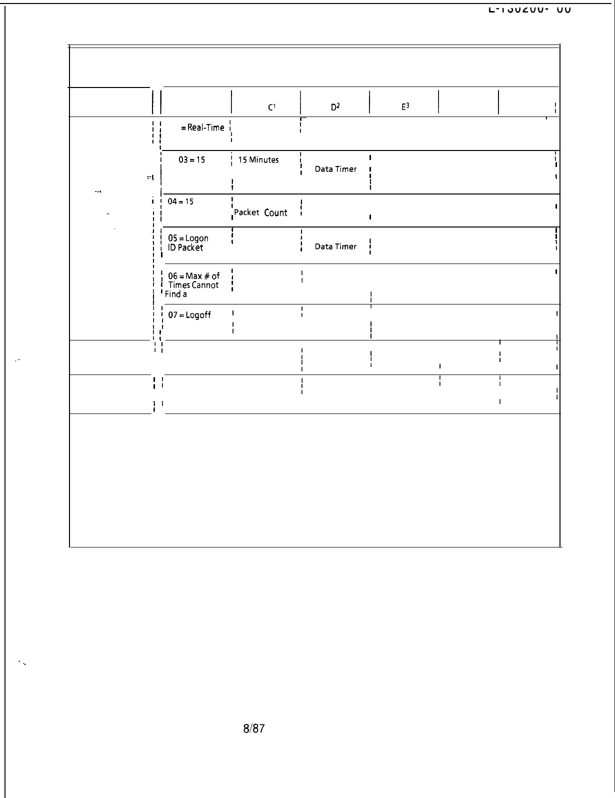
I
L-
I3uLuu-
I
vu
I
. .
I
I
REGISTER STORED DATA VALUE
I
I
II
I
II
III I I
i
FAULT CODE
I
B
C’ D* Es
HL
I
.:-
,
I
.
.
.
I
I
i
1 02
=Real-Time
i
Real-Time
r
I
I
Real-Time
I
No Meaning
I
I
r
Packet Count
i
Packet Count I Data Timer
I
I
I
Error
II
I
II
I
I
i
03=15
i
15Minutes
i
15 Minutes
I
I
No Meaning
;
I
Minute Packet I Packet Count
i
DataTimer
;I
I
r
Count Lost
III
i
Sync
IIII
IIII
i
04=15
,
I
I
15 Minutes
I
r
15 Minutes
I
I
r
Minute Packet I
Packet
Count
I
Data Timer
I
No Meaning
I
I
I
I
Count Error
I
II
I
I
I I II
II
1
OS=Logon
[
Logon ID
i
Logon ID
II
I
No Meaning
I
I
IDPacket
I
I Packet Count
i
DataTimer
;I
I
Count Error
I
II
I
IIII
II
I
I
06=Max#of
!
Buffer Failure
I
I
I
II
; f
TimesCannot
i
Peg Value
I
00
I
No Meaning
II
I
,
Finda
Buffer
I
I
I
II
II
I
II
I
I
07=Logoff
III
I
I
I
i
i
Buffer I
I
I
I
00
I
I
00
I
No Meaning
I
I
I
(
(
Overflow
I
II
III
37-System Restart
I
II
I
I I I
00
I00
I I I I
I I I
t
I
I
III
I I
I
I I
CEC Reload
II
III
I I
II I I
I
III I I
II
I I
III I
I I
II
I
II
I
III
I
II
I
I
II I I
NOTES:
1.
2.
3.
4.
See Table 6-4
See Table 6-5
See Table 6-5, Register E
Fault 34 Reg E = Reason for Change
00 = MDR not in Service
01 = Timeout Waiting for ESP Acknowledgement
02 = Unexpected Input from ESP
06 = Acknowledge from ESP
12 = No-Acknowledge from ESP
5210 8187
M-33
Figure 2.2 Fault Code Quick Reference Guide (Continued)
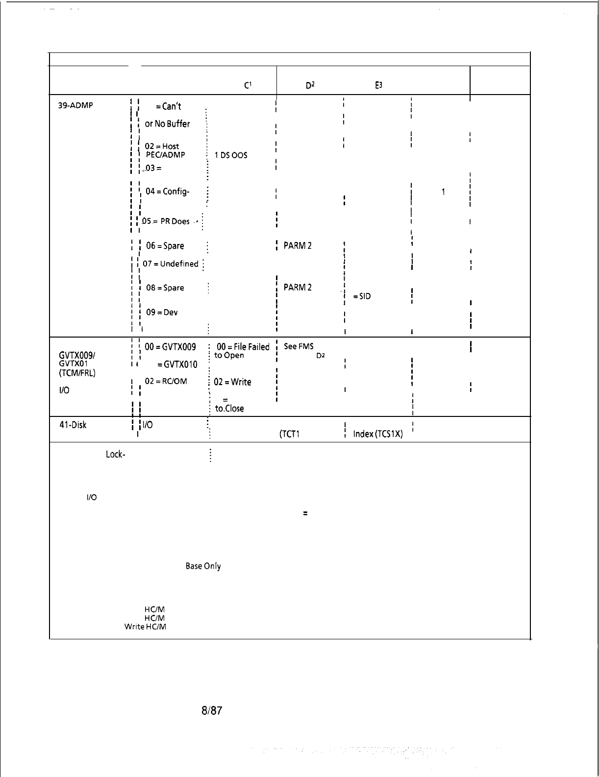
REGISTER STORED DATA VALUE
FAULT CODE
II
B
I
C’ D2
I
Es
I
HL
39-ADMP
t I
01
=Can’t
Initialization and
!!I I I
r
r
Enable ADMP
III
Associated
!
i
orNoBuffer
I
fI
II
.
I
II
Errors
f
1 Available
I
I
I
i
III
;
;
02=Host
;I
0 PECOOS
II I
;
;
PEUADMP
:
IDSOOS
II I I
I I I
I I
.*.03
=
Duplicate
i
iIII
II
I I initial Request
:
II
III
. .
I
I
04=Config-
I
III
I
I
urating Data
:i
DevTyp
I
Dev Number 1
I
I Dev Number 2
!
PARM
1!
PARM2
I
I
1 Error
i
Card Slot
I
I
II
III
i
I
D5=
PRDoes
‘m
i
PEC#
i
OWNGP
III
II
I I
Not Match
I
II
I
I I
III
I
I
06=Spare
;
PARM 1
;
PARMZ
II
I
I
;
PARM3
II
II
1
I
i
07=Undefined
j
Status
I
II,
I I
I
iI
Status
I
I
:I
I
II
!
!
08=Spare
I
j
PARM 1
;
PARMZ
I
II
f
I
: = DevTyp
.j
PARM3
I
;
=PEC
;
=SID
I
II
1
i
09=Dev
i
DevTyp
I
II
)i
Type Not
I
I
I
II
f
1 Implemented
ii
I I I
I I
I I
II
40-Disk Files
:
:
OO=GVTX009
GVTX009/
I
I
;
OO=FileFailed
!
SeeFMS
I I I
I I I
i
toOpen
i
Code for
D2
I I
I
GVTXOI 0
I
I
01
=GVTXOlO
. 0 1 = R e a d I Register Data
II
I
(TCMIFRL)
I I
I I
i
Record Error
i
Values
I
I
I
I
and
1 I
02=RC/OM
:
02=Write
II
l/O ERRORS
I
I:
Record Error
III
I
II
I I
i
03
=
File Failed
!
I
I
I
i
to.Close
II
I
I
I
II
I
I
I
III
I
41-Disk
I/O Error
II
I I
I/O
Request Code
i
Error Code (See DCB Table Index
r
DCB Sequence
I 1 (See Note 5)
i
Note 6)
(TCTl X))
;
I
Index(TCSlX)
,
DRB ADDR
42-Time Slot
Lock-
UP Time Slot
Hardware ID
Call Store
PEC Number
!
Number Number
NOTES:
5. I/O
Request Codes are as follows:
02 = Read PEC 0 Generic and Data Base
03 = Read PEC 1 Generic and Data Base
04 = Read PEC 2 Generic and Data Base
05 = Read PEC 3 Generic and Data Base
06 = Read MDR Generic and Data Base
08 = Read PEC 0 Data Base Only
09 = Read PEC 1 Data
BaseOnly
OA = Read PEC 2 Data Base Only
OB = Read PEC 3 Data Base Only
OC = Read MDR Data Base Only
OE = Write all Data Base
13 = Read
HC/M
Data
14 = Write
HUM
Data (MR)
15 =
Write
HC/M
Data (Power Fail)
18
=
Read a Recent Change Program
IA = Close Recent Change File
1 D = Read Featurephone Generic
1 E = Load a PEC (Parallel Loading)
1 F = Close Featurephone File
20 = Read PEC 4 Generic and Data Base
21 = Read PEC 5 Generic and Data Base
22 = Read PEC 6 Generic and Data Base
23 = Read PEC 7 Generic and Data Base
24 = Read PEC 4 Data Base
25 = Read PEC 5 Data Base
26 = Read PEC 6 Data Base
27 = Read PEC 7 Data Base
M-34
8187
5210
NOTES:
6.
Error Codes are as follows:
81 = Disk Directory Full
82
=
Not Enough Spare to Define File
83 = File Size Is Larger then Disk
84 = Filename in Use
85 = Record Size too Large
86 = Device’s not
tiqual
87 = Device Invalid
88 = Filename Is Invalid
89 = Security Violation
8A = File Does not Exist
88 = Not Allowed on FMS System File
. . .
8C = File Is Already Open
8D = Mode Is Invalid
8E =
FID(s)
not Available
-
8F =
FIDIslnvalid
90 = FID Is not an Active File
91 = FID Specified Is Already in Use
92 = FID in Use by Other Processor
5210 8187
M-35
93
=
Read Past Logical EOF Attempted
94
=
File Is not Open for Input
95
=
File Is not Open for Output
96
=
Write Past Physical EOF Attempted
97 = Seek Past EOF Attempted
98 = Record Sizes not Equal
99 = Files Open on Device
9A
= FID not Sized
9B
= Access Is Invalid
9E
= Device not Ready
9F
= Device I/O Error
A0
= Device Write Protected
Al = Device not Mounted
A2 = Request not Allowed on Mounted Disk
A3 = No Device Attached
A4 = Device Is Private
A8
=
Invalid Command Number
FF
=
Timeout
TTY Response
Log Display
2.1.3 A response log is provided within the system memory to
record the responses to tests performed. The system performs
these tests when certain tasks attempted will alter the system
configuration. For example, the system conducts a series of
tests when the PEC is to be placed in service or out of service.
A response message is associated with each task attempted. If
an operating system maintenance terminal is connected to the
in-service CEC, the response messages are printed as they
occur.
__
For most tasks, the response messages appear only if the task is
successfully completed. This is true even though some failures
occur. Each response message includes information about
those failures. The format for the
resoonse
messaaes is shown
M-36
in Figure 2.3. As a quick reference
guide
for the
response
codes, refer to Figure 2.4.
DATE
HOUR/MINUTE
ON-LINE CEC (0 )
(CONTROLS ON-LINE TTY)
CEC REPORTING
RESPONSE (0)
(REPORTS RESPONSE)
RESPONSE CODE
hdiECX
‘tih
B C D E H L
xx xx xx xxxx xx
I
XX = TWO
HEXAIDECIMAL
DIGITS
NN = TWO-DIGIT FAULT CODE
-.
--
-
REGISTER STORED DATA
VALUE AT TIME OF
RESPONSE
-
Hgure
2.3
Response Reporting Format on TTY
Em7
5210
TL-130200-1001
I
REGISTER STORED DATA VALUE
II
I I
I I
II
I
!
RESPONSE CODE
I
i
00-Task 1
I
;
PutPEC
I
I INS
I
II
;
:
..-I
)t
. . . I
I I
I I
I I
I
6
I
C
I
D
II
I
E
I
H
I
L
II
1
PECNo.
I
i
OO=PECisUP
I
I
I
Address of TCB
II
I
I
andRunning
I
III
II
II
I
II
II
II
II
II
II
I
I
I
I I
II
I I
I I
I
01 -Task 2
I
;
Put PEC
00s
f
I I
I
02-Task 4
I
I
I
AllowSBYCEC
I
i
to Check PEC
I
I Leads
I
I
I I
I
03-Task 5
I
i
CheckSBY
f
I CEC-PEC
I
I
I
5210
I I
1
Ol=PECHas
\
i
BadRAM
I
(
02 = Control
f
I
LeadTest
I
;
Failure
f
I
1 Address of Faulty
Byte
j
[
01
=CPRST
I
I
02=Request
I
;
03=10MS
!
I I I I I
I
. .
Ii
03=Common
i
I Memoryisbad I
I
Address of Faulty Byte
i
II
IIIII
f
I
i
04=DiskUnit
1
II
II
I
I
I
t
Failure
f t
I
II I I I
II I I
I
I
OS=Start
III
I
III
I
;
Unit Failure
II,
i
06=Channel
i
II
III
I
I
Memory
I I
I
I
I Failure on
I I I
I
I
I
Startup
II
I
III
:
PEC No.
I I I
Address of TCB
I
I
I
I
I
!
I
I I
II
I
I
;
PEC No.
I I
Address of
KB
I
I
II
II
I
II
t
I I
II
I
I I I
I
I I I
I
III I
I
;
PEC No. 1
OO=PECisUp
I
Address of TCB
III
I
1
andRunning
I
I
I
I
II
I
I
(
01 =PEC Has
III
II
Bad RAM
)
1 Address of Faulty Byte
;
I I I
L
Figure 2.4 Response Code/Quick Reference Guide
ah37
M-37
iI
I
t
REGISTER STORED DATA VALUE
I
II
1
I
III
I
1 RESPONSE CODE II
B
I
C
I
I
D
I
E
I
H
I
L
I
II
II
1
I
I
I
:I
II
02
=Control
i;
01 =CPRST
;I
I
I I 1 Lead Test
I
I
!
Failure
II
02=Request
I
I
I
I I
I;
03=10MS
1
I
I
I I
I
I
I
I
I I
I
I
03=Common
I
II
I
I I I Address of Faulty Byte
I
I
;:
II
MemoryisBad
I
I
f
II
I
:
I I
i
I I I
I I
I I
1
I
.--
04=
Disk
I I
I
I I
I
Unit Failure
i
I
II
I
I I
III
I
I I
I
,z=Start
I
I
I
I
I
:iII
I
Up Failure
I
II
1
I1.
;.
_
II
1
I
I
I
I
I
I
06=Chanel
I
II
I
I I
I
i
Memory Failure
II
I
IIII
I
I
onStartup
I I I
I
I I
II
I
!
04-Task
6
:
:
PEC No.
I I I
Address of TCB
II
I
i
CheckSBY
I
i
i
OO=PECisUp
I
I
andRunning
rI
II
I
CEC-PEC
I I
II I I
1
toINS
I I
I I
I
Ol=PEC
Has 1
r
Address of Faulty Byte
I
I
I
I
I;
BadRAM
I I ;
III
I
I
I I
I
I
I
II
I
I
02 = Control
f
Ol=CPRST
I
I
I
I
I
Lead Test
I!
02=Request
I
I
II
II
I
I Failure
I
I I 1
I
I
I
I
f
03=lOMS
;
II
i
I I
I
II
I
I
03 = Common
I
MemoryisBad
II
Address of Faulty Byte
II;
I
II
I
I
I I
I
04=Disk
I I
I
I I I
I I
I
I
I:
I
i
Unit Failure
I I I
IIII
II
II
I
i
05=Start
I I I
II
I
;
Up Failure
I I
I
I
I I
III
II
I
I
06 = Chanel
II
I I I
I
II
I
I
Memory Failure
I
II
I
I I
I
I
I
I
I
I
onstartup
I I I
II
III I I
I
OS-Task 7
I
OO=Make
III
1 I PEC No.
I
I I
;
OOS--INS
I
Address of TCB
II
1 Start
I
I
I
I I I
I
I Communication
I
I
i
01
=Make
I I I
i
Between CEC
I
I
I I
I
I I I
I
I I
;
00%SBY
I I
I
II I
II
I
I
Transition
I I
I
I I I
I
06-Task 15 I
I
I
I
Address of TCB
II
1I
I
Call Recovery
I
I I
I I I I I
II I 0
I
I
II
r
07-Communica-
i
I
Channel
I
I
I
r
tionschannel
is
I
I
No. I
I
1 Back Ins I I I
I
I
II
I I
I
I
I
/
08-H/HC
Tape I I
I
I I
I
I
WriteSuccessful
;
;I
II
I
09-Power
Re-
I I I
:
i
I
I
stored.
NoSystem
,
I
I
I
I Shut-down I I I
I
Figure 2.4 Response Code/Quick Reference Guide (Continued)
M-38
8187
5210
II
f
REGISTER STORED DATA VALUE
I
I
tI
t
i
RESPONSE CODE
t
II
B
I
C
I
D
I
E
I
t
H
I
L
I
I
1
lo-
Task 29
I
Agent Recovery
; ;
Agent
I
OO=Rec.OK
I
Address of TCB
i
No.of
II
I
’ ’
I.D.
I
FF=
REC. Fail
I
II
I
;
Attempt , ,
(
(Agt--00s)
;i
Recovery
I
I I , Attempts
I
I
I I
I I I
:
1 I-
CIP
Port
; ;
I
PEC No.
;
00 =
CIP
Port
;
Port No.
I
II
I
StatusChange
I I to 00s
I
I
I
I
I
I I
III
I
I
I I
I
t-
;
Ol=CIPPort
;
II
f
I t
I
I
to 1s
I
I
I
t
I
III
I. . . .
II
I
IO2=CIPPort
I
II
I
I I
I
I
III
II
II
toMOOS
;
I I
I
I I I
I
12-CIPCard
1 1 PEC No.
II
I I-
,.
f
OO=CIPCard
I
Card No.
I
)
Status Change
I
I I to 00s
;I
I I
II
I
IIII
I
I
I I
I
I
f
01 =CIPCard
;
I
I
I I
II
to
IS
,II
:
13-ESP
I
I
I
I
1 1 Previous Current ESP
, OF = Data
II
I
, ,
ESPState
;
I
II
I
State
I
Transm. to ESP
1
begins
at next
II
I
I I
;
02 = m-Service
I
I
II
:
I
i
qtr. hour
II
II
II
t I
I
I I ,
ID=Data
II
II
1
I I
I
I
Transm. begins
i
I
I
I
, in two qtr. hours I
I
II
II I I
II
i
14-SBY-CEC
Dynamic;
;
Not Applicable
I
;
Data Updated
I
I I
I
I
j
15-BLDU
i
;
PEC No.
III
;
BLDU No.
;
Error Type
*
I
,
I
I I
,
l 00 = Out of synchronization
,
t
I
I I
I
,
01 = In synchronization
I
II
I
,
t
II I
I
02 = Negative acknowledge
II I
I
I
I
I
i
03 = Invalid kev identitv
I
II
I
I
I
,
04=
Invalid
BLDU
number
I
Figure 2.4 Response Code/Quick Reference Guide (Continued)
Response Code.
Following are the response code descriptions listed in
Descriptions
numerical order:
Response Code 00
This message is printed in response to an attempt to put the PEC
in service. Before loading or putting a PEC in service, perform
the following tests:
(1)
Test all of the random access memory of the PEC.
(2)
Test the control lead by clearing the response word in
common memory and sending a Central Processor Reset
signal (CPRST). Clear the CPRST signal. Check the
response word in common memory to verify that the reset
has occurred.
(3)
Test the request lead by using the same procedure as
above.
5210
8187
M-39

(4)
Test the 10 ms interrupt line by using the same procedure
as above.
(5) Test the CEC-PEC common memory.
Register Stored Value
l Register B has the PEC number.
l Register C has a value of 00 through 06 (see Register C
value summary following Response Code 13). Value 00
indicates that the PEC has been successfully placed in
service and no further action is necessary.
NOTE: Other possible values for register C are explained where
applicable in the following response code?.
Response Code 06
Responds to a call recovery attempt and indicates that it was
completed.
RESPONSE CODE 08
Responds to the successful completion of the station status disk
write operation. It indicates that the station status dynamic data
was backed up on the disk in its entirety; This response is
posted after automatic write-on power failure or on maintenance
request operations. To write station status data on disk, refer to
maintenance request code
2E,
Response 08 does not use the
registers to convey information.
Response Code 09
Responds to the restored power after fault code 26 power failure
has occurred and indicates that there is no system outage before
power is restored. The station status memory may or may not be
backed up, depending on the power failure status. If the station
status write operation is in progress at the time of power
restoration, the operation will continue until completed. However,
if the operation has not begun, station status write operation will
not occur. Response registers are not used to convey
information.
8187
5210

5210
TL-130200-1001
Response Code 10
Responds to an Agent Instrument recovery task. See fault code
28 description in the fault tables for conditions under which
recovery will be attempted. If register C indicates that the
recovery has failed, the Agent Instrument will be put out of
service. If the recovery action is successful, the Agent
Instrument will remain in its current state.
Response Code 11
Responds to placing an Integrated Featurephone CIP port in or
out of service, or in a (MOOS) Maintenance Out-Of-Service
busy state. When the port has failed for any reason, Fault Code
_33 will be printed and the system will attempt a recovery (put
back in service). See Fault Code 33 description for the
conditions under which recovery will be attempted. If the
recovery attempt fails, the port (Integrated Featurephone) will be
put out of service. If the recovery attempt is successful, the port
will remain in its current state. The port is placed in MOOS state
when the Integrated Featurephone is in the process of
downloading.
Response Code 12
Responds to placing an Integrated Featurephone CIP card in or
out of service. See Fault Code 32 description for the conditions
under which the CIP card will change its state.
Response Code 13
This message indicates that the ESP state has been changed to
in service. This implies that MDR-ESP communications has
been established and that remote FADS data is transmitted to the
ESP as soon as the initial data collection period has ended.
Register B indicates the previous ESP state. Register C contains
the value 02 indication that the current ESP state is in service.
Register D indicates when remote FADS data collected for
15
minute periodic intervals begins to be transmitted to the ESP.
The value OF in register D indicates that data transmission
begins at the next quarter hour following the output of response
13. If D = 10, data transmission begins on the following quarter
hour. For example, response code 13 is received at
9:05;
if D =
OF, the data transmission begins at
9:15;
if D = 10, data
transmission will begin at
9:30.
8187
M-41

Response Code 14
This message indicates that the standby
CEC’s
dynamic data
has been updated by the in-service CEC. This task is
performed whenever a CEC goes from out of service to standby
and response 14 indicates completion of this task. To ensure
dynamic data integrity between
CECs,
recent change and CEC
generic writes should not be performed until a response code 14
has been printed after a CEC goes standby.
Response Code 15
This message indicates that the BLDU status has been changed
from out of service to in service or from in service to out of
service. Register B has the PEC number, register C has the
BLDU number, and register D has the error types.
8187
5210

TL-130200-1001
Automatic Circuit
2.1.4 The Automatic Circuit Assurance (ACA) log can be
Assurance Log
displayed on the system TTY or CRT terminal by entering the
Request Commands
ACA log commands. The ACA log is a record of the last 32
reports that were generated. A printout of these reports is
arranged in the same order that they occurred (earliest, first,
most recent, last). The commands for executing an ACA log
report are as follows:
This command prints ACA reports stored in the ACA log.
r-------------------------------------------------~
I I
I I
I
ACA INS. or ACA INS DUMP
I
I I
L-----------------------------_----------~
This command clears all reports in the ACA log.
r-------------------------------------------------~
I I
I I
I
ACA INS CLEAR
I
I I
L-------------------------------------------------~
This command prints all ACA reports and then clears the log.
5210
8187
ACA INS DUMP CLEAR
M-43
ACA Log Display
The ACA report is printed on the maintenance terminal in the
following format:
/
SITE: AAAA
MM/DD
HH:MM
I
I
SHORT
I
I
I
Trunk Group
I
I
Trunk Number
I
I
Short Calls
..-
I
Minutes
. . .
t
I
or
i
SITE: AAAA
MM/DD
HH:MM
I
LONG
I
I
I
I
Trunk Group
f
Trunk Number
I
Long Call
I
I
Minutes
ACA CALL REPORT
xx
xxx
xx
xxx
ACA CALL REPORT
xx
xxx
--
xxx
I
I
where
I
I
SITE = Site identification
]
MM/DD
= Month/day
!
HH:MM = Hour/minute
I
Short Calls = Number of short trunk seizures
!
Long Calls =
1 Minutes Long trunk seizure
I
= How long it took before the trigger threshold was reached
1
I
=>
I
I
I
IIIIIIIIIIII
I
I
=>
(
I
I
I
I
I
I
I
I
I
I
IIII
I
I
I
I
I
I
I
I
I
I
I
II
I
I
Traffic Data
21.5 The traffic data polling commands are used to request an
Polling Command
immediate dump of the traffic data registers. Either the active or
passive registers can be polled. The active registers are the
registers used to store the results of the current traffic study
period and the passive registers store the data of the previous
traffic study period. Input format for the traffic polling commands
is shown below. The traffic data will be transferred without
header.
To poll the active registers, enter:
r-------------------------------------------------~
I
I
I[CNTL] As
#
[CNTL] B. I
L-------------------------------------------------~
“s” is defined as the ASCII representation of the hexadecimal
site identity (site ID) defined in the data base (Table T6041).
M-44
6187
5210

I L-l 30200-l 001
To poll the passive registers, enter:
r-------------------------------------------------~
II
I
[CNTL] As ! [CNTL]
6.
I
L-------------------------_----____---------------------~
NOTE: Depress and hold the CNTL control key while entering A
and
B
in the traffic data polling command. Do not depress the
CNTL key when entering s,
#,
or !.
Time
tif
Day/Traffic
2.16 The Traffic Data (TD) commands provide a means of
. . .
Study Command
displaying and setting the time-of-day clock in the system, and
beginning and ending automatic traffic studies. The traffic data
scan rate, the format of and timing between traffic data reports,
. .
and the site identification printed with each traffic data report are
all controlled by the data base. The format of a traffic data report
is shown in Figure 2.5.
The data base determines how frequently the system will
collect traffic information, and how often a traffic report will be
printed out (refer to data base software Table T6041). Note that
the automatic output indicator (Table T6041) must be set for the
reports to be generated continuously. The reports will continue
until terminated by the appropriate command. The traffic data
command input and output formats are shown in Table 2.2.
NOTE: The status command is used to display the current
reading of the time-of-day clock.
5210
8187
M-45
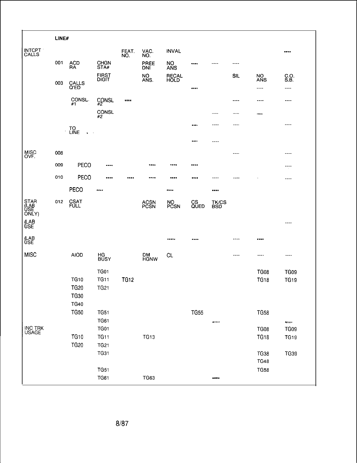
LINE#
CONTENTS (10 COUNTERS PER LINE)
REG
TIME
OUTS
ATTENDT
CONSOLE
LOOP
ATTEMPT
LOOP
USAGE
000 ----
TOLL
RESTR ;-E&T.
x/C.
INVAL
DID
NO. RESTR
0°’
lzD
ET
INV
AN#
KE
%s
---.
002 STILL
BUSY
;lg;
----
!&.
i%EL
CALL
PARK
Oo3
capELDLs
LEVEL LEVEL TIME
----
---.
1 WTG 2 WTG OUT
004
(2,ONSL.
CON’&
_-__
____ ____ ____
#2
. . .
005 CONSL
. . . . . . . . . . . . . . .
. . . .
#1
FNSL
MISC.
006 LINE
ATTEMPTS DTMF
‘%E
-.
CONF CALL TONE
---.
STORE
DETEC
MISC.
USAGE
007 ----
DTMF
CONF CALL TONE
---.
STORE
DETEC
008
----
DTMF
CONF CALL TONE ----
STORE
DETEC
RING
ATTEMPTS
RING
USAGE
RING
OVERFLOW
sLTAABR
I
OEY)
I
LsAEB
ONLY)
L
LsAEB
ONLY)
MISC
INC TRK
CALLS
009
PECO
____
____
----
----
----
0’0
PECO
----
___-
_-__
____
____
011
PECO
___-
____ ____
---_
____
012
Kii
NCS CSN
CSAT OOR
%ssNN
%SN
%ED
013 INV
PORT
ALR
QUED INV INV INV BAD
NETW STATE
PORT LINK
014 ----
-___ ____ ____
_----
-___
015
AIOD
BLOCKED
i&Y
DM
CL
____
HGC
:!NW
INT
LEVEL 3
016 TGOO
017
TGlO
018
TG20
019
TG30
020
TG40
021
TG50
022 TG60
023 TGOO
024
TGlO
025
TG20
026 TG30
027 TG40
028 TG50
029 TG60
TGOl TG02 TG03 TG04 TG05
TGll
TG12 TG13 TG14 TG15
TG21 TG22 TG23 TG24 TG25
TG31 TG32 TG33 TG34 TG35
TG41 TG42 TG43 TG44 TG45
TG51 TG52 TG53 TG54 TG55
TG61 TG62 TG63
. . . . . . . . . . . .
TGOl TG02 TG03 TG04 TG05
TGll
TG12 TG13 TG14 TG15
TG21 TG22 TG23 TG24 TG25
TG31 TG32 TG33 TG34 TG35
TG41 TG42 TG43 TG44 TG45
TG51 TG52 TG53 TG54 TG55
TG61 TG62 -,-G63
____ ____
CONF.
RESTR
CALL
HOLD
____
ACOF
RESTR
SIL
HOLD
----
DIGIT
T/OUT
____
____
INV
AI-l-
-_-_
____
.,...
DIGIT
STORE
DIGIT
STORE
DIGIT
STORE
INV
TS
INV
STATE
INV
OFST
NOT
QUED
TS
LOCK
____
TG06
TG16
TG26
TG36
TG46
TG56
.
.
.
.
.
.
TG06
TG16
TG26
TG36
TG46
TG56
-__-
TG07
TG17
TG27
TG37
TG47
TG57
TG07
TG17
TG27
TG37
TG47
TG57
----
TGO6
TG16
TG26
TG36
TG48
TG58
TG08
TGl8
TG28
TG36
TG46
TG56
----
TGO9
TGl9
TG29
TG39
TG49
TG59
.
.
.
.
.
.
TG09
TGl9
TG29
TG39
TG49
TG59
----
M-46
Figure 2.5 Traffic Register Layout
8187
5210
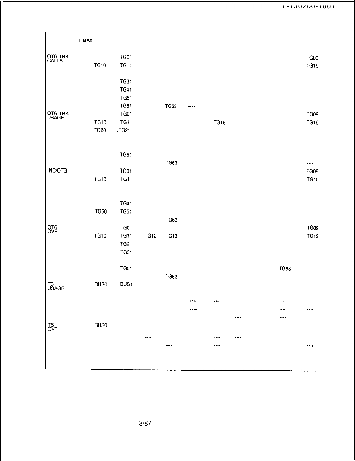
REG
LINE#
CONTENTS (10 COUNTERS PER LINE)
~~~L~RK
030 TGOO
TGOl TG02 TG03 TG04 TG05 TG06 TG07 TG08 TG09
031
TGlO TGll
TG12 TG13 TG14 TG15 TG16 TG17 TG18 TG19
032 TG20
TG21 TG22 TG23 TG24 TG25 TG26 TG27 TG28 TG29
033 TG30
TG31 TG32 TG33 TG34 TG35 TG36 TG37 TG38 TG39
034 TG40
TG41 TG42 TG43 TG44 TG45 TG46 TG47 TG48 TG49
035 TG50
TG51 TG52 TG53 TG54 TG55 TG56 TG57 TG58 TG59
.~_
036 TG60
TG61
TG62
-i-G63
__-_
____ ____ ____ ____
RLT
. . .
EGTERK
037 TGOO
TGOl TG02 TG03 TG04 TG05 TG06 TG07 TG08 TG09
038
TGlO TGll
TG12 TG13 TG14
TGl5
TG16 TG17 TG18 TG19
039
TG20
.TG21 TG22 TG23 TG24 TG25 TG26 TG27 TG28 TG29
040 TG30
TG31 TG32 TG33 TG34 TG35 TG36 TG37 TG38 TG39
041 TG40
TG41 TG42 TG43 TG44 TG45 TG46 TG47 TG48 TG49
042 TG50
TG51 TG52 TG53 TG54 TG55 TG56 TG57 TG58 TG59
043 TG60
TG61 TG62 TG63
____ ____ ____ ____ ____
---_
INC/OTG
ATB 044 TGOO
TGOl TG02 TG03 TG04 TG05 TG06 TG07 TG08 TG09
045
TGlO TGll
TG12 TG13 TG14 TG15 TG16 TG17 TG18 TG19
046 TG20
TG21 TG22 TG23 TG24 TG25 TG26 TG27 TG28 TG29
047 TG30
TG31 TG32 TG33 TG34 TG35 TG36 TG37 TG38 TG39
048 TG40
TG41 TG42 TG43 TG44 TG45 TG46 TG47 TG48 TG49
049
TG50 TG51
TG52
TG53
TG54
TG55 TG56 TG57 TG58 TG59
050 TG60
TG61 TG62 TG63
____ ____ ____ ____ ____
RLT
8$@
TRK 051 TGOO
TGOl TG02 TG03 TG04 TG05 TG06 TG07 TG08 TG09
052
TGlO TGll TGl2
TG13 TG14 TG15 TG16 TG17 TG18
TGl9
053 TG20
TG21 TG22 TG23 TG24 TG25 TG26 TG27 TG28 TG29
054 TG30
TG31 TG32 TG33 TG34 TG35 TG36 TG37 TG38 TG39
055 TG40
TG41 TG42 TG43 TG44 TG45 TG46 TG47 TG48 TG49
056 TG50
TG51 TG52 TG53 TG54 TG55 TG56 TG57 TG58 TG59
057 TG60
TG61 TG62 TG63
____ ____ ____ ____ ____
RLT
ZAGE
058
BUS0
BUS1
---- ____ BUS4 BUS5 BUS6 BUS7 ----
____
(GET STARTED FILE) (EXPANSION FILE)
059 ----
____ ____ ____ _-__ _-__ ____ ____ -.__ ____
060 ----
____ ____ ____
_--_
____ ____ ____ -___ .___
061 ----
____ ____ ____ ____ ____ .___ ____ --__ ____
ZF
062
BUS0
BUS1
(GET STARTED FILE) ---- ----
BUS4 BUS5 BUS6
BUS7 ----
____
(EXPASION FILE)
063 ----
____ _-__ ____ ____ __._ .___ ____ ____ ____
064 ----
-___ -___ __.. ____ ____ ____ _.__
065 ----
____ ____ ____
_.-_
____ ____ ____ ____ __._
Figure 2.5 Traffic Register Layout (Continued)
5210
8187
M-47
Table 2.2 Traffic Data Commands Input and Output Formats
INPUT FORMAT
TD DT.- to display the date and time of
day
TD DT
xx/yy/zz
nn:nn
-
to change the
time-of-day clock.
TD BS.
-
to-begin a traffic study
--
TD ES.- to end a traffic study
where
xx = the month
YY
= the day of the month
zz = the last two digits of the year
nn:nn = the time of day in hours and
minutes in 24-hour format
M-48
8187
OUTPUT FORMAT
xxIyy/zz nn : nn
DT xx/yy/zz nn : nn ? EXECUTED
BS
site
xx/yy/zz
nn/nn
aa
bbb
cccc dddd/eeee/: Y. EXECUTED
ES site
xxlyylzz
nn:nn
aa
bbb cccc
dddd/eeee/:?
Y.EXECUTED
where
site = the data-base controlled ID
xxlyylzz = the month, day, and
year request is made
aa
= the number of minutes be-
tween automatic traffic data
dumps
bbb = the number of seconds
between each traffic scan
cccc = the number of scans
between traffic data dumps
dddd/eeee
= the first and last
addresses of the traffic registers
Y. is entered by the user.
5210

5210
FTM 0184 The following information is being supplied to clarify the operation
of the traffic data facilities on the
OMNI
SI in areas of:
l All trunks busy
l Overflow
l Usage
ATB (lines 41-47 in traffic layout)
-
Pegging occurs each time
the last available trunk (defined as the last trunk in the idle trunk
state) is changed from idle to any other trunk state. It is valid to
have ATB pegged for an incoming only trunk group, an outgoing
only trunk group,. or for a 2-way trunk group.
OVF (lines 48-54 in traffic layout)
-
Pegging occurs when the
system tries to use a trunk group which has all trunks busy. It is
valid for a 2-way trunk group or an outgoing only trunk group to
peg this count. It is invalid to have an incoming only trunk group
peg this counter. It is pegged when the system tries to use a
trunk in the trunk group which has all trunks busy.
Usage will be shown if:
1. The call was properly pegged for the number of calls, but this
was during a previous scan period, and the call stayed up
throughout successive scans. This would give usage with no
calls to the trunk group.
2. The trunk is implemented in data base and exists physically,
but is not connected to a CO trunk. This is primarily a problem
with Ground Start trunks going to the “incoming preseized”
trunk state. The usage scan sees the trunk as not idle, or
maintenance busy.
3. Trunks are in the “system out of service” state (trunk state 13).
This will show up as usage with no calls to that trunk group.
This applies to the following cases:
a. The trunk and trunk group exists in data base, but the
trunk(s) are marked as unequipped in
T5551
when the
system comes up.
b. Whenever the PEC goes out of service, all the trunks in it will
will placed in a system out-of-service state.
c. If a
Tl
alarm occurs, all trunks in that
Tl
span will be placed
in a system out-of-service state.
NOTES:
1. Maintenance busy trunks are not counted in the usage
counts.
2. If the data base is set up correctly, it is possible to have
usage counters pegged up even though no calls have been
made.
8187
M-49

TL-1
3Uzuu-I
UUI
Display Command
2.1.7 The display command (Line, Trunk, Call State) is used to
list the addresses and data of the tables listed below:
l
T4170 Line State Table
. T4160
Line Call Store Link Table
. T8941
Trunk State Table
. T8944
Trunk Call Store Link Table
. T1390
Call Store Table
This information is used in call tracing and is shown in section
6.0.
The formats of the display commands are shown in Table 2.3.
M-50
8187
5210
Table 2.3 Display Command Input and Output Formats
Iisplay
Line State:
DISPLAY LINE DN <directory
number>STATE
output
PAGE ADDRESS
DATA
_--__-_
.2-
-_----_-_____ - -
_
- - -- - -
._..
xx
YYYY zz
tvherer
XX = page ID (DO, D2, D3, D4,
D5,06,
D7)
._
YYYY
=
address of line state
ZZ = present state (see Table 2.4 for CEC Line State Codes)
display
Line Call Store Link:
Input
Input
DISPLAY LINE DN <directory
number>CSLINK
OutPut
PAGE ADDRESS CS# PAGE CS ADDR RANGE
---m--v
-m------m-__-
--- ---------
__--_---_--____---_______
xx
YYYY
zz AA
BBBB-CCCC
Nhere:
XX = page of line call store link
YYYY
=
first of two addresses of line call store link
ZZ = call store number in decimal
BBBB = start address of call store
CCCC = end address of call store
Output
PAGE
------
ADDRESS CS#
------------- ---
PAGE
- - - - - - -
CS ADDR RANGE
---------------
xx
YYYY IDLE-NOT LINKED
Nhere:
XX and YYYY are as above
idle-not linked means the line is not presently linked to a
cal I store.
5210
8187
M-51
Table 2.3 Display Command Input and Output Formats (Continued)
Display Trunk State:
Input
DISPLAY TRUNK <trunk number>STATE
where: <trunk number>
.=
system trunk number in decimal (O-63).
=-
Output
PAGE ADDRESS
DATA
------- -------------
---_-----
xx
-
YYYY 22
where: XX = page ID (DO,
D2,03,
D4,
D5,06,
D7)
YYYY = address of trunk state
ZZ
=
present trunk state (see Table 2.5 for CEC Trunk State Codes)
Display Trunk Call Store Link:
Input
DISPLAY TRUNK <trunk
number>CSLINK
Output
PAGE ADDRESS CS# PAGE CSADDR RANGE
-- - - - --
---------_-_-
---
_-------- ------------_------------
xx
YYYY zz
AA
BBBB-CCCC
where: XX = page of trunk call store link
YYYY = first o two addresses of trunk call store link
ZZ = call store number in decimal
AA = page of call store (DO, D2, D3, D4,
05,
D6,
D7)
BBBB = start address of call store
CCCC = end address of call store,
or
output
PAGE
------
ADDRESS
---_________-
CS#
---
PAGE
-- - - - - -
CS ADDR RANGE
____----_-_____
xx
YYYY IDLE-NOT LINKED
where: XX and YYYY are as above
idle-not linked means the line is not presently linked to a
call store.
M-52
8187
5210
.b
I”“-“”
.““.
Table 2.3 Display Format (Continued)
Display Call Store Address:
,lnput
DISPLAY CS<CS
number>ADDRESS
where:
<CS
number>
=
call store number in decimal
output-
-..
PAGE
CS ADDR RANGE
..------ ----------_--------------
-
xx
BBBB-CCCC
where: XX
=
page
lD(D0,
Dl,
D2, D3, D4, D5, D6,
D7)
BBBB
=
start address of call store
CCCC
=
end address of call store
Table 2.4 CEC Line State Codes
CODE
LINE STATE
I
Line idle
1 Line ringing
02
Line busy
03
Line digit collection
04 Call-back in progress
05
Call-back ringing
06
Line locked out
07
Line maintenance busy
08
Staff for call-store assignment
09
Line stall (idle)
1 Line stall (off-hook)
I
06
1 Line off-hook recovery
I
M-53
5210
8187
:
Table 2.5 CEC Trunk State Codes
M-54
CODE
TRUNK STATE
01
Incoming pre-seized trunk
02
Incoming mishandled trunk
03
Incoming FX trunk wait for resources
04
Incoming not answered (idle)
05
incoming loop not answered (idle)
06
Incoming busy (idle)
97.
08
Incoming signaling A
Incoming signaling
8
I
09
)
Incoming dialing (idle) 1
OA
08
Incoming delay dial wait
Outgoing start dial wait
oc
I
Outgoing wink start wait
OD
OE
Outgoing busy (idle)
Outgoing guard after release
OF
10
Outgoing immediate dial
Outgoing glare check
Recorder Announcer message interval
12
Incoming seizure stall
13
System out of service (PEC out of service)
Outgoing wait for disconnect, PBX release first
15
Retry, put in service
16
Outgoing pre-seized
17
Spare
18
Outgoing dialing
19
Outgoing busy (busy)
1A
Outgoing not answered
18
Outgoing wink start time
1c
Panel Maintenance busy
1D
Not busy
8187 5210
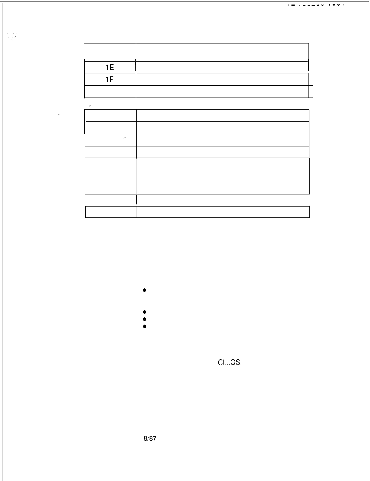
.-
.-----
.--.
Table 2.5 CEC Trunk State Codes (Continued)
CODE
TRUNK STATE
1E
I
1 Maintenance busy
1F
System busy
20
Incoming not answered (busy)
21
_.
1 Incoming loop not answered (busy)
I
.
.
.
.
22
Incoming busy (busy)
23
incoming dialing
24
.*
25
Incoming dialing (busy)
Recorder Announcer start
26
Recorder Announcer message cycle
27
Call recovery trunk off-hook
28
CAS Main ACD recorded announcement start
I
29
1 CAS Main ACD recorded message cycle
I
2A Nailed connection
Maintenance Commands
2.2 Maintenance commands are used to take suspected
defective lines, trunks, stations, or cards out of service. An
individual defective line, trunk, etc. can be taken out of service
without affecting the operation of the system. The defective unit
can be placed back in service after maintenance. The following
are the maintenance commands available in the system:
*
Force commands
l Memory watch command
l Put commands
*
Test commands
0
Trace commands
0
Unlock commands
Software Identity
The Software Identity (SID) for a line or trunk must be determined
Method
before using the PUT or FORCE SID method of maintenance
command entry; however some commands such as FORCE
DN...OS. or FORCE TR
CI...OS.
do not require SID.
5210 8187
M-55
Software Identity
For initial installations, the SID number for lines or trunks can be
Calculations
found in the Cable Pair Listing
-
Table in TL-130400-1001
Use the decimal listing under each line or trunk number.
1. To calculate the SID for lines use
R
C Table 221 and the
following calculation:
__
SID =RC Table 221 primary identifier x 8 + circuit number; or
SID =Line card’s position number in the Line Card Address
Table T2541 x 8 + the circuit number; where:
VCIP, DVCIP, VPLC (types VPLO and
VPLl),
and
VPLC2
(type
VP20 and VP21) cards are treated as voice cards
2:
To calculate the SID for ports, use RC Table 22 and:
SID =RC Table 221 secondary identifier x 8 + circuit
number,where VCIP, DVCIP, VPLC (type VPLO and
VPLl),
and
VPLC2 (type VP20 and VP21) cards are treated as data cards
To calculate the SID for the CIP, use the following calculation:
SID =RC Table 221 primary identifier x 8 + circuit number
3. To calculate SID for trunks, use the following calculation:
SID =Trunk circuit’s position number in the Trunk Card
Address Table T2581
4. To calculate the SID for DTMF receivers:
SID =DTMF receiver’s position number in the DTMF
Receiver Address Table T2661.
5. To calculate the SID for conference cards:
SID =0 if conference card is in Conference Card 0 Address
Table T2741
SID = 1 if conference card is in Conference Card 1 Address
Table T2742.
NOTE: All SID calculations and entries must be in decimal.
Fault Code responses given by the system are in hexadecimal
and must be converted to decimal prior to the SID calculation or
entry.
M-56
8187
5210
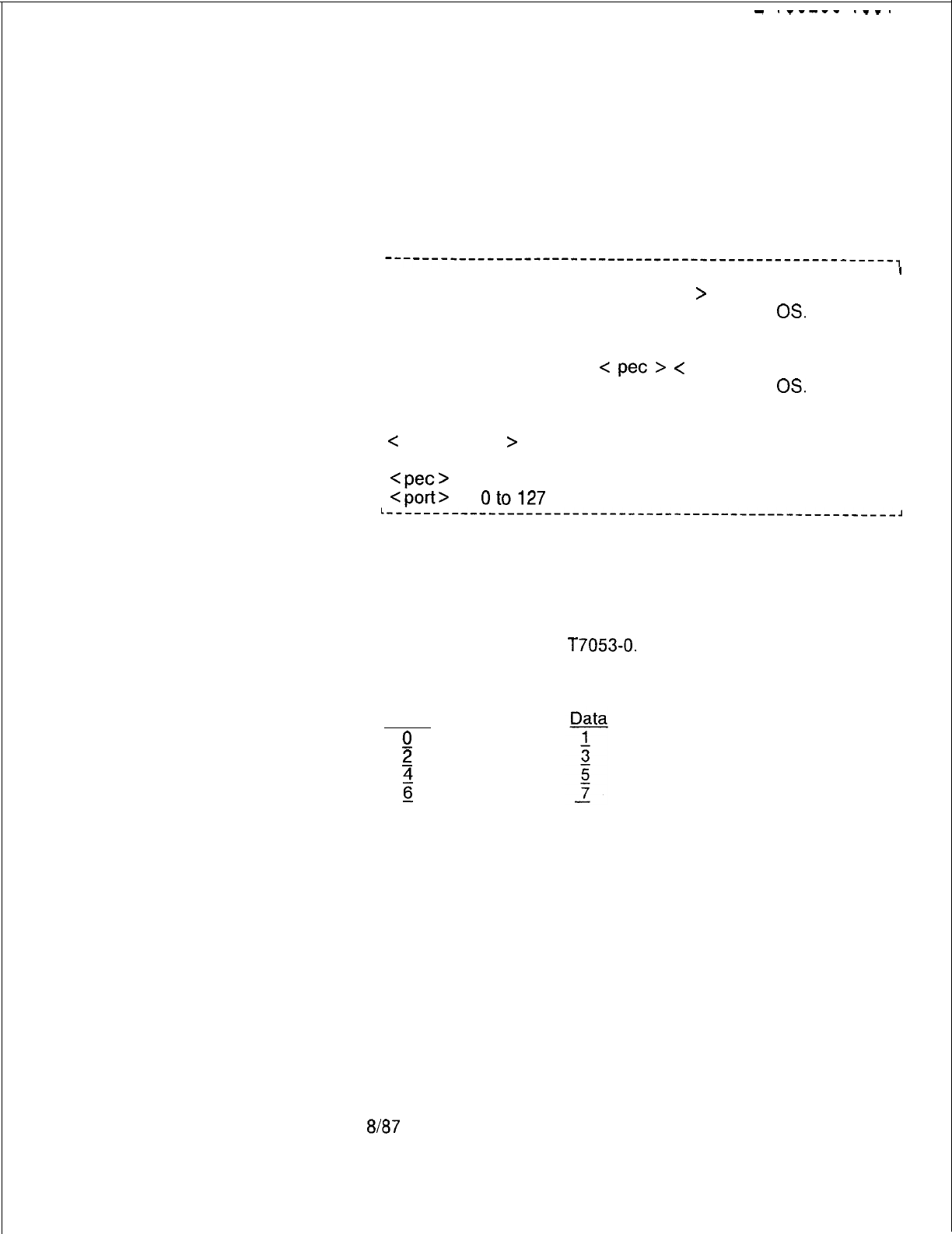
5210
-
.-----
.--.
Force In Service
2.2.1 The FORCE command can be used to force
Out
of Service
Command
devices and/or circuits into the maintenance busy state
when not idle. Removing a device from service using the
FORCE command takes the device down unconditionally.
Featurephones
2.2.1.1 To force an Analog or Digital Featurephone connected to
a CIP, DCIP, or DVCIP port in service .or out of service, enter the
following:
-------------------------------------------------------,
IS.
I
I
FORCE CIP DN <directory-no.
>
I
I
OS.
I
I
or
I
I
IS.
I
I
FORCE CIP PORT
<
pet
>
<
port>
I
I
OS.
III
/ where
I
I
I
I
C
directory-no.
>
= three- or four-digit directory number
I
I
I
I
Iof a Featurephone
I
I
Cpec>
= 0
I
I
I
<port>
=
oto127
I
I
t------_-_----------------------------------------------,
NOTES:
1 Port number is derived by relative CIP card number x 8 +
circuit number on card. The relative CIP card number is
determined by the card’s position in the Featurephone Data
Link Information Table
T7053-0.
2. For the DVCIP card, circuit numbers are defined:
Voice
0
2
8187
M-57
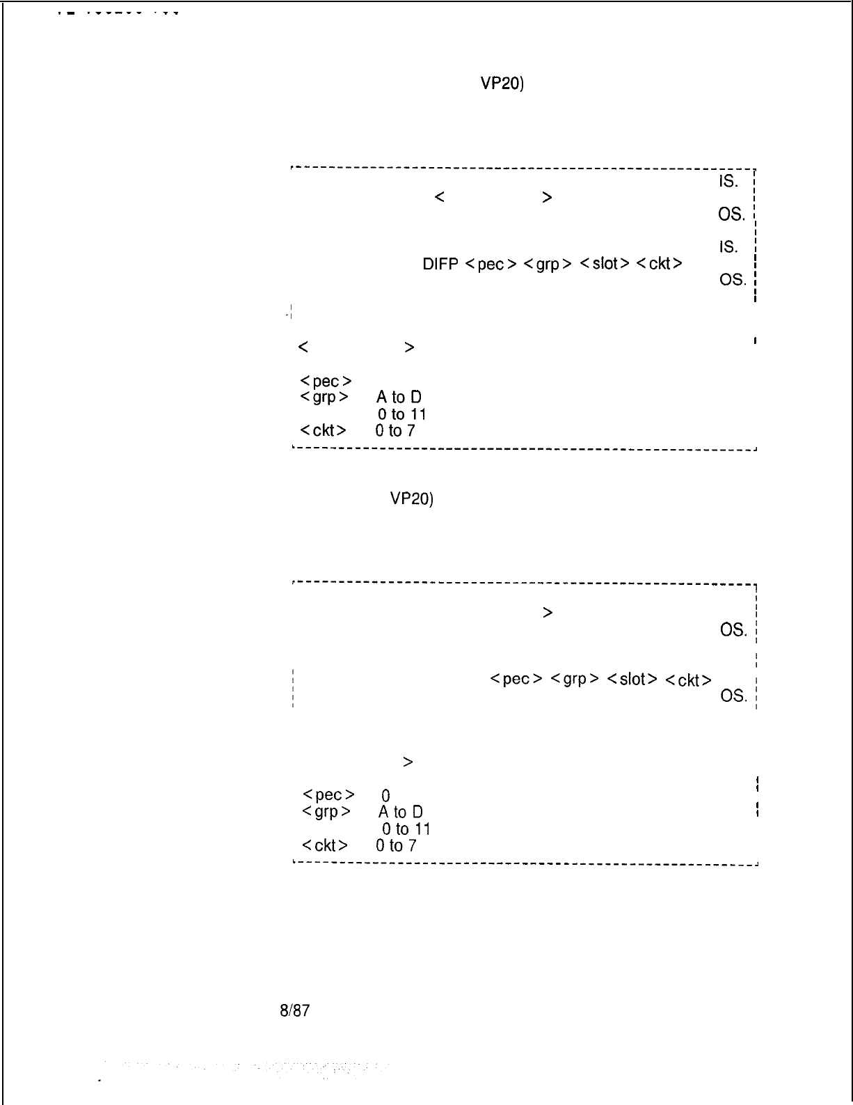
.-
.__---
.--
To force a Digital Featurephone, with voice application only,
connected to a VPLC2 (type
VP20)
port out of service, enter the
command given below:
~-------------------------------------------------------.
I
I
I
IS.
;
I
IFORCE DN
C
directory-no,
>
I
OS.
i
or
I
I
I
IFORCE
DIFP
<pet>
<grp>
<slot>
<CM>
I
I
OS.
;
I
I
-I
where
I
I
I
I
I
I
/
<
directory-no,
>
= three- or four-digit directory number
I
I
I
Iof a Featurephone
I
I
<pet>
= 0
I
I
I
<grp>
=
AtoD
I
I
i <slot> =
oto11
I
I
:
<ckt>
=
oto7
I
I
I
I
L-------------------------------------------------------~
To force a Digital Featurephone with the data option connected to
a VPLC2 (type
VP20)
voice and data combination port out of
service, enter the command given below:
r--------------------------------------------------------
/
I
IIS.
i
I
IFORCE DN <directory-no,
>
I
I
or
OS.
;
II
IIIS.
:
FORCE DFPAPM
<pet>
<grp>
<slot>
<ckt>
I
OS.
;
,
I where
II
/ <directory-no,
>
= three- or four-digit directory number
I
I
I
Iof a Featurephone
I
I
<pet>
=
0
I
I
I
Cgrp>
=
AtoD
I
I
I <slot> =
oto11
I
I
/
<ckt>
=
oto7
I
I
I
L------_----------_-------------------------------------~
M-58
8187
5210
5210
.-
.-“-WV
.--.
Line Cards with
2.2.1.2 To force a CIP, VCIP, or
DVCIP
interface card in
Featurephones
service, enter the following:
I
-------em
----
--------------------------------------------------,
II
I
IS.
I
I
FORCE
CIP CARD
<
pet
>
<card-no.
>
I
II
II
I
OS.
I
II
II
;
where
I
I
,I
I I
..-
;
<pet>
= 0
;
<card-no.> = 0 to 15
To force the VPLC2 (type VP20 or VP21) card out of service,
enter the command given below. This command causes all
ports on the card to be placed out of service regardless of port
type (voice, data, or voice and data). for VPLC2 cards with data
ports, a maintenance request is sent to the ADMP. The
command input is as follows:
r---------------------------------------------------------------,
I
I
IS.
I
I
I
IFORCE VPLC
<
pet
> <
grp
>
C
slot
>
I
I
II
I
OS.
I
I
I
I
I
I
where
I
I
I
I
I
I
1
<pet>
= 0
I
I
I
<grp>
=
AtoD
I
I
I <slot> =
oto11
I
I
L---------------------------------------------------------------,
Trunks
2.2.1.3 To force a trunk circuit from active to maintenance busy
using the physical location, enter the following:
I---------------------------------------------------------------,
1
FOWXTRUNK
CIRCUIT
<
pet
>
<
grp
>
<slot
>
<circuit
>
OS.
I
I
I
I
I
I
;
where
I
I
f
Cpec>
= 0 II
I
<grp’
=
AtoD
I
I
;
<slot>
=
oto11
I
I
f
<circuit> -= 0 to 3I
l--------------------------------------_------------------------~
8187
M-59
M-60
To force a trunk circuit from active to maintenance busy suing
the SID, enter the following:
I-----‘----‘--------‘-------------’---------------------------------,
II
i
FORCE TRUNK SID
<pet>
<sid
>
I
OS.
I
I
I
I
I
;
where
I
;
<pet>
= 0
I
I
;
<ski
>
= Trunk circuit SID relative to the PEC: 0 to 63
I
I
II
__
r-----,----,-------_,-___L-__,-___,____-------------------------J
Attehdant and Busy
2.2.1.4 To force an Attendant Console in service or out of
Lamp Display Unit
service, enter the following:
I-----‘-------I-------------------------------------------------,
I
I
IS.
II
1
FORCE CONSOLE < attendant console >
I
I
I
I
I
OS.
I
I
I
I
I
f
where
I
II
i <attendant console
>
I
=
oto1
I
I
L----------,-------__--__---__-----------------------------------------,
To force Busy Lamp Display Unit (BLDU) in service or out of
service, enter the following:
,---------------------------------------------------------------.
I
I
IS.
I
II
FORCE BLDU
<pet>
<bldu>
I
I
OS.
I
I
I
I I
j
where
I
I
I
I
I
I
<pet>
= 0 (only)
I
<bldu>
=
1,2
L---------------------------------------------------------------,
Agent Instruments
2.2.1.5 To force an Agent Instrument in service or out of service,
enter the following:
r-----
----------------------------------------------------------,
II
I
IS.
I
II
IFORCE AGENT <position-no.
>
I
I
OS.
I
I
I
II
i where
I
I
I
I
I
II
I <position-no.
>
= 0 to 191 II
L-----_------------______--___------------------------------------------,
8187
5210

Force Download and
2.2.1.6 Certain devices in the system require downloading
Load Commands
software from the disk into remote processors. These devices
are:
5210
1. Digital Integrated Featurephone (DIFP)
2. Digital Integrated Featurephone with Data Option (DFPAPM)
3.
VCIP
and
DVCIP
cards
4. Asynchronous Packet Manager (APM)
5. Synchronous Packet Manager (SPM)
6. VPLC2 card (type VP20 or VP21)
7. Universal Controller Board (UCB) DCP and NIC cards
8. ADMP card
The force download command is used to load Featurephone
control software into 2 and 3 above. The load command is used
to load Featurephone control software into 1 and 6. It can also
be used to load data call control software into 2, 4, 5, and 7, and
administrative software into 8.
Download to any of the card types involves a complete reload of
the device. Download to a Digital Featurephone involves sending
only data unique to the featurephone (i.e., directory number, etc.).
8187

The format of the force download command is as follows:
r---------------------------------------------------
I
-I
j FORCE DOWNLOAD
C
pet
>
<
sid
>
.
I
I
I
I
Ior
I
I
I FORCE DOWNLOAD DN
C
directory-number
>
I
I
I
I
I
I
; where
I
I
I
I
I
I
I
Cpec>
= 0
I
I
<sid>
= Software ID (SID) of a featurephone to
I
I
I
Idownload (0 to 225).
I
I
I
<
directory-number
>
= three-or four-digit directory
I
I
Inumber of the featurephon to be downloaded.
I
I
I
I
/ FORCE DOWNLOAD
<f&>
<sid>
INTERFACE
I
i
I
I
I
I
I where
I
I
II
II
I
Cpec>
= 0
I
I
I
<sid
>
= Software ID of a Digital Featurephone
I
I
I
I
Iplugged into the card (o to 225).
I
L----------__-----__--------------------------------,
The format of the load command is as follows:
LOAD <device>
C
pet
>
<grp>
<slot> OP.
where
<
device
>
= ADMP, DCP, VPLC, NIC
or
LOAD
<device>
Cpec>
Cgrp>
<slot>
<ckt>
OP.
where
I
I
/<device> = SPM, APM, DIFP, DFPAPM
Ior
/ LOAD DN <directory number
>
where
<directory number
>
= three- or four digit directory
number of a Digital Featurephone connected to a
VPLC2 circuit.
<pet>
= = 0
Cgrp>
= A to D
<slot> =
oto11
I
I
I
I
I
I
I
IIII
I
II
:
I
I
I
I
I
I
I
I
I
I
I
I
I
I
I
I
I
I
I
I
I
I
I
I
I
I
I
I
I
I
I
I
III
I
I
<ckt>
=
oto7
L--___-_________________________________------------~
M-62
8f87
5210
NOTES:
1. When a download to a card is completed, each of the
individual Digital Featurephones plugged into the card is
downloaded with data unique to the Digital Featurephone.
2. Download to a
VCIP
or
DVCIP
card puts all ports on the card
out of service until the download is complete.
3. For LOAD
DIFP
ALL command, the PEC number is appended
to the response message.
.=_
The following paragraphs provide guidelines and sample sue of
these commands.
. . .
Downloading
2.2.1.7 Several versions of the force download and load
Featurephones
commands have been provided for downloading Featurephones,
depending on type and application. Usage guidlines are
contained in Table 2.6.
Table 2.6 Download Con
Featurephone
Type/Application
Digital (without Data Option
System Voice
PD-200
Digital (with Data Option)
Voice Reload Only
System Voice
PD-200
Data Reload Only
CD-1 00
PD-200
Voice and Data Reload
CD-l 00
PD-200
nn
nands for Featurephones
Command
Version
FORCE DOWNLOAD...
LOAD DN...
(No separate command)
FORCE DOWNLOAD...
(No separate command)
LOAD
DFP/APM...
FORCE DOWNLOAD...
LOAD DN...
LOAD
DFP/APM...
NOTE; LOAD DN works with VPLC2 connected phones only
5210
8187
M-63

-
.---
--
.--.
----------------------------------------------------,
I
LOAD DN
<
directory number
>
I
.
I
I
M-64
8187
5210
I
I--
IduLuu-
I
vu
I
Downloading VCIP,
2.2.1.8 To download software into the VCIP, DVCIP, or VPLC
DVCIP, and VPLC Cards
card, use the following command:
r--‘-------------------------------------------------,
I
I
j
FORCE DOWNLOAD
<
pet
>
<
sid
>
INTERFACE
I
I
I
I
I
I
; where
I
;
Cpec>
= 0
I
;
<sid>
= Software ID of a Digital Featurephone plugged
i
1
_
i_nto
the card (0 to 225).
I
-
-
------____--------------------------------------
:
To download software into the VPLC2 (type VP20 or VP21) card,
use the following command:
r------------------------------------------------------------------
I
I
I
i
LOAD VPLC
<pet
>
<grp>
<slot>
OP>
I
I
I
where
I
I
I
I
\
I
I
,
<pet>
= 0or
I
I
I
<grp>
=
AtoD
FORCE DOWNLOAD
<
pet
>
>
sid
>
IN
>
I
I
I <slot> =
oto11
I
I
L-------------------______-____---------------------------------------------~
NOTES:
1.
When a download to a card is completed,
eacx
of the
individual Digital Featurephones plugged into the card is
downloaded with data unique to the Digital Featurephone.
2. Download to a VCIP, DVCIP, or VPLC card puts all ports on the
card out of service until the download is complete.
3. Load VPLC will be denied if there are no voice devices
connected to the card.
5210
8187
M-65
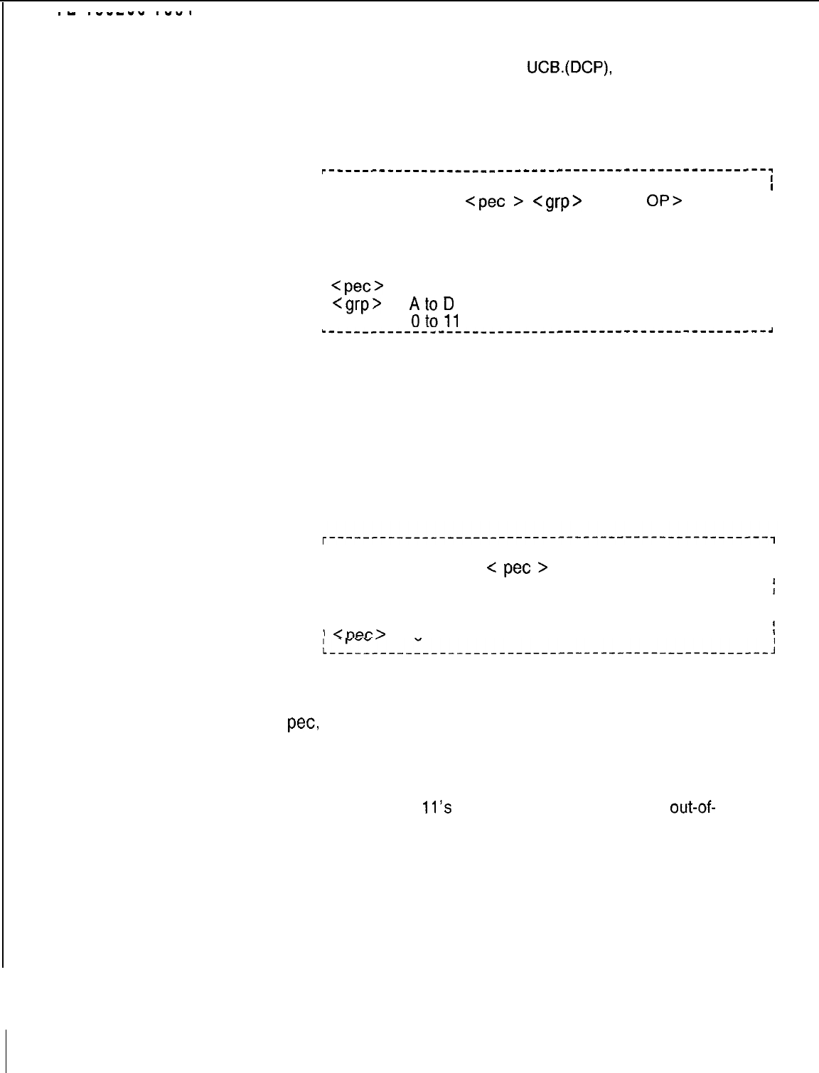
.-
.----v
.w...
Downloading ADMP,
2.2.1.9 To download the ADMP,
UCB.(DCP),
and NIC card, use
UCB (DCP),and
the following command:
NIC Card
. . .
r-----------------------------------------------------
I
I
I
I
I LOAD <device>
<pet
>
<grp>
<slot>
OP>
I
I
I
I
I
I
I
I where
I
I
I
I
I
I
I <device> = ADMP, DCP, NIC
I
I
I
<pet>
= 0
I
I
1
<grp>
=
AtoD
II
I
. .
I <slot> =
oto11
I
-----_--------------________--------------------------------~
Bulk Downloading
2.2.1.10 Several bulk downloading commands have been
Commands
provided for situations in which all circuits and/or cards need to
be downloaded.
Force Download All. To force download all Integrated
Featurephones, VCIP, DVCIP, and VPLC2 cards in one PEC, use
the following command:
I
I
I
I
) FORCE DOWNLOAD
<
pet
>
ALL.
II
I
I
f
I where
I
I
I
I
I
)
Cpec>
= 0
I
L----__--______--____---------------------------------~
After the last equipped and in-service port on the last equipped
and in-service card receives the download command from the
pet,
a download complete message will appear on the
maintenance TTY.
Example: 08.25 08: 35 DOWNLOAD COMPLETED BY PEC7
NOTE: Response
11’s
in-service and maintenance
out-of-
service can appear on the terminal after the download complete
message. This can happen if a phone received the download
command, but an oup-of-sync or some other problem
temporarily put the port out of service. Also, the message can be
put on the printer queue before the last card’s response 11 s.
8187
5210
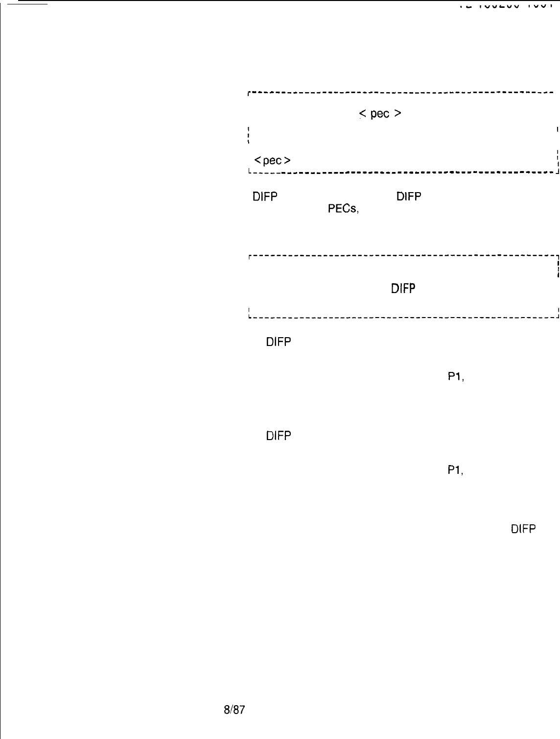
Force Download Stop. To stop the force download all process,
the following command is used:
5210
r
------_---_-----------------------------------------
1
I
I
FORCE DOWNLOAD
5
pet
>
STOP.
II
I
[
where
I
I
I
I
I
I
;
<pet>
= 0
I
L----- ___________---__-___---------------------------
:
Load
DIFP
All. To perform a load
DIFP
for all applicable
Featurephones in all
PECs,
the ALL form of the following
command may be used:
r----------------‘-----------------------------------,
I
I
I
I
I
I
IALL.
I
I
I
I
LOAD DIFP
I
,
I
STOP.
I
I
L_--_--__-____--_,__---------------------------------~
I
If LOAD
DIFP
ALL is typed, a request is sent to download all
Featurephones in each PEC. No request is sent to the data
switch. Messages are printed for each PEC download response,
e.g., IN PROGRESS PO, PEC NOT EQUIPT
Pl,
and IN
PROGRESS P2. As each voice circuit is downloaded, a
message, RESPONSE 11, is printed which indicates successful
completion.
If LOAD
DIFP
STOP is typed, a request is sent to stop download
of all Featurephones in each PEC. No request is sent to the data
switch. Messages are printed for each PEC STOP response,
e.g., IN PROGRESS PO, PEC NOT EQUIPT
Pl,
and IN
PROGRESS P2. Each PEC stops the downloading of
Featurephones.
Other ALL Commands. Other load command versions may be
used in bulk form in a similar manner to that of the LOAD
DtFP
ALL command.
8187
M-67
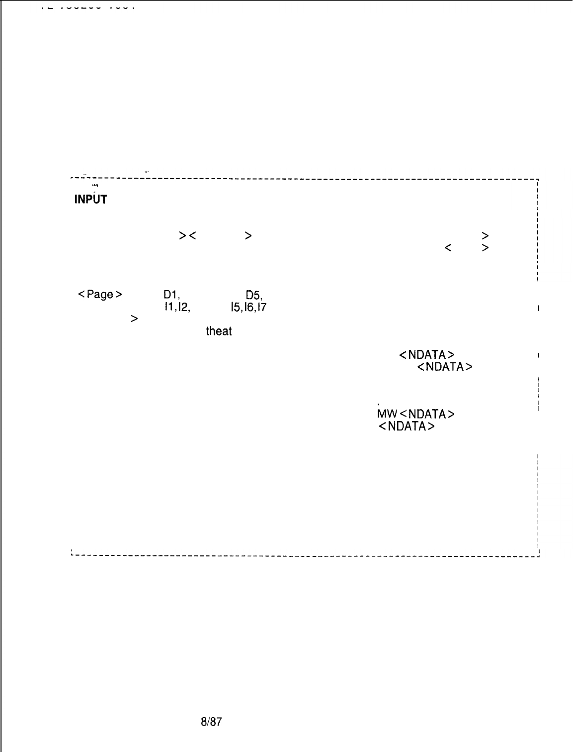
Memory Watch
2.2.2 The Memory Watch (MW) command is used to display
Command
data changes to an address on one of the CEC memory
pages. Memory watch can be initiated by either of the TTY
ports, but only one at a time. If the watch is in progress,
another watch cannot be initiated until the first memory watch
is turned off. Either TTY port can cancel the watch. Any one
of the CEC memory pages can be watched. The input/output
format for memory watch is shown in Table 2.7.
I
‘-..
/
INPUT OUTPUT
j 1. Initiate MEMORY WATCH
I
IMW ON C Page
>
C
Address
>
Watching <Address
>
Present Data < Data >
/ where
M-68
I
<Page>
I= DO,
Dl,
D2, D3, D4,
D5,
D6, D7,
IIO,
II,
12,
13, 14,
15,
16,
17
I <Address
>
= Address to be watched
/ <Data> = Initial data at
theat
address
i 2. Initiate memory watch if already
I
Ion MW ON <Page> <Address>
/ 3. Cancel memory watch
I
I
MW OFF
8187
I
I
I
I
I
II
MW < NDATA>
I
I
MW
C
NDATAB
I
II
I
I
I
MW
C
NDATA>
I
1
I
<NDATA>
= New Data
I
I
I
Turn watch off first
Watch turned off
5210
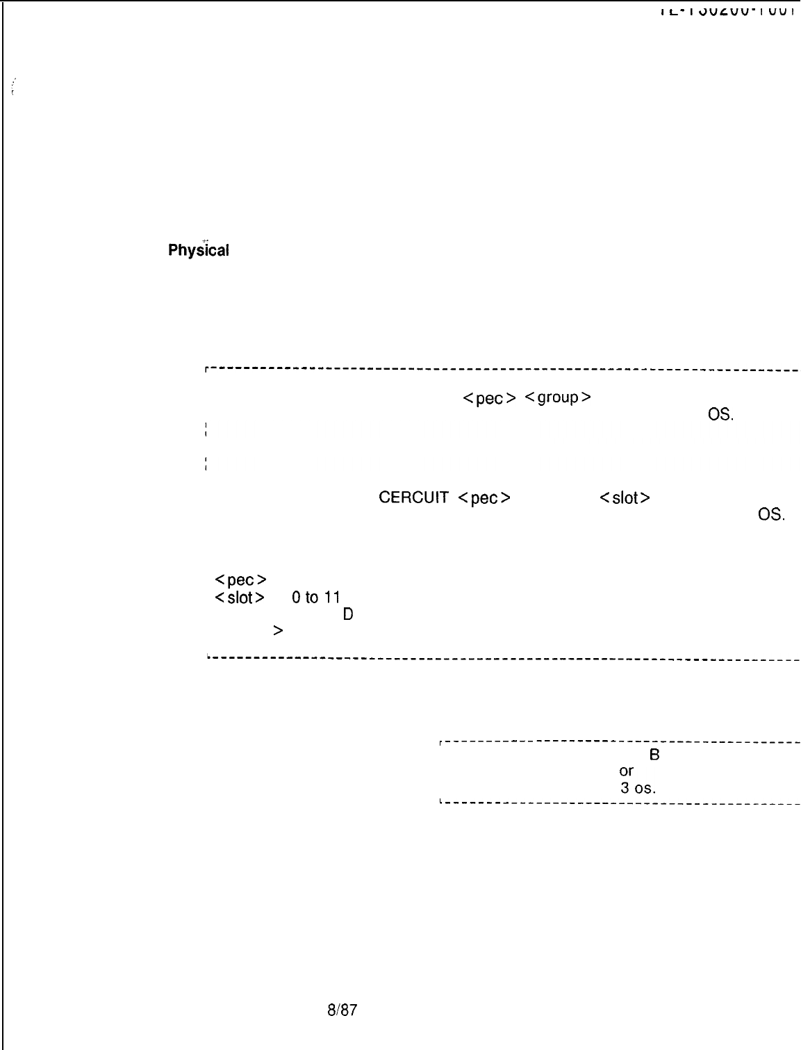
I
I--
l
e”L”“-
I
“”
I
PUT Command
2.2.3 Four methods are used to enter maintenance
Entry
commands into the system:
l Physical location
l Software identification
l Directory number
l Equipment number
The following are examples of each type of maintenance
command entry method:
. . . .
Phy&al
Location
Enter the following information into the system:
Method
NOTE: These forms of the PUT command cannot be used for
Integrated Featurephone lines.
ILINE IS
I
IPUT TRUNK CARD
<pet>
<group>
<slot>
I
I
I
DTMF
OS.
or
I
ILINE
I
IS
I
PUT TRUNK
CERCUIT
cpec>
<group>
<slot>
<circuit>
I
IDTMF
I
OS.
I
/ where
I
<pet>
= 0
I
<slot>
=
oto11
1 <group> = A to
D
I<circuit
>
= 0 to 7 for line circuits, 0 to 3 for trunk circuits, 0 to 3 for DTMF
I
Ireceivers.
L-----------------------------------------------------------------------~
For example:
r-----------
--------------------------------,
I
,PUT LINE CIRCUIT 0
6
9 4 OS.
I
I
I
Iput tr ci 0 c 2
03ros.
L---------------__--------------------------,
5210 8187
M-69
r-----------------------------------------------------------------------,
I
I
ILINE IS
1
IPUT TRUNK SID
<pet>
<sid>
I
IDTMF
OS.
.
.
IPUT TRUNK
CERCUIT
<pet>
<group> <slot> <circuit>
,
1DTMF
OS.
^
I
./
where.
.
I
I
I
L-----__----_-----------------------------------------------------------,
/
<pet>
= 0
I
C-sic!
>
= 0 to 255 for line circuits, 0 to 63 for trunk circuits, 0 to 7 for DTMF
I
Ireceivers
I
I
I--
I3ULUU-
I
vu
I
Software Identity
Enter the following information:
Method
For example:
I-------------------------------------------,
I
I
IPUT LI SID 0 255 IS. I
I
I
IPUT
Tl?SlD
0 63 OS.
I
I
I
I
I
L-------------------------------------------,
Directory Number
The directory number method must be used when changing the
Mlethod
state of line circuits associated with Featurephones. Enter the
following information:
r----
-------------------------------------------------------------------~
II
I
IS.
I
I I
IPUT LINE DN <directory number
>
I
I
I
I
OS.
I
I
I
! where
/
I
I
I
/ <directory number
>
= XXXX (three- or four-digit directory number)
I
I
For example:
,-------------------------------------------
I I
IPUT LINE DN 4112 OS.
1
I-----_-------------------------------------~
M-70
EN37
5210
Equipment Number
To change the status of a Release Link Trunk (RLT) using the
Method
equipment number, enter the following information:
r---------------‘--------------------------------------------------------
1
I
I
I
IS.
I
IPUT <equipment-type
>
<
equipment number
>
I
I
I
OS.
I
I
I
I
I
I
I where
I
I
I
I
. . .
;
__
I
I
I
<equipment-type
>
= RLT
<equipment number
>
= 0 to = 15 for
RLTs
L
---_-_______-----------------------------------------------------------
1
For example:
r------------------------------------------------------
I
I
IPUT RLT 15 OS. 1
I
L
------------------------------------------------------J
System response when PUT command is successfully entered
is:
r------------------------------------------------------~
I
I
IMR 00 EO.
I
L
------------------------------------------------------J
System response when PUT command is unsuccessfully entered
is:
r------------------------------------------------------~
I
I
IMR 00 EO.
I
L--------------_---------------------------------------J
Unsuccessful completions result because active circuits (and will
be completed when the circuit becomes idle), or because
circuits are already in the maintenance busy (out of service)
state. If a PUT command is entered to place an entire card in
maintenance and one of the circuits on the card is active, the
system will respond MR 00 EA., and only the idle circuits on the
card will go to the maintenance busy state. When the active
circuit becomes idle, it will change to the maintenance busy state
and the system will respond with MR 00 EO.
5210
8/87
M-71
PUT Cancel
When using a PUT or FORCE command after a prior PUT
Command
command, the following system response may appear:
r------------------------------------------------------
1
I
I
IMAINTENANCE COMMAND DENIED.
I
i_--------______---_____________________---------------j
This occurs when the prior PUT command has not been
completed because of waiting for circuits to become idle.
To avoid further waiting, cancel the PUT command by entering
the PUT CANCEL command. All circuits which have been put
out of service will remain out of service. Any circuits which were
not put our of service because of heing busy will remain in
service.
The command to cancel a PUT is:
r------------------------------------------------------~
I
I
IPUT CANCEL COMPLETE.
I
L-----------______________-__--------------------------------j
If the PUT CANCEL command is successful, the response is:
r------------------------------------------------------,
I
IPUT CANCEL COMPLETE.
I
I
If no PUT was in progress, the response is:
r------------------------------------------------------~
I
I
IPUT NOT IN PROGRESS.
I
L
------------------------------------------------------J
Test Command
22.4 The TEST command is used to perform a hardware
(Featurephone)
diagnostic on an Integrated Featurephone. To perform the test,
enter the following:
r----------__---_---------------------------------
/
I
1I
j TEST DN <directory-number
>.
I
I
I
I
I
I
Ior I
I
/
I
I
I
i TEST PHONE
<pet
>
<
sid
>.
I
I
I
where I
I
<
directory-number
>
= directory number
I
I
assigned to a Featurephone
I
I
<pet>
= 0
I
I
<sid
>
= 0 to 255
I
I
~~~-_-------_---__-~~~-~-~----~~~~~~~~~~~~~---~~~~
Test failure is indicated by PORT IS OS. or COMMAND
COMPLETED ON maintenance terminal.
8187
5210

5210
-----
----
Unlock Command
2.2.5 UNLOCK command is used to unlock a Featurephone
which has been locked by the user. To unlock a Featurephone,
enter the following:
r---------------------------------------------------
I
I
i
UNLOCK DN
<
directory-number
>
.
I where
I
I
I
C
directory-number
>
= directory number assigned
I
I
Ito a Featurephone
~______________------------------------------------~
Memory Access
2.3
Mem6ry
access commands can be used to control the
Commands
system configuration and make changes to the data base. This
paragraph covers the following memory access commands:
l General read command
l General write command
l Bulk input command
l Hardware write command
General Read and
2.3.1The
General Read (GR) command can be used to read a
Data General Read
single system memory location or a string of consecutive
Commands
memory locations. If a string of memory locations is read, the
output pattern will continue until the entire string has been output.
A string is output in groups of 8 hexadecimal numbers: therefore,
only every eighth memory address will be printed on a line. For
example:
xxxx
nn nn nn nn nn nn nn nn
4FCE 00 OA 1 F 3C 00 12 69
To stop the TTY output before completion of printing, momentarily
depress the escape (ESC) key.
8187
M-73
I
L-
I3lJLuu-
I
vu
I
The format for the GR command is shown as follows
r-----------------------------------------------------------------------~
I
I
I
I GR
<
memory> <begin
>
<end
>
.
I
I
I
I
j where
I
I
I
I
C
memory
>
=
IO,
II,
12,
13,
14,
15,
16,
17,
DO,
Dl,
02,
D3,
I
I
ID4, D5, D6,
07
I
I
I
I
I
I
I
I
I
I<begin> =Address to be read, or the beginning address
i
I
__
Iof a string of memory locations to be read.
i
I
I
I
I<end>
=.
ILast address of a string of memory locations
I
I
I
-
I
Ito be read (not needed if reading only one
I
.I . .
address).
I
I
I
I
I
I
I
IKEY
I
I
I
IO . ..17 =
I
ICEC instruction memory pages
IDO .
..D7
= CEC data memory pages
I
1
L-----------------------------------------------------------------------~
NOTE: Data pages can be read when security level 2 is used.
To read 10-17, security level 6 must be open.
The Data General Read (DGR) command allows the user to
selectively dump the contents of memory for many of the
PD-
200 Data System processors. The maintenance terminal is
made unavailable for other maintenance functions while the DGR
command is executing. The system allows the user to
discontinue a dump request by using the ESC key. To display
the memory data for the hardware or device at the location
defined, enter the following DGR command:
M-74
8l87
5210
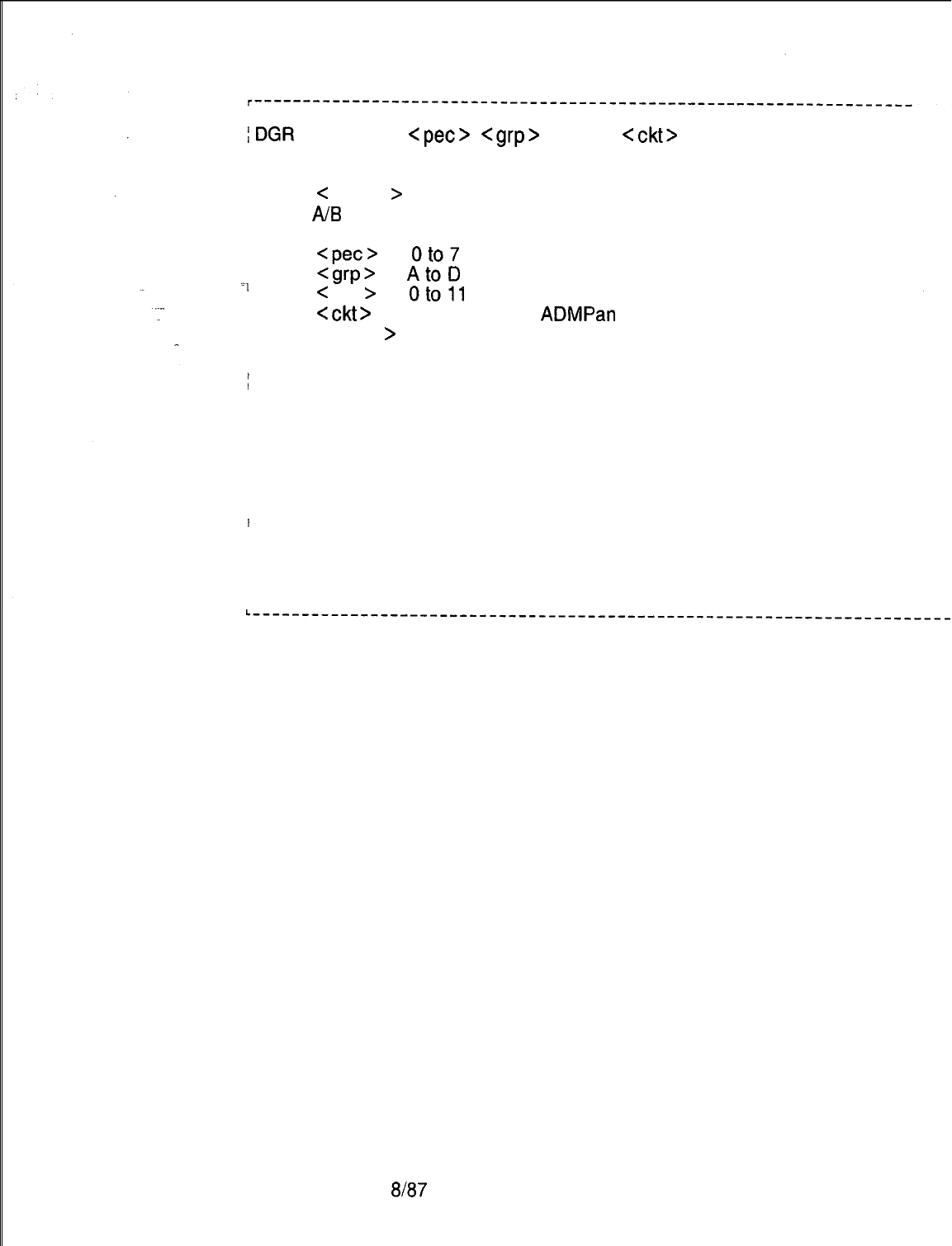
I
I
A
:DGR
<device>
<pet>
<grp>
<slot>
<ckt>
<begin> <end>.
I
j where
B
I
I
< device >
I
= ADMP, DCP, SPM, APM, DFPAPM, or NIC
I
AIB
=
I
refers to the A or B processor of the ADMP, DCP, and SPM
I
Idevices. (For ADMP, only A is supported.) Omit for other devices.
I
<pet>
=
oto7
I
I
7
<grp’
=
AtoD
I
<
slot
>
=
oto11
I
I
<ckt>
=
I
0 to 7 (Omit for ADMPan DCP.)
I
I<begin
>
= starting memory address. Valid values: 000000-FFFFFF
I<end> =
Iending memory address. Valid values: 000000-FFFFFF
I
I
IAddress must contain all 6 digits including leading zeroes.
I
I
I
IIf only one byte is to be read, the ending address can be omitted.
I
I
(Address range may not exceed 100 hexadecimal locations.)
I
I
I
I
Examples:
I
I
I
ITo dump 10 bytes of ADMP processor A: DGR ADMP A 0 D 02
I
0005CB.
I
I
I
I
ITo dump 1 byte of APM processor: DGR APM C 3 2 00043D.
5210
8187
M-75
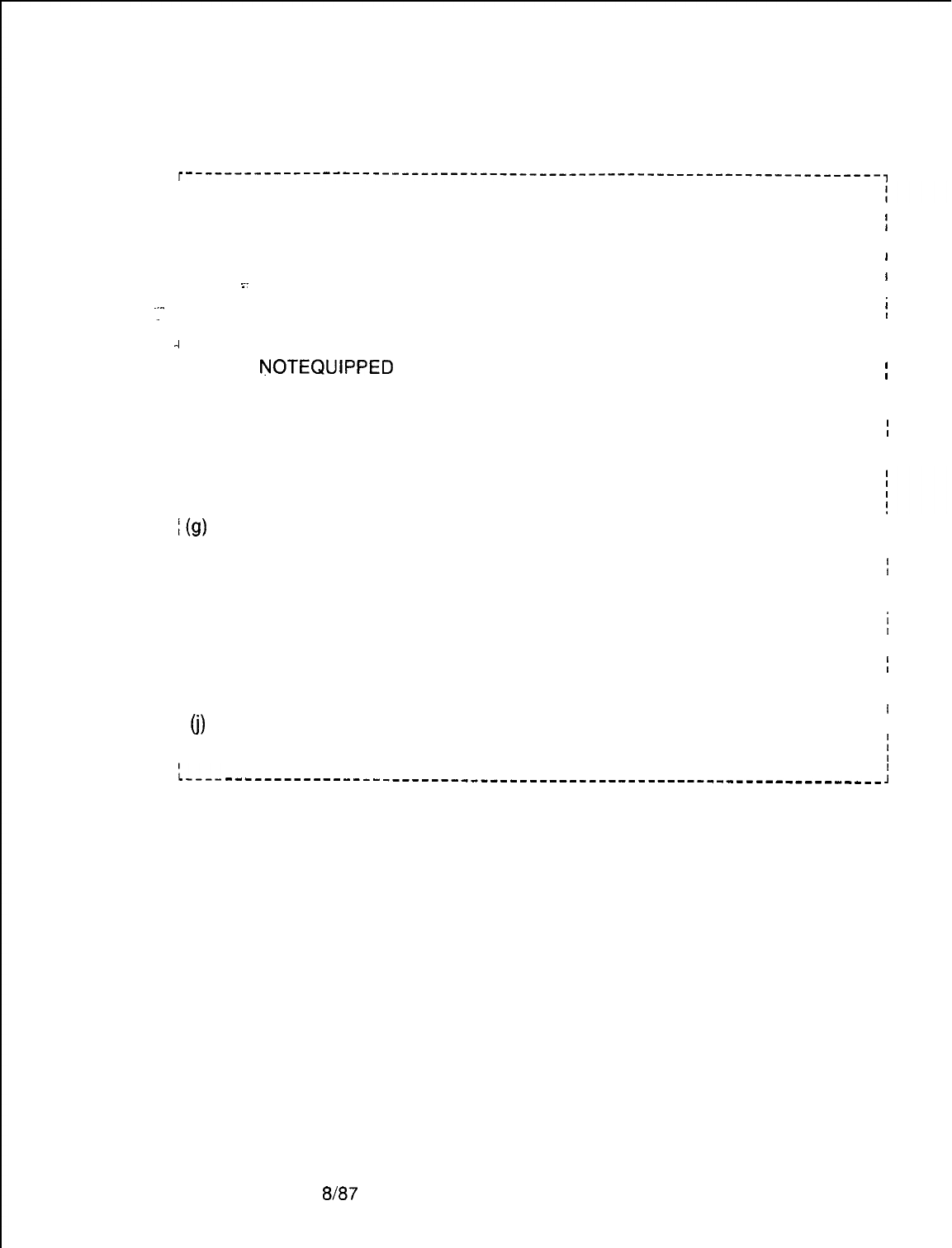
M-76
The system prints a message on the maintenance terminal to
indicate the status of the GR or DGR commands as follows in
Table 2.7:
Table 2.7 Status of the GR or DGR Command
r-----------------------------------------------------------------------,
I
i (a) SYNTAX ERROR The original input command wording
I
or abbreviations were not correct.
I
I
j (b) CABINET NOT IN SERVICE
I
_
.I
/ (c) COMMAND IN USE
I
-I
/ (d) PEC
NOTEQUiPPED
1 (e) PEC NOT INS
j (f) COMMAND COMPLETED
I(g)
IN PROGRESS
; (h) COMMAND FAILED
I
1 )i) MR TIMED OUT
1
(j)
ADDRESS DOES NOT
I
The CEC was not in service.
I
1
A command is already in progress from
i
an input terminal.
I
I
I
I
The command PEC number input is in
;
not equipped
I
I
I
I
The command PEC number input is not in
I
service.
I
I
Request successfully completed.
The system is executing this request. II
When the request is completed, a
I
I
message COMMAND COMPLETED
f
follows.
I
I
I
The request was not processed successfully.
i
II
The response was not received from the
I
ADMP in a system defined time.
I
I
I
I
IMATCH DEVICE TYPE
IThe device is not at the given PEC group
:.---
slot address.
[
________-----_~~_-------~~~~-~------~~~-~~~~~~~~~~~~~-~~~-~---~~~~~
:
6167
5210
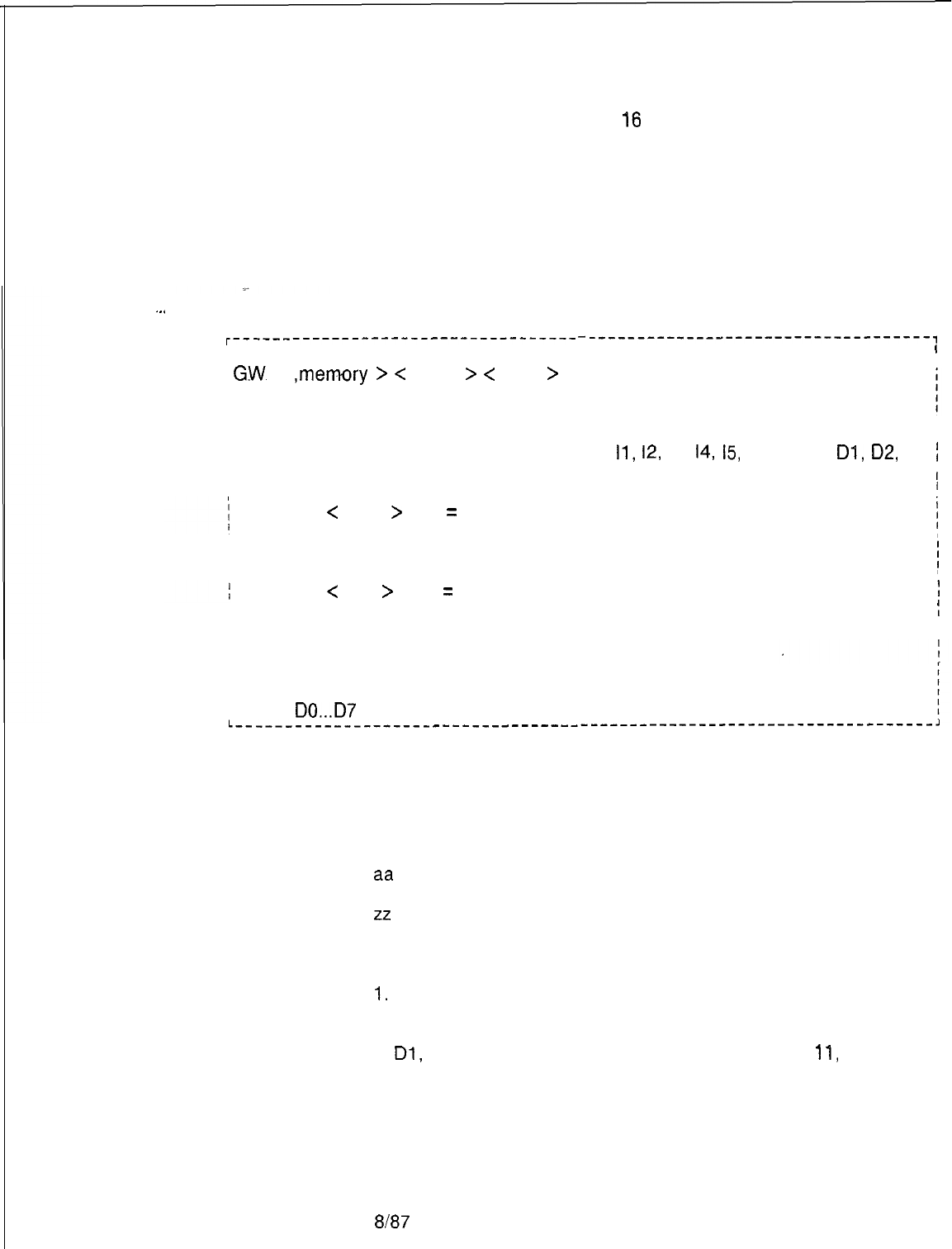
5210
TL-130200-1001
General Write
2.3.2 The General Write (GW) command is used to change the
Command
contents in memory at up to
16
consecutive memory locations
with the last change data entry followed by a period. The TTY
output will show the existing data in each memory location, the
new data to be entered, and a prompt when all requested
changes are displayed. If the changes are correct, the user
must enter Y followed by a period. If the changes displayed are
not correct, the user must enter N followed by a period to
terminate the input, and reenter the general write request.
Input/output formats for the GW command are as follows:
.
.
.
r-----------------------------------
I
/
G.W.
,memory
>
<
begin
>
<
data
>
I
Iwhere
I
I
I
I<memory> =
I
I
<
begin
>
=
<
data
>
=
I
IKEY
I
I
10 . ..17
I
I
DO...D7
-----------------------------------,
I
lo,
II,
12, 13, 14,
15,
16,
17,
DO,
DI,
02,
1
D3, D4, D5, D6, D7
I
I
I
Address to be read, or the beginning
address of a string of memory 1
I
locations to be read.
I
One hexadecimal byte of data. (This 1
field can be repeated up to a maximum
I
of 16 values.
I
I
CEC instruction memory pages
CEC data memory pages
L------------------------------------------------------------------------
The prompts and output from the GW command are as follows:
If new data (nn) is correct, type Y.
If not, type N.
xxxx = an address
aa
= the old data
nn
= the new data
zz
= page identity
NOTES:
1.
Up to 16 addresses can be entered.
2. Data base addresses on DO, D2, D3, D4, PO-P7 can be
written when security level 2 is used. All other areas on DO,
Dl,
D2, D3, D4, D5, D7, and all addresses on 10,
11,
12, 13,
14, 15, 16, and 17, can be written when security level 6 is
open.
8187
M-77
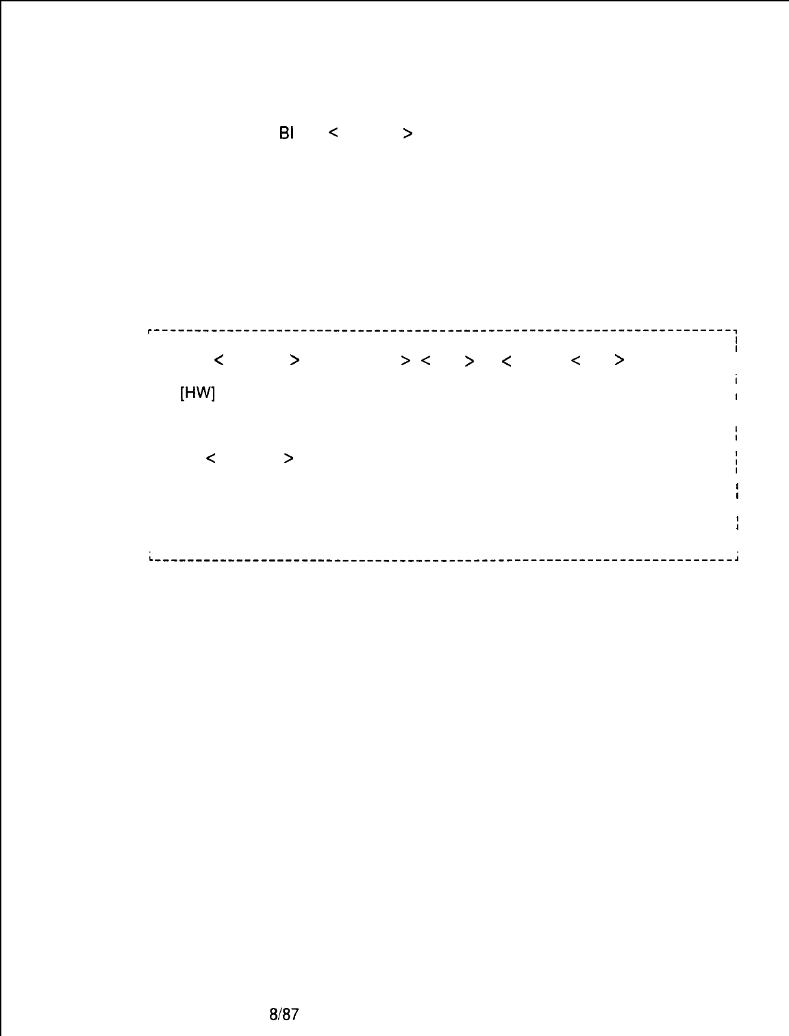
TL-130200-1001
Bulk Input
2.3.3 The Bulk Input (BI) command is used to change the data
Command
base data memory at up to 8 memory locations which need not
be consecutive. End each address-entry (excerpt the last) with
a
BI
GW
<
memory
>
.
End the last address-data entry with a
period. After the last address-data entry and period are
entered, the TTY prints the existing data and the new data for
each address specified, followed by a prompt. If correct, the
user must enter Y followed by a period. If incorrect as shown,
the user must enter N followed by a period to terminate the input,
and must reenter the command with the correct data.
Format for the BI command is as follows:
r-----------------------------------------------------------------------~
I
I
I
I
I BI [GW]
<
memory
><ADDRESS >< data > . . . < address < data > .
I
I
I
I
I
i
I
W’JI
I
I1
I
I
I
I
I
where
I
I
I
I
I
I
I
I
I
<
memory
>
=
Valid memory pages for the respective
commands (i.e., GW or HW)
i
I
I
I
I
I
I<ADDRESS> =
Address to be written to
I
I
I
I
I
i
I<data> =
One hexadecimal byte of data
I
I
I
I
I
8187
5210
TL-I
30200-l
001
Hardware Write
2.3.4 The Hardware Write (HW) command is used to write
Command
hardware addresses into the PEC
>
The list of changes can
include from 1 to
16
data entries. The last data entry must be
followed by a period. The HW command format is as follows:
. . .
~-----------------------------------------------------------------------,
I
I
I
I
I
l-j.W
<memory> <ADDRESS> <data>
II
I
I
I
I
I
Iwhere I
I
I
I
I
I
I
<
memory
>
= PO,
PI,
P2, P3, P4, P5, P6, P7
I
I
I
I
I
I
<ADDRESS
>
= Address written to or the beginning
II
address of a string of memory locations to
!
be written to. I
I
I
<data> =One hexadecimal byte of data. (This field
i
can be repeated up to a maximum of 16
!
values.)
I
I
I
NOTES:
1.
A security level of 6 or higher is required.
2. The valid address ranges are:
PEC Hardware;
500-5FF
Channel Memory 0:
400-47F
Channel Memory
1:
800-87F
Maintenance Request
2.4 The Maintenance
Request(MR)
command is used to initiate
Commands
the maintenance functions.
MR
codes are entered into the
system using a maintenance terminal. MR codes are used as
part of the MR command system. The
MR
command input
format is:
r------------------------------------------------------~
MR
xx. I
I
L------------------------------------------------------J
The output format (prompt) to a maintenance request code (xx,
above) asks the user for verification that he desires to execute
the command requested.
5210 8187
M-79
TL-130200-1001
. . .
r--------‘-------------------------------------------------~
I
I
I
MRxxnn
I
I
I
I
I
I xx
aa
(Y/N)
>
Y.Executed nn
I
I
I
I
I
I
I where
I
I
I
I
I
I
Ixx
= the request code.
I
__
I
Inn
= a response code.
I
I
laa
= a status command code.
I
I
I Y. is entered by the user.
I
I
L-------------------------------------------’---------------~
Maintenance Request
Codes
CODE
PROGRAM
09
OE
OF
10
11
12
13
26
Write system data base and PEC data base
Force the peripheral circuit to maintenance
busy
set the peripheral circuit to maintenance busy
when idle
Release the peripheral circuit from
maintenance busy
Disable the alarm
turn off present alarms
Enable the alarms
Restart system diagnostics on in-service
CEC
Alarm Command Codes
2.4.1 The alarm codes and their functions are as follows:
l Code 11 disables the alarm reporting circuits for alarms
indicated by steady lighting of the ALARM LED on the
Attendant Console. and any audible indication from devices
connected to relay 5 of the Attendant Interface (ATT12) card in
the PEG. Alarm reporting by the system remains disabled until
enabled by entering the proper code. Alarms will still be
recorded even while the alarm circuits are disabled. The fault
reporting system is not affected by the alarm codes. The
ALARM LED on the ESSD card will flash when a fault occurs.
l Code 12 turns off any existing alarm indications (indicated by
steady lighting of the ALARM LED) and any device connected
to relay 5 of the
ATT12
card). However, if the cause of the
alarm has not been corrected before executing this code, the
alarm indications will be repeated immediately afterwards.
l Code 13 resets the alarm reporting system and enables the
reporting of any recent or future alarms. This code is used to
enable the alarm reporting circuit after it has been disabled
(inhibited) by a Code
11.
M-80
8187
5210

TL-130200-1001
MR Data Base
2.4.2 When executed, maintenance busy codes remove
for Peripheral Circuits
individual circuits from service so that maintenance can be
performed. the system data base is used to identify system
hardware and to designate its status. the characteristics of a
particular system are documented on a hard copy of the system
data base. the identity information needed by the system for a
maintenance busy code is:
@
PEC number (always 0)
. .
0
Circuit type (Table 2.9)
Q
Software Code ID Number per circuit
5210
Table 2.8 Circuit-Type Codes for Maintenance Busy Functions
SOFTWARE
CIRCUIT TYPE
CODE
IDENTIFICATION
NUMBER
Line
Trunk
0
00-FF
1
00-3F
DTMF Receiver
I
2
I
00-07
I
1 Conference Bridge I
3
I
00-01
I
Console Interface
Release Link Trunk (RLT)
KEDU
Printer
400-01
5
00-OF
600-01
700-01
Unequipped
I
I
F
Software codes (circuit ID numbers) are stored in CEC memory
on data page 0, designated as Table T2241 (Table 2.10).
Circuit identity information is written into specific memory
locations via the CPG program prior to system installation, or via
general writes or Recent Change afterwards. When a
maintenance busy code is executed, the system automatically
accesses the addresses listed in
T2241
(Table 2.10). Therefore,
the circuit information must be entered into Table T2241 before
MR code is executed. Two bytes of data must be entered for
each circuit
(1
through 8, Table 2.10). The first half of the first
byte identifies the PEC number and the second half identifies the
type of circuit. The second byte must have the software
identification number, which is a piece of software information
which represents a specific, individual circuit. (Refer to the hard
copy of the local data base.)
8187 M-81
TL-130200-1001
,
Table 2241 )Table 2.10) has been filled in; the appropriate
maintenance busy code can be executed. the maintenance busy
codes and their functions are as follows:
l Code E
-
Forces a peripheral circuit to maintenance busy. If
a call using the specified circuit is in progress at the time the
maintenance request is made, the call is dropped.
l Code F
-
Sets a peripheral circuit to maintenance busy as
soon as any calls using the circuit are completed.
-..
l Code 10
-
Sets a circuit which is maintenance busy to the
in-service status.
BIT POSITIONS 7 6 54 32 1 0
ADDRESS DATA CIRCUIT
BYTE 1 6322
PEC 0
CIRCUIT TYPE
1
BYTE 2 6323 SOFTWARE ID
------------------------------------------------------------------------------------------------------------------------------------------------
6324
PEC 0
CIRCUIT TYPE
2
6325 SOFTWARE ID
6326
6327
PEC 0
CIRCUIT TYPE
3
SOFTWARE ID
6328
6329
PEC 0
CIRCUIT TYPE
4
SOFTWARE ID
632A
632B
PEC 0 CIRCUIT TYPE
5
SOFTWARE ID
632C
632D
PEC 0
CIRCUIT TYPE
6
SOFTWARE ID
6323
632F
PEC 0
CIRCUIT TYPE
7
SOFTWARE ID
6323
632F
PEC 0
CIRCUIT TYPE
8
SOFTWARE ID
5210
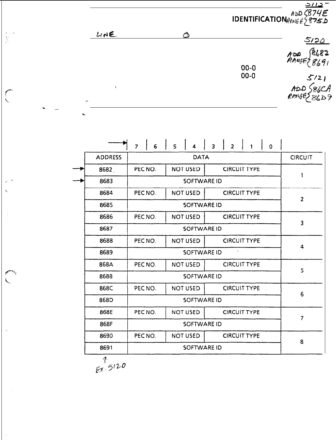
a/12-
SOFTWARE
BbD
87YE
lDENTIFICATIONg8bgg
8~g-a
CIRCUIT TYPE CODE RANGE
t
k
d
tz...
c3
Trunk
1
00-7F
S/%Q
DTMF Receiver
2
00-07
&.&@a
Conference Bridge
3
00-01
Console Interface
4
00-o
1
“hu@,
if
86
$
/
Release Link Trunk
(RLT)
5
00-o 1
KEDU
6
00-04
s-m/
’
Printer
7
00-04
__
Unequipped
F
L
.
.
.
L
Table 3-3. Layout of Table T2241, Data Page 0.
BIT POSITIONS
BYTE
1
BYTE
2
11


5210
TL-130200-1001
Successfully entered combined commands such as
r----------
----------------------------------,
I
I
1
MRE
I
L----------------------------------------
----A
will receive response output such as
r---------------
m-0-e-m
________-__---
---e---e,
I
I
MR OE EO
I
I
L--------------------------------------------
J
In summary:
MR =
Maintenance Request Command
OE = “FORCE” the Peripheral Circuit to Maintenance Busy
EO = successful Completion
Disk Backup of
2.4.3 The following room status dynamic data is backed onto
Room Status
disk when the command
MR 2E
is entered from the system maintenance terminal:
l
Message Waiting
o
Do Not Disturb
o
Room-to-Room Blocking
l
“wake-Up Calls
e
Room Restrictions
The Room Status data is saved in disk file XVHCM.
After a system cold start, the following are loaded from disk:
Generic Software
Data Base
Saved Room Status
8187
M-83

TL-130200-1001
THIS PAGE IS INTENTIONALLY LEFT BLANK.
M-84 8187
5210
TL-130200-1001
ON-LINE MAINTENANCE
3.0 The on-line Maintenance software is a part of the primary
system software. It consists of menu-driven programs which
provide maintenance capabilities while the system is on-line
and handling phone calls. When a particular transaction is
selected and executed, those parts of the system handling calls
are bypassed so that service is not interrupted. All test results
are given in plain language rather than codes.
. .
Some of the transactions simply call for displays of system
activities at that particular time. These displays provide
information which aids in maintenance and trouble shooting
decisions. Comparing several displays of a single transaction
can assist in isolating intermittent failures
Accessing On-Line .
3.1 In order to access the On-Line Maintenance feature, the
Maintenance
user must first access the System Options Menu. This procedure
is described in the following steps:
1. Type SL OL. (period)
The system responds: SECURITY CODE
>
2. Type four-character security code XXXX. (period)
NOTE: A security level of five or higher must be entered to work
with on-line maintenance.
The system responds: OPEN AT LEVEL 5
3. Type RC . Recent Change (period)
The system responds:
r-------------------------------------------------,
I
I
0
I
I
SYSTEM OPTIONS MENU
I
I
I I
II
I
1) SYSTEM RECENT CHANGE PRIMARY MENU
;
I
28) MAINTENANCE I
I
,I
I83) CAS
MAIN/ACD
SUPERVISOR OPTIONS
I
I I
I89) SAVE DATA BASE I
IX) END RECENT CHANGE I
I
I
I I
I
I
)
ENTER TRANSACTION NUMBER --
>28.
II
L-------------------------------------------------~
4. Type 28. (period) to select the Maintenance Options Menu.
The system responds:

TL-130200-1001
. .
r--------‘--‘--------------------’------------------,
I
28
:
I
MAINTENANCE OPTIONS MENU
I
II
;
29
SYSTEM STATUS DISPLAY
I
)
30
TOUCH CALL RECEIVER TEST
I
I
;
31
NETWORK TEST
;
;
32
TRAFFIC DATA OPTIONS
I
I
:
34
MEMORY TEST RESULTS
I
;
35
TRUNK SEQUENCE STATE DISPLAY
I
I
TOUCH CALL RECEIVER STATUS
I
:
37
I
I
DISPLAY
I
I
I
13
DATA SWITCH DEVICE STATUS DISPLAY
I
I
I
14
MASS STORAGE UTILITY
I
I
I
15
TABLE DISPLAY FACILITY
I
I
I
0
RETURN TO SYSTEM OPTIONS MENU
I
I
II
I
ENTER TRANSACTION NUMBER --
>
I
I
L----------_----____-------__-----------------------~
5. When an item is selected from the Maintenance Options
Menu(a primary menu), the transaction is loaded into system
memory and executed. After that particular test or display is
completed, the system responds:
ENTER END (E), REPEAT (R) OR TRANSACTION NUMBER (0
-
224)
With this prompt the user can end the exercise (type E period),
repeat the same transaction (type
R
period), or proceed to
another transaction (type another transaction number from zero
to 224 period).
If the user enters E, the Recent Change Options Menu
appears:
r-------------------------------------------------~
I
I
RECENT CHANGE OPTIONS
I
I
I
A) BEGIN
I
II
I
B) SAME ONE
I
I
II
I
C) BACK ONE
I
II
I
D) HELP
I
I
E) ERROR EXPLANATION
I
I
I
I I
I
F) SYSTEM OPTIONS MENU
I
I
X) END RECENT CHANGE
I
I
I
I
I
ENTER THE LETTER OF YOUR CHOICE HERE>
i
L--------------_-----------------_-----_----------~

5210
TL-130200-1001
The following explanations apply to the Recent Change Options
menu which is displayed after every On-Line Maintenance
Option transaction. This menu allows the user to select the next
transaction to enter.
A) BEGIN
-
Show the Recent Change System Options Menu
B) SAME ONE
-
Show the same menu just displayed
C) BACK ONE
-
Show the menu before the one just displayed
D) HELP
-
Show the Help Menu
E) ERROR EXPLANATION
-
Show the Error Explanation Menu
F) SYSTEM OPTIONS MENU
-
Show the Systems Option Menu
X) END RECENT CHANGE
-
End On-Line Maintenance
HELP (Option D) and ERROR EXPLANATION (Option E) are
used to assist the user in selecting additional transactions. The
HELP option cannot be used for certain applications, and a NOT
AVAILABLE prompt will appear.
An experienced user can omit the step of selecting transactions
from a menu by simply entering the correct transaction number.
Both the System Options Menu and the Maintenance Options
Menu offer a prompt which allows the user to input transaction
numbers. In this case, the user will see the following prompt:
ENTER TRANSACTION NUMBER --
>
Maintenance Options
3.2 The following paragraphs provide descriptions of
Maintenance Options Menu transactions:
TL-130200-1001
System Status Display
3.2.1 System Status Display (transaction 29) shows the number
of currently allocated system resources. For example, if the
Narrow Serial Device Controller (NSDC) port is marked as a TTY
in the data base, The presentation is a snapshot display. To
update this display, the program would have to be repeated. If the
NSDC port is marked as a CRT, the presentation is constantly
being updated until, an EXIT TRANSACTION function
(CONTROL-C) is entered. A sample Real-Time System Status
Display follows:
-..
r--‘-------‘--‘--‘---
----__-----------------------------------------
1
II
I
REAL-TIME SYSTEM STATUS DISPLAY
29
i
I
-.
I
f
12:02 6/09/87
I
I
II
I
RESOURCES IN USE:
I
I
I
fI
I
I I
I
CALL STORES
000
I
II
I
DIGIT STORES
I
I
000
I
I
I I
I I
I
I
TOUCH CALL RECEIVERS
000
I
I
I
I
I
i
BUSY LINES 000
I
II
I
BUSY TRUNKS
000
I
1
I
II
I
II
I
I
TIME SLOTS:
I I
II
I I
I
PCM BUS 0
00
I
I I
II
I
PCM BUS 1
00
I
I
II
I
PCM BUS 2 NOT AVAILABLE
I
i
I
I
I
f
PCM BUS 3 NOT AVAILABLE
I
I
I
I
I
I
PCM BUS 4
00
I
II
I
i
PCM BUS 5
00
I
I
I
:
I I
I
PCM BUS 6
00
I
fI
II
I
I
PCM BUS 7
00
I
:
I
I
I
DO YOU WANT TO REPEAT THIS FUNCTION
>
N.
I
II
I
:
I
-------------------------------------------------------------------J
M-66
6187
5210
TL-130200-1001
Touch Call
3.2.2 The Touch Call Receiver Test (transaction 30) is used to
Receiver Test
test Touch Call Receivers
(TCRs)
in a system. The test runs on
one or all
TCRs
by passing DTMF tones through a network
connection and then verifying digit decoding. If a failure occurs,
the physical location is given in the test results.
A sample
Touch Call Receiver Test Display appears below:
I
I
I
I
I
I
-.. I
I
I
II
II
I
I
I
I
I
I
I
I
I
I
I
III
I
I
I
I
I
I
I
II
I
I
I
I
I
I
I
I
III
I
I
II
I
I
I
I
TOUCH CALL RECEIVER TEST
30
13:48 10/01/87
ENTER “ALL”, OR SINGLE TCR NUMBER
>
ALL.
PEC-
TOUCH CALL RECEIVER PEC SID
NUM
0
1
2
3
4
5
6 7
0
PASS BUSY FAIL
FAIL
1
i
NO ERRORS DETECTED (OR IF CRT)
DO YOU WANT AN ERROR SUMMARY
>
Y.
(ON SECOND PAGE IF CRT)
SUMMARY OF DETECTED ERRORS:
TCR
#2
LOCATED IN PEC 0 GRP D UNIV SLOT 11 CIRCUIT 2
TCR
#3
LOCATED IN PEC 0 GRP D UNIV SLOT 11 CIRCUIT 3
DO YOU WANT TO REPEAT THIS FUNCTION (Y/N)
>
N.
I
L-----------------------_---------------------------------------------
J
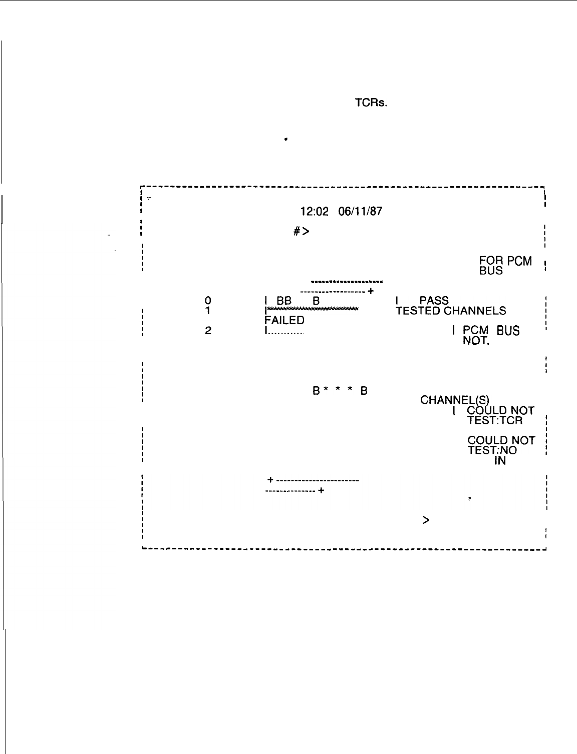
TL-130200-1001
Network Test
3.2.3 The Network Test (transaction 31) checks the network
used to carry DTMF tones to
TCRs.
The entire network or part of
the network can be tested. A TCR is required in each file for
testing with network connections made through each of the file’s
24 channels (0
-
23) to verify passing of DTMF tones Following
is a sample Network Test Display:
I
r-------------------------------------------------------------------
II
,
.~-
. . . I
NETWORK TEST
31
I
I
12:02
06/11/87
I
I
II
i
ENTER ALL, OR PCM BUS
#
>
ALL.
I
PCM BUS
0
RESULT/CHANNEL 23
RESULT
%sR
pcM
# +
~~~--------~~~~-----
I
I
3
4
5
6
7
I-
I ALL
+ES-Z~SCHANNELS
FAILED
. . . . . . . . . . . . . . . . . . . . . . . . . . . . . . . . . . . . . . . . . . . . . . . . . . . . . . . . . .
I
r&Y
BUS
._
.
AVAILABLE
I
. . . . . . . . . . . . . . . . . . . . . . . . . . . . . . . . . . . . . . . . . . . . . . . . . . . . . . . . . .
I PCM BUS
NOT
AVAILABLE
IBB
B***B
I
FAILURE IN
I
CHANNEL(S
. . . . . . . . . . . . . . . . . . . . . . . . . . . . . . . . . . . . . . . . . . . . . . . . . . . . . . . . . .
t
I
%k?C?fT
BUSY
I
. . . . . . . . . . . . . . . . . . . . . . . . . . . . . . . . . . . . . . . . . . . . . . . . . . . . . . . . . .
I
~~~+;~OT
TCR
I’N
BUS
I B
I
PASS
i
DO YOU WANT TO REPEAT THIS FUNCTION (Y/N)
>
N.
I
I
I
II
I
I
-------------------------------------------------------------------~
TL-130200-1001
Traffic Data Menu
3.2.4 The Traffic Data Menu (transaction 32) allows the user to
Options Menu
check traffic activities to determine if delays in system activity are
caused by faulty operation or by temporary peaks in traffic load.
The user selects the number of times that traffic data is collected
(scans) and the length of time that data is collected before
printing out automatically. The menu function may be repeated
manually to access updated traffic information.
The Traffic Data Menu provides the user with the following
options:
r-------------------------------------------------------------------~
II
I
I
TRAFFIC DATA MENU
32
;
I
I
I
I
A)
CHANGE TRAFFIC COLLECTION PARAMETERS II
I
I
II
B) DISPLAY TRAFFIC METERS
C) RETURN TO MAINTENANCE OPTIONS
f
ENTER THE LETTER OF YOUR CHOICE HERE --
>
I
I
I
I
L------------------_____________________----------------------------,
Current Collection 3.2.4.1
Selection of Current Collection Parameter Settings
Parameter Settings
(transaction A) allows the user to enter or change real-time
system status parameters before displaying intercepts and
timeout calculations. The following real-time parameters are
set for maintenance purposes:
r-------------------------------------------------------------------,
I
I
CURRENT COLLECTION PARAMETER SETTINGS 36
f
I
12:05 1 O/04/84
I
I
I
I I
I I
;
AUTOMATIC DUMP: ON
I
I
;
COLLECTION INTERVAL: 60 MINUTES
I
I
;
INTERVAL BETWEEN USAGE SCANS: 100 SECONDS
I
I
I I
i
ENTER NEW SETTINGS (PERIOD TO SKIP)
I
I
I
I I
I
I
;
AUTOMATIC DUMP (ON-OFF)
>
ON.
I
I
;
COLLECTION INTERVAL
(15-30-60)
>
60.
I
I
;
INTERVAL BETWEEN USAGE SCANS (lo-100 SECONDS)
>
100 SECONDS.
I
I
I I
I
I
; DO YOU WANT TO EXECUTE THIS CHANGE (YIN)
>
I
I
I I
I
I
i-------------------------------------------------------------------,
NOTE: During maintenance, allow 10 seconds between scans
before continuing a function.
TL-130200-1001
Traffic Meters
3.2.4.2 Selection of Traffic Meters Menu (transaction B) allows
Menu
the user to display the following specific traffic registers:
r-----------------------‘---‘--‘--”’----------------------------------------,
I
I
TRAFFIC METERS MENU 33
i
I I
I
A) INTERCEPTS AND TIMEOUTS
I
II
I
I
I
B) DTMF, CONFERENCE, LINE RING, CALL AND DIGIT STORE
i
I
-=. I
I
I
-..
I
C) CONSOLE RELATED
I
Ii
:
I
D) TIME SLOT
I
I
I
I
I
I
E) TRUNK GROUP, RLT TRAFFIC
I
II
II
I
X) RETURN TO TRAFFIC MENU
I
I I
i
ENTER THE LETTER OF YOUR CHOICE HERE
>
A.
I
I
I
I I
i
ACTIVE OR PASSIVE BUFFER
>
ACT.
I
I
I I
L---,,,--,-----_----________,,__________----------------------------J
M-92
8187
5210
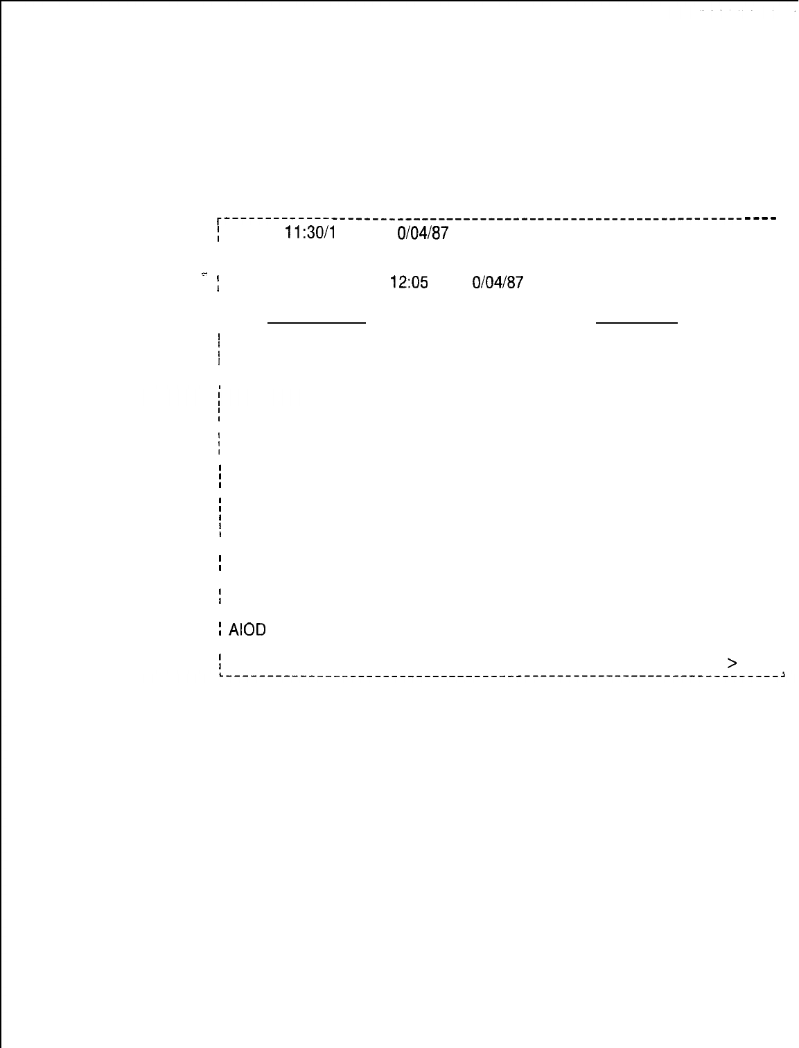
TL-130200-1001
The following are the contents of displays found in the Traffic
Meters Menu:
l INTERCEPTS AND TIMEOUTS (Transaction A)
. . . .
r---------------------------------------------------------------
;
PERIOD
11:30/l
2:00
1 O/04/87
I
I
I
I
INTERCEPTS AND TIMEOUTS
-.-
:
12:05 1 O/04/87
I
I
IIINTERCEPTS TIMEOUTS
I
I
f
TOLL RESTRICTED 0000 STILL BUSY 0033
I
----
j FEATURE RESTRICTED 0000 FIRST DIGIT 0027
:
VACANT NUMBER 0000 NO ANSWER 0002
I
:
INVALID NUMBER 0000 RECALL HOLD 0000
i
DID RESTRICTED 0000 CALL PARK 0000
i
CONFERENCE 0000 CALL HOLD 0000
t
RESTRICTED
:
ACOF RESTRICTED 0000 RLT HOLD 0000
!
DIGIT TIMEOUT
0031
RLT STILL BUSY 0000
;
AIOD
BLOCKED 0000 RLT NO ANSWER 0000
I
I
i
ENTER END (E), REPEAT (R) OR TRANSACTION NUMBER (O-224)
>
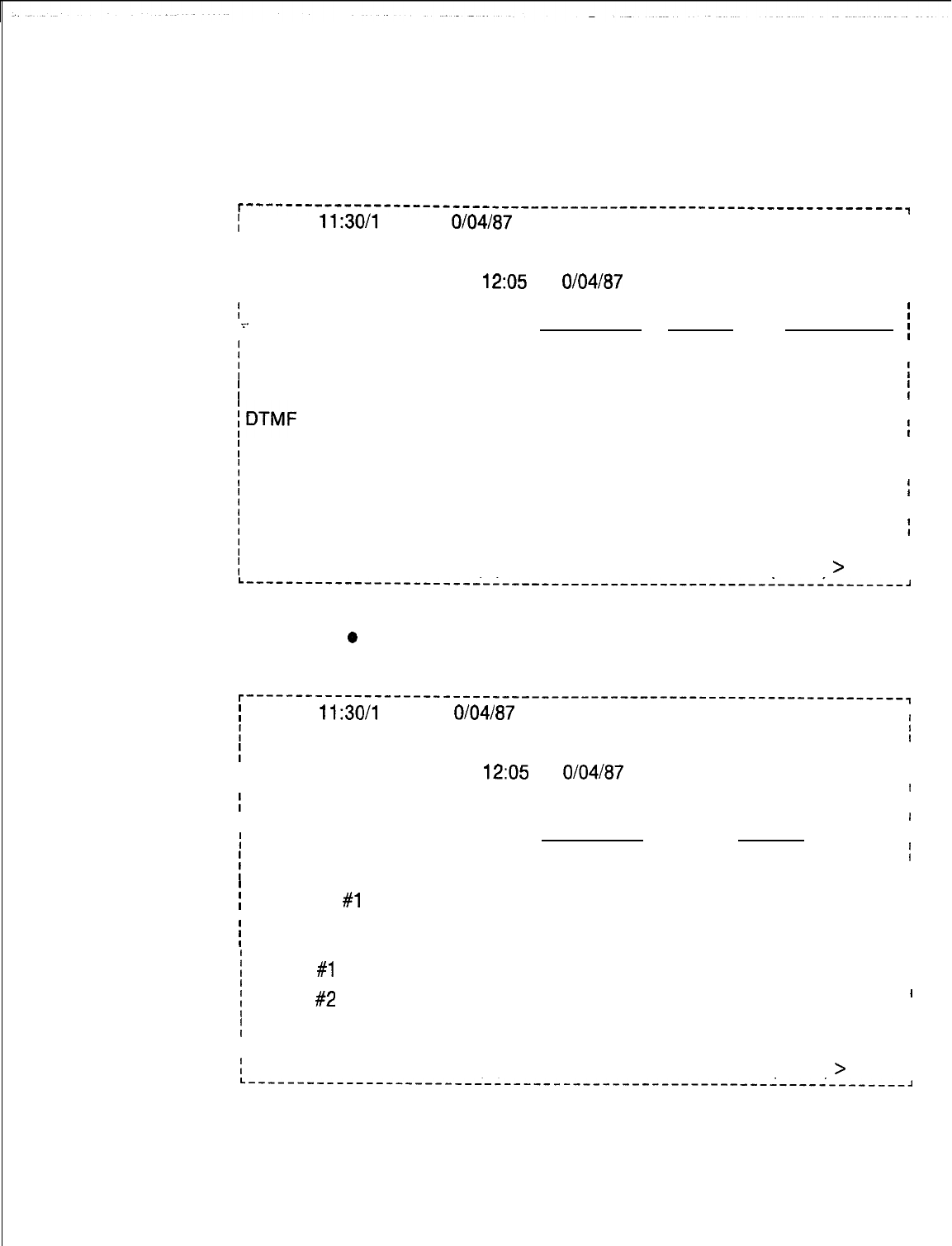
TL-130200-1001
. DTMF, CONFERENCE LINE RING, CALL AND DIGIT STORE
(Transaction B)
. .
r---------------------‘---‘----------’------------------------------,
;
PERIOD
11:30/l
2:00
1 O/04/87
I
I
II
II
MISCELLANEOUS
I
II
I
I
12:05
1
O/04/87
I
I I
I
, -:.
ATTEMPTS USAGE
I
OVERFLOW
i
;
LINE TO LINE
I
00525
I
1
I
HUNT GROUP BUSY 03525
I
;DTMF
.
I
01625
00081
00000
I
I
I
CONFERENCE00000 00000 00000
I
I
i
CALL STORE
I
02982
01751
00000
I
i
DIGIT STORE
t
01673 00110 00000
I
I
;
LINE RING PECO 00100 00034 00000
iI
I
:
ENTER END (E), REPEAT (R) OR TRANSACTION NUMBER (O-224)
>
II
L-------------------------------------------------------------------J
o
CONSOLE RELATED METERS (Transaction C)
r-------------------------------------------------------------------,
;
PERIOD
11:30/l
2:00
1 O/04/87
I
II
I
I
CONSOLE RELATED METERS
I
I
I
12:05
1
O/04/87
I
I
I
II
I
I
I
I
CONSOLE LOOP
I
I
ATTEMPTS USAGE
i
;I
j
CONSOLE #0
I
00000 00000
I
I
i
CONSOLE
#1
I
00000 00000
I
I
II
j
CALLS QUEUED
I
00000 II
i
LEVEL
#l
WAITING
I
00000 II
;
LEVEL
#2
WAITING I
00000
I
II
I
TIMEOUT 00000
I
I
I I
II
;
ENTER END (E), REPEAT (R) OR TRANSACTION NUMBER (O-224)
>
I
I
L-------------------------------------------------------------------,
M-94
8187
5210
5210
TL-130200-1001
l TIME SLOT TRAFFIC (Transaction D)
i
PERIOD
11:30/l
2:00
1 O/04/87
i
I
TIME SLOT TRAFFIC
I
PCM BUS
0
1
2
3
4
5
6
7
12:05
8125187
USAGE
00000
00000
NOT AVAILABLE
NOT AVAILABLE
00000
00000
00000
00000
I
f
I
OVERFLOW
]
00000
I
I
I
I
00000
I
I
I
i
00000
I
I
I
00000
I
I
00000
;
I
00000
I
i
f
ENTER END (E), REPEAT (R) OR TRANSACTION NUMBER (O-224)
>
I
I
8187
M-95
TL-130200-1001
l TRUNK GROUP , RLT TRAFFIC (Transaction E)
r---‘---“^----‘---‘“----------------------------------------------
;
PERIOD
11:30/l
2:00 1
O/04/87
I
I
i
I
TRUNK GROUP TRAFFIC
I
I
12:05
1
O/04/87
. . . .
I
.~_
:
TRUNK
I
GROUP INCOMING
-
-
-
-
-
-
-
-
-
-OUTGOING-
,
----wm-
i
NUMBER
CALLS
USAGE CALLS USAGE
I
ATB QVJ
I
i
I
02
I
03
I
I
04
I
I
05
I
06
I
I
08
I
09
II
10
I
I
RLT
I
00317 00403 00037
00046 00098 00000
00182
00008 00076 00149
00169 00603
00002 00000 00000
00006 00002
00001
00125 00135 00203
00295
00017
00000
00166
00155
00000
00002
00000
00000
00000
00000
00206 00000
00000
00099 00114
00099
00000
00020
00002
00011
00000
00000
00000
00030
I
I
I ENTER END (E), REPEAT (R) OR TRANSACTION NUMBER (O-224)
>
I
I
L--,----------------------------------------------------------------,
RETURN TO TRAFFIC MENU (Transaction X)
Returns user to Traffic Data Menu
Return to 3.2.4.3 Selection of Return to Maintenance Options (Traffic Data
Maintenance Options
Menu transaction C) returns the user to the Maintenance Options
Menu.
M-96
8187
5210
TL-130200-1001
Memory Test 3.2.5 Memory Test Results (transaction 34) provides the user
Results with a status display of system memory tests. When a memory
failure is detected, the physical location of the faulty card
appears in the error message.
r-------------------------------------------------------------------,
I
I
I.=.
MEMORY TEST RESULTS
34
i
I I
. .
I
II
I
17:22
09125187
I
I I
-
i
PRE-LOAD MEMORY TEST:- FAILURE DETECTED
sdrk
I
II
. . I
i
AT CEC INST MEMORY ADDRESS:
72E6,
PAGE: 0, FAULT CODE: 19
I
I
II
/
CARD FB-17314-A LOCATION: FILE Y , SLOT 1
I
I
I
I
STATIC MEMORY TEST: NO ERRORS DETECTED
I
I
I I
i
DYNAMIC MEMORY TEST: NO ERRORS DETECTED
I
I
I
II
I I
II
I
I
II
II
i
DO YOU WANT TO REPEAT THIS FUNCTION (Y/N)
>
I
I
I
I I
L
-------------------------------------------------------------------~
TL-130200-1001
Trunk Sequence
3.2.6 Trunk Sequence State
Qisplay
(transaction 35) provides the
State Display
user with a plain language description of trunk sequence states.
A CRT display updates the trunk sequence states until
CONTROL-C is entered. Without a CRT, the display is updated
by repeating the transaction. No display will be shown for a trunk
number not in use.
r-------------------------------------------------------------------~
I
I
REAL-TIME TRUNK SEQUENCE STATE DISPLAY
35
I
.=.
I
1
II
. . . I
I
13:46
1
O/04/82
I
II
:
ENTER STARTING TRUNK NUMBER (8 OPT. RANGE 1-14)
>
23 5.
I
II
II
II
I
Trunk Number
Sequence State
I
I
I23
I
01
INCOMING PRE-SEIZED
I
I
I
24 OUTGOING WINK START TIME
I
!
25
hi
OUTGOING START DIAL WAIT
I
I
;
27
1D
IDLE
I
II
I
I
I DO YOU WANT TO REPEAT THIS FUNCTION (Y/N)
>
I
I
L-------------------------------------------------------------------,
Touch Call Receiver
3.2.7 Real-Time Touch Call Receiver Status (transaction 37)
Status Display
provides the user with a status display of all system Touch Call
Receivers
(TCRs).
A CRT display updates the trunk sequence
states until CONTROL-C is entered. Without a CRT, the display
is updated by repeating the transaction.
r-----------------------------------------------------------------------~
II
!
REAL-TIME TOUCH CALL RECEIVER STATUS
37
I
I
II
I
12:02
1
O/04/87
I
II
II
I
TOUCH CALL RECEIVER PEC SID
I
II
’
PEC
I
I
;
NUM
I
0
1
2
3 4 5 6 7
I
I
I
I
I
l0
IDLE
. . . .
BUSY BUSY MAIN IDLE
. . . .
FAIL
I
I
II
I
II
II
;
DO YOU WANT TO REPEAT THIS FUNCTION (Y/N)
>
I
I
I
L-----------------------------------------------------------------------~
M-98
8187
5210
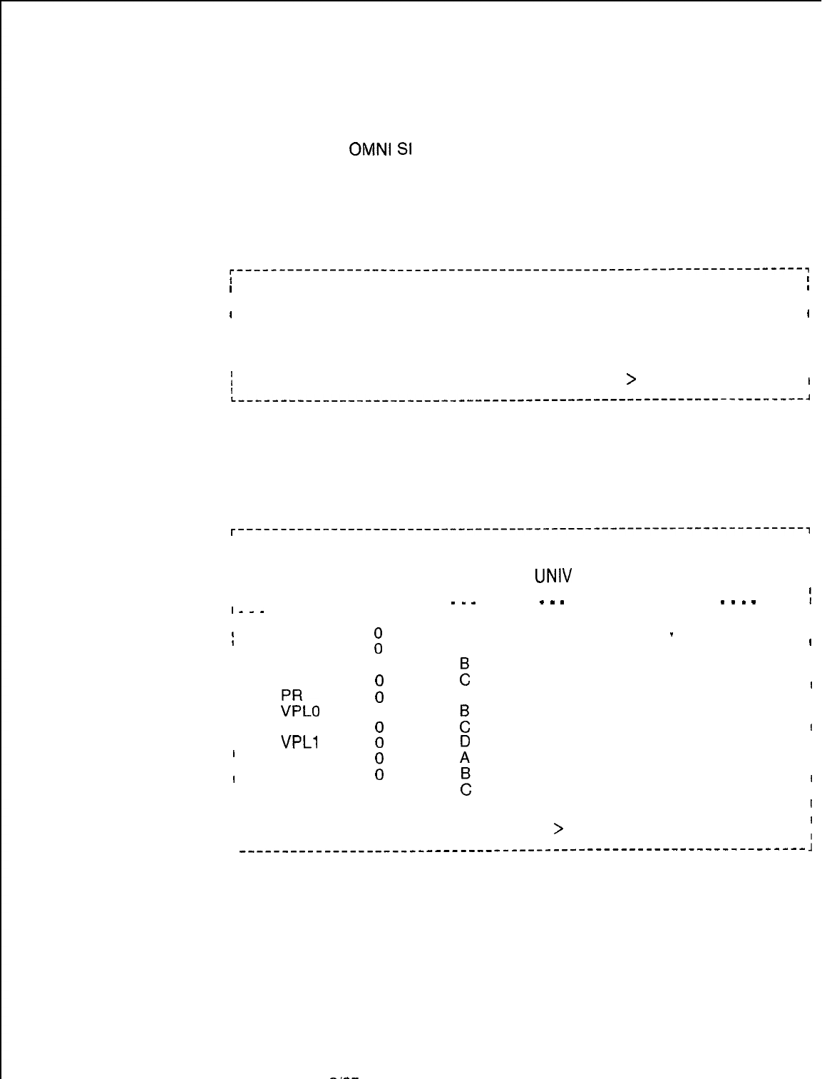
TL-130200-1001
Data Switch Device
3.2.8 The Data Switch Device Status Display (transaction 13)
Status Display
provides the user with in-service/ out-of-service information
for
OMNI
SI
PD-200 Packet Line Cards and Remote
Processors. The user selects transaction A to check the status
of Packet Line Cards, transaction B to check the status of
Remote Processors. or transaction C to exit the menu.
Data Switch Device Status Display
. . .
r-------------------------------------------------------------------~
I
I
13
I
I
DATA SWITCH DEVICE STATUS DISPLAY
I
I
I
II
II
I
A) PACKET LINE CARDS STATUS
I
I
B) REMOTE PROCESSORS STATUS
I
II
I
C) EXIT
I
II
I
TYPE THE LETTER OF THE DESIRED TOPIC
>
I
I
II
L-------------------------------------------------------------------~
Packet Line
3.2.8.1 Selection of Packet Line Cards Status (transaction A)
Cards Status
allows the user to monitor the in-service/ out-of-service status
of listed PD-200 Packet Line cards.
r-------------------------------------------------------------------,
II
I
I
PACKET LINE CARDS STATUS
I
I
II
II
ICARD
UNIV
I
I
TYPE PEC GRP SLOT STATUS
I
-----
-
-
- -
-
-
-----
-
-
-
-
I
I--m
I
II
I
I
ADMP
Fl
A
02
INS
-I
I
I
BT D08
00s
I
I
I
I
DCP
0
I
I
PBE
:
E
01
INS
I
I
01
00s
I
I
I
I
;:LO
A
01
INS
I
I
0
:
02
00s
I
I
I
I
DCPB
:
02
INS
I
I
I
I
VPLl
01
00s
I
I
1
I
RPTR
:
03
INS
I
I
I
I
NIC
ii
03
00s I
I
I
I
VP20
0
:
03
INS
I
I
I
I
VP21 0
D
02
00s
I
I
II
I
DO YOU WISH TO SEE MORE (Y/N)
>
I
I
L
__---_--____________-----------------------------------------------
1
5210
8187
M-99
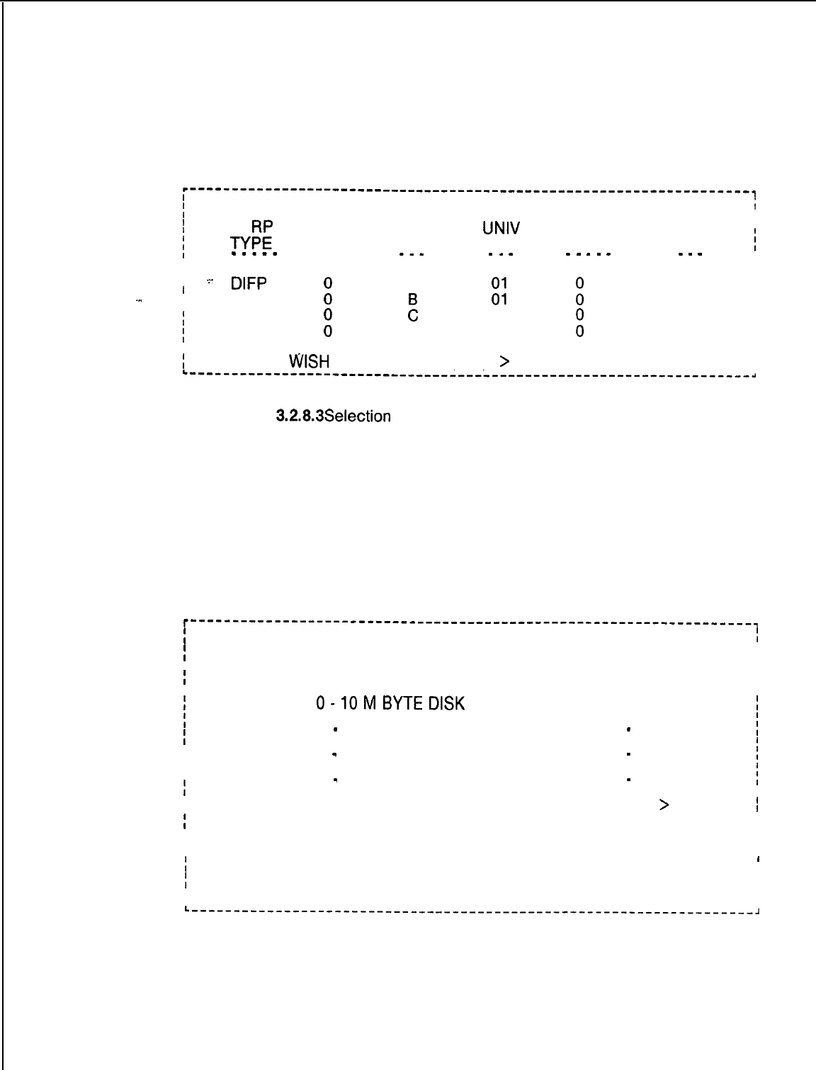
TL-130200-1001
Remote Processors
3.2.8.2 Selection of Remote Processors Status (transaction B)
Status
allows the user to monitor the in-service/out-of-service
status of listed PD-200 Remote Processor cards.
c-------------------------------------------------------------------.
I
f
REMOTE PROCESSORS STATUS
I
I
f
TYE
UNIV
I
t
I
PEC
GRP SLOT CKT
mm--m
STATUS
i
_--
_
-
_
-
-
-
-
-
-
-
-
-
I--‘----
II
II
I=-
DIFP
A
INS
I
I
-..
I
I
DFPAPM
iti
t
SPM
E
;:
i
INS
I
01
00s
I
I
I
APM
:
D01
i
INS
I
I
II
I
I
-DO YOU
WSH
TO SEE MORE (Y/N)
>
I
I
L--------------------------------------------------------------------
Exit
3.2.8.3Selection
Exit of (transaction C) of the Data Switch Device
Status menu allows the user to exit the menu.
Mass Storage
Utility Menu
3.2.9 The Mass Storage Utility Menu (transaction 14) allows the
user to control maintenance functions of the File Management
System (FMS). One function is to move files from the hard disk
to floppy disk, or from the floppy disk to hard disk. A second
function displays or changes FMS contents.
Security level 6 is required when working with FMS utilities .
r-------------------------------------------------------------------,
I
14
;
I
MASS STORAGE UTILITY MENU
I
I
I
I
I
CURRENT DEVICE ASSIGNMENTS
I
I
I I
:
0-10MBYTEDlSK
1 -NO DEVICE
;
!
I
2
-
800 K BYTE FLOPPY DISK 3
-
NO DEVICE
i
I
I
4
-
NO DEVICE 5
-
NO DEVICE
:
I
I
I
6
-
NO DEVICE 7
-
NO DEVICE
i
I
I
1
I
TYPE THE LETTER OF THE DESIRED TOPIC > B.
I
II
I
I I
I
A) DISK BACKUP
I
I I
I
B) DISPLAY DEVICE CATALOG
I
I
II
C) EXIT
I
I I
II
L-------------------------------------------------------------------,
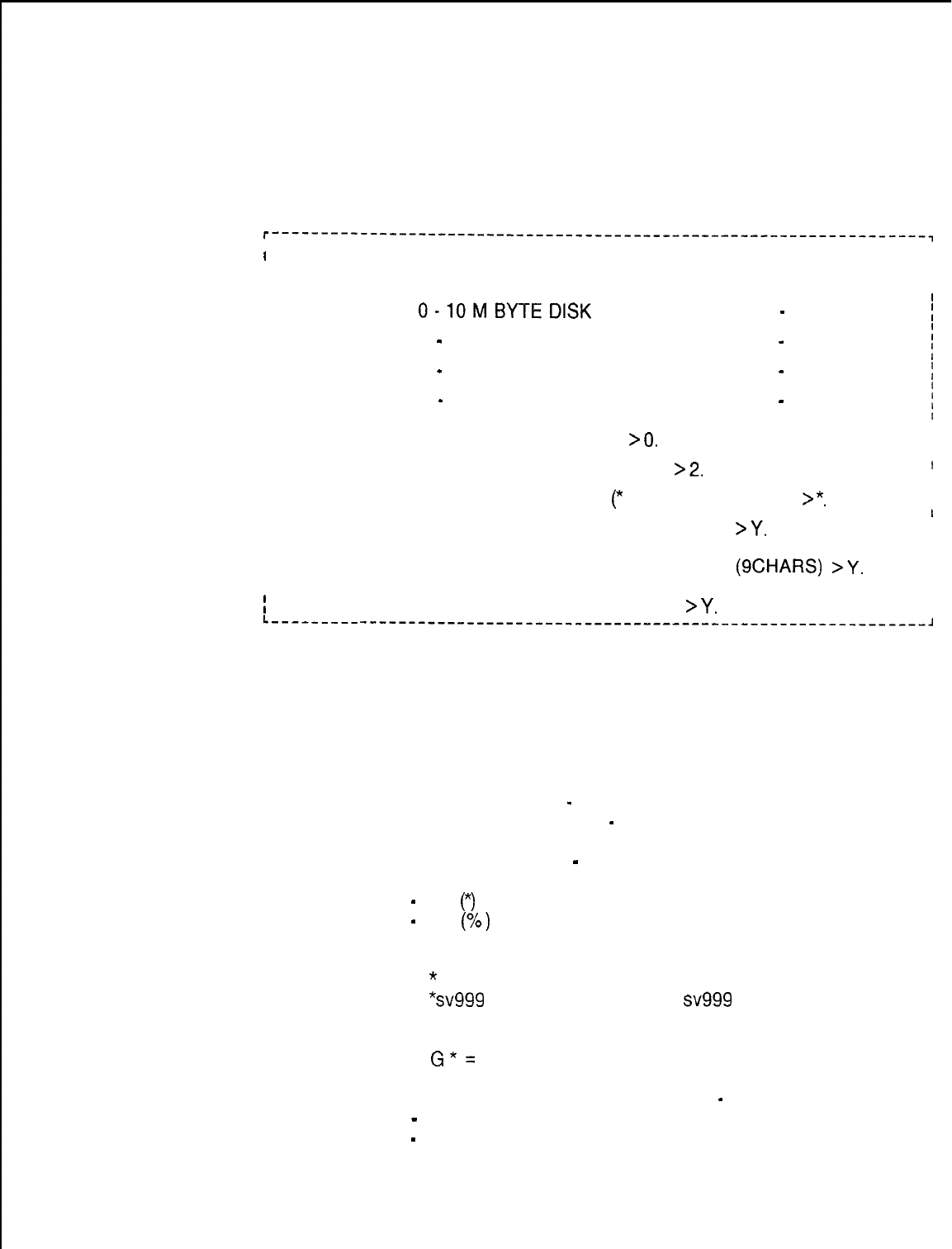
TL-130200-1001
Disk Backup
3.2.9.1 Selection of the Disk Backup Option (transaction 14)
Option
allows the user to transfer files from the hard disk to the floppy
disk, or from the floppy disk to the hard disk. The system
responds with the following menu:
r-------------------------------------------------------------------,
II
I
DISK BACKUP
I
II
I
CURRENT DEVICE ASSIGNMENTS
I
II
II
I
I
0-10MBYTEDlSK
1
-
NO DEVICE
;
I
I
I
2
-
800 K BYTE FLOPPY DISK 3
-
NO DEVICE
’
. .
I
III4
-
NO DEVICE 5
-
NO DEVICE
I
I
I
I
6
-
NO DEVICE 7
-
NO DEVICE
;
I
I
I
II
ITYPE SOURCE DEVICE (O-7)
>O.
I
II
IITYPE DESTINATION DEVICE (O-7)
>2.
I
I
II
II
IENTER FILE NAME MASK
(*
: STRING /CHAR)
>*.
I
II
II
I
REFORMAT DESTINATION DEVICE (Y/N)
>Y.
I
II
I
I
II
I
TYPE LABEL FOR DESTINATION DEVICE
(SCHARS)
>Y.
I
II
I
I
1 DO YOU WISH TO EXECUTE THIS COMMAND
>Y.
I
I
L---------
----------------------------------------------------------J
Current Device Assignments lists the hardware found in the FMS.
A lo-megabyte hard disk and an 800-kilobyte floppy disk drive
are listed here.
l When working with the Disk Backup Option, the user answers
the following prompts:
1. SOURCE DEVICE
-
hard disk, enter 0; floppy disk enter 2
2. DESTINATION DEVICE
-
hard disk, enter 0; floppy disk
enter 2
3. FILE NAME MASK
-
single or multiple files to be
transferred
-
the
(*)
wild card matches any string
-
the
(%)
wild card matches any character
Example:
*
= All files
“sv999
= All files ending with
sv999
C% % % = All files four characters long and start with
letter C
G*=
All files starting with letter G (all data base files)
4. REFORMAT DESTINATION DEVICE
-
Yes or No
-
Yes reply destroys all data on destination device
-
If reformatting, prompt for LABEL FOR DESTINATION
DEVICE will appear. This prompt will not appear if
reformatting is not entered.
TL-130200-1001
--
Label is used to identify disk if more than one copy
exists
-- Label limited to nine characters
l If a backup floppy disk is wanted type
“Y
“,
if not type “N
“.
A
new disk should be formatted and used for each backup
floppy disk. Use of old disks can affect usable space, and
cause security problems.
-
If space runs out on a backup floppy disk, the following
prompt will appear:
FMS ERROR: NOT ENOUGH SPACE ON DISK
-
To override this prompt, type a period. The system will
respond:
MOUNT A FLOPPY
-
HIT. (PERIOD) WHEN READY
-
System will display prompt for reformatting. Follow
instructions , and disk backup will continue. The system
will respond:
BACKUP COMPLETED, if the backup was successful, or
BACKUP FAILED, if backup was unsuccessful.
Device Catalog
3.2.9.2 The Device Catalog Display Option (transaction 16)
Display Option
allows the user to display selected directory or file contents of
FMS hardware devices. The system responds with the following
menu:
r-------------------------------------------------------------------,
I
I
16
;
I
I
DEVICE CATALOG DISPLAY
I
I
CURRENT DEVICE ASSIGNMENTS
I
I
II
I
I
0
-
10 M BYTE DISK 1
-
NO DEVICE
;
I
I
I
2
-
800 K BYTE FLOPPY DISK 3
-
NO DEVICE
i
I
4
-
NO DEVICE 5
-
NO DEVICE
j
I
I
i
6
-
NO DEVICE 7
-
NO DEVICE
(
II
I
I
TYPE THE DEVICE IDENTIFIER (O-7)
>
0.
I
I
L------,,-----------------------------------------------------------~
l Current Device Assignments lists the hardware found in the
FMS. A 10 megabyte hard disk, and an 800 kilobyte floppy disk
drive is listed here.
l When working with the Device Catalog Display Option, the user
answers the following prompt:
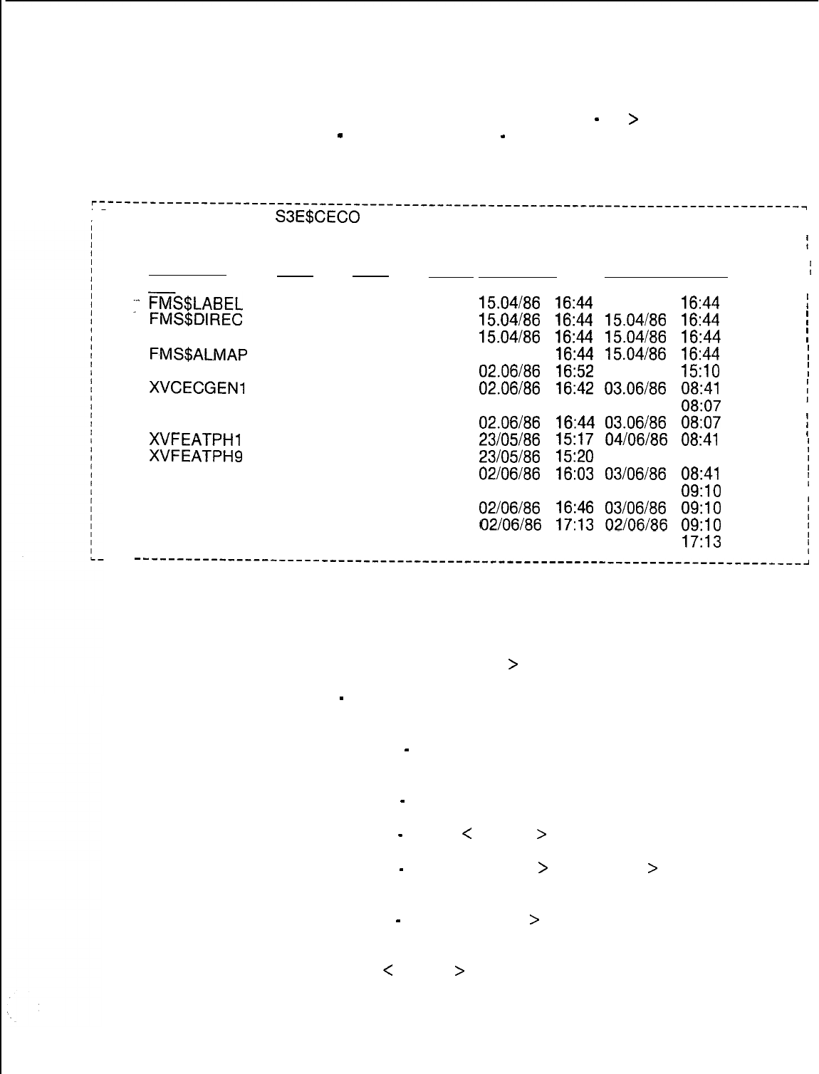
TL-130200-1001
TYPE THE DEVICE IDENTIFIER (0
-
7)
>
-
DEVICE IDENTIFIER
-
hard disk, enter 0; floppy disk, enter
2. The system responds with the following directory:
r-----------------------------------------------------------------------------------~
I CATALOG LISTING OF
S3E$CECO
DEVICE =10 MBYTE FIXED DISK
I
I
REC FILE RECS I
SECURITY 1
I
FILE NAMESIZE SIZE USED LAST UPDATED RD
;
WR --- CREATED
I
I
:FM&LABEL
016 00001 00001
15.04/86
16:44 15.04186 16:44 02 15
;
FMS$DIREC
032
00320 00320
15.04186 16:44
15.04/86
16:44 02 15
!
FMS$BADSP 256
00001 00001
15.04/86
16:44
15.04/86 16:44
02 15
!
F.MS$ALMAP
256
00020 00020
15.04186 16:44
15.04/86
16:44 02 15
;
FMS$GENER
256
00104 00104
02.06/86
16:52 05.06186
15:lO
02 15
!
XVCECGEN2
512
01017 00262
02.06186 16:44
04.06/86
08:41 05 06
XVCECGENl
512
01017 00828
02.06/86
16:42
03.06/86 08:07
05 06
i
I
XVPEC 512 00112 00106
02.06/86
16:44
03.06/86 08:07
05 06
XVFEATPHl
512
00043 00043
31/07/85
15:08
04/06/86
08:41 05 05
)
XVFEATPH8 512 00045 00045
23/05/86
15:17
04/06/86
08:41 05 05
;
XVFEATPHS
512
00053 00053
23/05/86
15:20
04/06/86
08:41 05 05
;
XVRCGSVR
512 00901
00794
02/06/86
16:03
03/06/86 09:lO
02 02
;
I
XVMDR 512 00256 00246
02/06/86
16:46
03/06/86 09:lO
05
06
XVHCM 512 00025 00017
02/06/86
16:46
03/06/86 09:lO
02 05
i
ZVSBYUPDY
016
01000 00000
02/06/86
17:13
02/06/86
17:13 00 15
;
;
-------------------------------------------------------------------------------~
l After writing the device directory, the system will provide the
following prompt:
ENTER COMMAND
>
-
The user responds to this prompt by entering the following
two-letter, UP, or END instructions:
(CO)
-
COPY <device> <name>. <device> <name>
= Make a copy of file.
(DE)
-
DELETE <name> = Delete a file from this device
(DO)
-
DOWN
<
nnnnnn
>
= Display the next set of files
(RE)
-
RENAME <name
>
<new name
>
= Rename a file
on this device
(SE)
-
SELECT <name
>
= Select a file to display from
this device
UP
<
nnnnnn
>
= Display the previous set of files
END = End this program
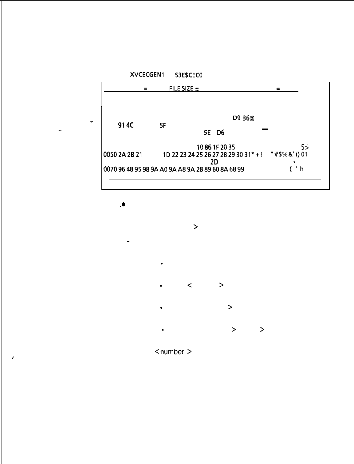
,
TL-130200-I 001
For example, if the response SE is selected, the following file
dump occurs:
FILE:
XVCECGENI
ON
53EBCECO
DEVICE =10 MBYTE FIXED DISK
RECORD SIZE
=
512
FILESIZE
=
01017 RECORD USED
=
00828
RECO
-.-
.
.
.
.
RD #OOOO
0000 40 7A 01 F4 30 00 02 00 00 00 00 00 83 02
D9
B6@
0
0010
914C
4A 29 91
SF
00 00 03 02 00 00 F2 OC 00 00 LJ)
-
0020 00 00 00 00 00 00 00 00 00 00
SE
06
82 20 00 00 A
0030 00 00 07 3185 05 06 86 05 06 86 00 00 00 00 00 1
004000000000000000000003
1086lF2035
3E
5>
00502A-2B21
01 3D
lD22232425262728293031*+!
=
“#$%a’()01
0060 11 32 33 34 36 37 38 39 3A 3B 2E
2D
1 F B8 13 EO 23456789:
;
-
0070964895989AAO9AA89A2889608A6899
10 H
(
‘h
ENTER COMMAND >
.*
After writing the file contents, the system provides the following
prompt:
ENTER COMMAND
>
-
The user responds to this prompt by entering the following
two-letter, UP, or END instructions:
(CH)
-
CHECKSUM = Calculate and update data switch
record checksum
(DO)
-
DOWN
<
number
>
= Display the next record, or
current record plus number
(RD)
-
RDOFFSET <offset
>
= Display this record
starting at offset
(WR)
-
WROFFSET <offset
>
<data
>
= Change data
stored in the record
UP
<number
>
= Display the previous record or current
record-number
END =End this program
UP and (DO) DOWN scroll records within a file.
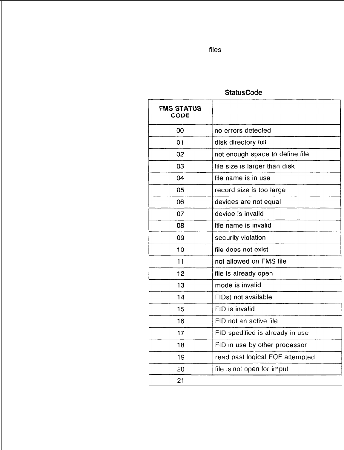
TL-130200-1001
File Management
When loading the FMS
files
into the system, certain errors may
System (FMS) Errors
be received. For example, “FMS error 14” is received. This
means that FILE D is not available for creation, for opening, or for
seizure. Refer to Table 3.1 for status code and explanation.
Table 3.1 FMS StatusCode and Explanation
EXPLANATION
file is not open for output
5210
8187
M-l 05
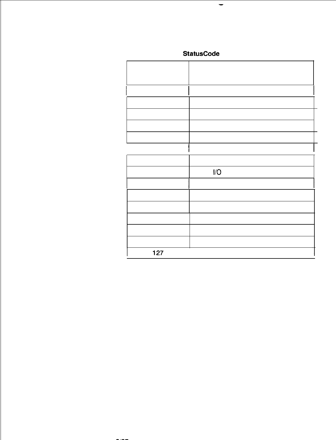
TL-130200-1001
Table 3.1 FMS StatusCode and Explanation (Continued
FMS STATUS
CODE
EXPLANATION
22
I
write past physical EOF attempted
23
seek past physical EOF attempted
24
record sizes not equal
25
files open on device
26
FID not seized
. 1
27
]
access is invalid
30
device not ready
31
device
I/O
error
32
I
device write protected
34 not allowed on mounted disk
35
no device attached
36
device is private
40 invalid commander number
126
command awaiting execution
M-l 06
command executing
6187
5210

SYSTEM MAINTENANCE
GENERAL PRINCIPLES
.
.
Preventive Maintenance
System Voltage Checks
System Operation
Checks
Spare Cards
Quick Reference Chart
5210
TL-130200-1001
4.0 Maintenance commands are input via the maintenance
terminal to designate particular parts of the system hardware as
“maintenance busy” so that system software will not try to use
that hardware during system operation. Hardware is out of
service when designated as maintenance busy. That piece of
hardware becomes available for maintenance purposes and can
be physically removed from the system and replaced with a
spare card. This will not cause interruption of service.
The maintenance terminal is also used to place parts of the
system back into service. However, the part is tested by the
system before it is placed back into use. When testing is
completed, the system outputs response codes to any attempts
to place equipment into service. A response code is outputted if
the attempt is successful, or if the equipment fails system testing
and is not placed into service. The responses are an aid to
maintenance and troubleshooting.
4.1 The system does not require regularly scheduled preventive
maintenance. Cabinet cooling is based on natural convection
with no fans or air filters to clean or replace.
4.2 Voltage checks are performed as part of troubleshooting and
are discussed in the TL-130300-1001. Voltage adjustments
are set at the factory and should not be altered as a part of field
maintenance. Battery packs are checked during installation and
are charged by the system.
4.3 System operation checks simply use the standard functions
of the system to ensure proper operation. Checks are usually
performed when installation is completed and, selectively, at the
conclusion of a corrective maintenance action. Refer to
TL-
130100-l 001 for detailed operating procedures when attempting
to make particular types of calls and execute particular system
features.
4.4 Spare cards should be tested for correct operation after the
system is completely tested and operational. To test the spare
cards, replace a working card with an identical spare and test the
feature or function associated with it. Once the function of the
spare has been confirmed, remove it and replace the original.
4.5 Table 2.1 is a listing of the fault codes and functions
associated with the system.
M-l 07

TL-130200-1001
Attendant Console
4.6 The memory of each CEC provides an area called the fault
Code Display Fault
log which records system faults. It records the last 32 faults
detected. When a fault is detected, the ALARM LED on each
Attendant Console flashes, indicating that a fault has occurred.
Each console displays all faults reported in the fault log
independently of the other consoles in the system. All of the
faults listed on the fault log are displayed by repeated
depressions of the ALARM pushbutton. If all faults have been
displayed at an Attendant Console, an additional depression of
the ALARM pushbutton causes the station number display to go
off and the ALARM LED to stop flashing, unless a MAJOR alarm
exists which will cause the ALARM LED to light steady. A steady
ALARM LED should cause the Attendant to call for maintenance
assistance.
Depressing the ALARM pushbutton associated with the flashing
LED displays a three- or four-digit number in the station
number display on the Attendant Console. This display is
interpreted as follows:
l The first two digits indicate the fault type. Refer to Table 4.1
l The third digit indicates in which equipment complex the fault
occurred. Refer to Table 4.1.
*
If provided, the fourth digit gives additional information. Refer
to Table 4.1.
M-l 08
8187
5210
TL-130200-1001
Table 4.1 Attendant Console Fault Log Decoding Summary
-..
FUNCTION
ATENDANT CONSOLE
STATIONS NUMBER DISPLAY
FAULT TYPE SELECTED
OPTIONAL
DIGIT
DIGIT 1 DIGIT 2 DIGIT 3 + DIGIT 4
CEC
block-parity
error
CEC dynamic-memory failure
CEC network read-after-write-error
CEC-PEC common memory read-after-write-error
CEC total communication failure
CEC single communication failure
CEC system network test error
Preloading test failure
Peripheral Equipment Complex (PEC)
Network test error
PEC directive test error
PEC directive hopper full
PEC illegal event error
PEC read-in after-write channel memory
PEC self-test error
PEC
lo-ms
test error
Tl
alarm fault
CEC
lo-ms
interval timer failure
CEC alarm fault or PEC alarm fault
CEC memory block-parity error
CEC preloading memory failure
Peripheral equipment data hopper failure
Peripheral equipment data directive hopper error
Spare
Real-time clock failure
Power failure
Station status disk backup failure
CAS
Main/ACD
agent data link error
CAS
Main/ACD
message queue error
Attendant Console recovery data check error
PEC ODDB backup failure
CIp
card failure
CIp
port failure
Remote FADS data transmission error
Remote FADS reporting error
* Not used
+ Demarcation unit; See CEC Fault Log
0
0
0
0
0
0
0
0
0
0
1
1
1
1
1
1
1
1
1
1
2
2
2
2
2
2
2
2
3
3
3
3
3
3
9
0
1
2
3
4.
5
6
7
8
9
0
1
2-4
*
*
*
*
Channel no.
Channel no.
*
*
*
*
*
*
*
*
*
*
*
*
*
*
PEC no.
PEC no.
Peripheral
Equipment
*
*
*
*
*
Console no.
*
Card no.
Port no.
TL-130200-1001
Fault Code 00
Description:
Block Parity Failure
When a program is loaded into the system, the CPU85 will
generate block parity for each 256 bytes of instruction data and
static data. This is done by an exclusive OR of the data table.
Periodically, the CPU85 will recalculate the block parity and
compare it with the value calculated earlier (detect memory
failures and data mutilation).
.
.
Register Data as System Prints:
CECO CECO Fault 00 B C D E H I
Test
Failure Address of
Faulty Byte
I
Failing
I
00
01
02
03
04
05
06
07
Software Pace:
= Instruction Page 0
= Instruction Page 1
= Data Page 0
= Data Page 1
= Instruction Page 2
= Instruction Page 3
= Data Page 2
= Data Page 3
Fault Resolution Steps:
1.
Remove fuse on battery pack.
2.
Power down
-
turn off main circuit breaker at rear of
OMNI
SI cabinet.
3.
Remove and replace Ml MB in
Y/01,
FB-17314-1A
(check
strapping).
4.
Power up and reload system
-
depress reset on PSUPY
card.
5.
Monitor PSUPY in
P/O1
for ASW LED to light.
6.
If fault occurs, power down and reinstall original
MlMB
card,
and replace the MPG16 card.
7.
If fault is still present, read the data for the pre-loading,
memory test (see disk handling and and Fault Code 19) and
replace the Ml MB card.
8.
Power up and reload syste.
9.
Monitor PSUPY in
P/O1
for ASW LED to light.
10. Replace fuse in battery pack.
M-110
8187
5210
TL-130200-1001
FAULT CODE 00
POWER DOWN
SYSTEM
1
R&R Ml MB IN
Y/O1
FB-17314
(Check Strapping)
POWER UP
AND RELOAD
I
I
YES
POWER DOWN
&
REINSTALL ORIGINAL
Ml MB CARD
1
R&R
MP85
IN
Y/O2
FB-17213
(Check Strapping)
1
POWER UP
AND RELOAD
1
MONITOR
PSUPY FOR
“ASW” TO LIGHT
f
REPLACE
BATTERY
PACK FUSE
1
5210
8187
M-111
TL-130200-1001
Fault Code 01
Description:
Dynamic RAM Memory
The system tests dynamic memory. A block of five bytes is put
into a temporary storage area. A series of test patterns is read
into the area of memory being tested and then verified. The data
is returned to its original location and the test advances to the
next five bytes of dynamic memory (interrupts are disabled during
this test).
.
.
Register Data as System Prints:
CECO CECO Fault 01 B C D E H L
00 00
\02
xx
v
Test
Failure
T
Address of
Faulty Byte
Failing
1 Software
Page:
00
= Instruction Page 0
01 =
Instruction
Page
1
02 =
Data Page
0
03 =
Data Page
1
04 =
Instruction
Page
2
05 =
Instruction
Page
3
06 =
Data Page
2
07
z
Data Page
3
M-112
1
Fault Resolution Steps:
1.
2.
3.
4.
5.
6.
7.
8.
9.
10.
ai87
Remove fuse on battery pack.
Power down
-
turn off main circuit breaker at rear of
OMNI
SI cabinet.
Remove and replace Ml MB in
Y/01,
FB-17314-A (check
strapping).
Power up and reload system
-
depress “reset“ on PSUPY
card.
Monitor PSUPY in
P/O1
for ASW LED to light.
If fault recurs, power down and reinstall original Ml MB card
and replace the MPG16 card.
Remove and replace MP85 in Y/02, FB-17213-A (check
strapping).
Power up and reload system.
Monitor PSUPY in
P/O1
for ASW LED to light.
Replace fuse in battery pack.
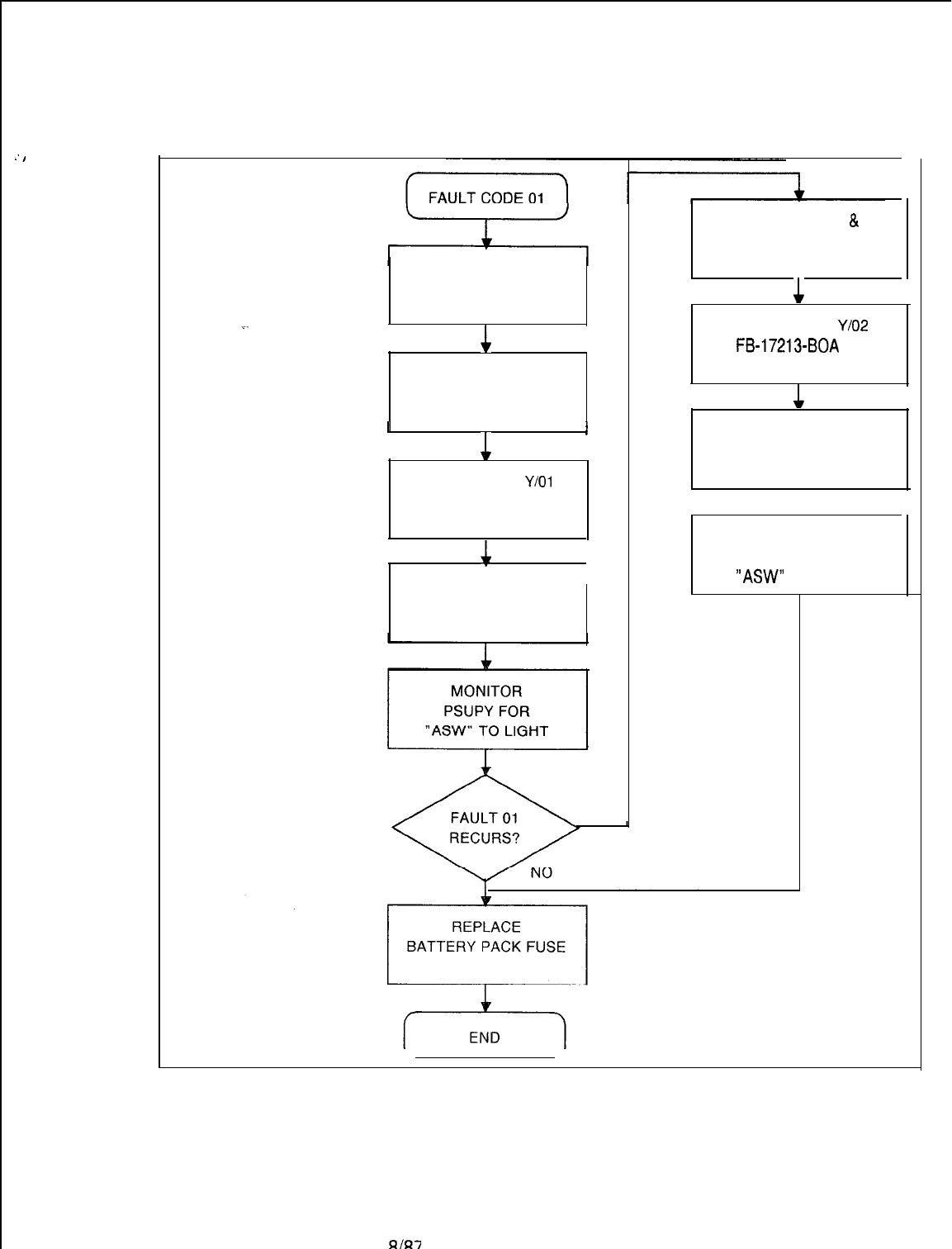
:
I
TL-130200-1001
FAULT CODE 01
REMOVE
BATTERY
PACK FUSE
c
POWER DOWN
SYSTEM
I
1
I
R&R Ml MB IN
Y/O1
FB-17314
(Check Strapping)
4
1
POWER UP
AND RELOAD
YES
POWER DOWN
&
REINSTALL ORIGINAL
Ml MB CARD
1
R&R MPG16 IN
Y/O2
FB-17213-BOA
(Check Strapping)
1
POWER UP
AND RELOAD
1
MONITOR
PSUPY FOR
“ASW”
TO LIGHT
5210
8l87
M-113
TL-130200-1001
Fault Code 02
Description:
Control Memory
When a byte of data is written into the network memory, it is
Read-After-Write
immediately read back and verified.
Failure
.
.
.
M-114
Register Data as System Prints:
CECO CECO Fault 02
6
C D E H L
O0
O0
Y
xx
=-I--
Data
i
Address of
Written Faulty Byte
Data
Read
J
Fault Resolution Steps:
1.
Power down
-
turn off main circuit breaker at rear of
OMNI
SI
cabinet-
2.
Remove and replace EPCMN in
Y/09,
FB-17217-A (check
strapping).
3.
Power up system.
4.
Monitor PSUPY in
P/O1
for ASW LED to light approximately
15 seconds to warm site.
5.
If fault recurs, power down and reinstall original EPCMN
card.
6.
Remove and replace INCKS in Y/l 1 (check strapping).
7.
Power up system.
8.
Monitor PSUPY in
P/O1
for ASW LED to light.
9.
If fault recurs, power down and reinstall original INCKS card.
10. Remove battery pack fuse.
11. Remove and replace MPG1 6 in
Y/02,
FB-17213-BOA
(check strapping).
12. Power up and reload system
-
depress reset on PSUPY
card.
13. Monitor PSUPY in
P/O1
for ASW LED to light.
14. Replace battery pack fuse.
8187
5210
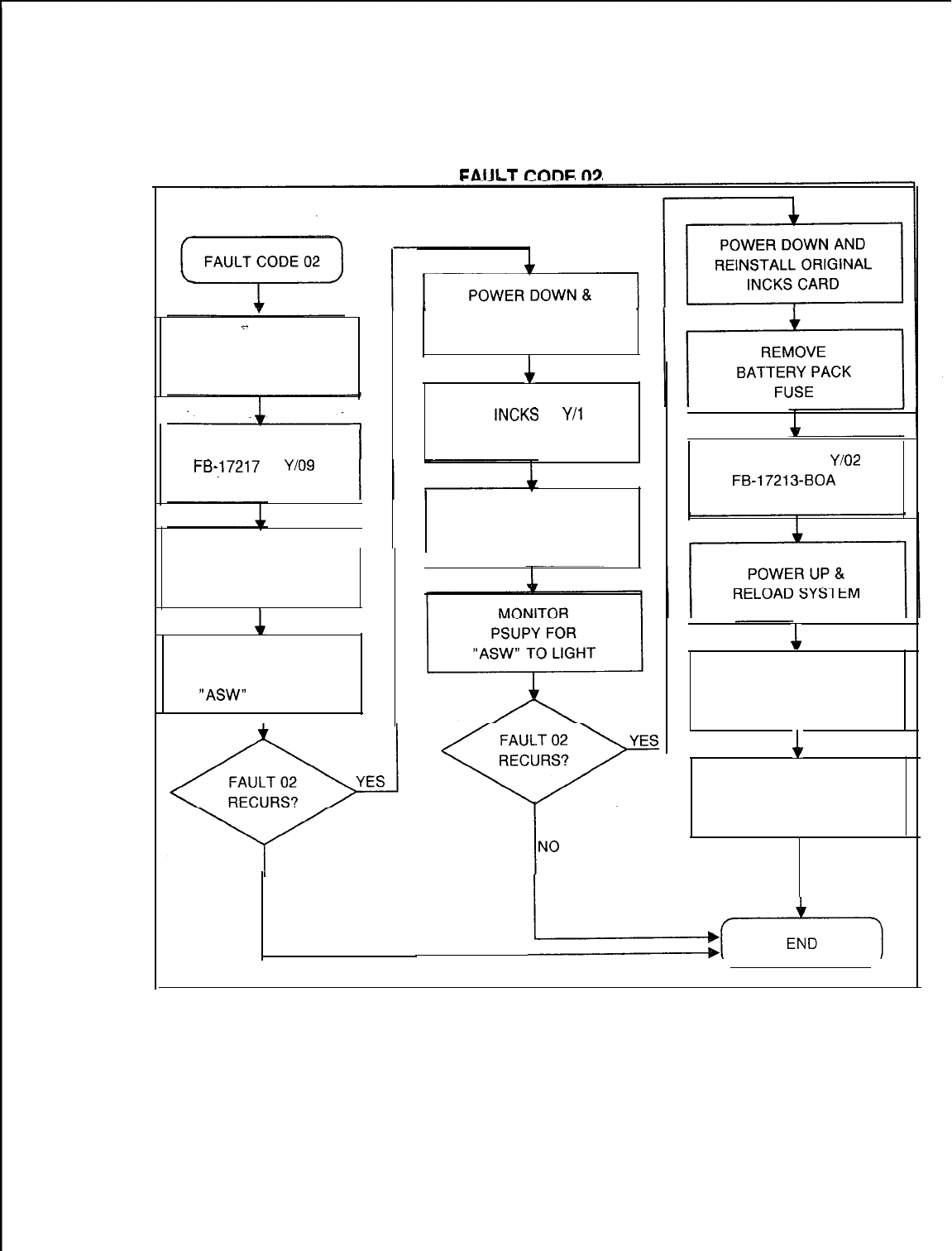
TL-130200-1001
FAIII
T
cnnr
n3
.=_
POWER DOWN
SYSTEM
R&R EPCMN
FB-J7217
IN
Y/O9
(Check Strapping)
POWER UP
AND RELOAD
1
MONITOR
PSUPY FOR
“ASW”
TO LIGHT
I
NO
REINSTALL ORIGINAL
EPCMN CARD
1
R&R INCKS IN
Y/i
1
(Check Strapping)
POWER UP
SYSTEM
R&R Ml MB IN
Y/O2
FB-17213-BOA
(Check Strapping)
1
MONITOR
PSUPY FOR
“ASW” TO LIGHT
1
REPLACE
BATTERY PACK
FUSE
5210
8187
M-115
TL-130200-1001
Fault Code 07
Description:
Disk Error
Before loading the system memory from the disk, the system
tests its memory (except common memory). The number of
CRC errors is checked before loading.
Register Data as System Prints:
CECO CECO Fault 07 B C D E H L
00 xx 00 00 00 00
T
Number
of CRC
errors
Fault Resolution Steps:
1.
Determine number of CRC.errors identified in C register (if
less than 12 errors, disregard fault 07; if more, continue).
::
Reload system -depress reset on PSUPY in P/01.
Monitor PSUPY in
P/O1
for ASW LED to light.
4.
If fault recurs, power down system
-
turn off switch at rear
of
OMNI
SI cabinet.
5.
Remove and replace FMS in Y/07, FB-17220-BOA (check
strapping).
6.
Power up and reload system.
7.
Monitor PSUPY in
P/O1
for ASW LED to light.
8.
If fault recurs, power down and reinstall original FMS card.
9.
Remove and replace floppy disk drive.
10. Power up and reload system.
11. Monitor PSUPY in
P/O1
for ASW LED to light.
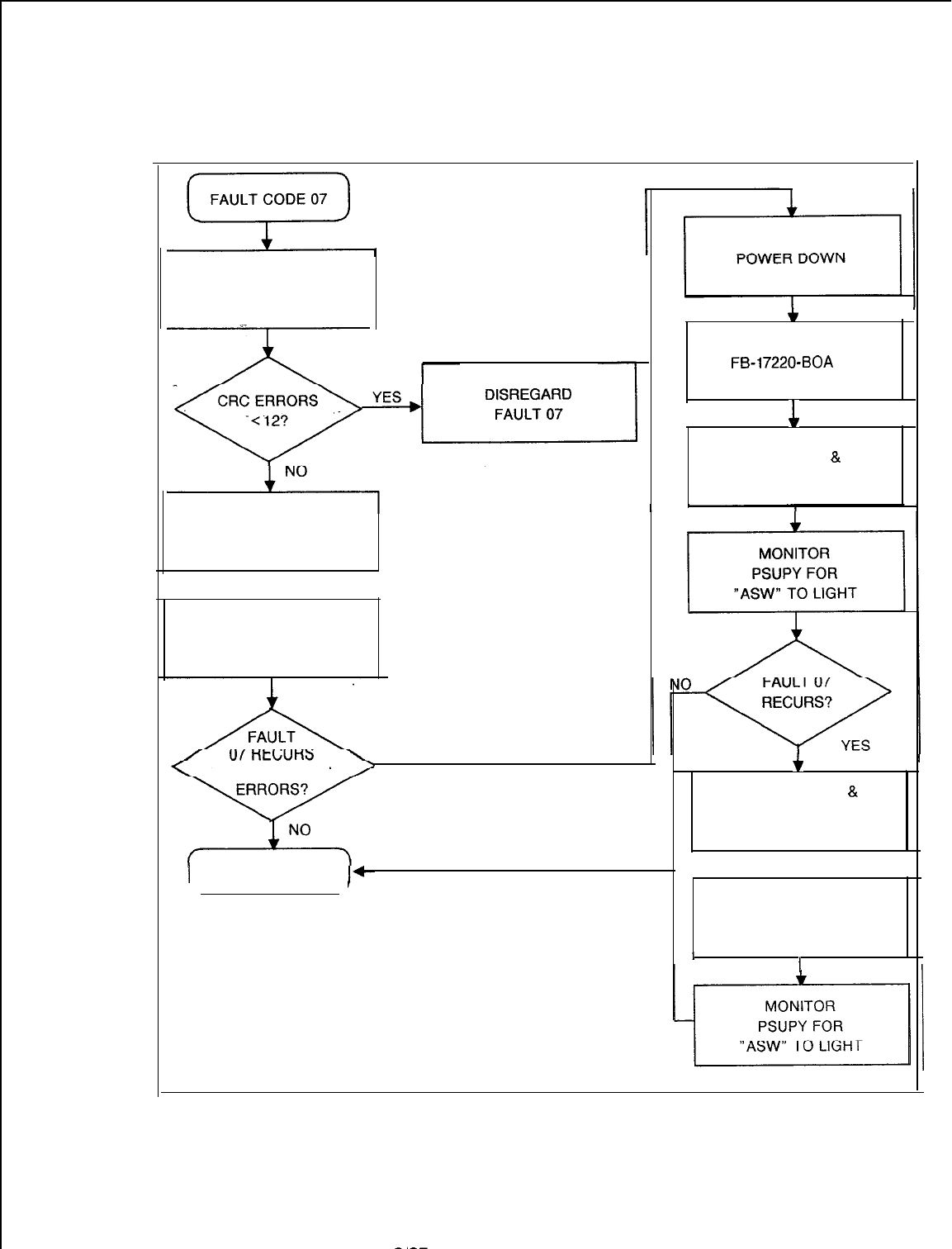
TL-130200-1001
FAULT CODE 07
DETERMINE NUMBER
OF CRC ERRORS
(C Register Value)
-
RELOAD
SYSTEM
1
MONITOR
PSUPY FOR
“ASW” TO LIGHT
YESYES
EXCESSIVE CRCEXCESSIVE CRC
I
END
c
R&R FMSD IN Y/02
FB-I
7220-BOA
(Check Strapping)
1
POWER UP
&
RELOAD SYSTEM
f
POWER DOWN
&
REINSTALL ORIGINAL
FMS CARD
1
R&R FLOPPY
DISK DRIVE
II
5210
8187
M-117
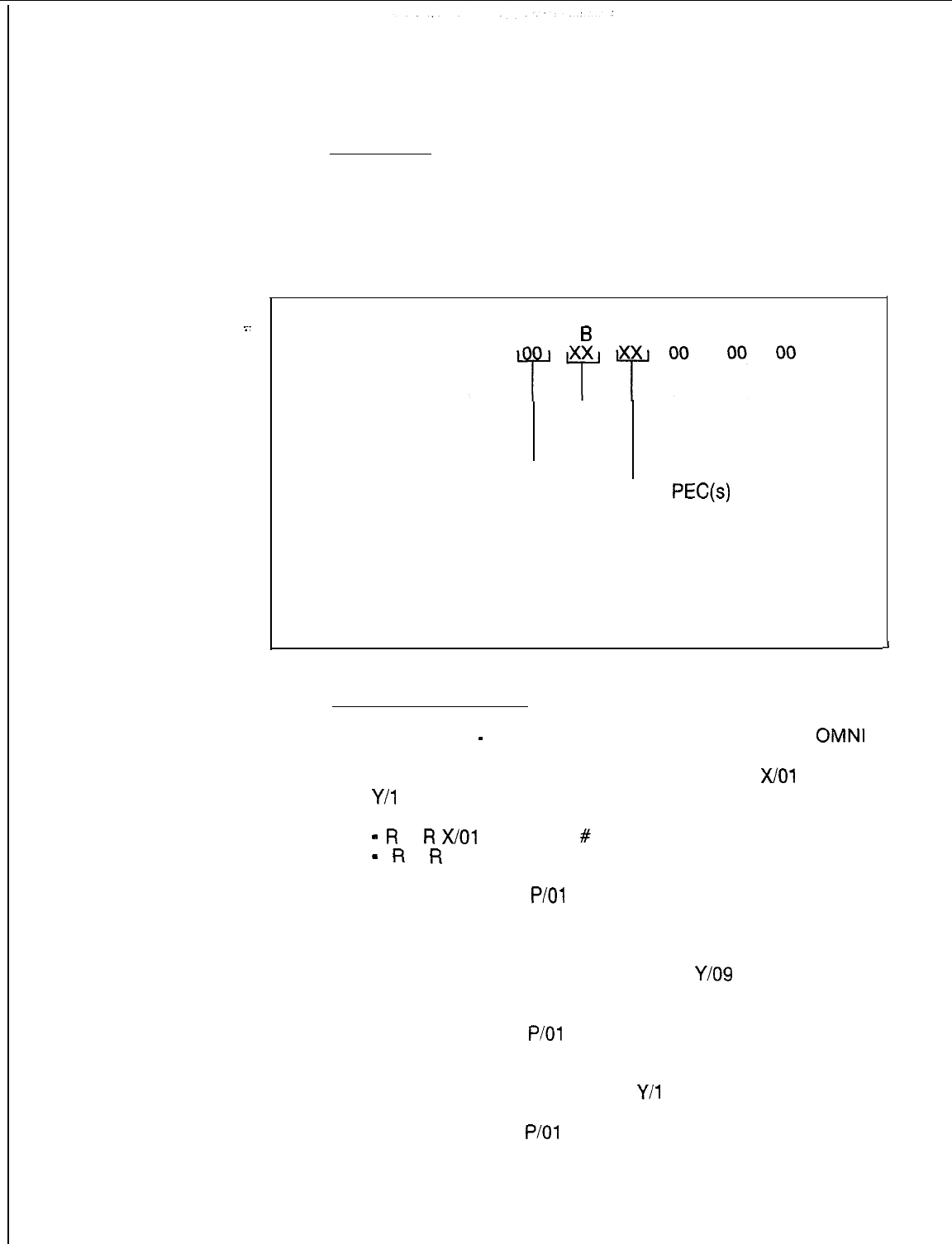
TL-130200-1001
Fault Code 08
Description:
Network Test Failure
The system tests the PCM network connecting a time slot to
itself; it then sends a test pattern through the network. This fault
code indicates that a failure has occurred in the PCM network.
Register Data as System Prints:
_
CECO CECO Fault 08
6
C D E H L
Time
Slot
#
PEC Fault Type Code:
Number
00
=
PEC(s)
did not respond
(Always 0) 02 = Test Failure
Fault Resolution Steps:
1.
Power down
-
turn off main circuit breaker at rear of
OMNI
SI cabinet.
2.
Remove and replace CHM85, FB-17218-A, in
X/O1
and /or
Y/l
5:
(check strapping)
-
R
+
R
X/O1
if time slot
#
is odd
-
R
=
R
Y/l 5 if time slot # is even
3.
Power up system.
4.
Monitor PSUPY in
P/O1
for ASW LED to light -approximately
15 seconds to warm start.
5.
If fault recurs, power down and reinstall original CHM85
card.
6.
Remove and replace , FB-17217-A in
Y/O9
(check
strapping).
7.
Power up system.
8.
Monitor PSUPY in
P/O1
for ASW LED to light.
9.
If fault recurs, power down and reinstall original EPCMN
card.
10. Remove and replace INCKS in
Y/l
1 (check strapping).
11. Power up system.
12. Monitor PSUPY in
P/O1
for ASW LED to light.
13. If fault recurs, remove and replace cables between EPCMN
and target CHM85 cards.
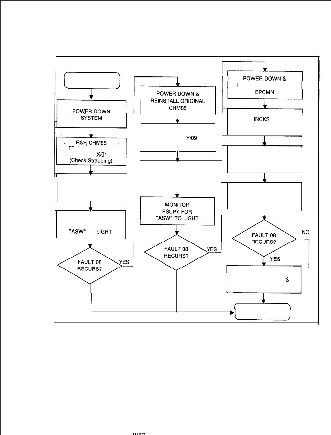
5210
TL-130200-1001
FAULT CODE 08
FAULT CODE 08
FB-17218 IN Y/15
AND/OR
X/O1
POWER UP
SYSTEM
1
MONITOR
PSUPY FOR
“ASW”
TO
LlG.HT
7
R&R EPCMN
FB-17217 IN
Y/O9
(Check Strapping)
1
POWER UP
SYSTEM
NO
REINSTALL ORIGINAL
R&R
INCKS
IN Y/l 1
(Check Strapping)
POWER UP
SYSTEM
1
MONITOR
PSUPY FOR
“ASW” TO LIGHT
I
R&R CABLES
BETWEEN EPCMN
&
CHM85 CARDS
i
I
NO
.I
END
l-
8187
M-119
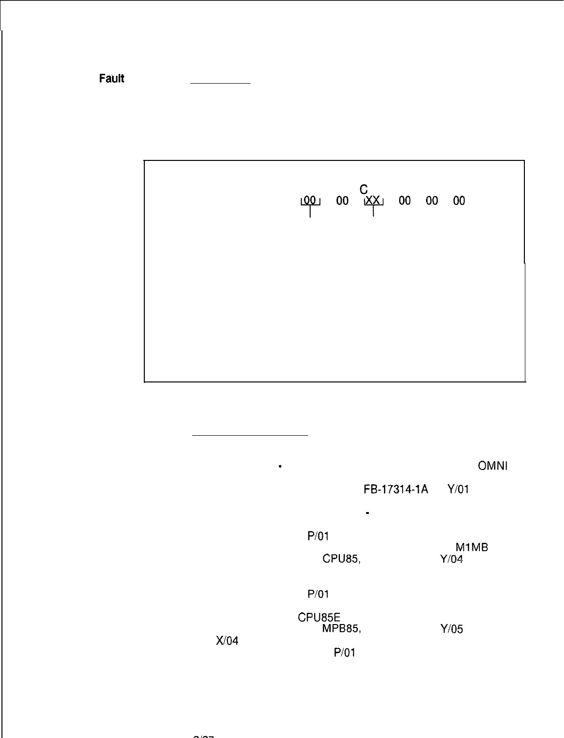
TL-130200-1001
Fault
Code 09
Description:
Directive Test
A simulated directive is sent to test the hopper loaders and
Malfunction
unloaders. This fault indicates that the system did not respond
with the correct event.
Register Data as System Prints:
CECO CECO Fault 09 B
C
D E H L
“i”
O0
Y
O0
O0
O0
PEC
00 = System did not respond
Number correctly to directive test
(Always 0) 03 = System made an invalid
response to the directive
test
Fault Resolution Steps:
1.
2.
3.
4.
5.
6.
7.
a.
9.
10.
11.
12.
ala7
Remove battery pack fuse.
Power down
-
turn off main circuit breaker at rear of
OMNI
SI cabinet.
Remove and replace Ml MB,
FB-17314-1A
in
Y/O1
(check
strapping).
Power up and reload system
-
depress reset on PSUPY
card
Monitor PSUPY in
P/O1
for ASW LED to light.
If fault recurs, power down and reinstall original
MlMB
card.
Remove and replace
CPU85
FB-17288-A in
Y/O4
(check
strapping).
Power up and reload system.
Monitor PSUPY in
P/O1
for ASW LED to light.
If fault recurs, replace battery pack fuse, power down and
reinstall original
CPU85E
card.
Remove and replace
MPB85,
FB-17215-A in
Y/O5
and
X/O4
(check strapping).
Monitor PSUPY card in
P/O1
for ASW LED to light.
5210
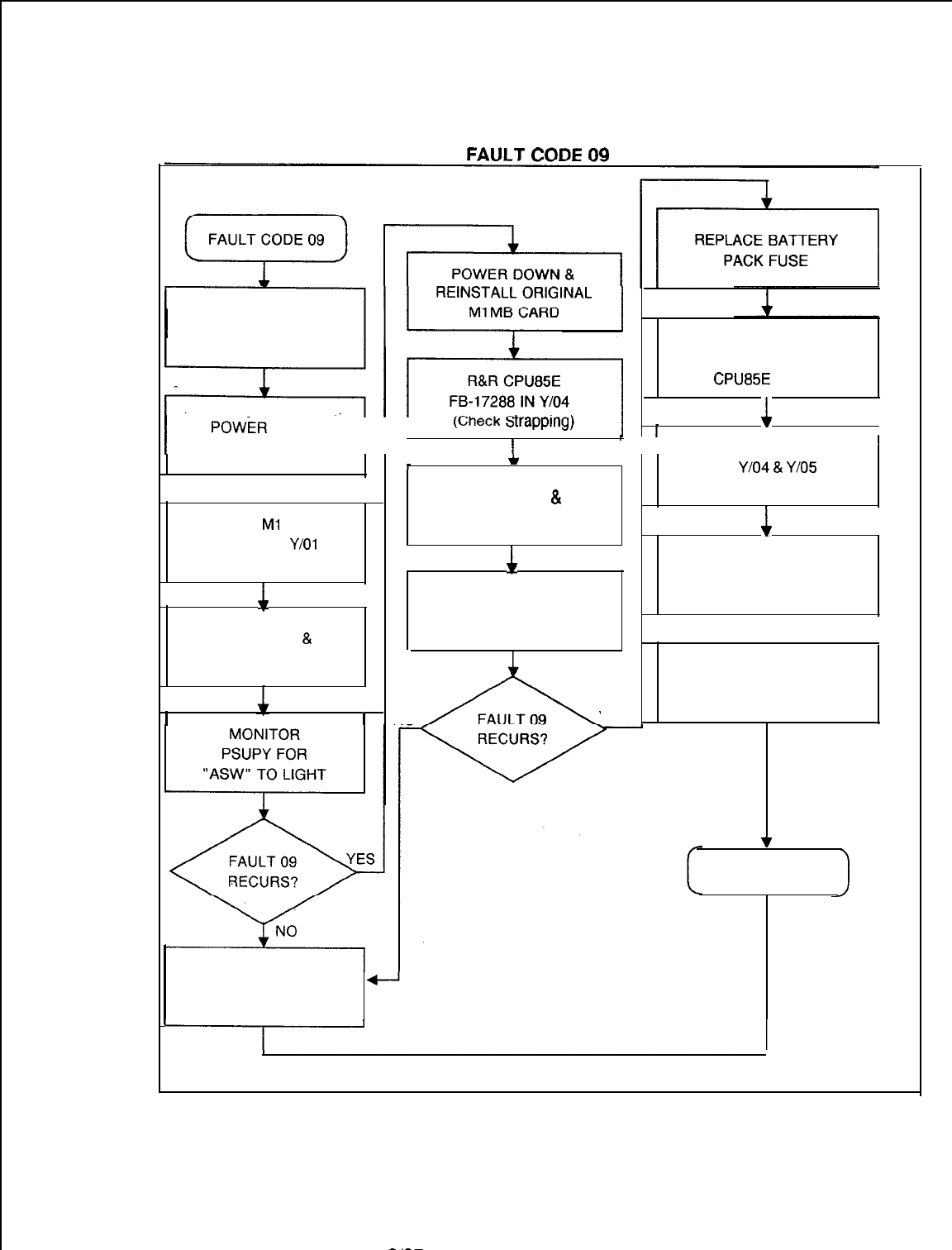
TL-130200-1001
FAULT
Cnl3F
Ml
REMOVE BATTERY
PACK FUSE
r
POWER DOWN &
REINSTALL ORIGINAL
CPU85E
CARD
I
POWiR
DOWN
SYSTEM II’
(WeCk
S
I’
II R&R MPB85 FB-17215 1
I
1
1
1
R&R
Ml
MB
FB-17314 IN
Y/O1
(Check Strapping)
4
i-
c
IN
Y/Cl4
&
Y/O5
POWER UP
8,
(Check Strapping)
RELOAD SYSTEM
1
4
POWER UP
MONITOR SYSTEM
PSUPY FOR
POWER UP
&
“ASW” TO LIGHT 1
RELOAD SYSTEM MONITOR
PSUPY FOR
“ASW” TO LIGHT
1 NO
YES
v
END
A
REPLACE BATTERY
PACK FUSE
5210
8187
M-121
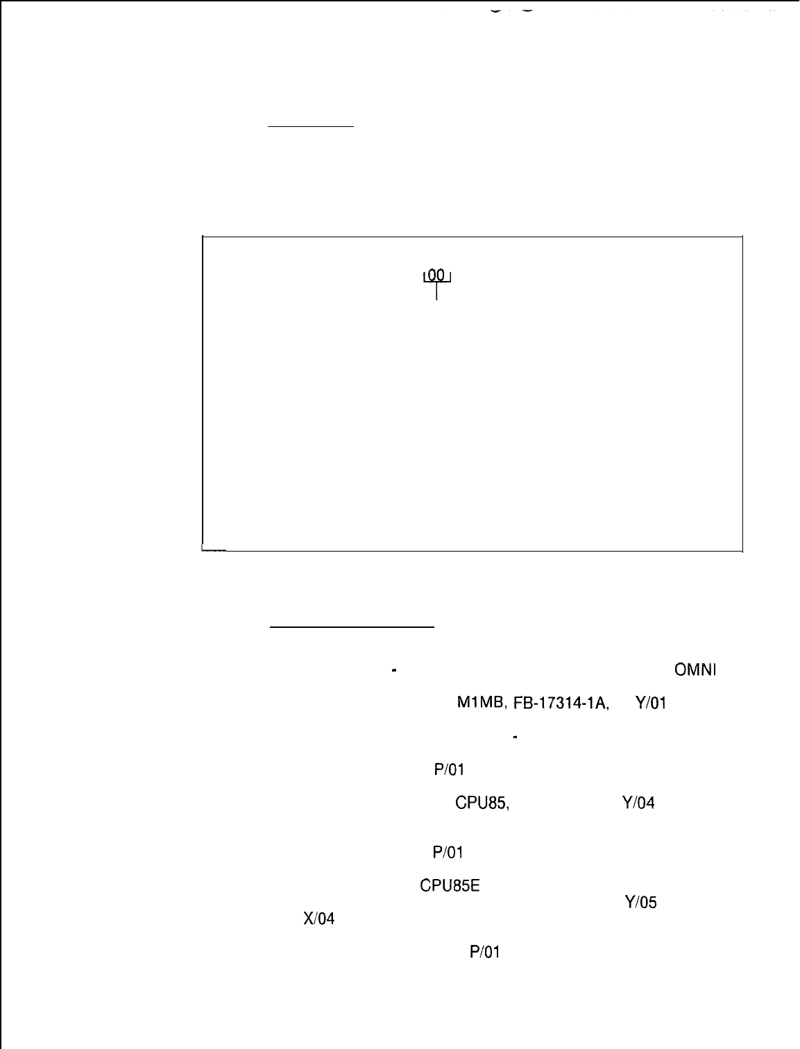
TL-130200-1001
Fault Code 10
Description:
Directive Hopper Full
The hopper is tested to ensure that directives are being
Malfunction
unloaded. This fault indicates that the system is failing to unload
its directive.
M-l 22
Register Data as System Prints:
CECOCECO Fault10 B C D E H L
@f
00 00 00 00 00
PEC
Number
(Always 0)
Fault Resolution Steps:
1.
2.
3.
4.
5.
6.
7.
a.
9.
10.
11.
12.
13.
Remove battery pack fuse.
Power down
-
turn off main circuit breaker at rear of
OMNI
SI cabinet.
Remove and replace
MlMB,
FB-17314-lA,
in
Y/O1
(check
strapping).
Power up and reload system
-
depress reset on PSUPY
card.
Monitor PSUPY in
P/O1
for “ASW” LED to light.
If fault recurs, power down and reinstall original Ml MB card.
Remove and replace
CPU85
FB-17288-A in
Y/O4
(check
strapping).
Power up and reload system.
Monitor PSUPY in
P/O1
for ASW LED to light.
If fault recurs, replace battery pack fuse, power down and
reinstall original
CPU85E
card.
Remove and replace MPB85, FB-17215-A, in
Y/O5
and
X/O4
(check strapping).
Power up system.
Monitor PSUPY card in
P/O1
for ASW LED to light.
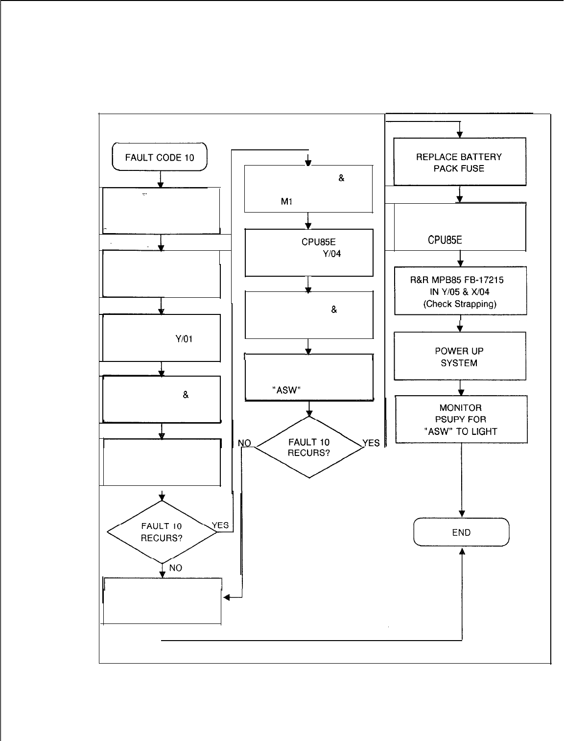
TL-130200-1001
FAULT CODE 10
.~.
REMOVE BATTERY
PACK FUSE
POWER DOWN
SYSTEM
R&R Ml MB
FB-17314 IN
Y/O1
(Check Strapping)
POWER UP
&
RELOAD SYSTEM
MONITOR
PSUPY FOR
I“ASW” TO LIGHT
I I
c
POWER DOWN
&
REINSTALL ORIGINAL
Ml
MB CARD
i
R&R
CPU85E
FB-17288 IN
Y/O4
(Check Strapping)
&
POWER UP
&
RELOAD SYSTEM
I
4
I
MONITOR
PSUPY FOR
“ASW”
TO LIGHT
REPLACE BATTERY
1
PACK FUSE
POWER DOWN &
REINSTALL ORIGINAL
CPU85E
CARD
POWER UP
.
SYSTEM
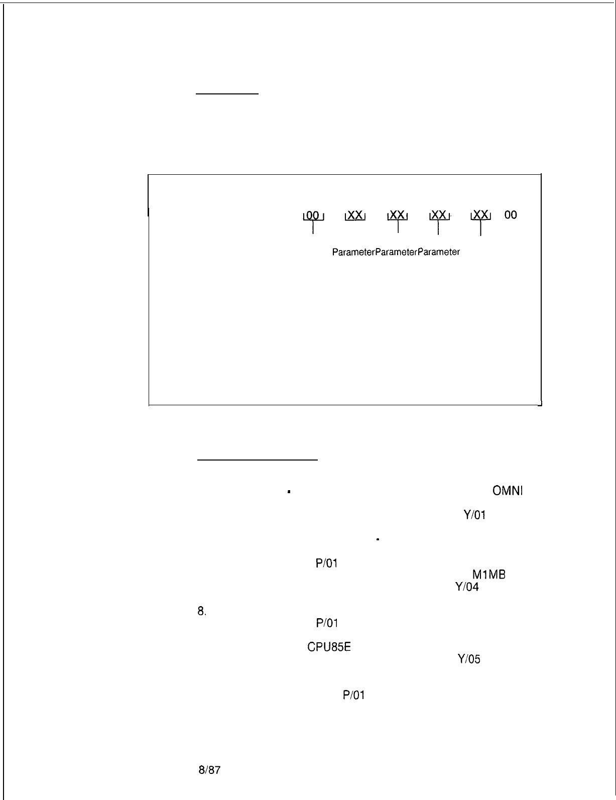
TL-130200-I 001
Fault Code 11
Description:
illegal Event Error
This fault is reported when the system receives an illegal value.
Malfunction
This fault indicates that the system has failed to respond
correctly to a directive.
M-l 24
8187
5210
Register Data as System Prints:
CECO CECO Fault 11 B
C
DE
H L
PEC Event Event Event Event
Number
ParameterParameterParameter
Number
(Always 0) 1
2 3
1.
2.
3.
4.
5.
6.
7.
8.
9.
10.
11.
12.
13.
Fault Resolution Steps:
Remove battery pack fuse.
Power down
-
turn off main circuit breaker at rear of
OMNI
SI cabinet.
Remove and replace Ml MB, FB-17314-IA, in
Y/O1
(check
strapping).
Power up and reload system
-
depress reset on PSUPY
card.
Monitor PSUPY in
P/O1
for ASW LED to light.
If fault recurs, power down and reinstall original
MlMB
card.
Remove and replace CPU85, FB-17288-A in
Y/O4
(check
strapping).
Power up and reload system.
Monitor PSUPY in
P/O1
for ASW LED to light.
If fault recurs, replace battery pack fuse, power down, and
reinstall original
CPU85E
card.
Remove and replace MPB85, FB-17215-A, in
Y/O5
and
X/O4 (check strapping).
Power up system.
Monitor PSUPY card in
P/O1
for ASW LED to light.
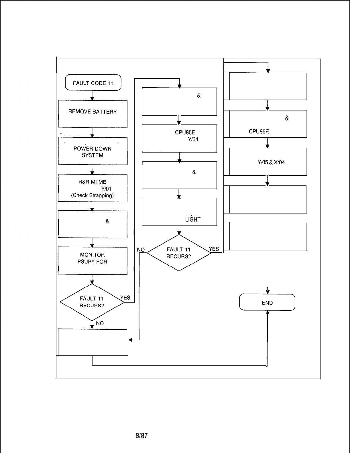
TL-130200-1001
FAULT CODE 11
PACK FUSE
FB-17314 IN
Y/O1
POWER
UP
&
RELOAD SYSTEM
“ASW” TO LIGHT
POWER DOWN
&
REINSTALL ORIGINAL
Ml MB CARD
1
R&R
CPU85E
FB-17288 IN
Y/O4
(Check Strapping)
REPLACE BATTERY
+
PACK FUSE
POWER UP
&
RELOAD SYSTEM
1
MONITOR
PSUPY FOR
“ASW” TO
LIGHT
I
REPLACE BATTERY
PACK FUSE
1
POWER DOWN
&
REINSTALL ORIGINAL
CPU85E
CARD
1
R&R MPB85 FB-17215
IN
YlO5
&
x/O4
(Check Strapping)
11
POWER UPPOWER UP
SYSTEMSYSTEM
11
MONITORMONITOR
PSUPY FORPSUPY FOR
“ASW” TO LIGHT“ASW” TO LIGHT
I
5210
8187
M-125
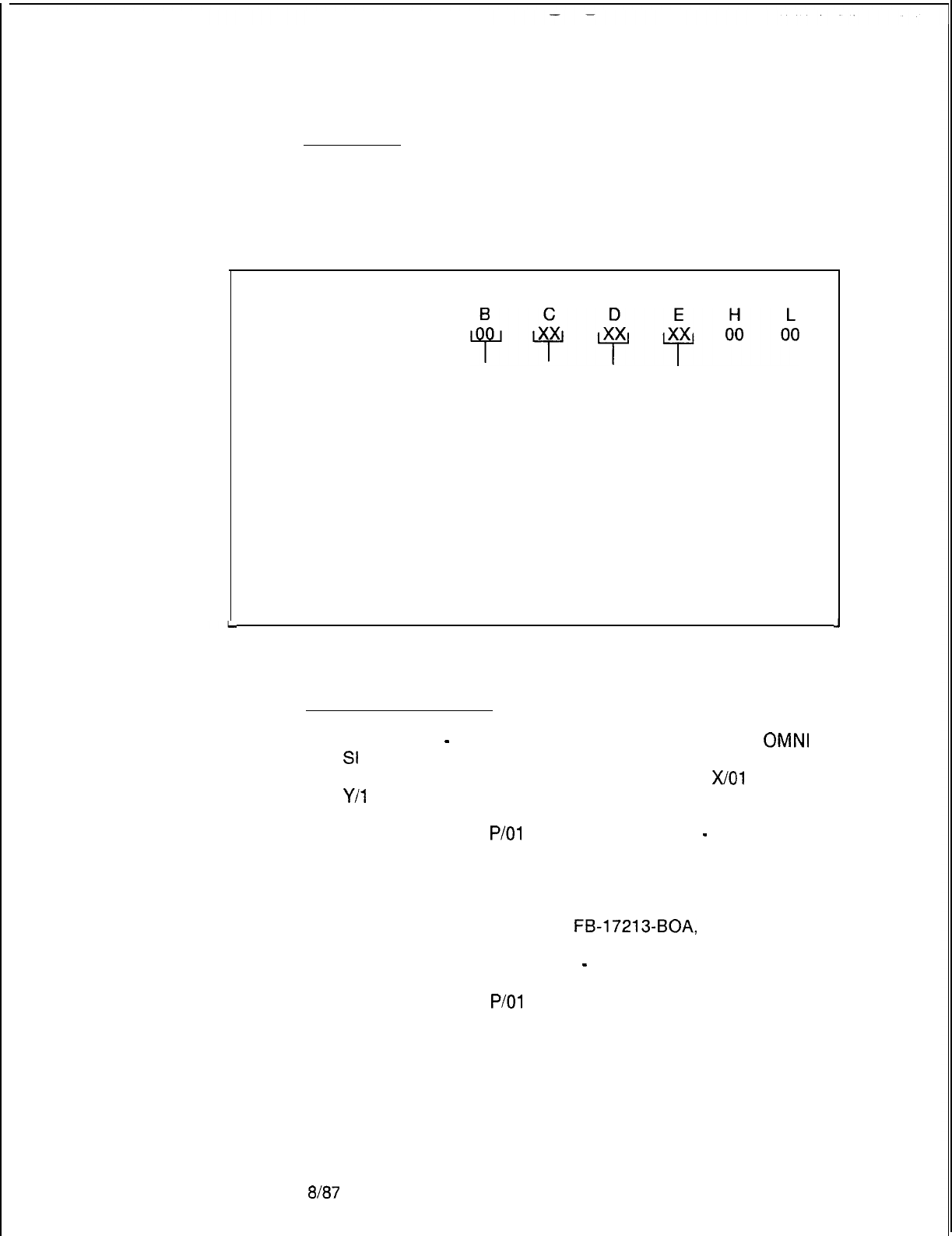
TL-130200-1001
Fault Code 12
Description:
Read -After-Write
Failure in
When data is written into channel memory, it is immediately read
back and verified. This fault indicates that a failure has occurred
Channel Memory in channel memory.
Register Data as System Prints:
CECO CECO Fault 12 B
C
dlfyp++ik
PEC Channel Data Data
Number Number Written
Read
(Always 0) (00-5F)
J
Fault Resolution Steps:
1.
Power down
-
turn off main circuit breaker at rear of
OMNI
St
cabinet.
2.
Remove and replace CHM85, FB-17218-A, in
X/O1
and
Y/l
5 (check strapping).
3.
Power up system.
4.
Monitor PSUPY in
P/O1
for ASW LED to light
-
approximately 15 seconds to warm start.
5.
If fault recurs, power down and reinstall original CHM85
cards.
6.
Remove fuse from battery pack.
7.
Remove and replace Ml MB,
FB-17213-BOA,
in Y/O2
(check strapping).
8.
Power up and reload system
-
depress reset on PSUPY
card.
9.
Monitor PSUPY in
P/O1
for ASW LED to light.
10. Replace fuse in battery pack.
8187
5210
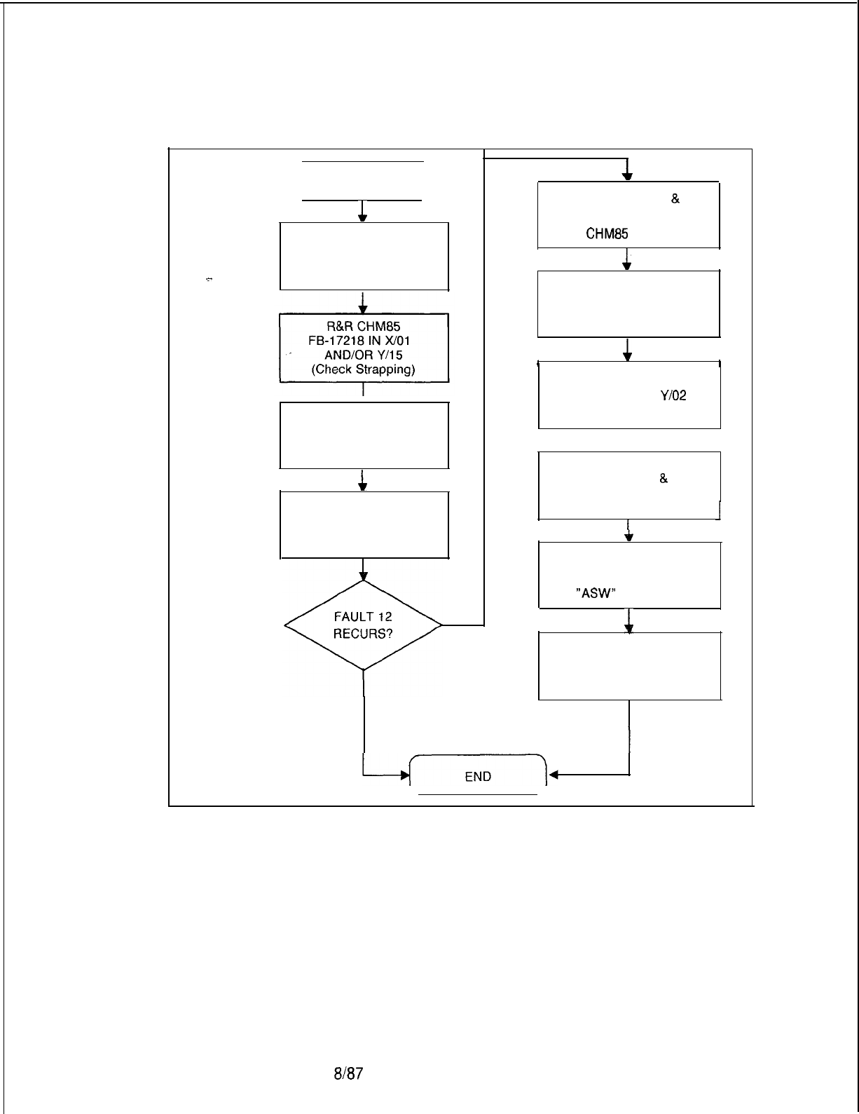
TL-130200-1001
FAULT CODE 12
FAULT CODE 12
1
POWER DOWN
SYSTEM
POWER UP
SYSTEM
I
1
I
MONITOR
PSUPY FOR
“ASW” TO LIGHT
YES
NO
POWER DOWN
&
REINSTALL ORIGINAL
CHM85
CARD
1
REMOVE FUSE
FROM BATTERY PACK
I
1
I
R&R Ml MB
FB-17213-BOA IN
Y/O2
(Check Strapping)
1
POWER UP
&
RELOAD SYSTEM
1
I
+
MONITOR
PSUPY FOR
“ASW”
TO LIGHT
1
REPLACE FUSE IN
BATTERY PACK
5210
8f87
M-127
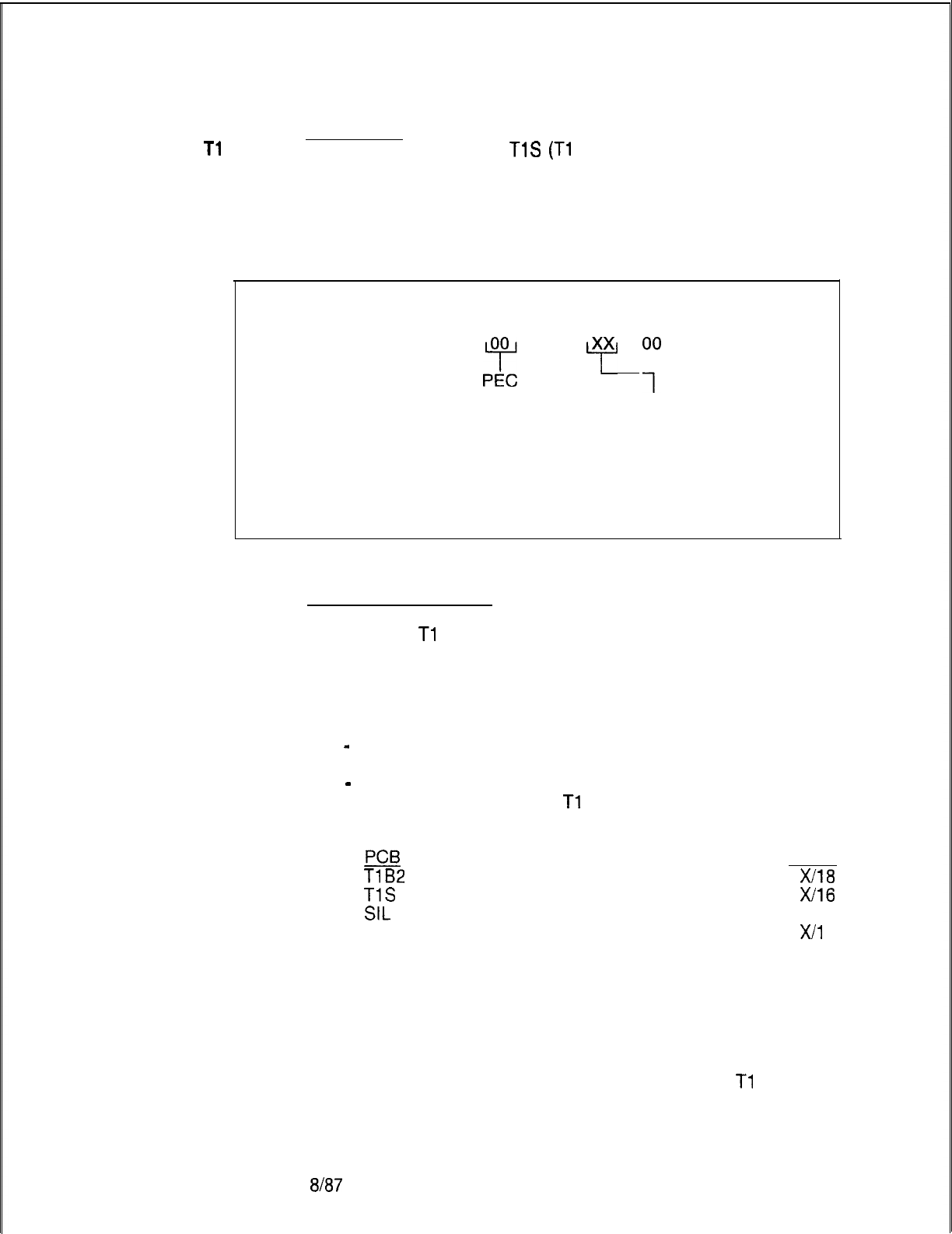
TL-130200-1001
Fault Code 15
Description:
Tl
Alarm
The system monitors the
TlS
(Tl
Supervision Circuit Card) for
hardware alarms. This fault indicates that the data framing of a
span has failed for 36 ms, the power has failed in the local office
terminating equipment, or synchronization has been lost at the
distant office for 1.2 seconds.
M-l 28
Register Data as System Prints:
CECOCECO Fault15 B C D E H L
2
00
py
0;
00 00
Alarm Number
Number
00
= System Alarm
(Always 0)
01
= Remote Alarm
02
= Cutoff Alarm
03
= Local Alarm
Fault Resolution Steps:
1.
Observe
Tl
-Type Supervisory Card, FB-20718-1, in
X/16.
2.
SYS lamp lit indicates any alarm condition exists.
3.
LOC lamp lit indicates framing synchronization is lost (fault
code D, register value is 03). Complete the following steps:
-
Remove and replace FDC, FB-15278-A, in X/l 0 (check
strapping).
-
If LOC lamp remains lit, repeat preceding procedure by
replacing sequentially all
Tl
cards until the fault is cleared
(check strapping):
pcB
SLOT
TlB2
X/18
TlS
X/16
SIL
X/l 4
LCM
X/l
2
4.
REM lamp lit indicates problem exists at remote location
(fault code D, register value is 01). Report condition to
remote end personnel.
5.
RPF lamp lit indicates power has failed at remote location
(fault code D, register value is 01). Report condition to
remote end personnel.
6.
Check with remote end personnel to ensure that
Tl
alarm is
not a temporary trunk failure condition.
8187
5210
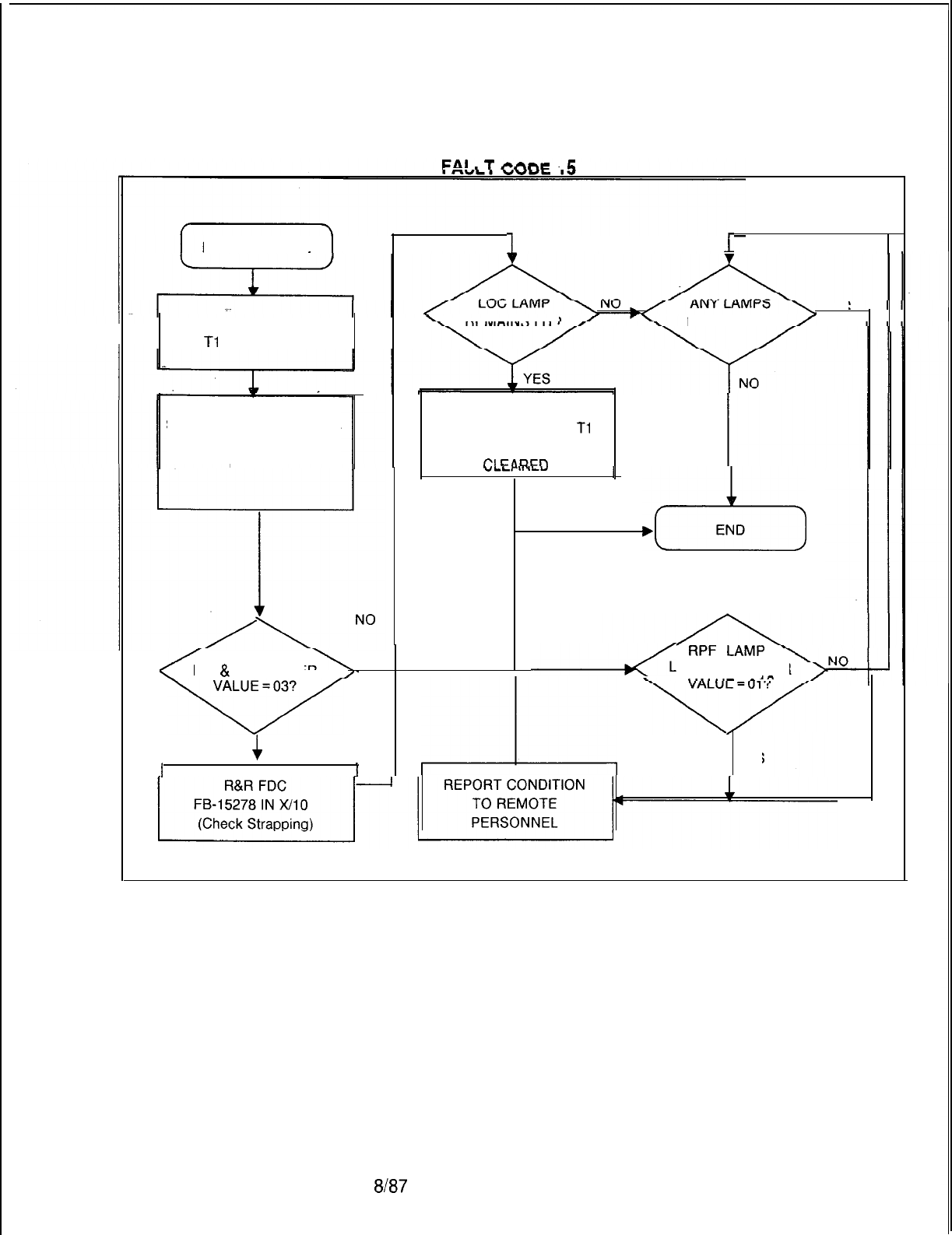
TL-130200-1001
EAI
II
T
1 E
FAULT CODE 15
11
YES
REMAIN LIT?
OBSERVE FRONT OF REMAINS LIT?
. .
Tl
S FB-20718
SYS LAMP LIT INDICATES
ANY ALARM CONDITION
EXISTS
R&R
SEQUENTIALLY ALL
Tl
CARDS UNTIL FAULT IS
Cl
FA.RFn
I
“LL,
I.
.LY
I
&
END
LOC LAMP
LIT
&
D REGISTER
,-
II
4
RPF
LAMP
LIT & D REGISTER
>^
c
YES
II
L
YES
5210
8l87
M-129
TL-130200-1001
Fault Code 16 Description:
10 ms Stopped Failure
The system performs checks to ensure that the 10 ms interrupt is
operating. A time check is performed to see if the background
scheduler has been interrupted to perform foreground scheduler
tasks. If the average time is too short, it is assumed that the
interrupt is not operating.
M-130
8187
i
Register Data
as
System
Prints:
CECOCECO Fault16
6
C D E H L
00 00 00 00 00 00
Fault Resolution Steps:
1.
Power down
-
turn off main circuit breaker at rear of
OMNI
SI
cabinet.
2.
Remove and replace CPU85E, FB-17288-A, in Y/O4
(check strapping).
3.
Power up system.
4.
Monitor PSUPY card in
P/O1
for ASW LED to light.
5210
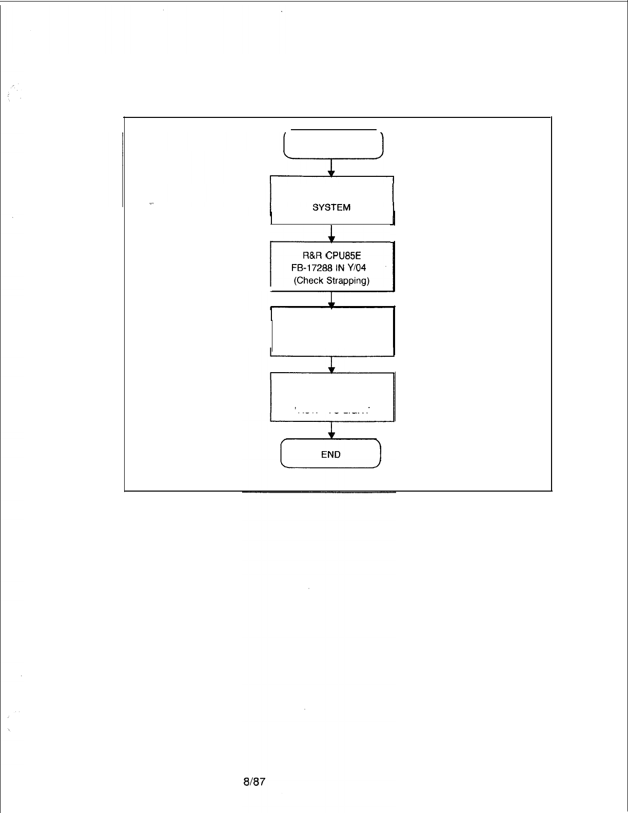
TL-130200-1001
FAULT CODE 16
FAULT CODE 16
POWER DOWN
I
R&R
CPU85E
FB-17288 IN
Y/04
(Check Strapping)
POWER UP
AND RELOAD
MONITOR
PSUPY FOR
“ASW” TO LIGHT
5210
M-131
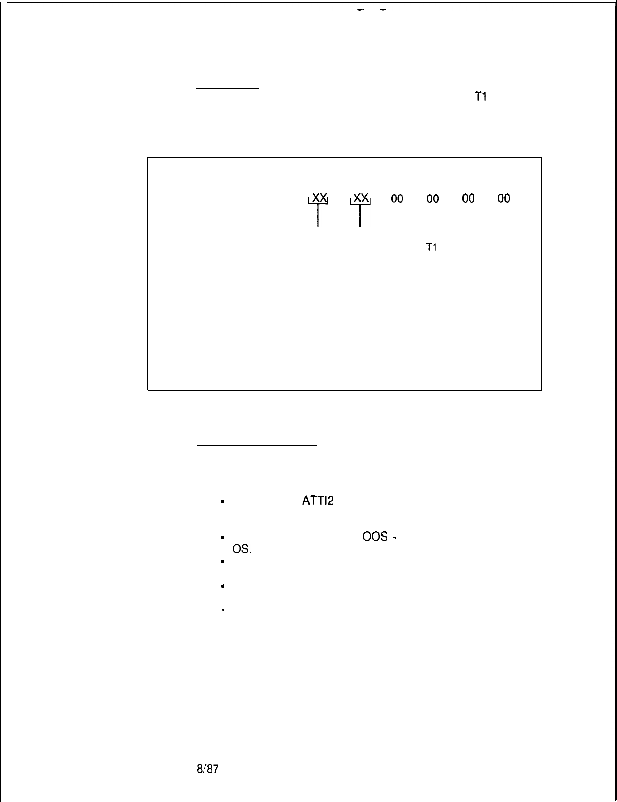
TL-130200-1001
Fault Code 17
Description:
Alarm Fault
This fault indicates that a fault has been detected in a
Tl
span or
the alarm relays have been pulled on the ATT12 card.
M-l 32
Register Data as System Prints:
CECO CECO Fault17 B C D E H L
xx
00
00
00
00
“i”
T
Attendant 00
= ATT12
card has failed
Console 01 = Fault on
Tl
span
Oor 1 09 = Attendant 0 transmission fault
OA
= Attendant 1 transmission fault
Fault Resolution Steps:
1.
If C register value is 00, 09, or OA, complete the following
steps:
-
Identify which
ATT12
card has failed (B register value
indicates Attendant Console number). Examine T2621 in
the system data base to isolate PCMUS.
-
Force Attendant Console
00s
-
FORCE CONSOLE X
OS.
-
Remove and replace ATTl2, FB-17208-A, in identified
PCMUS slot (check strapping).
-
Force Attendant Console in service -FORCE CONSOLE
x IS.
-
If fault recurs, replace Attendant Console.
2.
If C register value is 01, go to fault code 15 to begin
trouble- shooting.
8187
5210
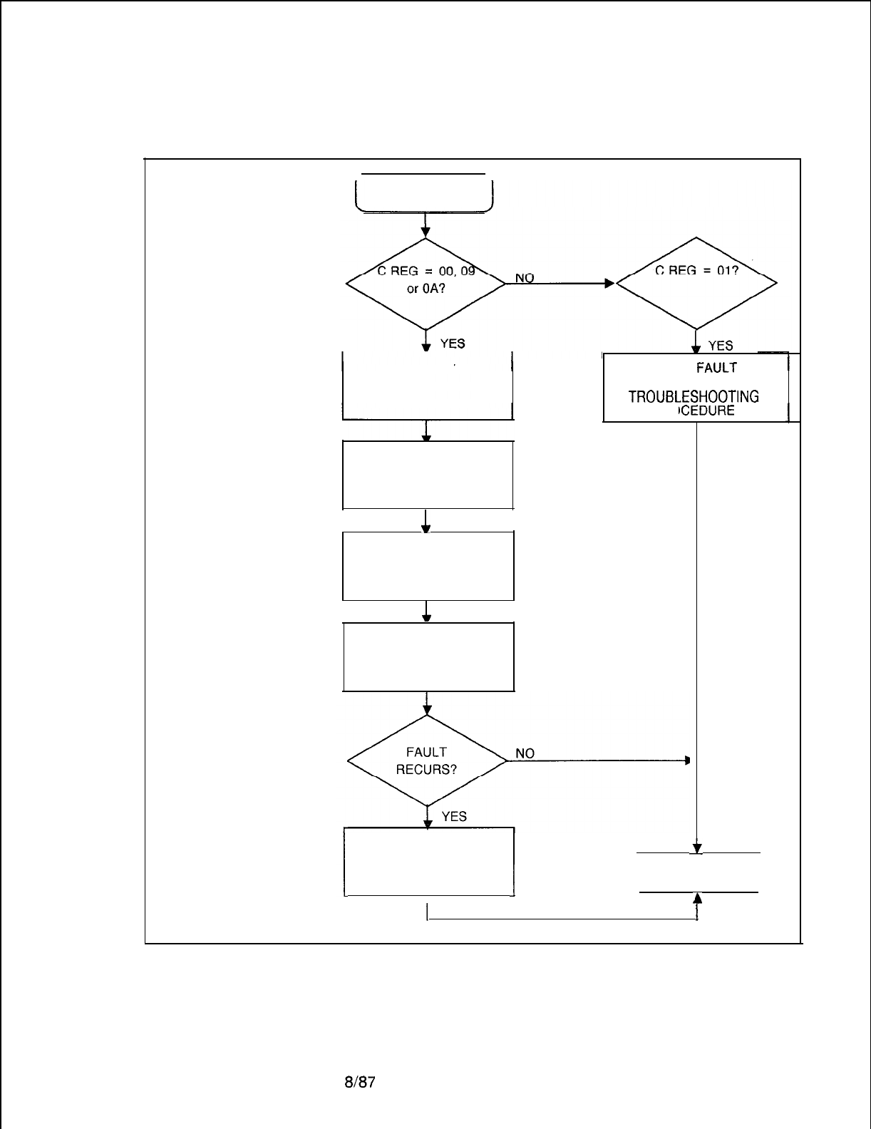
TL-130200-1001
FAULT CODE 17
FAULT CODE 17
IDENTIFY
CONSOLE/ATT1 2
CARD VIA T2621
I
GO TO
FIWLT
CODE
15
TROUBL
---
.ESHOOTING
PRCCEDURE
I
FORCE CONSOLE
00s
1
R&R ATT1 2
FB-17208
(Check Strapping)
1
FORCE CONSOLE
IN-SERVICE
.
R&R ATTENDANT
I
CONSOLE
I
END
I
4
5210
I I
8l87
M-133
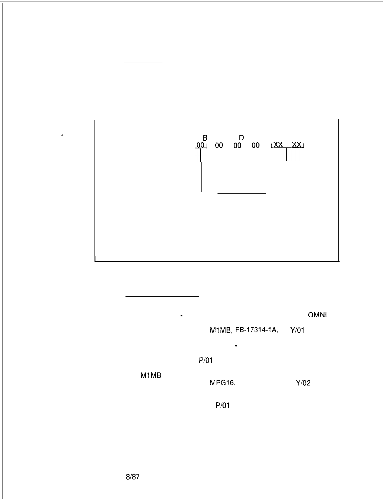
TL-130200-1001
Fault Code 19
Description:
Pre-Loading Memory
Before the contents of the disk are loaded into the system
Failure Test
memory, all eight pages of the RAM are tested and any error is
detected. This fault indicates that there is a failure in the RAM
memory card.
Register Data as System Prints:
CECOCECO Fault19
6
C
D
E H L
P
00
00
00
xx
xx
-T-
Address of
Failing Byte
Failing
Software Paae:
00 =
instruction Page
0
01
=
Instruction Page
1
02 =
Data Page
0
03 =
Data Page
1
04=
Instruction Page
2
05=
Instruction Page
3
06=
Data Page
2
07=
Data Page
3
Fault Resolution Steps:
1.
2.
3.
4.
5.
6.
7.
Remove and replace
MPG16,
FB-17213-BOA in
Y/O2
(check strapping).
8.
Power up and reload.
9.
Monitor PSUPY card in
P/O1
for ASW LED to light.
10.
Replace fuse in battery pack.
Remove fuse from battery pack.
Power down
-
turn off main circuit breaker at rear of
OMNI
SI cabinet.
Remove and replace
MlMB,
FB-17314-IA,
in
Y/O1
(check
strapping).
Power up and reload system
-
depress reset on PSUPY
card.
Monitor PSUPY in
P/O1
for ASW LED to light.
If fault recurs, power down system and reinstall original
MIMB
card.
M-l 34
8187
5210
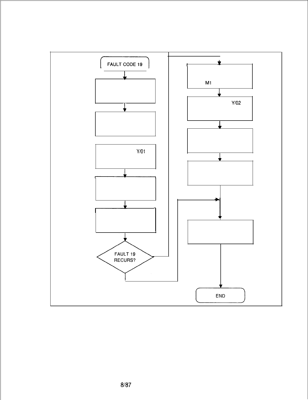
TL-130200-1001
FAULT CODE 19
(FAULTCODE1S)
REMOVE FUSE
FROM BATTERY
PACK
&
POWER DOWN
. .
SYSTEM
1
R&R Ml MB IN
Y/O1
FB-17314
(Check Strapping)
POWER UP
AND RELOAD
MONITOR
PSUPY FOR
“ASW” TO LIGHT
I
YES
I
NO
T
*
POWER DOWN &
REINSTALL ORIGINAL
Ml
MB CARD
L
R&R MPG16 IN
Y/O2
FB-1721’3
(Check Strapping)
POWER UP
AND RELOAD
&
MONITOR
PSUPY FOR
“ASW” TO LIGHT
REPLACE FUSE
IN BATTERY
PACK
5210
a/a7
M-135
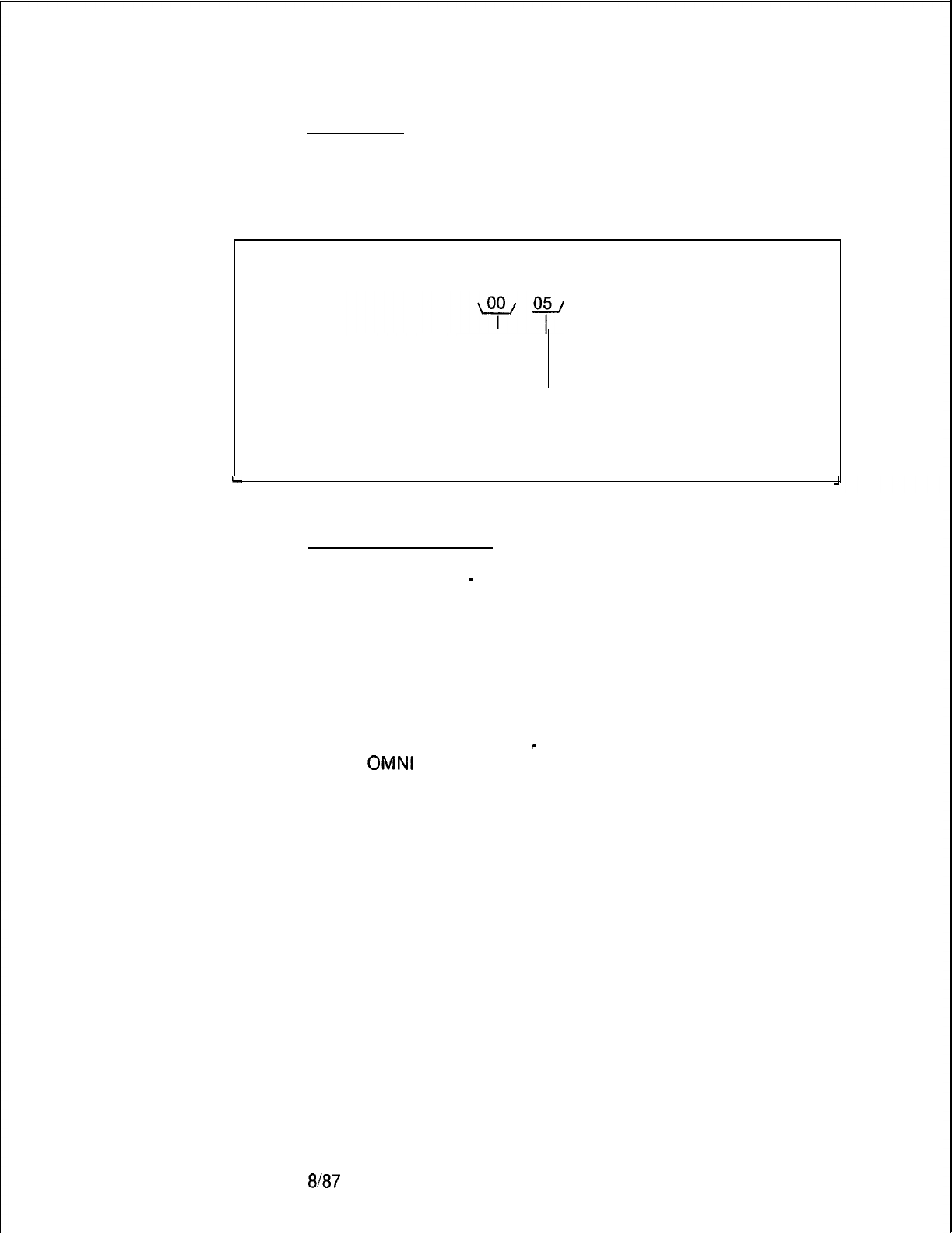
TL-130200-1001
Fault Code 22 Description:
MDR SDC Fault
An ambiguous MDR port assignment exists.
M-l 36
Register Data as System Prints:
CECO CECO Fault 22 B C D E H L
FF 00 00
PEC
Number
(Always 0)
05
= Improper SDC port
assignment
L
Fault Resolution Steps:
1.
Reload system
-
depress reset on PSUPY card.
2.
If terminal records output on port 0, mark MDR port 0 in
service in Table T4551; port 1 must be marked out of
service; back up the data base.
3.
If terminal records output on port 1, mark MDR port 1 in
service in Table T4551; port 0 must be marked out of
service; back up the data base.
4.
Connect the output device to the MDR SDC output port (the
port which is not marked as maintenance).
5.
Warm start the system
-
cycle main circuit breaker at rear
of
OMNI
SI cabinet.
6.
Place a trunk call which should be recorded by MDR.
7.
If no MDR output, ask for assistance.
NOTE: MDR SDC port transmission data is derived from Table
T6051.
8187
5210
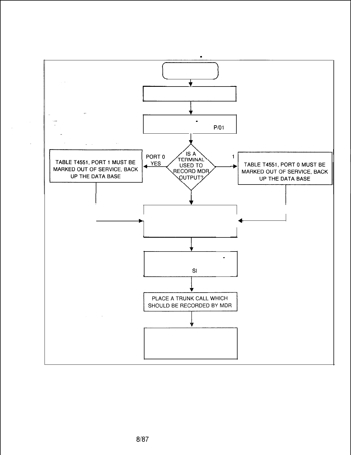
TL-130200-1001
FAULT CODE
-
22
FAULT CODE 22
f
REGISTER C = 05
RELOAD SYSTEM
-
DEPRESS
“RESET” ON PSUPY IN
P/O1
1
MARK MDR PORT 0 IN SERVICE IN
PORT
YES
MARK MDR PORT 1 IN SERVICE IN
NO
I
CONNECT THE OUTPUT DEVICE
I
L
TO THE MDR SCD OUTPUT PORT
+
(THE PORT WHICH IS NOT
MARKED AS MAINTENANCE)
WARM START THE SYSTEM
-
CYCLE MAIN CIRCUIT BREAKER
AT REAR OF
St
CABINET
IF NO MDR OUTPUT, ASK FOR
ASSISTANCE. NOTE: MDR SDC
PORT TRANSMISSION DATA IS
DERIVED FROM TABLE T6051.
5210
8187
M-137
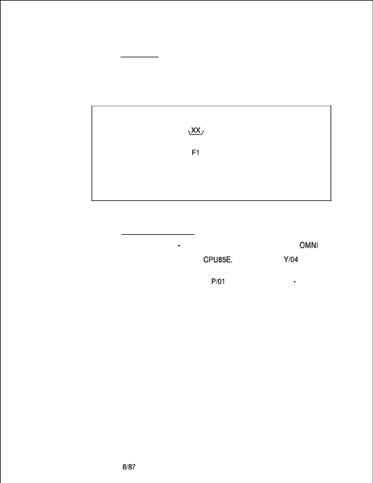
TL-130200-1001
Fault Code 25
Description:
Real-Time Clock Failure
This fault indicates a problem with the Real-Time Clock which is
part of the CPU85 card.
.
Register Data as System Prints:
CECO CECO Fault 25 B C D E H L
\xx/
00 00 00 00 00
I
00
= Clock is out of range
Fl
= Read-after-write error
F2
= Real time clock problem
Fault Resolution Steps:
1.
Power down
-
turn off main circuit breaker at rear of
OMNI
SI cabinet.
2.
Remove and replace CPU85E, FB-17288-A‘ in Y/O4
(check strapping).
3.
Power up system.
4.
Monitor PSUPY card in
P/O1
for ASW LED to light
-
approximately 15 seconds to warm start.
8187
5210
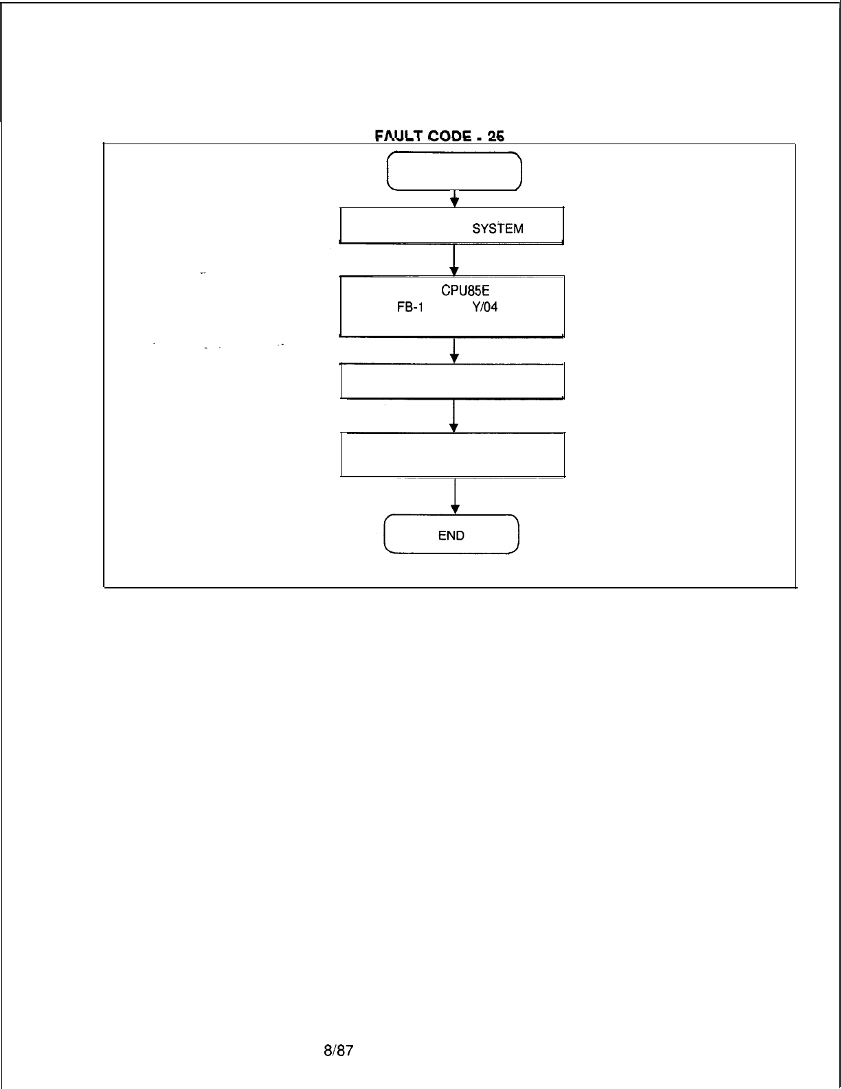
TL-130200-1001
.
..--.
-v-w
--
FAULT CODE 25
+
POWER DOWN
SYSTEM
.R&R
CPU85E
FB-I
7288 IN
Y/04
(Check Strapping)
POWER UP AND RELOAD
MONITOR PSUPY FOR
“ASW” TO LIGHT
5210
a/a7
M-139
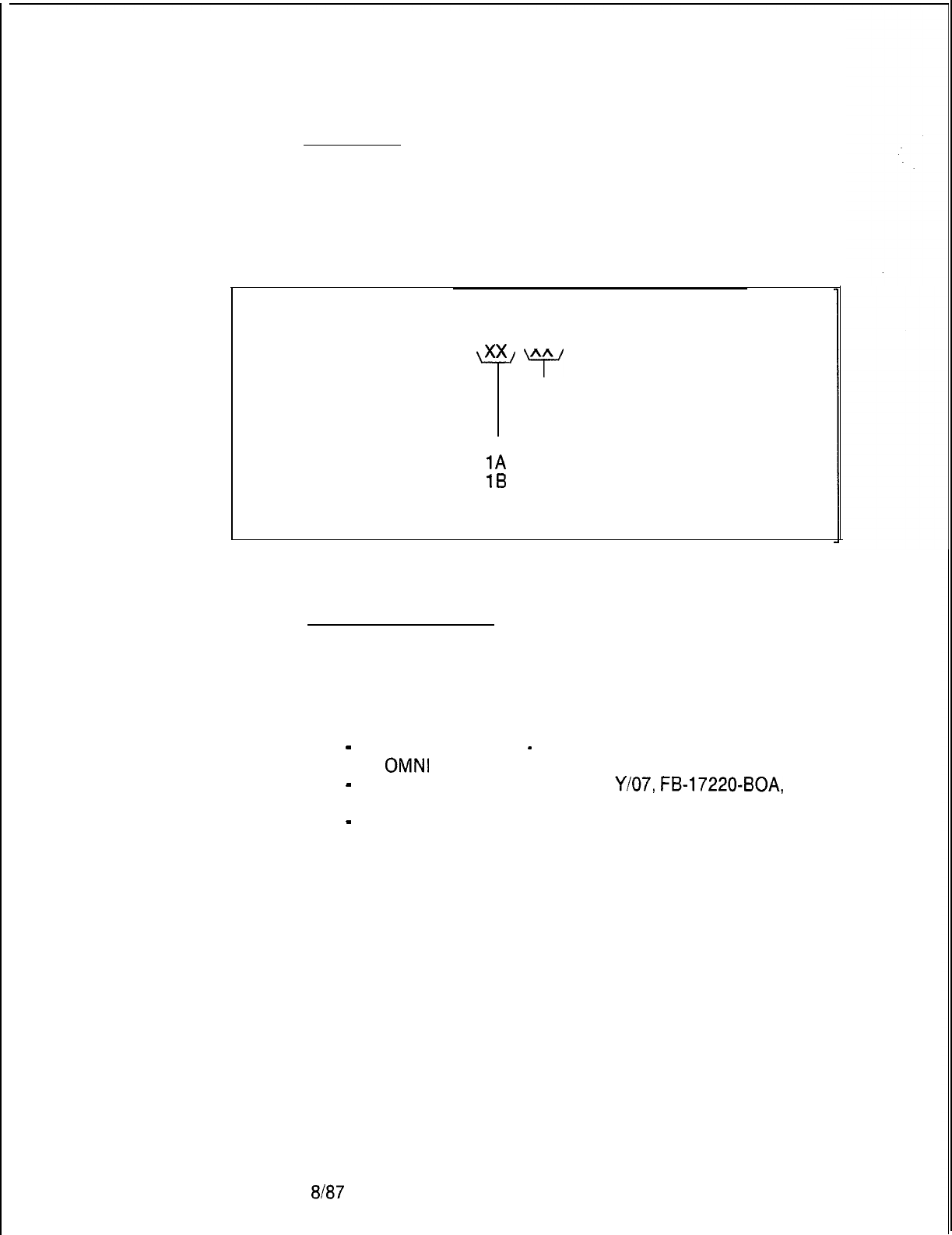
TL-130200-1001
Fault Code 27
Description:
Disk Backup Failure
When a power failure occurs, dynamic memory (containing
wake-up, message, etc.) is automatically written to disk to
preserve data. This fault indicates that the Hotel/Health Care
dynamic data was not backed up onto the disk.
M-l 40
Register Data as System Prints:
CECO CECO Fault 27 B C D E H L
\xx/
xx 00 00 00 00
Y
01
= Disk operation failed
02
= Disk request failed
00
= Disk backup successful
1A
= File read failed
1B
= File write failed
Fault Resolution Steps:
1.
Inform customer that the data has been lost and must be
reentered.
2.
If the problem is hardware related, perform the following
procedures:
-
Power down system
-
turn off main circuit breaker at rear
of
OMNI
SI cabinet.
-
Remove and replace FMSD in
Y/07,
FB-17220-BOA,
(check strapping).
-
Monitor PSUPY for ASW LED to light.
ala7
5210
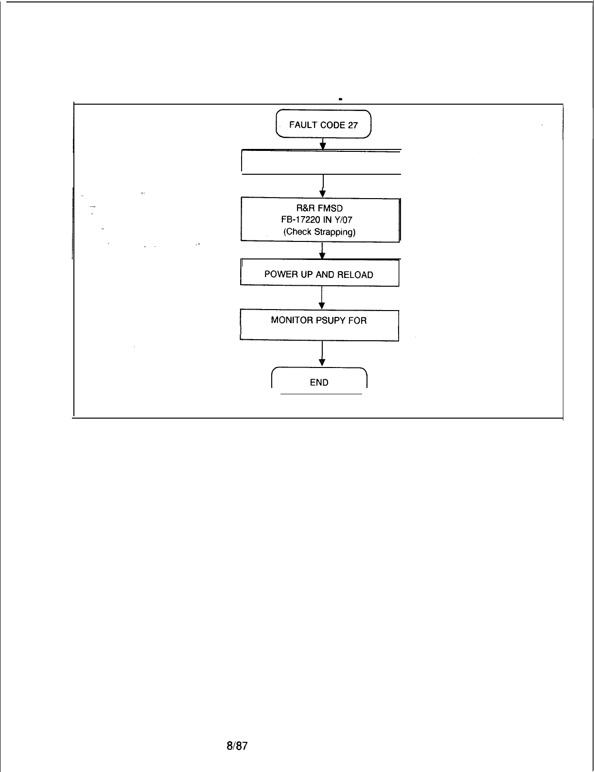
TL-130200-1001
FAULT CODE
-
27
I
POWER DOWN SYSTEM
I
“ASW” TO LIGHT
5210
a/a7
M-141
TL-130200-1001TL-130200-1001
Fault Code 30
Fault Code 30
Description:Description:
Attendant ConsoleAttendant Console
Common transmission to an Attendant Console has failed.Common transmission to an Attendant Console has failed.
RecoveryRecovery
Data Check ErrorData Check Error
_.
Register Data as System Prints:
CECO CECO Fault 30 B C D E H L
‘X7’
\x7(/
00
Yxxy
00 00
Console
0 or 1
08
= Check sum
09
= Data link
OA = Timeout occurred
M-142M-142
8187
5210
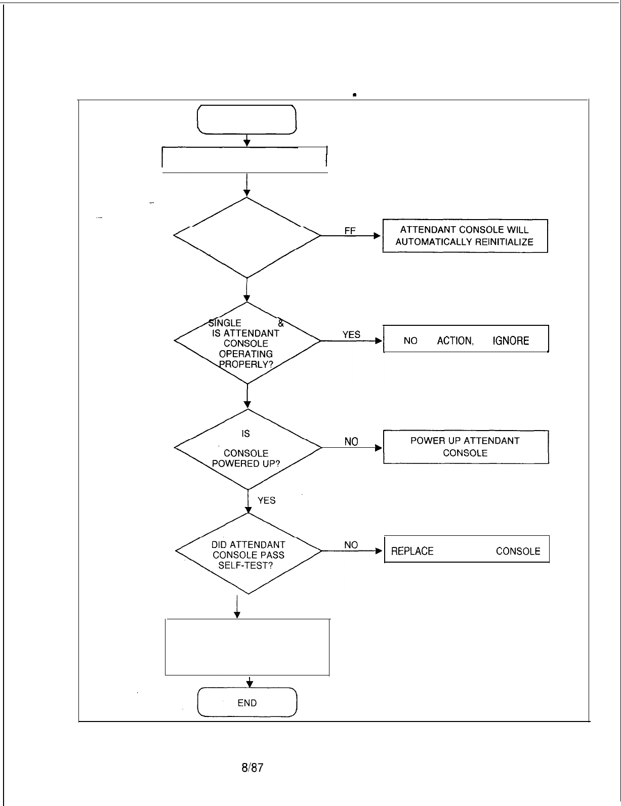
TL-130200-1001
FAULT CODE
-
30
I
FAULT CODE 30
I
I
NOTE CONSOLE NUMBER 1
REGISTER E = ?
1
A, 9, OR 8
ANGLE
FAULT
h
A”‘-
NO
ACTION,
IGNORE
_
1
NO
ATTENDANT
NO
,]I
lab
REPLACE
ATTENDANT
CONSOLE
1
YES
FORCE ATTENDANT CONSOLE OS
AND REMOVE AND REPLACE THE
ATT12 CARD. FORCE CONSOLE
IN SERVICE.
5210
8187
M-143
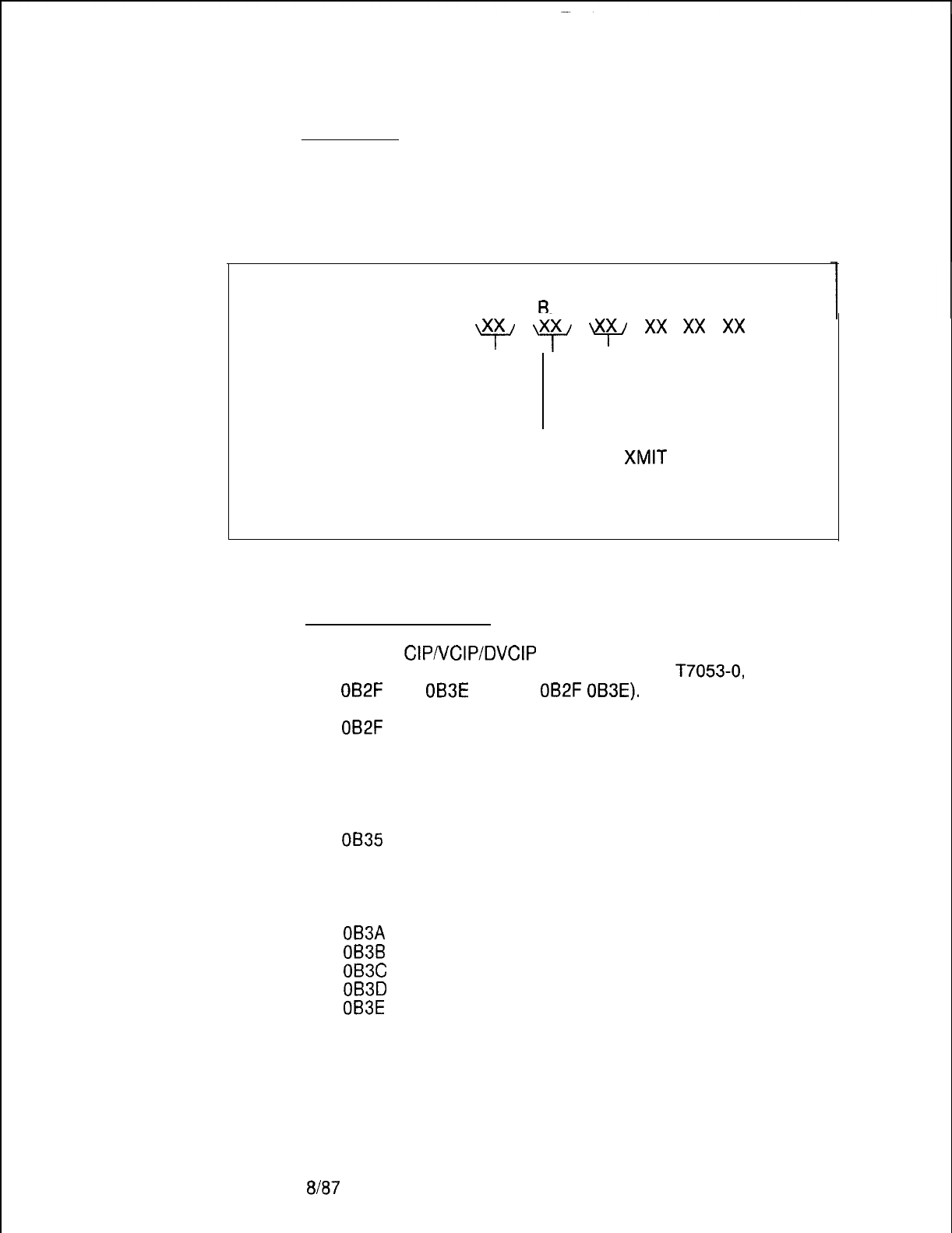
TL-130200-1001
Fault Code 32
Description:
CIPNCIPIDVCIP Card
This fault indicates a failure in the CIPNCIPIDVCIP or VP20 card.
Failure
M-l 44
Register Data as System Prints:
CECO CECO Fault 32
B
C D E H L
y
9
lxp
xx
xx
xx
PEC Card
Number Number
(Always 0) (O-15)
00
= Card Test Failure
01
= Card
XMIT
Error
02
= Card Watch Dog Timer Error
03
= Card Hardware Error
04
= Card Initialization Error
Fault Resolution Steps:
1.
Identify
CIP/VCIP/DVCIP
or VP20 relative card number
location by performing a general read of
T7053-0,
address
OB2F
thru
OB3E
(GR D2
OB2F
OB3E).
OB2F
= Relative Cl Card No. 0
OB30 = Relative Cl Card No. 1
OB31 = Relative Cl Card No. 2
0832 = Relative Cl Card No. 3
0833 =Relative Cl Card No. 4
OB34 = Relative Cl Card No. 5
0835
= Relative Cl Card No. 6
0836 =Relative Cl Card No. 7
0837 =Relative Cl Card No. 8
0838 = Relative Cl Card No. 9
OB39 = Relative Cl Card No. 10
OB3A
= Relative Cl Card No. 11
OB3B
= Relative Cl Card No. 12
OB3C
= Relative Cl Card No. 13
OB3D
= Relative Cl Card No. 14
OB3E
= Relative Cl Card No. 15
2. Interpret contents to indicate physical location of card.
8187
5210
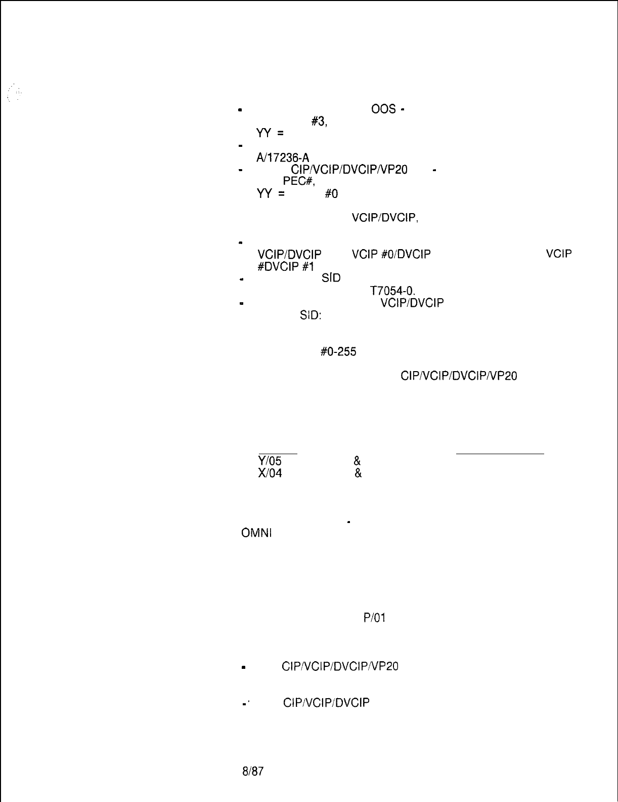
5210
TL-130200-1001
2.
If C register is 00, 02, 03, 05, 06, or 07, complete the following
steps:
-
Force CIPNCIPIDVCIP
00s
-
FORCE CIP CA X YY OS.
x=PEC
#3,
Always 0 or FORCE VPLC (PEC GRP SLOT)
W=
CARD 30 -15
-
Remove and replace CIPNCIPIDVCIP, FB -17235
A/17236-A
in identified slot (check strapping).
-
Force
CIPNCIPIDVCIPNP20
INS
-
FORCE CIP CA X YY IS.
x=
PEC#,
Always 0 or FORCE VPLC (PEC GRP SLOT)
W=
CARD
#O
-15
3.
If PCB replaced is a
VCIP/DVCIP,
FB-17235-A/17236-A, force
download the PCB as follows:
-
Identify data links associated with relative card number of the
.
VCIP/DVCIP
(i.e.,
VCIP
#O/DVCIP
#0 = Data Links O-7,
VCIP
#DVCIP
#l
= Data Links 8-15, etc.)
-
Identify any
SID
associated with any previously defined data
link by reading Table
T7054-0.
-
Force download of this
VCIPIDVCIP
using the previously
defined
SiD:
Force download X YYY IN.
x=PEC#, Always 0
YYY= SID
#O-255
4.
If fault recurs, reinstall original
CIPNCIPIDVCIPnIP20
card and
download.
5.
Identify MPB85, FB-17215-A associated with identified
CIPNCIPIDVCIP card:
MPB85 PCMUS GROUP
Y/O5
Groups A
&
B
X/o4
Groups C
&
D
6.
Power down system
-
turnoff main circuit breaker at rear of
OMNI
SI cabinet.
7.
Remove and replace MPB85, FB-17215-A previously
identified.
8.
Power up system.
9.
Monitor PSUPY card in
P/O1
for ASW LED to light.
10.
If C register value is 04, complete the following steps:
-
If a
CIPIVCIPIDVCIPNP20
card is supposed to be in an
unequipped slot, install a CIPNCIPIDVCIP card.
-.
If a
CIP/VCIP/DVCIP
card is correctly installed in the PCMUS,
follow procedures for C register value 00 listed above.
8187
M-145
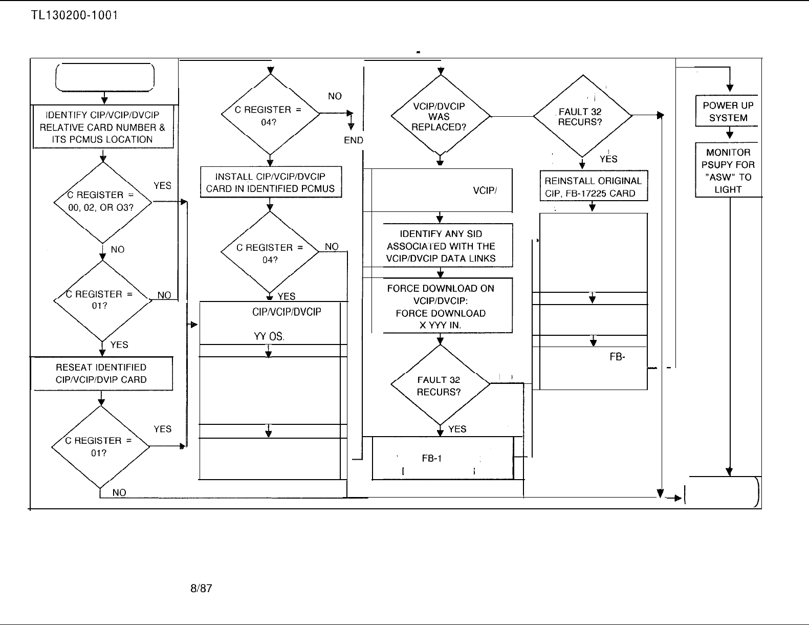
TL130200-1001
FAULT CODE 32
1
FAULT CODE
-
32
I I
1
FORCE
CIP/VCIP/DVCIP
b
CARD OS: FORCE CIP CA X
w
OS.
$r
FORCE CIPNCIPIDVCIP
CARD.
CIP, FB-17225
VCIP, FB-17235
DVCIP, FB-17236
4
I
FORCE CIPNCIPIDVCIP
CARD INS:
FORCE CIP CA X YY IS.
x-
YES
IDENTIFY DATA LINKS
ASSOCIATED WITH
VCIP/
DVCIP RELATIVE CARD NO.
NO
NO
NO
REINSTALL ORIGINAL
VCIP,
FB-I
7235 OR
DVCIP, FB-17236
IDENTIFY MPB85,
r
FB-17215
ASSOCIATED WITH
PCMUS HOUSING
CIPNCIPIDVCIP
CARD
+
POWER DOWN
SYSTEM
+
R&R MPB85,
FB-
17215 PREVIOUSLY
-
IDENTIFIED
-A
END
M-146
ah37
5210
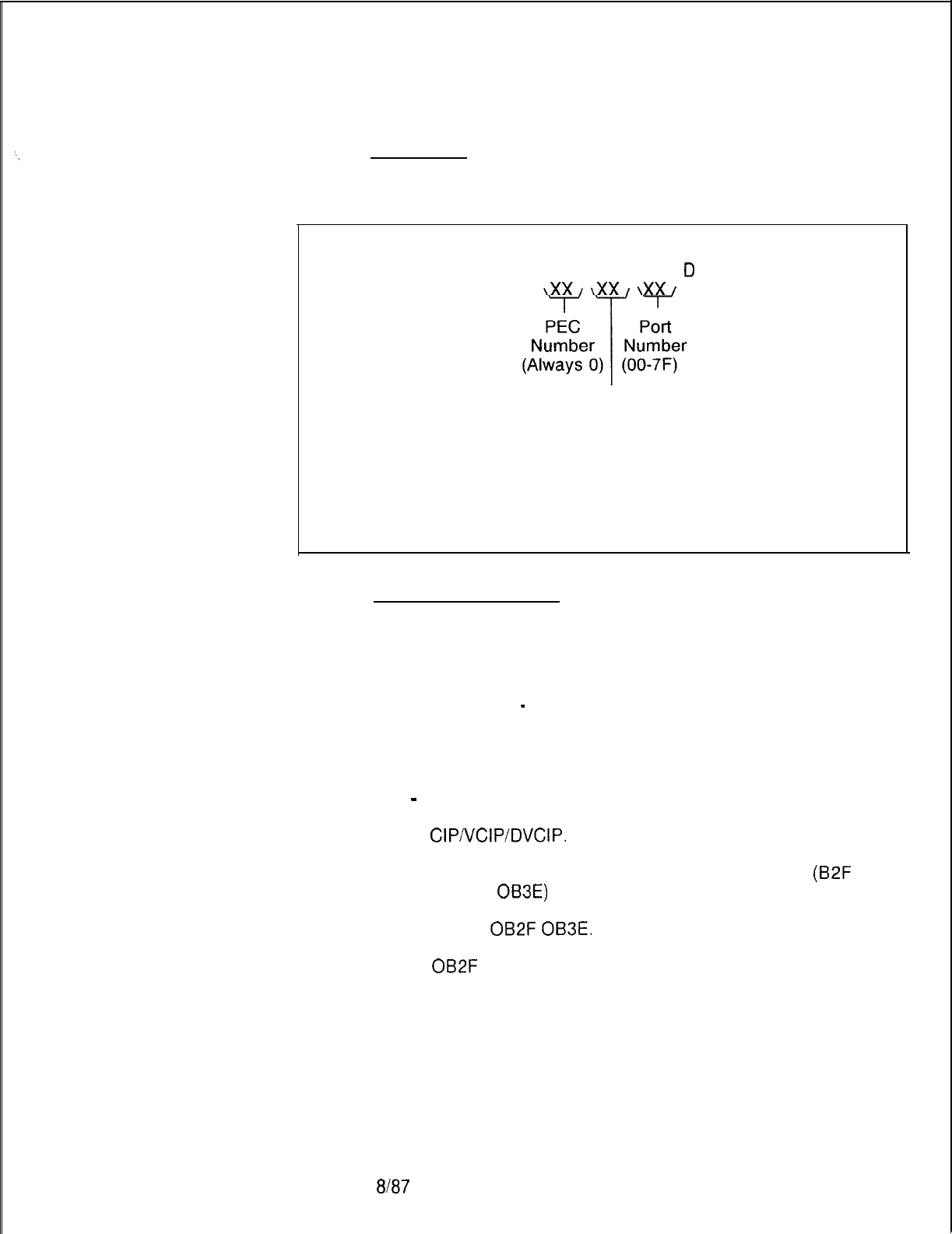
TL-130200-1001
Fault Code 33
Description:
CIPNCIPIDVCIP
This fault indicates a failure in the Integrated/Digital
Port Failure
Featurephone cabling or CIPNCIPIDVCIP card.
5210
Register Data as System Prints:
CECO CECO Fault 33 B C
D
E H L
00 00 00
00
= Data Link Error
01
= CIP Port Protocol Error
02
= Port Sync Error
03
= Port Enable Error
04 = CIP Other Port Errors
05
= Test Failure
06 = Download Failure
07 = Port Recovery Errors
Fault Resolution Steps:
1.
Identify and locate Featurephone associated with fault report
(customer complaint) or determine DN by deciphering port
number
2.
Ensure that Featurephone is powered up.
3.
Run self-test
-
TEST PHONE DN XXXX or TEST DN
XXXX. If test fails, remove and replace Featurephone.
4.
If Featurephone passes self-test, complete the following
steps:
-
At system maintenance terminal call up Recent Change
menu 117 to show the PCMUS associated with the
CIP/VCIP/DVCIP.
When PCMUS is defined, identify
CIPNCIPIDVCIP relative card number location by
performing a general read of 17053-O address
(B2F
through
OB3E)
as shown below:
GR D2
OB2F
OB3E.
OB2F
= Relative Cl Card No. 0
OB30 = Relative Cl Card No. 1
OB31
= Relative Cl Card No. 2
OB32 = Relative Cl Card No. 3
OB33 = Relative Cl Card No. 4
OB34 = Relative Cl Card No. 5
0835 = Relative Cl Card No. 6
OB36 =Relative Cl Card No. 7
8167
M-l 47
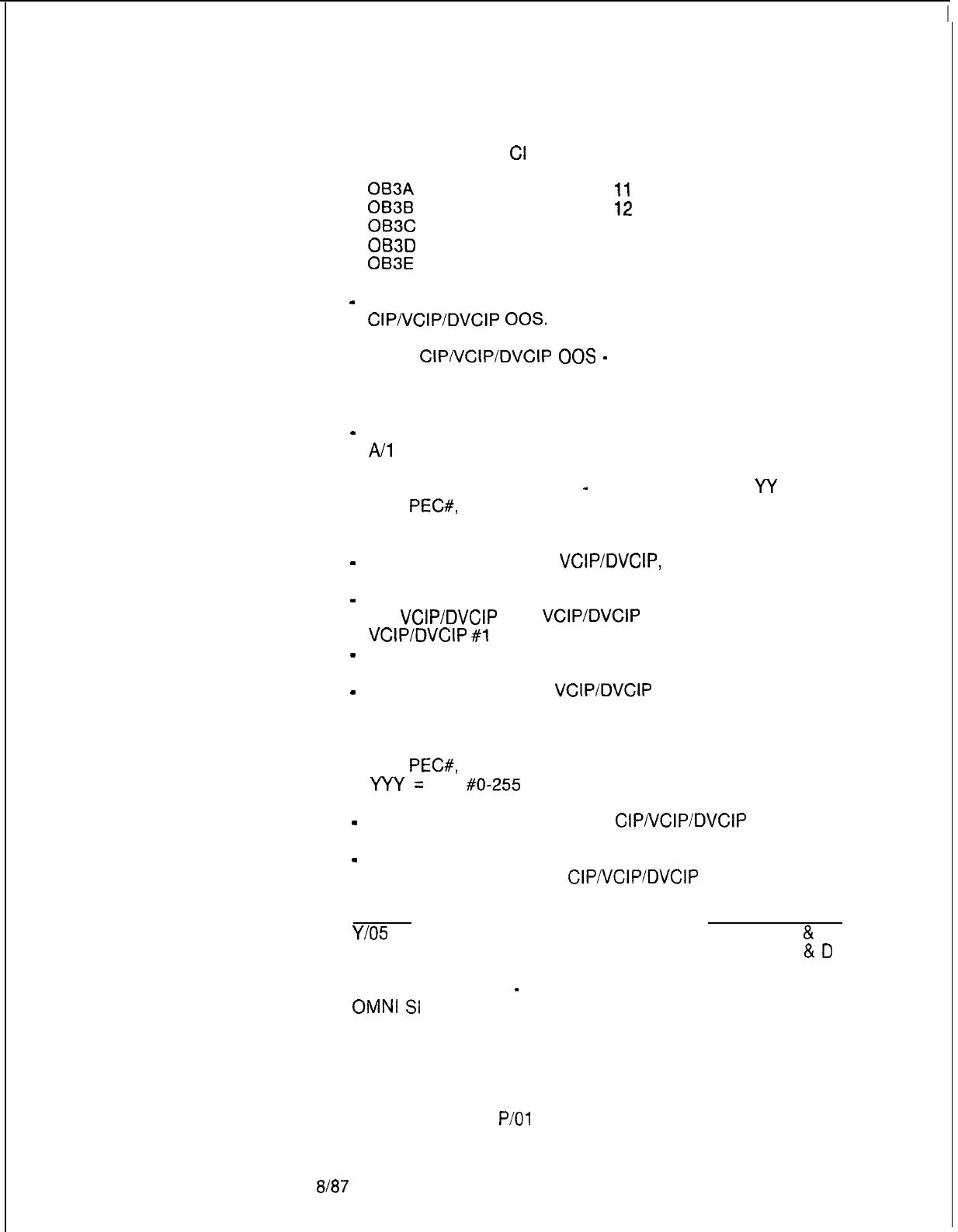
TL-130200-1001
0637 = Relative Cl Card No. 8
OB38 =Relative
Cl
Card No. 9
0839 = Relative Cl Card No. 10
063A
= Relative Cl Card No.
11
OB3B
= Relative Cl Card No.
12
OB3C
= Relative Cl Card No. 13
OB3D
= Relative Cl Card No. 14
OB3E
= Relative Cl Card No. 15
-
Using the relative Cl card number, force the
CIP/VCIP/DVCIP
00s.
Force
CIPAJCIPIDVCIP
00s
-
FORCE CIP CA X YY OS.
x=PEC#, Always 0
YY= CARD #O-l 5
-
Remove and replace CIPNCIPIDVCIP, FB-17235
A/l
7236-A in identified slot (check strapping).
Force CIPNCIPIDVCIP INS
-
FORCE CIP CA X
YY
IS.
x=
PEC#,
Always 0
YY= CARD #O-l 5
-
If PCB replaced was a
VCIPIDVCIP,
F&17235-
A/17236-A, force download PCB as follows:
-
Identify data links associated with relative card number of
the
VCIPIDVCIP
(i.e.,
VCIP/DVCIP
#0 = Data Links O-7,
VCIP/DVCIP
#l
= Data Links 8-15,etc.).
-
Identify any SID associated with any previously defined
data link by reading Table T-7054.
-
Force download of this
VCIP/DVCIP
using the previously
defined SID:
Force download X YYY IN.
X =
PEC#,
Always 0
YYY=
SID
#O-255
-
If fault recurs, reinstall original
CIPIVCIPIDVCIP
card.
-
Identify MPB85, FB-17215-A, associated with PCM
group housing identified
CIP/VCIP/DVCIP
card.
MPB85 PCMUS GROUP
Y/O5
Group A
&
B
x/o4 Group C
&
D
5.
Power down system
-
turn off main circuit breaker at rear of
OMNI
Sl
cabinet.
6.
Remove and replace MPE385, FB-17215-A, previously
identified.
7.
Power up system.
8.
Monitor PSUPY in
P/O1
for ASW LED to light.
M-148
8187
5210
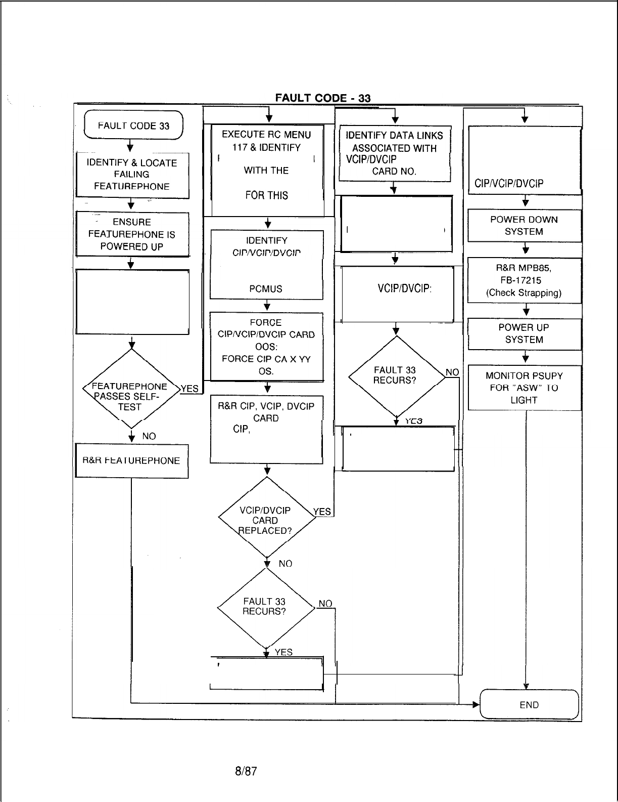
RUN SELF-TEST ON
FEATUREPHONE TEST
PHONE, DN XXXX, OR
TEST DN XXXX.
TL-130200-1001
IDENTIFY ANY SID
ASSOCIATED WITH
PREVIOUSLY DEFINED
DATA LINKS
RELATIVE CARD NO.
4
ASSOCIATED WITH
FORCE DOWNLOAD
ON
VCIP/DVCIP:
FORCE DOWNLOAD
X YYY IN.
f
REINSTALL ORIGINAL
VCIP, FB-17235, OR
DVCIP, FB-17236
I
REINSTALL ORIGINAL
CIP, FB-17225 CARD
IDENTIFY MPB85,
FB-17215
ASSOCIATED WITH
PCMUS HOUSING
ClPNClPlDVClP
CARD
PCMUS ASSOCIATION
CIPNCIPIDVCIP PCB
VCIP/DVCIP
RELATIVE
FEATUREPHONE
‘ZIP,
FB-17225
VCIP, FB-17235
DVCIP, FB-17236
5210
8l87
M-149
TL-130200-1001
Fault Code 36
Description:
Change MDR System
This fault indicates that receiving a CRIB (Call Record
Clock Failure
Information Buffer) from the idle crib list failed
The indication is
that MDR failed to change its system clock after a request from a
user. If this happens, there were too many calls in progress to
handle the request.
M-l 50
Register Data as System Prints:
CECO CECO Fault 36 B C D E H L
,xx,,xx,,xx,\xx/
?<x/?<x/
Old OIL
I
New
Hours Seconds Minutes
Old New New
Minutes Hours Seconds
Fault Resolution Step:
Repeat the request to change the system clock. If the fault is
reported again, repeat the request when traffic over the switch is
lighter.
8187
5210
TL-130200-1001
Fault’Code
37
Description:
System Warm Start
Fault Code 37 is generated every time a warm or cold start
occurs in the system. Register B in Fault Code 37 contains the
total count of warm starts which have occurred since the last
cold start. If Register B = 0, then a cold start has occurred.
Register C contains the threshold count for this fault. If register C
contains any value other than 0, the system has attempted a
warm start in 4 minutes or less since the last warm start. If
register C is 5, the system will attempt a cold start.
hedster Data as Svstem Prints:
-CECO
CECO
<ault
37 B C D E H L
,xx,
,xx/
00 00 00 00
Number of
I
I
warm starts
since the
Threshold count
last cold
if value of register
start
is more than zero
5210
7187
M-l 51
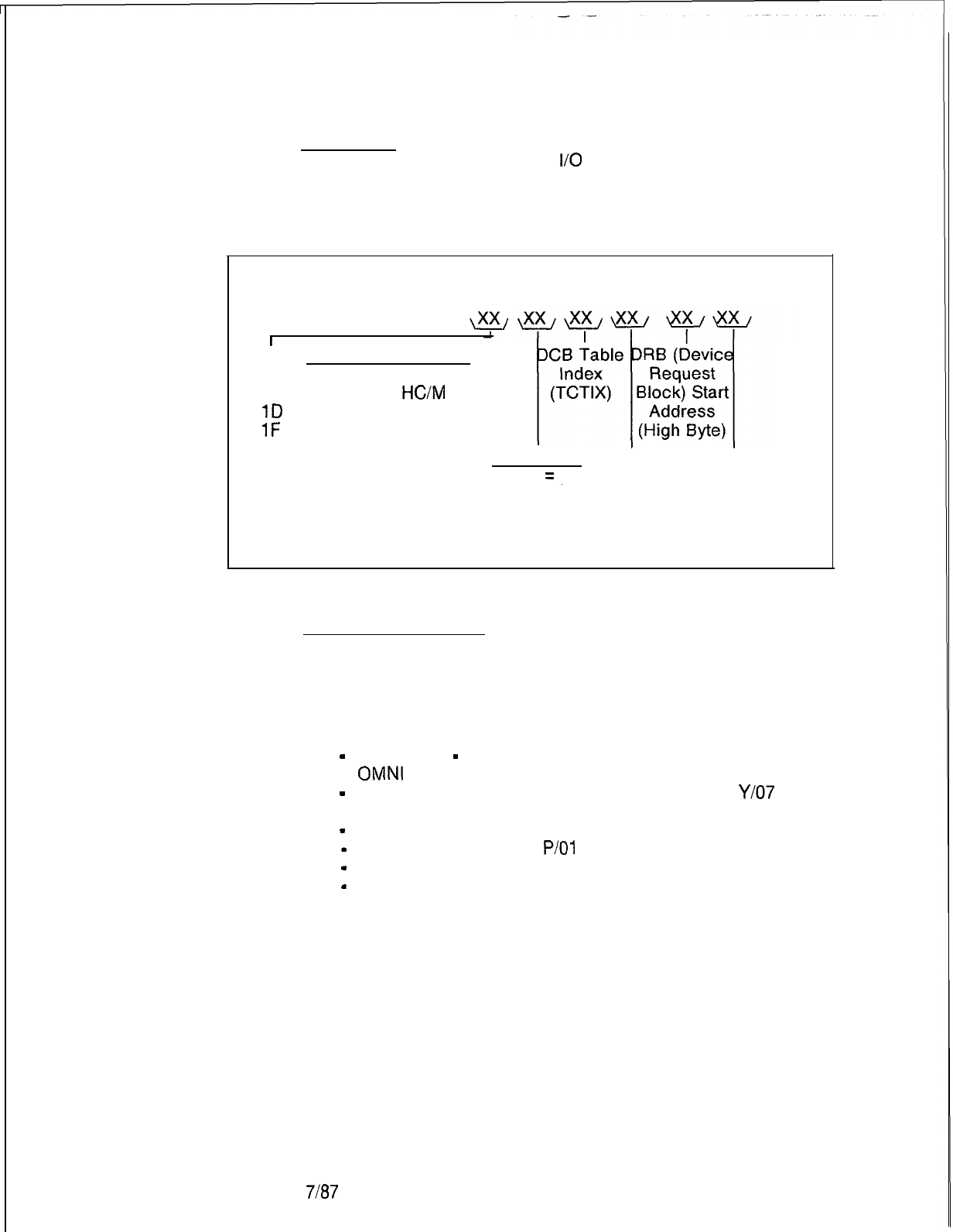
TL-130200-1001
Fault Code 41
Description:
FMS Disk Error
This fault indicates genera
M-l 52
.I disk
I/O
errors.
Register Data as System Prints:
CECO CECO Fault 41 B C D E H L
r
Request which failed
OE = Writing Out Data Base
14 = Writing Out
HC/M
1D
= Downloading F/P File
1F
= Closing F/P File
Error Code DCB DRB Start
FF
=.
Sequence Address
Timeout Index (Low Byte)
(TCSIX)
Fault Resolution Steps:
1.
Repeat the task that was being performed when fault
occurred. If fault recurs, continue.
2.
If the C register value is FF, this might indicate a hardware
problem. Complete the following steps:
-
Power down
-
turn off main circuit breaker at rear of
OMNI
SI cabinet.
-
Remove and replace FMSD, FB-17220-BOA, in
Y/O7
(check strapping).
-
Power up system.
-
Monitor PSUPY card in
P/O1
for ASW LED to light.
-
If fault recurs, remove and replace the floppy disk drive.
-
If fault still recurs after performing above procedures, this
indicates an internal data base or software problem and
the technician should call for assistance.
7187
5210
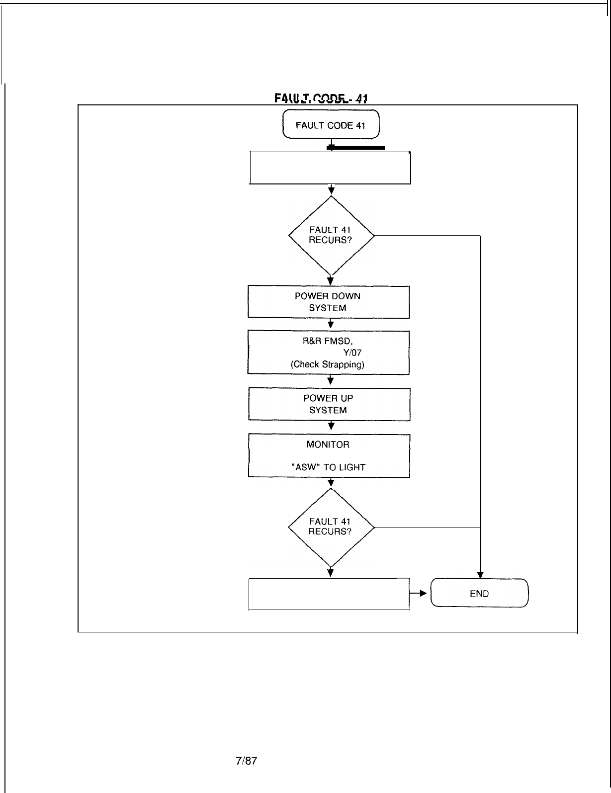
TL-130200-1001
.
c-w-.
VVIb
-r.
.
REPEATTASK
JUST PERFORMED
+
.
NO
*
YESC=FF
FB-17220 IN
Y/O7
PSUPY FOR
NO
*
YES
R&R FLOPPY
DISK DRIVE
5210
7187
M-153
TL-130200-1001
Fault Code 42
Description:
Time Slot Lockup
Fault Code 42 is generated when a time slot lockup is detected.
When allocating a time slot, a check should be made to see if the
hardware ID is already in channel memory. If it is, then a time
slot is locked up. The old time slot is released before allocating
the new time slot.
Register Data as System Prints:
CECO CECO Fault 42 B C D E H L
00
\xx
y
\xx
00
00
Hardware
ID
Time Slot Call Store
Number Number
M-l 54
7187
5210

-
-
TROUBLESHOOTING
Fault isolation
. .
Fault Code Procedures
and Flowcharts
5210
Attendant Console
Attendant Console
Fault Isolation
TL-130200-1001
5.0 Maintenance personnel can determine the source of most
system failures based on built-in software fault reporting. Fault
messages on the system terminal are used with standard
troubleshooting procedures to isolate problems with specific
components. Replacement or repairs can then be made. Many
times this will only involve card replacement.
5.1 A comprehensive set of troubleshooting procedures indexed
by fault codes follows. The technician should first examine all
faults reported on terminal printouts and/or the fault log.
5.2 The procedures and flowcharts which follow list
specifications and steps which should be taken for each of the
system’s fault codes.
5.2.1 Always check the Attendant Console power source for
proper voltages before replacement if a failure occurs. System
-related console troubleshooting is contained in TL-1301
OO-
1001.
Description:
The attendant is unable to complete calls or the system does not
respond to specific, keyed digits; console pushbuttons or
displays do not function properly, or the console is completely
dark, and the system will not respond to any input from the
console.
8/W

TL-130200-1001
START
i-i
CONSOLE PUSHBUTTON
AND/OR DISPLAYS DO NOT
FUNCTION PROPERLY (NOTE 1).
PUSHBUTTONS FUNCTION,
BUT ASSOCIATED LEDS
REPLACE THE
ATT12
CARD
(CARD POSITION VARIABLE)
(NOTE 2).
IF THE PROBLEM IS NOT
SOLVED, REINSTALL THE
ORIGINAL AI-l-12 CARD (NOTE
2). REPLACE THE ATTENDANT
CONSOLE.
IF THE PROBLEM IS NOT
SOLVED, REINSTALL THE
ORIGINAL CARDS AND
REQUEST ASSISTANCE.
i?
END
NOTES:
1.
Before performing any work on the console, it
must be powered down.
2. See paragraph 1.4.5
M-1 56
Figure
5.1
menaanf
Gonsole
ana
indicator
Troublesnootmg
Flowchart
8187
5210
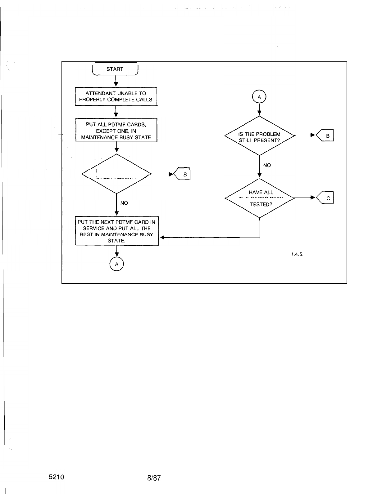
TL-130200-1001
START
+,
YES
/1
IS THE PROBLEM
STILL PRESENT? YES
,(_1
B
THECARDSBEEN
YES
NO
NOTE: See paragraph
1.4.5.
Figure 5.2 Attendant Console Troubleshooting Flowchart (Sheet 1 of 2)
8l87
M-157
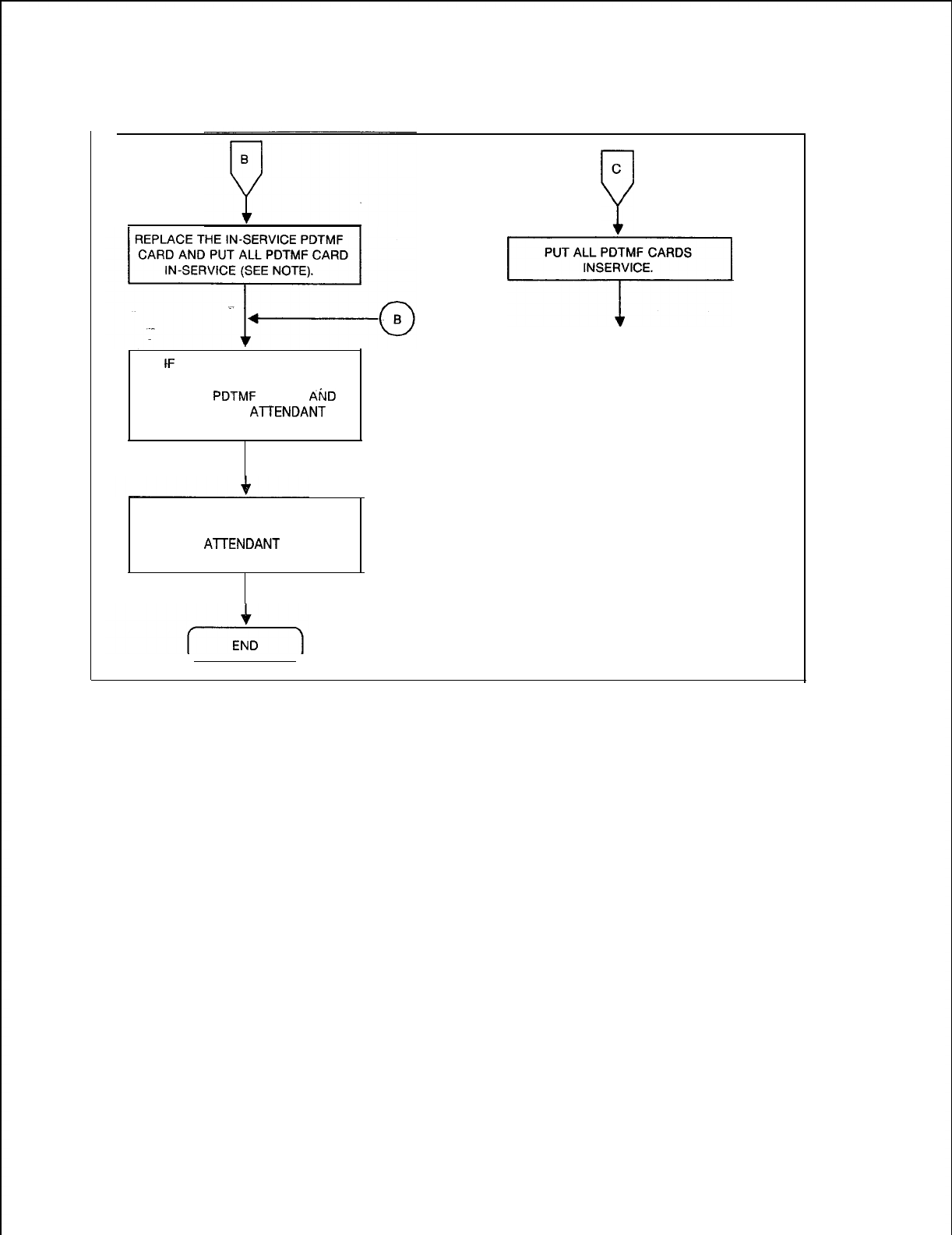
TL-130200-1001
M-158
tF
THE PROBLEM IS STILL
PRESENT, REINSTALL ALL THE
ORIGINAL
PDTMF
CARDS
AF;D
REPLACE THE
AlTENDANT
CONSOLE.
IF THE PROBLEM IS STILL NOT
SOLVED, REINSTALL THE
ORIGINAL
A-lTENDANT
CONSOLE
AND REQUEST SERVICE.
C
0
]I
0
B
Figure 5.2 Attendant Console Troubleshooting Flowchart (Sheet 2 of 2)
8187
5210
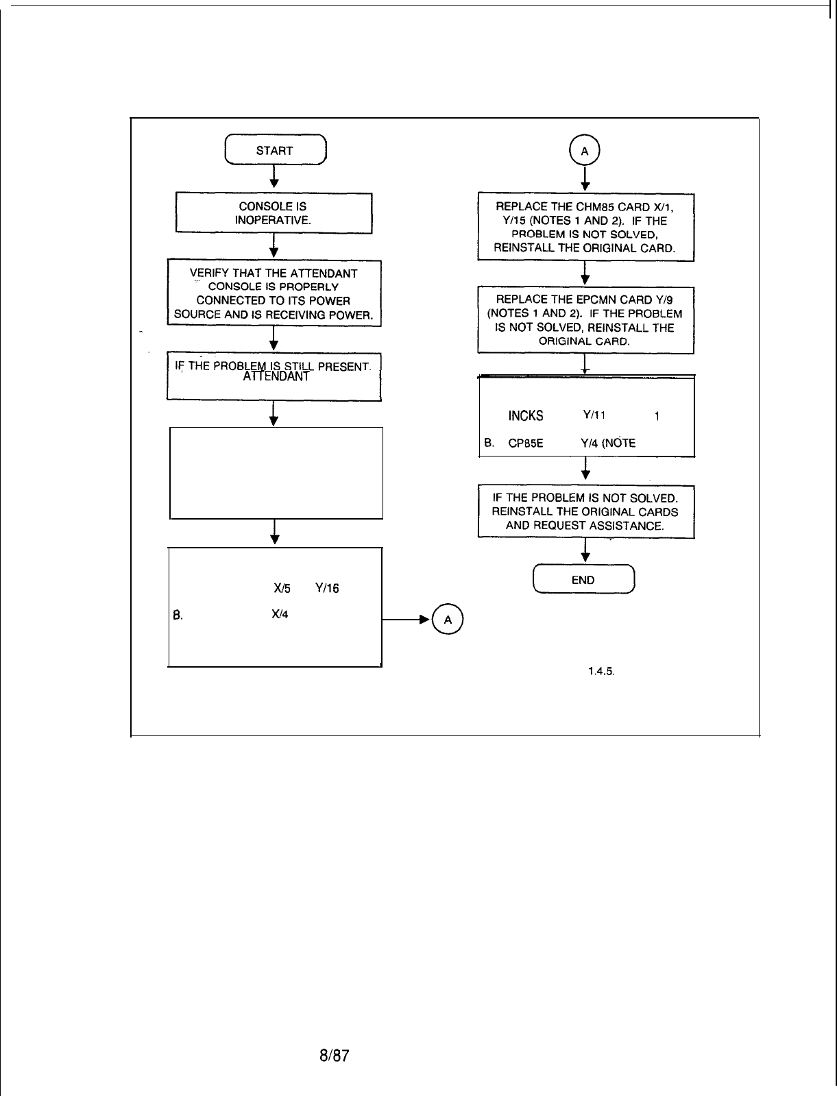
TL-130200-1001
TURN THE
AllENDANT
CONSOLE
OFF AND THEN BACK ON.
IF THE PROBLEM IS STILL PRESENT,
REMOVE HEADSET. REPLACE Al72
CARD (POSITION VARIABLE). THEN
REINSTATE HEADSET. IF PROBLEM
IS NOT SOLVED, REINSTALL
ORIGINAL ATT12 CARD.
REPLACE THE FOLLOWING CARDS
IN SEQUENCE:
A.
INCKS
CARD
Y/l1
(NOTES
1
AND 2)
8. CPBBE
CARD
Y/4
(NOTE
1).
REPLACE THE FOLLOWING CARDS
IN SEQUENCE:
A.
PCMFS CARD
W5
OR
Y/16
(NOTE 1)
8.
MPB85 CARD
X/4
OR Y/5 (SEE
NOTE 1)
IF PROBLEM IS NOT SOLVED,
REINSTALL THE ORIGINAL CARD. NOTES:
I
1. See paragraph
1.45
2.
Before removing or replacing these cards,
disconnect the cables from the front of the card.
Figure 5.3 Attendant Console Operation Troubleshooting Flowchart
5210
8187
M-l 59
TL-130200-1001
BLDU Unit
5.2.2 Operational tests for the BLDU are contained in
Troubleshooting
TL-130100-1001. Refer to Tables 5.1 through 5.3 for BLDU
Procedures
tests diagnostics.
Table 5.1 BLDU Station 100s Group Key Test
I
STEP
I
OPERATION
I
RESULT
I
1
..- :-
Depress the Hundreds Group
keys (1-l 0) across the front of
the BLDU.
The Hundreds Group digit will appear in
-/-segment display for each
programmed Hundred s Group.
STEP
Table 5.2 BLDU
LCDs
and
LEDs
Test
OPERATION
RESULT
1
Simultaneously depress the last All
LCDs
are lit (no numbers visible in
two keys on right of BLDU (keys line display field, no Bs or Rs visible in
9 and 10). trunk group field, and 88 displayed in
7-segment display).
2
Release keys 9 and 10. All
LCDs
and
LEDs
will be
extinguished.
Table 5.3 BLDU Self-Diagnostics
STEP
OPERATION
RESULT
1
Remove BLDU cover (see note) (a)
-
1 displayed in
7segment
and set dipswitch 4 to ON. display for successful completion of
ROM test. If not displayed, ROM test
failed.
(b)
-
1 displayed in 7-segment
display for successful completion of
RAM test. If not displayed, RAM test
failed. All LCD segments illuminated
for 2 seconds.
(c)
-
1 displayed in 7-segment
display to indicate completion of LCD
test. All
LEDs
are on, with -4
displayed in 7-segment display.
M-l 60
8187
5210
TL-130200-1001
Table 5.3 BLDU Self-Diagnostics (Continued)
I
STEP
I
OPERATION
RESULT
I
2
Within 5 seconds, depress key.
The key number will be displayed in
hex on the
7-segment
display.
3
4
.--
Continue to depress keys. Key numbers will be displayed.
Do not make a key depression Unit will start tests over, with 1
for 5 seconds.
displayed in
-/-segment
display.
5
Set dipswitch 4 to OFF and
Displays will be cleared (no numbers or
replace BLDU cover.. letters visible).
5210
8187
M-l 61
NOTE: To remove the BLDU cover, remove the two screws at
the top back side of unit, slide the cover to the front (forward) of
the BLDU approximately
l/2
inch, lift the cover upward until the
tip stops (approximately 1 inch), slide the cover toward the rear of
the unit (approximately
3/4
inch), then lift the cover up and out.
To attach the cover, reverse the procedure.
TL-130200-1001
Featurephone 5.3
Perform the
procedures
listed in Table 5.4 for Featurephone
Self
-Test
self-test diagnostics.
Diagnostics
Table 5.4 Featurephone Self-Test Diagnostics
STEP
I
OPERATION
-1
. .
Depress and hold
#.
2
-
Release
#.
3
Select one of fhe following three
tests and continue.
RESULT
(a) Receive beep
(b) “DIAGNOSTICS
“
appears.
“WHICH TEST =
?“
appears.
I
TEST 1
-
Audible Signals
OPERATION
RESULT
Depress 2(a) “AUDIBLE TEST“
(b) Audible signals heard once each as
follows:
(1) Single beep
(2) Double beep
(3) Triple beep
(4) Continuous ring
Inside call = 1 sec. on; 3 sec.
Off.
(5) Optional buzzer
NOTE:
Beep = 1
/lO
sec. signal
(c) Display clears
a/a7
5210
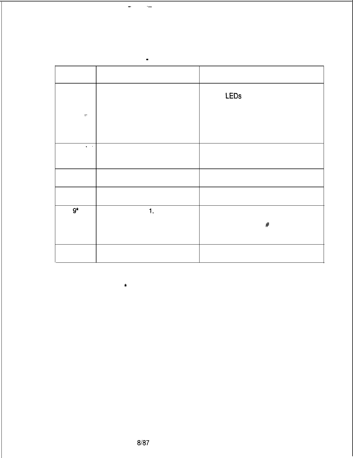
-
._
TL-130200-1001
TEST 2
-
LEDS, Feature Buttons, Keypad
STEP OPERATION RESULT
5
Depress 3. (a) “LED TEST”
(b) ALL
LEDs
ON
(c) After 2 seconds, “BUTTON TEST”
NOTE: In the following tests, the
sequence described must be followed
or else a programmable error will
result.
6
-.
Starting at the top left, depress (a) LED ON
and hold the feature button.
(b) The specific feature programmed
is displayed.
7
Release the feature button. (a) LED OFF
(b) Display remains
8
9*
Continue down the button rows
When the last feature button is
performing Steps 5 and 6 above.
released, “Keypad TEST” is displayed.
Starting with key
1,
proceed left (a) Display fills with characters
to right, top to bottom, depressed.
depressing each key.
(b) 2-3 seconds after
#
released:
(1) Double beep heard
(2) Display clears
10
To terminate test, go off-hook
then back on-hook.
5210
8187
M-l 63
*
For the digital Featurephone, the keys need not be pressed in
order.
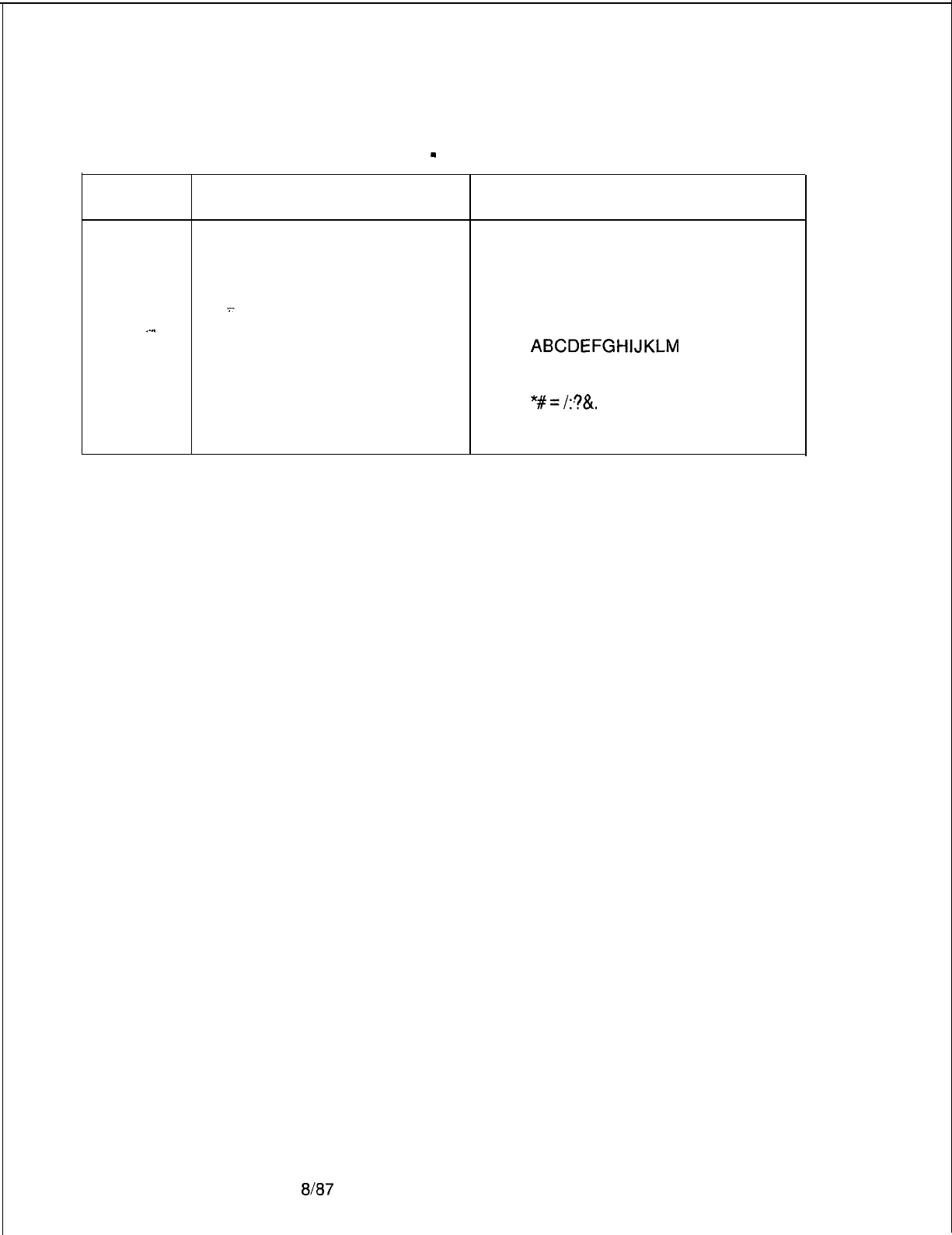
TEST 3
-
Display
STEP
11
OPERATION
Depress 4.
RESULT
(a) The following each appear for 2-3
seconds in sequence:
.-..
(1) “DISPLAY TEST”
(2) ALL LCDS active.
(3) Blank display
(4)
ABCDEFGHIJKLM
(5) NOPQRSTUVWXYZ
(6)
1234567890
(7) *#=/:?&.
(b) Display clears.
TL-130200-1001
M-164
8187
5210
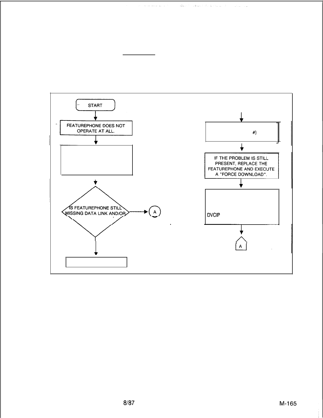
5210
TL-130200-1001
Featurephone
Description:
Troubleshooting
Charts
The Featurephone does not operate. The Featurephone
pushbuttons and displays do not function properly; the system
does not respond to one or more of the Featurephone
pushbuttons.
*
START
-.Lz
0
A
FEATUREPHONE DOES NOT
OPERATE AT ALL. EXECUTE A “FORCE
DOWNLOAD (PEC
#)
(SID)”
MAINTENANCE REQUEST.
I
VERIFY THAT THE
FEATUREPHONE IS PROPERLY
CONNECTED TO ITS POWER
SOURCE AND IS RECEIVING
POWER.
I
VOICE CHANNEL?VOICE CHANNEL?
BOTH MISSINGBOTH MISSING
1
ONLY VOICE MISSING
4
IF THE PROBLEM IS STILL
PRESENT, REINSTALL THE
ORIGINAL FEATUREPHONE AND
REPLACE THE CIP, VCIP, OR
DVCIP
CARD. EXECUTE “FORCE
DOWNLOAD”.
GO TO FIGURE 5-8.
Figure 5.4 Featurephone Troubleshooting Flowchart (Sheet 1 of 3)
8187
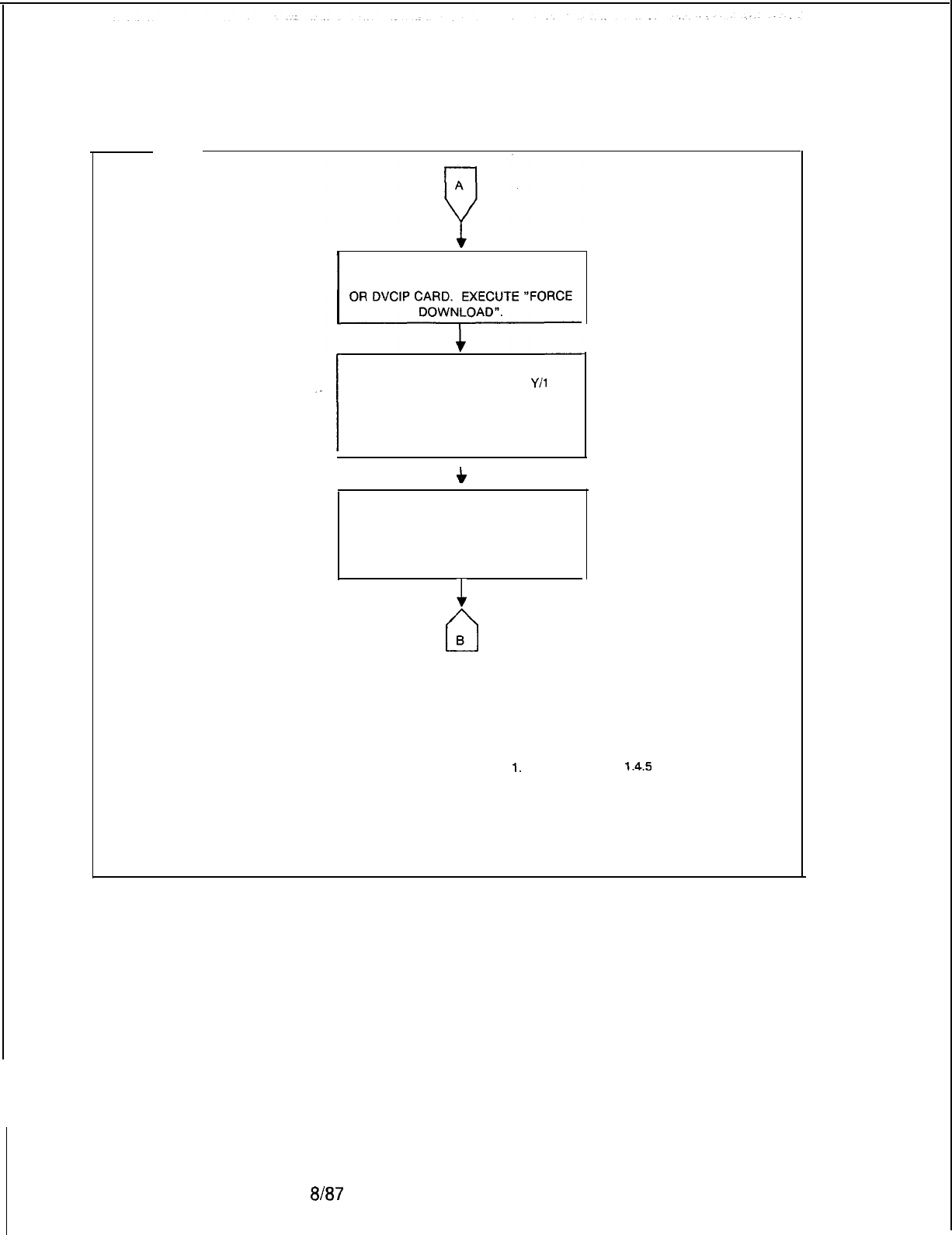
TL-130200-1001
IF THE PROBLEM IS STILL PRESENT,
REINSTALL THE ORIGINAL CIP, VCIP,
REPLACE THE FOLLOWING CARDS IN
SEQUENCE: PCMFS X/5 OR
Y/l
5
(NOTES 1 AND 2).
MPB85 X/4 OR Y/5 (NOTE 1) IF
PROBLEM IS STILL PRESENT,
REINSTALL ORIGINAL CARDS.
c
REPLACE THE FOLLOWING CARDS IN
SEQUENCE: CHM85 X/l, Y/15 (NOTES
1 AND 2).
IF PROBLEM IS STILL PRESENT,
REINSTALL ORIGINAL CARDS.
1
cl
B
NOTES:
I.
See paragraph
1.4.5
2. Before removing or replacing these
cards, disconnect the cable from the
front of the card.
Figure 5.4 Featurephone Troubleshooting Flowchart (Sheet 2 of 3)
M-l 66
m37
5210
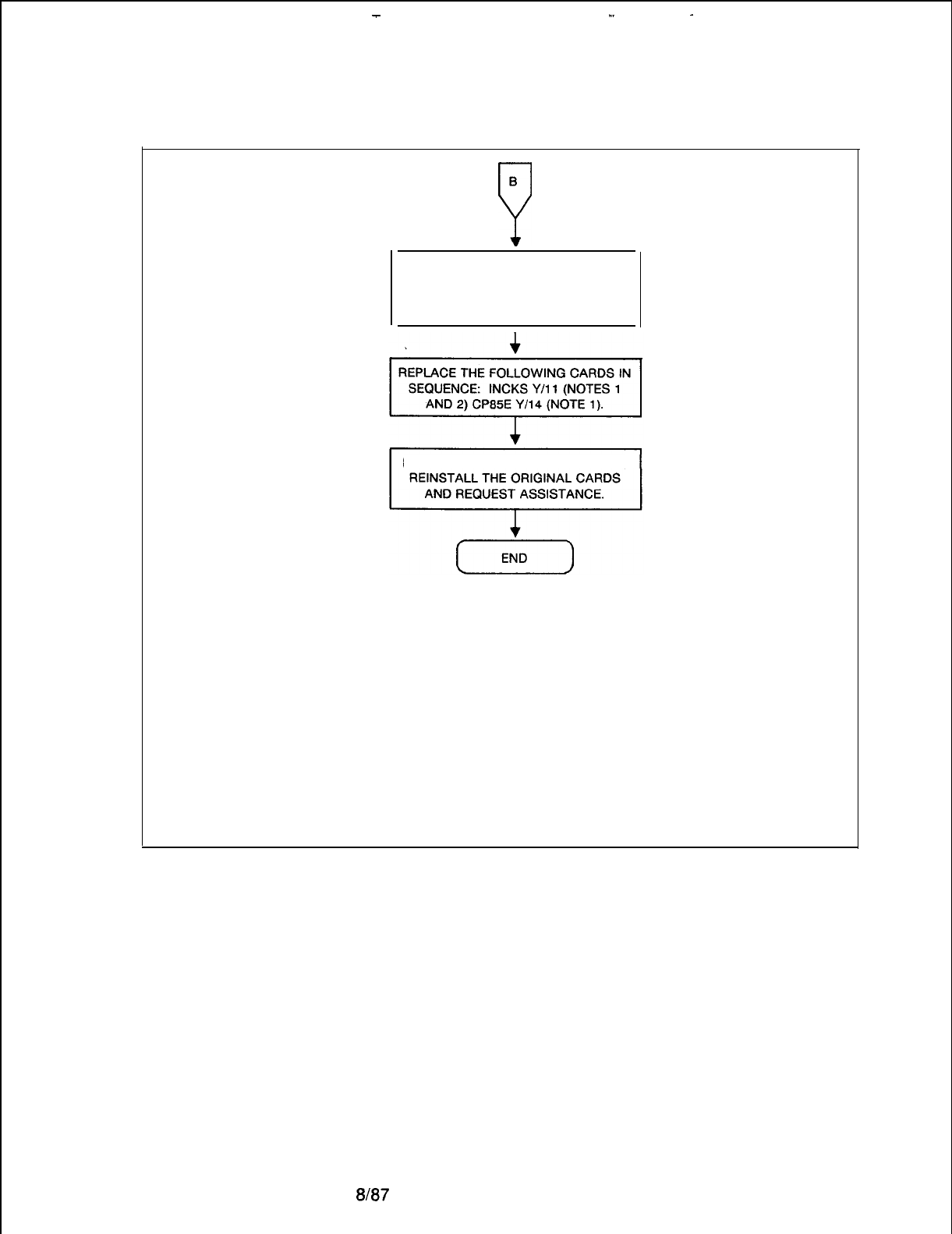
-
_.
.
TL-130200-1001
5210
B
P
REPLACE THE EPCMN CARD Y/9
(NOTES 1 AND 2). IF THE PROBLEM
IS STILL PRESENT, REINSTALL THE
ORIGINAL CARDS.
I
IF THE PROBLEM IS STILL PRESENT,
NOTES:
1. See paragraph 1.4.5.
2. Before removing or replacing these cards,
disconnect the cable from the front of the
card.
Figure 5.4 Featurephone Troubleshooting Flowchart (Sheet 3 of 3)
8l87
M-l 67
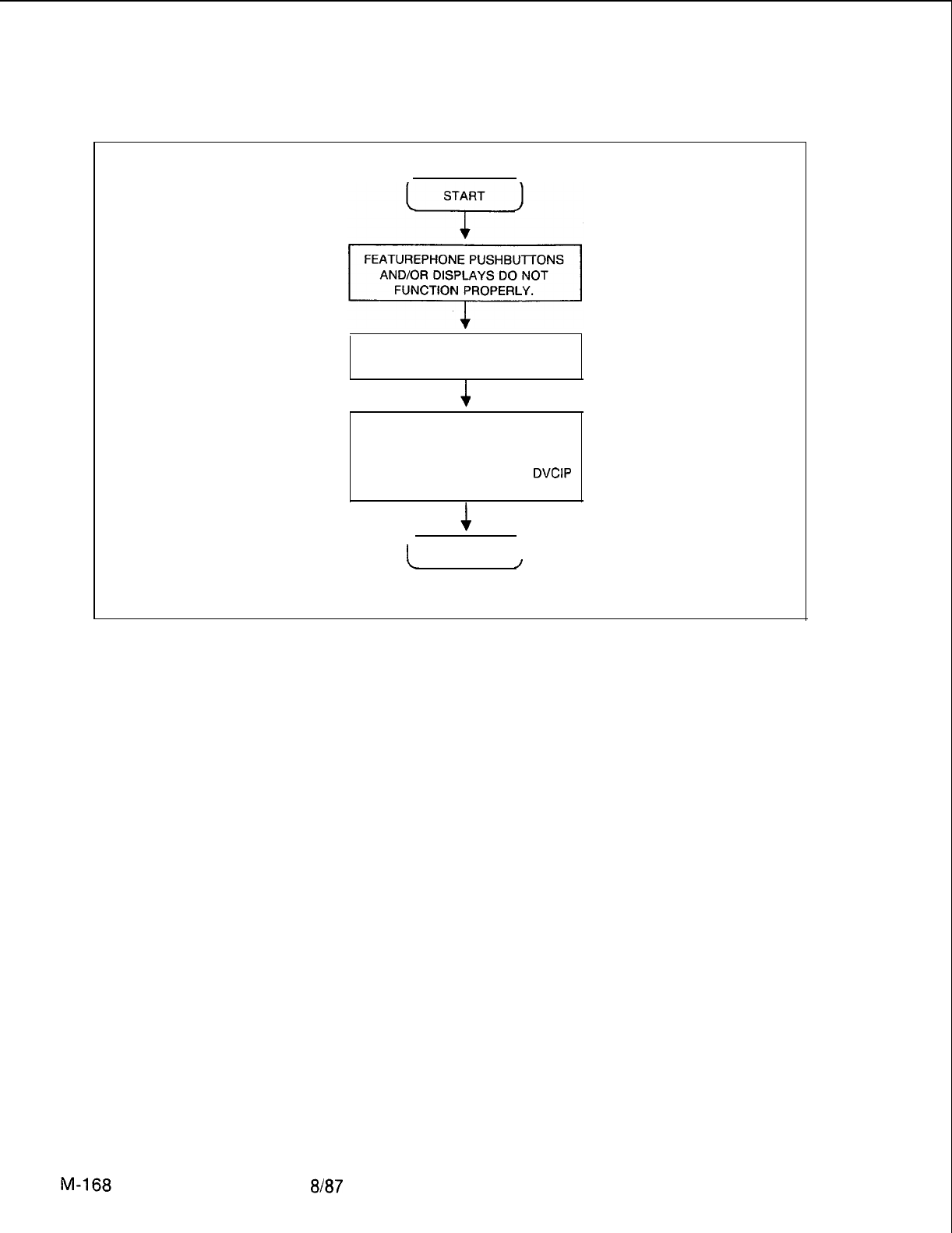
TL-130200-1001
.
REPLACE FEATUREPHONE AND
EXECUTE A “FORCE DOWNLOAD.”
IF THE PROBLEM IS STILL
PRESENT, REINSTALL THE
ORIGINAL FEATUREPHONE AND
REPLACE THE CIP, VCIP, OR
DVCIP
CARD (SEE NOTE).
I
END
I
L
/
NOTE: See paragraph 1.45.
Figure 5.5 Featurephone Control and Indicator Troubleshooting Flowchart
8187
5210
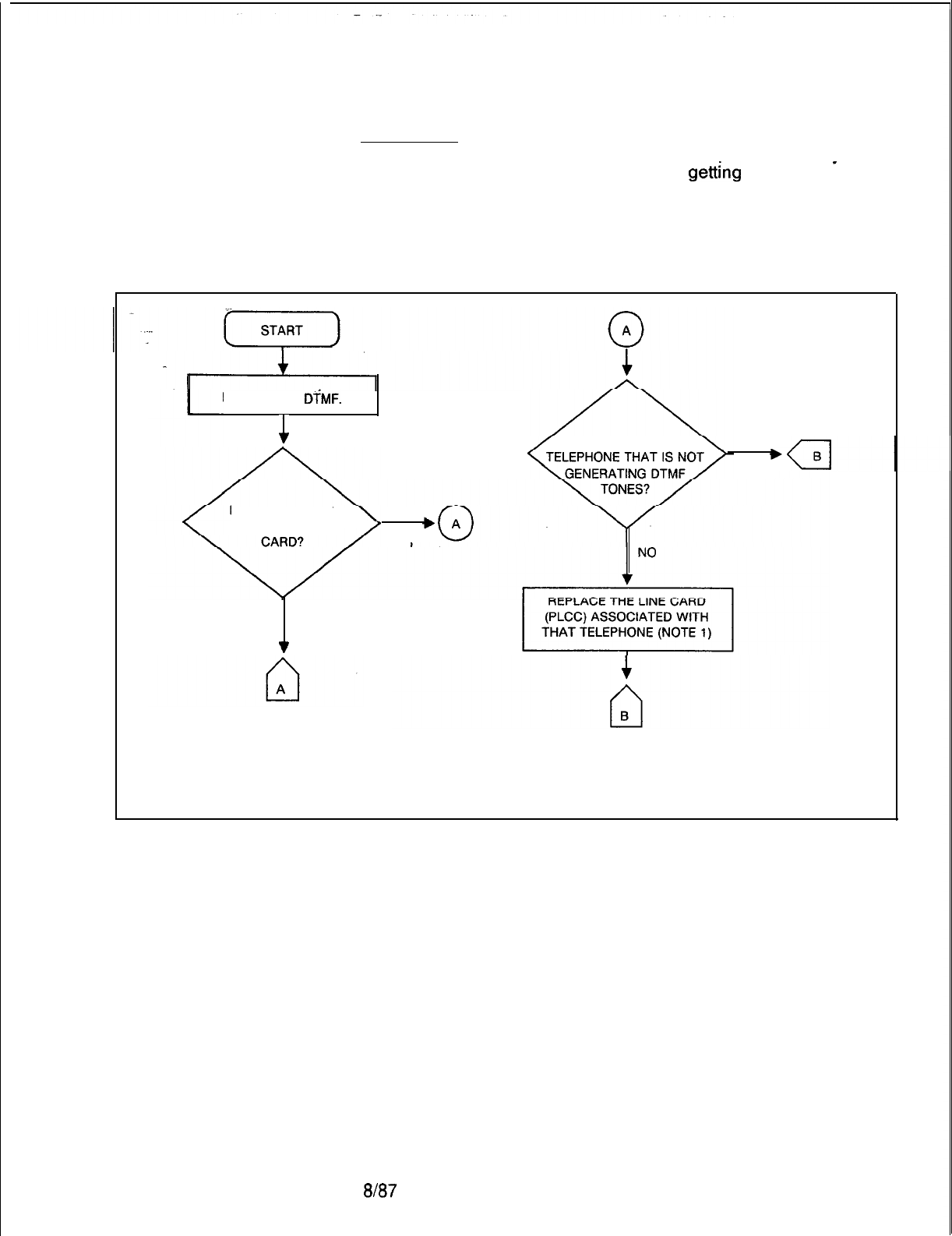
TL-130200-1001
Station/Line/Trunk
Description:
Troubleshooting
Stations are unable to complete DTMF calls properly. They are
having problems completing calls or are
getting
wrong
-
terminators. Stations are having transmission problems such as
no transmission, double connections, no tones, and the wrong
tones. A station will not ring at all, or it rings without interruption.
A line or trunk does not function properly.
NO STATION
DiMF.
c
IS THE PROBLEM ONE
YES
IS THE PROBLEM
ONLY ON LINE
YES
NO
v
Figure 5.6 Station DTMF Troubleshooting Flowchart (Sheet 1 of 2)
5210
a/a7
M-169
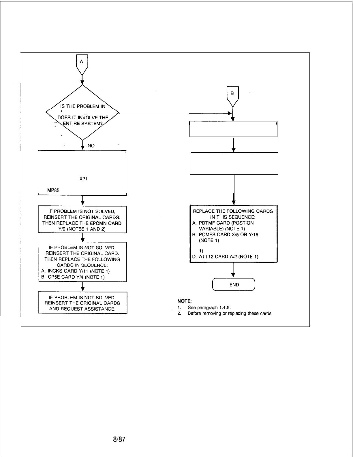
TL-130200-1001
A
P
ONLY ONE-FILE OR
YES
REPLACE THE TELEPHONE
IF PROBLEM IS NOT SOLVED,
REINSERT THE ORIGINAL CARD. IF THE PROBLEM IS NOT SOLVED,
THEN REPLACE THE FOLLOWING REINSTALL THE ORIGINAL LINE
CARDS IN SEQUENCE: CARD OR TELEPHONE.
A. CHM85 CARD
X?l
OR Y/15
(NOTES 1 AND 2)
B.
MP85
CARD X/4 OR Y/5 (NOTE 1).
C. MPB85 CARD X/4 OR Y/5 (NOTE
disconnect the cables from the front of the card.
Figure 5.6 Station DTMF Troubleshooting Flowchart (Sheet 2 of 2)
8l87
5210
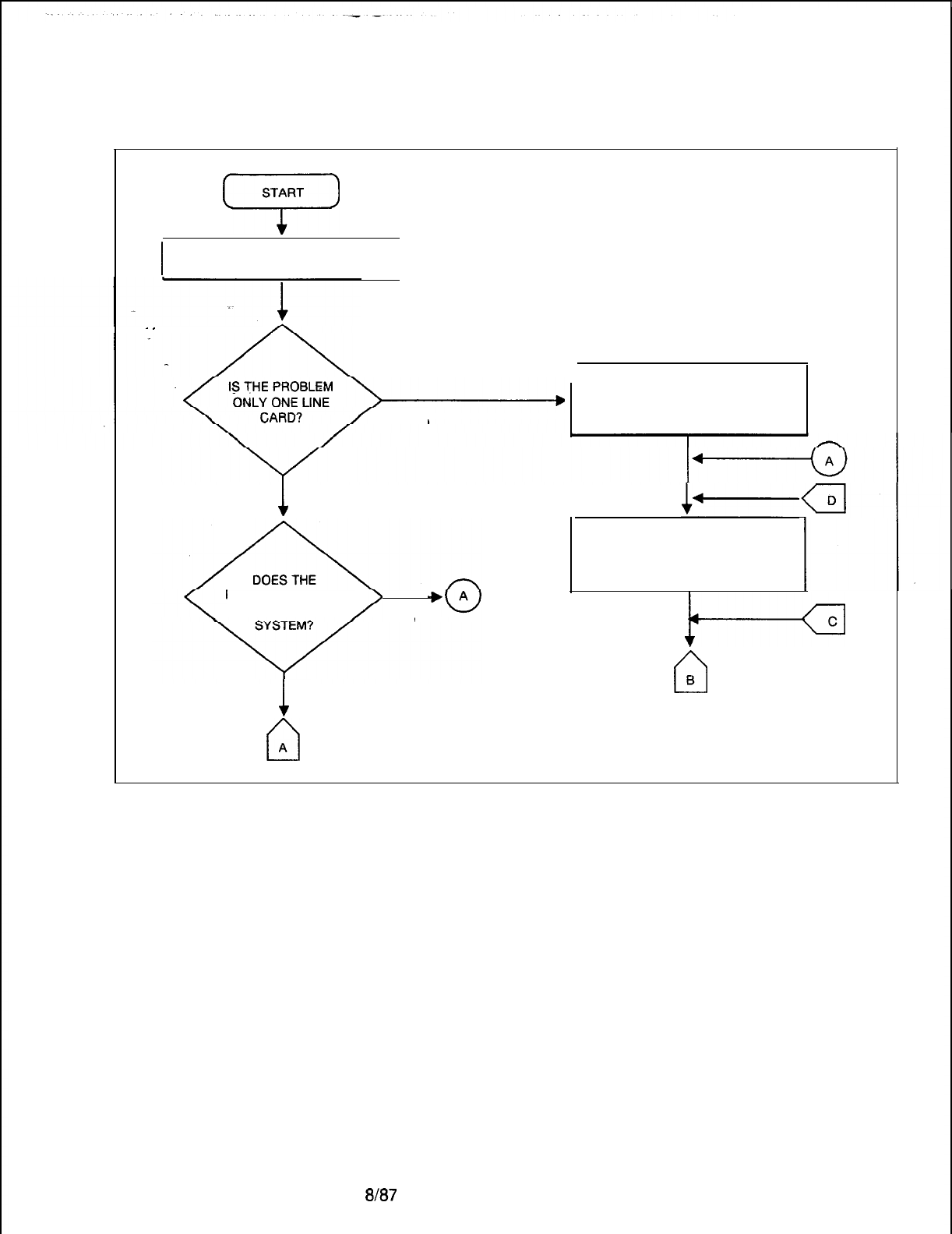
TL-130200-1001
START
7
I
NO RINGING OR CONSTANT
RINGING
I
.
.
1
NO
PROBLEM INVOLVEPROBLEM INVOLVE
THE ENTIRETHE ENTIRE
YESYES
1
NO
/
YES
cl
A
r
REPLACE THE FAULTY LINE CARD
(PLCC) (NOTE). IF THE PROBLEM
IS NOT SOLVED, REINSERT THE
ORIGINAL CARD.
REPLACE THE PSUPY CARD
(NOTE 1). IF THE PROBLEM IS NOT
SOLVED, REINSERT THE ORIGINAL
CARD.
e
n
B
NOTE: Ses paragraph 1.4.5.
Figure 5.7 Ringing Operation Troubleshooting Flowchart (Sheet 1 of 3)
5210
ah37
M-171
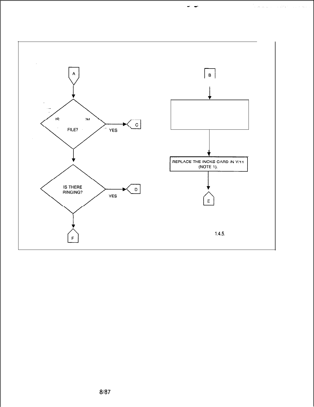
-
-
TL-130200-1001
r-l
B
V
1
-IS THE
PROBLEM
ONLY IN ONE
1
NO
1
NO
.
REPLACE THE ASSOCIATED MPB85
IN X/4 OR Y/5 (NOTE) IF THE
PROBLEM IS NOT SOLVED,
REINSERT THE ORIGINAL MPB85
CARD (NOTE).
NOTE: See paragraph
1.4.5.
Figure 5.7 Ringing Operation Troubleshooting Flowchart (Sheet 2 of 3)
M-l 72
8187
5210
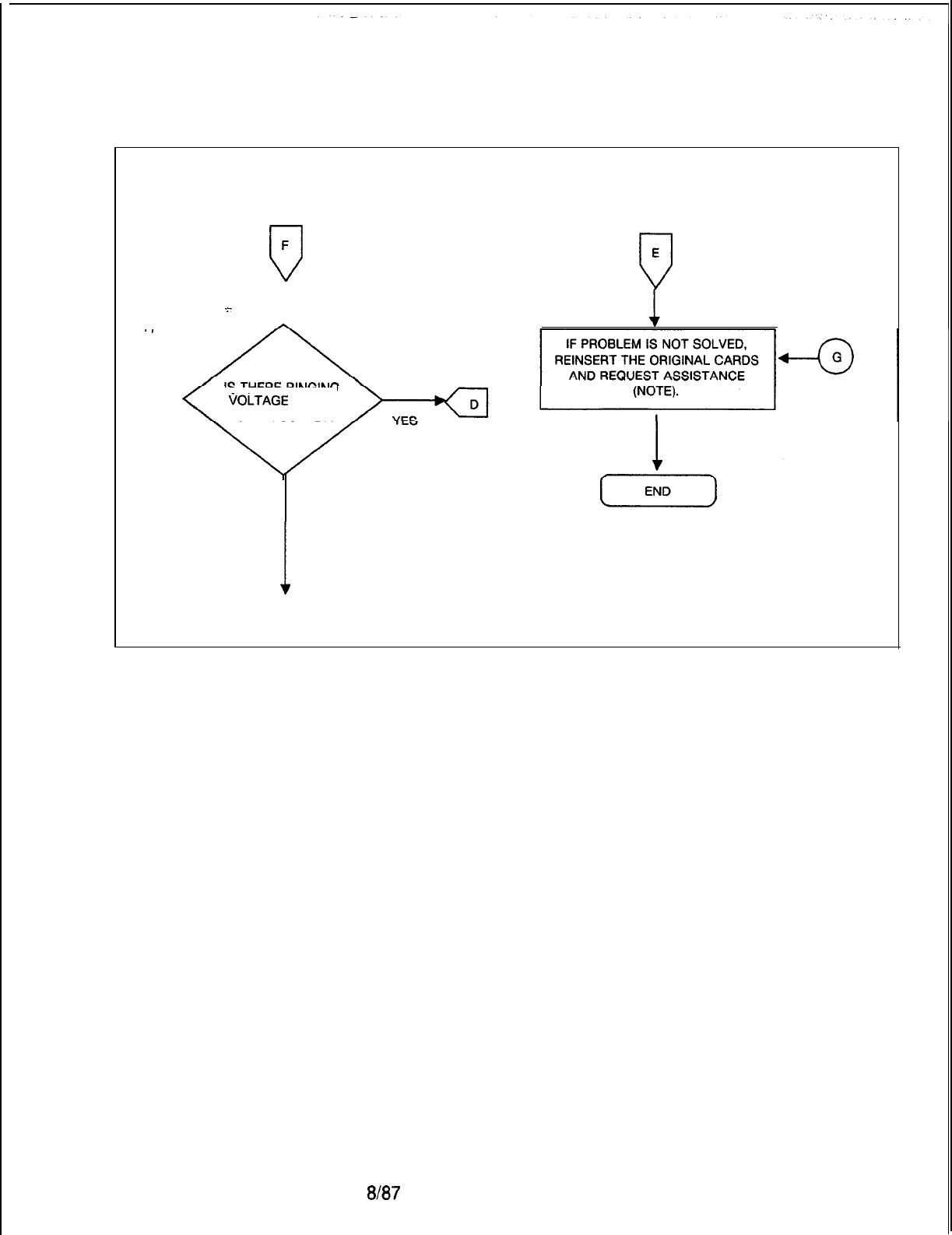
TL-130200-1001
F
u
-.-
1
.
.
IS THERE RINGING
VOLTAGE
AT THE
POWER SUPPLY?
I
NO
0
G
NOTE:
See paragraph 1.4.5.
Figure 5.7 Ringing Operation Troubleshooting Flowchart (Sheet 3 of 3)
5210
8187
M-173
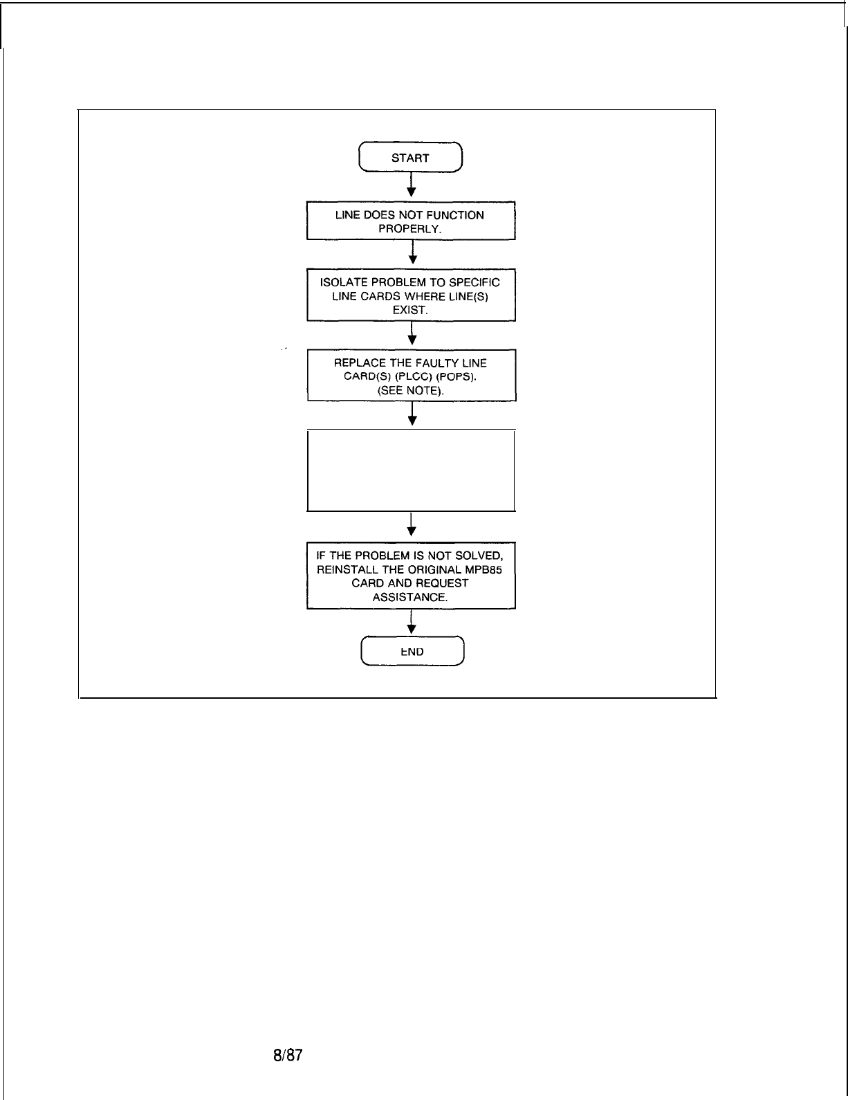
TL-130200-1001
IF THE PROBLEM IS NOT SOLVED,
REINSERT THE ORIGINAL LINE
CARD(S) AND REPLACE THE
ASSOCIATED MPB85 CARD.
(SEE NOTE).
NOTE: See paragraph 1.4.5.
M-174
a/a7
Figure 5.8 Analog Line Operation Troubleshooting Flowchart
5210
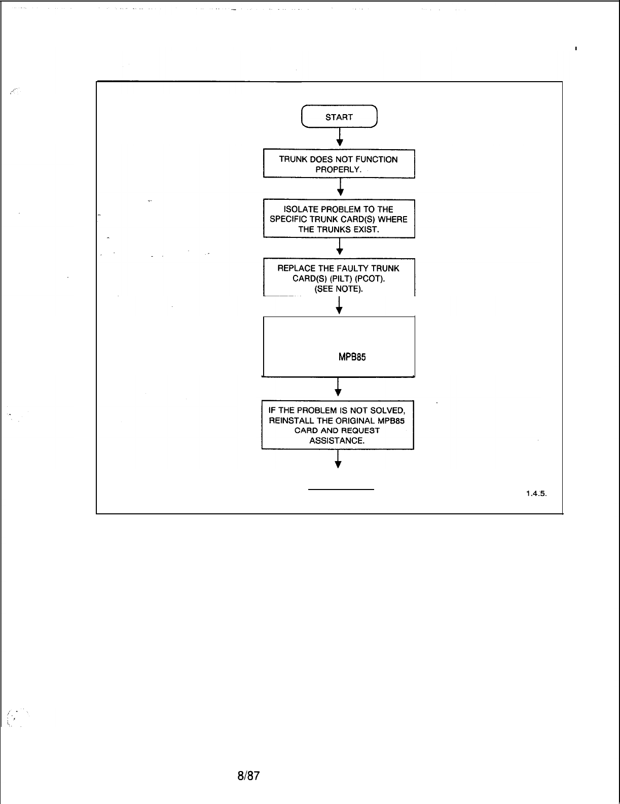
5210
TL-130200-1001
START
i-’
IF THE PROBLEM IS NOT SOLVED,
REINSERT THE ORIGINAL TRUNK
CARD(S) AND REPLACE THE
ASSOCIATED
MPB85
CARD.
(SEE NOTE).
(END)
NOTE: See paragraph
l&5.
Figure 5.9 Trunk Operation Troubleshooting Flowchart
8187
M-175

TL-130200-1001
Tl
-Type Trunk
5.4 The Tl-Type Supervisory and Alarm Cards
Maintenance
(FB-20718-1A)
have buffers which retain the status of the
sense and control points (see Table 5.5). With the maintenance
TTY, maintenance personnel can read or write into the digital
trunk address in the same manner as with the analog trunks.
Refer to Table 5.6 for trunk addresses. Be advised that analog
trunk card locations are preempted from use when
Tl
is
implemented.
When referring to Table 5.5, note that the channel A and B
signaling used with FX trunks does not provide for returning
reverse battery from the CO. Therefore, the RB bit (bit 4 of the
FX sense word) is an inactive bit and always appears as a 0 to
the CPU.
Bit 5 of the FX trunk work, the CF (Current Flow) bit, is a
logic-
gated sense point. The Tl-Type Supervisory Card gates the
loop closure instruction forwarded to the far end with the
detection of the IS (Incoming Seizure) sense bit to create the CF
bit.
BIT 7
GD
GS
Table 5.5 Sense and Control Words for Digital Trunks
BIT 6 BIT 5 BIT 4 BIT 3 BIT 2
BIT 1
BIT 0
IS
CF RB
FX TRUNK
SENSE
WORD
IS E&M
TRUNK
SENSE
WORD
LP
FX TRUNK
CONTROL
WORD
LP
E&M
TRUNK
CONTROL
WORD
GD = Ground Detected
GS = Ground Start
IS =Incoming Sequence
CF
= Current Flow
RB =Reverse Battery
LP = Close Loop
8187
5210
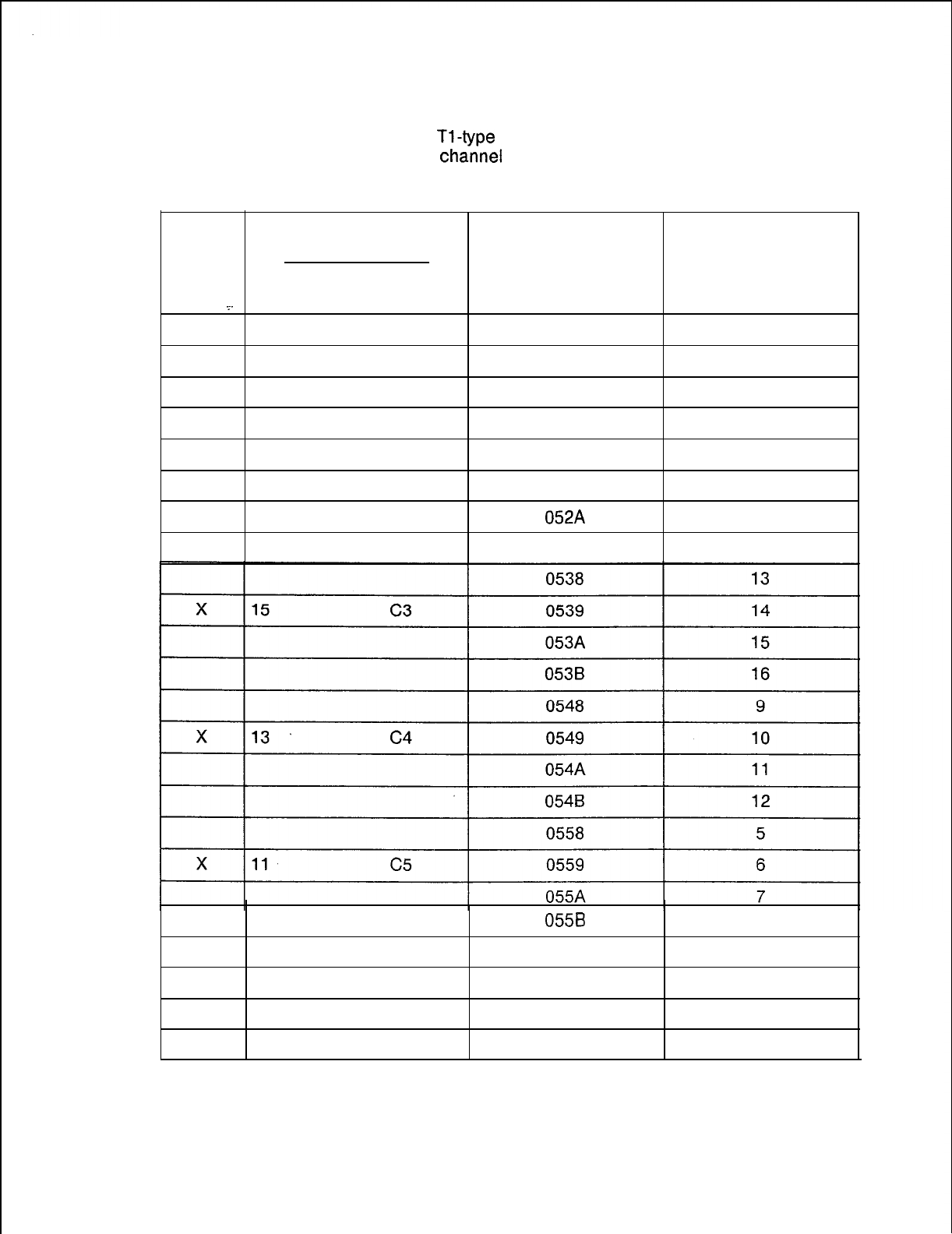
5210
TL-130200-1001
Channel Unit Removal 5.5 The
Tl-tvoe
interface cards do not detect removal of a
loopstart
chainel
unit at the CO and use should be avoided.
Table 5.6 Trunk to Digital Span: Channel Correlation
ANALOG TRUNK
CARD LOCATION HARDWARE DIGITAL SPAN
FILE
SLOT UNIV. POS ADDRESS CHANNEL
IDENTIFICATION IDENTIFICATION
_.
19
Cl 0518
21
X
0519 22
051A
23
051 B 24
17
c2 0528
17
X0529
18
052A
19
0528
20
055B
8
0568
1
x
9C6 0569 2
056A
3
056B
4
8187
M-l 77
--
TL-130200-1001
Removal of a ground-start channel unit at the CC causes the
GD (Ground-Detected) sense point, bit 7, in the FX trunk sense
word Table (5.5) to become true, making the associated trunk
busy to the system.
Removal of an E
&
M or incoming loop dial channel unit at the far
end causes an incoming seizure to the system. If the system
data base is configured for the trunk circuit as a
ringdown
to the
attendant, the removal of the far-end channel unit causes an
incoming call to the attendant’s loop.
If a channel unit at the CO channel bank is equipped with a busy
key, operation of the busy key is equivalent to removing the
channel unit from service.
NOTE:The FX channel unit, when configured as a loopstart
channel unit, is not detected as removed from service when the
busy key is operated.
Alarms 5.6 The SYS LED on the Tl-Type Supervisory card
(FB-
20718-1A)
is activated when any one of the following occurs:
0
A local alarm
*
A remote alarm
0
A RPR ( remote power failure alarm)
e
When the digital trunks are in a loop test mode
l When alarms above are off, but bit 2 (inhibit) is still being
forwarded to the other end during the alarm
restoral
sequence.
An alarm signal to the Tl-type Supervisory Card will be
forwarded when the Frame, Detector card (FB-15278-A)
determines that the frame sequence from the CO has been lost
8187
5210
TL-130200-1001
System alarms are associated with the system’s status as a
slave. If the FB-20922-A Network Clock card should lose
frequency synchronization with the
SINX
input for more that 2
seconds, a fault code 15 will be generated. When the
FB-20922-A Card regains frequency synchronization on the
SINX
input, a response code is generated.
When the RPF and SYS
LEDs
light (Tl-Type Supervisory card),
a power failure has occurred in the CO terminating equipment. A
power failure occurs when a normally operated device, such as a
relay, restores and closes a
Tl
PF
Tl
(Power Failure) circuit
grounding input lead in the Tl-Type Supervisory Card. When
the power failure is detected, the RFP LED lights. If the power
failure exists for longer than the local alarm (strapping option)
threshold on the Tl-Type Supervisory Card, the local alarm is
activated. If a common power source feeds the office
terminating repeaters, only two or more power sources are used,
wire one
Tl
PF and
Tl
PFG pair per power source.
Testing
5.7 The loop test determines if the Tl-Type interface can
achieve frame synchronization. Before any loop test is initiated,
all trunks must be in the maintenance busy state to avoid
disconnection a customer from an established connection.
To perform the loop test, set the
AC0
(Alarm Cutoff) switch on the
Tl-Type Supervisory card to the UP position, then set the LPT
(loop) switch to the UP position. During the loop test, the
incoming bipolar stream is terminated into a
loo-ohm
resistor.
An all one (1) logic value is transmitted to the distant end. The
outgoing unipolar transmit signal is looped back to the receiver
side. The framing synchronization during the loop test is such
that the incoming bipolar stream is offset one channel from the
outgoing unipolar stream.
If framing synchronization is achieved during the loop test, the
SYS, ACO, and LOOP
LEDs
remain on. If framing
synchronization is achieved in the system, but not with the far
end, the span interface card may be defective. In most
instances, if the loop test framing synchronization is achieved, it
will also be achieved with the distant end barring any external
wiring or repeater problems.
If an alarm condition exists before a loop test, or if an alarm
condition appears after the system is placed in loop test, the
alarm state will persist for approximately 13.5 seconds. If the
alarm condition persists longer than 13.5
+
or
-
3 seconds, a
failure has occurred in one or more of the cards.
5210
8l87
M-l 79

-!-L-l
30200-l 001
--
To test the network clock synchronization, ensure that the
Tl-
type card group is frame-synchronized to the far end. Once this
has been determined and the coaxial cables are properly
connected between the Span Interface card and the Network
Clock card, the SINX input can be cabled. If the
SINX
input
cabled to a span interface card in an active Tl-type group
cannot be selected, then that cable or span interface card is
faulty. This testing can be done with the system off-line. The
Tl-Type Supervisory Card must not be in the loop test mode. If
more than one LED on the Network Clock card handle is on, the
system is not frequency-synchronizing to a master clock.
Tl Trunk Trouble
5.8 Verify the the failure is not system related before starting any
troubleshooting procedure on the digital trunk interface cards.
Check the system fault log for codes
15
and 17. Trouble-
shooting flowcharts for Tl are shown in Figures 6-25 through
6-28.
The following failures have been categorized in four different
modes on the digital trunk interface:
1. Supervision failure is the full or partial loss of supervisory
signaling capability between the system digital interface and
the distant-end equipment when the span is synchronized.
2. Transmission failure is the full or partial loss of voice (analog)
signals over the digital span while the system is synchronized.
3. Frame synchronization failure (misframing) occurs when the
system cannot identify the start of a frame in the incoming
span. Misframing results in loss of communication from the far
end. In misframing errors, the clocks are assumed to be
running synchronously, but the digital trunk interface cards
cannot decode the incoming span data properly and locate the
245channel
frames.
4. A clock synchronization (frequency synchronization) problem,
or loss-of-slaving condition, results when the system clock
is running at a frequency other than that of the bit frequency on
the incoming Tl-type span. The system can maintain frame
synchronization, but because of differences in clock
frequencies, it will occasionally skip over a frame and never
decode that frame of information. The system is slipping
frames.
M-l 80
8187
5210
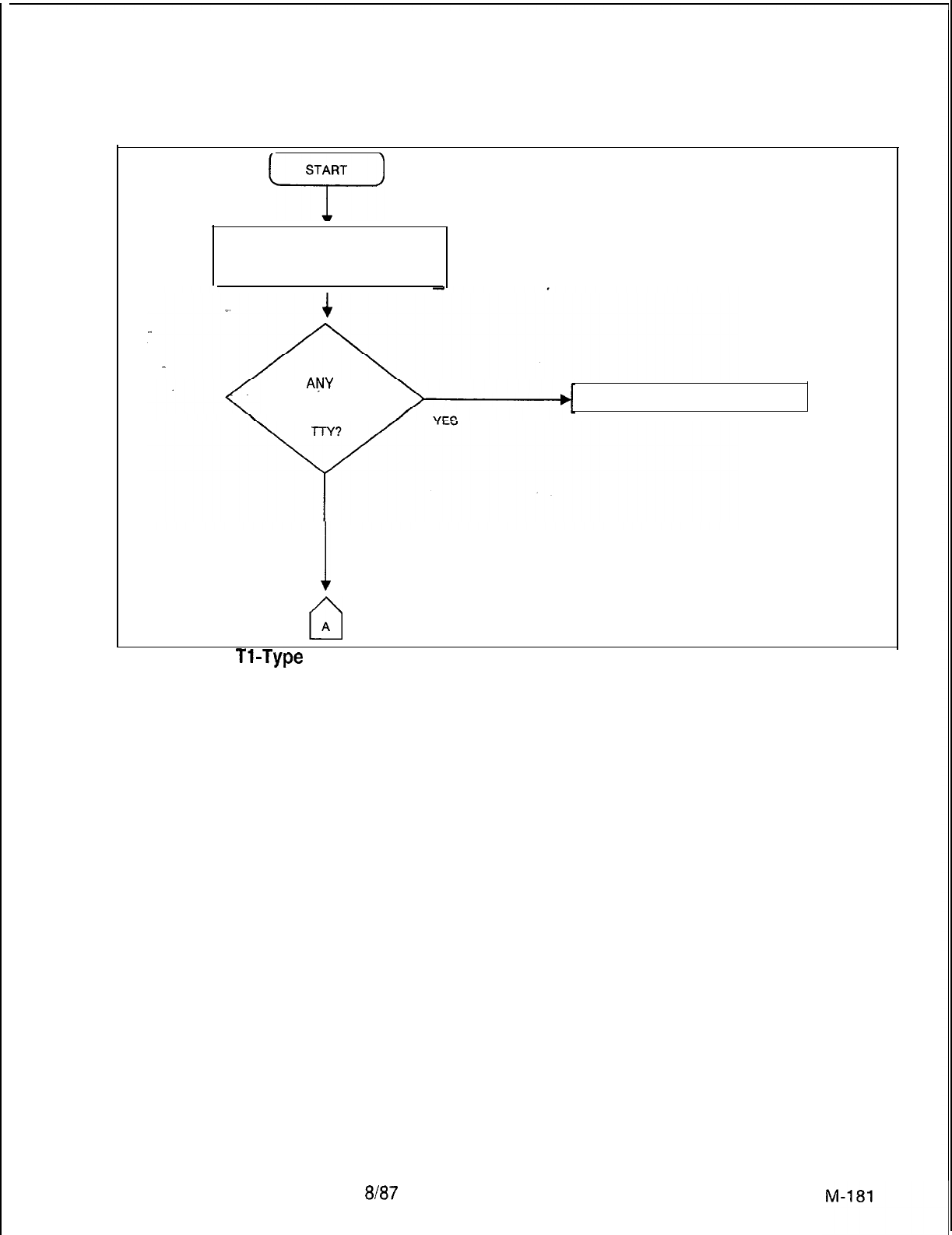
TL-130200-1001
START
ci
SYSTEM HAS LOST PARTIAL OR
FULL SUPERVISION IN THE DIGITAL
TRUNK INTERFACE.
I
ARE
ANY
FAULT
CODES PRINTED ON REFER TO SYSTEM FAULT TABLES
THE MAINTENANCE
I
NO
cl
A
Figure 5.10
Tl-Type
Trunk Loss of Supervision Troubleshooting Flowchart (Sheet 1 of 7)
5210
8h37
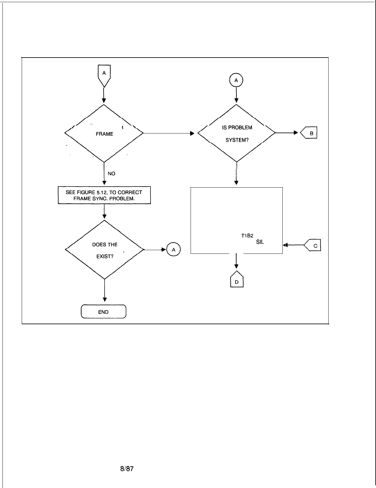
TL-130200-1001
IS THE SYSTEM
b
COMMON TO THE
SYNCHRONIZED?
YES YES
NO
;,
PROBLEM STILL
YES
1
NO
(--Z---l
1
NO
REMOVE AND REPLACE THE
FOLLOWING DIGITAL TRUNK
CARDS ONE AT A TIME. IF THE
TROUBLE STILL EXISTS AFTER
EACH REPLACEMENT, REINSTALL
EACH ORIGINAL CARD.
FB-17192-A
TlB2
FB-17277-A OR 15277-1
SIL
FB-15280-A LCM
.
Figure 5.10 Tl-Type Trunk Loss of Supervision Troubleshooting Flowchart (Sheet 2 of 7)
M-l 82
8187
5210
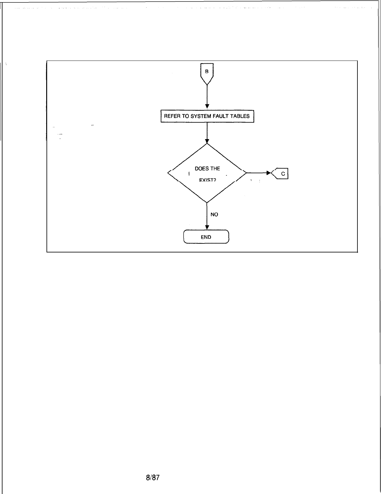
TL-130200-1001
PROBLEM STILL
YES
Figure 5.10 Tl-Type Trunk Loss of Supervision Troubleshooting Flowchart (Sheet 3 of 7)
5210
8A37
M-183
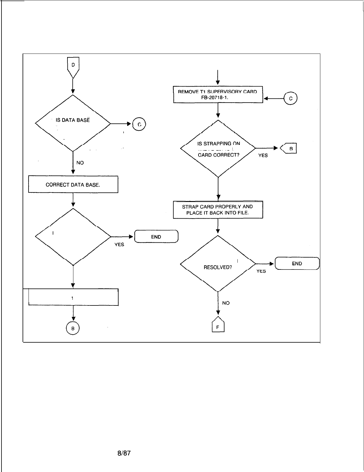
TL-130200-1001
D
7
0
B
---CORRECT?
YES
THE FB-20718-l
NO
IS THE PROBLEM
RESOLVED?
IS THE
PROBLEM
NO
‘I
REPLACE
f
MB CARD.
Figure 5.10 Tl-Type Trunk Loss of Supervision Troubleshooting Flowchart (Sheet 4 of 7)
5210

TL-130200-1001
B
P
REMOVE AND REPLACE
FB-207181 CARD.
I
IF PROBLEM STILL EXISTS,
REINSERT THE ORIGINAL CARD
AND REPLACE MPB85
FB-17215-
A CARD IN
x/4
(NOTE).
PROBLEM STILL
YES
NOTE: See paragraph 1.4.5.
Figure 5.10 Tl-Type Trunk Loss of Supervision Troubleshooting Flowchart (Sheet 5 of 7)
5210
8l87
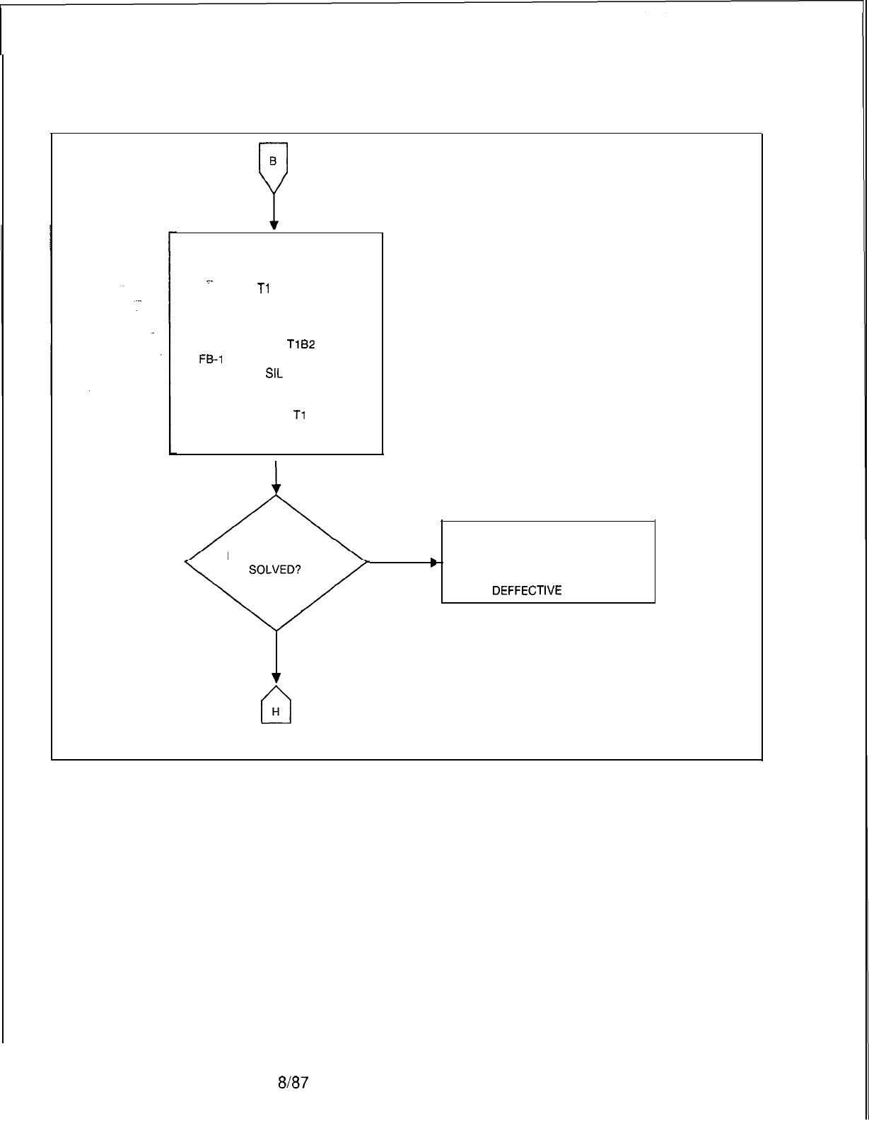
TL-130200-1001
B
P
REINSTALL ORIGINAL MPB85
CARD. REMOVE ALL OTHER
CARDS RESIDING IN FILE WITH
_.
TROUBLED
Tl
-TYPE TRUNK
INTERFACE EXCEPT THE CARDS
REMOVED PREVIOUSLY.
FB-17192-A
TlB2
FE1
7277-A OR 15277-1
SIL
FB-15278-A FDC
FB-15280-A LCM
FB-20718-l
Tl
SUPERVISORY
FB-17215-A MPB85
I
IS THE PROBLEM
D
YES
NO
v
n
H
Figure 5.10 Tl-Type Trunk Loss of Supervision Troubleshooting Flowchart (Sheet 6 of 7)
ISOLATE DEFECTIVE CARD BY
REINSTALLING REMOVED CARDS,
ONE AT A TIME, UNTIL FAILURE
OCCURS. REMOVE AND REPLACE
DEFFECTIVE
CARD.
I
M-186
8187
5210
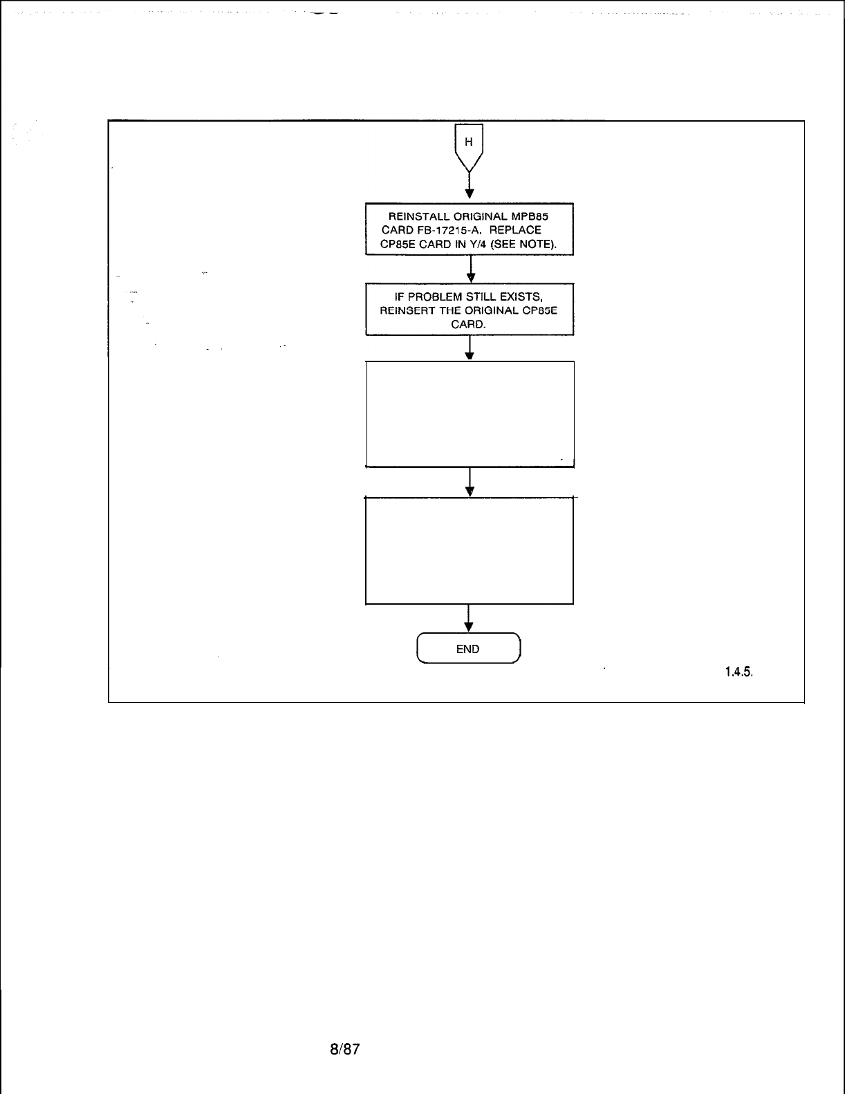
TL-130200-1001
Figure 6.10 Tl-Type Trunk Loss of Supervision Troubleshooting Flowchart (Sheet 7 of 7)
AT THIS POINT CHECK FOR THE
PROBLEM IN THE INTERFACE
CABLE BETWEEN THE FILES.
REPLACE CABLE ONE AT A TIME.
IF THE PROBLEM STILL EXISTS
AFTER EACH REPLACEMENT,
REINSTALL THE ORIGINAL CABLE.
IF THE PROBLEM STILL EXISTS,
CALL EXPERIENCED
MAINTENANCE PERSONNEL. THE
PROBLEM MAY BE DUE TO A
MULTIPLE CARD FAILURE.
BACKPLANE WIRE, OR FAR-END
INTERFACING EQUIPMENT.
NOTE: See paragraph
1.4.5.
5210
8187
M-187
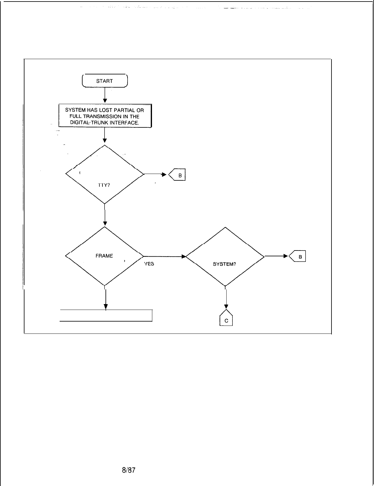
TL-130200-1001
START
ci
ARE ANY FAULTARE ANY FAULT
CODES PRINTED ONCODES PRINTED ON
THE MAINTENANCETHE MAINTENANCE
YESYES
1
NO
IS THE SYSTEM
SYNCHRONIZED?
IS PROBLEM
COMMON TO THE
a
B
YES
NO NO
v v
REFER TO SYSTEM FAULT TABLES
n
C
Figure 5.11 Tl-Type Trunk Loss of Transmission Troubleshooting Flowchart
(Sheet 1 of 6)
8l87
5210
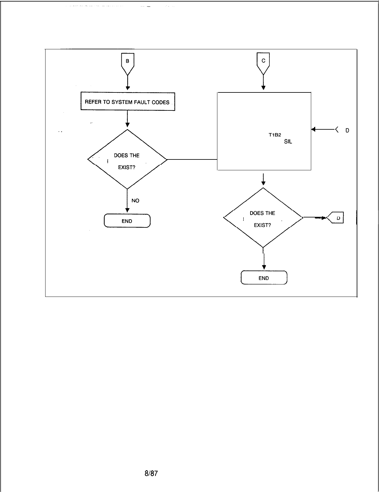
TL-130200-1001
C
P
.
.
PROBLEM STILL
l
YES
REMOVE ALL OTHER CARDS
RESIDING IN FILE WITH TROUBLED
Tl -TYPE TRUNK INTERFACE
EXCEPT THE CARDS REMOVED
PREVIOUSLY.
FB-17192-A
TlB2
FB-17277-A OR 15277-1
SIL
FB-15278-A FDC
FB-15280-A LCM
FB-20718-I Tl
SUPERVISORY
I
4
+D
cl
PROBLEM STILL
YES
1
NO
(END)
Figure 5.11 Tl-Type Trunk Loss of Transmission Troubleshooting Flowchart
(Sheet 2 of 6)
5210
Em7
M-189
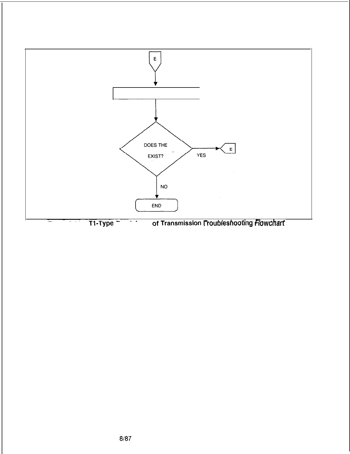
TL-130200-1001
E
Y
REFER TO SYSTEM FAULT CODES
PROBLEM STILL
M-190
Figure 6.11
Tl-Type
Trunk Loss
ot
Transmlsslon
I
rouDlesnoortng
rlowcnarr
(Sheet 3 of 6)
8187
5210
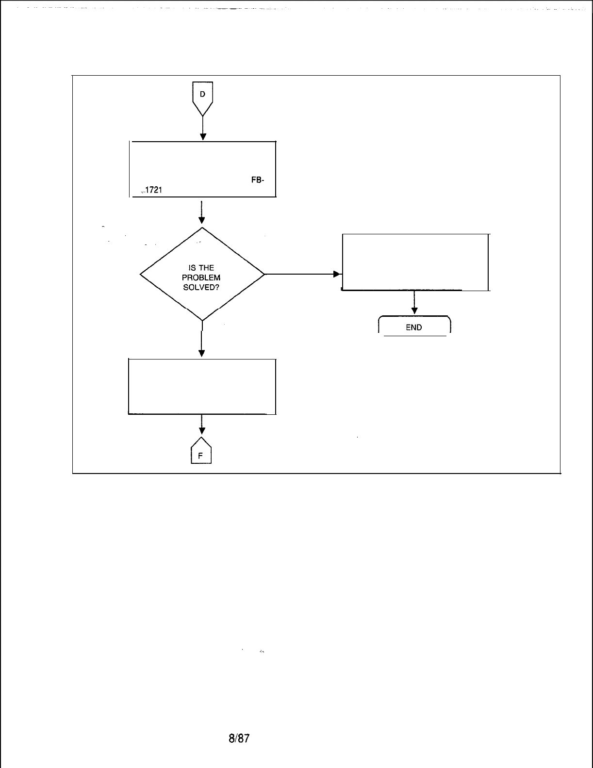
TL-130200-1001
D
7
REMOVE ALL OTHER CARDS IN
FILE EXCEPT FOR THE FIVE
DIGITAL TRUNK CARDS REMOVED
PREVIOUSLY AND THE MPB85
FB-
-T-1721
5-A CARD (SEE NOTE).
I
1
b
YES
1
NO
REINSTALL ALL CARDS REMOVED
FROM THE FILE. REMOVE AND
REPLACE THE CHM85
FB-17218-A CARD IN X/l
(NOTES 1 AND 2).
II
F
ISOLATE DEFFECTIVE CARD BY
INSTALLING THE REMOVED CARDS
ONE AT A TIME UNTIL FAILURE
OCCURS. REMOVE AND REPLACE
THE DEFFECTIVE CARD.
NOTE: See paragraph 1.4.5.
Figure 5.11 Tl-Type Trunk Loss of Transmission Troubleshooting Flowchart
(Sheet 4 of 6)
5210
8187
M-191
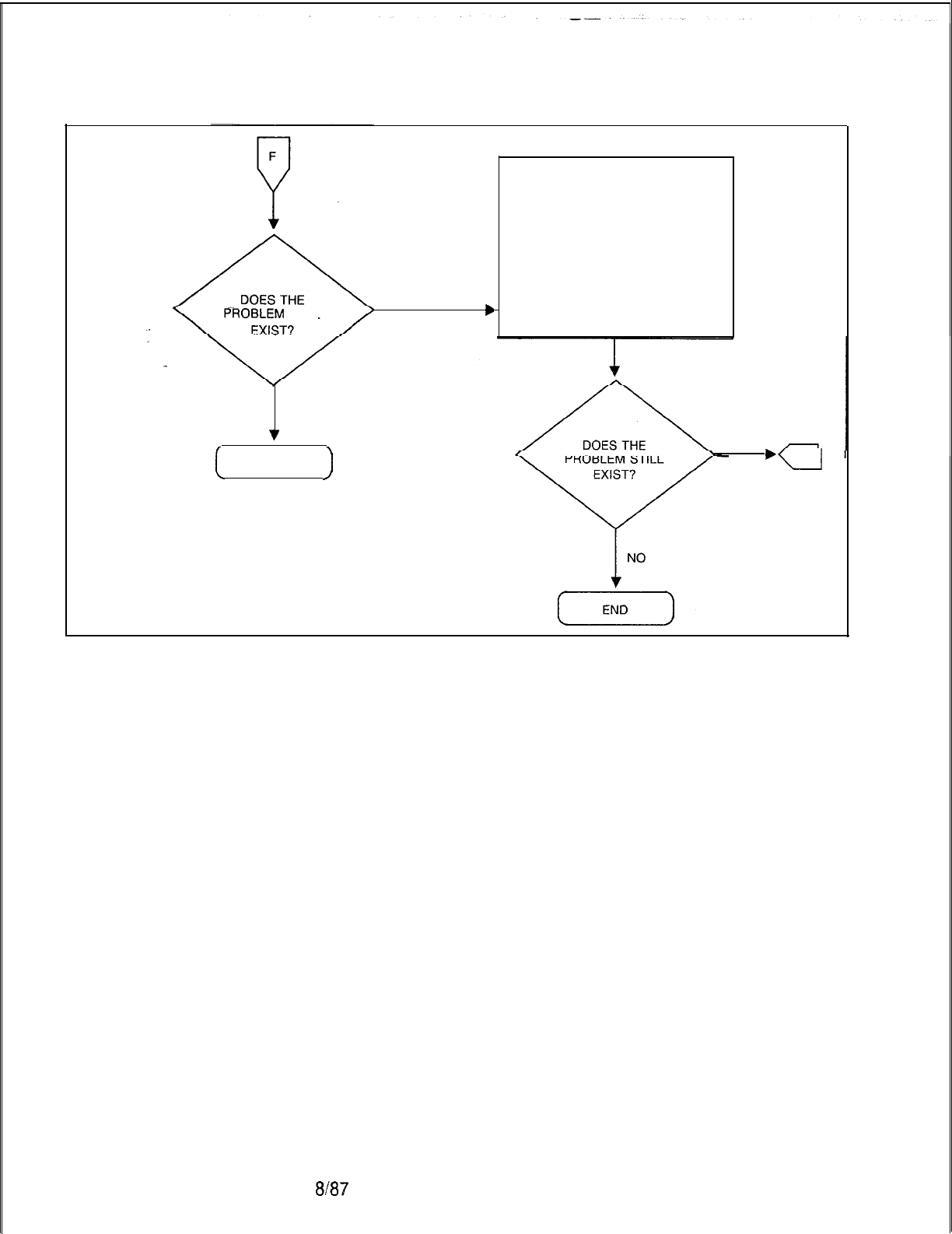
TL-130200-1001
PROBLEM
STILL
PROBLEM
STILL
bb
YESYES
NONO
v
[
END
)
REINSTALL ORIGINAL CHM85
FB-17218-A CARD INTO THE
FILE. CHECK FOR PROBLEM IN
THE INTERFACE CABLES BETWEEN
THE CHM85 CARD AND THE
EPCMN FB-17217-A CARD.
REMOVE AND REPLACE ONE TAB
CABLE AT A TIME. IF THE
PROBLEM IS NOT SOLVED,
REINSERT THE ORIGINAL CABLE
ONE AT A TIME.
YES
‘=
Figure 5.11 Tl-Type Trunk Loss of Transmission Troubleshooting Flowchart
(Sheet 5 of 6)
M-192
8l67
5210
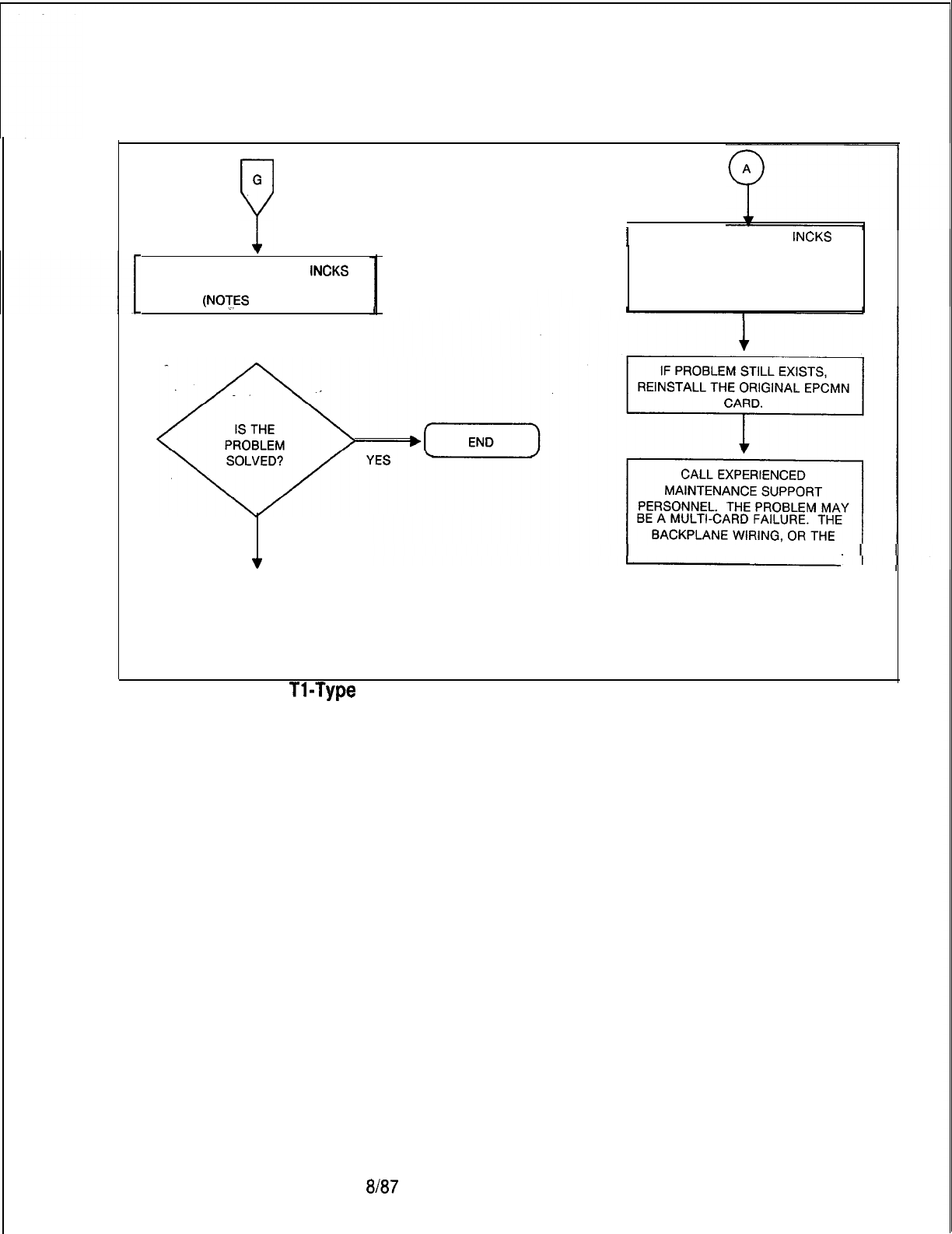
TL-130200-1001
G
P
I
REINSTALL ORIGINAL
INCKS
.
REMOVE AND REPLACE
INCKS
FB-20992-A OF INC FB-20771 l-1
(NOTES
1 AND 2)
I
FB-20992-A CARD. REMOVE
AND REPLACE EPCMN
FB-17217-A CARD IN Y/9.
(NOTES 1 AND 2)
. .
1
NO FAR-END INTERFACE EQUIPMENT.
‘I
0
A
NOTES:
1. See paragraph 1.4.5.
2. Before removing or replacing these cards,
disconnect the cables from the front of the card.
Figure 5.11 Tl-Type Trunk Loss of Transmission Troubleshooting Flowchart
(Sheet 6 of 6)
5210
ala7
M-193
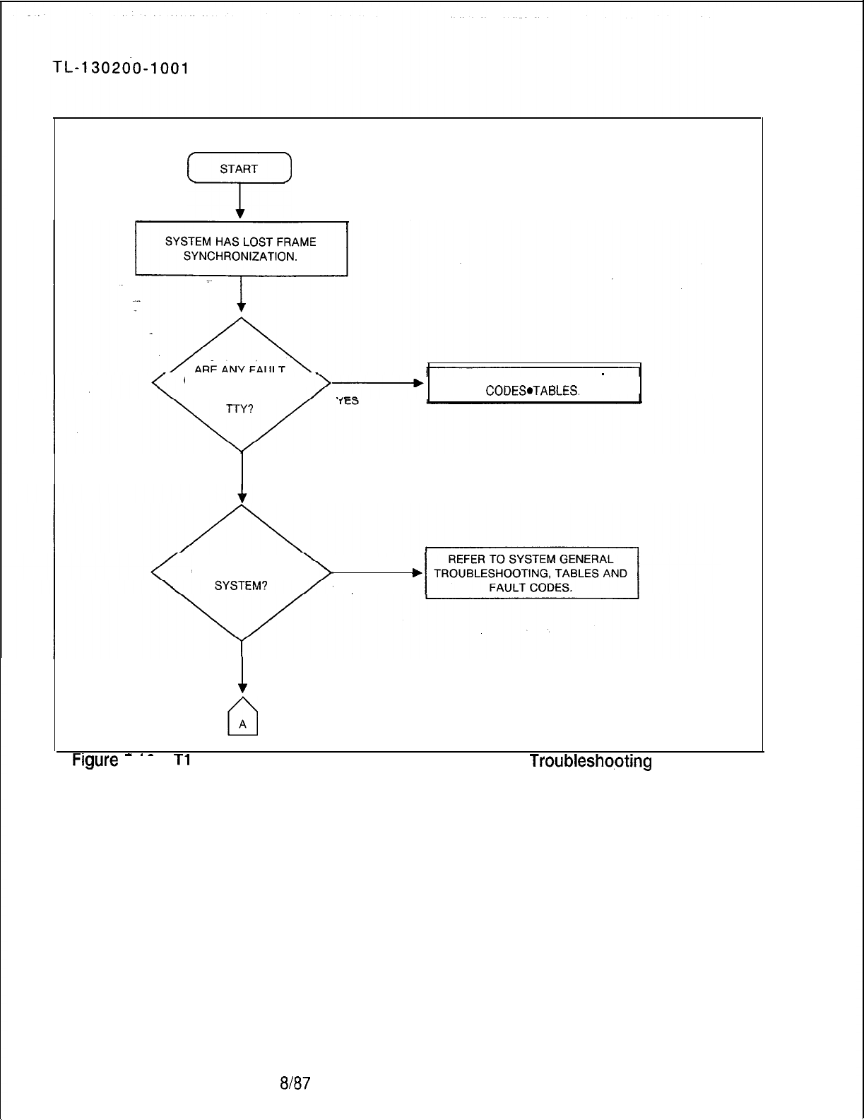
START
7
CODES PRINTED ON REFER TO SYSTEM FAULT
THE MAINTENANCE
CODES.TABLES.
NO
IS THE PROBLEM
COMMON TO THE
YES
1
NO
cl
A
-.
-.-
-.-
FIgWe 5.12
Tl
-Type Trunk Loss of Frame Synchronization Troubleshopting Flowchart
(Sheet 1 of 10)
%I87
5210
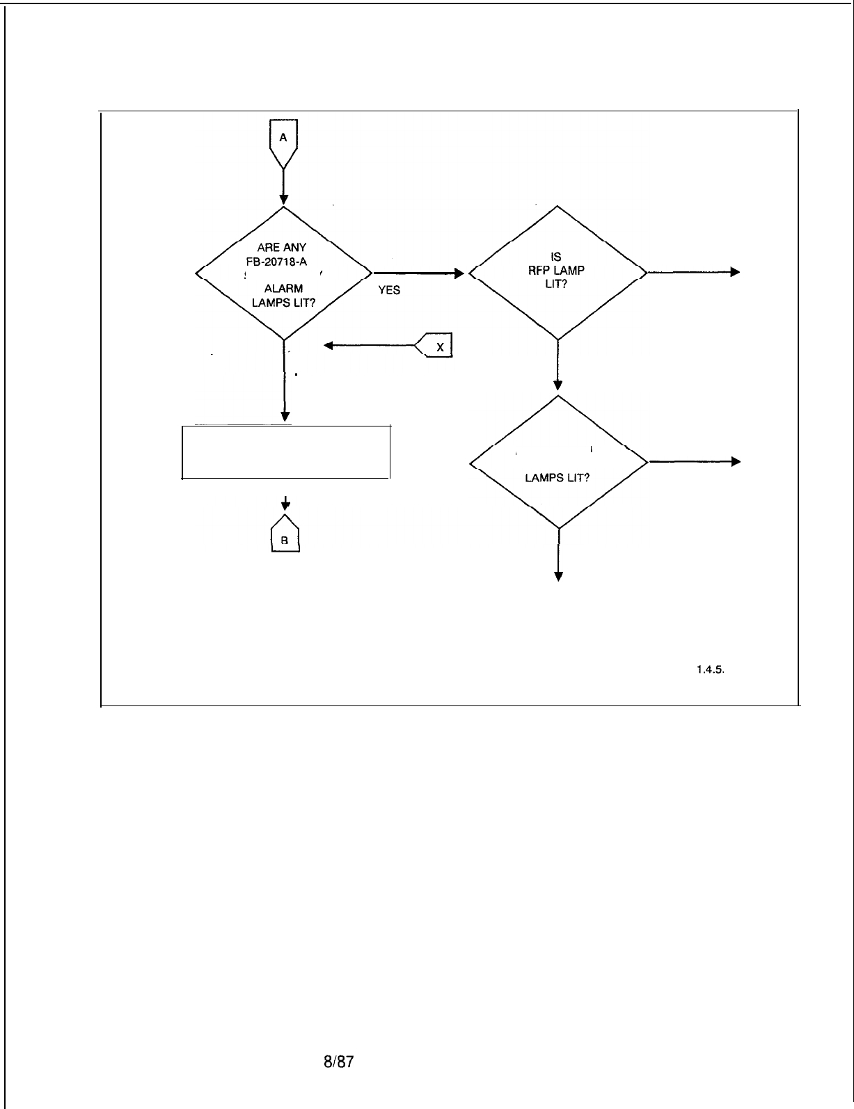
TL-130200-1001
SUPERVISORYSUPERVISORY
NO
-A
0
REMOVE FB-20718-l CARD AND
CORRECT ANY STRAPPING
ERRORS
I
-
D
YES
cl
1
NO
ARE LOC-REM
OR SYSTEM
-
c
YES
cl
1
NO
0
A
NOTE: SEE PARAGRAPH
1.4.5.
Figure 5.12 Tl-Type Trunk Loss of Frame Synchronization Troubleshooting Flowchart
(Sheet 2 of 10)
5210
8l87
M-195
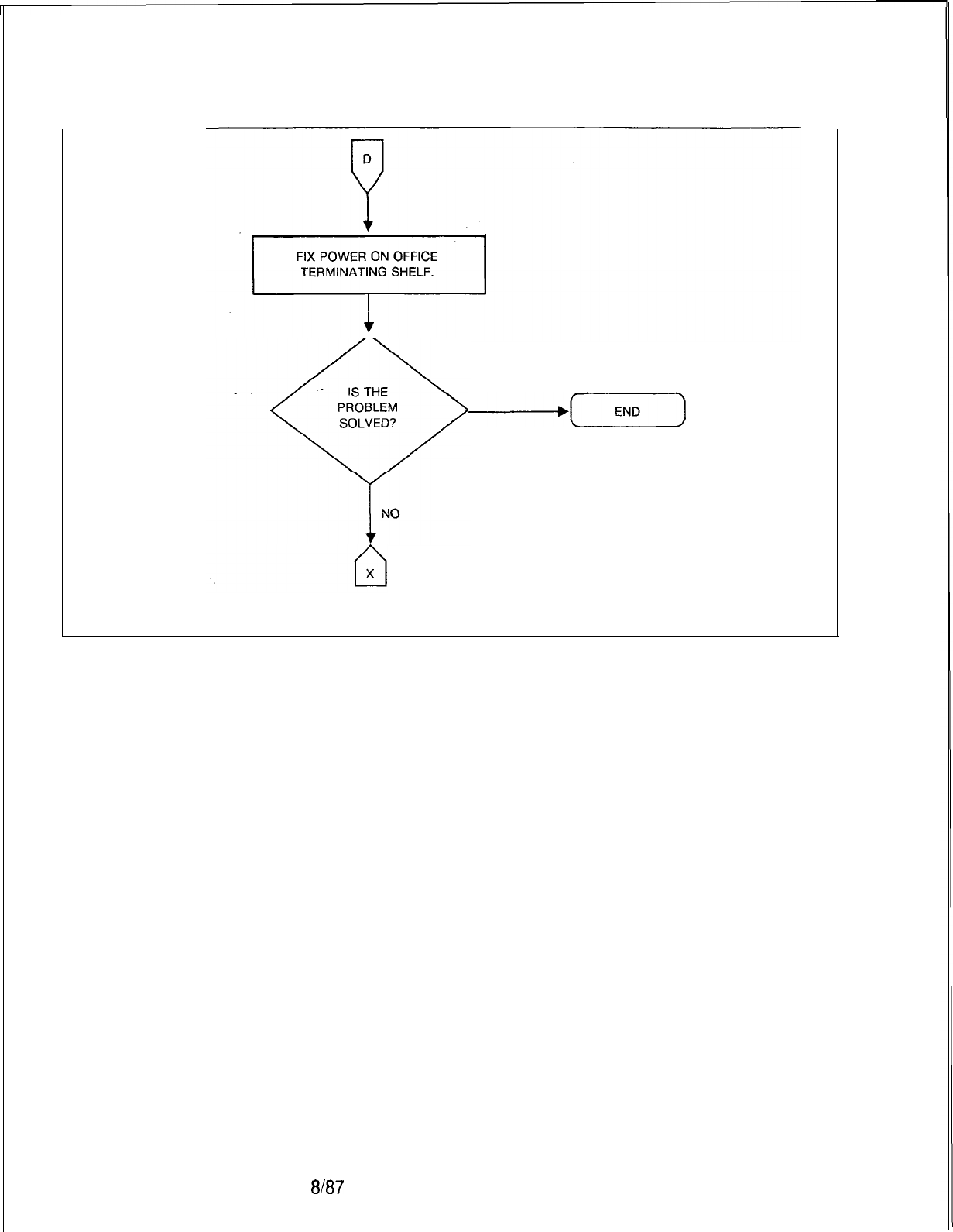
TL-130200-1001
-[END)
YES
NOTE: See paragraph
1.4.5.
Figure 5.12 Tl-Type Trunk Loss of Frame Synchronization Troubleshooting Flowchart
(Sheet 3 of 10)
M-196
8l87
5210
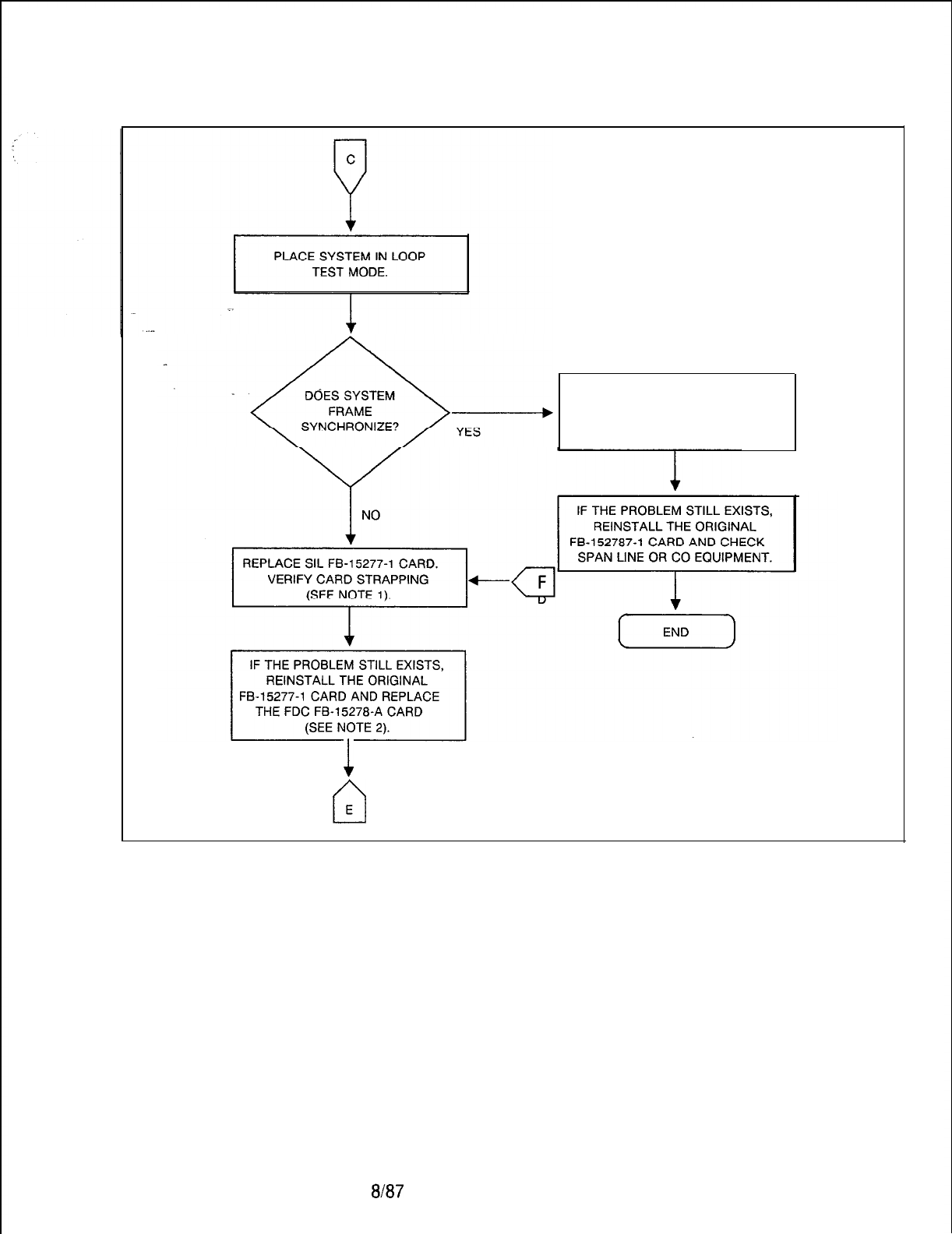
TL-130200-1001
IF THE SYSTEM WILL NOT STAY
SYNCHRONIZED WITH CO,
REPLACE SIL FB-15277-1 CARD
1
NOTES:
cl
1. See paragraph 1.4.5.
2.
Before removing or replacing these cards,
E
disconnect the cables from the front of the card.
Figure 5.12 Tl-Type Trunk Loss of Frame Synchronization Troubleshooting Flowchart
(Sheet 4 of 10)
5210 8187
M-l 97
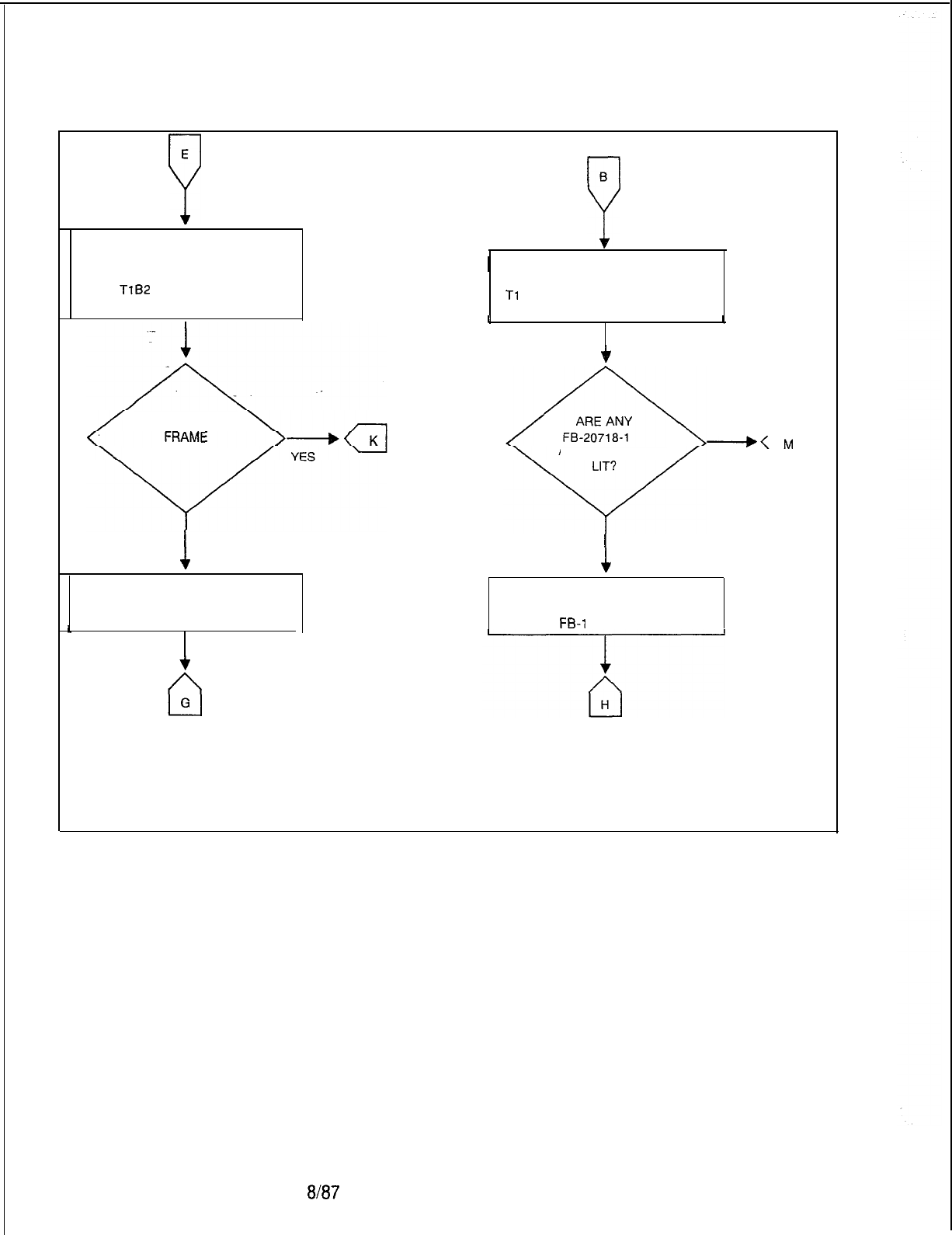
TL-130200-1001
E
P
IF THE PROBLEM STILL EXISTS,
REINSTALL THE ORIGINAL
FB-15278-A CARD AND REPLACE
THE
TlB2
FB-17192-A CARD.
DOES SYSTEM
SYNCHRONIZE?
1
NO
REINSTALL ORIGINAL
FB-17192-A CARD.
B
Y
I
1IF SYSTEM FRAME WILL NOT
1
SYNCHRONIZE WITH CO, REPLACE
Tl
SUPERVISORY FB-20718-l.
I I
f
ALARM LAMPS
---+M
YES
cl
I
NO
f
REINSTALL THE ORIGINAL
FB-20718-l CARD AND REPLACE
Fe-1
5278-A.
NOTE: SEE PARAGRAPH 1.4.5.
Figure 5.12 Tl -Type Trunk Loss of Frame Synchronization Troubleshooting Flowchart
(Sheet 5 of 10)
5210
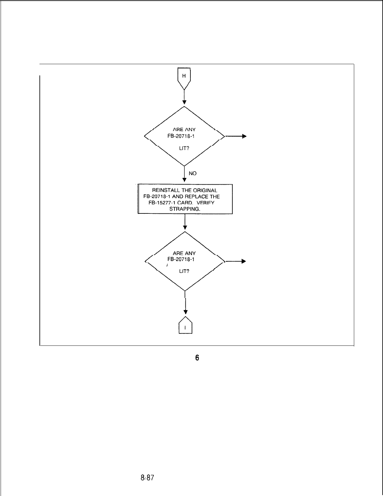
TL-130200-1001
r
-
+
N
+
N
ALARM LAMPSALARM LAMPS
YESYES
clcl
ALARM LAMPS
+
N
YES
cl
1
NO
Figure 5.12 Tl-Type Trunk Loss of Frame Synchronization Troubleshooting Flowchart
(Sheet
6
of 10)
5210 8187
M-199
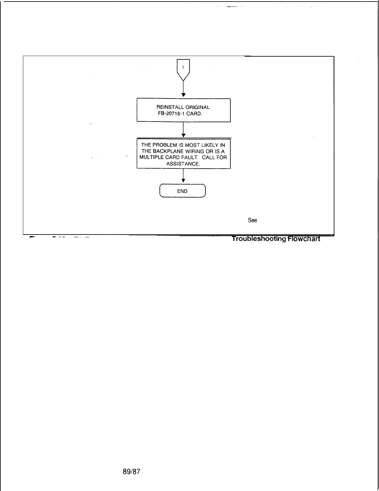
TL.-130200-1001
NOTE: See
paragraph 1.45
Figure 5.12 Tl-Type Trunk Loss of Frame Synchronization Troubleshootmg Flowchart
(Sheet 7 of 10)
89187
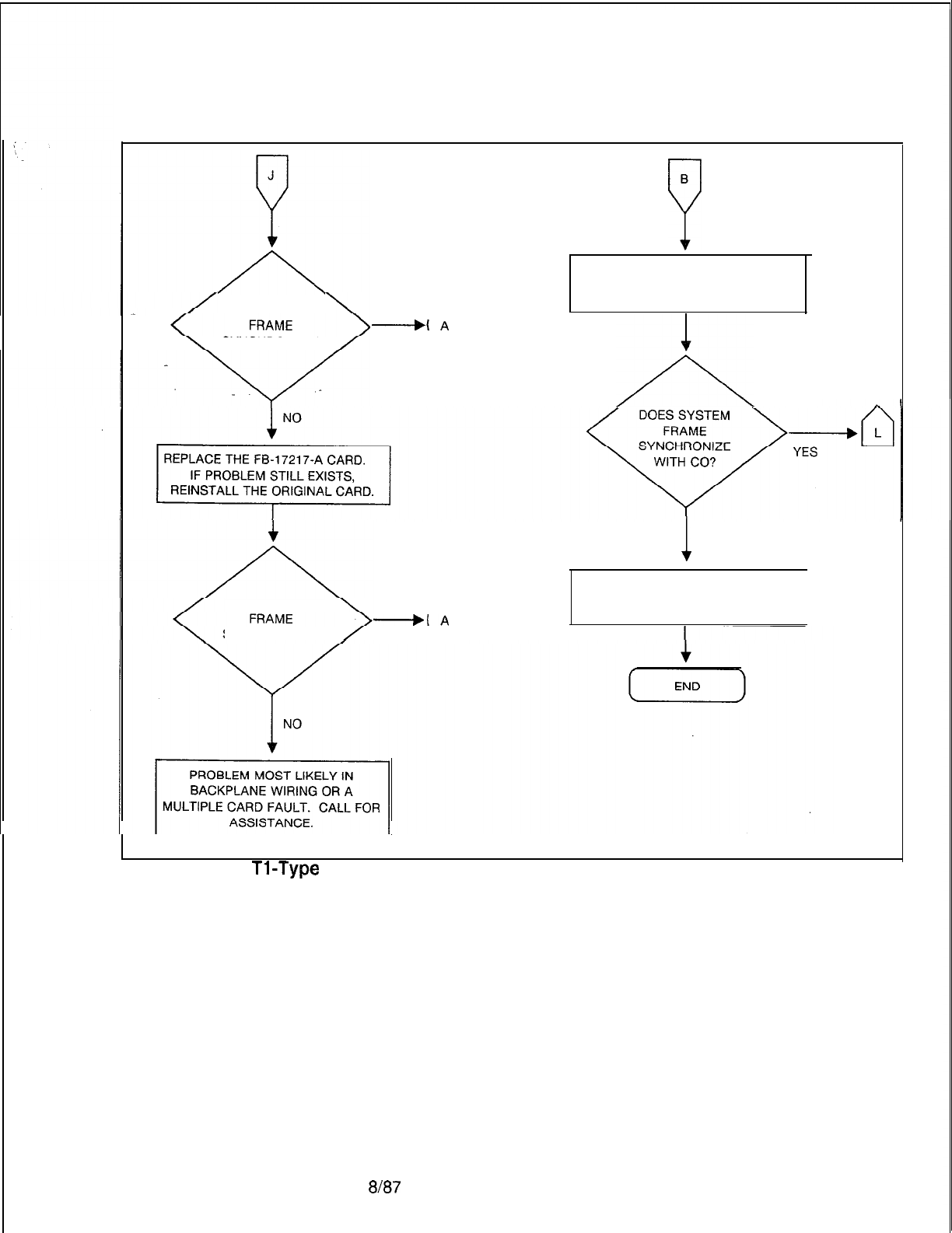
TL-130200-1001
DOES SYSTEM
.
----,A
SYNCHRONIZE?
YES
0
B
P
REMOVE SYSTEM FROM
LOOP TEST MODE. -A
0
/A
DOESSYSTEM
+A
SYNCHRONIZE?
YES
0
1
NO
PROBLEM NOT IN SYSTEM.
CHECK SPAN LINE OR CO.
1
Figure 5.12
Tl-Type
Trunk Loss of Frame Synchronization Troubleshooting Flowchart
(Sheet 8 of 10)
5210 8187 M-201

TL-130200-1001
+
K
SYNCHRONIZE?
YES
cl
1
NO
REINSTALL ORIGINAL
FB-17218-1. REPLACE CABLES
BETWEEN THE FB-17218-l AND
THE FB-17217-A. REPLACE
CABLES ONE AT A TIME. IF THE
PROBLEM STILL EXISTS AFTER
EACH REPLACEMENT, REINSTALL
THE ORIGINAL CABLE.
1
n
J
DOES SYSTEM
+
F
SYNCHRONIZE?
YES
cl
1
NO
REMOVE SYSTEM FROM
SYNCHRONIZE
--,
D
YES
cl
EQUIPMENT?
NO
/A
0
Figure 5.12 Tl-Type Trunk Loss of Frame Synchronization Troubleshooting Flowchart
(Sheet 9 of 10)
M-202
at87
5210
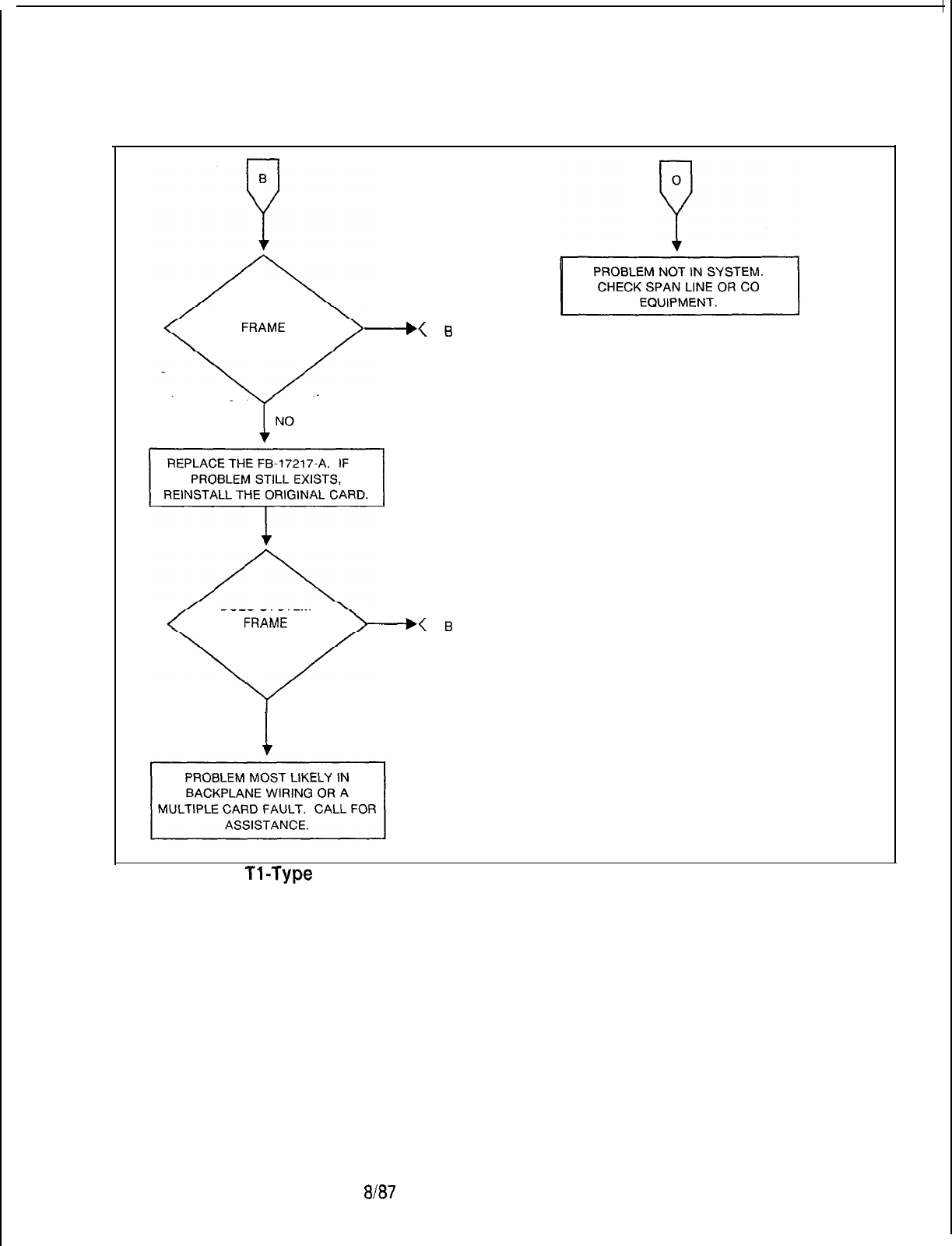
TL-130200-1001
DOESSYSTEM
NB
. .
SYNCHRONIZE?
YES
a
DOES SYSTEM
---+B
SYNCHRONIZE?
YES
a
I
NO
Figure 5.12
TI-Type
Trunk Loss of Frame Synchronization Troubleshooting Flowchart
(Sheet 10 of 10)
5210 w37
M-203
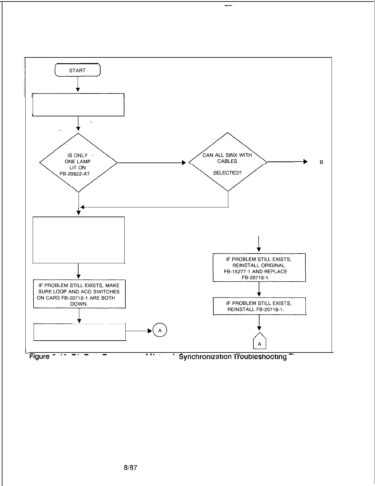
--
TL-130200-1001
LOSS OF NETWORK CLOCK
SYNCHRONIZATION.
9
,
+
-
B
YES
CONNECTED BE
YES
cl
NO NO
4
+‘
ENSURE THAT ALL CABLES ARE
SECURE BETWEEN FB-20992-A A
AND FB-15277-1. IF PROBLEM 0
STILL EXISTS, REPLACE CABLES
ONE AT A TIME. IF PROBLEM STILL
EXISTS, REINSTALL ORIGINAL
1
CABLE.
IF PROBLEM STILL EXISTS,
+
~,
REPLACE FB-15277-l CARD.,
cl
A
-. -
_-
-.
- -
. .
___~
.-
. . . .
-
. . . . .
-_
i
Figure 5.13
Tl-Type Trunk Loss of Network
Synchronization
TrOUbleShOOtIng
Flowchart
(Sheet 1 of 2)
M-204
8187
5210
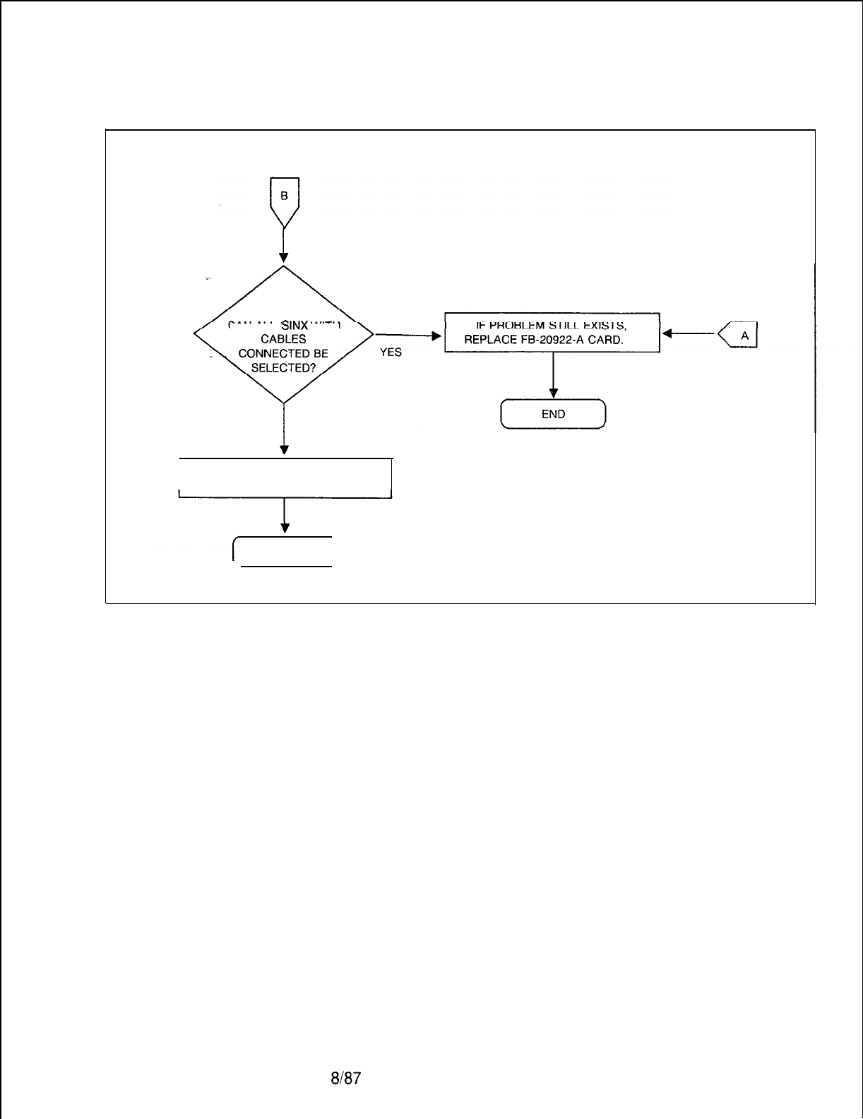
TL-130200-1001
CAN ALL
SINX
WITH
!
NO
PROBLEM IS NOT IN SWITCH. FAR
END CLOCK IS OUR OT SPEC.
END I
Figure 5.13 Tl-Type Trunk Loss of Network Synchronization Troubleshooting Flowchart
(Sheet 2 of 2)
5210 8/87
M-205
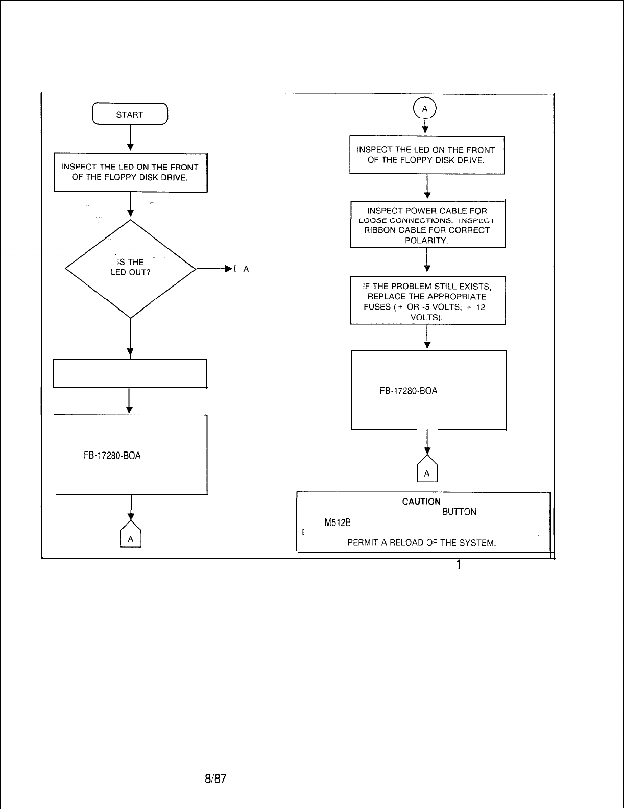
TL-130200-1001
+A
YES
0
NO
INSPECT RIBBON CABLE FOR
CORRECT POLARITY.
IF PROBLEM STILL EXISTS,
REPLACE, ONE AT A TIME, THE
FOLLOWING:
FB-17280-BOA
FMSD
FLOPPY DISK DRIVE
DEPRESSTHEPSUPY
RESET SWITCH EACH TIME.
b
A
IF THE PROBLEM STILL EXISTS,
REPLACE, ONE AT A TIME, THE
FOLLOWING:
FB-17280-BOA
FMSD
FLOPPY DISK DRIVE
DEPRESSTHEPSUPY
RESET SWITCH EACH TIME.
h
A
DEPRESSING THE PSUPY RESET
BUTTON
OR REMOVING
THE
M512B
CARD WILL DESTROY THE SYSTEM MEMORY.
DO NOT DO EITHER UNLESS A DISK DRIVE IS PRESENT TO
Figure 5.14 System Loading Troubleshooting Flowchart (Sheet
1
of 4)
M-206
8187
5210
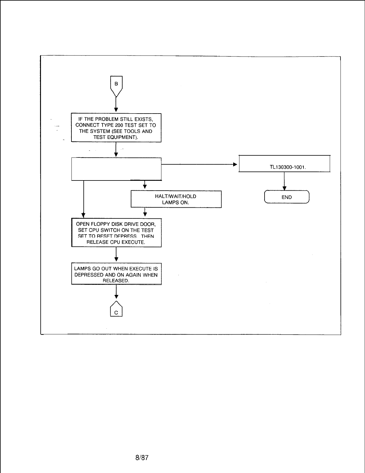
TL-130200-1001
CHECK TEST SET LAMPS.
INTERRUPT ENABLE AND SYNC
SHOULD BE ON.
NO LIGHTS CHECK POWER.
SEE
TL130300-1001.
LAMPS
ON
Figure 5.14 System Loading Troubleshooting Flowchart (Sheet 2 of 4)
5210 8187
M-207
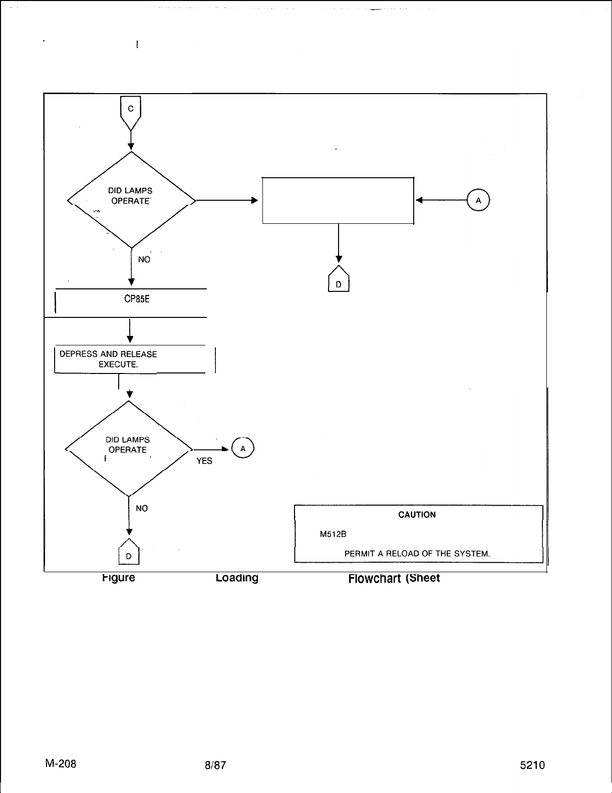
TL-130200-1001
.-..
PROPERLY?
CLOSE FLOPPY DISK DRIVE DOOR.
DEPRESS RESET SWITCH ON THE
b
YES
PSUPY CARD IF PROBLEM STILL
EXISTS.
I
REPLACE
CP85E
CARD
FB-17288-A (SEE NOTE).
I
1
1
DEPRESS;;F,;;;ASE
CPU 1
PROPERLY?PROPERLY?
DEPRESSING THE PSUPY RESET BUTTON OR REMOVING
THE
M512B
CARD WILL DESTROY THE SYSTEM MEMORY.
DO NOT DO EITHER UNLESS A DISK DRIVE IS PRESENT TO
tlgure
5.14 system
Loaarng
Troubleshooting
FlOWChart
(sneet
3 of 4)
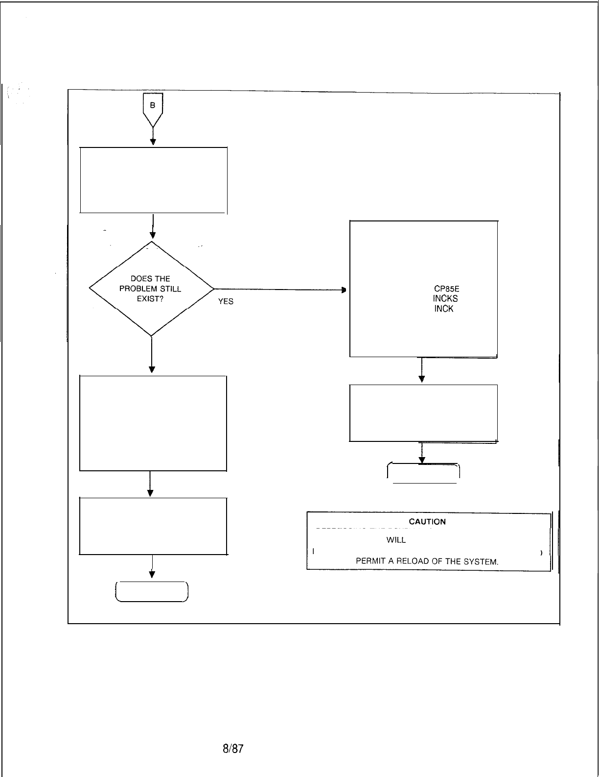
TL-130200-1001
UNPLUG THE FOLLOWING CARDS
FROM THE BACKPLANE:
A. FB-17217-A EPCMN
B. FB-17215-A MPB85
C. FB-20992-A NSDC
DEPRESS RESET SWITCH.
L
NO
REINSERT, ONE AT A TIME; THE
CARDS THAT WERE UNPLUGGED
ABOVE (SEE NOTE). DEPRESS THE
PSUPY RESET SWITCH AFTER
EACH CARD. IF TROUBLE
REAPPEARS, REPLACE CARD THAT
WAS LAST REINSERTED. CHECK
CABLES CONNECTED TO CARD
FB-17217-A.
IF TROUBLE STILL EXISTS WHEN
CABLES ARE CONNECTED,
PERFORM SYSTEM
TROUBLESHOOTING. REFER TO
OFF-LINE DIAGNOSTICS.
c
REPLACE, ONE AT A TIME, THE
FOLLOWING CARDS. DEPRESS
THE PSUPY RESET SWITCH AFTER
INSTALLING EACH CARD. IF
TROUBLE STILL EXISTS,
REINSTALL THE ORIGINAL CARD.
A. FB-17288-A
CP85E
B. FB-20922-A
INCKS
OR
FB-20771 -A
INCK
C. FB-17213-BOA MPG-16
D. FB-17314-A Ml MB
E. FB-17188-A TP12
(SEE NOTE.)
IF TROUBLE STILL EXISTS WHEN
CABLES ARE CONNECTED,
PERFORM SYSTEM
TROUBLESHOOTING. REFER TO
OFF-LINE DIAGNOSTICS.
/
I
END
1
DEPRESSING THE PSUPY RESET BUTTON OR REMOVING
THE Ml MB CARD
WILL
DESTROY THE SYSTEM MEMORY.
DO NOT DO EITHER UNLESS A DISK DRIVE IS PRESENT TO
[
END
)
NOTE: Before removing or replacing these cards, disconnect the
cables from the frot of the card.
Figure 5.14 System Loading Troubleshooting Flowchart (Sheet 4 of 4)
5210 8187
M-209

THIS PAGE IS INTENTIONALLY LEFT BLANK.
ah37
5210
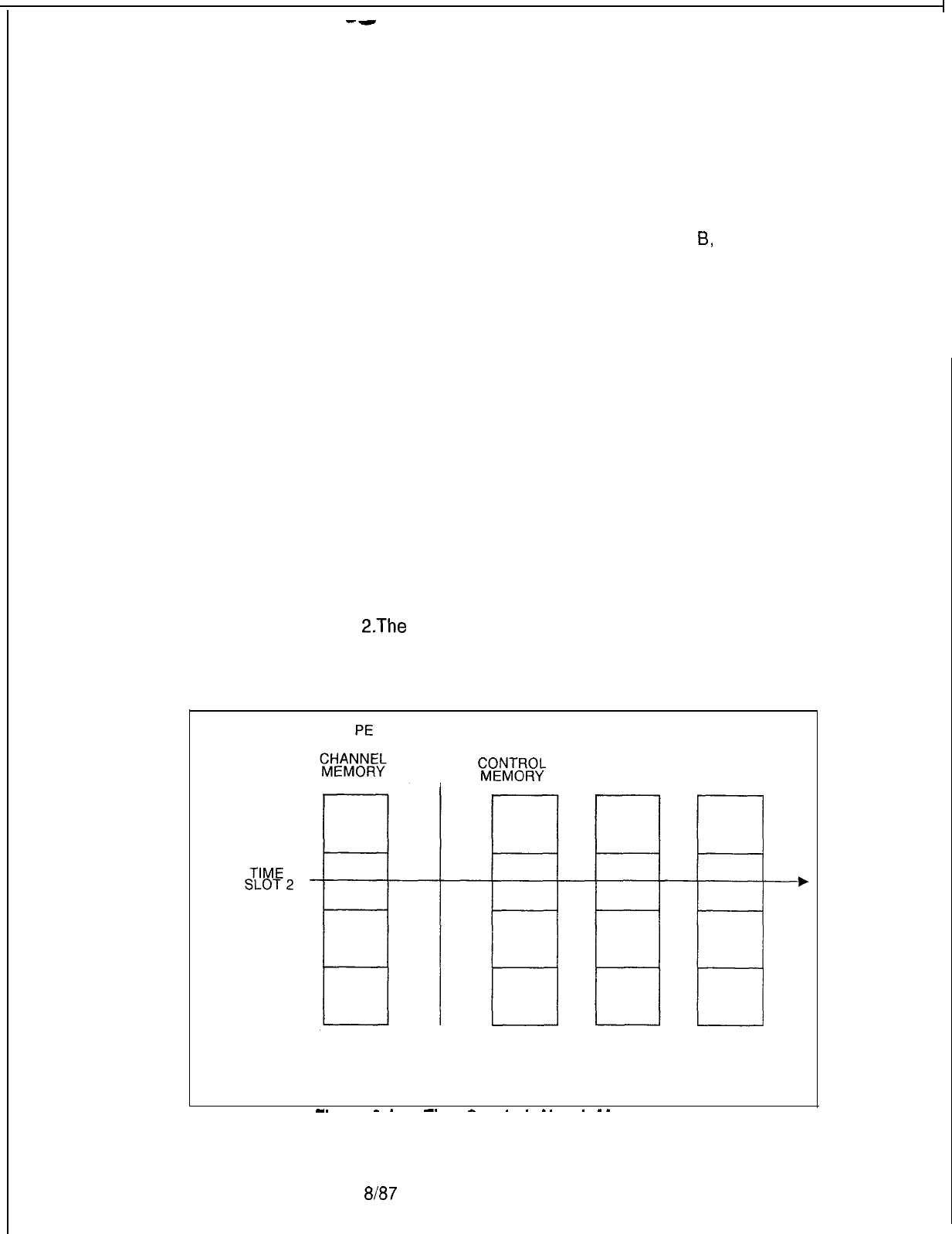
--
5210
TL-130200-1001
CALL TRACING 6.0 Call tracing provides troubleshooting information for
experienced technical personnel trained in the operation and
maintenance of the system.
Call tracing involves analyzing the address data contents of
channel memory, control memories A and
6,
and pad memory
as the system makes voice/data connections. Connections take
place during a period of time, and employ certain parts of the
system. The time interval is called a time slot, and the parts
which come into play depends on the type of connection (see
Figure 6.1). The channel memory and control memory A are
used in two-party calls while channel memory and control
memories A and B are used in three-party calls.
All of these memories are interrelated with a time slot/channel
number. A complete memory cross-reference is shown in
Table 6.1.
A brief description of how a call is processed will help the user
understand call tracing.
1. A call has been established between Directory Number 2083
(physical location: group A, universal card slot 5, circuit 6) and
directory number 2055 (physical location. group B, universal
card slot 6, circuit 3) (see Figure 6.2).
2.The
system stores the hardware ID of the off-hook directory
number in a time slot (channel number) in channel memory.
Here, 2083 (HID 56 hex) is assigned channel 18 (address
0449) in channel memory.
CEC
INFORMATION
I
?8fE!ix
PAD
MEMORY
MEMORY
THE l-TO-1 CORRESPONDENCE BETWEEN THE
MEMORY LOCATIONS IS CALLED A TIME SLOT.
-.
-_
-_
-
..__
.__
Figure 6.1
Time-Switch Network Memories
8187
M-21 1
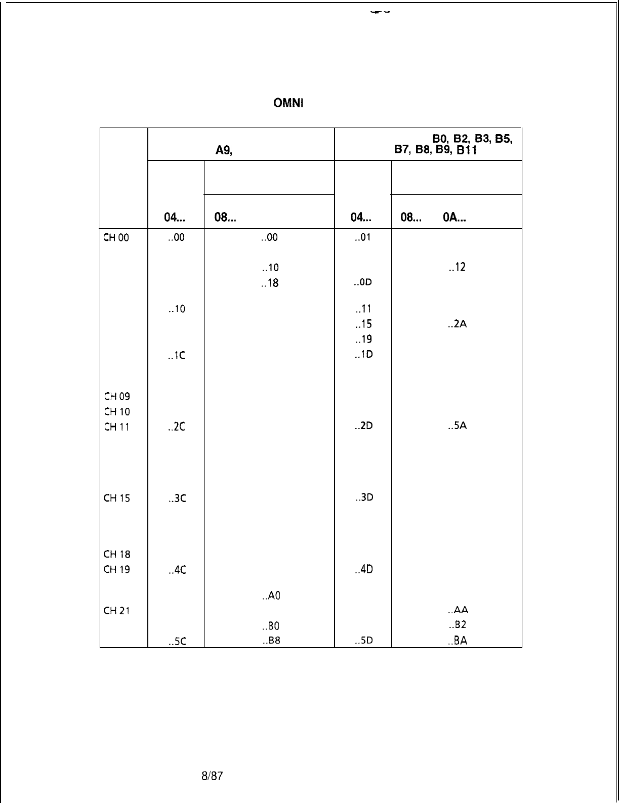
--
TL-130200-1001
M-212
Table 6.1 Memory Cross-Reference
Fujitsu GTE
OMNI
SI: Get Started File
Channel Memory to PCMN Network Memory Cross-Reference
GROUP 0 SLOTS AO, A2, A4, A5,
GROUP 1
SLOTS
A7,
A9,
Al
0, Al 1
80,
82,
83,
B5,
B6,
87,
88,
B9,
Bll
CHAN PCMN NET CHAN PCMN NET
MEM MEMORY MEM MEMORY
CMA CMB PAD CMA CMB PAD
04... 08... OA... OC... 04... 08... OA..,
OC...
CHOO
. ..oo . ..oo .
..Ol . ..02
CM 01
. ..04
.
. ..08 . ..05 . ..OA
CH 02
. ..08
. ..I0
. ..09
. ..I2
CH03
. ..oc
. ..I8 . ..OD
. ..lA
CH04
. ..lO
. ..20
.
..I1 . ..22
CH05
. ..14 . ..28
. ..I5 . ..ZA
CH06
. ..18 . ..30
. ..I9
. ..32
CH07
. ..lC
. ..38
. ..lD
. ..3A
CH08
. ..20 . ..40
. ..21
. ..42
CH09
. ..24 . ..48 . ..25 . ..4A
CHIO
. ..28 . ..50 . ..29 . ..52
CHll
. ..2c
. ..58
. ..2D . ..SA
CH 12
. ..30 . ..60
. ..31
. ..62
CH13
. ..34 . ..68 . ..35 . ..6A
CH14
. ..38 . ..70 . ..39 . ..72
CH15
. ..3c
. ..78
. ..3D
. ..7A
CH16
. ..40 . ..80
. ..41
. ..82
CH17
. ..44 . ..88 . ..45 . ..8A
CH18
. ..48 . ..90 . ..49 . ..92
CH19
. ..4c
. ..98
. ..4D
. ..9A
CH20
. ..50
. ..A0
. ..51
. ..A2
CH21
. ..54 . ..A8 . ..55
.
..AA
CH22
. ..58
.
..I30
. ..59
. ..BZ
CH23
. ..sc . ..B8 . ..5D .
..BA
Em7
5210
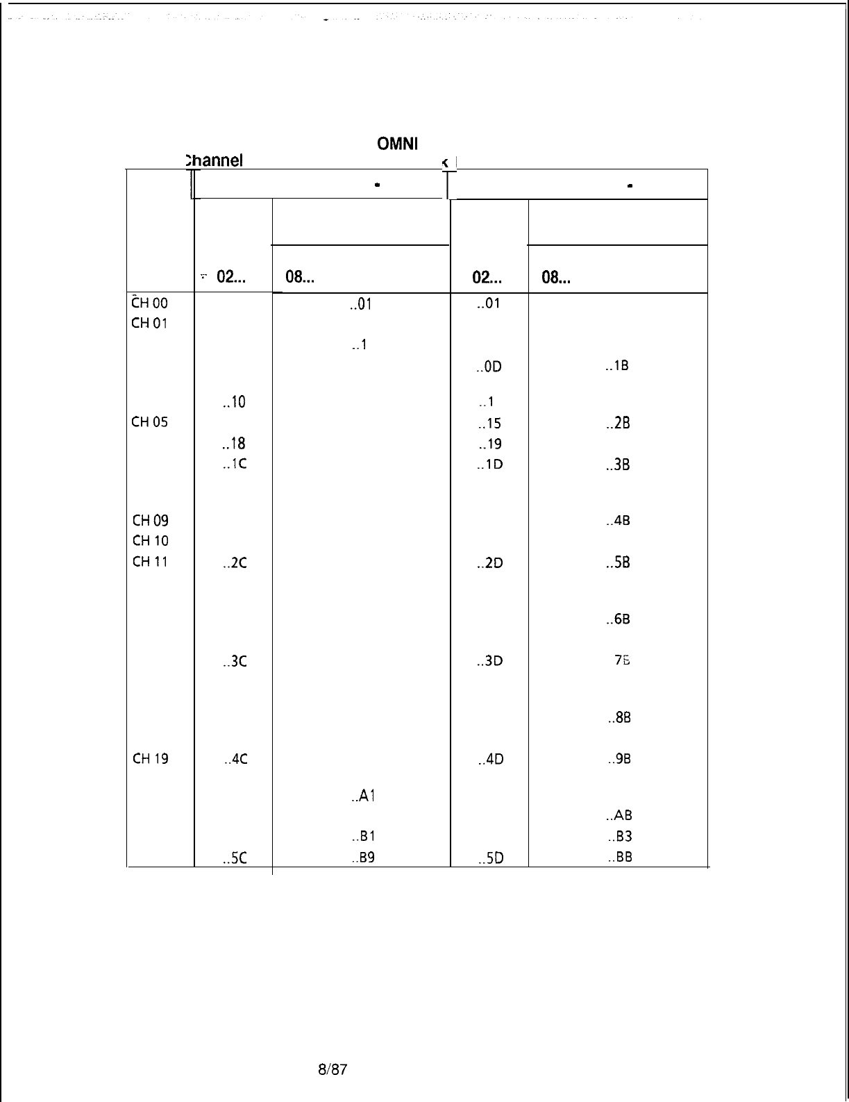
r
TL-130200-1001
Table 6.1 Memory Cross-Reference (Continued)
FUJITSU GTE OMNI SI: Expansion File
C
tH00
CHOl
CH02
CH03
CH04
CHOS
CH06
CH07
CH08
CH09
CHIO
CHll
CH12
CH13
CH14
CH15
CH16
CH17
CH18
CH19
CH20
CH21
CH22
CH23
5210
iannel
Memory to PCMN Networl
GROUP
4 SLOTS Cl
-C6
CHAN
PCMN NET
MEM
MEMORY
CMA CMB
PAD
-~-
02... 08...
OA...
OC...
. ..oo
.
..Ol
. ..04 . ..09
. ..08 .
..l
1
. ..oc . ..19
. ..lO
. ..21
. ..14 . ..29
. ..I8
. ..31
. ..lC
. ..39
. ..20
. ..41
. ..24 . ..49
. ..28
. ..51
. ..2c
. ..59
. ..30
. ..61
. ..34 . ..69
. ..38
. ..71
. ..3c
. ..79
. ..40
. ..81
. ..44 . ..89
. ..48
. ..91
. ..4c
. ..99
. ..50
. ..A1
. ..54 . ..A9
. ..58
.
..Bl
. ..5c . ..B9
8187
CMA CMB
PAD
08...
OA... OC...
Memory Cross-Reference
GROUP 5SLOTS C7 -
Cl
1
CHAN
PCMN NET
MEM
MEMORY
02...
.
..Ol
. ..03
. ..05 . ..OB
. ..09 . ..13
. ..OD . ..lB
.
..I
1 . ..23
. ..I5 . ..ZB
. ..I9
. ..33
. ..lD . ..3B
. ..21
. ..43
. ..25
. ..4B
. ..29 . ..53
. ..2D . ..5B
. ..31
. ..63
. ..35
. ..6B
. ..39 . ..73
. ..3D
. . .
7s
. ..41
. ..83
. ..45
. ..8B
. ..49 . ..93
. ..4D . ..9B
. ..51
. ..A3
. ..55
. ..AB
. ..59
. ..B3
. ..5D . ..BB
1
M-213
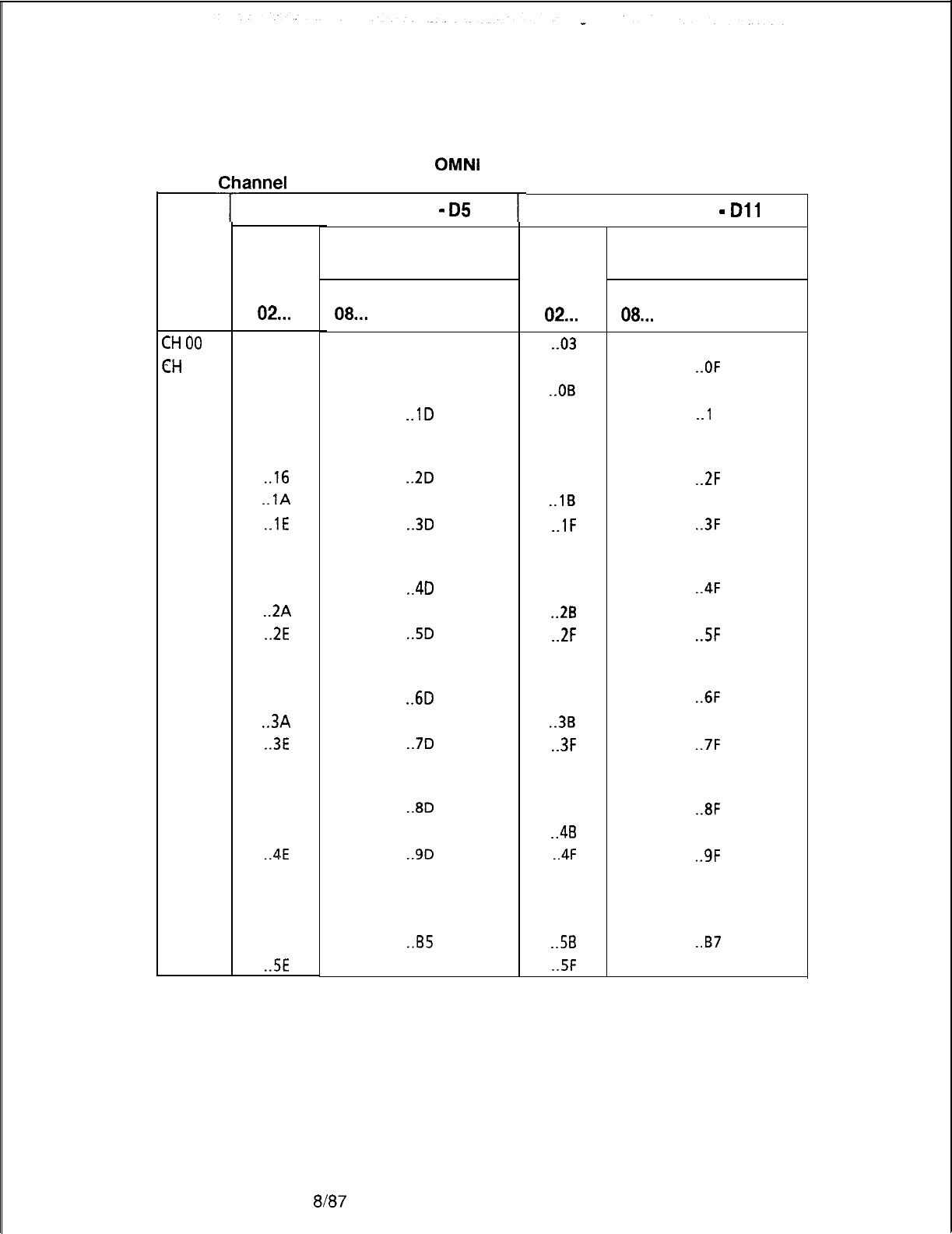
TL-130200-1001
Table 6.1 Memory Cross-Reference (Continued)
FUJITSU GTE
OMNl
SI: Expansion File
M-21 4
CHOO
EH
01
CH
02
CH 03
CH 04
CH
05
CH
06
CH
07
CH 08
CH 09
CH 10
CH 11
CH 12
CH 13
CH 14
CH 15
CH 16
CH
17
CH
18
CH
19
CH
20
CH 21
CH 22
CH
23
lannel
Memory to PCMN Networl
GROUP 6 SLOTS DO
-
05
CHAN
MEM
02...
. ..02
. ..06
. ..OA
. ..OE
. ..12
.
..I6
.
..lA
.
..lE
. ..22
. ..26
.
..ZA
.
..2E
. ..32
. ..36
.
..3A
.
..3E
. ..42
. ..46
. ..4A
.
..4E
. ..52
. ..56
. ..5A
.
..5E
k
T
PCMN NET
MEMORY
CMA CMB PAD
08...
OA... OC...
. ..05
. ..OD
. ..15
.
..lD
. ..25
.
..2D
. ..35
.
..3D
. ..45
.
..4D
. ..55
.
..5D
. ..65
.
..6D
. ..75
.
..7D
. ..85
.
..8D
. ..95
.
..9D
. ..A5
. ..AD
.
..B5
. ..BD
8187
Memory Cross-Reference
GROUP 7 SLOTS D6
-
Dll
CHAN
MEM
02...
.
..03
. ..07
. ..OB
. ..OF
. ..13
. ..17
.
..lB
.
..lF
. ..23
. ..27
.
..2B
.
..2F
. ..33
. ..37
.
..3B
.
..3F
. ..43
. ..47
.
..4B
.
..4F
. ..53
. ..57
.
..5B
.
..5F
PCMN NET
MEMORY
CMA CMB PAD
08...
OA... OC...
. ..07
. ..OF
. ..17
.
..l
F
. ..27
.
..2F
. ..37
.
..3F
. ..47
.
..4F
. ..57
.
..5F
. ..67
.
..6F
. ..77
.
..7F
. ..87
.
..8F
. ..97
.
..9F
. ..A7
. ..AF
.
..B7
. ..BF
1
5210
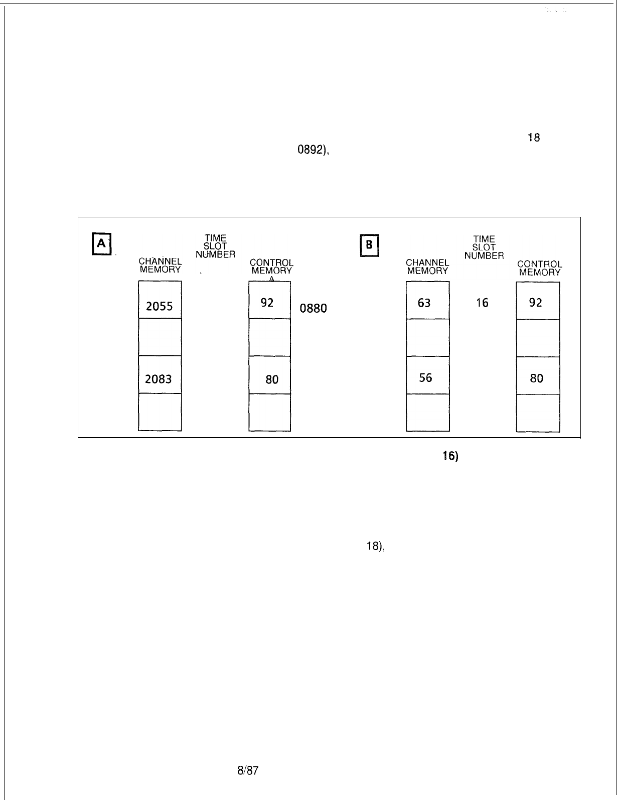
TL-130200-1001
At the same time, the system assigns channel 18 in control
memory A. channel memory and control memory A are
connected by channel 18.
4. By looking at the Control Memory address of Channel
18
(address
0892)
the system knows that Directory Number 2083
is calling directory number 2055. Control memory address
0892 (80 hex) is pointing to 0880 (92 hex). See Figure 6.2.
16
17
18
19
0892
0440
0449
'16
17
18
19
Figure 6.2 Time-Switch Memory Setup
(Channel 16)
5. Once the connection is complete, the system scans each
channel. For each channel in use, the system takes a data
sample and writes that sample into the matching channel in the
Information memory. After taking data samples from directory
number 2083 (channel
18),
the system goes to the directory
number 2055 (channel 16) in control memory A. The system
goes to channel 16 in the information memory to retrieve data
which is sent to 2083.
Call tracing involves looking at the samples passing from one
memory location to another and analyzing the samples for
contents and/or errors.
5210
8187 M-21 5
TL-130200-1001
Memory Dumps
6.1 Call tracing involves analyzing the address contents of
channel memory, control memories A and B, and pad memory.
Memory dumps, or printouts of memory contents, are made by
entering General Read (GR) commands at the terminal keyboard
(see Section 2.0, Maintenance Commands).
The GR commands for control memory A and B and pad
memory dumps are listed in Table 6.2. Examples of Channel
Memory dumps and a Pad Memory dump are also listed.
Table 6.2 Memory Dump General Read Commands
Maintenance Commands Dump Memory of:
M-21 6
GR DO 800 8BF Control Memory A for both the Get Started and
Expansion Files
GR DO
A00
ABF Control Memory B for both the Get Started and
Expansion Files
GR DO COO CBF
Pad Memory for both the Get Started and Expansion
Files
Memory Dump
6.2 Memory dumps contain information about data contents and
Contents
traffic patterns. The following facts apply to information displayed
in a memory dump:
1. Channel Memory:
-
The dedicated time slot assigned to the DTMF receiver is AO.
It appears in every channel memory dump.
-
Channel assignments (time slots) appear with the highest
number listed first.
-
Memory address data includes the Hardware Identification
Number (HID).
2. Control Memories:
D
When a memory dump occurs, random data appears at
various addresses.
-
Control memories A and B are used for three-way
conversations. The address data in control memory A is the
same as that in control memory B for two-party connections.
8187
5210
TL-130200-1001
Call Tracing
6.3 Assume that the
OMNI
SI
in the following examples has an
Examples
Expansion File. The attendant line circuit is located in the
Expansion File, group C, universal card slot 1, Circuit 4.
_.
Two-Party Connection
These examples use the Hardware Identification Number (HID)
only. Final determination of the connection requires the data
base listing or use of Recent Change. It is assumed that
references are made to the memory cross-reference tables
(see Table 6.1). Only the addresses are identified since absolute
addresses are used for all Control and Pad Memory tables (see
Section 2.0, Maintenance Commands
-
Hardware Write
Commands for addressing procedures).
6.3.1 Trace connection between two parties:
1. See channel memory Expansion File dump in Table 6.4.
Address
02%
has HID data 16.
2. See control memory A dump in Table 6.5 and control memory
E3
dump in Table 6.6 to see that addresses 0889 and
OAB9
both have data 92.
3. Address 0892 shows interchange data
89
confirms two-way
connection.
4. See channel memory Get Started File in Table 6.3. Address
shows location to be file Y, universal card slot 3, circuit 7 at
address 0449.
Three-Party Connection
6.3.2 An unknown trunk is connected to line 2281.
1. Find the HID of line 2281 using the site-dependent data base
printout or Recent Change. Line 2281 is in Get Started File Y,
universal card slot 4 (file slot
21),
circuit 6.
2. See Channel Memory Get Started File dump in Table 6.3. Scan
the two group 0 columns (first and fifth two-character address
data columns) to locate data
11.
Look to address column and
see that 0448 contains data 11 and look to channel number
column to see that channel 18 is used (use information from
memory dump or check memory cross-reference table).
3. See CEC control memory A dump in Table 6.5. Locate
channel number 18 and group 0 to get address coordinates
(memory cross-reference table shows address 0890 contains
data B2). Data B2 shows the second two characters of a
control memory address that line 2281 is listening to (data in
information memory or interchange data). Checking address
08B2
fails to locate the corresponding interchange data
(90),
so this could be a three-way call.
5210 8187
TL-130200-1001
4. See CEC control memory B dump in Table 6.6. Locate
address for channel number
18
and group 0. Data BA is
different from that in control memory A
(82)
which shows that
this is a three party connection.
5. See pad memory dump in Table 6.7. Locate address by
channel number 18 and group 0 (also use memory
cross-
reference table). Address
OC90
contains data 17 which means
that Bit 7 (CMM A) of the pad memory control word is set to 1.
This indicates that interconnect memory is in use. Refer to
Pad Memory Word Layout.
6. PEC 0 Channel Memory addresses 0459 and
0450
are found
using memory cross-reference. These two addresses show
. the location is file B, HID
-
91 and 24.
Connection to a TCR
6.3.3 Trace connection to a TCR with dial tone present.
1. See channel memory Expansion File dump in Table 6.4.
Address
025F
has HID data 14.
2. See control memory A dump in Table 6.5. Address 08BF has
data CO (dial tone)
3. Identify locations of
TCRs
using data base information.
4. TCR could be found in (a) the same file as HID receiving dial
tone, (b) the same group combination, or (c) the
interconnected group. In Table 6.5, group 6 column
(08A5,
AB, B4, and BD) shows interchange data BF in address 08BD
relates to step 2 statement. Address OCBD shows that
interconnect memory is not used.
Dedicated Time Slot
6.3.4 Trace dedicated time slot.
1. See channel memory Get Started File dump in Table 6.3.
Address
044C
has data 14 indicating file
X,
universal card slot
1,
circuit 4 with time slot allocated.
2. See Control Memory A dump in Table 6.5 and control memory
B dump in Table 6.6 to check that addresses 0898 and OA98
both have
08
(quiet code).
3. Inter-digit quiet could be taking place but interchange data
(98) is not found with a TCR associated address. Data base
shows this is the attendant’s line circuit, a dedicated time slot,
and that the attendant was idle at the time of the dump.
8187
5210

5210
TL-130200-1001
Connection Between
6.3.5 Trace connection between files.
Files
1. See channel memory Expansion File dump in Table 6.4.
Address 025C has HID data 16.
2. See control memory A dump in
Table’65
and Control Memory
6
dump in Table 6.6 to see that addresses 0889 and
OAB9
both have data 92.
3. Address 0892 shows interchange data
B9
confirms connection.
4. See channel memory Get Started File in Table 6.3. Address
shows location to be file Y, universal card slot 3, circuit 7 (a
line) at address 0449.
8187 M-21 9

TL-130200-1001
Table 6.3 Channel Memory Get Started File
0400
0408
0410
0418
0420
0428
0430
0438
-
0440
0448
0450
0458
FO FO
-
-
FO FO
-
-
FO FO
-
-
FO FO
-
-
FO FO
-
-
FO FO
-
-
FO FO
-
-
FO FO
-
-
FO 46
-.
-
11 37
-
-
03 FF
-
-
01 91
-
-
EVEN CHANNEL
GROUPS
0 1
-
-
Table 6.4
0200
0208
0210
0218
0220
0228
0230
0238
0240
0248
0250
0258
M-220
FO FO FO FO
FO FO FO FO
FO FO FO FO
FO FO FO FO
FO FO FO FO
FO FO FO FO
FO FO FO FO
FO FO FO FO
FO
Fd
FO FO
FO FO FO FO
FO FO 03 FO
FO FO 01 FO
EVEN CHANNEL
GROUPS
4 5 6 7
8187
FO FO
-
-
FO FO
-
-
FO FO
‘-
-
FO FO
-
-
FO FO
-
-
FO FO
-
-
FO FO
-
-
FO FO
-
-
FO FO
-
-
14 FO
-
-
02 FO
-
-
00 24
-
-
ODD CHANNEL
GROUPS
0 1
-
-
00
and
01
02
and
03
04
and
05
06 and 07
08 and 09
10
and
11
12
and
13
14
and
15
16
and
17
18
and
19
20
and
21
22
and
23
CHANNEL
NUMBERS
Channel Memory Expansion File
FO FO FO FO
FO FO FO FO
FO
FO FO FO
FO FO FO FO
FO FO FO FO
FO FO FO FO
FO FO FO FO
FO FO FO FO
FO FO FO FO
FO FO FO FO
00
and
01
02 and 03
04
and
05
06
and
07
08
and
09
10 and
11
12
and
13
14
and
15
16 and 17
18 and 19
FO FO
02
FO
20
and
21
16
FO
00 14 22 and 23
CHANNEL
ODD CHANNEL NUMBERS
-
GROUPS
4
5 6
7
5210
0800
0808
0810
0818
y.0820
0328
0830
0838
0840
0848
0850
0858
0860
0868
0870
0878
0880
0888
0890
0898
08A0
08A8
0880
08B8
5210
GR DO 800
8BF
PAGE DO
D8
08
D8
D8
D8
D8
D8
D8
08
D8
D8
D8
D8
D8
D8
D8
08
D8
B2
D8
D8
08
D8
D8
GRP
0
Table 5.5 Control Memory A
TL-130200-1001
D8
D8
D8
D8
08
D8
-D8
D8
D8
08
08
D8
D8
D8
D8
08
D8
D8
D8
D8
D8
08
D8
92
GRP
4
D8
D8
D8
D8
D8
08
D8
D8
D8
D8
D8
D8
D8
D8
D8
D8
76
D8
B9
D8
08
D8
BA
82
GRP
1
D8
D8
D8
D8
D8
D8
D8
D8
D8
D8
D8
D8
08
D8
D8
D8
D8
D8
D8
D8
D8
D8
08
D8
GRP
5
GRP
D8
08
D8
D8
08
D8
D8
D8
08
D8
D8
D8
D8
D8
08
D8
08
D8
D8
D8
D8
D8
D8
BF
GRP
6
GRP
8187
D8
D8
D8
D8
D8
D8
D8
D8
D8
08
D8
D8
D8
D8
D8
D8
D8
D8
D8
D8
D8
D8
D8
co
GRP
7
00
01
02
03
04
05
06
07
08
09
10
11
12
13
14
15
16
17
18
19
20
21
22
23
CHANNEL
NUMBER
M-221
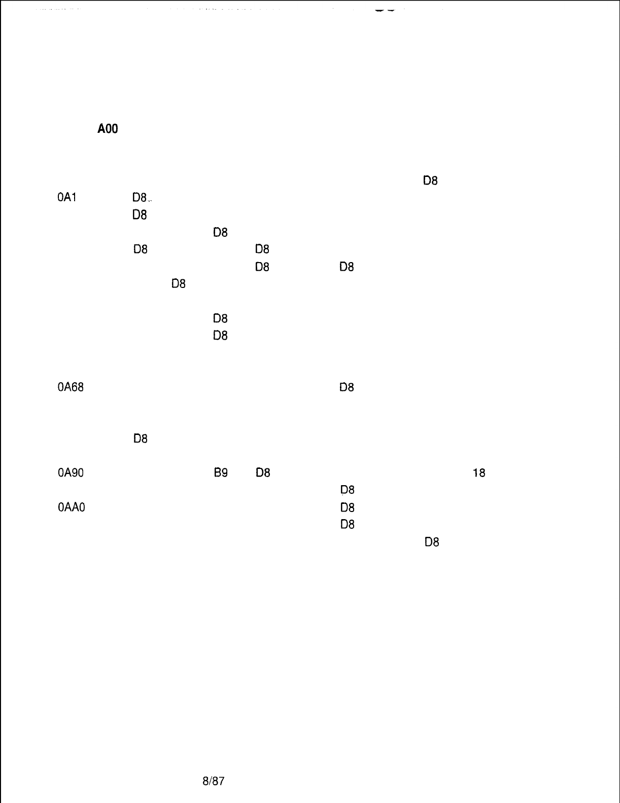
TL-130200-1001
Table 6.6 Control Memory B
GR DO
A00
ABF
PAGE DO
OAOO
OA08
OAl 0
OA18
OA20
OA28
OA30
OA38
OA40
OA48
OA50
OA58
OA60
OA68
OA70
OA78
OA80
OA88
OA90
OA98
OAAO
OAA8
OABO
OAB8
M-222
D8
D8
D8;..
08
D8
08
D8
D8
D8
D8
D8
D8
D8
D8
D8
D8
08
D8
BA
D8
D8
D8
D8
D8
D8
D8
D8
D8
D8
D8
D8
08
D8
D8
D8
D8
D8
D8
D8
D8
D8
D8
D8
D8
D8
D8
D8
92
GRP GRP
0 4
D8
D8
D8
D8
08
.
D8
D8
D8
D8
08
08
D8
D8
D8
D8
D8
76
D8
B9
D8
D8
D8
90
90
GRP
1
D8
D8
D8
D8
D8
08
08
D8
D8
D8
D8
D8
D8
D8
D8
D8
D8
D8
08
D8
D8
D8
D8
D8
GRP
5
GRP
D8
D8
D8
D8
D8
D8
08
D8
D8
D8
D8
D8
D8
08
D8
D8
D8
D8
D8
D8
08
08
D8
D8
GRP
6
GRP
8187
D8
08
D8
D8
D8
D8
D8
D8
D8
D8
D8
D8
D8
D8
D8
D8
D8
D8
D8
D8
D8
D8
08
D8
GRP
7
00
01
02
03
04
05
06
07
08
09
10
11
12
13
14
15
16
17
18
19
20
21
22
23
CHANNEL
NUMBER
5210
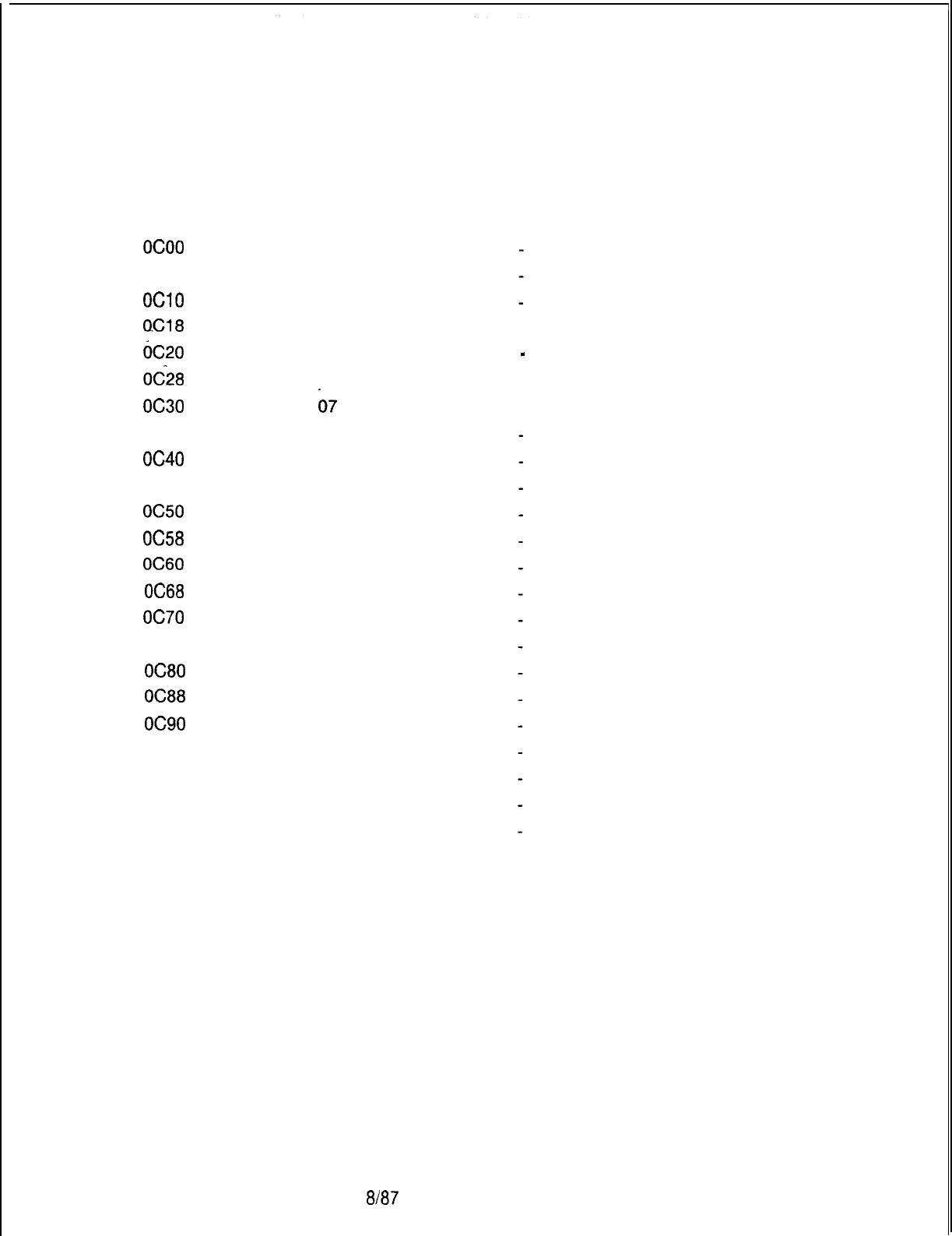
GR DO COO CBF
PAGE DO
ocoo
OC08
OClO
O.Cl8
oc20
OC28
oc30
OC38
oc40
OC48
oc50
OC58
OC60
OC68
oc70
OC78
OC80
OC88
oc90
OC98
OCAO
OCA8
OCBO
OCB8
5210
07
07
07
07
07
07
07
07
07
07
07
07
07
07
07
07
07
07
17
07
07
07
07
07
GRP
0
Table
6.7
Pad Memory
07
07
07
07
07
07
07
07
07
07
07
07
07
07
07
07
07
07
37
07
07
07
17
17
GRP
1
07
07
07
07
07
07
07
07
07
07
07
07
07
07
07
07
07
07
07
07
07
07
07
07
GRP
5
-
GRP
07
07
07
07
07
07
07
07
07
07
07
07
07
07
07
07
07
07
07
07
07
07
07
07
GRP
6
07
07
07
07
07
07
b7
07
07
07
07
07
07
07
07
07
07
07
07
07
07
07
07
37
GRP
4
8187
GRP
TL-130200-1001
07
07
07
07
07
07
07
07
07
07
07
07
07
07
07
07
07
07
07
07
07
07
07
07
GRP
7
00
01
02
03
04
05
06
07
08
09
10
11
12
13
14
15
16
17
18
19
20
21
22
23
CHANNEL
NUMBER
M-223
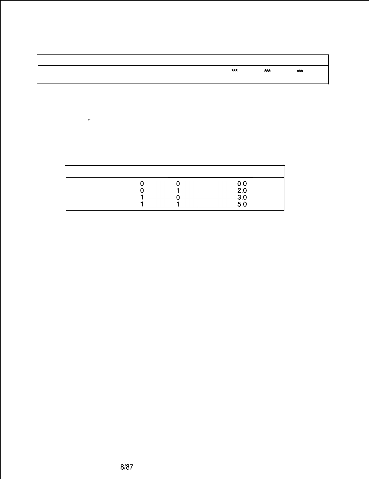
TL-130200-1001
PAD MEMORY WORD LAYOUT
CMM CMM
PAD PAD
PAD
-
*
km
A B
1
02
. .
_.
BITS 7, 6: interconnect memory steering bits.
Bits 5, 4, 3: pad Information bits as follows:
M-224
8187
1 BITS
5 4
DB loss
NOTE: CMMA and CMMB are the ninth bit for control memory A
and control memory B, respectively. Either bit set to true (1)
indicates that the sample will be taken from the Interconnect
memory; a bit set to false (0) indicates that the sample will be
taken from the network information memory.
5210
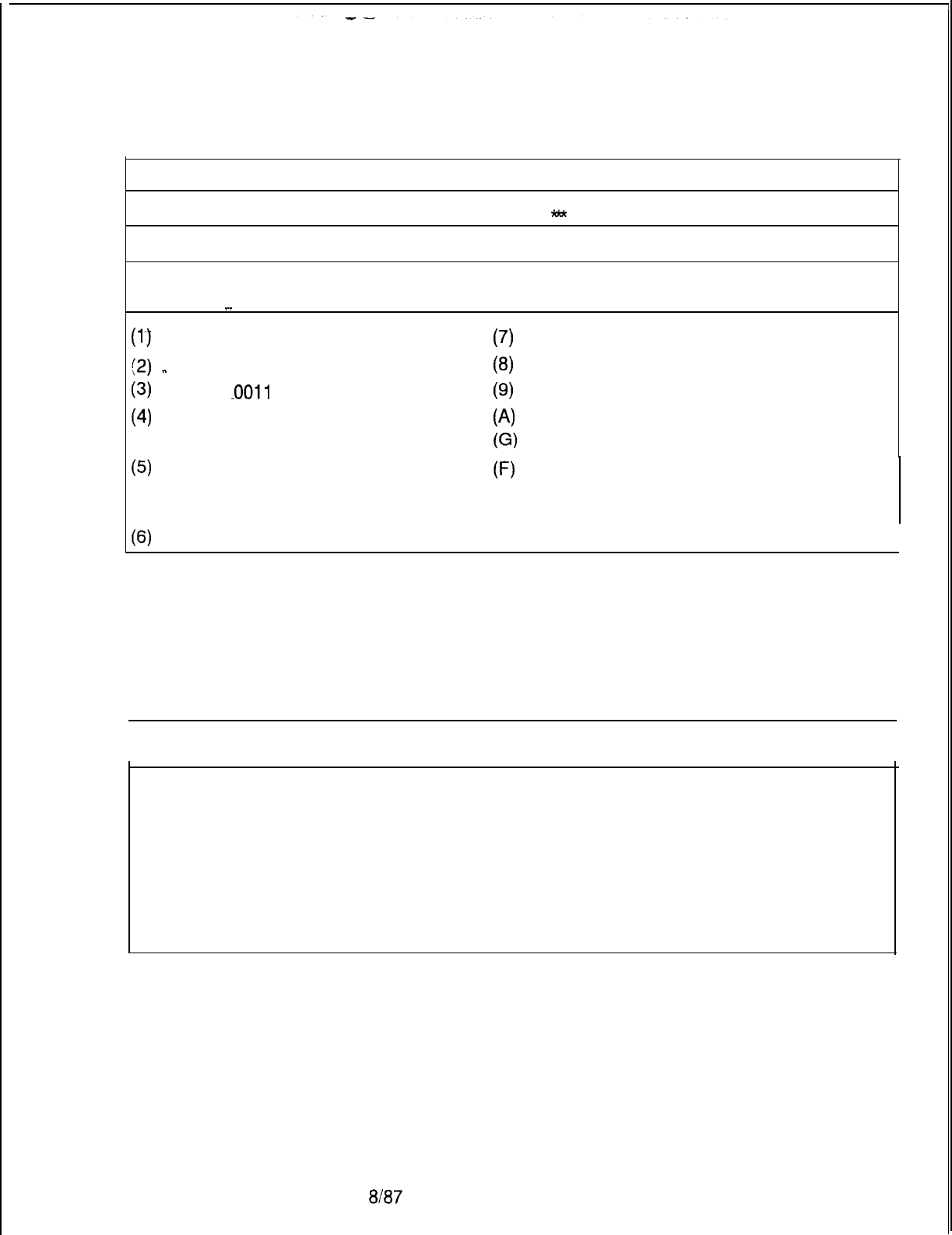
TL-130200-1001
BITS
765
4
3 2
1
0
THE UNIVERSAL CARD SLOT
-
CIRCUIT NUMBER ON CARD
NOTE: Card slots are identified as follows:
HEX BINARY UNIVERSAL HEX BINARY POSITION
.~.
POSITION UNIVERSAL
(l-2
0001
1
(7) 0111 7
(2)
-
0010
2
(8)
1000 8
(3)
.OOll
.
3(9) 1001 9
(4)
0100
4(A) 1010 10
G)
1011
11
(5) 0101 5
F)
1111
INDICATES SPECIAL
ASSIGNMENT
03)
0110
6
I
Word content FO indicates an idle channel, and FF indicates a
network test).
CONTROL MEMORY DATA DEFINITIONS
I
1
ADDRESS DATA DEFINITIONS
I
00
BF
co
FF
Hex data indicates the last two digits of the PCMN Memory address
(connected party voice) being listened to, and is also the last two digits of
the Control Memory address assigned to that time slot.
Hex data indicates the last two digits of PCMN Memory address (system
generated tones) being listened to.
Refer to Channel Memory Get Started File
5210 8187
M-225
TL-130200-1001
Table 6.8 Get Started File
CARD SLOT CKT ADDRESS CARD SLOT CKT ADDRESS
A0
A0
A0
A0
A2
A2
A2
A2
A4
A4
A4
A4
A5
A5
A5
A5
A7
A7
A7
A7
A8
A8
A8
A8
A9
A9
A9
A9
A10
A10
A10
A10
All
All
All
All
. .
0
1
2
3
0
1
2
3
0
1
2
3
0
1
2
3
0
1
2
3
0
1
2
3
0
1
2
3
0
1
2
3
0
1
2
3
0500
BO
00504
0501
0502
0503
0520
0521
0522
0523
0540
0541
0542
0543
0550
0551
0552
0553
0570
0571
0572
0573
0580
0581
0582
0583
0590
0591
0592
0593
05A0
05Al
05A2
05A3
05BO
05Bl
05B2
05B3
BO
BO
BO
B2
B2
B2
B2
83
83
B3
B3
B5
B5
B5
85
,
B6
B6
86
B6
87
B7
B7
B7
B8
88
B8
B8
B9
B9
B9
B9
Bll
Bll
Bll
Bll
1
2
3
0
1
2
3
0
1
2
3
0
1
2
3
0
1
2
3
0
1
2
3
0
1
2
3
0
1
2
3
0
1
2
3
0505
0506
0507
0524
0525
0526
0527
0534
0535
0536
0537
0554
0555
0556
0557
0564
0565
0566
0567
0574
0575
0576
0577
0584
0585
0586
0587
0594
0595
0596
0597
0584
0586
05B7
0588
M-226
8187
5210
TL-130200-1001
Table 6.9 Expansion File
Card
Slot ckt
Addr
Card
Slot ckt
Addr
Card
Slot
act
Addr
Card
Slot ckt
Addr
Cl 0
Cl 1
Cl
Cl
c2
c2
c2
c2
c3
c3
c3
c3
c4
c4
c4
c4
c5
c5
c5
c5
C6
C6
C6
C6
2
3
0
1
2
3
0
1
2
3
0
1
2
3
0
1
2
3
0
1
2
3
0518
_.
0519
051A
0516
0528
0529
052A
052B
0538
0539
053A
0538
0548
0549
054A
054B
0558
0559
055A
055B
0568
0569
056A
056B
c7
c7
c7
c7
‘C8
C8
C8
C8
c9
c9
c9
c9
Cl0
Cl0
Cl0
Cl0
Cl1
Cl1
Cl1
Cl1
0
1
2
3
0
1
2
3
0
1
2
3
0
1
2
3
0
1
2
3
0578
0579
057A
057B
0588
0589
058A
058B
0598
0599
059A
059B
05A8
05A9
05AA
05AB
05B8
0589
05BA
05BB
DO
DO
DO
DO
Dl
Dl
Dl
Dl
D2
D2
D2
D2
D3
03
D3
D3
04
04
D4
D4
D5
D5
D5
D5
0
1
2
3
0
1
2
3
0
1
2
3
0
1
2
3
0
1
2
3
0
1
2
3
05oc
050D
050E
05OF
051 c
051 D
051 E
051 F
052C
052D
052E
052F
053c
053D
053E
053F
054c
054D
054E
054F
055c
055D
055E
055F
D6
D6
D6
D6
D7
D7
D7
D7
D8
D8
D8
D8
D9
D9
D9
D9
DlO
DlO
DlO
DlO
Dll
Dll
Dll
Dll
0
1
2
3
0
1
2
3
0
1
2
3
0
1
2
3
0
1
2
3
0
1
2
3
056C
056D
056E
056F
057c
057D
057E
057F
058C
058D
058E
058F
059c
059D
059E
059F
05AC
05AD
05AE
05AF
05BC
05BD
05BE
05BF
5210
The information in Figures 6.3 through 6.6 is provided for
maintenance personnel thoroughly trained in system operation,
and provides very specialized troubleshooting data.
8187
M-227
TL-I 30200-l 001
STATE 00
1 -WAY
C/S
NETWOR
C
A
(4
-----
T
W)
STATE 01 2-WAY TERM
US
X
=
H
t
PREVIOUS TE-RM
PORTS FOR DIVERTS
C
A
T
~
B
I
D/S.15
OPTIONAL
I
,------------------------------------L-----------------------------------.
I
STATE 02 2-WAY STATE 03 2-WAY SPLIT
c/s
0A
T
~
B
NETWORK
c/s
NETWORK
C
A
0
Q
B
(A)
(B)
TONE
TONE
STATE 04
I
3-WAY TERM
II
STATE 05 3-WAY SPLIT
US
C
A
0
i
B
T
C
NETWORK
-
TONE
;
D/S IS OPTIONAL
I
I
I
------------------------------------~
STATE 06 3-WAY
II
us
c
A
0
~
B
T
C
(4
0)
NETWORK
I
------------------------------------L
STATE
08
3-WAY DOUBLE TERM I
I
c/s
NETWORK
II
C
B = RINGING LINE
I
II
C = RINGING RELEASE LINK TRUNK I
NOTE: CAS BRANCH ONLY I
I
C
0-V
0
63
NETWORK
---I
D/S
II
i
--a
----- TONE
I1
-____-----------------------------
STATE 07 0. G. SERIES
THIS CS STATE
CONTAINS-
NO ACTIVE PORTS
_______---------------------------
STATE 09 2-WAY
ausY
c/s
NETWORK
C
A
T
F
a
TONE
B = BUSY LINE
Figure 6.3 Call State Definitions (Sheet 1 of 2)
M-228
Em7
5210

TL-130200-1001
--------------------_______________
~----------------------------------
STATE 10 HOLD-l PARTY
;
STATE 11 2-WAY BUSY AFTER FLASH
Cl-5
TA
C
El
E
us
NETWORK
(A)
------
f---l
D/S
C
A
0
Y
6
TONE
TON
I
8
=
ATTENDANTOR
II
PAGE QUEUE
----_-___---------_---------
STATE 12 3-WAY BUSY
B
= BUSY LINE
I I
I
-l---
~--_--~---___-_____---~~~-~-~~~~
STATE 13 HOLD-2 PARTY
I
us
C
A
0
H
8
T
C
us
0A
T
El
B
CC
NETWORK
TONE
TONE
II
--I--
l
I
C
= BUSY LINE
-----_---_
STATE 14
C = ATTENDANT
I I
-_____----___--__--~~---~-~~~~~~
STATE 15 3-WAY SPLIT-TERM
-_------~~~~-__--_
3-WAY BUSY AFTER
INCLUDE SOURCE
us
C
A
0
Y
B
T
C
NETWORK
US
NETWORK
0
T
C
I
(A)
@I
A = ATTENDANT
B
= BUSY LINE B = RINGING LINE
I
I
C = RINGING RELEASE LINK TRUNK
NOTE:
CAS BRANCH ONLY
~---__------~_-____________
I
-----Lee
---_---__-_---_-------------------- r----------------------------------
STATE 16 1 -WAY AFTER ATB
;
STATE 17 1 -WAY AFTER ATB (FLASH)
US
C
A
T
El
B
NETWORK US
C
A
T
El
B
NETWORK
(4
(A)
TONE
TON
I
B = TRUNK GROUP NO.
I
B = TRUNK GROUP NO.
-----------------------------------L----------------------------------
Figure 6.3 Call State Definitions (Sheet 2 of 2)
5210 8187
M-229
TL-130200-1001
Digit Store
6.4 The Digit Store is used to store temporary call processing
information. This type of data is used by the system to analyze
dialed digits and initiate the proper telephone connection(s) as
follows:
BIT 7BIT
6 BIT 5 BIT4
BIT3
BIT 2
BIT
1
BIT 0
DDFPl
_. 0
0.
FORWARD POINTER (LOW ORDER ADDRESS) 0
DDFPZ
1
0
-
FORWARD POINTER (HIGH ORDER ADDRESS)
1
DDBPl
2
0
BACKWARD POINTER (LOW ORDER ADDRESS)
-
2
DDBPZ
3
0
BACKWARD
POINTER
(HIGH ORDER ADDRESS)
-
3
DDTRP
4
0
-RETURN INDEX 4
DDTIM
54 -RETURN TIMEOUT VALUE 5
DDCSN
6CALL STORE NUMBER(HIGH ORDER ADDRESS) 6
DDCSN
7CALL STORE NUMBER (LOW ORDER ADDRESS) 7
DDTCR
8TOUCH-CALLING RECEIVEREQUIPMENT NUMBER 8
DDTCT
3TCR
-
TIME SLOT 3
M-230
DDSCS
10 DIGIT STORE CONTROL STATE 10
Figure 6.4
I
Digit Store Layout (Sheet 1 of 7)
8187
5210
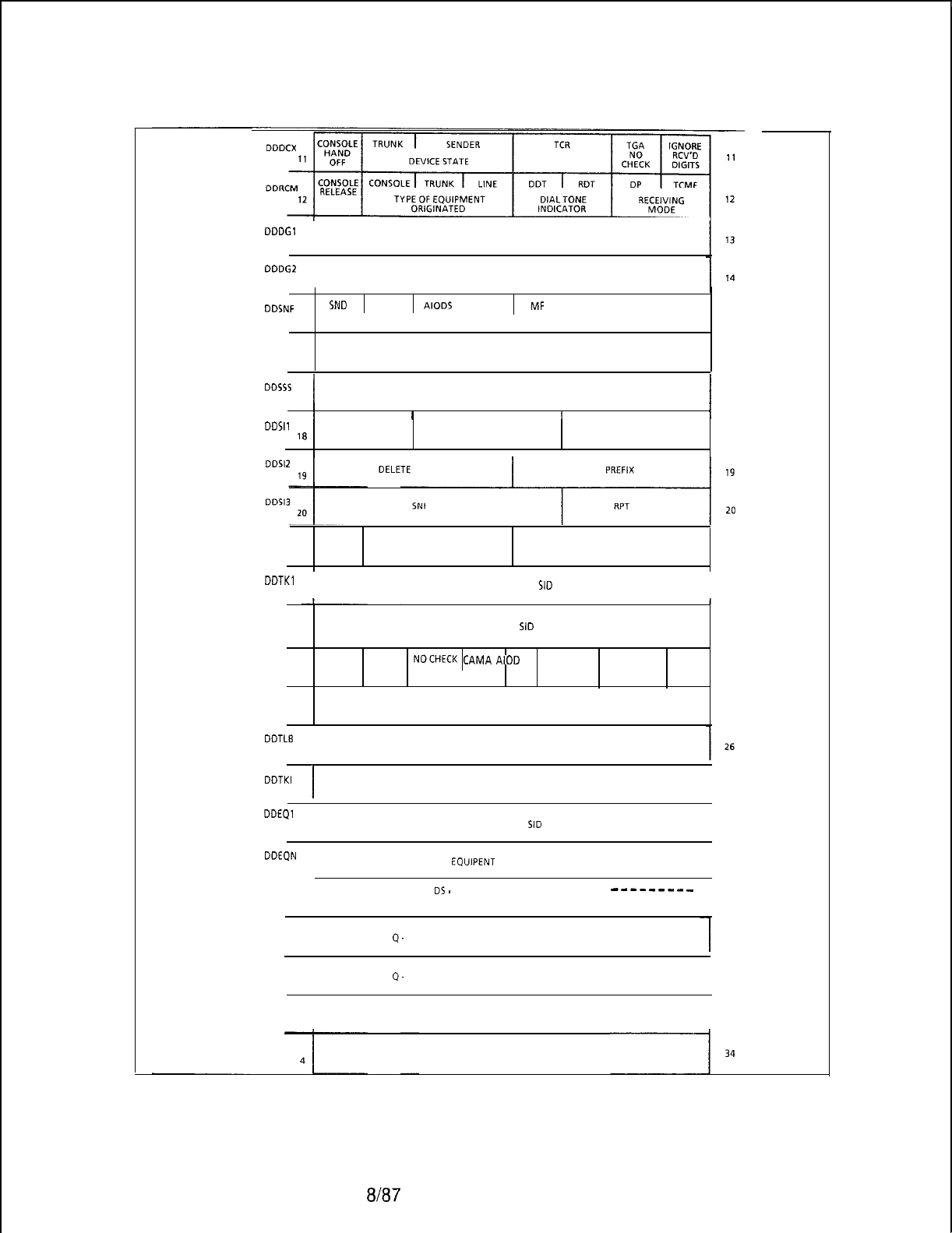
TL-130200-1001
DDDGl
13
I
NUMBER OF DIGIT ACCUMULATED COUNT
DDDGZ
14
I
NUMBER OF DIGIT EXPECTED COUNT
DDSNF SND BDT AIODS SDC MF RDT DP TCMF
15 15
SENDER FLAGS
DDSNP
16 SENDER SEND DIGIT CONTROL 16
DDSSS
17
I
SENDERSEND SEQUENCE STATE
I
17
1
I I I I
DDSll
18 SKIP PREFIX INDEX PAUSE 10
I
Figure 6.4 Digit Store Layout (Sheet 2 of 7)
DDPTG PAUSE DESTINATION TYPE DESTINATION
21 FLAG SELECTION COUNT 21
DDTKl
22
I
PEC NUMBER OF TERMINATING SID
22
DDTRK 23 TERMINATING EQUIPMENT SID
23
DDTOL DC CUT IN NOCHECK
CAMA
AIOD
TOLL REST. EXPANDTOLL TOLL
24 24
OUT-GOING TRUNK TOLL INFORMATION
DDTLA 25 CODE TYPE FROM TRANSLATION
25
DDTLB
26
CODE TYPE IDENTIFIER. FROM TRANSLATION
DDTKI
27
I
INCOMING TRUNK GROUP NUMBER ORTG REST. INDEX
I
27
DDEQl
28
I
PEC NUMBER OF ORIGINATING SID
I
20
DDEQN 29
I
ORIGINATING EQUIPENT SOFTWARE ID
I
29
DDRCO
----------
DS
-
INFORMATION TRANSFER BUFFER
---_----_
0Q-FORWARD POINTER (LOW ORDER ADDRESS)
30
1
I
9.
FORWARD POINTER (HIGH ORDER ADDRESS) 31
2
0.
BACKWARD POINTER (LOW ORDER ADDRESS)
32
3Q-BACKWARD POINTER (HIGH ORDER ADDRESS)
I
33
5210
8187
M-231
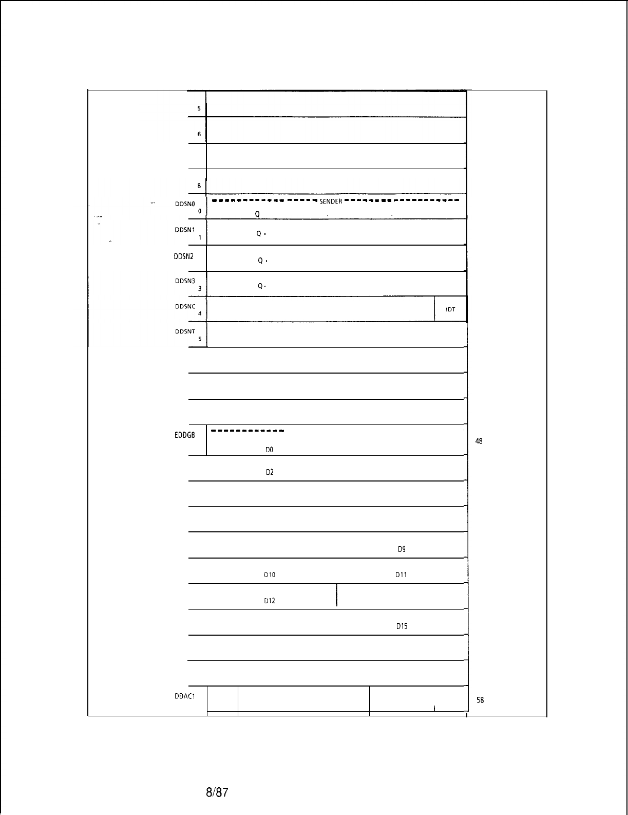
TL-130200-1001
M-232
7
------------
-----
SENDER
------
--
-----------
P
-FORWARD POINTER (LOW ORDER ADDRESS)
Q
-
FORWARD POINTER (HIGH ORDER ADDRESS)
DDSNZ
.
2Q
-
BACKWARD POINTER (LOW ORDER ADDRESS)
Q.
BACKWARD POINTER (HIGH ORDERADDRESS)
SENDER CONTROL STATE OR DIGIT STORE NUMBER
INTERDIGITAL TIMER OR MF PULSING COUNT
DDSND
6PULSE SEND COUNTER
DDSNE
7TRUNK HARDWARE ID
DDSNM
I
TRUNK HIGH ORDERADDRESS OR PORT NUMBER
8WHERE TRUNK IS LOCATED IN CS
------------
EDDGE
DIGIT STORE DIGIT BUFFER ------------
0CALLED NUMBER
I
CALLED NUMBER
DO
Dl
CALLED NUMBER
I
CALLED NUMBER
1
D2 D3
CALLED NUMBER
I
CALLED NUMBER
2D4 D5
CALLED NUMBER
I
CALLED NUMBER
3D6 D7
CALLED NUMBER
I
CALLED NUMBER
4
DB
D9
CALLED NUMBER
I
CALLED NUMBER
5DlO
Dll
CALLED NUMBER
I
CALLED NUMBER
6
012
D13
CALLED NUMBER
I
CALLED NUMBER
7D14 D15
DDDGN CALLING NUMBER
I
CALLING NUMBER
0N4 N5
CALLING NUMBER
I
CALLING NUMBER
1
N6 N7
DDACl ACCESS NUMBER OF ACCOUNT CODE DIGITS NUMBER OF ACCESS CODE
CODE DIGITS
FLAG
I I I I I
Figure 6.4 Digit Store Layout (Sheet 3 of 7)
35
36
37
38
39
40
41
42
43
44
45
46
47
48
49
50
51
52
53
54
55
56
57
58
8l87
5210
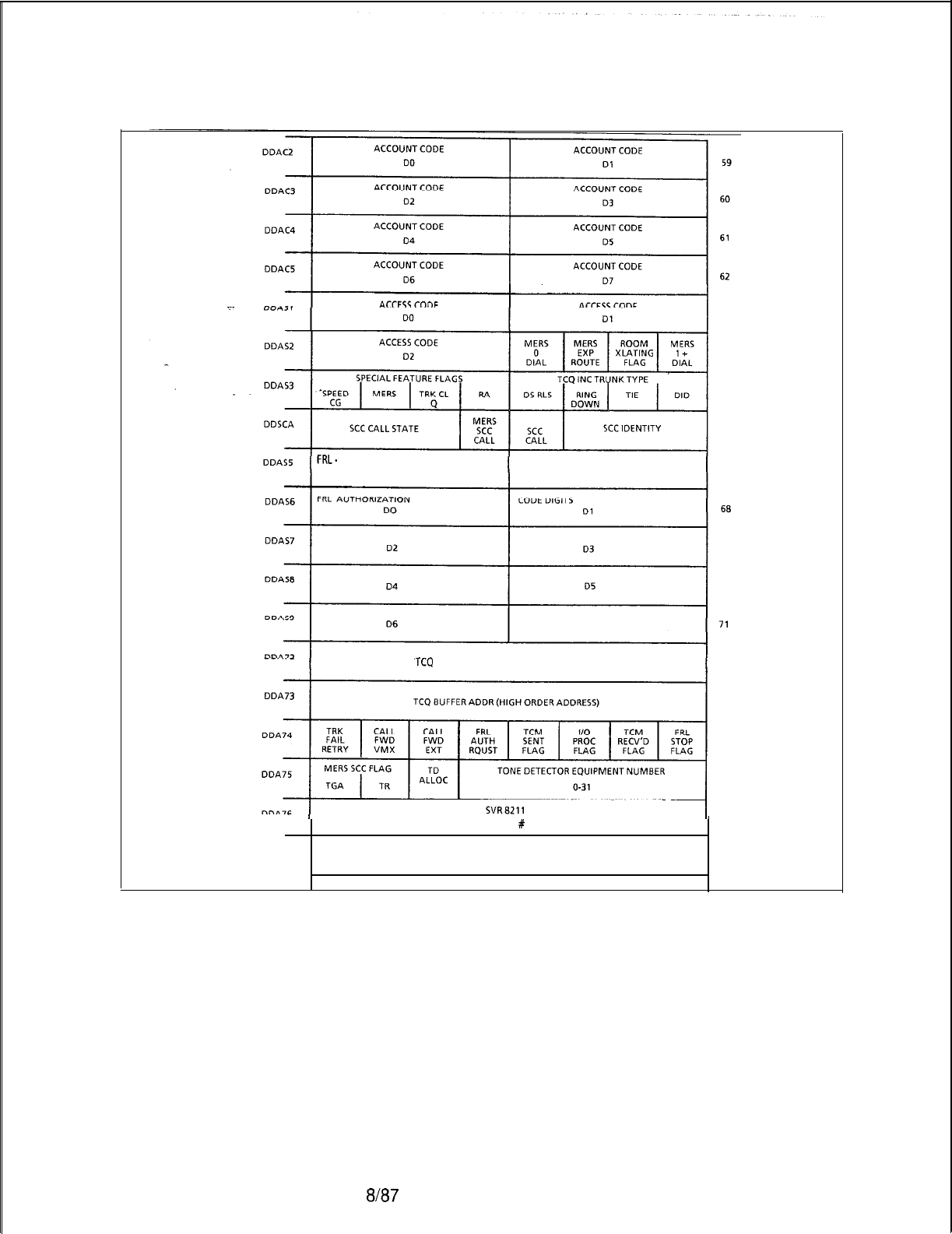
TL-130200-1001
.~.
63
. .
64
65
66
FRL.
FACILITY RESTRICTION LEVEL NUMBER OF FRL AC DIGITS 67
69
70
TCQ
BUFFER ADDR (LOW ORDER ADDRESS) 72
73
74
75
SPEED CALL LIST
#
LOW BYTE 76
DDA77
77
Figure 6.4 Digit Store Layout (Sheet 4 of 7)
5210 8/87
M-233
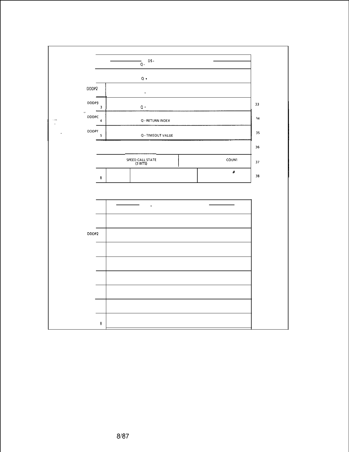
TL-130200-1001
M-234
SPEED CALL USAGE OF THE INFORMATION TRANSFER BUFFER
ODDPO
I
DS.
INFORMATION TRANSFER BUFFER
0
4.
FORWARD POINTER (LOW ORDER ADDRESS)
DDDPl 1
Q
-
FORWARD POINTER ( HIGH ORDER ADDRESS)
DDDPZ
2
I
Q
-
BACKWARD POINTER (LOW ORDER ADDRESS)
P
-
BACKWARD POINTER (HIGH ORDER ADDRESS)
DDDPD
6
DIGIT STORE #
DDDPE
7
I
ACCUMULATED DIGIT
COUNl
(5 BITS)
DDDPM SPEED SPEED CALL
#
8CALL
HIGH BYTE
TYPE (3 BITS)
30
31
32
FRL AC TCM USAGE OF THE INFORMATION TRANSFER BUFFER
DDDPO DS
-
INFORMATION TRANSFER BUFFER
0FRL
DISK RECORD BUFFER 30
DDDPl FRL DISK RECORD BUFFER
31
1
DDDPZ
2FRL
DISK RECORD BUFFER 32
DDDP3
3
33
FRL DISK RECORD BUFFER
DDDPC
4
DDDPT
5
DDDPD
6
DDDPE
7
DDDPM
8
34
FRL DISK RECORD BUFFER
35
FRL DISK RECORD BUFFER
36
FRL DISK RECORD BUFFER
FRL
DISK RECORD
BUFFER
37
38
Figure 6.4 Digit Store Layout (Sheet 5 of 7)
8l87
5210
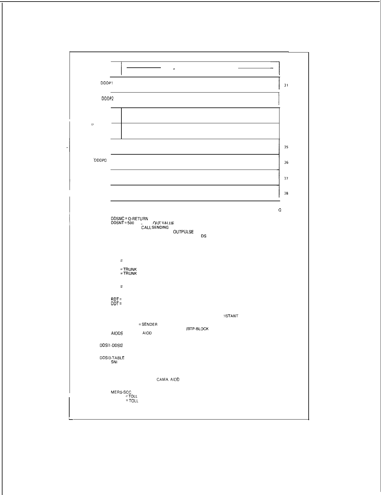
5210
TL-130200-1001
VMX USAGE OF THE INFORMATION TR
A
NSFER BUFFER
DDDPO
0
I
DS
-
INFORMATION TRANSFER BUFFER
COMMAND CODE
-1
30
DDDPl
1
DDDPZ 2
I
32
DDDP3
333
_.
DDDPC
34
4
DDDPT
5
.DDDPD
6
I
DDDPE
7
DDDPM
8
THE SENDER IS ALSO USED FOR CODE CALL SENDING, THE FIRST FOUR WORDS IS USED FOR
(1
ADDRESSES, AND THE FOLLOWING WORDS ARE DEFINED AS:
DDSNC=@-RETURN
INDEX
DDSNT=JOO
MS TIME
OUTVALllE
DDSND = CODE
?ALL
S&DING
CONTROL STATE
DDSNE = SEND CYCLE AND DIGIT
OUTPULSE
COUNT
DDSNM = DIGIT OUT AND ACCESS COUNT FROM
DS
DDSCS-DIGIT STORE CONTROL STATE. IT IS DEFINED IN FP-413346
ODDCX-DEVICE STATE
00 = DEVICE NOT ASSIGNED
01
=
DEVICE IS ASSIGNED
TGA NO CHECK
00
=TRUNK
GROUP ACCESS RESTRICTIONS CHECKED
01
=TRUNK
GROUP ACCESS RESTRICTION CHECKS BYPASSED
IGNORE RECEIVED DIGITS
00 = DO NOT IGNORE DIGITS WHICH ARE RECEIVED
01
=
IGNORE DIGITS WHICH ARE RECEIVED
DDRCM-RECEIVING MODE-P. ‘1’ MEANS THAT FIELD IS TRUE
RDT=
RETURN REGULAR DIAL TONE
DOT=
RETURN DISTINCT DIAL TONE
DDSNF-SENDER FLAGS-A ‘1’ MEANS THAT FIELD IS TRUE
RDT
= REGULAR DIAL TONE IS EXPECTED FROM
‘ISTANT
OFFICE
MF, DP, TCMF = MODE OF OUTPULSING
SND
=SENDER
NEEDS DIGIT
SDC
= 1 FOR SPEED CALLING
(ETP-BLOCK
TRANSMISSION FLAG)
AIODS
=
AIOD
SEND COMPLETED
BDT
= 300 MS BURST OF DIAL TONE SENT ON MERS DDD ROUTE
DDSll-DDSl2
SENDER SEND INSTRUCTIONS,
SKIP, PAUSE, DELETE, AND PREFIX ARE DEFINED IN FL1 1413631
DDSl3.TABLE
NO. FOR MERS ROUTING
SNI
= SENDER INSTRUCTION TABLE NO.
RPT= ROUTING TABLE NO
DDTOL-OUTGOING TRUNK TOLL INFORMATION
TOLL, EXPANDED TOLL,
CAMA.
AIOD
ARE MARKS EXTRACTED FROM TRUNK GROUP
CLASSMARK TABLE TOLL RESTRICTION IS EXTRACTED FROM LINE CLASSMARK TABLE
NO CHECK IS A FUNCTION OF SPEED CALLING TABLE, THE SCC ACCESS FEATURE, AND THE
MERS-SCC
FEATURE
0
=TOLL
ACCESS RESTRICTIONS ARE CHECKED
1
=TOLL
ACCESS RESTRICTIONS ARE BYPASSED
CUT-IN IS A FUNCTION OF DIGIT ANALYSIS
A ‘1’ MEANS THAT FIELD IS TRUE
DC = DIALING COMPLETE
L
Figure 6.4
Digit Store Layout (Sheet 6 of 7).
8187
M-235
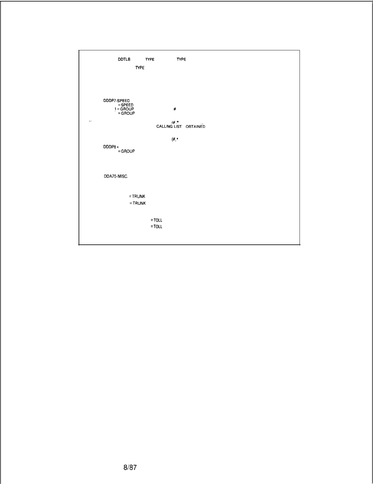
TL-130200-1001
M-236
DDTLA,
DDTLS
. CODE
TYPE
AND CODE
TYPE
IDENTIFIER
THE CODE TYPE IS DEFINED IN FP-413622.
THE CODE
lYPE
IDENTIFIER REPRESENTS A DIGIT, A LINE, TRUNK, TURRET, OR TRUNK GROUP
NUMBER. IT MAY CONTAIN A INTERCEPT CODE NUMBER AS DEFINED IN FP-413846, OR IT IS
NOT USED.
THIS INFORMATION IS DERIVED FROM DIGIT ANALYSIS
DDSNC . SENDER CONTROL FLAG
IDT = INTERDIGITAL TIME FLAG
DDDP7.SPEED
CALLING STATE FIELD
0
=SPEED
CALLING UPDATES ARE NOT IN PROGRESS
!
=GROUP
SPEED CALLING LIST
#
OBTAINED READY TO RECEIVE SPEED CALLING FLAG DATA
2
=GROUP
SPEED CALLING FLAG DATA OBTAINED READY TO RECEIVE SPEED CALLING ENTRY
DATA
3 = RECEIVE SPECIAL ENTRIES
(#.
*
OR DELAYS) FOR GROUP INPUT
4 = INDIVIDUAL SPEED
CALLING‘LiST
#
OBTAINE’D
READY TO RECEIVE INDIVIDUAL SPEED
CALLING ENTRY
DATA
5 = RECEIVE SPECIAL ENTRIES
(#,
*
OR DELAYS) FOR INDIVIDUAL
DDDPE
-
SPEED CALL TYPE FLAG
0
=GR.OUP
SPEED CALLING
1 = SCC ACCESS
DDA75-MISC.
MERS-SCC INFORMATION
TONE DETECTOR NUMBER (0 TO 31)
TGA FLAG-TRUNK GROUP ACCESS RESTRICTION BYPASS
0
=TRUNK
GROUP ACCESS RESTRICTIONS CHECKED
1
=TRUNK
GROUP ACCESS RESTRICTION CHECKS BYPASSED
TOLL RESTRICTION BYPASS
0
=TOLL
ACCESS RESTRICTIONS ARE CHECKED
1
=TOLL
ACCESS RESTRICTIONS ARE BYPASSED
Call Store 6.5 The call store is used to temporarily store information used
by call processing to establish and break telephone
communications.
a/a7
5210
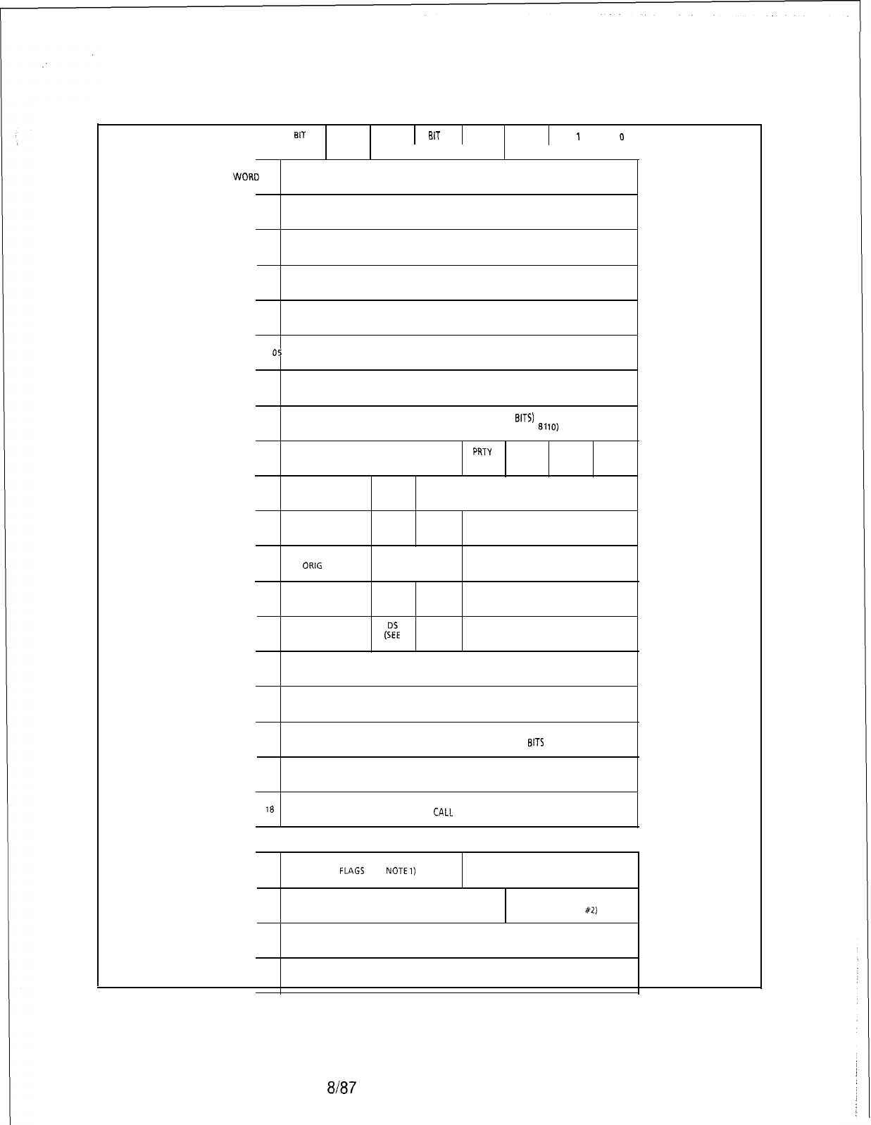
TL-130200-1001
BIT
7
BIT 6 BIT 5 BIT
4
BIT 3 BIT 2
BIT
1
BIT 0
COMMON AREA
WORD
00
FORWARD LINK
LOW
ORDER BYTE
WORD 01
FORWARD LINK HIGH ORDER BYTE
WORD 02
BACKWARD LINK
LOW
ORDER BYTE
__
WORD 03
BACKWARD LINK HIGH ORDER BYTE
WORD 04
QUEUE RETURN POINTER
WORD
05
.
TIMER
WORD 06
CALL STORE NUMBER LOW ORDER BITS
WORD 07 CALL STORE NUMBER (HIGH ORDER
BITS)
(CALL STORE NUMBER IS A 9 BIT NUMBER FOR 81 IO)
PRTY CAS ACD ACD
WORD OB ATTEMPTS CALL
MAIN
RECORD PRESS
QUEUE ANN IND
DATA
WORD 09
TERM PORT PRCT CALL TYPE
WORD 10
CONT PORT CLRF RTF DIGIT 4
CALL
WORD 11
ORIG PORT FORWARDING DIGIT 5
LEVEL COUNT
DID
WORD 12
QUEUE PORT TRUNK
DG
DIGIT 6
FLAG
WORD 13
BREAK IN
PORT (54’, TC DIGIT 7
NOTE 3)
WORD 14 DIGIT STORE LINK
(CALL STORE HAS BEEN REMOVED FROM THIS FIELD 8110)
WORD 15
CALL STORE NUMBER LINK HIGH ORDER BITS
(CALL STORE NUMBER LINK HAS IT OWNS BYTES FOR 8110)
WORD 16
CALL STORE NUMBER LINK LOW ORDER EITS
WORD 17
ATTENDANT CONSOLE
‘WORD
18 CALL
STATE
PORT 1 AREA
WORD 19
FLAGS
(SEE
NOTE
I)
FORT TYPE
WORD 22
(PEC
SEE NOTE
#2)
WORD 25
WORD 28
EQUIPMENT NUMBER
TIME SLOT
Figure 6.5 Call Store Layout
5210
a/a7
M-237
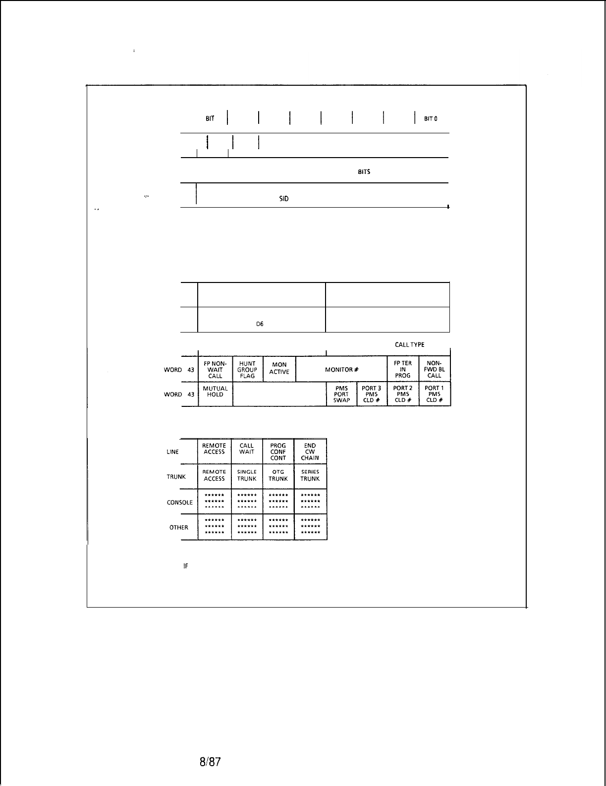
TL-130200-1001
M-238
BIT
7
1
BIT 6
1
BIT5
1
BIT4
1
BIT3
1
BIT2
1
BIT1
1
BIT0
WORD 31
1
OA
1
OB
1
TONE NUMBER
I
WORD 34
I
PORT CALL STORE NUMBER LINK HIGH ORDER BIT5
I
WORD 35
I
PORT CALL STORE NUMBER LINK LOW ORDER BITS
.~.
(USED ALSO FOR SIO STORAGE FOR CALL WAITING)
I
1
.
.
WORDS 20 AND 21 ARE THE SAME AS WORD 19, WORD5 23 AND 24
ARE THE SAME AS WORD
22,
ETC., WORD 36 AND 37 ARE THE SAME AS WORD 34, WORD
35.
COMMON AREA
WORD 40
DIVERT OVERRIDE DIVERT OVERRIDE
D4 D5
WORD 41
DIVERT OVERRIDE DIVERT OVERRIDE
06
D7
WORD 42
I
FEATUREPHONE CLIENT ID
I
FEATUREPHONE CALLTYPE
I
NOTES: 1 THE FLAG IS PORT TYPE DEPENDENT:
2THE PEC # FIELD IS NOT USED FOR PORT TYPES OF TURRET AND CONFERENCE
3
IF
THIS BIT IS SET IT COULD MEAN EITHER DIGIT STORE LINK FIELD OR CALL STORE LINK FIELD
SHOULD BE USED.
Figure 6.5 Call Store Layout (Continued)
a/a7
5210

TL-130200-1001
To view the following information, enter the DISPLAY command
on the system maintenance terminal. See paragraph 2.1.7 for
the DISPLAY command format.
*
Line Call Store Link Addresses (T4160) (data page 5)
l Trunk Call Store Addresses (T8944) With Hex Addresses (data
l CEC Trunk State Addresses (T8941) (data page 2)
0
CEC Line State Address (T4170) (data page 2)
@
Call Store (T139) (data page 0)
5210
8187
M-239
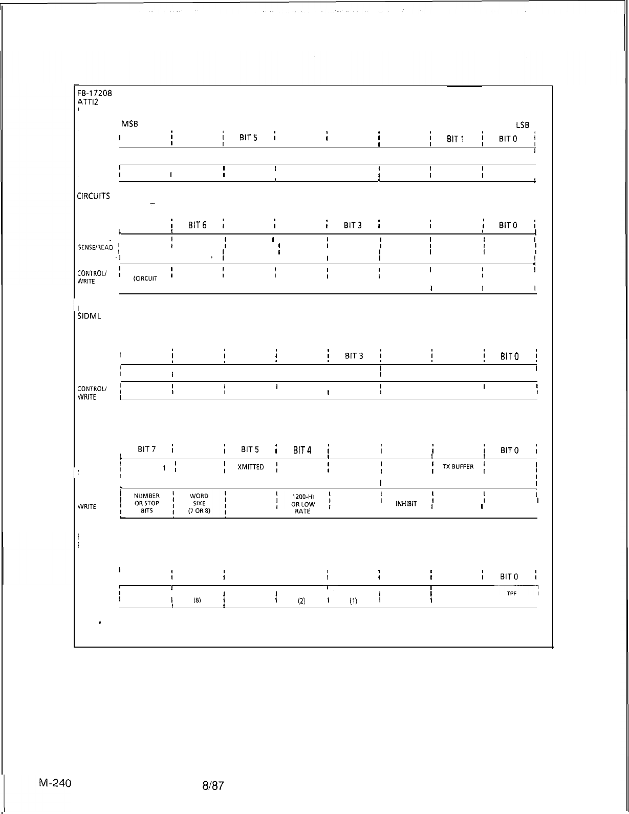
TL-130200-1001
II
1 1
/
,
,
I’
~5-17208
4TTl2
*
CIRCUIT 0 OR 2
MS6
LSB
’
BIT7
j
BIT6
i
BIT5
;
BIT4
;I
BIT3
i
BIT2
i
BIT1
i
BIT0
i
IIII I
DATA
I I I
SENSE/READ I
I
DATA I DATA I DATA
I
DATA I DATA IDATA I DATA
I
CONTROU
;I
DATA
I
DATA
;
DATA
’
I
DATA
I
WRITE
I
DATA
;
DATA
;
DATA
;I
DATA ,
IItI
1
IIRCUITS
1 AND 3
_
MSB LSB
I BIT7
;
BIT6
;
BIT5
i
BIT4
;
BIT3
;
BIT2
;
BIT1
i
BIT0
i
1
II I I I I I
I
SENSE/READ
;
, ALARM1
;
ALARM2
;
XMITTED
’
REMAINING
I
II
REGISTER
;
ERROR ,OVERFLOW
;
PARITY
;
TXBUFFER
f
DATA
’
ERROR
I
ERROR
I
REGISTER
I
READY
(
.I
I
-
I
EMPTY ,
I I
, EMPTY ,
t
,4
:ONTROU
;
RELAY 5
;
RELAY4
;
RELAY 3
;
RELAY2
;
RELAY 1
;I
RESET
;
LOAD
’
JVRITE
,
(CIRCUIT
,
, ONLY) ,
(CIRCUIT ,
ONLY) ,
(CIRCUIT ,
ONLY) ,(CIRCUIT ,
ONLY) ,(CIRCUIT ,
ONLY) ,
I I I
I I I
FB-17209
SIDML
CIRCUIT 0 OR 2
MSB LSB
1 BIT7
i
BIT6
i
BIT5
i
BIT4
/
BIT3
i
BIT2
i
BIT1
;
BIT0
i
SENSE/READ
:IIIIII I I
DATA
I
DATA
I
DATA I DATA I DATA
I
DATA I DATA I DATA I
CONTROL/
;
DATA
DATA
1
DATA
’
DATA
I
I
1
DATA
I
DATA
I
,
DATA
l
I
DATA
I
“VRITE
1
,
CIRCUITS 1 AND 3
MSB LSB
I
BIT7
i
BIT6
i
BITS
i
BIT4
i
BIT3
i
BIT2
i
BIT 1
;
BIT0
;
1
III
1
II
1
I
’
ALARM
1
;
ALARM2
SENSE/READ
i
1
XMITTED
;
, REGISTER ,REMAINING
;
OVERFLOW
;
ERROR , ERROR ,PARITY
;
TXEUFFER
;
DATA
’
I
ERROR ,REGISTER ,READY
;
I I
, EMPTY ,
II
, EMPTY ,
I
k
CONTROU
vVRlTE
LOOP
OR
ODD/EVEN
1
PARITY ,PARITY
I
INHISIT
I
MASTER
;i
CONTROL
I
RISK
,
RATE
RESET
I
REGISTER ,
I I I I
LOAD
I
‘B-1 7203
‘DTMF
MSB LSB
1
I BIT7
;
BIT6
;
BIT5 :BIT4 1BIT3
i
BIT2
;
BIT1
;
BIT0
;
SENSE/READ
iII
I
7
II
CLOCKED& ,
HEX
I
HEX
I
HEX
I
HEX
I
ALWAYS
I
ALWAYS;
-7
TPF
’
LATCHED
1
18)
I
(4)
I
(2)
’
(1)
’
0
1
0
I
LATCHED ,
!
tI I
NOTE:
*
= RESPONSE FROM SELECTED CIRCUIT (UP TO 4 MAXIMUM)
Figure 6.6 Sense and Control Address Words (Sheet 1 of 4)
8187
5210
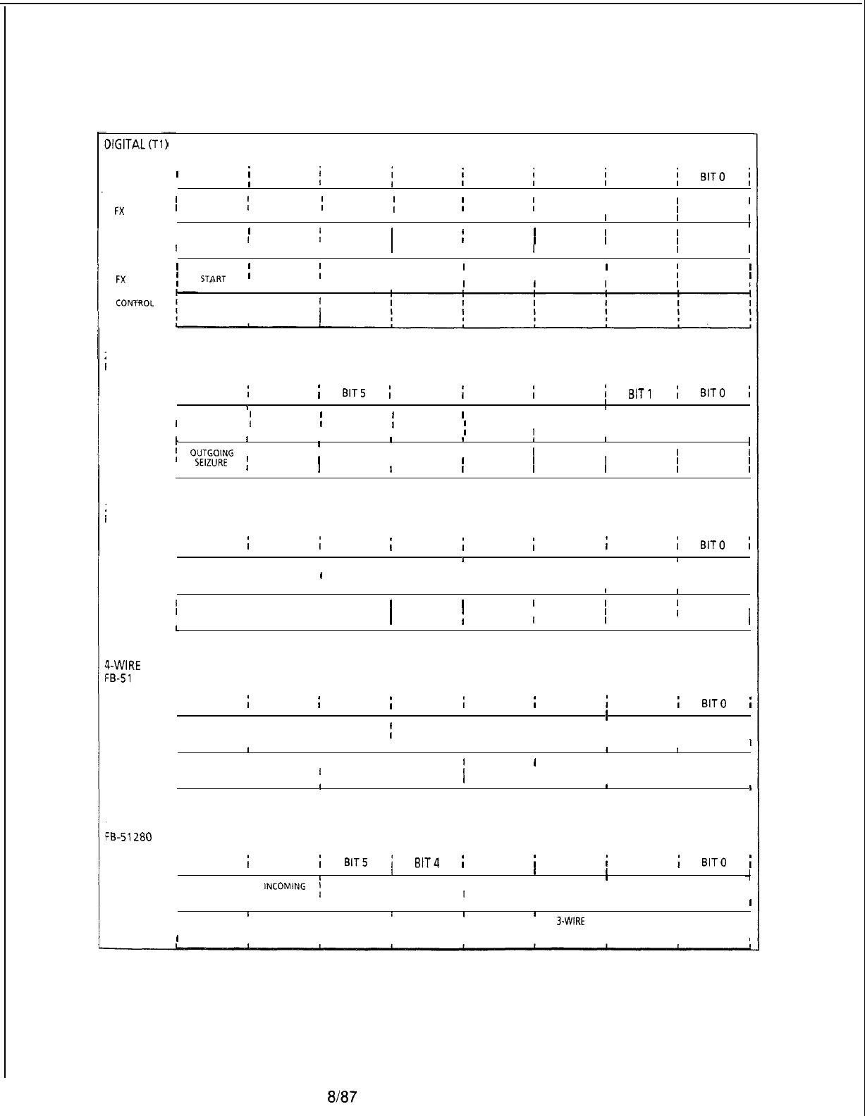
XGITAL
(Tl
SENSE
FX
TRUNK
TL-130200-1001
SENSE
E&M TRUNK
)
TRUNK
CONTROL
FX
TRUNK
CONPROL
E&M TRUNK
’
BIT7
i
BIT6
i
BIT5
i
BIT4
i
BIT3
i
BIT2
i
BIT1
i
BIT0
j
IIIIIIII,
’
GROUND
(
’
DETECTED ,INCOMING
;
SEIZURE ,CURRENT
;
FLOW ,
REVERSE
;
BATTERY ,
III I
II,
IIIII
,I
II I I I ,
I’
INCOMING
If
SEIZURE ,
I
f
I I I
I
IIIIIII I
I I
’
GROUND
;
CLOSE
;IIII I
;
STJRT
, LOOP ,
III I I I
II I I I I
I
CLOSE
(
I
, LOOP
l
!-WAY LOOP TRUNK.
-B-l 7202 OR FB-17202-80
I BIT7
;
BIT6
;
BITS
;
BIT4
;
BIT3
;
BIT2
;
BIT1
;
BIT0
i
III I I I II
I i I
SENSE
I
GROUND
;
INCOMING
;
CURRENT
;
REVERSE
’III
’
DETECTED ,SEIZURE ,FLOW BATTERY
;III
I
IIII
t
I
1
I
4
I
! I
CONTROL
;
OUTGOlNG
, CLOSE ,
I I III I
SEIZURE
I
LOOP
’IIIIII
IIIIIII
, ,
!-WIRE E&M TRUNK
‘B-1 7201
I BIT7
;
BIT6
;
BIT5
i
BIT4
i
BIT3
i
BIT2
i
BIT 1
i
BIT0
i
IIIIIIII
I I IIII
SENSE
I
I E-LEAD I
IIIIII
II
INCOMING
IIIIIII
I
I SEIZURE I
IIIIII
I,, I I III
CONTROL
I
I M-LEAD I
I
SML
II I I
I
I OFF-HOOK I
IIII I
I
I CONTROL I
I I
1
III
L
,
q-WIRE
E&M TRUNK
-B-51
267
I BIT7
;
BIT6
i
BIT5
i
BIT4
;
BIT3
i
BIT2
;
BIT1
i
BIT0
i
IIIIIIII
, I I II I
SENSE
I
I E-LEAD I
I I I I I
I
I INCOMING I
II I I I I
I I
SEIZURE I
II I I I I
t
II I II
1
I
CONTROL II M-LEAD I
IIIIII
I
I OFF-HOOK
II I II
I
I CONTROL I
IIIII I
I,
8
I I I,I
l-WAY INCOMING TRUNK
FB-51280
OR FB-51280-80
I BIT7
i
BIT6
i
BITS
i
BIT4
;
BIT3
i
BIT2
i
BIT 1
;
BIT0
i
t
I I III
1
I
,I I
-I
SENSE
I ,
I
INCOMING
:IIIIII
I I IIIII
I
SEIZURE
IIIIII
IIII
1
II
i
CONTROL IREVEERSE I
III
I
3.WIRE
I
I
I
I
BATTERY I
IIII
“C’ LEAD I
I I
I
SUPVRY.
II I I
I CONTROL
III
Figure 6.6 Sense and Control Address Words (Sheet 2 of 4)
5210 8187 M-241
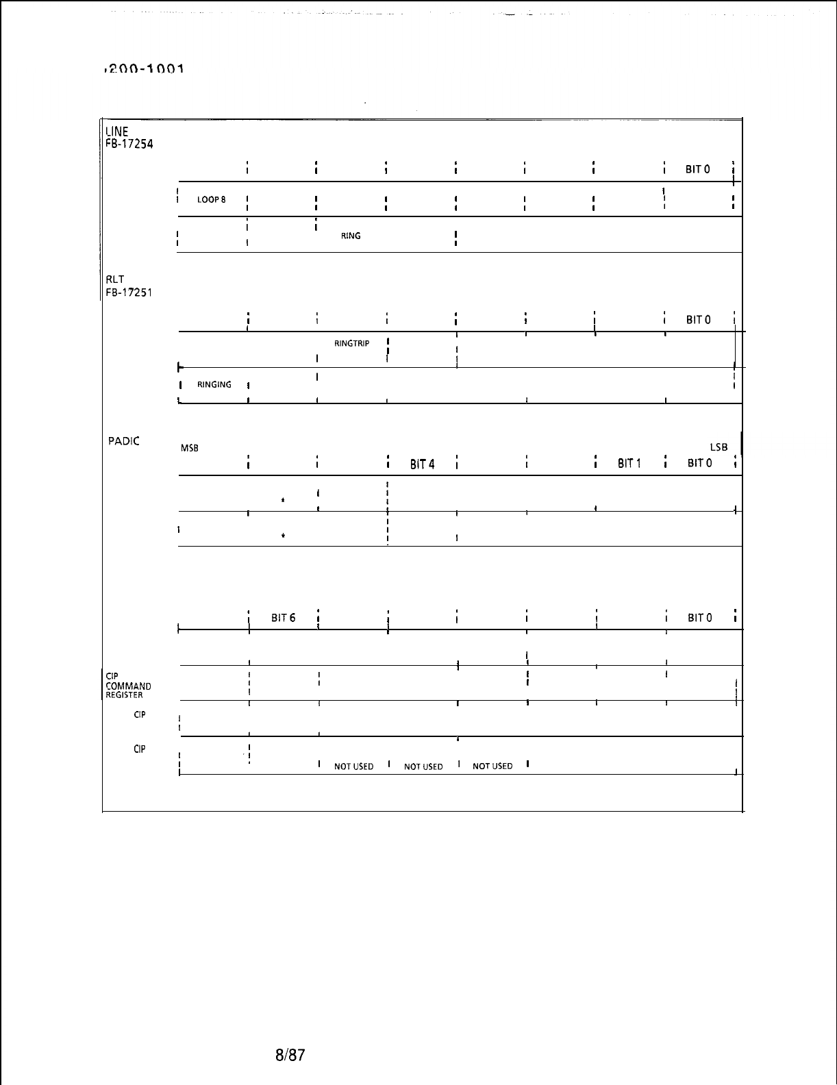
TL-130
M-242
PINE
CIRCUITCARD
:B-17254
OR FB-17254-l
I
BIT7
i
BIT6
i
BIT5
;
BIT4
;
BIT3
i
BIT2
;
BIT1
i
BIT0
i
IIIIIIII
i
II I I I I I
1
SENSE
I
I
LOOP8
;
LOOP7
;
LOOP6
;
LOOPS
;
LOOP4
;
LOOP3
;
LOOP2
;
LOOP 1
;
Ii i I I I
ii i
CONTROL
;
RING
I
RING
I
RING
I
RING
;
RING
I
RING
I
RING
I
RING
I
II I I I I I
?LT
TRUNK
:B-17251
I
BIT7
i
BIT6
i
BIT5
i
BIT4
;
BIT3
i
BIT2
i
BIT1
i
BIT0
i
II
I1
I
IIII
I
I
I
RINGTRIP
;
II I I
SENSE
I I III I I
I I
1
DISCONN.
lI I I
k
II
I I
CLOSE
lIIII I
CONTROL
l
RINGING
1
II I I i
I LOOP
IIIII II
c
I I I II I I
FB-17210
PADIC
MSB
I BIT7
;
BIT6
;
BIT5
;
BIT4
i
BIT3
i
BIT2
;
BIT1
;
BIT0
;
IIII I IIII
I
SENSE
I
I
I
I
CONTROL
1
I
I DICTATION I
I
BUSY
I
I
*I
II
I
I DICTATION I
I BUSY
I
I+I
II
i
I
I I I I
IIIII
, I II
II
i
I
PAGE I PAGE
I
PAGE
I
PAGE
I
I
ZONE I ZONE
I
ZONE
I
ZONE I
I
4
I
3
I I
1
I
I BIT7
i
BIT6
;
BIT5
;
BIT4
;
BIT3
i
BIT2
;
BIT 1
i
BIT0
i
I
COMMAND
I
REGISTER
I
I
I
CIP
PORT STATUS/;
ZOMMAND
TEGISTER
I
t
CIP
I
READ/WRITE
;
I
I I
t
IIII
IIIIII
I I I I I I
I I I
SEE NOTE 3
I I I I
I I I II I I
II I I I II
III
t
IIiIII
I
SEE NOTE 1
II I I
f
I I I I I I
II IIIII
II I I I I I
III
BYTE OF DATA
I I I I
II I I I I I
I I
IIIII I I I
CIP
I
STATUS
;
REGISTER
I
I I
SEE NOTE 2
I I I I
I I I I I I
Il
NOTUSED
l
NOTUSED
l
NOTUSED
lI I I
I I I
I
Figure 6.6 Sense and Control Address Words (Sheet 3 of 4)
8187
5210
TL-130200-1001
NOTE: 1 NOTE: 3
CIP PORT STATUS REGISTER
I I IIIIII1
’
07
’
06
’
05
’
04
’
03 I 02
I
01
I
00
I
I
I
i
1*1*1*1*1*1*1*1*,
I IIIIII
CIP COMMAND REGISTER
IIIII
’
07
’
06
’
05
’
04
’
03
’
02
’
01
I
00
I
II
l*l*l*1*l*l*l*,‘,
I
1
II I
1
II
07 =
PS7
06..=
PS6
05 =
PS5
04
=-PS4
03 =
PS3
02 =
PS2
01
=
PSI
00 =
PSO
M PRTM PORT 7 STATUS
M PRTM PORT 6 STATUS
M PRTM PORT 5 STATUS
M PRTM PORT 4 STATUS
M PRTM-PORT 3 STATUS
M PRTM PORT 2 STATUS
M PRTM PORT 1 STATUS
M PRTM PORT 0 STATUS
07-00 = Command indexnumber
COMMAND
co
DEFINITION
Disable Port 0 and clear associated
buffer /counts
01
Disable Port 1 and clear associated
buffer /counts
02 Disable Port 2 and clear associated
buffer /counts
*
0 = Buffer not full
1 = Buffer full
NOTE: 2
CIP STATUS REGISTER
1
IIIII I
t
’
07
’
06
’
05
’
04
’
03
’
02
’
01 I
00
I
,I I
1*1*1*1*,*1*1*1*,
I I I IIII I
1
07
-
CIP OUTPUT BUFFER FULL
06-CIP-
>
PECSENDDATA
05 -Not Used
04
-
Not Used
03
-
Not Used
02
-
PEC
-
CIP SEND COMMAND
01
-
PEC
-
CIPXMIT
ERROR
00
-
PEC
-
CIP SEND DATA
03 Disable Port 3 and clear associated
buffer/counts
04 Disable Port 4 and clear associated
buffer/counts
05 Disable Port 5 and clear associated
buffer/counts
06
07
08
09
OA
OB
Disable Port 6and clear associated
buffer/counts
Disable Port 7and clear associated
buffer/counts
Enable Port0
Enable Port 1
Enable Port 2
Enable Port 3
oc
OD
OE
OF
10
Enable Port4
Enable Port 5
Enable Port 6
Enable Port 7
Clear CIP
*
0 = False (reset)
1 = True (set)
5210
Figure 6.6 Sense and Control Address Words (Sheet 4
of
4)
Tables 6.10 through 6.14 are provided for maintenance personnel
thoroughly trained in system operation, and provides very
specialized troubleshooting data.
8187
M-243
TL-130200-1001
Table 6.10 Call-Type Codes
1 CODE CALL TYPE
Local
Forei
WAT
8
n Exchange (FX)
Tie
line
Still busy
No answer
Information
Intercept
Long-distance restriction
Transfer
Series
Special
Attendant originating
Table 6.11 Pot-t-Type Codes
CODE CALL TYPE
Idle
Line
Trunk
(C.0)
~~~sd~~e)
Conference
Paging
Page queue
Code call
Recorded announcement
Dictation trunk
Hold queue
RLT
M-244
8187
5210

CODE
01
02
03
04
05
06
. .
07
08
09
.
OA
08
oc
OD
OE
OF
10
11
12
13
14
15
16
17
18
19
1A
16
1c
1D
1E
1F
20
21
22
23
24
25
26
27
28
29
2A
5210
Table 6.12 CEC Trunk State Codes.
TRUNK
STATE
Incoming pre-seized trunk
Incoming mishandled trunk
Incoming FX trunk wait for resources
Incoming, not answered (idle)
Incoming loop, not answered (idle)
Incoming busy (idle)
Incoming signaling A
Incoming signaling B
Incoming dialing (idle)
Incoming delay dial wait
Outgoing start dial wait
Outgoing wink start wait
Outgoing busy (idle)
Outgoing guard after release
Outgoing immediate dial
Outgoing glare check
Recorder-Announcer message interval
Incoming seizure stall
System out of service (PEF out of service)
Outgoing wait for disconnect, PBX release first
Retry, put in service
Outgoing pre-seized
Spare
Outgoing dialing
Outgoing busy (busy)
Outgoing not answered
Outgoing wink start time
Panel maintenance busy
Not busy (idle)
Maintenance busy
System busy
Incoming, not answered (busy)
Incoming loop, not answered (busy)
Incoming busy (busy)
Incoming dialing
Incoming dialing (busy)
Recorder-Announcer start
Recorder-Announcer message cycle
Call recovery trunk off-hook
CAS Main ACD recorded announcement start
CAS Main ACD recorded message cycle
Nailed connection
8187
TL-130200-1001
M-245
TL-130200-1001
Table 6.13 CEC Line State Codes
CODE LINE STATE
Line idle
Line ringing
I
Line busy
03
Line digit collection
04
Call-back in progress
05 .Call-back ringing
06
Line locked out
07
Line maintenance busy
08
Staff for call-store assignment
09
Line stall (idle)
OA
OB
Line stall (off-hook)
Line off-hook recovery
Table 6.14 Call State Codes
CODE CALL STATE CODE CALL STATE
00
One-way
09
Two-way busy
01
Two-way terminating
OA
#old
one party
02
Two-way
OB
Two-way busy after flash
03
Two-way split
OC
Three-way busy
04 Three-way terminating
OD
Hold
two
party
05
Three-way split
OE
Three-way busy after include source
06 Three-way
OF
Three-way split term
07
Idle
IO
One-way after ATB
08 Three-way double team
11
One-way after ATB (Flash)
M-246
8187
5210
5210
TL-I
30200-l 001
PD-200
7.0 This section describes the maintenance and administration
Maintenance
facilities which are available within the OMNI
SI
PABX for the
PD-200 Data System. Maintenance personnel normally
communicate with the
OMNI
SI via the system maintenance
terminal. The terminal connects to the CEC card ‘and is used for
entering system commands or receiving system-related reports.
The terminal is the source of input/output interfaces with the
PABX for maintenance and diagnostic initialization. Commands
are entered on the terminal and are analyzed by the CEC to
determine syntax correctness. Syntactically correct messages
are sent directly to the ADMP for processing. They are then
analyzed by the ADMP to determine which function is being
requested. That specific function is executed and the results are
reported back to the the maintenance terminal.
The maintenance terminal provides access to the following
system functions:
l Maintenance commands and displays
0
On-line maintenance program
l Recent Change program
Before accessing system maintenance, the security lock must be
opened by using the security lock command (SL) and a
password. Once a valid password is entered, the system
responds with the message OPEN AT X, where X is the security
level.
Unauthorized access to the
OMNI
SI software will result in the
following prompt:
“INVALID SECURITY ACCESS”
These programs are operational only when an
OMNI
system is
operating on system software. To diagnose an off-line system,
independent of system software, an off-line maintenance
program is provided. This program is available on floppy disk.
In a typical, integrated voice/data
OMNI
SI
system, two terminals
are installed for maintenance and administrative functions. They
are:
Q
An
input’output
maintenance terminal (normally used for the
voice only part of the
OMNI
switch).
o
An
input/output
maintenance terminal for the PD-200 Data
System.
8187
M-247

TL-130200-1001
The data-only maintenance terminal is required for the
integrated voice/data system. The option
“s”
of connecting a
data-only terminal to the RS-232C port of the ADMP is
available. This enables the user to do administrative functions
for the data switch even if the voice switch becomes disabled.
--
When the PD-200 Data System is administered from the
data-
only maintenance terminal, this terminal is referred to as the
ADMP console. Since the ADMP console software provides full
screen editing capabilities, it is required to be a VT-101 console
or its equivalent-type video terminal.
NOTE: A separate data console is recommended.
Data System
7~1
Assuming that the proper password is entered, the user may
Administrative and
access one of the following functions which pertain to the data
Maintenance Features
switch.
l Table Editor (TED). The data system relies on disk and
memory-resident data tables to perform its functions. The
table-editing (Recent Change) function of the ADMP allows
users to interactively view and alter the tables. All table
accesses are provided by the ADMP table editor. Detailed
TED command information is provided in Section 278-921-
180, Appendix 1.
0
Maintenance and Interactive Diagnostics (MAID). The ADMP
maintenance functions provide a limited set of maintenance
diagnostic commands via the MAID program menus. The user
interactively monitors and/or changes the status of the entire
data system (while on-line). The MAID allows the user to:
-
Place X.25 calls
-
Read device data signals
-
Set device data signals
-
Check communication between ADMP and device
-
Restart device
-
Display device status
-
Display network status
@
ADMP File Utility (FUTIL). The ADMP disk file maintenance
capability allows the user to create, delete, copy, dump, or
rename files.
Accounting Reports
7.2 Data and voice call-processing accounting is stored and
forwarded by the ADMP. The ADMP can be configured to report
accounting records to any data device in either ASCII or binary
form. The ADMP either makes a data call to the device or
accepts an incoming data call. A printer, host, or other terminal
can be the recipient of these accounting records.
M-248
8187
5210

Event Reports
Maintenance Commands
.
and Displays
l
Put a data device out of service
l
Force a data device out of service
l
Reload a data device
l
Put a data device in service
l
Force a data device in service
l
Display the software version of a device
l
Read the memory of a device
TL-130200-1001
7.3 An event is an occurrence in the data system which is of
some significance. It is usually a report about an error or
malfunction. Events are stored and forwarded by the
ADMP
in
much the same manner as accounting records, and they can be
reported to any device by either incoming or outgoing data calls.
Event reports can also be sent to the CEC and/or combined with
accounting reports to the same end-point. This is done by
configuring the ADMP tables (using TED). Thus, a single device
can be the recipient of account reports, event reports, or both.
7.4 Maintenance support is similar to Recent-Change
support in that any maintenance function resulting in a change to
the data system is reported by the CEC to the ADMP.
Commands such as putting a data device out of service,
reloading a device, or forcing a device in service or out of
service are performed via the maintenance terminal. The CEC
request to the ADMP is acknowledged or rejected, and the
results are sent to the CEC. The following data-related
maintenance functions are performed via the maintenance
terminal:
5210
a/a7
M-249

TL-130200-1001
The system allows loading of specific data components while the
system is operational. The purpose is to permit reloading of
devices which may be malfunctioning but are still in service. A
device must be in service in order to load it with operational
code.
Devices in the data system which are ROM or hardware based,
can only be FORCED out of service. However,
loadable
devices
can be PUT or FORCED out of service. The
DFP/APM
is treated
as two devices having the same physical location whether in
service or out of service.
Forcing a device out of service accomplishes taking the device
down unconditionally. Putting the device out of service causes
the system to wait until the device is not active before it is taken
down
Forcing a device in service causes the device to come up.
When this happens, it is loaded, if loadable, or restarted if it is a
ROM-based device.
Backing up and reformatting system disks is accomplished via
the system on-line maintenance facilities. These facilities are
described in TL-130300-1001. Access to on-line
maintenance is via the maintenance terminal.
Data
System
7.5 The operational status of the data sub-system can be
Troubleshooting
determined by looking at the Expanded System Status Display
(ESSD) card indicator lamps in the CEC. The ESSD card
provides a DTC lamp which represents the data option of the
OMNI
SI system. This lamp indicates whether the ADMP is
communicating with the voice switch (light is on) or not
communicating with the voice switch (light is off). This lamp is
controlled by the CEC.
The status of the lamp is received from event messages
generated by the data switch. Each minute an assurance
request message is sent by the ADMP to the PEC, and the PEC
responds with an assurance response message. If the PEC
does not respond to the
ADMP’s
message, the data switch
knows that a problem exists with the voice switch. Every 5
minutes, the PEC checks that at least one assurance message
has been received since the last check. If the PEC does not
receive the ADMP message, the PEC sends an event message
to the CEC that is interpreted as a request to set the ADMP out of
service. The data switch may still be working even though the
voice switch and the ADMP are not communicating.
M-250
8187
5210
-
-
TL-130200-1001
5210
8187
M-251
Additionally, the PEC periodically reads register 3 of all resident
PRs
and tests for a non-zero condition which is an error
condition. Should the error be detected, the PEC generates a PR
event message for the ADMP. If the CEC, PEC, and/or disk has
switched over, it will send a switch-over message to- the ADMP.
The status of all line cards in the integrated switch can be
displayed via the on-line Maintenance Option Menu, Program
28. The Recent-Change data link displays will indicate the
in-
service/out-of-service status of equipped data cards and
remote processors.
The displays will appear in the following formats:
DATA SWITCH DEVICE STATUS DISPLAY
A) PACKET LINE CARDS STATUS
B) REMOTE PROCESSORS STATUS
C) EXIT
TYPE
T.HE
LETTER OF THE DESIRED
TOPIC>
(followed by)
TYPE “S” FOR SYSTEM DISPLAY OR 0 TO 7 FOR PEC #
>
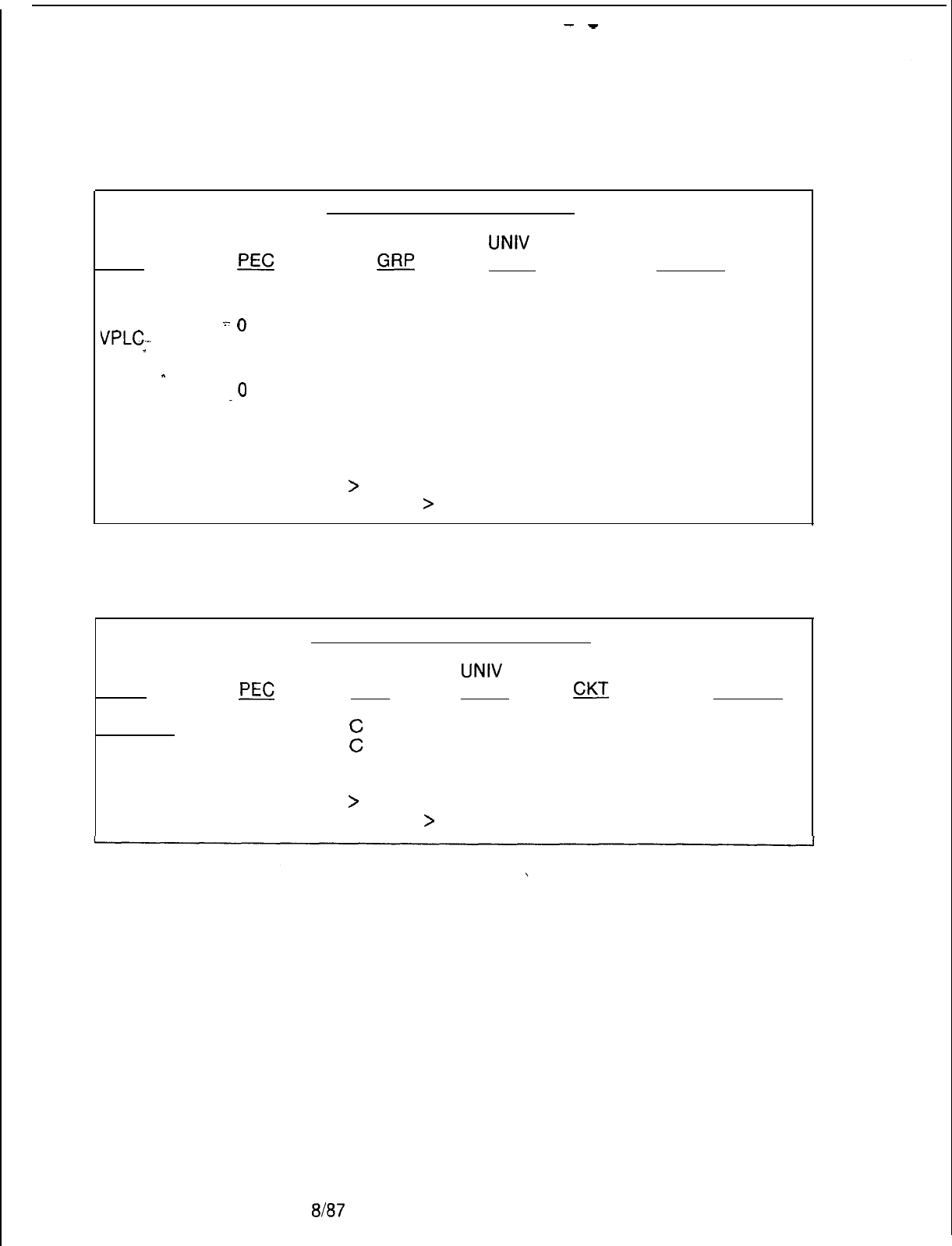
-
-
TL-130200-1001
PACKET LINE CARD STATUS
CARD
UNIV
TYPE
PEC GRP
SLOT STATUS
ADMP
0
A
2
INS
DCP
..-
0B2
INS
VPLC--. 0C5
00s
PR
-
0
A
0
INS
BT
-
0
A
10
INS
BT
-0
.
B
11
INS
PBE
0B0
INS
NIC
0B5
INS
Do you wish to see more (Y/N)
>
Do you wish to repeat this function (Y/N)
>
REMOTE PROCESSORS STATUS
CARD
TYPE
PEC
GRP
UNIV
SLOT
gcJ
DFPAPM
0 3 0
APM -0
5
1
SPM
0C5 6
Do you wish to see more (Y/N)
>
Do you wish to repeat this function (Y/N)
>
STATUS
INS
INS
INS
M-252
8187
5210
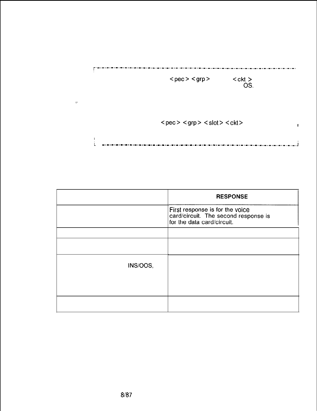
5210
TL-130200-1001
PD-200 Data 7.6 To force PD-200 Data System devices in service or out of
System Devices
service, use the following command:
r’
_.-.-.-.-.-.-.-.-.-.-.-.-.-.-.-.-.-.-.-.-.-.-.-.-.-.-.-.-.-.-.-.-.-.-.-.-.-.-.-.-.-.-.
1
II
IFORCE device
<pet>
<grp>
<slot>
<ckt
>
IS.
I
I
I
I
OS.
i where
I
I
DCP, PR, VPLC, NIC, SPN, APM, , DFPAPM
. .
I
.~.
i device =
I
I
I
Ior
I
I
I
I
I
FORCE device
<pet>
<grp>
<slot>
Cckt>
IS. I
I
i .
I
! where
I
i
device = ADPM
I
-.-.-.-.-.-.-.-._._.-.-.-.-.-.-.-.-.-.-.-.-.-.-.-.-.-.-.-.-.-.-.-.-.-.-.-.-.-.-.-,-.
i
Table 7.1 below shows the responses for the various source
commands at the maintenance terminal.
Table 7.1 Responses for Force Commands at Terminal
INPUT
If device is VPLC2 with both voice
and data circuits equipped,
If the voice device is already IS/OS,
If the PEC is not able to force the
voice device IS/OS,
If everything is all right with the
voice device and FORCE
INSOOS,
If the ADMP is not able to force the
data device IS/OS,
si
Frrst
response IS for the
voice
card/circuit. The second response is
A message prints: CARD/PORT IS IS/OS
A message prints: COMMAND FAILED,
indicating unsuccessful completion.
A message prints: IN PROGRESS. When
the request is completed, the following
message is printed: COMMAND
COMPLETED, indicating successful
completion. The voice device will be IS and
ready to test or OS.
A message is sent from the ADMP which
explains the situation.
8187
M-253
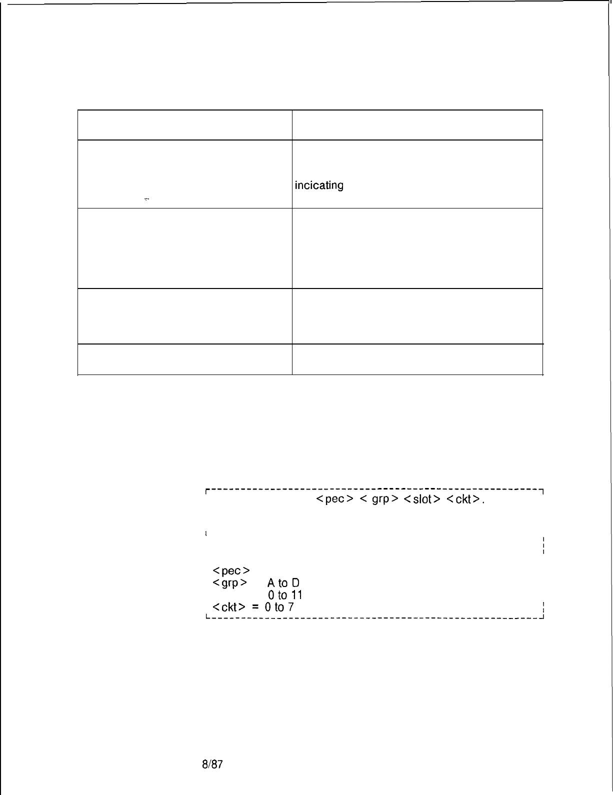
TL-130200-1001
Table 9.1 Responses for Force Commands at Terminal (Continued)
M-254
INPUT RESPONSE
If everything is all right with the
ADMP, but the data device cannot be
accessed,
_.
If everything is all right with the
ADMP, and FORCE IS/OS is
successful,
A message prints: IN PROGRESS.
When the request is completed, the following
message is printed: COMMAND FAILED,
incicating
unsuccessful completion. The data
device will be IS or OS.
A message prints: IN PROGRESS.
When the request is completed, the
following message is printed:
COMMAND COMPLETED, indicating
successful completion. The data device
will be IS or OS.
If something is wrong with the
ADMP, or the ADMP takes too long
(more than a predefined time)
to respond,
A message prints: MR TIMED OUT.
If the device is not at the given PEC
group slot circuit address, A message prints: ADDRESS DOES NOT
MATCH DEVICE TYPE.
Display Software
7.7 The Display Software Version (DSPSV) command displays
Version Command
the software version for the data hardware or data device at the
location defined. The command is as follows:
r-------------------------------------------------------~
; DSPSW <device>
<pet>
C
grp>
<slot>
<ckt>.
I
I
I
I
I
I
; where
I
I
II
j <device> = ADMP, DCP, VPLC, SPM, APM, DFPAPM, or
i
1 NIC
I
I
1
<pet>
= 0
I
I
I
<cvp>
=
AtoD
I
I
1 <slot> =
oto11
I
I
;
<CM> =Oto7
i
L----------__-------------------------------------------~
8187
5210
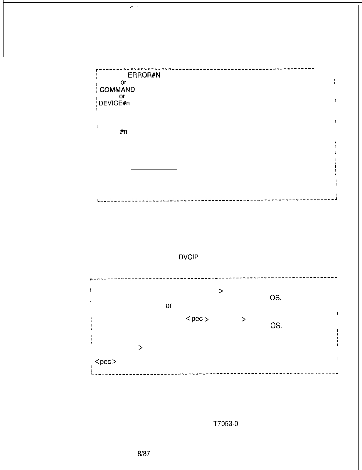
-
.-
TL-130200-1001
The system prints the following on the maintenance terminal:
r---------------------
_____-----__-_--_-__---------------
_---em
-----1
j
SYNTAX
ERROR#N
= an error was found in the input message
I
j
COMMFND FAILED
= the request was not processed successfully
I
i
DEVICl%n
aa.bb.cc
I
I
1
where
I
I
I
I
#n
= the following types:
1
I09 =
ADMP
I
I. OA = DCP
I
IOE = SPM
I
IOF = APM
I
I12 =
DFPAPM
I
I13 = NIC
I
I
I
I
and where
I
Iaa.bb.cc. = the version of the software loaded in the device
I
I
II
II
I
I
I
I
I
I
I
I
I
I
II
I
i
I
I
I
I
:
II
I
I
I
I
Force
7.8 The FORCE command can be used to force devices and or
In Service/Out of Service
circuits into the maintenance busy state when not idle.
Command
Removing a device from service using the FORCE command
takes the device down unconditionally.
Featurephones
7.8.1 To force an Analog or Digital Featurephone connected to a
CIP, DCIP, or
DVCIP
port in service or out of service, enter the
following:
r-----------‘- ----------------------------------------------~---------~
I
I
I
I
II
IFORCE CIP DN <directory-no.
>IS.
I
I
OS.
I,
/
I
I
Or
FORCE CIP PORT
<
pet
>
<port -no.
>IS.
OS.
I
I
I
/
where
I <directory-no.
>
= three- or four-digit directory number of a
II
I Featurephone
I
I
)
<pet>
= 0
I
I
I
<port-no.> = 0 to 127
I
I
L---------^-----------------------------------------------------------
2
NOTES:
1. Port number is derived by relative CIP card number times 8
plus circuit number on the card. The relative CIP card number
is determined by the card’s position on the Featurephone Data
Link Information Table
T7053-0.
5210
8187
M-255
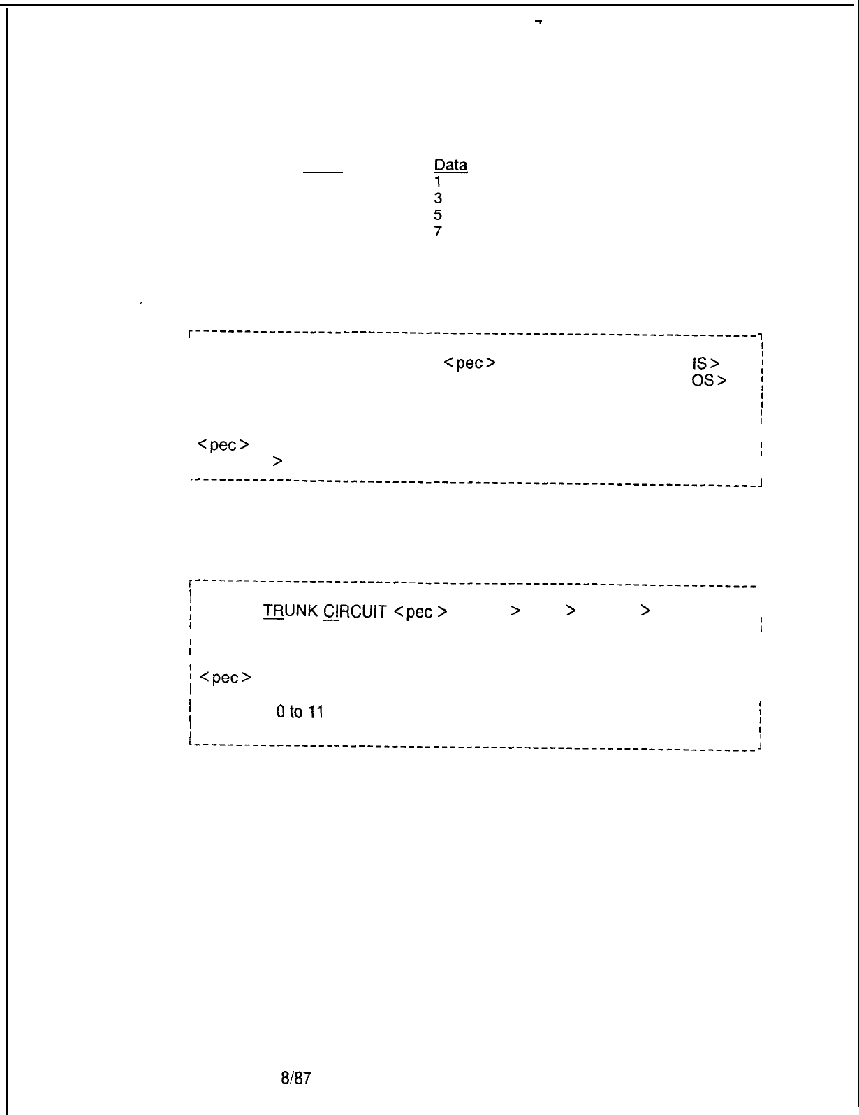
-
TL-1~30200-1001
2. For the DVCIP card, circuit numbers are defined:
Voice
0
2
4
6
Line Cards with
Featurephopnes
7.8.2 To force a CIP, VCIP, or DVCIP interface card in service or
out of service, enter the following:
.
.
r’-------------‘---
--------------------------------------------------
I
1
I
‘FORCE CIP CARD
<pet>
<card-no. >
IS>
/
OS>
;
where
I
I
I
<pet>
= 0
I
<card-no.
>
= 0 to 15
I
II
‘-----“-----------------------------------------------------------------~
Trunks
7.8.3 To force a trunk circuit from active to maintenance busy
using the physical location, enter the following:
I--------------------------------------------------------------------
I
1
[
FORCE
TRUNK
&lRCUlT
<pet
>
<group
>
<slot
>
<circuit
>
OS.
I
I
I
I
II
;
where
I
I
I
I
i
<pet>
= 0
I
II
f
<group> = A to D
I
I
1 <slot> =
oto11
I
;
<circuit> = 0 to 3
I
L-----------------
____-___-________-______________________-----------
;
8187
5210
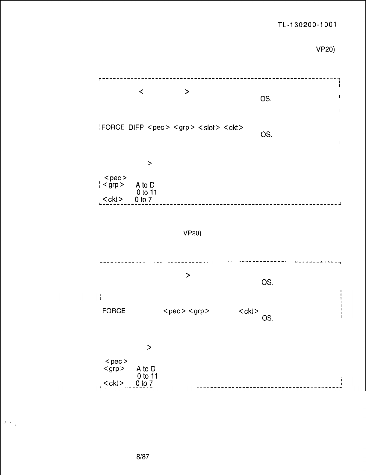
,!
.
.
5210
TL-130206-1001
To force a Digital Featurephone connected to VPLC2 (type
VP20)
voice port out of service, enter the command given below
r------------------------------------------------------------------~
I
I
I
i FORCE DN
<
directory-no.
>
I
I
I
I
I
IS.
I
I
OS.
I
II
I
I
I
Ior
I
I
I
II
lFORCE
DIFP
<pet>
<grp>
<slot>
<ckt>
IS.
I
I
I
I
I
OS.
I
II
I
I
I where .
I
I
I
I
I
I
I <directory-no.
>
= three- or four-digit directory number of a
I
I
I Featurephone
I
I
I
<pet>
= 0
I
I
I
<grp>
=
AtoD
I
I
I <slot> =
oto11
I
I
i
<ckt>
=
oto7
I
I
L------------------------------------------------------------------~
To force a Digital Featurephone with the data option connected to
a VPLC2 (type
VP20)
voice and data combination port out of
service, enter the command given below:
r----------------------------------------------------.
I
I
/ FORCE DN <directory-no.
>
I
I
IS.
OS.
------------7
II
or
iFORCE
DFPAPM
<pet>
<grp>
<slot>
<ckt>
I
I
OS.
I where
/ <directory-no.
>
= three- or four-digit directory number of a
I Featurephone
I
<pet>
= 0
I
<grp>
=
AtoD
I <slot> =
oto11
1
Cckt>
=
oto7
IS.
8187
M-257
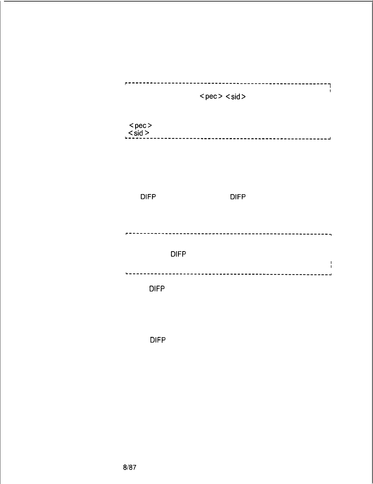
TL-130200-1001
Load Commands
M-258
To force a trunk circuit from active to maintenance busy using
the SID, enter the following:
r-------------------------------------------------------~
I
1
I
I FORCE TRUNK SID
<pet>
<sid>
OS>
II
I
I
j where
I
I
I
I
I
I
I
I
<pet>
= 0
I
I
I
Csid
>
= Trunk circuit SID relative to the PEC; 0 to 63
I
I
L-------------------------------------------------------~
7.9 LOAD commands are used only in data applications
The purpose of the load commands are to permit reloading of
devices which may be malfunctioning but are still in service. A
device must be in service to load it with operational code.
Load
DIFP
All. To perform a load
DIFP
for all applicable
Featurephones in PEC 0, use the ALL form of the following
command:
r-------------------------------------------------------~
II
II
IIALL
I
I
I
I
ILOAD
DIFP
I
ISTOP
I
I
I
I
II
L-------------------------------------------------------~
If LOAD
DIFP
ALL is typed, a request is sent to download all
Featurephones in the PEC. No request is sent to the data switch.
Messages are printed for the PEC download response, e.g., IN
PROGRESS PO> As each voice circuit is downloaded, a
message, RESPONSE 11, which indicates successful
completion, is printed.
If LOAD
DIFP
STOP is typed, a request is sent to stop download
of all Featurephones in the PEC. No request is sent to the data
switch. Messages are printed for each PEC STOP response,
e.g., IN PROGRESS PO. The PEC stops the downloading
Featurephones.
8187
5210
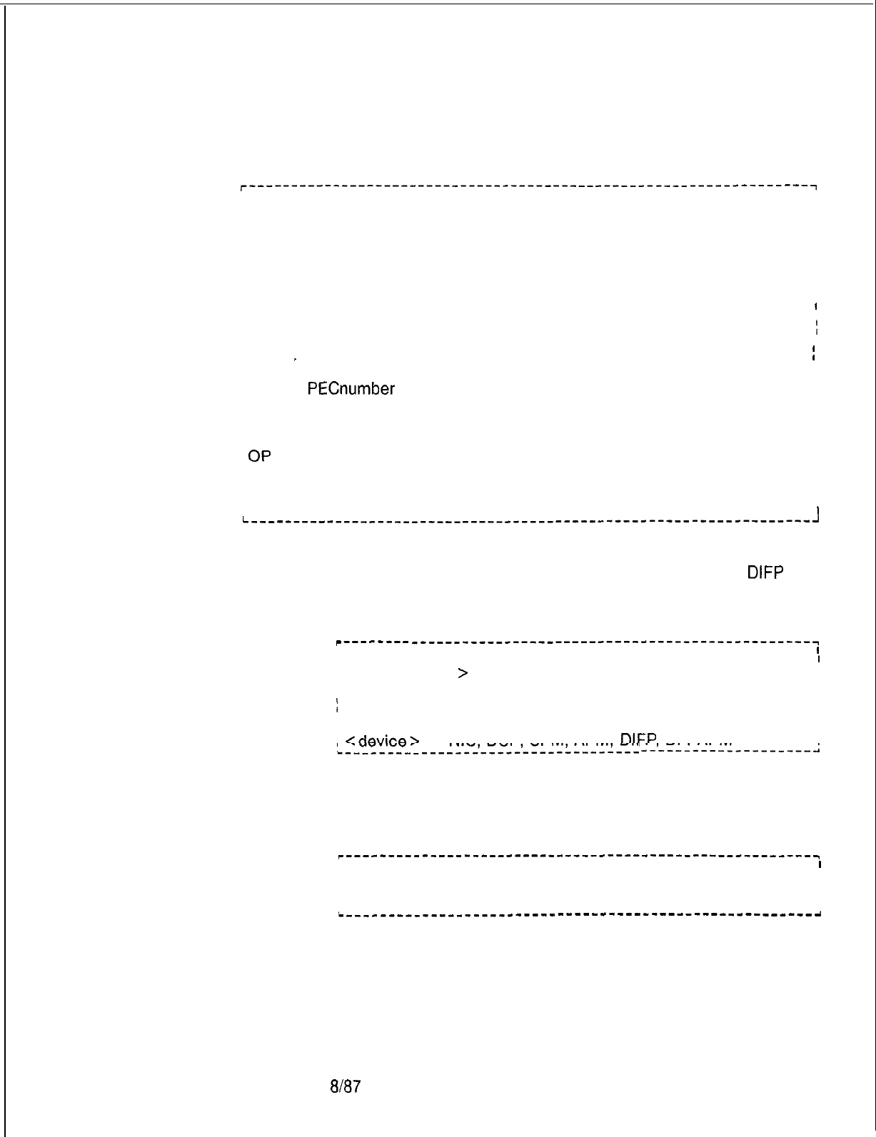
5210
TL-130200-1001
If LOAD DEVICE SPECIFIC is typed, the device indicated is reset
and reloaded. Any call up on the device is lost.
r-------------------‘------------------------------------------------~
; LOAD DEVICE- TYPE PEC GROUP SLOT CIRCUIT OP
I
I
; or
I
I
I LOAD DEVICE- TYPE ALL
I
I
I or
I
I
) LOAD DATA
I
I
I
I
I
I
I where
I
I
1
I
/DEVICE TYPE =ADMP, DCP, SPM, APM, OR DATA (Option ADMP
I
I
I
I_ reloads ADMP only. Option Data reinitializes the entire network.)
I
I
I
I
PEC =
PECnumber
I
I
GROUP = file group
SLOT = physical slot within a group
CIRCUIT =circuit on a given card
OP
= load operational load
DATA =reload the data switch
ALL =load all specified device types with operational load
II
I
I
I
I
I
II
I
I
I
I
I
I
i--------,---------__----_-----,-----------------------------------------~
Other ALL commands. Other load command versions may be
used in bulk form in a similar manner to that of the LOAD
DIFP
ALL command. The general form of this command is as follows:
r-------- _----_-----------------------------------------~
I
I
I
I
I LOAD <device
>
ALL.
I
I
I
I
I
I
)
where
I
I
I
I
1
I
i
<device>
= NIC DCP SPM APM
DIFP
DFPAPM
I
,-___-______----‘-----‘----‘----l-----
I
--‘--_----------_---,
Load Data. The following is a bulk load command which can be
used to download all PD-200 cards and devices:
r---~~_--_~---_~_~--~~~~~~ ---------------_--------------~
I
I
II
I
I
ILOAD DATA.
I
I
I
I
I
i___L_______________-------------------------------------
8J87
M-259

TL-130200-1001
I
M-260
8h37
Table 7.2 shows the responses for the various
load
data
commands seen at the maintenance terminal.
Table 7.2 Responses for Load Data Commands at Terminal
INPUT RESPONSE
Type in LOAD DATA when the A message prints:
data switch cannot be loaded. COMMAND FAILED,
.~.
followed by an explanation given by
the ADMP.
Type in LOAD DATA when the
data switch can be loaded.
The data switch will be loaded and
a message will print: IN PROGRESS
When the load is complete, a message
indicating the status of the data switch
is printed.
5210
TL-l30200-1001
Load
Conlmand
9.9.1
Table 7.3 shows the responses for the various load
Responses commands at the maintenance terminal.
Table 7.3 Responses for Load Commands at Terminal
,f
the device input is VPLC2, and the
device is VPLC2 with both voice and
data
circuits equipped,
If the PEC is not able to do a download
3n
the voice device,
If-everything is all right in the PEC, and
ihe
voice circuits start downloading,
If the ADMP is not able to do an
operational load on the data
device,
If everything is all right with the data
device,
If something is wrong with the ADMP or
the ADMP takes too long (more than a
predefined time) to respond,
If the device is not at the given PEC
group slot address,
If the device is VPLC and it is a data
only card,
For devices ADMP, DCP, SPM, APM,
DIFP,
or DFPAPM,
If the ADMP is not able to do a load for
all devices at this time,
If the ADMP is able to load the devices
with operational load,
-irst
response is for the voice
;ard/circuit.
Second response is
:or
:he
data card/circuit.
4 message prints: COMMAND FAILED
4
message prints:
NOT A FEATUREPHONE
4
messag?
prints:COMMAND FAILED,
‘ollowed
by an explanation given by the
ADMP.
The device is loaded with the
operational load and a message prints:
COMMAND COMPLETE
A message prints:
MR TIMED OUT
A message prints:
ADDRESS DOES NOT MATCH
DEVICE TYPE
A message prints:
INVALID COMMAND FOR
DATA ONLY CARD
A load request is sent to the ADMP.
A load request is not sent to the switch.
A
message prints:
COMMAND FAILED, followed by an
explanation message from the ADMP
A message prints:
IN PROGRESS, followed by a
message indicating the success or
failure of operational load for each
device. When all devices are
finished with the load process, a
COMMAND COMPLETE is printed.
5210
a/E!7
M-261

TL-130200-1001
THIS PAGE IS INTENTIONALLY LEFT BLANK.
5210
278-922-300
PD-200 Maintenance 7.10
This section contains information related to maintenance
Tools and Fault Isolation
tools and fault isolation.
Maintenance Tools
7.10.1 This paragraph covers information on visual fault/lamp
indicators and peripheral devices, maintenance commands, and
on-line diagnostics. Maintenance personnel will be able to do
the following:
. .
l Identify and interpret data terminal tests and parameters
l
Identify and interpret ADMP terminal commands and menus
l
Classify fault code responses into functional categories of
maintenance
Figure.7.1
Visual Fault Indicator
-
VPLC (INSIOOS LED)
Red indicator This VPLC is in service. This VPLC is out of
service.
5210
8187
M-263
278-922-300
Figure 7.2 Visual Fault Indicator
-
ADMP-A (INSlOOS LED and RESET BUTTON)
7
e+
-
-1
*4i-
El-
-
00
00
l e
00
eo
oe
l o
l e
-
Red indicator lamp
_
Reset button
_
ADMP terminal cable connection
50-pin male ribbon connector
3m/part
no. 3433
LAMP
Red indicator
ON STEADY
This ADMP is in
service.
FLASHING (60 IPM)
This ADMP is out of
service while
attempting to load
(requests
loading). Passed ROM
memory self-test.
FLASHING (120 IPM)
Failed ROM
memory self-tests.
8187
5210
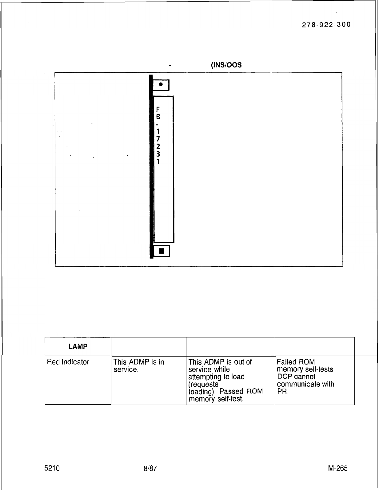
Figure 7.3 Visual Fault Indicator
-
UCB (DCP) (INSIOOS LED and RESET BUTTON)
Red Indicator Lamp
Reset button
Reset Button: Initializes DCP by accessing hard disk files via ADPM for loading DCP memory
Red
indicator
5210
ON STEADY
This
ADMP
is
in
service.
FLASHING (60 IPM)
This
ADMP
is
out
of
service
while
attempting
to
load
(requests
loading).
Passed
ROM
memory
self-test.
FLASHING (120 IPM)
Failed
ROM
memory
self-tests
DCP
cannot
communicate
with
PR.
8/87 M-265
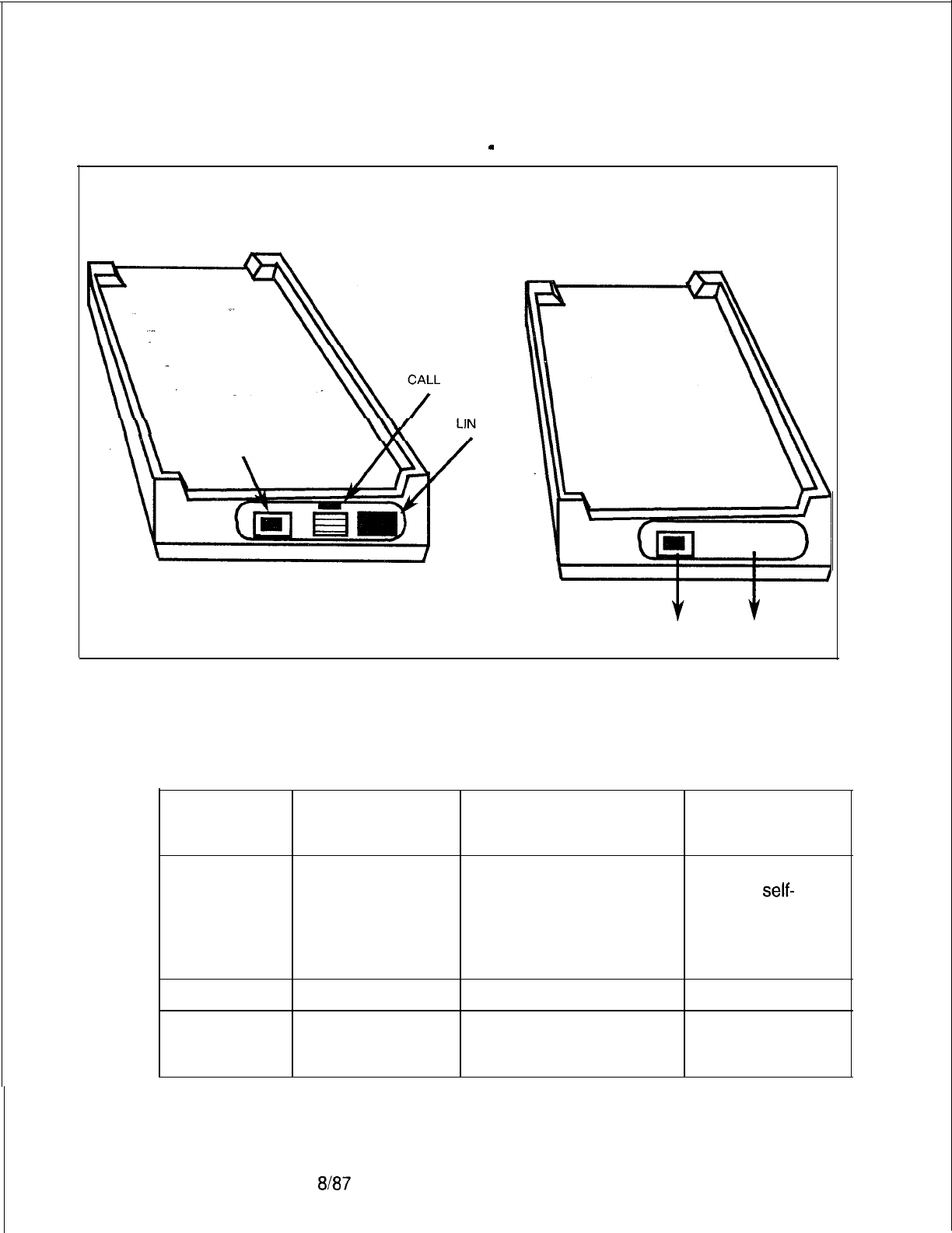
278-922-300
Figure 7.4 Visual Lamp Indicators and Switches
-
Asynchronous Packet Manager (APM)
K
TEST BUTTON
TEST LAMP
LAMP
ON STEADY FLASHING (60 IPM) FLASHING (120
IPM)
Link
LAMP
Call
This APM is in This APM is out of Failed ROM
service (loaded). service while memory
self-
attempting to load tests.
(Requests down loading). APM DTE/DCE
Passed ROM memory switch is in the
self-test. wrong position.
ON STEADY
OFF
Terminal busy Terminal idle (no
(connected to connection).
another terminal).
M-266
8187
5210
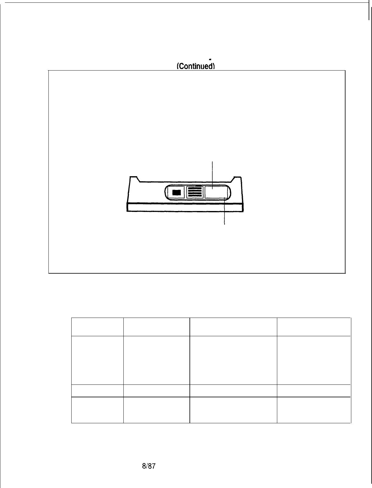
278-922-300
Figure 7.4 Visual Lamp Indicators and Switches
-
Asynchronous Packet Manager (APM)
(Continued1
VIEW SHOWING LAMPS
CALL
LINK
5210
LAMP
ON STEADY FLASHING (60 IPM) FLASHING (120 IPM)
Red indicator This APM is in This APM is out of Failed ROM
lit service (loaded). service while memory self-tests.
attempting to load APM DTEIDCE
(Requests down loading). switch is in the
Passed ROM memory wrong position.
self-test.
LAMP
ON STEADY
OFF
Call Terminal busy Terminal idle (no
(connected to connection).
another terminal
8J87
M-267
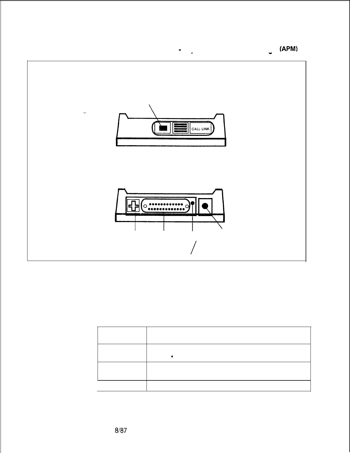
278-922-300
Figure 7.4 Visual Lamp Indicators and Switches
-
Asynchronous Packet Manaaer (APMI
(Continued
-
-
.
VIEW SHOWING BUTTONS
TEST
_
FRONT
- -
REAR
LINE
DATA r-l
RESET
OUT IN
/
DCE DTE
BUTTON FUNCTIONS
BUTTON
Test
Reset
FUNCTION
Causes test message to appear on ADMP terminal
screen
-
ERMA CH(2).
Interrupts any data call and resets APM; requests
reload from ADMP.
DTE/DCE Selects DTE or DCE mode of operation.
$187
5210
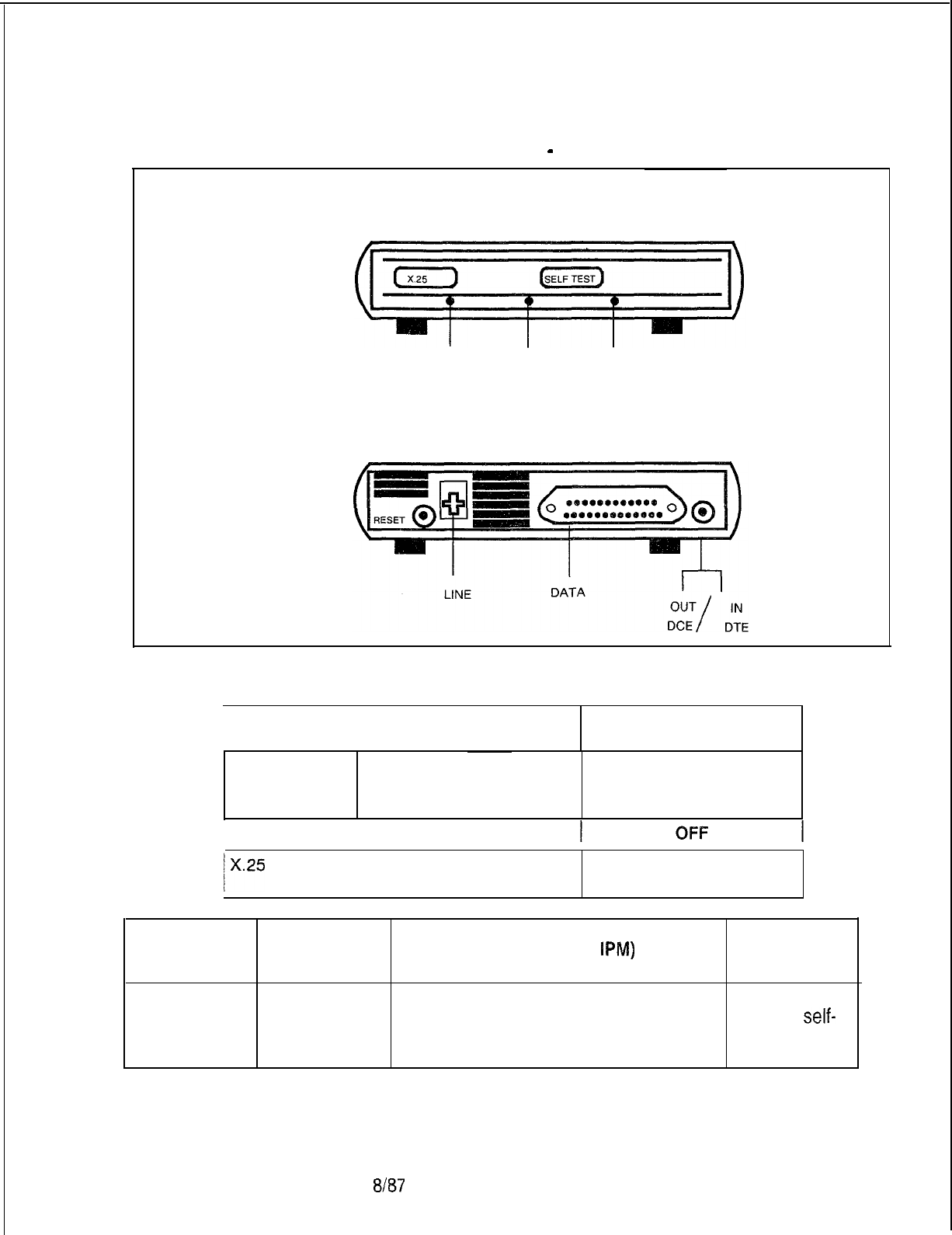
278-922-300
Figure 7.5 Visual Lamp indicators and Switches
-
Synchronous Packet Manager (SPM)
FRONT
. .
X.25
SWITCH
X.25
TE
ST
REAR
I
LAMP
I
ON STEADY
OFF
X.25 Test
Active During a link X.25 test
(X.25 test button
pressed)
During an idle state
(no link connection)
I
LAMP
I
ON STEADY
lx.25
During a link X.25 host During an idle state (no
link connection)
LAMP
ON STEADY FLASHING (60
IPM)
FLASHING
(120 PM)
Switch Link This SPM is in This SPM is out of service Failed ROM
service while attempting memory
self-
(loaded). to load (requests downloading). test.
Passed ROM memory self-test.
5210
8/87
M-269

278-922-300
THIS PAGE IS INTENTIONALLY LEFT BLANK.
8187
5210
TL-130200-1001
Maintenance Terminal
Table 7.4 is a listing of the maintenance terminal fault codes and
Fault Code Listings
their functions.
CODE
I--
00
_- 01
,...
--
I-
02
5210
I03
I
04
I05
j
06
I
07
I
08
I
I
09
10
11
F
12
I
I
13
Table a.4 Fault Code Listings
FUNCTIONS
CEC BLOCK PARITY
CEC DYNAMIC RAM MEMORY FAILURE
CEC-PEC CONTROL MEMORY READ-AFTER-WRITE
FAILURE
CEC-PEC COMMON MEMORY READ-AFTER-WRITE
FAILURE
CEC-TO-CEC TOTAL COMMUNICATION LINK FAILURE
CEC-CEC SINGLE COMMUNICATION LINK FAILURE
CEC SYSTEM NETWORK TEST FAILURE
CEC LOADING MALFUNCTION
PEC NETWORK TEST MALFUNCTION
PEC DIRECTIVE TEST MALFUNCTION
PEC DIRECTIVE HOPPER FULL MALFUNCTION
PEC ILLEGAL EVENT ERROR MALFUNCTION
PEC READ-AFTER-WRITE FAILURE IN CHANNEL
MEMORY
PEC SELF-TEST ERRORS MALFUNCTION
PEC 10 MS MALFUNCTION
Tl
SUPERVISOR GENERAL ALARM
CEC 1 MS STOPPED-FAILURE
CEC ALARM
COMMON MEMORY BLOCK PARITY ERROR FAILURE
PRE-LOADING MEMORY TEST FAILURE
PERIPHERAL EQUIPMENT DATA (PED) EVENT HOPPER
FAILURE
PERIPHERAL EQUIPMENT DATA (PED) DIRECTIVE
HOPPER FAILURE
8/87 M-271
Table 7.4 Fault Code Listings (Continued)
I
CODE
I
FUNCTIONS
I
22
1 MDR OUTPUT CONTROL FAULT
I
23
I
FUTURE
24
FUTURE
_.
25
REAL- TIME CLOCK FAILURE
I
26
I
POWER FAILURE
I.27
.
1 HOTEUHEALTH CARE DISK BACK-UP
FAlLURE
I
28
1 CAS
MAIN/ACD
AGENT INSTRUMENT DATA LINK ERROR 1
29
CAS
MAIN/ACD
MESSAGE QUEUE ERROR
30
ATTENDANT CONSOLE DATA CHECK ERROR
I
31
1 PEC ODDB BACK-UP FAILURE
I
32
1
CIPNCIP
CARD FAILURE
I
33
1 CIPNCIP PORT FAILURE
34
REMOTE FADS REPORTING ERROR
35
REMOTE FADS REPORTING ERROR
I
36
1 SYSTEM RESET
37
FUTURE
38
CEC-PEC COMMON MEMORY READ ERROR
I
39
1 ADMP INITIALIZATION RELATED ERRORS
40
DISK FILES
GVTXOOS
AND’
GVTXOlO
(TCM/FRL)
I/O
ERRORS
)
DISK I/O ERRORS
TL-130200-1001
8187
5210
TL-130200-1001
5210
ADMP Terminal and
l Terminal Prerequisites
User Prerequisites
-
Must be a DEC VT-l 00, VT-l 01, or equivalent type video
terminal
-
Baud rate set to 1200
-
Secondary keypad requires key function overlay as shown in
VT-l 01 Secondary Keypad Overlay
NOTE: Must have full cursor flow control.
VT-1 01 Secondary Keypad Overlay
GET PUT
MEM MEM SEARCH
MEM
GET
PROD PUT
PROD
GET
OTHER PUT
OTHER
FIELD RECORD
DEFAULT DEFAULT
SEARCH
PROD EXIT
HELP REFRESH
SCREEN
I
0
User Prerequisites
-
Level 0 password required to view most menus
-
Level 5 password required to perform all procedures in
ADMP User’s Guide
ADMJ’
Terminal
8
Exit Key: The Exit (EXIT) key on the VT-101 is the dash (-)
Special Keys
key on the numerical keypad. Use this key to exit a menu or
screen. Continue to depress the (EXIT) key until the desired
screen is reached.
l Numerical Keypad: The numerical keypad on the right side of
the VT-101 keyboard has special functions as defined in the
Data Table Options section. All numbers must be typed using
the keys across the top of the keyboard.
*
Caps Lock Key: The
UIPKG
does not differentiate between
upper- and lower-case letters. Therefore, the (CAPS LOCK)
should generally be left in the up position to facilitate use of the
number keys.
8187
M-273

o
Enter Key: The (ENTER) key is the large key at the bottom
right corner of the numerical keypad to the right of the
keyboard.
ADMP Terminal Cursor
o
During the first screen display, the cursor is positioned at the
Positioning
first changeable field.
o
To move forward to the next field, depress (tab), (return), or
(right arrow) keys.
l To move backward to the previous field, depress (left arrow)
key
NOTES:
1. Forward means a field to the right or below the current
cursor position.
2. Backward means a field to the left or above the current
cursor position.
l If the cursor is positioned at the first field and the (left) arrow is
depressed, the cursor will wrap around to the last field of the
screen.
o
If the cursor is positioned at the last field and the (right) arrow,
(tab), or (return) key is depressed, the cursor will wrap around
the first field on the screen.
e
The (up) and (down) arrows can be used to position to the first
or last input field (respectively) currently on the screen.
For the function keys on the ADMP terminal:
8
MEM refers to the live memory of the system.
8
PROD refers to actual files on hard disk.
*
OTHER is not operational at this time.
Function Keys
8)
GET command
-
to produce a record from a MEM or PROD.
8
PUT command
-
to write/modify a record from MEM or
PROD.
@
SEARCH command
-
to locate an unknown record by
entering the content of a particular field within that record.
o
FIELD DEFAULT
-
changes the values of a particular field to
the program default values of that field.
o
RECORD DEFAULT
-
changes the values of a complete
record to the program default values of that record.
e
REFRESH key
-
On occasion, because of network or line
problems, a garbled character may appear on the user’s
screen. The (REFRESH) command may be used to clear and
8187
5210
TL-130200-1001

5210
Active
DCPs
0600
1
l/21/86
13:32:34
(Uptime 1
21:01:14)
8187

TL-130200-1001
2. ENTER PASSWORD
SYSTEM LEVEL:
@
ADMIN
OPTIONS
Select the
ADMIN
option you choose to work
with
1. Data Base Editor
2. Maintenance and Administration
3. Run ADMP A-side test code
4. Reload the ADMP
NOTES:
ENTER the number of your choice: 1
Press RETURN
Enter 1 to 5
1. The system will allow three chances for correct password and
then return to NETPKG.
2. User Guide is written for level 5 passwords.
8187
5210
TL-130200-1001
Fault Resolution
7.10.2
This paragraph focuses on the use of maintenance tools
to resolve faults, and, in addition, on the interpretation and
application of feedback from the ADPM maintenance terminal .
PCB
Removal NOTE: The following cards cannot be removed and replaced
and Replacement
without placing them
00s.
MNEMONIC FB NUMBER DESCFWI-ION
.
VPLC
FB-17226-A Voice Packet Line Card (8 circuits)
PBE/T
PR
FB-17227-A
FB-17228-A
Packet Bus Extender/Terminator Card (See
Note)
Packet Router (See Note)
ADMP-A FB-17229-A Administrative Maintenance Processor (See
Note)
ADMP-B FB-17230-A Administrative Maintenance Processor
CB (DCB = P)
FB-17231 -A
Universal Control Board (Data Control
Processor)
5210
NOTE: Disconnect the cables from the front of these cards
before removing or replacing them.
8187
M-277
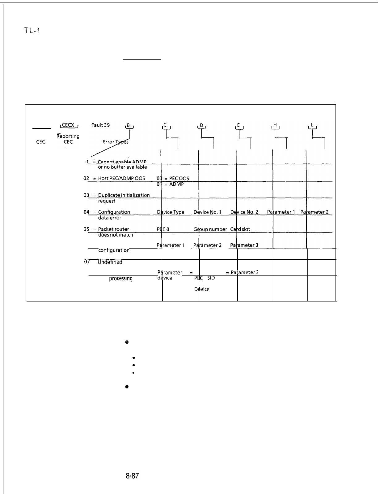
TL-I
30200-l 001
Fault Code 39
Description:
ADMP Initialization
This fault indicates errors in the ADMP-PEC interface. The
Related Errors
PEC, which has the ADMP in it, has some problems (e. g., PEC
OOS, PEC has lost communication with the ADMP). This fault
may also indicate inconsistency in data switch related data base.
Register Data As System Prints:
, CECX ,
OnlineCEC
A!gi
7
0
06 = Noresponseon
contlguratlon
data
01
=
Undetlned
Status
08 = No associated voice
call
processing
(VW)
09 = Device type
not implemented
status
Pprameter
1
=
P rameter 2
=
Pa-ameter
=
d&ice
type
PEC 0 SID
Device
type’
NOTE; See Fault Log, Section 2.0.
Fault Resolution Steps:
*
If B register value is 01 or 02, complete the following steps:
-
Ensure host PEC is in service.- MR 50 thru MR 57.
-
Ensure ADMP card is seated properly.
-
Ensure ADMP is loaded and in service.
o
If B register value is 03 thru 09, this indicates an internal data
base problem and the technician should call for assistance.
8187
5210
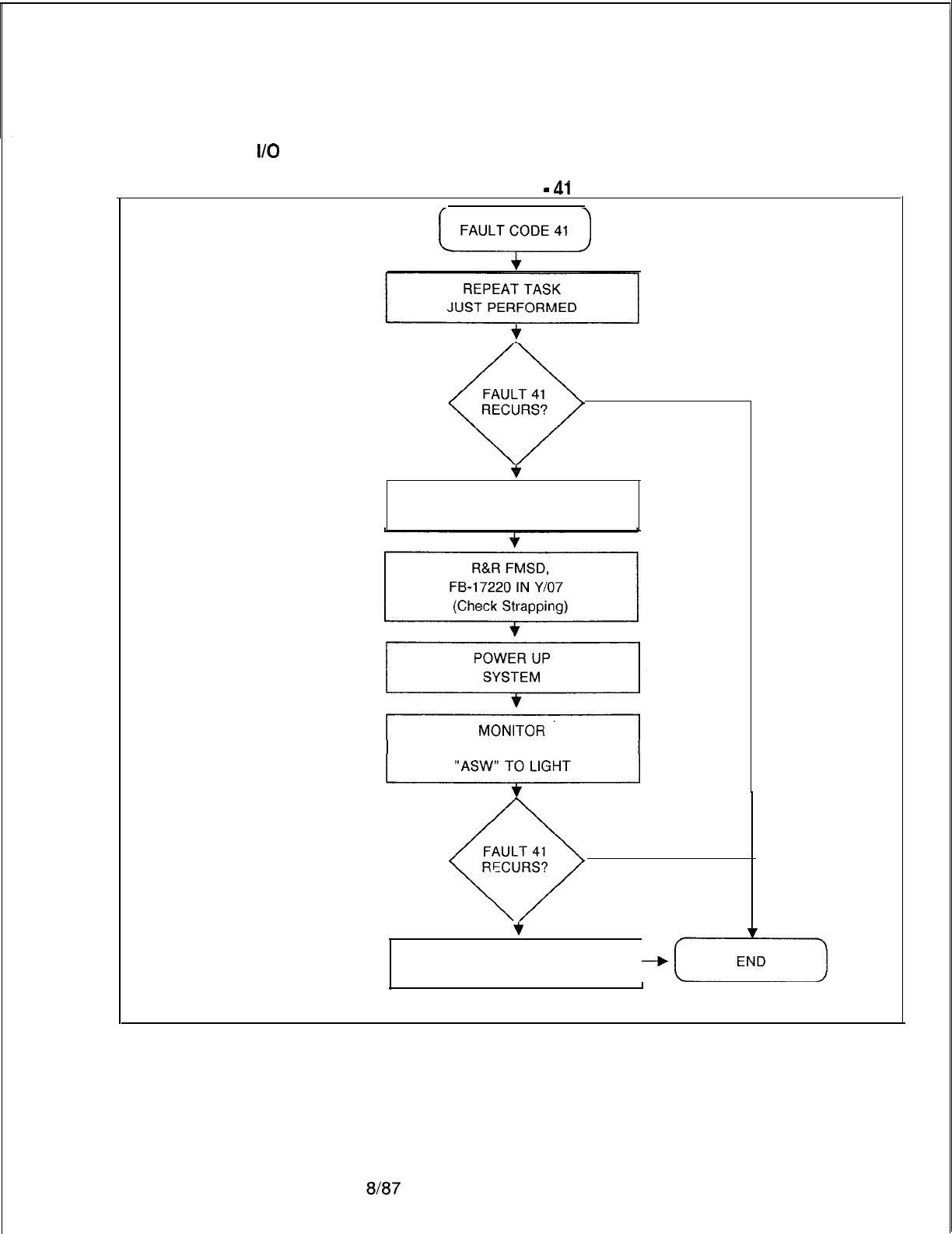
TL-130200-1001
Fault Code 41
Disk I/O Errors
FAULT CODE
-
41
NO
q
YESC=FF
POWER DOWN
SYSTEM
PSUPY FOR
NO
+
YES
R&R FLOPPY
DISK DRIVE
-q-e-)
5210 M-279

TL-130200-1001
THIS PAGE IS INTENTIONALLY LEFT BLANK.
M-280
8187
5210
TL-130200-1001
RECENT CHANGE
8.0 The Recent Change feature is part of the primary system
software. Plain language entries are used to display, or change
data base information. The SHOW,
LlST,
or DISPLAY functions
display data base information, while ADD, CHANGE, or DELETE
functions are used to change data base information.
-..
Recent Change allows the user to modify the data base in order
to satisfy voice communications and data processing
requirements. Recent Change is also used to keep up with
hardware changes in the system. As hardware is upgraded,
Recent Change is used to make necessary changes in system
software.
Access Recent Change
8.1 The correct Security Code must be entered in order to
access Recent Change (see paragraphs 1.2 and 1.3). A Security
Level 4 is required to complete most Recent Change
transactions.
The System Recent Change Primary Options Menu, On-Line
Maintenance, and the CAS
Main/ACD
Supervisor Options are
found in the Systems Option Menu. Use the following steps to
access the Systems Options Menu:
NOTE: All entries made in recent change transactions end with a
period. Type the
(.)
Period.
1. Type SL OL. (period)
The system responds: SECURITY CODE
>
2. Type four-character Security Code XXXX. (period)
NOTE: A Security
Level
of four or higher must be entered to work
with Recent Change.
The system responds: OPEN AT LEVEL 4
3. TYPE
RC.
(Recent Change period)
The system responds:
r-------------------------------------------------~
I
I
0
I
I
I
SYSTEM OPTIONS MENU
I
II
I
I
I
1) SYSTEM RECENT CHANGE PRIMARY MENU
i
I I
I
28) MAINTENANCE
I
I
83) CAS
MAlN/ACD
SUPERVISOR OPTIONS
I
I I
I I
I
89) SAVE DATA BASE I
I
X) END RECENT CHANGE I
I
I
II
I
I
I
ENTER
TRANSACTION
iwm3m
--
>
I
I
L-----____----------------------------------------~
5210
8187
M-281
TL-130200-1001
Detailed descriptions and applications of System Recent
Change transactions are covered in the
OMNI
SI
Recent
Change Manual S.V.R.
5.2.1.0.
The Recent Change Manual
includes the following information:
List of Recent Change Transactions
Recent Change Menu Options
Manual Recent Change
Recent Change Transaction Sequences
On-Line Maintenance appears in part three of this section,
while CAS
Main/ACD
Supervisor Options coverage follows
here in paragraph 4.2
The Recent Change transaction, Save Data Base transaction
number 89, is accessed from the System Options Menu. The
minimum security level required is data base programmable in
data base table
T6071,
system feature table, byte 7, bits 5-7.
This transaction writes the office dependent base from memory
to the hard disk.
CAS Main/ACD
8.2 The CAS
Main/ACD
Supervisor Options allow the user to
Supervisor Options
display or change data base information for Centralized Attendant
Service (CAS) Main, or Automatic Call Distribution (ACD) system
operations. This option is accessed in the following manner:
1. From the Systems Options Menu select transaction 83.
The system responds:
r-------------------------------------------------------------------,
I
I
83
;
I
I
CAS
MAIN/ACD
SUPERVISOR OPTIONS
f
I I
I I
I
90) FADS DISPLAY
I
II
I
I
I
38) CAS
MAIN/ACD
SUPERVISORY RECENT CHANGE MENU
;
II
II
I
85) SUPERVISOR MESSAGE HANDLER
I
II
II
I
0) GO TO SYSTEM OPTIONS MENU
I
I I
II
;
ENTER TRANSACTION NUMBER --
>
I
I
L-------------------__-_______________---------------------------------------------,
2. When an item is selected from the CAS
Main/ACD
Supervisor
Menu (a primary menu), the transaction is loaded into system
memory and executed. After that particular change or display
transaction is completed, the system responds:
ENTER END (E), REPEAT (R) OR TRANSACTION NUMBER (0
-
224)
>
IM-282
8187
5210
5210
TL-130200-1001
With this prompt the user ends the exercise (type E period),
repeats the same transaction (type
R
period), or proceeds to
another transaction (type another transaction number from zero
to 224 period).
If the user enters E, the Recent Change Options Menu appears:
r-------------------------------------------------~
I
RECENT CHANGE OPTIONS
I
I I
I
I
A) BEGIN
I
I
I I
I
6)
SAME ONE
I
I
IC) BACK ONE
I
I
I
ID) HELP
I
I
I
I
E) ERROR EXPLANATION I
I
I
F) SYSTEM OPTIONS MENU
I
I
X) END RECENT CHANGE
I
I
II
I
ENTER THE LETTER OF YOUR CHOICE HERE
>
i
L--__---------------------------------------------~
The following explanations apply to the Recent Change Options
menu displayed after every CAS
Main/ACD
Supervisor Option
transaction. This menu allows the user to select the next
transaction.
A) BEGIN
-
Show the Recent Change System Options Menu
8)
SAME ONE
-
Show the same menu just displayed
C) BACK ONE
-
Show the menu before the one just displayed
D) HELP
-
Show the Help Menu
E) ERROR EXPLANATION
-
Show the Error Explanation Menu
F) SYSTEM OPTIONS MENU
-
Show the Systems Option Menu
X) END RECENT CHANGE
-
End CAS
Main/ACD
Supervisor
Option
a/a7
M-283
TL-130200-1001
CAS Main/ACD Help
8.2.1
HELP (Option D) and ERROR EXPLANATION (Option E)
assist the user in selecting additional transactions.
When working in CAS
Main/ACD,
or FADS, Help Menus for most
transactions are accessed by entering CONTROL H (press the
CNTRL and H keys at the same time). The System will respond :
r----------------------------------------------------------------------------------~
I I
I
HOW TO USE THE HELP MENUS I
I
.=.
I
II
I.._
MOST OF THE SUPERVISORY RECENT CHANGE AND FAD DISPLAYS 1
I I
I
HAVE A HELP MENU ASSOCIATED WITH THEM. EACH HELP MENU GIVES
I
I
-A
DESCRIPTION, PURPOSE AND USE OF ITS ASSOCIATED RECENT
I
iCHANGE
OR FAD DISPLAY.THE HELP MENUS CAN BE VIEWED BY ENTERING A
i
ICNTRL-H
WHILE IN THE DISPLAY FOR WHICH THE USER WISHES TO SEE THE HELP
!
;
MENU. ONCE THE USER HAS COMPLETED VIEWING THE HELP MENU, A RESPONSE OF
:
:
N TO THE PROMPT AT THE BOTTOM WILL RETURN THE USER TO THE START OF THE
:
I
DISPLAY I
I
I
I
IN WHICH A CNTRL
-
H WAS ENTERED.
I
II
I
I
I
II
I I
I
I
IENTER END (E), REPEAT (R) OR TRANSACTION NUMBER (0
-
224)
>
I
I
I
I
1
I I
I I
I
I
L----------------------------------------------------------------------------------~
1. If no help menu exists for that transaction, the system
responds:
HELP NOT AVAILABLE
>
INVALID INPUT
2. Help is provided for a single transaction, or the help
message will affect two or three related transactions.
3. Help consists of a description of the transaction, how the
transaction impacts software, and how the information
displayed is used in CAS
Main/ACD,
or FADS system
operation.
An experienced user can omit the step of selecting
transactions from a menu by simply typing the correct
transaction number. Both the System Options Menu and the
CAS
Main/ACD
Supervisor Options Menu offer a prompt
which allows the user to directly input transaction numbers.
In this case, the following prompt will appear:
ENTER TRANSACTION NUMBER --
>
M-284
8187
5210
TL-130200-1001
FADS, CAS
Main/ACD
8.2.2 Once the user accesses the CAS
Main/A0
Supervisor
Transactions Options Menu (transaction
83),
additional menus and
sub-
menus are available by entering the correct transaction number.
These transactions, along with required Security Level, are listed
below.
FADS, CAS
Main/ACB
Recent Change Transactions
CATEGORY SECURITY
TRANS-
TRANSACTION
.~.
LEVEL ACTION #
FADS
-
-
-1
.
-
-1
-
-
-1
_
-
-1
-
-
-1
-
-
-1
-
-
_
-1
-
-1
-
-2-
--
-2-
__
45
-
-2-
--
-
-2
-
_
-
-2
CAS
Main/ACD
Supervisory
Recent Change
-
-1
-
-
-1
-
-
_
-1
-2-
--
-2-
--
-2-
-
2-
-
-
-
-2-
-l-
-
-
-
-1
-
-1
-
91
92
95
96
93
98
94
77
78
79
72
74
75
76
48
41
42
43
44
45
46
47
71
55
56
A-C-D-S
5210
8187
Real-Time Agent Status Display
Real-Time System Status Display
System Status Report
CAS
Main/ACD
Source Group Report
Agent Status Report
Trend Report
CAS
Main/ACD
Source Group Calls
Report
Display All FADS Options
Change FADS Collection Period
Change FADS Automatic Dump Period
Change FADS Automatic Dump
Selections
Change FADS Data Collection Start Time
Initiate a Trend Report
Cancel a Trend Report
Display Status of Agent Positions
Display Status of Agent Positions by Agent
Group
Display Night Destination of Agent Groups
Change the Group/Supervisor of an Agent
Position
Change the State of an Agent Position
Change the Night Destination of an Agent
Group
Add an Agent Group
Delete an Agent Group
Display/Change FADS Delay Timing
Display Breakdown of all CAS Main/ ACD
Trunks by Trunk Numbers
Display Breakdown of all CAS Main/ ACD
Trunks by Agent Group
M-285
TL-130200-1001
.~.
-
-
-1
-2-
-
FADS, CAS
~ai~/~C~
Recent Change Transactions
(Continued)
-.
..
_:._
CATEGORY SECURITY
TRANS-
LEVEL ACTION #
A-C-D-S
51
52
-2-
_
-2-
-
-
-
-1
58
-2-
-
59
-
-
-1
67
-
-
-1
68
-
-
-1
69
-2-
-
62
-2-
63
4
-
64
-2-
_
65
-2-
-
-
-
-1
81
-2-
-
82
-
-
-1
86
-2-
-
87
-
-
-2 49
-
-
-2
97
-
-
-1
84
-2-
-
88
M-286
8187
53
54
66
Display all CAS
MainlACD
trunks with a
Specific Source
Change
IS/OS
state of a CAS
Main/ACD
Trunk
Change Source Group of a CAS Main/
ACD Trunk
Change Primary Destination for a Trunk
Group
Display Source Messages
Change a Specific Source Message
Display Trunk Number and Status of all
CAS
Main/ACD
R/A
Display Delay Routing of all Agent Groups
Display Call Waiting Levels of all Agent
Groups
First Recorded ‘Announcement
Second Recorded Announcement
Delay or Repetition Timing
Change Alternate Routing of an Agent
Group
Change Call Waiting Levels for an
Agent Group.
Display a Repertory Dial Key Set
Change a Repertory Dial Key Set
Display Day/Night Mode
Change Day/Night Mode of an Agent
Group
Send Special Message
Send Unique Message
Display Special Message
Change a Special Message
5210
-.
-
-
-
TL-130200-1001
FADS Recent
Change 8.3 The Force Administration Data System (FADS) collects and
stores information for CAS Main and ACD agents, agent
groupsor
the overall CAS Main/ACD system. Information is
stored in the form of reports which can be accessed through
FADS Recent Change transactions
. .
The results of two of these reports
-
Real Time Agent Status
Display (transaction 91) and Real Time System Status Display
(transaction 92)
-
occur on a real-time basis. This means that
information displayed exists at the present time and is
continuously updated. Other reports contain information
collected over a specified time period. Periodic intervals are
selected by the user and range from 15, 30, 45, or 60 minutes.
Daily intervals are also selected by the user and range from 1, 4,
8, 12, or, 24 hours. A periodic report and a daily report can run
at the same time.
FADS Display Options
8.4 The FADS Display Options Menu is accessed through the
Menu CAS Main/ACD Supervisor Options Menu. The following steps
are used to access the menu:
1. Select transaction 90 from the CAS Main/ACD Supervisor
Options Menu.
The system responds:
i
I
I
FADS DISPLAY OPTIONS
90
i
91)
92)
95)
96)
93)
98)
94)
63)
I
REAL TIME AGENT STATUS DISPLAY
I
I
REAL TIME SYSTEM STATUS DISPLAY
t
SYSTEM STATUS REPORT
I
CAS MAIN/ACD SOURCE GROUP REPORT
I
I
AGENT STATUS REPORT
I
I
TREND REPORT
I
CAS MAIN/ACD SOURCE GROUP CALLS
I
I
GO TO CAS MAIN/ACD SUPERVISOR OPTIONS MENU
I
I
I
II
I
ENTER TRANSACTION NUMBER-->
I
L-------------------------------------------------------------------
.I
2. Select the correct transaction or sub-menu.
5210
8187
M-287
-
-
TL-130200-1001
FADS Display
8.5 The following paragraphs describe transactions listed in the
Transactions
FADS Display Options Menu. The transactions listed here are
used to display FADS data for information purposes only.
Real-Time Agent
Status Display
8.51 Real-Time Agent Status Display (transaction 91) lists
call-handling information for agents in agent groups
at the time of the display. Agents are identified by their agent
position number. The header remains the same while contents is
updated to show the status of each agent during normal
.~.
operations. A CRT is required to display this transaction.
r---------------------------------------------------------------------------,
I
I
REAL TfME AGENT STATUS
91
I
I
I
12:02
08129179
I
I
I
POSITIONHSTATE
I
II
;
GRPO
1
GRPl
:
GRP2
f
GRP3
;
GRP4
%2
013/B
020/A
126/O
EE
014/B
021/W
Et
111/P
114/B
121/W
127lW
003/A
015/B
:
where
;
A Position is available for calls
I B Agent is busy with an incoming call
I
0 Position is out of service
;
U Position is un-staffed
;
W A ent is in an after call work state
I PA?ET is being initialized
i
P Agent is using outgoing PABX service
004/B
016/A
00%
104/B
005/B
017/B
%r
105/P
117/B
:%r
006/U
018/U
106/P
118/U
007/B
107/B
008/A
108/A
M-288
8187
5210
TL-130200-1001
Real-Time System
8.5.2 Real-Time System Status Display (transaction 92) lists the
Status Display
amount of activity in each agent group at the time of the display.
The header remains the same while contents is updated to show
system status during normal operations. A CRT is required to
display this transaction.
r----------------------
_____-_-__----______----------------------------------
-------l
;
REAL TIME SYSTEM STATUS
I
92
I
I
II
I
I
_
12:02 08129179
I
I
I
I
#AGT
#
. .
# #
# DEL TOTAL MAX DELAY
I
I
i
GRP STF BUSY WORK AVL
OTG
#2
WAIT MIN--SEC MODE
i
10-12
8
4 0
0 2
2
l--O2
D
I
;1
-7.4
0 3
0 0
0
O-00
D
I
I
2
7 3
0 3
1 0
0o--o0
D
I
I
3 8 3
3
0
2 4
6
l--l 5
D
:
I
4 12 8
4 0
0 2
2
l--O2
D
:
;
5 7 4
0
3
0 0
0
o--o0 D
;
I
6
7 3
0 3
1 0
0o--o0
D
I
I
7
6 3
3 0
0 4
6
l--l 5
D-
;
;TOTAL
66 32
14 6
4 12
16
I
I
II
I
where
I
I
I
I
!
GRP = Agent group number
I
:
# AGT STF = Number of agent positions staffed
I
;
# BUSY
I
= Number of busy agents
I
I
;#WORK
= Number of agents in work state I
I
I#OTG
= Number of agents in outgoing state
I
I
!#AVL
= Number of available agents
I
I
I
MAX DELAY
I
I
iDEL#2
= = Longest delayed call per agent group I
Number of calls waiting for or received R/A
#2
II
;
TOTAL WAIT = Total number of calls waiting
I
I
;MODE
= System mode, day or night II
I
I
II
L----------------------------------------------------------------------------------~
System Status
Report
8.5.3 System Status Report (transaction 95) lists the amount of
incoming and outgoing calls on all CAS Main and ACD agent
groups over a period of time selected by the user. Before
information is displayed, the user selects Periodic Report with
collection periods of 15, 30, 45, or 60 minutes, or Daily Report
with collection periods of
1,
4, 8, 12, or 24 hours.
r-------------------------------------------------------------------,
I
I
I
I
SYSTEM STATUS REPORT
I
95
i
II
I
A)PERIODIC
REPORT
I
II
II
I
B)DAILY
REPORT
I
;
ENTER THE LETTER OF THE DESIRED REPORT >A.
I
I
L-------------------------------------------------------------------
J
5210
8187
M-289
--
-
TL-130200-I 001
See Change FADS Periodic Data Report Collection Period
(transaction 78) to change time of Periodic Report, and Change
FADS Automatic Dump Period (transaction 79) to change time of
Daily Report.
r---------------------------‘-----------------------------------------,
i
PERIOD
11:30/l
2:00
I
1 O/l O/79
I
I
I I
I I
1SYSTEM STATUS REPORT
I
I
12:02 1 O/l O/79
I
II
I
AUG AUG AUG AUG
I
i
GRP
POSCA#LLCA#LL
CAL#LSN#D
CA#LL
CAL#L
AUL ANS HNLD SUL
i
I
I
OFRD ANSANS DELABAN OUFL TIME TIME TIME
I
I
I
I
I
I
I
II
II
I
I
f
I
I
I
I
I
III
I
i
I
I
I
I
I
f
I
II
I
I
III
I
II
f
I
I
I
0
11
112
111
12 7
1
1
11
715 86
I
I
1
686 86 940 012 614 82
I
I 2
5
56 54 8 2 0 19 13 17 67
I
I 3
440 39 5
;
2
0
14 15 15
71
I
I 6
11
112
111
12 7
1 1
11
715 86
t
/TO;
440 39 5 3 2 0 14 15 15
71
52 588 580 688 42 10 215 12 15 76
;
ENTER END (E), REPEAT (R) OR TRANSACTION NUMBER (O-224)
>
f
where
I
I
GRP
-
Agent group numbers
!
AUG POS STF
-
Average positions staffed
f
# CALL OFRD
-
Number of calls offered
I#
CALLS ANS = Number of calls answered
:
# CALL DEL =
;#2NDDEL
= Number of calls delayed
>
‘IX”
seconds
!
# CALL
ABAN
Number of calls receiving second announcement
= Number of calls abandoned
:
#
CALL OUFL = # of calls overflowed to an alternate group
:
AUG AUL TIME = Average time available
!
AUG ANS TIME = Average answer time per call
!
AUG HNLD TIME
jSUL
= = Average handle time per call
Service level
i
L-------------------------------------------------------------------,
M-290
8f87
5210
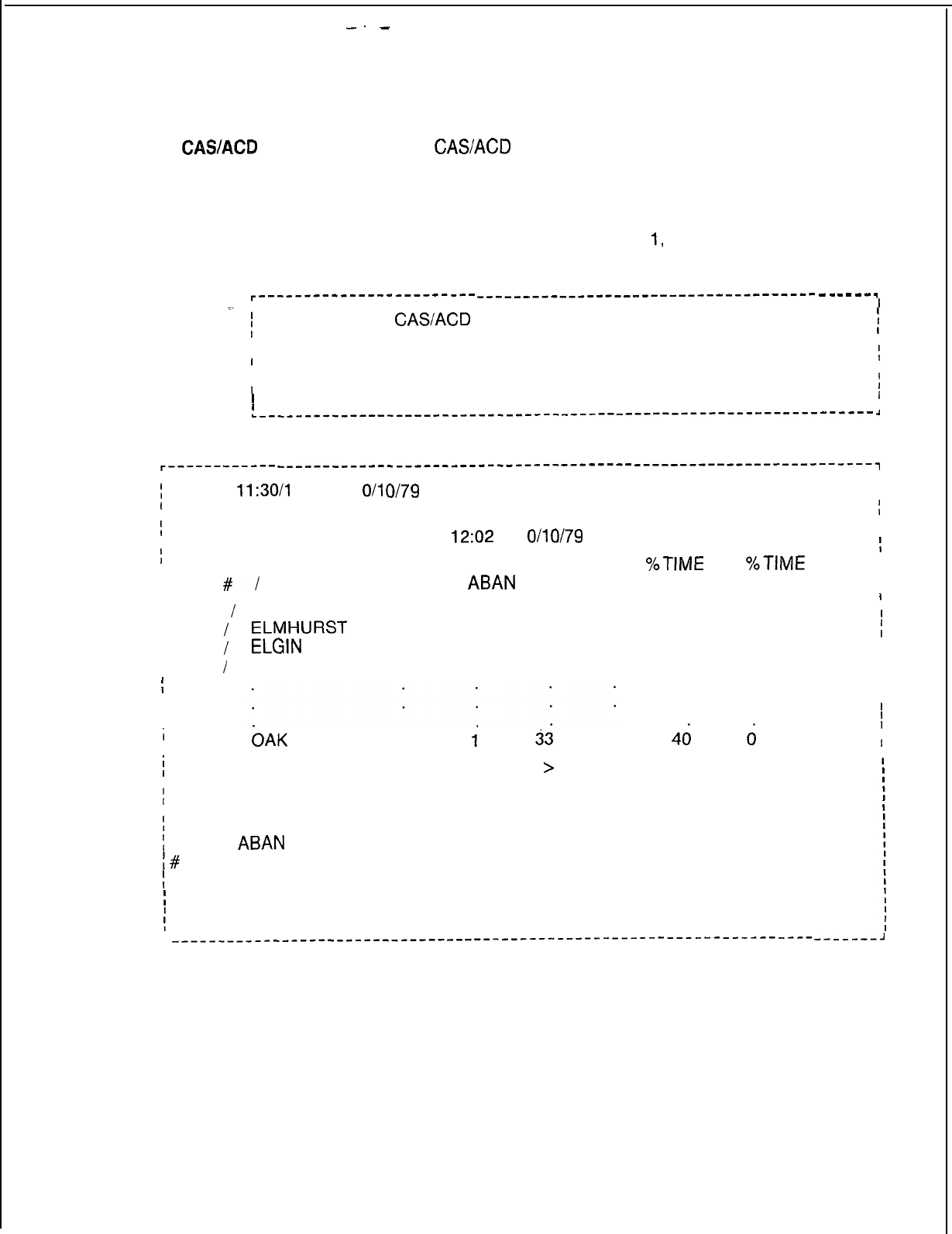
--
-
TL-130200-1001
CASACD Source
8.5.4 The
CASACD
Source Group Report (transaction 96) lists
Group Report
the amount of incoming trunk traffic from each source group
servicing agent groups over a period of time selected by the
user. Before information is displayed, the user selects Periodic
Reports with collection periods of 15, 30, 45, or 60 minutes, or
Daily Report with collection periods of
I,
4, 8, 12, or 24 hours.
r------------------------
__-________________------------------
-
-
-
-
-
-
.
I
*-
I
I
CAS/ACD
SOURCE GROUP REPORT 96
i
I
I
A) PERIODIC REPORT
I
II
II
I
B) DAILY REPORT
t
I
I
I
ENTER THE LETTER OF THE DESIRED REPORT >A. 1
I
L---_---____---_____------------------------------------------------
A
r------------
^-----__--_______-__-------------------
--------------------------,
i
I
;
PERIOD
11:30/l
2:00
1 O/l O/79
PAGE 1 II
I
I
I
CAS/ACD SOURCE GROUP REPORT
II
12:02 1 O/l o/79
I
I
t
I
I
SOURCE GRP #CALL #CALL #CALL #CALL
%TIME %TlME
I
I
I
I
#/
ID OFRD
ABAN
ANS DEL BUSY ATB
I
I
f
65 4
I
I
I
I
I
00
I
I
I
01
I
I
I
02
I
II
03
I
:
I
II
CHICAGO
115 5110 12
ELMHURST
82
1
81
8
ELGIN
60 060 4
DES PLAINES
38
1
37 3
i
I16 .
OAK
PARK 34
1.
4
58
1
I
49
1
I
I
38 0
I
I
I
I
I
I
4d
d
I
I
II
j
DO YOU WISH TO CONTINUE THIS DISPLAY
>
Y.
I
I
where
I
I
# CALL OFRD = Number of calls offered to the system
;
# CALL
ABAN
= Number of calls abandoned
;#
CALL ANS =Number of calls answered
:
# CALL DEL = Number of calls delayed
!
% TIME BUSY =Percentage that a trunk is busy
;
% TIME ATB = Percentage that all trunks are busy
i
__-__________-__-___---------------------------------------------------------J
5210 8187 M-291
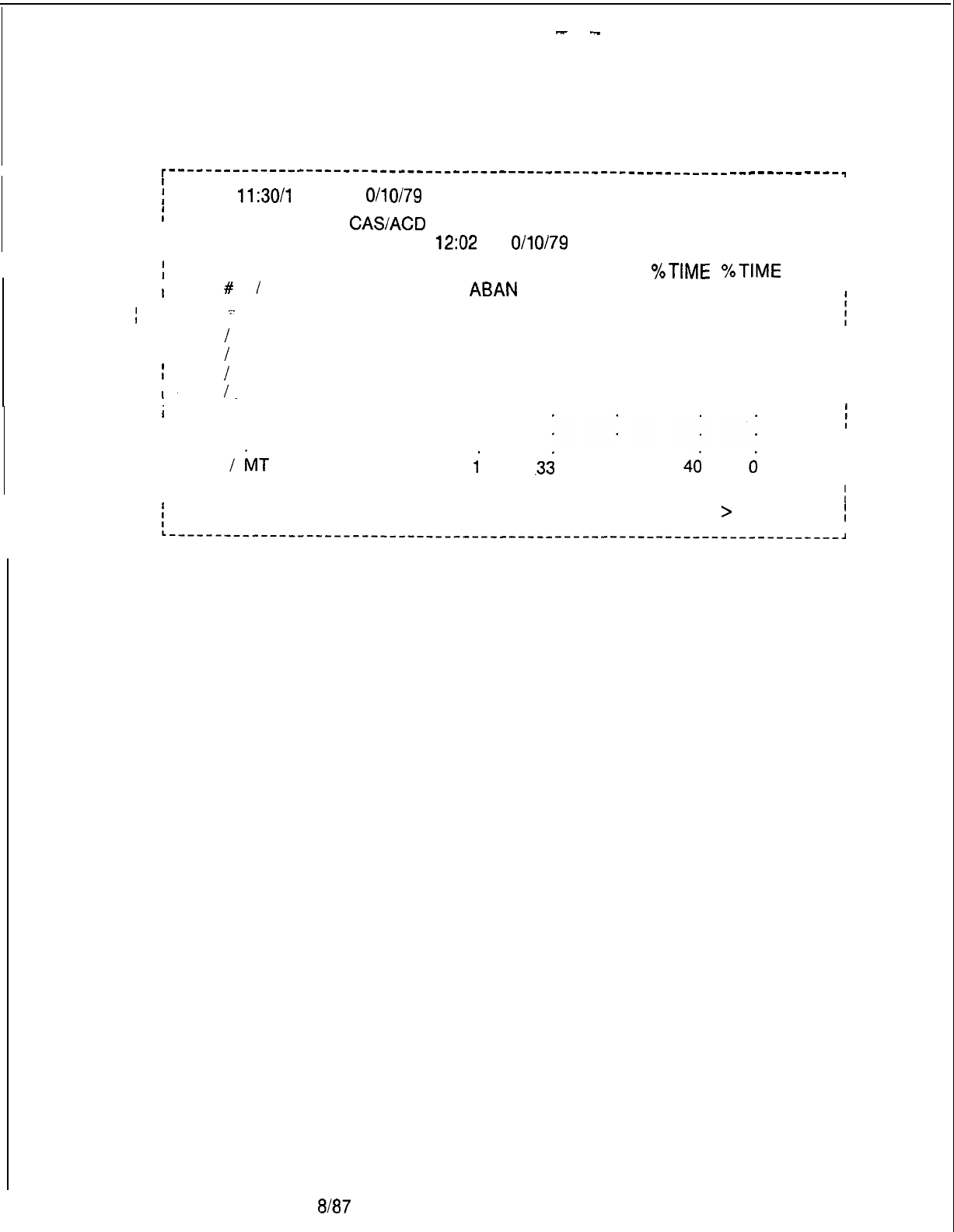
-
-
TL-130200-1001
I
r---‘----------‘----------‘-------------------------------------
-----e------q
i
PERIOD
11:30/l
2:00
i
1 O/l O/79
PAGE 2
I
I
II
I
I
CAS/ACD
SOURCE GROUP REPORT
I
I
I
12:02 1 O/l o/79
I
I
I
I
I
SOURCE GRP #CALL #CALL
I
I
#/
ID OFRD
ABAN
I
I_.
I
. .
I
17
/
CALUMET
112 2
.
I
I
18
/
EVANSTON
86
1
I-
I
19
I
GARY
56 0
I.
20 1.
HAMMOND
38
1
I
i
I
I
I
I
I
I
31
/
ivlT
PROSPECT 34
1.
I
I
TOTAL
846 25
110 12 65 4
85 8
58 1
56
449 1
37 3
38 0
.33
4
4d d
821
91 51
02
I
II
i
ENTER END (E), REPEAT (R) OR TRANSACTION NUMBER (O-224)
>
I
I
#CALL#CALL
%TIME
%TIME
ANS DEL BUSY
I
L---_----_,---------______,_____________----------------------------------,
IM-292
8187
5210
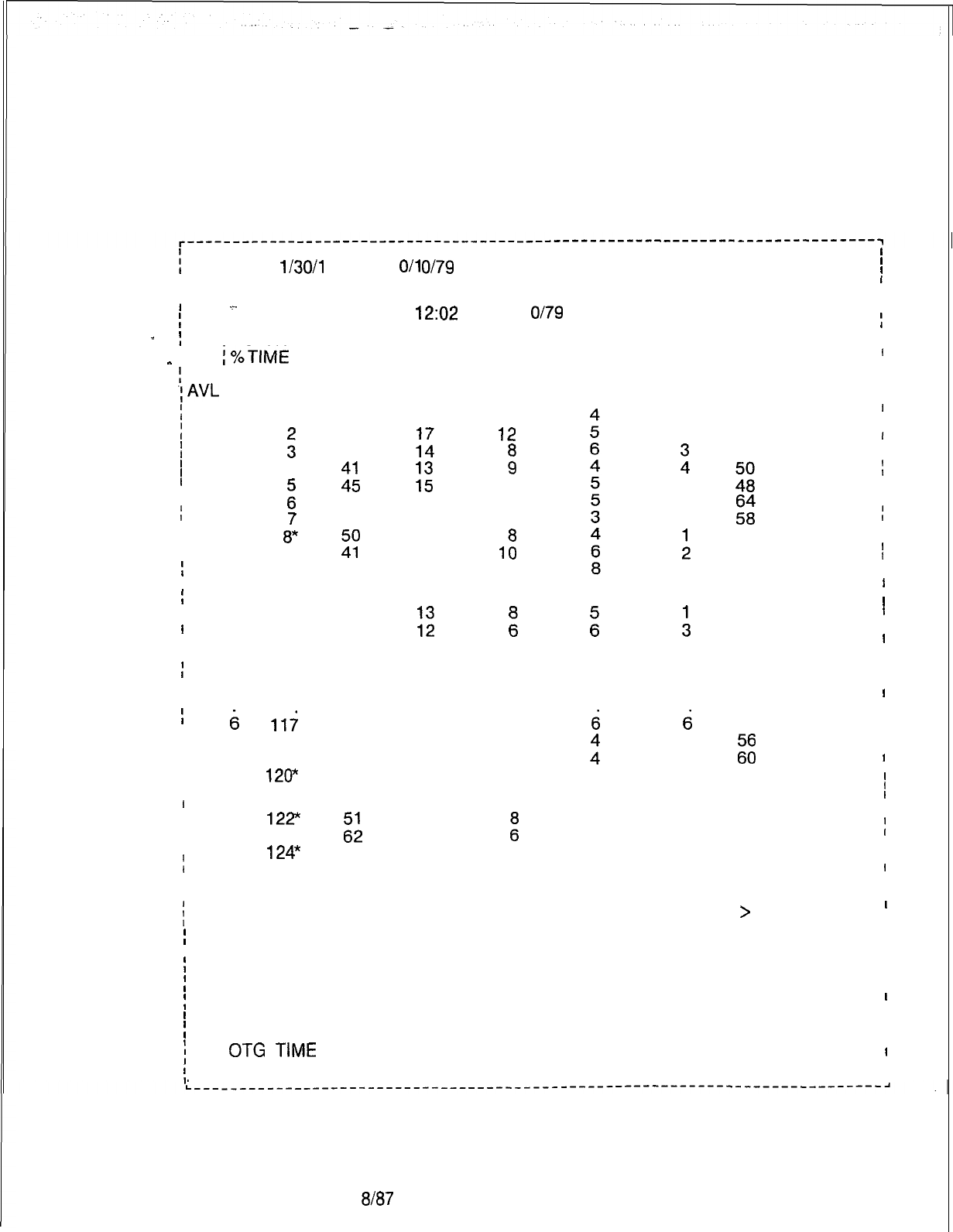
TL-130200-1001
Agent Status Report
8.5.5 The Agent Status
Report
(transaction 93). lists call handling
information for individual agents in an agent group collected over
a period of time selected by the user.
;
PERIOD 1 l/30/1 2:00 1 O/l o/79
I
I
I
AGENT STATUS REPORT
93
I
_.
12:02
I
-I
AGENT AGT # CALL AVG HNLD
1 O/l o/79
AVG BUSY AVG WORK AVG OTG
-
:%TIME
;
GROUP POS
.;AVL
I
I
I
I
I
I
I
I
I
I
I
I
I
I
I
I
I
I
I
I
I
I
I
I
I
I
I
II
I
II
I
I
I
I
I
I
I
I
I
I
I
I
I
I
0
1
5
4
:
G
9
10
1
12
13
14
15
6 117
118
119
120*
7
121”
122”
123”
124*
HNLD
56
34
45
t:
59
60
3:
34
71
62
63
45
23
39
61
45
70
z;
46
12
:1:
ii
11
10
12
16
19
9
::
15
18
17
12
14
10
14
12
16
TIME
8
12
:
10
6
7
1:
11
7
ii
9
12
13
8
9
5
:
11
TIME
2
z
6
6
t
5
5
6
6
5
TIME
2
1
:
3
0
3
:
5
2
;
1
6
3
4
1
2
4
3
1
TIME
65
45
56
20s
ii;:
47
46
35
47
43
45
56
78
2:
54
63
45
43
57
*AGENT(S) NOT STAFFED FOR ENTIRE COLLECTION PERIOD
i
ENTER END (E), REPEAT (R) OR TRANSACTION NUMBER (O-224) >
i
where
I
I
AGT POS = Agent position
;
# CALL HNLD =
Number of calls handled
;
AVG HNLD TIME = Average handle time for position
’
AVG BUSY TIME =
:
AVG WORK TIME Average busy time for position
I
AVG
ox
TIME
=
= Average work time for position
i
% TIME AVL Average outgoing time for position
= Percentage of time position is available
I
I
I
I
I
,
I
II
I
I
I
II
I
I
I
I
I
I
II
I
III
I
I
I
I
II
I
I
I
I
I
I
I
I
I
I
I
I
I
I
IIII
I
,
II
I
I
I
I
I
I
I
I
I
I
III
I
IIIII,II
I
I
IIIII
I
I
I
5210
8187
M-293
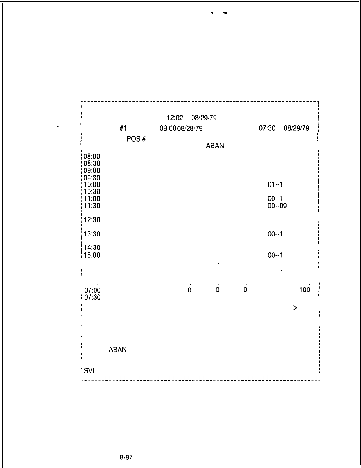
r
-
-
TL-130200-1001
Trend Report
8.5.6 The Trend Report (transaction 98) lists incoming call
information over a period of time by agent group to identify
possible call-handling trends. Collection periods are limited to
24 hours each, but these may be collected for up to seven days.
-..
r
-------------------------------------------------------------------,
I
I
I
TREND REPORT
98
;
I
12:02
08129179
I
!
I
I
GROUP
#l
START
08:OO
08/28/79
END:
07:30
08/29/79
;
!
TIME AVG
POS#
CALL #CALL #CALL #CALL MAX DELAYSVL
i
M-294
i
PERIOD
/
08:OO
;
08:30
;
09:oo
;
09:30
)
1o:oo
;
10:30
;
11:oo
;
11:30
;
12:oo
f
12:30
;
13:oo
:
13:30
)
14:oo
I14:30
I
1500
I
I
I
i
I
II
I
07:ob
I
07:30
I
_ STF
OFRD
DEL
ABAN OVFL MIN--SEC
23 102 92
1
oo--54
24 89 6
1
0
00--27
26 78 300
oo--37
29 100
5
1
0
00--23
28 123 820
01--l
6
28 126 5 0
1
00--24
29 131 300
00--l
0
26 142 200
00-09
27 120 8
1
0
oo--47
26 78 200
oo--07
28 99
1
0 0
oo--04
26 107 4
1
0
00--l
4
25 110 200
00--08
26 105 4 0 0
00--26
25 94
1
00
00--l
1
lb
23 45
d
d
78
00
d
0
. I
I
oo--00
I
oo--00
106
;
100 I
I
I
I
87
i
78
;
90
;
91
;
89
:
94
:
98
:
98
I
92
I
90
I
99
I
89
!
97
1
90
I
97
I
I
I
I
;
ENTER END (E), REPEAT (R) OR TRANSACTION NUMBER (O-224) >
I
I
I
I
where
i
I
;
AVG POS STF =
;
#CALL OFRD Average positions staffed
= Number of calls received
;
# CALL DEL =
!
# CALL ABAN Number of calls delayed
= Number of calls abandoned
!
# CALL OVFL
= Number of calls overflowed to an alternate
:
MAX DEL =
;
SVL Longest answer time
= Service level
8187
5210
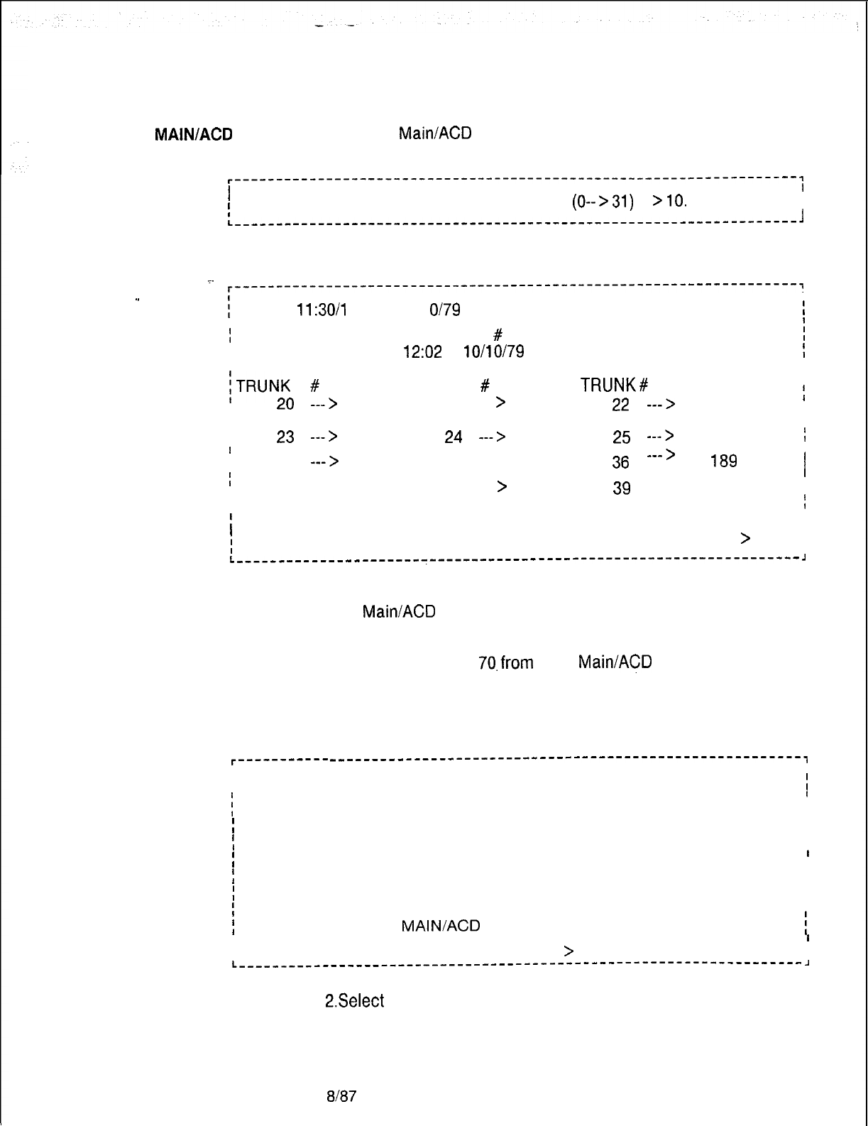
TL-130200-1001
CAS MAINIACD Source
8.5.7 CAS
Main/ACD
Source Group Calls (transaction 94) lists
the number of incoming calls per trunk in the source group.
r-------------------------------------------------------------------,
II
I
!
ENTER A SOURCE GROUP #
(0-->31)
>lO.
I
I
I
L-------------------------------------------------------------------~
_.
r-------------------------------------------------------------------,
I
. .
i
PERIOD
11:30/l
2:00
1 O/l O/79
I
I
I
SOURCE GROUP
#
10 CALLS 94
i
I
I
12:02 10/10/79
I
II
/TRUNK
#
I
TOTAL TRUNK
#
TOTAL
TRUNK#
TOTAL
I
I
I
I
20
--->
175
21
---
>
69 22
--->
145
I
I
II
I
I
23
--->
156
24
--->
198
25
--->
201
I
I
I
I
I
34
--->
144 35
--->
167
36
--->
189
I
I
;
I
I
37
--->
109 38
>
99 39
--->
100
I
---
I
I
I
I
40 ---
>
125
I
I
I
;
ENTER END (E), REPEAT (R) OR TRANSACTION NUMBER (O-224)
>
I
II
L----------------------------------------------------------------------
J
FADS Control
8.5.8 The FADS Control Data Menu is accessed through
Data Menu
CAS
Main/ACD
Supervisory Recent Change. The following steps
are used to access the menu:
1. Select transaction
70,from
CAS
Main/ACD
Supervisory Recent
Change .
The system responds:
l------------
--------------------------------------------------------,
II
I
I
FADS CONTROL DATA 70
;
i
77) DISPLAY ALL FADS OPTIONS
I
I
I
;
78) CHANGE FADS COLLECTION PERIOD
I
I
;
79) CHANGE FADS AUTOMATIC DUMP PERIOD
I
I
;
72) CHANGE FADS AUTOMATIC DUMP SELECTIONS
I
I
;
74) CHANGE FADS DATA COLLECTION START TIME
I
I
;
75) INITIATE A TREND REPORT
I
I
;
76) CANCEL A TREND REPORT
I
)
39) GO TO CAS
MAIN/ACD
SUPERVISORY RECENT CHANGE MENU
i
II
II
I
ENTER TRANSACTION NUMBER --
>
I
L-------------------------------------------------------------------
A
2.Select
the correct transaction.
5210 8187
M-295
-
-
TL-130200-1001
FADS Control
8.6 The following paragraphs describe transactions listed in the
Transactions
FADS Control Data Menu. The transactions listed here are used
to change or initiate FADS Control Data information.
Display All FADS Options
8.6.1 Display All FADS Options (transaction 77) allows the user
to see all FADS options currently in use.
I----------------------------------------------------------------------,
II
I
FADS OPTIONS DISPLAY
77
I
. .
II
t
PERIODIC DATA COLLECTION PERIOD: 15 MINUTES
I
I
-
I
I
I
TRENT REPORT DATA COLLECTION PERIOD: 15 MINUTES
I
I
I
I
I
I
TRENT
REPORT
AGENT
GROUP
:
0
I
I
I
I
I
I
i
AUTOMATIC DUMP PERIOD: 8 HOURS
I
I
I
I
I
AUTOMATIC DUMPS IN EFFECT:
I
I
SYSTEM STATUS REPORT
I
I
I
I
I
ISOURCE GROUP REPORT
I
I
I
I
ENTER END (E), REPEAT (R) OR TRANSACTION NUMBER (O-224)
>
i
II
I
i
I I
L------,---------------------------------------------------------------,
Change FADS Periodic
8.6.2 Change FADS Periodic Data Collection Period (transaction
Data Collection Period
78) allows the user to change the time period for FADS reports.
This time period can range from 15, 30, 45, or 60 minutes.
M-296
r---------------------------------------------------------------------~
I
I
I
I
ICHANGE FADS PERIODIC DATA COLLECTION PERIOD
78
I
I
I
I
CURRENT FADS COLLECTION PERIOD: 15 MINUTES
I
I
I
I
I
I
NEW FADS COLLECTION PERIOD:
I
I
I
A)
DISABLE
I
I
I
W
15 MINUTES I
I
I
II
C)
30 MINUTES
I
I
II
W
45 MINUTES
I
I
I
El
60 MINUTES
I
I I
I I
IIENTER THE LETTER OF THE DESIRED PERIOD
>C.
I
I
I
I
IDO YOU WANT TO EXECUTE THIS CHANGE (Y/N)
>Y.
I
I
II
IIENTER END (E), REPEAT (R) OR TRANSACTION NUMBER (O-224)
>
I
I
I I
8187
5210
TL-130200-1001
Change FADS
Automatic Dump
8.6.3 Change FADS Automatic Dump Period (transaction 79)
allows the user to change the timing of automatic dumps. Dump
Period
periods can range from one-half hour, one hour, four hours,
eight hours, twelve hours, or twenty-four hours.
r’-----------------‘-----‘-----------’------------------------------,
II
I
I
CHANGE FADS AUTOMATIC DUMP PERIOD 79
;
II
I
.=.
I
CURRENT AUTOMATIC DUMP PERIOD: 8 HOURS
I
I
I
I
I
-..
;
NEW AUTOMATIC DUMP PERIOD:
1
I
A)
DISABLE DUMP
I
I
I
I
I
6)
‘l/2
HOUR
I
I
II
C)
1
-HOUR
I
I
I
I
I
D)
4HOURS
I
I
I
I
E)
8 HOURS
I
I
F)
12 HOURS
I
I
I
I
G)
24 HOURS
I
I
I
I
I
I
IENTER THE LETTER OF THE DESIRED PERIOD
>F.
I
II
I
I
IDO YOU WANT TO EXECUTE THIS CHANGE (Y/N)
>Y.
I
I
I
I
I
ENTER END (E), REPEAT (R), OR TRANSACTION NUMBER (O-224)
i
L-----------__------------------------------------------------------~
Change the FADS
8.6.4 Change the FADS Automatic Dump Selections (transaction
Automatic Dump
72) allows the user to select which reports are dumped
Selections
automatically by FADS. The System Status Report and the
Source Group Report are affected by this transaction.
l------------
---------------------------------------------------------,
I
f
I
CHANGE THE FADS AUTOMATIC DUMP SELECTIONS 72
;
I
I
I
CURRENT FADS REPORTS AUTOMATICALLY DUMPED:
I
I
I
SYSTEM STATUS REPORT
I
I
I
SOURCE GROUP REPORT
I
I
I I
I I
IDUMP THE SYSTEM STATUS REPORT AUTOMATICALLY? N. I
I I
I I
I
DUMP THE SOURCE GROUP REPORT AUTOMATICALLY? Y.
I
I
I
DO YOU WISH THE REPORT TO BE DUMPED TO THIS TERMINAL? Y.
i
II
I
DO YOU WANT TO EXECUTE THIS CHANGE (Y/N)
>Y.
I
I
I
I I
I
I
I
ENTER END (E), REPEAT (R), OR TRANSACTION NUMBER (O-224)
f
I
I
I
I
I
L-----------______--_--________________------------------------------,
5210
8187
M-297
TL-130200-1001
Change FADS Data
8.6.5 Change FADS Data Collection Start Time (transaction 74)
Collection Start Time
allows the user to change the start time and start date for FADS
data collection. The time and date entered shows when data will
be collected for daily FADS reports.
r-------------------------------------------------------------------,
I I
IICHANGE FADS DATA COLLECTION START TIME 74
]
I I
I I
I
CURRENT FADS DATA COLLECTION START TIME :
12:OO
I
I
I
I ~-
IENTER A NEW FADS DATA COLLECTION START TIME
-
!
. .
I
HOURS (00 ---
>23)
>8
I
I
I
I I
IMINUTES
(OO---
>59)
>o.
I
I
I
START ON CURRENT DATE (Y/N)
>
N.
I
I
I
I’
-ENTER STARTING DATE
-
MONTH ~I
I(1-12)
>l.
II
I
IDAY (1-31)
>18.
I
I
IYEAR (00-99)
>
84.
I
I
I I
I
DO YOU WANT TO EXECUTE THIS CHANGE (Y/N)
>Y.
I
I
I
I
IIENTER END (E), REPEAT (R), OR TRANSACTION NUMBER
(O-224)>
I
;
Initiate a Trend
8.6.6 Initiate a Trend Report (transaction 75) allows the user
Report to initiate a trend report starting at a time and date, and lasting for
a specified period of time.
INITIATE A TREND REPORT
75
ENTER AN AGENT GROUP
#
(0 ---
>
7)
>
1.
ENTER A STARTING HOUR (00
-
>
23)
>
8. MINUTES (00-
>
59)
>
0.
START ON CURRENT DATE? (Y/N)
>
N.
ENTER STARTING DATE
-
MONTH
(l--12)
>7.
DAY
(l--31)
>
18.
YEAR (00-99)
>
82.
COLLECTION PERIOD:
A) 15
MINUTES
B)
30 MINUTES
Cl
45 MINUTES
D)
60 MINUTES
ENTER LETTER OF COLLECTION PERIOD
>A.
ENTER THE NUMBER OF PERIODS
(l--48)
>48
A TREND REPORT FOR GROUP #
1
WILL START AT
08:OO
on
7/18/82.
IT WILL BE COLLECTED EVERY 15 MINUTES FOR 48 PERIODS.
DO YOU WANT TO EXECUTE THIS CHANGE (Y/N)
>Y.
ENTER END (E), REPEAT (R), OR TRANSACTION NUMBER
(O-224)>
M-298
8187
5210
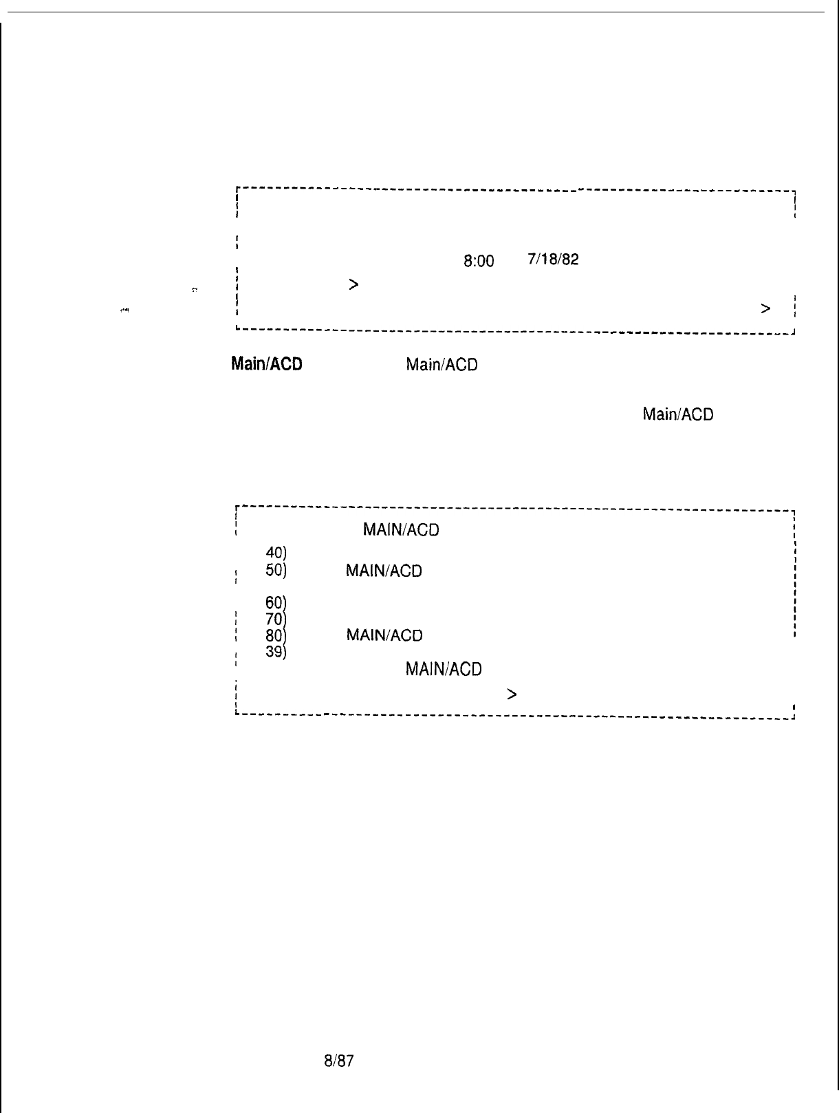
TL-130200-1001
Cancel a Trend Report
8.6.7 Cancel a Trend Report (transaction 76) allows the user to
cancel a trend report,
.-..
r-----------------------------------------
I
--------------------------,
I
I
I
CANCEL A TREND REPORT
I
76 1
I
I
AGENT GROUP: 1
I
I
I
I
CURRENT START TIME:
I
I
800
ON
7/18/82
I
II
CANCEL?
>
Y.
I
II
.=_
I
I
I
ENTER END (E), REPEAT (R), OR TRANSACTION NUMBER (O-224) >
:
L---------------,---------------------------
I
------------------------,
CAS
Main/AC33
Supervisory
8.6.8 CAS
Main/ACD
Supervisory Recent Change (transaction
Recent Change
38) is a primary menu consisting of a list of sub-menus. Each
transaction listed will lead the user to a subgroup of transactions
whose purpose is to display or change CAS
Main/ACD
data
information. This process was shown above with FADS Control
Data (transaction 70). The remaining transactions will be
covered here.
i-------------
I
-------------------------------------------------------,
I
CAS MAINIACD SUPERVISORY RECENT CHANGE
I
38
i
I
I
40)
I
i
50)
I
57)
I
I
60)
;
70)
I
80)
I
:
39)
I
83)
I
AGENT DATA
CAS MAIN/ACD TRUNK DATA
SOURCE MESSAGES
CALL WAITING DATA
FADS CONTROL DATA
CAS MAIN/ACD INSTRUMENT CONTROL DATA
DAY/NIGHT MODE DATA’
GO TO CAS MAIN/ACD SUPERVISOR OPTIONS MENU
I
i
ENTER TRANSACTION NUMBER --
>
I
I
I
I
L---------m
---------------------------------------------------------~
5210
8187
M-299
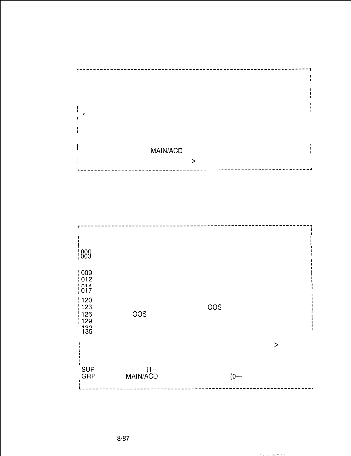
TL-130200-1001
Agent Data Displays
8.7 The Agent Data Menu (transaction 40) allows the user to
and Changes
display or change information related to agents or agent groups.
r-------------------------------------------------------------------,
II
I
I
AGENT DATA 40
I
II
I
48)
DISPLAY STATUS OF AGENT POSITIONS
I
I
I
41) DISPLAY STATUS OF AGENT POSITIONS BY AGENT GROUP
:
II
I
42)
DISPLAY NIGHT DESTINATION OF AGENT GROUPS
I
43) CHANGE THE GROUP/SUPERVISOR OF AN AGENT POSITION
i
I
I
.=-
44) CHANGE THE STATE OF AN AGENT POSITION
I
I
II
I
45)
CHANGE THE NIGHT DESTINATION OF AN AGENT GROUP
I
t
46)
ADD AN AGENT GROUP
I
I
II
I
47)
DELETE AN AGENT GROUP
I
II
I
71)
DISPLAY/CHANGE FADS DELAY TIMING
I
f
I
38)
GO TO CAS
MAIN/ACD
SUPERVISORY RECENT CHANGE MENU
!
I
I
I
ENTER TRANSACTION NUMBER --
>
I
I
II
L-------------------------------------------------------------------~
Agent Position
8.7.1 Agent Position Status Display (transaction 48) shows all
Status Display
agents in the system, supervisor, agent group, and in-service or
out-of-service state.
NOTE: Only equipped agent groups are displayed.
r-------------------------------------------------------------------,
I
I
AGENT POSITION STATUS 48
;
j
POS SUP GRP STATE POS SUP GRP STATE POS SUP GRP STATE
i
1000
1
3
INS
001 2 0
INS
002 2 0
INS
i
1003
3
7
INS 004
2 0
INS
005 2 0
INS
I
(006
2
0
INS
007 2 6
‘INS
008
2
1
INS
1009
2
1
INS
010
1
3
INS
011
1
3
INS
;
1012
1
3
INS
013
1
3
INS 014
2 0
INS
/
1014 2 0
INS
015 8 5
INS
016 8 4
INS
I
1017 2 0
INS
018 2 0
INS
019
8
4
INS
I
1120 7
2
INS
121
7
2
INS
122
7
2
INS
:
1123 7 2
INS
124 7 2
00s
125 7 2
00s
I
1126
7
2
00s
127 7 2
00s
128 7 2
00s
I
1129
7 2
00s
130 7
2
00s
131
2
0
00s
I
1132 2
1
00s
133 2
1
00s
134
2
1
00s
I
1135
2
1
00s I
I
II
i
ENTER (E), REPEAT (R) OR TRANSACTION NUMBER (O-224)
>
I
I
I
I
where
I
I
I
POS = Agent position (O---
191)
I
I
lSUP
= Supervisor
(l--
8)
I
I
~GRP
= CAS
MAINIACD
agent group number
(0---
7)
I
I
;
STATE = In-service/out-of-service state
I
I
L-------------------------------------------------------------------~
M-300
8187
5210

.._
.’
TL-130200-1001
5210
Agent Status
The state of an agent position is described as follows:
l INS (In Service). Agent has control of the instrument. The agent
can LOG ON or LOG OFF, and accept or extend CAS
Main/ACD
calls.
@
00s
(Out-Of-Service). Agent has no control over the
instrument. Initially, instrument was fully loaded and identified,
but in this state system will not direct calls to the instrument, or
recognize any command from it. This status is similar to a
Maintenance Busy State.
Note: The system data base will consider this line to be in
service, but the agent can be initialized to an Out-Of-Service
state by making bit 5, byte zero of the Agent Data Base table
equal to zero.
l UNE (Unequipped) Agent has no control over the instrument.
The instrument was never loaded since the data base makes
no provisions as to where the position’s line 1 circuit or the
data link circuit are located.
In order to place an unequipped position into service, the
technician must supply (using Recent Change) all data
concerning the physical location of the position’s line 1 circuit
and, if a PACET, the position’s data link circuit. Once the
system has received and verified this information, the
instrument is loaded. When completed successfully, the
instrument is placed into service with control given to the
agent.
8187 M-301
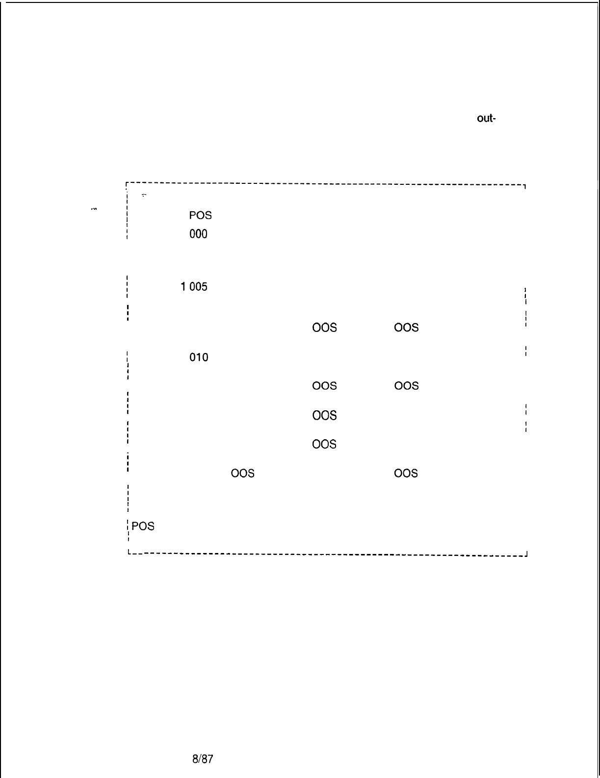
TL-130200-1001
Agent Group
Status Display
8.7.2 Agent Group Status Display (transaction 41)
allows the
user to display an organizational summary of each agent group.
This summary includes agent position, and in-service or
out-
of-service state of each position.
NOTE:
Only equipped agent groups are displayed.
._..
i
_.
I
I
I
POS
AGENT GROUP STATUS
41
STATE
INS
INS
INS
IIIIIIIIIIIIIIIII
II
I
I
f
II
I
IIIIIIII
I
I
I
IIIIIIIIIIIIIIIIIII
;
GROUP 0
000
I
I
004
I
I
016
I
I
031
i
GROUP
1
005
I
032
!
GROUP 2 120
II
124
II
128
I
I
GROUP 3
010
i
GROUP 4 020
II
024
;
GROUP
5170
I
174
;
GROUP
6070
I
074
I
j
GROUP 7 080
I
184
I
STATE POS
INS
001
INS 006
INS 017
00s
050
INS 007
00s
033
INS
121
00s
125
00s
129
INS
011
INS
021
00s
025
INS
171
00s
175
INS
071
00s
075
INS
081
00s
185
STATE POS
INS 002
INS 014
INS
018
INS
INS
008
00s
034
INS
122
00s
126
00s
130
INS
112
INS
022
00s
026
INS
172
00s
176
INS
072
00s
076
INS
082
00s
186
STATE POS
INS 003
INS
015
INS
019
INS 009
00s
035
INS
123
00s
127
00s
INS
113
INS 023
00s
027
INS
173
00s
177
INS 073
00s
077
INS 083
00s
187
i
ENTER (E), REPEAT (R), OR TRANSACTION NUMBER (O-224)
i
where
I
(POS
= Agent position (O---
191)
I
STATE = In-service/out-of-service state
I
INS
00s
INS
00s
INS
INS
00s
INS
00s
INS
00s
INS
00s
>
L--
-----------------------------------------------------------------J
M-302
8187
5210

-
-
TL-130200-1001
Night Destination of
8.7.3 ‘Night Destination of All Agent Groups (transaction 42)
All Agent Groups
allows the user to see night destinations for all agent groups.
Night destinations include the following:
. .
l Another agent group
l A directory number
@
An attendant
l A trunk group
l Third recorded announcement
*
No destination
Night Destination
The night destination of an agent group can be changed to a
trunk group if the following conditions are met:
1. All CAS trunk groups assigned to the agent group whose night
destination is being changed must have disconnect supervisor
in either an incoming or two-way state
2. The trunk group used for the new night destination must have
its trunk direction in either an outgoing or two-way state.
3. The destination trunk group must be one of the following:
-
Central Office (CO)
-
Foreign Exchange (FX)
-
TIE
-
WATS
4. If CAS trunk groups assigned to the agent group whose night
destination is being changed does not have disconnect
supervisor in either an incoming or two-way state, this agent’s
group night destination cannot be changed to a trunk group.
5. If the trunk group used for the new night destination does not
have its trunk direction in either an outgoing or two-way state,
or if the destination trunk group is not one of those four listed
above, the trunk group that was to be used for the agent
group’s night destination cannot be used.
5210
8/87
M-303
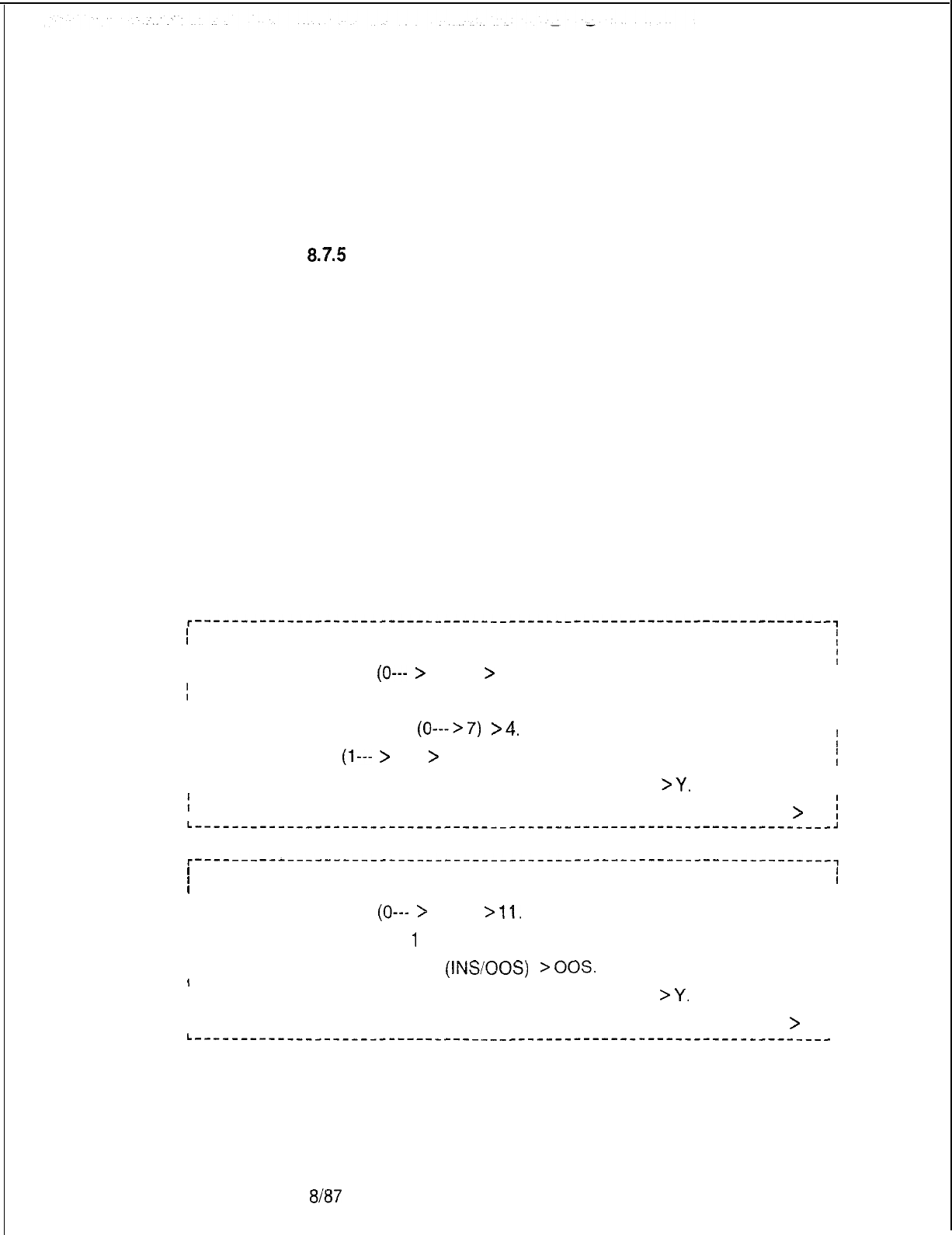
TL-130200-I 001
Change the
8.7.4 Change the Group/Supervisor of an Agent Position
Group/Supervisor
(transaction 43) allows the user to change the agent group and/or
of an Agent Position
supervisor of a specified agent position.
Change the State
87.5
Change the State of an Agent Position (transaction 44)
of an Agent Position
allows the user to place an agent position in-service, or take a
position out of service. Validity checks only the position number.
If the supervisor attempts to place an in-service position into an
out-of-service state while it is handling a call, the following
events will occur:
1.. The position is removed from the active agent group.
2. The supervisor receives a delayed message when the position
is actually placed out-of-service.
These events cause a warning message if the last in-service
position in an agent group is placed out-of-service, or if the
new state is the same as the existing state. If the new state is the
same as the existing state, the change is not processed. If a
position is placed out-of-service while an agent is still logged
on, a log off function is performed by the agent.
I
I
I
CHANGE THE GROUP/SUPERVISOR OF AN AGENT POSITION 43
I
;
I
I
I
AGENT POSITION
(0---
>
191)
>
20.
I
I
II
ICURRENT AGENT GROUP IS 5, CURRENT SUPERVISOR IS 3
I
I
I
INEW AGENT GROUP
(0--->7)
>4.
I
I
Ii
I
I
SUPERVISOR
(1---
>
8)
>
8.
I
I
I
I
DO YOU WANT TO EXECUTE THIS CHANGE (Y/N)
>Y.
I
I
I
I
ENTER END (E), REPEAT (R), OR TRANSACTION NUMBER (O-224)
>
i
L------_----__-----___-_____-___________------------------------------~
II
I I
I
CHANGE THE STATE OF AN AGENT POSITION 44
I
II
I
I
I
AGENT POSITION
(0---
>
191)
>
11.
I
I
I
I I
IAGENT POSITION 01
-I
HAS A CURRENT STATUS OF: INS
I
I
I
I I
INEW POSITION STATUS
(INSOOS)
>OOS.
I
I
I
IIDO YOU WANT TO EXECUTE THIS CHANGE (Y/N)
BY.
I
IIENTER END (E), REPEAT (R), OR TRANSACTION NUMBER (O-224)
>
L-----------__-___--_----___-___________------------------------------
M-304
8187
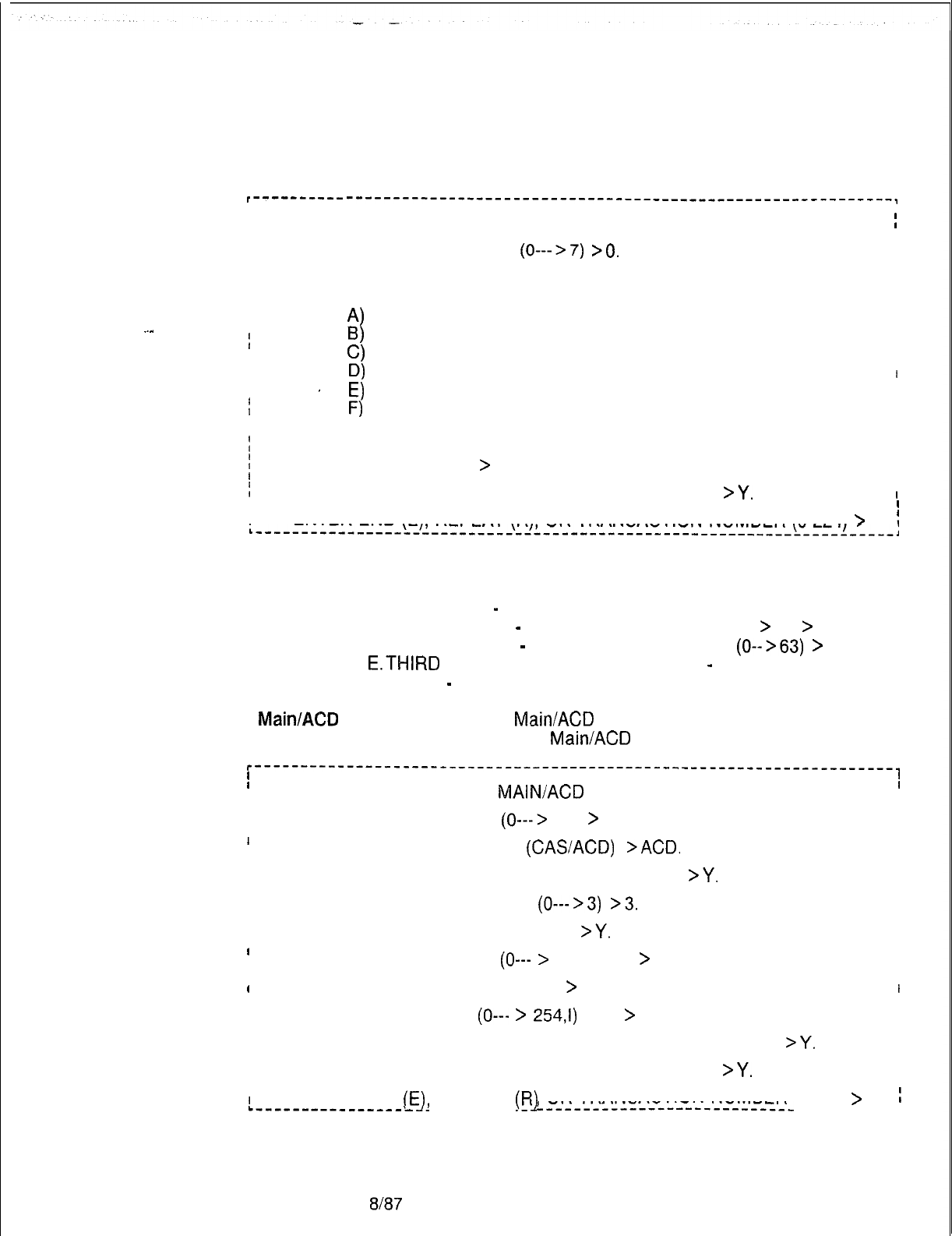
TL-130200-1001
Change Night
Destination of an
8.7.6 Change Night Destination of an Agent Group (transaction
Agent Group
45) allows the user to change the night destination of any agent
group.
I---------- -----------------------------------------------------------,
II
I
I
CHANGE NIGHT DESTINATION OF AN AGENT GROUP 45
I
I I
I I
IIAGENT GROUP NUMBER
(0--->7)
>O.
I
I
I
CURRENT NIGHT DESTINATION: DIRECTORY NUMBER 5678
I
I
I
II
I
NEW DESTINATION TYPE:
I
I
I
A)
DIRECTORY NUMBER II
..-
I
I
I
B)
ATTENDANT(S)
I
I
0)
AGENT GROUP
I
I
I
D)
TRUNK GROUP I
I
I
I I
I
THIRD RECORDED ANNOUNCEMENT
I
f
’
El
F)
NONE
I
I
I
I
I
t
ENTER LETTER OF NEW DESTINATION TYPE >A.
I
I
I
I
DIRECTORY NUMBER
>
1234. II
I
I
f
IDO YOU WANT TO EXECUTE THIS CHANGE (Y/N)
>Y.
I
I
I
I
I
ENTER END (E), REPEAT (R) OR TRANSACTION NUMBER (O-224)
>
!
.---------------------------------------------------------------,
A. DIRECTORY NUMBER
Prompt entries include the following:
B.ATTENDANT
-
NONE
C.AGENT GROUP
-
ENTER AGENT GROUP (0--
>
7)
>
D.TRUNK GROUP
-
ENTER TRUNK GROUP
(0-->63)
>
E.THIRD
RECORDED ANNOUNCEMENT
-
NONE
F. NONE
-
NONE
Add a CAS Main/ACD
8.7.7 Add A CAS
Main/ACD
Agent Group (transaction 46) allows
Agent Group
the user to add a CAS
Main/ACD
agent group.
r---------------------------------------------------------------------~
II
I I
IADD A CAS
MAIN/ACD
AGENT GROUP
46
I
II
I
I
I
AGENT GROUP NUMBER
(0--->
7)
>
0.
I
I
I
1
I
IAGENT GROUP FUNCTION
(CASACD)
>ACD.
I
I
I
II
IMUSIC TO BE PLAYED WHILE ON HOLD (Y/N)
>Y.
I
I
I
I
I
I
REPERTORY DIAL KEY SET
(0--->3)
>3.
I
I
I
I
I
I
MONITOR WARNING TONE (Y/N)
>Y.
I
I
I
I
I
II
I
FADS CALL DELAY TIME
(0---
>
255) SEC
>
120. I
I
I
I
I
I
HANDS-FREE OPERATION (Y/N)
>
Y.
I
I
IITIME IN WORK STATE
(0---
>
254,i)
SEC
>
60. I
I
I
II
I
ATTENDANT/LINE TO AGENT TRANSFER ALLOWED (Y/N)
>Y.
I
I
I
I
DO YOU WANT TO EXECUTE THIS CHANGE (Y/N)
>Y.
I
I
I
I
I
I
I
ENTER END
(E],
REPEAT
(R]
OR TRANSACTION NUMBER p-224)
>
.---------_-------
-----------
L---------------------------
:
-------_--a
5210
8187
M-305
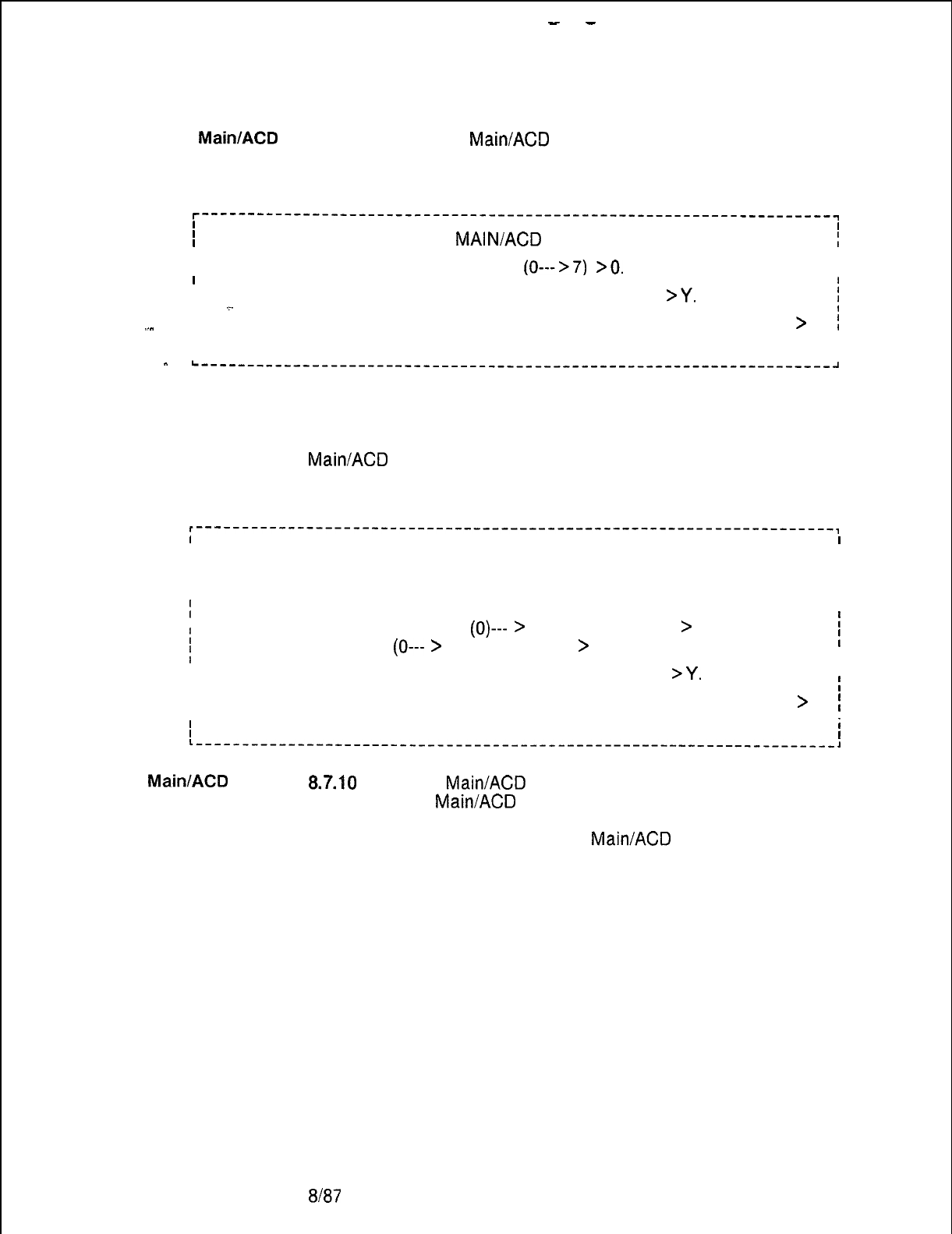
-
-
TL-130200-1001
Delete a CAS Main/ACD
8.7.8 Delete a CAS
Main/ACD
Agent Group (transaction 47)
allows the user to delete an agent group having no agents.
r--------------------------------------------------------------------~
II
I
I
DELETE A CAS
MAINIACD
AGENT GROUP 47
I
II
I
I
AGENT GROUP TO BE DELETED
(0--->7)
>O.
I
I
I
I
IDO YOU WANT TO EXECUTE THIS CHANGE (Y/N)
>Y.
i
I.~. I
I
.._
IIENTER END (E), REPEAT (R), OR TRANSACTION NUMBER (O-224)
>
;
I
I
I
I
I
-
L-----~~~~~~~~~~~~~~~~~~~~------~~~-~-~~~~~~~~~~-~~~~~~~~~~~~~~~~~~-~~
Display/Change FADS
8.7.9 Display/Change FADS Delay Timing (transaction 71) allows
Delay Timing
the user to display or change FADS delay timing. The delay
timing value defines the point at which an incoming CAS
Main/ACD
call is considered as delayed. The delay timing value
is applied only if there is no agent available when a call enters
the system.
r---------------------------------------------------------------------,
II
I
I
IDISPLAY/CHANGE FADS DELAY TIMING
71
I
II
II
I
AGENTGROUP 0 1 2 3 4 5 6 7
I
I
DELAY TIME 120 030 060 045 090 150 240 180
I
II
I
AGENT GROUP TO CHANGE
(0)---
>
7) OR E TO EXIT
>
7.
I
II
f
FADS DELAY TIME
(0---
>
255) SECONDS
>
120.
I
I
I
I
I
IDO YOU WANT TO EXECUTE THIS CHANGE (Y/N)
>Y.
I
I
I
ENTER END (E), REPEAT (R), OR TRANSACTION NUMBER (O-224)
>
I
II
I
i
II
L-----_---------------------------------------------------------------,
CAS Main/ACD Trunk
8.7.10
The CAS
Main/ACD
Trunk Data Menu is accessed
Data Menu
through CAS
Main/ACD
Supervisory Recent Change. The
1. Select transaction 50 from CAS
MairVACD
Supervisory Recent
Change.
The system responds:
M-306
Em7
5210
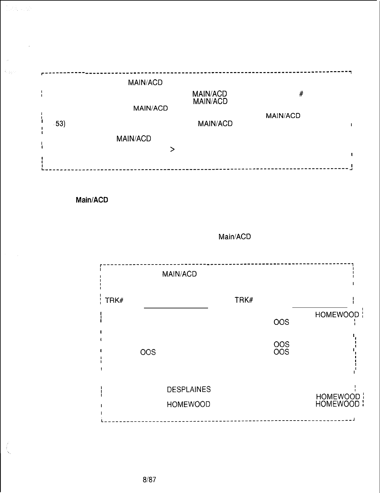
TL-130200-1001
l------------
-----------------------------------------------------------------------~
I
I
I
I
CAS
MAINIACD
TRUNK DATA
50
I
I
II
f
55) DISPLAY BREAKDOWN OF ALL CAS
MAIN/ACD
TRUNKS BY TRUNK
#
I
I
II
I
56) DISPLAY BREAKDOWN OF ALL CAS
MAIN/ACD
TRUNKS BY AGENT GROUP
I
I
I
I
51) DISPLAY ALL CAS
MAIN/ACD
TRUNKS WITH A SPECIFIC SOURCE
I
I
52) CHANGE IN-SERVICE/OUT-OF-SERVICE STATE OF A CAS
MAIN/ACD
TRUNK
I
I
’
-53)
CHANGE SOURCE GROUP OF A CAS
MAIN/ACD
TRUNK
I
II
I
54) CHANGE PRIMARY DESTINATION FOR TRUNK GROUP
,
I
I
38) GO TO CAS
MAIN/ACD
SUPERVISORY RECENT CHANGE MENU
I
II
II
I
ENTER TRANSACTION NUMBER--
>
I
I
I
I
I
I
I
II
I I
L----------------------------------------------------------------------------------
-I
2. Select the correct transaction.
CAS Main/ACD Trunk
8.8 The following paragraphs describe transactions listed in the
Data Transactions
CAS Main/ACD Trunk Data Menu. The transactions listed here
are used to display or change trunk data.
Display Trunks by Trunk
8.8.1 Display Trunks by Trunk Number (transaction 55) allows
Number
the user to see all CAS
Main/ACD
trunks listed according to
system trunk number.
r----------------------------
---------------------------------------,
I
I
;
55
CAS
MAIN/ACD
TRUNK BREAKDOWN BY TRUNK NUMBER
i
I
I
I
I
AGT AGT
I
;
TRK#
GRP STA SOURCE
I
TRK#
GRP STA SOURCE
I
I
I--
I
---
I
I
16 4 INS PARK FOREST 17 1INS
HOMEWOOD
:
I
I
19 0 INS PARKFOREST 20 2
00s
PARK FOREST
;
II
I
34 6 INS PARK FOREST 37 3INS CENTRAL
I
II
I
OFFICE
I
I
38 3 INS “BLANK- 39 0
00s
FLOSSMOOR
i
I
I
40 0
00s
“BLANK- 41 0
00s
“BLANK-
I
I
45 1INS WOODFIELD 46 1INS WOODFIELD
i
I
I
47 1INS WOODFIELD 48 1INS WOODFIELD
;
I
I
49 0 INS CHICAGO HEIGHTS 50 7INS CHICAGO
I
I
II
I
HEIGHTS
I
I
I
51 5 INS
DESPLAINES
52 0INS DES PLAINES
;
I
I
53 6 INS PARK FOREST 54 2INS
HOMEWOOD
;
I
I
55 2 INS
HOMEWOOD
56 2INS
HOMEWOOD
!
I
I
57 3 INS SECURITY 58 2INS SECURITY I
,
II
L-------------------------------------------------------------------~
5210
8187
M-307
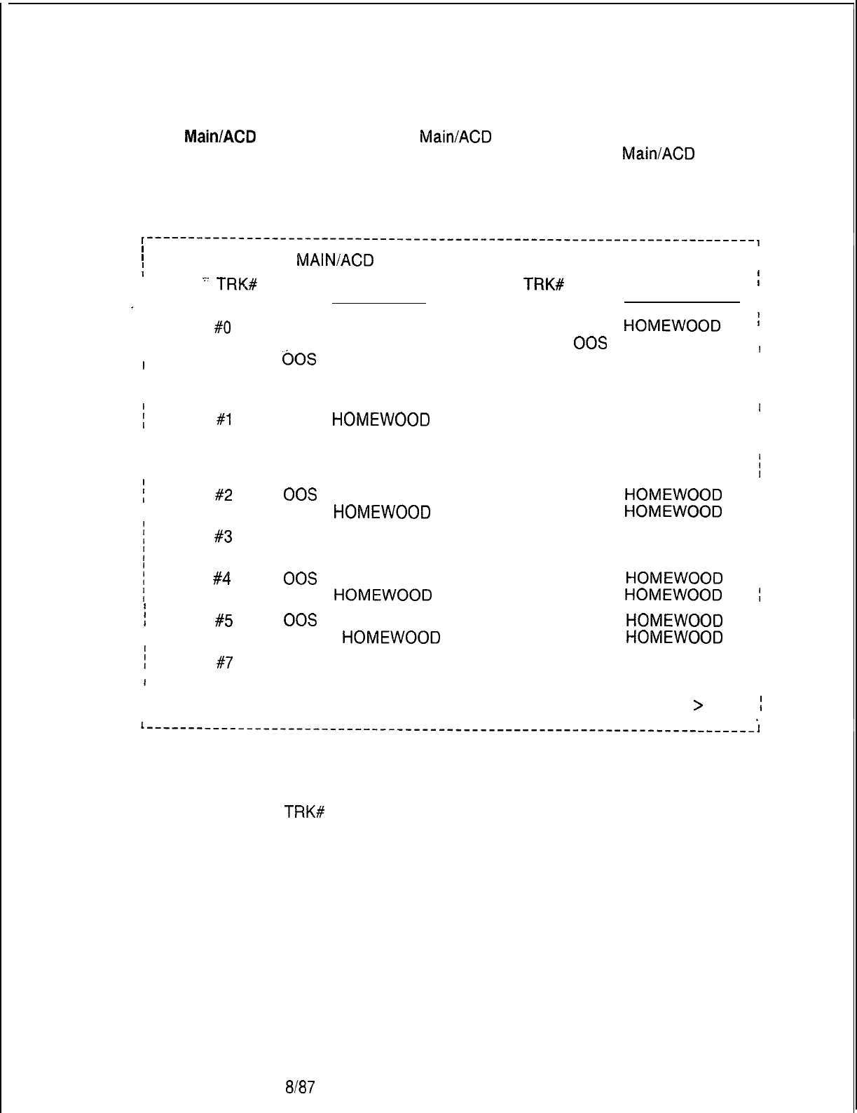
r
TL-130200-1001
Display CAS Main/ACD
Trunks by Agent
8.8.2 Display CAS
Main/ACD
Trunks by Agent Group Number
(transaction 56) allows the user to see all CAS
Main/ACD
trunks
Group Number
listed by trunk number, in addition to the service state and source
message.
M-306
I
I
;
CAS
MAINIACD
TRUNKS BY AGENT GROUP NUMBER 56
I
I
.=-
TRK#
STA SOURCE
TRK#
STA SOURCE
I
--
-
I --
~-GROUP
#o
16 INS PARK FOREST
19
INS
HOMEWOOD
I
I34 INS PARK FOREST
39
00s
FLOSSMOOR
I
I
40
60s
“BLANK-
41
00s “BLANK-
I
I
49 INS CHICAGO HEIGHTS 50 INS CHICAGO
IIHEIGHTS
i
GROUP
#I
17 INS
HOMEWOOD
45
INS WOODFIELD
I
I
46 INS WOODFIELD
47
INS WOODFIELD
I
I
48
INS WOODFIELD
51
INS OAK FOREST
I
I
52
00s “BLANK”“’
53
INS EVANSTON
j
GROUP
#2
20
00s
PARK FOREST
54
INS
HOMEWOOD
I
I
55 INS
HOMEWOOD
56
INS
HOMEWOOD
i
GROUP
#3
37 INS CENTRAL OFFICE
38
INS “BLANK-
I
61
INS SECURITY
62
INS SECURITY
i
GROUP
#4
21
00s
PARK FOREST
22
INS
HOMEWOOD
f
23
INS
HOMEWOOD
24 INS
HOMEWOOD
i
GROUP
#5
30
00s
PARK FOREST
32
INS
HOMEWOOD
I
I
33
INS
HOMEWOOD
35
INS
HOMEWOOD
i
GROUP
#7
15 INS CENTRAL OFFICE 19 INS “BLANK-
I
I
58
INS SECURITY
59
INS SECURITY
I
II
I
ENTER END (E), REPEAT (R), OR TRANSACTION NUMBER (O-224)
>
III
t
III
I
II
1
I
IIIII
I
IIIII
II
I
I
I
IIIIII
I
I
I
I
II
I
I
I
I
I
I
I
I
I
I
I
I
where
TRK#
= System trunk number
STA = In-service/out-of-service state
SOURCE =Source message
8187
5210
TL-130200-1001
Display Trunks with a
8.8.3 Display Trunks With a Specific Source Group (transaction
Specific Source Group
51) allows the user to see trunks in specific source group.
Trunks are displayed by trunk number, service state, trunk group,
and agent group.
. .
r-------------------------------------------------------------------,
I
I
I
TRUNKS IN A SPECIFIED SOURCE GROUP 51
i
I
..- I
I
I
i
SOURCE GROUP NUMBER
(0--->31)
>8.
I
SOURCE MESSAGE: WOODFIELD
II
I
I
TRUNK
#
STATE TRUNK GROUP AGENT GROUP
j
II
I--
I
II
I
I
45
INS
2 7
I
I
I
46
INS
2
1
I
II
I
I
47 INS
2
1
I
I
I
I
I
48
INS
31 3
I
I
I
I
ENTER END (E), REPEAT (R), OR TRANSACTION NUMBER (O-224)
!
II
L-------------------------------------------------------------------~
Change the State of a
8.8.4 Change the State of a CAS
Main/ACD
Trunk (transaction
CAS Main/ACD Trunk
52) allows the user to change the service state of CAS
Main/ACD
trunks.
r------------------------------
-------------------^-----------------~
II
I
I
CHANGE THE STATE OF A CAS
MAIN/ACD
TRUNK 52
:
II
II
II
I
TRUNK NUMBER
(0---
>
63)
>
20.
I
I
I
I
CURRENT STATE:
00s
I
II
II
I
NEW STATE
(INSOOS)
>
INS.
I
I
II
I
DO YOU WANT TO EXECUTE THIS CHANGE (Y/N)
>Y.
I
I
I
I
I
I
ENTER END (E), REPEAT (R), OR TRANSACTION NUMBER (O-224)
I
;
L-------------------------------------------------------------------,
5210 8187
M-309
TL-130200-1001
Change the Source
Group of a Trunk
8.8.5 Change the Source Group of a Trunk (transaction 53)
allows the user to change the source group associated with a
system trunk.
r-------------------------------------------------------------------,
I I
I
I
CHANGE SOURCE GROUP OF A TRUNK 53
:
I
I
I
I
TRUNK NUMBER
(O-+63)
>38.
I
.=.
I
I
. .
I
CURRENT SOURCE GROUP NUMBER: 3
f
I
I
I
CURRENT SOURCE MESSAGE:
*
BLANK
-
I
I
II
I
:
NEW SOURCE GROUP NUMBER
(00--->31)
>13.
I
NEW
SdURCE
MESSAGE I
I
>
MELROSE
PARK. I
I
I
I I
IDO YOU WANT TO EXECUTE THIS CHANGE (Y/N)
>Y.
I
I
I
I
I
II
I
ENTER END (E), REPEAT (R), OR TRANSACTION NUMBER (O-224)
;
Change the Primary
Destination of a
8.8.6 Change the Primary Destination of a Trunk Group
(transaction 54) allows the user to change the primary destination
Trunk Group
of a trunk group. This transaction checks the trunk group
application to ensure that only CAS
Main/ACD
trunk groups are
changed.
I
I
I
CHANGE PRIMARY DESTINATION FOR A TRUNK GROUP
54
j
I I
I I
I I
I
TRUNK GROUP NUMBER
(0--->63)
>lO.
I
I I
I I
IPRIMARY DESTINATION AGENT GROUP 3
I
I I
I I
IENTER NEW DESTINATION AGENT GROUP
(0--->7)
>O.
I
II
1
I
I
DO YOU WANT TO EXECUTE THIS CHANGE (Y/N)
>Y.
I
II
II
IENTER END (E), REPEAT (R), OR TRANSACTION NUMBER (O-224)
j
M-31 0
8187
5210
r
TL-130200-1001
Source Message Data
Menu 8.9 Source Message Data Menu (transaction 57) is a
sub-
menu of CAS
Main/ACD
Supervisory Recent Change.
Transactions in this sub-menu allow the user to select source
message information to be displayed or changed.
r-------------------------------------------------------------------~
I
I
I
I
SOURCE MESSAGE DATA
I
57
I
iI
58) DISPLAY SOURCE MESSAGES
I
II
I
59)
CHANGE A SPECIFIC SOURCE MESSAGE
I
I
I
38)
I
GO TO CAS
MAIN/ACD
SUPERVISORY RECENT CHANGE MENU
i
I
ENTER TRANSACTION NUMBER-->
I
I
I
II
I
L----------------_--------------------------------------------------~
Source Message Display
8.9.1 Source Message Display (transaction 58) allows the user
to examine source message displays.
r-------------------------------------------------------------------,
I
I
I
SOURCE MESSAGE DISPLAY
I
I
58
;
I
I
SRC
I
SRC I
II
I
GRP
#
MESSAGE GRP
#
MESSAGE
I
II
II
II
I
I
0
PARK FOREST I
1
FLOSSMOOR
I
i
2
CHICAGO HEIGHTS
I
3
HOMEWOOD
I
I
4
OAK FOREST I
I
5
“BLANK- I
I
I
6
“BLANK-
I
7
“BLANK-
I
I
I
I
9
WOODFIELD
9
I
WHEATON
I
I
10
MAYWOOD
I
11
ELMHURST
I
t
12
EVANSTON
13
I
I
14
NORTHLAKE
15
MELROSE
PARK
i
IDES
PLAINES
I
I
16
“BLANK-
17
“BLANK-
I
II
I
18
“BLANK-
19
“BLANK-
I
I
I
20
“BLANK-
21
I
CENTRAL OFFICE
i
I
22
“BLANK-
23
SECURITY I
I
I
24
“BLANK-
25
I
ADVERTISING
I
I
I
26
“BLANK-
27
-BLANK-
I
II
I
28
GARY
29
“BLANK-
I
II
I
30
HAMMOND
31
“BLANK- I
II
I
I
I
ENTER END (E), REPEAT (R), OR TRANSACTION NUMBER (O-224)
>
:__-__-______-___----
;
I
-----------------------------------------------,
where
SRC
GRP#
= Source group number
5210 8187 M-31
1
.,.
._
:. .
TL-130200-1001
Change a Source
Message
8.9.2 Change A Source Message (transaction 59) allows the
user to change a specific source’ message. Every agent
instrument is updated when the change is executed. The new
source message is always justified left. No periods may be
entered since the system sees them as “END OF INPUT.“
r-------------------------------------------------------------------,
I
i
_.
CHANGE A SOURCE MESSAGE
I
59
i
I
I
._.. I
I
SOURCE GROUP NUMBER
(O--+31) >31.
I
II
,
II
CURRENT MESSAGE: “BLANK-
I
I
II
I
I
I
NEW MESSAGE (16 CHARACTERS MAXIMUM)
I
I
I
ENTER MESSAGE IN DOUBLE QUOTES > “PARK RIDGE”.
II
II
I
I
DO YOU WANT TO EXECUTE THIS CHANGE (Y/N)
>Y.
I
I
I
I
I
ENTER END (E), REPEAT (R), OR TRANSACTION NUMBER (O-224)
i
L-------------------------------------------------------------------~
8187
5210
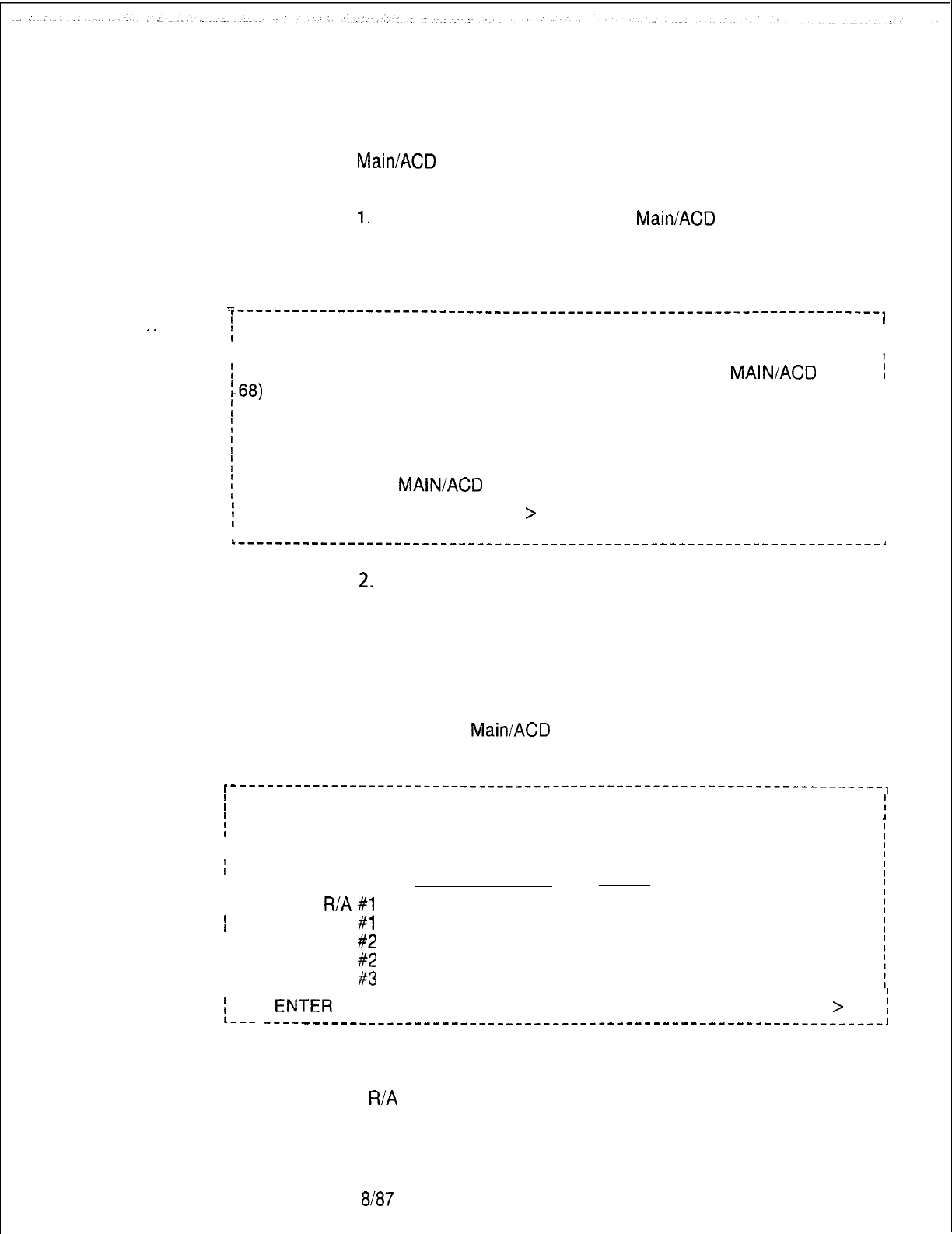
TL-130200-1001
Call Waiting
8.10 The Call Waiting Data Menu is accessed through CAS
Data Menu Access
Main/ACD
Supervisory Recent Change. The following steps are
used to access the menu:
1.
Select transaction 60 from CAS
MainlACD
Supervisory Recent
Change.
The system responds:
.
.
..-
,----------------------------------------------------------------------,
1I
f
CALL WAITING DATA
60
I
I
I
I
I
;
67) DISPLAY TRUNK NUMBER AND STATUS OF ALL CAS
MAIN/ACD
R/A
i
:68)
DISPLAY DELAY ROUTING OF ALL AGENT GROUPS
I
I
:
69) DISPLAY CALL WAITING LEVELS OF ALL AGENT GROUPS I
I
!
61) CHANGE DELAY ROUTING OF AN AGENT GROUP
II
!
65) CHANGE ALTERNATE ROUTING OF AN AGENT GROUP
I
I
!
66) CHANGE CALL WAITING LEVELS FOR AN AGENT GROUP
I
I
i
38) GO TO CAS
MAIN/ACD
SUPERVISORY RECENT CHANGE MENU
I
I
I
i
ENTER TRANSACTION NUMBER--
>
I
I
I
I I
L---------------__-----------------------------------------------------,
2.
Select the correct transaction.
Call Waiting
8.10.1 The following paragraphs describe transactions listed in
Data Menu
the Call Waiting Data Menu. The transactions listed here are
used to display or change call waiting data.
Display R/A Trunk
8.10.2 Display Recorded Announcement Trunk Number and
Number and State
State (transaction 67) allows the user to display the trunk number
of each CAS
MainiACD
recorded announcement, and the service
state of each trunk.
I-----------------------------------------------------------------------,
I
I
i
67 DISPLAY RECORDED ANNOUNCEMENT TRUNK NUMBER AND STATE
i
I
TRUNK NUMBER STATE
I
III
R/A
#l
59
INS
I
I
ALT R/A
#1
60
INS
I
I
R/A
#2
61
INS
I
I
ALT R/A
#2 62
INS
I
I
R/A
#3 63
INS
is__
JNTER
END (E), REPEAT (R), OR TRANSACTION NUMBER (O-224)
>
i
---------------------------------------------------------------,
where
R/A
= Recorded Announcement
ALT = Alternate
5210 8187 M-31 3
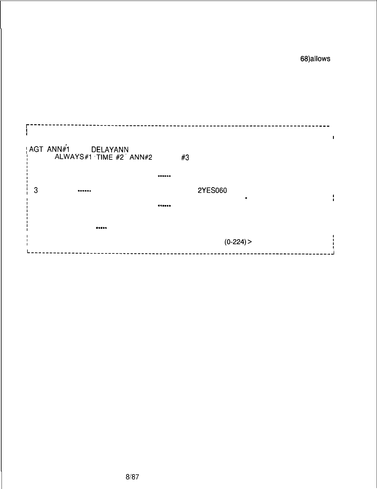
TL-130200-1001
Agent Group Delay 8.10.3
Agent Group Delay Routing Display (transaction 68)aliows
Routing Display
the user to examine the routing of agent groups. Routing
information includes R/A display options, delay repetition timing,
alternate destinations, and alternate route timing. Delay time is
the time span between the first announcement and the second
announcement. Repetition time is the time span between repeats
of the second announcement.
r----------------------------------------------------------------------------------
1
I
I
AGENT GROUP DELAY ROUTING
68
I
I
II
I
I
REC
^
REC
REC REPT
REC
ALT
I
;AGT
ANN#l
ANN
DELAYANN
REC REPT ANN ALTERNATE
I
RTE
I
;
GRP
ALWAYS#l
-TIME
#2-
ANN#2
TIME
#3
I
DESTINATION TIME
I
I
j
0 YES
I
1 120 2YES 090 YES DIR NUM 4513
240
I
;
1 NO
I
A 060 2 NO
_-____
NO TRUNK GROUP 12
120
I
I
;
2 YES A 180 AYES 030 YES AGENTGROUP 7
180
I
I
I
3
-_____
A120
2YES060 NO
I
I
j
4 YES
R/A
-
TRUNK 62
200
;
1
045 A NO
_-----
NO
PABX ATTENDANT 220
I
I
;
5 YES
I
I
;
6 NO 1 030
2
YES 090 NONE
255
I
I
I
7
YES
A
_-_--
NONE
255
I
----- -----
I
II
i
ENTER END (E), REPEAT (R), OR TRANSACTION NUMBER (O-224)>
I
II
where
REC ANN = Recorded announcement
ALT =
Alternate
1st =
First recorded announcement
2nd =
Second recorded announcement
AGT GRP
= Agent group
REPT Time =Reporting time
ALT RTE TIME =
Alternate route timing value
M-31 4 8187
5210
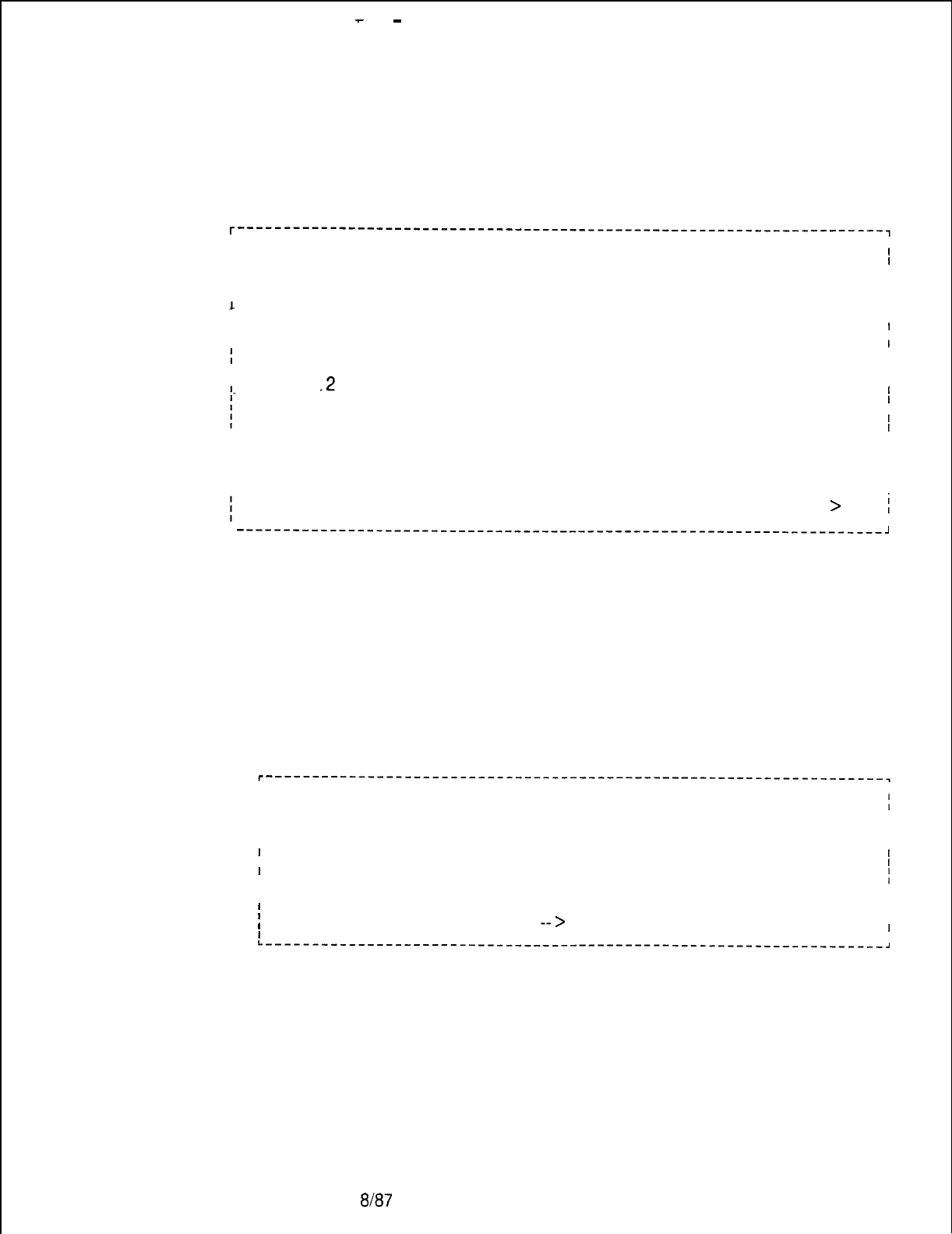
-
-
TL-130200-1001
Agent Group Call
8.10.4
Waiting Levels
Agent Group Call Waiting Levels (transaction 69) allows
the user to examine call waiting levels for every agent group.
I
I
L
I
I
. .
I
I
I
I
I
AGENT GROUP CALL WAITING LEVELS
69
I
I
I
AGENT
I
I
GROUP
I
LEVEL 1 LEVEL 2 LEVEL 3
I
I
I
0
1
.2
3
4
5
6
7
I
001 002 003
I
I
001 002 003
I
I
001 002 003
I
I
001 002 003
I
I
UNE
I
I
UNE I
I
UNE
I
I
UNE I
I
ENTER END (E), REPEAT (R), OR TRANSACTION NUMBER (O-224)
>
j
I
L
----------------------------------------------------------------------~
where
UNE = Agent group not implemented
Change Delay Routing
of an Agent Group
8.10.5 Change Delay Routing of an Agent Group (transaction 61)
allows the user to change the routing data of an agent group.
Displayed information includes recorder announcement options,
and delay or repetition timing.
II
I
I
CHANGE DELAY ROUTING OF AN AGENT GROUP 61
;
I
I
I
I
I
I
I62) FIRST RECORDED ANNOUNCEMENT
,
II
I
63) SECOND RECORDED ANNOUNCEMENT
I
I
I
64)
DELAY OR REPETITION TIMING
I
I
60)
GO TO CALL WAITING DATA MENU I
I
I
i
ENTER TRANSACTION NUMBER
-->
62. I
I
I
I
I
L--------_-----_----------------------------------------------------,
5210
8187
M-31 5
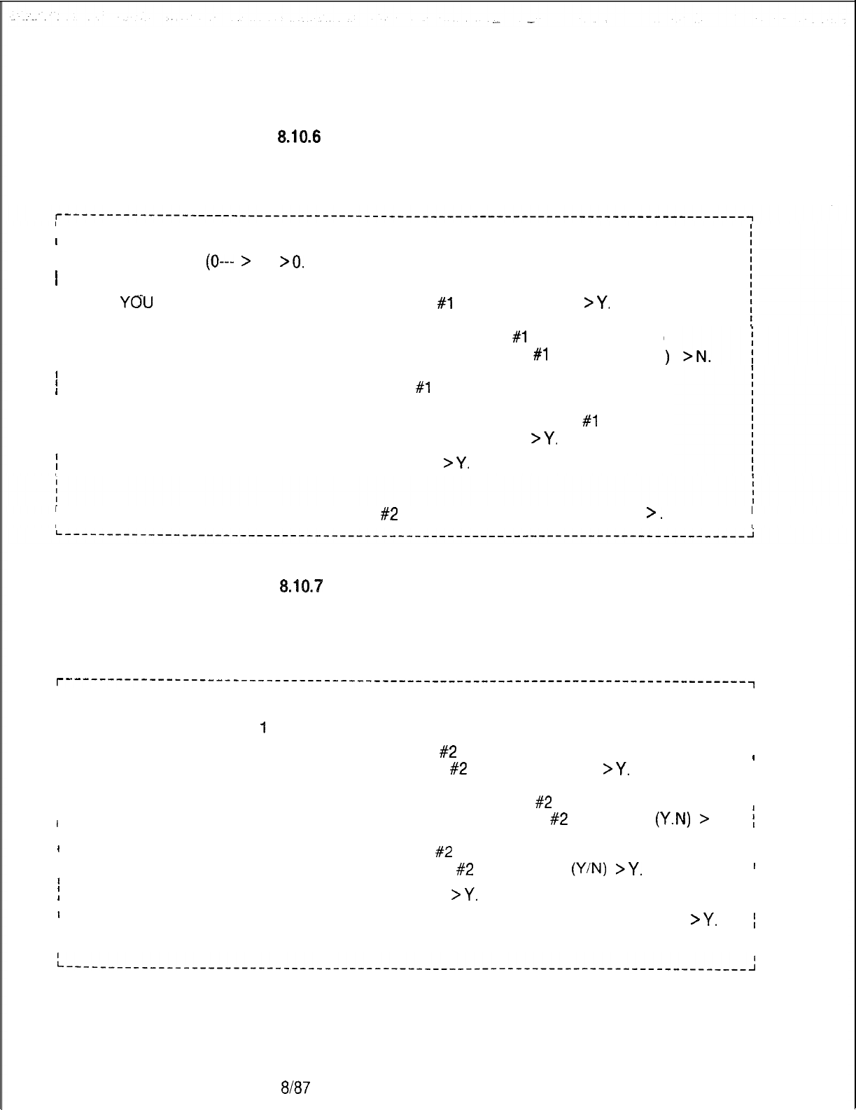
TL-130200-I 001
Change First Recorded
610.6
Change First Recorded Announcement (transaction 62)
Announcement
allows the user to change the first recorded announcement for a
specific agent group.
I
I
I
CHANGE FIRST RECORDED ANNOUNCEMENT
62
I
I
IAGENT GROUP
(0---
>
7)
>O.
I
I
I
CURRENTLY RECORDED ANNOUNCEMENT # 1 IS PLAYED
I
IDO
YOU
WANT RECORDED ANNOUNCEMENT
#1
TO PLAY (Y/N)
>Y.
I
I
I
I
CURRENTLY RECORDED ANNOUNCEMENT
#I
IS ALWAYS PLAYED
I
I
BEFORE ROUTING TO AN AGENT GROUP IS TRUE
I
I
DO YOU WANT TO ALWAYS PLAY RECORDED ANNOUNCEMENT
#l
I
I
IBEFORE ROUTING TO AN AGENT GROUP (Y/N) .
>Y.
;
DO YOU WANT TO EXECUTE THIS CHANGE (Y.N)
>Y.
I
I
I
ICURRENTLY ALTERNATE RECORDED ANNOUNCEMENT
#l
IS NOT PLAYED
I
IDO YOU WANT ALTERNATE RECORDED ANNOUNCEMENT
#l
TO PLAY (Y.N
I
I
IDO YOU WANT TO CHANGE REC-ANN
#2
FOR THIS AGENT GROUP (Y/N)
>.
I
I
I
I
Change Second
&IO.‘%
Change Second Recorded Announcement (transaction
Recorded 63) allows the user to change the second recorded
Announcement
announcement for a specific agent group. Enter a period to
retain old value.
r----------------------------------------------------------------------------------~
I
I
I
ICHANGESECONDRECORDEDANNOUNCEMENT
63
I
I
I
I
I
IAGENTGROUP =
1
I
I
I
I
I
CURRENTLY RECORDED ANNOUNCEMENT
#2
IS PLAYED
I
I
I
IDO YOU WANT RECORDED ANNOUNCEMENT
#2
TO PLAY (Y/N)
>Y.
I
I
I
I
I
II
ICURRENTLY ALTERNATE RECORDED ANNOUNCEMENT
#2
IS PLAYED I
I
I
I
DO YOU WANT ALTERNATE RECORDED ANNOUNCEMENT
#2
TO PLAY
(Y.N)
>
N
;
II
I .I
I
I
ICURRENTLY RECORDED ANNOUNCEMENT
#2
IS REPEATED I
I
I
IDO YOU WANT RECORDED ANNOUNCEMENT
#2
REPEATED
(Y/N)
>Y.
I
I
I
I
DO YOU WANT TO EXECUTE THIS CHANGE (YIN)
>Y.
II
II
I
I
IDO YOU WANT TO CHANGE DELAY TIMING FOR THIS AGENT GROUP (Y/N)
>Y.
1
I
II
I
I
L-__-_---__----_________________________-------------------------------------------~
M-31 6
8l87
5210
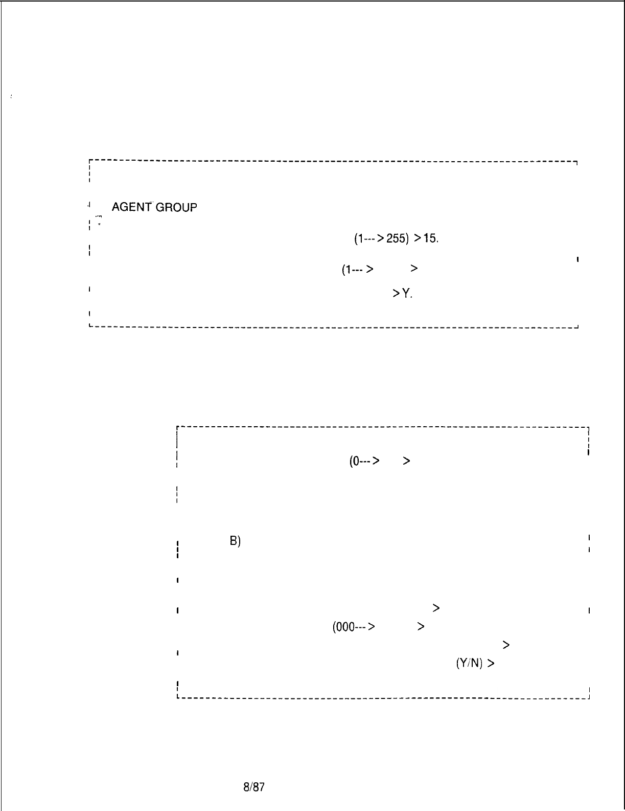
TL-130200-1001
:
Change Recorded
Announcement Delay
8.10.8 Change Recorded Announcement Delay or Repetition
or Repetition Timing
Timing (transaction 64) allows the user to change the recorded
announcement delay, or repetition timing for a specific agent
group.
r-------------------------------------------------------------------------------~
j
CHANGE RECORDED ANNOUNCEMENT DELAY OR REPETITION TIMING
I
64
I
I
I I
I I
II
-I
AGENT~GROUP
= 1
I
II
,
.-.. I
I
-
DELAY TIMING
I
I
II
I
_
OLD VALUE: 030 NEW VALUE
(l--->255)
>15.
I
II
I
I
I
REPETI-TION TIMING
I
I
I
OLD VALUE: 045
INEW VALUE
(l---
>
255)
>
30.
I
II
I I
I
I
I
I
I
DO YOU WANT TO EXECUTE THIS CHANGE (Y.N)
>Y.
I
I
I
IENTER END (E), REPEAT (R) OR TRANSACTION NUMBER (O-224)
I
I
I
I-----_-----__------____________________----------------------------------------~
Change Alternate
8.10.9 Change Alternate Destination of an Agent Group
Destination of an
(transaction 65) allows the user to change the alternate routing
Agent Group
destination for a specific agent group.
r-------------------------------------------------------------------,
I
I
I
CHANGE ALTERNATE DESTINATION OF AN AGENT GROUP
65
1
I
i
AGENT GROUP NUMBER
(0--->
7)
>
1.
I
I
II
I
I
CURRENT ALTERNATE DESTINATION: AGENT GROUP 0
I
I
CURRENT ALTERNATE ROUTE TIMING: 120 SECONDS
I
II
I
I
I
INEW DESTINATION TYPE:
I
I I
I I
IA) DIRECTORY NUMBER
I
II
I
8)
ATTENDANT
I
I
I
C) AGENT GROUP
I
I
I
I
ID) TRUNK GROUP I
IE) SYSTEM RECORDED ANNOUNCEMENT I
I
I
I
I
I
F) NONE I
I
I
I
ENTER LETTER OF NEW DESTINATION
>
A. I
I
I
I I
I I
IDIRECTORY NUMBER
(000--->
9999)
>
4567. I
I I
IINEW ALTERNATE ROUTE TIMING (O-225) SECONDS
>
90. II
I
I
I
I
I
DO YOU WANT TO EXECUTE THIS CHANGE
(Y/N)
>
Y. I
II
I
ENTER END (E), REPEAT (R) OR TRANSACTION NUMBER (O-224) j
I
L________-__----_____________________---------------------------------------~
5210
8187
M-31 7
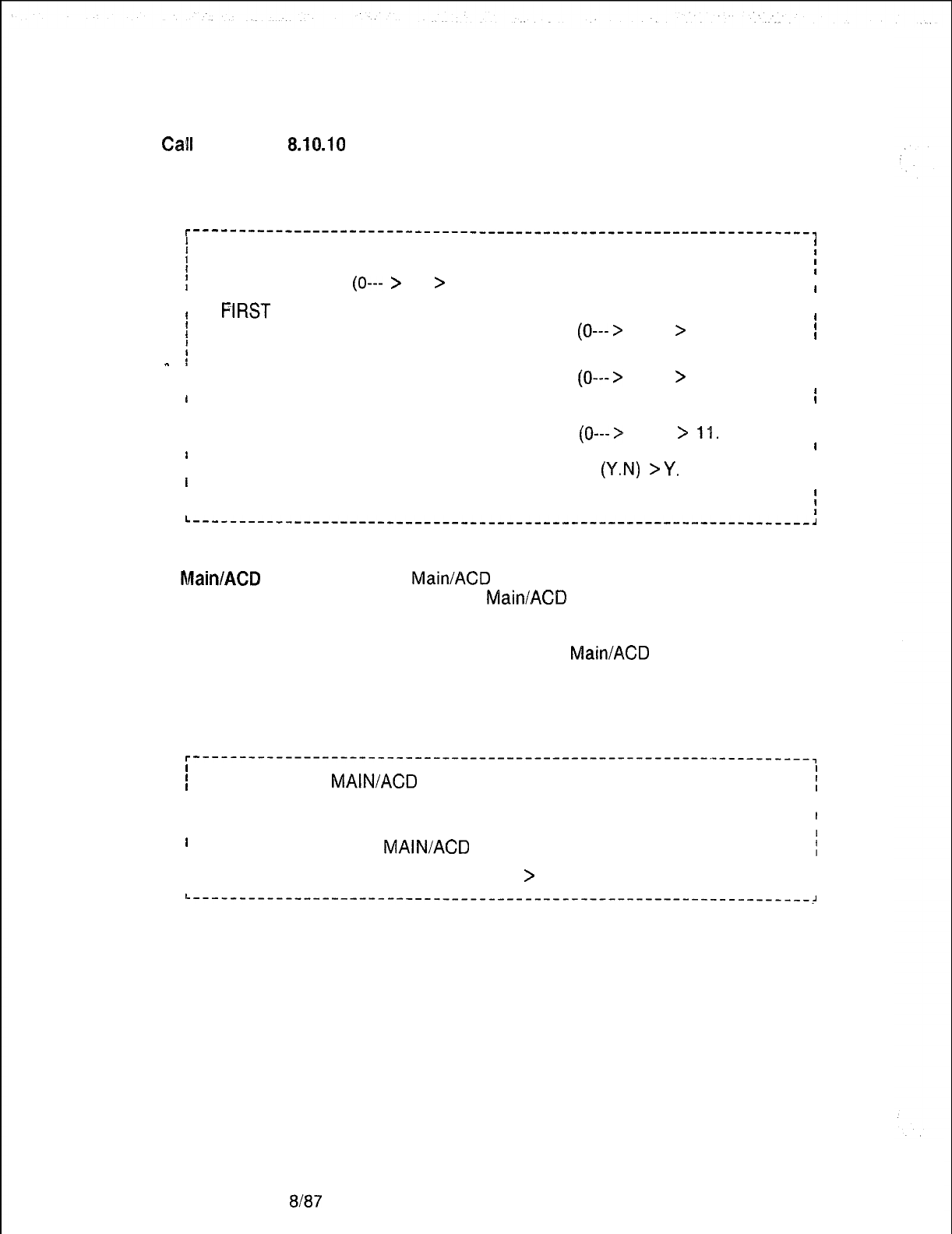
TL-130200-I 001
Change
Call
Waiting 8.10.10
Change Call Waiting indicator Levels (transaction 66)
indicator Levels
allows the user to change the calf waiting indicator level for a
specific agent group.
r-------------------------------------------------------------------,
I
I
I
CHANGE CALL WAITING INDICATOR LEVELS
164
;
f
AGENT GROUP
(0---
>
7)
>
2.
I
I
II
I
f
PiRST
CALL WAITING LEVEL
I
I
II
1OLD VALUE: 001 NEW VALUE
(0--->
255)
>
5. 1
iI
SECOND CALL WAITING LEVEL
I
_
II
I
I
OLD VALUE: 002 NEW VALUE
(0--->
255)
>
8.
I
I
I
I
II
I
THIRD CALL WAITING LEVEL
I
II
I
I
I
OLD VALUE: 003
I
I
NEW VALUE
(0--->
255)
>
11.
I
II
II
I
DO YOU WANT TO EXECUTE THIS CHANGE
(Y.N)
>Y.
I
II
I
I
I
ENTER END (E), REPEAT (R), OR TRANSACTION NUMBER (O-224)
i
L-------------------------------------------------------------------,
CAS Main/ACD
8.11 The CAS
Main/ACD
Instrument Control Data Menu is
Data
Menu
Instrument Control
accessed through CAS
Main/ACD
Supervisory Recent Change.
The following steps are used to access the menu:
1. Select transaction 80 from CAS
Main/ACD
Supervisory Recent
Change.
The system responds:
r--------------------------------------------------------~----------,
I
I
I
CAS
MAIN/ACD
INSTRUMENT CONTROL DATA 80
:
II
II
I
81)
DISPLAY A REPERTORY DIAL KEY SET
I
II
I
82)
CHANGE A REPERTORY DIAL KEY SET
I
I
38)
GO TO CAS
MAIN/ACD
SUPERVISORY RECENT CHANGE MENU
i
I I
I I
IENTER TRANSACTION NUMBER ----
>
I
I I
L-------------------------------------------------------------------~
2. Select the correct transaction.
M-31 88187 5210
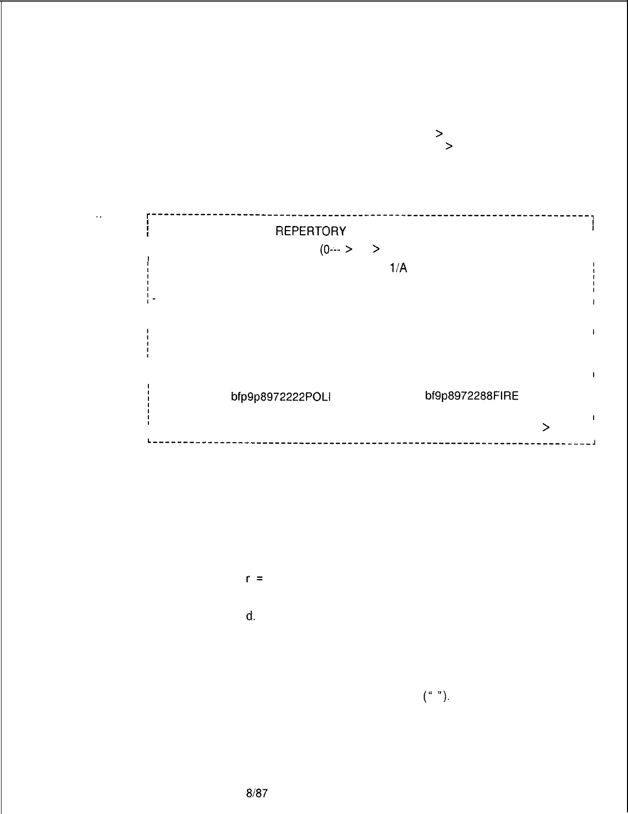
TL-130200-1001
Display a Repertory
8.11.1 Display a Repertory Dial Key Set (transaction 81) allows
Dial Key Set
the user to examine the repertory dial numbers in a specific key
set along with agent groups using the key set. A CAS group has
seventeen repertory dial keys (0 ---
>
16). An ACD group
has sixteen repertory dial keys (0 ---
>
15). Each repertory
dial number may have a maximum of 16 characters.
.
.
r------------------------------------------------------------------------,
II
I I
I
DISPLAY A
REPERTCRY
DIAL KEY SET
81
I
I I
I I
I
ENTER REP DIAL KEY SET
(0---
>
3)
>
1.
I
I
.
I
KEY SET 1 IS SHARED BY AGENT GP:
l/A
2/A 3/C 4/C
KEY REP DIAL NUMBER KEY REP DIAL NUMBER
00
02
04
06
10
08
12
14
16
fp200 AUTO
fp208 TOYS
fp212 MENSWEAR
fp240 SHOES
fp245 CATALOG
fp242 MANAGER
bfp9p8972222POLI
I
01
fp205 HARDWARE
I
I
03
fp209 FURNITURE
I
I
05
fp213 LADIES
I
I
07
fp241 HOUSEHOLD
I
I
11
I
I
09
fp244 WILL CALL
I
I
13
I
I
15
bf9p8972288FIRE
I
I
I
I
ENTER END (E), REPEAT (R), OR TRANSACTION NUMBER (O-224)
>
I
I
I
L------------------------------------------------------------------------,
where
A=ACD group
B= CAS group
f
= Flash
P
= Pause for dial tone
a
= Key will auto-correct on line 1
b
= Key will auto-correct on line 2
r=
Release
c. = Key will function on line 1 only
d.
= Key will function on line 2 only
Change a Repertory 8.11.2 Change Repertory Dial Key Set (transaction 82) allows the
Dial Key Set user to change a repertory dial number in a specific key set.
Changes are applied to all instruments and agent groups using
that key set. In the display, enter new repertory dial numbers
between double quotation marks
(“
“).
5210 8187 M-31 9
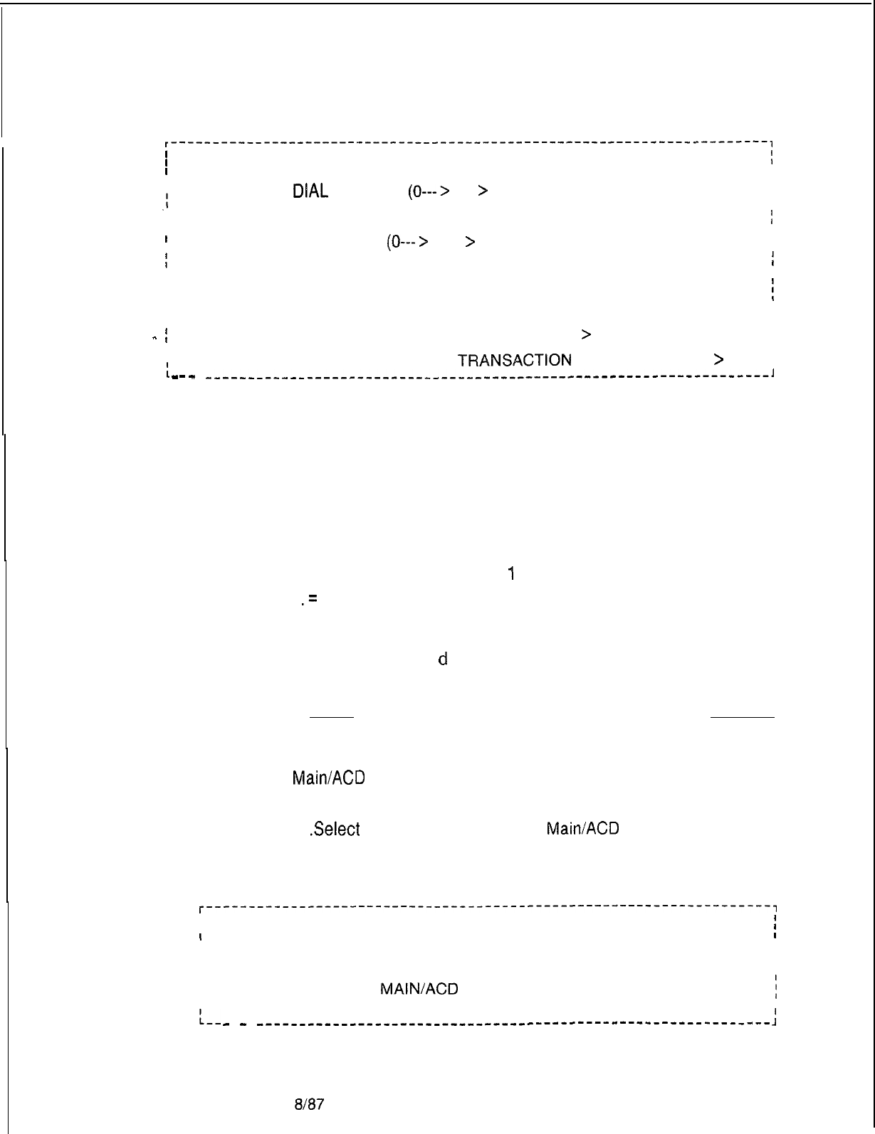
TL-130200-1001
I
r----------------------I--------------------------------------------------~
I
I
I
CHANGE A REPERTORY DIAL KEY SET
82
I
I
II
I
ENTER REP
DlAL
KEY SET
(0--->
3)
>
1.
I
.I
I
I
I
KEY SET 1 IS SHARED BY AGENT GP: l/A 2/A 3/C 4/C
I
I
II
I
ENTER REP DIAL KEY #
(0--->
46)
>
5.
I
I
ICURRENT REP DIAL NUMBER: XXXXXXXXXX.
I
I
I
I
I
NEW REP DIAL NUMBER(16 CHARACTERS MAX) IN DOUBLE QUOTES
:
I
I“95551212”.
I
I
I
-
i
DO YOU WANT TO EXECUTE THIS CHANGE (Y/N)
>
Y.
I
I
II
.I
I
_
ENTER END-(E), REPEAT (R), OR
TRANSACTlON
NUMBER (O-224)
>
I
I
-
-
__--___-_____----___-----------------------------------------------l
where
A= ACD group
B=CAS group
f
= Flash
P
= Pause for dial tone
a
= Key will auto-correct on line 1
b
= Key will auto-correct on line 2
r
= Release
c.
= Key will function on line
1
only
d
.=
Key will function on line 2 only
2. Select the correct transaction,
NOTE: a, b, c, and
d
are mutually exclusive, and, if used, must
appear in the first position:
VALID
A 4566 INVALID
4566 or 4567
Day/Night Mode 8.12 Day/Night Mode Data Menu is accessed through CAS
Data Menu
Main/ACD
Supervisory Recent Change. The following steps are
used to access the menu:
1
.Select
transaction 39 from CAS
Main/ACD
Supervisory Recent
Change.
The system responds:
r-------------------------------------------------------------------,
II
I
DAY/NIGHT MODE DATA 39
i
II
II
I86) DISPLAY DAY/NIGHT MODE I
II
87)
CHANGE DAY/NIGHT MODE OF AGENT GROUP I
I
I
38)
GO TO CAS
MAINIACD
SUPERVISORY RECENT CHANGE MENU
i
I
I
:--
ENTER TRANSACTION NUMBER-->
-
-
---------------__--------------------------------------------
:
M-320
8187
5210
r
-
-
TL-130200-I 001
Display Day/Night
812.1
Mode (86)
This display allows the supervisor to see all agent groups’
day/night mode. An example of this display is as follows:
. .
r----------
---------------‘-----------------------------------------,
I
I
I
DISPLAY DAY/NIGHT MODE 86
\
II
I I
I
AGENT GROUP
#
DAY/NIGHT MODE
I
I I
I
0
DAY
I
I
1
NIGHT
I
L
I
_. I I
I
2
NIGHT
I
I I
I
3
DAY
I
I ~I
I
4
NIGHT
I
I
5
DAY
I
iI
. . I
I
6
NIGHT
I
II
7
DAY
I
I
I
f
ENTER END (E), REPEAT (R), OR TRANSACTION NUMBER (O-224)
>
:
L------~~~~-~~~~~--~~---~~~-~~~~-~~~~---~~~~~~~~~~~--~-~~~~~~~~~~~-~J
Change Day/Night
8.12.2 This display allows the supervisor to change the agent
Mode
(87)
groups’ day/night mode.
r-------------------------------------------------------------------,
I
I
I
CHANGE DAY/NIGHT MODE 87
i
I
I
I
AGENT GROUP
#
(0--->
7)
>
0.
I
I
I
I
I
I
CURRENT MODE: DAY
I
II
I
I
I
NEW MODE (DAY/NIGHT)
>
NIGHT.
I
I
I
DO YOU WANT TO EXECUTE THIS CHANGE (Y/N)
>
Y.
I
I
~_E_N_~ER-_E_N_D-[E~
REPEAT
(~1
0~
TRANSACTION
NUMBER
(0-224)
>
i
L----w-----
L---__---------------------------
-------I
Supervisor
Message Handler
8.13 This display allows the supervisor to see all agent groups.
The Supervisor Message Handler allows the supervisor to send
three different types of communication-directed messages to
the agents’ instruments:
*
Broadcast Message. A broadcast message is sent to all
equipped agent positions.
e
Agent Group Message. This message is sent to all equipped
agent positions in the agent group(s).
o
Agent Message. This message is sent to the agent position(s)
specified.
The supervisor may store messages that are frequently sent in
the SPECIAL MESSAGE TABLE. A total of eight stored
messages is allowed. Additional
Unique
messages are sent by
choosing the appropriate menu.
5210 8187 M-321
TL-130200-1001
Supervisor Message
Options Menu (85)
8.13.1 This menu lists the types of message options the
supervisor can send or update.
..^
I
I
I
SUPERVISOR MESSAGE OPTIONS 85
i
I
I
I
49) SEND SPECIAL MESSAGE I
I
I
f
97) SEND UNIQUE MESSAGE
I
_
I
I
84) DISPLAY SPECIAL MESSAGES II
I
88)
CHANGE A SPECIAL MESSAGE
I
I
I
I
83)
GO TO CAS
MAIN/ACD
SUPERVISOR OPTIONS MENU
I
I
II
f
ENTER TRANSACTION NUMBER-->
I
I
II
Send a Special
8.13.2 This menu describes the actions required to send a
Message (49) special message.
I I
I
I
SEND SPECIAL MESSAGE
49
I
I
I
I
I
I
SPECIAL MESSAGE NUMBER
(0--->
7)
>
2.
I
I
II
I
MESSAGE: CHANGE GROUP
I
I I
I
TYPE OF MESSAGE I
I
I
I
A) BROADCAST
I
I
I
B) AGENT GROUP(S) I
I
I
I
I
C) AGENT POSITION(S) I
I
I
D) NONE I
I
I
I
I
I
ENTER THE LETTER OF THE DESIRED MESSAGE TYPE
>
B. I
I
I
I
I
I
ENTER AGENT GROUP NUMBER(S)
(0--->
7)
>
0 6 7. I
I
I
I
ENTER END (E), REPEAT (R), OR TRANSACTION NUMBER (O-224)
>
;
I
I
I
I
L----------_--------____________________-------------------------------,
Another possible prompt is as follows:
C) AGENT POSITION(S)
-
ENTER AGENT POSITIONS
(up to 16)
(O--.+63)
>
M-322
8187
5210
TL-130200-1001
Send a Unique
Message (97)
8.13.3 This menu describes the actions required to send a
unique message.
r-------------------------------------------------------------------------------~
I
I
SEND UNIQUE MESSAGE
I
I
97
I
II
II
I
I
ENTER MESSAGE (UP TO 16 CHARACTERS) IN DOUBLE QUOTES
>
“message”.
I
II
I
TYPES OF MESSAGE
I
1
A) BROADCAST
I
;
I
.
I
-
I
B) AGENT GROUP(S)
I
1
I
-
C) AGENT POSITION(S)
I
II
ID) NONE
I
II
ENTER THE LETTER OF THE DESIRED MESSAGE TYPE
>
C.
i
I
IENTER AGENT POSITIONS (UP TO 16)
(0---
>63)
>
5 7 20 63. I
II
II
IENTER END (E), REPEAT (R), OR TRANSACTION NUMBER (O-224)
>
I
I
I
I
L---^___-_---_---_--____________________----------------------------------------~
5210
Special Message
Display (84)
8.13.4 The display allows the supervisor to display all special
messages stored in the agent instruments.
r---------------------------------------------------------------------
I
I
I
SPECIAL MESSAGE DISPLAY
84
I
I
I
MSG # MESSAGE MSG
#
I
MESSAGE
I
I
I
I
0
COFFEE BREAK 1LUNCH
I
I
2
END OF SHIFT
3
CHANGE GROUP
I
I
4
NEW NUMBER
5
HARDWARE 316
I
I
6
-
BLANK
-
7
-
BLANK
-
I
I
I
:
ENTER END (E), REPEAT (R), OR TRANSACTION NUMBER (O-224)
>
L----_------_---------------------------------------------------------
8187
M-323
-.:
_...
._
TL-130200-1001
Change Special
8.13.5 This transaction allows the supervisor to change the
Message (88)
special message of a specific agent group.
r----------------------------------------------------------------------~
II
II
I
CHANGE A SPECIAL MESSAGE
88
I
II
I
I
SPECIAL MESSAGE NUMBER
(0--->
7)
>
6.
II
II
I
CURRENT MESSAGE: COFFEE BREAK
I
I
I
.._
I
I
I
I
I
I
NEW MESSAGE (16 CHARACTERS MAXIMUM)
I
-
I
ENTER MESSAGE IN DOUBLE QUOTES
>
“LUNCH BREAK”
I
II
I
I
I
IS
THIS THE SPECIAL MESSAGE FOR LINE TO AGENT GROUP CALLS
;
I
I
>
Y.
I
I
I
I
I
I
DO YOU WANT TO EXECUTE THIS CHANGE (Y/N)
>
Y. I
II
I
CHG SETTING AGT GRP LINE TO SPECIAL MSG NOW I
I
II
IIDO YOU WANT TO EXECUTE THIS CHANGE (Y/N)
>
Y. I
I
I
I
I
ENTER END (E), REPEAT (R), OR TRANSACTION NUMBER (O-224)
>
i
I
I
II
II
L---_------________----------------------------------------------------~
Manual Changes and 8.14
All data base changes should be made using the TTY and
Recent Change
the English language recent change feature. Only if the recent
Summary
change feature is not available should manual data base
(Voice Configuration)
changes be performed. Following are a list of functions and the
Recent Change transactions required for each function. For
cases where Recent Change cannot provide the entire function,
data base tables which must be manually updated and a brief
description of their contents are listed. If a feature or service is
to be added, changed, or deleted, each associated function must
be reviewed for updating requirements. The data base table
layout and list of possible entries are given in the header of each
table in the hard copy printout of the office-dependent data
base. The manual data base changes are made by using the
General Write (GW) or Bulk Input (BI) commands.
M-324
8187
5210
CATEGORY
Access Codes
. .
ACD- Feature Data
^
Agent Groups
Agent Position Data
Attendant Console
.
.
5210
TL-130200-1001
Manual Recent Change (Sheet 1
of
9)
TABLE NO.
NAME
T6241
T6251
Digit analysis for first digit
Digit analysis second digit access
code
T608D
Time-out option table 2
T6391
ACD features table
Add agent group (46)
Change delay routing (61)
Change alternate routing of an agent
grow
(65)
Change call waiting indicator levels
(66)
Change night destination of an agent
group
(45)
ADD/DEL/SHOW miscellaneous
directory number (218)
CHGSHOW
agent supervisor data
(142)
T5961
T5962
ADD/CHG/DEL/SHOW
instrument
data (directory number) (117)
Add Attendant console (181)
Change attendant calling number for
billing (188)
ADD/CHG/DEL/DIS
BLDU (190)
Console MERS time, change
restriction
Console ward time change restriction
Attendant
Miscella-
neous Features
T5931
Miscellaneous attendant system
features
Audit Record Control T6512 Audit record control table
Busy Lamp Display
Data
ADD/CHG/DEL/SHOW
BLDU circuit
(189)
Busy Lamp Key Data
ADD/CHG/DEL/DIS
BLDU (190)
Call Code Data
T6371
Paging and code call
8187
M-325
Manual Recent Change (Sheet 2 of 9)
CATEGORY TABLE NO.
NAME
CAS Branch Features
T636l
RLT class of service
T6381
Camp on recorder-announcer table
CAS Branch Secondary ADD/DEL/SHOW miscellaneous
directory number (218)
Change Feature by
T639D
Change/restore feature primary/
Access Code secondary access code type table
Class of Call Control
T6461
Class of call controlled routing
Routing Data
Code Blocking Numbers
ADD/CHG/DEL/SHOW
MERS Code
Blocking (199)
Code Restriction
T6271
Digit analysis code restriction
Numbers
Common Attendant
Data
Common Attendant/
Attendant Line Number
Customer-Defined
Terminal Data
Dl
/D2
Translation
Data
Displayable Class of
Service
M-326
8187
T6521
T605F
T5981
TL-130200-1001
I
Change common attendant data
(186)
Change night answer for the attendant
(187)
Change attendant features (185)
Attendant assignment for
room-to-
room blocking
ADD/DEL/SHOW miscellaneous
directory number (218)
Customer-defined terminal charac-
teristics
Dl
and D2 translation table
CHGSHOW
displayable class of
service 1 (211)
CHGSHOW
displayable class of
service 2 (213)
5210

TL-130200-1001
Manual Recent Change (Sheet 3 of 9)
DTMF Receiver Data
Expanded or Conflict-
ing Code Check Tables
. .
.=.
FRL Authorization Codes
Frame Image Card
Data
Group Speed Calling
Hotel/Health Care
Miscellaneous Data
Hotel/Health Care
Printer Assignment
Hundreds Data
Hunt Group Data
Hunt Group Member
Data
Intercept Routing
Numbers
International Counting
Code Data
KEDU Assignment Data
5210 Em7
T64 21
T6261
T6471
T6501
T3202
T3202
T6421
T63Wl
T63W2
T63W3
T6482
T3201
T6551
ADD/DEL/SHOW cards (221)
DTMF receiver in service/out of
service
Digit analysis expanded/conflict-
ing code
ADD/CHG/DEL/SHOW
FRL
authorization/destination code (215)
ADD/DEL/SHOW card (221)
ADD/DEL/SHOW group speed
calling group (207)
ADD/ CHG /DEL SHOW
/SHOW
-
WHERE line features 1 (113)
ADD/CHG/DEL/SHOW
group speed
calling list entry (202)
Hotel/Motel miscellaneous data
Change intercept routing destina-
tions (206)
Printer assignment number table
Printer address (PEC 0)
Printer baud rate and parity (PEC 0)
Dl/D2
line (room) number table
Add hunt group pilot numbers (127)
ADD/DEL/SHOW hunt group mem-
ber (126)
Change intercept routing destina-
tions (206)
IDDD
First Digit Check
IDDD
First Two Digit Check
IDDD
First Three Digit Check
KEDU assignment
KEDU address (PEC 0)
KEDU function inhibit
M-327

TL-130200-1001
Manual Recent Change (Sheet 4 of 9)
CATEGORY TABLE NO. NAME
KEDU Special Function
Access Data T5441
Line Appearance
-..
Line Data
Master KEDU Data
MDR Port Data
MDR Screening
Options 1
MDR Screening
Options 2
M-328
T6481
T6491
T6492
T6552
T4451
T4472
T4482
T4473
T4474
T4483
T4484
8187
KEDU special function access
ADD/DEL/SHOW lines on a
Featurephone
ADD/CHG/DEL/SHOW
instrument
data (agent position) (111)
ADD/CHG/DEL/SHOW
instrument
data (line circuit) (146)
ADD/CHG/DEL/SHOW/SHOW-
WHERE line features 1 (directory
number) (113)
ADD/CHG/DEL/SHOW/SHOW-
WHERE line features 1 (agent
position) (115)
ADD/CHG/DEL/SHOW/SHOW-
WHERE line features 1 (line circuit)
(147)
ADD/CHG/DEUSHOW
line features 2
(directory number) (121)
ADD/CHG/DEUSHOW
line features 2
(agent position) (122)
ADDICHGIDELSHOW
line features 2
(line circuit) (123)
Master KEDU number
Master KEDU security code table 1
Master KEDU security code table 2
Master KEDU function inhibit table
MDR SDC control options
MDR terminal billing options table
2
MDR cartridge billing options table 2
MDR terminal billing options table
3
MDR terminal billing options table 4
MDR cartridge billing options table 3
MDR cartridge billing options table 4
5210
5210
Manual Recent Change (Sheet 5 of 9)
CATEGORY TABLE NO.
MERS On-Net station Number
MERS
NPAABC
Translation Data
MERS Routing Line
MERS Sending
MERS Six-Digit
Translated NPA Data
MERS Three-Digit
Translated NPA Data
MERS Time Period
Data
Message Detail
Recorder Data
Nailed Trunk
Connection
N Displayable Class
of Service
8167
T6291
T5951
T548-I
T6301
T6311
T63Yl
T6281
T6291
T5951
i5941
T4441
T4461
TLC471
T448 1
T6151
TL-130200-1001
NAME
Digit analysis on-net reserved
station number table
Digit analysis MERS
NPAIABC
-
translation
MERS time period routing
combination
Digit analysis MERS trunk routing bits
Digit analysis MERS routing list
Digit analysis MERS sending
instruction
MERS FRULDN Indexes
Digit analysis MERS NPA index
Digit analysis MERS
NPAIABC
translation
MERS time period routing
combination
MERS time period data
MDR output device type
MDR call answer time-out
MDR terminal billing options table 1
MDR cartridge billing options table 1
Cabinet IS/OS table
ADDICHGIDELSHOW
nailed trunk
connection (166)
CHGSHOW
N displayable class of
service 1 (212)
CHGSHOW
N displayable class of
service 2 (214)
M-329

TL-130200-1001
Manual Recent Change (Sheet 6 of 9)
M-330
CATEGORY TABLE NO.
NPA and Office Code
Translation Data
Office Equipment
.
.
Office Features
Office Features Circuits
Office Time-Out
Values
Office Timing Values
Other Directory
Numbers
Paging Zone
Prefix Code Digits
Prefix Code Digits
&
LDN
15971
T6231
T6401
T6071
T6151
T7059
T705B
T4441
T5291
T5572
T639A
T5311
T6071
T5346
T2541
T6111
T6134
T5401
T639A
T608M
T6061
T6371
T5321
T63Zl
8187
NAME
NPA and office code translation
Digit analysis office code for billing
System configuration table
Office features table
Cabinet IS/OS table
PEC number table (PEC 0)
PEC type table (PEC 0)
MDR output device type table
NCC interface table
CHGSHOW office features (209)
CHGSHOW system FRL data (219)
MERS FRL default table
Hookswitch flash timing table
Digit analysis public network
authorization digit table
System feature table
CAS
MainlACD
miscellaneous data
Line Card Address Table (PECO)
Miscellaneous circuits in service/out
of service
Music-on-hold interface
Line signaling mode and in service/
out of service
CHGSHOW timeout values (201)
Hookswitch flash timing values
CHGSHOW timeout values (201)
Time-Out option space
ADD/DEL/SHOW miscellaneous
directory numbers (218)
Paging and code call zones
Paging and code call
System prefix digit table
MERS LDN Prefix Digits
5210

Manual Recent Change (Sheet 7 of 9)
CATEGORY TABLE NO.
NAME
Predetermined Night Change predetermined
Answer Pilot number night answer (203)
Recorder Announcer Change recorder announcer (204)
.
.
Remote Access
T6531
Remote access class mark
exchange
^
Authorization
Repertory Dial Key Code Change repertory dial key code (82)
RLT Circuit Data ADD/DE&HOW cards (221)
T6351
RLT equipped status and PEC
T3121
RLT card address (PEC 0)
T3161
RLT trunk type (PEC 0)
T6431
D3iD4
line (room) number
T6441
Line (room) number translation
Room Number First
T6451
Room number first digit table
Digit
SCC Authorization
Codes
Security Lock
Character Data
Serial Device Data
Service Code MERS
Translation
Service Codes
Source Message
Special Messages
5210
8187 M-331
TX003
T6055
T6051
T5571
T5661
T5691
T5701
-
TL-130200-1001
ADD/CHG/DEUSHOW
MERS SCC
-
authorization code (216)
ADD/CHG/DEL/SHOW
MERS SCC
authorization code assignment (217)
System access password table
Security lock
CHGSHOW
terminal data (221)
Serial device controller option
Service code for MERS translation
Trunk group restrictions table
Trunk group 11 N service code
Trunk group
Nil
service code
Change source messages (59)
Change a special message (88)

-
TL-130200-1001
Manual Recent Change (Sheet 8 of 9)
M-332
CATEGORY
Specialized Common
Carrier Data
Supervisor Talk
/
Monitor Repertory
Dial Key Code
Tone Detector Data
Traffic Data Facilities
Transaction Record
Control
TABLE NO.
T6001
T6012
T5080
T5336
T5349
T6041
T6511
Trunk Circuit Data
T6321
T6331
T5541
T5471
Trunk Group Data
8187
T5641
T5661
15711
T5721
T5741
T5751
T5771
T5991
T6341
NAME
Specialized common carrier digit
sizing length
Specialized common carrier access
digits
Specialized common carrier timing
Supervisor talk/monitor repertory
dial key code
Supervisor silent monitor repertory
dial key code
ADD/DEL/SHOW card (221)
Traffic data option
Transaction record control
Add a trunk (153)
Change trunk characteristics (158)
Change source group of a trunk (53)
Tl
trunk in service/out of service ta-
ble
Tl
trunk map
Trunk
AIOD
trunk number table
Trunk to CO line table
Add a trunk (153)
ADDCHG
trunk group characteristics
1 (161)
ADD/CHG/SHOW
trunk group
characteristics 2 (169)
Trunk group direction, disconnect
supervisor application
Trunk group restrictions
Trunk group ACD pilot number
Trunk group calling number for billing
Trunk group missing digits on DID
Trunk group
AIOD
channel and
reverse battery check
Trunk group 1
+
toll restriction index
Trunk group delete digit on DID
Trunk group miscellaneous flags
5210

TL-130200-1001
Manual Recent Change (Sheet 9 of 9)
CATEGORY
Trunk Group Data 2
TABLE NO.
T5661
T5671
15681
T5751
T5761
T5771
T5791
T5801
T5811
T5821
T5831
T5841
T6341
T6541
Trunk Group Digit
Absorption Data
T5781
Ward Control Data T5944
T6195
NAME
ADDCHG
trunk group characteristics
1 (161)
ADDICHGISHOW trunk group
characteristics 2 (169)
Trunk group restrictions
Trunk group first toll access code
Trunk group second toll access code
Trunk group
AIOD
channel and
reverse battery check
Trunk group toll restriction index
Trunk group 1
+
toll restriction index
Trunk group MERS escape digit
Trunk group MERS pausing value
after seizure
Trunk group MERS pausing value
after escape digit
Trunk group MERS Pausing after toll
barrier code
Trunk group trunk momentary open
Trunk group outpulsing delay
Trunk group miscellaneous flag
Trunk group message peg indicator
Trunk group digit absorption table
Ward DND time period data
Ward control activation/deactivation
Typical Recent Change
8.15 Typical recent change functions are listed below along
Sequences
with a sequence of transactions needed to complete the function.
5210 8187
M-333
TL-130200-1001
Table 8.1 Recent Change Sequences
FUNCTION TRANSACTION
NUMBER
.
Display several lines
(or all agents). 117 (or 111,146)
113 (or 115,147)
_.
and 121 (or 122,123)
._^
Add a POTS phone with
117
default value.
Add Digital Integrated
117,113.118
Featurephone (DIFP).
Add another line
appearance to an
existing DIFP.
118
Delete
a
DIFP. (a) 118, 113,
117
or
(b) 118, 146,
147
or
123
Delete
a
non-primary
control line. 113 or 121
Delete a line
appearance.
118
Add a switch direct line
(hot line).
117 (or 146)
113 (or 147),
211
Delete
a
switch direct (a) 113,
117,
or 121
line (hot line). (b) 146,
147,
or 123
M-334
8187
COMMENTS
Three transactions are
needed to display all data
items for a line or sequence
of lines.
Add instrument data
Same transactions as
for POTS phones. Add
more line appearances if
necessary
The line must already have
been defined CPG or 113.
Add line data.
Delete all data associated
with the line by line circuit.
Delete all data associated
with the line. First, delete all
line appearances. Then,
delete phone as for POTS.
Remove the appearance.
Add a line which is set to
always divert to another
station. Class of service
must be properly set.
Delete all line data by
directory number.
Delete all line data by
line circuit.
5210
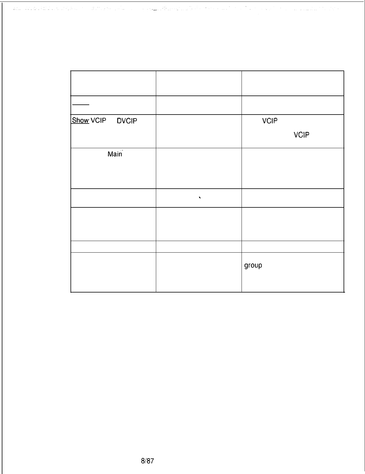
r
5210
8187
M-335
TL-130200-1001
Table 8.1 Recent Change Sequences (Continued)
FUNCTION TRANSACTION
NUMBER
COMMENTS
Show CIP card location
and assigned ports. 221,146 Show CIP card location
ShowVCIP
or
DVCIP
card location and
assigned ports.
221
146
Show
VCIP
or DVCIP card
location.
Show lines on a
VCIP
or
DVCIP card.
Add a CAS
Main-
or
ACD agent.
111
115
43
142
Add instrument data.
Add line feature data.
Add agent group
Change supervisor
status association.
Delete a CAS Main
or ACD agent. 115 (or 111)
_
Delete phone.
Add Asynchronous
Packet Manager (APM)
or Synchronous Packet
Manager (SPM).
146
Add data device.
Delete APM or SPM.
Add a NIC
146
221, 161
153,168
Delete data device.
Add a trunk to a NIC trunk
group
Add a trunk to a NIC trunk
group and set up a
nailed connection.

THIS PAGE IS INTENTIONALLY LEFT BLANK.
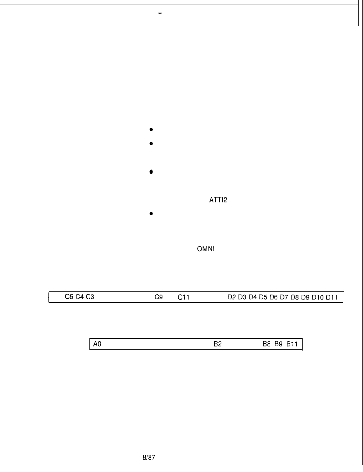
-
TL-130200-100-t
OFF-LINE
9.0 The off-line maintenance disk contains the software for
DIAGNOSTICS
conducting off-line diagnostic testing. Diagnostic tests are only
performed on off-line equipment because the generic and data
base software are voided when the maintenance disk is is loaded
into the system.
The following tests are conducted using the Off-Line
Diagnostics Testing Program:
*
Line Cards and Direct-Inward-Dialing (DID) Trunk Cards
0
System Memory
o Channel Memory
0
Network
o Disk Drive
l Page, Tone, and
ATT12
Cards
o
Touch-Calling Receivers
Physical Locations
9.1 During off-line diagnostic testing, the technician must, at
times, enter physical locations according to file, group and card
slot number. The
OMNI
SI universal card slots are organized
according to PCMUS Group (letters A, B, C and D) and card slot
number (numbers 0 thru 11). The universal line/trunk slots are
labeled as follows:
1 C6
C5C4C3
C2 Cl C7 C8
C9
Cl0
Cl1
DOD1
D2D3D4D5D6D7D8DgDlODll
EXPANSION FILE
5210
A0
A2 A4 A7 A8 A9 A10 All BO
82
B3 B5 B7
88
B9
Bll
GET STARTED FILE
Test Options Menu
9.2 Menu numbers are assigned to each test option. In order to
run a certain test, the technician types in the menu number on
the maintenance terminal and follows the program prompts. The
menu of test options for off-line diagnostic testing appears in
Table 9.1.
8187
M-337
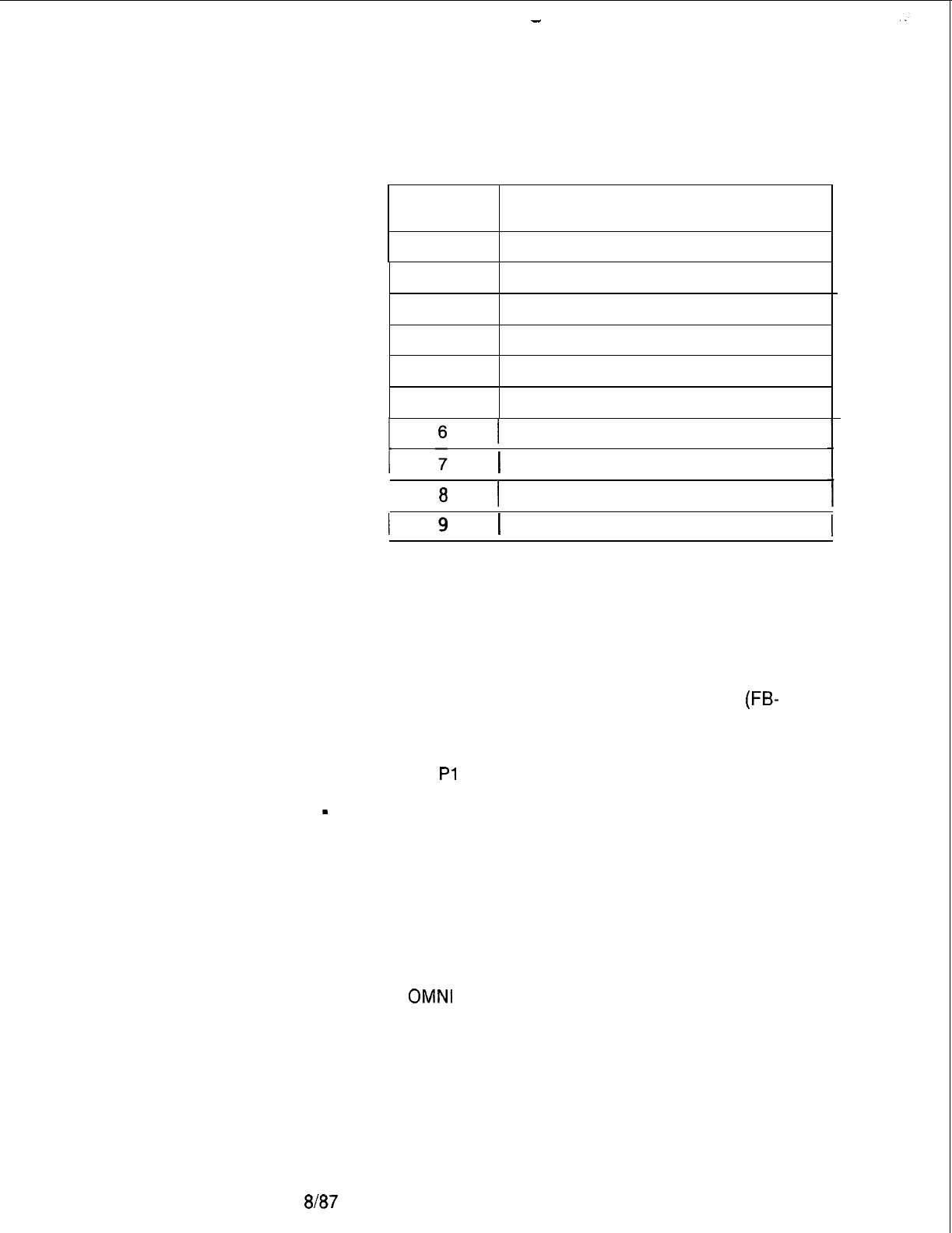
-
TL-130200-1001
Table 9.1 Menu of Test Options
Menu No. Test Option
0
SYSTEM MEMORY TEST
1
CHANNEL MEMORY TEST
2
PAGING CARD TEST
3
NETWORK TEST
4
DISK DEVICE TEST
5
SERIAL DEVICE CONTROLLER TEST
I
TONE CARD TEST
1 ATT12 CARD TEST
I
8
I
LINES/TRUNKS TEST
1 TOUCH CALLING RECEIVER TEST 1
Loading the Program
9.3 The following steps load the Off-Line Maintenance
Program:
1. Place the program disk into the disk drive.
2. Connect the maintenance terminal to the NSDC card
(FB-
20992-A), port 0.
3. Press the reset button on the PSUPY card (FB-17197-A)
located in slot
Pl
of the cabinet power file.
-
Flashing red LED on the disk drive indicates the program is
loading into the system.
4. Program loads into system memory on instruction page 1.
5. When the program has been loaded, set the baud rate at 300,
or 1200. Press the return key to lock in the baud rate.
6. The terminal display appears:
THE GTE
OMNI
SI DIAGNOSTIC DISK
DOES THIS SYSTEM HAVE AN EXPANSION FILE?
IF YES, TYPE “Y”, IF NOT TYPE “N”.
M-338
8187
5210
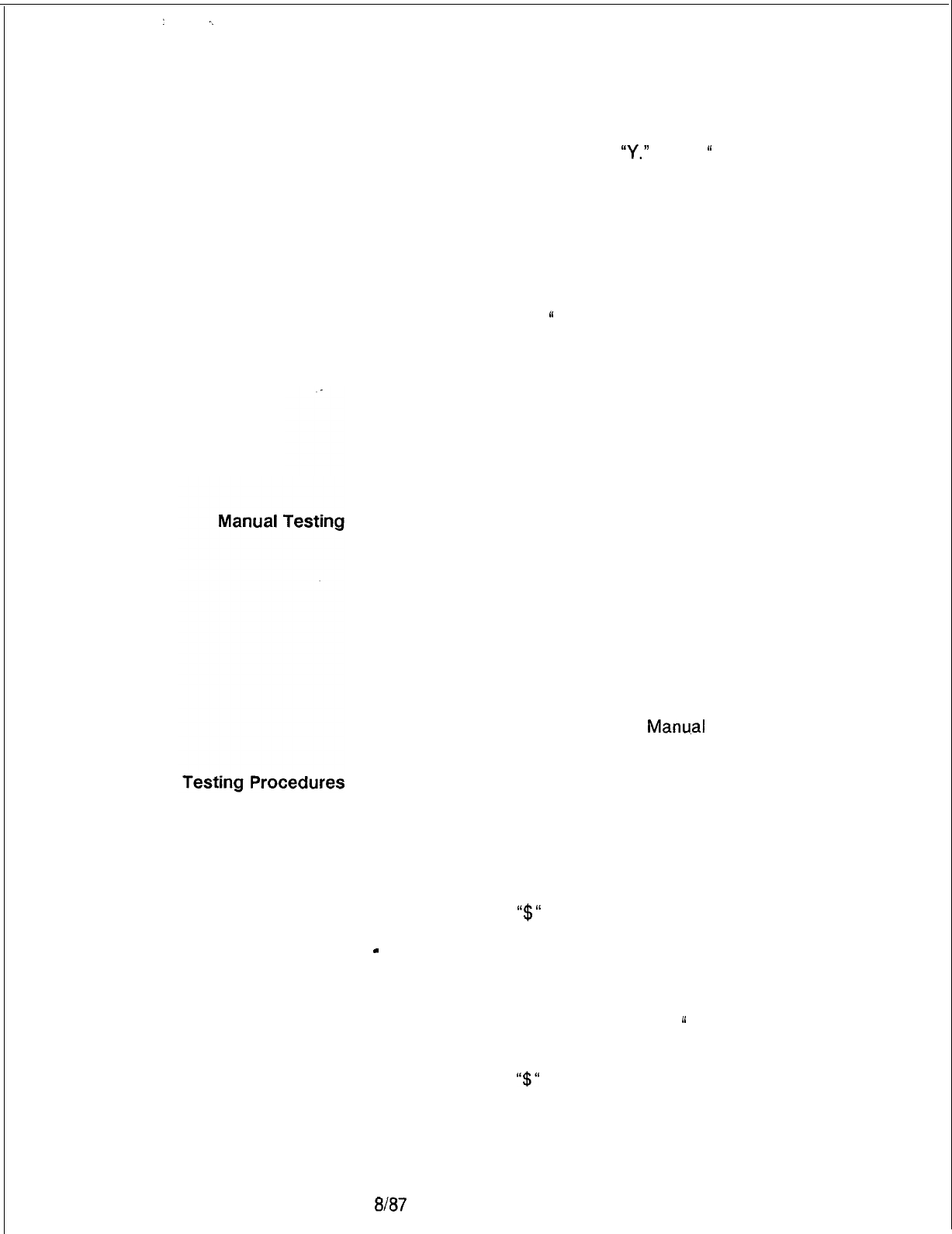
:._
TL-130200-1001
7. Answer the prompt by typing
“Y.”
or “N.
“
The Menu of Test
Options appears on the terminal display screen. Choose the
test and type the menu number.
8. The test selected runs with the results shown on the terminal
screen
NOTES:
1. Type “CONTROL-C
“
to abort a test. The Menu of Test
Options appears on the terminal screen.
5210
2. Type “CONTROL-X” to restart a System Memory or Channel
Memory test. This entry also aborts other diagnostic tests.
3. Except for the System Memory test, any test can be
immediately repeated. After completing one test, the user can
select another from the menu list when it appears on the
screen.
9.4 Memory tests identify failures in cards. The programs work
by writing various test patterns into memory and reading them
back after a default or user-specified delay. Memory testing is
entirely automatic or partially manual/partially automatic. If
entirely automatic, defaulted or modified time delays are used.
Manual testing detects soft memory faults in which CPU
operation is interrupted for a time period set by the user. Manual
testing consists of the first two of a set of four tests used in
memory testing. The first two tests write data patterns “00” and
“FF” throughout the entire memory range with a user specified
delay between the write and read.
Manu.al
testing runs with all
pages or just one page, and with all ranges or just one range.
The following events occur as part of manual testing:
1. Type in first test pattern “00”
2. Terminal indicates that CPU is in waiting state.
3. Wait for desired amount of time delay between write and read
functions. Type
I‘$“
to begin read-back portion of test.
-
Card is tested for memory storage ability. Test results are
displayed on the terminal screen.
4. WAIT message reappears on terminal screen. Repeat process
by typing in second test pattern “FF.
“
5. Wait for desired amount of time delay between read and write
functions. Type
I‘$“
to begin read-back portion of the test.
Results are displayed on the terminal screen.
8t87
M-339
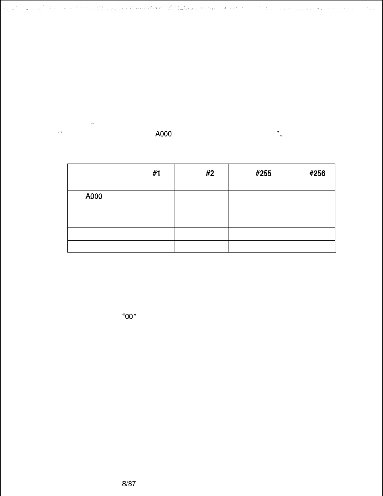
TL-130200-1001
Automatic Testing
9.5 After all manual tests are completed, the program changes
over to automatic testing with test results displayed as before.
Automatic testing repeats tests one and two under CPU control
with a one-second delay between write and read. Test three
writes all possible data patterns into each address location with
data in the adjacent address location incremented by one.
Example:
.
.
If address
A000
contained a data pattern of “01
“,
successive
address locations in test three appear as follows:
M-340
Address
A000
A001
A002
A003
A004
Pass
#l
Data
01
02
03
04
05
Pass #2
Data
02
03
04
05
06
Pass #255
Data
FF
00
01
02
03
Pass #256
Data
00
01
02
03
04
Every address location is tested with every data pattern. Tests
are also conducted for internal memory chip errors such as
multiple address activation, adjacent memory cell interaction,
and data bridging. All 256 individual write/read trials are
performed in test three with the data base pattern “01“ through
“00”
displayed during each testing sequence.
Test four increments the data written into each block of one
hundred hexadecimal addresses. Checks are made for address
decoding errors, multiple memory chip activations, and memory
location with all possible data pattern combinations. As with test
three, 256 individual trials are performed with the data base
pattern displayed during each sequence. Test results are
displayed at the end of the trial sequence following test three and
test four.
The delays for all tests can change to meet certain conditions.
Tests one and two default to one second between write and read.
Tests three and four are set not to delay because of the time
involved in writing all possible combinations in all memory
locations. If the delays are changed in tests three and four, the
time it would take to run these tests could be extremely long.
8167
5210

TL-130200-1001
Fast Test Option
Retest Option
System
Memory Test
9.6 Fast test option reduces the amount of time spent running
memory tests. This is done by using a shorter data pattern which
reduces the number of patterns written to memory in tests three
and four.
9.7 Automatic testing restarts the retest option if no failures have
occurred. If a failure does occur, testing stops and the results of
all ranges are displayed in circular order.
9.8 This test checks the ability of system memory to
store information on the One Megabyte Memory card
(FB-
17314-A -lA) and the Multiprocessor Buffer 8085 card
(FB-
17215-A). One memory page, or part of a memory page, can
be selected for testing. The “all or one page“ option selects the
number of pages. The “page set“ option selects the exact page.
The amount of memory tested is defined by range numbers.
System memory is divided into blocks of memory addresses
called ranges with each assigned a number used for memory
testing purposes only. The blocks of memory addresses and
range number assignments appear in Table 9.2.
There is a relationship between range numbers and their
physical location on a circuit card. Excluding part of the memory
from testing limits the amount of information about the card. Full
memory tests should be run in order to obtain as much
information about the card as possible.
The System Memory Test cannot be repeated without loading the
maintenance disk into memory. The memory content is the last
test pattern used in the actual test when the System Memory Test
is completed.
5210
8f87
M-341
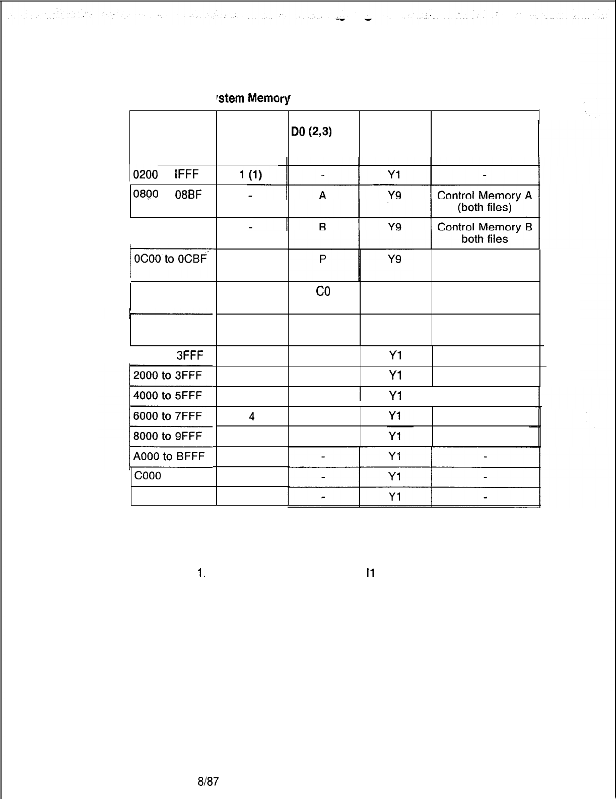
TL-130200-1001
Table 9.2 S
‘stem
Mema
r
Test Card and Address Range Correlation
IO-17
Dl-D7
Range No.
Address
Range
Do
(2,3)
Range No. Card Slot
Function
I0200
to
IFFF
0860
to
08BF
1
OAOO to OABF
/OCOO
Pad Memory
(both files)
1000 to 13FF
co
Y5 Common Memory
Get Started File
Cl Y4 Common Memory
Expansion Fife
1400 to 17FF
( 2050 to
3FFF 2
Yl
Yl
2
3
I
Yl
I
4
5
6
7COO0
to DFFF
EOOO to FFFF 8
NOTES:
1.
Range 1 does not exist for Il.
I1
contains the Off-Line
Diagnostic Program at range 1 during the test.
2. Ranges A, B, and P will always be tested.
3. Ranges CO and Cl are tested only if data page 0 is tested.
Range 0 is tested if common memory tests were specified.
Range Cl is tested if both common memory tests were
specified and the Expansion File was specified in the system’s
configuration when testing was started.
M-342
8187
5210
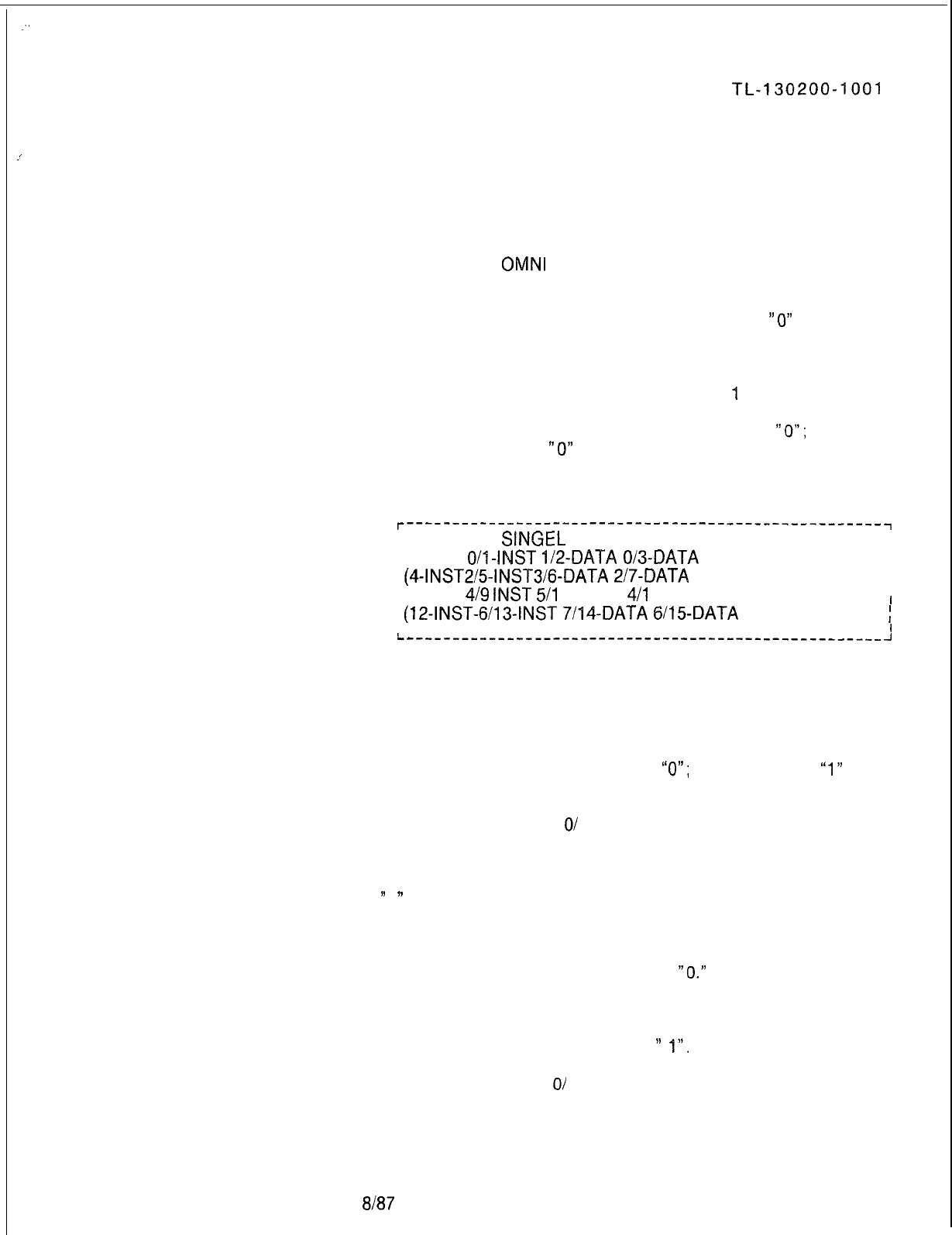
:
TL-130200-1001
_’
System Memory
9.8.1
Testing Procedures
Use the following steps to conduct the System Memory
Test:
1. Select option “0“ from the Menu of Test Options. The system
responds:
Fujitsu GTE
OMNI
SI SYSTEM MEMORY TEST
TO DEFAULT ALL VALUES TYPE 0 OTHERWISE TYPE 1
2. If all values are to stay at their default values type
“0”
If not,
type “1.” If a “0” value was typed, the test begins. If a “1” was
typed, the system responds:
ALL PAGES TYPE 0; OTHERWISE TYPE
4
3. If all data and instruction pages are tested, type a
“0”;
otherwise, type “1” If
“0”
was typed, go to step 5; otherwise,
the system responds:
r----------------------------------------------------~
; TO TEST A
SINGEL
PAGE, TYPE PAGE #
I
I
; (0-INST
O/l-INST
l/2-DATA
O/3-DATA
1)
I
I
;
(4-INST2/5-INST3/6-QATA
2/7-DATA
3)
I
I
; (8-INST
4/9
INST
5/l
0 DATA
4/l
4 -DATA 5)
I
I
;
(12-INST-6/13-INST
7/14-DATA
6115~DATA
7)
I
I
I
L,---------------------------------------------------~
4. Type the number that matches the page tested. The system
responds:
FOR COMMON MEMORY TEST TYPE 0 /NO TEST TYPE 1
5. If common memory is tested, type
“0”;
otherwise, type
“1”
The
system responds:
FOR RETEST TYPE
O/
SINGLE TYPE 1
6. If testing is to continue after a complete pass on all pages and
ranges selected, type “0.” If only one pass is desired, type
”
1 ” .
The system responds:
TO RUN FAST TEST TYPE 0 LONG TEST TYPE 1
7. If the short memory test is used, type
“0.”
The short test does
not do any of the extensive address checking, nor does it have
a delay between the write and read of a memory location. The
short memory test detects all hard errors and some soft errors.
If the normal test is desired, type
”
I”.
The system responds;
5210 8187
M-343
AUTO TEST TYPE
01
MANUAL TYPE 1
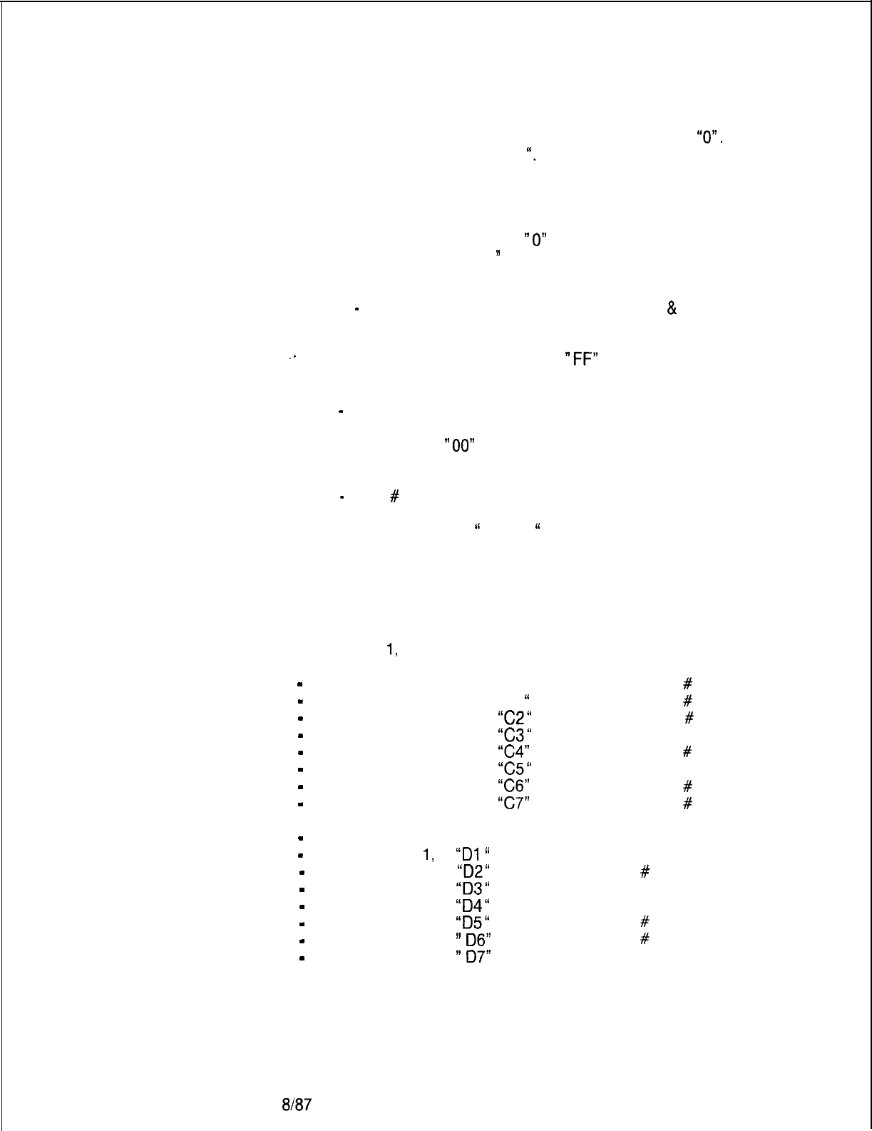
TL-130200-1001
8. If automatic delay (under system control) is used, type
“0”.
For manual time delay, type “1
“.
The system will respond:
TO DEFAULT INTER TEST TIME DELAY TYPE 0,
OTHERWISE TYPE 1
9. If default values are used, type
“0”
and tests begin. If other
time values are used, type
”
1.” The system responds:
FOR EACH TEST’S DELAY TIME, TYPE TWO DIGITS:
XX
-
FOR # OF SECONDS DELAY IN TEST 1
&
2
10.
Enter values from “00“ to “FF” for the time delay on tests 1
‘*
and 2 (“00” means no time delay,
“FF”
means 255
seconds). The system responds:
XX
-
FOR # OF SECONDS DELAY IN TEST 3
11.
Enter values from
“00”
to “FF“ for the time delay on test 3.
The system responds:
XX
-
FOR
#
OF SECONDS DELAY IN TEST 4
12.
Enter values from “00
“
to “FF
“
for the time delay on test 4.
Test Results
9.8.2 All of the test results described may not appear since they
depend on how the System Memory Test was set up. A
response should appear for each range tested.
1. Page location and range number are printed as each range
passes test
1,
2, 3, and 4. The pages appear as follows:
-
For Instruction Page 0, a “CO” precedes the range
#
-
For Instruction Page 1, a “Cl
“
precedes the range
#
-
For Instruction Page 2, a
“C2”
precedes the range
#
-
For Instruction Page 3, a
“C3“
precedes the range #
-
For Instruction Page 4, a
“C4”
precedes the range
#
-
For Instruction Page 5, a
“C5“
precedes the range #
-
For Instruction Page 6, a
“C6”
precedes the range
#
-
For Instruction Page 7, a
“C7”
precedes the range
#
-
For Data Page 0, a “DO” precedes the range #
-
For Data Page
1,
a
“Dl
I‘
precedes the range #
-
For Data Page 2, a
“D2”
precedes the range
#
-
For Data Page 3, a
“D3“
precedes the range #
-
For Data Page 4, a
“D4“
precedes the range #
-
For Data Page 5, a
“D5”
precedes the range
#
-
For Data Page 6, a
”
D6”
precedes the range
#
-
For Data Page 7, a
”
D7”
precedes the range #
2. If a failure does occur, the following sample message appears
on the terminal screen:
8187
5210
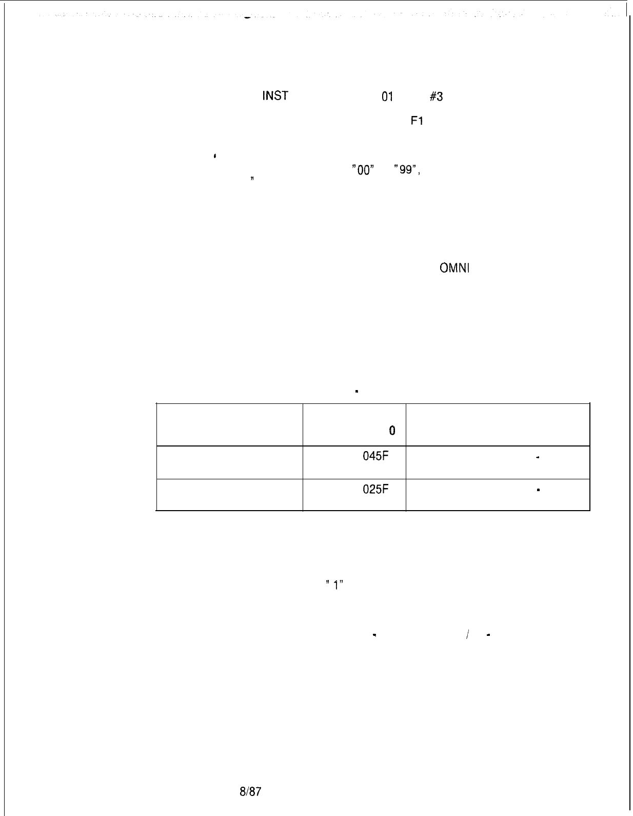
5210
l-L-1 30200-l 001
INST
PAGE 0 RANGE
01
TEST
#3
MEMORY FAILURE LOCATION IS: 5FE0
DATA: WRITTEN FO READ
Fl
3. A pass count occurs after all ranges selected for testing are
*
completed and a retest requested. The count appears in
decimal, runs from
“00”
to
“99”,
and repeats beginning at
”
00.”
4. Testing stops on the range for that pass only when a failure
occurs. At the start of each pass, all ranges selected for
testing are retested if the retest option was selected.
5. If a failure occurs on ranges CO and Cl, replace the MPB85
card (FB-17215-A) and cable in the
OMNI
SI Get Started
File and then the Expansion File. Reinstall the original card if
the replacement does not fix the problem.
Channel Memory Test
9.9 This test checks the ability of the channel memory to store
information on the Channel Memory 8085 card (FB-17218-A).
None, one, or both channel memories can be tested. In order to
test both channels memories, an Expansion File is needed.
Table 9.3 Channel Memory Test
-
Card and Address Range Correlation
Card Slot Address Range
on Data Page
0Function
Y15 0400 to
045F
Channel Memory
-
Get Started File
x01 0200 to
025F
Channel Memory
-
Expansion File
Channel Memory
9.9.1 Use the following steps to conduct the Channel Memory
Testing Procedures
Test:
1. Select option
”
1”
from the Menu of Test Options. The system
responds:
CHANNEL MEMORY TEST
ENTER EACH FILE (0
-
GET STARTED
/
1
-
EXPANSION)
THAT IS TO BE TESTED, THEN A (CR)
8187
M-345

2. Enter a “0” if the Get Started File is tested and/or a “1” if the
Expansion File is tested, followed by a (CR). If both files’
channel memories are tested, type “01”. If all files are
selected, then a (CR) is not needed. The system responds:
FOR RETEST TYPE 0; OTHERWISE TYPE 1
3. Now refer to step five of the System Memory Test procedures
and continue (paragraph 96.1).
.:
Test Results 9.9.2 All of the test results described may not appear since they
depend on how the Channel Memory Test was set up.
1
LAS
each file is finished with a pass, the message “PASS”
along with the pass number is displayed under each file’s
header. The pass number is incremented by one with each
pass. The count is reset to 00 after reaching 99 if multiple
tests are requested.
EXAMPLE:
A successful single test for both files causes the following
message to be displayed:
FILES: GET STARTED EXPANSION
PASS 00 PASS 00
2. An error message giving the file and test which failed, the
locations where the failure was detected, and the data written
versus the data read is displayed on finding a failure. The
error message appears as follows:
GET STARTED FILE
TEST
#l
MEMORY FAILURE LOCATION: 0400
DATA: WRITTEN AA
READ FF
3. The entire range(s) are tested.
Paging Card Test
9.10 This test checks the Memory Paging 16 Page card
(FB-
17213-BOA)
for wrong settings or multiple writes. One
memory location for each range on a page is checked. Memory
addresses are initialized to “FF“ and then the page number of
that particular page is written. The memory is checked for
proper numbering and cross-checked for duplicate writes. All
memory pages are thus checked for no writes or duplicate
writes.
Paging Card
8.10.1 The following action begins the Paging Card Test:
Testing Procedures
Select option “2” from the Menu of Test Options and follow the
procedures.
8187
5210

TL-130200-1001
Test Results
9.192
After completion of the Paging Card Test, the system
responds with the following :
1. With successful completion of the test the system responds:
PAGING CARD PASSES TEST
2. Memory read-after-write error on instruction page 0,
memory address 1100. The system responds:
MEMORY WRITE FAILURE ON PAGING TEST
PAGE 00
MEMORY FAILURE LOCATION IS: 1100
3. Paging failure in which page write went to Instruction Page 1
instead of instruction page 0 writing to range
#l.
The system
responds:
PAGING CARD FAILURE
CORRECT PAGE
#
00 INCORRECT PAGE
#
01 RANGE
#l
MEMORY FAILURE LOCATION IS: 1100
5210
Network Test
9.11 This test checks the networking capability of the Channel
Memory 8085 card (FB-17218-A). The card test follows:
1. Control memories for a time slot are written to return a PCM
sample.
2. “FF“ is written into channel memory for that time slot. When it
recognizes the “FF”, the card sends the test “10101010” ,or its
inverse to the network and expects the same thing back during
the time slot. The pattern is inverted for the next frame. A
failure latch is set if the test pattern is not returned correctly.
Network Testing
9.11.1
Use the following steps to conduct the Network Test:
Procedures
1.
Select Option
”
3” from the Menu of Test Options. The system
responds:
NETWORK TEST
2. The system runs the Network Test.
Test Results
9.11.2 Depending on the results, the system responds in the
following manner:
1. If the network test was successful, the system responds:
NETWORK PASSES TEST
8/87
M-347
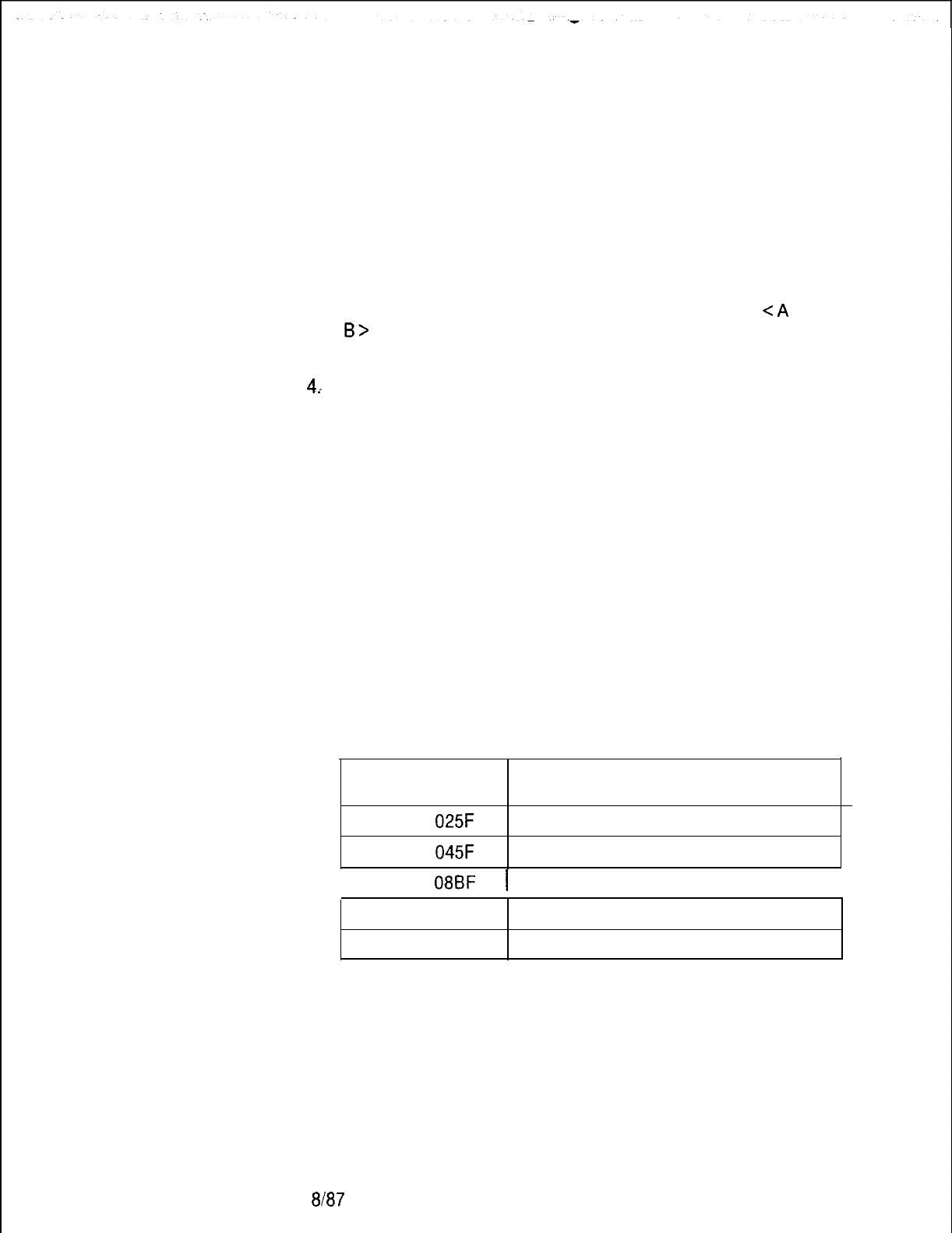
TL-130200-1001
2. If the channel memory was not initialized, the system responds:
NETWORK FAILURE: CAN’T WRITE TO CHANNEL
MEMORY
TESTING STOPPED DUE TO THE ABOVE ERRORS
3. If control memories A or B were not initialized, the system
responds:
NETWORK FAILURE: CAN’T WRITE TO CONTROL
<A
OR
B>
TESTING STOPPED DUE TO THE ABOVE ERRORS
4..
If pad memory was not initialized, the system responds:
NETWORK FAILURE: CAN’T WRITE TO PAD MEMORY
TESTING STOPPED DUE TO ABOVE ERRORS
5. If channel, control, or pad memory was not read, testing ends
and the system responds:
READ AFTER WRITE FAILURE
MEMORY FAILURE LOCATION IS: XXXX
6. If network failure occurs three times, the system responds:
NETWORK FAILURE: ADDRESS = XXXX
XXXX is the memory address at which the fault is located.
Use the following table to determine which card caused the
failure:
Memory Address Problem Area
M-348
0200 to
025F
0400 to
045F
Expansion File Channel Memory
Get Started File Channel Memory
I0800 to
08BF
1 Control Memory A
I
OAOO to OABF
Control Memory B
OCOO to OCBF
Pad Memory
NOTE: A network failure occurs if there is a problem writing to
channel, control, or pad memory, or if the latch bit returned
during the test indicates failure.
8187
5210
TL-130200-1001
Fault Correction
9.11.3 The following steps correct faults detected by the Network
Test:
1. If the problem was found to be initializing or writing to channel,
control, or pad memory, replace the Channel Memory 8085
card (FB-17218-A). Reinstall the original card if the problem
continues after replacement.
2. Repeat the Network Test.
3. If the failure continues, check all cabinet cables for short
circuits. If an open is found, replace the faulty cable and rerun
the Network Test.
NOTE: Steps 4, 5, and 6 are used if there was no initialization or
write check error.
4. Replace the Expandable Pulse Code Modulation Network card
(FB-17217-A) and repeat the Network Test. Reinstall the
original card if the problem continues after replacement,
5 Replace the Intermediate Network Clock card
(FB-20771-
1A)
or Synchronized Intermediate Network Clock card
(FB-
20922-A) and repeat the Network Test. Reinstall the original
card(s) if the problem continues after replacement.
6. Perform the System Memory Test.
Disk Device Tests
9.12 These tests check the operation of the disk subsystem
including the File Management System Data card
(FB-17229-
BOA), the disk drive, and the Administrative Maintenance
Processor A (FB-17229-A) and B (FB-17230-BOA) cards.
Diagnostic tests of the disk subsystem sends sequences of
command messages to the FMSD card. Status messages and
other outputs returned by the File Management System measure
the successful execution of each command. Because of the
nature of these tests, successful completion means that the
tested devices are fully operational.
Disk Device Testing
9.12.1
Use the following steps to conduct Disk Device Tests :
Procedures
1. Select option
“4”
from the Menu of Test Options. The system
responds:
DISK DEVICE TESTS
2. The system conducts a test of the File Management System
(FMS) to CEC communications link. This enables further
non-destructive testing. The system also conducts a check
of the on-board FMS RAM, and an equipment status check
for site configuration.
5210 8187
M-349
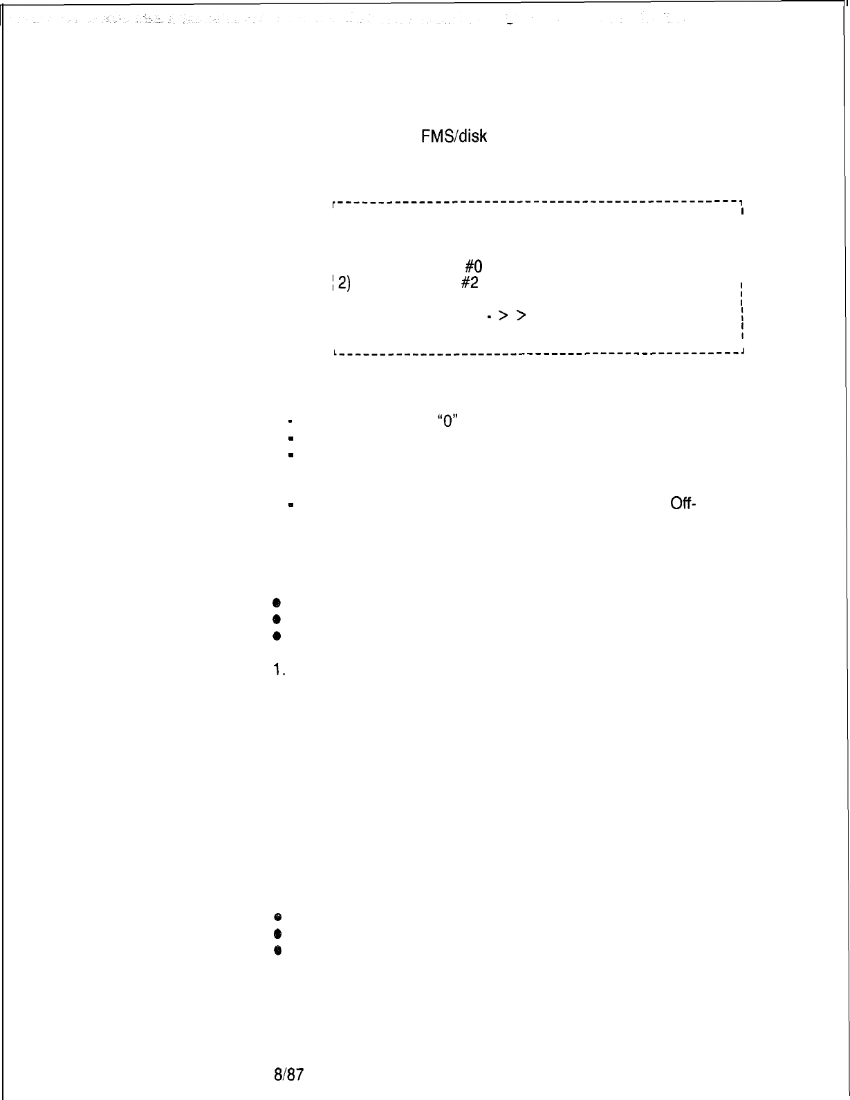
TL-130200-1001
3. Verification of the
FMS/disk
communications link generates the
following menu:
I-------------------------------------------------,
I
I
/ DISK DEVICE TEST SELECTION MENU
I
I
I
) 0) REPEAT FMS TEST
I
I
I 1) TEST DEVICE
#O
(10 MBYTE FIXED)
I
I
I2)
TEST DEVICE
#2
(800 KBYTE)
I
I X) RETURN TO MAIN OFF LINE DIAGNOSTICS MENU
i
) ENTER SELECTION
-
>
>
I
I
I
!
I
I
L---___------__-----------------------------------,
-
Selection of option
“0”
repeats the FMS test (on-line)
-
Selection of option “1” repeats the FMS test (on-line) .
-
Selection of option “2“ executes tests of the 800 Kbyte
floppy disk (on-line)
-
Selection of Option “X“ returns the user to the Main
Off-
Line Diagnostics Menu
Repeat FMS Test 9.12.2 Repeat FMS Test (Option 0) instructs the system to
repeat the following tests:
*
FMS to CEC communications test
*
FMS RAM test
0
Poll for FMS disk configuration
1.
Progress of the test appears on the terminal screen as the
system completes each step:
FMS TEST IN PROGRESS....
PERFORMING FMS COMMUNICATION TEST
PERFORMING FMS RAM TEST
POLLING FMS FOR DISK CONFIGURATION
FMS TEST SUCCESSFULLY COMPLETE The system then
displays the “DISK DEVICE TEST SELECTION MENU”
prompt.
2. An error detected in any part of the FMS Test results in the
following:
e
Display of an error message
@
Termination of FMS Test
o
Display of “DISK DEVICE TEST SELECTION MENU” without
option 1.
M-350
8187
5210
TL-130200-1001
5210
3. Examples of FMS Test error messages include:
. FMS COMMUNICATIONS ERROR
PERFORMING
FMS
COMMUNICATION TEST
ERROR DETECTED WHILE PERFORMING FMS
COMMUNICATION TEST
FMS TEST ENDED
l FMS RAM ERROR
PERFORMING FMS RAM TEST
ERROR DETECTED WHILE PERFORMING FMS RAM TEST
FMS TEST ENDED
o
FMS CONFIGURATION ERROR
POLLING FMS FOR DISK CONFIGURATION
ERROR DETECTED WHILE POLLING FMS FOR DISK
CONFIGURATION
FMS TEST ENDED
l DISK TEST MENU WHEN FMS TEST FAILS
DISK DEVICE TEST SELECTION MENU
0) REPEAT FMS TEST
X) RETURN TO MAIN OFF-LINE DIAGNOSTIC MENU
ENTER SELECTION
>
>
Test Device
#O
9.12.3 Test device
#O
(option 1) instructs the system to perform
a read/write verification for the FMS and the hard disk
(10MBYTE
Fixed Disk). The hard disk must be verified prior to starting the
test. If the test is performed on a drive which is not formatted, the
test will fail.
Testing fixed disk devices begins with a request to the controller
board to execute its on-board diagnostic programs. These
programs test the disk drive controller, its on-board RAM
memory, and the disk drive. Successful completion of these
tests ensures that the controller is communicating with File
Management Systems (FMS) and that the disk is properly
formatted.
Following the successful completion of the controller’s on-board
diagnostic programs, a test file containing up to 2,500 records is
created. Data is written to the disk and then read back to prove
the disk’s rear and write capabilities. After reading all records
from disk, the
?st
file is deleted and the fixed disk test
terminated.
8187
M-351
The above steps generate the following messages as the system
completes each operation:
~-------------------------------------------------------------~
! FIXED DISK DEVICE TEST IN PROGRESS....
I
1 PERFORMING DISK CONTROLLER DIAGNOSTICS
I
I
I
-
STILL PERFORMING DISK CONTROLLER DIAGNOSTICS
:
I DELETE TEST FILE
j
DETERMINING
DISK
FREE SPACE
ICREATING TEST FILE
/ WRITING TO TEST FILE
I
STILLWRiTiNG
TO TEST FILE
I
ISTILLWRITING TO TEST FILE
I
I
I
STiLLWRiTiNG
TO TEST FILE
I
ISTILLWRITING TO TEST FILE
I
I
STILLWRiTiNG
TO TEST FILE
I
ISTILLWRITING TO TEST FILE
I
ISTILLWRITING TO TEST FILE
I
ISTILLWRITING TO TEST FILE
I
ISTILLWRITING TO TEST FILE
1 CLOSING TEST FILE
I
OPENIONG
TEST FILE
/ READING TEST FILE
ISTILL READING TO TEST
FiLE
I
ISTILL READING TO TEST FILE
I
ISTILL READING TO TEST FILE
I
ISTILL READING TO TEST FILE
I
I
ISTILL READING TO TEST
FiLE
I
ISTILL READING TO TEST FILE
I
ISTILL READING TO TEST
FILE
ISTILL READING TO TEST FILE
: CLOSING TEST
FiLE
j DELETING TEST
FiLE
l -------------_-----_____________
-----
TL-130200-1001
in addition, three diagnostic tests performed by the disk drive
controller are executed before creating the test file. These
diagnostic programs test the disk drive controller, the disk drive
controller buffer RAM, and the disk drive itself. Successful
completion of these tests ensures communication between the
controller and host, verifies that the disk has been formatted, and
guarantees that the first field ID of each track is good. if any
errors are found, ail, except three, will be reported to the user
and will result in termination of the test. if the diagnostics are
successful, a test file will be created and a read/write identical to
that performed for the floppy disk will be executed. Successful
completion of the Fixed Device Test is shown in the prompt
below.
M-352
8187
5210
TL-130200-1001
r---------------------
----------------------------~
;
FIXED DEVICE TEST SUCCESSFULLY COMPLETED
f
I
I
L-------------------------------------------------~
The system displays the “DISK DEVICE TEST SELECTION
MENU” on completion of this test.
Test Device #2
9.12.4 Test Device
#l
(option 2) instructs the system to perform
a read/write verification for the FMS and a floppy disk in the disk
drive. The following prompts appear:
INSERT A SPARE FLOPPY DISK IN DISK DRIVE
NOTE: ANY DATA ON DISK WILL BE OVERWRITTEN BY
THIS TEST
PRESSANYCHARACTERTOSTARTTEST
>>
The following caution appears on the terminal screen:
5210
CAUTION
ANY DATA ON THE FLOPPY DISK WILL BE
DESTROYED BY THIS TEST. DO NOT USE CURRENT
GENERIC, DATA BASE, OR OFF-LINE DIAGNOSTIC
1. When the user inserts a floppy disk into the disk drive and
types any character, the test tells the system to do the
following:
a. Format the floppy disk.
b. Determine the number of records available on the floppy
disk (675 maximum).
c. Create a file with maximum number of records.
d. Write all records of the file.
e. Read and verify all records of the file.
f. Delete the file.
2. The steps listed above generate the following messages as the
system completes each operation:
FLOPPY DISK DEVICE TEST IN PROGRESS
DISMOUNTING FLOPPY DISK
FORMATTING FLOPPY DISK
STILL FORMATTING FLOPPY DISK
8l87
M-353

.
.
TL-130200-1001
STILL FORMATTING FLOPPY DISK
MOUNTING FLOPPY DISK
DETERMINING DISK FREE SPACE
CREATING TEST FILE
WRITING TO TEST FILE
STILL WRITING TO TEST FILE
STILL WRITING TO TEST FILE
CLOSING TEST FILE
OPENING TEST FILE
READING TEST FILE
STILL READING TEST FILE
STILL READING TEST FILE
CLOSING TEST FILE
DELETING TEST FILE
FLOPPY DISK DEVICE TEST
SUCCESSFULLY COMPLETED
The system displays the “DISK DEVICE TEST SELECTION
MENU” on completion of this test.
Return to Main Menu
9.12.5 Return to Main Menu (Option X) instructions the system to
display the Off-Line Diagnostic Menu. The following prompt
appears:
DISK DEVICE TESTS ENDED
The system then displays the Menu of Test Options.
Serial Device
9.13 This test checks the terminal and Narrow Serial
Controller Test
Device Controller card (FB-20992-A) for correct key
recognition.
M-354
Em7
5210

TL-130200-1001
Serial Device Controller
Testing Procedures
9.13.1 Use the following steps to conduct the Serial Device
Controller Test:
1. Select Option “5” from the Menu of Test Options. The system
responds:
TYPE THE SDC PORT
#
YOU WISH TO TEST (0 OR 1)
>
>
_.
2. If Off-Line Diagnostics is not running on this port go to step 4.
Otherwise, the system responds:
TYPE ANY CHARACTER AND IT WILL BE ECHOED ON
THE TERMINAL.
TYPE CONTROL-K TO EXIT FROM THIS TEST
3. Any character key typed on the terminal keyboard will be
echoed at the terminal.
4. If the user selects “O“, the system responds:
THE BAUD RATE IS REQUIRED FOR PORT 1
TYPE THE LETTER OF THE APPROPRIATE BAUD RATE:
A. 110 BAUD
B. 150 BAUD
C. 300 BAUD
D. 600 BAUD
E. 1200 BAUD
F. 2400 BAUD
G. 4800 BAUD
H. 9600 BAUD
5. Enter the correct letter and the system responds:
ATTENTION SHOULD NOW BE DIRECTED TO THE PORT
1
DEVICE
6. To end the test, type CONTROL-K on the tested terminal. The
system responds:
SERIAL DEVICE CONTROLLER TEST OVER
Fault Correction
9.13.2 Replace the NSDC card (FB-20992-A). If the wrong
character echoes on the terminal, reload the system and repeat
the test.
Tone Test
9.14 This test checks the tone output of the System Pulse Code
Modulation card (FB-20974-A). The test begins with a tone
time slot number written into the control memory of the network.
The user audibly and visually verifies each tone by listening and
following the terminal display.
5210
6187
M-355

TL-130200-1001
Tone Test
9.14.1
Use the following steps to conduct the Tone Test:
Testing Procedures
1. Select option “6” from the Menu of Test Options. The system
responds:
TONE CARD TEST
PICK A CONVENIENT PHONE WITH WHICH TO LISTEN
TO THE TONES. ENTER THE PHYSICAL LOCATION OF
THIS PHONE.
FILE NUMBER (A --
>
D)
>
>
. .
2. Type the correct file letter. The system responds:
SLOT NUMBER (0 --
>
11)
>
>
. .
3. Type the correct universal card slot number. The system
responds:
CIRCUIT NUMBER (0 --
>
7)
>
>
. .
4. Type the correct circuit number.
Test Results
9.14.2 The following Tone Test results may appear:
1. When the Tone Test is successfully completed, the system
immediately connects the phone to the first system tone and
prints the tone description. Tone Test outputs appear in Table
9.4.
Type “G” to listen to the next tone.
With the connection of the last tone, the system responds:
END OF TONE TEST
2. If channel memory does not initialize, the system responds:
NETWORK FAILURE: CAN’T WRITE TO CHANNEL
MEMORY
TESTING ENDED DUE TO ABOVE ERRORS
3. If control memory A or B is not initialized, the system responds:
NETWORK FAILURE: CAN’T WRITE TO CONTROL
MEMORY
<
A OR B
>
TESTING ENDED DUE TO ABOVE ERRORS
M-356 6B7
5210
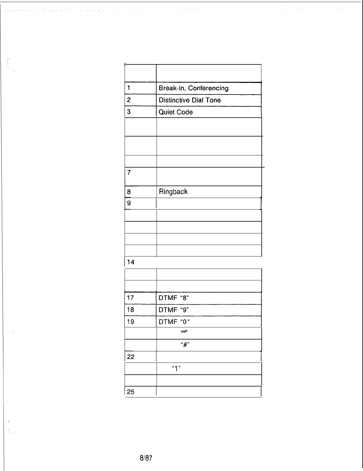
Table 9.4 Tone Test Outputs
r
No.
Terminal Output
4
Busy Tone,
Feature Confirmation Tone
5
6
Reorder, Camp on
Call-Waiting Tone
Tick Tone
Test Tone (1004 Hz, 1
Milliwatt)
Ringback
Tone
I
Dial Tone
10
DTMF “1”
11
DTMF “2”
12
DTMF “3”
13
DTMF “4”
114
I
DTMF “5”
I
15
DTMF “6”
16
DTMF “7”
20
DTMF
I’*”
21
DTMF
‘I#”
1
MF “KP”
23
MF
“1”
24
MF “2”
125
I
MF “3”
TL-130200-1001
5210
8187
M-357
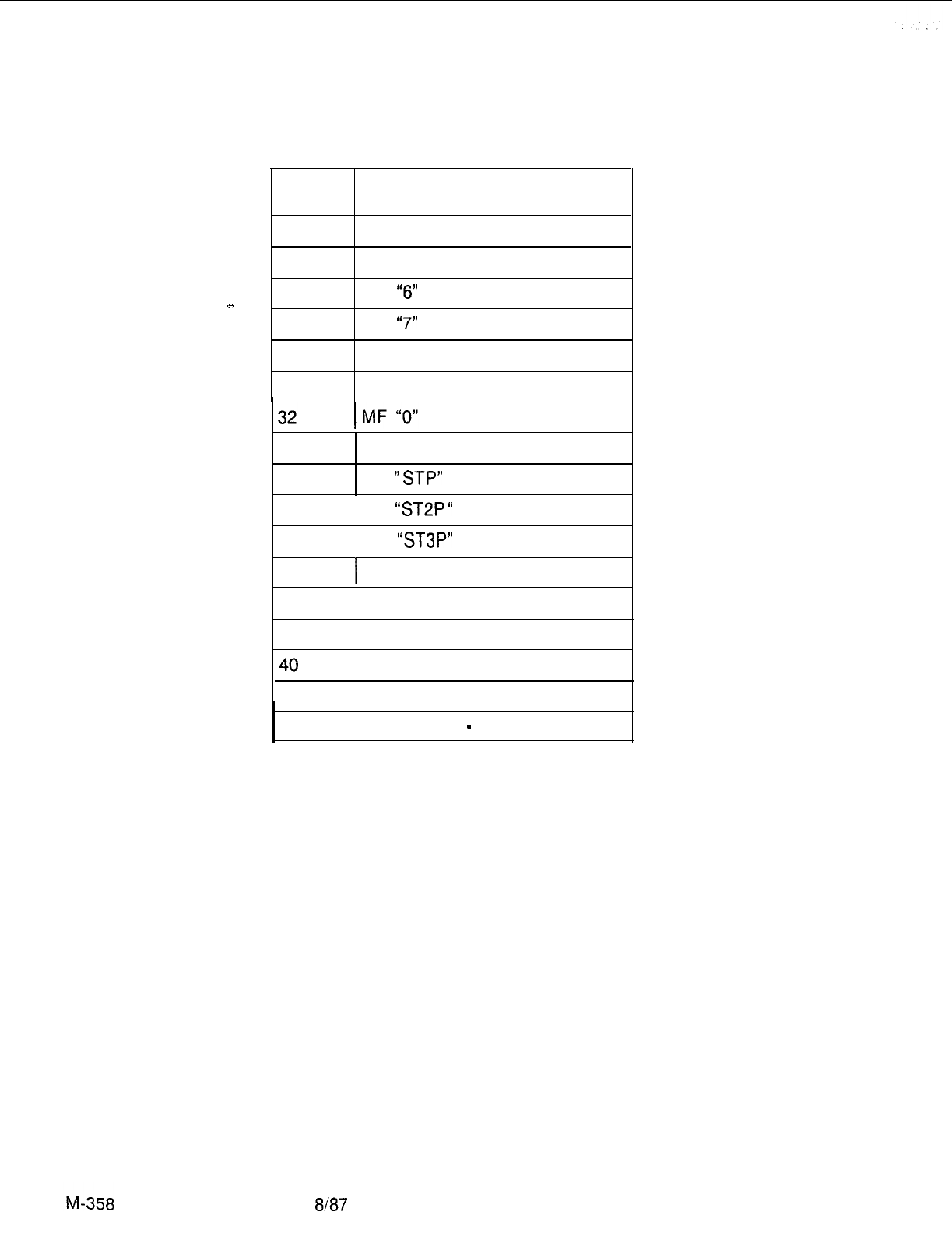
TL-130200-1001
Table 9.4 Tone Test Outputs (Continued)
No.
Terminal Output
26M F “4”
27
M F “5”
28
MF
“6”
29
MF
“7”
30
MF “8”
31 MF “9”
33
MF “ST”
34 MF
“STP”
35
MF
“ST2P“
36
MF
“ST3P”
37
I
CAS Tone (440 Hz)
38
CAS Tone (480 Hz)
39
Confirmation Tone
Interrupted Dial Tone
41
CAS Tone (620 Hz)
42
Dial Tone at
-
19 DBM
8187
5210

TL-130200-1001
4. If Pad memory not initialized, the system responds:
NETWORK FAILURE: CAN’T WRITE TO PAD MEMORY
TESTING ENDED DUE TO ABOVE ERRORS
5. If, during test, channel, control, or pad memory cannot be
read, the system responds:
READ AFTER WRITE FAILURE
MEMORY FAILURE LOCATION IS: XXXX
TESTING ENDED DUE TO ABOVE ERRORS
NOTE: See Network Test Results (Paragraph 8.11) to
memory address of the card causing the problem.
6. The system will continue sending the same tone if a “G” is not
entered to send the next tone.
7. If the phone tested in steps 1 through 4 does not actually exist,
the system responds:
PHONE HARDWARE NOT AVAILABLE
Fault Correction
9.14.3 The following steps correct faults detected by the Tone
Test:
1. If the problem is found to be initializing or writing to channel,
control, or pad memory, replace the Channel Memory 8085
card (FB-17218-A). Reinstall the original card if the problem
continues after replacement.
2. Replace the System Pulse Code Modulation card
(FB-
20974-BOA)
if tones do not work. Initialize the new card by
writing “FF” into address
08FF
on memory page DO.
3. Repeat the Tone Test.
4. Reinstall and initiate the original card. Conduct the Network
Test and/or the Line/Trunk Test on the circuit if the tones still
do not work.
5. Check the data base for a different phone and repeat the Tone
Test, if the original phone hardware was not available.
Attendant Interface Card
9.15 This test checks for transmission errors on the Attendant
Interface Number 2 (ATT12) card (FB-17208-A). The test
consists of sending a data pattern out of the card and looping it
back to the input. The two data patterns are compared to see if
the data pattern received is exactly the same as the data pattern
sent. The test flags an error if the two data patterns somehow
are different.
Temporary wiring changes are required to conduct this test.
Exercise extreme care when making these wiring changes.
5210
8f87
M-359
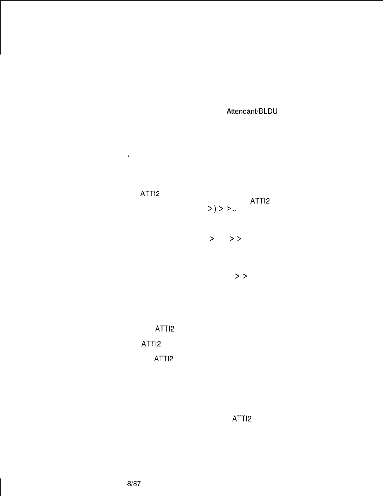
TL-130200-1001
Attendant Interface
9.15.1
Use the following steps to conduct the Attendant Interface
Card Test
Card test:
Testing Procedures
1. Remove the Attendant Interface card (FB-17208-A) from the
cabinet. Make sure that all four dip-toggle switches are in the
off position. Reinstall the card into the cabinet.
2. Disconnect the cable for the
Attendant/BLDU
interface on the
Attendant Interface card.
3. Strap together the transmit (TRAN) and receive (REC) leads on
the Attendant Interface card (FB-17208-A). Pin 93 is
strapped to pin 95 for Port 0 while pin 56 is strapped to pin 58
-
for Port 1.
4. Select Option “7” from the Menu of Test Options. The system
responds:
ATT12
CARD TEST
ENTER THE LOCATION OF THE
ATT12
CARD
FILE NUMBER (A --
>)
>
>..
5. Type the correct file letter. The system responds:
SLOT NUMBER (0 --
>
11)
>
>
6. Type the correct universal card slot number. The system
responds:
CIRCUIT NUMBER (0 OR 1)
>
>
7. Type the correct circuit number (port) to test.
Test Results
9.15.2 The following Attendant Interface Card Test results may
appear:
1. If the
ATT12
card passes the test, the system responds:
ATT12
CARD PASSES TEST
2. If the
ATT12
card fails the test, the system responds:
ATT12 CARD FAILURE, DATA = XX
(XX = data pattern which caused failure)
3. If test could not start due to the lack of a steady signal, the
system responds:
NO READY SIGNAL FROM
ATT12
CARD
4. If no phone hardware exists, the system responds:
M-360
8187
PHONE HARDWARE NOT AVAILABLE
5210

TL-130200-1001
Fault Correction
9.15.3 The following steps correct faults detected by the
Attendant Interface Card Test:
1. Check the transmit and receive strapping if a “NO READY
“
signal error occurs. Also, remove the AMP connector from the
ATT12 card slot and repeat the test. Replace the ATT12 card if
the “NO READY“ signal error appears again and repeat the
test.
2. If the ATT12 card itself failed the test, replace the card, and
repeat the test.
3. If the actual phone hardware was not available, check for a
different instrument, and repeat the test.
Line/Trunk Test
9.16 This test checks the two-way connection between a
specified phone and a test phone. Due to the lack of a central
office response, only those trunk circuits found on the
Direct-
Inward-Dialing (DID) Trunk card (PILT, FB-51280-A) are
tested. Line circuits found on PCM Off-Premises Station Line
cards (POPS, FB-17250-A) and PCM Line Circuit cards
(PLCC,
FB-17254-1A)
are also tested. Attach phones to the
circuits at the CDF by referring to Table
9.5.an
9.6.
5210
667
M-361
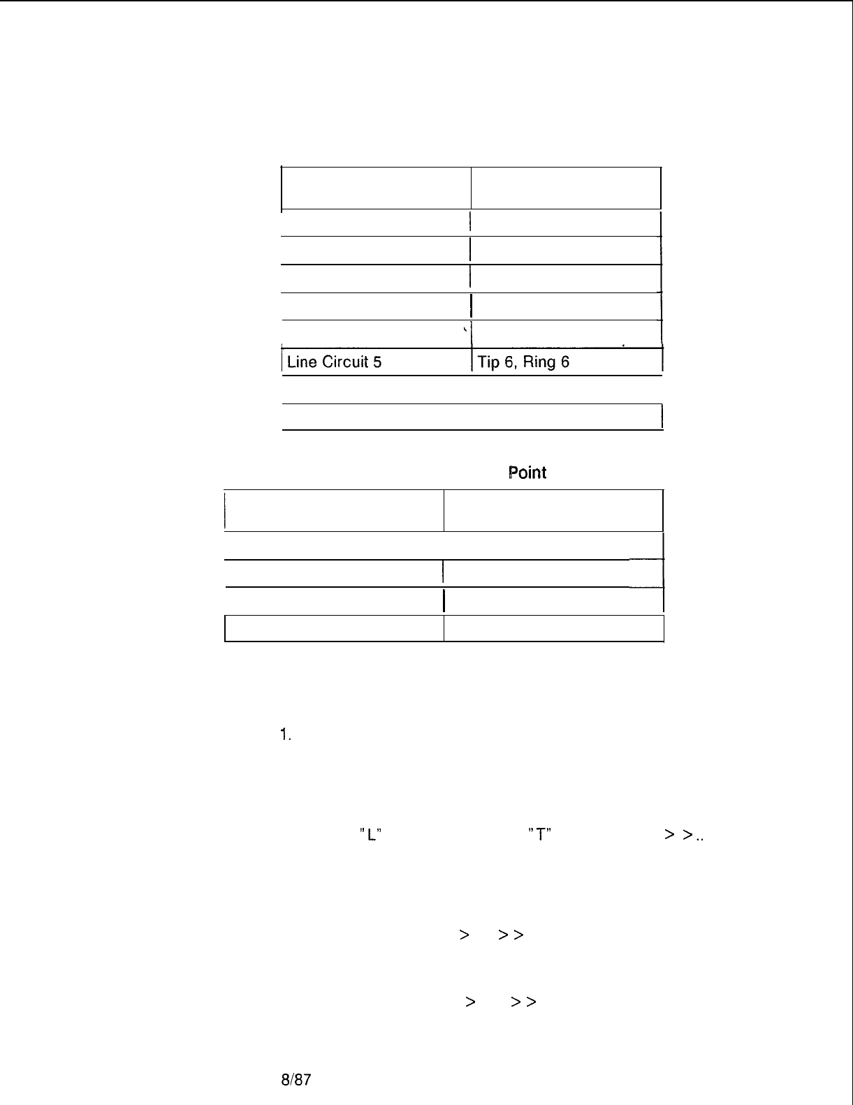
TL-130200-1001
Table 9.5 Line/Trunk Pair to Point Conversion
Circuit No. CDF Points
1 Line Circuit 0 1 Tip 1, Ring 1
1 Tip 2, Ring 2
I
Tip 3, Ring 3
1 Tip 4, Ring 4
’
Tip 5, Ring 5
1
Line Circuit 1
Line Circuit 2
Line Circuit 3
Line Circuit 4
Line Circuit 6
I
Tip 7, Ring 7
I
Line Circuit 7 Tip 8, Ring 8
Table 9.6 Line/Trunk Pair to CDF
Roint
Conversion
Circuit No. CDF Points
Trunk Circuit 0 Tip 1, Ring 1
Trunk Circuit 1
I
Tip 2, Ring 2
I
Tip 3, Ring 3
Tip 4, Ring 4
Trunk Circuit 2
Trunk Circuit 3
Line/Trunk Test
9.16.1 Use the following steps to conduct the Line/Trunk Test:
Testing Procedures
1.
Select Option “8” from the Menu of Test Options. The system
responds:
LINE AND TRUNK TEST
IS THE FIRST CIRCUIT ON A LINE CARD OR TRUNK
CARD?
TYPE
“L”
FOR LINES, TYPE
“T”
FOR TRUNKS
>
>..
2. Type the correct response for the line or trunk circuit. The
system responds:
ENTER THE PHYSICAL LOCATION OF THIS PHONE
FILE NUMBER (A --
>
D)
>
>
. .
3. Type the correct file letter for the circuit. The system responds:
SLOT NUMBER (0 --
>
11)
>
>
. .
M-362
8187
5210

TL-130200-1001
4. Type the correct universal card slot number for the circuit. The
system responds:
ClRCUlT
NUMBER (0 --
>
X)
>
>
. .
where X = 3 for a trunk card
and X = 7 for a line card
5. Type the correct circuit number for the line or trunk circuit. The
system responds:
.-..
IS SECOND CIRCUIT ON A LINE CARD OR ON A TRUNK
CARD?
TYPE “L” FOR LINES,
TYPE,“T”
FOR TRUNKS
>
>
. .
6. Type the correct response for the second line or trunk circuit.
Repeat steps two through five for this circuit.
Test Results 9.16.2 The following Line/Trunk Test results may appear:
1. With successful test completion the system responds:
THE TWO SELECTED CIRCUITS NOW HAVE A
TRANSMISSION PATH. WHEN YOU WISH TO EXIT FROM
THIS TEST AND CLEAR THE NETWORK DEPRESS ANY
CHARACTER > > . .
I.
5210 8/87 M-363

To end the test and break the transmission path, type any
character.
2. If channel memory does not initialize, the system responds:
NETWORK FAILURE: CAN’T WRITE TO CHANNEL MEMORY
TESTING ENDED DUE TO ABOVE ERRORS
3. If control memory A or B is not initialized, the system responds:
NETWORK FAILURE: CAN’T WRITE TO CONTROL MEMORY
<AORB>
TESTING ENDED DUE TO ABOVE ERRORS
4. If pad memory is not initialized, the system responds:
NETWORK FAILURE: CAN’T WRITE TO PAD MEMORY
TESTING ENDED DUE TO ABOVE ERRORS
5. During test if it cannot read channel, control, or pad memory,
the system responds:
READ AFTER WRITE FAILURE
MEMORY LOCATION IS: XXXX
TESTING ENDED DUE TO ABOVE ERRORS
NOTE: See Network Test Results (Paragraph 9.11) to find
memory address of the card causing the problem.
6. If the phones tested in steps one through five do not actually
exist, the system responds:
PHONE HARDWARE NOT AVAILABLE
Fault Correction
9.16.3 The following steps correct faults detected by the Line/
Trunk Test:
1. If the transmission path is distorted, replace the tested
PILT
card, POPS card, or PLCC card, and repeat the test.
2. If no transmission path was established, replace the tested
PILT
card, POPS card, or PLCC card, and repeat the test.
3. If replacement of the PILT, POPS, or PLCC card does not
solve the problem, perform the Network Test (see paragraph
8.11).
4. If the Network Test passes, reinstall the original card and
repeat the Network Test.
8187
5210

TL-130200-1001
Touch Calling Receiver
Test
Automatic Testing
Procedures
Automatic Test
Results
5210
9.17 This test checks a specified PCM Dual Tone Multiple
Frequency receiver (PDTMF, FB-17203-A) for proper tone
reception. The test may be conducted either automatically or
manually. The automatic test procedure places a particular time
slot (information memory location) into the control memory of the
PDTMF. The microprocessor address of the Multi-Processor
Buffer 8085 (MPB85, FB-17215-A) is monitored for correct
tone translation. If the correct translation occurs, a new tone is
tested. An error message is displayed if this translation is
incorrect. The manual test links a specified touch calling phone
to the PDTMF. As each number of the touch calling phone is
depressed, a DTMF tone is sent to the PDTMF. A description of
the DTMF tone is displayed as it is translated by the PDTMF.
9.17.1
Use the following steps to conduct the automatic Touch
Calling Receiver Test:
1. Select option “9” from the Menu of Test Options. The system
responds:
TOUCH CALLING RECEIVER TEST
DO YOU WISH TO USE THE TONE CARD?
IF YES TYPE
“Y”
, IF NO TYPE
“N”
2. Type
“Y’
if there is a PDTMF card in the system. The system
responds:
ENTER THE LOCATION OF THE TCR TO BE TESTED
FILE NUMBER (A --
>
D)
>
>
. .
3. Type the correct file letter of the TCR. The system responds:
SLOT NUMBER (0 --
>
11)
>
>
4. Type the correct universal card slot number. The system
responds:
CIRCUIT NUMBER (0 --
>
3)
>
>
. .
5. Type the correct circuit number. The test begins.
9.17.2 The following automatic Touch Calling Receiver Test
results may appear:
1. If the PDTMF passes the test, the system responds:
TCR PASSES TEST
2. If the PDTMF fails the test, the system responds:
TCR FAILED DIAGNOSTIC
8187
M-365

r
TL-130200-1001
Manual Testing
9.17.3 Use the following procedures to conduct the manual
Procedures
Touch Calling Receiver Test:
M-366
1. Select option “A” from the Touch Calling Receiver Test Option.
The system responds:
TOUCH CALLING RECEIVER TEST
DO YOU WISH TO USE THE TONE CARD?
IF YES TYPE
“Y”g
IF NO TYPE
“N”
2. Type “N
“.
The system responds:
A TOUCH CALLING PHONE IS TO BE USED TO SEND
TONES TO THE TCR RECEIVER. ENTER THE LOCATION
OF THIS PHONE.
FILE NUMBER (A --
>
D)
>
>
. .
3. Type the correct file letter. The system responds:
SLOT NUMBER (0 --
>
11)
>
>..
4. Type the correct universal card slot number. The system
responds:
CIRCUIT NUMBER (0 --
>
7)
>
>..
5. Type the correct circuit number. The system responds:
ENTER THE LOCATION OF THE TCR TO BE TESTED
FILE NUMBER (A.--
>
D)
>
>..
6. Type the correct file letter of the TCR. The system responds:
SLOT NUMBER (0 --
>
11)
>
>..
7. Type the correct universal card slot number. The system
responds:
CIRCUIT NUMBER (0 --
>
3)
>
>
. .
8. Type the correct circuit number. The system responds:
ANY DIGIT WHICH IS DEPRESSED WILL BE ECHOED ON
THE TELETYPE. WHEN YOU WISH TO EXIT FROM THIS
TEST, TYPE ANY CHARACTER
>
>..
9. Depress any digit and monitor the terminal tone description.
10. After all digits are checked, type any character on the
terminal to end the test.
8187
5210
TL-130200-1001
A
Access Recent Change, M-281
Access On-Line Maintenance, M-85
Acrxunting
Reports, M-248
Add-a
CAS
Main/ACD
Agent Group, M-305
Agent
-Data
Displays and Changes, M-300
Agent Group Call Waiting Levels, M-315
Agent Group Delay Routing Display, M-314
Agent Instruments, M-60
Agent Position Status Display, M-300, M-302
Agent Status Report, M-293
Alarms, M-l 78
Alarm Command Codes, M-80
Attendant and Busy Lamp Display Unit, M-60
Attendant Console Code Display Fault, M-108
Attendant Interface Card, M-359
Attendant Interface Card Test Testing Procedures, M-360
Automatic Circuit Assurance Log Request Commands, M-43
Automatic Testing, M-340
Automatic Testing Procedures, M-365
Automatic Test Results, M-365
BLDU Unit Troubleshooting Procedure, M-160
Bulk Downloading Commands, M-66B
Bulk Input Command, M-788
Call Store, M-236
Call Waiting Data Menu, M-313
Call Waiting Data Menu Access, M-313
F=TL-130000-1001
O=TL.130100-1001 M=TL-130200-1001 I=TL-130300-1001 D=TL-130400-1001 S=TL-130500-1001 A=TL-100000-1001
Features Operation Maintenance Installation Data
Base
System
ConfIguration
ADMP
UsersGuide

TL-130200-1001
Card List, M-17
CALL TRACING, M-21 1
Call Tracing Examples, M-217
Cancel a Trend Report, M-299
CASACD
Source Group Report, M-291
CAS
Main/ACD
Data
.-Menu
Instrument, M-31 8
CAS
Main/ACD
Help, M-284
CAS
MAlNiACD
Source, M-295
CAS
Main/ACD
Supervisor Options, M-282
CAS
Main/ACD
Supervisory Recent Change, M-299
CAS
Main/ACD
Trunk Data Menu, M-306
CAS
Main/ACD
Trunk Data Transactions, M-307
Change a Repertory Dial Key Set, M-319
Change a Source Message, M-312
Change Alternate Destination of an Agent Group, M-317
Change Call Waiting Indicator Levels, M-318
Control Card Removal and Replacement, M-20
Change Day/Night Mode
(87),
M-321
Change Delay Routing of an Agent Group, M-315
Change FADS Automatic Dump Period, M-297
Change the FADS Automatic Dump Selections, M-297
Change FADS Data Collection Start Time, M-298
Change FADS Periodic Data Collection Period, M-296
Change First Recorded Announcement, M-31 6
Change Night Destination of an Agent Group, M-305
Change Recorded Announcement Delay or Repetition Timing, M-317
Change Second Recorded Announcement, M-31 6
Change Special Message
(88),
M-324
Change the Group/Supervisor of an Agent Position, M-304
Change the Source Group of a Trunk, M-31
Change the State of an Agent Position, M-304
Change the State of a CAS
Main/ACD
Trunk, M-309
Channel Memory Test, M-345
Channel Memory Testing Procedures, M-345
F=TL-I~OOOO-iooi O=TL-130100-1001
M = TL-130200-1001
I=TL-130300-1001 D=TL-130400-1001 S-TL-130500-1001 A=TL-100000-1001
FeatlIES
Operation Maintenance Installation Data Base System Configuration ADMP Users
Guide
r
TL-130200-1001
Channel Unit Removal, M-177
Connection Between Files, M-21 9
Connection to a TCR, M-218
Current Collection Parameter Settings, M-91
D
Display Command, M-50
Downloading Featurephones, M-63
Downloading VCIP, DVCIP., and VPLC Cards, M-65
Downloading, ADMP, UCB (DCP), and NIC Card, M-66
Disk Backup of Room Status, M-83
Data Switch Device Status Display, M-99
Disk Backup Option, M-101
Device Catalog Display Option, M-102
Dedicated Time Slot, M-218
Digit Store, M-230
Data System Administrative and Maintenance Features, M-248
Data System Troubleshooting, M-250
Display Software Version Command, M-254
Display All FADS Options, M-296
Delete a CAS
Main/ACD,
M-306
Display/change FADS Delay Timing, M-306
Display Trunks by Trunk Number, M-307
Display CAS
MainiACD
Trunks by Agent Group Number, M-308
Display
R/A
Trunk Number and State, M-313
Display a Repertory Dial key Set, M-319
Day/Night Mode Data Menu, M-320
Display Day/Night Mode
(86),
M-321
Disk Device Tests, M-349
Disk Device Testing Procedures, M-349
Display Trunks with a Specific Source Group, M-309
E
Event Reports, M-249
F=TL-130000-1001 O=TL-130100-1001 M=TL-130200-1001
I
=TL-130300-1001 D=TL-130400-1001 S=TL-130500-1001 A=TL-100000-1001
Features Operation Maintenance Installation Data Base System
ConfiguratIon
ADMP Users Guide
TL-130200-1001
FADS, CAS
Main/ACD
Transactions, M-285F
FADS Control Transactions, M-296
FADS Control Data Menu, M-295
FADS Display Options Menu, M-287
FADS Display Transactions, M-288
FADS Recent Chang, M-287
Fast Test Option, M-341
Fault Code Procedures and
F!owcharts,
M-155
Fault
CorrectionM
-349, M-355, M-361, M-364
Fault Isolation, M-l 55
Fault Log Request Commands, M-24
Fault Resolution, M-277
Featurephones, M-57
Featurephones
(PD-200)
M-255
Featurephone Self-Test Diagnostics, M-l 62
Force Download, M-61
Force In Service Out of Service Command, M-57, M-255
Frame Image, M-15
3GENERAL,
M-l
General Read and Data General Read Commands, M-73
General Write Command, M-77
Handling Cards, M-20
Hardware Write Command, M-79
nitiate a Trend Report, M-298
Line Cards with Featurephones, M-59
F=TL-130000-1001 O=TL-130100-1001 hl=TL-130200-1001 I=TL-130300-1001 D=TL-130400-1001 S=TL-130500-1001 A=TL-100000-1001
Features Operation Maintenance
Installation
Data Base System Configuration ADMP
UsersGuide

TL-130400-1001
Line/Trunk Test, M-361
Line/Trunk Test Testing Procedures, M-362
Load Commands, M-258
Load Command Responses, M-261
Loading the Program, M-338
Maintenance Command,M -55
MAINTENANCE COMMANDS AND DISPLAYS, M-23, M-249
Manual Changes and Recent Change Summary (Voice Configuration), M-324
Maintenance Displays, M-23
Maintenance Options, M-67
Maintenance Request Command, M-79
Maintenance Terminals, M-l 3
Maintenance Tools, M-263
Manual Hardware Testing, M-l 5
Manual Testing, M-339
Manual Testing Procedures, M-366
Mass Storage Utility Menu, M-100
Memory Access Commands, M-73
Memory Dumps, M-216
Memory Dump Contents, M-216
Memory Test Results, M-97
Memory Watch Command, M-68
Network Test, M-90
Network Test, M-347
Network Testing Procedures, M-347N
Night Destination of All Agent Groups, M-303
F=TL-130000-1001 O=TL-130100-1001 M=TL-130200-1001 I=TL-130300-1001 D=TL-130400-1001 S=TL-130500-1001 A=TL-100000-1001
Features Operation
Maintenance
Installation
Data Base System Configuration ADMP Users Guide

TL-I
30400-l 001
OFF-LINE DIAGNOSTICS, M-337
ON-LINE MAINTENANCE. M-85
Packet Line Cards Status, M-99
Paging Card Test, M-346
Paging Card Testing Procedures, M-346
PD-200 Data-System Devices, M-253
PD-200 MAINTENANCE, M-247
PD-200 Maintenance Tools and Fault Isolation, M-263
Physical Locations, M-337
Power Restrictions, M-20
Preventive Maintenance, M-l 07
PUT
Command Entry, M-69
Quick Reference Chart, M-107
Reference Documents, M-l 5
Return to Maintenance Options, M-96
Remote Processors Status, M-l 00
1 RECENT CHANGE, M-28
Real-Time Agent Status Display, M-288
Real-Time System Status Display, M-289
Retest Option, M-341
Repeat FMS Test, M-350
Return to Main Menu, M-354
s
Security Codes, M-14
Security Levels, M-l 3
Self-Testing Diagnostics, M-l 4
F=TL-130000-1001 O=TL-130100-1001 hl=TL-130200-1001 I=TL.130300-1001 D=TL-130400-1001 S-TL-130500-1001 A=TL-100000-1001
Features Operation Maintenance Installation
Data
Base
SystemConfiguration
ADMPUsers
Guide
i’
TL-130400-1001
Send a Special Message
(49),
M-322
Send a Unique Message
(97)
M-323
Serial Device Controller Test, M-354
Serial Device Controller Testing Procedures, M-355
Software Identity Calculations (Lines), M-28
Source Message Display, M-31 1
Special Message Display
(84)
M-323
Spare Cards, M-107
Super&or Message Handler, M-321
Supervisor Message Options Menu
(85),
M-322
System Configuration, M-l 5
System Diagnostics,
M-l
4
SYSTEM MAINTENANCE GENERAL PRINCIPLES, M-107
System Memory Test, M-341
System Memory Testing Procedures, M-343
System Operation Checks, M-107
System Software and Maintenance Applications, M-l 3
System Status, M-23
System Status Display, M-88
System Status Report, M-289
System Voltage Checks, M-107
Test Command (Featurephone), M-72
Test Device #0, M-351
Test Device
#2,
M-353
Testing, M-l 79
Test Options Menu, M-337
Test Results, M-344, M-346, M-347, M-356,M -360, M-363
Three-Party Connection, M-21 7
Tone Test, M-355
Tone Test Testing Procedures, M-356
Touch Call Receiver Status, M-96
Touch Call Receiver Test, M-89
F
=TL-130000-1001 Cl=TL-130100-1001 M=TL-130200-1001 I=TL-130300-1001 D=TL-130400-1001 S-TL-130500-1001 A=TL-100000-1001
Features Operation Maintenance Installation
Data
saw.2
System Configuration ADMP Users Guide

TL-130400-1001
Touch Calling Receiver Test, M-365
Traffic Data Menu Options Menu, M-91
Traffic Meters Menu, M-92
TROUBLESHOOTING, M-155
Trunks, M-59, M-256
Trunk Sequence State Display, M-98
Tl
-Type Trunk Maintenance, M-l 76
Tl
Trunk Trouble, M-180
TTY Response Log Display, M-36
Two-Party Connection, M-21 7
Typical Recent Change Sequences, M-333
IJ
Unlock Command, M-73
F=TL-130000-1001 O=TL-130100-1001 M
=TL-130200-1001 I
=TL-130300-1001 D=TL-130400-1001 S=TL-130500-1001 A=TL-100000-1001
Fe.dWS
Operation Maintenance Installation Data Base System Configuration ADMP Users Guide
