Service Information A02 158 FW V795
User Manual: FW-V795
Open the PDF directly: View PDF ![]() .
.
Page Count: 11

Service Information
Service
Service
Service
Service
Service
Product Service Group CE Audio
3139 785 30072
30 - 05 - 2002
FW-V795
A02 - 158
Already published Service Informations :
ADDITION TO SERVICE MANUAL
*Power Booster:
Repair information and selected spare parts are now available for
the Power Booster. For this reason layout, circuit drawing and parts
list are enclosed (Page 1 to 10).
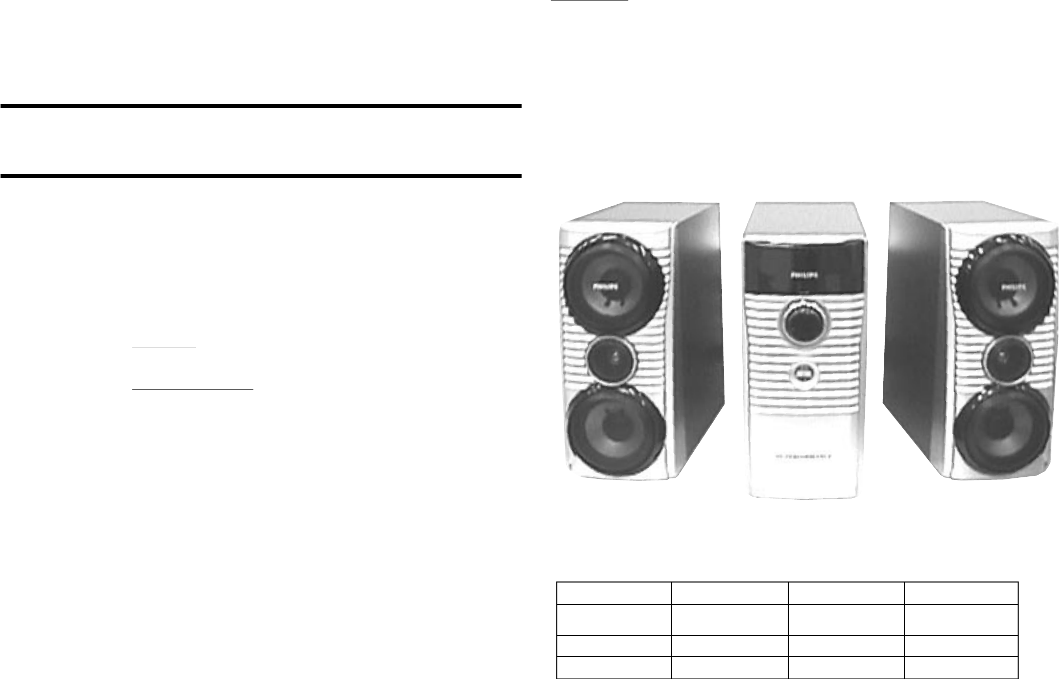
Power Booster Speaker Box
Power Booster Amplifier Box
Power Booster Speaker Box
POWER BOOSTER
TABLE OF CONTENTS
Power Booster:
Technical Specifications & Version Variations ................... 1
Power Booster Amplifier Box:
Dismantling Instructions & Service positions ..................... 2
Wiring Diagram ................................................................... 4
Component Layout (/21/21M Version) ............................... 5
Component Layout (/37 Version) ....................................... 6
Circuit Diagram ................................................................... 7
Exploded View & Mechanical parts list .............................. 8
Electrical parts list (Main Board) ........................................ 9
Electrical parts list (Control Board) .................................. 10
1 1
SPECIFICATIONS
Mains voltage : 110-127V/220-240V Switchable for /21/21M
: 120V for /37
Mains frequency : 50/60Hz
Power Consumption : 25W at Standby
: 150W at Active for /21/21M
: 135W at Active for /37
O/P Power : 100W
FTC Power : 85W
I/P Sensitivity : 775mV +/-15%
Frequency Response : 20Hz-20kHz +/-3dB
Channel Different : 2dB (250Hz to 6.3kHz)
Distortion : 0.4% (1W 1kHz)
: 0.4% ( 1W 40Hz)
: 0.9% (1W 16kHz)
Channel Separation : >65dB (1kHz)
: >50dB (250Hz)
: >50dB (10kHz)
VERSION VARIATIONS:
FW-C798/21 FW-C798/37 FW-V795/21M
POWER BOOSTER 3139 118 79650 3139 118 79640 3139 118 79630
(PWB-C798/01) (PWB-C798/17) (PWB-V795/01)
AMPLIFIER BOX 9965 000 13808 9965 000 13800 9965 000 13725
SPEAKER BOX 9965 000 13809 9965 000 13801 9965 000 13726
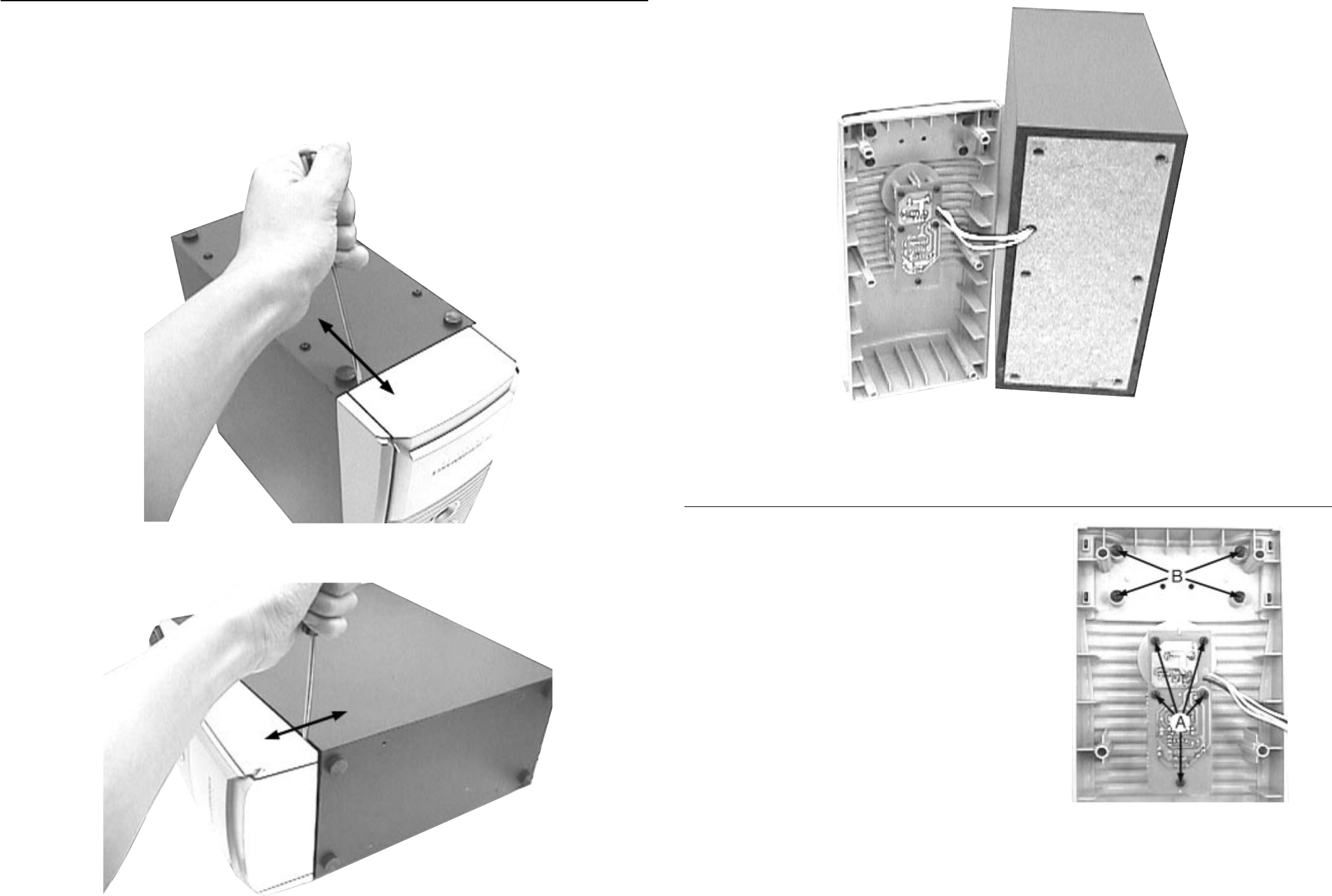
1. Remove 5 screws A (see Picture 3) to loosen the Control
Board (pos 6).
2. Remove 4 screws B (see Picture 3) to remove the Panel
Ornamental (pos 17).
DISMANTLING INSTRUCTIONS (POWER BOOSTER AMPLIFIER BOX)
Dismantling the Front Assembly
22
1. Place the Power Booster Amplifier Box as shown in
Picture 1 and Picture 2 and use a screw driver (minus
type) to force open the Front assembly.
Caution: Do not break the bundle of wires to the front.
Service Position A
Dismantling the Control Board and the Panel Ornamental
Picture 1
Picture 2
Picture 3
Service Position B
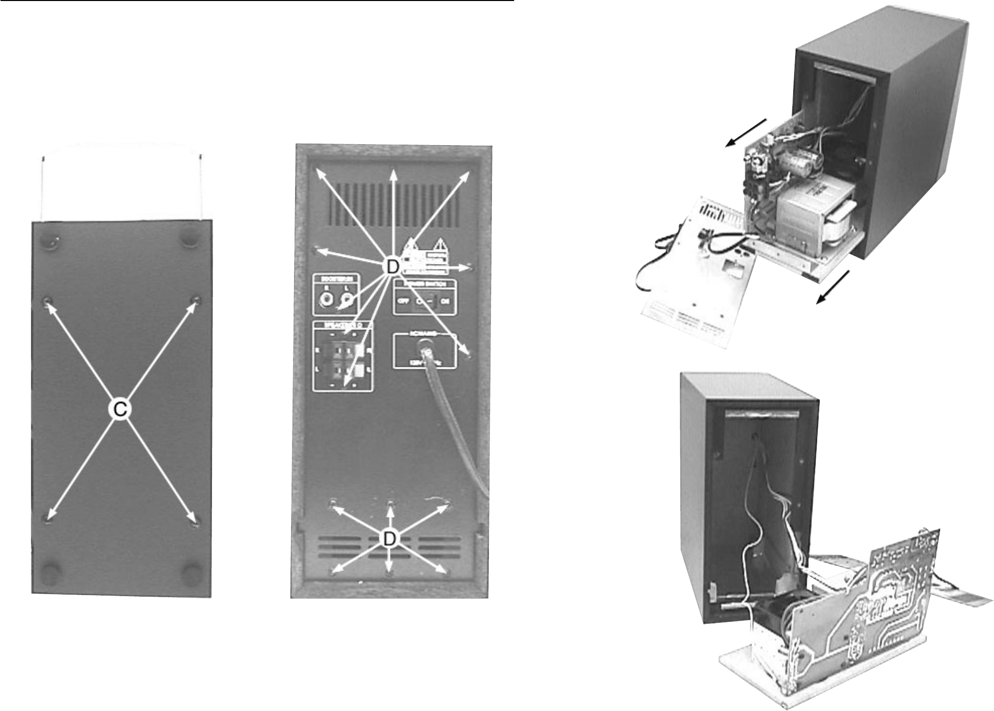
DISMANTLING INSTRUCTIONS (POWER BOOSTER AMPLIFIER BOX)
Dismantling the Rear Assembly
33
Service Position C
1. Remove 4 screws C at the bottom of the Power Booster
Amplifier Box as shown in Picture 4.
2. Remove 15 screws D (see Picture 5) to remove the Metal
Panel (pos 1).
3. Slide out the Main PCB assembly as shown in Service
Position B.
Picture 5Picture 4
Note: After repair, be very sure that the cables are tied and
restored properly to its original position.

Wiring Diagram (PWB-C798/01 & PWB-V795/01) dd wk0212
Wiring Diagram (PWB-C798/17) dd wk0212
44
WIRING DIAGRAM - POWER BOOSTER AMPLIFIER BOX (/21/21M VERSION) WIRING DIAGRAM - POWER BOOSTER AMPLIFIER BOX (/37 VERSION)
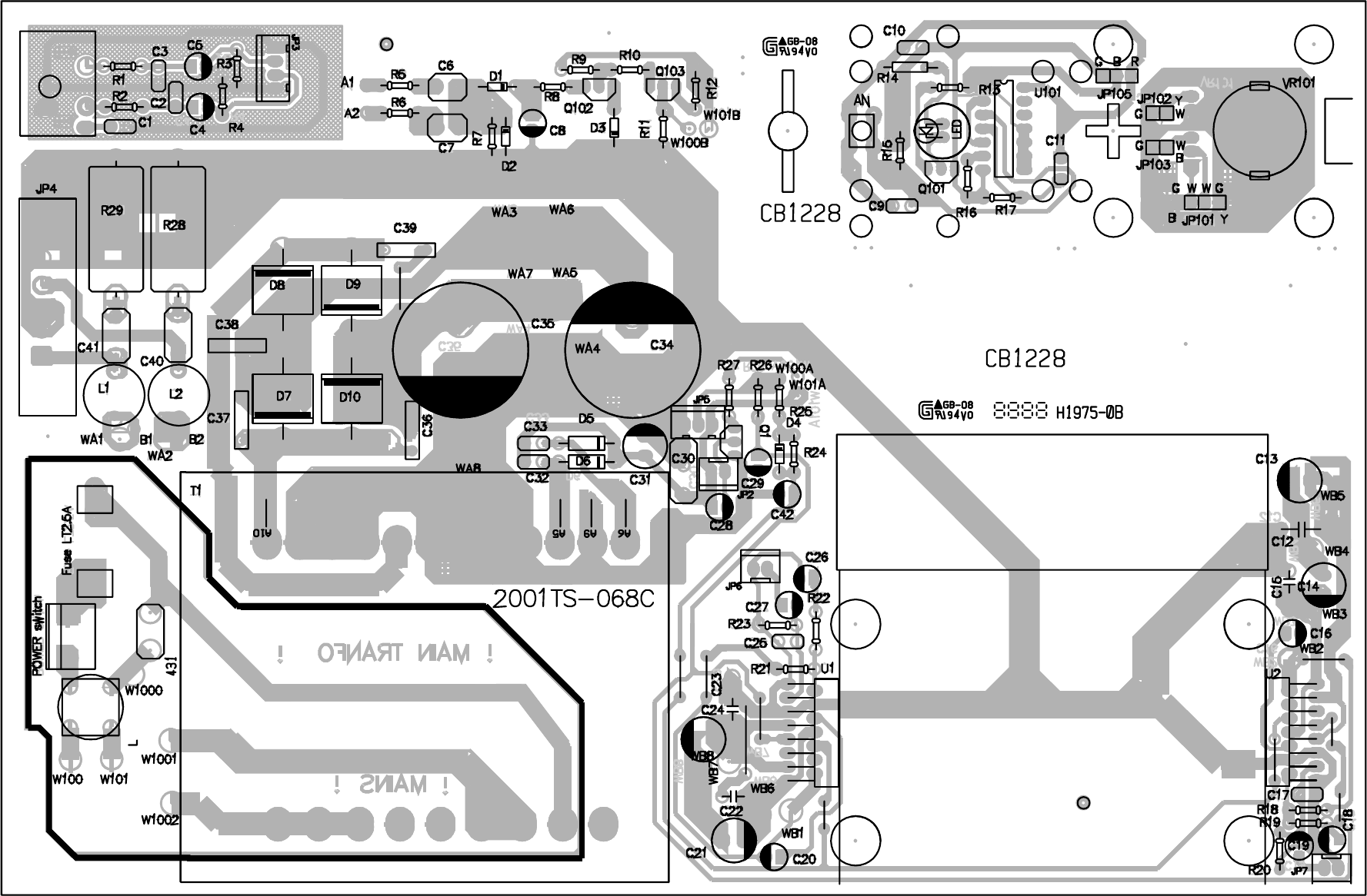
Layout (PWB-C798/01 & PWB-V795/01) dd wk0216
55
COMPONENT LAYOUT - POWER BOOSTER AMPLIFIER BOX (/21/21M VERSION)

Layout (PWB-C798/17) dd wk0217
6 6
COMPONENT LAYOUT - POWER BOOSTER AMPLIFIER BOX (/37 VERSION)
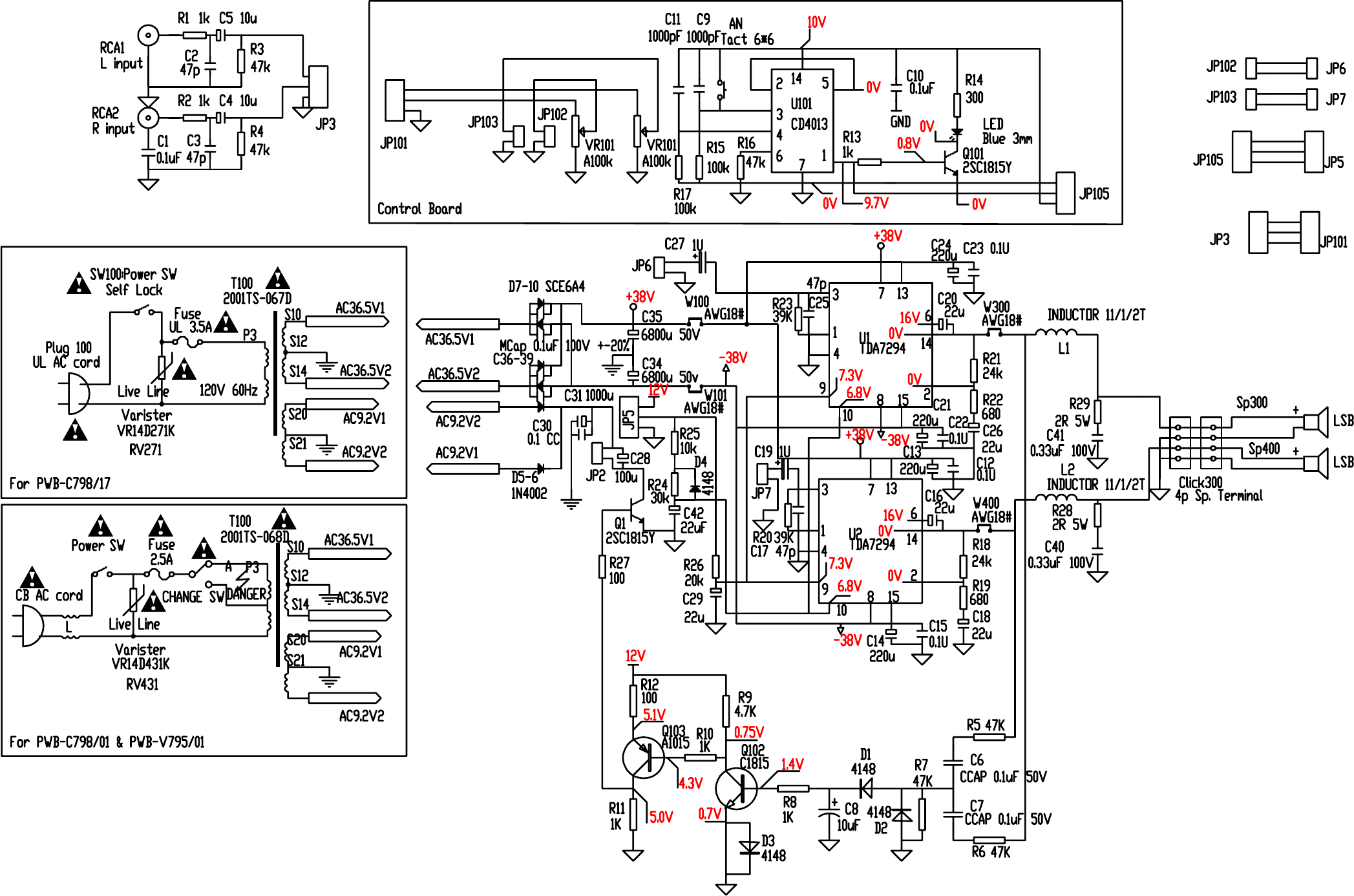
Circuit Diagram (Power Booster Amp. Box) dd wk0217
Note : Some values may varies, see respective parts list for correct value.
77
CIRCUIT DIAGRAM - POWER BOOSTER AMPLIFIER BOX
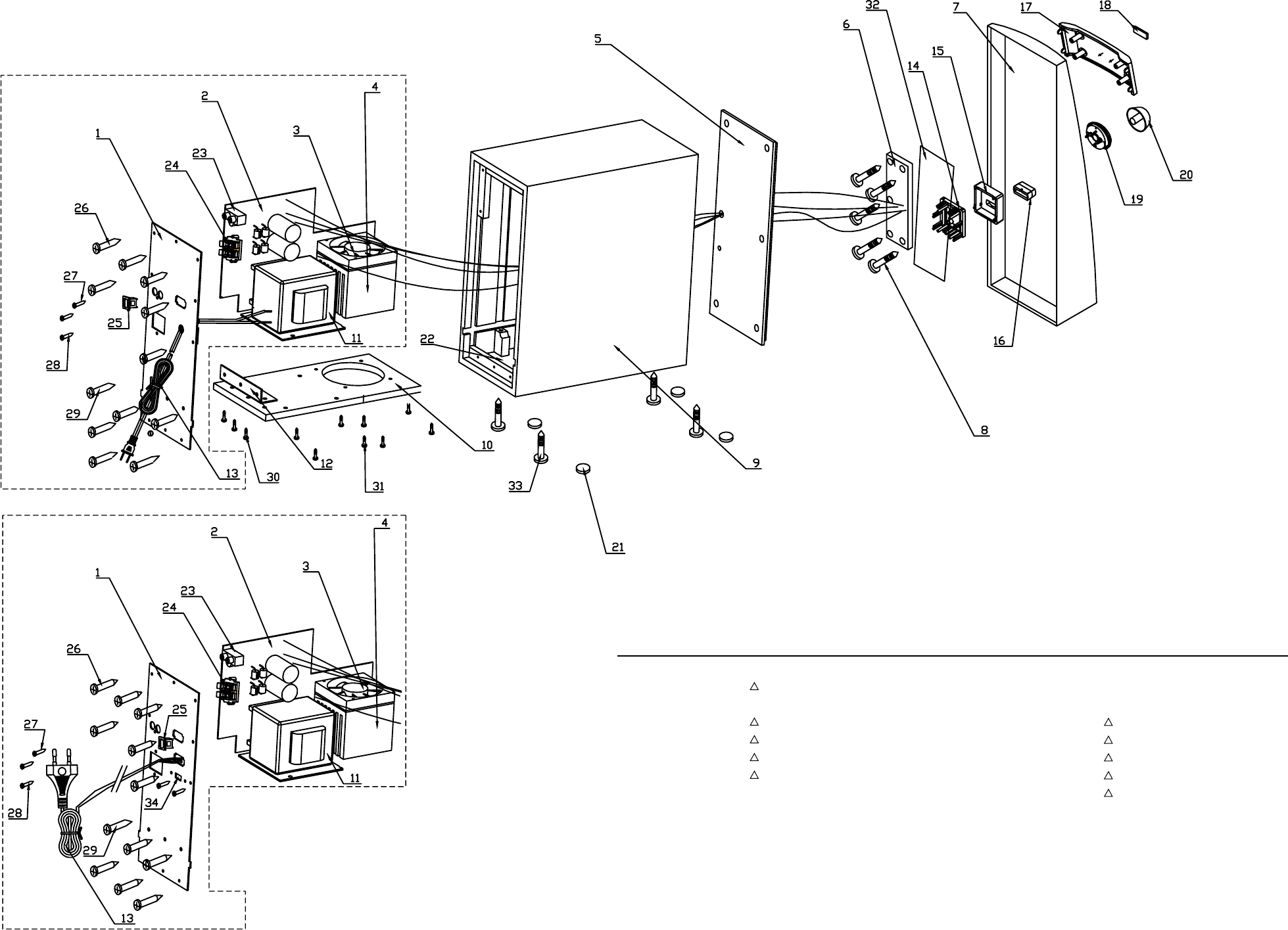
Exploded View (Power Booster Amp. Box) dd wk0220
For PWB-C798/17
For PWB-C798/01 & PWB-V795/01
8 8
EXPLODED VIEW - POWER BOOSTER AMPLIFIER BOX
MECHANICAL & ACCESSORIES PARTS LIST - POWER BOOSTER AMPLIFIER BOX
3 9965 000 13727
!
Fan 80*80, 0.17A, RDH8025S
7 9965 000 13728 Front Panel
11 * 9965 000 13729
!
Transformer 2001TS-068D
11 ^ 9965 000 13802
!
Transformer 2001TS-067D
13 * 9965 000 13730
!
AC Cord
13 ^ 9965 000 13803
!
AC Cord
14 9965 000 13731 Light Guide Primary
15 9965 000 13732 Light Guide
16 9965 000 13733 Knob Power
17 9965 000 13734 Panel Ornamental
18 9965 000 12992 Badge (PHILIPS)
19 9965 000 13735 Volume Ring
20 9965 000 13736 Volume Knob
21 9965 000 13737 Rubber Foot Dia 15 D=5mm
23 9965 000 13738 RCA Jack 2P Blue/Green
24 9965 000 13739 Speakers Terminal 4P
25 * 9965 000 13741
!
Power Switch
25 ^ 9965 000 13804
!
Power Switch
34 * 9965 000 13742
!
Voltage Selector 127V/240V
* 9965 000 13740
!
AC Socket
^ 9965 000 13805
!
Strain Relief
* for /21/21M version only
^ for /37 version only
Note : Only the parts mentioned in this list are normal
service spare parts.

9
ELECTRICAL PARTS LIST - POWER BOOSTER AMPLIFIER BOX (Main Board)
MISCELLANEOUS
FUSE 9965 000 13777
!
Fuse 2.5A /21/21M
FUSE 9965 000 13807
!
Fuse 3.5A /37
RV431 9965 000 13776
!
VR14D431K /21/21M
RV271 9965 000 13806
!
VR14D271K /37
CAPACITORS
C1 9965 000 13755 M CAP 0.1uF 100V 20%
C2 9965 000 13756 C CAP 47pF 50V 20%
C3 9965 000 13756 C CAP 47pF 50V 20%
C4 9965 000 13748 E CAP 10uF 25V 20%
C5 9965 000 13748 E CAP 10uF 25V 20%
C6 9965 000 13757 C CAP 0.1uF 50V 20%
C7 9965 000 13757 C CAP 0.1uF 50V 20%
C8 9965 000 13748 E CAP 10uF 25V 20%
C12 9965 000 13755 M CAP 0.1uF 100V 20%
C13 9965 000 13750 E CAP 220uF 50V 20%
C14 9965 000 13750 E CAP 220uF 50V 20%
C15 9965 000 13755 M CAP 0.1uF 100V 20%
C16 9965 000 13749 E CAP 22uF 25V 20%
C17 9965 000 13756 C CAP 47pF 50V 20%
C18 9965 000 13749 E CAP 22uF 25V 20%
C19 9965 000 13747 E CAP 1uF 25V 20%
C20 9965 000 13749 E CAP 22uF 25V 20%
C21 9965 000 13750 E CAP 220uF 50V 20%
C22 9965 000 13755 M CAP 0.1uF 100V 20%
C23 9965 000 13755 M CAP 0.1uF 100V 20%
C24 9965 000 13750 E CAP 220uF 50V 20%
C25 9965 000 13756 C CAP 47pF 50V 20%
C26 9965 000 13749 E CAP 22uF 25V 20%
C27 9965 000 13747 E CAP 1uF 25V 20%
C28 9965 000 13751 E CAP 100uF 16V 20%
C29 9965 000 13749 E CAP 22uF 25V 20%
C30 9965 000 13757 C CAP 0.1uF 50V 20%
C31 9965 000 13752 E CAP 1000uF 16V 20%
C34 9965 000 13753 E CAP 6800uF 50V +80/-20%
C35 9965 000 13753 E CAP 6800uF 50V +80/-20%
C36 9965 000 13755 M CAP 0.1uF 100V 20%
C37 9965 000 13755 M CAP 0.1uF 100V 20%
C38 9965 000 13755 M CAP 0.1uF 100V 20%
C39 9965 000 13755 M CAP 0.1uF 100V 20%
C40 9965 000 13754 M CAP 0.33uF 100V 20%
C41 9965 000 13754 M CAP 0.33uF 100V 20%
C42 9965 000 13749 E CAP 22uF 25V 20%
RESISTORS
R1 9965 000 13759 Carbon Film Res 1k 1/8W 5%
R2 9965 000 13759 Carbon Film Res 1k 1/8W 5%
R3 9965 000 13760 Carbon Film Res 47k 1/8W 5%
R4 9965 000 13760 Carbon Film Res 47k 1/8W 5%
R5 9965 000 13760 Carbon Film Res 47k 1/8W 5%
R6 9965 000 13760 Carbon Film Res 47k 1/8W 5%
R7 9965 000 13760 Carbon Film Res 47k 1/8W 5%
R8 9965 000 13759 Carbon Film Res 1k 1/8W 5%
R9 9965 000 13764 Carbon Film Res 4.7k 1/8W 5%
R10 9965 000 13759 Carbon Film Res 1k 1/8W 5%
R11 9965 000 13759 Carbon Film Res 1k 1/8W 5%
R12 9965 000 13762 Carbon Film Res 100R 1/8W 5%
R18 9965 000 13767 Carbon Film Res 24k 1/8W 5%
R19 9965 000 13763 Carbon Film Res 680R 1/8W 5%
R20 9965 000 13769 Carbon Film Res 39k 1/8W 5%
R21 9965 000 13767 Carbon Film Res 24k 1/8W 5%
R22 9965 000 13763 Carbon Film Res 680R 1/8W 5%
R23 9965 000 13769 Carbon Film Res 39k 1/8W 5%
R24 9965 000 13768 Carbon Film Res 30k 1/8W 5%
R25 9965 000 13765 Carbon Film Res 10k 1/8W 5%
R26 9965 000 13766 Carbon Film Res 20k 1/8W 5%
R27 9965 000 13762 Carbon Film Res 100R 1/8W 5%
R28 9965 000 13775 Power Res 2R 5W 10%
R29 9965 000 13775 Power Res 2R 5W 10%
DIODES
D1 4822 130 30621 1N4148
D2 4822 130 30621 1N4148
D3 4822 130 30621 1N4148
D4 4822 130 30621 1N4148
D5 5322 130 30684 1N4002
D6 5322 130 30684 1N4002
D7 9965 000 13772 Diode 6A 400V SCE6A4
D8 9965 000 13772 Diode 6A 400V SCE6A4
D9 9965 000 13772 Diode 6A 400V SCE6A4
D10 9965 000 13772 Diode 6A 400V SCE6A4
COILS & FILTERS
L 9965 000 13774 Inductor 2001TS-098 /21/21M
L1 9965 000 13773 Inductor 11.5T Vertical
L2 9965 000 13773 Inductor 11.5T Vertical
TRANSISTORS & INTEGRATED CIRCUITS
Q1 4822 130 41947 2SC1815Y
Q102 4822 130 41947 2SC1815Y
Q103 4822 130 42959 2SA1015Y
U1 4822 209 90939 TDA7294
U2 4822 209 90939 TDA7294
Note : Only the parts mentioned in this list are normal
service spare parts.

10
ELECTRICAL PARTS LIST - POWER BOOSTER AMPLIFIER BOX (Control Board)
MISCELLANEOUS
AN 9965 000 13770 Tact Switch 6*6, 4 Pins
LED 9965 000 13744 LED Dia 3mm, Blue
VR101 9965 000 13771 VR 100KA*2, 6 Pins
CAPACITORS
C9 9965 000 13745 C CAP 0.001uF 50V 20%
C10 9965 000 13746 C CAP 0.1uF 16V 20%
C11 9965 000 13745 C CAP 0.001uF 50V 20%
RESISTORS
R13 9965 000 13759 Carbon Film Res 1k 1/8W 5%
R14 9965 000 13758 Carbon Film Res 300R 1/4W 5%
R15 9965 000 13761 Carbon Film Res 100k 1/8W 5%
R16 9965 000 13760 Carbon Film Res 47k 1/8W 5%
R17 9965 000 13761 Carbon Film Res 100k 1/8W 5%
TRANSISTORS & INTEGRATED CIRCUITS
Q101 4822 130 41947 2SC1815Y
U101 9965 000 13743 CMOS IC Dual D Trigger,CD4013
Note : Only the parts mentioned in this list are normal
service spare parts.
