GA21 9084 9_IBM_System3_Installation Manual_Physical Planning_Jul77 9 IBM System3 Installation Manual Physical Planning Jul77
GA21-9084-9_IBM_System3_InstallationManual_PhysicalPlanning_Jul77 GA21-9084-9_IBM_System3_InstallationManual_PhysicalPlanning_Jul77
User Manual: GA21-9084-9_IBM_System3_InstallationManual_PhysicalPlanning_Jul77
Open the PDF directly: View PDF ![]() .
.
Page Count: 64
IBM
System/3
Installation
Manual-
Physical
Planning
aaaa aaaa
3!3!..........333!
aaaaaaaaaaaaaaaaaa
aaaaaaaaaaaaaaaaa.
....
o.........:3
3 3
aaaa aaaa
aaaa aaaa
3333..........3333
aaaaaaaaaaaaaaaaaa
aaaaaaaaaaaaaaaaa.
aaaaaaaaaaaaaaaaaa
aaaa aaaa aaaa
aaaa aaaa aaaa
oaaa aaaa aaaa
aaaaaaaaaaaaaaaaaa
aaaaaaaaoaaaaaaaaa
aaaaaaaaaaaaaaaa
aaaaaa aoaaaa
aaaa aaao
aaaa
a aaa
aaaaa
aaaaaaa
aaaa aaaaaaaa
oaaa aaaaaaa
aaaaaaaaaaaaaa
aaaaaaaaaaaa
aaaaaaaaaaaa
aaaoaaaaaaaaaa
aaoa aaaaaaa
aaao aoaaaaaa
aaaaaaa
aaaaa
aaaa
aaaa
aaaaaa
aaaaaa
aaaaaa
aaaaaa
aaaa aaaa
aaaa aaaa
aaaaaaaaaaaaaaaaaa
aaaaaaaaaaaaaaaaaa
aaaaaaaaaaaaaaaaaa
aaaaaaaaaaaaaaaaaa
aaaa aaaa
aaaa aaaa
aaaaaa
aaaaaa
aaaaaa
aaaaaa
aaaa oaaaa
aaaaa aaaaaaa
aaaaaa aaaaaaaaa
aaaaaaa aaaaaaaaaa.
oaaaaaa aaaaaaaaaaa
aaaa aaao aaaa
aaaa oaaa oaaa
aaaa aaaa aaaa
aaaaaaoaaaaa aaaaaa
aaaaaaaaaaaa aaaaaa
aaaaaaaaaa aaaaa
aaaaaaaa aaaa
aaaaaa
aaaa aaaaa
aaaoa aaaoaaa
aaaaaa aaaaaaaac
aaaaaaa aaaaaaaaa..
aaaaaaa aaaaaoaaaaa
aaaa aaaa aaaa
aaaa oaaa aaaa
aaaa aaaa aaaa
aaaaaaaaaaaa aaaaaa
aaaaaaaaaaoa aaaaaa
aaaaaaaaaa aoaaa
aaaaaaaa aaaa
aaaaaa
GA21,9084-9
File
No.
S3-15
aa
aa
Preface
This
publication
contains
infqrmation
about
the
physical
installation
of
an
IBM
System/3.
lt includes
information
about
space requirements
and
site selection,
a
proposed
planning
schedule,
and a
brief description
of the
System/3
units
and
their layouts
(plan
views).
with
explanations
of
electrical
and environmental
requirements.
The requirements
of the
system
are
subject to modif
ication
by engi
neering development.
Tenth
Edition
(July
19771
Thisisamajorrevisionof,andobsoletes,GA2l-9084-8.
Minorchangeshavebeenmade
through the manual. changes
are
indicated by a
vertical
line at the left of the change.
changes
are
continually
made
to the specifications
herein;
any such
changes
will be
reported in subsequent
revisions
or technical newsletters.
Requests
for copies of IBM publications
should
be made to your IBM representative
or to the IBM branch
office serving
your locality.
lf you have
a request
for a change in
programming
or hardware
design.
contact
your local
IBM branch
office.
lf you have
any comments
on the manual
content,
address them to IBM Corporation,
Publications,
Department
245, Rochester,
Minnesota
5590,|.
@ Copyright
lnternational
Business Machines
Corporation
1969,
1970, 1971,1973,
1974,1975.1977
SECTION
1, PREINSTALLATION
PLANNING.
System
Arrangement
and Space
Requirements
Raised
Floors
Schedu
I ing
Six Months
before
Delivery
Four Months
bef
ore Delivery
One
Week
before
Machine
Delivery.
Environmental
Considerations
Temperature
and Humidity
Dirt
and
Air Pollution
Room Acoustics.
Fire
Protection
Equipment
Cabling
Electrical
Requirements ....14
PowerSupply . ... ... .14
PowerDistribution. .. -. .14
PhaseRotation .......14
Grounding. .......14
LightningProtection ....1_5
Convenience
Outlets .1_5
ServicingRequirements ...1_5
ShippingDimensions ......1_s
Standard
Symbols
and Specif
ications. .
t
_5
sEcTfoN2. sysTEMSpEctFtcATtoNS . . . . . . . . . . .24
System/3Model
4. .......24
System/3Model
6. .......2_6
System/3Model
8. .......2_B
System/3
Model
10
with IBM 5422 Disk Enclosure . . . .2-10.1
System/3
Model 10
with IBM 5424 MFCU . - .2-10.2
System/3
Model
12
with 5203 . . . .2_12.1
System/3
Model
12
with 5203 and
5471 . . . . .2-12.2
System/3
Model
15
with IBM 5422 Disk
Enclosure " . . .2-15.1
System/3
Model 15
with tBM 5424 MFCU . . .2-15.2
System/3
Model
15
with IBM 541S
processing
Unit,
ModelsB,C,andD ...2-15.3
sEcTtoN3. MACH|NESPEC|F|CAT|ONS
. . . . . . . . 3_129
1
29 Card Data Recorder . 3_l 29
1255
Magnetic
Character
Reader
Models
1.2,
21,
and 22 3_1255.1
1255 Magnetic Character
Reader
Models
3 and 23 . . . 3:1255.2
1270
Opticaf
Reader
Sorter
Models
1, 2,3, and 4 . _
. . 3-1270
1403
Printer
Models
2 and 5. . . 3-1403.1
1403
Printer
Model
Nt . 3-1403.2
1442Card Read
Punch
Models6 and 7 . . . 3-1442
2501 Card Reader
Models
A1 and
A2 . . . 3-2501
2560 Multi-Function
Card Machine
Models
Al
andA2. ...3-2560
3284 Printer
Models
1, 2,
and 3. . . 3_gZA4
3340 Disk
Storage
Modet
A2 . . . 3_3340.1
3340 Disk
Storage
Modets
B1
and
82 . . . 3-3340.2
3340 Disk
Storage
Model
C2 3-3340.3
3344 Direct
Access
Storage
Model
82 . . . ....3-3344
3410
Magnetic
Tape
Unit Models
t, Z,
and 3 3_34j0
3411
Magnetic
Tape
Unit
and
Conrrol
Models
1.
2,and3 ... 3-3411
Contents
374lDataStationModelsl
and2 . . ., . . . 3-3j41
3741 ProgrammableWork
Station Models3and4 . . . . 3-3741
3881 Optical MarkReaderModel
'l
. ....._3-3881
5421 PrinterControl (For 1403Attachment). . . . . . . 3-5421
5445 Disk
Storage Drive Models
1 and
2. . . 3-5445.1
S445DiskStorageDriveModel3. . . . . . . 3-5445.2
5448DiskstorageDrive. .....3-5443
5486 Card Sorter Models 1 and2 . 3-5486
5496DataRecorderModelsl
and2. . . . . . 3-5496
SECTION
4. SYSTEM/3
CABLING INFORMATION. . . . .4-1
Modef
4CablingSchematic .....4-1
G0HertzSystems ......4-1
s0HertzSystems ......4-1
Model
6CabfingSchematic ........4-2
60HertzSystems ......4-2
S0Hertzsystems ......4-2
Model
8CablingSchematic ........4-3
60HertzSystems ......4-3
SoHertzsystems ......4-3
Model
l0CablingSchematic. .....44
GOHertzSystems ......44
SOHertzSystems .....44
Mndel
l2CablingSchematic. .......4-5
G0HertzSystems ......4-5
SOHertzSystems ......4-s
Model
15CablingSchematic. .......4-6
60HertzSystems. ..... _.4-6
50HertzSystems. .........4-7
Cabf ing
Summary
Chart . . . .4-B
SECTION
5, SYSTEM/3SPECIFICATION
SUMMARY . . .5-1
EnglishUnits .... "...5-1
Metricunits .....S-3
InchtoCentimeterConversionChart. . . . . .. .5-5
.1
-1
.1
-1
.
1-1
.1
-2
,l-z
.1
-2
- t-z
1a
.
1-3
1-?
.1-3
.1-3
Il

Customers
planning
an
IBM
System/3
installation
should
use this
manual
as a
guide
to determine
how
they
can
best
prepare
their
property
for the
arrival
and installation
of
the
system.
Care{ul
advance
planning
makes
it possible
for
a customer
to install his
equipment
and
units
with little
or
no
interruption
of the daily
office routine. lf tne
recom_
mendations
contained
in
this
manual
are
followed,
all
physical
and environmental
requirements
will be
satisf
ied
before
the machines
arrive.
IBM
sales representatives,
customer
engineers,
and in-
stallation
planning
representatives
are
available
to consutt
with customers
and
provide
assistance
when requested
to
do
so.
SYSTEM
ARRANGEMENT
AND SPACE
REQUIREMENTS
The IBM
System/3
is a
compact
arrangement
of its f
unc-
tioning
units. This
reduces
space requirements,
reduces
the
need
for raised
floors,
and
provides
efficient
ano
con-
venient
operator
access.
Because data
processing
areas
differ
in room
sizes,
column
spacing,
and
combinations
of
machines,
equipment,
and work areas.
it is
advisable
to
prepare
a
floor plan
of the proposed
data
processrng
area
showing
the location
and
arrangement
of all
equipment
to
be
included.
As
you plan
the
area,
consider the
possibility
of future
expansion
so
that, as
your business
grows,
you
can
add additional
equipment
to the initial
installation
without
costly
and time-consuming
revisions
to the
origin-
al
plans
or system area.
lf the installation
will include
several
cable connected
units, a raised
floor area should
be
considered.
Each
installation
will also have
other
equipment,
such
as
work tables,
desks,
chairs,
and
storage
cabinets,
that
should
be included
in
the
floor plans
for the
system
area. Enough
space
should
also
be
provided
to
prevent
loss
in operating
eff iciency.
As an
aid
in
determining
your floor plan,
IBM provides
plastic
templates
(order
number
X21-9098)
of each of the
System/3
units. The
templates
are
scaled at j/4 inch
= 1
foot (1
mm =
50 mm),
and
show the
floor space
and work-
ing
clearance
required for each
unit. When
cut
out and used
on
an
equivalent
scale
drawing
of the
data
processing
area,
the
templates
can
be
moved
about
to help determine
the
best room arrangement.
Service
clearances
can be
over-
lapped
if the
larger
clearance is
maintained.
Space limita-
tions,
cover
clearance,
storage
space,
and
access
aisles may
dictate
several tentative
arrangements
before
the
final
floor
plan
is established.
lf the
scale
drawing
is on translucent
Section
1. Preinstallation Planning
materlal
and the templates
are
fastened
lightly
to the
drawing
with transparent
tape, the
proposed
f
loor
plans
can be
copied by many
standard
reproducing
machines.
Weights
of the
various
units do not exceed
the floor loading
capacity of most
buildings.
lf it seems that
the
floor loading
capacity may
be exceeded, refer
the matter
to your engi-
neering
staff
or consultants
for investigation.
ln summary,
consider
the
following
items
when deter-
mining
space
requirements
and
unit locations:
1. Work
space
2. Storage space
3. Desk
space
4. Aisle space
5. Service clearance
6. Future expansion
7 . Weights
and
floor loading
8. Heat dissipation
9. Electrical requirements,
including
service, outlets.
and
communications
faci I ities.
10. Doorway
sizes.
elevator
capacities. and loading facil-
ities used
in
getting
the
machines
to their
locations.
Raised
Floors
A raised floor:
o Allows future
layout
change with minimum
reconstruc-
ilon cost.
o Protects
the interconnecting
cables
and power
receptacl
es.
o Provides
personnel
safety.
A raised
f loor
can be constructed
of steel, aluminum, or
fire-resistant
wood. (The
free-access
type
raised
floor is
preferred.)
lf metal
is used, there must
be
no
metal
exposed
to the walking
surface.
Such exposure
is con-
sidered
an
electrical
safety
hazard.
An exposed
metal
surface can
also cause
static
discharge
problems.
The
raised
floor should
be high enough
to accommodate
IBM cables,
power
distribution, etc. A floor height
be-
tween 4 inches
and'l
2 inches
(10
cm and
31 cm) usually
is
acceptable.
1-1
SCHEDULING
To be
sure
that the machine
area is ready
when the system
is delivered.
make
a
physical
planning
schedule.
Because
each
installation
will differ
in
some respect
from any other,
it is not possible
to provide
a
precise
schedule
in
this
pub_
lication.
The following
schedule
can
be
modified
to meet
the needs
of a
given
installation.
Six Months before
Delivery
Review
the order
six
months
before
equipment
delivery.
At this
time
the
preliminary
layout
of the
proposed
instal-
lation
should
be
prepared.
Four Months before
Delivery
Four
months
before
machines
are
scheduled
to arrive,
plans
for
the machine
room
should
be
complete
and should
have
been
approved
by both the customer
and
the IBM repre-
sentative.
lf building
alterations
(such
as
painting,
plaster-
ing. or expanding
electric
service
or communications
facilities)
are
required,
have
all drawings
and
specifications
for these
alterations
complete
and
the areas
ready
for
work to start. lf external
cables
are
required
between
units
of the
system,
submit
a cable
order
form at this
time if
it has
not
already
been
submitted.
One
Week
before
Machine
Delivery
Have
all
planned
modifications
for wiring,
air conditioning,
and
communications
facilities
complete
and tested
by one
week before
machine
delivery.
Building
alterations
should
also be
complete
at
this time.
ENVI
RONMENTAL CONSIDERATIONS
Temperature
and Humidity
The temperature
and
humidity
of a
data
processing
area
are
influenced
by many
factors.
These
include:
. Heat
loads
produced
by mechanical
and electrical
equrpment.
o The volume
of fresh
air
entering
the
room.
its
temper-
ature,
and
its
humidity.
r The amount of body heat
introduced
by personnel.
r The amount of heat
introduced
or dissipated
through
walls, ceilings,
and floors.
The heat
produced
by IBM units,
listed
in Btu/hr
and
kcal/hr
in the
summary
of specifications
at the back
of
this manual,
may
be
a significant
factor.
As
these
factors
change, varying
amounts of heat
and
hu-
midity may
need
to be deliberately
introduced
or dissipated
by means
of heating,
cooling.
and
humidity
controlling
equipment
to maintain
an acceptable
environment.
All System/3 units
are
designed
to operate
at
altitudes up
to 7000
feet
(2134m)
and
are
air cooled. Fans
or natural
convection
bring
cool
air into the
unit from the bottom
or
side.
circulate
the
air.
and exhaust
the resulting
heated
air
into
the data
processing
room.
See the specif
ication pages
for temperature
and relative
humidity
requi
rements.
Air conditioning
equipment
may
be
needed
in
some
cases because
of possible
extremes
in temperature
or
humidity
in the
data
processing
area. When
such equipment
is required,
it is recommended
that it be designed
for oper-
ation between
70o
and 75"F (Z1r"
and 24oC)
and 40%
and
50% relative
humidity. This
recommended
range
for
temperature
or humidity provides
a
large
unit-available
time buffer between
the time that temperature
or
humidity
leaves
the range
and reaches
the
permitted
ex-
treme. The operator
can use
this time
buffer
to take
corrective
measures.
This range
has
also
proven
to be
a
generally
acceptable
personnel
comfort level.
H u
m id ity -A ssoc i atd Prob I em
s
Extremes
in relative
humidity,
if maintained
for long
periods
of time, may have
an
adverse
effect on the overall
operating
efficiency
of the installation
and
should be
avoided
whenever
possible.
Humidity levels
approaching
the maximum
limit may
cause improper
feeding
and
stacking
of cards.
paper
documents
and continuous
forms.
High relative
humidity may
also cause operator
discomfort
and
condensation
on windows
and outside
walls.
Humidity levels
approaching
the
minimum limit
aggravare
problems
associated
with static electricity.
Static
charges,
which
are usually
dissipated
without any
adverse effects,
tend
to build
into
significant
charges
when
the humidity is
low. This
accumulation
causes
paper
to cling
together
and
can
also interfere
with the most eff icient feeding
ano
stacking
of cards
and paper. High
voltage
static
discharges
f
rom moving
people,
carts, furniture,
paper,
etc,
can oe
objectionable
to operating
personnel
and, in extreme
cases,
can interfere
with the correct operation
of electronic
equrpment.
1-2

Card
and Paper
Document Storage
Storage
areas
for
cards
and
paper
should
be kept
at the
same relative
humidity
as the
air in the data
processing
room.
Otherwise.
extremes
in
humidity
differences
in the
two areas may
alter the
size
and weight of the
card and
paper
when
the documents
are moved
into
the working
area.
This
rapid
change can result
in warpage,
the most
frequent
source of feeding
and
stacking
problems.
lf working
and storage
areas
cannot
be kept
at the same
relative
humidity,
allow
ample time
for
cards
and
paper
to
achieve
a moisture
balance
with
the data
processing
room
atmosphere
before
using
the documents.
Do not
store
cards near heating
pipes,
radiators,
or in
places
that
are hot
and dry. lf you
do,
the
cards may lose
moisture,
shrink in
all
dimensions,
and buckle.
Dirt
and
Air Pollution
The
amount of
contamination
usually found
in
air within
a normal
business
environment
will not
interfere
with
the
operation
of the
IBM equipment.
However,
take
normal
precautions
to keep
dust. dirt.
and
other
foreign matter
away from
the machines.
lf the
system
must be
installed
in
an
area
having
a
high
dust
content or where
there is
an
exposure
to abrasive materials
or corrosive
gases,
contact
an
IBM
installation
planning
engineer
for
advice and
recommendatio
ns.
Room
Acoustics
lf
you
need
a
quieter
room,
consider
the following
acous-
tical
treatments:
1. The
greatest
sound
reduction
will be
achieved by
treating the
ceiling.
Best
results
can
be expected
from
a
dropped
porous
ceiling. lf overhead ducts
exist,
noise
may be
transmitted
from room
ro room
unless
proper precautions
are taken.
2. For large rooms,
the floor is
the
second most
effec-
tive area on which
to
apply absorbent
material.
Reflective
and transmitted
sound can be reduced
by
proper
treatment
of the walls.
Fire
Protection
Equipment
The
machine
room
should be equipped
with portable
f
ire extinguishers
of suitable
size for
quick,
eff icient
use.
A nonwetting
fire
extinguishing
agent
for
electrical
equipment
(Class
C hazard) is recommended.
lf local
building
codes,
ordinances,
or
insurance
regulation require
automatic
water
sprinklers,
a
pre-action
sprinkler
system
is suggested,
provided
that
this type of sprinkler
is in
agreement with local
codes
and
regulations.
CABLING
The compact arrangement
of System/3
units reduces
the
need for external cables. Electrical
connections between
the
processing
unit
and units that can
be
physically
attached to it are
made with internal cables. These cables
are supplied
with the units
and
do not require
special
orderi
ng.
Other units
can
be
connected to System/3 by means
of
IBM-provided
external interconnecting cables. The cables
required for this
interconnection
are
shown in
section
4,
System /3 Cab I i ng I n format i o
n.
Each
cable is identified
by a cable
group
number
and
is
ordered by filling
in the
desired length on the Cable Order
Form (212O-215O].
. The cable
length is determined
by
measuring the center-to-center
distance
between machine
cable entry
holes
along
the intended
route
of the cable.
When machines are mounted on a
raised
floor.
add twice
the height
of the raised
floor to the distance between
machine cable entry
holes. IBM
makes
allowance
for
that portion
of the cable that is from the
floor into the
machine.
Cable
lengths
should be
kept
as
short
as
prac-
ti ca bl e.
External
cables
must be ordered
at least
120 days
prior
to
machine delivery.
Orders
with less than 120
days lead
time,
or orders for cables that exceed the maximum length,
may
result in
extra charges. Consult
your IBM
sales
representative.
External
cables should be protected
from physical
damage
in
some
manner that does
not present
a safety
hazard
to
operating
personnel.
3.
1-3
ELECTR
ICAL
REOUI
REMENTS
All reasonable
efforts
have
been
made
in
the
machine
design
to ensure
satisfactory
operation
from the normal
power
supplied
by most
power
companies.
There
are,
however.
many
outside
sources
that
can
cause rranstent
electrical
noise
signals
which
may
affect machine
operatrons.
The electric
power
environment
should
be
checked
for
unusual
loads
which
might
induce
excessive
noise
into
the
branch
circuit
for the system.
Switching heavy
inductive
loads
or operating
certain
types
of equipment
near
the
system
can
cause problems,
even
though
the source
is
on
a
different
branch
circuit. lf such
a condition
is
suspected,
a thorough
investigation
should
be
made
to determine
whether
corrective
measures
should
be
taken. In
some
cases.
it may be
advisable
to provide
a separate
feeder
for
the
system directly
from the main
building
power. In
extreme
cases of severe electrical
noise,
it may be
necessary
to install
an isolation
transformer
and/or
an R F
f ilter.
Some
common sources of electrical
noise
are:
air conditioning
devices
electrical
welders
electrical
furnaces
elevators
electrostatic
copying machi nes
large,
brush-type
morors
An IBM installation
planning
engineer
should be
consulted
if doubt exists
whether
corrective
or preventive
measures
should be
taken.
Power
Supply
The IBM
System/3
processing
units
operate
on standard
three-phase
power
(single
phase
operation
is
available
for
the
Models
4 and 6 in2O81230
volt,60 Hz
only). Most
other
units
used
with the
system
operate
on
single
phase
power. Refer
to the
summary
of specifications
for the
requirements
of individual
units.
The voltage
tolerance
must
be maintained
within t10% of
the rated
machine
voltage
(measured
at the receptacle)
when
the units
are operating.
The
line frequency
must
be maintained
within t1 12
cvcle
per
second
(Hz).
The
maximum harmonic
content
of the
power
system vol-
tage waveforms
on the equipment
feeder
must not exceed
157o
when
the equipment
is
not
operating.
Power
Distribution
System/3
requires
no
special
power
distribution.
The
system
can operate
on the feeder
that
supplies
other loads
if there
are
no
unusual
loads,
as
discussed
in the preceding
text. Of course,
all wiring installed
should
comply
with
local
eiectrical
codes.
One
branch
circuit
is
required
for
the processing
unit (30
ampere,
three
phase
or 20
ampere.
single
phase
for the
5406;30 ampere,
three
phase
for the
5408,
b410
and
5415). An additional
30 ampere,
three
phase
brancn
circuit
is required
for the 5421
. Power
is
distributed
via
internal
system
cabling
from the
processing
unit to all
physically-attached
units
with the
exception
of the
5421.
Additional
branch
circuits
may
be
required
for other
units (see
Section 5, System/3 Specification Summary).
Branch
circuits
should
be
protected
by circuit
breakers
suitable for motor load
application
and
should
contain
wiring
that will handle
the
same load. The
circuit
breakers
should be
placed
in
an unobstructed
and well-
lighted
area in
the data
processing
room.
As
a safety
precaution,
there
should
also be
provisions
for
simultaneously
disconnecting
power
to all data
processing
equipment
in
the
room. The
disconnecting
means
should
be
controlled
from locations
readilV
accessible
to the
operator
and
at designated
exits from the data processirrg
room.
Phase
Rotation
The three
phase power receptacles
for use
with the system
must
be wired for correct phase
rotation. The correct
phase
rotation
(looking
at
the
face
of the
receptacle)
is
counterclockwise
from the
ground pin
to phase
1, to
phase
2,
and to phase
3.
Grounding
Power
cords
supplied
with each IBM
unit have
a
green
(or
green
with yellow
trace) wire
grounding
conductor
for
equipment
ground. The
branch
circuit
receptacres
recommended
provide
for connection
of this equipment
ground. Each
customer-supplied
branch
circuit
must nave
an insulated
wire conductor,
equal
to the
size
of the
phase
conductors,
for the purpose
of grounding
equipment.
All
branch
circuit
grounding
wires
must
be
tied to a common
ground point
at the
distribution
panel,
and
a single
grounding
wire
should
be run from the distribution
panel
to service
ground
or suitable
building
ground. This
is a
noncurrent carrying ground, not a neutral. conduit must
not be used
as the only
grounding
means.
1-4
Lightning
Protection
It is recommended
that the
customer
install
lightning
pro-
tection
on his
secondary
power
source
when
one or more
of the following
conditions
apply:
1. The
utility company
installs
lightning
protectors
on
the
primary.
2. Primary
power
is
supplied
bv an overhead
power
se
rvicr'.
3. The area is sr-rl.rject
to electrical
storms or equivalent
por,ver
surges.
Convenience
Outlets
A suitable
number
of convenience
outlets
should be
installed
in the
system
area
for use
by building
maintenance
personnel,
customer
engineers,
etc. The
same
general
rules
for electric
power
environment
apply for the
wiring of the
convenience outlets. lf the
system
is connected
to a sepa-
rate
feeder,
the convenience
outlets
should
be connected
to
lighting or other
building
circuits
rather
than the
svstem
feed
e r.
SERVICING REQUI
REMENTS
Consider
space
requirements
related
to servicing the
equipment
when
you make floor plans
of the data
processing
room. Provide
space for storing
systems manuals
and maintenance documentation
and
allow space for ser-
vicing
the equipment.
The
service clearances
shown in
tfre
specification
pages
and in the
specifications
summary
tables
are
minimum
clearances
needed
to service the
equip-
ment. The manuals
can be
placed
in
a
book
cart, which
can lhen be
placed
anywhere irr
the
data
processinq
room
that does not interfere
with normal
work routines. For
example,
if the manuals
are
placed
in a customer
engineer's
book
cart
(which
is
approximately
22 inches by 24 inches
in dinrension), documentation
can be
stored
within the
service area
designated
for the system.
SHIPPING
DIMENSIONS
Unless
otherwise noted,
all
System/3
units
can be reduced
to 29-1
/2 inches x 60 inches or smaller by removing unit
covers,
upending
the unit,
or both. lf the
unit
must
be
upended,
request SF9840
(on
5404, 5406,
541
2,
and
5415).
A Frame
Separation
Kit, SFg190,
may be required
at
those locations
where building dir.rensions
(doorways,
hallways,
stairways, etc) do
not
allclw
movemerrt
of tire
central
processor
15412
or 5415)
as one
unit. The
local
irrstaiiation
pianning
represirntative
r.,vill
determine
it this
kit is required.
STANDARD
SYMBOLS
AND SPECI FICATIONS
The
specification
sections of the manual contain
individual
pages
of information
about the basic systems
and the units
used with the
systems. At the
end of the
manual, a chart
summarizes
the specifications.
Standard symbols used
on
the specifications
pages
and
physical planning
templates
are:
Power
cord exit
(power
cords
are measured
from
power
cord
exit)
O
T cover
swings
-Tl-i
Li -,'
- -c--
Gate
swings
Service area boundary
Casters
Leveling
pads
or
glides
Cable entry
and
exit in
base of unit
Use meter
location
CE service
panel
+
(-,
tr<l
Tnn
r-t..
1-5
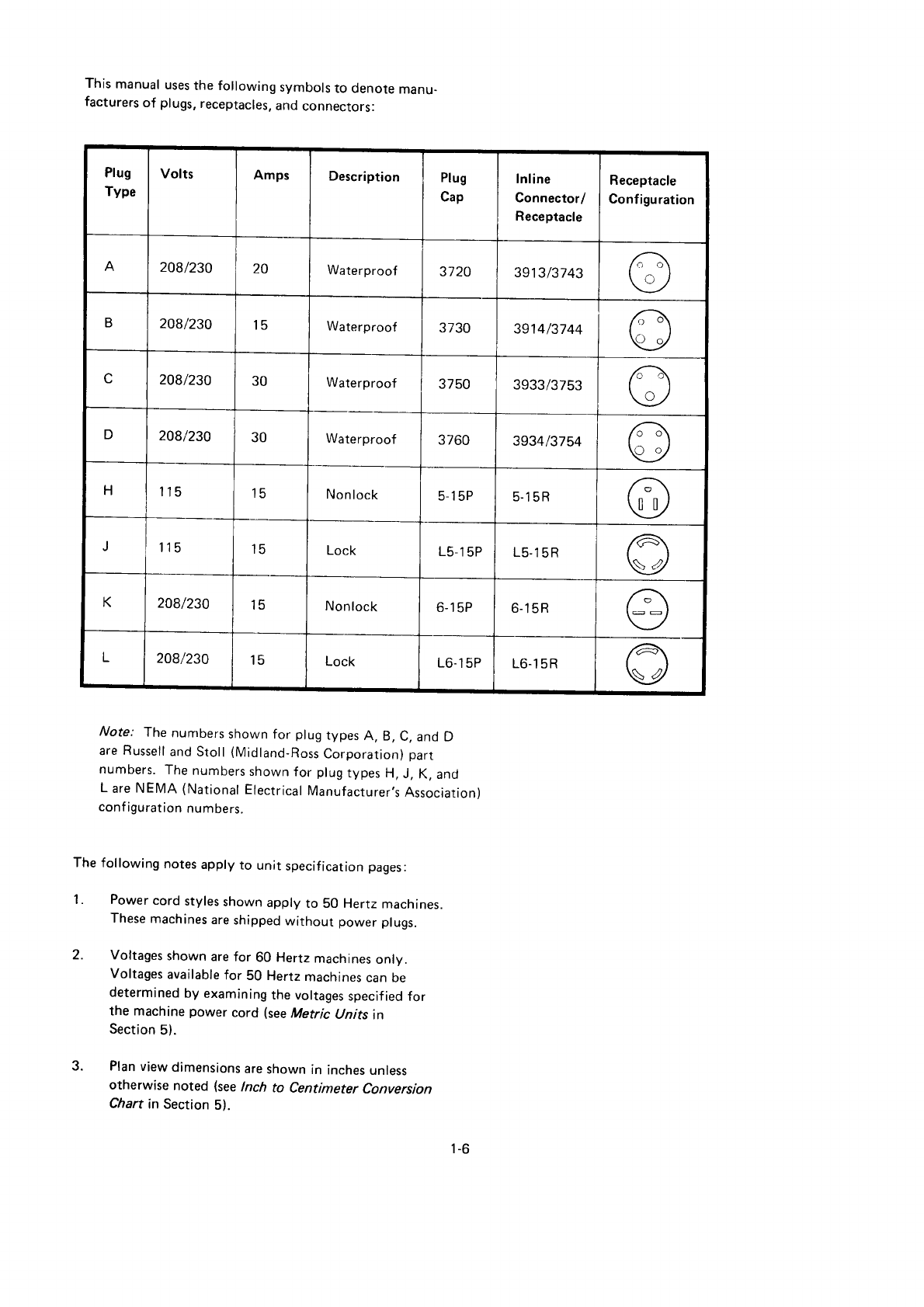
This
manual
uses
the following
symbols
to denore
manu-
facturers
of plugs,
receptacles,
and
connectors:
Plug
Type
Volts Amps Description Plug
cap
Inline
Connector/
Receptacle
Receptacle
Configuration
A208/230 ZU Waterproof 3720 3913/3743 /t-\
f,
B2A8/230 15 Waterproof JIJU 3914/3744 6\
e.t
208/230 30 Waterproof 3750 3933/3753 6\
\y
D208/230 30 Waterproof 3760 3934/3754 6\
qv
H115 15 Non
lock 5 15P 5-15R @
I
J115 l5 Lock L5
15P L5-15R A
V
K208/230 l5 Nonlock 6-1
5P 6-15R A\
q7
L208/230 t3 Lock L6-1
5P L6-15R @
Note: The
numbers
shown for plug
types
A, B,
C,
and D
are
Russell
and
Stoll
(Micjland-Ross
Corporation)
part
numbers.
The
numbers
shown
for plug
types
H,
J, K,
and
L are NEMA (National
Electrical
Manufacturer.s
Association)
conf
iguration
numbers.
The
following
notes
apply
to unit
specif
ication
pages:
1. Power
cord
styles
shown
apply
to 50 Hertz
machines.
These
machines
are
shipped
without power
plugs.
2. Voltages
shown
are
for 60 Hertz machines
only.
Voltages
available
for 50 Hertz
machines
can
oe
determined
by examining
the voltages
specif
ied for
the machine power cord (see
Metric lJnits in
Section
5).
Plan
view
dimensions
are
shown
in
inches
unless
otherwise
noted
(see
lnch to Centimeter
Conversion
Chart
in
Section
5).
3.
1-6
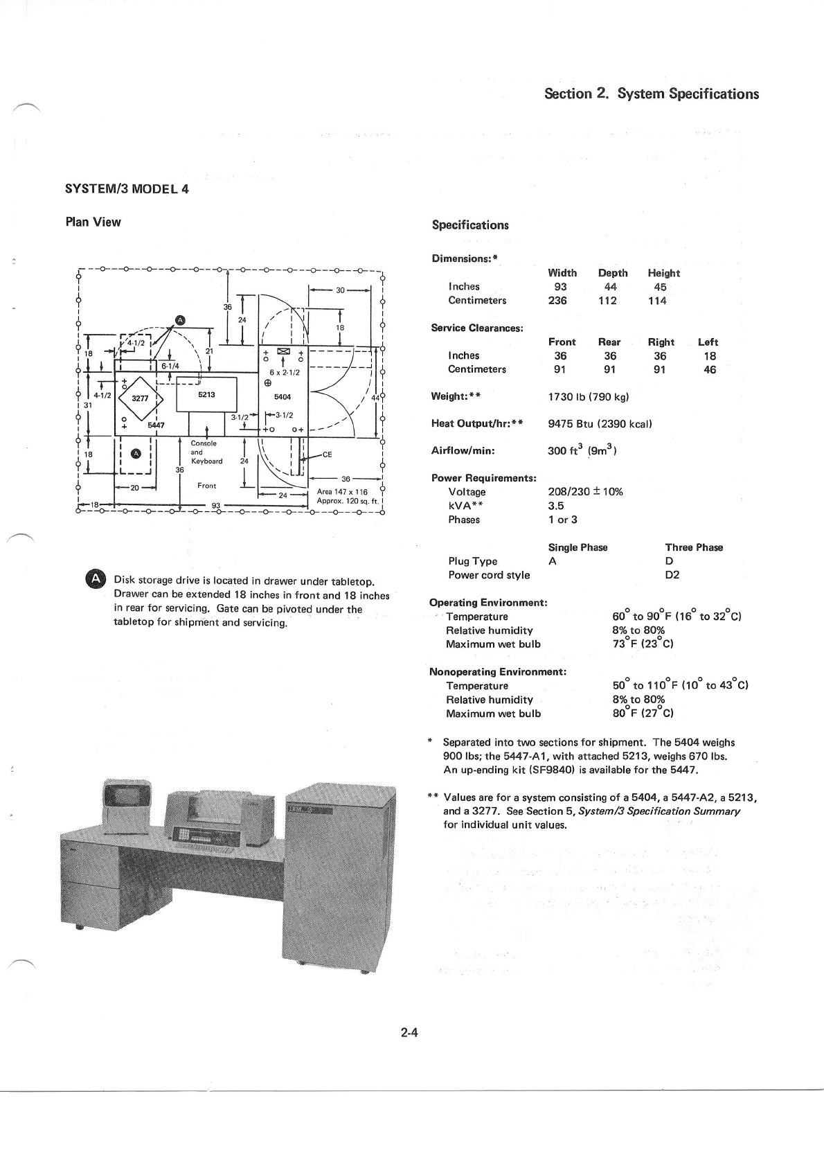
SYSTEM/3
MODEL
4
Plan
View
Section
2. System:
Specifications
Width Depth Height
93 44 45
236 112 114
Specifications
Dimensions:*
I
nches
Centimeters
Service
Clearances:
I nches
Centimeters
Weightr**
Heat Output/hr:**
Airflodmin:
Power Requirements:
Voltage
KVA**
Phases
Front Rear
36 36
91 91
1730
lb
(790
ks)
9475
Btu (2390
kcall
300 ft3 (9m3
)
2081230!10%
3.5
1or3
Right
36
91
Left
18
46
dl
it
tT-
i18
9l
Disk storage drive is located in drawer under tabletop.
Drawer can be extended 18 inches
in front and 18 inches
in rear
for servicing. Gate
can be pivoted under the
tabletop for shipment and servicing.
Single Phase
Plug Type A
Power
cord style
Operating
Environment:
' Temperature
Relative humidity
Maximum wet bulb
Nonoperating Environmont:
Temperature
Relative humidity
Maximum wet bulb
Three
Phase
D
D2
600 to gooF
{16o
to 32oc)
8o/o to 80o/o
73"r (23oc)
soo to 1 looF (1oo
to 43ocl
8%toSOYo
goor (27ocl
* Separated
into
two sections
for shipment. The 5404 weighs
900
f bs;
the 5447-A1, with attached
5213, weighs
670 lbs.
An up-ending
kit (SF9840)
is available
for the 5447,
* * Vaf ues
are
for a system consisti
ng ol a 54Q4, a 5447
-A2,
a 521
3,
and
a 3277 . See Section 5, System/3 Specification
Summary
for individual
unit values.
+El 1
ofo
6
t 2-112
5404
?3i/2
I
+o o+
.il
--r I
.20_l
2-4
-o- - -o- - -o- - -o- - + - {-l- I
I
I
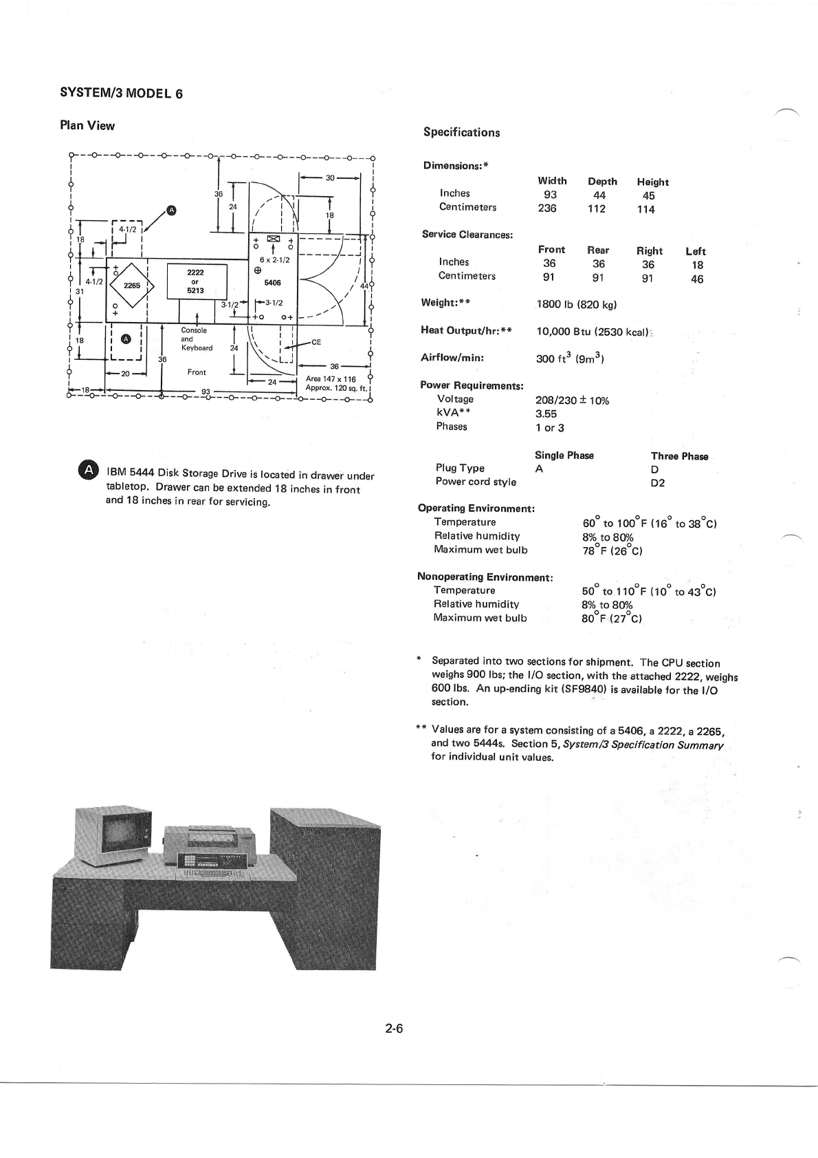
SYSTEM/3
MODEL
6
Plan
View
Front Rear
36 36
91 91
r-
?
I
6
I
ir
!18
:I
q+
it
tl
?l
131
dr
tl
if
?T
i18
?l
I
Y
I
Fll
Specifications
Dimensions:*
I nches
Centimeters
Service
Clearances:
I nches
Centimeters
Weight:**
Heat
OutpuVhr:**
Airflow/min:
Power
Requirements:
Voltage
KVA**
Phases
Width Depth Heighr
93 44 45
236 1'.t2 114
Right Left
36 18
91 46
?- 24 -1 Artsc
r+, x I ro T
Approx. 120
sq. ft. I
-o- - -r - -o- - -o- - -o- - :o- _ _o_
_ _o_ __6
1800
lb {820
k9)
10,000
Btu
(2530
kcat)l
3oo tt3 (9'n3)
2O8l23O!
1U/o
3.55
1or3
@ f
efU
b444
Disk
Storage
Drive
is located
in drawer
under
tabletop.
Drawer
can
be extended
1g inches
in front
and
18
inches
in rear
for
servicing.
Single Phase Three
phase
Plug
Type A D
Power
cord style D2
Operating
Environment:
Temperature 60o
to loooF (16o
to ggocl
Relative
humidity 8o/o to 8U/o
Maximum
wet
bulb TgoF
(26oC)
Nonoperating
Environ,ment:
Temperature 5Oo
to I 10oF
(10"
to 43ocl
Relative
humidity 8o/o to BOo/o
Maximum
wet bulb go"F,.(27oc)
Separated
into
two sections
for shipment.
The
CpU
section
weighs
900 lbs;
the t/O section, with the
attached
2222,
weighs
600 lbs. An up-ending
kit (SF9840)
is available
for the l/O
section.
*
" Values
are for a
system
consisting
of a b406,
a 2222,
a 2265,
and two 5444s, Section
5, System/S
Specification
Summary
for
individual
unit values.
7@ l'i
T-i;t7,1/ Il
'L-li., i
>\-'
i i)
+El +
olo
I
6x2-112
5406
?31/2
I
+o o+
4.112 2222
or
52r3
t_oVi
+l
18
console I
Keyboard 24
Front t
::_!p,:
i.il
t---,
I
F20d{
\rl
r\ | I
\r 14.
\-L-i {
_ 36_l
At6147
x116 ?
Approx.
120
sq. ft.
I
--+-
2-6
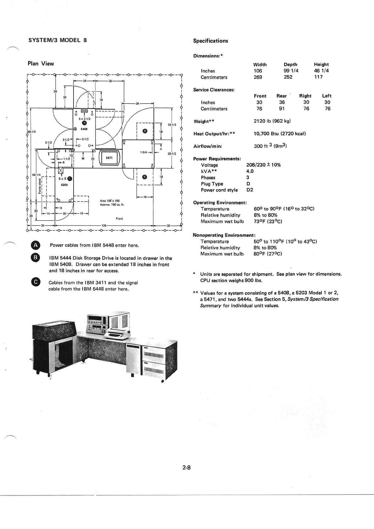
SYSTEM/3 MODEL 8
Plan
View
Specifications
Dimensions:*
I
nches
Centimeters
L€ft
30
76
width
106
269
Front
30
76
Dopth Height
99.,114 46114
252 117
--o---o---o---o---o-- -o--+- {---o---+ --o
32.1t2
I
nches
Centimeters
Weight**
Heat Output/hr:r*
Airflow/min:
Power Requirements:
Voltage 2@l23Ot1O%
kvA** 4.0
Phases 3
Plug
Type D
Power
cord style D2
Operating Environment:
Temperature 60o
to 90oF
(16o
to 32oC)
Ref
ative humidity 8o/o to 8Qo/o
Maximum
wet bulb 73oF
(23oC)
Nonoperating Environment:
Temperatu
re 500 to 1 1 ooF (
1 oo to 430C)
Relative
humidity 8o/o to 80:/o
Maximum
wet bulb 80oF
(27oC)
* Units
are separated
for shipment.
See
ptan
view
for dimensions.
CPU section weighs
900 lbs.
** Values for a system consisting
of a 5408,
a 5203
Model I or 2,
a 547 1, and two 5444s, See
Section 5, System
/3 Specification
Summary
for individual unit values.
t **,". ctsarances:
I
Y
I
I
Y
I
I
Y
I
A
Y
I
I
Y
I
1
Y
I
+
I
I
It
+
I
+
I
?
I
+
I
Rear
- Right
36 30
91 76
-T
2120
tb {962
kg)
10,700 Btu (2720
kcal)
3oo
ft 3 (9m3)
t "l'
ll
1
_i
@
@
o
Power cables
from IBM
5448
enter here.
IBM 5444 Disk Storage Drive
is located in drawer
in the
IBM 5408. Drawer
can
be
extended 18 inches
in
front
and
18
inches in rear for access.
Cables
from the I
BM 341
1 and the signal
cable from the I
BM 5448 enter here.
I
I
-J
2-8
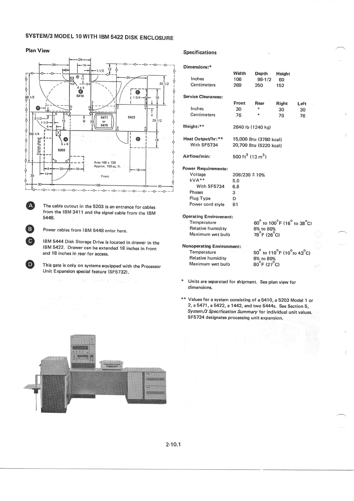
SYSTEM/3
MODEL
1O
WITH
IBM
5422
DISK
ENCLOSURE
Plan
View
The
cable
cutout in
the 5203
is an
entrance
for cables
from
the IBM
341 1
and
the
signal
cable from
the IBM
5448.
Power
cables
from IBM
5448
enter
here.
IBM
5444
Disk
Storage
Drive
is located
in
drawer
in the
IBM
5422. Drawer
can
be
extended
18
inches
in
front
and 18
inches
in,rear
for access.
This
gate
is
only on systems
equipped
with the
processor
Unit Expansion
special
feature
(SFS732).
Voltage 20gl230
t't|o/o
kvA* * 5.0
With SF5734 6.8
Phases 3
Plug
Type D
Power
cord
style 81
Operating
Environment:
Temperature 600
to loooF (16o
to 3gocl
Ref
ative
humidity 8o/o to BO%
Maximum
wer bulb TgoF
(26oC)
Nonoperating
Environment:
| -F-t---o-
h-r-vz rl 0
i------or- -j
l/ 13
l----. I I /
| ',,
V/
t Nl
t'l ,/ "L-
E;-//'--1,1i
l/l s47r
l\ |
20ll o, lll
lU s475
l/ l+
t+ ta
------i-_1
\l
\l
\\l
Area 166
x 128
Approx. 1
50 sq. fr.
Front
-106-
-o---o---o---o-
--.CF- -O_ _ r+
i
szlrz
\,
tt?
*r'el I
rll d
ttll
--T-- |
Tt +
"
rr\,, i
IT
l/,
IY
li
1.8 I
IT
+
+
I
+
+
--o---o---l
a
is il
'"^lf
-l
r2z I
*l
ot-
oi
I
----J- I
I
*"-] I
_1.
Specifications
Dimensions:*
I nches
Centimeters
Service Clearances:
Inches
Centimeters
Weight:**
Heat
Output/hn*+
With
SF5734
Airflow/min:
Power
Requirements:
Temperature
Relative
humidity
Maximum
wet
bulb
Depth Height
98-112 60
250 152
fr
tl
+t
il
98.1t2
il
itT
d|l
i
lui,
d|l
itl
ilI
it
+l
o
o
o
width
106
269
3.J/2J ll ,,o
\1.1/2--lF 'i
>-lsJ-
'tti--l
t.
h | | 5x6
Sl
I I u,o'
+i:-l'-'!
ll.'F,J
F14+l ./
l--.2
-30-J--
Front Rear
30*
76*
2640 tb (1240
kg)
15,000
Btu
(3780
kcat)
20,700
Btu (5220
kcatl
5oo
ft3 (13
m3)
Right Loft
30 30
76 76
I
* ro*1
-*----
soo to 1
looF
(1ooto
43oc)
8% to 8tr/o
gooF
(27oc)
* Units
are separated
for shipment.
See
plan
view for
dimensions.
** Values
for a
systern
consisting of a 5410,
a
5203 Model
1
or
2,
a 547 1,
a 5422,
a 1 442,
and two 5444s. See
Section
5,
System/S
Specification
Summary
for individual
unit values.
SF5734
designates
processing
unit
expansion.
2-10.1
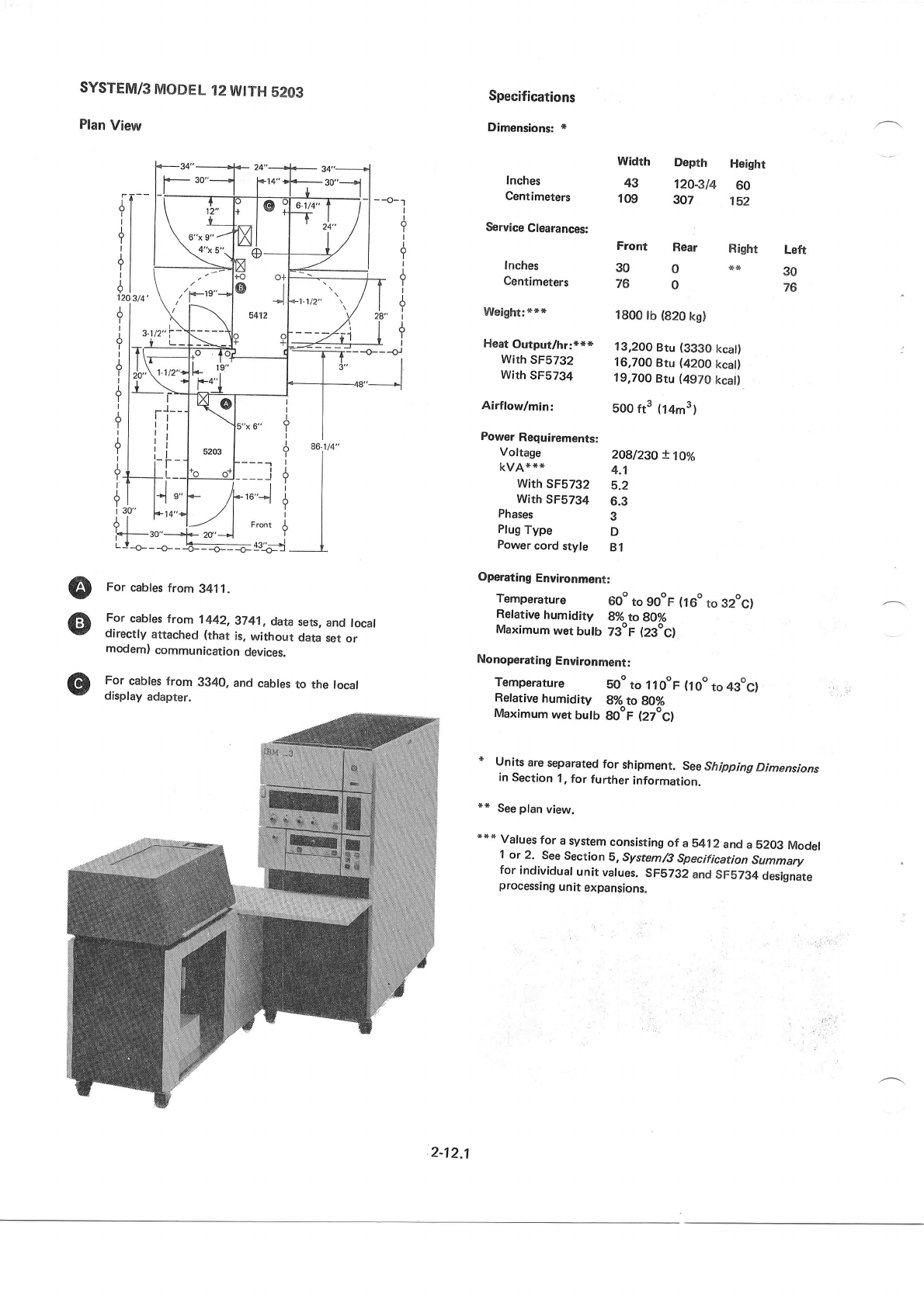
SYSTEM/s
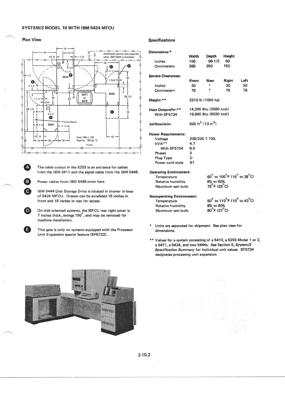
MODEL 10 WITH IBM 5424 MFCU
Plan View Specif
ications
Dimensions:+
lnches
Centimeters
Service
Clearances:
I nches
Centimeters
Wqight:**
Heat Output/hr:**
with
sF5734
Airflow/min:
Power Requirements:
Voltage
KVA**
with sF5734
Phases
Plug Type
Power cord style
Width Depth Height
106 98-112 60
269 250 152
Front Rear Right
30*30
76+76
2310
lb
{1050
kg}
14,20O
Btu (3580
kcal)
19,900
Btu {5020
kcal)
5oo
ft3 (13
m3)
208l2g} ! 10%
4.7
6.5
3
D
B1
LEft
30
76
o
e
o
The
cable cutout in the 5203 is an
entrance
for cables
from the IBM
341
1
and tlre signal cable
from the IBM
5448.
Power
cables from IBM 5448 enter
here.
IBM
5444 Disk Storage Drive
is located in
drawer
in base
ot 5424
MFCU. Drawer
can
be
extehded 18 inches in
front and
18 inches
in rear for access.
On disk-oriented systems,
the MFCU rear
right cover is
7 inches thick, swings
150",
and
may
be removed
for
machine installation.
This
gate
is only on systems
equipped
with the
Processor
Unit Expansion
special
feature
(SF5732).
* Units are separatd
for shipment.
See
plan
view
for
dimensions.
** Values
for a system consisting
of a 5410, a
5203
Model
1 or 2,
a5471,a8424, and
two 5444s.
See Section S,System/3
Specification Summary
for individual unit values, SF5734
designates
processing
unit expansion.
Operating
Environment:
Temperature
Relative humidity
Maximum wet bulb
Nonoporating
Environment:
Temperature
Relative
humidity
Maximum wet bulb
60"
to loooF (16o
to 38"c)
8o/o to 8U/o
TB.F
(26oc)
Eoo
to I 1
ooF (
1
oo to 43oc)
8o/o
to9Wo
SooF
(27ocl
I
-+- - -o- - -o- - -a- - -+- - -o- * -o- - -o- - -o- - -o- - -o- - -o- * -o- - -o- - r
2.10.2
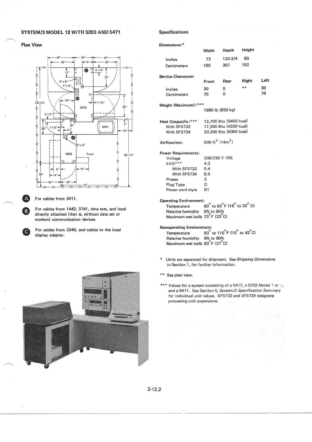
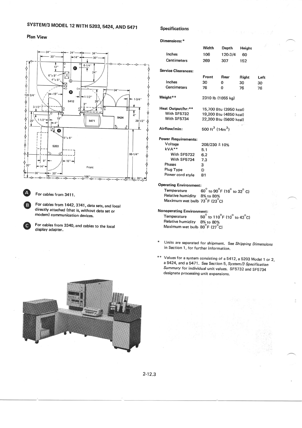
SYSTEM/3
MODEL
12
WITH
5203
Plan
View
Specifications
Dimensions:
*
Inches
Centimeters
Service
Clearances:
Inches
Centimeters
Weight:
***
Heat
Output/hr:***
with sF5732
with
sF5734
Airflodmin:
Power
Requirements:
Voltage
kvA
*
**
with sF5732
With
SFS734
Phases
Plug
Type
Power
cord style
Width Depth Height
43 120-314 60
109 307 152
--o-
Front
30
76
1800lb
(820
kg)
13,200
Btu (3330
kcat)
16,700
Btu (4200
kcal)
19,700
Btu (4970
kcall
5oo
ft3 (14m3)
2O8l23O X 16o7o
4.1
5.2
6.3
3
D
B1
Rear Right Left
0*o30
976
o
oFor
cables
from
341 1.
For cabfes
trom 1442,9741, data
sets,
and
local
directly
attached
(that is,
without data
set
or
modem)
communication
devices.
For cables
from 3340,
and
cables
to the local
display
adapter.
Operating
Environment:
Temperature 60" to gOoF
(16o
to 32oC)
Relative
humidity go/o
to gOyo
Maximum
wer
bulb 73oF
(23ocl
Nonoperating
Environment:
Temperature Sooto
llooF (1oo
to 43oc)
Relative humidity 8o/o
to gOTo
Maximum wet bulb goor (27oc)
* Units
are
separated
for shipment. SeeShipping
Dimensions
in Section
1,
for further
information.
** See
plan
view,
*s
* Values
for a system
consisting
ot a 5412
and
a 5203
Model
1 or 2. See
Section
5, System/3
Specification
Summary
for individual
unit values,
SFS732
and
SFS734
designate
processing
u
nit expansions,
2-12.1
SYSTEM/3 MODEL 12 WITH 5203
AND 5471
Plan
View
Specifications
Dimensions:
*
lnches
Centimeters
Service Clearances:
Inches
Centimeters
Weight
(Maximum):***
width Depth Height
73 120-314 60
185 307 152
Front Rear Right
300**
760
1860
lb (850
kgl
Left
30
76
Heat Output/hr:*** 13,700
Btu (3450
kcal)
with sF5732 17,200
Btu (4330
kcal)
With SF5734 20,200 Btu {5090
kcal}
,u"!
I
A
Y
I
A
Y
I
A
Y
I
A
Y
I
I
Y
Airflow/mn:
Power Requirements:
Voltage
kvA***
with
sF5732
With
SF5734
Phases
Plug
Type
Power
cord style
5oo
ft3 (14m3)
2O8l23O
+ 1Oo/o
4.3
5.4
6.5
3
D
B1
@
@
For cables
from 341 1.
For cables
trom 1442,3741, data sets,
and
local
directly attached
(that is, without data
set
or
modem) communication devices.
For
cables
from 3340, and
cables
to the local
display adapter.
Operating
Environment:
Temperature 60" to 90oF
(16o
to 32o c)
Relative
humidity 8%to8O%
Maximum wet b;lb z3"P (23oc)
Nonoperating
Environment:
Temperature 5oo to 11ooF
(1oo
to 439c)
Relative
humidity 8To to ffio/o
Maximum
wet bulb SooF
(27oc)
* Units
are separated
for shipment.
SeeShipping
Dimensions
in Section
1, for further information.
** See
plan
view.
*** Vafues for a system consisting
of a5412,
a 5203
Model
1
or ;,
and a5471. See Section 5, System/3
Specification Summary
for individual unit values.
SF5732
and
SF5734 designate
processing
unit expansions.
2-12.2
SYSTEM/3
MODEL
12
WITH
5203,5424,AND
5471
Plan
View
For
cables
from 341
1.
For
cabfes
trom 1442,3741
, data
sets,
and local
directly attached
(that is,
without data
set
or
modeml
communication
devices.
For
cables
from 3340,
and
cables
to the local
display
adapter.
307
Temperature 60o
to go"F (160
to 32o
c)
Refative humidity 8o/o to 8}o/o
Maximum wet bulb 73oF (23ocl
Nonoperating Environment:
Temperature soo
to 1 1
o"F (1
oo to 43oc)
Relative
humidity 8o/o
to &o/o
Maximum
wet bulb gooF (27oc)
Specifications
Dimensions:
*
Inches
Centimeters
Service
Clearances:
Inches
Centimeters
Weight**
Heat
Output/hr:**
With
SF5732
with sF5734
Airflow/min:
Power
Requirements:
Voltage
KVA*+
with sF5732
with sF5734
Phases
Plug
Type
Power
cord
style
Operating
Environrnent:
Depth Heighr
120-314 60
width
106
269 152
Right
30
76
Laft
30
76
Front Rear
300
760
2310 lb
(1055
ks)
15,700
Btu (3950
kcat)
19,20O
Btu (4850
kcat)
22,2OO
Btu (5600
kcat)
500
ft" {14mr)
2O8l23O
!10%
5.1
6.2
7.3
3
D
B1
o
o
* Units are
separated
for shipment. See
Shipping
Dimensions
in Section
1.
for
further
information.
** Vafues
for
a system
consisting
ot aS412,a
b203
Mooet
I or
2,
a 5424, and
a 8471. See
Section
5. System/3
Specification
Summary
for individual
unit values.
SF5732
and
SF5734
designate processing
unit expansions.
+
I
Y
I
II
+
I
+
I
?
I
2"9
I
+
i
9
I
?
i
II
?
I
I
-t
1-l*
'o^"
+F-T
-I-T I
|
*,J;,
'if
tl
i,,1,,,,.
2-12.3
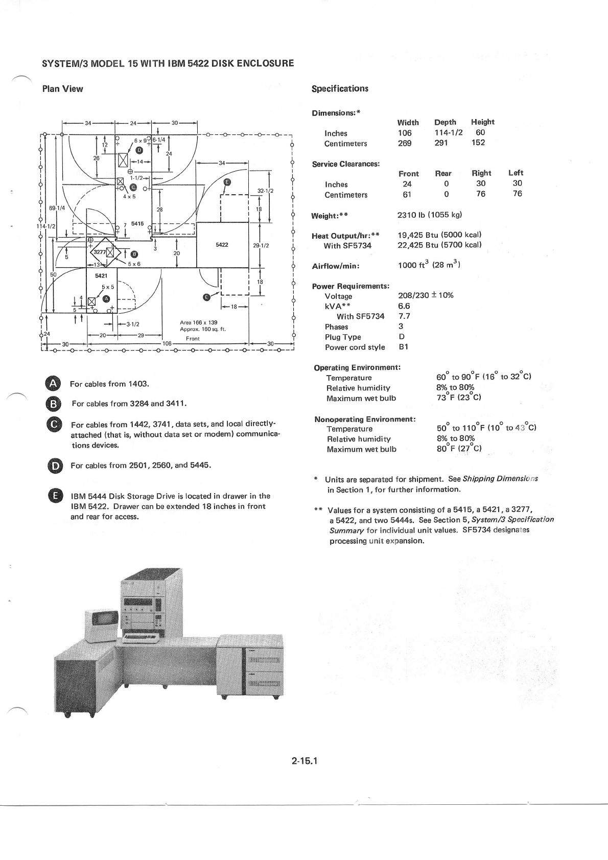
SYSTEM/3 MODEL 15 WITH
'B,M5422 DISK ENCLOSURE
Plan View
T- 24
t\
r
-
L
I
12
l_
)
' 6x9:
.J
o'
lxlt*r4-
o-
Yl 1.1/21
\@ ol
75415
;.1t4
|
TI
'f/
I/
*,r/
34
>
--\
>=-
I
I
'----
I
32-
-l-
I
18
5422 29-1t2
I
t
T
_I
ffite.'
I ,z'
r4
ll
5421
x'o --J
\li
u'i:,,-
3-112 | Area 166 x 139
I Approx,
160
sq.
fi
II
dT-----t-Ii-I.- | | d
ll |'l -Al-a:n I Area166x139 I !
ll I ll -'- | npprox.160sq.ft.
| |
lrf f-zo-f.-zs---*l Front I t
i*l- go
.+l<- 1
06
+l- 30-------n
L.t-O---O-- -b---O---O- --O----g.---g----+---p----O---O- --O---+--l
J.
Y
I
?
A
Y
Heat
Output/hr:** 19,425
Btu (5000
kcal)
With
SF5734 22,425 Btu (5700
kcal)
Specif
ications
Dimensions:*
Inches
Centimeters
Service
Clearances:
lnches
Centimeters
Weight:**
Airflow/min:
Power Requirements:
Voltage
KVA**
with sF5734
Phases
Plug Type
Power cord
style
Operating Environment:
Temperature
Relative
humidity
Maximum wet bulb
Width Depth Height
106 114-112 60
269 291 152
Front Rear Right Left
2403030
6107676
2310
lb
(1055
kg)
looo
tt3 (28
m3)
2o8l23o + 1oo/o
6.6
7.7
3
D
B1
60o
to gooF
{16"
to 32oc}
8o/o to BV/o
73oF
(23"c)
sz.tiz I
-Tl ?
'Pl t
t{ !
--f-- I
to
tt
A
Y
I
A
Y
I
A
Y
I
Y
te*l i
@
@
o
o
o
For cables
from 1403.
For
cables
from 3284 and
341
1.
For
cables
trom 1442,3741
, data
sets,
and local
directly'
attached
(that
is,
without
data
set or modem) communica'
tions
devices,
For
cables
from 2501,
2560, and
5445.
IBM 5444
Disk Storage Drive is located
in drawer in the
IBM
5422. Drawer can be extended 18 inches
in front
and rear
for access.
Nonoperating
Environment:
Temperature 50o
to 1
looF (1oo
to 43oc)
Ref
ative
humidity 8o/o toSff/o
Maximum wet bulb 80oF
(27ocl
* Units are separated
for shipment.
SeeShipping
Dimensirtns
in
Section
1" for further
information.
** Vaf
ues
for a
system consisting
of a 541
5, a 5421, a
3277,
a5422, and two 5444s. See Section
5, System/3
Specification
Summary
for individual
unit
values.
SF5734
designates
processing
unit expansion.
2-15."1
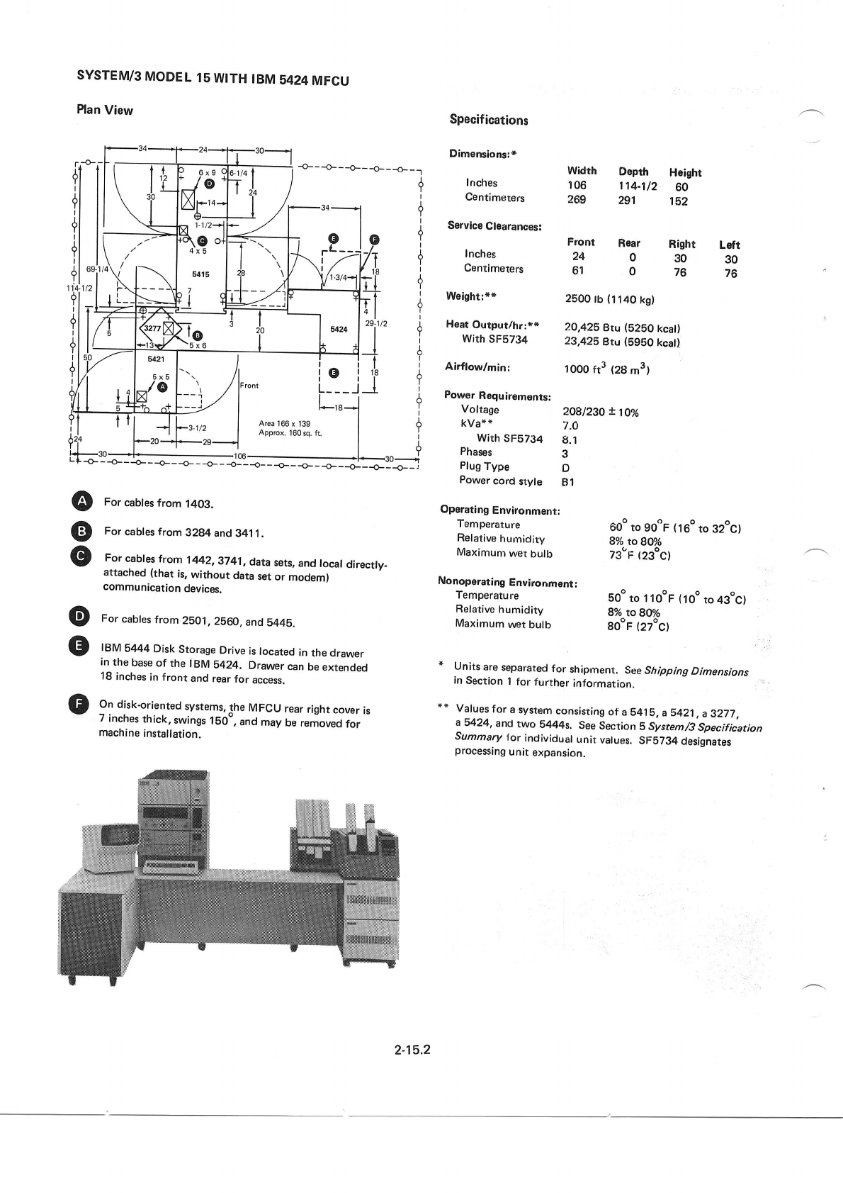
SYSTEM/3
MODEL
15
WITH
IBM
5424MFCU
Plan
View
-cts--{- - -o-- _o__ _o_ _r
Specif
ications
Dimensions:*
Inches
Centimeters
Service
Clearances:
Inches
Centimeters
Weight:**
Heat
Outprrt/hr:**
With
SF57g4
Airflow/minl
Power
Requirements:
Voltage
kVa**
With
SFS7g4
Phases
Plug
Type
Power
cord
style
Operating
Environnrent:
Temperature
Relative
humidity
Maximum
wer
bulb
Width Depth Height
106 | 14-112 60
269 291 152
A
T
I
A
Y
I
A
T
A
Y
I
6
I
6
I
I
?
I
A
Y
I
T
A
Y
I
A
Y
I
A
Y
Front Rear
240
61 0
Right Lsfr
30 30
76 76
29-1/2
I
I
__l t
18
_1
oi
--_J
2500
lb
(11a0
kg)
20,425
9tu (5280
kcal)
23,425
Btu (5950 kcat)
1000
ft3 (28
m3)
2O8l23O
t loa/o
7.O
8.1
3
D
B1
Area
i66 x 139
Approx.
160
sq. ft,
<- - -.- - -o- - -o- - -o- - -o- _
{_ _ _o_
_
-o_
_ -o_
_ _o_
_
J=:r;l
@ forcabtesfrom
1403.
() Forcabtesfrom
3284and
3411.
For
cabfes
trom 1442,
9741,
data
sets,
and
local
directly.
attached
(that
is,
without
data
set
or modem)
communication
devices.
O For
cabtes
from.2501,
2b60.
and
5445.
O IBM
5444
Disk
Storage
Drive
is
located
in
the drawer
in
the
base
of the IBM 5424, Drawer
can
be
extended
18
inches
in front and
rear
for access,
On diskoriented
systems,
the MFCU
rear
right
cover
is
/ Inches
thick,
swings
1b0-,
and
may
be removed
for
machine
installation.
60o to gooF
(160
to 32oc)
8o/o
lo 8oo/o
z3"F (23oc)
Nonoperating
Environment;
Temperature bgo
to 1 lOoF
{1Oo to 4gog}
Relative
humidity go/o
to g1o/o
Maximum
wet
bulb gooF
(27oC)
* Units
are
separated
for shipment. See
Shipping
Dimensions
in
Section
1
for further
information.
** Valuesfora
system
consisting
of
a S415.
a5421,
a3277,
a 5424,
and
two S444s. See
Section
B System/3
Specification
Summary
for individual
unit vatues.
SFS734
desijnates
processing
u nit expansion.
2-15.2
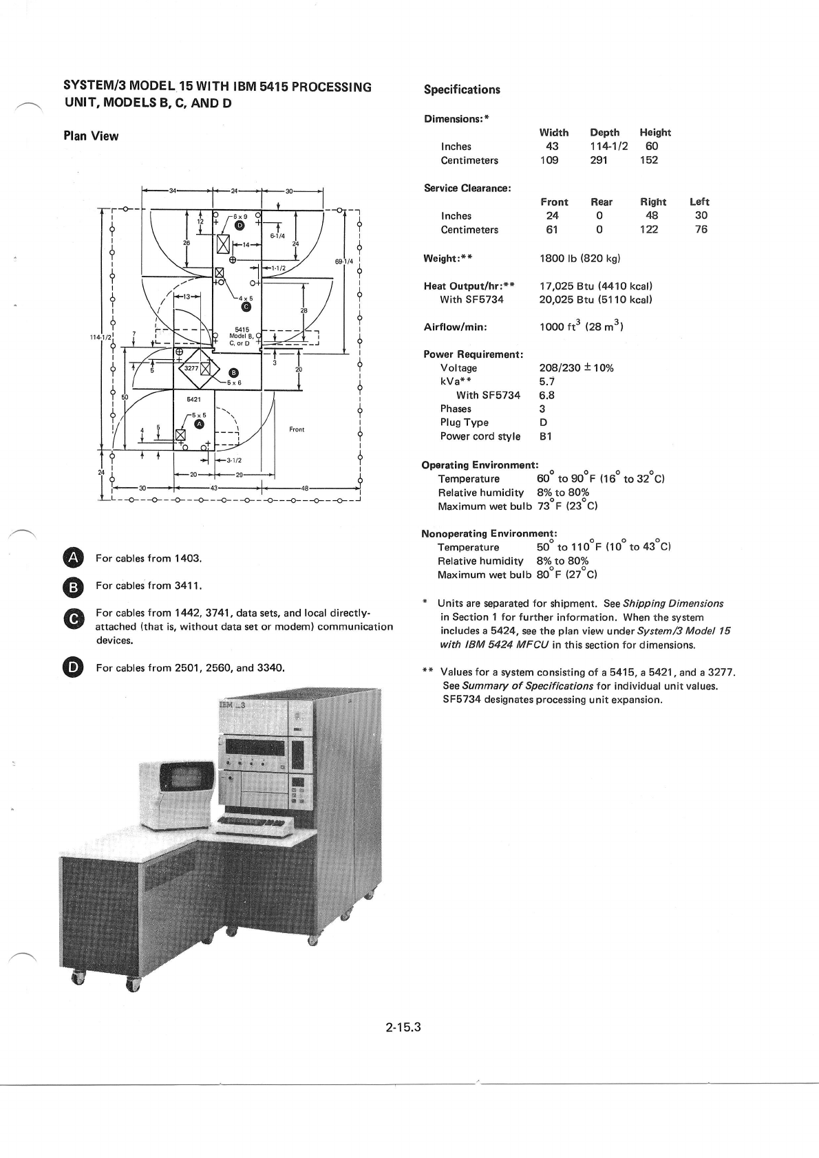
SYSTEM/3
MODEL
15 WITH
IBM 5415 PROCESSING
UNIT, MODELS
B,
C,
AND D
Plan
View
Specifications
Dimensions:*
I nches
Centimeters
Service Clearance:
I nches
Centimeters
Weight:**
Heat
Output/hr:**
With SF5734
Airflow/min:
Power
Requirement:
Voltage
kVa*
"
With SF5734
Phases
Plug
Type
Power
cord style
Width Depth Height
43 114-112 60
109 29't 152
Front Rear Right
24048
61 0 122
1800 lb
(820
ks)
17,O25 Btu (4410
kcal)
20,025
Btu
(51
10
kcal)
1000 ft3 (28
m3)
2081230
!100/0
5.7
6.8
3
D
B1
+
I
+
I
+
I
6
I
6
I
I
L
, .6x9 !
'/
o n
t\tl
aJr'.*
A-
!l
'q oj
L4x5
o
915
) [-,lod€t
B,
(
' C,orD
a
-Tl
61/4 | l
j/
-rry'
l- 1
L-/
?
I
+
I
+
I
,a_
Tf t-
t' KM 3
it_
8421
T5x5
/@
VI
+.-
-l ,/
i/
'-r)-
?3-1/2
Front
20
It=:;{- -o- - -o- - -+- - -o-- -o- - -o- - -o- - J
-ze-------->1 A
.-]-_48_____+
Op€ratingEnvironment:
.
Temperature 60o
to ggoF
(16o
to 32oC)
Relative
humidity 8o/o to 80o/o
Maximum
wet bulb 73"F
(23oc)
Nonoperating
Environment:
Temperature 50o to I looF (1oo
to 43oc)
Relative
humidity 8o/o
lo 80o/o
Maximum wet bulb
SooF
(27oc)
* Units
are separated
for shipment. See Shipping Dimensions
in Section 1 for further
information. When the system
incf
udes a5424, see the
plan
view
underSystem/S
Model 15
with IBM 5424 MFCU in this
section
for dimensions.
*x Values for a system
consisting ot a 5415, a 542'1, and a 3277.
See Summary
of Specifications for individual unit values.
SF5734 designates
processing
unit expansion.
--l
9
I
?
Left
30
76
os.ilq !
t+
I
J.
Y
I
{
I
J.
Y
A
Y
I
I
Y
I
A
Y
I
?
I
A
Y
I
@
@
o
For
cables
from
1403.
For
cables
from
341 1.
For cables
trom 1442,3741, data
sets. and
local directly-
attached
(that
is, without data set or modem) communication
devices,
O For
cables
from 2501, 2560. and 3340.
2-15.3

This
page
intentionally
left
btank,
2-15.4
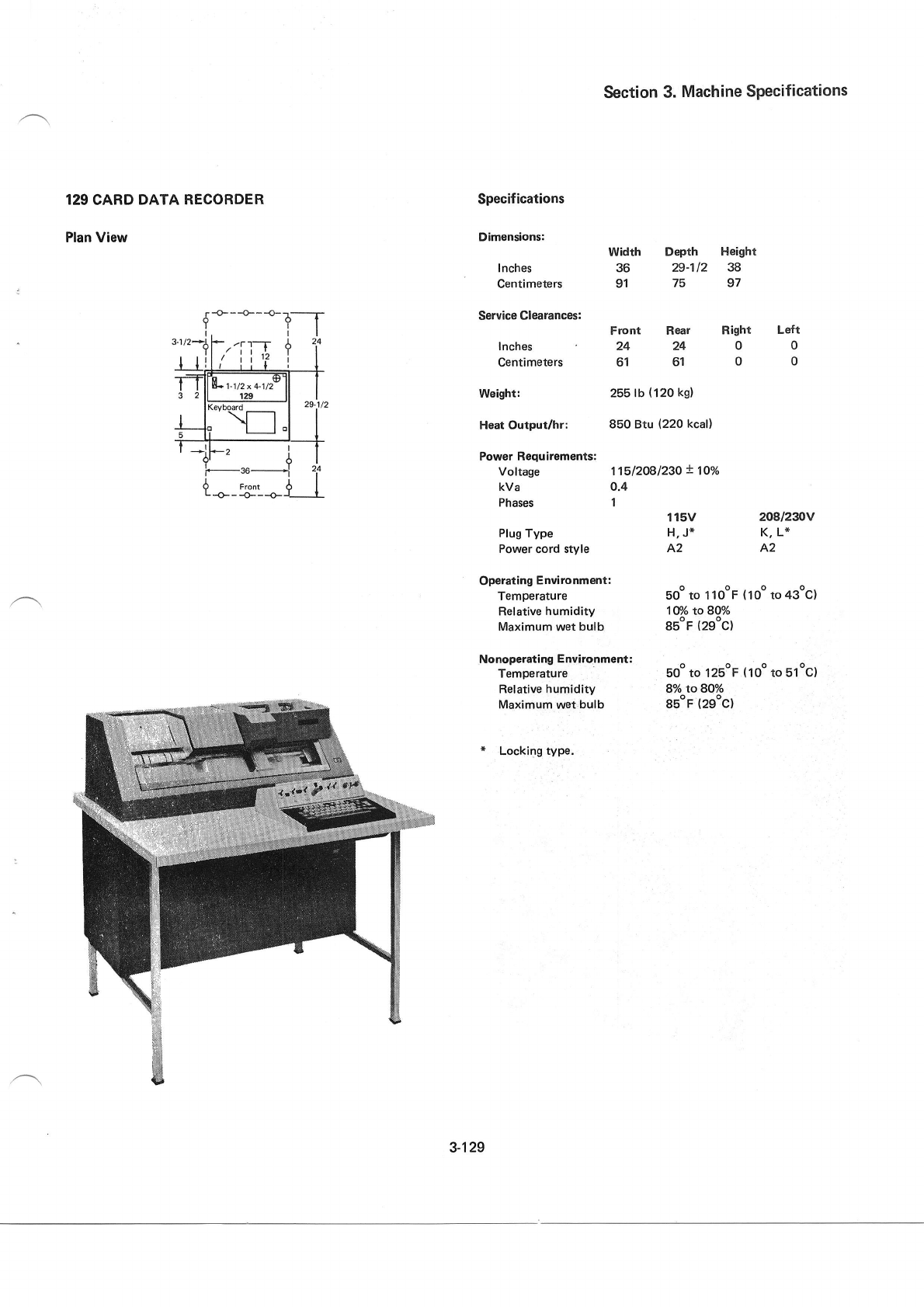
129
CARD
DATA RECORDER
Plan View
Specifications
Dimensions:
I nches
Centimeters
Service
Clearances:
Inches
centimeters
Weight:
Heat
Output/hr:
Power Requirements;
Voltage
Nonoperating
Environment:
Temperature
Relative humidity
Maximum
wet
bulb
* Locking type.
Section
3. Machine
Specifications
Width Depth Height
36 29-112 38
91 75 97
Front Rear Right Left
242400
616100
255 lb
(120
kg)
850 Btu (220
kcal)
't1512081230
t 10./"
boo
to l2EoF
(1oo
to 51oc)
8o/o
to 80o/o
gsop
(29"c)
kVa 0.4
Phases 1 115V 208l23rJV
Plug Type H,
J* K, L*
Power
cord style A2 A2
Operating
Environment:
Temperature 50o to 1 1 ooF
(
10o to 43oc)
Relative
humidity 1V/o to 80o/o
Maximum wet
bulb 85oF
(29oc)
1-112
x 4-112
3-129
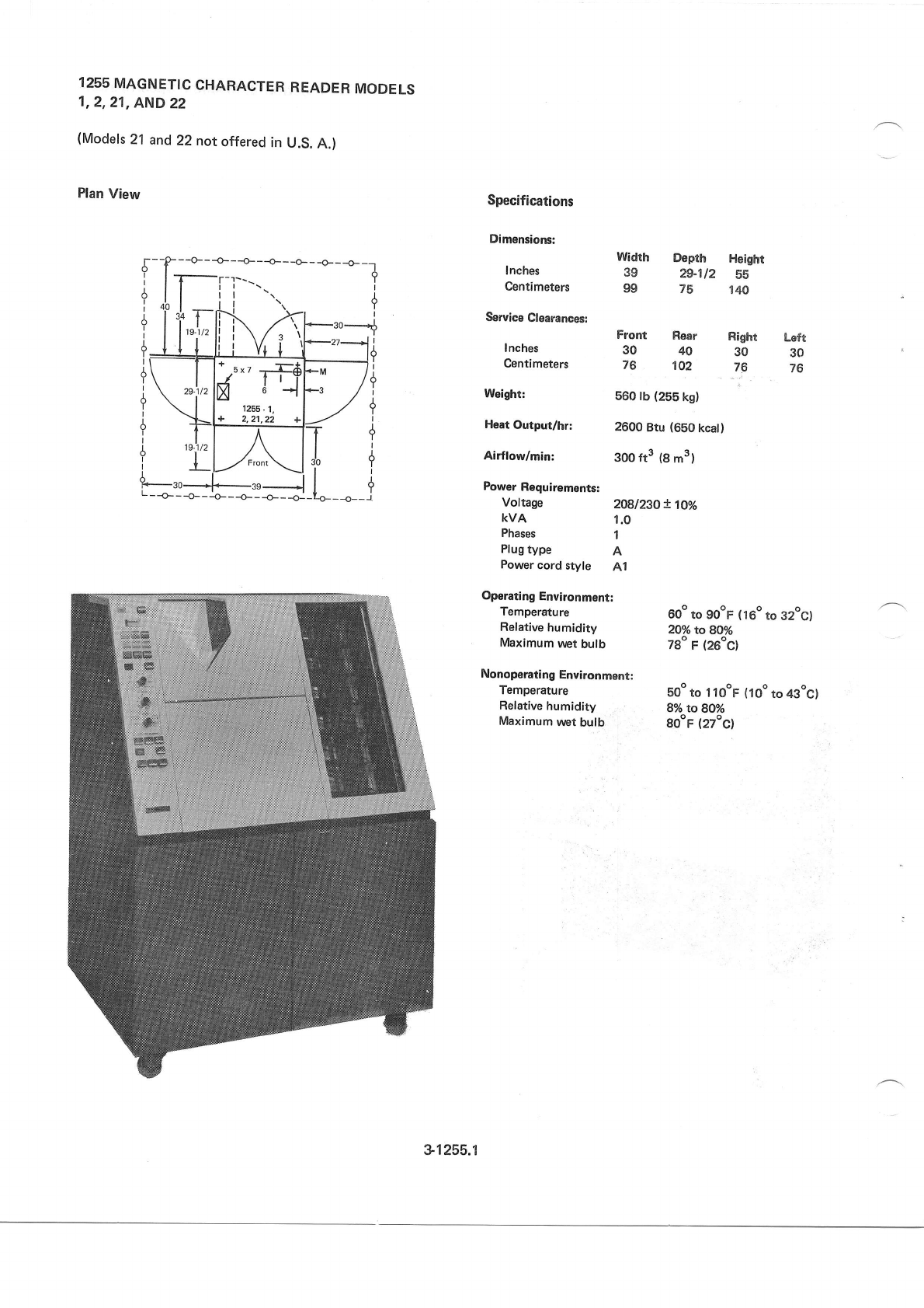
1255
MAGNETIC
CHARACTER
READER
MODELS
1,2,21,
AND
22
(Models
21
and
22notoffered
in U.S.
A.)
Plan
View Specifications
Dimensions:
lnches
Centimeters
Service
Clearances:
lnches
Centimeters
Weight:
Heat
Output/hr:
Airflow/min:
Power
Requirements:
Width Depth Height
39 29-112 55
99 75 ,t40
Front Rear
30 40
76 102
560 lb (255
kg)
2600
Btu (650
kcat)
300 ft3 (8
m3)
Right Lsft
30 30
76 76
Voftage 208l2gOX1Oo/o
KVA 1.0
Phases 1
Plug
type A
Power
cord
style Al
Operating
Environment:
Temperature 60o
to go"F (16o
to g2oc)
Refative
humidity 2oo/otog1o/o
Maximum
wer
bulb 7go
F (26oCl
Nonoperating
Environment:
Temperature goo
to llooF (loo to 43oC)
Relative
humidity 8o/o to 81o/o
Maximum
wet
bulb gOoF
(27oC)
+-Fl
/u" lt9.
X
at
1255 - 1,
c1255.1
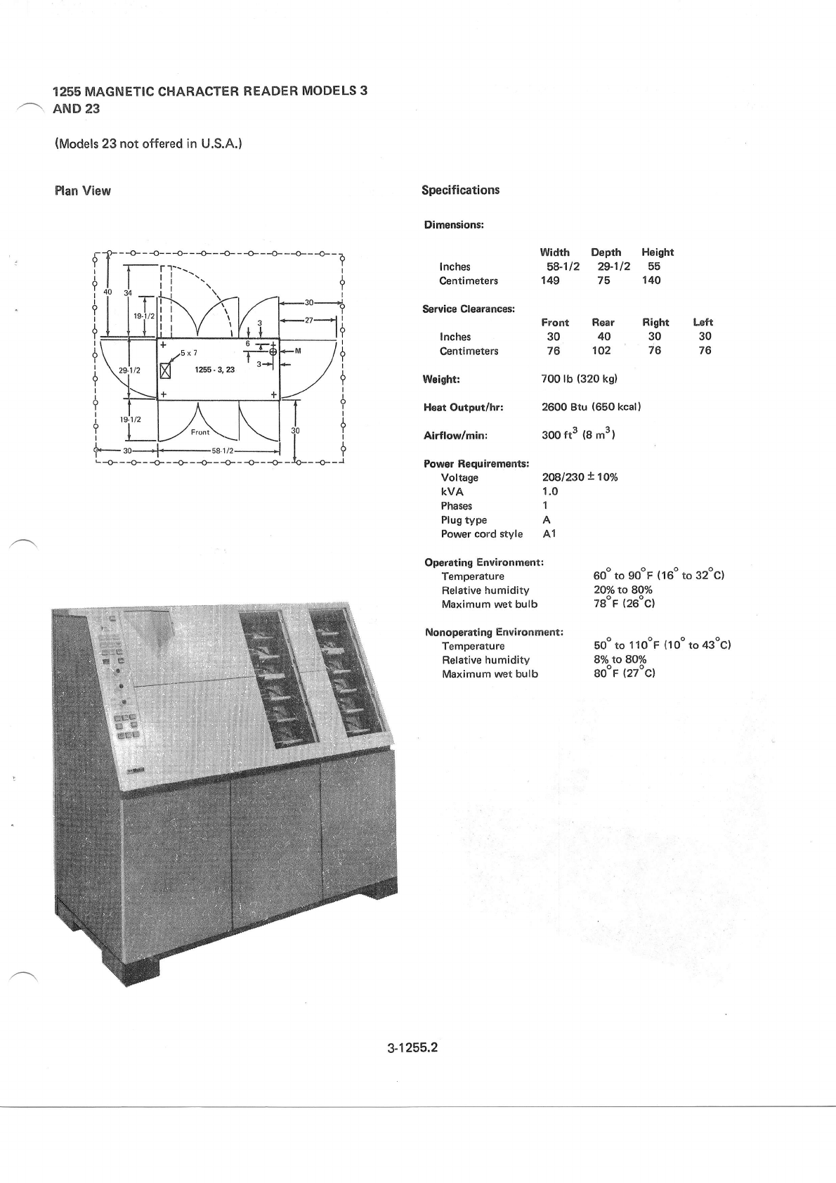
1255 MAGNETIC CHARACTER
READER
MODELS 3
AND
23
(Models
23
not
offered
in
U.S.A.)
Plan View Specifications
Dimensions:
I nches
Centimeters
Service Clearances:
I nches
Centimeters
Weight:
Heat Output/hr:
Airflow/min:
Power
Requirements:
Voltage
KVA
Phases
Plug type
Power
cord style
Width Depth Height
58-112 29-112 55
149 75 140
Rear
40
102
700
lb (320
ks)
2600 Btu (650 kcal
)
3oo
ft3 {8
m3)
2081230x100/0
1.0
1
A
A1
Right Left
30 30
76 76
Front
30
76
Operating
Environment:
Temperature
Relative
humidity
Maximum wet bulb
Nonoperating
Environment:
Temperature
Relative
humidity
Maximum
wet bulb
60o
to gooF
(16"
to 32oe)
2Qo/oto
8oo/o
TBoF
(26oc)
Eoo to 1 1
ooF
(1
oo to 43oc)
8o/oIo 8Oo/o
Boor
(2zoc)
I
?
i
?
I
?
I
+
I
?
I
+
I
?
L -O- - -O- - -O-. - -O- - -O- - -O- - -O-- -O-
40
,{l
t+
ti
t9
I
9
I
?
I
1
Y
6
I
-l
3-1255.2
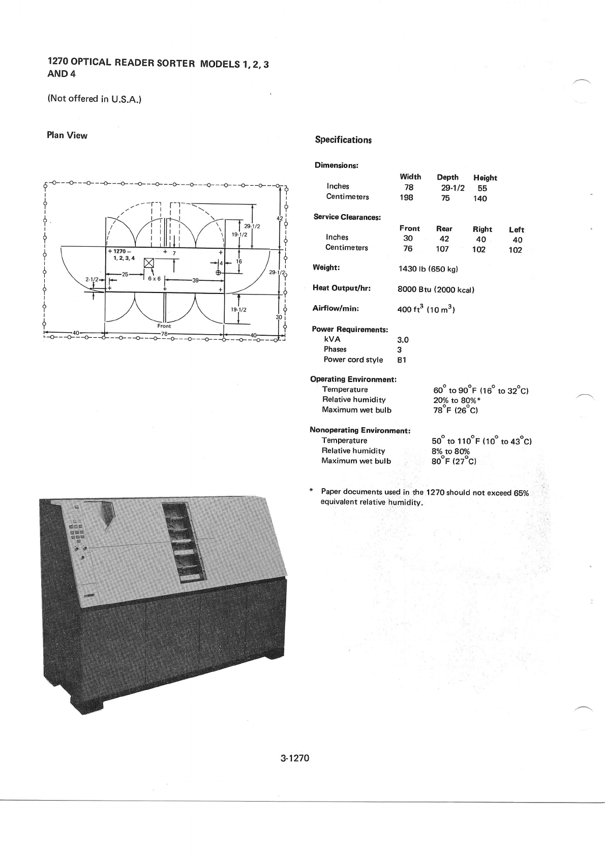
1270
OPTICAL
READER
SORTER
MODELS
1,2,3
AND 4
(Not
offered
in
U.S.A.)
Plan
View Specifications
Dimensions:
Width Depth Height
fnches 7g 29-112 Sb
Centimeters lg8 75 14O
Service
Clearances:
Front Rear Right Left
Inches 30 42 40 40
Centimeters 76 107 1O2 102
Woight: 1430 tb {650
kg)
Heat
OutpuVhn 8000
Btu (2000
kcall
Airflow/min: 4OO
ft3 (10
m3)
Power
Requirementsl
kvA 3.0
Phases 3
Power
cord style Bl
Operating
Environmentl
Temperature 60o
to go"F (16"
to 32oc)
Ref
ative
humidity 2Oo/o to 8oo/o*
Maximum
wet bulb TgoF
(26"c)
Nonoperating
Environment:
Temperature g9o
to 1
10oF
(1Oo
to 43oC)
Relative
humidity 8% to8tr/o
Maximum
wet
bulb gOoF
(27ocl
* Paper
documents
uied
in the 1270
should not
exceed
65%
equivalent
relative
humidity.
,5
-O- - -O- - -O- - -O- - -O- - -O- - -O- - -O- - -O- - -e- _ _e_ _ _€_ _ _o_ _
YIi
?
I
Y
I
A
Y
I
+
!
3-1270
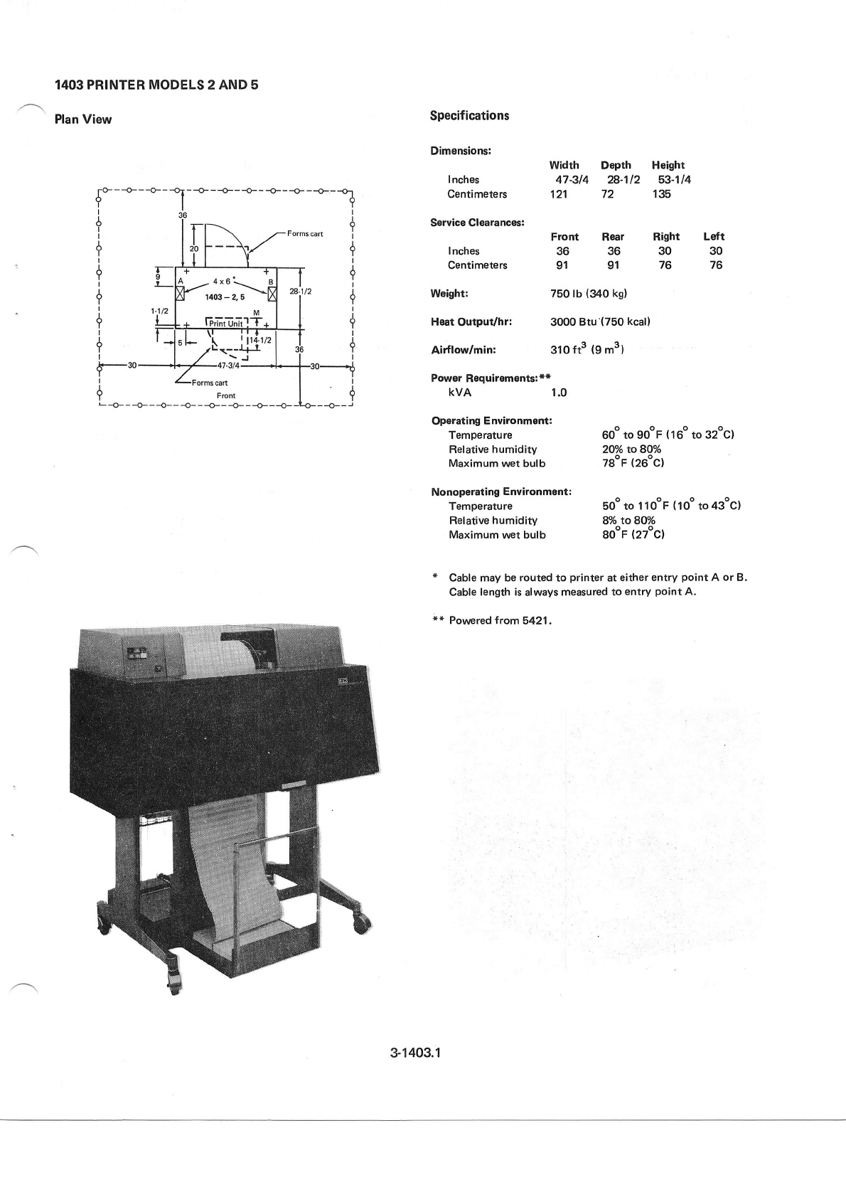
1403 PRINTER
MODELS
2 AND 5
Plan View
I
Y Front
L-O-- -O-- -O---O- --O-- -O---O---O-
A
ormscart T
Specifications
Dimensionsl
I nches
Centimeters
Service Clearances:
I
nches
Centimeters
H€at
Outpuvhr:
Airflow/min:
Width Dopth Height
47-314 28-112 53-114
121 72 135
+
+
I
t
?
II
Left
30
76
Front Rear
36 36
91 91
Right
30
76
28.112 Weight: 750
lb (340
ks)
3000
Btu'(750
kcall
310
ft3 (9
m3
)
Power
Requirements:**
kvA 1.0
Operating
Environment:
Temperature
Relative
humidity
Maximum
wet bulb
Nonoperating
Environment:
Temperature
Relative humidity
Maximum
wet bulb
60o
to gooF
(16o
to 32ocl
2Oo/o
to 8oo/o
zSoF
(26oc)
Eoo to I 1
ooF (
1 oo to 43oc)
8/o
toSW/o
SooF
(22"c)
* Cable may be
routed
to printer
at
either
entry
point
A or B.
Cable
length is
always
measured to entry
point
A.
l* Pornpred from5421,
3-1403.1
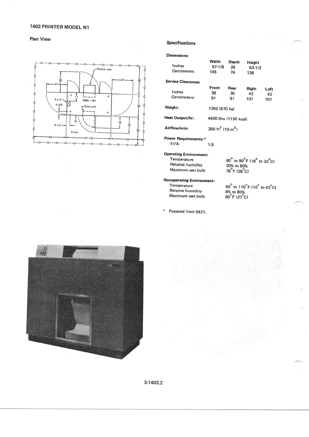
1403
PRINTER
MODEL
Nl
Plan
View
+
+
I
+
I
+
I
iI
T
I
+
I
{-o'
L -+---O---o--_+___o__ _o__ _o___o___o___o__-o__
Specifications
Dimensions:
I
nches
Centimeters
Service
Clearances:
lnches
Centimeters:
Weight:
Hoat
Output/hr:
Airflow/min:
Power
Requirements:*
KVA
Operating
Environmant:
Temperature
Relative
humidity
Maximum
wet
bulb
Nonoperating
Environment;
Temperature
Relative
humidity
Maximum
uret
bulb
" Powered
from5421,
Front Rear Right Left
36 36 42 42
91 91 1O7 107
1250
(570
kg)
4500
Btu
(1130
kcat)
350 ft3 (10
m3)
1.5
60" to gooF
(16o
to 32oc)
2@/o
to 80%
78oF
(26oc)
so" to 1 1
ooF (
i oo
to 43oc)
8o/o to 8Oo/o
SooF
(27oc)
-t
Y
A
T
I
?
A
Y
I
?
I
Y
I
A
Y
I
A
T
I
Width Depth
57-118 29
145 74
Height
53-1t2
136
Y'l::l'
3-1403.2

1442
CARD READ PUNCH MODELS
6 AND 7
Plan View Specifications
Dimensions:
Width Depth Height
lnches 43 24 49
Centirneters 109 61 '1.24
Service Clearancesl
Front Rear Right Left*
Inches 36 30 6 18
Centimeters 91 76 15 46
Maximum
Weight: 520 tb (240
kg)
Heat
Output/hr: 1800
Btu (450
kcat)
Airflow/min: SO
fr3
(1.4
m3)
Power
Requirements:**
kvA O.7
Operating
Environment:
Temperature 60o
to gOoF
(16o
to 32oC)
Ref ative
humidity 2Oo/o
to 8Oo/o
Maximum
wet bulb 78oF
(26oc)
Nonoperating Environment:
Temperature bo" to I lOoF
(10o
to 43oc)
Relative humidity 8o/o toSQ%
Maximum
wet
bulb go"F
(27oC)
* Left
service clearance
not required from floor level to 30 inches
(76
cm)
above the
floor.
** Powered from
the
processing
unit.
1442
- 6,7
-=-- - -- -
l}J-5 x
6
3-1442
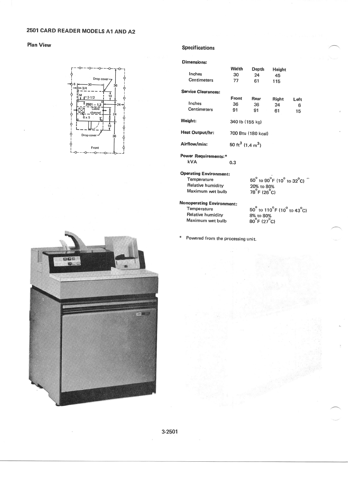
2501
CARD
READER
MODELS
A1
AND
A2
Plan
View
-o---o---o---o- -l*l
t+
li
36 1
r9
ll
ld
T*-i
l?
24i
td
tr
-Tl
t+
lr
364
ti
t9
$__ j
Front
--o---o---o--
Specif
ications
Dimensions:
Inches
Centimeters
Service
Clearances:
I
nches
Centimeters
Weight:
Haat
Output/hr:
Airflow/min:
Power
Requirementsl*
KVA
Width Deprh Heighr
30 24 45
77 61 115
Front Rear Right Left
3636246
91 91 61 15
340 lb
(155
kg)
700
Btu
(180
kcat)
50
ft3 (1.4
m3)
0.3
soo
to gooF
(ioo to 32oc)
2O%
toSO%
zSor (26oc)
soo
to I 1
o"F (
1
oo to 43ocl
8o/o to 80o/o
go"F (22"c)
Operating
Environment:
Temperature
Relative
humidity
Maximum
uret
butb
Nonoperating
Environment:
Temperature
Relative
humidity
Maximum
wet
bulb
" Powered
from the processing
unit,
3-2501
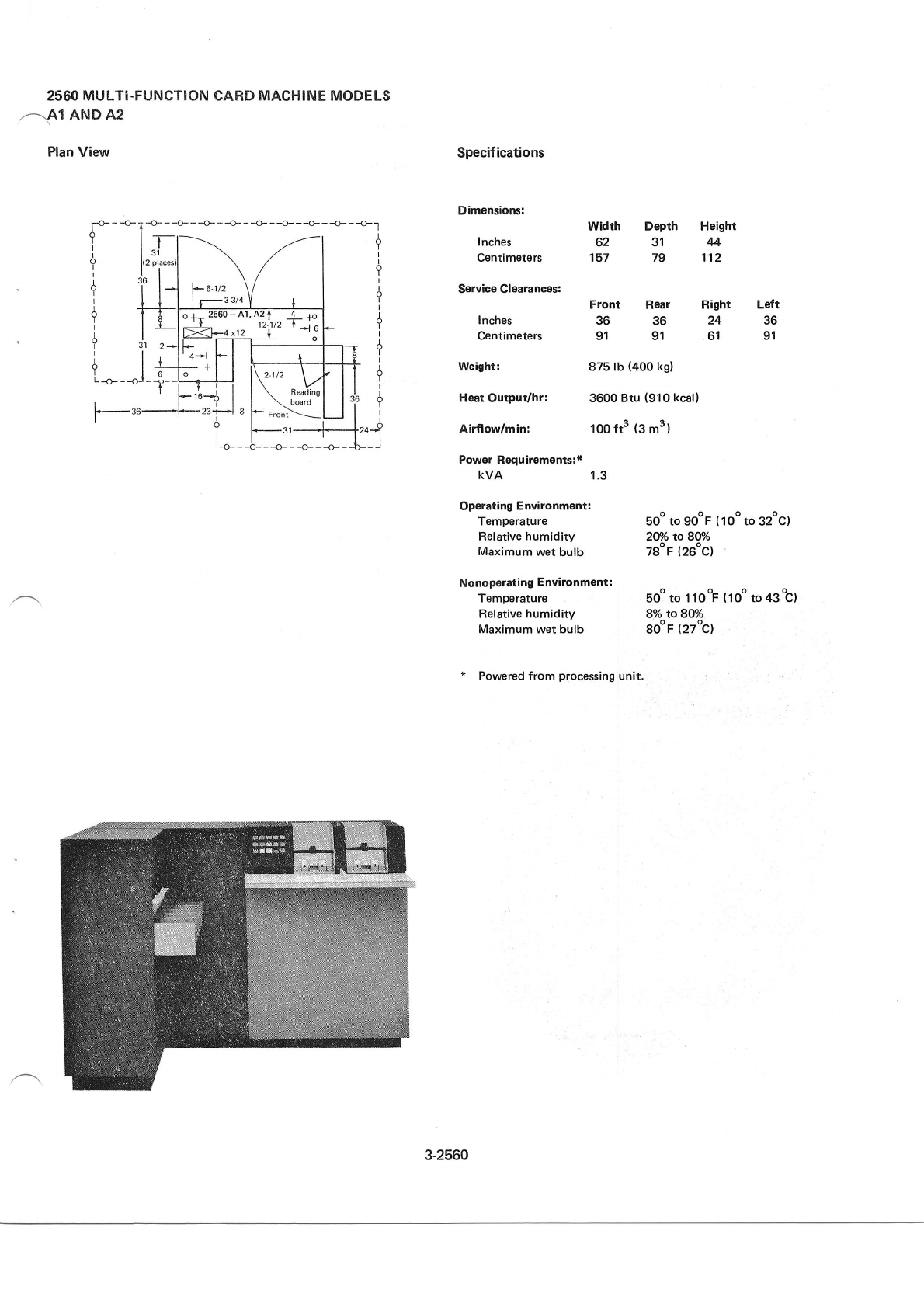
2560
MUI.TI.FUNCTION
CARD
MACHINE
MODELS
,-\A1 AND A2
Plan View
Depth
31
79
--o---o---o--
?
I
5
I
i
o
I
I
A
Y
6
I
I
A
Y
*T1-I
l.ll
l{2
era@srl
36t I
l11
T-T-F
I Llr
I Ik
1' ,*ll-
Irl
--.l-j-:E
-o- --o- - -o---o-1
.-l i
t:
-+--t i
,
i_rij
l* t
--l--T I
\ l-+f i
',""k;f
ll T
-\Y'! T i
-s'--f--Jz-f
^ki
ltr
I Ft'
Specif ications
Dimensions:
I
nches
Centimeters
Service Glearances:
Inches
Centimeters
Weight:
Heat Output/hr:
Airflow/min:
Power Requirements:*
KVA
Front Rear Right Left
36 36 24 36
91 91 61 91
87s lb
(400
ks)
3600 Btu
(910
kcall
1oo
ft3
(3
m3l
1.3
width
62
157
Height
44
112
Oporating
Environment:
Temperature 5oo
to 90oF
(1oo
to 32oc)
Ref
ative
humidity 2V/o to 8oo/o
Maximum
wet
bulb 78oF
(26oC)
Nonoperating
Environment:
Temperature 5oo to 1
10
oF
(
1oo to 43
oc)
Relative
humidity 8%to8tr/o
Maximum wet bulb SOoF
{2zoc}
* Powered from processing
unit.
pl
l2
I
o +- Zb60 - Al. AZ | _3_ +o
*=+!_li''rj
i--tl
'o--t
Fl I I
. *l I N;;-I
I ttll
l*,u-? |
?
I
+-
Reading
board
3-2560
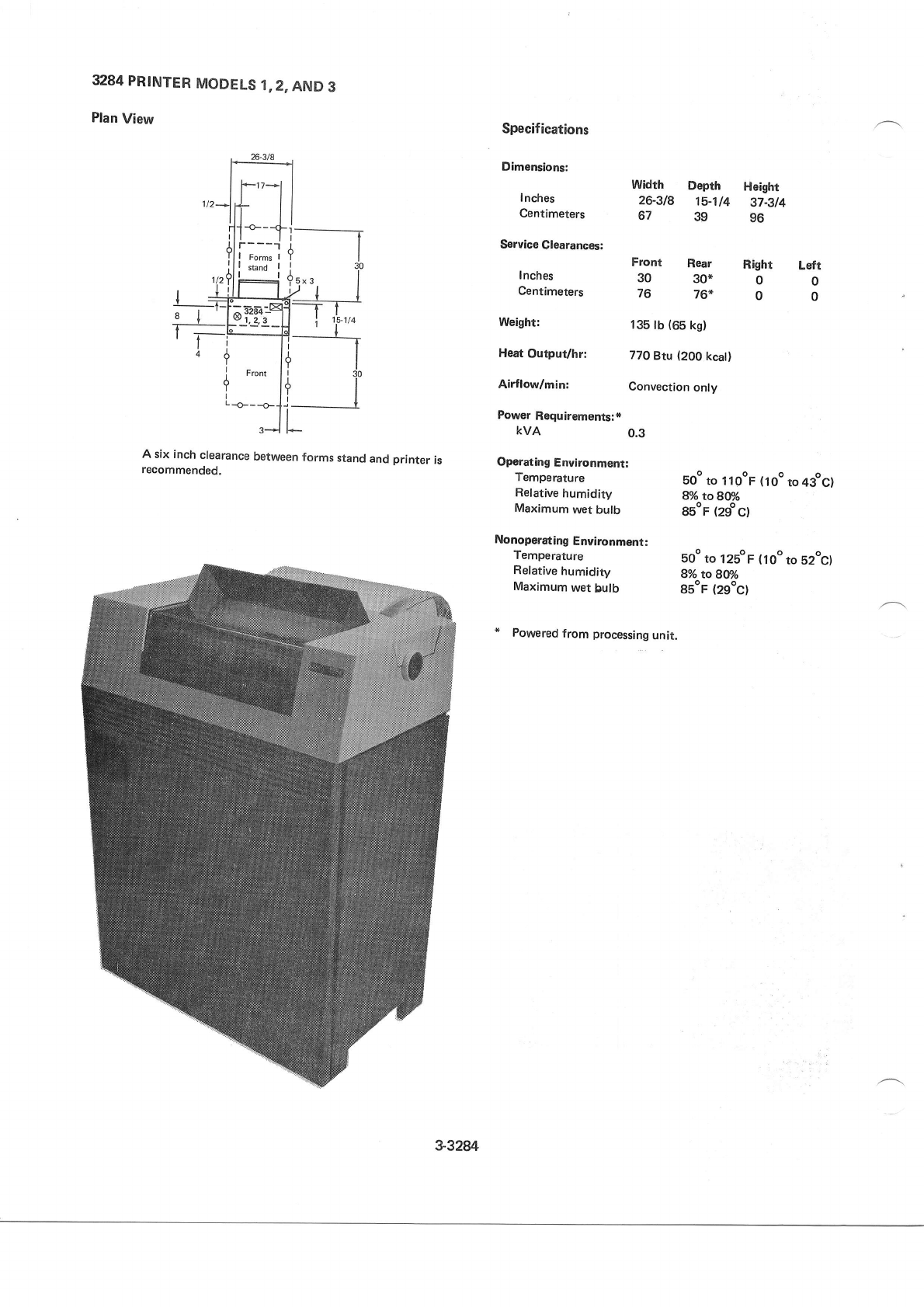
3284
PRINTER
MODELS
1,2,
AND
3
Plan
View Specifications
Dimensions:
I nches
Centimeters
Service
Clearances:
Inches
Centimeters
Weight:
Heat
Output/hr:
Airflow/min:
Power
Requirements:*
KVA
Width Depth Height
26-318 15-114 37A14
67 39 96
Front Rear
30 30*
76 76*
135
lb
(65
kg)
770
Btu (200
kcat)
Convection
only
0.3
Right Lefr
00
00
I
I
Y
I
A
Y
I
I
A six inch
clearance
between
forms
stand
and
printer
is
recommended. Operating
Environment:
Temperature boo
to 1lOoF
(1oo
to4gocl
Refative
humidity g%rcgef/o
Maximum
wet bulb gsoF
(2go
C)
Nonoperating
Environment:
Temperature Eoo
to l2boF (loo to s2oc)
Relative
humidity 8o/o
to g@/o
Maximum
wet bulb gsoF
(2goc)
* Powered
from processing
unit.
3-32W
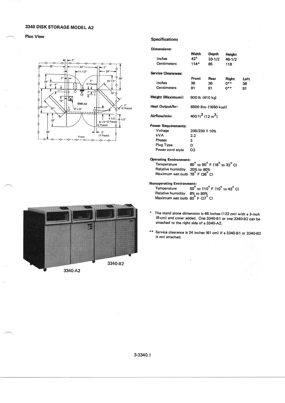
3340
DISK
STORAGE
MODEL
A2
Plan
View
r--O---O---O- ---o-
Y
I
I
I
i__
{ ,i'"
i - -o-l
-o-
-
-o- -
-- -
Jy5-- -- _ _*1i _
i
rracest I
Specifications
Dimensions:
lnches
Centimeters
Service
Clearances:
Inches
Centimeters
Weight
(Maximum):
Heat Output/hr:
Airflodmin:
Power
Requirements:
Voftage 2O8l23O
! loo/o
kvA 2.2
Phases 3
Plug
Type D
Power
cord
style D2
Operating Environment:
Temperature 6oo
to 9oo F (160
to 32o
cl
Relative
humidity 20%to BOyo
Maximum
wet
bulb 7go F (26o
c)
Nonoperating Environment:
Temperature boo
to 1 loo F (ioo to 43o
c)
Ref
ative humidity 8%
to 80%
Maximum
wet
bulb goo
F (27o
cl
* The
stand
alone
dimension
is 48 inches
i.122 cml with a 3_inch
(8+m)
end cover
added,
One
3340-Bl or one
3340-82
can be
attached
to the right side of a 3g4O-A2.
** Service
clearance
is 24 inches
(61
cm) if a 3340-8l or 3340-82
is not
attached.
--{---o-- o __+-_r_T
+3" dI
*2c.'l I
---l +,1,,
Width Dopth Hoight
42" 33-112 46.-112
114* 85 118
Rear Right
36 0**
91 0**
900 lb
(410
kg)
6500 Btu (1650
kcal)
,too
tts
(tz
m3)
fT" Left
36
91
Front
36
91
73"
(2
Places)
3-3340.1
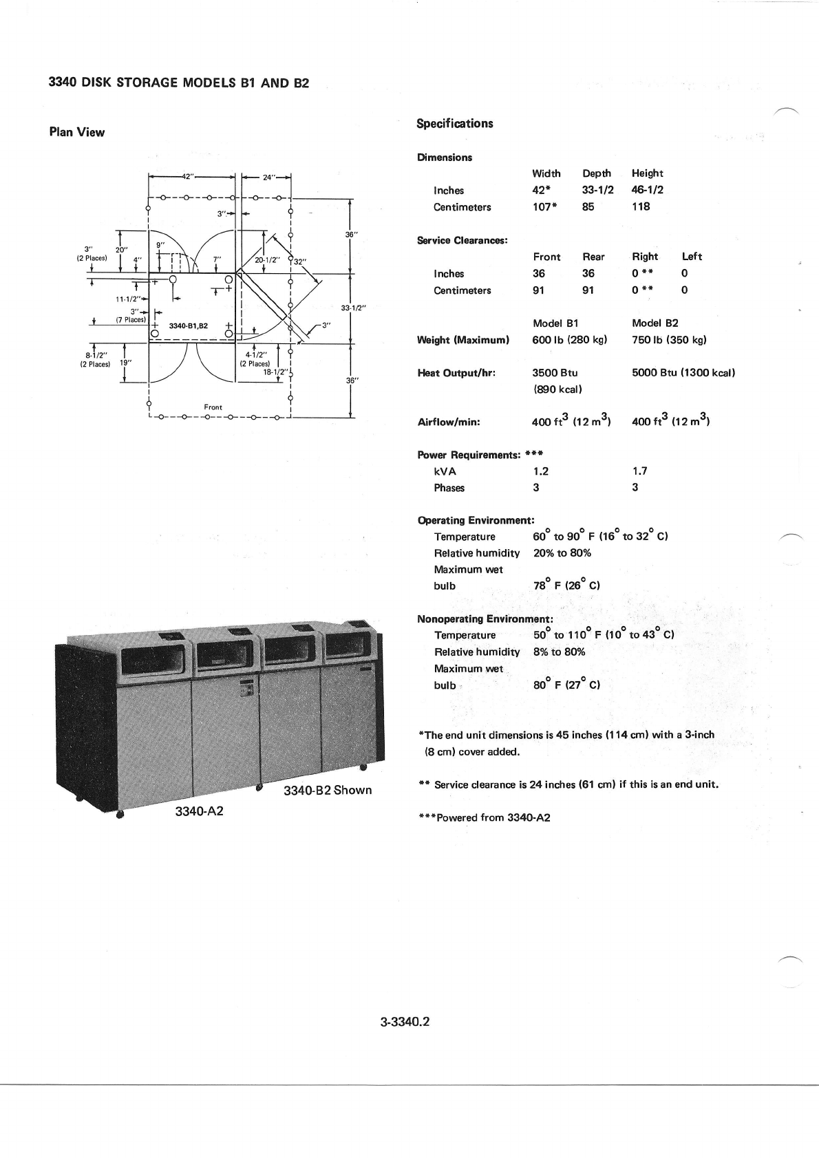
:?_-_____
il
;lfi* T
33-12"
4-1
t2"
(2
Places)
18-1/2"
Y
3340
D|SK
Plan
View
STORAGE MODELS
81 AND 82
(2 Places)
8.
(2 Places) 19"
Specifications
Dimensions
lnches
Centimeters
Service Clearances:
lnches
@ntimeters
Weight
(Maximuml
Heat Output/hr:
Airflow/min:
Width Depth
42* 33-112
107* 85
Front Rear
36 36
91 91
Model 81
600
lb (280
kg)
3500 Btu
(890
kcall
22
400
ft- (12
m-)
Height
$-1t2
118
Right Left
0** 0
0** 0
Model 82
750 lb'
(350
kg)
5000 Btu
(1300
kcal)
400
ft3 (tz m3)
1.7
3
Power Requiremgnts:
***
kvA 1.2
Phases 3
Operating
Environment:
Temperature 600 to 9oo
F (160
to 32o cl
Ref
ative
humidity 20% to 8O%
Maximum
wet
butb z8o
r (260
c)
a-
Nonoperating
Environment:
Temperature Eo9 to 1loq F (1oo
to 43o c)
Relative
humidity 8% to 80%
Maximum
wet
butb 8oo F (2zo
c)
*The
end unit dimensions is
45 inches
(1
14
cm)
with a
3-inch
(8
cm)
cover added.
'* Service
clearanc€ is 24
inches
(61
cml if this
isan
end unit.
**{Powered from 3340-A2
iil
r9l
y Front i I
L-ao---ao---1o---O---O---O-I Y
3-3340.2
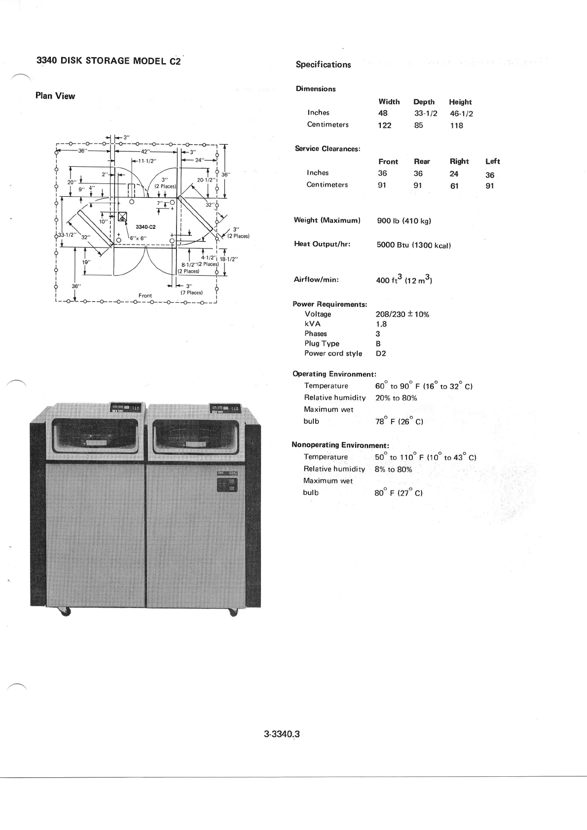
3340
DISK STORAGE
MODEL
C2
Plan
View
Specifications
Dimensions
Inches
Centimeters
Service
Clearances:
I nches
Centimeters
Heat Output/hr:
Airflow/minr
Power Requirements:
Voltage
KVA
Phases
Plug
Type
Power
cord style
Width Depth Height
48 33-112 46-112
122 85 118
Weight
(Maximuml 900 tb
(410
kg)
Front
36
91
5000
Btu
(1300
kcat)
4oo
ft3 (12
m3)
2O8l23O
! 1go/o
1.8
3
B
D2
Rear Right Left
36 24 36
91 61 91
/3"
(2
Places)
tffiTF*j^,4,.
i I rY | ,/ \ ll 8.1/2"{2Places)
I
? l+ l--'/ \l{4:rq-+f
I ,1. -1L... i
I I - {7
Placesl Y
i _
_o_L _o_
_ _o_ _
-_ _
J:I__ _o_ _
_o_ _ _o_
_ _.1
Operating Environment:
Temperatu
re 6oo
to
goo
F (16o
to 32o
ct
Ref ative humidity 2Oo/o
to 8Oo/o
Maximum wet
bulb 78" F (26o
c)
Nonoperating
Environment:
Temperature so"
to 11oo
F (1oo
to 43o
cl
Ref
ative humidity 8o/o
to 8Oo/o
Maximum wet
butb Boo F (27o
c)
r - -{- - -o- - -o-i;-o- - -o- - -o- - -o- - -o- - -o- -1 T
+.-36"___ri F_4r"___*l F3, I I
I fl ?11jt2" lf-'"-- |
?
I";-rTltrK /;lf;,!,i
3',',
n"t'r
lI iti-\1
'','f*oll,,\
I+
| 20"
?r
+
3-3340.3
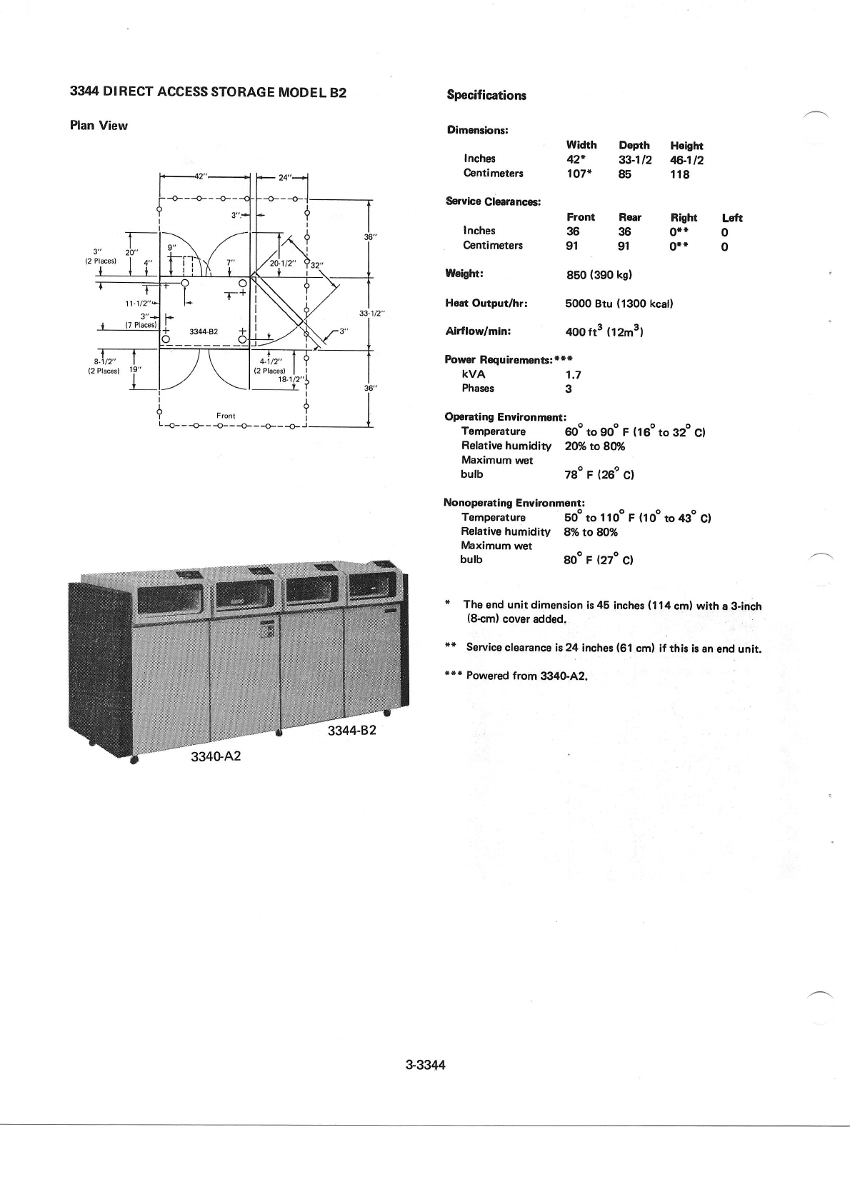
33IT4 DIRECT
ACCESS
STORAGE
MoDEL
B2
Plan
View
Specifications
Dimensbns:
Inches
Centimeters
Servhe
Clearances:
Inches
Centimeters
t{eigtrt:
Heat
Output/hr:
Airflodmin:
Power
Requiremen8:***
KVA
Phases
Width Depth Hoiglrt
42* 33-112 4f,-112
107+ 85 118
Right
0*t
o**
850
(390
kg)
5000
Btu
(1300
kcal)
4ooft3
(12m3)
1.7
3
Left
0
0
Front Rear
36 36
91 91
Operating
Enuironment:
Temperature @o to 9oo F (160
to 32o
cl
Relative humidity 2O/o
to 8M
Maximum
wet
butb 78o F (26P
c)
Nonoperating
Environment:
Temperature 50o to 1
loo F (loo to 4go c)
Relative humidity 8%
to 80%
IVlaximum
wet
butb goo
F (27o
c)
* The
end
unit dirnension
is
45 inches
(114
cm) with a 3-inch
(8+m)
cover added.
** Service
clearance
is
24 inches
(61
cml if this is an
end
unit.
**r Powered
from 3340-A2.
$3344
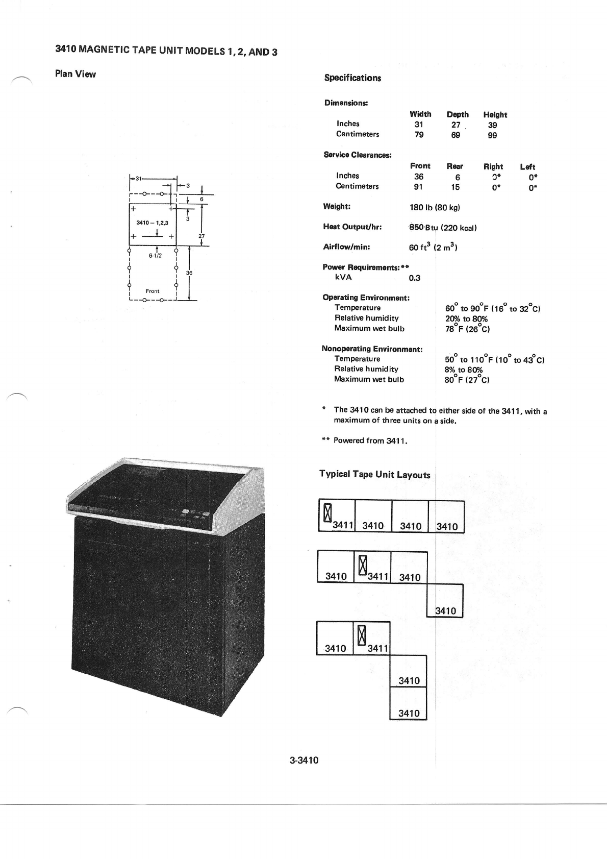
3410
MAGNETIC
TAPE
UNIT
MODELS1,z,AND
3
Plan
View Specifications
Dimentionr:
Inches
Centimeters
Service Clearances:
Inches
Centimeters
l4leight:
Heet
Output/hr:
Airflodmin:
Dopth Height
27 39
69 99
widrh
31
79
Right Left
J* 0{
0* 0+
15
91
Front Rear
366
180 lb (80
kg)
850 Bty Q2O kcatl
60
ft3 (2 m3l
jl
I
Front
{---o-
Poriror
Roquiloments!
**
kvA 0.3
Operating Envaronmgnt:
Temperature
Relative
humidity
Maximum
wet
bulb
Nonoperating
Environment:
Temperature
Relative humidity
Maximum
wet
bulb
600
to gooF
(i60 to 32ocl
2MotoSO%
78oF
(26oc)
5oo
to 1 1
ooF (
1
oo to 4gocl
8o/o toSff/o
gooF
(27oc)
i The
3410
can
be
attached to either
side of the
341 1
,
with a
maximum
of three
units on
a side.
** Porryered
trom3411.
Typical
Tape
Unit Layouts
8ro'
'3410 3410 3410
341
08ro''3410
t410
3410 8,0,',
3410
3410
3-3410
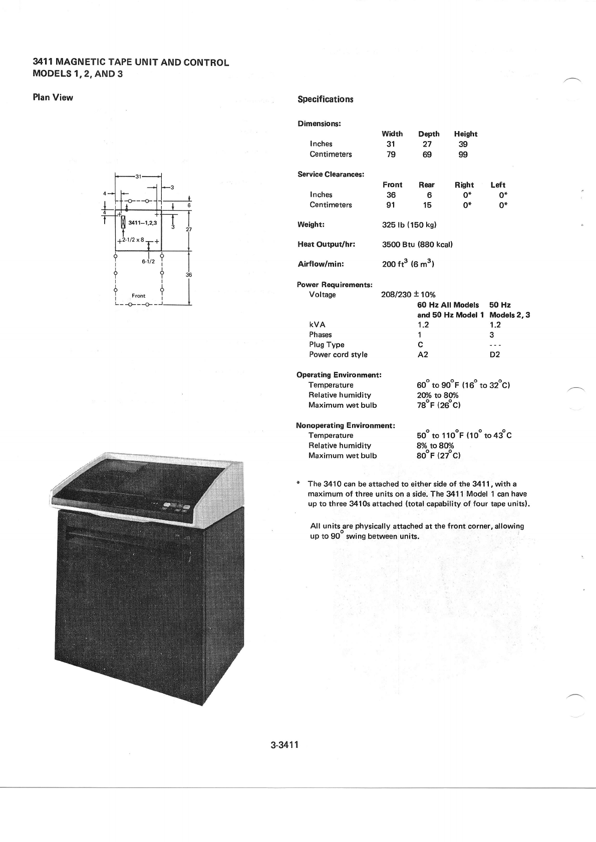
3411 MAGNETIC
TAPE UNIT
AND
CONTROL
MODELS
1.2,
AND
3
Plan
View Specifications
Dimensions:
I nches
centimeters
Service Clearances:
Inches
Centimeters
Weight:
Heat
OutpuVhr:
Airflodmin:
Frcnt Rear Right
3660*
91 15 0*
325 lb
(150
kg)
3500 Btu (880
kcal)
2oo
ft3 (6 m3)
1.2
1
c
A2
width
31
79
Height
39
99
Depth
27
69
Lsft
0*
0f
F ront
-o---o-
{ ,1,
ll
il
_ J___---______l_
Power Requirements:
Voltage 2Ogl23O
!1oo/o
60 Hz All Models 50 Hz
and 50 Hz Model 1 Models 2,3
KVA
Phases
Plug
Type
Power
cord style
Operating Environment:
Temperature
Relative humidity
Maximum
wet bulb
Nonoperating
Environment:
Temperature
Relative
humidity
Maximum
wet bulb
60o
to gooF
(160
to 32oc)
2U/o roSt/o
78oF
(26"c1
soo
to 1 looF {1oo
to 43oc
8To toBWo
SooF
(27ocl
1.2
3
D2
The 341 0 can be attached to either side of the 341 1
, wilh a
maximum of three units
on
a sidd. The 341 1
Model
1 can
have
up to three 3410s attached
(total
capabitity of four tape
unitsl,
All units^are
physically
attached at the
front corner, allowing
up to 90- swing between units.
--l
12-112x8-q
3-3411
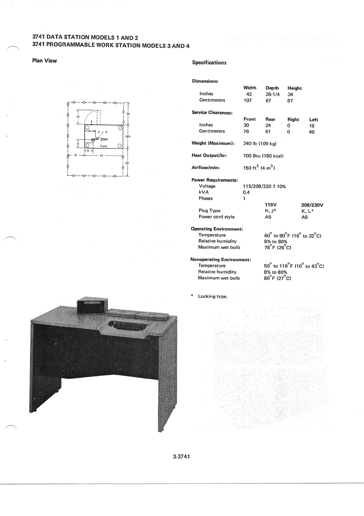
3741 DATA
STATION
MODELS
1
AND 2
3741 PROGRAMMABLE
WORK
STATION
MODELS
3 AND 4
Plan
View Specifications
Dimensions:
Width Depth
fnches 42 26-114
Centimeters 1O7 67
Service
Clearances:
Front Rear
Inches 30 24
Centimeters 76 61
Weight
(Maximum): 240
lb (109
kg)
Heat
Output/hr: 700
Btu
(180
kcal)
Airflow/min: 1b0 ft3 (4
m3)
Power
Requirements:
Voltage 11512081230
! l0o/.
kvA O.4
Phases 1
115V 2A8n30V
Plug
Type H,
J* K, L*
Power
cord
style AS As
Operating
Environment:
Temperature 60o
to gOoF
(160
to 32oC)
Refative
humidity 8%to80o/o
Maximum
wet butb 7g"F (26oC)
Nonoperating
Environment:
Temperature soo to 1 looF (10o
to 43oc)
Refative
humidity SoAtoSO%
Maximum
wet
bulb BOoF
(27oC)
* Locking
type.
Height
u
87
Right Left
018
046
?
+
,lr- rg
Y
I
a2 --"-------4,
Y
i l3o
l_o_
_ _o_
_ _o_ _
_*
__* _1_l
3-374I
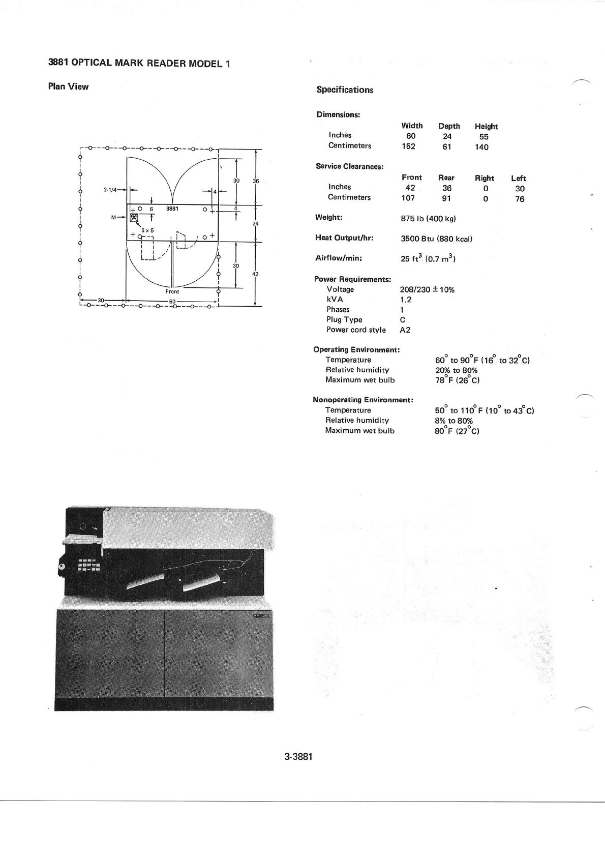
3881
OPTICAL
MARK
READER
MODEL
1
Plan
View Specifications
Dimensions:
I nches
Centimeters
width
60
15.2
Depth
24
61
Rear
36
91
Height
55
140
Right Loft
030
076
Service
Clearances:
Front
Inches 42
Centimeters 1O7
Weishr: 875 tb (400
kg)
Heat
Output/hr: 3500 Btu (880
kcal)
Airftodmin: 25
ft3 (0.7
m3)
Power
Requirements:
Voltage 2OBI23O
! 1!o/o
kvA 1.2
Phases I
Plug
Type C
Power
cord style A2
Operating
Environment:
Temperature 60o to gooF
(16"
to 32oc)
Relative humidity 2Oo/o to SOYo
Maximum
wet bulb 78oF
(26oc)
Nonoperating Environment:
Temperature boo to I
1oo
F (
10o to 4goc)
Ref
ative
humidity 8o/o to 8U/o
Maximum
wet
bulb Soor
(27oCl
3-3881
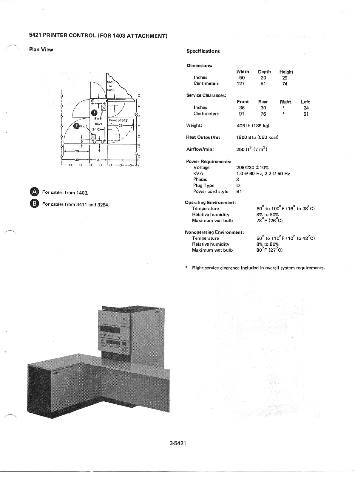
5421 PRINTER
CONTROL
(FOR
1403
ATTACHMENT}
Plan
View
L--O---O---O-- -O- --o---o-
For
cables
from 1403.
For
cables
from 341
1 and
3284.
Power
Rgquirements:
Vof
tage 2O8l23O
! 1lo/o
kVA 1.0 @
60
H2,2.2
@ 50 Hz
Phases 3
Plug
Type D
Power
cord
style B 1
Operating Environment:
Temperature 60o to loooF (16o
to 38oc)
Relative humidity 8% toSU/o
Maximum
wet
butb 78oF
(26oC)
Nonoperating Environment:
Temperatu re 50o to 1 1 0o
F {
1 Oo to 43oC}
Ref
ative
humidity 8o/o
to 8ff/o
Maximum
wet bulb 8oor (27oc)
* Right service
clearance
included
in
overall
system
requirements.
Specifications
Dimensions:
Inches
Centimeters
Service Glearances:
Inches
Centimeters
Weight:
Hsat
Output/hr:
Airflow/min:
Width Depth
50 20
127 51
Front Rear
36 30
91 76
405 lb (185
kgl
1800
Btu (550
kcal)
250
ft3 (7
m3)
Height
29
74
Right
*
*
Left
24
6't
@
o
I
?
I
Y
I
+
I
+
I
{
I
{_
Fronr of 5421
3.1/21
Zrl
3-5421
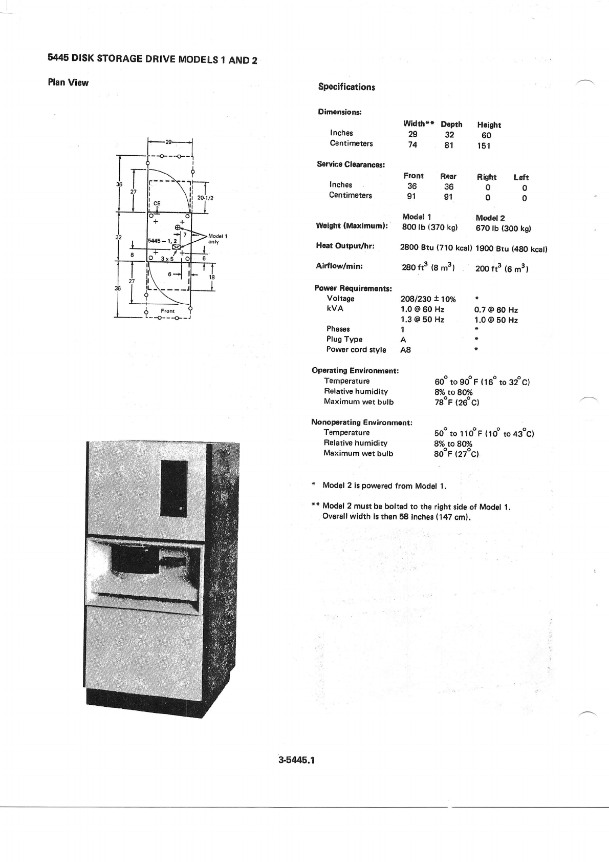
5445
DISK
STORAGE
DRIVE
MODELS
1
AND
2
Plan
View Specifications
Dimensionr:
Inches
Centimeters
Service
Clearances:
Inches
Centimeters
Width*" Dopth Hoight
29 32 60
74 81 151
Front Roar Right Lsft
363600
919100
Modd
I Modol
2
Weight
(Maximuml: 800 tb (3TO
kg) 670 lb (300
kgl
Heat
Output/hr: 2B0O
Btu (7.|0
kcal)
1900
Btu (4g0
kcatl
AirfloVmin: 280 ft3 (8 m3, 2OO
ft3 (6
m3t
Power
Requirements:
voltage ZOgl23O
X1O% r
kVA 1.0
@
60
Hz 0.7
@
60
Hz
1.3
@ 50 Hz 1.0
@ E0 Hz
Phases 1 *
Plug
Type A *
Pow€r
cord stylo A8 *
Operating
Environmont:
Temperarure 60o
to gooF
(16o
to 32oc)
Ref
ative
humidity 8/o to 8V/o
Maximum
wet bulb TgoF
(26oC)
Nonoperating
Environment:
Temperature
Relative
humidity
Maximum
wet
bulb
soo to il oo F (
1
oo to 4goc)
8o/o to 8V/o
SooF
(27oc)
* Model
2 is
powered
from Model L
+t Model
2 must be
bolt€d
to tho
right side
of Model
L
Overall
width is then
58 inches
(147
cm).
Flont
3-5445.1
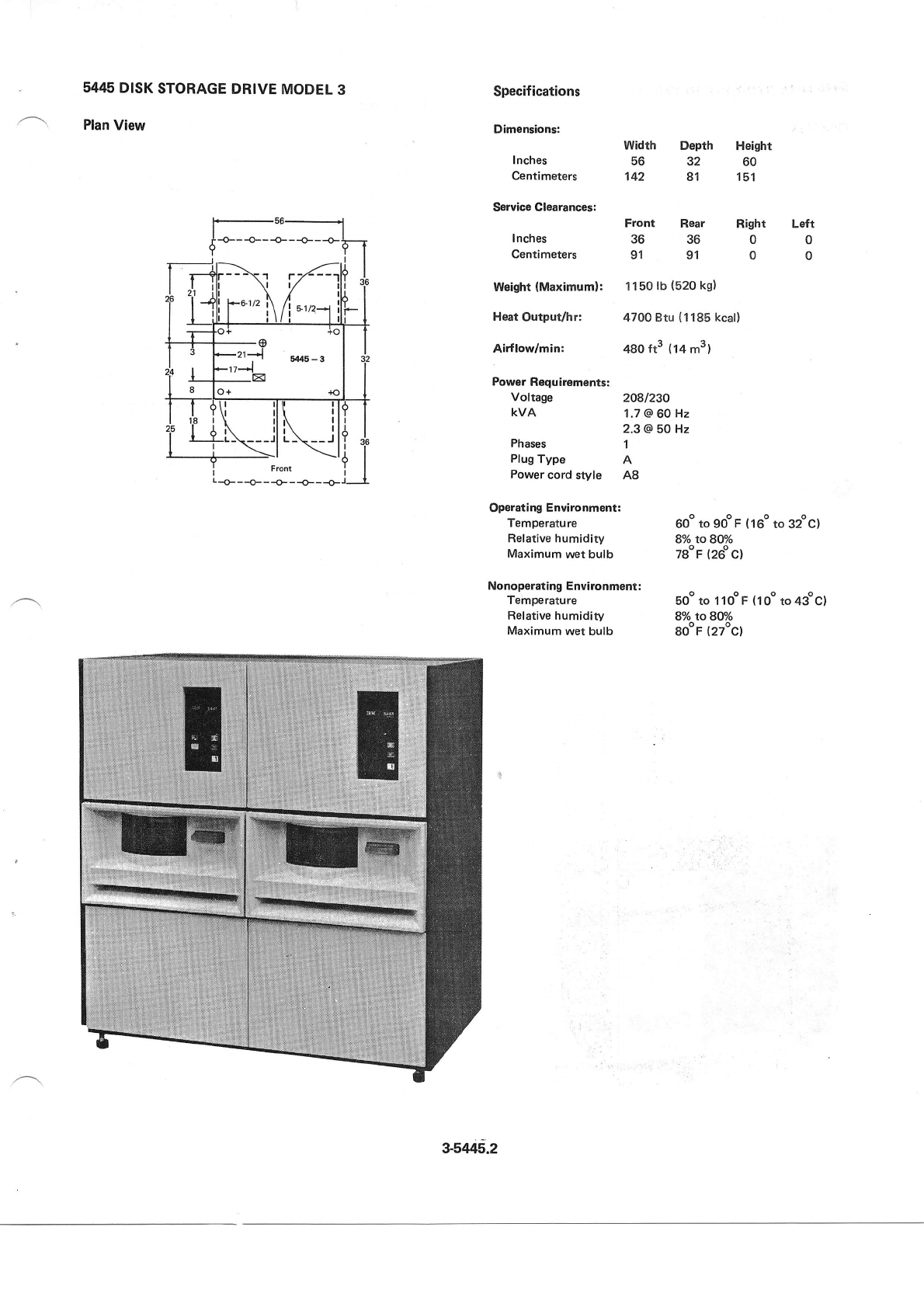
5445
DISK
STORAGE
DRIVE
MODEL
3
Plan
View
Specifications
Dimensions:
Inches
centimeters
Service Clearances:
Inches
Centimeters
Weight
(Maximuml:
Heat
Output/hr:
Airflow/min:
Width Depth Heighr
56 32 60
142 81 151
Front Rear
36 36
91 91
Right Left
00
00
1 150
lb
(520
kg)
4700 Btu (
1
185 kcal)
480
ft3 (14
m3l
Power
Requirements:
Vof
tage 2O8/23A
kVA 1.7
@ 60
Hz
2.3 @ 50 Hz
Phases 1
Plug
Type A
Power
cord style AB
Operating
Environment:
Temperature 60o
to gooF
(16o
to 32oc)
Relative humidiry 8o/o
to 8Oo/o
Maximum
wer bulb 78oF
(26oc)
Nonoperating
Environment:
Temperature soo to 110oF
(10o
to43oc)
Relative humidity 8o/o toBff/o
Maximum
wet bulb SOoF
(27ocl
3-5445.2
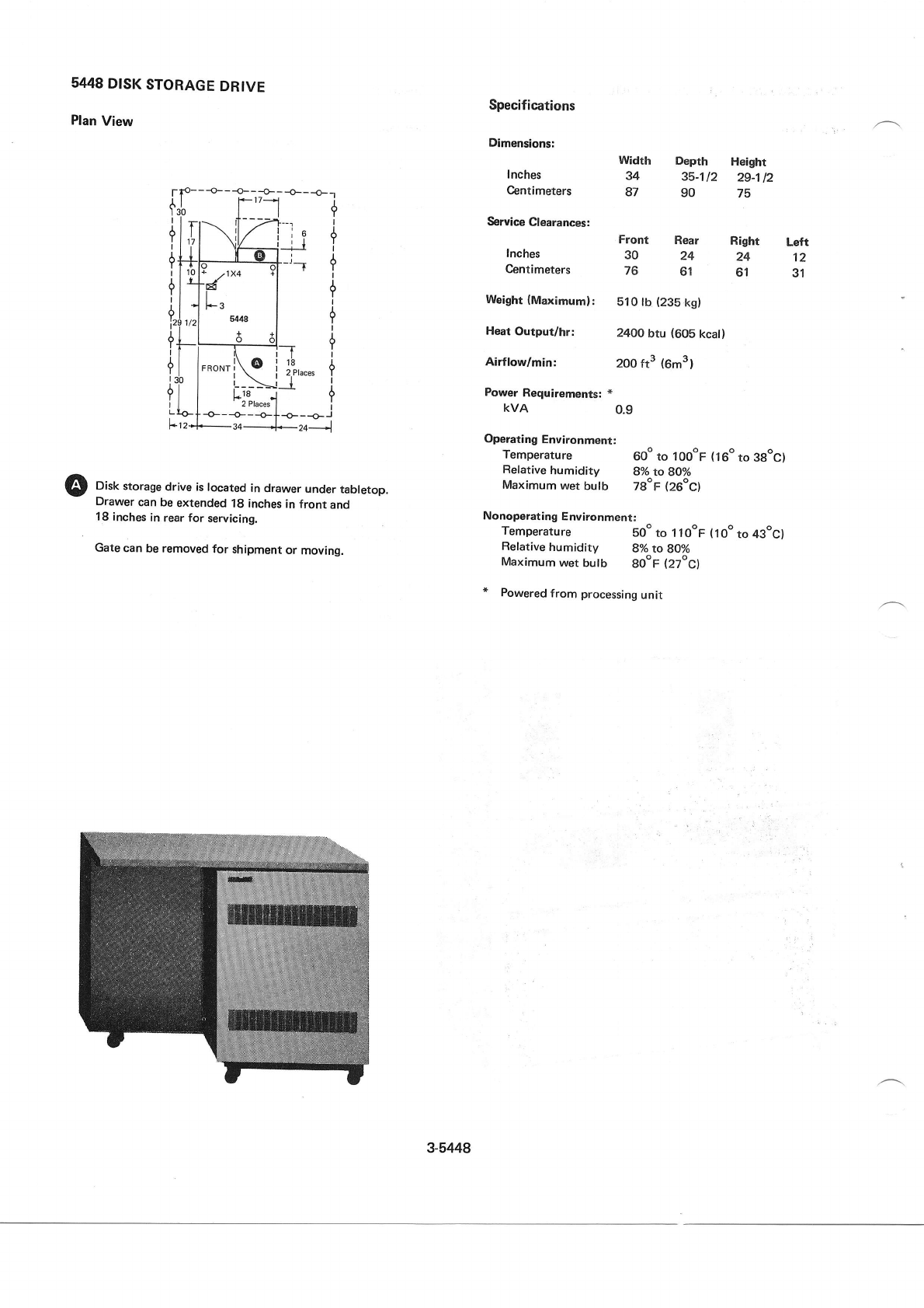
5448
DISK
STORAGE
DRIVE
Plan
View Specifications
Dimensions:
I
nches
Centimeters
Service
Clearances:
Inches
Centimeters
Weight
(Maximuml:
Heat
Output/hr:
Airflow/min:
Power
Requirements:
*
KVA
Width Deprh Height
34 35-112 29-1
12
87 90 75
Front Rear Right Left
30 24 24 12
76 61 61 31
510 lb (235
kg)
2400
btu (605
kcal)
2oo ft3 (6m31
0.9
f p- - -o- - -o-- -o- - -o- - -o- -1
| | F- 17-d
f.lollt
{1il\ilZllr i
++r_
)(_%rl
{
iltbl;,rx+ Yl " ,
6l
'+d' I
:t tt , ?
il -lf*-t | |
?,j,,,1 5/u8 | ?
i-j'-l * .l I
e+ | o ot_ 6
!l I l\ r T I
+l l,'o"l\o i
l',n*,
+
i.p j r___->jl ,
Yl I H8- .t ?
I J I zPraces
| |
I t+ f -+-- -o- - -o- | -o- - -o- i
F.
1
2*+*- 34
---+-- 24-_-l
Disk
storage
drive is
located
in
drawer
under
tabletop.
Drawer
can be
extended
18 inches
in
front and
18 inches
in
rear for servicing.
Gate
can
be removed
for shipment
or moving.
Operating Environrnent:
Temperature 60" to 100oF (160
to 3gog)
Relative humidity 8o/o
to BOo/o
Maximum wet bulb TgoF (26oC)
Nonoperating Environmentl
Temperature so" to 1 |ooF (1oo
to 43oc)
Refative
humidity 8o/o to BO%
Maximum
wet
butb gO"F
(27oC)
" Powered
from processing
unit
3-5448
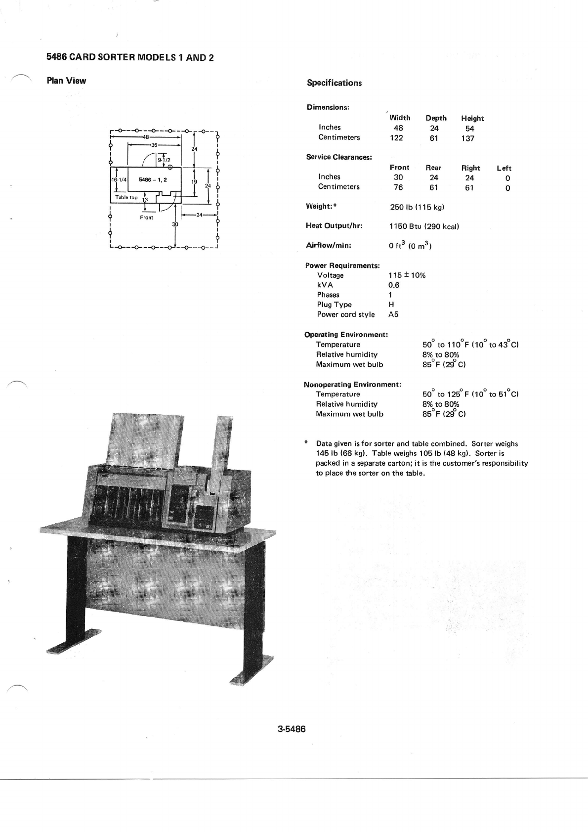
5486
CARD
SORTER
MODELS
1
AND 2
Plan
View Specifications
Dimensions:
Inches
Centimeters
Service Clearances:
Inches
Centimeters
Weight:+
Heat
Output/hr:
Airflodmin:
Power
Requ3rements:
Voltage
KVA
Phases
Plug
Type
Power
cord
style
Operating
Environment:
Temperature
Relative humidity
Maximum
wet bulb
Nonoperating Environment;
Temperature
Relative humidity
Maximum wet bulb
Width
48
122
Depth Height
24 54
61 137
Front Rear Right Left
3024240
7661610
250 lb
(1
1
5
kg)
1150 Btu
(290
kcal)
o ft3 (o
m3)
1'.15
! 100/0
0.6
1
H
A5
boo
to 1
looF (1oo
to 43oc)
8o/o to8@/o
BsoF
(29oc)
so" to 125oF
(1oo
to bloc)
8o/o toSOYo
SsoF
(zgoc)
* Data
given
is for sorter and table combined. Sorter weighs
145 lb
(66
kgl. Table
weighs 105
lb
(48
kg).
Sorter
is
packed
in
a
separate
carton; it is the customer's responsibility
to place
the sorter on the table.
p
-€---0- - +- -+ - {-
t-_48_l
3-5486
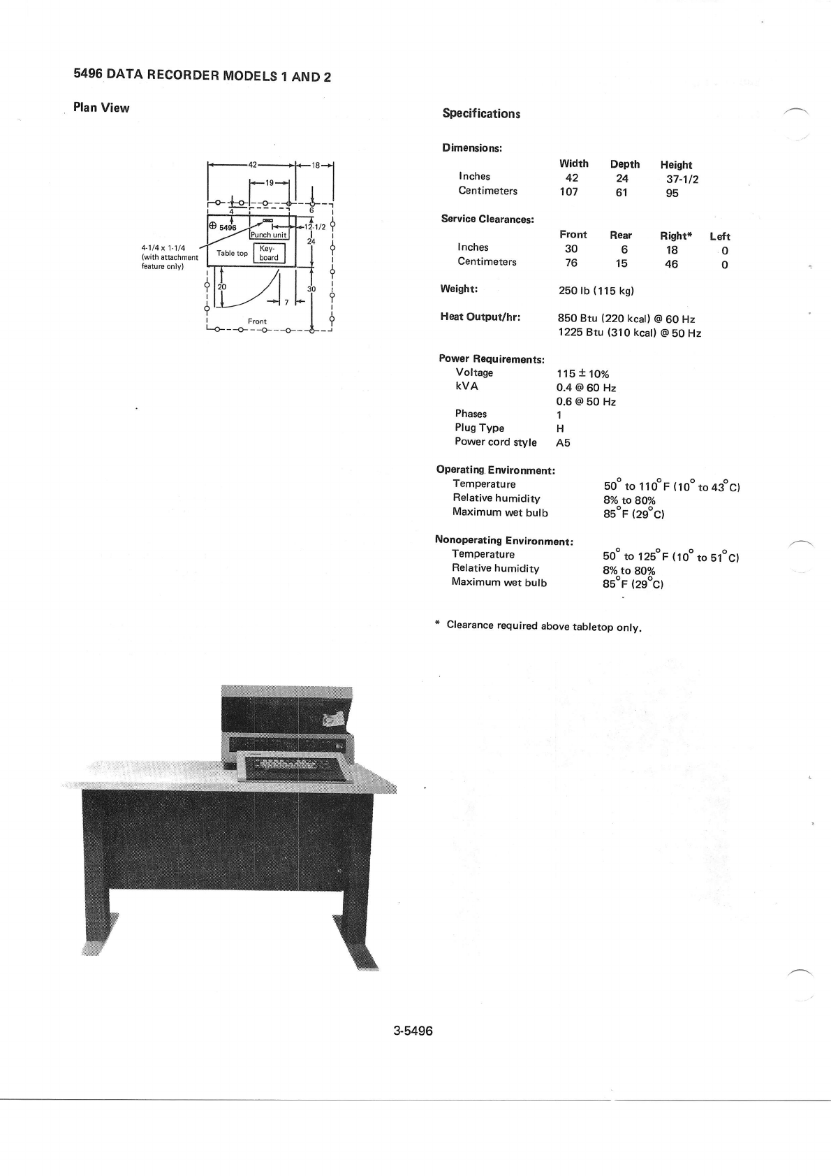
5496
DATA
RECORDER
MODELS
1 AND
2
Plan
View
,,r
lI
I
Y
I
a
I
Specifications
Dimensions:
lnches
Centimeters
Service
Clearances:
lnches
Centimeters
Heat
Output/hr:
Power
Requirements:
Voltage
KVA
Phases 1
Plug
Type H
Power
cord
style Ab
Operatlng.
Environment:
Temperature
Relative
humidity
Maximum
vvet
bulb
Width Depth Height
42 24 37-112
107 61 95
Front Rear
306
76 15
Right* Left
180
460
soo
to llooF (loo
to 43ocl
8o/o
to 8@/o
8E"F
(29oc)
{
I
?
Weight: 2b0
tb
(115
kg)
850 Btu (220
kcall
@
60 Hz
1225
Btu (310
kcat)
@ 50 Hz
115
! 1,o/o
0.4 @
60 Hz
0.6
@ 50 Hz
Nonoperating
Environment:
Temperature sOo
to l2soF (1oo
to blocl
Relative
humidity 8% to g1o/o
Maximum
wet
bulb gsoF
(29oC)
* Clearance
required
above
tabletop
only.
3-5496
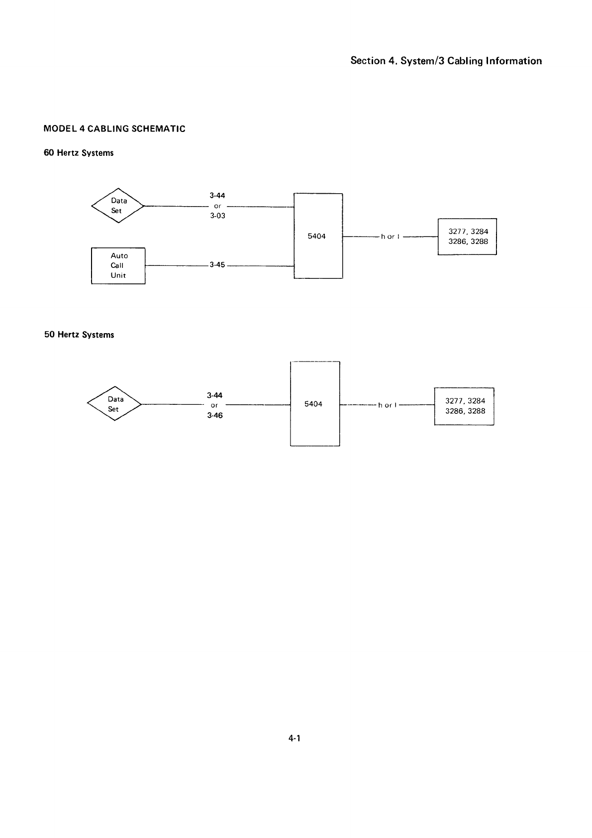
Section
4. System/3 Cabling Information
MODEL
4
CABLING SCHEMATIC
60 Hertz
Systems
-r#- 3-44
\*, ./-- r?i,
50 Hertz
Systems
4-1
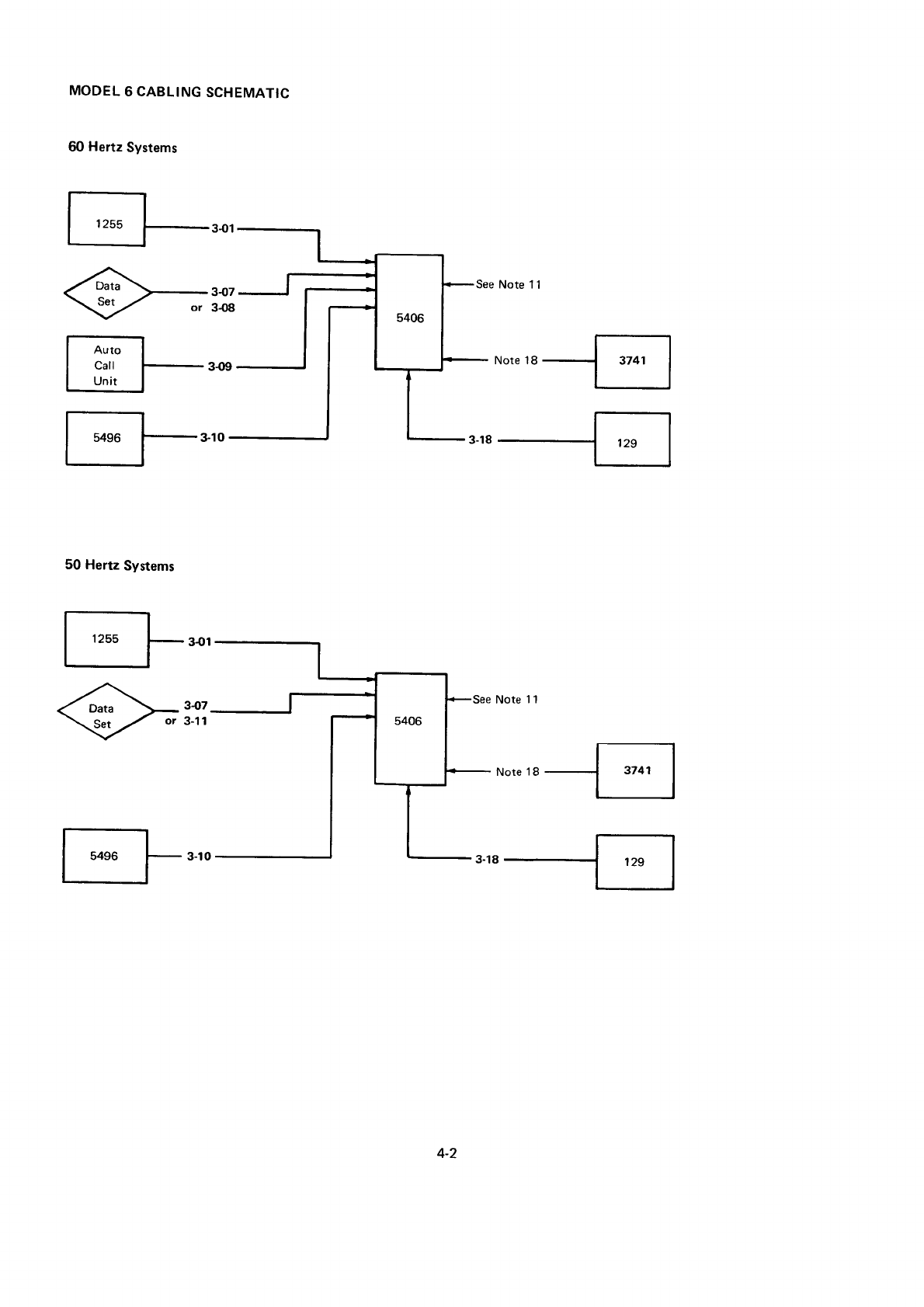
MODEL
6 CABLING
SCHEMATIC
60 Hertz
Systems
See Note 1
1
l*. I
| ;:1i
l-'* No,e18-{4
I 54s6 J- s-to
50 Hertz
Systems
1255
5496
4-2
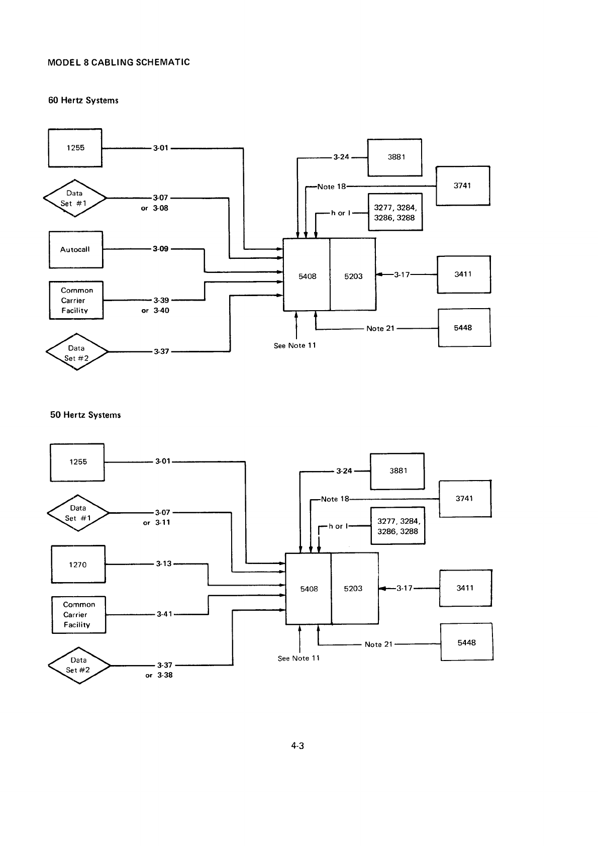
MODEL 8 CABLING
SCHEMATlC
60
Heru Systems
339
or 34O
50 Hertz
Systems
*,"-.l;1
ii
I
ffi
'o''..Bj
3277
,3244,
32a6,3288
r-l
l'F"' trr-Fl
t07
311
4-3
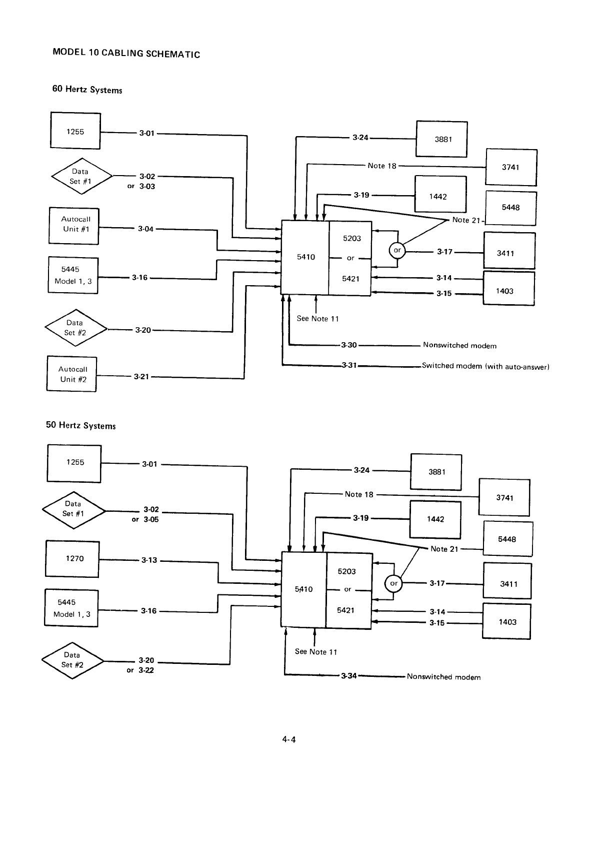
MODEL
1O CABLING
SCHEMATIC
60 Hertz
Systems
I ,,ruu l-- 3.01
f -Jl
I unit
#1 [-
3-o4
| 544s I
I rvr.oer
r,
s
l-3-16
A
\-z-3-2o
| ^,.*l
I unit
*z f-- 3-21
50
Hertz
Systems
| 1255 l- 3_01
I nto l-- 3-13
ll
1..., I
I rvr"oer
r,
g l-- 3-16
I l----t
-Jls++al
Note
21-l I
"rr-E
:l:--l-;]
See
Note 1 l
See
Note 1
1
'"'{
3-30- Nonswitched
modem
itched
modem (with auto-answer)
Note
21
5448
"rr-E
334 Nonswitched
modem
4-4
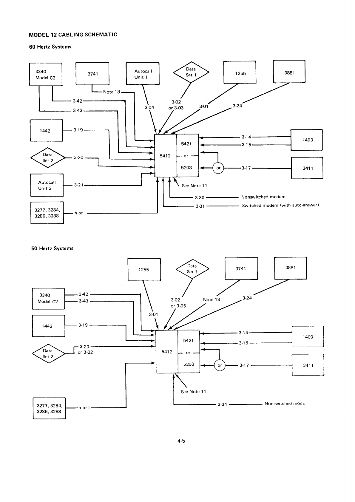
MODEL
12
CABLING
SCHEMATIC
60 Hertz Systems
342
343
342
or 3{3
50 Hertz Systems
3340
Model
C2
3277
,3284,
3286, 3288
See Note 1 1
See
Note 1 1
a-,04
t-'uru
,tr{
Nonswitched
modem
Switched
modem (with auto-answer)
a'roJ | 1403 |
3-15{
F;F,,,
I
i,r*
]-.,'
3277,3244,
3286,
3288
3-20
or 3-22
EEE
/-
3I2 Note 18 _3-24
or
3{5
1
442
4-5
3-34
- Nonswitchod
modt
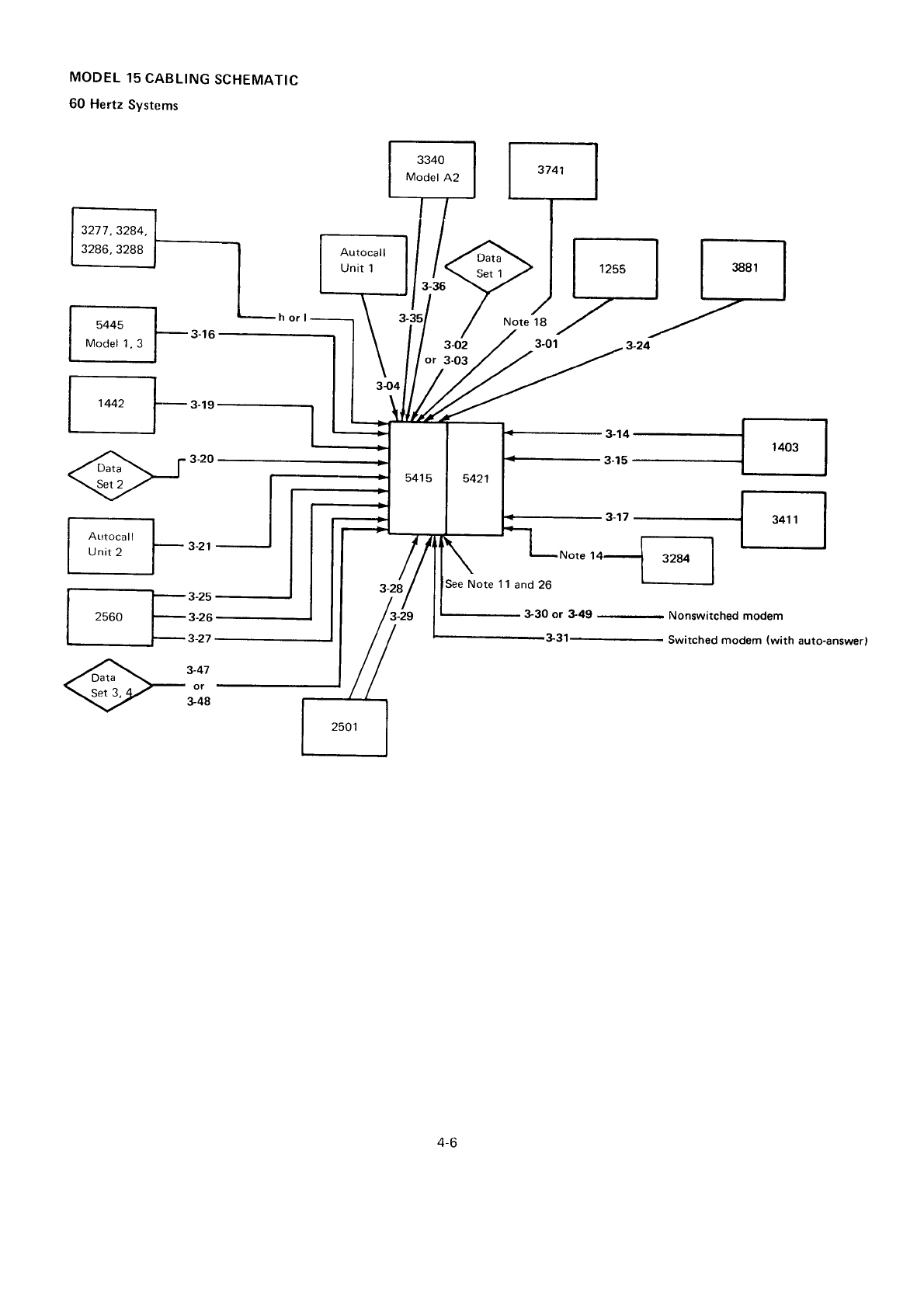
MODEL
15
CABLING
SCHEMATIC
60 Hertz
Systems
5445
Model
1,3 3-O2
or 3-03
Autocal
l
Unit
2
)FF
330 or &49 Nonswitched modem
331 Switched modem (with auto-answerl
3-25
3-26
3-27
3-47
or
348
1
442
4-6
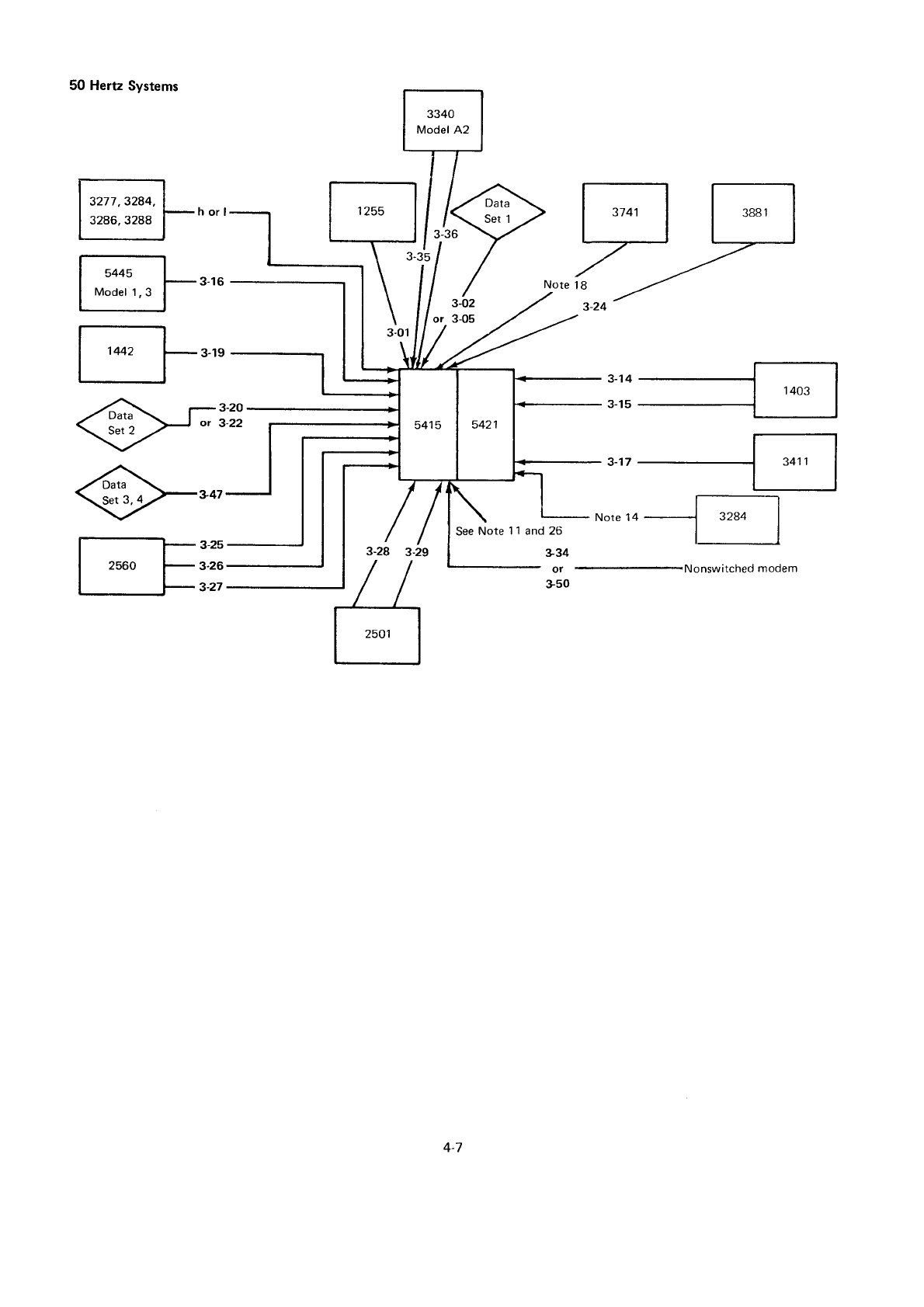
50 Hertz
Systems
3277,3284,
3286, 3288
5445
Model
1,3 3-02
or 3-05
f--t- s-zs
| 2s6o f- 3-26
| +t-r,
See
Note 1
126
334
or
350
ano
"rr{
Nonswitched
modem
1442
4-7
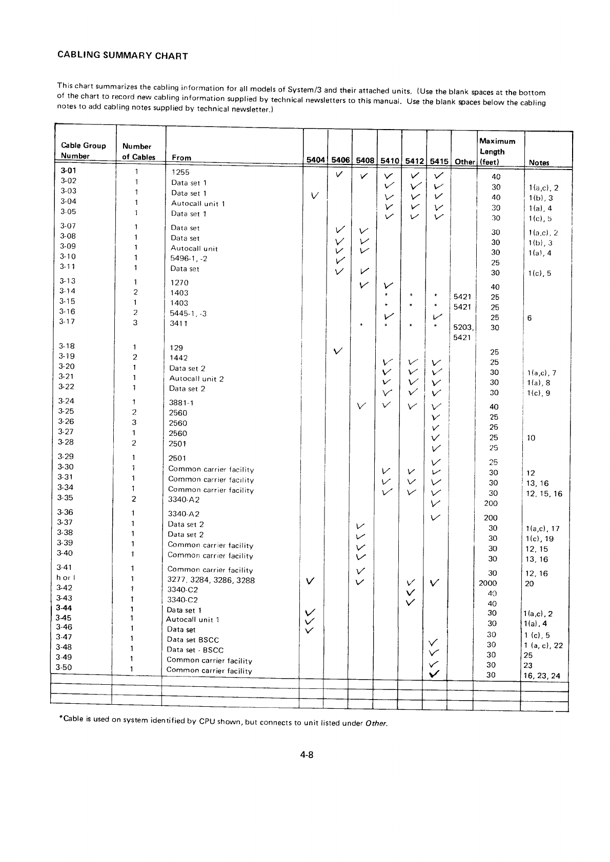
CABLING
SUMMARY
CHART
This
chart
summarizes
the
cabling
information for all models
of System/3
and
their
attached
units. (Use
the
btank
spaces at the bottom
of the
chart
to record
new
cabling
information
supplied
by technical
newsletters
to this manual. Use
the blank spaces
below
the cabling
notes
to add
cabling
notes
supplied
by technical
newsletter.)
v.
v/
40
30
40
30
30
t,'
V
V
\/'
1\a,cl
,
2
1
(b),
3
1
(a),
4
1
(c),
5
t(a,c)
,2
1
(bi.
3
|la.\
,
4
1
(c),
5
V/
I
I
I
5421 |
5421 |
I
5203,
I
5421 )
30
30
30
25
30
4A
z3
30
z2
AE
30
30
30
40
25
25
z3
13
12
JU
30
30
200
v.
vl
V
V
V
V
v/
V
\'/
w
v'
V
l la,c)
,
7
1(a),8
l
tc), 9
l0
12
13,16
rz, 13.
to
1
\a,c)
,
17
1{c), 19
11 1E
13,
16
12,16
20
1(a,cl
,2
1(at,,4
1
(c),5
1
\a,
c!,22
25
z5
16,23,24
200
30
30
30
30
30
2000
40
4A
30
30
30
30
30
30
30
301
3-02
3-03
3-O4
305
3-07
3-08
3-09
3-1
0
J-l I
3-1 3
3-14
J-t3
J-to
3-17
J-rd
J. IY
3-20
3-21
J- 22
3-24
J- ZC
5- Zt)
3-28
3-29
3-30
J-J I
3-34
J- JC
sJo
3-31
J.Jd
J- JY
3-40
3-41
horl
J.Z+J
3-44
345
3-46
3-41
3-48
3-49
J-5U
1255
Data set l
Data set 'l
Autocall unit 1
Data set 1
Data set
Data set
Autocall unit
5496-1 , -2
Data set
127
0
I 403
1
403
5445-1
, -3
341
1
129
1 442
Data
set
2
Autocall
unit
2
Data
set
2
3881-1
2560
2560
2560
2501
2501
Common
carrier
facility
Common
carrier
faci
lity
Common
carrier
f
acil
ity
3340,A2
3340.A2
Data
set 2
Data
set
2
Common
carrier
tacility
Common carrier
faci I ity
Common
carrier
facil
ity
3217, 3284,3286, 3288
3340.C2
3340.C2
Data
set 1
Autocall
unit
1
Data
set
Data
set
BSCC
Data
set
- BSCC
Common
carrier
facil
ity
Common
carrier
facility
V
lt/
V
V
*cable is used
on system
identified
by cpu shown,
but connects
to unit rasted
under
other.
4-8
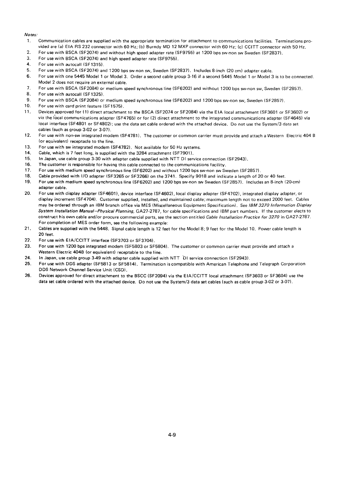
Notes:
1. Communication
cables
are supplied
with the
appropriate termination
for attachment to communications facilities.
Terminations
pro-
vided
are
(a)
EIA RS 232
connector with
60 Hz;
(b)
Burndy MD 12
MXP
connector with
60 Hz;
(c)
CCITT
connector
with 50
Hz.
2. For use with BSCA
(SF2074)
and
without high
speed
adapter rate
(SF9755)
at 1 200 bps
sw-non
sw
Sweden
(SF2837).
3. For use with BSCA
(SF2074)
and
high
speed
adapter rate
(SF9755).
4. For
use with
autocall
(SF1315).
5. For use
with BSCA
(SF2074)
and 1200 bps
sw-non sw,
Sweden
(SF2837). Includes
8-inch
(20 cm) adapter cable.
6. For use with one
5445 Model 1
or Model
3. Order a second cable
group
3-16 if a second 5445 Model 1
or Model
3 is
to be
connected.
Model
2 does
not require
an
external cable.
7. For use
with BSCA
(SF2084)
or medium speed synchronous
line
(SF6202)
and without 1200 bps
sw-non sw,
Sweden
(SF2857).
8. For
use with autocatl
(SF1325).
9. For use with BSCA
(SF2084)
or medium speed synchronous line
(SF6202)
and 1 20o bps
sw-non sw.
Sweden
(SF2857).
10. For
use with
card
print
{eature
(SF1575).
11. Devicesapprovedfor(1)directattachmenttotheBSCA(SF2074orSF2084)
viatheElAlocal
attachment(SF3601 orSF3602)
or
via
the lbcal
communications
adapter
(SF4765)
or for (2)
direct attachment to the integrated
communications adapter
(SF4645)
via
local
interface
(SF4801
or SF4802l; use
the
data
set cable ordered
with the attached
device. Do not use the Svstem/3
data
ser
cables
(such
as
group
3-02 or 3-07).
12. Forusewithnon-swintegratedmodem(SF4781).
ThecustomerorcommoncarriermustprovideandattachaWestern Electric4O4B
(or
equivalent)
receptacle
to rhe line.
13. For use
with sw integrated
modem (SF4782). Not available for 50 Hz systems.
14. Cable, which is 7 feet long,
is supplied with the 3284 attachment
(SF7901
).
15. In Japan, use
cable
group
3-30 with adapter cable
supplied
with NTT Dl service connection
(SF2943).
16. The
customer
is responsible
for having
this
cable connected to the communications
facility.
17. For use with medium speed
synchronous line
(SF6202)
and
without 1200 bps
sw-non sw
Sweden
(SF2857)
.
18. Cable
provided
with l/O adapter
(SF3265
or SF3266)
on the 3741. Specify 9018 and indicate a length of 20 or 40 feet.
19. For use
with medium speed
synchronous line (SF6202)
and 1200 bps sw-non sw
Sweden
(SF2857). lncludes an
8-inch
(20-cm)
adapter
cable.
20. For
use
with display adapter
(SF4601),
device
interface
(SF4602),
local display
adapter
$F47O2\, integrated
display adapter,
or
display
increment
(SF4704). Customer
supplied,
installed, and
maintained cable; maximum length not to exceed
2000 feet. Cables
maybeorderedthroughanlBMbranchofficeviaMES(MiscellaneousEquipmentSpecificationl
. SeelEM32TOlnformationDisplay
System lnstallation Manual-Physical Planning, GA27-2787. for cable
specif ications and IBM part numbers. lf the customer elects
to
construct his own cable and/or procure commercial parts,
see the section entitled Cabte lnstattation Practice for 3270 in GA27-2787.
For
completion of MES
order
form, see the following
example:
21
. Cablesaresupplidwiththe5443.
Signal
cablelengthisl2feetfortheModel
8;9feetfortheModel 10.
Powercablelengthis
20 feet.
22. For
use with EIA/CCITT interface
(SF3703
or SF37O4).
23. For use with 1200 bps
integrated modem (SF5803
or SF58O4).
The
customer or common carrier must
provide
and attach
a
Western Electric
4048 (or
equivalent) receptable
to the line.
24. In Japan,
use cable
group
349 with adapter
cable supplied with NTT bl service
connection
(SF2943).
25. For
use with DDS
adapter
(SF5813
or SF5814). Termination
is compatible
with American
Telephone
and
Telegraph Corporation
DDS Network Channel
Service Unit (CSD).
26. Devices
approved
for direct
attachment
to the BSCC
(SF2094)
via the EIA/CCITT local
attachment
(SF3603
or SF3604) use the
data
set cable ordered with the attached device. Do not use the System/3 data
set
cables
(such
as cable
group
3-02 or 3-07).
4-9
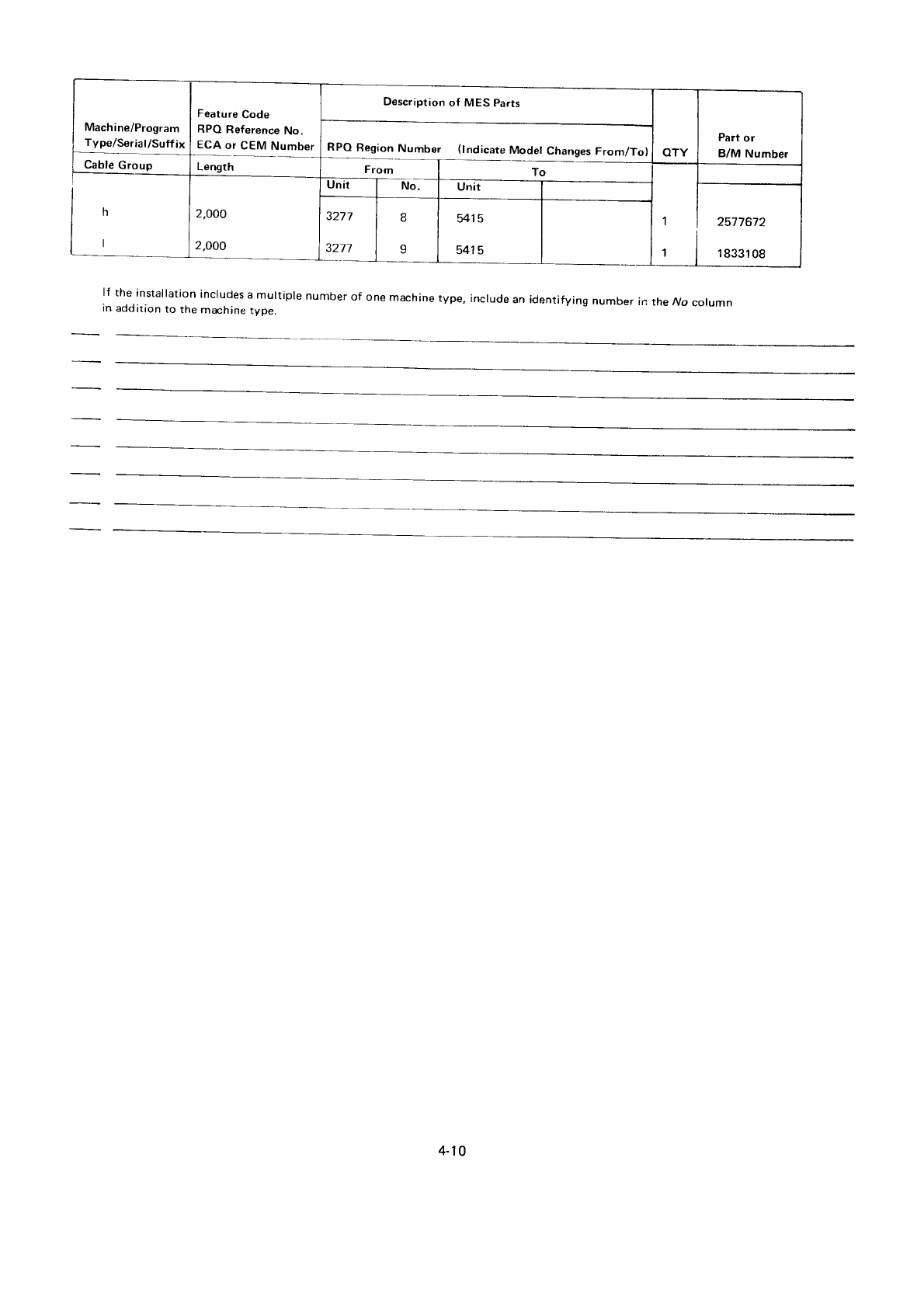
Mach ine/Program
_t"q1s"9/sgl:!
Cable
Group
Feature
Code
RPQ
Reference
No.
Ecl:'cEll]|'.b"1
Length
Description
of MES Parts
OTY
Part
or
B/M Number
RPO
Region
Number (lndicate
Modet
Changes
From/To)
From I fo
1
1
h2,OOO
2.OOO
Unit No
2577672
1833108
3271
3277
8
I
il15
541
5
lf the installation
includes
a muitiple number
of one
machine
type, include
an identifying
number
in the ly'o
column
in addirion
to the
machine
type.
4-10
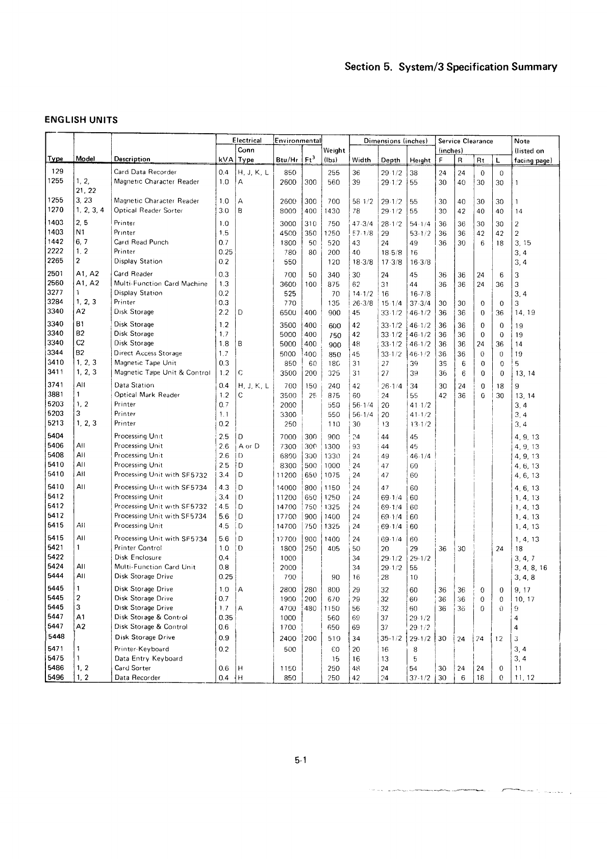
ENGLISH
UNITS
Section
5. System/3 Specification
Summary
Service Clearance
36 129r2138 124124 L0l0
39 1291?155 130 140 130 130 lr
56121291215b
i30 140 30 130 ll
;8 lze
t
2 l55 130 142 140 1
40 i
r4
jo"ojrr,rloo.lru
l.u lro l.o l,
157
t
8
129 153
1
2
i3b 136 142 142 12
43 124 149 t36 l30 I 6 ir8 13,ls
40 t185/8 t16 3,4
1)
21,22
J, ZJ
1,2.3,
4
N1
6,7
41,
A2
AI, A2
1
1,2,3
B1
6l
B2
1,2,3
1, 2,3
Atl
I
3
114
Arl
Ail
Atl
Atl
Atl
Card Data Recorder
lVlagnetrc
Character
Reader
Magnetic
Character
Reader
Optical Reader
Sorter
Pri
nte
r
Pnnter
Card
Read Punch
Printer
Display
Station
Card Reader
Multi'Function
Card Machine
Display
Station
Pr
i
nter
Drsk
Storage
Disk
Storage
Disk Storage
Disk
Storage
Direct
Access
Storage
Magnetic
Tape
Unir
l\4agnetic
Tape
Unit & Control
Data Station
Optical Mark Reader
Prinler
Pr
i nter
Pri
nter
Processing
Un t
Processing
Unit
Processing
Unit
Processing
Unil
Processing l.Jnit
with SF5732
Processing
Unrt
with SF5734
Processing
Unit
Processing
Unlt wrth SF5732
Processing
Unit with
SF5734
Processing
Unrt
Processing
Unit w;1L
tOUtaO
Printer
Control
Disk Fnclosure
l\4ulti-Function
Card
Unit
Disk
Storage
Drive
Disk Storage
Drive
Disk
Storage Drive
Drsk Storage
Drive
Disk Storage
& Control
Disk Storage
& Control
Disk Storage Drive
Pr
i
nte r-Key
board
Data Entry Keyboard
Card Sorter
Data Recorder
0.4
1.0
1.0
3.0
t.0
1.5
0.7
0.25
0.2
0.3
o.2
0.3
2.2
11
1.7
1.8
1.1
0.3
11
0.4
1.2
0.r
'l.l
0.2
2.5
2e,
2.6
2.5
J.+
4.3
3.4
4.5
5.6
4.5
56
10
0.4
0.8
o.25
't.0
o.7
1.1
0.35
0.6
0.9
o.7
H,J,K,L
A
A
ts
B
C
H,
J ., L
C
D
Aor D
D
D
D
D
D
D
D
D
D
D
850
2600
2600 |
300
800c I
400
3000 |
31 0
4500 |
350
1800
| 50
780 | 80
550
700 | 50
3600 |
100
525
770
650U
|
400
3500 | 400
5000 |
40t)
5000 |
400
5000 1400
I 700
I
1430
| 750
I
1250
i 520
j zoo
| 120
l:i3
iro
I
ras
i 900
I 600
I 1?9
3,4
1,4,
13
1.4. 13
r.
4. l3
1,4.13
t,
4,
13
34
4,6.13
300
255
560
900
850
r80
325
240
250
I z+u
I 8/5
I 5s0
110
I e00
I
1300
1 330
I
1000
I
1075
]rrsc
i
izso
tt
1325
I
raoo
|
1325
I
r+oo
| 405
I
lgo
I
| 8oo
| 6i0
Ir
rso
i soo
I oso
I
sro
I
i00
] ,5
I 2s0
18-3/8
|
17 318
|
16 3/B
30 124 145 136 136 124 6 l3
6? l31 144 136 136 i24 36 l3
14
1',2
|
16 |
16.7
8
850 i 60
26.J',8
115
141373/4
130 130 l0l0 l3
loo lr:i214612136 lao I
o
lro I'0.'o
142 i3312146r2136 136 |
0
|
0
lrs
142 t331/21461,2136
136 |
0 | 0 lre
lo8 i331214612136
136 124 i36 l14
!45 l33r
1
1461? 136 136
|
0 i 0 lre
131 127 r3o 135 I
6 |
0 | 0 15
,r, lr, lr, lsololololra,r+
142 26.1t4
tt34 130 124
i 0 |
18
is
ioo ,zq lss l+z lao i
o i:o
irs,rq
i56r4]20 t41121 I I i lrn
15614120 t4i12tt | | irq
i.o i,, l,?12 '1 1l
',?4 \44 i45 4.9,
13
193 t44 l4ti 4,
9, 1-?
)24 i
ne 46 1t4
)24 147 100 4,
9,
13
4.6. 13
24 )41 160 4.6. 13
24 i47 160
3500 |
200
700 |
150
3500
| 25
Ail
1
2ooo
I
3300
|
250 i
7000
i
300
r300 300
68co
|
3oo
8300
|
500
r1200
I650
14000
I
800
rranrr latr^
14700
i
750
17tAO 900
14700 750
17700
|
900
1
800 |
250
1000
|
2000 |
7oo
I
28oo
|
280
1
9c0 i
200
4700
I
480
1000
I
17oo
I
24OO
l,2OO
5oo
I
I
1150 |
24 t69.1.14 t60
24 i69.1i4 t60
24 1691/4 160
24 i69-1/4 160
24 l(i9-1i4 160
50 l2O i29 r36 r30
34 t29.1t2 t29.1t2
34 |
29
1,'2
|
55
16 i28 i10
!8
3,4,7
Atl
Atl
I
2
?
3.4.8.
16
3,4,8
29 l3?_ i60 136 i36 :0 | 0 l9,r/
?9 132 16() 36 l:16 0 | 0 1
10.1/
56 t32 i60 136 '3o i 0 | 0 lt
69 137 1
79 1
,'2 4
69 137 :29
1i2
0.6
0.4 850
ce 13/ iz!1tzi I i i 14 |
34 las-lz l2s.1pl3o izq lzq ltz lt I
zo l,u ja I i i i l.,o I
16 113 15 i i i | 13,4 i
i: l,o. l:i" i:9l'ii?11:lll.^
|
42 l?4 i37,1t2
]|30 l.
6 |
rB | 0 I il, 12 ,
129
1255
1
255
1210
1 403
1 403
1 442
2222
ztbS
zcu I
2560
3271
3284
3340
3340
3340
3340
3344
341 0
341
1
37
41
3881
5203
5203
5213
5404
5406
5408
541 0
541 0
541 0
5412
5412
5412
541 5
541
5
5421
5422
5424
5444
5445
5445
5445
5447
5447
5444
547
1
5475
5486
5496
5-1
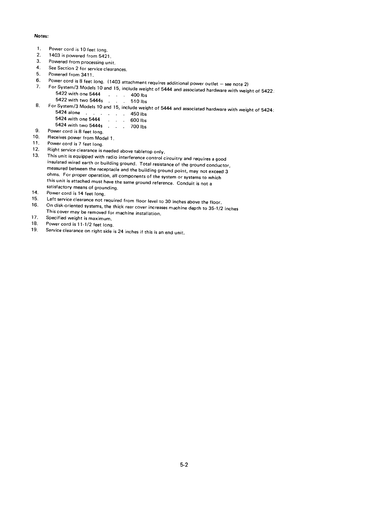
10.
11.
12.
tJ.
Notes:
1. Power
cord
is
10 feet
long.
2. 1403 is
powered
from S421.
3. Powered
from processing
unit.
4. See
Section
2 for service
clearances.
5. Powered
f
rom 34.1
l.
6' Power
cord is
I feet
tong. (1403
attachment
requires
additional
power
outlet - see
note
2)
7
' For system/3 Models
10
and 15,
include
weight
of 5444
and
associated
hardware
with weight
of s422:
5422 with one 5444 400 tbs
5422 with two 5444s 510 tbs
8' For system/3 Models
10
and 15,
include
weight
of 5444
and
associated
hardware
wirh weight
of s424:
8424 alone 450 lbs
5424with one 5444 600 tbs
5424 with two 5444s 700 tbs
Power
cord is 8 feet
long.
Receives power
from Model
1.
Power
cord is 7 feet
long.
Right
service
clearance
is
needed
above
tabletop
only.
This
unit is
equipped
with radio
interference
control circuitry and
requires
a
good
insulated
wired
earth
or buirding ground. Totar
resistance
of the
ground
conductor,
measured
between
the receptacle
and
the building ground
point, may not exceed
3
ohms. For proper
operation,
all
components
of the
system
or systems
to which
this
unit is
attached
must have
the same
ground
reference.
Conduit is not a
satasfactory
means
of grounding.
Power
cord is 14
feet
long.
Left service
clearance
not required from floor level
to 30 inches
above
the floor.
On disk-oriented
systems,
the thick rear
cover
increases
machine
depth
to 35_1/2
incnes
This
cover
may be removed
for machine
installation.
Specif
ied
weight is
maximum.
Power
cord is 11-1/2
feet
long.
Service
clearance
on right
side is
24 inches
if this is
an
end
unit.
14.
15.
16.
17.
18.
19.
5-2
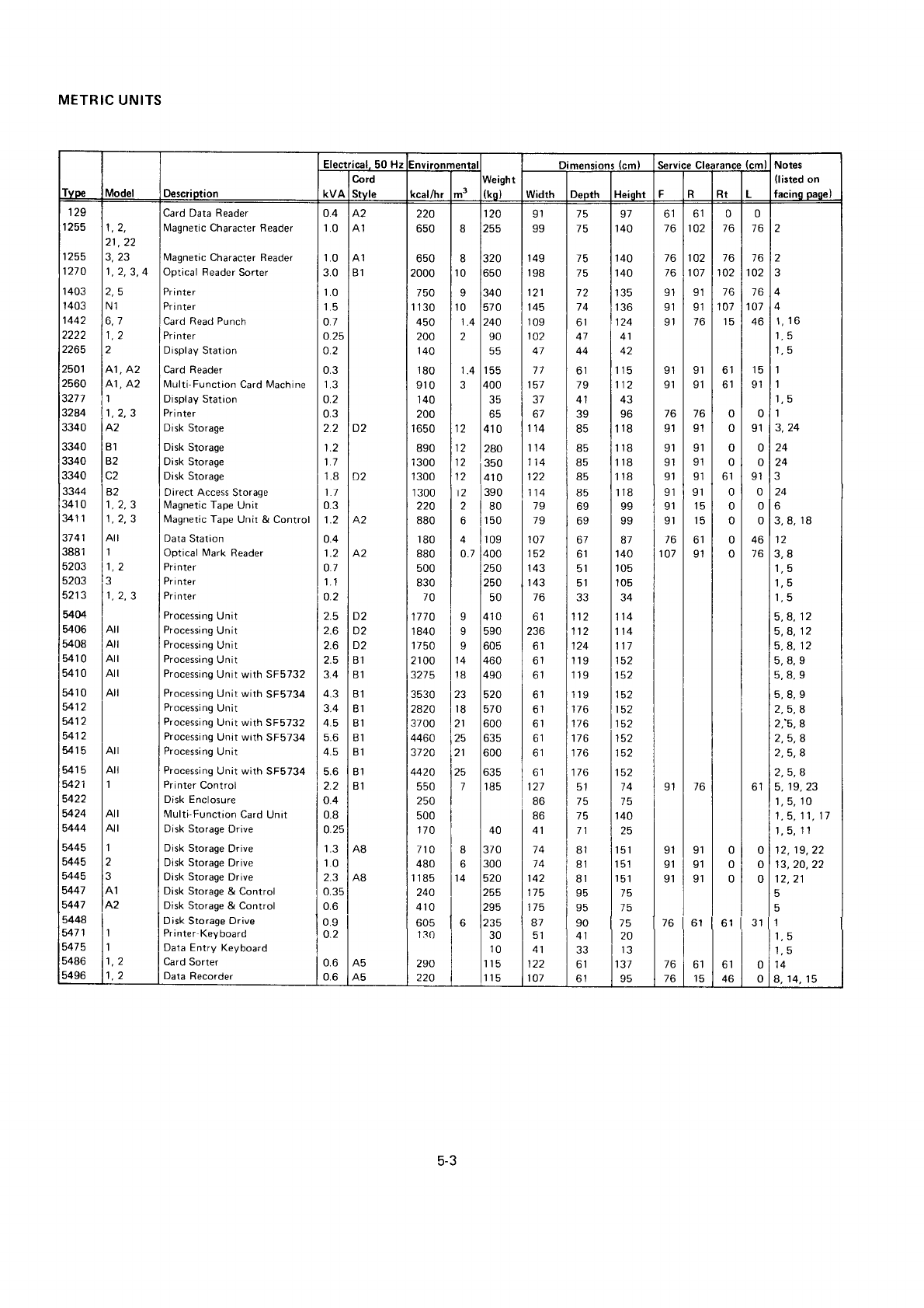
METRIC
UN!TS
lype Model Descriotion
Electrical,
50 Hz nvironmenta
iVeight
Iko I
Dimensions
(cm) Service Clearance
(cm) Notes
(listed
on
facino oaoe)KVA
Cord
Stvle <cal/hr m3 width Deoth Heidht FRRt L
129
zcJ
255
270
2501
2560
32A4
3340
1 403
1 403
1442
2222
2265
3340
3340
3340
3344
341 0
3/11
37
41
Jdb I
5203
5203
5213
54(X
5406
908
541
0
541 0
5410
5412
5412
5412
5415
541 5
5421
5422
5424
5444
945
5445
5445
5447
5447
5448
547'l
5475
5486
5496
1)
21,22
3,23
1,2,3,
4
)q
N1
6,1
1)
41, A2
41, A2
'|
1,2,3
A2
B,I
82
C2
a2
1,2,3
1,2,3
Atl
1
't,
2
1.2.3
1
1
't.2
1,2
Atl
Atl
1
Atl
Atl
Atl
Atl
Arl
Atl
All
1
3
A2
Card Data Reader
Magnetic
Character Reader
It4agnetic
Character Reader
Optical Reader
Sorter
Pr i nter
Pri
nter
Card
Read Punch
Pri nter
Display
Station
Card Reader
Multi-Function
Card Machine
Display Station
Pr
i
nter
Disk
Storage
Disk Storage
Disk Storage
Disk Storage
Direct Access
Storage
l,4agnetic
Tape Unit
Magnetic Tape
Unit & Control
Data
Station
Optical llark Reader
Pri nter
Pr
i nter
Pri
nter
Processing
Unit
Processing
Unit
Processing
Unit
Processing
Unit
Processing
Unit with SF5732
Processing
Unit with SF5734
Processing
Unit
Processing
Unit with SF5732
Processing
Unit with SF5734
Processing
Unit
Processing
Unit with SF5734
Printer
Control
Disk Enclosure
Multi-Function
Card
Unit
Disk Storage
Drive
Disk
Storage
Drive
Disk Storage
Drive
Disk Storage
Drive
Disk Storage
& Control
Disk
Storage & Control
Disk Storage
Drive
Printer-Keyboard
Data Entry Keyboard
Card Sorter
Data
Recorder
0.4
1.0
'1.0
3.0
1.0
1.5
0.7
o.25
0.2
0.3
I.J
o.2
0.3
2.2
1.2
1.7
1.8
1.1
0.3
1.2
0.4
1.2
o.7
't
.1
o.2
2.5
2.6
2.6
2.5
3.4
q.J
3.4
4.5
5.6
5.6
0.4
0.8
o.25
1.3
1.0
2.3
0.35
0.6
0.9
0.2
0.6
0.6
B1
D2
D2
A2
A2
D2
D2
nt
B1
B1
B1
B1
B1
B1
B1
B1
B,I
A8
A8
A5
A5
220
650
650
2000
750
1 130
450
200
14Q
180
910
140
200
1 650
890
1
300
1
300
1
300
220
880
180
880
500
830
70
1770
1
840
1 750
21
00
JZIJ
3530
2820
3700
4460
372A
4420
550
250
500
170
110
480
1 185
240
410
605
130
290
220
I
I
0
I
0
1^
2
2
2
2
2
2
6
o.7
1A
J
6
I
I
I
14
18
23
r8
11
25
21
25
7
8
6
A
|
120
l'""
I
I
320
|
650
I
340
157
0
240
90
400
410
280
350
I
410
|
3s0
180
|
150
I
10e
|
400
I
250
|
250
410
590
605
460
490
520
570
600
635
600
635
185
4o
370
300
520
255
I
2e5
t^^-
I zJ3
lrn
t;;
lrrs
t115
vl
99
149
r98
121
145
109
102
41
77
157
6t
114
107
t5z
143
143
76
ol
tJo
ol
61
bl
61
61
61
ol
ol
74
74
142
I t)
175
87
61
A1
107
114
tlz
79
79
61
127
86
86
A1
75
75
15
15
74
ol
47
44
ol
19
41
39
eq
85
85
85
85
69
69
67
61
5r
51
??
12
12
24
19
19
19
76
76
to
76
76
51
75
15
71
81
81
81
95
95
90
41
33
6l
61
g7
140
140
140
135
tJb
124
A1
42
115
't
12
qJ
96
118
'I
18
'l
18
118
118
99
99
87
140
'105
105
1't 4
't
14
117
t3z
t3z
tcz
taz
152
152
tJz
t5z
74
75
140
25
'151
tf,t
151
75
75
75
20
IJ
131
95
61
16
I6
76
91
91
9l
to
vl
91
91
91
9',]
91
91
76
107
91
91
91
9l
9r
91
76
76
76
102
't07
91
91
/o
9r
91
to
9't
91
91
91
9r
15
15
61
91
ot
102
76
91
91
91
6t
61
15
0
76
to
102
76
107
15
ol
61
0
0
0
0
bl
0
0
0
DI
0
0
0
61
46
0
16
76
102
16
107
46
15
91
0
9l
0
0
9l
0
0
0
46
76
ol
31
0
0
0
0
0
I
J
24
3
24
6
3,8,
18
4
1,16
1R
16
1
1
1,5
1
3,24
12
3.8
1,5
1,5
'1,
5
5,4, 12
5,8, 12
5,8, 12
5,8,9
5,8,9
Eeo
2,5,A
2,'5,8
2,5,8
2,5,8
z, ), d
5,
19,
23
1,5,
10
1,5, 11, 17
1,5,11
12. 19,22
13,20,22
't2,21
5
5
1
'1,
5
1q
14
8,14,15
5-3
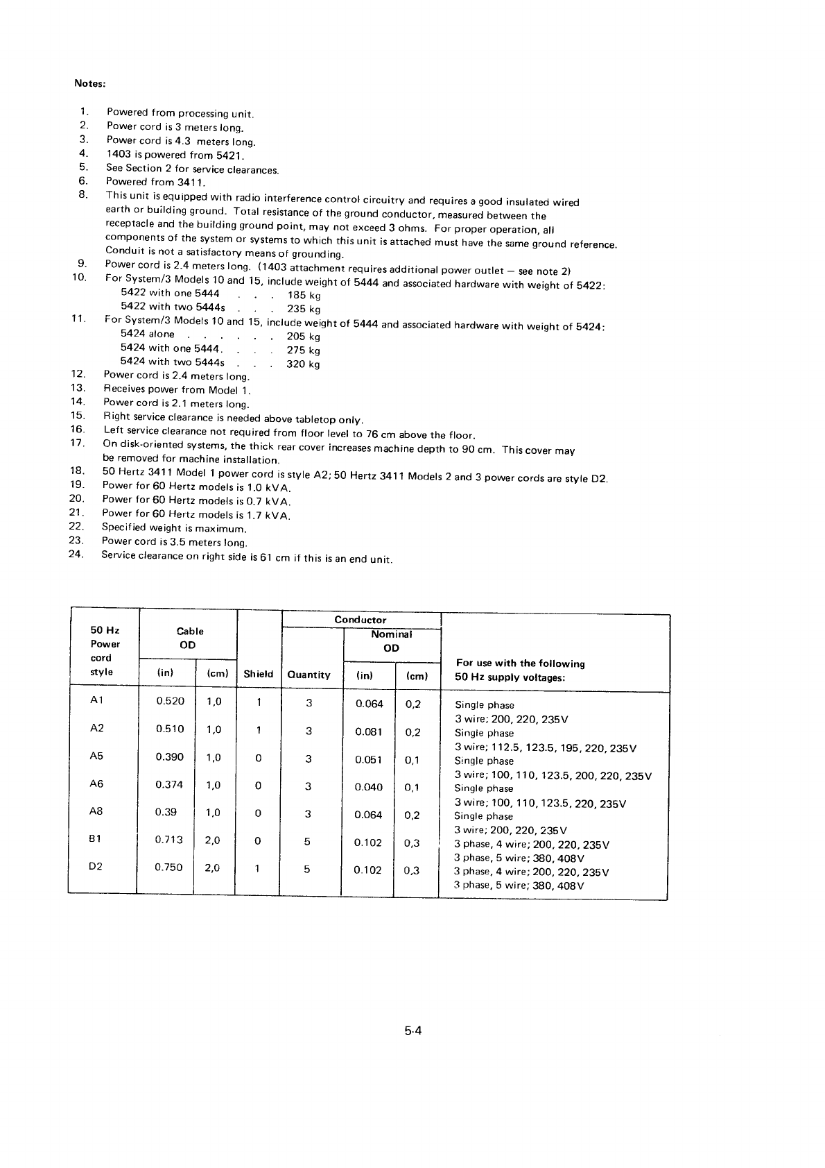
Notes:
1. Powered
f rom processing
unit.
2. Power
cord is
3 meters
long.
3. Power
cord is 4.3 meters
long.
4. 1403
ispowered
from5421.
5. See
Section
2 for service
clearances.
6. Powered
f
rom 341
1.
8' This
unit is
equipped
with radio
interference
control circuitry and requires
a
good insulated
wired
earth
or building ground. Total resistance
of the
ground
conductor,
measured
between
the
receptacre
and
the
buirding ground
point, may not exceed
3 .hms. For proper
operation,
arl
components
of the system
or systems
to which this
unit is attached
must have
the
same
ground
reference
Conduit is
not a satisfactory
means
of grounding.
9' Powercordis2'4meterslong.
(l403attachmentrequiresadditional
powerouflet-seenote2)
10 For system/3 Models
10
and 15,
include
weight
of 5444
and associated
hardware
with weight
of 5422
5422 wirh one 5444 1g5 kg
5422 with two 5444s 235 ko
11' For System/3
Models
10
and 15,
include
weight
of 5444 andassociated
hardware
with weight
of 5424:
5424 alone 205 kg
5424 with one SM4. 275 kg
5424 with two 5444s 320 ko
12. Power
cord is 2.4
meters
long.
'13. Fleceives power
f
rom Model
1 .
14. Power
cord is 2.
j meters
long.
15. Right
service
clearance
is needed
above
tabletop
onry.
16. Left seruice
clearance
not required
from froor rever
to 76
cm above the froor.
17' ondisk-orientedsystems,thethickrearcoverincreasesmachinedepthtogocm.
Thiscovermay
be
removed
for machine
installation.
18' 50 Hertz
3411 Model 1
power
cord is
style
A2;50 Hertz
34,|1 Models
2 and 3 power
cords
are
style D2.
19. Power
for 60 Hertz
models
is
1
.0 kVA.
20. Power
for 60 Hertz
models
is 0.7 kVA.
21
. Power
for 60 Hertz
models
is
1.7 kVA.
22. Specif
ied
weight
is
maximum.
23. Power
cord is
3.5 meters
long.
24- Service
clearance
on right
side
is
6l cm if this is
an
end
unit.
50 Hz
Power
cord
styl6
Cable
OD
Shield
Conductor
For use
with the following
50 Hz supply voltages:
Ouantity
Nominal
OD
(in
I(cm) (in) (cm)
A1
A2
A5
A6
A8
B1
0.520
o.510
0.390
o.374
0.39
0.71
3
0.750
1,0
1,0
1,0
1,O
1,0
2,O
2,4
I
I
0
0
0
0
1
J
?
J
J
o.064
0.o81
0.051
0.040
0.064
0.102
o.102
o,2
o,2
o,1
0,1
o,2
n?
0,3
Single
phase
3 wire;
200,
22O,235V
Single
phase
3
wire;
I 12.5,123.5,195,22O,235V
Si
ngle
phase
3 wire;
1 OO, 1 1
O, 1
23.5,
2OO, 22O,
235V
Single
phase
3 wire;
1
00, 1 1
O,
1
23.5,
22O, 23SV
Single phase
3 wire;
2O0,
22O,235V
3 phase,
4 wire;2OO,22O,235V
3 phase,
5 wire;380,408V
3 phase.
4 wire; 2OO,
22O, 235V
3 phase,
5 wire;380. 408V
5-4
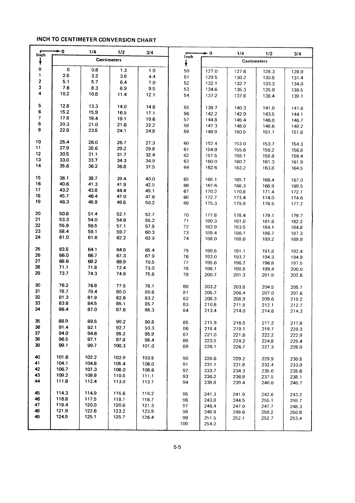
INCH TO
CENTIMETER
CONVERSION
CHART
5
6
7
I
9
10
11
12
13
14
20
21
22
23
24
25
26
27
28
29
30
31
32
33
34
35
36
37
38
s)
Q
41
42
43
4
45
$
47
€
49
r-.+0
I
nch 1t4 112 3t4
+
50
51
E'
q2
54
55
56
57
58
59
60
61
oz
63
64
65
66
6l
68
69
70
71
a,
73
74
15
76
17
7B
79
80
B1
6Z
OJ
84
B6
88
B9
90
ol
92
93
94
96
98
99
100
1.9
4.4
7.O
OE
12.1
14.6
17
.1
19.6
22.2
24.8
2't.3
29.8
32.4
34.9
37.5
40.0
42.5
45.1
47 .6
so.2
52.7
55.2
57.8
60.3
62.9
65.4
67.9
70.5
73.0
75.6
78.1
80.6
83.2
d5. /
88.3
90.8
93.3
oEo
98.4
101
.0
103.5
'106.0
108.6
111.1
113.7
116.2
118.7
121
.3
123.8
126.4
0
2.5
5.1
7.6
10.2
't2.8
15.2
17.8
20.3
22.9
25.4
27.9
30.5
33.0
35.6
38.1
40.6
43.2
45.7
48.3
50.8
53.3
5s.9
58.4
61
.0
63.5
66.0
68.6
71
.1
73.7
76.2
78.7
81.3
83.8
86.4
88.9
91.4
94.0
96.5
99.1
10't.6
104.1
106.7
1@.2
111.8
114.3
1t6.8
119.4
121 .9
124.5
0.6
3.2
5.7
8.3
10.8
13.3
15.9
18.4
21 .O
23.5
26.0
28.6
31.1
33.7
36.2
x.7
41 .3
43.8
46.4
48.9
51.4
54.0
56.5
59.1
61
.6
64.1
66.7
69.2
71.8
74.3
76.8
79.4
81.9
84.5
87.0
89.5
92.1
94.6
97.1
99.7
102.2
104.8
107.3
109.9
1't2.4
114.9
117.5
120.O
122.6
125.1
1.3
3.8
6.4
8.9
11.4
't4.o
16.5
r9.1
21 .6
24.1
26.7
29.2
31 .7
34.3
36.8
39.4
41
.9
44.4
47.O
49.5
52.1
54.6
57.1
59.7
62.2
il.8
67.3
69.9
72.4
74.9
77.5
80.0
82.6
85.1
87.6
90.2
92.7
95.2
97.8
r
00.3
r
02.9
1
05.4
108.0
1 10.5
113.0
r 15.6
r
18.1
120.6
123.2
125.7
127.O
129.5
132.1
134.6
137.2
139.7
142.2
144.8
147.3
149.9
152.4
154.9
157
.5
160.0
162.6
165.1
167.6
170.2
172.7
1
75.3
111
.8
180.3
182.9
185 4
188.O
190.5
193.0
195.6
198.1
200.7
203.2
205.7
208.3
210.8
213.4
215.9
218.4
221 .O
)ra R
226.1
224.6
231
.1
233.7
236.2
238.8
241 .3
243.8
246.4
248.9
251 .5
254.O
127.6 | 128.3
130.2 I 130.8
132.7 | 133.3
135.3 | 135.9
137.8 | 138.4
140.3 | 141 .0
142.9 I 143.5
145.4 | 1
46.0
12A.0 | 148.6
150.5 | 151.1
153.0 I 153.7
155.6 l 156.2
158.1 | 158.8
160.7 I 161
.3
163.2 | i
63.8
1
65.7 [ 166.4
168.3 | 168.9
i 70.8 | 171
.4
173.4 | 114.0
175.9 I 1
76.5
178.4 | 179.1
r81.0 I 18i.6
183.5 I 184.1
136.1 I 186.7
1
88.6 | 189
.2
191.1 | 191.8
193.7 I 194.3
196.2 | 196.8
198.8 | 199.4
201 .3 I 201.9
206-4 | 2O1 .O
211.5 l 212.1
214.0 | 214.6
216.5 | 211 .2
219.1 | 219.7
221 .6 | 222.2
224.2 | 224.8
231
.8 | 232.4
234.3 | 235
.0
241 .9 | 242.6
244.5 | 255.1
247.0 | Zqt.t
249.6 | 250.2
I26-3
131
.4
134.0
136.5
139.1
141
.6
144 .1
146.1
149.2
r5t.u
'154.3
rcb.d
159.4
161
.9
164.5
167.0
I
oy.3
112.1
174.6
177 .2
179
-7
182.2
184.8
187.3
189.9
192.4
194.9
197
.5
200.o
202.6
205.1
207.6
210.2
212.7
214.3
211 .8
220.3
222.9
225.4
224.O
230.5
233.0
235.6
238.1
240.7
z4J -Z
255.1
248.3
250.8
253.4
5-5


E==€
International
Business
Machines
Corporation
General
Systems
Division
41
11
Northside
Parkway
N.W.
P.O.
Box
2150
Atlana, Georgia
30301
(U.S.A.
only)
General
Business
Group/lnternational
tl4 South Broadway
White
Plains,
New York 10601
u.s.A.
{lnternationall
u)
o
3
o
3
o
I
o
o
d
'Tl
o
z
ct
(.)
ol
o
U'
N
5
@
GA21-9084-9
