GA34 0031 0_Customer_Direct_Program_Control_Adapter_Features_Description_Nov76 0 Customer Direct Program Control Adapter Features Description Nov76
GA34-0031-0_Customer_Direct_Program_Control_Adapter_Features_Description_Nov76 GA34-0031-0_Customer_Direct_Program_Control_Adapter_Features_Description_Nov76
User Manual: GA34-0031-0_Customer_Direct_Program_Control_Adapter_Features_Description_Nov76
Open the PDF directly: View PDF ![]() .
.
Page Count: 19
1
•
•
-
--
G
A34
-0031 -0 .
-
--
--
---
-
--
-
---
- - -
---
-
---
-
_.-
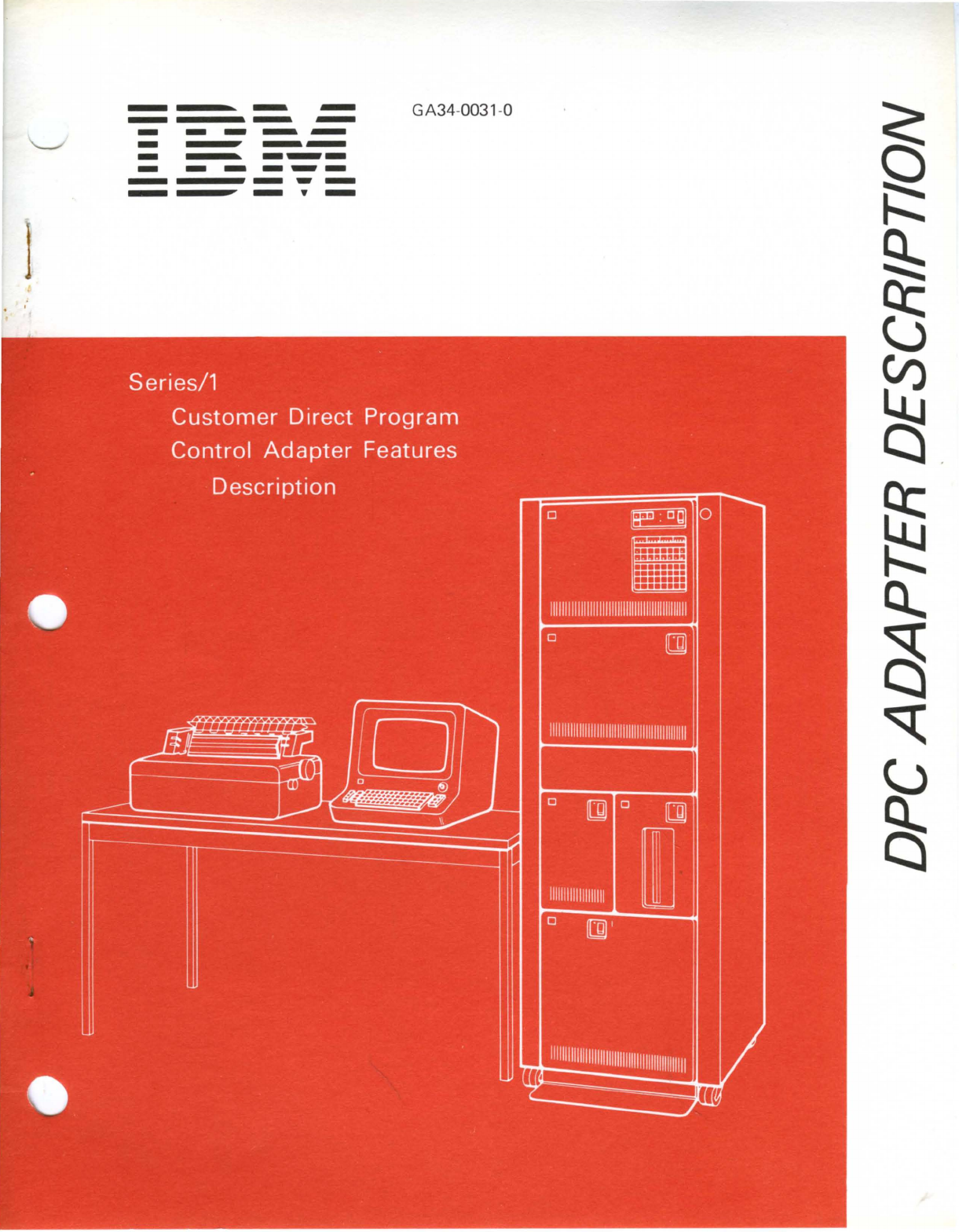
Series/1
Customer
Direct
Program
Control
Adapter
Features
.
Description
r.
[J
l&t
rl)
h
~
rill
0
P 1 ° @
-
I
~
~
0
lE3
0
II
1
1111111
1
11111111111111111111111111111111111111
0
[]
11
1111111111111111
1
11111111111111111111111111111
0 []) 0 [])
1111111111111111111
m
0
[]J
I
~
1111
11111111111111111111
1
11111111111111111111111
If
I
~
~
.
m
~
I
o~
'.~\
\.,-
'rio
~
o
0
';'
'"
-
--
-
--
GA34-0031-0
-
----
-
--
-----
---
---
-
---
-
_.-
Series/1 '
Customer Direct Program
Control
Adapter
Features
Description
ii
GA34-0031
First Edition (November 1976)
Changes are periodically made to the information herein; any such changes will
be
reported in
subsequent revisions or Technical Newsletters.
Text for this manual has been prepared with the
IBM
Magnetic Tape Selectric® Composer.
Requests for copies
of
IBM
publications should be made to your
IBM
representative
or
the
IBM
branch office serving your locality.
A form for readers' comments
is
provided
at
the back
of
this publication.
If
the form has been
removed, send your comments to
IBM
Corporation, Systems Publications, Department 27T, P.O. Box
1328, Boca Raton, Florida 33432. Comments become the property
of
IBM.
©Copyright International Business Machines Corporation 1976
o
o
o
o
o
Preface v
Prerequisite Publications v
Related Publications v
Customer Direct Program Control Adapter
Feature
Commands
1
Addressing 2
Condition
Codes Reported During the Operate
I/O
Instruction 2
Adapter-Directed Commands 3
Read Adapter
Status
Word 3
Read Diagnostic Data 4
Prepare 4
Set Diagnostic Mode 4
Bit 0 = 0 4
Bit 0 = 1 5
Reset Diagnostic Mode 5
Device-Directed Commands 6
Read
ID
6
Device Reset 6
Designer-Defined Device-Directed
Commands
6
Read Data 6
Read
Status
6
Write
Data
6
Write Control 6
Interrupt
Presentation and
Status
Words 6
Interrupt
Condition Codes 6
Interrupt
Information
Byte 7
Interrupt
Status
Byte 7
Status
After Power On Transitions and Resets 7
Contents
Contents
iii

iv
GA34-0031
(-.'.
)
o
o
This pliblic:.ttioll describes the
purpose
of
and
the
command
and
interrupt
structure
for the C'ustomer Direct Program
Cont
wi
Auapter. The manual is designed for use
by
programmers
who
program in assembler language,
but
who
require knowledge
of
machine language.
This manllal consists
of
a 'single
chapter
containing
an
introdllctioll
to
the
Customer
Direct Program
Control
Adapter
and the description
of
the applicable
commands.
This mUllllal will be revised in
the
future
to
discuss
other
lIser
adapter
features.
This manllal is directly related
to
the
IBM Series/l Model
3 4953 Processor and Processor Features Description
and
the IBM Series/l Model 5 4Y55 Processor and Processor
Features Descriptioll mall uals. Knowledge
of
either
of
these
two
publications is assumed.
Preface
Prerequisite Publications
IBM Series/1 Model 3 4953 Processor and Processur
features Descriptiun, GA34-0022
IBM Series/l Model 5 4955 Processor and Processor
features Description, GA34-0021
Related Publications
IBM .\'eries/l System Summary, GA34-0035
IBM Series/l
User's
Attachment
Manual, GA34-0033
IBM Series/l Physical Planning Manual, GA34-0029
Preface v

vi
GA34-0031

o
c
Customer Direct Program Control Adapter Feature
The direct program control adapter feature card provides a
convenient means
of
attaching I/O devices and subsystems
to a Series/I. The adapter
is
designed to perform direct
program control (DPC) functions only; cycle steal
operations cannot be performyd. The feature card can be
configured to accommodate 4, 8, or
16
I/O device
addresses. The adapter allows for interrupt vectoring
of
16
interrupt sources.
User attachment
is
through three top-card connectors.
There are 75 signal lines. These include: 18 data bus
out,
18 data bus in, 16 interrupt request in, 3 function bits, 4
modifier bits, 4 device address bits, and
12
control and
response lines. The data flow
is
always 16 bits without
parity option or 18 bits with parity option (2 parity bits).
This manual provides a functional description and
programming information for the Customer Direct Program
Control Adapter feature. For publications containing other
kinds
of
information, refer to the preface
of
this manual.
COMMANDS
The Customer Direct Program Control Adapter feature
is
connected to the processor through the I/O channel. Direct
Program Control (DPC) commands are used for
all
I/O
operations;
that
is, cycle steal mode
is
not
implemented.
The Operate I/O instruction (10)
is
executed for each
command.
I/O
Instruction
o 1 1 0 1
The Operate I/O instruction generates an effective address
that points
to
an immediate device control block (lDCB).
The IDCB contains a command field, a device address field,
and
an
immediate data field. Refer to Chapter 7
of
IBM
Series/l Model 5 4955 Processor and Processor Features
Description, GA34-0021, or Chapter 6
of
IBM Series/l
Model 3 4953 Processor and Processor Features
Description, GA34-0022, for additional information about
I/O operations.
Commands to the Customer Direct Program Control
Adapter
are
of
two kinds: adapter directed and device
directed.
Adapter-directed commands are specifically defined
by
IBM.
These commands perform specific actions using only
the adapter. They must use the function and modifier codes
specified.
Device-directed commands are defined by the customer.
Because
IBM
does
not
know what device will be attached
to
the feature card,
we
can define the commands only in a
general way that specifies whether information will be
transferred from the processor
to
the device or from the
device to the processor. For specific information about
device-directed commands, consult the designer
of
the
device and its adapter circuits.
Operation
code
1
'----~......L...--"----L---___L____---'
'---_
Effective address
+
IDCB (immediate device control block)
'-c_o_m_m_a_n_d_f_ie_l_d
___
-L-D_eV_ic_e_a_d_d_re_s_s
_fi_eZ_d
__
-,--Im_m_e_d_ia_te_d_a_t_a
_fi_e_1d-J U
o 7 8
15
16
31
*Indirect addressing
bit
Customer Direct Program
Control
Adapter Feature
Addressing
The Customer Direct Program Control Adapter can be
configured for 4, 8, or
16
device addresses by
field-installable jumpers.
The first four (high-order) bits
of
the device address field
of
the IDCB are defined
by
field installable connectors on
the feature card. The
next
two
bits are defined
by
field
installable connectors only
if
the feature card
is
configured
for four or eight devices. The low-order bits
that
are
not
used to address the adapter card are used for device
addressing within the domain established
by
the feature
card address.
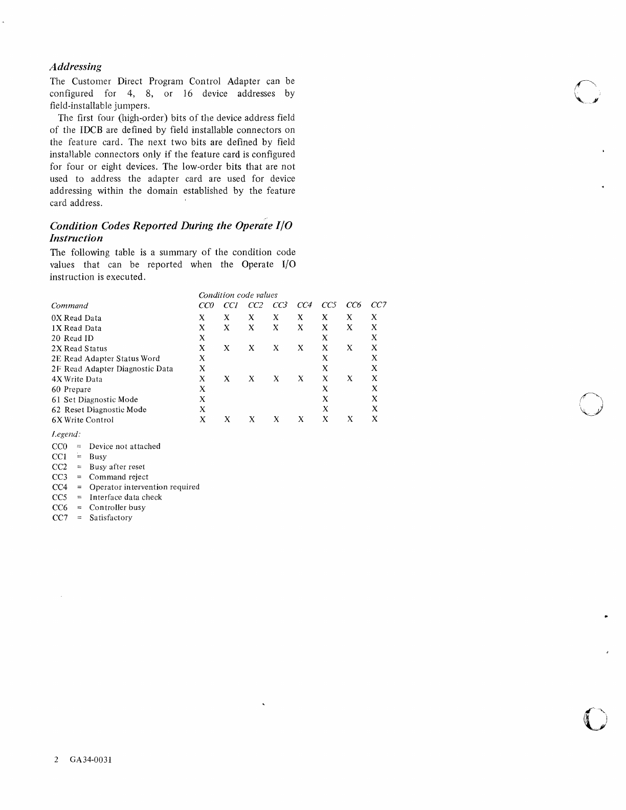
Condition Codes
Reported
During
the
Operate 110
Instruction
The following table is a summary
of
the condition code
values
that
can be reported when the Operate I/O
instruction
is
executed.
Condition code values
Command
CCO
CCl CC2
CC3
OX
Read
Data
X X X X
IX
Read
Data
X X X X
20
Read
ID X
2X
Read
Status
X X X X
2E
Read
Adapter
Status
Word X
2F
Read
Adapter
Diagnostic
Data
X
4X
Write
Data
X X X X
60
Prepare
X
61
Set
Diagnostic Mode X
62
Reset
Diagnostic
Mode
X
6X
Write
Control
X X X X
j.egend:
CCO
Device
not
attached
CCI
Busy
CC2 Busy
after
reset
CC3
Command
reject
CC4
Operator
in
tervention
required
CC5
Interface
data
check
CC6
Controller
busy
CC7 Sa
tisfactory
2
GA34-003l
CC4 CC5 CC6 CC7
X X X X
X X X X
X X
X X X X
X X
X X
X X X X
X X
X X
X X
X X X X
C
'
r
_.
1
,0
c
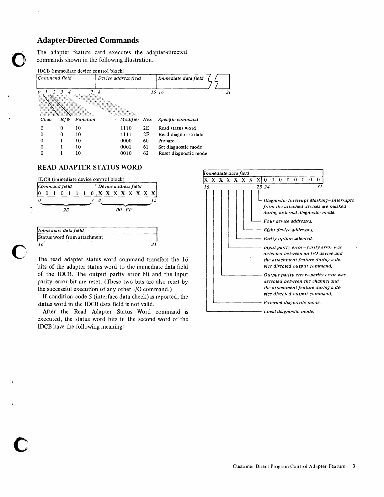
Adapter-Directed
Commands
The adapter feature card executes the adapter-directed
commands shown in the following illustration.
IDeB
(immediate device control block)
Device address field
Immediate
data
field
15
16
Hex
Specific
command
0 0
10
1110 2E Read status word
0 0 10 1111
2F
Read diagnostic data
0 10 0000 60 Prepare
0 10 0001
61
Set diagnostic mode
o
31
0 10
0010
62 Reset diagnostic mode
READ
ADAPTER
STATUS
WORD
IOCB (immediate device
control
block)
Command
field
Device address
field
00101
1
lOX
X X X X X X X
o 7 8
15
~~
____
-v
____
~J
'~----vv----~~
2E
OO-FF
Immediate
data
field
Status word from
attachment
16
31
The read adapter status word command transfers the 16
bits
of
the adapter status word
to
the immediate data field
of
the
IDCB.
The
output
parity error
bit
and the input
parity error bit are reset. (These two bits are also reset by
the successful execution
of
any other I/O command.)
If
condition code 5 (interface data check)
is
reported, the
status word in the
IDCB
data field
is
not
valid.
After the Read Adapter Status Word command
is
executed, the status word bits in the second word
of
the
IDCB
have the following meaning:
mmediate
data
field
X X X X X X X X 0 0 0 0 0 0 0 0
16
23
24
31
~
Diagnostic
Interrupt
Masking-Interrupts
from
the
attached
devices
are
masked
during
external
diagnostic
mode.
Four
device
addresses.
-,
Eight
device
addresses.
'-----
Parity
option
selected.
L..-
____
Input
parity
error-parity
error
was
detected
between
an
I/O
device
and
the
attachment
feature
during
a de-
vice
directed
output
command.
L.--
______
Output
parity
error-parity
error
was
detected
between
the
channel
and
the
attachment
feature
during
a de-
vice
directed
output
command.
L..-
_______
External
diagnostic
mode.
L.--
________
Local
diagnostic
mode.
Customer Direct Program
Control
Adapter Feature 3
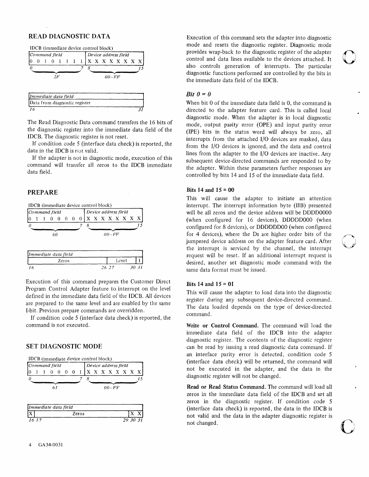
READ DIAGNOSTIC DATA
IDCB (immediate device
control
block)
Command
field
Device
address
field
0 0 1 0 1 I 1 X X X X X X X X
0 7 8
15
....
'" " '"
v v
2F
OO-FF
Immediate
data
field
Data
from
diagnostic register
16
31
The Read Diagnostic Data command transfers the 16 bits
of
the diagnostic register into the immediate data field
of
the
IDCB. The diagnostic register
is
not
reset.
If
condition code 5 (interface data check)
is
reported, the
data in the IDCB
is
not
valid.
If
the adapter
is
not
in diagnostic mode, execution
of
this
command will transfer all zeros to the IDCB immediate
data field.
PREPARE
IDCB
(immediate
device
control
block)
o 7 8
15
~~------v~------
~~----~~----~'"
60
()O--FP
Level
16
26
27
30
31
Execution
of
this command prepares the Customer Direct
Program Control Adapter feature
to
interrupt
on the level
defined in the immediate data field
of
the IDCB.
All
devices
are prepared
to
the same level and are enabled by the same
I-bit. Previous prepare commands are overridden.
If
condition code 5 (interface data check)
is
reported, the
command
is
not
executed.
SET DIAGNOSTIC MODE
IDeB
(immediate
device
control
block)
Command
field
Device
address
field
0 I 1 0 0 0 0 X X X X X X X X
0 7 8
15
...
'"
" '"
v
61
OO-FF
IImmediate
data
field
X I Zeros
16
17
29
30
31
4 GA34-0031
Execution
of
this command sets the adapter
into
diagnostic
mode and resets the diagnostic register. Diagnostic mode
provides wrap-back
to
the diagnostic register
of
the adapter
control and data lines available
to
the devices attached.
It
also controls generation
of
interrupts. The particular
diagnostic functions performed are controlled
by
the bits in
the immediate data field
of
the IDCB.
Bit
0 = 0
When bit 0
of
the immediate data field
is
0, the command
is
directed
to
the adapter feature card. This
is
called local
diagnostic mode. When the adapter is in local diagnostic
mode,
output
paFity error (OPE) and
input
parity error
(IPE) bits
in
the status word will always be zero,
all
interrupts from the attached I/O devices are masked, data
from the I/O devices
is
ignored, and the data and control
lines from the adapter to the I/O devices are inactive. Any
subsequent device-directed commands are responded
to
by
the adapter. Within these parameters further responses are
controlled by bits 14 and
15
of
the immediate data field.
Bits 14 and 15 = 00
This will cause the adapter
to
initiate an
attention
interrupt. The interrupt information
byte
(lIB) presented
will be all zeros and the device address will be
DDDDOOOO
(when configured for
16
devices),
DDDDDOOO
(when
configured for 8 devices), or
DDDDDDOO
(when configured
for 4 devices), where the
Ds
are higher order bits
of
the
jumpered device address on the adapter feature card. After
the
interrupt
is
serviced
by
the channel, the interrupt
request will be reset.
If
an additional
interrupt
request
is
desired, another set diagnostic mode command with the
same data format must be issued.
Bits 14 and 15 =
01
This will cause the adapter
to
load data
into
the diagnostic
register during any subsequent device-directed command.
The data loaded depends on the type
of
device-directed
command.
Write
or
Control Command. The command will load the
immediate
data
field
of
the IDCB into the adapter
diagnostic register. The contents
of
the diagnostic register
can be read by issuing a read diagnostic data command.
If
an interface parity error is detected, condition code 5
(interface data check) will be returned, the command will
not
be executed in the adapter, and the data in the
diagnostic register will
not
be changed.
Read
or
Read Status Command. The command will load all
zeros in the immediate data field
of
the IDCB and set
all
zeros in the diagnostic register.
If
condition code 5
(interface data check)
is
reported, the data in the IDCB
is
not
valid and
the
data in the adapter diagnostic register
is
not
changed.
C
II.)
'j,
o
c
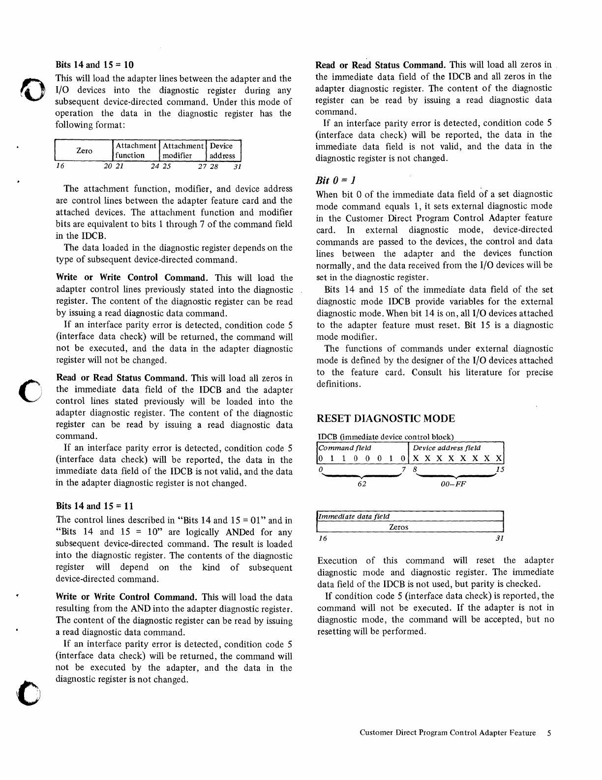
Bits 14 and 15 = 10
This will load the adapter lines between the adapter and the
I/O devices into the diagnostic register during any
subsequent device-directed command. Under this mode
of
operation the data in the diagnostic register has the
following format:
Zero
16
The attachment function, modifier, and device address
are control lines between the adapter feature card and the
attached devices. The attachment function and modifier
bits are equivalent
to
bits 1 through 7
of
the command field
in
the IDCB.
The data loaded in the diagnostic register depends on the
type
of
subsequent device-directed command.
Write
or
Write Control Command. This will load the
adapter control lines previously stated into the diagnostic
register. The content
of
the diagnostic register can be read
by issuing a read diagnostic data command.
If
an interface parity error
is
detected, condition code 5
(interface data check) will be returned, the command will
not
be executed, and the data in the adapter diagnostic
register will
not
be changed.
Read or Read Status Command. This will load
all
zeros in
the immediate data field
of
the IDCB and the adapter
control lines stated previously will be loaded into the
adapter diagnostic register. The content
of
the diagnostic
register can be read by issuing a read diagnostic data
command.
If
an interface parity error is detected, condition code 5
(interface data check) will be reported, the data in the
immediate data field
of
the IDCB
is
not
valid, and the data
in the adapter diagnostic register is
not
changed.
Bits 14 and 15 =
11
The control lines described in "Bits 14 and
15
=
01"
and in
"Bits 14 and
15
=
10"
are logically ANDed for any
subsequent device-directed command. The result
is
loaded
into the diagnostic register. The contents
of
the diagnostic
register will depend on the kind
of
subsequent
device-directed command.
Write or Write Control Command. This will load the data
resulting from the AND into the adapter diagnostic register.
The content
of
the diagnostic register can be read by issuing
a read diagnostic data command.
If
an interface parity error
is
detected, condition code 5
(interface data check) will be returned, the command will
not
be executed by the adapter, and the data in the
diagnostic register
is
not
changed.
Read or Read Status Command. This will load all zeros in .
the immediate data field
of
the IDCB and
all
zeros in the
adapter diagnostic register. The content
of
the diagnostic
register can be read by issuing a read diagnostic data
command.
If
an interface parity error
is
detected, condition code 5
(interface data check) will be reported, the data in the
immediate data field
is
not
valid, and the data in the
diagnostic register
is
not changed.
Bit
0 = 1
When
bit 0
of
the immediate data field
of
a set diagnostic
mode command equals 1, it sets external diagnostic mode
in the Customer Direct Program Control Adapter feature
card. In external diagnostic mode, device-directed
commands are passed to the devices, the control and data
lines between the adapter and the devices function
normally, and the data received from the I/O devices will be
set in the diagnostic register.
Bits 14 and
15
of
the immediate data field
of
the set
diagnostic mode
IDCB
provide variables for the external
diagnostic mode. When bit 14
is
on, all I/O devices attached
to the adapter feature must reset. Bit
15
is
a diagnostic
mode modifier.
The functions
of
commands under external diagnostic
mode
is
defined by the designer
of
the I/O devices attached
to
the feature card. Consult his literature for precise
definitions.
RESET DIAGNOSTIC MODE
IDCB (immediate device control block)
Command
field
Device address
field
o 1 1
000
lOX
X X X X X X X
o 7 8
15
~
......
---..,.v----~
~"""---"""v---'~
62
OO-FF
,Immediate
data
field
Zeros
16
31
Execution
of
this command will reset the adapter
diagnostic mode and diagnostic register. The immediate
data field
of
the
IDCB
is
not used,
but
parity
is
checked.
If
condition code 5 (interface data check)
is
reported, the
command will
not
be executed.
If
the adapter
is
not
in
diagnostic mode, the command will be accepted,
but
no
resetting will be performed.
Customer Direct Program
Control
Adapter
Feature
5
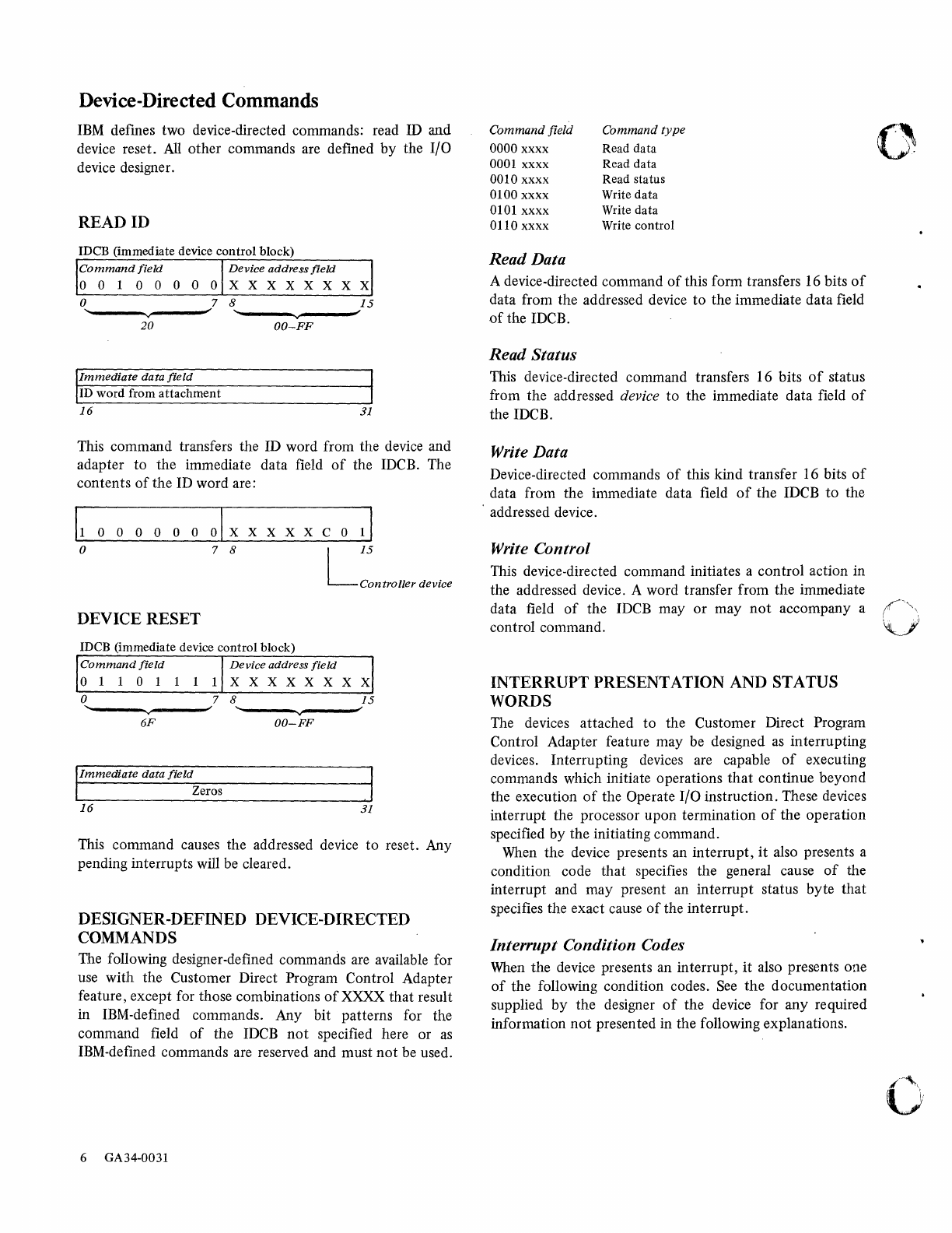
Device-Directed
Commands
IBM
defines two device-directed commands: read ID
and
device reset.
All
other commands are defined by the
If
0
device designer.
READID
rDCB (immediate device
control
block)
Command
field
Device
address
field
001
0
000
0 X X X X X X X X
o 7 8
15
~"""---v".---'"
~"""---v-v
---'"
20
OO-FF
Immediate
data
field
ID word from
attachment
16
31
This command transfers the ID word from the device and
adapter
to
the immediate data field
of
the IDCB. The
contents
of
the ID word are:
11
0 0 0 0 0 0 0 I X
XXXXC
011
o 7 8 L
IS
Controller
device
DEVICE RESET
IDCB (immediate device control block)
Command
field
o 1
101
1 1
Device
address
field
XXXXXXXX
o 7 8
15
~"""----~v~------j
~"""----~v~-----j
6F
OO-FF
IImmediate
data
field
Zeros
16
31
This command causes the addressed device
to
reset. Any
pending interrupts will be cleared.
DESIGNER-DEFINED DEVICE-DIRECTED
COMMANDS
The following designer-defined commands are available for
use with the Customer Direct Program Control Adapter
feature, except for those combinations
of
XXXX that result
in IBM-defined commands. Any bit patterns for the
command field
of
the
IDCB
not
specified here or
as
IBM-defined commands are reserved and must
not
be used.
6 GA34-0031
Command field Command
type
0000
xxxx
Read data
0001
xxxx
Read data
0010
xxxx
Read status
0100
xxxx
Write data
0101
xxxx
Write data
0110
xxxx
Write control
Read Data
A device-directed command
of
this form transfers 16 bits
of
data from the addressed device
to
the immediate data field
of
the IDCB.
Read Status
This device-directed command transfers 16 bits
of
status
from the addressed device
to
the immediate data field
of
the IDCB.
Write Data
Device-directed commands
of
this kind transfer 16 bits
of
data from the immediate data field
of
the IDCB
to
the
, addressed device.
Write Control
This device-directed command initiates a control action in
the addressed device. A word transfer from the immediate
data field
of
the IDCB
mayor
may
not
accompany a
control command.
INTERRUPT PRESENTATION AND STATUS
WORDS
The devices attached to the Customer Direct Program
Control Adapter feature may be designed
as
interrupting
devices. Interrupting devices are capable
of
executing
commands which initiate operations
that
continue beyond
the execution
of
the Operate I/O instruction. These devices
interrupt the processor upon termination
of
the operation
specified by the initiating command.
When
the device presents an interrupt,
it
also presents a
condition code that specifies the general cause
of
the
interrupt and may present an interrupt status byte that
specifies the exact cause
of
the interrupt.
Interrupt Condition Codes
When
the device presents an interrupt,
it
also presents one
of
the following condition codes.
See
the documentation
supplied by the designer
of
the device for any required
information
not
presented in the following explanations.
0
(""\
~_JJ
o
c
o
CCO-Controller End. This condition code
is
reported by a
controller after it has successfully reported condition code
6 (controller busy) to an I/O instruction. Controller end
signifies that the controller
is
free to accept I/O commands
for devices which it controls. The device address reported
with the controller end interrupt
is
the lowest numerical
value
of
the group
of
devices controlled by
that
controller
domain. The lIB will be zero.
CCI-Reserved.
This condition code should never be
reported by a device attached
to
this feature.
CC2-Exception
Interrupt. This condition code
is
reported
by
the device when an error or exception condition
is
associated with the interrupt. The condition
is
described in
the interrupt status byte and in device dependent status
words,
if
required.
CC3-Device End. This condition code
is
reported by the
device when no error, exception, or attention conditions
occurred during the I/O operation.
CC4-Attention.
This condition code
is
reported by the
device only when the interrupt was caused by an external
event rather than execution
of
an I/O command. If the
event has a singular meaning, no further status recording
is
required.
CCS-Reserved. This condition code should never be
reported by this feature.
CC6-Attention
and Exception. This condition code
is
reported by the device when an attention condition occurs
at the same time
as
an
exception condition.
CC7
-Attention
and Device End. This condition code
is
reported when an attention condition occurs at the same
time
as
device end.
Interrupt Information
Byte
Each interrupting device may implement an interrupt
information byte (lIB). The lIB
is
used to record status that
cannot be indicated to the program
via
condition codes.
The meaning
of
each bit in the lIB depends on the device.
For
information on the meaning
of
the lIB,
see
the
documentation supplied
by
the designer
of
the device. The
lIB has the following format:
lIB
I NOtU_sed ]
~---
o 7 8
15
Interrupt Status
Byte
The interrupt status byte (ISB)
is
a special format
of
the
lIB and
is
presented only when interrupt condition codes 2
and 6
are
reported. Unless the condition code presentation
of
2 or 6
is
singular
in
meaning, the ISB will never be zero.
Bits in the
ISB
are normally set
as
a result
of
status errors
which occur in
an
operation
that
was initiated by a
command but which cannot be indicated to the program via
a condition code. After the device has recognized
that
its
interrupt request has been taken by the processor, the
ISB
is
reset.
The
ISB
for devices has the following format:
Bit 0
Bit 1
Bits
2-7
Device dependent status available
Delayed command reject
Device dependent
STATUS AFTER POWER
ON
TRANSITIONS
AND RESETS
• Halt I/O Command or Machine Check Reset. The
diagnostic mode, the diagnostic· register, and the status
word are reset.
• System Reset. The diagnostic mode, the diagnostic
register, the prepare register, and the status word are
reset.
• Power
On
Reset. The diagnostic mode, the diagnostic
register, the prepare register, and the status word are
reset.
Consult the documentation supplied by the designer
of
the device for reset conditions
that
apply to each device
attached to this feature.
Customer
Direct
Program
Control
Adapter
Feature
7

8 GA34-0031
(
""'.'
" "J
Series/ I
Customer
Direct Program
Control
Adapter
Features
Description
GA34-0031-0
Your
views
about
this
publicatioll
may
help
improve
its llsefulness,' this
form
will
be
sent
to
the
author's
department
for
appropriate
action. Using this
form
to
request system assistance
or
additional publications will delay response,
however. For
more
dir(!ct halldling
of
such
requests, please
contact
your
IBM
representatil'e
or
the
I
BiH
Branch
Office
serving
your
locality.
Possible topics for
comment
are:
Clarity Accuracy Completeness Organization Index Figures Examples Legibility
What
is
your
occupation?
Number
of
latest Technical Newsletter
(if
any) concerning this pUblication:
Please indicate
your
name
and address in
the
space below
if
you
wish a reply.
Thank
you
for
your
cooperation.
No
postage
stamp
necessary
if
mailed in
the
U.S.A. (Elsewhere,
an
IBM
office or representative will be
happy
to
forward
your
comments.)
READER'S
COMMENT
FORM
GA34-0031-0
Your
commen
ts, please . . .
This manual
is
part
of
a library
that
serves
as
a reference source for systems analysts,
programmers, and operators
of
IBM
systems. Your
comments
on the
other
side
of
this
form will be carefully reviewed
by
the persons responsible for writing and publishing
this material. All
comments
and suggestions become the
property
of
IBM.
Fold Fold
Business Reply Mail
No postage
stamp
necessary
if
mailed in the U.S.A.
IBM
Corporation
Systems Publications,
Dept
27T
P.O. Box 1328
Boca
Raton,
Florida
33432
First Class
Permit
40
Armonk
New
York
Fold Fold
International Business Machines Corporation
General Systems Division
57750
Glenridge Drive N.
E.
P.O. Box 2150
Atlanta, Georgia 30301
(U.S.A. only)
<"'.l
=
....
en
(1)
t:!.
(1)
~
-
~
0-
S
(1)
'"i
t::I
::;.
(1)
~
'"C
'"i
0
Otl
'"i
$l:>
/~.~.
s
(J
(~)
0
::s
r::t
g.
:>
~
$l:>
"C
<t
'"i
"Tj
(1)
$l:>
S-
'"i
~
t::I
(1)
'"
(")
~.
o·
::s
'"C
'"i
~:
(1)
~
S·
c:::
en
~
Q
:>
w
~
6
0
w
-
6
0
I.'

o
o
c
--..-
-
---
....
~
-,
-
---
-
----
..
-..
---
--
--
---
-~-~-
----- _
..
-®
International Business Machines Corporation
General Systems Division
57750
Glenridge Drive
N.
E.
P.O.
Box 2150
Atlanta, Georgia 30301
(U.S.A. only)
GA34-0031-0
o
~
;!
CD
c.
3'
c
en
~
G)
:t>
{.
w
~
g 1
~
'0
o
THE COMPUTER MUSEUM HISTORY CENTER
111111111111
11111
n~lllll~~I~I"~IIIIIIIIIIII
