GALaxy III Traction Elevator Controller V3.3.15
User Manual: GALaxy III Traction Elevator ControllerV3.3.15
Open the PDF directly: View PDF ![]() .
.
Page Count: 472 [warning: Documents this large are best viewed by clicking the View PDF Link!]
- Introduction
- 1.1 Physical Layout of the Controller
- 1.2 Typical Physical Layout
- 1.3 Selector System
- 1.4 Tape Selector System
- 1.5 Tapeless System
- 1.6 Secondary Speed Feedback
- 1.7 Modes of Operation
- 1.8 Operating Sequence
- 1.9 Reset Mode
- 1.10 Safety String Open Mode
- 1.11 Controller Inspection Mode
- 1.12 Car Top Inspection Mode
- 1.13 Access Mode
- 1.14 Independent Service Mode
- 1.15 Load Weighing Bypass Mode
- 1.16 Attendant Service Mode
- 1.17 Code Blue Hospital Service Mode
- 1.18 Fire Service Phase I Mode
- 1.19 Fire Service Phase I Alternate Return Mode
- 1.20 Fire Service Phase II Mode
- 1.21 Emergency Power
- 1.22 Earthquake Mode
- 1.23 Stalled Mode
- 1.24 Automatic Mode
- Section 2 ‐ Product Description
- 2.1 General Information
- 2.2 Site Selection
- 2.3 Environmental Considerations
- 2.4 Wiring Guidelines and Instructions
- 2.5 The Wiring Prints
- 2.6 Ground Wiring
- 2.7 Hoistway Wiring
- 2.8 Elevator Car Wiring
- 2.9 Machine Room Wiring
- 2.10 Wiring to Top of Car Selector
- 2.11 Slowdown Limits
- 2.12 Normal and Final Limit Switches
- 2.13 Tape Selector Installation
- 2.14 Tapeless Selector Installation
- Figure 2.5: Tapeless Selector Mounted on Crosshead
- Figure 2.5a: Tapeless Selector Magnet Placement
- Figure 2.6: Door Zone Template Used to Set Selector Distance
- Figures 2.7: Sensor Orientation and Wiring
- Figure 2.8: Sensor Orientation Upside Down
- Figures 2.9 & 2.10: Door Zone Template
- Figure 2.11: Tapeless Selector - Sensor Adjustment
- Figure 2.12: Tapeless Selector – Close-up of Notch & Sensor
- 2.15 Tapeless Selector Assembly Installation
- 2.16 Transfer Relay Diagram
- Section 3 ‐ Adjustment of the GALaxy controller DSD 412 Drive
- 3.1 General Information
- 3.2 Check Main Line Voltage
- 3.3 SCR Drive Motor Field Current
- 3.4 Set Toggle Switches
- 3.5 Make Sure the Car Is Safe
- 3.6 Check Controller Voltage
- 3.7 Verify the Main CPU is Operating
- 3.8 Preset Adjustable Variables on Safety Processor Board and Main CPU
- 3.9 1066 LCD interface "Adj Var" Menu
- 3.10 1021/1101/1005 LCD interface "Adjustable Variables -> Car Motion" Submenu
- 3.11 Place Stop Switch in Run Position
- 3.12 Hoist Motor Data
- 3.13 SCR Drive Self Tune
- 3.14 Pre‐set the Digital Speed Clamps
- 3.15 Ready to Run On Inspection
- 3.16 Adjust the Brake Voltage
- 3.17 Check the Run Direction
- 3.18 Car Runs in the Wrong Direction
- 3.19 Drive Trips Immediately
- 3.20 Check Inspection Speed
- 3.21 Verify Controller Encoder Direction
- 3.22 Verify Selector and Slowdown Inputs
- 3.23 Verify Car Speed on Safety Processor Board
- 3.24 Correct Car Speed When Using a Tape Installed in Hoistway
- 3.25 Correct Car Speed When Using 485 Tapeless System
- 3.26 Correct Car Speed When Using CAN Open Tapeless System
- 3.27 Learn the Hoistway
- 3.28 Automatic Run
- 3.29 Fine Tune the Ride Quality
- 3.30 Adjust the Stop
- 3.31 Adjust the Start
- 3.32 Verify Top Speed
- 3.33 Adjust Safety Processor Board Speed Clamps
- 3.34 Adjust Digital Slowdown Speed Clamps
- 3.35 Verify Inspection Velocity Clamp On Safety Processor Board
- 3.36 Analog Load Weigher Setup
- 3.37 Empty Car Setup
- 3.38 Full Car Setup
- 3.39 Load Weighing Calibration Sequence
- 3.40 Adjust the Motor Pre‐torque
- 3.41 Verify the Doors Are Safe
- 3.42 Fine Tune the Ride Quality
- Section 4 ‐ Adjustment of the GALaxy controller HPV‐600/900 (Induction Motor- Geared Machine)
- 4.1 General Setup
- 4.2 Check Main Line Voltage
- 4.3 Set Toggle Switches
- 4.4 Make Sure the Car Is Safe
- 4.5 Check Controller Voltage
- 4.6 Verify the Main CPU is Operating
- 4.7 Preset Adjustable Variables on Safety Processor Board And Main CPU
- 4.8 1066 LCD interface "Adj Var" Menu
- 4.9 1021/1101/1005 LCD interface "Adjustable Variables -> Car Motion" Submenu
- 4.10 Place Stop Switch in Run Position
- 4.11 Hoist Motor Data
- 4.12 Pre‐set the Digital Speed Clamps
- 4.13 Ready to Run On Inspection
- 4.14 Adjust the Brake Voltage
- 4.15 Check the Run Direction
- 4.16 Car Runs the Wrong Direction
- 4.17 Drive Trips Immediately
- 4.18 Car Runs Extremely Slow
- 4.19 Check Inspection Speed
- 4.20 Verify Controller Encoder Direction
- 4.21 Verify Car Speed on Safety Processor Board
- 4.22 Correct Car Speed When Using a Tape
- 4.23 Correct Car Speed When Using 485 Tapeless System
- 4.24 Correct Car Speed When Using CAN Open Tapeless System
- 4.25 Learn the Hoistway
- 4.26 Automatic Run
- 4.27 Drive Adaptive Tune
- 4.28 Fine Tune the Ride Quality
- 4.29 Adjust the Stop
- 4.30 Adjust the Start
- 4.31 Verify Top Speed
- 4.32 Adjust Safety Processor Board Speed Clamps
- 4.33 Adjust Digital Slowdown Speed Clamps
- 4.34 Verify Inspection Velocity Clamp on Safety Processor Board
- 4.35 Analog Load Weigher Setup
- 4.36 Empty Car Setup
- 4.37 Full Car Setup
- 4.38 Load Weighing Calibration Sequence
- 4.39 Adjust the Motor Pre‐torque
- 4.40 Verify the Doors Are Safe
- 4.41 Fine Tune the Ride Quality
- Section 5 ‐ Adjustment of the GALaxy Non‐ Distance Feedback controller ‐ HPV‐600/900
- 5.1 General Setup
- 5.2 Check Main‐line Voltage
- 5.3 Set Toggle Switches
- 5.4 Make Sure the Car Is Safe
- 5.5 Check Controller Voltage
- 5.6 Verify the Main CPU is Operating
- 5.7 Preset Adjustable Variables on Safety Processor Board And Main CPU
- 5.8 1066 LCD interface "Adj Var" Menu
- 5.9 1021/1101/1005 LCD interface "Adjustable Variables -> Car Motion" Submenu
- 5.10 Place Stop Switch in Run Position
- 5.11 Hoist Motor Data
- 5.12 HPV 900/600 Drive
- 5.13 GPD 515 Drive
- 5.14 Ready to Run On Inspection
- 5.15 Adjust the Brake Voltage
- 5.16 Check Run Direction
- 5.17 Car Runs Wrong Direction
- 5.18 Verify Encoder Connection
- 5.19 Check Inspection Speed
- 5.20 Check Selector Inputs
- 5.21 Verify Slowdown Limits
- 5.22 Verify Car Speed on Safety Processor Board
- 5.23 Correct Car Speed When Using a Tape
- 5.24 Automatic Run
- 5.25 Adjust the Drive Speed Profile
- 5.26 Drive Adaptive Tune (HPV 900 /600 Only)
- 5.27 Adjust the Stop
- 5.28 Adjust the Start
- 5.29 Adjust Safety Processor Board Speed Clamps
- 5.30 Verify Inspection Velocity Clamp on Safety Processor Board
- 5.31 Analog Load Weigher Setup
- 5.32 Empty Car Setup
- 5.33 Full Car Setup
- 5.34 Load Weighing Calibration Sequence
- 5.35 Check the Doors
- 5.36 Fine Tune Ride and Stops
- Section 6 ‐ Adjustment of the GALaxy Controller DC Quattro Drive
- 6.1 General Information
- 6.2 Check Main Line Voltage
- 6.3 Set Toggle Switches
- 6.4 Make Sure the Car Is Safe
- 6.5 Check Controller Voltage
- 6.6 Verify the Main CPU is Operating
- 6.7 Preset Adjustable Variables on Safety Processor Board and Main CPU
- 6.8 1066 LCD interface "Adj Var" Menu
- 6.9 1021/1101/1005 LCD interface "Adjustable Variables ->Car Motion" Submenu
- 6.10 Place Stop Switch in Run Position
- 6.11 Hoist Motor Data
- 6.12 Quattro Drive Self‐Tune
- 6.13 Pre‐set the Digital Speed Clamps
- 6.14 Ready to Run On Inspection
- 6.15 Adjust the Brake Voltage
- 6.16 Check the Run Direction
- 6.17 Car Runs in The Wrong Direction
- 6.18 Drive Trips Immediately
- 6.19 Check Inspection Speed
- 6.20 Verify Controller Encoder Direction
- 6.21 Verify Selector and Slowdown Inputs
- 6.22 Verify Car Speed on Safety Processor Board
- 6.23 Correct Car Speed When Using A Tape Installed In Hoistway
- 6.24 Correct Car Speed When Using 485 Tapeless System
- 6.25 Correct Car Speed When Using CAN Open Tapeless System
- 6.26 Learn the Hoistway
- 6.27 Automatic Run
- 6.28 Fine Tune the Ride Quality
- 6.29 Adjust the Stop
- 6.30 Adjust the Start
- 6.31 Verify Top Speed
- 6.32 Adjust Safety Processor Board Speed Clamps
- 6.33 Adjust Digital Slowdown Speed Clamps
- 6.34 Verify Inspection Velocity Clamp On Safety Processor Board
- 6.35 Analog Load Weigher Setup
- 6.36 Empty Car Setup
- 6.37 Full Car Setup
- 6.38 Load Weighing Calibration Sequence
- 6.39 Adjust the Motor Pre‐torque
- 6.40 Verify the Doors Are Safe
- 6.41 Fine Tune the Ride Quality
- Section 7 ‐ Adjustment of the GALaxy Combivert F5 AC Drive
- 7.1 General Setup
- 7.2 Check Main Line Voltage
- 7.3 Set Toggle Switches
- 7.4 Make Sure the Car Is Safe
- 7.5 Check Controller Voltage
- 7.6 Verify the Main CPU is Operating
- 7.7 Preset Adjustable Variables On Safety Processor Board And Main CPU
- 7.8 1066 LCD interface "Adj Var" Menu
- 7.9 1021/1101/1005 LCD interface "Adjustable Variables -> Car Motion" Submenu
- 7.10 Place Stop Switch in Run Position
- 7.11 Hoist Motor Data
- 7.12 Pre‐set the Digital Speed Clamps
- 7.13 Adjust the Brake Voltage
- 7.14 Motor Learn Procedure
- 7.15 Encoder Learn Procedure, v1.62 (Unroped machine)
- 7.16 Encoder Learn Procedure, v1.72 (Unroped or Roped machine)
- 7.17 Check Inspection Speed
- 7.18 Verify Controller Encoder Direction
- 7.19 Run The Car On Inspection With The Ropes On The Sheave Of The Motor
- 7.20 Ready to Run On Inspection
- Figure 7.1: Inspection String Circuit
- 7.21 Verify Selector and Slowdown Inputs
- 7.22 Verify Car Speed on Safety Processor Board
- 7.23 Correct Car Speed When Using a Tape
- 7.24 Correct Car Speed When Using 485 Tapeless System
- 7.25 Correct Car Speed When Using CAN Open Tapeless System
- 7.26 Learn the Hoistway
- 7.27 Automatic Run
- 7.28 Fine Tune the Ride Quality
- 7.29 Adjust the Stop
- 7.30 Adjust the Start
- 7.31 Adjust Safety Processor Board Speed Clamps
- 7.32 Adjust Digital Slowdown Speed Clamps
- 7.33 Verify Inspection Velocity Clamp on Safety Processor Board
- 7.34 Analog Load Weigher Setup
- 7.35 Empty Car Setup
- 7.36 Full Car Setup
- 7.37 Load Weighing Calibration Sequence
- 7.38 Adjust the Motor Pre‐torque
- 7.39 Verify the Doors Are Safe
- 7.40 Fine Tune the Ride Quality
- Section 8 ‐ Adjustment of the GALaxy ‐ HPV‐ 900 Permanent Magnet AC Gearless Motor
- 8.1 General Setup
- 8.2 Check Main Line Voltage
- 8.3 Set Toggle Switches
- 8.4 Make Sure the Car Is Safe
- 8.5 Check Controller Voltage
- 8.6 Verify the Main CPU is Operating
- 8.7 Preset Adjustable Variables on Safety Processor Board And Main CPU
- 8.8 1066 LCD interface "Adj Var" Menu
- 8.9 1021/1101/1005 LCD interface "Adjustable Variables -> Motion" Submenu
- 8.10 Place Stop Switch in Run Position
- 8.11 Hoist Motor Data
- 8.12 Pre‐set the Digital Speed Clamps
- 8.13 PM Start‐Up Procedure
- 8.14 Adjust the Brake Voltage
- 8.15 Encoder Learn Procedure and Motor Auto Tune Procedure
- 8.16 Check Inspection Speed
- 8.17 Verify Controller Encoder Direction
- 8.18 Ready to Run On Inspection
- 8.19 Verify Selector and Slowdown Inputs
- 8.20 Verify Car Speed on Safety Processor Board
- 8.21 Correct Car Speed When Using a Tape
- 8.22 Correct Car Speed When Using 485 Tapeless System
- 8.23 Correct Car Speed When Using CAN Open Tapeless System
- 8.24 Learn the Hoistway
- 8.25 Automatic Run
- 8.26 Fine Tune the Ride Quality
- 8.27 Adjust the Stop
- 8.28 Adjust the Start
- 8.29 Verify Top Speed
- 8.30 Adjust Safety Processor Board Speed Clamps
- 8.31 Adjust Digital Slowdown Speed Clamps
- 8.32 Verify Inspection Velocity Clamp On Safety Processor Board
- 8.33 Analog Load Weigher Setup
- 8.34 Empty Car Setup
- 8.35 Full Car Setup
- 8.36 Load Weighing Calibration Sequence
- 8.37 Adjust the Motor Pre‐torque
- 8.38 Verify the Doors Are Safe
- 8.39 Fine Tune the Ride Quality
- Section 9 ‐ Troubleshooting
- Section 10 – 1021/1101/1005 LCD Interface
- 10.1 Operating the 1021/1101/1005 LCD Interface
- 10.2 1021/1101/1005 LCD Interface Main Menu
- 10.3 Elevator Status
- 10.4 Elevator Service
- 10.5 Fault Status
- 10.6 Elevator Status
- 10.7 Door Status
- 10.8 Rear Door Status
- 10.9 Set Calls and Lockouts
- 10.10 Car Call Test
- 10.10a CAN Encoder Comm Status Submenu
- 10.10b UPS Comm Status Submenu
- 10.11 Lockouts Front Car Calls
- 10.12 Car/Group Inputs & Outputs
- 10.13 Job Statistics – Clear Job Statistics
- 10.14 Adjustable Variables
- 10.15 Car Timers
- 10.16 Date and Time
- 10.17 Diagnostics
- 10.18 View System Status
- 10.19 Group Comm Status
- 10.20 Car Comm Status
- 10.21 Drive Comm Status
- 10.22 Software Utilities
- 10.23 LCD Interface - SD Card Read - Write Data Submenu
- 10.24 LCD Interface - Power-Up Mode
- 10.25 LCD Interface - Update - Verify Program Submenu
- 10.26 Select Video Display
- 10.27 Display Hoistway Table
- 10.28 Auto/Inspection Learn Hoistway
- 10.29 DZ & DZ Offset, Sel Cnt
- 10.30 FL & FL Offset Count
- 10.31 Reset Update Count Trig, Pulse Count Update Data
- 10.32 Elevator Setup/Speed Clamps
- 10.33 Inspection Open – Close Doors
- 10.34 Lift Brake on Inspection
- 10.35 Load Weigher Setup
- 10.36 View - Modify Load Weigher Limits
- 10.37 Calibrate Load Weigher
- 10.38 Counterweight & Buffer Test
- 10.39 Overspeed Test
- 10.40 Reset Gripper Menu
- 10.41 Fault Log
- LCD Interface Flowcharts
- LCD Interface Main Menu
- LCD Interface Main Menu - Elevator Status
- LCD Interface - Set Calls and Lockouts
- LCD Interface - Car Call Test Submenu
- LCD Interface - Lockout Front Car Calls Submenu
- LCD Interface Main Menu - Inputs and Outputs
- LCD Interface Main Menu - Job Statistics
- LCD Interface Main Menu - Adjustable Variables
- LCD Interface Main Menu - Car Timers Submenu
- LCD Interface Main Menu - Date and Time
- LCD Interface Main Menu - Diagnostics
- LCD Interface - View System Status Log Submenu
- LCD Interface - Group Comm Status Submenu
- LCD Interface – Car Comm Status Submenu
- LCD Interface CAN Encoder Comm Status
- LCD Interface – UPS Comm Status Submenu
- LCD Interface - Drive Comm Status Submenu
- LCD Interface Main Menu - Software Utilities
- LCD Interface - SD Card Read - Write Data Submenu
- LCD Interface - Power-Up Mode
- LCD Interface - Update - Verify Program Submenu
- LCD Interface Main Menu - Select Video Display
- LCD Interface Main Menu - Hoistway Tables – Display - Mod Hoistway Tables Submenu
- LCD Interface - Hoistway Tables - Learn Hoistway Submenu
- LCD Interface Main Menu - DZ & DZ Offset, Sel Cnt Submenu
- LCD Interface Main Menu - FL & FL Offset, Sel Cnt Submenu
- LCD Interface Main Menu - Reset Update Count Trig, Pulse Count Update Data Submenu
- LCD Interface Main Menu - Elevator Setup
- LCD Interface - Open - Close doors
- LCD Interface - Lift Brake On Inspection Submenu
- LCD Interface - Load Weigher Setup Submenu
- LCD Interface - View - Modify Load Weigher Limits
- LCD Interface - Calibrate Load Weigher
- LCD Interface - Car Buffer Test Submenu
- LCD Interface – Overspeed Test Submenu
- LCD Interface - Reset Gripper Fault
- LCD Interface - Fault Log
- Section 10a - Service Activation Timers
- LCD Interface Main Menu - Service Activation Timer
- LCD Interface - Set Month/Day Timers Submenu
- LCD Interface - Clear Timer Submenu
- LCD Interface - Copy Day of Week Timers Submenu
- LCD Interface – View/Modify Timer Status Submenu
- LCD Interface - Set Timer Service Submenu
- LCD Interface - Set Day of Week Timers Submenu
- Section 11 Main CPU Faults
- Section 12 Combined Field Adjustable Variables
- Section 13 ‐ Safety Processor 1066 LCD Interface
- Operating the 1066 LCD Interface
- Safety Processor Functions
- 1066 LCD Interface Main Menu
- 1066 LCD Interface Elevator Service
- Table 1: Safety Processor Elevator Service
- 1066 LCD Interface Car Speed
- 1066 LCD Interface Encoder Comm
- 1066 LCD Interface Encoder Status
- 1066 LCD Interface Pulse Count
- 1066 LCD Interface Adjustable Variables
- 1066 LCD Interface Inputs & Outputs
- Table 3: Safety Processor Inputs & Outputs
- 1066 LCD Interface Limit Velocity
- 1066 LCD Interface Faults
- Table 2: Safety Processor Faults
- 1066 LCD Interface Clear Faults
- 1066 LCD Interface Reset Fault Latch
- 1066 LCD Interface Board Temperature
- 1066 LCD Interface External Temperature
- Section 14 - GALX‐0320AN NTSD Board
- Appendix A - Mnemonics
- Appendix B - Compliance Testing
- 1.0 Overspeed Test on a DSD-412
- 2.0 Overspeed Test on a KEB Drive (For AC Geared & PM Gearless)
- 3.0 Overspeed Test on a HPV-600/900 W Distance Feedback (Also For Quattro Cube)
- 4.0 Buffer Test
- 5.0 Normal Terminal Slowdown Test
- 6.0 Emergency Terminal Limit Test
- 7.0 Reset Gripper Fault or Emergency Brake Fault
- Appendix C – GALX-1100 CPU

Traction
Elevator Controller Manual
GAL Manufacturing
Corp.
50 East 153rd Street
Bronx, NY 10451
Technical Support:
1‐877‐425‐7778
Foreword
G.A.L. has developed this manual with usability and safety in mind. General and specific safety notices
and precautions are defined in the manual. However, G.A.L. cannot be responsible for any injury to
persons or damage to property (including the elevator equipment) resulting from negligence, misuse of
the equipment, misinterpretation of instructions included in this manual, or due to any other cause
beyond the control of G.A.L.
All drawings, illustrations and information herein are the property of G.A.L. and must not be made
public or reproduced by any individual or entity other than the purchaser hereof without the express
written permission of G.A.L.
Rev 3.3.15 September 16th, 2017
P a g e | iii
Table of Contents
Introduction .................................................................................................................................................. 1
1.1 Physical Layout of the Controller ........................................................................................................ 2
1.2 Typical Physical Layout ........................................................................................................................ 2
Figure 1.0: Typical Physical Layout ........................................................................................................ 3
1.3 Selector System ................................................................................................................................... 4
1.4 Tape Selector System .......................................................................................................................... 4
Figure 1.1: Tape Selector ...................................................................................................................... 4
Figure 1.2: Tapeless System – Absolute Encoder .................................................................................. 5
Figure 1.2A: Tapeless System – CAN Open Encoder ............................................................................. 6
1.5 Tapeless System .................................................................................................................................. 7
1.6 Secondary Speed Feedback ................................................................................................................ 7
1.7 Modes of Operation ............................................................................................................................ 7
1.8 Operating Sequence ............................................................................................................................ 7
1.9 Reset Mode ......................................................................................................................................... 8
1.10 Safety String Open Mode .................................................................................................................. 9
1.11 Controller Inspection Mode .............................................................................................................. 9
1.12 Car Top Inspection Mode .................................................................................................................. 9
1.13 Access Mode ................................................................................................................................... 10
1.14 Independent Service Mode ............................................................................................................. 10
1.15 Load Weighing Bypass Mode .......................................................................................................... 10
1.16 Attendant Service Mode ................................................................................................................. 11
1.17 Code Blue Hospital Service Mode ................................................................................................... 11
1.18 Fire Service Phase I Mode ............................................................................................................... 12
1.19 Fire Service Phase I Alternate Return Mode ................................................................................... 12
1.20 Fire Service Phase II Mode .............................................................................................................. 13
1.21 Emergency Power ........................................................................................................................... 13
1.22 Earthquake Mode ........................................................................................................................... 13
1.23 Stalled Mode ................................................................................................................................... 14
1.24 Automatic Mode ............................................................................................................................. 14
Section 2 ‐ Product Description .................................................................................................................. 15
2.1 General Information ......................................................................................................................... 15
2.2 Site Selection ..................................................................................................................................... 15
2.3 Environmental Considerations .......................................................................................................... 15
2.4 Wiring Guidelines and Instructions ................................................................................................... 15
2.5 The Wiring Prints ............................................................................................................................... 15
2.6 Ground Wiring ................................................................................................................................... 16
2.7 Hoistway Wiring ................................................................................................................................ 16
2.8 Elevator Car Wiring ........................................................................................................................... 16
2.9 Machine Room Wiring ...................................................................................................................... 16
2.10 Wiring to Top of Car Selector .......................................................................................................... 16
2.11 Slowdown Limits ............................................................................................................................. 16
Table 1: Slowdown Distances from Terminal Landings ...................................................................... 17
2.12 Normal and Final Limit Switches ..................................................................................................... 18
2.13 Tape Selector Installation ............................................................................................................... 18
Figure 2.0: Typical Tape Mounting & Magnet Placement .................................................................. 20
Figure 2.1: Typical Mounting of Selector ............................................................................................ 23
Figure 2.2: Selector Board GALX-1011BN ........................................................................................... 24
Figures 2.3 & 2.4: Selector Tape Layout & Magnet Placement .......................................................... 25
2.14 Tapeless Selector Installation ......................................................................................................... 26
Figure 2.5: Tapeless Selector Mounted on Crosshead ........................................................................ 26
Figure 2.5a: Tapeless Selector Magnet Placement ............................................................................. 27
Figure 2.6: Door Zone Template Used to Set Selector Distance ......................................................... 27
Figures 2.7: Sensor Orientation and Wiring ........................................................................................ 28
Figure 2.8: Sensor Orientation Upside Down ..................................................................................... 29
Figures 2.9 & 2.10: Door Zone Template ............................................................................................ 30
Figure 2.11: Tapeless Selector - Sensor Adjustment ........................................................................... 31
Figure 2.12: Tapeless Selector – Close-up of Notch & Sensor ............................................................ 32
2.15 Tapeless Selector Assembly Installation ......................................................................................... 33
Figure 2.13 Selector, Door zone and Normal Terminal Slowdown Limit Mounting. .......................... 34
Figure 2.14 Placement of Sensor Labels on Selector Box ................................................................... 35
Figure 2.15 Typical Selector Box Installation ...................................................................................... 35
Figure 2.16 Typical Slowdown Bracket Installation ............................................................................ 36
2.16 Transfer Relay Diagram ................................................................................................................... 37
Figure 2.13 – All Controllers Off .......................................................................................................... 37
Figure 2.14 – Leftmost Controller Off ................................................................................................. 37
P a g e | v
Section 3 ‐ Adjustment of the GALaxy controller DSD 412 Drive ............................................................... 38
3.1 General Information ......................................................................................................................... 38
3.2 Check Main Line Voltage ................................................................................................................... 38
3.3 SCR Drive Motor Field Current .......................................................................................................... 38
3.4 Set Toggle Switches ........................................................................................................................... 39
3.5 Make Sure the Car Is Safe ................................................................................................................. 39
3.6 Check Controller Voltage .................................................................................................................. 39
3.7 Verify the Main CPU is Operating ..................................................................................................... 39
3.8 Preset Adjustable Variables on Safety Processor Board and Main CPU ........................................... 39
3.9 1066 LCD interface "Adj Var" Menu ................................................................................................. 40
3.10 1021/1101/1005 LCD interface "Adjustable Variables -> Car Motion" Submenu .......................... 40
3.11 Place Stop Switch in Run Position ................................................................................................... 41
3.12 Hoist Motor Data ............................................................................................................................ 41
3.13 SCR Drive Self Tune ......................................................................................................................... 42
3.14 Pre‐set the Digital Speed Clamps .................................................................................................... 42
3.15 Ready to Run On Inspection............................................................................................................ 43
Figure 3.1: Inspection String ............................................................................................................... 44
3.16 Adjust the Brake Voltage ................................................................................................................ 44
3.17 Check the Run Direction ................................................................................................................. 45
3.18 Car Runs in the Wrong Direction .................................................................................................... 45
3.19 Drive Trips Immediately .................................................................................................................. 45
3.20 Check Inspection Speed .................................................................................................................. 46
3.21 Verify Controller Encoder Direction ................................................................................................ 46
3.22 Verify Selector and Slowdown Inputs ............................................................................................. 47
3.23 Verify Car Speed on Safety Processor Board .................................................................................. 47
3.24 Correct Car Speed When Using a Tape Installed in Hoistway ......................................................... 47
3.25 Correct Car Speed When Using 485 Tapeless System .................................................................... 47
3.26 Correct Car Speed When Using CAN Open Tapeless System .......................................................... 48
3.27 Learn the Hoistway ......................................................................................................................... 48
3.28 Automatic Run ................................................................................................................................ 49
3.29 Fine Tune the Ride Quality .............................................................................................................. 49
3.30 Adjust the Stop ................................................................................................................................ 49
Figure 3.2: S-Curve Parameters .......................................................................................................... 50
3.31 Adjust the Start ............................................................................................................................... 50
3.32 Verify Top Speed ............................................................................................................................. 51
3.33 Adjust Safety Processor Board Speed Clamps ................................................................................ 51
3.34 Adjust Digital Slowdown Speed Clamps .......................................................................................... 52
Table 3.1: Slowdown Clamps .............................................................................................................. 52
3.35 Verify Inspection Velocity Clamp On Safety Processor Board ........................................................ 52
3.36 Analog Load Weigher Setup ............................................................................................................ 53
3.37 Empty Car Setup.............................................................................................................................. 53
3.38 Full Car Setup .................................................................................................................................. 53
3.39 Load Weighing Calibration Sequence ............................................................................................. 54
3.40 Adjust the Motor Pre‐torque .......................................................................................................... 54
3.41 Verify the Doors Are Safe ................................................................................................................ 55
3.42 Fine Tune the Ride Quality .............................................................................................................. 55
Section 4 ‐ Adjustment of the GALaxy controller HPV‐600/900 (Induction Motor- Geared Machine) ...... 57
4.1 General Setup ................................................................................................................................... 57
4.2 Check Main Line Voltage ................................................................................................................... 57
4.3 Set Toggle Switches ........................................................................................................................... 57
4.4 Make Sure the Car Is Safe ................................................................................................................. 58
4.5 Check Controller Voltage .................................................................................................................. 58
4.6 Verify the Main CPU is Operating ..................................................................................................... 58
4.7 Preset Adjustable Variables on Safety Processor Board And Main CPU ........................................... 58
4.8 1066 LCD interface "Adj Var" Menu ................................................................................................. 58
4.9 1021/1101/1005 LCD interface "Adjustable Variables -> Car Motion" Submenu ............................ 59
4.10 Place Stop Switch in Run Position ................................................................................................... 59
4.11 Hoist Motor Data ............................................................................................................................ 60
4.12 Pre‐set the Digital Speed Clamps .................................................................................................... 61
4.13 Ready to Run On Inspection............................................................................................................ 61
Figure 4.1: Inspection String ............................................................................................................... 63
4.14 Adjust the Brake Voltage ................................................................................................................ 63
4.15 Check the Run Direction ................................................................................................................. 64
4.16 Car Runs the Wrong Direction ........................................................................................................ 64
4.17 Drive Trips Immediately .................................................................................................................. 65
4.18 Car Runs Extremely Slow ................................................................................................................ 66
P a g e | vii
4.19 Check Inspection Speed .................................................................................................................. 66
4.20 Verify Controller Encoder Direction ................................................................................................ 67
4.21 Verify Car Speed on Safety Processor Board .................................................................................. 67
4.22 Correct Car Speed When Using a Tape ........................................................................................... 68
4.23 Correct Car Speed When Using 485 Tapeless System .................................................................... 68
4.24 Correct Car Speed When Using CAN Open Tapeless System .......................................................... 68
4.25 Learn the Hoistway ......................................................................................................................... 69
4.26 Automatic Run ................................................................................................................................ 70
4.27 Drive Adaptive Tune ........................................................................................................................ 70
4.28 Fine Tune the Ride Quality .............................................................................................................. 70
4.29 Adjust the Stop ................................................................................................................................ 71
Figure 4.2: S‐Curve Parameter ............................................................................................................ 72
4.30 Adjust the Start ............................................................................................................................... 72
4.31 Verify Top Speed ............................................................................................................................. 72
4.32 Adjust Safety Processor Board Speed Clamps ................................................................................ 72
4.33 Adjust Digital Slowdown Speed Clamps .......................................................................................... 73
Table 4.1: Slowdown Clamps .............................................................................................................. 74
4.34 Verify Inspection Velocity Clamp on Safety Processor Board ......................................................... 74
4.35 Analog Load Weigher Setup ............................................................................................................ 74
4.36 Empty Car Setup.............................................................................................................................. 75
4.37 Full Car Setup .................................................................................................................................. 75
4.38 Load Weighing Calibration Sequence ............................................................................................. 76
4.39 Adjust the Motor Pre‐torque .......................................................................................................... 76
4.40 Verify the Doors Are Safe ................................................................................................................ 77
4.41 Fine Tune the Ride Quality .............................................................................................................. 77
Section 5 ‐ Adjustment of the GALaxy Non‐
Distance Feedback controller ‐ HPV‐600/900 ....................... 79
5.1 General Setup ................................................................................................................................... 79
5.2 Check Main‐line Voltage ................................................................................................................... 79
5.3 Set Toggle Switches ........................................................................................................................... 79
5.4 Make Sure the Car Is Safe ................................................................................................................. 80
5.5 Check Controller Voltage .................................................................................................................. 80
5.6 Verify the Main CPU is Operating ..................................................................................................... 80
5.7 Preset Adjustable Variables on Safety
Processor Board And Main CPU .......................................... 80
5.8 1066 LCD interface "Adj Var" Menu .................................................................................................. 80
5.9 1021/1101/1005 LCD interface "Adjustable Variables -> Car Motion" Submenu ............................ 81
5.10 Place Stop Switch in Run Position ................................................................................................... 81
5.11 Hoist Motor Data ............................................................................................................................ 81
5.12 HPV 900/600 Drive .......................................................................................................................... 81
5.13 GPD 515 Drive ................................................................................................................................. 84
5.14 Ready to Run On Inspection ............................................................................................................ 85
Figure 5.1: Inspection String Circuit .................................................................................................... 86
5.15 Adjust the Brake Voltage ................................................................................................................ 87
5.16 Check Run Direction ........................................................................................................................ 87
5.17 Car Runs Wrong Direction ............................................................................................................... 88
5.18 Verify Encoder Connection ............................................................................................................. 88
5.19 Check Inspection Speed .................................................................................................................. 89
5.20 Check Selector Inputs ...................................................................................................................... 89
5.21 Verify Slowdown Limits ................................................................................................................... 89
5.22 Verify Car Speed on Safety Processor Board .................................................................................... 90
5.23 Correct Car Speed When Using a Tape ........................................................................................... 90
Figure 5.2: Selector Magnet Placement .............................................................................................. 90
5.24 Automatic Run ................................................................................................................................ 91
5.25 Adjust the Drive Speed Profile ........................................................................................................ 91
5.26 Drive Adaptive Tune (HPV 900 /600 Only) ...................................................................................... 92
5.27 Adjust the Stop ................................................................................................................................ 92
5.28 Adjust the Start ............................................................................................................................... 93
5.29 Adjust Safety Processor Board Speed
Clamps ................................................................................ 93
Table 5.1: Slowdown Clamps .............................................................................................................. 94
5.30 Verify Inspection Velocity Clamp on Safety
Processor Board ......................................................... 95
5.31 Analog Load Weigher Setup ............................................................................................................ 95
5.32 Empty Car Setup .............................................................................................................................. 95
5.33 Full Car Setup .................................................................................................................................. 96
5.34 Load Weighing Calibration Sequence ............................................................................................. 97
5.35 Check the Doors .............................................................................................................................. 97
5.36 Fine Tune Ride and Stops ................................................................................................................ 97
Section 6 ‐ Adjustment of the GALaxy Controller DC Quattro Drive ........................................................... 98
P a g e | ix
6.1 General Information ......................................................................................................................... 98
6.2 Check Main Line Voltage ................................................................................................................... 98
6.3 Set Toggle Switches ........................................................................................................................... 98
6.4 Make Sure the Car Is Safe ................................................................................................................. 99
6.5 Check Controller Voltage .................................................................................................................. 99
6.6 Verify the Main CPU is Operating ..................................................................................................... 99
6.7 Preset Adjustable Variables on Safety
Processor Board and Main CPU .......................................... 99
6.8 1066 LCD interface "Adj Var" Menu .................................................................................................. 99
6.9 1021/1101/1005 LCD interface "Adjustable Variables ->Car Motion" Submenu .......................... 100
6.10 Place Stop Switch in Run Position ................................................................................................. 100
6.11 Hoist Motor Data .......................................................................................................................... 101
6.12 Quattro Drive Self‐Tune ................................................................................................................ 101
6.13 Pre‐set the Digital Speed Clamps .................................................................................................. 102
6.14 Ready to Run On Inspection .......................................................................................................... 103
Figure 6.1: Inspection String Circuit .................................................................................................. 104
6.15 Adjust the Brake Voltage .............................................................................................................. 105
6.16 Check the Run Direction ............................................................................................................... 105
6.17 Car Runs in The Wrong Direction .................................................................................................. 105
6.18 Drive Trips Immediately ................................................................................................................ 106
6.19 Check Inspection Speed ................................................................................................................ 106
6.20 Verify Controller Encoder Direction .............................................................................................. 107
6.21 Verify Selector and Slowdown Inputs ........................................................................................... 107
6.22 Verify Car Speed on Safety Processor Board .................................................................................. 107
6.23 Correct Car Speed When Using A Tape
Installed In Hoistway ...................................................... 108
6.24 Correct Car Speed When Using 485
Tapeless System .................................................................. 108
6.25 Correct Car Speed When Using CAN Open
Tapeless System ........................................................ 108
6.26 Learn the Hoistway ....................................................................................................................... 109
6.27 Automatic Run .............................................................................................................................. 110
6.28 Fine Tune the Ride Quality ............................................................................................................ 110
Figure 6.2: S‐Curve Parameters ......................................................................................................... 110
6.29 Adjust the Stop .............................................................................................................................. 111
6.30 Adjust the Start ............................................................................................................................. 112
6.31 Verify Top Speed ........................................................................................................................... 112
6.32 Adjust Safety Processor Board Speed
Clamps .............................................................................. 112
6.33 Adjust Digital Slowdown Speed Clamps ........................................................................................ 113
Table 6.1: Slowdown Clamps ............................................................................................................ 114
6.34 Verify Inspection Velocity Clamp On Safety
Processor Board ....................................................... 114
6.35 Analog Load Weigher Setup .......................................................................................................... 114
6.36 Empty Car Setup ............................................................................................................................ 115
6.37 Full Car Setup ................................................................................................................................ 115
6.38 Load Weighing Calibration Sequence ........................................................................................... 116
6.39 Adjust the Motor Pre‐torque ........................................................................................................ 116
6.40 Verify the Doors Are Safe .............................................................................................................. 117
6.41 Fine Tune the Ride Quality ............................................................................................................ 117
Section 7 ‐ Adjustment of the GALaxy Combivert F5 AC Drive ................................................................. 119
7.1 General Setup ................................................................................................................................. 119
7.2 Check Main Line Voltage ................................................................................................................. 119
7.3 Set Toggle Switches ......................................................................................................................... 119
7.4 Make Sure the Car Is Safe ............................................................................................................... 120
7.5 Check Controller Voltage ................................................................................................................ 120
7.6 Verify the Main CPU is Operating ................................................................................................... 120
7.7 Preset Adjustable Variables On Safety
Processor Board And Main CPU ........................................ 120
7.8 1066 LCD interface "Adj Var" Menu ................................................................................................ 120
7.9 1021/1101/1005 LCD interface "Adjustable Variables -> Car Motion" Submenu ......................... 121
7.10 Place Stop Switch in Run Position ................................................................................................. 121
7.11 Hoist Motor Data .......................................................................................................................... 122
7.12 Pre‐set the Digital Speed Clamps .................................................................................................. 123
7.13 Adjust the Brake Voltage .............................................................................................................. 124
7.14 Motor Learn Procedure ................................................................................................................ 124
7.15 Encoder Learn Procedure, v1.62 (Unroped
machine) .................................................................. 125
7.16 Encoder Learn Procedure, v1.72 (Unroped
or Roped machine) .................................................. 125
7.17 Check Inspection Speed ................................................................................................................ 126
7.18 Verify Controller Encoder Direction .............................................................................................. 127
7.19 Run The Car On Inspection With The Ropes On
The Sheave Of The Motor ................................. 127
7.20 Ready to Run On Inspection .......................................................................................................... 127
Figure 7.1: Inspection String Circuit ...................................................................................................... 129
P a g e | xi
7.21 Verify Selector and Slowdown Inputs ........................................................................................... 129
7.22 Verify Car Speed on Safety Processor Board .................................................................................. 130
7.23 Correct Car Speed When Using a Tape ......................................................................................... 130
7.24 Correct Car Speed When Using 485
Tapeless System .................................................................. 130
7.25 Correct Car Speed When Using CAN
Open Tapeless System ....................................................... 131
7.26 Learn the Hoistway ....................................................................................................................... 131
7.27 Automatic Run .............................................................................................................................. 132
7.28 Fine Tune the Ride Quality ............................................................................................................ 133
7.29 Adjust the Stop .............................................................................................................................. 133
7.30 Adjust the Start ............................................................................................................................. 134
Figure 7.2: Speed clamps .................................................................................................................. 136
7.31 Adjust Safety Processor Board Speed Clamps .............................................................................. 136
7.32 Adjust Digital Slowdown Speed Clamps ....................................................................................... 137
Table 7.1: Slowdown Clamps ............................................................................................................ 137
7.33 Verify Inspection Velocity Clamp on Safety
Processor Board ....................................................... 138
7.34 Analog Load Weigher Setup .......................................................................................................... 138
7.35 Empty Car Setup ............................................................................................................................ 138
7.36 Full Car Setup ................................................................................................................................ 139
7.37 Load Weighing Calibration Sequence ........................................................................................... 140
7.38 Adjust the Motor Pre‐torque ........................................................................................................ 140
7.39 Verify the Doors Are Safe .............................................................................................................. 141
7.40 Fine Tune the Ride Quality ............................................................................................................ 141
Section 8 ‐ Adjustment of the GALaxy ‐ HPV‐ 900
Permanent
Magnet AC Gearless
Motor ....................... 143
8.1 General Setup ................................................................................................................................. 143
8.2 Check Main Line Voltage ................................................................................................................. 143
8.3 Set Toggle Switches ......................................................................................................................... 143
8.4 Make Sure the Car Is Safe ............................................................................................................... 143
8.5 Check Controller Voltage ................................................................................................................ 144
8.6 Verify the Main CPU is Operating ................................................................................................... 144
8.7 Preset Adjustable Variables on Safety
Processor Board And Main CPU ........................................ 144
8.8 1066 LCD interface "Adj Var" Menu ................................................................................................ 144
8.9 1021/1101/1005 LCD interface "Adjustable Variables -> Motion" Submenu ................................ 145
8.10 Place Stop Switch in Run Position ................................................................................................. 145
8.11 Hoist Motor Data .......................................................................................................................... 145
8.12 Pre‐set the Digital Speed Clamps .................................................................................................. 147
8.13 PM Start‐Up Procedure ................................................................................................................. 148
8.14 Adjust the Brake Voltage .............................................................................................................. 148
8.15 Encoder Learn Procedure and Motor Auto Tune Procedure ........................................................ 148
8.16 Check Inspection Speed ................................................................................................................ 149
8.17 Verify Controller Encoder Direction .............................................................................................. 149
8.18 Ready to Run On Inspection .......................................................................................................... 150
Figure 8.1: Inspection String Circuit .................................................................................................. 151
8.19 Verify Selector and Slowdown Inputs ........................................................................................... 151
8.20 Verify Car Speed on Safety Processor Board .................................................................................. 152
8.21 Correct Car Speed When Using a Tape ........................................................................................ 152
8.22 Correct Car Speed When Using 485
Tapeless System .................................................................. 152
8.23 Correct Car Speed When Using CAN
Open Tapeless System ........................................................ 153
8.24 Learn the Hoistway ....................................................................................................................... 153
8.25 Automatic Run .............................................................................................................................. 154
8.26 Fine Tune the Ride Quality ............................................................................................................ 154
Figure 8.2: S‐Curve Parameters ......................................................................................................... 155
8.27 Adjust the Stop .............................................................................................................................. 155
8.28 Adjust the Start ............................................................................................................................. 156
8.29 Verify Top Speed ........................................................................................................................... 156
8.30 Adjust Safety Processor Board Speed
Clamps .............................................................................. 157
8.31 Adjust Digital Slowdown Speed Clamps ....................................................................................... 157
Table 8.1: Slowdown Clamps ............................................................................................................ 158
8.32 Verify Inspection Velocity Clamp On Safety
Processor Board ....................................................... 158
8.33 Analog Load Weigher Setup .......................................................................................................... 158
8.34 Empty Car Setup............................................................................................................................ 159
8.35 Full Car Setup ................................................................................................................................ 159
8.36 Load Weighing Calibration Sequence ........................................................................................... 160
8.37 Adjust the Motor Pre‐torque ........................................................................................................ 160
8.38 Verify the Doors Are Safe .............................................................................................................. 161
8.39 Fine Tune the Ride Quality ............................................................................................................ 161
Section 9 ‐ Troubleshooting ...................................................................................................................... 163
P a g e | xiii
9.1 General Information ........................................................................................................................ 163
9.2 Microprocessor CPU........................................................................................................................ 163
9.3 Input/Output Boards ....................................................................................................................... 163
Figure 9.0 - High Voltage & Low Voltage .......................................................................................... 164
Figure 9.1 Run Sequence ................................................................................................................... 165
Figure 9.2 – Safety Processor Board.................................................................................................. 166
9.4 System Faults .................................................................................................................................. 167
Section 10 – 1021/1101/1005 LCD Interface ............................................................................................ 168
10.1 Operating the 1021/1101/1005 LCD Interface ............................................................................. 168
10.2 1021/1101/1005 LCD Interface Main Menu ................................................................................. 169
10.3 Elevator Status .............................................................................................................................. 169
10.4 Elevator Service ............................................................................................................................. 170
10.5 Fault Status ................................................................................................................................... 170
10.6 Elevator Status .............................................................................................................................. 173
10.7 Door Status .................................................................................................................................... 173
10.8 Rear Door Status ........................................................................................................................... 174
10.9 Set Calls and Lockouts ................................................................................................................... 175
10.10 Car Call Test................................................................................................................................. 175
10.10a CAN Encoder Comm Status Submenu ....................................................................................... 176
10.10b UPS Comm Status Submenu ..................................................................................................... 176
10.11 Lockouts Front Car Calls .............................................................................................................. 176
10.12 Car/Group Inputs & Outputs ....................................................................................................... 176
10.13 Job Statistics – Clear Job Statistics .............................................................................................. 176
10.14 Adjustable Variables ................................................................................................................... 177
10.15 Car Timers ................................................................................................................................... 177
10.16 Date and Time ............................................................................................................................. 177
10.17 Diagnostics .................................................................................................................................. 177
10.18 View System Status ..................................................................................................................... 177
10.19 Group Comm Status .................................................................................................................... 177
10.20 Car Comm Status ......................................................................................................................... 178
10.21 Drive Comm Status ..................................................................................................................... 178
10.22 Software Utilities......................................................................................................................... 178
10.23 LCD Interface - SD Card Read - Write Data Submenu ................................................................. 178
10.24 LCD Interface - Power-Up Mode ................................................................................................. 178
10.25 LCD Interface - Update - Verify Program Submenu .................................................................... 178
10.26 Select Video Display .................................................................................................................... 178
10.27 Display Hoistway Table ............................................................................................................... 179
10.28 Auto/Inspection Learn Hoistway ................................................................................................ 179
10.29 DZ & DZ Offset, Sel Cnt ............................................................................................................... 179
10.30 FL & FL Offset Count ................................................................................................................... 179
10.31 Reset Update Count Trig, Pulse Count
Update Data ................................................................... 179
10.32 Elevator Setup/Speed Clamps ..................................................................................................... 180
10.33 Inspection Open – Close Doors ................................................................................................... 180
10.34 Lift Brake on Inspection .............................................................................................................. 180
10.35 Load Weigher Setup .................................................................................................................... 180
10.36 View - Modify Load Weigher Limits ............................................................................................ 180
10.37 Calibrate Load Weigher .............................................................................................................. 180
10.38 Counterweight & Buffer Test ...................................................................................................... 181
10.39 Overspeed Test ........................................................................................................................... 181
10.40 Reset Gripper Menu .................................................................................................................... 181
10.41 Fault Log ...................................................................................................................................... 181
LCD Interface Flowcharts .......................................................................................................................... 182
LCD Interface Main Menu ................................................................................................................. 182
LCD Interface Main Menu - Elevator Status ...................................................................................... 183
LCD Interface - Set Calls and Lockouts .............................................................................................. 184
LCD Interface - Car Call Test Submenu.............................................................................................. 185
LCD Interface - Lockout Front Car Calls Submenu ............................................................................ 186
LCD Interface Main Menu - Inputs and Outputs ............................................................................... 187
LCD Interface Main Menu - Job Statistics ......................................................................................... 188
LCD Interface Main Menu - Adjustable Variables ............................................................................. 189
LCD Interface Main Menu - Car Timers Submenu ............................................................................ 190
LCD Interface Main Menu - Date and Time ...................................................................................... 191
LCD Interface Main Menu - Diagnostics ............................................................................................ 192
LCD Interface - View System Status Log Submenu ........................................................................... 193
LCD Interface - Group Comm Status Submenu ................................................................................. 194
LCD Interface – Car Comm Status Submenu ..................................................................................... 195
P a g e | xv
LCD Interface CAN Encoder Comm Status ........................................................................................ 196
LCD Interface – UPS Comm Status Submenu .................................................................................... 197
LCD Interface - Drive Comm Status Submenu .................................................................................. 198
LCD Interface Main Menu - Software Utilities .................................................................................. 199
LCD Interface - SD Card Read - Write Data Submenu ....................................................................... 200
LCD Interface - Power-Up Mode ....................................................................................................... 201
LCD Interface - Update - Verify Program Submenu .......................................................................... 202
LCD Interface Main Menu - Select Video Display ............................................................................. 203
LCD Interface Main Menu - Hoistway Tables – Display - Mod Hoistway Tables Submenu .............. 204
LCD Interface - Hoistway Tables - Learn Hoistway Submenu ........................................................... 205
LCD Interface Main Menu - DZ & DZ Offset, Sel Cnt Submenu ......................................................... 206
LCD Interface Main Menu - FL & FL Offset, Sel Cnt Submenu .......................................................... 207
LCD Interface Main Menu - Reset Update Count Trig, Pulse Count Update Data Submenu ............ 208
LCD Interface Main Menu - Elevator Setup ...................................................................................... 209
LCD Interface - Open - Close doors ................................................................................................... 210
LCD Interface - Lift Brake On Inspection Submenu ........................................................................... 211
LCD Interface - Load Weigher Setup Submenu ................................................................................. 212
LCD Interface - View - Modify Load Weigher Limits ......................................................................... 213
LCD Interface - Calibrate Load Weigher ............................................................................................ 214
LCD Interface - Car Buffer Test Submenu ......................................................................................... 215
LCD Interface – Overspeed Test Submenu ....................................................................................... 215
LCD Interface - Reset Gripper Fault .................................................................................................. 217
LCD Interface - Fault Log ................................................................................................................... 218
Section 10a - Service Activation Timers .................................................................................................... 219
LCD Interface Main Menu - Service Activation Timer ....................................................................... 221
LCD Interface - Set Month/Day Timers Submenu ............................................................................. 222
LCD Interface - Clear Timer Submenu ............................................................................................... 223
LCD Interface - Copy Day of Week Timers Submenu ........................................................................ 223
LCD Interface – View/Modify Timer Status Submenu ...................................................................... 224
LCD Interface - Set Timer Service Submenu ..................................................................................... 225
LCD Interface - Set Day of Week Timers Submenu ........................................................................... 226
Section 11 Main CPU Faults ...................................................................................................................... 227
Determining “Gripper/EBK Fault” Device ............................................................................................. 296
11.1 Detailed Faults .............................................................................................................................. 297
Car Com Device Reset – HC Com Device Reset ..................................................................................... 306
Serial Hall Calls – Secondary Device ...................................................................................................... 307
Serial RGB Car Stations – Secondary Device & Specific I/O .................................................................. 307
Section 12 Combined Field Adjustable Variables ......................................................................................... 309
Section 13 ‐ Safety Processor 1066 LCD Interface..................................................................................... 403
Operating the 1066 LCD Interface ........................................................................................................ 403
Safety Processor Functions ................................................................................................................... 405
1066 LCD Interface Main Menu ........................................................................................................ 406
1066 LCD Interface Elevator Service ................................................................................................. 407
Table 1: Safety Processor Elevator Service ........................................................................................ 408
1066 LCD Interface Car Speed........................................................................................................... 409
1066 LCD Interface Encoder Comm .................................................................................................. 409
1066 LCD Interface Encoder Status ................................................................................................... 410
1066 LCD Interface Pulse Count ........................................................................................................ 411
1066 LCD Interface Adjustable Variables .......................................................................................... 412
1066 LCD Interface Inputs & Outputs ............................................................................................... 413
Table 3: Safety Processor Inputs & Outputs ..................................................................................... 414
1066 LCD Interface Limit Velocity ..................................................................................................... 416
1066 LCD Interface Faults ................................................................................................................. 417
Table 2: Safety Processor Faults ....................................................................................................... 418
1066 LCD Interface Clear Faults ........................................................................................................ 421
1066 LCD Interface Reset Fault Latch ............................................................................................... 421
1066 LCD Interface Board Temperature ........................................................................................... 422
1066 LCD Interface External Temperature ....................................................................................... 422
Section 14 - GALX‐0320AN NTSD Board .................................................................................................... 423
Appendix A - Mnemonics .......................................................................................................................... 429
Appendix B - Compliance Testing ............................................................................................................. 436
1.0 Overspeed Test on a DSD-412 ........................................................................................................ 437
2.0 Overspeed Test on a KEB Drive (For AC Geared & PM Gearless) ................................................... 438
3.0 Overspeed Test on a HPV-600/900 W Distance Feedback (Also For Quattro Cube) ...................... 438
4.0 Buffer Test ....................................................................................................................................... 439
5.0 Normal Terminal Slowdown Test .................................................................................................... 440
P a g e | xvii
6.0 Emergency Terminal Limit Test ....................................................................................................... 441
7.0 Reset Gripper Fault or Emergency
Brake Fault ............................................................................... 442
Appendix C – GALX-1100 CPU.................................................................................................................... 443
GALX‐1100 CPU (Replacement CPU for TS‐5300 board) ............................................................................... 444
GALX‐1100 CPU ...................................................................................................................................... 444
GALX‐1100 CPU Board Replacement‐
Installation ....................................................................................... 444
LCD Display ............................................................................................................................................ 446
Software Utilities Menu ........................................................................................................................... 448
SD Card Read/Write Data ....................................................................................................................... 450
Detailed Fault Data .................................................................................................................................. 453
The label WARNING identifies procedures and
practices that may result in personal injury
and/or
equipment damage if not correctly
followed.
The label NOTE identifies information intended to
be helpful in the described procedure or practice.
WARNING: Installation and wiring must be in
accordance with the national electrical code, all
local
codes, and all elevator safety codes and
standards. The 3‐phase AC power supply to the
equipment
must originate from a properly fused
disconnect or circuit breaker (not capable of
delivering more
than 10,000 RMS symmetrical
amperes). Improper motor branch circuit
protection will void warranty
and may create a
hazardous condition.
WARNING: Wiring to the controller terminals
must be installed in a careful, neat manner.
Stranded
wire conductors must not have strands
left out of the terminals. Leaving strands of wire
out of the
terminals creates potential shorts. All
terminals and cable connectors must be seated
properly.
WARNING: Elevator control products must be
installed by elevator personnel who have been
trained
in the construction, maintenance, repair,
inspection, and testing of elevator equipment.
The elevator personnel must comply with all
applicable safety codes and standards.
WARNING: This equipment is an O.E.M. product
designed and built to comply with CSA
B44.1/ASME
A17.5, and the national electrical
code, and it must be installed by a qualified
contractor. It is the
responsibility of the
contractor to make sure that the installation is
performed safely, and that it
complies with all
applicable codes.
WARNING: Proper grounding is vitally important
to the safe and successful operation of this
system. A
separate ground wire should be
installed from the building earth ground to the
earth ground terminal
in each controller. Proper
conductor size must be utilized for grounding. In
order to minimize
resistance to ground, the
shortest possible route should be used for the
ground conductor. See
national electrical code
article or related local applicable code.
WARNING: Use only the correct rated fusing for
controller protection. Use of improperly rated
fusing
will void the warranty.
NOTE: Every precaution, whether or not
specifically stated in this document, should be
taken when
installing, adjusting or servicing any
elevator. All safety precautions should be
followed to make sure
life and limb of the service
person and public is not endangered.
NOTE: Keep the control room/control space clean.
Do not install the controller in a dusty area.
Do not install the controller in a carpeted area.
Keep control room/control space temperature
between 32 F and 110 F. Avoid condensation on
the equipment. Do not install the controller in a
hazardous location and where excessive amounts
of vapors or chemical fumes may be present.
Make sure that the power supply feeding the
elevator controller does not fluctuate more than
+/‐ 10 percent

Introduction
P a g e | 1
Introduction
The GALaxy traction elevator controller is a computer‐based system that offers superior performance,
flexibility and reliability. It has been designed to save time in installation and troubleshooting, but it is
still very important that the field personnel familiarize themselves with this manual before attempting
to install the equipment.
Specifications:
Environment:
35° F to 110° F ambient
12,000 feet altitude
95% humidity
Standard Features:
CSA B44.1 / ASME A17.5
Inspection Operation (car top and controller)
Access Operation
Independent Service
Fire Service Phase I
Fire Service Phase I Alternate Return
Fire Service Phase II
Emergency Power
Earthquake Service
On Board Diagnostics LEDs
On Board LCD Interface
Motor Protection Timers
Door Motor Protection Timer
Field Adjustable Parameters
Elevator Duty Rated NEMA Motor
Optional Features:
Selective Rear Doors
Attendant Service
Code Blue Hospital Service
Security
Remote Diagnostics
Emergency Power
1.1 Physical Layout of the Controller
1.2 Typical Physical Layout
Figure 1.0 shows a typical layout of the GALaxy controller in a standard G.A.L. cabinet. Below, is a brief
description of each block:
1. Main Control Board: The 1064 main control board contains input and output devices, controller
switches, fuses and field wiring terminal connections.
2. Safety Processor Board: The Safety Processor board uses a microprocessor and a PAL device to
implement the independent speed and redundancy checks required for A17.1‐2000 compliance.
This board has its own LCD interface for parameter adjustment and diagnostics.
3. Main CPU: The TS‐5300 computer board is a single board IBM compatible computer (see
Appendix C for GALX-1100 information.). It executes the program and turns on and off the
inputs and outputs.
4. LCD Interface: The 1021/1101/1005 LCD Interface board provides a user interface to all
controller adjustment and setup parameters. It also shows diagnostic information.
5. Power Supply: The power supply provides power to the computer and its peripheral boards. It is
a 5-volt DC regulated power supply rated at 3 amps with overvoltage, and short circuit
protection.
6. Dynamic Braking Resistors: Additional space for dynamic braking resistors and brake resistors.
7. Options: This section of the controller can be used for options such as the Hall Call I/O board,
job specific I/O expansion and a digital PI display driver.
8. Transformer: The system transformer is located in the lower part of the cabinet. It is usually a
500VA building power to 120VAC transfer. It is used to convert the building power to a lower
voltage for the signals and other controller functions.
9. Contactors: These are various contactors used for the brake, brake cooling, and run control.
10. Drive: Magnetek DSD‐412 DC SCR Drive, Magnetek DC Quattro, HPV‐ 600/900/900 PM or KEB
Combivert F5.
11. Motor Contactors: DC or AC rated motor contactor sized for each specific job.
12. Ground Terminal: The ground terminal block is where the earth ground is attached.

Introduction
P a g e | 3
Figure 1.0: Typical Physical Layout
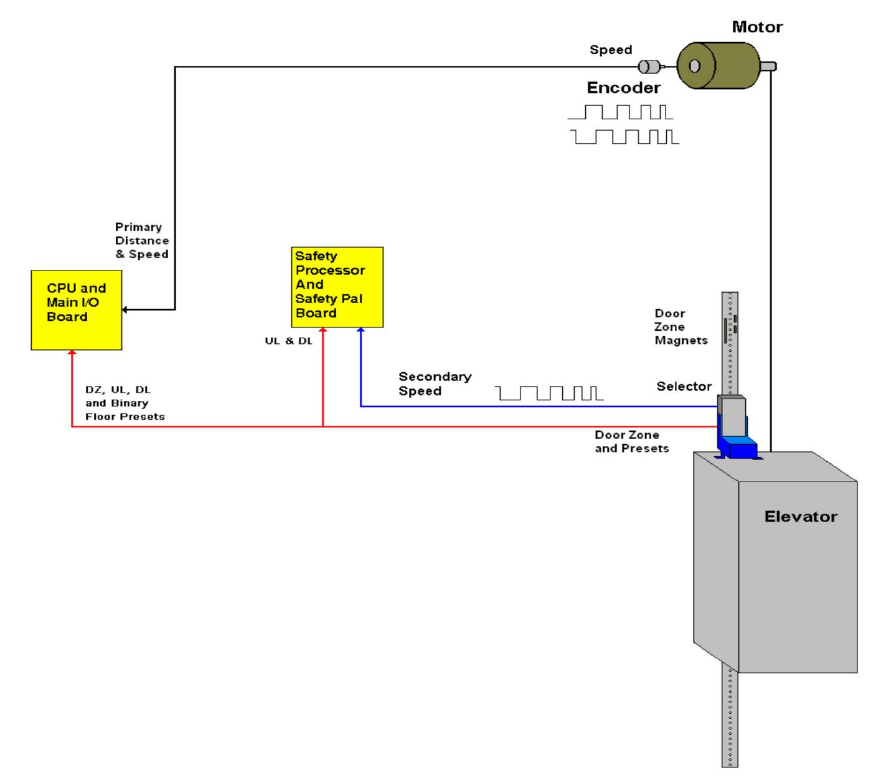
1.3 Selector System
The selector system for the GALaxy controller can be either a tape system or tapeless one.
1.4 Tape Selector System
The tape system uses a perforated steel tape that is hung the length of the Hoistway. A set of magnets
are placed on the tape at each floor having one 8” magnet as the door zone magnet and one to five
smaller 2” magnets as binary position preset magnets. The selector is mounted on the car and is guided
along the tape by nylon guides to keep the tape and magnets the proper distance from the selector
sensors. The controller uses the door zone magnet to determine the elevator’s level position relative to
the floor. At the dead level position, the binary preset inputs are read in order to verify that the car is at
the correct floor. A block diagram of the tape system is shown in Figure 1.1.
Figure 1.1: Tape Selector
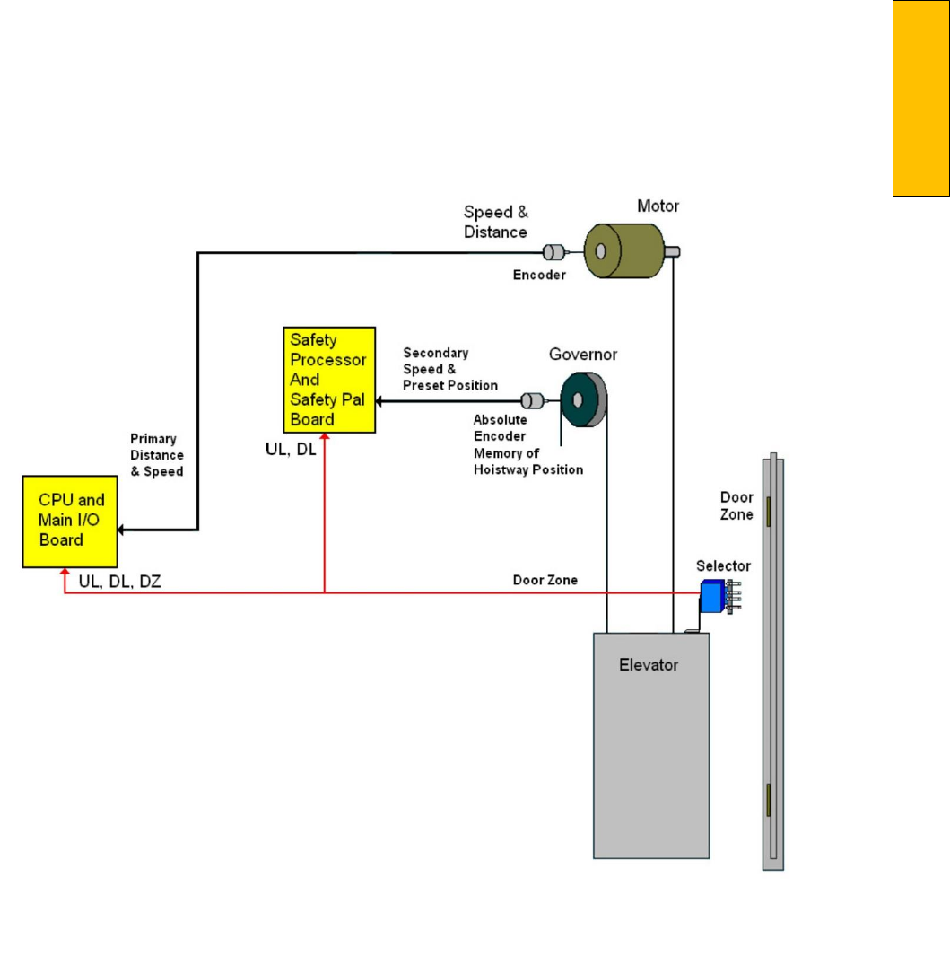
Introduction
P a g e | 5
Figure 1.2: Tapeless System – Absolute Encoder
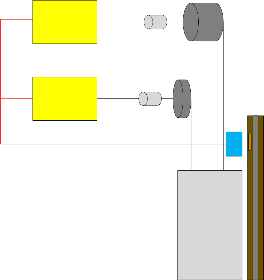
Figure 1.2A: Tapeless System – CAN Open Encoder
Safety Processor
& Safety PAL
Board
CPU
& Main I/O Board
Elevator
Tapeless
Selector
Motor
Incremental
Encoder
Secondary
Speed
Governor
CAN Open
Encoder
Primary
Speed
&
Position
UL, DZ, DL
Door Zone
UL, DL

Introduction
P a g e | 7
1.5 Tapeless System
The tapeless system uses an absolute encoder
mounted on the governor and a four sensor
selector on
the car top to read the door zone
magnet for each floor. The door zone magnets
are placed in the
corner of the rail.
There are two configurations of the tapeless
system; 485 configuration and CAN
Open
configuration. The 485 configuration uses the governor mounted encoder for secondary speed
feedback and for absolute position of the car.
The CAN Open configuration uses the governor
mounted encoder for the primary speed
feedback and position of the car. The encoder is
coupled to a
rotating shaft on the governor. If
the governor on the job does not have a rotating
shaft, it must be
replaced with one that does
The door zone sensors are used for exact floor
position on stop and re‐leveling the car. A block diagram
of the tapeless selector system using an Absolute Encoder is shown
in Figure 1.2. The tapeless selector
system using an CAN Open Encoder is shown in Figure 1.2A.
1.6 Secondary Speed Feedback
With a tape system, the tape is perforated with
3/8 inch holes every 3/8 of an inch. A sensor is
mounted
on the selector to provide a secondary
speed feedback to the Safety Processor Board.
With the 485
tapeless system, the Safety
Processor receives position information from the
absolute encoder and uses
the change in
position to calculate velocity. With the CAN open
tapeless system, the Safety Processor
receives
position information from the machine mounted
incremental encoder and uses the change in
position to calculate velocity. With all three
methods, the Safety Processor uses this velocity
to verify
that the car is traveling at a safe speed
when slowdown limits are activated, when the
car doors are
open and when running on
inspection. There are two type of inputs used to
verify the car speed at the
terminal landing. The
“UT & DT” slowdown limits are always used to
verify the velocity of the car at the
terminal
landings. The emergency slowdown limits “UTS & DTS” are used on traction cars greater
than 200 fpm, traction cars with reduced stroke
buffers and all hydro cars. Traction cars less than
200
fpm read the “UTS & DTS” velocity values
but will not shut the car down from the velocity
check. For
all control systems, the “UT & DT”
limits are used to verify the operation of “UTS &
DTS” and vice versa.
1.7 Modes of Operation
1.8 Operating Sequence
Normal elevator operation, Automatic Mode, is
selective‐collective. When the elevator is
traveling
upwards to answer calls, all up hall calls
at floors above the car are answered in the order
reached by the
car, regardless of the order in
which the calls were registered. Upon reaching
each landing with a car call
or hall call registered,
the car and hall doors at that floor are
automatically opened.
The doors stay opened for a dwell time that is
field adjustable. There are three different dwell
times
depending on whether it is a lobby call, car
call, or hall call. The door will close before the
set dwell time
has elapsed if a passenger presses
the door close button. The door will reopen
before it is fully closed if
the door open button is
pressed, if a passenger pushes on the safety
edge, if the photo‐eye light beam is
interrupted,
or if a call for that floor in the direction of travel
is pushed. The door will close when the
door
opening condition is eliminated. When the door
has fully closed, the calls are answered.
When all up hall calls and car calls above the car
have been answered, the elevator reverses
direction
and travels downward to answer car
calls and down hall calls placed below the car.
The calls are
answered as previously described
for up calls. When all calls below a down car are
answered, the car
reverses direction to repeat
the cycle. In short, an elevator traveling up will
bypass down hall calls, and
an elevator traveling
down will bypass up hall calls.
In buildings with more than one elevator
grouped together, the actual time of arrival,
“real time”, is
used to estimate how long each
elevator will take to answer a hall call. The
elevator that can respond
the fastest takes the
call. Real time based dispatching permits the
controllers to quickly respond to
actual demand
for elevator service. Some of the criteria used to
estimate the time of arrival are listed
below:
Actual elevator floor to floor runs times.
Actual run time to the floor whether it is
a multi‐floor run or a one floor run.
Whether the elevator is in or out of
service.
Whether the elevator is in load weigh
bypass mode.
The direction and position of each
elevator in the group.
The average door cycle time at each
stop.
Status of each elevator, accelerating, full
speed, decelerating, actual time in
motion.
Number of stops required due to car
calls.
Number of stops required due to
previously assigned hall calls.
System demand.
The above performance criteria are continuously
measured and stored for improved accuracy in
the
dispatching algorithm. All of the above data
is continuously scanned and the hall calls are
reassigned if
the conditions change and another
car can respond faster. The ability to measure
actual hall waiting
time virtually eliminates long
waiting and improves the average hall call
waiting intervals throughout
the building.
1.9 Reset Mode
Reset mode is initiated when the elevator power
is first turned on, or when the system is reset.
When
the reset mode is initiated, the controller
program is automatically loaded, and internal
tests are run
to ensure that both the car and
controller are electrically operational before
putting the car into
service. The car will not
move until reset mode is completed. Some of the
internal tests that the
controller performs are as
follows: is the safety string made up; is the
elevator on inspection operation;
is the door
close limit open; are the interlocks made up; is
hoistway position correct. If all the safeties
are
made up, and the elevator is on automatic
operation, and it is at floor level, the elevator will
go into
automatic mode. If the elevator is not at
floor level, it will run slow speed down to the
nearest floor,
level into the floor, and reset the
floor position count.

Introduction
P a g e | 9
1.10 Safety String Open Mode
Safety string open mode is initiated when a
safety is open. Some of the safeties are listed
below:
Reverse phase relay.
Top final
Bottom final
Pit switch
Car top stop switch
Governor over speed switch
Safety operated switch
Drive Ready relay
When the safety string is made back up, the
elevator will go back to reset mode.
1.11 Controller Inspection Mode
The controller inspection mode is initiated by
placing the “INSP” switch on the 1064 board in the
inspection position (down). Controller
inspection mode permits operation of the car
from the machine
room. This mode performs the
following operations:
Enables the controller inspection
“ENABLE”, “UP” and “DOWN” push
buttons
Door locks are active and must be closed
to move the car.
Pressing the controller “ENABLE” and
“UP” push‐button causes elevator to
move at inspection
speed in the up
direction.
Pressing the controller “ENABLE” and
“DOWN” pushbutton causes the
elevator to move at
inspection speed in
the down direction.
1.12 Car Top Inspection Mode
This inspection mode is initiated by placing the
inspection switch on top of the car in the
inspection
position. Inspection mode permits
operation of the car from the car top inspection
station. This mode
performs the following
operations:
Disables access top and access bottom
hall switches.
Disables the controller "ENABLE", "UP"
and "DOWN" push buttons.
Door locks are active and must be closed
to move the car.
Enables the car top inspection station
"SAFE", "UP" and "DOWN" push buttons
Pressing the inspection station "UP" and
"SAFE” push buttons causes the elevator
to move at
inspection speed in the up
direction.
Pressing the inspection station "DOWN"
and "SAFE" push buttons causes the
elevator to move
at inspection speed in
the down direction.
1.13 Access Mode
The access mode is initiated by placing the key
operated access switch located in the car
operating
panel to the on position. Access mode
allows entrance into the Hoistway by qualified
and authorized
elevator personnel for
equipment inspection and service. Access to the
top of the car is possible from
the top landing,
and access to the pit is possible from the bottom
landing. Enabling this mode permits
the
following operation:
Enables the access key switches at the top and bottom landing in the entrance door jambs.
Bypasses the gate switch to allow car movement with the car door open.
Bypasses the top or bottom landing hall door lock, depending on which terminal access switch is
being keyed.
Turning the access key switch to the up position causes the elevator to move at inspection
speed in the up direction.
Turning the access key switch to the down position causes the elevator to move at inspection
speed in the down direction.
1.14 Independent Service Mode
The independent service mode is initiated by
placing the key operated independent switch
located in
the car operating panel to the on
position, or by placing the controller toggle
switch “IND” to the down
position. Independent
mode permits operation of the car with an
operator. This mode performs the
following
operations:
Hall initiated calls are ignored.
Hall lanterns and gongs are disabled.
The doors open automatically and stay
open until closed by the operator.
Closing the doors requires constant
pressure on the door close button.
When the car door is closed, the car
answers the nearest car initiated call in
the direction of
travel.
1.15 Load Weighing Bypass Mode
The load weighing bypass mode is initiated when
the car is loaded to a predetermined percentage
of full
capacity, by closing a connection between
terminals “LC” and “LW” or from serial
communication from a

Introduction
P a g e | 11
load weighing device.
Load weigh bypass mode allows the car to
answer car calls and lighten the load
before
answering any more hall calls. This mode
performs the following operations:
Hall initiated calls are ignored.
All other elevator functions operate as if on full automatic service.
1.16 Attendant Service Mode
The attendant service mode is initiated by
placing the key operated attendant switch
located in the car
operating panel to the on
position. Attendant mode permits operation of
the car with an attendant. This
mode performs
the following operations:
The doors open automatically and stay
open until closed by the attendant.
Closing the doors requires a momentary
pressure on the door close button, or
the up or down
buttons located in the
car operating panel.
Hall initiated calls are answered unless
there is constant pressure on the bypass
button.
Hall lanterns and gongs are enabled.
The direction of preference can be
specified by momentary pressure on the
up or down buttons
located in the car
operating panel.
1.17 Code Blue Hospital Service Mode
Code blue hospital service mode is initiated by
turning one of the code blue switches, located at
each
floor where medical emergency service is
required, to the on position. A car is selected to respond to
the code blue call. That car will
perform the following:
Cancel all car calls
Any hall calls previously assigned will be
transferred to another car.
If traveling toward the code blue call, it
will proceed nonstop to the code blue
call floor.
If traveling away from the code blue call,
it will slow down and stop at the nearest
floor, maintain
doors closed, reverse
direction and proceed nonstop to the
code blue call floor.
If at a floor other than the code blue call
floor, the elevator will close the doors
and proceed
nonstop to the code blue
call floor.
Once at the code blue call floor, the
doors will open and remain open.
The code blue in car switch located in
the car operating panel must then be
turned to the on
position. If the code
blue in car switch is not turned to the on
position within 60 seconds from the
time
the doors reach full open on the code
blue call floor, the car will revert back to
normal
operation.
Upon activation of the key switch, it will
allow the car to accept a car call for any
floor, close the
doors, and proceed
nonstop to the floor desired.
The return of the code blue in car key
switch to the normal position will
restore the car to
normal service.
1.18 Fire Service Phase I Mode
Fire service phase I is initiated when the primary
smoke sensor is activated or the fire key switch
located
in the hall station on the primary return
floor is turned to the on position. The primary
return floor is
usually the lobby floor, but could
be another landing if it better serves the needs
of emergency
personnel when fighting a fire or
performing rescues. When fire service phase I is
enabled:
The fire emergency return light
illuminates and the fire buzzer sounds.
The emergency stop switch is disabled
when the door closes.
The car travels to the primary return
floor without answering any calls, then
parks with the door
open. The fire
buzzer turns off, but the fire emergency
return light stays illuminated.
If the car is at a landing with the doors
open, the doors will close, and the car
will return non‐
stop to the primary
return floor.
If the car is traveling away from the
primary return floor, the car will stop at
the next landing,
and then go
immediately to the primary return floor.
Turning the fire service key switch to the
bypass position will restore the elevator
to normal
service.
The elevator will perform per ASME
A17.1 requirement 2.27.3 unless
otherwise specified.
1.19 Fire Service Phase I Alternate Return Mode
Fire service phase I alternate return is initiated
when the smoke sensor in front of the elevator
at the
primary return floor is activated. When
fire service phase I alternate return is enabled:
The fire emergency return light
illuminates and the fire buzzer sounds.
The emergency stop switch is disabled
when the door closes.
The car travels to the alternate return
floor without answering any calls, then
parks with the
door open. The fire
buzzer turns off, but the fire emergency
return light stays illuminated.
If the car is at a landing with the doors
open, the doors will close, and the car
will return
nonstop to the alternate
return floor. If the car is traveling away
from the alternate return floor,
the car
will stop at the next landing, and then go
immediately to the alternate return
floor.
Turning the fire service key switch to the
bypass position will restore the elevator
to normal
service.

Introduction
P a g e | 13
The elevator will perform per ASME
A17.1 requirement 2.27.3 unless
otherwise specified.
1.20 Fire Service Phase II Mode
To initiate fire service phase II, the car must first
have been placed in fire service phase I, and, as
a
result, be parked at the designated level with the door fully open. Following that, the key
operated fire
service phase II switch, located in
the car operating panel must be placed in the on
position. Fire service
phase II permits operation
of the car by a fire fighter. This mode performs
operations in accordance
with ASME A17.1
requirement 2.27.3 as follows:
The doors close only with constant
pressure on the door close button, after
they have been fully
opened.
The doors open only with constant
pressure on the door open button, after
they have been fully
closed.
Hall lanterns and gongs are disabled.
Safety edge and electric eye are disabled
All registered car calls can be canceled
with momentary pressure on the call
cancel button
located in the car
operating panel.
All hall calls are disabled.
To remove the car from fire service
phase II the car must be at the fire return
landing with the
doors in the full open
position and the phase II switch turned
to the off position.
See ASME A17.1 requirement 2.27.3 for
specific operation of fire service phase II.
1.21 Emergency Power
Emergency power is initiated when a connection
is made between terminals “HC” and “EMP”.
This mode
performs the following operations:
All cars are returned to the bottom floor
one at a time, and remain there with
their doors open.
If a car is selected to run it will go back
into normal operation.
Removing the connection between
terminals “HC” and “EMP” will remove
the cars from
emergency power
operation.
1.22 Earthquake Mode
Earthquake mode is initiated upon activation of
a seismic switch or counterweight derailment
switch.
This mode performs the following
operations:
If in motion, and the seismic switch is
activated, the car will decelerate into
slow speed,
proceed to the nearest
available floor, open the doors and shut
down.
If in motion, and the counterweight
derailment switch is activated, and the
car is moving away
from the
counterweight, then the car will
decelerate into slow speed, and proceed
to the
nearest available floor, open the
doors and shut down.
If in motion, and the counterweight
derailment switch is activated, and the
car is moving toward
the counterweight,
then the car will perform an emergency
stop, then move at slow speed
away
from the counterweight to the nearest
available floor. After stopping at the
nearest floor,
the doors will open and
the car will shut down.
1.23 Stalled Mode
Stalled mode is initiated when the elevator has
been in run mode longer than the field
adjustable anti‐
stall timer. This mode performs
the following operations:
Shuts down the elevator.
Does not allow the elevator to restart
until elevator is put on inspection or
main line switch is
cycled.
The door open button remains active.
1.24 Automatic Mode
Since this is the normal operating mode, the
controller automatically enters this mode if none
of the
previously described modes are activated,
and if no fault is detected. The following
operations are
performed in automatic mode:
The car operates in selective‐ collective control sequence when answering calls.
Hall calls and car calls are functional.
Hall lanterns and gongs are operational.
Simplex Cars Park at the last call answered unless simplex lobby parking has been enabled in the
program. In a multi‐car group, a car is always parked at the lobby if no other demand exists.
The doors remain closed when the car is parked

Section 2 – Product Description
P a g e | 15
Section 2 ‐ Product Description
2.1 General Information
This section provides basic guidelines and recommendations for the proper installation of the controller
equipment. These guidelines should be used as general instructions. They are not intended to usurp
local codes and regulations.
2.2 Site Selection
When choosing the installation site of the controller, several factors should be considered. If at all
possible, the controller should be installed in a location where the mechanic has a good view of the
machine when he is standing in front of the controller. There should be no obstructions around the
controller that would prevent proper routing of necessary conduits entering the controller. The
controller doors should have enough room to fully open and close. All clearances, working space,
lighting, and guarding should comply with governing codes.
2.3 Environmental Considerations
The standard controller package is provided with a NEMA 1 enclosure. This type of controller should be
installed in a clean and dry environment. Ideally, the equipment room should be temperature controlled
between 70 and 90 degrees F. However, control equipment will function properly within an ambient
temperature range of 32 to 110 degrees F. If temperatures remain at the upper and lower extremes of
this range for an extended period of time, the life expectancy of the control equipment may be
shortened. If wet, dusty, or corrosive environments are expected, then optional non‐standard
enclosures can be provided. For example, NEMA 4, NEMA 12, or NEMA 4X.
The control system is designed to have a high immunity to electrical noise, radio frequency radiation,
and magnetic interference. However, high levels of these items could cause interference with certain
parts of the control system.
The power supply feeding the controller should have a fluctuation of no greater than + or ‐ 10%.
2.4 Wiring Guidelines and Instructions
2.5 The Wiring Prints
A complete set of wiring schematics will be provided for each job. Each set of wiring schematics is job
specific. The job name and number will be listed in the bottom right corner of each page of the print.
2.6 Ground Wiring
Proper grounding of the power supply, controller, elevator car, and hoistway is required. Separate
conductors should be run for EG (earth ground) and GND terminals. These terminals and conductors are
detailed on the wiring schematics.
2.7 Hoistway Wiring
All hoistway wiring is detailed on the wiring schematics. The number of hoistway conductors is
calculated and listed per job on the wiring schematics. A job specific "pull sheet" is also provided with
the wiring schematics.
2.8 Elevator Car Wiring
All elevator car wiring is detailed on the wiring schematics. The number of traveling cable conductors is
calculated and listed per job on the wiring schematics. A job specific "pull sheet" is also provided with
the wiring schematics.
2.9 Machine Room Wiring
All machine room wiring is detailed on the wiring schematics. All wire sizes are listed for main power
supply, motor wiring, brake wiring (traction only), and field wiring.
2.10 Wiring to Top of Car Selector
The car top selector is wired according to the schematics for the job. When using tape selector system,
special attention should be given to wiring the pulse sensor on the selector since the output on this
device uses +15VDC. Terminal PPS on the selector is wired to PPS on the controller and selector terminal
PP/US is wired to PP on the controller.
2.11 Slowdown Limits
There are two sets of slowdown switches used, the UT/DT switches (including UT1, UT2, UT3, DT1, DT2,
and DT3) and the UTS/DTS switches. UT, UT1, UT2, UT3 & DT, DT1, DT2, DT3 are used to clamp the
speed command to the drive at the terminal landings independent of the control of the CPU.
UTS & DTS are emergency slowdown limit switches used on cars with a top speed greater than 200 fpm
or having reduced stroke buffers. These switches are used as the slowdown speed verification points by
the Safety Processor board. If the car hits the limit at a speed greater than the preset speed parameter,
power is immediately removed from the motor and brake for an emergency stop independent of the
main CPU.

Section 2 – Product Description
P a g e | 17
The UT & DT limit switches are also used as speed verification points by the Safety Processor board.
When the limit is first activated, the Safety Processor counts an adjustable number of pulse counts from
the activation point to determine the velocity trip point. Since cars with only one slowdown limit would
activate the limit at high speed when performing a recovery run, the extra pulse counts from allows the
car to slow down before the trip point is reached.
The Safety Processor board uses the UT & DT limits to verify the operation of the UTS & DTS limits. The
pulse input is also verified while running on automatic.
The distance that the limits are placed from the terminal landing depends on the speed of the car. Table
1 shows the slowdown limit locations with respect to contract speed. All distances are show in inches.
Table 1: Slowdown Distances from Terminal Landings
FPM
UT/ DT
UT1/ DT1
UT2/ DT2
UT3/ DT3
UT4/ DT4
UT5/ DT5
UT6/
DT6
UT7/ DT7
UTS/ DTS
UTS/ DTS
(Reduced
Stroke
buffer)
50
10”
Not Used
8”
100
21”
Not Used
17”
150
31”
Not Used
28”
200
41”
Not Used
39”
250
52”
36”
36”
300
31”
62”
40”
40”
350
40”
80”
52”
52”
400
50”
99”
66”
66”
450
60”
120”
81”
81”
500
71”
143”
98”
98”
600
65”
130”
195”
137”
137”
700
85”
170”
255”
181”
181”
800
80”
160”
240”
320”
232”
232”
900
98”
196”
293”
391”
289”
289”
1000
93”
187”
280”
374”
467”
353”
353”
1100
110”
219”
329”
439”
548”
380”
380”
1200
106”
211”
317”
422”
528”
633”
448”
448”
1300
103”
206”
310”
413”
516”
619”
723”
521”
521”
1400
102”
204”
306”
408”
510”
612”
714”
816”
600”
600”
2.12 Normal and Final Limit Switches
The up and down directional limit switches UN & DN should be set to open two inches past the terminal
floor levels. The top and bottom final limit switches should be set to open four inches past the terminal
floor levels.
2.13 Tape Selector Installation
When installing the selector, please follow all
steps below.
1. Mount one of the tape brackets to the rail mounting bracket as shown in Figure 2.0
2. Mount the tape to the tape bracket as show, only FINGER TIGHTEN bolts. This is necessary for
proper tape alignment.
3. Measure the distance from the rail to the tape.
4. Unreel the tape from the top of the car while running down on inspection.
5. At the bottom feed the remaining tape down next to the car. Then move the car back up out of
the way.
6. Mount the spring mounted tape brackets to the rail mounting bracket as shown in Figure 2.0
ensure that the distance to the rail is the same as what was measured at the top.
7. Connect the bottom of the tape to the mounting bracket with proper spring tension.
8. With tape under tension tighten top
tape bolts. And double check tape
position.
NOTE: At this time the tape should be
parallel to the rail in all directions. This
is a requirement to
maximize the life of
the nylon guides, and minimize tape
noise. While the tape head is allowed to
move, it should not need to move.
9. Mount the selector couple to the tape by the nylon guides. It is preferred to mount the selector
to the car sling for maximum stability. The selector location should be adjusted so the tape head
is located in the center of the slot, and the tape head pivot bolts are horizontal and equally
supporting the head.
NOTE: As a check, observe that the head is centered in both directions when the car is at the top and
bottom of the hoistway.
Figure 2.1 shows a typical mounting of the
selector to the crosshead. Figure 2.2 shows the
new selector
board (PCB‐1011BN).
1. To install floor magnets, level the
door exactly at the desired floor.
And mark tape at the top left
of the
selector through a factory cut guide
hole

Section 2 – Product Description
P a g e | 19
2. Move the car to gain access to the
section of tape that was marked
while the car was at floor
level.
3. Place the door zone template,
provided by G.A.L., at the door zone
mark just made.
4. Remove backing and adhere binary
preset magnets in the appropriate
template locations. The
location of
each magnet is shown in Figure 2.3. & Figure 2.4.
5. Repeat steps 10 thru 13 for each
floor.
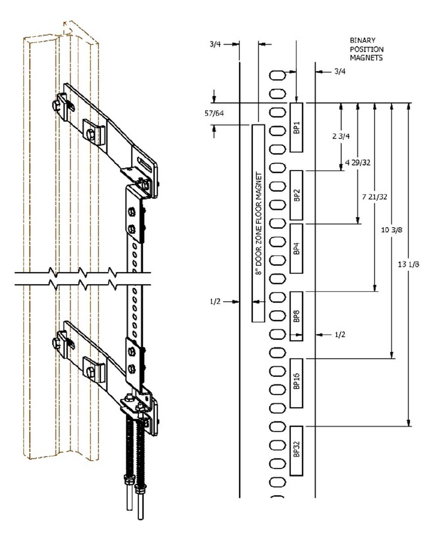
Figure 2.0: Typical Tape Mounting & Magnet Placement

Section 2 – Product Description
P a g e | 21
Binary Preset Magnets
Floor
BP32
BP16
BP8
BP4
BP2
BP1
1
0
0
0
0
0
1
2
0
0
0
0
1
0
3
0
0
0
0
1
1
4
0
0
0
1
0
0
5
0
0
0
1
0
1
6
0
0
0
1
1
0
7
0
0
0
1
1
1
8
0
0
1
0
0
0
9
0
0
1
0
0
1
10
0
0
1
0
1
0
11
0
0
1
0
1
1
12
0
0
1
1
0
0
13
0
0
1
1
0
1
14
0
0
1
1
1
0
15
0
0
1
1
1
1
16
0
1
0
0
0
0
17
0
1
0
0
0
1
18
0
1
0
0
1
0
19
0
1
0
0
1
1
20
0
1
0
1
0
0
21
0
1
0
1
0
1
22
0
1
0
1
1
0
23
0
1
0
1
1
1
24
0
1
1
0
0
0
25
0
1
1
0
0
1
26
0
1
1
0
1
0
27
0
1
1
0
1
1
28
0
1
1
1
0
0
29
0
1
1
1
0
1
30
0
1
1
1
1
0

Binary Preset Magnets
Floor
BP32
BP16
BP8
BP4
BP2
BP1
31
0
1
1
1
1
1
32
1
0
0
0
0
0
33
1
0
0
0
0
1
34
1
0
0
0
1
0
35
1
0
0
0
1
1
36
1
0
0
1
0
0
37
1
0
0
1
0
1
38
1
0
0
1
1
0
39
1
0
0
1
1
1
40
1
0
1
0
0
0
41
1
0
1
0
0
1
42
1
0
1
0
1
0
43
1
0
1
0
1
1
44
1
0
1
1
0
0
45
1
0
1
1
0
1
46
1
0
1
1
1
0
47
1
0
1
1
1
1
48
1
1
0
0
0
0
49
1
1
0
0
0
1
50
1
1
0
0
1
0
51
1
1
0
0
1
1
52
1
1
0
1
0
0
53
1
1
0
1
0
1
54
1
1
0
1
1
0
55
1
1
0
1
1
1
56
1
1
1
0
0
0
57
1
1
1
0
0
1
58
1
1
1
0
1
0
59
1
1
1
0
1
1
60
1
1
1
1
0
0
61
1
1
1
1
0
1
62
1
1
1
1
1
0
63
1
1
1
1
1
1

Section 2 – Product Description
P a g e | 23
Figure 2.1: Typical Mounting of Selector
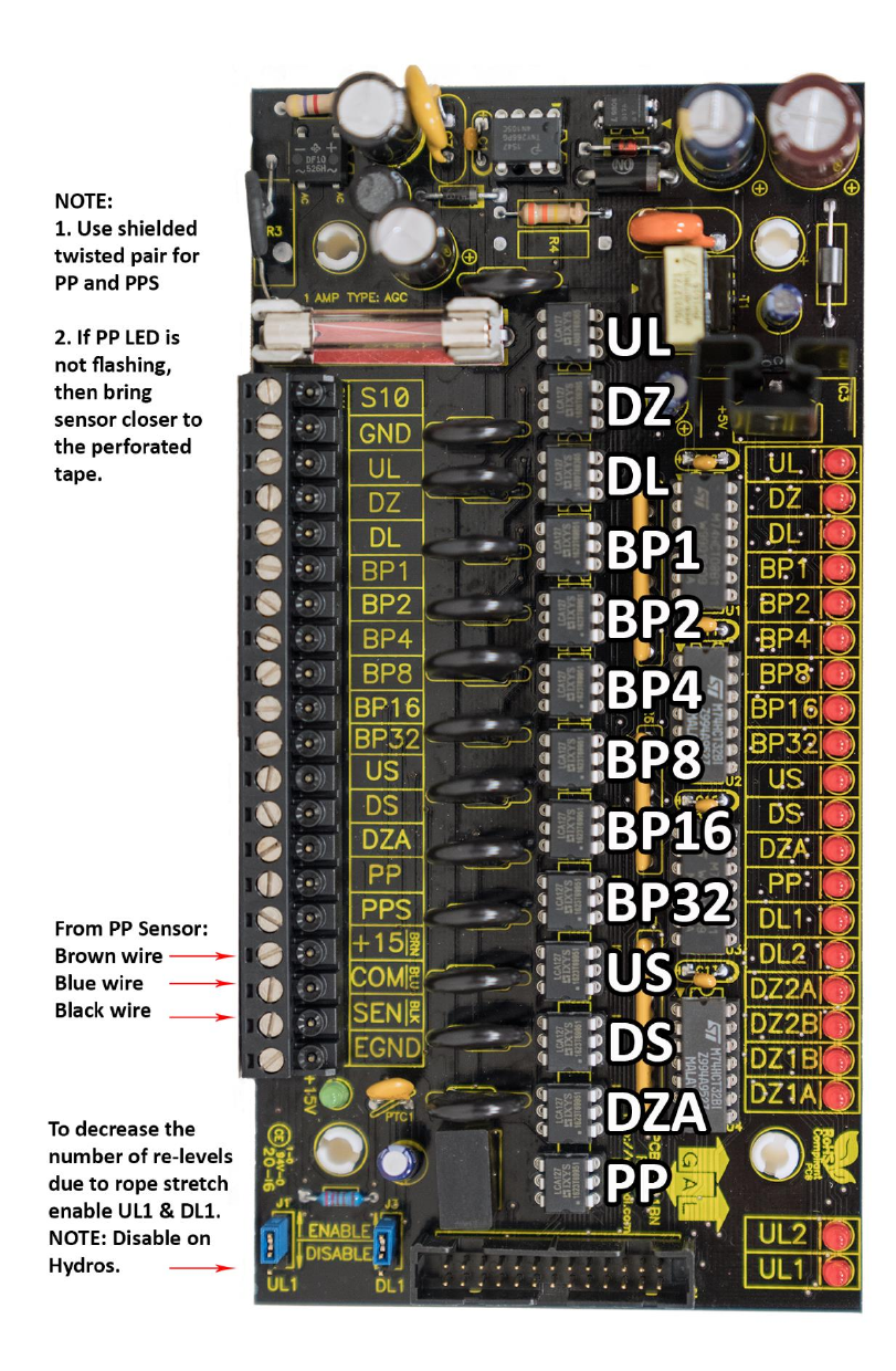
Figure 2.2: Selector Board GALX-1011BN
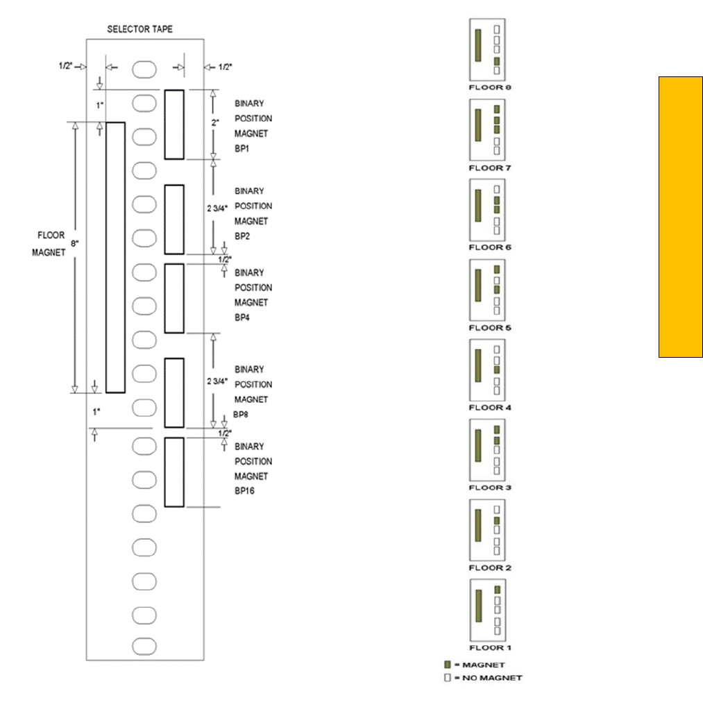
Section 2 – Product Description
P a g e | 25
Figures 2.3 & 2.4: Selector Tape Layout & Magnet Placement
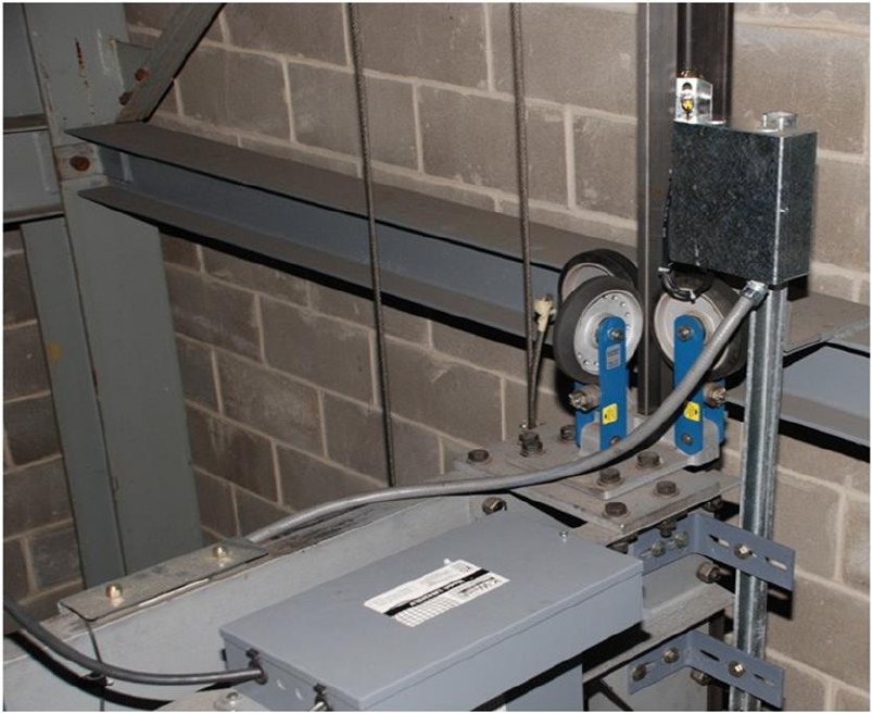
2.14 Tapeless Selector Installation
Installation of the tapeless selector begins with replacing the existing governor if it does not have a
rotating shaft to one that does. Mount the encoder on the governor and connect the encoder cable to
the Safety Processor Board as per the job prints.
Mount the selector box on top the car with the provided brackets, see figures 2.5 and 2.5A and 2.6.
The magnets will be placed in the corner of the rail. The door zone sensors will face the magnet and
make a 45-degree angle with the face of the rail.
Use the template to position the selector head the correct distance from the rail, see figure 2.5 and 2.5a
and 2.6. The mounting screws on the selector box and on the brackets are slotted to make the necessary
alignments.
Figure 2.5: Tapeless Selector Mounted on Crosshead
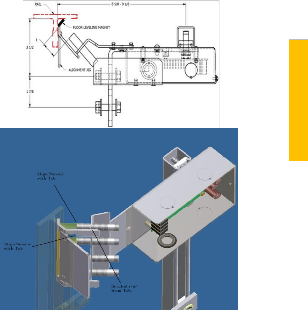
Section 2 – Product Description
P a g e | 27
Figure 2.5a: Tapeless Selector Magnet Placement
Figure 2.6: Door Zone Template Used to Set Selector Distance
Figures 2.7: Sensor Orientation and Wiring
Section 2 – Product Description
P a g e | 29
Figure 2.8: Sensor Orientation Upside Down
The selector head can be mounted with a left or
right vertical orientation. Each of the sensor
wires are
individually plugged into the selector
board according to the orientation of how the
box is mounted. The
sensors are wired with UL at
the top then DZU, DZD and finally DL at the
bottom, see Figure 2.7. If the
box has to be
mounted upside down (having the PC board
upside down) simply re‐wire the sensors in
the
order listed above always starting with the top
sensor as UL, see figure 2.8. Since the PC board
mounting holes are symmetrical, the board can
be rotated to the right side up position. With the
selector and car top box mounted on the car top,
wire the selector board to the car top board. The
UL
and DL sensors are mounted in slotted holes
to allow fine adjustment of the "floor level zone” after the
elevator is running on automatic
operation. However, these sensors should be set
in the middle of the
adjustment slot as a starting
point prior to final adjustment.
After the selector installation is complete and the
car is running on inspection, door zone magnets
can be
placed at each floor. With the car dead
level at the floor, place the template in the corner
of the rail
with the tab lined up with top of the
selector door zone sensor bracket see figure 2.9.
Make a mark across the flat edge of the template. Move the car down then place the template on the rail
and align the position mark. Place the magnet in the slot and remove the template. It is important to
limit the side‐to‐side movement of the car to 1/4" between the rails to maintain consistent floor levels.
After final adjustment, magnets should be secured with an adequate amount of adhesive caulk in order
to prevent movement.
Figures 2.9 & 2.10: Door Zone Template
Section 2 – Product Description
P a g e | 31
Figure 2.11: Tapeless Selector - Sensor Adjustment
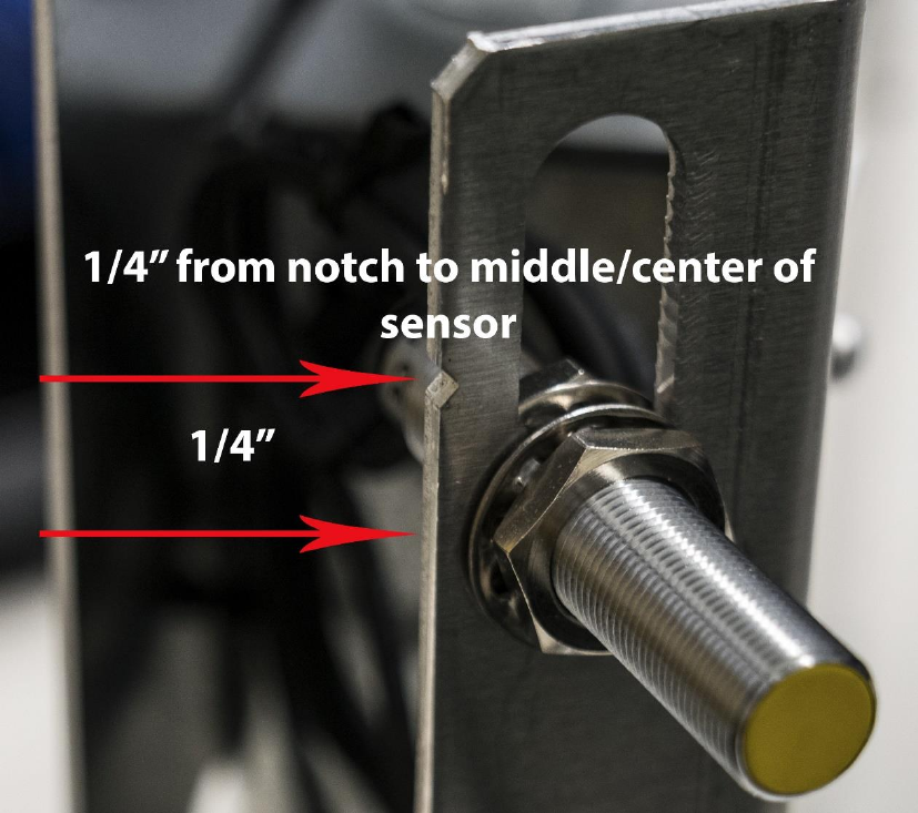
Figure 2.12: Tapeless Selector – Close-up of Notch & Sensor

Section 2 – Product Description
P a g e | 33
2.15 Tapeless Selector Assembly Installation
Place the car dead level at any intermediate floor. Mount the selector box on the elevator cross head
with the bracket provided. Notice that the box mounting holes are slotted to adjust the position of the
box. Refer to figure 2.13 for an overall view setup of the selector box and the door zone and slowdown
limit brackets. Mount one of the slim door zone metal strips on the far end of a rail bracket. Mount the
door zone/rail bracket on the rail where the door zone metal strip lines up with the door zone sensors
on the selector box. Make sure that the rail bracket is pushed completely on to the rail while tightening
the adjacent rail clip bolt. Place the door zone magnet on the slim metal strip and complete the
alignment of the selector box and the door zone in the correct position. This will ensure that all the door
zone and slowdown magnets line up with the correct sensor. Adjust the door zone sensors to be 1 inch
from the door zone magnet.
Continue to mount the door zones using the slim door zone/rail brackets at all the intermediate floors or
if preferred, proceed to a terminal landing to work from one particular end of the hoistway.
Bring the car dead level to a terminal landing. There will be two wide door zone plates included that are
specifically used for the terminal landings. Theses plates have three large holes to mount the normal
limit magnets. The down normal limit DN is placed in the middle hole of the plate. The up normal limit
UN is placed in the top hole of the plate. Notice that the bottom hole becomes the top hole if the plate
is rotated 180 degrees. The door zone magnet is placed adjacent to the three normal limit holes but in
line with the mounting screw holes. Mount the bracket at the terminal floor so that the door zone
magnet lines up with the door zone sensors. Make sure that when at the top terminal floor, the magnet
for the up normal limit is at the top of the door zone magnet. The down normal magnet at the bottom
terminal floor will appear to be at the middle of the door zone magnet. Because of the placement of the
limit sensors on the selector box, the up normal limit will activate 2 inches above the top floor and the
bottom one will activate 2 inches below the bottom floor.
The selector box should be marked on the top to show the location of each slowdown sensor. If the box
is not marked, us a black marker and mark the locations from the picture in figure 2.14. Using the
slowdown distance table in section 3, mount each slowdown rail bracket at the measured distance. The
appropriate slowdown flat metal extension strip mounts on the rail bracket depending on the limit
location on the selector box. Look at which side of the rail the selector box is mounted for the specific
elevator. The slowdown limits that line up in between the rail and the door zone use the short straight
flat metal strip. These metal strips are mounted vertically on the rail bracket. The slowdown limits that
line up outside of the door zone from the rail will use the long slowdown flat metal extension strips and
will mount diagonally from the rail bracket. Mount the magnet on the metal extension strip and verify
the alignment. Make sure that the magnet is ½ inch to ¾ inch from the slowdown sensor.
Once the top of car is wired and power is supplied to the selector, verify the activation of each door
zone and slowdown magnet. Since the slowdown sensors will latch from passing a magnet, the sensor
can possible be initially set incorrectly. To change the state of the sensor, pass a magnet across the
sensor. The LEDs on the door zone sensors and on the selector board will aid in verifying the setup off all
the door zone and slowdown limit magnets. Review the pictures in figures 2.15 and 2.16 for a typical
tapeless installation.
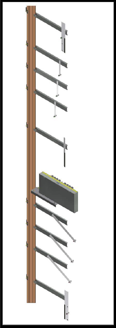
Figure 2.13 Selector, Door zone and Normal Terminal Slowdown Limit Mounting.
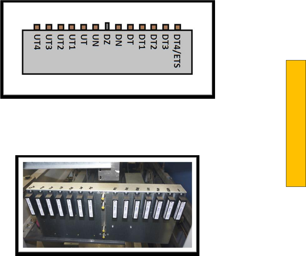
Section 2 – Product Description
P a g e | 35
Figure 2.14 Placement of Sensor Labels on Selector Box
Figure 2.15 Typical Selector Box Installation
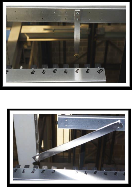
Figure 2.16 Typical Slowdown Bracket Installation
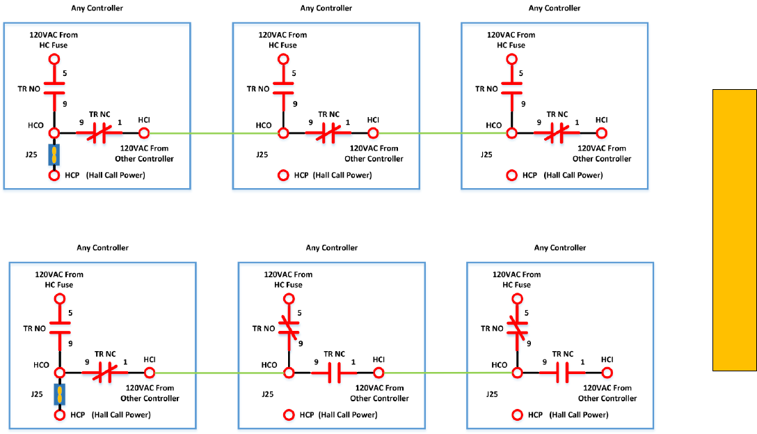
Section 2 – Product Description
P a g e | 37
2.16 Transfer Relay Diagram
Figure 2.13 – All Controllers Off
Figure 2.14 – Leftmost Controller Off
Hall Call boards can be mounted in any controller in the group. The controller that has the hall call
boards will have the “In Dispatcher Car Only” jumper (J25) installed. These diagrams illustrate transfer
power for hall calls but applies to any type of power transfer.
Actual “Dispatcher Car” is set in Adjustable Variables->Group Options->Dispatcher Car. This parameter is
usually left at “0” making Car 1 the Dispatcher Car.
Figure 2.13 shows all controllers with power disconnected.
Figure 2.14 shows the leftmost controller off and the other two on, as if the power was disconnected on
the controller with the hall call boards. As can be seen the leftmost controller now uses the 120VAC
from the middle controller to power the hall call boards
TR Relay – NO / NC Contacts
HCI – Transfer Power Input
HCO – Transfer Power Output
HCP – Transfer Power
Section 3 ‐ Adjustment of the GALaxy controller DSD 412
Drive
In order to obtain a running platform in "car top inspection", see the "Quick Start‐up Guide for GALaxy
Controller DSD‐412 DC Drive with Distance Feedback". This procedure should be used only for
installation purposes. When installation of all equipment is complete, and unit is ready for adjustment,
proceed to Section 3.2, Check Main Line Voltage, and follow instructions.
3.1 General Information
Before adjustment begins the following items must be completed.
1. All field wiring and safety circuits installed
2. Temporary jumpers from terminal HC to terminals MES & ALT
3. All hoistway limit switches installed
4. All car and hoistway doors and interlocks installed and pre‐adjusted
5. Selector installed and magnets pre‐ adjusted
6. Familiarize yourself with all wiring schematics
7. Familiarize yourself with the DSD‐412 SCR drive, drive manual, parameter adjustment, etc.
8. Motor encoder should be properly installed and wired.
9. Car should be properly counterbalanced.
10. Initial Power‐up
3.2 Check Main Line Voltage
With the main‐line disconnect in the off position, check the line‐side voltage with a volt meter to ensure
the voltage matches the controller name tag “Input Power” voltage. Check to ensure all three phases
are present. If voltage is not correct or all three phases are not present, do not proceed until corrected.
3.3 SCR Drive Motor Field Current
Verify that the rated motor field current is set properly on the SCR drive unit by first checking the name
plate field current on the hoist motor. Compare the name plate field current with the setting of the S1
dip switch on the SCR drive unit, and verify that the setting is correct.

Section 3 – DSD 412
P a g e | 39
3.4 Set Toggle Switches
Set all toggle switches on the 1064 board as follows:
DOOR LOCKS "OFF"
IND ‐ "IND"
AUTO DOOR ‐ "OFF"
STOP ‐ "STOP"
INSPECTION ‐ "INSP"
3.5 Make Sure the Car Is Safe
Verify that all elevator doors are closed and that all safety circuits are functional.
3.6 Check Controller Voltage
Turn the main‐line disconnect to the on position. Check the voltage at L1, L2, and L3 on the SCR drive.
Verify that all three phases are present. Check the voltage at fuses L1, L2, and L3 (if present) on
controller. If correct, check the voltage at terminal LIN with respect to GND. The voltage should read
120VAC. If correct, check the voltage at terminals S10, LC, & HC with respect to GND. All should read
120VAC. If not, check wiring diagram to determine the problem before continuing.
3.7 Verify the Main CPU is Operating
Check to make sure that the "axy" of GALaxy on the 1021/1101/1005 LCD interface display is blinking. If
the "axy" is blinking, continue to the next step. If not, check voltage at terminals 5V to 0V on the 1064
board to insure 5VDC. If 5VDC is present and the "axy" on the 1021/1101/1005 LCD interface is not
blinking, then contact factory.
3.8 Preset Adjustable Variables on Safety Processor Board and Main CPU
The 1066 LCD interface (safety processor board) and the 1021/1101/1005 LCD interface (main CPU) are
normally preset prior to leaving the factory. However, it is prudent to check the setup values for the
proper settings. Refer to Section 13 of this manual for the operation of the 1066 LCD interface,
and refer to Section 10 for operation of the 1021/1101/1005 LCD interface. The following adjustable
variables must be set properly.
NOTE: If the controller uses an NTS board please refer to Section 14, GALX-0320AN NTSC Board.
3.9 1066 LCD interface "Adj Var" Menu
Top Spd (contract speed)
Enc RPM (if Fdbk Typ=0 (Tape), not applicable) (if Fdbk Typ=1 (Encoder), set to rpm of governor)
(if Fdbk Typ=4 (Incremental Encoder), set to value of Function #11 in DSD 412 drive, MOTOR
RPM)
Enc PPR (if Fdbk Typ=0 (Tape), not applicable) (if Fdbk Typ=1 (Encoder), set to 8192) (if Fdbk
Typ=4 (Incremental Encoder), set to PPR of machine/motor encoder)
Fdbk Typ (0=tape, 1=enc, 4=InEnc)
Ctrl Typ (2=Tract DF)
2 Stop (0=Mult, 1=2 stop)
RearDoor (0=Front only, 1=Rear)
UTS Vel (Set to top speed)
DTS Vel (Set to top speed)
INS Vel (Set to 140)
LEV Vel (Set to 140)
UT Vel (Set to top speed)
DT Vel (Set to top speed)
UL Vel (Set to 160 if Non‐DF)
DL Vel (Set to 160 if Non‐DF)
SoftStop (Set to 3)
NOTE: The velocity values for the terminal limit switches above are only temporary settings until car is
running high speed. In the final adjustment procedure, these variables must be set according to the
procedures in Section 3.33, Adjust Safety Processor Board Speed Clamps.
3.10 1021/1101/1005 LCD interface "Adjustable Variables -> Car Motion"
Submenu
Top Speed (set to contract speed)
Inspect Speed (set to 25 fpm)
Encoder PPR (set to machine/motor encoder PPR)
Encoder RPM (if tape selector, set to value of Function #11 in DSD 412 drive, MOTOR RPM), (if
485 tapeless selector, set to value of Function #11 in DSD 412 drive, MOTOR RPM), (if CAN open
tapeless selector, set to governor rpm)

Section 3 – DSD 412
P a g e | 41
DON Start Control (set to 1)
NOTE: See Section 3.25, Correct Car Speed When Using 485 Tapeless System, for determining governor
rpm.
3.11 Place Stop Switch in Run Position
Flip the “STOP” toggle switch on the 1064 board to the up position. Verify that input LED’s for “LC, HC,
DN, UN, SS, GTS, RDY and CS” are all on. If not, then correct field wiring.
3.12 Hoist Motor Data
At this time the hoist motor data must be entered into the SCR drive. The following functions must be
entered or verified using the drive display unit (SCDU). Follow the instructions in the SCR drive manual
to enter the following data for each function:
Function #3 ‐ RATED ARM AMP (from machine/motor nameplate)
Function #7 ‐ RATED ARM V (from machine/motor nameplate)
Function #10 ‐ ENCODER P/R (PPR of encoder on machine/motor)
Function #11 ‐ MOTOR RPM (from machine/motor nameplate)
NOTE: The MOTOR RPM value may need to be fine‐tuned to provide the correct rpm to run the
machine/motor at controller demanded speed.
Function #17 ‐ RATED FT/MIN (from controller data)
Function #21 ‐ ACC RATE FT/SEC2 (~ 4.2)
Function #40 ‐ RESPONSE (~ 6.0)
Function #41 ‐ SYSTEM INERTIA (~ 2.5)
Function #49 ‐ WEAK FIELD AMP (from controller data)
Function #50 ‐ FULL FIELD AMP (from controller data)
Function #52 ‐ RATED FIELD VDC (from controller data)
Function #53 ‐ STANDING FIELD AMP (from controller data)
Function #56 ‐ FIELD STRENGTH SPEED (~ 75)
Function #57 ‐ FIELD WEAKEN SPEED (~ 75)
Function #994 ‐ to save data just entered
After Function #994 has been performed successfully, proceed to the next step.
3.13 SCR Drive Self Tune
To have the SCR drive unit learn the parameters of the hoist motor the drive self‐tune must be
performed. Remove the drive reset “RST” wire from TB1 pin 49 of the drive. Turn on the main
disconnect. Perform a FUNCTION #997 (see SCR drive manual) to self‐tune the hoist motor. During this
test, the “MC” contactor will energize for short period of time. After the self‐tune is performed
correctly, “PASS” will appear on the drive unit display. If a fault appears on the drive unit display, the
problem must be corrected and the self‐tune performed again. If the self‐tune is successful, then the
following FUNCTIONS must be viewed and recorded.
Function #613
Function #614
Function #615
The value of Function #613 should be manually entered into Function #4 ‐ ARM OHMS.
The value of Function #614 should be manually entered into Function #6 ‐ ARM L.
The value of Function #615 should be manually entered into Function #51 ‐ FIELD L/R.
3.14 Pre‐set the Digital Speed Clamps
Pre‐set the software digital speed clamps from the 1021/1101/1005 LCD interface under the “Elevator
Setup Menu”. The submenus for the clamp speeds are as follows:
Set INS/Leveling Clamp
Set DT/UT Slowdown Clamp Set DT1/UT1 Slowdown Clamp Set DT2/UT2 Slowdown Clamp Set DT3/UT3
Slowdown Clamp Set DTS/UTS Slowdown Clamp
Set the speed for Ins/Leveling for 140 fpm and all the remaining slowdown limit speeds to the contract
speed of the car. Please note that the displayed value of “Clamp Speed” is the value the clamp should be
set to. The slowdown limit “Clamp Speed:” will show 0000 until the car is run into the limits and the
speed is recorded. Please refer to Section 10, 1021/1101/1005 LCD Interface, for the Elevator Setup
Menu.
NOTE: The values of the clamp speed velocities above are only temporary settings until the car is
running high speed. In the final adjustment procedure, these values must be set according to the
procedures in Section 3.34, Adjust Digital Slowdown Speed Clamps.

Section 3 – DSD 412
P a g e | 43
3.15 Ready to Run On Inspection
The car should be ready to run on inspection if all is wired correctly. Select the “Elevator Status” on the
1021/1101/1005 LCD interface. The display should show “Out of Service” on the first line and
“Inspection Mode” on the second. The 1066 LCD interface will display one of the following types of
inspection:
“MR INS” (Motor Room)
“CT INS” (Car Top)
“ACCESS” (Access)
“IC INS” (In Car)
“AUTO” (Not on Inspection)
To run the car from the motor room, “MR INS” should be displayed.
The “inspection string” consists of contacts from the inspection switches and the gate and lock bypass
switches in series. One and only one of the five inspection inputs should be on for the car to run.
Starting from the car top inspection input, the five inspection inputs are, “INS” for car top, “ACC” for
access, “ICI” for in‐car, “MRI” for motor room, and “AUTO” for automatic (no inspection). The inspection
string circuit is shown in Figure 3.1.
Note: Any one of the following conditions will cause an inspection error:
More than one inspection input is on
No inspection input is on
Gate or Lock bypass switch is open and the car is not on car top inspection
If the controller is not on motor room inspection at this point, then verify all switch positions and wiring
before proceeding.
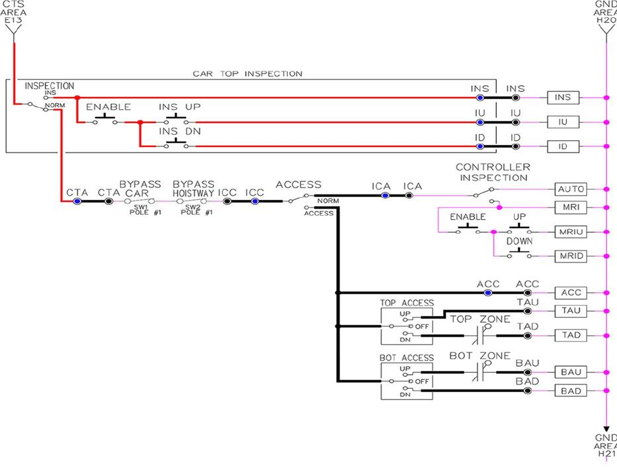
Figure 3.1: Inspection String
3.16 Adjust the Brake Voltage
Momentarily push the inspection UP or DOWN push button on the 1064 board while checking the DC
brake voltage with a meter. If the voltage is not correct, it must be adjusted according to the following
procedures.
If the controller utilizes an electronic brake board 1047 or 1051, then the brake voltage is adjusted
through the 1021/1101/1005 LCD interface, "Car Brake" sub‐ menu. If the controller utilizes resistors
and rectifiers for the brake coil circuit, then the brake voltage is adjusted by moving the adjustable tap
on the brake resistor.
NOTE: Remove power before adjusting the resistor taps.
To adjust the brake voltage when using and electronic brake board, navigate to the "Adjustable
Variables" menu, "Car Brake" and adjust "Brake Pick Volt", "Brake Hold Volt" and "Brk AC L‐L Volt" to the
proper values. Make sure that the brake is lifting and setting properly before proceeding.

Section 3 – DSD 412
P a g e | 45
3.17 Check the Run Direction
Momentarily push the inspection “UP” or “DOWN” push button on the 1064 board. One of the following
should take place:
The elevator will run controlled, in the correct direction (up for “UP” button, down for “DOWN” button)
with no drive faults. If so, proceed to “Check Inspection Speed”.
The elevator will run controlled, but in the wrong direction (down for “UP” button, up of “DOWN”
button) with no drive faults. If so, proceed to Section 3.18, Car Runs in the Wrong Direction.
The elevator will try to run, but immediately trip on a drive fault #99. If so, proceed to Section 3.19,
Drive Trips immediately.
3.18 Car Runs in the Wrong Direction
If the elevator runs controlled but in the wrong direction, with no drive faults, then turn off the main
disconnect, swap the hoist motor field wires.
Also swap the encoder direction by swapping the encoder wires or if an encoder isolation board (1022N)
is used, move J5 and J7 on the encoder board. Refer to the jumper diagram on the board.
J5 swaps A & A NOT – J7 swaps B & B NOT.
To change the encoder direction at the drive, swap the following wires:
A+ (TB3‐2) with B+ (TB3‐4)
A‐ (TB3‐3) with B‐ (TB3‐5)
Turn the main disconnect on, run the elevator on inspection again, and it should run controlled and in
the correct direction. If so, proceed to Section 3.20, Check Inspection Speed. If not contact the factory.
3.19 Drive Trips Immediately
If the elevator tries to run, but immediately trips on a drive fault #99, then turn off the main disconnect,
and swap the encoder direction by swapping the wires or if an encoder isolation board (1022N) is used,
move J5 and J7 on the encoder board. Refer to the jumper diagram on the board.
J5 swaps A & A NOT – J7 swaps B & B NOT.
To change the encoder direction at the drive, swap the following wires:
A+ (TB3‐2) with B+ (TB3‐4)
A‐ (TB3‐3) with B‐ (TB3‐5)
Turn on the main disconnect and run the elevator on inspection again. If the elevator runs controlled
and in the correct direction, proceed to next section.
If the elevator runs controlled but in the wrong direction, then go back and follow the directions in
Section 3.17, Car Runs the Wrong Direction.
If the car still trips immediately on a drive fault #99, then contact the factory.
3.20 Check Inspection Speed
With a hand held tachometer, check the speed of the elevator while running on inspection. The elevator
should be running at 25 FPM. Also run the elevator while monitoring Function #600 on the SCR drive
display. This parameter should also read 25 FPM. If speed is not correct, re‐check drive data in
FUNCTION #10 and FUNCTION #11.
From the 1021/1101/1005 LCD interface select the "Elevator Status" menu, navigate until the display
shows "Dmd" and "Vel". While running on inspection, monitor the controller demand speed "Dmd", and
the speed feedback "Vel". These values should both display 25. If the demand and feedback on the
1021/1101/1005 LCD interface is incorrect, check the Encoder RPM and PPR parameters from the
“Adjustable Variables” menu. These variables should be set according to the procedures in Section
3.8.
If the speed on the hand held tachometer and on "Dmd" and "Vel" all read approximately 25 fpm (within
+/‐2 fpm) continue to the next step. If not, contact the factory.
3.21 Verify Controller Encoder Direction
From the 1021/1101/1005 LCD interface "Elevator Status" menu, navigate to display "Dir" and "DP".
While moving the car on inspection, monitor "Dir" (direction) and "DP" (pulse counts). "Dir" should
display "Up" when the car is moving up, and "Dn" when the car is moving down. The value of "Dp"
should increment when the car is moving up, and should decrement when the car is moving down.
If the direction is wrong or the pulse counts change in the wrong direction, then the encoder direction
to the controller must be changed. If an encoder isolation board (1022N) is used, move J1 and J3 on
the encoder board. Refer to the jumper diagram on the board.
J1 swaps A & A NOT – J3 swaps B & B NOT.
If no encoder isolation board is used, the A+ and A‐ encoder wires from the drive must be swapped.
Note that the motor encoder wires are daisy chained from the encoder to the drive and then from the
drive to the controller encoder board. Only the A+ and A‐ wires from the drive to the controller board
must be swapped. The wires from the encoder to the drive must remain on the same terminal locations
on the drive.
If the encoder is counting properly continue to the next step. If not, contact the factory.

Section 3 – DSD 412
P a g e | 47
3.22 Verify Selector and Slowdown Inputs
Run the elevator up on inspection until it stops on the up normal limit. The up and down normal limits
should be set two inches above and below the terminal floors respectively. Verify the selector inputs are
being set properly on the controller by running the elevator down until it stops on the down normal
limit.
As the car approaches floor level going down, “DL” turns on first, then “DZ” and then finally “UL”. At
floor level, “UL, DL, and DZ” inputs should all be on at the same time. Leaving the floor going down “DL”
will turn off first, then “DZ” and last “UL”.
Also verify that the up and down terminal slowdown limits inputs “UT, UTS, DT & DTS” are breaking at
the proper distances as shown in the slowdown table 2.0. “UT, UTS, DT & DTS” turn off when active.
3.23 Verify Car Speed on Safety Processor Board
Run the car in either direction or check the car speed on the 1066 LCD interface. The speed shown
should match the car’s actual speed. If the speed does not match and the secondary feedback comes
from pulses from the tape go to “Correct Car Speed When Using a Tape”. If using 485 tapeless, go to
"Correct Car Speed When Using 485 tapeless". If using CAN Open tapeless, go to "Correct Car Speed
When Using CAN Open tapeless". If the correct speed is shown proceed to Section 3.27, Learn the
Hoistway.
3.24 Correct Car Speed When Using a Tape Installed in Hoistway
The tape has holes every 3/8” that are 3/8” in diameter. On the selector unit adjust the PP sensor closer
to the tape until the orange LED at the end of the sensor turns on. Then turn the sensor inwards another
1/8” and lock in the sensor. While running on top of car inspection verify that the orange LED at the end
of the PP sensor turns on and off as it passes by the holes on the tape. The safety processor measures
the time between each pulse to calculate the velocity. If the velocity is not displayed correctly first make
sure that the feedback type in the safety processor board adjustable variable is set to 0 for a tape
application. Next, while the car is running, make sure that the PULSE LED on this board is pulsing. As the
car increases in speed the LED will glow solid on. If the LED does not pulse, try swapping the wires at the
PPS and PP terminals. If the LED still does not work, contact the factory. If the correct speed is shown
proceed to Section 3.27, Learn The Hoistway.
3.25 Correct Car Speed When Using 485 Tapeless System
When using the 485 tapeless system, the secondary speed feedback comes from the encoder mounted
on the governor. The 1066 board uses a serial interface to a Turck absolute encoder, part #
T8.5882.3F0B.3001.
In the 1066 LCD interface "Adj Var" menu, set the "Fdbk Typ = 1", and set the "Enc PPR = 8192". The
"Enc RPM" value must be calculated as described below. To calculate the RPM, divide the contract
speed of the car by the distance traveled in one revolution with the governor as shown below:
RPM = Speed fpm/ (diameter GOV * pi)
For a 1 ft. diameter governor: RPM = 350/ (1*pi) = 350/3.1415 = 111.4
For a 16 in diameter governor (16/12 = 1.33ft): RPM = 350/ (1.33* 3.1415) = 350/4.188 = 83.5
3.26 Correct Car Speed When Using CAN Open Tapeless System
When using the CAN Open tapeless system, the secondary speed feedback comes from the incremental
encoder mounted on the machine/motor.
In the 1066 LCD interface "Adj Var" menu, set the "Fdbk Typ = 4", and set the "Enc PPR" equal to the PPR
of the machine/motor‐mounted incremental encoder, and set the "Enc RPM" to the rpm of the
machine/motor at contract speed.
On the 1066 LCD interface, navigate to the "Pls Cnt" menu. While running the elevator on inspection,
verify that the pulse count value increments when running up and decrements when running down. The
"Pls Cnt" value can be considerably out of range but will automatically correct during the "Learn
Hoistway" procedure. To reverse the direction of pulse counting, navigate on the 1066 LCD interface to
the "Adj Var" menu, "Enc Dir" and set to "0" for clockwise or "1" for counter‐clockwise.
Navigate on the 1066 LCD interface to the "Car Spd" menu. Monitor the "Car Spd" while running the car
at a known inspection speed. The value displayed should match the actual car speed measured with a
hand held tachometer. If not, re‐check the values set in "Enc RPM" and "Enc PPR" in the 1066 LCD
interface. If the speed is correct, proceed to Section 3.27, Learn The Hoistway.
3.27 Learn the Hoistway
Run the elevator down on inspection until it stops on the down normal limit switch. Verify that the “DN
and DL” input LED’s are both off and that the "UL" and "DZ" LED's are on. From the 1021/1101/1005 LCD
interface navigate to the "Elevator Setup" menu, "Learn Hoistway". The learn procedure can be
performed automatically by choosing "Auto" from the menu items, or performed manually by choosing
"Insp" from the menu items. After choosing the learn method, follow the instructions displayed on
1021/1101/1005 LCD interface.
In general, the car will run up from the "down normal limit" to the "up normal limit" at 30 fpm. During
this learn run, the DP count for each floor level and each limit switch will be stored in memory.
NOTE: The car must run the entire hoistway without stopping.
As the elevator moves up the hoistway, navigate to the "Hoistway Tables" menu, "Disp/Mod Hoistway
Table", and verify that the "DP" count is incrementing as the elevator moves up. Also as the elevator
passes each floor, the pulse count and distance for that floor should change and be stored. Verify that
the floor distances are valid. The pulse count for the terminal slowdowns will also be stored. The
elevator will stop when it reaches the up normal limit. Follow the instructions on the 1021/1101/1005
LCD interface by putting the car on inspection, and then the message "Hoistway Learn Complete" should
be displayed.

Section 3 – DSD 412
P a g e | 49
Move the elevator on inspection until the “DZ and DL” LED’s are on. Set the "INS" switch on the 1064
board to the "NORMAL" position and the elevator should level down to floor level at the top floor. If so,
proceed to final adjustment.
If the car levels down but does not run, then check “Elevator Status” and “View Fault Log” on the
1021/1101/1005 LCD interface for any fault information. Correct items causing faults and perform
hoistway learn again. After problem is corrected, and a successful hoistway learn is performed, proceed
to final adjustment.
3.28 Automatic Run
The elevator should now be sitting idle at the top floor. The "AUTO DOOR" switch should be set to the
"OFF" position and the "IND" switch should be set to the "IND" position. If the learn procedure was
successful, the elevator should be ready to make an automatic run.
The default parameter settings for the ride quality should be adequate for an initial run. From the
1021/1101/1005 LCD interface navigate to the "Set Calls and Lockouts" menu, "Setup Car Calls" and
enter a car call. The elevator should run to answer the call. When the elevator levels in and stops at the
floor, the doors will remain closed.
The acceleration and deceleration of the car should be smooth and stepless regardless of the distance of
the run. If the elevator does not function as described above, then the problem should be analyzed
before proceeding.
3.29 Fine Tune the Ride Quality
In order to fine tune the ride quality, refer to Figure 3.2 which describes what part of the S‐curve that
the different parameters effect. In general, higher numbers in the given parameters, cause quicker and
more abrupt changes from one mode to the next during a run. All of the S‐curve parameters have a
minimum and maximum value. The controller will not allow you to enter values that are not valid. After
adjusting the S‐ curve parameters, proceed to the next step.
3.30 Adjust the Stop
When at floor level the “UL, DL, & DZ” input LEDs should be on. If the elevator continually tries to seek
floor level by leveling up and down, check the motor field voltage to be at the nameplate voltage while
leveling. If the motor field voltage is correct but the car seems sluggish then increase the response of the
drive by increasing the value of Function #40 in the drive. If the car still re‐levels at the floor, try the
following steps to correct the problem:
Reduce the leveling and re‐leveling velocity parameters from the 1021/1101/1005 LCD interface
"Adjustable Variables" menu, "Car Motion", "Leveling Speed" and "Relevel Speed".
If the car still oscillates, adjust the "floor level zone" on the selector. The "floor level zone" is
increased by moving the "UL" and "DL" sensors closer together.

If the car stops hard on the brake, then make the following adjustments. From the
1021/1101/1005 LCD interface navigate to the "Adjustable Variables" menu, "Car Motion", and
adjust both "Brake Drop Del" (brake drop delay) and "Soft Stop Time". These variables should be
adjusted so that zero speed is observed at the end of the run prior to the brake setting. The
controller should hold the car at zero speed for the duration of the "Soft Stop Time" which
should continue while the brake is setting and for a short time after the brake sets. The "Soft
Stop Time" MUST be set to at least 0.5 seconds LONGER than the "Brake Drop Del".
NOTE: The "Soft Stop Time" setting in the 1021/1101/1005 LCD interface should be compared with the
setting in the 1066 LCD interface "Adj Var" menu, "SoftStop". The setting of "SoftStop" in the 1066 LCD
interface should be greater than the "Soft Stop Time" setting in the 1021/1101/1005 LCD interface.
If the car spots when approaching the floor, the cause is usually due to the car not tracking (the drive
response is set too low) or the speed profile into the floor is too aggressive. First try to increase the
response of the drive by increasing the value of Function #40 in the drive.
If the car still spots, from the 1021/1101/1005 LCD interface, navigate to the "Adjustable Variables"
menu, "Car Motion" and increase the value of "Floor Targ Dis" (floor targeting distance). The default
value for the floor targeting distance is 12 inches. Increase it by steps of 2 or 3 and continue retesting
until the parameter is adjusted to 18. If no change is noticed, start again from 12 and decrease the
value.
The deceleration rate can also be reduced to help remove the spotting. Once the proper stop is
achieved, proceed to “Adjust the Start”.
Figure 3.2: S-Curve Parameters
3.31 Adjust the Start
To provide a proper start, from the 1021/1101/1005 LCD interface, navigate to the "Adjustable
Variables" menu, "Car Motion" and adjust "Brake Pick Del" (brake pick delay), "Pattern Delay", and "Soft
Start Jerk". Initially, set the brake pick delay to 0 and increase the pattern delay by 0.1 seconds until the
controller picks the brake completely before the motor starts to move. If roll back occurs, then reduce
the pattern delay until there is no roll back. Sometimes, the timing works out better if the brake pick

Section 3 – DSD 412
P a g e | 51
delay is set to 0.1 second. If load weighing is used, pre‐torquing can be used to provide a smoother start.
See Section 3.40, Adjust the Motor Pre‐torque.
Increase the soft start jerk rate in order to provide a quicker transition from the start to constant
acceleration. Keep in mind that the larger the soft start number, the quicker the start. The ride should
now be acceptable.
3.32 Verify Top Speed
To fine tune high speed, make high speed runs while monitoring Function #600 on the SCR drive display.
The display should read contract speed.
If the speed is slightly under contract speed, then verify that Function #10 Encoder PPR and Function
#11 Rated Motor RPM are set properly. The speed displayed at Function #600 should match the speed
displayed on the 1021/1101/1005 LCD interface, "Elevator Status" menu, "Dmd" and "Vel". This speed
should also match the speed displayed on the 1066 LCD interface, "Car Spd" menu. When all of these
speeds are the same (+/‐ 2 fpm), then proceed to the next step.
3.33 Adjust Safety Processor Board Speed Clamps
The 1066 Safety Processor Board monitors the speed of the elevator at the terminal landings
independently from the main CPU.
When the "UT, DT, UTS, and DTS" limit switches are activated, the 1066 board calculates the velocity of
the elevator and compares that velocity with a stored value of speed clamp. If the velocity when the
switch activates is greater than the speed clamp value, then the 1066 board will generate a fault that
stops the elevator.
From the 1066 LCD interface, navigate to the "Lim Vel" menu, and view the recorded velocities
displayed for the “UT, DT, UTS & DTS” slowdown limits. “UTS & DTS” are used on cars with reduced
stroke buffers or with a top speed greater than 200 fpm. The velocity value is shown from the “LIM VEL”
menu on the 1066 LCD interface.
The velocity value shown on the display for the “UT or DT” limit is the value after the car activates the
limit then counts an adjustable number of counts set from the 1066 LCD interface, "Adj Var" menu, "UT
Count" or "DT Count". These count values can be adjusted to provide adequate distance, following the
limit switch activation, to allow the elevator to begin its normal decel pattern. The default "UT Count"
and "DT Count" values are normally adequate. However, these values may need to be field adjusted to
allow enough distance for the car to begin its normal decel pattern. If the "UT Count" and "DT Count"
values are modified, the limit velocities must be re‐checked
Run the car again to the top repeatedly from 2 floors, then 3 floors, etc., until top speed is reached.
From the 1066 LCD interface "Lim Vel" menu, record the limit velocities displayed each time the car
stops at the top floor.
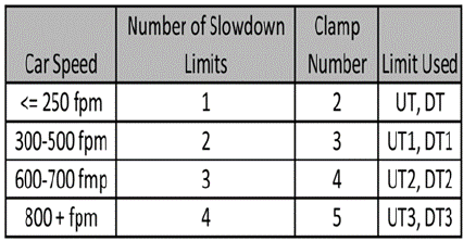
Make the same runs to the bottom floor starting from 1 floor, then 2 floors, then 3 floors, etc., until top
speed is reached. From the 1066 LCD interface "Lim Vel" menu, record the limit velocities displayed each
time the car stops at the bottom floor.
Take the highest speed value recorded in the runs above and add 20 fpm to that value to use as the
clamp speed values for the respective limit switches. Enter these clamp speed values into the 1066 LCD
interface "Adj Var" menu, "UT Vel", "DT Vel", "UTS Vel", "DTS Vel" respectively.
3.34 Adjust Digital Slowdown Speed Clamps
Having just made several runs into the top and bottom landings, the main CPU has also recorded the
car’s velocity when the slowdown limits were activated. If the car has been powered down prior to this
step, several runs must be made to the terminal landings to allow the main CPU to record the limit
velocity values.
From the 1021/1101/1005 LCD interface, navigate to the "Elevator Setup" menu, "Set DT/UT Slowdown
Clamp" and view the speed displayed for "Clamp Speed". Add 20 fpm to this "Clamp Speed" value and
enter it into the "DT/UT Limit" value.
Adjust speed clamps for each slowdown limits used as determined by the elevator’s contract speed.
The number of slowdown limits depends on the speed of the car as show in the table below:
Table 3.1: Slowdown Clamps
3.35 Verify Inspection Velocity Clamp On Safety Processor Board
Place the car on inspection operation. From the 1066 LCD interface, navigate to the "Adj Var" menu, "Ins
Vel" and set the speed clamp velocity to 25 fpm. From the 1021/1101/1005 LCD interface, navigate to
the "Adjustable Variables" menu, "Car Motion" and set the "Inspect Speed" to 50 fpm. Run the car in
either direction and verify that the car shuts down when the speed rises above 25 fpm.
From the 1066 LCD interface, navigate to the "Adj Var" menu, "Ins Vel" and set the speed clamp to 140
fpm. From the 1021/1101/1005 LCD interface, navigate to the "Adjustable Variables" menu, "Car
Motion" and set the "Inspect Speed" to the desired value.

Section 3 – DSD 412
P a g e | 53
3.36 Analog Load Weigher Setup
If the job uses an analog load weigher purchased from G.A.L., complete the following procedure.
NOTE: It is recommend using two people, one moving the weights and one in the machine room to set
up the load weigher.
Mount the load weigher as described by the manufacturer. The load weigher control box will also
contain a board supplied by G.A.L. that connects to the controller serial CAN bus and reads in the analog
output from the load weighing device. Wire the load weigher and G.A.L. board according to the
controller schematics.
Calibrate the load weighing device hardware according to the manufacturer’s instructions. Following
proper installation of the load weighing device, proceed to Section 3.37, Empty Car Setup.
3.37 Empty Car Setup
Verify that the load weighing device is communicating to the main CPU by performing the following
steps. From the 1021/1101/1005 LCD interface, navigate to the "Diagnostics" menu, "Car Comm Status",
"Car to LW Board" and verify that "On‐ line = 1". If "On‐line = 0" then verify wiring and installation of
load weighing device.
From the 1021/1101/1005 LCD interface, navigate to the "Elevator Setup" menu, "Load Weigher Setup",
"Setup Load Weigher" and follow the instructions on the display as you go through the procedure.
It is okay to exit the setup screen to place a call and then return to it while the setup is being performed.
Run the car to the bottom floor and press Enter on the 1021/1101/1005 LCD interface when prompted
to do so to start the automatic setup sequence. If the car is at the bottom floor and the doors are not
closed (the doors will not close automatically from turning off the auto‐door switch) then place a car call
to run the car up one floor, then back again. The doors will close when the call is placed.
When the automatic sequence is activated, the car will run to each floor and measure the empty load
value. The 1021/1101/1005 LCD interface will indicate when the sequence if finished.
3.38 Full Car Setup
NOTE: The empty car setup must be successfully completed to run the full load setup.
Once the empty car setup is complete, run to the loading floor and set the "AUTO DOOR" switch to the
"ON" position to allow weights to be loaded on the car. With the car fully loaded, set the "AUTO DOOR"
switch to the "OFF" position and run the car to the bottom floor. Again if the doors are not closed, make
a one floor run to force the doors to close.
With the car at the bottom floor, follow the instructions on the 1021/1101/1005 LCD interface to start
the full load setup sequence. The car will automatically run to each floor and measure the full load
value. When the full load measurement is complete, the car can be run to the loading floor and the
weights removed.
After the weights are removed, cycle the doors to complete the procedure. From the 1021/1101/1005
LCD interface, navigate to the "Elevator Setup" menu, "Load Weigher Setup", "View/Modify LW Setup"
and verify the load weigher status, "LW Device Stat: ON OK". If the status is "ON OK", then the load
weigher should be accurately measuring the car load in real time. The percent load will be displayed,
"Load: _%".
The percent load values for different service options can now be set. From the 1021/1101/1005 LCD
interface, navigate to the "Adjustable Variables" menu, "Service Options", and set the following
variables:
"Load Bypass"
"Load Antinuisance"
"Load Dispatch"
"Load Overload"
NOTE: Setting the values of the variables above to 0% will disable that particular option.
3.39 Load Weighing Calibration Sequence
The load weigher is automatically calibrated once each week. If an error is detected during this
calibration sequence, the load weigher and the pre‐torque feature (if used) is disabled.
A load weighing calibration sequence can be manually activated by performing the following procedure.
From the 1021/1101/1005 LCD interface, navigate to the "Elevator Setup" menu, "Load Weigher Setup",
"Load Weigher Calibration" and follow the instructions on the display.
3.40 Adjust the Motor Pre‐torque
NOTE: The motor pre‐torque uses the load value obtained from the analog load weigher and will only
work if the load weigher has been installed properly, and the "Load Weigher Setup" has been
performed successfully.
To enable pre‐torquing on the drive, set Function #114 on the DSD‐412 drive to “ON”. Remember to go
to Function #994 to save any changed parameters. Run the empty car to a middle floor. From the
1021/1101/1005 LCD user interface, navigate to the "Adjustable Variables" menu, "Car Motion" and
adjust the following parameters:
"Balanced Load = 40" (typically car is 40% counterbalanced, but verify counterbalance
percentage for each specific job)
"Torque Amount = 10"
"Pattern Delay = 2.5"
"Brake Pick Del = 0.1"

Section 3 – DSD 412
P a g e | 55
The long pattern delay will allow an exaggerated amount of roll back in order for the pre‐torquing to be
set accurately. Make a one floor run down and observe the roll back when the brake picks at the start of
the run. Increase the "Torque Amount" variable and continue to monitor the roll back while performing
one floor runs in the down direction. As the "Torque Amount" is increased, the roll back should be
minimized until the car will hold zero speed for the entire "Pattern Delay" time. A typical value for the
"Torque Amount" is 40%. If the value is too large, the car will roll forward during the "Pattern Delay"
time.
Note: The pattern delay must be at least 0.15 seconds (150 milliseconds). Setting the torque amount to
0.00 will disable the pre‐torque feature. Also if the load weighing calibration sequence detects a load
weighing error, the pre‐ torque feature is also automatically disabled.
3.41 Verify the Doors Are Safe
The elevator should now be adjusted. Verify that all door locks, gate switches, and safety circuits are
operational. Set the "INSP" switch to the "NORM" position and set the "AUTO DOOR" switch to the "ON"
position. The elevator should level into the floor and open the doors. If the doors do not open, check the
door operator wiring and cam adjustment. If the doors do open, the elevator is now on independent
service.
3.42 Fine Tune the Ride Quality
Ride the elevator and evaluate the ride quality. Fine tune ride quality by navigating to the "Adjustable
Variables" menu, "Car Motion" and adjusting the variables shown in Figure 3.2. Keep in mind that if
acceleration or deceleration values are changed, the speed clamps for the safety processor board and
the S‐curve board may need to be re‐adjusted.
To fine tune the floor level accuracy, determine if the controller is set to stop when "UL" and "DL"
signals turn on, or if controller is set to stop off of the position count. From the 1021/1101/1005 LCD
interface, navigate to the "Adjustable Variables" menu, "Car Motion" and view the "Stop On Pos Cnt"
variable. If "Stop On Pos Cnt = 0" then controller is set to stop when the "UL and "DL" signals turn on. If
"Stop On Pos Cnt = 1" then controller is set to stop on a combination of the floor level magnet and the
position count.
With "Stop On Pos Cnt = 0", the floor levels should be set by adjusting the floor level magnet at each
floor. For proper operation, the floor magnets should be set to exactly floor level. After the floor levels
are set properly, perform another hoistway learn procedure.
With "Stop On Pos Cnt = 1", the floor levels are set by using both the floor magnet and the position
count. For proper operation with this setting, the floor magnet should be set to exactly floor level. The
final stop can then be fine‐tuned by performing the following adjustments.
From the 1021/1101/1005 LCD interface, navigate to the "Hoistway Tables" menu, "DZ & LZ Offset, Sel
Cnt" and adjust "Dn Lev Dist" and "Up Lev Dist". The units for these variables are in "pulse counts". With
"Stop On Pos Cnt =1" the car will continue to move for the "Dn Lev Dist" or "Up Lev Dist" after "UL and
DL" turn on. Use the "Dn Lev Dist" and the "Up Lev Dist" parameters to make level changes at all floors.
To make level changes at individual floors, perform the following adjustments. From the
1021/1101/1005 LCD interface, navigate to the "Hoistway Tables" menu, "FL and FL Offset Count", and
the offset count can be adjusted. These variables introduce an offset (+/‐) to the stored floor count that
was determined in the hoistway learn procedure.
NOTE: The number of pulse counts per inch can be viewed from the 1021/1101/1005 LCD interface,
"Hoistway Tables", "DZ & LZ Offset, Sel Cnt”, "Pulses/Inch".
NOTE: Regardless if "Stop On Pos Cnt=0" or if "Stop On Pos Cnt =1", the floor magnet must be set
properly at floor level. If too large of values are entered into "Dn Lev Dist", "Up Lev Dist", or "Offset", the
car will drive past the floor level magnet and re‐level.
Check all signal devices for proper operation and remove all temporary jumpers. The adjustment should
now be complete.

HPV-600/900 AC Geared
P a g e | 57
Section 4 ‐ Adjustment of the GALaxy controller HPV‐
600/900 (Induction Motor- Geared Machine)
In order to obtain a running platform in "car top inspection", see the "Quick Start‐up Guide for GALaxy
Controller HPV 600/900 with Distance Feedback". This procedure should be used only for installation
purposes. When installation of all equipment is complete, and unit is ready for adjustment, proceed to
Section 4.2, Check Main Line Voltage, and follow instructions.
4.1 General Setup
Before adjustment begins the following items must be completed.
1. All field wiring and safety circuits installed.
2. Temporary jumpers from terminal "HC" to terminals "MES & ALT".
3. All hoistway limit switches installed.
4. All car and hoistway doors and interlocks installed and pre‐adjusted.
5. Selector installed and magnets pre‐ adjusted.
6. Familiarize yourself with all wiring schematics.
7. Familiarize yourself with the Magnetek HPV 900/600 AC Vector Elevator Drive Technical Manual.
8. Verify that the AC motor is properly wired.
9. Verify that the motor encoder is connected properly.
10. Car should be properly counterbalanced.
4.2 Check Main Line Voltage
With main‐line disconnect in the off position, check the line‐side voltage with a volt meter to insure the
voltage matches the controller name tag "Input Power" voltage. Check to insure all three phases are
present. If voltage is not correct or all three phases are not present, do not proceed until corrected.
4.3 Set Toggle Switches
Set all toggle switches on the 1064 board down except for the gate and lock bypass switches as follows:
DOOR LOCKS ‐ "OFF"
IND ‐ "IND"
AUTO DOOR ‐ "OFF"
STOP ‐ "STOP"
INSPECTION ‐ "INSP"
4.4 Make Sure the Car Is Safe
Verify that all elevator doors are closed and that all safety circuits are functional.
4.5 Check Controller Voltage
Turn the main‐line disconnect to the on position. Check the voltage at R, S, and T on the AC drive. Verify
that all three phases are present. Check the voltage at fuses L1 and L2 on controller. If correct, check the
voltage at terminal "LIN" with respect to "GND". The voltage should read 120VAC. If correct, check the
voltage at terminals "S10, LC, & HC" with respect to "GND". All should read 120VAC. If not, check wiring
diagram to determine problem before continuing.
4.6 Verify the Main CPU is Operating
Check to make sure that the "axy" of GALaxy on the 1021/1101/1005 LCD interface is blinking. If the
"axy" is blinking, continue to the next step. If not, check voltage at terminals 5V to 0V on the 1064 board
to insure 5VDC. If 5VDC is present and the "axy" on the 1021/1101/1005 LCD interface is not blinking,
then contact factory.
4.7 Preset Adjustable Variables on Safety Processor Board And Main CPU
The 1066 LCD interface (safety processor board) and the 1021/1101/1005 LCD interface (main CPU) are
normally preset prior to leaving the factory. However, it is prudent to check the setup values for the
proper settings. Refer to Section 13 of this manual for the operation of the safety processor board 1066
LCD interface. The following adjustment variables must be set properly:
NOTE: If the controller uses an NTS board please refer to Section 14, GALX-0320AN NTSD Board.
4.8 1066 LCD interface "Adj Var" Menu
Top Spd (contract speed)
Enc RPM (if Fdbk Typ=0 (Tape), not applicable) (if Fdbk Typ=1 (Encoder), set to rpm of governor)
(if Fdbk Typ=4 (Incremental Encoder), set to value of "CONTRACT MTR SPD" parameter in HPV
900/600 drive)
Enc PPR (if Fdbk Typ=0 (Tape), not applicable) (if Fdbk Typ=1 (Encoder), set to 8192) (if Fdbk
Typ=4 (Incremental Encoder), set to PPR of motor encoder)

HPV-600/900 AC Geared
P a g e | 59
Fdbk Typ (0=tape, 1=enc, 4=InEnc)
Ctrl Typ (2=Tract DF)
2 Stop (0=Mult, 1=2 stop)
RearDoor (0=Front only, 1=Rear)
UTS Vel (Set to top speed)
DTS Vel (Set to top speed)
INS Vel (Set to 140)
LEV Vel (Set to 140)
UT Vel (Set to top speed)
DT Vel (Set to top speed)
UL Vel (Set to 160 if Non‐DF)
DL Vel (Set to 160 if Non‐DF)
SoftStop (Set to 3)
NOTE: The velocity values for the terminal limit switches above are only temporary settings until car is
running high speed. In the final adjustment procedure, these variables must be set according to the
procedures in Section 4.32, Adjust Safety Processor Board Speed Clamps.
4.9 1021/1101/1005 LCD interface "Adjustable Variables -> Car Motion"
Submenu
Top Speed (set to contract speed)
Inspect Speed (set to 25 fpm)
Encoder PPR (set to motor encoder PPR)
Encoder RPM (if tape selector, set to value of "CONTRACT MTR SPD" in HPV 900/600 drive), (if
485 tapeless selector, set to value of "CONTRACT MTR SPD" in HPV 900/600 drive), (if CAN open
tapeless selector, set to governor rpm)
NOTE: See Section 4.23, Correct Car Speed When Using 485 Tapeless System, for determining governor
rpm.
4.10 Place Stop Switch in Run Position
Set the "STOP" toggle switch on the 1064 board to the "RUN" position. Verify that input LED's for "LC,
HC, DN, UN, SS, GTS, RDY and CS" are all on. If not, then correct field wiring.
4.11 Hoist Motor Data
At this time the hoist motor data must be entered into the AC drive. The following functions must be
entered or verified using the drive digital operator. Follow the instructions in the HPV 900 or HPV 600
drive manual to enter the following data:
DRIVE A1 Sub Menu
CONTRACT CAR SPD (from controller data)
CONTRACT MTR SPD (from motor nameplate RPM)
NOTE: The CONTRACT MTR SPD value may need to be fine‐tuned to provide the correct rpm to
run the machine/motor at controller demanded speed.
ENCODER PULSES (PPR from encoder on motor)
MOTOR A5 Sub Menu
RATED MTR PWR (from motor nameplate)
RATED MTR VOLTS (from motor nameplate)
RATED MOTOR CURR (from motor nameplate) MOTOR POLES
For 1800rpm motor set MOTOR POLES to 4.
For 1200rpm motor set MOTOR POLES to 6.
For 900rpm motor set MOTOR POLES to 8.
RATED MTR SPEED (RPM from motor nameplate) NOTE: This is a preliminary setting for the
RATED MTR SPEED parameter. The final value of this parameter will be set in the "Adaptive
Tune" procedure after the car is running high speed.
Most of the drive parameters have been preset to values required for your specific job. Other
parameters not listed here may need to be adjusted in the field. Please refer to the Magnetek HPV
Technical manual for more parameter information and troubleshooting guidelines.
From the digital operator for the drive, reset any active faults and clear the fault history log.

HPV-600/900 AC Geared
P a g e | 61
4.12 Pre‐set the Digital Speed Clamps
Pre‐set the software digital speed clamps from the 1021/1101/1005 LCD interface under the "Elevator
Setup Menu". The submenus for the clamp speeds are as follows:
Set Ins / Leveling Clamp
Set DT/UT Slowdown Clamp
Set DT1/UT1 Slowdown Clamp
Set DT2/UT2 Slowdown Clamp
Set DT3/UT3 Slowdown Clamp
Set DTS/UTS Slowdown Clamp
Set the speed for Ins/Leveling for 140 fpm and all the remaining slowdown limit speeds to the contract
speed of the car. Please note that the displayed value of "Clamp Speed" is the value the clamp should be
set to. The slowdown limit "Clamp Speed:" will show 0000 until the car is run into the limits and the
speed is recorded. Please refer to Section 10, 1021/1101/1005 LCD Interface, for the Elevator Setup
Menu.
NOTE: The values of the clamp speed velocities above are only temporary settings until the car is
running high speed. In the final adjustment procedure, these values must be set according to the
procedures in Section 4.33, Adjust Digital Slowdown Speed Clamps.
4.13 Ready to Run On Inspection
The car should be ready to run on inspection if all is wired correctly. Select the "Elevator Status" on the
1021/1101/1005 LCD interface. The display should show "Out of Service" on the first line and
"Inspection Mode" on the second. The 1066 LCD interface will display one of the following types of
inspection:
"MR INS" (Motor Room)
"CT INS" (Car Top)
"ACCESS" (Access)
"IC INS" (In Car)"
"AUTO" (Not on Inspection)
To run the car from the motor room, "MR INS" should be displayed.
The "inspection string" consists of contacts from the inspection switches and the gate and lock bypass
switches in series. One and only one of the five inspection inputs should be on for the car to run.
Starting from the car top inspection input, the five inspection inputs are, "INS" for car top, "ACC" for
access, "ICI" for in‐car, "MRI" for motor room, and "AUTO" for automatic (no inspection). The inspection
string circuit is shown in Figure 4.1
Note that any one of the following conditions will cause an inspection error:
More than one inspection input is on
No inspection input is on
Gate or Lock bypass switch is open and the car is not on car top inspection
If the controller is not on motor room inspection at this point, then verify all switch positions and wiring
before proceeding.

HPV-600/900 AC Geared
P a g e | 63
Figure 4.1: Inspection String
4.14 Adjust the Brake Voltage
Momentarily push the inspection “UP” or “DOWN” push button on the 1064 board while checking the
DC brake voltage with a meter. If the voltage is not correct, it must be adjusted according to the
following procedures.
If the controller utilizes an electronic brake board 1047 or 1051, then the brake voltage is adjusted
through the 1021/1101/1005 LCD interface, "Car Brake" sub‐ menu. If the controller utilizes resistors
and rectifiers for the brake coil circuit, then the brake voltage is adjusted by moving the adjustable tap
on the brake resistor.
NOTE: Remove power before adjusting the resistor taps.
To adjust the brake voltage when using and electronic brake board, navigate to the "Adjustable
Variables" menu, "Car Brake" and adjust "Brake Pick Volt", "Brake Hold Volt" and "Brk AC L‐L Volt" to the
proper values.
Make sure that the brake is lifting and setting properly before proceeding.
4.15 Check the Run Direction
Again momentarily push the inspection “UP” or “DOWN” push button on the 1064 board. One of the
following should take place:
The elevator will run controlled, in the correct direction (up for “UP” button, down for “DOWN”
button) with no drive faults. If so, proceed to “Check Inspection Speed”.
The elevator will run controlled, but in the wrong direction with no drive faults. If so, proceed to
"Car Runs The Wrong Direction"
The elevator will try to run, but immediately trips on a drive ENCODER FLT. If so, proceed to
“Drive Trips Immediately”.
The elevator runs much slower than the inspection speed demand. If so, follow the steps in
Section 4.18, Car Runs Extremely Slow.
4.16 Car Runs the Wrong Direction
If the elevator runs controlled but in the wrong direction with no drive faults, then change the run
direction of the motor by one of the following two ways.
Change the motor rotation on the drive from forward to reverse.
USER SWITCHES C1 MOTOR ROTATION
Run the elevator on inspection again and verify that the car runs controlled and in the correct direction.
If so, proceed to "Check Inspection Speed". If not contact the factory.
Turn off the main line disconnect and swap 2 of the motor leads. Also, reverse the encoder direction. If
an encoder isolation board is not used, then change the encoder direction by swapping the wires at the
drive as shown below:
HPV900 – A+ (TB1‐21 with A‐ (TB1‐20)
HPV600 – A+ (63) with A‐ (62)

HPV-600/900 AC Geared
P a g e | 65
If an encoder isolation board (1022N) is used, move J5 and J7 on the encoder board instead of moving
the encoder wires at the drive. Refer to the jumper diagram on the board.
J5 swaps A & A NOT – J7 swaps B & B NOT.
Turn the main disconnect on and run the elevator on inspection again.
The car should run controlled and in the correct direction. If so proceed to “Check Inspection Speed”. If
not contact the factory.
4.17 Drive Trips Immediately
If the elevator tries to run, but immediately trips on a drive ENCODER FLT, recheck the drive motor
parameters. This fault is most likely caused by improper parameter settings. Carefully review the drive
MOTOR A5 parameters to match the motor data. Correct any invalid parameters and re‐test the car.
If the parameters are correct, then measure the voltage of the encoder at the drive terminals as shown
below:
Voltage between A+ and A‐ should read greater than 1.5 VDC. For the HPV 900 drive, check
terminals A (TB1‐21) and A‐ (TB1‐20). For the HPV 600 drive, check terminals A+ (63) and A‐ (62).
Voltage between B+ and B‐ should read greater than 1.5 VDC. For the HPV 900 drive check
terminals B+ (TB1‐23) and B‐ (TB1‐22). For the HPV 600 drive, check terminals B+ (65) and B‐
(64).
Voltage between +5 and 0V should read roughly 5 VDC. For the HPV 900 drive check terminals
+5 (TB1‐25) and 0V (TB1‐19). For the HPV 600 drive, check terminals +5 (67) and 0V (61).
If the voltage is incorrect then verify the encoder cable connections. Refer to the job schematics to
correct any wiring error. If no error is found, then contact the factory.
If the voltage is correct then change the encoder direction.
Turn off the main disconnect. If an encoder isolation board is not used, then change the encoder
direction by swapping the wires at the drive as shown below:
HPV 900 ‐ A+ (TB1‐21) with A‐ (TB1‐20)
HPV 600 ‐ A+ (63) with A‐ (62)
If an encoder isolation board (1022N) is used, move J5 and J7 on the encoder board instead of moving
the encoder wires at the drive. Refer to the jumper diagram on the board.
J5 swaps A & A NOT – J7 swaps B & B NOT.
Turn on the main disconnect and run the elevator on inspection again. If the elevator runs controlled
and in the correct direction, proceed to “Check Inspection Speed”. If the elevator runs controlled but in
the wrong direction, the go back and follow the directions in Section 4.16, Car Runs The Wrong
Direction.
If the car still trips immediately on an ENCODER FLT, then contact the factory.
4.18 Car Runs Extremely Slow
If the car runs much slower than the inspection speed demand, then change the encoder direction.
Turn off the main disconnect. If an encoder isolation board is not used, then swap the encoder direction
by swapping the wires at the drive as shown below:
HPV 900 ‐ A+ (TB1‐21) with A‐ (TB1‐20)
HPV 600 ‐ A+ (63) with A‐ (62)
If an encoder isolation board (1022N) is used, move J5 and J7 on the encoder board instead of moving
the encoder wires at the drive. Refer to the jumper diagram on the board.
J5 swaps A & A NOT – J7 swaps B & B NOT.
Turn on the main disconnect and run the elevator on inspection again. If the elevator runs controlled
and in the correct direction, proceed to "Check Inspection Speed". Otherwise contact the factory.
4.19 Check Inspection Speed
With a hand held tachometer, check the speed of the elevator while running on inspection. The elevator
should be running at 25 fpm. Also run the elevator while monitoring the HPV 900/600 digital operator,
D1 menu, "SPEED FEEDBACK". The display should read 25 fpm.
From the 1021/1101/1005 LCD interface, "Elevator Status" menu, navigate until the display shows
"Dmd" and "Vel". While running on inspection, monitor the controller demand speed "Dmd", and the
speed feedback "Vel". These values should both display 25.
If the demand and feedback on the 1021/1101/1005 LCD interface is incorrect, check the Encoder RPM
and PPR parameters from the “Adjustable Variables” menu. These variables should be set to the values
listed in Section 4.9, 1021/1101/1005 LCD interface "Adjustable Variables -> Car Motion" Submenu.
If the speed on the hand held tachometer and on "Dmd" and "Vel" all read approximately 25 fpm (within
+/‐2 fpm) continue to the next step. If not, contact the factory.

HPV-600/900 AC Geared
P a g e | 67
4.20 Verify Controller Encoder Direction
From the 1021/1101/1005 LCD interface "Elevator Status" menu, navigate to display "Dir" and "DP".
While moving the car on inspection, monitor "Dir" (direction) and "DP" (pulse counts). "Dir" should
display "Up" when the car is moving up, and "Dn" when the car is moving down. The value of "Dp"
should increment when the car is moving up, and should decrement when the car is moving down.
If the direction is wrong or the pulse counts change in the wrong direction, then the encoder direction
to the controller must be changed.
If an encoder isolation board (1022N) is used, move J1 and J3 on the encoder board. Refer to the jumper
diagram on the board.
J1 swaps A & A NOT – J3 swaps B & B NOT.
If no encoder isolation board is used, the A+ and A‐ encoder wires from the drive must be swapped.
Note that the motor encoder wires are daisy chained from the encoder to the drive and then from the
drive to the controller encoder board. Only the A+ and A‐ wires from the drive to the controller board
must be swapped. The wires from the encoder to the drive must remain on the same terminal locations
on the drive.
If the encoder is counting properly continue to the next step. If not, contact the factory.
Verify Selector and Slowdown Inputs
Run the elevator up on inspection until it stops on the up normal limit. The up and down normal limits
should be set two inches above and below the terminal floors respectively. Verify the selector inputs are
being set properly on the controller by running the elevator down until it stops on the down normal
limit.
As the car approaches floor level going down, “DL” turns on first, then “DZ” and then finally “UL”. At
floor level, “UL, DL, and DZ” inputs should all be on at the same time. Leaving the floor going down “DL”
will turn off first, then “DZ” and last “UL”.
Also verify that the up and down terminal slowdown limits inputs “UT, UTS, DT & DTS” are breaking at
the proper distances as shown in the slowdown table 2.0. “UT, UTS, DT & DTS” turn off when active.
4.21 Verify Car Speed on Safety Processor Board
Run the car in either direction and check the car speed on the 1066 LCD interface. The speed shown
should match the car’s actual speed. If the speed does not match and the secondary feedback comes
from pulses from the tape go to “Correct Car Speed When Using A Tape”. If using 485 tapeless, go to
"Correct Car Speed When Using 485 tapeless". If using CAN Open tapeless, go to "Correct Car Speed
When Using CAN Open tapeless". If the correct speed is shown proceed to Section 4.25, Learn the
Hoistway.
4.22 Correct Car Speed When Using a Tape
The tape has holes every 3/8” that are 3/8” in diameter. On the selector unit adjust the PP sensor closer
to the tape until the orange LED at the end of the sensor turns on. Then turn the sensor inwards another
1/8” and lock in the sensor. While running on top of car inspection verify that the orange LED at the end
of the PP sensor turns on and off as it passes by the holes on the tape. The safety processor board on
the controller measures the time between each pulse to calculate the velocity. If the velocity is not
displayed correctly first make sure that the feedback type in the safety processor board adjustable
variable is set to 0 for a tape application. Next, while the car is running, make sure that the PULSE LED
on this board is pulsing. As the car increases in speed the LED will glow solid on. If the LED does not
pulse, try swapping the wires at the PPS and PP terminals. If the LED still does not work, contact the
factory. If the correct speed is shown proceed to “Learn the Hoistway”.
4.23 Correct Car Speed When Using 485 Tapeless System
When using the 485 tapeless system, the secondary speed feedback comes from the encoder mounted
on the governor. The 1066 board uses a serial interface to a Turck absolute encoder, part #
T8.5882.3F0B.3001.
In the 1066 LCD interface "Adj Var" menu, set the "Fdbk Typ = 1", and set the "Enc PPR = 8192". The
"Enc RPM" value must be calculated as described below. To calculate the RPM, divide the contract
speed of the car by the distance travel in one revolution with the governor as shown below:
RPM = Speed fpm/ (diameter GOV * pi)
For a 1 ft. diameter governor: RPM = 350/ (1*pi) = 350/3.1415 = 111.4
For a 16 in diameter governor (16/12 = 1.33ft): RPM = 350/ (1.33* 3.1415) = 350/4.188 = 83.5
4.24 Correct Car Speed When Using CAN Open Tapeless System
When using the CAN Open tapeless system, the secondary speed feedback comes from the incremental
encoder mounted on the machine/motor.
In the 1066 LCD interface "Adj Var" menu, set the "Fdbk Typ = 4", and set the "Enc PPR" equal to the ppr
of the machine/motor‐mounted incremental encoder, and set the "Enc RPM" to the rpm of the
machine/motor at contract speed.

HPV-600/900 AC Geared
P a g e | 69
On the 1066 LCD interface, navigate to the "Pls Cnt" menu. While running the elevator on inspection,
verify that the pulse count value increments when running up and decrements when running down. The
"Pls Cnt" value can be considerably out of range but will automatically correct during the "Learn
Hoistway" procedure. To reverse the direction of pulse counting, navigate on the 1066 LCD interface to
the "Adj Var" menu, "Enc Dir" and set to "0" for clockwise or "1" for counter‐clockwise.
Navigate on the 1066 LCD interface to the "Car Spd" menu. Monitor the "Car Spd" while running the car
at a known inspection speed. The value displayed should match the actual car speed measured with a
hand held tachometer. If not, re‐check the values set in "Enc RPM" and "Enc PPR" in the 1066 LCD
interface. If the speed is correct, proceed to Section 4.25, Learn the Hoistway.
4.25 Learn the Hoistway
Run the elevator down on inspection until it stops on the down normal limit switch. Verify that the “DN
and DL” input LED’s are both off and that the "UL" and "DZ" LED's are on. From the 1021/1101/1005 LCD
interface navigate to the "Elevator Setup" menu, "Learn Hoistway". The learn procedure can be
performed automatically by choosing "Auto" from the menu items, or performed manually by choosing
"Insp" from the menu items. After choosing the learn method, follow the instructions displayed on
1021/1101/1005 LCD interface.
In general, the car will run up from the "down normal limit" to the "up normal limit" at 30 fpm. During
this learn run, the DP count for each floor level and each limit switch will be stored in memory.
NOTE: The car must run the entire hoistway without stopping.
As the elevator moves up the hoistway, navigate to the "Hoistway Tables" menu, "Disp/Mod Hoistway
Table", and verify that the "DP" count is incrementing as the elevator moves up. Also as the elevator
passes each floor, the pulse count and distance for that floor should change and be stored. Verify that
the floor distances are valid. The pulse count for the terminal slowdowns will also be stored. The
elevator will stop when it reaches the up normal limit. Follow the instructions on the 1021/1101/1005
LCD interface by putting the car on inspection, and then the message "Hoistway Learn Complete" should
be displayed.
Move the elevator on inspection until the “DZ and DL” LED’s are on. Set the "INS" switch on the 1064
board to the “NORMAL” position and the elevator should level down to floor level at the top floor. If so,
proceed to final adjustment.
If the car levels down but does not run, then check “Elevator Status” and “View Fault Log” on the
1021/1101/1005 LCD interface for any fault information. Correct items causing faults and perform
hoistway learn again. After problem is corrected, and a successful hoistway learn is performed, proceed
to final adjustment.
4.26 Automatic Run
The elevator should now be sitting idle at the top floor. The "AUTO DOOR" switch should be set to the
"OFF" position and the "IND" switch should be set to the "IND" position. If the learn procedure was
successful, the elevator should be ready to make an automatic run.
The default parameter settings for the ride quality should be adequate for an initial run. From the
1021/1101/1005 LCD interface navigate to the "Set Calls and Lockouts" menu, "Setup Car Calls" and
enter a car call. The elevator should run to answer the call. When the elevator levels in and stops at the
floor, the doors will remain closed.
The acceleration and deceleration of the car should be smooth and stepless regardless of the distance of
the run. If the elevator does not function as described above, then problem should be analyzed before
proceeding.
4.27 Drive Adaptive Tune
To complete the setup of the drive, an adaptive tune is required. It is necessary that the car run 70% of
contract speed when running this test so that the drive does not go into flux weakening. In the DRIVE A1
Sub Menu, set the CONTRACT MTR SPD parameter to 70% of the rated motor RPM. If this value was
adjusted to correct the top speed of the car, use 70% of the adjusted value. To calculate 70%, multiply
the value by 0.7. For example, if the motor RPM is 1050 then 70% of the motor RPM is (1050 x 0.7 =
735).
This procedure will also require a balanced load in the car. Follow the adaptive tune procedure set in the
Magnetek HPV 900 or HPV 600 Technical Manual. After completing the adaptive tune, reset the
CONTRACT MTR SPD parameter and then proceed to the next step.
4.28 Fine Tune the Ride Quality
In order to fine tune the ride quality, refer to Figure 4.2 which describes what part of the S‐ curve that
the different parameters effect. In general, higher numbers in the given parameters, cause quicker and
more abrupt changes from one mode to the next during a run. All of the S‐curve parameters have a
minimum and maximum value. The controller will not allow you to enter values that are not valid. After
adjusting the S‐ curve parameters for the desired ride, proceed to the next step.

HPV-600/900 AC Geared
P a g e | 71
4.29 Adjust the Stop
When at floor level the “UL, DL, & DZ” input LED’s should be on. If the elevator continually tries to seek
floor level by leveling up and down, try the following steps to correct the problem:
Increase the response of the drive by increasing the value of A1 RESPONSE in the HPV 900/600 drive,
and retesting the car.
Reduce the leveling and re‐leveling velocity parameters from the 1021/1101/1005 LCD interface
"Adjustable Variables" menu, "Car Motion", "Leveling Speed" and "Relevel Speed".
If the car still oscillates, adjust the "floor level zone" on the selector. The "floor level zone" is increased
by moving the "UL" and "DL" sensors closer together.
If the car stops hard on the brake, then make the following adjustments. From the 1021/1101/1005 LCD
interface navigate to the "Adjustable Variables" menu, "Car Motion", and adjust both "Brake Drop Del"
(brake drop delay) and "Soft Stop Time". These variables should be adjusted so that zero speed is
observed at the end of the run prior to the brake setting. The controller should hold the car at zero
speed for the duration of the "Soft Stop Time" which should continue while the brake is setting and for a
short time after the brake sets. The soft stop time MUST be set to at least 0.5 seconds LONGER than the
"Brake Drop Del".
NOTE: The "Soft Stop Time" setting in the 1021/1101/1005 LCD interface should be compared with the
setting in the 1066 LCD interface "Adj Var" menu, "SoftStop". The setting of "SoftStop" in the 1066 LCD
interface should be greater than the "Soft Stop Time" setting in the 1021/1101/1005 LCD interface.
If the car spots when approaching the floor, the cause is usually due to the car not tracking (the drive
response is set too low) or the speed profile into the floor is too aggressive. First try to increase the
response of the drive by increasing the value of parameter A1 RESPONSE in the drive.
If the car still spots: from the 1021/1101/1005 LCD interface, navigate to the "Adjustable Variables"
menu, "Car Motion" and increase the value of "Floor Targ Dis" (floor targeting distance). The default
value for the floor targeting distance is 12 inches. Increase it by steps of 2 or 3 and continue retesting
until the parameter is adjusted to 18. If no change is noticed, start again from 12 and decrease the
value.
The deceleration rate can also be reduced to help remove the spotting. Proceed with adjusting the start
once the proper stop is achieved.
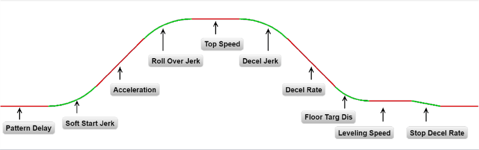
Figure 4.2: S‐Curve Parameter
4.30 Adjust the Start
To provide a proper start, from the 1021/1101/1005 LCD interface, navigate to the "Adjustable
Variables" menu, "Car Motion" and adjust "Brake Pick Del" (brake pick delay), "Pattern Delay", and "Soft
Start Jerk". Initially, set the brake pick delay to 0 and increase the pattern delay by 0.1 seconds until the
controller picks the brake completely before the motor starts to move. If roll back occurs, then reduce
the pattern delay until there is no roll back. Sometimes, the timing works out better if the brake pick
delay is set to 0.1 second. If load weighing is used, pre‐torquing can be used to provide a smoother start.
See Section 4.39, Adjust the Motor Pre‐torque.
Increase the soft start jerk rate in order to provide a quicker transition from the start to constant
acceleration. Keep in mind that the larger the soft start number, the quicker the start. The ride should
now be acceptable.
4.31 Verify Top Speed
To fine tune high speed, make high speed runs while monitoring the SPEED FEEDBACK in the D1
submenu on the HPV drive display. The display should read contract speed, and it should match the
speed displayed on the 1021/1101/1005 LCD interface, "Elevator Status" menu, "Dmd" and "Vel". This
speed should also match the speed displayed on the 1066 LCD interface, "Car Spd" menu. If all of these
values are the same (+/‐ 2 fpm), then proceed to the next step. If the speed is not correct increase or
decrease drive parameter A1 CONTARCT MTR SPD until the AC drive display reads contract speed. When
the speed displayed is correct, proceed to the next step.
4.32 Adjust Safety Processor Board Speed Clamps
The 1066 Safety Processor Board monitors the speed of the elevator at the terminal landings
independently from the main CPU.

HPV-600/900 AC Geared
P a g e | 73
When the "UT, DT, UTS, and DTS" limit switches are activated, the 1066 board calculates the velocity of
the elevator and compares that velocity with a stored value of speed clamp. If the velocity when the
switch activates is greater than the speed clamp value, then the 1066 board will generate a fault that
stops the elevator.
To set the speed clamps, make a one floor run to the top floor.
From the 1066 LCD interface, navigate to the "Lim Vel" menu, and view the recorded velocities
displayed for the “UT, DT, UTS & DTS” slowdown limits. “UTS & DTS” are used on car with reduced
stroke buffers or with a top speed greater than 200 fpm. The velocity value is shown from the “LIM VEL”
menu on the 1066 LCD interface.
The velocity value shown on the display for the “UT or DT” limit is the value after the car activates the
limit then counts an adjustable number of counts the 1066 LCD interface, "Adj Var" menu, "UT Count" or
"DT Count". These count values can be adjusted to provide adequate distance, following the limit switch
activation, to allow the elevator to begin its normal decel pattern. The default "UT Count" and "DT
Count" values are normally adequate. However, these values may need to be field adjusted to allow
enough distance for the car to begin its normal decel pattern. If the "UT Count" and "DT Count" values
are modified, the limit velocities must be re‐ checked.
Run the car again to the top repeatedly from 2 floors, then 3 floors, etc., until top speed is reached.
Record the limit velocities each time the car stops at the top floor. From the 1066 LCD interface "Lim
Vel" menu, record the limit velocities displayed each time the car stops at the top floor.
Make the same runs to the bottom floor starting from 1 floor, then 2 floors, then 3 floors, etc., until top
speed is reached. From the 1066 LCD interface "Lim Vel" menu, record the limit velocities displayed each
time the car stops at the bottom floor.
Take the highest speed value recorded in the runs above and add 20 fpm to that value to use as the
clamp speed values for the respective limit switches. Enter these clamp speed values into the 1066 LCD
interface "Adj Var" menu, "UT Vel", "DT Vel", "UTS Vel", "DTS Vel" respectively.
4.33 Adjust Digital Slowdown Speed Clamps
Having just made several runs into the top and bottom landings, the main CPU has also recorded the
car’s velocity when the slowdown limits were activated. If the car has been powered down prior to this
step, several runs must to be made to the terminal landings to allow the main CPU to record the limit
velocity values.

From the 1021/1101/1005 LCD interface, navigate to the "Elevator Setup" menu, "Set DT/UT Slowdown
Clamp" and view the speed displayed for "Clamp Speed". Add 20 fpm to this "Clamp Speed" value and
enter it into the "DT/UT Limit" value.
The number of slowdown limits depends on the speed of the car as show in the table below:
Table 4.1: Slowdown Clamps
Adjust speed clamps for each slowdown limits used as determined by the elevator’s contract speed.
4.34 Verify Inspection Velocity Clamp on Safety Processor Board
Place the car on inspection operation. From the 1066 LCD interface, navigate to the "Adj Var" menu, "Ins
Vel" and set the speed clamp velocity to 25 fpm. From the 1021/1101/1005 LCD interface, navigate to
the "Adjustable Variables" menu, "Car Motion" and set the "Inspect Speed" to 50 fpm. Run the car in
either direction and verify that the car shuts down when the speed rises above 25 fpm.
From the 1066 LCD interface, navigate to the "Adj Var" menu, "Ins Vel" and set the speed clamp to 140
fpm. From the 1021/1101/1005 LCD interface, navigate to the "Adjustable Variables" menu, "Car
Motion" and set the "Inspect Speed" to the desired value.
4.35 Analog Load Weigher Setup
If the job uses an analog load weigher purchased from G.A.L., complete the following procedure.
Mount the load weigher as described by the manufacturer. The load weigher control box will also
contain a board supplied by G.A.L. that connects to the controller serial CAN bus and reads in the analog
output from the load weighing device. Wire the load weigher and G.A.L. board according to the
controller schematics.

HPV-600/900 AC Geared
P a g e | 75
Calibrate the load weighing device hardware according to the manufacturer’s instructions. Following
proper installation of the load weighing device, proceed to Section 4.36, Empty Car Setup.
NOTE: It is recommended using two people, one moving the weights and one in the machine room to
set up the load weigher.
4.36 Empty Car Setup
Verify that the load weighing device is communicating to the main CPU by performing the following
steps. From the 1021/1101/1005 LCD interface, navigate to the "Diagnostics" menu, "Car Comm Status",
"Car to LW Board" and verify that "On‐ line = 1". If "On‐line = 0" then verify wiring and installation of
load weighing device.
From the 1021/1101/1005 LCD interface, navigate to the "Elevator Setup" menu, "Load Weigher Setup",
"Setup Load Weigher" and follow the instructions on the display as you go through the procedure.
It is okay to exit the setup screen to place a call and then return to it while the setup is being performed.
Run the car to the bottom floor and press Enter on the 1021/1101/1005 LCD interface when prompted
to do so to start the automatic setup sequence.
If the car is at the bottom floor and the doors are not closed (the doors will not close automatically from
turning off the auto‐door switch) then place a car call to run the car up one floor then back again. The
doors will close when the call is placed.
When the automatic sequence is activated, the car will run to each floor and measure the empty load
value. The 1021/1101/1005 LCD interface will indicate when the sequence is finished.
4.37 Full Car Setup
NOTE: The empty car setup must be successfully completed to run the full load setup.
Once the empty car setup is complete, run to the loading floor and set the "AUTO DOOR" switch to the
"ON" position to allow weights to be loaded on the car. With the car fully loaded, set the "AUTO DOOR"
switch to the "OFF" position and run the car to the bottom floor. Again if the doors are not closed, make
a one floor run to force the doors to close.
With the car at the bottom floor, follow the instructions on the 1021/1101/1005 LCD interface to start
the full load setup sequence. The car will automatically run to each floor and measure the full load
value. When the full load measurement is complete, the car can be run to the loading floor and the
weights removed.
After the weights are removed, cycle the doors to complete the procedure. From the 1021/1101/1005
LCD interface, navigate to the "Elevator Setup" menu, "Load Weigher Setup", "View/Modify LW Setup"
and verify the load weigher status, "LW Device Stat: ON OK". If the status is "ON OK", then the load
weigher should be accurately measuring the car load in real time. The percent load will be displayed,
"Load: _%".
The percent load values for different service options can now be set. From the 1021/1101/1005 LCD
interface, navigate to the "Adjustable Variables" menu, "Service Options", and set the following
variables:
"Load Bypass"
"Load Antinuisance"
"Load Dispatch"
"Load Overload"
NOTE: Setting the values of the variables above to 0% will disable that particular option.
4.38 Load Weighing Calibration Sequence
The load weigher is automatically calibrated once each week. If an error is detected during this
calibration sequence, the load weigher and the pre‐torque feature (if used) is disabled. A load weighing
calibration sequence can be done manually by performing the following procedure. From the
1021/1101/1005 LCD interface, navigate to the "Elevator Setup" menu, "Load Weigher Setup", "Load
Weigher Calibration" and follow the instructions on the display.
4.39 Adjust the Motor Pre‐torque
NOTE: The motor pre‐torque uses the load value obtained from the analog load weigher and will only
work if the load weigher has been installed properly, and the "Load Weigher Setup" has been performed
successfully.
On the HPV‐600 or HPV‐900 drive under User Switches C1 parameter, set Pre‐Torque source to serial.
Run the empty car to a middle floor. The long pattern delay will allow an exaggerated amount of roll
back in order for the pre‐torquing to be set accurately. Make a one floor run down and observe the roll
back when the brake picks at the start of the run. Increase the "Torque Amount" variable and continue

HPV-600/900 AC Geared
P a g e | 77
to monitor the roll back while performing one floor runs in the down direction. As the "Torque Amount"
is increased, the roll back should be minimized until the car will hold zero speed for the entire "Pattern
Delay" time. A typical value for the "Torque Amount" is 40%. If the value is too large, the car will roll
forward during the "Pattern Delay" time.
NOTE: Pattern delay must be at least 0.15 seconds (150 milliseconds). Setting the torque amount to 0.0
will disable the pre‐ torque feature. Also if the load weighing calibration sequence detects a load
weighing error, the pre‐torque feature is also automatically disabled.
4.40 Verify the Doors Are Safe
The elevator should now be adjusted. Verify that all door locks, gate switches, and safety circuits are
operational. Set the "INSP" switch to the "NORM" position and set the "AUTO DOOR" switch to the "ON"
position. The elevator should level into the floor and open the doors. If the doors do not open, check the
door operator wiring and cam adjustment. If the doors do open, the elevator is now on independent
service.
4.41 Fine Tune the Ride Quality
Ride the elevator and evaluate the ride quality. Fine tune ride quality by navigating to the "Adjustable
Variables" menu, "Car Motion" and adjusting the variables shown in Figure 4.2. Keep in mind that if
acceleration or deceleration values are changed, the speed clamps for the safety processor board and
the S‐curve board may need to be re‐adjusted.
To fine tune the floor level accuracy, determine if the controller is set to stop when "UL" and "DL"
signals turn on, or if controller is set to stop off of the position count. From the 1021/1101/1005 LCD
interface, navigate to the "Adjustable Variables" menu, "Car Motion" and view the "Stop On Pos Cnt"
variable. If "Stop On Pos Cnt = 0" then controller is set to stop when the "UL and "DL" signals turn on. If
"Stop On Pos Cnt = 1" then controller is set to stop on a combination of the floor level magnet and the
position count.
With "Stop On Pos Cnt = 0", the floor levels should be set by adjusting the floor level magnet at each
floor. For proper operation, the floor magnets should be set to exactly floor level. After the floor levels
are set properly, perform another hoistway learn procedure.
With "Stop On Pos Cnt = 1", the floor levels are set by using both the floor magnet and the position
count. For proper operation with this setting, the floor magnet should be set to exactly floor level. The
final stop can then be fine‐tuned by performing the following adjustments.
From the 1021/1101/1005 LCD interface, navigate to the "Hoistway Tables" menu, "DZ & LZ Offset, Sel
Cnt" and adjust "Dn Lev Dist" and "Up Lev Dist". The units for these variables are in "pulse counts". With
"Stop On Pos Cnt =1" the car will continue to move for the "Dn Lev Dist" or "Up Lev Dist" after "UL and
DL" turn on. Use the "Dn Lev Dist" and the "Up Lev Dist" parameters to make level changes at all floors.
To make level changes at individual floors, perform the following adjustments. From the
1021/1101/1005 LCD interface, navigate to the "Hoistway Tables" menu, "FL and FL Offset Count", and
the offset count can be adjusted. These variables introduce an offset (+/‐) to the stored floor count that
was determined in the hoistway learn procedure.
NOTE: The number of pulse counts per inch can be viewed from the 1021/1101/1005 LCD interface,
"Hoistway Tables", "DZ & LZ Offset, Sel Cnt”, "Pulses / Inch".
NOTE: Regardless if "Stop On Pos Cnt=0" or if "Stop On Pos Cnt =1", the floor magnet must be set
properly at floor level. If too large of values are entered into "Dn Lev Dist", "Up Lev Dist", or "Offset", the
car will drive past the floor level magnet and re‐level.
Check all signal devices for proper operation and remove all temporary jumpers. The adjustment should
now be complete.

P a g e | 79
HPV-600/900 Non-Distance Feedback
Section 5 ‐ Adjustment of the GALaxy Non‐
Distance
Feedback controller ‐ HPV‐600/900
5.1 General Setup
Before adjustment begins the following items
must be completed.
1. All field wiring and safety circuits
installed
2. Temporary jumpers from terminal “HC”
to terminals “MES & ALT”
3. All hoistway limit switches installed
4. All car and hoistway doors and interlocks
installed and pre‐adjusted
5. Selector installed and magnets pre‐
adjusted
6. Familiarize yourself with all wiring
schematics
7. Familiarize yourself with the appropriate
Magnetek HPV 900 or HPV 600 AC Vector
Elevator Drive
Technical Manual.
8. Verify that the AC motor is properly
wired.
9. Verify that the encoder (if closed loop) is
connected properly.
10. Car should be properly counterbalanced.
5.2 Check Main‐line Voltage
With main‐line disconnect in the off position,
check the line‐side voltage with a volt meter to
insure the
voltage matches the controller name
tag “Input Power” voltage. Check to insure all
three phases are
present. If voltage is not correct
or all three phases are not present, do not
proceed until corrected.
5.3 Set Toggle Switches
Set all toggle switches on the 1064 board as
follows:
DOOR LOCKS ‐ "OFF"
IND ‐ "IND"
AUTO DOOR ‐ "OFF"
STOP ‐ "STOP"
INSPECTION ‐ "INSP"
5.4 Make Sure the Car Is Safe
Verify that all elevator doors are closed and that
all safety circuits are functional.
5.5 Check Controller Voltage
Turn the main‐line disconnect to the “On”
position. Check the voltage at R, S, and T on the
AC drive.
Verify that all three phases are present.
Check the voltage at fuses L1 and L2 on the
controller. If correct,
check the voltage at
terminal “LIN” with respect to “GND”. The
voltage should read 120VAC. If correct,
check the
voltage at terminals “S10, LC, & HC” with respect
to “GND”. All should read 120VAC. If not,
check
wiring diagram.
5.6 Verify the Main CPU is Operating
Check to make sure that the “axy” of GALaxy on
the 1021/1101/1005 LCD interface is blinking. If the
“axy” is
blinking, continue to the next step. If not, check
voltage at terminals 5V to 0V on the 1064 board
to insure 5VDC. If 5VDC is present and the “axy”
on the 1021/1101/1005 LCD interface is not blinking,
then
contact factory.
5.7 Preset Adjustable Variables on Safety
Processor Board And Main CPU
The 1066 LCD interface (safety processor board)
and the 1021/1101/1005 LCD
interface (main CPU) are
normally preset prior to leaving the factory.
However, it is prudent to check the setup values
for the
proper settings. Refer to Section 13 of this
manual for the operation 1066 LCD interface, and
refer to
Section 10 for operation of the 1021/1101/1005 LCD
interface. The following adjustment variables
must
be set properly:
5.8 1066 LCD interface "Adj Var" Menu
Top Spd (contract speed)
Fdbk Typ (0=tape)
Ctrl Typ (1=Tr NDF)
2 Stop (0=Mult, 1=2 stop)
RearDoor (0=Front only, 1=Rear)
UTS Vel (Set to top speed)
DTS Vel (Set to top speed)
INS Vel (Set to 140)
LEV Vel (Set to 140)

P a g e | 81
HPV-600/900 Non-Distance Feedback
UT Vel (Set to top speed)
DT Vel (Set to top speed)
UL Vel (Set to 160 if Non‐DF)
DL Vel (Set to 160 if Non‐DF)
SoftStop (Set to 3)
NOTE: The velocity values for the terminal limit
switches above are only temporary settings until car is
running high speed. In the final adjustment
procedure, these variables must be set according
to the
procedures in Section 5.29, Adjust Safety Processor Board Speed Clamps.
5.9 1021/1101/1005 LCD interface "Adjustable Variables -> Car Motion"
Submenu
Top Speed (set to contract speed)
Inspect Speed (set to 25 fpm)
Encoder PPR (set to motor encoder PPR)
Encoder RPM (if tape selector, set to value of
"CONTRACT MTR SPD" in HPV 900/600 drive)
5.10 Place Stop Switch in Run Position
Set the “STOP” toggle switch on the 1064 board
to the “RUN” position. Verify that input LED’s for
“LC,
HC, DN, UN, SS, GTS, RDY and CS” are all on.
If not, then correct field wiring.
5.11 Hoist Motor Data
At this time the hoist motor data must be entered
into the AC drive. The following functions listed
in the
appropriate drive section must be entered
or verified using the specific drive interface tool.
Proceed to
the HPV 900/600 or GPD 515 drive
section below.
5.12 HPV 900/600 Drive
Follow the instructions in the HPV 900 or HPV 600
drive manual to enter the following data:
DRIVE A1 Sub Menu
CONTRACT CAR SPD (from controller data)
CONTRACT MTR SPD (from motor nameplate
RPM)
NOTE: The CONTRACT MTR SPD value may
need to be fine‐tuned to provide the correct rpm
to run the
machine/motor at controller
demanded speed.
ENCODER PULSES (PPR from encoder on motor)
MOTOR A5 Sub Menu
RATED MTR PWR (from motor nameplate)
RATED MTR VOLTS (from motor nameplate)
RATED EXCIT FREQ (from motor nameplate)
RATED MOTOR CURR (from motor nameplate)
MOTOR POLES
for 1800rpm motor set MOTOR POLES to 4
for 1200rpm motor set MOTOR POLES to 6
for 900rpm motor set MOTOR POLES to 8
RATED MTR SPEED (RPM from motor
nameplate) NOTE: This is a preliminary setting for
the
RATED MTR SPEED parameter. The final
value of this parameter will be set in the
"Adaptive
Tune" procedure after the car is
running high speed.
% NO LOAD CURR (from motor nameplate)
S‐CURVES A2 Sub Menu
ACCEL RATE 0 = 2.5
DECEL RATE 0 = 2.5
ACCEL JERK IN 0 = 3.0
ACCEL JERK OUT 0 = 3.0
DECEL JERK IN 0 = 3.0
DECEL JERK OUT 0 = 3.0
MULTISTEP A3 Sub Menu
SPEED CMD 0 = 0
SPEED CMD 1 = Lev Speed
SPEED CMD 2 = Ins Speed

P a g e | 83
HPV-600/900 Non-Distance Feedback
SPEED CMD 3 = High
SPEED CMD 4 = 0
SPEED CMD 5 = 0
SPEED CMD 6 = 0
SPEED CMD 7 = 0
SPEED CMD 8 = 0
SPEED CMD 9 = 0
CONFIGURE C0 Sub Menu
LOGIC INPUT 1 = Drive Enable
LOGIC INPUT 2 = Run Up
LOGIC INPUT 3 = Fault Reset
LOGIC INPUT 4 = Run Down
LOGIC INPUT 5 = Contact Confirm
LOGIC INPUT 6 = Step Ref B0
LOGIC INPUT 7 = Step Ref B1
LOGIC INPUT 8 = no function
Most of the drive parameters have been preset
to values required for your specific job. Other
parameters not listed here may need to be
adjusted in the field. Please refer to the
Magnetek HPV 900
or HPV 600 Technical manual
for more parameter information and
troubleshooting guidelines.
From the digital operator for the drive, reset any
active faults and clear the fault history log.
5.13 GPD 515 Drive
Follow the instructions in the GPD 515 drive
manual to enter the follow data:
C1‐10 Acc/Dec Time Setting = 0
C1‐01 Accel Time 1 = Top Speed/150
C1‐02 Decel Time 1 = Top Speed/150
Note: This will set the accel and decel rates to 150 fpm/s or 2.5 f/s^2. (0.66 for 100 fpm)
C2‐01 S‐curve Accel Start = 0.2
C2‐02 S‐curve Accel End = 0.2
C2‐03 S‐curve Decel Start = 0.2
C2‐04 S‐curve Decel End = 0.2
D1‐01 Frequency Ref = 0
D1‐02 Frequency Ref = Lev Speed
D1‐03 Frequency Ref = Ins Speed
D1‐04 Frequency Ref = High Speed
D1‐05 through D1‐09 = 0
E1‐01 Input Voltage = Line Voltage
E1‐03 V/F Pattern = 1
E1‐04 Max Frequency = 60
E2‐01 Motor Current = Nameplate Motor Amps
E2‐03 No‐Load Amps = Nameplate Motor
No‐Load Amps
E2‐04 Num of Poles = 4 (~1800 rpm) 6 (~1200 rpm) 8 (~900 rpm)
H1‐01 Multi‐function = 24
H1‐02 Multi‐function = 14
H1‐03 Multi‐function = F
H1‐04 Multi‐function = 3
H1‐05 Multi‐function = 4
H1‐06 Multi‐function = F
H3‐05 Multi‐function = 1F

P a g e | 85
HPV-600/900 Non-Distance Feedback
With Encoder
F1‐01 Encoder Const = Encoder PPR
F1‐05 PG Rotation = 0 CCW, 1 CW
The following data is set from the factory and is
shown here for reference:
A1‐02 Control Method =0 (V/F if no encoder
used)
A1‐02 Control Method =3 (Flux Vector if
encoder used)
A1‐03 Initialize Parameters = 2220
B1‐01 Reference Selection = 1
B1‐02 Operation Method = 1
B1‐03 Stopping Method = 1
B5‐01 PID Control = 0
H2‐01 Operation Ready = 6
Most of the drive parameters have been preset
to values required for your specific job. Other
parameters not listed here may need to be
adjusted in the field. Please refer to the
Magnetek GPD 515
Technical manual for more
parameter information and troubleshooting
guidelines.
5.14 Ready to Run On Inspection
The car should be ready to run on inspection if all
is wired correctly. Select the “Elevator Status” on
1021/1101/1005 LCD interface. The display should show “Out
of Service” on the first line and “Inspection
Mode” on the second. The 1066 LCD interface
will display one of the following types of
inspection:
“MR INS” (Motor Room)
“CT INS” (Car Top) “ACCESS” (Access)
“IC INS” (In Car)
“AUTO” (Not on Inspection)
To run the car from the motor room, “MR INS”
should be displayed.
The “inspection string” (Figure 5.1) consist of
contacts from the inspection switches and the
gate and
lock bypass switches in series. One and
only one of the five inspection inputs should be
on for the car to
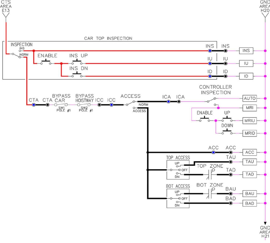
run. Starting from the car top
inspection input, the five inspection inputs are,
“INS” for car top, “ACC”
for access, “ICI” for in‐car, “MRI” for motor room, and “AUTO” for
automatic (no inspection).
Note that any of the following conditions will
cause an inspection error:
More than one inspection input is on
No inspection input is on
Gate or Lock bypass switch is open and the car
is not on car top inspection
If the controller is not on motor room inspection
at this point, then verify all switch positions and
wiring
before proceeding.
Figure 5.1: Inspection String Circuit

P a g e | 87
HPV-600/900 Non-Distance Feedback
5.15 Adjust the Brake Voltage
Momentarily push the inspection “UP” or
“DOWN” push button on the 1064 board while
checking the
DC brake voltage with a meter.
If the voltage is not correct, it must be adjusted
according to the following procedures.
If the controller utilizes an electronic brake board
1047 or 1051, then the brake voltage is adjusted
through the 1021/1101/1005 LCD interface, "Car Brake" sub‐
menu. If the controller utilizes resistors
and
rectifiers for the brake coil circuit, then the brake
voltage is adjusted by moving the adjustable tap
on the brake resistor.
NOTE: Remove power before adjusting the
resistor taps.
To adjust the brake voltage when using and
electronic brake board, navigate to the
"Adjustable
Variables" menu, "Car Brake" and
adjust "Brake Pick Volt", "Brake Hold Volt" and
"Brk AC L‐L Volt" to
the proper values. Make sure
that the brake is lifting and setting properly
before proceeding.
5.16 Check Run Direction
Momentarily push the inspection “UP” or
“DOWN” push button on the 1064 board. One of
the following
should take place:
The elevator will run controlled, in the correct
direction (up for “UP” button, down for “DOWN”
button)
with no drive faults. If so, proceed to
“Check Inspection Speed”.
The elevator will run controlled, but in the wrong
direction (down for “UP” button, up of “DOWN”
button) with no drive faults. If so, proceed to "Car
Runs the Wrong Direction".
The elevator will try to run, but immediately trips
on a drive fault. Re‐check the drive parameters.
If an
encoder is used and the drive records an
ENCODER FLT proceed to “Verify Encoder
Connection”. If no
encoder is used, then contact
the factory.
The elevator will run controlled but very slow;
proceed to “Verify Encoder Connection”.
5.17 Car Runs Wrong Direction
If the elevator runs controlled but in the wrong
direction, with no drive faults, then change
rotation of
the motor. For an HPV 900 or 600
drive the motor rotation can be changed from the
drive command.
For a GPD 515 drive the motor
leads will need to be swapped.
With HPV 900 or HPV 600
USER SWITCHES C1
MOTOR ROTATION
With GPD 515
Turn off the power and switch any two motor
leads. If an encoder is used, then swap the A+ and
A‐ wires
as follows:
A+ (TA1‐4) with A‐ (TA1‐5)
The motor should run controlled in the correct
direction. If not then contact the factory,
otherwise,
proceed to “Run Inspection Speed”.
5.18 Verify Encoder Connection
If the elevator tries to run, but immediately trips
on a drive ENCODER FLT or if the car runs very
slow,
then the drive encoder direction needs to
be changed.
If the controller has an encoder isolation board
(1022N), change the encoder direction for the
drive by
moving jumper J5 from “POS 1” to “POS
2”. This will swap the A and A‐ signals. Refer to
the jumper
diagram on the 1022 board.
J5 swaps A & A NOT – J7 swaps B & B NOT.
If the controller does not have an encoder
isolation board, then turn off the main
disconnect, and swap
the encoder wires at the
drive as follows:
With HPV 900 A+ (TB1‐21) with A‐ (TB1‐20)
With HPV 600 A+ (Encoder Card Terminal 63) with A‐ (Encoder
Card Terminal 62)
With GPD 515
A+ (TA1‐4) with A‐ (TA1‐5)

P a g e | 89
HPV-600/900 Non-Distance Feedback
Turn on the main disconnect, run the elevator on
inspection again.
If the elevator runs controlled, in the correct
direction, proceed to the next step. If the
elevator runs
controlled but in the wrong
direction, with no drive faults, then turn off the
main disconnect, and swap
the hoist motor field
wires. Also swap the encoder wires or the
encoder isolation board jumpers back as
they were to begin with. Turn the main disconnect on.
The car should now run controlled in the correct
direction. If not, contact the factory.
5.19 Check Inspection Speed
With a hand held tachometer, check the speed of
the elevator while running on inspection. The
elevator
should be running at 25 fpm. Also run
the elevator while monitoring speed feedback on
the HPV 900,
HPV 600 or GPD 515 drive display.
The display should show the inspection speed
value in feet per
minute or in hertz. If the speed
on both of these devices reads within +/‐ 2 fpm
of the programmed
speed, then continue to the
next step. If not, contact the factory.
If using a GPD 515 drive, the speed display will be
in hertz. Top speed will usually be 60Hz. The
following
formula is used to calculate the speed
in Hz.
Speed (Hz) = (Speed (fpm)/ Top Speed (fpm)) *60
Example: Top Speed = 200 fpm Inspection Speed = 25 fpm Maximum Drive Frequency = 60 Hz Ins.
Speed
(Hz) = (25/200) * 60=7.5 Hz
5.20 Check Selector Inputs
Run the elevator up on inspection until it stops on
the up normal limit. The up and down normal
limits
should be set two inches above and below
the terminal floors respectively. Verify the
selector inputs
are being set properly on the
controller by running the elevator down until it
stops on the down normal
limit. As the car
approaches floor level going down, “DL” turns on
first, then “DZ” and then finally “UL”.
At floor
level, “UL, DL, and DZ” inputs should all be on at the same time. Leaving the floor going down
“DL”
will turn off first, then “DZ” and last “UL”.
5.21 Verify Slowdown Limits
As the car is running down verify that the up and
down slowdown sensors for each floor, “US and
DS”,
activate prior to reaching the landing. Also
verify that the up and down terminal slowdown
limits inputs
“UT, UTS, DT & DTS” are breaking at
the proper distances as shown in the slowdown
table 2.0. “US and
DS” turn on when active but
“UT, UTS, DT & DTS” turn off when active.
“UT & DT” should turn off one inch closer to the
terminal floor levels than when the “US & DS”
inputs
turn on.
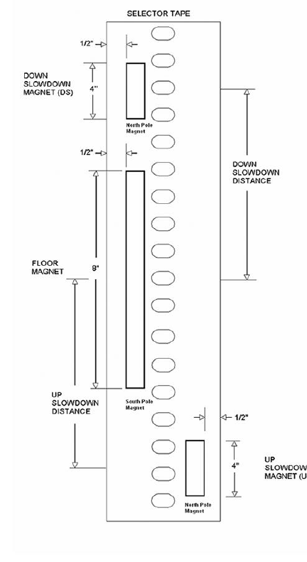
5.22 Verify Car Speed on Safety Processor Board
Run the car in both directions and check the car
speed on the 1066 LCD interface. The speed
shown
should match the car’s actual speed. If the
speed does not match and the secondary
feedback comes
from pulses from the tape, go to
Section 5.23, Correct Car Speed When using A Tape. If the
correct
speed is shown proceed to Section 5.24, Automatic Run.
5.23 Correct Car Speed When Using a Tape
The tape has holes every 3/8” that are 3/8” in
diameter. The safety processor measures the
time
between each pulse to calculate the
velocity. If the velocity is not displayed correctly,
first make sure
that the feedback type in the
safety processor board adjustable variable is set
to “0” for a tape
application. Next, while the car
is running, make sure that the PULSE LED on this
board is pulsing. As the
car increases in speed the LED will glow solid on. If the LED does not pulse,
try swapping the wires at the
PPS and PP
terminals. If the LED still does not work, contact
the factory. If the correct speed is shown
proceed to “Final Adjustment”.
Figure 5.2: Selector Magnet Placement

P a g e | 91
HPV-600/900 Non-Distance Feedback
5.24 Automatic Run
With the car on inspection, bring it to a normal
limit at a terminal landing. Make sure the normal limit
input is off. The "AUTO DOOR" switch
should be set to the "OFF" position and the "IND"
switch should be
set to the "IND" position. Set the
"INS" switch to the "NORMAL". The car should
level into the floor. From
the 1021/1101/1005 LCD interface
navigate to the "Set Calls and Lockouts" menu,
"Setup Car Calls" and
enter a car call. The
elevator should run to answer the call. When the
elevator levels in and stops at the
floor, the doors
will remain closed.
5.25 Adjust the Drive Speed Profile
The S‐Curve parameters in the drive adjust the
ride and performance of the car. Since the
slowdown
distances for each floor are fixed
distances, these parameters must be adjusted to
bring the car into the
floor without over shooting
or spotting at the floor. The following
parameters adjust the speed profile.
With HPV 900 or HPV 600
S‐CURVE A2
Accel Rate 0
Decel Rate 0
Accel Jerk In 0
Accel Jerk Out 0
Decel Jerk In 0
Decel Jerk Out 0
MULTISTEP REF A3
Speed Command 1
Speed Command 2
Speed Command 3
Speed Command 4
With GPD 515
C1‐01 Accel Time 1
C1‐02 Decel Time 1
C2‐01 S‐curve Accel Start
C2‐02 S‐curve Accel End
C2‐03 S‐curve Decel Start
C2‐04 S‐curve Decel End
D1‐03 Freq Ref = Lev Speed
D1‐04 Freq Ref = High Speed
D1‐09 Freq Ref = Ins Speed
Perform a preliminary adjustment of the speed
profile from the drive so that several successful
runs
from floor to floor can be made.
If using an HPV 900 or HPV 600, run the adaptive
tune procedure next, otherwise, if using a GPD
515
proceed to adjust the stop. Keep in mind that
the response of the drive may need to be
adjusted.
5.26 Drive Adaptive Tune (HPV 900 /600 Only)
To complete the setup of the drive, an adaptive
tune is required. It is necessary that the car run
70% of
contract speed when running this test so
that the drive does not go into flux weakening. In
the DRIVE A1
Sub Menu, set the CONTRACT MTR
SPD parameter to 70% of the rated motor RPM.
If this value was
adjusted to correct the top speed
of the car, use 70% of the adjusted value. To
calculate 70%, multiply
the value by 0.7. For
example, if the motor RPM is 1050 then 70% of
the motor RPM is (1050 x 0.7 =
735). This procedure will also require balanced load in the
car. Follow the adaptive tune procedure
set in
the Magnetek HPV 900 or HPV 600 Technical
Manual. After completing the adaptive tune reset
the CONTRACT MTR SPD parameter and then
proceed to the next step.
5.27 Adjust the Stop
When at floor level the “UL, DL, & DZ” input LEDs
should be on. If the elevator continually tries to
seek
floor level by leveling up and down, try the
following steps to correct the problem:
Increase the response of the drive and retest
the car.
Reduce the leveling and re‐leveling velocity
parameters in the car and retest.
Make sure the brake is dropping quickly enough.
If the car still oscillates, adjust the "floor level"
on the selector. The "floor level" is increased by
moving
the selector sensor boards closer
together.

P a g e | 93
HPV-600/900 Non-Distance Feedback
If the car spots when approaching the floor, the
cause is usually due to the car not tracking. Try
increasing the response of the drive again. The
deceleration rate can also be reduced a little to
help
remove the spotting. Once the proper stop
is achieved, proceed to the next step.
5.28 Adjust the Start
To provide a proper start, from the 1021/1101/1005 LCD
interface, navigate to the "Adjustable
Variables"
menu, "Car Motion" and adjust "Brake Pick Del"
(brake pick delay) and "Pattern Delay". Also
adjust the start jerk rate in the drive.
Initially, set the brake pick delay to 0 and increase
the pattern delay by 0.1 seconds until the
controller
picks the brake completely before the
motor starts to move. If roll back occurs, then
reduce the
pattern delay until there is no roll
back. Sometimes, the timing works out better if
the brake pick
delay is set to 0.1 second.
Adjust the drive start jerk rate to smooth out the
start.
With the HPV 900 or HPV 600
Adjust Jerk Rate 1
With the GPD 515
Adjust C2‐01 S‐curve Accel Start
Refer to the GPD 515 manual for instructions to
adjust the following parameters:
B6‐01, B6‐02, B6‐03 and B6‐04
Once the ride is acceptable, proceed to the next
step.
5.29 Adjust Safety Processor Board Speed
Clamps
The 1066 Safety Processor Board monitors the
speed of the elevator at the terminal landings
independently from the main CPU.
When the "UT, DT, UTS, and DTS" limit switches
are activated, the 1066 board calculates the
velocity of
the elevator and compares that
velocity with a stored value of speed clamp. If the
velocity when the
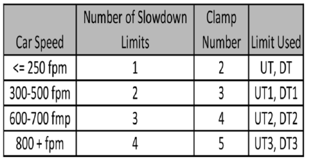
switch activates is greater than
the speed clamp value, then the 1066 board will
generate a fault that
stops the elevator.
To set the speed clamps, make a one floor run to
the top floor.
After the car stops, record the velocity the car hit
the “UT, DT, UTS & DTS” slowdown limits. “UTS
& DTS” are used on car with reduced stroke
buffers or with a top speed greater than 200 fpm.
The
velocity value is shown from the “LIM VEL”
menu on the 1066 LCD interface.
The velocity value shown on the display for the
“UT or DT” limit is the value after the car activates
the
limit then counts an adjustable number of
counts set from the 1066 LCD interface, "Adj Var"
menu,
"UT Count" or "DT Count". These count
values can be adjusted to provide adequate
distance, following
the limit switch activation, to
allow the elevator to begin its normal decel
pattern. The default "UT
Count" and "DT Count"
values are normally adequate. However, these
values may need to be field
adjusted to allow
enough distance for the car to begin its normal
decel pattern. If the "UT Count" and
"DT Count"
values are modified, the limit velocities must be
re‐checked.
Run the car again to the top repeatedly from 2
floors, then 3 floors, etc., until top speed is
reached.
From the 1066 LCD interface "Lim Vel"
menu, record the limit velocities displayed each
time the car
stops at the top floor. Make the
same runs to the bottom floor starting from 1
floor, then 2 floors,
then 3 floors, etc., until top
speed is reached. From the 1066 LCD interface
"Lim Vel" menu, record the
limit velocities
displayed each time the car stops at the bottom
floor. Take the highest speed value
recorded in
the runs above and add 20 fpm to that value to
use as the clamp speed values for the
respective
limit switches. Enter these clamp speed values
into the 1066 LCD interface "Adj Var" menu,
"UT
Vel", "DT Vel", "UTS Vel", "DTS Vel" respectively.
The number of slowdown limits depends on the
speed of the car as show in the table below:
Table 5.1: Slowdown Clamps

P a g e | 95
HPV-600/900 Non-Distance Feedback
5.30 Verify Inspection Velocity Clamp on Safety
Processor Board
Place the car on inspection operation. From the
1066 LCD interface, navigate to the "Adj Var"
menu,
"Ins Vel" and set the speed clamp velocity
to 25 fpm. From the 1021/1101/1005 LCD interface, navigate
to the "Adjustable Variables" menu, "Car
Motion" and set the "Inspect Speed" to 50 fpm.
Run the car in
either direction and verify that the
car shuts down when the speed rises above 25
fpm.
From the 1066 LCD interface, navigate to the "Adj
Var" menu, "Ins Vel" and set the speed clamp to
140
fpm. From the 1021/1101/1005 LCD interface, navigate
to the "Adjustable Variables" menu, "Car
Motion" and set the "Inspect Speed" to the
desired value.
5.31 Analog Load Weigher Setup
If the job uses an analog load weigher purchased from G.A.L., complete the following procedure.
NOTE: It is recommended using two people, one moving the weights and one in the machine room to
set up the load weigher.
Mount the load weigher as described by the
manufacturer. The load weigher control box will also
contain a board supplied by G.A.L. that
connects to the controller serial CAN bus and
reads in the analog
output from the load
weighing device. Wire the load weigher and G.A.L. board according to the
controller
schematics.
Calibrate the load weighing device hardware
according to the manufacturer’s instructions.
Following
proper installation of the load weighing
device, proceed to Section 5.32, Empty Car
Setup.
5.32 Empty Car Setup
Verify that the load weighing device is
communicating to the main CPU by performing
the following
steps. From the 1021/1101/1005 LCD interface,
navigate to the "Diagnostics" menu, "Car Comm
Status",
"Car to LW Board" and verify that "On‐
line = 1". If "On‐line = 0" then verify wiring and
installation of
load weighing device.
From the 1021/1101/1005 LCD interface, navigate to the
"Elevator Setup" menu, "Load Weigher
Setup",
"Setup Load Weigher" and follow the instructions
on the display as you go through the
procedure.
It is okay to exit the setup screen to place a call and then return to it while the setup is being
performed.
Run the car to the bottom floor and press Enter
on the 1021/1101/1005 LCD interface when prompted,
to
start the automatic setup sequence.
If the car is at the bottom floor and the doors are
not closed, (the doors will not close automatically
from
turning off the auto‐door switch), then
place a car call to run the car up one floor then
back again. The
doors will close when the call is
placed.
When the automatic sequence is activated, the
car will run to each floor and measure the empty
load
value. The 1021/1101/1005 LCD interface will indicate
when the sequence if finished.
5.33 Full Car Setup
NOTE: The empty car setup must be successfully
completed to run the full load setup.
Once the empty car setup is complete, run to the
loading floor and set the "AUTO DOOR" switch to
the
"ON" position to allow weights to be loaded
on the car. With the car fully loaded, set the
"AUTO DOOR"
switch to the "OFF" position and
run the car to the bottom floor. Again if the doors
are not closed, make
a one floor run to force the
doors to close.
With the car at the bottom floor, follow the
instructions on the 1021/1101/1005 LCD interface to start
the full load setup sequence. The car will
automatically run to each floor and measure the
full load
value. When the full load measurement
is complete, the car can be run to the loading
floor and the
weights removed.
After the weights are removed, cycle the doors to
complete the procedure. From the 1021/1101/1005
LCD
interface, navigate to the "Elevator Setup" menu,
"Load Weigher Setup", "View/Modify LW Setup"
and verify the load weigher status, "LW Device
Stat: ON OK". If the status is "ON OK", then the
load
weigher should be accurately measuring the car load in real time. The percent load will be
displayed,
"Load: %".
The percent load values for different service
options can now be set. From the 1021/1101/1005 LCD
interface, navigate to the "Adjustable Variables"
menu, "Service Options", and set the following
variables:
"Load Bypass"
"Load Antinuisance"
"Load Dispatch"
"Load Overload"

P a g e | 97
HPV-600/900 Non-Distance Feedback
NOTE: Setting the values of the variables above
to 0% will disable that particular option.
5.34 Load Weighing Calibration Sequence
The load weigher is automatically calibrated once
each week. If an error is detected during this
calibration sequence, the load weigher and the
pre‐torque feature (if used) is disabled.
A load weighing calibration sequence can be
manually activated by performing the following
procedure.
From the 1021/1101/1005 LCD interface,
navigate to the "Elevator Setup" menu, "Load
Weigher Setup",
"Load Weigher Calibration" and
follow the instructions on the display.
5.35 Check the Doors
The elevator should now be adjusted. Verify that
all door locks, gate switches, and safety circuits
are
operational. Set the "INS" switch to the
"NORM" position and set the "AUTO DOOR"
switch to the "ON"
position. The elevator should
open the doors. If the doors do not open, c h e c k the door operator
wiring and cam adjustment. If
the doors do open, the elevator is now on
independent service.
5.36 Fine Tune Ride and Stops
Ride the elevator and evaluate the ride quality.
Fine‐tune the ride quality with the drive S‐Curve
parameters in the drive. Fine‐tune the floor level
magnets. Check all signal devices for proper
operation
and remove any temporary jumpers.
The adjustment should now be complete.
Section 6 ‐ Adjustment of the GALaxy Controller DC
Quattro Drive
6.1 General Information
In order to obtain a running platform in "car top
inspection", see the "Quick Start‐up Guide for
GALaxy
Controller Quattro DC Drive with
Distance Feedback". This procedure should be
used only for
installation purposes. When
installation of all equipment is complete, and unit
is ready for adjustment,
proceed to Section 6.2, Check Mail Line Voltage, and follow instructions.
Before adjustment begins the following items
must be completed:
1. All field wiring and safety circuits installed
2. Temporary jumpers from terminal “HC” to
terminals “MES & ALT”
3. All hoistway limit switches installed
4. All car and hoistway doors and interlocks
installed and pre‐adjusted
5. Selector installed and magnets pre‐adjusted
6. Familiarize yourself with all wiring schematics
7. Familiarize yourself with the Quattro drive,
drive manual, parameter adjustment, etc.
8. Motor encoder should be properly installed
and wired.
9. Car should be properly counterbalanced.
6.2 Check Main Line Voltage
With main‐line disconnect in the “OFF” position,
check the line‐side voltage with a volt meter to
insure
the voltage matches the controller name
tag “Input Power” voltage. Check to insure all
three phases are
present. If voltage is not correct
or all three phases are not present, do not
proceed until corrected.
6.3 Set Toggle Switches
Set all toggle switches on the 1064 board as
follows:
DOOR LOCKS ‐ "OFF"
IND ‐ "IND"
AUTO DOOR ‐ "OFF"

P a g e | 99
DC Quattro Drive
STOP ‐ "STOP"
INSPECTION ‐ "INSP"
6.4 Make Sure the Car Is Safe
Verify that all elevator doors are closed and that
all safety circuits are functional.
6.5 Check Controller Voltage
Turn the main‐line disconnect to the on position.
Check the voltage at L1, L2, and L3 on the Quattro
drive.
Verify that all three phases are present.
Check the voltage at fuses L1, L2, and L3 (if
present) on
controller. If correct, check the
voltage at terminal “LIN” with respect to “GND”.
The voltage should read
120VAC. If correct, check
the voltage at terminals “S10, LC, & HC” with respect to “GND”. All should read
120VAC. If not,
check wiring diagram to determine problem
before continuing
6.6 Verify the Main CPU is Operating
Check to make sure that the “axy” of GALaxy on
the 1021/1101/1005 LCD interface is blinking. If the
“axy” is
blinking, continue to the next step. If not, check
voltage at terminals 5V to 0V on the 1064
board
to insure 5VDC. If 5VDC is present and the “axy”
on the 1021/1101/1005 LCD interface is not
blinking, then
contact factory.
6.7 Preset Adjustable Variables on Safety
Processor Board and Main CPU
The 1066 LCD interface (safety processor board)
and the 1021/1101/1005 LCD interface (main CPU) are
normally preset prior to leaving the factory.
However, it is prudent to check the setup values
for the
proper settings. Refer to Section 13 of this
manual for the operation of the 1066 LCD
interface, and refer
to Section 10 for operation of
the 1021/1101/1005 LCD interface. The following adjustable
variables must
be set properly:
NOTE: If the controller uses an NTS board please refer to Section 14, GALX-0320AN NYSD Board.
6.8 1066 LCD interface "Adj Var" Menu
Top Spd (contract speed)
Enc RPM (if Fdbk Typ=0 (Tape), not applicable) (if
Fdbk Typ=1 (Encoder), set to rpm of governor)
(if Fdbk
Typ=4 (, set to value of CONTRACT MTR SPD in
Quattro drive)
Enc PPR (if Fdbk Typ=0 (Tape), not applicable) (if Fdbk
Typ=1 (Encoder), set to 8192) (if Fdbk
Typ=4 (Incremental Encoder), set to ppr
of machine/motor encoder)
Fdbk Typ (0=tape, 1=enc, 4=InENC)
Ctrl Typ (2=Tract DF)
2 Stop (0=Mult, 1=2 stop)
RearDoor (0=Front only, 1=Rear)
UTS Vel (Set to top speed)
DTS Vel (Set to top speed)
INS Vel (Set to 140)
LEV Vel (Set to 140)
UT Vel (Set to top speed)
DT Vel (Set to top speed)
UL Vel (Set to 160 if Non‐DF)
DL Vel (Set to 160 if Non‐DF)
SoftStop (Set to 3)
NOTE: The velocity values for the terminal limit
switches above are only temporary settings until car is
running high speed. In the final adjustment
procedure, these variables must be set according
to the
procedures in Section 6.32, Adjust Safety Processor Board Speed Clamps.
6.9 1021/1101/1005 LCD interface "Adjustable Variables ->Car Motion"
Submenu
Top Speed (set to contract speed)
Inspect Speed (set to 25 fpm)
Encoder PPR (set to machine/motor encoder
PPR)
Encoder RPM (if tape selector, set to value of
CONTRACT MTR SPD in Quattro drive), (if 485
tapeless selector, set to value of CONTRACT
MTR SPD in Quattro drive), (if CAN open tapeless
selector, set to governor rpm)
NOTE: See Section 6.24, Correct Car Speed When Using 485 Tapeless System, for determining
governor
rpm.
6.10 Place Stop Switch in Run Position
Set the “STOP” toggle switch on the 1064 board
to the up position. Verify that input LED’s for
“LC, HC,
DN, UN, SS, GTS, RDY and CS” are all on.
If not, then correct field wiring.

P a g e | 101
DC Quattro Drive
6.11 Hoist Motor Data
At this time the hoist motor data must be entered
into the Quattro drive. The following functions
must
be entered or verified using the drive
display unit. Follow the instructions in the
Quattro drive manual
to enter the following data
for each function:
Drive A1
CONTRACT CAR SPD (from controller data)
CONTRACT MTR SPD (from motor nameplate)
NOTE: The CONTRACT MTR SPD value may need
to be fine‐tuned to provide the correct rpm to run
the
machine/motor at controller demanded
speed.
ENCODER PULSES (PPR of encoder on
machine/motor)
Line Side Power Convert A5
INPUT L‐L VOLTS (measured at drive)
Motor A6
RATED MTR CURRENT (from machine/motor
nameplate)
ARMATURE VOLTAGE (from machine/motor nameplate)
FULL FLD CURRENT (from controller data)
WEAK FIELD CURRENT (from controller data)
STANDBY FIELD (from controller data)
6.12 Quattro Drive Self‐Tune
To have the Quattro drive unit learn the
parameters of the hoist motor the drive self‐ tune
must be
performed. Place a temporary jumper
from S10 to terminal MC on the GALX‐ 1064AN
board. This will
energize the MC contactor coil to
enable the drive to perform a motor self‐tune.
Turn on the main
disconnect. Navigate to the
Auto Tune option under MS Pwr Convert A4 on
the Magnetek Operator.
The Magnetek Operator
will display “Start Tune?” Press the enter key on
the Magnetek operator to start
the auto tune
process. During this test, the “ME” contactor in
the Quattro drive will energize for short
period of
time. After the self‐ tune is performed correctly,
“Auto Tune Finish” will appear on the
Magnetek
Operator. If a fault appears on the Magnetek
Operator, the problem must be corrected and
the
self‐tune performed again. If the self‐tune is
successful, then the following functions must be
viewed
and recorded under MS Power Data D2.
Auto Meas Arm L
Auto Meas IRDrop
Auto Meas Arm R
Auto
Field Res
Auto Field TC
The value of MS Power Data D2 Auto Meas Arm L should be manually entered into Function MS
Pwr
Convert A4, Arm Inductance.
The value of MS Power Data D2 Auto Meas Arm
R should be manually entered into Function MS
Pwr
Convert A4, Arm Resistance.
The value of MS Power Data D2 Auto Field Res
should be manually entered into Function MS
Pwr
Convert A4, Motor Field Res.
The value of MS Power Data D2 Auto Field TC
should be manually entered into Function MS
Pwr
Convert A4, Motor Field TC.
After these values are entered successfully, set
parameter MS Pwr Convert A4, Gain Selection to
“Use
Self Tune”. Remove temporary jumper from
S10 to MC on the GALX‐1064AN board.
6.13 Pre‐set the Digital Speed Clamps
Pre‐set the software digital speed clamps from
the 1021/1101/1005 LCD interface under the “Elevator
Setup
Menu”. The submenus for the clamp speeds are
as follows:
Set Ins /Leveling Clamp
Set DT/UT Slowdown Clamp
Set DT1/UT1 Slowdown Clamp
Set DT2/UT2 Slowdown Clamp
Set DT3/UT3 Slowdown Clamp
Set DTS/UTS Slowdown Clamp
Set the speed for Ins/Leveling for 140 fpm and all
the remaining slowdown limit speeds to the
contract
speed of the car. Please note that the
displayed value of “Clamp Speed” is the value the
clamp should
be set to. The slowdown limit “Clamp Speed:” will show 0000 until the car is run
into the limits and the
speed is recorded.

P a g e | 103
DC Quattro Drive
Please refer to Section 10, 1021/1101/1005 LCD Interface, for
the Elevator Setup Menu.
NOTE: The values of the clamp speed velocities
above are only temporary settings until the car is
running high speed. In the final adjustment
procedure, these values must be set according to
the
procedures in Section 6.33, Adjust Digital Slowdown Speed Clamps.
6.14 Ready to Run On Inspection
The car should be ready to run on inspection if all
is wired correctly. Select the “Elevator Status” on
the
1021/1101/1005 LCD interface. The display should show
“Out of Service” on the first line and
“Inspection
Mode” on the second. The 1021/1101/1005 LCD interface on
the Safety Processor Board will
display one of the
following types of inspection:
“MR INS” (Motor Room)
“CT INS” (Car Top)
“ACCESS” (Access)
“IC INS” (In Car)
“AUTO” (Not on Inspection)
To run the car from the motor room, “MR INS”
should be displayed.
The “inspection string” consists of contacts from
the inspection switches and the gate and lock
bypass
switches in series. One and only one of the
five inspection inputs should be on for the car to
run. Starting
from the car top inspection input, the five inspection inputs are, “INS” for car top,
“ACC” for access,
“ICI” for in‐ car, “MRI” for
motor room, and “AUTO” for automatic (no
inspection). The inspection string
circuit is shown
in Figure 6.1.
NOTE: Any one of the following conditions will
cause an inspection error:
More than one inspection input is on
No inspection input is on
Gate or Lock bypass switch is open and
the car is not on car top inspection
If the controller is not on motor room inspection
at this point, then verify all switch positions and
wiring
before proceeding.
Figure 6.1: Inspection String Circuit

P a g e | 105
DC Quattro Drive
6.15 Adjust the Brake Voltage
Momentarily push the inspection “UP” or
“DOWN” push button on the 1064 board while
checking the
DC brake voltage with a meter. If the
voltage is not correct, it must be adjusted
according to the
following procedures.
If the controller utilizes an electronic brake board
1047 or 1051, then the brake voltage is adjusted
through the 1021/1101/1005 LCD interface, "Car Brake" sub‐
menu. If the controller utilizes resistors
and
rectifiers for the brake coil circuit, then the brake
voltage is adjusted by moving the adjustable tap
on the brake resistor.
NOTE: Remove power before adjusting the
resistor taps.
To adjust the brake voltage when using and
electronic brake board, navigate to the
"Adjustable
Variables" menu, "Car Brake" and
adjust "Brake Pick Volt", "Brake Hold Volt" and
"Brk AC L‐L Volt" to
the proper values. Make sure
that the brake is lifting and setting properly
before proceeding.
6.16 Check the Run Direction
Momentarily push the inspection “UP” or
“DOWN” push button on the 1064 board. One of
the following
should take place:
The elevator will run controlled, in the correct
direction (up for “UP” button, down for “DOWN”
button)
with no drive faults. If so, proceed to
“Check Inspection Speed”.
The elevator will run controlled, but in the wrong
direction (down for “UP” button, up of “DOWN”
button) with no drive faults. If so, proceed to
Section 6.17, Car Runs In The Wrong Direction.
The elevator will try to run, but immediately trip
on a drive fault “Encoder Fault”. If so, proceed to
Section 6.18, Drive Trips immediately.
6.17 Car Runs in The Wrong Direction
If the elevator runs controlled but in the wrong
direction, with no drive faults, then turn off the
main
disconnect, swap the hoist motor field
wires.
Also swap the encoder direction by swapping the
encoder
wires or if an encoder isolation board (1022N)
is
used, move J5 and J7 on the encoder board. Refer
to the jumper diagram on the board.
J5 swaps A & A NOT – J7 swaps B & B NOT.
To change the encoder direction at the drive,
swap the following wires:
A+ (TB3‐2) with B+ (TB3‐4)
A‐ (TB3‐3) with B‐ (TB3‐5)
Turn the main disconnect on, run the elevator on
inspection again, and it should run controlled and
in
correct direction. If so, proceed to “Check
Inspection Speed”. If not, contact the factory.
6.18 Drive Trips Immediately
If the elevator tries to run, but immediately trips
on a drive fault “Encoder Fault”, then turn off the
main
disconnect, and swap the encoder direction
by swapping the encoder wires or if an encoder isolation
board (1022N) is used, move J5 and J7 on the
encoder board. Refer to the jumper diagram on
the board.
J5 swaps A & A NOT – J7 swaps B & B NOT.
Turn on the main disconnect and run the elevator
on inspection again. If the elevator runs
controlled and
in the correct direction, proceed
to next section.
If the elevator runs controlled but in the wrong
direction, then go back and follow the directions
in
Section 6.17, Car Runs The Wrong Direction. If
the car still trips immediately on a drive fault,
then
contact the factory.
6.19 Check Inspection Speed
With a hand held tachometer, check the speed of
the elevator while running on inspection. The
elevator
should be running at 25 f.p.m. Also run
the elevator while monitoring Function Speed
Feedback on the
Quattro drive under Display D0,
Elevator Data D1, and Speed Feedback. This function
should also read
25 f.p.m.
From the 1021/1101/1005 LCD interface select the "Elevator
Status" menu, navigate until the display
shows
"Dmd" and "Vel". While running on inspection,
monitor the controller demand speed "Dmd",
and
the speed feedback "Vel". These values
should both display 25. If the demand and
feedback on the
1021/1101/1005 LCD interface is incorrect,
check the Encoder RPM and PPR parameters
from the
“Adjustable Variables” menu. These
variables should be set to values listed in Section 6.9,
1021/1101/1005 LCD interface "Adjustable Variables ->Car Motion" Submenu.
If the speed on the hand held tachometer and on
"Dmd" and "Vel" all read approximately 25 fpm
(within
+/‐2 fpm) continue to the next step. If not,
contact the factory.

P a g e | 107
DC Quattro Drive
6.20 Verify Controller Encoder Direction
From the 1021/1101/1005 LCD interface "Elevator Status"
menu, navigate to display "Dir" and "DP".
While
moving the car on inspection, monitor "Dir"
(direction) and "DP" (pulse counts). "Dir" should
display "Up" when the car is moving up, and "Dn"
when the car is moving down. The value of "Dp"
should
increment when the car is moving up, and
should decrement when the car is moving down.
If the direction is wrong or the pulse counts
change in the wrong direction, then the encoder
direction
to the controller must be changed. If an
encoder isolation board (1022N) is used, move J1
and J3 on the
encoder board. Refer to the jumper
diagram on the board.
J1 swaps A & A NOT – J3 swaps B & B NOT.
If no encoder isolation board is used, the A+ and
A‐ encoder wires from the drive must be
swapped.
Note that the motor encoder wires are
daisy chained from the encoder to the drive and
then from the
drive to the controller encoder
board. Only the A+ and A‐ wires from the drive to
the controller board
must be swapped. The wires
from the encoder to the drive must remain on the
same terminal locations
on the drive.
If the encoder is counting properly continue to
the next step. If not, contact the factory.
6.21 Verify Selector and Slowdown Inputs
Run the elevator up on inspection until it stops on
the up normal limit. The up and down normal
limits
should be set two inches above and below
the terminal floors respectively. Verify the
selector inputs
are being set properly on the
controller by running the elevator down until it
stops on the down normal
limit.
As the car approaches floor level going down,
“DL” turns on first, then “DZ” and then finally
“UL”. At
floor level, “UL, DL, and DZ” inputs
should all be on at the same time. Leaving the
floor going down
“DL” will turn off first, then “DZ”
and last “UL”.
Also verify that the up and down terminal
slowdown limits inputs “UT, UTS, DT & DTS” are
breaking at
the proper distances as shown in the
slowdown table 2.0. “UT, UTS, DT & DTS” turn off
when active.
6.22 Verify Car Speed on Safety Processor Board
Run the car in either direction and check the car
speed on the 1066 LCD interface. The speed
shown
should match the car’s speed actual
speed. If the speed does not match and the
secondary feedback
comes from pulses from the
tape go to “Correct Car Speed When Using A
Tape”. If using 485 tapeless,
go to "Correct Car
Speed When Using 485 tapeless". If using CAN
Open tapeless, go to "Correct Car
Speed When
Using CAN Open tapeless". If the correct speed is
shown proceed to
Section 6.26, Learn
the Hoistway.
6.23 Correct Car Speed When Using A Tape
Installed In Hoistway
The tape has holes every 3/8” that are 3/8” in
diameter. On the selector unit adjust the PP
sensor closer
to the tape until the orange LED at
the end of the sensor turns on. Then turn the
sensor inwards
another 1/8” and lock in the
sensor. While running on top of car inspection
verify that the orange
LED at the end of the PP
sensor turns on and off as it passes by the holes
on the tape. The safety
processor measures the
time between each pulse to calculate the
velocity. If the velocity is not
displayed correctly
first make sure that the feedback type in the
safety processor board adjustable
variable is set
to 0 for a tape application. Next, while the car is
running, make sure that the PULSE LED
on this
board is pulsing. As the car increases in speed the
LED will glow solid on. If the LED does not
pulse,
try swapping the wires at the PPS and PP
terminals. If the LED still does not work, contact
the
factory. If the correct speed is shown proceed
to “Learn the Hoistway”.
6.24 Correct Car Speed When Using 485
Tapeless System
When using the 485 tapeless system, the
secondary speed feedback comes from the
encoder mounted
on the governor. The 1066
board uses a serial interface to a Turck absolute
encoder, part #
T8.5882.3F0B.3001.
In the 1066 LCD interface "Adj Var" menu, set the
"Fdbk Typ = 1", and set the "Enc PPR = 8192". The
"Enc
RPM" value must be calculated as described
below. To calculate the RPM, divide the contract
speed of
the car by the distance travel in one
revolution with the governor as shown below:
RPM = Speed fpm/ (diameter GOV * pi)
For a 1 ft. diameter governor: RPM = 350/ (1*pi) = 350/3.1415 = 111.4
For a 16 in diameter governor (16/12 = 1.33ft):
RPM = 350/ (1.33* 3.1415) = 350/4.188 = 83.5
6.25 Correct Car Speed When Using CAN Open
Tapeless System
When using the CAN Open tapeless system, the
secondary speed feedback comes from the
incremental
encoder mounted on the
machine/motor.
In the 1066 LCD interface "Adj Var" menu, set the
"Fdbk Typ = 4", and set the "Enc PPR" equal to the
ppr of
the machine/motor‐mounted incremental
encoder, and set the "Enc RPM" to the rpm of the
machine/motor at contract speed.
On the 1066 LCD interface, navigate to the "Pls
Cnt" menu. While running the elevator on
inspection,
verify that the pulse count value
increments when running up and decrements
when running down. The
"Pls Cnt" value can be
considerably out of range but will automatically
correct during the "Learn

P a g e | 109
DC Quattro Drive
Hoistway" procedure.
To reverse the direction of pulse counting,
navigate, on the 1066 LCD interface, to
the "Adj
Var" menu, "Enc Dir" and set to "0" for clockwise
or "1" for counter‐clockwise.
Navigate on the 1066 LCD interface to the "Car
Spd" menu. Monitor the "Car Spd" while running
the car
at a known inspection speed. The value
displayed should match the actual car speed
measured with a
hand held tachometer. If not,
re‐check the values set in "Enc RPM" and "Enc
PPR" in the 1066 LCD
interface. If the speed is
correct, proceed to Section
6.26, Learn the Hoistway.
6.26 Learn the Hoistway
Run the elevator down on inspection until it
stops on the down normal limit switch. Verify
that the “DN
and DL” input LED’s are both off.
From the 1021/1101/1005 LCD interface navigate to the
"Elevator
Setup" menu, "Learn Hoistway". The
learn procedure can be performed automatically
by choosing
"Auto" from the menu items, or
performed manually by choosing "Insp" from the
menu items. After
choosing the learn method,
follow the instructions displayed on 1021/1101/1005 LCD
interface.
In general, the car will run up from the "down
normal limit" to the "up normal limit" at 30 fpm.
During
this learn run, the DP count for each floor
level and each limit switch will be stored in
memory.
NOTE: The car must run the entire hoistway
without stopping.
As the elevator moves up the hoistway, navigate
to the "Hoistway Tables" menu, "Disp/Mod
Hoistway
Table", and verify that the "DP" count is
incrementing as the elevator moves up. Also as
the elevator
passes each floor, the pulse count and distance for that floor should change and be
stored. Verify that
the floor distances are valid.
The pulse count for the terminal slowdowns will
also be stored. The
elevator will stop when it
reaches the up normal limit. Follow the
instructions on the 1021/1101/1005
LCD interface by putting
the car on inspection, and then the message
"Hoistway Learn Complete"
should be displayed.
Move the elevator on inspection until the “DZ
and DL” LED’s are on. Set the “INS” toggle switch
on
the 1064 board to the “NORMAL” position,
and the elevator should level down to floor level
at the top
floor. If so, proceed to final
adjustment.
If the car levels down but does not run, then
check “Elevator Status” and “View Fault Log” on
the
1021/1101/1005 LCD interface for any fault information.
Correct items causing faults and perform
hoistway learn again. After problem is corrected
and a successful hoistway learn is performed,
proceed
to final adjustment.
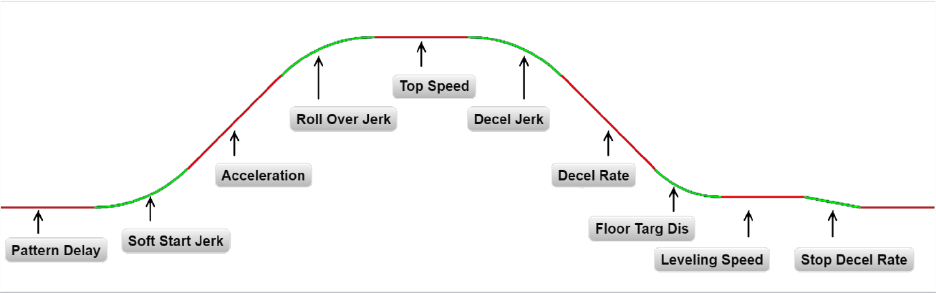
6.27 Automatic Run
The elevator should now be sitting idle at the top
floor. The "AUTO DOOR" switch should be set to
the
"OFF" position and the "IND" switch should
be set to the "IND" position. If the learn
procedure was
successful, the elevator should be
ready to make an automatic run.
The default parameter settings for the ride
quality should be adequate for an initial run.
From the 1021/1101/1005 LCD interface navigate to the "Set
Calls and Lockouts" menu, "Setup Car
Calls" and
enter a car call. The elevator should run to
answer the call. When the elevator levels in and
stops at the floor, the doors will remain closed.
The acceleration and deceleration of the car
should be smooth and stepless regardless of the
distance
of the run. If the elevator does not
function as described above, then the problem
should be analyzed
before proceeding.
6.28 Fine Tune the Ride Quality
In order to fine tune the ride quality, refer to
Figure 6.2 which describes what part of the S‐
curve
that the different parameters effect. In
general, higher numbers in the given parameters,
cause quicker
and more abrupt changes from one
mode to the next during a run. All of the S‐curve
parameters have a
minimum and maximum
value. The control will not allow you to enter
values that are not valid. After
adjusting the S‐
curve parameters, proceed to the next step.
Figure 6.2: S‐Curve Parameters

P a g e | 111
DC Quattro Drive
6.29 Adjust the Stop
When at floor level the “UL, DL, & DZ” input LED’s
should be on. If the elevator continually tries to
seek
floor level by leveling up and down, check
the motor field voltage to be at the nameplate
voltage while
leveling. If the motor field voltage
is correct but the car seems sluggish then
increase the response of
the drive by increasing
the value of RESPONSE in the drive A1 submenu.
If the car still re‐levels at the
floor, try the
following steps to correct the problem:
1. Reduce the leveling and re‐leveling velocity
parameters from the 1021/1101/1005 LCD interface
"Adjustable Variables" menu, "Car Motion",
"Leveling Speed" and "Relevel Speed".
2. If the car still oscillates, adjust the "floor level zone" on the selector. The "floor level zone" is
increased by moving the "UL" and "DL" sensors
closer together.
If the car stops hard on the brake, then make the
following adjustments. From the 1021/1101/1005 LCD
interface navigate to the "Adjustable Variables"
menu, "Car Motion", and adjust both "Brake
Drop Del"
(brake drop delay) and "Soft Stop
Time". These variables should be adjusted so that
zero speed is
observed at the end of the run prior
to the brake setting. The controller should hold
the car at zero
speed for the duration of the "Soft
Stop Time" which should continue while the
brake is setting and for
a short time after the
brake sets. The soft stop time MUST be set to at
least 0.5 seconds LONGER than
the brake drop
delay.
The "Soft Stop Time" setting in the 1021/1101/1005 LCD
interface should be compared with the setting
in
the 1066 LCD interface "Adj Var" menu,
"SoftStop". The setting of "SoftStop" in the 1066
LCD
interface should be greater than the "Soft
Stop Time" setting in the 1021/1101/1005 LCD interface.
If the car spots when approaching the floor, the
cause is usually due to the car not tracking (the
drive
response is set too low) or the speed profile
into the floor is too aggressive. First try to
increase the
response by increasing the value of
drive parameter A1 RESPONSE.
If the car still spots, from the 1021/1101/1005 LCD interface, navigate to the "Adjustable Variables"
menu,
"Car Motion" and increase the value of "Floor
Targ Dis" (floor targeting distance). The default
value for the floor targeting distance is 12 inches.
Increase it by steps of 2 or 3 and continue
retesting
until the parameter is adjusted to 18.
If no change is noticed, start again from 12 and
decrease the value.
The deceleration rate can also be reduced to help
remove the spotting. Once the proper stop is
achieved,
proceed to “Adjust The Start”.
6.30 Adjust the Start
To provide a proper start, from the 1021/1101/1005 LCD
interface, navigate to the "Adjustable
Variables"
menu, "Car Motion" and adjust "Brake Pick Del"
(brake pick delay), "Pattern Delay", and
"Soft
Start Jerk". Initially, set the brake pick delay to 0
and increase the pattern delay by 0.1 seconds
until the controller picks the brake completely
before the motor starts to move. If roll back
occurs, then
reduce the pattern delay until there
is no roll back. Sometimes, the timing works out
better if the brake
pick delay is set to 0.1 second.
If load weighing is used, pre‐torquing can be
used to provide a smoother
start. See Section
6.39, Adjust the Motor Pre‐torque.
Increase the soft start jerk rate in order to
provide a quicker transition from the start to
constant
acceleration. Keep in mind that the
larger the soft start number, the quicker the
start. The ride should
now be acceptable.
6.31 Verify Top Speed
To fine tune high speed, make high speed runs
while monitoring Elevator Data Submenu D1,
Speed
Feedback on the Quattro drive display. The
display should read contract speed.
If the speed is slightly under or over contract
speed then verify that Drive A1 Submenu,
Contract MTR
SPD is set properly. The speed
displayed on the drive should match the speed
displayed on the
1021/1101/1005 LCD interface, "Elevator
Status" menu, "Dmd" and "Vel". This speed
should also match
the speed displayed on the
1066 LCD interface, "Car Spd" menu. When all of
these speeds are the same
(+/‐ 2 fpm), then
proceed to the next step. When the Quattro
display reads contract speed, proceed to
the next
step.
6.32 Adjust Safety Processor Board Speed
Clamps
The 1066 Safety Processor Board monitors the
speed of the elevator at the terminal landings
independently from the main CPU.
When the "UT, DT, UTS, and DTS" limit switches
are activated, the 1066 board calculates the
velocity of
the elevator and compares that
velocity with a stored value of speed clamp. If the
velocity when the
switch activates is greater than
the speed clamp value, then the 1066 board will
generate a fault that
stops the elevator.
To set the speed clamps, make a one floor run to
the top floor. After the car stops, record the
velocity
the car hit the “UT, DT, UTS & DTS” slowdown limits. “UTS & DTS” are used on car with reduced

P a g e | 113
DC Quattro Drive
stroke buffers or with a top speed
greater than 200 fpm. The velocity value is shown
from the “LIM VEL”
menu on the 1066 LCD
interface.
The velocity value shown on the display for the
“UT or DT” limit is the value after the car activates
the
limit then counts an adjustable number of
counts set from the 1066 LCD interface, "Adj Var"
menu, "UT
Count" or "DT Count". These count
values can be adjusted to provide adequate
distance, following the
limit switch activation, to
allow the elevator to begin its normal decel pattern. The default "UT Count"
and "DT Count"
values are normally adequate. However, these
values may need to be field adjusted
to allow
enough distance for the car to begin its normal
decel pattern. If the "UT Count" and "DT Count"
values are modified, the limit velocities must be
re‐checked.
Run the car again to the top repeatedly from 2
floors, then 3 floors, etc., until top speed is
reached.
From the 1066 LCD interface "Lim Vel"
menu, record the limit velocities displayed each
time the car
stops at the top floor.
Make the same runs to the bottom floor starting
from 1 floor, then 2 floors, then 3 floors, etc.,
until
top speed is reached. From the 1066 LCD
interface "Lim Vel" menu, record the limit
velocities displayed
each time the car stops at the
bottom floor.
Take the highest speed value recorded in the runs
above and add 20 fpm to that value to use as the
clamp
speed values for the respective limit
switches. Enter these clamp speed values into the
1066 LCD
interface "Adj Var" menu, "UT Vel",
"DT Vel", "UTS Vel", "DTS Vel" respectively.
6.33 Adjust Digital Slowdown Speed Clamps
Having just made several runs into the top and
bottom landings, the main CPU has also recorded
the
car’s velocity when the slowdown limits were
activated. If the car has been powered down
prior to this
step, several runs must be made to
the terminal landings to allow the main CPU to
record the limit
velocity values.
From the 1021/1101/1005 LCD interface, navigate to the
"Elevator Setup" menu, "Set DT/UT Slowdown
Clamp" and view the speed displayed for "Clamp
Speed". Add 20 fpm to this "Clamp Speed" value
and
enter it into the "DT/UT Limit" value.
The number of slowdown limits depends on the
speed of the car as shown in the table below.
Adjust speed clamps for each slowdown limits
used as determined by the elevator’s contract
speed.
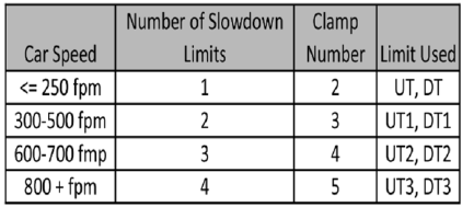
The number of slowdown limits depends on the
speed of the car as show in the table below:
Table 6.1: Slowdown Clamps
6.34 Verify Inspection Velocity Clamp On Safety
Processor Board
Place the car on inspection operation. From the
1066 LCD interface, navigate to the "Adj Var"
menu,
"Ins Vel" and set the speed clamp velocity
to 25 fpm. From the 1021/1101/1005 LCD interface, navigate
to the "Adjustable Variables" menu, "Car
Motion" and set the "Inspect Speed" to 50 fpm.
Run the car in
either direction and verify that the
car shuts down when the speed rises above 25
fpm.
From the 1066 LCD interface, navigate to the "Adj
Var" menu, "Ins Vel" and set the speed clamp to
140
fpm. From the 1021/1101/1005 LCD interface, navigate
to the "Adjustable Variables" menu, "Car
Motion" and set the "Inspect Speed" to the
desired value.
6.35 Analog Load Weigher Setup
If the job uses an analog load weigher purchased
from G.A.L., complete the following procedure.
NOTE: It is recommended using two people, one
moving the weights and one in the machine room
to set
up the load weigher.
Mount the load weigher as described by the
manufacturer. The load weigher control box will
also
contain a board supplied by G.A.L. that
connects to the controller serial CAN bus and
reads in the analog
output from the load
weighing device. Wire the load weigher and G.A.L. board according to the
controller
schematics.
Calibrate the load weighing device hardware
according to the manufacturer’s instructions.
Following
proper installation of the load weighing
device, proceed to Section 6.36, Empty Car
Setup.

P a g e | 115
DC Quattro Drive
6.36 Empty Car Setup
Verify that the load weighing device is
communicating to the main CPU by performing
the following
steps. From the 1021/1101/1005 LCD interface,
navigate to the "Diagnostics" menu, "Car Comm
Status",
"Car to LW Board" and verify that "On‐
line = 1". If "On‐line = 0" then verify wiring and
installation of
load weighing device.
From the 1021/1101/1005 LCD interface, navigate to the
"Elevator Setup" menu, "Load Weigher
Setup",
"Setup Load Weigher" and follow the instructions
on the display as you go through the
procedure.
It is okay to exit the setup screen to place a call and then return to it while the setup is being
performed.
Run the car to the bottom floor and press Enter
on the 1021/1101/1005 LCD interface when prompted
to do so to start the automatic setup sequence.
If the car is at the bottom floor and the doors are
not closed (the doors will not close automatically
from
turning off the auto‐door switch) then place
a car call to run the car up one floor, then back
again. The
doors will close when the call is placed.
When the automatic sequence is activated, the
car will run to each floor and measure the empty
load
value. The 1021/1101/1005 LCD interface will indicate
when the sequence if finished.
6.37 Full Car Setup
The empty car setup must be successfully
completed to run the full load setup.
Once the empty car setup is complete, run to the
loading floor and set the "AUTO DOOR" switch to
the
"ON" position to allow weights to be loaded
on the car. With the car fully loaded, set the
"AUTO DOOR"
switch to the "OFF" position and
run the car to the bottom floor. Again if the doors
are not closed, make
a one floor run to force the
doors to close.
With the car at the bottom floor, follow the LCD
interface instructions to press enter to start the
full
load setup sequence. The car will
automatically run to each floor and measure the
full load value. When
the full load measurement
is complete, the car can be run to the loading
floor and the weights
removed.
After the weights are removed, cycle the doors to
complete the procedure. From the 1021/1101/1005
LCD interface, navigate to the "Elevator Setup" menu, "Load Weigher Setup", "View/Modify LW Setup"
and verify the load weigher status, "LW Device
Stat: ON OK". If the status is "ON OK", then the
load
weigher should be accurately measuring the
car load in real time. The percent load will be
displayed,
"Load: %".
The percent load values for different service
options can now be set. From the 1021/1101/1005 LCD
interface, navigate to the "Adjustable Variables"
menu, "Service Options", and set the following
variables:
"Load Bypass"
"Load Antinuisance"
"Load Dispatch"
"Load Overload"
NOTE: Setting the values of the variables above
to 0% will disable that particular option.
6.38 Load Weighing Calibration Sequence
The load weigher is automatically calibrated once
each week. If an error is detected during this
calibration sequence, the load weigher and the
pre‐torque feature (if used) is disabled.
A load weighing calibration sequence can be
manually activated by performing the following
procedure.
From the 1021/1101/1005 LCD interface,
navigate to the "Elevator Setup" menu, "Load
Weigher Setup",
"Load Weigher Calibration" and
follow the instructions on the display.
6.39 Adjust the Motor Pre‐torque
NOTE: The motor pre‐torque uses the load value
obtained from the analog load weigher and will
only
work if the load weigher has been installed
properly, and the "Load Weigher Setup" has been
performed
successfully.
On the Quattro drive under User Switches C1
parameter, set Pre‐Torque source to serial. Run
the empty
car to a middle floor. From the 1021/1101/1005 LCD user interface, navigate to the "Adjustable
Variables" menu, "Car Motion" and adjust the
following parameters:
"Balanced Load = 40" (typically car is 40%
counterbalanced, but verify counterbalance

P a g e | 117
DC Quattro Drive
percentage for each specific job)
"Torque Amount = 10"
"Pattern Delay = 2.5"
"Brake Pick Del = 0.1"
The long pattern delay will allow an exaggerated
amount of roll back in order for the pre‐torquing
to be
set accurately. Make a one floor run down
and observe the roll back when the brake picks at
the start of
the run. Increase the "Torque
Amount" variable and continue to monitor the
roll back while performing
one floor runs in the
down direction. As the "Torque Amount" is
increased, the roll back should be
minimized until
the car will hold zero speed for the entire
"Pattern Delay" time. A typical value for the
"Torque Amount" is 40%. If the value is too large,
the car will roll forward during the "Pattern
Delay"
time.
NOTE: The pattern delay must be at least 0.15
seconds (150 milliseconds). Setting the torque
amount
to 0.00 will disable the pre‐ torque
feature. Also if the load weighing calibration
sequence detects a load
weighing error, the pre‐
torque feature is also automatically disabled.
6.40 Verify the Doors Are Safe
The elevator should now be adjusted. Verify that
all door locks, gate switches, and safety circuits
are
operational. Set the "INS" switch to the
"NORM" position and set the "AUTO DOOR"
switch to the "ON"
position. The elevator should
level into the floor and open the doors. If the
doors do not open, check
the door operator
wiring and cam adjustment. If the doors do open,
the elevator is now on independent
service.
6.41 Fine Tune the Ride Quality
Ride the elevator and evaluate the ride quality.
Fine tune the ride quality by navigating to the
"Adjustable Variables" menu, "Car Motion" and
adjusting the variables shown in Figure 6.2. Keep
in
mind that if acceleration or deceleration values
are changed, the speed clamps for the safety
processor
board and the S‐curve board may need
to be re‐adjusted.
To fine tune the floor level accuracy, determine if
the controller is set to stop when "UL" and "DL"
signals
turn on, or if controller is set to stop off of
the position count. From the 1021/1101/1005 LCD interface,
navigate to the "Adjustable Variables" menu,
"Car Motion" and view the "Stop On Pos Cnt" variable.
If “Stop On Pos Cnt= 0” then the controller is set to stop when the "UL and "DL"
signals turn on. If
"Stop On Pos Cnt = 1" then the
controller is set to stop on a combination of the
floor level magnet and
the position count.
With "Stop On Pos Cnt = 0", the floor levels
should be set by adjusting the floor level magnet
at each
floor. For proper operation, the floor
magnets should be set to exactly floor level. After
the floor levels
are set properly, perform another
hoistway learn procedure.
With "Stop On Pos Cnt = 1", the floor levels are
set by using both the floor magnet and the
position
count. For proper operation with this
setting, the floor magnet should be set to exactly
floor level. The
final stop can then be fine‐tuned
by performing the following adjustments.
From the 1021/1101/1005 LCD interface, navigate to the
"Hoistway Tables" menu, "DZ & LZ Offset, Sel
Cnt" and adjust "Dn Lev Dist" and "Up Lev Dist".
The units for these variables are in "pulse
counts". With
"Stop On Pos Cnt =1" the car will continue to move for the "Dn Lev Dist" or "Up Lev
Dist" after "UL and
DL" turn on. Use the "Dn Lev
Dist" and the "Up Lev Dist" parameters to make
level changes at all floors.
To make level changes at individual floors,
perform the following adjustments. From the
1021/1101/1005 LCD interface, navigate to the "Hoistway
Tables" menu, "FL and FL Offset Count", and
the
offset count can be adjusted. These variables
introduce an offset (+/‐) to the stored floor count
that
was determined in the hoistway learn
procedure.
NOTE: The number of pulse counts per inch can be viewed from the 1021/1101/1005 LCD interface,
"Hoistway Tables", "DZ & LZ Offset, Sel Cnt”,
"Pulses /Inch".
NOTE: Regardless if "Stop On Pos Cnt=0" or if "Stop On Pos Cnt =1", the floor magnet must be set
properly at floor level. If too large of values are entered into "Dn Lev Dist", "Up Lev Dist", or "Offset", the
car will drive past the floor level magnet and re‐level.
Check all signal devices for proper operation and remove all temporary jumpers. The adjustment should
now be complete.

P a g e | 119
Combivert F5 AC Drive
Section 7 ‐ Adjustment of the GALaxy Combivert F5 AC
Drive
7.1 General Setup
In order to obtain a running platform in "car top
inspection", see the "Quick Start‐up Guide for
GALaxy
Controller KEB Combivert F5 AC Drive - PM Gearless" if using a pmac gearless machine. If using a
geared machine with an induction motor, see the "Quick Start-up Guide for GALaxy Controller KEB
Combivis F5 Drive AC Geared". This procedure should
be used only for installation purposes. When
installation of all equipment is complete, and unit
is ready for adjustment, proceed to Section 7.2, Check
Main Line Voltage,
and follow instructions.
Before adjustment begins the following items
must be completed.
1. All field wiring and safety circuits installed
2. Temporary jumpers from terminal “HC” to
terminals “MES & ALT”
3. All hoistway limit switches installed
4. All car and hoistway doors and interlocks
installed and pre‐adjusted
5. Selector installed and magnets pre‐adjusted
6. Familiarize yourself with all wiring schematics
7. Familiarize yourself with the KEB Combivert
F5 Elevator Drive Technical Manual.
8. Verify that the motor is properly
wired.
9. Verify that the encoder is connected properly.
10. Car should be properly counterbalanced.
7.2 Check Main Line Voltage
With main‐line disconnect in the off position,
check the line‐side voltage with a volt meter to
insure the
voltage matches the controller name
tag “Input Power” voltage. Check to insure all
three phases are
present. If voltage is not correct
or all three phases are not present, do not
proceed until corrected.
7.3 Set Toggle Switches
Set all toggle switches on the 1064 board as
follows:
DOOR LOCKS ‐ "OFF"
IND ‐ "IND"
AUTO DOOR ‐ "OFF"
STOP ‐ "STOP"
7.4 Make Sure the Car Is Safe
Verify that all elevator doors are closed and that
all safety circuits are functional.
7.5 Check Controller Voltage
Turn the main‐line disconnect to the on position.
Check the voltage at R, S, and T on the AC drive.
Verify
that all three phases are present. Check
the voltage at fuses L1 and L2 on controller. If
correct, check
the voltage at terminal “LIN” with respect to “GND”. The voltage should read 120VAC. If correct,
check the voltage at terminals
“S10, LC, & HC” with respect to “GND”. All should
read 120VAC. If not,
check wiring diagram to
determine problem before continuing.
7.6 Verify the Main CPU is Operating
Check to make sure that the “axy” of GALaxy on
the 1021/1101/1005 LCD interface is blinking. If the
“axy” is
blinking, continue to the next step. If not, check
voltage at terminals 5V to 0V on the 1064 board
to insure 5VDC. If 5VDC is present and the “axy”
on the 1021/1101/1005 LCD interface is not blinking,
then
contact factory.
7.7 Preset Adjustable Variables On Safety
Processor Board And Main CPU
The safety processor (1066) board is normally
preset prior to leaving the factory; however, it is
prudent
to check the setup values for the proper
settings. Refer to Section 13 of this manual for the
operation of
the safety processor board 1066 LCD
interface. The following adjustment variables
must be set properly.
NOTE: If the controller uses an NTS board please refer to Section 14, GALX-0320AN NTSD Board.
7.8 1066 LCD interface "Adj Var" Menu
Top Spd (contract speed)
Enc RPM (if Fdbk Typ=0, not applicable) (if Fdbk
Typ=1, set to rpm of governor) (if Fdbk Typ=4,
set
to value of LF.11 in KEB drive)
Enc PPR (if Fdbk Typ=0, not applicable) (if Fdbk
Typ=1, set to 8192) (if Fdbk Typ=4, set to 2048)
Fdbk Typ (0=tape, 1=enc, 4=IncEnc)
Ctrl Typ (2=Tract DF)
2 Stop (0=Mult, 1=2 stop)

P a g e | 121
Combivert F5 AC Drive
RearDoor (0=Front only, 1=Rear)
UTS Vel (Set to top speed)
DTS Vel (Set to top speed)
INS Vel (Set to 140)
LEV Vel (Set to 140)
UT Vel (Set to top speed)
DT Vel (Set to top speed)
UL Vel (Set to 160 if Non‐DF)
DL Vel (Set to 160 if Non‐DF)
SoftStop (Set to 3)
NOTE: The velocity values for the terminal limit
switches above are only temporary settings until car is
running high speed. In the final adjustment
procedure, these variables must be set according
to the
procedures in Section 7.31, Adjust Safety Processor Board Speed Clamps.
7.9 1021/1101/1005 LCD interface "Adjustable Variables -> Car Motion"
Submenu
Top Speed (set to contract speed)
Inspect Speed (set to 25 fpm)
Encoder PPR (set to 2048 PPR)
Encoder RPM (if tape selector, set to value of
LF.11 in KEB drive), (if 485 tapeless selector, set
to
value of LF.11 in KEB drive), (if CAN open
tapeless selector, set to governor rpm)
NOTE: See Section 7.24, Correct Car Speed When Using 485 Tapeless System, for determining
governor
rpm.
7.10 Place Stop Switch in Run Position
Set the “STOP” toggle switch on the 1064 board
to the “RUN” position. Verify that input LED’s for
“LC,
HC, DN, UN, SS, GTS, RDY and CS” are all on.
If not, then correct field wiring.
7.11 Hoist Motor Data
At this time the hoist motor data must be entered
into the AC drive. The following functions must
be
entered or verified using the drive "Operator"
display unit. Follow the instructions in the
Combivert F5
drive manual to enter the following
data:
Motor Data
US.10 ‐ Motor type configuration (for pm sync gearless set to P9LSS), (for pm sync geared set to
PCLSd), (for induction motor with geared machine set to ICLSd).
US.83 - Encoder PPR output from drive (set to 1)
US.4 – Load (Perform configuration load.)
LF.10 ‐ Motor HP ‐ Read only. Cannot be
entered. This is calculated from rated speed and
torque
for PM gearless configuration.
LF.2 ‐ (Set to "SErSP")
LF.11 ‐ Rated Motor Speed (from
machine/motor nameplate)
LF.12 ‐ Rated Motor Current (from
machine/motor nameplate)
LF.13 ‐ Rated Motor Frequency (from
machine/motor nameplate)
LF.14 ‐ Rated Motor Voltage (from
machine/motor nameplate)
LF.17 ‐ Rated Motor Torque (from
machine/motor nameplate, or LF.17 = HP * 5258 / LF.11)
Machine Data
LF.20 ‐ Contract Speed (from controller data)
LF.21 ‐ Sheave Diameter (in)
LF.22 ‐ Gear Reduction Ration (1 if gearless), (actual gear ratio if geared)
LF.23 ‐ Roping ratio (1:1 or 2:1)
LF.27 ‐ 2048 for EnDat encoder with pm ac gearless), (PPR of motor mounted incremental
encoder with geared traction)
LF.76 ‐ 8 (absolute encoder)
The number of poles is provided below if you
are using one of the following PM AC Gearless machines:
MAG05 = 66 poles
MAG10 = 66 poles
MAG15 = 66 poles

P a g e | 123
Combivert F5 AC Drive
Leroy Somer Z2 = 16 poles
Leroy Somer Z3 = 16 poles
Leroy Somer Z4 = 16 poles
Leroy Somer Z6 = 32 poles
Leroy Somer Z10 = 32 poles
Leroy Somer Z20 = 32 poles
Imperial 474 = 20 poles
Imperial 475 = 24 poles
Imperial 522 = 20 poles
Imperial 525 = 20 poles
Imperial 805 = 44 poles
Hollister Whitney = 28 poles
If you are not using one of the following PM AC Gearless machines listed above and need to calculate
the motor poles or
motor rated speed, use the following formula
based from the motor name plate
data:
Poles= 2 X 60 X Motor Excitation Frequency
(Hz)/Rated Motor Speed (RPM)
The number of motor poles will always be a
whole, even number.
Most of the drive parameters have been preset
to values required for your specific job. Other
parameters not listed here may need to be
adjusted in the field. Please refer to the Combivert
F5 manual for more parameter
information and troubleshooting guidelines.
7.12 Pre‐set the Digital Speed Clamps
Pre‐set the software digital speed clamps from
the 1021/1101/1005 LCD interface under the “Elevator
Setup
Menu”. The submenus for the clamp speeds are
as follows:
Set Ins /Leveling Clamp
Set DT/UT Slowdown Clamp
Set DT1/UT1 Slowdown Clamp
Set DT2/UT2 Slowdown Clamp
Set DT3/UT3 Slowdown Clamp
Set DTS/UTS Slowdown Clamp
Set the speed for Ins/Leveling for 140 fpm and all
the remaining slowdown limit speeds to the
contract
speed of the car. Please note that the
displayed value of “Clamp Speed” is the value the
clamp should
be set to. The slowdown limit
“Clamp Speed:” will show 0000 until the car is run
into the limits and the
speed is recorded. Please
refer to Section 10, 1021/1101/1005 LCD Interface, for the
Elevator Setup
Menu.
NOTE: The values of the clamp speed velocities
above are only temporary settings until the car is
running high speed. In the final adjustment
procedure, these values must be set according to
the
procedures in Section 7.32, Adjust Digital Slowdown Speed Clamps.
7.13 Adjust the Brake Voltage
If the controller utilizes an electronic brake board
1047 or 1051, then the brake voltage is adjusted
through the 1021/1101/1005 LCD interface, "Car Brake" sub‐
menu. If the controller utilizes resistors
and
rectifiers for the brake coil circuit, then the brake
voltage is adjusted by moving the adjustable tap
on the brake resistor.
NOTE: Remove power before adjusting the
resistor taps.
To adjust the brake voltage when using and
electronic brake board, navigate to the
"Adjustable
Variables" menu, "Car Brake" and
adjust "Brake Pick Volt", "Brake Hold Volt" and
"Brk AC L‐L Volt" to
the proper values.
7.14 Motor Learn Procedure
Lower the inspection speed on the controller to
zero. Remove one wire from the brake coil to prevent
the main brake from picking. If the unit has an emergency brake, the emergency brake and the
emergency brake switch must remain operational during the learn procedure. On the drive operator
keypad set parameter LF.3 to “S.Lrn”. Press Enter
and the drive keypad will display “Start”. Press
and
hold the up or down inspection switch and the enable switch. You
will hear all the contactors (BRK, RUN
and MC)
pick and stay energized on the controller. The
drive operator keypad will change as a number of
motor measurements are made. This process
takes 2 to 5 minutes. When the drive operator
keypad
displays “Done”, release the up or down
inspection button. Return the wires back to the
main brake to
allow the brake to
pick again.

P a g e | 125
Combivert F5 AC Drive
7.15 Encoder Learn Procedure, v1.62 (Unroped
machine)
NOTE: This procedure is not required for geared traction using an induction motor.
If you are using v1.62 on the Combivert F5 drive,
the encoder position must be learned with the
ropes
removed from the machine. From the 1021/1101/1005 LCD interface, navigate to the "Adjustable
Variables" menu, "Car Motion" and set the
"Inspect Speed = 0". Verify the motor wiring from
the drive
to the motor, U to U, V to V and W to W. Verify that drive parameter 2.LF.26 = “Conn”.
This parameter
indicates that serial
communication is established between the
encoder and the drive. If 2.LF.26 does
not display
“Conn”, check the encoder wiring and drive
settings LF.26, LF.27, LF.28, and LF.29. This
problem must be rectified before proceeding.
Once communication is established with the
encoder, set
LF.3 to “P Lrn” and press enter on
the drive operator keypad. The drive operator
keypad will display
“Start”. Press and hold the
"UP" or "DN" inspection button. The motor
sheave will begin to move back
and forth and the
drive display will display a numeric value. If the
sheave begins to move, but an E.EnC1
error
occurs on the drive, the drive will swap the
encoder channels in LF.28 automatically and then
display “retry”. Press and hold the "UP" or "DN"
inspection button again. If the sheave does not
move
and an E.EnC1 occurs, verify the brake is
picking and the sheave is able to move freely.
When
sheave is able to move freely, perform "P
Lrn" again. If this does not resolve the problem,
try swapping
output motor phases and try the "P
Lrn" procedure again. When the process is
complete the sheave will
stop rotating and the
drive will display “done” and the "UP" or "DN"
inspection button can be released.
Make a note
of LF.77 value which is the learned encoder
position value. Return the "Inspect Speed" on
the 1021/1101/1005 LCD interface to the previous setting, and
set the drive parameter LF.3 to "run".
Important: If the encoder is removed, absolute
position will need to be relearned!
7.16 Encoder Learn Procedure, v1.72 (Unroped
or Roped machine)
NOTE: This procedure is not required for geared traction using an induction motor.
If you are using v1.72 on the Combivert F5 drive
you can learn the encoder position with or
without the
ropes removed from the machine.
From the 1021/1101/1005 LCD interface, navigate to the
"Adjustable
Variables" menu, "Car Motion" and
set the "Inspect Speed = 0". Verify the motor
wiring from the drive
to the motor, U to U, V to V
and W to W. Verify that drive parameter 2.LF.26
= “Conn”. This parameter indicates that serial
communication is established between the
encoder and
the drive. If 2.LF.26 does not display
“Conn”, check the encoder wiring and drive
settings LF.26, LF.27,
LF.28, and LF.29. This
problem must be rectified before proceeding.
Once communication is established
with the
encoder, set LF.3 to “SPI” and press enter on the
drive operator keypad. The drive operator
keypad will display “Start”. Press and hold the
"UP" or "DN" inspection button. The drive will
take ten
encoder position samples. When the
process is complete the drive keypad will display
“done” and the
“UP” or “DN” inspection button
can be released. Make a note of LF.77 value
which is the learned
encoder position value.
Return the "Inspect Speed" on the 1021/1101/1005 LCD
interface to the
previous setting, and set the
drive parameter LF.3 to "run". After making a trial
run, if the current in
LF.93 is excessive, change the value in LF.28 from 0 to 1 or from 2 to 3 and
repeat the process.
Important: If the encoder is removed, absolute
position will need to be relearned!
7.17 Check Inspection Speed
If the ropes have been removed from the sheave,
adjust the following drive parameters to the
values
listed below prior to running on inspection
speed. If the ropes are on the sheave leave these
drive
parameters at the initial settings listed
below.
Change A.LF.31 from 3000 to 300
Change d.LF.31 from 3000 to 300
Change A.LF.32 from 350 to 50
Change d.LF.32 from 250 to 50
Change A.LF.33 from 3000 to 0
Change d.LF.33 from 1000 to 0
Make sure that on the drive parameter LF.3 is set
to “run”. From the 1021/1101/1005 LCD interface,
navigate
to the "Adjustable Variables" menu, "Car
Motion" and set the "Inspect Speed = 25". Run
the
elevator on inspection, and verify that there
is zero current draw in LF.93. Press the “UP”
inspection
button and verify motor is rotating in
the up direction, and then press the “DOWN”
inspection button
and verify that the motor is
rotating in the down direction. If not, then
change LF.28 from 0 to 2 or
from 1 to 3 and re‐
verify direction. If LF.28 is changed, you must
relearn the encoder if using a PM AC
Gearless machine. With a hand held
tachometer, check the speed of the elevator
while running on
inspection. The elevator should
be running at 25 fpm.
From the 1021/1101/1005 LCD interface, select the "Elevator
Status" menu; navigate until the display
shows
"Dmd" and "Vel". While running on inspection,
monitor the controller demand speed "Dmd",
and
the speed feedback "Vel". These values
should both display 25.
If the demand and feedback on the 1021/1101/1005 LCD
interface is incorrect, check the Encoder
RPM and
PPR parameters from the “Adjustable Variables”
menu. These variables should be set to
values
listed in Section 7.9, 1021/1101/1005 LCD interface "Adjustable Variables -> Car Motion" Submenu.
If the speed on the hand held tachometer and on
"Dmd" and "Vel" all read 25 fpm (within +/‐ 2
fpm),
continue to the next step. If not, contact
the factory.

P a g e | 127
Combivert F5 AC Drive
7.18 Verify Controller Encoder Direction
From the 1021/1101/1005 LCD interface "Elevator Status"
menu, navigate to display "Dir" and "DP".
While
moving the car on inspection, monitor "Dir"
(direction) and "DP" (pulse counts). "Dir" should
display "Up" when the car is moving up, and "Dn"
when the car is moving down. The value of "Dp"
should
increment when the car is moving up, and
should decrement when the car is moving down.
If the direction is wrong or the pulse counts
change in the wrong direction, then the encoder
direction
to the controller must be changed.
On the encoder isolation board (1022N), move J1
and J3 on the encoder board. Refer to the jumper
diagram on the board.
J1 swaps A & A NOT – J3 swaps B & B NOT.
If the encoder is counting properly and the ropes
were removed from the sheave, then set
the
following drive parameters back to their
original settings.
A.LF.31 to 3000
d.LF.31 to 3000
A.LF.32 to 350
d.LF.32 to 250
A.LF.33 to 3000
d.LF.33 to 3000
Replace the ropes and proceed to Section 7.19, Run The Car On Inspection With The Ropes On The
Sheave Of The Motor.
If the encoder is counting properly, and the ropes were not removed, proceed to Section 7.19, Run The
Car On Inspection With The Ropes On The Sheave Of The Motor.
If the encoder is not counting properly, contact G.A.L. Technical Support.
7.19 Run The Car On Inspection With The Ropes On
The Sheave Of The Motor
7.20 Ready to Run On Inspection
From the 1021/1101/1005 LCD interface, navigate to the
"Adjustable Variables" menu, "Car Motion”
and
verify that "Inspect Speed = 25". Before moving
the car on inspection, verify again that all door
locks, gate switches, safety circuits, and limit
switches are functioning properly.
The car should be ready to run on inspection if all
is wired correctly. Select the “Elevator Status” on
the
1021/1101/1005 LCD interface. The display should show
“Out of Service” on the first line and
“Inspection Mode” on the second. The 1066 LCD interface
will display one of the following types of
inspection:
“MR INS” (Motor Room)
“CT INS” (Car Top)
“ACCESS” (Access)
“IC INS” (In Car)”
“AUTO” (Not on Inspection)
To run the car from the motor room, “MR INS”
should be displayed.
The “inspection string” consists of contacts from
the inspection switches and the gate and lock
bypass
switches in series. One and only one of the
five inspection inputs should be on for the car to
run. Starting
from the car top inspection input,
the five inspection inputs are, “INS” for car top,
“ACC” for access,
“ICI” for in‐ car, “MRI” for
motor room, and “AUTO” for automatic (no
inspection). The inspection string
circuit is shown
in Figure 7.1.
NOTE: Any one of the following conditions will
cause an inspection error:
More than one inspection input is on
No inspection input is on
Gate or Lock bypass switch is open and the car
is not on car top inspection
If the controller is not on motor room inspection
at this point, then verify all switch positions and
wiring
before proceeding.
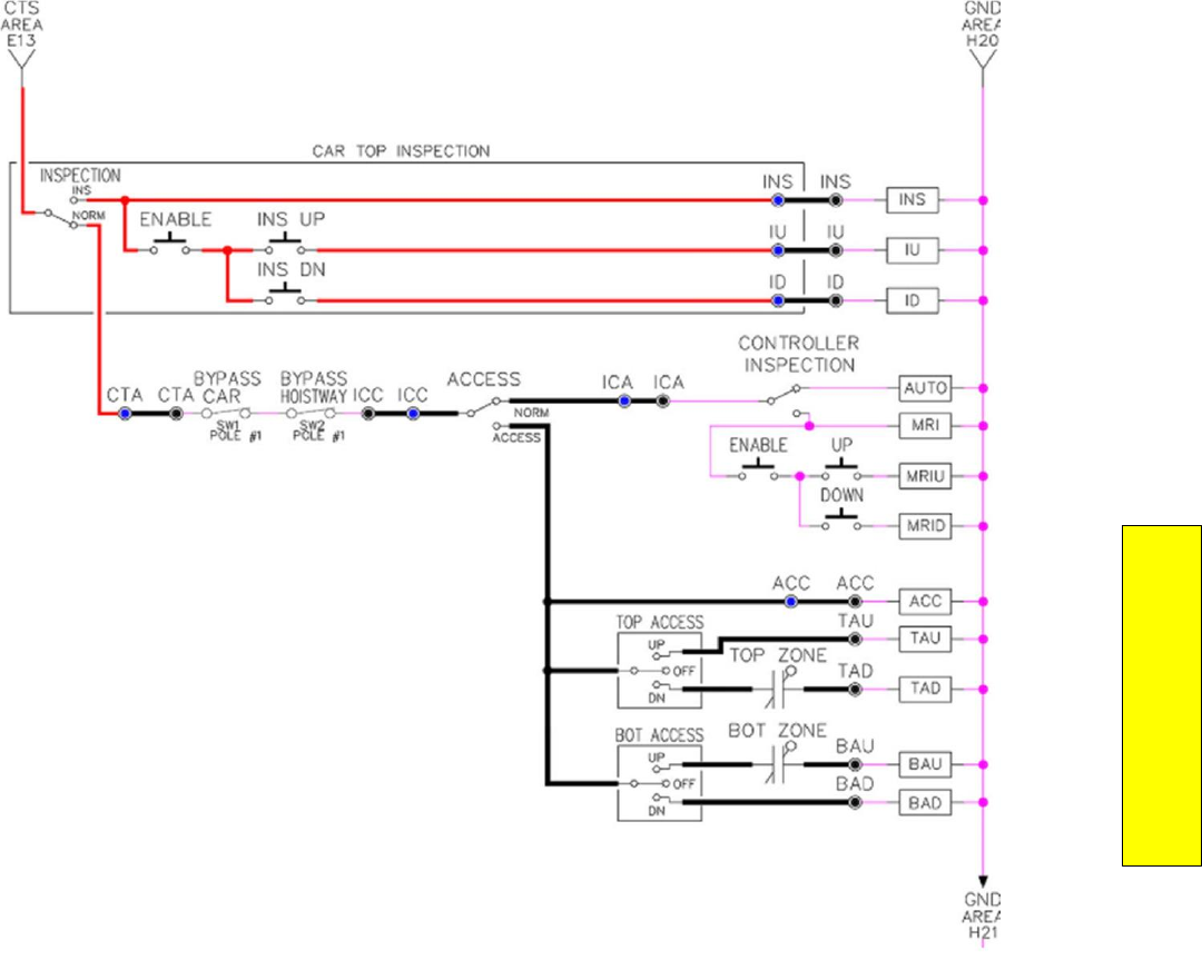
P a g e | 129
Combivert F5 AC Drive
Figure 7.1: Inspection String Circuit
7.21 Verify Selector and Slowdown Inputs
Run the elevator up on inspection until it stops on
the up normal limit. The up and down normal
limits
should be set two inches above and below
the terminal floors respectively. Verify the
selector inputs
are being set properly on the
controller by running the elevator down until it
stops on the down normal
limit.
As the car approaches floor level going down,
“DL” turns on first, then “DZ” and then finally
“UL”. At
floor level, “UL, DL, and DZ” inputs
should all be on at the same time. Leaving the
floor going down
“DL” will turn off first, then “DZ”
and last “UL”.
Also verify that the up and down terminal
slowdown limits inputs “UT, UTS, DT & DTS” are
breaking at
the proper distances as shown in the slowdown table 2.0. “UT, UTS, DT & DTS” turn off
when active.
7.22 Verify Car Speed on Safety Processor Board
Run the car in either direction and check the car
speed on the 1066 LCD interface. The speed
shown
should match the car’s actual speed. If the
speed does not match and the secondary
feedback comes
from pulses from the tape go to
“Correct Car Speed When Using A Tape”. If using
485 tapeless, go to
"Correct Car Speed When
Using 485 tapeless". If using CAN Open tapeless,
go to "Correct Car Speed
When Using CAN Open
tapeless". If the correct speed is shown proceed
to Section 7.26, Learn The
Hoistway.
7.23 Correct Car Speed When Using a Tape
The tape has holes every 3/8” that are 3/8” in
diameter. On the selector unit adjust the PP
sensor closer
to the tape until the orange LED at
the end of the sensor turns on. Then turn the
sensor inwards
another 1/8” and lock in the
sensor. While running on top of car inspection
verify that the orange
LED at the end of the PP
sensor turns on and off as it passes by the holes
on the tape. The safety
processor board on the
controller measures the time between each pulse
to calculate the velocity. If the
velocity is not
displayed correctly first make sure that the
feedback type in the safety processor board
adjustable variable is set to 0 for a tape
application. Next, while the car is running, make
sure that the
PULSE LED on this board is pulsing.
As the car increases in speed the LED will glow
solid on. If the LED
does not pulse, try swapping
the wires at the PPS and PP terminals. If the LED still does not work,
contact the factory. If the
correct speed is shown proceed to Section 7.26, Learn The Hoistway.
7.24 Correct Car Speed When Using 485
Tapeless System
When using the 485 tapeless system, the
secondary speed feedback comes from the
encoder mounted
on the governor. The 1066
board uses a serial interface to a Turck absolute
encoder, part #
T8.5882.3F0B.3001.
In the 1066 LCD interface "Adj Var" menu, set the
"Fdbk Typ = 1", and set the "Enc PPR = 8192". The
"Enc
RPM" value must be calculated as described
below. To calculate the RPM, divide the contract
speed of
the car by the distance travel in one
revolution with the governor as shown below:
RPM = Speed fpm/(diameter GOV * pi)
For a 1 ft. diameter governor:
RPM = 350 / (1*pi) = 350/3.1415 = 111.4

P a g e | 131
Combivert F5 AC Drive
For a 16 in diameter governor (16/12 = 1.33ft):
RPM = 350/ (1.33* 3.1415) = 350/4.188 = 83.5
7.25 Correct Car Speed When Using CAN
Open Tapeless System
When using the CAN Open tapeless system, the
secondary speed feedback comes from KEB drive
parameter US.83 and is normally set to "1" which
is 2048 ppr (US.83 set to "0” is 1024 ppr).
In the 1066 LCD interface "Adj Var" menu, set the
"Fdbk Typ = 4", and set the "Enc PPR" equal to the
ppr
from the KEB drive parameter US.83, and set
the "Enc RPM" to the nameplate rpm of the
machine/motor which should be the same value
of parameter LF.11 in the KEB drive.
On the 1066 LCD interface, navigate to the "Pls
Cnt" menu. While running the elevator on
inspection,
verify that the pulse count value
increments when running up and decrements
when running down. The
"Pls Cnt" value can be
considerably out of range but will automatically
correct during the "Learn
Hoistway" procedure.
To reverse the direction of pulse counting,
navigate on the 1066 LCD interface to
the "Adj
Var" menu, "Enc Dir" and set to "0" for clockwise
or "1" for counter‐clockwise.
Navigate on the 1066 LCD interface to the "Car
Spd" menu. Monitor the "Car Spd" while running
the car
at a known inspection speed. The value
displayed should match the actual car speed
measured with a
hand held tachometer. If the
speed is correct, proceed to Section 7.26, Learn The Hoistway.
7.26 Learn the Hoistway
Run the elevator down on inspection until it stops
on the down normal limit switch. Verify that the
“DN
and DL” input LED’s are both off and that the
"UL" and "DZ" LED's are on. From the 1021/1101/1005 LCD
interface navigate to the "Elevator Setup" menu,
"Learn Hoistway". The learn procedure can be
performed automatically by choosing "Auto"
from the menu items, or performed manually by choosing
"Insp” from the menu items. After
choosing the learn method, follow the
instructions displayed on
1021/1101/1005 LCD interface.
In general, the car will run up from the "down
normal limit" to the "up normal limit" at 30 fpm.
During
this learn run, the DP count for each floor
level and each limit switch will be stored in
memory.
NOTE: The car must run the entire hoistway
without
stopping.
As the elevator moves up the hoistway, navigate
to the "Hoistway Tables" menu, "Disp/Mod
Hoistway
Table", and verify that the "DP" count is
incrementing as the elevator moves up. Also as
the elevator
passes each floor, the pulse count
and distance for that floor should change and be
stored. Verify that
the floor distances are valid.
The pulse count for the terminal slowdowns will
also be stored. The
elevator will stop when it
reaches the up normal limit. Follow the
instructions on the 1021/1101/1005
LCD interface by putting
the car on inspection, and then the message
"Hoistway Learn Complete"
should be displayed.
Move the elevator on inspection until the “DZ
and DL” LED’s are on. Set the “INS” toggle switch
on
the 1064 board to the “NORMAL” position,
and the elevator should level down to floor level
at the top
floor. If so, proceed to final
adjustment.
If the car levels down but does not run, then
check “Elevator Status” and “View Fault Log” on
the
1021/1101/1005 LCD interface for any fault information.
Correct items causing faults and perform
hoistway learn again. After problem is corrected, and a successful hoistway learn is performed,
proceed
to final adjustment.
7.27 Automatic Run
The elevator should now be sitting idle at the top
floor. The "AUTO DOOR" switch should be set to
the
"OFF" position and the "IND" switch should
be set to the "IND" position. If the learn
procedure was
successful, the elevator should be
ready to make an automatic run.
The default parameter settings for the ride
quality should be adequate for an initial run.
From the
1021/1101/1005 LCD interface navigate to the "Set
Calls and Lockouts" menu, "Setup Car Calls" and
enter a car call. The elevator should run to
answer the call. When the elevator levels in and
stops at the
floor, the doors will remain closed.
At this point the acceleration and deceleration of
the car should be smooth and stepless regardless
of the
distance of run.
The high speed of the car should be verified. To
fine tune high speed, make high speed runs while
monitoring parameter LF.90 on the drive. The
display should read contract speed.
If the speed is slightly under or over contract
speed, then verify that parameter LF.11 is set
properly. The
speed displayed on the drive
should match the speed displayed on the 1021/1101/1005 LCD interface,
"Elevator Status" menu, "Dmd"
and “Vel". This speed should also match the speed displayed on the
1066 LCD interface, "Car
Spd" menu. If LF.11 is changed, then go to the
1021/1101/1005 LCD
interface, "Adjustable Variables" menu,
"Car Motion" and change the value of "Encoder
RPM" to match
the drive. When all of these
speeds are the same (+/‐ 2 fpm), then proceed to
the next step.

P a g e | 133
Combivert F5 AC Drive
7.28 Fine Tune the Ride Quality
NOTE: A.LF.xx' parameters refer to gains during
acceleration and also high speed.
In order to fine tune the ride quality, refer to
Figure 7.2 which describes what part of the S‐
curve
that the different parameters effect. In
general, higher numbers in the given parameters,
cause quicker
and more abrupt changes from one
mode to the next during a run. All of the S‐curve
parameters have a
minimum and maximum
value. The controller will not allow you to enter
values that are not valid.
In some instances, the response of the drive may
need to be adjusted so that the drive will properly
follow the S‐curve (demanded speed) from the
controller. The response of the drive can be
increased by
adjusting the gain parameters in the
drive. Preliminary adjustments can be made to
the following
parameters to increase the
response.
Proportional gains ‐ A.LF.31 and d.LF.31Integral
gains ‐ A.LF.32 and d.LF.32 Integral offset gains ‐
A.LF.33
and d.LF.33 (offsets added to the integral
gains for more control at low speeds). The
complete
description of these parameters and
their effect on the control and ride quality can be found in the KEB
drive manual. In general, the "A"
parameters affect the acceleration gains and the
"d” parameters affect
deceleration gains. Lower
values make the drive less responsive, and higher
values make the drive more
responsive. As the
gains are increased, the drive will cause the
motor to follow the S‐curve more closely.
If these
values are increased too much, vibrations and
audible noise may occur in the motor.
After the car is running high speed with an
acceptable ride quality, it is recommended to
perform a
"System Inertia Learn" on the KEB
drive in order to provide optimum drive
performance. This procedure
is outlined in the
KEB manual. After this procedure is completed,
the "Feed Forward Torque Control”
FFTC will be
enabled in the drive. With the FFTC active, the
drive gains listed above can be reduced,
and the
drive will still follow the S‐curve from the
controller. This is helpful if the higher values of
the
gain parameters are causing vibration and
audible noise in the motor.
After performing the adjustments above the ride
quality during acceleration, high speed, and
deceleration should be good. If so, proceed to
Section 7.29, Adjust The Stop.
7.29 Adjust the Stop
When at floor level the “UL, DL, & DZ” input LEDs
should be on. If the elevator continually tries to
seek
floor level by leveling up and down, try the
following steps to correct the problem:
Reduce the leveling and re‐leveling v e l o c i t y parameters from the 1021/1101/1005 LCD interface
"Adjustable Variables" menu, "Car Motion",
"Leveling Speed" and "Relevel Speed".
If the car still oscillates, adjust the "floor level
zone" on the selector. The "floor level zone" is
increased by moving the "UL" and "DL" sensors
closer together.
If the car stops hard on the brake, then make the
following adjustments. From the 1021/1101/1005 LCD
interface navigate to the "Adjustable Variables"
menu, "Car Motion", and adjust both "Brake
Drop Del"
(brake drop delay) and "Soft Stop
Time". These variables should be adjusted so that
zero speed is
observed at the end of the run prior
to the brake setting. The controller should hold
the car at zero
speed for the duration of the "Soft
Stop Time" which should continue while the
brake is setting and for
a short time after the
brake sets.
The soft stop time MUST be set to at least 0.5
seconds LONGER than the brake drop delay.
The "Soft Stop Time" setting in the 1021/1101/1005 LCD
interface should be compared with the setting
in
the 1066 LCD interface "Adj Var" menu,
"SoftStop". The setting of "SoftStop" in the 1066
LCD
interface should be greater than the "Soft
Stop Time" setting in the 1021/1101/1005 LCD interface.
If the car spots when approaching the floor, the
cause is usually due to the car not tracking (the
drive
response is set too low) or the speed profile
into the floor is too aggressive. First try to
increase the
response of the drive, see Section
7.28, Fine Tune The Ride Quality.
If the car still spots, increase the floor targeting distance and retest the ride. The default value for
the
floor targeting distance is 12 inches. Increase
it by steps of 2 or 3 and continue retesting until the
parameter is adjusted to 18. If no change is
noticed, start again from 12 and decrease the
value.
The deceleration rate can also be reduced to help
remove the spotting. Proceed with adjusting the
start
once the proper stop is achieved.
7.30 Adjust the Start
To provide a proper start, from the 1021/1101/1005 LCD
interface, navigate to the "Adjustable
Variables"
menu, "Car Motion" and adjust "Brake Pick Del"
(brake pick delay), "Pattern Delay", and
"Soft
Start Jerk". Initially, set the brake pick delay to 0
and increase the pattern delay by 0.1 seconds
until the controller picks the brake completely
before the motor starts to move. If roll back
occurs, then
reduce the pattern delay until there
is no roll back. Sometimes, the timing works out
better if the brake
pick delay is set to 0.1 second.
In order to provide a smooth start with no roll
back and without feeling the car move under the
brake, it may be necessary to utilize the motor
pre‐torque feature. There are two pre‐ torque
options.

P a g e | 135
Combivert F5 AC Drive
The first option is using a load‐ weighing
device described in Section 7.34, Analog Load Weigher Setup.
The second
option is using the KEB drive’s Synthetic Pre‐
Torque" feature. To enable the "Synthetic Pre‐
Torque" option, set LF.30 = 5 in the KEB drive.
During the "Synthetic Pre‐Torque" sequence, the
KEB drive introduces a high gain for a very short
time
period immediately after the brake picks
and clears the machine drum or rotor. In order for the feature
to work properly, with no noise or
vibration, the timing and the gain values have to
be coordinated with
a high degree of precision.
In the first phase of the sequence, the drive uses
a "hold off" timer, US.17, to allow the machine
brake
to release prior to the high gain being
introduced. US.17 should be set to expire at
exactly the time the
brake clears the drum or
rotor. A typical initial value of US.17 = 0.2 sec. If
this timer expires before the
brake releases,
audible noise and vibration from the motor will
occur. If this timer expires after the
brake
releases, the car will roll back before the high gain
is introduced by the drive. The brake pick delay
timer may also need to be adjusted from the
1021/1101/1005 LCD interface, by navigating to the
"Adjustable Variables" menu, "Car Motion" and
adjusting "Brake Pick Del". In general, the value
of
US.17 will be greater than the value of "Brake
Pick Del".
In the second phase of the sequence, the drive
introduces the gain parameter, P.LF.32, after the
US.17
timer expires. The value of P.LF.32 should
be increased until the car is held at zero speed
when the
brake is released. Values as high as
20,000 are normal for parameter P.LF.32. If this
value is set too low,
the drive will not hold the
motor at zero speed when the brake releases. If
this value is set too high,
then audible noise and
vibration from the motor will occur. If audible
noise and vibration occur, it is
important to
determine if it is caused by P.LF.32 being set too
high, or if it is caused by US.17 expiring
before the
brake releases. Small increments (0.05 sec) to
US.17 can be made until roll back is
observed,
and then decreased again until there is no roll
back. By performing these small adjustments
in an iterative fashion, the correct setting
combination can be achieved.
Also during this second phase of the sequence, second timer, US.18, begins timing at the same point
that US.17 expires. The US.18 timer sets the duration that the P.LF.32 gain parameter is asserted. A
typical initial value for US.18 = 0.15 sec., but this value must be fine‐ tuned as well. As a general rule, the
value US.18 will be less than the value US.17 after the adjustment is complete. It is critical that the
pattern delay timer from the controller expires at exactly the same time that US.18 expires. To adjust
the pattern delay from the 1021/1101/1005 LCD interface, navigate to the "Adjustable Variables" menu,
"Car Motion" and adjust "Pattern Delay". If the "Pattern Delay" value is too short, then acceleration will
be demanded from the controller while the high gain is being asserted and vibration and noise from the
motor will occur. If the "Pattern Delay" is set too long, then roll back will occur after US.18 expires. In
general, the value of "Pattern Delay" will be greater than the sum of the values of US.17 and US.18.
Again, by performing small adjustments in the iterative fashion described above, the correct setting
combination can be achieved.

After the "Synthetic Pre‐Torque" is set properly, the car will start smoothly with no roll back and without
feeling the brake. The soft start jerk rate can now be increased to provide a quicker transition from start
to constant acceleration.
From the 1021/1101/1005 LCD interface, navigate to the "Adjustable Variables" menu, "Car Motion"
and adjust the "Soft Start Jerk Rate”. The ride quality should now be acceptable.
Figure 7.2: Speed clamps
7.31 Adjust Safety Processor Board Speed Clamps
The 1066 Safety Processor Board monitors the speed of the elevator at the terminal landings
independently from the main CPU.
When the "UT, DT, UTS, and DTS" limit switches are activated, the 1066 board calculates the velocity of
the elevator and compares that velocity with a stored value of speed clamp. If the velocity when the
switch activates is greater than the speed clamp value, then the 1066 board will generate a fault that
stops the elevator.
To set the speed clamps, make a one floor run to the top floor.
After the car stops, record the velocity the car
hits the “UT, DT, UTS & DTS” slowdown limits.
“UTS
& DTS” are used on cars with reduced stroke
buffers or with a top speed greater than 200 fpm.
The
velocity value is shown from the “LIM VEL”
menu on the 1066 LCD interface.
P a g e | 137
Combivert F5 AC Drive
The velocity value shown on the display for the
“UT or DT” limit is the value after the car activates
the
limit then counts an adjustable number of
counts set from the 1066 LCD interface, "Adj Var"
menu,
"UT Count" or "DT Count". These count
values can be adjusted to provide adequate
distance,
following the limit switch activation, to
allow the elevator to begin its normal decel
pattern. The default
“UT Count" and "DT Count"
values are normally adequate. However, these
values may need to be field
adjusted to allow
enough distance for the car to begin its normal
decel pattern. If the "UT Count" and
"DT Count"
values are modified, the limit velocities must be
re‐checked.
Run the car again to the top repeatedly from 2
floors, then 3 floors, etc., until top speed is
reached.
From the 1066 LCD interface "Lim Vel"
menu, record the limit velocities displayed each
time the car
stops at the top floor. Make the
same runs to the bottom floor starting from 1
floor, then 2 floors,
then 3 floors, etc., until top
speed is reached. From the 1066 LCD interface
"Lim Vel" menu, record the
limit velocities
displayed each time the car stops at the bottom
floor. Take the highest speed value
recorded in
the runs above and add 20 fpm to that value to
use as the clamp speed values for the
respective
limit switches. Enter these clamp speed values
into the 1066 LCD interface "Adj Var" menu,
"UT Vel", "DT Vel", "UTS Vel", "DTS Vel" respectively.
7.32 Adjust Digital Slowdown Speed Clamps
Having just made several runs into the top and
bottom landings, the main CPU has also recorded
the
car’s velocity when the slowdown limits were
activated. If the car has been powered down
prior to this
step, several runs must be made to
the limits to allow the main CPU to record the
limit velocity
values.
From the main CPU LCD interface, choose
“Elevator Setup” and hit enter. Next choose
“DT/UT
Slowdown Clamp” and again hit enter.
From the 1021/1101/1005 LCD interface, navigate to the
"Elevator Setup" menu, "Set DT/UT Slowdown
Clamp" and view the speed displayed for "Clamp
Speed". Add 20 fpm to this "Clamp Speed" value
and
enter it into the "DT/UT Limit" value.
The number of slowdown limits depends on the
speed of the car as show in the table below:
Table 7.1: Slowdown Clamps
Adjust speed clamps for each slowdown limits
used as determined by the elevator’s contract
speed.
7.33 Verify Inspection Velocity Clamp on Safety
Processor Board
Place the car on inspection operation. From the
1066 LCD interface, navigate to the "Adj Var"
menu,
"Ins Vel" and set the speed clamp velocity
to 25 fpm. From the 1021/1101/1005 LCD interface, navigate
to the "Adjustable Variables" menu, "Car
Motion" and set the “Inspect Speed" to 50 fpm.
Run the car in
either direction and verify that the
car shuts down when the speed rises above 25
fpm.
From the 1066 LCD interface, navigate to the "Adj
Var" menu, "Ins Vel" and set the speed clamp to
140
fpm. From the 1021/1101/1005 LCD interface, navigate
to the "Adjustable Variables" menu, "Car
Motion" and set the “Inspect Speed" to the
desired
value.
7.34 Analog Load Weigher Setup
If the job uses an analog load weigher purchased
from G.A.L., complete the following procedure.
NOTE: It is recommended using two people, one
moving the weights and one in the machine room
to set
up the load weigher.
Mount the load weigher as described by the
manufacturer. The load weigher control box will
also
contain a board supplied by G.A.L. that
connects to the controller serial CAN bus and
reads in the analog
output from the load
weighing device. Wire the load weigher and G.A.L. board according to the
controller
schematics.
Calibrate the load weighing device hardware
according to the manufacturer’s instructions.
Following
proper installation of the load weighing
device, proceed to Section 7.35, Empty Car
Setup.
7.35 Empty Car Setup
Verify that the load weighing device is
communicating to the main CPU by performing
the following
steps. From the 1021/1101/1005 LCD interface,
navigate to the "Diagnostics" menu, "Car Comm
Status",
"Car to LW Board" and verify that "On‐
line = 1". If "On‐line = 0" then verify wiring and
installation of
load weighing device.
From the 1021/1101/1005 LCD interface, navigate to the
"Elevator Setup" menu, "Load Weigher
Setup",
"Setup Load Weigher" and follow the instructions
on the display as you go through the
procedure.
It is okay to exit the setup screen to place a call and then return to it while the setup is being
performed.

P a g e | 139
Combivert F5 AC Drive
Run the car to the bottom floor and press Enter
on the 1021/1101/1005 LCD interface when prompted
to do
so to start the automatic setup sequence.
If the car is at the bottom floor and the doors are
not closed (the doors will not close automatically
from
turning off the auto‐door switch) then place
a car call to run the car up one floor, then back
again. The
doors will close when the call is placed.
When the automatic sequence is activated, the
car will run to each floor and measure the empty load
value. The 1021/1101/1005 LCD interface will indicate
when the sequence is finished.
7.36 Full Car Setup
The empty car setup must be successfully
completed to run the full load setup.
Once the empty car setup is complete, run to the
loading floor and set the "AUTO DOOR" switch to
the
"ON" position to allow weights to be loaded
on the car. With the car fully loaded, set the
"AUTO DOOR"
switch to the "OFF" position and
run the car to the bottom floor. Again if the doors
are not closed, make
a one floor run to force the
doors to close.
With the car at the bottom floor, follow the
instructions on the 1021/1101/1005 LCD interface to start
the full load setup sequence. The car will
automatically run to each floor and measure the
full load
value. When the full load measurement
is complete, the car can be run to the loading
floor and the
weights removed.
After the weights are removed, cycle the doors to
complete the procedure. From the 1021/1101/1005
LCD
interface, navigate to the "Elevator Setup" menu,
"Load Weigher Setup", "View/Modify LW Setup"
and verify the load weigher status, "LW Device
Stat: ON OK". If the status is "ON OK", then the
load
weigher should be accurately measuring the
car load in real time. The percent load will be
displayed,
"Load: _%".
The percent load values for different service
options can now be set. From the 1021/1101/1005 LCD
interface, navigate to the "Adjustable Variables"
menu, "Service Options", and set the following
variables:
"Load Bypass"
"Load Antinuisance"
"Load Dispatch"
"Load Overload"
NOTE: Setting the values of the variables above
to 0% will disable that particular option.
7.37 Load Weighing Calibration Sequence
The load weigher is automatically calibrated once
each week. If an error is detected during this
calibration sequence, the load weigher and the
pre‐torque feature (if used) is disabled.
A load weighing calibration sequence can be
manually activated by performing the following
procedure.
From the 1021/1101/1005 LCD interface,
navigate to the "Elevator Setup" menu, "Load
Weigher Setup",
"Load Weigher Calibration" and
follow the instructions on the display.
7.38 Adjust the Motor Pre‐torque
NOTE: This section describes the adjustment
procedure if using the load value obtained from
the analog
load weigher to generate the proper
pre‐torque signal to the drive. This option will
only work if the
load weigher has been installed
properly, and the "Load Weigher Setup" has been performed
successfully.
If the option of "Synthetic Pre‐Torque" is used, see Section 7.30, Adjust The Start.
On the KEB drive, set parameter LF.30 = 3 to
enable the pre‐torque function from a load
weighing
device. Run the empty car to a middle
floor. From the 1021/1101/1005 LCD user interface, navigate
to
the "Adjustable Variables" menu, "Car
Motion" and adjust the following parameters:
"Balanced Load = 40" (typically car is 40%
counterbalanced, but verify counterbalance
percentage for each specific job)
"Torque Amount = 10"
"Pattern Delay = 2.5"
"Brake Pick Del = 0.1"
The long pattern delay will allow an exaggerated
amount of roll back in order for the pre‐torquing
to be
set accurately. Make a one floor run down
and observe the roll back when the brake picks at
the start of
the run. Increase the "Torque
Amount" variable and continue to monitor the
roll back while performing
one floor runs in the
down direction. As the "Torque Amount" is
increased, the roll back should be
minimized until
the car will hold zero speed for the entire
"Pattern Delay" time. A typical value for the
"Torque Amount" is 40%. If the value is too large,
the car will roll forward during the "Pattern
Delay"
time.

P a g e | 141
Combivert F5 AC Drive
NOTE: The pattern delay must be at least 0.15
seconds (150 milliseconds). Setting the torque
amount
to 0.00 will disable the pre‐ torque
feature. Also if the load weighing calibration
sequence detects a load
weighing error, the pre‐
torque feature is also automatically disabled.
7.39 Verify the Doors Are Safe
The elevator should now be adjusted. Verify that
all door locks, gate switches, and safety circuits
are
operational. Set the "INS" switch to the
"NORM" position and set the "AUTO DOOR"
switch to the "ON"
position. The elevator should
level into the floor and open the doors. If the
doors do not open, check
the door operator
wiring and cam adjustment. If the doors do open,
the elevator is now on independent
service.
7.40 Fine Tune the Ride Quality
Ride the elevator and evaluate the ride quality.
Fine tune the ride quality by navigating to the
"Adjustable Variables" menu, "Car Motion" and
adjusting the variables shown in Figure 7.2.
Keep in mind that if acceleration or deceleration
values are changed, the speed clamps for the
safety
processor board and the S‐curve board
may need to be re‐adjusted.
To fine tune the floor level accuracy, determine if
the controller is set to stop when "UL" and "DL"
signals
turn on, or if controller is set to stop off of
the position count. From the 1021/1101/1005 LCD interface,
navigate to the "Adjustable Variables" menu,
"Car Motion" and view the "Stop On Pos Cnt"
variable.
If "Stop On Pos Cnt= 0" then controller
is set to stop when the "UL and "DL" signals turn
on. If "Stop On
Pos Cnt = 1" then controller is set
to stop on a combination of the floor level magnet and the position
count.
With "Stop On Pos Cnt = 0", the floor levels
should be set by adjusting the floor level magnet
at each
floor. For proper operation, the floor
magnets should be set to exactly floor level. After
the floor levels
are set properly, perform another
hoistway learn procedure.
With "Stop On Pos Cnt = 1", the floor levels are
set by using both the floor magnet and the
position
count. For proper operation with this
setting, the floor magnet should be set to exactly
floor level. The
final stop can then be fine‐tuned
by performing the following adjustments.
From the 1021/1101/1005 LCD interface, navigate to the
"Hoistway Tables" menu, "DZ & LZ Offset, Sel
Cnt" and adjust "Dn Lev Dist" and "Up Lev Dist".
The units for these variables are in "pulse
counts". With
"Stop On Pos Cnt =1" the car will continue to move for the "Dn Lev Dist" or "Up Lev
Dist" after "UL and
DL" turn on. Use the "Dn Lev
Dist" and the "Up Lev Dist" parameters to make
level changes at all floors.
To make level changes at individual floors,
perform the following adjustments. From the
1021/1101/1005 LCD interface, navigate to the "Hoistway
Tables" menu, "FL and FL Offset Count", and
the
offset count can be adjusted. These variables
introduce an offset (+/‐) to the stored floor count
that
was determined in the hoistway learn
procedure.
NOTE: The number of pulse counts per inch can
be viewed from the 1021/1101/1005 LCD interface,
"Hoistway Tables", "DZ & LZ Offset, Sel Cnt”,
"Pulses /Inch".
NOTE: Regardless if "Stop On Pos Cnt=0" or if
"Stop On Pos Cnt =1", the floor magnet must be
set
properly at floor level. If too large of values
are entered into "Dn Lev Dist", "Up Lev Dist", or
"Offset",
the car will drive past the floor level
magnet and re‐level.
Check all signal devices for proper operation and
remove all temporary jumpers. The adjustment
should
now be complete.

P a g e | 143
HPV-900 PM AC Gearless
Section 8 ‐ Adjustment of the GALaxy ‐ HPV‐ 900
Permanent
Magnet AC Gearless
Motor
8.1 General Setup
Before adjustment begins the following items
must be completed.
1. All field wiring and safety circuits installed.
2. Temporary jumpers from terminal “HC” to
terminals “MES & ALT”.
3. All hoistway limit switches installed.
4. All car and hoistway doors and interlocks
installed and pre‐adjusted.
5. Selector installed and magnets pre‐ adjusted.
6. Familiarize yourself with all wiring schematics.
7. Familiarize yourself with the Magnetek HPV
900 PM Elevator Drive Technical Manual.
8. Verify that the PM AC motor is properly
wired.
9. Verify that the encoder is connected properly.
10. Car should be properly counterbalanced.
8.2 Check Main Line Voltage
With main‐line disconnect in the “OFF” position,
check the line‐side voltage with a volt meter to
insure
the voltage matches the controller name
tag “Input Power” voltage. Check to insure all
three phases are
present. If voltage is not correct
or all three phases are not present, do not
proceed until corrected.
8.3 Set Toggle Switches
Set all toggle switches on the 1064 board as
follows:
DOOR LOCKS ‐ "OFF"
IND ‐ "IND"
AUTO DOOR ‐ "OFF"
STOP ‐ "STOP"
8.4 Make Sure the Car Is Safe
Verify that all elevator doors are closed and that
all safety circuits are functional.
8.5 Check Controller Voltage
Turn the main‐line disconnect to the on position.
Check the voltage at R, S, and T on the AC drive.
Verify
that all three phases are present. Check
the voltage at fuses L1 and L2 on controller. If
correct, check
the voltage at terminal “LIN” with
respect to “GND”. The voltage should read
120VAC. If correct, check
the voltage at terminals
“S10, LC, & HC” with respect to “GND”. All should
read 120VAC. If not, check
wiring diagram to
determine problem before continuing.
8.6 Verify the Main CPU is Operating
Check to make sure that the “axy” of GALaxy on
the 1021/1101/1005 LCD interface is blinking. If the
“axy” is
blinking, continue to the next step. If not, check
voltage at terminals 5V to 0V on the 1064
board
to insure 5VDC. If 5VDC is present and the “axy”
on the 1021/1101/1005 LCD interface is not
blinking, then
contact factory.
8.7 Preset Adjustable Variables on Safety
Processor Board And Main CPU
The safety processor (1028N/1066) board is
normally preset prior to leaving the factory;
however, it is
prudent to check the setup values
for the proper settings. Refer to Section 13 of this
manual for the
operation of the safety processor
board 1066 LCD interface. The following
adjustment variables must
be set properly:
NOTE: If the controller uses an NTS board please refer to Section 14, GALX-0320AN NTSD Board.
8.8 1066 LCD interface "Adj Var" Menu
Top Spd (contract speed)
Enc RPM (if Fdbk Typ=0, not applicable) (if Fdbk
Typ=1, set to rpm of governor) (if Fdbk Typ=4,
set
to value of "CONTRACT MTR SPD" parameter
in HPV 900/600 drive)
Enc PPR (if Fdbk Typ=0, not applicable) (if Fdbk
Typ=1, set to 8192) (if Fdbk Typ=4, set to 8 times
the ppr of motor encoder)
Fdbk Typ (0=tape, 1=enc, 4=InEnc)
Ctrl Typ (2=Tract DF)
2 Stop (0=Mult, 1=2 stop)
RearDoor (0=Front only, 1=Rear)
UTS Vel (Set to top speed)
DTS Vel (Set to top speed)
INS Vel (Set to 140)

P a g e | 145
HPV-900 PM AC Gearless
LEV Vel (Set to 140)
UT Vel (Set to top speed)
DT Vel (Set to top speed)
UL Vel (Set to 160 if Non‐DF)
DL Vel (Set to 160 if Non‐DF)
SoftStop (Set to 3)
NOTE: The velocity values for the terminal limit
switches above are only temporary settings until car is
running high speed. In the final adjustment
procedure, these variables must be set according
to the
procedures in Section 8.30, Adjust Safety Processor Board Speed Clamps.
8.9 1021/1101/1005 LCD interface "Adjustable Variables -> Motion" Submenu
Top Speed (set to contract speed)
Inspect Speed (set to 25 fpm)
Encoder PPR ((if tape selector or if 485
tapeless selector, set to 8 times ppr of motor
encoder) (if
CAN open tapeless selector, set to
motor encoder ppr)
Encoder RPM (if tape
selector, set to value of "CONTRACT MTR SPD"
in HPV 900/600 drive), (if
485 tapeless selector,
set to value of "CONTRACT MTR SPD" in HPV
900/600 drive), (if CAN open
tapeless selector,
set to governor rpm)
NOTE: See Section 8.22, Correct Car Speed When Using 485 Tapeless System, for determining
governor
rpm.
8.10 Place Stop Switch in Run Position
Set the “STOP” toggle switch on the 1064 board
to the "RUN" position. Verify that input LED’s for
“LC,
HC, DN, UN, SS, GTS, RDY and CS” are all on.
If not, then correct field wiring.
8.11 Hoist Motor Data
At this time the hoist motor data must be entered
into the AC drive. The following functions must
be
entered or verified using the drive digital
operator. Follow the instructions in the HPV 900
PM drive
manual to enter the following data:
Basics U9 Sub Menu
DRIVE MODE (set to PM)
DRIVE A1 Sub Menu
CONTRACT CAR SPD (from controller data)
CONTRACT MTR SPD (from motor nameplate
RPM)
ENCODER PULSES (PPR from encoder on
motor)
POWER Convert A4 Sub Menu
INPUT L-L VOTS (Nominal line-line AC input Voltage, RMS)
MOTOR A5 Sub Menu
MOTOR ID (pm default)
RATED MTR PWR (from motor nameplate)
RATED MTR VOLTS (from motor nameplate)
RATED EXCIT FREQ (rated exicitation frequency in Hz)
RATED MTR SPEED (rated motor speed at full load)
RATED MOTOR CURR (from motor nameplate)
MOTOR POLES (number of motor poles)
The number of poles is provided below is you
are using one of the following motors:
MAG05 = 66 poles
MAG10 = 66 poles
MAG15 = 66 poles
Leroy Somer Z2 = 16 poles
Leroy Somer Z3 = 16 poles
Leroy Somer Z4 = 16 poles
Leroy Somer Z6 = 32 poles
Leroy Somer Z10 = 32 poles
Leroy Somer Z20 = 32 poles
Imperial 474 = 20 poles

P a g e | 147
HPV-900 PM AC Gearless
Imperial 475 = 24 poles
Imperial 522 = 20 poles
Imperial 525 = 20 poles
Imperial 805 = 44 poles
Hollister Whitney = 28 poles
If you are not using one of the following motors
listed and need to calculate the motor poles, use
the
following formula based from the motor
name plate data:
Poles=2 X 60 X Motor Excitation frequency (Hz) /
Rated Motor Speed (RPM)
The number of motor poles will always be a
whole, even number.
RATED MTR SPEED (motor RPM on nameplate)
Most of the drive parameters have been preset
to values required for your specific job. Other
parameters not listed here may need to be
adjusted in the field. Please refer to the
Magnetek HPV
Technical manual for more
parameter information and troubleshooting
guidelines.
From the digital operator for the drive, reset any
active faults and clear the fault history log.
8.12 Pre‐set the Digital Speed Clamps
Pre‐set the software digital speed clamps from
the 1021/1101/1005 LCD interface under the “Elevator
Setup
Menu”. The submenus for the clamp speeds are
as follows:
Set Ins/Leveling Clamp
Set DT/UT Slowdown Clamp
Set DT1/UT1 Slowdown Clamp
Set DT2/UT2 Slowdown Clamp
Set DT3/UT3 Slowdown Clamp
Set DTS/UTS Slowdown Clamp
Set the speed for Ins/Leveling for 140 fpm and all
the remaining slowdown limit speeds to the
contract
speed of the car. Please note that the
displayed value of “Clamp Speed” is the value the
clamp should
be set to. The slowdown limit
“Clamp Speed:” will show 0000 until the car is run into the limits and the
speed is recorded. Please
refer to Section 10, 1021/1101/1005 LCD Interface, for the
Elevator Setup
Menu.
NOTE: The values of the clamp speed velocities
above are only temporary settings until the car is
running high speed. In the final adjustment
procedure, these values must be set according to
the
procedures in Section 8.31, Adjust Digital Slowdown Speed Clamps.
8.13 PM Start‐Up Procedure
8.14 Adjust the Brake Voltage
If the controller utilizes an electronic brake board
1047 or 1051, then the brake voltage is adjusted
through the 1021/1101/1005 LCD interface, "Car Brake" sub‐
menu. If the controller utilizes resistors
and
rectifiers for the brake coil circuit, then the brake
voltage is adjusted by moving the adjustable tap
on the brake resistor.
NOTE: Remove power before adjusting the
resistor taps.
To adjust the brake voltage when using and
electronic brake board, navigate to the
"Adjustable
Variables" menu, "Car Brake" and
adjust "Brake Pick Volt", "Brake Hold Volt" and
"Brk AC L‐L Volt" to
the proper values.
8.15 Encoder Learn Procedure and Motor Auto Tune Procedure
NOTE: The Magnetek manual states that for Cables longer than 15 meters (50’) the sense wires should
be connected and JP1 and/or JP2 on the EnDAT board should be set to the 2-3 position.
This is only applies to EnDat encoders with the EnDat option card installed in the Magnetek drive.
Both JP1 & JP2 should be set to the 2-3 position on the Magnetek EnDat option board and the EnDat
cable Sense +/- wired to:
WHITE (S-) to TB2-75
BLUE (S+) to TB2-76
NOTE 2: It may be necessary to perform the ecoder alignment using “HF Inject” instead of “Auto” as
an alignment method.
From the 1021/1101/1005 LCD interface, navigate to the "Adjustable Variables" menu, "Car Motion"
and set the "Inspect Speed = 0". Remove one wire from the brake coil, to prevent the main brake from
picking. If the unit has an emergency brake, the emergency brake and the emergency brake switch must
remain operational during the learn procedure.

P a g e | 149
HPV-900 PM AC Gearless
On the HPV‐900 digital operator go to the
Utilities U0 option and press enter. Scroll through
the Utilities
options to Rotor Align U10 and press
enter. Verify ALIGNMENT METHOD is set to AUTO ALIGN. Scroll to
ALIGNMENT and press enter to
change parameter ALIGNMENT from DISABLE to
ENABLE and press
enter.
Change the parameter BEGIN ALIGNMENT to to ON RUN. Wire the controller to run
from car top
inspection. See prints or quick start‐up guide for
wiring. Give the controller a command to run on
inspection up or down. The procedure should only take a few seconds. If the procedure is successful,
the drive will store a value in the A5 - ENCODER ANG OFFST parameter. Run the procedure multiple
times to determine that a consistent value is established in the A5 - ENCODER ANG OFFST parameter. If
a fault occurs on the drive
please consult the section on PM Start‐Up
Procedure in the HPV‐900 PM
Technical manual
to resolve any faults. If faults persist, contact G.A.L. Technical Support.
After the encoder angular offset is established, then navigate to the U12 menu - AUTOTUNE SEL and
change the parameter AUTOTUNE SELECT to ON RUN. Give the controller a command to run on
inspection up or down. The procedure should only take a few seconds. If the procedure is successful,
values for A5 parameters D AXIS INDUCTANCE, Q AXIX INDUCTANCE & STATOR RESISTANCE are learned
and saved automatically.
After the encoder learn and the motor learn procedures are complete, reconnect the brake coil wire and
return the inspection speed parameter to 25 fpm.
8.16 Check Inspection Speed
With a hand held tachometer, check the speed of
the elevator while running on inspection. The
elevator
should be running at 25 fpm. Also
monitor the speed on the drive digital operator
D1 submenu, SPEED
FEEDBACK, and verify that it
displays 25 fpm while running on inspection.
From the 1021/1101/1005 LCD interface, select the "Elevator
Status" menu; navigate until the display
shows
"Dmd" and "Vel". While running on inspection,
monitor the controller demand speed "Dmd",
and
the speed feedback "Vel". These values
should both display 25. If the demand and
feedback on the
1021/1101/1005 LCD interface is incorrect,
check the Encoder RPM and PPR parameters
from the
“Adjustable Variables” menu.
If the speed on the hand held tachometer and on
"Dmd" and "Vel" all read 25 fpm (within +/‐ 2
fpm),
continue to the next step. If not, contact
the factory.
8.17 Verify Controller Encoder Direction
From the 1021/1101/1005 LCD interface "Elevator Status"
menu, navigate to display "Dir" and "DP".
While
moving the car on inspection, monitor "Dir"
(direction) and "DP" (pulse counts). "Dir" should
display "Up" when the car is moving up, and "Dn"
when the car is moving down. The value of "Dp"
should
increment when the car is moving up, and
should decrement when the car is moving down.
If the direction is wrong or the pulse counts change in the wrong direction, then the encoder
direction
to the controller must be changed.
On the encoder isolation board (1022N), move J1
and J3 on the encoder board. Refer to the jumper
diagram on the board.
J1 swaps A & A NOT – J3 swaps B & B NOT.
If the encoder is counting properly then place the
ropes on the sheave of the motor and continue
to the
next step. If not, contact G.A.L. Technical
Support.
8.18 Ready to Run On Inspection
From the 1021/1101/1005 LCD interface, navigate to the
"Adjustable Variables" menu, "Car Motion”
and
verify that "Inspect Speed = 25". Before moving
the car on inspection, verify again that all door
locks, gate switches, safety circuits, and limit
switches are functioning properly.
The car should be ready to run on inspection if all
is wired correctly. Select the “Elevator Status” on
the
1021/1101/1005 LCD interface. The display should show
“Out of Service” on the first line and
“Inspection
Mode” on the second. The 1066 LCD interface
will display one of the following types of
inspection:
“MR INS” (Motor Room) “CT INS”
(Car
Top) “ACCESS” (Access)
“IC INS” (In Car)”
“AUTO” (Not on Inspection)
To run the car from the motor room, “MR INS” should be displayed.
The “inspection string” consists of contacts from the inspection switches and the gate and lock bypass
switches in series. One and only one of the five inspection inputs should be on for the car to run.
Starting from the car top inspection input, the five inspection inputs are, “INS” for car top, “ACC” for
access, “ICI” for in‐ car, “MRI” for motor room, and “AUTO” for automatic (no inspection). The
inspection string circuit is shown in Figure 8.1
Note that any one of the following conditions will cause an inspection error:
More than one inspection input is on
No inspection input is on
Gate or Lock bypass switch is open and the car is not on car top inspection
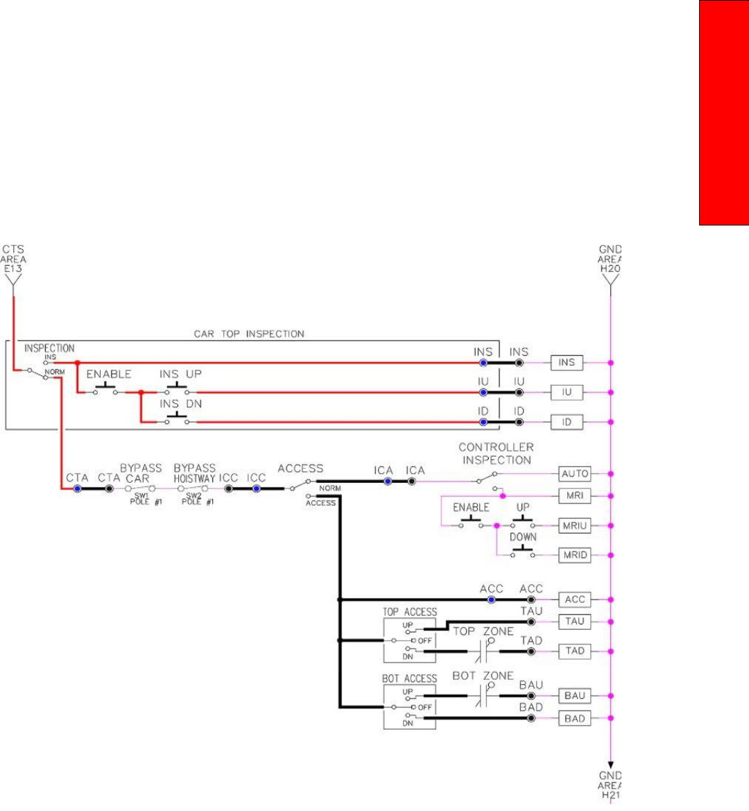
P a g e | 151
HPV-900 PM AC Gearless
If the controller is not on motor room inspection at this point, then verify all switch positions and wiring
before proceeding.
Figure 8.1: Inspection String Circuit
8.19 Verify Selector and Slowdown Inputs
Run the elevator up on inspection until it stops on
the up normal limit. The up and down normal
limits
should be set two inches above and below
the terminal floors respectively. Verify the
selector inputs
are being set properly on the
controller by running the elevator down until it
stops on the down normal
limit.
As the car approaches floor level going down,
“DL” turns on first, then “DZ” and then finally
“UL”. At floor level, “UL, DL, and DZ” inputs
should all be on at the same time. Leaving the
floor going
down “DL” will turn off first, then “DZ”
and last “UL”.
Also verify that the up and down terminal
slowdown limits inputs “UT, UTS, DT & DTS” are
breaking at
the proper distances as shown in the
slowdown table 2.0. “UT, UTS, DT & DTS” turn off
when active.
8.20 Verify Car Speed on Safety Processor Board
Run the car in either direction or check the car
speed on the 1066 LCD interface. The speed
shown
should match the car’s actual speed. If the
speed does not match and the secondary
feedback comes
from pulses from the tape go to
“Correct Car Speed When Using A Tape”. If using
485 tapeless, go to
"Correct Car Speed When
Using 485 tapeless". If using CAN Open tapeless,
go to "Correct Car Speed
When Using CAN Open
tapeless". If the correct speed is shown proceed
to Section 8.24, Learn The
Hoistway.
8.21 Correct Car Speed When Using a Tape
The tape has holes every 3/8” that are 3/8” in
diameter. On the selector unit adjust the PP
sensor closer
to the tape until the orange LED at
the end of the sensor turns on. Then turn the
sensor inwards
another 1/8” and lock in the
sensor. While running on top of car inspection
verify that the orange
LED at the end of the PP
sensor turns on and off as it passes by the holes
on the tape. The safety
processor board on the
controller measures the time between each pulse
to calculate the velocity. If the
velocity is not
displayed correctly first make sure that the
feedback type in the safety processor board
adjustable variable is set to 0 for a tape
application. Next, while the car is running, make
sure that the
PULSE LED on this board is pulsing.
As the car increases in speed the LED will glow
solid on. If the LED
does not pulse, try swapping
the wires at the PPS and PP terminals. If the LED
still does not work,
contact the factory. If the
correct speed is shown proceed to “Learn the
Hoistway”.
8.22 Correct Car Speed When Using 485
Tapeless System
When using the 485 tapeless system, the
secondary speed feedback comes from the
encoder mounted
on the governor. The 1066
board uses a serial interface to a Turck absolute
encoder, part #
T8.5882.3F0B.3001.

P a g e | 153
HPV-900 PM AC Gearless
In the 1066 LCD interface "Adj Var" menu, set the
"Fdbk Typ = 1", and set the "Enc PPR = 8192". The
"Enc
RPM" value must be calculated as described
below. To calculate the RPM, divide the contract
speed of
the car by the distance travel in one
revolution with the governor as shown below:
RPM = Speed fpm/ (diameter GOV * pi)
For a 1 ft. diameter governor: RPM = 350/ (1*pi) = 350/3.1415 = 111.4
For a 16 in diameter governor (16/12 = 1.33ft):
RPM = 350/ (1.33* 3.1415) = 350/4.188 = 83.5
8.23 Correct Car Speed When Using CAN
Open Tapeless System
When using the CAN Open tapeless system, the
secondary speed feedback comes from the HPV
900/600 drive and should be set to 8 times the
ppr of the motor encoder.
In the 1066 LCD interface "Adj Var" menu, set the
"Fdbk Typ = 4", and set the "Enc PPR" equal to 8
times
the ppr from the motor encoder.
On the 1066 LCD interface, navigate to the "Pls
Cnt" menu. While running the elevator on
inspection,
verify that the pulse count value increments when running up and decrements
when running down.
The "Pls Cnt" value can be
considerably out of range but will automatically
correct during the "Learn
Hoistway" procedure.
To reverse the direction of pulse counting,
navigate on the 1066 LCD interface to
the "Adj
Var" menu, "Enc Dir" and set to "0" for clockwise
or "1" for counter‐clockwise.
Navigate on the 1066 LCD interface to the "Car
Spd" menu. Monitor the "Car Spd" while running
the car
at a known inspection speed. The value
displayed should match the actual car speed
measured with a
hand held tachometer. If the
speed is correct, proceed to Section 8.24, Learn The Hoistway.
8.24 Learn the Hoistway
Run the elevator down on inspection until it stops
on the down normal limit switch. Verify that the
“DN
and DL” input LED’s are both off and that the
"UL" and "DZ" LED's are on. From the 1021/1101/1005 LCD
interface navigate to the "Elevator Setup" menu,
"Learn Hoistway". The learn procedure can be
performed automatically by choosing "Auto"
from the menu items, or performed manually by
choosing
"Insp” from the menu items. After
choosing the learn method, follow the
instructions displayed on
1021/1101/1005 LCD interface.
In general, the car will run up from the "down
normal limit" to the "up normal limit" at 30 fpm.
During
this learn run, the DP count for each floor
level and each limit switch will be stored in
memory.
NOTE: The car must run the entire hoistway
without stopping.
As the elevator moves up the hoistway, navigate to the "Hoistway Tables" menu, "Disp/Mod
Hoistway
Table", and verify that the "DP" count is
incrementing as the elevator moves up. Also as
the elevator
passes each floor, the pulse count
and distance for that floor should change and be
stored. Verify that
the floor distances are valid.
The pulse count for the terminal slowdowns will
also be stored. The
elevator will stop when it
reaches the up normal limit. Follow the
instructions on the 1021/1101/1005
LCD interface by putting
the car on inspection, and then the message
"Hoistway Learn Complete"
should be displayed.
Move the elevator on inspection until the “DZ
and DL” LED’s are on. Set the "INS" toggle switch
on
the 1064 board to the "NORMAL" position,
and the elevator should level down to floor level
at the top
floor. If so, proceed to final
adjustment.
If the car levels down but does not run, then
check “Elevator Status” and “View Fault Log” on
the
1021/1101/1005 LCD interface for any fault information.
Correct items causing faults and perform
hoistway learn again. After problem is corrected,
proceed to final adjustment.
8.25 Automatic Run
The elevator should now be sitting idle at the top
floor. The "AUTO DOOR" switch should be set to
the
"OFF" position and the "IND" switch should
be set to the "IND" position. If the learn
procedure was
successful, the elevator should be
ready to make an automatic run.
The default parameter settings for the ride
quality should be adequate for an initial run.
From the
1021/1101/1005 LCD interface navigate to the "Set Calls and Lockouts" menu, "Setup Car Calls" and
enter a car call. The elevator should run to answer the call. When the elevator levels in and stops at the
floor, the doors will remain closed.
The acceleration and deceleration of the car should be smooth and stepless regardless of the distance of
the run. If the elevator does not function as described above, then problem should be analyzed before
proceeding.
8.26 Fine Tune the Ride Quality
In order to fine tune the ride quality, refer to Figure 8.2 which describes what part of the S‐ curve that
the different parameters effect. In general, higher numbers in the given parameters, cause quicker and
more abrupt changes from one mode to the next during a run. All of the S‐curve parameters have a
minimum and maximum value. The control will not allow you to enter values that are not valid.
After adjusting the S‐curve parameters for the desired ride, proceed to the next step.
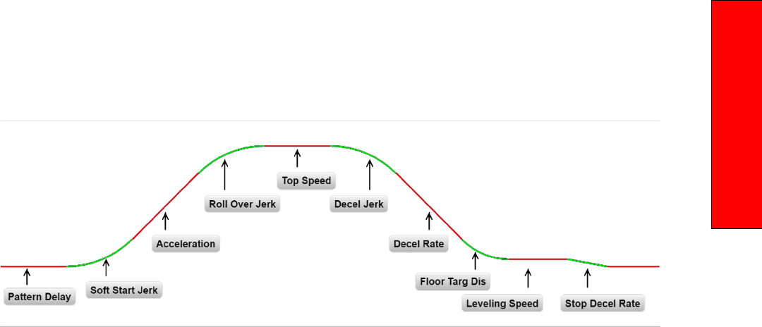
P a g e | 155
HPV-900 PM AC Gearless
Figure 8.2: S‐Curve Parameters
8.27 Adjust the Stop
When at floor level the “UL, DL, & DZ” input LED’s should be on. If the elevator continually tries to seek
floor level by leveling up and down, try the following steps to correct the problem:
Increase the response of the drive by increasing the value of A1 RESPONSE in the HPV 900/600 drive,
and retesting the car.
Reduce the leveling and re‐leveling velocity parameters from the 1021/1101/1005 LCD
interface
"Adjustable Variables" menu, "Car Motion",
"Leveling Speed" and "Relevel Speed".
If the car still
oscillates, adjust the "floor level
zone" on the selector. The "floor level zone" is
increased by moving
the "UL" and "DL" sensors
closer together.
If the car stops hard on the brake, then make the
following adjustments. From the 1021/1101/1005 LCD
interface navigate to the "Adjustable Variables"
menu, "Car Motion", and adjust both "Brake
Drop Del"
(brake drop delay) and "Soft Stop
Time". These variables should be adjusted so that
zero speed is
observed at the end of the run prior
to the brake setting. The controller should hold
the car at zero
speed for the duration of the "Soft
Stop Time" which should continue while the
brake is setting and for
a short time after the
brake sets. The soft stop time MUST be set to at
least 0.5 seconds LONGER than
the "Brake Drop
Del".
The "Soft Stop Time" setting in the 1021/1101/1005 LCD
interface should be compared with the setting
in
the 1066 LCD interface "Adj Var" menu,
"SoftStop". The setting of "SoftStop" in the 1066
LCD
interface should be greater than the "Soft
Stop Time” setting in the 1021/1101/1005 LCD interface.
If the car spots when approaching the floor, the
cause is usually due to the car not tracking (the
drive
response is set too low) or the speed profile
into the floor is too aggressive. First try to
increase the
response of the drive by increasing
the value of parameter A1 RESPONSE in the drive.
If the car still spots, from the 1021/1101/1005 LCD interface,
navigate to the "Adjustable Variables"
menu,
"Car Motion" and increase the value of "Floor
Targ Dis" (floor targeting distance). The default
value for the floor targeting distance is 12 inches.
Increase it by steps of 2 or 3 and continue
retesting until the parameter is adjusted to 18. If
no change is
noticed, start again from 12 and
decrease
the value.
The deceleration rate can also be reduced to help
remove the spotting. Proceed with adjusting the
start once the proper stop is achieved.
8.28 Adjust the Start
To provide a proper start, from the 1021/1101/1005 LCD
interface, navigate to the "Adjustable
Variables"
menu, "Car Motion" and adjust "Brake Pick Del"
(brake pick delay), "Pattern Delay", and
"Soft
Start Jerk". Initially, set the brake pick delay to 0
and increase the pattern delay by 0.1 seconds
until the controller picks the brake completely
before the motor starts to move. If roll back
occurs, then
reduce the pattern delay until there
is no roll back. Sometimes, the timing works out
better if the brake
pick delay is set to 0.1 second.
If load weighing is used, pre‐torquing can be used
to provide a smoother
start. See Section 8.37, Adjust the Motor Pre‐torque.
Increase the soft start jerk rate in order to
provide a quicker transition from the start to
constant
acceleration. Keep in mind that the
larger the soft start number, the quicker the
start. The ride should
now be acceptable.
8.29 Verify Top Speed
To fine tune high speed, make high speed runs
while monitoring the SPEED FEEDBACK on the
HPV drive
display. The display should read
contract speed, and it should match the speed
displayed on the
1021/1101/1005 LCD interface, "Elevator
Status" menu, "Dmd" and "Vel". This speed
should also match
the speed displayed on the
1066 LCD interface, "Car Spd" menu. If all of these
values are the same (+/‐ 2
fpm), then proceed to the next step. If the speed is not correct increase
or decrease drive parameter A1
CONTARCT MTR
SPD until the AC drive display reads contract
speed, If A1 CONTRACT MTR SPD is
changed, then
go to the 1021/1101/1005 LCD interface, "Adjustable
Variables" menu, "Car Motion" and
change the
value of "Encoder RPM" to match the drive.
When the speed displayed is correct, proceed
to
the next step.

P a g e | 157
HPV-900 PM AC Gearless
8.30 Adjust Safety Processor Board Speed
Clamps
The 1066 Safety Processor Board monitors the
speed of the elevator at the terminal landings
independently from the main CPU. When the
"UT, DT, UTS, and DTS" limit switches are
activated, the
1066 board calculates the velocity
of the elevator and compares that velocity with a
stored value of
speed clamp. If the velocity when
the switch activates is greater than the speed
clamp value, then the
1066 board will generate a
fault that stops the elevator.
To set the speed clamps, make a one floor run to
the top floor.
From the 1066 LCD interface, navigate to the
"Lim Vel" menu, and view the recorded velocities
displayed
for the “UT, DT, UTS & DTS” slowdown
limits. “UTS & DTS” are used on car with reduced
stroke buffers
or with a top speed greater than
200 fpm. The velocity value is shown from the
“Lim Vel” menu on
the 1066 LCD interface.
The velocity value shown on the display for the
“UT or DT” limit is the value after the car activates
the
limit then counts an adjustable number of
counts set from the 1066 LCD interface, "Adj Var"
menu, "UT
Count" or "DT Count". These count values can be adjusted to provide adequate
distance, following the
limit switch activation, to
allow the elevator to begin its normal decel pattern. The default “UT Count"
and "DT Count"
values are normally adequate. However, these
values may need to be field adjusted
to allow
enough distance for the car to begin its normal
decel pattern. If the "UT Count" and "DT Count"
values are modified, the limit velocities must be
re‐checked.
Run the car again to the top repeatedly from 2
floors, then 3 floors, etc., until top speed is
reached.
From the 1066 LCD interface "Lim Vel"
menu, record the limit velocities displayed each
time the car
stops at the top floor.
Make the same runs to the bottom floor starting
from 1 floor, then 2 floors, then 3 floors, etc.,
until
top speed is reached. From the 1066 LCD
interface "Lim Vel" menu, record the limit
velocities displayed
each time the car stops at the
bottom floor.
Take the highest speed value recorded in the runs
above and add 20 fpm to that value to use as the
clamp
speed values for the respective limit
switches. Enter these clamp speed values into the
1066 LCD
interface "Adj Var" menu, "UT Vel",
"DT Vel", "UTS Vel", "DTS Vel" respectively.
8.31 Adjust Digital Slowdown Speed Clamps
Having just made several runs into the top and
bottom landings, the main CPU has also recorded
the
car’s velocity when the slowdown limits were
activated. If the car has been powered down
prior to this
step, several runs must be made to the terminal landings to allow the main CPU to
record the limit
velocity values.
From the 1021/1101/1005 LCD interface, navigate to the
"Elevator Setup" menu, "Set DT/UT Slowdown
Clamp" and view the speed displayed for "Clamp
Speed". Add 20 fpm to this "Clamp Speed" value
and
enter it into the “DT/UT Limit"

The number of slowdown limits depends on the
speed of the car as show in the table below:
Adjust
speed clamps for each slowdown limits
used as determined by the elevator’s contract
speed.
Table 8.1: Slowdown Clamps
8.32 Verify Inspection Velocity Clamp On Safety
Processor Board
Place the car on inspection operation. From the
1066 LCD interface, navigate to the "Adj Var"
menu,
"Ins Vel" and set the speed clamp velocity
to 25 fpm. From the 1021/1101/1005 LCD interface, navigate
to the "Adjustable Variables" menu, "Car
Motion" and set the "Inspect Speed" to 50 fpm.
Run the car in
either direction and verify that the
car shuts down when the speed rises above 25
fpm.
From the 1066 LCD interface, navigate to the "Adj Var" menu, "Ins Vel" and set the speed clamp to
140
fpm. From the 1021/1101/1005 LCD interface, navigate
to the "Adjustable Variables" menu, "Car
Motion" and set the “Inspect Speed" to the
desired value.
8.33 Analog Load Weigher Setup
If the job uses an analog load weigher purchased
from G.A.L., complete the following procedure.
NOTE: It is recommended using two people, one
moving the weights and one in the machine room
to set
up the load weigher.
Mount the load weigher as described by the
manufacturer. The load weigher control box will
also
contain a board supplied by G.A.L. that
connects to the controller serial CAN bus and
reads in the analog
output from the load
weighing device. Wire the load weigher and G.A.L. board according to the
controller
schematics.
Calibrate the load weighing device hardware
according to the manufacturer’s instructions.
Following
proper installation of the load weighing
device, and proceed to Section 8.34, Empty Car
Setup.

P a g e | 159
HPV-900 PM AC Gearless
8.34 Empty Car Setup
Verify that the load weighing device is
communicating to the main CPU by performing
the following
steps. From the 1021/1101/1005 LCD interface,
navigate to the "Diagnostics" menu, "Car Comm
Status",
"Car to LW Board" and verify that "On‐
line = 1". If "On‐line = 0" then verify wiring and
installation of
load weighing device.
From the 1021/1101/1005 LCD interface, navigate to the
"Elevator Setup" menu, "Load Weigher
Setup",
"Setup Load Weigher" and follow the instructions
on the display as you go through the
procedure.
It is okay to exit the setup screen to place a call and then return to it while the setup is being
performed.
Run the car to the bottom floor and press Enter
on the 1021/1101/1005 LCD interface when prompted
to do
so to start the automatic setup sequence.
If the car is at the bottom floor and the doors are
not closed (the doors will not close automatically
from
turning off the auto‐door switch) then place
a car call to run the car up one floor then back
again. The
doors will close when the call is placed.
When the automatic sequence is activated, the
car will run to each floor and measure the empty
load
value. The 1021/1101/1005 LCD interface will indicate
when the sequence if finished.
8.35 Full Car Setup
NOTE: The empty car setup must be successfully
completed to run the full load setup.
Once the empty car setup is complete, run to the
loading floor and set the "AUTO DOOR" switch to
the
"ON" position to allow weights to be loaded
on the car. With the car fully loaded, test the
"AUTO
DOOR" switch to the "OFF" position and
run the car to the bottom floor. Again if the doors
are not
closed, make a one floor run to force the
doors to close.
With the car at the bottom floor, follow the
instructions on the 1021/1101/1005 LCD interface to start
the full load setup sequence. The car will
automatically run to each floor and measure the
full load
value. When the full load measurement
is complete, the car can be run to the loading
floor and the
weights removed.
After the weights are removed, cycle the doors to
complete the procedure. From the 1021/1101/1005
LCD
interface, navigate to the "Elevator Setup" menu,
"Load Weigher Setup", "View/Modify LW Setup"
and verify the load weigher status, "LW Device
Stat: ON OK". If the status is "ON OK", then the
load
weigher should be accurately measuring the
car load in real time. The percent load will be
displayed,
"Load: _%".
The percent load values for different service
options can now be set. From the 1021/1101/1005 LCD
interface, navigate to the "Adjustable Variables"
menu, "Service Options", and set the following
variables:
"Load Bypass"
"Load Antinuisance"
"Load Dispatch"
"Load Overload"
NOTE: Setting the values of the variables above
to 0% will disable that particular option.
8.36 Load Weighing Calibration Sequence
The load weigher is automatically calibrated once
each week. If an error is detected during this
calibration sequence, the load weigher and the
pre‐torque feature (if used) is disabled.
A load weighing calibration sequence can be
manually activated by performing the following
procedure.
From the 1021/1101/1005 LCD interface,
navigate to the "Elevator Setup" menu, "Load
Weigher Setup",
"Load Weigher Calibration" and
follow the instructions on the display.
8.37 Adjust the Motor Pre‐torque
NOTE: The motor pre‐torque uses the load value
obtained from the analog load weigher and will
work
only if the load weigher is installed and
successfully setup.
On the HPV‐900 PM drive under User Switches C1
parameter, set Pre‐Torque source to serial. Run
the
empty car to a middle floor. From the 1021/1101/1005 LCD user interface, navigate to the "Adjustable
Variables" menu, "Car Motion" and adjust the
following parameters:
"Balanced Load = 40" (typically car is 40%
counterbalanced, but verify counterbalance
percentage for each specific job)
"Torque Amount = 10"
"Pattern Delay = 2.5"
"Brake Pick Del = 0.1"
The long pattern delay will allow an exaggerated
amount of roll back in order for the pre‐torquing
to be
set accurately. Make a one floor run down
and observe the roll back when the brake picks at
the start of
the run. Increase the "Torque
Amount" variable and continue to monitor the
roll back while performing

P a g e | 161
HPV-900 PM AC Gearless
one floor runs in the
down direction. As the "Torque Amount" is
increased, the roll back should be
minimized until
the car will hold zero speed for the entire "Pattern Delay" time. A typical value for the
"Torque Amount" is 40%. If the value is too large,
the car will roll forward during the "Pattern
Delay"
time.
Note: The pattern delay must be at least 0.15
seconds (150 milliseconds). Setting the torque
amount to
0.00 will disable the pre‐torque
feature. Also if the load weighing calibration
sequence detects a load
weighing error, the pre‐
torque feature is also automatically disabled.
8.38 Verify the Doors Are Safe
The elevator should now be adjusted. Verify that
all door locks, gate switches, and safety circuits
are
operational. Set the "INS" switch to the
"NORM" position and set the "AUTO DOOR"
switch to the "ON"
position. The elevator should
level into the floor and open the doors. If the
doors do not open, check
the door operator
wiring and cam adjustment. If the doors do open,
the elevator is now on independent
service.
8.39 Fine Tune the Ride Quality
Ride the elevator and evaluate the ride quality.
Fine tune ride quality by navigating to the
"Adjustable
Variables" menu, "Car Motion" and
adjusting the variables shown in Figure 4.2. Keep
in mind that if
acceleration or deceleration values
are changed, the speed clamps for the safety
processor board and
the S‐curve board may need
to be re‐adjusted.
To fine tune the floor level accuracy, determine if
the controller is set to stop when "UL" and "DL"
signals
turn on, or if controller is set to stop off of
the position count. From the 1021/1101/1005 LCD interface,
navigate to the "Adjustable Variables" menu,
"Car Motion" and view the "Stop On Pos Cnt"
variable.
If "Stop On Pos Cnt= 0" then controller
is set to stop when the "UL and "DL" signals turn
on. If "Stop On
Pos Cnt = 1" then controller is set
to stop on a combination of the floor level
magnet and the position
count.
With "Stop On Pos Cnt = 0", the floor levels
should be set by adjusting the floor level magnet
at each
floor. For proper operation, the floor
magnets should be set to exactly floor level. After
the floor levels
are set properly, perform another
hoistway learn procedure.
With "Stop On Pos Cnt = 1", the floor levels are
set by using both the floor magnet and the
position
count. For proper operation with this
setting, the floor magnet should be set to exactly
floor level. The
final stop can then be fine‐tuned
by performing the following adjustments.
From the 1021/1101/1005 LCD interface, navigate to the
"Hoistway Tables" menu, "DZ & LZ Offset, Sel
Cnt" and adjust "Dn Lev Dist" and "Up Lev Dist".
The units for these variables are in "pulse
counts". With
"Stop On Pos Cnt =1" the car will continue to move for the "Dn Lev Dist" or "Up Lev
Dist" after "UL and
DL" turn on. Use the "Dn Lev
Dist" and the "Up Lev Dist" parameters to make
level changes at all floors.
To make level changes at individual floors,
perform the following adjustments. From the
1021/1101/1005 LCD interface, navigate to the "Hoistway
Tables" menu, "FL and FL Offset Count", and
the
offset count can be adjusted. These variables
introduce an offset (+/‐) to the stored floor count
that
was determined in the hoistway learn
procedure.
NOTE: The number of pulse counts per inch can be viewed from the 1021/1101/1005 LCD interface,
"Hoistway Tables", "DZ & LZ Offset, Sel Cnt”, "Pulses /Inch".
NOTE: Regardless if "Stop On Pos Cnt=0" or if
"Stop On Pos Cnt =1", the floor magnet must be
set
properly at floor level. If too large of values
are entered into "Dn Lev Dist", "Up Lev Dist", or
"Offset",
the car will drive past the floor level
magnet and re‐level.
Check all signal devices for proper operation and
remove all temporary jumpers. The adjustment
should
now be complete.

P a g e | 163
Section 9 - Troubleshooting
Section 9 ‐ Troubleshooting
9.1 General Information
The GALaxy controller is equipped with a number
of features that aid in troubleshooting any
problems
that may occur. The physical layout of
the controller provides ready access to all I/O in
order to make
voltage measurements. All inputs
have LED’s that monitor the state of the input.
The controller is
equipped with the 1021/1101/1005 LCD
interface for the Main CPU and the 1066 LCD
interface for the
Safety Processor Board. Section
10 describes the use of the 1021/1101/1005 LCD interface,
and Section
13 describes the use of the 1066 LCD
interface. In this section the basic points of
troubleshooting will be
detailed.
9.2 Microprocessor CPU
The CPU is very reliable and normally trouble
free. With power turned on, the “axy” in GALaxy
on the
1021/1101/1005 LCD interface should be blinking at
one second intervals to indicate that the CPU is
running. If it is not blinking, then check voltage at
the 5V terminal with respect to the 0V terminal on the
1064 board. This voltage should read
5VDC. If not, then check the input and output
voltage of the DC
power supply. If the “axy” is not
blinking and 5VDC is present at the 5V terminal
with respect to the 0V
terminal, then contact the
factory.
All job parameters that are field adjustable are
stored in a non‐volatile SRAM chip on the GALX-1036
memory (older)
board, or GALX-1100AN (newer) CPU board. If the field adjustable parameters return
to
the default settings when the main power is
turned off, check that the J1 (Pin Devices) jumper on the
1036 board is set to 28 pin and the J2
(VDROP) jumper on the 1036 board is on. Both
jumpers are
located on the lower right hand
corner of the 1036 board, the GALX-1100 CPU board does not have this
option.
9.3 Input/Output Boards
The two main sections of all the I/O boards are
the low voltage and the high voltage sections.
The
low voltage section consists of all the digital interfacing necessary for the CPU to
communicate with the
field components. The
high voltage section consists of the field
components (buttons, switches, lights,
relays and
sensors) and their associated input and output
signals. The standard voltage for all I/O is
120VAC. However, if necessary, the I/O boards
can accept a voltage range from 24V to 120V AC
and 24V
DC. The GALX-1064AN main board only accepts 120V AC. See Figure 9.0.
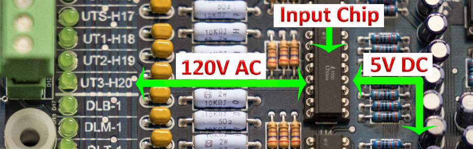
Figure 9.0 - High Voltage & Low Voltage
It is very important that the wiring schematics are
reviewed in order to determine the voltages for
which
the controller was designed before
applying power. The majority of problems that
may arise with the
control system are due to
faulty inputs or outputs on the high voltage side
of the system. For example,
having a limit switch
not feeding or an acknowledgment light out. The
GALaxy control system is designed
to enable the
technician to check both the high voltage section
and the low voltage section to correct
the
problem. The high voltage section is checked with
a digital voltmeter or with the individual LEDs
that
are associated with each input. Depending
on the particular input or output, the voltage
measured at
the terminal will either be “high” or
“low” with respect to its reference point. For
example, to determine
whether or not the up
terminal slowdown limit switch was feeding, the voltage should be measured at
terminal “UT”
with respect to “GND”. Another means by which to determine
whether the switch is
feeding is to view the “UT”
input LED. If the LED is on, the switch is feeding.
If the LED is off, the switch is
open.
The previous example determines whether or
not the field component is functioning properly.
However, to determine if the signal is actually
being communicated to the CPU the signal must
be
checked on the low voltage section of the
board. The low voltage section is checked from
the
1021/1101/1005 LCD interface. Using the previous
example, from the 1021/1101/1005 LCD interface,
navigate
to the "Inputs and Outputs" menu, "Car Inputs
and Outputs" and scroll through the I/O list
until the "UT" input is located. The LCD will display
"UT=1" if the "UT" switch is feeding and "UT=0"
if
the switch is open.
A second example will show how to determine if
an output is working properly. With the car at
the
first floor and the controller designed for
120VAC discrete position indicators, the “P1”
output should be
on. The voltage measured at
terminal “P1” with respect to “GND”, should
read 120VAC. If the voltage
reads less than
50VAC, the voltage supplied to the output device
must be checked. The schematic, in
this case,
would show the “P1” voltage is supplied at the
“PIC” terminal. A voltmeter would be used
to
measure the voltage between “PIC” and “GND”.
If that voltage is at the terminal but the indicator
is
not on. The 1021/1101/1005 LCD interface could be used
to view if the CPU is turning the “P1” output
on.
From the 1021/1101/1005 LCD interface, navigate to the
"Inputs and Outputs" menu, "Car Inputs
and
Outputs" and, scroll through the I/O list until the “P1” is located. The display will show “P1=1”
which
indicates that the CPU is sending a signal
to turn on the “P1” output. For this example,
since the CPU
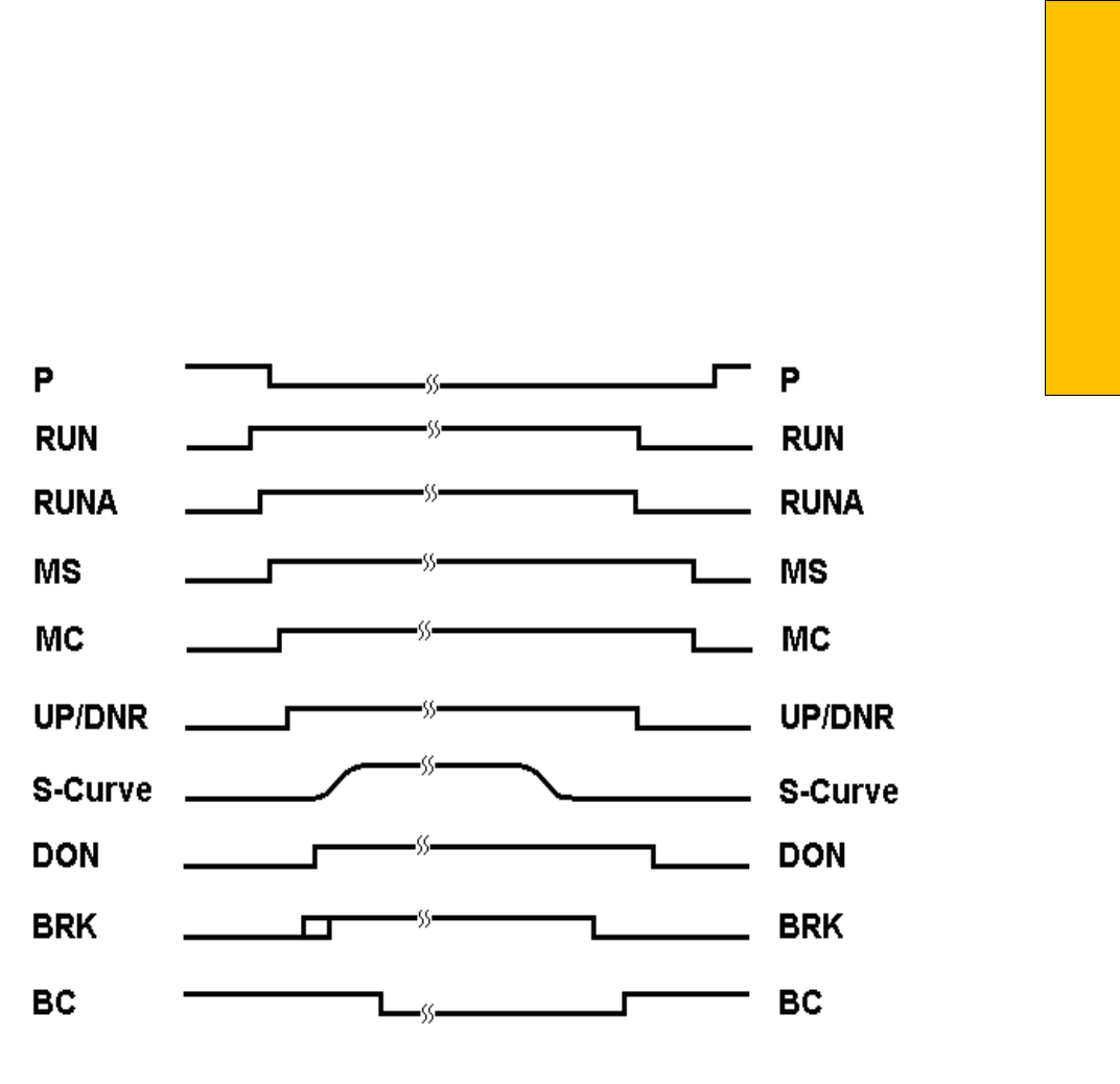
P a g e | 165
Section 9 - Troubleshooting
is turning on the output, and the
correct voltage is at the output common but not
at the output terminal,
it would indicate that the
output solid‐state relay for “P1” is defective and
should be replaced.
All of the I/O’s are optically isolated between the
high voltage section and the low voltage section.
The
input optoisolators and the output solid‐
state relays are socketed IC's that are labeled on
the silk screen
of the various I/O boards with a
"U" number (for example U45). If it is
determined through the previous
troubleshooting procedures that the input signal
is present at the terminal, but is not being
communicated to the CPU, the input
optoisolator may be defective and can be
replaced in the field. If it
is determined that the
CPU is communicating the output signal to the
solid‐state relay, but the voltage
does not go
high at the terminal, the solid‐state relay may be
defective and can be replaced in the field.
Any
time IC’s are replaced, the power should be
turned off and care should be taken in removal
of the
old chip and replacement of the new one.
All of the I/O and their associated IC’s are listed
in the wiring schematics.
The following diagram in Figure 9.1 shows the
run sequence of the controller. The timing of
BRK changes
with the adjustment variable DON
Start Control. When set to 0 the BRK output
turns on before DON and
when set to 1 BRK turns on after DON. The BRK timing typical works best with the adjustable variable set
to 0 for VVVF and 1 for DC SCR.
Figure 9.1 Run Sequence
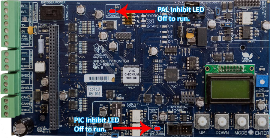
Figure 9.2 – Safety Processor Board
The Safety Processor Board has two fault LED’s,
one on the top center and one on the bottom
center of
the board. The top center LED is for
PAL inhibit and the bottom center one is for PIC
inhibit (See Figure
9.2).
Important: When either LED is on, this board
will prevent the car from running.
The Safety Processor Board performs the
following functions (See “Safety Processor Functions” in
Section 13):
Verifies the speed of the car when terminal
limits are activated
Verifies that the doors are closed and safe to
run
Verifies all inspection operations
Verifies that the car velocity is not greater
than 150 fpm in the door zone and with the
doors
open.
While the Safety Processor Board cannot turn
on any run control signals, it can turn off the
follow signals
from the main CPU: RUNA, BRK,
UP, DNR, UPF and DF. The SFC relay in the
safety string is also controlled
by the Safety
Processor Board.
The Safety Processor board detects two types of
faults, active faults and velocity faults. Active
faults are
input conditions that are considered
as unsafe or an error such as the lock bypass
switch place on while
the car is on automatic.
Velocity faults are generated when the Safety
Processor Board detects that the car speed is
too high
during certain conditions, such as
hitting the DTS terminal limit at a speed greater
than the speed setting
for that limit. Both types
of faults are reset after a 2 second delay, the
condition is corrected and the
main CPU is not
commanding an up or down run.

P a g e | 167
Section 9 - Troubleshooting
When troubleshooting errors detected by the
Safety Processor board, take the following
steps:
Check LED status. Either PAL inhibit or PIC
inhibit LED on indicates an error.
View the elevator service “Elev Serv”.
Anything other than Automatic or a valid
inspection
service is an error.
From the 1066 LCD interface, navigate to the
"Inp/Out" menu, and view all of the I/O status.
See
Section 13 for a complete description of the
input and output signals.
From the 1066 LCD interface, navigate to the
"Faults" menu, and view the recorded faults.
The
Safety Processor Board faults are recorded
in ram and will be lost when power is turned
off.
As mentioned earlier, RUNA is one of the signals
that can be turned off by the Safety Processor
Board. If
a "RUNA Off" error is generated on the
1021/1101/1005 LCD interface (main CPU), it is typically
caused
by the Safety Processor detecting an
error at the instant the run is starting. When a
RUNA Off error is
recorded, check the status of
the Safety Processor board first.
During a fault condition when the Safety
Processor drops the SFC relay, every input after
the SFC
terminal will lose voltage including the
inputs for the normal and terminal limits. This
could cause an Up
or Down directional limit
error on the main CPU.
Additional fault information is shown in the
next section, System Faults.
9.4 System Faults
Faults that are detected by the main CPU can be
viewed on the 1021/1101/1005 LCD interface by
navigating
to the "Fault Log" menu, "View Fault Log". The possible faults detected by the main CPU
are
listed in Section 11, Main CPU Faults. By
pressing the "ENTER" button on the 1021/1101/1005 LCD
interface when the particular fault is being
displayed, the interface will display detailed
information for
that fault. The Detailed Faults Section (Section 11) describes this information. In general, when a fault
occurs, the system records the state of all the items listed in the Detailed Fault and makes that
information available for troubleshooting purposes.
Faults that are detected by the Safety Processor board can be viewed on the 1066 LCD interface by
navigating to the "Faults" menu. The possible faults detected by the Safety Processor are listed in
Section 13, Safety Processor 1066 LCD Interface.
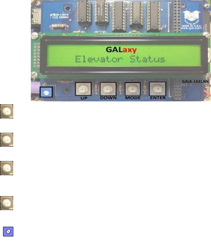
Section 10 – 1021/1101/1005 LCD Interface
10.1 Operating the 1021/1101/1005 LCD Interface
UP button is used to scroll up to the next menu item or to increment a data
value.
DOWN button is used to scroll down to
the next menu item or to decrement a
data value.
MODE button is used to go back to the
previous menu or to select a digit of a
data value.
ENTER button is used to select the
menu item or to complete the
operation of changing a data value.
Potentiometer is used to adjust the
viewing angle. It will make the display
lighter or darker.

P a g e | 169
Section 10 – 1021/1101/1005 LCD
Interface
The LCD display interface board uses a 2
line by 24-character display and four
buttons. This interface
allows the user to
adjust parameters, view critical
controller information, to implement
the controller
setup and to view the
elevator status. Upon power‐up the
display shows a blinking GALaxy name to
indicate the controller is running as
show above.
The four inputs buttons used with the
LCD display are, UP, DOWN, MODE and
ENTER. The UP and
DOWN buttons are
used to scroll up and down to each menu
item. When an appropriate menu item is
reached, the ENTER button is used to
select the item. Some menu items, once
selected, show a second
menu. Again, use the UP and DOWN buttons to scroll through the menu items and the ENTER button to
select a particular item. The MODE button is used to go back to the previous menu. When a menu item
is an adjustable variable, select the item with the ENTER button and change the variable with the UP or
DOWN button. The MODE button is used to move the cursor to the next digit. When the appropriate
value is reached, used the ENTER button to complete the variable change operation and return to the
current menu.
The following are descriptions of the flowcharts at the end of the chapter. The descriptions and
flowcharts are separated to allow more page territory to the graphics and make them more readable.
The descriptions are in the same order as the flowcharts.
10.2 1021/1101/1005 LCD Interface Main Menu
This flowchart shows all the top level
menus in the system.
10.3 Elevator Status
The elevator status display continuously
updates to show the current status and
fault information. The
Up and Down keys
allows access to both the status display and
the velocity display. When a system fault
occurs, it will be displayed on the top
line of the status display while the fault
exists and will remain
for 60 seconds after
the fault is cleared. The following status
information can be displayed:
10.4 Elevator Service
Out of Service
Automatic Service
Independent Service
Load Weighing By Pass
Attendant Service
Code Blue Service
Fire Service Phase 2
Emergency Power Service
Earth Quake Service
Fire Phase 1 Main Return
Fire Phase 1 Alt Return
Homing
Reset Going Up
Reset Going Down
Stalled Out of Service
10.5 Fault Status
Reset Fault
Out Of Step Fault
Binary Input Fault
Safety String Fault
Door Zone Fault
Stalled Fault
Door Open Fault
Door Close Fault
Up Directional Fault
Dn Directional Fault
No Potential Fault
Stop Switch Fault
Gate or Interlock
LC Fuse Blown Fault

P a g e | 171
Section 10 – 1021/1101/1005 LCD
Interface
HC Fuse Blown Fault
Drive Ready Fault
'P' Input Off Fault
Car Safe Fault
UL or DL off Fault
Delta off Fault
UT count Fault
UT1 count Fault
UT2 count Fault
UT3 count Fault
DT count Fault
DT1 count Fault
DT2 count Fault
DT3 count Fault
Rear Door Open Flt
Rear Door Close Flt
Group Comm Loss
Car 1 Comm Loss
Car 2 Comm Loss
Car 3 Comm Loss
Car 4 Comm Loss
Car 5 Comm Loss
Car 6 Comm Loss
RUN I/O Failed ON
RUN I/O Failed OFF
RUNA I/O Failed ON
RUNA I/O Failed OFF
UP I/O Failed ON
UP I/O Failed OFF
DNR I/O Failed ON
DNR I/O Failed OFF
UPF I/O Failed ON
UPF I/O Failed OFF
DF I/O Failed ON
DF I/O Failed OFF
MCC I/O Failed ON
MCC I/O Failed OFF
MCA I/O Failed ON
MCA I/O Failed OFF
BRK I/O Failed ON
BRK I/O Failed OFF
DON I/O Failed ON
DON I/O Failed OFF
RUN I/O or UP Fail
RUN I/O or DNR Fail
Top Door Lock Fault
Mid Door Lock Fault
Bot Door Lock Fault
Gate Switch Fault
Rear Top Lock Fault
Rear Mid Lock Fault
Rear Bot Lock Fault
Rear Gate Sw Fault
'P' Input On Fault
Estop Fault
Inspection Input Flt
Gate/Lock Byp Sw Flt
GRT1 input ON Fault
GRT1 input OFF Fault
GRT2 input ON Fault
GRT2 input OFF Fault
Gripper did not Pick
Gripper Trip Fault

P a g e | 173
Section 10 – 1021/1101/1005 LCD
Interface
10.6 Elevator Status
Reset Mode PI= 1
Inspection Mode PI= 1
Up Fast PI= 1
Up Transition PI= 1
Leveling Up PI= 1
Down Fast PI= 1
Down Transition PI= 1
Leveling Down PI= 1
Soft Start Mode PI= 1
Constant Accel PI= 1
Roll Over Max Vel PI= 1
Constant Velocity PI= 1
Roll Over Deccel PI= 1
Constant Deccel PI= 1
Targeting Floor PI= 1
Emergency Slowdown PI= 1
Safety String Open PI= 1
Elevator Off Line PI= 1
Elevator Parked PI= 1
Waiting Assignment PI= 1
Door Procedure PI= 1
Elevator Stalled PI= 1
10.7 Door Status
Elev Door Closed PI= 1
Elev Door Opening PI= 1
Elev Door Dwelling PI= 1
Elev Door Open PI= 1
Elev Door Closing PI= 1
Elev Door Nudging PI= 1
F1RET Door Open PI= 1
F2CPO Door Open PI= 1
F2CPO Door Opening PI= 1
F2CPO Door Closed PI= 1
F2CPO Door Closing PI= 1
F2CPC Door Open PI= 1
F2CPC Door Opening PI= 1
F2CPC Door Closed PI= 1
F2CPC Door Closing PI= 1
F2HLD Door Open PI= 1
F2HLD Door Opening PI= 1
F2HLD Door Closed PI= 1
F2HLD Door Closing PI= 1
F2MBC Door Open PI= 1
F2MBC Door Opening PI= 1
F2MBC Door Closed PI= 1
F2MBC Door Closing PI= 1
10.8 Rear Door Status
Rear Door Closed PI= 1
Rear Door Opening PI= 1
Rear Door Dwelling PI= 1
Rear Door Open PI= 1
Rear Door Closing PI= 1
Rear Door Nudging PI= 1
F1RET RDor Open PI= 1
F2CPO RDor Open PI= 1
F2CPO RDor Opening PI= 1
F2CPO RDor Closed PI= 1
F2CPO RDor Closing PI= 1
F2CPC RDor Open PI= 1
F2CPC RDor Opening PI= 1
F2CPC RDor Closed PI= 1

P a g e | 175
Section 10 – 1021/1101/1005 LCD
Interface
F2CPC RDor Closing PI= 1
F2HLD RDor Open PI= 1
F2HLD RDor Opening PI= 1
F2HLD RDor Closed PI= 1
F2HLD RDor Closing PI= 1
F2MBC RDor Open PI= 1
F2MBC RDor Opening PI= 1
F2MBC RDor Closed PI= 1
F2MBC RDor Closing PI= 1
10.9 Set Calls and Lockouts
When a car is in the group the menu
system allows access to setting both hall calls and car calls.
When not the group,
only car calls can be set. Rear lockouts
are only displayed only when the car has
a
rear door.
10.10 Car Call Test
This menu allows the mechanic to
initiate a continuous test of the elevator.
The test can be conducted
with the
“AUTO DOORS” switch set to “ON” or
“OFF”. By following the instructions
from the menu, the
“Car Call Test” can be initiated or discontinued. When
performing the “Car Call Test”, the car
will
answer all of the registered calls in
one direction. When the last call has
been answered, the calls will
be re‐
initiated automatically, and the car will answer the calls in the opposite
direction. This operation
will continue
until one of the following occurs.
1. The test is discontinued from the
1021/1101/1005 LCD interface
2. The car is taken out of automatic
operation
3. A fault occurs
NOTE: The car will not perform the “Car
Call Test” if it is on “Independent
Service”.
NOTE: When performing the “Car Call
Test” with the “AUTO DOORS” switch set
to “OFF”, it is
recommended to set the
“Non‐interference Time” to at least 5
seconds. From the 1021/1101/1005 LCD
interface,
navigate to the “Adjustable Variables”
menu, “Car Timers” and set “Non
Interfer T = 5”.
10.10a CAN Encoder Comm Status Submenu
This menu indicates if the CAN Open Encoder is on-line and communicating.
10.10b UPS Comm Status Submenu
This menu indicates is the UPS System is on-line and also gives battery status.
10.11 Lockouts Front Car Calls
Procedure to lock out front car calls.
10.12 Car/Group Inputs & Outputs
Inputs and outputs show a “1” for ON
and a “0” for OFF. A list every input and
output used on the
controller and the
board it is located on is shown in
Appendix A. The controller determines which boards
are used depending on the
options selected and the number of
front and rear floors. All the I/Os for a
given board are displayed even if a
particular I/O is not used.
10.13 Job Statistics – Clear Job Statistics
The Job Statistics menu shows the
number car calls and the number and
percent of hall calls serviced
since the
job was started or since the job statistics
were cleared. Below is a list of all the
categories
maintained:
Number of Car Calls
Number of Up Hall Calls
Number of Down Hall Calls
Number of Up Hall Calls with < 15 second wait time
Number of Up Hall Calls with < 30 second wait time
Number of Up Hall Calls with < 45 second wait time
Number of Up Hall Calls with < 60 second wait time
Number of Up Hall Calls with > 60 second wait time
Number of Down Hall Calls with < 15 second wait time
Number of Down Hall Calls with < 30 second wait time
Number of Down Hall Calls with < 45 second wait time
Number of Down Hall Calls with < 60 second wait time

P a g e | 177
Section 10 – 1021/1101/1005 LCD
Interface
Number of Down Hall Calls with > 60 second wait time
Percent of Hall Calls with < 15 second wait time
Percent of Hall Calls with < 30 second wait time
Percent of Hall Calls with < 45 second wait time
Percent of Hall Calls with < 60 second wait time
Percent of Hall Calls with > 60 second wait time
10.14 Adjustable Variables
This is the Adjustable Variables sub‐
menu.
10.15 Car Timers
This is an example of a sub‐menu in
Adjustable Variables.
10.16 Date and Time
It is important to set the date and time
on the controller clock so that the fault
log shows the correct
time sequence
that faults occur.
10.17 Diagnostics
In this menu the car comm, group
comm, and drive communications can
be verified.
10.18 View System Status
This is a running log of all the steps taken
during operation of the elevator.
10.19 Group Comm Status
T
he group communications status shows
the number of data packets successfully
transmitted and
received from the
group to the cars, for the “group” car,
and from the car to the group for the
remaining cars. The communication sequence is always initiated by the
group. The group sends a
data packet to
the car and after the car validates the
checksum of the packet, it responds with
a data
packet to the group. The transmit
and receive counters should always be
incrementing in both the car
and the
“group” car. If either counter does not
increment, it would indicate a poor cable
connection or
that there is electrical
noise on the communications cable.
Electrical noise is usually caused by
installing the communications cable in
the same conduit with high voltage
wires.
10.20 Car Comm Status
The car communications status shows
the number of data packets successfully
transmitted and received
from the car to
devices on the car’s CAN bus. These
devices can be mounted in the motor
room, in the
car operating panel or on
the car top. The second line of the car
status shows the device software
version number and if the device is
currently on line communicating. The
transmit and receive counters
should
always be incrementing for all devices. If
the receive counter does not increment,
it would
indicate a poor cable
connection or that there is electrical
noise on the communications cable.
Electrical
noise is usually caused by
installing the communications cable in
the same conduit with high voltage
wires.
10.21 Drive Comm Status
The drive communications status shows
the number of data packets successfully
transmitted and
received from the car to
the drive. The second line of the drive
status shows the drive’s software
version
number and if the drive is
currently on line communicating. The
transmit and receive counters should
always be incrementing for all devices. If
the receive counter does not increment,
it would indicate a
poor cable
connection or that there is electrical
noise on the communications cable.
10.22 Software Utilities
The software utilities menu allows the
user to view the controller’s software
version or to place the
controller in file
transfer mode to upload or download
the controller software to another
version. To
place the car in file transfer
mode, the car must be on inspection. As
shown in the above diagram, the
controller is programmed to be Car # 1,
having software version 6.00.31.
10.23 LCD Interface - SD Card Read - Write Data Submenu
In this menu various data can be written/backed up to the SD Card and also read from the SD Card.
10.24 LCD Interface - Power-Up Mode
Power-Up mode is reached by powering up the controller without an SD Card, or it can be activated
from Software Utilities. In this mode you can reset the watchdog timer, update/verify software and run
the controller program.
10.25 LCD Interface - Update - Verify Program Submenu
This menu is used to update the GALaxy controller software.
10.26 Select Video Display
This flowchart is valid when the monitor
is installed on the dispatcher car. If the
monitor is installed on a
non‐dispatcher
car, then only information for that car is
displayed on the monitor.

P a g e | 179
Section 10 – 1021/1101/1005 LCD
Interface
10.27 Display Hoistway Table
This menu is useful for checking the
direction of the encoder by watching if
pulse counts are counting
up or down.
Once the hoistway is learned, the pulse
count values for each floor can be
displayed. If the
pulse count for each
floor is zero, the hoistway has not been
learned or retained in memory. The
velocity displayed here is the speed of
the car read from the motor encoder.
10.28 Auto/Inspection Learn Hoistway
This operation is used to automatically
learn the hoistway on initial setup. From
the LCD Interface, select
the “Elevator
Setup” menu, use the up or down button
to select the “Learn Hoistway” item and
then hit
enter. Follow the directions
displayed for each step. Learn Hoistway
can be initiated with the car
located
anywhere in the hoistway but is usually
quicker to run the car to the bottom first.
This operation is used to manually learn
the hoistway on initial setup. From the LCD Interface, select
the “Elevator
Setup” menu, use the up or down button
to select the “Learn Hoistway” item and
then hit
enter. Follow the directions
displayed for each step. Learn Hoistway
can be initiated with the car
located
anywhere in the hoistway but is usually
quicker to run the car to the bottom first.
10.29 DZ & DZ Offset, Sel Cnt
This menu provides status information
when using a CAN open encoder. It also
allows the mechanic to
adjust the “Dn
Lev Dist” and “Up Lev Dist” parameters
in order to “fine tune” the floor levels
after the
car is running high speed.
These parameters are valid when the
“Stop on Pos” adjustable variable is
enabled. Refer to Sections “Fine Tune
The Ride Quality” in Sections 3,4,6,7, & 8
for proper adjustment.
10.30 FL & FL Offset Count
This menu allows the mechanic to adjust
the stored floor count for each floor
level. It also allows offsets
to be used to
“fine tune” the floor levels after the car
is running high speed. The “Floor Level
Offset” is
valid when the “Stop on Pos”
adjustable variable is enabled. Refer to
Sections “Fine Tune The Ride
Quality” in
Sections 3,4,6,7, & 8 for proper
adjustment.
10.31 Reset Update Count Trig, Pulse Count
Update Data
This menu is valid when the “Pos Count
Upd” variable is enabled. When this variable is enabled, the DP
count will be
updated while the car is in motion. The
“Pulse Count Update Data” menu
provides
detailed information in order to
properly set this variable. The “Reset
Update Count Trig” menu allows
the
mechanic to manually reset the “Update
Trigger”.
10.32 Elevator Setup/Speed Clamps
From this menu, the user can select to
set all of the speed clamps, learn the
hoistway, run an overspeed
test, run a
car buffer test or run a counterweight
buffer test, open and close the doors on
inspection and
setup the load weigher.
Once the car is running on automatic, the acceleration and deceleration rates are adjusted, and several
runs have been made to the top and bottom terminals at contract speed, the speed clamps can then be
adjusted. Using the set speed clamp menus on the LCD interface, select the clamp to adjust and hit
enter to access that particular speed clamp setting. In the above illustration, the suggested setting is
shown as the “Clamp Speed” and the actual clamp setting is shown as “Ins/ Level Spd”. The enter button
is used to enter and exit the edit mode. Once in the edit mode, the mode button selects the next digit to
edit. The up and down buttons increment or decrement the clamp speed setting. All speed clamps are
adjusted in the same manor. The speed clamps that can be adjusted are the inspection/leveling speed
clamp, the Down and Up Terminal Slowdown speed clamps (DT/UT, DT1/UT1, DT2/UT2 and DT3/UT3)
and the Down and Up Emergency Terminal Speed clamp (DTS/UTS).
10.33 Inspection Open – Close Doors
The menu allows the user to open or
close the elevator doors from the up or
down LCD interface
buttons while the
car is on inspection.
10.34 Lift Brake on Inspection
WARNING: Brake will lift during this test.
Make sure all safety procedures are
observed.
The flowchart describes the steps
needed to lift the brake on inspection.
10.35 Load Weigher Setup
The load weigher hardware is setup
according to the manufacturer’s
instructions. The controller is then
setup
to read the empty and full load values at
every floor
10.36 View - Modify Load Weigher Limits
In this menu the load limits can be
modified.
10.37 Calibrate Load Weigher
This is the procedure for calibrating the
Loadweigher.

P a g e | 181
Section 10 – 1021/1101/1005 LCD
Interface
10.38 Counterweight & Buffer Test
The car and counterweight buffer test
follow the same menu operation. For
specific instruction on
executing a buffer
test, refer to Appendix B.
10.39 Overspeed Test
The overspeed test disables the velocity
check for the car traveling faster than
15% over contract speed.
The
mechanism is disabled for one run. See
Appendix B for instruction on running an
overspeed test.
10.40 Reset Gripper Menu
This shows the procedure for resetting
a Gripper Fault
10.41 Fault Log
This menu allows the user to view or
clear the fault log.
The fault display shows the fault, the car
position, time and date the fault
occurred and the number of
occurrences. Faults are displayed in the
order of occurrence with the order
number displayed on the top
left. The
largest order number signifies the last
fault that has occurred. Faults are stored
in a circular
buffer that fits up to 50
faults. Once the buffer is full the next
fault over writes the oldest fault. Refer
to the system faults in the troubleshooting section of this manual for possible causes of the fault and a
description of the detailed fault data.
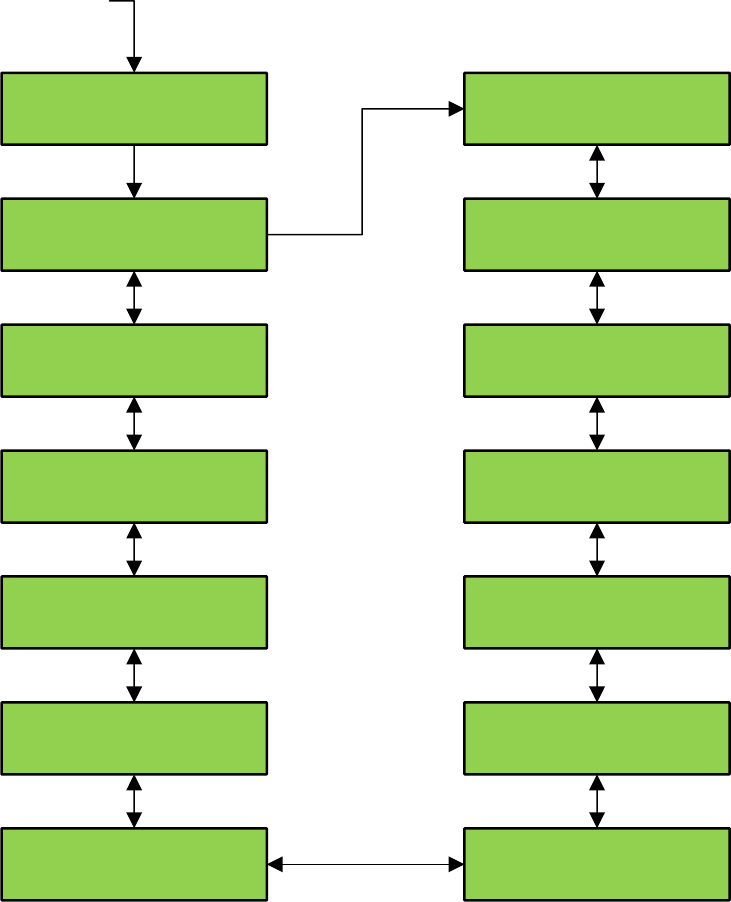
LCD Interface Flowcharts
LCD Interface Main Menu
GALaxy
CONTROLLER
GALaxy
Elevator Status
GALaxy
Set Calls and lockouts
GALaxy
Inputs and outputs
GALaxy
Job Statistics
GALaxy
Adjustable Variables
GALaxy
Date and Time
GALaxy
Fault Log
GALaxy
Elevator Setup
GALaxy
Hoistway Tables
GALaxy
Service Activation Timer
GALaxy
Select Video Display
GALaxy
Software Utilities
GALaxy
Diagnostics
Power Up
Mode
Up
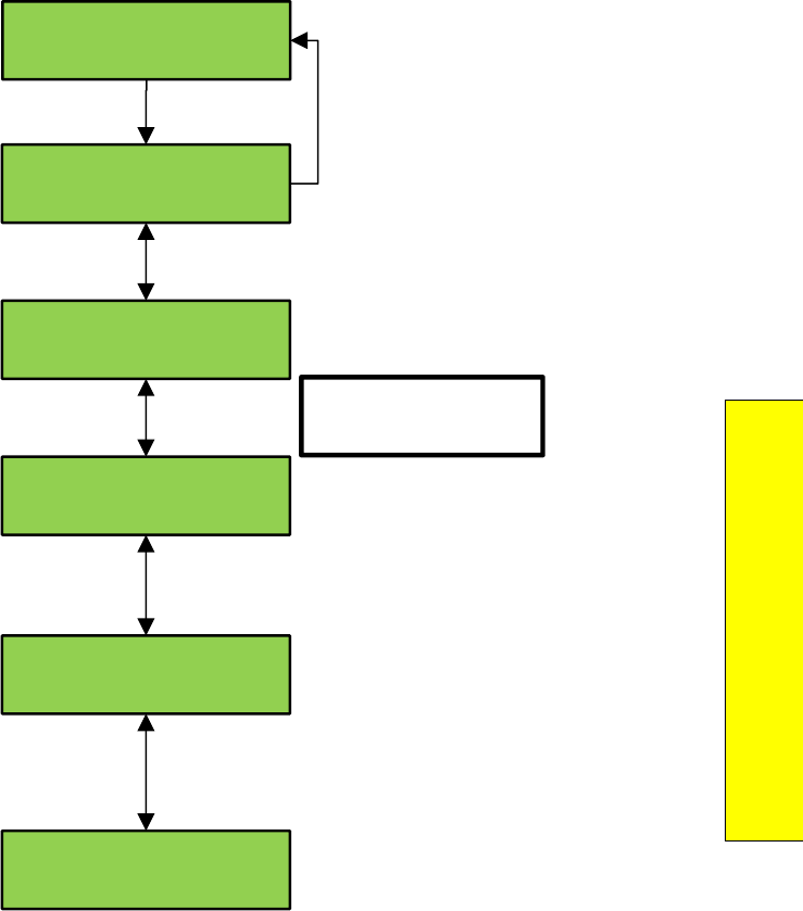
P a g e | 183
Section 10 – 1021/1101/1005 LCD
Interface
LCD Interface Main Menu - Elevator Status
GALaxy
Elevator Status
Automatic Service
Waiting Assignment PI=L
BkV Rq=120 BkvOut=118.5
BkV In=220 Bk Amp=3.5
Run=6.50 Lev=2.70
PDO=0 SFI=0 Roll=0
EXT Temp = 76 F
SPB Temp = 93 F
Dmd=350 Vel=350 Dir=Up
Dif=0 DP=1778556 PI=26
Enter
Mode
Elevator Status Floor Position
Brake Voltage Requested
Voltage Input to Brake
Board
Brake Voltage Output
Brake Amperage output
Above is valid if job has
electronic brake board
Brake to Brake Run Time Time In Leveling Mode
Time In Pre-Opening Mode
Indication of
Short Floor Run
Indication of early roll
out on short floor run
Demand Velocity
Feedback
Velocity
Feedback Direction
Floor Position
Digital Pulses
Velocity Difference
EXT Temp valid if
temp sensor provided
Temp of Safety Processor
board
LCD Interface - Set Calls and Lockouts

P a g e | 185
Section 10 – 1021/1101/1005 LCD
Interface
LCD Interface - Car Call Test Submenu
GALaxy
Set Calls and Lockouts
Set Calls and Lockouts
Setup Hall Calls
Set Calls and Lockouts
Car Call Test
Set Calls and Lockouts
Lockout Front Car Calls
Set Calls and Lockouts
Setup Up Hall Calls
Set Calls and Lockouts
Setup Down Hall Calls
Press Enter to Setup a
Car Call at Floor L
Press Enter to Setup a
Car Call at Floor PH
Press Enter to Setup a
Car Call at Floor 21
Press Enter to Setup a
Car Call at Floor 2
Enter
Mode
Enter
Enter to
Car Call Test Menu
Enter to
UP Hall Calls Submenu Enter
Enter to
Front Car Calls Submenu
Enter to
Down Hall Calls Submenu
If car has rear openings,
Rear call menus will appear.
Sets Car Call at Floor 2
Up
Down
Up
Down
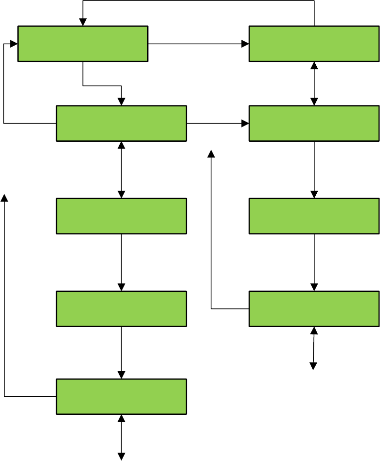
LCD Interface - Lockout Front Car Calls Submenu
Se Calls and Lockouts
Car Call Test
Do you want to continue
with previous CC test? Y
Are you sure you want to
enable CC test? No
Do you want to continue
with previous CC test? N
Press ENTER to Setup a
Car Call at Floor 1*
Press ENTER to Setup a
Car Call at Floor 1
Are you sure you want to
enable CC test? Yes
Press ENTER to Setup a
Car Call at Floor 1
Press ENTER to Setup a
Car Call at Floor 1*
Mode
Mode
Enter
Enter if CC test is
enabled
Enter if CC test is disabled
Enter
Enter
Enter
Up
Down
Removes asterisk
to disable CC test
at that floor.
To disable CC test
at other floors.
Down
Up
Enter
Enter Asterisk appears beside floor
number to denote CC test is
enabled for that floor.
To enable CC test
at other floors.
Up
Down
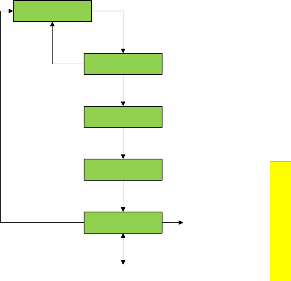
P a g e | 187
Section 10 – 1021/1101/1005 LCD
Interface
LCD Interface Main Menu - Inputs and Outputs
Set Calls and Lockouts
Lockout Front Car Calls
Are you sure you want to
secure car calls? No
Are you sure you want to
secure car calls? Yes
Press ENTER to Modify
Front CC Access At: 6
Press ENTER to Modify
Front CC Access At: 6*
Enter
Enter
Enter
Enter
Down
Up
Up
Down
Mode
Asterisk appears beside
floor number to denote
Car call is locked out.
To lock out car calls
at other floors.
ENTER Removes asterisk
to unlock car call
NOTE: Navigation to lock out Rear Car
Calls is similar to procedure below.
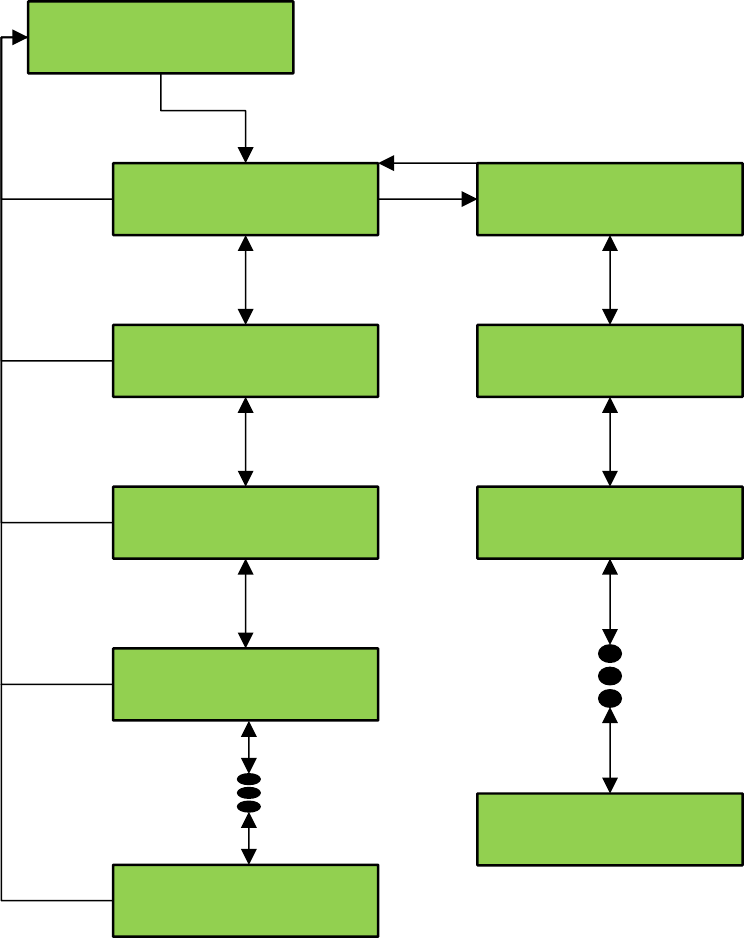
LCD Interface Main Menu - Job Statistics
GALaxy
Inputs and Outputs
Inputs and Outputs
Car Inputs and Outputs
Inputs and Outputs
Group Inputs and Outputs
Hall Call Board #1
Comm Status = 1
3U=0 4U=0 5U=1
6U=0 7U=0 8U=1
Main I/O Board
Block #1
EPLH=0
EPRL=0 EPSL=0 FLH=0
FS=0 FSX=0 BP=1
MES=1 RTL=1 MRS=1
DN=1 DT=1 DTS=1
DT1=1 DT2=1 DT3=1
Mode
Mode
Mode
Mode
Enter
Enter
Up
Up
Up
Up
Down
Down
Down
Down
Mode
If Car is Group
Dispatcher
2D=0 3D=1 4D=0
5D=0 6D=0 7D=1
Up
Down
Mode
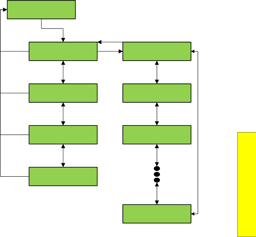
P a g e | 189
Section 10 – 1021/1101/1005 LCD
Interface
LCD Interface Main Menu - Adjustable Variables
GALaxy
Job Statistics
Job Statistics
View Job Statistics
Job Statistics
Clear Job Statistics
Press Enter to
Clear Job Statistics
Job Statistics
Cleared
Car Calls
15
Hall Calls > 60 Sec.
0%
Hall Calls < 60 Sec.
100%
Hall Calls < 60 Sec.
100%
Mode
Mode
Mode
Mode
Enter
Enter
Up Up
Down Down
Mode
Enter
Enter
Up
Down
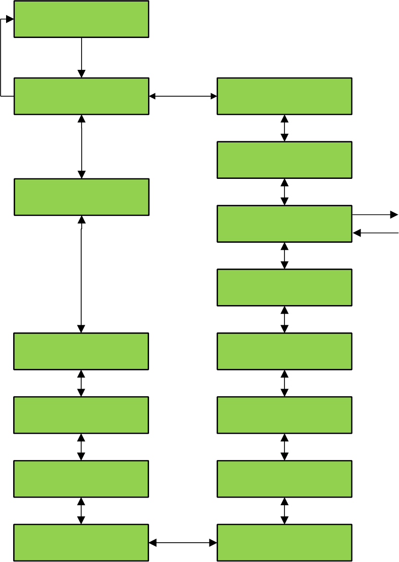
GALaxy
Adjustable Variables
Adjustable Variables
Car Motion
Adjustable Variables
Drive Parameters
Adjustable Variables
System options
Adjustable Variables
CB, VIP, & HSec Call Light
Adjustable Variables
HC & IR Call Lights
Adjustable Variables
CC & COP Lights
Adjustable Variables
Car Brake
Adjustable Variables
Modified Motion
Adjustable Variables
Car Timers
Adjustable Variables
Car Options
Adjustable Variables
Service options
Adjustable Variables
Fire Options
Adjustable Variables
Group Dispatch
Adjustable Variables
Group Options
Up Down
Enter
The above is
only on jobs
with KEB drive.
Enter
To Submenu
Mode
From Submenu
LCD Interface Main Menu - Car Timers Submenu
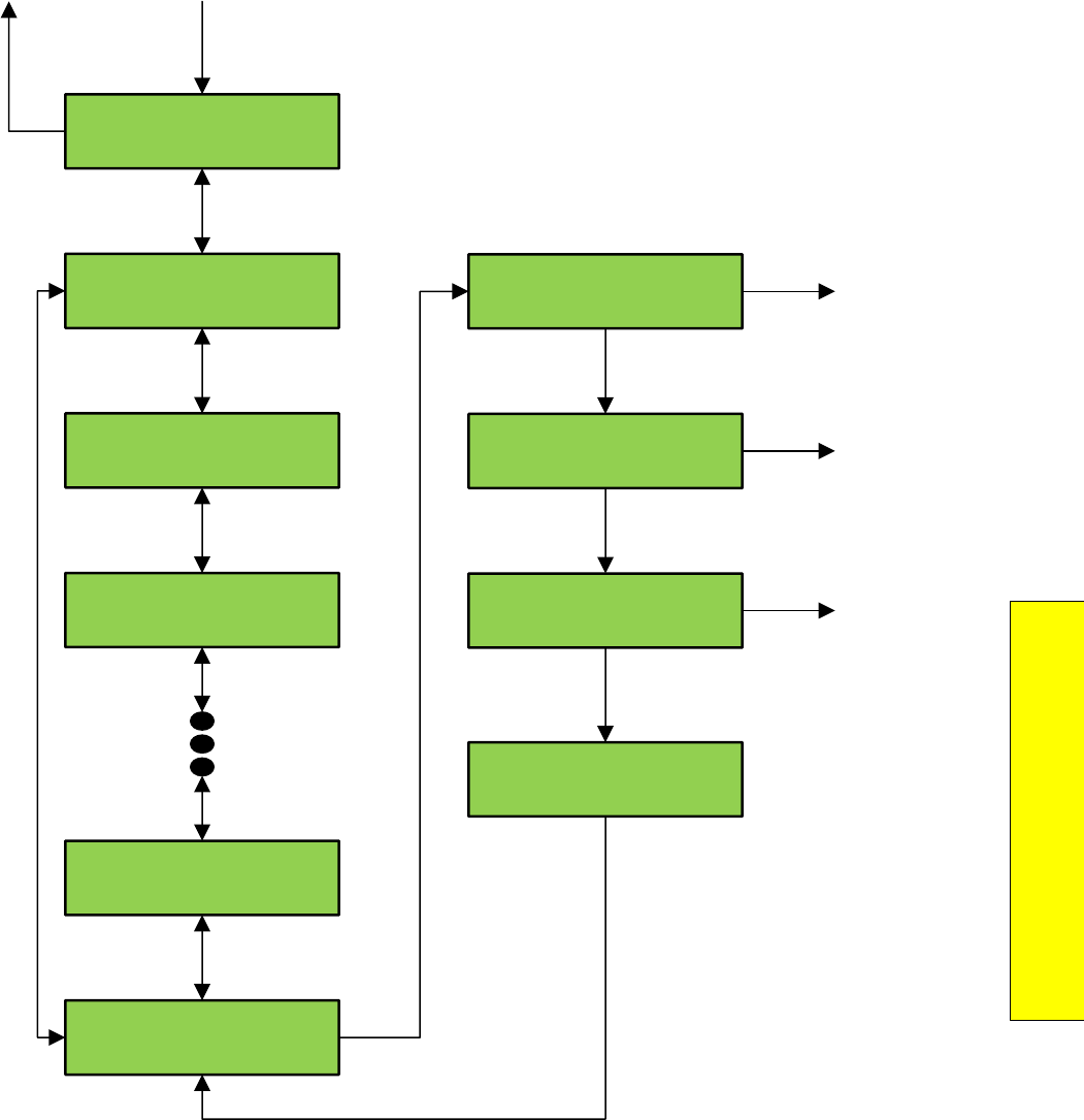
P a g e | 191
Section 10 – 1021/1101/1005 LCD
Interface
LCD Interface Main Menu - Date and Time
Car Timers
Y Delta Time = 000.15
Car Timers
OSER Sopen Tim = 0060.0
Car Timers
OSER BTFlr Tim = 0060.0
Car Timers
OSER Ncall Tim = 0600.0
Car Timers
Reset Time = 0005.0
Car Timers
Fault Time = 0002.0
Min=0 Max=10.0 Sec
Fault Tome = 0002.0
Min=0 Max=10.0 Sec
Fault Time = 0002.1
Min=0 Max=10.0 Sec
Fault Time = 0002.0
Min=0 Max=10.0 Sec
Fault Time = 0002.0
ENTER
From Adjustable Variables Menu
MODE
To Adjustable
Variables Menu
Up
Down
Up Increments Number
Down Decrements Number
Mode Selects Next Field
Enter Stores the value
Enter Stores the
value
Enter Stores the
value
Enter Stores the
value
NOTE: This flowchart shows the “Car
Timers” submenu. Other “Adjustable
Variables” submenus are similar.
Enter
Enter

LCD Interface Main Menu - Diagnostics
GALaxy
Date and Time
Date and Time
Set Date and Time
Date and Time
View Day of the Week
Day of the Week
Saturday
Press Enter to Set
14:45 3/28/2014
Press Enter to Set
14:45 3/28/2014
Press Enter to Set
14:46 3/28/2014
Press Enter to Set
14:45 3/28/2014
Enter
Enter
Enter
Mode
Down
Mode
Mode
Up
Down
Selects the next field.
Increments Number
Decrements Number
Enter Stores the Value
Enter Stores the Value
Enter Stores the Value
Enter Stores the Value
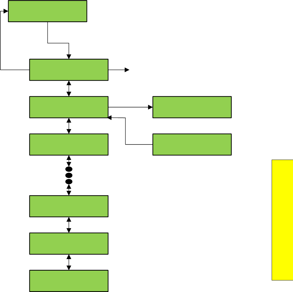
P a g e | 193
Section 10 – 1021/1101/1005 LCD
Interface
LCD Interface - View System Status Log Submenu
GALaxy
Diagnostics
Diagnostics
View System Status Log
Diagnostics
Clear Drive Comm Status
Diagnostics
Drive Comm Status
Diagnostics
Clear Group Comm Status
Diagnostics
Group Comm Status
Diagnostics
Clear System Status Log
Press Enter to Clear the
Drive Comm Status
Drive Comm Status
Cleared
Mode
Enter
Up Down
Enter
Mode
Enter to select
NOTE: Similar procedure to clear:
System Status Log
Car Comm Status
Group Comm Status
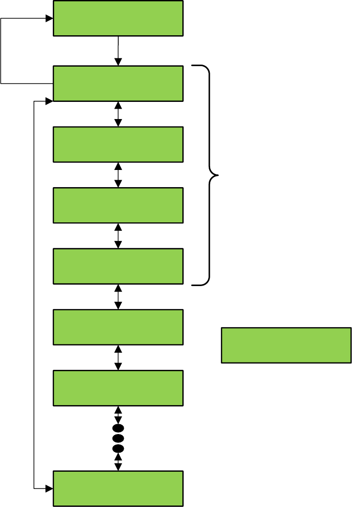
LCD Interface - Group Comm Status Submenu
Diagnostics
View System Status Log
000 Status Buffer PI=1
Automatic Service
000 Status Buffer PI=1
Waiting Assignment
000 Status Buffer PI=1
Status OK
000 Status Buffer PI=1
No faults
-001 Status Buffer PI=1
Automatic Service
-001 Status Buffer PI=1
Waiting Assignment
-001 Status Buffer PI=1
Automatic Service
-255 Status Buffer PI=1
Reset Fault
Enter
Mode
Up
Down
Buffer Index Floor Position
Status Messages
Elevator Status
Type of service
Condition status
Fault status
Status
Buffer is
grouped
into 256
blocks
with 4
events
per block

P a g e | 195
Section 10 – 1021/1101/1005 LCD
Interface
LCD Interface – Car Comm Status Submenu
Diagnostics
Group Comm Status
Group to Car #1
Internal Comm
Group to Car #1
Ver: 7.00 On-line=1
Group to Car #2
TxCnt 3196 RxCnt 3195
Group to Car #2
Ver: 7.00 On-line=1
Group to Car #3
TxCnt 4567 RxCnt 4569
Group to Hall #1
Ver: 5.54 On-line=1
Car #2 to Group
TxCnt 10132 RxCnt 10235
Car #2 to Group
Ver: 7.00 On-line=1
Enter
Enter
Down Up Up
Down
Mode
Name of comm device
Transmit count Receive count
Enter to update count
If On-line=1, device is communicating.
If On-line=0 device is not communicating
For car that is the
group dispatcher
For car that is not the
group dispatcher
Software version
LCD Interface CAN Encoder Comm Status
Diagnostics
Car Can Comm Status
Can Bus Error Count
TxErr 0 RxErr 0
Car to TOC #9
Ver: 5.54 On-line=1
Car to TOC #9
TxCnt 3196 RXCnt 3195
Car to SEB #21
Ver: 5.54 On-line=1
Car to SEB #21
TxCnt 4567 RxCnt 4569
Car to Brake
TxCnt 2183 RXCnt 2165
Enter
Mode
Down
Up If On-line=1 device is
communicating.
If On-line=0, device is
not communicating.
ENTER
To update count
Name of comm device
Transmit count Receive count
Diagnostics
CAN Encoder Comm Status
Can Enc Bus Error Count
TxErr 0 RxErr 0
Car to Can EncoderPPR:
10000 On-Line = 1
Car to Can Encoder
TxCnt 0 RxCnt 0
Enter
Mode
Down
Up If On-line=1 device is
communicating.
If On-line=0, device is
not communicating.
ENTER
To update count
Transmit count Receive count
P a g e | 197
Section 10 – 1021/1101/1005 LCD
Interface
LCD Interface – UPS Comm Status Submenu
Diagnostics
UPS Comm Status
Car to UPS
TxCnt 460 RxCnt 466
Car to UPS
Battery Capacity 0.00 %
Car to UPS
Status: 00 On-Line = 1
Enter
Mode
If On-line=1 device is
communicating.
If On-line=0, device is
not communicating.
Transmit count Receive count
LCD Interface - Drive Comm Status Submenu
Diagnostics
Drive Comm Status
Car to HPV-6/900
TxCnt 5387 RxCnt 5163
Car to HPV-6/900
Ver: 1.01 On-line=1
Enter
Mode ENTER
To increment count
Down
Up
Receive count
Transmit count
If On-line=1, device
Is communicating.
If On-line=0, device
Is not communicating
Name of drive type
P a g e | 199
Section 10 – 1021/1101/1005 LCD
Interface
LCD Interface Main Menu - Software Utilities
GALaxy
Software Utilities
Software Utilities
View Software Version
Software Utilities
SD Card Status
Software Utilities
SD Card Read / Write data
Software Utilities
Reset Debug Variables
Software Utilities
Test Watchdog Reset
Software Utilities
Run Power-Up Mode
Car #1 HR
Software Ver: 6.00.31
Enter
Mode
SD Card Status
Press Enter for Status
SD Card Status
Init=1, HC=1, Vstat=1
Debug Variables
Reset
Place car on Inspection
and then hit Enter
Place car on Inspection
and then hit Enter
Enter
Mode
Enter
Mode
Enter
Mode
Enter
Mode
Mode
Enter
Press Enter to Select SD Card Read Write Data Menu
Press Mode to return
Enter
Enter
Main CPU
performs reset
Main CPU jumps to
Power-Up Mode
Mode Enter
Software Utilities
Clear Trace
Software Utilities
Initialize & Start Trace
Software Utilities
Load 1036 Hoistway Setup
Software Utilities
Load 1036 Field variables Used for CPU replacement
Used for CPU replacement
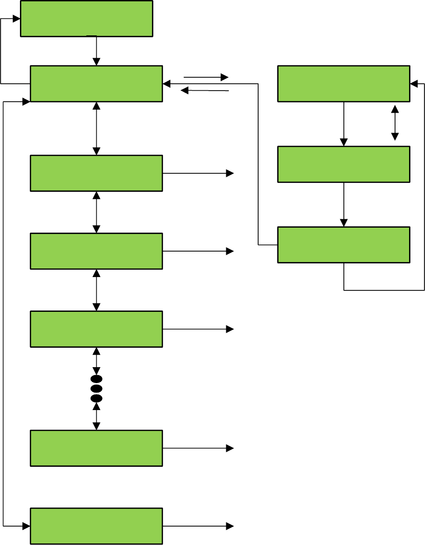
LCD Interface - SD Card Read - Write Data Submenu
Software Utilities
SD Card Read / Write Data
Place Car on Ins / Press Enter
Write Field variables
Place Car on Ins / Press Enter
Write Job Statistics
Place Car on Ins / Press Enter
Write Long Term Faults
Place Car on Ins / Press Enter
Write Fault Log
Place Car on Ins / Press Enter
Read Security Data
Place Car on Ins / Press Enter
Read Field Variables
Press Enter to select
Write Faul Log submenu
Press Enter to select
Write Long Term Faults submenu
Press Enter to select
Write Fault Log submenu
Press Enter to select
Read Security Data submenu
Press Enter to select
Read Field Variables submenu
Write Field Variables
Overwrite Existing File? Y
Write Field Variables
Writing…..Please Wait
Write Field Variables
Data Written to File
Enter
Mode
Enter
Mode
Enter
Enter
Enter
Up/Down Y/N
NOTE: All submenus work
In a similar manner.
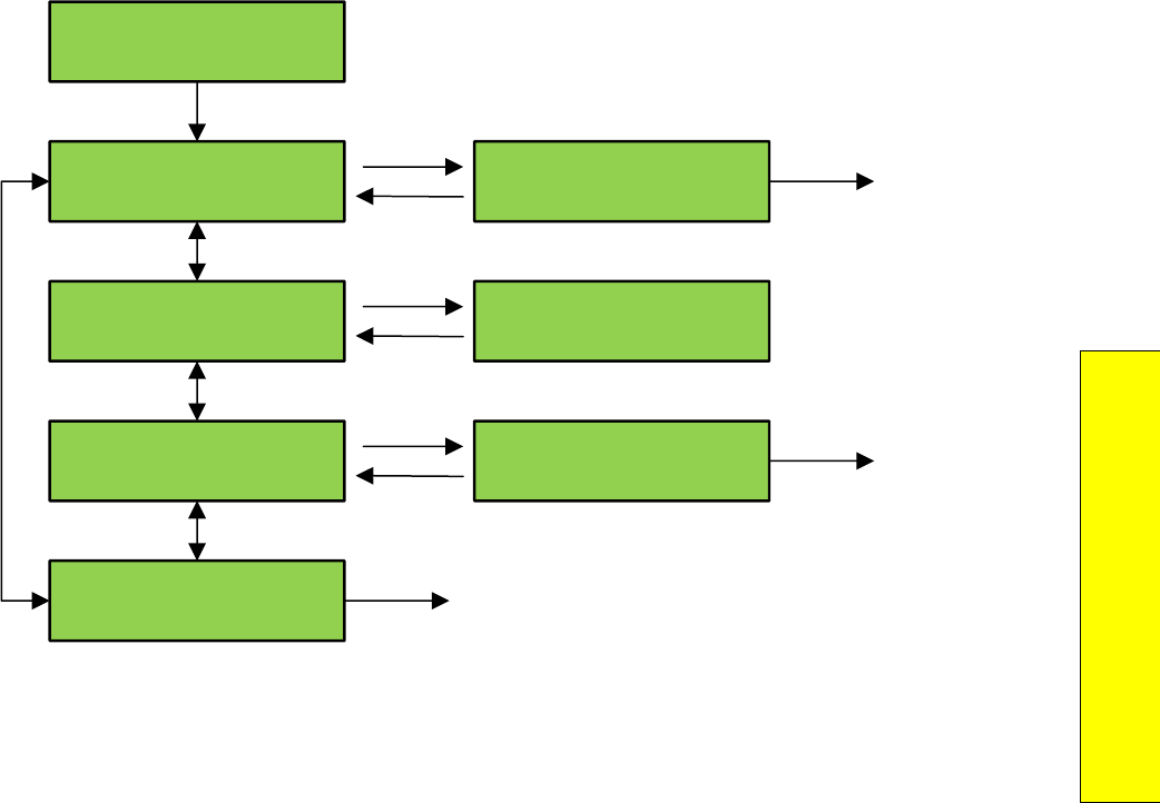
P a g e | 201
Section 10 – 1021/1101/1005 LCD
Interface
LCD Interface - Power-Up Mode
GALaxy
Power-Up Mode
GALaxy
Test Watchdog Reset
GALaxy
View Software Version
GALaxy
Run Controller program
GALaxy
Update / Verify Program
Press Enter to Run
Or Mode to Cancel
Power-Up Routine
Software Ver: 1.00.05
Press Enter to run
Watchdog reset
Enter
Mode
Enter
Mode
Enter
Mode
ENTER to select
Update / Verify Program Menu
ENTER
Main CPU
performs Reset
ENTER
Main CPU jumps to
Controller Program
Power-Up mode is reached by
powering up the controller without
an SD Card, or it can be activated
from Software Utilities.
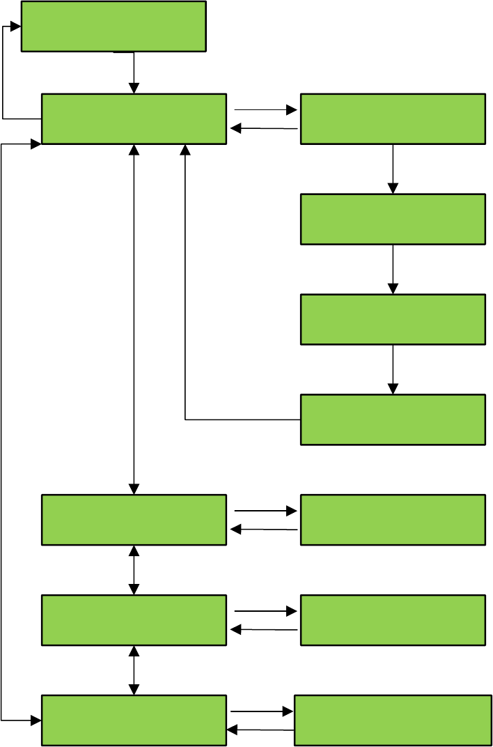
LCD Interface - Update - Verify Program Submenu
GALaxy
Update / Verify Program
Update / Verify Program
Load Program from SD Card
Press Enter to Begin
Or Mode to Cancel
Load Program from SD Card
Erasing Flash…..
Load Program from SD Card
Programming Flash…..
Load Program from SD Card
Operation Complete
SD Card Status
Init=1, HC=1, Vstat=1
Cons File Status
Cons File Okay
Program Verify OK
mRam225B39C0,Pgm225B39C0
Update / Verify Program
SD Card Status
Update / Verify Program
Cons File Status
Update / Verify Program
Program Status
Enter
Mode
Enter
Mode
Enter
Mode
Enter
Mode
Enter
Mode
SD Card Initialized - High Capacity - Voltage Status
Cons File Verified OK
Program File Verified OK
Mram Checksum Program Checksum
Flash Erased
Flash Programming
Finished

P a g e | 203
Section 10 – 1021/1101/1005 LCD
Interface
LCD Interface Main Menu - Select Video Display
GALaxy
Select Video Display
Press Enter to Set Video
To Group Display
Press Enter to Set Video
To Group I/O Display
Press Enter to Set Video
To Car 1, I/O Screen 1
Press Enter to Set Video
To Car 1, I/O Screen 2
Press Enter to Set Video
To Car 1, Fault Log
Press Enter to Set Video
To Car 3, Fault Log
Enter
Enter
Enter
Enter
Enter
Enter
Enter
Mode
Sets Monitor
To Group Display
Sets Monitor
To Group I/O display
Sets Monitor
To Car 1, page 1
I/O Screen
Sets Monitor
To Car 1, page 2
I/O Screen
Sets Monitor
To Car 1 fault
screen
Sets Monitor
To Car 3 fault
screen
NOTE: This flowchart is valid when the video
monitor is installed on the dispatcher car. If
the monitor is installed on a non-dispatcher
car, then only information from that car is
displayed on the monitor
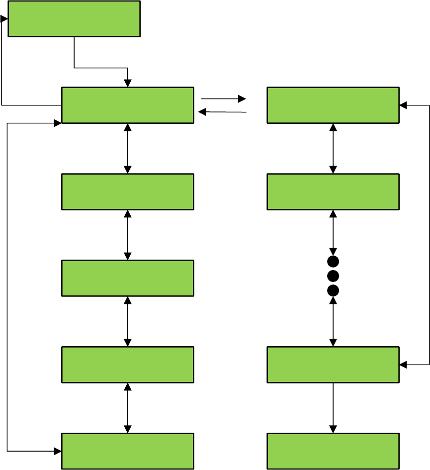
LCD Interface Main Menu - Hoistway Tables – Display - Mod Hoistway Tables
Submenu
GALaxy
Hoistway Tables
Hoistway Tables
Disp / Mod Hoistway Tables
Hoistway Tables
Reset Update Count trig
Hoistway Tables
Pulse Count Update Data
Hoistway Tables
FL & FL Offset Count
Hoistway Tables
DZ & LZ Offset, Sel Cnt
DP=1483661 Vel=350 Dir=U
P1=9778 .1
DP=1483661 Vel=350 Dir=U
UT1=6683179 232.9
DP=1483661 Vel=350 Dir=U
P2=353841 12.1
DP=1483661 Vel=350 Dir=U
P2=353841 12.1
Enter
Mode
Enter
ENTER selects count value
MODE selects digit
UP increments digit
DN decrements digit
ENTER stores value
To force value in
Floor table
Limit switch and
stored pulse count
Current pulse
count
Current demand
velocity
Current
direction
Floor level and
Stored pulse count
Distance from
DN Normal limit
Up
Down
Enter
Mode
Up
Down
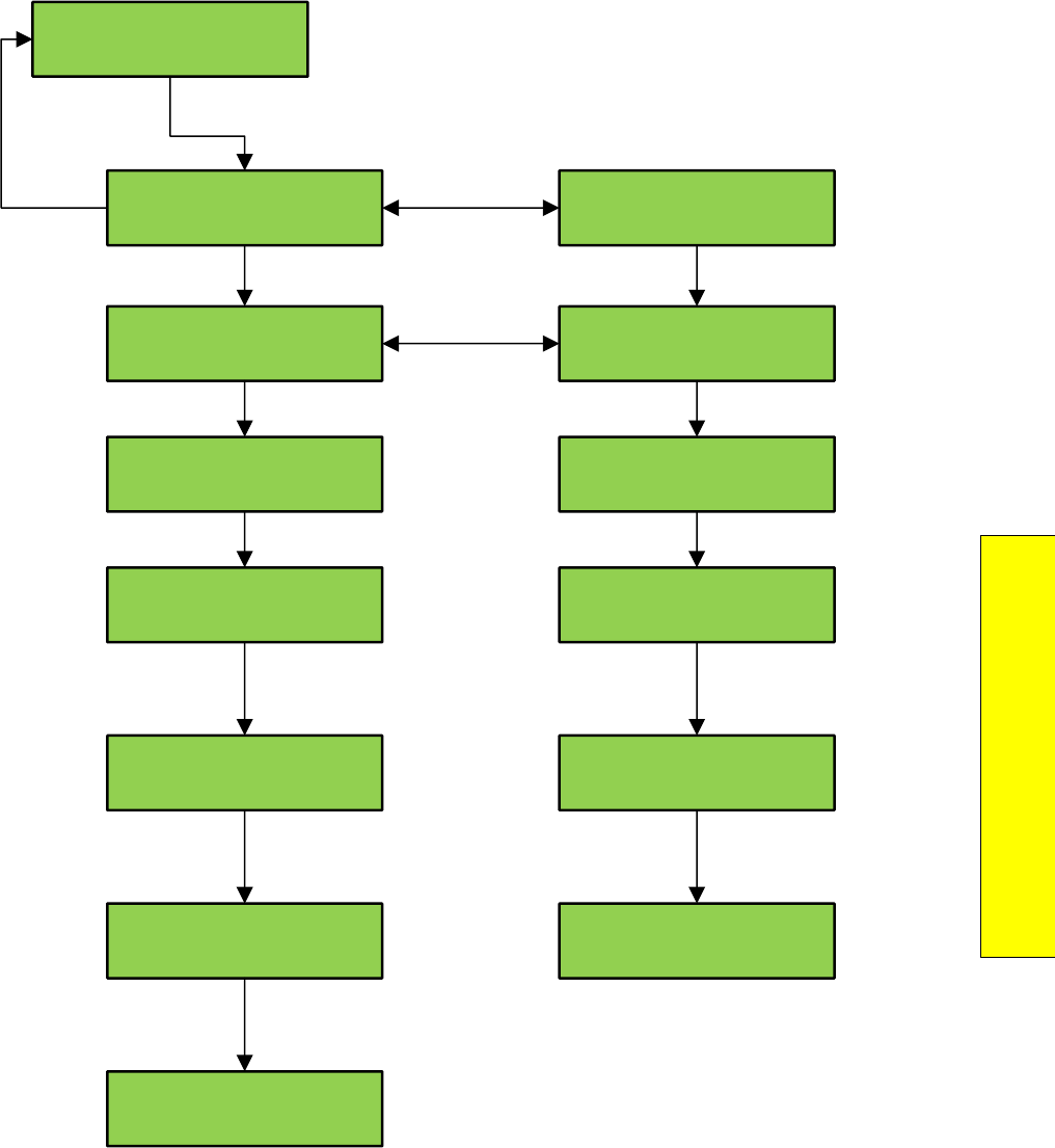
P a g e | 205
Section 10 – 1021/1101/1005 LCD
Interface
LCD Interface - Hoistway Tables - Learn Hoistway Submenu
Hoistway Setup
Learn Hoistway
<UP/DN> to Select then
<ENTER> to Learn Auto
<UP/DN> to Select then
<ENTER> to Learn Insp
Keep Existing UL and DL
Level Zone Offsets Y
Press the Enter Button
To Start the Learn Mode
Run Elevator UP on Ins
Non Stop to Top Dir Stop
DP=678935 Vel=30 Dir=U
PI=7 653821 87.4 ft
Hoistway Learn
Complete
Keep Existing UL and DL
Level Zone Offsets N
Press the Enter Button
To Start the Learn Mode
Put Elevator on
Automatic Operation
DP=678935 Vel=30 Dir=U
PI=7 653821 87.4 ft
Put Elevator on
Inspection Operation
Hoistway Learn
Complete
Up
Down
Mode
Enter
Enter Enter
UP or DOWN
Selects Y or N
Run elevator non-stop
To top of normal limit
Set “INSP”
switch to “INSP”
Elevator will run to
top normal limit
Set “ISNP” switch
to “NORM”
NOTE: Hoistway Learn procedure
below begins with elevator on
down normal limit, with “UL” and
“DZ” signals “ON”; and “DL” signal
“OFF”.
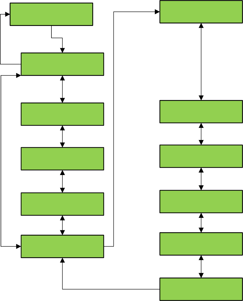
LCD Interface Main Menu - DZ & DZ Offset, Sel Cnt Submenu
GALaxy
Hoistway Tables
Hoistway Tables
Disp / Mod Hoistway Table
Hoistway Tables
Reset Update Count Trig
Hoistway Tables
Pulse Count Update Data
Hoistway Tables
FL & FL Offset Count
Hoistway Tables
DZ & DZ Offset, Sel Cnt
Dn DZD Dist=000115
Up DZU Dist-000115
PPR=2048 Base=10
DPP=20984 IC=12
Vel=5 EncVel=6
Pulses/Inch = 40.5
UL/DL Count = 000084146
Offset Cnt = 000084146
Sel Top Cnt = 000316263
Sel Bot Cnt = 000005316
Dn Lev Dist = 000000
Up Lev Dist = 000000
Enter
Mode
Up
Down
Enter
Mode
Distance from DL to DZ
In down direction
ENTER to change
values
Distance from UL to DZ
in up direction
ENTER selects DZD
UP & DN switches to DZU
ENTER selects value
MODE selects digit
ENTER stores value
MODE deselects value
MODE returns to menu
CAN open encoder PPR
Difference of encoder
count and DP count
Encoder reset count
DP count
Demand velocity Encoder velocity
# of pulses per inch
Selector top count
Selector bottom count
Down level distance
Up level distance ENTER selects Dn Lev Dist
UP & DN switches to Up Lev Dist
ENTER selects value
MODE selects digit
ENTER stores value
MODE deselects value
MODE returns to menu
ENTER to change
values
Valid when adjustable
variable “Stop On Pos Cnt”
is enabled.
Up
Down
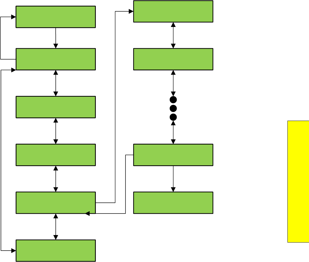
P a g e | 207
Section 10 – 1021/1101/1005 LCD
Interface
LCD Interface Main Menu - FL & FL Offset, Sel Cnt Submenu
GALaxy
Hoistway Tables
Hoistway Tables
Disp / Mod Hoistway Table
Hoistway Tables
Reset Update Count Trig
Hoistway Tables
Pulse Count Update Data
Hoistway Tables
FL & FL Offset Count
Hoistway Tables
DZ & DZ Offset, Sel Cnt
Up
Down
Enter
Mode
FL 1 = 00006416
Offset = 000000
Fl 17 = 01483661
Offset = 000000
FL 2 = 00012357
Offset = 000000
FL 2 = 00012357
Offset > 000000
Enter
Mode
Up
Down
NOTE: The “Offset value below is valid when
the “Stop On Pos Count” adjustable variable
is enabled.
ENTER to add offset or change
stored floor count
ENTER selects offset
UP & DN switches from Offset to FL
ENTER selects value
MODE selects digit
UP & DN increments and decrements value
ENTER stores value
MODE deselects Offset or FL
MODE returns to menu

LCD Interface Main Menu - Reset Update Count Trig, Pulse Count Update Data
Submenu
GALaxy
Hoistway Tables
Hoistway Tables
Disp / Mod Hoistway Table
Hoistway Tables
Reset Update Count Trig
Hoistway Tables
Pulse Count Update Data
Hoistway Tables
FL & FL Offset Count
Hoistway Tables
DZ & DZ Offset, Sel Cnt
Up
Down
Enter
Mode
Pulse Count Update
Trigger Reset
Press Enter To
Reset the Update Trigger
P1 pf=7 Tr=2 Max=0
VUDif=000023 Vel=000389
P1 pf=7 Tr=2 Max=0
Diff=00023 VErC=000000
P1 pf=7 Tr=2 Max=0
VUDif=000015 Vel=000398
Enter
Enter
Mode
Mode
Up
Down
NOTE: The “Reset Update Count Trig” and the
“Pulse Count Update Data” are valid when the
“Pos Count Upd” adjustable variable is enabled.
They are used to provide information to properly
set this variable.
Trace flag
Floor Position
Process flag
DP count
difference
Velocity error
count
Velocity count
update difference
Velocity
at update
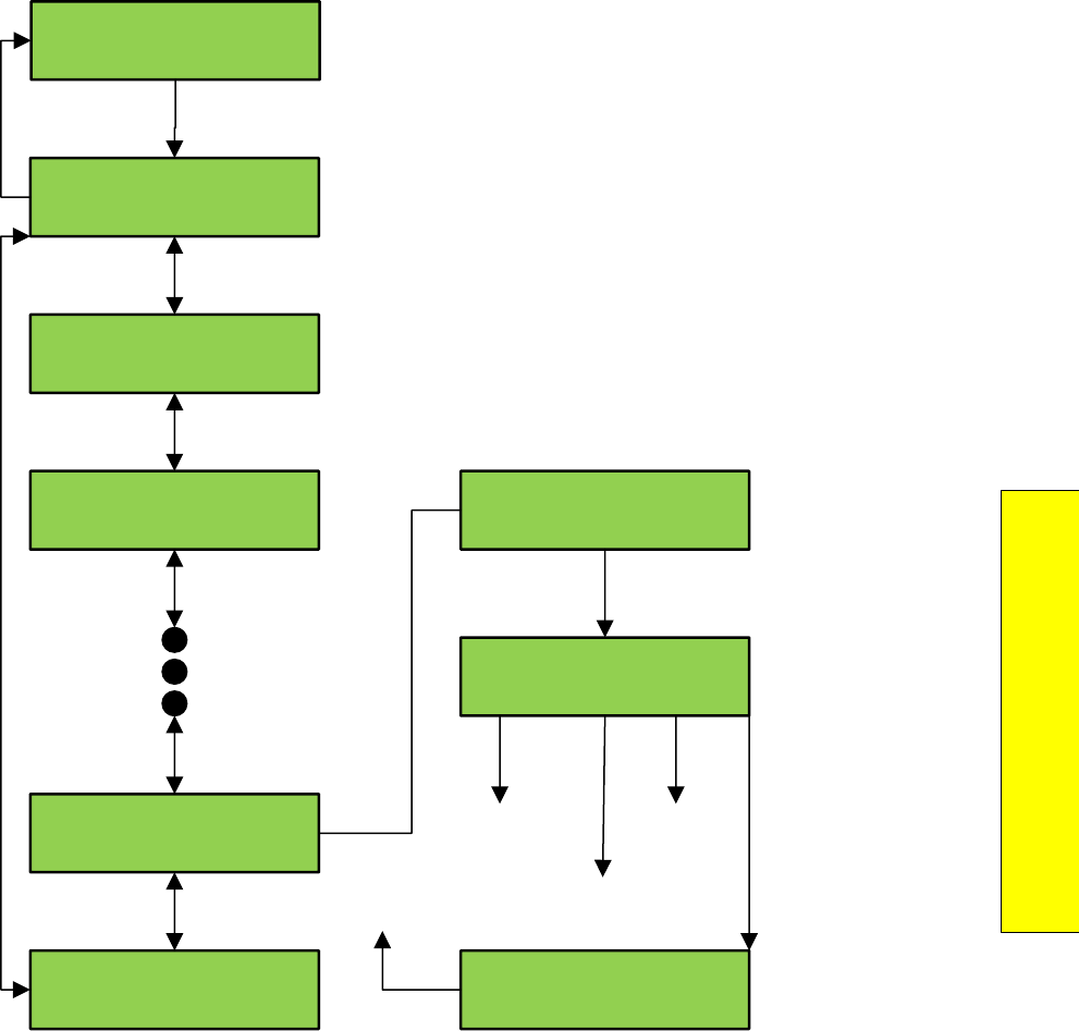
P a g e | 209
Section 10 – 1021/1101/1005 LCD
Interface
LCD Interface Main Menu - Elevator Setup
GALaxy
Elevator Setup
Elevator Setup
Learn Hoistway
Elevator Setup
Lift Brake on Inspection
Elevator Setup
Reset Gripper / EBK Fault
Elevator Setup
Set Ins / Leveling Clamp
Elevator Setup
Learn Limit Velocities
Clamp Speed: 0140 fpm
Ins / Lev spd: 0140 fpm
Clamp Speed: 0140 fpm
Ins / Lev spd: 0140 fpm
Clamp Speed: 0140 fpm
Ins / Lev spd: 0140 fpm
Up Mode Down Enter
Increments
value
Decrements
value
Selects next
digit Stores
value
Enter
Enter
Up
Down
Enter
Mode
Mode
LCD Interface - Open - Close doors
Elevator Setup
Open / Close Front Door
Press UP to open F Door
Press DN to close F Door
Car must be on
Inspection or Safeties
Enter
Mode
Up
Down
Elevator Setup
Open / Close Rear Door
Press UP to open R Door
Press DN to close R Door
Car must be on
Inspection or Safeties
Enter
Mode
Up
Down
Car must be on inspection. If not
message below is displayed
P a g e | 211
Section 10 – 1021/1101/1005 LCD
Interface
LCD Interface - Lift Brake On Inspection Submenu
Elevator Setup
Lift Brake On Inspection
Lift Brake On Inspection
Car must be on Inspection
Lift Brake On Inspection
Ins Up & Dn Must Be Off
Car Not Safe
Press Dn to Override
Car Not Safe
Press Mode to Continue
Car Not Safe
Press Up and Enter Buttons
Car Not Safe
Lifting Brake 15 Seconds
Car Not Safe
Brake Dropped: Timed-out
Car Not Safe
Press Up and Enter Buttons
Car Not Safe
Lifting Brake 15 Seconds
Car Not Safe
Brake Dropped: Timed-out
Enter
Enter
Down
Mode
UP & Enter
UP & Enter
Released
UP & Enter
Released
UP & Enter
Released
UP & Enter
Released
Up & Enter pressed
for 15 seconds
Up & Enter pressed
for 15 seconds
MODE to return to menu
Mode
If car is on
inspection
If car is not on inspection If inspection
“UP” or “DN”
buttons are off
If door lock and
gate switch are
closed
If Inspection buttons
“UP” or “DN” are on.
If door lock or gate
switch is open
If car is on inspection
and door lock and
gate switch are
closed.
WARNING: Brake will
lift during this test. Make
sure that all safety
procedures are observed.
NOTE: This flowchart describes the
navigation required to prepare the
LCD interface to allow the service
brake to be lifted for testing of the
rope-gripper or emergency brake.
Other actions must also be
performed which are specific to the
controller type. See “Controller Test
Procedure” document for complete
details.
LCD Interface - Load Weigher Setup Submenu
Elevator Setup
Load Weigher Setup
Load Weigher Setup
Setup Load Weigher
Load Weigher Setup
Load Weigher Calibration
Load Weigher Setup
View / Modify load Limits
Load Weigher Setup
View / Modify LW Setup
LW Device Stat: ON:OK
Input: 0283 Load: 027%
LW Device Stat: ON:OK
Input: 0283 Load: 027%
Place Car on Independent
With Autodoor Switch off
Run Car to the
Bottom Floor
Press Enter to Start
Load Weigher Empty Setup
Car Running Empty Car
Load Weigher Setup
Empty Car Setup Finished
Run Car to Loading Floor
Place Full Load in Car
Turn Autodoor Switch Off
With Full Load In car
Press Enter to Start
Car Running Full
Load Setup
Load Weigher Setup
Complete
Enter
Enter
Enter
Mode
Enter
Enter
Enter
Enter
Enter
Up
Down
Up
Down
Enter
To Load Weigher Calibration
To View / Modify Load Limits
A/D input reading
from load weigher
Percent Load
Status blinks to modify
To store
Status options
ON:OK – LW on and device is ok
ON:ERR – LW on and device has error
OFF:OK – LW off and device is ok
OFF:ERR – LW off and device has error
NOT:SET – LW device is not set
To force status
change
Empty car runs to all floors
and records load readings
Set “AUTO DOOR” switch
“ON” to load car
Set “AUTO DOOR” switch
“OFF” after loading car
Full car runs to all the floors
and records load reading
P a g e | 213
Section 10 – 1021/1101/1005 LCD
Interface
LCD Interface - View - Modify Load Weigher Limits
Elevator Setup
Load Weigher Setup
Load Weigher Setup
Setup Load Weigher
Load Weigher Setup
Load Weigher Calibration
Load Weigher Setup
View / Modify Load Limits
Load Weigher Setup
View Modify LW Setup
Floor #1 Load Limits
Empty: 0126 Full> 0768
Floor #2 Load Limits
Empty> 0145 Full: 0785
Floor #2 Load Limits
Empty: 0145 Full> 0785
Floor #1 Load Limits
Empty> 0126 Full: 0768
Floor #15 Load
Limits
Empty: 0158 Full> 0796
Floor #15 Load
Limits
Empty: 0158 Full> 0796
Enter
Enter
Enter
Mode
Mode
Up
Down
Up
Down
Up
Up
Down
Down
Arrow indicates
value to edit
Switches arrow to
next value to edit
Selects value
MODE selects digit
UP increments value
DN decrements value
ENTER stores value
MODE returns to menu

LCD Interface - Calibrate Load Weigher
Elevator Setup
Load Weigher Setup
Load Weigher Setup
Setup Load Weigher
Load Weigher Setup
Load Weigher Calibration
Load Weigher Setup
View / Modify Load Limits
Load Weigher Setup
View / Modify LW Setup
Place car on Auto, Door
Closed and D Switch Off
Press Enter to
Calibrate Load Weigher
Load Weigher Calibration
Flag has been Activated
Load Weigher
Calibration Complete
Enter
Mode
Up
Down
Enter
Mode
Enter
Car on Automatic with
“AUTO” door switch set
to “OFF”
Car runs to bottom
floor and calibrates
load weigher
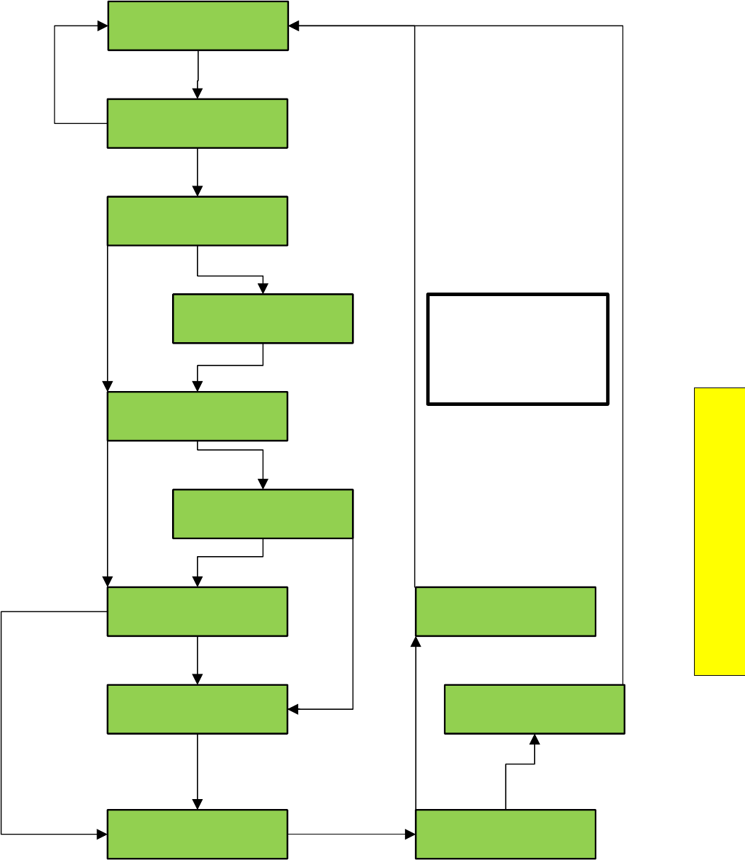
P a g e | 215
Section 10 – 1021/1101/1005 LCD
Interface
LCD Interface - Car Buffer Test Submenu
LCD
Elevator Setup
Car Buffer Test
Put Elevator on
Inspection Operation
Press Enter to Continue
with Test Procedure
Turn Automatic Door
Switch Off
Turn Inspection Sw to Norm
and Place Car on Ind
On a terminal floor. To
position car press Enter
Press Enter to position
car or press UP to skip
Waiting for car to
reach test position
Press Enter Button to
Run Buffer Test
Press Enter Button to
Cancel Buffer Test
Buffer Test Complete
Press Mode for Menu
Buffer Test Cancelled
Press Mode for Menu
Mode Enter
Enter
Enter
Mode
Mode
Enter
Enter
Enter
Turn Machine Room
Inspection switch to “INSP”
Set “AUTO DOOR”
Switch to “OFF”
If “AUTO DOOR”
Switch is “OFF”
Car not on a
Terminal floor
Car is on independent
and door is disabled
Car in position
Car must be
positioned so
that it will
reach top
speed when
hitting buffer Terminal limits are disabled
automatically in software
during test so physical limits
do not need to be jumped out
WARNING:
Car / Counterweight will run
at high speed to pit buffer
during this test. Make sure
that all safety procedures are
observed.
Up
Car runs to buffer
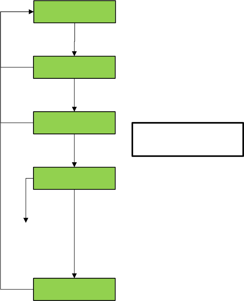
Interface – Overspeed Test Submenu
Hoistway Setup
Overspeed Test
Turn Automatic Door
Switch to Off
Press the Enter Button
To Enable Overspeed Test
Overspeed Test Active
Hit Up & Enter to Hold Brk
Overspeed Test Complete
Press Mode for Menu
Enter
Enter
Mode
Mode
Mode
Mode
Up & Enter
To navigate
to set car call
Set “AUTO DOOR”
Switch to “OFF”
This step allows main
brake to stay picked until
test is complete in order
for gripper or e-brake to
stop and hold car when
overspeed switch trips. To
run test, set car call and
navigate back to screen
above to keep main brake
picked during test.
NOTE: Before performing Overspeed test
procedure, the following parameters should
be adjusted to force the car to run faster than
contract speed.
For DSD 412 drive - drive function #11
Motor RPM
For HPV600/900 – drive parameter A1
Contract MTR Speed
For KEB F5 – from the Controller’s LCD
interface, “Adjustable Variables”, “Car
Motion” adjust “DRV Speed Mult”.
After test s complete, return parameters to
proper values for contract speed.
WARNING: Car will overspeed during this
test. Make sure that all safety procedures
are observed.
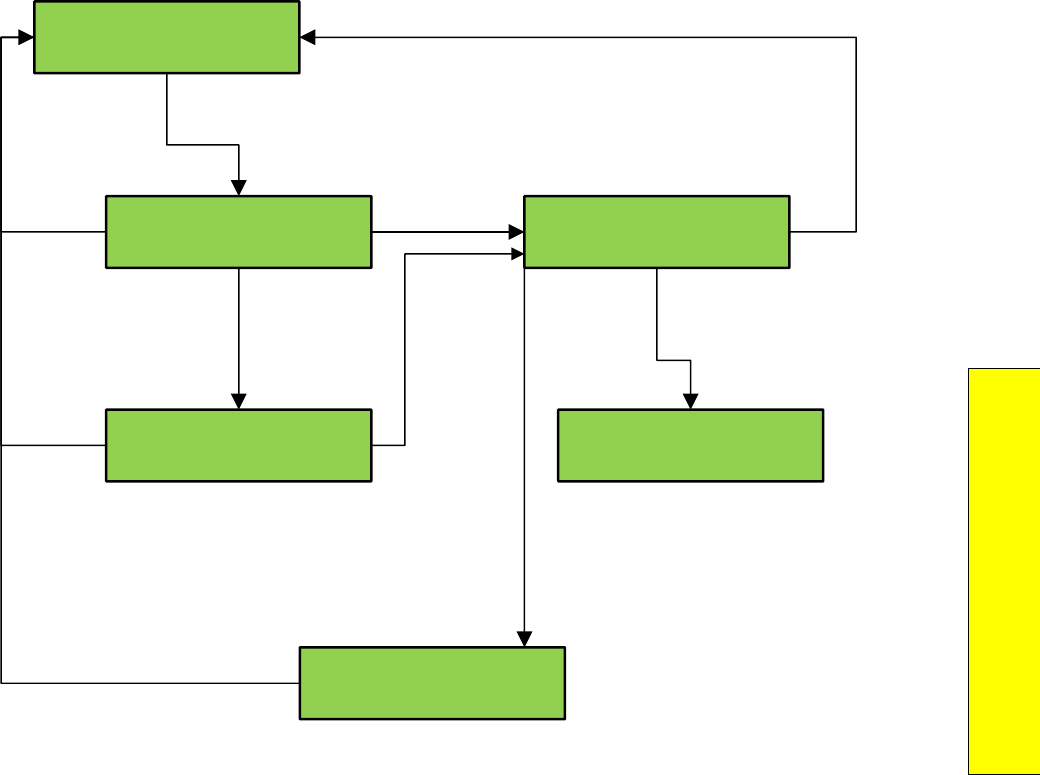
P a g e | 217
Section 10 – 1021/1101/1005 LCD
Interface
LCD Interface - Reset Gripper Fault
Elevator Setup
Reset Gripper / EBK Fault
GOV must not be tripped
To Reset Gripper Fault
Press and Hold Enter
To Reset Gripper Fault
Car must be on Inspection
To Reset Gripper Fault
Rope Gripper
Is Reset
No Rope Gripper Fault
GTS Input Off
Mode
Mode
Mode
Mode
Enter
Enter
If governor
is tripped
If car not
on inspection Car placed
on
Inspection
operation.
Must hold Enter button
Until LCD displays:
“Rope Gripper is Reset”
Gripper Sets
Release Enter button
Press Mode to return to menu
If gripper fault is
reset and GTS input
remains off
Reset
governor

LCD Interface - Fault Log
GALaxy
Fault Log
Fault Log
View Fault Log
Fault Log
Clear Fault Log
Press Enter to
Clear the Fault Log
Fault Log
Cleared
1 Inspection Input Flt
P=12 15:21:06 08/27 #1
2 Reset Fault
P=12 15:28:53 08/27 #1
8 At Floor Shutdown
P=17 08:12:27 08/29 #1
srv=1 prc=15 drf=0
rdf=0 dpr=0 dri=0
Dp= 833619 Tg=833619
Dmd=0 Enc Vel=0
emp=0 med=0 cbl=0
equ=0 fir=0 rfl=0
Enter
Mode
Mode
Mode
Mode
Enter
Enter
Up
Down
Enter
Mode
Mode
Mode
Up
Down
Enter
Up
Down
Order of
ocurrence Type of fault
Car
position
Time of
fault
Date of
fault
Detailed
Fault
data

P a g e | 219
Section 10a – Service Activation Timers
Section 10a - Service Activation Timers
All services have either an input trigger or a timer
condition that makes the service become active.
The "Service Activation Timers" can be used to
allow a feature to be turned on during specific
times of
the day without the need of a specific
condition or switch to be turned on and off. All
GALaxy traction
and complex hydro controllers
have the “Service Activation Timers” feature that
allows up to ten
different timers to be separately
programmed.
These timers will turn on services that will
operate only during these predefined times. The
different
services that can be programmed are
listed below.
Parking
Alternate Parking
Next Up
Up Peak
Down Peak
Alternate Lobby
Alternate Floor Security
Car Call Lockouts
Group Car Call Lockouts
Car Call Override
Group Car Call Override
Sabbath
CC Push Button Security
Floor Security Table 2‐ 4
There are two different settings to choose from to determine when the timers will operate:
Day of the Week: this will allow the timer to
turn on and off services for each individual day
of
the week. There are a total of seven on and off
time settings.
Month and Day: this will allow the timer to turn
on and off only for the date that is programmed.
There are three on and off settings for this type.
The most common setting will be “day of the
week” but “month and day” timers will be useful
for
programming special events or holidays. You
could set day of the week timers. When the “day
of week”
timers are set, the chosen service will
operate repeatedly for each day of the week that
is programmed.
Month and Day timers will
operate only once a year.
Programming the timers can be accomplished
through the LCD interface or the Galileo
Interface. Once
the timers are programmed they
can be “disabled” or “enabled” without
modifying other settings. In
other words, a timer
could be programmed completely and remain
disabled until the building is ready
for
implementation. At that point the timer can be” enabled” and it will function as programmed.
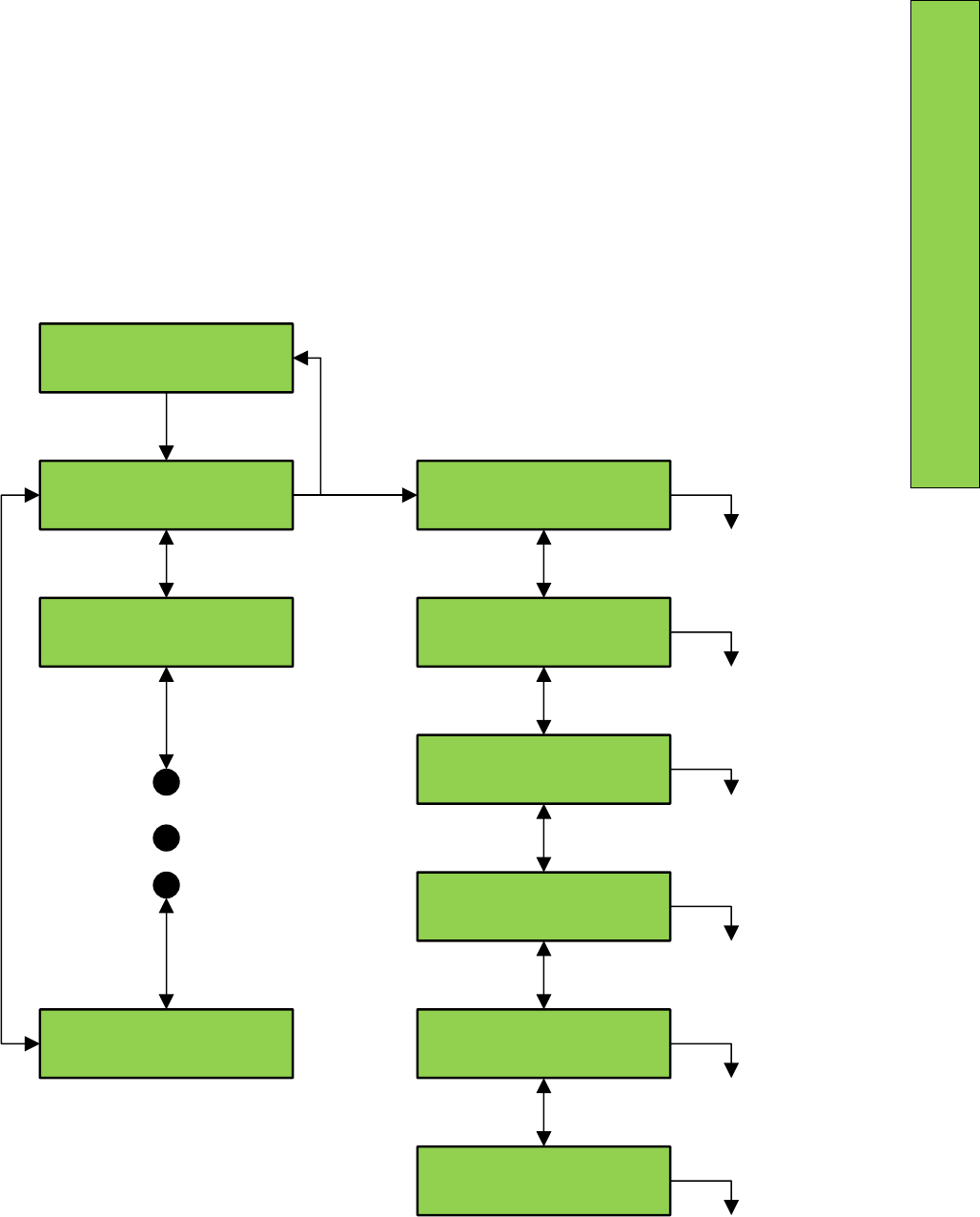
P a g e | 221
Section 10a – Service Activation Timers
LCD Interface Main Menu - Service Activation Timer
GALaxy
Service Activation Timer
Service Activation Timer
Service Timer # 0
Service Activation Timer
Service Timer # 9
Service Activation Timer
Service Timer # 1
Service Timer # 0
Set Month/Day Timers
Service Timer # 0
Clear Timer
Service Timer # 0
Copy Day Of Week Timers
Service Timer # 0
View/Modify Timer Status
Service Timer # 0
Set Timer Service
Service Timer # 0
Set Day of Week Timers
NOTE: This flow chart shows the Sub-Menu
for Service Timer # 0. The Sub-menus for
Service Timers #1 through #9 are similar.
Up
Down
Enter
Up
Down
Mode
Enter to Set Month/
Day Timers
Enter to Clear
Timer
Enter to Copy Day
of Week Timers
Enter to View/Modify
Timer Status
Enter to Set Timer
Service
Enter to Set Day of
Week timers
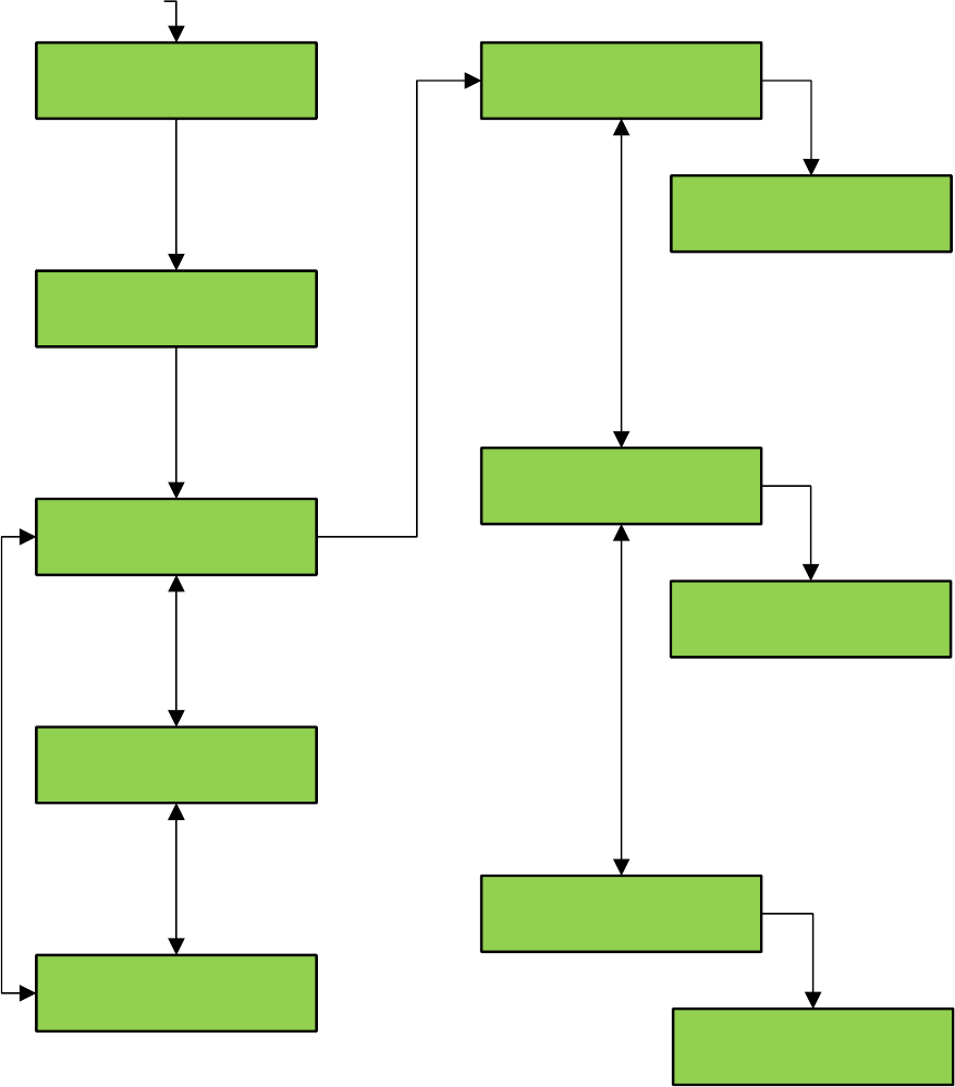
LCD Interface - Set Month/Day Timers Submenu
From Service Activation Timer
Main Menu
Service Timer # 0
Set Month/Day Timers
Set Month/Day Timers
Service Timer # 0
Set Month/Day Timers
Month/Day Timer # 0
Set Month/Day Timers
Month/Day Timer # 2
Set Month/Day Timers
Month/Day Timer # 1
Month/Day Timer Date # 0
Month/Day: 00/00
Month/Day Timer Date #0
Month/Day: 00/00
Month/Day Timer Date # 0
Off Time: 00:00
Month/Day Timer Date # 0
Off Time: 00:00
Month/Day Timer Date # 0
On Time: 00:00
Month/Day Timer Date # 0
On Time: 00:00
Up
Up
Up
Down
Down
Down
Enter
Enter
Enter
Enter
Enter
MODE selects digit
UP increments value
DN decrements value
DOWN ENTER stores value
MODE returns to sub-menu
MODE selects digit
UP increments value
DN decrements value
DOWN ENTER stores value
MODE returns to sub-menu
MODE selects digit
UP increments value
DN decrements value
DOWN ENTER stores value
MODE returns to sub-menu
NOTE: This flow chart shows
the sub-menu for Month/Day Timer Date # 0
Month/Day Timer Date # 1 and #2 are similar.
Enter
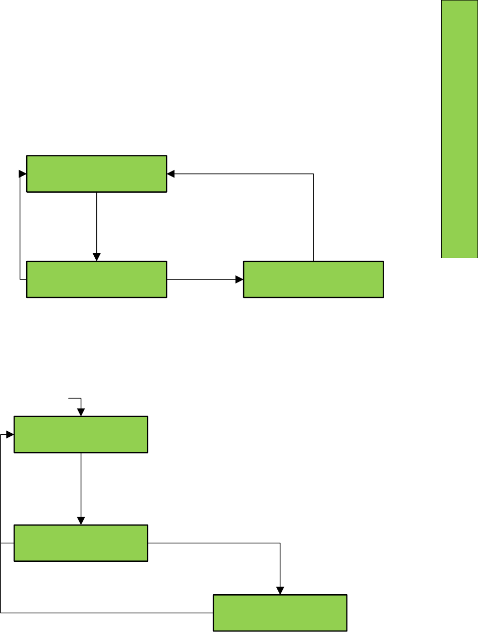
P a g e | 223
Section 10a – Service Activation Timers
LCD Interface - Clear Timer Submenu
LCD Interface - Copy Day of Week Timers Submenu
Service Timer #0
Clear Timer
Clear Timer
Hit Enter to Clear Timer
Clear Timer
Timer Cleared
From Service Activation Timer
Main Menu
Mode
Mode
Enter
Enter
From Service Activation Timer
Main Menu
Enter copies the timer setting for
Monday into the timer setting for
Tuesday through Friday and the
display shows
“Copied”
Mode
Mode
Enter
Enter
Service Timer # 0
Copy Day Of Week Timers
Copy Day Of Week Timers
Monday -> Tuesday - Friday
Copy Day Of Week Timer
Monday -> Tue-Fri Copied
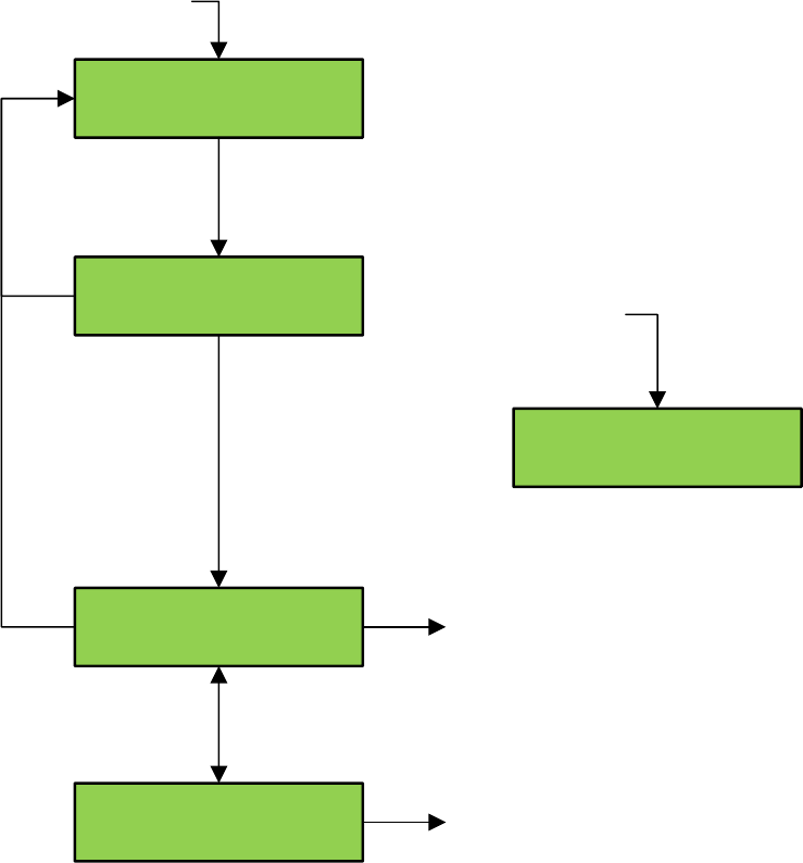
LCD Interface – View/Modify Timer Status Submenu
From Service Activation Timer
Main Menu
Service Timer # 0
View/Modify Timer Status
View/Modify Timer Status
Timer Off / Disabled
View/Modify Timer Status
Timer Off / Disabled
View/Modify Timer Status
Timer Off / Enabled
View/Modify Timer Status
Timer On / Enabled
If time of day on the real time
clock falls within window of the
timer setting, and the timer is
enabled, then display shows this
screen.
ENTER Disables Timer
ENTER Enables Timer
Enter
Enter
Up
Down
Mode
Mode
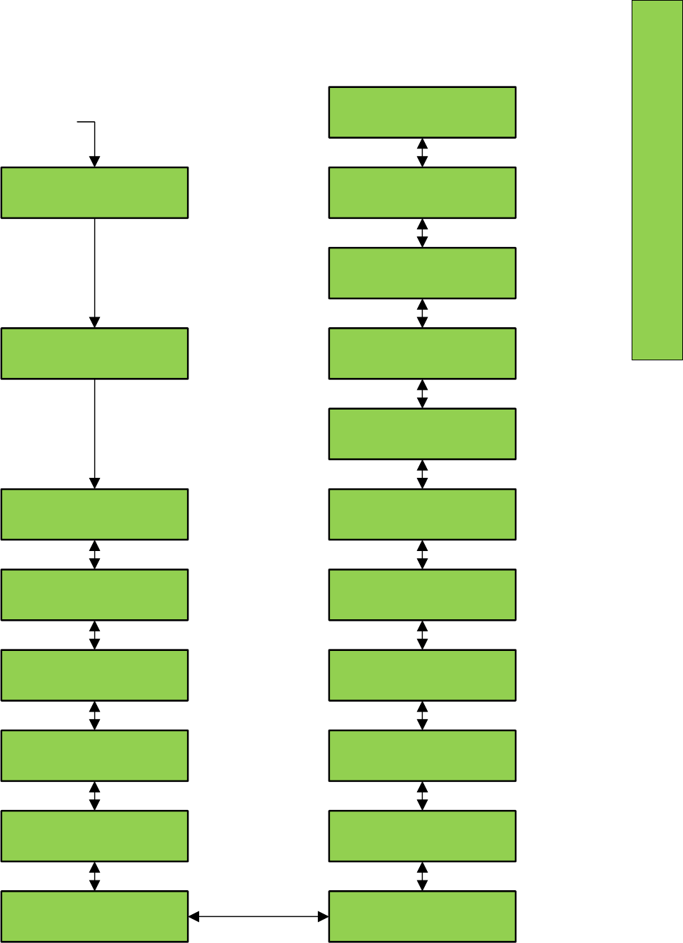
P a g e | 225
Section 10a – Service Activation Timers
LCD Interface - Set Timer Service Submenu
From Service Activation Timer
Main Menu
Service Timer # 0
Set Timer Service
Set Timer Service
Group Car Call Lockouts
Set Timer Service
Group Car Call Lockouts
Set Timer Service
Car Call Lockouts
Set Timer Service
Alternate Floor Security
Set Timer Service
Alternate Lobby
Set Timer Service
Down Peak
Set Timer Service
Up Peak
Set Timer Service
Car Call Override
Set Timer Service
Group Car Call Override
Set Timer Service
Sabbath
Set Timer Service
CC Push Button Security
Set Timer Service
Floor Security Table 2
Set Timer Service
Floor Security Table 3
Set Timer Service
Floor Security Table 4
Set Timer Service
No Service Selected
Set Timer Service
Parking
Set Timer Service
Alternate Parking
Set Timer Service
Next Up
Enter
Enter
LCD Interface - Set Day of Week Timers Submenu
From Service Activation Timer
Main Menu
Up
Down
Down
Up
Enter
Enter
Enter
Enter
Service Timer # 0
Set Day of Week Timers
Set Day of Week Timers
DOW Timer: Saturday
Set Day of Week Timers
DOW Timer: Friday
Set Day of Week Timers
DOW Timer: Sunday
DOW Timer: Saturday
On Time: 00:00
DOW Timer: Saturday
On Time: 00:00
DOW Timer: Saturday
Off Time: 00:00
DOW Timer: Saturday
Off Time: 00:00
NOTE: This flow chart shows
the sub-menu for
DOW Timer: Saturday.
Other days of week
are similar.
MODE selects digit
UP increments value
DN decrements value
ENTER stores value
MODE returns to sub-menu
MODE selects digit
UP increments value
DN decrements value
ENTER stores value
MODE returns to sub-menu

P a g e | 227
Section 11 – Main CPU Faults
Section 11 Main CPU Faults
Faults
Description
Possible Cause/Suggested Fix
Adv PreTrq Start Flt
Did not get safe on advance
pre-torque start
•
Advance pre-torque is enabled. When it activated, the
controller waits for 5 seconds and expects the car to have
moved by then. if the car has not moved in the 5 seconds the
fault gets declared. Possible Door operator or door lock failure
caused car not to go.
ASV Time-out Car 1
Automatic Service Time-out
Car 1
•
Car was not able to answer group hall call within the
automatic service time-out timer. Look for fault condition on
car.
ASV Time-out Car 2
Automatic Service Time-out
Car 2
•
Car was not able to answer group hall call within the
automatic service time-out timer. Look for fault condition on
car.
ASV Time-out Car 3
Automatic Service Time-out
Car 3
•
Car was not able to answer group hall call within the
automatic service time-out timer. Look for fault condition on
car.
ASV Time-out Car 4
Automatic Service Time-out
Car 4
•
Car was not able to answer group hall call within the
automatic service time-out timer. Look for fault condition on
car.
ASV Time-out Car 5
Automatic Service Time-out
Car 5
•
Car was not able to answer group hall call within the
automatic service time-out timer. Look for fault condition on
car.
ASV Time-out Car 6
Automatic Service Time-out
Car 6
•
Car was not able to answer group hall call within the
automatic service time-out timer. Look for fault condition on
car.
ASV Time-out Car 7
Automatic Service Time-out
Car 7
•
Car was not able to answer group hall call within the
automatic service time-out timer. Look for fault condition on
car.
ASV Time-out Car 8
Automatic Service Time-out
Car 8
•
Car was not able to answer group hall call within the
automatic service time-out timer. Look for fault condition on
car.

Faults
Description
Possible Cause/Suggested Fix
At Floor Shutdown
At floor shutdown
•
Car faulted out while at floor. Look at the fault log for a
different fault at the same time to determine cause of failure.
Aut Swg Fr Door
Open
Automatic Swing Front Door
Open Fault. The swing door
can only close by removing
the door open signal and
allowing the door to close
mechanically. This fault is
declaring the door stayed
open when the open signal
was removed.
•
Verify that the ADO output has not failed on. If so then
replace the output chip.
•
Verify that the door is not binding and is being prevented
from closing.
Aut Swg Rr Door
Open
Automatic Swing Rear Door
Open Fault. The swing door
can only close by removing
the door open signal and
allowing the door to close
mechanically. This fault is
declaring the door stayed
open when the open signal
was removed.
•
Verify that the ADOR output has not failed on. If so then
replace the output chip.
•
Verify that the door is not binding and is preventing from
closing.
Binary Input Fault
The floor position, read
from binary inputs on the
selector, does not match the
car position.
•
Excessive wear on the selector guides.
•
Preset magnet is missing or misaligned.
•
Faulty hall effect sensor on sensor board.
•
Faulty output on selector driver board.
•
Improper wiring between selector and the Top of Car board
(1037 or 1040 board).
•
Faulty BP1, BP2 or BP4 input
BKS Fault
Slowdown
BKS Brake Switch Fault
Slowdown. The brake lift
switch dropped during the
run causing the car to slow
down at the next available
floor
•
Faulty brake lift switch.
•
Low brake hold voltage
Bot Final Limit Flt
Bottom Final Limit Open
•
Car traveled onto the bottom final limit.
•
Faulty wiring of the final limit circuit.

P a g e | 229
Section 11 – Main CPU Faults
Faults
Description
Possible Cause/Suggested Fix
Bottom Door Lock
Fault
The Bottom Door Lock failed
on while the door was open.
•
Faulty door lock.
•
Door lock not adjusted properly.
•
Jumper placed on door lock circuit.
•
Faulty wiring to DLB input.
•
Faulty DLB and DLB-1 inputs (For this to occur both DLB and
DLB-1 inputs must fail on).
•
DOL input failed. Replace DOL input chip.
•
Door operator open limit DOL is not adjusted properly
Brake Drop Fault
Brake failed to drop. The
BKS input did not close
while stopped.
•
Improper adjustment of brake switch.
•
Brake failed to drop.
Brake Pick Fault
Brake failed to pick. The BKS
input did not open during
the run.
•
Improper adjustment of brake switch.
•
Brake failed to pick.
Brake Test Stall Flt
Brake Test Stall Fault. The
elevator stalled during a
brake test. A stall timer is
running during the test
using the Learn HW Stall
time in the Car Timers
menu. There is a protection
timer that should never time
out. In an event that the car
does not move during the
test, the 6 second velocity
timer should always expire
first.
•
Make sure the elevator can run properly at high speed.
•
Make sure the Learn HW Stall timer is set to 30 seconds or
higher. The value set during a successful automatic hoistway
learn would work fine.
BRK CAN Com Error
Brake Board CAN
Communication Error.
•
Faulty CAN communication wire connection. Verify proper
twisted pair wires to the canh and canl terminals on the brake
board.
•
Noise on the CAN bus. Verify that the shield wire is
connected according to the job print.
Brk Flt Set EM
Brake
Emergency brake set from
brake fault
•
'Brake Lift Sw' parameter is set to 2 in 'Car Options'. There
was a brake fault and this triggered an emergency brake/
gripper fault.

Faults
Description
Possible Cause/Suggested Fix
Brk Flt Set Gripper
The Rope Gripper was
tripped when the brake did
not drop. The 'Brake Lift Sw'
adjustable variable in 'Car
Options' can be set to only
show the brake drop fault if
the brake does not drop.
•
Improper adjustment of brake switch.
•
Brake failed to drop.
BRK I/O Failed Off
The BRKi input or BRK
output chip has failed off.
The BRK contactor coil is
wired through a NO contact
of MC, a NO regulator
release contact of the drive
(DON) and a BRK triac of the
controller.
•
Improper wiring of the brake BRK coil. Refer to prints for
wire connections.
•
Faulty BRKi input. Replace BRKi input chip on 1038 board.
•
Faulty BRK output. Replace BRK output chip on 1038 board.
BRK I/O Failed On
The BRK input or output has
failed on.
•
Improper wiring of the brake BRK coil. Refer to prints for
wire connections.
•
Faulty BRKi input. Replace BRKi input chip on 1038 board.
•
Faulty BRK output. Replace BRK output chip on 1038 board.
BRK Low DC Bus
Volts
Brake DC Bus Voltage (BK+,
BK-) is less than 80% of
expected
•
Incorrect Setting of Line to Line Brake voltage in Adjustable
Variables
•
Incorrect dipswitch setting for Three Phase or Single Phase
•
Low Line Voltage
•
Rectifiers Blown or have bad connection
BRK No Currnt
w/Volt
Reading a resistance value
(Vout/Aout) of 1000Ω or
greater
•
No Brake Connected
•
Bad Current Sensor
BRK No DC Bus
Volts
DC Bus Voltage (BK+, BK-) is
less than 5VDC
•
No AC Voltage Coming into AC1-AC2-AC3
•
Rectifiers Blown or have bad Connection
BRK No Output
Volts
If no DC Bus Faults,
Requested Output Voltage is
greater than 0, Actual
Output voltage is less than
3VDC
•
IGBT Not Gating

P a g e | 231
Section 11 – Main CPU Faults
Faults
Description
Possible Cause/Suggested Fix
BRK Over Current
Flt
Average Current is higher
than Preset Limit (based on
board configuration)
•
IGBT Shorted
•
Free Wheeling Diode Shorted
•
Gating Circuitry Shorted ON
BRK Over Voltage
Flt
Output Voltage is at least
20V greater than the
Voltage Requested.
•
IGBT Shorted
•
Gating Circuitry shorted ON
BRK Rq Volt > DC
Bus
Requested Output Voltage is
5% greater than
the DC Bus Voltage (BK+, BK-
)
•
Incorrect Setting of Pick/Hold/Relevel Voltage in Adjustable
Variables
•
Low Line Voltage
Buffer Switch Fault
Buffer Switch Open
•
Verify that the buffer switch is set and the switch is closed.
•
Faulty wiring on the buffer switch circuit.
•
Car hit the buffer
Can Bus Off Error
CAN Bus Off Error. The can
bus has been inactive for
too long a period of time.
•
Faulty CAN bus wiring. Check the CAN bus terminal
connections on all boards.
CAN spb bad
command
Unintended Motion
Command to Safety
Processor unintentionally
set
•
This fault should never occur. Contact GAL.
Car 1 Comm Loss
Controller can't have this
fault.
•
Faulty ram-flash memory chip.
•
Reset fault. If faults returns, replace memory chips.
Car 2 Comm Loss
The group car is not
communicating with Car 2.
•
Faulty wiring from R/T+ and R/T- from car to car.
•
Faulty 75176 driver chip on 1036 board.
•
Noise on shield wire. Connect shield only on one end.
•
Noise on the communication wires. Run wires in separate
conduit.
Car 3 Comm Loss
The group car is not
communicating with Car 3.
•
Faulty wiring from R/T+ and R/T- from car to car.
•
Faulty 75176 driver chip on 1036 board.
•
Noise on shield wire. Connect shield only on one end.
•
Noise on the communication wires. Run wires in separate
conduit.

Faults
Description
Possible Cause/Suggested Fix
Car 4 Comm Loss
The group car is not
communicating with Car 4.
•
Faulty wiring from R/T+ and R/T- from car to car.
•
Faulty 75176 driver chip on 1036 board.
•
Noise on shield wire. Connect shield only on one end.
•
Noise on the communication wires. Run wires in separate
conduit.
Car 5 Comm Loss
The group car is not
communicating with Car 5.
•
Faulty wiring from R/T+ and R/T- from car to car.
•
Faulty 75176 driver chip on 1036 board.
•
Noise on shield wire. Connect shield only on one end.
•
Noise on the communication wires. Run wires in separate
conduit.
Car 6 Comm Loss
The group car is not
communicating with Car 6
•
Faulty wiring from R/T+ and R/T- from car to car.
•
Faulty 75176 driver chip on 1036 board.
•
Noise on shield wire. Connect shield only on one end.
•
Noise on the communication wires. Run wires in separate
conduit.
Car 7 Comm Loss
The group car is not
communicating with Car 7
•
Faulty wiring from R/T+ and R/T- from car to car.
•
Faulty 75176 driver chip on 1036 board.
•
Noise on shield wire. Connect shield only on one end.
•
Noise on the communication wires. Run wires in separate
conduit.
Car 8 Comm Loss
The group car is not
communicating with Car 8
•
Faulty wiring from R/T+ and R/T- from car to car.
•
Faulty 75176 driver chip on 1036 board.
•
Noise on shield wire. Connect shield only on one end.
•
Noise on the communication wires. Run wires in separate
conduit.
Car Call Light Fuse
Car Call Light Fuse Blown
•
Check for short on the Car Call Light circuit.
Car Call Power Fuse
Car Call Power Fuse Blown
•
Check for short on Car Call Power circuit.
Car Com Device
Reset
Serial Car board reset
unexpectedly. Usually
caused by loss of power to
the individual board.
•
Usually caused by loss of power to the individual board.
Check for loose connection on power terminal of the board.
•
Faulty I/O board.

P a g e | 233
Section 11 – Main CPU Faults
Faults
Description
Possible Cause/Suggested Fix
Car Gate Safe Fault
Car Gate safe fault
•
After Controller was safe with doors, gate switch and locks
made, and ready to run, a Gate switch (front or rear) input
turned OFF.
Car Safe Fault
The Car Safe Fault occurs
from the wanting to run but
does not have a critical
input energized. Some of
the conditions for a car safe
fault will also cause other
faults to be logged.
•
The car does not have the gate or lock inputs and is running
or trying to run
•
The gripper GTS input is not on.
•
The stop switch is open.
•
An Inspection String input fault. Only one input should be on
in the inspection string (AUTO, CTI, ICI, ACC or MRI)
•
Gate or Lock Bypass switch is on when not on car top
inspection.
Car Safe Fault
Preop
The car had a car safe fault
while pre-opening the door.
•
The car lost the DZ input while leveling into the floor and the
door was open.
Car Safe Fault Start
The car had an onward call,
had the door close limit but
the car gate or door locks
did not make after a 3
second time-out.
•
The locks are not making properly when the door closes.
•
The door is not closing properly.
Car Safety Sw. Fault
Car Safety Switch Fault
•
Safety String Fault
•
Verify that the car safety is not tripped.
•
Faulty wiring in the car safety circuit
Car Top Stop Switch
Car top stop switch
•
Safety String Fault. Refer to Safety String Page on diagrams.
Check/replace CTS input Chip.
CCB FET Open Blue
Car Call Board FET open blue
•
Faulty LED signal from RGB Board. Look at detailed car faults
log to determine device. 'dev' gives you address for global CAN
device, 'dv2' gives you local CAN device and 'pf1' the number
for the IO location within the local board.
CCB FET Open
Green
Car Call Board FET open
green
•
Faulty LED signal from RGB Board. Look at detailed car faults
log to determine device. 'dev' gives you address for global CAN
device, 'dv2' gives you local CAN device and 'pf1' the number
for the IO location within the local board.

Faults
Description
Possible Cause/Suggested Fix
CCB FET Open Red
Car Call Board FET open red
•
Faulty LED signal from RGB Board. Look at detailed car faults
log to determine device. 'dev' gives you address for global CAN
device, 'dv2' gives you local CAN device and 'pf1' the number
for the IO location within the local board.
CCB FET Short Blue
Car Call Board FET short
blue
•
Faulty LED signal from RGB Board. Look at detailed car faults
log to determine device. 'dev' gives you address for global CAN
device, 'dv2' gives you local CAN device and 'pf1' the number
for the IO location within the local board.
CCB FET Short
Green
Car Call Board FET short
green
•
Faulty LED signal from RGB Board. Look at detailed car faults
log to determine device. 'dev' gives you address for global CAN
device, 'dv2' gives you local CAN device and 'pf1' the number
for the IO location within the local board.
CCB FET Short Red
Car Call Board FET short red
•
Faulty LED signal from RGB Board. Look at detailed car faults
log to determine device. 'dev' gives you address for global CAN
device, 'dv2' gives you local CAN device and 'pf1' the number
for the IO location within the local board.
CCB LED Open Blue
Car Call Board LED open
blue
•
Faulty LED signal from RGB Board. Look at detailed car faults
log to determine device. 'dev' gives you address for global CAN
device, 'dv2' gives you local CAN device and 'pf1' the number
for the IO location within the local board.
CCB LED Open
Green
Car Call Board LED open
green
•
Faulty LED signal from RGB Board. Look at detailed car faults
log to determine device. 'dev' gives you address for global CAN
device, 'dv2' gives you local CAN device and 'pf1' the number
for the IO location within the local board.
CCB LED Open Red
Car Call Board LED open red
•
Faulty LED signal from RGB Board. Look at detailed car faults
log to determine device. 'dev' gives you address for global CAN
device, 'dv2' gives you local CAN device and 'pf1' the number
for the IO location within the local board.
CCB LED Short Blue
Car Call Board LED short
blue
•
Faulty LED signal from RGB Board. Look at detailed car faults
log to determine device. 'dev' gives you address for global CAN
device, 'dv2' gives you local CAN device and 'pf1' the number
for the IO location within the local board.

P a g e | 235
Section 11 – Main CPU Faults
Faults
Description
Possible Cause/Suggested Fix
CCB LED Short
Green
Car Call Board LED short
green
•
Faulty LED signal from RGB Board. Look at detailed car faults
log to determine device. 'dev' gives you address for global CAN
device, 'dv2' gives you local CAN device and 'pf1' the number
for the IO location within the local board.
CCB LED Short Red
Car Call Board LED short red
•
Faulty LED signal from RGB Board. Look at detailed car faults
log to determine device. 'dev' gives you address for global CAN
device, 'dv2' gives you local CAN device and 'pf1' the number
for the IO location within the local board.
CCB No Comm Aux
Bd 1
Car Call Board local aux
board 1 comm loss
•
Comm loss to RGB Auxiliary Car Call Board. Check wiring and
bus termination jumpers on boards. If problem persists, check
Car Comm Status under diagnostics.
CCB No Comm Aux
Bd 2
Car Call Board local aux
board 2 comm loss
•
Comm loss to RGB Auxiliary Car Call Board. Check wiring and
bus termination jumpers on boards. If problem persists, check
Car Comm Status under diagnostics.
CCB No Comm
Board 1
Car Call Board local board 1
comm loss
•
Comm loss to RGB Car Call Board. Check wiring and bus
termination jumpers on boards. If problem persists, check Car
Comm Status under diagnostics.
CCB No Comm
Board 2
Car Call Board local board 2
comm loss
•
Comm loss to RGB Car Call Board. Check wiring and bus
termination jumpers on boards. If problem persists, check Car
Comm Status under diagnostics.
CCB No LED Board
Car Call LED board missing
•
Faulty LED signal from RGB Board. Look at detailed car faults
log to determine device. 'dev' gives you address for global CAN
device, 'dv2' gives you local CAN device and 'pf1' the number
for the IO location within the local board.
CCB Stuck Button
Car Call Board stuck button
•
Faulty LED signal from RGB Board. Look at detailed car faults
log to determine device. 'dev' gives you address for global CAN
device, 'dv2' gives you local CAN device and 'pf1' the number
for the IO location within the local board.
Comp. Switch Fault
Compensating Rope Switch
Open
•
Verify that the compensating rope switch is set and the
switch is closed.
•
Improper cabling of the compensating ropes on the sheave.

Faults
Description
Possible Cause/Suggested Fix
CWT Sw Error at DT
Car “above cwt” flag was set
for above the counterweight
when the car hit the down
terminal slowdown limit.
•
The counterweight switch was not hit during the run or the
car was lost when powered up.
•
Faulty wiring of the counterweight switch.
•
Improper adjustment of the counterweight switch.
CWT Sw Error at UT
Car “above cwt” flag was set
for below the counterweight
when the car hit the up
terminal slowdown limit.
•
The counterweight switch was not hit during the run or the
car was lost when powered up.
•
Faulty wiring of the counterweight switch.
•
Improper adjustment of the counterweight switch.
DBR Temperature
Flt
Dynamic Braking Resistor
Temperature Fault. The
temperature for the
dynamic braking resistors is
read through a temperature
sensor mounted above the
resistors. The temperature
sensor connects to the
temperature sensor input
board mounted on the DIO1
connector on the CPU
board. When the
temperature sensor opens a
contact, the CPU detects a
temperature fault, an error
is recorded, the car is shut
down at the next floor and
the DBC relay is de-
energized to open the DB
Resistor circuit.
•
Faulty Temperature Sensor. If the DB Resistors are not hot,
check the temperature sensor input board connected to the
CPU board. The input LED should be on when the
temperature is okay. If the LED is not on, jump the two
terminals on the temperature input board and the LED should
go on. If the LED goes on then the Temperature Sensor is bad.
Replace the Temperature Sensor mounted near the resistors
•
Faulty Temperature Sensor Input Board. Test the sensor
input as above. If the LED does not turn on when the input
terminals are jumped together, replace the Temperature
Sensor Input Board connected to the CPU.
Delta Off Fault
DEL input did not come on
at start or went off during a
run.
Traction
DEL=1 (on) at beginning and during a run. This fault means DEL
never turned on or maybe dropped off during a run.
•
Faulty DEL input. Replace the DEL input chip.
Hydro
•
The delta contact did not make on a Y-Delta starter.
•
The MC contact did not make on an across-the- line starter
•
The “at speed” contact did not make on an electronic soft-
starter.
NOTE: On a Hyrdo DEL only turns on when moving UP, it is off
when the car is moving down.

P a g e | 237
Section 11 – Main CPU Faults
Faults
Description
Possible Cause/Suggested Fix
Delta On Fault
DEL input failed on when is
should have been off. This
would occur at the start of a
run when the I/Os are
checked. The input failed on
or the contact for the input
failed closed.
Traction
DEL=0 when the car is not running. This fault means that the
input did not turn off when it was supposed to.
•
Faulty DEL input (failed on). Check the input and output
status on the LCD interface.
•
Faulty contact for DEL input failed on. Replace the DEL input
chip.
Hydro
DEL did not turn off when it should have.
•
Faulty DEL input. Replace the DEL input chip.
NOTE: On a Hyrdo DEL only turns on when moving UP, it is off
when the car is moving down.
DL & DL-1 Opposite
Input failure on one of the
Down Level sensor input
•
Faulty DL or DL-1 input (replace input chips).
DL Failed On Fault
DL Failed On Fault. The DL
leveling sensor did not turn
off during a run.
•
DL hall effect sensor bad on selector sensor board. Replace
sensor board.
•
DL Output Driver failed on. Replace output on selector driver
board GALX-1011.
•
DL traveling cable wire is shorted to 120 VAC. Remove input
wire to 1038 or 1064 board and verify that LED goes out.
Correct short condition.
•
DL inputs failed on. Short on 1038 or 1064 main I/O board.
Replace main I/O board.
DL20 Phone Test
Failed
Phone Test from DL20
phone monitoring device
indicated a failure
•
Refer to the manufacturers troubleshooting guide for the
DL20.
DLB & DLB-1
Opposite
Input failure on one of the
Door Lock Bottom (DLB)
inputs.
•
Faulty DLB or DLB-1 input (replace input chip).
DLM & DLM-1
Opposite
Input failure on one of the
Door Lock Middle (DLM)
inputs.
•
Faulty DLM or DLM-1 input (replace input chip).
DLT & DLT-1
Opposite
Input failure on one of the
Door Lock Top (DLT) inputs.
•
Faulty DLT or DLT-1 input (replace input chip).

Faults
Description
Possible Cause/Suggested Fix
Dn Normal SW
Setup
Down Normal must always
be on unless the car is
below the lowest landing.
•
The down normal needs to be moved down so when the car
is Dead level at the bottom landing DN is ON. Allow at least 2
inches run before DN turns OFF
DNR I/O Failed Off
The DNR input or output has
failed off.
Traction
•
Fault on Safety Processor Board. This board can disable the
run control to the DNR output chip. Check if the PIC or PAL
inhibit LED turns on when the car attempts to run. Check the
elevator service, faults, and inputs/outputs on the Safety
Processor Board LCD display.
•
Faulty DNR output or DNRi input. Replace the DNR output
and DNRi input chip.
•
No 24VDC from the drive. Refer to Schematics.
•
Incorrect jumper placement on 1038 board. Verify that
jumpers on the bottom of the board are positioned for the
correct drive type (DSD or HPV).
•
RUN, MC or BRK auxiliary contact not making properly.
Contact GAL for instructions.
Hydro
•
Faulty wiring to the SD or SC terminal on the 1038/1064
board.
•
Faulty wiring to the Down valve.
•
Faulty SD output or SDi input. Replace output and input chip.
DNR I/O Failed On
The DNR input or output has
failed on.
Traction
•
Faulty DNR output. Replace the DNR output chip.
•
Faulty DNRi input. Replace DNRi input chip.
•
Incorrect jumper placement on 1038 board. Verify that
jumpers on the bottom center of the board are positioned for
the correct drive type (DSD or HPV). If necessary move the
jumpers to the correct drive type.
Hydro
•
Faulty SDi input (replace input chip).
•
Faulty SD output (replace output chip).

P a g e | 239
Section 11 – Main CPU Faults
Faults
Description
Possible Cause/Suggested Fix
DON I/O Failed Off
The DON input or the drive
run relay contact has failed
off. The run relay on the
drive turns on the DON
input (Drive ON) indicating
that the regulator is
released and the drive is
controlling the motor.
•
Loss of voltage on terminal CS.
•
MC contact in series with the drive run relay opened.
•
The drive faulted on start and dropped the run contact .
Check the drive fault log.
•
Faulty run relay in the drive.
•
Faulty DON input on the controller. Replace the DON input
chip.
•
The run relay in the drive is not programmed properly.
Check the default drive setup for the Configure C3, Relay Coil
2= Speed Reg Rls parameter for a Magnetek drive.
Check do.83=DRO on a KEB drive.
DON I/O Failed On
The DON input or the drive
output has failed on. When
the drive is turned off, the
run relay on the drive will
drop out turning off DON.
•
Improper wiring of the brake BRK coil. Refer to prints for
wire connections.
•
Faulty BRKi input. Replace BRKi input chip on 1038 board.
•
Faulty BRK output. Replace BRK output chip on 1038 board.
•
Fault on 1028 Safety Processor Board. The Safety Processor
Board can disable the run control to the BRK output chip.
Check if the PIC or PAL inhibit LED turns on when the car
attempts to run. Check the elevator service, faults, and
inputs/outputs on the Safety Processor Board LCD display
Door Close Fault
The door did not reach the
Door Close Limit within the
door close protection time.
•
Door Close Limit (DCL) not adjusted properly.
•
Faulty Door Close Limit (DCL). Replace DCL input chip.
•
Trash in door track preventing door from closing.
Door Lock Safe
Fault
Door lock safe fault
•
After Controller was safe with doors, gate switch and locks
made and ready to run, a door lock inputs turned OFF.
Door Low Voltage
Flt
Door Line Voltage Low
•
Voltage Sensor Board Related. Voltage being monitored for
Door Operator dropped below the setting for parameter 'Low
Door Volt '
Door Motor
Overload
Door Motor Overload
•
Door Motor Overload signal tripped. Check Input chip for
DMO signal
Door Open Fault
The door did not reach the
Door Open Limit within the
door open protection time.
•
Door Open Limit (DOL) not adjusted properly.
•
Faulty Door Open Limit (DOL). Replace DOL input chip.

Faults
Description
Possible Cause/Suggested Fix
Door Zone Aux On
Flt
The auxiliary door zone
input failed on.
•
DZA output on selector board GALX-1011 failed on. (Replace
DZA output on selector driver board).
•
One or both of the DZA sensors on the selector sensor board
failed. Replace selector sensor board.
•
DZA input on the 1037/1040 board failed. Replace DZA input
on 1037/1040 board.
Door Zone Off Fault
The door zone input failed
off.
•
DZ output on selector board GALX-1011 did not turn on.
(Replace DZ output on selector driver board).
•
One or both of the DZ sensors on the selector sensor board
failed. Replace selector sensor board.
•
DZ input on the 1040 board failed. Replace DZ input on
1037/1040 board.
Door Zone On Fault
The door zone input failed
on.
•
DZ output on selector board GALX-1011 did not turn off.
(Replace DZ output on selector driver board).
•
One or both of the DZ sensors on the selector sensor board
failed. Replace selector sensor board.
•
DZ input on the Main I/O board failed on. Replace DZ input
on Main I/O board.
DoorZone Aux Off
Flt
The auxiliary door zone
input failed off.
•
DZA output on selector board GALX-1011 did not turn on.
(Replace DZA output on selector driver board).
•
One or both of the DZA sensors on the selector sensor board
failed. Replace selector sensor board.
•
DZA input on the 1040 board failed. Replace DZA input on
1037/1040 board.
Down Directional
Fault
Car unexpectedly hit the
Down Normal Limit while
running down.
•
Faulty wiring for the DN limit.
•
The power common to the limit switches (CS) was lost.
Check safety string prior to the CS terminal.
DPM Input Fault
The DPM input fault occurs
when door opens and the
DPM input did not turn off.
•
DPM Cam not setup properly on the door operator.
•
Faulty DPM input. Replace DPM input chip.
DPM Off/GS or DL
On
DPM Off with Gate Switch or
Door Lock On. The Door
Protection Module input
must go on before gate
switch or door lock inputs
go on.
•
The DPM switch on the door operator is not setup properly.
•
There is no DPM input on the door operator. Jump the DPM
input to the GS (Gate Switch) terminal.
•
Fault DPM input. Replace the DPM input chip.

P a g e | 241
Section 11 – Main CPU Faults
Faults
Description
Possible Cause/Suggested Fix
Drive Com 8259
Error
Drive Communications 8259
Error. This error is used to
detect a hardware failure on
the controller
communications port to the
drive.
•
Hardware failure on the CPU board or 1036 board. If this
error occurs, contact G.A.L.
Drive Com Int Error
Drive Communications
Interrupt Enable Error. This
error is used to detect a
hardware failure on the
controller communications
port to the drive.
•
Hardware failure on the CPU board or 1036 board. If this
error occurs, contact G.A.L.
Drive Com Rcv Error
Controller has a
communications error with
drive. The controller has
not received a valid message
from the drive for more
than one second.
•
Faulty communications cable connection. Check the drive
twisted pairs connected from the drive to the 1036 board.
•
Noise on the communication cable. Verify that the shield on
the communications cable to the drive is connected to earth
ground on one end.
•
Faulty communication chip. Replace the 75176 driver chips
on the 1036 board.
Drive Com Trm
Error
Drive Communications
Transmit Error. This error is
used to detect a hardware
failure on the controller
communications port to the
drive.
•
Hardware failure on the CPU board or 1036 board. If this
error occurs, contact G.A.L.
Drive Com Tx Stop
Er
Drive Communications
Transmit Stop Error. This
error is used to detect a
hardware failure on the
controller communications
port to the drive.
•
Missing jumper on J7 of the 1036 board (COM1 IRQ6). Install
the jumper.
•
Hardware failure on the CPU board or 1036 board. If this
error occurs and the jumper J7 is in place, contact G.A.L.
Drive Com TxEmpty
Er
Drive Communications
Transmit Stop Error. This
error is used to detect a
hardware failure on the
controller communications
port to the drive.
•
Missing jumper on J7 of the 1036 board (COM1 IRQ6). Install
the jumper.
•
Hardware failure on the CPU board or 1036 board. If this
error occurs and the jumper J7 is in place, contact G.A.L.

Faults
Description
Possible Cause/Suggested Fix
Drive has Com Error
Drive has a communications
error. The controller has
received a message from the
drive that it has
communication receive
errors.
•
Faulty communications cable connection. Check the drive
twisted pairs connected from the drive to the 1036 board.
•
Noise on the communication cable. Verify that the shield on
the communications cable to the drive is connected to earth
ground on one end.
•
Faulty communication chip. Replace the 75176 driver chips
on the 1036 board.
Drive Ready Fault
The drive has a fault
•
The drive has or had a fault. Check the drive fault log.
•
Faulty RDY input. (Replace the RDY input).
DT Count Fault
The verification position
count for the DT input
switch was off by more than
10 inches when the switch
was activated. This position
count refers to the pulse
count recorded during a
hoistway learn.
•
The car was lost due to a preset error. Check the guides on
the selector. Check the fault log for binary preset errors.
•
The controller has a faulty encoder signal for the pulse
count. Check that the car can make long runs without
overshooting the floor or stopping short of the floor. This
refers to the CPU speed feedback.
•
The power common to the limit switches (CS) was lost.
Check safety string prior to the CS terminal.
•
Incorrect counting of pulse counts. Check encoder
connection to motor and encoder wiring.
•
Hoistway not learned properly. Perform a hoistway learn
procedure.
•
DT switch not adjusted properly. Check at slow speed if
switch is breaking, making and then breaking again. Switch
needs to be closer to the cam.
DT Failed On Fault
DT input Failed On Fault.
The car was at the bottom
floor and the DTS input was
low true (DTS switch open)
but the DT input was high
(DT not made).
•
The DTS switch is not wired or the DTS switch is not used. If
the DTS switch is not used, jump the DT and DTS inputs
together.
•
The DT did not break at the bottom terminal landing. Adjust
or replace the DT switch.
•
Faulty DT input. Replace the DT input chip.

P a g e | 243
Section 11 – Main CPU Faults
Faults
Description
Possible Cause/Suggested Fix
DT1 Count Fault
The verification position
count for the DT1 input
switch was off by more than
10 inches when the switch
was activated. This position
count refers to the pulse
count recorded during a
hoistway learn.
•
The car was lost due to a preset error. Check the guides on
the selector. Check the fault log for binary preset errors.
•
The controller has a faulty encoder signal for the pulse
count. Check that the car can make long runs without
overshooting the floor or stopping short of the floor.
•
The power common to the limit switches (CS) was lost.
Check safety string prior to the CS terminal.
•
Incorrect counting of pulse counts. Check encoder
connection to motor and encoder wiring.
•
Hoistway not learned properly. Perform a hoistway learn
procedure.
•
DT1 switch not adjusted properly. Check at slow speed if
switch is breaking, making and then braking again. Switch
needs to be closer to the cam.
DT2 Count Fault
The verification position
count for the DT2 input
switch was off by more than
14 inches when the switch
was activated. This position
count refers to the pulse
count recorded during a
hoistway learn.
•
The car was lost due to a preset error. Check the guides on
the selector. Check the fault log for binary preset errors.
•
The controller has a faulty encoder signal for the pulse
count. Check that the car can make long runs without
overshooting the floor or stopping short of the floor.
•
The power common to the limit switches (CS) was lost.
Check safety string prior to the CS terminal.
•
Incorrect counting of pulse counts. Check encoder
connection to motor and encoder wiring.
•
Hoistway not learned properly. Perform a hoistway learn
procedure.
•
DT2 switch not adjusted properly. Check at slow speed if
switch is breaking, making and then braking again. Switch
needs to be closer to the cam.
DT3 Count Fault
The verification position
count for the DT3 input
switch was off by more than
18 inches when the switch
was activated. This position
count refers to the pulse
count recorded during a
hoistway learn.
•
The car was lost due to a preset error. Check the guides on
the selector. Check the fault log for binary preset errors.
•
The controller has a faulty encoder signal for the pulse
count. Check that the car can make long runs without
overshooting the floor or stopping short of the floor.
•
The power common to the limit switches (CS) was lost.
Check safety string prior to the CS terminal.
•
Incorrect counting of pulse counts. Check encoder
connection to motor and encoder wiring.
•
Hoistway not learned properly. Perform a hoistway learn
procedure.
•
DT3 switch not adjusted properly. Check at slow speed if
switch is breaking, making and then braking again. Switch
needs to be closer to the cam.

Faults
Description
Possible Cause/Suggested Fix
DT4 count Fault
The verification position
count for the DT4 input
switch was off by more than
24 inches when the switch
was activated. This position
count refers to the pulse
count recorded during a
hoistway learn.
•
The car was lost due to a preset error. Check the guides on
the selector. Check the fault log for binary preset errors.
•
The controller has a faulty encoder signal for the pulse
count. Check that the car can make long runs without
overshooting the floor or stopping short of the floor.
•
The power common to the limit switches (CS) was lost.
Check safety string prior to the CS terminal.
•
Incorrect counting of pulse counts. Check encoder
connection to motor and encoder wiring.
•
Hoistway not learned properly. Perform a hoistway learn
procedure.
•
DT4 switch not adjusted properly. Check at slow speed if
switch is breaking, making and then braking again. Switch
needs to be closer to the cam.
DT5 count Fault
The verification position
count for the DT5 input
switch was off by more than
32 inches when the switch
was activated. This position
count refers to the pulse
count recorded during a
hoistway learn.
•
The car was lost due to a preset error. Check the guides on
the selector. Check the fault log for binary preset errors.
•
The controller has a faulty encoder signal for the pulse
count. Check that the car can make long runs without
overshooting the floor or stopping short of the floor.
•
The power common to the limit switches (CS) was lost.
Check safety string prior to the CS terminal.
•
Incorrect counting of pulse counts. Check encoder
connection to motor and encoder wiring.
•
Hoistway not learned properly. Perform a hoistway learn
procedure.
•
DT5 switch not adjusted properly. Check at slow speed if
switch is breaking, making and then braking again. Switch
needs to be closer to the cam.
DT6 count Fault
The verification position
count for the DT6 input
switch was off by more than
42 inches when the switch
was activated. This position
count refers to the pulse
count recorded during a
hoistway learn.
•
The car was lost due to a preset error. Check the guides on
the selector. Check the fault log for binary preset errors.
•
The controller has a faulty encoder signal for the pulse
count. Check that the car can make long runs without
overshooting the floor or stopping short of the floor.
•
The power common to the limit switches (CS) was lost.
Check safety string prior to the CS terminal.
•
Incorrect counting of pulse counts. Check encoder
connection to motor and encoder wiring.
•
Hoistway not learned properly. Perform a hoistway learn
procedure.
•
DT6 switch not adjusted properly. Check at slow speed if
switch is breaking, making and then braking again. Switch
needs to be closer to the cam.

P a g e | 245
Section 11 – Main CPU Faults
Faults
Description
Possible Cause/Suggested Fix
DTS count Fault
Down Terminal Slowdown
Limit Count Fault. The
verification position count
for the DTS input switch was
off by more than 10 inches
when the switch was
activated. This position
count refers to the pulse
count recorded during a
hoistway learn.
•
The car was lost due to a preset error. Check the guides on
the selector. Check the fault log for binary preset errors.
•
The controller has a faulty encoder signal for the pulse
count. Check that the car can make long runs without
overshooting the floor or stopping short of the floor.
•
The power common to the limit switches (CS) was lost.
Check safety string prior to the CS terminal.
•
Incorrect counting of pulse counts. Check encoder
connection to motor and encoder wiring.
•
Hoistway not learned properly. Perform a hoistway learn
procedure.
•
DTS switch not adjusted properly. Check at slow speed if
switch is breaking, making and then braking again. Switch
needs to be closer to the cam.
DTS Failed On Fault
DTS input Failed On Fault.
The car was at the bottom
floor and the DT input was
low true (DT switch open)
but the DTS input was high
(DTS not open).
•
The DT switch is not wired or DT input was lost.
•
The DTS did not break at the bottom terminal landing.
Adjust or replace the DTS switch.
•
Faulty DTS input. Replace the DTS input chip.
EBAi Input Off Fault
Emergency brake test
contacts in BA1,BA2 failed
off
•
Possible bad NC contact on BA1 or BA2 relays
•
Check wiring on emergency brake relays
•
Replace EBAi input on expansion i/o board
EBAi Input On Fault
Emergency brake test
contacts in BA1,BA2 failed
on
•
Make sure BA1 and BA2 relays are being cycled
•
Replace EBAi input on expansion i/o board
EBBi Input Off Fault
Emergency brake test
contacts in BB1,BB2 failed
off
•
Possible bad NC contact on BB1 or BB2 relays
•
Check wiring on emergency brake relays
•
Replace EBBi input on expansion i/o board
EBBi Input On Fault
Emergency brake test
contacts in BB1,BB2 failed
on
•
Make sure BB1 and BB2 relays are being cycled
•
Replace EBBi input on expansion i/o board
EBK1 Input Failed
OFF
Emergency Brake EBK1i
failed off fault
•
Locate EBK1 and visually determine if output is turning ON
and OFF Faulty EBK1i input chip. Replace the EBK1i input chip.
•
Faulty EBK1 output Chip. Replace the EBK1 output chip.
•
Make sure the blue jumper connecting the input EBK1 to the
output EBK1i is in place.

Faults
Description
Possible Cause/Suggested Fix
EBK1 Input Failed
ON
Emergency Brake EBK1
failed on fault
•
Locate EBK1 and visually determine if output is turning ON
and OFF Faulty EBK1i input chip. Replace the EBK1i input chip.
•
Faulty EBK1 output Chip. Replace the EBK1 output chip.
•
Make sure the blue jumper connecting the input EBK1 to the
output EBK1i is in place.
EBK2 Input Failed
OFF
Emergency Brake EBK2
failed off fault
•
Locate EBK2 and visually determine if output is turning ON
and OFF Faulty EBK2i input chip. Replace the EBK2i input chip.
•
Faulty EBK2 output Chip. Replace the EBK2 output chip.
•
Make sure the blue jumper connecting the input EBK2 to the
output EBK2i is in place.
EBK2 Input Failed
ON
Emergency Brake EBK2
failed on fault
•
Locate EBK2 and visually determine if output is turning ON
and OFF Faulty EBK2i input chip. Replace the EBK2i input chip.
•
Faulty EBK1 output Chip. Replace the EBK2 output chip.
•
Make sure the blue jumper connecting the input EBK1 to the
output EBK1i is in place.
EE Ram Failed
EE Ram (Flash Memory)
Fault. Valid flash memory is
not found or memory chip is
not large enough
•
Call factory to verify memory size on 1036 board. Replace
memory chip with larger size.
•
Faulty 1036 board. Replace 1036 board
EE Tst EE1 Failed
OFF
Electric Eye Test. Freight
door electric eye input EE1
failed off.
•
Verify that the electric eye input EE1 pulses on during the
electric eye test.
•
Possible faulty electric eye device.
•
Possible faulty EE1 input - replace the input.
EE Tst EE1 Failed
ON
Electric Eye Test. Freight
door electric eye input EE1
failed on.
•
Verify that the electric eye input EE1 is off before the
electric eye test.
•
Possible faulty electric eye device.
•
Possible faulty EE1 input - replace the input.
EE Tst EE2 Failed
OFF
Electric Eye Test. Freight
door electric eye input EE2
failed off.
•
Verify that the electric eye input EE2 pulses on during the
electric eye test.
•
Possible faulty electric eye device.
•
Possible faulty EE2 input - replace the input.

P a g e | 247
Section 11 – Main CPU Faults
Faults
Description
Possible Cause/Suggested Fix
EE Tst EE2 Failed
ON
Electric Eye Test. Freight
door electric eye input EE2
failed on.
•
Verify that the electric eye input EE2 is off before the
electric eye test.
•
Possible faulty electric eye device.
•
Possible faulty EE2 input - replace the input.
EE Tst EER1 Faild
OFF
Electric Eye Test. Freight
rear door electric eye input
EER1 failed off.
•
Verify that the electric eye input EER1 pulses on during the
electric eye test.
•
Possible faulty electric eye device.
•
Possible faulty EER1 input - replace the input.
EE Tst EER1 Faild
ON
Electric Eye Test. Freight
rear door electric eye input
EER1 failed on.
•
Verify that the electric eye input EER1 is off before the
electric eye test.
•
Possible faulty electric eye device.
•
Possible faulty EER1 input - replace the input.
EE Tst EER2 Faild
OFF
Electric Eye Test. Freight
rear door electric eye input
EER2 failed off.
•
Verify that the electric eye input EER2 pulses on during the
electric eye test.
•
Possible faulty electric eye device.
•
Possible faulty EER2 input - replace the input.
EE Tst EER2 Faild
ON
Electric Eye Test. Freight
rear door electric eye input
EER2 failed on.
•
Verify that the electric eye input EER2 is off before the
electric eye test.
•
Possible faulty electric eye device.
•
Possible faulty EER2 input - replace the input.
EM Brake Input OFF
After the controller turns on
the output EBKC, EBKi never
came on
•
Improper wiring of the brake EBRKC coil. Refer to prints for
wire connections.
•
Faulty EBKi input. Replace EBKi input chip on i/o board.
•
Faulty EBKC output. Replace EBKC output chip on i/o board
EM Brake Input ON
The EBKi input or EBKC
output has failed on.
•
Improper wiring of the brake Emergency Brake coil. Refer to
prints for wire connections.
•
Faulty EBKi input. Replace EBKi input chip on i/o board.
•
Faulty EBKC output. Replace EBKC output chip on i/o board.
EM Brake Switch
OFF
Emergency brake switch
EBKS failed off once the car
stopped
•
Improper wiring of Emergency brake switch.
•
Faulty EBKS input. Replace EBKS input chip on i/o board.

Faults
Description
Possible Cause/Suggested Fix
EM Brake Switch
ON
Emergency brake switch
EBKS failed off once the car
stopped
•
Improper wiring of Emergency brake switch.
•
Faulty EBKS input. Replace EBKS input chip on i/o board.
•
Check adjustment of Emergency brake switch.
EM BRK CAN Com
Error
Emergency Brake Board Can
Communication Error.
•
Faulty CAN communication wire connection. Verify proper
twisted pair wires to the CANH and CANL terminals on the
brake board.
•
Noise on the CAN Bus. Verify that the shield wire is
connected according to the job print.
Emergency Brake
Trip
Emergency Brake Trip fault
•
Controller may have seen car overspeed, unintended motion
or lost governor input (GOV). See last page of this Section for
more detailed information: Determining "Gripper/EBK fault"
Device.
Emergency Exit Flt
An emergency stop occurred
while moving.
•
The Safety string opened while the car was running. Check
the safety circuit.
•
The LC input is off. Check the LC fuse. If the LC fuse is blown
check for short from LC to GND.
Enc Can Bus Ack Err
Encoder CAN Bus
acknowledge error
Can Open Encoder is not pulling the acknowledge line when
data is being transmitted to it. Verify the following:
•
The Encoder is properly wired according to the schematic.
•
The Controller's encoder can baud rate matches that of the
encoder: Adjustable Variables->System Options->Encoder
Baud
•
Proper voltage is supplied to the encoder.
Enc Can Bus Idle Err
Encoder CAN Bus idle
Encoder CAN bus is floating for too many bit times so an idle
bus is detected. Verify the following:
•
The Encoder is properly wired according to the schematic.
•
The Controller's encoder can baud rate matches that of the
encoder: Adjustable Variables->System Options->Encoder
Baud
•
Proper voltage is supplied to the encoder.

P a g e | 249
Section 11 – Main CPU Faults
Faults
Description
Possible Cause/Suggested Fix
Enc Can Bus Off Err
Encoder CAN Bus off
Controller detected more than 255 transmit errors on CAN bus
to the encoder. The CAN bus device is re-initialized to re-
establish communications to the encoder. Verify the
following:
•
The Encoder is properly wired according to the schematic.
•
The Controller's encoder can baud rate matches that of the
encoder: Adjustable Variables->System Options->Encoder
Baud
•
Proper voltage is supplied to the encoder.
Enc Can Packet
Fault
Encoder CAN Bus packet
fault
Can Open Encoder did not respond with the expected packet.
This could be caused by noise on the encoder cable. Make
sure the encoder cable is properly shielded.
Encoder Busy Error
Encoder busy fault
Can Open Encoder appears as busy and it is not taking signals
from controller. Check encoder to see if it failed. Check wiring
and shield connections as well as voltage from the GALX- 1100
CPU Board.
Encoder Com Error
Encoder communication
error. Encoder board
detected Comm error while
talking to the CAN Open
encoder
•
Verify Connections on Encoder Board. Possible Noise on
Encoder cable. Check Encoder Voltage. Check that the shield is
wired on GALX-1100 CPU Board.
Encoder Count
Error
Encoder Count Error. An
error is announced when
the encoder count value is
greater than 4 inches in 3
milliseconds. This is based
on PPR (Pulses Per Inch) and
the encoder is sending too
many pulses.
•
Faulty encoder connection. Verify the encoder connection
to the 1022 encoder isolation board.
•
Faulty 4I30 encoder board. Replace the 4I30 board.
•
Faulty 1022 encoder isolation board. Replace the encoder
isolation board.
•
Bus address problem on the PC/104 bus. Contact GAL
regarding this fault.
Encoder Dir Fault
Encoder direction fault.
Controller is in motion with
an encoder velocity of more
than 50 feet per minute and
the direction of the encoder
feedback is opposite to the
direction run command
•
Check for proper Voltage on Encoder. Verify Connections on
Encoder Board. Possible Noise on Encoder cable. Check that
the shields are wired on encoder Isolation Board.

Faults
Description
Possible Cause/Suggested Fix
Encoder Init
Encoder initialization fault.
Encoder board failed to
initialize CAN open Encoder
•
Verify Connections on Encoder Board.
•
Possible Noise on Encoder cable. Check Encoder Voltage.
•
Check that the shields are wired on GALX- 1100 CPU Board.
Encoder PPR Error
PPR setting error from CAN
Open encoder
•
Controller attempted to set PPR on the CAN Open Encoder
but when we read it back, it did not change.
•
Possible Noise on Encoder cable. Check Encoder Voltage.
•
Check that the shields are wired on GALX- 1100 CPU Board.
Encoder Preset Flt
Encoder Preset error
generated because
controller could not
establish position from Can
open encoder.
•
Can Open Encoder / Encoder Board lost track of car position.
•
Possible Noise on Encoder cable. Check Encoder Voltage.
•
Check that the shields are wired on GALX- 1100 CPU Board.
EP Recall Car 1 OT
Emergency Power Recall Car
Out of Service Car 1
•
Car 1 was out of service while elevators were in an
Emergency Power Recall Sequence
•
Check faults for car 1
EP Recall Car 2 OTS
Emergency Power Recall Car
Out of Service Car 2
•
Car 2 was out of service while elevators were in an
Emergency Power Recall Sequence
•
Check faults for car 2
EP Recall Car 3 OTS
Emergency Power Recall Car
Out of Service Car 3
•
Car 3 was out of service while elevators were in an
Emergency Power Recall Sequence
•
Check faults for car 3
EP Recall Car 4 OTS
Emergency Power Recall Car
Out of Service Car 4
•
Car 4 was out of service while elevators were in an
Emergency Power Recall Sequence
•
Check faults for car 4
EP Recall Car 5 OTS
Emergency Power Recall Car
Out of Service Car 5
•
Car 5 was out of service while elevators were in an
Emergency Power Recall Sequence
•
Check faults for car 5
EP Recall Car 6 OTS
Emergency Power Recall Car
Out of Service Car 6
•
Car 6 was out of service while elevators were in an
Emergency Power Recall Sequence
•
Check faults for car 6

P a g e | 251
Section 11 – Main CPU Faults
Faults
Description
Possible Cause/Suggested Fix
EP Recall Car 7 OTS
Emergency Power Recall Car
Out of Service Car 7
•
Car 7 was out of service while elevators were in an
Emergency Power Recall Sequence
•
Check faults for car 7
EP Recall Car 8 OTS
Emergency Power Recall Car
Out of Service Car 8
•
Car 8 was out of service while elevators were in an
Emergency Power Recall Sequence
•
Check faults for car 8
EPR Pwr Lost
Moving
EP Recovery power lost
while moving
•
Controller failed to turn on Normal Power Drive and
Emergency Power Drive outputs (NPD and EPD) while in
motion. Condition should not occur.
EPRecall Car1 Tim-
ot
Emergency Power Recall
Time-out Car 1
•
Car 1 timeout while it was in Emergency power recall mode
•
Make sure the field variable "Recall Timeout" is set properly
to allow the car enough time to recover if it is between floors
and away from Emergency Power Floor
•
If you have a blind shaft, consider increasing the Recovery
Speed (default 25fpm)
EPRecall Car2 Tim-
ot
Emergency Power Recall
Time-out Car 2
•
Car 2 timeout while it was in Emergency power recall mode
•
Make sure the field variable "Recall Timeout" is set properly
to allow the car enough time to recover if it is between floors
and away from Emergency Power Floor
•
If you have a blind shaft, consider increasing the Recovery
Speed (default 25fpm)
EPRecall Car3 Tim-
ot
Emergency Power Recall
Time-out Car 3
•
Car 3 timeout while it was in Emergency power recall mode
•
Make sure the field variable "Recall Timeout" is set properly
to allow the car enough time to recover if it is between floors
and away from Emergency Power Floor
•
If you have a blind shaft, consider increasing the Recovery
Speed (default 25fpm)
EPRecall Car4 Tim-
ot
Emergency Power Recall
Time-out Car 4
•
Car 4 timeout while it was in Emergency power recall mode
•
Make sure the field variable "Recall Timeout" is set properly
to allow the car enough time to recover if it is between floors
and away from Emergency Power Floor
•
If you have a blind shaft, consider increasing the Recovery
Speed (default 25fpm)

Faults
Description
Possible Cause/Suggested Fix
EPRecall Car5 Tim-
ot
Emergency Power Recall
Time-out Car 5
•
Car 5 timeout while it was in Emergency power recall mode
•
Make sure the field variable "Recall Timeout" is set properly
to allow the car enough time to recover if it is between floors
and away from Emergency Power Floor
•
If you have a blind shaft, consider increasing the Recovery
Speed (default 25fpm)
EPRecall Car6 Tim-
ot
Emergency Power Recall
Time-out Car 6
•
Car 6 timeout while it was in Emergency power recall mode
•
Make sure the field variable "Recall Timeout" is set properly
to allow the car enough time to recover if it is between floors
and away from Emergency Power Floor
•
If you have a blind shaft, consider increasing the Recovery
Speed (default 25fpm)
EPRecall Car7 Tim-
ot
Emergency Power Recall
Time-out Car 7
•
Car 7 timeout while it was in Emergency power recall mode
•
Make sure the field variable "Recall Timeout" is set properly
to allow the car enough time to recover if it is between floors
and away from Emergency Power Floor
•
If you have a blind shaft, consider increasing the Recovery
Speed (default 25fpm)
EPRecall Car8 Tim-
ot
Emergency Power Recall
Time-out Car 8
•
Car 8 timeout while it was in Emergency power recall mode
•
Make sure the field variable "Recall Timeout" is set properly
to allow the car enough time to recover if it is between floors
and away from Emergency Power Floor
•
If you have a blind shaft, consider increasing the Recovery
Speed (default 25fpm)

P a g e | 253
Section 11 – Main CPU Faults
Faults
Description
Possible Cause/Suggested Fix
Estop Fault
An emergency stop occurred
while moving or attempting
to move.
Traction
•
The “P” input did not drop from MC, BRK or RUN contactors
being energized.
•
The drive on (DON) input did not energize or dropped out
while running.
•
The BRK contactor did not energize or dropped out while
running.
•
BRKI input did not turn on or dropped out while running.
Hydro
•
The DEL contactor did not energize or dropped out while
running
•
The DEL input did not turn on or dropped out while running.
•
An emergency power recall was initiated while the car was
running up.
Both Traction and Hydro
•
The stop switch was pulled while running.
•
The car was not safe usually from clipping a door lock. See
Car Safe Fault.
•
The stall protection timer timed-out.
•
The pulse count stopped counting.
FDoor Close Cont
Flt
Door Close Contact safe
fault
•
After Controller was safe with doors, gate switch, door
contacts and locks made and ready to run, a door contact
input turned OFF.
FETST OFF Fault
Front Door Electric Eye Test
Failed OFF. Output is turned
on cause the electric eye
outputs to controller input
EE1 and EE2 to pulse.
•
FETST output or FETST input failed in the off state.
•
Replace the FETST output chip.
•
Replace the FETST input chip.
FETST ON Fault
Front Door Electric Eye Test
Failed ON. Output is turned
on cause the electric eye
outputs to controller input
EE1 and EE2 to pulse.
•
FETST output or FETST input failed in the on state.
•
Replace the FETST output chip.
•
Replace the FETST input chip.
Field Vars Deflt Ini
Field Variables Default
Initialization. Field
adjustable variables are
being initialized for the first
time.
•
Job related parameters are invalid. This error occurs on the
first time the 1036 board is being powered up.

Faults
Description
Possible Cause/Suggested Fix
Field Vars
Relocated
Field Variables Relocated. In
software version 5.08 the
adjustable field variables
were relocated to a new
location in flash memory to
allow for additional future
field variables.
•
The software has been updated to a version
5.08 or higher from a previous version. This is normal and
should only occur once. If an older version software (earlier
than 5.08) is later installed, the job parameters may be lost.
Fire Fighter Stop Sw
Fire Fighter Stop switch is
pulled while the car is in
motion.
•
Fire Fighter Stop switch is pulled.
•
Faulty wire connection in the Fire Fighter stop switch circuit.
Fld Var Partial Init
Field variables partial table
initialized. Controller did not
see extended memory
initialized before. It should
occur once when updating
controller software
•
The software has been updated. This is normal and should
only occur once. If fault constantly occurs please contact GAL.
Front Det Edge
Fault
Front Detector Edge Time-
out
•
The Electric Eye signal stayed on continuously for longer than
the parameter 'EE Time-out' is set to.
FST I/O Failed Off
The FST input on the 1038
board did not pick up when
expected.
•
Faulty FST output chip. Replace output chip.
•
Faulty FSTI input chip. Replace input chip.
FST I/O Failed On
The FST input on the 1038
board did not drop out
when expected.
•
Faulty FST output chip. Replace output chip.
•
Faulty FSTI input chip. Replace input chip.
FSTP I/O Failed Off
The FSTP input on the 1038
board did not pick up when
expected.
•
Faulty FST1 output chip. Replace output chip.
•
Faulty FSTI input chip. Replace input chip.
FSTP I/O Failed On
The FSTP input on the 1038
board did not drop out up
when expected
•
Faulty FST1 output chip. Replace output chip.
•
Faulty FSTI input chip. Replace input chip.
FVARS Backup Init
Field Variables Backup Init.
Field variables backed up for
the first time.
Older software did not backup the field variables. When new
software replaces the older software this error will be
displayed. If this error occurs every time the CPU powers up,
then the CPU may be faulty and should be replaced.

P a g e | 255
Section 11 – Main CPU Faults
Faults
Description
Possible Cause/Suggested Fix
FVARS Backup Tbl
Cksm
Field Variables Backup Table
Checksum Error. The
verification checksum for
the backup field variable
table has failed.
During power outages or brown-outs, enough noise can be
generated on the 5V DC supply to cause an error in reading
the field variables table on power up. For this reason we keep
the data in two separate tables. If only one table checksum
error occurs, then valid data will be restored. No action is
required.
FVARS Backup Tbl
Err
Field Variables Backup Table
Error. The field variables
from the backup MRAM
table does not match the
variable read into memory
from the main MRAM table.
Most likely, if this error occurs, other FVARS errors will also
occur. A once-in-a-while occurrence of this error can be
ignored if it is not accompanied by the following errors: FVARS
Both Tbl Chksum error or FVARS Tbl Chksum Error. If either
error occurs with this error, the main CPU board should be
replaced.
FVARS Both Tbl
Chksum
Field Variables Both Table
Checksum Table error. The
verification checksum for
both the main field variable
table and backup table has
failed.
Field Variable data is stored in two separate MRAM tables and
a checksum of each table is stored in a separate location.
When the system powers up, the checksum of each table is
verified. If one table fails verification, the field variables are
copied from the table that passed verification and then both
tables are updated with valid data. If both checksum
verifications fail, data is copied from the main table and an
error code is displayed.
•
If this fault occurs, replace the main CPU board.
FVARS Tbl Chksum
Err
Field Variables Table
Checksum Error. The
verification checksum for
the main field variable table
has failed.
During power outages or brown-outs, enough noise can be
generated on the 5V DC supply to cause an error in reading
the field variables table on power up. For this reason we keep
the data in two separate tables. If only one table checksum
error occurs, then valid data will be restored. No action is
required.
Gate Switch Fault
The Gate Switch failed on
while the door was open.
•
Gate switch not adjusted properly.
•
GS input failed on. Replace GS input on 1038/1064 board.
Gate/Lock Bypass
Switch Fault
The gate or lock bypass
switch was on while the car
was NOT on car top
inspection.
•
Gate or Lock bypass switch on the controller 1038 board is in
the on position.
•
Gate or Lock bypass input failed on. Replace GBP OR LBP
input chip on 1038 board.
Governor Switch Flt
Governor Switch Tripped.
•
Verify that the governor switch is set properly.
•
Verify that the drive is setup properly and that the car does
not overspeed.

Faults
Description
Possible Cause/Suggested Fix
Gripper did not Pick
The rope gripper did not
pick when the GR1 and GR2
relays were energized.
•
Faulty wiring to the rope gripper.
•
Faulty GTS switch on rope gripper. Make sure that the
switch opens and closes properly when the gripper is
energized and dropped.
•
Faulty GTS input. Replace the GTS input chip.
Gripper Trip Fault
An overspeed or
uncontrolled motion caused
the rope gripper to trip.
•
Check if the governor has tripped from.
•
Make sure that the brake can hold the car.
Group Comm Loss
Car 2 (or another car) is not
communicating with Car 1.
•
Faulty wiring from TX+/TX- from car to car.
•
Faulty 75176 driver chip on the 1036 Comm/Memory board
(next to the connector for the group comm).
•
Noise on shield wire. Connect shield only on one end.
•
Noise on the communication wires. Run wires in separate
conduit.
Grp Comm Config
Err
Group Comm configuration
error.
•
There as a device trying to get initialized that should not be
on the bus.
•
Check detailed fault data for "dev" to identify board address
GRT1 input Off
Fault
While testing the rope
gripper relays, the contacts
for GR1R or GR2R did not
close or the GRT1 input
failed off.
•
Faulty GR1R or GR2R relays. Replace both GR1R and GR2R
relays.
•
Faulty GRT1 input. Replace the GRT1 input chip.
GRT1 Input On
Fault
While testing the rope
gripper relays, the contacts
for GR1R or GR2R did not
open or the GRT1 input
failed on.
•
Faulty GR1R or GR2R relays. Replace both GR1R and GR2R
relays.
•
Faulty GRT1 input. Replace the GRT1 input chip.
GRT2 input Off
Fault
While in a door zone the DZ
and DZ1 contacts used in
the rope gripper circuit were
not closed or the GRT2 input
failed off.
•
Faulty DZ or DZ1 relays. Replace both DZ and DZ1 relays.
•
Faulty GRT2 input. Replace the GRT2 input chip.
•
Faulty LE or LE1 outputs. When a DZ input is turned on from
the selector DZ output, LE and LE1 outputs control the DZ and
DZ1 relays respectively. Replace the LE and LE1 output chips.

P a g e | 257
Section 11 – Main CPU Faults
Faults
Description
Possible Cause/Suggested Fix
GRT2 input On Fault
The DZ and DZ1 contacts
used in the rope gripper
circuit did not open during a
run or the GRT2 input failed
on.
•
Faulty DZ or DZ1 relays. Replace both DZ and DZ1 relays.
•
Faulty GRT2 input. Replace the GRT2 input chip.
•
Faulty LE or LE1 outputs. When a DZ input is turned on from
the selector DZ output, LE and LE1 outputs control the DZ and
DZ1 relays respectively. Replace the LE and LE1 output chips.
GS & GS-1 Opposite
Input failure on one of the
Gate Switch (GS) inputs.
•
GS or GS-1 input failed on. Replace GS or GS-1 input chip.
Check status of input from Input and Output menu on the LCD
interface.
GTS Input Off Fault
Emergency Brake: GTS input
did not turn on while doing
the safety check for PFC and
SFC relays.
•
Check wiring for emergency brake
•
Check emergency brake relays during safety check
•
Faulty GTS input chip. Replace input chip.
GTS Input On Fault
Emergency Brake: GTS input
did not turn off while doing
the safety check for PFC and
SFC relays.
•
Check wiring for emergency brake
•
Check emergency brake relays during safety check
•
Faulty GTS input chip. Replace input chip.
Hall Call Light Fuse
Hall Call Light Fuse Blown
•
Check for short on the Hall Call Light circuit.
HC Com Device
Reset
Serial Hall Call board reset
unexpectedly. Usually
caused by loss of power to
the individual board.
•
Usually caused by loss of power to the individual board.
•
Faulty power connection to board.
•
Faulty hall call board.
HC DrvBd Rx from
Bot
Not receiving packets from
the bottom station
•
Cable is bad or disconnected
•
Cables going to wrong port (i.e., switched TO ABOVE and TO
BELOW)
•
Transmitter from device above or below is bad, check faults
for that device.
•
Receiver on driver board is bad – replace device

Faults
Description
Possible Cause/Suggested Fix
HC DrvBd Tx to Bot
Can't internally read
information from
Transmitter to bottom
station
•
Cable connecting two devices could be flip- flopped (i.e., gray
wire goes from pin 1 on one end to pin 8 on the other end <-
this is wrong). Disconnect cable, and if fault changes to Rx
Fault, the problem is the cable.
•
Cables going to wrong port (i.e., switched TO ABOVE and TO
BELOW)
•
Transmitter on driver board is bad – replace the Device.
HC DvrBd Rx from
Top
Not receiving packets from
the top station.
•
Cable is bad or disconnected
•
Cables going to wrong port (i.e., switched TO ABOVE and TO
BELOW)
•
Transmitter from device above or below is bad, check faults
for that device.
•
Receiver on driver board is bad – replace device
HC DvrBd Too Few
Dev
Too Few stations detected
based on configuration –
will only trigger if loop is
closed (i.e. will not trigger if
device #5 is not functioning,
causing driver to establish
communication with all but
one station.)
•
Check configuration and number of stations
HC DvrBd TooMany
Dev
Too Many stations detected
based on configuration.
•
Check configuration and number of stations
HC DvrBd Tx to Top
Can't internally read
information from
Transmitter to top station.
•
Cable connecting two devices could be flip- flopped (i.e., gray
wire goes from pin 1 on one end to pin 8 on the other end <-
This is wrong). Disconnect cable, and if fault changes to Rx
Fault, the problem is the cable.
•
Cables going to wrong port (i.e., switched TO ABOVE and TO
BELOW)
•
Transmitter on driver board is bad – replace the Device.
HC Fuse Blown
Fault
The HC input is off. No
power on HC.
•
Make sure that the hall call power for each car is in phase.
During a power up for car 1 while car 2 is powering the hall
call power could cause a momentary short if the hall call
power for each car is not in phase.
•
Short circuit in the hall call lighting circuitry.

P a g e | 259
Section 11 – Main CPU Faults
Faults
Description
Possible Cause/Suggested Fix
HCB Ax Dn Input
Ovld
HCB Aux Down input
overload
•
Controller detected overload in the input from the Aux
terminal at the station. To identify fault device refer to
Detailed Fault Log 'dev' and 'dv2' will provide address for Serial
Driver address and Station where the fault was generated.
HCB Ax Up Input
Ovld
HCB Aux Up input overload
•
Controller detected overload in the input from the Aux
terminal at the station. To identify fault device refer to
Detailed Fault Log 'dev' and 'dv2' will provide address for Serial
Driver address and Station where the fault was generated.
HCB Device Comm
Loss
The Driver does not see this
HCB device
•
Comm faults above and below a device – check wiring
•
Board not powering up – check 24VAC (solid LED) and MCU
(blinking LED) on device.
•
Fuses blown on driver.
HCB Device Reset
The HCB has just comeback
online
•
Fixed previous problem.
•
There is a power/communication problem, where the board
is either resetting (power) or temporarily losing
communication on both ports.
HCB Dn FET Open
HCB fet open down
•
Replace GALX-1054AN (old) or GALX-1093AN (new)
HCB Dn FET Short
HCB fet short down
•
Replace GALX-1054AN (old) or GALX-1093AN (new)
HCB Dn Input
Ovrload
HCB Down input overload
•
Controller detected overload in the input from the LED board
at the station. To identify fault device refer to Detailed Fault
Log 'dev' and 'dv2' will provide address for Serial Driver
address and Station where the fault was generated.
HCB Dn LED Open
HCB led open down
•
Make Sure there is a GALX-1056AN (old) or PBLB-0006AN
(new) attached to the proper connector (Up LED always
attached to CN5, Down LED attached to CN5 if only down call
at that station (like the top floor), otherwise attached via
ribbon at CN6.
•
Replace GALX-1056AN (old) or PBLB-0006AN (new) for the
associated up or down call.

Faults
Description
Possible Cause/Suggested Fix
HCB Dn LED Short
HCB led short down
•
Make Sure there is a GALX-1056AN (old) or PBLB-0006AN
(new) attached to the proper connector (Up LED always
attached to CN5, Down LED attached to CN5 if only down call
at that station (like the top floor), otherwise attached via
ribbon at CN6.
•
Replace GALX-1056AN (old) or PBLB-0006AN (new) for the
associated up or down call.
HCB FET Open Blue
Dn
HCB fet open blue down
•
Replace GALX-1054AN (old) or GALX-1093AN (new)
HCB FET Open Blue
Up
HCB fet open blue up
•
Replace GALX-1054AN (old) or GALX-1093AN (new)
HCB FET Open Grn
Dn
HCB fet open green down
•
Replace GALX-1054AN (old) or GALX-1093AN (new)
HCB FET Open Grn
Up
HCB fet open green up
•
Replace GALX-1054AN (old) or GALX-1093AN (new)
HCB FET Open Red
Dn
HCB fet open red down
•
Replace GALX-1054AN (old) or GALX-1093AN (new)
HCB FET Open Red
Up
HCB fet short red up
•
Replace GALX-1054AN (old) or GALX-1093AN (new)
HCB FET Short Blu
Dn
HCB fet short blue down
•
Replace GALX-1054AN (old) or GALX-1093AN (new)
HCB FET Short Blu
Up
HCB fet short blue up
•
Replace GALX-1054AN (old) or GALX-1093AN (new)
HCB FET Short Grn
Dn
HCB fet short green down
•
Replace GALX-1054AN (old) or GALX-1093AN (new)
HCB FET Short Grn
Up
HCB fet short green up
•
Replace GALX-1054AN (old) or GALX-1093AN (new)
HCB FET Short Red
Dn
HCB fet short red down
•
Replace GALX-1054AN (old) or GALX-1093AN (new)
HCB FET Short Red
Up
HCB fet short red up
•
Replace GALX-1054AN (old) or GALX-1093AN (new)

P a g e | 261
Section 11 – Main CPU Faults
Faults
Description
Possible Cause/Suggested Fix
HCB Invalid Floor
HCB has invalid floor
•
This fault is only intended for internal use to identify floors
that need to be skipped in diagnostics. It should never occur
HCB LED Open Blue
Dn
HCB led open blue down
•
Make Sure there is a GALX-1056AN (old) or PBLB-0006AN
(new) attached to the proper connector (Up LED always
attached to CN5, Down LED attached to CN5 if only down call
at that station (like the top floor), otherwise attached via
ribbon at CN6.
•
Replace GALX-1056AN (old) or PBLB-0006AN (new) for the
associated up or down call.
HCB LED Open Blue
Up
HCB led open blue up
•
Make Sure there is a GALX-1056AN (old) or PBLB-0006AN
(new) attached to the proper connector (Up LED always
attached to CN5, Down LED attached to CN5 if only down call
at that station (like the top floor), otherwise attached via
ribbon at CN6.
•
Replace GALX-1056AN (old) or PBLB-0006AN (new) for the
associated up or down call.
HCB LED Open Grn
Dn
HCB led open green down
•
Make Sure there is a GALX-1056AN (old) or PBLB-0006AN
(new) attached to the proper connector (Up LED always
attached to CN5, Down LED attached to CN5 if only down call
at that station (like the top floor), otherwise attached via
ribbon at CN6.
•
Replace GALX-1056AN (old) or PBLB-0006AN (new) for the
associated up or down call.
HCB LED Open Grn
Up
HCB led open green up
•
Make Sure there is a GALX-1056AN (old) or PBLB-0006AN
(new) attached to the proper connector (Up LED always
attached to CN5, Down LED attached to CN5 if only down call
at that station (like the top floor), otherwise attached via
ribbon at CN6.
•
Replace GALX-1056AN (old) or PBLB-0006AN (new) for the
associated up or down call.
HCB LED Open Red
Dn
HCB led open red down
•
Make Sure there is a GALX-1056AN (old) or PBLB-0006AN
(new) attached to the proper connector (Up LED always
attached to CN5, Down LED attached to CN5 if only down call
at that station (like the top floor), otherwise attached via
ribbon at CN6.
•
Replace GALX-1056AN (old) or PBLB-0006AN (new) for the
associated up or down call.

Faults
Description
Possible Cause/Suggested Fix
HCB LED Open Red
Up
HCB led short red up
•
Make Sure there is a GALX-1056AN (old) or PBLB-0006AN
(new) attached to the proper connector (Up LED always
attached to CN5, Down LED attached to CN5 if only down call
at that station (like the top floor), otherwise attached via
ribbon at CN6.
•
Replace GALX-1056AN (old) or PBLB-0006AN (new) for the
associated up or down call.
HCB LED Short Blu
Dn
HCB led short blue down
•
Make Sure there is a GALX-1056AN (old) or PBLB-0006AN
(new) attached to the proper connector (Up LED always
attached to CN5, Down LED attached to CN5 if only down call
at that station (like the top floor), otherwise attached via
ribbon at CN6.
•
Replace GALX-1056AN (old) or PBLB-0006AN (new) for the
associated up or down call.
HCB LED Short Blu
Up
HCB led short blue up
•
Make Sure there is a GALX-1056AN (old) or PBLB-0006AN
(new) attached to the proper connector (Up LED always
attached to CN5, Down LED attached to CN5 if only down call
at that station (like the top floor), otherwise attached via
ribbon at CN6.
•
Replace GALX-1056AN (old) or PBLB-0006AN (new) for the
associated up or down call.
HCB LED Short Grn
Dn
HCB led short green down
•
Make Sure there is a GALX-1056AN (old) or PBLB-0006AN
(new) attached to the proper connector (Up LED always
attached to CN5, Down LED attached to CN5 if only down call
at that station (like the top floor), otherwise attached via
ribbon at CN6.
•
Replace GALX-1056AN (old) or PBLB-0006AN (new) for the
associated up or down call.
HCB LED Short Grn
Up
HCB led short green up
•
Make Sure there is a GALX-1056AN (old) or PBLB-0006AN
(new) attached to the proper connector (Up LED always
attached to CN5, Down LED attached to CN5 if only down call
at that station (like the top floor), otherwise attached via
ribbon at CN6.
•
Replace GALX-1056AN (old) or PBLB-0006AN (new) for the
associated up or down call.

P a g e | 263
Section 11 – Main CPU Faults
Faults
Description
Possible Cause/Suggested Fix
HCB LED Short Red
Dn
HCB led short red down
•
Make Sure there is a GALX-1056AN (old) or PBLB-0006AN
(new) attached to the proper connector (Up LED always
attached to CN5, Down LED attached to CN5 if only down call
at that station (like the top floor), otherwise attached via
ribbon at CN6.
•
Replace GALX-1056AN (old) or PBLB-0006AN (new) for the
associated up or down call.
HCB LED Short Red
Up
HCB led short red up
•
Make Sure there is a GALX-1056AN (old) or PBLB-0006AN
(new) attached to the proper connector (Up LED always
attached to CN5, Down LED attached to CN5 if only down call
at that station (like the top floor), otherwise attached via
ribbon at CN6.
•
Replace GALX-1056AN (old) or PBLB-0006AN (new) for the
associated up or down call.
HCB Low Supply
Volt
Hall call board has low
supply voltage
•
Low voltage at Hall call device level. To identify fault device
refer to Detailed Fault Log 'dev' and 'dv2' will provide address
for Serial Driver address and Station where the fault was
generated.
HCB No Dn Led
Board
HCB No Down Led Board
Detected
•
HCB board could not detect an LED board
•
Replace LED board (GALX-1085AN)
HCB No Up Led
Board
HCB No Up Led Board
Detected
•
HCB board could not detect an LED board
•
Replace LED board (GALX-1085AN)
HCB Rx from above
fl
HCB rx fault up to above
floor
•
Receiver on driver board is bad – replace device
•
Cable is bad or disconnected
•
Cables going to wrong port (i.e., switched to above and to
below)
•
Transmitter from device above is bad.
HCB Rx from below
fl
HCB rx fault down from
below floor
•
Receiver on driver board is bad – replace device
•
Cable is bad or disconnected
•
Cables going to wrong port (i.e., switched to above and to
below)
•
Transmitter from device below is bad.

Faults
Description
Possible Cause/Suggested Fix
HCB Stuck Dn
Button
HCB stuck button down
•
Button is physically stuck – fix button
•
Input is stuck on or shorted – replace device
HCB Stuck Up
Button
HCB stuck button up
•
Button is physically stuck – fix button
•
Input is stuck on or shorted – replace device
HCB Tx to above fl
Can't internally read
information from
Transmitter to device above
•
Cable connecting two devices could be flip- flopped (i.e., gray
wire goes from pin 1 on one end to pin 8 on the other end <-
this is wrong). Disconnect cable, and if fault changes to Rx
Fault, the problem is the cable.
•
Transmitter is bad, Replace the Device
HCB Tx to below fl
Can't internally read
information from
Transmitter to device below
•
Cable connecting two devices could be flip- flopped (i.e., gray
wire goes from pin 1 on one end to pin 8 on the other end <-
this is wrong). Disconnect cable, and if fault changes to Rx
Fault, the problem is the cable.
•
Transmitter is bad, Replace the Device
HCB Up FET Open
HCB fet open up
•
Replace GALX-1054AN (old) or GALX-1093AN (new)
HCB Up FET Short
HCB fet short up
•
Replace GALX-1054AN (old) or GALX-1093AN (new)
HCB Up Input
Ovrload
HCB Up input overload
•
Controller detected overload in the input from the LED board
at the station. To identify fault device refer to Detailed Fault
Log 'dev' and 'dv2' will provide address for Serial Driver
address and Station where the fault was generated.
HCB Up LED Open
HCB led open up
•
Make Sure there is a GALX-1056AN (old) or PBLB-0006AN
(new) attached to the proper connector (Up LED always
attached to CN5, Down LED attached to CN5 if only down call
at that station (like the top floor), otherwise attached via
ribbon at CN6.
•
Replace GALX-1056AN (old) or PBLB-0006AN (new) for the
associated up or down call.

P a g e | 265
Section 11 – Main CPU Faults
Faults
Description
Possible Cause/Suggested Fix
HCB Up LED Short
HCB led short up
•
Make Sure there is a GALX-1056AN (old) or PBLB-0006AN
(new) attached to the proper connector (Up LED always
attached to CN5, Down LED attached to CN5 if only down call
at that station (like the top floor), otherwise attached via
ribbon at CN6.
•
Replace GALX-1056AN (old) or PBLB-0006AN (new) for the
associated up or down call.
Hoist Motor
Overload
Hoist Motor Overload
•
Hoist Motor Overload signal tripped. Check Input chip for
HMO input
Hoistway Default Ini
Hoistway Default
Initialization. Hoistway
values are being initialized
for the first time.
•
Job related hoistway setup information is invalid. This occurs
the first time the 1036 board is being powered up.
Hoistway Learn
Fault
Car is on automatic and the
hoistway has not been
learned.
•
Hoistway learn procedure needs to be performed.
•
Faulty ram-flash memory chip.
Hoistway Update
Init
Hoistway Update
Initialization. Table of door
zone positions for hoistway
used to update position
count while traveling has
been initialized for the first
time.
•
Job related hoistway setup information is invalid. This occurs
on the first time the 1036 board is being powered up.
Inspection Input
Fault
More than one input is on in
the inspection string or no
input are on. The inspection
string condition is also
shown on the safety
processor.
•
Faulty Top of Car inspection wiring. Verify voltage on CTA
and ICA terminals when car top inspection switch is in the run
position. Verify INS input when switch in the inspection
position.
•
Verify that one and only one inspection string inputs is on:
AUTO, MRI, INS, ICI and ACC.
•
Faulty inspection string input: AUTO, MRI, INS, ICI or ACC.
Replace faulty input chip

Faults
Description
Possible Cause/Suggested Fix
Inspection Up/Dn
Sw
An up or down inspection
run input was on when first
entering into inspection
operation. This caused from
a faulty inspection up or
down switch or from
someone holding the up or
down run button when
placing the car on
inspection.
•
Faulty inspection up or down input: IU, ID, MRIU, MRIU,
BAD, BAU, TAD or TAU. Replace faulty input chip.
•
Faulty inspection wiring keeping an inspection up or down
input on.
•
Placing the car on inspection while holding an up or down
run button
Invald DT or DT1
Cnt
Invalid DT or DT1 Count. The
position count for DT is
greater than the count for
DT1
•
Invalid hoistway learn. Re-learn the hoistway.
•
The hoistway has not been learned. Learn the hoistway.
•
If this problem is not corrected with a hoistway learn,
contact the factory
Invald FL Offset Cnt
Invalid Floor Offset Count.
If the offset count is greater
than 3 inches.
•
The offset starts out at zero and is modified by the adjuster.
This value should never be greater than 3 inches.
•
Encoder was changed from lower resolution to higher
resolution which would cause the offset value to be out of
range. Correct the offset value.
Invalid DN or DT
Cnt
Invalid DN or DT Count. The
position count for DN is
greater than the count for
DT
•
Invalid hoistway learn. Re-learn the hoistway.
•
The hoistway has not been learned. Learn the hoistway.
•
If this problem is not corrected with a hoistway learn,
contact the factory
Invalid Floor Count
Invalid Floor Count. The
floor count of the floor
above must always be larger
than the floor below. An
above floor count was lower
than the floor below in the
floor hoistway table
•
Invalid hoistway learn. Re-learn the hoistway.
•
The hoistway has not been learned. Learn the hoistway.
•
If this problem is not corrected with a hoistway learn,
contact the factory
Invalid SEL Bot Cnt
Invalid Selector Bottom
Count. (Tapeless selector)
The bottom floor count is
less than 4000. The count is
initialized at 5000.
•
Invalid hoistway learn. Re-learn the hoistway.
•
The hoistway has not been learned. Learn the hoistway.
•
If this problem is not corrected with a hoistway learn,
contact the factory

P a g e | 267
Section 11 – Main CPU Faults
Faults
Description
Possible Cause/Suggested Fix
Invalid SEL Top Cnt
Invalid Selector Top Count.
The top selector count – the
bottom selector count is less
than the number of floors
times 30. The count
averaged less than 30
counts per floor.
•
Invalid hoistway learn. Re-learn the hoistway.
•
The hoistway has not been learned. Learn the hoistway.
•
If this problem is not corrected with a hoistway learn,
contact the factory
Invalid UT or UN
Cnt
Invalid UT or UN Count. The
position count for UT is
greater than the count for
UN
•
Invalid hoistway learn. Re-learn the hoistway.
•
The hoistway has not been learned. Learn the hoistway.
•
If this problem is not corrected with a hoistway learn,
contact the factory
Invld DT1 or DT2
Cnt
Invalid DT1 or DT2 Count.
The position count for DT1 is
greater than the count for
DT2
•
Invalid hoistway learn. Re-learn the hoistway.
•
The hoistway has not been learned. Learn the hoistway.
•
If this problem is not corrected with a hoistway learn,
contact the factory
Invld DT2 or DT3
Cnt
Invalid DT2 or DT3 Count.
The position count for DT2 is
greater than the count for
DT3
•
Invalid hoistway learn. Re-learn the hoistway.
•
The hoistway has not been learned. Learn the hoistway.
•
If this problem is not corrected with a hoistway learn,
contact the factory
Invld DT3 or DT4
Cnt
Invalid DT3 or DT4 Count.
The position count for DT3 is
greater than the count for
DT4
•
Invalid hoistway learn. Re-learn the hoistway.
•
The hoistway has not been learned. Learn the hoistway.
•
If this problem is not corrected with a hoistway learn,
contact the factory
Invld DT4 or DT5
Cnt
Invalid DT4 or DT5 Count.
The position count for DT4 is
greater than the count for
DT5
•
Invalid hoistway learn. Re-learn the hoistway.
•
The hoistway has not been learned. Learn the hoistway.
•
If this problem is not corrected with a hoistway learn,
contact the factory
Invld DT5 or DT6
Cnt
Invalid DT5 or DT6 Count.
The position count for DT5 is
greater than the count for
DT6
•
Invalid hoistway learn. Re-learn the hoistway.
•
The hoistway has not been learned. Learn the hoistway.
•
If this problem is not corrected with a hoistway learn,
contact the factory

Faults
Description
Possible Cause/Suggested Fix
Invld DZU or DZD
Cnt
Invalid DZU or DZD Count. If
the DZU count is greater
than the floor position
count or the DZD count is
less than the floor position
count, then this error is
declared.
•
Invalid hoistway learn. Re-learn the hoistway.
•
The hoistway has not been learned. Learn the hoistway.
•
If this problem is not corrected with a hoistway learn,
contact the factory
Invld UT1 or UT Cnt
Invalid UT1 or UT Count. The
position count for UT1 is
greater than the count for
UT
•
Invalid hoistway learn. Re-learn the hoistway.
•
The hoistway has not been learned. Learn the hoistway.
•
If this problem is not corrected with a hoistway learn,
contact the factory
Invld UT2 or UT1
Cnt
Invalid UT2 or UT1 Count.
The position count for UT2 is
greater than the count for
UT1
•
Invalid hoistway learn. Re-learn the hoistway.
•
The hoistway has not been learned. Learn the hoistway.
•
If this problem is not corrected with a hoistway learn,
contact the factory
Invld UT3 or UT2
Cnt
Invalid UT3 or UT2 Count.
The position count for UT3 is
greater than the count for
UT2
•
Invalid hoistway learn. Re-learn the hoistway.
•
The hoistway has not been learned. Learn the hoistway.
•
If this problem is not corrected with a hoistway learn,
contact the factory
Invld UT4 or UT3
Cnt
Invalid UT4 or UT3 Count.
The position count for UT4 is
greater than the count for
UT3
•
Invalid hoistway learn. Re-learn the hoistway.
•
The hoistway has not been learned. Learn the hoistway.
•
If this problem is not corrected with a hoistway learn,
contact the factory
Invld UT5 or UT4
Cnt
Invalid UT5 or UT4 Count.
The position count for UT5 is
greater than the count for
UT4
•
Invalid hoistway learn. Re-learn the hoistway.
•
The hoistway has not been learned. Learn the hoistway.
•
If this problem is not corrected with a hoistway learn,
contact the factory
Invld UT6 or UT5
Cnt
Invalid UT6 or UT5 Count.
The position count for UT6 is
greater than the count for
UT5
•
Invalid hoistway learn. Re-learn the hoistway.
•
The hoistway has not been learned. Learn the hoistway.
•
If this problem is not corrected with a hoistway learn,
contact the factory

P a g e | 269
Section 11 – Main CPU Faults
Faults
Description
Possible Cause/Suggested Fix
Invlid Top Floor Cnt
Invalid Top Floor Count. The
top floor count is zero.
•
Invalid hoistway learn. Re-learn the hoistway.
•
The hoistway has not been learned. Learn the hoistway.
•
If this problem is not corrected with a hoistway learn,
contact the factory
KEB Not In Run
Mode
Keb drive not in run mode.
We need to verify that the
drive is in Run Mode before
we do every Run.
•
LF.03 was not set to zero with the car in automatic. If the
error occurred while troubleshooting disregard error. If it
happens when in service, check drive for possible cause of this
parameter not being set properly.
L1 Low Line Voltage
L1 Line Voltage Low
•
Voltage Sensor Board Related. Voltage being monitored on
L1 dropped below the setting for parameter ' Low Line Volt '
L2 Low Line Voltage
L2 Line Voltage Low
•
Voltage Sensor Board Related. Voltage being monitored on
L2 dropped below the setting for parameter ' Low Line Volt '
L3 Low Line Voltage
L3 Line Voltage Low
•
Voltage Sensor Board Related. Voltage being monitored on
L3 dropped below the setting for parameter ' Low Line Volt '
LC Fuse Blown Fault
The LC input is off. No
power on LC.
•
Short from LC to GND.
Learn HW Safe
Fault
Part of the safety string
open while in automatic
learn hoistway mode
•
Check for possible faults on the safety processor or drive
•
Door locks, gate switch or contacts open while in motion
Learn HW Stall
Fault
Car timed out while learning
hoistway in auto mode.
•
Increase field variable "Hoistway Learn Stall Time" and try
again
Lev Flt Set EM
Brake
Emergency brake set from
leveling fault
•
A leveling fault occurred and the parameter 'Adjustable
Options->Car Options->Leveling Fault
= ' is set so it trips the Rope Gripper/Emergency Brake
Lev Flt Set Gripper
Gripper set from leveling
fault
•
A leveling fault occurred and the parameter 'Adjustable
Options->Car Options->Leveling Fault
= ' is set so it trips the Rope Gripper/Emergency Brake

Faults
Description
Possible Cause/Suggested Fix
Level Stop Cnt Fault
Leveling stop fault occurred
from incorrect count. As the
car was leveling off the
pulses, UL or DL turned off.
•
Floor offset value set too high
•
Increase dead zone when the car is configured to stop on the
pulses instead of just the magnet
•
Ensure outer sensors are set no more than 7.5" apart
Leveling Fault
Leveling Fault. When the
car attempted to drop the
brake, the car moved out of
the dead level. The leveling
fault count was
incremented. If this occurs
more times than the
adjustable variable “Level
Fault Cnt” then this error is
declared.
•
Brake is dropping too slowly. Adjust the drop of the brake.
•
The drive is not holding zero speed. Run the car on
inspection at 5fpm and while running change the inspection
speed to zero. The car should stop and hold zero.
•
The response is not high enough on the drive.
•
Brake contactor is not dropping properly.
Leveling Tim-out Flt
Leveling Time-out Fault
•
Car overshot floor and continue leveling.
•
Car targeted floor too soon and was creeping to the floor in
leveling.
•
Check for causes of invalid pulse counts or invalid floor
positions
•
Invalid floor position preset
•
Faulty encoder connection
•
Faulty encoder wiring
Limit Opp Dir Flt
Car hit limits in wrong
direction. In a single Run
every Limit switch signal
should only change state
once or not change at all. If
car was travelling down and
an Up Terminal Slowdown
switch goes LOW after we
go in motion we will detect
that as a fault.
•
If Controller is not really faulting, check that Slowdowns are
not at the same position as the dead level position. In Gear-
less jobs roll back could cause this extra change of state and
therefore generate the fault. In that event reposition Terminal
Slowdown by a couple of inches.
Load Weigh Var Init
Load weigher init
•
Invalid load weigher table on power up. The load weigher
table will be re-initialized to zero and the load weigher must
be re-setup.
•
If this error persist, the MRAM on the CPU board is faulty.
Replace the CPU board.
•
Ignore this error if the load weigher is not being used.

P a g e | 271
Section 11 – Main CPU Faults
Faults
Description
Possible Cause/Suggested Fix
Lobby Hall Call Fuse
Lobby Call common fuse
•
Lobby Common fuse blown. Check Input chip for LHC
LW Calibration
Error
Load Weigher Calibration
Error. The Load Weigher
attempted to do an
automatic calibration and
could not be calibrated.
The load weigher device should be re-calibrated according to
the manufacturer's instructions.
MCA I/O Failed Off
The MCA input or output
has failed off.
•
Faulty MCAi input chip. Replace input chip.
•
Faulty MCA output chip. Replace output chip.
MCA I/O Failed On
The MCA input or output
has failed on.
•
Faulty MCAi input chip. Replace input chip.
•
Faulty MCA output chip. Replace output chip.
MCC I/O Failed Off
The MCC input or output
has failed off.
•
Faulty MCCi input chip. Replace input chip.
•
Faulty MCC output chip. Replace output chip.
MCC I/O Failed On
The MCC input or output
has failed on.
•
Faulty MCCi input chip. Replace input chip.
•
Faulty MCC output chip. Replace output chip.
Middle Door Lock
Fault
The Middle Door Lock failed
on while the door was open.
•
Faulty door lock.
•
Jumper on door lock circuit.
•
Door lock not adjusted properly.
•
Faulty wiring to DLM input.
•
Faulty DLM and DLM-1 inputs (For this to occur both DLM
and DLM-1 inputs must fail on).
•
DOL input failed. Replace DOL input chip.
•
Door operator open limit DOL is not adjusted properly
Motion Exit GTS Flt
GTS Motion emergency exit
GTS input opened unexpectedly during a run.
•
Faulty GTS switch on the rope gripper. Replace or correct
the switch activation
Motion Exit Ins Flt
Emergency motion exit from
inspection
Car was in motion before going in inspection Mode. Check for
inspection inputs faulting out or Automatic input going low.
MRAM Hardware
Fault
MRAM Fault
The MRAM is tested on power up and has failed the test.
Replace the CPU board.

Faults
Description
Possible Cause/Suggested Fix
MRAM Write Error
MRAM Write Error. After
parameter data RAM has
been modified through the
user interface, the data is
automatically written to
MRAM for non-volatile
storage. After the data is
stored it is compared with
the original parameter data.
If it does not match a fault is
recorded.
•
This error should not occur. If it does occur, the problem is
either a fault CPU board or MRAM chip. Replace the CPU
board.
NV Ram Failed
NV Ram (Battery Backed)
Fault. Valid battery backed
ram memory is not found or
memory chip is not large
enough
•
Call factory to verify memory size on 1036 board. Replace
memory chip with larger size.
•
Faulty 1036 board. Replace 1036 board
Overspeed Fault
Car overspeed fault. If the
car goes 15% over contract
speed the fault will be
logged and the car will do an
emergency stop.
•
Encoder PPR incorrectly set. Set to match the Drive’s
Encoder Pulses.
•
Encoder RPM incorrectly set. Set to match the Motor’s RPM.
•
The drive is not controlling the hoist machine motor. Check
the response setting on the drive.
P input off Fault
The normally closed
contacts on MC, BRK or RUN
contactors did not drop.
•
Not enough current draw through all three contacts. Place a
10K 3W resistor from the normally closed contact of RUN to
GND.
•
Faulty normally closed contacts on MC, BK (traction only) or
RUN. Replace auxiliary contacts.
P Input On Fault
The “P” input did not drop
out while the car was
running. This input should
drop out when MC, BRK and
Run contactors are
energized.
Traction
•
Faulty contactor or auxiliary contacts on MC, BRK or RUN.
Replace auxiliary contacts or entire contactor.
Hydro
•
Faulty Soft-Starter Fault contactor failed to pick. Verify that
the fault contactor has power from MST output. Refer to
schematic and check voltage for Soft-Starter overload.
PC/104 Bus Error
PC/104 Bus Error. During
two consecutive reads to
the encoder board the
count value was different.
•
This error detects a hardware error on the PC/104 bus.
Contact GAL regarding this error.

P a g e | 273
Section 11 – Main CPU Faults
Faults
Description
Possible Cause/Suggested Fix
PFC Relay Failed Off
PFC relay did not pick up as
expected
•
Faulty PFC output chip. Replace output chip.
•
Faulty PFC relay on main I/O Board (1038 or 1064). Replace
PFC relay.
PFC Relay Failed On
PFC relay did not drop as
expected when performing
a SFC/PFC test.
•
Faulty PFC output chip. Replace output chip.
•
Faulty PFC relay on main I/O Board (1038 or 1064). Replace
PFC relay.
PFC-SFC Test Lost
DZ
Lost DZ input when
performing a SFC/PFC test.
•
DZ output on selector board did not turn on. (Replace DZ
output on selector driver board).
•
One or both of the DZ sensors on the selector sensor board
failed. Replace selector sensor board.
•
DZ input on the 1040 board failed. Replace DZ input on
1037/1040 board.
•
Check leveling magnet.
Pit Door Switch Flt
Pit Door Switch Open
•
Verify that the pit door switch is closed.
•
Faulty wiring on the pit door switch circuit.
Pit Switch Fault
Pit Switch Input Open
•
Verify that the pit switch is closed.
•
Faulty wiring on the pit switch circuit.
Pls Er 75% Top
Speed
Pulse Error occurred while
car is running greater than
75% of contract speed. The
pulse counts have to change
a minimum distance by the
time the car reaches 75% of
top speed.
•
This error occurs if the car loses its pulse feedback from the
encoder. Make sure that the encoder is not slipping. Check
the encoder cable from the drive to the controller. Also check
the ribbon cable from the encoder isolation board (1022N) to
the encoder board (4I30) on the PC/104 CPU stack.
•
Possible faulty encoder isolation board (1022N), faulty
ribbon cable or faulty encoder board (4I30).
Position Fault
The Terminal limits do not
match the car position (UT
or DT is hit but the car
position is not at the top or
bottom floor).
•
Car is out of step from faulty selector inputs. Check that the
DZ, UL and DL selector inputs work properly at each floor.
•
UT or DT input lost from the safety string being opened.
•
Improper adjustment of UT or DT limit switches.
Hydro
•
Car missed a slowdown input magnet. Check that the US
and DS selector inputs work properly prior to each landing.

Faults
Description
Possible Cause/Suggested Fix
Possible DRV/1028
Err
The controller CPU lost the
car top stop switch input
CTS, but has the SS and GTS
inputs ON indicating that
the drive or Safety Processor
(1028) board has opened
the safety string.
•
View the faults on the Safety Processor board display and
debug from the fault code listed.
•
Traction Only - View the drive faults log or led status and
debug as directed from the drive manual.
Power Up Reset
Whenever power is cycled
on the controller this error
will indicate that the
controller CPU was reset.
•
This error code is normal for a power loss. If power was not
lost and the CPU re-boots, verify the +5VDC on the CPU power
connector reads in the range of 4.90 and 5.1 VDC. If out of
range, adjust the 5VDC supply pot for the correct voltage.
Pulse Error > 75
fpm
Pulse count shows a travel
distance less than 2 inches
while the car demand
velocity is greater than 75
fpm. Insufficient number of
pulses from the encoder.
•
Make sure that the encoder is not slipping. Check the ribbon
cable from the encoder isolation board (1022N) to the encoder
board (4I30) on the PC/104 CPU stack.
•
Possible faulty encoder isolation board (1022N), faulty
ribbon cable or faulty encoder board (4I30).
PWL UPS Comm
Fault
Power loss: Controller
cannot establish comm to
UPS
•
Check wiring and shielded pairs
•
Defective comm board
•
Possible bad UPS unit
PWL UPS Low Bat
Flt
Power loss: ups battery
fault
•
UPS Battery voltage has dropped below 18V
•
Replace unit
PWL UPS Low Bat
Volt
Power loss: ups batter fault
•
Defective battery inside UPS unit
•
Make sure the UP is charging.
•
Replace UPS
PWL UPS On Bat
Power
Power loss: ups on battery
power
•
No Line voltage on UPS. Unit running on battery power
PWL UPS Turned
Off
Power loss: ups turned off
•
Power loss on UPS. Power has been turned off

P a g e | 275
Section 11 – Main CPU Faults
Faults
Description
Possible Cause/Suggested Fix
RCM / Lock Flt
Retiring Cam/Lock fault. Job
has door contacts and door
lock inputs as well as retiring
cam output. Door locks are
not coming on when trying
to leave the floor.
•
Door Contacts were already closed and the controller
attempted to energize the retiring cam (RCM) several times
and the door locks did not turn on. After 4 attempts, it will
declare this fault. Check locks or retiring cam device.
RDoor Close Cont
Flt
Rear Door Close Contact
safe fault
•
After Controller was safe with doors, gate switch, door
contacts and locks made and ready to run, a door contact
input turned OFF.
Rear Bottom Door
Lock Fault
The Rear Bottom Door Lock
failed on while the door was
open (door on the rear door
open limit).
•
Faulty door lock.
•
Jumper placed on door lock circuit.
•
Rear door lock not adjusted properly.
•
Faulty wiring to DLB input.
•
Faulty DLB and DLB-1 inputs (For this to occur both DLB and
DLB-1 inputs must fail on).
•
DOLR input failed. Replace DOLR input chip.
•
Rear door operator open limit is not adjusted properly
Rear Det Edge Fault
Rear Detector Edge Time-
out
•
The Rear Electric Eye signal stayed on continuously for longer
than the parameter 'EE Time-out' is set to.
Rear Door Close
Fault
The rear door did not reach
the Rear Door Close Limit
within the door close
protection time.
•
Rear Door Close Limit (DCLR) not adjusted properly.
•
Faulty Rear Door Close Limit (DCLR). Replace DCRL input.
•
Trash in door track preventing door from closing.
Rear Door Open
Fault
The rear door did not reach
the Rear Door Open Limit
within the door open
protection time.
•
Rear Door Open Limit (DOLR) not adjusted properly.
•
Faulty Rear Door Open Limit (DOLR). Replace DOLR input.
Rear Gate Switch
Fault
The Rear Gate Switch failed
on while the door was open.
•
Rear Gate switch not adjusted properly.
•
RGS input failed on. Replace RGS input.

Faults
Description
Possible Cause/Suggested Fix
Rear Middle Door
Lock Fault
The Middle Door Lock failed
on while the door was open.
•
Faulty door lock.
•
Jumper placed on door lock circuit.
•
Rear door lock not adjusted properly.
•
Faulty wiring to RLM input.
•
Faulty RLM and RLM-1 inputs (For this to occur both RLM
and RLM-1 inputs must fail on).
•
DOLR input failed. Replace DOLR input chip.
•
Rear door operator open limit is not adjusted properly
Rear Top Door Lock
Fault
The Rear Top Door Lock
failed on while the door was
open.
•
Faulty door lock.
•
Jumper placed on door lock circuit.
•
Rear door lock not adjusted properly.
•
Faulty wiring to DLT input.
•
Faulty DLT and DLT-1 inputs (For this to occur both DLT and
DLT-1 inputs must fail on).
•
DOLR input failed. Replace DOLR input chip.
•
Rear door operator open limit is not adjusted properly
Reset Fault
Any time the system detects
one of the following faults a
reset fault is logged:
•
Power is cycled
•
Controller finds itself out
of the door zone.
•
Binary input fault.
•
Terminal limits do not
match the current position.
•
Car has been switched off
of inspection.
•
After an open safety string
has been closed.
•
This fault is logged under normal conditions. Check the fault
log for error that would indicate a fault condition prior to the
reset fault.
RETST OFF Fault
Rear Door Electric Eye Test
Failed OFF. Output is turned
on cause the electric eye
outputs to controller input
EER1 and EER2 to pulse.
•
RETST output or RETST input failed in the on state.
•
Replace the RETST output chip.
•
Replace the RETST input chip.
RETST ON Fault
Rear Door Electric Eye Test
Failed ON. Output is turned
on cause the electric eye
outputs to controller input
EER1 and EER2 to pulse.
•
RETST output or RETST input failed in the on state.
•
Replace the RETST output chip.
•
Replace the RETST input chip.

P a g e | 277
Section 11 – Main CPU Faults
Faults
Description
Possible Cause/Suggested Fix
RGS & RGS-1
Opposite
Input failure on one of the
Rear Gate Switch (RGS)
inputs.
•
Faulty RGS or RGS-1 input. Replace input chip.
RLM & RLM-1
Opposite
Input failure on one of the
Rear Lock Middle (RLM)
inputs
•
Faulty RLM or RLM-1 input. Replace input chip.
RPM Input Fault
RPM Input Fault. The Rear
Door Protection input
stayed on when the rear
door reached full open.
•
RPM switch not setup properly on the door operator.
•
Faulty RPM input. Replace RPM input chip.
RPM Off/RGS or DL
On
RPM Off with Rear Gate
Switch or Door Lock On.
The Rear Door Protection
Module input must go on
before rear gate switch or
door lock inputs go on.
•
The RPM switch on the door operator is not setup properly.
•
There is no RPM input on the door operator. Jump the RPM
input to the RGS terminal.
•
Faulty RPM input. Replace the RPM input chip.
Run Fault:
Shutdown
Run Fault: Shutdown. If the
car attempts to run 4
consecutive times and incurs
a specific type of emergency
stop without making a
successful run, the car is
shut down and this error
code is shown. The specific
types of emergency stops to
cause this fault are as
follows:
1.
The car has picked the
brake and is in the run mode
for more than 2 seconds and
the position pulse has not
changed.
2.
The car is demanding a
velocity greater than 75 fpm
and change in position
count is less than 3 inches.
3.
The run stall protection
timer has expired
(Adjustable Varibles->Car
Timers->Stall Time).
•
Verify that the brake is lifting properly.
•
Verify that the encoder pulses increment and decrement
when running up or down.

Faults
Description
Possible Cause/Suggested Fix
RUN I/O Failed On
The RUN input or output has
failed on (has not dropped).
Traction
•
Faulty wiring to RN1 terminal.
•
Faulty RUNi input. Replace the RUNi input chip.
•
Faulty RUN output. Replace the RUN output chip.
Hydro
•
Faulty wiring at the SC terminal. Verify that the valve
common SC terminal on the 1038 board is connected properly.
•
Faulty RUNi input. Replace the RUNi input chip.
•
Faulty RUN output. Replace the RUN output chip.
Run Inhibit Rset Cnt
Run inhibit from reset count
•
Once the car is in Reset mode, the controller attempted 5
times to come off reset but it keeps being sent back in reset.
RUN O/RUN I Failed
RUN output failed off or run
input failed on
•
Faulty RUNi input chip. Replace input chip.
•
Faulty RUN output chip. Replace output chip.
RUN O/RUNA I
Failed
RUN output failed off or
RUNAi input failed on
•
Faulty RUNAi input chip. Replace input chip.
•
Faulty RUN output chip. Replace output chip.
RUNA I/O Failed Off
The RUNA input or output
has failed off.
Traction
•
Fault on Safety Processor Board. This board can disable the
run control to the RUNA output chip. Check if the PIC or PAL
inhibit LEDs are on or if they turn on when the car attempts to
run. Check the elevator service, faults, and inputs/outputs on
the Safety Processor Board LCD display.
•
Faulty RUNAi input. Replace the RUNAi input chip.
•
Faulty RUNA output. Replace the RUNA output chip.
Hydro
•
Faulty wiring at the SC terminal. Verify that the valve
common SC terminal on the 1038 board is connected properly.
•
Faulty RUNAi input. Replace RUNAi input chip.
•
Faulty RUNA output. Replace RUNA output chip.
•
Faulty RUN output. Replace RUN output chip.

P a g e | 279
Section 11 – Main CPU Faults
Faults
Description
Possible Cause/Suggested Fix
RUNA I/O Failed Off
The RUNA input or output
has failed off.
Traction
•
Fault on Safety Processor Board. This board can disable the
run control to the RUNA output chip. Check if the PIC or PAL
inhibit LEDs are on or if they turn on when the car attempts to
run. Check the elevator service, faults, and inputs/outputs on
the Safety Processor Board LCD display.
•
Faulty RUNAi input. Replace the RUNAi input chip.
•
Faulty RUNA output. Replace the RUNA output chip.
Hydro
•
Faulty wiring at the SC terminal. Verify that the valve
common SC terminal on the 1038/1064 board is connected
properly.
•
Faulty RUNAi input. Replace RUNAi input chip.
•
Faulty RUNA output. Replace RUNA output chip.
•
Faulty RUN output. Replace RUN output chip
RUNA I/O Failed On
The RUNA input or output
has failed on
Traction
•
Faulty RUNAi input. Replace the RUNAi input chip.
•
Faulty RUNA output. Replace the RUNA output chip.
Hydro
•
Faulty wiring at the SC terminal. Verify that the valve
common SC terminal on the 1038 board is connected properly.
•
Faulty RUN output. Replace RUN output chip.
•
Faulty RUNAi input. Replace RUNAi input chip.
•
Faulty RUNA output. Replace RUNA output chip.
RUNA O/RUN I
Failed
RUNA output or RUNI input
failed
•
RUNA output failed off. Replace the RUNA output chip. Or
•
RUNI input failed off. Replace the RUNI input chip.
Safety String Fault
Safety string fault occurs
from the following
conditions:
•
The safety string is open
(SS input is off).
•
The drive ready input is
not energized from the
drive.
•
The potential to run input
“P” is off.
•
The safety string is open (SS input if off). Refer to the job
prints and check all circuits ahead of the SS input.

Faults
Description
Possible Cause/Suggested Fix
SEB CAN Com Error
Serial Expansion Board CAN
Communications Error. One
of the Serial Expansion
boards is not
communicating with the
main CPU.
•
From the LCD user interface, select the Diagnostic menu and
then the Car Com Status menu. The device that is not
communicating will be shown with the online status equal 0.
Check the terminal connection for the twisted pair wires and
check power to the board. A 5V LED should be on solid and the
MCU & COM LEDs should blink on and off at the same rate.
Selector Count
Fault
Selector Count Fault. If the
hoistway has been learned
and the selector count init
flag (tapeless selector) is not
set then this error is
declared.
•
The governor encoder has lost battery power.
•
The encoder was disconnected from the governor.
•
Faulty encoder connection to the governor
•
Loss of communications from the Safety Processor Board to
the encoder.
Selector Preset Flt
Selector preset position
fault
•
Controller could not establish position from selector pulse
count or tapeless encoder. It tried to establish position but
pulse count did not match floor tables.
•
Check pulses on Safety processor board, encoder comm and
485 encoder.
SFC Relay Failed Off
SFC relay did not pick up as
expected.
•
Faulty SFC output chip. Replace output chip.
•
Faulty SFC relay on main I/O Board (1038 or 1064). Replace
SFC relay.
•
Verify the software version on the safety processor board
(1028) is 3.07 or higher.
SFC Relay Failed On
SFC relay did not drop as
expected when performing
a SFC/PFC test.
•
Faulty SFC output chip. Replace output chip.
•
Faulty SFC relay on main I/O Board (1038 or 1064). Replace
SFC relay.
•
Verify the software version on the safety processor board
(1028) is 3.07 or higher.
Side Emerg. Exit Flt
Side Emergency Exit Fault
•
Verify that the side emergency exit is properly shut and the
switch is closed.
•
Faulty wiring in the side emergency exit circuit.
Slip Detect Fault
SPB Velocity difference
fault. There is a speed
difference between the CPU
and the safety processor
board possibly because of
Rope Slippage
•
This is a Slip detection mechanism required for 2010 code.
The parameter Adjustable Variables->Car Options->Slip Vel Diff
determines how many feet per minute the two speeds could
be apart when Adjustable Variables->Car Options->Slip Det Dis
is set to zero.

P a g e | 281
Section 11 – Main CPU Faults
Faults
Description
Possible Cause/Suggested Fix
SPB CAN Com Error
Safety Processor Board CAN
Communications Error. The
Safety Processor Board is
not communicating to the
main CPU.
•
Check the terminal connection for the twisted pair wires.
•
Verify that the bus termination jumper is placed on the
Safety Processor Board (1028 or 1066).
•
Verify that the bus termination jumper is place on the 1036
Comm/Memory board.
•
Disconnect the CAN wires to the traveling cable. If the SPB
(1028 or 1066) starts communicating, verify that the bus
termination jumper is placed on the TOC board (1037 or 1040).
Replace the traveling cable CAN wires.
SPB Enc Opp Dir Flt
Safety Processor encoder
opposite direction fault in
tapeless encoder jobs. Car
moving up while CPU is
giving a Down command or
vice versa.
•
Speed was greater than 100 foot per minute while the Safety
Processor detected velocity in the opposite direction of the
controller run command.
•
Possible Noise on Encoder cable. Check Encoder Voltage.
•
Check for wires shield connections on GALX- 1102 Board.
•
Make sure AdjVar->Enc Dir is set correctly in the Safety
Processor.
SPB SFC Off Fault
Safety Processor Board SFC
fault. CPU detected SFC
(Secondary Fault Controller)
turn off while the ready
input (RDY) was still on
•
Check faults in safety processor board
•
Replace SFC (EQR) input chip
•
If no voltage at SFC terminal and no faults in safety
processor, replace output chip for SFC on the main i/o board
SPB Unintend
Motion
Safety Processor Board
unintended motion
•
Safety processor detected unintended motion of elevator
with the doors open.
Speed Control Exit
Speed Control Exited from a
fault condition.
•
The Electrical Safety String was open during a run. Check the
safety string inputs.
•
The Drive dropped the SFD relay causing the RDY input to
drop. Check the drive for faults.
•
The S10 input turned off. Possible short in traveling cable or
bad S10 input. Correct short condition or replace S10 input on
1064 board.
•
GTS input turned off during run. Rope Gripper turned off.
•
Inspection Switch applied during run.

Faults
Description
Possible Cause/Suggested Fix
Stalled Fault
Stall Fault occurs if the
motion run timer exceeds
the stall protection time.
The motion run timer is
incremented while the car is
trying to run.
•
Increase Stall Timer on the controller under Adjustable
Variables and Car Timers.
Stop Switch Fault
Stop switch is pulled while
the car is in motion.
•
Stop switch is pulled (in car stop switch).
•
Faulty wire connection in the stop switch circuit.
Target Fault at DT
When going down, the
target count should always
be below the position count.
This fault is logged if the
target count is above the
position count when the DT
slowdown limit is hit.
•
This fault should never occur. Please call the factory if this
fault occurs.
Target Fault at DT1
This fault is logged if the
target count is above the
position count when the
DT1 slowdown limit is hit.
•
This fault should never occur. Please call the factory if this
fault occurs.
Target Fault at DT2
This fault is logged if the
target count is above the
position count when the
DT2 slowdown limit is hit.
•
This fault should never occur. Please call the factory if this
fault occurs.
Target Fault at DT3
This fault is logged if the
target count is above the
position count when the
DT3 slowdown limit is hit.
•
This fault should never occur. Please call the factory if this
fault occurs.
Target Fault at DT4
This fault is logged if the
target count is above the
position count when the
DT4 slowdown limit is hit.
•
This fault should never occur. Please call the factory if this
fault occurs.

P a g e | 283
Section 11 – Main CPU Faults
Faults
Description
Possible Cause/Suggested Fix
Target Fault at DT5
This fault is logged if the
target count is above the
position count when the
DT5 slowdown limit is hit.
•
This fault should never occur. Please call the factory if this
fault occurs.
Target Fault at DT6
This fault is logged if the
target count is above the
position count when the
DT6 slowdown limit is hit.
•
This fault should never occur. Please call the factory if this
fault occurs.
Target Fault at DTS
This fault is logged if the
target count is above the
position count when the
DTS slowdown limit is hit.
•
This fault should never occur. Please call the factory if this
fault occurs.
Target Fault at UT
When going up, the target
count should always be
above the position count.
This fault is logged if the
target count is below the
position count when the UT
slowdown limit is hit.
•
This fault should never occur. Please call the factory if this
fault occurs.
Target Fault at UT1
This fault is logged if the
target count is below the
position count when the
UT1 slowdown limit is hit.
•
This fault should never occur. Please call the factory if this
fault occurs.
Target Fault at UT2
This fault is logged if the
target count is below the
position count when the
UT2 slowdown limit is hit.
•
This fault should never occur. Please call the factory if this
fault occurs.
Target Fault at UT3
This fault is logged if the
target count is below the
position count when the
UT3 slowdown limit is hit.
•
This fault should never occur. Please call the factory if this
fault occurs.

Faults
Description
Possible Cause/Suggested Fix
Target Fault at UT4
This fault is logged if the
target count is below the
position count when the
UT4 slowdown limit is hit.
•
This fault should never occur. Please call the factory if this
fault occurs.
Target Fault at UT5
This fault is logged if the
target count is below the
position count when the
UT5 slowdown limit is hit.
•
This fault should never occur. Please call the factory if this
fault occurs.
Target Fault at UT6
This fault is logged if the
target count is below the
position count when the
UT6 slowdown limit is hit.
•
This fault should never occur. Please call the factory if this
fault occurs.
Target Fault at UTS
This fault is logged if the
target count is above the
position count when the
UTS slowdown limit is hit.
•
This fault should never occur. Please call the factory if this
fault occurs.
TOC CAN Com Error
Top of Car Board
Communication Error.
•
Faulty CAN wire connection. Verify the traveling cable
connections from the 1036 Comm/Memory board, to the
Safety Processor Board (GALX-1028 or GALX-1066) and to the
TOC board (1037 or 1040).
•
Jumper for bus termination resistors not placed. Verify that
the bus termination resistor jumpers are placed on the TOC
(1037 or 1040), on the 1036 Comm/Memory Board, and on the
Safety Processor Board (GALX-1028 or GALX-1066).
•
Noise on the communication cable. Verify that the traveling
cable shield wires are connected only at one end or is not
connected at all.
•
Faulty communication chip. Replace the CAN bus drive chip
82C251.
•
Faulty 5V isolated supply for CAN driver on TOC board (1037
or 1040). Measure DC voltage between pins 2 and 3 on the
82C251 CAN driver chip. Call GAL for instructions.

P a g e | 285
Section 11 – Main CPU Faults
Faults
Description
Possible Cause/Suggested Fix
Top Door Lock Fault
The Top Door Lock failed on
while the door was open.
•
Faulty door lock.
•
Jumper on door lock circuit.
•
Door lock not adjusted properly.
•
Faulty wiring to DLT input.
•
Faulty DLT and DLT-1 inputs (For this to occur both DLT and
DLT-1 inputs must fail on).
•
DOL input failed. Replace DOL input chip.
•
Door operator open limit DOL is not adjusted properly
Top Emerg. Exit Flt
Top Emergency Exit Fault
•
Verify that the top emergency exit is properly shut and the
switch is closed.
•
Faulty wiring in the top emergency exit circuit.
•
Faulty wiring in the side emergency exit circuit.
Top Final Limit Flt
Top Final Limit Open.
•
Car traveled onto the top final limit.
•
Faulty wiring of the final limit circuit.
UF I/O Failed On
The UF input or output has
failed on.
Traction
•
Faulty UF or B1 output. Replace the UF or B1 output chip.
•
Faulty UFi or B1i input. Replace UFi or B1i input chip.
•
Incorrect jumper placement on 1038 board. Verify that
jumpers on the bottom center of the board are positioned for
the correct drive type (DSD or HPV). If necessary move the
jumpers to the correct drive type.
Hydro
•
Faulty SUFi input (replace input chip).
•
Faulty SUF output (replace output chip).
UL & UL-1 Opposite
Input failure on one of the
Up Level sensor input
•
Faulty UL or UL-1 input (replace input chips).
UL and DL Fault
Both UL and DL level sensors
are off when car is at a floor.
•
Faulty adjustment of the selector head.
•
Worn selector guides. Replace selector guides.
•
Faulty Door Zone Magnet. If this fault occurs at one
particular floor, replace the door zone magnet at the floor.
•
Faulty sensor board. Replace the selector sensor board.

Faults
Description
Possible Cause/Suggested Fix
UL Failed On Fault
UL Failed On Fault. The UL
leveling sensor did not go
off during a run.
•
UL hall effect sensor is bad on selector sensor board. Replace
sensor board.
•
UL Output Driver failed on. Replace output on selector driver
board.
•
UL traveling cable wire is shorted to 120 VAC. Remove input
wire to 1038 or 1064 board and verify that LED goes out.
Correct short condition.
•
UL inputs failed on. Short on 1038 or 1064 main I/O board.
Replace main I/O board.
UL,DL & DZ Off at FL
UL, DL & DZ sensors off at
floor. The car thinks it
should be at a floor or is at a
floor and all the floor
sensors have turned off.
•
Loss of power on the selector.
•
Faulty cable from the selector driver board to the sensor or
sensor board.
•
Faulty wiring from the selector driver board to the main I/O
board (1038 or 1064).
UL,DL Learn Cnt Flt
Pulses per inch are incorrect
from the Encoder RPM/ PPR
settings
•
Dead Zone was estimated to be greater than eight inches.
•
Make sure the car is running at correct speed before learning
the hoistway.
•
The recommended distance between UL and DL sensors in
tapeless system is 7.5 inches (center of UL to center of DL) if
the controller is configured to stop on pulses.
UL/DL Dir Seq Fault
UL and DL Direction Fault.
Once the car is in Motion,
controller verifies the order
for the leveling signals. UL,
DZ and DL should come in
the right sequence
depending in the direction
of travel.
•
During Setup, the leveling signals may be wired incorrectly.
Once in service this fault should not occur. If detected, Check
Detailed Fault data to determine direction of travel as well as
possible inputs causing error.
Unintended Motion
Flt
Unintended Motion fault
•
Unintended motion occurred. Car moved out of door zone
with doors open or it had a speed feedback when not running
from main encoder. Please keep Encoder feedback to the
Safety Processor away from power wires to prevent induced
voltages.
If Adjustable Variables->Car Options->Griper/EBK Trip is SET
then Safety processor speed could cause fault as well.

P a g e | 287
Section 11 – Main CPU Faults
Faults
Description
Possible Cause/Suggested Fix
Up Directional Fault
Car unexpectedly hit the Up
Normal Limit while running
up.
•
Faulty wiring for the UN limit.
•
The power common to the limit switches (CS) was lost.
Check safety string prior to the CS terminal.
UP I/O Failed Off
The UP input or output has
failed off
Traction
•
Fault on Safety Processor Board. This board can disable the
run control to the UP output chip. Check if the PIC or PAL
inhibit LED turns on when the car attempts to run. Check the
elevator service, faults, and inputs/outputs on the SPB LCD
display.
•
Faulty UP output or UPi input. Replace the UP output and
UPi input chips.
•
No 24VDC from the drive. Refer to Schematics.
•
Incorrect jumper placement on 1038/1064 board. Verify
that jumpers on the bottom of the board are positioned for
the correct drive type (DSD or HPV).
•
RUN or MC auxiliary contact not making properly. Contact
GAL for instructions.
Hydro
•
Faulty wiring to the SU or SC terminal on the 1038/1064
board.
•
Faulty wiring to the Up valve.
•
Faulty SUi input. Replace SUi input chip.
•
Faulty SU output. Replace SU output chip.
UP I/O Failed On
The UP input or output has
failed on.
Traction
•
Faulty UP output. Replace the UP output chip.
•
Faulty UPi input. Replace UPi input chip.
•
Incorrect jumper placement on 1038/1064 board. Verify
that jumpers on the bottom center of the board are positioned
for the correct drive type (DSD or HPV).
Hydro
•
Faulty SUi input. Replace SUi, input chip.
•
Faulty SU output. Replace SU output chip.
Up Normal SW
Setup
Up Normal must turn off
after reaching the top floor
dead level.
•
Up Normal (UN) switch turned off before controller detected
top landing. The up normal switch must be mounted to break
above the top landing. If problem persists, look at hoistway
tables to detect possible defective magnets.

Faults
Description
Possible Cause/Suggested Fix
UPF I/O Failed Off
The UPF input or output has
failed off.
Traction
•
Fault on Safety Processor Board. This Board can disable the
run control to the UPF/B1 output chip. Check if the PIC or PAL
inhibit LED turns on when the car attempts to run. Check the
elevator service, faults, and inputs/outputs on the Safety
Processor Board LCD display.
•
Faulty UPF/B1 output. Replace the UPF/B1 output chip.
•
Faulty UPFi/B1i input. Replace UPFi/B1i input chip.
•
No 24VDC from the drive. Verify the 24VDC between
terminals 10 and 12 on the drive.
•
Incorrect jumper placement on 1038 board. Verify that
jumpers on the bottom center of the board are positioned for
the correct drive type (DSD or HPV). If necessary move the
jumpers to the correct drive type.
•
RUN, MC or BRK auxiliary contact not making properly.
Contact GAL for instructions.
Hydro
•
Fault on 1028 Safety Processor Board. The Safety Processor
Board can disable the run control to the UPF output chip.
Check if the PIC or PAL inhibit LED turns on when the car
attempts to run. Check the elevator service, faults, and
inputs/outputs on the Safety Processor Board LCD display.
•
Faulty wiring to the SC common on the 1038 board.
•
Faulty wiring to the SUF terminal on the 1038 board.
•
Faulty wiring to the Up Fast valve.
UPS Low Bat
Capacity
Power loss ups battery
capacity low fault.
Battery Capacity went below the threshold set by the
parameter Adjustable Variables->System Options->Low Bat
Cap Lev.
User Variable Init
User variable initialization
User related parameters such a password and telephone
numbers are being initialized. This error occurs on the first
time the GALX-1100 CPU board is being powered up.

P a g e | 289
Section 11 – Main CPU Faults
Faults
Description
Possible Cause/Suggested Fix
UT Count Fault
The verification position
count for the UT input
switch was off by more than
10 inches when the switch
was activated. The car was
lost due to a preset error or
the controller has a faulty
encoder signal for the pulse
count. This position count
refers to the pulse count
recorded during a hoistway
learn.
•
The car was lost due to a preset error. Check the guides on
the selector. Check the fault log for binary preset errors.
•
The controller has a faulty encoder signal for the pulse
count. Check that the car can make long runs without
overshooting the floor or stopping short of the floor.
•
The power common to the limit switches (CS) was lost.
Check safety string prior to the CS terminal.
•
Incorrect counting of pulse counts. Check encoder
connection to motor and encoder wiring.
•
Hoistway not learned properly. Perform a hoistway learn
procedure.
•
UT switch not adjusted properly. Check at slow speed if
switch is breaking, making and then braking again. Switch
needs to be closer to the cam.
UT Failed On Fault
UT input Failed On Fault.
The car was at the top floor
and the UTS input was low
true (UTS switch made) but
the UT input was high (UT
not made).
•
The UTS switch is not wired or the UTS switch is not used. If
the UTS switch is not used, jump the UT and UTS inputs
together.
•
The UT did not break at the bottom terminal landing. Adjust
or replace the UT switch.
UT1 Count Fault
The verification position
count for the UT1 input
switch was off by more than
10 inches when the switch
was activated. The car was
lost due to a preset error or
the controller has a faulty
encoder signal for the pulse
count. This position count
refers to the pulse count
recorded during a hoistway
learn.
•
The car was lost due to a preset error. Check the guides on
the selector. Check the fault log for binary preset errors.
•
The controller has a faulty encoder signal for the pulse
count. Check that the car can make long runs without
overshooting the floor or stopping short of the floor.
•
The power common to the limit switches (CS) was lost.
Check safety string prior to the CS terminal.
•
Incorrect counting of pulse counts. Check encoder
connection to motor and encoder wiring.
•
Hoistway not learned properly. Perform a hoistway learn
procedure.
•
UT1 switch not adjusted properly. Check at slow speed if
switch is breaking, making and then braking again. Switch
needs to be closer to the cam.

Faults
Description
Possible Cause/Suggested Fix
UT2 Count Fault
The verification position
count for the UT2 input
switch was off by more than
14 inches when the switch
was activated. The car was
lost due to a preset error or
the controller has a faulty
encoder signal for the pulse
count. This position count
refers to the pulse count
recorded during a hoistway
learn.
•
The car was lost due to a preset error. Check the guides on
the selector. Check the fault log for binary preset errors.
•
The controller has a faulty encoder signal for the pulse
count. Check that the car can make long runs without
overshooting the floor or stopping short of the floor.
•
The power common to the limit switches (CS) was lost.
Check safety string prior to the CS terminal.
•
Incorrect counting of pulse counts. Check encoder
connection to motor and encoder wiring.
•
Hoistway not learned properly. Perform a Hoistway learn
procedure.
•
UT2 switch not adjusted properly. Check at slow speed if
switch is breaking, making and then braking again. Switch
needs to be closer to the cam.
UT3 Count Fault
The verification position
count for the UT3 input
switch was off by more than
18 inches when the switch
was activated. The car was
lost due to a preset error or
the controller has a faulty
encoder signal for the pulse
count. This position count
refers to the pulse count
recorded during a hoistway
learn.
•
The car was lost due to a preset error. Check the guides on
the selector. Check the fault log for binary preset errors.
•
The controller has a faulty encoder signal for the pulse
count. Check that the car can make long runs without
overshooting the floor or stopping short of the floor.
•
The power common to the limit switches (CS) was lost.
Check safety string prior to the CS terminal.
•
Incorrect counting of pulse counts. Check encoder
connection to motor and encoder wiring.
•
Hoistway not learned properly. Perform a hoistway learn
procedure.
•
UT3 switch not adjusted properly. Check at slow speed if
switch is breaking, making and then braking again. Switch
needs to be closer to the cam.
UT4 count Fault
The verification position
count for the UT4 input
switch was off by more than
24 inches when the switch
was activated. The car was
lost due to a preset error or
the controller has a faulty
encoder signal for the pulse
count. This position count
refers to the pulse count
recorded during a hoistway
learn.
•
The car was lost due to a preset error. Check the guides on
the selector. Check the fault log for binary preset errors.
•
The controller has a faulty encoder signal for the pulse
count. Check that the car can make long runs without
overshooting the floor or stopping short of the floor.
•
The power common to the limit switches (CS) was lost.
Check safety string prior to the CS terminal.
•
Incorrect counting of pulse counts. Check encoder
connection to motor and encoder wiring.
•
Hoistway not learned properly. Perform a hoistway learn
procedure.
•
UT4 switch not adjusted properly. Check at slow speed if
switch is breaking, making and then braking again. Switch
needs to be closer to the cam.

P a g e | 291
Section 11 – Main CPU Faults
Faults
Description
Possible Cause/Suggested Fix
UT5 count Fault
The verification position
count for the UT5 input
switch was off by more than
32 inches when the switch
was activated. The car was
lost due to a preset error or
the controller has a faulty
encoder signal for the pulse
count. This position count
refers to the pulse count
recorded during a hoistway
learn.
•
The car was lost due to a preset error. Check the guides on
the selector. Check the fault log for binary preset errors.
•
The controller has a faulty encoder signal for the pulse
count. Check that the car can make long runs without
overshooting the floor or stopping short of the floor.
•
The power common to the limit switches (CS) was lost.
Check safety string prior to the CS terminal.
•
Incorrect counting of pulse counts. Check encoder
connection to motor and encoder wiring.
•
Hoistway not learned properly. Perform a hoistway learn
procedure.
•
UT5 switch not adjusted properly. Check at slow speed if
switch is breaking, making and then braking again. Switch
needs to be closer to the cam.
UT6 count Fault
The verification position
count for the UT6 input
switch was off by more than
42 inches when the switch
was activated. The car was
lost due to a preset error or
the controller has a faulty
encoder signal for the pulse
count. This position count
refers to the pulse count
recorded during a hoistway
learn.
•
The car was lost due to a preset error. Check the guides on
the selector. Check the fault log for binary preset errors.
•
The controller has a faulty encoder signal for the pulse
count. Check that the car can make long runs without
overshooting the floor or stopping short of the floor.
•
The power common to the limit switches (CS) was lost.
Check safety string prior to the CS terminal.
•
Incorrect counting of pulse counts. Check encoder
connection to motor and encoder wiring.
•
Hoistway not learned properly. Perform a hoistway learn
procedure.
•
UT6 switch not adjusted properly. Check at slow speed if
switch is breaking, making and then braking again. Switch
needs to be closer to the cam.
UTM Contact/GTS
Flt
UTM contact/GTS input pick
fault
GTS input did not come on. Gripper (or UTM Relay) is set and
GTS did not come on or turned OFF momentarily.

Faults
Description
Possible Cause/Suggested Fix
UTS count Fault
Up Terminal Slowdown Limit
Count Fault. The
verification position count
for the UTS input switch was
off by more than 10 inches
when the switch was
activated. The car was lost
due to a preset error or the
controller has a faulty
encoder signal for the pulse
count. This position count
refers to the pulse count
recorded during a hoistway
learn.
•
The car was lost due to a preset error. Check the guides on
the selector. Check the fault log for binary preset errors.
•
The controller has a faulty encoder signal for the pulse
count. Check that the car can make long runs without
overshooting the floor or stopping short of the floor.
•
The power common to the limit switches (CS) was lost.
Check safety string prior to the CS terminal.
•
Incorrect counting of pulse counts. Check encoder
connection to motor and encoder wiring.
•
Hoistway not learned properly. Perform a hoistway learn
procedure.
•
UTS switch not adjusted properly. Check at slow speed if
switch is breaking, making and then braking again. Switch
needs to be closer to the cam.
UTS Failed On Fault
UTS input Failed On Fault.
The car was at the top floor
and the UT input was low
true (UT switch open) but
the UTS input was high (UTS
switch made).
•
The UT switch is not wired or UT input was lost.
•
The UTS did not break at the top terminal landing. Adjust or
replace the UTS switch.
Velocity Diff Fault
Velocity difference between
demand and encoder
feedback.
•
Controller detected a difference between demand and
feedback speed greater than the setting under 'Velocity Diff'.
Make sure speed is tracking properly in acceleration and
deceleration. Set Adjustable Variables->Car Options->Velocity
Diff based on Speed of the car.

P a g e | 293
Section 11 – Main CPU Faults
Faults
Description
Possible Cause/Suggested Fix
Wrong Dir Pls Run
Dn
Wrong Direction Pulses
while car running down.
The pulse counts should be
counting down while the car
is running down.
This fault refers to CPU pulses.
If CAN Open Encoder speed feedback:
Check “Encoder Dir” in the Car Motion menu. Run the car in
the up direction. If the controller pulse count increments then
the “Encoder Dir” bit is fine, else if the count decrements,
change the “Encoder Dir” parameter to the opposite value.
Check for roll back of the car. The controller will allow for
some counts in the wrong direction on start but if the roll back
becomes excessive, the fault may occur. If this job is not in
setup and has been running with an older mechanical Turck
encoder, the encoder could be faulty. The mechanical Turck
encoders use reed switches in the encoder to latch higher
order digits of the absolute value. If this encoder is placed
near a magnetic source or if the reed switch is faulty, the
count can appear to jump in the opposite direction. Please
also check for accompanying fault messages.
If Motor Encoder speed feedback:
•
Check the jumper on the encoder isolation board. If this car
has been previously running properly, the encoder isolation
board could be faulty. If during initial setup, change the
jumpers for A and A not.

Faults
Description
Possible Cause/Suggested Fix
Wrong Dir Pls Run
Up
Wrong Direction Pulses
while car running up. The
pulse counts should be
counting up while the car is
running up.
This fault refers to CPU pulses.
If CAN Open Encoder speed feedback:
Check “Encoder Dir” in the Car Motion menu. Run the car in
the up direction. If the controller pulse count increments then
the “Encoder Dir” bit is fine, else if the count decrements,
change the “Encoder Dir” parameter to the opposite value.
Check for roll back of the car. The controller will allow for
some counts in the wrong direction on start but if the roll back
becomes excessive, the fault may occur. If this job is not in
setup and has been running with an older mechanical Turck
encoder, the encoder could be faulty. The mechanical Turck
encoders use reed switches in the encoder to latch higher
order digits of the absolute value. If this encoder is placed
near a magnetic source or if the reed switch is faulty, the
count can appear to jump in the opposite direction. Please
also check for accompanying fault messages.
If Motor Encoder speed feedback:
•
Check the jumper on the encoder isolation board. If this car
has been previously running properly, the encoder isolation
board could be faulty. If during initial setup, change the
jumpers for A and A not.
XBK Low DC Bus
Volts
Aux Brake board low dc bus
voltage fault
•
Incorrect Setting of Line to Line Brake voltage in Adjustable
Variables
•
Incorrect dip-switch setting for Three Phase or Single Phase
•
Low Line Voltage
•
Rectifiers Blown or have bad Connection
XBK No Currnt
w/Volt
Aux Brake board no current
fault with voltage applied
•
No Brake Connected
•
Bad Current Sensor
•
Check if board is low current or high current board.
XBK No DC Bus
Volts
Aux Brake board no dc bus
voltage fault
•
No AC Voltage Coming into AC1-AC2-AC3
•
Rectifiers Blown or have bad Connection
XBK No Output
Volts
Aux Brake board not output
voltage fault
•
IGBT Not Gating

P a g e | 295
Section 11 – Main CPU Faults
Faults
Description
Possible Cause/Suggested Fix
XBK Over Current
Flt
Aux Brake board over
current fault
•
IGBT Shorted
•
Free Wheeling Diode Shorted
•
Gating Circuitry Shorted ON
XBK Over Voltage
Flt
Aux Brake board over
voltage fault
•
IGBT Shorted
•
Gating Circuitry shorted ON
XBK Rq Volt > DC
Bus
Aux Brake board demand
voltage greater than dc bus
voltage fault
•
Incorrect Setting of Pick/Hold/Re-level Voltage in Adjustable
Variables
•
Low Line Voltage
Zero Vel Decel Roll
Zero Velocity Deceleration
Roll. The controller
calculated a velocity value of
zero during the roll in to
constant deceleration.
•
This fault should never occur. Please call the factory if this
fault occurs.

Determining “Gripper/EBK Fault” Device
This section explains how to determine what might be causing “Gripper/EBK Fault” status by looking
at the device number. The device number can be found in the detailed faults screen of the
1021/1101 LC Screen: go to Fault Log->View Fault Log and press “Enter” when you find: “Gripper Trip
Fault” or “Emergency Brake Trip”, press “Enter” again to see the detailed faults.
For each detailed fault you will see a list of all the flags that were set at the time when the fault
occurred. Look for what the “dev” (old CPU) or “PF1” (new CPU) is equal to and compare that to the
table below.
dev / PF1
#
Fault Description
1
Encoder velocity is over 125% compared to car speed set in the cons file. You may
want to check the parameter "Adjustable Variables->Car Motion->Overspeed Trip"
and set the percentage properly.
2
This also relates to of the car but it occurs when the field adjustable variable
"Adjustable Variables->Car Options->Gripper/EBK Trip" is set to +2 for over
speeding.
3
Gripper fault with this device will only occur if field adjustable variable "Adjustable
Variables->Car Options->Gripper/EBK Trip" is set to +1 (SPB) or +4 (ENC) or both
added together. Mainly you should check the Safety Processor or the Encoder.
4
Gripper fault with this device will only occur if the GOV input is low and LC input is
high and field adjustable variable "Adjustable Variables->Car Options->GOV
Gripper/EBK" is set to "0".
5
Faults with this device number only occur when you are on Car Top or Machine
Room inspection mode and both car gate and hoistway doors are open and you are
not on a door zone.
6
When on Automatic, both car gate and hoistway doors are open and car moves
from door zone will cause the fault with this DEV/PF1 number.
NOTE: If emergency brakes are enabled you would get an "Emergency Brake Trip" fault,
otherwise you would get "Gripper Trip Fault".

P a g e | 297
Section 11 – Main CPU Faults
11.1 Detailed Faults
SRV Service Flag
0 = Out of Service
1 = Automatic
2 = Independent
3 = Load Weighing Bypass
4 = Attendant
5 = Code Blue
6 = Fire Phase 2
7 = Emergency Power
8 = Earthquake Emergency
9 = Fire Phase 1 Main Egress
10 = Fire Phase 1 Alternate Egress
11 = Homing
12 = Reset Run Up
13 = Reset Run Down
14 = Low Oil Operation
15 = Return to Lobby
16 = Load Overload
17 = Massachusetts Medical Emergency
18 = Calibrate load weigher
19 = CS Elevator Off
20 = HS Elevator Off
21 = Low Pressure Operation
22 = Hospital Service Operation
23 = VIP Service Operation
24 = Security Recall
25 = Sabbath service
26 = TUG Service operation
PRC Process Flag
1 = Reset
2 = Inspection
3 = Motion:
hsf=1, dir=1, Up Fast
hsf=0, dir=1, ul=0 Up Transition
hsf=0, dir=1, ul=1, Up Leveling
hsf=1, dir=2, Down Fast
hsf=0, dir=2, dl=0, Down Transition
hsf=0, dir=2, dl=1, Down Leveling
4 = Motion Mode 1 – Soft Start
5 = Motion Mode 2 – Constant Acceleration
6 = Motion Mode 3 – Roll Over to Max Velocity
7 = Motion Mode 4 – Constant Velocity
8 = Motion Mode 5 – Roll Over to Deceleration
9 = Motion Mode 6 – Constant Deceleration
10 = Motion Mode 7 – Targeting Floor
11 = Motion Mode 8 – Emergency Slowdown
12 = Safety String
13 = Turned Off
14 = Parked
15 = Waiting Assignment
16 = Doors Operation
17 = Elevator Stalled (or Low Oil for Hydro)
18 = Elevator Resetting Hydro Jack
19 = Elevator on Low Oil Pressure mode
20 = Elevator is in Automatic Learn Hoistway
DRF Front Door Flag
0 = Door Closed
1 = Door Opening
2 = Door Dwelling
3 = Door Closing
4 = Door Nudging Closed
RDF Rear Door Flag
0 = Door Closed
1 = Door Opening
2 = Door Dwelling
3 = Door Closing
4 = Door Nudging Closed
DPR Direction Preference Flag
0 = None
1 = Up
2 = Down
DIR Car Direction Flag
0 = None
1 = Up
2 = Down
EMP Emergency Power Flag
0 = Not on Emergency Power
1 = On Emergency Power Waiting
2 = On Emergency Power Waiting with Doors Open
3 = On Emergency Power Returning Home
4 = On Em. Power Returned Home with Doors Open
5 = On Em. Power Returned Home with Doors Closed
6 = On Emergency Power and Selected to Run
7 = On Emergency Power waiting with Doors Closed

P a g e | 299
Section 11 – Main CPU Faults
MED Medical Emergency
0 = No Medical Emergency Service
1 = Recall Car to Medical Emergency Recall Floor
2 = At Return Floor with Door Open (Return Complete)
4 = On EMS Car Call Service
5 = On EMS Car Hold Service (key off but not at the recall floor)
CBL Code Blue Flag
0 = No Code Blue
1 = Recall to Emergency Floor
2 = At Code Blue Floor
3 = At Code Blue Floor with Door Open
4 = Finished Code Blue
EQU Earthquake Flag
0 = Not on Earthquake Operation
1 = Earthquake Sensor Activated
2 = Counterweight Derailment Sensor Activated
3 = Recover Away From the Counterweight
4 = Stopped at a Floor
FIR Fire Flag
0 = Not on Fire Service
1 = Phase 1 Main Egress Return
2 = Phase 1 Alternate Egress Return
3 = Phase 1 Completed
4 = Phase 2 Door Hold
5 = Phase 2 Constant Pressure Door Open
6 = Phase 2 Constant Pressure Door Close
7 = Phase 2 Door Hold
RFI Rear Fire Flag
0 = Not on Fire Service
1 = Phase 1 Main Rear Egress Return
2 = Phase 1 Alternate Rear Egress Return
3 = Phase 1 Completed
4 = Phase 2 Rear Door Hold
5 = Phase 2 Constant Pressure Rear Door Open
6 = Phase 2 Constant Pressure Rear Door Close
7 = Phase 2 Rear Door Hold
HSF High Speed Flag
0 = No High Speed
1 = High Speed

STF Start Flag
0 = Not valid Start
1 = Start of Run
CAL Direction of Calls
0 = No Call
1 = Above Call
2 = Below Call
3 = Above and Below Calls
ESP Emergency Stop Flag
1 = Emergency Stop
NST Need to Stop Flag
1 = Car need to stop at next floor
RLV Re‐level Flag
1 = Car in re‐leveling
STE Step Flag
1 = Step to the next position (non‐distance feedback)
PDO Pre‐open Door Flag
1 = Pre‐open door
STO Next Stop Floor
Floor number of next stop
INS Inspection Status Flag. (Status bit set to “1” when switch is on)
Bit 0: Car Top Inspection
Bit 1: Machine Room Inspection
Bit 2: Access
Bit 3: In Car Inspection
Bit 4: Lock Bypass
Bit 5: Gate Bypass
Bit 6: Not in Automatic (AUTO==0)
NDS Next Car Up Sequence
0 = Initiate Next Up Door Open
1 = Opening Next Up Door
2 = Door full open on Next Up
3 = Allow door close for onward call
4 = Allow door close while on next up
DEV – Boards not communicating. (p.306)

P a g e | 301
Section 11 – Main CPU Faults
PF1 – Internal GAL use
PF2 – Internal GAL use
DV2 – Internal GAL use
STATUSF Control Status Flag. (Status bit set to “1” when status active)
Example: 00000400 = BIT10: Stop Switch open
(Third set of bits -- BIT 8=Binary 1 / Bit 9=Binary 2 / Bit 10=Binary 4 / Bit 11=Binary 8)
Bit 0: NO LC power
Bit 1: NO HC power
Bit 2: NO SS input
Bit 3: Drive not ready
Bit 4: Gripper error
Bit 5: I/O error during redundancy check
Bit 6: Inspection or lock bypass fault
Bit 7: Binary Position Input Error
Bit 8: Position Error
Bit 9: No automatic Doors
Bit 10: Stop switch open
Bit 11: Door Zone fault
Bit 12: Gate or Door lock fault
Bit 13: No Potential “P” Input
Bit 14: No DCL
Bit 15: No gate or lock
Bit 16: Brake lift switch error
Bit 17: Top of Car Communications Error
Bit 18: Drive Communications Error
Bit 19: Safety Processor Board Comm Error
Bit 20: DB Resistor Temp. Error
Bit 21: Shutdown (too many fault runs)
Bit 22: Annual Safety Test
Bit 23: Waiting for Car to be safe
Bit 24: UT, UTS, DT or DTS limit error
Bit 25: GTS input off
Bit 26: UL, DL and DZ off at floor
Bit 27: Brake Board Can Error
Bit 28: Fire Fighter Stop Switch
Bit 29: Selector Can error
Bit 30: UL or DL fault
Bit 31: Leveling fault
IO0 to IOD (p.308)
DPP Position counts in pulses

TG Target Count in pulses
DMD Velocity in feet per minute
ENC Encoder Velocity in fpm
SPB Position Count in pulses
Service – Safety Processor Service (Section 13)
Example: 11h = UNMOTION
0 = AUTO
1 = CT INS
2 = GATE BYP
3 = LOCK BYP
4 = ACCESS
5 = MR (Motor Room Inspection)
6 = IC INS (In Car Inspection)
7 = INS ERR
8 = BYP ERR
9 = Inspection VEL ERR
0A = UP ERR
0B = DNR ERR
0C = DNR/UP
0D = EEP ERR
0E = NO UTS
0F = NO DTS
10 = PLS ERR
11 = UNMOTION
SPB Vel – Safety processor Velocity in fpm
Status – Safety Processor Status.
Example: 5h = Bit0 + Bit2 = Secondary Fault + Leveling Speed Control
Bit 0: Secondary Fault Control
Bit 1: PIC Enable (On is normal)
Bit 2: Leveling Speed Control
Bit 3: Comm Fault
Bit 4: Velocity Fault
Bit 5: Position Count Initialized
Bit 6: Active Fault
Bit 7: Position Count Updated
P a g e | 303
Section 11 – Main CPU Faults
STATUSF Control Status Flag
8th Digit → 0000 0000 ← 1st Digit
Gate or Door Lock Flt
1
No Potential "P" Input
0
No DCL
1
No Gate or Lock
1
4th Digit
Decoding IO0 - IOD
IO1 = 2C h
0 1 2 3 4 5 6 7
0000 0001 0010 0011 0100 0101 0110 0111
8 9 A B C D E F
1000 1001 1010 1011 1100 1101 1110 1111
0 0 1 0 1 1 0 0
RLM DLT DLM DLB UT3 UT2 UT1 UTS
IO1
In the example above we are illustrating IO1=2Ch. The hsignifies that the number is in
hexadecimal notation, the actual hexadecimal number is 2Cand the hcan be ignored.
The 2Cis converted to binary using the chart above (green) and the binary values transferred to
the appropriate IO line, IO1 in our example (blue). In binary notation we count from the right - LSB
– (Least Significant Bit) to the left – MSB - (Most significant Bit), which is why binary 1is written
as 0001 – it begins at the right.
A binary 1indicates a high input or output, meaning it is ON. A binary 0indicates the input
or output is low, meaning it is OFF.
In our example above we can see that UTS, UT1, DLB, DLT and RLM are all low, or OFF, and UT2,
UT3, and DLM are all ON.
Decoding Statusf
Statusf = 0000 D000
0 1 2 3 4 5 6 7
0000 0001 0010 0011 0100 0101 0110 0111
8 9 A B C D E F
1000 1001 1010 1011 1100 1101 1110 1111
1st Digit
4th Digit
Starting from the right it can be seen that there is a Gate or Door Lock Fault, a No DCLfault,
and a No Gate or Lockfault.
Safety Processor Statusand Inspection Statuswork similarly.
8th Digit
Example: Statusf=0000 D000 = 0000 0000 0000 0000 1101 0000 0000 0000
Satusf is 32 bits long and each digit in =0000 0000is four bits.
0 1 2 3 4 5 6 7
0000 0001 0010 0011 0100 0101 0110 0111
8 9 A B C D E F
1000 1001 1010 1011 1100 1101 1110 1111
Leveling Fault
UL or DL Fault
Selector Can Err
Fire Fighter Stop Sw
Brake Board CAN Err
UL, DL, DZ Off At Floor
GTS Input Off
UT, UTS, DT, DTS Lim Err
8th Digit =
7th Digit =
Waiting For Safe
Annual Safety Test
Too Many Flt Runs
DB Resistor Temp Err
Safety Proc Comm Err
Drive Comm Error
TOC Comm Error
Brake Lift Sw Err
6th Digit =
5th Digit =
No Gate or Lock
No DCL
No Potential "P" Input
Gate or Door Lock Flt
Door Zone Fault
Stop Sw Open
No Automatic Doors
Position Error
4th Digit =
3rd Digit =
Binary Position Err
Ins or Lock Bypass Error
IO Error - Redundancy
Gripper Error
Drive Not Ready
NO SS Input
NO HC Power
NO LC Power
2nd Digit =
STATUSF Control Status Flag
8th Digit → 0000 0000 ← 1st Digit
1st Digit =
INS Inspection Status Flag
2nd Digit → 00 ← 1st Digit
Only updated when ON inspection - If on AUTO this shows last Inspection status
GBP (Gate Bypass)
NOT AUTO
Not Used
1st Digit =
2nd Digit =
CTI (Car Top Insp)
MRI (Motor Room Insp)
ACCESS
ICI (In Car Insp)
LBP (Lock Bypass)
P a g e | 305
Section 11 – Main CPU Faults
0 1 2 3 4 5 6 7
0000 0001 0010 0011 0100 0101 0110 0111
8 9 A B C D E F
1000 1001 1010 1011 1100 1101 1110 1111
SPB Stat - Safety Processor Status
2nd Digit → 00 ← 1st Digit
Secondary Fault Control (SFCO) 0=Normal Operation PIC Enable 1=Normal Operation
Pos Count Initialized
Active Fault
Position Count Updated
1st Digit =
2nd Digit =
Secondary Fault
PIC Enable
Leveling Speed Ctrl
Comm Fault
Velocity Fault
Car Com Device Reset – HC Com Device Reset
Look for DEV=xxh in the detailed fault log, find the HEX number below, in the RED column. The board
address to the right of the HEX number refers to the DIP switch address of the I/O board (if the board
has a dip switch – the car top board for example has a permanent address of “9” and no DIP switch).
Device (HEX) Description of the Device
02h Can start index
02h Encoded Tape Selector
03h Emergency Brake
04h Brake Board
05h Safety processor board
06h Selector board
07h Front Door board
08h Rear Door Board
09h Load Weigher
0Ah Voltage Sensor
0Bh Serial I/O Expansion board address 1
0Ch Serial I/O Expansion board address 2
0Dh Serial I/O Expansion board address 3
0Eh Serial I/O Expansion board address 4
0Fh Serial I/O Expansion board address 5
10h Serial I/O Expansion board address 6
11h Serial I/O Expansion board address 7
12h Serial I/O Expansion board address 8
13h Serial I/O TOC Top of Car Board address 9
14h Serial PI and Lantern (global address for all pi and lantern devices)
14h Serial I/O Expansion board address 10 (Uses special address)
15h Serial I/O Expansion board address 11
16h Serial I/O Expansion board address 12
17h Serial I/O Expansion board address 13
18h Serial I/O Expansion board address 14
19h Serial I/O Expansion board address 15
1Ah Serial I/O Expansion board address 16
1Bh Serial I/O Expansion board address 17
1Ch Serial I/O Expansion board address 18
1Dh Serial I/O Expansion board address 19
1Eh Serial I/O Expansion board address 20
1Fh Serial I/O Expansion board address 21
20h Serial I/O Expansion board address 22
20h Last can device
29h Special address for SEB 10 since it conflicts with PI address
32h ID to swap to standard address for pi/lantern board 20
FFh Global can address
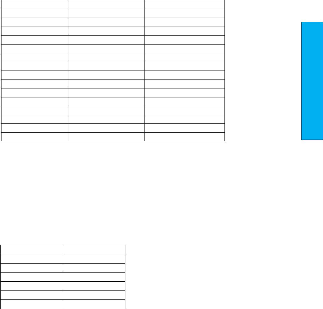
P a g e | 307
Section 11 – Main CPU Faults
Serial Hall Calls – Secondary Device
For serial hall calls the dev=XX (previous page) indicates which serial driver board and dv2=XX indicates
which hall station has communications errors.
The possible faults are:
hcb tx dn
hcb dev reset
hcb fet short green up
hcb tx up
hcb dn led brd
hcb fet short blue up
hcb rx dn
hcb up led brd
hcb fet short blue dn
hcb rx up
hcb led short red up
hcb fet short green dn
hcb stuck up
hcb led short green up
hcb fet short red dn
hcb stuck dn
hcb led short blue up
hcb fet open red up
hcb led open dn
hcb led short blue dn
hcb fet open green up
hcb led open up
hcb led short green dn
hcb fet open blue up
hcb led short dn
hcb led short red dn
hcb fet open blue dn
hcb led short up
hcb led open red up
hcb fet open green dn
hcb fet open dn
hcb led open green up
hcb fet open red dn
hcb fet open up
hcb led open blue up
hcb low supply voltage
hcb fet short dn
hcb led open blue dn
hcb up input overload
hcb fet short up
hcb led open green dn
hcb dn input overload
hcb inv fl
hcb led open red dn
hcb xu input overload
hcb no com
hcb fet short red up
Serial RGB Car Stations – Secondary Device & Specific I/O
For Serial RGB Car Stations dev=XX (previous page) indicates which driver board has comm issues (bear
in mind that Serial RGB drives have three board addresses: example Address 18, 19 & 20 for first serial
RGB driver board), dv2=XX indicates which board in the local bus and pf1-XX indicates which I/O is
declaring an error.
The possible faults are:
ccb led short red
ccb fet short green
ccb led short green
ccb fet short blue
ccb led short blue
ccb fet open red
ccb led open red
ccb fet open green
ccb led open green
ccb fet open blue
ccb led open blue
ccb led board
ccb fet short red
ccb stuck button

0 1 2 3 4 5 6 7
0000 0001 0010 0011 0100 0101 0110 0111
8 9 A B C D E F
1000 1001 1010 1011 1100 1101 1110 1111
UT UN DT3 DT2 DT1 DTS DT DN
RLM DLT DLM DLB UT3 UT2 UT1 UTS
TAD BAU BAD ACC RLM-1 DLT-1 DLM-1 DLB-1
SS HC FS BP ALT MES MRS HWS
5D 4D DT5/3D DT4/2D 4U RTL/3U UT5/2U UT4/1U
DL-1 UL-1 BKS DEL AD IND LBP GBP
INS LC GS-1 GS DPM DL DZ UL
AUTO MRID MRIU MRI ICI CS ID IU
DON BRKI GTR2 GTR1 RDY GTS FST P/RTL
LVC SECF/SVSD RGS-1 RGS MCAI MCCI RUNAI RUNI
PS GOV RDPM CTS UFI UPI DFI DNI
DS US DZA BP16 BP8 BP4 BP2 BP1
LWD LWB OVL LWA SE EE DCL DOL
CLF FB/NB FL CDL P6 NUD DC DO
IOC =
IOD =
IO6 =
IO7=
IO8 =
IO9 =
IOA =
IOB =
IO5 =
IO0 =
IO1 =
IO2 =
IO3 =
IO4 =

P a g e | 309
Section 12 – Combined Field Adjustable Variables
Section 12 Combined Field Adjustable Variables
This section contains the combined field adjustable variables:
Main CPU Adjustable Variables
Safety Processor Adjustable Variables
NTS Processor Adjustable Variables

Table 1: Car Motion
Field Variable
Min
Max
Initial
Units
Description
Acceleration
50
300
92
fpm/s
Acceleration Rate.
The constant acceleration rate to reach top speed.
Access Speed
0
75
35
fpm
Access Speed.
Car velocity while running on access.
Adv Pre Torque
0
0
0
Advance Pretorque.
When set, the controller will pick the motor contactor and
pretorque the motor when the door closes to the DLM limit. It
is enabled to improve floor to floor times when pretorque is
used.
0=Off
1=On
Balanced Load
0
100
40
%
Balanced Load.
Percent load of the counterweight.
Decel Jerk
50
480
125
fpm/s/s
Deceleration Jerk Rate.
Maximum jerk rate to roll from top speed to constant
deceleration.
Decel Rate
50
300
92
fpm/s
Deceleration Rate.
The constant deceleration rate from top speed to leveling
speed when stopping for a floor.
Dist Feed Fwd
0
1.3
0
Distance Feed Forward.
During the final approach to the floor, when using a tape
selector, the number of pulses to calculate the velocity is 64
pulses per foot. So during this time, if the CPU does not see a
distance change, it calculates the distance the car should move
over the next ten millisecond period and then uses that value
to calculate next velocity value. This value is a multiplier for
what percentage of the velocity calculation to uses. When the
next pulse comes in, the CPU calculates the velocity value as
normal.

P a g e | 311
Section 12 – Combined Field Adjustable Variables
Table 1: Car Motion
Field Variable
Min
Max
Initial
Units
Description
DON Start Ctrl
0
1
1
‐
Drive ON Start Control.
0 = Off
1 = The controller starts the pattern delay after the drive on
signal (DON) from the drive.
Drv Speed Mult
0.25
2.000
1.000
‐
Drive Speed Multiplier.
Used for KEB drive to adjust the speed of the elevator.
EM Decel Lev
50
300
100
fpm/s
Emergency Deceleration Leveling Rate.
The rate at which the elevator will go from decel to leveling
while on Emergency Slowdown.
Em Decel Rate
80
360
180
fpm/s
Emergency Deceleration Rate.
The rate at which the elevator will decelerate when it is doing
an emergency slowdown.
Encoder Dir
0
1
0
‐
Encoder Direction for CAN Bus Encoder.
Set to zero or one during Setup to get correct direction of
pulses for the CAN encoder.
Encoder PPR
60
3200
2048
PPR
Encoder Pulses Per Revolution.
The number of pulses the motor encoder generates per
revolution.
Encoder RPM
1
3000
105
RPM
Encoder Revolutions Per Minute.
The number of revolutions per minute the motor makes at top
speed.
Field Weaken
60
110
110
% vel
Field Weakening Velocity.
Percent of velocity above which the motor field is weakened to
allow the car to reach top speed.
Floor Targ Dis
1.2
25
12
inches
Floor Target Distance.
Distance to start leveling mode into the floor. Increasing this
distance will lower the jerk rate.

Table 1: Car Motion
Field Variable
Min
Max
Initial
Units
Description
Ins Decel Stop
50
480
300
fpm/s
Inspection Deceleration Stop Rate.
The rate for the elevator to decelerate from inspection speed
to zero.
Inspect Speed
0
150
40
fpm
Inspection Speed.
Maximum car speed while running on inspection.
Leveling Speed
1
15
5
fpm
Leveling Speed.
Maximum car speed while leveling into the floor.
Motor RPM
0
3000
500
rpm
Motor RPM.
Used for KEB drive only.
Overspeed Trip
80
125
110
%
Over Speed Trip.
Percentage of contract speed at which the controller will drop
the rope gripper.
Pattern Delay
0
3
0
sec
Pattern Delay.
Delay time before the speed profile will start.
Pls Cnt Upd Ere
0
2
1
inches
Position Count Update Error.
If the pulse count is off by more than this value and the update
flag is enabled, the position pulse count is updated. If this
value is set to zero and the update flag is enabled, then the
pulse count is updated every time the DZ is hit at high speed.
Pls Err Delay
1
10000
5000
1/sec
Position Count Update Error Delay.
This number is the time delay from when DZ is hit until the
input is read. The time delay parameter, times the current
speed of the car, is used to estimate the number of pulses the
count will change during the turn on time of the DZ input.

P a g e | 313
Section 12 – Combined Field Adjustable Variables
Table 1: Car Motion
Field Variable
Min
Max
Initial
Units
Description
Pos Count Upd
0
7
0
Position Count Update Flag.
The pulse count is checked every time the DZ input is hit.
+1=Update the DPP floor count as the elevator passes by a
landing and hits DZ.
+2=Interrupt the CPU when DZ hit otherwise the update is
done during the loop time (roughly 1 msec).
+4=Update every time the DZ is hit and the car is at constant
speed regardless of the pulse count update error value.
Preopen Delay
0
3200
0.5
sec
Preopen Delay.
Delay time to preopen the door starting from when the car
reaches 3 inches from dead level and the door can safely be
opened.
Recovery Speed
15
100
25
fpm
Recovery Speed.
Recovery Speed to the nearest floor.
Relev Pat Dly
0
3
0
sec
Relevel Pattern Delay.
Delay time before speed profile will start on a relevel.
Relev St Time
0
2
0
sec
Relevel Start Velocity Hold Time.
If relevel start speed is set to a non zero value, the controller
will use that value for the speed before going in relevel velocity
This parameter controls how long we stay in Relevel Start
Velocity.
Relev Strt Spd
0
15
0
fpm
Re‐level Start Speed.
Maximum starting velocity for a re‐level. Car will stay in relevel
Start speed for a time set by parameter ' Relev St Time ' and
then switch to relevel Speed
Relevel Speed
1
15
6
fpm
Re‐level Speed.
Maximum car speed during re‐leveling operation.
Roll Over Jerk
50
480
125
fpm/s/s
Rollover Jerk Rate.
Maximum roll jerk rate while rolling into top speed.

Table 1: Car Motion
Field Variable
Min
Max
Initial
Units
Description
Rope Comp Torq
0
50
0
offset
Rope Compensation Torque.
Used primarily on gearless machines that do not have any
compensating chains. This parameter adds torque to the
pretorque value to compensate for weight of the elevator
cables holding the car. The value is calculated from the
position of the car in the hoistway.
Soft Start Jerk
50
480
125
fpm/s/s
Soft Start Jerk Rate.
Maximum jerk rate to roll into constant acceleration from a
dead stop.
Soft Stop Time
0.2
30
1
sec
Soft Stop Time.
Hydraulic Elevators – time the motor is kept running after the
valve is turned off.
Traction Elevators – time that zero speed is held until the
brake is set.
Stop Decel Rate
5
225
50
fpm/s
Stop Deceleration Rate.
Rate to bring the velocity from leveling speed to zero speed.
Stop On Pos Cnt
0
1
0
Stop On Position Count.
Enable to stop the elevator on position pulse count. Used only
for tapeless application. It requires cons file setting to be
enabled and readjustment of leveling sensors for it to work.
0= Off
1=On
Top Speed
25
Contract
Speed
0
fpm
Top Speed or Contract Speed of the Car.
If set to zero, or set to a value greater than top speed, it will
use top speed in cons file.
Torque Amount
0
100
0
gain
Torque Amount.
Multiplier for the amount of torque proportional to the load. A
value of 100 will give 100percent torque with 100 percent load
or 60 percent torque with an empty car.

P a g e | 315
Section 12 – Combined Field Adjustable Variables
Table 1: Car Motion
Field Variable
Min
Max
Initial
Units
Description
Torque Down
Amt
0
100
0
gain
Torque Down Amount.
Torque Amount for down direction of travel. Multiplier for the
amount of torque proportional to the load. A value of 100 will
give 100 percent torque with 100 percent load or 60 percent
torque with an empty car. If this value is set to zero then the
Torque Amount parameter above will be used for both up and
down direction.
Torque Ramp
Tim
0
1
0
sec
Torque Ramp Time.
The amount of time for the torque to ramp up prior to the
elevator leaving the floor during pattern delay.

Table 2: Car Brake
Field Variable
Min
Max
Initial
Units
Description
BrakeDropDel
0
5
0.1
sec
Brake DropDelay.
Delay time to drop the brake after the car has stopped and is
dead level at the floor.
BrakeHold Volt
10
400
160
volts
Brake Hold Voltage.
Voltage to hold the brake for the remainder of the run.
BrakeOptoDly
0
7372
5500
3686/msec
Brake OptoDelay.
The SCR Brake board trigger circuit uses optocoupler devices that
have a turn on delay of roughly 1 millisecond but can vary from
part to part and vary from different input filtering. This
parameter is used to compensate for different turn on delays to
start of triggering of the SCRs. Only change this value at the
advice of a G.A.L.Technician.
BrakePick Del
0
5
0
sec
Brake PickDelay.
Delay time to pick the brake after the run relay is energized.
BrakePick Time
0.1
6
3
sec
Brake PickTime.
Duration of applied brake pick voltage before changing to the
hold voltage.
BrakePick Volt
10
400
230
volts
Brake PickVoltage.
DC Voltage to pick the brake. Brake voltage will start at start
voltage and then ramp to pick voltage.
Brk ACL‐L Volt
80
300
240
volts
Brake AC Line to LineVoltage.
AC input voltage to the brake board.
BrkDropRate
0
5
0
sec
Brake Drop RateTime.
Time value for brake to ramp from start voltage to zero.
BrkDropStart
0
1
0
‐
Brake Drop Timing During Leveling.
0 = Normal brake drop
1 = Early drop selected

P a g e | 317
Section 12 – Combined Field Adjustable Variables
Table 2: Car Brake
Field Variable
Min
Max
Initial
Units
Description
BrkDropVolt
0
200
0
volts
Brake Initial Drop Voltage.
DC Voltage to start the brake drop. Brake voltage will start at this
value ramp down to zero volts.
Brk Pick Rate
0
2
0
sec
Brake Pick Rate Time.
Time value for brake to ramp from start voltage to pick voltage.
Brk Pick Start
0
400
0
volts
Brake Pick Start Voltage.
Initial DC Voltage to pick the brake. Brake voltage will ramp to
pick voltage.
BrkRelev Rate
0
2
0
sec
Brake Relevel Rate Time.
Time value for brake to ramp from relevel start voltage to relevel
voltage.
BrkRelev Start
0
400
0
volts
Brake Relevel Start Voltage.
Initial DC Voltage to pick the brake on a relevel. Brake voltage will
ramp to relevel voltage.
BrkRelev Volt
10
400
230
volts
Brake Relevel Voltage.
Brake voltage applied on the brake coil during a relevel. This
parameter is useful to have a partial brake lift on relevel. Relevel
brake voltage will start at relevel start voltage and then ramp to
relevel voltage.
Brk Resistance
0.1
500
283
Ohms
Brake Resistance.
Resistance value measured on the brake coil in ohms.
EmBkDropDly
0
360
0
sec
Emergency Brake Drop Delay.
Delay time to drop the brake after the car has stopped and is
dead level at the floor.
EmBkDropRate
0
1.5
0
sec
Emergency Brake Drop Rate Time.
Time value for brake to ramp from start voltage to zero.

Table 2: Car Brake
Field Variable
Min
Max
Initial
Units
Description
EmBkHold Volt
0
400
160
volts
Emergency Brake Hold Voltage.
Voltage to hold the emergency brake for the remainder of the
run.
EmBkL‐L VAC
80
300
240
volts
Brake AC Line to Line Voltage.
AC input voltage to the brake board.
EmBkOptoDly
0
7372
5500
3686/msec
Emergency Brake Opto Delay.
The SCR Brake board trigger circuit uses optocoupler devices that
have a turn on delay of roughly 1 millisecond but can vary from
part to part and vary from different input filtering. This
parameter is used to compensate for different turn on delays to
start of triggering of the SCRs. Only change this value at the
advice of a G.A.L. Technician.
EmBkPick Rate
0
2
0
sec
Emergency Brake Pick Rate Time.
Time value for emergency brake to ramp from start voltage to
pick voltage. Only used if two brake boards are installed.
EmBkPick Tim
0
10
3
sec
Emergency Brake Pick Time.
Duration of applied emergency brake pick voltage before
changingto the hold voltage. Only used if two brake boards are
installed.
EmBkPick Volt
10
400
230
volts
Emergency Brake Pick Voltage.
DC Voltage to pick the emergency brake. Brake voltage will start
at start voltage and then ramp to pick voltage. Only used if two
brake boards are installed.
Pwl BkOffTim
0
5
0
sec
Power Loss Brake Off Time.
When Pwl Bk On Tim and Pwl Bk Off Tim are set to a non zero
values, the timers are used to pulse the brake contactor output
on and off while recovering the car with Power loss brake option.

P a g e | 319
Section 12 – Combined Field Adjustable Variables
Table 2: Car Brake
Field Variable
Min
Max
Initial
Units
Description
Pwl BrkOnTim
0
5
1
sec
Power Loss Brake On Time.
When Pwl Bk On Tim and Pwl Bk Off Tim are set to a non zero
values, the timers are used to pulse the brake contactor output
on and off while recovering the car with Power loss brake option.
RelevBrk Delay
0
5
0
sec
Relevel Brake Delay.
Time delay to lift the brake during a relevel.
RelevBrk LowV
0
1
0
‐
Relevel Brake Low Voltage.
Set to a 1 to relevel the car with the hold voltage to create a
partialpickof the brake. Not used with electronic brakeboard.
0=Off
1=On

Table 3: Modified Motion
Field Variable
Min
Max
Initial
Units
Description
EP Accel Rate
50
300
92
fpm/s
Emergency Power Accel Rate
EPDecelJerk
50
480
125
fpm/s/s
Emergency Power Decel Jerk Rate
EPDecelRate
50
300
92
fpm/s
Emergency Power Decel Rate
EP Recov Speed
10
100
25
fpm
Emergency Power Recovery Speed.
Recovery speed during emergency car recovery. Used when the
emergency power recovery source can only provide enough
powerto to bring the car to the floor in the direction of the load.
EP Roll Jerk
50
480
125
fpm/s/s
Emergency Power Roll Jerk Rate
EPSoftStJerk
50
480
125
fpm/s/s
Emergency Power Soft Start Jerk
EPTargetDist
1.2
25
12
inches
Emergency Power Floor Target Distance
EPTopSpeed
10
Contract
Speed
100
fpm
Top Speed for Emergency Power
ShFlAccel Rate
50
300
92
fpm/s
Short Floor Acceleration Rate.
The constant acceleration rate to reach top speed.
ShFlDecelRate
50
300
92
fpm/s
Short Floor Deceleration Rate.
The constant deceleration rate from top speed to leveling speed
when stopping for a floor.
ShFlSoftStJrk
50
480
125
fpm/s/s
Short Floor Soft Start Jerk Rate.
Maximum jerk rate to roll into constant acceleration from a dead
stop.

P a g e | 321
Section 12 – Combined Field Adjustable Variables
Table 3: Modified Motion
Field Variable
Min
Max
Initial
Units
Description
ShortFlCntrl
0
7
0
‐
Short Floor Control.
0=Default. The car relevels to the shortfloor.
+1=Car will make a run between very short floors instead of re‐
leveling.
+2= Short floor slowdown magnets between short floors (non‐
distancefeedback).
+4=Mid Short floor slowdown magnets between short floors
(non‐ distancefeedback).
ShortFlDist
10
72
30
inches
Short Floor Distance.
Any floor less than this distance is considered a short floor.The
short floor flag gets set and if preopening is enabled, it can be
specifically disabled for the short floorrun.
ShrtFlDeclJrk
50
480
125
fpm/s/s
Short Floor Deceleration Jerk Rate.
Maximum jerk rate to roll over from top speed to constant
deceleration.
ShrtFlRoll Jrk
50
480
125
fpm/s/s
Short Floor Rollover Jerk Rate.
Maximum roll jerk rate while rolling into top speed (acceleration).
ShrtFlTargDis
1.2
25
8
inches
Short Floor Target Distance.
Distance to start leveling mode into the floor. Increasing this
distance will lower the jerk rate.

Table 4: Car Timers
Field Variable
Min
Max
Initial
Units
Description
AdvDoorEnTim
0
240
0
sec
Advanced Door Enable Time.
Door open advance enable time to open the opposite door when
operating with non‐simultaneous doors. If there is a request for both
doors, instead of waiting for the first open door to close completely
before opening the second door, the second door starts to open after
the advance door enable time while the first door is closing.
AttBuz Delay
0
900
60
sec
Attendant Buzzer Delay. If this parameter is enabled, Service options-
> HC Acknwldg Buz will not work.
Buzzer sounds if a hall call is entered and the car has not started
moving within this delay time. This function is disabled when set to
zero.
AttBuzOffTime
0
30
0
sec
Attendant Buzzer Off Time.
Cycle off time to turn attendant buzzer on and off once attendant
delaytime function has been met (See ATT Buz Delay). Buzzer will stay
on continuously if this timer set to zero.
AttBuzOnTime
1
30
5
sec
Attendant Buzzer On Time.
Cycle on timer to turn attendant buzzer on and off once attendant
delaytime function has been met (See ATTBuzDelay).
AutoSwgDODly
0
10
1.0
sec
Auto Swing Door Open Delay.
Delay time to enable the auto swing door open output.
CarCallDwell
1
900
2
sec
Car Call Dwell.
Door open dwell time when answering a car call only.
CBDoorTime
1
3200
60
sec
Code Blue Door Time.
Door time for Code blue operation once elevator is at the emergency
floor before EMS is energized.
ChimeonCCTime
0.1
2
0.2
sec
Chime on Car Call Time.
Handicap buzzer on Car Call. Length of beep time.
CL Pulse Time
0
320
5
sec
Car Lantern Pulse Time.

P a g e | 323
Section 12 – Combined Field Adjustable Variables
Table 4: Car Timers
Field Variable
Min
Max
Initial
Units
Description
DoorDelayTime
0
1.5
0
sec
Door Delay Time.
Delay time between DO and DC to switch when opening or closing the
door.
DoorFailTime
10
3200
25
sec
Door Fail Time.
Time with power on the door without getting the door open
limit.
EETestTime
0
2
2
sec
Electric Eye Test Time for Automatic Freight Doors.
EETime‐ out
0
3200
40
sec
Electric Eye Time‐out Time.
If the Electric Eye or detector edge is on continuously for this amount
of time, it will be flagged as timed‐out and the controller will ignore
the EE input and close the door on nudging. When set to zero, this
feature is disabled.
FaultTime
0
10
2
sec
Fault Time.
Delay time before allowing the car to run after a fault
occurs.
FR DCTime‐ out
1
3200
1
sec
Freight Door Close Time‐out.
The amount of time prior to closing the doors on automatic freight
door operation.
FR PwrDOTime
0
30
1
sec
Freight Door Power Door Open Time.
The amount of time to turn on the power door open relay on
automatic freight door operation.
Gen/Lt/FanTime
30
3200
360
sec
Generator Run/Cab Light/Fan Time.
Length of time to leave the generator running or the Cab light and fan
on after there is no longer a demand to run.
Grip/EBK Rset T
0
20
4
sec
Gripper/Emergency Brake Reset Time.
The amount of time it takes for the rope gripper to reset on power‐up.

Table 4: Car Timers
Field Variable
Min
Max
Initial
Units
Description
HallCallDwell
1
60
4
sec
Hall Call Dwell.
Door open dwell time when answering a hall call or both a hall and car
call.
HallLantDly
0
15
0
sec
Hall Lantern Delay Time.
By default, when set to zero, hall lanterns go off as soon as the car
starts to slow down to arrive at a floor. When set to a nonzero value,
this will be used as a timer for the hall lantern to go off prior to
arriving at the floor.For example, if set to three seconds, hall lanterns
will turn on approximately three seconds before the car arrives to the
floor regardless of the speed of the car. We recommend to set this
parameter for high speedcars.
Handicap Dwell
1
120
25
sec
Handicap Dwell.
Extended door time from pressing the ED button in the car.
HEOFAuto Rst T
0
3200
0
sec
HEOF Auto Reset Time.
When the hall elevator off function is activated from the HEOF
inputbeing turned on, the car will be taken out of service until the
input is turned off. Once the input is off, the car will stay out of service
until the auto reset timer times out.
LantOffTime
0
2
0.2
sec
Lantern Off Time.
Used for double stroke gongs. The lantern off time is the delay time
after the lantern first turns on until it turns off.
LantOnTime
0
2
0.7
sec
Lantern On Time.
Used for double stroke gongs. The lantern will turn on, turn off and
then turn on again. The Lantern on time is the delay time from when
the lantern first turns on until it turns on the second time.

P a g e | 325
Section 12 – Combined Field Adjustable Variables
Table 4: Car Timers
Field Variable
Min
Max
Initial
Units
Description
LearnHW Stall
1
3200
30
sec
Automatic Hoistway Learn Stall Time.
The time required for a hoistway learn is calculated by the numberof
floors at an average height of 12.5 feet. This stall time value is added
to the calculated value for the maximum time allowed for the
autohoistway learn to run. If floor heights are taller or if there is a
blind shaft, this timer may need to be increased to the additional floor
height times1.2 (multiplier for car running at 30fpm). For a blind shaft
of 50 feet use a timer value of 50 * 1.2 = 60.0 seconds.
LobbyDwell
1
60
5
sec
Lobby Dwell.
Door open dwell time for a car at the lobby.
ManDoor BuzDly
0
900
0
sec
Manual Door Buzzer Delay.
On a car with manual doors, sound the buzzer if the door is left open
and a call is entered after this time delay. This function is disabled
when set to zero.
MaxDoorHldT
0
3200
0
sec
Maximum Door Hold Time.
Hold time to be allowed when the extended dwelling input (ED) is
pressed. If set to zero, there will be no limit on how long the car will
be held on ED. When set to a value, this will be the maximum
allowedtime for the car to held by ED input, then the car will go on
regular dwelling timers (car or hall call dwelling timers).
Non InterferT
1
60
2
sec
Non‐Interference Time.
Time between when you stop and when you can run again.
Nudging Time
20
3200
60
sec
Nudging Time.
Delay time for a door to be held before going into nudging.
OSERBTFlrTim
0
900
60
sec
Out of Service Between Floors Time.
Timer to control the OSERL output. Used with OSERL Control option 1
for 'between floors for over a minute' set to 2.
OSERNcall Tim
0
900
600
sec
Out of Service Not Responding to Calls Time.
Timer to control the OSERL output. Used with OSERL Control option 1
for 'not responding to calls' set to 1.

Table 4: Car Timers
Field Variable
Min
Max
Initial
Units
Description
OSERSopenTim
0
900
60
sec
Out of Service Safety String Open Time.
Time to control the OSERL output. Used with OSERL control option 1
for ' SS open' set to 4.
PasChimeTime
0.2
2
0.5
sec
Floor Passing Chime Time.
Length of time the floor passing chime will sound when a floor is
passed.
RCdropfailTim
0.5
5.5
0.5
sec
Retiring Cam Drop Fail Time.
Retiring cam drop fail safe delay for manual doors. Time it waits when
car arrives to the floor before it drops the output.
RC Pick Delay
0
7
0
sec
Retiring Cam Pick Delay.
The amount of delay time for the retiring cam to pick once the doors
are closed.
RelevDlyTim
0
2
1
sec
Relevel Delay Time.
The amount of delay time before the car will re‐level. This would be
used for jobs that have excessive rope stretch.
ResetTime
0
10
5
sec
Reset Time.
Delay time in the reset mode before allowing the car to run.
RTLDwellTime
1
60
8
sec
Return To Lobby Dwell Time.
If Return To Lobby is set to cycle doors at the lobby, use this timer to
control how long they will dwell before closing in return to lobby
mode.
RunCycleTime
0
300
0
hours
Run Cycle Time.
Used to initiate a run when the elevator has been sitting idle for a
period of time. Used for jobs that have high friction bearing machines.

P a g e | 327
Section 12 – Combined Field Adjustable Variables
Table 4: Car Timers
Field Variable
Min
Max
Initial
Units
Description
SabbBuzz Delay
1
10
5
sec
Sabbath Door Buzzer Timer Prior To Doors Closing.
In jobs where the light curtain is disabled in Sabbath operation it is
required to ring a buzzer prior to the door closing sequence.This timer
warns people when the light curtains are about to been eabled
(output name: SABUZ).
SabbathDwell
1
60
10
sec
Sabbath Door Dwell Time.
The Car will wait this amount of time on every floor forSabbath
operation except at the lobby where it will follow the handicap dwell
door time (separate timer).
SecDisableTim
0
3200
0
sec
Security Disable Time.
This timer is used with a security disable input button at the
lobby.When the button is pressed, the car call security is disabled for
the time value set from this parameter.
ShortDwellTim
0
60
1
sec
Short Door Dwell Time.
Door open dwell time when the doors re‐open on a door open button,
electric eye, safety edge or door hold button.
StallTime
20
3200
60
sec
Stall Time.
Maximum time a run is requested but the car is not moving.
VIPDoorTime
1
3200
20
sec
VIP Door Time.
The amount of time the car will park at the VIP recall floor prior to
returning to automatic service.
YDeltaTime
1
5
1.5
sec
Y‐Delta Time.
Transfer time to change motor from Y start to Delta run. This timer is
also used for DEL or MCX turn on time with controllers without y‐delta
starters.

Table 5: Car Options
Field Variable
Min
Max
Initial
Units
Description
Arrival Lant
0
1
0
‐
Arrival Lantern
0=Disable
1=Activate lant/gong without onward call
BehindCCCanc
0
1
0
‐
Behind Car Call Cancel.
When enabled the elevator will not latch any car calls in the
opposite direction of travel.
Binary Preset
0
1
0
‐
Binary Preset.
0=Update the car position count based on the binary preset when
the car recovers into afloor.
1=Always update the car position count based on binary preset
when the position doesn’t match.
BrakeLiftSw
0
2
1
‐
Brake Lift Switch.
If set to 1 or 2 a brake lift switch fault isdetected.
0=The Brake switch is ignored.
1=The car is prevented from running if the brake does not drop or
if the brake did not pick on the previous run. The car is allowed to
run after the brake drops.
2=The rope gripper will set if the brake does not drop and then
can only be reset by placing the car on inspection and back to
automatic.
CabLantCtrl
0
2
0
‐
Cab Lantern Control.
The default is for the cab lanterns to go off when the door is fully
open. This allows the cab lanterns to go off earlier.
+1 Ring cab lanterns as soon as door starts to open.
+2 Ring the cab lanterns when the door reaches DPM point.
CCSonSabbath
0
1
0
‐
Car Call Security on Sabbath.
When this parameter is enabled, sabbath car calls will not latch
on floors that have been secured using car call lockouts security.
Cl Gate No Pref
0
1
0
‐
Close Gate (Swing Door) When No Onward Preference.
The gate on a swing door normally stays open until a call is
placed. This bit causes the gate to close while the car is sitting at
the floor.

P a g e | 329
Section 12 – Combined Field Adjustable Variables
Table 5: Car Options
Field Variable
Min
Max
Initial
Units
Description
COP/RemoteCC
0
7
0
‐
COP/Remote Car CallSelect.
0=Both: COP and Remote Car Call Station used to enter calls.
+1=Separate: COP only or Remote CC only used to enter car calls.
+2=C‐R: Car calls entered on the COP sets the acknowledgment
light on the Remote station.
+4=R‐C: Car calls entered on the Remote station sets the
acknowledgment light on the COP.
COP/RemoteDis
0
14
0
‐
COP/Remote Disable.
+1=Up Direction DisableCOP
+2=Down Direction Disable COP
+4=Up Direction Disable Remote Panel
+8=Down Direction Disable Remote Panel
DCBCancDwell
0
1
0
‐
Door Close Button Cancel Dwell Time.
0= The DCB cancels door dwell time.
1= DCB does not cancel the door dwell time.
This parameter basically disables DCB to shorten door dwell time.
DO NoActvDOL
0
1
0
Door Open Output When No Active DOL.
When the door is fully open and hits the DOL, the DO is turned off
and stays off even if the door drifts off DOL.
With this bit set, the DO output will turn on any time the DOL is
lost.
DOBOverNudg
0
1
0
DOB Over Nudging.
If set the door open button will open the door when the door is
nudging closed.
DoorOpen LCtrl
0
16
0
‐
Door Open Light Control.
The way 'DoorOpenL Ctrl' parameter works is as below:
+1=Set OPENL on phase 1 completed
+2=Set OPENL on RTL return to lobby
+4=Set OPENL on EMP returne home with doors open, also sets
OPENL on EMP and selected to run
+8=Set OPENL on when Lobby Floor
+16=Set OPENL all the time.

Table 5: Car Options
Field Variable
Min
Max
Initial
Units
Description
DoubleStroke
0
1
1
‐
Double Stroke Gong Selection.
Select 1 or 2 gongs for down hall calls.
0=1 Gong
1=2 Gongs.
DriveRdy Flts
1
10
5
count
Drive Ready Fault Reset Count.
Number of times the drive can be reset in a 20 minute time
period.
DZ gripper ctl
0
1
0
‐
DZ Gripper Trip Control.
0=The gripper will trip when the car is out of the door zone, only
DZ needs to go low.
+1=The gripper will trip when both DZ and DZA go low which
changes the trip zone from 2 inches to 6 inches.
EECancelDwell
0
1
0
‐
Electric Eye Cancel Dwell.
By turning this parameter on you disable the short dwelling door
time from the electric eye signal (EE). By default the short
dwelling time is enabled.
EM Brake Sw
0
1
0
‐
Emergency Brake Switch Control.
0=Don't start if brake switch does notpick.
1=Ignore brake switch on start.
Enc DirFltDis
0
1
0
‐
Encoder Direction Fault Disable.
0=Enable Fault.
1=Disable Fault.
GOVGripper/E BK
0
1
0
‐
Governor Switch Gripper/Emergency Brake Trip Control.
0=Sets and latches a gripper fault immediately when the governor
switch is opened.
1=Latches the gripper fault only if the governor switch is opened
while the car is traveling at contract speed or above 150 fpm.
When the gripper fault is latched it must be reset from the LCD
interface for the car to run.

P a g e | 331
Section 12 – Combined Field Adjustable Variables
Table 5: Car Options
Field Variable
Min
Max
Initial
Units
Description
Griper / EB K Buz
0
1
0
‐
Gripper/Emergency Brake Buzzer.
Turn on buzzer if you have an active rope gripper or emergency
brake fault.
Gripper/E BKTrip
0
3
3
‐
Gripper/Emergency Brake Trip.
0=Off
+1=Safety Processor Speed
+2=Overspeed
HB/PIDisNVFl
0
1
0
‐
Handicap Buzzer/PI Display Control.
1=Do not sound HB or update floor PI when passing an invalid
floor.
Hndcap TimeFlr
Bottom
Floor
Top
loor
1
floor
Handicap Time Floor.
If the job is configured to have an extended door input at a hall
station, this parameter configures the floor number when
parameter will change door timing. Follows fvexdt timer. It will
operate for EDHL (Extended Door Hold) only.
IInvertBLS
0
1
0
‐
Invert Brake Lift Switch.
1=Inverts the logic for the brake lift switch to use a normally
closed switch instead of normally open.
InvertCLF
0
1
1
‐
Invert The Logic For The Car Light/Fan.
0=Car light fan is normally open.
1=Car light fan is normally closed.
InvertISER
0
7
0
‐
Invert In Service Output.
1=The in service light output is turned off when the car is in
service instead of turned on.
2=The ISER output will function as an elevator in use light.
4=This output functions as out of service from a shutdown and
doesnot include independent, inspection or recovery mode.

Table 5: Car Options
Field Variable
Min
Max
Initial
Units
Description
LantPref Dly
0
3
0
sec
Lantern Preference Change Delay.
When the direction preference for the elevator changes, we clear
the lanterns and wait for this amount of time before the lanterns
are turned on again.
LevelFaultCnt
3
10
3
count
Level Fault Count.
Maximum count of consecutive re‐level tries when a re‐level error
is detected. A relevel error is detected when the brake is dropped
and the car moves out the level zone.
Leveling Fault
0
1
0
‐
Leveling Fault Effect.
0=Drop everything
1=Set emergency brake or gripper when a leveling fault occurs.
The fault will have to be manually reset.
Lim DirFltDis
0
1
0
‐
Limit Direction Fault Disable.
Controller confirms the car direction of travel as it hits the
terminal limits.
0=Enable Fault.
1=Disable Fault.
LobbyLan NCU/IR
0
1
0
‐
Lobby Lantern NCU/IR.
0=Light the lanterns on IR service at each floor. The lantern will
notlight at the lobby if next up operation is selected because the
IR car will not be selected to be the next upcar.
1=The IR car will light the lantern at all the floors and the lobby
even with the system on next up
operation.
LowDoorVolt
0
600
198
Vrms
Low Door Voltage.
Settings for Line Voltage Monitor Board.
This parameter sets the value of voltage for 'Door Low Voltage
Fault' to be triggered.
LowLineVolt
0
600
198
Vrms
Low Line Voltage.
Settings for Line Voltage Monitor Board.
This parameter sets the value of voltage for a 'Low Line Voltage
Fault' to be triggered.

P a g e | 333
Section 12 – Combined Field Adjustable Variables
Table 5: Car Options
Field Variable
Min
Max
Initial
Units
Description
MinDoorTimEn
0
1
0
‐
Minimum Door Time Enable.
1=The minimum door time for a car call or a hall call is set from
the car or hall call dwell timers and cannot be shortened by the
Door Close button.
NCULantCtrl
0
3
0
‐
Next Up Direction Lantern Control.
+1=Turn off hall lantern after next uptime.
+2=Turn off cab lantern after next uptime.
NCUPref Ctrl
0
1
0
‐
Next Up Preference Control.
1=Allows direction preference to change before the door starts to
close, after the next up door time.
No HCDoorReop
0
3
0
‐
No Hall Call Button Door Reopen.
1=Do not reopen the door from an at floor hall call.
Non‐SimulDoors
0
2
0
‐
Non‐Simultaneous Doors.
0=Both front and rear doors will open at the same time if there is
a demand at both the front and rear openings.
1=The front doors will open first before the rear doors open if
there is a demand to open.
2=The rear doors will open first before the front doors open if
there is a demand to open.
NudgeDisCtl
0
7
0
‐
Nudging Disable Control.
+1=Do not turn on the NUD output when doors are in nudging
close mode, basically you are disabling nudging output.
+2=When doors are in nudging close mode and SE input is ON,
keep doors open and also keep FB/NB output latched.
+4=Sound the nudging buzzer but do not close the doors on
nudging.
Nudge No Calls
0
1
0
‐
Nudge With No Calls.
1=The doors will close on nudging even if the elevator has no
onward calls.

Table 5: Car Options
Field Variable
Min
Max
Initial
Units
Description
OSERLOutCtrl1
0
7
0
‐
Out of Service Light Control.
+1=Not responding to calls.
+2=Between floors for over a minute.
+4=SS open. When this parameter as well as OSERL OutCtrl 2 is set
to zero,the output will just operate as an Out of Service light.
OSERLOutCtrl2
0
1
0
‐
Out of Service Light Control 2.
+1=Alarm. When this parameter as well as OSERL OutCtrl 2 is set
to zero,the output will just operate as an Out of Service light.
Preopen Doors
0
3
0
‐
Preopen Doors.
+1=Will enable preopening of the doors. If retiring cam used with
auto door, RCM will also turn on at the preopening point.
+2=Exclude short floors.
RadPos Ind
6
48
6
inches
Radial Position Indicator.
Used for radial Position indicator output. This parameter adjusts
the range for the distace from the floor where the poistion
indicator outputs should turn on and off.
RCFoutenable
0
1
0
‐
Retiring Cam for Freight Output Enable.
When you turn on this parameter it creates a retiring cam output
in the controller, RCF, that mirrors the signal from RCM. You need
to reboot CPU everytime you change this parameter for the
change to take effect.
RCMControl
0
3
0
‐
Retiring Cam Control.
1=Hold the retiring cam up at the floor if there is no pilot to open
the door (manual doors). The retiring cam will drop after 5
minutes.
2=RCM output turns on when DZ is hit to advance the RCM ahead
of the door open (auto door with retiring cam) otherwise the
default is that RCM turns on when dead level.
If preopening is set RCM and DO turn on when DZ is hit.

P a g e | 335
Section 12 – Combined Field Adjustable Variables
Table 5: Car Options
Field Variable
Min
Max
Initial
Units
Description
SabbathEnCtl
0
7
0
‐
Sabbath Enable Control.
0=Disables all options.
+1=Allow IR momentarily to override Sabbath operation.
+2=Lobby Dwell time in Sabbath follows handicap door dwell time
instead of the lobby dwell time.
+4=Wait until car is at lobby to turn off Sabbath operation.
SabbathEnCtl2
0
3
0
‐
Sabbath Enable Control 2.
+1=When the car is placed on Sabbath operation, it waits to go to
the lobby before switching to Sabbath Operation.
+2=Use the cab lanterns as directional arrows. This allows people
on the hallways to know direction of travel for the elevator.
Sabbath Mode
0
1
0
‐
Sabbath Collective Mode.
0=Down collective car calls
1=Up collective car calls.
SecndRisr Lant
0
1
0
‐
Second Riser Lantern.
Turn on cab lantern only when IR call answered. If this parameter
is set cab lanterns will only turn on when answering second riser
calls.
SlipDetDis
0
1
0
‐
Slip Velocity Difference Disable.
0=Enable Fault.
1=Disable Fault Can only be disabled with code previous to
A17.12010.
SlipVelDiff
0
300
150
fpm
Slip Velocity Difference Fault Trip Value.
This parameter determines Maximum allowable difference
between Safety processor speed and controller speed.
SPB DirFltDis
0
1
0
‐
SPB Direction Fault Disable.
0=Enable Fault.
1=Disable Fault.

Table 5: Car Options
Field Variable
Min
Max
Initial
Units
Description
ULDLDirFltDis
0
1
0
‐
UL/DL Direction Fault Disable.
Controller confirms the car direction of travel when it passes the
UL and DL door zone limits.
0=Enable Fault.
1=Disable Fault.
VelDiffDis
0
1
0
fpm
Velocity Difference Fault Disable.
0=Enable Fault.
1=Disable Fault.
Velocity Diff
50
300
150
fpm
Velocity Difference.
Maximum velocity difference between Encoder feedback and
demand velocity. When the difference exceeds this setting,
'Velocity DiffFault' will occur.

P a g e | 337
Section 12 – Combined Field Adjustable Variables
Table 6: Service Options
Field Variable
Min
Max
Initial
Units
Description
Access BotFl
Bottom
Floor
Top
Floor
1
floor
Access Bottom Floor.
Floor for bottom access.
AccessDoorCls
0
1
0
‐
Access Door Close.
When on access operation the car runs with the Door Lock
and GS open. By turning this parameter on, the car needs to
have the gate switch signal ON in order to run. It should be
used on hoistways where the car door will physically hit
something if moved on access operation.
Access TopFl
Bottom
Floor
Top
Floor
2
floor
Access Top Floor.
Floor for top access.
Att Buz ctrl
0
1
1
‐
Attendant Buzzer Control.
0=Hall Calls only.
1=Hall Calls and Car Calls.
Att CCfromHC
0
1
0
‐
Attendant Car Call from Hall Call.
When set to 1 and the car is on Attendant service the
respective car call will register when a hall call is registered.
CB Buzzer Ctrl
0
1
0
‐
Code Blue Buzzer Control.
1=Turn buzzer on while in code blue recall.
CB OverInd
0
1
0
‐
Code Blue Override Independent.
1=Wait for timer to expire and then recall the car.
CB singlecall
0
1
0
‐
Code Blue Single Car Call.
0=Car on Code Blue operation allows multiple car calls on
Hospital Service.
1=Allow only a single call once placed on Hospital Service.

Table 6: Service Options
Field Variable
Min
Max
Initial
Units
Description
CCPBS onGp Sec
0
1
0
‐
CCPBS On Group Car Call Security.
This variable enables Car Call Push Button Security with
group car call lockout switches.The configuration (CONS) file
setting for security type and car call push button security
must also be set.
CEOFControl
0
7
0
‐
Car Elevator Off Options.
+1=Recall.
+2=Keep Door Open.
+4=Turn off CLF.
CEOFControl2
0
15
0
‐
Car Elevator Off Options 2.
+1=Keep doors Closed (do not cycle on reversal).
+2=Do not blink Elevator Off Light.
+4=Elevator Off Auto Reset With Timer.
+8=Enable Elevator Off Light to indicate the car finished
recall of elevator off mode.
DOBOverSec
0
5
0
‐
DOB Override Security.
This parameter allows the car to open the door at a secured
floor when the car is secured from the followingconditions:
1=The DOB will be allowed to open the door at any secured
floor.
2=The DOB can open the door at floors secured from group
security floor mask table.
3=Allows the DOB to open the front door at floors secured by
car call lockout security (switches or cardreader).
4=Allows the DOB to open the rear door at floors secured
from rear car call lockout security.
5=Allows the DOB to open the door at floors locked out by
group security floor mask tables when the car is also on
Independent.
DoorHold Msg
0
1
0
‐
Door Hold Message.
Set to enable Extended Door Time Message Indicator in CE
Driver board.

P a g e | 339
Section 12 – Combined Field Adjustable Variables
Table 6: Service Options
Field Variable
Min
Max
Initial
Units
Description
Elev OffRet Fl
0
Top
Floor
0
floor
Elevator Off Return Floor.
Related to HEOF input. This setting is to be used in
conjunction with 'Elev Off Ctl =+1'. If the elevator is
configured to recall, this parameter will determine what floor
the car should be recalled to in elevator off mode. If
Parameter is set to zero, car will be returned to the lobby.
Em Power Floor
Bottom
Floor
Top
Floor
1
floor
Emergency Power Recall Floor.
EMS/HSafterCB
0
1
0
‐
EMS (Emergency Medical Service) / HS (Hospital Service)
after Code Blue.
This is a Code Blue bypass control.
0=Car goes from Auto to Hospital service, by passing the
code blue sequence when EMS switch is turned on.
1=Hospital service only activates after a code blue recall.
EP Recovery Dir
0
1
0
‐
Emergency Power Recovery Direction.
Recover to the nearest floor on emergency power.
0=Based on movement of the car when brake is picked.
1=Based on load weighing device. Used when the emergency
power recovery source can only provide enough power to
bring the car to the floor in the direction of the load.
EPS SelNo Grp
0
2
0
‐
Emergency Power Selection Switch Operation with no
Group Active.
0=Run Automatic.
1=Recall first and then run Automatic.
2=Recall only; do not run after recall.
FlashCBLight
0
1
0
‐
Flash Code Blue Light.
1=The code blue light inside the car station will flash.
Handicap Load
0
100
40
%
Handicap Load (Car Capacity).
Percent of load, when above this value, the car may not have
enough room for a person in a wheelchair. Cars with
loadsbelow this value would be given a preference to get an
assignment at a floor requested by a handicap person.

Table 6: Service Options
Field Variable
Min
Max
Initial
Units
Description
HCAcknwldg Bzz
0
1
0
‐
HC Acknowledge Attendant Buzzer ‐ Buzz Once (for one
second every time a call comes in). Car Timers->Att Buz
Delay must be set to “0”.
0=Disable.
1=Enable.
HEOFControl
0
7
0
‐
Hall Elevator Off Control.
+1=Recall car when key switch activated.
+2=Keep door open at the shutdown floor.
+4=Allow the cab light and fan to time‐out even though the
door is open but the car is shutdown.
HEOFControl2
0
15
0
‐
Hall Elevator Off Options 2.
+1=Keep doors Closed (do not cycle).
+2=Do not blink HEOFL.
+4=Auto Reset when input off and timer expires.
+8=Use HEOFL to indicate car finished recall.
HEOFControl3
0
1
0
‐
Hall Elevator Off Options 3.
+1=Only activate if doors are closed.
See other Hall Elevator Off Options as well.
HEOFOverInd
0
1
0
‐
Hall Elevator Off Override Independent.
1=Wait for timer to expire and then recall the car.
HSV DoorClCC
0
1
0
‐
Hospital Service Close Door Car Call.
Close the doors from a car call when the car is on Hospital
Service.
IND DoorClCC
0
1
0
‐
Independent Door Close Car Call.
1=Enable to close the doors from a car call when the elevator
is on independent.
Ind OverSec
0
7
0
‐
Independent Overrides Security.
1=Allow independent service to override security car call
lockouts.
2=Override Security Floor Mask configurations.
4=Override remote car call station.

P a g e | 341
Section 12 – Combined Field Adjustable Variables
Table 6: Service Options
Field Variable
Min
Max
Initial
Units
Description
IND Rclto Lby
0
1
0
‐
Independent Recall to Lobby.
1=Forces the car to recall to the lobby when on independent
and no calls are made.
INDRcl2Lby tmr
10
60
20
sec
Independent Recall to Lobby Timer.
Recall delay for car in independent when 'IND Rcl to Lby' is
set.
InsDoorClose
0
1
0
‐
Inspection Door Close.
1=The door close output will turn on when the up or down
inspection run button is
pressed.
INSECOutpCtl
0
1
0
‐
INSEC ‐ In Security Output Invert.
Output located on the car call security board.
LoadAntinuisan
0
100
20
%
Load Anti‐nuisance.
Percent of load, when below this set point will cause the car
to drop its car calls.This function is disabled when set to zero.
LoadBypass
0
100
60
%
Load Bypass.
Percent of load, when above this set point will cause the car
to bypass hall calls.This function is disabled when set to zero.
Load Dispatch
0
100
40
%
Load Dispatch.
This set point is used as a trigger to activate Up Peak
operations in the group. Each time the car leaves the lobby
with a load greater than this value, the group will increment
the Up Peak Trigger.This function is disabled when set to
zero.

Table 6: Service Options
Field Variable
Min
Max
Initial
Units
Description
LoadOverload
0
125
110
%
Load Overload.
Percent of load, when above this set point will cause the car
to go on overload operation (sit at the floor with the door
open and the overload light on). When the load goes below
this value,the car will automatically return to service.This
function is disabled when set to zero.
LWAnti‐ nuisan
0
50
0
count
Load Weighing Anti‐nuisance.
Set to the maximum number of car calls that can be
enentered before all car calls are cancelled without the load
switch LWA input on. Once the load switch is on, all car calls
will stay latched. If set to 0, this function is
disabled.
ManualDirEn
0
4
0
‐
Attendant Manual Direction Enable.
1=Works in conjunction with the ATTUP and ATTDN to
determine direction of travel.
2=Reads the ATTUP input and use it as a START button.
4=Will not allow car calls to be registered until the door is
fully closed.
MedCCSOvrride
0
1
0
‐
Medical Service Override Car Call Security.
1=Medical service car will override car call security.
MedDoorReopen
0
2
0
‐
Medical Service Door Reopen.
When car is in medical Service, this parameter determines
the door open sequence for re‐open:
0=Stop.
1=Constant pressure.
2=Momentary to DOL.
MedEmFloor
Bottom
Floor
Top
Floor
1
floor
Medical Emergency Return Floor.
Med EmSwLoc
0
1
0
‐
Medical Emergency Switch Location.
Selects the switch location for the front or rear door.

P a g e | 343
Section 12 – Combined Field Adjustable Variables
Table 6: Service Options
Field Variable
Min
Max
Initial
Units
Description
MedInd Ovrride
0
2
0
‐
Medical Service Overrides Independent Control.
0=Immediate.
1= After Delay.
2=No override.
No Psg Run Cnt
0
10
0
count
No Passenger Run Count.
When set to a number other than zero, the car call
antinuisance feature is activated. This count is the number of
times the car will run from a car call without detecting that a
passenger has broken the detector edge. Once the count is
reached, all remaining car calls will be cancelled.
PI Serv Msg1
0
Max
Service
0
Service
Number
PI Service Message 1.
When the car service matches this number, user message 1 is
sent to the PI display. This will correspond to user P Idisplay
message 17.
PI Serv Msg2
0
Max
Service
0
Service
Number
PI Service Message 2.
When the car service matches this number, user message 2 is
sent to the PI display. This will correspond to user PI display
message 18.
PI Serv Msg3
0
Max
Service
0
Service
Number
PI Service Message 3.
Used for Custom messages. Need to be programmed byCE
electronics and GAL for special messages.
ReturnToLobby
0
7
0
‐
Return to Lobby Option.
+1=Cycle door at lobby.
+2=Cancel car calls when activated.
+4=Cycle door on reversal.
RTLDoorSelct
0
2
0
‐
Return To Lobby Door Select.
This variable allows you to specify door open type on 'Return
to Lobby' service.
0=The car will open only the front door.
1=The car will open only the rear door.
2=The car will open both front and rear doors.

Table 6: Service Options
Field Variable
Min
Max
Initial
Units
Description
Sec Reassign CC
0
3
0
‐
Security Reassign Car Call.
Re‐assign secured car call to opposite door. Used with
security configuration, cons.dat file setting: cons[SecFlCfg]=2.
0=Disabled.
+1=In case front CC are secured, reassign them as rear.
+2=In case rear CC are secured, reassign them as front.
Sec Recall2
0
2
0
‐
Security Recall Control 2.
0=Out of group on first recall.
1=Out of group on all recalls.
2=No out of group recalls.
Security Floor
0
Top
Floor
1
floor
Security Floor.
The security recall floor. This is the floor where the security
guard would be stationed. This floor would not be locked out
when on security.
Security Recall
0
15
0
‐
Security Recall Selection.
0=No Recall.
+1=Recall to Security Floor on activation of security.
+2=Cycle front door once recalled to the Security Floor.
+4=Cycle rear door once recalled to the Security Floor.
+8 =Always recall to security floor after each run.

P a g e | 345
Section 12 – Combined Field Adjustable Variables
Table 6: Service Options
Field Variable
Min
Max
Initial
Units
Description
ServiceLTCTL
0
30
0
Service
Number
Service Light Control.
When the configuration file parameter cons[servOUT] is set
to 1 or 2, the service output SERVO will turn on when the car
service matches the car service number in this parameter.
The available options are:
0: Out of Service
1: Automatic Service
2: Independent Service
3: Load Weighing Bypass
4: Attendant Service
5: Code Blue Service
6: Fire Service Phase 2
7: Emergency Power Service
8: Earthquake Service
9: Fire Phase 1 Main Return
10: Fire Phase 1 Alt Return
11: Homing
12: Reset Going Up
13: Reset Going Down
14: Stalled Out of Service
15: Return to Lobby
16: Load Weighing Overload
17: Medical Emergency Serv
18: Calibrate Load Weigher
19: Car Switch Elevator Off
20: Hall Switch Elevator Off
21: Low Pressure
22: Hospital Service
23: Priority Service
24: Security Recall
25: Sabbath Service
26: TUG Service
27: Hot Oil Operation
28: Riot Control
29: Car Switch Elevator Off 2
SR CCSecbyDir
0
2
0
‐
Second Riser Car Call Security by Direction.
Allows calls in the one direction but disables them in the
other.
1=Allow calls in the up direction (above the floor) but disable
them going down.
2=Allow calls in the down direction (below the floor) but
disable then going up.

Table 6: Service Options
Field Variable
Min
Max
Initial
Units
Description
StopAt Lobby
0
15
0
‐
Stop at Lobby.
0=Do not automatically stop at lobby.
+1=The car will stop at the lobby when the car is traveling up
and the car is below the lobby floor.
+2=The car will stop at the lobby when the car is traveling
down and the car is above the lobby floor.
+3=The car will stop at the lobby when traveling in either
direction.
+4=Stop at lobby with any onward call past the lobby.
+8=Recall to the lobby.
Vip LantCtrl
0
3
0
‐
VIP Lantern Control.
0=Do not ring lanterns on VIP.
1=Ring up or down lantern at VIP floor when the door is fully
open.
2=Ring up or down lantern at VIP floor before the door is
opened.
VIP multicall
0
1
0
‐
VIP Multiple Calls.
0=VIP feature works as single call.
1=The car will be allowed to make multiple VIP calls until no
more car calls are entered and until the VIP sequence time‐
out timer is expired.

P a g e | 347
Section 12 – Combined Field Adjustable Variables
Table 7: Fire Options
Field Variable
Min
Max
Initial
Units
Description
ALTFireFloor
Bottom
Floor
Top
Floor
2
floor
Alternate Fire Floor.
Alt RclFSOff
0
3
0
‐
Alternate Floor Recall Fire Service Off.
+1=Have the elevator recall back to the alternate floor when the
lobby fire switch is turned to the off position and car recalled to the
main fire floor.
+2=Allows the car to return to the alternate landing even if sensor
was reset.
Aux.FireSw.
0
1
0
‐
Auxiliary Fire Switch.
1=The controller expects an auxiliary hall fire switch to be used.
CB overFS
0
1
0
‐
Code Blue Over Fire Service.
+1=Prevent Code Blue car from recalling in Fire Service.
Cl DoorF1Rcl
0
1
0
‐
Close Door After Fire Phase 1 Recall.
1=Elevator will close the doors after phase 1 recall and reopen from
a hall call (Denver Fire service amendment).
F1DCTime‐out
10
60
20
sec
Fire Phase 1 Door Close Time‐out.
The amount of time it will take before the car doors start to close
while the car is on Independent or Attendant service prior to
recalling the elevator on Fire Phase 1.
F1DoorDwell
1
90
60
sec
Fire Phase 1 Door Dwell Time.
Fire Service Phase one complete dwell time when 'Cl Door F1Rcl'
parameter is set. (Denver FS phase 1 dwell time).
F2DOBovrDCB
0
1
0
‐
Fire Phase 2 Door Open Button Overrides Door Close Button.
1=Allows the Door Open Button to override Door Close Button
when on phase 2. (Miami Fire Service).
FireMain Floor
Bottom
Floor
Top
Floor
1
floor
Fire Main Floor.

Table 7: Fire Options
Field Variable
Min
Max
Initial
Units
Description
FireOption
0
3
0
‐
Fire Option. Recall Reset Selection.
0=Reset fire service phase 1 after hall switch is turned off and car
returns to fire floor.
1=Reset phase 1 immediately after hall switch is turned off.
FireOption2
0
3
1
‐
Fire Option 2.
+1=Initiate a phase 2 recall only when the door is open (Chicago
Fire Service).
+2=Disable flashing FL on phase 2 (Chicago Fire service).
FireSwLoc
0
4
0
‐
Fire Switch Location. Location of Fire Hall Switch.
0=Main/Alt Front.
1=Main Rear/Alt Front.
2=Main Front/Alt Rear.
3=Main/Alt Rear.
4=Set from Dispatcher Car selection.
FireLEmerPwr
0
1
1
‐
Fire Light Control During Emergency Power.
1=Cause the fire light FL to turn off if the car is not selected to run.
FireLOTSRet
0
1
0
‐
Fire Light Control for Out of Service Cars.
1=Enabling this parameter will turn off the fire light in the event the
car cannot recall for being out of service. The cause could be due to
Earthquake, low oil, stall,etc.
FS2DoorReopen
0
1
0
‐
NYC FS2 Door Reopen on Stop Switch.
When the elevator is on FS2 and DCB is pressed, the doors will
behave thus:
0=While the door is closing, if you hit the in car stop switch the
doors continue to close.
1=While the door is closing and you hit the in car stop switch,the
doors re‐open.

P a g e | 349
Section 12 – Combined Field Adjustable Variables
Table 7: Fire Options
Field Variable
Min
Max
Initial
Units
Description
HallFireLight
0
4
0
‐
Hall Fire Light.
This variable controls the FLH output on the controller so it can be
used for a hall fire light or a fire security override.
0=FLH turns on while the car is on phase 1 or phase 2 fire service.
+1=FLH turns on while phase 1 is ineffect.
+2=Flash FLH at 1 second intervals while activated.
+4=FLH follows the Fire Light (FL) logic.
Hoistw FireRet
0
1
0
‐
Hoistway Fire Sensor Return Floor Selection.
0=Return to the Main fire floor.
1=Return to the Alternate fire floor.
HWS2FireLoc
0
1
50
‐
Fire Service Hoistway HWS2 Sensor Location.
0= Same hoistway.
1=Separate hoistway.
HWS2FireRet
0
1
0
‐
Second Hoistway Fire Service Sensor Return Option.
0=Main recall floor.
1=Alternate recall floor.
MachRm FireRet
0
1
0
‐
Machine Room Fire Sensor Return Floor Selection.
0=Return to the Main fire floor.
1=Return to the Alternate fire floor.
RclfromF1Alt
0
1
0
‐
Recall From Fire Phase 1 Alternate Floor.
0=If the car has returned to the alternate floor from a smoke sensor
and when two fire hall switches are used, both must be on to recall
the car from the alternate floor to the main floor.
1=The car will recall from the alternate floor to the main floor from
either hall fire key switch. (Set to 1 for Mass. fire service).
Recall Reset
0
3
0
‐
Recall Reset Selection.
0=Reset fire service phase 1 after hall switch cycled through reset
and turned off and car returns to fire floor.
1=Reset phase 1 immediately after hall switch is cycled through
reset and then turned off.
2=Reset fire service without cycling fire switch through reset but
turned off only if the smoke sensors were not activated.

Table 7: Fire Options
Field Variable
Min
Max
Initial
Units
Description
Recall Reset 2
0
1
0
‐
Recall Reset Selection 2.
0=Reset fire service phase 1 with car at any floor.
1=Reset phase 1 only if car at fire recall floor.

P a g e | 351
Section 12 – Combined Field Adjustable Variables
Table 8: Group Dispatch
Field Variable
Min
Max
Initial
Units
Description
AltLobbyFloor
1
Top
Floor
1
floor
Alternate Lobby Floor.
Galaxy groups can be configured to have an alternate lobby.
Switching between regular lobby and alternate lobby can be
done by means of liftnet, Galileo, controller input or service
timer. Oncethe alternate lobby is enabled, controllers will use
this landing as the lobby floor for all dispatching purposes.
Alt Parking Fl
1
Top
Floor
1
floor
Alternate Parking Floor.
Normally, during parking operation, one car is always parked at
the lobby. With alternate parking floor operation, a free car is
parked at the alternate parking floor instead of the lobby
floor.This operation is controlled by an input or from a service
timer.
Asgn Park FlDO
0
1
0
‐
Assign Parking Floor with Door Open.
By default we only park cars that have the doors closed after a
time delay. This parameter allows to re‐assign parking to cars
with doors open as long as they do not have a direction to run.
AutoSVCtm‐out
0
1
0
‐
Auto Service Time‐out.
When this parameter is enabled and 'Auto SVC tot TM'
parameter time is set accordingly, each car is checked for
answering assigned hall calls. If the car does not move to answer
calls in the required time, it is put into AST service. Hall calls that
are assigned to that car are reassigned to working cars in the
group. The group then periodically assigns hall calls to the AST
car to verify if it can beput back into the group for normal
operation.
0=Disable.
1=Enable
AutoSVCtotTM
10
3200
120
sec
Auto Service Time Out Time.
This time, in seconds, is used in conjunction with 'Auto
SVCtm‐out' and is the amount of time that the group will wait
before setting a 'not moving/responding' car as timed out.
Dn Peak Contrl
0
1
0
‐
Down Peak Control.
0=Normal down peak.
1=Heavy down peak.

Table 8: Group Dispatch
Field Variable
Min
Max
Initial
Units
Description
Dn PkTrigCnt
1
100
12
count
Down Peak Trigger Count.
Number of down hall calls above the lobby that are set within
the down peak trigger time to place the system on down peak
operation.
Dn PkTrigTime
0
3200
60
sec
Down Peak Trigger Time.
The time interval to count the number of down hall calls above
the lobby to activate down peak operation.
DownPeak Pool
0
Number
Cars
0
car
Down Peak Pool.
Number of cars to be utilized for down peak.
DownPeak Time
0
3200
180
sec
Down Peak Duration Time.
The duration time for down peak operation once down peak is
activated.
ETA CoCCTime
0
60
15
sec
ETA Coincident Car Call Time.
Hall calls will be assigned to the car with the coincident car call
unless the car without the coincident car call can reach the call
faster then ETA Coincident Car Call Time.
ETAMin Time
0
60
6
sec
ETA Minimum Time.
For a hall call to be assigned to a new car, the difference in ETA
must be greater than the ETA Minimum Time.
GrpTimerPark
0
Number
Cars
0
car
Group Service Timer Park Cars.
This is the number of parking cars when parking is set from the
Service Activation Timer for Group parking.

P a g e | 353
Section 12 – Combined Field Adjustable Variables
Table 8: Group Dispatch
Field Variable
Min
Max
Initial
Units
Description
High PriortyFL
0
Top
Floor
0
floor
High Priority Floor.
When this parameter is set to a floor number other than zero the
high priority operation is activated. If there is a call latched at the
high priority floor and the timer set from the 'High PriorityTM'
expires, the group will choose the best car by considering only
car calls. It will remove all hall calls on that best car except for
the priority floor hall call. The car will serve all car calls and then
service the priority floor before being assigned another hall call
from the group.
High PriortyTM
6
254
60
sec
High Priority Time.
Works in conjunction with parameter 'High Priority Floor', it is
the amount of time to wait before removing hall calls assigned to
the selected best car.
LobbyFloor
Bottom
Floor
Top
Floor
1
floor
Lobby Floor.
LobbyReq Cntrl
0
1
0
‐
Lobby Request Control.
If the lobby request variable is set to non‐zero, then that is how
many cars are requested to the lobby all the time.
1=The lobby request is only used when next up is active. Next Up
can be active all the time, from a dedicated input or from
UpPeak.
LobbyRequest
0
Number
Cars
0
car
Lobby Request.
Number of Cars Requested to the Lobby floor. Used with Next
Car Up operation.

Table 8: Group Dispatch
Field Variable
Min
Max
Initial
Units
Description
NextCarUp
0
7
0
‐
Next Car Up.
Set to 1 or 2 will activate the Next Car Up operation.
+1=The Next Up car will open its door at the lobby and keep it
open. The car is allowed to leave the floor after the Lobby Dwell
time expires but will remain at the floor with the door open until
an onward call is assigned to it.
+2=The Next Up car will close its door after the Lobby Dwell time
expires and go off on Next Up but will remain at the lobby. An up
hall call at the lobby will cause the car to open its door and go on
Next Up.
+4=Next Up is activated on Up Peak detection only. Next Up can
also be activated from an input.
ParkDelayTime
0
120
8
sec
Parking Delay Time.
Time delay an idle car waits before being parked.
Parking
0
Number
Cars
1
car
Number of Cars to Park.
One car is parked at the lobby. The remaining cars in the group
are parked at the most used floors of the building. If set to zero,
no cars are parked.
Parking floor1
0
Top
Floor
0
floor
Parking Floor 1.
Floor to park the second idle car, the first idle car is parked at the
Lobby. If set to zero, the group will use number of hall call history
to decide where to park the car. The 'Parking' variable must be
set to at least 1 for this function to work. See also Parking Type.
Parking floor2
0
Top
Floor
0
floor
Parking Floor 2.
Floor to park the third idle car, the first idle car is parked at the
Lobby. If set to zero, the group will use number of hall call history
to decide where to park the car. The parking variable must be set
to at least 1 for this function to work. See also Parking Type.

P a g e | 355
Section 12 – Combined Field Adjustable Variables
Table 8: Group Dispatch
Field Variable
Min
Max
Initial
Units
Description
Parking floor3
0
Top
Floor
0
floor
Parking Floor 3.
Floor to park the fourth idle car, the first idle car is parked at the
Lobby. If set to zero, the group will use number of hall call history
to decide where to park the car. The parking variable must be set
to at least 1 for this function to work. See also Parking Type.
Parking floor4
0
Top
Floor
0
floor
Parking Floor 4.
Floor to park the fifth idle car, the first idle car is parked at the
Lobby. If set to zero, the group will use number of hall call history
to decide where to park the car. The parking variable must be set
to at least 1 for this function to work. See also Parking Type.
Parking floor5
0
Top
Floor
0
floor
Parking Floor 5.
Floor to park the sixth idle car, the first idle car is parked at the
Lobby. If set to zero, the group will use number of hall call history
to decide where to park the car. The parking variable must be set
to at least 1 for this function to work. See also Parking Type.
Parking floor6
0
Top
Floor
0
floor
Parking Floor 6.
Floor to park the seventh idle car, the first idle car is parked at
the Lobby. If set to zero, the group will use number of hall call
history to decide where to park the car. The parking variable
must be set to at least 1 for this function to work. See also
Parking Type.
Parking floor7
0
Top
Floor
0
floor
Parking Floor 7.
Floor to park the eighth idle car, the first idle car is parked at the
Lobby. If set to zero, the group will use number of hall call history
to decide where to park the car. The parking variable must be set
to at least 1 for this function to work. See also Parking Type.

Table 8: Group Dispatch
Field Variable
Min
Max
Initial
Units
Description
Parking Type
0
3
0
‐
Parking Type.
Determines the type of parking operation that is implemented by
the group.
0=Park free cars to floors with the most hall calls for that
15-minute period.
1=Divide the hoistway by the number of cars and place a car in
each zone starting with the lobby.
2=Park cars according to the adjustable variable 'Parking Floor'.
Note that during parking, a car is always parked at the Lobby
except when the option for alternate parking floor is selected
through an input.
Parking Width
0
Top
Floor
0
floor
Parking Width.
The number of floors that a car is within to be considered parked
at the parking floor. See also ParkingType.
Up Peak Contrl
0
1
0
‐
Up Peak Control.
0=Normal up peak.
1=Heavy up peak.
Up Peak Pool
0
Number
Cars
1
car
Up Peak Pool.
Number of cars to be utilized for up peak.
Up Peak Time
0
3200
180
sec
Up Peak Duration Time.
The duration time for up peak operation once up peak is
activated. If set to zero, up peak operation will never turn on.
Up PkCCCount
1
40
3
count
Up Peak Car Call Count.
Number of car calls the car must have when leaving the lobby to
count as an up peak trigger.
Up PkTrigCnt
1
100
3
count
Up Peak Trigger Count.
The number of up peak triggers that are set within the up peak
trigger time to activate up peak operation. Up peak triggers are
counted when the car leaves the lobby with the load dispatch
input set or with more car calls than the up peak car call count.

P a g e | 357
Section 12 – Combined Field Adjustable Variables
Table 8: Group Dispatch
Field Variable
Min
Max
Initial
Units
Description
Up PkTrigTime
0
3200
60
sec
Up Peak Trigger Time.
The time interval to count the number of up peak triggers.

Table 9: Group Options
Field Variable
Min
Max
Initial
Units
Description
1st EP Run Car
0
Number
Cars
1
car
First Emergency Power Run Car.
This is the first car selected to run. If this car cannot run,
the next consecutive car is selected.
1st Rcl EPSF2
0
Number
Cars
2
car
Frst Return Car Emergency Power Service Feeder 2.
This will be the first car recalled in Emergency Power
(the rest are done sequentially in a loop) for power
feeder 2.
1stRecall Car
0
Number
Cars
1
car
First Recall Car.
This is the first car allowed to recall during the
emergency power recall sequence. The recall sequence
continues in consecutive order and then loops around
until all cars are recalled.
1stRun EPSF2
0
Number
Cars
2
car
First Run Car Emergency Power Service Feeder 2.
This will be the first car selected to run on emergency
power (the rest are done sequentially in a loop) for
power feeder 2.
2nd IRCar
0
Number
Cars
0
car
2nd Inconspicuous Riser Car.
Set this option to have a second car answer the
Inconspicuous Riser calls.
ATT Pref Time
0
60
0
sec
Attendant ETA Preference Time.
When set to non‐zero, the car not on attendant service
has this time added to its ETA time. This causes the
attendant car to be given a preference for the hall call.
CB Button Loc
0
2
0
‐
Code Blue Location.
0=CB onCB.
1=CB on HCB.
2=CB onIR.

P a g e | 359
Section 12 – Combined Field Adjustable Variables
Table 9: Group Options
Field Variable
Min
Max
Initial
Units
Description
CBIRPenalty
0
60
10
sec
IR Car Code Blue Penalty Time.
This is used to calculate and give preference to cars in
fully automatic operation.
CB Rcll Any Car
0
1
0
‐
Code Blue Recall Any Call.
0=Disable.
1=Enables dispatcher to recall any car If Code Blue Cars
1 and 2 are not available. If you want to select any car as
your primary option, make Code Blue Car and Code Blue
Car #2 equal to zero and enable this setting.
CB Req Ind Car
0
1
0
‐
Code Blue Request Independent Car.
Code blue request for car on independent operation. Set
to a 1 in dispatcher and in all cars so the car can be
requested (flash EML) if the car is in independent mode.
CB SelIRCar
0
1
0
‐
Code Blue Over IR Car.
CBSRiserCar
0
Number
Cars
0
car
Code Blue Second Riser Car Select.
CodeBlue Car
0
Number
Cars
0
car
Code Blue Car.
When a code blue call is initiated, this will be the first car
to respond. If car is not available, see variables 'Code
Blue Car# 2' and'CB Rcll Any Car' for more options.
CodeBlue Car#2
0
Number
Cars
0
car
Code Blue Car# 2.
When a code blue call is initiated, this will be the second
car to respond. In the event that first 'Code Blue Car' is
not available, seevariables 'Code Blue Car' and 'CB Rcll
Any Car' for more options.
Dis OppHC Time
10
30
10
sec
Disable Opposite Hall Call Time.
Specify amount of time the opposite hall call will be
disabled.

Table 9: Group Options
Field Variable
Min
Max
Initial
Units
Description
DisableOppHC
0
15
0
‐
Disable Opposite Hall Call After Initial Hall Call Is
Entered.
When the first up or down hall call is hit, disable
opposite call for the time set;
+1=Front HC riser.
+2=Rear HC riser.
+4=IR Front HC riser.
+8=IR Rear HC riser.
Dispatcher Car
0
Number
Cars
0
car
Dispatcher Car.
If set to 1, this car is allowed to become the dispatcher.
Innormal operation, this variable would be set to zero
and car #1 would bethe dispatcher. If car #1 is shut
down, car #2 automatically becomes the dispatcher.
During installation, it may be necessary to force car #3
or above to be the dispatcher until car #1 or #2 are
brought online.
Em Power Cars
1
Number
Cars
1
car
Number of Emergency Power Cars.
Number of cars that can run at the same time on the
emergency power source.
Emerg Dispatch
0
7
0
‐
Emergency Dispatch.
This parameter is applied to both the car that is selected
as the dispatcher and also the non‐dispatcher cars. If set
to 1 and hall call is power lost, the dispatcher car will set
down hall calls above the lobby and up hall calls at and
below the lobby. For the non‐dispatcher cars, if set to a
1, and communications is lost to the dispatcher car, the
car will dispatch itself to down hall calls above the lobby
and up hall calls below the lobby. The front hall call and
rear hall call bits settings are only used for the
dispatcher car and when set, if communication is lost to
a particular hall call board, hall calls are set for the
affected floors.

P a g e | 361
Section 12 – Combined Field Adjustable Variables
Table 9: Group Options
Field Variable
Min
Max
Initial
Units
Description
EMPATTcar 1st
0
1
0
‐
Emergency Power Attendant Car First.
Select and Prioritize the attendant car for running on
emergency power service. It won't be recalled. After
recall is complete for the group, It recovers and goes
back in service.
EmPwrOpOutput
0
3
0
‐
Emergency Power Operation LED.
This parameter controls the group outputs for
emergency power status for each car.
0=Outputs are on for cars that are operational.
1=Outputs are on for cars on normal power.
2=Outputs are on for cars on emergency power.
3=Outputs are on for cars that are being recalled.
EmPwrPk Output
0
2
0
‐
Emergency Power Park LED.
This parameter controls the group outputs for
emergency power parked status for eachcar.
0=Cars are parked on emergency power.
1=Cars are parked or selected to run.
EP ManSelEn
0
3
1
‐
Emergency Power Manual Select Enable.
0=The recall sequence is aborted and any moving car will
stop at the next floor to allow the selected car torun.
+1=Car is selected to run when the currently selected car
completes its recall.
+2=Makes the selected car wait for all the cars to recall
before being selected to run.
EP RclOuten
0
1
0
‐
Emergency Cars Finished Recalling Output Enable.
This enables an output in the hall call board for
Emergency Power Complete (EPCOM). This setting is
only read in power up so after changing this setting you
need to reboot the controller.

Table 9: Group Options
Field Variable
Min
Max
Initial
Units
Description
EP Recall Delay
0
3200
15
sec
Emergency Power Recall Delay Time.
Time delay before the group starts the emergency
power recall sequence.
EP Recover Tim
1
60
20
sec
Emergency Power Recover Time.
When elevators are in Emergency Power recall, this is
the time that the dispatcher will wait for each car to
recover to a floor. If the car is in the middle of a blind
shaft, you need to calculate the time each car may take
to get to a floor in emergency power recovery speed.
GrpCCOvrride
0
1
0
‐
Group Car Call Override.
Normally visitor access allows the car call security to be
overridden momentarily from a push button in an
owner's apartment.
1=The security override works directly from a key switch
input.
Grp CCSecOvrT
1
240
60
sec
Group Car Call Security Override Timer.
This is the amount of time that the car call security is
overridden when a group car call security override
button is pressed.
Handicap Wait
0
255
0
sec
Handicap Car Wait Time.
Special operation that when a passenger presses a
handicap hall button, the group adds this time to the
ETA of all cars that do not have enough capacity. See
Handicap Capacity in 'Car Options'. Normally, if a car is
at the floor of the handicap hall call, it will get the
assignment regardless of the handicap capacity unless
this value is set to 255.

P a g e | 363
Section 12 – Combined Field Adjustable Variables
Table 9: Group Options
Field Variable
Min
Max
Initial
Units
Description
HC Asg SecType
0
15
0
‐
Hall Call Assignment Security Type.
Use with Special Priority Service. Determines what hall
calls should be given a special priority.
1=Up.
2=Down.
4=Up Rear.
8=Down Rear.
HCSecurtyctrl
0
2
0
‐
Hall Call Security Control.
Set what riser the hall call security inputs work with:
0=Only standard hall calls.
1=Standard hall calls and Second Riser hall calls.
2=Only Second Riser hall calls.
HC X‐AssignEn
0
5
0
‐
Hall Call Cross Assignment Enable.
1=Front hall call cross assignment is enabled.
4=Rear hall call cross assignment.
5=Front and rear hall call cross assignment.
The group will look for cross assignment calls as well as
hall calls.
Power should be cycled on controller after this variable
is modified so all communications to all devices are
made.
2=Hall call cross cancellation is used and hall calls are are
not cancelled when all cars are out ofservice.
A setting of 3 for both hall call assignment and
cancellation is not valid and may cause unpredictable
results.
HCX‐AssignETA
0
500
60
sec
Hall Call Cross Assignment ETA Limit.
If ETA for hall call assignment is greater than this ETA
limit, the hall call will be cross‐assigned to the old group
controller.

Table 9: Group Options
Field Variable
Min
Max
Initial
Units
Description
IRCar
0
Number
Cars
0
car
Inconspicuous Riser Car.
This car is assigned all the IR hall calls.
IRControl
0
7
0
‐
Inconspicuous Riser Control.
This parameter alters how IR riser service is activated
or deactivated.
0=IR active from ICR or RICR input.
+1=IR activated when any IR call is activated.
+2=Finish car calls then answer IR calls.
+4=Finish car calls before going off IR.
Number VipCars
0
Number
Cars
1
Number of VIP Cars.
Number of cars allowed to service VIP (priority service)
calls at one time.
OTS NoHCCanc
0
1
0
‐
Out of Service No Hall Call Cancelled.
Do not cancel hall calls if cars are out of service. This is
used inaccordance with cross assignment feature.
Recall Timeout
1
600
60
sec
Recall Time‐out.
The time allowed for the car to reach the recall floor
during the emergency power recall sequence. If this
timer expires, the next car is selected to recall.
Sabbath Restart
0
3200
8
sec
Sabbath Restart Delay Time.
The amount of time after the elevator answered the last
sabbath call to restart the process.

P a g e | 365
Section 12 – Combined Field Adjustable Variables
Table 9: Group Options
Field Variable
Min
Max
Initial
Units
Description
SecndRisr Ctl
0
3
0
‐
Second Riser Control.
Defines the second riser operation.
0=Car defined for second riser answer second riser call
and standard hall calls.
1=Car defined for second riser answer only second riser
calls.
2=Second riser call or’ed with standard riser calls if
second riser operation not selected from input.
SingleAuto PB
0
5
0
‐
Single Automatic Push Button Operation.
0=Manual Doors (this would be the normal operation for
cars with manual doors).
1=Enable SAPB operation for simplex car with automatic
doors.
2=Disable SAPB operation for cars with manual doors.
3=Invalid setting.
4=Allow only one car call to be entered at floor for cars
with manual doors regardless of the door position.
5=Allow only one car call to be entered at floor for cars
with automatic doors.
This feature normally allows only hall calls and car calls
to register when the doors are closed.
Skip
Car@RcFLDO
0
1
0
‐
Skip Car at Recall Floor with Door Open.
While on Emergency Power Recall sequence, if enabled,
out of service cars at the Emergency Power Recall floor
with door open will be given a chance to run.
0=Override immediately.
1=Override after time delay.
Time delay defined by variable 'EP RecoverTim'.
SkipCarN@
RcFLDO
0
1
0
‐
Skip Car Not at Recall Floor with Door Open.
While on Emergency Power Recall sequence, if enabled,
out of service cars at the Emergency Power Recall floor
with door open will be given a chance to run.
0=Override immediately.
1=Override after time delay.
Time delay defined by variable 'EP RecoverTim'.

Table 9: Group Options
Field Variable
Min
Max
Initial
Units
Description
ThirdRisr Ctrl
0
1
0
‐
Third Riser Control.
Defines the third riser operation.
0=Car defined for third riser answers third riser calls and
standard hall calls.
1=Car defined for third riser answers only third riser
calls.
Vid PosCar1
1
Number
Cars
1
car
Video Position Car 1.
The column where the car is displayed, on the group
screen, starts from left to right for positions 1 through 6
(8 for high rise cars). Car 1 through 6 positions are
defaulted to display positions 1 through 6 respectively.
Changing the car’s video position changes the column
where the car is displayed.
Vid PosCar2
1
Number
Cars
2
car
Video Position Car 2.
See Video Position Car 1 for an explanation.
Vid PosCar3
1
Number
Cars
3
car
Video Position Car 3.
See Video Position Car 1 for an explanation.
Vid PosCar4
1
Number
Cars
4
car
Video Position Car 4.
See Video Position Car 1 for an explanation.
Vid PosCar5
1
Number
Cars
5
car
Video Position Car 5.
See Video Position Car 1 for an explanation.
Vid PosCar6
1
Number
Cars
6
car
Video Position Car 6.
See Video Position Car 1 for an explanation.
Vid PosCar7
1
Number
Cars
7
car
Video Position Car 7.
See Video Position Car 1 for an explanation.
P a g e | 367
Section 12 – Combined Field Adjustable Variables
Table 9: Group Options
Field Variable
Min
Max
Initial
Units
Description
Vid PosCar8
1
Number
Cars
8
car
Video Position Car 8.
See Video Position Car 1 for an explanation.
Vip Button Loc
0
2
0
‐
VIP Button Location.
0=VIP on VIP Board.
1=VIP on HC Board.
2=VIP on IR Board.
VIPOperation
0
3
0
‐
VIP (Priority Call) Operation.
+1=Cancel hall call if no cars available for VIP call.
+2=Cancel car call upon initiation of being selected as
the VIP car.
X‐Assign Cars
0
Number
Cars
0
car
Cross Assignment Cars.
Number of cars in the old group to assign calls using
cross assignment system.

Table 10: CC & COP Lights
Field Variable
Min
Max
Initial
Units
Description
Backlight Lt
0
63
0
color
Enable Backlight Output Lights for RGB Style Output Lights in COP.
Bit 0: Fire
Bit 1: Medical
Bit 2: Emergecy
Bit 3: OTS (Out Of service)
Bit 4: Att Up/DnLight
Bit 5: Non‐CC
CC AttDnBlue
0
100
0
%
Car Call Button Attendant Down Light Blue Intensity.
CC AttDn Bright
0
100
100
%
Car Call Button Attendant Down Light Brightness.
CC AttDn Color
0
15
0
color
Car Call Button Attendant Down Light Color.
0 Based on Parameters
1 Red
2 Orange
3 Yellow
4 Chartreuse
5 Green
6 Aquamarine
7 Cyan
8 Azure
9 Blue
10 Violet
11 Magenta
12 Rose
13 Rose White
14 Warm White
15 Cool White
CC AttDnGreen
0
100
0
%
Car Call Button Attendant Down Light Green Intensity.
CC AttDnRed
0
100
100
%
Car Call Button Attendant Down Light Red Intensity.
CC AttUpBlue
0
100
0
%
Car Call Button Attendant Up Light Blue Intensity.
CC AttUpBright
0
100
100
%
Car Call Button Attendant Up Light Brightness.

P a g e | 369
Section 12 – Combined Field Adjustable Variables
Table 10: CC & COP Lights
Field Variable
Min
Max
Initial
Units
Description
CC AttUp Color
0
15
0
color
Car Call Button Attendant Up Light Color
0 Based on Parameters
1 Red
2 Orange
3 Yellow
4 Chartreuse
5 Green
6 Aquamarine
7 Cyan
8 Azure
9 Blue
10 Violet
11 Magenta
12 Rose
13 Rose White
14 Warm White
15 Cool White
CC AttUpGreen
0
100
100
%
Car Call Button Attendant Up Light Green Intensity.
CC AttUpRed
0
100
0
%
Car Call Button Attendant Up Light Red Intensity.
CCLightCtl
0
3
0
Flashing Car Call Lights.
+1=Flash Car Call Security.
+2=Flash Attendant Annunciator Sequence.
CCOffBlue
0
100
50
%
Car Call Off Blue Intensity.
CCOffBright
0
100
20
%
Car Call Output Off Brightness For LED.

Table 10: CC & COP Lights
Field Variable
Min
Max
Initial
Units
Description
CCOffColor
0
15
15
color
Car Call Button Light Off Color
0 Based on Parameters
1 Red
2 Orange
3 Yellow
4 Chartreuse
5 Green
6 Aquamarine
7 Cyan
8 Azure
9 Blue
10 Violet
11 Magenta
12 Rose
13 Rose White
14 Warm White
15 Cool White
CCOffGreen
0
100
100
%
Car Call Off Green Intensity
CCOffRed
0
100
62.5
%
Car Call Off Red Intensity
CCOnBlue
0
100
50
%
Car Call On Blue Intensity
CCOnBright
0
100
100
%
Car Call Output On Brightness For LED

P a g e | 371
Section 12 – Combined Field Adjustable Variables
Table 10: CC & COP Lights
Field Variable
Min
Max
Initial
Units
Description
CCOnColor
0
15
15
color
Car Call Button Light On Color
0 Based on Parameters
1 Red
2 Orange
3 Yellow
4 Chartreuse
5 Green
6 Aquamarine
7 Cyan
8 Azure
9 Blue
10 Violet
11 Magenta
12 Rose
13 Rose White
14 Warm White
15 Cool White
CCOnGreen
0
100
100
%
Car Call On Green Intensity
CC OnRed
0
100
62.5
%
Car Call On Red Intensity
CCSecBlue
0
100
100
%
Car Call Security Light Blue Intensity
CCSecBright
0
100
100
%
Car Call Security Light Brightness

Table 10: CC & COP Lights
Field Variable
Min
Max
Initial
Units
Description
CCSecColor
0
15
15
color
Car Call Button Security Color
0 Based on Parameters
1 Red
2 Orange
3 Yellow
4 Chartreuse
5 Green
6 Aquamarine
7 Cyan
8 Azure
9 Blue
10 Violet
11 Magenta
12 Rose
13 Rose White
14 Warm White
15 Cool White
CCSecGreen
0
100
0
%
Car Call Security Light Green Intensity
CCSecRed
0
100
100
%
Car Call Security Light Red Intensity
EmerLtBlue
0
100
0
%
Emergency Light Blue Intensity
EmerLtBright
0
100
100
%
Emergency Light Brightness

P a g e | 373
Section 12 – Combined Field Adjustable Variables
Table 10: CC & COP Lights
Field Variable
Min
Max
Initial
Units
Description
EmerLtColor
0
15
0
color
Emergency Light Color
0 Based on Parameters
1 Red
2 Orange
3 Yellow
4 Chartreuse
5 Green
6 Aquamarine
7 Cyan
8 Azure
9 Blue
10 Violet
11 Magenta
12 Rose
13 Rose White
14 Warm White
15 Cool White
EmerLtGreen
0
100
100
%
Emergency Light Green Intensity
EmerLtRed
0
100
75
%
Emergency Light Red Intensity
FireLtBlue
0
100
50
%
Fire Light Blue Intensity
FireLtBright
0
100
100
%
Fire Light Brightness

Table 10: CC & COP Lights
Field Variable
Min
Max
Initial
Units
Description
FireLtColor
0
15
0
color
Fire Light Color
0 Based on Parameters
1 Red
2 Orange
3 Yellow
4 Chartreuse
5 Green
6 Aquamarine
7 Cyan
8 Azure
9 Blue
10 Violet
11 Magenta
12 Rose
13 Rose White
14 Warm White
15 Cool White
FireLtGreen
0
100
100
%
Fire Light Green Intensity
Fire LtRed
0
100
62.5
%
Fire Light Red Intensity
MedLtBlue
0
100
100
%
Medical Light Blue Intensity
MedLtBright
0
100
100
%
Medical Light Brightness

P a g e | 375
Section 12 – Combined Field Adjustable Variables
Table 10: CC & COP Lights
Field Variable
Min
Max
Initial
Units
Description
MedLtColor
0
15
0
color
Medical Light Color
0 Based on Parameters
1 Red
2 Orange
3 Yellow
4 Chartreuse
5 Green
6 Aquamarine
7 Cyan
8 Azure
9 Blue
10 Violet
11 Magenta
12 Rose
13 Rose White
14 Warm White
15 Cool White
MedLtGreen
0
100
0
%
Medical Light Green Intensity
MedLtRed
0
100
0
%
Medical Light Red Intensity
OTSLtBlue
0
100
0
%
Out of Service Light Blue Intensity
OTSLtBright
0
100
100
%
Out of Service Light Brightness

Table 10: CC & COP Lights
Field Variable
Min
Max
Initial
Units
Description
OTSLtColor
0
15
0
color
Out of Service Light Color
0 Based on Parameters
1 Red
2 Orange
3 Yellow
4 Chartreuse
5 Green
6 Aquamarine
7 Cyan
8 Azure
9 Blue
10 Violet
11 Magenta
12 Rose
13 Rose White
14 Warm White
15 Cool White
OTSLtGreen
0
100
40
%
Out of Service Light Green Intensity
OTSLtRed
0
100
100
%
Out of Service Light Red Intensity

P a g e | 377
Section 12 – Combined Field Adjustable Variables
Table 11: HC & IR Call Lights
Field Variable
Min
Max
Initial
Units
Description
HCOffBright
0
100
20
%
Hall Call Light Off Brightness.
Select the brightness for LED hall call button when button is NOT pressed.
Used only with GAL serial hall button fixtures.
HCOnBrght
0
100
100
%
Hall Call Light On Brightness for LED Hall Call Buttons.
Used only with GAL serial hall button fixtures.
HCDnOffBlue
0
100
50
%
Hall Call Down Light Off Blue Intensity.
Used only with GAL serial hall button fixtures.
HCDnOffBrght
0
100
20
%
Hall Call Down Light Off Brightness for LED Hall Call Buttons.
Used only with GAL serial hall button fixtures.
HCDnOffColor
0
15
15
color
Hall Call Down Light Off Color.
Select what color LED to illuminate on hall call button when button is
NOT pressed. Used only with GAL serial hall button fixtures.
0 Based on Parameters
1 Red
2 Orange
3 Yellow
4 Chartreuse
5 Green
6 Aquamarine
7 Cyan
8 Azure
9 Blue
10 Violet
11 Magenta
12 Rose
13 Rose White
14 Warm White
15 Cool White
HCDnOffGreen
0
100
100
%
Hall Call Light Down Off Green Intensity.
Used only with GAL serial hall button fixtures.
HCDnOffRed
0
100
62.5
%
Hall Call Light Down Off Red Intensit
Used only with GAL serial hall button fixtures.

Table 11: HC & IR Call Lights
Field Variable
Min
Max
Initial
Units
Description
HCDnOnBlue
0
100
50
%
Hall Call Light Down On Blue Intensit
Used only with GAL serial hall button fixtures.
HCDnOnBright
0
100
100
%
Hall Call Light Down On Brightness for LED Hall Call Button
Used only with GAL serial hall button fixtures.
HCDnOnColor
0
15
15
color
Hall Call Down On Light Color.
Select what color LED to illuminate on hall call button when button is
pressed. Used only with GAL serial hall button fixtures.
0 Based on Parameters
1 Red
2 Orange
3 Yellow
4 Chartreuse
5 Green
6 Aquamarine
7 Cyan
8 Azure
9 Blue
10 Violet
11 Magenta
12 Rose
13 Rose White
14 Warm White
15 Cool White
HCDnOnGreen
0
100
100
%
Hall Call Light Down On Green Intensit
Used only with GAL serial hall button fixtures.
HCDnOnRed
0
100
62.5
%
Hall Call Light Down On Red Intensity
Used only with GAL serial hall button fixtures.
HCUpOffBlue
0
100
50
%
Hall Call Up Light Off Blue Intensity
HCUpOffBrght
0
100
20
%
Hall Call Up Light Off Brightness for LED

P a g e | 379
Section 12 – Combined Field Adjustable Variables
Table 11: HC & IR Call Lights
Field Variable
Min
Max
Initial
Units
Description
HCUpOffColor
0
15
15
Hall Call Button Up Light Off Color
0 Based on Parameters
1 Red
2 Orange
3 Yellow
4 Chartreuse
5 Green
6 Aquamarine
7 Cyan
8 Azure
9 Blue
10 Violet
11 Magenta
12 Rose
13 Rose White
14 Warm White
15 Cool White
HCUpOffGreen
0
100
100
%
Hall Call Up Light Off Green Intensity
HCUpOffRed
0
100
62.5
%
Hall Call Up Light Off Red Intensity
HCUpOnBlue
0
100
50
%
Hall Call UP Light On Blue Intensity
HCUpOnBright
0
100
0
%
Hall Call Up Light On Brightness for LED

Table 11: HC & IR Call Lights
Field Variable
Min
Max
Initial
Units
Description
HCUpOnColor
0
15
15
color
Hall Call Button Up Light On Color
0 Based on Parameters
1 Red
2 Orange
3 Yellow
4 Chartreuse
5 Green
6 Aquamarine
7 Cyan
8 Azure
9 Blue
10 Violet
11 Magenta
12 Rose
13 Rose White
14 Warm White
15 Cool White
HCUpOnGreen
0
100
100
%
Hall Call Up Light On Green Intensity
HCUpOnRed
0
100
62.5
%
Hall Call Up Light On Red Intensity
IRColorCtrl
0
1
0
‐
IR Light Color Control
0=IR Color.
1=HC Color until IR activated.
IRDnOffBlue
0
100
50
%
Hall Call IR Down Light Off Blue Intensity
IRDnOffBrght
0
100
20
%
Hall Call IR Down Light Off Brightness

P a g e | 381
Section 12 – Combined Field Adjustable Variables
Table 11: HC & IR Call Lights
Field Variable
Min
Max
Initial
Units
Description
IRDnOffColor
0
15
15
color
Hall Call IR Down Light Off Color
0 Based on Parameters
1 Red
2 Orange
3 Yellow
4 Chartreuse
5 Green
6 Aquamarine
7 Cyan
8 Azure
9 Blue
10 Violet
11 Magenta
12 Rose
13 Rose White
14 Warm White
15 Cool White
IRDnOffGreen
0
100
100
%
Hall Call IR Down Light Off Green Intensity
IRDnOffRed
0
100
62.5
%
Hall Call IR Down Light Off Red Intensity
IRDnOnBlue
0
100
50
%
Hall Call IR Down Light On Blue Intensity
IRDnOnBright
0
100
20
%
Hall Call IR Down Light On Brightness

Table 11: HC & IR Call Lights
Field Variable
Min
Max
Initial
Units
Description
IRDnOnColor
0
15
15
color
Hall Call IR Down Light On Color
0 Based on Parameters
1 Red
2 Orange
3 Yellow
4 Chartreuse
5 Green
6 Aquamarine
7 Cyan
8 Azure
9 Blue
10 Violet
11 Magenta
12 Rose
13 Rose White
14 Warm White
15 Cool White
IRDnOnGreen
0
100
100
%
Hall Call IR Down Light On Green Intensity
IRDnOnRed
0
100
62.5
%
Hall Call IR Down Light On Red Intensity
IRUpOffBlue
0
100
50
%
Hall Call IR Up Light Off Blue Intensity
IRUpOffBrght
0
100
100
%
Hall Call IR Up Light Off Brightness

P a g e | 383
Section 12 – Combined Field Adjustable Variables
Table 11: HC & IR Call Lights
Field Variable
Min
Max
Initial
Units
Description
IRUpOffColor
0
15
15
color
Hall Call IR Up Light Off Color
0 Based on Parameters
1 Red
2 Orange
3 Yellow
4 Chartreuse
5 Green
6 Aquamarine
7 Cyan
8 Azure
9 Blue
10 Violet
11 Magenta
12 Rose
13 Rose White
14 Warm White
15 Cool White
IRUpOffGreen
0
100
100
%
Hall Call IR Up Light Off Green Intensity
IRUpOffRed
0
100
62.5
%
Hall Call IR Up Light Off Red Intensity
IRUpOnBlue
0
100
50
%
Hall Call IR Up On Blue Intensity
IRUpOnBright
0
100
100
%
Hall Call IR Up On Brightness

Table 11: HC & IR Call Lights
Field Variable
Min
Max
Initial
Units
Description
IRUpOnColor
0
15
15
color
Hall Call IR Up On Color
0 Based on Parameters
1 Red
2 Orange
3 Yellow
4 Chartreuse
5 Green
6 Aquamarine
7 Cyan
8 Azure
9 Blue
10 Violet
11 Magenta
12 Rose
13 Rose White
14 Warm White
15 Cool White
IRUpOnGreen
0
100
100
%
Hall Call IR Up On Green Intensity
IRUpOnRed
0
100
62.5
%
Hall Call IR Up On Red Intensity

P a g e | 385
Section 12 – Combined Field Adjustable Variables
Table 12: CB, VIP & Hsec Call Lights
Field Variable
Min
Max
Initial
Units
Description
CB OffBlue
0
100
100
%
Hall Call CB Light Off Blue Intensity
CBOffBright
0
100
20
%
Hall Call CB Light Off Brightness
CB OffColor
0
15
0
color
Hall Call CB Light Off Color
0 Based on Parameters
1 Red
2 Orange
3 Yellow
4 Chartreuse
5 Green
6 Aquamarine
7 Cyan
8 Azure
9 Blue
10 Violet
11 Magenta
12 Rose
13 Rose White
14 Warm White
15 Cool White
CBOffGreen
0
100
0
%
Hall Call CB Light Off Green Intensity
CB OffRed
0
100
0
%
Hall Call CB Light Off Red Intensity
CB OnBlue
0
100
100
%
Hall Call CB Light On Blue Intensity
CBOnBright
0
100
100
%
Hall Call CB Light On Brightness

Table 12: CB, VIP & Hsec Call Lights
Field Variable
Min
Max
Initial
Units
Description
CB OnColor
0
15
0
color
Hall Call CB Light On Color
0 Based on Parameters
1 Red
2 Orange
3 Yellow
4 Chartreuse
5 Green
6 Aquamarine
7 Cyan
8 Azure
9 Blue
10 Violet
11 Magenta
12 Rose
13 Rose White
14 Warm White
15 Cool White
CBOnGreen
0
100
0
%
Hall Call CB Light On Green Intensity
CB OnRed
0
100
0
%
Hall Call CB Light On Red Intensity
HC SecBlue
0
100
100
%
Hall Call Light Security Blue On Intensity
Used only with GAL serial hall button fixtures.
HCSecBright
0
100
100
%
Hall Call Security Brightness for Secured Floors

P a g e | 387
Section 12 – Combined Field Adjustable Variables
Table 12: CB, VIP & Hsec Call Lights
Field Variable
Min
Max
Initial
Units
Description
HCSecColor
0
15
15
color
Hall Call Security Color
Select what color to illuminate the hall buttons when the system is on
security. Used only with GAL serial hall button fixtures.
0 Based on Parameters
1 Red
2 Orange
3 Yellow
4 Chartreuse
5 Green
6 Aquamarine
7 Cyan
8 Azure
9 Blue
10 Violet
11 Magenta
12 Rose
13 Rose White
14 Warm White
15 Cool White
HC SecCtl
0
7
0
‐
Hall Call Button Security Light Control
+1=Invert security.
+2=Flash security.
+4=Master Security Enabled.
HCSecGreen
0
100
0
%
Hall call Light Green Intensity When On Security.
Used only with GAL serial hall button fixtures.
HC SecRed
0
100
100
%
Hall Call Light Red Intensity When On Security.
Used only with GAL serial hall button fixtures.
Vip OffBlue
0
100
0
%
Hall Call VIP Light Off Blue Intensity
VipOffBright
0
100
20
%
Hall Call VIP Light Off Brightness

Table 12: CB, VIP & Hsec Call Lights
Field Variable
Min
Max
Initial
Units
Description
VipOffColor
0
15
0
color
Hall Call VIP Light Off Color
0 Based on Parameters
1 Red
2 Orange
3 Yellow
4 Chartreuse
5 Green
6 Aquamarine
7 Cyan
8 Azure
9 Blue
10 Violet
11 Magenta
12 Rose
13 Rose White
14 Warm White
15 Cool White
VipOffGreen
0
100
40
%
Hall Call VIP Light Off Green Intensity
Vip OffRed
0
100
100
%
Hall Call VIP Light Off Red Intensity
Vip OnBlue
0
100
0
%
Hall Call VIP Light On Blue Intensity
VipOnBright
0
100
100
%
Hall Call VIP Light On Brightness

P a g e | 389
Section 12 – Combined Field Adjustable Variables
Table 12: CB, VIP & Hsec Call Lights
Field Variable
Min
Max
Initial
Units
Description
VipOnColor
0
15
0
color
Hall Call VIP Light On Color
0 Based on Parameters
1 Red
2 Orange
3 Yellow
4 Chartreuse
5 Green
6 Aquamarine
7 Cyan
8 Azure
9 Blue
10 Violet
11 Magenta
12 Rose
13 Rose White
14 Warm White
15 Cool White
VipOnGreen
0
100
40
%
Hall Call VIP Light On Green Intensity
Vip OnRed
0
100
100
%
Hall Call VIP Light On Red Intensity

Table 13: System Options
Field Variable
Min
Max
Initial
Units
Description
Auto Fault Dpy
0
1
0
‐
Automatic Fault Display.
Enable to automatically display a fault on the LCD screen.
CANBaud Rate
0
1
0
bps
CAN Baud Rate.
Set to zero and do not change. Special jobs uitilize a different
baud ratefor CAN Bus. All devices need to be reconfigured for
new rate.
0=115.2K
1=57.6K
CANSync Count
0
7
4
count
CAN Sync Count.
Frequency to update CAN Bus devices. Units are 1/4 seconds. It
sets Synchronization Count in 250 millisecond increments.
COM1Baud Rate
0
3
0
bps
Com 1 User Interface Baud Rate.
Selects the bit rate of the COM 1 serial port.
0=2400bps.
1=4800bps.
2=9600bps.
3=19200bps.
Com 1Port Sel
0
3
0
‐
Com 1 Port Select.
Selects the operation of COM 1 port.
0=Comm Diag.
1=Comm Debug
2=Galcom.
3=DL20.
Com 2Baud Rate
0
3
0
bps
COM 2 User Baud Rate.
Selects the bit rate of the COM 2 serial port.
0=2400bps.
1=4800bps.
2=9600bps.
3=19200bps.

P a g e | 391
Section 12 – Combined Field Adjustable Variables
Table 13: System Options
Field Variable
Min
Max
Initial
Units
Description
Com 2Port Sel
0
3
0
‐
Com 2 Port Select.
Selects the operation of COM 2 port.
0=Comm Diag.
1=Comm Debug.
2=Galcom.
3=DL20.
CPUTimOutput
0
7
0
‐
CPU Timing Output.
The CPU has three test point pins that output timing signals
depending upon the setting of this parameter. These are 5
Volt signals that can be monitored by an oscilloscope.
0=Z6 LED 1 second pulse.
1=Inc time.
2=Grp IO.
4=10 msec.
DriveBaud Rate
0
3
0
bps
Drive Baud Rate.
0=19200 (HPV‐900, DSD‐412, HPV‐600 and QuattroDrives).
1=38400 (KEBDrives).
2=57600.
3=115000.
DriveModbus
0
5
0
‐
Drive Modbus Protocol.
0‐5 = N1, N2, E1, E2, O1, O2 (Always 8 data bits, parity, stop
bits).Used for Delta drive.
DrvUpdate Rate
0
2
0
‐
Drive Command Update Rate.
Rate at which commands are sent to the drive.
0=10 msec (HPV‐900, DSD‐412, HPV‐600 and QuattroDrives).
1=15msec.
2=20msec.
EEMemoryType
0
1
0
‐
EE Memory Type.
Selects the type of memory chip used with the TS‐5600 CPU.
0=STK16C88
1=STK16C68.
Not used with GALX‐1100AN CPU board.

Table 13: System Options
Field Variable
Min
Max
Initial
Units
Description
Encoder Baud
0
1
0
bps
Encoder CAN Open Baud Rate.
0=250K bits per second.
1=125K bits per second.
Encoder Intrvl
1
5
3
‐
Encoder Interval.
Defines the intervals for sampling the encoder reads for
calculating speed. Default value of 3 will work on most jobs.
For cars with distance feedback from pulses on a tape selector,
a value of 5 will work best.
Encoder NodeID
1
127
63
‐
Encoder Node ID.
Selects the Node ID for the CAN Open encoder. Must be set for
the specific vendor’s encoder (also see encoder type):
1=Dynapar.
63=Turck
127=Wachendorff.
Not used when Encoder Type = 4 (TapeSelector).
Encoder Sample
2
10
10
‐
Encoder Samples.
Determines the number of samples used to calculate the speed
from the encoder. Default values should work in all jobs.
Encoder Type
0
3
0
‐
Encoder Type.
Selects type of encoder feed back used.
0=CONS file setting.
1=Turck CAN Open Encoder.
2=Dynapar CAN Open Encoder.
3=Wachendorff CAN Open Encoder.
Exclusion FLT 1
0
Max Faults
0
fault
Exclusion Fault 1.
Set to fault code number. This prevents faults from being
recorded in the fault log. It should only be set for nuisance and
noncritical faults. Controller still goes through all the logic for
each fault code except a fault is not recorded in the fault log.

P a g e | 393
Section 12 – Combined Field Adjustable Variables
Table 13: System Options
Field Variable
Min
Max
Initial
Units
Description
Exclusion FLT 2
0
Max Faults
0
fault
Exclusion Fault 2.
Set to fault code number. This prevents faults from being
recorded in the fault log. It should only be set for nuisance and
noncritical faults. Controller still goes through all the logic for
each fault code except a fault is not recorded in the fault log.
Exclusion FLT 3
0
Max Faults
0
fault
Exclusion Fault 3.
Set to fault code number. This prevents faults from being
recorded in the fault log. It should only be set for nuisance and
noncritical faults. Controller still goes through all the logic for
each fault code except a fault is not recorded in the fault log.
Exclusion FLT 4
0
Max Faults
0
fault
Exclusion Fault 4.
Set to fault code number. This prevents faults from being
recorded in the fault log. It should only be set for nuisance and
noncritical faults. Controller still goes through all the logic for
each fault code except a fault is not recorded in the fault log.
Exclusion FLT 5
0
Max Faults
0
fault
Exclusion Fault 5.
Set to fault code number. This prevents faults from being
recorded in the fault log. It should only be set for nuisance and
noncritical faults. Controller still goes through all the logic for
each fault code except a fault is not recorded in the fault log.
Exclusion FLT 6
0
Max Faults
0
fault
Exclusion Fault 6.
Set to fault code number. This prevents faults from being
recorded in the fault log. It should only be set for nuisance and
noncritical faults. Controller still goes through all the logic for
each fault code except a fault is not recorded in the fault log.
KEB Dpy Type
0
1
0
‐
KEB Display Type.
0=Standard Red LED Display.
1=LCD Display.
Power must be cycled for change in serial protocol
LowBat CapLev
0
101
50
%
UPS Low Battery Capacity.
For UPS Systems, this is the battery level at which the
controller will decclare a fault due to Low Battery Capacity.

Table 13: System Options
Field Variable
Min
Max
Initial
Units
Description
Password
0
9999
0
‐
Password.
Password code to modify and adjust field variables.
Pword Time‐out
0
3200
300
sec
Password Time‐out.
The amount of inactive time for the LCD to lock out the field
variables.
RS485COMBaud
0
3
0
bps
RS485 COM Baud Rate.
0=2400.
1=4800.
2=9600.
3=19.2K.
SafeTestDay
1
31
0
day
Safety Test Day.
SafeTestMonth
1
12
0
month
Safety Test Month.
SafeTestYear
2000
2999
0
year
Safety Test Year.
ServiceUPS
0
1
0
‐
Service UPS Mode.
Turning on this parameter disables UPS faults. It should only be
used in Construction mode or while servicing the UPS.
UPS Baud Rate
0
3
2
bps
UPS Baud Rate.
0=2400.
1=4800.
2=9600.
3=19200.
Video Timeout
0
3200
0
sec
Video Time‐out.
Turn off the machine room video after this timer times out.
This function is disabled when set to zero.

P a g e | 395
Section 12 – Combined Field Adjustable Variables
Table 14: Safety Processor Adjustable Variables
Field Variables
Min
Max
Initial
Units
Description
2Stop
0
1
0
2 Stop.
Set to 1 if this car travels to only two landings. This parameter tells the
Safety Processor that there are no middle door locks.
BuffTyp
0
1
0
‐
Buffer Type.
This parameter is set to 1 when there is a reduced stroke buffer, and
enables the use of the ETU and ETD verification limits. This parameter
must match the job configuration setting for reduced stroke buffer
in the configuration file (CONS) and the ETS board must be detected
by the PAL on the 1066 (Safety Processor) board. If all three do not
match, the car is not allowed to run.
CANBaud
0
1
0
bps
CAN Baud Rate.
Sets the baud rate for the CAN Bus.
0=115.2K.
1=57.6K
ComChk
0
1
0
‐
Communications Check.
This parameter disables the CAN Bus communications check. This
variable allows a new Safety Processor Board to be used on older
GALaxy I or II controllers that did not use CAN Bus communications.
On GALaxy III controllers, the main CPU must have CanBus
communications.
CtrlTyp
0
2
0
‐
Control Type.
This parameter tells the Safety Processor what the controller
cofiguration is intended to be.
0=Hydro.
1=Traction Non‐Distance Feedback.
2=Traction Distance Feedback.
DTCount
0
10000
12
count
DT Count.
Number of pulse count after the DT limit is hit when the slowdown
velocity check is made.

Table 14: Safety Processor Adjustable Variables
Field Variables
Min
Max
Initial
Units
Description
DT Vel
0
500
200
fpm
Down Terminal Slowdown Velocity.
Maximum velocity to hit the down terminal slowdown “software”
limit.
The sequence is this: the DT Switch is hit and the software counts the
number of pulses set in "DT Count" (See above, set to 12), it is when
the "DT Count" elapses that the velocity check is performed.
Hitting the limit at a higher velocity than set by this parameter will
cause the safety processor board to shut the car down from a velocity
error.
DTSVel
0
1600
200
fpm
Down Emergency Terminal Slowdown Velocity.
Maximum velocity allowed when activating the down terminal
slowdown limit. Hitting the limit at a higher velocity will cause the
Safety Processor board to shut the car down from a velocity error. For
cars with speeds greater than 200 fpm.
DTS2Vel
0
1600
200
fpm
Down Emergency Terminal 2 Slowdown Velocity.
When the car is setup with reduced stroke buffer, if the car hits the
DTS2 limit at a velocity greater than this value, the PAL will drop the
RUN and Brake contactors to stop the car.
EncDir
0
1
0
‐
Encoder Direction.
Determines if rotation for the up direction is clockwise or
counter‐clockwise.
0 =CW.
1=CCW.
EncPPR
10
18000
2048
PPR
Encoder PPR.
Pulses Per Revolution of the Encoder.
EncRPM
2.5
1800
105
RPM
Encoder RPM.
Revolutions Per Minute of the Encoder.

P a g e | 397
Section 12 – Combined Field Adjustable Variables
Table 14: Safety Processor Adjustable Variables
Field Variables
Min
Max
Initial
Units
Description
FdbkType
0
4
0
‐
Feedback Type.
Type of feedback used by the Safety Processor to calculate the car’s
velocity.
0=Tape.
1=Governor Encoder.
2=Encoded Tape.
3=Governor Pulses.
4=Incremental Encoder.
InsVel
0
200
140
fpm
Inspection Velocity.
Maximum velocity the car is allowed to run on inspection.
LevVel
0
200
140
fpm
Leveling Velocity.
Maximum velocity the car is allowed to run while leveling with the
doors open.
PlsFtim
1
10
2
sec
Pulse Count Fault Delay Time.
Time delay to detect that the selector pulses have stopped.
Pulses/Ft
1
3200
16
ppf
Pulses Per Foot.
Number of pulses in one foot.
RearDoors
0
1
0
‐
Rear Door.
Indicates that the car has rear doors and the Safety Processor must
verify the rear door gate and locks.
ShortFl
0
3
0
‐
Short Floor.
This parameter informs the Safety Processor there is a short floor at
the top or bottom landing. This parameter informs the safety
processor that the car can be on floor next to the terminal landing and
have the terminal limits still active.
0=No Short Floor.
1=Top Floor.
2=Bottom Floor.
3=Both.

Table 14: Safety Processor Adjustable Variables
Field Variables
Min
Max
Initial
Units
Description
SoftStop
1
10
1
sec
Soft Stop Timer.
During a soft stop, the speed command is brought to zero, then the
brake is dropped and finally the run outputs are turned off. This timer
is used to keep the run outputs from timing out during a soft stop.
SpdChk
0
1
0
‐
Speed Check.
If the car speed is 150 fpm or less, the Safety Processor Speed Check
can be disabled from this variable. If the speed is greater than 150
fpm, the variable can still be disabled but the speed check is made
anyway. The speed check function, verifies the car speed on
inspection, in leveling with the door open and when the UT, DT, UTS
and DTS limits are hit. The Safety Processor will also shut the car down
if it stops getting pulses while the car is running (has an up or down
run signal).
TopSpd
25
2000
200
fpm
Top Speed or Contract Speed of the car.
UnMotion
0
1
0
‐
Unintended Motion Check.
0=Enable Motion Check.
1=Disable Unintended Motion Check.
UTCount
0
10000
12
count
UT Count.
Number of pulse count after the UT limit is hit where the slowdown
velocity check is made.
UT Vel
0
500
200
fpm
Up Terminal Slowdown Velocity.
Maximum velocity to hit the down terminal slowdown “software”
limit.
The sequence is this: the UT Switch is hit and the software counts the
number of pulses set in "UT Count" (See above, set to 12), it is when
the "UT Count" elapses that the velocity check is performed.
Hitting the limit at a higher velocity than set by this parameter will
cause the safety processor board to shut the car down from a velocity
error.

P a g e | 399
Section 12 – Combined Field Adjustable Variables
Table 14: Safety Processor Adjustable Variables
Field Variables
Min
Max
Initial
Units
Description
UTSVel
0
1600
200
fpm
UP Emergency Terminal Slowdown Velocity.
Maximum velocity to hit the up terminal slowdown limit. Hitting the
limit at a higher velocity will cause the Safety Processor board to shut
the car down from a velocity error. For cars with speeds greater than
200 fpm.
UTS2Vel
0
1600
200
fpm
UP Emergency Terminal 2 Slowdown Velocity.
When the car is setup with reduced stroke buffer, if the car hits the
UTS2 limit at a velocity greater than this value, the PAL will drop the
RUN and Brake contactors to stop the car.

Table15: NTS Processor AdjustableVariables (GALX‐0320AN Board)
Field Variables
Min
Max
Initial
Units
Description
CANBaud Rate
0
1
0
bps
CAN Baud Rate.
Set the baud rate for the CAN Bus.
0=115.2K.
1=57.6K
DecRate
50
700
180
fpm/sec
Deceleration Rate.
Deceleration rate for the demand velocity when an emergency
slowdown is commanded.
LevVel
2
25
6
fpm
Leveling Velocity.
After an emergency slowdown is activated, the demand velocity is
reduced at the deceleration rate until the Leveling Velocity is reached.
The leveling velocity is demanded until the controller demand velocity
to the drive goes below the Leveling Velocity.
NumLim
1
4
4
‐
Number of Slowdown Limits.
The number of Up and Down slowdown limit pairs monitored. UT/DT
is counted as one slowdown limit.
DTVel
0
1000
200
fpm
Down Terminal Slowdown Velocity.
Maximum velocity to hit the down terminal slowdown limit. Hitting
the limit at a higher velocity will cause the NTS Processor to initiate an
emergency slowdown. The NTS processor will independently
decelerate the demand velocity to the drive at the Decel Rate until
the Lev Vel is reached. The demand velocity to the drive will stay at
the Lev Vel value until the demand velocity from the controller goes
below that value.
DT1Vel
0
1000
200
fpm
Down Terminal Slowdown Velocity 1.
Maximum velocity to hit the down terminal slowdown limit. Hitting
the limit at a higher velocity will cause the NTS Processor to initiate an
emergency slowdown. The NTS processor will independently
decelerate the demand velocity to the drive at the Decel Rate until
the Lev Vel is reached. The demand velocity to the drive will stay at
the Lev Vel value until the demand velocity from the controller goes
below that value.

P a g e | 401
Section 12 – Combined Field Adjustable Variables
Table15: NTS Processor AdjustableVariables (GALX‐0320AN Board)
Field Variables
Min
Max
Initial
Units
Description
DT2Vel
0
2000
200
fpm
Down Terminal Slowdown Velocity 2.
Maximum velocity to hit the down terminal slowdown limit. Hitting
the limit at a higher velocity will cause the NTS Processor to initiate an
emergency slowdown. The NTS processor will independently
decelerate the demand velocity to the drive at the Decel Rate until
the Lev Vel is reached. The demand velocity to the drive will stay at
the Lev Vel value until the demand velocity from the controller goes
below that value.
DT3Vel
0
2000
200
fpm
Down Terminal Slowdown Velocity 3.
Maximum velocity to hit the down terminal slowdown limit. Hitting
the limit at a higher velocity will cause the NTS Processor to initiate an
emergency slowdown. The NTS processor will independently
decelerate the demand velocity to the drive at the Decel Rate until
the Lev Vel is reached. The demand velocity to the drive will stay at
the Lev Vel value until the demand velocity from the controller goes
below that value.
DrvBaud
0
3
0
baud
Drive Baud Rate.
0=19200 (HPV‐900, DSD‐412, HPV‐600 and Quattro Drives).
1=38400.
2=57600.
3=11500. (KEB Drives).
MtrRPM
0.5
1800
1170
rpm
Motor RPM.
Revolutions per Minute of the Motor.
DrvType
0
3
0
‐
Drive Type.
Type of drive used. 0=HPV‐
900 (HPV or Quattro).
1=DSD‐412.
2=KEB LED Keypad.
3=KEB LCD Keypad.
TopSpd
25
2000
200
fpm
Top Speed.
Contract speed of the car.

Table15: NTS Processor AdjustableVariables (GALX‐0320AN Board)
Field Variables
Min
Max
Initial
Units
Description
UTVel
0
1000
200
fpm
Up Terminal Slowdown Velocity.
Maximum velocity to hit the up terminal slowdown limit. Hitting the
limit at a higher velocity will cause the NTS Processor to initiate an
emergency slowdown. The NTS processor will independently
decelerate the demand velocity to the drive at the Decel Rate until
the Lev Vel is reached. The demand velocity to the drive will stay at
the Lev Vel value until the demand velocity from the controller goes
below that value.
UT1Vel
0
1000
200
fpm
Up Terminal Slowdown Velocity 1.
Maximum velocity to hit the up terminal slowdown limit. Hitting the
limit at a higher velocity will cause the NTS Processor to initiate an
emergency slowdown. The NTS processor will independently
decelerate the demand velocity to the drive at the Decel Rate until
the Lev Vel is reached. The demand velocity to the drive will stay at
the Lev Vel value until the demand velocity from the controller goes
below that value.
UT2Vel
0
2000
200
fpm
Up Terminal Slowdown Velocity 2.
Maximum velocity to hit the up terminal slowdown limit. Hitting the
limit at a higher velocity will cause the NTS Processor to initiate an
emergency slowdown. The NTS processor will independently
decelerate the demand velocity to the drive at the Decel Rate until
the Lev Vel is reached. The demand velocity to the drive will stay at
the Lev Vel value until the demand velocity from the controller goes
below that value.
UT3Vel
0
2000
200
fpm
Up Terminal Slowdown Velocity 3.
Maximum velocity to hit the up terminal slowdown limit. Hitting the
limit at a higher velocity will cause the NTS Processor to initiate an
emergency slowdown. The NTS processor will independently
decelerate the demand velocity to the drive at the Decel Rate until
the Lev Vel is reached. The demand velocity to the drive will stay at
the Lev Vel value until the demand velocity from the controller goes
below that value.
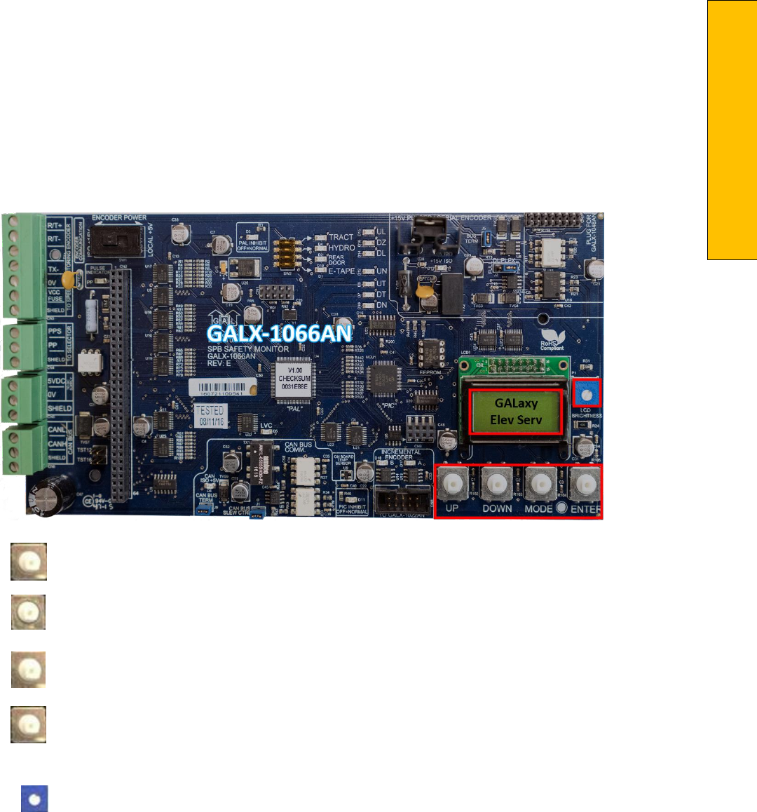
P a g e | 403
Section 13 – Safety Processor
Section 13 ‐ Safety Processor 1066 LCD Interface
Operating the 1066 LCD Interface
UP button is used to scroll up to the next
menu item or to increment a data value.
DOWN button is used to scroll down to
the next menu item or to decrement a data value.
MODE button is used to go back to the
previous menu or to select a digit of a
data value.
ENTER button is used to select the menu
item or to complete the operation of changing a data
value.
Potentiometer is used to adjust the
viewing angle. It will make the display lighter or darker.
The four inputs buttons used with the 1066 LCD
interface are, UP, DOWN, MODE and ENTER. The
UP
and DOWN buttons are used to scroll up and
down to each menu item. When an appropriate
menu
item is reached, the ENTER button is used to
select the item. Some menu items, once selected,
show a
second menu. Again, use the UP and
DOWN buttons to scroll through the menu items
and the ENTER
button to select a particular item.
The MODE button is used to go back to the
previous menu. When a
menu item is an
adjustable variable, select the item with the ENTER
button and change the variable with
the UP or
DOWN button. The MODE button is used to move
the cursor to the next digit. When the
appropriate
value is reached, used the ENTER button to
complete the variable change operation and
return to the current menu.
The diagram in the next page illustrates the Safety Processor Functions. All these functions are
monitored and any one function can cause the Safety Processor to deny or stop a run.
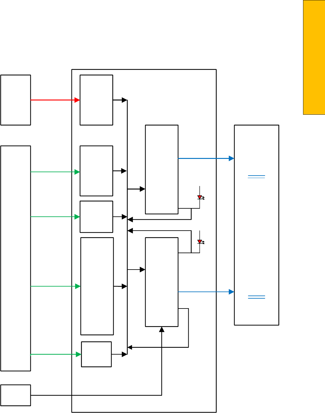
P a g e | 405
Section 13 – Safety Processor
Safety Processor Functions
UP
DNR
UF
DF
RUNA
BRK
DLT
DLM
DLB
RLM
GBP
LBP
UT
DT
UTS
DTS
AUTO
ICI
ACC
TAU
TAD
BAU
BAD
INS
IU
ID
MRI
MRIU
MRID
UL
DZ
DL
CPU
Outputs
Elevator
Inputs
Distance
Vel Upd
Absolute Encoder - Tape
Serial Comm - PP/PPs
Run
Control
Door
Status
Terminal
Limit
Status
Inspection
Status
And
Control
Door
Zone
Status
PAL
Logic
PIC
Software
Calculate
Leveling
Velocity LSC
Leveling
Speed
Control
UP
UF
DNR
DF
BRK
RUNA
SFC
PAL
Inhibit
PIC
Inhibit
Safety Processor Board
Safety Processor
Board Outputs
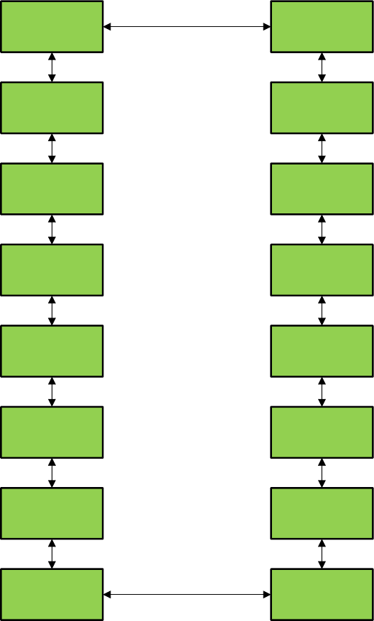
1066 LCD Interface Main Menu
GALaxy
Elev Serv
GALaxy
PAL I/O
GALaxy
PAL Vrsn
GALaxy
Version
GALaxy
Ext Temp
GALaxy
Brd Temp
GALaxy
Faults
GALaxy
Clr Flts
GALaxy
Reset
GALaxy
Car Spd
GALaxy
Enc Com
GALaxy
Enc Stat
GALaxy
Pls Cnt
GALaxy
Adj Var
GALaxy
Inp/Out
GALaxy
Lim Vel
Power up Status

P a g e | 407
Section 13 – Safety Processor
1066 LCD Interface Elevator Service
This diagram below shows the current operation type
based on the state of the inspection inputs and the
gate and lock bypass switch inputs. It also displays
the door status based on the condition of the gate and
lock inputs. If any inputs are in error, the error
status is displayed. The list below describes the
different types of satus and errors displayed
GALaxy
Elev Serv
MR INS
Open Up
Car Status
Door
Status
Car
Dir
Mode
Enter

Table 1: Safety Processor Elevator Service
Table 1: Safety Processor Elevator Service
Elevator Service
Condition for Service
AUTO
Auto input is on and all inspection inputs are off.
CT INS
Car is on car top inspection
GATE BYP
Car is on car top inspection and the gate bypass switch is on.
LOCK BYP
Car is on car top inspection and the lock bypass switch is on.
ACCESS
Car is on access operation.
MR INS
Car is on motor room inspection.
IC INS
Car is on in car inspection
INS ERR
An inspection error has occurred. There must be one and only one
inspection
or auto input on. All inputs are off or more than one
input
is on.
BYP ERR
A gate or lock bypass switch is on but the car is not on car top
inspection.
VEL ERR
The car has a velocity error from inspection speed, leveling speed or
a
terminal slowdown speed.
UP ERR
The up output is on during power up.
DNR ERR
The down output is on during power up.
DNR/UP
Both up and down outputs are on during power up.
EEP ERR
Safety Processor board has an EEPROM error.
NO UTS
UTS input not detected at top terminal landing.
NO DTS
DTS input not detected at bottom terminal landing.
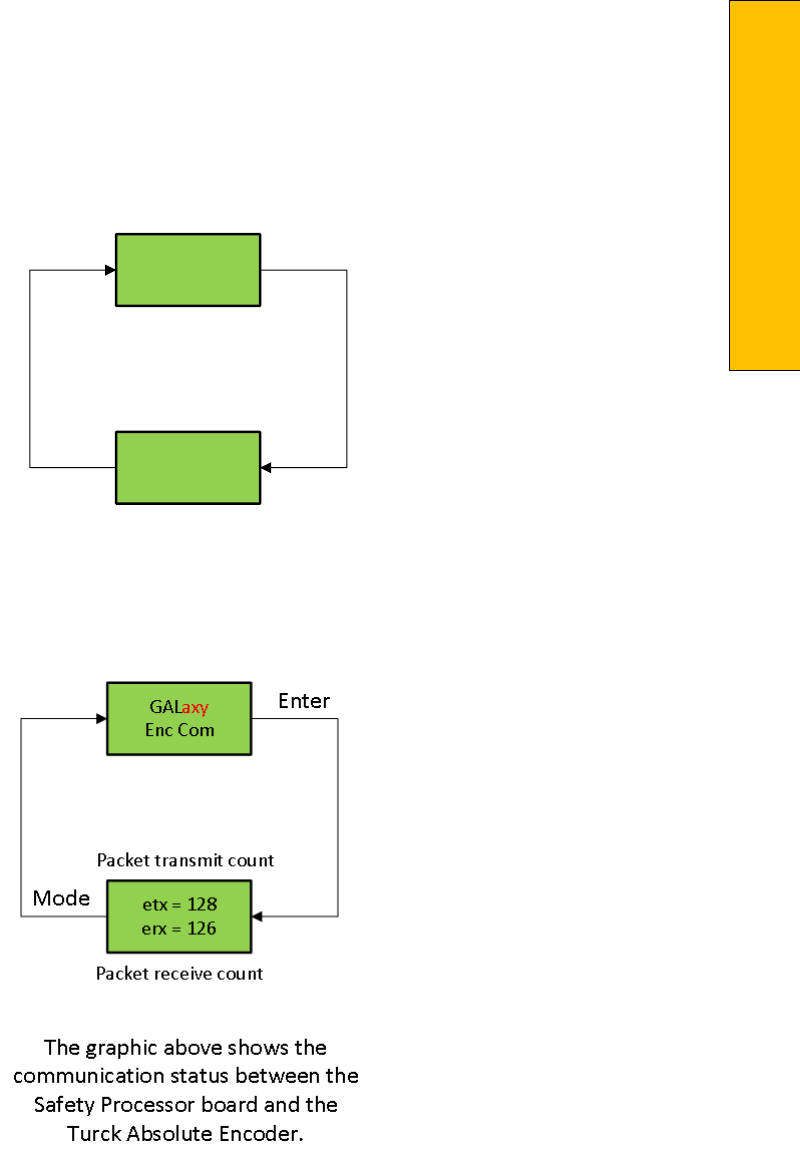
P a g e | 409
Section 13 – Safety Processor
1066 LCD Interface Car Speed
1066 LCD Interface Encoder Comm
The diagram above shows the communications status between the Safety Processor Board and the
Turck Absolute Encoder.
GALaxy
Car Spd
Car Spd U
350 fpm
Actual car speed from
feedback device
Car
Direction
Mode
Enter
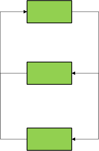
1066 LCD Interface Encoder Status
GALaxy
Enc Stat
Bat: Ok
Norm CW
Car Status
Operating
Status
Rotation
direction
Mode
Enter
Encoder
Com Flt
Mode
If Com is
faulty
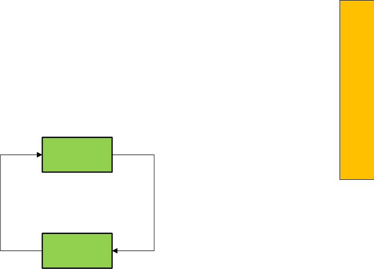
P a g e | 411
Section 13 – Safety Processor
1066 LCD Interface Pulse Count
GALaxy
Pls Cnt
Pls Cnt
15000
Car pulse count from
secondary speed feedback
Mode
Enter
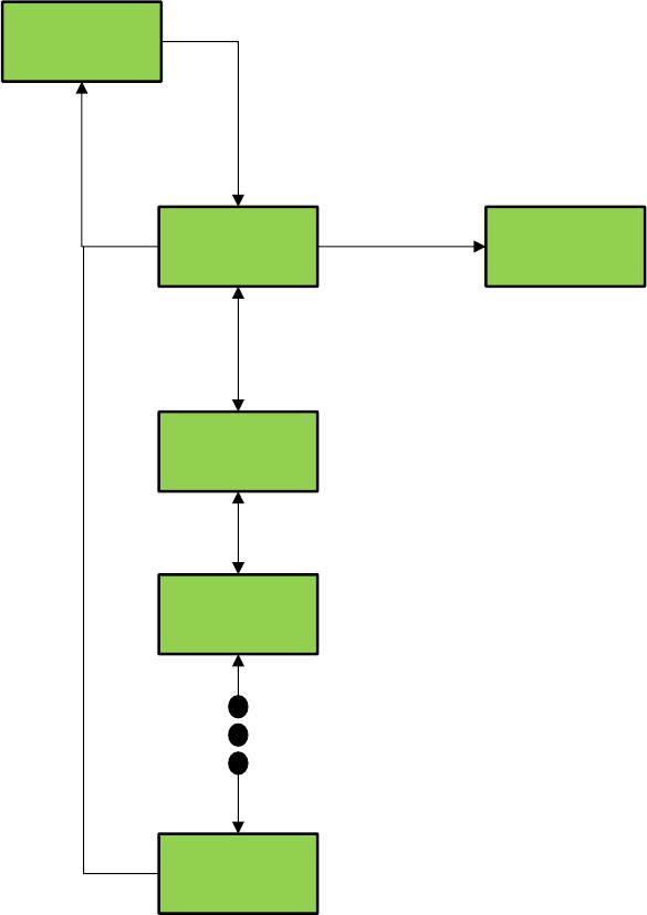
1066 LCD Interface Adjustable Variables
GALaxy
Adj Var
Adj Var
Top Spd
Adj Var
CAN Baud
Adj Var
UnMotion
Adj Var
Enc RPM
Top Spd
0350 fpm
Up
Down
Enter
Enter
Mode
Mode
MODE - Selects Digit
UP – Increments Value
DOWN – Decrements Value
ENTER – Stores Value
MODE – Returns To Menu
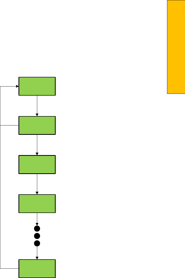
P a g e | 413
Section 13 – Safety Processor
1066 LCD Interface Inputs & Outputs
This display shows all of the inputs and outputs for the Safety Processor. The following table lists these
I/Os
and their associated descriptions.
GALaxy
Inp/Out
Inp/Out
DLT-1 = 1
Inp/Out
DLM-1 = 1
Inp/Out
DLB-1 = 1
Inp/Out
PALIH = 1
Mode
Enter
Down
Up

Table 3: Safety Processor Inputs & Outputs
Table 3: Safety Processor Inputs & Outputs
Name
Description
DLT‐1
Door Lock Top Secondary Input. Input equals 1 when the top door lock is made.
DLM‐1
Door Lock Middle Secondary Input. Input equals 1 when the middle door locks are made.
DLB‐1
Door Lock Bottom Secondary Input. Input equals 1 when the bottom door lock is made.
GS‐1
Gate Switch Secondary Input. Input equals 1 when the front door gate switch is made.
RLM‐1
Rear Lock Middle Input. Input equals 1 when the rear middle locks are made.
RGS
Rear Gate Switch. Input equals 1 when the rear door gate switch is made.
GBP
Gate Bypass. This is the input from the gate bypass switch. 1=bypass switch is on.
LBP
Lock Bypass. This is the input from the lock bypass switch. 1=bypass switch is on.
MRI
Motor Room Inspection. Input equals 1 when the car is on motor room inspection.
CTI
Car Top Inspection. Input equals 1 when the car is on car top inspection.
ACC
Access. Input equals 1 when the car is on access operation.
ICI
In Car Inspection. Input equals 1 when the car is on in‐car inspection operation.
AUTO
Auto Input. Input equals 1 when the car is on automatic operation.
UL‐1
Up Level Secondary Input. Input from the selector that the car is on the up level sensor in the door
zone.
DL‐1
Down Level Secondary Input. Input from the selector that the car is on the down level sensor in the
door zone.
UP
Up Run Output. Output from the main CPU when the car is running up.
DNR
Down Run Output. Output from the main CPU when the car is running down.
UTS
Up Emergency Terminal Slowdown. Input goes low when the car is on the up emergency terminal
slowdown limit.
P a g e | 415
Section 13 – Safety Processor
Table 3: Safety Processor Inputs & Outputs
Name
Description
DTS
Down Emergency Terminal Slowdown. Input goes low when the car is on the down emergency
terminal slowdown limit.
UT
Up Terminal Slowdown. Input goes low when the car is on the up terminal slowdown limit.
DT
Down Terminal Slowdown. Input goes low when the car is on the down terminal slowdown limit.
LSCS
Leveling Speed Control. Output comes on when the car is traveling less than 150 fpm.
SFCO
Safety Fault Control Output. Output must be on to energize the SFC relay. When this relay is dropped
out, the safety string will be opened.
PICEN
PIC Enable. The Safety Processor uses a PIC CPU. This is the enable line to the PAL device that allows
the run outputs from main CPU. 1=OK to run.
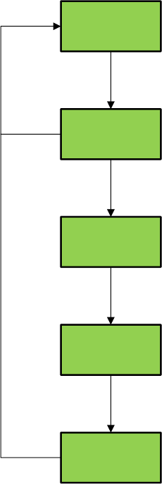
1066 LCD Interface Limit Velocity
When the car runs to the terminal landings and
activates the terminal limit switches, the velocity
of the
car is recorded at each limit switch. This
velocity value is cleared when the car runs in the
opposite
direction. This display is used to setup
the Safety Processor Board speed clamps in the
1066 LCD
interface, "Adj Var" menu. Once the car
is running on automatic, send the car to the
terminal landing
and record the velocity values after the car stops. Begin with a one‐floor run and
increase the distance of
the run by one floor until
the car reaches top speed.
When the highest value is determined for each
limit switch, add 20 fpm and enter those values in
the
1066 LCD interface "Adj Var" menu, "UTS
Vel", "UT Vel", "DTS Vel", and "DT Vel"
respectively.
GALaxy
Lim Vel
UTS Vel
180 fpm
DTS Vel
0 fpm
UT Vel
100 fpm
DT Vel
0 fpm
Enter
Mode
Up
Down
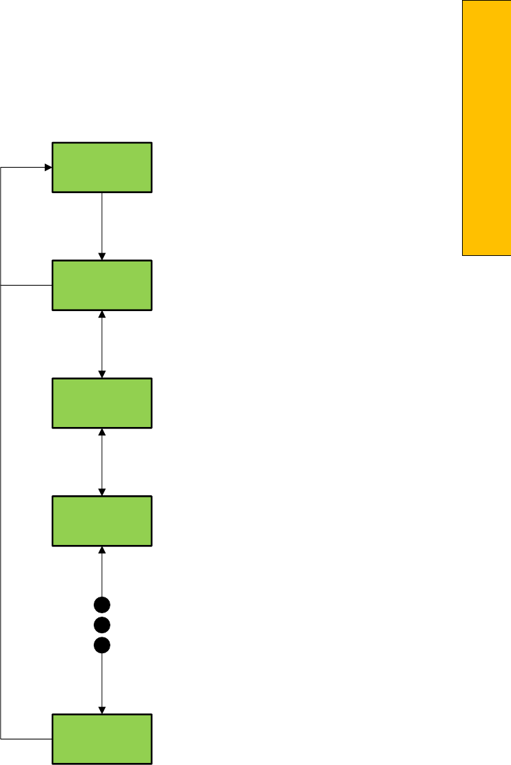
P a g e | 417
Section 13 – Safety Processor
1066 LCD Interface Faults
Faults are4 displayed in the order that they occur with index “0” being the most recent. In the figure
above, an EEprom fault occurred followed by an Inspection Speed fault followed by a UTS Speed fault.
Any index location that does not yet contain a fault will show “No Flt”.
There are 10 fault locations all of which are cleared on power up or from the Clear Fault menu. Below is
a list of faults and their possible causes.
GALaxy
Faults
Faults
0 UTS Spd
Faults
1 INS Sp
Faults
2 EEprom
Faults
9 No Flt
Enter
Mode
Down
Up
Index
Number
Fault
Message

Table 2: Safety Processor Faults
Table 4: Safety Processor Faults
Fault
Description and Cause
DL/GS
Door Lock/Gate Switch Fault. Car is moving outside the door zone with the door open.
The car will immediately shut down.
Add Er
Address for Safety Processor Board should not be set internally to a value different than
5. Replace PIC micro controller unit
Com Er
CAN communication with CPU timed out. Safety Processor Board stopped receiving
packages from the CPU. This fault always occurs once when the controller powers up.
DT Spd
DT Speed Fault. The car hit the DT limit at a higher velocity than the value set for the DT
Velocity adjustable variable. The car will immediately shut down.
DTS Sp
DTS Speed Fault. The car hit the DTS limit at a higher velocity than the value set for the
DTS Velocity adjustable variable. The car will immediately shut down.
EEprom
EEprom fault. Defective EEprom device or EEprom device is not installed. The car will
not be able to run until the EEprom is installed or replaced.
EncBat
Encoder Battery Error. The encoder uses an internal battery to maintain position of the
car when power is off. While the system is powered up and communicating, the Safety
Processor Board monitors the status of the encoder battery. If the battery level is too
low to maintain the position count, a battery error is declared. Replace the encoder.
EncCom
Encoder Communication Error. Encoder and Safety Processor Board stopped
communicating. Possible causes:
•
Improper connection on SPB for R./T+ or R/T‐
•
Faulty driver chip on Safety Processor Board
•
Improper connection on Encoder
•
Fault Encoder
EncFlt
Encoder Fault. The encoder has detected an internal fault. Replace the encoder.
EncIni
Encoder Initialization Error. On power up of the controller the Safety Processor Board
will request the position count from the encoder. If the SPB is unable to receive the
position count and the encoder is still communicating, an initialization error will be
declared. See possible causes under EncCom error.

P a g e | 419
Section 13 – Safety Processor
Table 4: Safety Processor Faults
Fault
Description and Cause
EncPos
Encoder Position Error. Once the encoder position count has been initialized during
the
learn hoistway procedure, the Safety Processor Board will monitor that the
count
does not go above 30,000,000. If it does, then a position error is declared.
Possible
causes:
•
Faulty encoder coupling to governor
•
Car was lost from fault UT or DT limit switch and ran down. If the count decrements
past zero it will roll over to 35,000,000.
EncVel
Encoder Velocity Error. To calculate velocity from the encoder a position update must be
received every 50 milliseconds. If the SBP fails to receive 5 consecutive data packets
from
the encoder, then the velocity cannot be calculated properly and you will get this
error. See EncCom error for possible causes.
INS DO
Inspection Door Open Fault. A door is open while running on inspection and the gate
and locks are not being bypassed. The car will immediately shut down.
INS Sp
Inspection Speed Fault. The car exceeded the INS Velocity adjustable variable while
running on inspection. The car will immediately shut down.
Invalid
Invalid fault number. (This can only be caused by a programming error in the chip).
IO Flt
I/O Fault. An input is on in error. The Elev Serv display will show the I/O error. Possible
causes are as follows:
•
All inspection inputs and the auto input are off.
•
More than one inspection or auto input is on at the same time.
•
A bypass input is on while the car is not on Car top inspection.
•
Both up and down run output from the main CPU are on at the same time.
The car will not be able to run until the error is cleared.
LEV Sp
Leveling Speed Fault. The car exceeded the LEV Velocity adjustable variable while
leveling with a door open. The car will immediately shut down.
No Flt
No fault is recorded in this index location.
PAL Er
•
PAL chip not responding
•
Reset Safety Processor Board
•
Replace PAL chip
•
Replace Safety Processor
Table 4: Safety Processor Faults
Fault
Description and Cause
Pls Er
Pulse Error. Not enough pulses have occurred during the Pulse Fault Time period.
This error is detected only on automatic operation. Verify that the pulse LED on the
Safety Processor board blinks while the car is running on inspection. Possible
causes are as follows:
•
Improper connection for PP and PPS. Refer to the job specific prints.
•
PP and PPS field wires need to be swapped.
•
Photocoupler in selector is faulty. Call the Factory.
•
Voltage from PP to PPS on the Safety Processor Board is less than 15 VDC with
the PP and PPS wires disconnected. Call the Factory.
UmotEr
Unintended motion detected. No up or down run signal and velocity greater than
75 fpm.
UT Spd
UT Speed Fault. The car hit the UT limit at a higher velocity than the value set for
the UT Velocity adjustable variable. The car will immediately shut down.
UTS Sp
UTS Speed Fault. The car hit the UTS limit at a higher velocity than the value set for
the UTS Velocity adjustable variable. The car will immediately shut down.
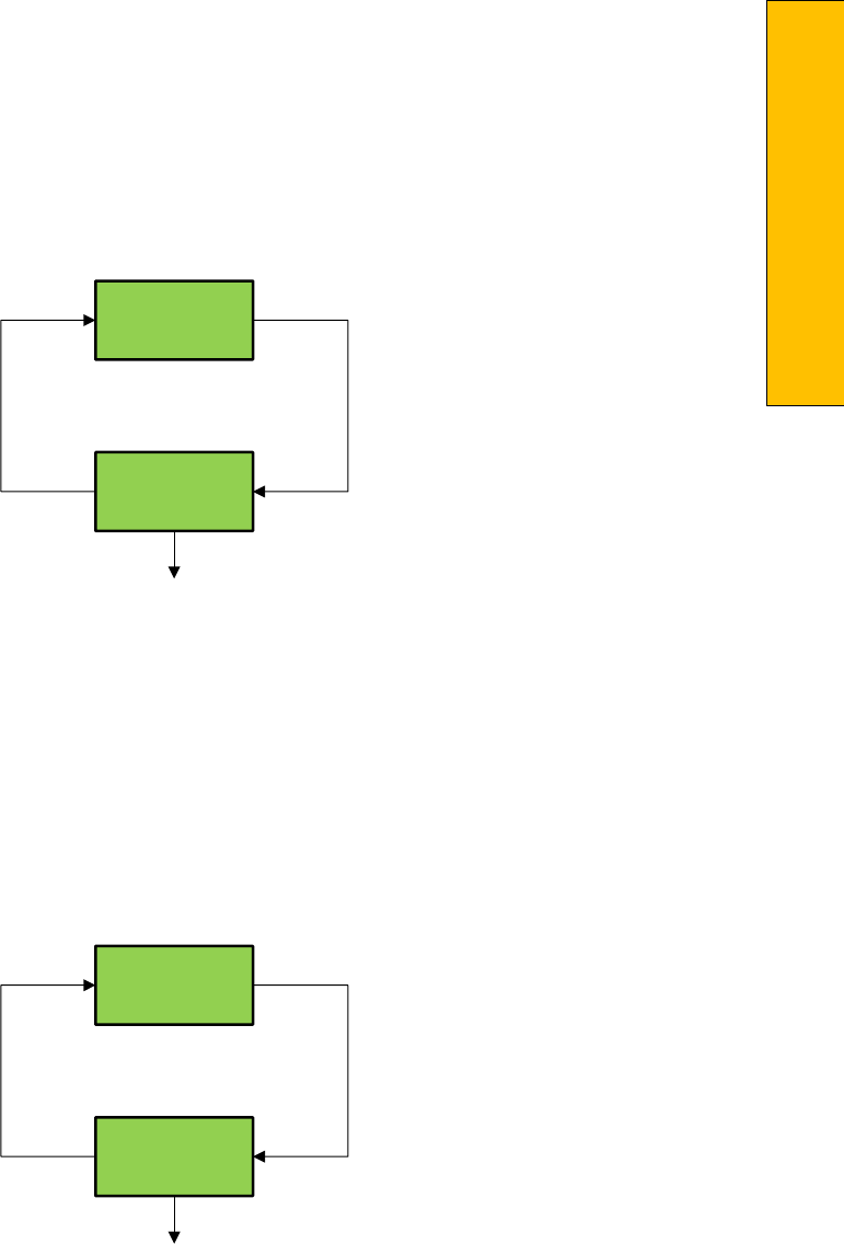
P a g e | 421
Section 13 – Safety Processor
1066 LCD Interface Clear Faults
1066 LCD Interface Reset Fault Latch
GALaxy
Clr Flts
Clr Flts
Hit Entr
Enter clears faults
Mode
Enter
GALaxy
Reset
Reset
Hit Entr
Enter resets fault latch
Mode
Enter
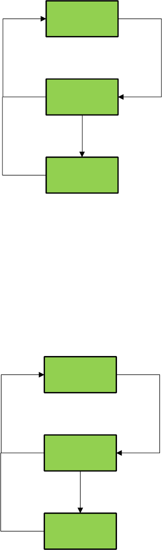
1066 LCD Interface Board Temperature
1066 LCD Interface External Temperature
GALaxy
Brd Temp
Brd Temp
36 C
Mode
Enter
Brd Temp
97 F
Enter
GALaxy
Ext Temp
Ext Temp
36 C
Mode
Enter
Ext Temp
97 F
Enter
NOTE: Only valid if external
Temperature sensor is provided
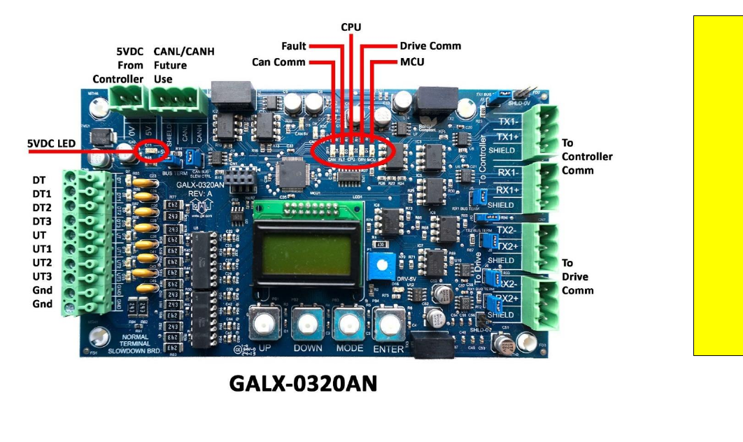
P a g e | 423
Section 14 – GALX-0320AN NTSD Board
Section 14 - GALX‐0320AN NTSD Board
This board is a retrofit for the GALaxy III Controller.
The board’s function is to detect if the set limit velocities are exceeded, if so then the board commands
the drive to slow
down through the drive communications.
The image below shows the connections and LEDs for the board.

In the schematic example below we only monitor DT/UT.

P a g e | 425
Section 14 – GALX-0320AN NTSD Board
When the board is first installed the GALX‐0320AN board has to be inserted into the controller/drive
communications.
The communications wiring is as follows: Controller ‐> GALX‐0320AN ‐> Drive.
Next the adjustable variables must be set in the GALX‐0320AN.
Top Speed – Number of Pairs of Limits – Drive Type – Drive Baud Rate, must all be set.
The limit velocities in the adjustable variables must be determined using the “Lim Vel” menu. If running
on construction
mode set the limit velocities to car speed.
Make long runs to the top and bottom floors and write down the values in “Lim Vel” for each of your
limits. This menu
will display values for the UT limits when you reach the top landing and the DT limits
when you reach the bottom
landing.
Add 20 to the numbers obtained from the “Lim Vel” menu and enter these numbers in Adj Var‐>UT
Vel, UT1 Vel, etc.

The table below can be used to determine how many limits you should have.
FPM
UT/ DT
UT1/
DT1
UT2/
DT2
UT3/
DT3
UT4/
DT4
UT5/
DT5
UT6/
DT6
UT7/
DT7
50
10”
100
21”
150
31”
200
41”
250
52”
300
31”
62”
350
40”
80”
400
50”
99”
450
60”
120”
500
71”
143”
600
65”
130”
195”
700
85”
170”
255”
800
80”
160”
240”
320”
900
98”
196”
293”
391”
1000
93”
187”
280”
374”
467”
1100
110”
219”
329”
439”
548”
1200
106”
211”
317”
422”
528”
633”
1300
103”
206”
310”
413”
516”
619”
723”
1400
102”
204”
306”
408”
510”
612”
714”
816”
P a g e | 427
Section 14 – GALX-0320AN NTSD Board
GALX‐0320AN Menu Structure
Run Stat
Normal / Com
Run / Com status
Car Dmd
FPM
Current demand speed from controller
Drv Dmd
FPM
Current demand speed from drive
Car Com
CTX / CRX
Car Com status
Drv Com
DTX / DRX
Drive Com status
Can Com
NTX / NRX
Can Bus Comm status
Adj Var
Top Spd
FPM
Top Speed of Car
Dec Rate
FPM
Decel Rate
Lev Vel
FPM
Leveling Velocity
Num Limit
Total number of
limit pairs (UT/DT= 1 pair)
UT Vel
FPM
Velocity limit for UT
UT1 Vel
FPM
Velocity limit for UT1
UT2 Vel
FPM
Velocity limit for UT2
UT3 Vel
FPM
Velocity limit for UT3
DT Vel
FPM
Velocity limit for DT
DT1 Vel
FPM
Velocity limit for DT1
DT2 Vel
FPM
Velocity limit for DT2
DT3 Vel
FPM
Velocity limit for DT3
Mtr RPM
RPM
Nameplate RPM
Drv Typ
0 ‐ 3
0=HPV
1=DSD412
2=KEB
3=KEBlc (LCD Keypad)
Drv Baud
0 ‐ 3
0=19.2 (HPV, DSD412)
1=38.4 (KEB)
2=57.6
3=115.2
Can Baud
0 ‐ 1
0=115.2, 1=57.6
Inp/Out
UT
1=made, 0=open
UT1
1=made, 0=open
UT2
1=made, 0=open
UT3
1=made, 0=open
DT
1=made, 0=open
DT1
1=made, 0=open
DT2
1=made, 0=open
DT3
1=made, 0=open

Lim Vel
UT
Speed when limit is opened
UT1
Speed when limit is opened
UT2
Speed when limit is opened
UT3
Speed when limit is opened
DT
Speed when limit is opened
DT1
Speed when limit is opened
DT2
Speed when limit is opened
DT3
Speed when limit is opened
Faults
UT Spd
UT speed clamp fault. Elevator speed exceeded limit when UT switch opened.
Check UT speed clamp parameter.
UT1 SPD
UT1 speed clamp fault. Elevator speed exceeded limit when UT1 switch
opened.
Check UT1 speed clamp parameter.
UT2 Spd
UT2 speed clamp fault. Elevator speed exceeded limit when UT2 switch
opened.
Check UT2 speed clamp parameter.
UT3 Spd
UT3 speed clamp fault. Elevator speed exceeded limit when UT3 switch
opened.
Check UT3 speed clamp parameter.
DT Spd
DT speed clamp fault. Elevator speed exceeded limit when DT switch opened.
Check DT speed clamp parameter.
DT1 Spd
DT1 speed clamp fault. Elevator speed exceeded limit when DT1 switch
opened.
Check DT1 speed clamp parameter.
DT2 Spd
DT2 speed clamp fault. Elevator speed exceeded limit when DT2 switch
opened.
Check DT2 speed clamp parameter.
DT3 Spd
DT3 speed clamp fault. Elevator speed exceeded limit when DT3 switch
opened.
Check DT3 speed clamp parameter.
Clr Faults
Clears all current faults
Reset
Resets board
GALaxy Version
Firmware version
P a g e | 429
Appendix A - Mnemonics
Appendix A - Mnemonics
Appendix A will help with the identification of common mnemonics.
Mnemonic
I/O Name
1C‐29C
1st – 29th Floor Car Call Inputs
1CA‐29CA
1st – 29th Floor Car Call Acknowledge Outputs
1CAR‐29CAR
1st – 29th Floor Rear Car Call Acknowledge Outputs
1CR‐29CR
1st – 29th Floor Rear Car Call Inputs
1U‐28U
1st – 28th Floor Up Hall Call Inputs
1UA‐28UA
1st – 28th Floor Up Hall Call Acknowledge Outputs
1UAR-28UAR
1st – 28th Floor Rear Up Hall Call Acknowledge Outputs
1UR‐28UR
1st – 28th Floor Rear Up Hall Call Inputs
2D‐29D
2nd – 29TH Floor Down Hall Call Inputs
2DA‐29DA
2nd – 29th Floor Down Hall Call Acknowledge Outputs
2DAR‐29DAR
2nd – 29th Floor Rear Down Hall Call Acknowledge Outputs
2DR‐29DR
2nd – 29TH Floor Rear Down Hall Call Inputs
ACC
Access Operation Input.
AD
Automatic Door Switch Input
AD0‐AD11
Analog to Digital Input Data
ALT
Alternate Fire Smoke Detector Sensor Input
ATT
Attendant Operation Input.
ATTDN
Attendant Down Input.
ATTUP
Attendant Up Input.
AUTO
Automatic Operation Input.
B16
Binary Position Sensor 16 Input
BAD
Bottom Access Down Input.
BAU
Bottom Access Up Input.
BKC
Brake Cool Pilot Output

Mnemonic
I/O Name
BKS
Brake Switch Input
BP
Fire Phase I Smoke Detector Bypass Input
BP1
Binary Position Sensor 1 Input
BP2
Binary Position Sensor 2 Input
BP4
Binary Position Sensor 4 Input
BP8
Binary Position Sensor 8 Input
BRK
Brake Pilot Output
BRKI
Brake Control Input.
CAR
Car number
CDL
Cab Down Lantern Output
CNV
DAC Convert Output
COL
Counter Weight Collision Switch Input (Traction Elevators)
CUL
Cab Up Lantern Output
DA0‐DA7
Digital to Analog Output Data
DC
Door Close Output
DCB
Door Close Button Input
DCBR
Door Close Button Rear Input
DCC
DAC Clear Output
DCL
Door Close Limit Input
DCLR
Door Close Limit Rear Input
DCR
Door Close Rear Output
DCS
DAC Chip Select Output
DDA
Down Direction Arrow Output
DEL
Delta Relay Input
DF
Down Fast Pilot Output
DFI
Down Fast Input
DL
Down Level Sensor Input
DL‐1
Down Level Sensor Secondary Input.
DLB
Door Lock Bottom Input.

P a g e | 431
Appendix A - Mnemonics
Mnemonic
I/O Name
DLB‐1
Door Lock Bottom Secondary Input
DLM
Door Lock Middle Input
DLM‐1
Door Lock Middle Secondary Input
DLT
Door Lock Top Input.
DLT‐1
Door Lock Top Secondary Input.
DN
Down Normal Limit Input
Dni
Down Run Input.
DNR
Down Pilot Output
DO
Door Open Output
DOB
Door Open Button Input
DOBR
Door Open Button Rear Input
DOL
Door Open Limit Input
DOLR
Door Open Limit Rear Input
DON
Drive On.
DOR
Door Open Rear Output
DPR
Door Protect Relay Input
DS
Down Slowdown Sensor Input
DT
Down Terminal Limit Input
DT1
Down Terminal Input 1
DT2
Down Terminal Input 2
DT3
Down Terminal Input 3
DZ
Door Zone Relay Input
EE
Electric Eye Input
EER
Electric Eye Rear Input
EMP
Emergency Power Input
EPS
Emergency Power Select Input
EQ
Earthquake Sensor Input
FB
Fire Buzzer Output
FF
Full Field Pilot Output

Mnemonic
I/O Name
FL
Fire Phase I Light Output
FS
Fire Phase I On Hall Switch Input
FS2
Fire Switch Phase II On Input
FS2C
Fire Switch Phase II Call Cancel Input
FS2H
Fire Switch Phase II Hold Input
FST
Fire Stop Switch Override Output
FSTi
Fire Stop Switch Override Input
GBP
Gate Switch Bypass Input.
GR1R
Rope Gripper 1 Relay Output.
GR2R
Rope Gripper 2 Relay Output.
GRT1
Rope Gripper Test Switch Input 1.
GRT2
Rope Gripper Test Switch Input 2.
GS
Car Gate Switch Input
GS‐1
Gate Switch Secondary Input.
GTS
Rope Gripper Trip Switch Input.
HB
Handicap Buzzer Output
HBE
Handicap Buzzer Enable Input
HC
Hall Call Common Input
HWS
Hoistway Smoke Sensor Input
ICI
In‐Car Inspection Input.
ICR
Inconspicuous Riser Input
ICS
In Car Stop Switch Input
ID
Car Top Inspection Down Input
IND
Independent Input
INS
Car Top Inspection Input
ISER
In Service Output
IU
Car Top Inspection Up Input
LBE
DAC Low Byte Enable Output
LBP
Lock Bypass Input

P a g e | 433
Appendix A - Mnemonics
Mnemonic
I/O Name
LC
Logic Common Input
LD
Down Hall Lantern Output
LDR
Rear Down Hall Lantern Output
LE
Level Enable Output
LE1
Level Enable 1 Output.
LE2
Level Enable 2 Output.
LOA
DAC Load Output
LU
Up Hall Lantern Output
LUR
Rear Up Hall Lantern Output
LW
Load Weighing Bypass Input
MCA
Motor Contactor Output
MCAI
Motor Contactor Input.
MCC
Motor Contactor Output
MCCI
Motor Contactor Input.
MES
Main Egress Smoke Detector Sensor Input
MRI
Motor Room Inspection Input.
MRID
Motor Room Inspection Down Input.
MRIU
Motor Room Inspection Up Input.
MRS
Motor Room Smoke Sensor Input
NB
Nudging Buzzer Output
NUD
Door Nudging Output
NUDR
Door Nudging Rear Output
OT1
OT1 Job Specific Output 1/Fire Service On Output
OT2
OT2 Job Specific Output 2/Motor Starter Timer Relay Output
OT3
OT3 Job Specific Output 3/Generator Pilot Output
OT4
OT4 Job Specific Output 4/Field Weakening Pilot Output
OVL
Overload Input
P
Potential (Run Contactor) Input
P1‐P29
1ST – 29th Discrete Floor Position Indicator Outputs

Mnemonic
I/O Name
PFC
Primary Fault Control Output.
RDY
Drive Ready Input
RGS
Rear Car Gate Switch Input.
RGS‐1
Rear Car Gate Switch Secondary Input.
RLM
Rear Lock Middle Input.
RLM‐1
Rear Lock Middle Secondary Input.
RST
Reset Drive Output
RTL
Return to Lobby Input
RUN
Run Pilot Output
RUNAi
Run Auxiliary Input.
RUNi
Run Input.
SC1
Speed Clamp 1 Output (Used by CPU for setup)
SC2
Speed Clamp 2 Output (Used by CPU for setup)
SC3
Speed Clamp 3 Output (Used by CPU for setup)
SC4
Speed Clamp 4 Output (Used by CPU for setup)
SC5
Speed Clamp 5 Output (Used by CPU for setup)
SE
Safety Edge Input
SER
Safety Edge Rear Input
SPI#
Spare Input, # references input number
SPO#
Spare Output, # references output number
SS
Safety String Input
TAD
Top Access Down Input.
TAU
Top Access Up Input.
TPL
Temp Low Input (Hydraulic Elevators)
UDA
Up Direction Arrow Output
UFi
Up Fast Input
UL
Up Level Sensor Input
UL‐1
Up Level Sensor Secondary Input
UN
Up Normal Limit Input
P a g e | 435
Appendix A - Mnemonics
Mnemonic
I/O Name
UP
Up Pilot Output
UPF
Up Fast Pilot Output
UPi
Up Run Input.
US
Up Slowdown Sensor Input
UT
Up Terminal Limit Input
UT1
Up Terminal Input 1
UT2
Up Terminal Input 2
UT3
Up Terminal Input 3

Appendix B - Compliance Testing
Appendix B is a useful guide to performing common compliance tests.

P a g e | 437
Appendix B – Compliance Testing
1.0 Overspeed Test on a DSD-412
To perform an overspeed test, the
mechanic should follow the required
precautions and procedures set
forth
in the local and national elevator
codes.
1. With the car on automatic, run the car to the top or bottom (away from the desired test run
direction).
2. Access the Overspeed Reference Multiplier parameter (Function #81) in the drive and set to the
desired multiplier value (1.25 for 125%).
3. Set the Overspeed % (Function #12) fault trip value to a number greater than the desired over
speed.
4. Set the Overspeed Test flag (Function
5. #80) in the drive. This will cause the drive to run over speed for one run.
6. Please note that the “Weak Field Current” parameter (Function #49) may need to be adjusted to
allow the car to reach the desired overspeed velocity.
7. On the controller main LCD interface select “Run Overspeed Test” under the Elevator Setup
menu. Follow the directions on the LCD display to make sure the automatic door switch is off
and the car is level at the floor on automatic operation. Enabling the overspeed test will prevent
the CPU from detecting an overspeed condition for one run.
8. Place a car call to run the car in the desired direction to perform the overspeed test.
9. Place the car on inspection and inspect the car.
10. Reset the Overspeed % (Function #12) back to the original setting.
11. When the test is complete, return the car to automatic operation.
If there is any uncertainty about performing
this tests with a GALaxy controller, please call toll free at 1
(877) 425‐7763 for free
technical assistance.
2.0 Overspeed Test on a KEB Drive (For AC Geared & PM Gearless)
To perform an overspeed test, the mechanic should follow the required precautions and procedures set
forth in the local and national elevator codes.
1. With the car on automatic, run the car to the top or bottom (away from the desired test run
direction).
2. Set LF.20 (car speed) to 135% of the value already there.
3. Set LF.42 (high speed) to 135% of the value already there.
4. In the controller change the following: Adj Var -> Car Motion -> MTR RPM to 125% (or more if
necessary) of the value already there.
5. In the controller, go to: Elevator Setup -> Overspeed Test and press “Enter”. You can now place
a car call in the direction you need to test. The car will overspeed in the desired direction.
6. Return all parameters to the original values.
If there is any uncertainty about performing this tests with a GALaxy controller, please call toll free at 1
(877) 425‐7763 for free technical assistance.
3.0 Overspeed Test on a HPV-600/900 W Distance Feedback (Also For Quattro
Cube)
To perform an overspeed test, the mechanic should follow the required precautions and procedures set
forth in the local and national elevator codes.
7. With the car on automatic, run the car to the top or bottom (away from the desired test run
direction).
8. Access the Overspeed Mult parameter (sub menu A1) in the drive and set the % overspeed.
9. Set the Overspeed Test Flag (sub menu U4) in the drive. This will cause the drive to over speed
for one run.
10. On the controller main LCD interface, select “Run Overspeed Test” under the Elevator Setup
menu. Follow the directions on the LCD display to make sure the automatic door switch is off
and the car is level at the floor on automatic operation. Enabling the overspeed test will prevent
the CPU from detecting an overspeed condition for one run.
11. Place a car call to run the car in the desired direction to perform the overspeed test.
12. Place the car on inspection and inspect the car.
13. Return the car to automatic operation.
If there is any uncertainty about performing this tests with a GALaxy controller, please call toll free at 1
(877) 425‐7763 for free technical assistance.

P a g e | 439
Appendix B – Compliance Testing
4.0 Buffer Test
To perform a buffer test, the mechanic
should follow the required precautions
and procedures set forth
in the local
and national elevator codes. The
following test procedure is written to
show how to
override the car’s
position system so that it will run into
the terminal landing at contract speed
but is
not intended to circumvent any
procedure mandated by the elevator
code.
Inspect and prepare the car according
to the “Elevator Industry Inspection
Handbook”. Make sure that
the car is
loaded properly for the test and that
the appropriate car or counterweight
safety is tied.
14. For the car buffer test, jump DT, DT1, DT2, DT3 and DTS terminal limits to SFC (110VAC). For the
counterweight buffer test, jump UT, UT1, UT2, UT3 and UTS terminal limits also to SFC. Refer to
the job schematics specific terminal wiring locations.
15. From the Controller’s LCD display, select the “Elevator Setup” menu and then select “Car Buffer
Test” or Counterweight Buffer Test”.
16. Turn off the automatic door switch. To execute the test, the car must be level at the floor and
on automatic operation.
17. The test also cannot be started from a terminal landing. If the car is at a terminal landing, the
LCD display will show “To position the car press Enter”. Pressing “Enter” will place a car call in
the middle of the hoistway. If the car is already positioned properly for the run, the display will
give the option to position the car or the skip to the next step.
18. Once the car is located in the correct starting position, select “Run Buffer Test”. When the
“Enter” button is pressed, the car’s position will be modified internally to the top of the
hoistway for a car buffer test or to the bottom of the hoistway for a counterweight buffer test.
The car will then run high speed to the appropriate buffer.
19. While the car is in motion, the LCD display will change to “Press Enter Button to Cancel Buffer
Test”. Pressing the “Enter” button will cause the car to execute an emergency slowdown.
20. After the test is complete, place the car on inspection and inspect the car and buffer.
21. Remove all jumpers, remove load weights and untie the car or counterweight safeties if
previously tied.
22. Return the car to automatic operation.
If there is any uncertainty about
performing this tests with a GALaxy
controller, please call G.A.L. toll free
at 1 (877) 425‐7778 for free technical
assistance.
5.0 Normal Terminal Slowdown Test
To perform a normal terminal
slowdown test, the mechanic should
follow the required precautions and
procedures set forth in the local and
national elevator codes. The following
test procedure is written to
show how
to override the car’s position system
so that it will run into the terminal
landing at contract
speed but is not
intended to circumvent any procedure
mandated by the elevator code.
Inspect and prepare the car according
to the “Elevator Industry Inspection
Handbook”. Make sure that
the car is
loaded properly for the test.
1. For the bottom normal terminal slowdown test, jump DTS terminal limit to SFC (110VAC). For
the top normal terminal slowdown limit test jump UTS terminal limit also to SFC. Refer to the
job schematics for specific terminal wiring locations.
2. From the Controller’s LCD display, select the “Elevator Setup” menu and then select “Car Buffer
Test” to perform a bottom normal terminal slowdown test or “Counterweight Buffer Test” to
perform a top terminal slowdown limit test.
3. Turn off the automatic door switch. To execute the test, the car must be level at the floor and
on automatic operation.
4. For this test only adjust parameters UT Vel and DT Vel on the Safety Processor Board to contract
speed.
5. The test also cannot be started from a terminal landing. If the car is at a terminal landing, the
LCD display will show “To position the car press Enter”. Pressing “Enter” will place a car call in
the middle of the hoistway. If the car is already positioned properly for the run, the display will
give the option to position the car or the skip to the next step.
6. Once the car is located in the correct starting position, select “Run Buffer Test”. When the
“Enter” button is pressed, the car’s position will be modified internally to the top of the
hoistway for a car buffer test or to the bottom of the hoistway for a counterweight buffer test.
The car will then run once high speed to the appropriate limit.
7. While the car is in motion, the LCD display will change to “Press Enter Button to Cancel Buffer
Test”. Pressing the “Enter” button will cause the car to execute an emergency slowdown.
8. After the test is complete remove all jumpers and adjust the UT Vel and DT Vel parameters on
the Safety Processor Board back to their original values.
If there is any uncertainty about performing
this tests with a GALaxy controller, please call G.A.L. toll free
at 1 (877) 425‐7778 for free
technical assistance.

P a g e | 441
Appendix B – Compliance Testing
6.0 Emergency Terminal Limit Test
To perform an emergency terminal limit test,
the mechanic should follow the required
precautions and
procedures set forth in the
local and national elevator codes. The
following test procedure is written to
show
how to override the car’s position system so
that it will run into the terminal landing at
contract
speed but is not intended to
circumvent any procedure mandated by the
elevator code.
Inspect and prepare the car according to the
“Elevator Industry Inspection Handbook”.
Make sure that the car is loaded properly for
the test.
1. For the bottom emergency terminal limit test, jump the bottom normal terminal slowdown limit
switches DT, DT1, DT2, DT3 depending on how many normal slowdown switches the job has to
SFC (110VAC). For the top emergency terminal limit test jump the top normal terminal
slowdown limit switches UT, UT1, UT2,UT3 also to SFC. Refer to the job schematics specific
terminal wiring locations.
2. From the Controller’s LCD display,
select the “Elevator Setup” menu and
then select “Car Buffer
Test” to
perform a bottom emergency
terminal limit test or “Counterweight
Buffer Test” to
perform a top
emergency terminal limit test.
3. Turn off the automatic door switch. To
execute the test, the car must be level
at the floor and on
automatic
operation.
4. The test also cannot be started from a
terminal landing. If the car is at a
terminal landing, the
LCD display will
show “To position the car press
Enter”. Pressing “Enter” will place a
car call in
the middle of the hoistway.
If the car is already positioned
properly for the run, the display will
give the option to position the car or
the skip to the next step.
5. Once the car is located in the correct
starting position, select “Run Buffer
Test”. When the
“Enter” button is pressed,
the car’s position will be modified
internally to the top of the hoistway
for a car buffer test or to the bottom
of the hoistway for a counterweight
buffer test. The car will
then run once
high speed to the appropriate limit.
6. While the car is in motion, the LCD
display will change to “Press Enter
Button to Cancel Buffer
Test”.
Pressing the “Enter” button will cause
the car to execute an emergency
slowdown.
7. After the test is complete remove all
jumpers.
If there is any uncertainty about
performing this tests with a GALaxy
controller, please call G.A.L. toll free
at 1 (877) 425‐7763 for free technical
assistance.
7.0 Reset Gripper Fault or Emergency
Brake Fault
To reset a rope gripper fault, first
verify that the cause of the rope
gripper fault has been corrected and
then follow the directions below:
1. Place the car on machine room
inspection.
2. From the LCD Interface, select the
Elevator Setup menu and press the
enter button.
3. Use the up or down button to select
the “Reset Rope Gripper” menu and
press enter.
4. Follow the directions on the screen to
press and hold the enter button to
reset the gripper.
The enter button must be held for
approximately 10 seconds. If the car
moves unexpectedly within the
10
second delay time, releasing the enter
button will cause the gripper to re‐
engage.
When the gripper is full reset the
screen will display “Gripper is Reset”.
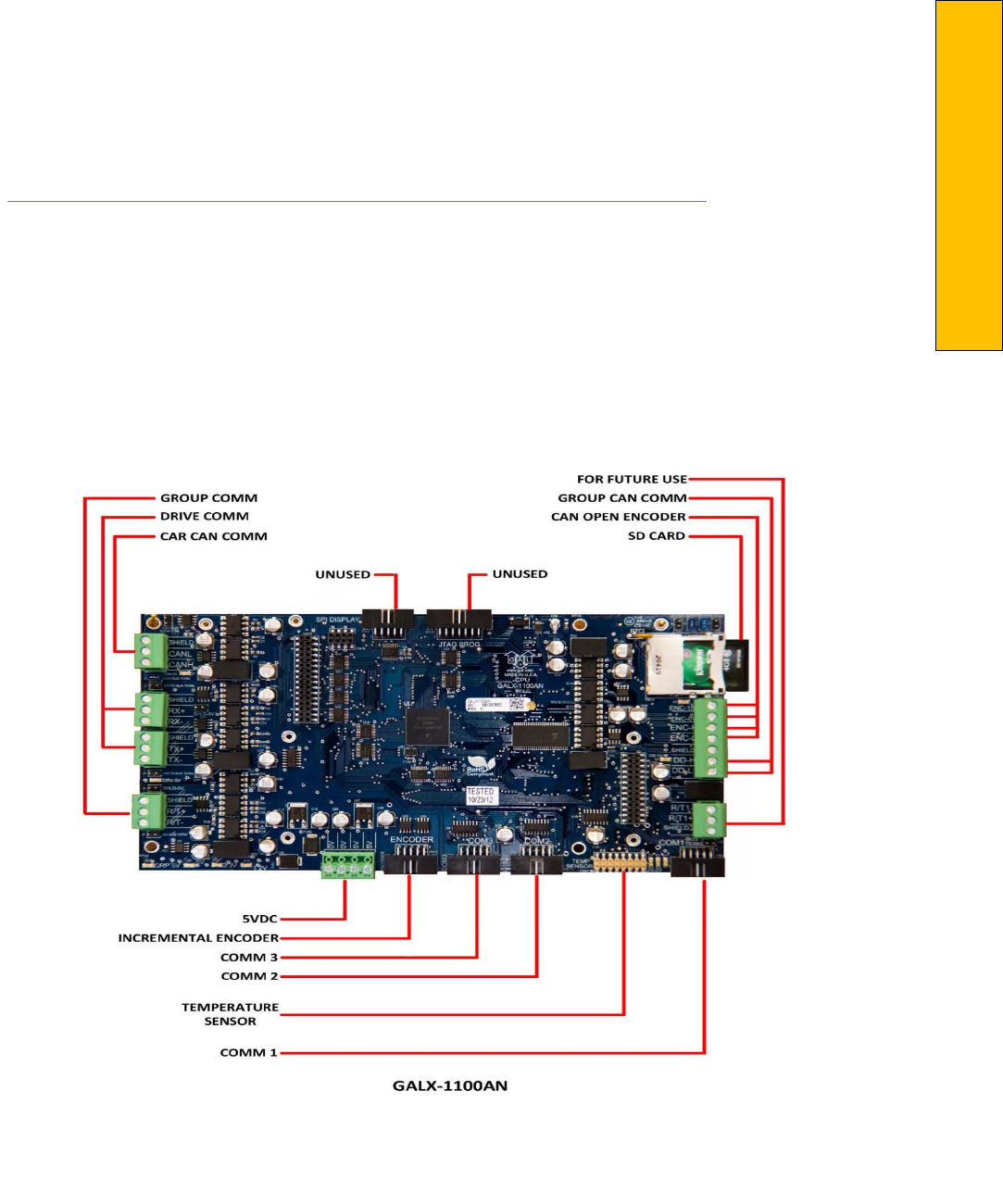
P a g e | 443
Appendix C – GALX-1100 CPU
Appendix C – GALX-1100 CPU
Appendix C is a guide for the latest GAL CPU, the GALX‐1100. Please note that this CPU is backwards
compatible with previous versions.
GALX‐1100 CPU (Replacement CPU for TS‐5300 board)
GALX‐1100 CPU
The GALaxy GALX‐1100 CPU has been implemented as the replacement board for the previously used TS‐5300
CPU (now obsolete). The new CPU uses a dual‐core 32‐bit Freescale CPU
that include all the components and
features used on the GALX‐1036 COMM Memory Board, the GALX‐ 1092 Encoder Board, the TS‐SER2 serial
expansion board and the existing TS‐5300 CPU. It uses Secured
Digital Card storage instead of Compact Flash so
that program upgrades and data/parameter storage
can be easily transferred to any device
that can copy text
files from an SD Card file.
The TS‐9500 VGA board and GALX‐
1021 board combination is replaced
with a single GALX‐1101 LCD/VGA
board. The single GALX‐1021/1101/1005 LCD board is replaced with a GALX‐1005 LCD board.
GALX‐1100 CPU Board Replacement‐
Installation
Items required for installations:
Laptop (to copy configuration file
from CF card to SD card), small common
screwdriver, USB Card
Reader to read and write CF card and
SD card, GALX‐1100 CPU board, 10‐pin
encoder
cable (supplied with CPU),
GALX‐1101 LCD/VGA board or GALX‐
1005 LCD board, SD card with one of
the
following controller files: tract.mot,
tracthr.mot or hydro.mot files.
The procedure to replace an existing
CPU, COMM Memory board and Encoder board is as follows:
Place the car on inspection.
Power the controller off.
Remove the CF card from
the existing CPU and copy
the cons.dat or conshr.dat
file to the SD card for the
GALX‐1100 CPU.
Disconnect the encoder
connector from the
encoder board on the stack
and then remove all boards
off
the stack except the
1036 comm memory board.
Disconnect the comm
connectors from 1036
board.
Plug in the new CPU on to
PC‐104 connector on top of
the 1036 board.
Install spacers onto new CPU board to support the LCD or LCD/VGA display board and plug in the display
board.
Wire the power connector to the new CPU board and then power up the controller.
From the LCD screen, select the Software Utilities menu and then select to “Load 1036 Field Variables”.
If data is read successful, the field variables are now stored in the new CPU. If not, the parameters must
be added manually and the car must be re‐ adjusted.
From the LCD screen select the menu “Load 1036 Hoistway Setup”. If data is read successful, the
hoistway setup data and the load weigher data is now stored in the new CPU. If not, the load weigher

P a g e | 445
Appendix C – GALX-1100 CPU
must be setup and a hoistway learn must be done once the 1036 board is removed. It is recommended
to do a hoistway learn regardless of the outcome of the hoistway read.
Once both the parameter and hoistway data tables are read from the 1036 board, power down the
controller, remove the LCD or LCD/VGA board, remove the new CPU and then remove the 1036 board.
Re‐install the new CPU adding the required screws and then re‐ install the LCD or LCD/VGA board also
adding the required screws.
Connect the communications connectors that were previously on the 1036 board to the new CPU board.
The new CPU board is supplied with an encoder cable. If the existing system had used a 1092 board,
plug in the encoder cable from the 1092 board to the CPU board encoder connector (left most 10‐pin
connector on the board). If the existing system used a 4I30 encoder, replace the encoder cable with the
supplied cable from the encoder isolation board to the CPU board.
Power up the controller.
Run the car on inspection making sure the CPU pulse count is incrementing or decrementing in the
correct direction. If the direction needs to be reversed, then change the “Encoder Dir” parameter to the
opposite value under the “Car Motion” menu listed under the “Adjustable Variables” menu.
Run the hoistway learn setup procedure. (Recommended)
Place the car on automatic with the door service turned off and run the car to verify all is good.
Once the car operation is verified, place the car on inspection and from the “Software Utilities” menu;
select the “SD Card Read/Write Data” menu. Select the following menus to save the field variables, job
setup, hoistway table, and security and timer information to the SD card: “Write Field Variables”, “Write
Job Setup Data”, “Write Hoistway Data”, “Write Service Timers”, and “Write Security Data”.
Remove the SD Card and copy the data to a laptop using and SD card reader.
Replace the SD Card back into the controller CPU. The SD card must be installed in the CPU SD card slot
in order for the car to power up properly. The car will not run after power up if the SD card is not
installed.
Place the car on automatic service and enable door operation.
Load job software to CPU
The following procedure is used to load
the job software to the new CPU:
When the CPU is powered up, the program must be operating in the Power‐ Up Mode and have an SD
Card with the appropriate “.dat” and “.mot” files installed. If controller software is already copied into
Flash, either place the car on inspection and from the Software Utilities menu, select to run Power‐Up
Mode or cycle power on the CPU board while pressing the Mode and Enter button on the LCD Display.
Disconnect the Car to Car communications cable. While the CPU flash is being programmed, the output
pins for the Car to Car communications port may be left in an unfavorable state that can prevent it from
working properly. It is best to disconnect the cable to avoid loss of communications between the
remaining cars.
Once in Power‐Up Mode, select the “Update/Verify Program” menu and then select the “Load Program
from SDCard” menu.
Press the Enter button to begin the file transfer when prompted to do so. The flash memory will be
erased and then the new program will be copied to the onboard flash. Power must be kept on the CPU
throughout the entire process.
The display will show “Operation Complete” once the load is finished.
Cycle power on the CPU or hit the Mode button and then select the “Run Controller Program” menu, to
run the controller software.
LCD Display
The main menu on the LCD display now shows
Software Utilities instead of Software Version to
allow for
additional features implemented with the new GALX‐1100 CPU board. The diagram
below shows the new menu
items, in yellow, and
also includes the latest menu changes.
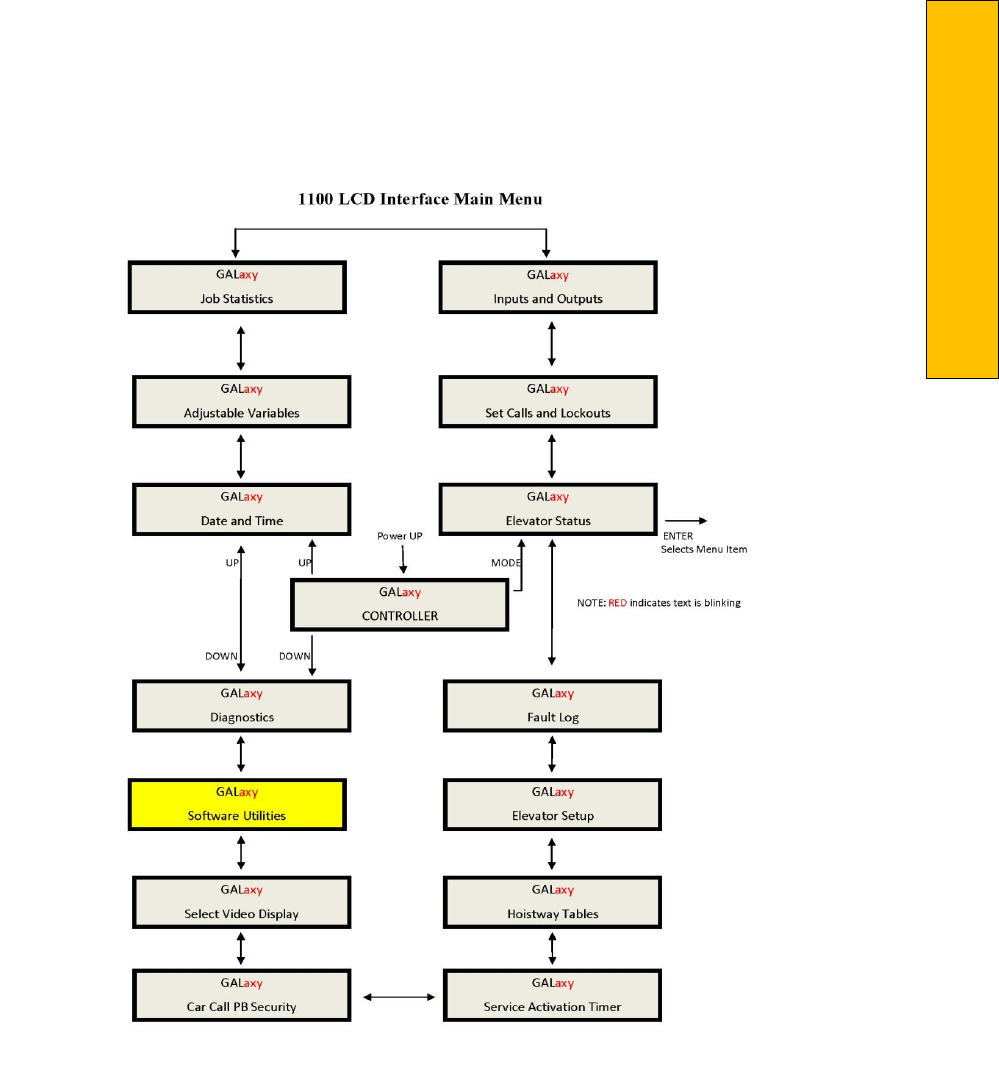
P a g e | 447
Appendix C – GALX-1100 CPU
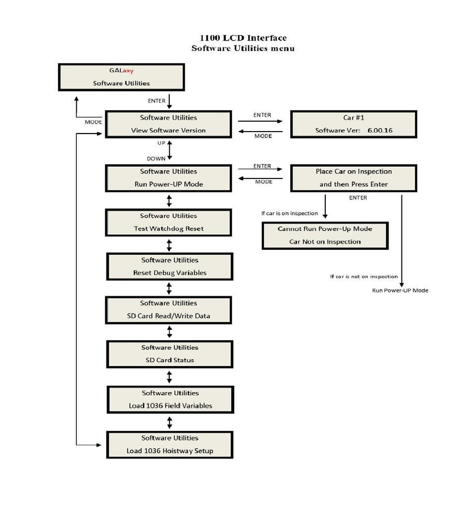
Software Utilities Menu
The Software Utilities menu provides access to
special functions that do not directly affect the
adjustment and
setup of the controller. Most functions in this menu require that the car be on
inspection to execute the
operation. The diagram
of this menu is shown below:

P a g e | 449
Appendix C – GALX-1100 CPU
Below is a list of the Software Utilities menu items
and the function of each menu:
View Software Version – Display the software version, revision and interim revision in the form
6.00.18.
Run Power‐Up Mode – The Power‐Up Mode is a program that executes first upon power up of
the controller. It checks that there is a valid controller program in memory and that a valid
cons.dat file is on the SD Card. Once this is validated, the power up program runs the controller
program. If the power up program is executed from the controller program or if during power
up, the user presses and holds the enter and mode buttons, this routine does not run the
controller program but stays in the power up routine to allow for updates of the controller
program.
Test Watchdog Reset – The watchdog is a CPU timer that must be updated periodically in
software to confirm that the program is still running correctly. If the watchdog is not updated,
the timer will expire and cause the CPU to do a hard reset to allow the program to restart. To
test the watchdog timer, when the command is given, the controller program sits in an infinite
software loop without updating the watchdog time to test that the reset function works.
Reset Debug Variables – The debug variables are set by a software engineer to aid in debugging
a software problem. Some problems are especially difficult to catch because they occur
infrequently or at seemingly random times. The debug variables are displayed in the detailed
Elevator Status Menu so that a mechanic view the variable and report back to the software
engineer. The reset debug variables menu allows the mechanic to reset the variables to zero to
aid in debugging.
SD Card Read/Write Data – This menu item allows the user to read and write controller data to
and from the SD Card. This menu is explained in detail in the next section.
SD Card Status – This is the Secured Digital Card Status showing if the card has been initialized
(Init=1), if it is standard or High Capacity (HC=1), and if it can operate at an acceptable voltage
level (VStat=1).
Load 1036 Field Variables – If replacing a TS‐5300 CPU board with a GALX‐1100 CPU board, the
user can have the GALX‐1100 CPU read the Adjustable Field Variables from the 1036 board
memory before removing the 1036 board.
Load 1036 Hoistway Setup – If replacing a TS‐5300 CPU board with a GALX‐1100 CPU board, the
user can have the GALX‐1100 CPU read the Hoistway Setup Data from the 1036 board memory
before removing the 1036 board. The Hoistway Data includes the floor position counts, the
normal slowdown limit counts, the selector top and bottom counts, the DZU and DZD distances,
the up and down floor level distances, the floor offset values, the speed clamp data, the car call
security mask, the load weigher setup data and the service timers.
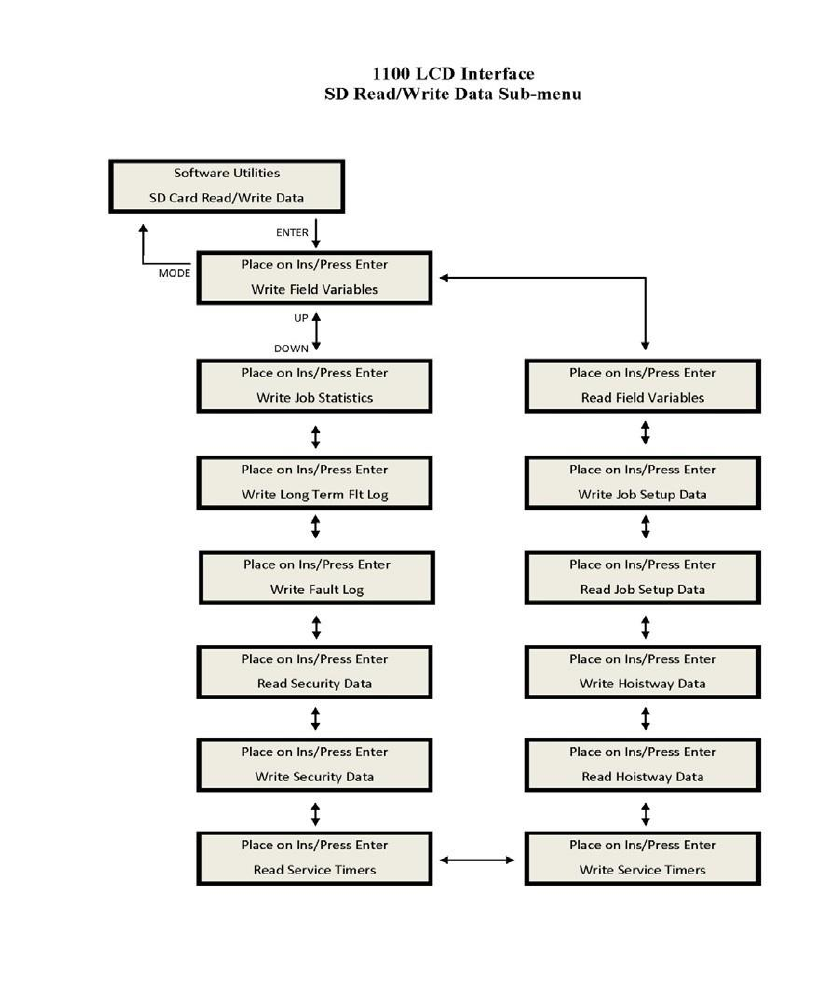
SD Card Read/Write Data
The SD Card Read/Write Data Menu give the
user the ability to store, retrieve and transfer controller data, to
and from the controller, the
SD Card and to a PC or Laptop. The SD Card
Read/Write Data menu is shown
below:

P a g e | 451
Appendix C – GALX-1100 CPU
Below is a list of the “SD Card Read/Write
Data” menu items and the purpose of each
menu. The files written to
the SD Card are
text files that can be viewed from a
Windows text editor such as Note Pad or
Word Pad.
Write Field Variables – Write Adjustable Field Variables to a text file, fvars.txt, on the SD Card.
Read Field Variables – Read Adjustable Field Variables from the text file, fvars.txt, on the SD
Card.
Write Job Setup Data – Write the job setup data to the setup.txt file on the SD Card.
The job setup data includes the speed clamp data, car call security mask and load weigher setup
data.
Read Job Setup Data – Read the job setup data from the setup.txt file on the SD Card.
Write Hoistway Data – Write the learned hoistway data to the hoistway.txt file on the SD Card.
The hoistway data includes the floor position counts, the normal slowdown limit counts, the
selector top and bottom counts, the DZU and DZD distances, the up and down floor level
distances, and the floor offset values.
Read Hoistway Data – Read the hoistway data from the hoistway.txt file on the SD Card.
Write Service Timers – Write the service timer tables to the SD Card file, svctmr.txt.
Read Service Timers – Read the service timer tables from the SD Card file svctmr.txt.
Write Security Data – Write the security data to the security.txt file on the SD Card.
This data is the codes tables for each floor for the Push Button Car Call Security option. There
are 200 codes per floor.
Read Security Data – Read the security data from the security.txt file on the SD Card.
Write Fault Log – Write the detailed fault data from the standard 50 fault buffer to the SD Card
file fault.txt.
Write Long Term Fault Log – Write the long term detailed data to the SD Card file ltfault.txt.
Each time a fault occurs, the fault data is stored in the 50 fault buffer and in the long term fault
buffer. The long term fault buffer stores the data for 600 faults in a circular buffer that cannot
be erased. Since there is so much data, the only way to view the data is by writing the fault data
to the SD Card, copying the data to a PC or Laptop and then viewing the data with Note Pad or
Word Pad.
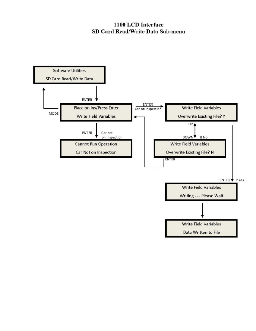
Below is an example of the “Write Field
Variables” Menu. All other SD Card Read/Write Data menus
function in a
similar manner.

P a g e | 453
Appendix C – GALX-1100 CPU
Detailed Fault Data
The Detailed Fault Data includes additional information from the Safety Processor Board. The typical
Detailed Fault would be written to the SD Card as follows:
3 Position Fault 11:18:06 6/05/2007 Position = 1 Occurrences =
1 srv=001, prc=015, drf=000, rdf=000, dpr=000,
dir=000, emp=000,
med=000 cbl=000, equ=000, fir=000, rfi=000, hsf=000, stf=000, cal=000, esp=000 nst=000,
rlv=000, ste=001, pdo=000, st0=000, ins=00h, nds=000, dev=00h pf1=00h, pf2=00h, dv2=00h, io0=02h,
io1=f0h,
io2=0fh, io3=dch, io4=00h io5=e8h, io6=7fh, io7=84h, io8=3dh, io9=30h, ioA=d0h, ioB=21h, ioC=01h ioD=ffh,
statusf=00000100h
DPP Count = 4831446, Target = 815660, Dmd Vel = 0, Enc
Vel =0 SPB Poscnt = 504433, SPB Serv = 0h, SPB Vel =
0, SPB
Stat = 0h
The additional Safety Processor data included in the fault log is described in the table below:

Detailed Fault Data
Description
SPB Poscnt
Safety Processor Board Position Count
SPB Serv
Safety Processor Board Service:
0: Automatic
1: Car Top Inspection
2: Gate Bypass Operation
3: Lock Bypass Operation
4: Access
5: Motor Room Inspection
6: In Car Inspection
7: Inspection Error
8: Gate or Lock Bypass Err
9: Velocity Error
10: UP Error on pwrup
11: DNR Error on pwrup
12: Both UNI and DNI inputs
13: EEprom Error
14: No UTS error
15: No DTS error
16: Pulse Error
17: Unintended Motion Error
SPB Vel
Safety Processor Board Velocity in fpm
SPB Stat
Safety Processor Board Status:
Bit 0: Secondary Fault Control (SFC Relay 0 = On)
Bit 1: Pic Enable (SPB CPU 1=Okay)
Bit 2: Leveling Speed Control (1=Speed < 150 fpm)
Bit 3: Comm Fault (1=fault)
Bit 4: Velocity Fault (1=fault)
B it 5: Position Count Initialized (1=initialized)
Bit 6: Active Fault (1=fault)
Bit 7: Position Count updated (1=count updated)
