GC21 7608 2_System3_15_SCP_macros_reference_manual_Mar80 2 System3 15 SCP Macros Reference Manual Mar80
GC21-7608-2_System3_15_SCP_macros_reference_manual_Mar80 manual pdf -FilePursuit
GC21-7608-2_System3_15_SCP_macros_reference_manual_Mar80 GC21-7608-2_System3_15_SCP_macros_reference_manual_Mar80
User Manual: GC21-7608-2_System3_15_SCP_macros_reference_manual_Mar80
Open the PDF directly: View PDF ![]() .
.
Page Count: 144 [warning: Documents this large are best viewed by clicking the View PDF Link!]
aaaa aaaa
aaaa aaaa
aaaaaaaaaaoaa aa aaa
aaaaaaaaaaaaaaaaaa
aaaaaaaaaaaaaaaaaa
aaaaaaaaaaaaaaaaaa
aaaa aaaa aaaa
aaaa aaaa aaao
aaao aaaa -aaa
aaaaaaaaaaaaaaaaaa
aaaaaaaaaaaaaaaaaa
aaaaaaaaaaaaaaaa
aaaaaa aaaaaa
aaaa aaaa
aaaa aaaa
aoaa aaaa
aaaaaaaaaaaaaaaaaa
aaaaaaaaaaaoaaaaaa
aaaaaaaaoaaaaaaaaa
a a a
a o a a a a a
a a aaa a
a a
aaaa aaaa
aaaa aaaa
aaaa aaaaa
aaaaa aaaaaaa
aaaaaa aaaaaaaaa
aaaaaaa aaaaaaaaaaa
aaaaaaa aaaaaaaaaaa
aaaa aaaa aaaa
aaaa aaaa aaaa
aoaa aaaa aaaa
aaaaaaaaaaaa aaaaaa
aaaaaaaaaaaa aaaaaa
aaaaaaaaaa aaaaa
aaaaaaaa aaaa
aaaaaa
aaaa aaaaa
aaaaa aaaaaaa
aaaaaa aaaaaaaaa
aaaaaaa aaaaaaaaaaa
aaaaaaa aaaaaaaaaaa
aaaa aaaa aaaa
aaaa aaaa aaaa
aaaa aaaa aaaa
aaaaaaaaaaaa aaaaaa
aaaaaaaaaaaa aaaaaa
aaaaaaaaaa aaaaa
aaaaaaaa aaaa
aaaaaa
IBM
System./3 Model 15
System
Control
Programming
Macros
Reference
Manual
aaaa
aaaa
aaaaaaa
aaaaa
aaa aa
aaaaaaa
aaaa
aaaa
aaaa
aaaa
aaaa
aaaaaa
aaaaaa
aaaaaa
aaaaaa
aaaa aaaa
aaaa aaaa
aaaaaaaaaaaaaaaaaa
aaaaaaoaaaaaaaaaaa
aaaaaaaaaaaaaaaaaa
aaaaaaaaaaaaaaaaaa
aaaaaaaaaa
aaaaaaaaaaa
aaaaaaaaaaa
aaaaaaaaoaa
aaaaaaaaaaa
aaaaaaaaaaa
aaaa aa a aaa
aaaaaaaaaaaaaaaaaa
aaaaaaaaaaaaaaaaaa
aaaaaaaaaaaaaaaaaa
aaooaaaaaaaaaaaaaa
aaaa aaaa
aaaa aaaa
GC21-7608-2
File No. 53-36
Page
of GC21
-7608-2
lssued 29 September
1978
By TNL: GN21-5649
Preface
Thismanua|describesthemacrcrinstrttcttcrtts1rtrlvic1t,ci|lisl..saiiii,i..i]i()ql;ir,|.;l-1i,'.,;\ri|l!i
the IBM System/3 Moclel 15. The publrc,riirrr:;i ir,tcnue,,j t;iiri-;
for persons
who are programrning in the iJasic
Assembler
Language
or its
equivalent
arrd who are
ianiiitdt
wiit, tirc .r ilt::.. 1'1,t,
.. , [r;-
, ,/tieri
r]i.i i),--,)t-open
DTF (Defirre
concept of macro instructions and syslr:ii lrrograrn:'niitti lnr ;:,i,.
1 ijilr,tr.il Ljlur.;ks f1,1
,srrra
rrjooir:.1
arrr{ tl
rsk
devices,
for
the IBM
Svstem/3 N4odel
15.
The
following
topics
are
discusse<l
in
thi: t-.r.rirircar;rrir F{eia
ti:rl l"ui.:ircatrt
ns
o Coding macro instructiotrs :.
.,iir;a.ai,(irri
i;,r r:;ilil
i,r1.,r
iriarrr,ril
wil!{.lir
rr:itrrci
r :.tt:;{
'i3SCr-ti;,;:.
: ,l)ir.j!
ijti.i:,r.,5,'1j
i ' r:..-r,
irldlLi.ti:
o Descriptions
of tlre
vaitous
lnacro rft:ir,,1cli(,r]:.
t ;i- i:'t l,,r5i1':;1 ,) it,:s't,,1{.t::g.',',/;if:;
i;elf:fellCe MeftUal,
a OCL necessary to call the f rracio llr{)crsi/rrr
. ,}i.-
j; /\iil
o Error conditions detected
by the rlacro i)rOccs:(ri qt i5ltli
,.:,,,,stx;i::J
frts:it:! 1i.
iiystel; (',ntroi Frogrammtng
iitJi:i;'t::::: 4,!art*al
li:. Pr,,'j;
arii
i\lrr;cer
5704
Si,1 .
t:'.'2 1-'Lt)'i I
t !!:!i/l :)v
j!-,,.)!t ::
lvlr:Jt'i .:\ .','r''\refi)
l.of:trt:l Pfoglratntning
Ct;rt: ','.'t;is
atrt! f-le:r.:rutr:,t
ltllanuai i.i, P1691ut Nirrnbel.
3 / !
)) :,i.
,
j i-r
{l:.r
'1 :, i { i:l
Third
Edition
(December
1976)
This is
a major revision
of
,
and obsolCtes,
GCl2l
-1608 I arrr;
't'-'c!irriLiii
l\.i-o!!\ieli1
!:i
GN21-5353 and GN21-5432. Inf ornration has
bcen a{ld.r,j
r,r
:iuL'p,i
I SCir
57O4-SC2 as well as SCP 57O4-SC1. Changes
to 1.,:,{1
,r,iri
r'r(,,ri'ti iins ..rr1:
'frilli
'rrrr
by a vertical line.
This edition applies to ver sior' f,Js,
mt.)lcrf irat orr 00 ol Jlrir
ii-ii.V
$y:ti-,rr.j fulor,],.r
':,
SystetnControl
Program5704-SCl,toversic)rrOl.rr;cciiirirti,rr;COr:1
trti'ii\i'll
Systeml3 Model 15 System Control Progranr
57O4 SC:l .r'rri
lr;,rli 5\rl]!equii,:r
versions
and modifications until otherwrse
ir'drcJted
rrlr"!'!,'{rrir.,r.,
:r Teci,
r,r.,,'
newslette
rs.
Changes
are periodically ntade to tirrr
Jpccil ic;)tions ftrr':ir' i)e
j
r:
r': uirril i
iii:
publicarion in connection wittr t!re
operation cl !8fui
:,;',rr:',r,: J,i!i.)ri
r'ii'
IBM System/3 Bibliography, {.-rC2O'BliSti-
ior Tt, Ljrl-i.r:r,i
: ,i ri
i.aiJI.):i.r.irl
and current.
Use this publication only ior the ltliri)oses
stalfj(l ilr ti:t .,, ,,,,
Publicalions are not stocke(j at the address
L.liUw [:ldrr,i,,\1:;
i{)i {.,-jr
j, ..
jr !Ui\l:
:,!jl)r,
cations
and for technical information about ttre syslein ,irorirrj
'irir
frr:r{.lij
r,.
!..rri iilliri
representattve Or tO the branch olfice servinll V.rur ti)0airi
!
This publication coultJ
contarn techiiical
inacr.ur,,rcre:.li
irtli:rjrfl,nrj.ijr,rrfi-):, ,:t,i.
Reader's
Comment Form at the back of this pul:lri:att(l1t
!.) ffl:tirc i)ir,i|,,,,ri
itl.)i,.,,
this publication. lf the form has
been retniuvuri,
arjdrer: ,yr.;r;r
: i,.irrl:rf
,i, tl ril\il
Corporation, Publicatrons, Department 245, Uochester. ,\linrrri(.,i.r ij5:l,J; !r:ii,,l
:ir,:jv rjrril
arrd
disr.
,bute anv of the informal-ioit
you jul-!pi,/
in aiiy wav rt betrevc5
rr;:,l1iiji).riiir.
without Incurrirlg
any obligation whaicver. You rn.::y, r..,i
io!ir5c. coriiiTru, t! ir:,.,
,,'"
inf
ormation you supplV.
O Copyright International
Business
Machines
Corpor,:1r,;,.
;t/'l tti:i!r.
i,j./rj
CHAPTER
1: TNTRODUCTTON
Writing
Macro
I
nstructions
System
Configuration
Macro Instructions
Provideo
CHAPTER
2: MACRO INSiRUCTION STATEMENTS
Programming
Considerations
System
Services Macros
System Reader
Support
System
Log
Support
General
SCP
Support
Input/Output Support
General l/O Support
Card Device
Supporl
Printer
Support
Disk Device
Support
3741 Device
Support
Tape Device
Supporr
Device Independent
gupporr
CRT/Keyboard
Display
Support
Program
Function
Key Support
Contents
CHAPTER
3: OCL
AND SAMPLE
PROGRAM
OCL for Macro Processor
Sample
Program
.
Purpose
of the Sample Program
Termination
of the
sample
Program
Macro Instructions
Used
in the
Sample
program
APPENDIX
A: ERROR
INFORMATTON
APPENDIX
B: DEFINE
THE FtLE
CONTROL
BLOCKS
APPENDIX
C: INPUT/OUTPUT
BLOCKS 106
Disk
Input/Output
Block 106
Timer
Input/Output
Block . 11 1
APPENDIX
D: MACRO INSTRUCTION
SUMMARY
CHART
I
4
4
1
7
7
o
I
12
22
22
28
33
?q
48
49
5b
58
58
61
63
63
63
63
63
66
67
68
INDEX
112
119

A macro
instruction
is
a source
statement
that
causes
generation
of a
predetermined
set
of assembler
statements
each
time
the macro
instruction
is
used.
The
Model
1b
Svstem
Control
Program
provides
macro
instructions
which
oer-
form
both
system
services
and
input/output
device
support.
By
using
these
macro
instructions,
you
can
perform
both
system
and input/output
operations
with less
coding.
Figure
1 is
an overview
of the
operation
of
the macro
processor.
The
OCL
statements
used
to call
the
macro
processor
are
explained
in Chapter
3: OCL
and
Sample
Program.
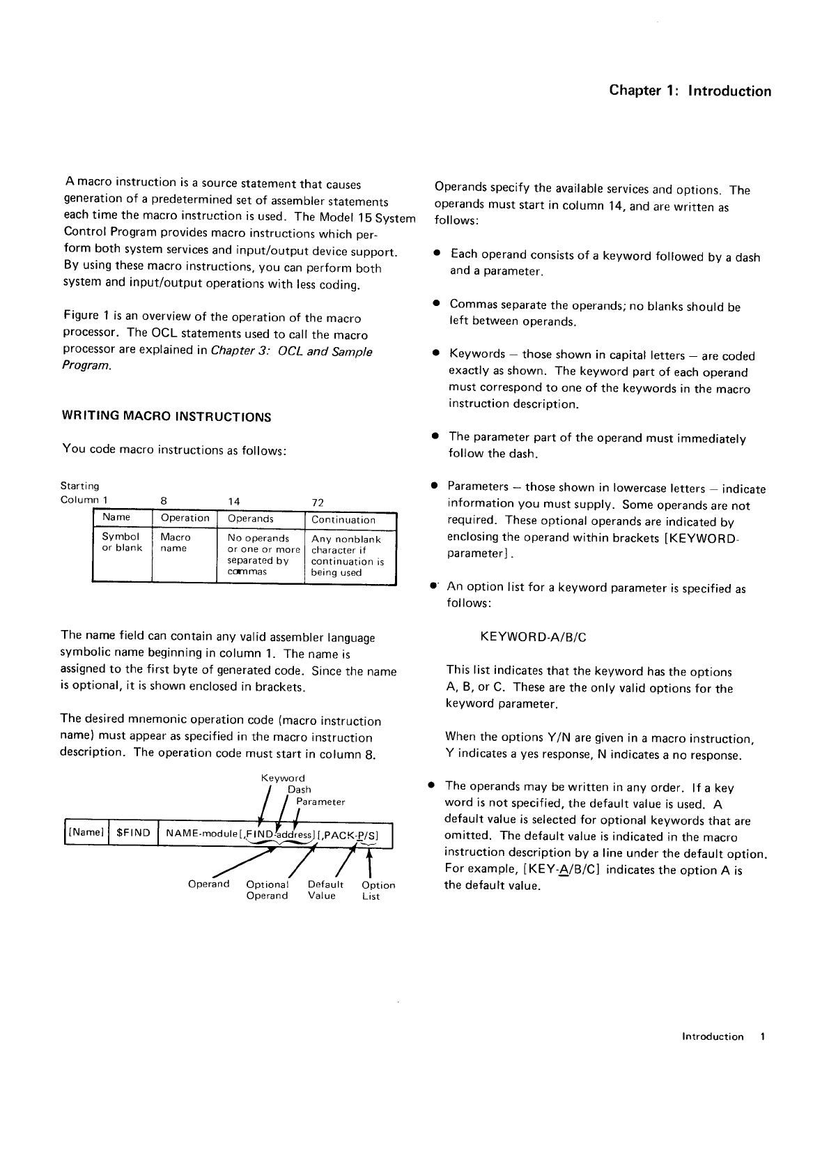
WR
ITING MACRO
INSTRUCTIONS
You
code macro
instructions
as
follows:
Start i ng
Column
1
Name Operation Operands Continuation
Symbol
or
blank Macro
na
me No operands
or one or more
separated
by
coTl mas
Any nonblank
character
if
continuation
is
being used
The
name field
can
contain
any valid
assembler
language
symbolic
name
beginning
in
column 1. The
name
is
assigned
to the first byte of generated
code. Since rne name
is
optional,
it is
shown
enclosed
in
brackets.
The
desired mnemonic
operation
code
(macro
instruction
name)
must
appear
as specified
in
the macro
instruction
description.
The
operation
code must
start in
column
g.
Operand
Chapter
1 : Introduction
Operands
specify
the
available
services
and
options. The
operands
must start in column 14, and
are written as
follows:
. Each
operand
consists
of a keyword followed bv a dash
and
a
parameter.
o Commas
separate
the
operands;
no blanks
should
be
left between
operands.
o Keywords
- those
shown in capital
letters
- are coded
exactly as shown. The keyword part of each
operand
must correspond
to one of the keywords in tne macro
instruction
description.
. The parameter
part of the operand must immediately
follow
the dash.
Parameters
- those
shown in lowercase
letters
- indicate
information you must
supply. Some
operands
are not
required.
These
optional
operands
are
indicated
by
enclosing
the
operand
within brackets
IKEyWORD-
parameterl
.
An option list for a keyword parameter
is
specified
as
follows:
KEYWORD-A/B/C
This
list indicates
that the keyword
has
the
options
A, B, or C. These
are the
only valid
options
for the
keyword parameter.
When
the options
Y/N are
given
in
a macro
instruction.
Y indicates
a yes
response,
N indicates
a no response.
The
operands
may
be
written in
any
order. lf a
xey
word is not specified,
the default
value
is used.
A
default value
is selected for optional keywords
that are
omitted. The
default
value
is indicated
in
the macro
instruction
description
by a line
under
the
default
option.
For
example,
IKEY-A/B/C] indicates
the option
A is
the default
value.
72
o
Optional Default
Operand Value Option
List
Keyword
NAM E-module
[,F
tN Dladd'ressj
LPACK
-,
I
ntroduction
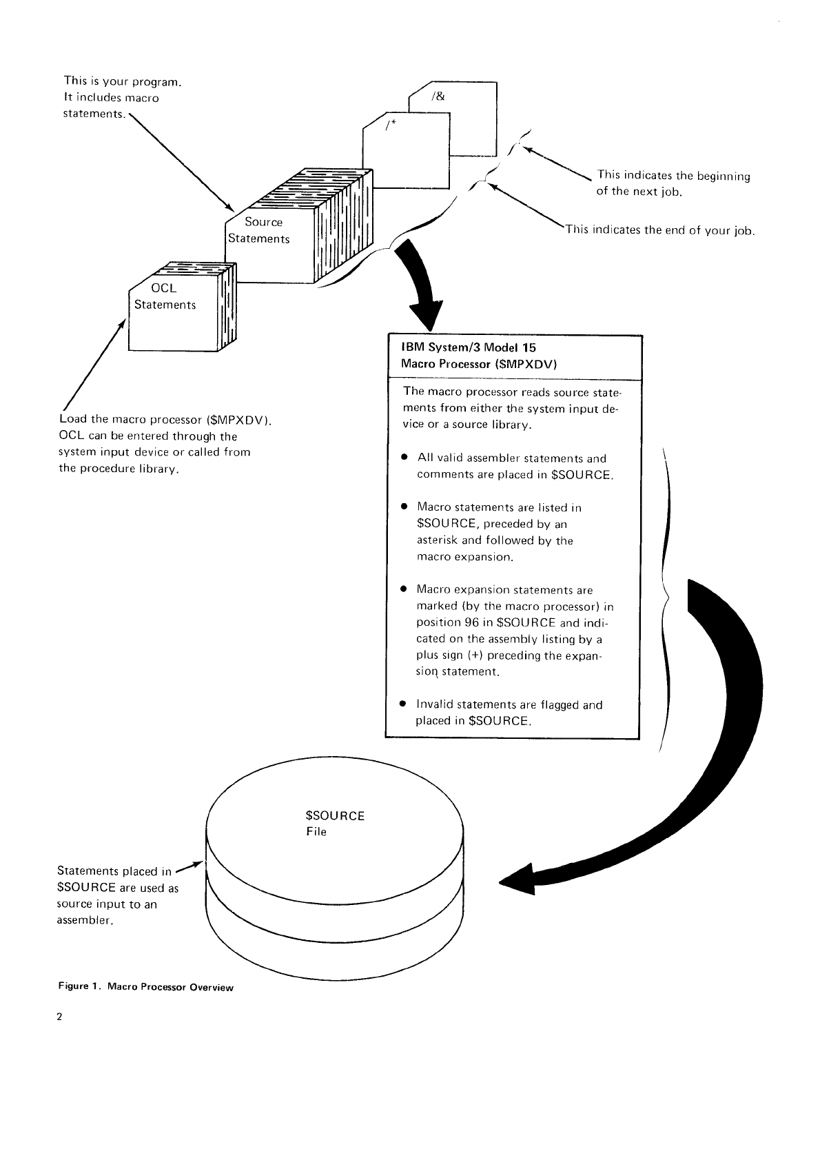
This
is
your program.
It includes
macro
statements.
Load
the macro
processor
($MPXDV).
OCL can be entered
through
the
system
input device or called
f
rom
the
procedure
library.
Statements
placed
in
y'
$SOURCE are used
as
source
input
to an
assembler.
Figure
1. Macro
Processor
Overview
z
----l / x*
-\_
a \-: Ihis indicates
the
begirrrring
,
\ ofthenextjob.
\-This indicates
the end
of your
job.
IBM
System/3 Model
15
Macro
Processor
(gMPXDV)
The macro processor
reads
source
state-
ments f
ronr
either
the system
input de-
vice or a source
librarv.
All valid
assembler
statements
and
comments
are
placed
in
$SOU
RCE.
Macro
statements
are listed
in
$SOURCE,
preceded
by
an
asterisk
and
followed
by the
macro
expanston.
Macro
expansion
statements
are
marked
(by
the macro
processor)
in
position
96 in
gSOI.JRCE
and indi-
cated
on the
assembly listing
by a
plus
sign
(+)
preceding
the
expan-
sioq statement.
Invalid
statements
are
flagged
and
placed
in
$SOURCE.
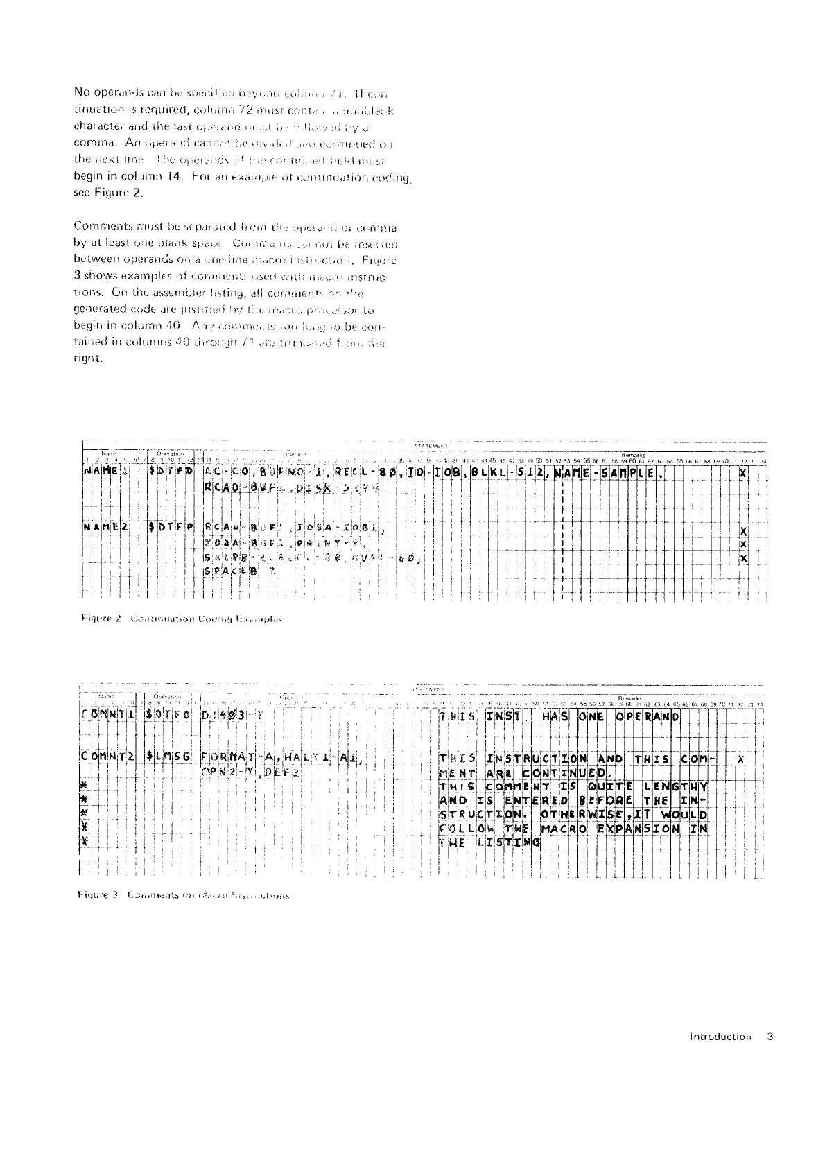
No opefatt'.i:,
r;.rit
[]" l;;,u,.;iltr:ri
i)r..r,,i.,1(t
r.olrJr,,rr
,r
I !i r:,,i,
tinUati\)n is rr:quiretl,
c.)liliitir'/2 ,nrist a:(rt-r'1.:ri,
.,
:ru;,l.,la:,li
Chal'dCler
attd
ilie ia:{ uyr,,,.rr,rt,rri,rt
i}(;
l,li.'r.i:.;r;
i ir.:
COmll.Ia An ,-;1i,lr;'lii
{:afriti
i i,c ri:i
(tt,ri ri,rr
rrrl;littr!tt{l
!)it
[he ric.<1
lirlt' I
llu t)t:i:r.:1,rr,t\)
r)i ]lr,'f}r,i!,'.rr:ll l!l-.iil
titlrsi
begin in colilinn l4- For i1l| e)(ir;,tirir ,)f i;\)||itntt.rlitrttr
(]aliilU.
see
Figure 2.
C0rlrrttents i'lrtsl
brj sepaini.ed iti.,r,r
t!
r,; .,r,utd,
(;
ilr {
j(
fiti.rla
by at least
Li)]e l)iitrlk
S[;.1r
L] a;(), irii(;iii.,
:,,-itii-ioi
1.,i, ;rrsrlilru
fietwggtt otrtlraircis
{Jri
d '-ilri
ltttu iida.rrr
lrr:_it
tr;.,i)rr.
FllqiJrC
3 si'rorrus
eXampl€r
1)t
riotitltJ!,t: Lit,r:(J
wrIl] tirrrij;i:
ritsrili,.l
tiorls. Ofl tile
assentl.'ier lastitlg,
a!i corir{il{iril!
o.r;1,,'
geilL'ratri(j
c(,ijC
tlte
lil5tiilrtii
i.)\/
tiitj tir.li;fr-,
llr(jr.ij:ri)!
tiJ
[-reqit; ir tjoldtilil
4fi. Arr / i.(]ltrilt(,,.it:
r,rI liiirrl !u l)e
tji)t]-
tei'itiJ
itt
COIUn)!rs4{J
ritriil
.Jir
/i diii ttrrrii:;
,,r;
t irir, tir,j
rigr
]
i.
',, l
I
I
16s
lul
K"5
"i-lo
tsY-
.tf].
ii
ri
1f
ii
r1
I
i1
rl
F ir,jur€
2 U.
F igu;e ,l
lntroductiorr 3
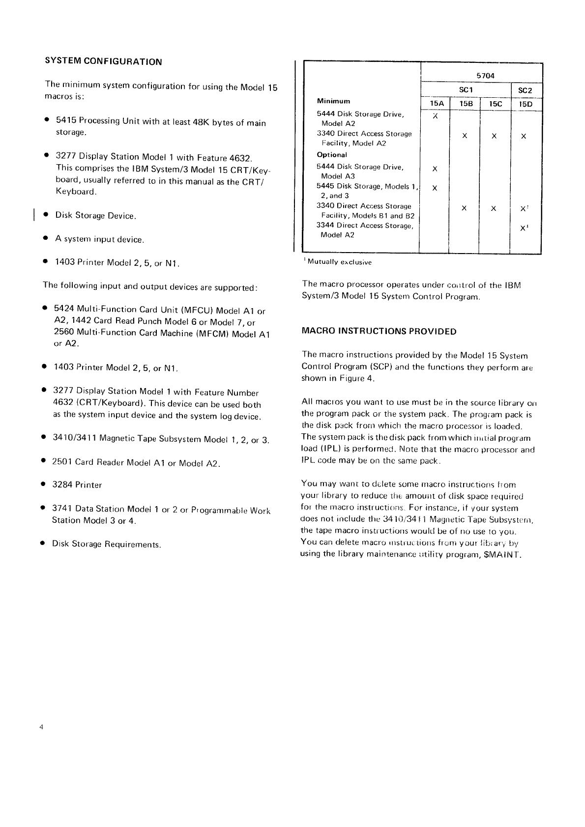
SYSTEM
CONFIGURATION
The
minimunt
system
configuration
for using
the
Model
15
macros
is:
5415 Processing
Unit
with at least
4gK bytes
of main
srorage.
3277 Display
Station Model 1 with Feature
4632.
This
comprises
the IBM
System/3
Model
15
CRT/Key
board,
usually
referred
to in
this
manual
as the
CRT/
Keyboard.
Disk
Storage
Device.
A system
input
device.
o
l.
o
. 1403 Printer
Model
2,
5, or N1.
The
following
input
and
output
devices
are
supported:
. 5424
Multi-Function
Card
Unit
(MFCU)
Model
A1
or
A.2,1442
Card
Read
punch
Model
6
or Model
7,
or
2560
Multi-Function
Card
Machine
(MFCM)
Model
A1
or 42.
. 1403 Printer
Model
2,
5,
or N1.
. 3277
Display
Station Model
1
with Feature
Number
4632
(CRT/Keyboard).
This
device
can
be
used
both
as the
system
input
device
and
the
system
log
device.
. 3410/3411
Magnetic
Tape
Subsystem
Model
1,2,
or
3.
o 2501
Card
Reader
Model
A1 or Model
A2
3284 Printer
3741
Dala
Station
Model
1 or Z
or progranrmahle
Wor-k
Station
Model
3 or 4.
Disk
Storage
Requirements.
'Mutually
exclusive
The macro
processor
operates under
coirtrol
of the lBlVl
System/3
Model 15 Systeni
Control Program.
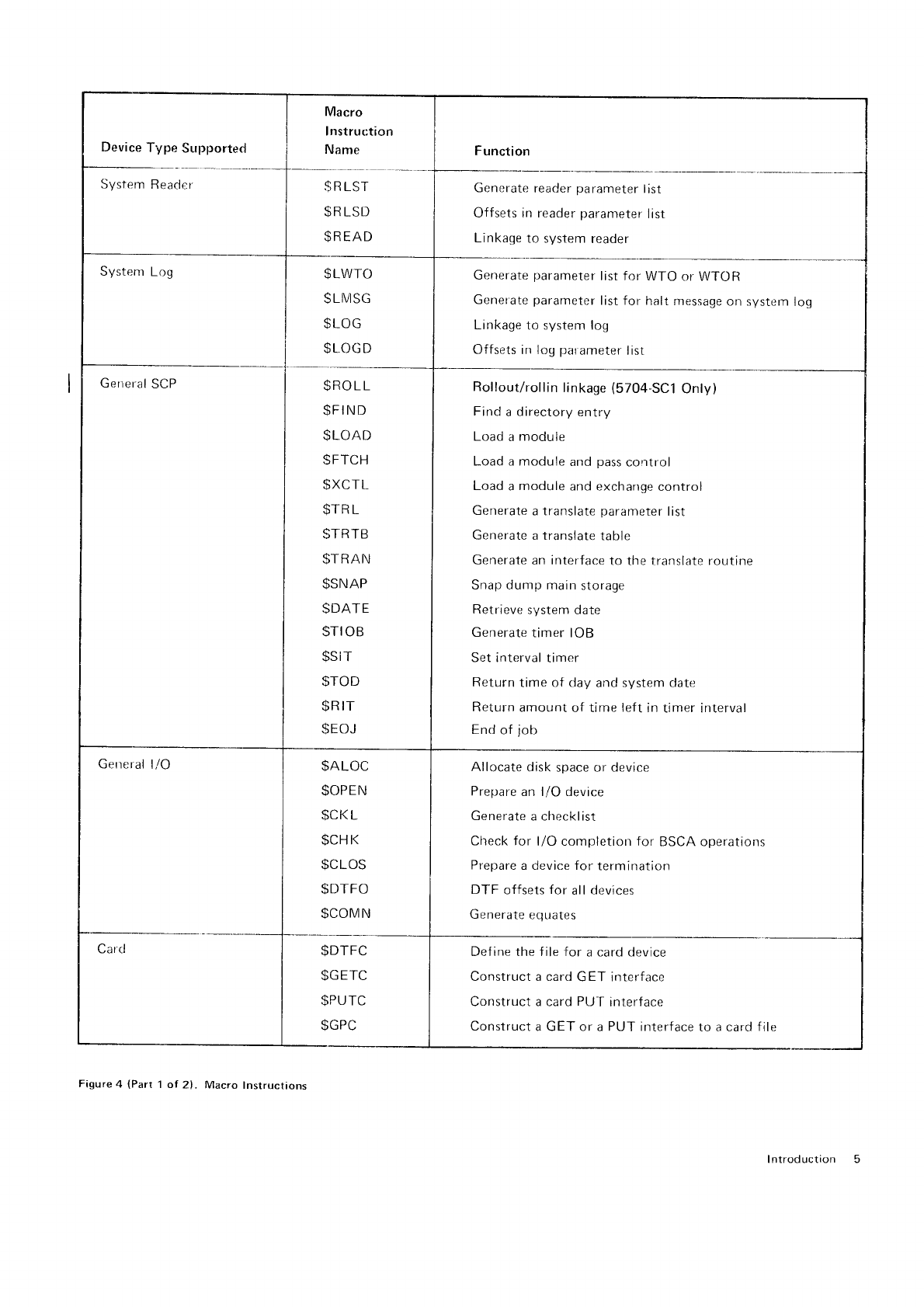
MACRO
INSTRUCTIONS
PROVIDED
The macro
instructions
provided
by the Model
1b System
Control Program
(SCP)
and the
functions
they
perform
are
shown
in Figure
4.
All maoos
you want to use must
be in
the source library
orr
the prograrn
pack
or the system
pack.
The progiam pack is
the disk pack
f
rorrr in"rhich
the macro
processor
is
loacjed.
The
system
pack
is
thc disk
pack
frorn
which
irirtial
prografir
load
(lPL) is
performeC.
l{ote
that the macro
processor
anct
lP[-
corle may
be on thc
same
pack.
You may
want
to cle lete
sonre rlracro
instrucircris
lionr
your library
to reduce
tfit,
amouirt of tlisk space
requirer_l
for the
rnacro
instructions.
For.
instarrce,
if your
system
does
not include
the 34 iili34 l1 Magrretic
1-ape
Subsysttrrrr.
the tape macro inslruclions
vyoult.l
be
of nr_,
use to yor_t.
You can delete macro
llslr.ul:tiolls
frilni
your lit:r
ari b,,,
using
the library
mainterrancie
titiliry
program,
$MAlNl-.
a
5704
scl I SC2
Minimum l--rsaT-rse i-,sc*T*,sD
5444DiskStoraseDrive, I x | | f_-
ModerA2 | I i
334CDirectAccessStorase
| | X I X I X
Facii,ty.
Model
A2 I
Optional I
5444 Disk
Storage
Drive, I X
Model
A3
5445 Disk
Storage, Ir/odels
1,1 X
Moclel 42
2,and3 I I I i
3340DirectAccessStora-r;e
i I X i X I Xl
Facility,
Models
81
and 82 | | | |
3344DirectAccessStorase,
| | I I x'
Device
Type Supported
System
Reacier $RLST
$R
LSD
$READ
System
Log $LWTO
SLIVISG
$LOG
$L
OGD
Gerreral
SCP $ROLL
$FI
ND
$LOAD
SFTCH
$XCTL
$TR
L
btr{ttJ
$TRAN
$SNAP
SDATE
STIOB
$SiT
STOD
$R
tT
$EOJ
Generate
reader
parameter
list
Off sets in reader
parameter
list
Linkage
to system
reader
Generate
parameter
list for WTO
or WTOR
Genefate
parameter
list for halt message
on system
Iog
Linkage
to system log
Offsets in log
parameter
list
Rollout/rollin
linkage
(5704-SCi
Only)
Find
a
directory
entry
Load
a
module
Load a module
and
pass
control
Lr:ad
a
module
and exchange
control
Generate
a translate
parameter
list
Generate a translate
table
Generate
an
interface
to the translate routine
Snap dump main
storage
Retrieve
system date
Generate
timer IOB
Set interval
timer
Return
time
of day
and system date
Return
amount
of time left in
timer interval
End
of
job
General
l/O $ALOC
$OPEN
$CI<
L
$CH
K
$CLOS
$DTFO
$COMN
$DTFC
$GETC
$PUTC
$GPC
Define the
Construct
Con struct
Con struct
Allocate
disk
space or device
Prepare
an l/O device
Generate
a checkl ist
Clreck for l/O completion for BSCA operations
Prepar
e a device for
termination
DTF offsets
for all
devices
Generate
equates
f ile for a card device
a card
GET interface
a card
PUT interface
a GET or
a
PUT interface
to a card
f
ile
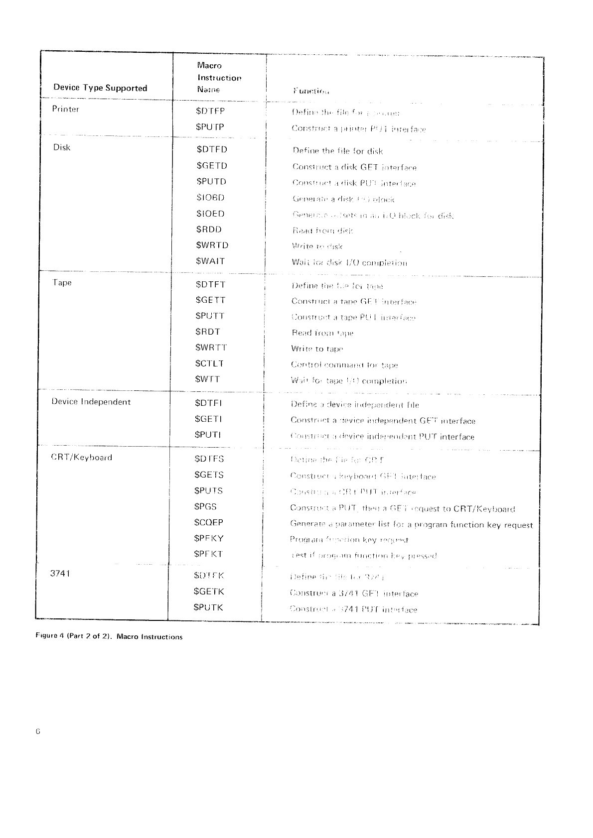
Figure
4 (Part
1 of 2). Macro Instructions
I ntrod ucti on
-."*"**--T-
Device
fype Supported
Printr:
r
D isl<
Device
Independent
(l
R T/l(ev
boai
d
3741
Frgure
4 (Part
2 of ?). Macro Instructtons
I
nstr
riction
Niriire
$D
TFP
$PU TP
$DTFt)
$GE
It)
$PUTI)
$r(]Bf)
$IOED
$RDi)
$WR
TD
$WAIT
$DTFI
$GF-f
t
SPUI
I
$RDT
$WRff
$CI
LT
$wil
$D-rF
I
$GETI
$PU
TI
i titrr:1ir',,
i),:rfin
' :l! i;j{.
{ )L
(lort5ii
trirt
I i,r
i,rfe
,,1c-;
frr.r)
tltor-i:rr r.
t-l
irl,.t--[ ;r,r
riiii
i)ei'lrre
.r ligyjr'3
11,1j,'1;1)rr.iFlrrt
ftle
(lt',rrstr;r.t
a l('vir-p
iIrrlr.)prr:y11!o111
GF'i rIrtet.face
I
:rri
l,:r' i
;
r:'t
:1
i
iovir-p
it
tdat,erri
l:,ri1
!)1..1-f
interface
il,'l,r;.
:lrr' ,
;,. ir: ijfr'I
lli:|]1;ittr.'r
I
:r,virnlt,i rli. I ;itt.,,l:la.r
i::.,cii
j ,r,
llfl!l:!Jl rr,ipr
:r-
I$D
I
trs
$GEIS
$PLr
rs
$PGS
SCOEP
$PF
t<Y
$PI
i<l
$[]rrK
$GE
TK
$PU
TK
,
r:.lr.reijt
to C RT/l{e',' ltoal I
a nIi)/.I-arn
ILrric'tion
key request
lriots,,rl
i
l.'I,r,.,
:i, irr l,
, 1,.,,
l
(:ilrlstr(,i,
r a,Ji/l'l {:tl: l trrteri'acp
:
rr
r;1r,,
I i4| i'lit,lr'
"L{'.,
I
I
I
I
J
Chapter 2. Macro lnstruction Statements
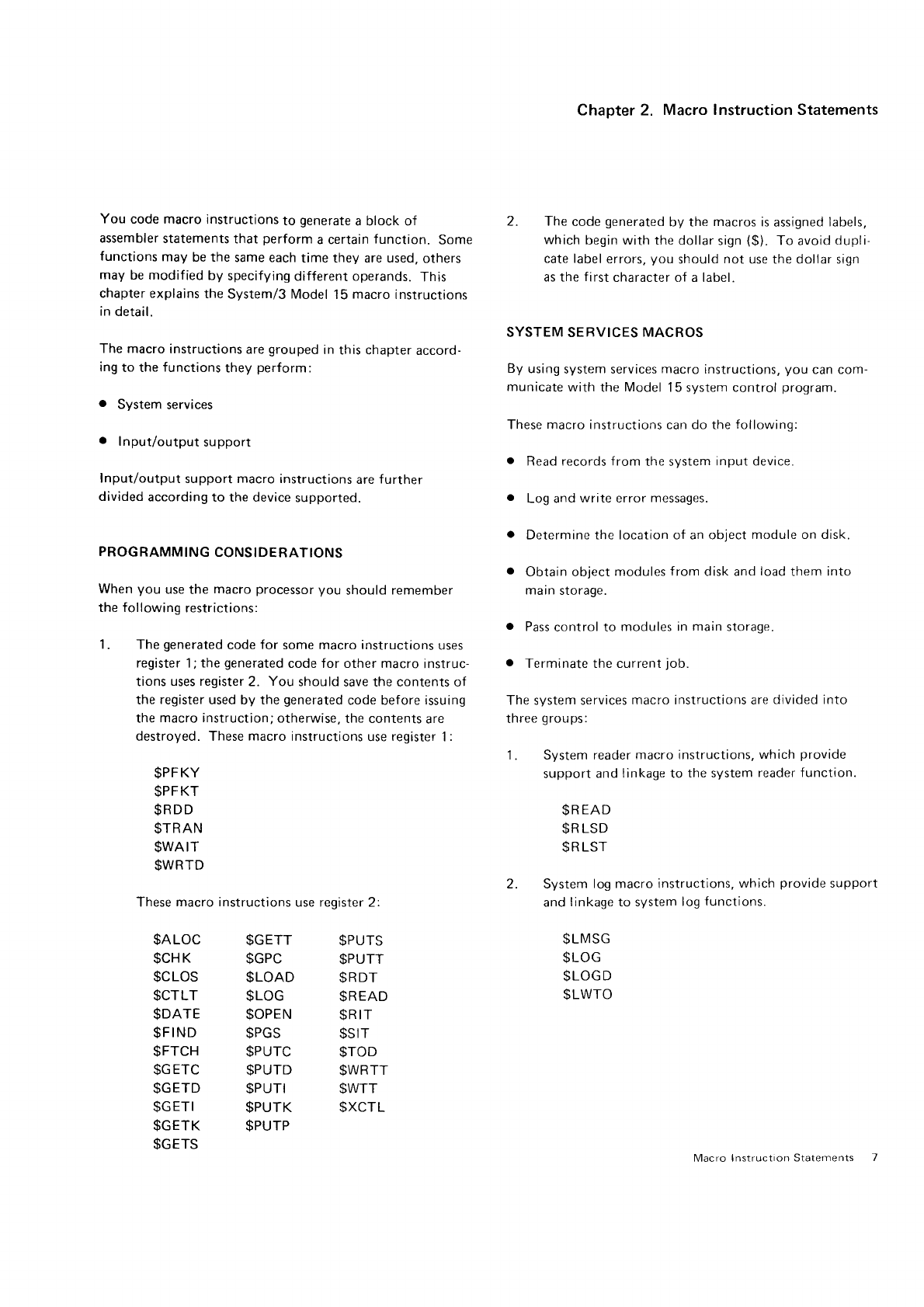
You code macro
instructionsto
generate
a block of 2. The
code
generated
by the
macros
is
assigned
labers,
assembler
statements
that perform
a certain
function. Some which
begin with the dollar
sign
($). To avoid
dupli
functions
may
be the
same each
time they are used,
others cate label
errors,
you should
not use the dollar sign
may
be modified
by specifying
different operands.
This as the
first
character of a label.
chapter explains
the
Svstem/3 Model
15
macro
instructions
in
detail.
SYSTEM SERVICES
MACROS
The macro
instructions
are
grouped
in
this chapter
accord-
ing
to the
functions
they
perform: By
using
system services
macro
instructions,
you can com-
municate
with the
Model
15 system control
program.
o System
services
These macro instructions can do the
followinq:
. Input/output
support
o Read records from the svstem
input device.
Input/output
support macro instructions
are
further
divided
according
to the device
supported. o Log and
write error
messages.
PROGRAMMING
CONSIDERATIONS
When
you use
the macro
processor
you should
remember
the following
restrictions:
1. The
generated
code
for some macro instructions
uses
o Determine the location of an object
module on disk.
. Obtain object
modules
f
rom disk and
load
them into
marn
storage.
o Pass
control to modules in
main
storage.
register
1;
the
generated
code for other macro
instruc- a Terminate the current
job.
tions
uses register
2. You should
save the contents of
the
register
used by the
generated
code before issuing The system services
macro instructions are
divided into
the
macro instruction;
otherwise,
the contents
are three
groups:
destroyed. These
macro
instructions use register
1
:
1. System reader
macro instructions,
which
provide
support
and linkage to
the system
reader function.
$R
EAD
$R
LSD
$R
LST
2. System
log macro instructions,
which
provide
support
and
linkage to system
log
functions.
$LMSG
$LOG
$LOGD
$LWTO
$PFKY
$PFKT
$RDD
$TRAN
$WAIT
$WRTD
These
macro instructions
use register 2:
$ALOC $GETT $PUTS
$CHK $GPC $PUTT
$CLOS $LOAD $RDT
$CTLT $LOG $READ
$DATE $OPEN $R
IT
$FIND $PGS $SIT
$FTCH $PUTC $TOD
$GETC $PUTD $WRTT
$GETD $PUTI $WTT
$GETI $PUTK $XCTL
$GETK $PUTP
$GETS Macro lnstruction Statements I
Page
of GC21-7608-2
lssued 28 March 1980
By TNL: GN21-5700
3. General
SCP
macro
instructions,
which
provide
linkage
to system
functions.
$DATE
$EOJ
$FIND
$FTCH
$LOAD
$ROLL
(5704-SC1
only)
$R
IT
$SIT
SSNAP
$TIOB
STRAN
$TR
L
$TRTB
$TOD
$XCTL
System Reader
Support
You
read
a record from
the
system reader
by
calling
the
system reader
routine
through
the
$READ
macro
instruc
tion. The
system
reader
may
be
one of
the followirrg:
CRT/Keyboard.
Only
96-byte,
single-buffered
input
is
allowed for
this device.
Double
buf fering
is ignored.
2501
Card
Reader.
Single
and double
buffering
are
supported.
Only
B0 bytes
of the
g6-byte
buffer
are
used
as
input;
the remaining
16 bytes
are
cleared
to
bl an ks.
2560
Multi-Function
Card
Machine
(MFCM).
Single
and
double
buffering
are
supported.
Only
80 bytes
of the
96-byte
buffer
are used
as input;
the remaining
16
bytes
are
cleared
to blanks.
Support for both the
primary
(MFCM)
and secondary
(MFCM2)
hoppers
is
provided.
'1442
Card Read Punch.
Single
and
double
buffering
are
supported.
Only
B0 bytes of the
96-byte
buffer
are used
as input;
the remaining
16 bytes
are
cleared
to blanks.
5424
Multi-Function
Card
Unit (MFCU). Both single
and
double
buffering
are
supported.
Support for both
the
primary (l\4FCU1)
arrd
secondary
(MFCU2)
hoppers
is
provided.
All 96 bytes
are used
as input.
Directly
attached
3741 Data
Station Model
1
or 2 or
Programmable
Work
Station
Model
3 or 4. Single
and
double
buffering
are
supported.
Only
96-byte records
may
be read.
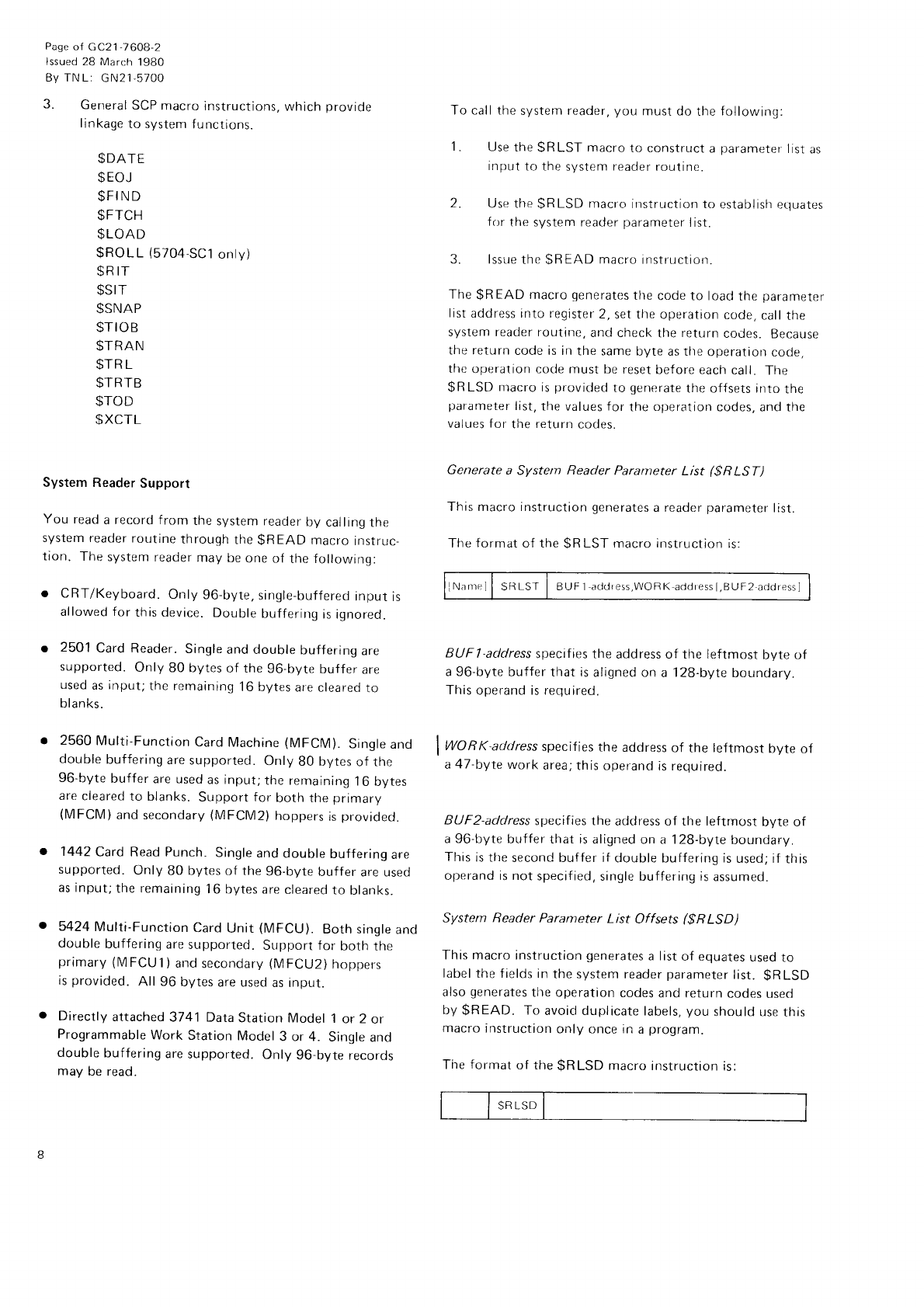
To call the
system reader,
you
must do
the
following:
1. Use
the
SRLST
macro
to construct
a
parameter
ltst
as
ilrput
to the
system
reader
routine.
2. Use the
SRLSD
macro
instruction to establish erluates
f
or
the system reader
parameter
list.
3. lssue
thr.
SREAD
macro
instruclrorr.
The
$R
EAD macro
generates
the
code to load
the
parameter
list
address into register
2,
set the operation
code,
call the
system reader routine,
and check
the
return
codes.
Because
the return
code is in
the same
byte as the
operatton
cooe,
the
operation cocle must
be reset
before each
call. The
$R
LSD macro is
provided
to generate
the offsets into
the
parameter
list,
the
values
for the
operation
codes, and the
values for
the
return
codes.
Generate a System Reader
Parameter List ($R LST)
This macro instruction
generates
a reader
parameter
list.
The
format
of the
SR
LST
macro
instruction
is:
N.rnr"ll
SRLST
I BUFl
arldress,WORK
addressl,BUF2
addressl
BUF |
-address
specif ies the address of tlre leftmost byte of
a 96-byte
buffer that is
aligned on a 128-byte
boundary.
This
operand is require<.t.
WORK-address
specifies
the address
of the leftmost byte of
a
47-byIe
work area;
this operand
is required.
BUF2-address
specifies the address of the leftmost byte of
a 96-byte
buffer that is
aligned on a 128-byte
boundary.
This
is the
second buffer if
double buffering is
used; if
this
operand is not
specified,
single buffering is
assumed.
System Reader Parameter List Offsets ($RLSD)
This macro
instruction
generates
a list
of equates
used
to
label the f ields
in
the system reader
parameter
list. $R
LSD
also
generates
the operation
codes and return
codes
usecl
by
$READ. To
avoid duplicate
labels,
you
should use
this
macro
instruction
only once in
a
program.
The
format
of the
$RLSD macro instruction
is:
o
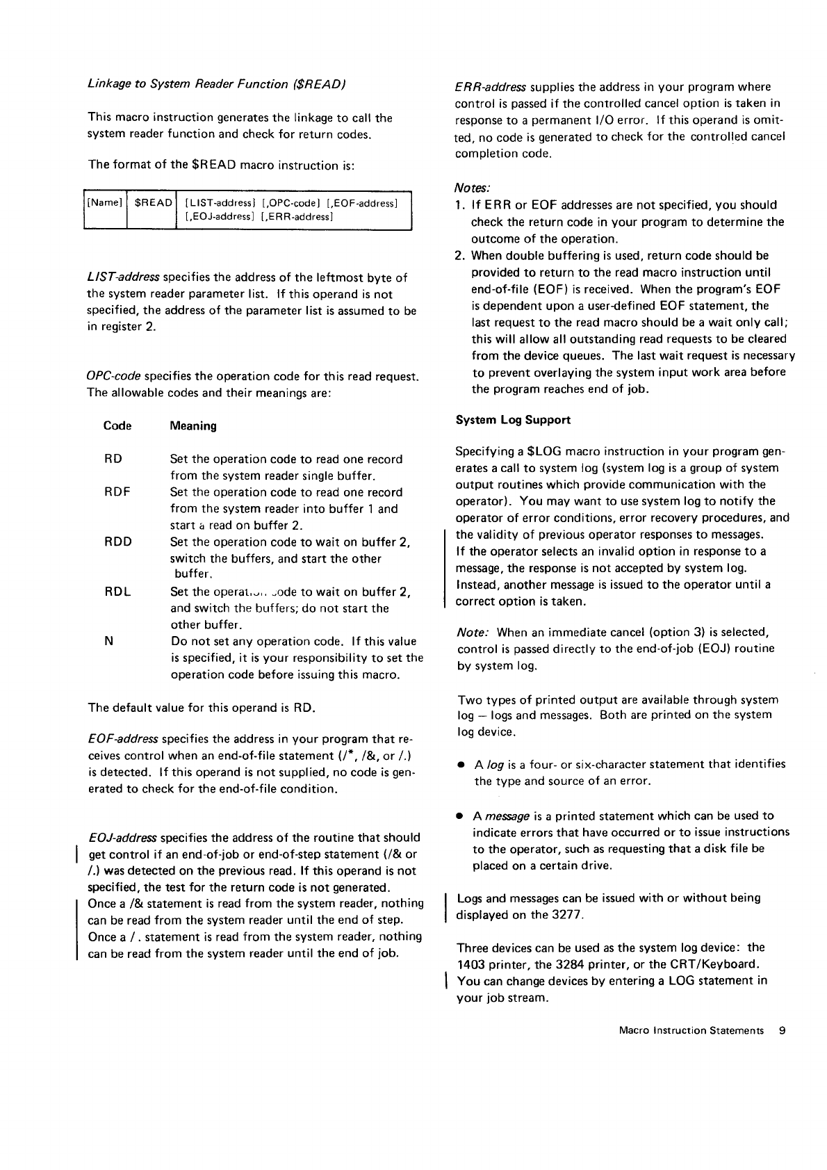
Linkage to System Reader Function ($READ)
This macro
instruction
generates
the linkage
to call
the
system reader function and check for return codes.
The format of the $READ macro instruction is:
INamel
| $READI ILIST-address] [,OPC-code]
[,EOF-addressJ
[,EOJ-address] [,ERR-addressl
LlST-address
specifies the address of the leftmost
byte
of
the system reader
parameter
list. lf this operand is not
specified,
the
address of the
parameter
list is
assumed
to be
in register
2.
OPC-code
specifies the operation
code
for
this
read
request.
The allowable
codes and their meanings
are:
Meaning
Set
the
operation code
to read
one
record
from
the system reader
single buffer.
Set
the
operation
code to read one record
from
the
system
reader
into buffer
1 and
start a read on
buffer 2.
Set
the operation
code to wait
on buffer 2.
switch the
buffers, and start the
other
buffer.
Set the
operat,-,,
-ode to wait
on bulfer 2,
and switch the buffers; do
not
start the
other buffer.
N Do not set any operation code. lf this value
is specified, it is
your responsibility
to set
the
operation
code before
issuing
this macro.
The default
value for this operand is RD.
EOF-address
specifies the address in your program that re-
ceives control when an
end-of-file
statement
(l* . l&. or /.1
is detected. lf this operand is not supplied.
no code is
gen-
erated to check
for the end-of-file
condition.
EOJ-address
specifies
the address of the routine that should
get
control
if an
end-of-job or end-of-step statement
(/& or
/.)
was
detected
on the
previous
read. lf this
operand is
not
specified. the test
for the return code is not generated.
Once a
/& statement
is read
from
the system reader,
nothing
can be read
from
the
system reader
until
the
end of step.
Once
a
/ . statement
is read
from
the system
reader, nothing
can be read
from
the
system reader
until the end of job.
ERR-address supplies the address
irr
your program
where
control
is
passed
if the controlled
cancel option
is taken in
response to a
permanent
l/O
error. lf this
operand
is omit-
ted.
no code
is
generated
to check
for the controlled
cancel
completion code.
Notes:
1. lf ERR
or EOF
addresses are
not specified,
you
should
check the
return
code in
your
program
to determine the
outcome
of the operation.
2. When
double buffering
is used, return
code should
be
provided
to return
to the read macro instruction until
end-of-file
(EOF)
is received. When the
program's
EOF
is dependent upon a user-defined
EOF
statement, the
last request
to the
read macro
should
be a wait only call;
this will allow all outstanding
read requests to be cleared
from
the device
queues.
The last wait
request is necessary
to prevent
overlaying the system
input work area
before
the
program
reaches end of job.
System Log Support
Specifying
a
$LOG
macro
instruction
in
your program
gen-
erates
a
call
to system log
(system
log is
a
group
of system
output
routines
which
provide
communication with the
operator).
You
may want to use
system log to notify
the
operator of error conditions, error
recovery
procedures,
and
the validity
of previous
operator responses to messages.
lf the operator selects an
invalid option in response to a
message.
the response is not accepted
by system
log.
Instead,
another
message
is
issued to the operator
until a
correct option is taken.
y'Vofe.'
When
an
immediate cancel
(option
3) is selected,
control
is
passed
directly to the end-of-job
(EOJ)
routine
by system
log.
Two
types of printed
output are available through
system
log
- logs
and
messages. Both
are
printed
on the
system
log device.
o A log is a
four-
or
six-character
statement that
identifies
the type and source
of an
error.
. A messge
is
a
printed
statement
which can
be used to
indicate
errors that
have
occurred
or to issue instructions
to the operator, such
as
requesting that a disk
file be
placed
on
a certain
drive.
Logs and
messages can be
issued with or without being
displayed
on the 3277.
Three devices can be
used as the system
log device: the
1403
printer,
the
3284
printer,
or the CRT/Keyboard.
You can change devices
by entering a LOG
statement
in
your
job
stream.
Code
RD
RDF
RDD
RDL
Macro Instruction
Statements I
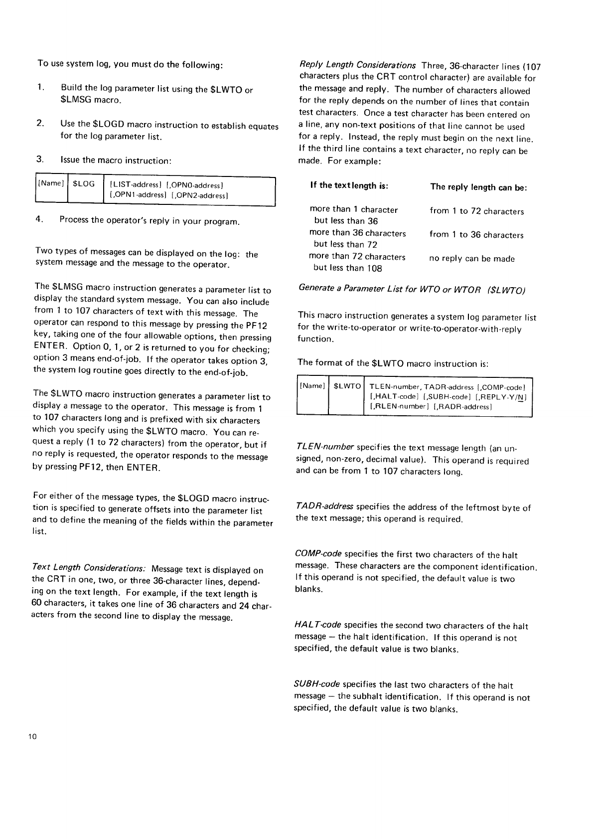
To use
system log,
you
must
do
the
following:
1. Build
the log
parameter
list
using
the
$LWTO or
$LMSG
macro.
2. Use
the
$LOGD
macro
instruction
to
establish
equates
for
the log
parameter
list.
3. lssue
the macro
instruction:
INamel
| $t-oc | [rtst-"oa.ess]
[,opN0-address]
[,OPN1
-address]
[,OPN2-address]
4. Process
the operator,s
reply in your program.
Two types
of messages
can
be
displayed
on the log: the
system
message
and
the message
to the operator.
The $LMSG macro instruction
generates
a parameter
list
to
display
the standard
system
message.
you can
also
include
from 1
to 107
characters
of text with this message.
The
operator
can respond
to this message
by pressing
the pF12
key,
taking
one
of the four allowable
options,
then
pressing
ENTER. Option
0. 1,
or 2 is returned
to you for checking;
option 3 means
end-of-job. lf the operator
takes
option 3,
the system
log routine
goes
directly to the end-of-job.
The $LWTO macro instruction
generates
a parameter
list
to
display
a message
to the operator. This message
is from 1
to 107 characters
long
and is
prefixed
with six characters
which
you specify
using
the
$LWTO macro. you can
re_
quest
a reply (1 to 72 characters)
from the operator,
but if
no reply is
requested.
the operator
responds
to the messaqe
by pressing
PF12,
then ENTER.
For either
of the message
types,
the $LOGD macro instruc_
tion is
specified
to generate
offsets
into the parameter
list
and
to define
the
meaning
of the fields
within
the
parameter
I ist.
Text Length Considerations.. Message
text is displayed on
the CRT in one,
two, or three
36-character
lines.
depend_
ing
on the text length. For example,
if the text length
is
60 characters,
it takes
one line
of 36 characters
and 24 char_
acters from the second
line
to display
the message.
Reply Length Considerations Three, 36-character lines (107
characters
plus
the CRT control character)
are available
for
the message
and reply. The number of characters
allowed
for the
reply
depends
on the number
of lines
that contain
test
characters.
Once
a test
character
has
been
entered
on
a line,
any non-text
positions
of that line
cannot
be used
for a reply. Instead,
the reply
must
begin
on the next
line.
lf the
third line
contains
a text character,
no reply
can
be
made. For
example:
lf the
text length
is:
more
than 1 character
but less
than
36
more
than 36 characters
but less
than 72
more
than 72 characters no reply can
be made
but less
than 108
Generate a Parameter List for WTO or WTOR ($LWTO)
This
macro
instruction
generates
a system
log
parameter
list
for the write-to-operator
or write-to-operator-with-reply
function.
The format of the $LWTO macro instruction is:
lNamel
| $LWTO
I TLEN-number,
TADR-address
[,COMp-code]
[,HALT-code]
[,SUBH-code]
[,REPLY-Y/N]
[,RLEN-number]
[,RADR-address]
TLEN-number specifies
the text message
length (an
un-
signed,
non-zero,
decimal
value).
This
operand
is required
and
can
be
from 1
to 107
characters
lonq.
TADR-address
specif ies
the address
of the leftmost bvte of
the text message;
this operand
is required.
COMP-code
specifies
the first two characters
of the halt
message.
These
characters
are the component identification.
lf this
operand
is not specif ied,
the default
value
is
two
blanks.
HALT-code specif
ies the second
two characters
of the halt
message
- the halt
identification.
lf this operand
is
not
specified,
the default
value
is two blanks.
SUBH-code
specifies
the last
two characters
of the halt
message
* the subhalt
identif
ication. lf this
operand
is not
specified,
the default value
is
two blanks.
The reply length can be:
from 1
to 72 characters
from 1 to 36 characters
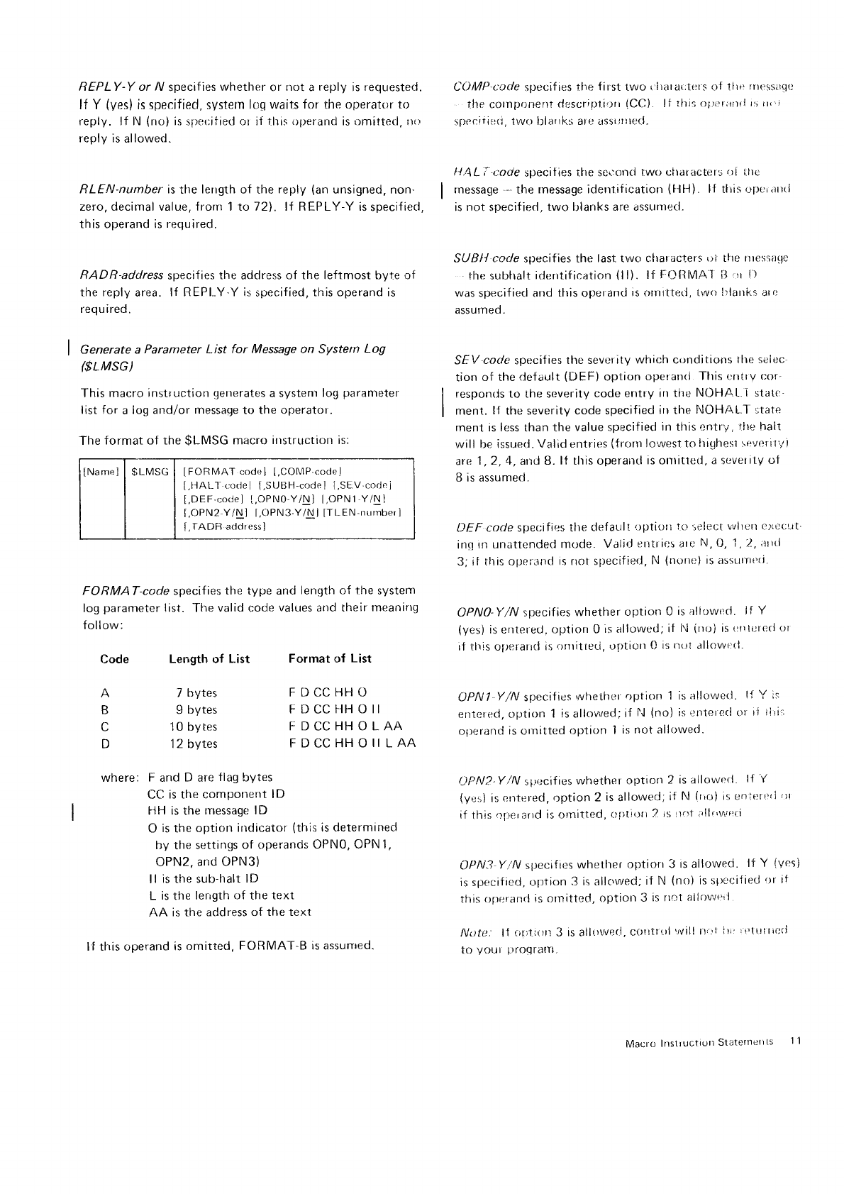
REPLY-Y or /i/
specif
ies whether
or not a
reply
is
requestecj. COIWP-t:ocle
specif
ies the
f irst
two (rlrara{;l.ets
of ltre
rnessirq{l
lf Y (yes)
is specified, system
l1-c1 waits
for the operat()r
to the cornpr;nenI
dr.scriDlii)rr
{CC) lt rhi5 o1.'er;rnLl
ts
tt,'r
reply. lf l\ (no)
is
spet;ified
ot if this operand is Lrmittecl, rro sper:iri6111,
{wrr
blarrk:;
arc irssuttteci.
reply is
allowed.
RLEN-numbel is
tlre
lerrgth
of the
reply
(an
unsigned, non-
zero, decirnal value, frorn 1 Ic:721
. lf REPLY
Y is
specif
ieci,
th is operand is
regu
ired.
RADR-address
specif
ies the aridress
of the leftmost byte of
the reply
area.
lf R EPI-Y Y is
specif
ied, this operand is
requ i red.
I Gerterate a Paraftteter List for Message on Systern
Log
($LMSG
)
This
macro instruction
qenerates
a systenr log
paranteter
list for a
log and/or
message
to the operator .
The
format of the
$LMSG macro
instruction is:
lNamel
I SLMS(j
I IFOnMAT codr'l
[,CONlP.corlel
[,1]At-l-
rtrlel [,StJUH-code]
I,SEV
cocle
j
[,DEF'code]
L,OPNO'Y/Nl
l.OPN1
Y/Nl
[,OPN2
Y/N] I,OPN3-Y/Nl
[Tt-EN'nurnberl
[,
fADF] adclressl
FORMAT-code specif
ies the type and length of the system
log
parameter
list. The
valid
code
values
and their
rneanittg
follow:
Code Length of List Format of List
l!.4L
i tode speciiies
the seconci
rwo
cttaractcts oi i.ltc
rnessage
--
the
rnessage identification
(['ll"t).
lf tlrrs
,.)l)i'r
,]r(i
is
not specif ied,
two blanks
are assurrteci-
SUBII
code
specif
ies
the
last two cllaracters
rrl
ttle
nrestit(le
rhe sr-rtrttalt
iderrtif
ication
(ll). lf FOtlltlAT il 'rr
f
l
was specifiecl and
tlris
operand
is otrtittr:d, ivuo
l.'lattkl
atr:
assumed
"
SEV-code specilies
the severity
which conditions
tlte selec'
tion
r'lf
the
default
(DEF)
option
opetanti
Tltis etttrv
cor'
responrls to the severity
code entry
in tne NOFIAL. i stalt:
ment.
lf the severity code
specif
led irt tlre
NOH/\L-I i;tate
ment is less than the
value specified
in this entry,
tlle halt
wi | | be issried.
Val id etrtries
(f
rorlt lowerst to
lrighest'r)vrrI
I
I
ii
I
are
1,2,
11,
arrd 8. lf tlris operancl
is
orlitted,
a severity
of
B is assumed-
DEF code specif
ies
tlte
clef aull
optiort
to 'jeleot
vvlloll
e)(()orrI
inq
In un.lttended
mode-
Valid
erltries are
N, [J,
'l
,2, arrrJ
3; it rhis opr:ronr-l
rs rrot slrecified,
N (norrc)
is asst.ttreri.
OPN0-y'/N specifies
whether
option
0 is all"rwr:d.
lf Y
{yes)
is enlefed" optiort
0 is allowed;
if l',1
(rroi
is
trtrlutecl
ot
it this optlrarrd
is
lrrritteri, oJrtiort
0 is not allowt:rl-
OPNI Y/N specif
ics wheiht:r
option 1 is allowecl . l{ Y i.r
entered, ct1-rtion
1
is
allowed;if
lJ
(no)
is i:trteterl or
iJ
tlri',
opr:rand
is ornitted
option I is not allowed^
L)PN2-Y/N si.'ecifres
wfrether
option
2 is allovvr:tl.
l{ Y
(yes)
is
eltTered, option
2 is
allowed;
if N (rio)
is eoiertrrl'rr
if this cperarid
is clrnitted,
()i)ti(lrr
2 is rtnt
;llr''wr:ri
OPN3 Y/N specif
ies
whether
optiorr
3 ts allowed. lt Y (vcs)
is sprrcified,
option 3 is
allc'wed;
ii N (no)
is sl>ecifieci
'tr it
this
oJreranrl
is ornitted,
optiol-l
3 is rrot;rilov;t"i
lv(lfrr. lf ti1:litttl 3 is allowed.
c()!l1r(-)l
vvill
tt'rt
ltil i'lrtl
lit)rl
to youl proqrallrl.
A 7
bytes
B 9 bytes
C 10 bytes
D 1 2 bytes
where: F
and
D are
flag
bytes
CC
is the component
lD
I'lll is the nressage lD
O is
the
option
irrdicator
(this
is deternrined
by the
settings
of operands
OPN0, OPN 1,
OPN2,
and OPN3)
ll is the sub-halt
lD
L is
the lerrgth
of the
text
AA is the address of the text
lf this operand
is
ornitted,
FORMAT B is assunred.
FDCCHH(J
FDCCI.IHOII
FDCCHIIOI-AA
FDCCHHOIILAA
Macro Instructioll Slaterndllts I 1
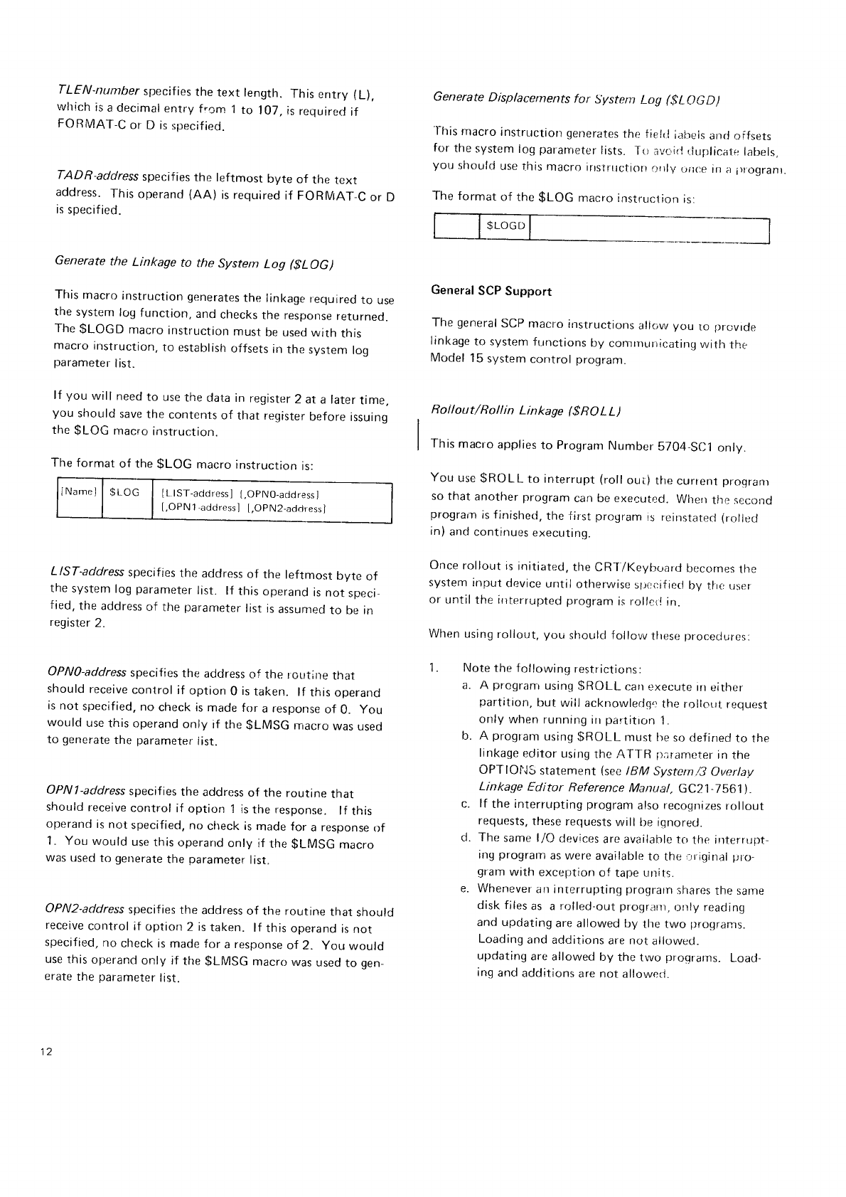
TLEN-number
specifies
the
text length.
This
entry (L),
vvhich
is
a decimal
entry
fr.crn
1
to 1O7,
is requirecl
if
FORMAT
C or
D is
specified.
TADB-address
specif
ies
the leftmost byte of the rext
address.
This
operand
(AA) is required
if FORMAT_C
or D
is
specified.
Generate
the Linkage to the System LoS $LOG)
This
macro
instruction
generates
the linkage
required
to use
the
system
log furrction,
and
checks
the response
returned.
The
$LOGD macro
instruction
must
be usecl
with this
macro
instruction,
to establish
offsets
in
the
system
rog
parameter
list.
lf you will need
to use
the
data in register
2 at a later
time,
you should
save
the
contents
of that register
before
issuing
the
$LOG
macro
inslruction.
The
format
of the
$LOG macro
instruction
is:
INamel
I gi
66 | lt tst-rdo'.rsl
t.opNo-adciressl
[.OPN1'addressl [,OPN2-adrJress]
L|ST-address
specifies
the address
of the leftmost bvte of
the
system
log
parameter
list. lf this
operand
is not specl_
fied,
the address
of the
parameter
list
is
assumed
to be in
register
2.
OPNO-address
specif ies
the address
of the r oLrtine
that
should
receive
control
if option
0 is
taken. lf this
operand
is not
specified,
no
check is
made
for a
response
of 0. you
would
use
this operand
only if the
$LMSG
macro
was
used
to generate
the parameter
iist.
OPN
1
-address
specifies
the address
of the routine tnat
should
receive
control
if option I is the fesponse. lf this
operand
is
not
specified,
no
check is
made for a response
of
1. You would use
this
operand
onlV
if the
$LMSG
macro
was
used
to generate
the
parameter
list.
OPN2-address
specif ies
the address
of the routine ttrat
should
receive
control
if option
2 is
taken. lf this
operand
is
not
specif ied,
ncl
clreck is
made
for a
response
of 2. you would
use
this
operand
only if the
$LMSG
macro
was
used
to qen_
erate
the
parameter
list.
Generate
Displacements for System LoS 6L()GD)
"l-his
macro
instructiorr
generates
the fierlr.l
idirsi5
s1r61
offsets
for
the
system
log
pararreter
lists"
To iivcirl
rluplicate
labels,
you should
use
Ihis
macro
irtstrrrcliort
r:nly
L,iloe
ril;)
i)l
ogrant.
The format
of the
$LOG macro
instruclion
is:
General
SCP
Support
The
general
SCP
macro
instructions
allcw
you ro l)rovrcte
linl<age
to system
functions
by conrrnlrnicatirrg
with the
Model
15
system
contror
program.
Roi
lout/Rol I in Lin kage (
$
RO
L L)
This
macro
applies
to Program
Number
5704-SC1
only.
You use
$ROLL to interrupt
(roll
out) the
cunent proqranl
so
that another
program
can be executed.
Wherr
the
second
prograin
is finislred,
the first
program
is reinstatecJ (rollec.l
in)
and
continues
execulng.
Once
rollout
is
initiatecl,
the
CR-T/Keyboard
becornes
the
system input
device
until
otherwise
s1.,ci:ified
by the user
or
until
the
interrupted
program
is rollctl
in.
When
using
rollr:r,rt,
you should follow
tlrese
Droceciures:
Note
the
fr:llowing
restrictions:
a. l\ prograrrr
using
$ROLL carr
execute
irr
either
partition,
but wiil ackr-rowledq'r
the rollout
requesr
only
when
running
irr
partitron
1.
b. A program
usinq
$ROLL must he
so
clefinecl
to the
linkage
eclitor
using
thc ATTR p;rameter
in
the
OPTIONS
statement
(see
IBM Systern/3
Ovenay
Linkage Editor Reference
Manual, GC21 7b61).
c. lf the interrupting
prograrn
also
recnclnizes
rollout
requests,
these requests
will lte iqnored.
d. The
samt'
l/f) devices
are availahle
tc)
the interrupT-
Ing
program
as were
available
to the
irrigirral
plo-
qram
wath
exception
of tape
r-rnits.
e. Whenever
an
interrupting
prograrn
shares
the sarne
disk
files
as a rolled-out
progr.nl,
only reading
and updating
are
allowed by the
two proqrar,ns.
Loading
and adCitions
are
not
allowecj.
updating
are allowed
by the two programs_
L.oad-
inq
and
additions
are not allowerJ.
tz
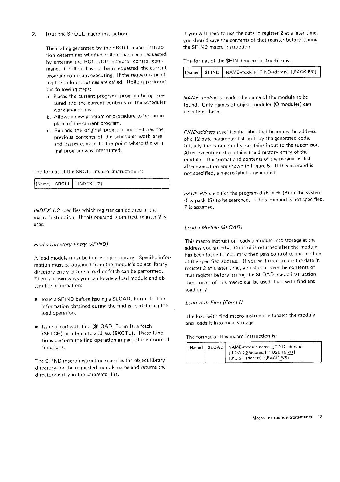
2. lssue
the
$ROLL macro instruction:
The coding
generated
by the
$ROLL macro
instruc-
tion determines
whether
rollout has been
requested
by entering
the ROLLOTJT
operator
control
com-
mand. lf rollout
has not been
requested,
the
current
program
continues
executing.
lf the
recluest
is
pend-
ing the
rollout
routines
are
called. Rollout
performs
the
following steps:
a. Places
the current
program
(program
being
exe-
cuted
and the current
contenis
of the scheduler
work area
on disk.
b. Allows
a
new
program
or procedure
to be
run in
place
of the
current
Program.
c. Reloads
the original
program
and restores
the
previous
contents
of the scheduler
work area
and passes
control
to the point where
the orig-
inal
Program
was
interruPted.
The
format
of the $ROLL macro instruction
is:
INarrrell
$RoLL
I ITNDEX
l/2
I
INDEX-1
/2 specif
ies
which register can
be used
in the
macro instruction.
lf this
operand
is omitted,
register
2 is
used.
Find a Directory Entry ($F IND)
A load
module
must be
in tire object
library. Specific
infor
matiorr
must be
obtained
from the
module's
object
library
directory
entry
before
a
load
or fetch
can
be
performed.
There are
two ways
you can
locate a
load
module and ob-
tain
the
information:
. lssue a
$FIND
before
issuing a
$LOAD,
Form ll. The
information
obtained
during
the
f
ind is used
durinq
the
load
operatiolr.
o lssue
a lcad
with find ($LOAD, Form l). a
fetch
($FTCH)
or a
fetch
to address
($XCTL). These
func-
tions
perform
the
find operation
as
part
of their
normal
f
u
nctions.
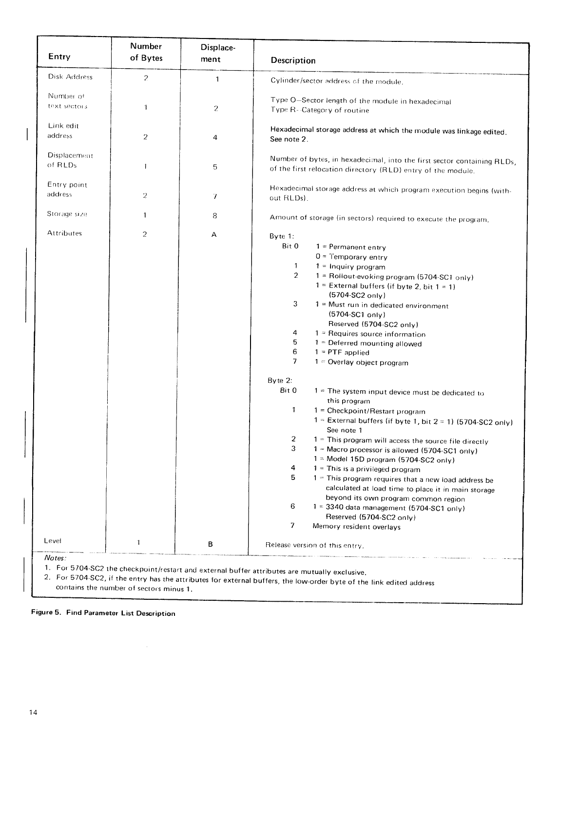
The $FIND macro
instruction searches
the
object
librarv
directory
for the
requested
module name
and
returns the
directory
entry
in the
parameter
list.
lf you will need to use the
data
in register 2 at a later time,
you should save
the contents
of that register before
issuing
the -qFlND
macro
instructiurt.
The
format
of the
$FIND macro
instruction is:
lNamel
| $FrND I NAME-module[.FlND'address]
t,PAcK-q/Sl
NAME-module provides
the name of the module to be
found. Only names of object
modules
(O
modules)
can
be
entered
here.
FIND-address
specifies
the label
that becornes
the address
of a 12-bvte
parameter
list built
by the
generated
code.
Initially the parameter
list corrtains
input to the supervisor.
After execution,
it contairrs
the
directory
entry of the
module. The
format and
contents
of the
parameter
list
after
execution are
shown
in Figure 5. lf this operand
is
not specified,
a nlacro
label
is
generated.
PACK-P/S
specif
ies
the program
disk pack (P)
or the system
disk
pack
(S)
to be searched.
lf this
operand
is not specified,
P is assumed.
Load a Module ($LOAD)
This
macro
instruction
loads a
module
into storage
at
the
address
you specify.
Controi
is returned
a{ter
the module
has been
loaded.
You may then
pass
control
to the
module
at
the specified
address.
lf you will need to use the
data
in
register 2 at a larer time. you shoulo
save
the contents
of
that
register
before
issuing
the
$LOAD macro
instruction'
Two forms of this
macro
can
be used:
load
with find and
load only.
Load with Find (Form l)
The
load
with f ind
macro
instrttction
locates the
module
and
loads
it into main storage.
The
format of this
macro
instruction
is:
tNamel | $LoAD I NAME-module
name
[,FlND-address]
[,LOAD-!/address]
[,USE-R/I\R]
[,PLlST-address]
t,PACKf/Sl
Macro
Instruction
Statements 13
Entry
Disk l\rlclress
Nurn[;er
oi
I(:Xl
5OcI()t.i
Link edit
aooross
D is
Pr
l2
6 s ry',,,
t,
of RLDs
Entry pornt
addr ess
Sloraqe
srzi:
AttributL,s
I
').
I
2
Displace-
ment
5
I
8
A
Description
Cylinder/sector
acldres:
of the rnoclule.
Type O Sector Iength
of the moclule
in hexadecir:ral
Type R- Category
of roulirre
Hexadecimal storage address
at which the rnodule was linkage edited.
See note 2.
Number of bytt:s,
in hexadeci:nal,
into the first sector
containinq RLDs
of the first relocation
directory (RLD) entry of rhe mooure.
Hexadecimal
storage
address
at which progrant
execution beqins
{with_
Out
HLDs)
Arnount
ol
Byte 1:
Bir O
1
2
4
5
6
7
Byte
2:
Bit
0
1
storage
(in
sectors)
required
to execute
the
Flrogranl.
1
= Permanent
entry
0 = -l-emporary
entry
1 = Inquiry program
1 = Rollout,evoking
program
(S704-SC1
r::nly)
I = External
buffers
(if
byte 2,
bit 1
= 1)
(57O4-SC2
onty)
1
= Must run
in
dedicated
envrronment
(57O4-SC1
onty)
Reserved
(5704-SC2
only)
1 - Requires
source
information
1 = Deferred
mounting
allowed
1
=
PTF
apptied
1 .. Overlay
object
program
1
= The system
input device
rnust
be
dedacateLJ
to
th;s
program
i = Checkpoint/Restart
prograrn
1
= Externat
buffers
(if
byte l, bir 2 = 1
) (5704-SC2
only)
See note 1
1 - This
prograrn
will access
the source
file directly
1
= Macro
processor
is
allowed
(5704-SC1
onty)
1
--
Model 15D
program
(5704-SC2
onty)
1
= This is
a privileged
prograrrl
1 .. This
program
requires
that a new load
address
be
calculated
at load
time to place
it in nrain
storage
J
q
beyond
its
own program
contrnon region
6 1
- 3340
data
managemenr
(5704-SC1
only)
Reserved
(5704-SC2
onty)
7 Memory resident
overlays
Releasr.versiorr
of thts
^ntry.
1
' For 5/04-sc2 rhe
checkpoint/restart
and external
buffer attributes
are
mutually
exclusive.
2' For 5704-sc2, if the entry has
the
attributes
for external
buffers,
the low-order
byre
of the link edited
aLidress
conta'ns
the
nuntbet
of sectors
minus
i.
Figure
5. Find Parameter
List Description
14
Entry
Number
of Bytes
Displace-
ment Description
Disk Address
Number of
text sectors
Link edited
address
Displacement
of R LDs
Relocated entry
point address
Load address
2
1
1
2
2
1
z
4
6
9
Cylinder/sector
address
of the module in hexadecimal. See
note 1.
Sector
length of the module, in hexadecimal.
Storage
addressat
which the module
was
linkage
edited. See
note 2.
Hexadecimal displacement,
in bytes,
into the
f
irst sector containing
RLDs,
of the
first relocation directory (RLD) entry of the module.
Storage address
at which program
execution begins, after
resolving RLDs.
Address at which the requested
module
is loaded.
Notes:
1. lf a directory
entry was
not found on a load
with f
ind,
the
f irst
byte contains
a character O.
2. For 57O4-SC2,
if the entry has
the attributes
for external
buffers,
the low-order byte of the link edited address
contains
the number
of sectors minus 1.
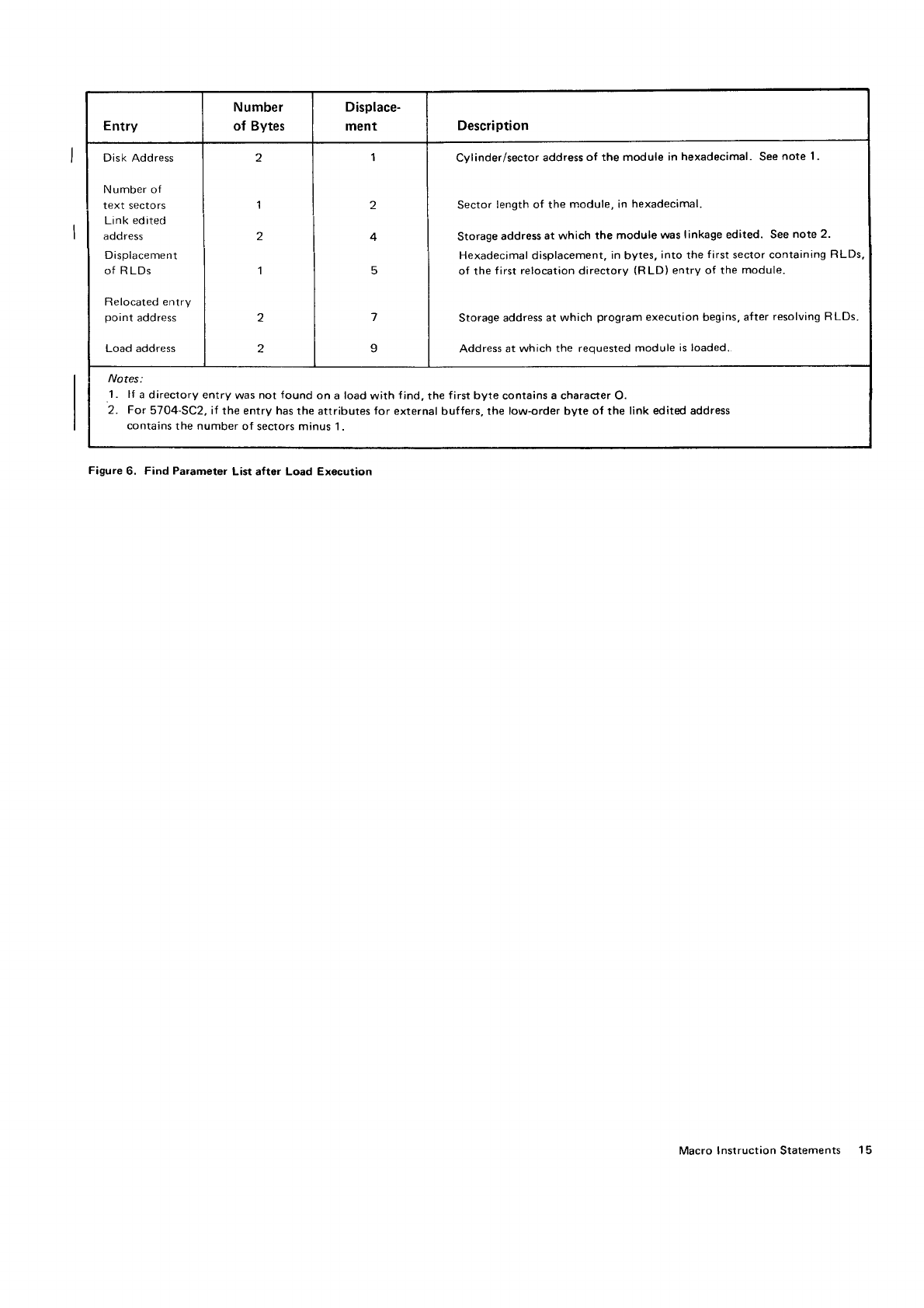
Figure 6, Find Parameter
List after Load Execution
Macro
Instruction Statements 15
NAME-module name provides
the name
of the module to
be loaded
and is
required. Only O modules
can
be
specif ied.
FIND-address becomes
the address
of the parameter list
passed
to the find routine. The parameter
list is
generated
by the macro
processor.
After execution
of the load.
this
parameter
list
contains
the modified entry for the module
as shown
in Figure
6.
LOAD-2/address
specifies
the address
where
the module
is
to be loaded
into main
storage.
The 2 indicates
that the
address
is in register
2; the address
is
the symbolic address
where
the
module
is to be loaded.
lf this
operand
is
not
specified,
2 is
assumed.
USE-R/NR indicates
whether the code
generated
by the
macro
instruction
is to be
reusable
(R) or nonreusable
(NR).
lf the
operand
is not specified,
NR is
assumed.
You can reuse
the generated
code
to load
the same module
more
than
one
time,
or to load
different
modules.
lf you
wish to load
different modules
using
the same
generated
code,
you should
also
specify
the PLIST
operano.
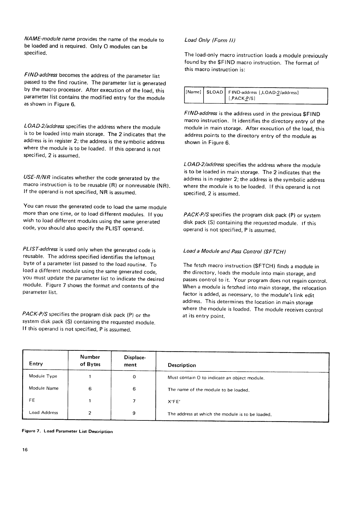
PLIST-address
is
used
only when the generated
code is
reusable.
The
address
specified
identifies
the leftmost
byte of a parameter
list passed
to the load
routine. To
load
a
different
module
using
the same
generated
code.
you must
update
the
parameter
list
to indicate
the
desired
module. Figure
7 shows
the format and
contents
of the
parameter
list.
PACK-P/S
specifies
the program
disk pack (p) or the
system
disk pack (S)
containing
the requested
module.
lf this
operand
is not specified,
P
is
assumed.
Load Only (Form ll)
The
load-only
macro
instruction
loads
a module
previously
found
by the
$FIND
macro
instruction.
The format
of
this
macro
instruction
is;
lName)
| $LOAD
I FIND-address
[,LOAD.2/address]
[,PACK-P/S]
FIND-address
is
the address
used
in the previous
$FIND
macro
instruction.
lt identif
ies the
directory
entry
of the
module
in main
storage.
After execution
of the load,
this
address
points
to the directory entry of the module as
shown
in Figure
6.
LOAD-2/address
specifies the address
where
the module
is
to be
loaded
in main storage.
The 2 indicates
that the
address
is in register
2; the address
is
the symbolic address
where
the module
is to be loaded.
lf this
operand is
not
specified,
2 is
assumed.
PACK-P/S specifies the program
disk pack (P)
or sysrem
disk
pack (S)
containing
the
requested
module. tf this
operand is
not specified, P
is
assumed.
Load a Module and Pass
Control ($FTCH)
The fetch
macro
instruction
(gFTCH)
finds
a module
in
the
directory,
loads
the
module
into main
storage,
and
passes
control to it. Your program
does not regain
control.
When
a module is fetched into main storage,
the relocation
factor
is
added,
as necessary,
to the module,s
link
edit
address.
This
determines
the location
in
main
storage
where
the module
is
loaded.
The module
receives
control
at its
entry
point.
Entry
Number
of Bytes
Displace-
ment Description
rvrooure
I
vpe
Module
Name
FE
Load
Address
I
o
1
0
o
9
Must
contain
O to indicate
an
object
module.
The
name
of the module
to be
loaded.
X'F E'
The address
at which the module
is to be
loaded.
FigweT. Load Parameter
List Description
16
lf you
will need
to use
the
data
in register
2
at a later
time,
you
should
save
the
contents
of that
register
before
issuing
the
$FTCH macro
instruction.
The
format
of
the
$FTCH
macro
instruction
is:
NAME-module name specif
ies
the object module to be
fetched into main storage.
The name
must be
rne same
as
the name
in the directory enrry.
PACK-P/S
specifies
the program
disk pack (p) or the
system
disk
pack
(S)
containing
the requested
module. lf
this operand
is
not specified,
p is
assumed.
Load a Module and Exchange Control ($XCTL)
This
macro
instruction
finds
a module
in
the
directory,
loads
the
module
into main
storage
at
the
address you
specify,
and
passes
control to it. Control is
not returned
to your program.
As
with the
$FTCH macro
instruction,
relocation
factors
are
resolved,
and
control is
passed
to
the entry point of the program.
The format
of the
$XCTL macro
instruction
is:
NAME-module name specifies
the name
of the module to
be loaded
and
given
control. The module must be
an O
module.
LOAD-2/address
specifies
the address
where
the module
is
to be
loaded
in main storage.
The 2 indicates
that the
address
is
in register
2; the address
is
the symbolic address
where
the
module
is
to be loaded.
lf this
operand
is
not
specified,
2 is
assumed.
PACK-P/S
specifies
the program
disk pack (p) or tne
system
disk
pack
(S)
containing
the reguested
module.
lf this operand
is
not specif
ied,
p is
assumed.
tNamel
| $XCTL I NAME-module
name[,LOAD_2/address]
t,PACK-P/Sl
Generate
a Translate
parameter List (gTRL)
This
macro
instruction
generates
a
parameter
list
neecied
by the
Model
15 Translate
routine. This
list
is
callecl
via
the
$TRAN macro
instruction.
gTRL does
nor
generate
executable
code. Figure
8 shows
the
format
of the
translate parameter
I
ist.
Translate Routine Operation
To use
the
Model
15
translate
routine, you must
provide
a
translate
area.
The format
of the
area
is:
Byte Field Description
0 Byte
contents
used
to determine
whether
a
character
is
to be
translated.
i Byte
contents
are
substituted
for
characters
that are not to be
translated.
2-257 256-byte
translate
table.
The
translate
routine processes
a
f
ield,
specif
ied
by the
$TRAN macro
instruction,
one
byte
at
a time.
The
translate
table
must
be
constructed
so that
the
disolace
ment
(from
the
beginning
of the
table)
of the
translated
representation
of a
character
is
equal
to the
hexadecimal
representation
of the untranslated
character. (For
example,
if
you
want
to translate
X,C1'to X,4
1,,
vou could
construct
a
translate
table
in
which
the
value
at
displace_
ment
X'Cf in
the
table
is
X,4i'.\
The
contents
of the
byte
at
a
given
displacement
are
com_
pared
with the
contents
of the
first
byte
in
the
translate
area
(byte
0). lf an
equal
compare
results,
the
cnaracter
is
considered
to be
invalid
and
the following
actions
are
performed:
The
completion
code
in tne
parameter
list
is
set
to indi-
cate
that
an
invalid
character
was
detected.
The
hexadecimal
value
in
the
second
byte
of the
trans_
Iate
area
(byte
1
) is
substituted
for the
original
cnaracter.
lf an
unequal
compare
results.
the hexadecimal
value in
the
translate
table
is
substituted
for the
original
character.
The
format
of the
$TRL macro
Instruction
is:
o
TO-address,FROM,address,LEN-number
TRT-address
Macro Instruction
Statements 1-t
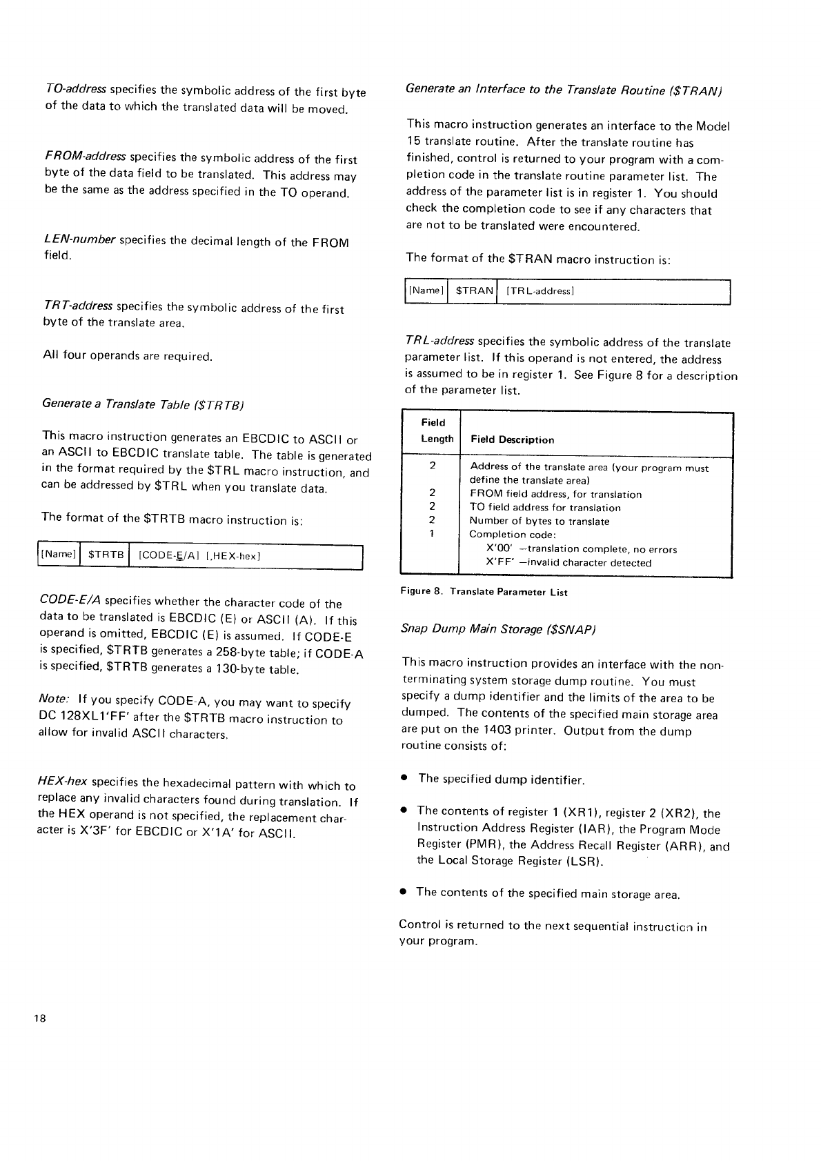
To-address
specifies
the symbolic address
of the first byte
of the
data
to which
the
translated
data
will be
moveo.
FROM-address
specifies
the symbolic address
of the first
byte
of the data
f
ield
to be
translated.
This
address
may
be
the
same
as the
address
specified
in
the
TO operand.
LEN-number specifies
the decimal
length
of the FROM
f ield.
TRT-address
specifies
the symbolic acldress
of the f
irst
byte
of the translate
area.
All four operands
are required.
Generate a Translate Table ($TRTB)
This
macro
instruction
generates
an EBCDIC
to ASCII
or
an
ASCII
to EBCDIC
translate
table. The
table
is
generated
in
the format
required
by the
$TRL macro
instruction,
and
can
be
addressed
by $-f
RL when you translate
data.
The format
of the
gTRTB macro
instruction
is:
INamel
I srnre I lcoDE.E/Al
I,HEX-hexl
CODE-E/A specifies
whether the character
code
of the
data
to be translated
is
EBCDIC
(E)
or ASCil (A). lf tfrls
operand
is
onritted,
EBCDIC
(E)
is
assumed.
lf CODE_E
is
specified,
$TRTB generates
a
258-byte
table;
if CODE-A
is
specified,
$TRTB generates
a 130-bvte
table.
Note: lf you specify
CODE A, you may want to specify
DC 128XL1'FF' after
the
$TRTB macro
instruction
to
allow
for invalid
ASCI I
characters"
HEX-hex specifies
the hexadecimal pattern
with which to
replace
any invalid
characters
found
during
translation.
lf
the
HEX operand
is
not specified,
the
replacement
char-
acter
is
X'3F'
for
EBCDIC
or X,1A,
for
ASCll.
Generate an lnterface to the Translate Routine ($TRAN)
This
macro instruction generates
an interface
to the Model
1
5 translate
routine. After the translate
routine
has
finished,
control
is returned
to your program
with a com-
pletion
code
in
the
translate
routine
parameter
list. Tlre
address
of the
parameter
list
is in register
1. You should
check
the completion code
to see
if any characters
that
are not to be
translated
were encountered-
The format
of the
$TRAN macro
instruction
is:
IName1|
$TRAN| [TRLaddressl
TR
L-address
specif
ies
the symbolic address
of the translate
parameter
list. lf this
operand is
not entered.
the
address
is
assumed
to be
in register
1. See
Figure
8 for a description
of the
parameter
list.
Snap
Dump Main Storage ($SNAP)
This
macro
instruction provides
an interface
with the
non-
terminating
system
storage
dump routine. you must
specify
a dump identifier
and the
limits
of the area
to be
dumped. The
contents
of the
specified
main
storage
area
are
put on
the 1403
printer. Output
from the
dump
routine
consists
of:
The
specified
dump identifier.
The
contents
of register
1 (XR
1), register
2 (XR2),
the
Instruction
Address
Register
(lAR), the
program
Mode
Register
(PMR),
the
Address
Recall
Register
(ARR),
and
the Local
Storage
Register
(LSR).
The
contents
of the
specif ied
main
storage
area.
Control is
returned
to the next
seqltential
instructicr-r
irr
your program.
Field
Length Field Description
2
2
z
1
Address
of the translate
area
(your
program
must
define
the translate
area)
FROM field address, for translation
TO f
ield
address for translation
Number
of bvtes
to translare
Completion
code:
X'00' -translation complete,
no errors
X'FF' -invalid character
detected
Figure
8. Translate
Parameter
List
18
-l-he
forrnat
of ttre
$SFJAP
rrr.r(:ro
irrstrrtctiorr
is:
r--.-T------l_*.-'
|[Name] | $SNAP I lD-ir''y,SIARl-actrlress,ENll-address
r.__.__-t__._
_ t _
lD-hex
specif ies
a 2.lry.re
hexa<jecirnal
rrurrrber
to be used
as the durnp
identif
ier.
START-address
specifies
tlre
symbolic u,ldr.r, of the low-
storage limit of the
area to lle
dunrped.
END-address
specifies
tlre
synrbolic
address
of the high-
storage
limit of the
area
to be
durnped.
All three
opet"ancls
are
requirecl.
Obtain Sysfern Date (tDAT E,)
This
macro instruction generates
the
code
necessary
to
retrieve
the
systern
date
and
place
it at
a specified
location
in
your proqram.
lf you will need
to use
the data irr
register
2 at
a
later
irme,
you should
save the
contents
of tllat register
bef
ore
issuing
the
$DAl-E macro
instruction"
'Ihe
format
of the
$DATE macru,
instruction
rs:
llNameJ | $DATE
| [LABEL.aooress] --_-l
___ _l_
_-_.___ _ _..".-,
_'_ I
LABEL.-address
irrdicates
tlre
arlrjrqss
of tirr:
leltrrro5t
byte
of a six-byte
area
in
which yor_r
want
the
systerrt
date
placed.
lf lfris
r,:[rerand
is rlr:t
sper:if
ierl,
ilre
arlr]ress
ar
whiclr
you want the rJate
to be
placerl
is
assrrrrrerl
to be- in
register
2.
Generate Tirner IQB (ST'l{JU)
-l
lris rnacro
instructiot't
generates
an lQU l(Jr
the tnterval
tinter.
$l IOB
rrrust
be usecl
il you
trse
$Sll. $[]lT, or
$TOD in
your program.
The for
rnat
o{ tl,c ti,rr1'r
IOB
is
showrr in Appenclix C: lnputiAutpui Bltscks.
The format
of the
$TIOB macro
instrrtction
is:
1lru",,-'ul lslor I lonrr
vlnrl
L - " t__. __l-- -,
DATE-Y/N specifies
whether
a date f
ield
is ro l;e
gcnerated
lf this operand is not entered.
N (no)
is assurnecl. lf the
$TOD macro
instruction
is used
in your prograrn,
Y (yes)
must
be entered.
lf DATE-Y is
specified. use of the
$SlT
macro
instruction
destroVs
the
date
in the timer lOB.
Set lnterval Timer ($SlT)
This macro
instruction
sets the interval
tinter to cause
a
timer interrupt
after the specified
amount
of tinre has
elapsed.
Before
issuing
this
macro
instruction
you rnust
place
the desired
interval in bytes 2-7 of the tirner lOB.
When
the interval is
set, byte
8 in the
timer IOB is
set to
X'00'. When
the interval is
expired,
byte
8 is
ser to X'40'.
The
format
of the
$SlT macro
instruction
is:
tNamei
| $SlTl
trOB
namel
[,TypE-DgJ/BtN/rL,iToD]
[,ITYP
E.R
EA
UWA IT/TASK
]
IOB-narne specifies the name of the tirner IOB
qeneratcrl
by
the
$TIOB
macro
instructiorr. lf tlris operand
is ornitted,
the
address of the IOB is
assr-imed to be irr re-qister
2.
TYPE-DEC/BlN/TU/TOD specif ies thr:
format of the time
interval
in the lOB. You nrust establish
the tirne interval
irr bytes 2-7 of the IOB before issuing
the
$Sll' ;iracro
rrr
struction. The valid
time interval
fclrrnats
are:
o DEC: Tlre
time interval is the
amount
of
tirne in decimal
that is
to elapse
Lrefore tire tirner interrupt. -Ihe
tirne
interval
is a six-byte decirnal nurnber
sperr,;ifyin.q1 hours,
minLrtes,
and seconds
(HHMMSS).
o BIN: The
tirne interval is
a 32-bit binary rrurnber
speci-
fying
the number
of seconds that
are to elapsr:
before the
tinrer interrupt. The binary valr-re
rnust
be riqfrt-justified
in bytes 4-7 of the
IOB field.
r TU: The tirne
interval
is a 32-bit binary
nunrber
speci-
fying
the number
of timer units
that are to r:lapse
before
the
tirner interrupt. One
tirner
unit is 3.33 nrilliseconds.
The binary
value must
be right-justified
in bytes 4.7
of
the
IOB field.
c TOD: l-he
time interval
is the actual tirne
of day when
tlre
tirnr:r interrupt
is to occur. The
tinre is
a
six-byte
rler:inral
number
specifying
the
hour, minutr:
arrd second
(HHMMSS).
It
this operand
is omitted, DEC
is assunred.
Macro Inslructicln
Slalements 19
o
ITYPE-REALMAIT/TASK
specifies
the type of interval
to
be timed.
The types
of time
intervals
are:
REAL: The
timer decrements
the
time
interval
continu_
ously
for
all types
of
processing.
WAIT: The
program
issuing
the
gSlT
macro
instruction
is
placed
in
a
wait
state
for
the
specified
time intervat.
When
the
time
has
expired,
control
returns
to
the instruc_
tion
following
the
$SlT
macro
instruction.
o TASK: The
timer
decrements
the
time
interval
only
while
the
task
issuing
the
$SlT
macro
instruction
is run_
ning.
lf this operand
is omitted,
REAL
is
assumed.
Return Time
and Date ($TOD)
This
macro
instruction
returns
the
time
of day
and the
system date
to the
program.
The
time
of day
is returned
in
bytes
2-7 of
the timer lOB,
the
system
date
in the
next
six
bytes.
DATE-Y
must
be specified
in
the
$TIOB
macro
instruction
if
the
$TOD
macro
instruction
is used.
The
format
of
the
$TOD
macro
instruction
is:
NameJ
I $TODI
tIOB-name]
[,REF.Y/NI
t,TYPE.DEC/BIN/TU
IOB-name
specifies
the name
of the timer IOB
generated
by the
$TIOB macro
instructir-rn.
lf this
operand
is omitted.
the address of the IOB is
assumed
to be in register
2.
REF-Y/N specifies
whether
the
macro
instruction
is being
issued from the transient
area
or a
program
partition. y
(yes)
indicates
the
macro
instruction
is
issued
bV
a transient
that must
be refreshed;N
(no)
indicates
it is
issued from a
program
partition. lf this
operand
is omitted,
N (no)
is
assu meo.
TYPE-DEC/BlN/TU specifies
how the time is
to be returned
in
the
timer lOB. The
valid
formats
are:
DEC: The
time
returned
is
a six-byte
decimal
number
indicating
the
time in hours,
minutes
and
seconds
(HHMMSS).
BIN: The
time
returned
is a
32-bit
binary number
indi-
cating
the time in
seconds.
The
bir.rary
number
is right-
justif
ied
in bytes
4-7
of the IOB
f
reld.
. TU: The
time
returned
is a 32-bit
bir-rary number
indicat-
ing
tlre
time
in timer
units.
One timer
unit is
3.33
milli-
seconds.
The
binary number
is right-justif
ied
in bvtes
4-7 of the IOB f
ield.
lf this
operand
is omitted.
DEC is
assumed.
Return lnterval Time ($RlT)
This macro
instruction
returns
the remairring
amount
of
time in
a time
interval
or cancels
an unexpired
time interval.
The remaining
time is returned
in bytes
2-7 of the
timer
IOB
established
by the
$TIOB macro
instruction.
The
time
interval
must have
been set
by the
$SlT macro
instruction
and
is
returned
in
the
format
specified in
that macro
instruc-
tion.
The
format
of the
$R
lT macro
instruction
is:
tNamel
| $RlT I llOB-namel LCANCEL-Y/Nl
IOB-name
specif ies the name
of the
timer IOB
generated
by
the
$TIOB macro
instruction.
lf this
operand
is omitted,
the
address of the IOB
is assumed
to be in reqister
2.
CANCEL-Y/N specifies
whether
the remaining
time in the
interval
is to be
cancelled.
lf this operand
is
omitted,
N (no)
is
assurned.
End-of-Job ($EOJ)
The
$EOJ
macro instruction
generates
the linkage
required
to execute
the end
of job routine. The
option
to perform
an rmmediate
cancel
or a controlled
cancel is
provided.
The format
of the
$EOJ macro instruction
is:
IName]I
$EOJ I [CANCEL-NORMALiIMMED/CoNTRL]
20
C A N
C E L N 9 frAAlL I M M E
D/C
O/VfFL specif ies
the
action
that the
system
should
take
as
it terminates
tne
program.
lf this
operand is
omittecl
or if NORMAL is
specified
arrd
the
system is in l-IALT
mocle,
an enti
of job
step message
is
issued
and
job processing
terminates
in the
partition;
if NOHALT mode is in
effect,
no
message
is
issued
and
job processing
continues.
lf IMMED is
specifieci,
the
disposition
of files
depencls
uporr
the function
being
perforrnecl
:
Ner,v {iles
being
created
will not be retained
Old
files
beinq
deleted
will
be retained
Old
files
being
added to will
not reflect
the addirrons
Old
f iles
being
updated
will ref lect
the updates
made
prior
to
the
point
at which
this
$EOj macro
instruction
was
executed
| . ROO f iles
(except
for consecutive)
will ref
lect
additions
I
I if file
sharing
(5704-SC2
only).
lf CONTRL is
specified,
the l'iles
being used
by your pro-
gram
reflect
all
activity
which
took place
up
to the
point
the
$EOJ
macro
instruction
was
executed.
Page
of G
C21
-7608-2
lssued
29 September
1978
By TNL: cN21-5649
lf
your
program
specifies CANCEL-IMMED
or CANCEL
CONTRL and it is
a step of a
job or a
procedure
in
a
chained
procedure,
all remaining
steps in the
job
or all
remaining
procedures
in
the
chained
procedure
are cancelled
Also,
EJ
or ES
is displayed
regardless
of the
status of the
system halt mode,
and
job processing
in
that partition
te rm i nates.
lf either
CANCEL-IMMED or CANCEL CONTR
L is speci-
f
ied, the input
stream is
flushed
in
the
following
manner:
lf you are executing in
job mode on
a system on
which
input
spooling is
active,
job processing
in
the partition
resumes
with the
next
job on the iob
input
queue.
lf you are
executing in
job mode
on a system on
which
input
spooling
is not active, the
job stream in the system
reader
is
flushed
until a
JOB
statement or a slash
oeriod
(/.)
statement is encountered.
lf you are
executing in step mode,
the input
stream
will
be
flushed
until a JOB, LOAD, CALL, slash
period
(/.)
or slash
ampersand
(/&) statement is encountered.
Macro I r'rstruction
Statements
General SCP Support 21
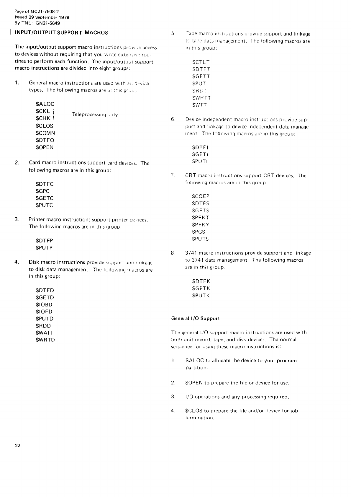
Pase
of GC21
-76O8-2
lssued
29 September 1978
By TNL: cN21-5649
INPUT/OUTPUT
SUPPORT
MACROS
The
input/output
support
macro instructrons
prov:d,t
access
to devices
without requiring
that
you wriie extcr:sr;r
rou-
tines
to perform
each function. The
input.toutput
slrpport
macro instructions
are divided into eight
groups.
1. General macro
instructions
are usctj wilh c;.
.tr-r!UU
types.
The
following
macros
rrc ,r :r::j
vl .
$ALOC
$cKL
I
$CHK
}
$CLOS
$COMN
$DTFO
$OPEN
Teleprocessrng
oniy
2. Card
macro instructions
support
card
devtces.
The
following
macros
are in
this
group.
$DTFC
$GPC
$GETC
$PUTC
3. Printer
macro instructions
suppcrt
prrnter
urcces.
The following macros
are in
thrs
qrouFr.
$DTFP
$PUTP
4. Disk macro
instructions
provide
!J.iiiJrt
airc :rrrkage
to disk data management. The tc'tiowtilg t-licjLrcs
are
in
this
group:
5 -lape
macrl
i{)sttucirols
provirtc
sutrport
and linkage
ir iape rjat: rnailagenrent.
Tfis foilorvrng
macros
are
in
this
g!.ot.tp.
SCTL
T
$D]
FT
$GETT
$PUTT
$\ruBT
T
$WTT
6 Devtce
inclcprg166n1 macto instructrons
provide
sup-
iiL)rt
and Iirrkage
to devrce
rndependent
data manage-
i:rerit
The
io;lowing
rnacros
are in this
group:
$DTF
I
SGETI
$PUTI
'l CRT
rnacro
instructions
supoort CRT devices.
The
':.jiiowlrg nraL'ros
are In this qroull:
$COEP
SDTF
S
SPF
KT
$PF
KY
SPGS
qpt rT(
8 374
i rnacro
instructrons
provide
support
and
linkage
ro 374
1 data
rranagement. fhe following
macros
are
iir
this
gro!rp,
$DTFK.
$GEI
K
$PUTK
General l/O Support
ifre qe:reral
liO support
macro instructions are used with
bcth unit record,
tape. ar-rd disk
devices. The normal
sc(lucrrcc
tor .rsirrg
tr;cse
mdcro
rnstr
Lrctions is:
$ALOC to allocate
the device to your program
oartitton.
$OPEN
to rrreDare
the
file
or device for use
liO operatiorrs and any
processing
required.
$CLOS
to prepare
the
file
and/or device
for iob
termrnatron.
$DTFD
$GETD
$IOBD
$IOED
$PUTD
$RDD
$WAIT
$WRTD
22
Allocate Space (gAtOC)
The
routines
called
by the
$ALOC macro
instruction
allo-
cate
unit record
input/output devices
and space
on disk and
tape
devices.
These
routines
check
to ensure
that:
o The system
supports
the requested
device.
o The device
requested
is
available
to the requesting
program.
o The LOCATION parameter
of the
OCL file
statement
is
valid.
o The
correct
disk
pack
is
mounted
and
space
is
available
to the
calling
llrogram.
o The number
of disk, tape,
and device
independent
DTFs
in
the
calling
program
is
limited
as follows:
- 5704-SC1-The
timit
is
40.
- 5704-SC2-The
limit is
192
with at teast
a 10K
partition. The
limit is
129
with only an
gK
pa
rt
ition.
For
5704-SC2,
not all
192
disk
and
tape
DTFs
may
be
allocated
in
a single
call
to allocate.
The
maximum
number
of tape
and/or
disk DTFs in a single
chain
is
as
follows:
- lf
all
are disk,
the
maximum
is
16b.
- lf all
are
tape,
the maximum
is
14g.
- For combinations
of disk
and
tape,
the maximum
varies
between
148
and
165. To
determine
whether
or not
the DTFs
can
be
allocated
in
a
single
call
to
allocate,
multiply
the number
of disk
DTFs
by 17
and multiply the number
of tape DTFs by 19. lf
the sum of the above
two numbers
is not greater
than 2816,
the DTFs may be
allocated
in a single
call.
lf the DTFs
cannot
all
be
allocated
in
a single
call,
make
two DTF chains
and
two calls
to allocate.
An allocate
request
requires
that pre-operr
DTFs
be sup_
plied
as input
to tlre routine. For
a cjescriptiorr
of DTFs.
see Def ine the File for Card ($DTFC), Def ine the File for
Disk ($DTFD), Define the File for Device lndependent
($DTFI), Define the Fite for printer ($DTf il. Define the
File for CBT ($DTFS), Define the Fite for Tape ($DTFT),
and Define the File for 3741 ($DTFK). When the allocate
request
is
for a disk,
a tape
device.
or a device
independent
file,
OCL file
statements
are
also required.
More
than
one
DTF can
be
allocated
at one
time
by chaining
the DTFs.
To chain DTFs, you must enter
the address
of the next
DTF in
the DTF you are
building.
The
last
DTF in
a chain
has
X'FFFF' entered
in
place
of the
address.
lf your
program
operates
as an interrupt handler,
such
as a binary
syncnronous
communications
program,
all
DTFs
in
the
program
should
be
chained
together
and allocated
in one
operation. When
an
error
condition occurs,
the allocate
routine
calls
halt/syslog
to display
the
proper
halt
code.
Note
that if you will need
to use
the data
in
register
2 at
a
later
time, you should
save
the contents
of that register
before
issuing
the $ALOC macro
instruction.
The
following
output is
produced
when
control
is
returned
to your program.
a The contents
of register
1 are
restored.
. The
format-1
labels
and
configuration
recoro
are up-
dated.
o For
a non-disk
or non-tape
DTF.
bit 1 in
the rightmost
byte of the attribute bytes
of the post-open
DTF is
set
on
to indicate
device
allocation.
o For
a
device
independent
DTF,
the
device
code
(dis-
placement
0 in
the
DTF - $DFDEV) is
altered
to
indicate
the
appropriate
device.
. The address
of the f
irst DTF allocated
is returned
in
register
2.
Note: ll you are using
telecommunications,
$ALOC must
not be
issued
while
a telecommunications
operation
is
in
process.
o The correct tape input f
ile is
mounted. or the tape label
is
written on the output file, and
that the tape is
posi_
tioned
at
the
beginning
of the
file.
l\,1,rcrtr
lr-rstiur:rr.n
Statements 23
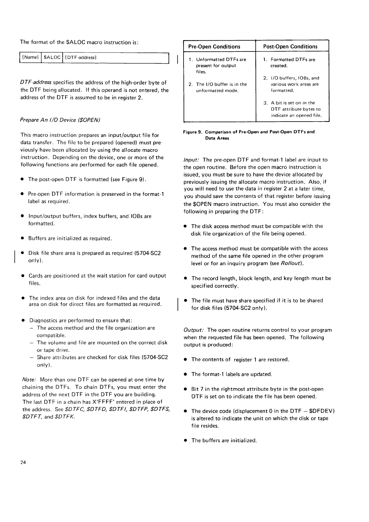
The format
of the
$ALOC
macro
instruction
is:
lNamel
l$ALoC I
IDTF-aodressl
DTF-address
specifies
the address of the high-order
byte of
the DTF being allocated. lf this operand is not entered, the
address of the DTF is
assumed to be in register
2.
Prepare An l/O Device ($OPEN)
This
macro instruction
prepares
an
input/output file for
data
transfer.
The file
to be
prepared
(opened)
must
pre-
viously have
been
allocated by using
the allocate macro
instruction. Depending
on the device,
one or more of the
following functions
are
performed
for each
f
ile opened.
o The
post-open
DTF is
formatted
(see
Figure
9).
o Pre-open
DTF information is
preserved
in
the
format-1
label
as reouired.
. Input/output
buffers, index buffers,
and
lOBs
are
formatted.
. Buffers
are initialized as reouired.
o Disk f ile
share area
is
prepared
as
required
(5704-SC2
only).
. Cards are
positioned
at the
wait station
for card
output
fi
les.
o The index
area
on disk for indexed
files
and the
data
area on disk
for direct
f
iles
are
formatted
as
required.
o Diagnostics
are
performed
to ensure
that:
- The
access
method
and the
f
ile organization
are
compatible.
- The
volume and
file
are
mounted
on
the
correct disk
or tape drive.
- Share attributes are checked
for disk
files
(5704-SC2
onlY).
/r/ote.'
More
than one DTF can be opened
at one time by
chaining the DTFs. To chain
DTFs,
you must enter
the
address of the
next DTF in
the DTF you are
building.
The last
DTF in
a
chain has X'FFFF'entered in
place
of
the address. See
$DTFC. $DTFD, $DTFl, $DTFP, $DTFS,
$DTFT. and
$DTFK.
Pre-Open
Conditions Post-Open
Conditions
1. Un{ormatted
DTFs
are
present
for output
files.
2. The l/O buffer is
in
the
unformatted
mode.
1. Formatted
DTFs
are
created.
2. l/O buffers,
lOBs,
and
various work areas are
f
ormatted.
A bit is
set
on in the
DTF attribute bytes
to
indicate
an opened
file
Figure
9. Comparison of Pre-Open and
Post-Open DTFs
and
Data
Areas
lnput: The pre-open
DTF and format-1 label
are
input to
the open
routine. Before
the open
macro instruction is
issued,
you must be sure to have the device allocated by
previously
issuing
the allocate
macro instruction. Also, if
you will need to use the data in register
2 at a later
time,
you should
save the contents of that register
before issuing
the
$OPEN
macro instruction.
You must
also consider
the
following
in
preparing
the DTF:
o The disk access
method must be
compatible
with the
disk
file
organization of the
file
being opened.
o The access
method must be
compatible
with the access
method of the same
file opened
in the other program
level
or for an inquiry program lsee
Rolloutl.
o The record
length,
block length. and key length must be
specified correctly.
o The file must have
share specified
if it isto be
shared
for disk files
(5704-SC2
only).
Output: The open routine returns
control to your program
when the requested file has
been
opened. The following
output is
produced:
o The contents of register 1 are
restored.
o The format-1 labels
are
updated.
o Bit 7 in the rightmost
attribute byte in the post-open
DTF is set on to indicate the
file
has
been
opened.
. The device code
(displacement
0 in
the DTF - $DFDEV)
is
altered to indicate
the
unit on
which
the
disk
or tape
file resides.
o The buffers are initialized.
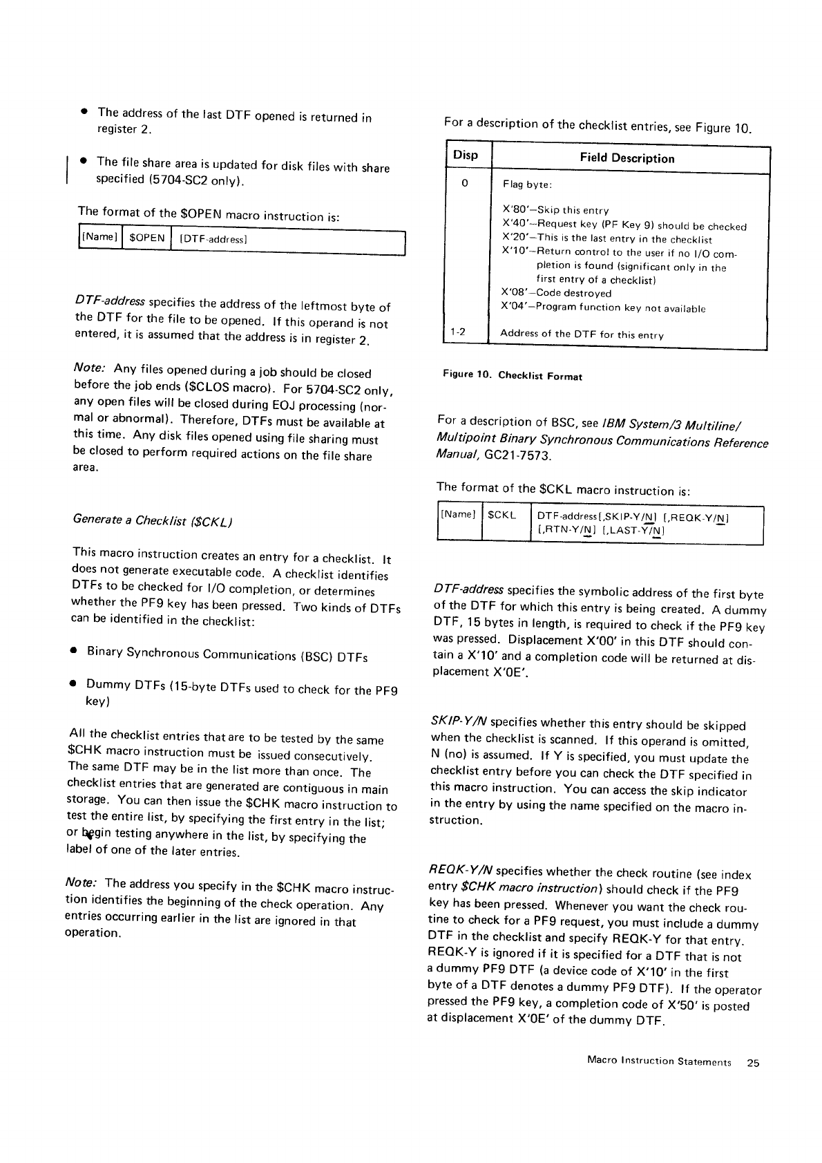
The
format
of
the
$OpEN macro
instruction
is:
l'
The address
of the last
DTF opened
is
returned
in
register
2.
The file share
area
is
updated
for disk
files
with share
specified
(5704-SC2
onty).
For
a description
of
the
checklist
entries,
see Figure
10.
Disp Field
Description
0
t-z
Flag
byte:
X'80'-Skip this
entry
X'40'-Request
key
(pF
Key
9) should
be
checked
X'2O'-This
is
the last
entry
in
the
checklist
X'10'*Return control
to the
user if
no l/O
com_
pletion
is found
(significant
only
in
the
first entry of a checklist)
X'08'-Code destroyed
X'04'-Program f
unction key not available
Address
of the DTF for this
entry
Figure
1O. Checklist
Format
For
a
description
of BSC,
see
lgM System/3
Muttiline/
Multipoint Binary synchronous communications Reference
Manual,
GC21-7573.
The
format
of the
gCKL
macro
instruction
is:
tNamel
| $cKL I orr aooress[,sKtp-y/Nl
t,REoK_yA]
t,RTN.Y/N] I,LAST-Y/N]
DTF-address
specifies
the symbolic address
of the first byte
of the DTF for which
this entry
is
being
created.
A dummy
DTF, 15
bytes
in length,
is
required
to check
if the
pFg key
was
pressed.
Displacement
X,00. in this DTF should
con_
tain
a X'10'and a completion
code
will be
returned
at dis_
placement
X'0E'.
SKIP-Y/N specifies
whether this entry should be
skipped
when the checklist
is
scanned. lf this operand
is
omitted,
N (no) is
assumed.
lf Y is
specified, you must update
the
checklist
entry before
you can
check
the DTF specified
in
this macro instruction. you can
access
the skip indicator
in the entry by using
the name
specified
on the macro in_
Struction.
REOK-Y/N specifies
whether the check
routine (see
index
entry $CHK macro instruction) should check if the pF9
key has
been
pressed.
Whenever
you want the check
rou_
tine to check for a PF9 request, you must include
a dummy
DTF in the checklist
and specify REOK-Y for that entry.
REOK-Y is
ignored
if it is
specified
for a DTF that is
not
a
dummy PF9
DTF (a
device
code
of X,10,
in
the first
byte
of a DTF denotes
a dummy pFg DTF). lf tne
operator
pressed
the PFg key, a
completion code
of X,SO,
is
posted
at displacement
X'0E' of the
dummy DTF.
DTF-address specifies
the address
of the leftmost byte of
the DTF for the
file
to be
opened. lf this
operand
is
not
entered.
it is assumed
that the address
is
in register
2.
Note: Any files
opened
during a
job should
be ctosed
before
the job ends
($CLOS
macro). For 5704-SC2
onty,
any open files
will be
closed
during EOJ
processing
(nor_
mal or abnormal). Therefore.
DTFs must be
available
at
this
time. Any disk
files
opened
using
file
sharing
must
be
closed
to perform required
actions
on the file share
area.
Generate a Checklist ($CKL)
This
macro instruction
creates
an
entry for a checklist. lt
does
not generate
executable
code. A checklist
identifies
DTFs to be
checked
for llO completion, or determines
whether
the PF9 key has
been
pressed.
Two kinds of DTFs
can
be identified
in
the
checklist:
. Binary
Synchronous
Communications
(BSC)
DTFs
o Dummy DTFs
(1b-byte
DTFs
used
to check
for the
pFg
kev)
All the checklist
entries
thatare to be
tested
by tne same
$CHK macro
instruction
must
be issued
consecutively.
The same
DTF may be in the list more
than once. The
checklist
entries
that are
generated
are
contiguous
in main
storage. You can
then issue
the $CHK macro
instruction
to
test
the entire list,
by specifying
the first entry in the list;
or $gin testing
anywhere
in the list,
by specifying
the
label
of one of the later
entries.
Note: The address
you specify
in the $cHK macro instruc-
tion identifies
the beginning
of the check
operation. Any
entries
occurring
earlier
in the list are
ignored
in that
operation.
Macro
Instruction
Statements 25
RTN-Y/N
specif
ies whether
you
want
control
returned
to
your program
even
if no
l/O operation is
complete.
This
operand is
valid only
for
the
first
entry in the check list. lf
this
operand
is not
entered, N (no)
is assumed.
LAST-Y/N specifies
whether
this
is
the
last errtry in the
checklist. LAST-Y
(yes)
must be specified
for
the
last
entry. lf this operand is omitted,
N (no)
is
assumed.
Check for l/O Completion ($CHK)
This macro
instruction
generates
the linkage required to use
the
check routine.
You
must issue the
$CHK
macro instruc-
tion
for each BSC
get, put,
read, write. or online
test
request. For
a
description of BSC macro instructions, see
I
BM System/3
Multiline/Multipoint Binary Synchronous
Co
m m un ications R
eference
M an ua
I, GC21
-7
57
3.
lf you
will need
to use
the
data in
register
2 at a
later time,
you
should save
the
contents
of that
register before
issuing
the
$CHK
macro instruction.
Check R outine Operation
lVofe.' When using this macro, the
user
program
must
equate
$PARM
to 2.
The
check
routine
tests
for completion of an
l/O operation
by
examining the
DTFs identified
in
the
cheiklist
- see
Generate a Checklist
($CKL). lf an l/O operation
is com-
plete,
the completion
code is set
in
the
DTF, and the
ad'
dress of the DTF
is returned
in register
2 to the calling
program.
No
subsequent
DTFs
in the list are tested.
When
no l/O completion
is found by the
end of the check-
list, control
is returned to your
program
with the address
of the
last DTF
in
the
list register 2 if
:
Each entry
in the
list is inactive,
closed,
or has the skip
indicator on (a
completion
code of X'57').
RTN-Y was specified
in the
$CKL
macro
instruction
that
created the
f irst entry
in
the
checklist
(a
comple-
tion code of X'56').
The
format of the
$CHK
macro
instruction is:
lNameJ l$cgr | [cKL-address]
CKL-address specif
ies the symbolic address
of the f irst entry
in
the checklist.
You can
also begin at a subsequent
point
in
the checklist
by specifying the symbolic
address of a
later entry. lf this operand
is omitted, the address
is
assumed
to be in register 2.
Note: fhe address
you specify
identifies the beginning
of
the check
operation. Any entries
occurring
earlier in the
list
are
ignored in that operation.
Prepare a Device for Termination ($CLOS)
The close
macro instruction
prepares
a
device
for job
termi-
nation. The routine
returns
post-open
DTFs
to their
pre-
open
state and
updates
file labels to reflect the current
file
status.
For devices other
than
disk or tape,
only the
entries
related
to the
requested
functions
are
restored. lf you will
need
to use the data
in register 2 at a
later
time,
you
should save
the contents
of that
register before
issuing the
$CLOS
macro instruction.
lnput to the close
routine consists
of the
post-open
DTF
and
the
format-1
labels. The allocate
and open
macro
in-
structions
must
have
previously
been
issued.
Output created by $CLOS is returned
to your program
when control
is
returned. The
output
consists
of
:
o The contents
of register 1 restored.
o The
post-open
DTFs
reinitialized
to the pre-open
state'
o Any pending
operations
for unit record devices
oerf ormed.
o The
format-'l label
for disk updated
to indicate
current
file status.
o The buffer contents
scheduled
for disk or tape
output
and
disk
update operations
written.
o The data
and
index
written to disk,
and an
indicator set
if key sorting
is required
at
end-of-job
for output
f iles
and
file
additions.
o Tape
trailer labels read
or written.
I o The f ile share area
is cleared
or updated
for the disk
I file specified
as share.
Note; More
than one
DTF can
be
cioseti.it
iine
tln{_, liy
chaining
the DTFs To chair DTFs,
eaci. DTF lL,, rre {j:olpc
must
contain
the
address
of the
nex.t
pJF: ir t!.ti.
cl-iarrr
The
last
DTF in
a chain has
X'FFFF'entere(i
rrr
llaco
of if:ir
add ress.
The format
of the
$CLOS
macro
insti-irctiL)n
is.
DTF-address specifies
th+ ad<lr.ess
of 1,:,
r.:
,1,11.)!r
j.),/,i.:.j.
the DTF to be closc,d. lf this <lperanr
j 1.:
,.;rr
{)!-r.t::r1,ij.
tiil
address
is
assumed
to be in Iegrst.r 2.
Generate DTF Offsets l$DTFO)
This macro
defines
the DTF labeis.
<;fi:iri: tieri.i
{r.,!rllrt:.
and field lengths
for all devices
a,rd
accr:;s
rrr,lirl_11;,r
!irfri,lJr.i
ed for the Model 15. To avoicl
ciuplrcati:
t31r,,i...
t,,; rnar.i.;.
Instruction should be r:sen'
O|rly
oncc r!r
riar.i-
i.rr.,,tr.]in:
1r,i)i,,
should also
set
the operands
to inclrcate
,l;:.7
!1,-:vri.i,s
y,^r;
plan to use
in the proqram.
The format of the $DTFO m.rcro irsi:!jc:r.
^ rs,
TDISK-YiN]
[,TAPE
Y,UJ
I,INI),Y;\]
IMFCUYIJ
:.|\1Ff'.
\ ;rl 1:,
[,D25O1
Y{\1] f .o:az+2 "N j :.ij1.113
y
t,D3284-Y{!i l,cnr v'\r l.aLL'v,\ri
i.F lt:
i-
D.
V 'tr't
i
Pase
of GC21
-7608-2
lssued
29
September
1978
By TNL: GN21-5649
MFCM Y l'l,
specif ies whether labels
are to be
generated
for
the MFCM. lf this
operand is not
specified, N (no)
is
assumed.
D374'! 't','AJ
specif
ies whether labels
are to be
generated
for
the
3741. lf this operand
is not specified,
N(no) is
assumed.
D25Oi '-"
,'1i
5psci{ies whether labels
are
to be
generated
for
the 250
I rr
tils ope.and is not entered, N (no)
is assumed.
D1442 Y'{ specif ies whether
labels
are to be
generated
for
the 1442 it this
operand ts not entered, N (no)
is
assumed.
D140..1
i '\,
.nscii:r'r
whether labels
are to be
generated
for
the l40lj !f this
operand is not entered, N (no)
is
assumed.
D3284 " t. snecrfies whether labels
are to be
generated
for
the 32E.1 ii ihis
operand
is
not entered,
N (no)
is
assumed.
CBT-Y rii
rrreci{ies
v;hether
labels
are
to be
generatecl
for
the C,?l- ;i this
operand is not entered,
N (no)
is
assumed.
AL L
'Y i.!'r
sDecif
;es
whether labels
are
to be
generated
for all
devices
sr.;;rnorted- lf this operand
is not
entered, N (no)
is
assumerl
FIELD .'' ,V
specrfies
whether
to generate
the labeis
which
def inc
1r"r' rrorrtenit
ior a
DTF field. lf this operand
is not
specifir',:
":'iyesl
't assumed.
COM
M
C
lV E,r Ltares
i
$COM
N
)
ihis q..i,,'
.r
.:rstiucl
i.rn
qenerates
eguates
for various
labels
dnci
v;i!.,'.,..
ruch
as
rr:)iJlster
equates,
which may be used in
the
pr
oi;r am. Th
is
macro
rnstruction
is not required.
The form;,ri
of the
SCOMN
macro instruction
is:
I .. ,^a^
DISK Y/N specif
ies
whr:ther
i;f;slr,
3,,'
11.
1;,
disk
devices.
lf this
operand is
noi enie'
irlr
assumed.
TAPE Y/N specif ies
whr:ther
labe!s
irrr,
i, .ri
tape device.
lt thrs
oftcraltd i-s
nc1
(;r'i
f
pf
.).1
assumed.
il.-:rlei:lti ir 1
4,,1t-lrl"r
, 1;i,':
,'
r ilr I I
i;: a
l! ii'.t ,i
IND YlN specif
ies wlretht:r
laheis
a", r
independent
device.
ll rhi5 r1;;19r;yr,l
iq
rs
assumed.
MFCU Y/N specif ies
whetlter labels
ar,.
:.) t)r'itrri,errT;.(,r rcl
the MFCU. lf this ctperarrd
is not entf re(i f..i
(,ro) is
assu,lecl
Macro I nstruction
StatemL.nts
General
l/O Support
Pase
of GC21
-7608-2
lssued
29
September
lgTg
By
TNL: cN21-5649
Card
Device
Support
This
section
describes
the
macro instructions
that support
card
devices.
The following
functions
are
providecl
:
Build
a
pre-open
DTF for card
device
and assiqn
its
off.
sets.
o Build
the interface
required
to read/punch/prrnt
records
using
a
card device.
The DTF provides
information
to the
card
tlevice
data man
agement routines
that perform
input/output
operartons.
Def ine the File for Card ($DTFC)
The DTF provides
information
needed
to allocate,
open,
and access
a
card
device. This macro instruction
qenerates
the code
that
builds
a card DTF.
The
format
of the
$DTFC macro
instruction
is:
IOBA-address
is
a
required
operand
specifying
the
address
of
the leftmost
byte
of the first
lOB.
The
area identified
by
this
operand must
be large
enough
to contain
one IOB
for
single
buffering
or
two lOBs
for
double
buffering
(specified
via the
operand
NIOB
2). The
sizes for
each
card
IOB
are:
2501
- 25 bytes
MFCU
- 29 bytes
1442
- 29
bytes
MFCM
- 31
bytes
NIOB-number
is
a requireti
clperand
specifying
the number
of lOBs
associated
with this DTF. This
entrv
must have
a
value c-if
1
or 2.
DEVcode specifies
the card
device
desirecl.
I'he
possible
values
for
code
are MFCUl, MFCU2,
MFCM1,
MFCM2,
1442,
and
2501. lf this
operand
is
omitted.
MFCUl is
assu med.
UP-tnask
specif ies
the nrask
to test the eight externai
indicators.
The
code for the UP-mask
must
be specified
as 8 binary
bits. For
example,
to test
bits
0,3, 5, and 7,
you
would
enter
UP-10010101.
The
UP-mask
is
compared
to the
external
indicators
set
on by the
SWITCH
statement
for conditionally
opening
files. lf the bits
that are
on in
the
UP-mask
are also
on in the
external indicators
set
on by the
SWITCH
statement.
the f
ile will be
opened. lf the Up-mask
is
all
zeroes
or not used,
the file
will be unconditionallv
opened.
Note: lnf
ormation
on settirrg
external
indicators
(SWITCH
statement)
can be found in the IBM System/3
Modet lS
System Control Programming Reference Manual (for
Program
Number
5704-SC1),
GC21-5077,
and in the
IBM System/3 Model l5 System Control programming
Concepts and Reference Manual (for Program Number
5704.SC2),
cC21 5162
IName]
| SDTFC I tOBA-address,
NtOB-number
[,DEVcodel
[,UP-mask]
[,CH
Naddress]
[,RCADaddress]
[,OPC<ode]
[,DEFER-Y/N] t,cAR
Dt-Y/Nl
t,PRrNT4-Y/Nl t,FEED-Y/Nl
[,STACKR-number]
[,R
EADA-address]
[,PUNCHA-address]
[,PR
I NTA.address]
[,R
EADL-number]
[,PUNCHL-numberl
[,PRl
NTL-number]
[,PRH
EAD-mask]
[,ALIGN-Y/N]
zo
Cf'lN-address
indicates
tirc
aridress
of the next DTF in the
chain
of DlFs lf there
is
rro
DTF
c;hain
or if
this is
the
last
DTF in
the
chairr.
the o1.rcr;.nd
should
be ornrtted
(X'F
F
F F' is
assiri'irt-'rl
).
flCAD,ar.lclress
sper:if
ics
thr lef1m651
byre of tlre
logical
recorcl
Ior .tn
.JutpLit
opelatror).
lf this
operand
rs
nor
errtered,
a rralue
of X'0000'is assr:med,
this
value
rnust
be
updated
before
an oLrtt)ut
{)peration
is
perfor.nred.
lt this
oLrerand
rs
specifierl for an input
operatron,
tlre
value
speci-
fied
will
not
be used,
arrcl liris
olterirnd
vyiti
bc modified
by
the
carcl
rlaia
rnarrarlement
rnodule
to contain
the
address
of
the
card
that
was read.
OPC-code
def ines
thc operation
code
tor the
Dl-F. A list
of the
possi[:le
codes
and
tlreir meanings
are:
Code Meanirig
FEED Y/N specif ies whether
or not to perform a feecl
oper-
ation
after
a 1442
punch
operation.
lf Y (yes)
is
specified
or if this operand
is omrtted,
a
feed
is
performed
aftef the
punch
operation.
STACKR-number specif ies the stacl<er
to be
used for this
card operation.
This
operand is
not used with the ZSOI" lf
this
operand
is not
specified,
the
byte
containing
rhe
stacker
number
will be set to X'00'.
Note: lf tlris
operar-rd
is zero
the followirrg
occurs:
stacker
one is used
if the
card originated
irr hopper
1;
the
higirest
nutnber
stacker
is used
if tlre
card origir-rated in hol.rper 2.
READA-address
specifies
the address
(at
a 128-bvte
tloun,
clary)
of the buffer
used
for read
or:erations.
lf double buf-
fering
is
used, both buffers
rrlust
be on i28-byte
bouncl-
aries,
and the
two buffers must
be contiguous
in
rnain
stor.
age.
You must
specify this
operand if you plan
to use this
DTF for a read operation.
PUNCHA-address
specif
ies
the address
(at
a 128-byte
boun-
dary) of the buffer
used for punch
operations
on the
1442,
MFCU,
or MFCM. lf dcuble buffering
is
used, both buffers
must be
on 128-byte
boundaries,
and the
two buffers mirst
be
contiguous in
storage.
You must
specify this
operarrd
if you plan
to use
this DTF for a
punch
operation.
PRINTA-address
specifies tl.re
adclress
(at
a 2b6-bVte
boun-
dary)
of the buffer used for print
operations
on
the MFCM
or the MFCU. For
the
MFCM,
the
buffer size
must be
64
bytes
times
the highest
print
head
used"
lf doultle
hrufferinti
is
used,
both print buffers
must
be contiguous
irr
main
stt_rr-
age. For
the MFCU,
the buffer
size must
be
128 bytes for
single buffering
and 256
bytes for dot.rble
buffering. lf two
DTFs
are being
used
for printing
from both hoppers
of the
MFCU,
the operation
must
be
single buftered
and
the DTFs
must use
the
same
256-byte
print
area.
You must
specify
this operand
if you plan
to use this
DTF for a
print operation
READL-number
specifies
the number
of card
columns
to
read.
This
operand
should
be used with thr_. MFCI\4
or 2b01
only. lf
this
operand
is not
specif ied,
the maxirnum
valrre
(80)
is
assumed.
PUNCHL-number
specif
ies
the number
of card
coturnns
tcl
punch. This
operand
should
be usecJ
rruitl'i
the l\,,1
FCM or
1442
only. lf this
operand is
not
specif
ierj.
the Inaxulrr,rrlr
value
(80)
is
assumed.
RD
PU
PR
PP
RPU
RPR
RPP
Read
Punch
Print
Punch
and
;.rrinl j Not allowed
for
Head
arrd
purrcir ( ft;f
f CVf
Ruari
arrd
prirrt ( o,
Read,
purrch,
and
print
I UfCrutZ
lf this
operand is not specified,
the operation
code
for a
feed
is
set.
DEFER-Y,/N
is used
only
with orrtprul
operations
to the
MFCM
and lVlFCU.
This
operand
enables
you
to print
one
record
or.r
a card and
punch
a clifferent
record
in
tne
same
card. The
$DTFC,
$PUTC,
and
$GPC
nracro
instructions
can
be usecj
to speciiy
rhis
plocess.
For
gGpC
or gpuTC,
yor.r
|1rLlst
first
issue
that macro
instruction
for either
a
pnnt
or
a
punch
with
DEFE
R-Y. You
then
modify
the
logical
recorcl
as needed
to a different
format
and issue
that
nracro
instruction
for the remaining
operatiorr with
DEFER'N. Both
olreratiorrs
are
theri
perfornrecj.
lf this
operand
is not spiecified,
N (rio)
is
assrrmerj.
CARDI Y,/fu
specif ies vrrhether
or not to perform a reacl
card
image
operation
onlt'': 1442
or 21501.
lf N (no)
is .
specified
or if this oJ;erancl
is
orrrirted,
a card imagr:
read
is
not performed.
PRINT4 Y/N specifies whether
to print
threc
or four
tiers
for a
print request frorn
the MFCU. Y (yes)
indicates
that
forrr
trers
shorrirl
be
printetl,
rl
thrs
operand is
omitted
or
if
N (no)
is
specified,
three
tier:;
are
printecl.
Macro
Instr uc
tion Statements 29
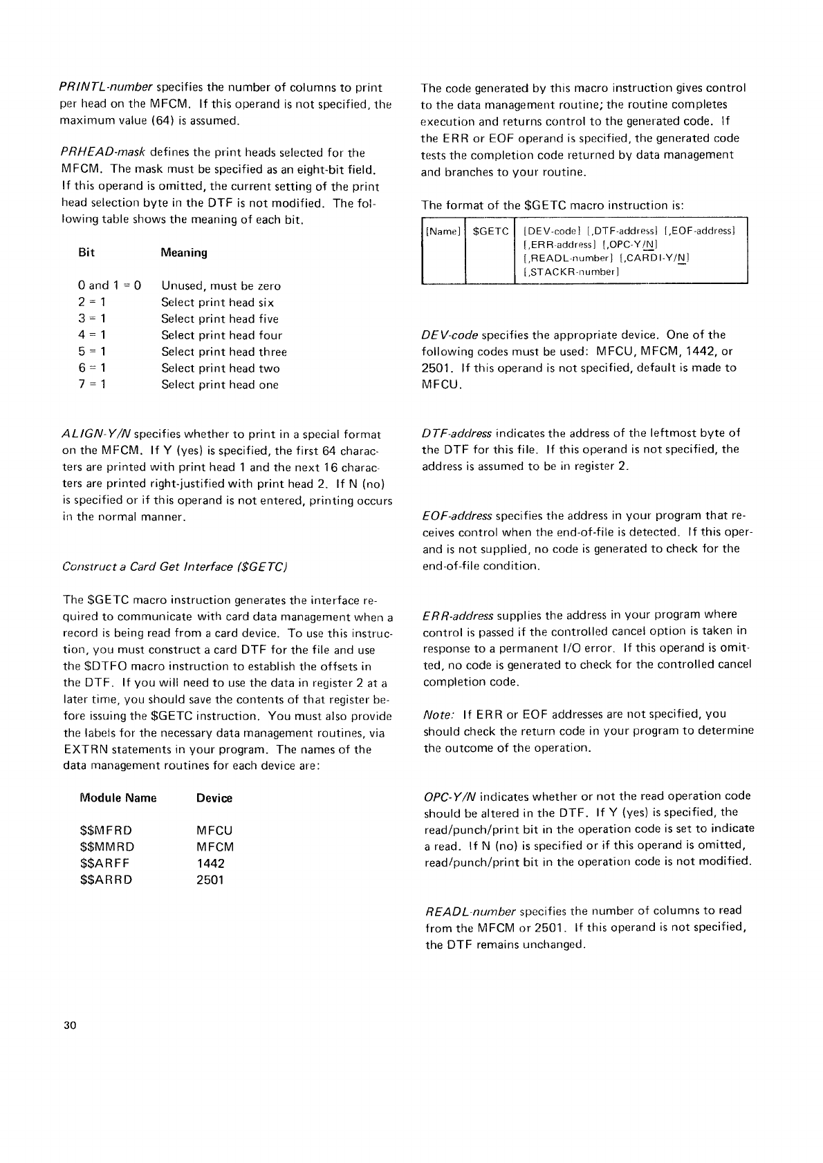
PRINTL-number specifies the number of columns
to print
per
head
on the
MFCM. lf this operand is not specified,
the
maximum value
(64)
is assumed.
PRHEAD-mask
def ines
the print heads
selected
for the
MFCM. The mask must
be
specified
as an eight-bit
field.
lf this operand
is omitted,
the current
setting of the
print
head
selection
byte
in
the DTF is not modified. The
fol-
lowing
table shows
the
meaning
of each
bit.
The code
generated
by this
macro instruction
gives
control
to the data
management routine;
the
routine
completes
execution
and
returns control to the
generated
code. lf
the ERR or EOF operand
is
specified,
the
generated
code
tests the completion
code
returned by data
management
and
branches to your routine.
The
format
of tlre
$GETC
macro instruction
is:
IName]
| $cETC | [DEV-code]
[.DTF'acldressl
I,EOF-address]
[,ERR-adclress]
[,OPC'Y/Nl
[,READL-number]
[,CARD
l-Y/N
J
[,STAC
KR'number]
DEV-code
specifies the appropriate
device.
One of the
following codes must
be
used: MFCU,
MFCt\4,
1442, or
2501. lf this operand is
not
specified,
default
is made
to
MFCU.
DTF-address
indicates
the address
of the leftmost byte of
the DTF for this
file. lf this
operand
is not
specified,
the
address
is assumed to be
ln reEister 2"
EOF-address specifies
the address
in your program
that re-
ceives control
when the end-of-f
ile is detected.
lf this oper-
and
is not supplied,
no code
is
generated
to check
for the
end-of
-f
i le cond
ition.
ERR-address
supplies
the address
in your program
where
control
is
passed
if the controlled
cancel
option is taken
in
response to a
permanent
l/O error. lf this operand
is omit-
ted, no code
is
gerrerated
to checl<
for the controlled cancel
completion
code.
Note: lf ER R
or EOF addresses
are
not specified,
you
should
check the
return code
in
your program
to determine
the
outcome of the
operation.
OPC-Y/N indicates
whether or not the read operation
code
should
be
altered
in the DTF. lf Y (yes)
is
specified,
the
read/punch/print
bit in the
operation
code
is
set to indicate
a
read. lf N (no)
is specified
or if this
operand
is
omitted,
read/punch/print
bit in the
operation
code
is not modified.
READL-number
specifies
the number
of columns
to read
lrom the
MFCM or 25O1. lf this operand
is not specified,
the DTF remains unchanged.
Bit
0and1=0
z- |
3=1
4=1
5=1
6=1
Meaning
Unused, must
be zero
Select
print
head
six
Select
print head five
Select
print
heacl
four
Select
print
head
three
Select
print head
two
Select
print
head
one
ALIGN Y/N specifies
whether
to print in
a special
format
on the
l\4FCM.
lf Y (yes)
is
specified, the first
64 charac-
ters are
printed
with print
head
1
and
the next 1
6 charac-
ters
are
printed
right-justified
with print head 2. lf N (no)
is specified
or if this operand is not entered,
prirrting
occurs
in
the
normal
manner.
Construct a Card Get lnterface ($GEfC)
The
$GETC
macro instruction
generates
the interface re-
quired
to communicate
with card data management
when
a
record
is
being
read from a card device.
To use this
instruc-
tion,
you must
construct a card DTF for the
file
and use
the
$DTFO macro instruction
to establish
the offsets
in
the DTF. lf you will need
to use
the data
in register
2 at a
later
tinre,
you should save the contents of that register
be-
fore issuing
the
$GETC
instruction. You must also
provide
the
labels for the necessary data rnanagement routines, via
EXTRN statements
in
your program.
The
names
of the
data
management routines
for each
device are:
Module
Name
$$MFRD
$$MMRD
$$anPr
$$AR
R D
Device
MFCU
MFCM
1442
2501
30
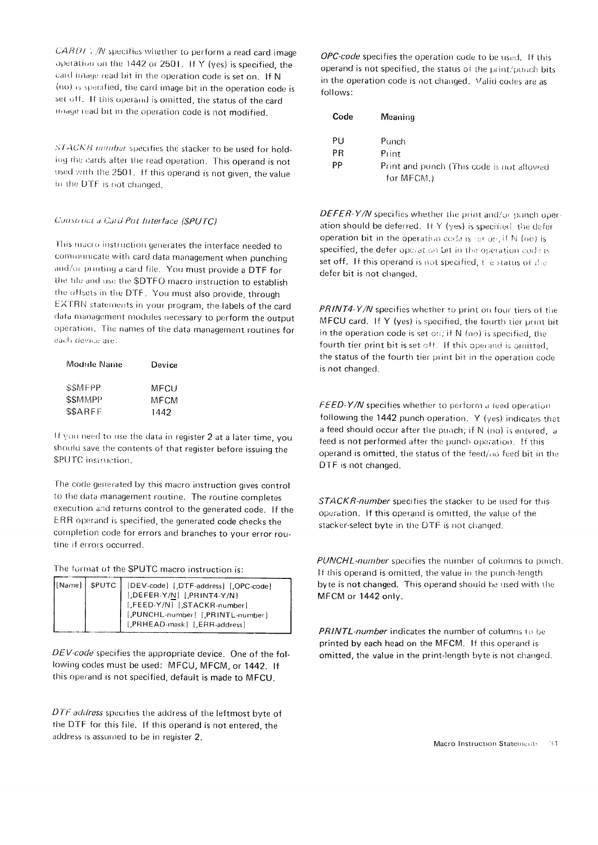
L'AB!-)l 1.,/A/
specifies rtrlrctlrer
tci
perfornr
a read
card image
\)i.)eralil,n()nli)e
l142ttr
250
1. lf \'(yes)
isspecified,the
c.rrtl
irit.rtltr
iearl
lri.t
in Llie oper-ation
code is
set on. lf N
irroi
i: s1i":r;r
fir:cl,
tire
carrl irnage
bit in
the operation
code is
set rrtf
. lf titis t_r1_ierarirl
is oriiitted,
tlrc,
status
of the
card
n,rd!J()
tt:ad
ltrt rrr
tlre
()lteratiorr
code is
not modif
ied.
.', /;1L"^
1:i r:titrtbtt :;rtlcrf
ies
tlre
slacker
to be used for hold-
rii(J
tirr
l:ards
after llre read
operation_
-l'his
operand
is not
Lrsr:ti
'i';itf
t
tlre
il50 I
. lf this
operarrd
is not
given,
the value
iri
tlrc D'l-l-:is
rri_rt
clrar-rge<1.
L',J!iii.i
t!L.L
a ilatti PuI lttterface l:$pU
fC)
l lris rirar;t.ir
instrrrctiorr
getic,fates
the interface
needed
to
corrrrrrrrrricale
uritli
card data
rnarragement
when
punching
arrrj,/t;r
;rr
rrrtirrg
a cartl filc. Yorr
rnust
provide
a DTF for
ilrt: I
ilr;
iiri(l
ri5(
j tlli)
$DTF0 macro
instruction
to establish
lltr: oft:els
in
tiie D-fF. Yorr
must
also
provide,
through
EX-TRl{
staterrterts
in
',rour
program,
the labels
of the
card
r.la1a
nr;rrragr:rnent
rnctdules
ltecessary
to pr;rform
the
output
ol)erati.)n.
Tire narnes
of the
data rnanagetnent
routines
for
tid(.1
i iic\Iii.ii ai e:
Motllrle ItJarue
$$r\4
FPP
$$IVI\4PP
$$ARFI:
Device
MFCU
tul
FCt\4
1442
lf 1'Lrrr
rret:tl
t()
lse the tlata
irt register
2 at a later
time,
yorl
shoLrlcr
save the
contents
of that register
before
issuing
the
$Pl.jTC
irrsir.r rr:1iorr.
fhe
code
gerroratecl
by this
ntacro
instruction
gives
control
to tlre data management
routine. The ror.rtine
completes
execLttion
a;':d returns
control
to the
generated
code. lf the
E
R R o1;r:rund
is
specif ied,
tlre
generated
code checks
the
conrpletiorr
ctitle for errors
and
branches
to your error
rou-
tine i
f ei rors
occLlrrecl.
-l-he
forrrrat
of the
$PUTC
macro
instruction
is:
DEV'code
specifies
the
appropriate
device.
One
of the
fol-
lourir-rg
cotles
must
be used: MFCU,
MFCM,
or 1442. I't
tl.ris operand
is not specified, default
is
made
to MFCU.
OPC-code
specifies
the operation
code to be us.;Lj. if tlris
operand
is not specified,
the
statirs of tlrr.:
J.riiirt,/lrLrrir:l'r
Lrits
in
the operation
code
is
not charrged.
\/alirj
coLlr-'s
are as
f
ol
lows:
Code Mcarring
Punch
Pl
int
Print
anC
trrrrrch
(-[his
ccde ir; rrut
alio-vvi:rJ
for l/l FCfl.,1
DEFER Y/N speci
fi€s
whetlrer
tltt:
prirrt
an{1,/u(
I)ilnch
uirer
ation should
be deferred.
lt Y'(,lesl
is
specirieil
tiie
clafer
operation
bit in
the
operalii/r'r itc,-i.t
r! :;r
r,l', if l.i
{ric}
is
specified,
tlre defer oi.lr-ii;i
i,,t l-it1 irr tir,:
olrotiltiLlrj
(.){)i.l::
t\
set off. lf this o[,,eranrl is rirrt
specificd, [ .r]
-11.atus oi ii..:
defer
bit is
not changed.
PRINT4-Y/N specifies whetirer ro prirrt
orr fotr tiers
oi tire
MFCU
card.
lf Y (yes)
is -specified.
the foLrrtir
rier
prirrt
bit
in
the operation
code is
set or; if N iira)
is
specifierl,
tlre
fcurth
tier
print
bit is sei rf
f lf this oper:,:rrri i,;i)riritterl,
the status of tlre
fourth tier
plint [lit ir-r tlie
operation
codo
is not changed.
FEED-Y/N
specif ies whether
to lierfornt
.r ieeri
oper-ariurr
followrng
tlte'1442
punch
operatiorr. Y (yes)
irrdicates
r-frat
a feed
should
occur
after
the
prritch;
if N (rro)
is enrereo,
tr
feed is not performecl
after thc piunclr
o;xl'atiorr"
!f tltis
ollerand is
omitted,
tlre status of the
feeclr,ro fueci
bit in
the
Dl-F is not changed.
STACKR-nurnber
specif
ies
the stacker to be Lrsed
fcr tlris
oper'<ition.
lf this
operarrd
is omrtted,
the valtre <-rf the
staci(cr-select byte irr t.ire tJTt- is not ciianged.
FLlltlCHL-nunber
specifies the
nurnber
of colrrrnrrs to prrrrch
lf t.his operand is
omittecl, the
value irr
the
ptrnr:h.lerrgth
byre is not changed. Thrs operand shouici f,,e
rrsed
with t-lrr
MFCM
or 1442 only.
PRINTL-number indicates the number
of columrrs ll l;e
printed
by each head on the
MFCI\4.
lf this operand is
omitted, the value
in the print-length
byte
is not clranged.
Dt I
PR
PP
DT I- aiiilress
specif ies
the DTF for
this file.
address is
assLrrrrecJ to
tl-re address
of the leftmost byte oi
lf this
operand is not
entered,
the
be in
register
2.
IDEV-codel
[,D-fF-addressj
[,OPC-code]
t,DEFER-Y/Nl
[,PR
tNT4-Y/N]
t,FEED-Y/Nl [,STACKR-number]
[,PUNCH
L-number]
[,PR
I NTL-number]
[,PRHEAD-rnask]
[,ERR-address]
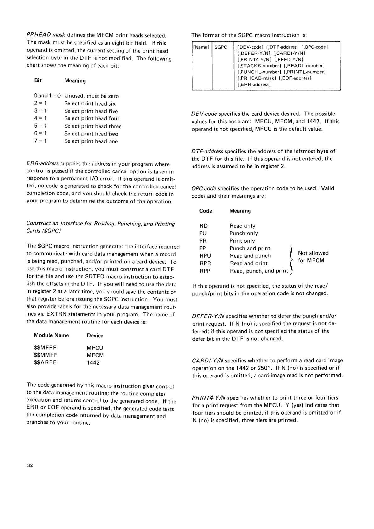
PRHEAD-mask defines
the MFCM print heads
selected.
The mask
must
be
specified
as
an eight
bit field. lf this
operand
is
omitted,
the current
setting
of the print head
selection
byte in the DTF is not modified. The following
chart
sl'rows
the meaning
of each
bit:
Meaning
Cand 1
=0 Unused,
must
be
zero
2 = 1 Select
print head
six
3 = 1 Select
print head five
4 = 1 Select
print head four
5 = 1 Select
print head
three
6 = 1 Select
print head
two
7 = 1 Select
print
head
one
ERR-address
supplies
the address in your program
where
control
is
passed
if the controlled
cancel option is
taken in
response
to a permanent
l/O error. lf this operand
is
omit-
ted, no code is
generated
to check for the controlled cancel
completion
code,
and
you should
check
the
return
code
in
your program
to determine
the outcome
of the operation.
Construct an lnterface for Reading, Punching, and Printing
Cards ($GPC)
The
$GPC
macro
instruction
generates
the interface
requirecl
to communicate
with card data
management
when a record
is
being read,
punched,
andlor
printed
on
a card device.
To
use this macro
instruction,
you must
construct
a card DTF
for the file
and use
the
$DTFO macro
instruction
to estab-
lish
the offsets
in the DTF. lf you will need
to use
the
data
in register
2 at a later
time,
you should
save
the contents
of
that register
before
issuing
the
$GPC
instruction.
You rlust
also
provide
labels for the necessary
data
management
rout-
ines
via EXTRN statements in
your program.
The nante
of
the data management
routine
for each
device is:
Module
Name
$$M
FF F
$$MM
F F
$$ARFF
Device
MFCU
MFCM
1442
The code
generated
by this macro instruction
gives
control
to the data
management
routine;
the routine comptetes
execution
and returns
control to the generated
code. lf the
ERR
or EOF
operand
is
specif ied,
the
generated
cooe
tests
the completion code returned
by data management
and
branches
to your routine.
DEV-code
specifies
tlre card device
desired. The possible
values
for this code are: MFCU, MFCM,
and 1442. lf this
operand is
not specified,
MFCU is the default value.
DTF-address
specifies the address
of the leftmost byte of
the DTF for this
fite. lf this
operand
is not entered, the
address
is
assumed to be
in reqister 2.
OPC-code specifies the operation code to be
used. Valid
codes and their
meanings
are:
Bit
Code
RD
PU
PR
PP
RPU
RPR
RPP
Meaning
Read only
Punch only
Print
only
Punch
and
print )
Read
and
punch I Not alow9d
Read
and
print I for MFCM
Read,
punch,
and
print )
lf this operand is
not specified.
the status
of tlre read/
punch/print
bits
in
the operation
code
is
not changed.
DEFER-Y/N specifies
whether to defer the punch and/or
print request. lf N (no) is specified
the request is
not de-
ferred; if this operand
is not specified the status of the
defer bit in
the DTF is not changed.
CARDI-Y/N specif
ies whether to perform a read
card image
operation on the 1442
or 2501. lf N (no)
is
specified
or if
this operand
is
omitted, a card-image
read is not performed.
PRINT4-Y/N specifies
whether to print three or four tiers
for a
print request from the MFCU. Y (yes)
indicates that
four tiers should
be
printed;
if this operand
is
omitted or if
N (no)
is
specif
ied, three tiers are
printed.
The
format
of the
$GPC
macro
instruction
is;
lNamel
| $GPC | [DEv-code] [,DTF-address]
[,OPC-code]
t.DEFER-Y/Nl [,CARDr-Y/N]
[.PRr
NT4-Y/N] t,FEED-Y/Nl
[,STACKR-number] [,READL'number]
[,PUNCHL-number] [.PRINTL-number]
[,PRH
EAD-mask]
[,EOF-address]
[,ERR-address]
32
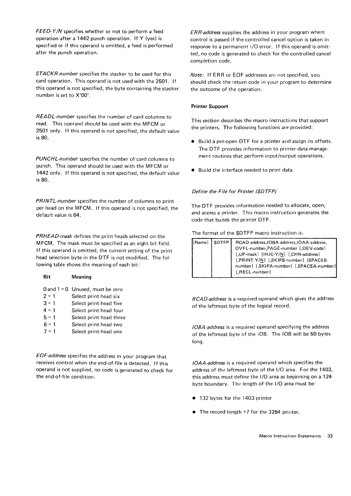
FEED-Y/N specifies whether
or not to perform a
feed
operation after a 1442
punch operation. lf Y (yes)
is
specified
or if this operand is omitted, a
feed is
performed
after the punch
operation.
STACKR-number specifies the stacker to be used for this
card
operation. This operand
is not used
with the
2501. lf
this operand is not specified, the
byte containing
the
stacker
number
is
set
to X'00'.
READL-number specifies
the number
of card columns
to
read. This operand
should
be
used with the MFCM or
2501
only. lf this
operand
is not specified. the default value
is
80.
PUNCHL-number specifies the number of card columns
to
punch. This operand
should be used with the
MFCM
or
1442
only. lf this operand is not specified,
the default
value
is
80.
PRINTL-number
specifies
the
number
of columns
to print
per
head on
the
MFCM. lf this
operand is
not specified,
the
default value is
64.
PRHEAD-mask defines
the print heads
selected on the
MFCM. The mask must
be specified
as an
eight
bit field.
lf this operand is omitted.
the current
setting of the print
head
selection byte
in
the DTF is not modified. The fol-
lowing
table shows the meaning
of each
bit:
Bit
0and
1
=0
2= 1
3=1
4=1
5=1
6=
1
7=1
Meaning
Unused,
must
be zero
Select
print
head
six
Select
print
head five
Select
print
head four
Select
print head
three
Select
print head
two
Select
print
head
one
EOF-address
specifies
the address
in your program
that
receives
control when the end-of-f
ile is
detected. lf this
operand is not supplied, no code is
generated
to check for
the end-of-file
condition.
ERR-address
supplies
the address
in your program
where
control is
passed
if the
controlled cancel option is taken in
response to a
permanent
l/O error. lf this operand is omit-
ted, no code is
generated
to check
for the controlled cancel
completion code.
Note: lt ER R or EOF
addresses are
not
specified,
you
should check the return code in
your program
to determine
the outcome of the operation.
Printer
Support
This
section
describes the
macro instructions that support
the
printers.
The
following
functions
are
provided:
o Build a pre-open
DTF for a printer and assign
its offsets.
The
DTF provides
informatron to printer
data
manage-
ment routines
that perform
input/output operations.
o Build
the interface
needed to print
data.
Def ine the File for Printer ($DTFP)
The
DTF provides
information
needed to allocate,
open,
and access a printer. This macro instructiorr
generates
the
code that builds the
printer
DTF.
The
format of the $DTFP macro instruction is:
RCAD-address
is
a required operand
which gives
the address
of the leftmost byte of the logical
record.
IOBA-address
is a required operand specifying
the address
of the leftmost
byte
of the lOB. The IOB will be 50 bytes
long.
IOAA-address
is a required
operand
which specifies the
address
of the leftmost byte of the l/O area. For the 1403,
this
address
must define
the l/O area as
beginning ona 124'
byte boundarV. The length
of the l/O area
must be:
132 bytes
for
the 1403
printer
The record length
+7
for
the 3284
prirrter.
It\amel | $DTFP I RCAD-address,lOBA-address,lOAA-address,
OVFL-number,PAGE-number
[,DEV-code]
[,UP-mask1
tHUC-Y/N] [,CHN-addressl
[,PRlNT-Y/N] [,SKlPB-number] [SPACEB-
numberl [,SKlPA-number] [,SPACEA-number
[,RECL-number]
Macro Instruction
Statements 33
Ol/FL nttrnber
specifies
the line
number
orr
the
prrnter
alter
which
rhe overflow
completion
code
will be returned.
lf this
operand
is rrot
specified,
default
is made
to 6 lines
less
than
the rrrrrnber
specified
for the
pAGE
operand.
PAGE-number
specifies
the number
of lines
to print per
page.
lf this
operarrtl
is
rrot
specified,
default
is
made
to the
systenr
value
for the
nunrber
of lines
per
page.
DEV-code
str"recifies
tlre
printer
desired.
The
possible
values
fcrr
this code
are 1403
and
3284. lf this
operancl
is not
specifierl,
1403
is
assurned.
UP+nask
specif
ies the mask
to test
the eight
externar
inrlicators. The cor.le
f
or the LJP-mask
must be
specified
as 8 binary
bits. For
example,
to rest
bits
0,3, b,
and
7,
t,rou
worrld
enter [JP-10010101.
The Up-mask
is compared
to the extet'nal
intlicators
set on by the
SWITCH
statement
tor corrciitionally
eponl''rn files. lf the
bits that are on in
the
[JP-rnask
are
also on in
the external
indicators
set on by the
SWll CH
statetnenr,
the file
will be
opened. lf the Up-mask
is
all zeroes
or not used,
tlre file
will be unconditionallv
oper-red.
//ote.. Infornrarion
on setting
exterital
indicators
(SWITCH
statement) carr be found in the IBM System/3 Model ls
Systettt Cor',trol Programming Reference Manual for pro-
granr
Number 5704-SC1
, GC21-5077
and tBM SystemR
Model 15 Systent Control Programming Concepts and
Reference
Manrtal for Progranr
Number S7O4
SC2, GC2j..
5162.
HUC \'/Al
specif
ies
whether
to halt
if an urrprintable
charac-
ter
is
detected.
lf N (no)
is
specified
or if this
operand is
omitted,
no halt
occurs.
CHN-acJdress
indicates
the address
of the next DTF in the
chain
of DTFs. lf there is no DTF chain
or if this is
the
last
DTF in
a chain,
this
operand
should
be
omitted
(a
value
of X'FFt-F'is
assumed).
PRINT'\'/N spccifies
n,lrethcr
to perform
a
print
and
a skip
or
space
or.only
a sl<ip
or space. Default
is
N (no)
,
mean-
ir.rg
that a
print is rrot
performed.
SKIPB-nutnber
specif ies the lirre
to skip
to before
the print
operation.
lf this
opera|rd is
not
eiltered,
the default value
is zero.
34
SPACEB-number
specif ies
the number of lines
(maximum
of 3 lines)
to space
before
the print
operation. lf this
operand
is
not entered,
the default
value
is
zero.
SKIPA-ttuntber
specif ies the line
to be skipped
to after the
print
operation. lf this
operand is not specified,
the default
value
is zero.
SPACEA-nunrber
specifies
the number of lines
to space
(0,
1,2, or 3) after tlre
print
operation. lf this
operand is not
specified.
it defaults
to a
value
oI zero
if DEV-1403
is
speci-
fied
or to a
value
of one if DEV 3284 is
specified. A space
after
of zero
is
not allowed for the
3284
printer,
and,
if
zero
is
specified,
the operand
defaults
to a
space
after of
one.
RECL-number specifies the length
of the line
to be
printed.
lf this
operand is
omitted,
default is
132
positions.
Constnrct a Printer Pttt lnterface ($PUTP)
This rnacro
instruction
generates
the
interface
needed
to
communicate
with printer
data management.
You must
provide
a
DTF for the f
ile
and
use
the
$DTFO macro
instruction
to establish
the offsets in
the DTF. You must
also
provide,
through
an EXTRN statement in
your pro-
gram,
the
label
$$LPRT,
for the 1403, or $$lpfUp,
for the
3284. (Tlrese
labels
are
for the
printer
data
management
nrodule
necessary
to perform
the
printer
output
opera-
tion.)
lf you will need
to use
thedata in register
2 at a later
time,
you should save
the contents
of that register
before
issuing
the
$PUTP
macro
instruction.
The code
gerrerated
by this macro instruction
gives
control
to the data management
routine. The
routine
completes
execution
and returns
control to the generated
code. lf the
ERR
operand is
specified.
the
generated
code
checks
the
completion
code for errors
and
branches to your error
routine
if errors
occurred.
l-he
fornrat
of the
$PUTP
macro
instruction
is:
INamel
| $PUTP
I IDEVcodel
[.DTF-addressl
t,pRtNT-Y/N]
[,SKlPB-number]
[,SPACEB-number]
lS
Kl PA-numberl [,SPACEA-number]
[,ERFi-addressl
[,OVF
L-address]
DEV-code
specif ies
the
printer
device
ciesrii:rl. The
possible Disk Device
support
values for
this code
are 1403
and3284. lf tnis operand is
not
specified,
1403 is the
default value. This
section
describes the
macro instructions that support
disk devices. The follorvirrg
f r-rnctions
are
1'lrovided:
DTF'address
specifies the address of the leftmost iryte
of o Builcl
a
pre,open
DTF for disk GE-f/PUT opcrations
the DTF for
this
file lf this
operand is not
entered,
the and assiqn
its
offsets.
address is
assumed
to be in reqister
2.
o Build
an inout/orrtrrut
block
(lOB)
for
disk
read/write
operations and assign
its
offscts.
PRINT Y/N specifies
whether
to perfrom
a
print
and
a skip
or space
or only a skip or space. lf this operand is not o Build
the
interfaces requirecl
to get
input recor-cls
from
a
specified,
the DTF remains
unchanged. disk device
via
a
get
or a
read.
r Build
the interfaces
required
to put output records
to a
SKIPB-nuntber
specifies the lir-re
to skip to before the
print disk device
via
a
put or a write.
operation. lf this operand is
not entered,
the DTF remair-ts
unchanged. o Build the interface t,l wait
for
disk completion.
The
disk DTFs
provide
information
to the disk data
man-
SPACEB-number
specifies the number
of lines
to space be- agement,
ancl
the disk lOBs
provide
information to the
fore
the
print
operation. lf this operand is not entered, the input/output supervisor routines that perform
the input
DTF remains unchanged. or output operations.
These
operations are
provided
through the disk support
macro instructions.
SKIPA-number
specifies the
line
to be skipped to after the The IBM 3340 Direct
Access
Storage
Facility
attaches
to
print
operation.
lf
this operand is not
entered,
the
DTF System/3
Models
158,
15C, and 15D. Also,
the
IBM 3344
remains
unchanged. Direct
Access
Storage attaches
to System/3 Model 15D.
Certain areas on the 3340 and 3344 disks are treated
as
SPACEA-number
specifies the number
of lines
to space
after 5444 disks. These
areas,
known as
simulation areas,
are
the
print
operation. lf this
operand
is
not entered,
the DTF used
for program
libraries and can also
be
usecl for data
remains unchanged. files.
These
areas cannot
contain multivolume
or inclexed
files.
The remainder
of the disk space, known
as
main
data areas. can onlv be used
for data
files.
ERR-address
supplies
the address
in
your program
where
control is
passed
if the controlled
cancel option is taken in Reference in this manual Io5444,5445, and 3340 are
to
response
to a
permanent
l/0 error. lf this operand is
omit- be interpreted according to which disk storage device(s)
ted, no code is
generated
to check for the controlled
cancel is
attached to the
system.
The following
table should be
completion
code, and
you s,hould check the return
code
in used to determine
the
rneaninq
of the reference:
your program
to determine the
outcome of the operation.
References
to D3
and
D4 Q-numbers
in
this manual mav be
replaced with D3
1 and
D41 for 5704-SC2.
OVFL-address
specif
ies
the address in your program
that
should
receive
control if page
overflow occurs.
Macro lnstruction Statenrents 35
Disk Device
SullPort
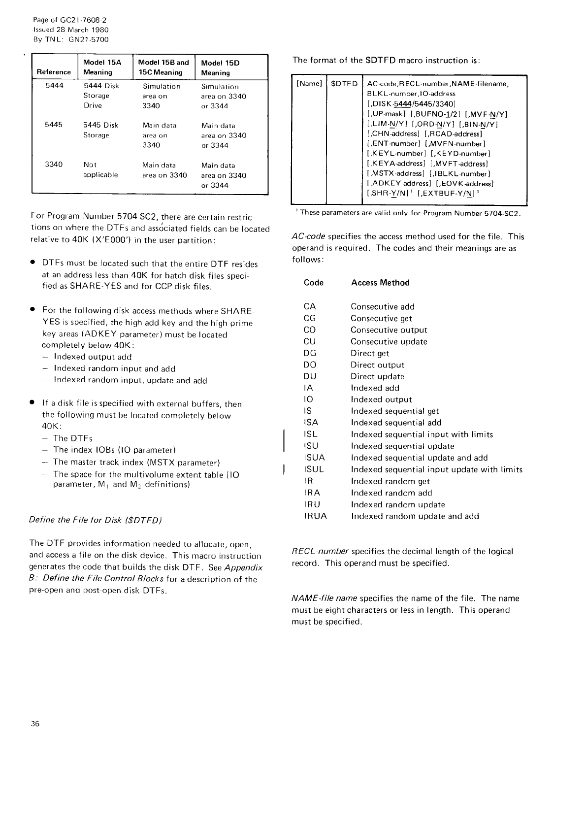
Page
of GC21-7608-2
lssued
28 March
1980
By TN L: GN21-5700
Reference
Model 15A
Meaning
Model 158 and
15C Meaning
Model 15D
Meaning
5444 5444 Disk Simulation Simulation
Storage area
on area
on 3340
Drive 3340 or 3344
5445 5445 Disk Main
data Main data
Storage area
on area on 3340
3340 or 3344
3340 Not Main
data Main
data
applicable area on 3340 area
on 3340
or 3344
For
Program
Number
5704
SC2,
there
are certain
restric-
tions
on where
the
DTFs
and
assdciated
fields
can
be located
relative
to 40K (X'E000')
in the user
partition:
o DTFs
must
be
located
such
that
the entire
DTF resides
at an
address less
than 40K for batch
disk files
speci-
fied
as
SHARE-YES
and
for
CCP disk
files.
. For
the following
disk
access methods
where
SHARE-
YES
is
specified,
the high
add key
and the high
prime
key
areas
(ADKEY parameter)
must
be
locateo
completely
below 40K:
- Indexed
output add
- Indexed
random
input
and add
Indexed
random
input,
update
and
add
o lf a
disk f
ile is
specif ied
with external
buffers,
then
the followirrg
must
be
located
completelv
below
40 K:
The
DTFs
- The
index lOBs
(lO
parameter)
- The master
track
index
(MSTX
parameter)
' The
space for
the multivolume
extent table
(lO
parameter,
M1
and
M2
definitions)
Define the File for Disk ($DTFD)
The DTF provides
irrformation
needed
to allocate,
open,
and access a f ile
on the
disk device.
This
macro instructior-r
generates
the code
that
builds
the disk DTF. See
Appendix
B: Define the File Control Blocks for a description
of the
pre-open
ancl
post-open
disk DTFs.
The format
of the
$DTFD macro instruction is:
tThese
parameters
are valid
only
f
or
Program
Number
5704-SC2.
AC+ode specifies the access method used for the
f
ile. This
operand is
required. The
codes and their meanings
are as
follows:
Code Access Method
CA
UL]
L(J
CU
UU
DO
DU
IA
ro
IS
ISA
ISL
ISU
ISUA
ISU
L
IR
IRA
IRU
I RUA
Consecutive
add
Consecutive
get
Consecutive
output
Consecutive update
Direct
get
Direct
output
Direct update
Indexed
add
Indexed
output
Indexed
sequential
get
Indexed
sequential add
lndexed
sequential
input with limits
I ndexed
sequential
update
Indexed
sequential
update and
add
Indexed
sequential
input update
with limits
Indexed
random
get
Indexed
random
add
Indexed
random update
Indexed
random
update
and add
RECL'number specif ies
the
decimal length of the
logical
record. This
operand
must be
specified.
NAME-f ile name specifies the name of the file. The name
must
be eight
characters
or less in length. This
operand
must
be soecified.
INamei
| $DTFD I AC{ode,RECL-number,NAME-filename,
B L K
L-number.lO-address
t,
D I s K
-E444ls
445
|
33401
[.UP-mask]
[,BUFNO-1/2]
t,MVF-N/Yl
[,LlM-N/Y] [,ORD-N/Y]
[,BtN-N/Y]
[,CHN-address]
[,RCAD-address]
[,E
NT-number]
[,MVFN-number]
[,K
EYL-number]
[,KEYD-number]
[,K
EYAgddress] [,MV
FT-address]
[,MSTX-address]
[,]
BLKL-number]
[,ADKEY-address]
[,EOVKeddress]
[,SHR.Y/N]' [,EXTBUF.Y/N]'
36
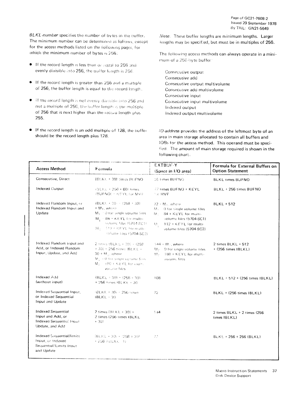
r:
I Access Method r l-irtttula i tspa.,e
in l1o areal
.-... _,_+._.,..-.._ _._
I Consecrtiue,
Direct {lll.
i(i. r J{J)
,.inrrt
iitr,:li0 :-r, I'm6rs
tst-!i:!..ritr
I
I
BLKL-number
specif ies
tfte nilrr-tber
of bvtes
in ttre irutfer.
The rrrinrrnurn
nur,.iber
can
oe
rjeterntirrl{t
as
fol',_r,rr.s.
rxcijirt
for the access methods
iisted
on the tolioi,r,,rir.j
paqlr:r,
fr)l
'vhich
the
minimum ilun'ii;er
of bytes r:256"
o lf tne recc,rd
lenllth rs less
trr;tn or :rilr...iti
to 2?6 :iriri
evenly
ciivisil-rlu,n1,r
256,
1l-re
Drr
ile!-
lr r;ql.il
is
;i:t-j
s lf fhe record ienilth
is
qreater
thar;
256 irrl{l d nii.jttrpie
of256, ti.re buffer iengt:h
is
equ;rl
to th,; r;.ccrii l::it;giir
.
0 if tfle ne(,{rril ieni;Iit 1.,
nLri iillLrj!iy
rji'u,:;il:i,,
i;ltii lt-jG alrj
nOl ii l-tttiriirls Of ?5e. tirl i.ir;f{1.1
ii:rrqiit ,.-
ine lnultip!C
of 256
that is
next
irigher
tharr
the
rilci.,,u
lr-,nutfr
irlur
255.
. lf the record lenqth
is an
odd rnuitipic
ol 128, tlre
luffer
shouid
be the record length
plus
12[3.
page
t:f GC21_76O9,2
tssued
29
September
1g7B
By
l'tJL: cN21-5649
Itlr-rr6f;
15.t* br-rffei lengths
are
niinimum
lengths. Larger
ir:rrgths
rrray
bc; specif:ed, but musi be in
multiples of 256.
-f
he
folir-r,'ving
access methods can
always
operate in
a
mini-
rrlu,tr
t-li.r .i'-'r,:'vtp
LUIter
Consr:lu
tive
outpul
Consecurive
add
Consecutive
oLrtput
nru
ltivolurne
Corr:Lrcuirve
adti mui tivolume
Corisecutive
input
Cr:,rsecutive
input inultivolunie
I|idexeri
ouiput
lritiexed
()utput
multivolume
,'(J-arlcdress
pl'ovides
tfre address
of the leftmost byte of an
area
irr main
storage
allocated to contain
all buffers
and
l{)[Js
tor the access method. f his
operand
must be speci-
iirri T iie
amount of nrain
storage
required
is
shown in the
tollowirrg
charl:
Formula
for External Buffers
on
0ption Statement
BLKL rrmes
UtiFNO
BLKL
+
256 times BUFNO
BLKL
+
512
2 times
Bt-KL
+
512
+
(256
times IBLKL)
BLKL.
! 512
+
\256
times IBLKL)
BLKL +
(256
times
lBl"-KLl
2 times
tiLKL +
2
times
{256
times IBLKL)
256
+
256
(BLKL)
Macro I nstrur:tion
Statements
l)isk Device
Support
Inclexed
Output ,l!!.i:.
l. , :,firi
r 6{)l rFnE! .'i trmes
Bt-jf:N0 r KEYL
'll'rill!',,ii-): r'.ii:
il. :irr M\,'
j 'u ilVF
indexed flandonr lriput, li \BLKr ' .:t) .
]v.t"d
, t1t /2 l:4, r.:t-:r,:r.
Indexed Randorn Inpul ancJ 1 1,.4
r
.
rryir.,r' \1, f] t:lr rinqle voirrrne iiles
Uptlate fo1
, i-j irt: ,,rrr_tl,r \,oiu:nr' ,,r'< it lj4 + NLYL tor rnrriri
M, 84 * K i yL i,rf .irullt- /oiunrs iilcrs
i5704-SC1)
',,,rir;fi
ltlg'.r
l!111,'!.tlL-li 1.',l li2 rKFyL.iormrrltr
:\rl
. :1'.;
L
't
r::r/, rr,,
:r:,,il-i ;olurne l!!cs
(5704-cC2'
' i,r
iti
r,!.
i ri,;: I
::7f)4-liC.:r
i
Inrlexeci Handom lrlput arid I rr:,r: liji_i..:-
r ll,, 1;lirF .t
44 , 1.,4
.
nrhere
Adcl.
or Indexed Random ,..tii; , 2b6 1i:rp! iF!
| i.:
i , L4. f.J
f
cr srnErt: \,rjiurl{: liles
Input, Updare.ant.l r\ctd 3r:r
+ ^l r.,rri,,., r..1
. l!(] i Kt:yi, tor rnurri
avl
_ i) lr.r :r
rrjrt ! (; ,rr[f] fi 1,\ Jr:)rutilli fi!{15
I\4- :1:,..
".t \
I r,:,
,,rr.
r'a)t."1:t,r
ltli,s
lnclexeci
AfJd iBll(i- ,-{{ri , r2ri8,
r 3iil
{wrthout irrput) +'J56 ',,'rr:s
rtiii
K ! . .l(.)
In(lelsd Se{.iuential lrip!f, ;i-ti.Ki i.l0r l?it: r:r:r|s
or lndexed Sequentiai tBLFi| li:i
lnput and Update
Indexed Sequential 2 tirrres il{t K
i..
. iJ0,
-
Input and Add, or 2 tirnes
('.lstj
tirnes
tBLFl.L
Indexeo Sequentr.r: l1l,{ji } Jill
tJpdate, antJ Add
indexed i.'qrrentiai/l[nirl itji.i. i. - -i,]; . ':.ilrl]
i .1i;r
ini,ur, t,l inr,'uxerj . zt,tj ,:;: l_.,t
'- 'i
;
Seuuclrtral.rl-rr:t
rtg
I nr:ui
and iJpdate
3'1
Page of GC21
-7608-2
lssued 29 September
1978
Bv
TNL: GN21-5649
DISK-5444/5445/3340 specif ies
whether the disk device is
the 5444 Disk Storage Drive,
the 5445 Disk Storage,
or the
3340 Direct Access
Storage Facility. lf this operand is not
specif ied,
5444 is
assumeq.
UP-mask
specifies
the mask
to test
the eight external
indicators. The code
for the UP-mask must be specified
as 8 binary
bits. Fclr
example,
to test bits
0,3,5, and 7,
you
would enter
UP-10010101. The
UP-mask is compared
to the
external indicators
set on by the
SWITCH statement
for conditionally
opening files. lf the bits
that are on in the
UP-mask
are also on in the external indicators
set
on bV the
SWITCH statement,
the f ile will be opened. lf the UP-mask
is
all
zeroes
or not used, the file
will be unconditionally
opened.
y'y'ofe.'
Information on setting
external indicators
(SWITCH
statement) can be found in the IBM System/3 Model 15
System Control Programmming Reference Manual (for
Program
Number
5704-SC1l, GC21-5O77,
and
in the IBM
System/3 Model l5 Control Programming Conceptsand
Reference
Manual (for Program
Numbr:r
5704 SC2).
GC21 5162.
EUFNO l/2 allows
you to specify either one
or two buffers
for the file. You can use
two buffers onlV with consecutive
access methods
and
indexed
output. All consecutive
access
methods
allow dual buffering
except
the consecutive up-
date
and consecutive update rnultivolume.
lf this
operand
is omitted
or if SFI
R-Y is specified,
one buffer is
assumed.
MVF N/Y specif
ies whether
the
access
methocl
is multi-
volume. lf this
operand
is
omitted, N (no)
is
assumed.
LIM-N/Y is specified only for indexed
sequentiai
get
and
indexed sequential update. lt specifies whether the sequen-
tial
access
is withrn limits. lf this operand
is
not entered,
N (no)
is
assumed.
ORD-N/Y specif
ies whether an ordered load is to be used
with the indexed output access method. This
operand
can
be specif
ied only with the indexed
output access method.
ORD Y must
be specif ied
for indexed
rnultivolume output
access methods. lf this operand is not enterecl,
N (no)
is
assumeci.
BIN-NN is specified only with the direct output, direct get,
and
direct update access
methods. Y (yes)
indicates direct
binary relative
record numbers;
N (no)
indicates
direct
deci-
mal
relative
record numbers. lf this operand
is omitted,
N
is
assumed.
CHN-address
specifies the address
of the next DTF in the
chain of DTFs. lf there is no DTF chain
or if this DTF is
the
last DTF in
the chain, this operand
should be omitted
and
X'FFFF'assumed.
RCAD-address
specifies the address
of the leftmost byte of
the logical record. lf this operand
is
not
entered, X'0000'
is assumed.
Depending on
the
disk access
method
being
used for an input operation,
either move
mode
or locate
mode is used. lf move mode is used, the record is
provided
at the address
specif
ied in the RCAD parameter.
lf locate
mode is
used, the address of the input
record is contained
at the displacement of $DF
LRA in the DTF.
The specified address
plus
the total length
of the area
must
be less than logical
X'E000'for f iles that
are
being
shared or for files that are
being used for external
buffers
(5704-SC2
onlv).
ENT-number specif ies
the number of entries in the master
track index. This
operand is specif
ied only
for indexed
random or indexed
add access
methods.
MVFN-number indicates the number
of volumes for a
multivolume
direct
access
method. This operand
must be
specif
ied
for these access
methods.
KEYL-number specifies the
length of the key f ield and
must be
used
for all
indexed access
methods, but no others.
The key
f
ield
length can
be no
more than 29
bytes.
KEYD-number is entered
for all indexed access
methods.
It indicates the displacement
into the
record of the
right-
most byte of the key f ield. The
displacement
of the
f irst
byte in the record
is zero,
the
second
byte is
one,
and
so
on.
?Q
KEYA-address
specif
ies
one of the following and is
a
required
operand
for these
access
methods:
. Main
storage
address
of the lef
tmost
byte
of the
kev
field
for indexed
random
access
methods.
. Main
storage
address
of the leftmost
bvte
of the relative
record
number
field
for direct
access
methods.
. Main
storage
address
of the leftmost
byte
of the save
area for current
and
last
keys
for indexeci
sequential
add
access
methods.
o Main
storage
address
of the leftmosi
hryte
of tne
save
area for high
and low keys for indexed
sequential
with
limits
access
methods
(LlM Y) The snecif
ied
address
plus
the
total length
of the
area must
be less
than
logrcal
X'E000'for f iles
that
are being
sharec.l
or for f iles
that are
being
used
for externat
buf{ers
(5704-SC2
onlv).
You must
allocate
the rnain
storage
space for the
f ields.
The
amount
of space
required
is:
. The
number
of bytes
in the
key field
for indexed
ran-
donr access
methods.
o 23 bytes
for direct
access
methods
with decimal
keys.
The
decimal
key is located
in
the rightmost
15
bytes
of
the f ield.
. 8 bytes for direct
access
methods
with binary
keys.
The
binary
key is located
in
the rightmost
3 bytes
of
the f
ield.
o Two times
the key length
for irrdexed
sequential
add
or
indexed
sequential
with limits
access methods.
The low
key
is located
in
the left
half
of the field;the
high
key in
the right
half.
MVFT-address
must
be
specif ied
for all multivolume
direct
files,
and only for the
access methods
used
with these files.
This
operand
specif ies
the
address
of the leftmost
byte of
the table
of extents
used for the access methods
used
with
these
f iles. You must
allocate
main
storage
space
for the
table. The
number
of bytes
allocated
must
be equal
to
seven
times
the number
of volumes
in
the f ile. ,,rVith
57O4-5C2,
if the multivolume
f
ile is
rcr be
sharetj,
the
number
of bytes
allocated
must
be ten
ttmes
the number
of volumes
in
the
f
ile. The
specif
ied
address
plus
the
total
length
of the area mLtst
be less
than loqlical
X,E000,tor
files
that
are
being
shared
or for files
that are bernq
used
for
external
buffers
(5704-SC2
onlv
).
Page
oi GC21-71608-2
lssued 29
Seotember
1978
Bv TN
L: G N21
-5649
MSTX-address
specif ies the
address
of the leftmost byte of
the master
track index
in mai:r
itor'age. This
operarro
must
be
specified for indexed randorn
and indexctl
add access
methods.
You must
allocate
space
in main
storage for the
master
track irrdex.
The
lr:ngth
of the mastei.track
index is
determined
by the following
formulas:
o For
singie
volume
random
access rnethods,
Length
= ENT (kev
length
+ 2i
a For
multivolume
randorn
access
methods.
Length
= ENT (keyiength
+ 2)
ENT must
be
equal io or greater
tlrarr
4.
The specified
address
plus
the total ierrqth
of the orea
,must
be
less
than logical
X'E000'for f iles
that are being
shared
or for files
that are being
used for external
buffers
(5704-SC2
onlv).
IBLKL-number specifies
the number clf
sectors in the index
buffer. This
operand
is used
only with indexed
access
methods. lf this
operand
is not specif
ieci.
one sector
is
assumed. For indexed
sequential
access
methods
wirh both
input
and
add, the
specified
index
buffer
size
applies to
both
the input index
Lruffer
and the
add index
buifer. For
indexed
random access methods,
the specified
br-rffer
size
applies
only to the
add index
buffer. Increasing
tfre size
oi
this
index
buffer
will increase
the eff iciency
o{ processing
for a
random
file"
ADKEY-address
specif ies
the addresr;
oi the leftmost bvte
of an area
used
to save the highest
key in the
primi-.
index
and the
highest
key in rhe
add
index. The
area
at this
dcl-
dress must
be
eciual in length
to 2
tirnes
KL:y i for
each vr.)l_
ume
used
by the file. l his
operand
is
requirrrJ
ior tr,r;exerl
add, indexed
random
input
and
add,
ancl iridexerl
r..rr.i{ii-irn
input,
update,
and
add access
methocis.
lt is iqnored
rt
specif ied
with other access
methods.
The
specif
iect
adclress
plus
the
total length
of the
area
must
be
less
than
loorcar
X'E000'for f iles
that are
being
shared
or for files
rhat
are
being
used
for external
buffers
(5704-5C2
onlv).
EOVKaddress specif
ies
the address
of the leftnrr:ist
byte oi
an area used
to save a key tf ir-rrce
end-cf-vol
.lme
is :;pec-
ified
(by
the HIKEY parameter
on the [:lLE
OCL
.;r;,te.
ment) for a
nrultivolume
indexed
output f ;lu "f
he
air;a at
this
address must
be equal in length
tu l,(
EY
i-. Th;s i,trer.
and is used
only when
the multivolurne
rndext.cj
outrr*i
access method
is used
and force
end-of.,roiunre
wiil Lre Lrserj
"f
he
specif ied
address
plus
fhe total lenEtlr o1
ihe area
must
be
less
than logicai
X'E000'for f
iles
th,.it afe iJeing
shared
or for f iles
that are beirrq
used for extr,,rn;rl br,rtfers
(5704-5C2
onlv).
Macro Instruct,on S:aremerrll 39
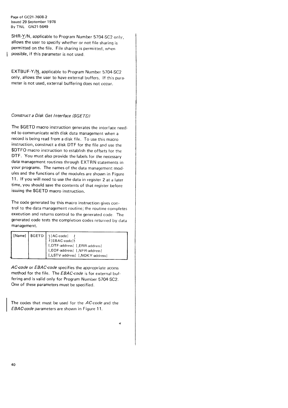
Pase
of GC21
-7608-2
lssued 29 September
1
978
By TNL GN2'l-5649
SHR-Y/N,
applicable
to Program
Number
5704-SC2
onlv,
allows
the user
to
specify
whether
or not
file
sharing is
permitted
on
the f ile. File
sharing
is
permittecl,
when
possible,
if this
parameter
is not
used,
EXTBUF-Y/N,
applicable
to Program
Number
5704 SC2
only, allows
the user
to have
external
buffers. lf this
para-
meter
is
not used,
external
buffering
does
not
occur.
Construct
a Disk Get lnterface ($GETE)
The
$GETD macro
instruction
generates
the interface
need-
ed
to communicate
with disk
data managemenr
when a
record
is
being
read from a disk file. To use
rhis macro
instruction,
construct
a disk DTF for the
file
and
use
the
$DTFO macro
instruction
to establish
the offsets 1or
tne
DTF. You must
also
provide
the labels
for the
necessary
data
management
routines
through EXI-R
N
statements
in
your programs.
The
names
of the data
management
mocl-
ules
and
the
functions
of the modules
are
shown in Figure
11. lf you will need
to use
the
data in
register
2 at a later
time,
you should
save the
contents
of that register
before
issuing
the
$GETD macro
instruction.
The
code
generated
bV
this
macro
instruction
gives
con-
trol to the
data management
routine;the
routine
corrrpletes
execution
and returns
control to the generated
co<je.
The
generated
code
tests
the cornpletion
cocles returned
bV data
management.
[Namel
|
$GETD
I llAc-codel I
| | I
tesaccoaetI
[,DTF-address]
[,ERR-address]
[,EOF-addressJ
[,N
FR-address]
[,LSTV-address]
[,NOKY-address]
AC-code
or EBAC-code
specif ies
the appropriate
access
method for the file. The EBAC-cctde
is for external buf,
fering
and is valid
only for Program
Number
5704 SC2.
One
of these
parameters
mLtst
be
specified.
The codes that must be used
for the AC-code and the
EBAC-code
parameters
are shown in Figure
11.
40
DTF-address
indicates
the address
of the leftmost byte of NOKY-address
supplies the address in your program
that is
the DTF for this file. lf this
operand is
not specified,
the to receive
coritrol under either
of the
following
conditions:
address is
assumed
to be in register
2.
o The requested
key is too low for the current volume
when
processing
an
indexed
random
offline multivolume
ERRaddress supplies
the address
in your program
where file.
control
is
passed
if the controlled
cancel
option is
taken
in
response
to a
permanent
l/O error. lf this
operand
is omit- o The requested
key is too high for any
volume
when
ted, no code is
generated
to check for the
controlled
cancel processing
an
indexed random
online multivolume file.
completlon
code.
This
operand is not used with other access methods.
EOF-address
specifies
the address in your program
that
receives
control when the end-of-file
is
detected. lf this Construct
a Disk
put lnterface ($pUTD)
operand is
not supplied,
no
code is
generated
to check for
the
end-of-file condition. You must
not use
this operand The
$pUTD macro
instruction
generates
the interface
need-
with random or direct access
methods' ed to communicate
with disk data management
when put-
ting a
record
to disk
or updating
a
previously
retrieved
Note: lI ERR
or EOF
addresses
are not specifieo,
you record. you must
provide
a DTF for the
file
and
use
the
should check
the return
code
in
your program
to determine $DTFO macro instruction
to establish
the offsets in
tne
the
outcome
of the
operation. DTF. You must
also
provide,
through
EXTRN statements
in
your program,
the labels
of the disk data management
modules necessary
to perform the output operation (see
NRF-address
must be used
only
for random
and direct Figure
11). lf you will need
to use
the data in register
2 at
access
methods. lt specifies
the address
in your program a later time, you should save the contents
of that register
that is
to receive
control when
a
no-record-found
condition before issuing
the
$pUTD macro instruction.
occu
rs.
LSTV-address
is used when processing
a random, offline,
multivolume
file. This
operand
supplies
the
address
in
your
program
which receives
control when the requested
key is
too high
for the
f inal
volume
in
a
multivolume
file.
Macro
lnstruction Statements 41
Disk Device
Support
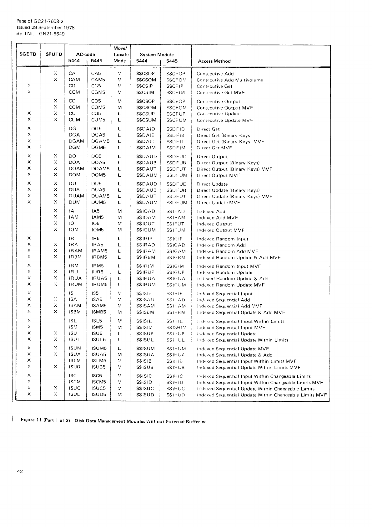
$GETD I $PUTD
Page
of GC21-7608,2
lssued
29
September 1978
BV
TN
L. GN21-5649
X
X
X
X
X
X
X
X
X
X
X
X
X
X
x
X
X
X
X
X
x
v.
X
X
x
X
Y
X
X
x
X
X
x
X
X
X
X
X
X
X
X
X
X
X
i(
X
M
M
M
M
M
M
L
L
L
L
L
L
L
L
L
L
L
tvl
M
M
M
L
L
L
L
L
;
M
M
M
M
M
L
L
L
M
rJl
M
M
M
M
M
CAM
.C
CGM
IRM
IRU
IRUA
IRUM
IS
ISA
ISAM
ISB
I\4
iSL
ISM
tsu
ISU L
ISUM
ISUA
ISLM
ISUB
ISC
ISCM
ISUC
ISUD
CA5
CAM5
CG5
CGIVIS
co5
COM5
nt t6
CUM5
DG5
DGA5
DGAMS
DGMS
DO5
DOA5
DOAM5
DOM5
DU5
DUA5
DUAM5
DUIVIs
lA5
IAM5
to5
toM5
rR5
IRA5
IRAM5
IR
BM5
IRM5
IIJR 5
IR UA5
IRUM5
rs5
ISAS
ISAM5
ISMB5
ISL5
ISM5
ISU5
ISU L5
ISUM5
ISUA5
IS LM5
ISU85
ISC5
ISCIVI5
ISUCS
ISU D5
S$CSOP
$$csoM
$$CS
I
P
$$cs i
M
SSC
I'OP
S$CF
()
M
S$CFIP
SSCi:
IM
$$CFOP
$$CF0M
$$CF
UP
$$CF
U N,4
S$D
F
It)
$$DFiB
$$D
F
tr
$$DF
IM
$$D
F U L')
$$D
F
Ui]
$$DFLJT
$$DFUM
$$DFUt)
SSII
F
Uts
$$DFUI'
SSD
F
U
I\4
s$ir-AD
$$tFAf\.4
SSIFUT
$$ rF
ri r.4
$$i.itP
S$
IGA D
$$
lGAll
s$rGBtu]
$$tcitM
$s t(l l.l
P
$s t(:,
ti A
$$ti,iJM
$$ |
r'l ll''
ii$
riiAt.;
9$
lHA,\,4
S$IHtsfu1
SSIHIL
l;$lsHl!\4
$SttiUP
S$IHIJL.
S$IHLJM
$srflLiA
s$ ilJ
tiJ
$$IHUI]
S$
iH
IC
SS tt-l i t)
$siii-rucl
$$ri{uil
nn
coM
CU
CUM
DG
DGA
DGAM
DGM
DO
DOA
DOAM
DOM
DU
DUA
DUAM
DUM
IA
IAM
to
toM
IR
IRA
IRAM
IRBM
$$csoP
$$CSOM
$$CSUP
$SCSUM
$$tl
A tD
$SDAIB
$SDA
IT
$$DAIM
$$DAUD
$$DAUB
$$DAUT
$$DAUM
$SDAUD
$St]AUB
$$DAUT
$$DAUM
$sroAD
$sloAM
$$
rour
$$rouM
Jilxrr
$srRArl
$$
rFr AM
$$IRBM
$$
!H
lM
$$rriuP
$$
IF] UA
$SlRtJM
$$
ls li'
$$
rsA ri
$$ISAM
$SISBM
.SSrSrL
$$
lS llvl
$S
ISU
P
$$ISU
L
S$ISUM
$$
ISUA
$$rsrB
s$rJUt
$$
rs rc
bbt>tLJ
$$ISUC
$$ISUD
Consecutive Add
Cor)sccutive
Add Multivolume
Consecutive Get
Consecutive Get MVF
Consecutive
Output
Consecutive
Output MVF
[)onsecutrve Update
Consecuiive
Update MVF
Drrect Grrt
Direct Get iBinary Keys)
Dirt;cl
Get (Binarl,Keys)
MVF
i)rrect Get MVF
[)irr]ct
Output
Drr0ct Output (Binary Keys)
DirecL
Output (Binary Keys) MVF
Lirr,rct
Output MVF
Dirt-.ct
Update
Drrect Update (Binary Keys)
[-irrect
Update (Brnary Keys) MVF
l);r1.r Update MVF
lndr:xe-d Add
lrtdexed Add IVIVF
l'rciexed
Output
lnde:<r:d Output MVF
indexr:d Random lnput
lfr(l{rx.rd Random Add
lrrlured
Random Add MVf
Indoxed Random Update & Add MVF
lndexed Random Input MVF
lrrdexed Randorn Update
inrlexed Random Update & Add
inrlexerl
Randorn Update MVF
in(li.xed
Sequential Input
i rrrltrr:cj
Serluential Add
ir;rlexed
Sequential Add MVF
l;rrlr:xed
Sr:que
nlral Update & Add MVF
i. ilt
red Secluential Input Within Limits
ii'rlr:xt:ci
Scquerrtial Input MVF
ir,rl',x(-,d
Sequential Updatr:
lrrj.agli Sequentrai Update Within Limits
lrrrjexed
Sequential Uf:tlate
MVF
irrrJexed
Sequential Update & Add
lrrcirxld Serluential Input Within Limits l\/VF
!nrli:xed
Sequential Update Within Limits MVF
i,rrlr:xi:d serluential Input within changeable Limits
lrrrJcxed
Secluerntial
Input Within Changeable Limits MVF
ir)iiexec,
Sequential
Update Within Changeable
Limits
lrrdexed
Secluential
Llpclate Within Chanqeable Limits MVF
Figure 11 (Part 1 of 2i. Disk [)ata Management Modules yvithout Exterrral Bulferinq
42
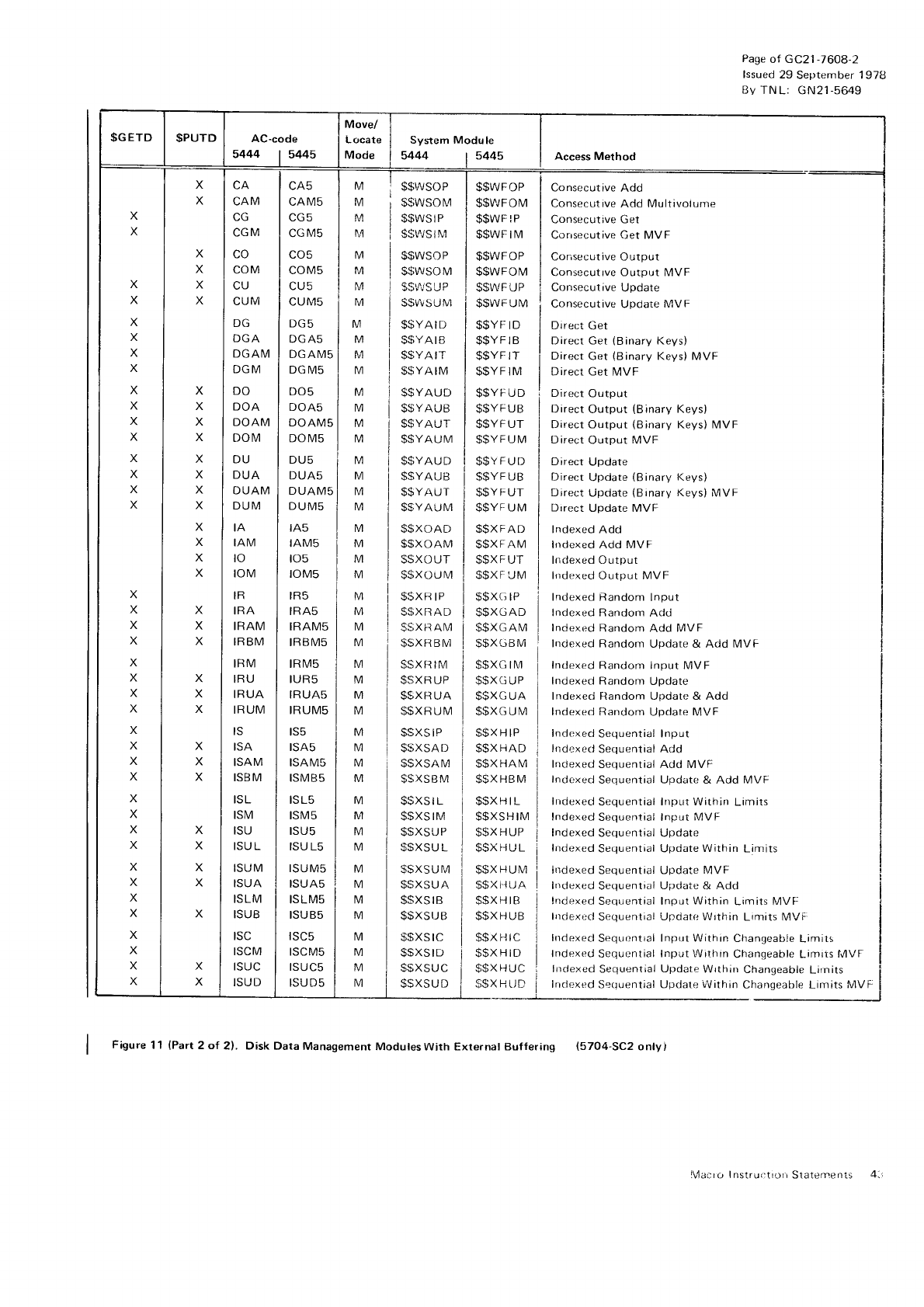
$GETD $PUTD AC-code
5444 I 5445
Move/
Locate
Mode
System Module
5444 | 5445 Access Method
X
X
X
X
X
X
X
X
X
X
X
X
X
X
X
X
X
X
X
X
X
X
X
X
X
X
X
X
X
X
X
X
X
X
X
X
X
X
X
X
X
X
X
X
X
X
X
X
X
X
X
X
X
X
X
X
X
X
X
X
X
X
X
X
X
X
X
X
X
X
X
X
X
CAM
CG
CGM
co
COM
CU
CUM
DGA
DGAIVI
DGM
DO
DOA
DOAM
DOIVI
DU
DUA
DUAM
DUM
IA
IAM
to
roM
IR
IRA
IRAM
IRBM
IBM
IRU
IRUA
IRUM
IS
ISA
ISAM
ISBM
ISL
ISM
ISU
ISU L
ISUM
ISUA
ISLM
ISUB
ISC
ISCM
ISUC
ISUD
cA5
CAMS
CG
M5
LU5
COM5
CU5
CUM5
DG5
DGA5
DGAM5
DG IVIs
DO5
DOA5
DOAM5
DOM5
DU5
DUAS
DUAM5
DUM5
rA5
IAM5
to5
roM5
tR5
IRA5
IRAM5
IRBM5
tR
tvl5
IUR5
IRUA5
IRUM5
ts5
ISA5
ISAM5
ISMB5
ISL5
tsM5
ISU5
ISU L5
ISUM5
ISUA5
ISLMS
ISUB5
ISC5
rscM5
ISUC5
ISUD5
M
M
M
I\4
M
M
M
M
M
M
M
M
M
M
M
M
M
M
M
M
M
M
M
M
M
M
M
M
M
M
M
M
M
M
M
M
M
M
M
M
M
M
M
M
M
M
M
M
$$wsoP | $$wFoP
$$wsoM i $$vrFOM
$$wsrP i $$wr
re
$$\rJStr\,1
l$$wFtM
$$wsoP | $$wFoP
$$wsoM | $$wFoM
$$"^'/SUP
I$$WFUP
s$v\su\,1
isswruna
$$YArD | $$Yr,tD
$$YArB | $$YFtB
$$YArr | $$YF
tr
s$YArM | $$YF
tM
$$YAUD | $$YFUD
$$YAUB | $$YFUB
$$YAUr | $$YFUr
$$YAUM
I $$YFUM
$$YAUD
$SYAUB
$$YAi-JT
$$YAUM
$$XOAD
S$XOAM
SSXOUT
$$xo{-JM
$$XR IP
S$XRAD
$SXI]
AM
$$XRBM
$SXI]
IM
$SXR
UP
$$XR
UA
$$XR
UM
$sxs
I
P
$SXSAD
$SXSAM
$SXSBM
$$XS
I L
$SXS
I M
$SXSUP
$SXSU L
$SXSUM
$SXSUA
$SXS
I B
$$XSIJB
$SXSIC
$SXSID
$$XSUC
SSXSUD
$$YFUD
$$YF
UB
olYFUl
$$YF
UM
S$XFAD
$$XFAM
)sArut
$$XF
UM
$$XG
IP
$$XGAD
$$XGAIVI
$$XGBM
$$XG
IM
$$XG
UP
$$XG
UA
$$XG
U
M
$$X
H
IP
$$X
HAD
$SX
HAM
$$X
HBM
$$XHIL
$$XSH
IM
$$X
H UP
$SXHUL
$$X
H
UM
$$xl-JLiA
$$XHIB
$$XHUB
$$X
H
IC
$$XHID
$$XHUC
$sx H
r.rD
Consecutive
Add
Consecut ive
Add Multivolunre
Consecutive Get
Corrsecutive Get MVF
Consecutive Output
Consecuttve Output IMVF
Consecutive
Update
Consecutive
Update
MVF
Direct
Get
Direct Get
(Binary
Keys)
Direct
Get
(Binary
KeVs) MVF
Direct Get
MVF
Direct
Output
Direct
Output (Binary
Keys)
Direct Output (Binary
Keys) MVF
Direct
Output MVF
Direct
Update
Direct
Update
{Binary
Keys)
Direct
Upclate
{Binary
Keys)
MVF
Drrect
Update MVF
Indexed Add
irtdexed Add MVF
Indexed Output
lndexed
Output MVF
Indexed Random
lnput
Indexed Random
Adci
Indexed
Random
Add MVF
Indexed Random Update & Add IVIVF
Indexed
Random input MVF
Indexed Random
Update
Indexed Random Update & Add
lndexed Random
Upclate MVF
Indexed
Sequential Input
Indexed
Sequential Add
Indexed
Sequential Add MVF
Indexed
Sequential Update & Add MVF
Indexed
Sequential
Input Within
Limits
Indexed
Sequential Input
MVF
Indexed
Sequentiai Update
lndexed
Sequential Update
Within
Limits
Irrdexed
Sequential Update MVF
Indexed
Sequential
Update
& Add
Indexed
Sequential Input
Within
Limits MVF
lndexrd
Sequential
Updatr: Wrthin
Limits MVF:
lndexecl
Sequcntial
Input Within
Changeable
Limirs
Indexed
Sequential
Input Within
Changeable Limits
filVF
lrrclexed
Sequential
Update
Wrthtn
Changeable
Lirnits
lriclexecl
Seouential
Update
i'\i ithin Changeable
Limits MVF
Figure
11 lPart
2 of 2). Disk
Data Management
Modules With External Buffering (5704-SC2
onlyl
Page
of GC21
-7608-2
lssued
29 September 1
978
Bv TNL: GN21-5649
\1alo Instructr0ri
Slatements 4
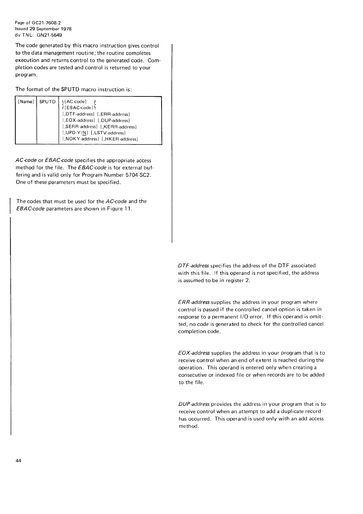
Page
of GC21
-7608-2
lssued 29
September 1978
Bv TNL: GN21-5649
The code
generated
by this macro
instruction gives
control
to the data management routine;
the routine
completes
execution
and returns
control to the generated
code. Com-
pletion
codes are tested and control is returned
to Vour
program.
The format
of the
$PUTD
macro instruction
is:
AC+ode or EBAC-code
specif
ies
the appropriate
access
method for the file. The
EBAC-code
is for external buf-
fering
and
is valid
only
for Program
Number
5704.SC2.
One of these
parameters
must be
specified.
The codes that must be used for the AC-code and
the
EBAC-code
parameters
are shown
in Fiqure
1 1.
DTF-address
specif
ies the address
of the DTF associated
with this
file. lf this operand
is not specified, the address
is assumed to be in register 2.
ERR-address
supplies the address
in your program
where
control
is
passed
if the
controlled cancel option is taken in
response
to a
permanent
l/O error. lf this
operand
is
omit-
ted,
no code is
generated
to check
for the controlled
cancel
completion code.
EOX-address
supplies the address
in your program
that is
to
receive
control
when
an end
of extent
is reached during
the
operation.
This
operand
is entered only when
creating a
consecutive or indexed
file
or when
records are to be added
to the
file.
DUP-address
provides
the address
in your program
that is
to
receive
control
when
an
attempt
to add
a duplicate
record
has
occurred.
This
operand
is used only with an add access
method.
[Namel
| $PUrD
I ltAc{ode] t
| | ileenccoael\
[,DTF-address]
[,ERR-address]
[.EOX
-address]
[,DUP-address]
[,SERR-address]
[,KERR-address]
t,UPD-Y/Nl [,LSTV-address]
[,NOKY-address]
[,HKER-address]
44
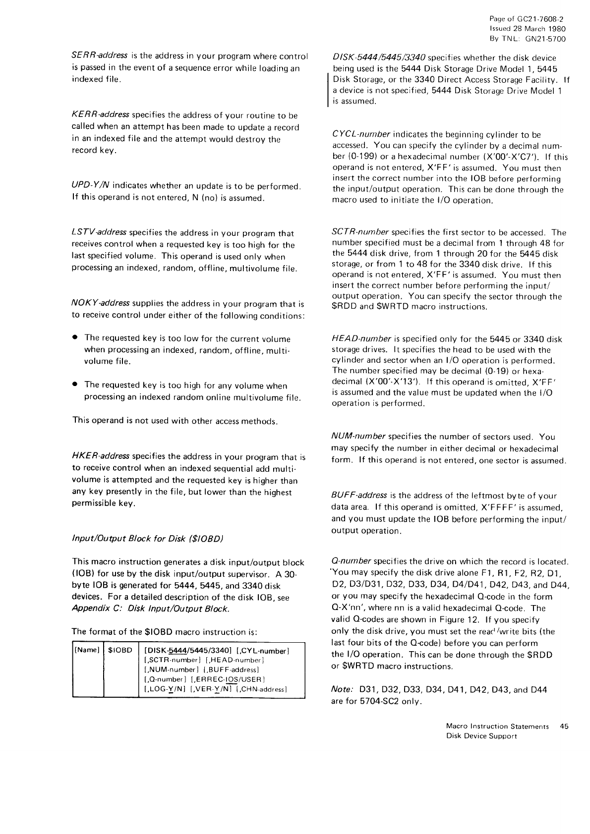
SERRaddress is
the address
in your program
where control
is
passed
in
the event
of a sequence
error
while loading
an
indexed
file.
KERR-address
specifies
the address
of Vour routine
to be
called
when
an attempt has
been
made
to update
a
recoro
in
an
indexed
f ile
and
the attempt
would
destroy
the
record
keV.
UPD-Y/N indicates
whether
an update is
to be performed.
lf this
operand is not
entered,
N (no)
is
assumed.
LSTV-address
specif ies
the address in your program
that
receives
control when a requested
key is too high
for the
last
specified volume.
This
operand is
used onlv
when
processing
an indexed,
random,
offline,
multivolume f ile.
NOKY-address
supplies
the address
in your program
that is
to receive
control
under
either
of the followinq
conditions:
o The
requested
key is
too low
for the current
volume
when
processing
an
indexed,
random,
offline.
multi-
volume
file.
. The
requested
key
is
too high
for any
volume
when
processing
an indexed
random
online
multivolume
file.
This
operand is not used
with other access
methoos.
HKER-address
specifies
the address in your program
that is
to receive
control when an indexed
sequential
add multi-
volume is
attempted
and the requested
key is higher
than
any key presently
in
the
file,
but lower
than
the highest
permissible
key.
lnput/Output Block for Disk ($IOBD)
This macro instruction
generates
a
disk input/output block
(lOB)
for use
by the disk input/output
supervisor.
A 30-
byte IOB is
generated
tor 5444,5445, and 3340 disk
devices. For
a detailed
description
of the disk lOB,
see
Appendix C: Disk lnput/Output Block.
The format
of the
$IOBD macro instruction
is:
[Namel
| $roBD I lDtsK-94441s445l334o]
[,cyL-number]
[.SCTR-number]
[,H
EAD-number]
[,NUM-number] [.BUFF'address]
[,O-number] [,ERREC-lOS/USER I
t.LOG-Y/N1
[,VER
Y/N] [,CHN'address]
Pase
of GC2
1
-7608,2
lssued
28 March
1980
By TN
L: cN21-5700
DISK 5444/5445/3340 specifies whether
the disk device
being used is
the 5444
Disk
Storage Drive Model
1,5445
Disk
Storage,
or the 3340 Direct
Access Storage
Facility. lf
a device is
not specif
ied,5444
Disk Storage
Drive Model
1
is
assumed.
CYCL-number
indicates
the beginning
cylinder to be
accessed.
You can
specify the cylinder
by a decimal num-
ber
(0-199)
or a
hexadecimal
number
(X'00'X'C7'). lf
this
operand is not entered, X'FF' is
assumed.
You must
then
insert
the correct
number
into
the IOB
before
performing
the input/output
operation. This
can
be done
throuqh the
macro
used
to initiate
the llO operation.
SCTR-number
specif ies the first sector
to be accessed. The
number
specified must
be
a
decimal
from 1
through 48 for
the
5444
disk drive, from i through 20 for the 5445 disk
storage,
or from 1 to 48 for the 3340
disk drive. lf this
operand
is not entered
, X'FF' is
assumed. You must
then
insert
the correct
number before
performing
the input/
output operation.
You can specify
the
sector through the
$RDD
and
$WRTD
macro
instructions.
HEAD-number is specified
only for the 5445 or 3340 disk
storage drives. lt specif ies
the
head
to be
used
with the
cylinder
and
sector
when
an l/O operation is
performed.
The number
specified
may
be
decimal
(0-'l
9) or hexa-
decimal
(X'00'-X'13') lf
this
operand is
omitted, X'FF'
is assumed
and the
value must
be
updated
when
the liO
operation is
performed.
NUM-number specif ies
the number
of sectors used. You
may
specify
the number in
either
decimal
or hexadecimal
form. lf this
operand is not entered,
one sector is
assumed.
BUFF-address
is
the address
of the leftmost byte of your
data
area. lf
this operand is omitted,
X'FFFF'
is assumed,
and
you must
update
the IOB
before
performing
the input/
output operatton.
Q-number
specifies
the drive on which the record
is located.
'You
may
specify
the
disk
drive
alone
F1,
R1, F2,
R2,
D1,
D2, D3/D31, D32,
D33, D34,
D4/D41,
D42,
D43, and
D44,
or you may
specify
the
hexadecimal
O-code in
the form
O-X'nn',
where
nn is
a
valid
hexadecimal
O-code. The
valid O-codes
are shown
in Figure
12. lf you specify
only
the
disk
drive,
you must
set the reacr/write bits
(the
last four bits of the Ocode) before
you can
perform
the l/O operation. This
can be done
through the
$RDD
or $WRTD
macro
instructions.
Note: D31.
D32, D33, D34,D41,D42,D43,
and
D44
are
for 5704-SC2
only.
Macro
Instruction
Statements
Disk
Device
Support
a3
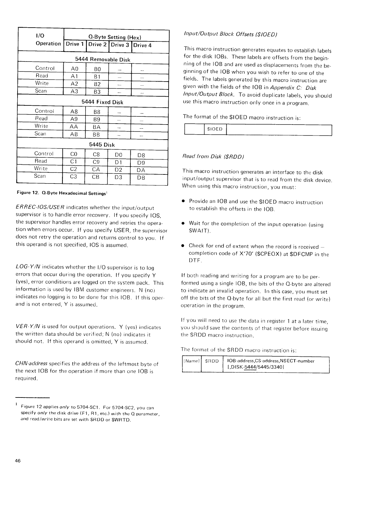
vo
Operation
O-Byte
Settinq
(Hex)
Drive
1Drive
2Drive
3Drive
4
5444 Removable
Disk
Control AO BO
Read A1 B1
Write A2 B2
Scan A3 B3
5444
Fixed
Disk
Control A8 B8
Bead Ag B9
Write AA BA
Scan ND BB
5445
Disk
Control CO CB DO DB
Read C1 C9 D1 D9
Write C2 CA D2 DA
Scan C3 CB D3 DB
Figure
12. O-Byte
Hexadecimal
Settingsr
ERREC
IOS/USFF
indicates
whether
the
input/output
supervisor
is
to handle
error recovery.
lf you
specif
y lOS,
the
supervisor
handles
error
recovery
and retries
the opera-
tion when
errors
occur.
lf you
specify
USER,
the
supervlsor
does not retry
the operation
and returns
control
to you. lf
this
operand
is not
specified,
IOS
is
assumed.
LOG Y/N indicates
whether
the l/O supervisor
is
to log
errors
that occur
during
the
operation.
lf you
specify
y
(yes),
error
conditions
are logged
on
the
sVstem
pack. This
information
is
used
by lBlVl
customer
errgineers.
lrl
(no1
indicates
no logging
is
to be done
for
this lOB. lf this
oper_
and is not entered, Y is
assumed.
VER-Y/N is
used for output operations.
Y (yes)
irrdicates
the
written
data
shoulci be verified;N
(no)
indicates
it
should not. lf this
operand is
omitted, Y is
assumed.
CHN-address
specif ies
the address
of thr: leftmost byte of
the next
IOB
for
the operation if more
than one IOB
is
req
u i red.
- Figure
12
applies
only to57O4-5C1.
For
5704-SC2,
you
can
specify
only the disk
drive
(F1,
R1, etc.)
wirh
the
O
paramerer.
and read/wriie
bits are
set
with gFl
DD
or
gWRTD.
lnput/Output Block Offsets ($
lO E D
)
This
macro
instruction
generares
equates
to establish
labels
for the disk
lOBs. These
labels
are
offsets from the
begin-
ning
of the
IOB
and
are
used
as displacements
from
the be-
ginning
of the IOB
when
you wish
to i-efer
to one
of the
fields.
The
labels
generated
by this
macro
instructron
are
given
with the
f
ields
of the IOB in
Appendix
C. Disk
lnput/Output
Block. f o avoid duplicate
labels, you should
use
this macro
instruction
only
once in
a
program.
The format
of
the
gIOED
macro
instruction
is:
$IOED
Read from Disk (gRDD)
This
macro
instruction generates
an interface
to the disk
input/output
supervisor
that is
to read fronr
tlre
disk
device
When
using
this
macro
instruclion, you
must:
o Provide
an
IOB
and use
the
$IOED
macro
instructrorr
to
establish
the
offsets
in
the lOB.
o Wait
for
the
completion
of the input
operation
(using
$WAIT).
o Check
for end
of extent
when
the record
is received
completion
code
of X'70'
($CpEOX)
at
$DFCMp
in
the
DTF.
lf both reading
and
writing
for a
program
are
to De
per-
formed
usrng
a single
lOB,
the
bits
of the O-byte
are
attered
to indicate
ar-r invalid
operation. In
this case,
you must
set
off the
bits of the O-byte
for all but
the
first
reacl
(or
write)
operation
in
the
proqram.
lf
you
will
need
to use
the data
in register
1 at
a later
time,
you
should
save
the contents
of that register
before
issuing
tlre
SRDD macro
inslruction.
The fornrat
'-ri
the
$RDD macro
instruction
is:
lNamel I $tlDD I IOB-address,CS-address,NSECT-number
[,D
ls
K-544415
44513340]
4b
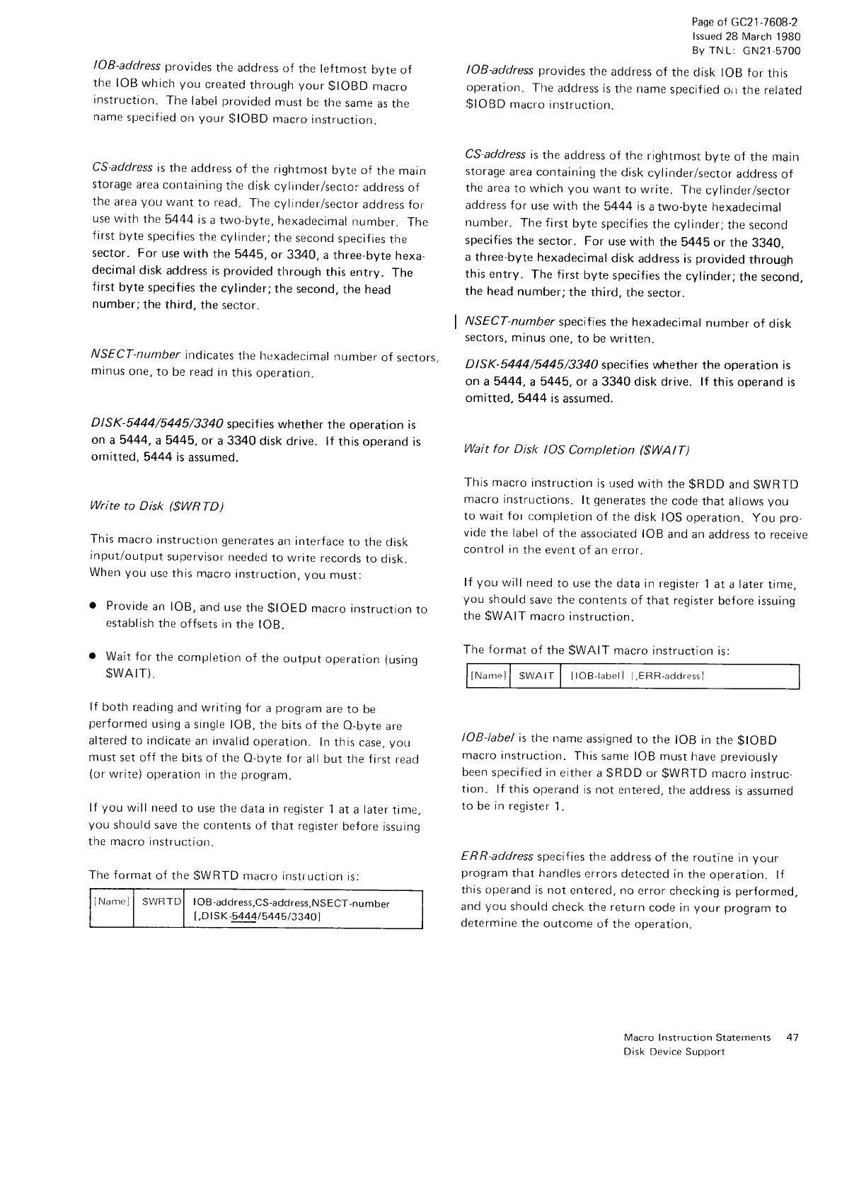
IOB-address
provides
the address
of the leftmost byte of
the IOB
which
you
created
through
your
gIOBD
macro
Instruction.
The
label
provided
must
be the
same
as the
name
specified
on
your
$IOBD
macro
instructiorr.
CS-address
is
the address
of the rightmost
byte of the main
storage
area
containing
the disk
cylinder/sector
address
of
the
area
you want
to read.
The
cylinder/sector
address for
use with rhe
5444
is
a two-byte,
hexadecimal
number. The
first
byte
specifies
the
cylinder;
the
second
specifies
the
sector. For use
with the 5445,
or 3340, a three-byte
hexa_
decimal
disk
address is
provided
tlrrough
this
entry. The
first
byte
specifies
the
cylinder;
the
second,
the head
number;
the third,
the
sector.
NSECT-nunber
indicates
the lrexadecimal
number
of sectors.
mrnus
one,
to be read
in
this
operation.
DISK-5444/5445/3340 specif ies
whether
the operation is
on a5444, a5445,
or a
3340
disk drive. lf this operand
is
omitted,
5444
is assumeo.
Write to Disk ($WRTD)
This macro
instruction
generates
an
interface
to the disk
input/output
supervisor
needed
to write
records
to disk.
Wherr
you
use
this macro
instr.uction, you
must:
. Provide
an
lOB,
and use
the
$IOED
macro
instructron
to
establ
ish
the
offsets
in the lOB.
o Wait for
the completion
of
the
output
operation
(using
$WAIT).
lf both reading
and writing for a
program
are
to be
performed
using
a
single lOB,
the
bits of
the O-byte
are
altered to indicate
an invalid
operation.
In this
case,
you
must
set off the
bits of the O-byte
for all but the
first
read
(or
write)
operation in
the
program.
lf
you
will need
to use
the dala in
register
1
at
a
later
time,
you
should
save the
contents of
that register
before
issuing
the macro instruction.
The format
of the
$WRTD
macro
instrucrion
is:
INarnel
I SWRTDI IOB-address,CS-address,NSECT-number
[,D
l sK-5444/5
445
I 3340]
Page
of
GC21-7608-2
lssued
28 March
1980
By TNL:
cN21-5700
IOB-address provides
the
address
of the disk
IOB for this
operation.
The
address is
the name
specified
oir
the
related
$IOBD
macro
instructiorr.
CS-address
is
the address
of the rightmost
bVte of the main
storage
area
containing
the disk
cylinder/sector
address
of
the area
to which
you want
to write. The
cvlinder/sector
address for use
with the
5444 is
a two-byte hexadecimal
number. The f
irst
byte
specif ies
the
cylinder;
the second
specifies
the sector. For use
with the 5445 or the 3340,
a three-byte
hexadecimal
disk
address
is
provided
through
this
entry. The
f
irst
byte
specif ies
the
cylinder;
the
second.
the head
number;
the third,
the
sector.
NSECT-number
specifies
the hexadecimal
number
of disk
sectors, mtnus
one,
to be wfltten.
DISK-5444/5445/3340 specif ies whether
the operation
is
on
a 5444,
a 5445, or a
3340 disk drive. lf this operand
is
omitted, 5444 is
assumed.
Wait for Disk IOS Completion ($WAtT)
This macro
instruction
is used
with
the
gRDD
and
$WRTD
macro
instructions.
lt generates
the
code
that
allows
you
to wart for
completion
of the disk
IOS
operation.
You
pro-
vide the label
of the
associated
IOB
and an
address
ro recerve
control in
the event
of an error.
lf you
will
need
to use
the data in register
1
at
a
later
time,
you should
save the
contents
of that register
before issuing
the
$WAIT macro
instruction.
The
format
of the
$WAIT macro
instruction
is:
INarn"ll SWAII I llOB-labell ,FRR-adrlrpss'
IOB-label
is
the name
assigned
to the IOB in
the
gIOBD
macro instruction.
This same
IOB must have
previously
been
specif ied in
either
a
$RDD
or
$WRTD
macro
instruc-
tion. lf this
operand
is not entered,
the
address
is
assumed
to be
in regist€r
'l
.
ERR-address
specif ies
the address
of the routine
rn
your
program
that
handles
errors detected
in
the
operation.
lf
this operand
is not
entered, no
error
checking
is
performed,
and
you should
check
the
return
code in
your program
to
determine
the
outcome
of the operation.
Macro
I
nstruction
Statements
Disk
Device Support
41
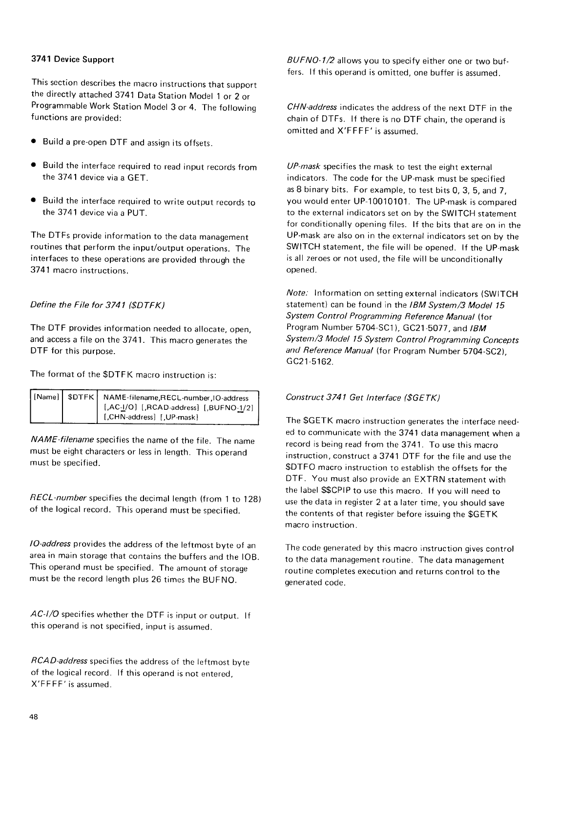
a
3741 Device
Support
This
section
describes
the macro
instructions
thar
support
the
directly
attached
3741
Data
Station
Model
1
or 2 or
Programmable
Work
Station
Model
3 or 4. The followino
functions
are
provided:
o Build
a
pre-open
DTF and
assign its
offsets.
Build
the interface
required
to read
input
records
from
the 3741
device
via
a GET.
Build
the interf
ace required
to write
output records
to
the 3741
device via
a
PUT.
The DTFs
provide
information
to the data
managemenr
routines
that perform
the input/output
operations.
The
interfaces
to these
operations
are
provided
through the
3741
macro
instructions.
Define the File for 3741 ($DTFK)
The
DTF provides
information
needed
to allocate,
open,
and access
a
file
on the
3741. This
macro
generates
the
DTF for this
purpose.
The format
of the
$DTFK macro
instruction
is:
INamei
| $DTFK | ruAME-titename,RECL-number,lO-address
t,AC--L/Ol
[,RCAD-address]
[,BUFNO-i/2]
[,CHN-address]
[,UP-mask]
NAME-filename specif ies
the name
of the f ile. The name
must
be eight
characters
or less
in length.
This
operand
must
be specif ied.
RECL-number
specifies
the decimal
length
(from 1
to 128)
of the logical
record.
This
operand
must
be specified.
lO-address
provides
the address
of the leftmost byte of an
area in main
storage
that contains
the
buffers
and the lOB.
This
operand
must
be specified.
The
amount
of srorage
must
be the record
length
plus
26
times
the BUFNO.
AC-l/O specif
ies whether
the DTF is
input
or output. lf
this operand
is not
specified,
input
is
assumed.
RCAD-address
specifies
the address of the leftmost byte
of the logical
record. lf this
operand is
not entered,
X'FFFF'is
assumed.
48
BUFNO-l /2 allows
you to specify either
one
or two buf-
fers. lf this
operand is
omitted,
one buffer
is
assumeo.
CHN-address
indicates
the address of the next DTF in the
chain
of DTFs. lf there
is
no DTF chain,
the operand is
omitted
and X'FFFF'is assumed.
UP-mask
specif ies
the mask
to test
the eight external
indicators.
The
code for the UP-mask
must
be
specified
as 8 binary bits. For
example,
to test bits
0, 3, 5, and 7,
you
would
enter
UP-l0010101.
The
UP-mask is
comoareo
to the
external indicators
set on bV the SWITCH
statement
for
conditionally
opening files. lf the bits
that
are on in
the
UP-mask
are
also
on in
the external
indicators
set on bv the
SWITCH
statement,
the file
will be
opened. lf the UP-mask
is
all zeroes
or not
used,
the file willbe
unconditionallv
ooeneo.
/Vofe. lnformation
on setting
external indicators
(SWITCH
statement)
can be found in the IBM System/3 Model lS
System Control Programming Reference Manual (Ior
Program
Number
5704
SC1). GC21
-5017.
and
tBM
System/3 Model l5 System Control programming Concepts
and Reference
Manual (for Program
Number 5704-SC2).
G
C2
1
-51
62.
Construct 3741 Get lnterface ($GETK)
The
$GETK macro
instruction
generates
the
interface
need-
ed to communicate
with the 3741
data management
when a
record
is
being read from the 3741 . f o use
this macro
instruction,
construct
a 3741 DTF for the
f
ile and
use the
$DTFO macro
instruction
to establish
the offsets for
the
DTF. You must
also
provide
an
EXTRN statement
with
the
label
$$CPIP
to use
this macro. lf you will need
to
use
the data in register
2 at a later
time,
you should save
the contents
of that register
before
issuing
the
$GETK
macro
instruction.
The
code
generated
by this macro instruction gives
control
to the data management
routine. The
data management
routine
completes
execution
and returns
control
to the
generated
code.
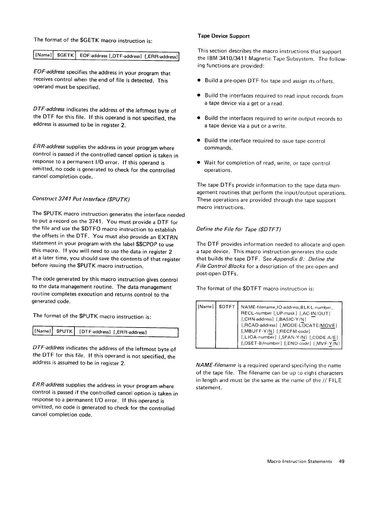
The
format
of the
$GETK
macro
instruction
is:
tNamell $Cerrcl eOf-aOOress
[,DTF-address]
[,ERR-addressl
EOF-address
specifies
the
address
in your program
that
receives
control
when
the
end
of file
is detected.
This
operand
must
be specified.
DTF-address
indicates
the address
of the leftmost
byte of
the DTF
for
this file. lf this
operand
is
not
specified,
the
address
is
assumed
to be
in register
2.
ERR-address
supplies
the
address
in your progr.am
where
control
is
passed
if the
controlled
cancel
option
is
taken
in
response
to a
permanent
l/O
error. lf this
operand
is
omitted,
no
code
is
generated
to check
for the
controlled
cancel
completion
code.
Construct
3741 Put lnterface ($pUTK)
The
$PUTK
macro
instruction generates
the
interface
needed
to put
a record
on the
3741. You
must
provide
a DTF for
the
file
and use
the
$DTFO
macro
instruction
to establish
the offsets in
the DTF. You
must
also
provide
an EXTRN
statement
in
your
program
with the
label
$$CpOp
to use
this
macro.
lf you
will
need
to use
the
data in register
2
at a later
time,
you
should
save
the
contents
of that
register
before
issuing
the
$PUTK
macro
instruction.
The
code
generated
by
this macro
instruction gives
control
to the data
management
routine.
The
data management
routine
completes
execution
and returns
control
to the
generated
code.
The
format
of the
$PUTK
macro
instruction
is:
lNamell $PUTK
| [D-Ir-aodress]
[,ERR-address]
DTF-address indicates
the address
of the leftmost byte of
the DTF for this file. lf this
operand
is not
specified,
the
address
is
assumed
to be in register
2.
ERB-address
supplies
the address
in your program
where
control is
passed
if the controlled cancel
option is taken in
response
to a permanent
l/O error. lf this operand
is
omitted, no code
is
generated
to check
for the controlled
cancel
completion code.
Tape Device
Support
This
section describes
the
macro
instructions
that support
the IBM 341013411
Magnetic
Tape
Subsystem.
The
follow.
ing functions
are
provided:
o Build
a
pre-open
DTF for tape and
assign tts
of
fsets.
o Build
the interfaces
required
to read
input
records
from
a tape device
via
a
get
or a
read.
o Build the interfaces
required
to write
output records
to
a tape
device via
a put
or a
write.
o Build
the interface
required
to issue
tape
control
commands.
o Wait for completion
of read,
write,
or tape
control
operations.
The
tape DTFs
provide
information
to the
tape data man-
agement routines
that perform
the input/output
operations.
These
operations
are
provided
through the tape
support
macro
instructions.
Define the File for Tape ($DTFT)
The DTF provides
information needed
to allocate
and open
a tape device.
This macro instruction
generates
the code
that builds
the tape DTF. See
Appendix B: Def ine the
File Control Blocks for a description of the pre-open
and
post-open
DTFs.
The format
of the
$DTFT macro
instruction is:
INamel
| $DTFT I NAME-filename,tO-address,BLKL-number,
RECL-number
[,UP-mask]
[.AC-tN/OUT]
[,CHN-address]
LBASIC-YiN
J
I,RCAD-addressl
t,MODE-6CATE/MOVEI
[,MBUFF-Y/N ] [.RECFM-code]
[,LlOA-number]
t,SPAN-Y/Nl
t.CODE-A/El
[,OSET-B/number]
[,END
code]
[.MVF-Y/N]
NAME-filename is
a required operand
specifying the name
of the tape file. The
filename
can be up
to eight
characters
in length
and
must
be the same as the
narne
of the
// FILE
statement.
Macro Instruction Statements 49
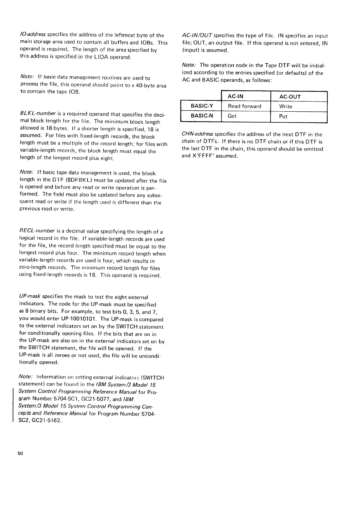
lO-address
specif
ies the address
of the leftmost byte of the
main
storage
area
used to contain
all
buffers
and lOBs. This
operand
is required.
The length
of the area
specified
bv
this
address
is specified
in
the LIOA operand.
Noti:: l{ basic
data managentent
routines
are used
to
process
the file,
tlris
operarrd
should
poir)t
to a 40_bvte
area
to contain
the
tape
lOB.
BLKL-number is
a required
operand
that specifies
the deci-
mal
block
length
for the
f
ile. The minimum block
length
allowed
is
18
bytes. if a
shorter
length
is
specified,
1g is
assumed.
For
f
iles
with fixed-length
records,
the
block
length
must
be
a
multiple
of the record
length;
for files
with
variable-length
records,
the
block length
must
equal
the
length
of the longest
record
plus
eight.
Note: lf basic
tape
data management
is
used.
the
block
length
in
the DTF ($DFBKL) must
be
updated
after
the file
is
opened
and
before
any read
or write
operation
is
per_
formed. The field
must
also
be updated
before
any
subse-
quent
read
or write if the
length
used
is
different
than
the
prevrous
read
or write.
RECL-number
is
a decimal
value
specifying
the
length
of a
logical
record
in
the file. lf variable-length
records
are used
for the
file,
the record
length
specified
must
be equal
to the
longest
record
plus
four. The minimum record
length
when
variable-length
records
are
used is four,
which
results
in
zero-length
records.
The minimum record
length for files
using f
ixed-length
records
is 18. This
operand
is
required.
UP-mask
specifies
the mask
to test
the eight
external
indicators. The code
for the UP-nrask
must be
specified
as
8 binary
bits. For
example,
to test bits
0,3, 5, and 7,
you would
enter
UP-10010101.
The
Up-mask
is compared
to the external
indicators
set
on by the SWITCH
statement
for
conditionally
opening
files. lf the
bits that are on in
the
UP-mask
are also
on in
the
external
indicators
set
on by
the
SWITCH
statement,
the
file
will be
opened. lf the
UP-mask
is
all zeroes
or not used,
the file
will be uncondi-
tionally
opened.
Note: lnformation orr setting
external
indicatr:rrs
{SWITCH
statement)
can
be found int-he
IBM Svstem/3
Modet lS
System Control Programming Reference Manual for pro-
gram
Number
5704-SC1
,
GC2|-5O77,
and IBM
System/3 Model l5 System Control Programming Con-
cepts
and Reference
lVlanual
for Program Number 5704-
sc2.
GC21.5162.
AC-lN/OUT specif ies
the type of file. lN specif ies
an input
file;
OUT, an output file. lf this operand
is not entered,
lN
(input)
is
assumed.
Note: The
operation
code in
the Tape DTF will be initial-
ized
according
to the entries
specified
(or
defaults)
of the
AC and BASIC
operands,
as
follows:
CHN-address
specifies
the address of the next DTF in the
chain
of DTFs. lf there is no DTF chain
or if this DTF is
the last DTF in
the
chain, this operand
should
be omitted
and X'FFFF'assumed.
AC-IN AC-OUT
BASIC-Y Read forward Write
BASIC.N Get Put
EASIC
Yt'N
specrfies
whetlrer
riris
t)'f-F
uses
the
basic
access
method. lf tlris operarrd
is rrot
entered,
N (no)
is
assumed.
lVotes'
1" BASIC Y ntusr
be specified
i{
any
of the following
macro
rnsl.rLt{:tioils
are used
to t.rrocess
fhq
f ile: $RD-f
, $Wnff ,
$CfLl or $W'tT.
2. lf you process
ASCII
f
iles
us;inq
tfre
basic
access method,
you must
tfanslate
the
characters
in
your program.
3. Multivolume
f
iles
are supported
with the
hasic
access
rnethocl,
but the EXTRN statement
that is
provided
must
be
$$BTMM for multivolume
support. $$Afnvl
and $$BTMM should
not be r-rsed
irr
tfre
same
program.
$$Sf MM supports
both
single
ancl mrrltivolr-rme
f
iles.
4" Deferred
cperr
is rrot
allowe<J
with the basic
access
method.
RCAD-address
specif ies
the syrrrbolic
rr:corcl
area
;rdr:lress.
-Ihis
operancl
is required
for all
operatiorrs
using
the
basic
access
method. lf standard
data
rnarragefirent
is userj,
this
operand
is required
for an
output operation
ancl for an
input operation
using move
mocle.
MODE-LOCATEiMOVF irrdir;ates
wlrether
the
lo661s
m66s
or move
rnode
is
used. l{ this
oprerancl
is rrot
specified,
fulOVE
is
assurned. When
locate
rnode
is
sper:ifir:cJ,
tlre
record
address
(RCAD-address)
is
set
tr.l thr:
acicirers of tlre
rr:cord
in
the
buffer. When
move
moclr:
is
Lrsed. re<;orrls
are
rrloveo
fronr the lrr-rffer
tr-r the locatiorr
sltecifiecl
bv tht recorr:
adrlr ess"
Locate
mocle
is valid
only
for iriput filr:s. llric
otraranrj
shoultl
not be used
if BASIC
Y is sr:er;if
ierJ
RE(.:FlVl-t:ttde
specif ies
the reccrcl fornr;11
rrst:tl ior tlrr_, {i1e.
Tlr,'
':odcs
and
their
nrearrirrqs
arr:
Code
F
FB
Vts
i-)
DB
Record Format
Fixecl,
EBCDIC
or
ASCIt
Fixed
blocl<ecl. F-UCt.)lC
or A,SCll
Var iable,
EBCD
lC
Variable
blockerJ,
E
B(lD l(l
Variable,
ASC I I
Variable
blocked,
ASCI
I
lf tiris
operarrd is not specified. F is
assulnecl.
MBUFF-Y/N indicates
whether
rnore
tltar r.rrr:r
irrrf
fr:r
j,r
used.
lf this
operand
is not
specified,
N (rro)
is
assurrrerl.
^fhe
number
of buffers is
deterrnirrer_l
by lltr: lorrqtlr
of tlre
l/O area,
specified
by the LIOA operancl.
.l
iris olrr:rarrrr
should
not be used
if BASIC Y is
spr:ci1ieri.
LIOA-nuntber
is
the
total
r-lecirrral
lenglh
of tlre
l/O area
if
more
than
two buffers
are requirecl
(tvlULjFF
y). lf ttre
number
specified
is zero
or if tiris
entry
is
r.rrrritrcri,
twcr
buffers
are
allocatcd
in the
l/O
area lf this
errrry
is rrr,,l
zero,
as many
buffers
as
possible
are
allocated
in the l,/O
area.
The following
formula
can
be usecl
to rJeternrirre
rire
lerrgth
of the l/O area:
Length
of the l/O area
.= (40 r block lr:ncltlr)
tirrres
(nrrmber
of brrffprsi
This
operand
should not be
used
if BASI()
Y is
slrecified.
SPAN-Y/N
specifies wlretlrer
spannecl
recorrls
arn
Lrst_.r1.
li
spanned
records
are used,
BASIC Y rrrust
also
lrr:
sPr:r;ifilrtl.
lf this
operand is
omitted, N (no)
is assr.rrrrr:r,1.
Sp,,rcifying
SPAN Y causes
the
sparrrretl rer:rird
bit irr
tlrrr tir1.;e l;rtr|l
to
be
set on. When
you use
SPAN.Y,
you n)l.rit
i|ari Ilrr:
rBC-
ords from block
to block.
CODE-A/E
specif ies
wheth+:r
tlrr:
Iilrr
rs
arr
FU{]it lO
f ilt: or
ASCII file. lf the file
is an FBCDIC file,
spr--r-:ity
CODE
l:
lf the file
is
an ASCII file
or
carr
he
r:illrer
ASOII
or EBCDIC,
s;.rtrcify
CODE-A. lf tlris
rtperarrtl
is rrot
lrrtlr:rl_ F
is
assu
rne
(l
_
OSET-B/rtuntber
specif ies
ther lrrr{ f r.:r o
i
fsr
l ,r
i 'rrr
/\SC
I I
blocl<.
B indicates
that the
first
four [lytt:s
o1 tIrr: irlor:k
corr
taitt
the decirrral
block length
and rro l.rrrIfr:r
;;1i:],,i
!r!
l)r{}ii
enl. B is
valid
only when
RECFM U
or tlE(l i lM
DU is
alscr
specif
ied.
Only OSET"B
or CXiE'T,00
;r e vaiitl f
or outf)ut
iiles"
OSt:l-rrunrLrei
s;'recifies,
iri tlnt:irnal,
tlrc
leirc;tfr
rif
tlre
buffer
offset for the
ASCII block. -l-lris
bLrf [er
of fset
is
skipped
over wlten
the
record
is sr"rltlrlrr:rl
t(r
yi)ur
l)toqrlln.
'fhe
maximurn
valid
specification is
OSF-f {ltJ lf rf ris
opr:r
and
is not
specif ied, zero
is assumed.
Macro Inslru(;trorr
Slatt,rrrents 51
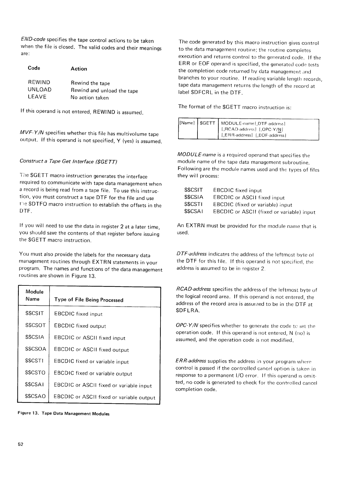
END-code
specifies
the tape
control actions
to be
when
the f
ile
is
closed.
The
valid
codes
and
their
are :
The
code
generated
by this
macro
instruction
gives
control
to the
data management
routine;the
routirre
cnmpletes
execution
and returns
control
to the
generated
code" lf the
ER
R
or EOF
operarrd
rs
specif
ied,
the
generate(J
cLrcl(l tests
the completion
code returned
by data
manageme
nt jlnd
branches
to your routine. lf reading
variatrle
lcnqtlr
recortjs,
tape
data management
returns
tlre length
of the recoro
at
label
$DFCRL
in
the
DTF.
The format
of the
gGETT rnacro
instruction
is:
MODU
LE-name
f
.DTF,address
l
[,RCAD-addrcssl
[,OPC-Y/N]
[,ER
R-acldressl
[,EOF-address]
MODU
LE-name is
a
required
operand
that
specif
ies
the
module
name
of the
tape data
management
subroutine.
Following
are
the module
names
used
ar-rd tfre
types
of files
they
will process:
$$CSIT EBCD
lC f
ixed input
$$CSIA EBCD
lC
or ASCII
fixed
input
$$CSTI EBCDIC
(fixed
or variable)
lnput
$$CSAI EBCDIC
or
ASCII
(f
ixed
or
variable)
input
An EXTRN must
be
provided
for the
rnodule
nanre
that is
used.
DTF-address
indicates
the address of the leftrnost
bytr:
of
the DTF for this tile. lf this
operand is not
specifir;ri,
tlre
address
is
assurned
to be
irr
register
2.
RCAD-address
specif ies
the address
of the leftmost llyte of
the logical
record
area. lf this operand
is not entered,
the
address
of the record
area
is
assur,red
to be in
the DTF at
$DF
LRA.
OPC-Y/N
specif ies whether to generate
the cotje
tL_- set the
operation
code. lf this
operand is nc,rt
entered,
N (no)
is
assumed,
and
the
operation
code is not modified.
ERR-address
supplies the address it-r
your progranr
wherrc
control is
passed
if the corrtrolled
cancel
option is
taken irr
response
to a
permanent
l/O error. lf this operand
rs
omit-
ted,
no
code is
generated
to check
for the contrcrlied
cancel
completion
code.
taken
mean
ings
Code
REWIND
UNLOAD
LEAVE
Action
Rewind
the
tape
Rewind
and unload
the
tape
No
action
taken
lf
this
operand
is not
entered,
REWIND
is
assumed.
MVF Y/N specifies
whether
this
f
ile
has
multivorume
rape
output. lf this
operand
is not specif ied,
y (Ves)
is
assumed.
Construct a Tape Get lnterface ($GETT)
l-ire
$GETT macro
instruction
generates
the interface
required
to communicate
with tape
data
management
when
a record
is
being read
from a tape file. To use
this
instruc_
tion,
you must
construct
a
tape DTF for the file
ano
use
t
re
$DTFO macro
instruction
to establish
the
offsets
in
the
DTF.
lf you will need
to use
the data
in register
2 at a later
time,
you should
save
the
contents
of that register
before
issuing
the
$GETT macro
instructron.
You must
also
provide
the labels
for the necessary
oata
management
routines
through
EXTRN statements
in
your
program.
The
names
and functions
of the data
management
routines
are
shown
in Figure
13.
Figure 13. Tape Data Management Modules
Module
Name Type of File Being Processed
$$CSIT
$$csor
$$CSIA
$$CSOA
$$CSTI
$$CSTO
$$CSAI
$$CSAO
EBCDIC
f
ixed
input
EBCDIC
f ixed
output
EBCDIC
or
ASCII fixed
input
EBCDIC
or
ASCII f
ixed
output
EBCD
lC tixed
or variable
input
EBCDIC
f ixed
or variable
output
EBCDIC
or ASCII
fixed
or variable
input
EBCDIC
or
ASCII fixed
or variable
outpul
52
EOF-address
specif
ies
the address
in your program
that
receives
control
when
the enrJ-of_file
is
detected.
lf this
operand
is
not supplied,
no
code
is
generated
to check
for
the
end
of-file
condition.
Note: lf E
R
R
or EOF
addresses
are
not
specif
ieo, you
should
check
the
return
code
in
your program
to determine
the
outcome
of the
operation
Cottstrrjct a Tape
put lnterface ($pUTT)
This
macro
instruction
generates
the interface
neecled
to
communrcate
with tape
data
management
when
writing
a
record
to tape. You must
provide
a DTF for the
file
and
use
the
$DTFO macro
instruction
to establish
the
offsets
In
the
DTF. You
must
also
provide,
through
EXTRN
statements
in
your program,
the
labels
of the
tape
oata
rnanagement
modules
necessary
to perform
the
output
operation (see
Figure
13).
lf yoir
will need
to use
the
data
in register
2 at
a tater
t,me,
you should
save
the
contents
of that register
before
issuino
the
SPUTT
rnacro
instruction.
The
code generated
by this
macro
instruction
gives
control
to the
data
management
routine.
The
routine
completes
cxecution
and
returns
control
to the
generated
code. lf
the ERR
operand
is
specified,
the
generated
code
checks
the
completion
code
for errors
and
branches
to Vour
error
routine
if errors
occurred.
The
format
of the
$pUTT macro
instruction
is:
MODUI_E-name,is
a recluired
operarrd,
and
specifies
the
name
of the
tape
data
management
subroutine
to be
used.
Following
are
the
module
names
used
and
the
type of
.
files
they
will process:
LENAD-address
specifies
the address
of the rightmost byte
of a two-byte
area
which
contains
the
length
of the
current
record.
This
operand
is
used
only for
variable
files. lf this
operand
is
not
specified,
the
length
of the
record
is
assumed
to be in
the DTF at
$DFCRL.
RCAD-addre,ss
specifies
the address
of the leftmost byte of
the record
to be
put. lf this operand
is not entered,
the
record
address
is
assumed
to be in
the DTF at label
$DFLRA.
OPC-Y/N
specifies
whetner
to generate
the code
to set
the
operation
code. lf this
operand
is
not entered,
N (no)
is
assumed,
and
the
operation
code
is
not modif
ied
in
the
DTF.
ERR-address
specifies
the address
in your program
where
control
should
be
passed
if a
permanent
l/O error
occurs.
lf this
operand
is not entered,
no permanen
L l/O error
checking
code
is
generated
and
you should
check
the
return
code
in
your program
to determine
the
outcome
of
the
operation.
Bead from Tape (gRDT)
This
macro
instruction
generates
an interface
to basic
tape
data
management
to read
from a tape
device.
When
usinq
this
macro
instruction,
you must:
o Provide
a
tape
DTF and
use
$DTFO to estabt
rsh
th€r
offsets
in the DTF.
o Wait
for
completion
of the
input
operation
ancJ
;irr,;l<
for
end-of-file
by using
the
$WTT macro
insrructron.
o Provide
EXTRN statements
in
your program
for ti.;ir
basic
tape
data management
module ($$BTAF,4
rrr
$$BTMM) and for the entry point to the read
rourine
in
that module
(DMBTRW).
lf you will need
to use
the
data
in register
2
at a later
time,
you should
save
the contents
of that register
before
issuing
the $RDT macro instruction. The generated
code
for this
macro
instruction uses
register
2.
The
code generated
by
this
macro
instruction
branches
to
basic
tape
data
management
to begin
the read
operation.
$$CSOT
$$CSOA
$$CSTC)
$$CSAO
EBCDIC
fixed
output
EBCD
lC
or
ASCII
f ixed
ourput
EBCDIC
fixed
or
variable
output
EBCDIC
or
ASCII
fixed
or
variable
output
DTF-atlrJress
specif
ies
the address
of the leftmost byte of
the
DTF for the file. lf this
operand
is not
specified.
the
address
is
assumed
to be
in register
2.
Macro
lnstruction
Statements 53
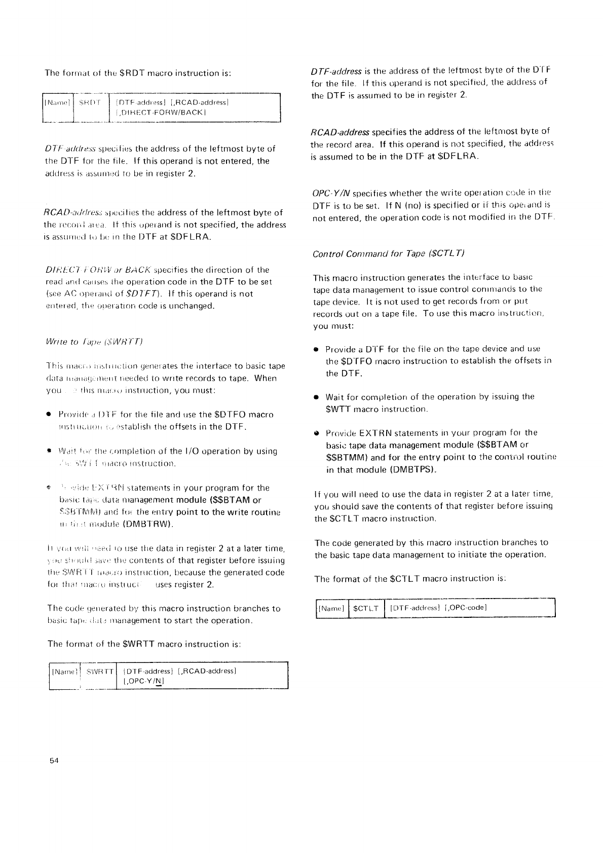
{DTF
addrerssJ
[,RCAD-address]
l.tl
I Fr F_cT,FOHW/BACK
I
The
forrrrat
of the
$RDT macro
instruction
is:
DT t' adrlress slreuit;(js the address of the leftmost byte of
the Dl-F for
the
file. lf this operand is not entered, the
aclrjress
is ilssurn,rrl to be in register 2.
RCAI.)-;ttirlres.t
sl.,ortities the address of the leftmost byte of
tlre rcr:rir,l
,rrr,;i.
lt this
ul)(.riand is not
specified, the address
is
asslttrrtr,l t'.; lrt;
irt
the tJTF
at $DF
LRA.
Dlt':t:(.:'i
i 0lirV :tr
BACi<.
specif
ies the direction
of the
rear,1 arrtl ciirses
llrc operation code in the DTF to be
set
(see
A(l {)t)er.lr1(l
oI .9D7'FT\.
lf this operand
is not
errtererl,
Tlie
(,r.)etatrol
cocle is unchanged.
ItVrrte
tct Iaite i$WH'l'[)
I fris
trrai;i,r rrislr rrr;tion
qerier
ates the
irttertace
to basic tape
rlirta
rr,rra(;{.rrt*rt rrceclecJ
to
wnte rer:ords
to tape. When
yoU 'lils
rrr.i',,r rrrSliltCtiOn,
yOLt
fnUSt:
. Provirlr',r
l)l F tor
tlre
file
and
use the
$DTFO
macro
It:;tt{l(.1.t{]rl r,,
,rsta[ilislr
thc
offsets
in the DTF.
r \{.11
i,ii ftte
(.r)r}rpletion
of the l/O operation by using
., -.'.r
i l':irrr:lU
tilitilli;tiOl1.
* 'r,irlr:
t.')l
i
til'l
slatements
irr
your program
for
tfre
b.rsir:
l.ri,.. Li.tta nlanagenrent
module
($$BTAM
or
s,iitJ
l'tirM,
.ltd l'(,j
the entry
point
to the write routine
rr,
!i:
,l
rtl{)LJ{ll,-'
(DMB
I RW).
it r.'(;ir
\\;tii
:,iirr(l
iil rJse
tlre data irr register
2 at a
later time,
_r
,rtr
sir'
rlii
|
..jiriir
tlrij contents of that register
bef ore
issrrilrg
tire:ii\lVFi
I i iir.r,.rrr instrrrction,
itecause
the
generatecl
code
frlr llrat
1r)ai;i
ri
instt
LtLi Llses register
2.
The r;cicle
qererated
b5,this macro instruction
branches to
llasit; t;r1.r,,
i
j.ji
-,
nlanagetnent
to Start
the
OperatiOn.
The forrnat of the
$WRTT macro instruction is:
DTI:-adclress
is tlre address
of tfre
leftnrost
byte of the D-l'F
for the
file. lf this
t.;perand
is
not
specif
icd, tlte address
of
the
DTF is assunretl
to be
in registcr
2.
RCAD-address specif
ies the address
of the le
firrrost byte of
the
record area.
lf this operand
is
not specified,
the
addiess
is assumed
to be
in the DTF at
$DFLRA"
OPC'Y/N
specifies
whether the
write
operatrorl
t;r;de
in tlte
DTF is
to be set. lf N (no)
is
specified
or il th;s
irile,dtrd ts
not entered,
the operation
code
is not modified
irr the
DTF:'
Control Conrmand tor Tape (.gCTL-7')
l'his macro
instruction
generates
the
inlerf
ace
to basrc
tape data
management
to issue control
conllllands
to the
tape
device.
lt is
not used
to get
records
from or pttt
records out on a
tape
file. To use
this macro
illstrtlcli(lrr,
you Inust:
o Provicle
a D"l-F
ft-rr
the
file on the tape
device
and
trse
the
$D'f
FO rnacro
instruction
to establish the offsets
in
the DTF.
o Wait
for completiorr
of the operation
by issuing the
$WTT macro
instruction.
e Provitle EXTRN staternet)ts
ttr
yuur progrdm
f or the
basid
tape data
management
module
($$BTAM
or
$$BTMlvl)
and for the entry point to the corrir'ol
routinc
in
that nrodule
(DMBTPS)"
lf you will need
to use the
data
in register 2 at a
later lirne,
you
should save
the cotrtents
of that register
bef ore
issuing
the
$C'TL
T rnacr
o irtstrtrction.
The code
generated
by this
rnacro itrstruction branches
to
the
basic tape data
managernent
to initiate
the olleration.
The format of the
$CTLT macro
lnstruction
is:
r--- .-fl--r. _- --""
llNu'r,,1 I $clrr | [Lll
F.adciress]
[,OPC-code] |
l l l ,.-------*_--"-l
Fit-l I
DTF adclressl
[,RCAD-address]
[.oPC,Y/N ]
54
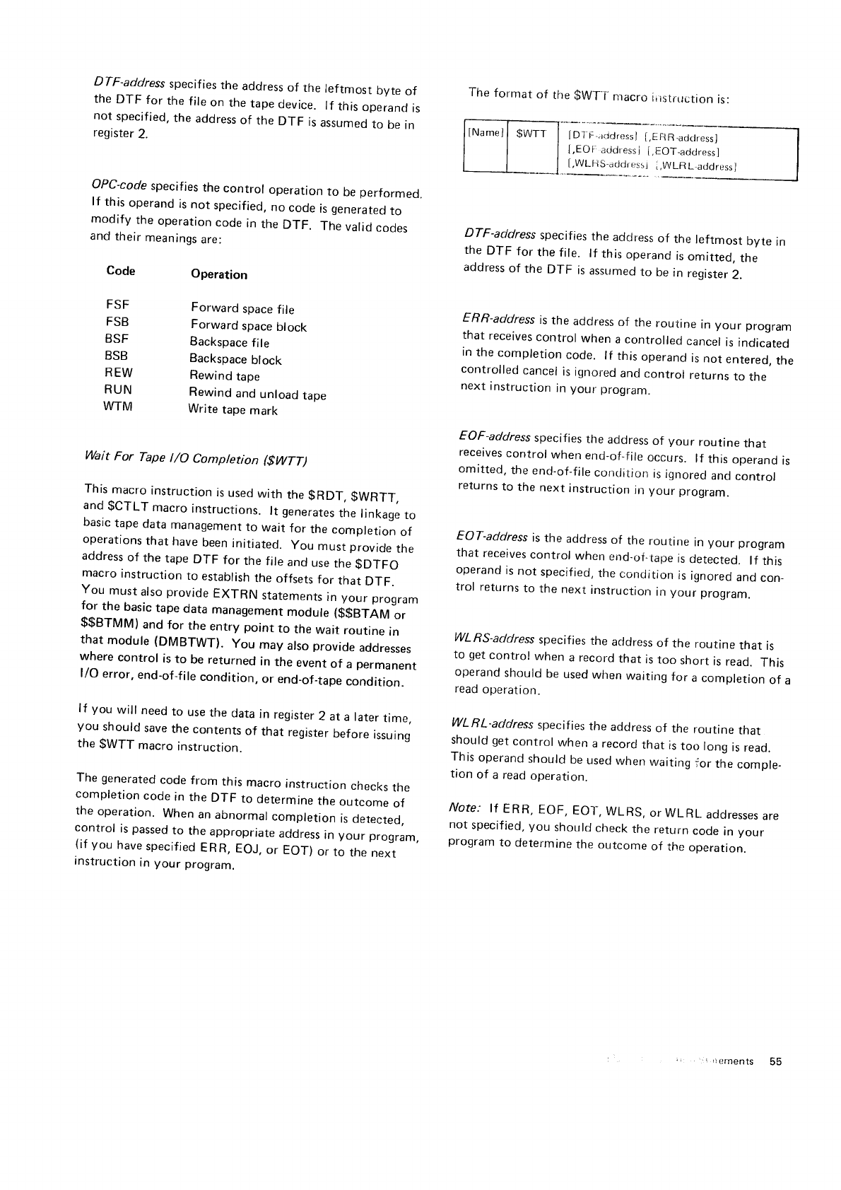
DTF-address
specifies
the address
of the leftmost byte of
the
DTF for the
file
on the
tape
device.
lf this
operand
is
not
specified,
the
address
of the
DTF is
assumed
to be
in
register
2.
OPC-code
specifies
the
control operation
to be
performed.
lf this
operand
is
not specified,
no
code
is
generated
to
modify the
operation
code
in
the
DTF. The
valid
codes
and
their
meanings
are:
Code Operation
The
format
of the
$WT'I.
nracro
i;rstruction
is:
I
DT
F-rrjdressl
i,ERR,addressl
l,EOF,
acidress
j I,EOT_addressl
[,WLl-lS-addrerss]
i.WLR
L atjcjressl
FSF
FSB
BSF
BSB
REW
RUN
WTM
Forward
space
file
Forward
space
block
Backspace
file
Backspace
block
Rewind
tape
Rewind
and
unload
tape
Write tape
mark
DTF-address
specifies
the address
of the leftmost byte in
the
DTF for the
file. lf this
operand
is
omitted,
the
address
of the DTF is
assumed
to be
in register
2.
ERR-address
is
the address
of the routine in your program
that
receives
control
when
a controlled
cancel
is
indicated
in
the
completion
code. lf this
operand
is
not
entered,
the
controlled
cancel
is
ignored
and
control
returns
to the
next
instruction
in
your program.
EOF-address
specif
ies
the address
of your routine that
receives
control
when
end-of_f
ile
occurs.
lf thts
operand
is
omitted,
the
end-of"file
condition
is
ignored
and
control
returns
to the
next
instruction
in
your program.
EOT-address
is
the address
of the routine in your program
that
receives
control
when
end-of"tape
is
detected.
lf this
operand
is
not specified,
the
corrdition
is
ignored
and
con_
trol returns
to the
next
instruction
in
your program.
WLRS-address
specifies
the address
of the routrne
that is
to get
control when a record
that is
too short is
read. This
operand
should
be
used
when
waiting
for a completion
of a
read
operation.
WL
R
L-address
specif
ies
the address
of the routine that
should get
control
when
a record
that is
too long
ls
read.
This
operand
should
be
used
when
waiting
jor the
comple_
tion
of a read
operation.
NOIC: IT
ERR,
EOF, EOT,
WLRS,
Or WLRL.
AdOTCSSCS
ArE
not
specified,
you should
check
the
return
code
in
your
program
to determine
the
outcome
of the
operation.
Wait For Tape t/O Completion ($WfT)
This
macro
instruction
is
used
with the
gRDT, $WRTT,
and
gCTLT macro
instructions.
lt generates
the
linkage
to
basic
tape
data
management
to wait
for the
completion
of
operations
that
have
been
initiated.
you must provide
the
address
of the
tape
DTF for the
file
and
use
the
gDTFO
macro
instruction
to establish
the
offsets
for that DTF.
You must
also
provide
EXTRN statements
in
your program
for the basic
tape
data management
module ($$BTAM or
$$BTMM) and for the entry point to the wait routine in
that module (DMBTWT). you may also
provide
addresses
where
control is
to be returned
in the event
of a permanent
l/O error,
end-of-file
condition, or end_of_tape
condition.
lf you will need
to use
the
data
in register
2 at
a tater
time,
you should
save
the contents
of that register
before
issuing
the
$WTT macro
instruction.
The
generated
code
from this
macro
instruction
checks
the
completion
code
in
the
DTF to determine
the
outcome
of
the
operation.
When
an
abnormal
completion
is
detected,
control is
passed
to the
(
i f y
o
u h
a v e
s
p
e
c i f
i e
d
. ;td'
:uj: :..'i3
fi :',",
:
T : r":"rJ'.,
instruction
in
your program.
,r
ernents 55
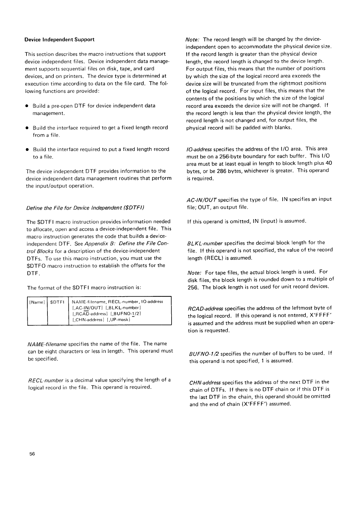
Device Independent Support
This section describes
the
macro instructions that support
device independent
files. Device
independent data manage-
ment
supports
sequential
f iles on disk. tape, and card
devices, and on printers.
The device type is determined at
execution
time
according
to data on the
file
card. The
fol-
lowing
functions
are
provided:
o Build a pre-open
DTF for device
independent data
management.
o Build
the interface
required to get
a
fixed
length record
from a
file.
o Build
the interface required to put
a
fixed
length
record
to a
file.
The
device independent
DTF provides
information
to the
device
independent data
management
routines
that perform
the input/output operation.
Define the File for Device lndependent ($DTFI)
The
$DTFI macro
instruction
provides
information
needed
to allocate,
open and
access
a device-independent
file. This
macro
instruction
generates
the code
that builds
a device-
independent DTF. See
Appendix B: Define the File Con-
trol Blocks
for a description
of the device-independent
DTFs. To use this
macro instruction,
you must use the
$DTFO macro instruction
to establish
the offsets
for the
DTF.
The
format of the
$DTFI macro instruction
is:
ltrtamel
I $DTFI I NAME-filename,
RECL-number,
lO-address
[,AC-l
N/OUT] [,BLKL-number]
[,RCAD-address]
[,BUFNO-1
/2]
[.CHN-address]
[,UP-mask]
NAME-filename specifies
the name of the f ile. The name
can be
eight characters
or less in length.
This operand
must
be
specified.
RECL-number
is a
decimal
value specifying
the
length of a
logical record
in the
f
ile. This
operand
is required.
Note: The record length
will be
changed by the device-
independent open to accommodate
the
physical
device size.
lf the record
length is
greater
than
the
physical
device
length, the record length
is changed
to the
device
length.
For output files,
this
means that
the
number of positions
by which the size
of the logical
record area
exceeds
the
device
size
will be
truncated
from the
rightmost
positions
of the logical
record. For input
f iles, this
means that
the
contents
of the positions
by which the size
of the logical
record area
exceeds
the device
size
will not be
changed.
lf
the record length
is less than
the physical
device length,
the
record length
is not changed
and,
for output files, the
physical
record will be
padded
with blanks.
lO-address
specifies
the address
of the l/O area. This area
must be
on a 256-byte boundary for each buffer. This l/O
area
must be at least
equal
in length to block
length
plus
40
bytes.
or be
286 bytes,
whichever
is
greater. This operand
is
required.
AC-tN/OUT specifies
the
type of file. lN specif
ies an
input
file;
OUT,
an
output file.
lf this
operand
is omitted,
lN (input)
is assumed.
BLKL-number specifies
the decimal
block length
for the
file. lf this
operand
is
not specified,
the
value of the
record
length
(RECL)
is assumed.
Note: For tape
files, the actual
block length
is
used. For
disk
files. the block
length
is rounded
down to a multiple
of
256. The
block
length
is
not used
for unit record
devices.
RCAD-address
specifies
the address
of the leftmost byte of
the
logical
record. lf this operand
is not entered,
X'FFFF'
is
assumed
and
the address
must
be supplied
when an opera-
tion is
requested.
EUFNO-I 2 specifies
the
number
of buffers
to be
used. lf
this
operand
is not specified,
1 is assumed.
CHN-address
specifies
the address
of the next DTF in the
chain
of DTFs. lf there
is
no DTF chain or if this DTF is
the
last
DTF in
the chain,
this operand
should be
omitted
and
the
end of chain
(X'FFFF')
assumed.
56
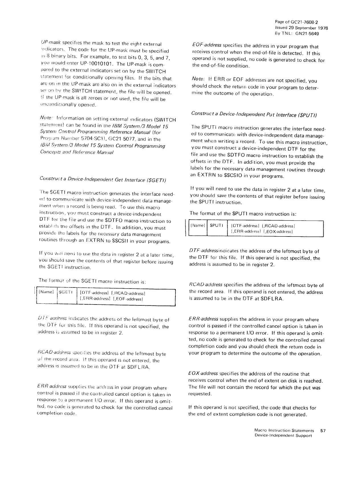
i-.lP-ntask
specif
tes
tire mask
to test the eiqht
external
,riiicatorr. l-he
cocjl for tl.rc
L,rp-masi<
must be
specifiecl
.:,8
binar'/
bits. For
example.
to test
b;ts
0,3, 5, and 7,
y.rrr
v1/outd
enter
UP-''|
00j0101. The Up-mask is
com_
lrare:r.i
to the
externa!
indicators
-set
on lly the
SWITCH
riilirrmeni
tr-rr
conditiorrally
opr:rring
files. lf tl.ie
bits
that
a!'c
()r-i
l!'!
the LJP'rnask
arc
also
on in
rhe
externai
indicators
!cr.jfr I'v the
SWITCH
staterneril,
the
file,,vili
be
oirenecl.
ti the
LiP-nrask
is
all zeroes
or riot
used,
the fi!e
will be
.
J!
lui,ilrii
I :,.lnal
ly opett-:tl.
Note lnltymation
on
setting
uxrernal
rrldicatr:rs (SWITCH
staierilrrnr)
can
be foLrnd
in the ltlM System/3
Model lS
Si,srerri Coritrcl Praerantnting Referenr:e Manual (Ior
Pro,j:rm
i\ii:iirire:-
5704-SC1i,
(jC21 b077.
and
in
the
!iliv4 Sotsternt3 f,4odel 15 Sy:;tetn Cantrol programming
Cr.t
nc e7 t
rc a n rJ fl r:f
i:.ett
ce M
a,n r.
ta
I
Corsstruct
a Device-lndependent Get lnterface t$GETt)
i-l;e
$GETI macro
instruclron
generates
the intertace
need
e{i
to commuricate
with rlevice_irrdepenclent
data
manage_
irenl ,./vileri
a record
is
berng
reaci.
-To
use
this
rnacro
insti
uctiori, y()'-J
must
construct
a device-independent
DTF ir.rr
tire fiie
irrrd use
the
$D'IFC)
macro
instructron
to
estaili,::f
i rnc
ojfsets
in
the llT F. lrr
adclition,
you must
provrde
thu
iabels
fttr
the
nu{lessary
data managernent
routrnes
rnfc)ugh
an
[:Xl-RN to $$CSll in your programs.
lf yr:r,i
rr,,li
i!e.+(j
to use
the
rjat_a
in rr:gister
2 at
a
later
time,
Vor-i
shoi:id
save
[he
content$
of that
register
before
rssuirrg
the
$G
E-J'l
instructtr-;n.
The
flrnrar:f the
$GETI macrt_r
instruction
is:
Df ! auriress iriiircati;s
the
address
of the leflmost
byte
oi
ihc flTF iur i.itis
iiic. lf this
operantl
is rrot
specifiecl,
the
acjdress
ir usbumed
to be in
rt:gister
2.
h'CAD,aci,Jre.rs:'lrec;i:cs
the adclress
of the leftmost byte
ui ftrer.ecord
al;a. ii this
oprerand
is not eirterecl,
the
address
rs
assirmer_{
ti.r lte
rn
tire
D
T
F ar
$DF
L RA.
EllR address
sr.tprg.rlig5
f.iic
a{J(lr:jss
in your progran}
wnere
control
is
passetl
il iire
contrrrlicd
cancei
option is
taken
in
resporise
io a
pernl.rrrent
l/O error. lf this
operantJ
is
omit.
ted,
no
cocle
is
qirner
ated
to check
for
the
controlled
cancel
cornpletion
codc.
Pase
of
GC21_7608_2
lssued
29
September
197g
By TN
L: c
N21-5649
EAF-address
specif
ies
the address
in your program
that
receives
control
when
the
end-of-file
is
detected.
lf this
operand
is
not supplied,
no
code
is
generated
to check
for
the
end-of-file
condition.
Note: lt ERR or EOF
adclresses
are
not
specified,
Vou
should
check
the
return
code in
your program
to deter-
rnine
the
outcome
of the
operatron.
Construct a Device-lndependent put lnterface ($pUTt)
I he
$Pl-.t'l-l macro instructron
generates
the interface
need_
ed
to commur-ricate
with device_independent
data
manage-
ment
when
writing
a record.
To use
this
macro
instruction,
you must
construct
a device-independent
DTF for the
f
ile
and
use
the
$DTFO macro
instruction
to establish
the
oifsets
in
the If
TF. In
addition, you must
provade
the
labels
f
or the
necessary
data
management
routines
throuoh
an EXTRN
ro
$$CSIO
in
your
programs.
lf you will need
to use
the
data
in
register
2 at
a
later
time.
you
should save
the contents
of that register
before
issuing
the
gpurl instruction.
Jhe format
of the
gPUTI
macro
instruction
is:
INanrel
| $PUTI i IDTF
addressl
l,RCAD.addressl
[.ERR-address ] {,EOX.addressl
DTF addressincl;cates
the address
of the lef
tmost byte of
the DTF for this file. lf this
operand
is not specified,
the
address is
assumed
to be in reqister
2.
RCAD-adclress
specif ies
the address
of the leftmost bvte of
the record
area. lf this
operand
is not enterecl.
the
address
is
assumed
to be in
the DTF
at
$DFLRA.
ERR-address
supplies
the address in your program
where
control
is
passed
if the controlled
cancel
option is taken in
response
to a permanent
l/O error. lf this
operand is
omit,
ted,
no
code is
generated
to check
for the controlled
cancel
completion
code
and
you should
check
the return
code in
your program
to determine
the outcome
of the operation.
EOX-address
specif
ies the address
of the routine tnat
receives
control
when
the
end of extent
on disk is reached.
The file
will not contain
the
record
for which
the
put was
requested.
lf this
operand
is
not specified,
the code
that
checks for
the end
of extent
completion
code is not generated.
Macro
Instruclion
Statements 57
Device-
I
ndependent
Support
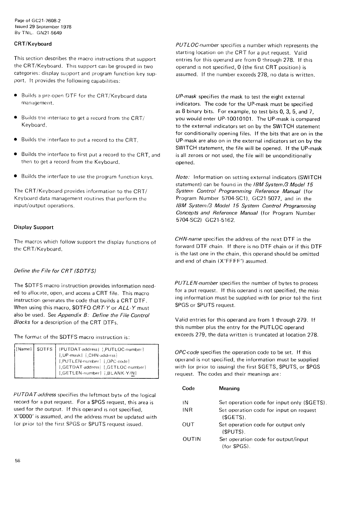
Page
of GC21-76O8-2
lssued 29 September 1978
BY
TN
L. GN2I-5649
CRT/Keyboard
This section describes
the
rnacro
instructions
that
support
the
CRT/Keyboard. This
support
carr be
grouped
irr
two
categories:
display
sur.lport and
prograrn
functicn key
sup
port. lt provides
the
following
capabilities:
Builds
a
pre-open
D]-F for the CRTi Keyboard
data
manilgernerlt.
BuilrJs
tne
intertace
to get
a record
{rom tne
CRTi
Keyboard.
Builds
the
interface
to put
a record
to the
CRT.
Builds
the interface
to first
put
a record
to the
CRT,
and
then
to get
a record f rorn
the KeVboard.
o Builds
the interface
to use
the
prograrn
functron
keys.
The
CRT/Keyboard
provides
information
to the
CRTI
Keyboard
data management
routines
that J:erform
the
input/output
operations.
Display
Support
The macrcs
which follow support
the display functions
of
the CRT/Keyboard.
Define the File for CRT ($DTFS)
The
$DTFS
macro instruction
provides
information
need-
ed to allocate,
open, and
access
a
CRT file. This
macro
instruction
genetates
the code
that builds
a CRT DTF.
When
using
this
macro,
$DTFO CRT-Y or 4LL-Y must
also be used. See Appendix B: Define the File Control
Rlocks
for a description
of the
CRT DTFs.
The
formar
of the
$DTFS
macro instruction
is:
IName]
| $DTFS I lPUTDAT,addressl
I.PUTLOC-numberl
[,UP-mask
I i.CHN'address]
[,PLJ-ILEhl-nurrrber
I i,OPC.code ]
I,GETDAT addressj
[,GETLOC nurnberl
[,GETLEN-number] i,BLANK,Y/N l
PUT'DAT-address
specifies
the leftmost byte of the logical
record for a
put request. For
a
$PGS
request,
this area is
used f
or the
output. lf this operand
rs rrot
specif ied,
X'0000' is
assumed,
and
the
addr-ess rnust
be
updatecl
with
(or
prior
to) the
f irst
$PGS
or $PUTS
request
issued.
PUTLOC-number
specif ies
a
number
which represents
the
starting location
on
the CRT for a
put request.
Valid
entries for
this operand
are
from 0 through 278. lf this
operand rs not specif
ied,
0 (the
f irst
CRT position)
is
assumed.
lf the number
exceeds
278.
no
data is written.
UP-mask
specif
ies
tl're maSk to test
the eight
external
indicators. The
code
for the UP-mask must be specif ied
as 8 binary
bits.
For
example,
to test bits
0,3,5, and 7,
you
would enter
UP-10010101.
The
UP-mask
is
compared
to the external
indicators
set on bV the SWITCH statement
for conditionally
opening f
iles. lf the bits that
are on in
the
UP-mask
are also on in
the external indicators
set on by the
SWITCH statement,
the file
will be
opened. lf the UP-mask
is all
zeroes
or not used.
the file will be unconditionally
opened.
fuote.' Information
on setting
external
indicators
(SWITCH
statement) can be found in the IBM system/3 Model |
5
Systen Control Programming Reference Manual (for
Program
Number
5704
SCll, GC21
5077,
and in the
IBM System/3 Model l5 System Control Programrning
Concepts and Reference Manual (for Program Number
5704 SC2) GC21.5162.
CHN-name
specif ies
the address of the rrext DTF in the
forward DTF chain, lf there is no DTF
chain or if this DTF
is the last
one
in
the chain,
this operand should be
omitted
and
end of chain
(X'FF
FF')
assumed.
PIJTLEN-number
specif
ies
the number of bytes to process
for a
put request. lf this operand is not specified,
the miss-
ing information must
be supplied with (or
prior
to) the first
$PGS or SPUTS
request.
Vaiid
entries
for this
operand are
from 1 through
279. ll
this number
plus
the entry for the
PUTLOC
operand
exceeds 279,the data written is
truncated at
location
278.
OPC-code specif ies the operation code to be set. lf this
operand is not specified,
the
information must
be supplied
with (or
prior
to rssuing)
the
first
$GETS, $PUTS,
or $PGS
request. The codes
and
their meanings
are:
Code
IN
INR
OUT
OUTIN
Meaning
Sct
operation code for input
only ($GETS).
Set operation code
for input
on request
($G
ETS).
Set
operation code
for output only
($PUTS).
Set operation code for output/input
(for
$PGS).
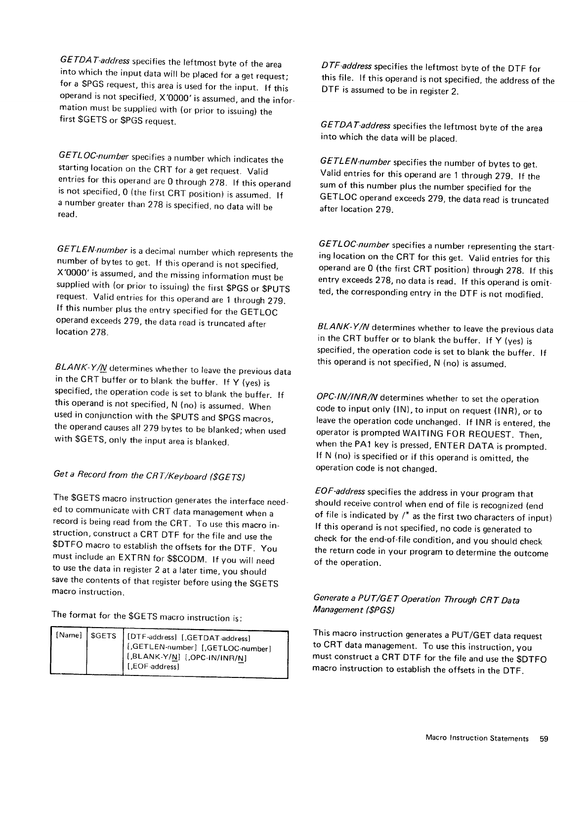
GETDAT-address
specifies
the leftmost byte of the area
into
which
the input
data
will be
placed
for a
get
request;
for a $PGS
request,
this
area
is
used
for the
input. lf this
operand
is
not specifiecl,
X.0000, is
assumed,
and
the infor
mation
must
be
suppliecJ
with (or
prior
to issuing)
the
first
$GETS
or $pGS
requesr.
GETLOC-number
specifies
a number which indicates
the
starting
location
on the
CRT for a
get
request.
Valid
entries
for this
operand
are
0 through
27g. lI this
operand
is
not
specified,
0 (the
first
CRT position)
is
assumed.
lf
a number
greater
than 27g is
specified,
no data
will be
read.
GETLEN-number is
a decimal
number which represents
tne
number
of bytes
to get. lf this
operand
is
not specified,
X'0000' is
assumed,
and
the
missing
information
must
be
supplied
with (or
prior
to issuing)
the first
$pGS
or $pUTS
request.
Valid
entries
for this
operand
are
1
through
279.
lf this
number plus
the
entry
specified
for the
GETLOC
operand
exceeds
279, the
data read
is
truncated
after
location
278.
ELANK-Y/A determines
whether to leave
the previous
data
in
the
CRT buffer
or to blank
the
buffer. lf y (yes)
ls
specified,
the
operation
code
is
set
to blank
the
butfer. lf
this
operand
is
not specified,
N (no)
is
assumed.
When
used
in
con.iunction
with the
$PUTS and
$pGS macros,
the
operand
causes
all
279
bytes
to be
blanked;
when
used
with $GETS.
only the
input
area
is
blanked.
Get a Record from the CRT/Keyboarcl ($GETSI
The $GETS macro instruction
generates
the interface
need-
ed
to communicate
with CRT
data
management
when
a
record
is
being
read
from the
CRT. To use
this
macro
in-
struction,
construct
a CRT DTF for
the
file
and
use
the
$DTFO macro
to establish
the
offsets
for the
DTF. you
must
include
an EX'f
RN
for $$CODM. lf you will need
to use
the
data
in register
2 atalater
time,
you should
save
the contents
of that register
before
using
the $GETS
macro
instruction.
The
format
for the
$GETS macro
instruction
is:
tNamel | $GETS I IDTF.address]
[.GETDAT_address]
[,G
ETLEN-number]
[,GETLOC-number]
[,BLANK-Y/N] t,OPC-I
N/I
NR/N]
[,EO
F
-addressl
DTF-address specif
ies
the leftmost byte of the DTF for
this
file. lf this
operand
is
not
specified,
the
acldress
of the
DTF is
assumed
to be in register
2.
GETDAT-address
specifies
the leftmost byte of the area
into
which
the
data
will be
placed.
GETLEN-number specifies
the number of bytes
to get.
Valid entries
for this operand
are 1 through 27g. lf the
sum
of this
number plus
the number
specified
for the
GETLOC operand
exceeds
279, the
data read
is
truncated
after location 279.
GETLOC-number specifies
a number representing
the start_
ing
location
on the
CRT for this
get. Valid
entries
for this
operand
are
0 {the
first
CRT position)
through
27g. lf this
entry exceeds
278, no data is read. lf this operand
is
omit_
ted,
the corresponding
entry in the DTF is not modified.
ELANK-Y/N determines
whether to leave
the previous
data
in
the
CRT buffer
or to blank
the buffer. lf y (ves)
is
specified,
the
operation
code
is
set
to blank
the buffer. lf
this
operand
is
not
specified,
N (no)
is
assumed-
OPC-lNlNR /y'y'
determines
whether
to set
the operalon
code
to input
only
(lN),
to input
on
request
(lNR),
or
to
leave
the
operation
code
unchanged.
lf INR is
entered.
the
operator
is
prompted
WAITING FOR REOUEST. Then,
when
the PA1
key is
pressed,
ENTER DATA is
prompted.
lf N (no)
is
specified
or if this
operand
is
omitted.
the
operation
code is
not changed.
EOF-address
specifies
the address
in your program
that
should
receive
control when end of file is
recognized
(end
of file is indicated
by /* as the first two characters
of input)
lf this operand
is
not specified,
no code is
generated
to
check
for the
end-of-f
ile condition,
and
you should
check
the return
code in your program
to determine
the ourcome
of the operation.
Generate a PIJT/GET Operation Through CRT Data
Management ($PGS)
This
macro instruction generates
a pUT/GET data request
to CRT data
management.
To use
this instruction,
you
must
construct
a
CRT DTF for the file
and use
the
$DTFO
macro instruction to establish
the offsets
in the DTF.
Macro
Instruction
Statements Sg
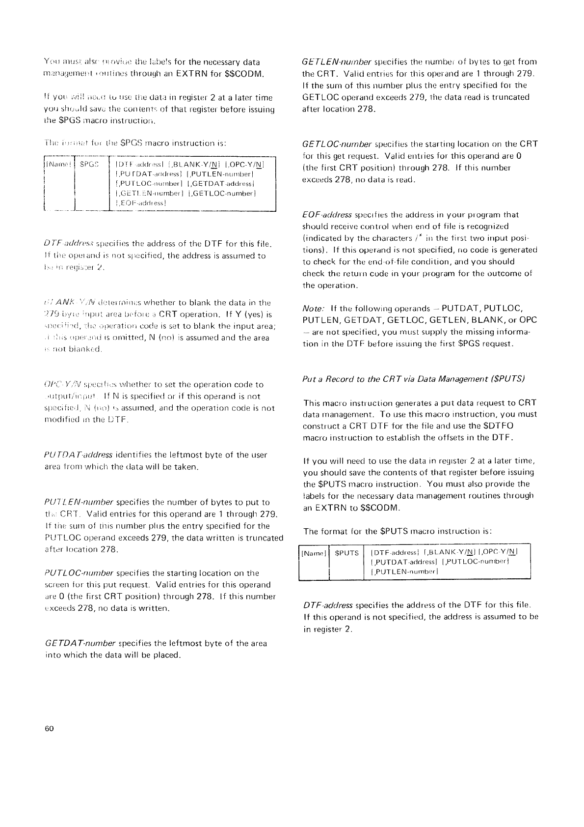
h;:J;;;.,-T
tll
iil
itl
.t_ -_-- __f-
Yi,{! itiu!i itls{ ilr'}vir
trl ilte l.;irels for-
the neccssary
data
mi.r!)td]crnellt
'lrrlint:s tlrrorrqh
an EXTRN for $$CODM.
It yor, ;,rill
;rrr(.r
j iu !tsc
tiio tlat.r irt registef
2 at a laler time
yorr shr,,.,l<1
save thc curtient.r
cf that register
before issuing
,he
$PGS
;ndcro irrstr'rrctrur,.
il;1;
ilri,tirf {L,r
tlre
$PCll rnacro
instruction
is:
D.l
F adcln's;
slrecif
ies
tho
address of the DTF for this file.
!f tirt: r'rfrurarrd is r0t slir:cified,
the adclress is assurned
to
lr'rrlllO{jii-el
7.
t; i ANk 'f'.fu
rillt{itrniiti;s rnrhether
to blank the data in tlte
'..1./1it',ri,:;rrprr'.
itrr:a bi'fort; .i
CllT operation. lf Y (yes)
is
.rici:itr''rl,
rlr.r,.rrrcralir:rrcoclc is
sot to blank the input
area;
.r
rlr,:
|trrr.rrrr.i rs
Ornittr:d, N (|o) is
assunred
and the area
i: fti)l
l)iilrll(ird.
!.)l'l:
y',t:\i
r;1.'ccrii':s
lvhether
to set the operation code
to
'ull)r.tl/'irtjril
lf frl
is specif ieti
or
if
this operand is not
s1;lr:illt:'1.
\ irrr-rJ
ir dssutfled,
iltrd the operation code is not
trodif
icti ur
the DTI-.
PLJ T t)A T-address
identif ies
the lef
tmost byte of the user
area
1rc)n)whiclrthe
rlata
will
be taken.
PUT
!, EAI-number
specif
ies
the number of bytes to put to
ti,,r CRT. Valid entries
for
this operand are 1 through 279.
lf lire
sunr ol tiris
number
plrrs
the entry
specified
for the
Pt
JTL..OC
olrerand exceeds
279, the data written is truncated
aft.rr
location
278.
PUTLOC-nurriber
specif ies the starting location
on
the
screen ior
this
put
request. Valid
entries
for
this operand
ar.e
0 (the
first
CRT
position)
through 278. lt this number
,
xcciiJs
2/8, no dala is written.
GETDAT-number specifies the leftrnost
byte of the area
into
which the data will be
placed.
GEf LEN-nurnber
specifies
tho numbe.
of bytes
to get
fronr
the
CRT. Valid entries
for
tlris
operand are 1 through 279.
lf the surn of this
number
plLrs
the entry specitied
I'or the
GETLOC
operarrcl
exceerls 2/9, the clata reaci
is
truncated
after
location 278.
GETLOC-nurnber specif
ies the starting
location
on the
CRT
for
this
get
re(luest. Valid errtr ies
for this operand
are
0
(the
first CRT positicln)
through
278. lf tfris number
excceds 278, no data is read.
EOF-address specrtres the address in your progranr
that
should receivc c()ntrol \'vhen end of file is recogrrized
(indicated
by the
characters
/* iri tire
tirst
tlnro irrput
posi.
tions). lf this operand
is
not specif
ied, no code
is
generated
to check for the er.rd-rif-file
condition,
arrd
you should
check
the
return
code
in
your pfogram
tor the outcome ot
the operation.
Note: lI the followinq operands
- PUT DAT, PUTLOC,
PUTLEN, GE-TDAT,
GETLOC.
GETLEN,
BLANK,
oT OPC
'- are not specitied,
you must
supply the missing
informa-
tion in tl.re
DTF:
before
issuing tlre
first
$PGS
request.
Put a Record to the CRT via Data Managentent ($PUTS)
This maclo instruction
generates
a
put
data request to CRT
data
tnanagement. To use this macro
instruction,
you must
construct a CRI'DTF for the file and
use
the
$DTFO
macrr.'
instr uction
to establish
the offsets
in the DTF.
lf you will need to use
tlle
data in
regrster
2 at a
later tirne,
you should
save the contents of tfrat
register
before
issuing
the
$PUTS
macro irrstruction.
You must
also
provide
the
labels for the necessary clata
management
routines
through
an
EXTRN
to $$CODM.
The fornrat
for the SPUTS
macro instruction is:
IDTF'addressi
t,BLANK
Y/Nl t,OPC
Y/!L]
[,PUTDAT-acldress] [,PUTLOC-nuntbt:r
j
[,PUTLEN-number
i
DTF'address specif
ies the address
<lt
the DTF for this f ile.
lf this operand is not specified,
the address
is assumed
to be
in
register 2.
IDI I ac]rlr,:ssl
i.BLANK-YiNj I.OPC-Y/Nl
l.PU
f DAI arjriressl
[,PUTLEN-nLrrrrtrer]
l,PlJ
IL.OC nLrrrberl [,GEfDAT,a<ftiress]
i,GL:i-l i:N'rrurnber
I [.GET
[-OC'nunrber]
i.IO[:;rdriressJ
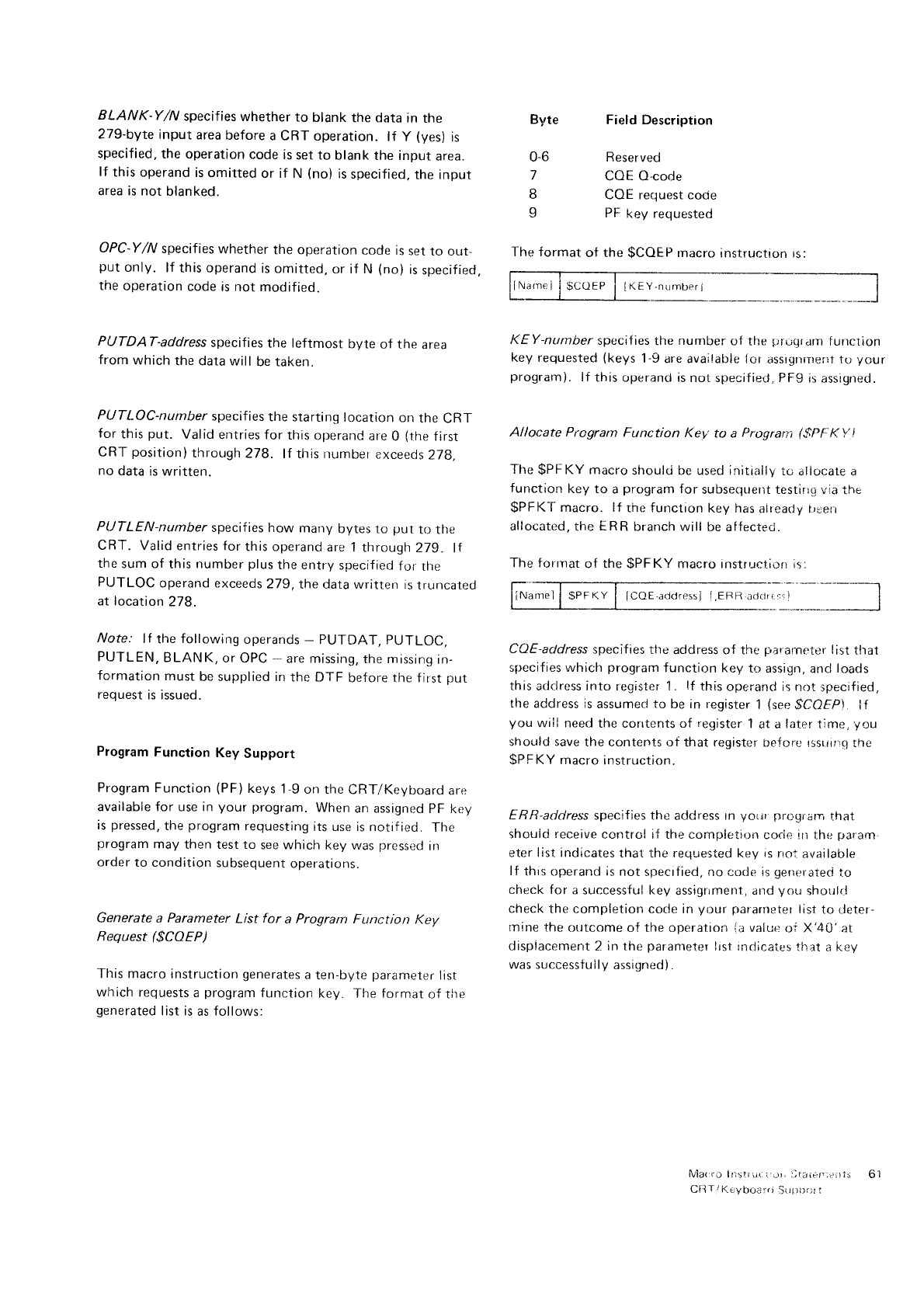
BLANK-Y/N specifies
whether
to blank the data in the
2
Z9-byte
input
area
before
a CRT operation. lf y (ves)
is
specified.
the
operation code
is
set to blank
the input
area.
lf this operand
is omitted
or if N (no)
is
specified,
the input
area is not blanked.
OPC-Y/N
specif ies
whether the operation
code
rs
set
to out-
put only. lf this operand
is
omitted,
or if N (no)
is
specified.
the
operation
code is not modified.
PrlJTDAT-address
specifies
the leftmost byte of the area
from which
the data will be taken.
PIiJTLOC-number
specifies
the starting
location on the CRT
for this
put. Valid
entries for this
operand
are
0 (the
first
CRT
position)through
278. lf this rrumber
exceeds
278.
no
data
is written.
PIJTLEN-number specif ies how many bytes to put to the
CRT. Valid
entries for
this operand
are
i through
279. lf
the
sum of this
number
plus
the entry
specified
for the
PTJTLOC
operand exceeds
279,the rlata
written is
truncated
at location
278.
N'ote: lf the
following
operands
- PUTDAT, PUTLOC,
PIJTLEN,
BLANK,
or OPC
- are missing,
the missrng
in-
fc,rmation
must
be supplied irr
the DTF before the first
put
request
is issued.
Program
Function Key Support
Program Function
(PF)
keys
1-9
on the
CRT/Kevboard
are
al'ailable for use in
your program.
When
an assigned
PF key
is
pressed,
the
program
requesting
its use is
notified. The
program
may
then test to see which
keV was
pressed
in
order
to condition
subsequent
operations.
Generate a Parameter List for a Program Function Key
Request ($COEP)
This macro
instruction
generates
a
ten-byte
parameter
list
which requests
a
program
funr:tion
key. The format
of the
generated
list is
as
follows:
KEY-number specif ies
the number of the p:ri.rqr.rm
{unction
key requested
(keys
1-9
are available lor assignrnenf to your
program). lf this operanrJ is
not specified, PFg
is
assigned.
Allocate Program Function Key tct a Prograrn ($PFKy'l
The
$PF
KY macro
shoulci be used initially
ro aliocate a
function
key to a
program
for subsequent testinG via
the
$PFKT'
macro. lf the function
key has
aiready i;i:err
allocated.
the ERR branch will be affecteri.
The forrnat
of the
$PFKY macro instructiori
is
CoE-address
specifies the address of the pararneter
list
that
specifies which program
function key
to assign, and
loads
this
adciress into registei 1. lf this
operand is not specified,
the address is
assumerJ to be in register
1 (see
$COFPi if
you wiil need
the contents of register
1
at a
later
time,
/ou
should save
the contents
of that register beJcre rssrrirrq
the
SPFKY
macro
instruction.
E R R-address
specif ies the address
In yc)r.n progtam that
shouid
receive
control if the completion
corie ilt the
param-
eter list irrdicates
that the requested
key is
rroi
available
lf this operand is
not specrfied, no codr:
iB
genelated
to
ctieck for a successful
key
assigrrment, and
you shoulri
check
the completion
code in
your []ararneier
list
to cleter-
rnine the
outcome
of the operation ia
vaiue
oi X'40'at
displacement
2 in
the
parameter
lrsf indicaies
that
a
key
was
successfully
assigned).
lviat:ro Ilistr iir: i J', illaiary;:lis
Cfl T
/KrVboarrj Sirtli),j:
t
Byte
06
7
8
I
Field Description
Reserved
COE O-code
COE request code
PF
key requested
The format
of the
$CQEP
rnacro
instruction rs:
It.E
Y
-n
umber
I
61
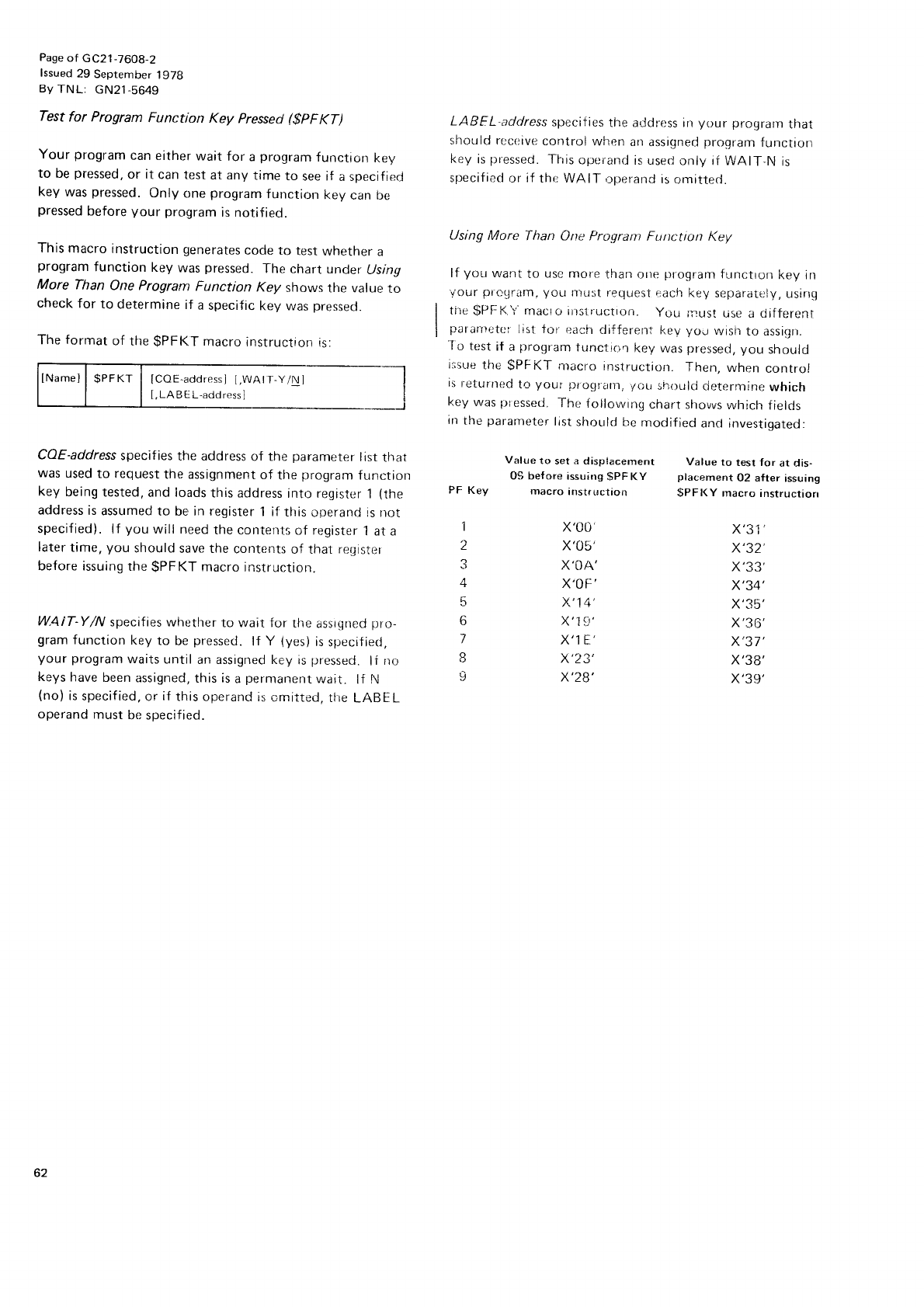
Page
of GC21
-7608-2
lssued
29 September
1978
8y TNL: cN21-5649
Test for Program Function Key pressed
($pFKT)
Your program
can
either
wait for a
program
f
unctron
Key
to be
pressed.
or it can
test
at any time to see if a specified
key
was
pressed.
Only
one
program
function
key
can bc
pressed
before
your proEram
is
notified.
This
macro
instruction
generates
code
to test
whetner
a
program
function key was
pressed.
The chart under
tJsing
More Than One Program Function Key shows tlie value to
check
for to determine
if a specific
key was
pressecl.
The
format of the
$PFKT macro
instruction
is:
lNamell
$PFKT
I lCOb.addrcssi
l,WAtr-y,Nl
[,
LA
B
E
L-add ress
]
CQE-address
specif ies
the address
of the parameter
list
tlrat
was
used
to request
the assignment
of the
program
function
key being
tested,
and loads
this address
into register
1 (the
address
is
assumed
to ber in register
1 if tlris
operancJ is not
specified).
lf you will need
the
contenl.s of register
1 at a
later
time,
you should
save the
content:;
of that rerlistttr
before issuing
the
$PFKT macro
instruction.
WAIT-Y/N specifies
whether
to wait for the
assrgned
pro-
gram
function
key
to be
pressed.
lf Y (yes)
is
specified,
your program
waits
until
an assigned key is
pressed.
lf rro
keys
have
been
assigned,
this is
a
permanent
wait. lf N
(no)
is
specified,
or
if
this
operand is
cmitted,
tlre
LABEL
operand
must
be specified.
LABEL-address
specifies
the address irr
your prograrn
that
should receivt-r
cnntrol
when
an
assigned
proqram
function
key
is
pressed.
Tfris
operand
is used
only if WAIT-N
is
specif
ied
or
if
the WAIT
,rperanC
is
omitted.
Using More 'fhan Orte Proqram Furtction Key
lf you warrt
to use more
ilhan
orre
proqram
functron
key in
vour prcqram,
you ff11:it request
each key
separatr:ly,
using
tile
$PF
K. Y'
rnacio
iilslructron. Y(ru
rrust r-ise
a ciifferent
paranretoi
list ior r:acfi
clifferent
keV
yod rvish
to assiqri.
'To
test
if a
program
tunctio't key
was
pressed,
you should
ilsue
the $PFKT nracro
instruction. Then,
when control
is
returrred
tLr
your Dr.ograrrn,
Torr
shilulci
cietermine
which
key
was
plessed.
The
iollowrng
chart
shovus
which
f ielcls
In
the
parameter
list
should
be
modified
ancl investigated:
Value to set a disp{acement Value to test for at dis-
09 before issuing gPFKY placement 02 after issuing
PF Key macro instruction $pFKy macro instructiorl
1 X',00
2 X',Ob',
3 X',Ol\'
4 X,OF'
5 X',14',
6 X',lai'
7 x'lE'
I x'23',
I X',28',
x'31'
x'32'
x'34'
Y',?1.'
x'36',
x'37',
X'38'
x'39',
62
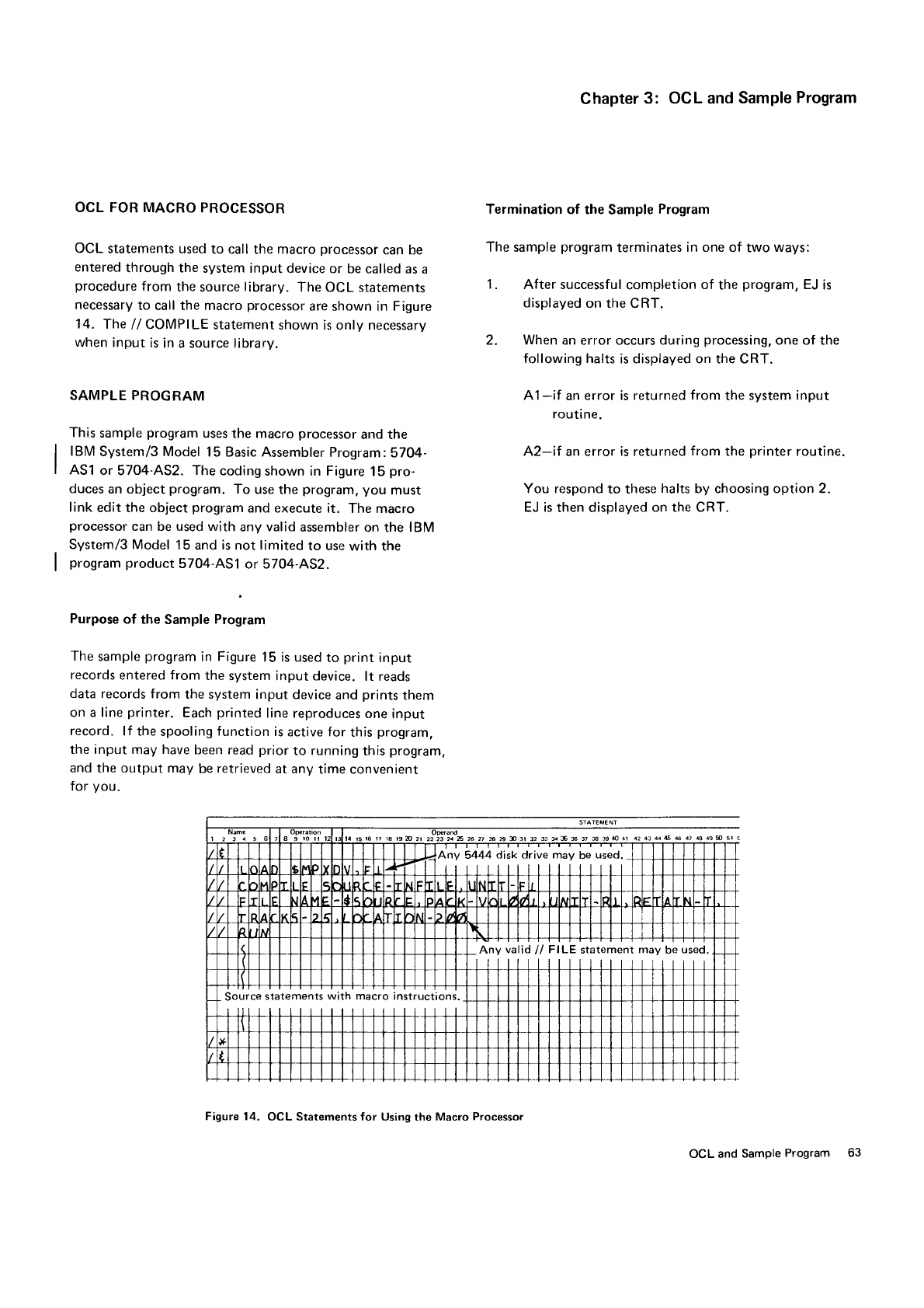
OCL FOR
MACRO PROCESSOR
OCL
statements used
to call
the
macro
processor
can be
entered
through the
system input device
or be called
as a
procedure
from
the
source
library.
The
OCL statements
necessary
to call the macro
processor
are
shown in Figure
14.
The
/i COMPILE
statement
shown is only necessary
when input
is
in a source library.
SAMPLE PROGRAM
This
sample
program
uses the macro
processor
and the
IBM
System/3 Model
15 Basic Assembler
Program:
5704-
AS1
or
5704-AS2.
The
coding
shown in Figure
15
pro-
duces
an object
program.
To use
the
program,
you
must
link
edit the object
program
and execute
it. The macro
processor
can
be
used with
any
valid
assembler
on the IBM
Svstem/3 Model
15 and
is
not
limited
to use
with the
program
product
5704-AS1
or 5704-AS2.
Purpose
of the Sample
Program
The
sample
program
in Figure
15 is used
to print input
records
entered from the system input device. lt reads
data records
from the system
input device
and prints
them
on a line
printer. Each
printed
line reproduces
one
input
record. lf the
spooling
f
unction is
active for this
program,
the input may
have been read
prior
to running
this
program.
and the output may be
retrieved
at any
time convenient
for you.
Chapter
3: OCL and
Sample
Program
Termination
of the
Sample
Program
The sample
program
terminates
in one
of two
ways:
1. After successful
completion
of the
program,
EJ
is
displayed
on the
CRT.
2. When an
error
occurs during
processing.
one of the
following halts
is displayed on the CRT.
A1-if an error is returned
from
the
system input
routi ne.
A2-if an error
is returned
from
the
printer
routine.
You respond
to these
halts by choosing option 2.
EJ is
then displayed
on the CRT.
Anv 5444 disk drive may be used.
Any valid
ll FILE statement
may be
used.
Source
statements
with macro
instructions.
Figure 14. OCL Statements for Using the Macro Processor
OCL and Sample
Program 63
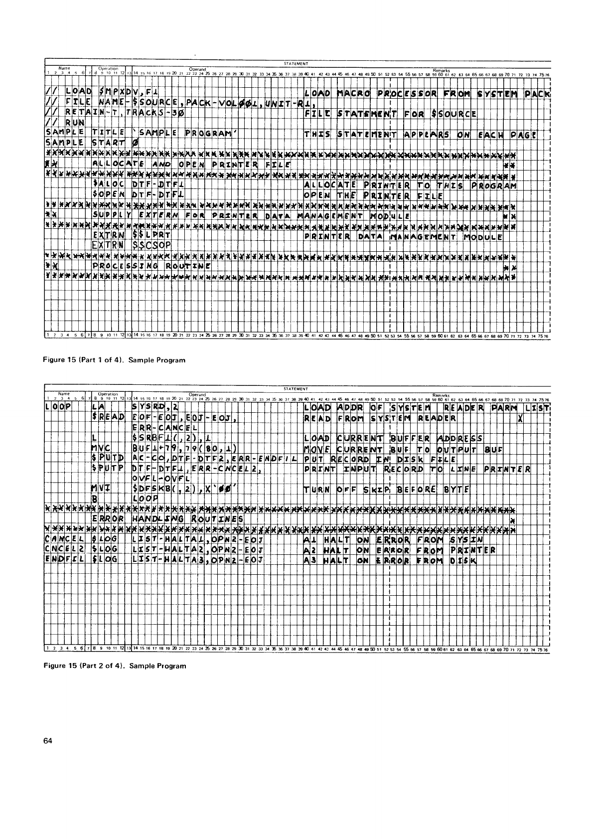
42 43 446 46 47 4 agS 51 52 53 * 55
15 16 r7 fa 19 n 21 22 23 24 6 6 27 2a A I 31 32 $ s tr S 3r S S { 11 a2 1a 11
$ 46.1 5152$s55S57$S 52 63 fl 656 67 s 59 70 71 72 73 7a 7516
Figure
15 (Part
1 of 41. Sample
Program
Figure
15 lPart2 ot 4). Sample
Program
51 52 53 s 55$ 57 $ 5sm6t 62 A il 65S 6r S 6970r1
14 rs16 rr rg 19 n2i 22 23 24 E N 2i n a I 3t 32 $ g4\ a2.a uS 6 47
G €S51 52fi g 55$ 57 $ sS61 52 s il 656 67 s @7071 12 i3 1a7516
64
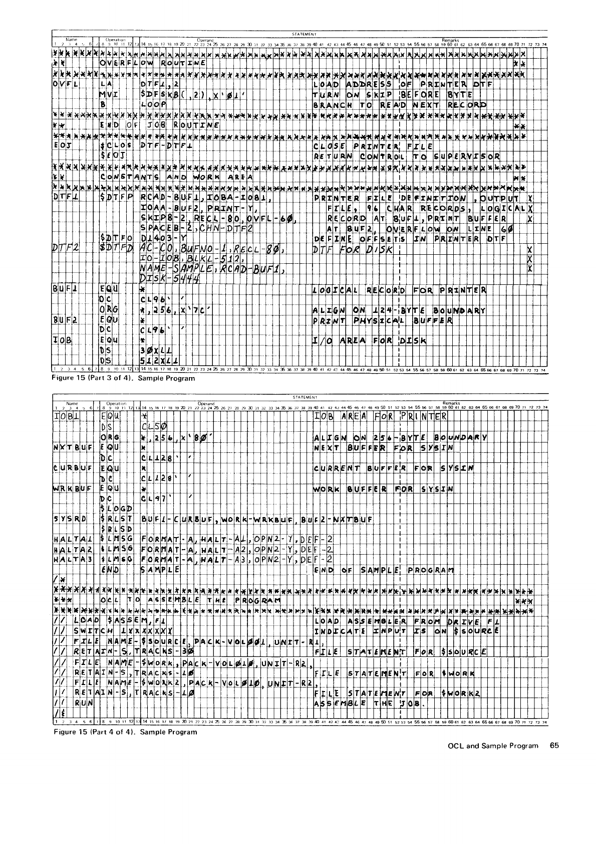
Figure
15
(Part
3 of 4).
4? 43 4445 46 47 48 499 51 5253 s 55$ 57 58
s96061 62 6364 656 67
@ 697071 7
s 37 S 3S4 41 424a A6 46
47 48 49$ st 5253 s 55$ 57 $ Sm61 52 S e 656 67 S 697071 72 13 14
$ 57 s 59 m6r 62 63 e 656 67 @ 697011 12 i3 )4
Figure 15 (Part 4 of 4). Sample Program
OCL and Sample
Program
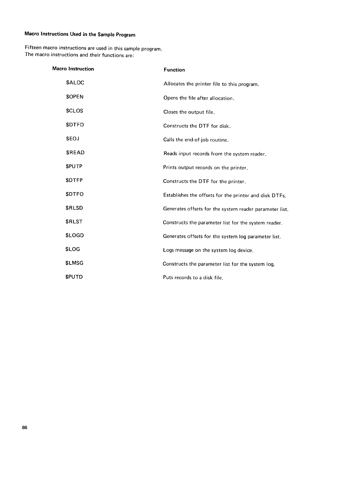
Macro
Instructions
Used
in the
Sample
program
Fifteen
macro
instructions
are
used
in
this
sample
program.
The
macro
instructions
and
their functions
are:
Macro
Instruction
$ALOC
$OPEN
$CLOS
$DTFD
$EOJ
$READ
$PUTP
$DTFP
$DTFO
$RLSD
$RLST
$LOGD
$LOG
$LMSG
$PUTD
Function
Allocates
the
printer
file
to this
program.
Opens
the
file
after
allocation.
Closes the output file.
Constructs
the DTF for disk.
Calls the end-of-job
routine.
Reads input records
from the system
reader.
Prints
output records
on the
printer.
Constructs
the DTF for the
printer.
Establishes
the offsets
for the
printer
and disk DTFs.
Generates
offsets
for the system reader
parameter
list.
Constructs
the parameter
list for the system
reader.
Generates offsets for the system log parameter
list.
Logs
message
on the system log device.
Constructs the parameter
list for the system log.
Puts
records
to a
disk
f ile.
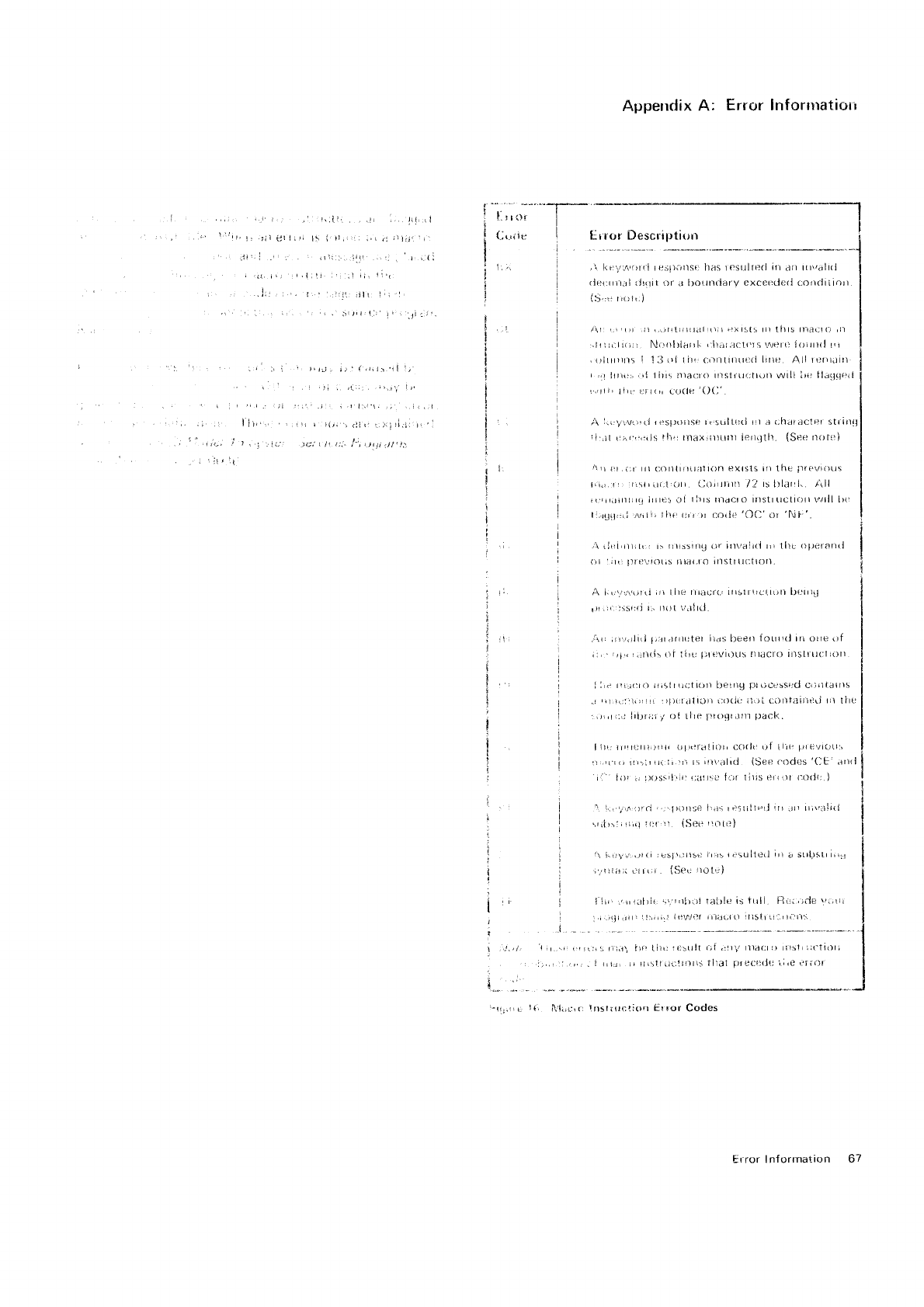
, lil.!l
1.1
jli;1r'r'
i.,,.tr-"'f*_
(-,..,ile I
Appelrdix
A: Error lnfonltatiorr
lir ror Descriptitirr
,\ l<e.,:n,orrl re:jl)ilnso ltas tesltlle(l irr
arr trrr,:rlrl
rler:rrr.rl
rirrtit or a llotrntlarv exct:t:dt:rl corrcliiion
iS,:fr
rrirtt.)
r\f r.,,r! it L.!i|[iilrli]lr()il
.rItStt
rrt
tltts
tnaCltl ,ll
'.trrrr:lr!rr.
Nlrtlrlarrf ,:lrer.rclt't:;
ttr)r()
i()irl(l r,r
,
olrrrrtrrs I 1:l
t'i 1ir, c,lntrtut)(l Itttt:.
All tt:ntaitt
| ',,
llltrrr,
i'1 lilr\ nracro urslru(:lt()t) will irt: llailuerl
r',,tlr'
llir'
.jtl(,,
Ut,(lt,'O(l'
/\ i.r'yl'vL,,il
resl)r)rrs6r tr5L'lt{)(l I I d (,ttitdcler stritt(J
,l.rl rr;r',,,:,ls
rh,:
rnaxiirrrrilt ierr,Jtlr.
(Scu
rr{)fr)
/rrr
{r il rt coill|[rtrllon extsls tr) the ltrerriirus
rLitr.rr,
isrrir..t
i)|. (ioi,rllrlt
72 rslrlarl.. i\ll
icrririnirlJ lrrrt::
oi tltrs
tnacro instrttctir;tt urtll ire
llJllil,;ri 4ri!, llrt'crr rr corle'OO'or 'l.if;'.
.:\.lr:i,rtrrt,,
r\ nlsslrU rtr irtrralrrl rrr llte olreratrl
oI Iilr: l)lu,"'rot;s
iliar,to Insttilctror)-
A l.rvrt!)r(i
ir ilre ntitcr(., itrstilrcltrrti
bt-'trrrl
tir.;,
i\seti ti, ll(lt \/,llld.
/ri, rrr','.rlirl
f,irrrlrrirtBr
ir,rs
lteen
iotrtttl iti oile uf
tr(i\,,1 :rrli
l,tr,\,t,,rl\
LtdL:r(r iir5ltlt(
lr('rr
I
i,a li:icri) iritlIeijli()D betng trrtr;c,-'ssr:d
c()rlIoll1s
.,,ir r,rt,l(i:rii
r)l){;t(lliO[ 1;()(jr] ij,)i Ci)rltilii]i:r,
lr1
tllil
:,r,,tr,l lriJriir/ o{ rlre
[)r01|ilrr pack.
I
irr:
rrrrrcrir,rrrr,
(ilrt:rilLi(Jr'
c(trit ot lile lri:vl()l'!
r:.,r'rr) !rr)i!
ri:,..r1 rs
irlvalid iSee
codes '(,'E'
artrl
ii iitr r,
ltossrl'lr {;il!rril laJr llliS errill {:O(1(j
)
', 1..,,',/,1
i)re ,....1)Oltie
t,,li r.,.5liltpr.l
in lir il,,itliri
.,rilrrl;trirl
r1'q
rr i$sil rirllrl)
1\
i\riyL/
!/r.i ivsl\rirlst) ir:r! iirsulte(l
rr!
a
sllUstr
i,i1l
i,,rllilji L'lrL,i 1Se,:
rrOt:)
!
1ir.
,,.il
lJlll{. ,.\-'rrrl,,:r!
lal)lc is ltrll Rti.,rde .,l,rtr
I,.,(jr,riri 1l:,ri,r
{dtr,/i,rl
rii;i(,r()
rllslr ii. rra'iiri
,llr r,i
lir,
l
:
t
!r, (.f
rrjr l,
rild\, ilr: litrt :C:ull (,f ,jry rltaCt
r) lirslr
lifttr)ri
,,,. I r'r,;, r' Ir5llrlr]1lI)rr!
tl:at ilreclliltl
i,,e aiil)l
't. ir!...:,rIn\1iir{:fiorr
Hr ror Codes
Error lnf ormation 67
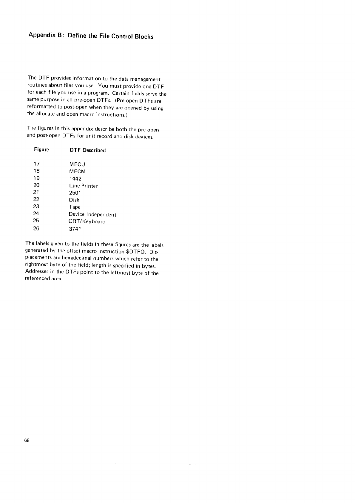
Appendix
B: Define
the
File
Control
Blocks
The
DTF provides
information
to the
data
managemenr
routines
about files
you use.
you must
provicle
one
DTF
for each
file
you use in
a
program.
Certain
fields
serve
the
same
purpose
in
all
pre-open
DTFs. (pre_open
DTFs
are
reformatted
to post-open
when they are
opened
by using
the
allocate
and
open
macro
instructions.)
The
figures
in
this
appendix
describe
both the
pre-open
and
post-open
DTFs
for unit record
and
disk
devices.
Figure
tt
18
19
20
21
22
23
24
25
26
DTF
Described
MFCU
MFCM
1442
Line Printer
2501
D
isk
Tape
Device
lndependent
C RT/Keyboard
3741
The
labels given
to the
fields
in
these
figures
are
the labels
generated
by the offset macro instruction
$DTFO. Dis_
placements
are hexadecimal
numbers
which
refer
to tne
rightmost
byte
of the field;
length
is
specified
in bytes.
Addresses
in
the
DTFs
point
to the
leftmost
byte
of the
referenced
area.
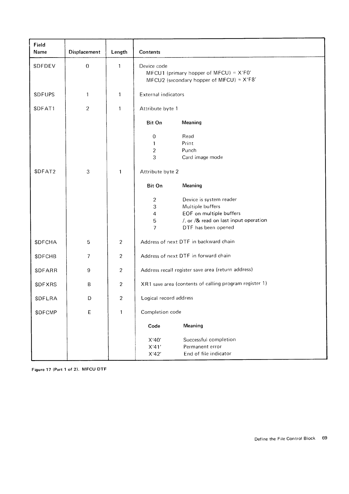
Field
Name Displacement Length Contents
$DFDEV
$D
F
UPS
SDFATl
$DFAT2
$DFCHA
$DFCHB
$DFAR
R
$DFXRS
$DF
LRA
$DFCMP
0
1
2
F
7
I
B
D
E
1
1
1
I
Z
z
z
z
1
Device
code
MFCUi (primary
hopper of MFCU)
=
X'F0'
MFCU2
(secondary
hopper
of MFCU)
=
X'F8'
External
indicators
Attribute byte 1
Bit On Meaning
0 Read
i Print
2 Punch
3 Card
image mode
Attribute
byte 2
Bit On Meaning
2 Device
is system
reader
3 Multiple buffers
4 EOF on multiple buffers
5 l. or /& read on last input operation
7 DTF has been oPened
Address
of next DTF in backward
chain
Address of next
DTF in forward
chain
Address recall
register
save area
(return
address)
XR1 save
area
(contents
of calling
program
register
1
)
Logical
record
address
Completion
code
Code
x'40'
x'41',
x'42',
Meaning
Successful
completion
Permanent
error
End
of
file indicator
Figure 17
(Part
1 of 2). MFCU
DTF
Def
ine the File Control Block 69
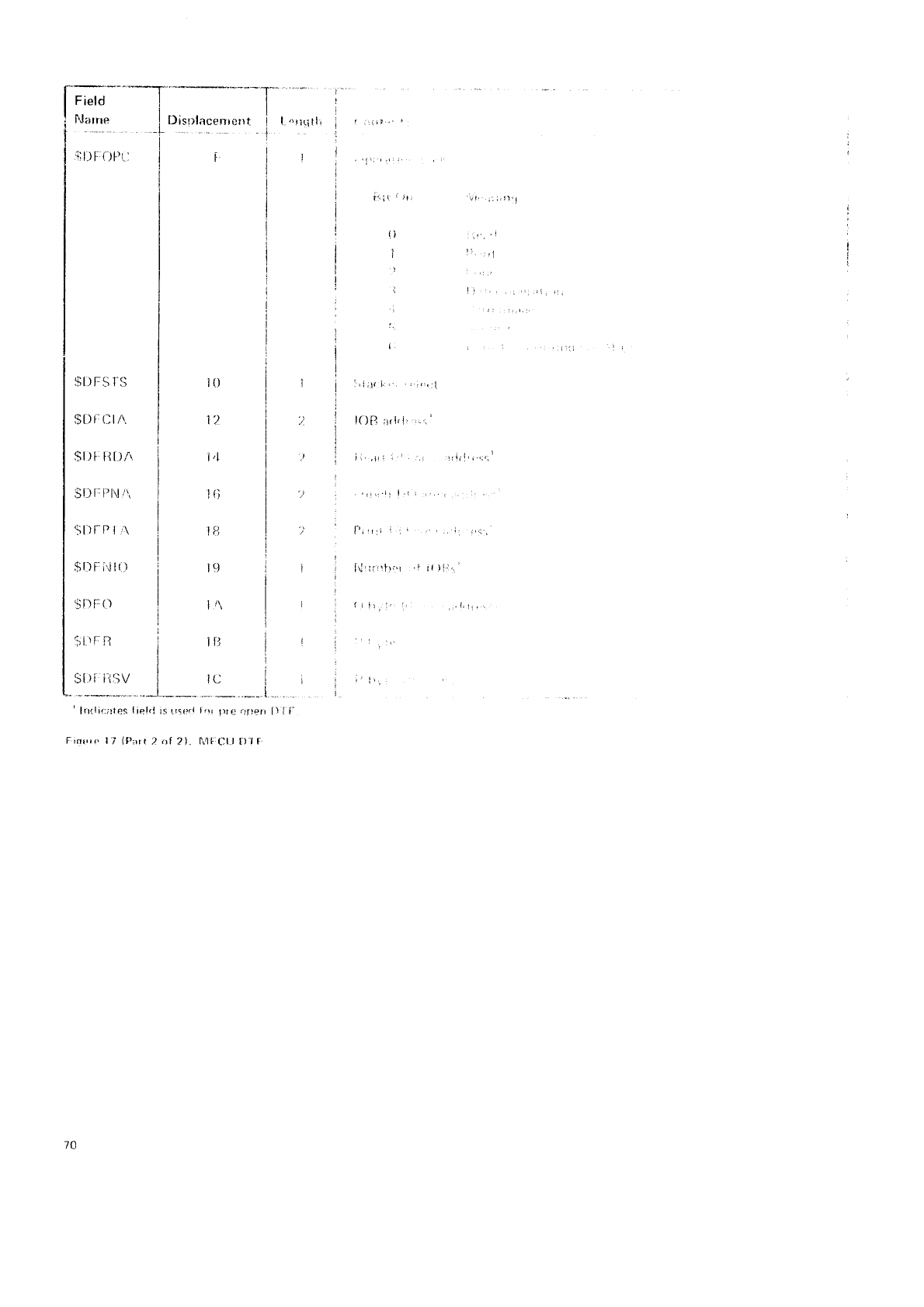
l'."'-
__I I
I FJ:rrrre I I)isulacenrcrrt
i 1..',rritl,
t-t
I
lil)fr{)P(tiilr
tai I i
:..
t:
,i;l(1,.':r.r,i
IOB
rrrl,l,
,-;'
i,,.til i ' :,r iriri',,:,;r
i-'t
!
r,1 i . , .. .. li i,,;
lrli
lrrl'.'r "l i{ ){.i,.'
{ rlt,
i, 1. ,,.1,rr,
i'l).
I) { t'
I0
1')
1,1
t{l
lu
i9
1/\
1il
ic
*--___"._"--_t
ra(,rl I,l lilc .jflen
2). lr4trCt.l
I)l l:
$r)FSrs I
I
$Dr,fln I
$t)
[: ft DA I
I
Sll F
irl\,r\, I
I
St)tP
I
r\ I
I
$DF:i.Jl()
i
I
$t)F() i
I
gr'Fn j
I
::t:::y
_1_
' ln(licittes
liel(l
is
{
iolrelTlPartTttt
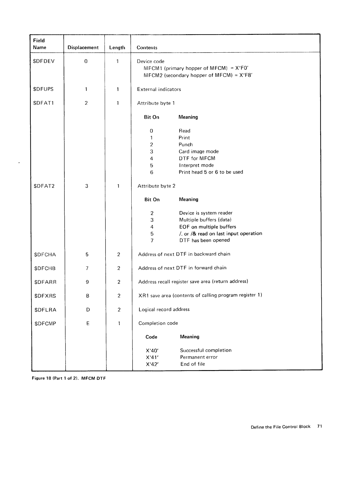
Field
Name Displacement Length cotrtelrts
SDFDEV
$DFUPS
$DFAT1
$DFAT2
$DFCHA
$DFCHB
$DFAR
R
$DFXRS
$DF
LRA
$DFCMP
0
1
z
3
5
l
I
B
D
E
1
I
2
2
2
2
2
1
Device
code
MFCMl (primary
hopper of MFCM) =
X'F0'
MFCM2 (secondary
hopper of MFCM) = X'F8'
External
indicators
Attribute byte 1
Bit on
0
1
z
4
5
6
Attribute byte 2
Bit On
2
4
5
7
Meaning
Read
Pri nt
Punch
Card image
mode
DTF
for MFCM
Interpret
mode
Print head 5 or 6 to be used
Meaning
Device is svstem
reader
Multiple
buffers
(data)
EOF
on multiple buffers
l. or l& read on last
input operation
DTF has
been
oPened
Address of next DTF in backward
chain
Address
of next DTF in forward chain
Address
recall
register save
area
(return
address)
XR1 save
area
(contents
of calling
program
register
1)
Logical
record address
Completion
code
Code
x'40
x'41
x'42
Meaning
Successful
completion
Permanent
error
End of file
Figure
18
(Part
1 of 2). MFCM
DTF
Def
ine the File Control Block 7'l
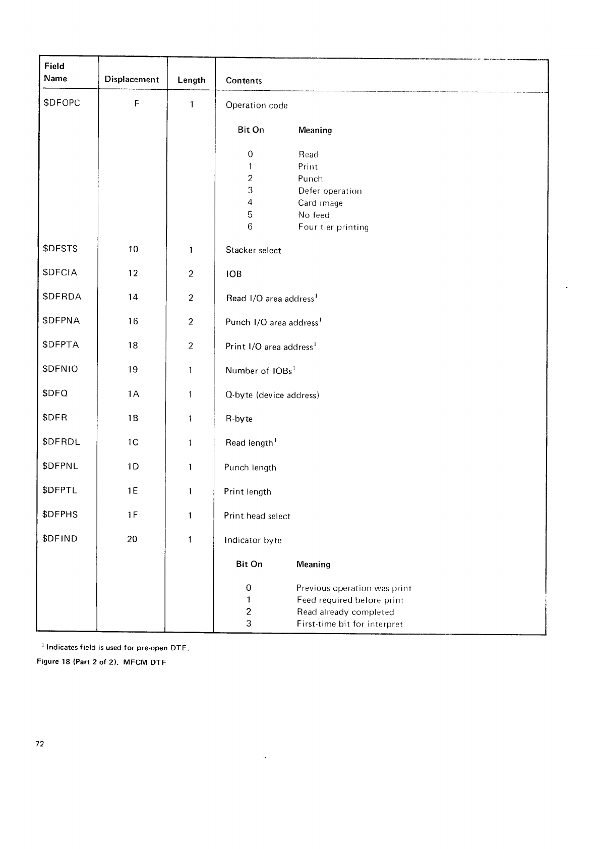
Field
Name Displacement Length t"".** _ _
Operation
code
Bit
On
0
1
4
6
if
Stacker
select
toB
Meaning
Read
rn nl
Pu
rrch
Defer
operation
Card image
No feed
Four
tier
printing
Read l/O area addressr
Punch
l/O area addressr
Print
l/O area
addressr
Number
of lOBsl
O-byte
(device
address)
R-byte
Read
length
t
Punch
length
Pri nt I ength
Print
head
select
Indicator
byte
Bit On Meaning
0 Previous
operation was
print
1 Feed
required
before
print
2 Read
already completed
3 First-time
bit
for
interpret
$DFOPC
$DFSTS
$DFCIA
$DF
RDA
$DFPNA
$DFPTA
$DFN
IO
$DFO
$DF
R
$DFRDL
$DFPN
L
$DFPTL
$DFPHS
$DF
IND
F
10
12
't4
16
18
19
1A
1B
1C
1D
1E
1F
20
1
I
2
2
z
1
1
1
1
1
1
I
1
I Indicates f
ield
is used f
or pre-open
DTF.
Figure
18 lPart
2 ol 2). MFCM DTF
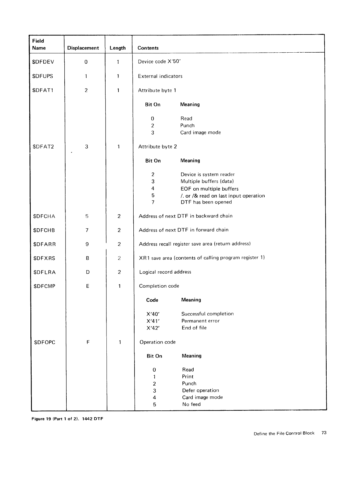
Field
Name Displacement Length Contents
$DFDEV
$DFUPS
$DFAT1
$DFAT2
$DFCHA
$DFCHB
$DFAR
R
$DFXRS
$DFLRA
$DFCMP
$DFOPC
0
1
2
J
5
I
B
D
E
F
1
1
1
2
2
I
2
z
1
1
Device
code
X'50'
External
indicators
Attribute byte 1
Bit On
0
2
Attribute byte
Bit
On
2
?
4
5
Meaning
Read
Punch
Card
image
mode
Meaning
Device is system
reader
Multiple buffers
(data)
EOF
on multiple buffers
/. or /& read on last
input operation
DTF has been opened
Address of next DTF in backward chain
Address of next DTF in forward chain
Address
recall
register save area
(return
address)
XR 1 save area
(contents
of calling
program
register
Logical
record address
Completion
code
1)
Code
x'40'
x'41',
x'42',
Operation
code
Bit
on
0
1
2
4
q
Meaning
Successful
completion
Permanent
error
End of
file
Meaning
Read
Pri nt
Punch
Defer
operation
Card
image
mode
No feed
Figure 19 (Parr
1 of 21. 1442 DTF
Def
ine the
File Control
Block 73
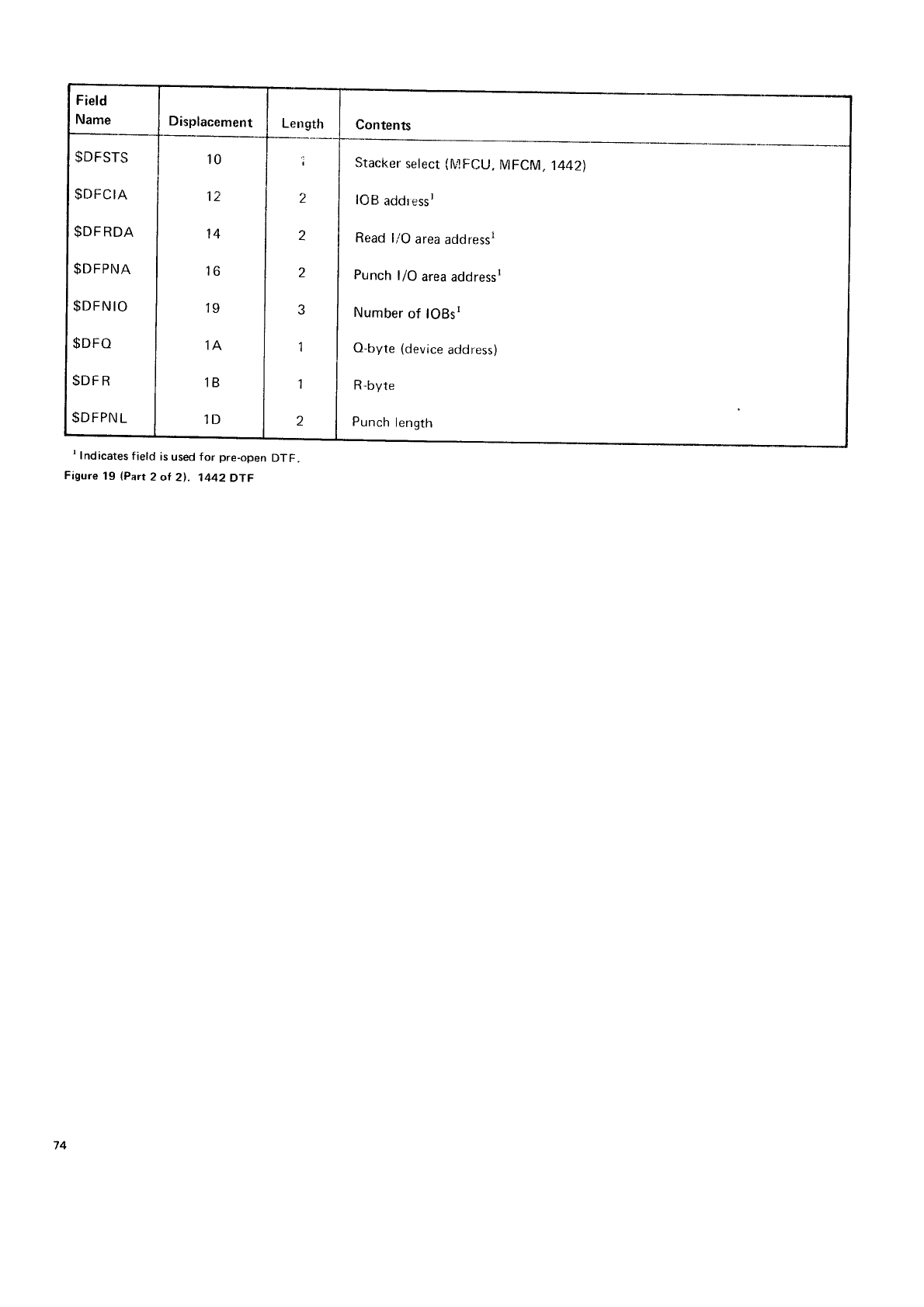
Field
Name Displacement Length Contents
$DFSTS
$DFCIA
$DF
RDA
$DFPNA
$DFN
IO
$DFO
$DF
R
$DFPN
L
10
12
14
16
19
iA
1B
1D
z
2
2
J
1
1
2
Stacker
select
(N4
FC|-J,
MFCM, 14421
l0B addressl
Read
l/O area
addressl
Punch l/O area addressr
Number
of lOBst
O-byte
(device
address)
R-byte
Punch
length
t Indicates
f
ield
is
used
for pre-open
DTF.
Figure
19
(Part
2 of 21.
1442DTF
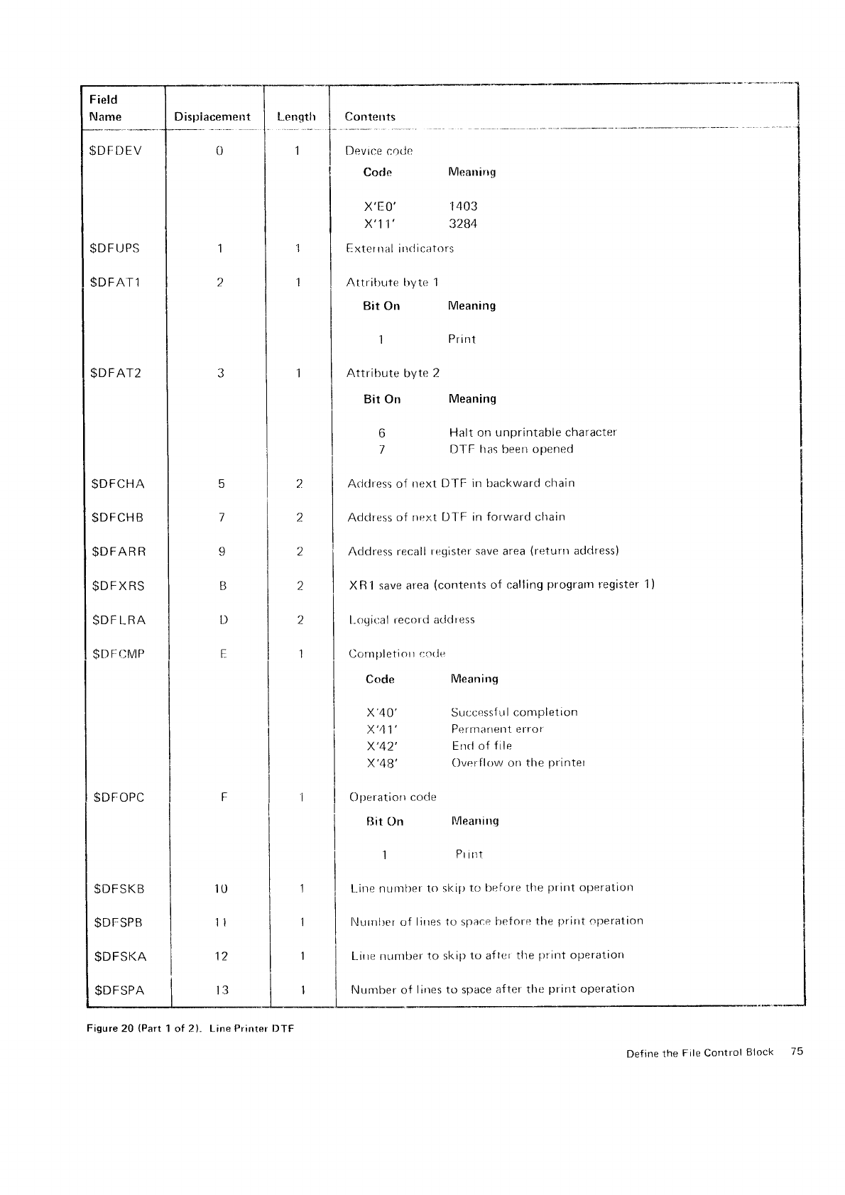
Field
Name
$DF
DEV
$D
F
IJPS
$DFAT1
$DFAT2
$DFCHA
$DFCHB
$DFAR
R
$DFXRS
SDF
LRA
$DFCMP
$DFOPC
$DFSKB
$Dt-sPB
$DFSKA
$DFSPA
Dispiacement
tr
7
9
B
l)
E
i0
ll
12
t3
---"- *tI
I
1
2
1
1
2
2
2
2
2
1
Contents
Devrce
cotlc
Code Mlearring
x'Eo' 1403
x'11' 3284
Exter rral irrtlica
tors
Attrihute
tryte 1
Bit On Meaning
1 Print
Attribute
byte
2
Bit On Meaning
6
1
Code
x'4
0'
x'41',
x'42'
x'48',
()lreratiorr
cocle
Bit On
Halt on
unprintable character
DTF tras
been
opened
Meaning
Succr.:ssf
r-r
I conrplet
ion
Permarrent
error
End of
file
Overf
lr-rw on
the
printet
Meanirrg
Pr irrt
Acldress of next DTF in backward chain
Address
of rrext D'l'F
in
forwarcl
chain
Address
recall
tegister
save
area
(returtr
address)
XB1 save area
(contents
of calling
progralll
register
l-ogir:al recottl
aclcitess
Cc-rrn
yrleti
ot
t
r:otlr:
1)
[.,ine nurnfler
to sl<iJr
tO hefore the
print operation
[,lurnlrcr of lirres to space
bef
ore the
[)rirlt
operatlon
[-i|]e nunrller
l.o
sl<ip
to aflcr
the
prirlt
operatior'l
Nurnber of lirres
to space
after the
print
operation
Figure
20 (Part
1 of 2)" Line
Printer
DTF
f)efine
the File Control Block 75
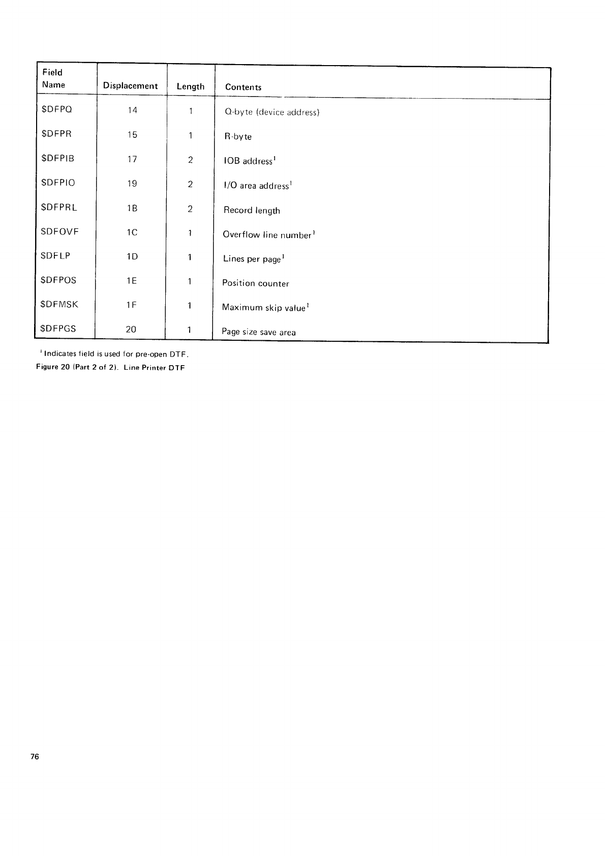
Field
Name Displacement Length Contents
$DFPO
$DFPR
$DFPIB
$DFPIO
$DFPRL
$DFOVF
$DF
LP
$DFPOS
$DFMSK
$D
FPGS
14
15
1l
19
1B
1C
1D
1E
1F
20
1
1
z
a
z
1
1
1
1
1
O-byte
(device
address)
R-byte
IOB
addressr
l/O area
addressr
Record
length
Overflow
lirre
numberr
Lines
per
paget
Position
counter
Maxinrum
skip
valuer
Page
size
save
area
' Indicates f ield
is used for pre-open
DTF
Figure
20 (Part
2 ol 2). Line Printer
DTF
to
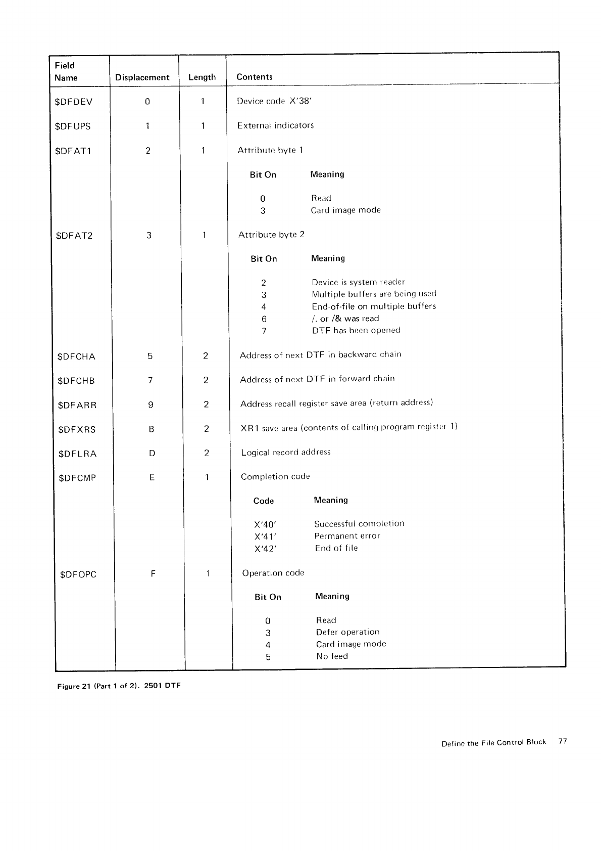
Field
Name Displacement Length Contents
$DFDEV
$DFUPS
$DFAT1
$DFAT2
$DFCHA
$D
FCH B
$DFAR
R
$DFXRS
$D
F LRA
$DFCMP
$DFOPC
.
I
,t
I
DevicecodeX'38'
1 I 1 | Externalindicators
tl
, I
t
I
Attributebytel
I I Bit on Meanins
I I t''^o"
ll0Read
| | 3 Card
image
mode
lr
3 | I I Attributebyte2
I I Bit
on Meaning
I I 2 Device
is svstem
readef
I I 3 Multiple
buffers
are
beinq
usecl
| | 4 End-of-f ile on
nrultipie
buffers
I | 6 l. or /& was
read
I I
7 DrF
has been
oPened
t
|
,
I
Address
of
next
DTF in backward
chairr
I
t
|
,
I
noot.t,
of
next
DTF
in
forward
chain
I t |
,
I
nOOrets
recall
register
save
area
(return
addressi
I
t
|
,
I
xnr save
area
(contents
of
callins
prosram re-oister
1)
I " |
,
I
t-ooicat
recordaddress
I
t
|
,t
I
comoretioncode
lllcoaeMeanins
| | | x'+o' successfulcomPletion
| | | x'41' Permanent
error
I | | x'+z' End or
rire
i ' | | oo.,.ution.oo.
| | | eit
ctn Meanins
lll'Reacl
I I | 3 DeferoPeration
I | | + cardimagemode
| | | 5 Nofeed
Figure 21 (Part
1 of 2l.. 2501 Df F
Def
ine the
File
Control
Block 77
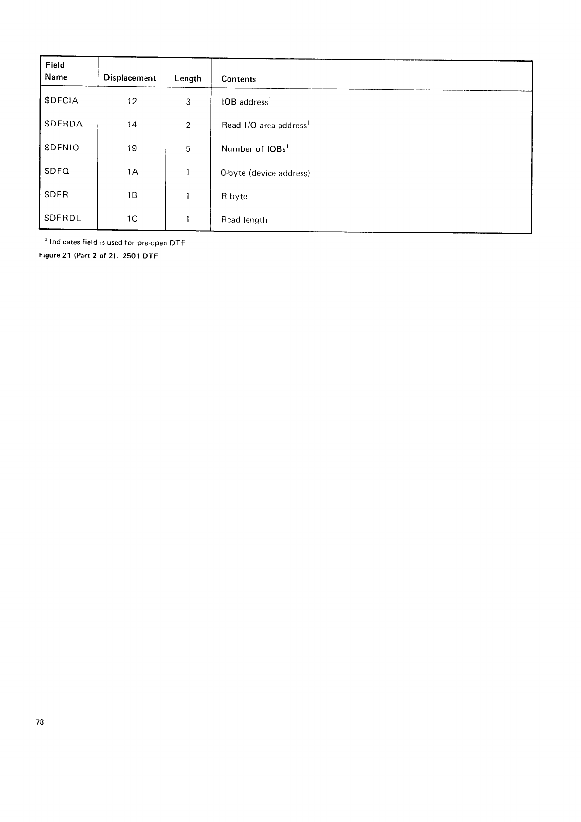
Field
Name Displacement Length Contents
$DFCIA
$DFRDA
$DFN
IO
$DFO
$DFR
$DFRDL
1a
14
19
,IA
1B
1t-
5
1
'l
1
IOB
address'
Read l/O area
addressr
Number
of lOBsr
O-byte
(device
address)
R-byte
Read
length
I Indicates
field is
used
for pre-open
DTF.
Figure
21 (Part
2 of 2). 2501 DTF
78
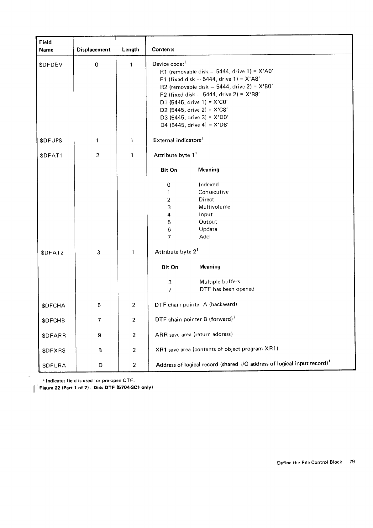
Field
Name Displacement Length Contents
$DFDEV
$DFUPS
$DFAT1
$DFAT2
l:",.:;
lil:l;
0
1
2
3
5
7
q
B
D
1
1
1
1
2
2
2
2
2
Device code:l
R1
(removable
disk
- 5444,drive
1)=
X'A0'
F1
(fixed
disk
- 5444,
drive 1)
=
X'A8'
R2
(removable
disk
- 5444,driue
2)
=
X'80'
F2
(fixed
disk
- 5444.
drive 2)
= X'88'
D1
(5445.
drive
'l)
=
X'CO'
D2
(5445,
drive
2)
=
X'C8'
D3
(5445,
drive
3)
=
X'D0'
D4
(5445,
drive 4)
=
X'D8'
External indicatorsr
Attribute
byte
1r
Bit On Meaning
0 Indexed
1 Consecutive
2 Direct
3 Multivolume
4 Input
5 Output
6 Update
7 Add
Attribute
byte
2r
Bit
On Meaning
3 MultiPle
buffers
7 DTF
has been
oPened
DTF
chain
pointer
A (backward)
DTF
chain
pointer
B (forward)r
ARR save
area
(return
address)
XR1 save
area
(contents
of object
program
XR1
)
Address of logical
record
(shared
l/O address
of logical
input record)1
I Indicates
f
ield
is
used
for preopen DTF.
|
'
risure 22 (Part
1 ot 71. Did( DTF (5704SC1 onlv)
Define
the File Control Block 79
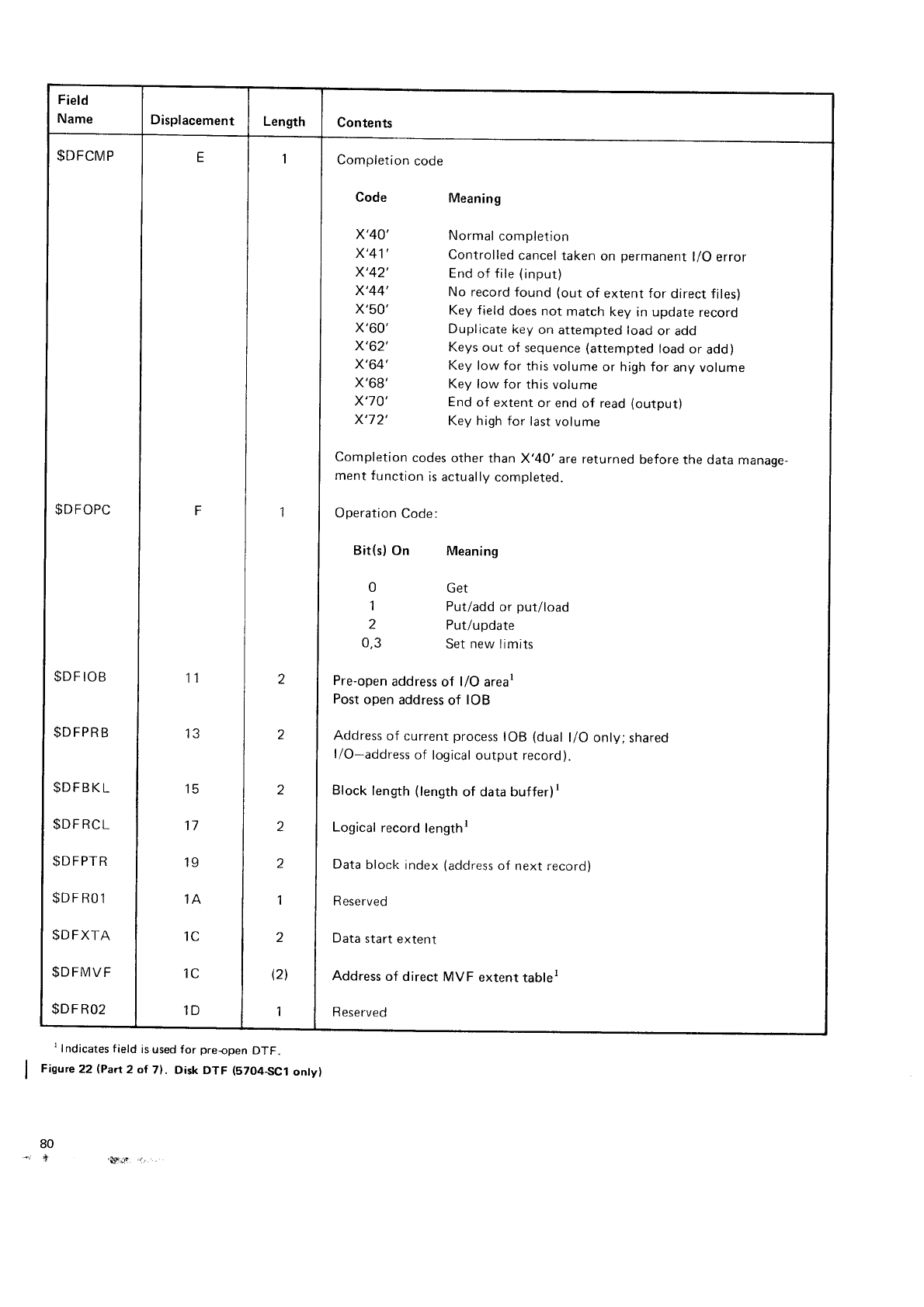
Field
Name Displacement Length Contents
$DFCMP
$DFOPC
$DF
IOB
$D
FPR
B
$DFBKL
$DF
RCL
$DFPTR
$DFRO1
$DFXTA
$DFMVF
$DF
R02
E
F
11
IJ
15
17
19
1A
ic
1C
1D
1
z
z
2
z
2
1
2
(21
1
Completion
code
Code
x'40'
x'41'
x'42'
x'44'
x'50'
x'60'
x'62',
x'64'.
x'68'
x'70'
x'72',
Meaning
Normal
completion
Controlled
cancel
taken
on permanent
l/O error
End
of f ile
(input)
No record
found (out
of extent for direct files)
Key field
does not match
key in update
record
Duplicate
key
on attempted
load
or add
Keys
out of sequence
(attempted
load
or add)
Key
low for this volume
or high for any
volume
Key low for this volume
End
of extent
or end
of read
(output)
Key high for last
volume
Completion
codes
other than
X'40' are returned
before the data
manage-
ment function
is actually
completed.
Operation
Code:
Bit(s)
On
0
1
2
0,3
Meaning
Get
Put/add
or put/load
Put/u
pdate
Set
new
limits
Pre-open
address
of l/O areat
Post
open address
of IOB
Address
of current
process
IOB (dual
l/O only;
shared
l/O-address
of logical
output record).
Block
length
(length
of data buffer)t
Logical
record
lengthr
Data
block
index
(address
of next record)
R eserved
Data
start extent
Address
of direct MVF extent tablel
R
eserved
t lndicates field is
used for preopen DTF.
Figwe 22 (Part 2 ol 7). Disk DTF (57O4-SC1
onty)
80
*i ,t "VJt 'a
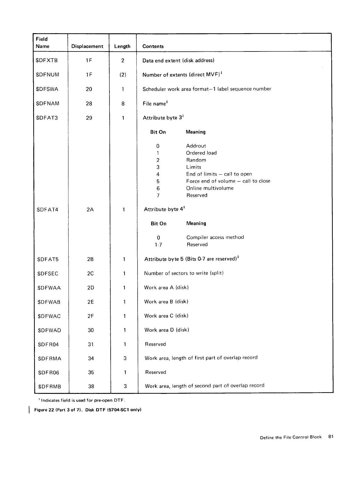
Field
Name Displacement Length Contents
$DFXTB
$DFNUM
$DFSWA
$DFNAM
$DFAT3
$DFAT4
$DFAT5
$DFSEC
$DFWAA
$DFWAB
$DFWAC
$DFWAD
$D
F RO4
$DFRMA
$DF
R06
$DF
RMB
1F
tr
20
28
29
2A
2B
zv
2D
2E
2F
30
JI
34
35
38
2
(2\
1
8
1
1
1
1
I
,l
1
1
1
3
1
3
Data end extent
(disk
address)
Number
of
extents
(direct
MVFIr
Scheduler
work
area
format-1 label sequence
number
File namer
Attribute byte
3t
Bit On
0
1
2
4
6
Attribute
byte
4r
Bit On
0
1A
t- I
Meaning
Addrout
Ordered
load
Random
Limits
End of limits
- call to open
Force
end
of volume
- call to close
Online
multivolume
Reserved
Meaning
Compiler
access
method
Reserved
Attribute
byte 5 (Bits
O-7 are
reserved)r
Number of sectors
to
write
(split)
Work
area
A (disk)
Work area B
(disk)
Work area
C
(disk)
Work
area
D (disk)
Reserved
Work area,
length
of
Reserved
first
part
of overlaP
record
Work area,
length of second
part
of overlap
record
I Indicates
f
ield is used
for preopen DTF.
Fiswe 22 (Part
3 of 71. Disk
DTF (5704SC1 only)
Def
ine
the
File Control
Block 81
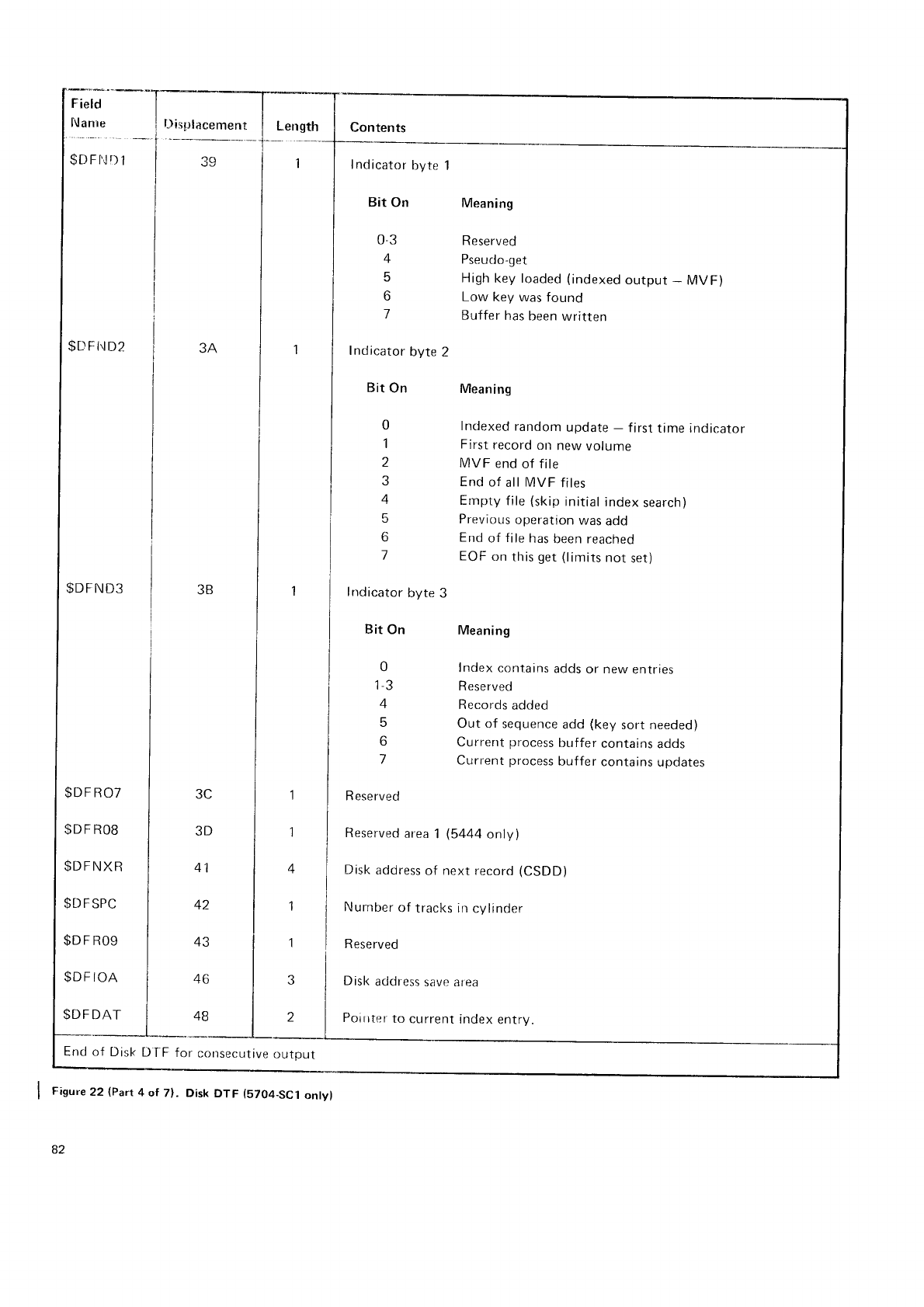
Field
^::1"
$DFl'l
D
1
l)is;rlacement Length Contents
1
39
3A
Indicator
byte
Bit On
03
4
6
o
7
Indicator
byte
2
Bit
On Meaning
Meaning
R eserved
Pseudo-get
High
key loaded
(indexed
output
- MVF)
Low key was
found
Buffer
has
been
written
$L)
F t! D2
$DFND3
$DF
R07
SD
F RO8
$DFNXR
$D
FSPC
$D
F
R09
$DF
IOA
$DF
DAT
Encl
of Disk
D
T'F for consecuilve
output
Figure22 (Part
4 of 7). Disk
DTF (5704-SC1
ontyl
82
Indexed
random
update
- f
irst time indicator
First
record
olt
new
volume
MVF end
of file
End
of
all MVF files
Empty
file
(skip
initial
index
search)
Previous
operation
was
add
End
of
file
has
been reached
EOF
on
this
get (limits
not
set)
Meaning
Index contains
adds
or new
entries
Reserved
Records
added
Out of sequence
add
(key
sort needed)
Current
process
buffer
contains
adds
Current
process
buffer
contains
updates
0
i
z
J
4
tr
6
7
I nd
icator
byte
Bit
On
0
|
-J
4
tr
o
7
R eserved
Reserved
area
1 (5444
only)
Disk
address
of next record
(CSDD)
Nurnber
of tracl<s irr
cylinder
R
eserved
Disk
address
save area
Poiirter
to
current
index
entry.
3C
3D
46
48
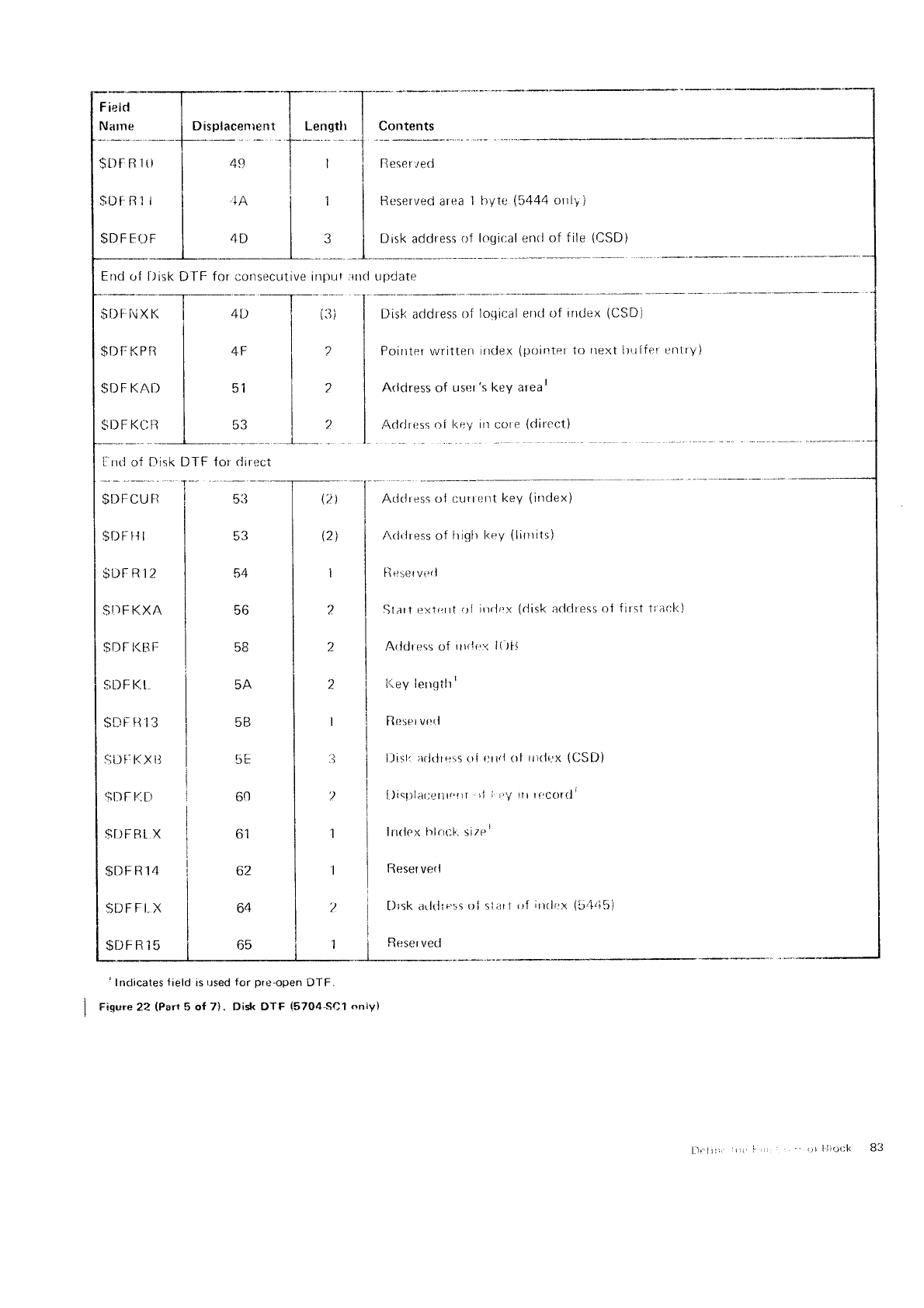
F
ieid
Narne
$t)F
R
1ti
$DFFOF
$DFCU
FI
$iti
F f'l I
$IJFR]2
$tI
F KXA
$D
t l<B
t:
$DF
t<.t
SD
F II'I
3
s;ii t-:
F{ x ll
$DF
11.[)
$t)FBI
X
$DFR14
$DFFI
X
$DFR15
49
.il\
4t)
tor direct
5:l
53
54
56
5B
5A
5B
5E
60
ol
oz
64
65
,i
:1
R ese rved
Resenved area
I
Disk
address
of
Displacenrent
I Lengtlr Contents
hyte
(5444
onlV
)
logir:al enrl
of f ile
(CSD)
ntl
I
I
i
lplll ir
(3)
uJrJate
Disk address
of
Poirrter
written
Arldress of uscr
AdrJress
oi l<ey
loilir:al
errrl of irrtlex
(CSD)
index
(pointer
1o
irext lrrrffer enlry)
's
key arear
in
core
(direct)
DTF
Address
oJ curtr:nt
key
(ittdex)
Aclriress of lriglr l<ey
(lirrrits)
flesetverl
Start extF?rt
ol irrrlr:x
(disk
adrlress
of first
A<ldr ess
of iurJc:< l(
ltJ
l{ey
ierrqth'
Rcsei
veri
l)ist:
arltlrel,s
oi crrrl of rrirli;x
(CSD)
l)i.1rl.rr:,,t1r,',,r,i
:,,/,tr
r,'Clttli
Ilr<ipx lrlrir:f,. size'
Beser
verl
j tlrsk arltlrr'.srrl
sl;rtl,rl
irrrl"r
(51,i51
I
(21
\2)
I
2
2
2_
I
.1
,)
1
1
')
1
t
r.aol(
)
' Indicates
field is
r.rsed for pre-open
DTF.
Fiqvre 22 (Parr
5 of 7). Disk DTF (5704-SC1
only)
B3
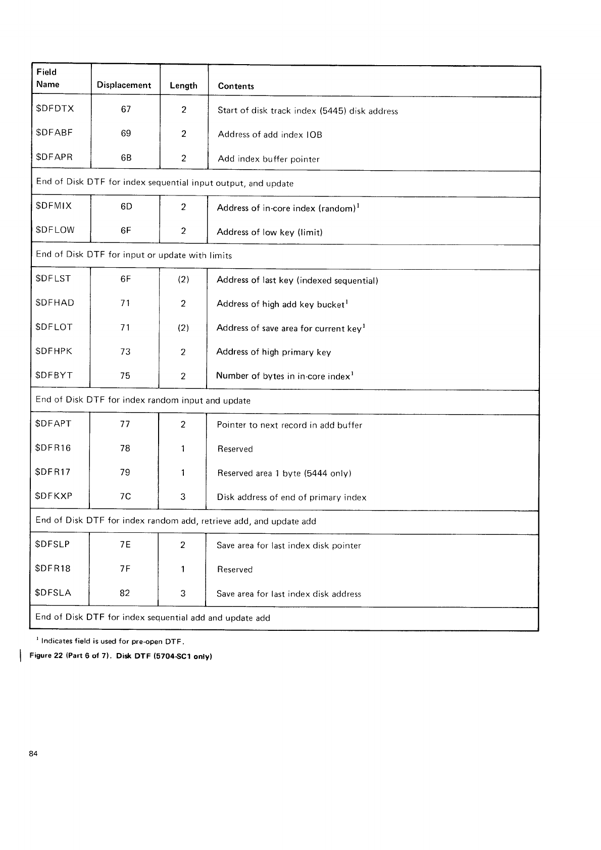
Field
Name Displacement Length Contents
$DFDTX
$DFABF
SDFAPR
67
69
6B
2
2
.)
Start of disk
track index
(5445)
disk
address
Address
of
add index
IOB
Add index
buffer
pointer
End
of Disk
DTF for
index
sequential
input
output,
and update
$DFIV]IX
SDF LOW
6D
6F
z
z
Address
of in-core
index
(random)r
Address
of low key (limit)
End
of Disk
DTF for
input
or update
with
limits
$D
F
LST
$DFHAD
$D
F
LOT
SDFHPK
$DFBYT
6F
71
71
75
(21
2
(21
2
2
Address
of last
key (indexed
sequential)
Address
of high
add key bucketr
Address
of save
area for current keyr
Address
of high
primary
key
Number
of bytes
in in-core
indexr
End
of Disk DTF for
index
random
input
and
uDdate
$DFAPT
$DFR16
$DFR17
$D F KXP
78
79
7C
z
1
1
Pointer
to next
record in
add buffer
R eserved
Reserved
area 1
byte (5444
only)
Disk
address
of end
of primary
index
End
of Disk
DTF for index random
add, retrieve
add. and update
add
$DFSLP
$DFR18
$DFSLA
7E
7F
82
2
1
Save
area
for
R
ese
rved
Save area for
last index disk
pointer
last index disk
address
End
of Disk
DTF for index
sequential
add and uodate
add
I Indicates field is
used
for pre-open
DTF.
Figure22 (Part
6 of 7). Disk
DTF (5704SC1 ontyl
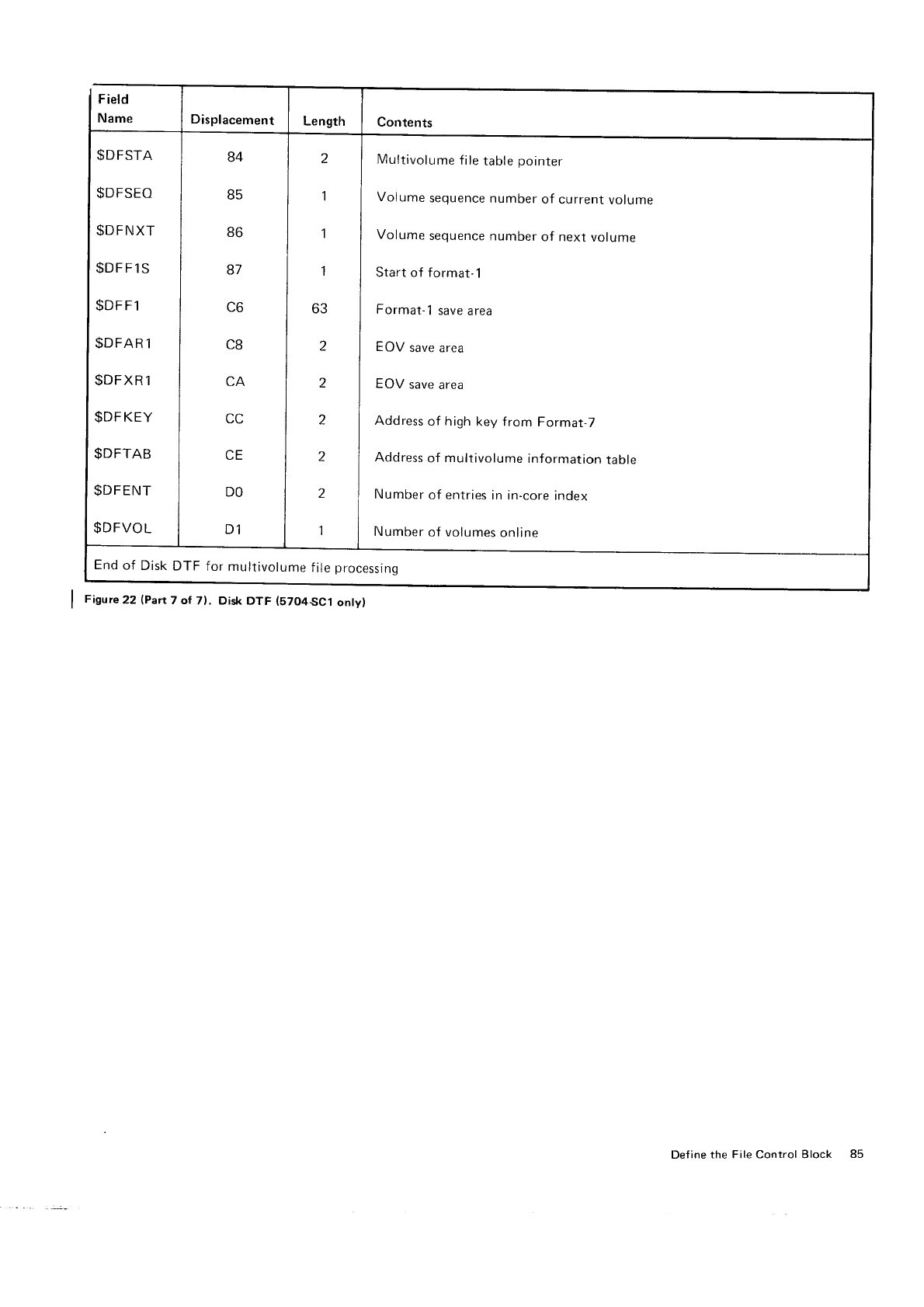
Field
Name Displacement Length Contents
$DFSTA
$DFSEO
$DFNXT
$DFF1S
$DFF1
$DFAR
1
$DFXR
1
$DF
KEY
$DFTAB
$DFENT
$DFVOL
84
d5
86
87
\,o
t-tt
CE
DO
D1
z
1
1
1
63
2
2
2
2
,
1
Multivolume
file
table
pointer
Volume
sequence
number
of current
volume
Volume
sequence
number
of next
volume
Start of format-1
Format-
1 save
area
EOV
save area
EOV
save
area
Address
of high
key f
rom Format-7
Address
of multivolume
information
table
Number
of entries
in in-core
index
Number
of volumes
online
End
of Disk
DTF for multivolume
f
ile
processing
Figure
22 (Part
7 of 71. Disk
DTF (57O4SC1
onty)
Def
ine the File Control Block 85
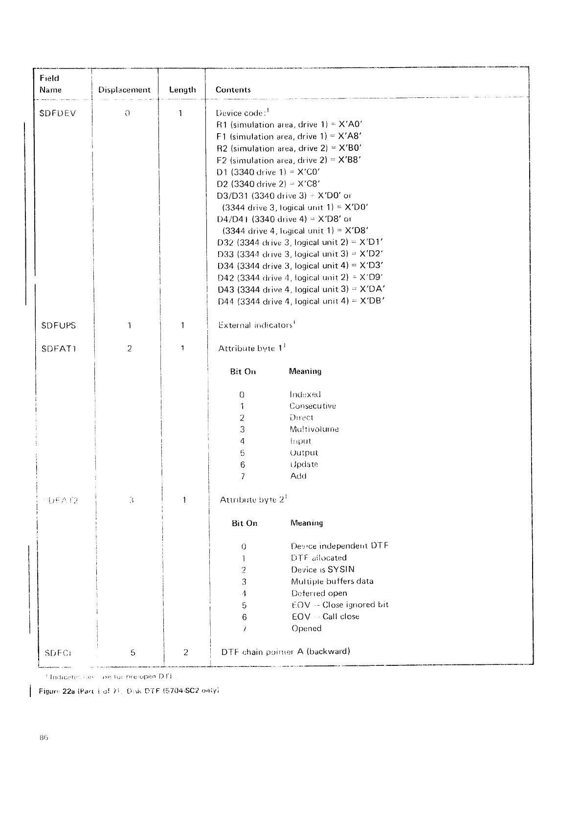
Frelrl
Narne
$DFDEV
$D
FUPS
$flf-AT'l
iii::.'\ I "/
.$l-r
F I t
- lilill(:itTr
Fignr'.22a (Psrr i ef i', Li si,.
f'-iF i?"7i)4-SC2
r:nivi
flisplace
rrre
nt
il
r5.t iur l)l(, ()Deo [) l-i
L)cvice cotlt::t
R1
(sinrulation
area,
drive 1)
= X'A0'
F1
(simulation
area,
drive
1)
= X'A8'
R2
(simulation
area,
drive 2)
- X'80'
F2
(simulation
afea,
clr
ive
2)
= X'88'
D1 (3340
drive 1)
= X'C0'
D2
(3340
drive
2)
- X'C8'
D3/D31
(3340
clrive
3)
' X'DO'oi
(3344
dr
ive
3,
ir.igical
uriit 1)
=
X'D0'
It4lD4l
(3340
drive
4)
- X'DB'or
(3344
drive 4,
lt-'gical
unit 1)
=
X'D8'
D32
(3344
rir ive
3,
logical urrit 2l = X'D1'
D33
(3344
cJr
rve 3,
logical
urrit 3)
=
X'D2'
D34
(3344
drive
3,
logical unit
4)
=
X'D3'
D42
(3344
drive 4,
logit;al
rrrtit 2l =
X'D9'
D43
(3344
drive
4, logical
unit 3)
=
X'DA'
t)44
(3344
drive
4,
logical
unit
4)
='
X'DB'
lixterrral irrrlrcatorsl
Contents
Attribute br,rre
1r
Bit Orr
0
1
2
3
4
5
7
Altfrl)rte
ltyte'.2\
tsit On
r.)
1
3
,1
5
6
l\4earrirrg
Inril;xrlt.l
Currsecu
titre
ill or:.t
lltr !.t iv
olut
r'e
llrf){lt
(Julput
i
Jprlate
Atlci
Nlean irtg
ljev,c;e
indeperrder
ri DT
F
[rTF .rii.rcated
Device
rs
SYSIN
Mulripte
birffers
data
Dr:terred
open
iOV -
Olose
ignot'ed
bit
EOV Call
close
Operred
DJ'F
r;hain
p,.-rtttiet
A (backward)
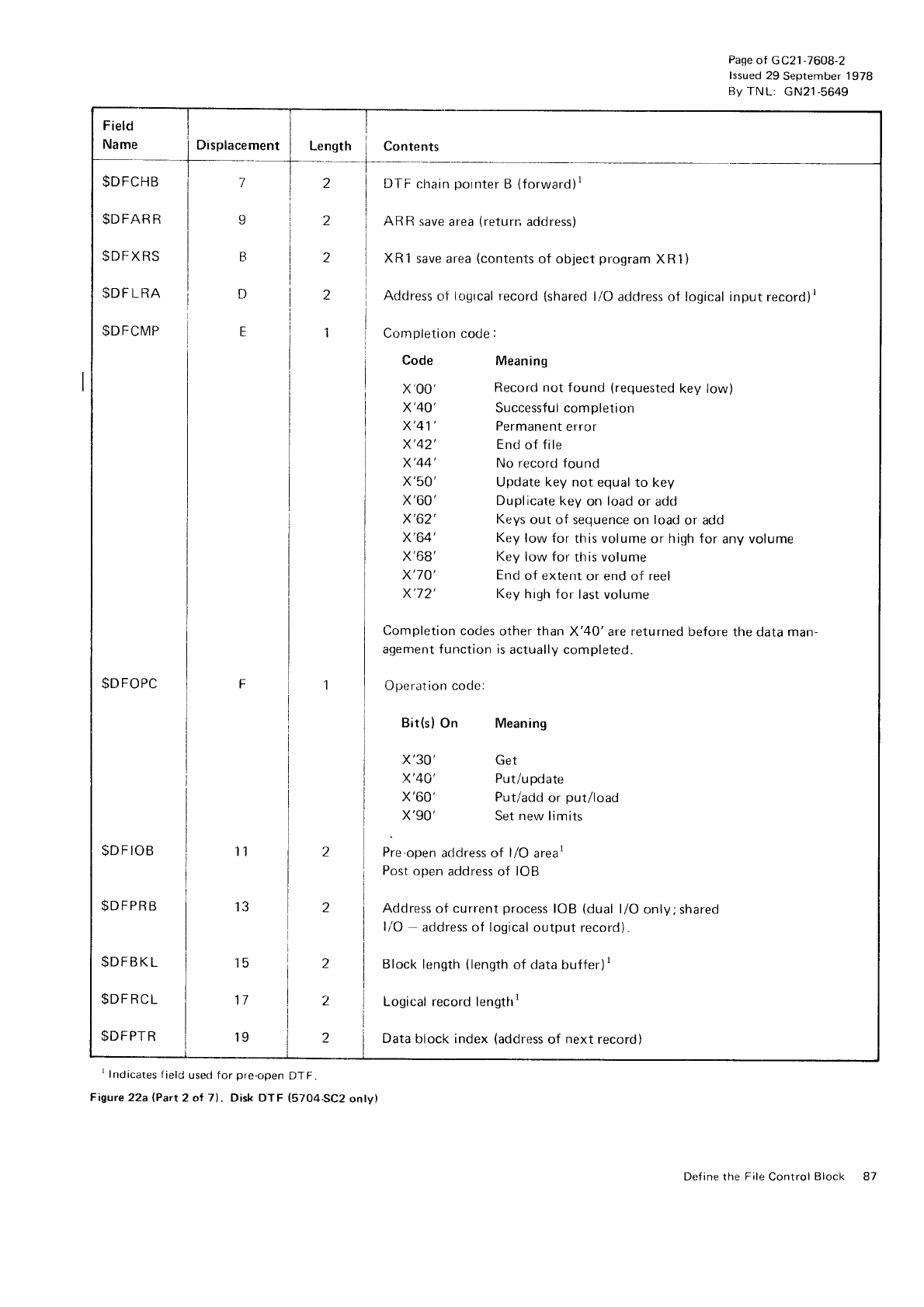
Name I Displacement
a
1
2
1
Field
$DFCHB i T
$DFARR | 9
$DFXRS I N
$DF
LRA i t)
$DFCMP ] E
$DFOPC i F
$DFTOB I r r
$DFPRB i 13
$DFBKL I I S
SDFRCL I 17
$DFPTR i ts
Length i Cont"ntt
DTF
chain
pointer
B
(forward)r
AR R
save
area
(return
address)
XRi save area
(contents
of object
program
XR1)
Address
of logical
record
(shared
liO address of logical input
record)r
Cr-rmpletion code
:
Code Meaning
X'00' Record not found (requested
key low)
X'40' Successful completion
X'41' Permanent
error
X'42' End
of f ile
X'44' No record
found
X'50' Update key not equal to key
X'60' Duplicate
key on load
or add
X'62' Keys
out of sequence
on load
or add
X'64' Key
low for this volume
or high for any
volume
X'68' Key low for this volunre
X'7O' End
of extent
or end of reel
X'72' Key
high for
last volume
Completion
codes
other than X'40'are returned before
the data man-
agement f unction is
actually completed.
Operation code:
Bit(s)
On Meaning
x'30' Get
X'40' Put/update
X'60' Put/add
or put/load
X'90' Set
new
limits
Pre-open
address of l/O arear
Post
open address
of IOB
Address
of current
process
IOB (dual
l/O only;shared
liO address of logical
output record)"
Block length
{length
of data buffer)t
Logical record lengtfri
2 i Data
block index
(address
of next
record)
Pase
of G C21
-7608-2
lssued
29 September
1978
Bv
TNL: GN21-5649
'lndicates
field
usecl for
pre-open
DTF.
Figwe22a (Part
2 ot 71. Disk DTF (5704SC2 onty|
Define the
File
Control Block 81
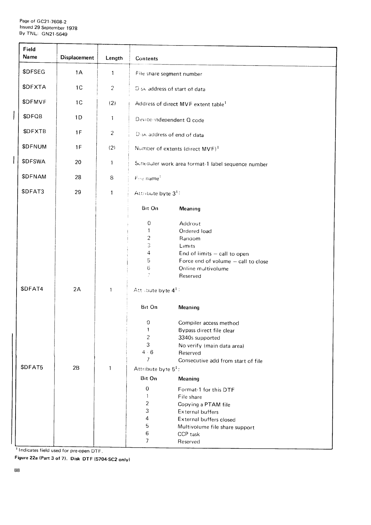
Page
of GC21-7608-2
lssued
29 September
lgTg
By TIJ
L; G N21
-b649
Displacement
$DFSEG
$DFXTA
$DFMVF
$D
FOB
$DFXTB
$DFNUM
$DFSWA
$DFNAM
$DFAT3
$DFAT4 2A
$DFAT5
' Indicates
f
ield
used f
or preopen DTF.
Figure 22a (Part
3 of lr). Disk DTF (57O4-SC2
onty)
88
Contents
Fiie
ihare
segment
number
li s" atldress
of start
of data
AdcJress
of direct
MVF extent
tabler
Devrce- rnCependent
O
code
D sri
arldress
of end
of data
Nr,nrirer
of extents
(cjirect
MVFir
SLlre{ruler
work area
fornrat-1
label
sequence
number
F.t lrirflt€;
Ai r r
,
L;ute
byte
3r
:
1A
lot 1
:
I
1
l
12l
IL
IU
iD
IF
1F
20
zo
2g
tsrt
On
0
1
1
j
4
0
:
Atl ,l-rute
byte
4r
Brt On
Meaning
Addrout
Ordered load
Farrtiom
Lrmrts
End
of limits
- call
to open
Force
end
of volume
- call
to close
Orrline multivolume
Reserved
Meaning
Compiler
access method
Bypass
direct file
clear
3340s
supported
No verify
(main
data
area)
Reserved
Consecutive
add f
rom
start
of f ile
28
1
a
4.6
7
Att riitute
Bit
On
fl
1
4
E
6
oyle
5-:
Meaning
Format-
l for
this DTF
File
share
Copying
a
PTAM file
External
buffers
External
buffers
closed
Multivolume
f
ile
share
support
CCP
task
Reserved
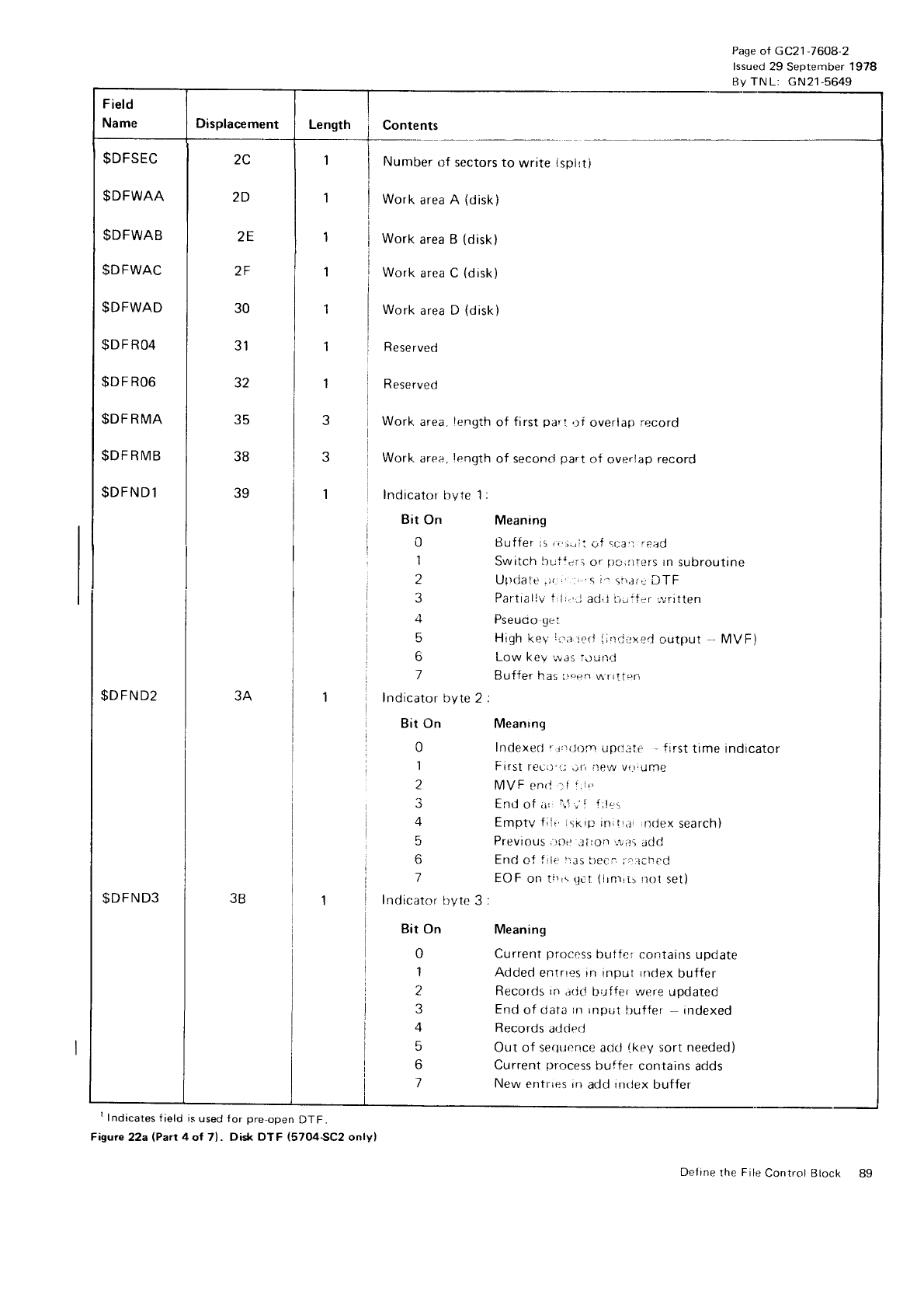
Page
of GC21
-7608-2
lssued 29 September
1978
Bv
TN
L: GN21-5649
$DFSEC
$DFWAA
$DFWAB
$DFWAC
$DFWAD
$D
F RO4
$DF
R06
$DFRMA
$DFRMB
$DFND1
Displacement Length Contents
2C
2D
2E
2F
30
31
32
35
JU
39
Number
ilf sectors to write {spl!ti
Work
area
A (disk)
Work
area B (disk)
Work area C (disk)
Work
area D (disk)
Reserved
R eserved
Work
area. length
of first
pari,tf overlap
record
Work
area, length
of second
part
of overiap
record
Indicator
bvte 1
:
Bit On
0
1
I
3
4
5
F;
7
Indicator
byte 2
;
Bir On
0
1
2
3
4
5
7
lndicator
byte
3
:
Bit On
0
1
2
3
4
5
6
l
$DFND2
$DFND3
'lndicates
field
is
used for
pre-open
DTF.
Figure 22a (Part 4 of 7) . Disk DT F (5704SC2 onlyl
Meaning
BufJer ls
i.r:irri:i;f
",ra',
read
Switch builei-i
Or
pc,nlers
rn
subroutine
Ulldate
.)r-
i :':
s i'.
srr.liu DTF
Partiaiiv 1r
i
r.,,.j
ad,
j Dijifsr'rjritten
High
keV
ii:;r':,:rJ
{ir-rClxed
output - MVF)
Low kev
was
ior-rnd
Buffer has i)eerl
\4
r rttf
n
Meanrng
Indexerl
f
r:r{J{lm up(l:tir - frrst
time indicator
First
reci:',.'j,ir-,
itew
vi,!iurne
MVF
enri :t
l.it
End
of iir,
iri
..
i l;!.::,
Emptv fiii,
lsrrp
initi.tr
rndex
search)
PTeViOUS
t.it)it
.,rlrOfl
r*-;:S
add
End
oi f rlr:
l:.rs
5eci.;rrrrched
EOF
on tlrrs
tJCt
iitnl!t:
no1 set)
Meaning
Current
process
bullc;' contains
uprlate
Added
entrres in
input
rndex
buffer
Records
in ar
jd l-rr.rf fer $/e!-e updated
End
of cJata
rrr Input
l)uffer indexed
Records
atlderJ
Out of sequcnce acicl
(key
sort
needed)
Current
process
buffer
contains
adds
New
entrres in add
inrlex
buffer
Define the File Control Block
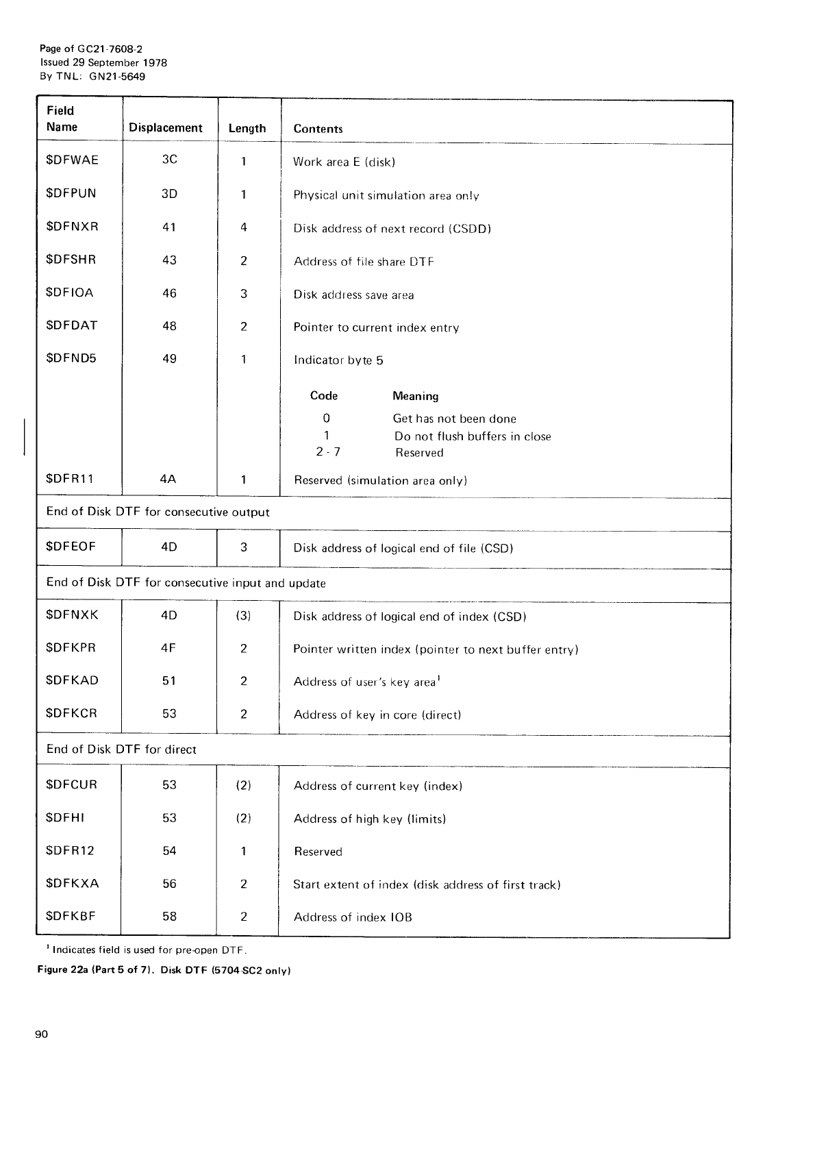
Pase
of GC21-76O8-2
lssued 29 September 1978
By TNL: GN21-5649
t Indicates f
ield
is
used for preopen DTF.
Figure22a (Part
5 of 7). Disk
DTF (5704SC2 onty)
1
End
of Disk
DTF for consecutive
output
End
of Disk
DTF for consecutive
input
and
update
Contents
Work area E (disk)
Physical
unit
simulation
area onry
4 | Disk
address
of next
record
(CSDD)
2 | Acldress
of trle
share DT
F
3 i Disk
acldress
save area
2 | Pointer
to current
index
entry
1 | Indicator
byte
5
Code Meaning
0 Get
has
not been done
1 Do not f lush buffers in r:lose
2 7 Reserved
Reserved
(simulation
area only)
Disk
address
of logical
end of {ile
(CSD}
Disk
address of logical end of index
(CSD)
Pointer
written index
(pointer
to next buffer
entry)
Address
of user's key
areal
Address
of key in core
(direct)
End
of Disk DTF for direct
Address
of current key (index)
Address
of high
key (limits)
Reserved
Start extent
of index
(disk
address of first
track)
Address
of index IOB
3D
41
+J
46
4B
49
$DFWAE
$DFPUN
$DFNXR
$D
FSH
R
$DFIOA
$DFDAT
$DFND5
$DFRl 1
4D
4F
51
tr?
$DFNXK
$DFKPR
$DFKAD
$DFKCR
53
5J
54
56
58
$DFCUR
$DFH
I
$DFR12
$DFKXA
$DFKBF
t2l
t2l
I
2
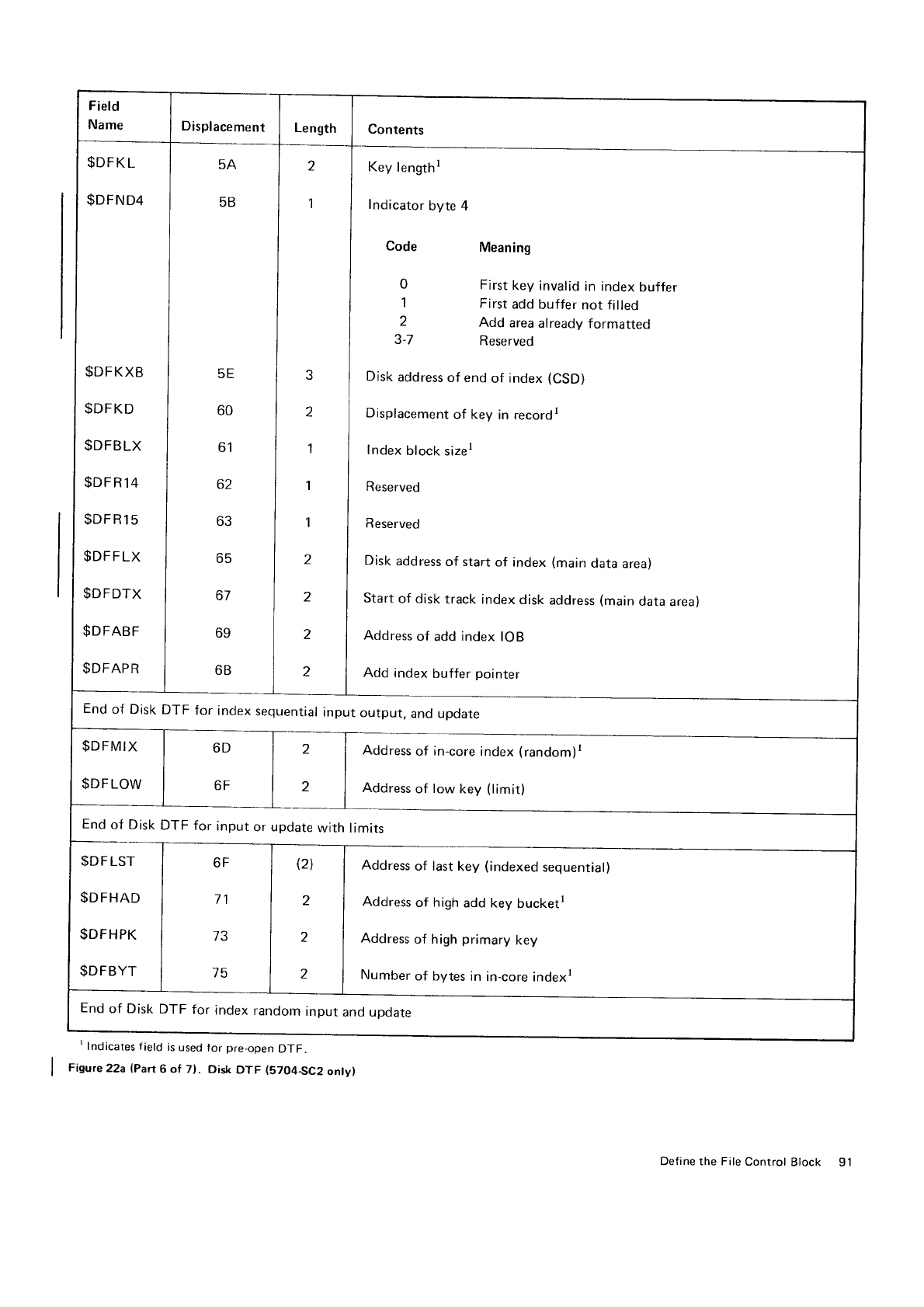
Field
Name Displacement Length Contents
I $DFKL
I $DFND4
$DFKXB
$DFKD
$DFBLX
$DF
R
14
$DF
R
15
$DFF
LX
$DFDTX
$DFABF
$DFAPR
5A
5B
5E
60
61
62
63
65
67
69
frt'
2
I
2
1
1
1
z
2
2
2
Key
length
I
Indicator
byte 4
Code
0
1
2
3.7
Meaning
First
key invalid
in index
buffer
First
add
buffer
not filled
Add area
already
formatted
Reserved
Disk
address
of end
of index
(CSD)
Displacement
of key in recordr
Index
block
sizer
Reserved
Reserved
Disk
address
of start
of index
(main
data
area)
Start
of disk
track
index
disk
address
(main
data
area)
Address
of add
index
IOB
Add index
buffer
pointer
End
of Disk
DTF for index
sequential
input
output,
and update
End
of_Disk
$DFLST
$DFHAD
$DFHPK
$DFBYT
$DFMIX
$DFLOW
6D
6F
2
2
Address
of in-core
index
(random)r
Address
of low key (limit)
TFfor input or pdate
with imits
Address
of last
key (indexed
sequential)
Address
of high
add key bucketr
Address
of high
primary
key
Number
of bytes in in-core
indexl
6F I '',',
11
l',
73
l',
75
12
End
of Disk
DTF for index
random
input
and upoate
I lndicates f
ield is
used
for pre-open
DTF.
Figure
22a
{Pan
6 of 7}. Disk
DTF (57O4SC2
onty)
Define the File
Control
Block 91
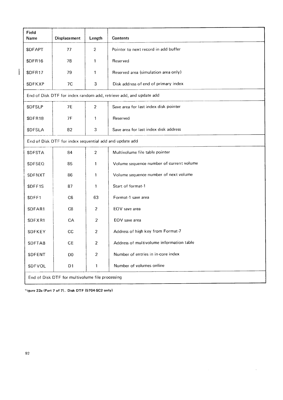
Field
Name Displacement Length Contents
$DFAPT
$DFR1
6
$DFR17
$DFKXP
77
78
l9
7C
z
1
'l
J
Pointer to next record
in add buffer
Reserved
Reserved
area
(simulation
area
only)
Disk
address
of end
of primary
index
End
of Disk DTF for index random
add.
retrieve
add, and
update add
$DFSLP
$DFR18
$DFSLA
]E
7F
82
2
1
Save area
for last
index disk
pointer
Reserved
Save area
for last
index disk address
End
of Disk
DTF for index sequential add and
update
add
$DFSTA
$DFSEO
$D
F
NXT
$DFF1S
$DFFl
$DFAR
1
$DFXR1
$DFKEY
$DFTAB
$DF
ENT
SDFVOL
84
85
uo
87
C6
CB
CC
CE
DO
D1
1
I
1
63
2
2
z
2
2
1
Multivolume
f ile table
Pointer
Volume
sequence
number of current
volume
Volume
sequence
number
of next volume
Start of format-1
Format-1 save area
EOV save area
EOV save area
Address of high key from Format-7
Address of multivolume
information
table
Number
of entries
in
in-core
index
Number
of volumes
online
End
of Disk
DTF for multivolume
file
processing
-igure22a(?art7 ol 7). Disk
DTF (5704-SC2
only)
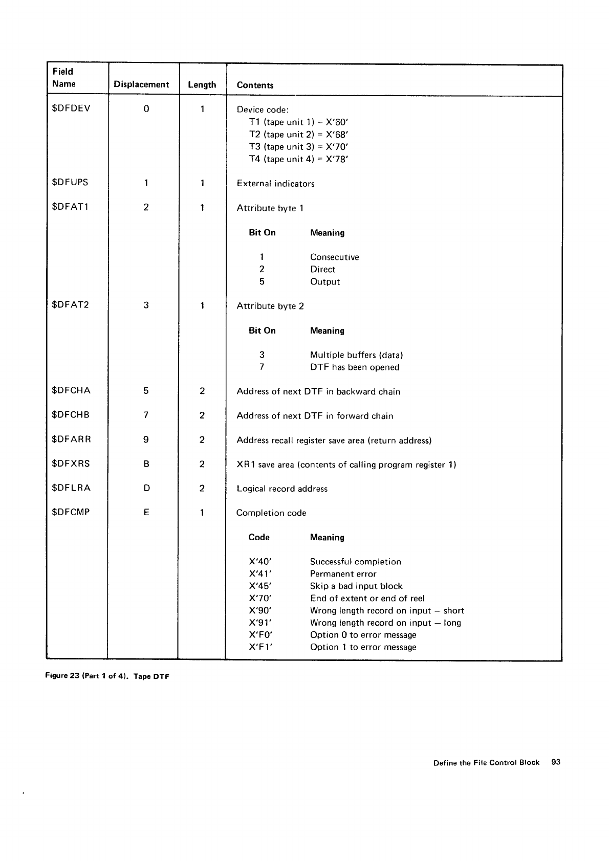
Field
Name Displacement Length Contents
$DFDEV
$DFUPS
$DFAT1
$DFAT2
$DFCHA
$DFCHB
$DFAR
R
$DFXRS
$DF
LRA
$DFCMP
0
1
2
3
E
7
9
B
D
E
1
1
'l
I
2
2
2
2
2
1
Device
code:
T1 (tape
unit 1)
=
X'60'
T2
(tape
unit 2)
=
X'68'
T3 (tape
unit 3)
= X'70'
T4 (tape
unit 4) = X'78'
External
indicators
Attribute
byte 1
Bit
On
1
2
5
Attribute
byte 2
Bit On
3
7
Meaning
Consecutive
Direct
Output
Meaning
Multiple
buffers
(data)
DTF has
been opened
Address
of next
DTF in
backward chain
Address of next DTF in forward chain
Address
recall register
save area
(return address)
XRl save
area
(contents
of calling
program
register
Logical record
address
Completion
code
1)
Code
x'40'
x'41'
x'45',
x'70'
x'90'
x'91',
X'FO'
X'F 1'
Meaning
Successful
completion
Permanent
error
Skip a bad
input
block
End of extent or end of reel
Wrong length record on input * short
Wrong length record on input - long
Option 0 to error message
Option 1 to error message
Figure
23 (Part
1 of 4). Tape
DTF
Define the File Control Block 93
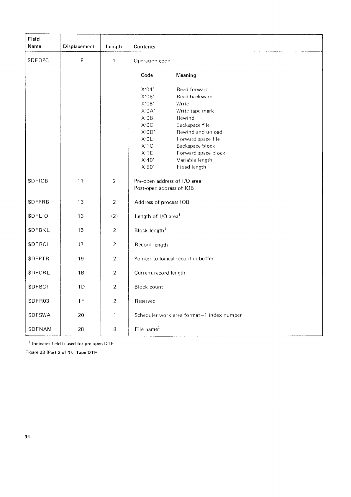
Field
Name Displacement [-ength Contents
$DFOPC
$DF
IOB
$DFPR
B
$DF
LIO
$DFBKL
$DF
RCL
$DFPTR
$DFCR
L
$DFBCT
$DF
R03
$DFSWA
$DFNAM
F
11
13
13
15
11
19
1B
1D
1F
20
28
z
1
(21
2
z
I
1
1
.J
Operatiorr
code
Code
x'04'
x'06'
x'08'
X'OA'
X'OB'
X'OC'
X'OD'
X'OE'
X'1C'
X'1E'
x'40'
X'BO'
Meaning
Read
forward
Rearj backward
Write
Write
tape
rnark
Rewind
Backspace fi le
Rewind and unload
Forward
space file
Backspace block
Forward
space
block
Variable
length
Fixed length
Pre-open
address
of l/O arear
Post-open
address of IOB
Address
of process
IOB
Length
of l/O arear
Block
lengtht
Record
lengthr
Poirrter
to logical record irr buffer
Current
record lerrgth
Block count
R eserved
SchedLrler
work area
format-1 inclex number
File
namer
t Indicates f ield is
used
for preopen Dl-F
Figure
23 (Part
2 ol 4). Tape
DTF
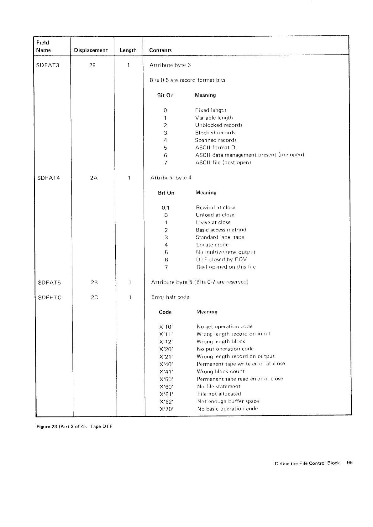
F
ield
Name Displacement Length Contents
$DFAT3
$DFAT4
I
$DFAr5
I $DFHTC
2S
2A
2B
2C
1
1
1
Attribute byte
3
Bits 0 5 are
record
forrnat bits
Bit On lMeaning
0
1
3
4
5
6
l
Fixed length
Variable
length
Unblocked
recorrls
Blocked
lecords
Spanned
records
ASCllformat
D.
ASCII
data management
ASCII
f
ile
(post-open)
present (pre-open)
AttribLrte byte
4
Bit On Meaning
0,1 Rewittci
at close
0 Unload at
close
1 l-,eave
at close
2 Basic
ar:cess
rnethod
3 Standarrl
l:rbel tal;e
4 l-r:rrate
rnt.rtle
5 I'll rnttltiv,rl'.trne outl'il1
6 t-)
I
F:
closetl
tly FOV
7 llsr.'l
r';u,rred
ori
111i5
Irie
Attribute
t-lvte 5 (Bit:;
0 7 ate rr,'served)
Error
halt cor.le
Code
x'1
0'
x'1 t'
x'12'
x'24'
x'21'
x'40'
x'41'
x'50'
x'60'
x'6r'
x'62'
x'70'
Meaninq
No
qet
operatiott
t;ot'le
Wronq
lergllt tecord
on
ttlllttt
Wronq
length hlock
No ptit
operatiorr
code
Wrong
length
record on outlrut
Permarrent
tape write
r:rrrtt
at
close
Wrong
block coitnt
Permanent tape
read
errc'r
a1 close
No f
ile statemen
t
Filr:
rrot allocated
Not enotrglr
buffer space
No basic operation
code
Figure 23 (Part
3 of 4). Tape
DTF
Def
ine
rhe
File Control
Block 95
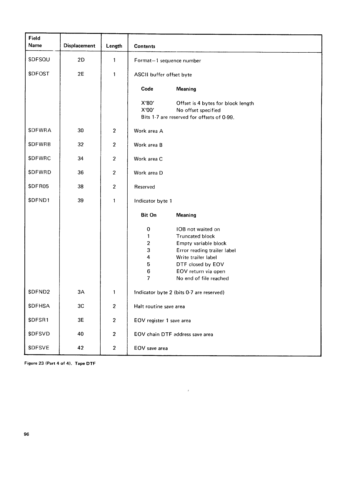
Field
Name Displacement Length Contents
$DFSOU
$DFOST
$DFWRA
$DFWRB
$DFWRC
$DFWRD
$DF
ROs
$DFND1
$DFND2
$DFHSA
$DFSR
1
$DFSVD
$DFSVE
2D
2E
30
32
34
36
38
39
3A
3C
3E
40
42
1
1
2
2
2
2
2
1
1
2
2
2
2
Format-1
sequence number
ASCII
buffer offset byte
Code
x'80'
x'00'
Meaning
Offset is
4 bytes for block length
No offset
specified
Bits
1-7
are
reserved for offsets
of 0-99.
Work
area
A
Work
area B
Work
area
C
Work
area
D
Reserved
Indicator
byte 1
Bit On Meaning
IOB
not waited
on
Truncated
block
Empty variable
block
Error reading
trailer label
Write
trailer label
DTF closed by EOV
EOV return via
open
No end
of file
reached
Indicator
byte 2 (bits
0-7 are
reserved)
Halt routine
save
area
EOV
register
1 save area
EOV
chain DTF address
save area
EOV
save area
Figure
23 (Part
4 of 4). Tape
DTF
96
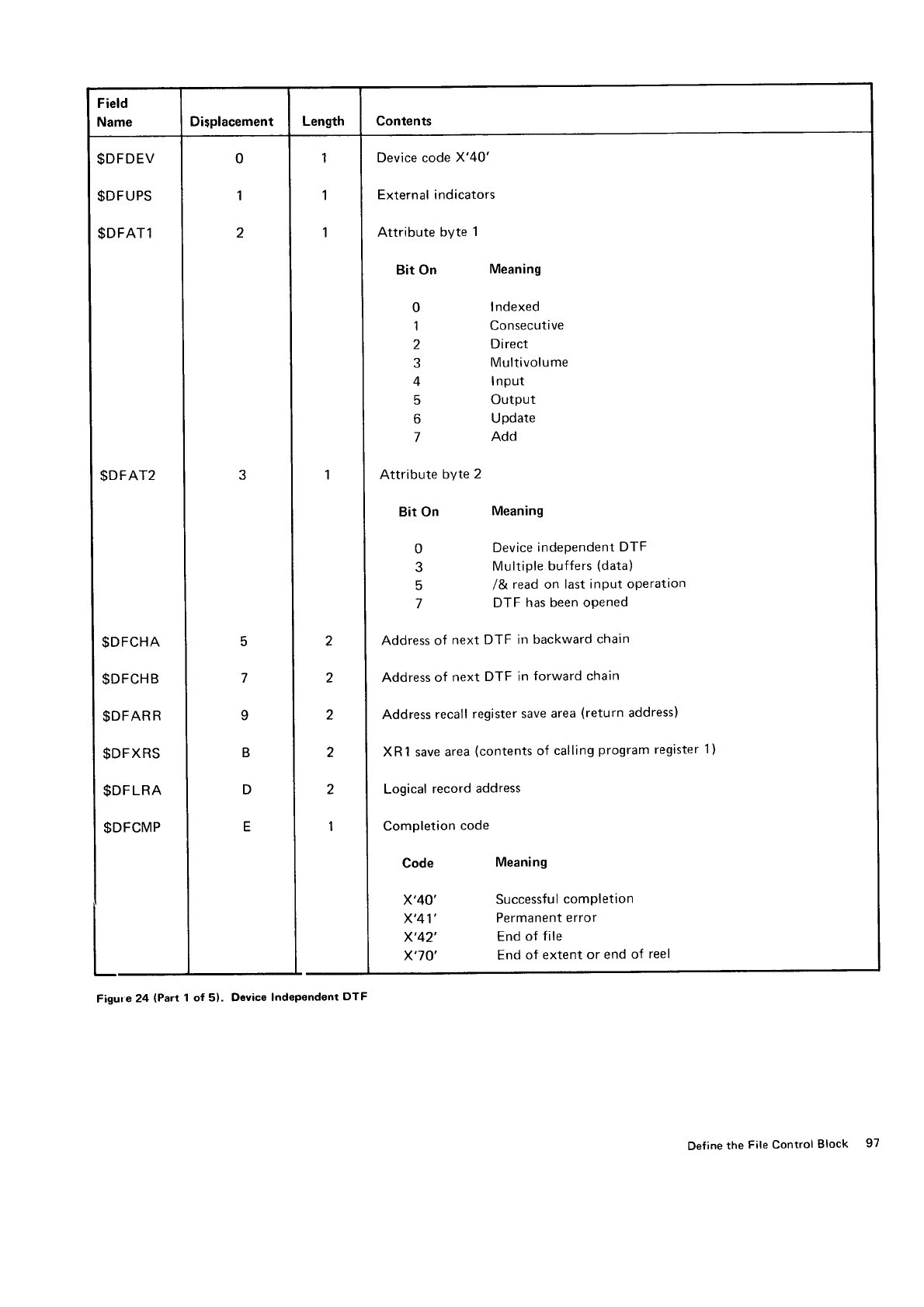
Field
Name Di$placement Length Contents
$DFDEV
$DFUPS
$DFAT1
$DFAT2
$DFCHA
$DFCHB
$DFAR
R
$DFXRS
$DF
LRA
$DFCMP
5
7
o
B
D
E
0
1
2
3
I
1
'l
1
2
2
2
2
2
1
Device code
X'40'
External indicators
Attribute byte 1
Bit On Meaning
0 Indexed
1 Consecutive
2 Direct
3 Multivolume
4 Input
5 Output
6 Update
7 Add
Attribute byte 2
Bit On Meaning
0 Device
indePendent
DTF
3 Multiple
buffers
(data)
5 /& read on last
inPut operation
7 DTF has been oPened
Address of next
DTF in backward
chain
Address
of next
DTF in
forward chain
Address
recall
register
save area
(return
address)
XR1 save area
(contents
of calling
program
register
1)
Logical
record
address
Completion
code
Code Meaning
X'40' Successful
comPletion
X'41' Permanent
error
X'42' End
of file
X'7O' End of extent or end of reel
Figure24 (Part 1 of 51. Device Independent DTF
Define
the File Control Block 97
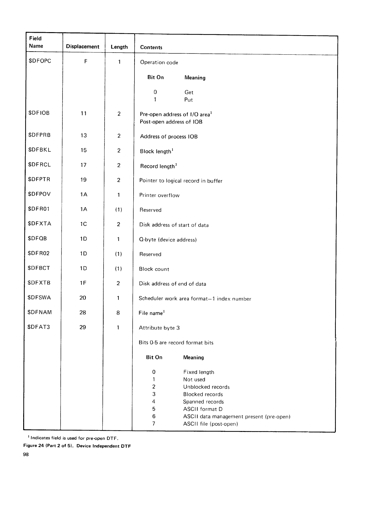
Field
Name Displacement Length Contents
$DFOPC
$DF
IOB
$DFPRB
$DFBKL
$DF
RCL
$DFPTR
$DFPOV
$DF
RO 1
$DFXTA
$DFOB
$DF
RO2
$DFBCT
$DFXTB
$DFSWA
$DFNAM
$DFAT3
F
1'l
13
15
17
19
1A
IA
1C
1D
1D
1D
1F
20
28
29
2
2
2
2
2
1
(1)
2
I
(1)
(1)
2
'l
a
1
I
Operation
code
Bit On Meaning
0 Get
1 Put
Pre-open
address
of l/O arear
Post-open
address
of IOB
Address
of process
IOB
Block
lengthr
Record
lengthl
Pointer
to logical record
in buffer
Printer
overflow
Reserved
Disk address
of start of data
O-byte
(device
address)
Reserved
Block count
Disk
address
of end
of data
Scheduler
work area
format-1 index number
File
namel
Attribute
byte 3
Bits
0-5 are record format
bits
Bit On
0
'l
2
3
4
5
6
Meaning
Fixed length
Not used
Unblocked records
Blocked records
Spanned
records
ASCII format
D
ASCII data management
present (pre-open)
ASCllfile
(post-open)
t Indicates
f ield
is
used
for preopen DTF.
Figure
24 (Part 2 of 5). Device lndependent DTF
98
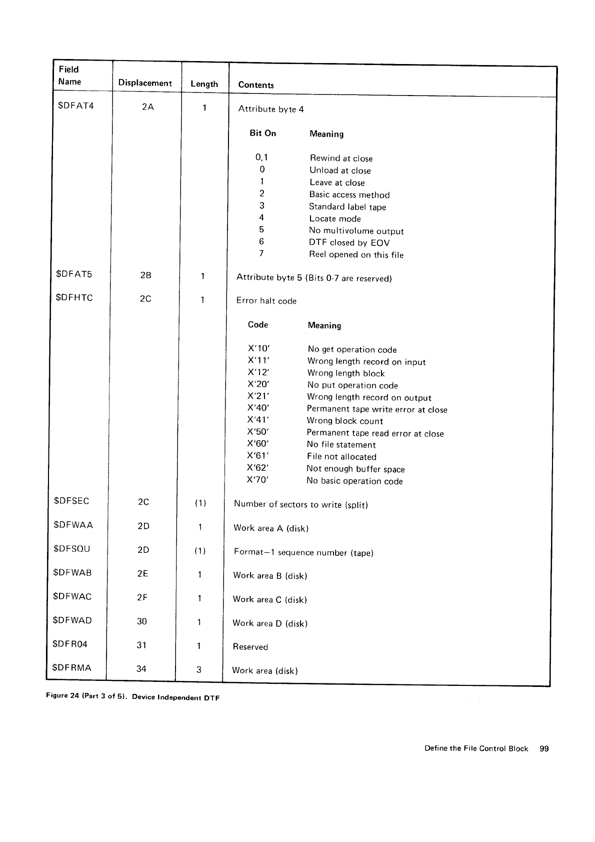
$DFAT4
$DFAT5
$DFHTC
$DFSEC
$DFWAA
$DFSOU
$DFWAB
$DFWAC
$DFWAD
$DF
R04
$DFRMA
Attribute byte 4
Bit
on
0,1
0
1
2
J
4
5
o
7
Attribute byte
5 (Bits
O-7 are reserved)
Error
halt
code
Meaning
Rewind
at close
Unload
at close
Leave
at close
Basic
access
method
Standard
label
tape
Locate
mode
No multivolume
output
DTF closed
by EOV
Reel
opened
on
this file
Meaning
No get
operation
code
Wrong
length
record
on input
Wrong
length
block
No put
operation
code
Wrong
length
record
on output
Permanent
tape
write
error
at close
Wrong
block
count
Permanent
tape read
error
at
close
No file
statement
File
not allocated
Not enough
buffer
space
No basic
operation
code
Code
x'1
0'
x'11',
x'12'
x'20'
x'21'
x'40'
x'41',
x'50'
x'60'
x'61',
x'62'
x'70'
Number
of sectors to write (split)
Work
area
R (disk)
Format-1 sequence number
(tape)
Work
area
B (disk)
Work
area
C (disk)
Work
area
D (disk)
R
eserved
Work
area
(disk)
Figure
24 (Part
3 of 5). Device Independent DTF
Define the File
Control Block
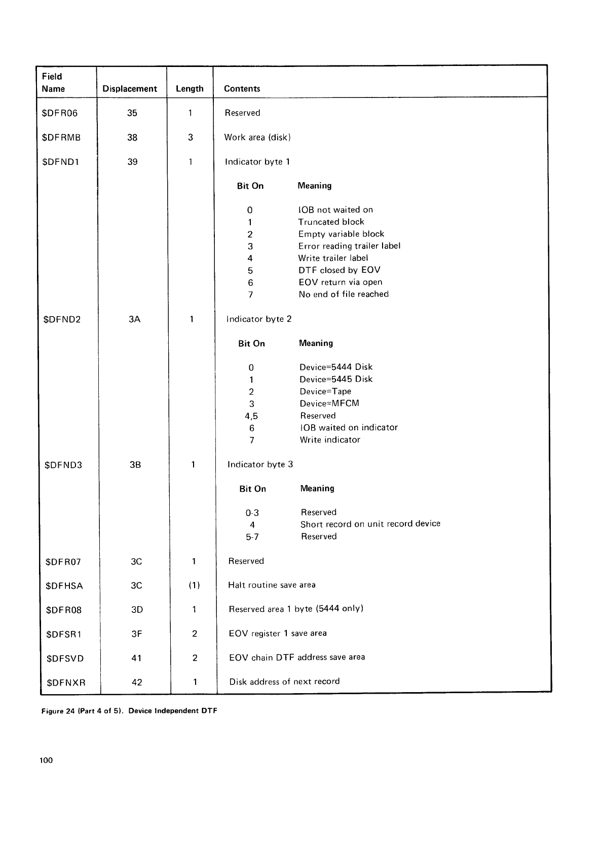
Field
Name Displacement Length Contents
$DF
RO6
$DF
RMB
SDFNDl
$DFND2
$DFND3
I
-""^
|
$DFR08
l
*orr*,
I :",,--
3C
3C
3D
3F
41
42
35
38
39
3A
3B 1
1
(1)
1
2
2
1
1
3
I
Reserved
Work
area
(disk)
Indicator byte 1
Bit On Meaning
0 IOB
not waited on
1 Truncated
block
2 Empty
variable block
3 Error
reading trailer
label
4 Write trailer
label
5 DTF closed
bY
EOV
6 EOV return
via oPen
7 No end
of file reached
Indicator byte 2
Bit On Meaning
0 Device=5444
Disk
1 Device=5445
Disk
2 Device=TaPe
3 Device=M
FCM
4,5 Reserved
6 IOB
waited
on indicator
7 Write
indicator
Indicator byte
3
Bit On Meaning
0 3 Reserved
4 Short record
on unit record
device
5-7 Reserved
L
I Reserved
I
I
I Halt routine save
area
I
I Reserved area
1
byte
(5444
onlY)
I
I
I EOV register 1 save
area
I
I
I
I EOV chain DTF address
save
area
I
I
I Disk address
of next record
Figure 24 (Part
4 of 5). Device Independent DTF
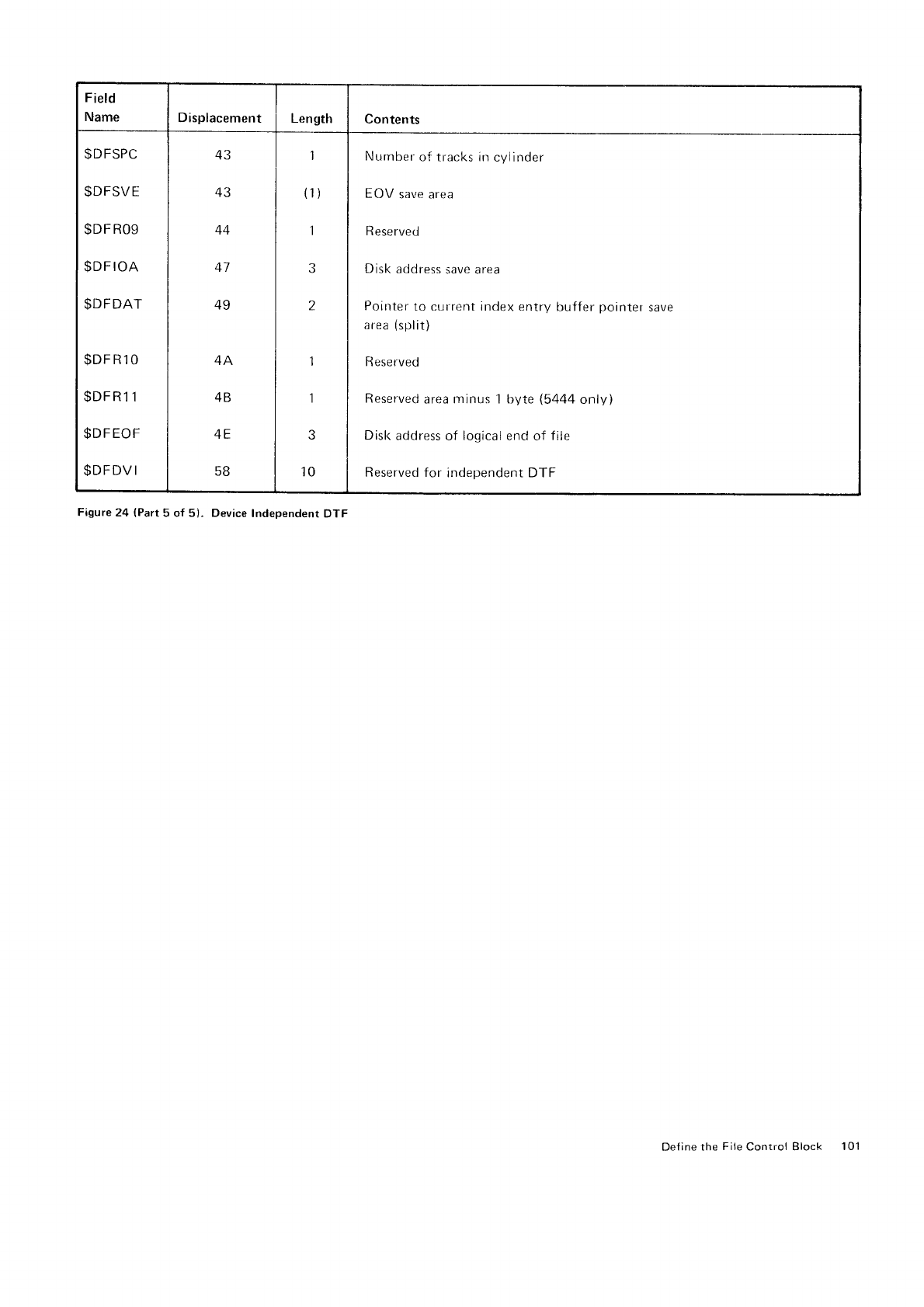
Field
Name Displacement Length Contents
$D
FSPC
$DFSVE
$DF
R09
$DFIOA
$DFDAT
$DFR1O
$DFR1
1
$DFEOF
$DFDV
I
43
44
41
49
4A
4B
58
1
(1)
1
J
z
1
1
10
Nurnber
of tracks in
cylinder
EOV save area
R
eserved
Disk
address
save area
Pointer
to current index entry
buffer
pointel
area
(split)
R eserved
sa
ve
Reserved
area nrinus 1 byte (5444
only)
Disk
address
of logical
end of file
Reserved for independent DTF
Figure
24 (Part
5 of 5), Device
Independent
DTF
Define
the
File
Control Block 101
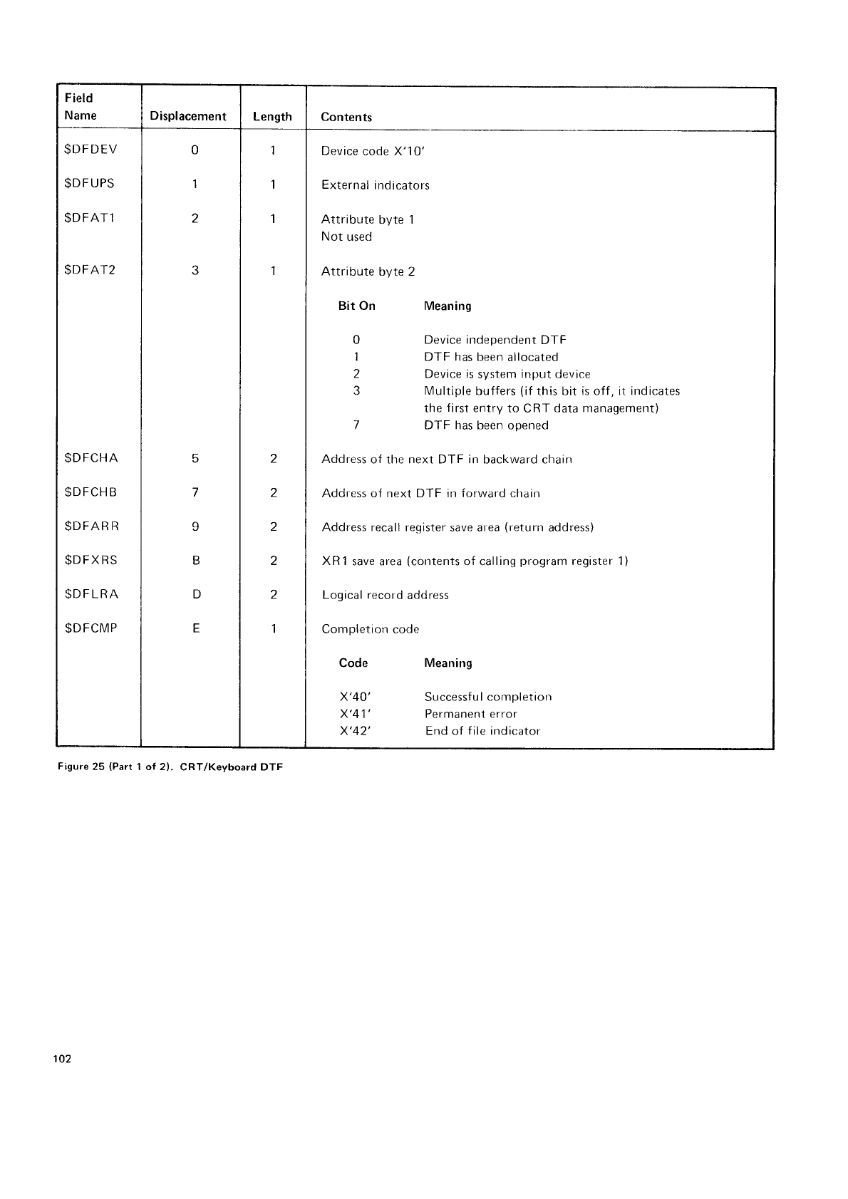
Field
Name Displacement Length Contents
$DFDEV
$D
F
UPS
$DFATl
$DFAT2
$DFCHA
$D
FCH B
$DFAR
R
$D
FX
RS
$D
F LRA
$DFCMP
0
1
2
5
I
D
E
1
1
1
1
2
a
z
2
2
I
Device
code X'10'
External
indicators
Attribute byte 1
Not used
Attribute byte 2
Bit On Meaning
Device ir.rdependent
DTF
DTF has
been allocated
Device is
system
input device
Multiple
buffers
(if
this bit is off
, it indicates
the
first
entry
to CRT data management)
DTF has been
opened
Address
of tlre next DTF in backward chain
Address of next DTF in forward chain
Address recall register
save area
(retunr
address)
XR1
save area
(contents
of calling
program
register 1)
Logical record
address
Completiorr code
Code
x'40'
x'41'
x'42'
Meaning
Successf
u I completior-r
Permanent error
End of
file
indicator
Figure
25 (Part
1 of 2). CRT/Keyboard DTF
102
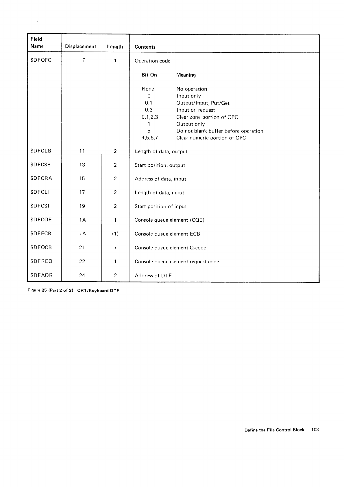
Field
Name Displacement Length Contents
$DFOPC
$DFCLB
$DFCSB
$DFCRA
$DFCLI
$DFCSI
$DFCOE
$DF
ECB
$DFOCB
$DF
REO
$DFADR
F
11
13
15
17
19
1A
,IA
21
22
24
1
z
2
2
2
2
I
(1)
7
I
2
Operation
code
Bit On
None
0
0,1
0,3
o,1,2,3
1
q
4,5,6,7
Meaning
No operation
Input only
Output/lnput, Put/Get
Input on request
Clear zone
portion
of OPC
Output only
Do not blank buffer before operation
Clear
numeric
portion
of OPC
Length
of data, output
Start
position,
output
Address
of data, input
Length
of data. input
Start
position
of input
Console
queue
element
Console
queue
element
Console
queue
elemenl
Console
queue
element
Address
of DTF
(coE)
ECB
O-code
request
code
Figure
25 lPart
2 ol 2). CRT/Keyboard DTF
Define
the File
Control Block 103
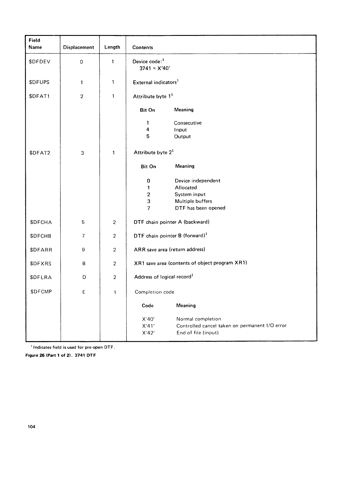
Field
Name Displacement Length Contents
$DFDEV
$DFUPS
$DFAT1
$DFAT2
$DFCHA
$DFCHB
$DFAR
R
$DFXRS
$D
F
LRA
$DFCMP
0
1
z
5
l
I
B
D
E
1
1
1
I
z
2
z
2
Z
1
Device code:l
3741
= X'40',
External
indicatorsl
Attribute byte
1r
Bit On
1
4
5
Attribute
byte
2r
Bit
On
0
1
2
3
7
Meaning
Consecutive
I nput
Output
Meaning
Device
independent
Allocated
System input
Multiple buffers
DTF has been
opened
DTF chain
pointer
A (backward)
DTF chain
pointer
B
(forward)l
ARR save
area
(return
address)
XRl save area
(contents
of obiect
program
XR1)
Address
of logical
recordr
Completion
code
Code
x'40'
x'41'
x'42'
Meaning
Normal
completion
Controlled
cancel taken
on permanent
l/O error
End
of file
(input)
I Indicates field is used for pre-open DTF
Figure
26 (Part 1 of 21. 3741 DTF
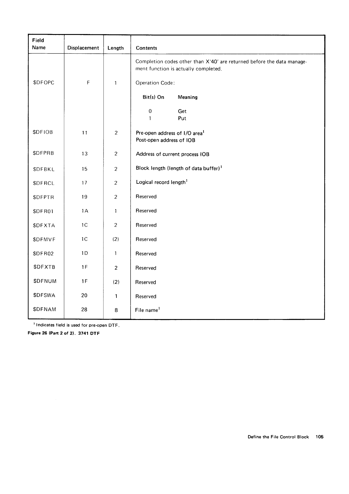
F
ield
Name Displacement Length Contents
$DFOPC
$DF
IOB
$DFPRB
$DFBKL
$DFRCL
$DFPTR
$DF
RO1
$DF
XTA
$DFIVIV
F
SDF
R02
$DFXTB
$DFNUM
$DFSWA
$DFNAM
F
I
13
15
11
19
,IA
'lc
1D
1tr
1F
20
28
2
1
z
1
I
12l
1
2
(2\
1
Completion codes other
than X'40' are
returned
ment
function is
actually completed.
Operation
Code:
Bit(s)
On Meaning
0 Get
1 Put
Pre-open
address
of l/O areal
Post-open
address of IOB
Address
of current process
IOB
Block length
(length
of data
buffer)
I
Logical
record lengthr
Reserved
Reserved
R
eserved
Reserved
Reserved
Reserved
R eserved
R eserved
File namer
before the data manage-
' Indicates
field is used for pre-open
DTF
Figure 26 lPan 2 of 21 . 3741 OTF
Def
ine
the File
Control Block 105
Appendix
C: Input/Output
Blocks
DISK
INPUT/OUTPUT
BLOCK
You
build
the disk
IOB
by issuing
the
gIOBD
macro
instruction.
lf
you
use
$RDD,
$WRTD.
or
gWAIT
in
your
program,
you
must
use
the
$IOED
macro
instruction
to
assign
the
offset in
the lOB.
The format
of
the IOB
and
the labef
s
assigned
to the f
ields
are shown
in Figure
27.
lOBs
for the
5444
Disk
Storage
Drive,
the
5445
Disk
Storage.
the
3340
Direct
Access
Storage
Facility.
and
the
3344
Direct
Access
Storage
are 30
bytes
long.
106
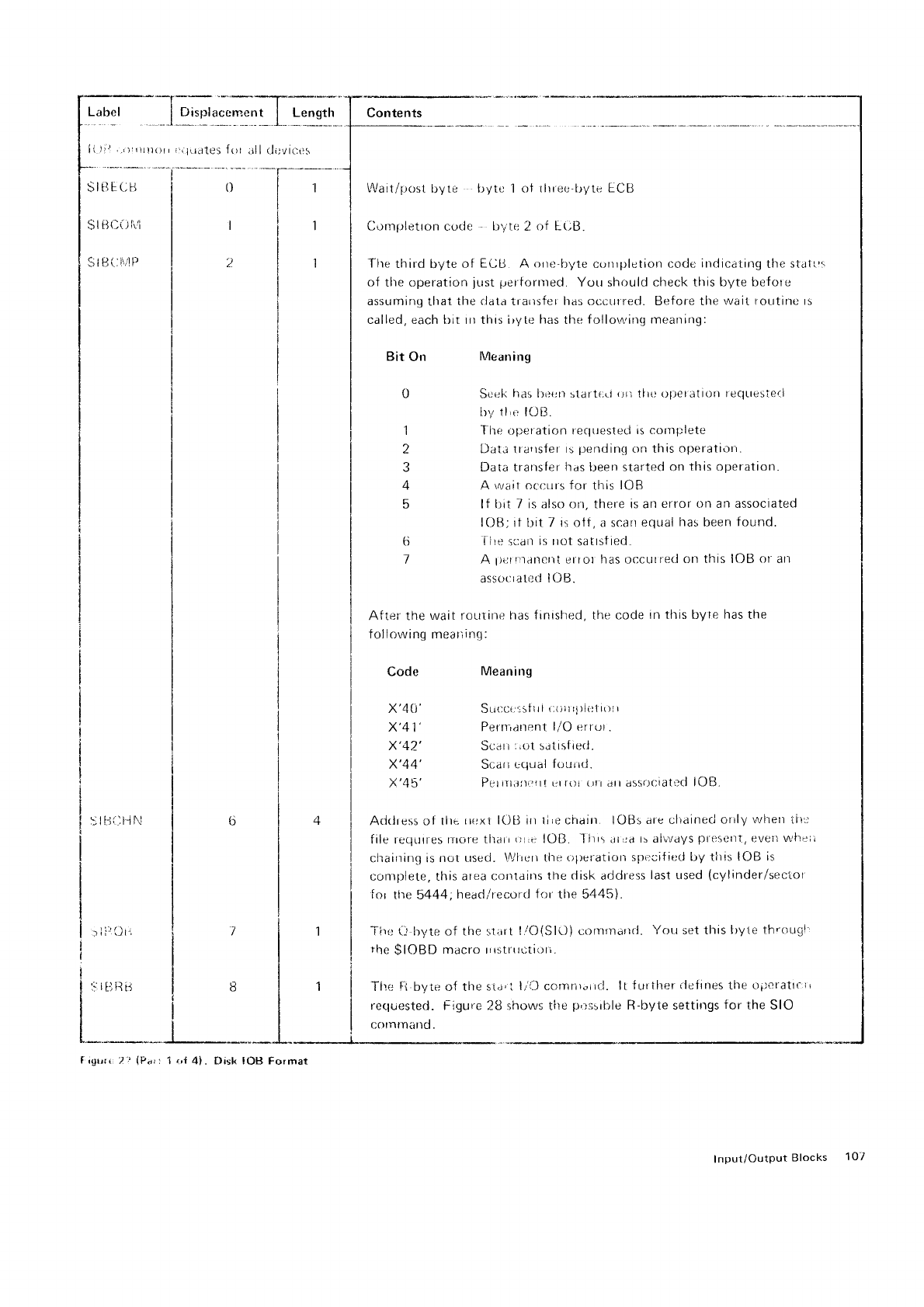
I igrrrr:2:'
(Pal 1 r,l 4]. Disk !OB Format
Input/OutputBlocks 107
.iLrcrtes
{()r
all dsvit:t:s
0-F-f a.",r'* -
I
-1
I Wail/trost
lryte l-ryte'i ot tlrree'byte
ECB
I
I Cornr;letron
cocie bytr: 2
of E-uB.
I
I The
third
byte
of ECij A orre'byte
currpletion
code inclicating
the
stal
I oi the operation
just
perfornred.
You should check
this byte before
I assuming
that
the
rlala trarrsfer has ot:crrrred. Before the wait routine rs
I called, each bit rn this iryte
has
tlre
follornrirrrt rneanirtg:
I
I Bit On lVlearring
I
| 0 Scel<
has l)ilert slart(;rl ori llrc
t)ltetatiorl reqtresie{l
I trr,r 1l,t: lOB.
i 1 Tlre operation requeslecl
is cornplete
2 DatJ
lrallsfef rs
pentlinq
ctn this
operatlon.
3 Dat;i transfer
has
been
started on
this opel ation.
4 A r,vait ccr;urs for this
IOB
5 lf bit
7 is also on, there is an
error on an associated
IOB; it
bit
7 is olt, a scarr
equal
has
been
found.
ti llle
sirdir
is not
satrstied.
7 A l)crllancnI
error has occutred
on this IOB
or
arr
assooratod
lOB.
After- the
wait routine
fras finisfrr:d, the code
irr this byte
has
the
tolIowing
meanirr.r;:
Code
x'4
(i'
x'41'
x'42_'
x'44'
x'45',
Meaning
Suocrlstlri rli)lr rl)liltl()l
I
Perniartr:nt
l/O errc,r
.
Scarir,cit
s;tislied.
Scarrcqual
fciuird.
Pcrrirlirrti,trt
urr()l {r| .rrr assrir;iatr'cl
loB
Ad<lress of tllL.
nrrxl IOB irr
tire
chairt. lOBs
are clraineci
orily
wl-retr
til:r
file requrres
r-rrore tltari
rr ,r lOB. I irrs
at,;a
ts always
pfeselrt,
eveit
whl;i
clrairrinq is
not
r-rsed. Wlrerr the
ol)eratiort specifiecl
by tlris IOB
is
conrplete, this
area c;onlairts
the
disk
address
last used
(cylinder/sector
f
or the
5444,
headlrecord
tor the 5445).
Tirrr i: byte of the sliirt
llO(SlO) eolnmarrd. Yott
set
this
l)y1e thr()uEl
the
$IOBD macro nrstfrtctiori.
Tire
[:t.bvie
of the
sia'i lr'i-) corntir"rrd.
lI fr-rrllrer
iletirres
the
opcrattr,rr
requested.
Figure 28 shows tite
p'r:;srllle
R-byte settirlgs
for the
SIO
c()tntniino.
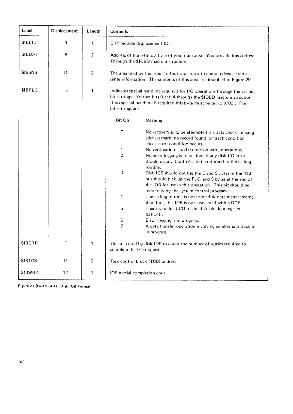
Label Displacement I Length Contents
$IBEID I | 1 | ERP
module
displacement lD.
$IBDAT I B I Z I Address
of the leftmost
byte
of
your
data
area.
You
provicle
this
acldress
Through
the
$IOBD
macro
instruction.
$IBSNS I D I Z I The
area
used
by
the input./output
stipervisor
tr) contain
device status
sense infornratiorr.
The
contents
nt this
area are described in Fiqure
29.
$IBFLG I f I t I Indicates
special handling
required
for l/O
operations
through the various
bit settings.
You set bits
0 and
4 through
the
$IOBD macro instruction.
lf no
special handling
is required this
byte mr:st
be set to X'00'. The
bit settings
are:
Bit On Meaning
5
o
No r.ecovery
is
to be
attempted
is
a
data check,
missing
address mark. no record
iound.
or track condition
check error condition
occurs.
No verification
is
to be
done on write operations.
No error logging
is
to be
done
if any disk l/O error
should occur. Control is to be returned
to the calling
routt ne.
Disk IOS
should not use
the C and S bytes in
the
lOB,
but should
pick
up
the F,
C,
and
S bytes
at the end of
ther IOB for use in this
operation.
This
bit should be
used
only by the
system control
program.
The
calling f outine is not using disk data management;
therefore.
this IOB
is not associated with a
DTF.
There
is no load l/O of the
disk
file
data
register
(DFD
R).
Error logging
is in
progress.
A data transfer operation involving
an
alternate track is
In progress.
l;
$IBERR I F | 1 | The
area
used
by disk IOS
to count the number
of retrir:s
required
to
complete
the l/O request.
$I
BTCB
$IBWRK
'11 2 | Task
control block (TCB)
arlilress.
12 1 | IOS
partial
completion code.
Figute 27 (Part 2 ol 4). Disk IOB Format
108
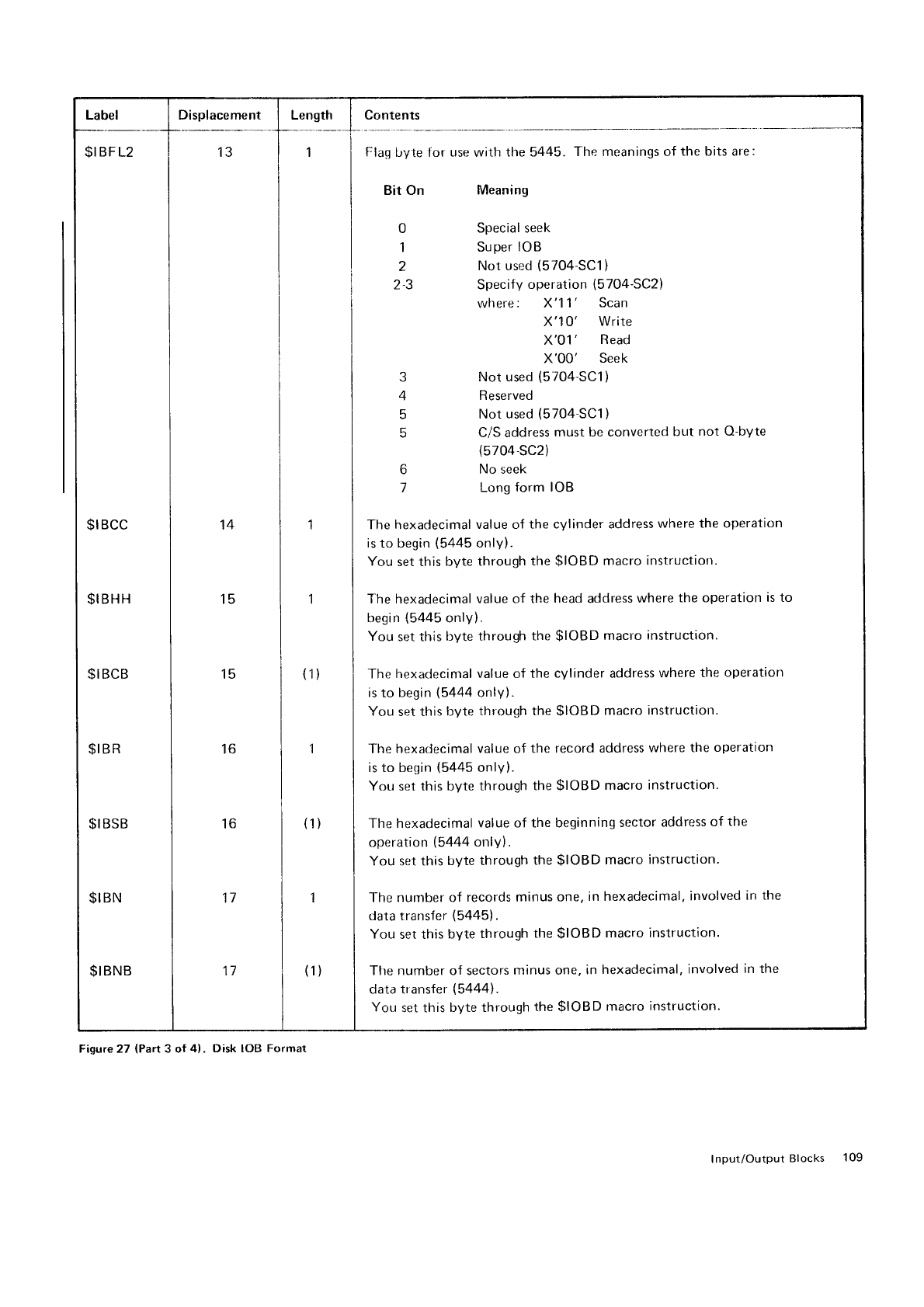
Label Displacement I Length I Contents
$|BFL2 | 13 | 1 | Flag
byte for use with the 5445. The meanings of the bits are:
I I I Bit on Meanins
til
I | | 0 SPecialseek
I I I t superloB
I I I z Not used
(5704
SC1)
I I | 23 Specifyoperation(5704-SC2)
I | | where: X'11' Scan
lll x'lo'write
I i I x'ot' Read
lli X'0O'Seek
I I I s Not used
(5704
sc1)
lil4Reserved
| | | 5 Not
used
(5704
SC1)
I | | 5 C/S address
must be converted
but not Q-byte
I I | (5704-sc2)
| | I 6 Noseek
| | | t LonsrormloB
ttl
ttt
$IBCC I lq I t I The hexadecimal
value of the
cylinder address
where
the operation
begin
(5445
only).
You set this
byte through
the
$IOBD macro
instruction
| | | is
to besin
(5445
only).
| | | You
set this byte
through
the
$IOBD
macro instructiort.
ttl
$IBHH I t5 | 1 I T.he hexadecimal
value of the
head
address
where
the operation
is to
$I
BCB 15 | (1)
$IB
R
$I
BSB 16 | (1)
$I
BN
$I
BNB
The
hexadecinral
value
of the cvlinder address
where
the operation
is
to begin
(5444
only).
You set this
byte
through the
$IOBD macro
instructiotr.
The
hexadecimal value of the record
address where
the
operation
is to begin
(5445
only).
You set this byte
through
the
$IOBD macro
instruction.
The hexadecimal
value of the beginning
sector
address
of the
operation
(5444
only).
You set this
byte through
the
$IOBD macro
instruction.
16
17 I t I The nunrber of records minus one,
in hexadecimal,
involved
in
the
data transfer
(5445).
You
set this
byte
through
the
$IOBD macro
instruction'
11 I ttl I Ttre number of sectors
minus one,
in
hexadecimal,
involved
in the
data transfer
(54441.
You set this
byte through
the
$IOBD rnacro
instruction.
Figure
27 (Part
3 of 4). Disk IOB Format
Input/Output
Blocks 109
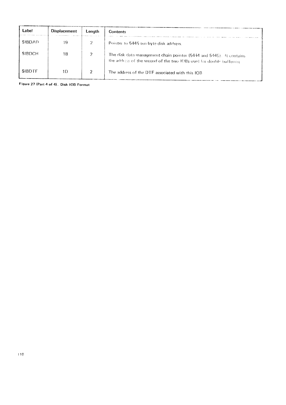
!'!:l
SIBDN
T)
$!RDCt]
$I BD IF
Displacement
19
1B
1D
tr-f
')
?
I
I
I
I
I
I
J
.Ilte
rlisk
rlala rnarratrernerrt
chain
poirrter
(5r1,14
arid h44rJ).
li rorrtainr
Ilte
arlrJrr;.;:,
trl tlre secr.lrrrl
of tlre tr,vo
lf
)[Js
useri
f
lr tlrlrlrl,,
ilrrf
fer t.;11
Tfre
a<Jclress
of tfre
Dl-F
associated
with this
IOB
Figure
27 (Part
4 of 4). Disk lC)B Formal
r10
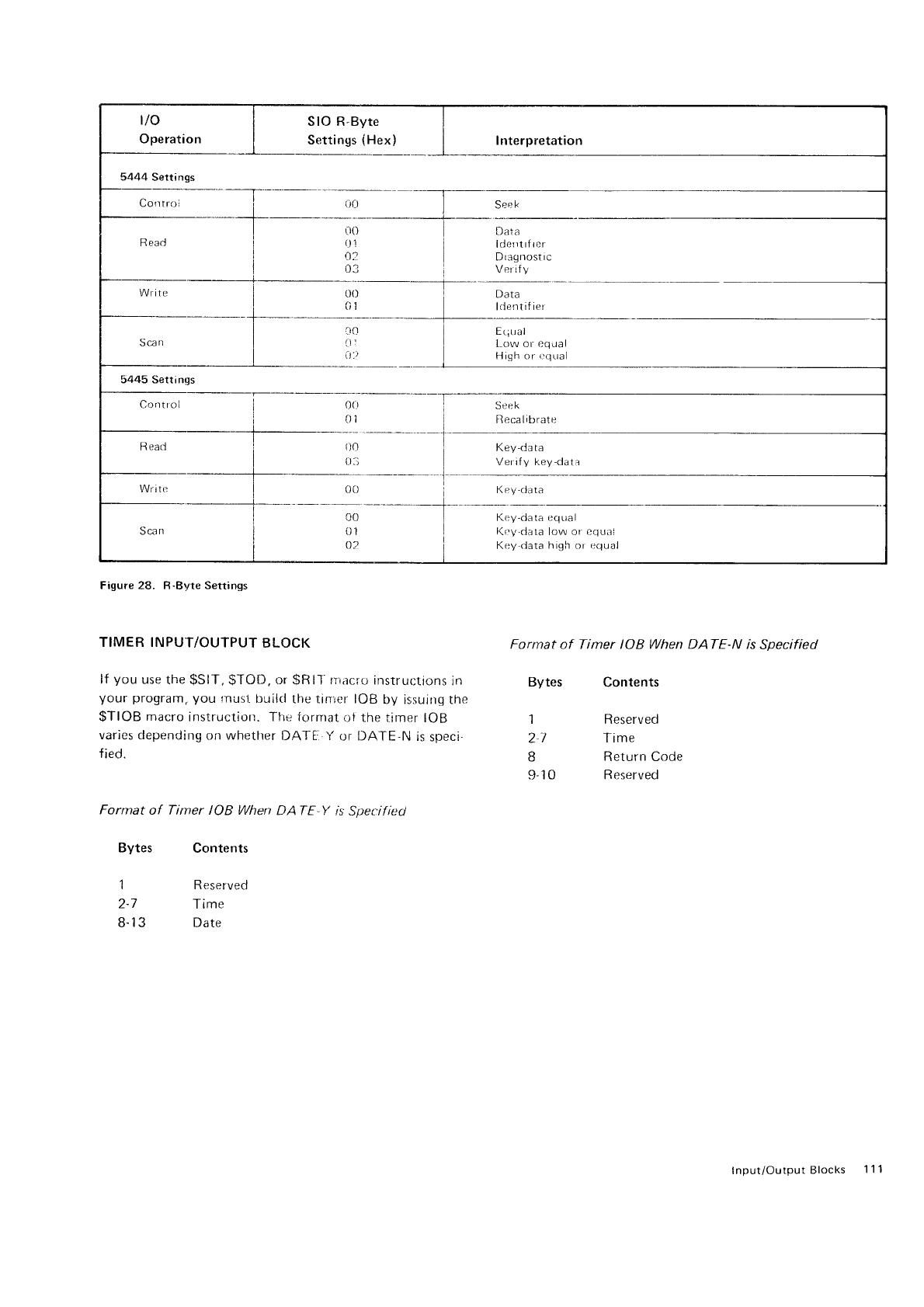
tlo
Operation
SIO R-Byte
Settings
iHex) I nterpretation
5444 Settings
Corr tro i
R
eacJ
Write
- -t*-
I
I
I
I
I
j
I
00 Sec
k
r.lO
it't
0?
o3
Data
lderrtrtrer
D
r:l!J nost ic
Verif
y
Sca
tt aio
il 1
at'.)
Da ta
ldentifier
EtiLral
LOW Or equal
Hir^h or cclual
5445 Settings
Control
h eaal
-r*.
Sca
n
I
I
l
I
o0
{}1
See
k
tlecalibrate
{i0
0:i
Key-da ra
Verify key'clata
oi) i
-+--
I
I
K e
y'da1a
CO
01
{)?
Key-data
eclual
l(fV-clata
low or eqLral
Key data high or erlual
Figure
28. R-Byte Settings
TlMER INPU
/OUTPUT BLOCK Format of Timer IOB When DATE-N is Specified
lf you use
the
$SlT" $TOD.
or SRll-nrircf o instructions
in Bytes Contents
your program, you rnusl
builcl
the tinrer IOB
by issuing the
$TIOB macro
instruction. Tlle
format
of the
tirner IOB 1 Reserved
varies depending
on whether
lf ,Al-i: Y or DATE-N is
speci. 2l Time
fied. g Return cocje
I 1 0 Reserved
Format of Tinter IOB When trATE.Y is Spet:if
iecl
Bytes Contents
1 Reserved
2-7 Time
8-
1
3 Date
Input/OutputBlocks 111
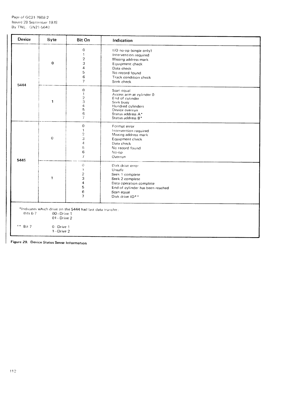
Pa,qe
of GC2 1,760i3,2
lssuert
29
Septe:rnber
l9/8
By iNL GN21-564-.i
Device i Byte Bit 0n
!
I
I
I
t1
I
I
i
1
5
o
1
5444
0
1
2
3
4
5
6
0
1
?-
3
,1
5
6
I
Scan equal
Access
arm at cylinder O
Fnd of cytrnder
Sr:ek
busy
Hurrdred
cylinders
Device
overrun
Status address A *
Status
address
Bn
Format error
!ntervention required
l',4rssing
acldress
mark
Equrpment check
Data check
No record found
l!o-op
Over ru n
i-l
I
2
J
5
o
7
Disk clr ive
error
LJ
nsafe
Seek 'l complete
Seek 2 complete
Data r:peration complete
End of cylrnder has
been reacneo
Scan equal
Disk <irive
lD* *
l/O no-op
(single
only)
lntervention
required
Missing
address
mark
Equtpnlent
check
Data
check
No record
tound
Track
conditrorr
check
Seek check
+
lndr{jater
which drrve
on the
5444
Bits
6.7 OO-Drive
1
Ol
- Drive
2
had ldst data tra'lsfer:
0 Drive
1
1 Drive 2
Figure 29. Device Status Sense Information
112
Appendix
D: Macro
lnstruction
Summary
Chart
Figure
3O is
a summary
chart containing
all
valid
macro
processor
instructions.
The macro
instructions
are listed
in
alphabetical
order. In
addition to the name,
three items
are
given
for each
macro instruction:
o Format
of the instruction
with all
valid
operands
a Function
of the macro instruction
a Maximum number of statements
generated
For
more
detailed information
on any
of the macro
instructions, see Chapter 2: Macro lnstruction Statements.
Pase of GC21-7608-2
lssued
29 Seotember
1978
Bv TNL: GN21-5649
Macro
Instruction
Summary
Chart 112.1

Page
of GC21
-76O8-2
lssued
29 September
1978
By
TNL: GN21-5649
This
page
intentionally
left
blank
112.2
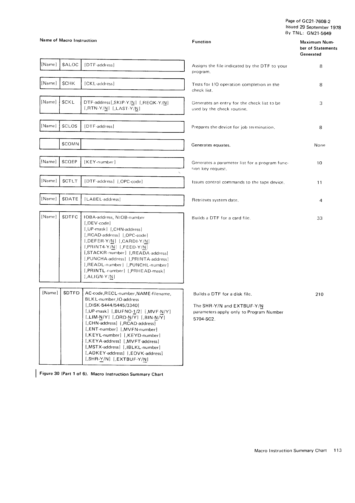
Name
o{ Macro
Instruction
Namcl
|
$ALoC I lDTf addressl
lNamel
l$CHK I ICKL-d(trtressl
lNamel | $CKr DTF-address
[,SK
I
P-YA] t,R
EOK-YlN
l
[,FTN,Y/N
I t,LAST-Y/N]
lNamel
ISCLoS I lDlF-acldressl
$COMN
tNamel
I
scoEP
I IKEY-number l
lName]
| $CTLT I iDTF
addressl
LopC-codel
lNamel
l$DATE | [LABEL
addressi
lNamel
| $DTFC I loBA-a.ld'.ss,
NtoB-numbel
[,DEV-code]
[,UP-mask
I [,CH
N-adclress]
[,RCAD-address]
[,OPC-code]
[,DEFERY/N]
t,CARDI
Y,/N]
[,PRrNr4-Y/Nl
i,FEED
Y/N]
[,STACKR
number] [.READA
address]
[,PUNCHA-acldress]
[,PR
I
NTA-address]
l,READL,numberl
[,PUNCH
L,number]
[,PRINTL
number]
[,PRHEAD-maskj
[,ALIGN
YiN]
lNamel | $DTFD I AC{ode,RECL-number,NAME-filerrarrre,
B LK
L-number,lO
-add
ress
[,D
I SK
-544415
445
13340)
[,UP-mask]
I,BUFNO-1 /21
[,MVF.N/Y]
t,LlM-N/Yl t,ORD-N/Yl
[,BlN-N/Y]
[,CH
N-address]
[,RCAD-address]
[,ENT-number]
[.MVFN-number]
l,K
EYL-numberl
[,KEYD-number]
[,K
EYA-address]
[,MV
FT-address]
[,MSTX-address]
[,lBLKL-number]
[,ADK
EY-address]
[,EOVK-address]
I,SHR.Y/N]
[,EXTBUF-Y/N]
I f iOur"
30 (Part
1
of 6). Macro Instruction
Summary
Charr
Function
Assigns
the
f
ile indicated
by the DTF
to your
prog
ra m.
Tests
f
or l/O operation
completion in the
check list.
Generates an entry for
the check
list
to be
used
by the
check routine.
Prepares
the devi ce
Generates equates.
for job termination.
Generates a parameter list for a program func-
tron key request.
lssues
control commands to the tape device.
Retrieves system date.
Builds
a DTF for a card file
Builds
a DTF
for
a
disk
file
The
SHR'Y/N
and EXTBUF-Y/N
parameters
apply
only to Program
Number
5704-SC2.
Page
of GC21
-7608-2
lssued
29 September
1978
By
TNL: GN21-5649
Maximum
Num-
ber of Statements
Generated
8
None
10
11
4
33
210
Macro Instruction Summarv
Chart 1'l 3
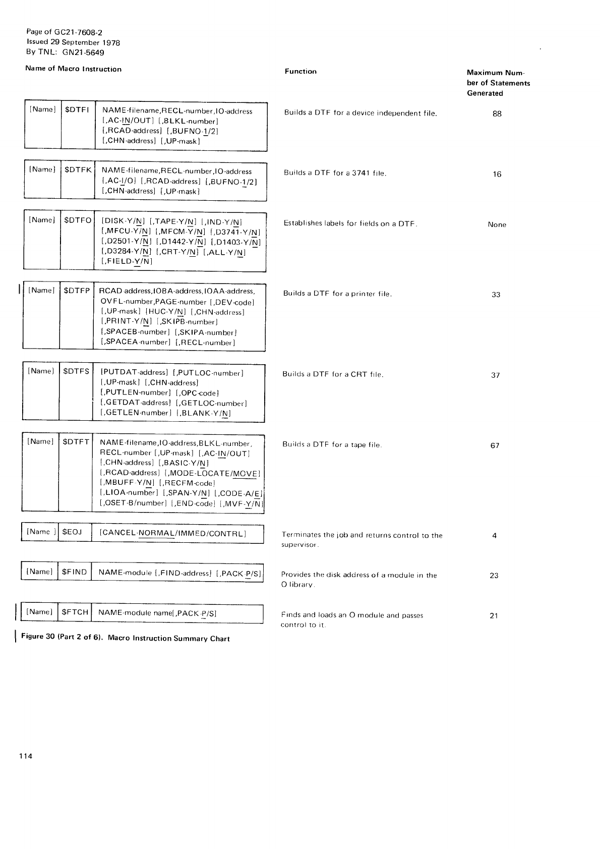
Pase
of GC21
-7608-2
lssued
29 September
1978
By TNL: cN21-5649
Name
of Macro
Instruction
IName] |
$DTFI I NAME-filename,RECL-number,lO-adctress
t,AC-lN/OUTI
[,BLK[.-number]
[,RCAD-address]
[,BUFNO-1
/2]
[,CHN
-address]
[,UP-nrask
]
lNarnel
|
$DTFK I NnME-tilename,RECL-number,lO-address
t,AC-Vol
[.RCAD-address]
i,BUFNo-1
/21
[,CHN-acldress]
[,UP-mask]
lNanreJ
|
$DTFS | [pUTDAT-address]
[,pUTLoC-number]
[,UP-mask]
[,CHN-address]
[,PUTLEN-number]
[,OPCrode]
[,GETDAT-address]
[,GETLOC-number]
[,GETLEN-numberi
{,BLANK.y/N]
lNamel
|
$DTFT
I wAME-fitename,tO-address,BLKL
number.
RECL-number
[,UP-mask]
[,AC,tN/OUT]
I,CHN-addressl
t,BAStC
Y/N
j
I,RCAD-address
I I,MODE-LbCATE/MCvE
l
I.MBUFF
Y/Ni [,RECFMccde]
[,LlOA-numfrr] i,SPAN-Y/Nl L,CODE-A/El
[,OSET,B/numberl
t,END-c;duJ
i.MVF
y/N
INameJ
l$FIND I NAME-modute
[,FtND-address]
t,pACK
p/Sl
tNamel |
$FTCH
| runMe
moCute
namel
,pACK
p/Sl
Figure
30 (Part
2 of 6). Macro Instruction
Summarv
Chart
Fu nction
Builds a DTF f or a devace independent f ile.
Builds a DTF
for a3141 file
Establishes labels
for fields
on a DTF
Builds a DTF for a printer f ile
Builds a DTF {or
a
CRT frlt,.
Builds
a DTF for
a rape file
Terrninates
the job and returns
control to the
supervisor.
Provides
the disk address
of a ntodule in the
O library.
Frnds
and loads
an O module and passes
control 1()
it.
Maximum
Num-
ber
of Statements
Generated
None
88
lo
JJ
37
67
21
INamel | $DTFP I RCAD address,lOBA-address,lOAA-address,
OV
F
L-number,PAGE-number
[,DEVcode]
[,UP-mask]
tHUC
Y/N
I [,CH
N-adctress]
t,PR
INT-Y/N
I l,SK
IPB-numberl
[,SPACEB-number]
[,SKlPA-number]
[,SPACEA-number]
[,Ft
EC
L-number]
ICANC
E L-NOR
N/IA
L/IMM
ED/CONTR
L]
114
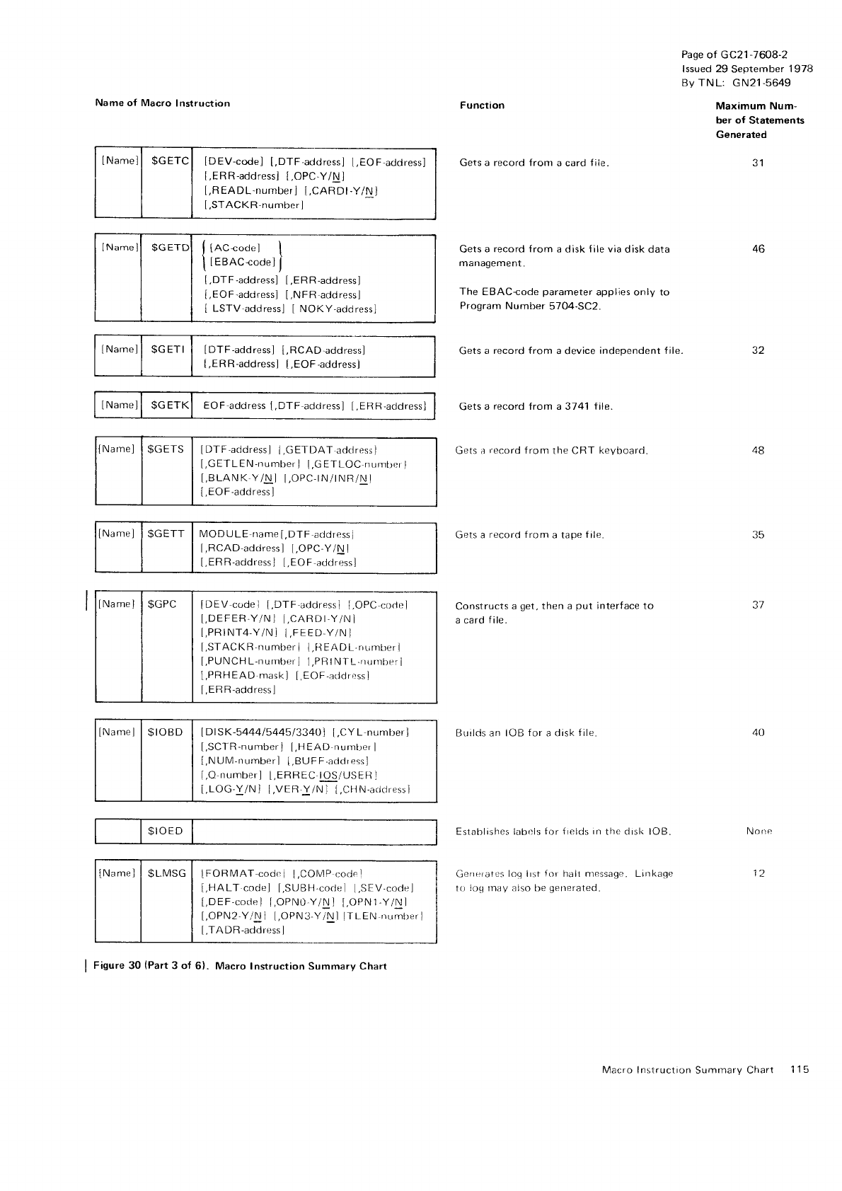
Name of Macro
Instruction
INamell $GETCI IDEV-code]
[,DTF-address]
I,EOF-addressl
[,ERR-address]
t,OPC-Y/N
l
[,READL-number
] l,CARDl
-Y/N j
[,STACKR-number
]
lNamell $cETD IACcode ] t
tEBAC"codel
I
.DTF
-addressl
[,ER
R-address]
,EOF'addressl
[,NFR
address]
LSTV'adrJressl
I NOKY-address]
I
DTF-addrr:ss]
[,RCAD-address]
[,ERR-address]
[,EOF
-addressl
lNarnel | $c
ETK EOF address
[,DTF
adclress]
[,ERR,address]
INarne]
| $GETS | [DTF
acldressl
I,GETDAT
ad<1ress]
[,GETLEN-number]
I.GETLOC
numt)er
I
[.BLANK
Y/N] l,OPC,tN/tNR/Nl
[.EO
F
-address
]
IName]
l$GETT I MODULE rramel,DTF
a(idressI
I,RCAD-addressl
[,OPC-Y/N
I
[,ERR-address J [,EOF
ad<jress]
lNamel | $GPC I tOf V code i [.DTF
acldressl
I.OPC
corle]
[,DEFER,Y/N
] [,CARDt-Y/N
I
[,PRrNT4-Y/N
j I,FEED-Y/N ]
[,STACKR-number ] {,H
EAif L.rrLlmL)er
I
[,PUNCH
L-nurnber
] l,PR
INTL-nurnber
i
l,PR
H
EAD maskl [,EOF,i:ddress]
[,ERR-actdress]
IName]
| $rOBD I IDISK-5444i544513340]
[.CYL numrrer]
[,SCTR-number]
[.HEAD
nurnber
I
[,N
UM'numberl
I,BUFF-aclclress]
f
,O
numberl
[,ERREC
IOS/USER
]
i,LOG'Y/Nl I,VER-YiNl
[.CHN-acldressl
$IOED
lNamel
I
SLMSG
I TFORMAT-cod,
r l.COMrr,o,lFr
I,HALT codel [,SUBF]-cocle
[,SEV,cocle]
[,DEF-code] I,OPN0.Y/Nl
[,OPN1
-YlN]
[,OPN2-Y/Nl [,OPN3-YlNl
ITLEN-rrr:mberl
[,TADR-address ]
Norte
12
Function
Gets a record fronr a card
fiie
Gets
a record f
rom a disk
f ile via
disk data
management.
The
EBACcode
parameter
applies only to
Prograrn
Number 5704-SC2.
Gets
a record from a device
independent file.
Gets
a record from a 3741 f ile.
Gets a
record
from the CRT keyboarci.
Gets a record from a tape file
Constructs
a
get
a card
file.
then a put interfaceIO
IJrrrlds an IOB for a drsk
{rle
Eslablislres labr-.ls
tor irelds in the drsk lOB.
Gefrefat0s
loq lrst
for halt ntessage. Linkage
to 1o!l
rnay also
be generaled.
Page
of GC21
-7608-2
lssued
29 September
1978
By TN
L: G N21-5649
Maximum Num-
ber of Statements
Generated
46
1a
48
35
37
40
I Figure
30 (Part
3 of 61. Macro
Instruction Summary Charl
Macro Instruction
Summarv Chart 1 15
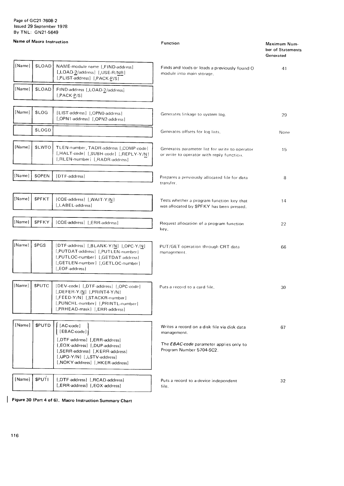
Page
of GC21
-7608-2
lssued 29 September 1978
By TNL: GN21-5649
Name
of Macro
lnstruction
lNamel
| $LOAD I NAME-module
name
[,FtND-address]
[,LOAD-2/address]
[,USE-R/NR]
l,PLlST-addressl
l,PACKt/Sf-
tNameJ
| $LOAD
I Ftruo-aocress
l,LoAD.Zladctressl
t,PACK-PiS]
lNamel
I St-oC I lLtst-.oor"rsl
l,opNO,addrnssl
[,OPN
1
-address
] [.OPN2-address I
$LOGD
tNamel
| $LWTO
I TLEN-numoer,
TADR.address
[,COMp
codel
[,HALT-codel
[,SUBH-code]
l,REpLy,y/Nl
I,RLEN-numberr
l,HADR.addrpssj
lNamel
| $OPEN
I IDTF-address]
INamel
| $PFKT | {coE-addressl
l,wArT.y/N
I
[,
LA B E
L-add ress]
lNamel
I SPFKY
| [COE-address]
I,ERR-6rtdressl
tNamel
| $PGS | [orF-aaaress]
[,BLANK-y/N] t,OpC
y/Nl
[,PUTDAT-address]
[,PtJTLEN-number]
[,PUTLOC-number]
[,6
9194T-address
I
[,GETLEN-numberl
l,c
ETLOC-number]
[,
EO
F-address
]
lNameJ
| $PUTC | [DEV-codej
[,DTF,address]
[,OpC-code]
[,DE
FER-Y/N] [,PR
I Nl'4-Y/N
j
t,FEED-Y/N
I [,STACKR-number]
[,PUNCH
L-number]
[,PR
INTL-number
I
[,PRHEAD-mask]
[,ERF]-addressl
tNamel
l$PUrD lf tnc-cooeJ
I
| |
| lesnc-coaeli
[,DTF-address]
[,ER
R-address]
[,EOX-address]
[,DUP-address]
[,SERR-address]
[,KERR-address]
t,UPD-Y/Nl [,LSTV-address]
[,NOKY-address]
[,HKER-address]
tt'lamel
| $eurt | [,otr-"oar.rsl I,RCAD-addressl
[,ERR-address]
[,EOX-address]
I f igur"
3O
{Part
4 of 6}. Macro Instrucrion
Summary
Charr
F unction
Finds
and loads
or loads
a
previously
found
O
module
into main
storaqe.
Generates linkagc
to svstem log.
Generates otfsets for log lisls-
Gprleraies
pdrameler
lrst tor
wr ttp
lo opcralol
or Wnte to operator wrth reply f
unctiorr.
Prepares
a prreviously
allocated file for data
transfer.
Tests
whether a program function kev that
was
allocated
by $PFKY has
been pressed.
Request allocation of a program function
key.
PUT/GET operation through CR-f data
management.
Puts
a recorcl
to a card file
Writes
a
record
on a disk f ile
via
disk data
management.
The EBACcode parameter
applies
only to
Program
Number
5704-SC2.
Puts a record to a device independent
f ile.
Maximum
Num-
trer
of Statements
Generated
41
29
14
22
66
30
6l
32
116
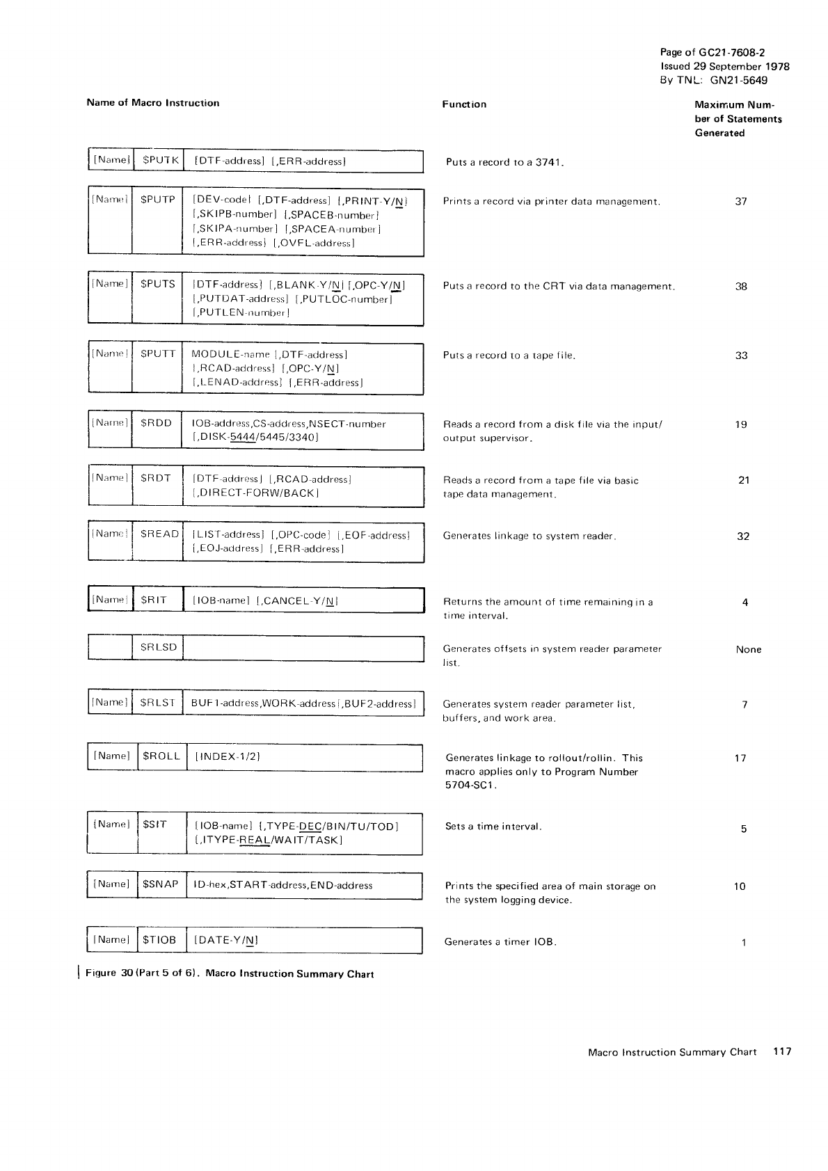
Name of Macro
Instruction
lNarn,.ll
$PUTp
| [DEV-codel
[,DTF-address]
t,pRtNr-y/Nl
[.SK
IPB-nunrber]
[,SPACEB-number]
f
,SKlPA'rrumberl [,SPACEA
number
]
{.ERR-addressl
[,OVFL-addressl
iNarneJl $PUTS
I IDTF-addressl
t,BLANK.Y/Ni
f
,OpC-y/Nl
[,PUTDAT-acldress]
[,PUTLOC-number]
I,PUTLEN
nurnberl
MODULE-name
I,DTF,acldressl
I,RCAD-adclressJ
t,OPC-Y/\J
[,t,ENAD-adoress]
[,ERR-acldress]
lN,rrnell $RDD i IOB-atldress,CS-address,NSECT-number
[,D
I SK-5444/5
445
13340]
lN.im"ll SRIJT I IDTF
atlrrr"ssJ
I,RCAD-addrpss,
I.DIR
ECT-FORW/BACK
I
lNarn.
I SRIT I ltOu.num. l I,CANCFL
y/Nl
INarnel
l$ROLL | [tNDEX
1i2
I
INar,e]
i
$SlT I ItOB-nanrel
t,TypE-DEC/BtN/TU/TODI
[,
ITYPE-R
EA L/WA
ITTTASK
]
lNarnel I
$SNAP I lD-hex,START-address.END-address
Puts
a record to a tape file.
F unct
ion
Putsarecordrca3-141.
Prints
a
record
via
printer
data managentent
Puts
a record
to the CRT via data manaqement
Page
of GC21
-7608-2
lssued 29 September 1978
By TNL: GN21-5649
Maximum
Num-
ber of Statements
Generated
None
31
J6
l9
21
52
Reads a record from a disk f ile via
the input/
outpul supervrsor-
Reads
a record from a tape file via
basic
tape data management.
Generates linkage to system reader-
Returns the
amount of time remaining
in a
tirne
interval.
Generates
offsets in
system
reader
parameter
I rst,
Generates system
reader
parameter
list,
buffers, and
work area.
Generates
linkage
to rollout/rollin.
This
macro
applies only to Program
Number
5704-SC1.
Sets a time interval.
Prints the specified
area of main storage
on
the system logging
device.
Generates a timer lOB.
11
10
I Figure 30
(Parr
5 of 6). Macro
Instruction
Summary Chart
Macro lnstruction Summarv
Chart 117
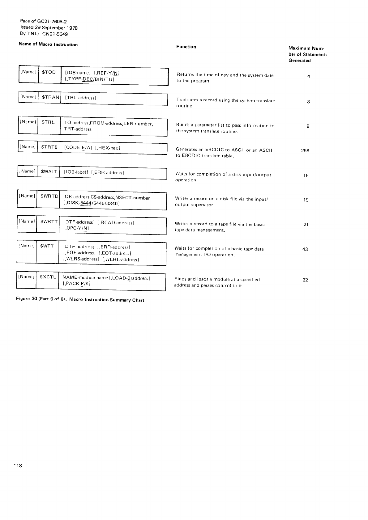
Pase
of GC21-7608-2
lssued
29 September
lgTg
By
TNL: GN21-5649
Name of Macro lnstruction
tNamel
| 91p11 | tO-acaress,FRoM-address,LEN-nurnber,
TRT-address
lNamej
| $WRTTI lDTF.addressl
I.RCAD-addressl
I,OPC-Y/N]
lNamell SWTT | [DTF-addressl
I,ERR-address]
[,EO
F-address
] [,EOT-address]
[,WLRS-address]
[,WLR
L--address]
tNamel
| $XCTL | runL,le
-moOute
name[,LOAD_2/address]
I,PACK-P/S]
I Fisut" 3O
(Part
6 of 6) Macro Instruction
Summary
Chart
F
unction
Returns
the
time
of day
and
the
system date
to the program.
Translates
a record
using
the
system
translate
routtne.
Builds
a
parameter
list
to pass
information
to
the
system
translate
routine.
Generates
an EBCDIC
to
ASCII
or
an ASCII
to EBCDIC
translate
table.
Waits
for completion
of a disk input/output
OPeratron.
Writes
a record
on
a disk
file
via
the input/
output
supervtsor.
Writes
a record
to a
tape
file
via
the
basic
tape data
management.
Waits f or
completion
of a basic
tape
data
managemer-tt
|
/O operation.
Finds
and loads
a module
at a
specif ied
address
and
passes
control
to it-
Maximum
Num-
ber of Statements
Generated
258
i5
19
21
43
22
118
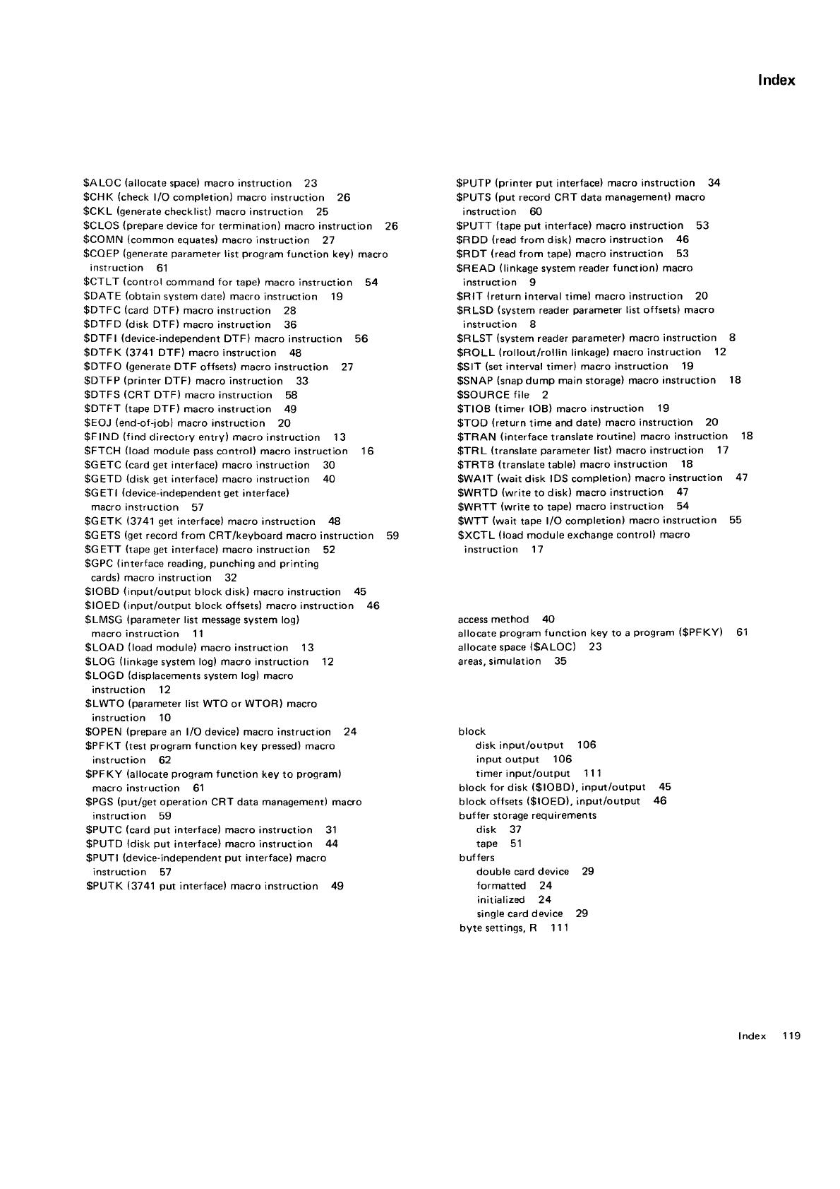
$ALOC (allocate
space)
macro instruction 23 $PUTP
(printer
put interface)
macro instruction 34
$CHK (check
l/O completion)
macro
instruction 26 $PUTS
(put record
CRTdata management) macro
$CKL (generate
checklistl macro instruction 25 instruction 60
$CLOS
(prepare
device for termination) macro instruction 26 $PUTT (tape
put interface)
macro instruction 53
$COMN (common
equates) macro instruction 21 $RDD (read
from disk) macro instruction 46
$COEP
(generate
parameter
list
program
function key) macro $RDT (read
from tape)
macro instruction 53
instruction 61 $READ (linkage
system
reader
function) macro
$CTLT (control
command
f
or tape) macro instruction 54 instruction I
$DATE (obtain
system date) macro
instruction i9 $RlT (return
interval time) macro
instruction 20
$DTFC (card
DTF) macro instruction 2a $RLSD (system
reader
parameter
list offsets) macro
$DTFD (disk
DTF) macro
instruction 36 instruction 8
$DTFI (device-independent
DTF) macro
instruction 56 $RLST (system
reader
parameter)
macro instruction 8
$DTFK (3741 DTFI macro
instruction 48 $ROLL (rollout/rollin linkage)
macro instruclion 12
$DTFO (generate
DTF offsets)
macro
instruction 27 $SlT (set
interval timer) macro instruction 19
$DTFP (printer
DTF) macro instruction 33 $SNAP (snap
dump main storage)
macro
instruction 18
$DTFS (CRT DTF) macro instruction 58 $SOURCE
file 2
$DTFT (tape
DTF) macro instruction 49 $TIOB (timer IOB) macro
instruction 19
$EOJ (end-of-job)
macro
instruction 20 $TOD (return
time and date)
macro
instruction 20
$FIND (f
ind
directory entry) macro
instruction 13 $TRAN (interface
translate
routine) macro instruction 18
$FTCH (load
module
pass
control) macro instruction 16 $TRL (translate
parameter
list)
macro instruciion 17
$GETC (card
get
interface)
macro
instruction 30 $TRTB (translate
table)
macro
instruction 18
$GETD (disk
get
interface) macro instruction 40 $WAIT (wait
disk IDS completion)
macro instruction 47
$GETI (device-independent
get
interface) $WRTD (write
to disk) macro
instruction 47
macro instruction 57 $WRTT (write
to tape)
macro instruction 54
$GETK (3741
get
interface)
macro instruction 48 $WTT (wait
tape l/O completion)
macro
instruction 55
$GETS (get
record
from CRT/keyboard macro instruction 59 $XCTL (load
module exchange
control) macro
$GETT (tape
get
interface)
macro
instruction 52 instruction 17
$GPC
(interface
reading,
punching
and
printing
cards)
macro instruction 32
$IOBD (input/output block disk)
macro instruction 45
$f
OED (input/output block offsets)
macro instruction 46
$LMSG (parameter
list
message system logl access
method 40
macro instruction 11 allocate
program
f
unction key to a program
($PFKY) 61
$LOAD (load
module) macro instruction 13 allocate space
($ALOC) 23
$LOG (linkage
system
log) macro instruction 12 areas.
simulation 35
$LOGD (displacements
system
log) macro
instruction 12
$LWTO (parameter
list WTO
or WTOR) macro
instruction 10
$OPEN
(prepare
an l/O device) macro instruction 24 block
$PFKT (test
program
function key pressed)
macro disk input/output 106
instruction 62 input output 106
$PFKY (allocate
program
function key
to programl timer input/output 11 1
macro instruction 61 block for disk ($loBD), input/output 45
$PGS
(put/get
operation
CRT data management) macro block offsets
($IOED), input/output 46
instruction 59 buffer storage
requirements
$PUTC (card put interface) macro instruction 31 disk 37
$PUTD (disk
put interface)
macro instruction 44 tape 51
$PUTI (device-independent
put interface) macro buffers
instruction 57 double card device 29
$PUTK (3741
put interface)
macro
instruction 49 formatted 24
initialized 24
single card
device 29
bytesettings,R 111
lndex
lndex 1 19
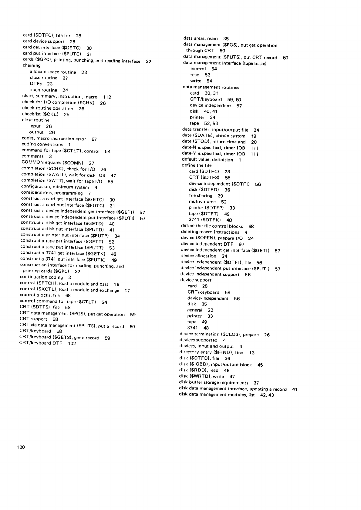
card
($DTFC),
fite
for 2g
card
device
support 28
card
get
inrerface
($GETC) 30
card
put interface
($pUTC} 31
cards
($GPC),
printing,
punching,
and
reading
interface 32
chaini
ng
allocate
space
routine 23
ctose
routine 27
DTFs 23
open routine 24
chart,
summary,
instruction,
macro 112
check
for t/O comptetion
($CHKI 26
check
routine
operation 26
checklist
($CKL) 25
close
routine
input 26
output 26
codes,
macro
instruction
error 67
coding
conventions 1
command
for tape
($CTLT), control 54
comments 3
COMMON equates
($COMN) 27
completion
($CHK), check
for t/O 26
completion ($WAtT),
wair for disk tOS 47
completion ($WTT),
wait for tape
t/O 55
configuration,
minimum system 4
considerations,
programming 7
consrruct
a card
get
interface
($GETC) 30
construct
a
card
put interface
($PUTC) 31
construct
a device
independent
get
interface
($GETI) 57
construct
a device
independent put interface
($pUTl) Sl
construct
a disk
get
interface
($GETD) 40
construct
a disk put interface
($PUTD) 41
construct
a
printer
put interface
($pUTp) 34
construct
a tape
get
'nterface
($GETT) 32
construct
a tape
pur interface
($PUTT) 53
construct
a 3741
get
interface
($GETK) 4g
construct
a 3741 put interface
($pUTKl 49
construct
an interface
for reading, punching,
and
printing
cards
($GpC) 32
continuation
coding 3
control (gFTCH), load
a module
and
pass 16
control ($XCTL), load
a module
and exchange 17
control
blocks, f
ile 68
control
command
for tape
($CTLT) 54
CRT
($DTFS).
f
ite 58
CRT data
management
($pGS),
put get
operation b9
CRT support 58
CRI via
data
management
($PUTS),
put a record 60
CRT/keyboard 58
CRT/keyboard
($GETS),
get
a record 59
CRT/keyboard
DTF 1O2
data
areas,
main 35
data
management
($pGS),
put get
operation
through
cRT 59
data management
($PUTS), put CRT record 60
data management
interface (tape
basic)
control 54
read 53
write 54
data management
rout ines
card 30.31
CRT/keyboard 59,60
device
independent 57
disk 40,41
printer 34
tape 52,53
data
transfer,
input/output file 24
date
($DATEI, obtatn
system 19
date
($TOD), return
time and 20
date-N
is
specif
ied,
timer IOB I i.l
date-Y
is
specified,
timer IOB '111
default
value,
definition 1
define
the
file
card
($DTFC) 2A
CRT
($DTFS} 58
device
independent
($DTFI) 56
disk
($DTFD) 36
file
sharing 39
multivolume 52
printer (gDTFPl 33
tape
(SDTFT) 49
3741 ($DTFKI 48
define
the
file control blocks 6g
deleting
macro
instructions 4
device
(SOPEN),
prepare
l/O 24
device
independent
DTF 97
device
independent get
interface
($GETI) 57
device
allocation 24
device
independenr
($DTFI), file 56
device
independenr put interface
($pUTl) 57
device
independent
support S6
device
support
card 28
CRT/keyboard 58
device-independent 56
d isk 35
general 22
printer 33
rape 49
37 4't zl8
device
rermination
($CLOS},
prepare 26
devices
supported 4
devices,
input and output 4
directory
entry
(gFlNDl,
f
ind 13
disk
($DTFD).
fite 36
disk
($IOBD),
input/output
block 45
disk ($RDD), read 46
disk
($WRTD),
write 47
disk
buffer storage
requirements 37
disk data management
interface, updating a record
disk
data management
modules,
list 42.43
41
120
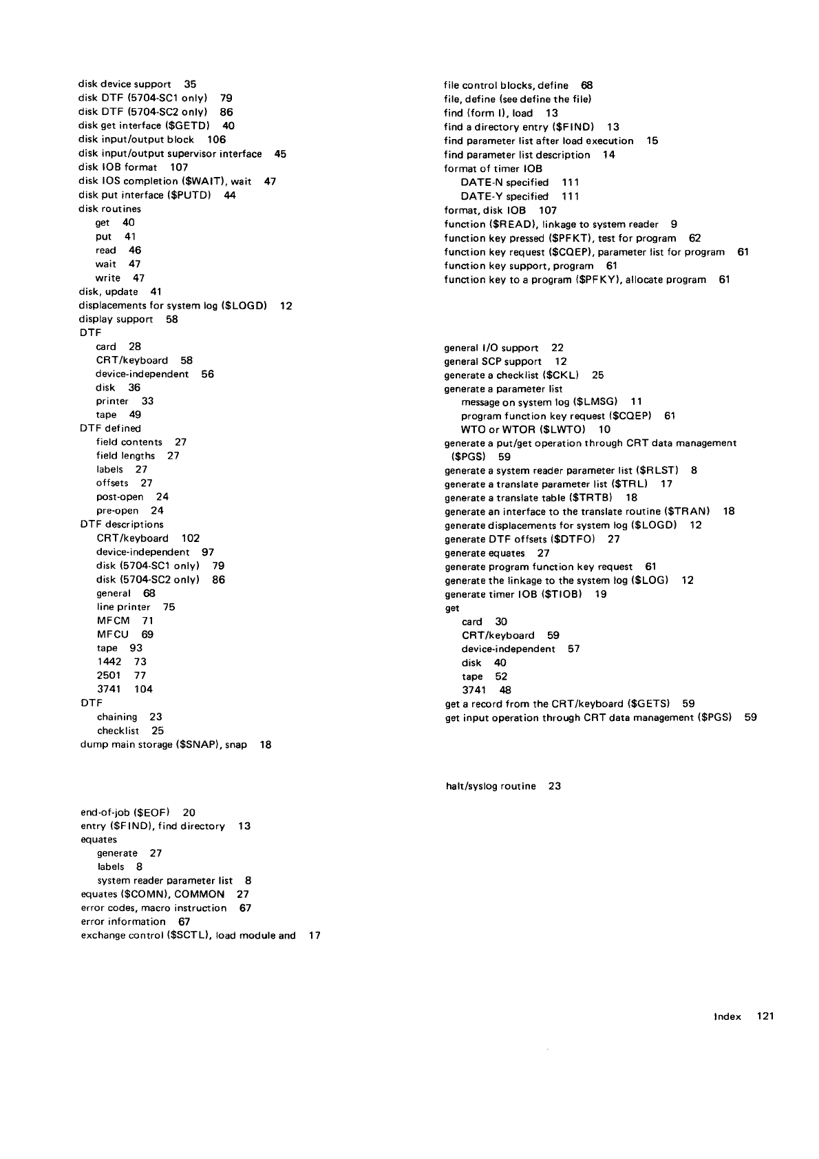
disk device
support 35 f ile
control blocks,
def ine 68
disk DTF (5704-SC1
onlyl 79 fite,
define (see
define
the fite)
disk DTF (5704-SC2
onty) 86 find (form l), toad 13
disk
get
interface
($GETD) 40 f
ind a directory entry (gF
IND) 13
disk input/output block 106 find parameter
list after load execution 15
disk input/output supervisor interface 45 find parameter
list
description 14
disk IOB format 107 format of timer IOB
disk IOS
completion
($WAIT), wait 47 DATE-N soecif ied 111
disk
put interface
($PUTD) 44 DATE-Y specif ied 111
disk routines format,
disk IOB 1O7
get 40 function ($READ), tinkage
to system
reader g
put 4'l function key pressed
($PFKT), test for program 62
read 46 function key request
($COEP),
parameter
list
for program 61
wait 47 function key support,
program 61
write 47 f
unction key to a program
($PFKY),
allocate
program 61
disk,
update 41
displacements
for system los ($LOGD) '12
display
support 58
DTF
card 2A general
l/O support 22
CRT/keyboard 58 general
SCP support 12
device-independent 56 generate
a checklist
($CKL) 25
disk 36 generate
a parameter
list
printer 33 message
on system
log
($LMSG) 11
tape 49 program
function key request
($COEP) 61
DTF def ined wTo or wToR ($LWTO) 10
field contents 27 generate
a put/get
operation
through CRT data
management
field lengths 27 ($pGS) 59
labels 27 generate
a system
reader
parameter
list
($RLST) 8
offsets 27 generate
a translate parameter list {$TR L} 17
post-open 24 generate
a translate
table ($TRTB) 18
pre'open 24 generate
an interface to the translate
routine ($TRAN) 18
DTF descriptions generate
displacements
for system
los ($LOGD) 12
CRT/keyboard 1O2 generate
DTF offsets
($DTFO) 27
device-independent 97 generate
equates 27
disk (5704-SC1
only) 79 generate
program
fundion key request 61
disk (5704-SC2
only) 86 generate
the linkage to rhe system
loS
($LOG) 12
general 68 generate
timer IOB ($TIOB) 19
line
printer 75 get
MFCM 71 card 30
MFCU 69 CRT/keyboard 59
tape 93 device-independent s7
1442 73 disk 40
2501 77 tape 52
3741 1O4 3741 I
DTF get a record from the CRT/keyboard ($GETS) 59
chaining 23 get
input operation through CRT data
management
($PGS) 59
checklist 25
dump main
storage
($SNAP),
snap 18
halt/syslog routine 23
end-of-job
($EOF) 20
entry
($FIND),
find
directory 13
eq uales
generate 27
labels I
system reader
parameter list 8
equates
($COMN),
COMMON 27
error codes, macro instruction 67
error information 67
exchange control {$SCTL},
load module
and 17
lndex 121
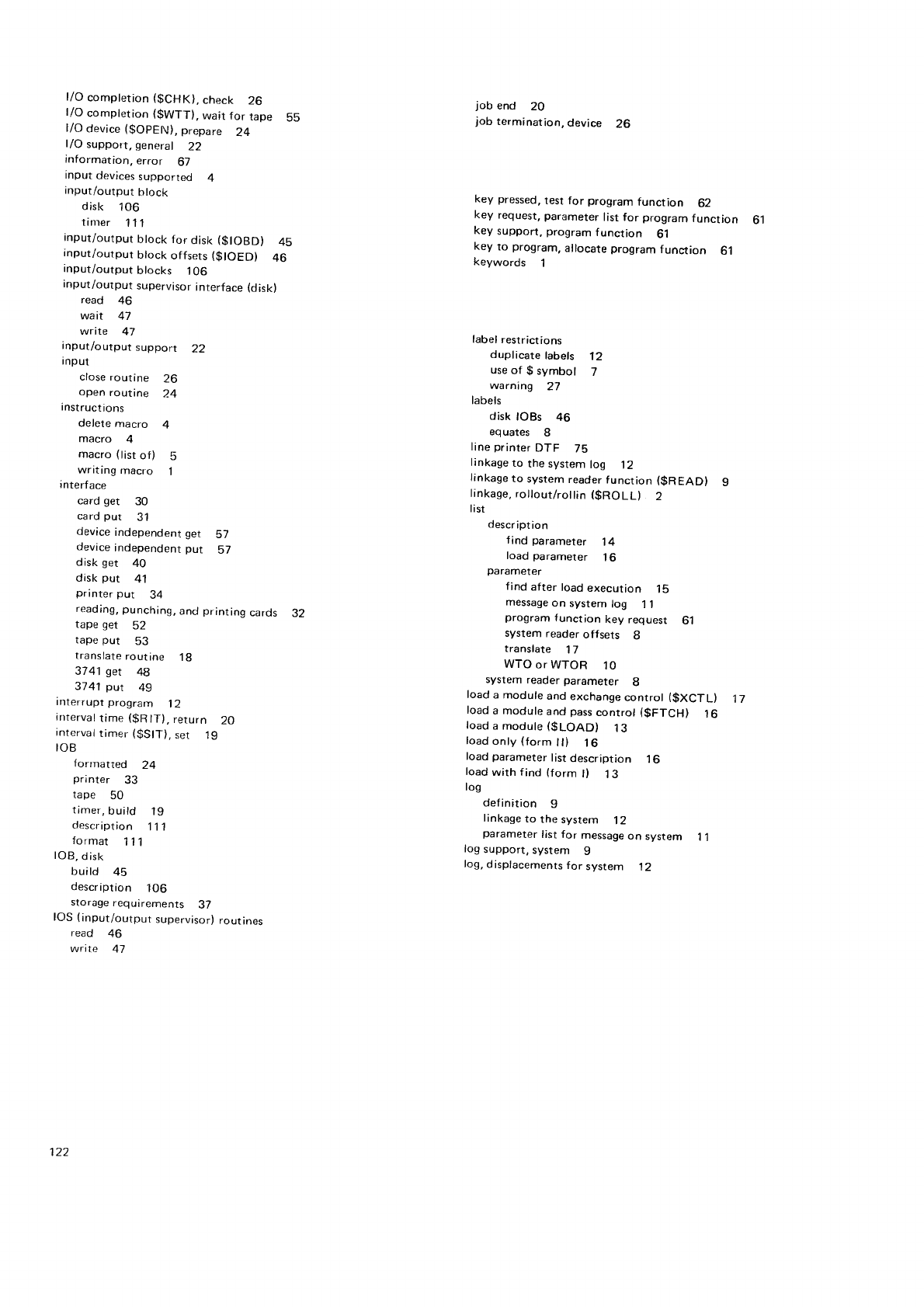
f
/O completion
($CHK),
cnecr 26
l/O completion
($WTTI,
wait for tape Ss
l/O device
($OpEN),
prepare 24
f/O support, general 22
information,
error 67
input
devices
supported 4
input/output hlock
disk 1Oo
tin-ler 111
input/output
block for
disk
($IOBD) 45
input/output btock
offsets
($IOED) 46
anput/outputblocks 106
input/output supervisor
interface
(disk)
read 46
wait 47
write 47
input/outputsupport 22
Input
close routine 26
open
routine 24
i
nstruct
io
ns
delete
macro 4
macro 4
macro
(list
of
) 5
wrating
rnacro 1
i
nterface
card get 30
card
put 31
device
independent
get E7
device
independent
put 57
disk
get 40
disk
put 4'l
printer
put 34
reading, punching,
and
printing
cards 32
tape
get 52
rape
put 53
translate
routine 1
B
3741 get 48
3741
put 49
lnterrupt
program 1Z
interval
time
($RlT),
return 20
Interval
timer
($SlT),
set 1g
roB
forrnatted 24
printer 33
tape 50
timer,
build l9
description 1 1 1
formar 111
lOB,
disk
build 45
description 106
storagerequirements
37
IOS
(input/output
supervisor)
routines
read 46
write 47
job end 20
iob termination,
device 26
key pressed,
test for program
function 62
Key
request, parameter
list for program
function 61
key support,
program
function 61
Key
to program,
allocate
program
f
unction 61
keywords 1
label
restrict
ions
duplicate
labels 12
use
of $ symbol 7
warning 27
labels
disk lOBs 46
equates 8
line
prinrer
DTF 75
linkage
to the system
log 12
linkage
to system
reader
f
unction ($READ) g
linkage,
rotlout/roilin ($ROLL) 2
list
descript
ion
find parameter 14
load
parameter l6
parameter
find after load
execution 15
message
on system
log 11
program
function key request 61
system
reader
offsets g
translate 17
WTO or WTOR 10
system
reader parameter B
load
a module
and
exchange
control ($XCTL) 17
load
a module
and
pass
control ($FTCH) l6
load
a module
($LOAD) 13
load
onty
(form
ll) l6
load
parameter
list
description 16
load
with f
ind
(form
l) 13
tog
def
inition g
linkage
to the
system 12
parameter
list for message
on system 11
log
support,
system g
log,
displacements
for system 12
I l2
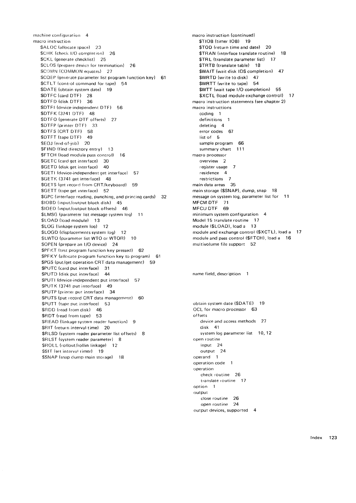
rr)achirfe
confiquration 4 macro instruction
(continued)
macro instruction $TIOB (timer
IOBI 19
$A
LOC
lallocate
space) 23 $TOD (return
time and
date) 20
$Ct-lK
(checi<
l/O
completlon) 26 $TRAN (interface
translate
routine) 18
$CKL (generate
checklist) 25 $TR
L (translate
parameter
list) 17
$CLOS
(prepare
clevice
for terrnination) 26 $TRTB (translate
table) 18
$C(.)N4l\
(COtvllMON
equares) 21 $WAIT (wait
disk IDS completion) 47
$COEP
(gererate
pararneter
list
program
f
r.rnction
key) 61 $WRTD (write
to disk) 47
$CTL'I (control
cornmand
for tape) 54 $WRTT (write
to tape) 54
$DATE (obtain
system
date) 19 $WTT (wait
tape liO completion) 55
$DTFC (card
DTF) 28 $XCTL (load
module exchange conrrol) '17
$DTFD (disk
DTF) 36 macro instruction
statements
(see
chapter
2l
$DTFI (device
independent DTF) 56 macro instructions
$DTFK (3741
Dl-F) 48 coding 1
$D
f FO (generate
DTF oifsets) 27 def initions 1
$DTFP
(printer
DTF) 33 deleting 4
$DTFS
(CRT
DTF) 58 error
codes 61
$llTFT (tape
Dl'F) 49 list of 5
$EOJ (errd'of-job) 20 sample
program 66
$FIND (find
directory entry) 13 summary chart 111
$FTCH (load
rnociule
pass
control) 16 macro
processor
$GETC
(card
qet
interface) 30 overview 2
$GEf D (dist<
get
interface) 40 register usage 7
$GETI (device-independent
get
interface) 5l residence 4
$GETK (3741
get
interface) 48 restrictions 7
$GEI
S
(get
recor.l f ronr
CRT/kcyboardl 59 main
data
areas 35
$GETT
(tape
get
rrrteriace)
52 main
storage
($SNAP),
dump, snap 18
$GPC
(interface
reading,
punching,
and
printing
cardsl 32 message
on system
log,
parameter
list
tor 1
1
$IOBD
(input/ourprut
block disk) 45 MFCM DTF 11
$IOED
(input/output
block offsets) 46 MFCU DTF 69
$LMSG {parameter
list message
system
log) 11 minimum system configuration 4
$L.OAD
(load
modulei 13 Model
15
translate
routine 17
$LOG (linkage
system log) 12 module
($LOADI,
load a 13
$LOGD (displacements
system log) 12 module and exchange control
($XCTL),
load
a 17
$LWTO
(paramerer
list WTO or
WTOR) 10 moduleand
pass
control
($FTCH),load
a 16
$OPEN
(prepare
an l/O device) 24 multivolume f ile support 52
$PFKT
(test
program
lunction
key
pressed) 62
$PFKY (allocate
program
function
key
to program) 61
$PGS
{put/get operation CRT data managernent) 59
$PLJfC
(card
put interface) 31
$PUTD (disk put interface) 44 narne f
ield, description 1
$PU-fl
{device
indeperrdent
put
interlace) 5-7
$PUIK (3741
put
ilrterface) 49
$PU-IP
(pr
irlter
pul interface) 34
$PUTS
(put record
CRT data
managernent) 60
$PUTT
(tape
put interface) 53 obtairr system
date
($DATEI 19
$RDD {read
trorn
disk) 46 OCL
for macro
processor 63
$RDT (read
from tape) 53 offsets
$R
EAD (linkage
systern reader
tunction) I device and access
methods 27
$R
lT (return
interval
time) 20 disk 41
$R
LSD (system
reader
parameter
list offsets) 8 system
log
parameter
list 10,12
$R
LST (system
reader
parameter) 8 open routine
$ROLL-
(rollout/rollrn
linkage) 12 input 24
$Sl
I (set
intervar rimer) 19 output ?.4
$SNAP
(snap
clurrrp main storage) 18 operand 1
operation
code 1
0oerat ioll
check
routine 26
translate
routine 11
option 1
outPut
close
routine 26
open
routine 24
or-rtput devices, supported 4
Index 123
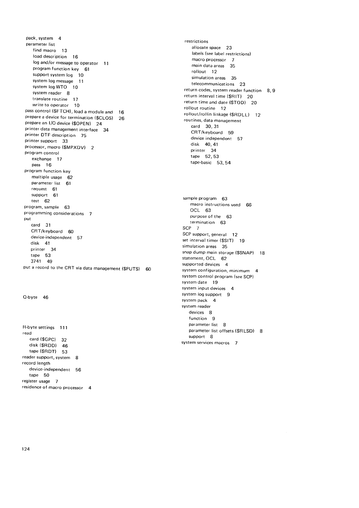
pack,
system 4
parameter
list
f
ind macro 13
load
description 16
log
and/or
message
to operator 11
program
function key 61
support
system
log 10
system
tog
message 11
system
tog
WTO 10
system reader 8
translate
routine 17
wnte to operator 10
pass
control
($FTCH),
load
a
module
and l6
prepare
a device for termination ($CLOSI 26
prepare
an l/O device
($OpEN) 24
pnnter data
management
interface 34
printer DTF description 75
pnnter support 33
processor,
macro
($MPXDV) 2
program
control
exchange 17
pass 1
6
program
function key
multiple usage 62
parameter
list 61
request 61
support 61
test 62
program,
sample 63
programmrng
considerations 7
put
card 31
CRT/keyboard 60
device-independent 51
disk 41
printer 34
tape 53
3741 49
put a record
to the CRT via
data
management
($pUTS) 60
O-byte 46
R-byte
settings 111
reaO
card
($GpC) 32
disk
($RDD) 46
tape
(gRDT) S3
reader
support,
system 8
record
length
device-independent 56
tape 50
register
usage 7
residence
of macro
processor 4
restrict
io ns
atlocate
space 23
labels
(see
label
restrictions)
macro
processor 7
main
data
areas 35
rollout 12
srmulation
areas 35
telecommunications
23
return
codes,
system
reader function 8, 9
return
intervaltime
($RlT) 20
return
time and
dare
($TOD) 20
rollout
routine 12
rollout/rollin
linkage
(gRDLL) 12
routines,
data
management
card 30,31
CRT/keyboard 59
device
independent 57
disk 40,41
printer 34
tape 52,53
tape-basic 53,54
sample
program 63
macro
instructions
used 66
ocl 63
purpose
of the 63
termanation 63
SCP -]
SCP
support,
general 12
set intervaltimer
($SlT) 19
simulation
areas 35
snap
dump
main
storage
($SNAP) 1g
starement,
ocL 62
supported
devices 4
system
configuration,
minimum 4
system
control program
(see
SCp)
system
date 1
9
system
Input
devices 4
system
log
support I
system
pack 4
system
reader
devices 8
f
unct
ion 9
parameter
Iist 8
parameter
list
offsers
($RLSD) 8
support 8
system
servrces
macros j
124
tape
data
management
interface
control
commands 54
get 52
pur 53
read 53
write 54
tape
data
management
routines 52
tape
data
management
routines
(basic) S3
table
of extents.
disk 37
table,
translate 17
tape
buffer storage
requirements 50
tape
device
support 49
tape
routines
control 54
get 52
put 53
read 53
wa
it 55
write 54
terminate
device 2a
test
for program
function key pressed ($pFKT)
time and
date,
return 20
timer
IOB
(see
IOB)
timer,
setting 19
translate
paramerer
list
($TRL) 17
translate
routine
operation 17
translate
table 17
wart
d
isk 47
tape 55
wait for disk IOS
completion 47
wait for tape
l/O comptetion
($WTT) 5
write to
disk
($WRTD) 47
operator
($LWTO) 10
tape
($WRTT) 54
62
lndex 125

aal Technical
Newsletter
I
BM
Corporation, Pu
bl
ications,
Departm ent 245,
R ochester,
Minnesota 55901
OIBM
Corp.
1978
This
Newsletter
No. GN21-5649
Date 29
September 1978
Base
Pubf ication
No. GC21-76O8-2
File No. 53-36
Previous Newsletters
None
IBM System/3
Model 15
System
Control Programming
Macros
Reference
Manual
O IBM
Corp.
1973,1975,1976
This
technical
newsletter,
a
part
of version
03, modification
00 of IBM
System/3 Model 15
System
Control
Program
Number
5704-SC2
(and
also
applicable to version
06, modification
00 of IBM
System/3Model
|5SystemControl
ProgramNumber5704-SC1),providesreplacementpagesforthe
subject
publication.
These
replacement
pages
remain in
effect for subsequent
versions
and modifications
unless
specifically
altered. Pages
to be
inserted
and/or removed
are:
Cover,
edition
notice
21, 22
27,28
37
through 44
57,58
61, 62
87
through 90
111, 112
1 12.1
, 112.2
(addedl
1
13 through 1 18
Changes
to text and illustrations
are indicated
by a
vertical
line
at the left
of the change.
Summary
of Amendments
. Miscellaneous
technical
chanoes
y'y'ote.'
Please
f ile
this cover
letter
at the back
of tlre manual
to provide
a record
of changes.
Pnnted in
U.S.A.

=:== /
t
T
@/
/
/
Technical
Newsletter
lBl\!
Corporation, Publications,
Department
245, Rochester,
Minnesota SS901
O IBM
Corp. 1980
This Newsletter No.
Date
GN21
5700
28 March
1980
Base
Pubf ication No. GC21-7608'2
Fite No. s3_36
Previous
Newsletters GN21_5649
IBM
System/3
Modet
15
System
Control
Programming
Macros
Reference
Manual
O IBM
Corp. 1913,
1915.
1916
This
technical
newsletter
applies
to version
8,
modification
0 of the IBM System/3
Model
15 System
Control Programming
Macros
and
provides
replacement
pages
for the
subject
publication.
These
replacement
pages
remain
in
effect for subsequent
versions
and modifications
unless
specificallv
altered
Pages
to be inserted
and/or removed
are:
7.8
35,
36
45
through
48
Changes
to text and illustrations
are indicated
by a
vertical
line
at the left
of the
chanqe.
Summary
of Amendments
Miscellaneous
technical
chanqes
y't/ote.'
Please
file this cover
letter
at the back
of the manual
to provide
a record
of changes.
Printed in
U.S.A.

{6'r Technical
Newsletter This Newsletter No. GN21-5720
Date 26
September
1980
Base
Pubf ication
No. GC21-52O7-1
Fite No. 53-34
PreviousNewsletters
None
IBM System/3
Model
15D
System
Measurement
Facility
Reference
and
Logic
Manual
OIBM
Corp. 1978.
1979
This
technical
newsletter
applies
to the current version
and modification of the applicable
System/3
program
listed
in the edition notice
and provides
replacement
pages
for the subject
publication.
These
replacement
pages
remain
in effect for subsequent
versions
and modifications unless
specifically
altered. Pages
to be inserted
andlor removed
are:
1-5, 1-6
Changes
to text and illustrations
are
indicated
by a vertical
line
at the
left
of the change.
Summary
of Amendments
Change to PERMANENT
DISK ERROR
message.
lVote.' Please
file this cover letter
at the back
of the manual
to provide
a record
of changes.
IBM
Corporation,
Publications,
Department
245,
Rochester,
Minnesota
55901
O IBM Corp. 1980 printed
in
U.S.A.


GC21-7608-2
E=F=€
International
Business Machines Corporation
General
Systems Division
5775D Glenridge Drive N.E.
Atlanta, Georgia
30301
(USA
Only)
General Business
Group
/ International
44 South
Broadway
White
Plains,
New
York 10601
u.
s. A.
'ion'rl
00
CI'
J
(^)
11
o
z
;
(,
(.)
o)
'o
:.
='
c
'U,
o
o
N
J
o)
o
@
N
GC21-7608-2
?
z
IBM System/3
Model
15
System
Control
Programming
Macros
Reference
o
!
;
a
o{
EU,
AJ
!
o.:
,F
=-
oa
E}
-6
FO
I
::
o\
€:
o
o
o
.2
a
=
o
E 3t:
E -o>>
nPen
I' g
E€
! 3">
* d:Y
E;
m:;7
;; €sfi
6.o €:;
Y',Lll=C
EE A3F
-":i
fs;
=a v c
Fh cFa
*; Ef
p
>; E;:
=o i?:3 t
eE oE:"P
= EE
:Eg€
F
5 l: 5*a:
s
,. 9E !€i3
i 9.e
EstE
I
E :; irSi
s
= ia t::3 :
8 €:
E;ng
$
a FE
EiEi
c "iF :Go=
ttt 9^fr,
o ;!
LlJ
E €=
o:
s9
>
o^;
cv=
:-
EE o
ell Z
8F
*. C
Lx
E; :
o-- Y
L=
9:
-O.:
56 H
Ea i;
.9: f
!F =
:€
o..9 6
>; .9
Ea :-
€E F
':6 X 6
;€ 3' ,i
ET
E
E€ 6 b
:- ,9 I
;; E \
f i e :
;E .! g
3,; b {
flg 'i
.{s
o.6

I
I
I
I
I
I
o
,
E
l
T
l
o
I
I
I
I
I
I
I
I
I
I
I
Fold I
I
GC21-7608-2
Fold
FIRST
CLASS
PERMIT NO. 387
ROCHESTER, MINN.
I
I
I
I
I
I
I
I
r6
r<
lut
l(D
t\
lo)
r1
to
,z
I9
ct
iP
l(,
'cD
I
-
-I
--
-
-
-
-
-I
-
-
-
-
BUSINESS REPLY
MAIL
NO POSTAGE STAMP NECESSARY IF MAILED IN THE UNITED STATES
POSIAGE WIIT 8E PAID BY
IBM
Corporation
General Systems
Division
Development
La boratory
Publications, Dept. 245
Rochester, Minnesota 55901
Fold
In'ternational Business
Machines
Corporation
Gelneral
Systems Division
5775D Glenridge Drive N.E.
Atlanta, Georgia 30301
(USA
Only)
Gelneral Business Group
/ International
44 South
Broadway
White Plains, New
York 10601
u.
s.
A.
(
| nternational
)
!
d
t-
IF
(t,
IP
I
r6)
'O
t\
trI
l6)
o
,@
IN
I
I
Fold
GC21-7608-2
IBM
System/3
Modet
15
System
Control
Programming
Macros
Reference
o
P
llE
r-r 2
o
o
l
@
.2
o
=
J
o
o
.E 9a-
tr Jc X
E 6>>
o P$-o
F 3 E€
Y Ru;
g-LY
*o:
e-
m::-
=.Y ;69
cE
-:E
3
0 !:;
:,-lt=c
EA A3F
:.; fs;
7o s c
Fh l-tr-
?c cO!L
ie1 .9:E'
>i E;:
(D-n E
oe; E
:* 'Pt':i "
= :E :fi€E F
5 i: 5*aE
I
l! of ll=>6
-;=:P=o
F?^.,3ogF
2 9E 'E.E':E
F
uJ o- r I o -
<-o.:c
E 3a
t:33
a
I ts
F;sg
$
? FE EiEi
oc ,;E :]i6.,s
rrJ :X
o ;!
ur =-
E €=
o=
o:
s9
j
Fv d
:*
t; o
-i z
8F
=.=
F1' F
LX
6-=
L=
9.:
:6c
66 E
8e'E
JO
q,.9 6
>; .9
=E 4
EO H
€E F'
':6 X 6
E:E } .\
>lt
=O
b: .9
P\
;; .e i
;; E \
q@3-a
E* o <
:F .g P.
g;. 6 {
eri ,i
8d
o-6
j
;
o
o
o{
Ecri
QJ
E
o.:
f,!
=-
=>
E9
vG
i,jo
iz
lo
I
I
I
I
I
-
l
T
o
I
I
I
I
I
I
GC21-7608-2
FIRST
C!"ASS
PERMIT
NO. 387
ROCHESTER,
MINN.
I
I
I
I
I
I
I
I
t-
r@
r3
ta
t4
t\
| (.)
,3
t-
to
,z
I9
(t
i?
l(,
' ct)
I
BUSINESS
REPLY MAIL
NO POSTAGE
STAMP NECESSAFY IF MAILED IN THE UNITED STATES
POSTAGE
WII.I.
8E PAID
BY
IBM
Corporation
General
Systems Division
Develop
ment
La boratory
Publications,
Dept.
245
Rochester,
Minnesota
55901
-
TI
r-
-
I-I
r-
III
II
I-
rEI
-
-
Fold
EE-==-
-;:=: =
International
Business
Machines
Corporation
General
Systems
Division
5775D
Glenridge Drive
N.E.
Atlanta,
Georgia
30301
(USA
Only)
General
Business Group
/ lnternational
44 South Broadway
White Plains,
New
York 10601
u. s. A.
(
| nternational
I
!
(D
l=
t-
?
t>
t!
I
ro
,o
lN
rtr
o
,@
IN
I
I
I
I
