GDA2020Technical Manual V1.2
User Manual:
Open the PDF directly: View PDF ![]() .
.
Page Count: 77

Intergovernmental Committee on Surveying and Mapping
Geocentric Datum of Australia 2020 Technical Manual 1
Version 1.2
Geocentric Datum of Australia 2020
Technical Manual
Version 1.2
Intergovernmental Committee on Surveying and Mapping (ICSM)
Permanent Committee on Geodesy (PCG)
24 August 2018
Intergovernmental Committee on Surveying and Mapping
Geocentric Datum of Australia 2020 Technical Manual 2
Version 1.2
Foreword
Since the implementation of Geocentric Datum of Australia 1994 (GDA94), many advances
have occurred in the fields of space geodesy, which have resulted in the improvement of
the International Terrestrial Reference System (ITRS) to better define the shape of the
Earth. Furthermore, high performance computing allows for the rigorous adjustment of
jurisdictional archives of Global Navigation Satellite System (GNSS) data and terrestrial
data.
Recognising the need to align the Australian datum with the reference frame of GNSS in
which many current users and future users will access the datum, the Intergovernmental
Committee on Surveying and Mapping requested that the Permanent Committee on
Geodesy commence work on developing the Geocentric Datum of Australia 2020
(GDA2020) along with the required technical tools, services and documentation.
The Permanent Committee on Geodesy was assisted with contributions from a number of
Commonwealth, state and territory representatives and from institutions engaged in the
teaching of surveying and geodesy. Many useful suggestions received from these sources
have been incorporated into this manual.
The Intergovernmental Committee on Surveying and Mapping thanks those who have
contributed to this manual and hope it assists those seeking a definitive explanation of
GDA2020.
Permanent Committee on Geodesy
Intergovernmental Committee on Surveying and Mapping
25 July 2017

Intergovernmental Committee on Surveying and Mapping
Geocentric Datum of Australia 2020 Technical Manual 3
Version 1.2
Document history
DATE
VERSION
AMENDMENTS
24 August 2018
1.2
Introduced Grid Reference information in Appendix D
Corrections to remove duplicate Terms and Definitions
Corrections to grammar
8 January 2018
1.1.1
Fixed typographical error on Page 8. Changed “�′+
10,000,0000 metres” to “false origin �′+ 10,000,000” metres
13 December 2017
1.1
Amendments to reflect the signing of the GDA2020
determination
Minor changes to wording to improve clarity
Inclusions to Table 3.4 for South Australian data
Corrections to grammar, table numbers, equation numbers
Added links to datum transformation tools
25 July 2017
1.0
New document for the release of GDA2020
© Commonwealth of Australia (Geoscience Australia) 2017.
With the exception of the Commonwealth Coat of Arms, and where otherwise noted, this
product is provided under a Creative Commons Attribution 4.0 International Licence.
http://creativecommons.org/licenses/by/4.0/legalcode
Intergovernmental Committee on Surveying and Mapping
Geocentric Datum of Australia 2020 Technical Manual 4
Version 1.2
Table of contents
Foreword ....................................................................................................................... 2
Document history .......................................................................................................... 3
Table of contents ........................................................................................................... 4
Terms and definitions .................................................................................................... 7
1 Introduction ........................................................................................................... 11
1.1 Purpose of the Technical Manual ......................................................................... 11
1.2 The Geocentric Datum of Australia 2020 ............................................................. 11
1.2.1 Terminology .................................................................................................... 11
1.2.2 Definition ........................................................................................................ 11
1.2.3 Legal traceability of position and Australian Fiducial Network ...................... 11
1.2.4 GDA2020 extent ............................................................................................. 12
1.3 Geodetic Parameter Registries ............................................................................. 13
1.3.1 EPSG Registry .................................................................................................. 13
1.3.2 ISO Registry ..................................................................................................... 14
1.4 History of Australian datums ................................................................................ 14
1.4.1 Early history .................................................................................................... 14
1.4.2 Australian Geodetic Datum 1966 ................................................................... 14
1.4.3 Australian Geodetic Datum 1984 ................................................................... 15
1.4.4 Geocentric Datum of Australia 1994 .............................................................. 16
1.4.5 Geocentric Datum of Australia 2020 .............................................................. 17
1.4.6 Summary of Australian horizontal datums ..................................................... 18
1.5 Overview of the differences among GDA2020, ITRF2014 and GNSS reference
frames ................................................................................................................... 18
1.5.1 GDA2020 and ITRF2014 .................................................................................. 18
1.5.2 World Geodetic System 1984 ......................................................................... 19
1.6 Map Grid of Australia 2020 (MGA2020) ............................................................... 19
2 Reference frame and coordinate system fundamentals ........................................... 22
2.1 Coordinate systems .............................................................................................. 22
2.1.1 Cartesian ......................................................................................................... 22
2.1.2 Geographic ...................................................................................................... 22
2.1.3 Local ................................................................................................................ 24
2.2 Transformations between reference frames ....................................................... 25
2.2.1 Rotation matrix sign convention .................................................................... 25
3 Coordinate transformation ..................................................................................... 26
Intergovernmental Committee on Surveying and Mapping
Geocentric Datum of Australia 2020 Technical Manual 5
Version 1.2
3.1 GDA94 to GDA2020 transformation parameters ................................................. 26
3.1.1 Example: GDA94 to GDA2020 (7–parameter transformation) ...................... 26
3.2 Transformation Grids ........................................................................................... 27
3.2.1 Overview ......................................................................................................... 27
3.2.2 Types of transformation grids ........................................................................ 28
3.2.3 Development of transformation grids ............................................................ 30
3.3 Plate motion model (ITRF2014 to GDA2020) ....................................................... 30
3.3.1 Example: ITRF2014 to GDA2020 (3–parameter transformation) ................... 31
3.4 Transformation from / to AGD66 and AGD84 ...................................................... 31
3.5 Transformation from / to ITRF (historic) .............................................................. 32
3.6 Transformation from / to MGA2020 .................................................................... 32
3.7 Transformation tools and services ....................................................................... 32
3.7.1 Transformation grids ...................................................................................... 32
3.7.2 Similarity transformation................................................................................ 35
3.7.3 Online transformation .................................................................................... 35
3.7.4 QGIS Plug-ins .................................................................................................. 35
4 Coordinate conversion ........................................................................................... 36
4.1 Geographic from / to grid ..................................................................................... 36
4.1.1 Krueger n-series equations ............................................................................. 36
4.1.2 Krueger -series equations (Redfearn’s formulae) ........................................ 43
4.1.3 Zone-to-zone transformations ....................................................................... 43
4.1.4 Tools / services ............................................................................................... 44
5 Coordinate computations ....................................................................................... 45
5.1 Ellipsoid computations ......................................................................................... 45
5.1.1 Reduction of measured distances to the ellipsoid ......................................... 45
5.1.2 Reduction of measured directions to the ellipsoid ........................................ 47
5.1.3 Positions, azimuth and distances ................................................................... 49
6 Australian Height Datum and geoid models ............................................................ 52
6.1 Australian Height Datum background .................................................................. 52
6.1.1 Metropolitan and buffer zones ...................................................................... 53
6.2 Heighting fundamentals ....................................................................................... 53
6.2.1 AHD: Normal-Orthometric height system ...................................................... 55
6.3 AUSGeoid2020 ...................................................................................................... 55
6.3.1 Overview ......................................................................................................... 55
6.3.2 Format of AUSGeoid2020 ............................................................................... 55
6.3.3 Differences between AUSGeoid09 and AUSGeoid2020 ................................. 56
6.4 AUSGeoid2020 tools and services ........................................................................ 56
Intergovernmental Committee on Surveying and Mapping
Geocentric Datum of Australia 2020 Technical Manual 6
Version 1.2
6.5 Australian Gravimetric Quasigeoid 2017 .............................................................. 56
References ................................................................................................................... 58
Appendix A – Recognized-value standards of measurement in the Australian Fiducial
Network ................................................................................................................ 60
Appendix B .................................................................................................................. 66
B1. AGD66 / AGD84 to GDA94 transformations ............................................................ 66
B1.1 Transformation grid details ............................................................................ 66
B1.2 National transformation grid coverage .......................................................... 66
B2. National 7 parameter similarity transformations ................................................ 68
B3. Regional 7 parameter similarity transformations for AGD66 .............................. 68
Appendix C .................................................................................................................. 70
C1. Grid bearings and ellipsoidal distance ..................................................................... 70
C1.1 MGA2020 coordinates from grid bearing and ellipsoidal distance ................ 71
C1.2 Traverse computations using arc-to-chord corrections and scale factors ..... 72
Appendix D .................................................................................................................. 76
D1. Grid references ........................................................................................................ 76
D1.1 Grid zones ....................................................................................................... 76
D1.2 100 000 metre square identification .............................................................. 76
D1.3 The grid reference .......................................................................................... 77

Intergovernmental Committee on Surveying and Mapping
Geocentric Datum of Australia 2020 Technical Manual 7
Version 1.2
Terms and definitions
Symbol
Definition
Equation / Comment
Ellipsoid semi-major axis
Ellipsoid semi-minor axis
Flattening of the reference ellipsoid
Inverse flattening or reciprocal flattening
Third flattening
First eccentricity of the reference ellipsoid
Second eccentricity of the reference ellipsoid
ρ
The radius of curvature at a point on an ellipsoid with respect to
the meridian through that point.
The radius of curvature at a point on an ellipsoid with respect to
the prime vertical through that point.
Geodetic latitude; this is negative south of the equator.
The angle that the normal to the ellipsoid at a point makes with the
equatorial plane of the ellipsoid.
A geodetic latitude differs from the corresponding astronomic
latitude by the amount of the meridional component of the
local deflection of the vertical.
Geodetic longitude; positive measured eastwards from the
Greenwich meridian.
The angle between the plane of the local geodetic meridian and the
Greenwich meridian.
A geodetic longitude differs from the corresponding astronomic
longitude by the amount of the prime vertical component of the
local deflection of the vertical.
Geodetic longitude of the central meridian

Intergovernmental Committee on Surveying and Mapping
Geocentric Datum of Australia 2020 Technical Manual 8
Version 1.2
Geodetic longitude difference measured from the central meridian;
positive measured eastwards
Azimuth; the horizontal angle measured from the meridian
measured clockwise from true north.
Ellipsoidal distance; the distance on the ellipsoid. Spheroidal
distance is the same as an ellipsoidal distance.
Easting; positive measured eastwards from a central meridian
Easting measured from the false origin
+ 500,000 metres
for MGA2020
Northing; negative measured southwards from the equator
Northing measured from the false origin
+ 10,000,000
metres in the
southern hemisphere
for MGA2020
Grid convergence; the angular quantity to be added algebraically to
an azimuth to obtain a grid bearing. In the southern hemisphere,
grid convergence is positive for points east of the central meridian
(grid north is west of true north) and negative for points west of the
central meridian (grid north is east of true north)
Grid bearing; the angle between grid north and the tangent to the
arc at the point. It is measured from grid north clockwise through
360°
Arc-to-chord correction; the angular quantity to be added
algebraically to a grid bearing to obtain a plane bearing
Plane bearing; the angle measured clockwise through 360°,
between grid north and the straight line on the grid between the
ends of the arc formed by the projection of the ellipsoidal distance
Plane distance is the straight-line distance on the grid between the
ends of the arc of the projected ellipsoidal distance. The difference
in length between the plane distance () and the grid distance () is
nearly always negligible. Using plane bearings and plane distances,
the formulae of plane trigonometry hold rigorously:
Central scale factor; the scale factor on the central meridian
0.9996 for MGA2020
and UTM

Intergovernmental Committee on Surveying and Mapping
Geocentric Datum of Australia 2020 Technical Manual 9
Version 1.2
Point scale factor; the ratio of an infinitesimal distance at a point on
the grid to the corresponding distance on the ellipsoid
Line scale factor; the ratio of a plane distance to the
corresponding ellipsoidal distance . The point scale factor will in
general vary from point to point along a line on the grid
Ellipsoidal height; the distance of a point measured along the
normal from the ellipsoid. Spheroidal height is the same as an
ellipsoidal height
Orthometric height; the height of a point above the geoid measured
along the plumbline
Height of a point above AHD
Ellipsoid to quasigeoid separation
Ellipsoid to AHD separation
A three dimensional coordinate system (Cartesian) which has its
origin at (or near) the centre of the Earth.
Meridian convergence; the change in the azimuth of a geodesic
between two points on the ellipsoid.
Reverse Azimuth =
Forward Azimuth +
Meridian
Convergence ± 180°
Line curvature; the change in grid bearing between two points on
the arc
Reverse grid bearing
= Forward grid
bearing + Line
curvature ± 180°
Meridian distance is the geodesic distance from the equator along
the meridian, negative southwards
Mean length of an arc of one degree of the meridian
Meridian distance expressed as units
Grid distance; the length measured on the grid, along the arc of the
projected ellipsoid distance.
Geometric mean radius of curvature

Intergovernmental Committee on Surveying and Mapping
Geocentric Datum of Australia 2020 Technical Manual 10
Version 1.2
Radius of curvature at a point in a given azimuth
at the mean latitude
at
Ratio of the ellipsoidal radii of curvature
Rectifying radius
Mean latitude
Foot point latitude; the latitude for which the meridian distance
Parametric latitude
Reduced latitude

Intergovernmental Committee on Surveying and Mapping
Geocentric Datum of Australia 2020 Technical Manual 11
Version 1.2
1 Introduction
1.1 Purpose of the Technical Manual
The purpose of the Geocentric Datum of Australia 2020 (GDA2020) Technical Manual is to:
define GDA2020;
provide descriptions, transformation parameters and examples to assist with
datum transformations between GDA2020, realisations of the International
Terrestrial Reference Frame (ITRF) and historic Australian datums;
provide descriptions and examples to assist with coordinate conversions between
Earth-centred Cartesian, geodetic and map projected coordinates;
provide descriptions and examples of coordinate computations; and
define the Australian Height Datum (AHD) and AUSGeoid2020, and describe how to
convert between ellipsoidal heights and AHD heights.
1.2 The Geocentric Datum of Australia 2020
Prior to the release of the GDA2020, the Geocentric Datum of Australia 1994 (GDA94) was
the only Australian datum that used the acronym GDA. As a consequence, the acronym
GDA was often used interchangeably with GDA94. When referring to any documents or
software developed prior to the release of GDA2020, the reader can assume GDA refers to
GDA94.
1.2.1 Terminology
Table 1.1: GDA2020 terminology.
Datum
Geodetic Coordinate Set
Grid Coordinates
GDA2020
GDA2020
MGA2020
1.2.2 Definition
Table 1.2: GDA2020 definition.
Reference frame
Epoch
Ellipsoid
Semi-major axis (m)
Inverse flattening
ITRF2014
2020.0
GRS80
6378137
298.257222101
1.2.3 Legal traceability of position and Australian Fiducial Network
The National Measurement Institute (NMI) administers the National Measurement Act
1960 and has the authority to appoint legal metrology authorities to verify reference
standards of measurement. Geoscience Australia is appointed as a Verifying Authority for
Position. As a Verifying Authority for Position, Geoscience Australia can issue certificates of

Intergovernmental Committee on Surveying and Mapping
Geocentric Datum of Australia 2020 Technical Manual 12
Version 1.2
verification under Regulation 13 of the National Measurement Regulations 1999. These are
commonly referred to as Regulation 13 Certificates.
Regulation 13 Certificates provide coordinates and their uncertainty with respect to the
Recognized-value standard of measurement of position (RVS) in Australia, which is the
Australian Fiducial Network (AFN). The AFN was updated in October 2017 and includes 109
stations from the Australian Global Navigation Satellite System network which:
are operated by Geoscience Australia or similar agency;
are located on the Australian Tectonic Plate, within Australia’s jurisdiction and
on a high quality survey monument; and
have residuals less than 1 mm/yr relative to the Australian plate motion model
(Section 3.3).
To define GDA2020, International Terrestrial Reference Frame 2014 (ITRF2014) coordinates
and velocities of the 109 AFN stations were mapped forward to the epoch of January 1,
2020 using the plate motion model (Section 3.3). GDA2020 is determined with respect to
the RVS with crustal velocities and their uncertainties. These velocities enable coordinates
to be mapped to any epoch. The list of 109 AFN stations including their coordinates and
velocities, and the equation for coordinate conversion is shown in Appendix A.
More information on Regulation 13 Certificates including the application process can be
found on the Geoscience Australia website (http://www.ga.gov.au/scientific-
topics/positioning-navigation/geodesy/regulation-13-certificates).
Table 1.3: Verifying Authority for Position scope of accreditation and least uncertainty.
Physical Quantity
Range of Measurement
Least Uncertainty (95%CI)
Position
(horizontal & vertical)
Australia and its Territories
7 mm horizontal
15 mm vertical
Note: “Least uncertainty” is synonymous with “best measurement capability”. It is the smallest
uncertainty of measurement that can realistically be expected under ideal conditions.
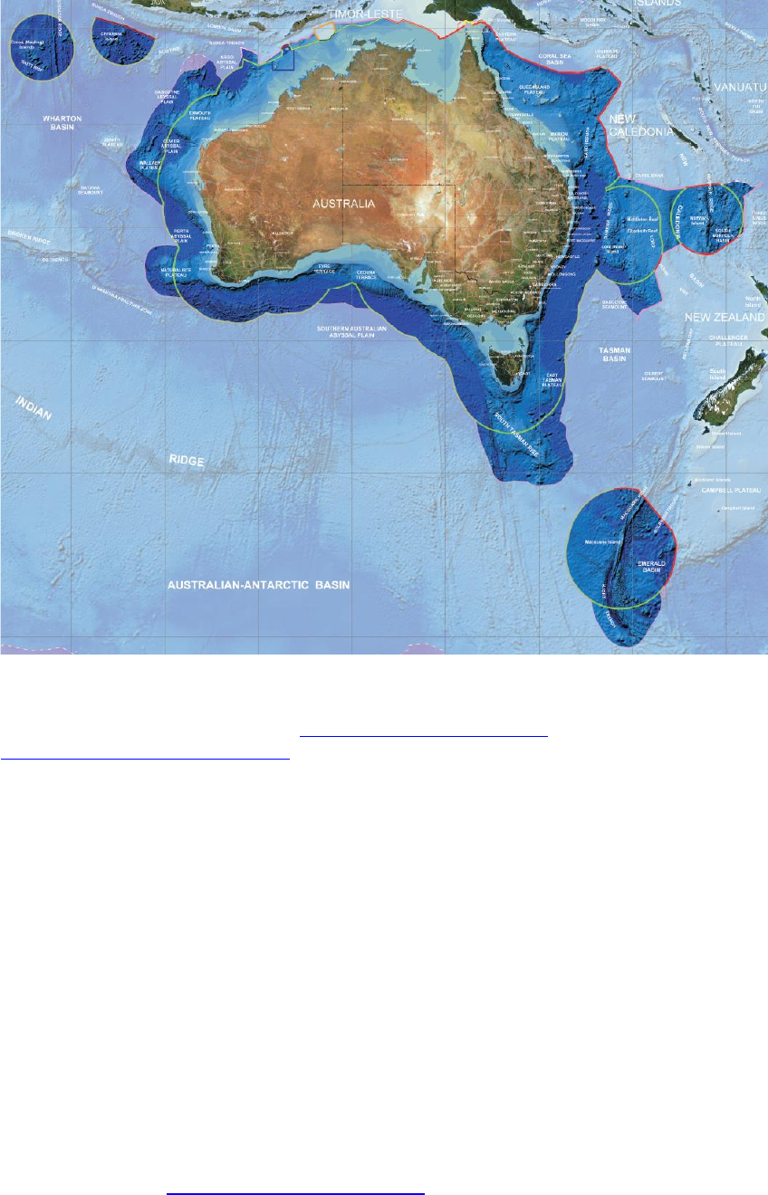
1.2.4 GDA2020 extent
The extent of the GDA2020 includes all the areas contained within Australia’s marine
jurisdiction (within 200 nautical miles of Australia) and its external territories, and the
areas of Australia’s continental shelf beyond 200 nautical miles as confirmed by the United
Nations Commission on the Limits of the Continental Shelf. The areas include Cocos
(Keeling) Islands, Christmas Island, Norfolk Island and Macquarie Island but excludes
Heard-McDonald Islands and the Australian Antarctic Territory (AAT) as shown in Figure
1.1. The extent of GDA2020 is the same as the extent of GDA94.
Intergovernmental Committee on Surveying and Mapping
Geocentric Datum of Australia 2020 Technical Manual 13
Version 1.2
Figure 1.1: The area shown in dark blue is the GDA2020 extent. The colours of the lines represent
different types of jurisdictional boundaries or proposed jurisdictional boundaries. For more information
on the type of boundary, please refer to http://www.ga.gov.au/metadata-
gateway/metadata/record/gcat_70362
1.3 Geodetic Parameter Registries
Internationally there are a number of geodetic registries that are relied upon as the source
of information for defining geodetic datums and the transformations between them. A
registry is a database of coordinate reference system information including ellipsoids,
units, datums, projections and transformations. Each database element is assigned a code
to identify it uniquely. The registry name, code number and type of registry element
provide a shorthand method for defining the relevant coordinate reference system
information.
For example, “EPSG::1168 Geodetic datum” refers to the defining elements of the
Geocentric Datum of Australia GDA2020 held in the EPSG registry.
1.3.1 EPSG Registry
The EPSG registry (http://www.epsg-registry.org/) is a reliable, freely available registry of
geodetic and transformation information. It is maintained on a “best effort” basis by the
Geomatics Committee of the International Association of Oil and Gas Producers (IOGP;

Intergovernmental Committee on Surveying and Mapping
Geocentric Datum of Australia 2020 Technical Manual 14
Version 1.2
previously known as the European Petroleum Survey Group or EPSG). It is updated on a
needs basis, which generally equates to two full release amendments per year.
Datum elements in this manual are identified by EPSG codes and registry element type
where they exist at the time of publication and the manual will be revised when additional
codes are available.
A number of organisations reproduce content from the EPSG registry but the IOGP site
http://www.epsg-registry.org/ is the only official EPSG dataset.
1.3.2 ISO Registry
The International Standards Organisation Technical Committee 211 Geographic
information / Geomatics (ISO/TC 211) is responsible for the ISO geographic information
series of standards. ISO/TC 211 is developing an ISO Geodetic Registry (ISO 19127) that will
ultimately replace the functions of the EPSG registry. Once ISO Registry codes are available
they will be referenced in future updates to this manual.
1.4 History of Australian datums
1.4.1 Early history
Between 1858 and 1966, geodetic surveys in Australia were computed on either a
jurisdiction (state or territory) or regional basis using more than four different spheroids
and as many as twenty coordinate origins.
The National Mapping Council (NMC), at its 23rd meeting in April 1965, adopted the
Geodetic Reference System 1967 (GRS 1967) ellipsoid, then recommended for general use
by the International Union of Geodesy and Geophysics, with the flattening term taken to
two decimal places. The NMC decided to call this spheroid the Australian National Spheroid
(ANS; see Table 1.6) (NMC, 1966).
1.4.2 Australian Geodetic Datum 1966
Re-computation and adjustment of all geodetic surveys in Australia on ANS were
commenced by the Division of National Mapping in June 1965. By 8 March 1966, all
geodetic surveys in Australia were re-computed and adjusted on the Australian Geodetic
Datum (AGD). This datum was subsequently adopted by the NMC on 21 April 1966, during
its 24th meeting in Melbourne, and was proclaimed in the Commonwealth Gazette No. 84
of 6 October 1966.
In 1966, the minor axis of the spheroid was defined as being parallel to the Earth's mean
axis of rotation at the start of 1962. In 1970 the NMC decided to adopt the Conventional
International Origin (CIO), previously known as the mean pole 1900.0-1906.0, for the
direction of the minor axis. The NMC decided that no change in the 1966 coordinates was
necessary. The AGD66 reference meridian plane of zero longitude was defined as being
parallel to the Bureau International de l'Heure (BIH) mean meridian plane near Greenwich.
This gave a value of 149° 00' 18.885” East for the plane contained by the vertical through
the Mount Stromlo photo zenith tube and the CIO. The position of the centre of the ANS is
defined by the following coordinates of Johnston Geodetic Station:

Intergovernmental Committee on Surveying and Mapping
Geocentric Datum of Australia 2020 Technical Manual 15
Version 1.2
Table 1.4: Johnston Geodetic Station coordinates.
Geodetic Latitude
25° 56' 54.5515” South
Geodetic Longitude
133° 12' 30.0771” East
Spheroidal Height
571.2 metres
The size, shape, position and orientation of ANS were thus completely defined, and
together with the coordinates of the Johnston Geodetic Station, defined AGD66. The
coordinates for Johnston Geodetic Station were derived from astronomical observations at
275 stations on the geodetic survey distributed all over Australia. The spheroidal height
was adopted to be 571.2 metres, which was equal to the height of the station above the
geoid as computed by trigonometrical levelling in 1965.
Due to the almost complete lack of geoidal profiles at the time of the 1966 national
adjustment, it was then assumed that the geoid-spheroid separation was zero not only at
Johnston Geodetic Station but also at all other geodetic stations listed in this adjustment.
This assumption implied that every distance used in the 1966 adjustment was a geoidal or
sea level distance (assumed spheroidal distance).
A Universal Transverse Mercator (UTM) projection was associated with AGD66 and was
referred to as the Australian Map Grid (AMG66). The AGD66 and UTM projection, AMG66,
were adopted by all the States and Territories in Australia, particularly in support of the
national mapping program.
1.4.3 Australian Geodetic Datum 1984
Since 1966, there were several readjustments of the national geodetic survey. Each
readjustment was referred to as a Geodetic Model of Australia (GMA) and was identified
by the year in which the data set used in the readjustment was compiled. The adjustment,
GMA82, included satellite Transit Doppler, Satellite Laser Ranging (SLR), Electronic Distance
Measurement (EDM) tellurometer and Very Long Baseline Interferometry (VLBI)
observations.
Recognising the need for Australia to eventually convert to a geocentric geodetic datum,
the NMC, at its 42nd meeting in October 1984, resolved that the GMA82 adjustment would
be adopted as the first step in the conversion process. However, the Council also resolved
that members could use their discretion in the timing of the conversion process.
The GMA82 adjustment maintained AGD as originally defined by the combination of the
1966 coordinate set for Johnston Geodetic Station and the defining parameters for the
ANS. This led to the development of the Australian Geodetic Datum 1984 (AGD84)
coordinate set and associated UTM projection, known as the Australian Map Grid 1984
(AMG84).
In order to prevent any confusion arising with regard to the terminology to be used in
conjunction with the 1966 and GMA82 adjustments, the NMC adopted the following
definitions for general usage:
Table 1.5: Terminology used to differentiate between AGD66 and AGD84.
Datum
Australian Geodetic Datum
Spheroid
Australian National Spheroid
1966 Coordinate Set
Australian Geodetic Datum 1966

Intergovernmental Committee on Surveying and Mapping
Geocentric Datum of Australia 2020 Technical Manual 16
Version 1.2
Australian Map Grid 1966
1982 Adjustment
GMA82
1984 Adopted Coordinate Set
Australian Geodetic Datum 1984
Australian Map Grid 1984
Unlike the 1966 adjustment, the GMA82 adjustment is a truly spheroidal adjustment.
Therefore, any observations used in conjunction with the AGD84 coordinate set should first
be reduced to the ANS using the appropriate geoid-spheroid separation values in terms of
N = +4.9 metres at Johnston Geodetic Station.
NOTE: Not all jurisdictions adopted AGD84. Northern Territory, New South Wales,
Australian Capital Territory, Victoria and Tasmania chose to stay on AGD66.
1.4.4 Geocentric Datum of Australia 1994
To align the Australian datum to a global reference frame, Australia adopted the
Geocentric Datum of Australia 1994 (GDA94) and UTM projection the Map Grid of Australia
1994 (MGA94). At this time the recommended reference ellipsoid was also changed from
ANS to the Geodetic Reference System 1980 (GRS80) ellipsoid after it was adopted at the
XVII General Assembly of the International Union of Geodesy and Geophysics (IUGG) in
Canberra, Australia, 1979 as the recommended best-fit ellipsoid for the Earth (Moritz,
2000). GRS80 has its geometric centre coincident with the centre of the mass of the Earth
whereas the centre of the ANS lay about 200 m from the centre. Hence, the GDA94
coordinates of a point differ by about 200 metres (north-east) compared to AGD
coordinates.
In 1992, as part of an International Global Navigation Satellite System Service (IGS)
campaign (previously known as the International GPS Service), continuous GPS
observations were undertaken on eight geologically stable marks at sites across Australia,
which formed the Australian Fiducial Network (AFN). During this campaign, GPS
observations were also carried out at a number of existing geodetic survey stations across
Australia. These were supplemented by further observations in 1993 and 1994, producing
a network of about 70 well-determined Global Navigation Satellite System (GNSS) sites,
with nominal 500 km spacing across Australia. These sites are collectively known as the
Australian National Network (ANN).
The GPS observations at both the AFN and ANN sites were combined in a single regional
GPS solution in terms of the International Terrestrial Reference Frame 1992 (ITRF92) and
the resulting coordinates were mapped to a common epoch of 1994.0.
The positions for the AFN sites were estimated to have an absolute accuracy of about 2 cm
at 95% confidence level in the horizontal component (Morgan et al., 1996), while the ANN
positions are estimated to have an absolute accuracy of about 5 cm in the horizontal
component. The positions of the AFN sites were used to determine GDA94 and were
published in the Commonwealth of Australia Government Gazette on 6 September 1995.
On 4 April 2012, the AFN was updated to include 21 sites. The purpose of the update was
to improve its consistency with the most recent realisation of International Terrestrial
Reference System (ITRS) at the time (ITRF2008). The updated AFN coordinates were
adopted from ITRF2008 and subsequently transformed to GDA94 (i.e. ITRF1992 at epoch
1994.0) using the Dawson and Woods (2010) transformation parameters. For those

Intergovernmental Committee on Surveying and Mapping
Geocentric Datum of Australia 2020 Technical Manual 17
Version 1.2
stations with multiple coordinate estimates in ITRF2008 the most recent coordinate
estimate was adopted.
1.4.5 Geocentric Datum of Australia 2020
Since the realisation of GDA94, there have been significant developments in technology
that provide ready access to accurate positioning systems. In the near future it is
anticipated that GNSS will be capable of providing positioning services with centimetre
accuracy in real-time to the mass market on mobile devices. Given that data from GNSS is
referenced to a global reference frame, it is appropriate that the Australian datum be
closely aligned to ITRF2014.
GDA2020 is based on a realisation of the ITRF2014 (ITRF2014; Altamimi et al., 2016) at
epoch 2020.0. The Geocentric Datum of Australia 1994 was based on the realisation of
ITRF1992 at epoch 1994.0. Since then:
due to plate tectonic motion, GDA94 coordinates have continued to diverge from
ITRF92 coordinates. By 2020, the difference will be approximately 1.8 m;
there have been many improvements and realisations of the ITRS which better
define the shape of the Earth. For example, differences between ITRF1992 and
ITRF2014 (on which GDA2020 is based) causes a ~9 cm change in ellipsoidal heights
in Australia (GDA2020 heights are ~9 cm less than GDA94 ellipsoidal heights); and
parts of the Australian crust have deformed (e.g. subsidence).
These refinements to the reference frame and local scale distortions have not been
reflected in changes to the Australian datum; some of which will begin to be noticeable to
some users of positioning services.
1.4.5.1 Computation of GDA2020 coordinates
GDA2020 coordinates were computed using a rigorous, 3D network adjustment of all
available GNSS and terrestrial data from Commonwealth, state and territory jurisdictional
archives. This adjustment enables the determination of GDA2020 coordinates and supports
the computation of positional uncertainty and relative uncertainty between any survey
control marks in Australia. The national GDA2020 adjustment was undertaken by
Geoscience Australia with input from geodetic specialist representatives from all
jurisdictional survey organisations.
The national GDA2020 network adjustment involved a rigorous least squares adjustment of
all data. In the past, adjustments were undertaken with higher order data being held fixed
in lower order adjustments. This resulted in distortions in the datum that have become
more apparent when compared with high accuracy GNSS data observed in ITRF2008 or
ITRF2014 and transformed back to 1994 using a 7-parameter similarity transformation. By
performing a single national rigorous adjustment these distortions have been reduced and
relative uncertainty can be computed for any given points on the datum.
The national GDA2020 network adjustment includes all available GNSS and terrestrial data
from the jurisdictional archives, constrained using the Asia-Pacific Reference Frame
(APREF) time series combination solution. This solution is calculated weekly by Geoscience
Australia for approximately 450 APREF stations within Australia’s jurisdiction and it
provides a link between ITRF2014 and GDA2020. The development of GDA2020 has also
seen the creation of the National GNSS Campaign Archive stored at Geoscience Australia.

Intergovernmental Committee on Surveying and Mapping
Geocentric Datum of Australia 2020 Technical Manual 18
Version 1.2
This archive contains all GNSS observations provided by state and territory jurisdictions
greater than six hours duration. The data was processed (and will continue to be as new
data is available) by Geoscience Australia to create a national high quality GNSS network.
1.4.6 Summary of Australian horizontal datums
A summary of the Australian datums is provided in Table 1.6. In some previous
documentation, GDA and AGD have been documented as the name of the datum and the
epoch has been appended to describe the coordinate set (e.g. AGD66). To avoid confusion,
it is recommended that the epoch be appended when describing the name of the datum so
users can differentiate between them (e.g. GDA94 and GDA2020). The EPSG codes for the
datums are shown in Table 1.7.
Table 1.6: Summary of the parameters of Australian datums.
Datum
Geographic
Coordinate
Set
Grid
Coordinates
Reference
Frame
Ellipsoid /
Spheroid
Semi-major
axis (m)
Inverse
Flattening
GDA2020
GDA2020
MGA2020
ITRF2014
GRS80
6378137.0
298.257222101
GDA94
GDA94
MGA94
ITRF1992
GRS80
6378137.0
298.257222101
AGD84
AGD84
AMG84
ANS
6378160.0
298.25
AGD66
AGD66
AMG66
ANS
6378160.0
298.25
Table 1.7: EPSG codes of Australian datums.
Datum
Geographic
Coordinate
Set
EPSG Code
Geodetic
Datum
EPSG Code
Geodetic CRS
(Geocentric)
EPSG Code
Geodetic CRS
(Geographic 3D)
EPSG Code
Geodetic CRS
(Geographic 2D)
GDA2020
GDA2020
1168
7842
7843
7844
GDA94
GDA94
6283
4938
4939
4283
AGD84
AGD84
6203
-
-
4203
AGD66
AGD66
6202
-
-
4202
1.5 Overview of the differences among GDA2020,
ITRF2014 and GNSS reference frames
1.5.1 GDA2020 and ITRF2014
GDA2020 is aligned with ITRF2014 (Altamimi et al., 2016) at epoch 2020.00. ITRF2014 is
the most recent realisation of a global network of accurate coordinates (and their
velocities) maintained by the International Earth Rotation and Reference Systems Service
(IERS) and derived from geodetic observations (VLBI, SLR, GPS and DORIS) (Seeber, 1993).
On January 1 2020, ITRF2014 at epoch 2020.0 will coincide with GDA2020. From January 1
2017 until January 1 2020, the difference between ITRF2014 coordinates (at the observed
epoch) and GDA2020 coordinates will continually converge as the Australian tectonic plate
moves 7 cm per year in a north-easterly direction. Until 2020, there will be an increasing
convergence in the coordinates of GDA2020 and ITRF2014. From January 1 2020, there will
be an increasing divergence in the coordinates of the GDA2020 and ITRF2014.
Intergovernmental Committee on Surveying and Mapping
Geocentric Datum of Australia 2020 Technical Manual 19
Version 1.2
1.5.2 World Geodetic System 1984
The World Geodetic System, of which the latest revision is WGS84 (G1762), is the datum
used by the GPS operated by the U.S. Department of Defense. The datum is defined and
maintained by the United States National Geospatial-Intelligence Agency (NGA). WGS84
has been revised several times since its conception and is at present aligned at the
centimetre level to ITRF2014 (NGA, 2014a). The WGS84 coordinates of tracking stations
used to compute the GPS broadcast orbit are adjusted annually for plate tectonic motion
to an epoch at the half year mark, e.g. WGS84 as used in the GPS broadcast orbit during
calendar year 2014 was ITRF2008 at 2014.5. Consequently, differences between the
ITRF2014 and WGS84 are negligible for most users.
For information on the reference systems of GLObal NAvigation Satellite System
(GLONASS), Galileo, BeiDou, Indian Regional Navigation Satellite System (IRNSS) and Quasi
Zenith Satellite System (QZSS), please refer to the United Nations Office of Outer Space
Affairs (UNOOSA, 2016).
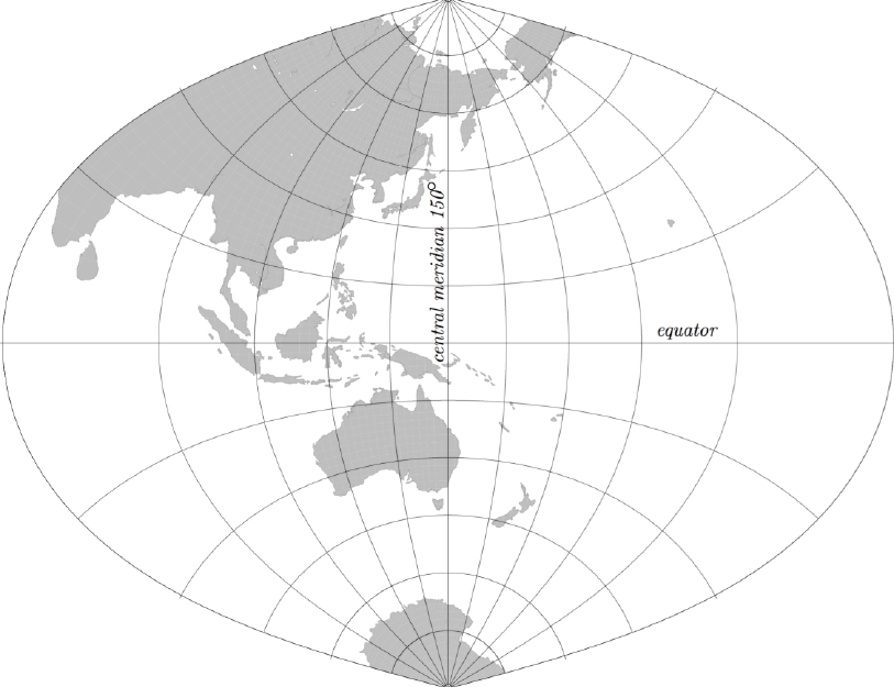
1.6 Map Grid of Australia 2020 (MGA2020)
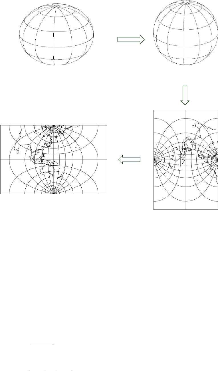
Geodetic coordinates (latitude and longitude) are represented on a map or chart, by
mathematically projecting them onto a two-dimensional plane. The Transverse Mercator
(TM) projection is a conformal mapping of geodetic coordinates from the ellipsoid onto a
plane where the equator and central meridian remain as straight lines and the scale along
the central meridian is constant while meridians and parallels are projected as complex
curves (Figure 1.2).
Figure 1.2: Transverse Mercator projection with central meridian of 150 degrees.
Intergovernmental Committee on Surveying and Mapping
Geocentric Datum of Australia 2020 Technical Manual 20
Version 1.2
The TM projection is useful to map regions with large extents of latitude; however,
distortions increase rapidly away from the central meridian.
The UTM system (Table 1.8) uses the TM projection and attempts to overcome this
limitation by dividing the Earth into 60 zones, each with a width of 6° of longitude. A
central meridian is placed in the middle of each longitudinal zone. As a result, within a
zone nothing is more than 3° from the central meridian and therefore locations, shapes
and sizes and directions between all features are very accurate.
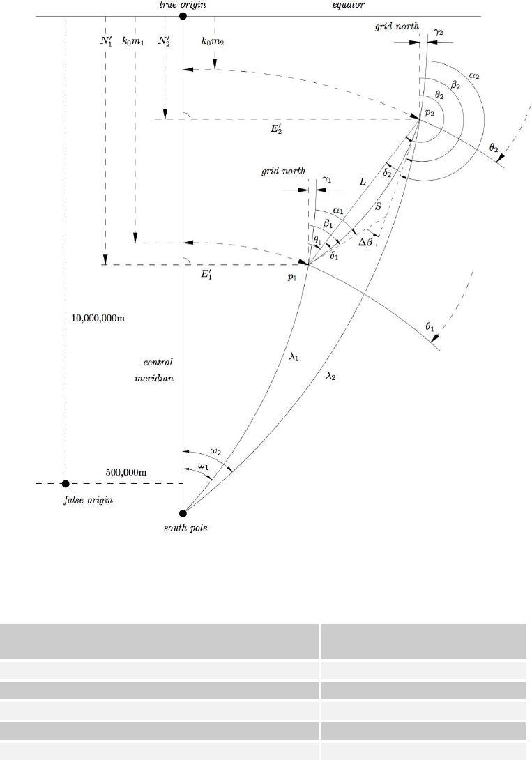
The true origin for each zone is the intersection of the equator and the central meridian,
but a false origin is often used to avoid negative coordinates (Figure 1.3).
Figure 1.3: Relationship between geographic coordinates and projected coordinates.
Table 1.8: UTM system parameters
Parameter
Value
Longitude of initial central meridian (Zone 1)
177 degrees west longitude
Zone width
6 degrees
Central scale factor
0.9996
False Easting
500,000 m
False Northing (in the southern hemisphere)
10,000,000 m
Intergovernmental Committee on Surveying and Mapping
Geocentric Datum of Australia 2020 Technical Manual 21
Version 1.2
The UTM system has been used with the GRS80 ellipsoid and GDA2020 latitudes and
longitudes to define Map Grid of Australia 2020 (MGA2020).
The Krueger n-series or Krueger -series formulae are used to convert between UTM (or
MGA2020) coordinates and geographic coordinates and vice versa (Section 4.1).
Intergovernmental Committee on Surveying and Mapping
Geocentric Datum of Australia 2020 Technical Manual 22
Version 1.2
2 Reference frame and coordinate system
fundamentals
2.1 Coordinate systems
2.1.1 Cartesian
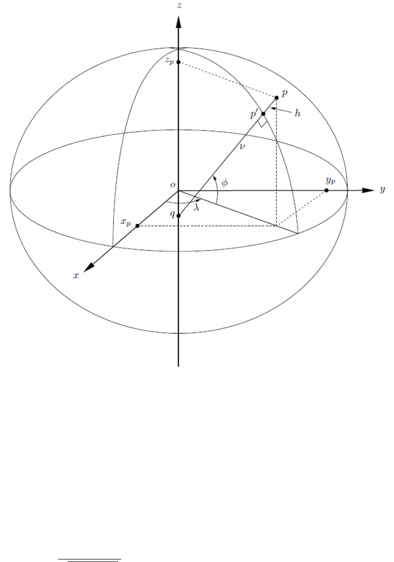
The Cartesian coordinate system is a three-dimensional system with positions referenced
to orthogonal axes with the origin at the centre of the reference ellipsoid (Figure
2.1). The -axis is in the direction of the rotational axis of the ellipsoid of revolution, the
plane is, by convention, the Greenwich meridian plane (the origin of longitudes) and
the plane is the equatorial plane of the ellipsoid (the origin of latitudes) (Gerdan and
Deakin, 1999).
2.1.2 Geographic
The geographic coordinate system is an ellipsoidal coordinate system. A specific type of
geographic coordinate system is a geodetic coordinate system; a three-dimensional system
with positions referenced using geodetic latitude , geodetic longitude and ellipsoidal
height (Figure 2.1). Geodetic latitude and longitude are, by convention, measured
relative to the equator and prime meridian plane respectively.
Equations 1-3 can be used to convert from Cartesian coordinates to geodetic coordinates.
( 1 )
( 2 )
( 3 )
where ( 4 )
( 5 )
( 6 )
( 7 )
Intergovernmental Committee on Surveying and Mapping
Geocentric Datum of Australia 2020 Technical Manual 23
Version 1.2
Figure 2.1: Relationship between Cartesian and geographic coordinate systems.
The following formulae can be used to convert from geodetic coordinates to Cartesian
coordinates.
( 8 )
( 9 )
( 10 )
where
( 11 )
( 12 )
( 13 )
Further reading on geographic to Cartesian conversion techniques including some well
suited for efficient use in software can be found in Gerdan and Deakin (1999).
Intergovernmental Committee on Surveying and Mapping
Geocentric Datum of Australia 2020 Technical Manual 24
Version 1.2
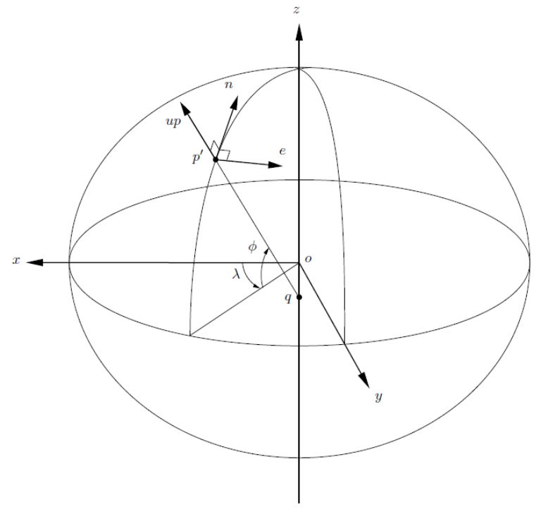
2.1.3 Local
The local reference system is a three-dimensional system with positions referenced using
orthogonal axes with the origin on or above a point on the ellipsoid, and orientation
with respect to a local geodetic meridian (Fraser, Leahy and Collier, 2017; Figure 2.2).
Vectors in the Cartesian reference frame can be represented in the local reference frame
as
( 14 )
A vector in the local reference frame is related to the Cartesian reference frame by
( 15 )
where is the rotation matrix with origin at latitude and longitude
( 16 )
Figure 2.2: The local coordinate reference system.
Intergovernmental Committee on Surveying and Mapping
Geocentric Datum of Australia 2020 Technical Manual 25
Version 1.2
2.2 Transformations between reference frames
A similarity transformation (also known as a conformal transformation) can be used to
transform coordinates (or vectors) from one geodetic reference frame (A) to another (B).
At the computational level this transformation is performed on the Cartesian
coordinates. The 14-parameter similarity transformation (Equation 17) is the 7-parameter
transformation (3 translations , 3 rotations and scale ) with an additional
7 parameters used to describe the rates of change of the translation , rotation
and scale in time and eliminating the negligible terms (Altamimi et al., 2002). This
allows for transformation between datums with data sets at any given epoch where is
the reference epoch. The translations and their rates are expressed in m and m/yr,
respectively. The rotation and their rates are expressed in radians and radians/yr,
respectively. The scale is unit-less and the scale rate is expressed in yr-1. Parameters
are the transformed coordinates.
( 17 )
2.2.1 Rotation matrix sign convention
There are two different ways of applying the sign conventions for the rotations. In both
cases a positive rotation is an anti-clockwise rotation, when viewed along the positive axis
towards the origin but:
1. The IERS assumes the rotations to be of the points around the Cartesian axes,
while;
2. The method historically used in Australia assumes the rotations to be of the
Cartesian axes around the points.
Although these two conventions exist, to enforce the property that all rotations describe
anticlockwise rotation as positive when viewed along the axis towards the origin, the
rotation of the coordinate axes around the points should be a skew-symmetric matrix with
the opposite sign to the rotation of the point/s around the coordinate axis.
The transformation parameters in the GDA2020 Technical Manual adhere to the Australian
convention. Due to the potential for confusion, it is advisable to ensure that the
conventions used in software are well understood and tested against the sample data
supplied in Section 3 of this manual.

Intergovernmental Committee on Surveying and Mapping
Geocentric Datum of Australia 2020 Technical Manual 26
Version 1.2
3 Coordinate transformation
Coordinate transformation is the process of changing coordinates from one reference
frame to another. Options for the transformation of coordinates to, and from, GDA2020,
are transformation parameters and transformation grids.
Table 3.1: Quick reference guide for assistance with transformations.
From
To
Section
GDA94
GDA2020
3.1, 3.2
ITRF2014
GDA2020
3.3
AGD66/84
GDA2020
3.4
ITRF (historic)
GDA2020
3.5
MGA94
MGA2020
3.6
3.1 GDA94 to GDA2020 transformation parameters
The 7-parameter similarity transformation (Equation (18)) is also known as a conformal
transformation and accounts for the difference in scale, rotation and translation between
two reference frames. In this section, the parameters are shown to transform between
GDA94 and GDA2020. The official GDA94 to GDA2020 7 transformation parameters and
associated uncertainties (Table 3.2) were computed using 18 GNSS CORS common to both
the GDA94 RVS and the GDA2020 RVS. The GDA94 RVS (from 2011) had 21 AFN stations.
GNSS CORS located at Cocos Island (COCO), Christmas Island (XMIS) and Macquarie Island
(MAC1) were excluded from the computation due to earthquake deformation.
( 18 )
Table 3.2: Transformation parameters for GDA94 to GDA2020 along with the one-sigma uncertainties
(1σ). Units are in metres for the translation, parts-per-million for scale, and arcseconds for rotations.
0.06155
-0.01087
-0.04019
-0.009994
-0.0394924
-0.0327221
-0.0328979
uncertainty
0.0007
0.0006
0.0007
0.00010
0.000011
0.000010
0.000011
The parameters to transform from GDA2020 to GDA94 can be computed by multiplying the
values in Table 3.2 by -1.
3.1.1 Example: GDA94 to GDA2020 (7–parameter
transformation)
GDA94 coordinates of Alice Springs (ALIC)
Latitude (DMS)
Longitude (DMS)
Ellipsoidal Height (m)
-23 40’ 12.446019”
133 53’ 07.847844”
603.3466

Intergovernmental Committee on Surveying and Mapping
Geocentric Datum of Australia 2020 Technical Manual 27
Version 1.2
Latitude (DD)
Longitude (DD)
Ellipsoidal Height (m)
-23.6701239
133.8855133
603.3466
X
Y
Z
-4052051.7643
4212836.2017
-2545106.0245
GDA2020 coordinates of Alice Springs (ALIC)
X
Y
Z
-4052052.7379
4212835.9897
-2545104.5898
Latitude (DMS)
Longitude (DMS)
Ellipsoidal Height (m)
-23 40’ 12.39650”
133 53’ 07.87779”
603.2489
Latitude (DD)
Longitude (DD)
Ellipsoidal Height (m)
-23.6701101
133.8855216
603.2489
Difference (GDA2020 – GDA94)
Latitude
Longitude
Height (m)
Alice Springs (ALIC)
0.04952"
0.02995"
-0.0977
N (m)
E (m)
U (m)
Alice Springs (ALIC)
1.5236
0.8487
-0.0977
3.2 Transformation Grids
3.2.1 Overview
Transformation grids provide users of spatial data with a simple and nationally consistent
method to transform data between datums. The transformation grids are National
Transformation version 2 (NTv2) files of binary grid shift (.gsb) format and are the
preferred method for transforming between Australian datums. The transformation grids
Table 3.5 and 3.6) are available from the ICSM GitHub repository (https://github.com/icsm-
au/transformation_grids)
NOTE: The NTv2 format does not store ellipsoidal height information and therefore cannot
be used to transform the heights of data from one datum to the other. To transform
heights it is recommended that you convert your data from latitude, longitude, height
to earth-centred Cartesian coordinates using equations 8-10, apply the 7-parameter
transformation from GDA94 to GDA2020 (Table 3.2) and then convert back to using
Intergovernmental Committee on Surveying and Mapping
Geocentric Datum of Australia 2020 Technical Manual 28
Version 1.2
equations 1-3. This step is shown in the similarity transformation spreadsheet (Section
3.7.2).
3.2.2 Types of transformation grids
Two types of GDA94 – GDA2020 transformation grids have been developed:
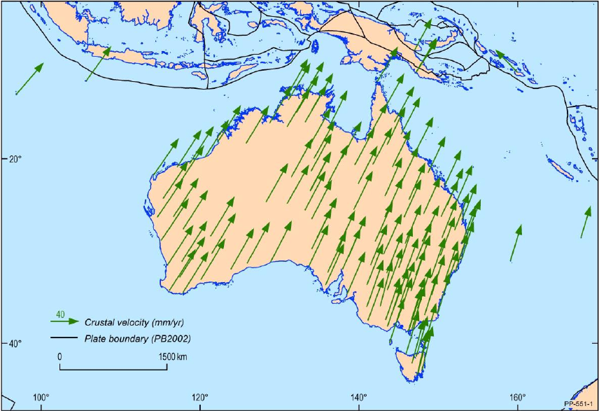
Conformal: predominantly plate tectonic motion (~1.8 m NNE)
Conformal + Distortion: includes regional distortion
The difference between GDA94 and GDA2020 coordinates is comprised of a conformal
transformation component primarily due to plate tectonic motion (Figure 3.1), and an
irregular (non-conformal) distortion component. The distortion component is attributable
to several second-order effects, such as an improved realisation of the global reference
frame over time; irregular ground movement since GDA94 was established; and a lack of
rigour in the computation of GDA94. These effects vary in magnitude and direction around
the country and can be as large as ~0.5 m.
The combined conformal and distortion grids model both the conformal transformation
(i.e. translation, rotation and scale) and distortion components of the differences in the
datums. In the case of GDA94 to GDA2020, the distortion component is caused by the
different strategies used by state and territories to propagate GDA94 coordinates onto
ground survey control mark networks from the AFN and surface movement of parts of the
Australian crust. The magnitude of the distortion varies between jurisdictions and can be in
the order of decimetres.
The GDA94 - GDA2020 conformal only transformation grid delivers the same result as the
7-parameter similarity transformation (Section 3.1). It has been developed at the request
of some software providers who are moving towards the use of grids as the preferred
method of geodetic transformation in selected software platforms. A particular example of
its application would be for users who may be using GDA94 coordinates which were
observed in ITRF2008/2014 and transformed back to GDA94 (e.g. CORS network operators)
using a 7-parameter similarity transformation. These coordinates are not impacted by
distortion in the realisation of the GDA94 datum and the use of the conformal and
distortion transformation grid would actually introduce distortion, not remove it.
The appropriate NTv2 transformation grid to use differs between jurisdictions and the
Positional Uncertainty (or accuracy) of the dataset being transformed. Please refer to Table
3.4 for recommendations.
Intergovernmental Committee on Surveying and Mapping
Geocentric Datum of Australia 2020 Technical Manual 29
Version 1.2
Figure 3.1: The difference between GDA94 and GDA2020 coordinates is primarily due to plate tectonic
motion.
Intergovernmental Committee on Surveying and Mapping
Geocentric Datum of Australia 2020 Technical Manual 30
Version 1.2
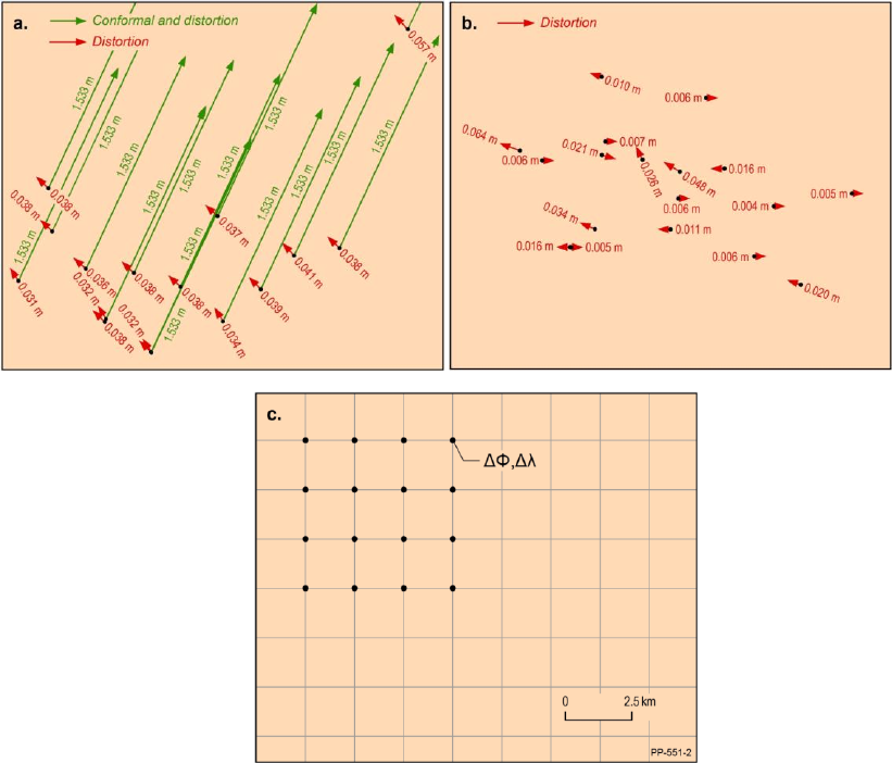
3.2.3 Development of transformation grids
The GDA94 – GDA2020 grids were developed using over 170,000 points at which both GDA94
and GDA2020 coordinates were available. The differences that remain after the conformal
component is removed, is the distortion component. In some regions the distortion
component is regular (Figure 3.2a) with a similar magnitude and direction, while in other
cases it is irregular (Figure 3.2b) with a different magnitude and / or direction. In regions with
an irregular distortion component, the transformation grid will be less reliable.
Figure 3.2: a) conformal (green) and distortion (red; high reliability) components of the transformation
grids; b) low reliability; c) the grid has a latitude component and longitude component.
After removing the conformal component, a least squares prediction was used to compute
the distortion in latitude and longitude on a regular 1’ grid (Figure 3.2c). The
conformal component is then added back to each grid point to complete the conformal +
distortion grid. For further information on the development of transformation grids, refer
to Collier (2002).
3.3 Plate motion model (ITRF2014 to GDA2020)
The plate motion model enables the transformation of coordinates (or vectors) from
ITRF2014 to GDA2020 and vice versa. The model was derived using 109 ARGN and AuScope
GNSS CORS which were used to define the RVS.

Intergovernmental Committee on Surveying and Mapping
Geocentric Datum of Australia 2020 Technical Manual 31
Version 1.2
The station coordinates and velocities were used to compute a conventional Euler plate
model. This 3-parameter model can be expressed as a 14-parameter transformation with
only rates of change rotation components (Table 3.3). Again, at the computational level
this transformation is performed on the Cartesian coordinates.
Table 3.3: Transformation parameters for ITRF2014 to GDA2020 along with their one sigma
uncertainties (1σ). Units are in meters (m) and m/yr for the translation and their rates, respectively,
parts-per-million (ppm) and ppm/yr for scale and its rate, respectively, and arcseconds and
arcseconds/yr for rotations and their rates, respectively. The reference epoch is 2020.0.
0.00
0.00
0.00
0.00
0.00
0.00
0.00
uncertainty
0.00
0.00
0.00
0.00
0.00
0.00
0.00
rates
0.00
0.00
0.00
0.00
0.00150379
0.00118346
0.00120716
uncertainty
0.00
0.00
0.00
0.00
0.00000417
0.00000401
0.00000370
3.3.1 Example: ITRF2014 to GDA2020 (3–parameter
transformation)
ITRF2014 at 2018.0 coordinates of Alice Springs (ALIC)
X (m)
Y (m)
Z (m)
-4052052.6588
4212835.9938
-2545104.6946
GDA2020 coordinates of Alice Springs (ALIC)
X (m)
Y (m)
Z (m)
-4052052.7373
4212835.9835
-2545104.5867
Difference (GDA2020 – ITRF2014 at 2018)
X (m)
Y (m)
Z (m)
Alice Springs (ALIC)
-0.0785
-0.0103
0.1079
3.4 Transformation from / to AGD66 and AGD84
ICSM has not defined a set of parameters that directly transform between historical
Australian geodetic datums (AGD66 and AGD84) and GDA2020. It is recommended to first
transform to GDA94 and then to GDA2020.
For transforming AGD66 or AGD84 coordinates to GDA94 the grid transformation process
using the appropriate ICSM transformation grids Appendix B is the most accurate and
preferred transformation method.

Intergovernmental Committee on Surveying and Mapping
Geocentric Datum of Australia 2020 Technical Manual 32
Version 1.2
3.5 Transformation from / to ITRF (historic)
Transformations between older ITRF realisations (i.e. ITRF2008 and older) and GDA2020
should be performed by first transforming to GDA94 as described in Dawson and Woods
(2010) and then transforming to GDA2020 using the ICSM transformation grids (Section 3.2).
3.6 Transformation from / to MGA2020
To transform data from one map grid (AMG66, AMG84, MGA94, MGA2020) to a different
map grid, the projected coordinates need to first be converted into geographical
coordinates. In the case of transforming coordinates from MGA94 to MGA2020, the
suggested approach is:
Grid to Geographic conversion (MGA94 to GDA94)
Datum transformation (GDA94 to GDA2020)
Geographic to Grid conversion (GDA2020 to MGA2020)
Options for converting coordinates are presented in Section 4.
3.7 Transformation tools and services
3.7.1 Transformation grids
If GDA94 coordinates were observed using Global Navigation Satellite System (GNSS)
technology, with corrections coming from a network of reference stations (e.g. GPSnet,
CORSnet-NSW), it is likely that the coordinates are unaffected by localised distortions and
the conformal only grid would be most suitable. However, if survey ground marks were
used for referencing / control, localised distortions will likely need to be accounted for and
the combined ‘conformal and distortion’ grid should be used. Some recommendations are
shown in Table 3.4, but if in doubt, contact your state / territory land survey authority.
Table 3.4: Advice on the use of NTv2 transformation grid files across jurisdictions
Jurisdiction
NTv2 transformation grid
Comments
ACT
GDA94_GDA2020_conformal
Recommended for users transforming
from GDA94 coordinates derived from
CORS
ACT
GDA94_GDA2020_conformal_and_distortion
Recommended for users transforming
from GDA94 coordinates derived from
survey control marks within ACTmapi
NSW
GDA94_GDA2020_conformal
Appropriate for users transforming
GDA94 coordinates derived from
unlocalised CORS or AUSPOS control.
NSW
GDA94_GDA2020_conformal_and_distortion
Appropriate for users transforming
GDA94 coordinates derived from SCIMS
(Survey Control Information
Management System) or SCIMS-localised
CORS control.
NT
GDA94_GDA2020_conformal
Appropriate for users transforming from
GDA94 coordinates determined from
CORS.

Intergovernmental Committee on Surveying and Mapping
Geocentric Datum of Australia 2020 Technical Manual 33
Version 1.2
NT
GDA94_GDA2020_conformal_and_distortion
Recommended for users transforming
from GDA94 coordinates determined
from the survey ground control network.
Qld
GDA94_GDA2020_conformal
Recommended for transforming all
GDA94 data sets in Queensland.
Qld
GDA94_GDA2020_conformal_and_distortion
Not recommended for use on
Queensland data sets due to distortions
at the state borders.
SA
GDA94_GDA2020_conformal
Appropriate for users transforming from
GDA94 coordinates determined from
CORS.
SA
GDA94_GDA2020_conformal_and_distortion
Recommended for users transforming
from GDA94 coordinates determined
from the survey ground control network.
Tas
GDA94_GDA2020_conformal
Appropriate for users transforming from
GDA94 coordinates determined solely
from unlocalised CORS or AUSPOS
observations.
Tas
GDA94_GDA2020_conformal_and_distortion
Recommended for users transforming
from GDA94 coordinates determined
from the survey ground control network
and where the origin of survey control is
unknown or mixed (e.g. aggregated
datasets available from LISTdata.)
Vic
GDA94_GDA2020_conformal
Recommended for users transforming
from GDA94 coordinates derived directly
from GNSS CORS.
Vic
GDA94_GDA2020_conformal_and_distortion
Recommended for users transforming
from GDA94 coordinates derived from
survey control marks within the Survey
Marks Enquiry Service (SMES).
WA
GDA94_GDA2020_conformal
Appropriate for users transforming from
GDA94 coordinates determined from
CORS.
WA
GDA94_GDA2020_conformal_and_distortion
Recommended for users transforming
from GDA94 coordinates determined
from the local geodetic network (GOLA).
WA –
Christmas
and Cocos
Island
GDA94_GDA2020_conformal
Recommended for Christmas and Cocos
Island when they become available.
The transformation grids cover the regions shown in Figure 3.3. Note that this does not yet
include Christmas Island, Cocos Island which will be coming soon. In regions that are not
covered by the grids, but are within the GDA2020 extent (Section 1.2.4), the 7-parameter
similarity transformation is recommended to transform between GDA94 and GDA2020.

Intergovernmental Committee on Surveying and Mapping
Geocentric Datum of Australia 2020 Technical Manual 34
Version 1.2
Figure 3.3: Extent of the GDA94-GDA2020 conformal, and conformal and distortion grids.
Table 3.5: NTv2 transformations grid files
Transformation
Grid File type
NTv2 Transformation file
AGD66 to GDA94
conformal and distortion
A66 National (13.09.01).gsb
AGD84 to GDA94
conformal and distortion
National 84(02.07.01).gsb
GDA94 to GDA2020
conformal
GDA94_GDA2020_conformal.gsb
GDA94 to GDA2020
conformal and distortion
GDA94_GDA2020_conformal_and_distortion.gsb
GDA94 to GDA2020
Christmas Island
conformal
GDA94_GDA2020_conformal_christmas_island.gsb
GDA94 to GDA2020
Cocos Island
conformal
GDA94_GDA2020_conformal_cocos_island.gsb
Table 3.6: EPSG codes for NTv2 transformation grid files
NTv2 Transformation file
EPSG
Transformation
Code
EPSG Transformation
Name
Comments
A66 National (13.09.01).gsb
1803
AGD66 to GDA94 (11)
See Appendix A for
coverage information
National 84(02.07.01).gsb
1804
AGD84 to GDA94 (5)
See Appendix A for
coverage information
GDA94_GDA2020_conformal.gsb
To be
confirmed
To be confirmed
GDA94_GDA2020_conformal_an
d_distortion.gsb
To be
confirmed
To be confirmed
GDA94_GDA2020_conformal_
christmas_island.gsb
To be
confirmed
To be confirmed
GDA94_GDA2020_conformal_
cocos_island.gsb
To be
confirmed
To be confirmed

Intergovernmental Committee on Surveying and Mapping
Geocentric Datum of Australia 2020 Technical Manual 35
Version 1.2
The transformation grids can be accessed under a BSD 3-Clause licence from the ICSM
GitHub repository (https://github.com/icsm-au) and by direct download from the Amazon
Simple Storage Service (S3):
GDA94-GDA2020 Conformal: https://s3-ap-southeast-2.amazonaws.com/transformation-
grids/GDA94_GDA2020_conformal.gsb
GDA94-GDA2020 Conformal and Distortion: https://s3-ap-southeast-
2.amazonaws.com/transformation-grids/GDA94_GDA2020_conformal_and_distortion.gsb
AGD66-GDA94: https://s3-ap-southeast-2.amazonaws.com/transformation-
grids/A66_National_13_09_01.gsb
AGD84-GDA94: https://s3-ap-southeast-2.amazonaws.com/transformation-
grids/National_84_02_07_01.gsb
3.7.2 Similarity transformation
An alternative to the transformation grid is the similarity transformation Spreadsheet
available from https://github.com/icsm-au/DatumSpreadsheets. This process performs the
7-parameter transformation (Table 3.2), i.e. only the conformal transformation and does
not include the distortion modelling.
3.7.3 Online transformation
ICSM has established a website (link available on http://positioning.fsdf.org.au) where you
can upload a file to be transformed. This transformation will use the transformation grids
and send you an email from where the transformed dataset can be downloaded.
3.7.4 QGIS Plug-ins
ICSM has arranged for an existing NTv2 transformation plugin for QGIS to be amended to
incorporate the NTv2 grids for transforming between AGD66 ⁄ 84 - GDA94 and GDA94 -
GDA2020. An ICSM branded plugin dealing only with the Australian datums has also been
developed.
Details of these plugins are available at http://www.icsm.gov.au/datum/gda-
transformation-products-and-tools/software-and-plugins.
Intergovernmental Committee on Surveying and Mapping
Geocentric Datum of Australia 2020 Technical Manual 36
Version 1.2
4 Coordinate conversion
Coordinate conversion is a conversion of coordinates from one coordinate system to a
different coordinate system referenced to the same datum (e.g. Cartesian coordinates to
geographic coordinates).
4.1 Geographic from / to grid
Two methods are presented to convert geographic to / from grid coordinates; Krueger n-
series equations and Krueger -series equations (Krueger, 1912). The Krueger -series
equations are also known as Redfearn’s formulae (Redfearn, 1948) and were used in the
GDA94 Technical Manual. These equations are accurate to better than 1 mm within any
zone of the Map Grid of Australia 1994 and Map Grid of Australia 2020 and can still be used
for many purposes. However, for applications where users are working across multiple
UTM/MGA zones, Krueger n-series equations are recommended and are explained in this
Technical Manual. The Krueger n-series equations are particularly beneficial in software to
avoid error build up when conversions are done back and forth between geographic and
grid coordinates.
4.1.1 Krueger n-series equations
Krueger’s n-series equations (Karney, 2011) with coefficients that are functions of (a
geometric constant of the reference ellipsoid known as the third flattening), give
micrometre accuracy anywhere within 30° of a central meridian (Deakin et al., 2012).
The National Geospatial-Intelligence Agency have adopted the Krueger n-series equations
(to the 6th power of n) for improved efficiency and expanded coverage of the ellipsoid.
Software that uses these formula are usually shorter and simpler to write, and, by
implication, less likely to have bugs than other methods (NGA, 2014b).
The development of the Krueger n-series equations for the transverse Mercator projection
involves three steps (Figure 4.1):
1. Mapping of the ellipsoid to a conformal sphere (a sphere of radius ).
2. Mapping of the conformal sphere to the plane using spherical transverse Mercator
projection equations with spherical latitude replaced by conformal latitude;
yielding Gauss-Schreiber coordinates with a scale factor on the central meridian,
which is not constant.
3. Mapping of Gauss-Schreiber coordinates (plane) to transverse Mercator
coordinates (plane) with a scale factor on the central meridian that is constant.
Intergovernmental Committee on Surveying and Mapping
Geocentric Datum of Australia 2020 Technical Manual 37
Version 1.2
(a) Ellipsoid (b) Conformal sphere
(d) Transverse Mercator (c) Gauss-Schreiber
Figure 4.1: Sequence of conformal mapping used for geographic to grid conversion using Krueger n-
series (adapted from Deakin, 2014).
4.1.1.1 Forward transformation (geographic to grid)
The forward transformation (geographic to grid) converts the latitude and longitude to
eastings and northings using the ellipsoidal parameters, the longitude of the central
meridian, the central scale factor and the offsets of the false origin.
The following are the steps required to perform the transformation. For more information
on the derivation of the equations or more efficient numerical evaluations, refer to Deakin
et al. (2012).
1. Compute ellipsoidal constants ()
( 18 )
( 19 )

Intergovernmental Committee on Surveying and Mapping
Geocentric Datum of Australia 2020 Technical Manual 38
Version 1.2
2. Compute the rectifying radius
( 20 )
3. Compute the coefficients for
2 3 4 5 6 7 8
2
2 3 4 5 6 7 8
4
3 4 5
6
1 2 5 41 127 7891 72161 18975107
2 3 16 180 288 37800 387072 50803200
13 3 557 281 1983433 13769 148003883
48 5 1440 630 1935360 28800 174182400
61 103 15061 1676
240 140 26880
n n n n n n n n
n n n n n n n
n n n
6 7 8
4 5 6 7 8
8
5 6 7 8
10
03 67102379 79682431
181440 29030400 79833600
49561 179 6601661 97445 40176129013
161280 168 7257600 49896 7664025600
34729 3418889 14644087 2605413599
80640 1995840 9123840 622702080
n n n
n n n n n
n n n n
6 7 8
12
78
14
8
16
212378941 30705481 175214326799
319334400 10378368 58118860800
1522256789 16759934899
1383782400 3113510400
1424729850961
743921418240
n n n
nn
n
( 21 )
4. Compute conformal latitude
( 22 )
where
( 23 )
5. Compute longitude difference
( 24 )
6. Compute the Gauss-Schreiber ratios from the
and
from the Gauss-
Schreiber coordinates

Intergovernmental Committee on Surveying and Mapping
Geocentric Datum of Australia 2020 Technical Manual 39
Version 1.2
( 25 )
( 26 )
7. Compute the transverse Mercator ratios
and
( 27 )
( 28 )
8. Compute the traverse Mercator coordinates
( 29 )
( 30 )
9. Compute the MGA2020 coordinates
( 31 )
( 32 )
where are the false easting and northing respectively.
10. Compute and (to order and )

Intergovernmental Committee on Surveying and Mapping
Geocentric Datum of Australia 2020 Technical Manual 40
Version 1.2
( 33 )
( 34 )
11. Compute the point scale factor
( 35 )
12. Compute the grid convergence
( 36 )
4.1.1.2 Inverse transformation (grid to geographic)
The inverse transformation (grid to geographic) converts eastings and northings to latitude
and longitude.
1. Compute ellipsoidal constants (). See Equations (18, 19)
2. Compute the rectifying radius . See Equation (20)
3. Compute the coefficients for . See Equation (21)
4. Compute the coefficients for

Intergovernmental Committee on Surveying and Mapping
Geocentric Datum of Australia 2020 Technical Manual 41
Version 1.2
2 3 4 5 6 7 8
2
2 3 4 5 6 7 8
4
3 4 5
6
1 2 37 1 81 96199 5406467 7944359
2 3 96 360 512 604800 38707200 67737600
1 1 437 46 1118711 51841 24749483
48 15 1440 105 3870720 1209600 348364800
17 37 209 5
480 840 4480
n n n n n n n n
n n n n n n n
n n n
6 7 8
4 5 6 7 8
8
5 6 7 8
10
12
569 9261899 6457463
90720 58060800 17740800
4397 11 830251 466511 324154477
161280 504 7257600 2494800 7664025600
4583 108847 8005831 22894433
161280 3991680 63866880 124540416
n n n
n n n n n
n n n n
6 7 8
78
14
8
16
20648693 16363163 2204645983
638668800 518918400 12915302400
219941297 497323811
5535129600 12454041600
191773887257
3719607091200
n n n
nn
n
( 37 )
5. Compute the transverse Mercator coordinates
( 38 )
( 39 )
6. Compute the transverse Mercator ratios and
( 40 )
( 41 )
7. Compute the Gauss-Schreiber ratios
and
( 42 )
( 43 )
8. Compute

Intergovernmental Committee on Surveying and Mapping
Geocentric Datum of Australia 2020 Technical Manual 42
Version 1.2
( 44 )
9. Solve for by Newton-Raphson iteration and then determine latitude
The equations linking and are (22) and (23) given here in
modified form
( 45 )
where
( 46 )
can be evaluated using the Newton-Raphson method for the real roots of the
equation given in the form of an iterative equation
( 47 )
where denotes the th iterate and is given by
( 48 )
and is a fixed value. The derivative is given by
( 49 )
An initial value for can be taken as and the functions and
evaluated from equations (46), (48) and (49). is computed from equation (47)
and this process repeated to obtain . This iterative process can be concluded
when the difference between and reaches an acceptably small value, and then
the latitude is given by

Intergovernmental Committee on Surveying and Mapping
Geocentric Datum of Australia 2020 Technical Manual 43
Version 1.2
( 50 )
10. Compute longitude difference and longitude from
( 51 )
( 52 )
11. Compute and . See Equations (33) and (34).
12. Compute the point scale factor . See Equation (35).
13. Compute the grid convergence . See Equation (36).
4.1.2 Krueger -series equations (Redfearn’s formulae)
The Krueger -series equations (also known as Redfearn's formulae) may be used to
convert between geographic coordinates (latitude, longitude) and grid coordinates
(easting, northing and zone) for a transverse Mercator projection, such as the Map Grid of
Australia (MGA). These formulae are accurate to better than 1 mm within any zone of the
Map Grid of Australia. Further information on the Krueger -series equations can be found
in the GDA94 Technical Manual.
If you require formulae to provide accurate geographic to / from grid conversion across
multiple zones, the Krueger n-series equations are recommended (Section 4.1.1).
4.1.3 Zone-to-zone transformations
If a point lies within 0.5° of a zone boundary, it is possible to compute the grid coordinate
of the point in terms of the adjacent zone. This can be done by:
1. converting the known grid coordinates to geographic coordinates using Krueger
n-series or Krueger -series equations (Redfearn's formulae), and then converting
back to grid coordinates in terms of the adjacent zone, or
2. using the formulae shown below (Jordan and Eggert 1941; Grossmann 1964).
These formulae have an accuracy of 10 mm anywhere within 0.5° of a zone
boundary.
Formulae
( 53 )
( 54 )

Intergovernmental Committee on Surveying and Mapping
Geocentric Datum of Australia 2020 Technical Manual 44
Version 1.2
( 55 )
( 56 )
where:
Z
is a point on the zone boundary,
are the known coordinates of the point to be transformed,
are the coordinates of the point in terms of the adjacent zone,
is the plane bearing from Z to the point to be transformed.
4.1.4 Tools / services
4.1.4.1 Krueger n-series
A spreadsheet is available on the ICSM GitHub repository (https://github.com/icsm-
au/DatumSpreadsheets) to perform geographic to grid conversions (and vice-versa) with
Krueger n-series equations (Karney, 2011; Deakin, 2014).
4.1.4.2 Krueger -series (Redfearn’s formulae)
A number of tools are available to perform conversions using Krueger -series equations
including:
Geographic to Grid: (http://www.ga.gov.au/geodesy/datums/redfearn_geo_to_grid.jsp)
Grid to Geographic: (http://www.ga.gov.au/geodesy/datums/redfearn_grid_to_geo.jsp)
Spreadsheet (https://github.com/icsm-au/DatumSpreadsheets)
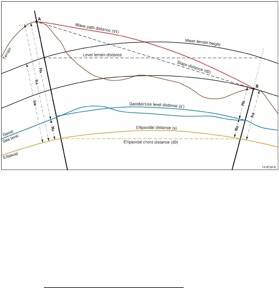
Intergovernmental Committee on Surveying and Mapping
Geocentric Datum of Australia 2020 Technical Manual 45
Version 1.2
5 Coordinate computations
5.1 Ellipsoid computations
5.1.1 Reduction of measured distances to the ellipsoid
Due to the effects of atmospheric refraction, the light waves or microwaves used by
Electronic Distance Measurement (EDM) devices follow a curved path. Before this curved
wave path distance can be used for geodetic computations, it should be reduced to the
surface of the ellipsoid by the application of both physical and geometric corrections.
Figure 5.1 Reduction of distance to the ellipsoid.
The difference between the wave path length and the wave path chord (slope distance)
is a function of the EDM equipment used and also of the meteorological conditions
prevailing along the wave path at the time of measurement. This difference can often be
ignored for distance measurements of up to 15 kilometres, using either light waves or
microwaves. These physical corrections, which involve the application of certain velocity
corrections to the measured wave path distance, are not discussed in this manual.
5.1.1.1 Combined formula
The reduction of the wave path chord distance , to the ellipsoidal chord distance , can
be given as a single rigorous formula (Clark, 1966)
( 57 )
The ellipsoidal chord distance is then easily reduced to the ellipsoidal arc distance
Intergovernmental Committee on Surveying and Mapping
Geocentric Datum of Australia 2020 Technical Manual 46
Version 1.2
( 58 )
where is the radius of curvature in the azimuth of the line.
For a distance of 30 kilometres in the Australian region the chord-to-arc correction is 0.028
m. For a distance of 50 km, the correction reaches about 0.13 m and it is more than 1 m at
100 km. The second term in the chord-to-arc correction is less than 1 mm for lines up to
100 km anywhere in Australia and can usually be ignored.
5.1.1.2 Separate formulae
The combined formula above includes the slope and ellipsoid level corrections. The slope
correction reduces the wave path chord to a horizontal distance at the mean elevation
of the terminals of the line (terrain distance) and the ellipsoid level correction reduces the
horizontal distance to the ellipsoid chord distance . The chord-to-arc correction is then
applied to the ellipsoid chord distance, as with the combined formula, to give the
ellipsoidal arc distance s.
Slope correction
( 59 )
Ellipsoidal correction
( 60 )
Chord to arc correction
( 61 )
Observations using total stations are often reduced to terrain distances, while GNSS
observations are reduced to the ellipsoid. These distances can be significantly different
depending on the height of the terrain. A change in height of 6.5 m causes approximately a
one part per million (1 ppm) effect on distances. For example, at 650 m above the ellipsoid,
the difference between terrain and ellipsoidal distances is approximately 100 ppm.
Similarly, variations in height across surveys covering a large area may also be significant
(DNRM, 2016).
5.1.1.3 Heights in distance reduction
The formulae given in this chapter use ellipsoidal heights . If the geoid-ellipsoid
separation is ignored and only the height above the geoid (orthometric or AHD height)
is used, an error of 1 ppm will be introduced for every 6.5 m of (plus any error due to the
change in value along the line). As the geoid-ellipsoid separation value varies from -35 m
in southwest Australia, to approximately 70 m in northeast Australia, errors from -5 to
approximately 11 ppm could be expected. In areas where the geoid-ellipsoid separation is
small and the corresponding error would also be small.
5.1.1.4 Radius of curvature
The radius of curvature of the ellipsoid is a function of latitude. For many applications the
geometric mean radius , can be used rather than the radius in the azimuth of the line
. However, there can be a large difference between the geometric mean radius and the
radius in the azimuth of the line.
For high accuracy applications the radius of curvature in the azimuth of the line should be
used.

Intergovernmental Committee on Surveying and Mapping
Geocentric Datum of Australia 2020 Technical Manual 47
Version 1.2
( 62 )
( 63 )
where:
( 64 )
( 65 )
5.1.2 Reduction of measured directions to the ellipsoid
When a total station is levelled to make an angular observation (direction or azimuth) it is
levelled according to the plumbline at that point, i.e. the normal to the geoid. This is
generally different from the normal to the ellipsoid at the same point. This difference is
known as the deflection of the vertical. The correction for this deflection is generally small,
but should be applied for the highest quality results. Deflection of the vertical can be
computed from astronomic and geodetic coordinates at the same point, or they can be
produced from a geoid model such as AUSGeoid2020.
A further correction can be made to account for the fact that the normals at each end of
the line are not parallel (the skew normal correction). This too is a small correction and
except in mountainous country, it can reasonably be ignored (Bomford, 1980).
Because they are related to a particular ellipsoid, deflection of the vertical, like geoid
ellipsoid separations, will be different for different datums. Within Australia, the maximum
deflection in terms of GDA94 and GDA2020 is of the order of twenty seconds of arc, which
could result in a correction to an observed direction or azimuth approaching half a second
of arc.
The Laplace correction defines the relationship between an astronomically observed
azimuth and a geodetic azimuth. It can be a significant correction, of the order of several
seconds of arc, and should always be applied to an astronomic azimuth before computing
coordinates.
The formulae for these corrections are often given using the astronomic convention, with
east longitude negative. However, the formulae used here have been rearranged to use
the geodetic conventions, as used elsewhere in this manual (east longitude positive).
5.1.2.1 Formulae
Direction (reduced) = Direction (measured)
+ Deflection correction
+ Skew normal correction
+ Laplace correction (Laplace for azimuth only)
Intergovernmental Committee on Surveying and Mapping
Geocentric Datum of Australia 2020 Technical Manual 48
Version 1.2
Deflection correction = ( 66 )
where = ( 67 )
If the elevation angle (e) is not known, an effective estimate can be obtained from:
( 68 )
Skew normal correction =
( 69 )
Laplace correction = ( 70 )
Intergovernmental Committee on Surveying and Mapping
Geocentric Datum of Australia 2020 Technical Manual 49
Version 1.2
5.1.3 Positions, azimuth and distances
There are a number of formulae available to calculate accurate geodetic positions,
azimuths and distances on the ellipsoid (Bomford, 1980). Vincenty's formulae (Vincenty,
1975) may be used for lines ranging from a few centimeters to nearly 20,000 km, with
millimetre accuracy. The formulae have been extensively tested for the Australian region
by comparison with results from other formulae (Rainsford 1955; Sodano 1965).
5.1.3.1 Vincenty’s inverse formula
Given the latitude and longitude of two points and Vincenty’s inverse formula
can be used to calculate the ellipsoidal arc distance and forward and reverse azimuths
between the points.
( 71 )
( 72 )
Starting with the approximation,
( 73 )
iterate the following equations, until there is no significant change in :
( 74 )
( 75 )
( 76 )
( 77 )
( 78 )
( 79 )
( 80 )
then:
( 81 )
( 82 )
( 83 )
( 84 )
( 85 )

Intergovernmental Committee on Surveying and Mapping
Geocentric Datum of Australia 2020 Technical Manual 50
Version 1.2
( 86 )
( 87 )
5.1.3.2 Vincenty’s direct formula
Given the latitude and longitude of a point , the geodetic azimuth and
ellipsoidal distance to a second point , Vincenty’s direct formula can be used to calculate
the latitude and longitude of the second point () and the reverse azimuth ().
( 88 )
( 89 )
( 90 )
( 91 )
( 92 )
( 93 )
Starting with the approximation
( 94 )
iterate the following three equations until there is no significant change in
( 95 )
( 96 )
( 97 )
then
( 98 )
( 99 )
( 100 )
( 101 )
( 102 )
( 103 )

Intergovernmental Committee on Surveying and Mapping
Geocentric Datum of Australia 2020 Technical Manual 51
Version 1.2
Note:
• "The inverse formulae may give no solution over a line between two nearly antipodal
points. This will occur when is greater than in absolute value." (Vincenty, 1975)
• In Vincenty (1975) is used for the difference in longitude, however for consistency with
other formulae in this Manual, is used here.
Sample Data
Table 5.1 Sample data to check Vincenty’s calculations
Flinders Peak
-37° 57’ 03.72030"
144° 25’ 29.52440"
Buninyong
-37° 39’ 10.15610"
143° 55’ 35.38390"
Ellipsoidal distance
54,972.271 m
Forward azimuth
306° 52’ 05.37"
Reverse azimuth
127° 10’ 25.07"
5.1.3.3 Ellipsoid computation tools
Tools available to perform ellipsoid computations are:
Vincenty’s inverse: (http://www.ga.gov.au/geodesy/datums/vincenty_inverse.jsp)
Vincenty’s direct: (http://www.ga.gov.au/geodesy/datums/vincenty_direct.jsp)
Spreadsheet (https://github.com/icsm-au/DatumSpreadsheets)
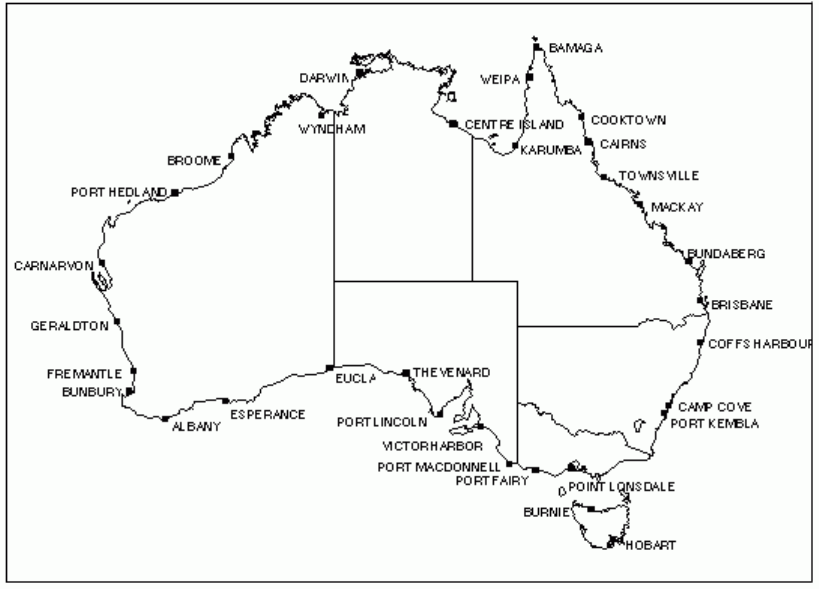
Intergovernmental Committee on Surveying and Mapping
Geocentric Datum of Australia 2020 Technical Manual 52
Version 1.2
6 Australian Height Datum and geoid models
6.1 Australian Height Datum background
The Australian Height Datum (AHD) is the official national vertical datum for Australia and
refers to Australian Height Datum 1971 (AHD71; Australian mainland) and Australian
Height Datum (Tasmania) 1983 (AHD–TAS83). Prior to AHD, many local height datums were
used in the states and territories.
AHD was adopted by the NMC at its 29th meeting in May 1971 as the datum to which all
vertical control for mapping was to be referred. The datum surface passes through mean
sea level (MSL) realised between 1966 – 1968 at 30 tide gauges around the Australian
mainland (Figure 6.1).
Figure 6.1: The locations of the tide gauges used to define AHD.
AHD heights were derived across Australia via a least squares adjustment of 97,320 km of
‘primary’ levelling (used in the original adjustment) and 80,000 km of ‘supplementary’
levelling (applied in a subsequent adjustment) (Roelse et al., 1971). Levelling observations
ran between junction points in the network, and were known as level sections. These level
sections were created by combining levelling observations along level runs (usually
following major roads). The interconnected network of level sections and junction points
was constrained at the 30 tide gauge sites, which were assigned a value of zero AHD. The
least squares adjustment propagated mean sea level heights, or AHD, across the level
network. Despite the best efforts of surveyors, systematic, gross and random errors crept
into the level sections and were distributed across the network within the least squares
adjustment.

Intergovernmental Committee on Surveying and Mapping
Geocentric Datum of Australia 2020 Technical Manual 53
Version 1.2
The Australian Height Datum (Tasmania) 1983 (AHD–TAS83) is based on mean sea level in
1972 at tides gauges in Hobart and Burnie. It was propagated throughout Tasmania using
third order differential levelling over 72 sections between 57 junction points and computed
via adjustment on 17 October 1983. Mean sea level at both Hobart and Burnie was
assigned the value of zero.
6.1.1 Metropolitan and buffer zones
Bench marks within the metropolitan areas of Perth and Adelaide were held fixed at
heights assigned by the Surveyors General of Western Australia and South Australia. The
areas in which these heights have been held fixed are termed "Metropolitan Zones". The
assigned heights within the Perth Metropolitan Zone are based on mean sea level at
Fremantle over a different epoch from that used in the adjustment of 5 May 1971. These
heights differed by not more than 40 mm from those computed in the adjustment.
The assigned heights within the Adelaide Metropolitan Zone are based on mean sea level
at Port Adelaide and these heights differ by not more than 18 mm from those determined
in the National Levelling Adjustment of 5 May 1971 (NMC, 1971)
1
.
The small differences between the heights determined by the adjustment of 5 May 1971
and those assigned by the Surveyors General to bench marks on the perimeter of the
Metropolitan Zones have been distributed through "Buffer Zones".
Details relating to the limits of the Metropolitan and Buffer Zones, and the levelling
sections within these zones may be obtained from the respective State Surveyors General.
The heights of bench marks in the Metropolitan Zones assigned by the Surveyors General
and the adjusted heights of bench marks in the Buffer Zones shall be regarded as being on
the Australian Height Datum.
6.2 Heighting fundamentals
Height determination in Australia requires a level of care due to the number and type of
reference and working surfaces to which heights can be referred, including: AHD, MSL,
Mean Sea Surface (MSS), ellipsoid and geoid (gravimetric or combined gravimetric and
geometric). These surfaces are shown in Figure 6.2.
1
The NMC 1971 reference to the Special Publication 8 is a WA annotated version in which the value of
40 mm is written and 4 mm is crossed out. PCG believe the value of 40 mm is correct. The notations
match the information in the document “Public Works Department Tidal Information – Western
Australian Coast”.
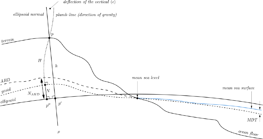
Intergovernmental Committee on Surveying and Mapping
Geocentric Datum of Australia 2020 Technical Manual 54
Version 1.2
Figure 6.2: Reference and working surfaces for height in Australia.
Ellipsoid: Simplified mathematical representation of the Earth often used as a reference
surface for positioning, navigation, map projections and geodetic calculations.
Ellipsoidal height: Distance between the ellipsoid and point of interest measured along a
straight line perpendicular to the ellipsoid.
Geoid: Surface of equal gravitational potential (or equipotential) that closely approximates
mean sea level.
Deflection of the vertical (): Deviation of actual gravity (i.e. gravity observed by
gravimeter) from normal gravity (i.e. approximation of actual gravity using a model (e.g.
ellipsoid)). It is made up of two components: north–south component (deflection in the
prime meridian, ) and an east–west component (deflection in the prime vertical, ).
Mean Sea Level: Mean sea level (MSL) is an observed tidal datum and is used as the
conventional reference surface to which heights on the terrain (e.g. contours, heights of
mountains, flood plains, etc.) and other tidal datums are related (Fraser, Leahy and Collier,
2017).
Mean Sea Surface: Mean sea surface (MSS) is the sum of the geoid (closely approximated
by MSL) and Mean Dynamic Topography (MDT) which describes the thermodynamic
motion of the oceans.
Mean Dynamic Topography (MDT): Mean Dynamic Topography is the offset between the
geoid and MSS.
For a thorough description of heighting fundamentals, refer to Heiskanen and Moritz
(1967); Featherstone and Kuhn (2006); Filmer et al. (2010) and Fraser, Leahy and Collier
(2017).
Intergovernmental Committee on Surveying and Mapping
Geocentric Datum of Australia 2020 Technical Manual 55
Version 1.2
6.2.1 AHD: Normal-Orthometric height system
When the AHD was established, insufficient gravity observations were available to apply
gravimetric height corrections. Instead, a truncated version of the normal-orthometric
correction of Rapp (1961) was applied to the spirit levelling observations (Roelse et al.,
1975; Featherstone and Kuhn 2006) which has no requirement for observed gravity in the
correction. Instead it uses the normal gravity field only to derive all necessary gravity field
related quantities. As such, the AHD is considered a normal-orthometric height system
(Holloway 1988; Featherstone and Kuhn 2006; Filmer et al., 2010).
6.3 AUSGeoid2020
6.3.1 Overview
AUSGeoid2020 has been developed to support improved determination of AHD height
estimates from GNSS observations. AUSGeoid2020 provides ellipsoid to AHD
separation values onshore with uncertainty.
( 104 )
Given that AHD is only an onshore datum, the AUSGeoid2020 model should only be used
onshore and on islands near to the coast where connections to AHD are known to exist.
Christmas Island, Cocos Island and some islands off the coast of north Queensland are
exceptions to this rule where AUSGeoid2020 provides ellipsoid to local mean sea level as
determined by tidal observations. For converting geometric heights to physical heights in
areas not covered by AUSGeoid2020, you may consider using the Australian Gravimetric
Quasigeoid 2017 (see Section 6.5).
Onshore, AUSGeoid2020 is a combined gravimetric - geometric model. The gravimetric
component is a by grid of ellipsoid – quasigeoid separation values created using data
from gravity satellite missions (e.g. GRACE, GOCE), re-tracked satellite altimetry, localised
airborne gravity, land gravity data from the Australian national gravity database and a
Digital Elevation Model to apply terrain corrections.
The geometric component is a by grid of quasigeoid – AHD separation values and is
developed using a dataset of collocated GNSS ellipsoidal height and AHD heights. The
geometric component attempts to account for an offset between AHD and the quasigeoid
that ranges from about -0.5 m (AHD below quasigeoid) in the south-west of Australia to
about +0.5 m (AHD above quasigeoid) in the north-east of Australia. The offset between
AHD and the quasigeoid is primarily due to the method by which AHD was realised. Given
that the warmer, less dense water off the coast of northern Australia is approximately one
metre higher than the cooler, denser water off the coast of southern Australia, by
constraining each of the tide gauges to zero AHD, the effects of sea surface topography
were propagated into the adjustment.
6.3.2 Format of AUSGeoid2020
AUSGeoid2020 is provided in two formats; ASCII text file (.txt) and NTv2 binary grid (.gsb).
Separate ASCII files exist for the ellipsoid to AHD separation (Table 6.1) and the uncertainty
in the ellipsoid to AHD separation (Table 6.2)

Intergovernmental Committee on Surveying and Mapping
Geocentric Datum of Australia 2020 Technical Manual 56
Version 1.2
Table 6.1: ASCII format of AUSGeoid2020 ASCII file.
ID
ellipsoid to AHD
separation (m)
Latitude
Longitude
deflection of the
vertical (seconds)
GEO
D
M
S
D
M
S
Table 6.2: ASCII format of AUSGeoid2020 uncertainty ASCII file. The deflection of the vertical are set to
zero in the uncertainty file.
ID
uncertainty
(1 sigma)
Latitude
Longitude
deflection of the
vertical (seconds)
GEO
D
M
S
D
M
S
6.3.3 Differences between AUSGeoid09 and AUSGeoid2020
6.3.3.1 Aligned with GDA2020
The change in the reference frame used for the development of GDA2020 (i.e. ITRF2014
compared to ITRF92 used for GDA94) means the ellipsoidal height of a point in GDA94 is
approximately 9 cm higher than GDA2020. As a result, AUSGeoid2020 is incompatible with
GDA94. Data referenced to GDA94 is only compatible with AUSGeoid09.
6.3.3.2 Uncertainty provided
AUSGeoid09 provided an estimate of the root mean square error at the input data points
used in the construction of the model (Brown et al., 2011). AUSGeoid2020 provides a
rigorous uncertainty value associated with the offset between the ellipsoid and AHD,
varying as a function of location. This value includes the uncertainty from the gravimetric
component and geometric component of the model.
6.4 AUSGeoid2020 tools and services
A web application is available on the Geoscience Australia website to perform AUSGeoid
computations using AUSGeoid98, AUSGeoid09 and AUSGeoid2020
(http://www.ga.gov.au/ausgeoid/nvalcomp.jsp).
6.5 Australian Gravimetric Quasigeoid 2017
The Australian Gravimetric Quasigeoid 2017 (AGQG2017) is the gravimetric component of
the AUSGeoid2020 model. It differs from AUSGeoid2020 (and AHD/MSL) by about 0.5 m in

Intergovernmental Committee on Surveying and Mapping
Geocentric Datum of Australia 2020 Technical Manual 57
Version 1.2
the north and south of Australia because of the influence of sea surface topography. Given
that AGQG2017 is not biased by the influence of errors from GNSS heights or AHD, it is a
smoother working surface, which is useful for large surveys or LiDAR datasets.
To avoid confusion with AUSGeoid2020, AGQG2017 has restricted distribution, however, if
you are interested in using it, please contact geodesy@ga.gov.au.

Intergovernmental Committee on Surveying and Mapping
Geocentric Datum of Australia 2020 Technical Manual 58
Version 1.2
References
Altamimi Z., Sillard P. and Boucher C., 2002, ITRF2000: A new release of the International
Terrestrial Reference Frame for earth science applications, Journal of Geophysical Research
107(B10).
Altamimi Z., Rebischung P., Métivier L. and Xavier C., 2016, ITRF2014: A new release of the
International Terrestrial Reference Frame modeling nonlinear station motions, Journal of
Geophysical Research Solid Earth, 121(8).
Bomford G., 1980, Geodesy (4th edn), Oxford, Clarendon Press.
Brown N. J, Featherstone W. E., Hu, G. and Johnston G. M., 2011, AUSGeoid09: a more
direct and more accurate model for converting ellipsoidal heights to AHD heights, Journal
of Spatial Science 56(1).
Clark D., 1966, Plane and Geodetic Surveying, London, England, Constable and Company,
Ltd.
Dawson J., and Woods A., 2010, ITRF to GDA94 coordination transformations, Journal of
Applied Geodesy, 4 (https://d28rz98at9flks.cloudfront.net/71433/71433.pdf).
Deakin R.E, 2014, Transverse Mercator Projection,
http://www.mygeodesy.id.au/documents/Karney-Krueger%20equations.pdf.
Deakin R.E., Hunter M.N., Karney C.F.F, 2012, A fresh look at the UTM projection: Karney-
Krueger equations, SSSI Conference, Melbourne, 18-21 April.
DNRM, Version 7.1, 2016, Cadastral Survey Requirements, Reprint 1,
(https://www.dnrm.qld.gov.au/?a=105601)
(https://www.dnrm.qld.gov.au/__data/assets/pdf_file/0011/223310/cadastral-survey-
requirements-consultation-changes-accepted.pdf)
Featherstone W.E. and Kuhn M., 2006, Height systems and vertical datums: a review in the
Australian context. Journal of Spatial Science 51(1).
Featherstone W.E. and Claessens S.J., 2008, Closed-form transformation between geodetic
and ellipsoidal coordinates, Geophysical Geodesy, 52(1).
Filmer M.S., Featherstone W.E. and Kuhn M, 2010, The effect of EGM2008-based normal,
normal-orthometric and Helmert orthometric height systems on the Australian levelling
network , Journal of Geodesy, 84(501).
Fraser R., Leahy F. and Collier P., (Eds.), 2017, DynaNet User's Guide, Geoscience Australia.
Gerdan G. P. and Deakin R. E., 1999, Transforming Cartesian coordinates X,Y,Z to
Geographical coordinates φ, λ, h, The Australian Surveyor, 44(1).
Grossmann, W., 1964, Geodetic calculations and illustrations in the National Survey
(Geodetische Rechnungen und Abbildungen). Wittwer-Verlag, Stuttgart.
Heiskanen and Moritz, 1967, Physical Geodesy, Freeman.
Intergovernmental Committee on Surveying and Mapping
Geocentric Datum of Australia 2020 Technical Manual 59
Version 1.2
Holloway R., 1988, The integration of GPS heights into the Australian Height Datum,
UNISURV Report S-33, University of New South Wales, Sydney
Jordan W., and Eggert O., 1941, Handbuch der Vermessungskunde.
Karney C.F.F., 2011, Transverse Mercator projection with an accuracy of a few nanometers,
Journal of Geodesy, 85.
Krueger L., 1912, Konforme Abbildung des Erdellipsoids in der Ebene, New Series 52, Royal
Prussian Geodetic Institute, Potsdam.
Moritz, H. 2000, Geodetic Reference System 1980, Journal of Geodesy, 74(1).
Morgan P. J., Bock Y., et al., 1996, A Zero Order GPS Network for the Australian Region.
UNISURV, Report S-46, University of NSW, School of Geomatic Engineering.
National Mapping Council, 1966, Australian Map Grid Technical Manual, National Mapping
Council of Australia Special Publication #7.
National Mapping Council, 1971, The Australian Height Datum (WA annotated version),
National Mapping Council of Australia Special Publication #8.
NGA, 2014a, The Universal Grids and the Transverse Mercator and Polar Stereographic
Map Projections, National Geospatial-Intelligence Agency Standardization Document, Ver.
2.0.0.
NGA, 2014b, Department of Defense World Geodetic System 1984 - Its Definition and
Relationships with Local Geodetic Systems, NGA.STND.0036_1.0.0_WGS84, Version 1.0.0,
National Geospatial-Intelligence Agency, Arnold, MO.
Rainsford H. F., 1955, Long Geodesics on the Ellipsoid, Bulletin géodésique, 37.
Rapp R. H., 1961, The orthometric height. Dissertation, The Ohio State University,
Columbus.
Redfearn J.C.B., 1948, Transverse Mercator formulae, Empire Survey Review, 9(69).
Roelse A., Granger H. W., et al., 1971, The adjustment of the Australian levelling survey
1970-1971, National Mapping Technical Report No. 12, 2nd edition. Canberra, Department
of National Development.
Seeber G., 1993, Satellite Geodesy, New York, de Gruyter.
Sodano E. M., 1965, General non-iterative solution of the inverse and direct geodetic
problems, Bulletin géodésique, 75(1).
Soler T., 1998, A compendium of transformation formulas useful in GPS work, Journal of
Geodesy, 72.
UNOOSA, 2016, Regional Reference Systems,
http://www.unoosa.org/oosa/en/ourwork/icg/resources/Regl-ref.html
Vincenty T., 1975, Direct and inverse solutions of geodesics on the ellipsoid with
application of nested equations, Survey Review XXI, 176.

Intergovernmental Committee on Surveying and Mapping
Geocentric Datum of Australia 2020 Technical Manual 60
Version 1.2
Appendix A – Recognized-value standards of measurement in the Australian
Fiducial Network
Global Cartesian coordinates of the Australian Fiducial Network can be expressed at any epoch t (years) through the application of the following
linear model using the coordinates and velocities
(A-1)
This model is valid for 15 years either side of 2020:
.
Coordinates (m) at 2020.0
Coordinate Uncertainty (m)
Velocity (m / year)
Velocity Uncertainty (m / year)
Site
X
Y
Z
95% CI
95% CI
95% CI
VX
VY
VZ
95% CI
95% CI
95% CI
Ceduna (SA)
-3753473.1960
3912741.0310
-3347959.6998
0.0244
0.0249
0.0229
-0.0421
0.0024
0.0501
0.0002
0.0002
0.0002
Manton Dam (NT)
-4091359.6096
4684606.4258
-1408579.1371
0.0098
0.0105
0.0072
-0.0355
-0.0137
0.0576
0.0002
0.0001
0.0002
Mt Stromlo (ACT)
-4467103.2062
2683039.4818
-3666948.7613
0.0100
0.0080
0.0090
-0.0367
0.0006
0.0452
0.0002
0.0002
0.0002
Sydney (NSW)
-4648240.8666
2560636.4510
-3526317.7982
0.0107
0.0082
0.0093
-0.0352
-0.0015
0.0453
0.0002
0.0002
0.0002
Tidbinbilla (ACT)
-4460996.9609
2682557.0875
-3674442.6411
0.0104
0.0082
0.0093
-0.0368
0.0007
0.0452
0.0002
0.0002
0.0002
Hobart (TAS)
-3950072.2586
2522415.3710
-4311637.4095
0.0094
0.0079
0.0098
-0.0395
0.0083
0.0411
0.0002
0.0002
0.0002
Melbourne (VIC)
-4130636.7623
2894953.1442
-3890530.2534
0.0098
0.0083
0.0094
-0.0393
0.0042
0.0448
0.0002
0.0002
0.0002
Parkes (NSW)
-4554255.2088
2816652.4429
-3454059.6981
0.0107
0.0085
0.0093
-0.0363
-0.0015
0.0467
0.0002
0.0002
0.0002
Hillarys (WA)
-2355572.1203
4886093.2099
-3343993.6599
0.0081
0.0112
0.0091
-0.0478
0.0106
0.0491
0.0002
0.0001
0.0002
Bundaberg (QLD)
-5125977.5335
2688801.2479
-2669890.2146
0.0113
0.0082
0.0082
-0.0311
-0.0105
0.0490
0.0002
0.0002
0.0002

Intergovernmental Committee on Surveying and Mapping
Geocentric Datum of Australia 2020 Technical Manual 61
Version 1.2
Coordinates (m) at 2020.0
Coordinate Uncertainty (m)
Velocity (m / year)
Velocity Uncertainty (m / year)
Site
X
Y
Z
95% CI
95% CI
95% CI
VX
VY
VZ
95% CI
95% CI
95% CI
Kalgoorlie (WA)
-2862346.1852
4678388.0851
-3245553.1345
0.0091
0.0120
0.0096
-0.0460
0.0069
0.0505
0.0002
0.0001
0.0002
Norfolk Island (NSW)
-5457454.4185
1166108.4501
-3078178.9928
0.0120
0.0071
0.0088
-0.0245
-0.0095
0.0398
0.0001
0.0002
0.0002
Albany (WA)
-2441715.0069
4629128.6333
-3633362.7930
0.0091
0.0125
0.0105
-0.0479
0.0122
0.0478
0.0002
0.0002
0.0002
Burnie (TAS)
-3989420.9187
2699532.9340
-4166619.7796
0.0100
0.0083
0.0101
-0.0397
0.0070
0.0426
0.0002
0.0002
0.0002
Liawenee (TAS)
-3973071.4774
2612492.7923
-4238233.8906
0.0099
0.0083
0.0103
-0.0396
0.0076
0.0418
0.0002
0.0002
0.0002
Burakin (WA)
-2511499.0840
4892172.2095
-3220858.0287
0.0088
0.0124
0.0096
-0.0471
0.0088
0.0501
0.0002
0.0001
0.0002
Kellerberrin (WA)
-2527265.3639
4813192.3590
-3324975.7001
0.0087
0.0124
0.0097
-0.0472
0.0095
0.0496
0.0002
0.0001
0.0002
Norseman (WA)
-2844072.6212
4589300.5857
-3385094.4352
0.0091
0.0117
0.0097
-0.0463
0.0080
0.0498
0.0002
0.0001
0.0002
Hyden (WA)
-2603131.0876
4717143.4739
-3402748.0718
0.0088
0.0122
0.0098
-0.0471
0.0096
0.0493
0.0002
0.0001
0.0002
Warakurna (WA)
-3583757.5864
4538446.7043
-2683056.6943
0.0090
0.0101
0.0081
-0.0420
-0.0014
0.0537
0.0002
0.0001
0.0002
Buckleboo (SA)
-3863896.2323
3723681.6406
-3436456.0075
0.0105
0.0102
0.0097
-0.0415
0.0024
0.0493
0.0002
0.0002
0.0002
Beechworth (VIC)
-4297030.4444
2827160.2393
-3759485.1907
0.0112
0.0091
0.0102
-0.0381
0.0023
0.0453
0.0002
0.0002
0.0002
Yeelana (SA)
-3787467.5311
3685160.4447
-3559786.1635
0.0093
0.0091
0.0090
-0.0420
0.0038
0.0486
0.0002
0.0002
0.0002
Saltia (SA)
-3998750.5658
3608798.4710
-3404651.9508
0.0098
0.0093
0.0090
-0.0407
0.0014
0.0493
0.0002
0.0002
0.0002
West Wylong (NSW)
-4471091.7769
2868001.2873
-3519326.3705
0.0103
0.0083
0.0091
-0.0370
-0.0005
0.0466
0.0002
0.0002
0.0002
Bairnsdale (VIC)
-4265638.5627
2701208.9154
-3884372.5851
0.0118
0.0094
0.0109
-0.0381
0.0034
0.0442
0.0002
0.0002
0.0002
Port Kembla (NSW)
-4599806.4397
2558778.9950
-3590075.1156
0.0116
0.0087
0.0100
-0.0356
-0.0007
0.0450
0.0002
0.0002
0.0002
Douglas Daly (NT)
-4079102.7002
4661682.9452
-1515238.0262
0.0113
0.0122
0.0079
-0.0360
-0.0128
0.0574
0.0002
0.0001
0.0002
Toowoomba (QLD)
-4994482.4972
2663618.0089
-2931171.1575
0.0121
0.0088
0.0091
-0.0324
-0.0079
0.0481
0.0002
0.0002
0.0002
Andamooka (SA)
-4035145.8277
3741808.3918
-3213842.4359
0.0098
0.0094
0.0088
-0.0403
-0.0002
0.0504
0.0002
0.0002
0.0002
Gabo Island (VIC)
-4379911.9542
2537393.8597
-3867574.2197
0.0112
0.0087
0.0103
-0.0370
0.0026
0.0436
0.0002
0.0002
0.0002
Coober Pedy (SA)
-3927330.9419
3965547.9511
-3077376.8165
0.0093
0.0093
0.0083
-0.0409
-0.0005
0.0514
0.0002
0.0002
0.0002

Intergovernmental Committee on Surveying and Mapping
Geocentric Datum of Australia 2020 Technical Manual 62
Version 1.2
Coordinates (m) at 2020.0
Coordinate Uncertainty (m)
Velocity (m / year)
Velocity Uncertainty (m / year)
Site
X
Y
Z
95% CI
95% CI
95% CI
VX
VY
VZ
95% CI
95% CI
95% CI
Katherine (NT)
-4147413.8177
4581462.5900
-1573359.0837
0.0098
0.0103
0.0072
-0.0358
-0.0128
0.0572
0.0002
0.0001
0.0002
Wagin (WA)
-2455774.3624
4735625.3849
-3485038.1973
0.0083
0.0112
0.0094
-0.0477
0.0110
0.0486
0.0002
0.0001
0.0002
Ravensthorpe (WA)
-2664852.2528
4602498.8360
-3509390.6909
0.0088
0.0116
0.0097
-0.0471
0.0100
0.0488
0.0002
0.0001
0.0002
Mt Cavanagh (NT)
-3929412.1216
4183417.4556
-2773890.6215
0.0096
0.0099
0.0083
-0.0404
-0.0028
0.0530
0.0002
0.0002
0.0002
Wiluna (WA)
-2871830.1215
4930661.0498
-2841419.6642
0.0083
0.0109
0.0083
-0.0452
0.0039
0.0524
0.0002
0.0001
0.0002
Tibooburra (NSW)
-4383698.9008
3417850.9363
-3117538.7823
0.0110
0.0096
0.0093
-0.0379
-0.0029
0.0501
0.0002
0.0002
0.0002
Ivanhoe (NSW)
-4310476.3634
3190508.6627
-3441393.5542
0.0098
0.0085
0.0088
-0.0384
-0.0001
0.0480
0.0002
0.0002
0.0002
Broome (WA)
-3234208.1569
5134028.8375
-1958815.1914
0.0088
0.0113
0.0075
-0.0413
-0.0046
0.0560
0.0002
0.0001
0.0002
Nhill (VIC)
-4035390.1167
3193137.6972
-3755906.1988
0.0100
0.0089
0.0095
-0.0402
0.0038
0.0464
0.0002
0.0002
0.0002
Warramunga (NT)
-4193700.6368
4289270.2773
-2160904.9454
0.0100
0.0102
0.0077
-0.0375
-0.0088
0.0553
0.0002
0.0002
0.0002
Mt Magnet (WA)
-2629526.8926
4978260.9506
-2987965.8480
0.0082
0.0112
0.0086
-0.0463
0.0064
0.0514
0.0002
0.0001
0.0002
Larrimah (NT)
-4208011.6662
4479077.7734
-1701337.7347
0.0111
0.0114
0.0078
-0.0360
-0.0122
0.0568
0.0002
0.0001
0.0002
Leonora (WA)
-2905528.2178
4775175.2276
-3062280.3715
0.0085
0.0109
0.0087
-0.0455
0.0053
0.0515
0.0002
0.0001
0.0002
Tuross Head (NSW)
-4477434.2788
2572331.0877
-3731376.5980
0.0101
0.0079
0.0092
-0.0365
0.0010
0.0444
0.0002
0.0002
0.0002
Bald Rock (VIC)
-4188591.0788
3020461.0294
-3731086.9242
0.0097
0.0083
0.0092
-0.0391
0.0027
0.0461
0.0002
0.0002
0.0002
Horn Island (QLD)
-4960946.6284
3834778.7885
-1164513.3408
0.0110
0.0094
0.0069
-0.0291
-0.0205
0.0564
0.0002
0.0002
0.0002
Mt Emu (VIC)
-4065544.7571
3013958.9753
-3869590.3370
0.0106
0.0090
0.0101
-0.0398
0.0044
0.0453
0.0002
0.0002
0.0002
Stony Point (VIC)
-4111952.8138
2856387.6375
-3938194.1385
0.0097
0.0082
0.0095
-0.0393
0.0046
0.0444
0.0002
0.0002
0.0002
Alice Springs (NT)
-4052052.7360
4212835.9841
-2545104.5883
0.0095
0.0098
0.0079
-0.0393
-0.0052
0.0540
0.0002
0.0002
0.0002
Roslyn Bay (QLD)
-5121089.4297
2863243.2415
-2493143.3274
0.0164
0.0118
0.0100
-0.0311
-0.0118
0.0503
0.0002
0.0002
0.0002
Larrakeyah (NT)
-4072230.1682
4713609.1735
-1366659.3497
0.0113
0.0122
0.0077
-0.0354
-0.0139
0.0577
0.0002
0.0001
0.0002
Broken Hill (NSW)
-4235701.4667
3372839.2104
-3360245.2676
0.0104
0.0092
0.0092
-0.0390
-0.0003
0.0489
0.0002
0.0002
0.0002

Intergovernmental Committee on Surveying and Mapping
Geocentric Datum of Australia 2020 Technical Manual 63
Version 1.2
Coordinates (m) at 2020.0
Coordinate Uncertainty (m)
Velocity (m / year)
Velocity Uncertainty (m / year)
Site
X
Y
Z
95% CI
95% CI
95% CI
VX
VY
VZ
95% CI
95% CI
95% CI
Cape Ferguson (QLD)
-5054583.3968
3275504.1131
-2091538.4726
0.0108
0.0086
0.0075
-0.0312
-0.0143
0.0529
0.0002
0.0002
0.0002
Wallal (WA)
-3060306.4338
5165740.4734
-2144656.6187
0.0086
0.0113
0.0077
-0.0425
-0.0023
0.0552
0.0002
0.0001
0.0002
Spring Bay (TAS)
-3988046.7045
2498705.5367
-4290516.8742
0.0113
0.0090
0.0113
-0.0392
0.0079
0.0411
0.0002
0.0002
0.0002
Eucla (WA)
-3410392.1827
4229088.8868
-3330284.3849
0.0093
0.0103
0.0091
-0.0439
0.0043
0.0504
0.0002
0.0002
0.0002
Coonabarabran (NSW)
-4687675.6162
2786705.8985
-3297865.3737
0.0110
0.0085
0.0092
-0.0352
-0.0034
0.0472
0.0002
0.0002
0.0002
Arubiddy (WA)
-3183133.6965
4393393.4410
-3342516.9213
0.0086
0.0100
0.0088
-0.0449
0.0057
0.0503
0.0002
0.0002
0.0002
Baladonia (WA)
-3002034.1354
4472882.6994
-3403723.4851
0.0087
0.0106
0.0091
-0.0457
0.0072
0.0498
0.0002
0.0002
0.0002
Mainoru (NT)
-4306320.1817
4444883.0498
-1537980.0653
0.0115
0.0116
0.0078
-0.0348
-0.0140
0.0571
0.0002
0.0002
0.0002
Bingleburra (NSW)
-4743762.8083
2559346.3040
-3399327.9127
0.0115
0.0085
0.0096
-0.0345
-0.0030
0.0459
0.0002
0.0002
0.0002
Portland (VIC)
-3926098.9113
3110284.5779
-3935497.1170
0.0110
0.0096
0.0108
-0.0408
0.0057
0.0452
0.0002
0.0002
0.0002
Rocklands (NT)
-4445289.3356
4025824.8715
-2164421.6420
0.0108
0.0103
0.0079
-0.0360
-0.0102
0.0549
0.0002
0.0002
0.0002
Thevanard (SA)
-3735034.6262
3908923.6990
-3372521.9630
0.0100
0.0102
0.0094
-0.0422
0.0027
0.0499
0.0002
0.0002
0.0002
Exmouth (WA)
-2417814.5397
5401707.5260
-2370380.3097
0.0080
0.0117
0.0079
-0.0452
0.0031
0.0533
0.0002
0.0001
0.0002
Fitzroy Crossing (WA)
-3547066.8913
4918047.3803
-1971686.4311
0.0095
0.0115
0.0077
-0.0401
-0.0064
0.0562
0.0002
0.0001
0.0002
Gnangara (WA)
-2368688.0424
4881316.7075
-3341794.9823
0.0081
0.0114
0.0092
-0.0477
0.0105
0.0492
0.0002
0.0001
0.0002
Flinders Island (TAS)
-4147112.4604
2567153.7563
-4096196.5874
0.0109
0.0087
0.0106
-0.0385
0.0056
0.0425
0.0002
0.0002
0.0002
New Norcia (WA)
-2414152.3781
4907778.6372
-3270644.2049
0.0088
0.0125
0.0096
-0.0475
0.0097
0.0496
0.0002
0.0001
0.0002
Tom Price (WA)
-2706524.4877
5221344.9511
-2461226.3825
0.0087
0.0124
0.0084
-0.0447
0.0021
0.0536
0.0002
0.0001
0.0002
North Star (NSW)
-4854589.1186
2752849.4480
-3078537.4439
0.0117
0.0088
0.0091
-0.0338
-0.0060
0.0479
0.0002
0.0002
0.0002
Cooladdi (QLD)
-4707740.5468
3213770.3725
-2852875.4128
0.0122
0.0098
0.0091
-0.0352
-0.0068
0.0504
0.0002
0.0002
0.0002
Birdsville (QLD)
-4355739.6469
3740194.4994
-2769171.5091
0.0113
0.0105
0.0090
-0.0378
-0.0053
0.0523
0.0002
0.0002
0.0002
Boulia (QLD)
-4496431.9209
3785936.3941
-2467980.3960
0.0111
0.0101
0.0083
-0.0363
-0.0083
0.0534
0.0002
0.0002
0.0002

Intergovernmental Committee on Surveying and Mapping
Geocentric Datum of Australia 2020 Technical Manual 64
Version 1.2
Coordinates (m) at 2020.0
Coordinate Uncertainty (m)
Velocity (m / year)
Velocity Uncertainty (m / year)
Site
X
Y
Z
95% CI
95% CI
95% CI
VX
VY
VZ
95% CI
95% CI
95% CI
Hughenden (QLD)
-4833918.6817
3485758.7318
-2266147.6174
0.0125
0.0101
0.0084
-0.0334
-0.0118
0.0531
0.0002
0.0002
0.0002
Julia Creek (QLD)
-4687826.4385
3697044.2812
-2237232.1656
0.0118
0.0103
0.0083
-0.0345
-0.0111
0.0539
0.0002
0.0002
0.0002
Neutral Junction (NT)
-4123557.7648
4274539.2155
-2318810.9705
0.0122
0.0124
0.0089
-0.0383
-0.0072
0.0548
0.0002
0.0002
0.0002
Lambina (SA)
-3957272.6859
4088878.0706
-2872293.9157
0.0097
0.0098
0.0084
-0.0404
-0.0022
0.0525
0.0002
0.0002
0.0002
Mt Doreen (NT)
-3916571.9695
4428011.7783
-2388294.0779
0.0119
0.0126
0.0089
-0.0396
-0.0055
0.0548
0.0002
0.0001
0.0002
Jervois (NT)
-4237233.1317
4077484.9793
-2462642.0014
0.0117
0.0116
0.0087
-0.0380
-0.0068
0.0540
0.0002
0.0002
0.0002
Coen (QLD)
-4956013.1005
3710714.3539
-1528615.7435
0.0150
0.0117
0.0081
-0.0305
-0.0179
0.0555
0.0002
0.0002
0.0002
Laura (QLD)
-5000453.3825
3572456.4740
-1701780.3240
0.0132
0.0107
0.0079
-0.0307
-0.0169
0.0547
0.0002
0.0002
0.0002
Northcliffe (WA)
-2311144.1346
4712785.4091
-3611358.5979
0.0084
0.0119
0.0100
-0.0483
0.0128
0.0476
0.0002
0.0001
0.0002
Kilkivan (QLD)
-5073245.0941
2668929.5700
-2787555.0317
0.0127
0.0091
0.0090
-0.0316
-0.0094
0.0486
0.0002
0.0002
0.0002
Meadow (WA)
-2373305.7835
5181466.1948
-2854287.0682
0.0084
0.0126
0.0089
-0.0467
0.0069
0.0514
0.0002
0.0001
0.0002
Yarragadee (WA)
-2389026.6159
5043317.0600
-3078529.5586
0.0080
0.0114
0.0087
-0.0472
0.0085
0.0505
0.0002
0.0001
0.0002
North Bourke (NSW)
-4587935.3985
3116314.3026
-3139419.8358
0.0113
0.0092
0.0093
-0.0363
-0.0040
0.0490
0.0002
0.0002
0.0002
Harding River Dam (WA)
-2713833.2684
5303935.1133
-2269513.7542
0.0081
0.0113
0.0077
-0.0441
0.0007
0.0542
0.0002
0.0001
0.0002
Port Headland (WA)
-2867484.8313
5242158.9057
-2223764.3419
0.0085
0.0118
0.0079
-0.0434
-0.0006
0.0547
0.0002
0.0001
0.0002
Murchison (WA)
-2556630.0412
5097138.2863
-2848384.7843
0.0083
0.0117
0.0085
-0.0462
0.0058
0.0518
0.0002
0.0001
0.0002
Gascoyne (WA)
-2482748.2739
5243145.5489
-2642213.9892
0.0093
0.0143
0.0094
-0.0458
0.0047
0.0525
0.0002
0.0001
0.0002
Normanton (QLD)
-4728960.2818
3819993.0037
-1923811.0896
0.0140
0.0122
0.0085
-0.0334
-0.0137
0.0550
0.0002
0.0002
0.0002
King Island (TAS)
-3953946.8747
2888865.8595
-4073040.9386
0.0096
0.0083
0.0097
-0.0403
0.0066
0.0437
0.0002
0.0002
0.0002
Hernani (NSW)
-4887853.3609
2545879.9420
-3202305.1047
0.0124
0.0088
0.0097
-0.0333
-0.0053
0.0466
0.0002
0.0002
0.0002
Christmas Island (WA)
-1696344.7537
6039590.0096
-1149275.0866
0.0075
0.0132
0.0072
-0.0419
-0.0015
0.0538
0.0002
0.0001
0.0002
Lord Howe Island (NSW)
-5082756.5673
1944860.6793
-3315203.5926
0.0116
0.0076
0.0092
-0.0304
-0.0056
0.0433
0.0002
0.0002
0.0002

Intergovernmental Committee on Surveying and Mapping
Geocentric Datum of Australia 2020 Technical Manual 65
Version 1.2
Coordinates (m) at 2020.0
Coordinate Uncertainty (m)
Velocity (m / year)
Velocity Uncertainty (m / year)
Site
X
Y
Z
95% CI
95% CI
95% CI
VX
VY
VZ
95% CI
95% CI
95% CI
Eidsvold (QLD)
-5049378.8605
2785132.1517
-2716869.1227
0.0147
0.0102
0.0100
-0.0319
-0.0097
0.0493
0.0002
0.0002
0.0002
Nebo (QLD)
-5068236.7291
3081711.6353
-2337561.3869
0.0163
0.0122
0.0101
-0.0314
-0.0126
0.0515
0.0002
0.0002
0.0002
Aramac (QLD)
-4827919.3114
3349814.0161
-2472422.8950
0.0114
0.0093
0.0082
-0.0338
-0.0102
0.0521
0.0002
0.0002
0.0002
Tambo (QLD)
-4820440.5593
3216767.7633
-2656380.4455
0.0154
0.0116
0.0104
-0.0341
-0.0088
0.0511
0.0002
0.0002
0.0002
Mulgathing (SA)
-3833528.0707
3961621.4057
-3197513.8708
0.0102
0.0103
0.0092
-0.0415
0.0009
0.0509
0.0002
0.0002
0.0002
Kidman Springs (NT)
-4017486.2068
4628837.9322
-1759281.7840
0.0171
0.0183
0.0106
-0.0372
-0.0107
0.0568
0.0002
0.0001
0.0002
Renner Springs (NT)
-4192073.9978
4368928.5517
-1999279.4623
0.0109
0.0112
0.0080
-0.0370
-0.0100
0.0559
0.0002
0.0002
0.0002
Esperance (WA)
-2800842.3479
4500734.2962
-3534898.1927
0.0171
0.0260
0.0185
-0.0466
0.0094
0.0489
0.0002
0.0002
0.0002
Jabiru (NT)
-4236472.9665
4559859.3702
-1388764.0422
0.0170
0.0175
0.0095
-0.0347
-0.0147
0.0576
0.0002
0.0001
0.0002
Yellowdine (WA)
-2698549.7646
4741476.9407
-3293657.2537
0.0147
0.0232
0.0163
-0.0466
0.0082
0.0501
0.0002
0.0001
0.0002
Walhallow (NT)
-4344184.0427
4247715.9745
-1934909.3899
0.0182
0.0186
0.0110
-0.0360
-0.0113
0.0559
0.0002
0.0002
0.0002

Intergovernmental Committee on Surveying and Mapping
Geocentric Datum of Australia 2020 Technical Manual 66
Version 1.2
Appendix B
B1. AGD66 / AGD84 to GDA94 transformations
B1.1 Transformation grid details
Initially State and Territories produced individual NTv2 transformation grids. These files
transformed from either AGD66 or AGD84 to GDA94, depending on which version of AGD
was previously adopted by that jurisdiction. Subsequently combined grids were produced
and ultimately two national transformation grid files (one each for AGD66 and AGD84)
were developed. It is these grids that are available under a BSD 3-Clause licence from the
ICSM GitHub repository (https://github.com/icsm-au) and recommended for use as the
preferred method to transform from AGD66 and AGD84 to GDA94. The uncertainty of each
of these transformations grids is estimated to be approximately 0.1 m.
See Tables B-1 and B-2 for details of various transformation files related to respective EPSG
transformation codes and names.
Table B-1 AGD66 to GDA94 NTv2 Transformation Grids
NTv2 Transformation file
name
EPSG
Transformation
Code
EPSG transformation
name
Comments
A66 National (13.09.01).gsb
1803
AGD66 to GDA94 (11)
Coverage - national. Replaces
Codes 1506, 1507, 1596
SEAust_21_06_00.gsb
1596
AGD66 to GDA94 (10)
Coverage - ACT, NSW, VIC.
Replaced code 1464
nt_0599.gsb
1507
AGD66 to GDA94 (7)
Coverage - NT.
tas_1098.gsb
1506
AGD66 to GDA94 (6)
Coverage – Tas
Vic_0799.gsb
1464
AGD66 to GDA94 (5)
Coverage – Vic
Table B-2 AGD84 to GDA94 NTv2 Transformation Grids
Transformation file name
EPSG
Transformation
Code
EPSG transformation
name
Comments
National 84(02.07.01).gsb
1804
AGD84 to GDA94 (5)
Coverage – Qld, SA, WA.
Replaces Code 1593
wa_0700.gsb
1593
AGD84 to GDA94 (4)
Coverage - WA. Replaced
code 1559
B1.2 National transformation grid coverage
Transformation file A66 National (13.09.01).gsb provides a complete national coverage
from AGD66 to GDA94. In NSW and Victoria the on-shore and close coastal areas of the
earlier combined State grid were included in the national grid, but elsewhere there may be
differences. These differences are generally small but may be larger near the state borders
and in areas where there was little or no common data (e.g. offshore). The AGD66 national
file also covers the offshore areas out to the Exclusive Economic Zone (EEZ). Although still
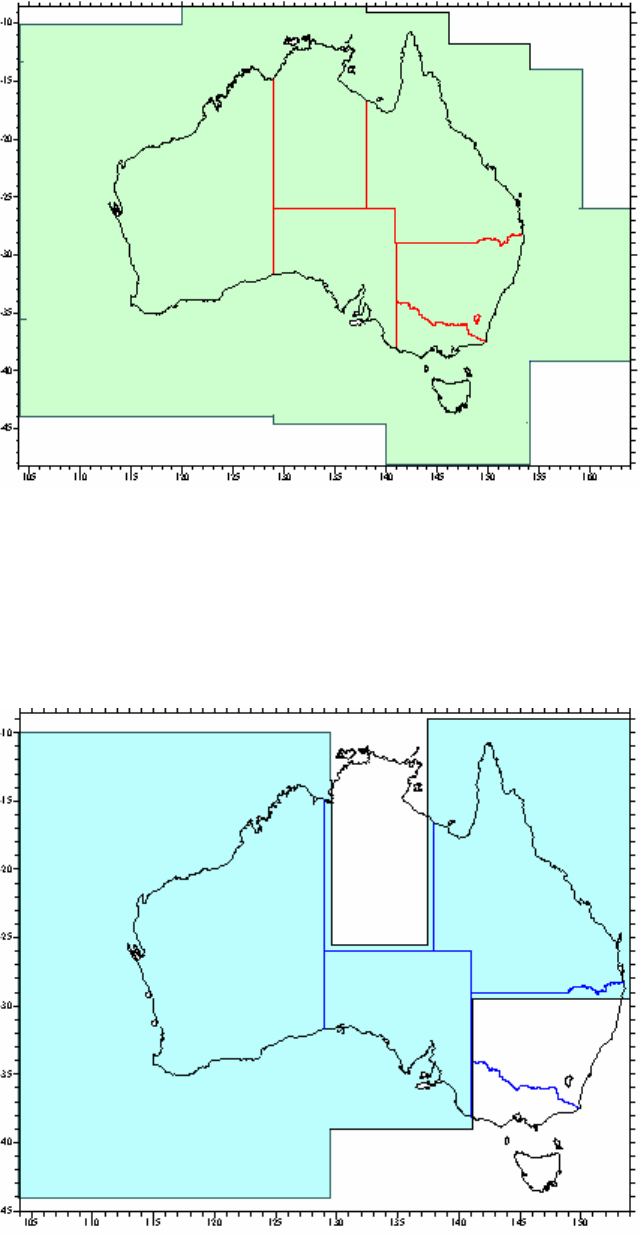
Intergovernmental Committee on Surveying and Mapping
Geocentric Datum of Australia 2020 Technical Manual 67
Version 1.2
in NTv2 format, a simple conformal transformation was used to generate the shifts in these
offshore areas.
Figure B-1 AGD66 to GDA94 Transformation Grid Coverage
Transformation file National 84(02.07.01).gsb has coverage for the states that previously
adopted AGD84 (Queensland, South Australia and Western Australia). This coverage was
produced by merging individual Queensland, South Australian and West Australian
transformation files, and differs slightly from the previous state files only near the merged
borders.
Figure B-2 AGD84 to GDA94 Transformation Grid Coverage

Intergovernmental Committee on Surveying and Mapping
Geocentric Datum of Australia 2020 Technical Manual 68
Version 1.2
For mathematical convenience and to suit the rectangular convention of the NTv2 format,
the national grids extend outside the Australian EEZ in some places, but these extents do
not infer any rights, nor do they imply the use of AGD or GDA94 coordinates in these areas.
B2. National 7 parameter similarity transformations
National similarity transformation parameters to convert between AGD66 / AGD84 and
GDA94 were developed (Table B-3 and B-4). Due to the inconsistent nature of the AGD66
coordinate set, it is not possible to perform a highly accurate 7-parameter similarity
transformation. The estimated uncertainty of the national AGD66 parameters is 3 metres
and they are only recommended for use in offshore environments. The estimated
uncertainty of 7-parameter similarity transformation for AGD84 to GDA94 parameters is
about 1 metre.
The parameters to transform between AGD84 and GDA94 were computed from 327 points
across Australia, which had both AGD84 and GDA94 coordinates.
Table B-3 National transformation parameters for AGD84 and AGD66 to GDA94. Units are in m for the
translation, parts-per-million (ppm) for scale, and arc-seconds (as) for the rotations.
Datum
EPSG
Code
AGD84
1280
-117.763
-51.510
139.061
-0.191
-0.292
-0.443
-0.277
AGD66
15979
-117.808
-51.536
137.784
-0.290
-0.303
-0.446
-0.234
Refer to Section 2.2.1 Rotation Matrix Sign Convention for important information about
the rotation signs.
Table B-4 EPSG details of national transformations for AGD84 and AGD66 to GDA94.
EPSG
Transformation
Code
EPSG transformation
name
Comments
1280
AGD84 to GDA94 (2)
AGD84 officially adopted only
in QLD, SA and WA
15979
AGD66 to GDA94 (12)
Recommended for use in
offshore areas only.
B3. Regional 7 parameter similarity transformations for
AGD66
Although it is possible to compute national similarity transformation parameters between
AGD84 and GDA94 that provide an estimated accuracy of transformation of 1 metre
AGD66/GDA94 similarity transformation parameters can only be accurately computed for
smaller areas where AGD66 is more consistent.
The parameters shown in Table B-4 are only valid for transformation between AGD66 and
GDA94 for the jurisdiction indicated.

Intergovernmental Committee on Surveying and Mapping
Geocentric Datum of Australia 2020 Technical Manual 69
Version 1.2
Table B-5 Regional transformation parameters for AGD66 to GDA94. Units are in m for the translation,
parts-per-million (ppm) for scale, and arc-seconds (as) for the rotations.
Region
EPSG
Code
ACT
5827
-129.164
-41.188
130.718
-2.955
-0.246
-0.374
-0.329
ACT
1458
-129.193
-41.212
130.730
-2.955
-0.246
-0.374
-0.329
TAS
1594
-120.271
-51.536
137.784
2.499
-0.217
0.067
0.129
VIC/NSW
1460
-119.353
-48.301
139.484
-0.613
-0.415
-0.260
-0.437
NT
1595
-124.133
-42.003
137.400
-1.854
0.008
-0.557
-0.178
Table B-6 EPSG details of regional transformations for AGD66 to GDA94
EPSG
Transformation
Code
EPSG transformation
name
Comments
5827
AGD66 to GDA94 (19)
Coverage – ACT
1458
AGD66 to GDA94 (10)
Coverage – ACT. Parameters
replaced in Code 5827
1594
AGD66 to GDA94 (8)
Coverage - Tas
1460
AGD66 to GDA94 (4)
Coverage – VIC/NSW
1595
AGD66 to GDA94 (9)
Coverage – NT
Intergovernmental Committee on Surveying and Mapping
Geocentric Datum of Australia 2020 Technical Manual 70
Version 1.2
Appendix C
C1. Grid bearings and ellipsoidal distance
The following formulae provide the only direct method to obtain grid bearings and
ellipsoidal distance from MGA2020 coordinates.
( C-1 )
where are the easting values measured positive eastwards from the central meridian
(i.e. does not include the false easting) of points 1 and 2 respectively
( C-1 )
( C-2 )
( C-3 )
(radians) ( C-4 )
(seconds) ( C-5 )
(radians) ( C-6 )
(seconds) ( C-7 )
( C-8 )
( C-9 )
The mean radius of curvature can be calculated as shown below, using an approximate
value for the mean latitude
. The approximate mean latitude can be calculated in two
steps, with an accuracy of about two minutes of arc, using the formulae shown below. This
approximation is derived from the formulae for meridian distance used with Krueger
series equations (Redfearn's) and the constants shown are the values and,
computed for GDA2020.
(C-10)
(C-11)
(C-12)
(C-13)
(C-14)
(C-15)
(C-16)
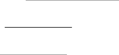
Intergovernmental Committee on Surveying and Mapping
Geocentric Datum of Australia 2020 Technical Manual 71
Version 1.2
C1.1 MGA2020 coordinates from grid bearing and ellipsoidal
distance
This computation is commonly used when the coordinates of one station are known and
the grid bearing and ellipsoidal distance from this station to an adjacent station have been
determined. The bearing and distance are applied to the coordinates of the known station
to derive the coordinates of the unknown station and the reverse grid bearing. The
formulae shown are accurate to 0.02" and 0.1 ppm over any 100 kilometre line in an MGA
zone. For lower order surveys:
• the underlined terms are often omitted
• the latitude function 1/6r2 becomes a constant and
• the formulae for
K
and
are replaced by simplified versions
Formulae
First calculate approximate coordinates for the unknown station:
(C-17)
(C-18)
(C-19)
If not already known the point scale factor may be approximated by:
(C-20)
(C-21)
(C-22)
(C-23)
(C-24)
(C-25)
(C-26)
(C-27)
(C-28)
(C-29)
(C-30)
The mean radius of curvature can be calculated as shown below, using an approximate
value for the mean latitude
. The approximate mean latitude can be calculated in two
steps, with an accuracy of about two minutes of arc, using the formulae shown below. This
approximation is derived from the formulae for meridian distance used with Krueger
series equations (Redfearn's) and the constants shown are the values and,
computed for GDA2020.
Intergovernmental Committee on Surveying and Mapping
Geocentric Datum of Australia 2020 Technical Manual 72
Version 1.2
(C-31)
(C-32)
(C-33)
(C-34)
(C-35)
(C-36)
(C-37)
C1.2 Traverse computations using arc-to-chord corrections and
scale factors
Traverses can be rigorously computed on the ellipsoid, using formulae such as those shown
in Section 5. The geographic results from these computations can then be rigorously
converted to grid coordinates using Krueger equations. However if necessary, the
computation can be varied to suit the requirements of the project. For example:
• the arc-to-chord corrections and line scale factors can be ignored and the
traverse computed using the formulae of plane trigonometry;
• if approximate MGA2020 coordinates of the traverse stations are available,
compute of the arc-to-chord corrections and line scale factors; or
• the arc-to-chord corrections and line scale factors can be computed precisely, and
the method becomes first order anywhere in a MGA2020 grid zone.
The precision obtained should be closely balanced against the labour involved, though with
modern computers and software, the difference between a rigorous and approximate
calculation is trivial. Prior to precise computation, approximate coordinates and bearings
may be carried through the traverse, using uncorrected field measurements, to ensure that
the observations are free of gross errors.
C1.2.1 Basic outline
There are many ways of arranging the computation. Essentially, the work is split into
stages:
1. approximate eastings and northings are computed from observed angles and
distances
2. arc-to-chord corrections and line scale factors are computed from the approximate
coordinates and applied to the observations to give plane angles and plane
distances
3. precise coordinates are computed by plane trigonometry
4. misclosure in grid bearing and position is analysed and the traverse is adjusted as
required.
Intergovernmental Committee on Surveying and Mapping
Geocentric Datum of Australia 2020 Technical Manual 73
Version 1.2
For precise computation, each line is rigorously computed before the next line is
calculated, so that errors in the approximate coordinates do not accumulate. True eastings
and differences in northing are the quantities carried through the computation. Sign
conventions can be disregarded and signs determined by inspection of a traverse diagram.
C1.2.2 Formulae and symbols
Formulae for arc-to-chord corrections and line scale factors are given above. If the
underlined terms are omitted, the errors for a 100 km line running north and south on a
zone boundary do not exceed 0.08” in bearing and 0.25 ppm in distance. As the final
coordinates of a precise traverse will nearly always be computed and adjusted by least
squares. For short lines near a central meridian it may be possible to omit the arc-to-chord
corrections and line scale factors and compute the traverse with observed angles and
distances, using the formulae of plane trigonometry.
If the symbol is used for the arc-to-chord correction at station 2 to station 1 and for
the correction at station 2 to station 3 and the angles are measured clockwise from station
1 to station 3, then the plane angle at station 2 is obtained from the observed angle
by (C-38)
where angles are measured clockwise only.
C1.2.3 Computations of arc-to-chord corrections and scale factors
Although there are several ways of arranging the computation, the following procedure, is
recommended:
1. compute the grid bearing to the "forward" station by applying the observed
horizontal angle at the "occupied" station to the known grid bearing of the "rear"
station
2. compute the point scale factor at the "occupied" station and multiply the
ellipsoidal distance to the "forward" station by this factor
3. using the distance obtained and the forward grid bearing, compute approximate
coordinates of the "forward" station by plane trigonometry
4. using the coordinates of the "occupied" station and the approximate coordinates of
the "forward" station, compute the arc-to-chord correction at the "occupied"
station and the line scale factor. If the line crosses the central meridian, is
negative
5. add the arc-to-chord correction to the forward grid bearing to obtain the plane
bearing and multiply the ellipsoidal distance by the line scale factor to obtain the
plane distance
6. using the plane bearing and plane distance, compute the coordinates of the
"forward" station by plane trigonometry
7. compute the arc-to-chord correction from the new station to the previously
occupied station and add this to the plane bearing reversed by 180° to obtain the
reverse grid bearing from the new station.
The above process is repeated for each new line of a traverse with the reverse grid bearing
of the previous line becoming the known grid bearing to the rear station.
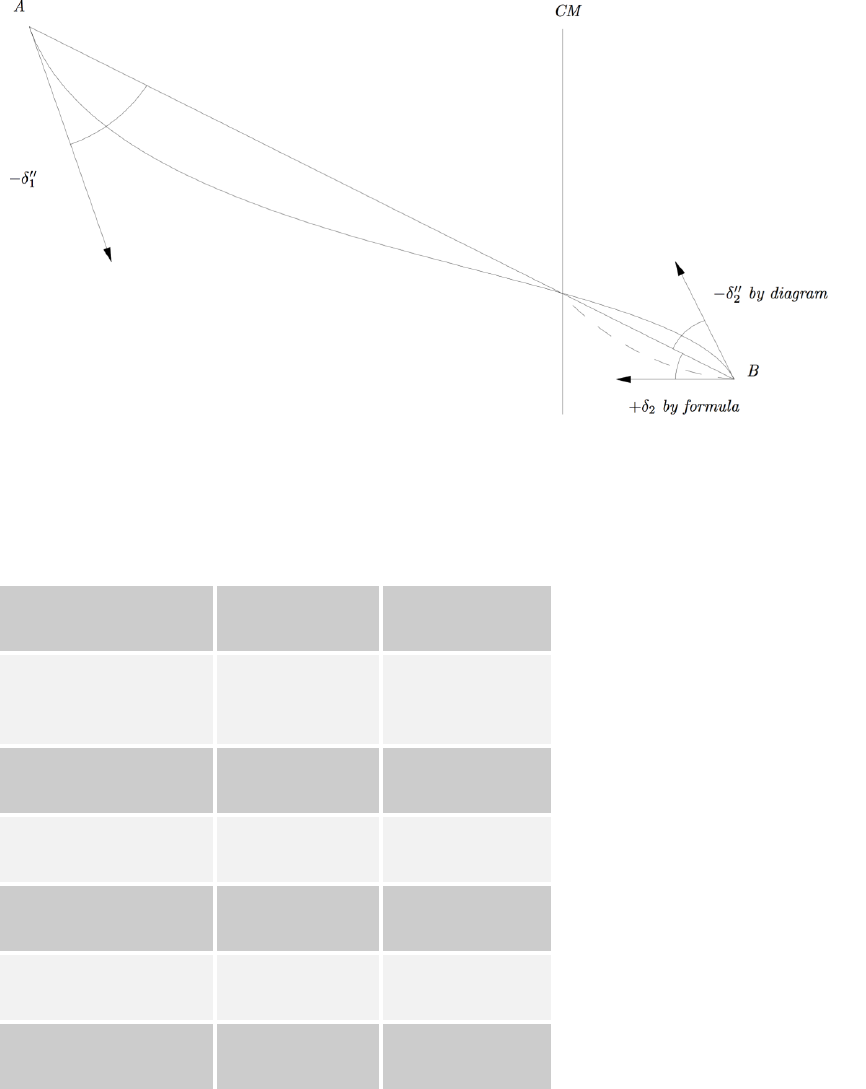
Intergovernmental Committee on Surveying and Mapping
Geocentric Datum of Australia 2020 Technical Manual 74
Version 1.2
The traverse diagram shown in Figure C.2 should be referred to with the above text.
Figure C.1 Arc-to-chord correction
Sample Data
Table C.1 Sample data to check grid calculations
Flinders Peak
Buninyong
MGA2020 (zone 55)
E 273 741.297
N 5 796 489.777
E 228 854.051
N 5 828 259.038
Ellipsoidal Distance (m)
54972.271
Plane Distance (m)
54992.279
Grid Bearing
305° 17’ 01.72"
125° 17’ 41.86"
Arc to chord
+19.47"
-20.67”
Line scale factor
1.000 363 97
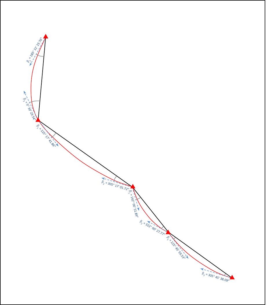
Intergovernmental Committee on Surveying and Mapping
Geocentric Datum of Australia 2020 Technical Manual 75
Version 1.2
Traverse Diagram
Figure C.2 Traverse diagram.
E 273 741.297 S 37 57’ 03.72030” -1 35’ 03.647”
N 5 796 489.777 E 144 25’ 29.52440” 1.000 230 558 6 k
FLINDERS
PEAK
E 228 854.051 S 37 39’ 10.15610” -1 52’ 43.219”
N 5 828 259.038 E 143 55’ 35.38390” 1.000 505 669 1 k
BUNINYONG
E 232 681.853 S 37 17’ 49.73133” -1 49’ 42.581”
N 5 867 898.032 E 143 59’ 03.16715” 1.000 480 346 2 k
SMEATON
E 290 769.028 S 38 09’ 05.22717” -1 28’ 32.238”
N 5 774 686.632 E 144 36’ 43.67715” 1.000 139 188 5 k
BELLARINE
E 320 936.377 S 38 21’ 13.12685” -1 16’ 19.020”
N 5 752 958.470 E 144 57’ 02.55485” 0.999 994 887 6 k
ARTHURS SEAT
1 = -27.05”
2 = +27.17”
1 = -20.67”
2 = +19.47”
1 = -12.22”
2 = +11.90”
1 = -11.00”
2 = +10.44”
s = 39 803.761 m
K = 1.000 492 99
L = 39 823.384 m
= 185 30’ 56.71”
01 = 187 21’ 06.34”
10 = 7 23’ 12.76”
s = 54 972.271 m
K = 1.000 363 97
L = 54 992.279 m
= 125 17’ 21.18”
12 = 127 10’ 25.07”
21 = 306 52’ 05.37”
s = 27 659.334 m
K = 1.000 184 28
L = 27 664.431 m
= 142 00’ 39.67”
23 = 143 35’ 55.53”
32 = 323 29’ 00.01”
s = 37 175.286 m
K = 1.000 065 17
L = 37 177.709 m
= 125 45’ 48.53”
34 = 127 14’ 31.76”
43 = 307 01’ 57.12”
All MGA2020 Eastings and Northings are in Zone 55
0
3
2
1
4
Intergovernmental Committee on Surveying and Mapping
Geocentric Datum of Australia 2020 Technical Manual 76
Version 1.2
Appendix D
D1. Grid references
The Universal Transverse Mercator (UTM) Grid, of which the Map Grid of Australia 2020
(MGA2020) is a part, provides the ability for the locations of features on the Earth to be
uniquely defined via a single grid reference. Grid references can be used with maps and
with online mapping systems, such as Google Maps.
Grid references are generalised forms of MGA2020 grid coordinates that consist of two
parts. The first part is an alphanumeric code that uniquely defines a rectangular region of
the Earth. The second part consists of the numerical location that defines the easting and
northing for the location within the region.
D1.1 Grid zones
A grid reference uses the UTM Grid Zones of 6 longitude bands together with the Military
Grid Reference System (MGRS) of 8 latitude bands (except for the most northerly band, X,
which covers 12 degrees of latitude from 72N to 84N). An extended MGRS can also be
used where the zones are further divided into 100 000 metre square regions identified by a
two letter code. This 100 000 metre square identification is presented in section D.1.2.
The Universal Polar Stereographic Grid is used north of the 84N latitude and south of the
80S latitude, but will not be discussed in this manual as it is outside the extents of
GDA2020 and thus beyond the limits of MGA2020.
The numbering of the longitude bands starts at the 180 meridian with zone 1 and
proceeds easterly with 6 intervals to define the 60 bands for the whole 360 around the
Earth.
The 8 bands of latitude are lettered from C to X (X is a 12 latitude band), omitting the
letters I and O, so as not to confuse them with the numbers one and zero. The southern
value of the first latitude band is 80S and with each band proceeding northwards to 84N.
There are 20 bands.
All the UTM longitude zones, MGRS latitude bands that lie within the extents of GDA2020
are depicted in figure D-1.
Each grid zone is thus one rectangle of the grid pattern established by these bands and is
designated by the figure of the longitude band followed by the letter of the latitude band.
Thus the zone hatched on figure D-1 lying between 132E and 138E and between 16S and
24S is designated 53K.
D1.2 100 000 metre square identification
To further subdivide the 6 x 8 grid zones, an extended MGRS has been defined where the
zones are divided into 100 000 metre square regions that are bounded by grid lines of
eastings and northings and identified by a two letter code.

Intergovernmental Committee on Surveying and Mapping
Geocentric Datum of Australia 2020 Technical Manual 77
Version 1.2
Each column and each row is identified by a letter which are combined to identify the
100 000 metre square. The letter pattern of 100 000 metre squares covers an area 18 east
to west by 2 000 000 metres north to south, and is not repeated within this area.
Starting at the 180 meridian and proceeding easterly along the equator for 18, the
100 000 metre columns, including partial columns along grid junctions, are consecutively
lettered A to Z, with I and O being omitted. This is repeated at 18 intervals.
The 100 000 metre rows are lettered A to V with I and O being omitted and reading from
south to north, with this partial alphabet being repeated every 2 000 000 metres. Every
odd-numbered UTM zone has the alphabet of the 100 000 metre row letters beginning at
the equator; the even-numbered UTM zones have the alphabet of the 100 000 metre row
letters beginning at the northing grid line 500 000 metres south of the equator. So for even
numbered easting zones the northing designators are offset by five characters, starting at
the equator with the letter F. This staggering lengthens the distance between 100 000
metre squares of the same identification.
For the extents of GDA2020, which lies wholly below the equator, the 100 000 metre row
letters also read from south to north, tying into the letters above in the same zone. These
principles are illustrated in figure D-2 for the south-eastern hemisphere of the Earth which
covers the extents of GDA2020.
D1.3 The grid reference
A grid reference will consist of a group of letters and numbers which indicate:
1. The Grid Zone Designation.
2. The 100 000 metre square identification.
3. The grid coordinates of the point expressed to the desired accuracy.
A reference will be written as a continuous number without spaces, parenthesis, dashes or
decimal points.
To assist in explaining how to define a grid reference, the GDA2020/MGA2020 location of
the Australian Fiducial Network site at Alice Springs (ALIC) is used as the example:
Latitude (DMS)
Longitude (DMS)
-23 40’ 12.39650”
133 53’ 07.87779”
Zone
Easting
Northing
53
386 353.2343
7,381,852.2986
This point would define the following grid references with increasing levels of accuracy:
1. 53KLP locating a point within a 100 000 metre square
2. 53KLP88 locating a point within a 10 000 metre square
3. 53KLP8681 locating a point within 1 000 metres
4. 53KLP863818 locating a point within 100 metres
5. 53KLP86358185 locating a point within 10 metres
6. 53KLP8635381852 locating a point within 1 metre
The Google Map reference for Alice Springs (ALIC) is 53KLP8635381852. Lower accuracy
grid references are not recognised by the web service, other than by adding zeros.
