GE 15251 15252 15253 Instructions
User Manual: GE-15251-15252-15253-Instructions
Open the PDF directly: View PDF ![]() .
.
Page Count: 2
SPECIFICATIONS
Input Voltage: 120 VAC, 208/240 VAC, or 277 VAC in all units based upon
dipswitch configuration.
15252 NEMA 3R Indoor & Outdoor BM-A301US5-O2
15253, 15251 NEMA 1 Indoor BM-A301US5-I2
15250 NEMA 3R Indoor & Outdoor EM-A301US9-O2
Switch Rating: DPDT Models
Normally Open Contacts
40A Resistive, 120-277Vac.
30A General Purpose, 120-277Vac.
20A Resistive, 30Vdc
1 HP, 120Vac ; 2HP, 240Vac
20A Ballast, 120-277Vac.
15A Tungsten, 120Vac
800VA, Pilot Duty, 120Vac.
720VA, Pilot Duty, 240Vac.
TV-5, 120Vac
Normally Closed Contacts
30A Resistive, 120-277Vac
15A General Purpose, 120-277Vac
15A Resistive, 30Vdc
20A Ballast, 120-277Vac
1/4HP, 120Vac; 1/2HP, 208-240Vac.
290VA, Pilot, 120Vac.
360VA, Pilot, 208-240Vac.
NOTE: If loads are connected to both NC and NO contacts, both contacts are
derated to 67% of the above values.
ENVIRONMENTAL RATINGS
Ambient Temperature: –40F to 130F
Humidity: 0-95% RH, Non-condensing
WIRING CONNECTIONS
Screw clamp terminals for up to 2 AWG #8 wires
per position. For supply connections, use 8AWG or larger wires suitable for at
least 105° C. Use copper conductors only.
LIGHTS
Power LED (Orange) – Light illuminates when power is applied to
the timer
Status LED (Green) – Light illuminates when power is applied to load.
INSTALLATION
CAUTION: Before wiring or service, power to this time switch and the
equipment it controls must be turned off. Turning off the timer switch only
will not prevent a shock hazard. Replace cover plate within housing before
supplying power to time switch. Installation should be performed by a licensed
electrician only. Before installing this product read all instructions carefully.
Remove protective cover panel within time switch housing by removing
screws located above timer face and at the bottom of the cover panel.
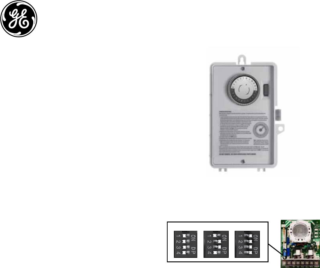
DIPSWITCH CONFIGURATION
WARNING: Failure to properly configure the dipswitch will result in
damage to the unit and void the warranty! Before installing and wiring the GE
Time Switch, proper configuration must be selected. This is accomplished as
follows:
INPUT VOLTAGE DIP SWITCH SETTING:
1. Do not apply power to the timer prior to setting correct Input Voltage DIP
switch.
2. Determine the input voltage which will be applied to the timer (i.e. L1 and
L2/N terminals, see wiring diagrams)
3. Set the DIP switch according to the diagram below.
NOTE: Unit is shipped with DIP switches set for 277VAC Input Voltage
CAUTION: Do not check circuits by “sparking” wires to terminals. Damage to
the timer may result.
NOTE: For outdoor locations (model GE 15252), rain tight or wet location
conduit hubs that comply with requirements of UL 514B (standard for fittings
for conduit and outlet boxes) must be used.
1. Remove 2 screws retaining the interior cover panel and remove panel
by prying out with a thin blade at the top.. Select knockouts to be used.
Remove the inner 1/2” knockout by inserting a screwdriver in the slot
and carefully punch knockout loose. Remove slug. If the 3/4” knockout
is required, remove the outer ring with pliers after removing the 1/2”
knockout. Smooth edges with knife if necessary.
2. Place enclosure in desired mounting location and mark the three
mounting holes.
3. Drill holes for #10 screws, start screws in holes.
4. Place enclosure over screws and tighten screws.
5. Connect conduit hubs to conduit before connecting the hubs to the
enclosure. After inserting hubs into enclosure, carefully tighten hub lock
nut. Do not over-tighten.
Dipswitch Setting continued:
6. Install in accordance with all applicable National and Local code
requirements. See Figure 1 and wiring diagrams.
7. Replace interior cover panel and 2 screws.
Time Switch
15251/15253
Indoor
NEMA 1-Rated Enclosure
15252
Indoor/Outdoor
NEMA 3R-Rated Enclosure
120VAC
277VAC (Default)
208~240VAC
NOTE: Unit is shipped with DIP Switches set for 277VAC Input Voltage.
CAUTION: Do not check circuits by “sparking” wires to terminals. Damage to
the timer may result.
INPUT VOLTAGE DIP SWITCH SETTING:
1. Do not apply power to the timer prior to setting correct Input Voltage DIP switch.
2. Determine the input voltage which will be applied to the timer (i.e. L1 and L2/N terminals,
see wiring diagrams).
3. Set the DIP Switch according to the diagram below.
http://waterheatertimer.org/GE-timers-and-manuals.html
http://waterheatertimer.org/How-to-wire-GE-15207-timer.html
GROUNDING:
This enclosure is of plastic construction and does not require a ground
connection and does not require bonding in pool applications.
This enclosure does not provide grounding between conduits. When using
non-metallic conduit or cable, connect the ground wires of all cables together
with a wire nut. When metallic conduit is used, use grounding type bushings
and a jumper wire between each conduit.
OPERATING INSTRUCTIONS:
When the Time Switch is installed and power applied, the timer’s dial will turn
clockwise maintaining time. The pointer on the face of the dial points to the
current time
1. Locate the segments around on the outer edge of the timer’s dial. These
segments, each representing 30 minutes, can be pushed down and away
from the edge of the dial (try using the tip of a pen or pencil). Conversely,
segments that have been pushed down can be easily pushed back up by
hand. Be sure all segments are pushed up before programming. Select a
time period (or periods) you want the device turned on, then push down
ALL the segments that fall on or within that time period. For example,
to have the timer turn a device on at 10PM and off at 2AM, push down
the segments representing 10PM and 2AM, and ALL the segments in
between. You may need to turn the dial clockwise to access the desired
segments.
2. Rotate the timer’s dial clockwise until the pointer on the face of the dial
points to the current time of day. Note: Nighttime hours (from 6:30 PM to
6:30 AM) are highlighted with a grey background.
3. Set master switch to the TIMER position.
4. To override timer program and control output load manually:
• set master switch to OFF (center position) to turn load OFF
• set master switch to ON (bottom position) to turn load ON
5. This is a Timer Control and should not be used for power disconnect.
Turn power off at main panel before servicing this switch or the
equipment it controls.
In case of power failure, reset the time of day as explained in step 2.
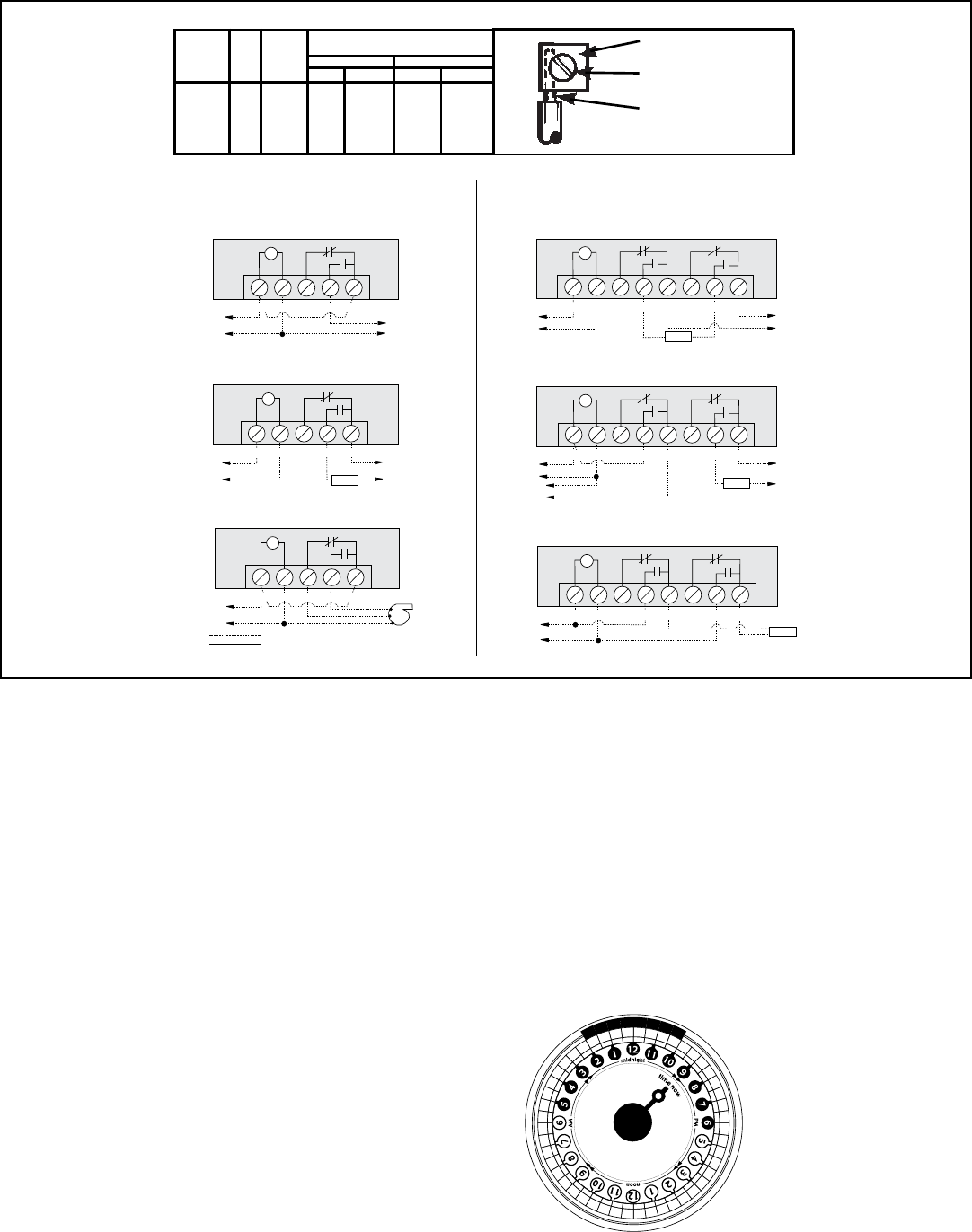
TIMERN CN O
COM
NC2
NO2
COM2
LOAD
L1
L2
TIMERN CN O
COM
TO 200/240/277V LINE
TO 120V LINE
NC2
NO2
COM2
H
N
LOAD
TIMERN CN O
COM
TO 24V LINE
NC2
NO2
COM2
H
N
LOAD
N
H
TO 120V LINE
TO LOAD
T
T
T
120V Timer, 120V Load and 24V Load
Wired as Single Throw
200/240/277V Timer, 200/240/277V Load, Double Break
Wired as Single Throw
120V Timer, 200/240/277V Load Double Break
Wired as Single Throw
Typical Wiring Diagrams—DPDT
TO POWER SUPPLY
TO POWER SUPPLY 1 TO POWER SUPPLY 2
Timer and Load, Same Voltage
Wired as Single Throw
TO LOAD
TO 120V LINE
H
N
HIGH
LOW
COM
T
LOAD
T
NCTIMERN OC OM
TIMERN CN OC OM
T
TIMERN CN OC OM
120V Two Speed Fan
Wired as Double Throw
Timer and Load, Different Voltage
Wired as Single Throw
Typical Wiring Diagrams—SPDT
Field Wiring
Timer Internab Wiring
FIGURE 1
PRESSURE PLATE
TERMINAL SCREW
MAKE SURE WIRE
INSULATION CLEARS
PRESSURE PLATE
MINIMUM
COPPER
WIRE SIZE
(AWG)
MAX.
LOAD
(AMP)
MIN.
INSUL-
ATION
TEMP(°C)
75°C INSULATION MAX. MOTOR
LOAD (HP)
SINGLE PHASE 3 PHASE
120 V. 240 V. 208 V. 240 V.
14
12
10
8
15
20
30
40
60
60
60
105
1/2
1
2
-
2
2 1/2
3
5
N/A
N/A
TIMER DIAL
Shows timer set to turn device
ON at 10PM and OFF at 2AM.
Notice ALL segments between
10PM and 2AM have been
pushed out. Current time is
9:00 PM.
