Sensor_Applications GE Intrusion Sensor Application Notebook
GE Intrusion Sensor Application Notebook GE Intrusion Sensor Application Notebook
User Manual: GE Intrusion Sensor Application Notebook AlarmHow.net Library
Open the PDF directly: View PDF ![]() .
.
Page Count: 192 [warning: Documents this large are best viewed by clicking the View PDF Link!]
- Preface
- Chapter 1 Glassbreak/shock sensors
- Product overview
- Prewire installation
- Inconspicuous installations
- Bathroom windows
- Skylights
- Windows with curtains and blinds
- Single window with wireless sensor
- Multiple windows with wireless sensors
- French doors and small windows
- Glass doors and windows that open
- Insulated glass
- Windows with film
- Thick glass
- Large rooms
- Small rooms
- Occupied areas
- Rooms with cleaning crews
- Storefront windows
- Roll-up metal shutters
- Glass display and jewelry cases
- Metal enclosures
- Filing cabinets
- Jewelry store safes
- ATM and night deposit boxes
- Chapter 2 Motion sensors
- Product overview
- Pets
- Wireless sensors
- Discreet appearance
- Flush mount
- Ceiling mount
- Antimasking
- Museums
- Office foyers
- Storefront windows
- Hallways and lobby lighting activation
- Partitions or other obstacles
- Request-to-exit door control
- Request-to-exit roll-up door control
- Room perimeters
- Multilevel homes
- Valuable equipment
- Vacation homes and garages
- Indoor swimming pools
- Large areas
- Long corridors or aisles
- Schools
- Outdoor areas
- Loading docks
- Drive-through pickup areas
- Vegetable gardens
- Outdoor swimming pools
- CCTV camera activation
- Outdoor lighting activation
- Extreme temperature conditions
- Explosive atmospheres
- Chapter 3 Magnetic contacts
- Product overview
- Nice-Duc surface wire concealment
- Sliding aluminum doors
- Automatic garage doors with switch shunting
- Wood doors with threshold contacts
- Steel doors with threshold contacts
- Recessed steel doors
- Deeply recessed doors
- Application
- Installation using a magnet with spacers
- Recommended products
- Figure 83. Deeply recessed door with magnet and spacers
- Figure 84. Deeply recessed door with switch mounted on jamb
- Figure 85. Deep recessed door installation with 1910 bracket
- Figure 86. Deep recessed door with L-bracket
- Figure 87. Deep recessed doors with a Z and L bracket
- Overhead or curtain doors
- Application
- Installation using a 2515A contact mounted on the channel.
- Recommended products
- Figure 88. Overhead door with 2515A mounted on the channel
- Figure 89. Overhead door with 1042TW contact
- Figure 90. Overhead door with 2302 or 2304 contact
- Figure 91. Overhead door with 2105 Magnapull contact
- Figure 92. Overhead door with 1092A kit
- Figure 93. Overhead door with lip mount installation
- Figure 94. Overhead door with smooth surface-mount installation
- Figure 95. Overhead door with rib-mount installation
- Figure 96. Overhead door with top-mount installation
- Panel or sectional overhead doors
- High security doors
- Explosion-proof, high-security switches
- Revolving doors
- Freezer doors
- Roller-plunger contacts
- Doors with uneven wiring holes
- Increase gap distances with a second magnet
- Mechanical recessed switch replacement
- Window ventilation without false alarms
- Window ventilation using two magnets
- Sliding aluminum windows
- Windows with thin frames
- Windows with thin steel frames
- Double-hung windows
- Pella casement or awning windows
- Anderson casement windows
- Hinged skylights
- Attic entry drop-down stairs
- Barrier Bars
- Roof hatches
- Metal enclosures
- Cash register drawers with Bill Trap
- Drawers
- China cabinets
- Guns and gun cabinets
- Art objects
- Hung art objects
- Computers, TVs, and stereos
- Recreational equipment
- Boat decks and cabins
- Boat moorings
- Trucks and trailers at loading docks
- Truck tailgates
- Chain-link rolling gates
- Fence gates
- Silent panic switches
- Chapter 4 Technical support
- Glossary
- Index

Intrusion Sensor
Application Notebook
Sensor_Applications.book Page i Tuesday, December 27, 2005 5:45 AM
Copyright Copyright © 2005, GE Security Inc. All rights reserved.
This document may not be copied or otherwise reproduced, in whole or in part, except as specifically
permitted under US and international copyright law, without the prior written consent from GE.
Document number/ revision: 1055178A (December 2005).
Disclaimer THE INFORMATION IN THIS DOCUMENT IS SUBJECT TO CHANGE WITHOUT NOTICE. GE ASSUMES NO
RESPONSIBILITY FOR INACCURACIES OR OMISSIONS AND SPECIFICALLY DISCLAIMS ANY LIABILITIES,
LOSSES, OR RISKS, PERSONAL OR OTHERWISE, INCURRED AS A CONSEQUENCE, DIRECTLY OR INDIRECTLY,
OF THE USE OR APPLICATION OF ANY OF THE CONTENTS OF THIS DOCUMENT. FOR THE LATEST DOCU-
MENTATION, CONTACT YOUR LOCAL SUPPLIER OR VISIT US ONLINE AT WWW.GESECURITY.COM.
This publication may contain examples of screen captures and reports used in daily operations. Exam-
ples may include fictitious names of individuals and companies. Any similarity to names and addresses
of actual businesses or persons is entirely coincidental.
Trademarks and patents GE and the GE monogram are registered trademarks of General Electric.
Other trade names used in this document may be trademarks or registered trademarks of the manufac-
turers or vendors of the respective products.
Intended use Use this product only for the purpose it was designed for; refer to the individual sensor installation
instructions for the latest product information or visit us online at
www.gesecurity.com.
Sensor_Applications.book Page ii Tuesday, December 27, 2005 5:45 AM

iii
Contents
Preface . . . . . . . . . . . . . . . . . . . . . . . . . . . . . . . . . . . . . . . . . . . . . . . . . . . . . . . . . . . . . . . . . . . . . . 1
Chapter 1. Glassbreak/shock sensors . . . . . . . . . . . . . . . . . . . . . . . . . . . . . . . . . 3
Product overview. . . . . . . . . . . . . . . . . . . . . . . . . . . . . . . . . . . . . . . . . . . . . . . . . . . . . . . . . . . . . 4
Prewire installation . . . . . . . . . . . . . . . . . . . . . . . . . . . . . . . . . . . . . . . . . . . . . . . . . . . . . . . . . .10
Inconspicuous installations. . . . . . . . . . . . . . . . . . . . . . . . . . . . . . . . . . . . . . . . . . . . . . . . . . .11
Bathroom windows . . . . . . . . . . . . . . . . . . . . . . . . . . . . . . . . . . . . . . . . . . . . . . . . . . . . . . . . . .13
Skylights . . . . . . . . . . . . . . . . . . . . . . . . . . . . . . . . . . . . . . . . . . . . . . . . . . . . . . . . . . . . . . . . . . .14
Windows with curtains and blinds. . . . . . . . . . . . . . . . . . . . . . . . . . . . . . . . . . . . . . . . . . . . . 15
Single window with wireless sensor . . . . . . . . . . . . . . . . . . . . . . . . . . . . . . . . . . . . . . . . . . .17
Multiple windows with wireless sensors . . . . . . . . . . . . . . . . . . . . . . . . . . . . . . . . . . . . . . .18
French doors and small windows. . . . . . . . . . . . . . . . . . . . . . . . . . . . . . . . . . . . . . . . . . . . . .19
Glass doors and windows that open . . . . . . . . . . . . . . . . . . . . . . . . . . . . . . . . . . . . . . . . . . .20
Insulated glass . . . . . . . . . . . . . . . . . . . . . . . . . . . . . . . . . . . . . . . . . . . . . . . . . . . . . . . . . . . . . .21
Windows with film. . . . . . . . . . . . . . . . . . . . . . . . . . . . . . . . . . . . . . . . . . . . . . . . . . . . . . . . . . .22
Thick glass. . . . . . . . . . . . . . . . . . . . . . . . . . . . . . . . . . . . . . . . . . . . . . . . . . . . . . . . . . . . . . . . . .23
Large rooms . . . . . . . . . . . . . . . . . . . . . . . . . . . . . . . . . . . . . . . . . . . . . . . . . . . . . . . . . . . . . . . .24
Small rooms . . . . . . . . . . . . . . . . . . . . . . . . . . . . . . . . . . . . . . . . . . . . . . . . . . . . . . . . . . . . . . . .25
Occupied areas . . . . . . . . . . . . . . . . . . . . . . . . . . . . . . . . . . . . . . . . . . . . . . . . . . . . . . . . . . . . .26
Rooms with cleaning crews. . . . . . . . . . . . . . . . . . . . . . . . . . . . . . . . . . . . . . . . . . . . . . . . . . .27
Storefront windows. . . . . . . . . . . . . . . . . . . . . . . . . . . . . . . . . . . . . . . . . . . . . . . . . . . . . . . . . .28
Roll-up metal shutters . . . . . . . . . . . . . . . . . . . . . . . . . . . . . . . . . . . . . . . . . . . . . . . . . . . . . . .29
Glass display and jewelry cases. . . . . . . . . . . . . . . . . . . . . . . . . . . . . . . . . . . . . . . . . . . . . . .30
Metal enclosures . . . . . . . . . . . . . . . . . . . . . . . . . . . . . . . . . . . . . . . . . . . . . . . . . . . . . . . . . . . .31
Filing cabinets . . . . . . . . . . . . . . . . . . . . . . . . . . . . . . . . . . . . . . . . . . . . . . . . . . . . . . . . . . . . . .32
Jewelry store safes . . . . . . . . . . . . . . . . . . . . . . . . . . . . . . . . . . . . . . . . . . . . . . . . . . . . . . . . . .33
ATM and night deposit boxes . . . . . . . . . . . . . . . . . . . . . . . . . . . . . . . . . . . . . . . . . . . . . . . . .34
Sensor_Applications.book Page iii Tuesday, December 27, 2005 5:45 AM

Intrusion Sensor
Application Notebook
iv
Chapter 2. Motion sensors . . . . . . . . . . . . . . . . . . . . . . . . . . . . . . . . . . . . . . . . . . 35
Product overview . . . . . . . . . . . . . . . . . . . . . . . . . . . . . . . . . . . . . . . . . . . . . . . . . . . . . . . . . . . 36
Pets. . . . . . . . . . . . . . . . . . . . . . . . . . . . . . . . . . . . . . . . . . . . . . . . . . . . . . . . . . . . . . . . . . . . . . . . 47
Wireless sensors . . . . . . . . . . . . . . . . . . . . . . . . . . . . . . . . . . . . . . . . . . . . . . . . . . . . . . . . . . . . 50
Discreet appearance . . . . . . . . . . . . . . . . . . . . . . . . . . . . . . . . . . . . . . . . . . . . . . . . . . . . . . . . 51
Flush mount . . . . . . . . . . . . . . . . . . . . . . . . . . . . . . . . . . . . . . . . . . . . . . . . . . . . . . . . . . . . . . . . 52
Ceiling mount. . . . . . . . . . . . . . . . . . . . . . . . . . . . . . . . . . . . . . . . . . . . . . . . . . . . . . . . . . . . . . . 53
Antimasking . . . . . . . . . . . . . . . . . . . . . . . . . . . . . . . . . . . . . . . . . . . . . . . . . . . . . . . . . . . . . . . . 54
Museums . . . . . . . . . . . . . . . . . . . . . . . . . . . . . . . . . . . . . . . . . . . . . . . . . . . . . . . . . . . . . . . . . . . 55
Office foyers . . . . . . . . . . . . . . . . . . . . . . . . . . . . . . . . . . . . . . . . . . . . . . . . . . . . . . . . . . . . . . . . 56
Storefront windows . . . . . . . . . . . . . . . . . . . . . . . . . . . . . . . . . . . . . . . . . . . . . . . . . . . . . . . . . 57
Hallways and lobby lighting activation . . . . . . . . . . . . . . . . . . . . . . . . . . . . . . . . . . . . . . . . 58
Partitions or other obstacles . . . . . . . . . . . . . . . . . . . . . . . . . . . . . . . . . . . . . . . . . . . . . . . . . 59
Request-to-exit door control . . . . . . . . . . . . . . . . . . . . . . . . . . . . . . . . . . . . . . . . . . . . . . . . . 60
Request-to-exit roll-up door control. . . . . . . . . . . . . . . . . . . . . . . . . . . . . . . . . . . . . . . . . . . 62
Room perimeters. . . . . . . . . . . . . . . . . . . . . . . . . . . . . . . . . . . . . . . . . . . . . . . . . . . . . . . . . . . . 63
Multilevel homes . . . . . . . . . . . . . . . . . . . . . . . . . . . . . . . . . . . . . . . . . . . . . . . . . . . . . . . . . . . . 64
Valuable equipment . . . . . . . . . . . . . . . . . . . . . . . . . . . . . . . . . . . . . . . . . . . . . . . . . . . . . . . . . 65
Vacation homes and garages. . . . . . . . . . . . . . . . . . . . . . . . . . . . . . . . . . . . . . . . . . . . . . . . . 66
Indoor swimming pools . . . . . . . . . . . . . . . . . . . . . . . . . . . . . . . . . . . . . . . . . . . . . . . . . . . . . .67
Large areas. . . . . . . . . . . . . . . . . . . . . . . . . . . . . . . . . . . . . . . . . . . . . . . . . . . . . . . . . . . . . . . . . 68
Long corridors or aisles . . . . . . . . . . . . . . . . . . . . . . . . . . . . . . . . . . . . . . . . . . . . . . . . . . . . . . 69
Schools. . . . . . . . . . . . . . . . . . . . . . . . . . . . . . . . . . . . . . . . . . . . . . . . . . . . . . . . . . . . . . . . . . . . . 70
Outdoor areas . . . . . . . . . . . . . . . . . . . . . . . . . . . . . . . . . . . . . . . . . . . . . . . . . . . . . . . . . . . . . . 71
Loading docks . . . . . . . . . . . . . . . . . . . . . . . . . . . . . . . . . . . . . . . . . . . . . . . . . . . . . . . . . . . . . . 72
Drive-through pickup areas . . . . . . . . . . . . . . . . . . . . . . . . . . . . . . . . . . . . . . . . . . . . . . . . . . 73
Vegetable gardens . . . . . . . . . . . . . . . . . . . . . . . . . . . . . . . . . . . . . . . . . . . . . . . . . . . . . . . . . . 74
Outdoor swimming pools . . . . . . . . . . . . . . . . . . . . . . . . . . . . . . . . . . . . . . . . . . . . . . . . . . . . 75
CCTV camera activation . . . . . . . . . . . . . . . . . . . . . . . . . . . . . . . . . . . . . . . . . . . . . . . . . . . . .76
Outdoor lighting activation . . . . . . . . . . . . . . . . . . . . . . . . . . . . . . . . . . . . . . . . . . . . . . . . . . 77
Extreme temperature conditions. . . . . . . . . . . . . . . . . . . . . . . . . . . . . . . . . . . . . . . . . . . . . . 78
Explosive atmospheres . . . . . . . . . . . . . . . . . . . . . . . . . . . . . . . . . . . . . . . . . . . . . . . . . . . . . .79
Sensor_Applications.book Page iv Tuesday, December 27, 2005 5:45 AM

v
Chapter 3. Magnetic contacts . . . . . . . . . . . . . . . . . . . . . . . . . . . . . . . . . . . . . . .81
Product overview. . . . . . . . . . . . . . . . . . . . . . . . . . . . . . . . . . . . . . . . . . . . . . . . . . . . . . . . . . . .82
Nice-Duc surface wire concealment . . . . . . . . . . . . . . . . . . . . . . . . . . . . . . . . . . . . . . . . . . .91
Sliding aluminum doors . . . . . . . . . . . . . . . . . . . . . . . . . . . . . . . . . . . . . . . . . . . . . . . . . . . . . .92
Automatic garage doors with switch shunting. . . . . . . . . . . . . . . . . . . . . . . . . . . . . . . . . .94
Wood doors with threshold contacts . . . . . . . . . . . . . . . . . . . . . . . . . . . . . . . . . . . . . . . . . .96
Steel doors with threshold contacts . . . . . . . . . . . . . . . . . . . . . . . . . . . . . . . . . . . . . . . . . . .97
Recessed steel doors. . . . . . . . . . . . . . . . . . . . . . . . . . . . . . . . . . . . . . . . . . . . . . . . . . . . . . . . .98
Deeply recessed doors . . . . . . . . . . . . . . . . . . . . . . . . . . . . . . . . . . . . . . . . . . . . . . . . . . . . . .103
Overhead or curtain doors . . . . . . . . . . . . . . . . . . . . . . . . . . . . . . . . . . . . . . . . . . . . . . . . . .106
Panel or sectional overhead doors . . . . . . . . . . . . . . . . . . . . . . . . . . . . . . . . . . . . . . . . . . .114
High security doors. . . . . . . . . . . . . . . . . . . . . . . . . . . . . . . . . . . . . . . . . . . . . . . . . . . . . . . . .115
Explosion-proof, high-security switches . . . . . . . . . . . . . . . . . . . . . . . . . . . . . . . . . . . . . .118
Revolving doors . . . . . . . . . . . . . . . . . . . . . . . . . . . . . . . . . . . . . . . . . . . . . . . . . . . . . . . . . . . .120
Freezer doors . . . . . . . . . . . . . . . . . . . . . . . . . . . . . . . . . . . . . . . . . . . . . . . . . . . . . . . . . . . . . .123
Roller-plunger contacts . . . . . . . . . . . . . . . . . . . . . . . . . . . . . . . . . . . . . . . . . . . . . . . . . . . . .124
Doors with uneven wiring holes. . . . . . . . . . . . . . . . . . . . . . . . . . . . . . . . . . . . . . . . . . . . . .125
Increase gap distances with a second magnet. . . . . . . . . . . . . . . . . . . . . . . . . . . . . . . . .126
Mechanical recessed switch replacement . . . . . . . . . . . . . . . . . . . . . . . . . . . . . . . . . . . . .127
Window ventilation without false alarms . . . . . . . . . . . . . . . . . . . . . . . . . . . . . . . . . . . . .128
Window ventilation using two magnets. . . . . . . . . . . . . . . . . . . . . . . . . . . . . . . . . . . . . . .129
Sliding aluminum windows . . . . . . . . . . . . . . . . . . . . . . . . . . . . . . . . . . . . . . . . . . . . . . . . . .131
Windows with thin frames. . . . . . . . . . . . . . . . . . . . . . . . . . . . . . . . . . . . . . . . . . . . . . . . . . .135
Windows with thin steel frames. . . . . . . . . . . . . . . . . . . . . . . . . . . . . . . . . . . . . . . . . . . . . .136
Double-hung windows . . . . . . . . . . . . . . . . . . . . . . . . . . . . . . . . . . . . . . . . . . . . . . . . . . . . . .137
Pella casement or awning windows . . . . . . . . . . . . . . . . . . . . . . . . . . . . . . . . . . . . . . . . . .140
Anderson casement windows. . . . . . . . . . . . . . . . . . . . . . . . . . . . . . . . . . . . . . . . . . . . . . . .143
Hinged skylights . . . . . . . . . . . . . . . . . . . . . . . . . . . . . . . . . . . . . . . . . . . . . . . . . . . . . . . . . . .145
Attic entry drop-down stairs. . . . . . . . . . . . . . . . . . . . . . . . . . . . . . . . . . . . . . . . . . . . . . . . .146
Barrier Bars. . . . . . . . . . . . . . . . . . . . . . . . . . . . . . . . . . . . . . . . . . . . . . . . . . . . . . . . . . . . . . . .147
Roof hatches . . . . . . . . . . . . . . . . . . . . . . . . . . . . . . . . . . . . . . . . . . . . . . . . . . . . . . . . . . . . . . .148
Metal enclosures . . . . . . . . . . . . . . . . . . . . . . . . . . . . . . . . . . . . . . . . . . . . . . . . . . . . . . . . . . .149
Cash register drawers with Bill Trap . . . . . . . . . . . . . . . . . . . . . . . . . . . . . . . . . . . . . . . . . .150
Drawers . . . . . . . . . . . . . . . . . . . . . . . . . . . . . . . . . . . . . . . . . . . . . . . . . . . . . . . . . . . . . . . . . . .151
China cabinets . . . . . . . . . . . . . . . . . . . . . . . . . . . . . . . . . . . . . . . . . . . . . . . . . . . . . . . . . . . . .153
Sensor_Applications.book Page v Tuesday, December 27, 2005 5:45 AM

Intrusion Sensor
Application Notebook
vi
Guns and gun cabinets . . . . . . . . . . . . . . . . . . . . . . . . . . . . . . . . . . . . . . . . . . . . . . . . . . . . . 155
Art objects. . . . . . . . . . . . . . . . . . . . . . . . . . . . . . . . . . . . . . . . . . . . . . . . . . . . . . . . . . . . . . . . . 157
Hung art objects . . . . . . . . . . . . . . . . . . . . . . . . . . . . . . . . . . . . . . . . . . . . . . . . . . . . . . . . . . . 158
Computers, TVs, and stereos . . . . . . . . . . . . . . . . . . . . . . . . . . . . . . . . . . . . . . . . . . . . . . . . 159
Recreational equipment . . . . . . . . . . . . . . . . . . . . . . . . . . . . . . . . . . . . . . . . . . . . . . . . . . . . 160
Boat decks and cabins . . . . . . . . . . . . . . . . . . . . . . . . . . . . . . . . . . . . . . . . . . . . . . . . . . . . . .161
Boat moorings . . . . . . . . . . . . . . . . . . . . . . . . . . . . . . . . . . . . . . . . . . . . . . . . . . . . . . . . . . . . . 162
Trucks and trailers at loading docks. . . . . . . . . . . . . . . . . . . . . . . . . . . . . . . . . . . . . . . . . . 163
Truck tailgates . . . . . . . . . . . . . . . . . . . . . . . . . . . . . . . . . . . . . . . . . . . . . . . . . . . . . . . . . . . . . 164
Chain-link rolling gates . . . . . . . . . . . . . . . . . . . . . . . . . . . . . . . . . . . . . . . . . . . . . . . . . . . . . 165
Fence gates. . . . . . . . . . . . . . . . . . . . . . . . . . . . . . . . . . . . . . . . . . . . . . . . . . . . . . . . . . . . . . . . 166
Silent panic switches . . . . . . . . . . . . . . . . . . . . . . . . . . . . . . . . . . . . . . . . . . . . . . . . . . . . . . . 167
Chapter 4. Technical support. . . . . . . . . . . . . . . . . . . . . . . . . . . . . . . . . . . . . . .169
Contacting technical support. . . . . . . . . . . . . . . . . . . . . . . . . . . . . . . . . . . . . . . . . . . . . . . . 170
Glossary. . . . . . . . . . . . . . . . . . . . . . . . . . . . . . . . . . . . . . . . . . . . . . . . . . . . . . . . . . . .171
Index . . . . . . . . . . . . . . . . . . . . . . . . . . . . . . . . . . . . . . . . . . . . . . . . . . . . . . . . . . . . . . .181
Sensor_Applications.book Page vi Tuesday, December 27, 2005 5:45 AM

1
Preface
This is the GE Intrusion Sensor Application Notebook. This document includes a product
overview, installation guidelines, and applications for the following products:
• glassbreak/shock sensors
• motion sensors
• magnetic contacts
Although the installation and tips in this document have been developed by engineers and
installers, GE disclaims any liability for injury or losses due to this information. This
document does not supersede codes, ordinances, or regulatory standards. Refer to each
sensor’s manual for detailed installation instructions. GE reserves the right to change
product specifications at any time.
To use this document effectively, you should have the following minimum qualifications:
• a basic knowledge of security and life safety sensors; and
• a basic knowledge of sensor installation requirements
The most current versions of this and related documentation may be found on our website.
Refer to Online publication library on page 170 for instructions on accessing our online
publication library.
Note: A qualified service person, complying with all applicable codes, should perform all required
hardware installation.
Sensor_Applications.book Page 1 Tuesday, December 27, 2005 5:45 AM

Intrusion Sensor
Application Notebook
2
Conventions used in this document
The following conventions are used in this document:
Safety terms and symbols
These terms may appear in this manual:
Bold Menu items and buttons.
Italic Emphasis of an instruction or point; special terms.
File names, path names, windows, panes, tabs, fields, variables, and other GUI
elements.
Titles of books and various documents.
Blue italic (Electronic version.) Hyperlinks to cross-references, related topics, and URL
addresses.
Monospace Text that displays on the computer screen.
Programming or coding sequences.
CAUTION: Cautions identify conditions or practices that may result in damage to the equipment
or other property.
WARNING: Warnings identify conditions or practices that could result in equipment damage or
serious personal injury.
Sensor_Applications.book Page 2 Tuesday, December 27, 2005 5:45 AM

Chapter 1 Glassbreak/shock sensors
This chapter provides information on glassbreak and shock
sensors including an overview of acoustic sensors, shock
sensors, and wireless-compatible sensors.
Applications in this chapter include different types of windows
and glass doors in a variety of rooms and buildings as well as
applications for metal enclosures such as filing cabinets and
safes.
Sensor_Applications.book Page 3 Tuesday, December 27, 2005 5:45 AM

Intrusion Sensor
Application Notebook
4
Product overview
There are two basic types of glassbreak sensors: acoustic and shock. Acoustic sensors listen
for the unique sound of glass breaking, while shock sensors feel the wave generated by glass
breaking.
Acoustic sensors
Acoustic glassbreak sensors are an important part of an effective perimeter detection system.
It is very important to choose the right sensor for a particular application or environment.
GE offers you a variety of choices for virtually any glassbreak application.
ShatterPro 3, the premier technology. ShatterPro 3 acoustic glassbreak sensors give
you a potent combination of range, reliability, flexibility, and ease of use. They offer a 25 ft.
(7.6 m) radius range for extended glassbreak detection. Using patented pattern recognition
technology, the sensor is designed to eliminate common false alarms and improve detection
of framed glass breaks. It does this by listening for the unique sound of glass breaking at
numerous points across the entire frequency spectrum, not just at one or two points.
ShatterPro Plus, 24 hours a day. The ShatterPro Plus is an acoustic glassbreak sensor
combined with a passive infrared motion sensor (PIR). The sensor can detect break-ins
through glass while eliminating occupant-generated false alarms.
Sensor_Applications.book Page 4 Tuesday, December 27, 2005 5:45 AM

Chapter 1
Glassbreak/shock sensors
5
Table 1 shows product comparison information of acoustic sensors to help you choose the
right product.
*Also available as 5845-ID, Point ID, NX488, and 60-873-95
Table 1. Acoustic sensors
Model
Range to
window
Automatic
test
End-user
verification
Pattern
recognition
technology
Occupied
area
perimeter
loop
24-hour
application/
built-in PIR
sensor
ShatterPro 3
58121NT 25 ft. (7.6 m) Yes Yes Yes Yes No
R5812NT 25 ft. (7.6 m) Yes Yes Yes Yes No
5812-RND 25 ft. (7.6 m) Yes Yes Yes Yes No
2000 25 ft. (7.6 m) Yes No No (3 x 3
technology)
Yes No
ShatterPro II
5820A 25 ft. (7.6 m) Yes Yes Yes Yes No
584503* 20 ft. (6.1 m) Yes No Yes Yes No
24-hour sensors
5885
ShatterPro
Plus
12 to 15 ft.
(3.7 to 4.6 m)
Yes Yes Yes Yes Yes
5600 10 ft. (3.1 m) No No No Yes Yes
Sensor_Applications.book Page 5 Tuesday, December 27, 2005 5:45 AM

Intrusion Sensor
Application Notebook
6
Acoustic sensor testing with the 5709C
To verify sensor range and operation for acoustic sensors (for 2000 models, see Acoustic
sensor testing with the GT-2 tester on page 7), use the 5709C tester and do the following:
1. Set the tester to the appropriate glass type. Use the tempered setting if you are
unsure about the glass type.
2. Hold the tester 1 in. (2.5 cm) from the sensor (Figure 1) and activate the sensor.
Figure 1. Hand-held tester
3. Hold the tester near the surface of the glass to be protected and aim the speaker at
the sensor. Be sure the tester is at the point on the glass furthest from the sensor. If
closed drapes or curtains are present, hold the test behind them (Figure 2).
Figure 2. Testing with drapes
4. Press the test button on the tester. The sensor should indicate the glass is within
detection range of the sensor. If not, move the sensor and retest.
• Single
• Continuous Plate •
Tempered •
Laminated •
Battery LED
Battery is OK if LED
stays on during test
5709C
Shatter Series Tester
Use for testing:
ShatterPro
Shatterbox
Shatterbox II
ShatterSwitch
SENTROL
5709C tester
Acoustic glassbreak sensor
1 in (2.5 cm)
S
ensor
Sensor_Applications.book Page 6 Tuesday, December 27, 2005 5:45 AM
Chapter 1
Glassbreak/shock sensors
7
Acoustic sensor testing with the GT-2 tester
To verify sensor range and operation for 2000 model acoustic sensors, use the GT-2 tester
and do the following:
1. Remove the cover from the glassbreak sensor.
2. To put the sensor in test mode, press the test button on the sensor two times. The
sensor LEDs will blink slowly. (See the sensor installation instructions for test
button location).
3. For a low frequency test, tap the wall or ceiling near the sensor. The sensor LEDs
should stay lit during the alarm event.
4. For a high frequency test, press the test button on the sensor two times. The sensor
LEDs should blink rapidly. Place the cover on the sensor. Place the GT-2 tester
behind the curtains of the window to be protected (see Figure 2 on page 6) and press
the test mode switch on the tester (Figure 3). The sensor LEDs should remain lit
during the alarm event.
5. The sensor will time out of test mode in 15 minutes.
Figure 3. GT-2 tester
TEST
LOW
BATTERY
Test mode switch
Sensor_Applications.book Page 7 Tuesday, December 27, 2005 5:45 AM

Intrusion Sensor
Application Notebook
8
Shock sensors
Breaking glass produces specific shock frequencies that travel through glass and window
frames. When shock sensors feel the wave generated by breaking glass, they signal an alarm.
These sensors mount directly on the glass or the frame and give you a product virtually
immune to false alarms. Shock sensors can operate on windows with heavy drapes or
shutters and they help prevent break-in attempts by providing a visual deterrent to intruders.
Most GE shock sensors are solid-state, with no mechanical part to wear out or fail. We
incorporate a piezo transducer specifically tuned to the shock frequency of glass breaking,
providing both excellent detection and false alarm immunity. Use Table 2 to choose the right
shock sensor for a particular application or environment.
Shock sensor testing
To test shock sensors, rap the protected glass with the handle of a screwdriver in the corner
farthest from the sensor. This should trip the sensor. If the sensor does not trip, you may need
to move the sensor, or use more than one sensor in the application.
Table 2. Shock sensors
Model Coverage Mounting site Powered Indicating LED Reed switch
5150 10 ft. (3.1 m) Glass Self No No
5600 10 ft. (3.1 m) Frame Wired Yes No
5620 10 ft. (3.1 m) Frame Wired Yes Yes
5414 10 ft. (3.1 m) Glass or frame Self Yes No
5415A 10 ft. (3.1 m) Glass or frame Self Yes Yes
GS600 Varies Glass, frame,
wall, or roof
Wired
(analyzer)
No No
GS611 Varies Glass, frame,
wall, or roof
Wired
(analyzer)
No Yes
5402 2 x 4 x 1 ft.
(0.6 x 1.2 x 0.3 m)
Metal enclosure Self No No
5422 2 x 4 x 1 ft.
(0.6 x 1.2 x 0.3 m)
Metal enclosure Wired Yes No
Sensor_Applications.book Page 8 Tuesday, December 27, 2005 5:45 AM

Chapter 1
Glassbreak/shock sensors
9
Wireless compatible sensors
Use Table 3 to choose the right wireless compatible acoustic/shock sensor for a particular
environment or application.
Installation guidelines
When using glassbreak sensors, follow these guidelines:
• Glass must be in good repair (not cracked) and securely mounted in its frame.
• A bullet or BB going through the glass will probably not be detected. The
glassbreak incident must leave a fist-sized hole before a sensor is expected to detect
the incident.
• Sensors are designed to work on glass that is a minimum of 1 square foot
(0.3 x 0.3 m).
• Acoustic glassbreak sensors are designed to detect breaks in framed windows from
the outside in.
Table 3. Wireless compatible acoustic/shock sensors
Model Coverage Mounting site LED Reed switch
5845 25 ft. (7.6 m) Omnidirectional Yes No
5645 10 ft. (3.1 m) Frame Yes Yes
5150 10 ft. (3.1 m) Glass No No
5812NT 5 ft. (1.5 m) Frame No No
60-873-05
NX488
Sensor_Applications.book Page 9 Tuesday, December 27, 2005 5:45 AM

Intrusion Sensor
Application Notebook
10
Prewire installation
Application. New construction applications offer the opportunity to prewire an acoustic
glassbreak sensor, creating an attractive, unobtrusive installation. The 5812NT and 2100
sensors, installed on a single-gang box, are especially appropriate for prewire installations.
Installation. Open the sensor and screw the back of the sensor onto the single-gang box as
shown in Figure 4.
Recommended products. 5812NT, 2100
Figure 4. Prewire 5812NT installation
Single-gang box Sensor
Sensor_Applications.book Page 10 Tuesday, December 27, 2005 5:45 AM

Chapter 1
Glassbreak/shock sensors
11
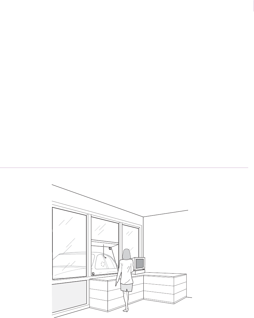
Inconspicuous installations
Application. Sometimes customers want their security system to be as inconspicuous as
possible. This is especially true in most residential, office foyers, executive offices, and
upscale retail store installations. The 5820A Recessed ShatterPro II sensor is the least
obtrusive acoustic glassbreak sensor available. When installed, the sensor is little larger than
a quarter and is rarely noticed. Another option is to hide a 5600 ShatterPoint sensor behind
curtains or blinds.
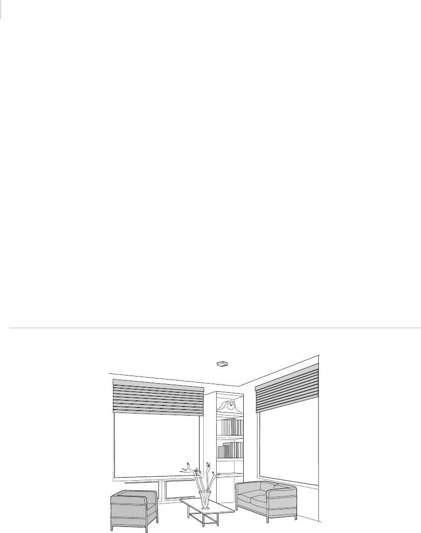
Installation. The 5820A (Figure 5) can protect an entire room. Sensor range is 25 ft.
(7.6 m) to the bottom of the glass in a 360-degree pattern. Mount the sensor on the ceiling,
the opposite wall, or an adjoining wall (Figure 6 on page 12). To install the sensor, do the
following:
1. Drill a 1 in. (2.5 cm) diameter hole through the drywall or ceiling tile in the desired
location.
2. Insert the 1 in. (2.5 cm) sleeve into the hole and insert the sensor into the sleeve. Use
the trim ring, if necessary, to cover any irregularities in the drywall hole.
The 5600 is a shorter range sensor that protects up to 10 ft. (3.1 m) of glass. For a hidden
appearance, mount the sensor on the window frame behind curtains or blinds (Figure 7 on
page 12). To protect windows that open, use a sensor with a built-in magnetic contact.
Recommended products. 5820A, 5600
Figure 5. 5820A installation
5820A recessed sensor
Sensor_Applications.book Page 11 Tuesday, December 27, 2005 5:45 AM

Intrusion Sensor
Application Notebook
12
Figure 6. Wall-mounted Recessed ShatterPro II
Figure 7. ShatterPoint mounted behind the curtains
5820A recessed sensor
SENTROL
5600 sensor
Sensor_Applications.book Page 12 Tuesday, December 27, 2005 5:45 AM

Chapter 1
Glassbreak/shock sensors
13
Bathroom windows
Application. Bathrooms are challenging environments for glassbreak sensors. Humidity
can be very high and bathrooms are acoustically live rooms. These attributes produce a
greater potential for false alarms when acoustic sensors are used. Shock sensors are a better
choice and have fewer problems than acoustic sensors in high humidity environments such
as bathrooms.
Installation. For best false alarm immunity in bathrooms, use the hermetically-sealed
GS600 shock sensor with 12 ft. (4 m) of range mounted on the glass (Figure 8). To protect
windows that open, use the frame-mounted GS611 shock sensor with built-in magnetic
contact. Both sensors work with the GS614 analyzer.
Recommended products. GS600, GS611
Figure 8. Bathroom window
GS600 shock sensor
Sensor_Applications.book Page 13 Tuesday, December 27, 2005 5:45 AM
Intrusion Sensor
Application Notebook
14
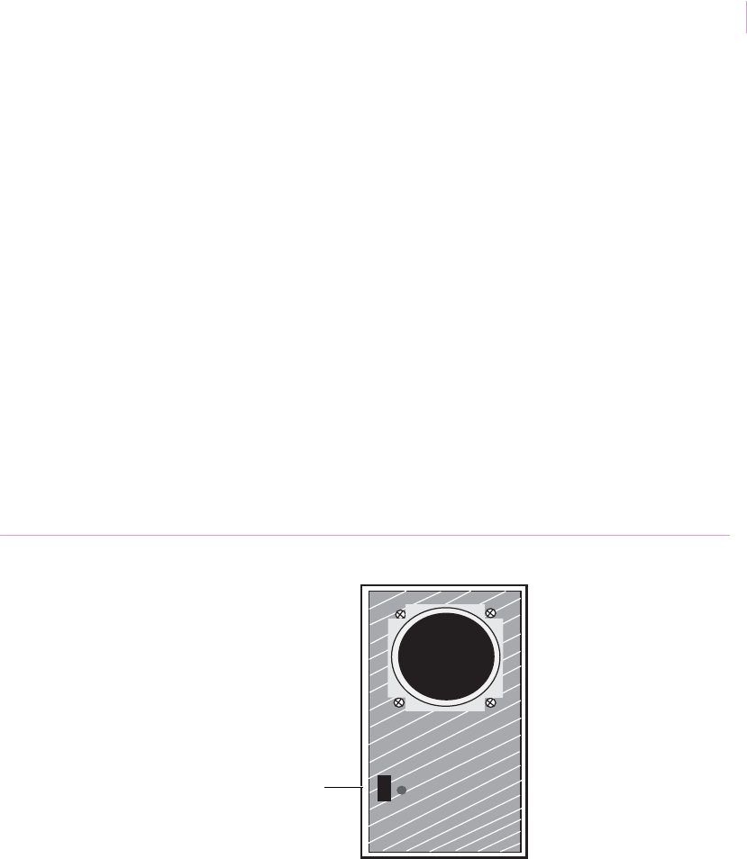
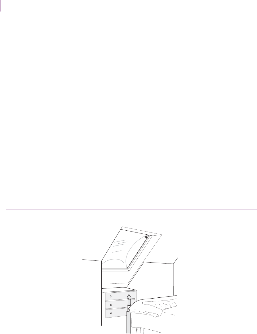
Skylights
Application. Skylights can be a vulnerable entry point to many homes and businesses. To
protect skylights made of Plexiglas or other types of plastic, use a shock sensor. To protect
glass skylights, use an acoustic glassbreak sensor.
Installation. To protect plastic skylights, mount a 5150 shock sensor in a corner of the
skylight 1 in. (2.5 cm) in from the frame (Figure 9). If more than 3.5 ft. (1.1 m) of range is
required, mount two sensors in opposite corners.
The plastic material in the skylight will absorb much of the shock energy from a break and
the range of a shock sensor on plastic is typically 50 percent less than the range on glass. For
example, a shock sensor with a 7 ft. (2.1 m) range on glass would generally have a 3.5 ft.
(1.1 m) range on a plastic skylight. See Shock sensor testing on page 8.
To protect glass skylights, mount a 5600 sensor on the ceiling or on any wall within range of
the skylight or use a GS600 sensor mounted on the frame. To protect vented skylights, use
the GS611 with built-in magnetic contact.
Recommended products. 5150, 5600, GS600, GS611
Figure 9. Skylights
5150 shock sensor
Sensor_Applications.book Page 14 Tuesday, December 27, 2005 5:45 AM
Chapter 1
Glassbreak/shock sensors
15
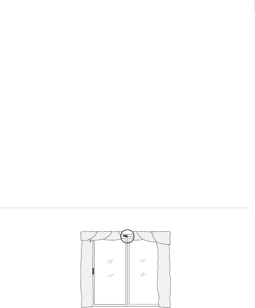
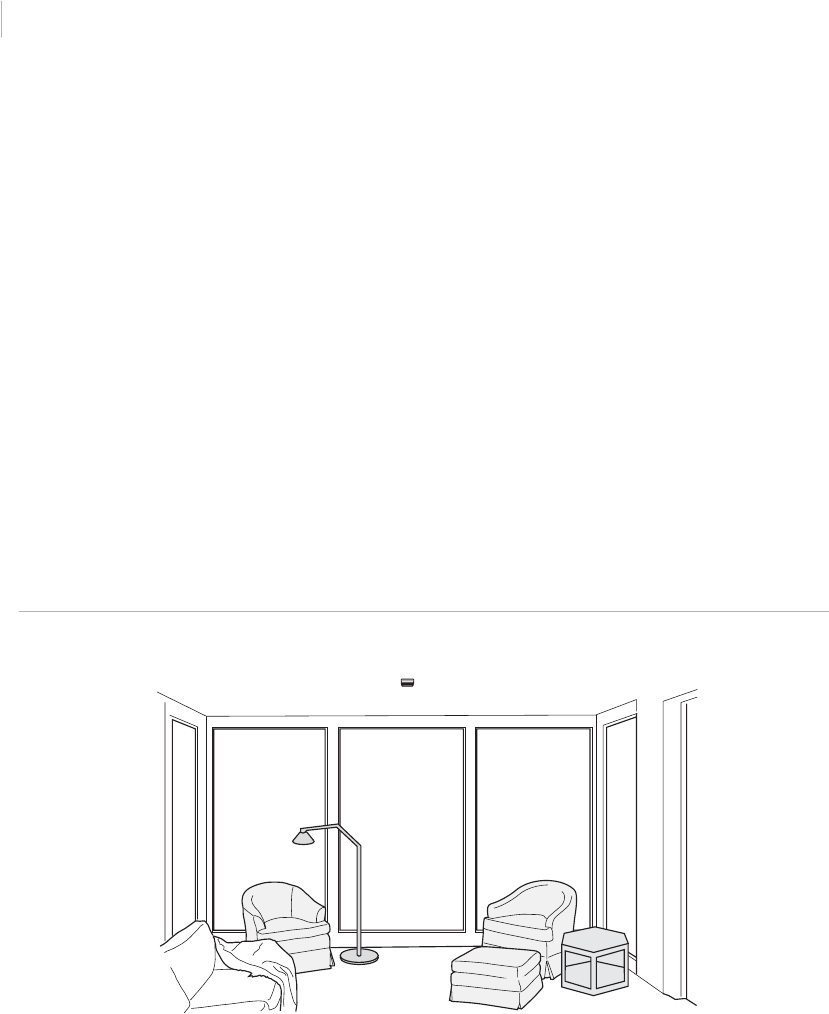
Windows with curtains and blinds
Application. Many homes and offices have windows with curtains or blinds. The 5150
shock sensor can protect windows regardless of the type of window covering present. With
proper placement, acoustic sensors can also protect windows with blinds and light drapes.
Installation. Mount shock sensors in the corner of the glass, 1 in. (2.5 cm) from the frame.
Shock sensors are not affected by curtains or blinds. See Shock sensor testing on page 8.
You can also mount a 5600 sensor on the window frame behind curtains or blinds to protect
one or more windows (Figure 10). The sensor will protect a 10 ft. (3.1 m) area, although the
range may be reduced if the window coverings are touching the glass. For windows that
open, use a sensor with a built-in magnetic contact.
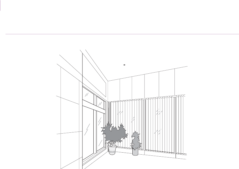
For a larger range on windows with venetian or vertical blinds, mount a 5812NT
ShatterPro 3 or a 5820A Recessed ShatterPro II on the ceiling (Figure 11 on page 16),
adjoining wall, or a wall opposite the glass you want to protect. See Acoustic sensor testing
with the 5709C on page 6.
Recommended products. 5150, 5600, 5812NT, 5820A
Figure 10. Sensor mounted behind curtains
Sensor
Sensor_Applications.book Page 15 Tuesday, December 27, 2005 5:45 AM
Intrusion Sensor
Application Notebook
16
Figure 11. Recessed sensor on ceiling
Sensor
Sensor_Applications.book Page 16 Tuesday, December 27, 2005 5:45 AM

Chapter 1
Glassbreak/shock sensors
17
Single window with wireless sensor
Application. A wireless-compatible shock sensor can be used for economical protection of
rooms with a single window. For glass doors or windows that open, use a wireless
compatible sensor with a built-in magnetic contact.
Installation. Mount the 5150 shock sensor on the glass, 1 in. (2.5 cm) in from the corner.
Range is a 7 ft. (2.1 m) radius out from the sensor.
The 564503 frame-mounted shock sensor can protect two fixed windows in the same
window opening (Figure 12). Range for the sensor is up to 10 ft. (3.1 m). Frame mounting
affects the sensor range, so it is essential to test the sensor (see Shock sensor testing on
page 8). The sensor includes a built-in magnetic contact to protect windows that open.
These sensors must be connected to a transmitter.
Note: The 564503 Wireless ShatterPoint shares the battery of the transmitter. Its current draw of up to
15 microamps may reduce transmitter battery life by up to 50 percent. Since other devices are
likely to need battery replacement before the sensor, this is rarely a problem.
Recommended products. 5150, 564503
Figure 12. Wireless sensor on single window
Sensor
Sensor_Applications.book Page 17 Tuesday, December 27, 2005 5:45 AM
Intrusion Sensor
Application Notebook
18
Multiple windows with wireless sensors
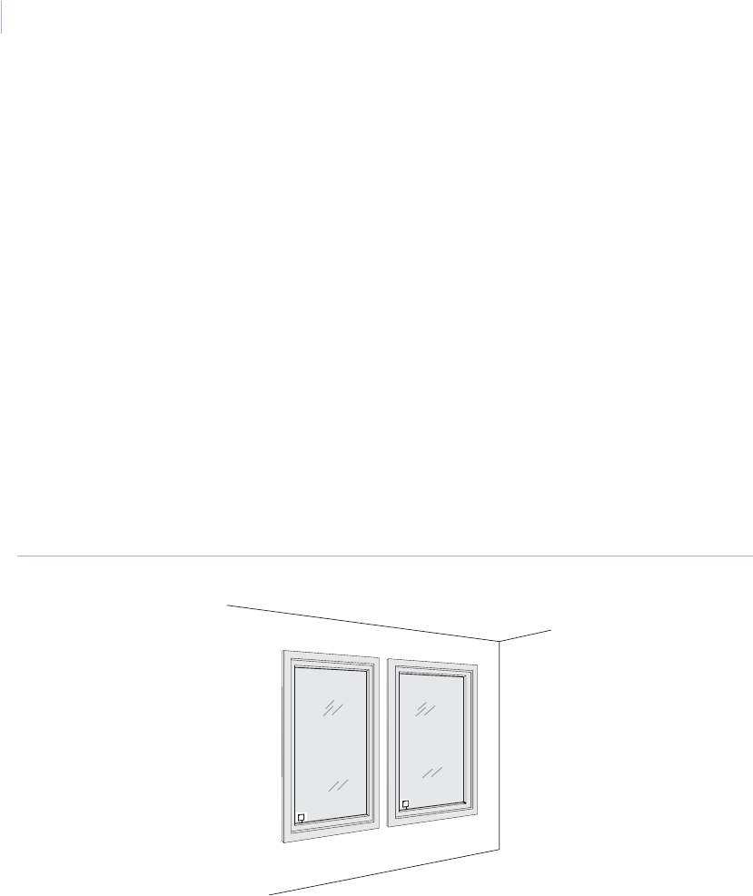
Application. To economically protect multiple windows use one transmitter and a 584503
Wireless ShatterPro acoustic sensor. The sensor combines excellent false alarm immunity
and consistent detection with wireless compatibility and has a coverage radius of 20 ft. (6.1
m) if mounted on a ceiling. A single sensor can typically protect an entire room.
Installation. To hide the transmitter and provide an integrated look, mount the transmitter
inside the back box of the 584503 sensor. The transmitter can also be mounted next to the
sensor on the bracket (included with the sensor).
Note: The sensor shares the transmitter battery, which may reduce battery life by up to 50 percent.
Since other devices are likely to need battery replacement before the sensor, this is rarely a
problem.
Position the 584503 sensor a minimum of 4 ft. (1.2 m) and a maximum of 20 ft. (6.1 m) from
the glass (Figure 13). See Acoustic sensor testing with the 5709C on page 6
Recommended products. 584503, NX488, 60-873-95
Figure 13. Multiple window with wireless sensors
Sensor
Sensor_Applications.book Page 18 Tuesday, December 27, 2005 5:45 AM

Chapter 1
Glassbreak/shock sensors
19
French doors and small windows
Application. Older homes often have windows with small panes and French doors. Small
windows have unique properties when they break. The sound output may be low since there
is not much glass to break and the glass may pop out of the window frame when hit instead
of breaking. Detection in both cases can be difficult.
Modern French doors are usually two large panes of glass with false dividers between them.
The dividers have little effect from a detection standpoint you do not need to take any
special precautions.
Installation. To
protect small windows with an acoustic sensor, use a 5600 ShatterPoint
mounted within 4 ft. (1.2 m) of the glass. See
Acoustic sensor testing with the 5709C
on page 6.
For more consistent detection, use a GS600 frame-mounted shock sensor. Often several
sensors will be needed to protect a frame of multiple windows. Make sure you test the sensor
(see Shock sensor testing on page 8) and use additional sensors as needed.
Minimum glass size for glassbreak sensors is 1 square foot (0.3 x 0.3 m).
Recommended products. 5600, GS600
Figure 14. Small window protection
Sensor
Sensor_Applications.book Page 19 Tuesday, December 27, 2005 5:45 AM
Intrusion Sensor
Application Notebook
20
Glass doors and windows that open
Application. Running wires from the glass to the frame can make glass door protection a
challenge. A shock or acoustic sensor with a built-in magnetic contact can make both
glassbreak and forced-open protection possible.
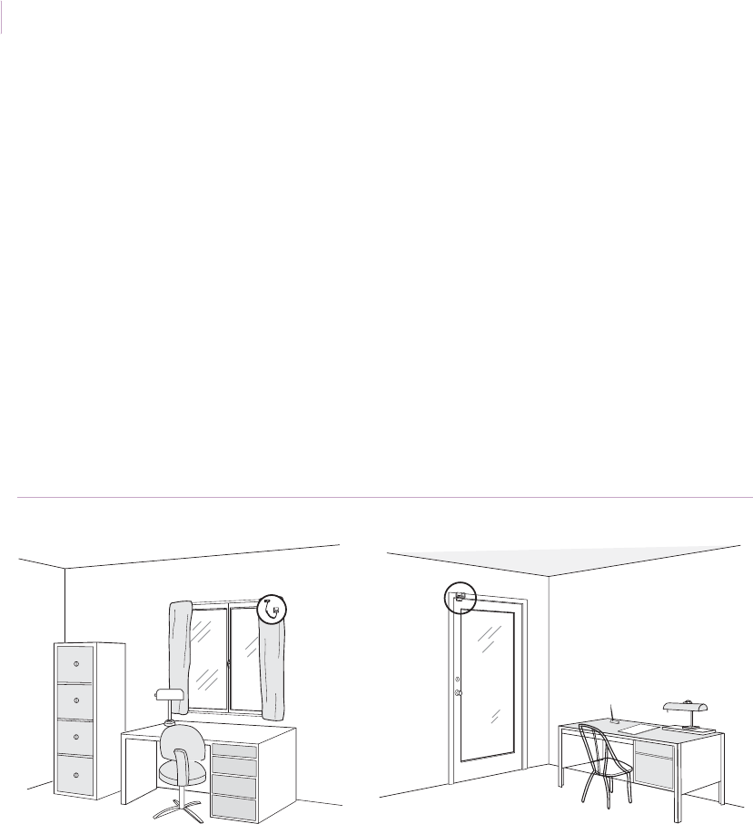
Installation. To protect glass doors and windows that open, use a 5150C or GS611 shock
sensor, or a 5620 shock/acoustic sensor. The 5150C sensor mounts on a corner of the frame
and ships with a 3 ft. (0.9 m) coil cord that reaches to a termination on the frame (Figure 15).
The 5620 and GS611 sensors have built-in magnetic contacts and mount on the frame.
Mount the sensor’s magnet on the door or movable window and mount the sensor on the
frame as close as possible to the magnet. See Shock sensor testing on page 8.
Recommended products. 5150C, 5620, GS611
Figure 15. Protection for windows and glass doors that open
SENTROL
Sensor Sensor
Sensor_Applications.book Page 20 Tuesday, December 27, 2005 5:45 AM
Chapter 1
Glassbreak/shock sensors
21
Insulated glass
Application. Many modern buildings use windows that contain two panes of glass divided
by an air space for added insulation. You can protect this insulated glass with shock and
acoustic glassbreak sensors. As long as the inside pane of the glass breaks, the sensor will
detect the break. It is possible to break the outside pane of glass without setting off an alarm.
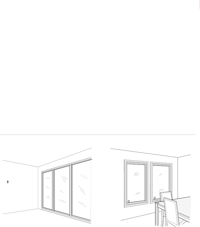
Installation. Installation for insulated windows is the same as for other windows. Mount
5150 or GS600 shock sensors in the corner of the glass or GS611 shock sensors on the
frame. Mount 5600, 5620 or 5812NT acoustic sensors so that the protected glass is within
the sensor’s range (Figure 16).
See Acoustic sensor testing with the 5709C on page 6 and Shock sensor testing on page 8.
Recommended products. 5150, 5600, 5620, 5812NT, GS600, GS611
Figure 16. Insulated glass protection
Sensor
Sensors
Sensor_Applications.book Page 21 Tuesday, December 27, 2005 5:45 AM
Intrusion Sensor
Application Notebook
22
Windows with film
Application. Film is applied to windows for a variety of reasons. In sunny climates some
commercial windows have a tinting film attached to the glass. Some commercial windows
have a plastic film attached to the glass to prevent shattering from impact or bullets. This
armor-coated glass can be found in bank drive-up windows, in retail stores, and in other
vulnerable buildings.
Installation. Tinted film does not affect shock sensors. To mount shock sensors on the
glass, cut away the film where the sensor will be placed so that the mounting tape is affixed
to the glass itself and not to the film (Figure 17).
Armor-coated glass may reduce shock sensor range. Thoroughly test shock sensors (see
Shock sensor testing on page 8) to see if additional sensors are needed.
Recommended products. Any GE shock sensor, as long as the installation guidelines
are followed.
Figure 17. Tinted film on windows
Sensor_Applications.book Page 22 Tuesday, December 27, 2005 5:45 AM
Chapter 1
Glassbreak/shock sensors
23
Thick glass
Application. Some installations may have glass thicker than the 0.25 in. (0.6 cm)
maximum thickness rating of acoustic and shock sensors. Since thick glass absorbs much of
the shock energy from a break, it is more of a challenge for glassbreak detection. Shock
sensors can be used on thick glass if they are thoroughly tested (multiple sensors may be
needed). ShatterPro sensors are not designed to protect thick glass and should not be used
for this application.
Installation. Use the 5150 or GS600 shock sensor and mount the sensor on the glass
approximately 1 in. (2.5 cm) in from the corner (Figure 18). See Shock sensor testing on
page 8 and add multiple sensors as needed.
Recommended products. 5150, GS600
Figure 18. Thick glass protection
Sensor_Applications.book Page 23 Tuesday, December 27, 2005 5:45 AM
Intrusion Sensor
Application Notebook
24
Large rooms
Application. Most large rooms have several windows, often widely spaced from each
other. The most economical way to protect large rooms with multiple windows is with a
single, long-range acoustic sensor. However, be careful to match sensor range to room size.
If the sensor range extends beyond the room boundaries it is vulnerable to false alarms.
Installation. Use a 5812NT ShatterPro 3 or a 5802A Recessed ShatterPro II to protect
large glass areas and up to four walls of glass. To protect glass on more than one wall, mount
the sensor on the ceiling (Figure 19). Make sure that all protected glass is within the sensor’s
coverage pattern. The distance from the bottom of the window to the sensor must be no more
than the sensor’s maximum range.
To protect one wall of glass, mount the sensor on the opposite wall (if all protected glass is
within the sensor’s range). See Acoustic sensor testing with the 5709C on page 6.
Recommended products. 5812NT, 5820A, 2000
Figure 19. Large rooms with multiple windows
Sensor
Sensor_Applications.book Page 24 Tuesday, December 27, 2005 5:45 AM

Chapter 1
Glassbreak/shock sensors
25
Small rooms
Application. False alarms are more likely in small, acoustically live rooms such as small
kitchens, glass entry airlocks, stairwells, small glass offices, and utility rooms. Shock
sensors offer the best false alarm immunity and are the most economical if there is only one
window to protect. If an acoustic sensor is preferred, you must match the range of the sensor
with the size of the protected room and glass to minimize false alarms.
Installation. In small room applications, follow these guidelines:
• To protect a single window in a small room, use a 5150 shock sensor mounted on
the glass or a 5414 or GS600 sensor mounted on the frame.
• For windows that open, use a 5415A or GS611 sensor with a built-in magnetic
contact (Figure 20). See Shock sensor testing on page 8.
• To protect multiple windows in a small room, use a 5600 ShatterPoint.
• Do not install an acoustic sensor with a large range in a small room. For example, a
sensor with 25 ft. (7.5 m) diameter range in a 10 ft. (3.1 m) room increases the risk
of false alarms. See Acoustic sensor testing with the 5709C on page 6.
Recommended products. 5150, 5414, 5415A, GS600, GS611, 5600
Figure 20. Small rooms
SENTROL
SENTROL
Sensor
Sensor_Applications.book Page 25 Tuesday, December 27, 2005 5:45 AM
Intrusion Sensor
Application Notebook
26
Occupied areas
Application. Occupied areas can be protected either on a perimeter loop or on a 24-hour
loop. On a perimeter loop, sensors are armed when the magnetic contacts on doors are
armed. On a 24-hour loop, sensors are armed continuously.
Installation. For 24-hour loop protection, mount a 5150 shock sensor on the glass 1 in.
(2.5 cm) in from the corner, or frame-mount a 5600 shock sensor with the correct sensitivity
setting (see Shock sensor testing on page 8). The 5885 ShatterPro Plus acoustic sensor can
also be used for 24-hour loop applications.
For perimeter loop protection, use a 5600 for glass areas smaller than 10 ft. (3.1 m). For
larger glass areas, use a 5812NT, 2000, or a 5820A recessed acoustic sensor. See Acoustic
sensor testing with the 5709C on page 6.
Recommended products. For 24-hour loop protection: 5150, 5600, 5885, GS600. For
perimeter loop protection: 5812NT, 5820A, 2000.
Figure 21. Occupied areas
Sensor
Sensor
Sensor
Sensor_Applications.book Page 26 Tuesday, December 27, 2005 5:45 AM
Chapter 1
Glassbreak/shock sensors
27
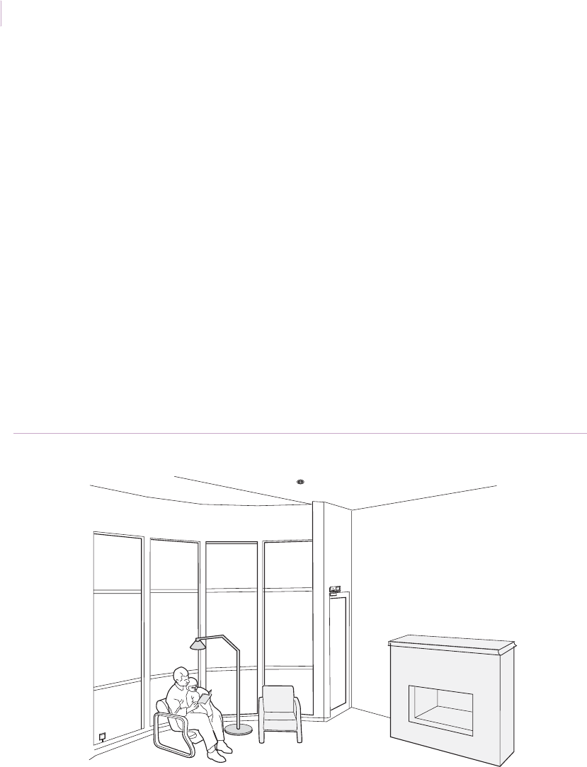
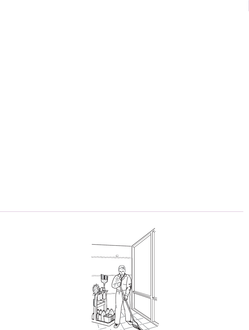
Rooms with cleaning crews
Application. Often the perimeter loop of the security system is armed when the cleaning
crews are in a building. If acoustic sensors are armed, they will be listening to all sounds,
including those made by night cleaning crews. Acoustic sensors are most likely to false
alarm to multiple sounds. The cleaning crews produce a combination of sounds from
vacuums, floor polishers, and clattering garbage cans, all of which combine to cause false
alarms for some sensors in some applications.
Installation. The 5150, 5600, and GS600 shock sensors provide the best false alarm
immunity for a building when it is occupied. However, multiple shock sensors can be
economically impractical for applications with large numbers of windows and may not be an
option in applications where appearance is important.When multiple shock sensors will not
work for your application, use the 5885 ShatterPro Plus acoustic sensor that combines a
passive infrared sensor with a glassbreak sensor (Figure 22). When an occupant enters the
field of view of the PIR, the glassbreak sensor is disabled for 70 seconds. This prevents false
alarms due to loud noises such as vacuums or floor buffers. The 5885 makes 24-hour
acoustic applications possible.
Recommended products. 5150, 5600, GS600, 5885
Figure 22. Cleaning crew protection
Sensor
Sensor_Applications.book Page 27 Tuesday, December 27, 2005 5:45 AM
Intrusion Sensor
Application Notebook
28
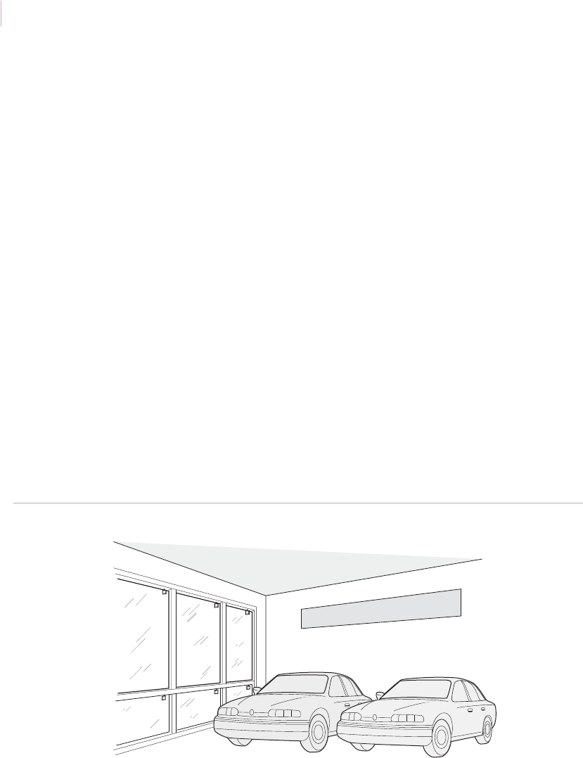
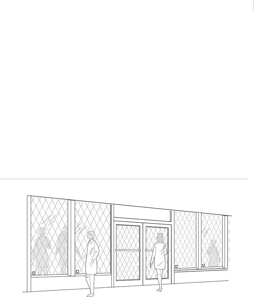
Storefront windows
Application. Merchants often want glassbreak protection on their front windows, in order
to have the alarm sound as soon as the glass breaks. While this does not prevent smash and
grab losses, it helps prevent burglars from actually entering the building.
Installation. To protect storefront windows, 5150, 5620, or GS600 shock sensors are the
best choice. The sensors mount on the glass or frame and are visible from the outside to
deter burglars before the glass is broken. Shock sensors are also less likely to be set off by
street noise or rolling metal shutters than acoustic sensors. However, multiple shock sensors
may be required to cover the same glass area that one acoustic sensor can protect
(Figure 23). See Shock sensor testing on page 8.
To successfully use acoustic sensors to protect storefront glass, store personnel must be
trained to keep the sensor’s line-of-sight clear. If the sensor’s vision is blocked by store
displays or furniture, the sensor is unlikely to detect a break-in. In stores without window
displays, mount a ShatterPro 3 or 5820A ShatterPro II on the ceiling. In stores with window
displays, Mount a 5600 ShatterPoint directly above the glass. See Acoustic sensor testing
with the 5709C on page 6.
Recommended products. 5150, GS600, 5600, 5620, 5812, 2000, 5820A
Figure 23. Storefront glass protection
New Models Are Here
Multiple
sensors
Sensor_Applications.book Page 28 Tuesday, December 27, 2005 5:45 AM
Chapter 1
Glassbreak/shock sensors
29
Roll-up metal shutters
Application. Retail shops in high-risk areas will often have roll-up metal shutters to
protect glass windows at night. The clanging and banging sounds of these shutters can cause
acoustic sensors to have false alarms. False alarms can also be caused by people rattling the
shutters by or other sources of vibration.
Installation. GS600 or 5150 shock sensors provide the best false alarm immunity on
windows with roll-up shutters. The sensors mount on the glass (Figure 24) and are easily
visible from the outside to deter break-ins. See Shock sensor testing on page 8.
If acoustic sensors are preferred, use the 5812, 2000, or 5820A sensors. Mount the sensor
away from the street and roll-up shutters and within specified range limits. See Acoustic
sensor testing with the 5709C on page 6.
Recommended products. 5150, GS600, 5812, 5820A, 2000
Figure 24. Store windows with roll-up metal shutter protection
Multiple
sensors
Sensor_Applications.book Page 29 Tuesday, December 27, 2005 5:45 AM
Intrusion Sensor
Application Notebook
30
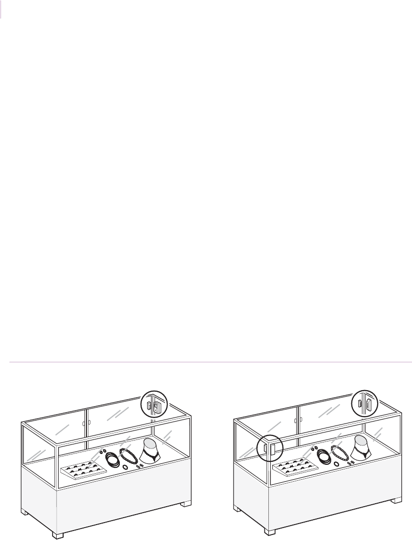
Glass display and jewelry cases
Application. Museum curators and retailers with glass display and jewelry cases often
want glassbreak sensors inside their cases. Both shock and acoustic sensors can be used in
this application.
Acoustic sensors sealed within a glass display case are extremely live and are vulnerable to
false alarms if the case is accidently struck by keys or other metal objects. For this reason,
acoustic sensors are only appropriate for applications where the sensor will only be armed
when the premises are not occupied. For occupied or 24-hour protection, use shock sensors.
Installation. The 5150 and GS600 shock sensors mount directly on the glass and are the
best choice if only one piece of glass needs to be protected. For protecting multiple glass
walls in the case, use one or more frame-mounted 5600 sensors. Use a 5620 sensor with
built-in magnetic contact to detect a forced opening. To prevent sensor tampering, you must
place the sensors inside the case (Figure 18). See Shock sensor testing on page 8 and use
multiple sensors as needed.
If using multiple shock sensors is not a viable solution, use a single acoustic sensor with a
limited range. We do not recommend the ShatterPro sensors for this application.
Recommended products. 5150, 5600, 5620, GS600
Figure 25. Glass case protection
SENTROL
SENTROL
5150 sensor 5600 sensors
Sensor_Applications.book Page 30 Tuesday, December 27, 2005 5:45 AM

Chapter 1
Glassbreak/shock sensors
31
Metal enclosures
Application. The 5402 and 5422 shock sensors eliminate the need for costly lined boxes or
placement of security system controls in a vault for UL mercantile applications. To meet UL
requirements, a tamper switch is required.
Installation. To protect metal enclosures, use the self-powered 5402 or 4-wire 5422 shock
sensor. Mount the sensor on the side wall on or near the hinge. If the hinge runs the length of
the side, center the sensor vertically (Figure 26). If the enclosure has multiple hinges, mount
the sensor next to the hinge nearest the middle of the enclosure.
To mount the sensor, do the following:
1. Peel back the paper from one side of the adhesive tape pad and press it onto the back
of the sensor. The tape pad must be flat against the plastic case.
2. Use a 50/50 solution of isopropyl alcohol/water to clean the mounting area. Dry the
mounting area, then peel the backing paper from the tape pad and press the sensor
against the metal. The tape will fully adhere within 24 hours.
3. Wire the sensor (if applicable) to the loop according to wiring instructions.
4. To test the sensor, use the metal shaft of a medium-size screwdriver to lightly scrape
back and forth against the edge of the metal enclosure farthest from the sensor
(Figure 26). If the sensor does not respond, a second sensor may be required.
Recommended products. 5402, 5422
Figure 26. Metal enclosure
Sensor
Screwdriver
Sensor_Applications.book Page 31 Tuesday, December 27, 2005 5:45 AM

Intrusion Sensor
Application Notebook
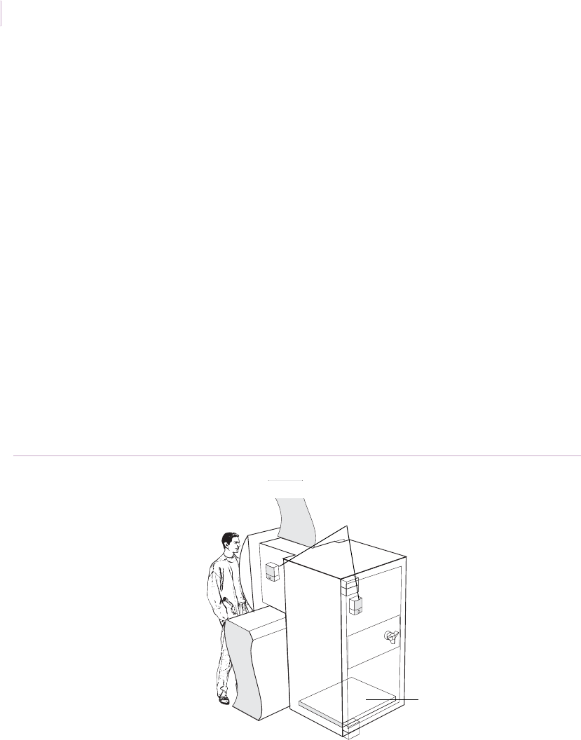
32
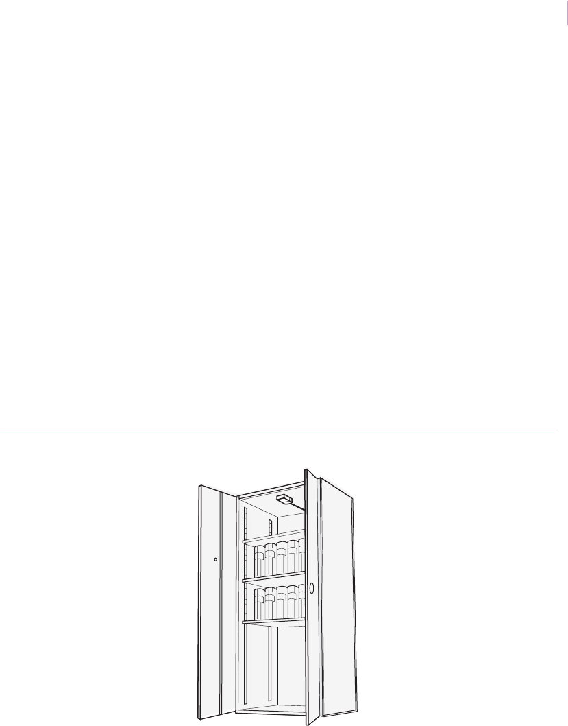
Filing cabinets
Application. Filing cabinets that contain high value documents in military, government, or
private business settings can be protected with the DV1201A sensor.
Installation. Since the lock is normally placed on one side of the upper drawer on the front
of the cabinet, mount one sensor on the side of the cabinet closest to the lock (Figure 27).
Mount the night position plate on the drawer and the day position plate on the side together
with the junction box DV1228A. Use cable kit DV1219A.
Recommended products. DV1201A (sensor), DV1219A (cable kit), DV1228A
(junction box), DV1215A (tester)
Figure 27. Filing cabinets
Sensor
Sensor_Applications.book Page 32 Tuesday, December 27, 2005 5:45 AM
Chapter 1
Glassbreak/shock sensors
33
Jewelry store safes
Application. Jewelry store safes present several protection challenges. The safes hold high
value merchandise, but are generally small in size. The stores are located in public locations,
such as shopping malls and strip malls, where employee turnover can be high. The
DV1201A sensor can protect safes from internal (employee) and external threats and lower
store owner’s loss risk.
Installation. Since most attacks against safes are aimed at the door and the locking
mechanism, mount one sensor on the body of the safe and another inside the door close to
the hinges (Figure 28). Use flexible cable kit DV1219A together with the junction box
DV1228A. Also add a magnetic contact (2707A or similar) on the door. Cable outlets are
normally provided in new safes, if not, we recommend you mount the sensors on the outside
of the safe.
Recommended products. DV1201A (sensor), DV1212 (mounting plate), DV1219A
(cable kit), DV1228A (junction box), 2707A (contact), DV1215A (tester)
Figure 28. Jewelry safe
Sensor
Sensor_Applications.book Page 33 Tuesday, December 27, 2005 5:45 AM
Intrusion Sensor
Application Notebook
34
ATM and night deposit boxes
Application. ATM (automatic teller machines) and night deposit boxes are located in high
activity public areas and involve cash. There is also environmental vibration from normal
operations. These factors combine to make protection a challenge.
The DV1221A sensor ignores environmental vibrations while ensuring actual attacks are
detected. The sensor sounds an alarm before the intruder gains access to the contents of the
machine.
Installation. For ATMs, the best locations for sensors are the door and as close to the
dispenser opening as possible. These locations are the most likely points of attack.
To protect night deposit boxes, use the same sensors. Attenuate the chute and the landing
place with rubber insulating material to reduce the noise created by the falling cash boxes
when deposited (Figure 29).
Recommended products. DV1221A (sensor), DV1219A (cable kit), DV1228A
(junction box), DV1215A (tester)
Figure 29. ATM and night deposit boxes
Rubber pad
Sensors
Sensor_Applications.book Page 34 Tuesday, December 27, 2005 5:45 AM

Chapter 2 Motion sensors
This chapter provides information on motion sensors.
Applications include both indoor and outdoor sensors for
residential, commercial, and industrial installations.
Sensor_Applications.book Page 35 Tuesday, December 27, 2005 5:45 AM

Intrusion Sensor
Application Notebook
36
Product overview
Passive infrared (PIR) motion sensor technology provides one of the most reliable and cost
effective methods for protecting spaces in homes, offices, or industrial facilities. PIR motion
sensors sense temperature contrasts between a relatively stable background and hotter or
colder objects moving across their fields of view. The sensors emit no energy of their own,
they merely see infrared images.
RCR sensors
The PrecisionLine dual technology sensors combine range-controlled radar (RCR)
technology with a passive infrared (PIR) system. This combination increases false alarm
immunity by allowing them to sense human-sized objects within a specified range. Both the
RCR and the PIR system must be triggered to set off an alarm, unless in stealth mode (radar
only). An internal jumper allows you to disable the PIR and use the radar-only stealth mode
to detect intruders faster. The stealth mode can also be used for covert installations (mounted
behind walls or drop-tile ceilings).
Sensor_Applications.book Page 36 Tuesday, December 27, 2005 5:45 AM

Chapter 2
Motion sensors
37
Choosing the right motion sensor
GE Security offers a complete line of motion sensors suitable for every application. The
sensors fit compactly and unobtrusively into any environment. Use Table 4 to help you
match the appropriate PIR sensor with your installation needs.
Table 4. PIR sensors and descriptions
Motion sensor Description
6255 SureShot Residential/commercial - 30 x 30 ft. room, wall, corner, or ceiling
mount, pet alley, curtain, 40 ft. single spot lens, stairwell coverage
6255FM SureShot Flush Mount Residential/commercial - Prewired wall or ceiling retro flush mount
6351 Sharpshooter DesignLine Residential/commercial - 35 x 35 ft. room, wall or corner mount, 90
degree wide angle, pet alley, vertical barrier lens, mounts 1/8 in. from
ceiling
6155 Sharpshooter Residential/commercial - 45 x 45 ft. room, wall or corner mount, pet
alley, curtain, 90 ft. long range, extra-wide lens
6187CTX Industrial
Sharpshooter
Commercial/industrial - Outdoors, warehouses, locker rooms, food
processing plants, underground parking lots, dusty, cold, or wet
environments
6197 Intrinsically Safe PIR Commercial - Hazardous areas with ignitable atmospheres,
government sites, pharmaceutical labs, oil refineries, grain elevators
Industrial - Hazardous areas, for use in Class I, II, and III; Division 1 and
2; Groups A, B, C, D, E, F, and G
6198 Non incendive PIR Industrial - Hazardous areas, for use in Class I Division 2, Groups A, B, C,
and D (only)
AP100PI Residential/commercial - Form A, mirror optic wall mount, 33 x 40 ft.
room, corner or wall mount, 5 curtains at 33 ft. each, mounting height 6
to 10 ft.
AP450
AP450A
Residential/commercial - Form A/Form C, 50 ft., wall mount, low profile,
9 curtains, mounting height 6 to 10 ft.
AP475 Commercial/Industrial - Form C, long range wall mount, 75 ft. single
curtain barrier, mounting height up to 16 ft.
Sensor_Applications.book Page 37 Tuesday, December 27, 2005 5:45 AM

Intrusion Sensor
Application Notebook
38
AP669 Commercial/industrial - Form C, 60 ft. diameter 360° coverage, ceiling
mount, 18 curtains at 30 ft. each, mounting height 7 to 15 ft., coverage
patterns: full 360°, 90° curtain, L-turn pattern, corridor intersection
AP633A Commercial/industrial - 200 ft. long range, 80 ft. wide angle, wall
mount, 12 selectable coverage patterns, mounting height 6 to 10 ft.
AP750 Residential/commercial - Form A/Form C, mirror optic wall mount, 50 x
65 ft. coverage, corner or wall mount, 7 curtains at 50 ft. each, mirror
mask allows coverage patterns, mounting height 6 to 10 ft.
AP-750W
NX482
Wireless residential/commercial - Form A/Form C, mirror optic wall
mount, 50 x 65 ft. coverage, corner or wall mount, 7 curtains at 50 ft.
each, mirror mask allows coverage patterns, mounting height 6 to 10 ft.
AP950PI Residential/commercial/industrial - Form A, 35 ft. range with up to 80
pound pet immunity, 50 ft. range with no pet immunity, corner or wall
mount, 9 curtains, 2 units in 1 housing, mounting height 7 to 10 ft.
AP950AM Commercial/industrial - Antimasking high security, 50 ft. range, corner
or wall mount, 9 curtains
RCR-50 Dual technology commercial - Range control: 20, 30, 40, and 50 ft.,
tamper, Form C, retail, warehouse, office space, public sector projects,
high security
RCR-PET Dual technology residential/commercial - Range control: 9, 18, 27, and
35 ft., Form A, pet immune up to 80 pounds
RCR-A (Form A)
RCR-C (Form C)
Dual technology residential/commercial/industrial - Range control: 9,
18, 27, and 35 ft., no pets, tamper (RCR-C only), retail, office space, public
sector projects, high security
RCR-90 Dual technology commercial/industrial - Range control: 60, 70, 80, 90
ft., tamper, Form C, retail, warehouse, office space, public sector
projects, high security
RCR-REX Dual technology commercial/industrial - Request-to-exit, Range: 3 to
15 ft. depth, 7.9 ft. width, mounting height 7 to 15 ft., tamper, Form C
60-511-319.0 Wireless residential/commercial - DS924 PIR, 35 x 40 ft. coverage,
tamper, sensitivity options, 3.6 VDC lithium battery
Table 4. PIR sensors and descriptions (continued)
Motion sensor Description
Sensor_Applications.book Page 38 Tuesday, December 27, 2005 5:45 AM

Chapter 2
Motion sensors
39
60-511-02-95 Wireless residential/commercial - DS924 PIR, 35 x 40 ft. coverage,
tamper, sensitivity options, 1.5 VDC lithium battery
60-639-95R Wireless residential/commercial - SAW PIR, 35 x 40 ft. coverage,
tamper, sensitivity options
60-639-95R-OD Wireless residential/commercial - Outdoor SAW PIR, 35 x 40 ft.
coverage, tamper, sensitivity option
60-639-02-95R Wireless residential/commercial - SAW PIR, pet immune to 40 pounds,
1.5 VDC lithium battery, 35 x 40 ft. coverage, tamper, sensitivity options
60-703-95 Wireless residential/commercial - Crystal PIR, 35 x 40 ft. coverage,
tamper, sensitivity options
60-807-95R Wireless residential/commercial - SAW PIR, pet immune up to 40
pounds, 35 x 40 ft. coverage, tamper, sensitivity options
60-807-01-95R Wireless residential/commercial - SAW PIR, pet immune to 40 pounds,
35 x 40 ft. coverage, tamper, 3.6 VDC lithium battery
60-807-02-95R Wireless residential/commercial - SAW PIR, pet immune to 40 pounds,
35 x 40 ft. coverage, tamper, 1.5 VDC lithium battery
60-880-95 Wireless residential/commercial - 315 MHz AP750W with learn mode
4D signal processing with gliding focus mirror optics
Table 4. PIR sensors and descriptions (continued)
Motion sensor Description
Sensor_Applications.book Page 39 Tuesday, December 27, 2005 5:45 AM

Intrusion Sensor
Application Notebook
40
Installation guidelines
Use the following installation guidelines for motion sensors:
• Position the sensor so that any intruder must cross the sensor’s field of view. To
trigger an alarm, an intruder must cross both the positive and negative elements of
one zone.
• Test the sensor in the direction of likely intruder motion and walk test monthly. See
Walk test on page 42.
• Locate the sensor so that valuables are well within its coverage pattern.
• Terminate each protection zone on a solid object such as a wall or floor.
• Use an industrial sensor in locations where a standard sensor may be affected by
water, steam, or oil.
• Do not aim sensors at sources of rapid heating or cooling. These sources include
forced air ducts, space heaters, fireplaces, direct sunlight, strong white lights, and
mirrors that can reflect strong light.
• Do not obstruct the sensor’s field of view.
• Seal optics when possible.
Sensor_Applications.book Page 40 Tuesday, December 27, 2005 5:45 AM

Chapter 2
Motion sensors
41
Outdoor installation guidelines
Test your application over a 24-hour period and use the following guidelines when installing
outdoor motion sensors:
Sunlight. Avoid direct sunlight on the plastic lens (even with UV stable plastics).
Temperature. Make sure the temperature range is within sensor specifications. For
example, the 6187CTX sensor is rated to work from -40 to 120°F (-40 to 50°C). Be
aware of temperatures in excess of the sensor’s specifications.
Humidity/rain/fog. If conduit is used, run conduit out the side or bottom of the sensor
to keep conduit condensation from draining into the sensor housing. Make sure the
conduit openings and the mounting holes on the sensor are well sealed.
Birds and animals. Depending on the size, speed, and proximity to the sensor, warm-
blooded animals can trigger an alarm. The larger the animal, the farther away it can be
detected. Avoid directing the sensor towards bushes or branches where birds can perch.
You can mount two sensors in parallel to require alarm verification.
Trees and bushes. Tree branches or bushes can cause an alarm when the wind moves
them, and can block detection. Keep branches and bushes at least 30 ft. (9.15 m) from
the sensor.
Sensor_Applications.book Page 41 Tuesday, December 27, 2005 5:45 AM

Intrusion Sensor
Application Notebook
42
Walk test
To ensure proper operation, always walk test the sensor location. To walk test, do the
following:
1. Mount the sensor in the desired location.
1. Walk throughout the intended coverage pattern.
2. Verify the sensor alarms (see the specific sensor installation instructions).
Most sensors walk test more accurately if you wait 10 seconds between tripping the sensor
and walking again. This allows the sensor to stabilize between trips.
Prewiring
Prewiring allows you to work with the builder in the planning stage to determine optimum
locations for sensors. It will also allow you to avoid many of the hazards inherent in post-
construction installations such as drilling through the electrical cables, plumbing, and duct-
work hidden in existing walls.
When wiring after construction, compromises are usually the norm. Existing walls, lighting
fixtures, air conditioning ducts, and other obstacles often determine sensor and control panel
locations. Compromises such as these can leave blind spots in security installations.
Motion sensors are available that will fit into standard outlet boxes just like a light switch.
The flush-mount SureShot (6255FM) sensor fits into a standard single-gang box, remodel
box, or rough-in plate in two easy steps.You simply connect the wires to the proper terminals
on the back of the unit, then screw the unit into an outlet box like you would a switch.
Sensor_Applications.book Page 42 Tuesday, December 27, 2005 5:45 AM
Chapter 2
Motion sensors
43
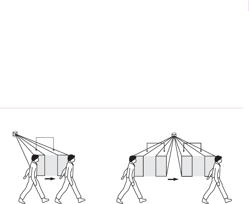
False alarm reduction
Many GE motion sensors allow you to select one or two zone detection (Figure 30). Each
zone is made up of two fields of view, one positive and one negative. With one zone
selected, an alarm will be indicated when an intruder moves across one positive and one
negative field. With two zones selected, an intruder must cross the positive and negative
fields of two zones before an alarm is indicated. We recommend two-zone detection (except
when using long-range and curtain lenses) to reduce the chance of false alarms. See the
sensor’s installation instructions for details on setting the zone detection.
Figure 30. Zone selection
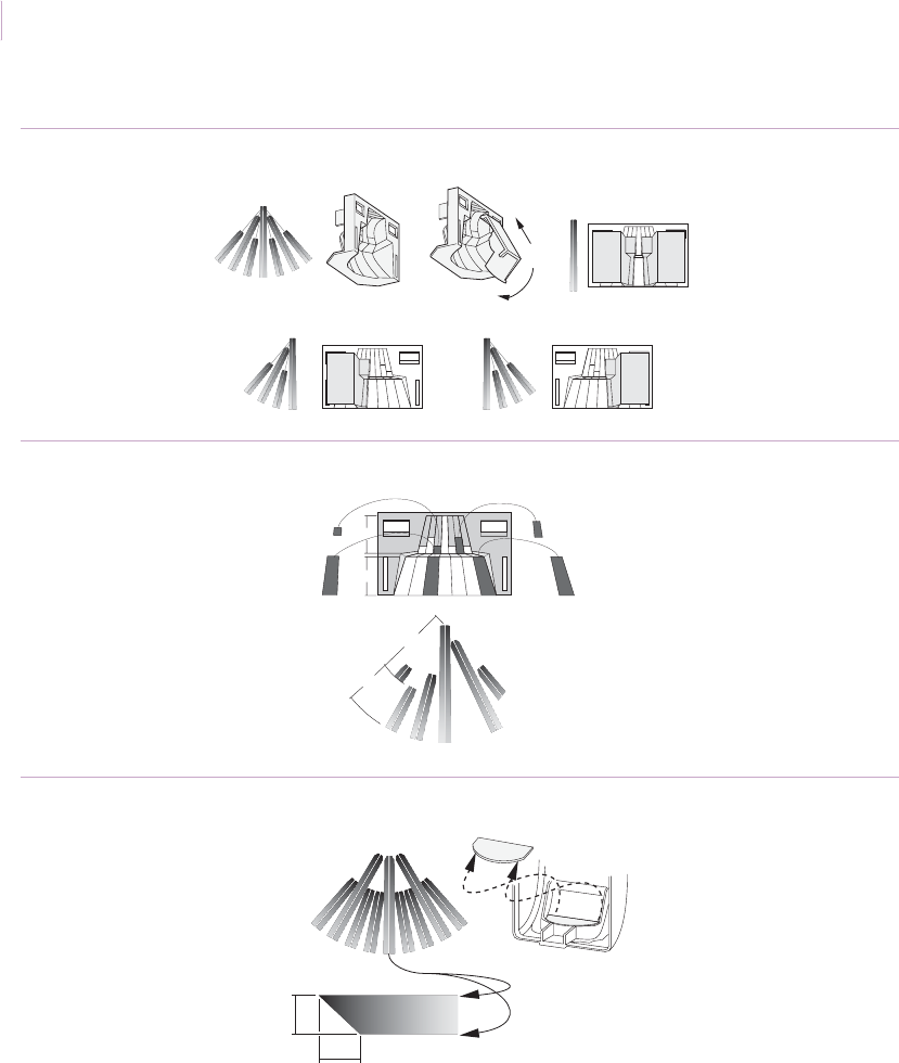
Masking areas on motion sensors
Most motion sensors include masks to modify the coverage pattern to fit specific
applications. Coverage curtains should be masked to avoid sources of false alarms such as
heaters, air conditioners, and windows. Available masks include:
• Plastic masks to cover large areas (Figure 31 on page 44)
• Adhesive labels used on mirror curtains (Figure 32 on page 44)
• Undercrawl window masks to improve false alarm immunity in the presence of
objects within 5 ft. (1.5 m) and directly under the sensor (Figure 33 on page 44)
One-zone detection Two-zone detection
2 beams
2 beams 2 beams
+-++
--
Sensor_Applications.book Page 43 Tuesday, December 27, 2005 5:45 AM
Intrusion Sensor
Application Notebook
44
Figure 31. Plastic masks
Figure 32. Adhesive labels for the mirror
Figure 33. Undercrawl mask
The examples show the AP750 sensor. For masking options for a specific motion sensor, see
the installation instructions for that sensor model.
1
1
2
2
A
A
B
B
7.9 ft.
(2.4 m)
5.0 ft.
(1.5 m)
Sensor_Applications.book Page 44 Tuesday, December 27, 2005 5:45 AM
Chapter 2
Motion sensors
45
Loop supervision
If a resistor is placed at the end of a protection zone (at the last unit in the line), that zone
becomes a supervised loop. A small amount of current can always be applied to that loop,
allowing it to watch the wiring at all times. You can then program the system to give a
warning light or audible alarm if it is tampered with during daytime hours. Supervising the
loop is a security technique used to prevent internal tampering.
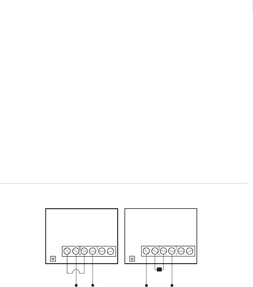
Terminal blocks with shared terminals
The SureShot and some older Sharpshooter sensors have SPDT (single-pole double-throw)
contacts in which the normally open (NO) and one of the tamper (TAMP) terminals are
shared. When wiring a tamper switch in series with the alarm output in the normally closed
configuration, be sure to wire the terminals as shown in the correct diagram in Figure 34. If
the jumper wire is placed from the normally closed (NC) terminal to the NO terminal, as
shown in the incorrect diagram, no alarm will sound. When wiring a tamper switch in series
with the normally closed alarm loop, place the jumper or EOL device between the COM and
T/NO terminals.
Figure 34. Wiring terminal blocks with shared terminals
NC COM T/NO TAMP + –
NC COM T/NO TAMP + –
Incorrect Correct
Sensor_Applications.book Page 45 Tuesday, December 27, 2005 5:45 AM
Intrusion Sensor
Application Notebook
46
Peripheral control
Motion sensors can be used to control peripheral devices in applications such as:
• CCTV cameras (see CCTV camera activation on page 76)
• Lights (see Hallways and lobby lighting activation on page 58 and on page 80)
• Recorded messages (see Museums on page 55)
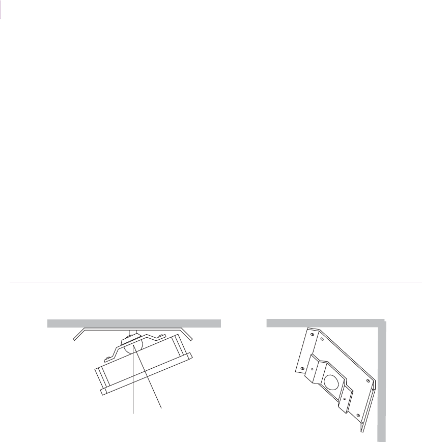
Swivel brackets
The 6083-N swivel bracket can be used with the 6187CTX outdoor PIR sensor, the 6198
nonincendive PIR sensor, and the 6197 intrinsically safe PIR sensor in areas where
mounting is difficult.
You can mount the bracket on a flat wall or in a corner (Figure 35). The maximum adjusting
angle for a flat-wall mount is 22.5 degrees. Mount the bracket with the small self-tapping
screws that ship with it.
Figure 35. Swivel bracket
Flat wall, tip view Corner view
22.5°
Sensor_Applications.book Page 46 Tuesday, December 27, 2005 5:45 AM

Chapter 2
Motion sensors
47
Pets
Application. Because PIR sensors are sensitive to moving, heat-radiating sources, they can
be triggered by animals as well as humans. To avoid this false alarm hazard, do one of the
following:
• Use a sensor with pet immunity
• Use a sensor with a pet alley lens
• Mount a sensor upside down to create a pet alley
Installation using a sensor with pet immunity. The introduction of the
PrecisionLine RCR-PET with its dual technology RCR (range-controlled radar) and PIR,
has virtually eliminated the need to create a pet alley associated with nominal motion
sensors. The RCR-PET provides excellent pet immunity for animals up to 80 pounds, and
detects only objects within a very precise range of user settings. Table 5 gives examples of
pet immunity limits for RCR-PET sensors. The table is not accurate for other sensors.
The AP100PI, PI6000, and AP950PI sensors also have pet immunity. See specific sensor
installation instructions for details.
Recommended products. RCR-PET, AP100PI, AP950PI, PI6000
Table 5. RCR-PET hair chart
Long hair
2 in. (5.1 cm) long
up to 80 lbs.
Medium hair
1.5 in. (3.8 cm) long
up to 50 lbs.
Short hair
1 in. (2.5 cm) long
up to 30 lbs.
Not recommended,
use a pet alley
application
Chinook Collie Basenji Doberman
Husky English setter Border terrier Great Dane
Poodle Pointer Cocker spaniel Greyhound
Retriever Pug French bulldog Mastiff
Sheepdog Toy poodle Mini bull terrier Pit bull
German shepherd Weimaraner Welsh corgi St. Bernard
Cats
Sensor_Applications.book Page 47 Tuesday, December 27, 2005 5:45 AM

Intrusion Sensor
Application Notebook
48
Installation with a pet alley lens. To install the sensor, do the following:
1. Mount the sensor, with the pet alley lens installed, against the wall at the desired
height.
2. Mask the sensor to avoid tables, chairs, cat climbing posts, and other objects a pet
could jump on. Remember that the size of the pet should also be considered while
aiming and adjusting the sensor.
3. Remind the homeowner that furniture moved into the sensor coverage pattern can
give a pet a place to climb or jump and can result in false alarms.
4. Test the sensor (see Walk test on page 42).
Recommended products. 6155 with 6074 pet alley lens, 6255 with pet alley shield
Figure 36. 6155 sensor with pet alley lens coverage
Top view
Side view
35 ft.
(10.7 m)
0 ft.
35 ft.
(10.7 m)
0 ft.
3.3 ft.
(1 m)
35 ft.
(10.7 m)
Sensor_Applications.book Page 48 Tuesday, December 27, 2005 5:45 AM
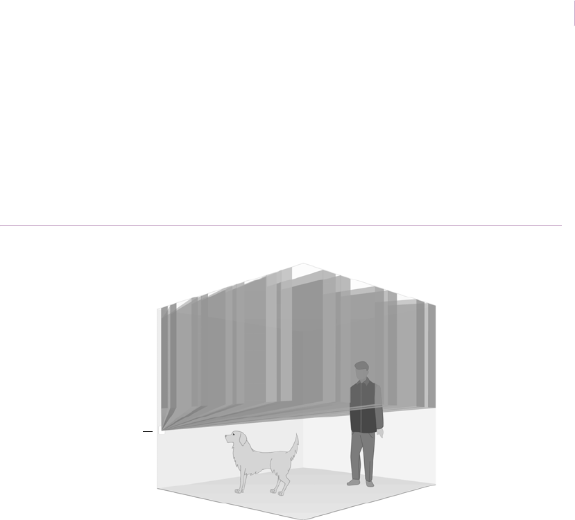
Chapter 2
Motion sensors
49
Installation creating a pet alley. To create a detection-free area close to the floor,
mount an AP450, AP750, or AP950 sensor 3.5 ft. (1.1 m) above the floor, upside down
(sensor window towards the ceiling). Make sure the under-crawl mask is in place to reduce
exposure to the ceiling. As shown in Figure 37, pets are free to roam below the mounting
height of the sensor without causing an alarm.
Recommended products. AP450, AP750, AP950
Figure 37. Pet alley
3.5 ft. (1.1 m)
Sensor
Sensor_Applications.book Page 49 Tuesday, December 27, 2005 5:45 AM
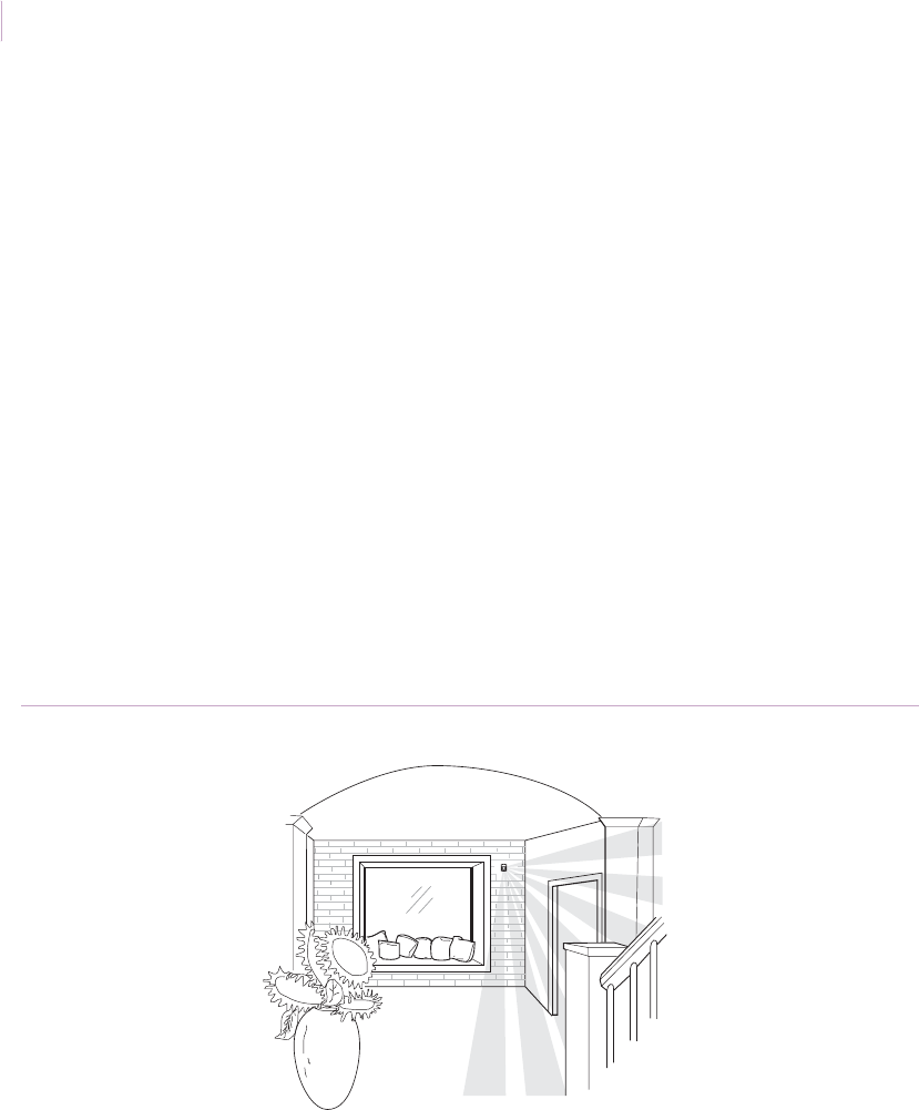
Intrusion Sensor
Application Notebook
50
Wireless sensors
Application. Wireless motion sensors can be used in residential and commercial
applications. Wireless sensors are especially useful for installations where it is difficult or
impossible to run wires. See Choosing the right motion sensor on page 37 for descriptions of
wireless sensor models.
Installation. Wherever possible, use a single sensor to cover more than one room
(Figure 38). To install the sensor, do the following:
1. Mount the back box.
2. Attach the sensor to the swivel bracket that is incorporated into the front cover of
the back box.
3. Walk test the sensor (see Walk test on page 42).
Recommended products. NX-482, AP750W, 60-880-95, 60-639-95R, 60-703-95,
60-511-02-95
Figure 38. Wireless sensor installation
Sensor
Sensor_Applications.book Page 50 Tuesday, December 27, 2005 5:45 AM
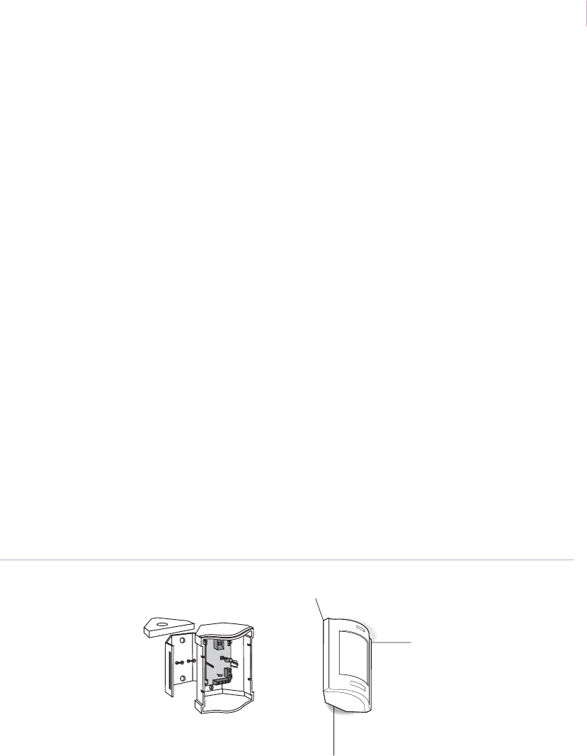
Chapter 2
Motion sensors
51
Discreet appearance
Application. When adding a security system to an existing residence, the appearance of the
system is often very important to the homeowner. The homeowner is concerned with sensor
placement, wiring and control panel location, and holes drilled through existing walls.
The 6351 DesignLine sensor combines an attractive, unobtrusive design with an easy-to-
mount snap-on bracket. It can be mounted in a corner within 1/8 in. (0.3 cm) of the ceiling.
This sensor can save you installation time and cost, and has a standard 90-degree lens that
provides entire room coverage with one sensor.
Installation. To install the sensor, do the following:
1. Choose a mounting location close to the ceiling in the corner adjacent to the room’s
entrance (Figure 39) to get the best sensor line of sight. Pull wiring through the
ceiling where possible for a faster, easier installation.
2. Using the foam spacer, mount the bracket to the wall. Connect the wires to the
sensor terminal block and snap the cover in place.
3. Most rooms need only one-zone sensitivity, but if the room is subject to temperature
fluctuations or other instability, adjust the sensor for two-zone sensitivity.
4. Test the sensor (see Walk test on page 42).
Recommended products. 6351
Figure 39. DL6351 mounting
6351
exploded view
6351
corner mount
Sensor_Applications.book Page 51 Tuesday, December 27, 2005 5:45 AM
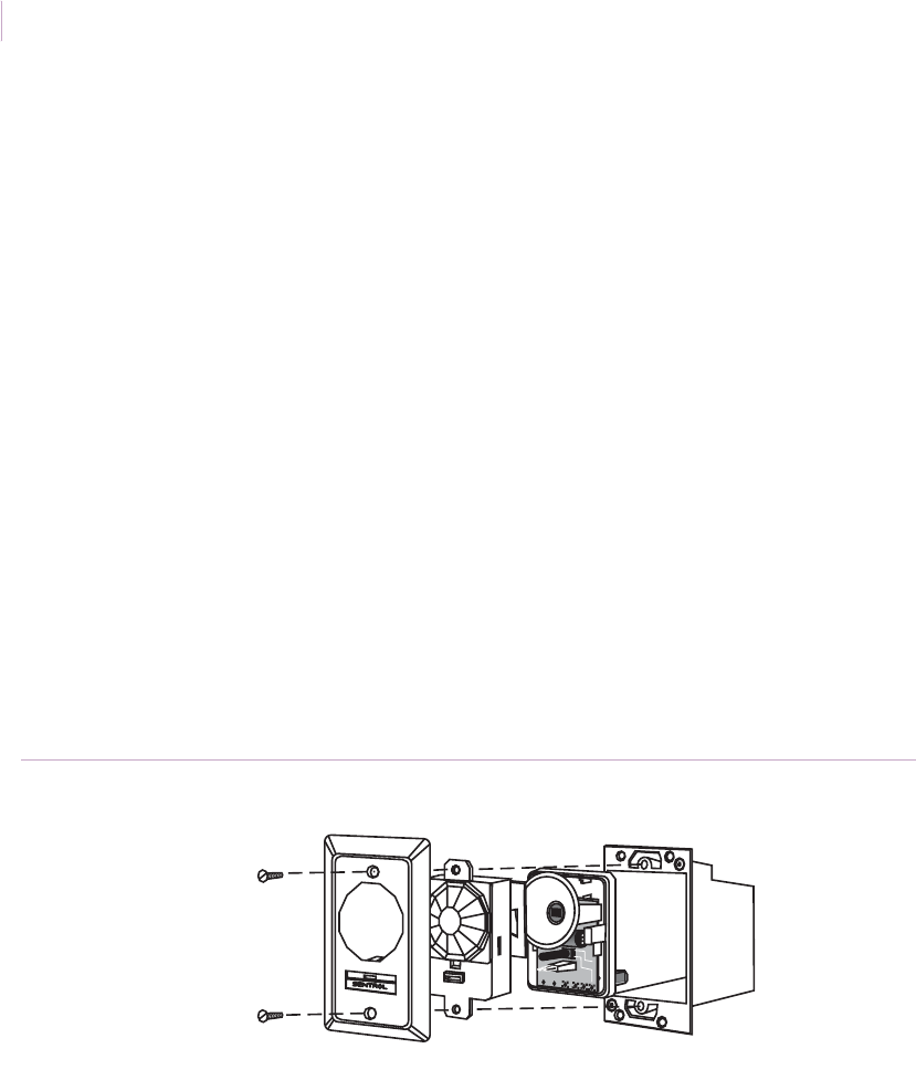
Intrusion Sensor
Application Notebook
52
Flush mount
Application. Flush-mount motion sensors make protection no more intrusive in a room
than an electrical outlet or switch. Flush-mount PIR sensors are most often used in prewired
security installations, but can also be used in retrofit installations.
Installation. The 6255FM flush mount SureShot (Figure 40) fits into a standard, plastic
single-gang box. If the security system is to be prewired, mount a single-gang box for each
sensor as planned with the builder. Sensor wires can be easily run through walls and routed
to the control panel. Due to noise problems, do not run PIR sensor wires beside AC wires.
To install the sensor, do the following:
1. Mount the box in the ceiling. For retrofit installations, take care to cut a hole in the
wall just large enough to fit the single-gang remodel box.
2. Run wires through the box to the sensor terminal block.
3. Screw the sensor into the single-gang box as you would an electrical outlet and walk
test the sensor to ensure correct operation. See Walk test on page 42.
Recommended products. 6255FM
Figure 40. 6255FM flush mount SureShot
PET
ALLEY
®
6255 flush mount sensor Single-gang box
Sensor_Applications.book Page 52 Tuesday, December 27, 2005 5:45 AM
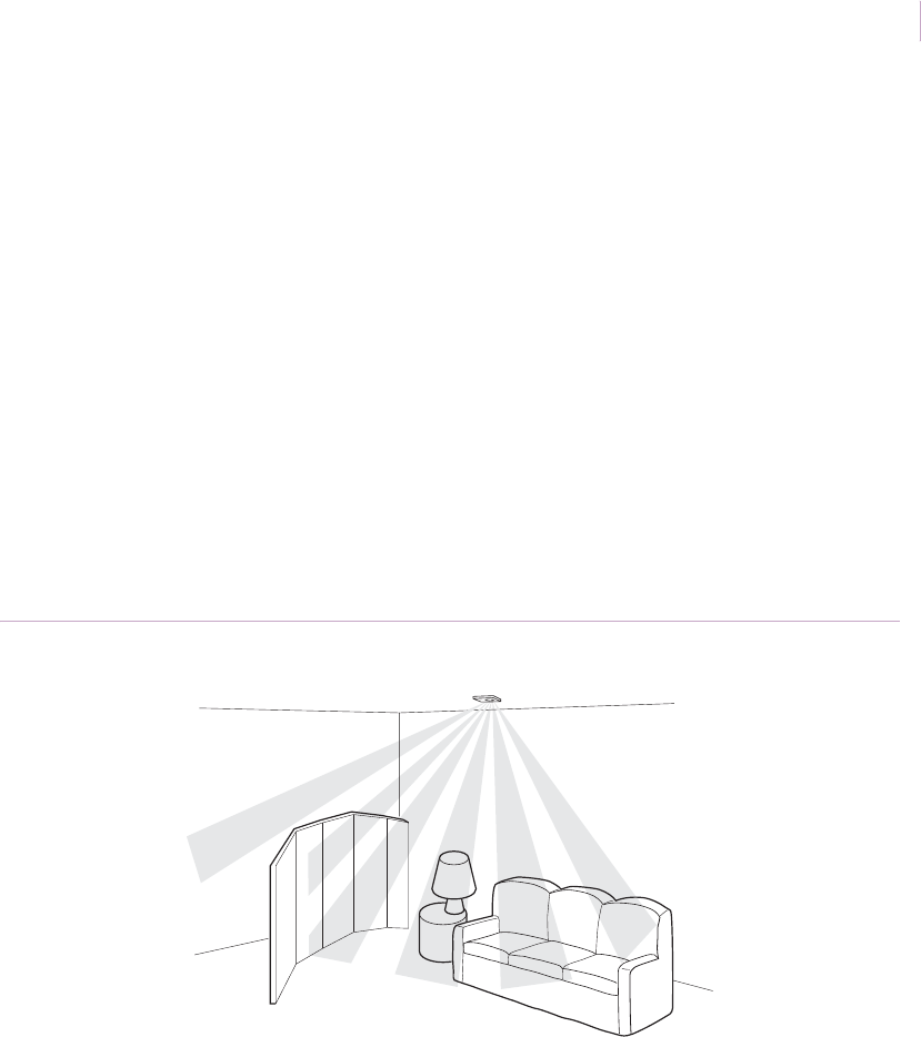
Chapter 2
Motion sensors
53
Ceiling mount
Application. Mounting a sensor in the ceiling is a good way to hide wiring in single-level
homes. Running wires in an attic allows you to easily avoid water pipes, duct work, and high
voltage wiring. It also provides complete coverage of rooms with obstructions such as half-
walls and shelving that can block wall mounted sensor coverage.
Installation. For flush mount installation, install a standard plastic single-gang outlet box
in the ceiling (Figure 41). Use a remodel box for homes where construction is already
complete. Always test the installation (see Walk test on page 42).
If you use the 6255 or 6255FM sensors, ensure the ceiling is less than 12 ft. (3.7 m) high. If
you use the AP669 sensor, ensure the ceiling is less than 16 ft. (4.9 m) high.
Recommended products. 6255, 6255FM, AP669
Figure 41. Ceiling mount
Sensor
Sensor_Applications.book Page 53 Tuesday, December 27, 2005 5:45 AM
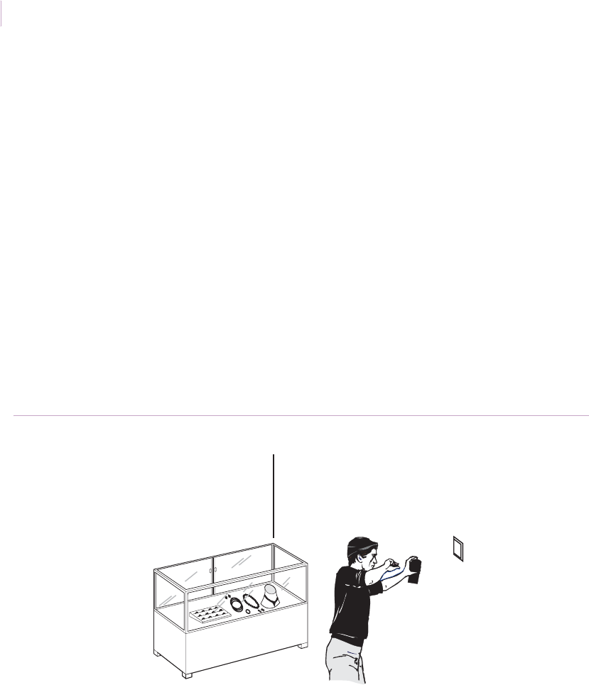
Intrusion Sensor
Application Notebook
54
Antimasking
Application. In high-risk applications, you may need to guard against an intruder disabling
a motion sensor. The intruder could gain access to the sensor when the installation is
disarmed and spray the lens (Figure 42) or cover the lens with a transparent piece of glass
that blocks the sensor window. The intruder could then return when the installation is armed
and know the sensor would not detect his presence.
The AP950AM antimasking motion sensors have built-in technology that looks for a
masking tamper and notifies the system of the problem.
Installation. Use a AP950AM motion sensor in this application and install the sensor as
appropriate to the installation environment. You do not need to do anything to enable the
antimasking feature.
Recommended products. AP950AM
Figure 42. Intruder masking a sensor
Sensor_Applications.book Page 54 Tuesday, December 27, 2005 5:45 AM
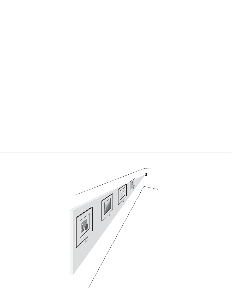
Chapter 2
Motion sensors
55
Museums
Application. Use a motion sensor to effectively protect areas where the presence of
valuable items increases the risk of theft or vandalism.
Installation. To protect a wall of paintings, mount a sensor on a side wall as shown in
Figure 43. Use the sensor to trigger an alarm or a recorded message warning patrons to stay
a certain distance from the paintings. You can also use a sensor mounted behind a painting or
wall hanging to sound an alarm if the object is moved.
Use a sensor with a curtain lens to provide blanket coverage of entry areas, or use a vertical
barrier lens to prevent intruders from crawling under the sensor’s field of view.
Recommended products. AP450, AP475, AP633, AP950AM
Figure 43. Museum protection
Sensor
Sensor_Applications.book Page 55 Tuesday, December 27, 2005 5:45 AM
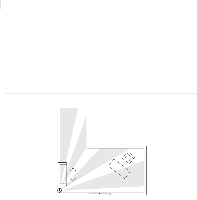
Intrusion Sensor
Application Notebook
56
Office foyers
Application. Large office foyers can be difficult to protect with a single motion sensor.
Installation. Mount a sensor in the corner on a wall or on the ceiling as shown in
Figure 44. to provide appropriate coverage of foyers, corridors, and hallways.
Recommended products. AP669, AP450, AP750, NX482, 60-880-95
Figure 44. Foyer coverage
Sensor
Sensor_Applications.book Page 56 Tuesday, December 27, 2005 5:45 AM
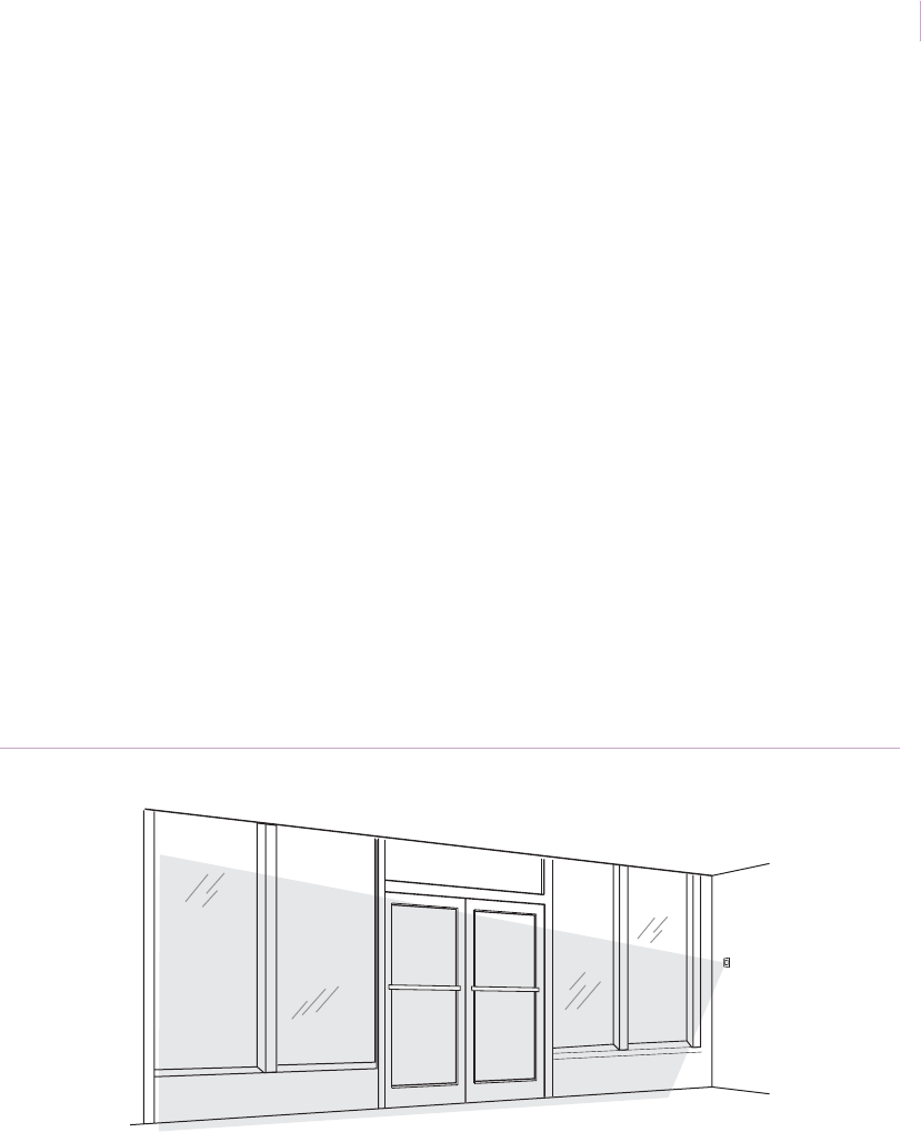
Chapter 2
Motion sensors
57
Storefront windows
Application. A curtain motion sensor, such as the AP450 or AP475, provides a cost-
effective and secure means of intrusion detection through large windows and doors that are
typical of a storefront or car showroom.
Installation. To mount the sensor, do the following:
1. Mount the sensor 3 ft. (0.9 m) from the window. This avoids any possibility that one
half of the curtain is looking at the window, while the other half is not (a potential
cause of instability). If this is not possible, angle the sensor slightly inwards.
2. Make sure the sensor is set to standard sensitivity and the appropriate range.
3. Install the appropriate mirror masks. Figure 45 shows the left side of the pattern
masked out (always mask out curtains that are directed at the windows), while the
right side is active to protect the inside of the store.
4. Test the sensor (see Walk test on page 42).
Recommended products. AP450, AP475, AP750, NX482, 60-880-95, RCR series
Figure 45. Storefront coverage
Sensor
Sensor_Applications.book Page 57 Tuesday, December 27, 2005 5:45 AM
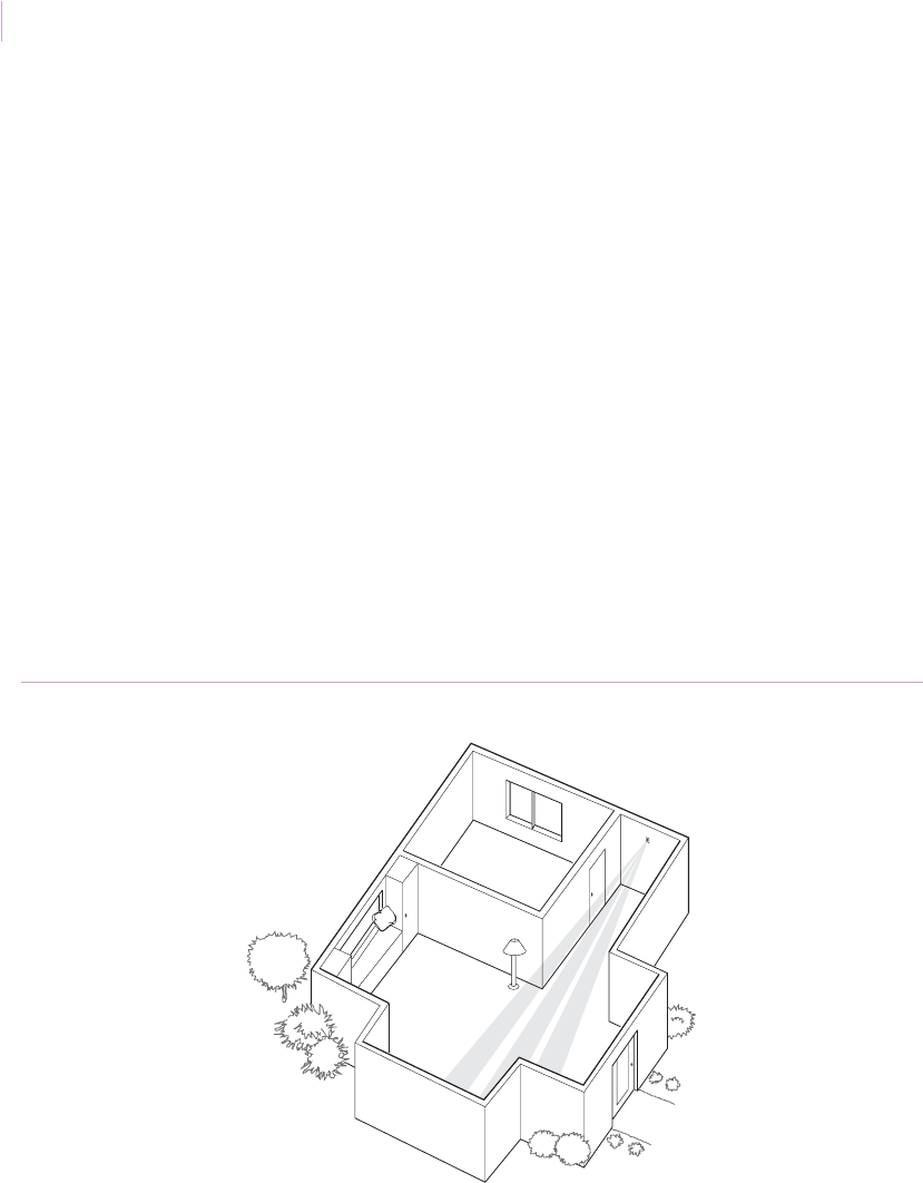
Intrusion Sensor
Application Notebook
58
Hallways and lobby lighting activation
Application. Use motion sensors to protect long narrow areas such as corridors or hallways
(see Long corridors or aisles on page 69 for commercial applications). You can also use a
sensor with a separate relay and power supply to activate lighting controls in hallways and
lobbies.
When choosing a sensor for this application, consider the length of the hallway, range and
appearance of the sensor, and if pets will be a factor.
Installation. Mount a sensor with a single-spot or vertical barrier lens at the opposite end
of a hallway or lobby from its entrance (Figure 46). Anyone entering the hallway from the
entrance or from side doors will be detected.
Recommended products. AP450, AP475, 6255, NX488 with a single-spot or vertical
barrier mask, 6155 with a long range or curtain lens, 6351 DesignLine with a vertical barrier
mask
Figure 46. Hallway lights
Sensor
Sensor_Applications.book Page 58 Tuesday, December 27, 2005 5:45 AM
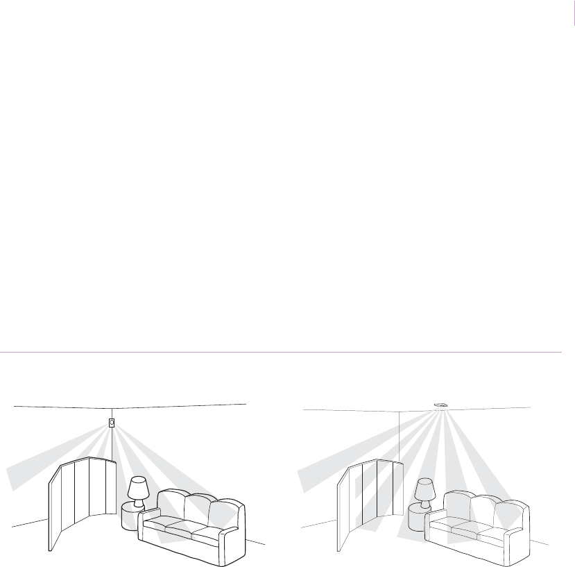
Chapter 2
Motion sensors
59
Partitions or other obstacles
Application. Partitions, half-walls, shelving, and filing cabinets in a room or office
environment can present installation challenges.
Installation. To avoid obstacles while protecting the space in a room, mount a sensor in
the ceiling. Position the sensor in a location where partitions will not block sensor coverage
pattern. Figure 47 shows incorrect and correct placement samples.
Test the installation to ensure correct operation (see Walk test on page 42) and instruct office
personnel to not move partitions or shelving without notifying the security consultant.
Recommended products. 6255, 6255FM, AP669
Figure 47. Incorrect and correct coverage with obstacles
Incorrect Correct
Sensor_Applications.book Page 59 Tuesday, December 27, 2005 5:45 AM
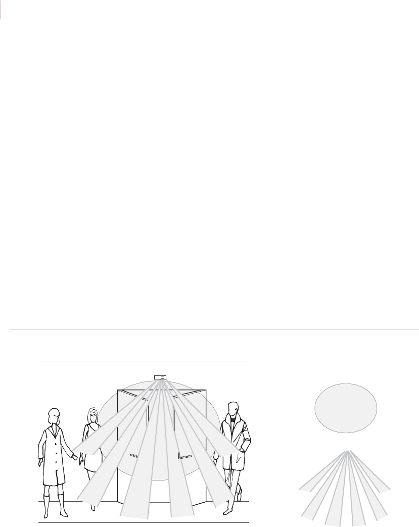
Intrusion Sensor
Application Notebook
60
Request-to-exit door control
Application. Hospitals, schools, commercial offices, warehouses, and a variety of other
access control applications require request-to-exit door control. Assuring that automatic
door opening devices prevent intrusion while permitting authorized ingress/egress can be a
challenge and often requires multiple sensors. The RCR-REX sensor meets this challenge.
The sensor’s range controlled radar (RCR) technology was originally intended to prevent
air-to-air collisions. Now GE has applied this technology to the RCR-REX for false alarm
immune motion detection.
Installation. Mount the sensor directly to a door mullion, the ceiling, or the wall just above
the door (Figure 48). The RCR-REX provides aiming and range control capabilities that
make it easy to adjust the distance for the appropriate coverage. The sensor will detect
motion toward the door and activate an event flag in the access control panel. The event flag
will start a macro that will unlock the door and shunt the door switch for the programmed
time period or until the switch is closed (Figure 49 on page 61).
Recommended products. RCR-REX
Figure 48. Request-to-exit door control
RCR-REX Sensor
Radar coverage pattern
PIR coverage pattern
Sensor_Applications.book Page 60 Tuesday, December 27, 2005 5:45 AM

Chapter 2
Motion sensors
61
Figure 49. Door control
Door
RCR-REX Door switch
Door latch
7 ft. (2.1 m)
typical
Built-in sounder tied to access panel Access
control
panel
DOTO (door open too long)
detection tied to access panel
Automatic door latch tied to access panel
Sensor_Applications.book Page 61 Tuesday, December 27, 2005 5:45 AM
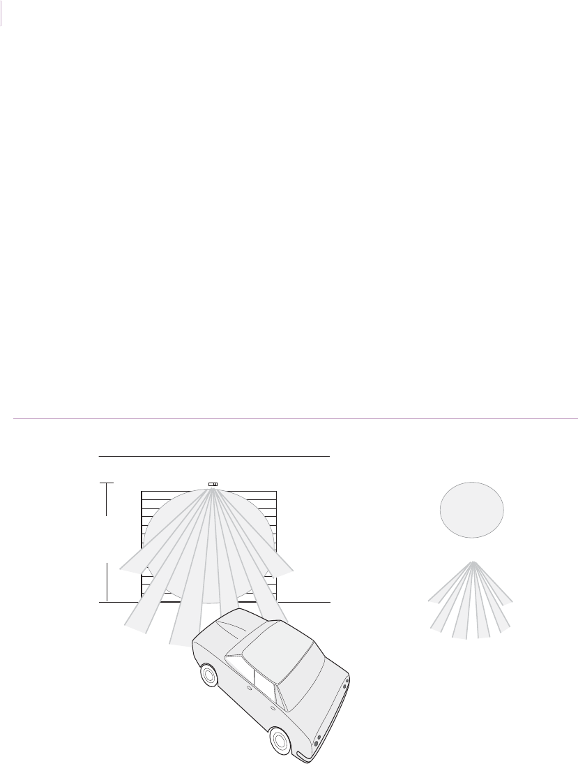
Intrusion Sensor
Application Notebook
62
Request-to-exit roll-up door control
Application. Drive-through areas with roll-up doors such as shipping docks, garages, and
car service centers, are good applications for request-to-exit door control using the RCR-
REX. Benefits include both security and economic advantages, such as heat conservation.
The sensor’s dual technology requires both heat from the car engine and vehicle motion
before the internal relay is triggered (Figure 50). You can use the 15 ft. (4.6 m) range of the
RCR-REX to signal an attendant with a bell or to automatically open the door. The sensor
can provide both local annunciation and an alarm with forced entry.
Installation. The RCR-REX is not designed for outdoor environments and is intended for
indoor use only. For pet or rodent immunity, adjust the radar curtain at a height from 1 to 2
ft. (0.3 to 0.6 m) above the floor. Adjust the internal turret for a maximum range of 7 ft. (2.1
m) when the device is mounted at 15 ft. (4.6 m).
Recommended products. RCR-REX
Figure 50. Roll-up door control
15 ft. (4.6 m)
RCR-REX
typical
Radar coverage pattern
PIR coverage pattern
Sensor_Applications.book Page 62 Tuesday, December 27, 2005 5:45 AM

Chapter 2
Motion sensors
63
Room perimeters
Application. Motion sensors can be sensitive to direct sunlight. In a room with multiple
windows, the windows can limit the choice of coverage patterns and mounting locations.
However, you can use four sensors to protect the entire perimeter.
Installation. Use a sensor in each corner (Figure 51). Mount the swivel bracket near a
corner and connect the back case of the sensor to the bracket. The outside coverage zone
should run parallel to, but not touch, the wall to be protected. With proper aiming you can
reduce the unprotected space near the wall.
Test the installation (see Walk test on page 42).
Recommended products. AP450, AP475, AP750, NX-482, 60-880-95
Figure 51. Room perimeter coverage
Sensor
Sensor
Sensor
Sensor
Sensor_Applications.book Page 63 Tuesday, December 27, 2005 5:45 AM
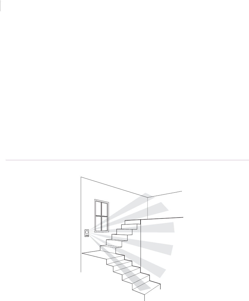
Intrusion Sensor
Application Notebook
64
Multilevel homes
Application. In homes with a multilevel floor plan, you must take care to ensure complete
coverage. The most cost-effective way to obtain complete coverage is to mount a sensor
with a 360-degree lens on the wall or ceiling. A standard, wall-mounted 90-degree lens may
leave unprotected zones that an intruder can use to invade a home.
Installation. Mount the sensor on a wall that is adjacent to the room’s entrance to get the
best sensor line of sight (Figure 52). You can also mount the sensor in the ceiling to achieve
360-degree coverage of the room.
Test the installation (see Walk test on page 42).
Recommended products. 6255, 6255FM
Figure 52. Stairwell in a multilevel house
Sensor
Sensor_Applications.book Page 64 Tuesday, December 27, 2005 5:45 AM
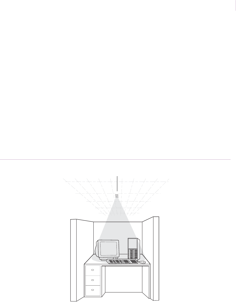
Chapter 2
Motion sensors
65
Valuable equipment
Application. To protect valuable equipment, such as computers, TVs, and video
equipment, mount a sensor in the ceiling above the equipment (Figure 53) and use a very
narrow coverage pattern.
Installation. Use a 6255 SureShot or a 6255FM SureShot with a single spot mask in this
application. Verify that the sensor range is suitable for the application. Mount the sensor in
the ceiling directly above the equipment and test (see Walk test on page 42).
You can also use an RCR-A or RCR-C set at a range of 9 ft. (2.7). If you want to hide the
sensor above a drop-tile ceiling, you must use the sensor’s stealth mode. See RCR sensors on
page 36 and the sensor’s installation instructions.
Recommended products. 6255, 6255FM, RCR-A, RCR-C
Figure 53. Computer spot coverage
Sensor
Sensor_Applications.book Page 65 Tuesday, December 27, 2005 5:45 AM
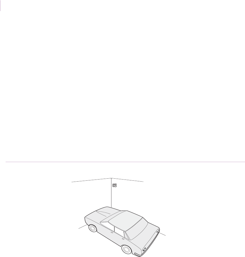
Intrusion Sensor
Application Notebook
66
Vacation homes and garages
Application. Garages and vacation homes often contain valuable objects and present some
protection challenges. They are not always temperature-regulated, and, in the case of
garages, there can be a risk of damage to sensors from accidental impacts with balls and
tools. The 6187CTX operates from -40 to 120°F (-40 to 50°C) and is ideal for protecting
garages and vacation homes in cold climates. The RCR series sensors are a good solution in
installations where temperature extremes are not an issue.
Installation. Mount the sensor as indicated by the specific sensor’s installation
instructions. Use the swivel bracket included with the sensors to aim and adjust the sensor
(Figure 54), if needed, and test the sensor (see Walk test on page 42).
Recommended products. 6187CTX, RCR series
Figure 54. Garage protection
Sensor_Applications.book Page 66 Tuesday, December 27, 2005 5:45 AM

Chapter 2
Motion sensors
67
Indoor swimming pools
Application. Use 6187CTX or 618703 sensors to sound a local alarm upon unauthorized
entrance into indoor swimming areas either in homes or in hotels. The cast metal housing of
the 6187CTX sensor provides water resistance in humid indoor swimming environments.
Installation. Mount the sensor approximately 7 ft. (2.1 m) high on a wall adjacent to the
entrance door, pointing downward (Figure 55), or in the ceiling pointing toward the door.
Walk test the installation (see Walk test on page 42).
If conduit is used, run the conduit out the side or bottom of the sensor to keep conduit
condensation from draining into the sensor housing. Make sure conduit openings and
mounting holes are well sealed.
Recommended products. 6187XCTX, 618703
Figure 55. Indoor swimming pools
Sensor
Sensor
Sensor_Applications.book Page 67 Tuesday, December 27, 2005 5:45 AM

Intrusion Sensor
Application Notebook
68
Large areas
Application. Large indoor areas such as factories, sports or concert halls, gymnasiums, and
warehouses, can require multiple sensors for adequate coverage. With an 80 ft. (24.4 m)
wide angle coverage pattern, a single AP633A can often do the job of several conventional
PIR sensors, saving material and labor costs. The coverage includes a complete 40 ft.
(12.2 m) curtain and a 200 ft. (60.9 m) long-range field of view (Figure 56) that can be
enabled when required. The combination of step focus mirror and microprocessor controlled
4D signal processing ensures excellent detection in all ranges and trouble-free performance
in these often difficult environments. If you need coverage of 90 ft. (27.4 m) or less, the
RCR-90 is also a good solution.
Installation. Mount the AP633A between 6 and 10 ft. (1.8 and 3.0 m) high. Select the
correct sensitivity for standard wide-angle detection. For fine adjustments, use the aiming
mechanism described in the installation instructions and walk test the installation (see Walk
test on page 42).
Recommended products. AP633A, RCR-90
Figure 56. AP633 coverage pattern
AP633A
40 ft.
(12.2 m) 80 ft.
(24.4 m)
200 ft.
(60.9 m)
Sensor_Applications.book Page 68 Tuesday, December 27, 2005 5:45 AM
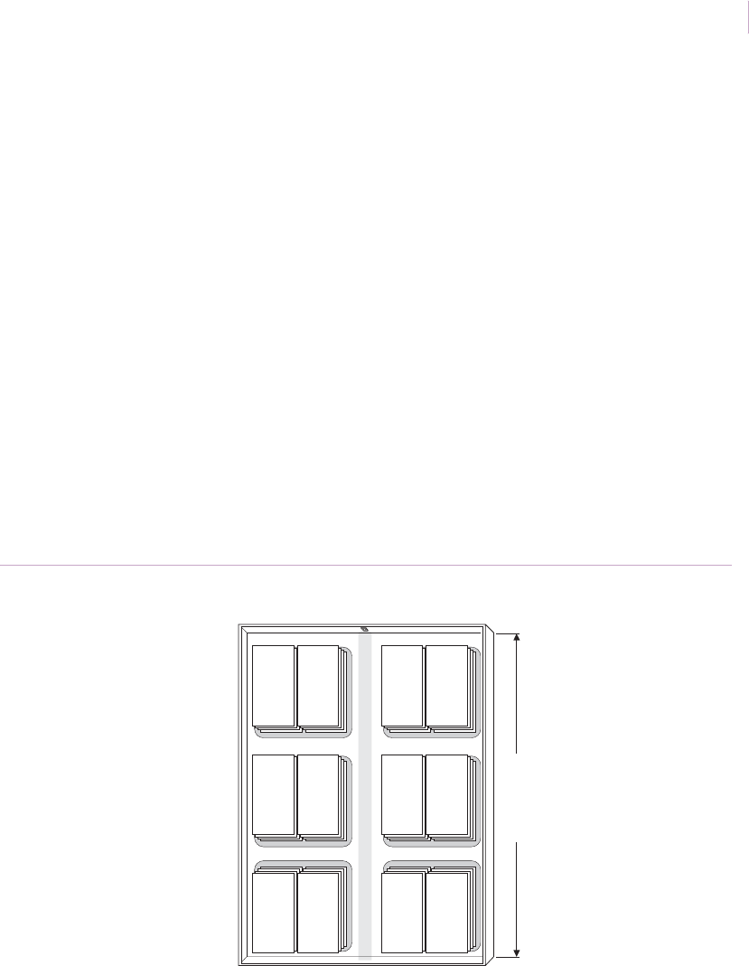
Chapter 2
Motion sensors
69
Long corridors or aisles
Application. Supermarkets, factories, and schools frequently have long corridors or aisles
that need protection. The AP633 with a range of 200 ft. (60.9 m) provides the longest
coverage range of any PIR sensor available. The step focus mirror ensures that even at
maximum range, detection is crisp and consistent without oversensitivity at closer ranges. If
you need coverage of 90 ft. (27.4 m) or less, the RCR-90 is also a good solution.
Installation. Mount the AP633 (Figure 57) between 6 and 10 ft. (1.8 and 3.0 m) high.
Select the correct sensitivity for Curtain/Long range detection. Carry out fine adjustments
using the aiming screws and install masking devices as described in the installation
instructions. Be aware that a minor horizontal or vertical reorientation can result in a major
displacement of the field of view at 200 ft. (60.9 m). Walk test the installation (see Walk test
on page 42). If detection is not satisfactory at long range, check the vertical orientation. An
uneven wall can make the sensor aim slightly downward, reducing range.
Recommended products. AP633, RCR-90
Figure 57. Long aisle protection
AP633 sensor
200 ft.
(60.9 m)
Sensor_Applications.book Page 69 Tuesday, December 27, 2005 5:45 AM
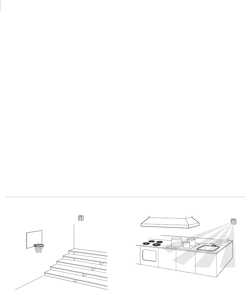
Intrusion Sensor
Application Notebook
70
Schools
Application. Protecting schools presents challenges to security system installers. Rooms
are typically larger than in other commercial environments (auditoriums, lecture halls,
gymnasiums), and hallways are longer. Vandalism is a concern and it may be necessary to
protect outdoor areas to prevent unwanted entry at certain times of the day or night.
Installation. Locate sensors high, near the corners of walls where they are least
conspicuous. For outdoor applications, mount the 6187CTX Industrial PIR with cast metal
housing out of reach of vandals, in areas where they will not be exposed to direct sunlight.
The 6187CTX is also ideal for areas that may be exposed to water, high humidity such as
school kitchens (Figure 58), or chemicals such as shops.
For larger areas and long hallways (see Long corridors or aisles on page 69), use the AP633.
It provides 80 ft. (24.4 m) wide angle, 40 ft. (12.2 m) curtain, and 200 ft. (60.9 m) long range
coverage patterns. If you need coverage of 90 ft. (27.4 m) or less, the RCR-90 is also a good
solution.
Recommended products. 6187CTX, AP633, RCR-90
Figure 58. School gyms and kitchens
6187CTX sensor6187CTX sensor
Sensor_Applications.book Page 70 Tuesday, December 27, 2005 5:45 AM
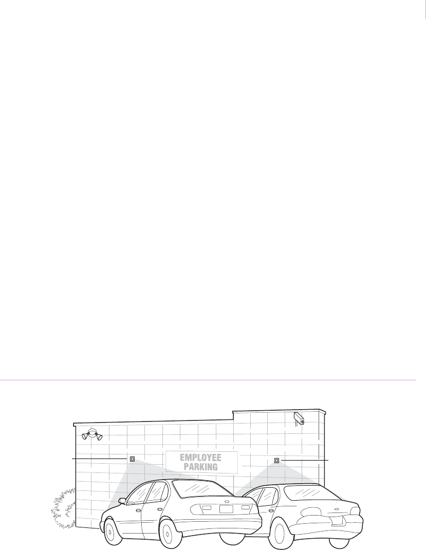
Chapter 2
Motion sensors
71
Outdoor areas
Application. There are many applications for outdoor motion protection. Most stem from
the need to protect property that is at risk. Residential yards, parking lots (Figure 59),
outdoor shopping areas, outdoor garden shops, auto dealerships, aircraft hangers, perimeters
of military installations, and public utility installations are all examples of such applications.
The cast metal housing of the 6187CTX PIR sensor is specifically designed for outdoor
applications, and the sensor provides water resistance and reliable detection in temperatures
from -40 to 120°F (-4- to 50°C). The 60-639-95R-OD is also rated for outdoor applications.
Both sensors should be used in fenced applications for local alarm or camera activation only.
Installation. Mount the sensor approximately 7 ft. (2.1 m) high (Figure 59). Avoid direct
sunlight on the lens and keep away from branches that may impede sensor coverage pattern.
See Outdoor installation guidelines on page 41. Walk test the installation (see Walk test on
page 42).
If conduit is used, run the conduit out the side or bottom of the sensor to keep conduit
condensation from draining into the sensor housing. Make sure conduit openings and
mounting holes are well sealed.
Recommended products. 6187CTX, 60-639-95R-OD
Figure 59. Outdoor area coverage
Sensor
Sensor
Sensor_Applications.book Page 71 Tuesday, December 27, 2005 5:45 AM
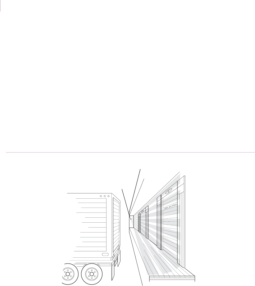
Intrusion Sensor
Application Notebook
72
Loading docks
Application. Loading docks are a frequent target for burglars. Early detection can avoid
costly break-ins to both the backs of trucks and the warehouse itself. Use the 6187CTX PIR
sensor, designed for outdoor use, with the 6083-N swivel bracket in this application. The
sensor should be used for local alarm or video activation only.
Installation. Mount the sensor equipped with a vertical-barrier lens on a 6083-N swivel
bracket and direct the sensor toward the area to be protected (Figure 60). Walk test the
installation (see Walk test on page 42).
Recommended products. 6187CTX, 6083-N (bracket)
Figure 60. Loading dock coverage
Sensor
Sensor_Applications.book Page 72 Tuesday, December 27, 2005 5:45 AM
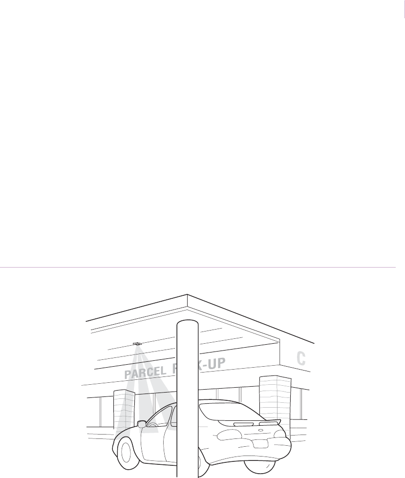
Chapter 2
Motion sensors
73
Drive-through pickup areas
Applications. Drive-through areas are used by stores and other businesses for parcel
pickups. A motion sensor with a long range lens can be used to signal the store attendant
with a bell and/or lights when a car pulls up at the pickup door. The long range lens provides
spot detection of automobiles and minimizes false alarms from people in the walkways next
to the drive-through lane. This configuration is designed for local annunciation, not alarm.
The sensor is responding to the heat of the car engine and upon initial startup some car
engines may not generate sufficient heat to trip the sensor.
Installation. Mount a 6187CTX sensor in the ceiling directly above the drive-through area
(Figure 61). Test the installation (see Walk test on page 42).
Recommended products. 6187CTX
Figure 61. Drive-through areas
Sensor
Sensor_Applications.book Page 73 Tuesday, December 27, 2005 5:45 AM

Intrusion Sensor
Application Notebook
74
Vegetable gardens
Application. Use a 6187CTX or 618703 motion sensor to sound a local alarm when
animals enter a fenced vegetable garden. The cast metal housing of the 6187CTX sensor is
specifically designed for outdoor applications and provides water resistance and reliable
detection in temperatures from -40 to 120 °F (-40 to 50°C). Use a curtain lens and mount a
sensor on all four sides of a fenced garden to provide complete perimeter detection. If the
sensors are covered to protect them from rain, outdoor-rated 60-880-95R-OD and 60-880-95
sensors are also good options.
Installation. Mount one sensor approximately 7 ft. (2.1 m) high at each corner of the
garden (Figure 62). Avoid direct sunlight on the lens and keep away from branches that may
impede sensor coverage. See Outdoor installation guidelines on page 41.
If conduit is used, run the conduit out the side or bottom of the sensor to keep conduit
condensation from draining into the sensor housing. Make sure conduit openings and
mounting holes are well sealed.
Recommended products. 6187CTX, 618703, 60-880-95R-OD, 60-880-95
Figure 62. Garden coverage
Sensor
Sensor_Applications.book Page 74 Tuesday, December 27, 2005 5:45 AM
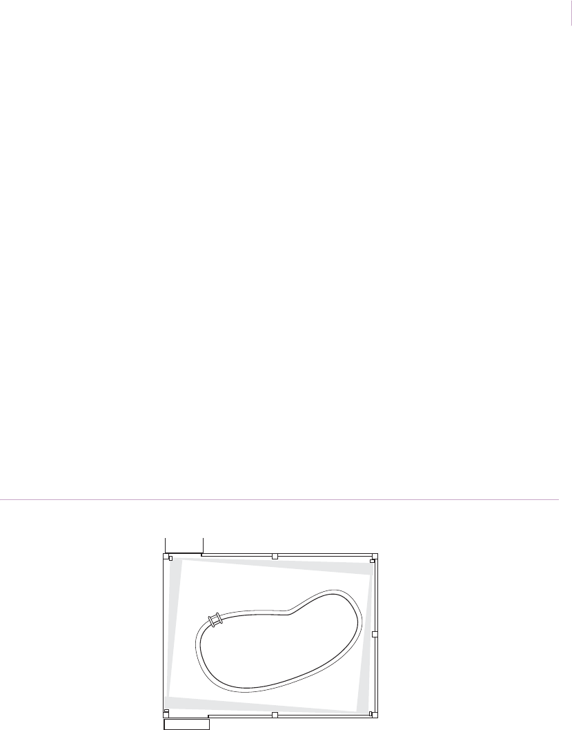
Chapter 2
Motion sensors
75
Outdoor swimming pools
Application. Use a motion sensor to sound a local alarm upon unauthorized entrance into
outdoor swimming areas either at homes or hotels. The cast metal housing of the 6187CTX
sensor is specifically designed for outdoor applications, and the sensor provides water
resistance and reliable detection in temperatures from -40 to 120°F (-4- to 50°C). The
618703 and 60-639-95R-OD sensors are also outdoor rated and can be used.
Note: The sensors in this application do not take the place of a fence. All outdoor swimming pools should
be surrounded by a fence for liability reasons.
Installation. Mount one sensor with a curtain lens approximately 7 ft. (2.1 m) high at each
corner of the pool area (Figure 63) to provide complete perimeter detection. Avoid direct
sunlight on the lens and keep away from branches that may impede sensor coverage. See
Outdoor installation guidelines on page 41. Walk test the installation (see Walk test on
page 42).
If conduit is used, run the conduit out the side or bottom of the sensor to keep conduit
condensation from draining into the sensor housing. Make sure conduit openings and
mounting holes are well sealed.
Recommended products. 6187CTX, 618703, 60-639-95R-OD
Figure 63. Outdoor pool coverage
Sensor
Sensor
Sensor
Sensor
Sensor_Applications.book Page 75 Tuesday, December 27, 2005 5:45 AM
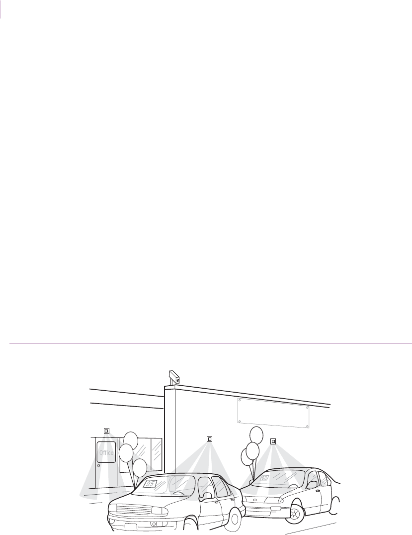
Intrusion Sensor
Application Notebook
76
CCTV camera activation
Application. Use a motion sensor to activate CCTV cameras that monitor outdoor parking
lots, auto dealerships, shopping areas, shipping areas, garden shops, aircraft hangars,
perimeters of military installations, and public utility installations. In this application, the
sensor does not directly activate a central station alarm. Rather, it alerts a guard station and/
or automatically starts a CCTV recording device. This prevents false alarms due to birds and
other animals that might enter the sensor’s coverage area.
Installation. Connect a 6187CTX or 60-639-95R-OD sensor to the local alarm switch in a
guard station or to a CCTV camera. Mount the sensor approximately 7 ft. (2.1 m) high
(Figure 64). Avoid direct sunlight on the lens and keep away from branches that may
impede the sensor coverage pattern. See Outdoor installation guidelines on page 41.
If conduit is used, run the conduit out the side or bottom of the sensor to keep conduit
condensation from draining into the sensor housing. Make sure conduit openings and
mounting holes are well sealed.
Recommended products. 6187CTX, any sensor with Form C (for indoor applications),
60-639-95R-OD
Figure 64. CCTV camera activation
S
A
L
E
Sensor
Sensor Sensor
Camera
Sensor_Applications.book Page 76 Tuesday, December 27, 2005 5:45 AM

Chapter 2
Motion sensors
77
Outdoor lighting activation
Application. Use a motion sensor to activate lighting controls around homes, detached
garages, gardens, backyard patios and decks, outdoor parking lots, auto dealerships,
shopping areas, shipping areas, garden shops, aircraft hangars, perimeters of military
installations, and public utility installations. When activating lights, use a separate relay and
power supply.
The cast metal housing of the 6187CTX PIR sensor is specifically designed for outdoor
applications, and the sensor provides water resistance and reliable detection in temperatures
from -40 to 120°F (-4- to 50°C). The 618703 and 60-639-95R-OD outdoor-rated sensors can
also be used.
Installation. Mount the sensor approximately 7 ft. (2.1 m) high (Figure 65). See Outdoor
installation guidelines on page 41. Walk test the installation (see Walk test on page 42).
If conduit is used, run the conduit out the side or bottom of the sensor to keep conduit
condensation from draining into the sensor housing. Make sure conduit openings and
mounting holes are well sealed.
Recommended products. 6187CTX, 618703, 60-639-95R-OD
Figure 65. Outdoor lighting activation
Sensor
Sensor_Applications.book Page 77 Tuesday, December 27, 2005 5:45 AM
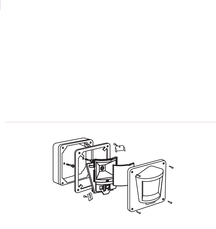
Intrusion Sensor
Application Notebook
78
Extreme temperature conditions
Application. Meat lockers, unregulated buildings in very hot or cold climates, and other
areas of extreme temperatures often require space protection. Use motion sensors in these
applications for zone verification or to trigger local alarms only.
Installation. For industrial applications in very cold environments, use the 6187CTX PIR
sensor (Figure 66) that operates down to -40°F (-40°C). The 6155CT can also be used in
cold climates, but is housed in standard plastic.
Recommended products. 6187CTX
Figure 66. 6187CTX
Sensor_Applications.book Page 78 Tuesday, December 27, 2005 5:45 AM

Chapter 2
Motion sensors
79
Explosive atmospheres
Application. Areas such as munitions depots, grain storage areas, and chemical plants can
involve explosive atmospheres. It is imperative that PIR sensors used in such areas
contribute no electrical signal or field that could cause ignition.
The 6197 Intrinsically Safe PIR System is FM-approved and UL Listed for use in hazardous
locations. For nonincendive applications that require Class I, Division 2, Groups A, B, C,
and D, use the 6198 PIR sensor.
Installation. To install the 6197 sensor, do the following:
1. Mount the sensor using either a sealed cable or sealed conduit fitting.
2. Replace the standard lens with either of the other two lenses if needed.
3. Mount the Barrier Box next to the alarm panel. Run wire between the Barrier Box
and the alarm panel terminals. Connect the ground lug on the bus bar inside the
Barrier Box to an intrinsically safe ground using a 12 AWG or larger wire. Connect
the chassis ground on the alarm panel to earth ground (Figure 67 on page 80).
4. Remove the front housing and install the jumpers in the sensor in the walk test
mode. Select either the one-zone mode or the two-zone mode. Replace the front
housing with the rubber gasket using four screws.
5. Walk test the sensor (see Walk test on page 42) and then install the Barrier Box lid.
Recommended products. 6197
Sensor_Applications.book Page 79 Tuesday, December 27, 2005 5:45 AM
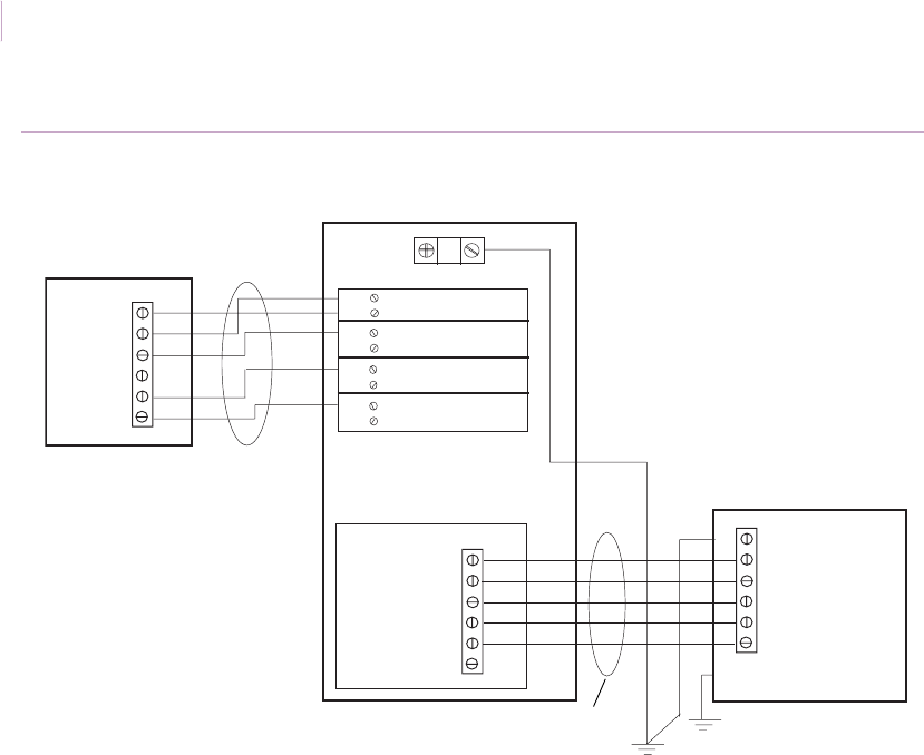
Intrusion Sensor
Application Notebook
80
Figure 67. Wiring diagram for explosive atmospheres
6197BB (Barrier Box)
Ground lug
Barriers
Switching module
12 AWG or larger
6197 PIR
Alarm panel
-
+
TAMP
COM
NC
+12V
TAMP
TAMP
NC
COM
NO
3
4
3
4
3
4
3
4
1
2
3
4
Cable or conduit
Cable or conduit
Intrinsically
safe ground
Earth ground
- Supply (return)
+ Supply (+12V NOM
)
- Tamper loop
+ Tamper loop
+ Alarm loop
- Alarm loop
Chassis
Sensor_Applications.book Page 80 Tuesday, December 27, 2005 5:45 AM

Chapter 3 Magnetic contacts
This chapter provides an overview of magnetic contacts and
how to use them in a variety of applications. Applications
include installations to protect doors, windows, gates, cabinets,
valuable objects, and people.
Sensor_Applications.book Page 81 Tuesday, December 27, 2005 5:45 AM

Intrusion Sensor
Application Notebook
82
Product overview
GE Security has earned its leadership position in the manufacture of magnetic contact
sensors by pioneering advances such as the use of multiple reads, wide gapping, and
numerous features that reduce false alarms. We have developed a range of innovative
designs to assure both greater sensitivity and complete reliability, even in the most
demanding environments. With over 400 models to choose from, we offer the most
comprehensive line of magnetic contacts and peripherals available.
Built for durability and dependability, GE magnetic contacts are conservatively rated at
10,000,000 cycles for closed loop (Form A), ensuring long life. UL rates SPDT (Form C) at
100,000 cycles. Every reed connection is hand soldered, and the switches in many models
are environmentally sealed in polyurethane. Each magnetic contact is tested before they
leave the factory.
Our world-class manufacturing standards and attention to detail virtually eliminate out-of-
box failures. You can install our magnetic contacts quickly and with confidence in their
reliability.
Many residential and commercial applications for magnetic contacts are similar. Residential
users, however, will typically be more concerned with appearance than commercial users.
Commercial considerations include specific issues such as how to protect valuables in
storefront windows or display cases, how to protect steel doors and windows, and how to
protect trucks at loading docks. Magnetic contacts are particularly suited for use on a
24-hour loop to protect occupied areas.
Sensor_Applications.book Page 82 Tuesday, December 27, 2005 5:45 AM

Chapter 3
Magnetic contacts
83
Specifications
Switch configurations:
• Closed loop (Form A) - Switch closed when magnet is in close proximity
• Open loop (Form B) - Switch open when magnet is in close proximity
• SPDT (single-pull, double-throw) (Form C) - Switch has common, open, and closed
sides
• DPDT (double-pull, double-throw) - Two switches, each has common, open, and
closed sides
Gap distances
Ratings are nominal and may vary ± 20%. Ratings are the distance for the switch to make.
Break distance is approximately 1.1 to 1.5 times the make distance.
Electrical specifications
Environmental specifications
WARNING: Each electrical rating is an individual maximum and cannot be exceeded. For
example, an application at 100 V @ 0.25 amp would be 25 watts and would exceed
the 7.5 watt rating of the switch (power = voltage x amps).
Rating Closed loop Open loop SPDT DPDT
Switching voltage (max.) 100 volts @ 0.075 A 30 volts @ 0.1 A 30 volts @ 0.1 A 30 volts @ 0.1 A
Switching current (max.) 0.5 amp @ 15 V 0.25 amp @ 12 V 0.25 amp @ 12 V 0.25 amp @ 12 V
Watts (max.) (volts x amps) 7.5 watts 3 watts 3 watts 3 watts
Temperature range -40 to 150°F (-40 to 65°C)
Shock 50 G’s @ 11 milliseconds
Impact Withstands drop of 2 in. (5 cm) diameter steel ball from 30 in. (76.2 cm)
Vibration 35 G’s @ 50-2000 Hz
Reed internal atmosphere Dry nitrogen
Sensor_Applications.book Page 83 Tuesday, December 27, 2005 5:45 AM
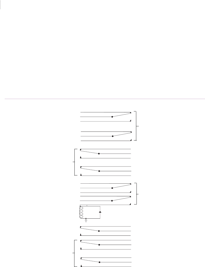
Intrusion Sensor
Application Notebook
84
Control switching using DPDT switches
This information describes how to achieve dual switching with one magnetic contact and
one magnet (Figure 68). DPDT (double-pull, double-throw) magnetic contacts such as the
1087D, 1084D, 2507AD, or 2707AD may be used in place of two contacts or one contact
and a floor mat for an annunciator panel. Other applications include access control multiplex
systems, computer monitoring of doors, lighting control and safety systems. DPDT switches
are available in recessed, steel door, surface, and industrial outdoor models.
Note: Each switch is electrically and mechanically isolated from the other and may switch at a slightly
different point.
Figure 68. Control switching using DPDT switches
To alarm system
DPDT switch contacts
To annunciator panel, light,
or low current chime
DPDT switch contacts
To alarm system
To CCTV
DPDT switch contacts
Relay coil 1 amp diode
Relay contacts
DPDT switch contacts
To alarm system
To 110 V lights, horn,
or high current device
To computer or access
control system
To alarm system
Sensor_Applications.book Page 84 Tuesday, December 27, 2005 5:45 AM
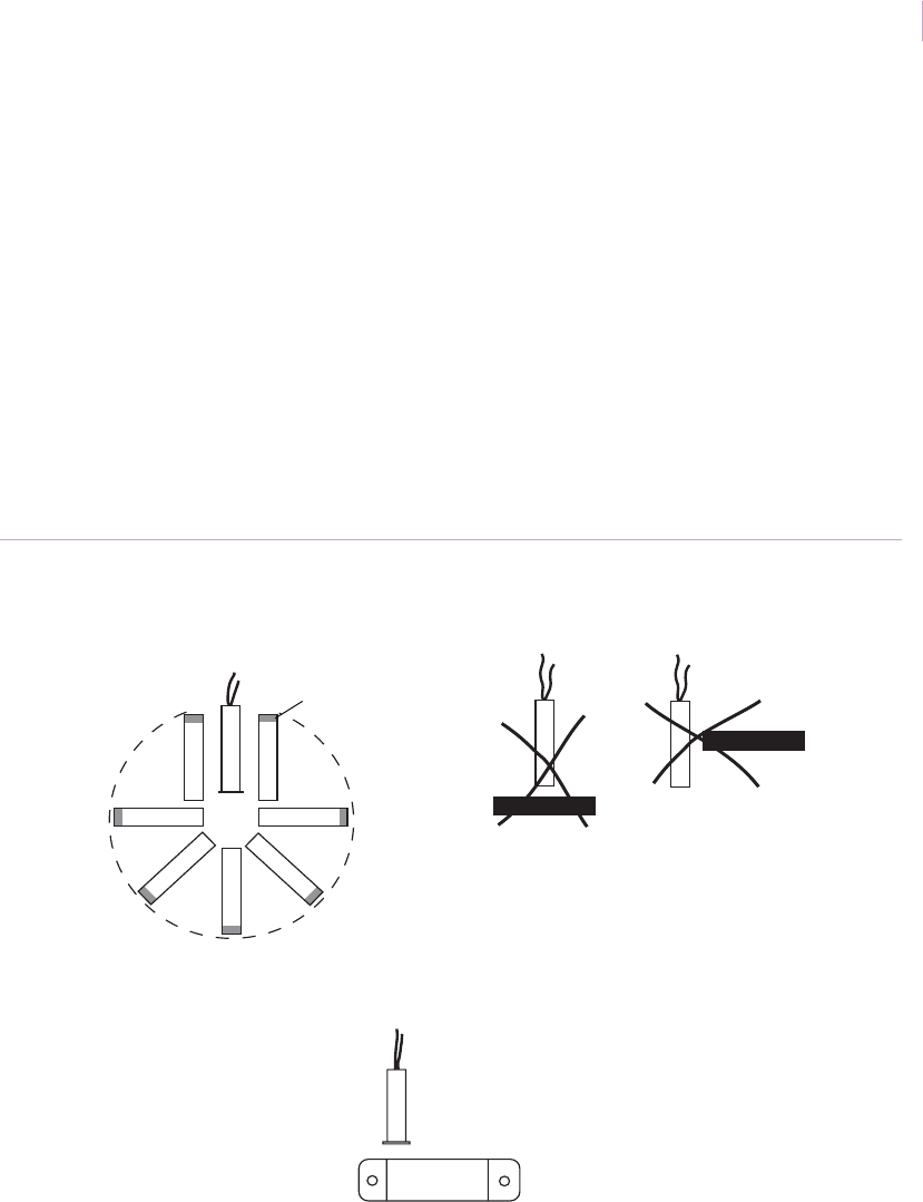
Chapter 3
Magnetic contacts
85
Mounting positions for recessed switches
Recessed contacts can be installed in a variety of positions to accommodate any application.
As shown in Figure 69, the switch and magnet can be mounted end-to-end within an
imaginary arc around the switch, or parallel to the switch. If using a wide-gap switch with a
bare magnet, the red end must be mounted away from the switch (wide-gap switches are
sensitive to the polarity of the magnet).
Gap distance will vary approximately 20% from the rated gap distance of the switch,
depending on the type of switch and the mounting position. It will be necessary for the
installer to experiment to determine if a given switch will work in a given position.
Note: Switch and magnet must not be mounted in a T configuration. In cases where a surface magnet
must be used with a recessed switch, use a surface-mount switch from the 1082 switch series.
Mount the magnet as shown in Figure 69
Figure 69. Mounting positions for recessed switches
GE
Acceptable mounting positions Unacceptable T configuration mounting positions
Recessed switch with surface-mount magnet
Recessed switch
Red end
(if wide gap)
Approximate arc of acceptable
magnet positions
Sensor_Applications.book Page 85 Tuesday, December 27, 2005 5:45 AM

Intrusion Sensor
Application Notebook
86
Professional tips for reliable installation
To prevent switch damage as green lumber dries, twists, and contracts:
• Over-drill (loose fit) the mounting hole. Use RTV mounting compound (1905) to
hold the unit in place.
• As an alternate, use an adapter such as the 1908 model.
• Use model 1275 or 1275W wing fit models.
To protect loose-fitting doors from false alarms:
• Mount the switch and magnet toward the hinge side of the door.
• Use a wide-gap switch to assure trouble-free performance.
To protect steel doors:
• Use wide-gap switches for maximum tolerance.
• Use recessed switches that provide adequate insulation from steel, such as the 1078
or 1078C model.
Ohmmeter testing
To verify switch operation with an ohmmeter, set the range to 200 Kohms. For a closed loop
(normally open) switch, the meter will read an open when the actuator is away. On a digital
meter this is typically displayed as OL. The meter will show resistance value when the
actuator is within sensing range. Metering at the switch you will see at or near 0 ohms when
the magnet is in proper alignment with the reed switch. In a typical residential setting you
will see a resistance value of 4 to 6 ohms when metering the switch and cable. If the circuit
includes an end-of-line (EOL) resistor, the meter will reflect the accumulated resistance of
the switch, cable, and resistor. You will see opposite readings when an open loop (normally
closed) switch is used.
Terms
Closed loop/open loop. Burglar alarm industry terms that reflect the condition of the
switch when the actuator is in place.
Normally closed/normally open. Electrical terms that reflect the condition of the
switch (without actuator).
Actuator. Magnet.
Sensor_Applications.book Page 86 Tuesday, December 27, 2005 5:45 AM

Chapter 3
Magnetic contacts
87
Steel door and window test
This section covers the results of tests on GE magnetic contacts used on steel doors and
windows.
Test procedures. Each sample was selected at random from finished goods inventory.
Tests on each contact measured pull-in (make), and drop-out (break) distances prior to
mounting on a 6 in. (15.2 cm) wide, 16 in. (40.6 cm) long, and 0.5 in. (1.3 cm) thick steel
plate.
Each contact pull-in (make) gap distance was measured:
• With the contact and magnet attached directly to the 0.5 in. (1.3 cm) steel plate with
no spacers.
• With a single 0.125 in. (0.3 cm) spacer under both the contact and magnet. A 0.5 in.
(1.3 cm) spacer was used under both the magnet and contact in the 2505 test.
All measurements were recorded to the nearest 0.05 in. (fifty-thousandths of an inch).
Test results. All dimensions in Table 6 are shown in inches.
Table 6. Test data
Contacts mounted on a 0.5 in. thick 6 x 16 in. steel plate Control tests in air
Switch number Make distance with
out spacers
Make distance with
magnet and
contact spacers
Make distance
pull-in
Break distance
drop-out
1085T 0.4 0.55 0.8 1.0
1085W 0.75 0.95 1.5 2.1
1082T 0.55 0.7 1.25 1.5
1084T 0.4 0.6 1.0 1.2
1084TW 0.9 1.2 2.3 2.55
2505 1.2 2.2 4.2
Sensor_Applications.book Page 87 Tuesday, December 27, 2005 5:45 AM

Intrusion Sensor
Application Notebook
88
Conclusions. Surface-mount contacts can be used in such applications as steel fire doors,
safes, file cabinets, truck doors, and roll-up garage doors. Allow a safety factor in
installation. We recommend installing the contact and magnet with no more separation than
approximately 50% of the pull-in distance. For instance, on the 1084TW measurements on
steel, a maximum separation of 0.5 in. (1.3 cm) to 0.6 in. (1.5 cm) should provide a reliable
system.
Steel door and window installation guidelines. Use the following installation
guidelines for steel door and window applications:
• The gap on steel is approximately half the distance achieved in the air.
• Space the switch and magnet approximately 25 percent of the rated gap in air for a
safety factor.
• Use a spacer whenever practical. If only one spacer is used, mount it under the
magnet.
• Applications on steel do not drain the magnet, but they do reduce the magnetic
field.
Sensor_Applications.book Page 88 Tuesday, December 27, 2005 5:45 AM

Chapter 3
Magnetic contacts
89
Voltage spike protection
When magnetic reed switches are wired in line with relay devices with coils, the reverse
voltage spike generated when current is removed from the relay can fuse the switch contacts
together.
As shown in Figure 70, when the contact is closed, current flows through the relay coil and
magnetizes the iron core. When the contact is opened, current from the power supply stops
and the magnetism of the relay iron drops to zero instantly. The collapsing magnetic field
draws voltage into the relay coil. Since the coil is open (open reed switch) and there is no
circuit loading to limit the voltage, spikes from the open relay can reach 500 volts or more,
causing arcing across the reed contacts. Most GE reeds arc between 150 and 200 volts, well
within this reverse voltage kick.
Repeated arcing roughens and pits the reed switch blades until they eventually stick together
mechanically. Tapping on the switch will cause the contacts to release (open). However, this
is only a temporary fix.
Figure 70. Current flow in a closed contact
+
-
DC power
supply
Relay
Switch
Magnet
Sensor_Applications.book Page 89 Tuesday, December 27, 2005 5:45 AM
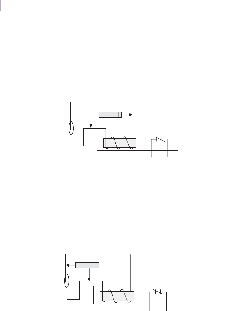
Intrusion Sensor
Application Notebook
90
DC circuit solution. Voltage kicks or transients from DC circuits are easily controlled by
adding a diode across the relay coil, as shown in Figure 71. The diode has no effect on the
circuit when the current flows in the right direction. However, when current from the power
supply stops suddenly and the relay coil generates a reverse voltage, it shorts through the
diode. The stripe on the diode points toward the + voltage. The diode used should be a
1N4002, 1N4003, 1N4004, or equivalent.
Figure 71. DC circuit solution
AC circuit solution. In AC circuits, current flows through the relay coil in both directions.
Using a diode would simply short out half of every cycle. However, a bidirectional transient
suppressor diode can be used to clip off voltage spikes in either direction installed in parallel
with the switch, as shown in Figure 72. The transient suppressor diode must be selected to
fit the voltage used in the circuit. To find the correct diode voltage rating, multiply the circuit
voltage times 1.414. For example, in a 24-volt circuit, a transient suppressor diode rated at
34 volts or more may be used (24 x 1.414 = 34).
Figure 72. AC circuit solution
- DC + DC
Reed switch
1N4004 diode
Relay coil
Relay output
AC AC
Reed switch
Bidirectional transient
suppressor diode
Relay coil
Relay output
Sensor_Applications.book Page 90 Tuesday, December 27, 2005 5:45 AM

Chapter 3
Magnetic contacts
91
Nice-Duc surface wire concealment
Application. Nice-Duc is the ideal self-adhesive wiring duct for concealing low-voltage
alarm systems in completed structures. You can use Nice-Duc on walls, ceilings, woodwork,
metal doors, and window frames. You can also use Nice-Duc to conceal a variety of other
wires and cables, including telephone, audio, and video.
Nice-Duc comes in mini and standard sizes (Figure 73). Both sizes come in a 60 in. (1.5 m)
length. A variety of right angles, T-connectors, inside and outside corners, and end caps are
also available. Nice-Duc comes in white, off-white, or brown.
Installation. For easy installation, Nice-Duc features a hinged design on one side and a
slot tract on the other that snaps shut with the wire inside. Low initial tack lets you move
Nice-Duc without damaging tape or surface. The thin wall design is easy to cut to fit. To
install Nice-Duc, clean the mounting surface with the alcohol cleaning pads included with
the product, strip off the self-adhesive cover, and place the Nice-Duc in position (use
connectors if needed).
Recommended products. ND5-WH-MINI, ND5-OW-MINI, ND5-BR-MINI, ND5-
WH-STD-2P, ND5-OW-STD-2P, ND5-BR-STD-2P, ND5-BE-STD-2P;
Connector packs: 5U5-WH-STD, 5U5-OW-STD, 5U5-STD-BR, 5U5-BE-STD
Figure 73. Nice-Duc
Mini
0.25 in, (0.64 cm) high
7/16 in. (1.11 cm) wide
60 in. (152 cm) long
Standard
3/8 in, (0.95 cm) high
5/8 in. (1.59 cm) wide
60 in. (152 cm) long
Sensor_Applications.book Page 91 Tuesday, December 27, 2005 5:45 AM

Intrusion Sensor
Application Notebook
92
Sliding aluminum doors
Application. To protect sliding aluminum doors against unauthorized entry, use one of the
following magnetic contact installation methods:
• Parallel recess mount
• Perpendicular recess mount
• Parallel recess mount with adhesive surface-mount switch
• Screw-down surface mount (do not drill into glass)
• Adhesive surface mount
Installation. The installation technique you select will depend on the gap distance
available and ease of installation.
To remove the door (Figure 74 on page 93), do the following:
1. Open the door as far as required.
2. Lift the door straight up into the upper channel.
3. Pull the door out from the bottom.
Install the contact using one of the methods shown in Figure 75 on page 93.
Recommended products. 1035, 1035W, 1055W, 1075, 1075W, 1085, 1085T, 1138T,
wireless model: NX-452
Sensor_Applications.book Page 92 Tuesday, December 27, 2005 5:45 AM
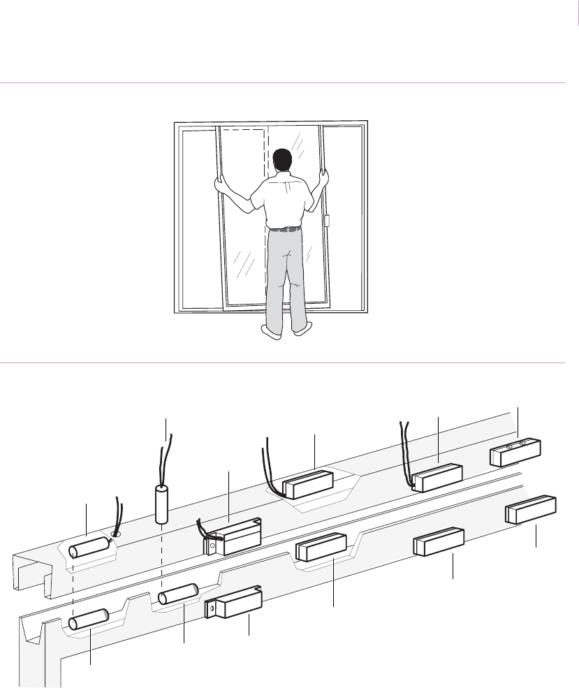
Chapter 3
Magnetic contacts
93
Figure 74. Removing the door
Figure 75. Aluminum sliding door mounting options
Magnet
Magnet
Parallel recessed
mount switch
Perpendicular recessed
mount switch
Surface
mount switch
Recessed surface switch
Surface switch
Magnet
Magnet
Magnet
Magnet
Terminal switch
Sensor_Applications.book Page 93 Tuesday, December 27, 2005 5:45 AM

Intrusion Sensor
Application Notebook
94
Automatic garage doors with switch shunting
Application. Use relays to provide on and off alarm protection when an exit delay is part of
the system and entrance and/or exit is via a door to the garage. The garage door must also
have an automatic opener that has a timed entrance light.
Installation. For installation, use two 110-volt AC SPST (single-pull, single-throw)
hermetically sealed relays (Figure 76 on page 95), and do the following:
1. Place the coil of Relay 1 across the AC line going to the motor which opens the
garage door.
2. Place the coil of Relay 2 across the AC line going to the light on the garage door
opener.
3. Place both sets of the 110-volt relay contacts in parallel and connect them together
across the garage door contact. Use a junction box to ease wiring.
User operation is as follows:
• Before leaving home, arm the alarm system and leave via the door leading to the
garage, which would normally be on the Exit/Entry delay loop.
• As you signal the garage door to rise, Relay 1 activates as the motor starts and
shunts the garage door contact, preventing an alarm.
• As the door rises, the light comes on and Relay 2 activates, also shunting the garage
door contact.
• Once the door is all the way open, the motor shuts off, causing Relay 1 to drop out.
However, the light remains on for a fixed period of time, so Relay 2 remains
activated, still shunting the garage door contact and preventing an alarm.
• Prior to the light going out (this should be timed), exit the garage and signal the door
to lower.
• The motor starts, activating Relay 1 and shunting the garage door relay.
• The light, still on, restarts the timed cycle and Relay 2 remains activated.
• When the door is completely closed, Relay 1 drops out.
• After a fixed time, Relay 2 drops out and returns the loop to the garage door contact
and normal operations.
Sensor_Applications.book Page 94 Tuesday, December 27, 2005 5:45 AM

Chapter 3
Magnetic contacts
95
Figure 76. Garage door switch shunting
Exit/entry
delay loop
Protective
zone loop
Door to
garage Garage door
Door contact
To other delay points
and/or EOL resistor
To motor
Power source
NO COM
Relay 1
Junction box
Light activated
by motor
NO COM
Sensor_Applications.book Page 95 Tuesday, December 27, 2005 5:45 AM

Intrusion Sensor
Application Notebook
96
Wood doors with threshold contacts
Application. For wood doors with aluminum thresholds, it is sometimes convenient to
mount the magnet in the bottom of the door and the switch in the hollow space beneath the
threshold. The distance between the magnet and switch will require a wide-gap switch.
Installation. Select a recessed-mount wide-gap switch, and do the following:
1. Drill a horizontal hole for the magnet in the outside edge of the door. Coat the
magnet with RTV mounting compound and insert the magnet in the hole. If using a
wide-gap switch with a bare magnet, insert the red end of the magnet toward the
outside of the door (switch is polarity sensitive).
2. Remove the threshold. Attach the switch on the inside of the threshold with RTV
mounting compound. Position the switch so it will be directly beneath (and parallel
to) the magnet when the threshold is replaced (Figure 77).
3. Replace the threshold and test (see Ohmmeter testing on page 86) while opening and
closing the door.
4. Connect the switch to the alarm loop.
Recommended products. 1055W, 1065W, 1057RT, 1075W, RTV 1905;
wireless model: NX-458
Figure 77. Wood door threshold with recessed contact
Door
Red end of magnet
Switch Aluminum threshold
Sensor_Applications.book Page 96 Tuesday, December 27, 2005 5:45 AM

Chapter 3
Magnetic contacts
97
Steel doors with threshold contacts
Application. For steel doors with aluminum thresholds, you can mount the magnet in the
bottom of the door and the switch in the hollow space beneath the threshold. The distance
between the magnet and switch requires a wide-gap switch.
Installation. Select a steel door magnet with a wide-gap switch and do the following:
1. Remove the door from the hinges and drill a 1 in. (2.5 cm) diameter hole in the
bottom of the door about 2 in. (5 cm) from the front edge of the door. Glue with
RTV or epoxy and snap-fit the magnet in the hole.
2. Remove the threshold and attach the switch on the inside of the threshold with RTV
mounting compound. Position it so it will be directly beneath and perpendicular to
the magnet with the end centered beneath it when the threshold is replaced
(Figure 78).
3. Replace the threshold and door and test (see Ohmmeter testing on page 86) while
opening and closing the door.
4. Connect the switch to the alarm loop.
Recommended products. 1055W or 1075W with 1921 magnet, RTV 1905
Figure 78. Steel doors with threshold contacts
Steel door
Aluminum threshold
1921 magnet
1055W or 1075W switch
Sensor_Applications.book Page 97 Tuesday, December 27, 2005 5:45 AM

Intrusion Sensor
Application Notebook
98
Recessed steel doors
Application. Some steel doors are recessed at the top, creating a large gap which must be
overcome when you use a concealed magnetic contact. Installation varies, depending on one
of the following recess depths:
• 0.25 to 0.5 in. (0.6 to 1.3 cm) recessed top
• 0.5 to 0.75 in. (1.3 to 1.9 cm) recessed top
• more than 0.75 in. (1.9 cm) recessed top
Installation with 0.25 to 0.5 in. (0.6 to 1.3 cm) recessed top. To install the contact,
do the following:
1. Align the position for the switch and magnet and drill a hole for the switch in the
door frame:
• 1078CW and 1078CTW: 0.75 in. (1.9 cm) with a hole punch; 11/16 in. (1.8 cm)
with a hole saw.
• 1078W and R1078: 1 in. (2.5 cm) with a hole punch; 15/16 in. (2.4 cm) with a
hole saw.
2. Wire the switch to the loop and insert in the frame.
3. Clean the top of the door and mount the magnet using tape (Figure 79 on page 99).
Close the door and test (see Ohmmeter testing on page 86).
4. Use RTV or epoxy to glue the magnet permanently in place and retest.
Recommended products. 1078W, R1078, 1078CW, 1078CTW, 1840, 1802, RTV 1905
Sensor_Applications.book Page 98 Tuesday, December 27, 2005 5:45 AM
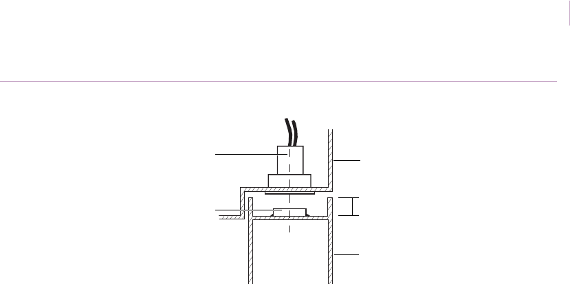
Chapter 3
Magnetic contacts
99
Figure 79. Steel doors with 0.25 to 0.5 in. recessed top
0.25 to 0.5 in.
Switch
Magnet
Door frame
Door
(0.64 to 1.27 cm) recess
Sensor_Applications.book Page 99 Tuesday, December 27, 2005 5:45 AM
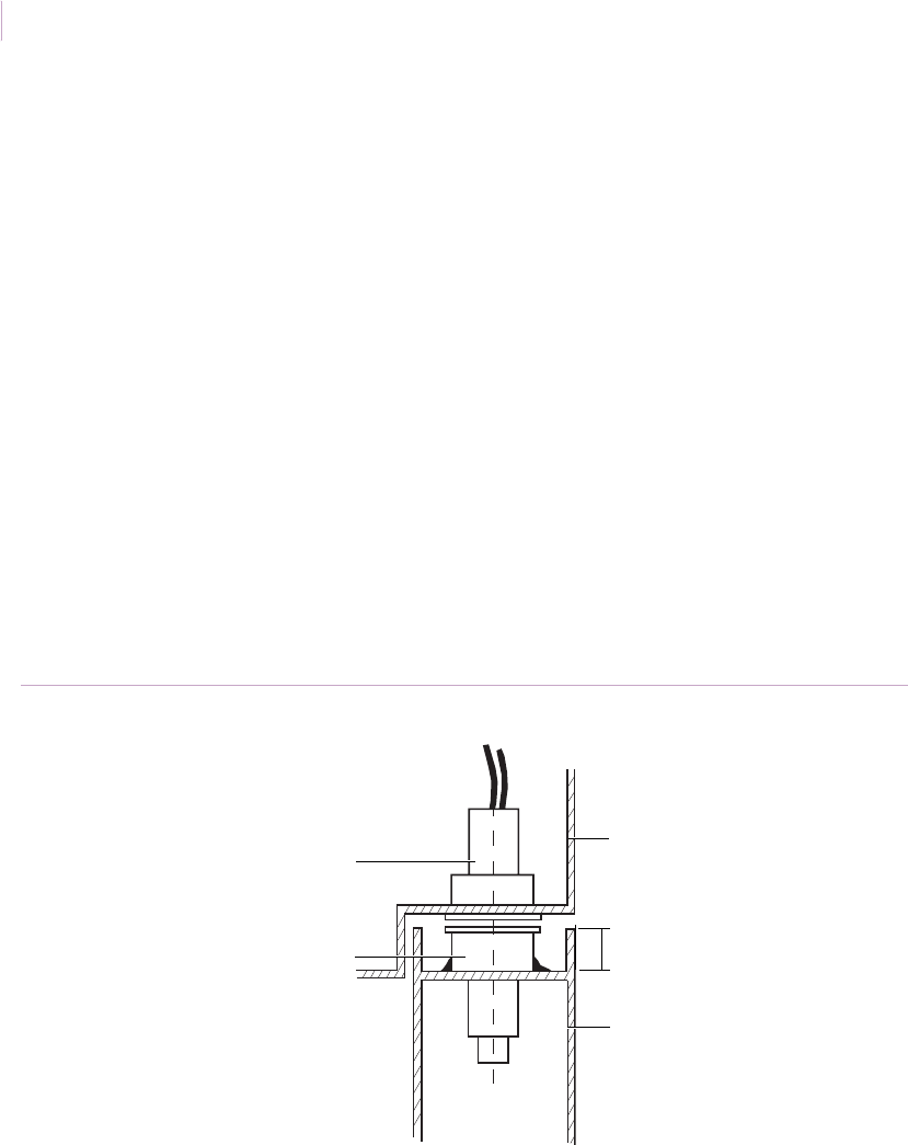
Intrusion Sensor
Application Notebook
100
Installation with 0.5 to 0.75 in. (1.3 to 1.9 cm) recessed top. To install the contact,
do the following:
1. Align the position for the switch and magnet and drill a hole for the switch in the
door frame:
• 1078CW: 11/16 in. (1.8 cm) with a hole saw; 0.75 in. (1.9 cm) with a hole punch.
• 1078W: 15/16 in. (2.9 cm) with a hole saw; 1 in. (2.5 cm) with a hole punch.
2. Drill a hole for the magnet in the top of the door:
• 1078CW: 11/16 in. (1.8 cm) with a hole saw; 0.75 in. (1.9 cm) with a hole punch.
• 1078W: 15/16 in. (2.9 cm) with a hole saw; 1 in. (2.5 cm) with a hole punch.
3. Wire the switch to the loop and insert the switch in the frame.
4. Clean the top of the door and mount the magnet in the hole (Figure 80). Hold in
place with tape. Close the door and test (see Ohmmeter testing on page 86).
5. Use RTV or epoxy to glue the magnet permanently in place and retest.
Recommended products. 1078W, 1078CW, 1078CTW, R1078, RTV 1905
Figure 80. Steel door with 0.5 to 0.75 in. recessed top
0.5 to 0.75 in.
Switch
Magnet
Door frame
Door
(1.27 to 1.9 cm) recess
Sensor_Applications.book Page 100 Tuesday, December 27, 2005 5:45 AM
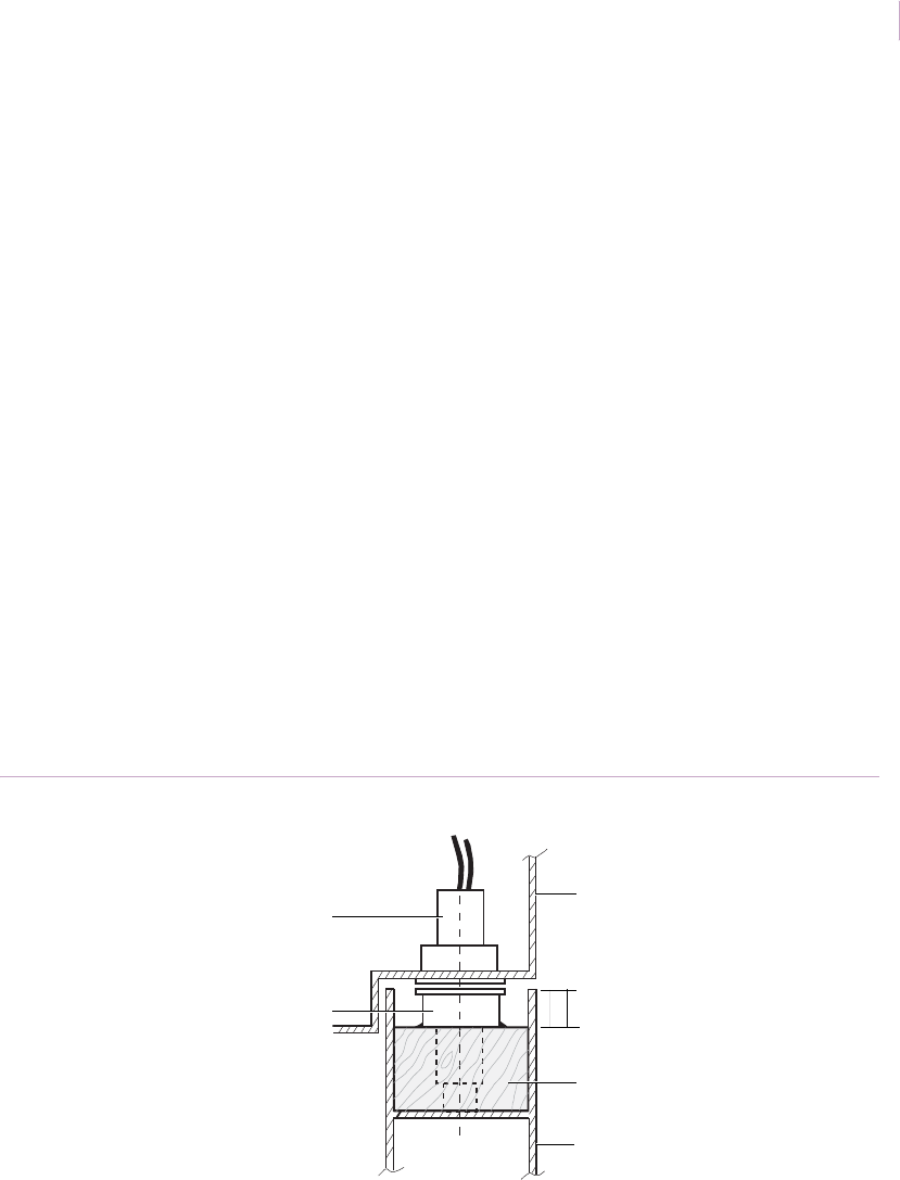
Chapter 3
Magnetic contacts
101
Installation with more than 0.75 in. (1.9 cm) recessed top. To install the contact,
do the following:
1. Glue a wood block in the top of the door. The thickness of the block should leave
5/8 in. (1.6 cm) to the top of the door.
2. Align the position for the switch and magnet. The end of the magnet must be
centered on the switch as shown in Figure 81. Drill a hole for the switch in the door
frame:
• 1078CW: 11/16 in. (1.8 cm)
• 1078W: 15/16 in. (2.4 cm)
3. Drill a hole for the magnet:
• 1078CW: 9/16 in. (1.4 cm)
• 1078W: 5/8 in. (1.6 cm)
4. Wire the switch to the loop and insert the switch in the frame.
5. Clean the top of the door and mount the magnet in the hole using tape (Figure 81).
Close the door and test (see Ohmmeter testing on page 86).
6. Use RTV or epoxy to glue the magnet permanently in place and retest.
Recommended products. 1078W, 1078CW, 1078CTW, R1078, RTV 1905
Figure 81. Steel door with more than 0.75 in. recessed top
5/8 in.
Switch
Magnet
Door frame
Door
Block of wood
(1.59 cm) recess
Sensor_Applications.book Page 101 Tuesday, December 27, 2005 5:45 AM
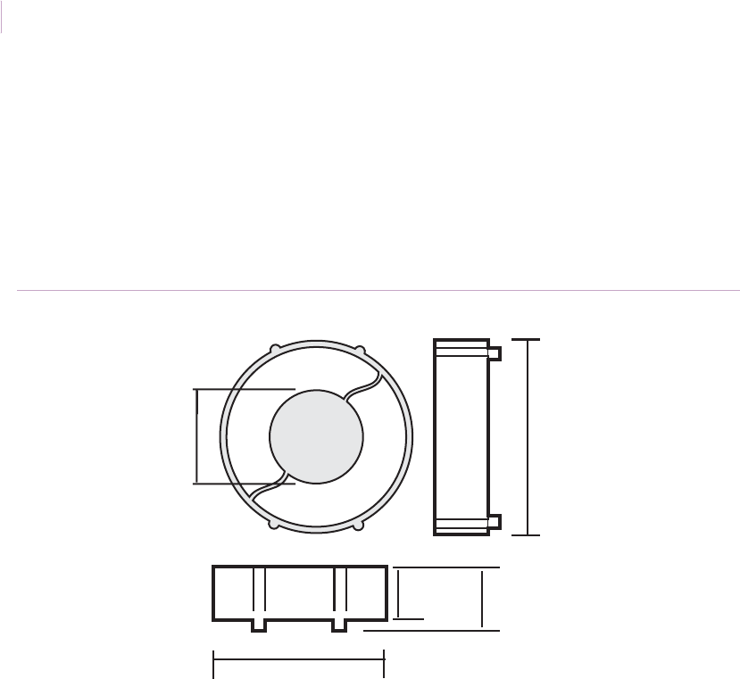
Intrusion Sensor
Application Notebook
102
Installation using the 1840 magnet. The 1840 rare earth magnet (Figure 82) is
designed for use in metal entry/exit doors with a channel in the top of the door. The magnet
eliminates the need to cut a mounting hole in the door channel. The flexible magnet housing
can be compressed to accommodate a variety of channel widths for quick, easy installation.
We recommend you use an adhesive with the magnet.
Recommended products. 1840 magnet
Figure 82. 1840 magnet
1.813 in.
(4.60 cm)
0.625 in.
(1.59 cm)
0.5 in.
(1.27 cm)
1.625 in.
(4.13 cm)
0.89 in.
(2.76 cm)
Legs may be cut for
height adjustment
Sensor_Applications.book Page 102 Tuesday, December 27, 2005 5:45 AM
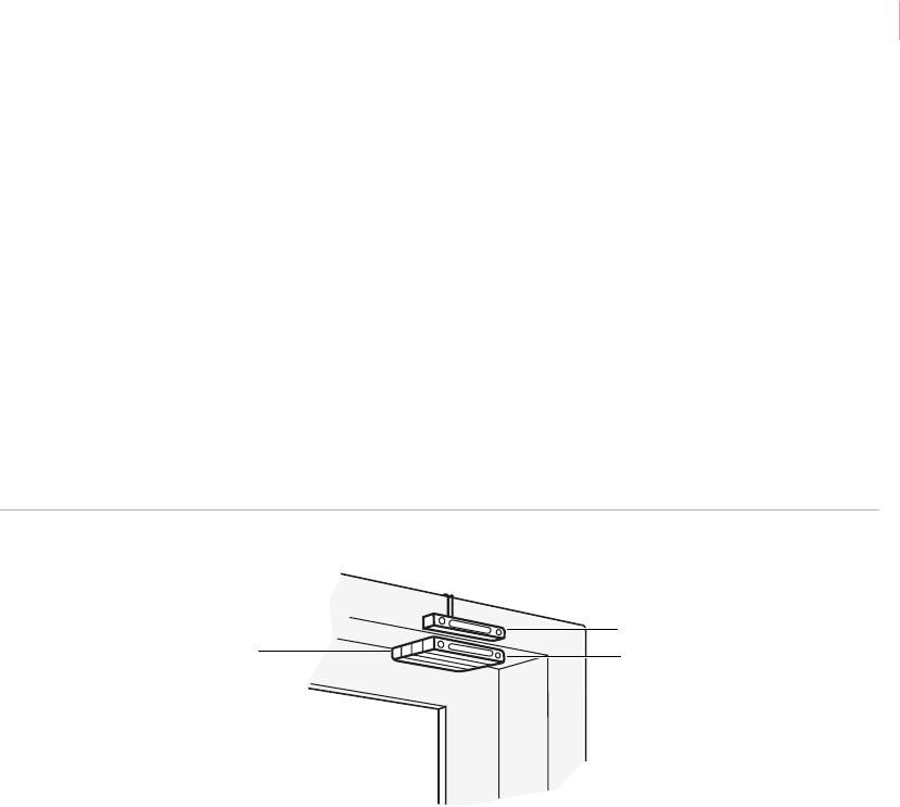
Chapter 3
Magnetic contacts
103
Deeply recessed doors
Application. Use one of the following installations to protect deeply recessed doors using
surface-mount contacts. When mounting on steel doors, use a spacer behind the switch and/
or use a wide-gap switch. Always test the installation (see Ohmmeter testing on page 86).
Installation using a magnet with spacers. There is a wide range of spacers available
for each contact series. Stack spacers until the magnet aligns with the switch when the door
is in the closed position (Figure 83).
Recommended products. 1082TW, 1085TW, 1045T, 1914T
Figure 83. Deeply recessed door with magnet and spacers
GE
GE
Switch
Magnet
Spacers
Sensor_Applications.book Page 103 Tuesday, December 27, 2005 5:45 AM
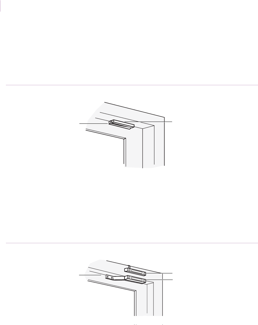
Intrusion Sensor
Application Notebook
104
Installation using a switch on the inside of the jamb. To avoid the use of brackets,
align and mount as shown in Figure 84. Use this technique only on a door with a reliable
stop so that the door cannot swing inward and hit the switch.
Recommended products. 1082TW, 1045T
Figure 84. Deeply recessed door with switch mounted on jamb
Installation using a 1910 or 1910-2 bracket. Verify that the distance from the inside
of the door frame to the inside of the door does not exceed 1.0 in. (2.5 cm). Align and mount
as shown in Figure 85. If the distance exceeds 1.0 in. (2.5 cm), use the 1912 or
1911 L-bracket or a 1940-1 bracket as shown in one of the following installations.
Recommended products. 1082TW with 1910 bracket, or a 1045T with a 19102 bracket
Figure 85. Deep recessed door installation with 1910 bracket
Switch
Magnet
GE
GE
Magnet
Bracket Switch
Sensor_Applications.book Page 104 Tuesday, December 27, 2005 5:45 AM
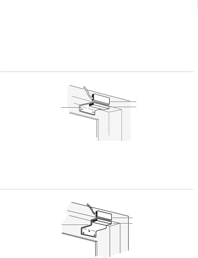
Chapter 3
Magnetic contacts
105
Installation using a 1912 L-bracket. Verify that the distance from the inside of the
door frame to the inside of the door does not exceed 2 in. (5.2 cm). Align and mount as
shown in Figure 86.
Recommended products. 1045T or 1085TW with 19122 L-bracket, 2500 with
1912 L-bracket
Figure 86. Deep recessed door with L-bracket
Installation using a 19401 Z-bracket and a 19122 L-bracket. Verify that the
distance from the inside of the door frame to the inside of the door does not exceed 3 in.
(7.6 cm). Align and mount as shown in Figure 87.
Recommended products. 2505A with 19401 Z-bracket and 1912 L-bracket
Figure 87. Deep recessed doors with a Z and L bracket
GE
Magnet
Bracket
Switch
GE
Magnet
Brackets
Switch
Sensor_Applications.book Page 105 Tuesday, December 27, 2005 5:45 AM

Intrusion Sensor
Application Notebook
106
Overhead or curtain doors
Application. There are many different types of overhead and curtain doors with different
mounting surfaces, such as ribs and lips. You can use a variety of magnetic contacts and
mounting techniques, depending on the specific overhead or curtain door. Always test the
installation (see Ohmmeter testing on page 86).
Installation using a 2515A contact mounted on the channel. The 2515A allows a
vertical gap distance of 6 in. (15.2 cm) and an overall side-to-side gap of 6 in. (15.2 cm). Use
this contact to install a security switch on the channel of overhead doors that do not line up
properly, sag, or are loose and move with wind and vibration. To install the contact, do the
following:
1. Mount the contact and magnet so both labels read in the same direction and the
mounting holes are parallel (Figure 88).
2. To ensure maximum operating gap, do not mount the magnet more than 3 in.
(7.6 cm) away from the contact. If the magnet is mounted 1 in. (2.5 cm) from the
contact and is offset by 1 in. (2.5 cm) either in front or back of the contact, the unit
will maintain a vertical gap distance of 6 in. (15.2 cm). If the magnet is mounted
2 in. (5.1 cm) from the contact and is offset by 1 in. (2.5 cm) either in front or back
of the contact, the unit will maintain a vertical gap distance of 4 in. (10.2 cm).
Recommended products. 2515A
Figure 88. Overhead door with 2515A mounted on the channel
GE
GE
Magnet
Switch
Bracket
Sensor_Applications.book Page 106 Tuesday, December 27, 2005 5:45 AM
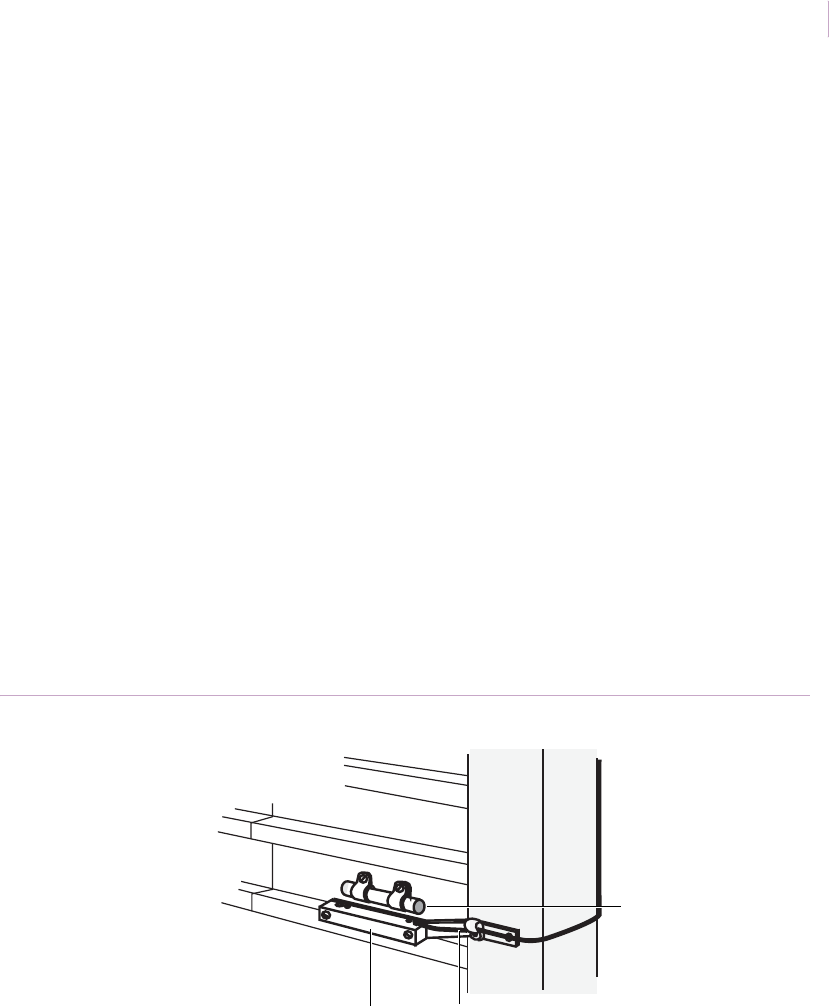
Chapter 3
Magnetic contacts
107
Installation using a 1042TW contact. Depending on your application, you can mount
the 1042TW contact on the channel or door lip. To mount the contact, do the following:
1. Close the door and tape the magnet in place with masking tape. Position the magnet
in the recessed portion of the slat as close to the edge of the door as possible. Mount
with the red end as shown in Figure 89.
2. Roll up the door, making sure the magnet clears and does not interfere with
operation of the door. Close the door.
3. Attach the magnet to the door with screws.
4. Attach the wires to the switch terminals. Attach the switch to the outside of the long
portion of the bracket. The label must be right side up and facing away from the
door when the bracket is mounted on the channel.
5. Attach the bracket to the channel with self-tapping screws. Position the bracket so
that the corner of the door lip clears as the door is opened and closed.
6. Test for proper operation of the switch by opening and closing the door.
7. Dress the wires with wire clamps and hook into the alarm loop. Retest for operation
and clearance.
Recommended products. 1042TW switch, 19102 bracket, 1923 magnet
Figure 89. Overhead door with 1042TW contact
Red end of magnet
Switch Bracket
Sensor_Applications.book Page 107 Tuesday, December 27, 2005 5:45 AM

Intrusion Sensor
Application Notebook
108
Installation using a 2302 or 2304 contact. Use the 2302 or 2304 contacts for
applications where you want to mount the switch on the channel and the magnet horizontally
in the door slats. To install the contact, do the following:
1. Close the door. Adjust the interlocking bracket into the appropriate slot in the switch
housing to fit the specific curtain door channel. Place the unit on the channel making
sure the outer lip of the switch housing is positioned so it overlaps the edge of the
channel.
2. Move the switch and bracket assembly so that it is no more than 36 to 48 in. (91.4 to
121.9 cm) from the surface of the floor. This allows the magnet to roll up with the
door without interference.
3. Tighten down the mounting bolt enough to hold the unit in place.
4. Position the magnet so that the word TOP is reading in the same direction as the
label on the switch housing, and the center line of the magnet is aligned with the
label on the switch housing (Figure 90 on page 109). The magnet end should be
within 0.24 to 0.5 in. (0.6 to 1.3 cm) from the edge of the switch housing for reliable
actuation on heavy steel surfaces.
5. Connect the switch to an ohmmeter to verify functioning. Push firmly on the door so
that the area the magnet occupies is moved to its farthest position away from the
switch in all directions. If the circuit is interrupted, slide the magnet closer to the
switch assembly. Repeat this procedure to ensure proper operation. Mark the
position on the door.
6. Establish the correct position, tighten the mounting bolt down and then fasten the
lock nut against the housing. For extra mounting strength, drill two 0.15 in. (0.4 cm)
diameter holes through the mounting holes in the housing and fasten with two #8
screws (not provided).
7. To mount the magnet, do one of the following:
• Drill two 0.15 in.(0.4 cm) diameter holes through the mounting holes in the
magnet housing. Fasten with the two #8 self-tapping screws provided.
• For faster installation, remove the magnet. Clean the door surface with alcohol,
dry it off, then mount with strips of double-stick adhesive tape. Mount the tape
to the magnet housing first and then attach the housing to the door, pressing
firmly to ensure proper adhesion.
Sensor_Applications.book Page 108 Tuesday, December 27, 2005 5:45 AM
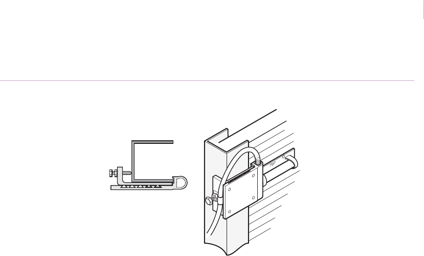
Chapter 3
Magnetic contacts
109
Recommended products. 2302, 2304
Figure 90. Overhead door with 2302 or 2304 contact
GE
Sensor_Applications.book Page 109 Tuesday, December 27, 2005 5:45 AM
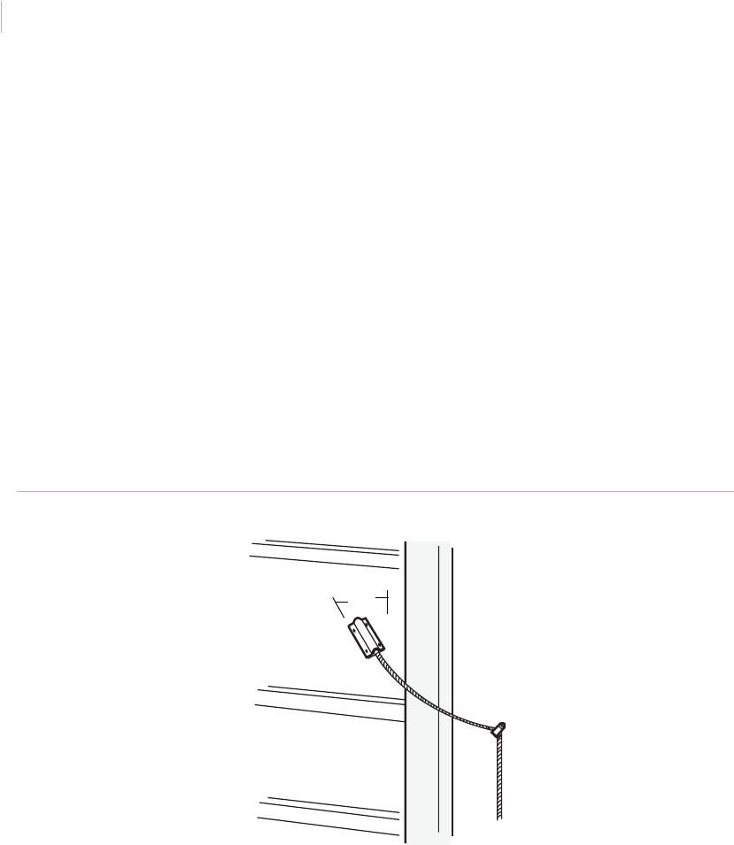
Intrusion Sensor
Application Notebook
110
Installation using the 2105 Magnapull. The Magnapull provides a quick and easy
method to protect overhead doors. There are no brackets to adapt and no drilling needed.
This is ideal for applications where there is a lot of play in the door. To install the
Magnapull, do the following:
1. Fasten the cable using a wire clamp so that if the switch is dropped it will not hit the
floor.
2. Mount the magnet housing at an angle approximately 20 degrees from vertical
(Figure 91) to prevent switch damage if the door is opened before the switch is
removed. (The user should be instructed to release the Magnapull switch before the
door is opened to prevent damage to the switch.)
3. Position the cable so there is slack between the magnet housing and the wire clamp.
4. To test proper operation, open the door.
Recommended products. 2105
Figure 91. Overhead door with 2105 Magnapull contact
Magnapull
Wire clamp
20°
Sensor_Applications.book Page 110 Tuesday, December 27, 2005 5:45 AM
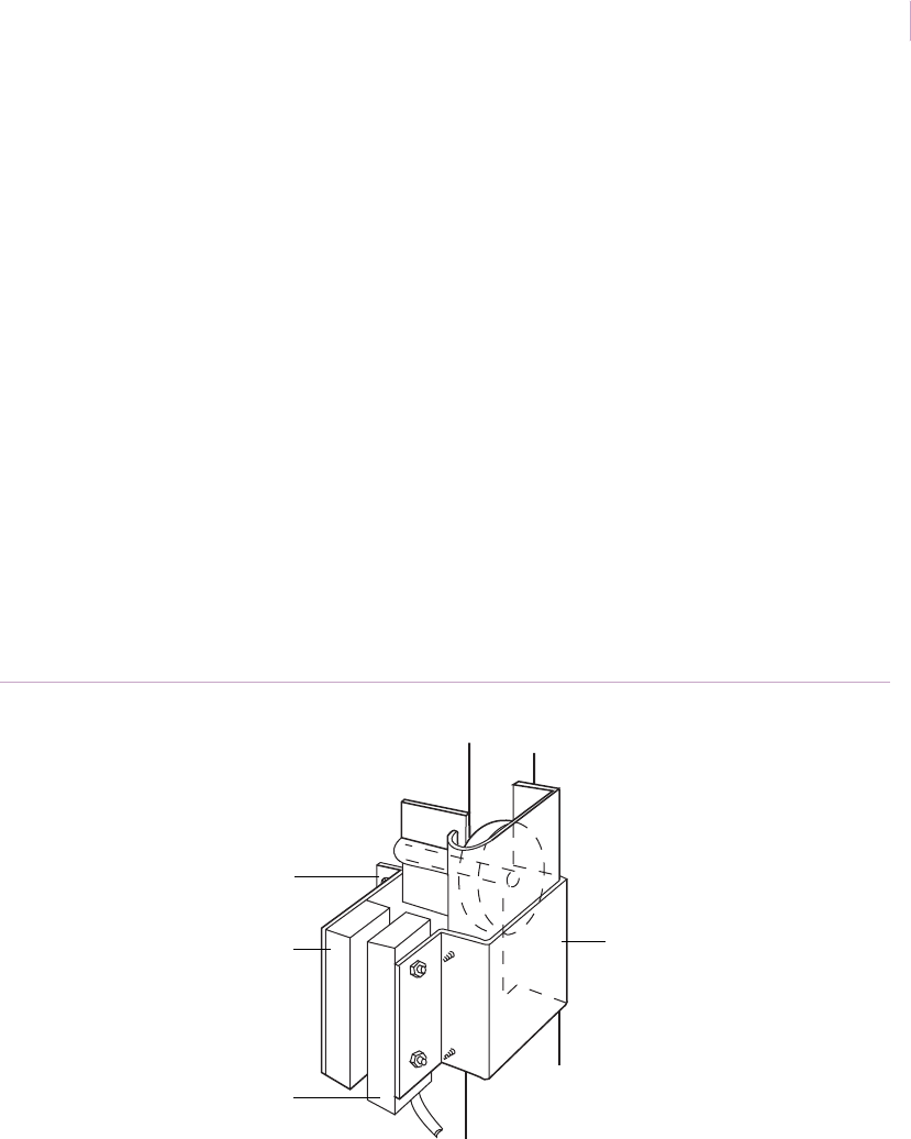
Chapter 3
Magnetic contacts
111
Installation using a 1092A kit. Mount the contact on the track at the bottom of
overhead doors. Make sure the door does not have a guard that extends around the track.To
install the contact, do the following:
1. Mount the unit on the side opposite the rope pull, or move the rope pull to the side
opposite the switch.
2. Mount the 1940 bracket on the track with two self-tapping screws. Tighten evenly
against the track. Mount the switch to the 1940 bracket.
3. Mount the 1912 bracket. Mount the magnet to the bracket, allowing about a 0.5 in.
(1.27 cm) gap between the switch and magnet (Figure 92). The switch and magnet
labels must read in the same direction (switch is polarity sensitive).
4. Test for clearance and operation (see Ohmmeter testing on page 86).
5. Loosen the holding screws on the 1940 bracket and apply RTV mounting compound
to the flat side of the track. Tighten the screws and retest.
Recommended products. 1092A kit (in some applications, 1082TW with 1912 and
1940 brackets)
Figure 92. Overhead door with 1092A kit
Magnet
Switch
1912 bracket
1940 bracket
Sensor_Applications.book Page 111 Tuesday, December 27, 2005 5:45 AM

Intrusion Sensor
Application Notebook
112
Installation using heavy-duty, low-profile contacts. You can use a variety of
mounting methods to use low-profile contacts to protect overhead doors. All of the methods
described use easy-to-mount 1982 magnets with the 2200 heavy-duty, low-profile series
contacts. The contacts feature active gap distances of up to 3 in. (7.6 cm) and heavy-duty
design. The mounting methods include:
• Lip mount (Figure 93)
• Smooth surface-mount (Figure 94 on page 113)
• Rib mount (Figure 95 on page 113)
• Overhead mount (Figure 96 on page 113)
To mount the 1982 magnet, use bolts through the steel door, or tap holes for #6 stainless
steel combo-head screws. The flange of the magnet features slots that allow you to move the
magnet left or right over the screw heads for best alignment.
Recommended products. 2202A, 2202AU, 2205A, 2205AU
Figure 93. Overhead door with lip mount installation
Magnet
Switch
Sensor_Applications.book Page 112 Tuesday, December 27, 2005 5:45 AM

Chapter 3
Magnetic contacts
113
Figure 94. Overhead door with smooth surface-mount installation
Figure 95. Overhead door with rib-mount installation
Figure 96. Overhead door with top-mount installation
Magnet
Switch
Magnet
Switch
Switch
Magnet
Sensor_Applications.book Page 113 Tuesday, December 27, 2005 5:45 AM

Intrusion Sensor
Application Notebook
114
Panel or sectional overhead doors
Application. The 2315A, 2317A, and 2325A contacts are specifically designed for panel
or sectional overhead doors. The contacts can be mounted directly to the door channel, with
the magnet mounted vertically on the door and out of the way. The contact’s integrated
mounting bracket is adjustable and can fit most door channel widths.
Installation. The contact should be mounted at least 13 in. (33 cm) from the floor. If other
track-mounted devices interfere, mount the switch under them.
To install the contact, do the following:
1. Slide the slot of the switch over the beveled edge of the L-bracket and snap it tightly
into place. Screw it down firmly.
Optional: Use the existing roller-track bolts to mount the switch without using the
L-bracket.
2. Align the magnet with the switch and use screws to attach it to the door (Figure 97).
The switch and magnet must be aligned within 0.5 in. (1.3 cm) of each other to
prevent false alarms.
3. Connect the switch wires to the alarm system and test (see Ohmmeter testing on
page 86).
Recommended products. 2315A, 2317A, 2325A
Figure 97. Panel door
Sensor_Applications.book Page 114 Tuesday, December 27, 2005 5:45 AM

Chapter 3
Magnetic contacts
115
High security doors
Application. High security magnetic contacts are used to protect doors in high security
locations or where high-value materials are stored. The contacts can be effectively used at
airports, biotechnology labs and other medical research settings, warehouses, manufacturing
plants, jewelry stores, banks, data processing centers, military bases and ships, ammunition
depots, and energy-generation facilities.
The 2757/2767 series is specifically designed for high security applications in prisons,
military installations, and government facilities. These contacts are virtually impossible to
defeat. Total encapsulation coupled with recess mounting prevents access to the switch and
to cabling, and prevents tampering with an external magnet. They are factory calibrated for
operation in steel and are not subject to sticking or freezing on seldom-used doors. In
addition, the 2767 contacts are adjustable for use in loose-fitting doors.
Sensor_Applications.book Page 115 Tuesday, December 27, 2005 5:45 AM
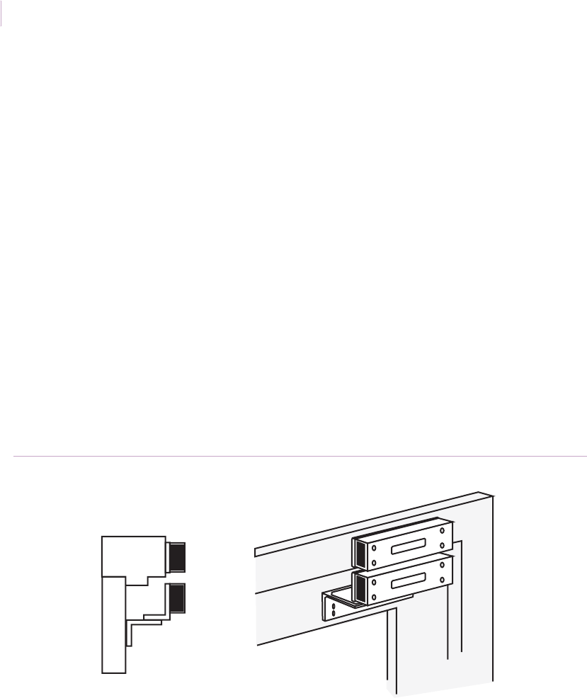
Intrusion Sensor
Application Notebook
116
Installation using surface mount contacts. See the specific contact’s installation
instructions for each recommended contact. To install the 2707A contact, do the following:
1. Bring the magnet toward the switch until an ohmmeter, connected to the closed loop
wires, reads 0 ohms. Mark this point.
2. Bring the magnet closer to the switch until the ohmmeter reads infinity. Mark this
point.
3. Position the magnet midpoint between the two marks.
4. Use the magnet template to mark the mounting holes.
5. Drill the mounting holes.
6. If a pry tamper plate is required for Certified Safe and Vault applications, install it
under the switch with two #6 x 0.75 in. flathead screws. Connect the gold and blue
pointed leads to the 24-hour circuit.
Note: Other contact models have unique installation instructions.
Recommended products. 2702A, 2707AD, 2706AS, 2706AP, 2767, 2757, 2757D,
2727A, 2747A
Figure 98. High security 2707A contact installed with 2 L-brackets
Switch
L brackets
Magnet
Sensor_Applications.book Page 116 Tuesday, December 27, 2005 5:45 AM
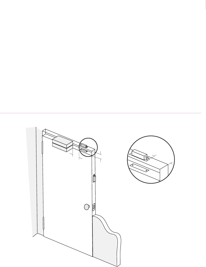
Chapter 3
Magnetic contacts
117
Installation using concealed contacts. The 2757/2767 contact are designed to fit into
standard ANSI cutouts for mortise installation. If door and jamb are provided with ANSI
cutouts and blanks, simply remove the blanks and install the switch and magnet in place.
If cutouts aren’t provided, cut holes (W x D x L) 1.25 x 4.875 x 1.25 in. (3.18 x 12.38 x 3.18
cm) in both the door and jamb for the 2757 and 2757D models, and 1.25 x 4.875 x 1.0 in.
(3.18 x 12.38 x 2.54 cm) for the 2767. Switch and magnet should be within 0.625 in. (1.58
cm) both vertically and horizontally for proper alignment.
Connect leads to a security loop per the electrical schematics and test (see Ohmmeter testing
on page 86).
Recommended products. 2757, 2767
Figure 99. Concealed contacts
4 in.
3/8 in.
max.
min.
Alternate
position
4 in.
max.
Sensor_Applications.book Page 117 Tuesday, December 27, 2005 5:45 AM

Intrusion Sensor
Application Notebook
118
Explosion-proof, high-security switches
Application. The explosion-proof, high-security switches have rugged die-cast aluminum
housings with conduit fittings. They are UL Listed for hazardous location classes (Class I
Group C and D, and Class II Group E, F, and G). These switches are used in high- security
applications such as airports, transportation depots, military locations, chemical plants,
nuclear power plants, and coal mines.
Installation. To install the 2804T switch (Figure 100 on page 119), do the following:
1. Place the bottom of the template provided on the frame approximately 0.25 in.
(0.6 cm) from the edge of the door. Mark the mounting holes.
2. Drill the four mounting holes 5/8 in. (1.6 cm) deep using a 5/32 in. drill. Tap the
holes for a #10-24 machine screw thread. Mount the contact with the #10-24 x
1.25 in. flathead screws provided.
3. Before running the conduit, attach an ohmmeter to the common and the closed loop
terminals. The meter should read INFINITY with the magnet away from the switch
(wiring diagram provided).
4. The magnet for the unit is contained in two pieces. The master magnet is brown and
the submagnet is silver. Place the submagnet housing into the master magnet
housing, making sure that the yellow dot on the subhousing is towards the switch.
5. Position the magnet and switch so that the labels read in the same direction and the
monogram on the magnet is directly aligned with the monogram on the switch. The
setup gap distance is 0.4 in. (1.0 cm). Switches will operate at approximately 0.2 to
0.6 in. (0.5 to 1.5 cm) on closing, and go into alarm at approximately 0.4 to 0.8 in.
(1.0 to 2.0 cm) on opening. Maximum gap is 0.1 in. (0.3 cm). However,
environmental conditions, such as the thickness of the metal to which the switch and
magnet are attached, may cause slight variations in gap distance. Therefore, we
recommend the following installation method:
• Bring the magnet toward the switch until the ohmmeter reads 0 ohms. Mark this
point.
• Continue bringing the magnet towards the switch until the meter reads
INFINITY. Mark this point.
• Use the magnet template and mark the mounting holes.
Sensor_Applications.book Page 118 Tuesday, December 27, 2005 5:45 AM
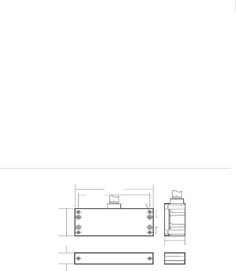
Chapter 3
Magnetic contacts
119
6. Drill the two inside mounting holes 5/8 in. (1.6 cm) deep, using a 9/64 in. drill. Tap
the holes for a #8-32 machine screw thread. Drill the two outside mounting holes
5/8 in. (1.6 cm) deep, using a 5/32 in. drill. Tap the holes for a #10-24 machine
screw thread.
7. Remove the submagnet housing from the master magnet housing. Mount the
submagnet housing first using the two center holes. Use the #8-32 x 1.5 in. machine
screws provided. Be sure that the yellow dot faces the switch.
8. Mount the master magnet housing directly over the submagnet housing. Use the
#10-24 x 1.75 in. machine screws provided. Be sure that the monogram labels on the
switch and magnet read in the same direction.
9. Test (see Ohmmeter testing on page 86).
10. Install the conduit.
Note: Other models have unique installation instructions.
Recommended products. 2804T, 2807T, 2814T, 2845T, 2847TH
Figure 100. Explosion-proof, high security 2804T contact
GE
GE
Switch
Magnet
2.0 in.
(5.08 cm)
5.75 in.
(14.61 cm)
5.25 in.
(13.34 cm) #10-24 thread
0.81 in.
(2.06 cm)
0.75 in.
(1.92 cm) 1.50 in.
(3.81 cm)
Conduit (0.50 threads)
Sensor_Applications.book Page 119 Tuesday, December 27, 2005 5:45 AM

Intrusion Sensor
Application Notebook
120
Revolving doors
Application. You can secure steel or aluminum revolving doors with magnetic contacts in
several ways, depending on their material and the availability of mounting space.
Installation for doors accessible from the top. To install the contact, do the
following:
1. Lock the door to check its position when secured. Mark the switch mounting
location in the top or canopy of the assembly. Offset it slightly as the magnet will be
positioned on the side of the door. Drill a 15/16 in. (2.4 cm) diameter hole when
using a saw hole, or 1 in. (2.5 cm) diameter hole when using a hole punch and
mount the switch in the hole using RTV mounting compound.
2. Place the magnet on the door as close to the rubber gasket as possible. Observe
polarity. If mounting the magnet on steel, use a spacer or order a special magnet
containing two magnets inside the housing (1920D). When using a surface-mount
magnet with the 1078W, position the left end of the magnet as you read the label,
centered off the G on the switch label (Figure 101).
3. Test (see Ohmmeter testing on page 86).
Recommended products. 1078W, 1080T, 1920D
Sensor_Applications.book Page 120 Tuesday, December 27, 2005 5:45 AM
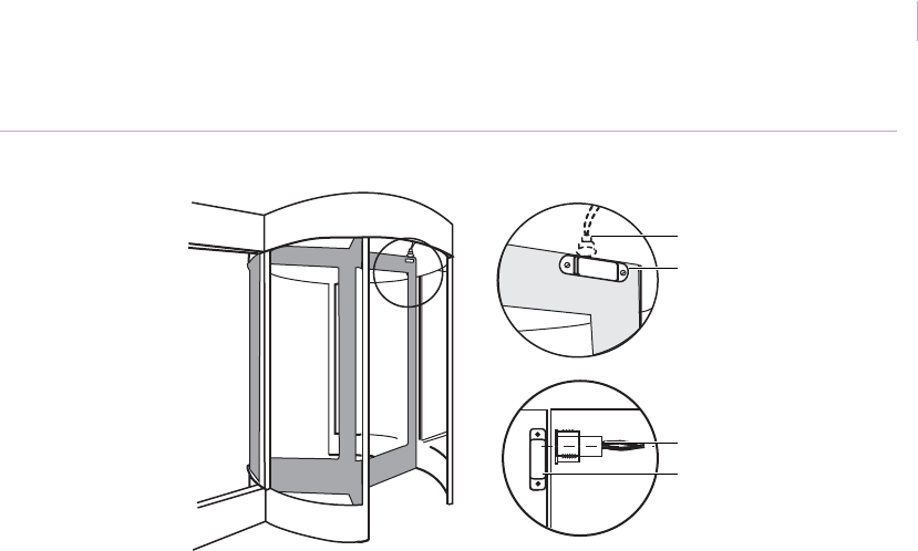
Chapter 3
Magnetic contacts
121
Figure 101. Revolving doors with contact mounted at the top
Installation for doors not accessible from the top. When you cannot install the
contact in the top of the canopy of the door assembly, do the following:
1. Lock the door to check its position when secured. Mark the switch mounting
location in the side of the door in the wall (Figure 102). Drill a 15/16 in. (2.4 cm)
diameter hole when using a hole saw, or 1 in. (2.5 cm) diameter hole when using a
hole punch and mount the switch in the hole using RTV mounting compound.
2. Place the magnet on the door as close to the rubber gasket as possible. Observe
polarity. If mounting the magnet on steel, use a spacer or order a special magnet
containing two magnets inside the housing. When using a surface-mount magnet
with the 1078W, position the left end of the magnet as you read the label, centered
off the G on the switch label (Figure 101 on page 121).
3. Test (see Ohmmeter testing on page 86).
Note: Some systems incorporate an electromagnetic break-away device, usually located in the drum.
Locate the magnetic contact far enough away to prevent adverse effects to the magnet. Stainless
steel armored cable is available if the switch will be exposed.
Recommended products. 1078W, 1080T, 1920D
GE
GE
Switch
Magnet
Switch
Magnet
Sensor_Applications.book Page 121 Tuesday, December 27, 2005 5:45 AM
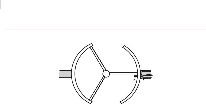
Intrusion Sensor
Application Notebook
122
Figure 102. Revolving door with switch mounted in the wall
SwitchMagnet
Sensor_Applications.book Page 122 Tuesday, December 27, 2005 5:45 AM
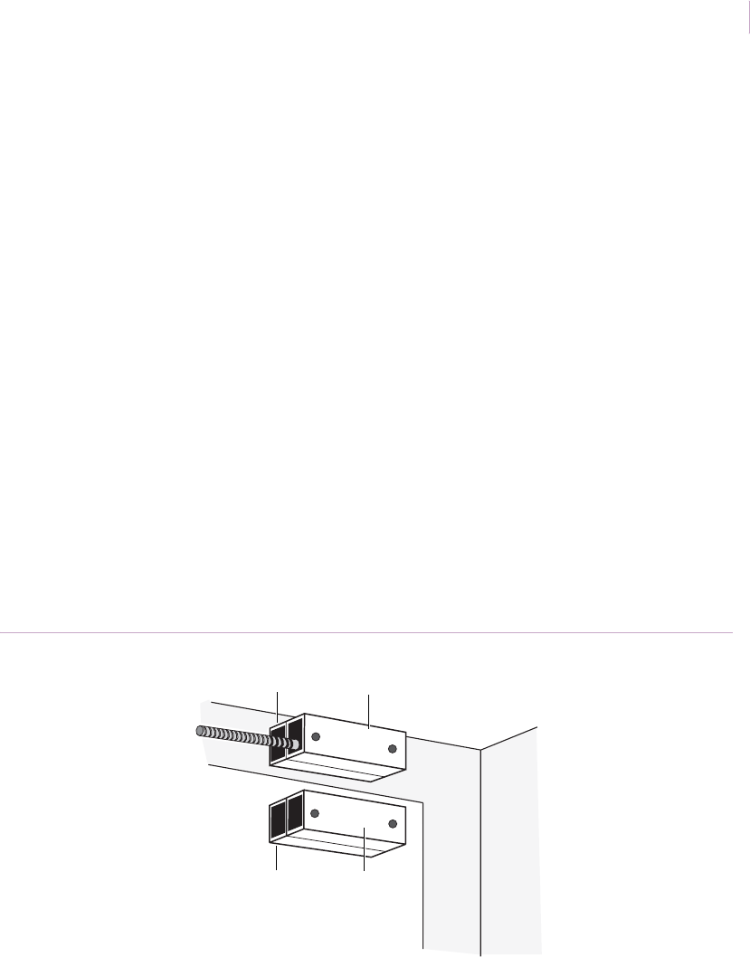
Chapter 3
Magnetic contacts
123
Freezer doors
Application. Use the 2505A-L industrial magnetic contact to secure walk-in freezer doors
against unauthorized entry. These closed loop contacts can withstand condensation or
temperatures in freezers down to -40°F (-40°C).
Installation. To install the contact, do the following:
1. Mount the switch with sheet metal screws inside the freezer on the door casing as
shown in Figure 103. Because steel can decrease the gap of the switch by as much
as half, mount 1913 anodized aluminum 0.5 in. (1.3 cm) spacers under the switch
and magnet to decrease the effect of the steel on the magnetic field.
The magnet and switch should be at the top of the door to prevent accidental
damage to the switch and to discourage tampering.
The labels on the magnet and switch must read in the same direction (switch is
polarity sensitive).
2. Test (see Ohmmeter testing on page 86).
Recommended products. 2505A-L, 1913, 1920D
Figure 103. Freezer door installation
GE
GE
Spacer Switch
Ceiling
Freezer door
Spacer Magnet
Sensor_Applications.book Page 123 Tuesday, December 27, 2005 5:45 AM

Intrusion Sensor
Application Notebook
124
Roller-plunger contacts
Application. Protect wood and steel doors with roller-plunger contacts that can be installed
without removing the door from its hinges. The 3008 is designed specifically for light, thin-
framed window and door applications.
Roller-plunger switches can also be used to protect windows, sliding patio doors, and high-
value objects such as antiques.
Note: In order to comply with UL installations, the contact should not be used on exterior doors that
open outward.
Installation. The roller-plunger contact must be mounted on the hinge side of the door
below the lowest hinge (Figure 104). To install the contact, do the following:
1. Open the door and drill a 0.75 in. (1.9 cm) diameter hole in the frame. The hole
should be 1.5 in. (3.8 cm) deep for the 3005 and 0.75 in. (1.9 cm) deep for the 3008.
2. Run wire through the frame and connect the switch to the alarm loop. Insert the
switch in the hole and test for proper operation by opening the door.
3. Screw the switch in place.
Recommended products. 3005, 3008
Figure 104. Roller-plunger contact placement
Sensor
Sensor_Applications.book Page 124 Tuesday, December 27, 2005 5:45 AM

Chapter 3
Magnetic contacts
125
Doors with uneven wiring holes
Application. During installation, holes can be overdrilled, underdrilled, or have an uneven
diameter. Press-fit 3/8 in. (0.9 cm) diameter switches can actually fall out of overdrilled
holes even when they initially seem to fit well. This necessitates a costly service call and the
use of adhesives. Additionally, many switches cannot withstand the pressure as green wood
in new construction dries and shrinks.
The 1275 contact addresses these problems. Its flexible, collapsible wings surrounding the
switch barrel, accommodate smaller or larger holes, and cushion the reed. With a 1.25 in.
(3.2 cm) gap, the 1275W also reduces costly time spent aligning the switch and magnet on
loose-fitting doors and windows.
Installation. To install the contact, do the following:
1. Find the best location for the switch in the header or sill, and the magnet in the door
or window frame. Drill 3/8 in. (0.9 cm) diameter holes. The switch measures 1 in.
(2.5 cm) long. The magnet is about 1.33 in. (3.4 cm) long.
2. Pull the wire and connect it to the switch. Squeeze the wings on the 1275 and press-
fit the switch into place. Press-fit the magnet into its hole (Figure 105).
3. Test (see Ohmmeter testing on page 86), then connect the switch to the loop.
Recommended products. 1275, 1275W
Figure 105. Uneven and oversize hole protection
Wings
Sensor_Applications.book Page 125 Tuesday, December 27, 2005 5:45 AM
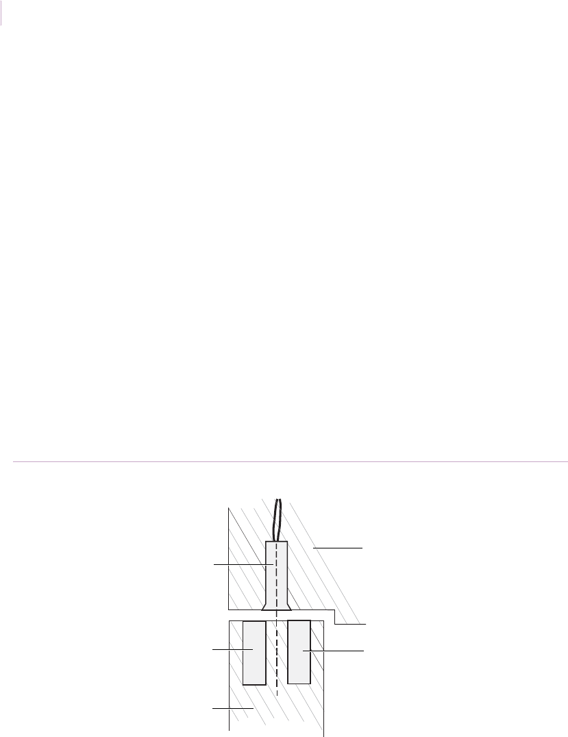
Intrusion Sensor
Application Notebook
126
Increase gap distances with a second magnet
Application. You can increase the gap distance of a recessed switch in a door an additional
40 percent, by placing two magnets side-by-side. This is helpful if you need to increase the
gap distance but do not have a wide-gap switch
Installation. Mount the magnets with like poles in the same direction; magnets will
actually push away from each other when mounted in this manner. To observe correct
polarity for wide-gap switches, the red ends of the magnets must be mounted away from the
switch.
To mount the magnet, do the following:
1. Drill holes for the magnets, spacing them equal distances from a line drawn through
the center of the switch. Mount magnets as close together as possible (Figure 106).
2. Test (see Ohmmeter testing on page 86).
3. Connect the switch to the alarm loop and retest.
Recommended products. 1075, 1075W, 1275, 1275W, 1924 magnet
Figure 106. Using a second magnet
Door frame
Switch
Magnet
Magnet
Door
Sensor_Applications.book Page 126 Tuesday, December 27, 2005 5:45 AM
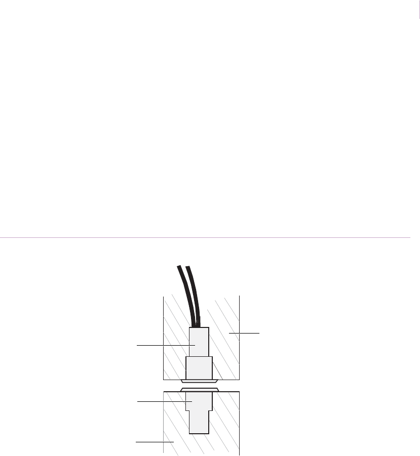
Chapter 3
Magnetic contacts
127
Mechanical recessed switch replacement
Application. Floating magnet-type mechanical switches can fail due to corrosion (the
switch is not hermetically sealed) or uneven wear of the plastic body. They can also be
crushed between the door and frame. Use a GE switch as a better alternative.
Installation. If the unreliable switch is a repel magnet type, remove the switch and magnet
and replace with a hermetically sealed, 0.75 in. (1.9 cm) diameter 1078C1. The hole should
be 1.5 in. (3.8 cm) deep. The 1078C1 self-locks in place, requiring no screws (Figure 107).
Recommended products. 1078C, 1078C1
Figure 107. 1078C-1 installation
Door frame
Switch
Door
Magnet
Sensor_Applications.book Page 127 Tuesday, December 27, 2005 5:45 AM
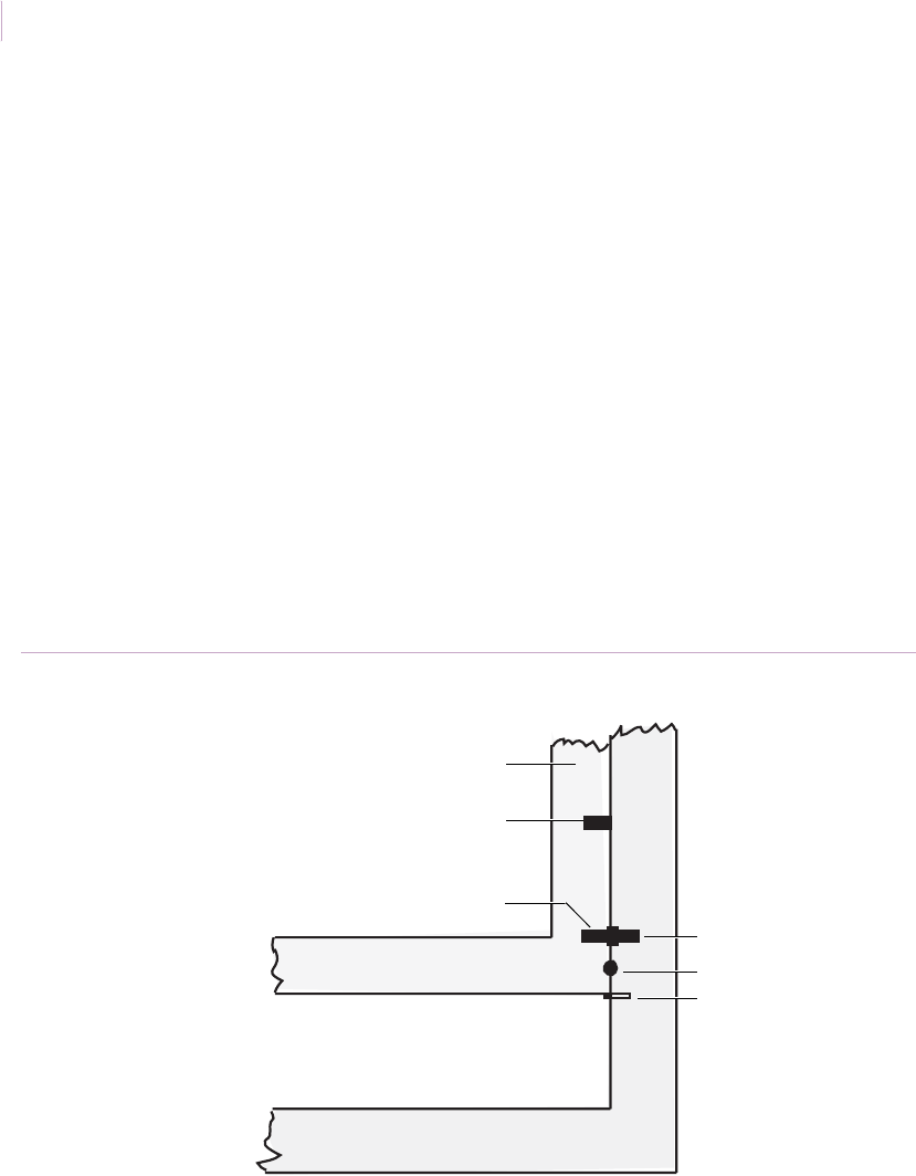
Intrusion Sensor
Application Notebook
128
Window ventilation without false alarms
Application. In some applications, you may need to be able to open a window for
ventilation without causing a false alarm.
Installation. We recommend one of the following methods for opening windows for
ventilation without causing a false alarm:
• Add a small dot, either adhesive or painted, to both the window frame and window
jamb. The dot marks the spot above which you should not open the window. The
user simply aligns the dot as shown in Figure 108. Or
• Provide a removable window stop so that the window cannot pass the alarm point in
normal usage. Drill a hole in the jamb for the stop and use a nail or small dowel as
the stop. The dowel or nail should protrude from the hole so it supports the opened
window as shown in Figure 108. To close the window, remove the stop.
See also Window ventilation using two magnets on page 129
Figure 108. Ventilating windows
Switch
Dot
Stop
Window frame
First magnet
Second magnet
Open for ventilation
Sensor_Applications.book Page 128 Tuesday, December 27, 2005 5:45 AM

Chapter 3
Magnetic contacts
129
Window ventilation using two magnets
Application. You can use two magnets and one wide-gap switch to vent sliding windows.
It is possible to obtain up to 5 in. (12.7 cm) ventilation with a 1.5 in. (3.8 cm) gap between
the magnets and the switch.
Installation. Use a wide-gap recessed switch and an additional 3/8 in. (0.9 cm) diameter
by 1.5 in. (3.8 cm) long magnet and do the following:
1. To remove the window frame, open the window as far as required, lift the window
straight up into the upper channel, and pull the window straight out from the bottom
(Figure 109 on page 130). Some windows have spring locks in the upper frame
channel that you must open before you can remove the window.
2. Slightly overdrill a vertical hole for the switch in the top of the frame, about 5.5 in.
(14 cm) from the edge of the frame. Coat the switch with RTV mounting compound
and insert in the hole.
3. Mount the magnets on the inside of the upper window channel toward the top of the
channel with RTV mounting compound (Figure 110 on page 130). Locate one
magnet at the edge of the channel, red end toward the edge of the window. Locate
the other magnet with the nonred end under the switch, red end pointing away from
the other magnet.
4. After the RTV sets (about 15 minutes), reinsert the window in the frame by
reversing the procedure in step 1.
5. Test (see Ohmmeter testing on page 86) for proper operation. If the switch drops out
anywhere within the ventilation range, move the inside magnet and switch closer to
the outside edge of the window.
6. Connect the switch to the alarm loop.
7. Instruct the user on proper use of the ventilation feature. If necessary, add a window
stop or mark the maximum permissible opening to prevent false alarms.
Note: Sliding windows can also be vented using a surface mounted switch and magnet. The 1275W
switch can also be used for this application.
Sensor_Applications.book Page 129 Tuesday, December 27, 2005 5:45 AM
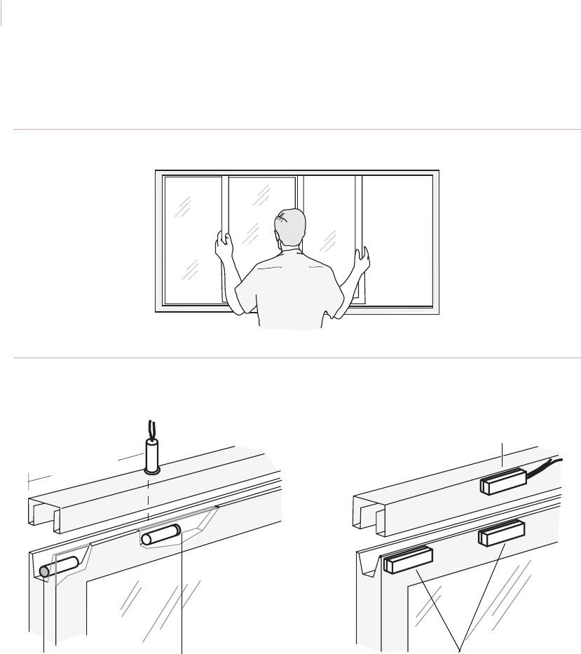
Intrusion Sensor
Application Notebook
130
Recommended products. Recessed: 1065W, 1075W, 1057-RT;
Surface: 1035W, 1145W, 1057-RT, RTV 1905
Figure 109. Removing the window
Figure 110. Window ventilation using two magnets
5.5 in.
Switch Switch
Magnets
(14 cm)
Align switch in an L configuration,
not a T configuration with the magnet.
Align switch parallel to magnet
Magnet red end
Magnet red end
Sensor_Applications.book Page 130 Tuesday, December 27, 2005 5:45 AM

Chapter 3
Magnetic contacts
131
Sliding aluminum windows
Application. There are several methods of protecting sliding aluminum windows. The
following installations give alternative instructions for installation with the window
removed or not, and using recessed or surface mount switches, or a combination of both.
Installation with window removal. If you are running the switch leads in the channel,
you must remove the window. To install the contact, do the following:
1. To remove the window frame, open the window as far as required, lift the window
straight up into the upper channel, and pull the window straight out from the bottom
(Figure 111 on page 132). Some windows have spring locks in the upper frame
channel that you must open before you can remove the window.
2. At the mounting position for the switch (either parallel or perpendicular to the
magnet), drill a hole in the window frame. Run wires and insert the switch into the
frame (Figure 112 on page 132).
3. Mount the magnet on the inside of the upper window channel, toward the top of the
channel, with RTV mounting compound. RTV should sufficiently set in about 15
minutes to permit replacement of the window in the frame.
4. Reinsert the window in the frame by reversing the procedure in step 1.
5. Test (see Ohmmeter testing on page 86) with the window in a closed position.
Note: Wide-gap switches are polarity sensitive. The red tip of the magnet must be aligned as shown in
Figure 112. The magnet must not be centered under the switch; a null may result and the switch
will not operate.
Recommended products. 1055, 1055W. 1065, 1975, 1275W, 1057-RT, RTV 1905,
wireless model: NX-458
Sensor_Applications.book Page 131 Tuesday, December 27, 2005 5:45 AM
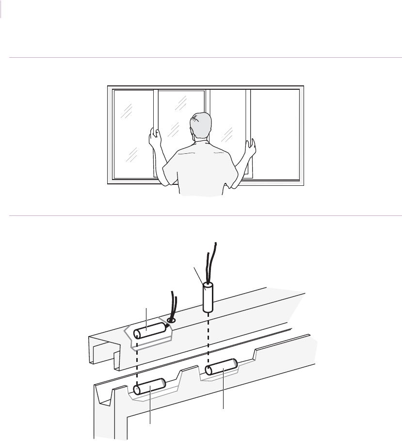
Intrusion Sensor
Application Notebook
132
Figure 111. Removing the window
Figure 112. Mounting in sliding aluminum windows with window removal
Parallel
switch
Perpendicular
switch
Magnet
Magnet
Sensor_Applications.book Page 132 Tuesday, December 27, 2005 5:45 AM

Chapter 3
Magnetic contacts
133
Installation without removing the window. Removing the window is not necessary
unless you are running the switch leads in the channel. To install the contact, do the
following:
1. If using a self-adhesive switch, clean the surface with alcohol before mounting to
ensure a good bond.
2. Mount the switch on the sash in the desired position (Figure 113).
3. Mount the magnet on the window directly opposite the switch when the window is
closed.
4. Test (see Ohmmeter testing on page 86) with the window in the closed position.
Recommended products. 1035, 1035W, 1085, 1085T, 1285T (Designer),
wireless models: NX-452, NX-450, NX-454. NX-650
Figure 113. Contact mounting on sliding aluminum windows
Surface-mount switch
Surface-mount switch
Magnet
Magnet
1285T designer switch
Magnet
Sensor_Applications.book Page 133 Tuesday, December 27, 2005 5:45 AM
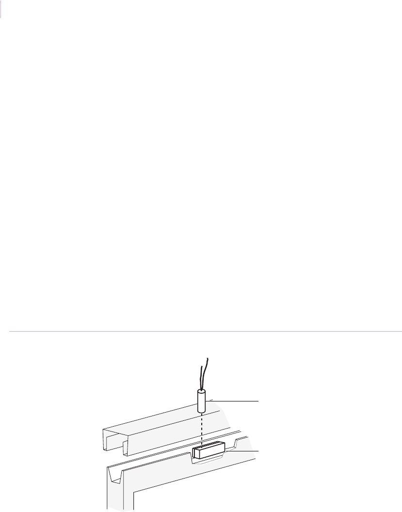
Intrusion Sensor
Application Notebook
134
Installation with combined recessed and surface mount. A 1075 or 1075W
switch with a 1927 magnet is ideal for this application. The magnet can be quickly installed
using double-sided tape instead of waiting for RTV mounting compound to set up.
To install the contact, do the following:
1. To remove the window frame, open the window as far as required, lift the window
straight up into the upper channel, and pull the window straight out from the bottom
(Figure 111 on page 132). Some windows have spring locks in the upper frame
channel that must be opened before you can remove the window.
2. At the mounting position for the switch (which should be perpendicular to the
magnet as shown in Figure 114), drill a hole in the window frame and run wires.
Insert the switch into the frame.
3. Mount the magnet on the inside of the upper window channel using the double-
sided tape provided. The label must read left to right. Align the left end of the label
with the center line of the switch.
4. Reinsert the window in the frame by reversing the procedure in step 1.
5. Test (see Ohmmeter testing on page 86) with the window in the closed position.
Recommended products. 1075W with 1927 or 1080T magnet
Figure 114. Combined recessed and surface installation
GE
Perpendicular recessed switch
Recessed magnet
Sensor_Applications.book Page 134 Tuesday, December 27, 2005 5:45 AM
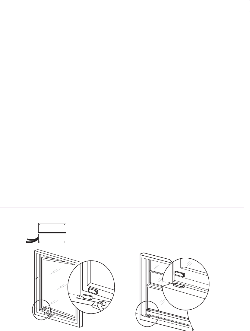
Chapter 3
Magnetic contacts
135
Windows with thin frames
Application. When Pella or sliding aluminum windows have thin window frames or
limited space for mounting the switch, use the 1145-W ultraminiature surface-mount contact
with a regular or wide-gap operating distance.
Installation. To install the contact, do the following:
1. Determine the best location for the switch and magnet. The magnet will mount on
the glass frame.
2. Clean the mounting surface with alcohol for good adhesion and mount the switch
and magnet with very high-bonding tape, silicon glue, or brass brads, depending on
the frame material.
3. For wide-gap versions, you must mount the switch and magnet with the mounting
holes to the outside in the four-corners position (Figure 115). The labels on the
switch and magnet must read from left to right. This ensures proper polarity. Wide-
gap operating distance is 0.75 in.(1.9 cm) for the 1145W model.
Recommended products. 1145W
Figure 115. Installation for thin frame windows
GE
GE
GE
GE
Magnet
Magnet
Magnet
Switch
Switch
Switch
Sensor_Applications.book Page 135 Tuesday, December 27, 2005 5:45 AM
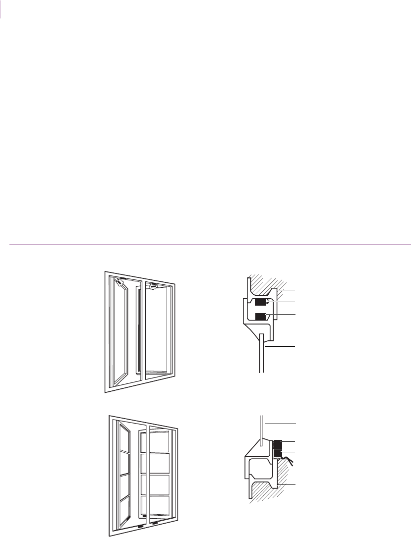
Intrusion Sensor
Application Notebook
136
Windows with thin steel frames
Application. When installing magnetic contacts on windows with thin steel frames that
present drilling and tapping difficulties, use 1035W or 1145W miniature contacts.
Installation. To mount the contact, use an adhesive-mount switch and do the following:
1. Clean the frame with alcohol for good adhesion and use one of the two mounting
methods shown in Figure 116.
2. Drill holes to conceal the wiring if desired.
Recommended products. 1035W, 1145W
Figure 116. Installation for thin steel frame windows
Window frame
Switch
Magnet
Window
Window frame
Switch
Magnet
Window
Sensor_Applications.book Page 136 Tuesday, December 27, 2005 5:45 AM
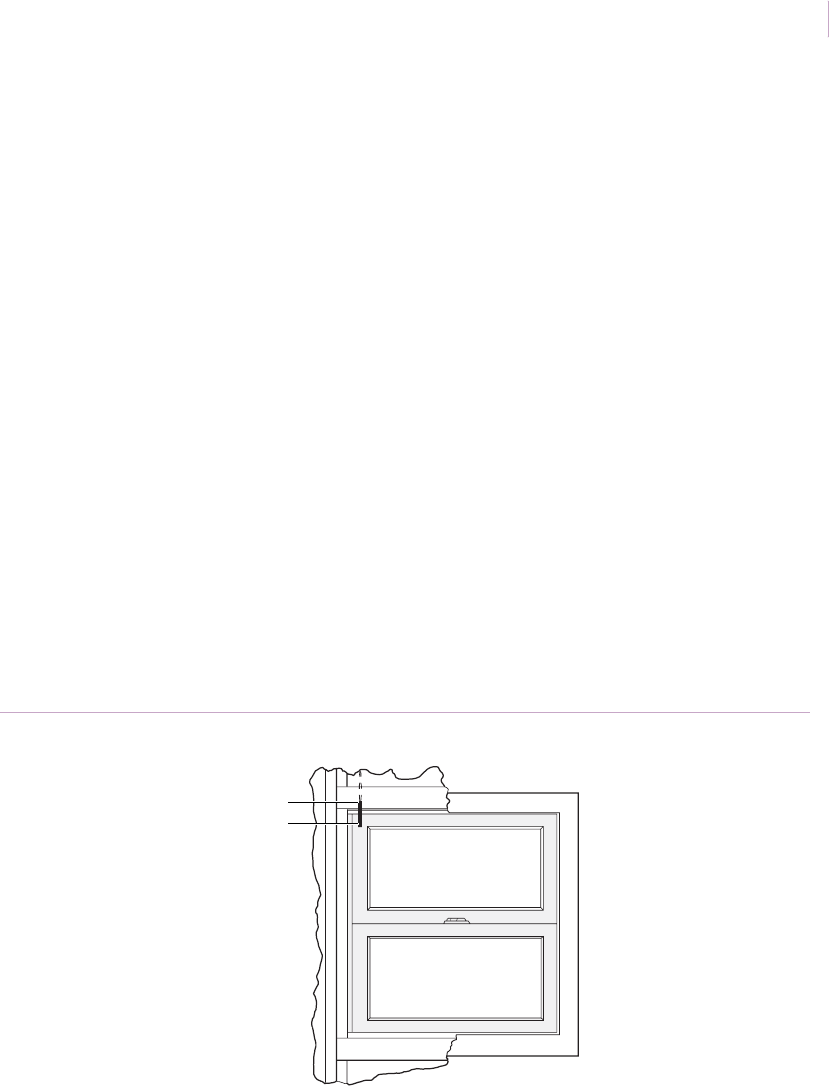
Chapter 3
Magnetic contacts
137
Double-hung windows
Application. You can protect double-hung windows with recessed or surface-mounted
magnetic contacts with regular or wide-gap switches.
Installation with recessed contacts in top or bottom of window. To mount the
contact, do the following:
1. Slightly overdrill holes at the magnet position in the window frame and the switch
position in the head or sill. Coat the magnet and switch with RTV mounting
compound and insert the magnet and switch in the holes (Figure 117).
Note: Wide-gap switches are polarity sensitive. If the switch uses a bare magnet, mount the
magnet with the red end away from the switch to observe correct polarity.
2. Test (see Ohmmeter testing on page 86).
3. Connect the switch to the alarm loop.
4. To improve appearance, cover the switch and magnet with wood filler.
Recommended products. 1015, 1055, 1065, 1075, 1125W, 1275W, RTV 1905,
wireless models: NX-650, NX-450, NX-652, NX-452
Figure 117. Top or bottom mount for double-hung windows
End-to-end recessed switch
Recessed magnet
Sensor_Applications.book Page 137 Tuesday, December 27, 2005 5:45 AM
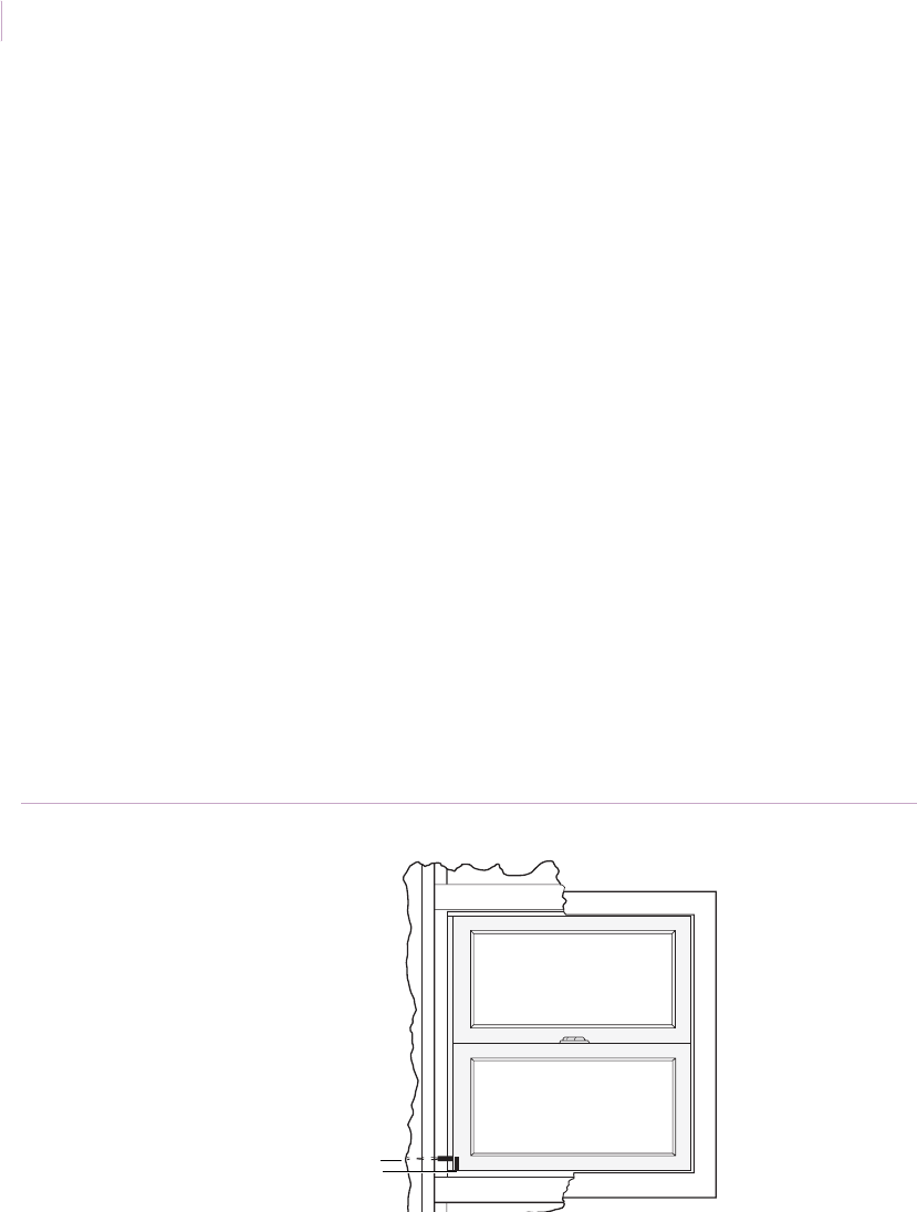
Intrusion Sensor
Application Notebook
138
Installation with recessed contacts in window sides. We recommend you only use
this method when walls are open and readily accessible for running wires. A finished wall
will make this method very difficult and awkward. This method requires perpendicular
mounting of the switch and magnet and may require a wide gap between the switch and
magnet.
To mount the contact, do the following:
1. Drill a vertical hole in the window frame for the magnet. Coat the magnet with RTV
mounting compound and insert it in the hole.
2. Select a position for the switch with the following requirements:
• The magnet must not be centered under the switch. The end of the switch must
be opposite the end of the magnet (perpendicular) as shown in Figure 118.
• If a wide-gap switch is used, mount the magnet with the red end away from the
switch end with wires to observe correct polarity.
3. Drill the hole for the switch and insert the switch in the hole.
4. Test (see Ohmmeter testing on page 86) with the window closed.
5. Connect the switch to the alarm loop.
Recommended products. 1055, 1055W, 1065, 1065W, 1075, 1075W, RTV 1905,
wireless model: NX-458
Figure 118. Installation in sides of double-hung windows
Perpendicular recessed switch
Recessed magnet
Sensor_Applications.book Page 138 Tuesday, December 27, 2005 5:45 AM
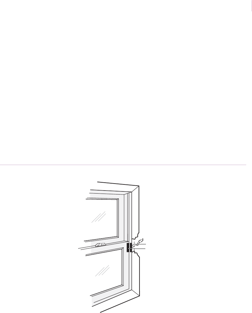
Chapter 3
Magnetic contacts
139
Installation with surface-mount contacts. Use a surface-mount contact and do the
following:
1. Mount the switch on the head, sill, or jamb in the desired position.
2. Mount the magnet on the window, directly opposite the switch when the window is
closed. If you use a self-adhesive switch, clean the surface with alcohol before you
mount it to ensure a good bond (Figure 119).
Note: If you use a wide-gap switch, be certain to align the labels on the switch and magnet so
they read in the same direction (switch is polarity sensitive).
3. Test (see Ohmmeter testing on page 86).
4. Connect the switch to the alarm loop.
Recommended products. 1032, 1032W, 1035, 1035W, 1045T, 1045W, 1082, 1082W,
1085, 1085T, 1085W, wireless models: XNX-454, NX-452
Figure 119. Double-hung windows with surface-mount contact
Surface-mount switch
Surface-mount magnet
Sensor_Applications.book Page 139 Tuesday, December 27, 2005 5:45 AM

Intrusion Sensor
Application Notebook
140
Pella casement or awning windows
Application. Use magnetic contacts to protect Pella casement and awning windows. Pella
recommends you do not mount switches in sills due to possible damage from water. If you
must drill into the sill, make sure you provide a solid, tight seal using RTV compound.
Installation with surface mount contacts. The miniature size and large number of
mounting options available for 1145W surface-mount contacts make these contacts
ideal for protecting Pella casement windows. The switch and magnet are concealed
when the window is closed. Concealed surface-mounting offers benefits over
recessed mounting because the construction of these windows makes recess
mounting difficult without breaking the glass. To install the contact, do the
following:
1. Select the position of the switch and contact. If ventilation is desired, locate near the
hinged side of the window.
2. Drill holes for the wires. Slant back at 15 to 30 degrees to make sure the wire will go
inside the wall (Figure 120 on page 141). If the 1145 W wide-gap contact is used,
align so that the ends of the switch and magnet are next to each other (switch is
sensitive to the polarity of the magnet).
3. Use one of the following mounting methods:
a. Mount with self-adhesive tape. Clean the back of the switch, magnet, and
mounting surfaces with alcohol. Remove backing from tape and attach the tape
to the switch or magnet, then attach the switch or magnet to the cleaned surface.
b. Mount with glue, epoxy, or RTV mounting compound. Attach the switch or
magnet to the surface with glue, epoxy, or RTV mounting compound.
4. Test (see Ohmmeter testing on page 86).
5. Connect the switch to the alarm loop.
Recommended products. 1145, RTV 1905, wireless model: NX-458
Sensor_Applications.book Page 140 Tuesday, December 27, 2005 5:45 AM
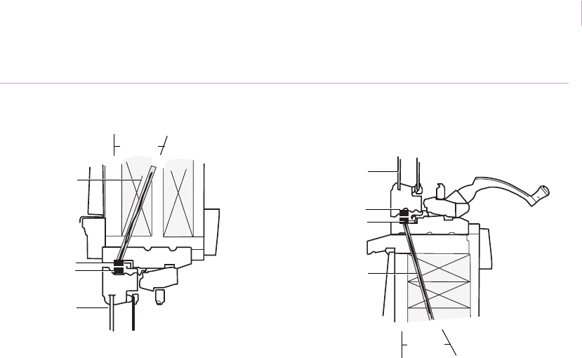
Chapter 3
Magnetic contacts
141
Figure 120. Surface-mount installation for Pella and awning windowsl
Top of window Bottom of window
Wire access
Magnet
Switch
Window
Window
Magnet
Switch
Wire access
15 to 30°
15 to 30°
Sensor_Applications.book Page 141 Tuesday, December 27, 2005 5:45 AM

Intrusion Sensor
Application Notebook
142
Installation with recessed contacts. Pella casement and awning windows may have
two separate pieces of glass or one Thermopane. Is is very important, therefore, to take extra
care when drilling the mounting holes to avoid the glass. To install the contact, do the
following:
1. Select the position of the switch in the top of the window frame if wires will run
above the window, or in the bottom of the window if wires will run below the
window.
2. Drill a 0.25 in. (0.6 cm) diameter x 1.25 in. (3.2 cm) deep hole in the window sash.
3. Insert the magnet in the hole. If using a wide-gap switch, insert the magnet with the
red end away from the switch end without wires.
4. Drill a 0.25 in. (0.6 cm) diameter hole in the frame at approximately 15 degrees
toward the inside of the wall. Align the switch hole center to within 0.25 in. (0.6 cm)
of the center of the magnet (Figure 121).
5. Insert the switch (if you place the 1055W close to the pivot point, you will allow for
some ventilation).
6. Test (see Ohmmeter testing on page 86) and glue the switch and magnet in place.
Recommended products. 1015, 1015W, 1055, 1055W, 1125W, 1125TW, R1125W,
R1125TW, wireless model: NX-458
Figure 121. Installation of pella casement or awning windows with recessed contacts
Wire access
Switch
Magnet
Window sash
Window
15°
Sensor_Applications.book Page 142 Tuesday, December 27, 2005 5:45 AM
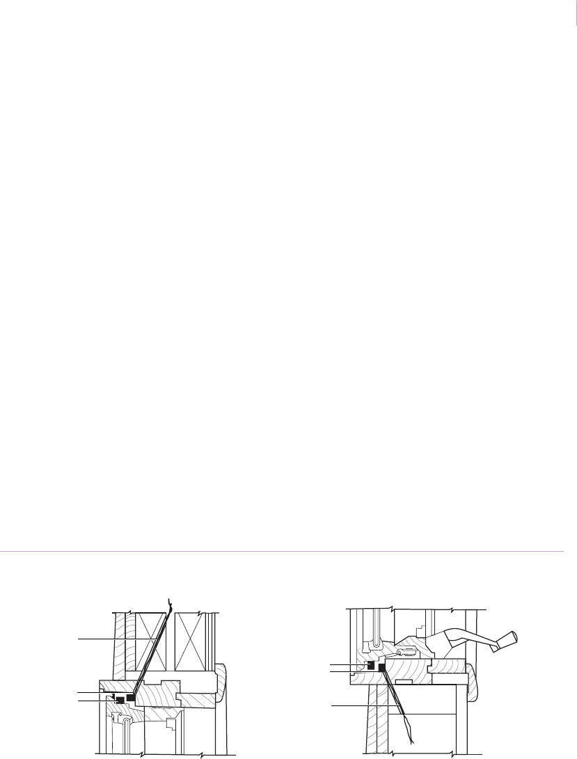
Chapter 3
Magnetic contacts
143
Anderson casement windows
Application. Use magnetic contacts to protect Anderson casement windows. Anderson
recommends you do not mount switches in sills due to possible damage from water. If you
must drill into the sill, make sure you provide a solid, tight seal using RTV compound.
Installation using surface-mount contacts. When using surface-mount contacts, the
switch and magnet are both concealed when the window is closed. Use off-white, white, or
brown units to match the plastic cover on the window. To install the contact, do the
following:
1. Select positions for the switch and magnet. For ventilation, use a wide-gap switch
on the top of the window near the hinged side. Drill a hole for the wire in the back of
the window frame. Angle this hole back toward the inside of the wall about 15 to 30
degrees (Figure 122).
2. Clean mounting surfaces with alcohol and peel the paper from the back of the
switch. Install as shown or screw in place (depending on the switch used). Peel the
paper from the back of the magnet and install on the sash frame with the label
reading in the same direction as the switch.
3. Close the window and test (see Ohmmeter testing on page 86).
Recommended products. 1125, 1125TW, R1125W, R1125TW, 1035, RTV 1905,
wireless models: NX-454, NX-452
Figure 122. Anderson windows using surface-mount contacts
Top of window Bottom of window
Wire access
Switch
Magnet Wire access
Switch
Magnet
Sensor_Applications.book Page 143 Tuesday, December 27, 2005 5:45 AM
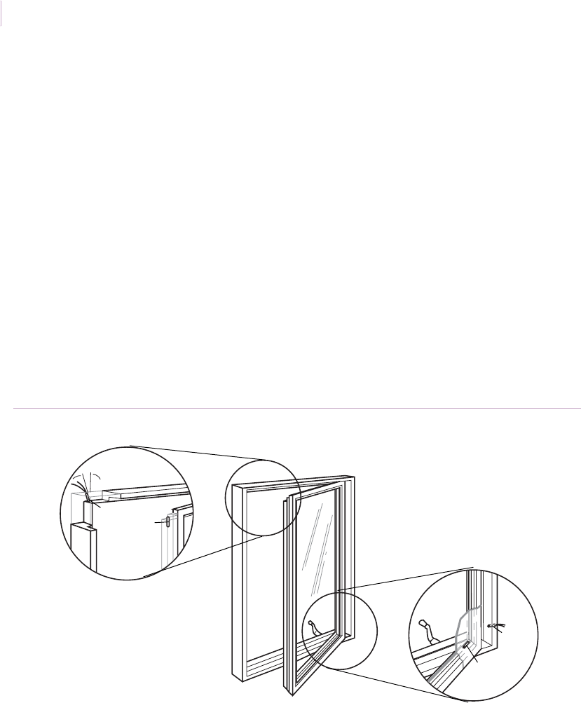
Intrusion Sensor
Application Notebook
144
Installation using recessed contacts. To use recessed contacts to protect Anderson
casement windows (Figure 123), you need to place the magnet in the sash on the step closest
to the inside of the window. To install the contact, do the following:
1. Install the magnet in the sash on the step closest to the inside of the window. Drill a
hole 0.25 in. (0.6 cm) in diameter and 1.25 in. (3.2 cm) deep. This step has a cross
section of about 0.5 by 0.5 in. (1.3 x 1.3 cm) and will hold the 0.25 in. (0.6 cm)
diameter magnet by centering the hole in the section.
2. Drill a hole for the switch opposite the magnet. Angle this hole back toward the
inside of the wall about 15 degrees.
3. Install the switch and test (see Ohmmeter testing on page 86).
4. Cover the ends of the switch and magnet with silicone rubber to protect them from
weather damage.
Recommended products. 1015, 1015W, 1055, 1055W, 1125W, 1125TW, R1125W,
R1125TW, RTV 1905, wireless models: NX-454, NX-452
Figure 123. Anderson casement windows with recessed contacts
15°
Switch
Magnet
Switch
Magnet
Sensor_Applications.book Page 144 Tuesday, December 27, 2005 5:45 AM
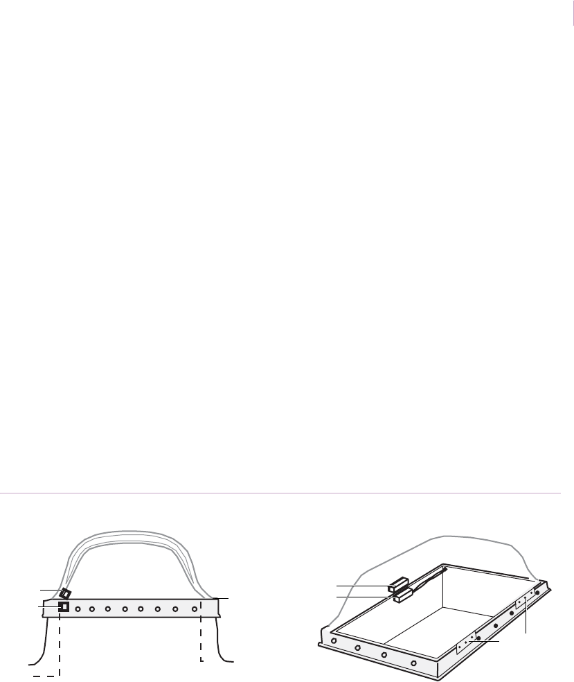
Chapter 3
Magnetic contacts
145
Hinged skylights
Application. Use surface-mount magnetic contacts to protect hinged skylights against roof
entry.
Installation. To install the contact, do the following:
1. Select the location for the switch and magnet on the side opposite the hinges
(Figure 124).
2. Mount the switch on the frame and the magnet on the skylight. Observe gap distance
tolerances. You may have to use spacers to achieve proper alignment.
If the skylight has a steel frame, the gap distance is generally reduced by half, and
you will need to use a wide-gap switch.
Mount the switch and magnet so the labels reads in the same direction (switch is
polarity sensitive).
3. Test (see Ohmmeter testing on page 86).
Recommended products. 1032, 1035, 1085, 1145, 1032W, 1035W, 1085W, 1085TW,
1085T, wireless model: NX-652
Figure 124. Hinged skylights
Hinges
Hinge
Magnet
Switch
Magnet
Switch
Sensor_Applications.book Page 145 Tuesday, December 27, 2005 5:45 AM

Intrusion Sensor
Application Notebook
146
Attic entry drop-down stairs
Application. Often the entry door from the garage to the house will be alarmed and the
garage door will be left unsecured. An intruder can gain access to the garage, enter the attic
via the drop-down stairway, cut a hole through the ceiling, and drop into the house without
triggering the alarm. Magnetic contacts on the stairway can prevent this intrusion.
Installation. To install the contact, do the following:
1. Position the switch on the stairway frame, and the magnet on the drop-down portion
of the stairway (Figure 125). There must be no interference to the stairway
mechanism from the switch or magnet.
2. Permanently attach the switch to the frame, and temporarily attach the magnet to the
stairway with masking tape.
3. Test (see Ohmmeter testing on page 86) with the stairway closed.
4. Permanently attach the magnet to the stairway and connect the switch leads to the
alarm loop.
Note: For high-security and wide-gap switches, labels on the switch and magnet must read in the same
direction. Also, observe minimum and maximum gap distances for high-security switches
Recommended products. 1035W, 1045T, 1082, 1085W, 1085TW, 2500 or H series,
wireless model: NX-652
Figure 125. Attic drop-down stairs protection
To alarm loop
Magnet
Switch
Frame
Sensor_Applications.book Page 146 Tuesday, December 27, 2005 5:45 AM

Chapter 3
Magnetic contacts
147
Barrier Bars
Application. Use pressure-switch-activated Barrier Bars to protect hinged skylights, attic
vents, basement windows, or other openings from unwanted intrusion.
Installation. You can surface or frame mount Barrier Bars in wired or wireless systems.
The spring-loaded assembly snaps into place with no screws or drilling. The self-adhesive,
epoxy-based switch adheres to brick or cement surfaces, forming a strong, permanent bond.
To install the contact, do the following:
1. Select the location for the switch so that the bar crosses the center of the opening
(Figure 126).
2. Remove the adhesive backing and press the switch in place.
3. Run cable to the switch and attach to the terminals.
4. Snap the bar into place, using a spacer for openings wider than 23 in. (0.6 m).
5. Test (see Ohmmeter testing on page 86).
Recommended products. BB-1GS (pressure-sensitive), BB-2 (mercury tilt switch),
AMDB-1 bracket, OVB-1 vertical bars.
Figure 126. Barrier Bars installation
Sensor_Applications.book Page 147 Tuesday, December 27, 2005 5:45 AM

Intrusion Sensor
Application Notebook
148
Roof hatches
Application. To stop entry via a roof hatch, use surface-mount switches. The switch used
will depend on the mounting method required by the space available and the connection to
the alarm circuit.
Installation. In hatch protection, it is important to mount both the switch and magnet so
they will not intrude into the open hatch space where they can catch on clothing and restrict
entry or exit.
To install the contact, do the following:
1. Attach the selected switch on the hatch frame opposite the hatch hinges. Be sure to
keep the gap distance between the switch and magnet within specified tolerance. If
the roof hatch and/or the frame is steel, allow for the gap distance to be halved or
use wide-gap switches.
2. When installed, switch and magnet must be parallel for best operation (Figure 127).
Mount the switch and magnet with the labels reading in the same direction (switch
is polarity sensitive).
3. To check for proper operation and circuit continuity, open and close the hatch.
Recommended products. 1032, 1032W, 1045T, 1045TW, 1082, 1082TW, 1085, 1085T,
1085W, 2505A, 1914T (spacer for 1045T), 1906T (spacer for 1082)
Figure 127. Roof hatch installation
Roof hatch closed
Spacer
Magnet
Switch
Switch
Magnet and spacer
Sensor_Applications.book Page 148 Tuesday, December 27, 2005 5:45 AM
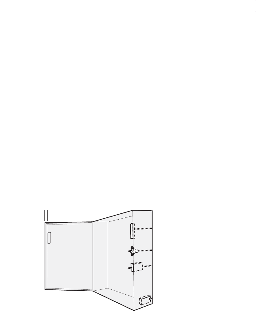
Chapter 3
Magnetic contacts
149
Metal enclosures
Application. Use magnetic contacts to protect control panels, bell boxes, or any metal
enclosures against unauthorized access. Contacts protect against tampering (through the key
hole or lock mechanism) and can be connected to the control’s 24-hour loop. Always test the
installation (see Ohmmeter testing on page 86).
Installation. To install the contacts (Figure 128), do one of the following:
•Surface mount. Use a 1035 surface-mount, self-adhesive switch. With self-
adhesive contacts, such as the 1035, locate the switch on the side or bottom of the
cabinet about 3/8 in. (0.9 cm) from the front edge. Align and mount the magnet.
•Plunger mount. The 3012 clips on 0.04 to 0.07 in. (0.10 to 0.18 cm) thick sheet
metal. The 3025T has shunt capability for servicing. All are hermetically sealed and
reed actuated for positive operation on seldom-used enclosure openings.
Recommended products. 1035, 3012, 3025T, 3015, 3027
Figure 128. Metal enclosure installation
3/8 in. (0.95 cm)
1035 surface-mount contact
3012 or 3012-1 clip-on plunger
3025T tamper switch
3025T tamper switch
Sensor_Applications.book Page 149 Tuesday, December 27, 2005 5:45 AM

Intrusion Sensor
Application Notebook
150
Cash register drawers with Bill Trap
Application. You can alert authorities to unauthorized removal of money from cash
register drawers with the Bill Trap. This simple device holds paper currency between a
magnetized clip and a back plate that contains magnetic reed contacts. Mount the Bill Trap
in a drawer and wire it to an open or closed loop to activate the alarm circuit when currency
is removed.
Installation. To install the Bill Trap, do the following:
1. Determine the best mounting location (take into account the length of currency).
2. Drill a 0.25 in. (0.6 cm) diameter hole through the back of the drawer. Leads can run
over the top of the drawer if there is clearance.
3. Pull the wire and connect it to the alarm loop. Special lead types and lengths are
available.
4. Temporarily mount the Bill Trap and insert currency between the Bill Trap’s clip
and back plate (Figure 129). Test for proper operation.
5. Clean the bottom of the Bill Trap and the mounting location in the drawer with
alcohol and use double-sided tape to adhere the Bill Trap to the drawer.
Recommended product. 3555 (Bill Trap)
Figure 129. Bill Trap installation
Bill Trap
Sensor_Applications.book Page 150 Tuesday, December 27, 2005 5:45 AM

Chapter 3
Magnetic contacts
151
Drawers
Application. Use one of the following installations to protect valuables in a drawer:
• Installation using surface-mount contacts
• Installation using recessed contacts
Installation using surface-mount contacts. Because it is difficult to use a
screwdriver inside a drawer, use a self-adhesive contact. Clean the mounting surfaces with
alcohol before attaching the contacts. Use wide-gap switches on steel file cabinets and desk
drawers (steel reduces operating distance by half). To install the contact, do the following:
1. Select mounting locations that will not interfere with the operation of the drawer:
a. Install the switch in the cabinet and the magnet on the drawer.
b. Mount the switch and magnet on the outside of the drawer (Figure 130).
If you use a wide-gap switch, the labels on the switch and magnet must read in the
same direction (switch is polarity sensitive).
2. Test (see Ohmmeter testing on page 86).
3. Connect the switch to the alarm loop. For higher security, install on a 24-hour loop
and provide a shunt switch in the circuit to permit access as needed.
Recommended products. 1032, 1035, 1082, 1085, 1085T, 1032 W, 1035W
Figure 130. Drawer with surface-mount contacts
Switch
Magnet Magnet
Magnet
Switch
Switch
Sensor_Applications.book Page 151 Tuesday, December 27, 2005 5:45 AM
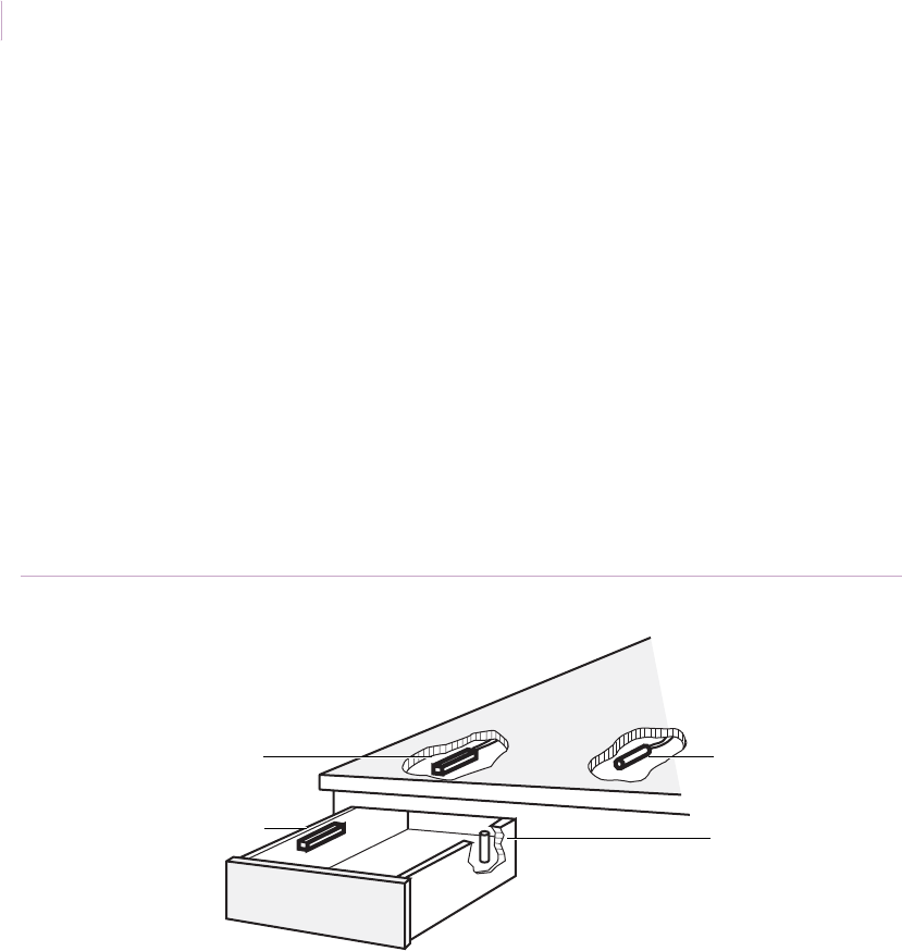
Intrusion Sensor
Application Notebook
152
Installation using recessed contacts. Do not use recessed contacts on metal drawers
(the metal is too thin). To install recessed contacts in nonmetal drawers, do the following:
1. Drill a vertical hole in the side of the drawer. Coat the magnet with RTV mounting
compound and insert the magnet in the hole.
2. Coat the switch with RTV mounting compound and attach the switch to the cabinet
perpendicular to the magnet. The magnet must not be centered below the switch, but
near the end of the switch. If you use a wide-gap switch, the red tip of the magnet
must be away from the switch (Figure 131).
3. Test (see Ohmmeter testing on page 86).
4. Install the switch in the alarm loop. For higher security, install on a 24-hour loop and
provide a shunt switch in the circuit to permit access as needed.
Recommended products. 1145, 1145W, 1055W, RTV 1905
Figure 131. Drawer with recessed contacts
Surface installation
Switch
Magnet
Recessed installation
Switch
Magnet
Sensor_Applications.book Page 152 Tuesday, December 27, 2005 5:45 AM

Chapter 3
Magnetic contacts
153
China cabinets
Application. Use one of the following installations to protect valuables in a china cabinet:
• Installation using surface-mount contacts
• Installation using recessed contact
You need to alarm both doors on a two-door cabinet and wire the switches in series. Do not
place contacts in the hinged portion of the cabinet door (the door could open wide before the
switch is tripped).
Installation using surface-mount contacts. If space is limited and you want an
unobtrusive installation, use the 1145W ultraminiature, wide-gap contact. To install the
contact, do the following:
1. Mount the switches and magnets. If you use a wide-gap or high-security switch,
align the switch and contact labels so they read in the same direction (switches are
polarity sensitive). Observe minimum gap distances for H series contacts.
2. Drill an exit hole for the wires in the back of the cabinet. Route the wires in the
joints of the cabinet, around the top of the cabinet and out the exit hole.
3. Test (see Ohmmeter testing on page 86).
4. Install the switch in the alarm loop. For higher security, install on a 24-hour loop and
provide a shunt switch in the circuit to permit access as needed.
Recommended products. 1032, 1035, 1082, 1085, 1085T, H Series, 1145W;
wireless models: NX-454, NX-450, NX-650, NX-452
Figure 132. China cabinet with surface-mount contacts
Surface-mount switch
Surface magnet
Sensor_Applications.book Page 153 Tuesday, December 27, 2005 5:45 AM
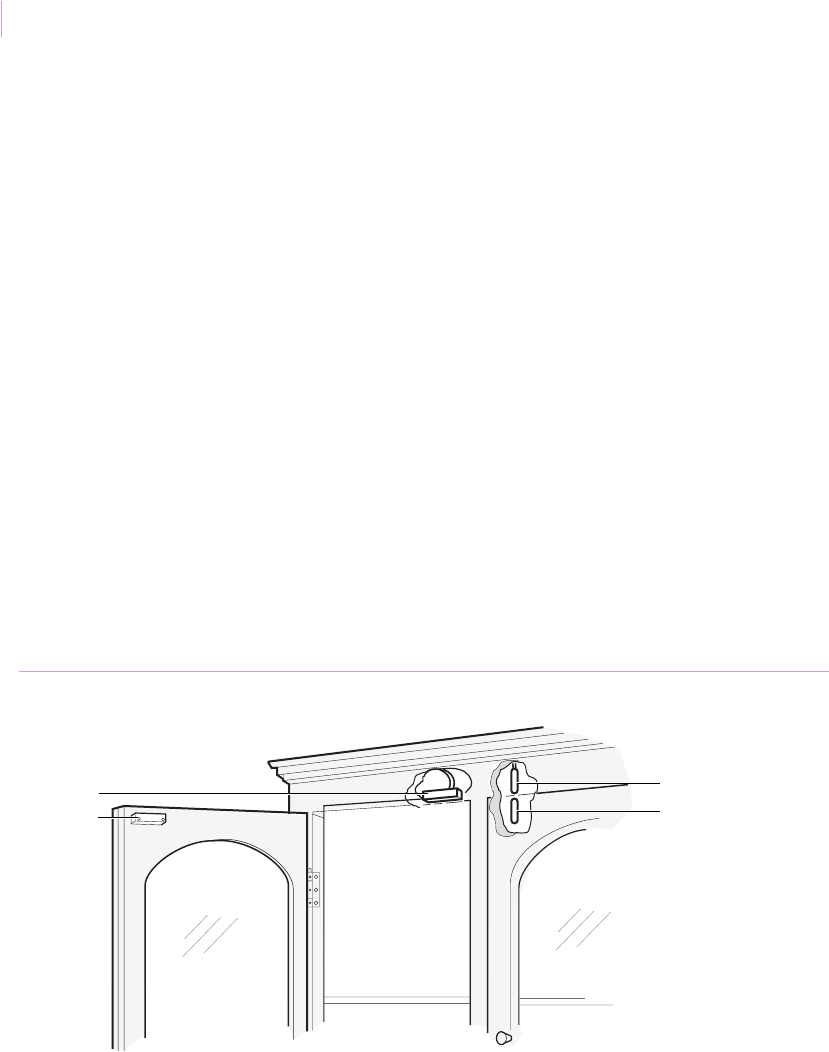
Intrusion Sensor
Application Notebook
154
Installation using recessed contacts. For aesthetic reasons, we recommend you use
recessed contacts instead of surface-mount contacts for this application where possible. To
install the contact, do the following:
1. Drill a vertical hole in the top of the cabinet door. Coat the magnet with RTV
mounting compound and insert the magnet in the hole. If you use a wide-gap switch,
mount the magnet with the red end toward the switch end with wires (switch is
polarity sensitive).
2. Drill a vertical hole in the cabinet for the switch and drill a hole at an angle from the
inside of the cabinet to meet the switch hole for the wires. Drill an exit hole for the
wires through the back of the cabinet.
3. Coat the switch with RTV mounting compound and insert the switch in the hole,
fishing the wires through the inside of the cabinet. Route the wires in the joint of the
cabinet, around the top of the cabinet and out the exit hole.
4. Test (see Ohmmeter testing on page 86).
5. Install the switch in the alarm loop. For higher security, install on a 24-hour loop and
provide a shunt switch in the circuit to permit access as needed.
Recommended products. 1055, 1065, 1075, RTV 1905, wireless model: NX458
Figure 133. China cabinet with recessed contacts
Recessed switch
Recessed magnet
Magnet
Switch
Sensor_Applications.book Page 154 Tuesday, December 27, 2005 5:45 AM

Chapter 3
Magnetic contacts
155
Guns and gun cabinets
Application. Gun cabinets can be protected using the same methods used for china
cabinets. However, since the glass front on a gun cabinet can be broken without sounding an
alarm, you can also use one of the following installations:
• Installation using a recessed roller switch
• Installation using a Magnapull
Always test the installation (see Ohmmeter testing on page 86).
Installation using a recessed roller switch to bug a gun. To install the contact, do
the following:
1. Select the gun to be protected. Drill a 0.75 in. (1.9 cm) diameter hole in the cabinet
butt cutout. Mount the roller switch in the hole (Figure 134).
2. Connect to a 24-hour circuit to provide protection even when the owner is home.
3. Instruct the user to disarm the system before removing the gun.
Recommended products. 3005, 3008
Figure 134. Gun installation with recessed roller switch
Recessed roller switch
Sensor_Applications.book Page 155 Tuesday, December 27, 2005 5:45 AM
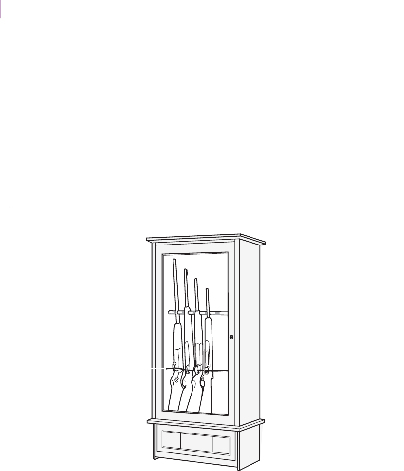
Intrusion Sensor
Application Notebook
156
Installation using a Magnapull. Use a Magnapull for guns on open gun racks. To
install the Magnapull, do the following:
1. Drill a hole through the wall near the end of the gun rack (if rack is mounted on the
wall).
2. Mount the magnet housing on the wall or other end of the gun rack.
3. Pull the wire through the trigger guards of all the guns (Figure 135).
4. Insert the switch into the magnet housing.
Recommended products. Magnapull 1005, 2105A, 2107A
Figure 135. Guns with a Magnapull
Magnapull wire
Sensor_Applications.book Page 156 Tuesday, December 27, 2005 5:45 AM

Chapter 3
Magnetic contacts
157
Art objects
Application. Use a roller switch to protect art objects such as statuary, vases, chests, or
other works of art not stored in cabinets.
Installation. Inspect the flat surface where the art object will rest. The art object must exert
sufficient weight to fully depress the roller of the switch when the object is in place. To
install the switch, do the following:
1. Drill a hole 0.75 in, (1.9 cm) in diameter and at least 1.5 in. (3.8 cm) deep in the
display stand.
2. Install the switch and test (see Ohmmeter testing on page 86). Connect to a 24-hour
loop, if available, to provide protection even if the perimeter loop is off.
Note: If the height of the switch’s flange causes the protected object to rock, recess the switch as shown
in Figure 136.
Recommended products. 3005, 3008
Figure 136. Art object with roller switch
3008 switch
Sensor_Applications.book Page 157 Tuesday, December 27, 2005 5:45 AM
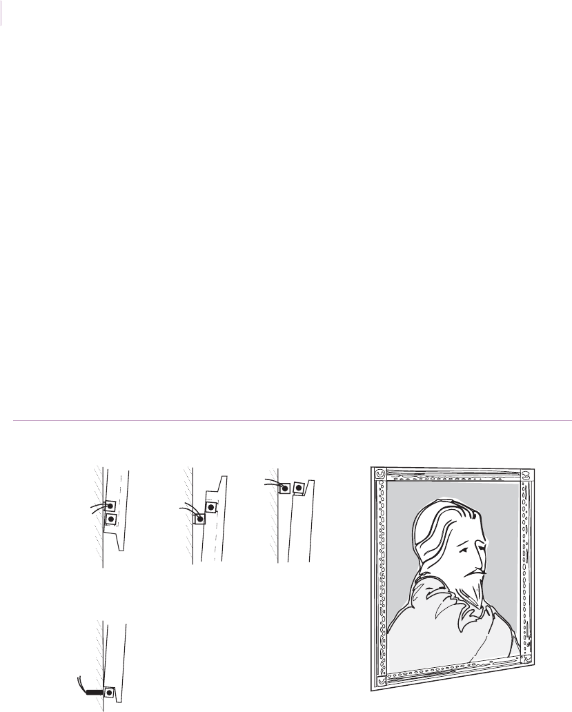
Intrusion Sensor
Application Notebook
158
Hung art objects
Application. Use surface-mount or recessed wide-gap contacts to protect paintings and
other hanging works of art.
Installation. Use a wide-gap switch if the gap is more than 0.5 in. (1.3 cm).To install the
contact, do the following:
1. Inspect the frame for an area to place the magnet.
2. Install the switch on the wall behind the magnet. If you use a recessed contact,
install the switch in the wall at right angles to the magnet, forming an L with the
switch and magnet as shown in Figure 137.
3. Test (see Ohmmeter testing on page 86). Wire the contact to a 24-hour loop, if
available, to provide protection even if the perimeter loop is off.
Recommended products. 1035W, 1145W, 1275W
Figure 137. Hung art objects
Surface installation
Recessed installation
Sensor_Applications.book Page 158 Tuesday, December 27, 2005 5:45 AM

Chapter 3
Magnetic contacts
159
Computers, TVs, and stereos
Application. Use a Magnapull switch to protect single items such as computers, TVs, and
stereo components.
Installation. To install the switch, do the following:
1. Use epoxy or screws (if appropriate for the item) to mount the housing receptacle to
the item you want to protect (Figure 138).
2. Insert the switch into the magnet housing.
3. Move the equipment around the desk or table as in normal use. Determine the
appropriate length of cord to accommodate minor movements. Affix the cord to the
table using a small wire clamp.
Note: Avoid mounting the switch too close to data disks and other media that can be adversely affected
by magnetic fields.
Recommended products. 1005
Figure 138. Equipment with Magnapull
Magnapull
Sensor_Applications.book Page 159 Tuesday, December 27, 2005 5:45 AM
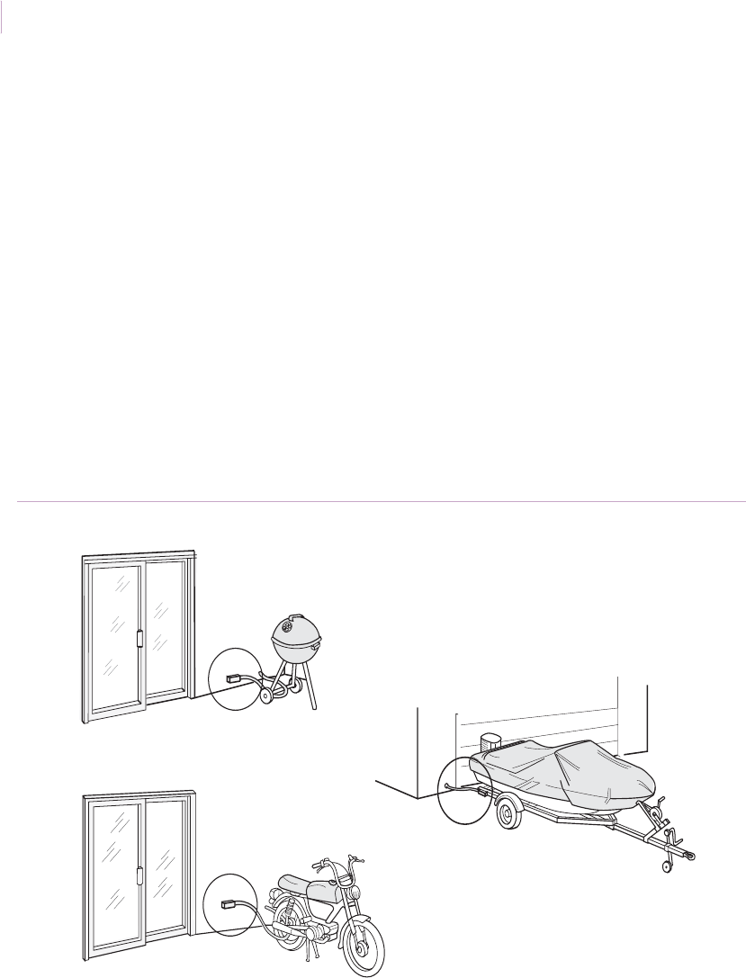
Intrusion Sensor
Application Notebook
160
Recreational equipment
Application. Use a Magnapull to protect recreational equipment such as motorcycles,
bikes, and boats. For commercial applications, pull an armored switch with leads through a
row of items to be protected.
Installation. To install the Magnapull, do the following:
1. Extend the switch cable from the house to the item you want to protect.
2. Either attach the magnet block to the item or loop the cable through the item and
back to the house and connect to the magnet block (Figure 139).
Note: Cable is available in a variety of lengths.
Recommended products. 2105A, 2107A
Figure 139. Recreational equipment with Magnapulls
Magnapull
Magnapull
Magnapull
Sensor_Applications.book Page 160 Tuesday, December 27, 2005 5:45 AM
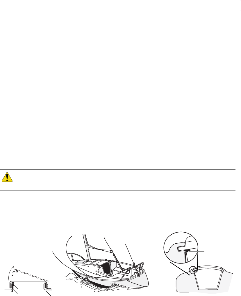
Chapter 3
Magnetic contacts
161
Boat decks and cabins
Application. Use a magnetic contact in a simple alarm system to protect the interior of a
boat. Use small surface-mount or recessed contacts to protect the hatches and
companionway. If you use open circuit switches, a relay, a shunt switch, and a horn, it is
possible to use the boat battery with no power drain.
Installation. To protect boats (Figure 140), do the following:
1. Install a switch and magnet in the hatch away from the hinges. If the hatch is plastic,
use surface-mount contacts. If the hatch is wood, use recessed contacts.
2. Install a switch and magnet in the sliding companionway boards or door.
3. If you use open contacts to drive the horn, install a latching relay to handle the
current.
4. Solder wire connections to prevent corrosion
Recommended products. 1037W, 1082, 1087, 1277
Figure 140. Boat decks and cabins
CAUTION: Magnets affect compass readings. Check the compass before and after you install
magnetic contacts.
Magnet
Switch
Hinge
Magnet
Switch
Sensor_Applications.book Page 161 Tuesday, December 27, 2005 5:45 AM
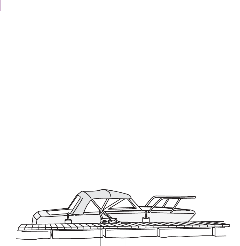
Intrusion Sensor
Application Notebook
162
Boat moorings
Application. Use a 2105A Magnapull to extend coverage of a normal marine alarm to the
dock or moorage where the boat is secured.
Installation. The magnet block may be attached in several locations on the dock,
depending on the structure of the moorage. If possible, mount it in a location where it will
not be visible. An extra magnet housing will be required if the boat owner wants to arm the
system at a different location from the usual moorage.
For example, it is possible to run the switch cord through a permanently attached fixture on
the dock, such as a cleat or ring, then back to the boat where the magnet housing is attached.
(Figure 141)
Note: Cable is available in a variety of lengths.
Recommended products. 2105A
Figure 141. Magnapull with magnet block on boar dock
Magnapull Magnet block
Sensor_Applications.book Page 162 Tuesday, December 27, 2005 5:45 AM
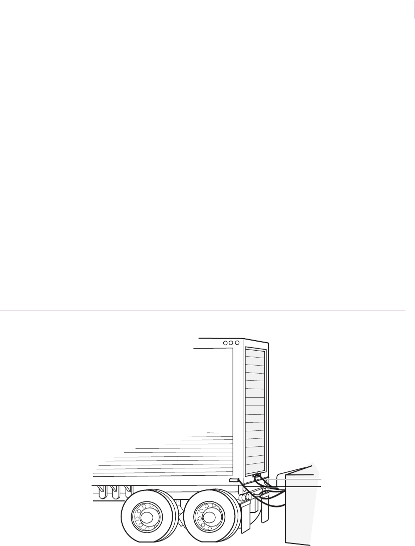
Chapter 3
Magnetic contacts
163
Trucks and trailers at loading docks
Application. Use the Magnapull to secure trucks and trailers at loading docks.
Installation. To install the Magnapull, do the following:
1. Extend a standard Magnapull from the perimeter loop on each loading dock.
2. Use one of the following mounting methods (Figure 142):
a. Method 1. Run the switch cord through a permanently attached part on the
truck and then back to the magnet block on the dock.
b. Method 2. Affix a magnet block to the truck so that when the truck is in the
loading dock, the switch cord can be plugged in. In this case, use an extra
magnet block on the dock to store the switch cord when the loading dock is
vacant.
Recommended products. 2105A, 2107A
Figure 142. Magnapulls on loading docks
Method 1
Method 2
Magnapull
Sensor_Applications.book Page 163 Tuesday, December 27, 2005 5:45 AM
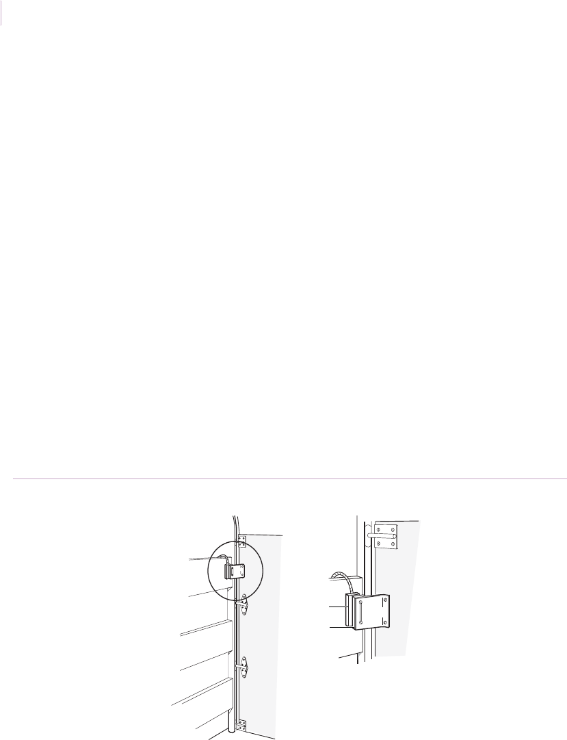
Intrusion Sensor
Application Notebook
164
Truck tailgates
Application. Use magnetic contacts that have sufficient durability, gap, and vibration
resistance to protect roll-up truck tailgates.
Installation. To install the contacts, do the following:
1. Select a location for the switch on wood or aluminum on the truck side just forward
of the track. It is best to mount near the top at a point where the track starts bending.
2. Place spacers behind the switch to build it out slightly beyond the track.
3. Mount the magnet on the tailgate door using a bracket. Position the magnet and
switch as close as possible with the door closed. Mount the end of the magnet about
0.5 in. (1.3 cm) past the end of the switch (Figure 143). Magnet and switch labels
should read in the same direction (switch is polarity sensitive).
4. Test (see Ohmmeter testing on page 86). Wire in the leads and dress the wires into
place. Do not hook directly into a high-current circuit, such as a vehicle horn. Use a
relay if switching more than 1/4 amp.
Recommended products. 2507A
Figure 143. Truck tailgate installation
Switch
Magnet
Sensor_Applications.book Page 164 Tuesday, December 27, 2005 5:45 AM
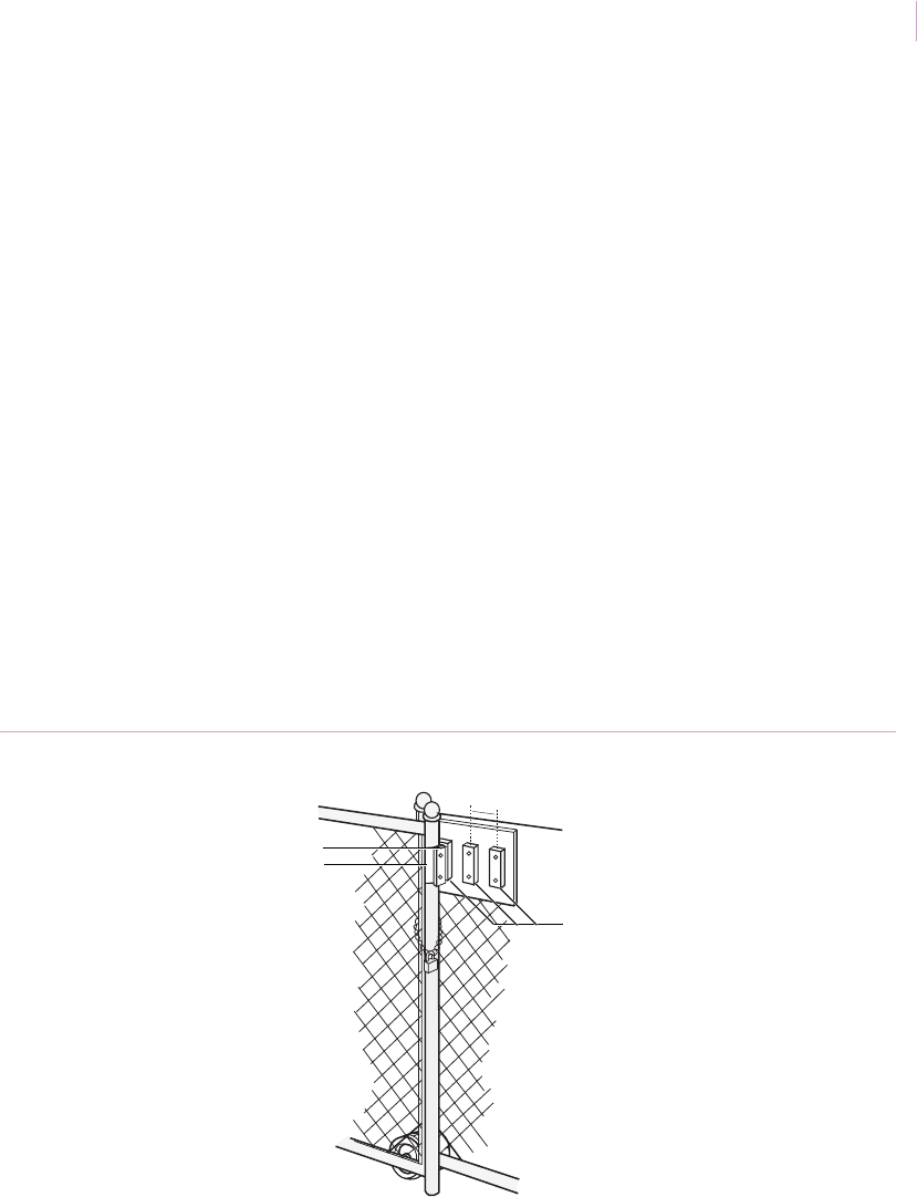
Chapter 3
Magnetic contacts
165
Chain-link rolling gates
Application. For most chain-link rolling gates, there is considerable tolerance and leeway
in the closed position. This makes it difficult to assure proper alignment of the gate switch
for alarm protection.
Installation. To assure security, particularly when a high-security biased switch is used, do
the following:
1. Mount the switch on the fence post using the appropriate bracket.
2. Mount multiple magnets (usually three) on a wooden board with 2 in. (5 cm)
spacing center-to-center. Mount the board on the gate (Figure 144). To observe
polarity, align the switch and magnet labels so they read in the same direction. If you
use the 2507H switch, observe a minimum gap of 0.74 in. (1.9 cm) and a make
distance of 6 to 8 in. (15.2 to 20.3 cm).
Note: To prevent false alarms, keep gate fastened tight with a chain or other restraining device.
Recommended products. 2507H, 1941, 1942, 1920
Figure 144. Chain-link rolling gates
1920 magnets
2507AH switch
1941 or 1942 bracket
2 in. (5 cm)
Sensor_Applications.book Page 165 Tuesday, December 27, 2005 5:45 AM

Intrusion Sensor
Application Notebook
166
Fence gates
Application. Use magnetic contacts to protect chain-link fence gates. You can attach
brackets to the gate post or on the gate frame, depending on the diameter of the post and
gate. The switch and magnet can be mounted on the inside, outside, or side of the bracket,
depending on the space between the post and gate.
Installation. To install the contact, do the following:
1. Select switch and magnet mounting positions. The switch has a 3 ft. (0.9 m)
armored cable. Run the cable to the junction box or to the inside of the pipe for
splicing.
2. Mount the brackets on the post and gate with masking tape. Swing the gate to check
clearance. Drill 9/64 in. (0.4 cm) diameter holes to mount the brackets, using self-
tapping screws.
3. Mount the switch and magnet to the brackets (Figure 145). The switch and magnet
labels should read in the same direction for proper polarity.
4. Test (see Ohmmeter testing on page 86). Wire the switch into the alarm loop and
retest.
Note: To prevent false alarms, keep gate fastened tight with a chain or other restraining device.
Recommended products. 1094A Kit
Figure 145. Fence gates
Fence
post
Fence
post
Fence
post
Ga t e
Ga t e
Ga t e
Gat e Post
Magnet Switch
Magnet Switch
Magnet Switch
Magnet Switch
Magnet Switch
Sensor_Applications.book Page 166 Tuesday, December 27, 2005 5:45 AM

Chapter 3
Magnetic contacts
167
Silent panic switches
Application. Use a manually operated silent panic/emergency alarm switch to protect
banks, jewelry stores, and other places where people and property are at risk. The following
devices can be used, depending on the application:
•3040. The 3040 (Figure 146 on page 168) has a separate latching LED circuit and
must be powered and reset by a push button 5 to 12 VDC source in or mounted
outside the alarm panel. This panic switch is ideal for retail outlets, banks, and
medical care facilities.
•3045. The 3045 has no latching LED. This panic switch is ideal for bedrooms and
bathrooms in residential installations and can be used by someone who is unable to
call for help.
•3050, 3055. The 3050 has a latching LED, the 3055 is nonlatching. These panic
switches feature a glowing LED for low-light visibility. The LED glows green when
powered up and turns red upon activation.
•3040CT, 3045CT. The 3040CT and 3045CT have been specifically modified for
low-temperature use in walk-in freezers (Figure 146 on page 168) to prevent
accidental lockup or intentional imprisonment. They can be used in garages or other
unheated facilities in cold climates. The 3045CT can also be used in wet
applications, such as shower rooms in fitness centers and hospitals.
Installation. To install a panic switch, do the following:
1. Determine the best location for the unit.
a. In retail outlets, banks, and medical facilities, the switch is most effective
when mounted out of view but within convenient reach of the user. Locations
such as under a counter top or inside the kneehole of a desk work well.
b. In a residential application, mount no higher than 4 ft. (1.2 m) so that it can be
reached by a person lying on the floor.
c. In a walk-in freezer application, mount the unit on the wall somewhere
between the floor and 4 in. (10.2 cm) below the door knob.
Allow at least 3 in. (7.6 cm) of clearance above the mounting surface to
accommodate the actuating lever when it is fully open. The device can be mounted
horizontally or vertically.
Sensor_Applications.book Page 167 Tuesday, December 27, 2005 5:45 AM
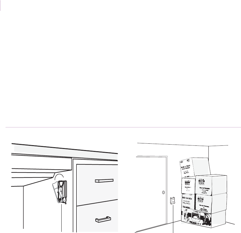
Intrusion Sensor
Application Notebook
168
2. Temporarily mount the unit with tape and test for ease of operation.
3. Mark the mounting holes and a hole for leads. Drill the pilot holes or start screws.
4. Connect the leads to the terminal block inside the housing and snap the cover in
place.
5. Test the unit. Pull the handle approximately 30 degrees from the normal locked
position to activate the alarm circuit and LED circuit. The LED will light. To reset
the LED circuit, interrupt power to the LED circuit with the handle open. The LED
will go out. Close the handle. The device is now fully armed.
Recommended products. 3040, 3040CT, 3045, 3045CT, 3050, 3055
Figure 146. Panic switch installations
Silent panic switch Silent panic switch
Sensor_Applications.book Page 168 Tuesday, December 27, 2005 5:45 AM

Chapter 4 Technical support
This chapter provides information on technical support and the
online publication library.
Sensor_Applications.book Page 169 Tuesday, December 27, 2005 5:45 AM

Intrusion Sensor
Application Notebook
170
Contacting technical support
For assistance installing, operating, maintaining, and troubleshooting sensors, refer to this
document and any other documentation provided. If you still have questions, you may
contact technical support during normal business hours (Monday through Friday, excluding
holidays, between 6 a.m. and 5 p.m. Pacific Time).
Note: Be ready at the equipment before calling for technical support.
Online publication library
Another great resource for assistance with your GE product is our online publication library,
available to all of our customers. To access the library, go to our website at the following
location:
http://www.gesecurity.com
In the Tools area at the top, click the Publication Library link. After you register and log on,
you may search through our online library for the documentation you need.1
Table 7. Sales and support contact information
Sales Technical support
Phone Toll-free: 888.GESECURity (888.437.3287 in the US, including Alaska and Hawaii;
Puerto Rico; Canada). Outside the toll-free area: 503.885.5700.
E-mail info@gesecurity.com generaltech@ge.com
Fax 800.483.2495 541.752.9096 (available 24 hours a day)
1. Many GE documents are provided as PDFs (portable document format). To read these documents, you
will need Adobe Acrobat Reader, which can be downloaded free from Adobe’s website at
www.adobe.com.
Sensor_Applications.book Page 170 Tuesday, December 27, 2005 5:45 AM

171
Glossary
This section explains some terms as they apply to sensors.
Table 8. Sensor terms explained
Term Definition
A/D converter A device for converting an analog input signal into a series of digital values
representing the instantaneous amplitude of the signal at regular sampling
intervals.
AC Alternating current. An electric current that flows first in one direction, then
reverses its flow direction at regular intervals.
acceptance test limit The poorest measured performance specification which a manufacturer is willing
to accept and ship in a product.
accuracy The degree of conformance of a test instrument to absolute standards, usually
expressed as a percentage of reading or a percentage of measurement range.
actuator A mechanism of the switch or switch enclosure that operates the contacts.
alnico A metal alloy of aluminum, nickel, cobalt, iron, and other elements that can be
strongly and permanently magnetized.
ammeter An electrical instrument used to measure current.
ampere Also referred to as amp, or amps. The electrical rate of flow in a circuit.
ampere-hour rating A number given in ampere-hours determined by multiplying the current in amps
times the length of time in hours a battery can deliver the current to a load.
ampere turn The sensitivity of a reed switch. The greater the amp-turns rating of a reed switch,
the less sensitive it is.
amplitude The magnitude of a signal, which may be expressed in a variety of units.
bandpass filter A filter which passes a specific frequency band essentially without attenuation
while attenuating frequencies both below and above the specified band.
battery An energy source that uses a chemical reaction to convert chemical energy into
electrical energy.
Sensor_Applications.book Page 171 Tuesday, December 27, 2005 5:45 AM

Intrusion Sensor
Application Notebook
172
bias The application of a DC voltage to a diode or other electronic device to produce a
desired mode of operation.
bit Binary digit, which may have only two possible states: on or off.
break To open an electrical circuit.
break gap The break gap (or break distance) is the minimum distance between separated
mating contacts in their fully open position.
capacitance The ability of a capacitor to store electrical charge.
capacitor An electrical device consisting of two conductive plates separated by an
insulating material and possessing the property of capacitance.
change An electrical property of matter that exists because of an excess or a deficiency
of electrons. Change can be either positive or negative.
circuit The complete path, or closed loop, that electricity requires to flow and do work.
circuit breaker A device that protects a circuit by automatically opening when excessive current
flows.
circuit ground A method of grounding whereby the metal chassis that houses the assembly or a
large conductive area on a printed circuit board is used as the common or
reference point, also called the chassis ground.
closed circuit A circuit with a complete current path.
closed-loop circuit In a closed-loop circuit, the sensing switch is closed until a change, such as a door
or window opening, causes the switch to open and set off an alarm.
codec Compression-decompression algorithm coder-decoder for reduced bit rate
transmission or recording/reproduction of digital audio, video, or still images.
Codecs reduce the required bit rate by using the available bit rate resources for
the most important portions of the signal.
complex circuit Combined series and parallel circuits. A complex circuit is also know as a series-
parallel circuit.
conductor A material in which electrical current is established with relative ease.
current Electrical rate of flow. Current is measured in amperes, or amps.
current consumption The amount of current required to power a sensor or control (excluding load).
Table 8. Sensor terms explained (continued)
Term Definition
Sensor_Applications.book Page 172 Tuesday, December 27, 2005 5:45 AM

173
D/A converter A device that converts a stream of digital numbers, each representing the
amplitude or a signal at a particular sampling time, into a corresponding analog
signal.
DC The abbreviation for direct current. Electric current that flows in one direction.
dB Decibel, a ratio unit for expressing signal amplitudes.
digital circuit A circuit that has only two stable states, operating in the manner of a switch
(either on or off).
DMM Digital multimeter. Device used to measure voltage, current, and resistance in an
electrical circuit.
DPDT Double-pole double-throw. Switches that make and break two separate circuits.
This circuit provides a normally open and normally closed contact for each pole.
DSP Digital signal processor. A specialized microprocessor designed for highly efficient
processing of digitized analog waveforms.
effective sensing
distance
The difference between nominal sensing distance and the +/- percent
manufacturing tolerance.
electrical Related to the use of electrical voltage and current to achieve desired results.
EMF Electromotive force. The force required to make current flow between two points.
EMF is another name for voltage, and is the V in Ohm’s Law.
enclosed switch A basic switch unit (contact block) enclosed in a durable housing.
environment-proof
switch
A switch that is completely sealed to ensure constant operating characteristics.
EOL End-of-line. A resistor that supervises the wiring between the alarm panel and the
switch, and prevent wire tampering on normal switches.
epoxy Generic name for any of several types of two-component adhesives.
explosion-proof Having the ability to contain an explosion within the sensor or housing, if one
occurs.
explosion-proof
switch
A UL listed switch capable of withstanding an internal explosion of a specified gas
without ignition of surrounding gases.
Table 8. Sensor terms explained (continued)
Term Definition
Sensor_Applications.book Page 173 Tuesday, December 27, 2005 5:45 AM

Intrusion Sensor
Application Notebook
174
frequency A measure of the rate of change of a periodic function: the number of cycles
completed in 1 s. The unit of frequency is the Hertz.
fuse A protective device that is destroyed when excessive current flows through a
circuit, thereby protecting the circuit.
ground Sometimes referred to as earth ground. The part of a circuit that is connected to a
metallic object buried in the earth.
hermetically sealed
switch
A switch completely sealed to provide constant operating characteristics.
high pass filter A filter that passes all frequencies above a specified value essentially without
attenuation, while attenuating frequencies below that value.
hysteresis, switching The principle associated with sensors, such that the operate point is not at the
same level as the release point.
IEC International Electrotechnical Commission. A body responsible for preparing and
publishing international standards for the electrical and electronic fields.
inductive technology Technology based on inductance, the property of an electric circuit by which an
electromotive force is induced in it by a variation of current, either in the circuit
itself, or in a neighboring circuit.
infrared (IR) The invisible radiation (as opposed to visible light) that certain LEDs emit.
input The voltage, current, or power applied to an electrical circuit to produce a desired
result.
insulator Any of several materials that offer resistance to the flow of electric current. Used
to cover wires and other electrical devices where current flow is not wanted.
integrated circuit (IC) An interconnected array of active and passive elements integrated within a single
semiconductor substrate or other compatible material, and capable of
performing one complete electronic function.
interface A common boundary between electronic systems, or parts of a single system.
interface circuit A circuit that links one type of device with another. Its function is to produce the
required current and voltage levels for the next stage of circuitry from the
previous stage.
intrinsically safe Limits electrical/thermal energy to levels incapable of causing ignition. External
barriers are required.
Table 8. Sensor terms explained (continued)
Term Definition
Sensor_Applications.book Page 174 Tuesday, December 27, 2005 5:45 AM

175
jitter The undesirable cycle-to-cycle variation in the period of a reference clock, such
as are used in digital audio converters.
leakage current Small current flowing through or leaking from the output device in the Off state
due to semiconductor characteristics.
LED Light emitting diode. A solid-state light source that emits variable light, or
invisible, infrared radiation.
load current The maximum amount of current that a proximity sensor will switch through its
load. Load current for a particular device can be calculated by dividing the load
voltage by the load resistance.
low pass filter A filter that passes all frequencies below a specified frequency essentially
without attenuation, while attenuating frequencies above that value.
LSB Least significant bit. The bit in a binary word representing the smallest possible
value change.
magnet Any of several devices that attract each other, as well as certain kinds of metallic
objects, through a force called magnetism.
magnetic dampening Steel and other iron-bearing materials tend to weaken or dampen the field of a
nearby magnet. Magnetic dampening decreases the strength of a magnet by
about half.
magnetic field A field of magnetic force surrounding all magnetic objects. The magnetic field is
strongest at the magnetic poles.
magnetic flux The line of force between the north and south poles of a permanent magnet or an
electromagnet.
make To close or establish an electrical circuit.
maximum load
current
The maximum amount of current that can flow through a sensor and not cause
sensor failure.
MPEG Moving Picture Expert Group. A working group in the ISO/IEC that sets standards
for low-bit-rate video and audio.
multimeter An instrument that measures voltage, current, and resistance.
multitester Device used to measure voltage, resistance, and current in a circuit. See DMM and
VOM.
Table 8. Sensor terms explained (continued)
Term Definition
Sensor_Applications.book Page 175 Tuesday, December 27, 2005 5:45 AM

Intrusion Sensor
Application Notebook
176
multitone Testing techniques with stimulus signals consisting of more than one sine wave.
Most multitone techniques use 15 or more sine waves distributed across the
audio spectrum.
NEMA ratings National Electrical Manufacturers Association ratings of an enclosure’s ability to
provide a degree of protection against contact with equipment and against
specified conditions.
nominal sensing
distance
An approximate dimension value measured from the face of the sensor to the
nearest point of the target. Also known as the operating point.
normally open (NO) Switch that must be actuated to pass current.
normally closed (NC) Switch that passes current until actuated.
ohm The unit of electrical resistance. Resistance through which a current of one
ampere will flow when a voltage of one volt is applied.
ohmmeter An instrument for measuring resistance.
Ohm’s law An electrical relationship, discovered by Georg Simon Ohm, that states that the
current flowing through a conductor is directly proportional to the electromotive
force (voltage) that produces it. V (voltage) = I (current in amps) times R (resistance
in ohms)
omega The Greek omega symbol, used as the electrical symbol for the ohm.
opacity The characteristic of an object that prevents light from passing through.
open circuit A circuit in which there is not a complete current path.
open-loop circuit In an open-loop circuit, the sensing switch remains open until a change, such as a
door or window being opened, causes the switch to close and set off the alarm.
operating
temperature
Actual temperature range over which sensors can be operated. Usage outside
the limits can result in loss of stability and damage to the sensor.
output The useful energy delivered by a circuit or device.
parallel circuit An electrical circuit that offers more than one path (parallel paths) for current flow.
A parallel circuit offers the same voltage to each path.
pole The number of completely separate circuits that can pass through a switch at
one time. A single-pole switch can control only one circuit at a time. A double-pole
switch can control two independent circuits at the same time.
Table 8. Sensor terms explained (continued)
Term Definition
Sensor_Applications.book Page 176 Tuesday, December 27, 2005 5:45 AM

177
pot Potentiometer or variable attenuator to control the gain of an amplifier.
potential The energy available for doing work.
power Power is produced when an electric current passes through the resistance in a
circuit.
power dissipation The amount of power that is consumed and converted to heat in normal
operation.
random noise Noise whose amplitude-vs-time distribution is mathematically random and
unpredictable, never repeating.
RC Resistor-capacitor. Commonly used to describe filters and oscillators, as opposed
to LC (inductor-capacitor).
reed technology Technology where the reed contacts are designed to be actuated by a magnet.
When a magnetic field is brought close to the reed contacts, the contacts are
drawn together to make the circuit.
relay An electromagnetically controlled mechanical device in which electrical contacts
are open or closed by a magnetizing current.
residual noise The irreducible noise in a measurement instrument which sets a floor for
amplitude measurements.
resistance Electrical resistance decreases the quantity of electricity that can flow through a
wire in a given time. All objects have resistance; those with greater resistance to
current flow are insulators, and those with little resistance are conductors.
resistor An electrical component that creates resistance when installed in a circuit.
response time The time it takes for a device to respond to an input signal.
retentivity The ability of a magnetic material to retain its magnetism after the magnetizing
force is removed.
reverse polarity
protection
Circuitry, usually a diode which prevents current from flowing into the control in
case of accidental miswiring of the plus (+) or minus (-) terminals, that prevents
damage to the unit.
ripple (1) Undesired AC variations on a DC power supply output. (2) Variations in
frequency response in the passband of a filter.
Table 8. Sensor terms explained (continued)
Term Definition
Sensor_Applications.book Page 177 Tuesday, December 27, 2005 5:45 AM

Intrusion Sensor
Application Notebook
178
RMS Root mean square. The preferred form of signal detection, which measures
amplitude in terms of its equivalent power content, regardless of signal
waveshape.
schematic A drawing that uses standard pictorial graphic elements to describe an electrical
circuit.
sensing distance The maximum recommended distance between the sensor and a standard target
at which the sensor will effectively and reliably detect the target.
sensor The basic element that usually changes some physical parameter to an electrical
signal.
series circuit An electrical circuit that offers only one path for current flow.
signal-to-noise ratio The difference in level between a reference output signal and the device output
with no signal applied, normally stated in dB.
SPDT Single-pole double-throw. Form C switch that may either make or break a circuit,
depending on how it is wired.
SPST Single-pole single-throw. Form A switch with only one moving and one stationary
contact. Available either normally open (NO) or normally closed (NC).
standard gap Standard gap (or make distance) refers to the minimum distance required before
the contact circuit restores to is normal state. For example, NO or NC.
supply current The amount of current necessary to maintain operation of a photoelectric control,
proximity sensor or control base. Sometimes referred to as current consumption.
supply voltage The range of power required to maintain proper operation of a photoelectric
control, proximity sensor or control base.
switch A device for controlling an electric circuit by breaking (opening) or making
(closing) one if its conductors.
switching frequency The actual number of targets to which the sensor can respond in a given time
period, usually expressed as Hertz (cycles per second).
symmetrical Balanced.
temporary magnet Magnetic material that remains magnetized only as long as it is in contact with a
magnetic field.
terminating Connecting the specified load resistance or impedance to a device.
Table 8. Sensor terms explained (continued)
Term Definition
Sensor_Applications.book Page 178 Tuesday, December 27, 2005 5:45 AM

179
termination A specific resistance or impedance value which must be connected to the output
or input of a device under test for certain parameters to be measured.
THD Total harmonic distortion. Normally computed from a series of selective
measurements of the amplitudes of all significant individual harmonic distortion
products.
transducer A device to change acoustical power into an electrical signal or electrical power
into an acoustical signal.
transformer A device formed by two or more windings that are magnetically coupled to each
other and provide a transfer of power electromagnetically from one winding to
another.
transient protection Circuitry to guard against spikes induced on the supply lines by inductive sources
such as heavy motors or solenoids turning on and off.
transients In electrical usage, usually refers to an unwanted, temporary, large increase or
decrease in current or supply voltage that only occurs occasionally.
triac A device that uses an electrical gate to switch currents (in amps) that are beyond
the capabilities of reed switches.
trigger An event which causes another event or action, often initiating a signal
generation or acquisition.
UL Underwriter’s Laboratories, Inc. A nonprofit organization that establishes,
maintains, and operates laboratories for the testing of devices, systems, and
materials, primarily for safety.
unbalanced An audio connection in which the desired signal is present as a voltage with
respect to ground or common, rather than as a differential signal across a pair of
balanced conductors.
usable sensing
distance
Sensing distance after temperature range tolerance and manufacturer’s
tolerance are taken into account.
VCA See voltage controlled amplifier.
VCO See voltage controlled oscillator.
volt The unit of voltage or electromotive force.
voltage The amount of energy available to move a certain number of electrons from one
point to another in an electric circuit.
Table 8. Sensor terms explained (continued)
Term Definition
Sensor_Applications.book Page 179 Tuesday, December 27, 2005 5:45 AM

Intrusion Sensor
Application Notebook
180
voltage controlled
amplifier
An audio amplifier with a DC voltage control port which electronically varies the
gain of the amplifier.
voltage controlled
oscillator
An oscillator whose frequency can be varied via a DC control voltage.
voltage drop The potential difference in voltage between two points when there is a drop in
energy level due to resistance.
voltmeter An instrument used to measure voltage.
VOM A volt-ohm-millimeter. This device is one of the two types of multitesters used to
measure voltage, resistance, and current in an electrical circuit.
watt Unit of electrical power. One watt is equal to one volt of electrical pressure
multiplied by one amp of current.
Table 8. Sensor terms explained (continued)
Term Definition
Sensor_Applications.book Page 180 Tuesday, December 27, 2005 5:45 AM

181
Index
A
acoustic glassbreak sensors.................................................. 4
acoustic sensors
testing .............................................................................. 6
acoustically live rooms ...................................................... 25
activation
CCTV cameras .............................................................. 76
hallway and lobby lighting............................................ 58
outdoor lighting............................................................. 77
aircraft hangars .................................................................. 77
aisles................................................................................... 69
aluminum thresholds.......................................................... 96
Anderson casement windows........................................... 143
anti-masking....................................................................... 54
armor-coated glass ............................................................. 22
art objects......................................................................... 157
hung............................................................................. 158
ATMs................................................................................. 34
attics
drop-down stairs.......................................................... 146
entry............................................................................. 146
vents............................................................................. 147
auto dealerships............................................................ 71, 77
automatic garage doors ...................................................... 94
automatic teller machines .................................................. 34
awning windows .............................................................. 140
B
back yard patios and decks ................................................ 77
bank drive-up windows...................................................... 22
Barrier Bars...................................................................... 147
basement windows........................................................... 147
bathroom windows............................................................. 13
bell boxes .........................................................................149
bikes ................................................................................. 160
Bill Trap ........................................................................... 150
blinds.................................................................................. 15
boats ................................................................................. 160
cabins........................................................................... 161
decks ............................................................................ 161
hatches......................................................................... 161
interiors ....................................................................... 161
moorages .....................................................................162
boxes
night deposit .................................................................. 34
bracket
swivel ............................................................................. 46
C
cabinets..................................................................... 153, 155
filing............................................................................... 32
camera controls .................................................................. 76
car service centers ..............................................................62
casement windows ........................................................... 143
cash register drawers........................................................150
CCTV camera activation.................................................... 76
chemical plants................................................................... 79
chests................................................................................ 157
china cabinets................................................................... 153
cleaning crews.................................................................... 27
cold environments ........................................................ 66, 78
computers ...................................................................65, 159
concert halls .......................................................................68
control panels ................................................................... 149
conventions .......................................................................... 2
curtain doors..................................................................... 106
curtains ............................................................................... 15
Sensor_Applications.book Page 181 Tuesday, December 27, 2005 5:45 AM

Intrusion Sensor
Application Notebook
182
D
Deeply recessed doors ..................................................... 103
deposit boxes...................................................................... 34
display cases ...................................................................... 30
door control.................................................................. 60, 62
doors
automatic garage........................................................... 94
curtain ......................................................................... 106
deeply recessed............................................................ 103
freezer.......................................................................... 123
high security ................................................................ 115
overhead...................................................................... 106
panel ............................................................................ 114
recessed ....................................................................... 103
recessed steel................................................................. 98
revolving...................................................................... 120
sectional....................................................................... 114
sliding aluminum........................................................... 92
steel.......................................................................... 97, 98
with explosion-proof switches ..................................... 118
wood .............................................................................. 96
double-hung windows...................................................... 137
DPDT switches .................................................................. 84
drawers..................................................................... 150, 151
drive-up areas..................................................................... 73
drop-down stairs .............................................................. 146
E
electrical specifications
magnetic contacts.......................................................... 83
enclosures................................................................... 31, 149
entry and exit doors............................................................ 58
environmental specifications
magnetic contacts.......................................................... 83
equipment........................................................................... 65
explosion-proof switches ................................................. 118
explosive atmospheres ....................................................... 79
extreme temperatures......................................................... 78
F
factories.............................................................................. 69
false alarm reduction.......................................................... 43
filing cabinets..................................................................... 32
film..................................................................................... 22
flush mount ........................................................................ 52
freezer doors..................................................................... 123
French doors....................................................................... 19
G
gap distances ...................................................................... 83
increase with second magnet....................................... 126
garages ......................................................................... 62, 66
garden shops................................................................. 71, 77
gardens ......................................................................... 74, 77
glass display cases.............................................................. 30
glass doors.......................................................................... 20
glass entry airlocks............................................................. 25
glassbreak sensors .......................................................... 4–27
glassbreak shock sensors......................................................8
grain storage areas.............................................................. 79
gun cabinets...................................................................... 155
guns .................................................................................. 155
gymnasiums ....................................................................... 68
H
half-walls............................................................................ 59
hallway lighting activation................................................. 58
hand-held tester ................................................................6, 7
high humidity environments .............................................. 13
high security
doors............................................................................ 115
switches........................................................................ 118
high security doors...........................................................115
hinged skylights ...............................................................145
homes
multilevel ....................................................................... 64
vacation ......................................................................... 66
Sensor_Applications.book Page 182 Tuesday, December 27, 2005 5:45 AM

183
hospitals ............................................................................. 60
humidity ............................................................................. 13
I
indoor swimming pools ..................................................... 75
installation guidelines
glassbreak........................................................................ 9
magnetic contacts.......................................................... 86
outdoor PIR motion detectors ....................................... 41
PIR motion detectors..................................................... 40
insulated glass .................................................................... 21
J
jewelry cases...................................................................... 30
jewelry store safe ............................................................... 33
K
kitchens .............................................................................. 25
L
large areas .......................................................................... 68
large rooms ........................................................................ 24
L-bracket.......................................................................... 105
lighting controls ........................................................... 58, 77
loading docks ............................................................. 72, 163
lobby lighting activation .................................................... 58
long corridors..................................................................... 69
loop supervision................................................................. 45
M
Magnapull ................................ 110, 156, 159, 160, 162, 163
magnetic contacts....................................................... 81–168
masking.............................................................................. 43
prevention...................................................................... 54
meat lockers ....................................................................... 78
mechanical recessed switch
replacement ................................................................. 127
mechanical switches.........................................................127
metal drawers ...................................................................152
metal enclosures.........................................................31, 149
metal shutters .....................................................................29
military installations..................................................... 71, 77
moorages .......................................................................... 162
motion detectors...........................................................35–76
motion sensors
false alarm reduction..................................................... 43
masking.......................................................................... 43
prewiring ....................................................................... 42
wireless.......................................................................... 50
motorcycles ...................................................................... 160
mounting positions
recessed switches........................................................... 85
multilevel homes................................................................ 64
multiple windows............................................................... 24
munitions depots ................................................................ 79
museums............................................................................. 55
N
Nice-Duc ............................................................................ 91
night cleaning crews........................................................... 27
O
objects .............................................................................. 157
occupied areas .................................................................... 26
office foyers ....................................................................... 56
ohmmeter testing................................................................ 86
outdoor areas.......................................................... 70, 71, 74
outdoor lighting activation................................................. 80
outdoor parking lots ........................................................... 77
outdoor swimming pools....................................................75
overhead doors................................................................. 106
P
paintings .....................................................................55, 158
panel doors ....................................................................... 114
parking lots......................................................................... 71
Sensor_Applications.book Page 183 Tuesday, December 27, 2005 5:45 AM

Intrusion Sensor
Application Notebook
184
partitions ............................................................................ 59
patio furniture .................................................................. 160
Pella casement windows .................................................. 140
perimeter loop .................................................................... 26
perimeters........................................................................... 63
peripheral control............................................................... 46
pet alley.............................................................................. 47
pets..................................................................................... 47
pickup areas ....................................................................... 73
PIR motion detectors ................................................... 35–76
plastic film ......................................................................... 22
plastic skylights.................................................................. 14
prewire installation
glassbreak sensors......................................................... 10
prewiring............................................................................ 42
product
overview............................................................... 4, 36, 82
public utility installations............................................. 71, 77
publication library............................................................ 170
R
recessed doors.................................................................. 103
recessed steel doors............................................................ 98
recreational equipment..................................................... 160
request-to-exit .............................................................. 60, 62
revolving doors ................................................................ 120
roll up door control ............................................................ 62
roller-plunger contacts ..................................................... 124
roll-up metal shutters ......................................................... 29
roof entry.................................................................. 145, 148
roof hatches...................................................................... 148
S
safe
jewelry ........................................................................... 33
safety terms and symbols..................................................... 2
schools ................................................................... 60, 69, 70
sectional overhead doors.................................................. 114
shared terminals ................................................................. 45
shipping areas..................................................................... 77
shipping docks.................................................................... 62
shock sensors........................................................................ 8
shopping areas....................................................................77
skylights .............................................................14, 145, 147
sliding aluminum doors......................................................92
sliding aluminum windows..............................................131
thin frames................................................................... 135
small windows.............................................................. 19, 25
stairwells ............................................................................ 25
statues............................................................................... 157
steel doors ....................................................................97, 98
magnetic contacts .......................................................... 87
roller-plunger contacts................................................ 124
steel window
thin frames................................................................... 136
stereos............................................................................... 159
store shutters ...................................................................... 29
storefront windows....................................................... 28, 57
supermarkets ...................................................................... 69
swimming pools
indoor............................................................................. 67
outdoor........................................................................... 75
switch configurations......................................................... 83
switch shunting .................................................................. 94
swivel bracket .................................................................... 46
T
technical support .............................................................. 170
temperature extremes ......................................................... 78
testing
acoustic glassbreak sensors............................................. 6
magnetic contacts .......................................................... 86
ohmmeter ....................................................................... 86
PIR motion detectors ..................................................... 42
shock sensors................................................................... 8
walk test......................................................................... 42
thick glass........................................................................... 23
thin frames........................................................................135
threshold contacts............................................................... 97
tinting film.......................................................................... 22
Sensor_Applications.book Page 184 Tuesday, December 27, 2005 5:45 AM

185
trailers .............................................................................. 163
trucks.......................................................................... 72, 163
TVs............................................................................. 65, 159
U
undercrawl mask ................................................................ 43
uneven wiring holes......................................................... 125
utility rooms....................................................................... 25
V
vacation homes .................................................................. 66
vandalism ........................................................................... 70
vases................................................................................. 157
video equipment................................................................. 65
voltage spikes..................................................................... 89
W
walk test ............................................................................. 42
walk-in freezer doors ....................................................... 123
warehouses............................................................. 60, 68, 72
window ventilation .................................................. 128, 129
windows
bank drive-up................................................................. 22
bathroom........................................................................ 13
casement ..............................................................140, 143
double-hung................................................................. 137
French............................................................................ 19
insulated glass ............................................................... 21
multiple.............................................................. 18, 24, 63
skylights .................................................................14, 145
sliding aluminum ......................................................... 131
small......................................................................... 19, 25
storefront .................................................................28, 57
that open ........................................................................ 20
thick glass ...................................................................... 23
thin frames................................................................... 135
thin steel frames........................................................... 136
ventilation ............................................................ 128, 129
with curtains and blinds ................................................ 15
with film......................................................................... 22
windows that open ............................................................. 20
wireless motion sensors ..................................................... 50
wood doors......................................................................... 96
roller-plunger contacts................................................ 124
Z
Z-bracket .......................................................................... 105
Numerics
24-hour loop.......................................................................26
Sensor_Applications.book Page 185 Tuesday, December 27, 2005 5:45 AM

Intrusion Sensor
Application Notebook
186
Sensor_Applications.book Page 186 Tuesday, December 27, 2005 5:45 AM
