GEM P1632_RP1_WI897G.65_PROG P1632 V10 Program Manual Alpha Keypads
User Manual: GEM-P1632 v10 Program Manual Alpha Keypads AlarmHow.net Library
Open the PDF directly: View PDF ![]() .
.
Page Count: 48
HARDWIRE WIRELESS
GEM-P1632
CONTROL PANEL/COMMUNICATOR
Programming the GEM-P1632 Control Panel with the
"Classic" GEM-RP1CAe2 Keypad and the "K Series" GEM-K1CA Keypad
WI897G 8/03 © Napco 2003
Quick Start (for "Classic" GEM-RP1CAe2)
1. Refer to the wiring diagram, connect Siren, Aux. Power,
PGM Output, Remote Bus, Earth ground, Zone and Tele-
phone wiring. NOTE: See Installation Instructions
(WI994).
2. Connect AC power first and then the battery.
3. Configure the keypad (see page 34).
4. Access the Easy Menu Driven (Dealer Program) Mode:
Press 456789 A
Press NO (g) until “ACTIVATE PROGRAM Y/N” appears on the
keypad display.
Press YES (F) to Enter Dealer Program Mode. Go to page 5.
Dealer Code
Quick Start (for "K-Series" GEM-K1CA)
1. Refer to the wiring diagram, connect Siren, Aux. Power,
PGM Output, Remote Bus, Earth ground, Zone and Tele-
phone wiring. NOTE: See Installation Instructions
(WI994).
2. Connect AC power first and then the battery.
3. Configure the keypad (see page 34).
4. Access the Easy Menu Driven (Dealer Program) Mode:
Press 456789 R
Press NO (Q) until “ACTIVATE PROGRAM Y/N” appears on the
keypad display.
Press YES (P) to Enter Dealer Program Mode. Go to page 5.
Dealer Code
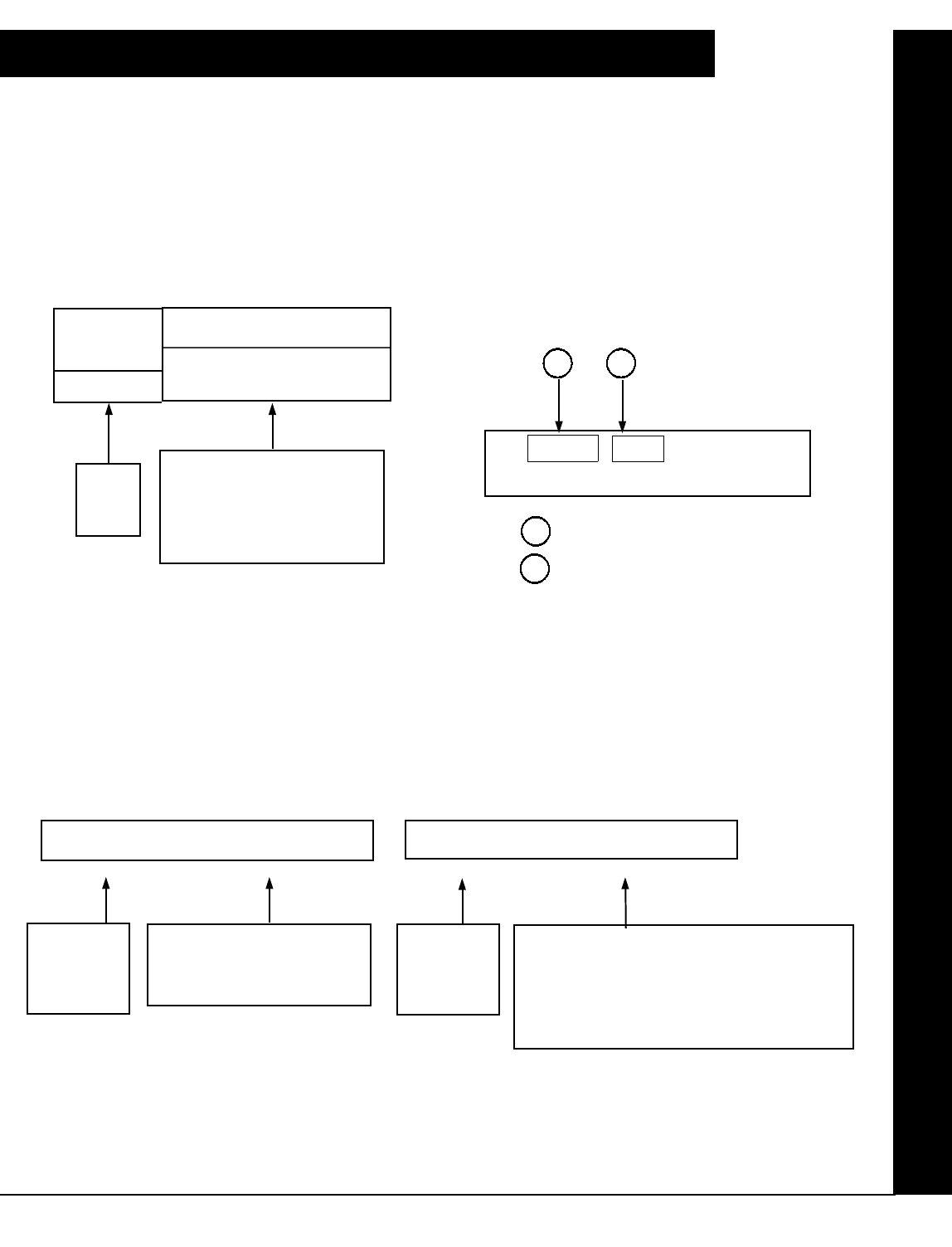
"K Series" GEM-K1CA
GEMINI
SYSTEM READY
01/01/00 12:00 AM
ARMED
COMPUTERIZED SECURITY SYSTEM
STATUS
R 1 2 3
B 4 5 6
C 7 8 9 0
U
NEXT/YES
P
PRIOR/NO
Q
AREA
G
PROGRAMMING
INSTRUCTIONS
R
"Classic" GEM-RP1CAe2
GEMINI
SYSTEM READY
01/01/00 12:00 AM
ARMED
COMPUTERIZED SECURITY SYSTEM
STATUS
A 1 2 3
B 4 5 6
C 7 8 9 0
D
NEXT/YES
E
PRIOR/NO
F
AREA
G
THIS MANUAL INCLUDES FEATURES WHICH ARE ONLY AVAILABLE IN CONTROL PANEL FIRMWARE
VERSION 10 OR LATER.
NAPCO Security Systems, Inc.
333 Bayview Avenue, Amityville, New York 11701
For Sales and Repairs, call toll free: (800) 645-9445
For direct line to Technical Service, call toll free: (800) 645-9440
Internet: http://www.napcosecurity.com
IMPORTANT NOTE
This manual supports the keypad programming of the GEM-P1632 control panel with the NAPCO "classic" GEM-
RP1CAe2 keypad as well as the GEM-K1CA "K Series" keypad. The new "K Series" GEM-K1CA model offers the new
STAY and AWAY buttons with simplified functionality, along with the new MENU and ENTER buttons.
While the instructions in this manual are depicted using the GEM-K1CA keypad, the manual applies to both the "classic"
and the "K Series" keypads.
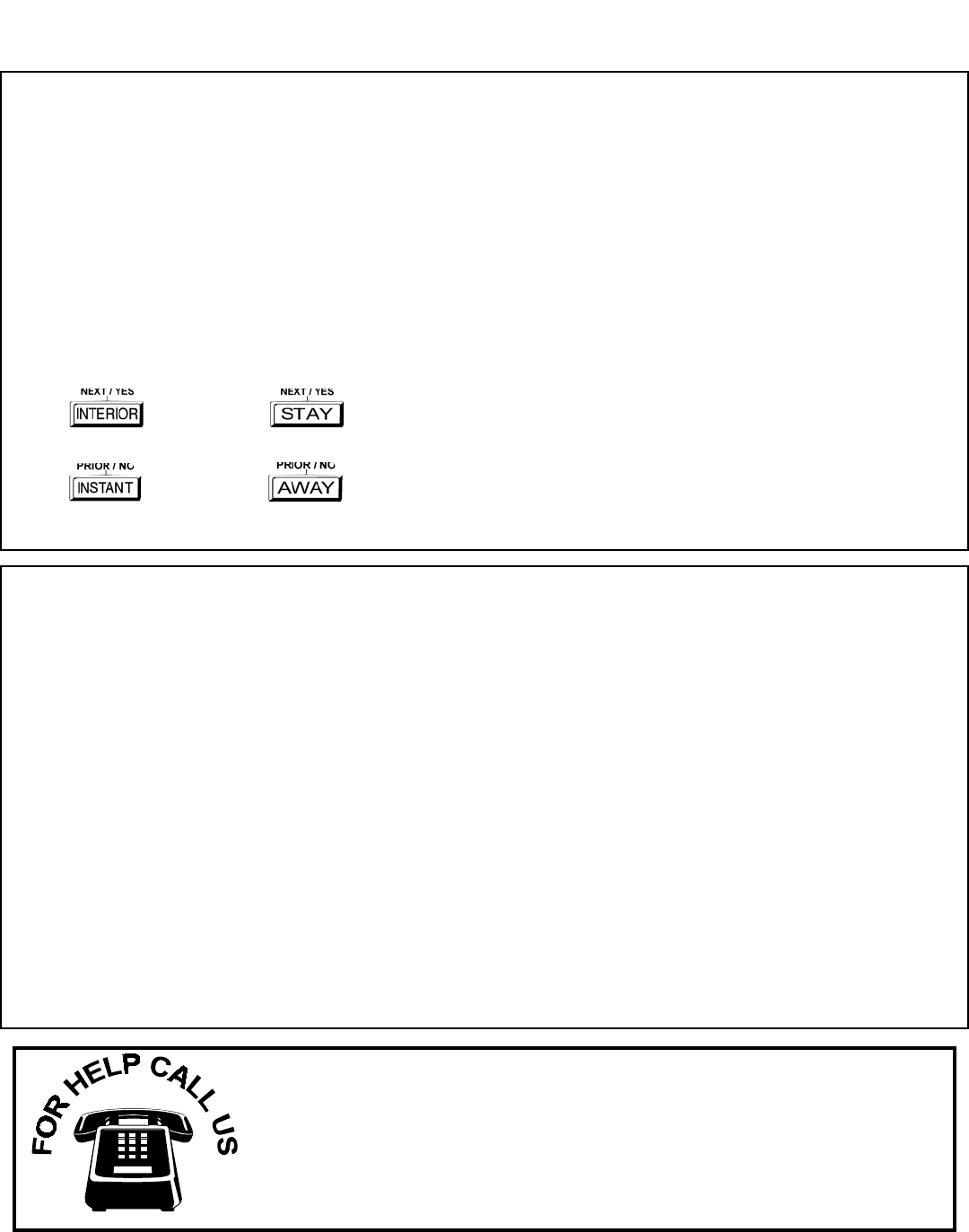
Program Mode is the same for both keypads--only the button names have changed, as follows:
•The A button and the R button operate identically (in Program Mode) for both keypads.
•The D button and the U button operate identically (in Program Mode) for both keypads.
•The button and the button operate identically (in Program Mode) for both keypads. The words
"NEXT/YES button" are used in this manual.
•The button and the button operate identically (in Program Mode) for both keypads. The words
"PRIOR/NO button" are used in this manual.
CHANGES FROM PREVIOUS EDITION
The following changes have been made to this manual (WI897G) since the previous edition (WI897F).
•Removed the following entries from the index: Change Pulse Output to Cadence, Enable Chirp on RF Arming, Enable Transmitter Telco 1,
Enable Transmitter Telco 3, Select Bell Output on RF Arming.
•Page 4, top, "Downloading From a Computer", the following sentence was added: "Unattended downloading from a computer is not allowed
for Fire Alarm or UL installations."
•Page 6, "Panel Zone Doubling", the second sentence was modified and now reads, "The 16 zones will remain EOL terminated zones…".
•Pages 4, 5, and 7, the "50mS Loop Response Zones" entries now contain the following notation: "Note: 750mS is required for Loop Response
time in UL installations."
•Page 7, the "Auto Bypass Re-entry Zones" entry was modified: "Not Evaluated by UL" notation was added.
•Page 8, the "Enter User Codes" entry was modified, and now states to "enter a code from 3 to 6 digits."
•In the Area Options/Explanation chart at the top of page 9, the following information was added: "Ambush: Allows user code to send Ambush
signal to Central Station".
•Top of page 16, under the heading, "Output Timeouts", the following reference was added: "Not UL listed for Commercial Installations".
•Page 18, Address 0720, bit 7 (Change Pulse Output to Temporal Output) was modified with the following notation: "This feature must be pro-
grammed in Fire Alarm applications."
•Page 29, Table 4: The following notation was added: "Keypad Tamper must be enabled in UL installations."
•Page 18--All references to 0720-Bit 6--"Enable PGM2 Chirp on Keyfob Arming" name changed to "Chirp Output on Keyfob Arm/Disarm".
•Page 18--All references to 0722-Bit 0--"Automatic Interior Bypass" name changed to "Automatic Interior Bypass/Easy Exit".
•Page 18--All references to 0721-Bit 7--"Enable Bell Output on Keyfob Arming" name changed to "Select Alarm Output for Keyfob Chirp".

L NAPCO Security Systems X GEM-P1632 Programming Instructions
!
Page 3
SYSTEM PROGRAMMING OPTIONS ............................ 4
INTRODUCTION ......................................................... 4
DOWNLOADING FROM A COMPUTER .................... 4
EASY MENU DRIVEN PROGRAM MODE ...................... 5
Dealer Program - Preliminary Information ................... 5
Accessing Dealer Program Mode ................................ 5
Customizing a Default Program .................................. 5
GEM-RP1CAe2/GEM-K1CA Easy Program Menu 6
Total Number of Zones in Area 1 ........................ 6
Panel Zone Doubling ........................................... 6
Fire Zones in Area 1 ............................................ 6
2-Wire Fire Zones in Area 1 ................................ 6
Local or Central Station Reporting System ......... 6
Exit/Entry Zones in Area 1 ................................... 6
Interior Zones in Area 1 ....................................... 6
24 Hour Zones in Area 1 ..................................... 6
Chime Zones in Area 1 ........................................ 7
Chime 2 Zones in Area 1 ..................................... 7
Exit/Entry2 Zones in Area 1 ................................. 7
50 mS Loop Response Zones ............................. 7
Aux Output Activated on Alarm Zones ............... 7
Sensor Watch Zones .......................................... 7
Keypad Sounder On Alarm Zones ...................... 7
Auto Bypass Re-entry Zones ............................... 7
Enable No EOLR Zones ...................................... 7
Enable Telco Line Fault Test? ............................. 7
Enable Burg Output Chirp on KeyFob? ............... 8
Enable SIA CP-01 Features? .............................. 8
Number of Keypads in Area 1 ............................ 8
Central Station Receiver 1 Telephone Number ... 8
Central Station Receiver 1 Account Number ....... 8
Central Station Receiver 1 Format ...................... 8
Enter User Codes ............................................... 8
RF Transmitter Points .......................................... 9
Key Fob Transmitters as Arm/Disarm & Control De-
vices .............................................................. 9
Key Fob Transmitters as Zone Input Devices .... 10
Enter Zone Descriptions ...................................... 10
Enter Date ........................................................... 10
Enter Time ........................................................... 10
Dealer Code ........................................................ 10
Clear Dealer Program .......................................... 10
Cold Start ............................................................. 10
DIRECT ADDRESS PROGRAM MODE .......................... 11
Direct Address Overview ............................................. 11
Address Mode Displays ............................................... 11
Binary (Bit) Format ............................................. 11
Decimal Format .................................................. 12
Hexadecimal Format .......................................... 13
Programming Conventions Used in this Manual ......... 14
System Delays & Timeouts (Addr 0000-0002, 1059 &
1179) .......................................................................... 15
System Delays & Timeouts (Addr 0711, 0715-0717) .. 15
System Output Timeouts (Addr 0710, 0712-0714) ..... 16
Download/Callback Opt. (Addr 1183, 0236-0255) ...... 16
Pager Format Options (Addr 0256 & 0257) ................ 16
Syst. Opt. & Ambush Code (Addr 0460-0485 & 1054) 17
System Options (Addr 0718-0722, 1060-1062) .......... 18
CS Receiver Opt. (Addr 0170-0235) ........................... 19
CS Subscriber Reporting Opt. (Addr 0259-0350) ....... 20
CS Zn Reporting Opt. (Addr 0358-0389 & 0391-0394) 21
CS User Reporting Opt. (Addr 0440-0459) ................. 22
EZM Group & Area Arming Opt. (Addr 0737-0744) .... 23
Area Bell Control Options (Addr 0745-0749) .............. 24
Keypad Options (Addr 0723-0736) ............................. 25
Zones 1-16 Options (Addr 0490-0595) ....................... 26
Zones 17-32 Options (Addr 0601-0705) ..................... 27
External Relay Control (Addr 0750-0829) ................... 28
RF Rcvrs. & Sup. Timers (Addr 1038-1053 & 1180) ... 30
Clear Program Features (Addr 1197 & 1198) ............. 31
USER PROGRAM MODE ................................................ 31
Preliminary Information ............................................... 31
Accessing User Program Mode .................................. 32
User Codes ................................................................. 32
Zone Descriptions ....................................................... 33
Date ............................................................................. 33
Time ............................................................................ 33
KEYPAD CONFIGURATION MODE ............................... 34
Keypad Installation ...................................................... 34
Configuring the Keypads ............................................. 34
EASY MENU PROGRAMMING WORKSHEETS ............ 36
ALPHABETICAL INDEX ................................................. 39
ADDRESS NUMBER INDEX ........................................... 42
GEM-P1632 WIRING DIAGRAM ..................................... 48
TABLE OF CONTENTS
Refer to accompanying GEM-P1632 Installation Instructions (WI808) for installation information.

X GEM-P1632 Programming Instructions L NAPCO Security Systems
! Page 4
SYSTEM PROGRAMMING OPTIONS
INTRODUCTION
The GEM-P1632 control panel may be programmed by various means, each of which will be covered in detail in the sec-
tions that follow. Keypad displays shown are for a GEM-RP1CAe2/K1CA (version 8 keypad), the recommended keypad
for programming. For Programming Instructions with the GEM-RP2ASe2/GEM-K2AS, GEM-RP3DGTL/GEM-K3DGTL
and the GEM-RP4RFC/GEM-K4RF series, see WI1148.
!Downloading From a Computer. This is the preferred method of programming. The panel may be
downloaded from (or uploaded to) an IBM PC-compatible computer, either locally or remotely. Napco's PCD3000
Quickloader software features context-sensitive help screens as well as an error-checking utility that prevents pro-
gramming of incompatible or conflicting data to ensure proper panel operation. Note: Unattended downloading from
a computer is not allowed for Fire Alarm or UL installations.
!Easy Menu-Driven Program (Dealer Program) Mode - Keypad Programming. The Easy Menu-Driven
Program Mode allows keypad programming of number of zones in area 1, panel zone doubling, number of fire zones
(both 4-wire and 2-wire), local or Central Station reporting, number of exit/entry zones, number of interior zones, num-
ber of 24 hour zones, number of chime zones, Chime 2 zones, Exit/Entry2 zones, 50ms loop response zones (Note:
750mS is required for Loop Response time in UL installations), aux output activated on alarm zones, sensor watch
zones, keypad sounder on alarm zones, auto bypass re-entry zones, EOLR zones, number of keypads in area 1,
Central Station telephone number, Central Station account number, Central Station receiver format, User Codes, RF
transmitter points, RF keyfob transmitters, zone descriptions, date/time, dealer code, Telco line fault test, Burg output
chirp on keyfob, keypad time/date display, enable CP-01 programming, and clear dealer program/cold start. For new
panels, a custom default program may be created at the keypad. A menu-driven utility prompts the installer to config-
ure the system. Further detailed customization is accomplished in the Direct Address Program Mode.
!Direct Address (Dealer Program) Program Mode - Keypad Programming. The Direct Address Pro-
gram Mode is an extension of the Dealer Program Mode wherein data is entered at the keypad by location. This
mode is accessed from the Easy Menu Driven Program Mode by pressing the C button at any time.
!User Program Mode - Keypad Programming. The User Program Mode is intended for
authorized users and is limited to keypad programming of User Codes, Time, Date and Zone
Descriptions.
DOWNLOADING FROM A COMPUTER
The control-panel program may be downloaded from the computer by any of the following methods.
Local Downloading
(Note: This procedure should be used after installation, after peripheral devices are connected).
For direct high-speed data transfer to the control panel from a desktop computer, connect the download jack (JP2)
on the panel to the LOCAL jack (J3) on the Napco PCI2000/3000 computer interface using the supplied 6-
conductor cable. (Refer to PCI2000/3000 Installation Instructions WI443 for wiring diagram and procedures).
Similarly, a high-speed local download may be made in the field using a notebook or laptop computer. Connect
JP2 on the control panel to a Napco PCI-MINI computer interface using the 6-conductor cable supplied. (Refer to
PCI-MINI Installation Instructions WI767).
Remote Downloading
(Also see PCI2000/3000 Installation Instructions WI443). Note: Unattended downloading from a computer is not
allowed for Fire Alarm or UL installations.
Function Mode
Start by establishing a telco connection between the computer operator and the installer. During this procedure,
voice contact will be lost, therefore both the installer and the computer operator should be familiar with the opera-
tion. When a steady high-pitched tone is heard at the site phone, access the “ACTIVATE DOWNLOAD” Function (see
Keypad Programming Modes), then press the J or U button or the NEXT/YES button; the site phone will go dead.
Hang up the phone and wait for a call from the central station confirming a successful download.
Callback Method
An installed, unattended panel may be programmed or reprogrammed remotely using the Callback-Method
Download feature of the PCD3000 software. Remote downloading requires a modem compatible with the
PCI2000/3000. Upon answering the call from the computer, the panel will verify the Download Security Code and,
if confirmed, will establish a connection. If a Callback Number is programmed into the panel, the panel will auto-
matically disconnect and call the computer at this number before establishing a connection.
L NAPCO Security Systems X GEM-P1632 Programming Instructions
!
Page 5
EASY MENU DRIVEN PROGRAM MODE
DEALER PROGRAM - PRELIMINARY INFORMATION
!Only Keypad #1 may be used for both Dealer and User programming, however this keypad may be located in any area.
!The Default Dealer Code is 4 5 6 7 8 9. Use this code to enter the Dealer Program Mode
to program a custom Dealer Code, which replaces the Default Dealer Code. If you clear your Dealer Code, use the Default
Dealer Code once again to enter programming.
!After entering codes or data, press the save U button. Data will not be stored into memory unless U is pressed.
!If the keypad is in the Program Mode and no activity is detected for longer than 4 minutes, a steady tone will sound.
!Silence the sounder by the G button to continue, or by pressing the C button to exit.
!A panel that has been COLD STARTED (Address Location 1198) performs identically to a new panel.
!When programming a Multiple Area System, Direct Address Programming Mode must be used to complete the program.
KEYPAD #1: For ease of programming, it is recommended that a GEM-RP1CAe2 or GEM-K1CA be used as Keypad
#1. (Regardless of which keypad is selected, all new keypads are configured as Keypad #1 out of the box). If a GEM-
RP2ASe2/GEM-K2AS is used, see WI 1148.
1. Press 456789 R
2. Press PRIOR/NO button until “ACTIVATE PROGRAM Y/N” appears on LCD screen.
3. Press NEXT/YES button to Enter Dealer Program Mode.
4. Press CC to Exit Dealer Program Mode when finished.
Dealer Code (Default = 456789)
•Number of Zones in Area 1
•Panel Zone Doubling
•Fire Zones in Area 1
•2-Wire Fire Zones in Area 1
•Local or Central Station Reporting System
•Exit/Entry Zones in Area 1
•Interior Zones in Area 1
•24 Hour Zones in Area 1
•Chime Zones in Area 1
•Chime 2 Zones in Area 1
•Exit/Entry2 Zones in Area 1
•50mS Loop Response Zones (Note: 750mS is
required for Loop Response time in UL installations).
•Aux Output Activated on Alarm Zones
•Sensor Watch Zones
•Keypad Sounder on Alarm Zones
•Auto Bypass re-entry Zones
•Enable no EOLR Zones
•Number of Keypads in Area 1
•Central Station Receiver 1 Tel. Number
•Central Station Receiver 1 Account Number
•Central Station Receiver 1 Format
•Enter User Codes
•RF Transmitter Points
•Quick Method
•Key Fob Transmitters
•Enter Zone Descriptions
•Enter Date
•Enter Time
•Dealer Code
•Enable Telco Line Fault Test
•Enable Burg Output Chirp on Keyfob
•Enable Keypad Time/Date Display
•Enable CP-01 Programming
•Clear Dealer Program
•Cold Start
NEW PANELS: The custom default program may be created for new panels only. Once the panel has been programmed by any
means, the number zones will be suppressed and cannot be changed. Should it be necessary to create a new custom default pro-
gram, (a) from the Dealer Program Mode, press the C button to enter the Direct Address Program Mode; (b) access Location
1197 (Clear Program); (c) press the U button and start over.
EASY MENU DRIVEN PROGRAM MODE
This procedure will automatically set up system keypads, EZMs, wireless transmitters, etc. After your basic default program has
been loaded, you may alter it as necessary in the Direct Address Program Mode.
ACCESSING DEALER PROGRAM MODE
CUSTOMIZING A DEFAULT PROGRAM
For new panels, you can design a default program that will best suit your application. Using this procedure, you will configure the panel for:

X GEM-P1632 Programming Instructions L NAPCO Security Systems
! Page 6
GEM-RP1CAe2/GEM-K1CA Keypad Easy Program Menu
To create a custom program using the GEM-RP1CAe2/GEM-K1CA keypad, simply answer the following questions and record
your information on the Easy Menu Programming Worksheet. In each of the following steps, press R to set cursor, the
NEXT/YES button to go forwards, the PRIOR/NO button to go backwards, U to save and C twice to exit at any time.
Total Number of Zones in Area 1 (New Program Only)
•Enter the total number of zones to be programmed for Area 1.
•Valid entries are from 01 to 32. Directly enter the total number of zones, including leading zeros.
•The system is based on groups of 4 zones each (after the first 8 zones), and will automatically
round up to the next group of 4. For example, if you enter 18, it will automatically convert this to
20 zones. Press U to save. Press the NEXT/YES button to proceed.
Panel Zone Doubling (New Program Only)
•To double the number of hardwired panel zones from 8 to 16, press YES.
•If Panel Zone doubling is not desired, press the PRIOR/NO button.
•The 16 zones will remain EOL terminated zones, requiring Normally Closed devices only.
•Refer to Wiring Diagram and Installation Instructions for wiring instructions
Fire Zones in Area 1 (New Program Only)
•Enter the zone number of any Fire Zones (including 2-wire, 4-wire or wireless).
•Valid entries are from 01 to 32.
•Directly enter each zone number, including leading zeros, and press U to save, and then re-
peat for any additional zone(s). Press the NEXT/YES button to proceed.
2-Wire Fire Zones in Area 1 (New Program Only)
•Enter the zone number of any Fire Zone (from previous question) to be used with 2-wire
smoke detectors.
•Valid entries are 07 and 08. Directly enter each zone number, including leading zeros.
•Press U to save, and repeat for any additional zone(s); press NEXT to proceed.
NOTE: Only zones which have been designated as Fire Zones can be programmed as 2 Wire
Fire zones. JP3 must be set to “2-WF” position for 2-wire fire. (refer to Installation Instructions).
Local or Central Station Reporting System (New Program Only)
Press the NEXT/YES button for all zones to report; press the PRIOR/NO button for local system
Exit/Entry Zones in Area 1 (New Program Only)
•Enter the zone numbers of zones to be used as Exit/Entry zones.
•Valid entries are from 01 to 32. Directly enter each zone number, including leading zeros.
•Press U to save and repeat for any additional zone(s); press the NEXT/YES button to proceed.
NOTE: Exit/Entry Entry time of 30 seconds will automatically be programmed.
Interior Zones in Area 1 (New Program Only)
•Enter the zone numbers to be used as Interior Zones.
•Valid entries are from 01 to 32. Directly enter each zone number, including leading zeros.
•Press U to save and then repeat for any additional zone(s).
•Press the NEXT/YES button to proceed.
•All Interior zones will also be automatically programmed as “Exit/Entry Follower” and as
"Power Up Delay" zones.
24 Hour Zones in Area 1 (New Program Only)
•Enter the zone numbers of zones to be used as 24 Hour zones.
•Valid entries are from 01 to 32. Directly enter each zone number, including leading zeros.
•Press U to save and repeat for any additional zone(s); press the NEXT/YES button to proceed.
NOTE: 24 Hour Zones will automatically be programmed as audible (Burg Output).
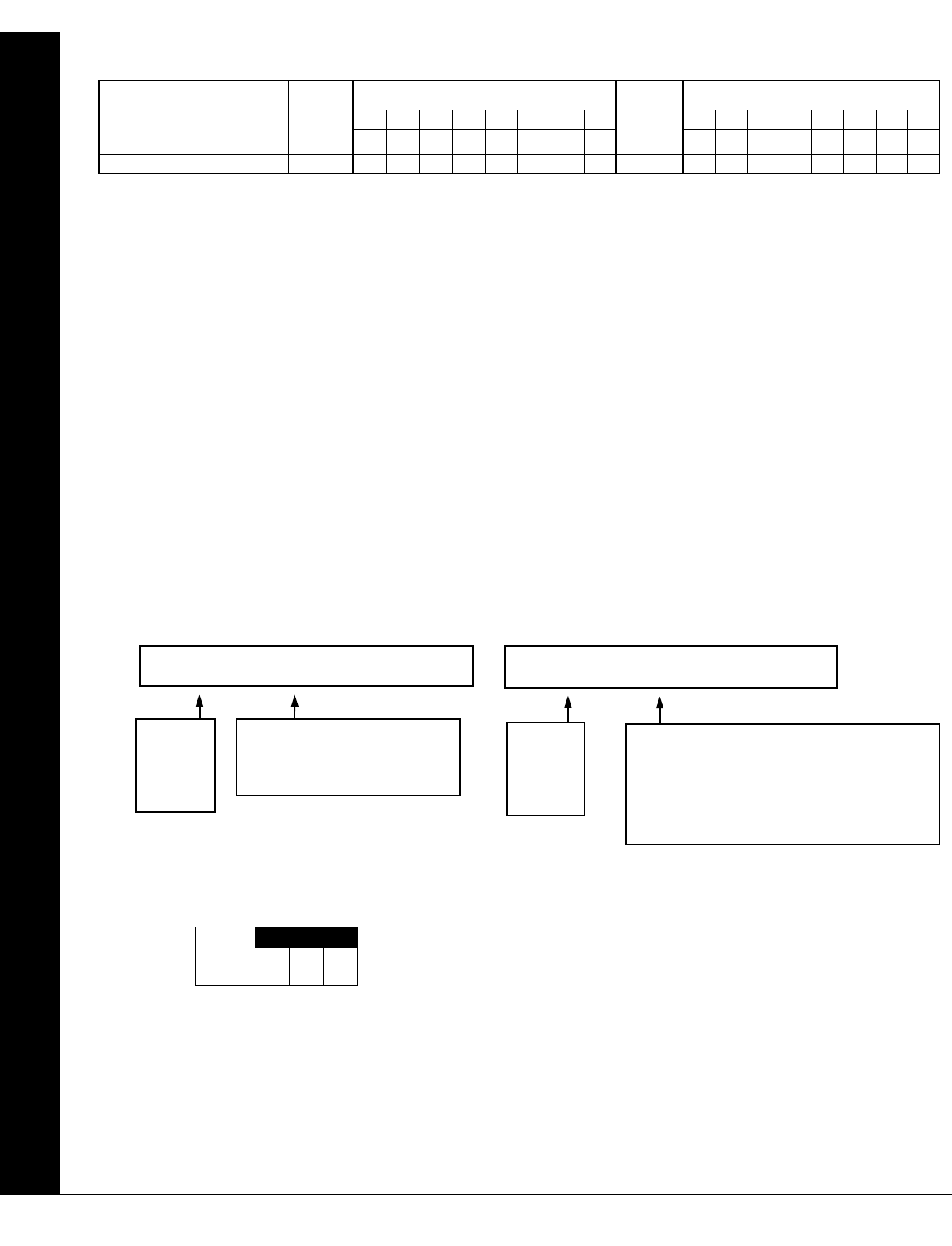
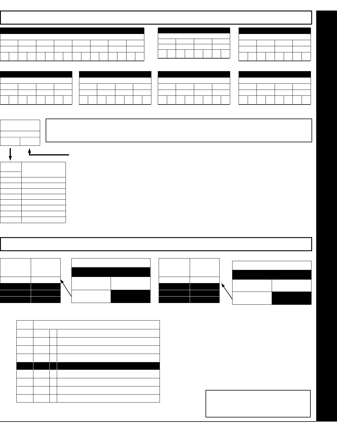
EASY MENU DRIVEN PROGRAM MODE
(Direct Entry)
#of Zns in Area1
Enter # Zones XX
(Press YES or NO)
EZ Zone Doubling
Enabled? Y/N
(Direct Entry)
Fire Zones
Enter Zone # °°
(Direct Entry)
2-Wire Fire Zns
Enter Zone # °°
(Press YES or NO)
Report All Zones
To Central? Y/N
(Direct Entry)
Exit/Entry Zones
Enter Zone # XX
(Direct Entry)
Interior Zones
Enter Zone # XX
(Direct Entry)
24 Hour Zones
Enter Zone # °°

L NAPCO Security Systems X GEM-P1632 Programming Instructions
!
Page 7
EASY MENU DRIVEN PROGRAM MODE
Chime Zones in Area 1 (New Program Only)
•Enter the zone numbers which are to be used as Chime Zones.
•Valid entries are from 01 to 32. Directly enter each zone number, including leading zeros.
• Press U to save and then repeat for any additional zone(s), press the NEXT/YES button to proceed.
NOTE: A chime time of 2 seconds will be automatically programmed.
Chime 2 Zones in Area 1 (New Program Only)
•Enter the zone numbers which are to be used as Chime 2 Zones.
•Valid entries are from 01 to 32. Directly enter each zone number, including leading zeros.
•Press U to save and then repeat for any additional zone(s), Press the NEXT/YES button to proceed.
NOTE: A chime time of 2 seconds will be automatically programmed.
Chime 2 zones give a distinct pulsating tone when zone is faulted.
Exit/Entry2 Zones in Area 1 (New Program Only)
•Enter the zone numbers of zones to be used as Exit/Entry zones.
•Valid entries are from 01 to 32. Directly enter each zone number, including leading zeros.
•Press U to save and repeat for any additional zone(s); press the NEXT/YES button to proceed.
NOTE: An Exit/Entry 2 Entry Time of 30 seconds will automatically be programmed.
50 mS Loop Response Zones (New Program Only) Note: 750mS is required for Loop Response
time in UL installations.
•Enter the zone numbers of zones to be have a 50mS loop response.
•Valid entries are from 01 to 08. Directly enter each zone number, including leading zeros.
•Press U to save and then repeat for any additional zone(s), Press the NEXT/YES button to proceed.
Note: Only panel zones 01-08 can be programmed for Quick Loop Response. All other zones can be
programmed via their respective EZM's (hardwire).
Aux Output Activated on Alarm Zones (New Program Only)
•Enter the zone numbers of zones to activate the PGM2 upon alarm.
•Valid entries are from 01 to 32. Directly enter each zone number, including leading zeros.
•Press U to save and then repeat for any additional zone(s), Press the NEXT/YES button to proceed.
NOTE: A PGM2 Timeout of 15 minutes will automatically be programmed.
Sensor Watch Zones (New Program Only)
•Enter the zone numbers of zones to be Sensor Watch zones.
•Valid entries are from 01 to 32. Directly enter each zone number, including leading zeros.
•Press U to save and then repeat for any additional zone(s), Press the NEXT/YES button to proceed.
NOTE: A Sensor Watch Time of 24 hours will automatically be programmed.
Keypad Sounder On Alarm Zones (New Program Only)
•Enter the zone numbers of all zones to activate the Keypad Sounder upon alarm.
•Valid entries are from 01 to 32. Directly enter each zone number, including leading zeros.
•Press U to save and then repeat for any additional zone(s), Press the NEXT/YES button to proceed.
Auto Bypass Re-entry Zones (New Program Only) (Not Evaluated by UL)
•Enter the zone numbers of zones to be Auto Bypass Re-entry zones.
•Valid entries are from 01 to 32. Directly enter each zone number, including leading zeros.
•Press U to save and then repeat for any additional zone(s), Press the NEXT/YES button to proceed.
•Auto Bypass Re-entry Zones allow the system to be armed with the zone faulted but come back into
the system (armed) when the zone is subsequently closed.
Enable No EOLR Zones (New Program Only)
•Press YES to program all zones except 24 Hr & fire zones for No End Of Line Resistor. Press NO to
continue.
•Do not program this feature for UL Installations.
Enable Telco Line Fault Test?
•Press YES to enable Telco Line Fault Test.
•Press NO to continue. NOTE: If enabled, a Telco Line Fault Test Delay of 60 sec. will auto-
matically be programmed.
(Direct Entry)
Chime Zones
Enter Zone # °°
(Direct Entry)
Chime 2 Zones
Enter Zone # °°
(Direct Entry)
Exit/Entry2 Zones
Enter Zone # °°
(Direct Entry)
50mS Loop Zones
Enter Zone # °°
(Direct Entry)
Aux Output Zones
Enter Zone # °°
(Direct Entry)
Sensor Watch Zns
Enter Zone # °°
(Direct Entry)
KP Sndr Alrm Zns
Enter Zone # °°
(Direct Entry)
Auto Byp REnt Zn
Enter Zone # °°
(Press YES or NO)
Enable No EOLR
Zones Y/N
(Press YES or NO)
Enable Telco
Line Test? Y/N
X GEM-P1632 Programming Instructions L NAPCO Security Systems
! Page 8
EASY MENU DRIVEN PROGRAM MODE
Enable Burg Output Chirp on KeyFob?
•Press the NEXT/YES button to enable Burg Output Chirp on KeyFob Arm / Disarm.
•Press the PRIOR/NO button to continue.
NOTE: The Burg Output will chirp once on Keyfob Arm and twice on Keyfob Disarm.
Enable SIA CP-01 Features?
•Press the NEXT/YES button to enable.
•Press the PRIOR/NO button to continue.
The SIA CP-01 Features are designed to reduce the incidence of false alarms. NOTE: Do not
enable unless reporting, otherwise system trouble Fail to Communicate may occur.
Number of Keypads in Area 1
•Enter the total number of Keypads to be installed in Area 1.
•Valid entries are from 01 to 07. Directly enter the number of keypads, including leading zeros.
Press U to save. Press the NEXT/YES button to proceed.
NOTE: Area 2 keypads must be assigned in Direct Address Programming. See Keypad Options.
Central Station Receiver 1 Telephone Number
•Enter telephone number of up to 16 digits.
•Press 1 through 9 for digits 1–9; G 0 for a zero and 0 for a blank (•).
•Press G 1 through G 5 for letters B–F, respectively.
•Pre-Dial Delay = “D” (G 4); Dial-Tone Detection = “E” (G 5).
•Press U to save and press the NEXT/YES button to proceed.
NOTE: Central Station Receiver 2 and 3 Telephone Numbers must be entered in Direct Ad-
dress Programming. See CS Receiver Options.
Central Station Receiver 1 Account Number
•Enter an account number of up to four digits.
•Press 0 through 9 for digits 0–9, and G 0 for a blank (•).
•Press U to save and press the NEXT/YES button to proceed.
NOTE: Central Station Receiver 2 and 3 Account Numbers
must be entered in Direct Address Programming. See CS
Reporting Options.
Central Station Receiver 1 Format
•From the table at the right enter the receiver format.
•Press 0 through 9, and G0 for blank (•).
•Press G1 through G4 for letters B–E.
•Press U to save and press the NEXT/YES button to proceed.
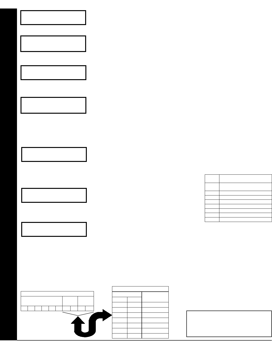
Enter User Codes (Press R to set cursor.)
For default program, enter up to 32 User Codes, with Area 1 and Area 2 Options.
•Press the (R) button once to set the cursor to the User Code.
•Press 0 through 9 to enter a code from 3 to 6 digits, leave blank (•) any trailing boxes.
•Press R to set the cursor to the Area 1 Options Level. Refer to the table below for available op-
tions. For Area 2 Options, press the R button once again.
•If “Enable Global Ambush Code” (Address 0720) is enabled and “Global Ambush Code” (Address 1054) is not left blank (•), do not program the
first two digits of ANY User Code the same as the “Global Ambush Code”.
•Press U to save. Note: Duplicate User Codes are not allowed; therefore a duplicate Code entered in the LCD Window will erase when U is
pressed. To proceed to the next User Code, press R to set the cursor to the User Number and change it using the number buttons. Press
the NEXT/YES button to proceed.
(Direct Entry)
Central Phone #
(Direct Entry)
Central Station
Account # (____)
DATA
ENTRY
CS RECEIVER 1 FORMAT
•
(blank)
Ademco Slow, Silent Knight
Slow
2 Radionics Fast
3 Silent Knight Fast
4 Radionics, DCI, Franklin Slow
5 Universal High Speed
B SIA
C Ademco Point ID
E Pager
(Direct Entry)
See WI for Info
Rcvr Format (0)
Enter user code
U01 123 - 9-
User# User Code Area 1 Area 2
OPTION
ENABLED
Disabled
Arm/Disarm
Arm Only
Service
Access
Ambush
* User Program
L R
blank(•) blank
blank(•) 1
blank(•) 2
blank(•) 3
blank(•) 4
blank(•) 5
DATA ENTRIES
blank(•) Add 8
USER AREA OPTIONS
USER OPTIONS
USER CODE
(UP TO 6 DIGITS)
AREA 1
OPTIONS
AREA 2
OPTIONS
Example: Program a code of “2222” for user
02, with area 1 options of “Arm/Disarm” and
“User Program”. Enter “2222” for a user code,
“• (blank) 9” for area 1 options and “• (blank) •
(blank)” for area 2 options.
(Direct Entry)
# Area 1 Keypads
Enter # KPs 01
(Press YES or NO)
Enable SIA CP-01?
Y/N
(Press YES or NO)
Enable Burg Out
Chirp? Y/N

L NAPCO Security Systems X GEM-P1632 Programming Instructions
!
Page 9
EASY MENU DRIVEN PROGRAM MODE
RF Transmitter Points (Press R to set cursor.)
For each transmitter enter: (For wireless systems only. Also see Quick Method, which follows)
•The zone number (01–32) to which the transmitter will be mapped.
•The 6-digit RF ID # and 1-digit checksum number printed on the transmitter and box,
•The point number (1–2); enter “9” for unsupervised (all points).
•Press U to save and NEXT/YES button to proceed when all transmitters have been entered.
NOTE: When programming the ID Code number, “0” through ”9” = 0 through 9 ; A =
G 0 ; B = G 1 ;
C = G 2 ; D = G 3 ; E = G 4 and “F” = G 5.
Quick Method. If a receiver is already installed in the panel, transmitter wireless points can be
programmed automatically (“enrolled”) using the following procedure. NOTE: The transmitter
point will be enrolled only if the signal strength is 3 or greater.
1. Enter the zone number to which the transmitter point will be mapped.
2. Press B to enter the Enroll Mode. The red and green LEDs on the keypad will flash and the
window will display as shown at left.
3. Open the loop of the point that is to be programmed (GEM-TRANS2 only).
4. Install the transmitter battery. The keypad will beep to indicate that the point has been successfully
enrolled. Multi-point transmitters can be mapped to successive zones simultaneously.
Key Fob Transmitters as Arm/Disarm & Control Devices (Press R to set cursor).
Key fobs can be programmed as “Arm/Disarm” devices using their On/Off buttons (refer to
WI752). For each Key Fob Transmitter, enter:
•The Key Fob Transmitter number (01–8).
•The area number to which transmitter is assigned (0 to disable keyfob, 1 or 2).
•The 6-digit RF ID # and 1-digit checksum number printed on the transmitter and box,
•The Aux 1 Option (see key fob aux 1 & aux 2 options).
•The Aux 2 Option (see key fob aux 1 & aux 2 options).
•Press U to save and NEXT/YES button to proceed when all key fobs have been entered.
NOTE: When programming the ID Code number, “0” through ”9” = 0 through 9 ; A = G 0 ; B = G 1 ;
C = G 2 ; D = G 3 ; E = G 4 and “F” = G 5.
ZN# XMIT#+CS P
Zn01- 000000:0-0
Zone # Xmitter Check Point
Mapped to ID Sum #
ZN# XMIT#+CS P
Zn01- 000000:0-0
ZN# XMIT#+CS P
ZN01- ENROLL:A--
Example. A 2-point transmitter has the RF ID number 287613:1.
Map point 1 to Zone 6 and point 2 to Zone 9.
1. Enter the Enroll mode as described above.
2. Enter Zone “06”.
3. Open point-1 loop.
4. Install the battery. The keypad will beep once to indicate that
one point has been programmed. (Transmitter 287613:1, point
1 will be mapped to Zone 6).
5. Enter Zone “09”.
6. Close point-1 loop and open point-2 loop.
7. Remove the transmitter battery, then re-install it. The keypad
will beep once to indicate that one point has been programmed.
(Transmitter 287613:1, point 2 is mapped to Zone 9).
KEY FOB ZONE ASSIGNMENT: Key fobs can also be assigned to zones to allow multiple wireless panic buttons on one alarm
system, each reporting to a central station, a pager or having a description on the keypad that describes the person holding the key
fob, the location where the person holding the key fob is stationed, or the special purpose of the key fob button being depressed.
See the next page on Key Fob Transmitters as Zone Input Devices .
KF A XMIT#+CS OP
01-0 000000:0 00
KF Area Xmitter Check Aux
# ID Sum 1&2
CHANGING OR CANCELING A CODE: To change any code, merely program over the existing code as described above and press U to save. Similarly, to
cancel a code, blank out each number of the code and press U to save.
AREA OPTIONS EXPLANATION
Disabled User Code not active in this area.
Arm/Disarm Allows User Code to arm/disarm this area.
Arm Only Prevents User Code from disarming this area.
Service A Service Code has restricted arm/disarm rights; if an area is armed with a Service Code, a “MONITOR ON” appears on the GEM-RP2ASe2 key-
pad and the area can be disarmed with any valid User Code, including a Service Code. If the area is armed with OTHER than a Service Code,
Access This is normally used to activate a door strike while an area is disarmed. Also program “Access Control on PGM2. Output” (Address 0719) and
“PGM2 Output Access Control Timeout” (Address 0711).
* User Program User Program Option is enabled for Keypad 1 only, wherever it is connected (Area 1 or Area 2). To enable User Program Option for any user
add 8 to the data entry for Area Option (see example). Then, User Programming can be performed only at Keypad 1 by a user code with user
program enabled.
Related User Options:“Enable Global Ambush Code” (Address 0720), “Global Ambush Code” (Address 1054) & “Enable Managers Mode” (Address 0719).
Ambush Allows user code to send Ambush signal to Central Station.

X GEM-P1632 Programming Instructions L NAPCO Security Systems
! Page 10
Key Fob Transmitters as Zone Input Devices
(Refer to display above: press the PRIOR button to go backwards).
Each of the 4 key fob buttons can be assigned to a zone. For example, On button = point 1; Off
button = point 2; A1 = point 3; A2 = point 4. Up to 32 key fobs (using 1 button) or 16 key fobs
(using 2 buttons) or 8 key fobs (using all 4 buttons) or any combination up to a maximum of 32
controlled zones can be assigned, providing multiple wireless panic buttons on a system, each re-
porting to a Central Station or a pager and/or annunciating on a keypad the key fob zone number
with a description. To assign a key fob to a zone: program the key fob as you would a transmitter,
entering the key fob's ID code, check sum and point number at the appropriate zone. The “Quick
Method” is not allowed. The zone may be hardwired to an electrical sensor as well as assigned to
a key fob (either one will activate the zone alarm output). NOTE: If assigning a key fob to a zone,
the “ON/OFF” buttons on the key fob will no longer arm/disarm the system. The key fob is con-
verted to a “panic only” device.
Enter Zone Descriptions
•Press 1 and 2 to place the cursor and; press 3 and 6 to select the character.
•For each zone, enter a description of up to two lines.
•Press U to save each description.
•To proceed to the next description, place the cursor under the Zone Number (e.g. “01”) and change the Zone Number using 3
and 6. Program new description as above.
•NOTE: Zone Descriptions can only be entered through the GEM-RP1CAe2 Keypad or by using the Napco Quickloader Software.
See Easy Menu Programming Worksheet for available zone description characters.
Enter Date (Press R to set cursor).
•Enter the current date in the format MM/DD/YY. (MM = month, DD = day and YY = year.
•Press U to save. Press the NEXT/YES button to proceed.
Enter Time (Press R to set cursor.)
•Enter the current time in format HH:MMA/P, where HH=hours (01–12); MM=minutes (00–
59).
•Select AM or PM by pressing any number button.
•Press U to save. Press the NEXT/YES button to proceed.
Dealer Code
•Directly enter the Dealer Code (default = 456789), using 0 through 9 buttons.
•Press U to save.
•Re-enter the Dealer Code to verify the previous code.
•Press U to save.
•Press the NEXT/YES button to proceed.
(Direct Entry)
Enter Date
( / / )
(Direct Entry)
Enter Time
( : )
Dealer Code
456789
DEALER CODE
RE-ENTER
CLEAR PROGRAM: Should it be necessary to create a new custom default program, (a) from the Dealer Program Mode, press
C to enter the Address Program Mode; (b) access Location 1197 (Clear Program) or 1198 (Cold Start); (c) press U and then
(d) press C to exit the Dealer Program Mode. A “SYSTEM TROUBLE/E09-00 SERVICE” will occur. Press C to silence the keypad.
Clear Dealer Program (Erases Dealer Program)
Use this feature to erase the Panel Program, while maintaining Scheduled Data and Zone Descrip-
tions. Access address 1197 and press U. Data entry is not allowed. NOTE: Enter Easy
Menu Driven Program Mode to reprogram system.
Cold Start (Erases Entire Program)
This erases all programmed data (Dealer Program, Zone Description Data and Schedules).
Access address 1198 and press U. Data entry is not allowed. NOTE: Some features
(schedules) can only be programmed again with the Downloading Software.
EASY MENU DRIVEN PROGRAM MODE
DATA
ENTRY
AUX 1/AUX 2
OPTIONS
0 None
1 Relay Group 1 Toggle
2 Relay Group 2 Toggle
9 Keypad Panic
A Keypad Aux.
B Instant
C PGM2 Ouput Toggle
D Access on PGM2 Output
E Arm STAY
F Interior Button
(Direct Entry)
01-
EXIT DEALER PROGRAM MODE: This completes the custom default program. Press C to enter the Direct Address Program
Mode for further programming or press C once again to end all programming and resume normal keypad operation.
1197 XX H
1198 XX H
L NAPCO Security Systems X GEM-P1632 Programming Instructions
!
Page 11
DIRECT ADDRESS OVERVIEW
Direct Address Programming allows you to go directly to the address locations (up to 1198) and change the data entries
manually in order to customize your control panel options. Whereas the Easy Menu Program Mode guides you through
limited selections to get you started, Direct Address Program Mode allows you to change all options directly. It con-
sists of up to 1198 address locations each with data entry locations as shown in the following diagram (below left). The
data entry location accepts data in one of three formats: Binary, Decimal and Hexadecimal (explained below in
"Address Mode Displays"). The following diagram (below right) illustrates a Decimal format data entry location (using
a GEM-RP1CAe2 keypad).
ADDRESS MODE DISPLAYS
There are three types of address displays when programming in Direct Entry Program Mode, as follows:
A) Binary (Bit) Format
Settings (such as Zone Features) display and accept data in "number" format. For example, Zone Features are
turned on by the pressing of keypad buttons 1 through 8, with the activated Zone(s) displaying the corresponding
decimal digit (replacing deactivated zones which are signified by dashes).
EXAMPLE: BIT Format with the GEM-RP1CAe2: Program Zones 2, 4, 5 and 7 as Exit/Entry Follower Zones.
DETERMINE THE DATA ENTRIES
1. Referring to ZONE FEATURES in the Programming Worksheets that follow, the Exit/Entry Follower for Zones 1
through 8 are located at address 0506.
DATA ENTRY
LOCATION
ADDRESS
LOCATIONS
0000
0000
TO
1198
DATA ENTRY LOCATION:
(One of three formats):
•Binary (Bit)
•Decimal
•Hexadecimal
DIRECT ADDRESS PROGRAM MODE
Direct Address Program Mode
GEM-RP1CAe2 Keypad Display Example
0000 060 D
1 2
= ADDRESS LOCATION
1
2 = DATA ENTRY LOCATION
0506 - - - - - - - - B 0506 - 2 - 4 5 - 7 - B
DATA ENTRY LOCATION:
Binary (Bit) Format
Press 2 4 5 and 7 in
order to activate Zones 2, 4, 5, and 7. (The "B"
on the right indicates "Binary" format).
DATA ENTRY LOCATION:
Binary (Bit) Format
•No zones yet activated
Address
0506
"Exit/Entry
Follower"
Address
0506
"Exit/Entry
Follower"
X GEM-P1632 Programming Instructions L NAPCO Security Systems
! Page 12
PROGRAM THE DATA ENTRIES
1. Enter the panel's Dealer Security Code, then press R.
2. Answer NO to all questions until “ACTIVATE PROGRAM Y/N” is displayed; then press YES. NOTE: If you pass
“ACTIVATE PROGRAM”, scroll backward using B.
3. Press C to enter the Address Program Mode. Address "0000" will display.
4. Press 0506 to access Address 0506. The existing data will display and the cursor will
advance to the data field.
5. Press 6 7 8. The numbers 6,7 and 8 will appear on the keypad display indicating the zones
activated.
6. Press U to save. Address 0506 is now programmed with “6,7,8”.
7. Enter another 4-digit address to continue programming or press C to exit and resume normal keypad op-
eration.
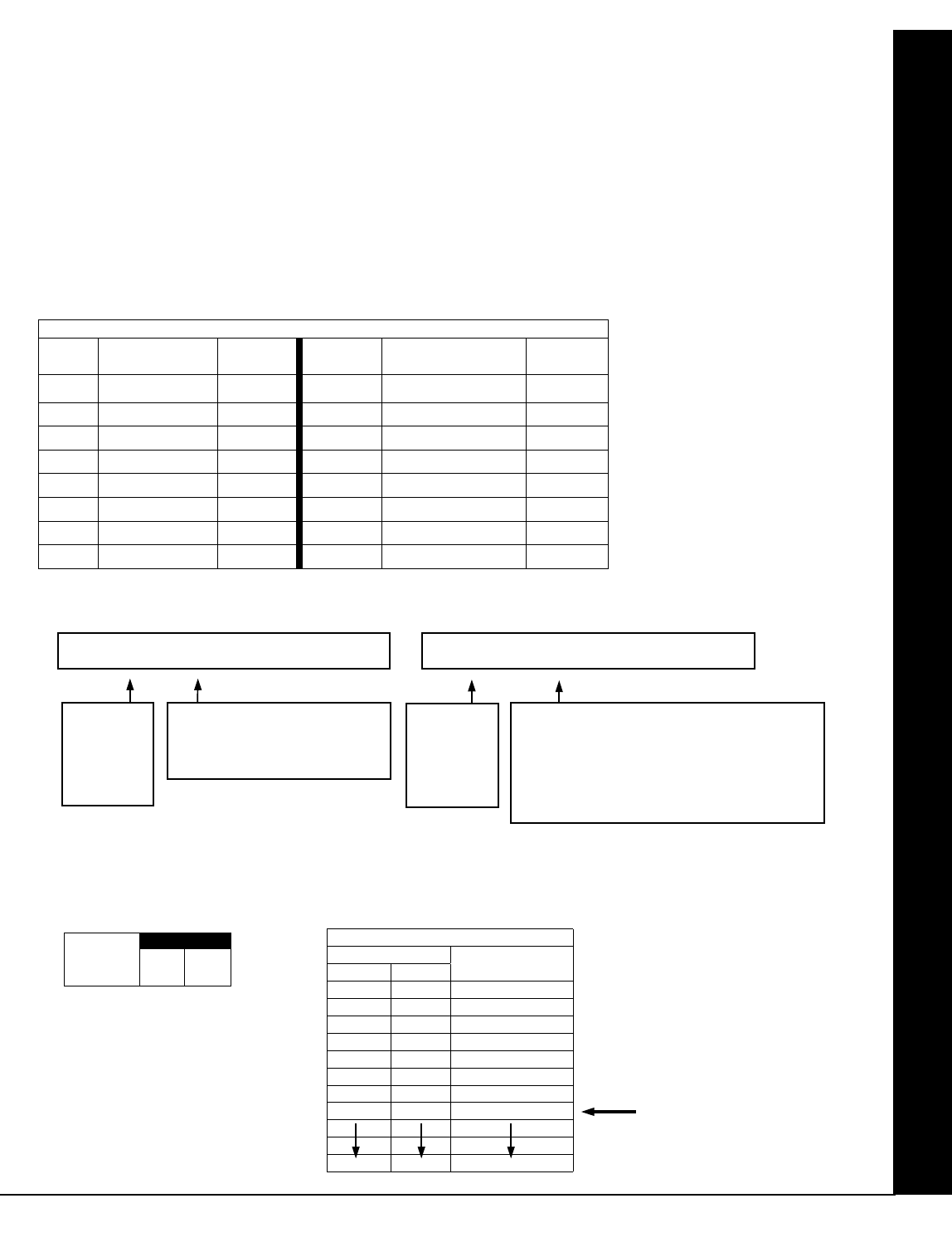
B) Decimal Format
Settings (such as Entry and Exit Delay) display and accept data in decimal format, as a 3 digit number. Data is en-
tered directly, by pressing keys 0 – 9, with the cursor automatically moving to the right upon each key press.
EXAMPLE: DECIMAL Format with the GEM-RP1CAe2: Program Abort Delay to be 15 seconds.
DETERMINE THE DATA ENTRIES
1. Referring to SYSTEM DELAYS & TIMEOUTS in the Programming Worksheets that follow, the Abort Delay is
located at address 0715:
PROGRAM THE DATA ENTRIES
1. Enter the panel's Dealer Security Code, then press R.
2. Answer NO to all questions until “ACTIVATE PROGRAM Y/N” is displayed; then press YES. NOTE: If you pass
“ACTIVATE PROGRAM”, scroll backward using B.
3. Press C to enter the Address Program Mode. Address "0000" will display.
4. Press 0715 to access Address 0715. The existing data will display and the cursor will
Direct Address Program Mode
0715 - - - D 0715 015 D
ZONES 1 " 8 ZONES 9 " 16
ZONE FEATURES ADDR Z1 Z2 Z3 Z4 Z5 Z6 Z7 Z8 ADDR Z9 Z10 Z11 Z12 Z13 Z14 Z15 Z16
1 2 3 4 5 6 7 8 1 2 3 4 5 6 7 8
Exit/Entry Follower 0506
6 7 8
0561
DATA ENTRY LOCATION:
Decimal Format
•No time yet entered
Address
0715
"Abort
Delay"
DATA ENTRY LOCATION:
Decimal Format
Press 0 1 5 in order to set
"Abort Delay" to 15 seconds. The "D" on the
right indicates "Decimal" format.
ABORT ADDRESS 0715
DELAY
(sec.)
[Default = 0 sec. = blank (•)]
Address
0715
"Abort
Delay"
L NAPCO Security Systems X GEM-P1632 Programming Instructions
!
Page 13
Direct Address Program Mode
advance to the data field.
5. Press 015. The numbers 015 will appear on the keypad display indicating the number of
seconds entered.
6. Press U to save. Address 0715 is now programmed with a 15-second Abort Delay.
7. Enter another 4-digit address to continue programming or press C to exit and resume normal keypad
operation.
C) Hexadecimal Format
Data such as Report Codes displays and accepts data by means of a Hexadecimal display. Data is entered di-
rectly, by pressing keys 1 – 9, G0 for zero, and G 1 through G 5 for hex B through F (11-15),
with the cursor automatically moving to the right upon key press. See table below.
EXAMPLE: HEXADECIMAL Format with the GEM-RP1CAe2: Program Chime Timeout to be 2 seconds.
DETERMINE THE DATA ENTRIES
1. Referring to SYSTEM DELAYS & TIMEOUTS in the Programming Worksheets that follow, the Chime Timeout
is located at address 0716. In the "Chime Timeout Options" table, the data entries needed to assign a time-
out of 2 seconds are "blank" and "8".
ENTRY
TOTAL
PRESS
N KEYPAD
DISPLAYS
ENTRY
TOTAL
PRESS
N KEYPAD
DISPLAYS
blank 0 • 8 8 8
1 1 1 9 9 9
2 2 2 10 G 0 0
3 3 3 11 G 1 B
4 4 4 12 G 2 C
5 5 5 13 G 3 D
6 6 6 14 G 4 E
7 7 7 15 G 5 F
HEXADECIMAL ENTRIES
CHIME ADDRESS 0716
TIMEOUT
(¼sec.)
[Default = 2 ¼sec. = ½ sec.]
DATA ENTRY LOCATION:
Decimal Format
•No time yet entered
DATA ENTRY LOCATION:
Decimal Format
Press 0 8 in order to set "Chime
Timeout" to 2 seconds. The "H" on the right
indicates "Hexadecimal" format.
Address
0716
"Chime
Timeout"
0716 - - H 0716 - 8 H
Address
0716
"Chime
Timeout"
2 seconds
CHIME TIMEOUT OPTIONS
TIMEOUT
LEFT RIGHT
blank (•) blank (•) 0 x ¼sec. = 0 sec.
blank (•) 2 2 x ¼sec. = ½ sec.
blank (•) 3 3 x ¼sec. = ¾ sec.
blank (•) 4 4 x ¼sec. = 1 sec.
blank (•) 5 5 x ¼sec. = 1.25 sec.
blank (•) 6 6 x ¼sec. = 1.5 sec.
blank (•) 7 7 x ¼sec. = 1.75 sec.
blank (•) 8 8 x ¼sec. = 2 sec.
F F 255 x ¼sec. = 63.25
DATA ENTRIES

X GEM-P1632 Programming Instructions L NAPCO Security Systems
! Page 14
Direct Address Program Mode
PROGRAM THE DATA ENTRIES
1. Enter the panel's Dealer Security Code, then press R.
2. Answer NO to all questions until “ACTIVATE PROGRAM Y/N” is displayed; then press YES. NOTE: If you pass “ACTIVATE
PROGRAM”, scroll backward using B.
3. Press C to enter the Address Program Mode. Address "0000" will display.
4. Press 0716 to access Address 0716. The existing data will display and the cursor will ad-
vance to the data field.
5. Since you wish the timeout to be for 2 seconds (and 8 multiplied by ¼ second equals 2 seconds), press
08. The numbers 08 will appear on the keypad display indicating the number of seconds entered.
6. Press U to save. Address 0715 is now programmed with a 2-second chime.
7. Enter another 4-digit address to continue programming or press C to exit and resume normal keypad op-
eration.
PROGRAMMING CONVENTIONS USED IN THIS MANUAL
The Keypad Programming Worksheets in the back are provided as an address-programming reference to help the in-
staller modify his custom default program or to make minor field alterations to an existing panel program. It is recom-
mended that the panel be uploaded to NAPCO's PCD-Windows software following any keypad programming and that
the PCD-Windows's error-check feature be utilized to reduce the possibility of programming omissions or conflicts.
3
Keep the Keypad Programming Worksheets on file for future reference.
General Programming Steps
!1. Contact the central station to ascertain receiver format, data format, event codes, subscriber numbers and tele-
phone number(s).
!2. Select the desired features by circling # the respective “address” boxes. Refer to the Programming Options
and Worksheets for guidance in selecting the “data” to be entered into those boxes.
!3. Program the data entered in the boxes on the worksheets into the respective addresses. The display will show
the entry numerically, but if hexadecimal format will display “0” for the number 10, and letters “B”, “C”, “D”, “E”, and
“F” for the numbers 11 through 15, respectively. To program a 10, press G 0. To program 11 through
15, press G 1 through G 5, respectively.
The displays will appear after a brief delay.
!Use R to toggle the cursor between the 4-digit address field and the data entry locations.
!Enter the address directly using the number buttons.
!The contents of the address will be read automatically, along with the feature name and programming information.
The cursor will advance to the data field. Enter the required data directly using the number buttons.
!IMPORTANT: Press U or D to save the contents of each address.
EXIT DIRECT ADDRESS PROGRAM MODE: When done, press C to exit and resume normal keypad operation.
L NAPCO Security Systems X GEM-P1632 Programming Instructions
!
Page 15
SYSTEM DELAYS & TIMEOUTS (ADDRESS 0000 TO 0002, 0711, 0715 & 1059)
Direct Address Program Mode
WARNING: Timers have uncertainty of +/-1 sec, so a "time" of 1 second may actually timeout IMMEDIATELY.
! Select delay/timeout (0-255 sec.) from the table shown.
EXIT/ENTRY DELAYS: Apply only to zones programmed with the following options “Exit/Entry 1, Exit/Entry
2, Exit/Entry Follower”. For UL Installations, the maximum exit delay is 60 seconds and the maximum entry
delay is 45 seconds. NOTE: Sensor Watch Time Options are similar to above table, except in hours.
! Press U or D to save.
SYSTEM DELAYS & TIMEOUTS (ADDRESS 0716 & 0717)
DEFAULTS: The defaults shown on this
page and on the following pages are
automatically set after exiting the Easy
Menu Driven Mode.
!1. Enter delay/timeout in corresponding address locations above.
Note: All entries for address 0716 are in quarter seconds (.25 seconds).
Therefore, the default of 008 results in a 2 second timeout.
!2. Press U or D to save.
EXIT ADDRESS 0000
DELAY
(sec.)
[Default = 060]
ENTRY ADDRESS 0001
DELAY 1
(sec.)
[Default = 030]
PGM2 Output ADDRESS 0711
Access Cntrl
Timeout (sec.)
[Default = 0 sec. = blank (•)]
ABORT ADDRESS 0715
DELAY
(sec.)
[Default = 030]
Sensor Watch ADDRESS 1059
Time
(Hrs.)
[Default = 024]
Report Cancel ADDRESS 1179
Window
(min.)
[Default = 0 sec. = blank (•)]
See Maximum Program Time
table (at left)
AC Fail ADDRESS 0717
Report Delay
(min.)
[Default = 060]
CHIME ADDRESS 0716
TIMEOUT
(¼sec.)
[Default = 008 x ¼ sec. = 2 sec.]
ENTRY ADDRESS 0002
DELAY 2
(sec.)
[Default = 030]
Maximum Program Time
Address Units Max Prog Time
1179 VERSION 10 - MIN
VERSION 9A - SEC
VERSION 10 - 254 MIN
VERSION 9A - 254 SEC

X GEM-P1632 Programming Instructions L NAPCO Security Systems
! Page 16
SYSTEM OUTPUT TIMEOUTS (ADDRESS 0710, 0712, 0713 & 0714)
!1. Select delay/timeout (0-255 min.) from the table shown.
!2. Enter in corresponding address locations above.
!3. Press U or D to save.
OUTPUT TIMEOUTS: If a timeout of “0 min.” is selected, then the output will remain active (ON)
until the system is reset or disarmed. For UL Residential Installations, the minimum timeout is 4
minutes. Not UL listed for Commercial Installations.
DOWNLOAD/CALLBACK OPTIONS (ADDRESS 1183 & 0236-0255)
NUMBER OF RINGS BEFORE PICKUP: Enter the number of rings before automatic
pickup by the control panel when downloading from a computer (see Glossary at the back
for more information).
!1. Enter digit only.
!2. Valid entries are: 03-15. NOTE: Default is 15 Rings.
!3. Press U or D to save.
CALLBACK TELEPHONE NUMBER: Enter telephone number to be used when downloading from a computer (see Glossary at
the back for more information).
!1. Enter digit only.
!2. Enter up to 20 digits from left to right. NOTE: Leave trailing boxes blank (•).
!3. Valid entries are: 1-9, B = *button, C = #button, D = 3 sec. pause, E = Wait for dial tone, F = ignore location.
!4. Press U or D to save.
PAGER FORMAT OPTIONS (ADDRESS 0256 & 0257)
LEADING DIGITS FOR PAGER FORMAT: In Pager Format reporting, the message typically begins with “00”.
However, for some pager services, this will cause the Pager's Voice Mail feature to activate. This option allows
you to program these digits to any number desired. A typical Pager report is “003 22 1234”, where 3 is the Event,
22 is the zone, and 1234 is the Subscriber ID number. For example, if the Leading Digits are programmed as “98”,
the Pager report will now appear as “983 22 1234”. NOTE: See CS Receiver Options to select Pager Format.
!1. Enter in 1st and 2nd Leading Digits as shown.
!2. Valid entries are: 0-9. Press U or D to save.
Callback
Telephone
ADDRESS 0236-0255 (RIGHT DIGITS 1-20)
0236 0237 0238 0239 0240 0241 0242 0243 0244 0245 0246 0247 0248 0249 0250 0251 0252 0253 0254 0255
(Digits 1-20)
[Default = blank (•) for all digits 1-20]
No. Rings ADDRESS 1183
Before
Pickup
[Default = 015 ]
PGM2 ADDRESS 0710
Output
Timeout (min.)
[Default = 0 min. = blank (•)]
Alarm ADDRESS 0712
Output
Timeout (min.)
[Default = 015]
Pulse Alarm ADDRESS 0713
Output
Timeout (min.)
[Default = 015]
PGM1 ADDRESS 0714
Output
Timeout (min.)
[Default = 0 min. = blank (•)]
DELAY/
TIMEOUT
blank (•) 0 min.
1 1 min.
2 2 min.
3 3 min.
4 4 min.
5 5 min.
6 6 min.
16 16 min.
255 255 min.
DATA
ENTRIES
Leading Digits for ADDRESS 0256
Pager Format
(1st Digit)
Leading Digits for ADDRESS 0257
Pager Format
(2nd Digit)
[Default = blank (•) blank (•)]
Direct Address Program Mode
L NAPCO Security Systems X GEM-P1632 Programming Instructions
!
Page 17
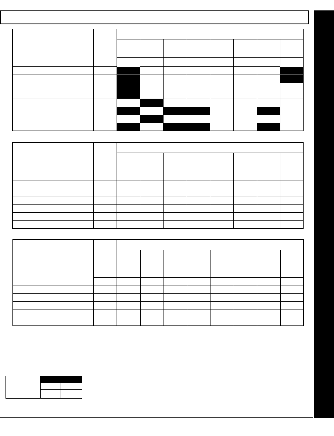
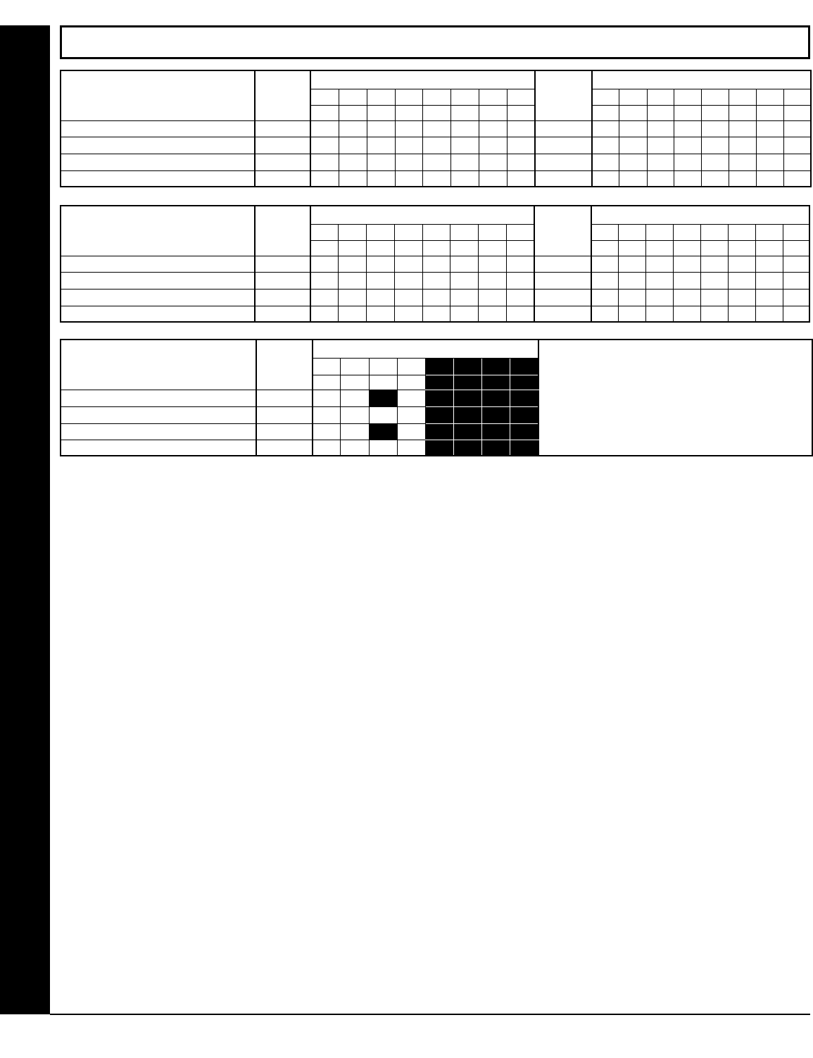
GLOBAL SYSTEM EVENT/TROUBLE
SYSTEM RESPONSE
ACTIVATED BY GLOBAL
EVENT/TROUBLE
ADDR TEST
TIMER
TELCO
FAILURE
RF RCVR.
TROUBLE
MEMORY
FAILURE
LOW
BATTERY AC FAIL EZM
TAMPER
Bell
Superv
1 2 3 4 5 6 7 8
Alarm Output 0460
Pulsed Alarm Output 0461
PGM1 Output 0462
PGM2 Output 0463
Report Event Telco 1 0464
Report Restore Telco 1 0465
Report Event Telco 3 0468
Report Restore Telco 3 0469
SYSTEM OPTIONS (ADDRESS 0460-0485 & 1054)
!1. Select the desired option entering the option number (1-8) for each digit.
!2. Enter corresponding option number in address location.
!NOTE: Dark shaded data value box shows option not available. Press U or D to save.
GLOBAL AMBUSH CODE: It is the 2-digits entered immediately prior to the regular disarm code. If
“Enable Global Ambush Code” (Address 0720) is selected and Address 1054 is left blank (•), then the
2-digit Global Ambush Code is “99”. If “Enable Global Ambush Code” is selected and Address 1054
is not left blank (•), then the 2-digit Global Ambush Code is the two digits entered in address 1054.
!Enter in address location (both 1st and 2nd digits); valid entries are 1-9. 3. Press U or D to
save.
Direct Address Program Mode
[Default = blank (•) blank (•)]
Global 1st digit 2nd digit
Ambush Code
ADDRESS 1054
SYSTEM RESPONSE
ACTIVATED BY AREA 1
EVENT/TROUBLE
AREA 1 SYSTEM EVENT/TROUBLE
ADDR AMBUSH KEYPAD
PANIC
KEYPAD
FIRE
KEYPAD
AUX. * KEYPAD
TAMPER
FAIL TO
OPEN
FAIL TO
CLOSE Keyfob
Low Batt
1 2 3 4 5 6 7 8
Pulsed Alarm Output 0470
Alarm Output 0471
PGM1 Output 0472
PGM2 Output 0474
Report Event Telco 1 0475
Report Event Telco 3 0477
[Default = blank (•) from address 0470-0477] * NOTE: Keypad Aux. is not to be selected for UL Installations.
SYSTEM RESPONSE
ACTIVATED BY AREA 2
EVENT/TROUBLE
AREA 2 SYSTEM EVENT/TROUBLE
ADDR AMBUSH KEYPAD
PANIC
KEYPAD
FIRE
KEYPAD
AUX. * KEYPAD
TAMPER
FAIL TO
OPEN
FAIL TO
CLOSE Keyfob
Low Batt
1 2 3 4 5 6 7 8
Pulsed Alarm Output 0478
Alarm Output 0479
PGM1 Output 0480
PGM2 Output 0482
Report Event Telco 1 0483
Report Event Telco 3 0485
[Default = blank (•) blank (•) from address 0478-0485] * NOTE: Keypad Aux. is not to be selected for UL Installations.
[Default = blank (•) from address 0460-0469]. Note: If Test Timer is enabled (above), Digital Dialer Test is also enabled.
X GEM-P1632 Programming Instructions L NAPCO Security Systems
! Page 18
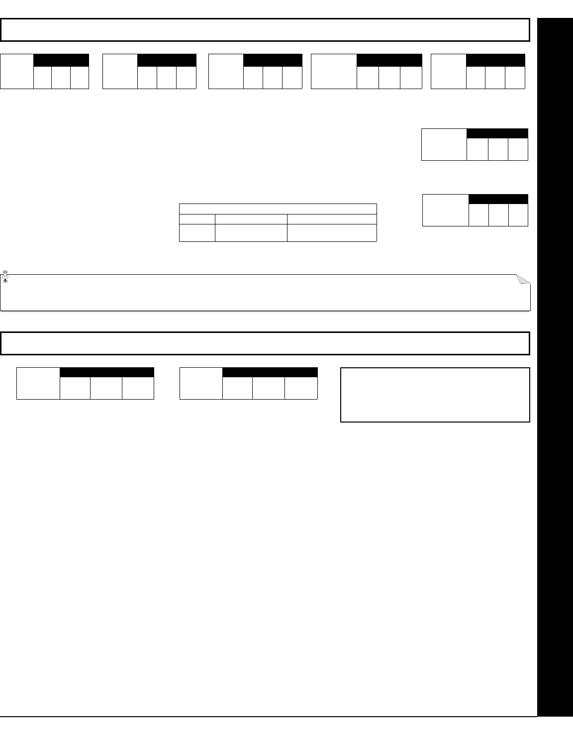
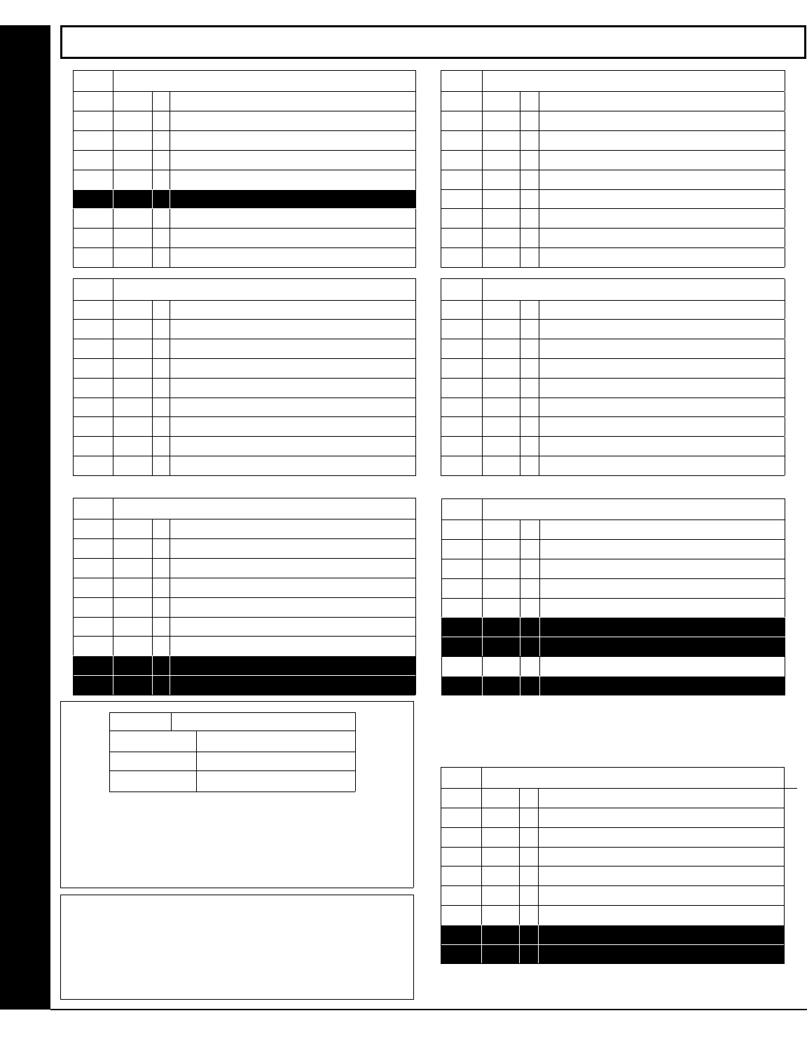
SYSTEM OPTIONS (ADDRESS 0718-0722, 1060-1062)
*NOTE: Address 0721: Default depends on Easy Menu Question :“EZ
ZONE DOUBLING? Y/N”. If yes, then [Default = 1]. If no, then [Default =
blank (•)].
**NOTE: To select “Line-Fault Test only when Armed”, you must also se-
lect “Enable Line-Fault Test” at address 0721.
*** NOTE: If “Enable Global Ambush Code” in Address 0720 is selected, then
program the 2-digit “Global Ambush Code” in Address 1054. If Address
1054 is left blank (•), then, the 2-digit “Global Ambush Code” will be “99”.
0718 System Options 0719
Default
Option Default Option
OFF 1 Opening Report Only after Alarm Report OFF 1 Auto Bell Test on Arming
OFF 2 Closing Report Only on Conditional Close OFF 2 Auto Reset after Burglary Output Timeout
OFF 3 Incl. Sel./Grp. Bypass in Cond. Close /Status OFF 3 Suppress Bypass Reminder when Armed
OFF 4 Status Report OFF 4 Enable Local Alarm on First Zone AND Trip
OFF 5 Reserved OFF 5 Access Control on PGM2 Output
OFF 6 Enable AutoArm if not closed at end of Window OFF 6 Maintained Keyswitch Arming
OFF 7 Enable Time/Date KP Display OFF 7 Enable Manager's Mode
OFF 8 Disable Zone Fault Scrolling OFF 8 Disable Keypad Instant Mode
System Options
0720 System Options 0721 System Options
Default Option Default* Option
OFF 1 Interior Normally Bypassed OFF* 1 Enable Zone Doubling (Zones 9-16)
OFF 2 Enable Global Ambush Code *** OFF* 2 Wireless Trouble Activates Telco 1
OFF 3 Reset Day Zone with Arm/Disarm Only OFF* 3 Wireless Trouble Activates Telco 3
OFF 4 Enable Residential Fire OFF* 4 Enable Alarm Output on Telco Fail only when Armed
OFF 5 Disable Keypad Function Mode Download OFF* 5 Line-Fault Test only when Armed**
OFF 6 Disable Callback Download OFF* 6 Enable Line-Fault Test**
OFF 7 Chirp Output on Keyfob Arm/Disarm OFF* 7 Inhibit System Trouble Audible at Keypad †
OFF 8 Change Pulse Output to Temporal Output§ OFF* 8 Select Alarm Output for Keyfob Chirp
† NOTE: Not for UL Installations.
§This feature must be programmed in Fire Alarm applications.
1060
Default Option
OFF 1 Enable Keypad Set Time/Date Message
OFF 2 Enable Cancel Report to Telco 3
OFF 3 Disable [ON/OFF] as Easy Exit
OFF 4 Enable GEM-PRINT Module
OFF 5 RESERVED
OFF 6 RESERVED
OFF 7 Disable System Trouble Audible Timeout
OFF 8 RESERVED
System Options
0722
Default Option
OFF 1 Automatic Interior Bypass/Easy Exit
OFF 2 Veri-phone Zones Trip PGM2 Output
OFF 3 Veri-phone Audio Priority Over Alarms
OFF 4 Resound on Wireless Smoke Low Battery
OFF 5 Don't Clear PGM2 Output with Disarm
OFF 6 Disable 2nd Call Ans. Machine Override
OFF 7 RESERVED
OFF 8 RESERVED
System Options
ADDRESS 1061: LUG E15 OUTPUT MODE
Select the options available from the table above.
!1. Enter digit only.
!2. Valid entries are “blank (•)” or “4”. Press U or D to save.
1061 Lug E15 Output Mode
DATA ENTRIES OPTION
blank (•) Armed
4 Armed Area 1 Away
Direct Address Program Mode
1062
Default Option
OFF 1 Exit Time Restart
OFF 2 Sound Alarm On Exit Error
OFF 3 Rpt Exit Err/Recent Close
OFF 4 Enable CP-01 Limits
OFF 5 Digital Dialer Rpt Enter /Exit Test Mode
OFF 6 Disable Call Waiting on 1st Attempt
OFF 7 RESERVED
OFF 8 RESERVED
System Options
L NAPCO Security Systems X GEM-P1632 Programming Instructions
!
Page 19
Direct Address Program Mode
NOTE: * See Pager Format Options to program
Leading Digits for Pager Format.
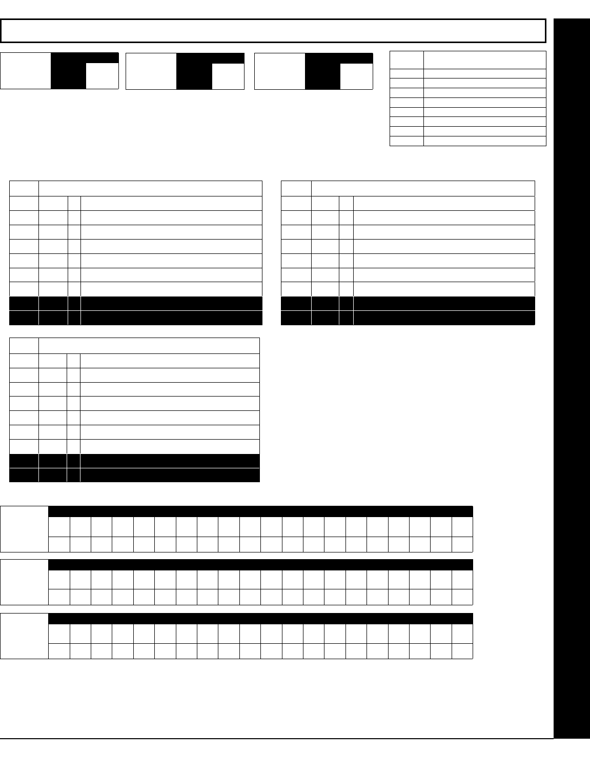
CS RECEIVER OPTIONS (ADDRESS 0170-0191, 0192-0213, 0214-0235)
Default for CS Receiver 1 Format depends on Easy Menu Question “RCVR FORMAT”. [Default = •(blank) •
(blank)] for CS Receivers 2 and 3 Formats.
CS RECEIVER FORMATS: Up to 3 CS Formats may be programmed.
!1. Select the desired CS Receiver Format from the table shown.
!2. Enter the corresponding digit in the address location for each CS Receiver. NOTE:
Dark
shaded data value box shows option not available. Press [Enter] of [ON/OFF] to save.
DATA
ENTRY
CS RECEIVER 1 FORMAT
blank (•) Ademco Slow, Silent Knight Slow
2 Radionics Fast
3 Silent Knight Fast
4 Radionics, DCI, Franklin Slow
5 Universal High Speed
B SIA
C Ademco Point ID
E Pager *
CS RECEIVER OPTIONS:
Select options for any of the three CS Receivers.
!1. Select the desired option entering the option number
(1-8) for each digit.
!2. Enter corresponding option number in address
location.
NOTE: Dark shaded data value box shows option not avail-
able. Press [Enter] or ON/OFF] to save.
*NOTE: If both are selected, 1400Hz
has priority over 2300Hz.
CS RECEIVER TELEPHONE NUMBERS: Enter telephone numbers for any of the three CS Receivers (Telco 1, 2 & 3).
!1. Enter digit only.
!2. Enter up to 20 digits from left to right. NOTE: Leave trailing boxes blank (•). Press [Enter] or [ON/OFF] to save.
!3. Valid entries are: 1-9, B = *button, C = #button, D = 3 sec. pause, E = Wait for dial tone, F = ignore location
Default for CS
Receiver 1 Tele-
phone Number
depends on Easy
Menu Question
“CENTRAL
PHONE #”.
[Default = blank (•)]
across digits 1-20
for CS Receiver
Telephone Num-
bers 2 and 3.
ADDRESS 0170
CS Receiver 1
Format
ADDRESS 0192
CS Receiver 2
Format
ADDRESS 0214
CS Receiver 3
Format
ADDRESS 0172-0191 (RIGHT DIGITS 1-20)
0172 0173 0174 0175 0176 0177 0178 0179 0180 0181 0182 0183 0184 0185 0186 0187 0188 0189 0190 0191
(Digits 1-20)
CS Receiver 1
Telephone
number
CS Receiver 2
Telephone
Number
ADDRESS 0194-0213 (RIGHT DIGITS 1-20)
0194 0195 0196 0197 0198 0199 0200 0201 0202 0203 0204 0205 0206 0207 0208 0209 0210 0211 0212 0213
(Digits 1-20)
CS Receiver 3
Telephone
Number
ADDRESS 0216-0235 (RIGHT DIGITS 1-20)
0216 0217 0218 0219 0220 0221 0222 0223 0224 0225 0226 0227 0228 0229 0230 0231 0232 0233 0234 0235
(Digits 1-20)
0171 CS Receiver Options 0193
Default Option Default Option
OFF 1 1400Hz Handshake/Kissoff * OFF 1 1400Hz Handshake/Kissoff *
OFF 2 2300Hz Handshake/Kissoff * OFF 2 2300Hz Handshake/Kissoff *
OFF 3 Enable Zone Number on Pulse Alarm OFF 3 Enable Zone Number on Pulse Alarm
OFF 4 Single Digit Only OFF 4 Single Digit Only
OFF 5 Sum Check OFF 5 Sum Check
OFF 6 3/1 with Extended Restores OFF 6 3/1 with Extended Restores
OFF 7 RESERVED OFF 7 RESERVED
OFF 8 RESERVED OFF 8 RESERVED
CS Receiver 2 Options
0215
Default Option
OFF 1 1400Hz Handshake/Kissoff *
OFF 2 2300Hz Handshake/Kissoff *
OFF 3 Enable Zone Number on Pulse Alarm
OFF 4 Single Digit Only
OFF 5 Sum Check
OFF 6 3/1 with Extended Restores
OFF 7 RESERVED
OFF 8 RESERVED
CS Receiver 3 Options
X GEM-P1632 Programming Instructions L NAPCO Security Systems
! Page 20
CS SUBSCRIBER ID & SYSTEM REPORTING OPTIONS (ADDRESS 0259-0350)
Default for CS Telco 1 Subscriber Event ID Number (Area 1) depends on Easy Menu Question “ACCOUNT #”. [Default = blank (•) blank (•) blank (•)
blank (•)] for all other ID Numbers.
CS TELCO SUBSCRIBER ID NUMBERS: Enter the Subscriber Opening/Closing and Event ID Numbers for any of the 3 CS Receivers.
!1. Enter 3 or 4 digits (depending on the CS receiver format) for each subscriber number from left to right.
NOTE: Leave trailing boxes blank (•).
!2. Valid entries are: 1-9, 0 and B-F. NOTE: A is not permitted. Press [Enter] or ON/OFF] to save.
CS SYSTEM REPORTING CODES:
1. Enter in corresponding address loca-
tion (left and right digits).
NOTE: Left digit is the first digit and
right digit is the second digit in a two
digit CS receiver format.
2. Valid entries are: 1-9, 0 and B-F.
NOTE: A is not permitted.
3. To disable a code leave boxes blank
(•).
NOTE: Dark shaded data value box
shows option not available.
4. Press U or D to save.
Direct Address Program Mode
* NOTE: Keypad Aux. is not to be selected for
UL Installations.
CS Telco 1 Sub-
scriber Event ID
Number (Area 2)
ADDRESS 0271-0274
(RIGHT DIGITS 1-4)
0271 0272 0273 0274
CS Telco 1 Sub-
scriber Opening/
Closing ID Number
(Area 2)
ADDRESS 0263-0266
(RIGHT DIGITS 1-4)
0263 0264 0265 0266
CS Telco 2 Sub-
scriber Event ID
Number (Area 2)
ADDRESS 0291-0294
(RIGHT DIGITS 1-4)
0291 0292 0293 0294
CS Telco 2 Sub-
scriber Opening/
Closing ID Number
(Area 2)
ADDRESS 0283-0286
(RIGHT DIGITS 1-4)
0283 0284 0285 0286
CS Telco 3 Sub-
scriber Event ID
Number (Area 2)
ADDRESS 0311-0314
(RIGHT DIGITS 1-4)
0311 0312 0313 0314
CS Telco 3 Sub-
scriber Opening/
Closing ID Number
(Area 2)
ADDRESS 0303-0306
(RIGHT DIGITS 1-4)
0303 0304 0305 0306
CS Telco 1 Sub-
scriber Event ID
Number (Area 1)
ADDRESS 0267-0270
(RIGHT DIGITS 1-4)
0267 0268 0269 0270
CS Telco 1 Sub-
scriber Opening/
Closing ID Number
(Area 1)
ADDRESS 0259-0262
(RIGHT DIGITS 1-4)
0259 0260 0261 0262
CS Telco 2 Sub-
scriber Event ID
Number (Area 1)
ADDRESS 0287-0290
(RIGHT DIGITS 1-4)
0287 0288 0289 0290
CS Telco 2 Sub-
scriber Opening/
Closing ID Number
(Area 1)
ADDRESS 0279-0282
(RIGHT DIGITS 1-4)
0279 0280 0281 0282
CS Telco 3 Sub-
scriber Event ID
Number (Area 1)
ADDRESS 0307-0310
(RIGHT DIGITS 1-4)
0307 0308 0309 0310
CS Telco 3 Sub-
scriber Opening/
Closing ID Number
(Area 1)
ADDRESS 0299-0302
(RIGHT DIGITS 1-4)
0299 0300 0301 0302
CS Telco 1 Sub-
scriber Event ID
Number (System)
ADDRESS 0275-0278
(RIGHT DIGITS 1-4)
0275 0276 0277 0278
CS Telco 2 Sub-
scriber Event ID
Number (System)
ADDRESS 0295-0298
(RIGHT DIGITS 1-4)
0295 0296 0297 0298
CS Telco 3 Sub-
scriber Event ID
Number (System)
ADDRESS 0315-0318
(RIGHT DIGITS 1-4)
0315 0316 0317 0318
[Default = blank (•) blank (•) from address 0319-0332]
[Default = blank (•) blank (•) from address 0333-0350]
CS SYSTEM REPORT-
ING CODES
ADDR
Alarm Restore blank (•) 0319
Trouble blank (•) 0320
Trouble Restore blank (•) 0321
Xmitter Low Battery blank (•) 0322
Xmitter Supervision blank (•) 0323
Xmitter Tamper blank (•) 0324
RESERVED blank (•) 0325 blank (•)
Opening blank (•) 0326
Closing blank (•) 0327
Opening after Alarm blank (•) 0328
Conditional Close blank (•) 0329
Cancel blank (•) 0330
Test Timer blank (•) 0332
ADDRESS 0319-0332 CS SYSTEM REPORTING
CODES
ADDR
Telco Fail 0333
RF Rec. Trouble 0334
Memory Fail 0335
Low Battery 0336
Panel AC Fail 0337
EZM Tamper 0338
Alarm Output Superv. 0339 bl
Ambush 0340
Panic 0341
Fire 0342
Auxiliary * 0343
Tamper 0344
Fail to Open 0345
Fail to Close 0346
Keyfob Low Battery 0347
Exit Error 0348
Recent Close 0349
Fault Find 0350
ADDRESS 0333-0350
L NAPCO Security Systems X GEM-P1632 Programming Instructions
!
Page 21
Default for Group Zone Report Codes depends on Easy Menu Question “RCVR. FORMAT”.
CS ZONE REPORTING OPTIONS (ADDRESS 0358-0389)
ADDRESS 0358-0365
CONTROL PANEL ZONES REPORT CODE
ZONE 1 ZONE 2 ZONE 3 ZONE 4 ZONE 5 ZONE 6 ZONE 7 ZONE 8
0358 0359 0360 0361 0362 0363 0364 0365
ADDRESS 0366-0369
ZONES REPORT CODE
ZONE 9 ZONE 10 ZONE 11 ZONE 12
0366 0367 0368 0369
ADDRESS 0370-0373
ZONES REPORT CODE
ZONE 13 ZONE 14 ZONE 15 ZONE 16
0370 0371 0372 0373
ADDRESS 0382-0385
ZONES REPORT CODE
ZONE 25 ZONE 26 ZONE 27 ZONE 28
0382 0383 0384 0385
ADDRESS 0386-0389
ZONES REPORT CODE
ZONE 29 ZONE 30 ZONE 31 ZONE 32
0386 0387 0388 0389
ADDRESS 0374-0377
ZONES REPORT CODE
ZONE 17 ZONE 18 ZONE 19 ZONE 20
0374 0375 0376 0377
ADDRESS 0378-0381
ZONES REPORT CODE
ZONE 21 ZONE 22 ZONE 23 ZONE 24
0378 0379 0380 0381
CS AREA & SYSTEM REPORTING OPTIONS (ADDRESS 0391, 0392 & 0394)
NOTE: If “Zone Doubling” (Address 0721) is not enabled, then Zones 1-8 are included in the control panel and
Zones 9-32 are EZM Zones. If “Zone Doubling” is enabled, then Zones 1-16 are included in the control panel
and Zones 17-32 are EZM Zones. See Address 0737-0742 to enable “EZM Zone Groups”.
PULSE EVENT CODE will be the first digit of the 2 digit reporting code. The second digit will be the
second digit of the reporting zone. For example, for zone 9 (address 0366), if the right digit is “3", then
the reporting code is ”39". For example, for zone 15 (address 0372), if the right digit is “4", then the
reporting code is ”45".
MODEM CODES determine the zone types reported for the following formats: SIA and ADEMCO Point ID.
!1. Select the desired Modem Code for each zone from the table shown.
!2. Press U or D to save.
Direct Address Program Mode
ZONE REPORT
CODE OPTIONS
DATA ENTRIES
DATA
ENTRIES
MODEM CODE
LEFT
1 Fire
2 Panic
3 Burglary
4 Hold up
7 Gas Alarm
8 Heat Alarm
0 Auxiliary Alarm
B 24 Hour Auxiliary
[Default = blank (•) blank (•)]
DISABLE OPENING REPORTS
LEFT DIGIT (SUM
OF DATA VALUES)
RIGHT DIGIT
blank (•)
ADDRESS 0391
* NOTE: If neither Touch-tone Dialing nor
Touch-tone w/Rotary Backup is selected, then
system defaults automatically to Rotary Dialing.
Leave blank (•) to select Rotary Dialing.
CS AREA & SYSTEM REPORTING OPTIONS:
!1. Select the desired option entering the
option number (1-8) for each digit.
!2. Enter corresponding option number in
address location.
NOTE: Dark shaded data value box shows op-
tion not available.
!3. Press U or D to save.
AREA
LEFT DATA
VALUES
(CIRCLE #)
AREA 1 1
RESERVED 2
RESERVED 4
RESERVED 8
[Default = blank (•) blank (•)]
DISABLE CLOSING REPORTS
LEFT DIGIT (SUM
OF DATA VALUES)
RIGHT DIGIT
blank (•)
ADDRESS 0392
AREA
LEFT DATA
VALUES
(CIRCLE #)
AREA 1 1
RESERVED 2
RESERVED 4
RESERVED 8
0394
Default Option
OFF 1 Backup Report on Telco 2
OFF 2 Touch-tone Dialing Only *
OFF 3 Touch-tone Dialing w/Rotary Backup *
OFF 4 RESERVED
OFF 5 Cancel Next Test Timer on any Report
OFF 6 Disable Wait for Silence
OFF 7 Disable Wait for Handshake
OFF 8 Disable Auto Dial Tone Detect
CS System Report Options
X GEM-P1632 Programming Instructions L NAPCO Security Systems
! Page 22
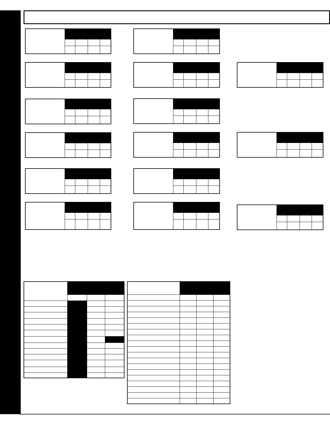
CS USER REPORTING OPTIONS (ADDRESS 0440-0459)
Direct Address Program Mode
USERS 1 " 8 USERS 9 " 16
ADDR U1 U2 U3 U4 U5 U6 U7 U8 ADDR U9 U10 U11 U12 U13 U14 U15 U16
1 2 3 4 5 6 7 8 1 2 3 4 5 6 7 8
Enable Opening Report, Telco 1 0440 0441
Enable Closing Report, Telco 1 0445 0446
Enable Opening Report, Telco 3 0450 0451
Enable Closing Report, Telco 3 0455 0456
Enable Users to Report Opening
and Closings
USERS 17 " 24 USERS 25 " 32
ADDR U17 U18 U19 U20 U21 U22 U23 U24 ADDR U25 U26 U27 U28 U29 U30 U31 U32
1 2 3 4 5 6 7 8 1 2 3 4 5 6 7 8
Enable Opening Report, Telco 1 0442 0443
Enable Closing Report, Telco 1 0447 0448
Enable Opening Report, Telco 3 0452 0453
Enable Closing Report, Telco 3 0457 0458
Enable Users to Report Opening
and Closings
USERS 33 " 36
Enable Users to Report Opening
and Closings
ADDR U33 U34 U35 U36
1 2 3 4 5 6 7 8
Enable Opening Report, Telco 1 0444
Enable Closing Report, Telco 1 0449
Enable Opening Report, Telco 3 0454
Enable Closing Report, Telco 3 0459
User 33 = Auto Arming/Disarming
User 34 = Quickloader Arming/Disarming
User 35 = Easy Arming (Opening not applicable)
User 36 = Keyswitch Arming
NOTE: These opening events will report as the user number
shown. Also, Keyfobs 1-8 (see Easy Menu Program Driven
Mode) will report as Users 25-32, respectively.
CS USER REPORTING OPTIONS: [Default = blank (•) from address 0440-0459]
!1. Select the desired option entering the option number (1-8) for each digit.
!2. At the keypad, enter corresponding option number in address location.
NOTE: Dark shaded data value box shows option not available.
!3. Press U or D to save.

L NAPCO Security Systems X GEM-P1632 Programming Instructions
!
Page 23
Default depends on Easy Menu Question “# OF ZNS IN AREA 1 ENTER # ZONES” and “EZ ZONE DOUBLING? Y/N”. For example, if 32 Zones are used and Zone Doubling
is not enabled, then all 6 Groups will be automatically enabled. If 32 Zones are used and Zone Doubling is enabled, then only Groups 1-4 will be automatically enabled.
NOTE: If “Zone Doubling” (Address 0721) is not enabled, then Zones 1-8 are included in the control panel and Zones 9-32
(Groups 1-6) are EZM Zones. If “Zone Doubling” is enabled, then Zones 1-16 are included in the control panel and Zones 17-32
(Groups 1-4) are EZM Zones (and Groups 5 and 6 must not be used).
EZM GROUP OPTIONS: Up to 6 Groups of 4 Zones each may be programmed
depending on the number of Zones used and which EZM modules are con-
nected. Each Group represents 4 Zones.
!1. Select EZM type from the table shown.
!2. Enter either blank (•) or "1" in corresponding address locations above.
NOTE: Dark shaded data value box shows option not available.
!3. Press U or D to save.
AREA ARMING OPTIONS (ADDRESS 0743 & 0744)
PRIORITY AREA ARMING:
!1. Select option from the table shown.
!2. Enter either blank() or "1" in corresponding address
location.
NOTE: Dark shaded data value box shows option not available.
!3. Press U or D to save.
Direct Address Program Mode
EZM GROUP OPTIONS (ADDRESS 0737-0742)
EZM Group 1
ADDRESS 0737
EZM Group 2
ADDRESS 0738
EZM Group 3
ADDRESS 0739
EZM Group 4
ADDRESS 0740
EZM Group 5
ADDRESS 0741
EZM Group 6
ADDRESS 0742
EZM TYPE
DATA
ENTRIES
OPTION
blank (•) Not used
(No EZM
1 4-Zone EZM
PRIORITY ARMING/AREA 1
DATA ENTRIES OPTION
blank (•) Not Used
Enabled 1
PRIORITY ARMING/AREA 2
DATA ENTRIES OPTION
blank (•) Not Used
Enabled 1
Priority
Arming
Area 1
ADDRESS
0743
[Default = blank (•)]
EZM
GROUP NORMAL DOUBLED
1 9-12 17-20
2 13-16 21-24
3 17-20 25-28
4 21-24 29-32
5 25-28
6 29-32
ZONES COVERED
Priority
Arming
Area 2
ADDRESS
0744
[Default = blank (•)]
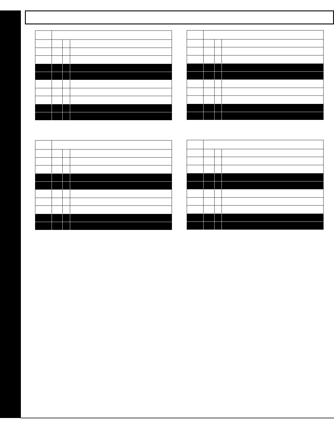
X GEM-P1632 Programming Instructions L NAPCO Security Systems
! Page 24
Direct Address Program Mode
0745 Burglary Output Turns Off upon Disarm
Default Option: Disarming Area 1:
ON 1 Area 1 Burg Output Silenced
OFF 2 Area 2 Burg Output Silenced
3 RESERVED
4 RESERVED
Default Option: Disarming Area 2:
OFF 5 Area 1 Burg Output Silenced
OFF 6 Area 2 Burg Output Silenced
7 RESERVED
8 RESERVED
OUTPUT TURNS OFF UPON DISARM:
Select options for any of the 4 Outputs.
By default, the ability to turn off an output upon disarm is not allowed.
For example, the ability to silence an Area 1 or Area 2 output via an Area 1 keypad is not enabled by default. To enable selected
area output control, enter the number (1,2,5,6) accordingly.
For example, if you wish to grant an Area 1 keypad the ability to turn off an Area 2 PGM2 output, enter "2" in Address 0749.
!Enter digit in address location.
NOTE: Dark shaded data value box shows option not available. Press U or D to save.
0746 Pulsed Burg Output Turns Off upon Disarm
Default Option: Disarming Area 1:
ON 1 Area 1 Pulsed Burg Output Silenced
OFF 2 Area 2 Pulsed Burg Output Silenced
3 RESERVED
4 RESERVED
Default Option: Disarming Area 2:
OFF 5 Area 1 Pulsed Burg Output Silenced
OFF 6 Area 2 Pulsed Burg Output Silenced
7 RESERVED
8 RESERVED
0747 PGM1 Output Turns Off upon Disarm
Default Option: Disarming Area 1:
OFF 1 Area 1 PGM1 Output Silenced
OFF 2 Area 2 PGM1 Output Silenced
3 RESERVED
4 RESERVED
Default Option: Disarming Area 2:
OFF 5 Area 1 PGM1 Output Silenced
OFF 6 Area 2 PGM1 Output Silenced
7 RESERVED
8 RESERVED
0749 PGM2 Output Turns Off upon Disarm
Default Option: Disarming Area 1:
OFF 1 Area 1 PGM2 Output Silenced
OFF 2 Area 2 PGM2 Output Silenced
3 RESERVED
4 RESERVED
Default Option: Disarming Area 2:
OFF 5 Area 1 PGM2 Output Silenced
OFF 6 Area 2 PGM2 Output Silenced
7 RESERVED
8 RESERVED
AREA BELL CONTROL OPTIONS (ADDRESS 0745-0747 & 0749)
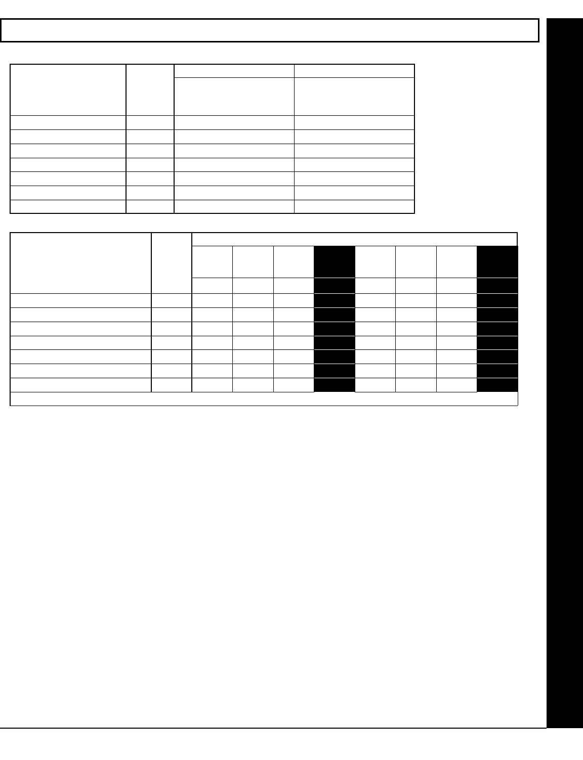
L NAPCO Security Systems X GEM-P1632 Programming Instructions
!
Page 25
Enable Keypad Options
Enable Keypad Options ADDR Keypad
Fire
Keypad
Aux.*
Keypad
Panic RSRVD Ambush Easy
Arming
Panel
Access RSRVD
1 2 3 4 5 6 7 8
Keypad 1 Options 0730
Keypad 2 Options 0731
Keypad 3 Options 0732
Keypad 4 Options 0733
Keypad 5 Options 0734
Keypad 6 Options 0735
Keypad 7 Options 0736
[Default = blank (•) from address 0730-0736] * NOTE: Keypad Aux. is not to be selected for UL Installations.
KEYPAD OPTIONS (ADDRESS 0723-0736 & 1055-1058)
Direct Address Program Mode
KEYPAD OPTIONS (ADDRESS 0723-0736)
Enable Keypad Type
& Activation
Enable Keypad Type Keypad Area Assignment
ADDR
Blank (•) = Burg Keypad
2 = Wizard *
* Not for UL Installations.
Blank (•) = Disabled
1 = Area 1
2 = Area 2
Keypad 1 0723
Keypad 2 0724
Keypad 3 0725
Keypad 4 0726
Keypad 5 0727
Keypad 6 0728
Keypad 7 0729
KEYPAD TYPE: Up to 7 key-
pads may be programmed, if
they are connected.
NOTE: See Keypad Configura-
tion Mode. By default from the
factory, each keypad is config-
ured as number 1.
1. Select keypad type for each
keypad from the tables
shown.
2. Enter data in corresponding
address locations.
3. Press U or D to save.
ENABLE KEYPAD OPTIONS: Select options for any of the 7 keypads.
!1. Select the desired option entering the option number (1-8) for each digit.
!2. At the keypad, enter corresponding option number in address location.
NOTE: Dark shaded data value box shows option not available.
!3. Press U or D to save.

X GEM-P1632 Programming Instructions L NAPCO Security Systems
! Page 26
ZONE OPTIONS - ZONES 1 TO 16 (ADDRESS 0490-0595)
Direct Address Program Mode
ZONES 1 " 8 ZONES 9 " 16
ZONE OPTIONS ADDR Z1 Z2 Z3 Z4 Z5 Z6 Z7 Z8 ADDR Z9 Z10 Z11 Z12 Z13 Z14 Z15 Z16
1 2 3 4 5 6 7 8 1 2 3 4 5 6 7 8
50ms Loop Response (A) 0490
0545
$% Priority 0491 0546
Priority with Bypass 0492 0547
Auto-Bypass 0493 0548
$% Selective Bypass 0494 0549
Keyswitch Arming 0495 0550
Auto-Bypass Re-entry 0496 0551
Pre-Alarm Warning 0497 0552
Never Arm 0498 0553
24-Hour Zone 0499 0554
$% Alarm Output 0500 0555
$ Pulsed Alarm Output 0501 0556
PGM1 Output 0502 0557
PGM2 Output 0503 0558
$ Entry/Exit 1 0504 0559
Entry/Exit 2 0505 0560
$ Exit/Entry Follower 0506 0561
$' Auto Reset 0507 0562
$' Swinger Shutdown 0508 0563
$ Chime 0509 0564
Abort Delay 0510 0565
Power-up Delay 0511 0566
Day Zone Open 0512 0567
Day Zone Short 0513 0568
Alarm on Day Zone 0514 0569
$ Alarm Telco 1 0515 0570
Alarm Restore 1 0516 0571
Trouble Telco 1 0517 0572
Trouble Restore 1 0518 0573
Alarm Telco 3 0519 0574
Alarm Restore 3 0520 0575
Trouble Telco 3 0521 0576
Trouble Restore 3 0522 0577
No EOL Resistor 0523 0578
Trouble on Open 0524 0579
Trouble on Short 0525 0580
$ Zone Area 1 0526 0581
Zone Area 2 0527 0582
Interior (Stay) Bypass 0528 0583
Keypad Sounder on Alarm 0529 0584
$ 2-Wire Smoke Detectors (B) 0530 0585
$ Fire (C) 0531 0586
Fire Alarm Verification (C) 0532 0587
RESERVED 0533 0588
Zone ANDing Group 1 0534 0589
Zone ANDing Group 2 0535 0590
Zone ANDing Group 3 0536 0591
Zone ANDing Group 4 0537 0592
Sensor Watch 0538 0593
RESERVED 0539 0594
Chime 2 0540 0595
$ When the Easy Program Menu is used, these features are enabled by default.
% Enabled when "Enable SIA CP-01 Features?" is activated (Answer "Yes" in the EZ Programming Menu).
' Disabled when "Enable SIA CP-01 Features?" is activated (Answer "Yes" in the EZ Programming Menu). Disable Auto-Reset on non-fire zones for SIA CP-01 installations.
ZONE OPTIONS: Select zone options for any zone.
!1. Select the desired zone option by entering the option number (1-8) for each selected zone.
!2. Enter corresponding option number in address location.
NOTE: Dark shaded data value box shows option not available. Press [Enter] or ON/OFF] to save

L NAPCO Security Systems X GEM-P1632 Programming Instructions
!
Page 27
ZONE OPTIONS - ZONES 17 TO 32 (ADDRESS 0601-0705)
Direct Address Program Mode
ZONES 17 → 24 ZONES 25 → 32
ZONE FEATURES ADDR Z17 Z18 Z19 Z20 Z21 Z22 Z23 Z24 ADDR Z25 Z26 Z27 Z28 Z29 Z30 Z31 Z32
1 2 3 4 5 6 7 8 1 2 3 4 5 6 7 8
$%
Priority 0601
0656
Priority with Bypass 0602 0657
Auto-Bypass 0603 0658
$%
Selective Bypass 0604 0659
Keyswitch Arming 0605 0660
Auto-Bypass Re-entry 0606 0661
Pre-Alarm Warning 0607 0662
Never Arm 0608 0663
24-Hour Zone 0609 0664
$%
Alarm Output 0610 0665
$
Pulsed Alarm Output 0611 0666
PGM1 Output 0612 0667
PGM2 Output 0613 0668
$
Entry/Exit 1 0614 0669
Entry/Exit 2 0615 0670
$
Exit/Entry Follower 0616 0671
$'
Auto Reset 0617 0672
$'
Swinger Shutdown 0618 0673
$
Chime 0619 0674
Abort Delay 0620 0675
Power-up Delay 0621 0676
Day Zone Open 0622 0677
Day Zone Short 0623 0678
Alarm on Day Zone 0624 0679
$
Alarm Telco 1 0625 0680
Alarm Restore 1 0626 0681
Trouble Telco 1 0627 0682
Trouble Restore 1 0628 0683
Alarm Telco 3 0629 0684
Alarm Restore 3 0630 0685
Trouble Telco 3 0631 0686
Trouble Restore 3 0632 0687
No EOL Resistor 0633 0688
Trouble on Open 0634 0689
Trouble on Short 0635 0690
$
Zone Area 1 0636 0691
Zone Area 2 0637 0692
Interior (Stay) Bypass 0638 0693
Keypad Sounder on Alarm 0639 0694
$
Fire (C) 0641 0696
Fire Alarm Verification (C) 0642 0697
Zone ANDing Group 1 0644 0699
Zone ANDing Group 2 0645 0700
Zone ANDing Group 3 0646 0701
Zone ANDing Group 4 0647 0702
Sensor Watch 0648 0703
RESERVED 0649 0704
Chime 2 0650 0705
$ When the Easy Program Menu is used, these features are enabled by default.
% Enabled when "Enable SIA CP-01 Features?" is activated (Answer "Yes" in the EZ Programming Menu).
' Disabled when "Enable SIA CP-01 Features?" is activated (Answer "Yes" in the EZ Programming Menu). Disable Auto-Reset on non-fire zones for SIA CP-01 installations.
NOTES: (A) 50ms Loop Response only available for zones 1-8. If Zone Doubling is enabled, Zones 9-16 will follow the loop response programming for Zones 1-8. For all other Zones,
loop response is determined by jumpers on the GEM-EZM8 and/or keypad configuration on the GEM-RP1CAe2 or GEM-K1CA.
(B) 2-wire Smoke Detectors only available for zones 7 & 8.
(C) If Fire Alarm Verification is selected, then Fire must also be selected.
DEFAULTS: The zone options indicated are automatically set after exiting the Easy Menu Driven Mode.
•Priority, Selective Bypass, Alarm Output, Auto Reset, Swinger Shutdown and Zone Area 1 are enabled for the total number of zones entered in “# OF ZONES IN AREA1 ENTER # ZONES”.
•Alarm Telco 1 is enabled for the zone number(s) entered in “REPORT ALL ZONES TO CENTRAL ZONES? Y/N”.
•Entry/Exit 1 and Chime are enabled for the zone number(s) entered in “ENTRY/EXIT ZONES ENTER ZONE #”.
•Exit/Entry Follower and Interior Bypass are enabled for the zone number(s) entered in “INTERIOR ZONES ENTER ZONE #”.
•Pulse Alarm Output is enabled for the zone number(s) entered in “FIRE ZONES ENTER ZONE #” or “2-WIRE FIRE ZNS ENTER ZONE #”.
•Fire is enabled for the zone number(s) entered in “FIRE ZONES ENTER ZONE #”.
•2-Wire Smoke Detector is enabled for the zone number(s) entered in “2-WIRE FIRE ZNS ENTER ZONE #”.
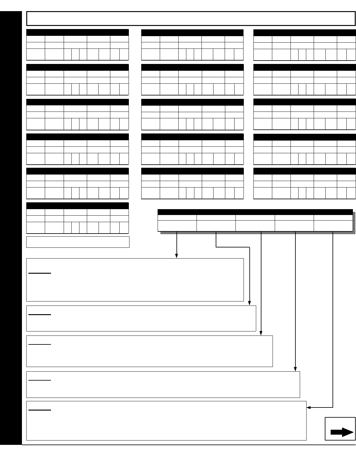
X GEM-P1632 Programming Instructions L NAPCO Security Systems
! Page 28
STEP 4
EVENT ID CODES: Each relay event can be assigned any of the available event IDs from Table 4.
!Select 2-digit Event ID from Table 4 (on next page); enter in corresponding address locations (left and right digit).
STEP 5
RELAY EVENT CONDITION OPTIONS: Each relay event can be assigned an alarm type; and an activation condition; also,
select a timeout type for each. Enter 5A in left area, enter 5B in right area.
!5A. Select Alarm Type and Timeout Type from Table 5A (on next page); enter in corresponding left address location.
!5B. Select Activation Conditions from Table 5B (on next page); enter in corresponding right address location.
STEP 2
AREA OPTIONS: Each relay event can be assigned to Area 1, Area 2 or both Area 1 and Area 2.
!Select the area from Table 2 (on next page); enter in corresponding address location.
EXTERNAL RELAY CONTROL (ADDRESS 0750-0829)
ADDRESS 0750-0754 (RELAY EVENT 1)
0750 0751 0752 0753 0754
RELAY # AREA TIMEOUT EVENT ID COND.
To program, follow the 5 steps below.
STEP 1
RELAY # OPTIONS: The GEM-P1632 supports 8 external relays from Relay Module RM3008.
Multiple events may be "mapped" to each relay, up to a maximum of 16
events.
!Select the relay number from Table 1 (next page); enter in corresponding address location.
Continued
Direct Address Program Mode
STEP 3
TIMEOUTS: Each relay event can be assigned a timeout depending on Alarm Type option.
!If Alarm Type is selected for timeout in minutes or seconds, enter the 3-digit timeout duration in correspond-
ing address location. To choose seconds or minutes, see step 5A below. 254 is maximum entry.
[Default = blank (•) from address 0750-0829].
RELAY EVENT OPTIONS
RELAY # AREA TIMEOUT EVENT ID COND.
See
Step 1 below
See
Step 2 below
See
Step 3 below
See
Step 4 below
See
Step 5 below
ADDRESS 0755-0759 (RELAY EVENT 2)
0755 0756 0757 0758 0759
RELAY # AREA TIMEOUT EVENT ID COND.
ADDRESS 0760-0764 (RELAY EVENT 3)
0760 0761 0762 0763 0764
RELAY # AREA TIMEOUT EVENT ID COND.
ADDRESS 0825-0829 (RELAY EVENT 16)
0825 0826 0827 0828 0829
RELAY # AREA TIMEOUT EVENT ID COND.
ADDRESS 0765-0769 (RELAY EVENT 4)
0765 0766 0767 0768 0769
RELAY # AREA TIMEOUT EVENT ID COND.
ADDRESS 0770-0774 (RELAY EVENT 5)
0770 0771 0772 0773 0774
RELAY # AREA TIMEOUT EVENT ID COND.
ADDRESS 0775-0779 (RELAY EVENT 6)
0775 0776 0777 0778 0779
RELAY # AREA TIMEOUT EVENT ID COND.
ADDRESS 0810-0814 (RELAY EVENT 13)
0810 0811 0812 0813 0814
RELAY # AREA TIMEOUT EVENT ID COND.
ADDRESS 0805-0809 (RELAY EVENT 12)
0805 0806 0807 0808 0809
RELAY # AREA TIMEOUT EVENT ID COND.
ADDRESS 0800-0804 (RELAY EVENT 11)
0800 0801 0802 0803 0804
RELAY # AREA TIMEOUT EVENT ID COND.
ADDRESS 0795-0799 (RELAY EVENT 10)
0795 0796 0797 0798 0799
RELAY # AREA TIMEOUT EVENT ID COND.
ADDRESS 0790-0794 (RELAY EVENT 9)
0790 0791 0792 0793 0794
RELAY # AREA TIMEOUT EVENT ID COND.
ADDRESS 0785-0789 (RELAY EVENT 8)
0785 0786 0787 0788 0789
RELAY # AREA TIMEOUT EVENT ID COND.
ADDRESS 0780-0784 (RELAY EVENT 7)
0780 0781 0782 0783 0784
RELAY # AREA TIMEOUT EVENT ID COND.
ADDRESS 0820-0824 (RELAY EVENT 15)
0820 0821 0822 0823 0824
RELAY # AREA TIMEOUT EVENT ID COND.
ADDRESS 0815-0819 (RELAY EVENT 14)
0815 0816 0817 0818 0819
RELAY # AREA TIMEOUT EVENT ID COND.
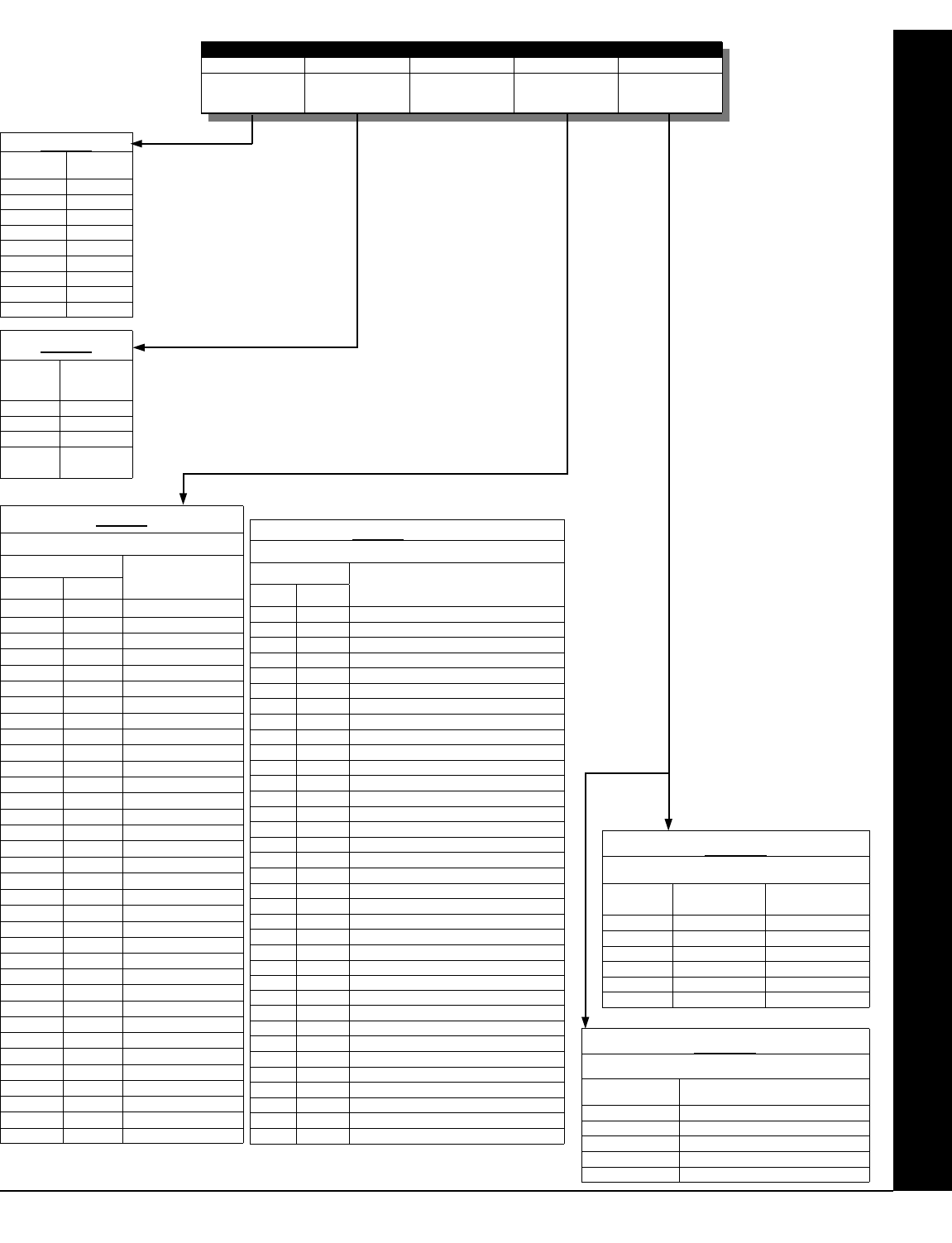
L NAPCO Security Systems X GEM-P1632 Programming Instructions
!
Page 29
* NOTE: Keypad Auxiliary is not to be selected for UL Installations.
NOTE: Keypad Tamper must be enabled in UL installations.
Table 4
EVENT ID CODES
DATA ENTRIES OPTION
LEFT RIGHT
blank (•) blank (•) Area 1 Arm
blank (•) 1 Area 2 Arm
blank (•) 8 Zone 1
blank (•) 9 Zone 2
blank (•) 0 Zone 3
blank (•) B Zone 4
blank (•) C Zone 5
blank (•) D Zone 6
blank (•) E Zone 7
blank (•) F Zone 8
1 blank (•) Zone 9
1 1 Zone 10
1 2 Zone 11
1 3 Zone 12
1 4 Zone 13
1 5 Zone 14
1 6 Zone 15
1 7 Zone 16
1 8 Zone 17
1 9 Zone 18
1 0 Zone 19
1 B Zone 20
1 C Zone 21
1 D Zone 22
1 E Zone 23
1 F Zone 24
2 blank (•) Zone 25
2 1 Zone 26
2 2 Zone 27
2 3 Zone 28
2 4 Zone 29
2 5 Zone 30
2 6 Zone 31
2 7 Zone 32
Table 4 (cont'd)
EVENT ID CODES
DATA ENTRIES OPTION
LEFT RIGHT
3 blank (•) Area 1 KP Ambush
3 1 Area 1 KP Panic
3 2 Area 1 KP Fire
3 3 Area 1 KP Aux *
3 4 Area 1 KP Tamper
3 5 Area 1 Fail to Open
3 6 Area 1 Fail to Close
3 8 Area 2 KP Ambush
3 9 Area 2 KP Panic
3 0 Area 2 KP Fire
3 B Area 2 KP Aux *
3 C Area 2 KP Tamper
3 D Area 2 Fail to Open
3 E Area 2 Fail to Close
4 blank (•) Test Timer
4 3 Memory Fail
4 4 Low Battery
4 5 AC Fail
4 6 EZM Tamper
4 7 Alarm Supervisory
4 D RF Receiver Trouble (Tamper/Fail)
4 E Wireless TX Tamper
4 F Wireless TX Trouble (LB/Supervisory)
C 8 Area 1 Arming AWAY
C 9 Area 2 Arming AWAY
D blank (•) Keypad Fail
D 1 EZM Fail
D 2 Quickloader Device Control
D 5 General System Alarm
D 8 Area 1 General System Alarm
D 9 Area 2 General System Alarm
F blank (•) Relay Control Group 1
F 1 Relay Control Group 2
F 8 Entry Relay Area 1
F 9 Entry Relay Area 2
LEFT DATA
ENTRIES ALARM TYPE TIMEOUT TYPE
blank (•) Burglary Minutes
1 Fire Minutes
4 Day Zone Minutes
8 Burglary Seconds
9 Fire Seconds
C Day Zone Seconds
Table 5A
RELAY EVENT
ALARM TYPE OPTIONS
RIGHT DATA
ENTRIES
OPTIONS
1 Alarm
2 Restore
3 Trouble
4 Trouble Restore
5 Follow Zone
Table 5B
RELAY EVENT ACTIVATION CONDITIONS
DATA
ENTRY
RELAY #
blank (•) NONE
1 1
2 2
3 3
4 4
5 5
6 6
7 7
8 8
Table 1
DATA
ENTRY
TURN OFF
ON AREA
DISARM
blank (•) NONE
1 Area 1
2 Area 2
3 Area 1 &
Area 2
Table 2
RELAY EVENT OPTIONS
RELAY # AREA TIMEOUT EVENT ID COND.
See
Table 1 below
See
Table 2 below
Enter a Time
period, in seconds
or minutes
See
Table 4 below
See
Tables 5A & 5B
below
Direct Address Program Mode
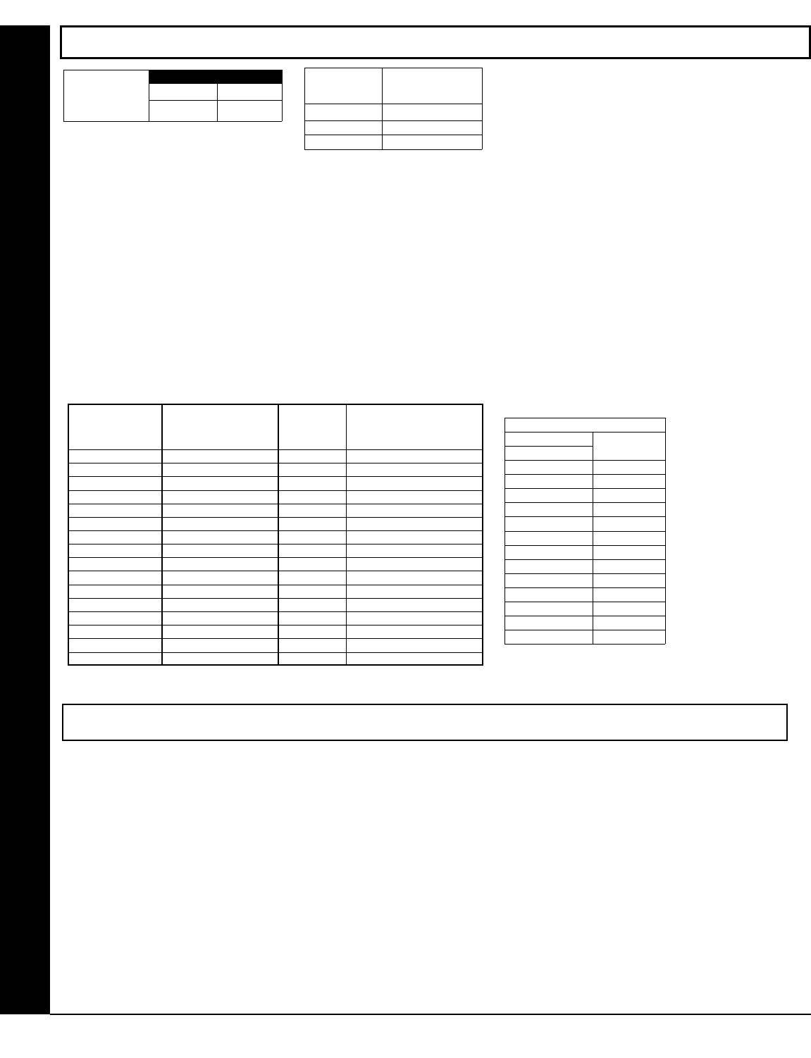
X GEM-P1632 Programming Instructions L NAPCO Security Systems
! Page 30
RF RECEIVER & SUPERVISORY TIMER OPTIONS (ADDRESS 1038-1053 & 1180)
Direct Address Program Mode
RF RECEIVERS: Up to 2 RF Receivers may be pro-
grammed. NOTE: This adds wireless capability to the
system, increasing up to 16 the number of zones.
!1. Select the number of receivers from the table
shown.
!2. Enter number in address location shown.
!3. Press U or D to save.
RF SUPERVISORY TIMERS: RF Supervisory Timers may be programmed for each type of trans-
mitter used. A transmitter will send a transmission every time it is tripped, when there is NO activity,
the transmitter sends a status transmission about once an hour. If the receiver does NOT receive
ANY signal (a trip or a status) from a transmitter in the time specified for transmitter type, a system
trouble “WIRELESS TROUBLE/E04-NN SERVICE” will be displayed at the keypad.
!1. Select timer delay from the table shown. Timers are programmed in increments of 30 minutes
each. Valid entries are [3] through [F] (90 minutes-450 minutes).
!2. Enter in corresponding address locations below.
!3. Press U or D to save.
NOTE: These timers apply only to Supervised RF Transmitters (see RF Transmitters in Easy Menu Driven Mode Programming).
DATA ENTRIES
blank (•) None
1 1
2 2
RF RECEIVER(S)
Default for Number of Receivers
depends on Easy Menu Question for
RF Transmitters.
ADDRESS 1180
LEFT DIGIT
Number of RF
Receivers RIGHT DIGIT
blank (•)
[Default = blank (•) from address 1046-1053]. Default = 8 (240 minutes)
RF SUPERVISORY
TIMER RF TRANSMITTER
RF SUPERVISORY DELAY
TIME (Select timer delay
from the table at right)
Type 0 Window/Door, 2 Pt. 1038
Type 1 Window/Door, 2 Pt. 1039
Type 2 Window/Door, 2 Pt. 1040
Type 3 Window/Door, 2 Pt. 1041
Type 4 Window/Door, 4 Pt. 1042
Type 5 PIR 1043
Type 6 PIR 1044
Type 7 Smoke Detector 1045
Type 8 Smoke Detector 1046
Type 9 Keyfob 1047
Type A Dual Tech. 1048
Type B Keyfob 1049
Type C Window/Door, 4 Pt. 1050
Type D PIR 1051
Type E Smoke Detector 1052
Type F Napco Glass Break 1053
ADDR RF SUPERVISORY TIMERS
DATA ENTRIES DELAY
3 90 min.
4 120 min.
5 150 min.
6 180 min.
7 210 min.
8 240 min.
9 270 min.
0 300 min.
B 330 min.
C 360 min.
D 390 min.
E 420 min.
450 min. F
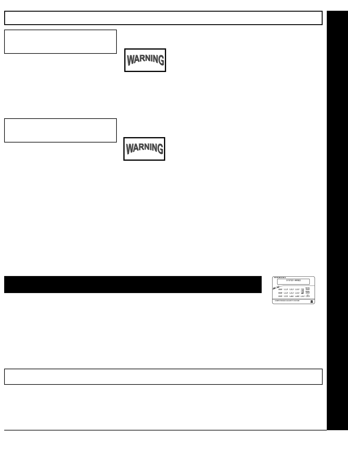
L NAPCO Security Systems X GEM-P1632 Programming Instructions
!
Page 31
CLEAR PROGRAM OPTIONS (ADDRESS 1197 & 1198)
Clear Dealer Program (Erases Dealer Program)
This erases the dealer program. Use this feature to start
a customized default program. Program Data and Sys-
tem Status Memory is erased where Scheduled Data and
Zone Descriptions are maintained.
Access address 1197, then press U. Data entry is not allowed.
NOTE: Enter Easy Menu Driven Program Mode to program system
again.
Cold Start (Erases Entire Program)
This erases the entire program including Dealer Program
by erasing Program Data, Zone Description Data and
System Status Data (similar to a new panel).
Access address 1198, then press U. Data entry is not allowed.
NOTE: Some features (schedules) can only be programmed again with
the Downloading Software.
1197 XX H
1198 XX H
Direct Address Program Mode--User Program Mode
USER PROGRAM MODE
PRELIMINARY INFORMATION
The User Program Mode is covered in detail in the operating instructions for the keypad in use.
!Only Keypad #1 may be used for programming, however this keypad may be located in any area.
!The Program Mode cannot be accessed while the communicator is transmitting except during the first three minutes after power-
up.
!After entering codes or data, press the save U button. Data will not be stored into memory unless this button is pressed.
!If the keypad is in the Program Mode and no activity is detected for longer than 4 minutes, a steady tone will sound.
!Press the C button to silence the sounder and exit the User Program Mode.
If a GEM-RP2ASe2/GEM-K2AS keypad is used, configure address jumpers as Keypad #1 (See WI1148).
NOTE: For ease of programming, it is recommended that a GEM K1CA (or GEM-RP1CAe2) be used as Keypad #1. A new GEM-
K1CA and a new GEM-RP1CAe2 are automatically configured as Keypad #1. See Keypad Configuration Mode.
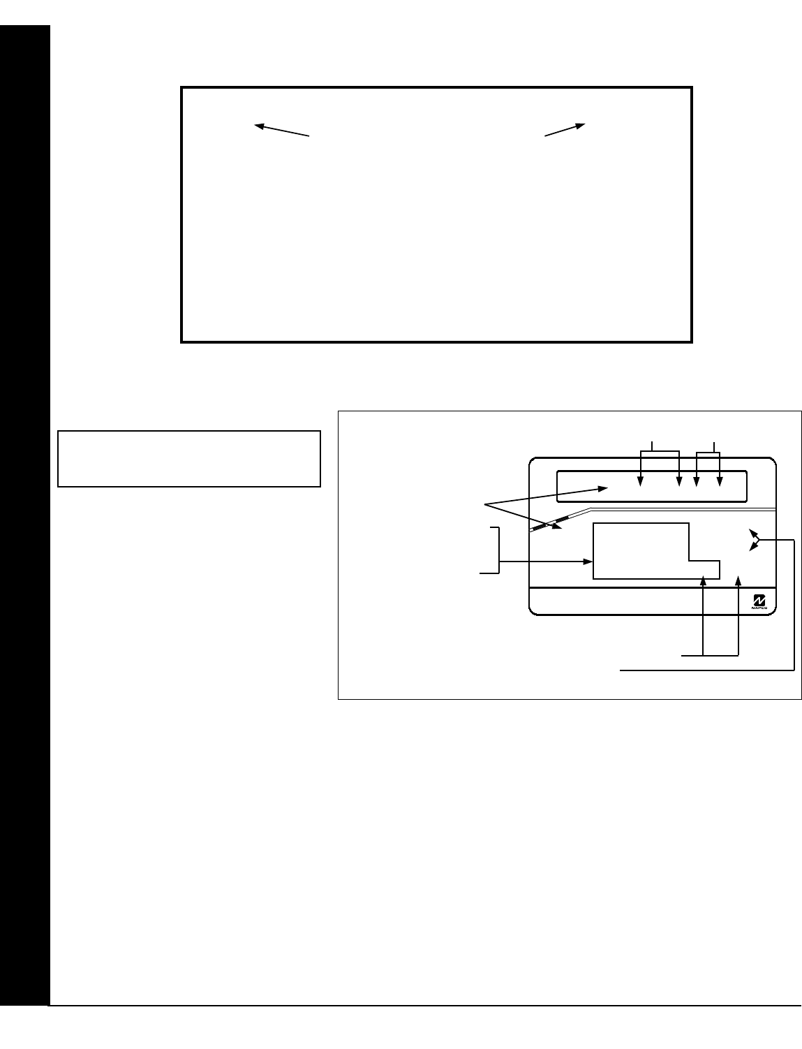
X GEM-P1632 Programming Instructions L NAPCO Security Systems
! Page 32
ACCESSING USER PROGRAM MODE
1. Press EEEEEE R
2. Press Q Until “ACTIVATE PROGRAM Y/N” appears on LCD screen.
3. Press P To Enter User Program Mode
4. Press C To Exit User Program Mode when finished
New Panel (Default User Code = 123)
Existing Panel (Any Code with User Program Option Enabled)
USER CODES
Up to 32 User Codes may be programmed.
NOTE: In this mode, only the code is pro-
grammable; the accompanying Area Options
must be programmed in the Dealer Program
Mode (see page 8).
!Use the A button to place the cursor
over the User Number.
!Enter a User Number (01–8) using the
number buttons. The cursor will then
advance to the User Code and read the
existing code, if any.
!Enter the new User Code using the number buttons (0-9). If an old code is displayed, program over it. To erase the digit at the
cursor, press G 0 button.
!Press the U button to save the code in memory.
!Repeat this procedure for each user. To proceed to Zone-Description programming, press the NEXT button or the PRIOR but-
ton.
GEM-K1CAe2 Keypad (Direct Entry)
Enter user code
U01 123 - 9-
User Program Mode
Programming User Codes with GEM-K1CAe2 Keypad
To Program User Codes
1. Set Cursor Position using the
R button.
2. Enter 2-digit User Number (01-
32) directly using number but-
tons (0-9).
3. Enter Code (1-6 digits) directly
using number buttons (0-9).
4. Press the U button to save
each code.
NOTE: Press G 0 button to clear character at cursor.
To continue press P or Q button.
GEMINI
Enter user code
U01 123 - -
ARMED
COMPUTERIZED SECURITY SYSTEM
STATUS
R 1 2 3
B 4 5 6
C 7 8 9 0
U
NEXT/YES
P
PRIOR/NO
Q
AREA
G
User Code NOT USED
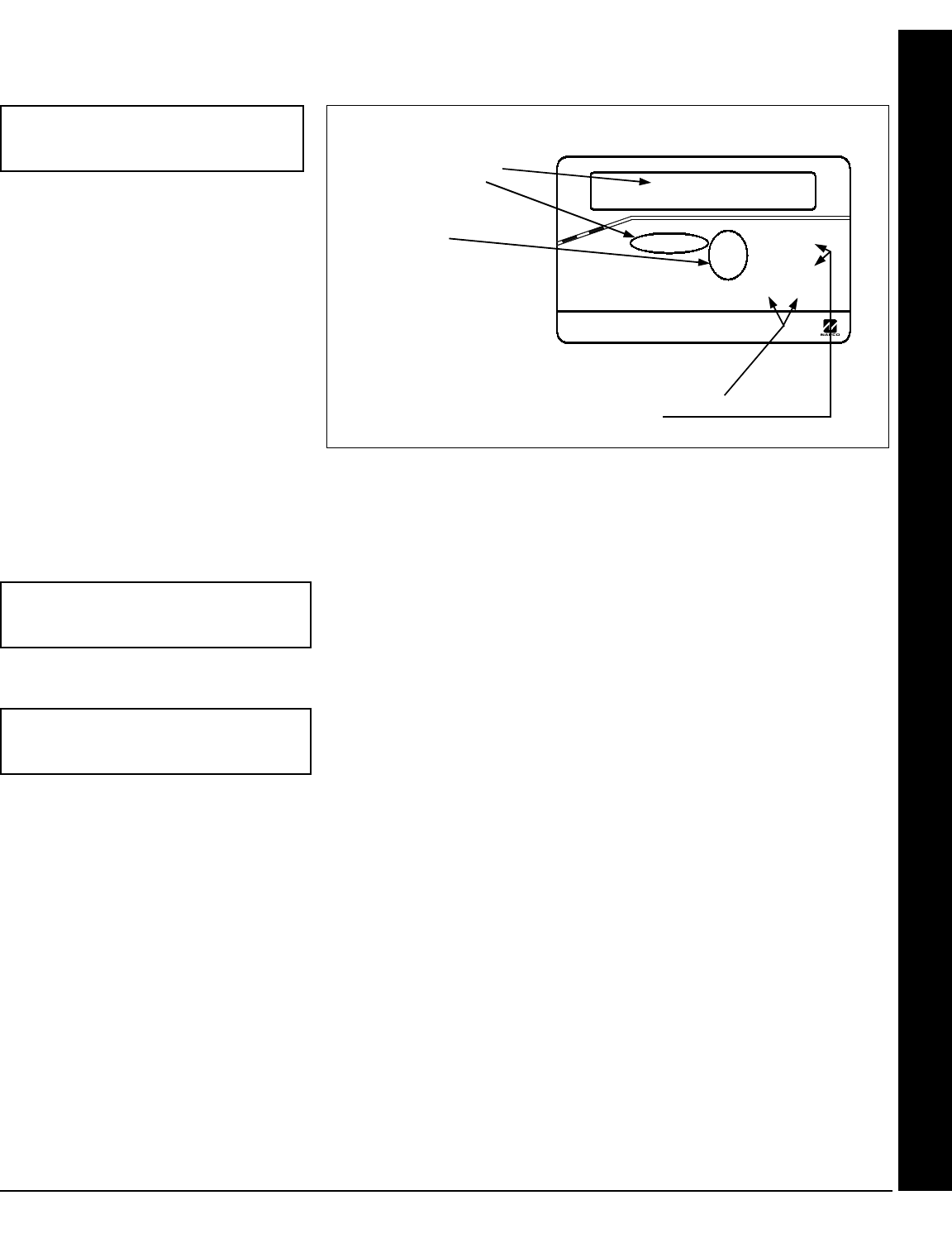
L NAPCO Security Systems X GEM-P1632 Programming Instructions
!
Page 33
(Direct Entry)
ZONE DESCRIPTIONS (GEM-RP1CAE2 / GEM-K1CA KEYPADS)
Enter an identifying description for each
zone. Buttons 1 and 2 set the
cursor position; buttons 3 and 6
scroll numbers, letters, punctuation marks,
etc.
!Position the cursor over the displayed
Zone Number (i.e., “01”) using buttons
1 and 2.
!Change the Zone Number using buttons
3 and 6.
!Position the cursor over the first
character of the description field.
Advancing the cursor between
characters, program a description of up
to two lines for the new zone using
buttons 3 and 6.
Press U to save. Advance to the next zone as in Steps 1 and 2 above and repeat this procedure until all zones have
been programmed. After programming the user codes, press the NEXT button to proceed.
Enter Date (Press the (R) button to set cursor.)
Enter the current date in the format MM/DD/YY, where MM = the month
(01–12); DD=the day (01–31); and YY=the year. Press U to save. Press
NEXT button to proceed.
Enter Time (Press the (R) button to set cursor.)
Enter the current time in the format HH:MMA/P, where HH=hours (01–12);
MM=minutes (00–59). Select Am or Pm by pressing any number button,
then press U once again to save.
NOTE: To enter the date and time, GEM-RP1CAe2/GEM-K1CA keypad (version 6 or greater) must be used and
“Enable Keypad Time/Date Display” (Address 0718) must be enabled.
01-
(Direct Entry)
Enter Date
( / / )
(Direct Entry)
Enter Time
( : )
Programming Zone Descriptions
To Program Zone Descriptions
1. Set the Cursor Position using
buttons 1 and 2.
2. Select characters for zone
description using buttons
3 and 6.
3. Press the U button to save
each descriptor.
NOTE: Press G 0 button to clear character at cursor.
To continue press P or Q button.
GEMINI
01-
ARMED
COMPUTERIZED SECURITY SYSTEM
STATUS
R 1 2 3
B 4 5 6
C 7 8 9 0
U
NEXT/YES
P
PRIOR/NO
Q
AREA
G
User Program Mode
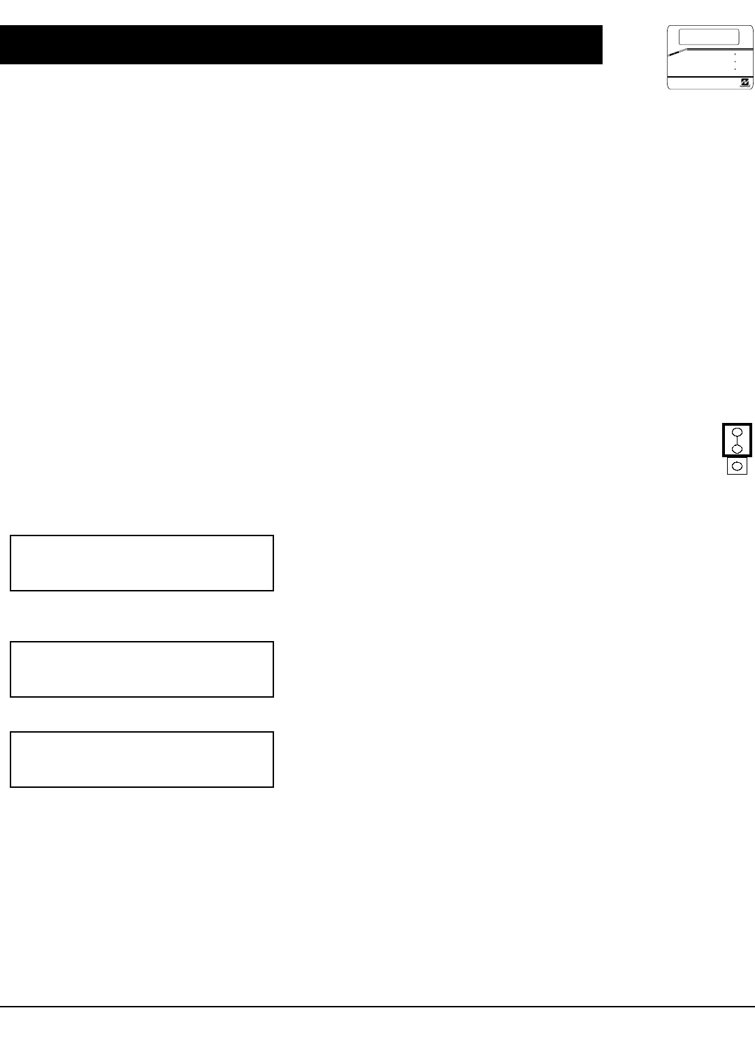
X GEM-P1632 Programming Instructions L NAPCO Security Systems
! Page 34
KEYPAD CONFIGURATION MODE
This section will focus on configuring the GEM-RP1CAe2/GEM-K1CA Keypads. If there is more than one keypad in the system, only
Keypad No. 1 may be used for programming.
KEYPAD INSTALLATION
Several types of keypads may be used with the GEM-P1632: the GEM-RP1CAe2/GEM-K1CA, the GEM-RP2ASe2/GEM-K2AS, the
GEM-RP3DGTL/GEM-K3DGTL, and the GEM-RP4RFC/GEM-K4RF series (see WI1148). Each must be assigned an address num-
ber (1–7) and each requires its own configuration procedure (see CONFIGURING THE KEYPADS, which follows, and DIRECT AD-
DRESS KEYPAD AREA OPTIONS). At least 1 keypad must be used; only 1 is required for a single-area Commercial Burglary instal-
lation.
GEM-RP1CAe2/GEM-K1CA - is a 2-line combination fire/burglary/access keypad capable of supporting 4 EZM zones and a
PGM output. The GEM-RP1CAe2 or GEM-K1CA is recommended for use as Keypad #1. See "Important Note" on page
2 for more information regarding the buttons on the GEM-RP1CAe2/GEM-K1CA keypads.
CONFIGURING THE KEYPADS
A total of up to 7 keypads may be connected to the panel. GEM-RP1CAe2/GEM-K1CA, GEM-RP2ASe2/GEM-K2AS, GEM-
RP3DGTL/GEM-K3DGTL, and GEM-RP4RFC/GEM-K4RF series keypads may be intermixed but require different configuration pro-
cedures, as described below and in WI1148.
Configuring the GEM-RP1CAe2/GEM-K1CA Keypad
Each GEM-RP1CAe2/GEM-K1CA keypad must be configured for (a) keypad tactile beep; (b) entry sounder; (c) keypad address; (d)
compatibility number; (e) EZM address; and (f) zone response.
To enter the Keypad Configuration Mode:
1. Move jumper JP1 (located in the center of the control panel board) from Pins 1-2 (top two) to Pins 2-3 (bottom
two). NOTE: See Wiring Diagram on page 48.
2. After about 15 seconds, the display will read “XX OUT OF SYSTEM”, where XX indicates the keypad address.
3. Press 11123 R and proceed as follows. (Repeat the following procedure for all keypads).
Keypad Tactile Beep
Upon entering the Keypad Configuration Mode, “KEYPAD BEEP ON” will be displayed,
indicating that the tactile beep, which sounds when any button is pressed, is on.
To turn off the tactile beep, press the U button (the U button will toggle the tac-
tile beep on and off). Press R to continue or press C to exit.
Entry Sounder
To turn off the keypad entry sounder during entry time, press U (the U button
will toggle the entry sounder on and off). Press R to continue or press
C to exit.
Keypad Address
If more than one keypad is installed, each must be assigned a unique keypad
address (that is, no two keypads may be numbered alike):
!Keypads must be numbered consecutively (missing numbers are not permitted)
!Only Keypad No. 1 may be used for programming.
To assign the keypad number, proceed as follows:
1. Enter the assigned keypad number 01–07, then press U to save. A valid
number will be acknowledged by a short beep; an invalid number will be re-
jected by a long beep.
2. Press R to continue or press C to exit.
Keypad Beep
ON
NORMAL
KEYPAD
CONFIGURE
R
COMPUTERIZED SECURITY SYSTEM
GEMINI
ARMED
STATUS
SYSTEM ARMED
01/01/97 12:00AM
12
4
3
56
7890
A
B
C
DE
F
G
NEXT/YES
PRIOR/NO
AREA
# OF ZONES IN AREA 1
ENTER # ZONES X X
# OF ZONES IN AREA
ENTER # ZONES XX
Entry Sounder
ON
Keypad Address
01

L NAPCO Security Systems X GEM-P1632 Programming Instructions
!
Page 35
Compatibility Number (Not Applicable)
THIS FEATURE IS NOT COMPATIBLE WITH THE GEM-P1632 CONTROL
PANEL.
Press the R button to continue or press the C button to exit.
EZM Address
The keypad's internal EZM (Expansion Zone Module) may be utilized to
provide four additional wired zones. Whether used alone or in conjunction
with optional GEM-EZM series modules or other keypad EZMs, it must be
assigned a unique address (or Group number, see Keypad Programming
Workbook) similar to its keypad address. If no other EZMs are to be used,
designate the keypad as Group “01” at the “EZM ADDRESS 00” display. In multiple-EZM systems, enter an assigned
group number “01” through “06”. (Each EZM must have a unique assigned group number, starting with “01” and pro-
ceeding consecutively.) Press the R button to continue or press the C button to exit.
Zone Response
The normal loop response of each keypad expansion zone is 750mS, how-
ever the response time of any zone can be reduced to 50mS as follows.
1. Of the following, circle the number(s) in parentheses associated with the
zone(s) to be changed: Zone 1=(1); Zone 2=(2); Zone 3=(4); Zone 4=(8)
2. Add up the circled numbers.
3. At the keypad, enter the sum as a two-digit number “01” through “15” on the display, then press U.
Example. Change Zones 2, 3 and 4 to 50mS response.
1. Circle numbers for Zones 2, 3 and 4: (2), (4) and (8).
2. Add up the circled numbers: 2 + 4 + 8 = 14.
3. Enter “14” at the keypad, then press the U button.
Press the R button to continue or press the C button to exit.
Program Control Message (Not Applicable)
THIS FEATURE IS NOT COMPATIBLE WITH THE GEM-P1632 CON-
TROL PANEL.
Press the R button to continue (the display will loop back through se-
lections, for changes) or press the C button to exit the Keypad Con-
figuration Mode (display will read “01 OUT OF SYSTEM”). Then replace Jumper JP1 across Pins 1–2 (top two).
New
Compat # 0000
EZM Address
01
Zone Response
00
Program Control
Message # ?
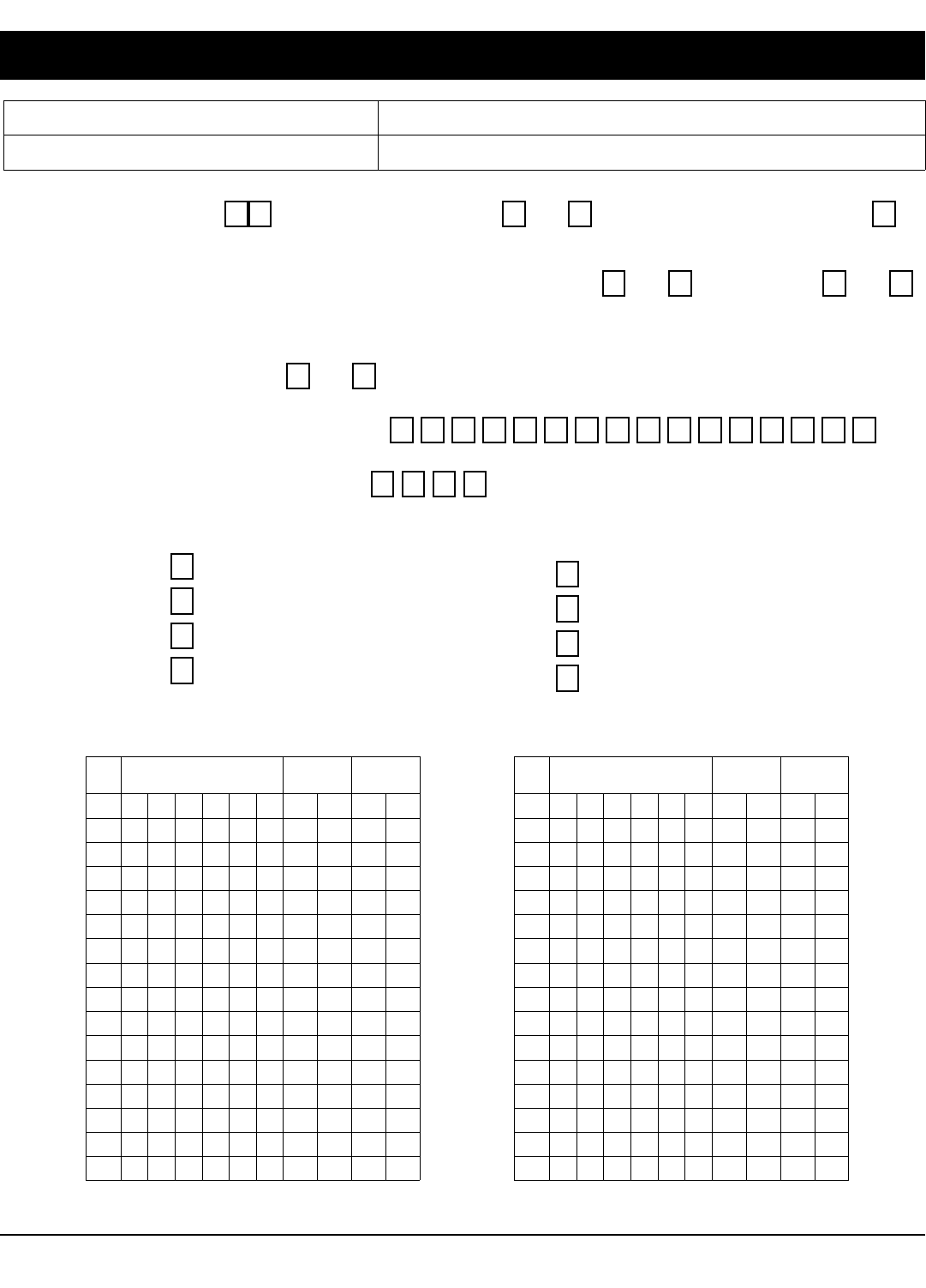
X GEM-P1632 Programming Instructions L NAPCO Security Systems
! Page 36
EASY MENU PROGRAMMING WORKSHEET - 1 OF 3
Name: Address:
Account Number: Installer:
Zone Doubling?: Yes No Area 1: # of Keypads (1-8) =
Area 1: # of Zones (1-32) =
NOTE: Area 2 Zones and Keypads are selected in Direct Address Mode. See Zone Options and Keypad Options.
Enter Fire Zones (1-32): __________ Yes No
2-Wire Fire Zones?: Zone 7 Yes No
Zone 8
Enter Entry/Exit Zones (1-32): __________ Enter Interior Zones (1-32): __________
Report all Zones to Central?: Yes No
Central Station Receiver 1 Telephone Number:
Central Station Receiver 1 Account Number:
Central Station Receiver 1 Format:
blank (•) = Ademco Slow, Silent Knight Slow
2 = Radionics Fast
3 = Silent Knight Fast
4 = Radionics, DCI, Franklin Slow
5 = Universal High Speed
B = SIA
C = Ademco Point ID
E = Pager
User Codes:
USER
#
CODE
(up to 6 digits)
AREA 1
OPTIONS
1
2
3
4
5
6
7
8
9
10
11
12
13
14
15
16
AREA 2
OPTIONS
USER
#
CODE
(up to 6 digits)
AREA 1
OPTIONS
17
18
19
20
21
22
23
24
25
26
27
28
29
30
31
32
AREA 2
OPTIONS
L NAPCO Security Systems X GEM-P1632 Programming Instructions
!
Page 37
EASY MENU PROGRAMMING WORKSHEET - 2 OF 3
XMTR
#
ZONE
#
CHECK
SUM
POINT
#
1
2
3
4
5
6
7
8
9
10
11
12
13
14
15
16
RF ID
(printed on xmtr box)
RF Transmitter Points:
XMTR
#
ZONE
#
CHECK
SUM
POINT
#
17
18
19
20
21
22
23
24
25
26
27
28
29
30
31
32
RF ID
(printed on xmtr box)
Key Fob Transmitters:
KEY FOB # Area CHECK
SUM
OPTION
1
OPTION
2
1
2
3
4
5
6
7
8
RF ID
(printed on xmtr box)

X GEM-P1632 Programming Instructions L NAPCO Security Systems
! Page 38
EASY MENU PROGRAMMING WORKSHEET - 3 OF 3
Zone Descriptions (GEM-RP1CAe2 Keypads Only):
ZN
#
1
2
3
4
5
6
7
8
9
10
11
12
13
14
15
16
17
18
19
20
21
22
23
24
25
26
27
28
29
30
31
32
1 2 3 4 5 6 7 8 9 10 11 12 13 14 15 16 17 18 19 20 21 22 23 24 25 26 27 28 29
CHARACTERS AVAILABLE (See below)
Dealer Code:
Characters Available for Zone Descriptions
! @ # $ % ^ & * ( ) _ + ! ¦ | { } [ ] ` , . < > ?
1 2 3 4 5 6 7 8 9 0
a b c e d f g h i j k l m n o p q r s t u v w x y z
A B C D E F G H I J K L M N O P Q R S T U V W X Y

L NAPCO Security Systems X GEM-P1632 Programming Instructions
!
Page 39
ALPHABETICAL INDEX
PROGRAMMING OPTION PROGRAM MODE ADDRESS LOCATION PAGE
24-Hour Zone (Enable Zone) Direct Address 0499, 0554, 0609, 0664 26-27
3/1 with Extended Restores Direct Address 0171, 0193 & 0215 19
50ms Loop Response (A) (Enable Zone) Direct Address 0490 26
Abort Delay (Enable Zone) Direct Address 0510, 0565, 0620, 0675 26-27
Abort Delay (Time) Direct Address 0715 15
Abort Delay Limit Enable Direct Address 1062 18
AC Fail Report Delay (Time) Direct Address 0717 15
Access Control on PGM2 Output Direct Address 0719 18
Alarm on Day Zone (Enable Zone) Direct Address 0514, 0569, 0624, 0679 26-27
Alarm Output (Enable Zone) Direct Address 0500, 0555, 0610, 0665 26-27
Alarm Output Timeout Direct Address 0712 16
Alarm Restore 1 (Enable Zone) Direct Address 0516, 0571, 0626, 0681 26-27
Alarm Restore 3 (Enable Zone) Direct Address 0520, 0575, 0630, 0685 26-27
Alarm Telco 1 (Enable Zone) Direct Address 0515, 0570, 0625, 0680 26-27
Alarm Telco 3 (Enable Zone) Direct Address 0519, 0574, 0629, 0684 26-27
AREA (PRIORITY) ARMING OPTIONS Direct Addresses 0743 & 0744 23
Area Bell Control Options Direct Address 745-747, 749 24
Auto Bell Test on Arming Direct Address 0719 18
Auto Reset (Enable Zone) Direct Address 0507, 0562, 0617, 0672 26-27
Auto Reset after Burglary Output Timeout Direct Address 0719 18
Auto-Bypass (Enable Zone) Direct Address 0493, 0548, 0603, 0658 26-27
Auto-Bypass Re-entry (Enable Zone) Direct Address 0496, 0551, 0606, 0661 26-27
Automatic Interior Bypass/Easy Exit Direct Address 0722 18
Backup Reporting on Telco 2 Direct Address 0394 21
Burglary Output Turns Off upon Disarm Direct Address 0745 24
Callback Telephone Number Direct Address 0236-0255 16
Cancel Next Test Timer on any Report Direct Address 0394 21
Cancel Report Code Direct Address 0330 20
Change Pulse Output to Temporal Output Direct Address 0720 18
Chime (Enable Zone) Direct Address 0509, 0564, 0619, 0674 26-27
Chime 2 (Enable Zone) Direct Address 0540, 0595, 0650, 0705 26-27
Chime Timeout Direct Address 0716 15
Chirp Output on Keyfob Arm/Disarm Direct Address 0720 18
Clear Dealer Program Direct Address 1197 31
Closing Report Only on Conditional Close Direct Address 0718 18
Cold Start Direct Address 1198 31
CS AREA & SYSTEM REPORTING OPTIONS Direct Addresses 0391, 0392 & 0394 21
CS Receiver 1, 2 & 3 Formats Direct Address 0170, 0192 & 0214 19
CS Receiver 1, 2 & 3 Telephone Numbers Direct Address 0172-0191, 0194-0213 & 0216-0235 19
CS RECEIVER OPTIONS Direct Addresses 0170-0191, 0192-0213, 0214-0235 19
CS SUBSCRIBER ID & SYSTEM REPORTING OPTIONS Direct Addresses 0259-0350 20
CS SYSTEM REPORTING CODES Direct Addresses 0319-0332, 0333-0350 20
CS Telco 1, 2 & 3 Subscriber Event ID Numbers (Area 1) Direct Address 0227-0270, 0287-0290 & 0307-0310 20
CS Telco 1, 2 & 3 Subscriber Event ID Numbers (Area 2) Direct Address 0271-0274, 0291-0294 & 0311-0314 20
CS Telco 1, 2 & 3 Subscriber Event ID Numbers (System) Direct Address 0275-0278, 0295-0298 & 0315-0318 20
CS Telco 1, 2 & 3 Subscriber Opening/Closing ID Numbers (Area 1) Direct Address 0259-0262, 0279-0282 & 0299-0302 20
CS Telco 1, 2 & 3 Subscriber Opening/Closing ID Numbers (Area 2) Direct Address 0263-0266, 0291-0294 & 0303-0306 20
CS USER REPORTING OPTIONS Direct Addresses 0440-0459 22
CS ZONE REPORTING OPTIONS Direct Addresses 0358-0389 21
Day Zone Open (Enable Zone) Direct Address 0512, 0567, 0622, 0677 26-27
Day Zone Short (Enable Zone) Direct Address 0513, 0568, 0623, 0678 26-27
Dealer Code Easy Menu Driven N/A 5
Digital Dialer Report Enter/Exit Test Mode Direct Address 1062 18
Disable [ON/OFF] as Easy Exit Direct Address 1060 18
Disable Auto Cancel on Disarm Direct Address 1060 18
Disable Auto Dial Tone Detect Direct Address 0394 21
Disable Call Waiting on 1st Attempt Direct Address 1062 18
Disable Callback Download Direct Address 0720 18
Disable Closing Reports Direct Address 0392 21
Disable Function Mode Download Direct Address 0720 18
Disable Keypad Function Mode Download Direct Address 0720 18
Disable Keypad Instant Mode Direct Address 0719 18
Disable Opening Reports Direct Address 0391 21
Disable Second Call Ans. Machine Override Direct Address 0722 18
Disable System Trouble Audible Timeout Direct Address 1060 18
Disable Wait for Handshake Direct Address 0394 21
Disable Wait for Silence Direct Address 0394 21
Disable Zone Fault Scrolling Direct Address 0718 18
DOWNLOAD/CALLBACK OPTIONS Direct Addresses 1183 & 0236-0255 16
Enable Alarm Output on Telco Fail only when Armed Direct Address 0721 18
Enable AutoArm if not closed at end of Window Direct Address 0718 18

X GEM-P1632 Programming Instructions L NAPCO Security Systems
! Page 40
ALPHABETICAL INDEX (CONT'D)
PROGRAMMING OPTION PROGRAM MODE ADDRESS LOCATION PAGE
Enable Cancel Report to Telco 3 Direct Address 1060 18
Enable CP-01 Limits Direct Address 1062 18
Enable EZM Group Direct Address 0737-0742 23
Enable GEM-PRINT Module Direct Address 1060 18
Enable Global Ambush Code Direct Address 0720 18
Enable Keypad Set Time/Date Message Direct Address 1060 18
Enable Line-Fault Test Direct Address 0721 18
Enable Local Alarm on First Zone AND Trip Direct Address 0719 18
Enable Manager's Mode Direct Address 0719 18
Enable Residential Fire Direct Address 0720 18
Enable Stay/Away Keypad Direct Address 1060 18
Enable Time/Date KP Display Direct Address 0718 18
Enable Zone Doubling Direct Address 0721 18
Enable Zone Number on Pulse Alarm Direct Address 0171, 0193 & 0215 19
Entry Delay 1 (Time) Direct Address 0001 15
Entry Delay 2 (Time) Direct Address 0002 15
Entry/Exit 1 (Enable Zone) Direct Address 0504, 0559, 0614, 0669 26-27
Entry/Exit 2 (Enable Zone) Direct Address 0505, 0560, 0615, 0670 26-27
Exit Delay (Time) Direct Address 0000 15
Exit Time Restart Direct Address 1062 18
Exit/Entry Follower (Enable Zone) Direct Address 0506, 0561, 0616, 0671 26-27
External Relay Control Direct Address 750-829 28-29
EXTERNAL RELAY CONTROL Direct Addresses 0750-0829 28-29
EZM GROUP OPTIONS Direct Addresses 0737-0742 23
Fire (C) (Enable Zone) Direct Address 0531, 0586, 0641, 0696 26-27
Fire Alarm Verification (C) (Enable Zone) Direct Address 0532, 0587, 0642, 0697 26-27
Global Ambush Code Direct Address 1054 17
Incl. Sel./Grp. Bypass in Cond. Close /Status Direct Address 0718 18
Include Select/Group Bypass in Conditional Close/Status Direct Address 0718 18
Inhibit System Trouble Audible at Keypad Direct Address 0721 18
Interior (Stay) Bypass (Enable Zone) Direct Address 0528, 0583, 0638, 0693 26-27
Interior Normally Bypassed Direct Address 0720 18
Key fob Transmitters Easy Menu Driven N/A 9
Keypad Options Direct Address 0723-0736, 1055-1058 25
Keypad Sounder on Alarm (Enable Zone) Direct Address 0529, 0584, 0639, 0694 26-27
KEYPAD TYPE OPTIONS Direct Addresses 0723-0736 25
Keyswitch Arming (Enable Zone) Direct Address 0495, 0550, 0605, 0660 26-27
Leading Digits for Pager Format Direct Address 0256 & 0257 16
Line-Fault Test only when Armed Direct Address 0721 18
Maintained Keyswitch Arming Direct Address 0719 18
Modem Codes (CS ZONE REPORTING) Direct Addresses 0358-0389 21
Never Arm (Enable Zone) Direct Address 0498, 0553, 0608, 0663 26-27
No EOL Resistor (Enable Zone) Direct Address 0523, 0578, 0633, 0688 26-27
Number of Rings before Pickup Direct Address 1183 16
Opening Report Only after Alarm Report Direct Address 0718 18
OUTPUT TURNS OFF UPON DISARM Direct Addresses 0745-0749 24
PAGER FORMAT OPTIONS Direct Addresses 0256 & 0257 16
PGM1 Output (Enable Zone) Direct Address 0502, 0557, 0612, 0667 26-27
PGM1 Output Timeout Direct Address 0714 16
PGM1 Output Turns Off upon Disarm Direct Address 0747 24
PGM2 Output (Enable Zone) Direct Address 0503, 0558, 0613, 0668 26-27
PGM2 Output Access Control Timeout Direct Address 0711 15
PGM2 Output Chirp on Key fob Arming Direct Address 0722 18
PGM2 Output Timeout Direct Address 0710 16
PGM2 Output Turns Off upon Disarm Direct Address 0749 24
PGM2, Don't Clear Output with Arm/Disarm Direct Address 0722 18
Power-up Delay (Enable Zone) Direct Address 0511, 0566, 0621, 0676 26-27
Pre-Alarm Warning (Enable Zone) Direct Address 0497, 0552, 0607, 0662 26-27
Priority (Enable Zone) Direct Address 0491, 0546, 0601, 0656 26-27
PRIORITY AREA ARMING OPTIONS Direct Addresses 0743 & 0744 23
Priority with Bypass (Enable Zone) Direct Address 0492, 0547, 0602, 0657 26-27
Pulse Event Codes (CS ZONE REPORTING) Direct Addresses 0358-0389 21
Pulsed Alarm Output (Enable Zone) Direct Address 0501, 0556, 0611, 0666 26-27

L NAPCO Security Systems X GEM-P1632 Programming Instructions
!
Page 41
ALPHABETICAL INDEX (CONT'D)
PROGRAMMING OPTION PROGRAM MODE ADDRESS LOCATION PAGE
Pulsed Alarm Output Timeout Direct Address 0713 16
Pulsed Burg Output Turns Off upon Disarm Direct Address 0746 24
Report Cancel Window Direct Address 1179 15
Report Exit Error/Recent Close Direct Address 1062 18
Reset Day Zone with Arm/Disarm Only Direct Address 0720 18
RF RECEIVER & SUPERVISORY TIMER OPTIONS Direct Addresses 1038-1053 & 1180 30
RF Transmitter Points Easy Menu Driven N/A 9
Select Alarm Output for Keyfob Chirp Direct Address 0721 18
Selective Bypass (Enable Zone) Direct Address 0494, 0549, 0604, 0659 26-27
Sensor Watch (Enable Zone) Direct Address 0538, 0593, 0648, 0703 26-27
Sensor Watch Time Direct Address 1059 15
Sound Alarm On Exit Error Direct Address 1062 18
Status Report Direct Address 0718 18
Sum check Direct Address 0171, 0193 & 0215 19
Suppress Bypass Reminder when Armed Direct Address 0719 18
Swinger Shutdown (Enable Zone) Direct Address 0508, 0563, 0618, 0673 26-27
SYSTEM DELAYS & TIMEOUTS Direct Addresses 0000- 0002, 0711, 0715, 1059, 0716, 0717 15
SYSTEM OPTIONS Direct Addresses 0718-0722, 1060-1062 18
SYSTEM OUTPUT TIMEOUTS Direct Addresses 0710, 0712, 0713 & 0714 16
SYSTEM RESPONSE ACTIVATED BY AREA 1 EVENT/TROUBLE Direct Addresses 0470-0477 17
SYSTEM RESPONSE ACTIVATED BY AREA 2 EVENT/TROUBLE Direct Addresses 0478-0485 17
SYSTEM RESPONSE ACTIVATED BY GLOBAL EVENT/TROUBLE Direct Addresses 0460-0469 17
Test Timer Direct Address 0332 20
Touch-tone Dialing w/Rotary Backup Direct Address 0394 21
Trouble on Open (Enable Zone) Direct Address 0524, 0579, 0634, 0689 26-27
Trouble on Short (Enable Zone) Direct Address 0525, 0580, 0635, 0690 26-27
Trouble Restore 1 (Enable Zone) Direct Address 0518, 0573, 0628, 0683 26-27
Trouble Restore 3 (Enable Zone) Direct Address 0522, 0577, 0632, 0687 26-27
Trouble Telco 1 (Enable Zone) Direct Address 0517, 0572, 0627, 0682 26-27
Trouble Telco 3 (Enable Zone) Direct Address 0521, 0576, 0631, 0686 26-27
User Codes Easy Menu Driven N/A 8
User Opening/Closing Telco 1 & 3 (Users 00-32 & 97-99) Direct Address 0430-0449 22
Veri-phone Audio Priority Over Alarms Direct Address 0722 18
Veriphone Zones trip PGM2 Output Direct Address 0722 18
Wireless Trouble Activates Telco 1 Direct Address 0721 18
Wireless Trouble Activates Telco 3 Direct Address 0721 18
Zone ANDing Group 1 (Enable Zone) Direct Address 0534, 0589, 0644, 0699 26-27
Zone ANDing Group 2 (Enable Zone) Direct Address 0535, 0590, 0645, 0700 26-27
Zone ANDing Group 3 (Enable Zone) Direct Address 0536, 0591, 0646, 0701 26-27
Zone ANDing Group 4 (Enable Zone) Direct Address 0537, 0592, 0647, 0702 26-27
Zone Area 1 (Enable Zone) Direct Address 0526, 0581, 0636, 0691 26-27
Zone Area 2 (Enable Zone) Direct Address 0637, 0692 27
Zone Descriptors Easy Menu Driven N/A 9
Zones Report Code (Zones 1-32) Direct Address 0358-0389 21

X GEM-P1632 Programming Instructions L NAPCO Security Systems
! Page 42
ADDRESS NUMBER INDEX
ADDRESS OPTION PAGE
0000 Exit Delay (Time) 15
0000- 0002 SYSTEM DELAYS & TIMEOUTS 15
0001 Entry Delay 1 (Time) 15
0002 Entry Delay 2 (Time) 15
0170 CS Receiver 1, 2 & 3 Formats 19
0170-0191 CS RECEIVER OPTIONS 19
0171 3/1 with Extended Restores 19
0171 Enable Zone Number on Pulse Alarm 19
0171 Sum check 19
0172-0191 CS Receiver 1, 2 & 3 Telephone Numbers 19
0192 CS Receiver 1, 2 & 3 Formats 19
0192-0213 CS RECEIVER OPTIONS 19
0193 3/1 with Extended Restores 19
0193 Enable Zone Number on Pulse Alarm 19
0193 Sum check 19
0194-0213 CS Receiver 1, 2 & 3 Telephone Numbers 19
0214 CS Receiver 1, 2 & 3 Formats 19
0214-0235 CS RECEIVER OPTIONS 19
0215 3/1 with Extended Restores 19
0215 Enable Zone Number on Pulse Alarm 19
0215 Sum check 19
0216-0235 CS Receiver 1, 2 & 3 Telephone Numbers 19
0227-0270 CS Telco 1, 2 & 3 Subscriber Event ID Numbers (Area 1) 20
0236-0255 Callback Telephone Number 16
0236-0255 DOWNLOAD/CALLBACK OPTIONS 16
0256 Leading Digits for Pager Format 16
0256 PAGER FORMAT OPTIONS 16
0257 Leading Digits for Pager Format 16
0257 PAGER FORMAT OPTIONS 16
0259-0262 CS Telco 1, 2 & 3 Subscriber Opening/Closing ID Numbers (Area 1) 20
0259-0350 CS SUBSCRIBER ID & SYSTEM REPORTING OPTIONS 20
0263-0266 CS Telco 1, 2 & 3 Subscriber Opening/Closing ID Numbers (Area 2) 20
0271-0274 CS Telco 1, 2 & 3 Subscriber Event ID Numbers (Area 2) 20
0275-0278 CS Telco 1, 2 & 3 Subscriber Event ID Numbers (System) 20
0279-0282 CS Telco 1, 2 & 3 Subscriber Opening/Closing ID Numbers (Area 1) 20
0287-0290 CS Telco 1, 2 & 3 Subscriber Event ID Numbers (Area 1) 20
0291-0294 CS Telco 1, 2 & 3 Subscriber Event ID Numbers (Area 2) 20
0291-0294 CS Telco 1, 2 & 3 Subscriber Opening/Closing ID Numbers (Area 2) 20
0295-0298 CS Telco 1, 2 & 3 Subscriber Event ID Numbers (System) 20
0299-0302 CS Telco 1, 2 & 3 Subscriber Opening/Closing ID Numbers (Area 1) 20
0303-0306 CS Telco 1, 2 & 3 Subscriber Opening/Closing ID Numbers (Area 2) 20
0307-0310 CS Telco 1, 2 & 3 Subscriber Event ID Numbers (Area 1) 20
0311-0314 CS Telco 1, 2 & 3 Subscriber Event ID Numbers (Area 2) 20
0315-0318 CS Telco 1, 2 & 3 Subscriber Event ID Numbers (System) 20
0319-0332 CS SYSTEM REPORTING CODES 20
0330 Cancel Report Code 20
0332 Test Timer 20
0333-0350 CS SYSTEM REPORTING CODES 20
0358-0389 CS ZONE REPORTING OPTIONS 21
0358-0389 Modem Codes (CS ZONE REPORTING) 21
0358-0389 Pulse Event Codes (CS ZONE REPORTING) 21
0358-0389 Zones Report Code (Zones 1-32) 21
0391 Disable Opening Reports 21
0391 CS AREA & SYSTEM REPORTING OPTIONS 21
0392 Disable Closing Reports 21
0392 CS AREA & SYSTEM REPORTING OPTIONS 21
0394 Backup Reporting on Telco 2 21
0394 Cancel Next Test Timer on any Report 21
0394 Disable Wait for Handshake 21
0394 Disable Wait for Silence 21
0394 Touch-tone Dialing w/Rotary Backup 21
0394 CS AREA & SYSTEM REPORTING OPTIONS 21
0394 Disable Auto Dial Tone Detect 21
0430-0449 User Opening/Closing Telco 1 & 3 (Users 00-32 & 97-99) 22
0440-0459 CS USER REPORTING OPTIONS 22
0460-0469 SYSTEM RESPONSE ACTIVATED BY GLOBAL EVENT/TROUBLE 17
0470-0477 SYSTEM RESPONSE ACTIVATED BY AREA 1 EVENT/TROUBLE 17
0478-0485 SYSTEM RESPONSE ACTIVATED BY AREA 2 EVENT/TROUBLE 17
0490 50ms Loop Response (A) (Enable Zone) 26

L NAPCO Security Systems X GEM-P1632 Programming Instructions
!
Page 43
ADDRESS OPTION PAGE
0491 Priority (Enable Zone) 26-27
0492 Priority with Bypass (Enable Zone) 26-27
0493 Auto-Bypass (Enable Zone) 26-27
0494 Selective Bypass (Enable Zone) 26-27
0495 Keyswitch Arming (Enable Zone) 26-27
0496 Auto-Bypass Re-entry (Enable Zone) 26-27
0497 Pre-Alarm Warning (Enable Zone) 26-27
0498 Never Arm (Enable Zone) 26-27
0499 24-Hour Zone (Enable Zone) 26-27
0500 Alarm Output (Enable Zone) 26-27
0501 Pulsed Alarm Output (Enable Zone) 26-27
0502 PGM1 Output (Enable Zone) 26-27
0503 PGM2 Output (Enable Zone) 26-27
0504 Entry/Exit 1 (Enable Zone) 26-27
0505 Entry/Exit 2 (Enable Zone) 26-27
0506 Exit/Entry Follower (Enable Zone) 26-27
0507 Auto Reset (Enable Zone) 26-27
0508 Swinger Shutdown (Enable Zone) 26-27
0509 Chime (Enable Zone) 26-27
0510 Abort Delay (Enable Zone) 26-27
0511 Power-up Delay (Enable Zone) 26-27
0512 Day Zone Open (Enable Zone) 26-27
0513 Day Zone Short (Enable Zone) 26-27
0514 Alarm on Day Zone (Enable Zone) 26-27
0515 Alarm Telco 1 (Enable Zone) 26-27
0516 Alarm Restore 1 (Enable Zone) 26-27
0517 Trouble Telco 1 (Enable Zone) 26-27
0518 Trouble Restore 1 (Enable Zone) 26-27
0519 Alarm Telco 3 (Enable Zone) 26-27
0520 Alarm Restore 3 (Enable Zone) 26-27
0521 Trouble Telco 3 (Enable Zone) 26-27
0522 Trouble Restore 3 (Enable Zone) 26-27
0523 No EOL Resistor (Enable Zone) 26-27
0524 Trouble on Open (Enable Zone) 26-27
0525 Trouble on Short (Enable Zone) 26-27
0526 Zone Area 1 (Enable Zone) 26-27
0528 Interior (Stay) Bypass (Enable Zone) 26-27
0529 Keypad Sounder on Alarm (Enable Zone) 26-27
0531 Fire (C) (Enable Zone) 26-27
0532 Fire Alarm Verification (C) (Enable Zone) 26-27
0534 Zone ANDing Group 1 (Enable Zone) 26-27
0535 Zone ANDing Group 2 (Enable Zone) 26-27
0536 Zone ANDing Group 3 (Enable Zone) 26-27
0537 Zone ANDing Group 4 (Enable Zone) 26-27
0538 Sensor Watch (Enable Zone) 26-27
0540 Chime 2 (Enable Zone) 26-27
0546 Priority (Enable Zone) 26-27
0547 Priority with Bypass (Enable Zone) 26-27
0548 Auto-Bypass (Enable Zone) 26-27
0549 Selective Bypass (Enable Zone) 26-27
0550 Keyswitch Arming (Enable Zone) 26-27
0551 Auto-Bypass Re-entry (Enable Zone) 26-27
0552 Pre-Alarm Warning (Enable Zone) 26-27
0553 Never Arm (Enable Zone) 26-27
0554 24-Hour Zone (Enable Zone) 26-27
0555 Alarm Output (Enable Zone) 26-27
0556 Pulsed Alarm Output (Enable Zone) 26-27
0557 PGM1 Output (Enable Zone) 26-27
0558 PGM2 Output (Enable Zone) 26-27
0559 Entry/Exit 1 (Enable Zone) 26-27
0560 Entry/Exit 2 (Enable Zone) 26-27
0561 Exit/Entry Follower (Enable Zone) 26-27
0562 Auto Reset (Enable Zone) 26-27
0563 Swinger Shutdown (Enable Zone) 26-27
0564 Chime (Enable Zone) 26-27
ADDRESS NUMBER INDEX (CONT'D)

X GEM-P1632 Programming Instructions L NAPCO Security Systems
! Page 44
ADDRESS OPTION PAGE
0565 Abort Delay (Enable Zone) 26-27
0566 Power-up Delay (Enable Zone) 26-27
0567 Day Zone Open (Enable Zone) 26-27
0568 Day Zone Short (Enable Zone) 26-27
0569 Alarm on Day Zone (Enable Zone) 26-27
0570 Alarm Telco 1 (Enable Zone) 26-27
0571 Alarm Restore 1 (Enable Zone) 26-27
0572 Trouble Telco 1 (Enable Zone) 26-27
0573 Trouble Restore 1 (Enable Zone) 26-27
0574 Alarm Telco 3 (Enable Zone) 26-27
0575 Alarm Restore 3 (Enable Zone) 26-27
0576 Trouble Telco 3 (Enable Zone) 26-27
0577 Trouble Restore 3 (Enable Zone) 26-27
0578 No EOL Resistor (Enable Zone) 26-27
0579 Trouble on Open (Enable Zone) 26-27
0580 Trouble on Short (Enable Zone) 26-27
0581 Zone Area 1 (Enable Zone) 26-27
0583 Interior (Stay) Bypass (Enable Zone) 26-27
0584 Keypad Sounder on Alarm (Enable Zone) 26-27
0586 Fire (C) (Enable Zone) 26-27
0587 Fire Alarm Verification (C) (Enable Zone) 26-27
0589 Zone ANDing Group 1 (Enable Zone) 26-27
0590 Zone ANDing Group 2 (Enable Zone) 26-27
0591 Zone ANDing Group 3 (Enable Zone) 26-27
0592 Zone ANDing Group 4 (Enable Zone) 26-27
0593 Sensor Watch (Enable Zone) 26-27
0595 Chime 2 (Enable Zone) 26-27
0601 Priority (Enable Zone) 26-27
0602 Priority with Bypass (Enable Zone) 26-27
0603 Auto-Bypass (Enable Zone) 26-27
0604 Selective Bypass (Enable Zone) 26-27
0605 Keyswitch Arming (Enable Zone) 26-27
0606 Auto-Bypass Re-entry (Enable Zone) 26-27
0607 Pre-Alarm Warning (Enable Zone) 26-27
0608 Never Arm (Enable Zone) 26-27
0609 24-Hour Zone (Enable Zone) 26-27
0610 Alarm Output (Enable Zone) 26-27
0611 Pulsed Alarm Output (Enable Zone) 26-27
0612 PGM1 Output (Enable Zone) 26-27
0613 PGM2 Output (Enable Zone) 26-27
0614 Entry/Exit 1 (Enable Zone) 26-27
0615 Entry/Exit 2 (Enable Zone) 26-27
0616 Exit/Entry Follower (Enable Zone) 26-27
0617 Auto Reset (Enable Zone) 26-27
0618 Swinger Shutdown (Enable Zone) 26-27
0619 Chime (Enable Zone) 26-27
0620 Abort Delay (Enable Zone) 26-27
0621 Power-up Delay (Enable Zone) 26-27
0622 Day Zone Open (Enable Zone) 26-27
0623 Day Zone Short (Enable Zone) 26-27
0624 Alarm on Day Zone (Enable Zone) 26-27
0625 Alarm Telco 1 (Enable Zone) 26-27
0626 Alarm Restore 1 (Enable Zone) 26-27
0627 Trouble Telco 1 (Enable Zone) 26-27
0628 Trouble Restore 1 (Enable Zone) 26-27
0629 Alarm Telco 3 (Enable Zone) 26-27
0630 Alarm Restore 3 (Enable Zone) 26-27
0631 Trouble Telco 3 (Enable Zone) 26-27
0632 Trouble Restore 3 (Enable Zone) 26-27
0633 No EOL Resistor (Enable Zone) 26-27
0634 Trouble on Open (Enable Zone) 26-27
0635 Trouble on Short (Enable Zone) 26-27
0636 Zone Area 1 (Enable Zone) 26-27
0637 Zone Area 2 (Enable Zone) 27
ADDRESS NUMBER INDEX (CONT'D)

L NAPCO Security Systems X GEM-P1632 Programming Instructions
!
Page 45
ADDRESS OPTION PAGE
0638 Interior (Stay) Bypass (Enable Zone) 26-27
0639 Keypad Sounder on Alarm (Enable Zone) 26-27
0641 Fire (C) (Enable Zone) 26-27
0642 Fire Alarm Verification (C) (Enable Zone) 26-27
0644 Zone ANDing Group 1 (Enable Zone) 26-27
0645 Zone ANDing Group 2 (Enable Zone) 26-27
0646 Zone ANDing Group 3 (Enable Zone) 26-27
0647 Zone ANDing Group 4 (Enable Zone) 26-27
0648 Sensor Watch (Enable Zone) 26-27
0650 Chime 2 (Enable Zone) 26-27
0656 Priority (Enable Zone) 26-27
0657 Priority with Bypass (Enable Zone) 26-27
0658 Auto-Bypass (Enable Zone) 26-27
0659 Selective Bypass (Enable Zone) 26-27
0660 Keyswitch Arming (Enable Zone) 26-27
0661 Auto-Bypass Re-entry (Enable Zone) 26-27
0662 Pre-Alarm Warning (Enable Zone) 26-27
0663 Never Arm (Enable Zone) 26-27
0664 24-Hour Zone (Enable Zone) 26-27
0665 Alarm Output (Enable Zone) 26-27
0666 Pulsed Alarm Output (Enable Zone) 26-27
0667 PGM1 Output (Enable Zone) 26-27
0668 PGM2 Output (Enable Zone) 26-27
0669 Entry/Exit 1 (Enable Zone) 26-27
0670 Entry/Exit 2 (Enable Zone) 26-27
0671 Exit/Entry Follower (Enable Zone) 26-27
0672 Auto Reset (Enable Zone) 26-27
0673 Swinger Shutdown (Enable Zone) 26-27
0674 Chime (Enable Zone) 26-27
0675 Abort Delay (Enable Zone) 26-27
0676 Power-up Delay (Enable Zone) 26-27
0677 Day Zone Open (Enable Zone) 26-27
0678 Day Zone Short (Enable Zone) 26-27
0679 Alarm on Day Zone (Enable Zone) 26-27
0680 Alarm Telco 1 (Enable Zone) 26-27
0681 Alarm Restore 1 (Enable Zone) 26-27
0682 Trouble Telco 1 (Enable Zone) 26-27
0683 Trouble Restore 1 (Enable Zone) 26-27
0684 Alarm Telco 3 (Enable Zone) 26-27
0685 Alarm Restore 3 (Enable Zone) 26-27
0686 Trouble Telco 3 (Enable Zone) 26-27
0687 Trouble Restore 3 (Enable Zone) 26-27
0688 No EOL Resistor (Enable Zone) 26-27
0689 Trouble on Open (Enable Zone) 26-27
0690 Trouble on Short (Enable Zone) 26-27
0691 Zone Area 1 (Enable Zone) 26-27
0692 Zone Area 2 (Enable Zone) 27
0693 Interior (Stay) Bypass (Enable Zone) 26-27
0694 Keypad Sounder on Alarm (Enable Zone) 26-27
0696 Fire (C) (Enable Zone) 26-27
0697 Fire Alarm Verification (C) (Enable Zone) 26-27
0699 Zone ANDing Group 1 (Enable Zone) 26-27
0700 Zone ANDing Group 2 (Enable Zone) 26-27
0701 Zone ANDing Group 3 (Enable Zone) 26-27
0702 Zone ANDing Group 4 (Enable Zone) 26-27
0703 Sensor Watch (Enable Zone) 26-27
0705 Chime 2 (Enable Zone) 26-27
0710 PGM2 Output Timeout 16
0710 SYSTEM OUTPUT TIMEOUTS 16
0711 PGM2 Output Access Control Timeout 15
0711 SYSTEM DELAYS & TIMEOUTS 15
0712 Alarm Output Timeout 16
0712 SYSTEM OUTPUT TIMEOUTS 16
0713 Pulsed Alarm Output Timeout 16
ADDRESS NUMBER INDEX (CONT'D)

X GEM-P1632 Programming Instructions L NAPCO Security Systems
! Page 46
ADDRESS NUMBER INDEX (CONT'D)
ADDRESS OPTION PAGE
0713 SYSTEM OUTPUT TIMEOUTS 16
0714 PGM1 Output Timeout 16
0714 SYSTEM OUTPUT TIMEOUTS 16
0715 Abort Delay (Time) 15
0715 SYSTEM DELAYS & TIMEOUTS 15
0716 Chime Timeout 15
0716 SYSTEM DELAYS & TIMEOUTS 15
0717 AC Fail Report Delay (Time) 15
0717 SYSTEM DELAYS & TIMEOUTS 15
0718 Closing Report Only on Conditional Close 18
0718 Disable Zone Fault Scrolling 18
0718 Enable AutoArm if not closed at end of Window 18
0718 Enable Time/Date KP Display 18
0718 Incl. Sel./Grp. Bypass in Cond. Close /Status 18
0718 Include Select/Group Bypass in Conditional Close/Status 18
0718 Opening Report Only after Alarm Report 18
0718 Status Report 18
0718-0722 SYSTEM OPTIONS 18
0719 Access Control on PGM2 Output 18
0719 Auto Bell Test on Arming 18
0719 Auto Reset after Burglary Output Timeout 18
0719 Disable Keypad Instant Mode 18
0719 Enable Manager's Mode 18
0719 Enable Local Alarm on First Zone AND Trip 18
0719 Maintained Keyswitch Arming 18
0719 Suppress Bypass Reminder when Armed 18
0720 Change Pulse Output to Temporal Output 18
0720 Disable Callback Download 18
0720 Disable Keypad Function Mode Download 18
0720 Enable Global Ambush Code 18
0720 Chirp Output on Keyfob Arm/Disarm 18
0720 Enable Residential Fire 18
0720 Interior Normally Bypassed 18
0720 Reset Day Zone with Arm/Disarm Only 18
0721 Enable Alarm Output on Telco Fail only when Armed 18
0721 Select Alarm Output for Keyfob Chirp 18
0721 Enable Line-Fault Test 18
0721 Enable Zone Doubling 18
0721 Inhibit System Trouble Audible at Keypad 18
0721 Line-Fault Test only when Armed 18
0721 Wireless Trouble Activates Telco 1 18
0721 Wireless Trouble Activates Telco 3 18
0722 Automatic Interior Bypass/Easy Exit 18
0722 PGM2 Output Chirp on Key fob Arming 18
0722 PGM2, Don't Clear Output with Arm/Disarm 18
0722 Disable 2nd Call Ans. Machine Override 18
0722 Veri-phone Audio Priority Over Alarms 18
0722 Veriphone Zones trip PGM2 Output 18
0723-0736 Keypad Options 25
0737-0742 Enable EZM Group 23
0743 AREA (PRIORITY) ARMING OPTIONS 23
0743 PRIORITY AREA ARMING OPTIONS 23
0744 AREA (PRIORITY) ARMING OPTIONS 23
0744 PRIORITY AREA ARMING OPTIONS 23
0745 Burglary Output Turns Off upon Disarm 24
0745-0747 Area Bell Control Options 24
0745-0749 OUTPUT TURNS OFF UPON DISARM 24
0746 Pulsed Burg Output Turns Off upon Disarm 24
0747 PGM1 Output Turns Off upon Disarm 24

L NAPCO Security Systems X GEM-P1632 Programming Instructions
!
Page 47
ADDRESS NUMBER INDEX (CONT'D)
ADDRESS OPTION PAGE
0749 PGM2 Output Turns Off upon Disarm 24
0749 Area Bell Control Options 24
0750-0829 EXTERNAL RELAY CONTROL 28-29
1038-1053 RF RECEIVER & SUPERVISORY TIMER OPTIONS 30
1054 Global Ambush Code 17
1055-1058 Keypad Options 25
1059 Sensor Watch Time 15
1059 SYSTEM DELAYS & TIMEOUTS 15
1060 Disable [ON/OFF] as Easy Exit 18
1060 Disable Auto Cancel on Disarm 18
1060 Disable System Trouble Audible Timeout 18
1060 Enable Cancel Report to Telco 3 18
1060 Enable GEM-PRINT Module 18
1060 Enable Keypad Set Time/Date Message 18
1060 Enable Stay/Away Keypad 18
1060-1062 SYSTEM OPTIONS 18
1062 Abort Delay Limit Enable 18
1062 Disable Call Waiting on 1st Attempt 18
1062 Enable CP-01 Limits 18
1062 Exit Time Restart 18
1062 Digital Dialer Report Enter/Exit Test Mode 18
1062 Report Exit Error/Recent Close 18
1062 Sound Alarm On Exit Error 18
1179 Report Cancel Window 15
1180 RF RECEIVER & SUPERVISORY TIMER OPTIONS 30
1183 DOWNLOAD/CALLBACK OPTIONS 16
1183 Number of Rings before Pickup 16
1197 Clear Dealer Program 31
1198 Cold Start 31

X GEM-P1632 Programming Instructions L NAPCO Security Systems
! Page 48
GEM-P1632 Wiring Diagram
GEM-P1632 WIRING DIAGRAM
NORMAL
KEYPAD
CONFIGURE
JP3
(GEM-RP1CAe2) 2 LINE KEYPAD
NOTES: 1. ALARM CURRENT CAN BE INCREASED BY REDUCING STANDBY CURRENT BY THE SAME AMOUNT.
2. THE FOLLOWING DEVICES MAY BE PLACE ON THE REMOTE BUS: GEM-RP1CAE2, GEM-RP2ASE2, GEM-EZM816, GEM-X10, GEM-RECV8,
GEM-RECV16, GEM-RECV96, RM3008, GEM-EVA1, WIZARD2, GEM-K1CA, GEM-K2AS AND GEM-K3DGTL.
3. REFER TO WI808 FOR U.L. LISTINGS
4. COMBINED STANDBY CURRENT = KEYPAD CURRENT + AUX CURRENT + FIRE POWER + PGM1 AND PGM2 CURRENT.
5. UNIT INTENDED TO BE MOUNTED VERTICAL ON WALL.
6. REFER TO WI808 FOR COMPATIBLE TWO WIRE SMOKE DETECTORS. DO NOT MIX DIFFERENT MODELS.
7. RECOMMENDED BATTERIES YUASA NP4-12 OR NP7-12. BATTERY SHOULD BE REPLACED EVERY 5 YEARS.
8. THIS PANEL SHALL BE CHECKED BY A QUALIFIED TECHNICIAN AT LEAST ONCE EVERY 3 YEARS.
9. AUX POWER AND FIRE POWER VOLTAGE RATING: 12.5 VDC TO 11.7 VDC. THE PANEL WILL DISREGARD INPUTS FROM ALL SENSORS WHEN
VOLTAGE DROPS BELOW 8.5V.
10. A.C. MUST BE DISCONNECTED WHEN PERFORMING WEEKLY TESTS.
11. THIS PANEL ONLY SUPPORTS ONE SMOKE DETECTOR IN ALARM FOR EACH ZONE.
12. DISABLE AUTO-RESET ON NON-FIRE ZONES FOR SIA CP-01 INSTALLATIONS.
(-)
E15
LA1469C
(E)
(E)
(E)
(E)
6
(NOTE 7)
ACTIVE WHEN
REPORTING
AR MED STATUS
TIP TIP RING RING
DESIGN EVALUATED BY UL IN
ACCORDANCE WITH
SIA CP-01
CONTROL PANEL STANDARD
FEATURES FOR FALSE
ALARM REDUCTION
JP1
