GEM P1632 V8H Program Manual
User Manual: GEM-P1632 v8H Program Manual AlarmHow.net Library
Open the PDF directly: View PDF ![]() .
.
Page Count: 68
R
HARDWIRE WIRELESS
WI897B 8/98© Napco 1998
Quick Start:
1. Refer to the wiring diagram, connect siren, aux. power,
pgm. output, remote bus, earth ground, zone and
telephone wiring. NOTE: See Installation Instructions (WI808).
2. Connect AC power first and then the battery.
3. Configure the keypad (see page 40).
4. Access the Easy Menu Driven (Dealer Program) Mode:
Press
Press
Until “ ” (GEM-RP1CAe2) or
“” (GEM-RP2ASe2)
appears on LCD screen.
Press
To Enter Dealer Program Mode (see page 6).
Dealer Code
R
ARMED
STATUS
NEXT/YES
PRIOR/NO
AREA
GEM-RP1CAe2 Keypad
GEM-RP2ASe2 Keypad
R
ARMED
STATUS
NEXT/YES
PRIOR/NO
AREA

NAPCO Security Systems, Inc.
333 Bayview Avenue, Amityville, New York 11701
For Sales and Repairs, call toll free: (800) 645-9445
For direct line to Technical Service, call toll free: (800) 645-9440
Internet: http://www.napcosecurity.com

NAPCO Security Systems
GEM-P1632 Programming Instructions
WI897B 8/98
Page 3
SYSTEM PROGRAMMING OPTIONS.............................4
Introduction ..................................................................4
Downloadin
g
from a Computer ....................................4
EASY MENU DRIVEN PROGRAM MODE.......................5
Dealer Pro
g
ram - Preliminary Information....................5
Accessin
g
Dealer Pro
g
ram Mode ................................5
Customizin
g
a Default Pro
g
ram ...................................5
GEM-RP1CAe2 KEYPAD ............................................6
Number of Zones in Area 1.....................................6
Panel Zone Doublin
g
..............................................6
Fire Zones in Area 1 ...............................................6
2-Wire Fire Zones in Area 1....................................6
Local or Central Station Reportin
g
System.............6
Exit/Entry Zones in Area 1......................................7
Interior zones in Area 1...........................................7
Number of Keypads in Area 1.................................7
Central Station Receiver 1 Tel. Number .................7
Central Station Receiver 1 Account Number ..........7
Central Station Receiver 1 Format..........................8
Enter User Codes ...................................................8
RF Transmitter Points.............................................9
Key Fob Transmitters .............................................10
Enter Zone Descriptions .........................................10
Dealer Code............................................................10
GEM-RP2ASe2 KEYPAD ............................................11
Number of Zones in Area 1.....................................11
Panel Zone Doublin
g
..............................................11
Fire Zones in Area 1 ...............................................11
2-Wire Fire Zones in Area ......................................12
Local or Central Station Reportin
g
System.............12
Exit/Entry Zones in Area 1......................................12
Interior zones in Area 1...........................................12
Number of Keypads in Area 1.................................13
Central Station Receiver 1 Tel. Number .................13
Central Station Receiver 1 Account Number ..........13
Central Station Receiver 1 Format..........................13
Enter User Codes ...................................................14
RF Transmitter Points.............................................15
Key Fob Transmitters .............................................16
Dealer Code............................................................16
DIRECT ADDRESS PROGRAM MODE...........................17
Keypad Pro
g
rammin
g
Overview ..................................17
Accessin
g
Direct Address Pro
g
ram Mode ...................17
What You See on the Keypad......................................17
Direct Address Pro
g
ram Mode Keypad Commands.... 18
Pro
g
rammin
g
Overview ...............................................19
Direct Address Pro
g
rammin
g
Example...................20
PROGRAMMING OPTIONS & WORKSHEETS ..............21
System Delays & Timeouts (Addr 0000-0002) ............22
System Delays & Timeouts (Addr 0711, 0715-0717)...22
System Output Timeouts (Addr 0710, 0712-0714) ......23
Download/Callback Opt. (Addr 1183, 0236-0255) .......23
Pa
g
er Format Options (Addr 0256 & 0257) .................23
Syst. Opt. & Ambush Code (Addr 0460-0485 & 1054) 24
System Options (Addr 0718-0722) ..............................25
CS Receiver Opt. (Addr 0170-0191, 0192-0213).........26
CS Receiver Opt. (Addr 0214-0235)............................26
CS Subscriber Reportin
g
Opt. (Addr 0259-0347) ........27
CS Zn Reportin
g
Opt. (Addr 0358-0389 & 0391-0394) 28
CS User Reportin
g
Opt. (Addr 0440-0459)..................29
EZM Group & Area Options (Addr 0737-0749)............30
Keypad Options (Addr 0723-0736) ..............................31
Zones 1-16 Options (Addr 0490-0592) ........................32
Zones 17-32 Options (Addr 0601-0702) ...................... 33
RF Rcvrs. & Sup. Timers (Addr 1038-1053 & 1180)....34
External Relay Control (Addr 0750-0829)....................35
System Reset Features (Addr 1197 & 1198)...............37
USER PROGRAM MODE.................................................38
Preliminary Information ................................................38
Accessin
g
User Pro
g
ram Mode ...................................38
User Codes ..................................................................38
Zone Descriptions ........................................................39
KEYPAD CONFIGURATION MODE................................40
Keypad Installation....................................................... 40
Confi
g
urin
g
the Keypads..............................................40
GEM-P1632 EASY MENU PROG. WORKSHEETS ........43
PROGRAMMING OPTIONS INDEX.................................46
GLOSSARY ......................................................................48
KEYPAD PROGRAMMING MODES................................64
GEM-P1632 WIRING DIAGRAM......................................68
Refer to accompanying GEM-P1632 Installation Instructions (WI808) for installation information.
NOTE: THESE PROGRAMMING INSTRUCTIONS ARE INTENDED AND WRITTEN FOR THE PROFESSIONAL INSTALLER HAVING SUITABLE
EXPERIENCE AND INSTALLATION EQUIPMENT. THE UNIT IS DESIGNED TO BE PROGRAMMED USING AN IBM-COMPATIBLE COMPUTER
WITH NAPCO PCD3000 SOFTWARE. AFTER PROGRAMMING, BE SURE TO RUN THE PCD3000 ERROR-CHECK UTILITY TO GUARD
AGAINST PROGRAMMING CONFLICTS FOR THE TYPE OF SERVICE SELECTED FOR THE INSTALLATION.
GEM-P1632 Programming Instructions NAPCO Security Systems
WI897B 8/98
Page 4
The GEM-P1632 control panel may be programmed by various means, each of which will be covered in detail in the
sections that follow. Keypad displays shown first are for a GEM-RP1CAe2, the recommended keypad for programming,
then for the GEM-RP2ASe2. The GEM-RP2ASe2 keypad functions similarly; however, because of its reduced display
capabilities, messages are abbreviated and will scroll through two or more screens. Zone descriptions cannot be
programmed using a GEM-RP2ASe2 keypad.
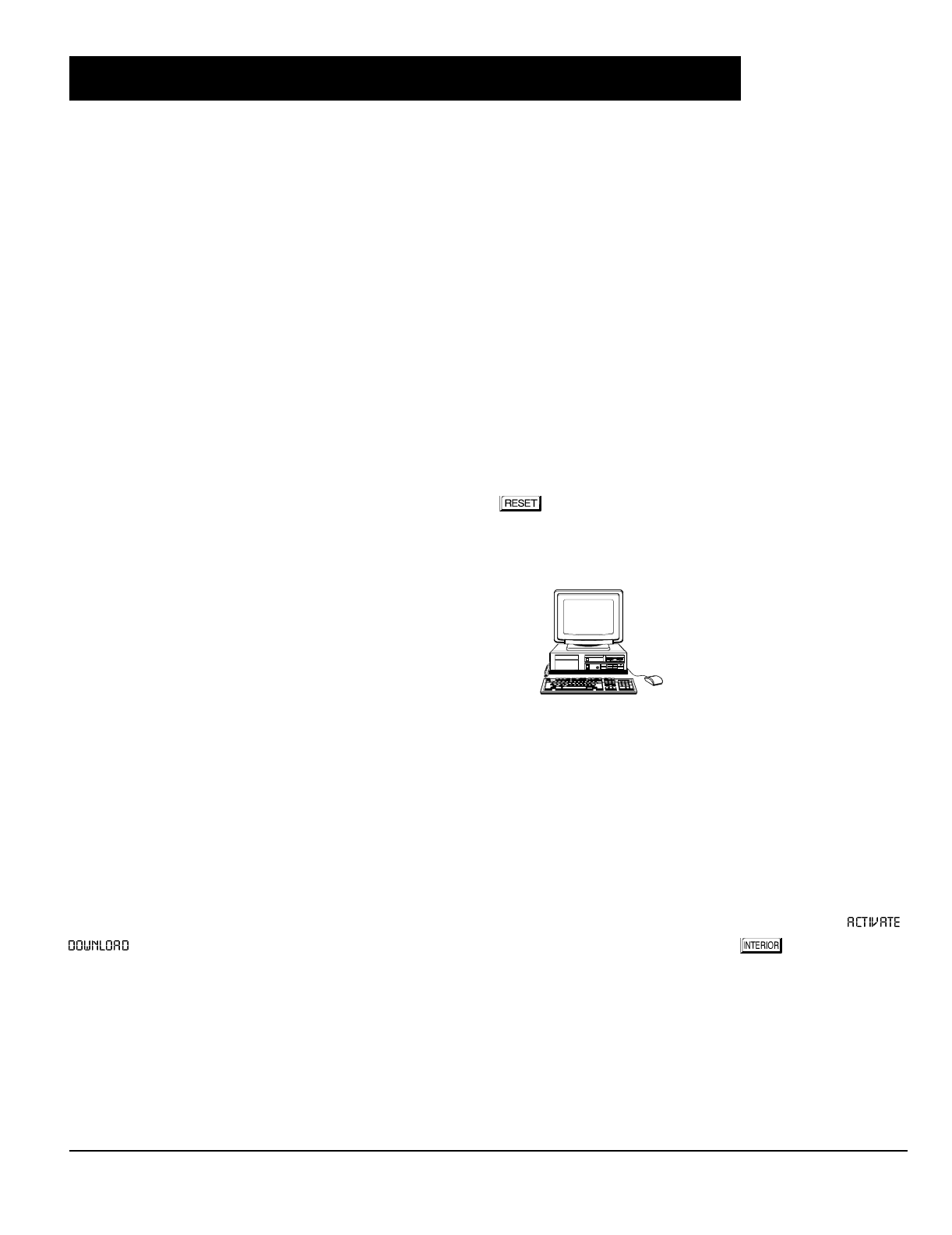
Downloading From a Computer. This is the preferred method. The panel may be downloaded from (or uploaded
to) an IBM PC-compatible computer, with a 386 (or higher) microprocessor, either locally or remotely. Napco's
PCD3000 Quickloader software, Version Update 3.26 or later features context-sensitive help screens as well as an
error-checking utility that prevents programming of incompatible or conflicting data to ensure proper panel operation.
Easy Menu Driven Program (Dealer Program) Mode - Keypad Programming. The Easy Menu Driven Program
Mode allows keypad programming of number of zones in area 1, zone doubling, number of fire zones (both 4-wire and
2-wire), central station reporting, number of entry/exit zones, number of interior zones, number of keypads in area 1,
central station telephone number, central station account number, central station receiver format, user codes, rf
transmitter points, rf key fob transmitters and zone descriptions. For new panels, a custom default program may be
created at the keypad. A menu-driven utility prompts the installer to configure the system. Further, detailed customiza-
tion is done in the Direct Address Program Mode.
Direct Address (Dealer Program) Program Mode - Keypad Programming. The Direct Address Program Mode
is an extension of the Dealer Program Mode wherein data is entered at the keypad by location. This mode is accessed
from the Easy Menu Driven Program Mode by pressing the button at any time.
User Program Mode - Keypad programming. The User Program Mode is intended for authorized users and is
limited to keypad programming of User Codes and Zone Descriptions.
The control-panel program may be downloaded from the
computer by either of the following methods.
Local Downloading
(Note: This procedure should be used prior to installation, before peripheral devices are con-
nected.)
For a direct high-speed data transfer to the control panel from a desktop computer, connect the download jack (JP2) on
the panel to the LOCAL jack (J3) on the Napco PCI2000/3000 computer interface using the supplied 6-conductor cable.
(Refer to PCI2000/3000 Installation Instructions WI443 for wiring diagram and procedures.)
Similarly, a high-speed local download may be made in the field using a notebook or laptop computer. Connect JP2 on the
control panel to a Napco PCI-MINI computer interface using the 6-conductor cable supplied. (Refer to PCI-MINI
Installation Instructions WI767.)
Remote Downloading
(Also see PCI2000/3000 Installation Instructions WI443.)
Function Mode. During this procedure, voice contact will be lost, therefore both the installer and the computer operator
should be familiar with the operation. When a steady high-pitched tone is heard at the site phone, access the “
” Function (see Keypad Programming Modes), then press the button or the YES ( ) button; the site
phone will go dead. Hang up the phone and wait for a call from the central station confirming a successful download.
Callback Method. An installed, unattended panel may be programmed or reprogrammed remotely using the Callback-
Method Download feature of the PCD3000 software. Remote downloading requires a modem compatible with the
PCI2000/3000. Upon answering the call from the computer, the panel will verify the Download Security Code and, if
confirmed, will establish a connection. If a Callback Number is programmed into the panel, the panel will automatically
disconnect and call the computer at this number before establishing a connection.

NAPCO Security Systems
GEM-P1632 Programming Instructions
WI897B 8/98
Page 5
Only Keypad #1 may be used for both dealer and user programming, however this keypad may be located in any area.
The Default Dealer Code is . Use this code to enter the Dealer Program Mode
to program a custom Dealer Code, which replaces the Default Dealer Code. If you clear your Dealer Code, use the Default Dealer
Code once again to enter programming.
After entering codes or data, press the save button. Data will not be stored into memory unless it is pressed.
If the keypad is in the Program Mode and no activity is detected for longer than 4 minutes, a steady tone will sound. Silence the
sounder by the button to continue, or by pressing the button to exit.
A panel that has been SYSTEM RESET performs identically to a new panel.
When programming a Multiple Area System, Direct Address Programming Mode must be used to complete the program.
If a GEM-RP2ASe2 is used, configure address jumpers as Keypad #1 (see Configuring the GEM-RP2ASe2 Keypad.).
Use the button to manually scroll through each selected option and at the end of each programming line.
For any new panel, you can design a default program that will best suit your application. Using this procedure, you will
configure the panel for:
KEYPAD #1: For ease of programming, it is recommended that a GEM-RP1CAe2 be used as Keypad #1. (Regardless of
which keypad is selected, all
new
keypads are configured as Keypad #1 out of the box.)
1. Press
2. Press
Until
“” (GEM-RP1CAe2) or
“” (GEM-RP2ASe2)
appears on LCD screen.
3. Press
To Enter Dealer Program Mode
4. Press
To Exit Dealer Program Mode when finished
Dealer Code (Default = 456789)
Number of Zones in Area 1
Panel Zone Doubling
Fire Zones in Area 1
2-Wire Fire Zones in Area 1
Local or Central station Reporting
Exit/Entry Zones in Area 1
Interior Zones in Area 1
Number of Keypads in Area 1
CS Receiver 1 Telephone Number
CS Receiver 1 Account Number
CS Receiver 1 Format
User Codes
RF Transmitter Points
Key Fob Transmitters
Zone Descriptions (GEM-RP1CAe2 Keypad
Only)
Dealer Code
NEW PANELS: The custom default program may be created for new panels only. Once the panel has been programmed
by any means, the number of areas, zones and keypads will be suppressed and cannot be changed. Should it be
necessary to create a new custom default program, (a) from the Dealer Program Mode, press the button to enter
the Direct Address Program Mode; (b) access Location 1197 (Clear Program); (c) press the button and start over.
EASY MENU DRIVEN PROGRAM MODE
R
ARMED
STAT US
NEXT/YES
PRIOR/NO
AREA
GEM-P1632 Programming Instructions NAPCO Security Systems
WI897B 8/98
Page 6
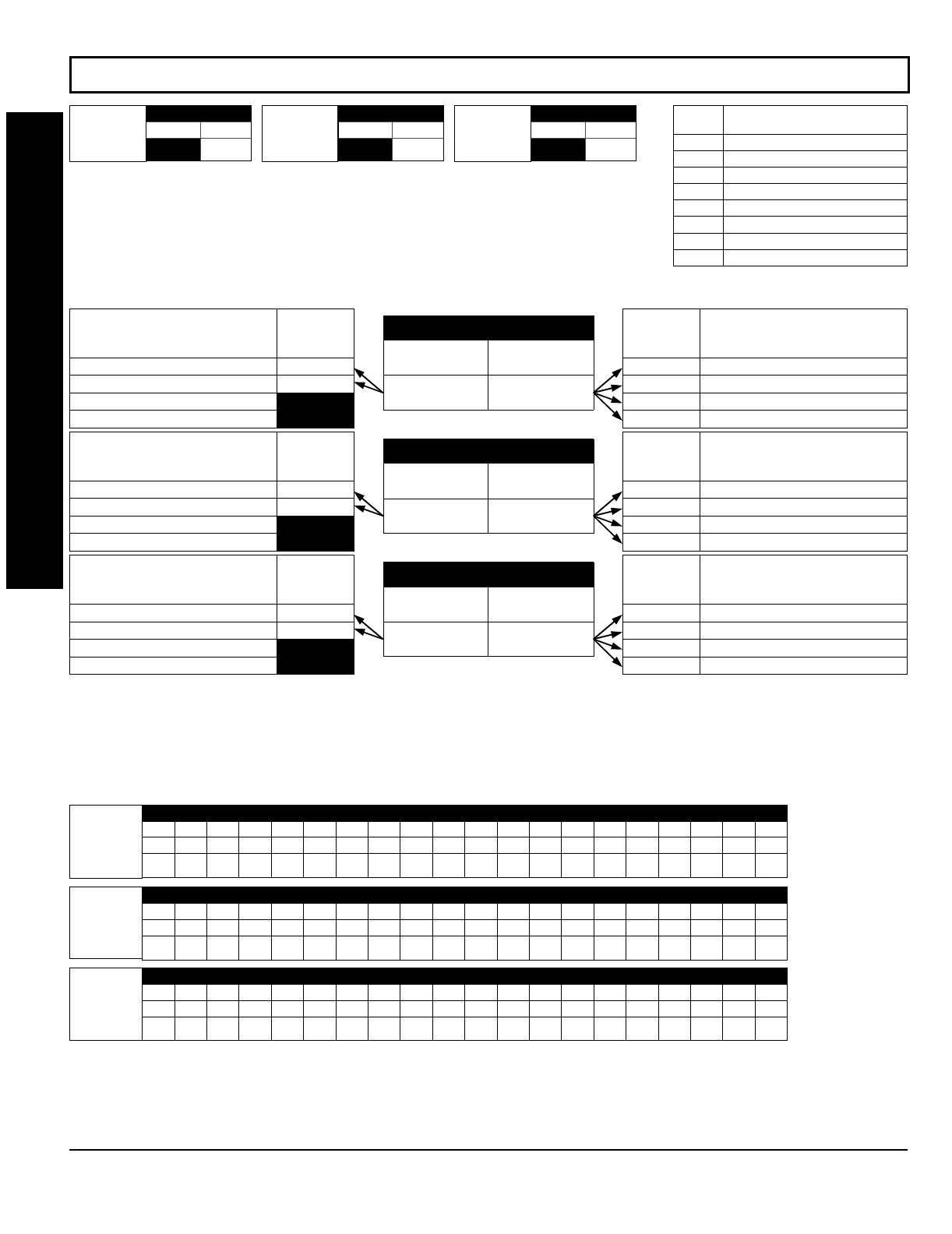
EASY MENU DRIVEN PROGRAM MODE
A. GEM-RP1CAe2 Keypad
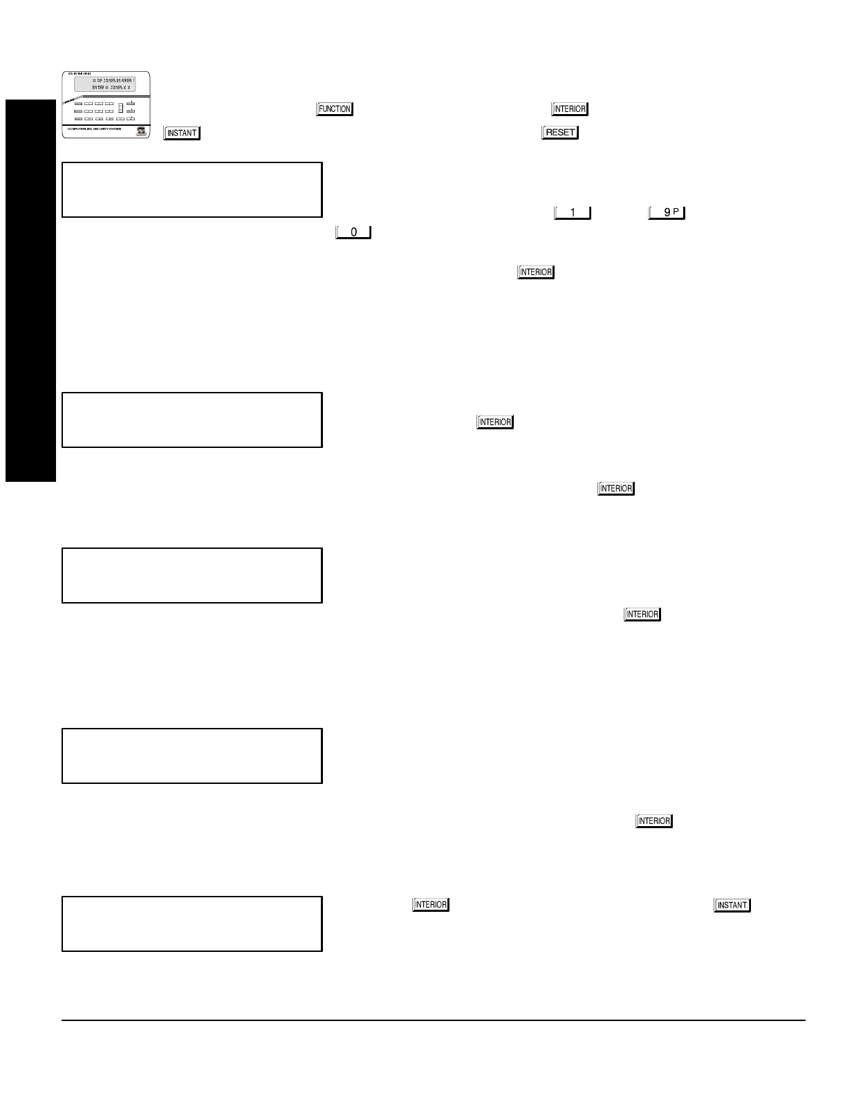
To create your customized default program using a GEM-RP1CAe2 keypad, enter the following parame-
ters and record your information on the
Easy Menu Pro
g
rammin
g
Worksheet
(see page 43). In each of the
following steps, press the button to set cursor, the NEXT ( ) button to go forwards, the PRIOR
() button to go backwards, the button to save and the button twice to exit at any time.
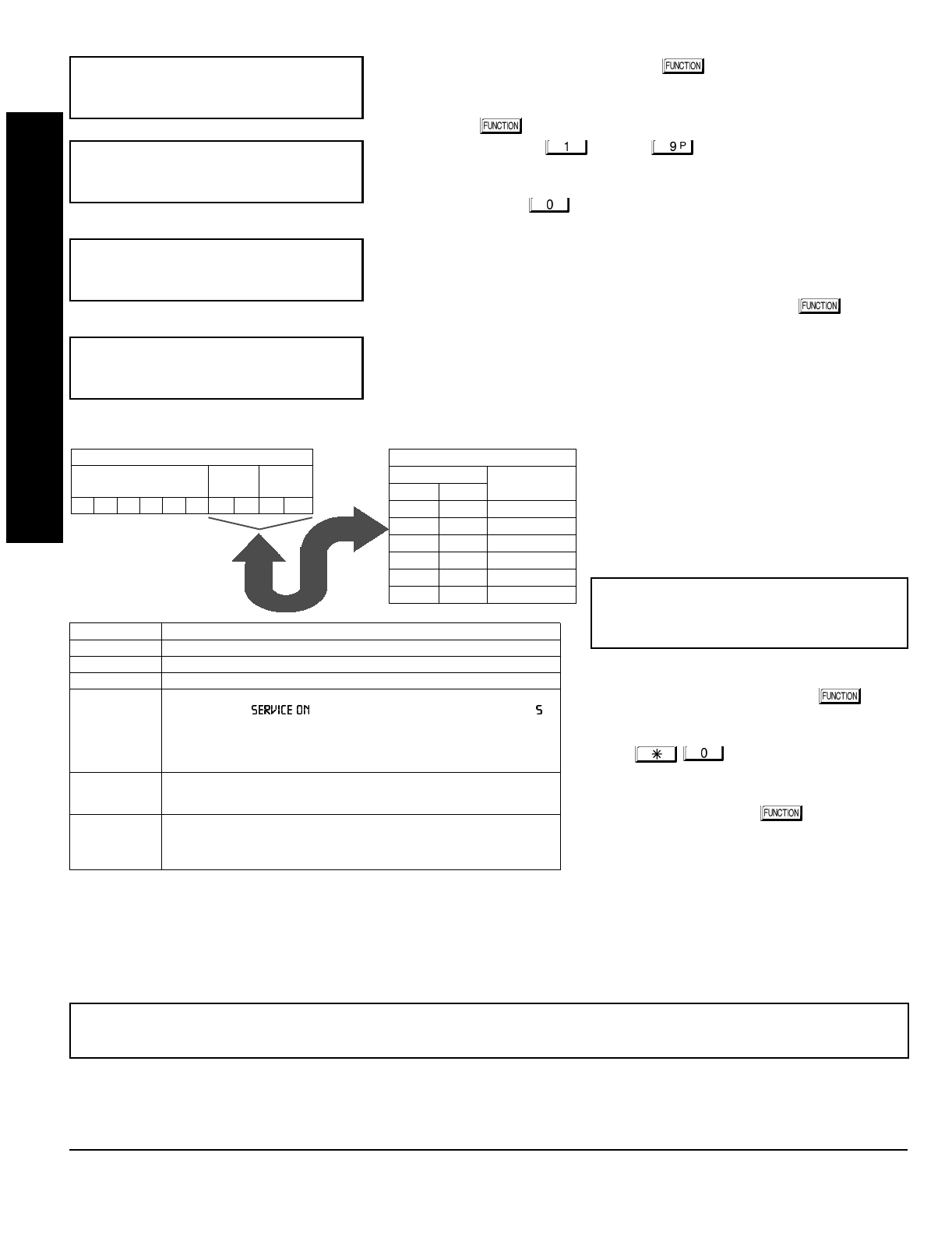
Total Number of Zones in Area 1
(Appears for New Panel Only)
Directly enter the total number of zones to be programmed for Area 1. Valid
entries are from 01 to 32. Directly enter the total number of zones, including
leading zeros. Use number buttons through . NOTE: Press the
button for a zero. The system is based on groups of 4 zones each
(after the first 8 zones), and will automatically round up to the next group of 4. For example, if you enter 18, it will
automatically convert this to 20 zones. Press to save. Press NEXT ( ) button to proceed. NOTE: If you are
programming a 2 Area system, enter the total number of zones required for Areas 1 & 2. The Direct Address Program
Mode can then be used to remove zones from Area 1 and place them in Area 2. See Zone Options. If Programming a
Wireless Only system, or using wireless only on Zones 9-32, enter the total number of zones in system. Enter the
transmitter points in the RF Transmitter section of the Easy Menu Driven Programming Mode.
Panel Zone Doubling
(Appears for New Panel Only)
If you wish to double the number of hardwired zones within the panel from 8
to 16, press the YES ( ) button. The 16 zones will no longer be EOL
zones, but will be designated for Normally Closed devices only. The terminal
for Zone 1 will now support both Zones 1 and 9 with the use of the supplied
EZ Zone DoublingTM resistors, E (2.2K) & Z (3.9K) supplied. (Refer to Wiring
Diagram and Installation Instructions). If Panel Zone doubling is not desired, press NO ( ).
Fire Zones in Area 1
(Appears for New Panel Only)
Enter the number of any zones which are to be used as Fire Zones (both
2-wire, 4-wire or wireless). Valid entries are from 01 to 32. Directly enter
each zone number, including leading zeros, and press to save, and then
repeat for any additional zone(s). Press NEXT ( ) button to proceed.
NOTE: If you are programming a 2 Area system, enter the total number of
zones required for Areas 1 & 2. The Direct Address Program Mode can then be used to remove zones from Area 1 and
place them in Area 2. See Zone Options.
2-Wire Fire Zones in Area 1
(Appears for New Panel Only)
Enter the number of any Fire Zones (from previous question) which are to be
used with 2-wire smoke detectors. The only valid entries are 07 and 08.
Directly enter each zone number, including leading zeros. Press to save,
and then repeat for any additional zone(s). NOTE: Only zones which have
been designated as Fire Zones may be programmed as 2 Wire Fire zones. Press NEXT ( ) button to proceed.
NOTE: JP3 must be set to “2-WF” position for 2-wire fire zones (refer to Installation Instructions).
Local or Central Station Reporting System
(Appears for New Panel Only)
Press YES ( ) button for all zones to report; press NO ( ) button
for no zones to report (LOCAL SYSTEM).
(Press YES or NO)
(Direct Entry)
(Direct Entry)
(Press YES or NO)
R
ARMED
STAT US
NEXT/ YES
PRIOR/NO
AREA
(Direct Entry)

NAPCO Security Systems
GEM-P1632 Programming Instructions
WI897B 8/98
Page 7
Entry/Exit Zones in Area 1
(Appears for New Panel Only)
Directly enter the zone number of any zones which are to be used as
Entry/Exit zones. Valid entries are from 01 to 32. Directly enter each zone
number, including leading zeros. Use number buttons through .
NOTE: Press the button for a zero. Press to save and then repeat
for any additional zone(s). Press NEXT ( ) button to proceed.
NOTE: Chime will automatically be programmed for all E/E zones. If you are programming a 2 Area system, enter the
total number of zones required for Areas 1 & 2. The Direct Address Program Mode can then be used to remove zone from
Area 1 and place them in Area 2. See Zone Options.
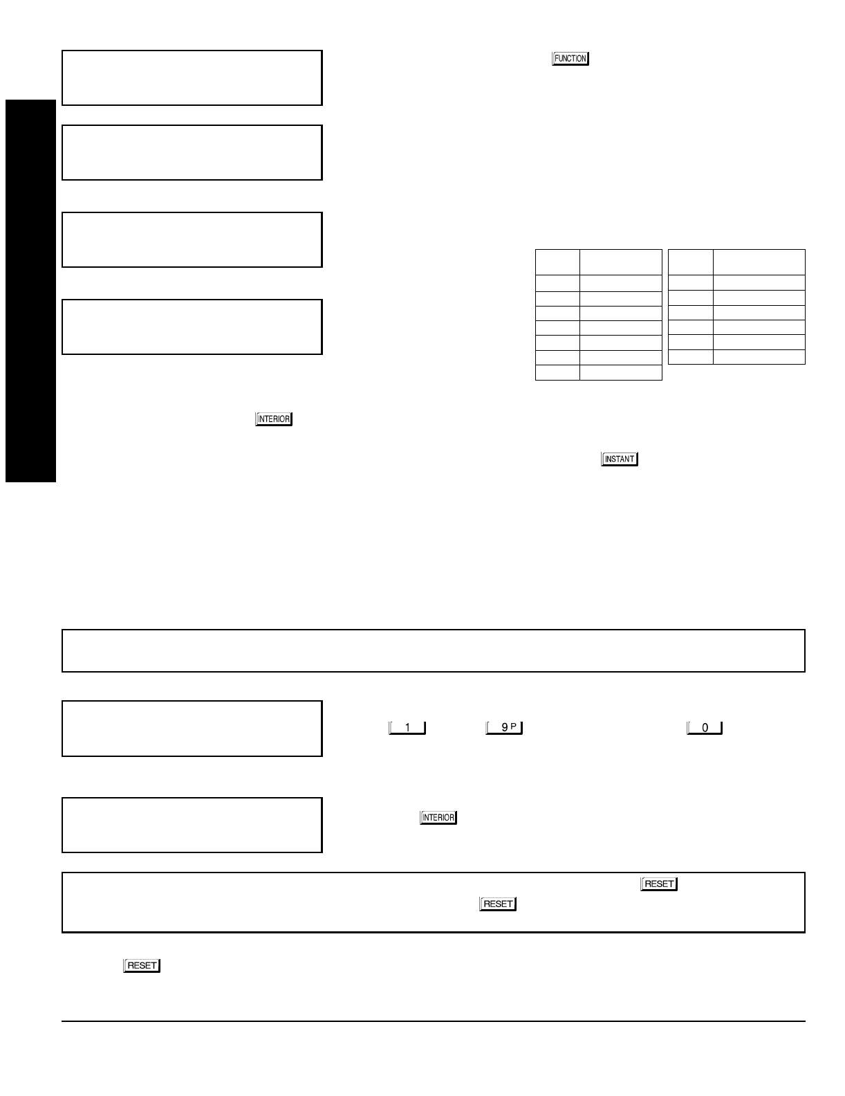
Interior Zones in Area 1
(Appears for New Panel Only)
Directly enter the zone number of any zones which are to be used as Interior
Zones. Valid entries are from 01 to 32. Directly enter each zone number,
including leading zeros. Use number buttons through . NOTE:
Press the button for a zero. Press to save and then repeat for any
additional zone(s). Press NEXT ( ) button to proceed.
NOTE: All Interior zones will also be automatically programmed as “Exit/Entry Follower” zones. If you are programming a
2 Area system, enter the total number of zones required for Areas 1 & 2. The Direct Address Program Mode can then be
used to remove zones from Area 1 and place them in Area 2. See Zone Options.
Number of Keypads in Area 1
Directly enter the total number of Keypads to be installed in Area 1. Valid
entries are from 01 to 07. Directly enter the number of keypads, including
leading zeros. Use number buttons through . NOTE: Press the
button for a zero. Press to save . Press NEXT ( ) button to
proceed. NOTE: Area 2 keypads can only be assigned in Direct Address
Programming. See Keypad Options.
Central Station Receiver 1 Telephone Number
Using number buttons, enter telephone number of up to 16 digits including-
prefix letters, if necessary, for receiver 1. Use number buttons
through for digits 1–9; press the button for a zero and
through for letters B–F, respectively. NOTE:
Pre-Dial Delay = “D”; Dial-Tone Detection = “E”. Pressing the button will produce a blank space (•). Press to
save . Press NEXT ( ) button to proceed.
NOTE: Central Station Receiver 2 and 3 Telephone Numbers can only be entered in Direct Address Programming. See
CS Receiver Options.
Central Station Receiver 1 Account Number
Enter an account number of up to four digits. Use number buttons
through for digits 1–9. NOTE: Press the button for a zero and
press button for a blank space (•). Press to save . Press
NEXT ( ) button to proceed.
NOTE: Central Station Receiver 2 and 3 Account Numbers can only be entered in Direct Address Programming. See CS
Reporting Options.
(Direct Entry)
(Direct Entry)
(Direct Entry)
(Direct Entry)
(Direct Entry)
EASY MENU DRIVEN PROGRAM MODE
GEM-P1632 Programming Instructions NAPCO Security Systems
WI897B 8/98
Page 8
Central Station Receiver 1 Format
From the table below, enter the central station's receiver format. Use number
buttons through . NOTE: Press the button for a zero.
and press for a blank space (•). Press through
for letters B–E, respectively.
Press to save. Press NEXT ( ) button to proceed.
Enter User Codes
(Press the
( )
button to set cursor.)
For default program, enter up to 32 User Codes, with Area 1 and Area 2
Options.
Press the ( ) button once to set the cursor to the User Code. Use
the number buttons through to enter a code of up to 6
digits. Enter up to 6 digits (4 digits is recommended) in the first six boxes
from left to right for each user code. Valid entries are: 0-9. NOTE: Press the button for a zero. No blank
spaces in between; leave blank (•) any trailing boxes. If “Enable Global Ambush Code” (Address 0720) is enabled and
“Global Ambush Code” (Address 1054) is left blank(•),
do not
program the first two digits of ANY User Code as '99'.
If the programmed code was less than 6 digits, press the button once to set the cursor to the Area 1 Options
Level. Refer to the table below for the available area options.
For Area 2 Options, press the
button once again. Refer to the table
above for available options. NOTE: Press
the for blank space (•).
Press to save. To proceed to the next
User Code, press the button to set
the cursor to the User Number and change
it using the number buttons.
Program a new User Code as previously de-
scribed. Remember to record your user codes
in the
Easy Menu Pro
g
rammin
g
Worksheet
at
the back of this manual.
(Direct Entry)
!"#
User# User Code Area 1 Area 2
"$
DATA
ENTRY CS RECEIVER 1 FORMAT
•(blank) Ademco Slow, Silent Knight Slow
2 Radionics Fast
3 Silent Knight Fast
4 Radionics, DCI, Franklin Slow
DATA
ENTRY CS RECEIVER 1 FORMAT
5 Universal High Speed
BSIA
C Ademco Point ID
E Pager
NOTE: Central Station Receiver 2 and 3 For-
mats can only be entered in Direct Address
Programming. See CS Receiver Options.
USER OPTIONS
USER CODE
(UP TO 6 DIGITS)
AREA 1
OPTIONS AREA 2
OPTIONS OPTION
ENABLED
Disabled
Arm/Disarm
Arm Only
Service
Access
* User Program
DATA ENTRIES
LR
blank(•) blank(•)
blank(•) 1
blank(•) 2
blank(•) 3
blank(•) 4
blank(•) Add 8
USER AREA OPTIONS
AREA OPTIONS:
Up to 32 User Codes may
be programmed.
Select the desired Area Options (Area 1
and Area 2) from the table shown and
enter in the remaining four boxes for
each user code.
Example:
Program a code of “2222” for user 02, with
area 1 options of “Arm/Disarm” and “User Program”.
Enter “2222” for a user code, “•(blank) 9” for area 1
options and “•(blank) •(blank)” for area 2 options.
Re-
lated User Options: “Enable Global Ambush Code” (Address 0720),
“Global Ambush Code” (Address 1054) & “Enable Managers Mode” (Address 0719).
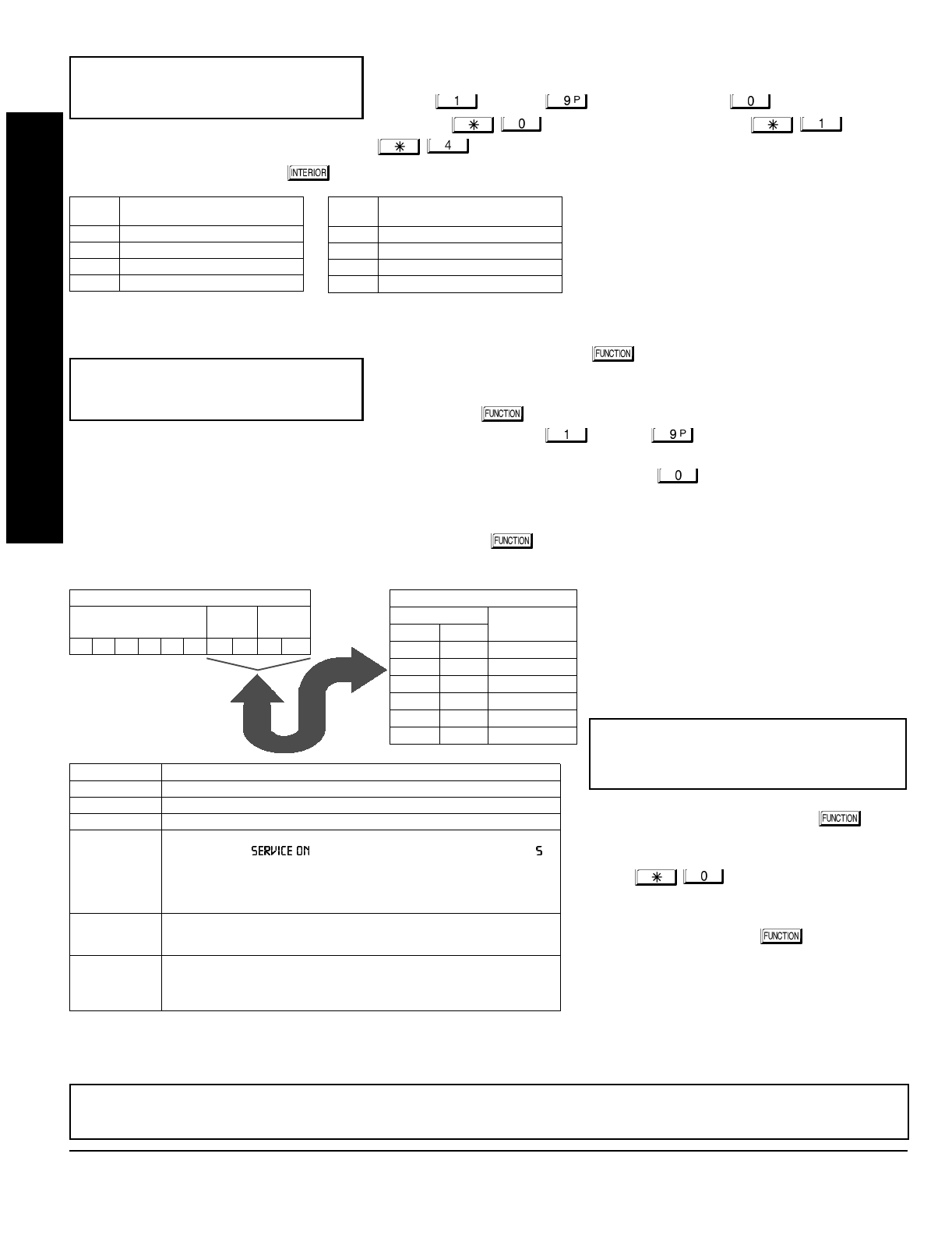
AREA OPTIONS EXPLANATION
Disabled User Code not active in this area.
Arm/Disarm Allows User Code to arm/disarm this area.
Arm Only Prevents User Code from disarming this area.
Service A Service Code has restricted arm/disarm rights; if an area is armed with a
Service Code, a “ ” appears on the GEM-RP1CAe2 keypad (a “ ”
on the GEM-RP2ASe2 keypad) and the area can be disarmed with any valid
User Code, including a Service Code. If the area is armed with OTHER than a
Service Code, it CANNOT be disarmed with a Service Code. This is typically
used to allow tradesmen access to premises under control of the owner.
Access This is normally used to activate a door striker while an area is disarmed.
Also program “Access Control on PGM2 Output” (Address 0719) and “PGM2
Output Access Control Timeout” (Address 0711).
* User Program User Program Option is enabled for Keypad 1 only, wherever it is connected
(Area 1 or Area 2). To enable User Program Option for any user add 8 to the
data entry for Area Option (see example). Then, User Programming can be
performed only at Keypad 1 by a user code with user program enabled.
CHANGING OR CANCELING A CODE: To change any code, merely program over the existing code as described above
and press to save. Similarly, to cancel a code, blank out each number of the code press to save to save.
EASY MENU DRIVEN PROGRAM MODE

NAPCO Security Systems
GEM-P1632 Programming Instructions
WI897B 8/98
Page 9
RF Transmitter Points
(Press the
( )
button to set cursor.)
(For wireless systems only. Also see Quick Method, which follows)
For each transmitter (key fob transmitters also), enter the zone number
(01–32) to which the transmitter will be mapped, the 6-digit RF ID #:1-digit
checksum number printed on the transmitter and box, the number of points
(1–4);
enter “9” for unsupervised
(all points). NOTE: When programming the
ID Code number, “A” = ; “B” = ; “C” = ; “D” = ; “E” = ;
“F” = . Press to save. Press NEXT ( ) button to proceed.
Quick Method.
If a receiver is already installed in the panel, Napco transmit-
ter wireless points can be programmed automatically (“enrolled”) using the
following procedure. NOTE: The transmitter point will be enrolled only if the
signal strength is 3 or greater.
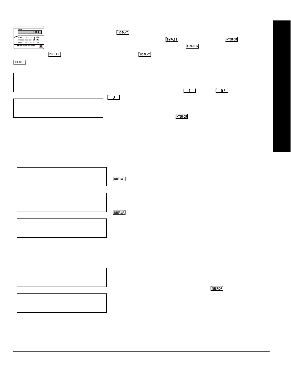
1. Enter the zone number to which the transmitter point will be mapped.
2. Press the button to enter the Enroll Mode. The red and green LEDs
on the keypad will flash and the window will display as shown at left.
3. Open the loop of the point that is to be programmed (GEM-TRANS2 or
GEM-TRANS4 only).
4. Install the transmitter battery. The keypad will beep to indicate that the point has been successfully enrolled. Multi-point
transmitters can be mapped to successive zones simultaneously (Example 1) or to selected zones point by point (Example
2).
Example 1. A 4-point transmitter has the RF ID number 410078:1. Map the first three points to Zones 11–13, respectively.
1. Enter the Enroll mode as described in step 2 above.
2. Enter Zone “11”.
3. Open the loops of points 1, 2 and 3.
4. Install the transmitter battery. The keypad will beep 3 times to indicate that three points have been programmed.
Transmitter 410078:1, point 1 will be mapped to Zone 11.
Transmitter 410078:1, point 2 will be mapped to Zone 12.
Transmitter 410078:1, point 3 will be mapped to Zone 13.
The keypad will now display Zone 13, the last zone enrolled.
Example 2. A 2-point transmitter has the RF ID number 287613:1. Map point 1 to Zone 6 and point 2 to Zone 9.
1. Enter the Enroll mode as described above.
2. Enter Zone “06”.
3. Open point-1 loop.
4. Install the battery. The keypad will beep once to indicate that one point has been programmed. (Transmitter 287613:1,
point 1 will be mapped to Zone 6.)
5. Enter Zone “09”.
6. Close point-1 loop and open point-2 loop.
7. Remove the transmitter battery, then re-install it. The keypad will beep once to indicate that one point has been
programmed. (Transmitter 287613:1, point 2 is mapped to Zone 9.)
Zone # Xmitter Check Point
Mapped to ID Sum #
%
"""""""&""
%
"""""""&""
%
"&
KEY FOB ZONE ASSIGNMENT: Key fobs can also be assigned to zones to allow multiple wireless panic buttons on one
alarm system, each reporting to a central station, a pager or having a description on the keypad that describes the person
holding the key fob, the location where the person holding the key fob is stationed, or the special purpose of the key fob
button being depressed.
See the next pa
g
e on Key fob Zone Assi
g
nment.
EASY MENU DRIVEN PROGRAM MODE
GEM-P1632 Programming Instructions NAPCO Security Systems
WI897B 8/98
Page 10
Key Fob Transmitters
(Press the
( )
button to set cursor.)
Keyfobs can be programmed as “Arm/Disarm” devices using their buttons
(refer to WI752). For each Key Fob Transmitter, enter:
the Key Fob Transmitter number (01–08).
area number to which transmitter is assigned (1 or 2); enter 0 to disable
keyfob.
the 6-digit RF ID # printed on the transmitter (enter all numbers and/or
letters, including leading “0”s, if any).
1-digit checksum number printed on the transmitter (enter all numbers
and/or letters, including leading “0”s, if any).
Aux-1 Option (see key fob aux 1 & aux 2 options).
Aux-2 Option (see key fob aux 1 & aux 2 options).
Note: If the Key Fob is converted for Two Button “Emergency Use” (by cutting an internal jumper), both top or bottom
buttons must be depressed to activate an alarms. In this case, the Aux-1 and Aux-2 cannot be programmed.
Press to save. Press NEXT ( ) button to proceed.
Key Fob Zone Assignment
(refer to display as shown on the previous pa
g
e: press the
()
button to
g
o backwards.)
Each of the 4 key fob buttons can be assigned to a zone. For example, On button = point 1; Off button = point 2; A1 = point
3; A2 = point 4. Up to 32 key fobs (using 1 button) or 16 key fobs (using 2 buttons) or 8 key fobs (using all 4 buttons) or any
combination up to a maximum of 32 controlled zones can be assigned, providing multiple wireless panic buttons on a
system, each reporting to the Central Station or a pager and/or annunciating on a keypad the key fob zone number with
description/location.
To assi
g
n a key fob to a zone:
program the keyfob as you would a transmitter, entering the keyfob's
ID code, check sum and point number at the appropriate zone. The “Quick Method” is not allowed. The zone may be
hardwired to a sensor as well as assigned to a key fob (either one will activate the zone alarm output). NOTE: If assigning
a key fob to a zone, the “ON/OFF” buttons on the key fob will no longer arm/disarm the system. The key fob is converted
to a “panic only” device.
Enter Zone Descriptions Press the and buttons to place the cursor; press the
and buttons to select the character. For each zone, enter a descrip-
tion of up to two lines. Press to save each description. To proceed to the
next description, place the cursor under the Zone Number (e.g. “01”) and
change the Zone Number using the and buttons. Program a
new description as above.
NOTE: Zone Descriptions can only be entered through the
GEM-RP1CAe2 Keypad or by usin
g
the Napco Quickloader
Software.
See
Easy Menu Pro
g
rammin
g
Worksheet
(page 45) for available zone description characters.
Dealer Code
Directly enter the Dealer Code (default = 456789), including leading zeros.
Use the through buttons. NOTE: Pres the button for a
zero. Press to save.
Re-enter the Dealer Code to verify the previous code. Press to save.
Press NEXT ( ) button to proceed.
CLEAR PROGRAM: Should it be necessary to create a new custom default program, (a) from the Dealer Program Mode,
press the button to enter the Address Program Mode; (b) access Location 1197 (Clear Program); (c) press and
start over.
KF Area Xmitter Check Aux
# ID Sum 1&2
%
""""""""&"""
(Direct Entry)
"
(Direct Entry)
'()*+,
(Direct Entry)
EXIT DEALER PROGRAM MODE: This completes the custom default program. Press the button to enter the
Direct Address Program Mode for further programming or press the button once again to end all programming and
resume normal keypad operation.
EASY MENU DRIVEN PROGRAM MODE
DATA
ENTRY AUX 1/AUX 2
OPTIONS
•(blank) None
1 Relay Group 1
2 Relay Group 2
3 Relay Group 3
4 Relay Group 4
5 Relay Group 5
6 Relay Group 6
DATA
ENTRY AUX 1/AUX 2 OP-
TIONS
7 Relay Group 7
8 Relay Group 8
9 Keypad Panic
0 Aux K.P. Panic
B Instant
C Toggle Aux Relay
NAPCO Security Systems
GEM-P1632 Programming Instructions
WI897B 8/98
Page 11
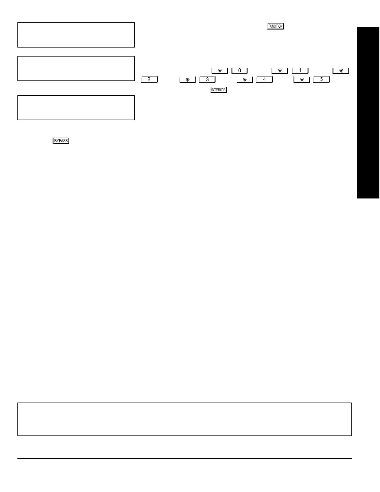
A. GEM-RP2ASe2 Keypad
Enter the Dealer Security Code (default = 456789) for a new panel or enter your custom Dealer Program
Code if programmed. Press NO ( ) repeatedly until “” is displayed. NOTE: If you pass
“”, you can scroll back by pressing the button. Press YES ( ) to enter the
Dealer Program Mode. In each of the following steps, press the button to set cursor, the NEXT
() button to go forwards, the PRIOR ( ) button to go backwards, the button to save and the
button twice to exit at any time.
Total Number of Zones in Area 1
(Appears for New Panel Only)
Directly enter the total number of zones to be programmed for Area 1. Valid
entries are from 01 to 32. Directly enter the total number of zones, including
leading zeros. Use number buttons through . NOTE: Press the
button for a zero. The system is based on groups of 4 zones each
(after the first 8 zones), and will automatically round up to the next group of
4. For example, if you enter 18, it will automatically convert this to 20 zones.
Press to save. Press NEXT ( ) button to proceed. NOTE: If you are
programming a 2 Area system, enter the total number of zones required for
Areas 1 & 2. The Direct Address Program Mode can then be used to remove zones from Area 1 and place them in Area
2. See Zone Options. If Programming a Wireless Only system, or using wireless only on Zones 9-32, enter the total
number of zones in system. Enter the transmitter points in the RF Transmitter section of the Easy Menu Driven
Programming Mode.
Panel Zone Doubling
(Appears for New Panel Only)
If the total number of zones in Area 1 entered was 16 or greater, press YES
() to effectively double the capacity of the control panel's hard wired
zones from 8 to 16. The 16 zones will no longer be EOL zones, but will be
designated for Normally Closed devices only. The terminal for Zone 1 will
now support Zones 1 and 9 with the use of the supplied EZ Zone
DoublingTM resistors, E & Z supplied. (Refer to Wiring Diagram and
Installation Instructions). If Panel Zone doubling is not desired, press NO
().
Fire Zones in Area 1
(Appears for New Panel Only)
Enter the number of any zones which are to be used as Fire Zones (both
2-wire, 4-wire or wireless). Valid entries are from 01 to 32. Directly enter
each zone number, including leading zeros, and press to save, and then
repeat for any additional zone(s). Press NEXT ( ) button to proceed.
NOTE: If you are programming a 2 Area system, enter the total number of
zones required for Areas 1 & 2. The Direct Address Program Mode can then be used to remove zones from Area 1 and
place them in Area 2. See Zone Options.
(Direct Entry)
(Press YES or NO)
(Direct Entry)
R
ARMED
STATUS
NEXT/YES
PRIOR/NO
AREA
EASY MENU DRIVEN PROGRAM MODE
GEM-P1632 Programming Instructions NAPCO Security Systems
WI897B 8/98
Page 12
2-Wire Fire Zones in Area 1
(Appears for New Panel Only)
Enter the number of any Fire Zones (from previous question) which are to be
used with 2-wire smoke detectors. The only valid entries are 07 and 08.
Directly enter each zone number, including leading zeros. Press to save,
and then repeat for any additional zone(s). NOTE: Only zones which have
been designated as Fire Zones in the prior question may be programmed as
2 Wire Fire zones. Press NEXT ( ) button to proceed. NOTE: JP3 must
be set to “2-WF” position for 2-wire fire zones (refer to Installation Instruc-
tions).
Local or Central Station Reporting System
(Appears for New Panel Only)
Press YES ( ) button for all zones to report; press NO ( ) button
for no zones to report (LOCAL SYSTEM).
Entry/Exit Zones in Area 1
(Appears for New Panel Only)
Directly enter the zone number of any zones which are to be used as Entry/
Exit zones. Valid entries are from 01 to 32. Directly enter each zone number,
including leading zeros. Use number buttons through . NOTE:
Press the button for a zero. Press to save and then repeat for any
additional zone(s). Press NEXT ( ) button to proceed.
NOTE: Chime will automatically be programmed for all E/E zones. If you are
programming a 2 Area system, enter the total number of zones required for
Areas 1 & 2. The Direct Address Program Mode can then be used to re-
move zone from Area 1 and place them in Area 2. See Zone Options.
Interior Follower Zones in Area 1
(Appears for New Panel Only)
Directly enter the zone number of any zones which are to be used as Interior
Follower Zones. Valid entries are from 01 to 32. Directly enter each zone
number, including leading zeros. Use number buttons through
. NOTE: Press the button for a zero. Press to save and then
repeat for any additional zone(s). Press NEXT ( ) button to proceed.
NOTE: All Interior Follower zones will also be automatically programmed as
“Exit/Entry Follower” zones. If you are programming a 2 Area system, enter
the total number of zones required for Areas 1 & 2. The Direct Address
Program Mode can then be used to remove zones from Area 1 and place
them in Area 2. See Zone Options.
(Direct Entry)
(Press YES or NO)
(Direct Entry)
(Direct Entry)
EASY MENU DRIVEN PROGRAM MODE
NAPCO Security Systems
GEM-P1632 Programming Instructions
WI897B 8/98
Page 13
Number of Keypads in Area 1
Directly enter the total number of Keypads to be installed in Area 1. Valid
entries are from 01 to 07. Directly enter the number of keypads, including
leading zeros. Use number buttons through . NOTE: Press the
button for a zero. Press to save. Press NEXT ( ) button to
proceed. NOTE: Area 2 keypads can only be assigned in Direct Address
Programming. See Keypad Options.
Central Station Receiver 1 Telephone Number
Using number buttons, enter telephone number of up to 16 digits including-
prefix letters, if necessary, for receiver 1. Use number buttons
through for digits 1–9; press the button for a zero and
through for letters B–F, respectively. NOTE:
Pre-Dial Delay = “D”; Dial-Tone Detection = “E”. Pressing the button
will produce a blank space (•). Press to save . Press NEXT ( ) button
to proceed.
NOTE: Central Station Receiver 2 and 3 Telephone Numbers can only be
entered in Direct Address Programming. See CS Receiver Options.
Central Station Receiver 1 Account Number
Enter an account number of up to four digits. Use number buttons
through for digits 1–9. NOTE: Press the button for a zero and
press button for a blank space (•). Press to save . Press
NEXT ( ) button to proceed.
NOTE: Central Station Receiver 2 and 3 Account Numbers can only be
entered in Direct Address Programming. See CS Reporting Options.
Central Station Receiver 1 Format From the table below, enter the central station's receiver format. Use number
buttons through . NOTE: Press the button for a zero.
and press for a blank space (•). Press through
for letters B–E, respectively. Press to save. Press NEXT
() button to proceed.
NOTE: Central Station Receiver 2 and 3 Formats can only be entered in
Direct Address Programming. See CS Receiver Options.
(Direct Entry)
(Direct Entry)
(Direct Entry)
!#
(Direct Entry)
!"#
DATA
ENTRY CS RECEIVER 1 FORMAT
•(blank) Ademco Slow, Silent Knight Slow
2 Radionics Fast
3 Silent Knight Fast
4 Radionics, DCI, Franklin Slow
DATA
ENTRY CS RECEIVER 1 FORMAT
5 Universal High Speed
BSIA
C Ademco Point ID
E Pager
EASY MENU DRIVEN PROGRAM MODE
GEM-P1632 Programming Instructions NAPCO Security Systems
WI897B 8/98
Page 14
Enter User Codes
(Press the Press the
( )
button to set cursor.)
For default program, enter up to 32 User Codes, with Area 1 and Area 2
Options.
Press the ( ) button once to set the cursor to the User Code. Use
the number buttons through to enter a code of up to 6
digits. Enter up to 6 digits (4 digits is recommended) in the first six boxes
from left to right for each user code. Valid entries are: 0-9.
NOTE: Press the button for a zero. No blank spaces in between;
leave blank (•) any trailing boxes. If “Enable Global Ambush Code”
(Address 0720) is enabled and “Global Ambush Code” (Address 1054) is
left blank(•),
do not
program the first two digits of ANY User Code as '99'.
If the programmed code was less than 6 digits, press the button
once to set the cursor to the Area 1 Options Level. Refer to the table
below for the available area options.
For Area 2 Options, press the
button once again. Refer to the table
above for available options. NOTE: Press
the for blank space (•).
Press to save. To proceed to the next
User Code, press the button to set
the cursor to the User Number and change
it using the number buttons.
Program a new User Code as previously described. Remember to record your user codes in the
Easy Menu Pro
g
rammin
g
Worksheet
at the back of this manual.
(Direct Entry)
"
$
(Direct Entry)
(Direct Entry)
USER OPTIONS
USER CODE
(UP TO 6 DIGITS)
AREA 1
OPTIONS AREA 2
OPTIONS
AREA OPTIONS:
Up to 32 User Codes may
be programmed.
Select the desired Area Options (Area 1
and Area 2) from the table shown and
enter in the remaining four boxes for
each user code.
Example:
Program a code of “2222” for user 02, with
area 1 options of “Arm/Disarm” and “User Program”.
Enter “2222” for a user code, “•(blank) 9” for area 1
options and “•(blank) •(blank)” for area 2 options.
CHANGING OR CANCELING A CODE: To change any code, merely program over the existing code as described above
and press to save. Similarly, to cancel a code, blank out each number of the code press to save to save.
EASY MENU DRIVEN PROGRAM MODE
OPTION
ENABLED
Disabled
Arm/Disarm
Arm Only
Service
Access
* User Program
DATA ENTRIES
LR
blank(•) blank(•)
blank(•) 1
blank(•) 2
blank(•) 3
blank(•) 4
blank(•) Add 8
USER AREA OPTIONS
Re-
lated User Options: “Enable Global Ambush Code” (Address 0720),
“Global Ambush Code” (Address 1054) & “Enable Managers Mode” (Address 0719).
AREA OPTIONS EXPLANATION
Disabled User Code not active in this area.
Arm/Disarm Allows User Code to arm/disarm this area.
Arm Only Prevents User Code from disarming this area.
Service A Service Code has restricted arm/disarm rights; if an area is armed with a
Service Code, a “ ” appears on the GEM-RP1CAe2 keypad (a “ ”
on the GEM-RP2ASe2 keypad) and the area can be disarmed with any valid
User Code, including a Service Code. If the area is armed with OTHER than a
Service Code, it CANNOT be disarmed with a Service Code. This is typically
used to allow tradesmen access to premises under control of the owner.
Access This is normally used to activate a door striker while an area is disarmed.
Also program “Access Control on PGM2 Output” (Address 0719) and “PGM2
Output Access Control Timeout” (Address 0711).
* User Program User Program Option is enabled for Keypad 1 only, wherever it is connected
(Area 1 or Area 2). To enable User Program Option for any user add 8 to the
data entry for Area 1 Option (see example). Then, User Programming can be
performed only at Keypad 1 by a user code with user program enabled.
NAPCO Security Systems
GEM-P1632 Programming Instructions
WI897B 8/98
Page 15
RF Transmitter Points
(Press the Press the
( )
button to set cursor.)
(For wireless systems only. Also see Quick Method, which follows)
For each transmitter (key fob transmitters also), enter the zone number
(01–32) to which the transmitter will be mapped, the 6-digit RF ID #:1-digit
checksum number printed on the transmitter and box, the number of points
(1–4);
enter “9” for unsupervised (all points)
. NOTE: When programming the
ID Code number, “A” = ; “B” = ; “C” =
; “D” = ; “E” = ; “F” = . Press
to save. Press NEXT ( ) button to proceed.
Quick Method.
If a receiver is already installed in the panel, Napco transmit-
ter wireless points can be programmed automatically (“enrolled”) using the
following procedure. NOTE: The transmitter point will be enrolled only if the
signal strength is 3 or greater.
1. Enter the zone number to which the transmitter point will be mapped.
2. Press the button to enter the Enroll Mode. The red and green LEDs on the keypad will flash and the window will
display as shown at left.
3. Open the loop of the point that is to be programmed (GEM-TRANS2 or GEM-TRANS4 only).
4. Install the transmitter battery. The keypad will beep to indicate that the point has been successfully enrolled. Multi-point
transmitters can be mapped to successive zones simultaneously (Example 1) or to selected zones point by point (Example
2).
Example 1. A 4-point transmitter has the RF ID number 410078:1. Map the first three points to Zones 11–13, respectively.
1. Enter the Enroll mode as described in step 2 above.
2. Enter Zone “11”.
3. Open the loops of points 1, 2 and 3.
4. Install the transmitter battery. The keypad will beep 3 times to indicate that three points have been programmed.
Transmitter 410078:1, point 1 will be mapped to Zone 11.
Transmitter 410078:1, point 2 will be mapped to Zone 12.
Transmitter 410078:1, point 3 will be mapped to Zone 13.
The keypad will now display Zone 13, the last zone enrolled.
Example 2. A 2-point transmitter has the RF ID number 287613:1. Map point 1 to Zone 6 and point 2 to Zone 9.
1. Enter the Enroll mode as described above.
2. Enter Zone “06”.
3. Open point-1 loop.
4. Install the battery. The keypad will beep once to indicate that one point has been programmed. (Transmitter 287613:1,
point 1 will be mapped to Zone 6.)
5. Enter Zone “09”.
6. Close point-1 loop and open point-2 loop.
7. Remove the transmitter battery, then re-install it. The keypad will beep once to indicate that one point has been
programmed. (Transmitter 287613:1, point 2 is mapped to Zone 9.)
.
(Direct Entry)
"
""""""
(Direct Entry)
&"-
EASY MENU DRIVEN PROGRAM MODE
KEY FOB ZONE ASSIGNMENT: Key fobs can also be assigned to zones to allow multiple wireless panic buttons on one
alarm system, each reporting to a central station, a pager or having a description on the keypad that describes the person
holding the key fob, the location where the person holding the key fob is stationed, or the special purpose of the key fob
button being depressed.
See the next pa
g
e on Key fob Zone Assi
g
nment.
GEM-P1632 Programming Instructions NAPCO Security Systems
WI897B 8/98
Page 16
Key Fob Transmitters
(Press the
( )
button to set cursor.)
Keyfobs can be programmed as “Arm/Disarm” devices using their buttons
(refer to WI752). For each Key Fob Transmitter, enter:
the Key Fob Transmitter number (01–08).
area number to which transmitter is assigned (1 or 2); enter 0 to disable
keyfob.
the 6-digit RF ID # printed on the transmitter (enter all numbers and/or
letters, including leading “0”s, if any).
1-digit checksum number printed on the transmitter (enter all numbers
and/or letters, including leading “0”s, if any).
Aux-1 Option (see key fob
aux 1 & aux 2 options).
Aux-2 Option (see key fob
aux 1 & aux 2 options).
Note: If the Key Fob is con-
verted for Two Button
“Emergency Use” (by cutting
an internal jumper), both top or
bottom buttons must be depressed to activate an alarms. In this case, the
Aux-1 and Aux-2 cannot be programmed.
Press to save. Press NEXT ( ) button to proceed.
Key Fob Zone Assignment
(refer to display as shown on the previous pa
g
e: press the
()
button to
g
o backwards.)
Each of the 4 key fob buttons can be assigned to a zone. For example, On button = point 1; Off button = point 2; A1 = point
3; A2 = point 4. Up to 32 key fobs (using 1 button) or 16 key fobs (using 2 buttons) or 8 key fobs (using all 4 buttons) or any
combination up to a maximum of 32 controlled zones can be assigned, providing multiple wireless panic buttons on a
system, each reporting to the Central Station or a pager and/or annunciating on a keypad the key fob zone number with
description/location.
To assi
g
n a key fob to a zone:
program the keyfob as you would a transmitter, entering the keyfob's
ID code, check sum and point number at the appropriate zone. The “Quick Method” is not allowed. The zone may be
hardwired to a sensor as well as assigned to a key fob (either one will activate the zone alarm output). NOTE: If assigning
a key fob to a zone, the “ON/OFF” buttons on the key fob will no longer arm/disarm the system. The key fob is converted
to a “panic only” device.
Dealer Code
Directly enter the Dealer Code (default = 456789), including leading zeros.
Use the through buttons. NOTE: Pres the button for a
zero. Press to save.
Re-enter the Dealer Code to verify the previous code. Press to save.
Press NEXT ( ) button to proceed.
CLEAR PROGRAM: Should it be necessary to create a new custom default program, (a) from the Dealer Program Mode,
press the button to enter the Address Program Mode; (b) access Location 1197 (Clear Program); (c) press and
start over.
(Direct Entry)
"
(Direct Entry)
""""""
(Direct Entry)
&"""
(Direct Entry)
(Direct Entry)
ZONE DESCRIPTIONS: GEM-RP2ASe2 cannot be used to enter Zone Descriptions. To enter Zone Descriptions you
must use the
GEM-RP1CAe2 Keypad or the Napco Quickloader Software.
EASY MENU DRIVEN PROGRAM MODE
DATA
ENTRY AUX 1/AUX 2
OPTIONS
•(blank) None
1 Relay Group 1
2 Relay Group 2
3 Relay Group 3
4 Relay Group 4
5 Relay Group 5
6 Relay Group 6
DATA
ENTRY AUX 1/AUX 2 OP-
TIONS
7 Relay Group 7
8 Relay Group 8
9 Keypad Panic
0 Aux K.P. Panic
B Instant
C Toggle Aux Relay
EXIT DEALER PROGRAM MODE: This completes the custom default program. Press the button to enter the
Direct Address Program Mode for further programming or press the button once again to end all programming and
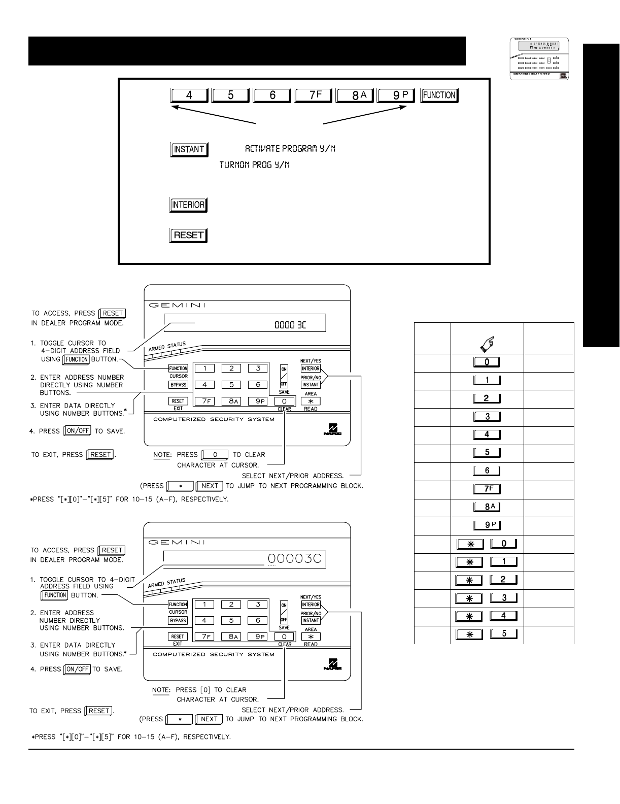
resume normal keypad operation.

NAPCO Security Systems
GEM-P1632 Programming Instructions
WI897B 8/98
Page 17
DIRECT ADDRESS PROGRAM MODE
This is an extension of the Dealer Program Mode. This method of programming is used in conjunction with the Keypad
Programming Worksheets that follow. Refer to these worksheets to identify the 4-digit location (address) of the feature to
be programmed. An illustrative example is provided on the next page.
Direct Address Programming allows you to go directly to the address
locations and change the data entries to customize your control panel
options. Whereas the Easy Menu Program Mode is a simple quick
start guide with limited options, the Direct Address Program Mode is
more flexible allowing you to change all the options.
It consists of multiple address locations (up to 1198) with two data
entry locations each (left and right) as shown in the adjacent diagram.
R
ARMED
STATUS
NEXT/YES
PRIOR/NO
AREA
DATA ENTRY
LOCATIONS
LEFT DIGIT RIGHT DIGIT
3C
ADDRESS
LOCATIONS
0000
0000
TO
1198
HEXADECIMAL DATA:
BLANK (•) = No Options
1 to 9 = Entries 1 to 9
0 = Entry of 10
B to F = Entries 11 to 15
GEM-RP2ASe2 Keypad
""""$
GEM-RP1CAe2 Keypad
""""$
= ADDRESS LOCATION
= DATA ENTRY LOCATION
1 2 1 2
1
2
1. Press
2. Press
Until
“” (GEM-RP1CAe2) or
“” (GEM-RP2ASe2)
appears on LCD screen.
3. Press
To Enter Dealer Program Mode
4. Press
To Exit Easy Menu Driven Program Mode
& Enter Direct Address Program Mode
Dealer Code (Default = 456789)

GEM-P1632 Programming Instructions NAPCO Security Systems
WI897B 8/98
Page 18
A. GEM-RP1CAe2 Keypads
B. GEM-RP2ASe2 Keypad
DIRECT ADDRESS PROGRAM MODE

NAPCO Security Systems
GEM-P1632 Programming Instructions
WI897B 8/98
Page 19
The displays shown on the previous page will appear after a brief delay.
Use the the button to toggle the cursor between the 4-digit address field and the data entry locations.
Enter the address directly using the number buttons.
The contents of the address will be read automatically, along with the feature name and programming information. The
cursor will advance to the data field. Enter the required data directly using the number buttons.
Press to save the contents of each address.
The Keypad Programming Worksheets in the back are
provided as an address-programming reference to help
the installer modify his custom default program or to make
minor field alterations to an existing panel program. It is
recommended that the panel be uploaded to Napco's
Quickloader software following any keypad programming
and that the PCD3000's error-check feature be utilized to
reduce the possibility of programming omissions or con-
flicts.
Note: Most of the addresses shown comprise two data
entry locations, left and right digits. Program the left digits
on the left data-display segment, and the right digit on the
right segment. For those addresses having only one pro-
grammable nibble, program the right segment only; the
left segment should display a blank (•).
Keep the Keypad Programming Worksheets on file for
future reference.
General Programming Steps
1. Contact the central station to ascertain receiver
format, data format, event codes, subscriber numbers
and telephone number(s).
2. Select the desired features by circling the re-
spective “address” boxes. Refer to the Programming
Options and Worksheets for guidance in selecting the
“data” (1,2,4,8) to be entered into those boxes.
3. Program the data entered in the boxes on the
worksheets into the respective addresses. The display
will show the entry numerically, but will display “0” for the
number 10, and letters “B”, “C”, “D”, “E”, and “F” for the
numbers 11 through 15, respectively. To program a 10,
press . To program 11 through 15, press
through , respectively.
NOTE: See the Direct Address Programming Example on the following page.
EXIT DIRECT ADDRESS PROGRAM MODE: When done, press the button to exit and resume normal keypad
operation. The panel is now programmed with your default program.
DATA ENTRY SELECTIONS
(BINARY VALUE CIRCLED)
ENTRY
TOTAL
PRESS KEYPAD
DISPLAYS
8421blank •
842 1 1
84 12 2
84 3 3
821 4 4
82 5 5
816 6
87 7
421 8 8
42 9 9
4110 0
411 B
21 12 C
213 D
114 E
15 F
Table 1. Determining data entry for a location (each
“nibble”). Numbers in parentheses indicate data for se-
lected zones or features. (See Programming Worksheets
that follow.)
DIRECT ADDRESS PROGRAM MODE
GEM-P1632 Programming Instructions NAPCO Security Systems
WI897B 8/98
Page 20
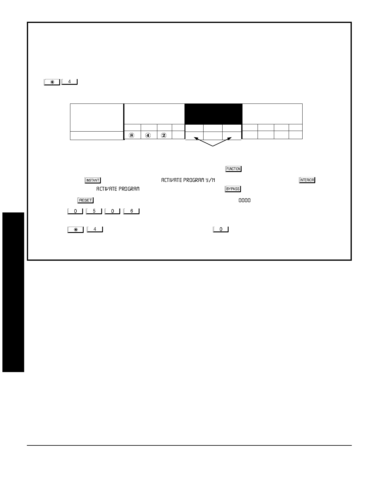
Direct Address Programming Example
Example:
Program Zones 6, 7 and 8 as Exit/Entry Follower Zones.
DETERMINE THE DATA ENTRIES
1. Referring to ZONE FEATURES in the Programming Worksheets that follow, Exit/Entry Follower for Zones 5
through 8 are located at address 0506, left digit. Circle the data values for Zones 5–8.
2. Add the data values for Zones 6, 7 and 8: 2+4+8=14. From Tables 1 and 2, “14” (E) is entered as press
. The right digit (for Zones 1 through 4, none of which are Exit/Entry Follower Zones) is entered as a
blank (•).
PROGRAM THE DATA ENTRIES
1. Enter the panel's Dealer Code (Default = 456789), then press the button.
2. Answer NO ( ) to all questions until “ ” is displayed; then press YES ( ).
NOTE: If you pass “ ”, scroll backward using the the button.
3. Press the button to enter the Address Program Mode. Address " " will display.
4. Press to access Address 0506.
The data for both di
g
its will display and the cursor
will advance to the data field.
5. Press to enter an “E” in the left digit and press to enter a blank (•) in the right digit.
6. Press to save.
Address 0506 is now programmed with “E•”.
ZONE OPTION
EXIT/ENTRY FOLLOWER
ZONES
LEFT DATA VALUES
SUM = 14 (CIRCLE )
ZN08 ZN07 ZN06 ZN05
1
ADDRESS
0506
L ADDR R
E 0506 blank (•)
ZONES
RIGHT DATA VALUES
SUM = 0 (CIRCLE )
ZN04 ZN03 ZN02 ZN01
842
1
ENTER DATA
DIRECT ADDRESS PROGRAM MODE
NAPCO Security Systems
GEM-P1632 Programming Instructions
WI897B 8/98
Page 21
R
ARMED
STATUS
NEXT/YES
PRIOR/NO
AREA
PROGRAMMING OPTIONS & WORKSHEETS
1. Press
2. Press
Until
“” (GEM-RP1CAe2) or
“” (GEM-RP2ASe2)
appears on LCD screen.
3. Press
To Enter Dealer Program Mode
4. Press
To Exit Easy Menu Driven Program Mode
& Enter Direct Address Program Mode
Dealer Code
ENTRY
TOTAL
PRESS KEYPAD
DISPLAYS
blank •
1 1
22
33
44
55
66
77
88
99
10 0
11 B
12 C
13 D
14 E
15 F
Determining data entry for a location (each
“nibble”). Numbers in parentheses indicate data
for selected zones or features. (See Program-
ming Worksheets that follow.)
GEM-RP1CAe2 Keypad
GEM-RP2ASe2 Keypad
GEM-P1632 Programming Instructions NAPCO Security Systems
WI897B 8/98
Page 22
ADDRESS 0000
LEFT RIGHT
EXIT
DELAY
(sec.)
[Default = 3C]
ADDRESS 0001
LEFT RIGHT
ENTRY
DELAY 1
(sec.)
[Default = 1E]
ENTRY
DELAY 2
(sec.)
[Default = 1E]
PROGRAMMING TIMEOUTS: Either use the tables provide or calculate your own timeout using the steps indicated.
WARNING: Timers have uncertainty of +0/-1sec, so a "time" of 1 second may actually timeout IMMEDIATELY.
ABORT
DELAY
(sec.)
[Default = blank (•) blank (•)]
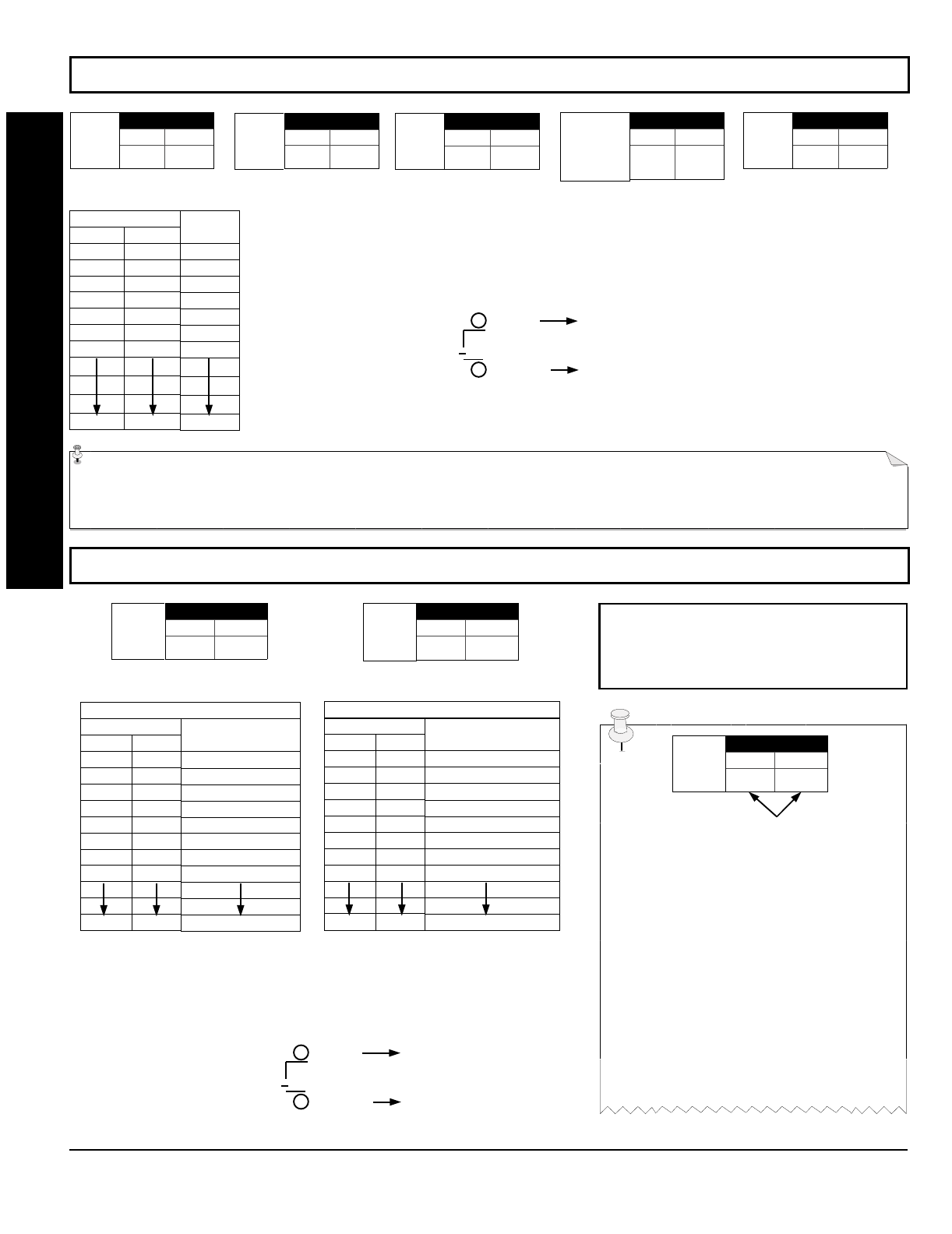
PROGRAMMING OPTIONS & WORKSHEETS
DATA ENTRIES
LEFT RIGHT
blank (•) blank (•)
blank (•) F
1E
2D
3C
50
78
FF
DELAY/
TIMEOUT
0 sec.
15 sec.
30 sec.
45 sec.
60 sec.
90 sec.
120 sec.
255 sec.
1. Select delay/timeout (0-255 sec.) from the table shown.
2. Enter in corresponding address locations above (left and right digits).
3. For a desired delay/timeout not listed do the following:
A. Choose a desired delay/timeout, ex: 20 sec.
B. Divide it by 16
EXIT/ENTRY DELAYS:
Ap- ply only to zones programmed with
the following options “Entry/Exit 1, Entry/Exit 2, Exit/Entry Follower”. For UL Installations, the
maximum exit delay is 60 seconds and the maximum entry delay is 45 seconds.
1 Quotient Left Digit
16 20
16
4 Remainder Right Digit
ADDRESS 0716
LEFT RIGHT
CHIME
TIMEOUT
(¼sec.)
[Default = blank (•) 2] [Default = blank (•) blank (•)]
ADDRESS 0717
LEFT RIGHT
AC Fail
Report
Delay
(min.)
DATA ENTRIES
LEFT RIGHT
blank (•) blank (•)
blank (•) 2
blank (•) 3
blank (•) 4
blank (•) 5
blank (•) 6
blank (•) 7
blank (•) 8
FF
TIMEOUT
0 ¼sec. = 0 sec.
2 ¼sec. = ½ sec.
3 ¼sec. = ¾ sec.
4 ¼sec. = 1 sec.
5 ¼sec. = 1.25 sec.
6 ¼sec. = 1.5 sec.
7 ¼sec. = 1.75 sec.
8 ¼sec. = 2 sec.
255 ¼sec. = 63.25 sec.
CHIME TIMEOUT OPTIONS
DATA ENTRIES
LEFT RIGHT
blank (•) blank (•)
blank (•) 1
blank (•) 2
blank (•) 3
blank (•) 4
blank (•) 5
blank (•) 6
blank (•) 7
FF
DELAY
0 min.
1 min.
2 min.
3 min.
4 min.
5 min.
6 min.
7 min.
255 min. = 4 Hr., 30 min.
AC FAIL REPORT DELAY OPTIONS
DEFAULTS: The defaults shown on this
page and on the following pages are auto-
matically set after exiting the Easy Menu
Driven Mode.
1. Select delay/timeout from the table shown.
2. Enter in corresponding address locations above (left and right digits).
3. For a desired delay/timeout not listed do the following:
A. Choose a desired delay/timeout, ex: 20
B. Divide it by 16 1 Quotient Left Digit
16 20
16
4 Remainder Right Digit
ENTER DATA
ADDRESS LOC.
LEFT RIGHT
Program
Option
PROGRAMMING STEPS:
1. Lookup desired Programming Option by
Address Location (highlighted in black).
2. Select the programming option data entry
from the tables shown.
3. Enter the selected data entry in the boxes
shown.
4. For more information on a programming
option refer to the Glossary at the end of this
manual.
ADDRESS 0711
LEFT RIGHT
PGM2 Output
Access
Control
Timeout
(sec.)
ADDRESS 0715
LEFT RIGHT
ADDRESS 0002
LEFT RIGHT
NAPCO Security Systems
GEM-P1632 Programming Instructions
WI897B 8/98
Page 23
[Default = blank (•) blank (•)]
[Default = 1 blank (•)]
[Default = 1 blank (•)]
[Default = blank (•) blank (•) ]
ADDRESS 0710
LEFT RIGHT
PGM2
Output
Timeout
(min.)
ADDRESS 0712
LEFT RIGHT
Alarm
Output
Timeout
(min.)
DATA ENTRIES
LEFT RIGHT
blank (•) blank (•)
blank (•) 1
blank (•) 2
blank (•) 3
blank (•) 4
blank (•) 5
blank (•) 6
1 blank (•)
FF
DELAY/
TIMEOUT
0 min.
1 min.
2 min.
3 min.
4 min.
5 min.
6 min.
16 min.
255 min.
ADDRESS 0714
LEFT RIGHT
PGM1
Output
Timeout
(min.)
ADDRESS 0713
LEFT RIGHT
Pulse Alarm
Output
Timeout
(min.)
1. Select delay/timeout (0-255 min.) from the table shown.
2. Enter in corresponding address locations above (left and right digits).
3. For a desired delay/timeout not listed do the following:
A. Choose a desired delay/timeout, ex: 20 min.
B. Divide it by 16
OUTPUT TIMEOUTS:
If a timeout of “0 min.” is selected, then
the output will remain active (ON) until the system is reset or disarmed. For UL Residential
Installations, the minimum timeout is 4 minutes. For UL Commercial Installations, the minimum
1 Quotient Left Digit
16 20
16
4 Remainder Right Digit
!"
NUMBER OF RINGS BEFORE PICKUP:
Enter the number of rings before automatic pickup by the
control panel when downloading form a computer (see Glossary at the back for more information).
1. Enter in right digit only (left digit is not used).
2. Valid entries are: 1-9, 0 = 10, B = 11, C = 12, D = 13, E = 14, F = 15
NOTE: Default is 15 Rings. Dark shaded data shows option not available.
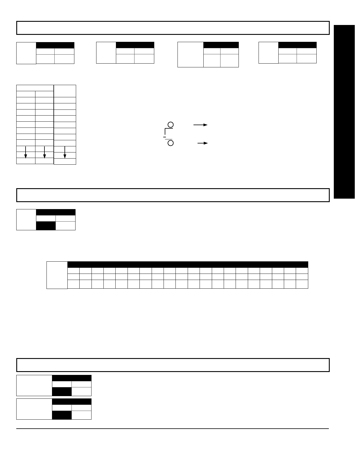
PROGRAMMING OPTIONS & WORKSHEETS
CALLBACK TELEPHONE NUMBER:
Enter telephone number to be used when downloading from a computer (see Glossary at the
back for more information).
1. Enter in right digit only (left digit is not used).
2. Enter up to 20 digits from left to right. NOTE: Leave trailing boxes blank (•).
3. Valid entries are: 1-9, B = button, C = button, D = 3 sec. pause, E = Wait for dial tone, F = ignore location
[Default = blank (•) for all digits 1-20]
ADDRESS 0236-0255 (RIGHT DIGITS 1-20)
0236 0237 0238 0239 0240 0241 0242 0243 0244 0245 0246 0247 0248 0249 0250 0251 0252 0253 0254 0255
RRRRRRRRRRRRRRRRRRRR
Callback
Telephone
Number
(Digits 1-20)
#$
LEADING DIGITS FOR PAGER FORMAT:
In Pager Format reporting, the message typically begins with “00”..
However, for some pager services, this will cause the Pager's Voice Mail feature to activate. This option allows
you to program these digits to any number desired. Typical Pager report is “003 022 1234”, where 3 is the Event,
22 is the zone, and 1234 is the Subscriber ID number. For example, if the Leading Digits are programmed as “98”,
the Pager report will now appear as “983 022 1234”. NOTE: See CS Receiver Options to select Pager Format.
1. Enter in 1st and 2nd Leading Digits in right digit only (left digit is not used) as shown.
2. Valid entries are: 0-9.
Leading Digits for
Pager Format
(1st Digit)
ADDRESS 0256
LEFT RIGHT
blank (•)
[Default = blank (•) blank (•) for both]
Leading Digits for
Pager Format
(2nd Digit)
ADDRESS 0257
LEFT RIGHT
blank (•)
ADDRESS 1183
LEFT RIGHT
blank (•)
No. Rings
Before
Pickup
[Default = blank (•) blank (•)]

GEM-P1632 Programming Instructions NAPCO Security Systems
WI897B 8/98
Page 24
See NOTE
[Default = blank (•) blank (•) from address 0478-0485]
[Default = blank (•) blank (•) from address 0470-0477]
[Default = blank (•) blank (•) from address 0460-0469]
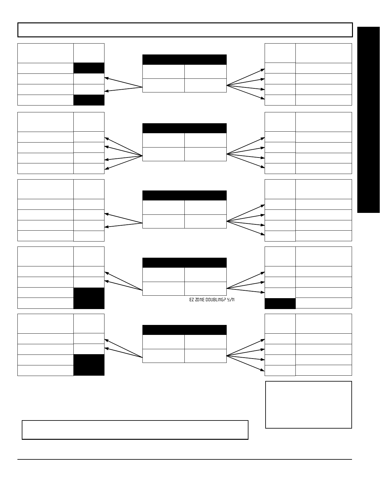
"!
SYSTEM RESPONSE AC-
TIVATED BY GLOBAL
EVENT/TROUBLE
Alarm Output
Pulsed Alarm Output
PGM1 Output
PGM2 Output
Report Event Telco 1
Report Restore Telco 1
Report Event Telco 3
Report Restore Telco 3
GLOBAL SYSTEM EVENT/TROUBLE
LEFT DATA VALUES (CIRCLE )
Bell
Superv. EZM
TAMPER AC FAIL LOW
BATTERY
8421
8421
8421
8421
8421
8421
8421
8421
ADDRESS
0460-0469
LEFT ADDR RIGHT
0460
0461
0462
0463
0464
0465
0468
0469
GLOBAL SYSTEM EVENT/TROUBLE
RIGHT DATA VALUES (CIRCLE )
MEMORY
FAILURE RF RCVR.
TROUBLE TELCO
FAILURE TEST
TIMER
8421
8421
8421
8421
8421
8421
8421
8421
SYSTEM RESPONSE AC-
TIVATED BY AREA 1
EVENT/TROUBLE
Pulsed Alarm Output
Alarm Output
PGM1 Output
PGM2 Output
Report Event Telco 1
Report Event Telco 3
AREA 1 SYSTEM EVENT/TROUBLE
LEFT DATA VALUES (CIRCLE )
Keyfob
Low Batt. FAIL TO
CLOSE FAIL TO
OPEN KEYPAD
TAMPER
8421
8421
8421
8421
8421
8421
ADDRESS
0470-0477
LEFT ADDR RIGHT
0470
0471
0472
0474
0475
0477
AREA 1 SYSTEM EVENT/TROUBLE
RIGHT DATA VALUES (CIRCLE )
KEYPAD
AUXILIARY KEYPAD
FIRE KEYPAD
PANIC AMBUSH
8421
8421
8421
8421
8421
8421
SYSTEM RESPONSE AC-
TIVATED BY AREA 2
EVENT/TROUBLE
Pulsed Alarm Output
Alarm Output
PGM1 Output
PGM2 Output
Report Event Telco 1
Report Event Telco 3
AREA 2 SYSTEM EVENT/TROUBLE
LEFT DATA VALUES (CIRCLE )
Keyfob
Low Batt. FAIL TO
CLOSE FAIL TO
OPEN KEYPAD
TAMPER
8421
8421
8421
8421
8421
8421
ADDRESS
0478-0485
LEFT ADDR RIGHT
0478
0479
0480
0482
0483
0485
AREA 2 SYSTEM EVENT/TROUBLE
RIGHT DATA VALUES (CIRCLE )
KEYPAD
AUXILIARY KEYPAD
FIRE KEYPAD
PANIC AMBUSH
8421
8421
8421
8421
8421
8421
1. Select the desired option by circling the data values for each digit (left and right).
2. Add the data values (ex: 15=1+2+4+8) from the selected options.
3. Enter in address location (left and right digits).
NOTE: Dark shaded data value box shows option not available.
PROGRAMMING OPTIONS & WORKSHEETS
[Default = blank (•) blank (•)]
Global
Ambush Code
ADDRESS 1054
LEFT RIGHT
GLOBAL AMBUSH CODE:
It is the 2-digits entered immediately prior to the regular disarm code.
If “Enable Global Ambush Code” (Address 0720) is selected and Address 1054 is left blank (•), then
the 2-digit Global Ambush Code is “99”. If “Enable Global Ambush Code” is selected and Address
1054 is not left blank (•), then the 2-digit Global Ambush Code is the two digits entered in address
1054.
Enter in address location (both left and right digits) ; valid entries are 1-9.
NAPCO Security Systems
GEM-P1632 Programming Instructions
WI897B 8/98
Page 25
[Default = blank (•) blank (•)]
Default depends on Easy Menu Question “ ”.
If yes, then [Default = •(blank) 1]. If no, then [Default = •(blank) •(blank)].
[Default = blank (•) blank (•)]
[Default = blank (•) blank (•)]
[Default = blank (•) blank (•)]
!%
ADDRESS 0718
LEFT DIGIT (SUM
OF DATA VALUES) RIGHT DIGIT (SUM
OF DATA VALUES)
LEFT DATA
VALUES
(CIRCLE )
1
2
4
8
SYSTEM OPTIONS
RESERVED
Enable AutoArm if not
closed at end of windows
Disable Time/Date
at Keypad
RESERVED
RIGHT DATA
VALUES
(CIRCLE )
1
2
4
8
SYSTEM OPTIONS
Opening Report Only
after Alarm Report
Closing Report Only on
Conditional Close
Incl. Sel./Grp. Bypass in
Cond. Close /Status
Status
Report
ADDRESS 0719
LEFT DIGIT (SUM
OF DATA VALUES) RIGHT DIGIT (SUM
OF DATA VALUES)
LEFT DATA
VALUES
(CIRCLE )
1
2
4
8
SYSTEM OPTIONS
Access Control
on PGM2 Output
Maintained Keyswitch
Arming
Enable
Manager's Mode
Disable
Instant Mode
RIGHT DATA
VALUES
(CIRCLE )
1
2
4
8
SYSTEM OPTIONS
Auto Bell Test
on Arming
Auto Reset after Burglary
Output Timeout
Suppress Bypass
Reminder when Armed
Enable Local Alarm on
First “ZoneAND” Trip
ADDRESS 0720
LEFT DIGIT (SUM
OF DATA VALUES) RIGHT DIGIT (SUM
OF DATA VALUES)
LEFT DATA
VALUES
(CIRCLE )
1
2
4
8
SYSTEM OPTIONS
Disable Keypad Function
Mode Download
Disable Callback
Download
PGM2 Output Chirp on
Keyfob Arming
Change Pulse Output to
Cadence
RIGHT DATA
VALUES
(CIRCLE )
1
2
4
8
SYSTEM OPTIONS
Interior 1
Normally Bypassed
Enable Global
Ambush Code *
Reset Day Zone with
Arm/Disarm Only
Enable
Residential Fire
ADDRESS 0721
LEFT DIGIT (SUM
OF DATA VALUES) RIGHT DIGIT (SUM
OF DATA VALUES)
LEFT DATA
VALUES
(CIRCLE )
1
2
4
8
SYSTEM OPTIONS
Line-Fault Test only
when Armed
Enable
Line-Fault Test
RESERVED
RESERVED
RIGHT DATA
VALUES
(CIRCLE )
1
2
4
8
SYSTEM OPTIONS
Enable Zone Doubling
(Zones 9-16)
Wireless Trouble
Activates Telco 1
Wireless Trouble
Activates Telco 3
RESERVED
1. Select the desired option by circling the data values for each digit (left and right).
2. Add the data values (ex: 15=1+2+4+8) from the selected options.
3. Enter in address location (left and right digits).
NOTE: To select “Line-Fault Test only when Armed”, you must also select
“Enable Line-Fault Test” at address 0721.
PROGRAMMING OPTIONS & WORKSHEETS
ADDRESS 0722
LEFT DIGIT (SUM
OF DATA VALUES) RIGHT DIGIT (SUM
OF DATA VALUES)
LEFT DATA
VALUES
(CIRCLE )
1
2
4
8
SYSTEM OPTIONS
Don't Clear PGM2 Output
with Arm/Disarm
2nd Ring Download
(Dis. Ans. Machine Overide)
RESERVED
RESERVED
RIGHT DATA
VALUES
(CIRCLE )
1
2
4
8
SYSTEM OPTIONS
Automatic
Interior Bypass
Veri-phone Zones Trip
PGM2 Output
Veri-phone Zones over
Priority Alarms
Resound on Wireless
Smoke Low Battery
* NOTE: If “Enable Global Ambush
Code” in Address 0720 is selected,
then program the 2-digit “Global Am-
bush Code” in Address 1054. If Ad-
dress 1054 is left blank (•), then, the
2-digit “Global Ambush Code” will be
“99”.
GEM-P1632 Programming Instructions NAPCO Security Systems
WI897B 8/98
Page 26
[Default = blank (•) blank (•)]
[Default = blank (•) blank (•)]
[Default = blank (•) blank (•)]
NOTE: * See Pager Format Options to
program Leading Digits for Pager Format.
&"%%""
ADDRESS 0170
LEFT RIGHT
blank (•)
CS Receiver 1
Format
Default for CS Receiver 1 Format depends on Easy Menu Question “RCVR FORMAT”. [Default = •(blank) •(blank)] for
CS Receivers 2 and 3 Formats.
CS RECEIVER FORMATS:
Up to 3 CS Formats may be programmed.
1. Select the desired CS Receiver Format from the table shown.
2. Enter in the corresponding right digit address location (left digit is not used) for each CS
Receiver. NOTE: Dark shaded data value box shows option not available.
ADDRESS 0192
LEFT RIGHT
blank (•)
CS Receiver 2
Format
ADDRESS 0193
LEFT RIGHT
blank (•)
CS Receiver 3
Format
DATA
ENTRY CS RECEIVER 1 FORMAT
blank (•) Ademco Slow, Silent Knight Slow
2 Radionics Fast
3 Silent Knight Fast
4 Radionics, DCI, Franklin Slow
5 Universal High Speed
BSIA
C Ademco Point ID
E Pager *
ADDRESS 0171
LEFT DIGIT (SUM
OF DATA VALUES) RIGHT DIGIT (SUM
OF DATA VALUES)
RIGHT DATA
VALUES
(CIRCLE )
1
2
4
8
CS RECEIVER 1 OPTIONS
1400Hz Handshake/Kissoff *
2300Hz Handshake/Kissoff *
Enable Zone Number on Pulse Alarm
Single Digit Only
LEFT DATA
VALUES
(CIRCLE )
1
2
4
8
CS RECEIVER 1 OPTIONS
Sum Check
3/1 with Extended Restores
RESERVED
RESERVED
CS RECEIVER OPTIONS: Select options for any of the three CS Receivers.
1. Select the desired option by circling the data values for each digit (left and right).
2. Add the data values (ex: 15=1+2+4+8) from the selected options.
3. Enter in address location (left and right digits).
NOTE: Dark shaded data value box shows option not available.
NOTE: * If both are selected, 1400Hz
has priority over 2300Hz.
CS Receiver 1
Telephone
Number
(Digits 1-20)
ADDRESS 0172-0191 (RIGHT DIGITS 1-20)
0172 0173 0174 0175 0176 0177 0178 0179 0180 0181 0182 0183 0184 0185 0186 0187 0188 0189 0190 0191
RRRRRRRRRRRRRRRRRRRR
ADDRESS 0193
LEFT DIGIT (SUM
OF DATA VALUES) RIGHT DIGIT (SUM
OF DATA VALUES)
RIGHT DATA
VALUES
(CIRCLE )
1
2
4
8
CS RECEIVER 2 OPTIONS
1400Hz Handshake/Kissoff *
2300Hz Handshake/Kissoff *
Enable Zone Number on Pulse Alarm
Single Digit Only
LEFT DATA
VALUES
(CIRCLE )
1
2
4
8
CS RECEIVER 2 OPTIONS
Sum Check
3/1 with Extended Restores
RESERVED
RESERVED
ADDRESS 0215
LEFT DIGIT (SUM
OF DATA VALUES) RIGHT DIGIT (SUM
OF DATA VALUES)
RIGHT DATA
VALUES
(CIRCLE )
1
2
4
8
CS RECEIVER 3 OPTIONS
1400Hz Handshake/Kissoff *
2300Hz Handshake/Kissoff *
Enable Zone Number on Pulse Alarm
Single Digit Only
LEFT DATA
VALUES
(CIRCLE )
1
2
4
8
CS RECEIVER 3 OPTIONS
Sum Check
3/1 with Extended Restores
RESERVED
RESERVED
CS Receiver 2
Telephone
Number
(Digits 1-20)
ADDRESS 0194-0213 (RIGHT DIGITS 1-20)
0194 0195 0196 0197 0198 0199 0200 0201 0202 0203 0204 0205 0206 0207 0208 0209 0210 0211 0212 0213
RRRRRRRRRRRRRRRRRRRR
CS Receiver 3
Telephone
Number
(Digits 1-20)
ADDRESS 0216-0235 (RIGHT DIGITS 1-20)
0216 0217 0218 0219 0220 0221 0222 0223 0224 0225 0226 0227 0228 0229 0230 0231 0232 0233 0234 0235
RRRRRRRRRRRRRRRRRRRR
CS RECEIVER TELEPHONE NUMBERS:
Enter telephone numbers for any of the three CS Receivers (Telco 1, 2 & 3).
1. Enter in right digit only (left digit is not used).
2. Enter up to 20 digits from left to right. NOTE: Leave trailing boxes blank (•).
3. Valid entries are: 1-9, B = button, C = button, D = 3 sec. pause, E = Wait for dial tone, F = ignore location
Default for CS Re-
ceiver 1 Telephone
Number depends on
Easy Menu Question
“CENTRAL PHONE
#”.
[Default = blank (•)]
across digits 1-20 for
CS Receiver Tele-
phone Numbers 2
and 3.
PROGRAMMING OPTIONS & WORKSHEETS
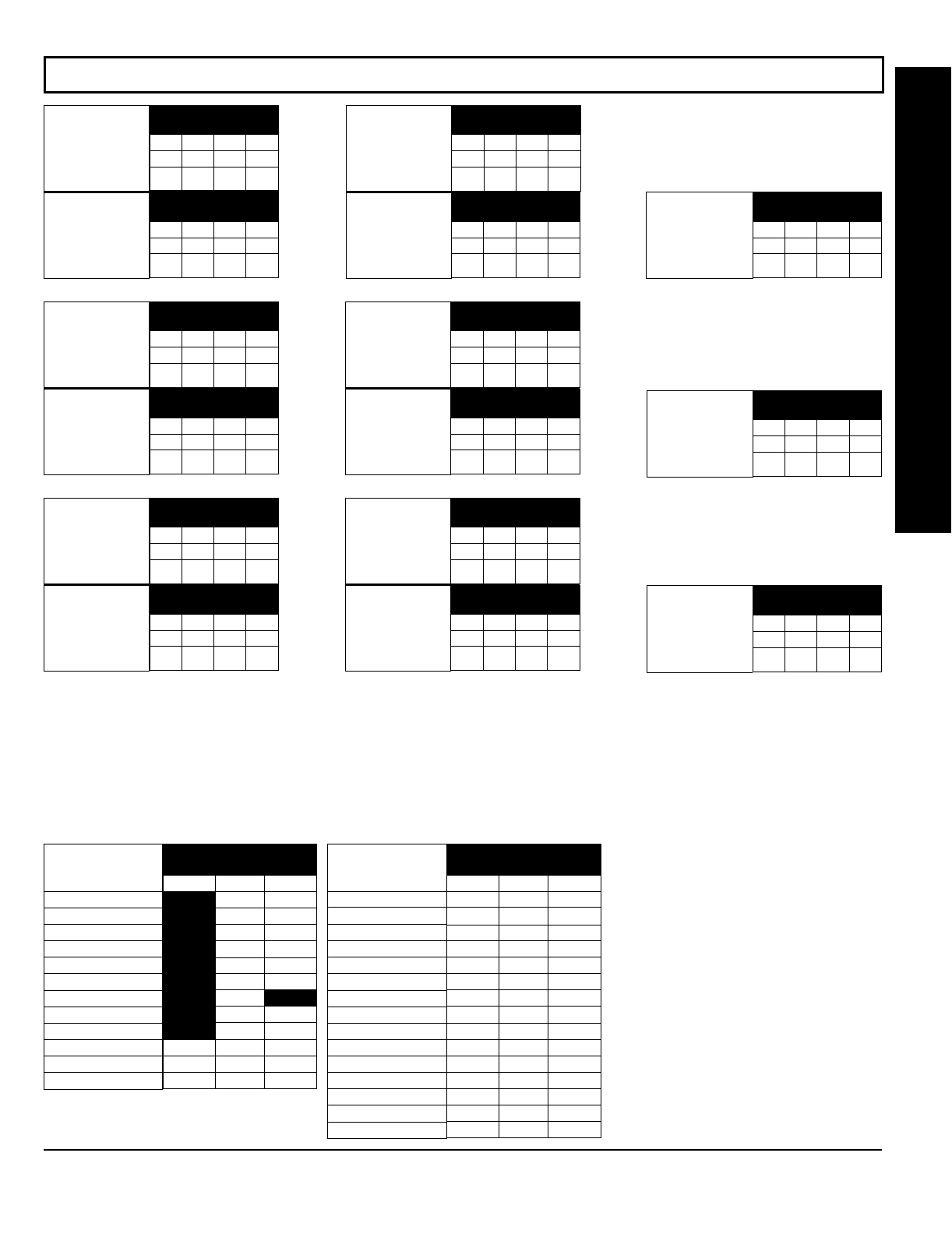
NAPCO Security Systems
GEM-P1632 Programming Instructions
WI897B 8/98
Page 27
#%"
CS Telco 1
Subscriber
Opening/Closing ID
Number (Area 1)
ADDRESS 0259-0262
(RIGHT DIGITS 1-4)
0259 0260 0261 0262
RRRR
CS Telco 1
Subscriber
Opening/Closing ID
Number (Area 2)
ADDRESS 0263-0266
(RIGHT DIGITS 1-4)
0263 0264 0265 0266
RRRR
CS Telco 1
Subscriber Event ID
Number (Area 1)
ADDRESS 0267-0270
(RIGHT DIGITS 1-4)
0267 0268 0269 0270
RRRR
CS Telco 2
Subscriber
Opening/Closing ID
Number (Area 1)
ADDRESS 0279-0282
(RIGHT DIGITS 1-4)
0279 0280 0281 0282
RRRR
CS Telco 2
Subscriber Event ID
Number (Area 1)
ADDRESS 0287-0290
(RIGHT DIGITS 1-4)
0287 0288 0289 0290
RRRR
CS Telco 3
Subscriber
Opening/Closing ID
Number (Area 1)
ADDRESS 0299-0302
(RIGHT DIGITS 1-4)
0299 0300 0301 0302
RRRR
CS Telco 3
Subscriber Event ID
Number (Area 1)
ADDRESS 0307-0310
(RIGHT DIGITS 1-4)
0307 0308 0309 0310
RRRR
CS Telco 1
Subscriber Event ID
Number (Area 2)
ADDRESS 0271-0274
(RIGHT DIGITS 1-4)
0271 0272 0273 0274
RRRR
CS Telco 2
Subscriber
Opening/Closing ID
Number (Area 2)
ADDRESS 0283-0286
(RIGHT DIGITS 1-4)
0283 0284 0285 0286
RRRR
CS Telco 2
Subscriber Event ID
Number (Area 2)
ADDRESS 0291-0294
(RIGHT DIGITS 1-4)
0291 0292 0293 0294
RRRR
CS Telco 3
Subscriber
Opening/Closing ID
Number (Area 2)
ADDRESS 0303-0306
(RIGHT DIGITS 1-4)
0303 0304 0305 0306
RRRR
CS Telco 3
Subscriber Event ID
Number (Area 2)
ADDRESS 0311-0314
(RIGHT DIGITS 1-4)
0311 0312 0313 0314
RRRR
CS Telco 1
Subscriber Event ID
Number(System)
ADDRESS 0275-0278
(RIGHT DIGITS 1-4)
0275 0276 0277 0278
RRRR
CS Telco 2
Subscriber Event ID
Number (System)
ADDRESS 0295-0298
(RIGHT DIGITS 1-4)
0295 0296 0297 0298
RRRR
CS Telco 3
Subscriber Event ID
Number (System)
ADDRESS 0315-0318
(RIGHT DIGITS 1-4)
0315 0316 0317 0318
RRRR
Default for CS Telco 1 Subscriber Event ID Number (Area 1) depends on Easy Menu Question “ACCOUNT #”. [Default = blank (•) blank (•) blank (•)
blank (•)] for all other ID Numbers.
CS TELCO SUBSCRIBER ID NUMBERS:
Enter the Subscriber Opening/Closing and Event ID Numbers for any of the 3 CS
Receivers.
1. Enter in corresponding right digit address location (left digit is not used).
2. Enter 3 or 4 digits (depending on the CS receiver format) for each subscriber number from left to right. NOTE: Leave trailing
boxes blank (•).
3. Valid entries are: 1-9, 0 and B-F. NOTE: A is not permitted.
[Default = blank (•) blank (•) from
address 0319-0330]
ADDRESS
0333-0347
LEFT ADDR RIGHT
0333
0334
0335
0336
0337
0338
0339
0340
0341
0342
0343
0344
0345
0346
0347
CS SYSTEM
REPORTING CODES
Telco Fail
RF Rec. Trouble
Memory Fail
Low Battery
Panel AC Fail
EZM Tamper
Alarm Output Superv.
Ambush
Panic
Fire
Auxiliary
Tamper
Fail to Close
Test Timer
Keyfob Low Battery
ADDRESS
0319-0330
LEFT ADDR RIGHT
blank (•) 0319
blank (•) 0320
blank (•) 0321
blank (•) 0322
blank (•) 0323
blank (•) 0324
blank (•) 0325 blank (•)
blank (•) 0326
blank (•) 0327
0328
0329
0330
CS SYSTEM
REPORTING CODES
Alarm Restore
Trouble
Trouble Restore
Xmitter Low Battery
Xmitter Supervision
Xmitter Tamper
RESERVED
Opening
Closing
Opening after Alarm
Conditional Close
Fail to Open
CS SYSTEM REPORTING CODES:
1. Enter in corresponding address
location (left and right digits). NOTE:
Left digit is the first digit and right digit
is the second digit in a two digit CS
receiver format.
2. Valid entries are: 1-9, 0 and B-F.
NOTE: A is not permitted.
3. To disable a code leave boxes
blank (•).
NOTE: Dark shaded data value box shows
option not available.
PROGRAMMING OPTIONS & WORKSHEETS
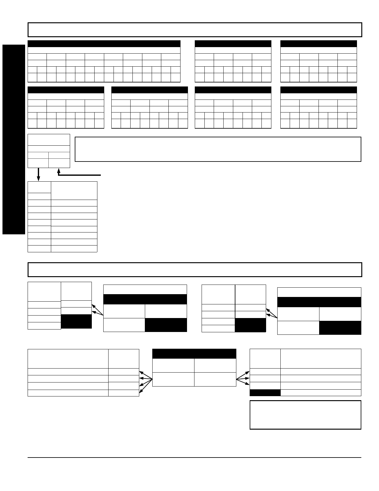
GEM-P1632 Programming Instructions NAPCO Security Systems
WI897B 8/98
Page 28
Default for Group Zone Report Codes depends on Easy Menu Question “RCVR.
[Default = blank (•) blank (•)]
[Default = blank (•) blank (•)]
[Default = blank (•) blank (•)]
'#!"!%
ADDRESS 0358-0365
CONTROL PANEL ZONES REPORT CODE
ZONE 1 ZONE 2 ZONE 3 ZONE 4 ZONE 5 ZONE 6 ZONE 7 ZONE 8
0358 0359 0360 0361 0362 0363 0364 0365
LRLRLRLRLRLRLRLR
ADDRESS 0366-0369
ZONES REPORT CODE
ZONE 9 ZONE 10 ZONE 11 ZONE 12
0366 0367 0368 0369
LRLRLRLR
ADDRESS 0370-0373
ZONES REPORT CODE
ZONE 13 ZONE 14 ZONE 15 ZONE 16
0370 0371 0372 0373
LRLRLRLR
ADDRESS 0382-0385
ZONES REPORT CODE
ZONE 25 ZONE 26 ZONE 27 ZONE 28
0382 0383 0384 0385
LRLRLRLR
ADDRESS 0386-0389
ZONES REPORT CODE
ZONE 29 ZONE 30 ZONE 31 ZONE 32
0386 0387 0388 0389
LRLRLRLR
ADDRESS 0374-0377
ZONES REPORT CODE
ZONE 17 ZONE 18 ZONE 19 ZONE 20
0374 0375 0376 0377
LRLRLRLR
ADDRESS 0378-0381
ZONES REPORT CODE
ZONE 21 ZONE 22 ZONE 23 ZONE 24
0378 0379 0380 0381
LRLRLRLR
#%"%
7 Gas Alarm
8 Heat Alarm
0 Auxiliary Alarm
B 24 Hour Auxiliary
DATA
ENTRIES
LEFT
1
2
3
4
MODEM CODE
Fire *
Panic
Burglary
Hold up
ZONE REPORT
CODE OPTIONS
DATA ENTRIES
LEFT RIGHT
NOTE: If “Zone Doubling” (Address 0721) is not enabled, then Zones 1-8 are included in the control panel and
Zones 9-32 are EZM Zones. If “Zone Doubling” is enabled, then Zones 1-16 are included in the control panel and
Zones 17-32 are EZM Zones. See Address 0737-0742 to enable “EZM Zone Groups”.
PULSE EVENT CODE
will be the first digit of the 2 digit reporting code. the second digit will be the
second digit of the reporting zone. For example, for zone 9 (address 0366), if the right digit is “3", then
the reporting code is ”39". For example, for zone 15 (address 0372), if the right digit is “4", then the
reporting code is ”45".
MODEM CODES
determine the zone types reported for the following formats: SIA and ADEMCO Point
ID.
1. Select the desired Modem Code for each zone from the table shown.
DISABLE OPENING REPORTS
ADDRESS 0391
LEFT DIGIT (SUM
OF DATA VALUES) RIGHT DIGIT
blank (•)
LEFT DATA
VALUES
(CIRCLE )
1
2
4
8
AREA
AREA 1
AREA 2
RESERVED
RESERVED
DISABLE CLOSING REPORTS
ADDRESS 0392
LEFT DIGIT (SUM
OF DATA VALUES) RIGHT DIGIT
blank (•)
LEFT DATA
VALUES
(CIRCLE )
1
2
4
8
AREA
AREA 1
AREA 2
RESERVED
RESERVED
ADDRESS 0394
LEFT DIGIT (SUM
OF DATA VALUES) RIGHT DIGIT (SUM
OF DATA VALUES)
LEFT DATA
VALUES
(CIRCLE )
1
2
4
8
CS SYSTEM REPORT OPTIONS
Cancel Next Test Timer on any Report
Disable Wait for Silence
Disable Wait for Handshake
Disable Dial Tone Detect
RIGHT DATA
VALUES
(CIRCLE )
1
2
4
8
CS SYSTEM REPORT OPTIONS
Backup Report on Telco 2
Touch-tone Dialing Only *
Touch-tone Dialing w/Rotary Backup *
RESERVED
* NOTE: If neither Touch-tone Dialing nor
Touch-tone w/Rotary Backup is selected, then
system defaults automatically to Rotary Dialing.
Leave blank (•) to select Rotary Dialing.
CS AREA & SYSTEM REPORTING OPTIONS:
1. Select the desired option by circling the data values for each digit (left and
right).
2. Add the data values (ex: 15=1+2+4+8) from the selected options.
3. Enter in address location (left and right digits).
NOTE: Dark shaded data value box shows option not available.
PROGRAMMING OPTIONS & WORKSHEETS
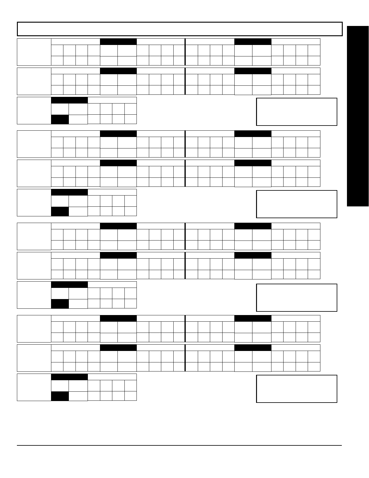
NAPCO Security Systems
GEM-P1632 Programming Instructions
WI897B 8/98
Page 29
#"%
User Opening
Telco 1
LEFT DATA VALUES
User
8User
7User
6User
5
8421
ADDRESS 0440
LEFT RIGHT
RIGHT DATA VALUES
User
4User
3User
2User
1
8421
LEFT DATA VALUES
User
16 User
15 User
14 User
13
8421
ADDRESS 0441
LEFT RIGHT
RIGHT DATA VALUES
User
12 User
11 User
10 User
9
8421
User Opening
Telco 1
LEFT DATA VALUES
User
32 User
31 User
30 User
29
8421
ADDRESS 0443
LEFT RIGHT
RIGHT DATA VALUES
User
28 User
27 User
26 User
25
8421
LEFT DATA VALUES
User
24 User
23 User
22 User
21
8421
ADDRESS 0442
LEFT RIGHT
RIGHT DATA VALUES
User
20 User
19 User
18 User
17
8421
User Opening
Telco 1
ADDRESS 0444
LEFT RIGHT
blank (•)
RIGHT DATA VALUES
User
00 User
99 User
98 User
97
8421
User Closing
Telco 1
LEFT DATA VALUES
User
8User
7User
6User
5
8421
ADDRESS 0445
LEFT RIGHT
RIGHT DATA VALUES
User
4User
3User
2User
1
8421
LEFT DATA VALUES
User
16 User
15 User
14 User
13
8421
ADDRESS 0446
LEFT RIGHT
RIGHT DATA VALUES
User
12 User
11 User
10 User
9
8421
User Closing
Telco 1
LEFT DATA VALUES
User
32 User
31 User
30 User
29
8421
ADDRESS 0448
LEFT RIGHT
RIGHT DATA VALUES
User
28 User
27 User
26 User
25
8421
LEFT DATA VALUES
User
24 User
23 User
22 User
21
8421
ADDRESS 0447
LEFT RIGHT
RIGHT DATA VALUES
User
20 User
19 User
18 User
17
8421
User Closing
Telco 1
ADDRESS 0449
LEFT RIGHT
blank (•)
RIGHT DATA VALUES
User
00 User
99 User
98 User
97
8421
User Opening
Telco 3
LEFT DATA VALUES
User
8User
7User
6User
5
8421
ADDRESS 0450
LEFT RIGHT
RIGHT DATA VALUES
User
4User
3User
2User
1
8421
LEFT DATA VALUES
User
16 User
15 User
14 User
13
8421
ADDRESS 0451
LEFT RIGHT
RIGHT DATA VALUES
User
12 User
11 User
10 User
9
8421
User Opening
Telco 3
LEFT DATA VALUES
User
32 User
31 User
30 User
29
8421
ADDRESS 0453
LEFT RIGHT
RIGHT DATA VALUES
User
28 User
27 User
26 User
25
8421
LEFT DATA VALUES
User
24 User
23 User
22 User
21
8421
ADDRESS 0452
LEFT RIGHT
RIGHT DATA VALUES
User
20 User
19 User
18 User
17
8421
User Opening
Telco 3
ADDRESS 0454
LEFT RIGHT
blank (•)
RIGHT DATA VALUES
User
00 User
99 User
98 User
97
8421
User Closing
Telco 3
LEFT DATA VALUES
User
8User
7User
6User
5
8421
ADDRESS 0455
LEFT RIGHT
RIGHT DATA VALUES
User
4User
3User
2User
1
8421
LEFT DATA VALUES
User
16 User
15 User
14 User
13
8421
ADDRESS 0456
LEFT RIGHT
RIGHT DATA VALUES
User
12 User
11 User
10 User
9
8421
User Closing
Telco 3
LEFT DATA VALUES
User
32 User
31 User
30 User
29
8421
ADDRESS 0458
LEFT RIGHT
RIGHT DATA VALUES
User
28 User
27 User
26 User
25
8421
LEFT DATA VALUES
User
24 User
23 User
22 User
21
8421
ADDRESS 0457
LEFT RIGHT
RIGHT DATA VALUES
User
20 User
19 User
18 User
17
8421
User Closing
Telco 3
ADDRESS 0459
LEFT RIGHT
blank (•)
RIGHT DATA VALUES
User
00 User
99 User
98 User
97
8421
CS USER REPORTING OPTIONS:
[Default = blank (•) blank (•) from address 0440-0459]
1. Select the desired option by circling the data values for each digit (left and right).
2. Add the data values (ex: 15=1+2+4+8) from the selected options.
3. Enter in address location (left and right digits). NOTE: Dark shaded data value box shows option not available.
User 97 = Auto Arming/Disarming
User 98 = Quickloader Arming/Disarming
User 99 = Easy Arming (Opening not applicable)
User 00 = Keyswitch Arming
NOTE: These opening events will report
as the user number shown. Also, Keyfobs
1-8 (see Easy Menu Program Driven
Mode) will report as Users 25-32, respec-
tively.
PROGRAMMING OPTIONS & WORKSHEETS

GEM-P1632 Programming Instructions NAPCO Security Systems
WI897B 8/98
Page 30
[Default = blank (•) blank (•)][Default = blank (•) blank (•)]
'#"
ADDRESS 0737
LEFT RIGHT
blank (•)
EZM Group 1
Default depends on Easy Menu Question “ ” and “ ”. For example, If 32 zones are used and Zone Doubling is
not enabled, then all 6 groups will be automatically enabled. If 32 zones are used and Zone Doubling is enabled, then only groups 1-4 will be automatically enabled.
ADDRESS 0738
LEFT RIGHT
blank (•)
EZM Group 2
ADDRESS 0739
LEFT RIGHT
blank (•)
EZM Group 3
ADDRESS 0740
LEFT RIGHT
blank (•)
EZM Group 4
ADDRESS 0741
LEFT RIGHT
blank (•)
EZM Group 5
ADDRESS 0742
LEFT RIGHT
blank (•)
EZM Group 6
NOTE: If “Zone Doubling” (Address 0721) is not enabled, then Zones 1-8 are included in the control panel and Zones 9-32 (Groups
1-6) are EZM Zones. If “Zone Doubling” is enabled, then Zones 1-16 are included in the control panel and Zones 17-32 (Groups 1-4)
are EZM Zones and groups 5 and 6 must not be used.
DATA
ENTRIES
RIGHT
blank (•)
1
OPTION
Not used
(No EZM
present)
4-Zone EZM
EZM TYPE
EZM GROUP OPTIONS:
Up to 6 Groups of 4 Zones each may be
programmed depending on the number of zones used and which EZM
modules are connected. Each group represents 4 zones.
1. Select EZM type from the table shown.
2. Enter in corresponding address locations above (right digit only).
NOTE: Dark shaded data value box shows option not available.
#
ADDRESS 0743
LEFT RIGHT
blank (•)
Priority Arming/
Area 1
DATA ENTRIES
LEFT RIGHT
blank (•) blank (•)
blank (•) 2
OPTION
Not Used
Enabled
PRIORITY ARMING/AREA 1
ADDRESS 0744
LEFT RIGHT
blank (•)
Priority Arming/
Area 2
DATA ENTRIES
LEFT RIGHT
blank (•) blank (•)
blank (•) 1
OPTION
Not Used
Enabled
PRIORITY ARMING/AREA 2
PRIORITY AREA ARMING:
1. Select option from the table shown.
2. Enter in corresponding right digit address location (left digit
is not used).
NOTE: Dark shaded data value box shows option not available.
PROGRAMMING OPTIONS & WORKSHEETS
EZM
TYPE
1
2
3
4
5
6
ZONES COVERED
NORMAL DOUBLED
9-12 17-20
13-16 21-24
17-20 25-28
21-24 29-32
25-28
29-32
[Default = blank (•) blank (•)]
RIGHT DATA
VALUES
(CIRCLE )
1
2
4
8
Disarming Area 1
Area 1 Burg Output Silenced
Area 2 Burg Output Silenced
RESERVED
RESERVED
LEFT DATA
VALUES
(CIRCLE )
1
2
4
8
Disarming Area 2
Area 1 Burg Output Silenced
Area 2 Burg Output Silenced
RESERVED
RESERVED
Burglary Output Turns Off
upon Disarm
ADDRESS 0745
LEFT DIGIT (SUM
OF DATA VALUES) RIGHT DIGIT (SUM
OF DATA VALUES)
[Default = blank (•) blank (•)]
RIGHT DATA
VALUES
(CIRCLE )
1
2
4
8
Disarming Area 1
Area 1 Pulsed Burg Output Silenced
Area 2 Pulsed Burg Output Silenced
RESERVED
RESERVED
LEFT DATA
VALUES
(CIRCLE )
1
2
4
8
Disarming Area 2
Area 1 Pulsed Burg Output Silenced
Area 2 Pulsed Burg Output Silenced
RESERVED
RESERVED
Pulsed Burg Output Turns Off
upon Disarm
ADDRESS 0746
LEFT DIGIT (SUM
OF DATA VALUES) RIGHT DIGIT (SUM
OF DATA VALUES)
OUTPUT TURNS OFF UPON DISARM:
Select options for any of the 4 Outputs.
1. Select the desired option by circling the data values for right digit only (left is not used).
2. Add the data values (ex: 15=1+2+4+8) from the selected options.
3. Enter in right digit address location. NOTE: Dark shaded data value box shows option not available.
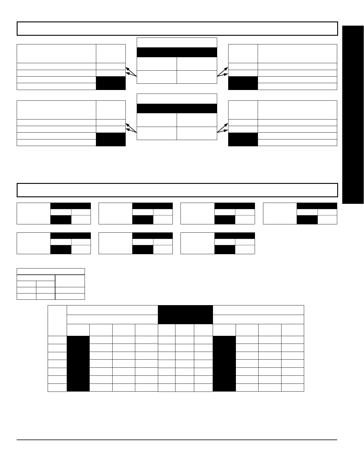
NAPCO Security Systems
GEM-P1632 Programming Instructions
WI897B 8/98
Page 31
%
[Default = blank (•) 1]
ADDRESS 0726
LEFT RIGHT
blank (•)
Keypad 4 Area
Assignment
[Default = blank (•) 1]
ADDRESS 0723
LEFT RIGHT
blank (•)
Keypad 1 Area
Assignment
[Default = blank (•) 1]
ADDRESS 0724
LEFT RIGHT
blank (•)
Keypad 2 Area
Assignment
[Default = blank (•) 1]
ADDRESS 0725
LEFT RIGHT
blank (•)
Keypad 3 Area
Assignment
[Default = blank (•) 1]
ADDRESS 0727
LEFT RIGHT
blank (•)
Keypad 5 Area
Assignment
[Default = blank (•) 1]
ADDRESS 0728
LEFT RIGHT
blank (•)
Keypad 6 Area
Assignment
[Default = blank (•) 1]
ADDRESS 0729
LEFT RIGHT
blank (•)
Keypad 7 Area
Assignment
KEYPAD AREA ASSIGNMENT:
Up to 7 keypads may be programmed, if they are connected.
NOTE: Keypad Number is configured by setting its jumper settings. By default from the factory, each
keypad is configured as number 1.
1. Select area assignment for each keypad from the table shown.
2. Enter in corresponding right digit address locations above (left digit is not used).
NOTE: Dark shaded data value box shows option not available.
DATA ENTRIES
LEFT RIGHT
blank (•) 1
blank (•) 2
OPTION
Area 1
Area 2
KEYPAD AREA ASSIGNMENT
KEYPAD OPTIONS:
Select options for any of the 7 keypads.
1. Select the desired option by circling the data values for each digit (left and right).
2. Add the data values (ex: 15=1+2+4+8) from the selected options.
3. Enter in address location (left and right digits). NOTE: Dark shaded data value box shows option not available.
PROGRAMMING OPTIONS & WORKSHEETS
OUTPUT TURNS OFF UPON DISARM:
Select options for any of the 4 Outputs.
1. Select the desired option by circling the data values for right digit only (left is not used).
2. Add the data values (ex: 15=1+2+4+8) from the selected options.
3. Enter in right digit address location. NOTE: Dark shaded data value box shows option not available.
[Default = blank (•) blank (•)]
RIGHT DATA
VALUES
(CIRCLE )
1
2
4
8
Disarming Area 1
Area 1 PGM1 Output Silenced
Area 2 PGM1 Output Silenced
RESERVED
RESERVED
LEFT DATA
VALUES
(CIRCLE )
1
2
4
8
Disarming Area 2
Area 1 PGM1 Output Silenced
Area 2 PGM1 Output Silenced
RESERVED
RESERVED
PGM1 Output Turns Off
upon Disarm
ADDRESS 0747
LEFT DIGIT (SUM
OF DATA VALUES) RIGHT DIGIT (SUM
OF DATA VALUES)
[Default = blank (•) blank (•)]
RIGHT DATA
VALUES
(CIRCLE )
1
2
4
8
Disarming Area 1
Area 1 PGM2 Output Silenced
Area 2 PGM2 Output Silenced
RESERVED
RESERVED
LEFT DATA
VALUES
(CIRCLE )
1
2
4
8
Disarming Area 2
Area 1 PGM2 Output Silenced
Area 2 PGM2 Output Silenced
RESERVED
RESERVED
PGM2 Output Turns Off
upon Disarm
ADDRESS 0749
LEFT DIGIT (SUM
OF DATA VALUES) RIGHT DIGIT (SUM
OF DATA VALUES)
[Default = blank (•) blank (•) from address 0730-0736]
KEYPAD
NO.
1
2
3
4
5
6
7
KEYPAD OPTIONS
LEFT DATA VALUES (CIRCLE )
RSRVD PANEL
ACCESS EASY
ARMING AMBUSH
8421
8421
8421
8421
8421
8421
8421
ADDRESS
0730-0736
LEFT ADDR RIGHT
0730
0731
0732
0733
0734
0735
0736
KEYPAD OPTIONS
RIGHT DATA VALUES (CIRCLE )
RSRVD KEYPAD
PANIC KEYPAD
AUXILIARY KEYPAD
FIRE
8421
8421
8421
8421
8421
8421
8421
"
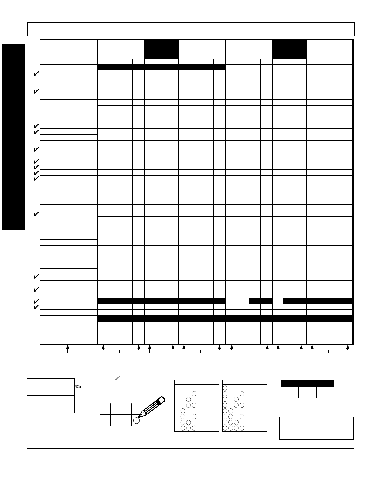
GEM-P1632 Programming Instructions NAPCO Security Systems
WI897B 8/98
Page 32
'"'%"%
ZONE OPTIONS
50ms Loop Response (A)
Priority
Priority with Bypass
Auto-Bypass
Selective Bypass
Keyswitch Arming
Auto-Bypass Re-entry
Pre-Alarm Warning
Never Arm
24-Hour Zone
Alarm Output
Pulsed Alarm Output
PGM1 Output
PGM2 Output
Entry/Exit 1
Entry/Exit 2
Exit/Entry Follower
Auto Reset
Swinger Shutdown
Chime
Abort Delay
Power-up Delay
Day Zone Open
Day Zone Short
Alarm on Day Zone
Alarm Telco 1
Alarm Restore 1
Trouble Telco 1
Trouble Restore 1
Alarm Telco 3
Alarm Restore 3
Trouble Telco 3
Trouble Restore 3
No EOL Resistor
Trouble on Open
Trouble on Short
Zone Area 1
Zone Area 2
Interior Bypass
Keypad Sounder on Alarm
2-Wire Smoke Detectors (B)
Fire (C)
Fire Alarm Verification (C)
RESERVED
Zone ANDing Group 1
Zone ANDing Group 2
Zone ANDing Group 3
Zone ANDing Group 4
ZONES 13-16
LEFT DATA VALUES
(CIRCLE )
ZN16 ZN15 ZN14 ZN13
8421
8421
8421
8421
8421
8421
8421
8421
8421
8421
8421
8421
8421
8421
8421
8421
8421
8421
8421
8421
8421
8421
8421
8421
8421
8421
8421
8421
8421
8421
8421
8421
8421
8421
8421
8421
8421
8421
8421
8421
8421
8421
8421
8421
8421
8421
8421
8421
ADDRESS
0546-0592
L ADDR R
0546
0547
0548
0549
0550
0551
0552
0553
0554
0555
0556
0557
0558
0559
0560
0561
0562
0563
0564
0565
0566
0567
0568
0569
0570
0571
0572
0573
0574
0575
0576
0577
0578
0579
0580
0581
0582
0583
0584
(•) 0585 (•)
0586
0587
(•) 0588 (•)
0589
0590
0591
0592
ZONES 9-12
RIGHT DATA VALUES
(CIRCLE )
ZN12 ZN11 ZN10 ZN9
8421
8421
8421
8421
8421
8421
8421
8421
8421
8421
8421
8421
8421
8421
8421
8421
8421
8421
8421
8421
8421
8421
8421
8421
8421
8421
8421
8421
8421
8421
8421
8421
8421
8421
8421
8421
8421
8421
8421
8421
8421
8421
8421
8421
8421
8421
8421
8421
ZONES 5-8
LEFT DATA VALUES
(CIRCLE )
ZN8 ZN7 ZN6 ZN5
8421
8421
8421
8421
8421
8421
8421
8421
8421
8421
8421
8421
8421
8421
8421
8421
8421
8421
8421
8421
8421
8421
8421
8421
8421
8421
8421
8421
8421
8421
8421
8421
8421
8421
8421
8421
8421
8421
8421
8421
8421
8421
8421
8421
8421
8421
8421
8421
ZONES 1-4
RIGHT DATA VALUES
(CIRCLE )
ZN4 ZN3 ZN2 ZN1
8421
8421
8421
8421
8421
8421
8421
8421
8421
8421
8421
8421
8421
8421
8421
8421
8421
8421
8421
8421
8421
8421
8421
8421
8421
8421
8421
8421
8421
8421
8421
8421
8421
8421
8421
8421
8421
8421
8421
8421
8421
8421
8421
8421
8421
8421
8421
8421
ADDRESS
0490-0537
L ADDR R
0490
0491
0492
0493
0494
0495
0496
0497
0498
0499
0500
0501
0502
0503
0504
0505
0506
0507
0508
0509
0510
0511
0512
0513
0514
0515
0516
0517
0518
0519
0520
0521
0522
0523
0524
0525
0526
0527
0528
0529
0530 (•)
0531
0532
(•) 0533 (•)
0534
0535
0536
0537
14444
2222
1.
Select
the desired
zone option.
ZONE OPTIONS
50ms Loop Response
Priority
Priority with Bypass
Auto-Bypass
Selective Bypass
2.
Enable
desired options
for each zone by drawing a
circle around its corre-
sponding binary data value.
NOTE: No circle = feature dis-
abled.
4
8
2
1
Draw Circle
ZN04
ZN03
ZN02
ZN01
3.
Search table
below
for data entry. 4.
Enter data
in address loca-
tions (left and right digits).
NOTE: Dark shaded data value box
shows option not available.
ADDRESS LOCATION
L ADDR R
blank (•) 0490 1
NOTE: See Direct Address
Programming Example on
page 20.
4821
DIGIT VALUE DATA ENTRY
Blank (.)
4821 1
4821 2
8124 3
4821 4
5
4821
4821 6
4821 7
421
DIGIT VALUE DATA ENTRY
8
421 9
421 0
124 B
421 C
D
421
421 E
421 F
8
8
8
8
8
8
8
8
PROGRAMMING OPTIONS & WORKSHEETS
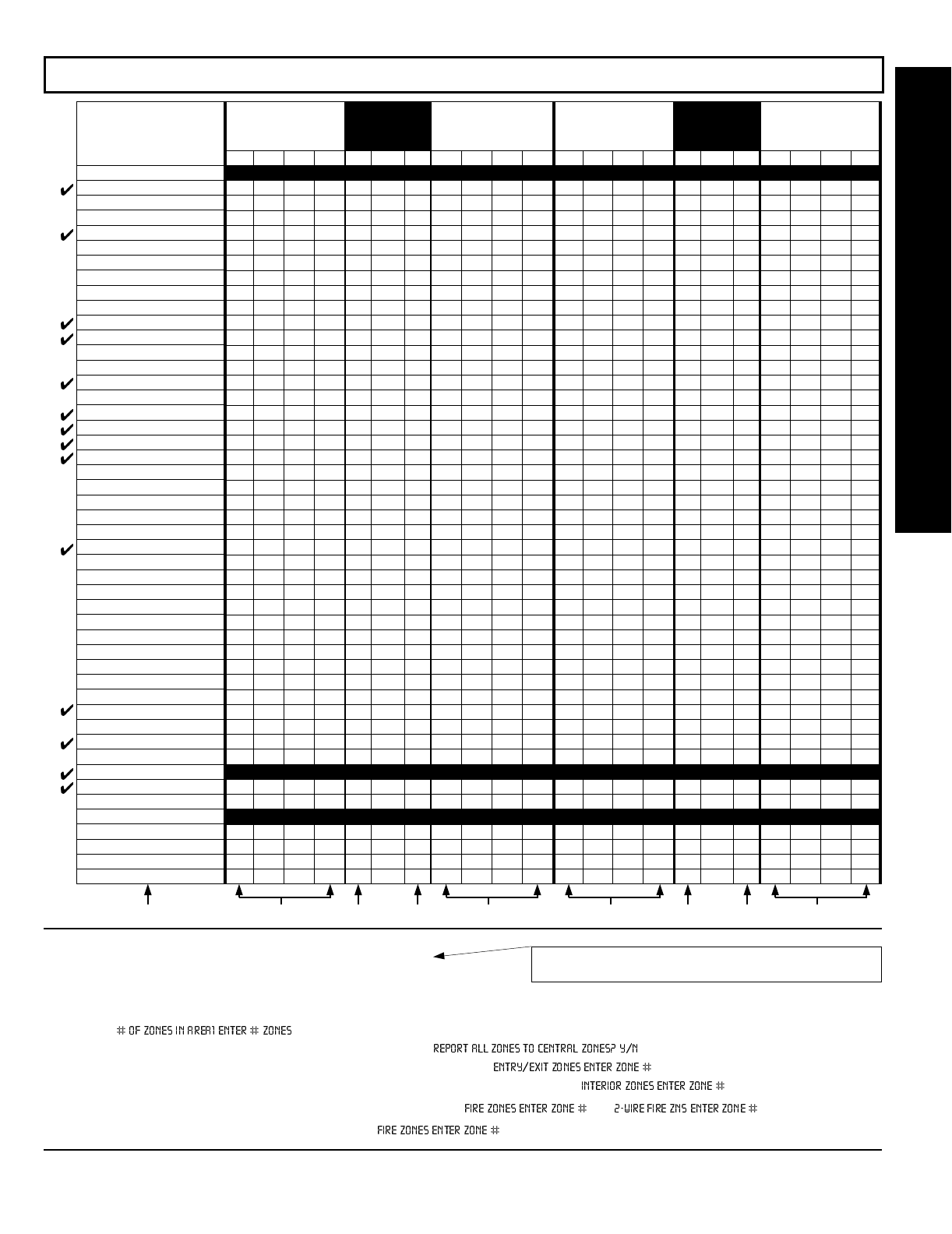
NAPCO Security Systems
GEM-P1632 Programming Instructions
WI897B 8/98
Page 33
NOTES: (A) 50ms Loop Response only available for zones 1-8.
(B) 2-wire Smoke Detectors only available for zones 7 & 8.
(C) If Fire Alarm Verification is selected, then Fire must also be selected.
DEFAULTS: The zone options indicated are automatically set after exiting the Easy Menu Driven Mode.
Priority, Selective Bypass, Alarm Output, Auto Reset, Swinger Shutdown
and
Zone Area 1
are enabled for the total number of zones entered
in “ ”.
Alarm Telco 1
is enabled for the zone number(s) entered in “ ”.
Entry/Exit 1
and
Chime
are enabled for the zone number(s) entered in “ ”.
Exit/Entry Follower
and
Interior Bypass
are enabled for the zone number(s) entered in “ ”.
Pulse Alarm Output
is enabled for the zone number(s) entered in “ ” or “ ”.
Fire
is enabled for the zone number(s) entered in “ ”.
'"'"
ZONE OPTIONS
50ms Loop Response (A)
Priority
Priority with Bypass
Auto-Bypass
Selective Bypass
Keyswitch Arming
Auto-Bypass Re-entry
Pre-Alarm Warning
Never Arm
24-Hour Zone
Alarm Output
Pulsed Alarm Output
PGM1 Output
PGM2 Output
Entry/Exit 1
Entry/Exit 2
Exit/Entry Follower
Auto Reset
Swinger Shutdown
Chime
Abort Delay
Power-up Delay
Day Zone Open
Day Zone Short
Alarm on Day Zone
Alarm Telco 1
Alarm Restore 1
Trouble Telco 1
Trouble Restore 1
Alarm Telco 3
Alarm Restore 3
Trouble Telco 3
Trouble Restore 3
No EOL Resistor
Trouble on Open
Trouble on Short
Zone Area 1
Zone Area 2
Interior Bypass
Keypad Sounder on Alarm
2-Wire Smoke Detectors (B)
Fire (C)
Fire Alarm Verification (C)
RESERVED
Zone ANDing Group 1
Zone ANDing Group 2
Zone ANDing Group 3
Zone ANDing Group 4
ZONES 29-32
LEFT DATA VALUES
(CIRCLE )
ZN32 ZN31 ZN30 ZN29
8421
8421
8421
8421
8421
8421
8421
8421
8421
8421
8421
8421
8421
8421
8421
8421
8421
8421
8421
8421
8421
8421
8421
8421
8421
8421
8421
8421
8421
8421
8421
8421
8421
8421
8421
8421
8421
8421
8421
8421
8421
8421
8421
8421
8421
8421
8421
8421
ADDRESS
0656-0702
L ADDR R
0656
0657
0658
0659
0660
0661
0662
0663
0664
0665
0666
0667
0668
0669
0670
0671
0672
0673
0674
0675
0676
0677
0678
0679
0680
0681
0682
0683
0684
0685
0686
0687
0688
0689
0690
0691
0692
0693
0694
(•) 0695 (•)
0696
0697
(•) 0698 (•)
0699
0700
0701
0702
ZONES 25-28
RIGHT DATA VALUES
(CIRCLE )
ZN28 ZN27 ZN26 ZN25
8421
8421
8421
8421
8421
8421
8421
8421
8421
8421
8421
8421
8421
8421
8421
8421
8421
8421
8421
8421
8421
8421
8421
8421
8421
8421
8421
8421
8421
8421
8421
8421
8421
8421
8421
8421
8421
8421
8421
8421
8421
8421
8421
8421
8421
8421
8421
8421
ZONES 21-24
LEFT DATA VALUES
(CIRCLE )
ZN24 ZN23 ZN22 ZN21
8421
8421
8421
8421
8421
8421
8421
8421
8421
8421
8421
8421
8421
8421
8421
8421
8421
8421
8421
8421
8421
8421
8421
8421
8421
8421
8421
8421
8421
8421
8421
8421
8421
8421
8421
8421
8421
8421
8421
8421
8421
8421
8421
8421
8421
8421
8421
8421
ZONES 17-20
RIGHT DATA VALUES
(CIRCLE )
ZN20 ZN19 ZN18 ZN17
8421
8421
8421
8421
8421
8421
8421
8421
8421
8421
8421
8421
8421
8421
8421
8421
8421
8421
8421
8421
8421
8421
8421
8421
8421
8421
8421
8421
8421
8421
8421
8421
8421
8421
8421
8421
8421
8421
8421
8421
8421
8421
8421
8421
8421
8421
8421
8421
ADDRESS
0601-0647
L ADDR R
0601
0602
0603
0604
0605
0606
0607
0608
0609
0610
0611
0612
0613
0614
0615
0616
0617
0618
0619
0620
0621
0622
0623
0624
0625
0626
0627
0628
0629
0630
0631
0632
0633
0634
0635
0636
0637
0638
0639
(•) 0640 (•)
0641
0642
(•) 0643 (•)
0644
0645
0646
0647
14444
2222
PROGRAMMING OPTIONS & WORKSHEETS
(Address Location 0530 can only be programmed as “blank (•) blank (•)”,
“4 blank (•)”, “8 blank (•)” or “C blank (•)”.
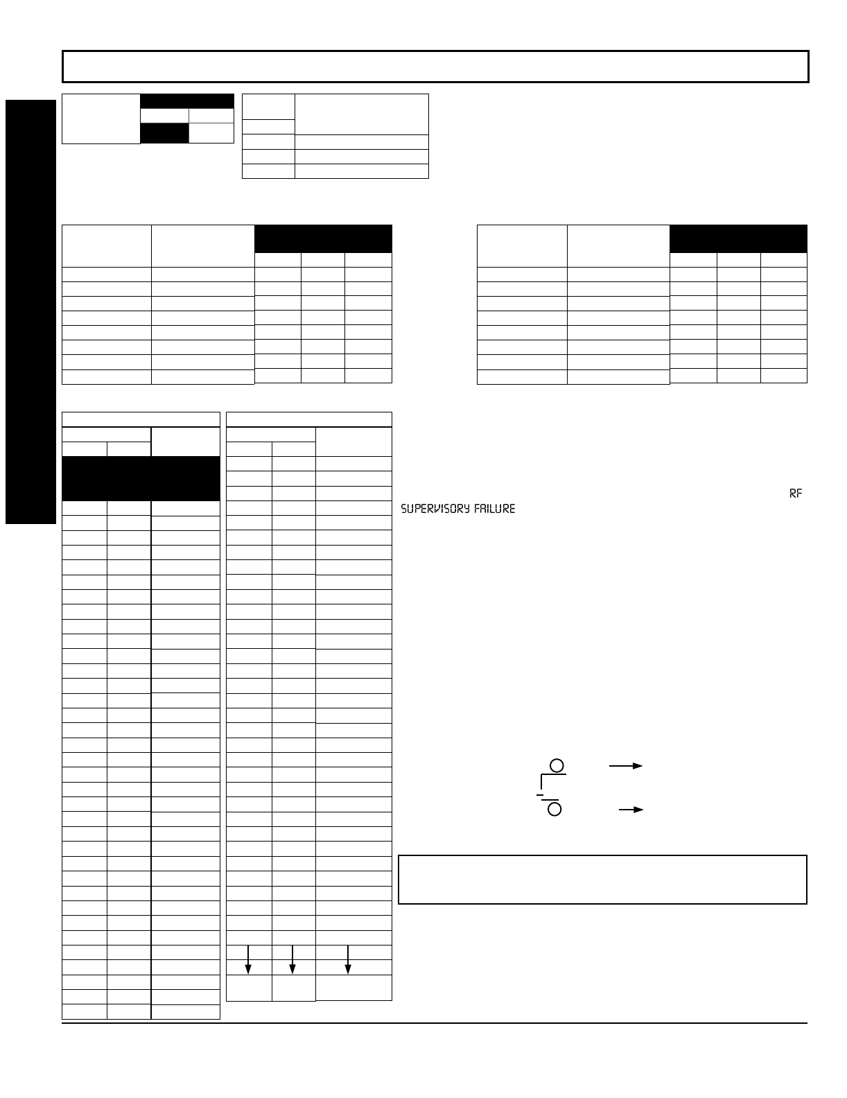
GEM-P1632 Programming Instructions NAPCO Security Systems
WI897B 8/98
Page 34
$&&!"!
Default for Number of Receivers de-
pends on Easy Menu Question for RF
Transmitters.
ADDRESS 1180
LEFT RIGHT
blank (•)
Number of RF
Receivers
DATA
ENTRIES
RIGHT
blank (•)
1
2
RF Receiver(s)
None
1
2
RF RECEIVERS:
Up to 2 RF Receivers may be programmed.
NOTE: This adds wireless capability to the system, increasing
up to 32 the number of zones. Also, the corresponding EZM
Group Number must be enabled (see address 0737-0742).
1. Select the number of receivers from the table shown.
2. Enter in corresponding right digit address location shown
(left digit is not used).
[Default = blank (•) blank (•) from address 1038-1045]
ADDRESS
1038-1045
LEFT ADDR RIGHT
1038
1039
1040
1041
1042
1043
1044
1045
RF SUPERVISORY
TIMER RF TRANSMITTER
Type 0 Window/Door, 2 Pt.
Type 1 Window/Door, 2 Pt.
Type 2 Window/Door, 2 Pt.
Type 3 Window/Door, 2 Pt.
Type 4 Window/Door, 4 Pt.
Type 5 PIR
Type 6 PIR
Type 7 Smoke Detector
[Default = blank (•) blank (•) from address 1046-1053]
ADDRESS
1046-1053
LEFT ADDR RIGHT
1046
1047
1048
1049
1050
1051
1052
1053
RF SUPERVISORY
TIMER RF TRANSMITTER
Type 8 Smoke Detector
Type 9 Keyfob
Type A Dual Tech.
Type B Keyfob
Type C Window/Door, 4 Pt.
Type D PIR
Type E Smoke Detector
Type F Napco Glass Break
DATA ENTRIES
LEFT RIGHT
blank (•) blank (•)
blank (•) 1
blank (•) 2
blank (•) 3
blank (•) 4
blank (•) 5
blank (•) 6
blank (•) 7
blank (•) 8
blank (•) 9
blank (•) 0
blank (•) B
blank (•) C
blank (•) D
blank (•) E
blank (•) F
1 blank (•)
11
12
13
14
15
16
17
18
19
10
1B
1C
1D
1E
1F
2 blank (•)
21
22
23
24
25
DELAY
0 min.
30 min.
60 min.
90 min.
120 min.
150 min.
180 min.
210 min.
240 min.
270 min.
300 min.
330 min.
360 min.
390 min.
420 min.
450 min.
480 min.
510 min.
540 min.
570 min.
600 min.
630 min.
660 min.
690 min.
720 min.
750 min.
780 min.
810 min.
840 min.
870 min.
900 min.
930 min.
960 min.
990 min.
1020 min.
1050 min.
1080 min.
1110 min.
RF SUPERVISORY TIMERS
DATA ENTRIES
LEFT RIGHT
26
27
28
29
20
2B
2C
2D
2E
2F
3 blank (•)
31
32
33
34
35
36
37
38
39
30
3B
3C
3D
3E
3F
4 blank (•)
41
42
43
44
45
46
FF
DELAY
1140 min.
1170 min.
1200 min.
1230 min.
1260 min.
1290 min.
1320 min.
1350 min.
1380 min.
1410 min.
1440 min.
1470 min.
1500 min.
1530 min.
1560 min.
1590 min.
1620 min.
1650 min.
1680 min.
1710 min.
1740 min.
1770 min.
1800 min.
1830 min.
1860 min.
1890 min.
1920 min.
1950 min.
1980 min.
2010 min.
2040 min.
2070 min.
2100 min.
7650 min. = 127
Hr., 30 min.
RF SUPERVISORY TIMERS
RF SUPERVISORY TIMERS:
RF Supervisory Timers may be pro-
grammed for each type of transmitter used. A transmitter will send a
transmission every time it is tripped, when there is NO activity, the
transmitter sends a status transmission about once an hour. If the
receiver does NOT receive ANY signal (a trip or a status) from a
transmitter in the time specified for transmitter type, a system trouble “
” will be displayed at the keypad.
1. Select timer delay from the table shown. Timers are programmed
in increments of 30 minutes each. Valid entries are 03-FF, 90
minutes-7650min (127hr,30min).
WARNING: Timers have uncertainty of +0/-30 minutes. Do not
use entries 0-2 (shaded areas).
2. Enter in corresponding address locations above (left and right
digits).
3. For a desired
timer not
listed do the following:
A. Choose a desired timer (intervals of 30),
ex: 3000 min. (50 Hours)
B. Divide it by 30, ex: 3000/30 = 100
C. Divide it by 16
6 Quotient Left Digit
16 100
96
4 Remainder Right Digit
PROGRAMMING OPTIONS & WORKSHEETS
NOTE: These timers apply only to Supervised RF Transmitters (see
RF Transmitters in Easy Menu Driven Mode Programming).

NAPCO Security Systems
GEM-P1632 Programming Instructions
WI897B 8/98
Page 35
AREA OPTIONS:
Each relay event can be assigned to Area 1, Area 2
or both Area 1 & Area 2.
2. Select the area from the table shown;
enter in corresponding right digit address
location (left digit is not used).
("!%
ADDRESS 0750-0754 (RELAY EVENT 1)
0750 0751 0752 0753 0754
LRLRLRLRLR
(•) (•)
ADDRESS 0755-0759 (RELAY EVENT 2)
0755 0756 0757 0758 0759
LRLRLRLRLR
(•) (•)
ADDRESS 0760-0764 (RELAY EVENT 3)
0760 0761 0762 0763 0764
LRLRLRLRLR
(•) (•)
ADDRESS 0765-0769 (RELAY EVENT 4)
0765 0766 0767 0768 0769
LRLRLRLRLR
(•) (•)
ADDRESS 0770-0774 (RELAY EVENT 5)
0770 0771 0772 0773 0774
LRLRLRLRLR
(•) (•)
ADDRESS 0775-0779 (RELAY EVENT 6)
0775 0776 0777 0778 0779
LRLRLRLRLR
(•) (•)
ADDRESS 0780-0784 (RELAY EVENT 7)
0780 0781 0782 0783 0784
LRLRLRLRLR
(•) (•)
ADDRESS 0785-0789 (RELAY EVENT 8)
0785 0786 0787 0788 0789
LRLRLRLRLR
(•) (•)
ADDRESS 0790-0794 (RELAY EVENT 9)
0790 0791 0792 0793 0794
LRLRLRLRLR
(•) (•)
ADDRESS 0795-0799 (RELAY EVENT 10)
0795 0796 0797 0798 0799
LRLRLRLRLR
(•) (•)
ADDRESS 0800-0804 (RELAY EVENT 11)
0800 0801 0802 0803 0804
LRLRLRLRLR
(•) (•)
ADDRESS 0805-0809 (RELAY EVENT 12)
0805 0806 0807 0808 0809
LRLRLRLRLR
(•) (•)
ADDRESS 0810-0814 (RELAY EVENT 13)
0810 0811 0812 0813 0814
LRLRLRLRLR
(•) (•)
ADDRESS 0815-0819 (RELAY EVENT 14)
0815 0816 0817 0818 0819
LRLRLRLRLR
(•) (•)
ADDRESS 0820-0824 (RELAY EVENT 15)
0820 0821 0822 0823 0824
LRLRLRLRLR
(•) (•)
ADDRESS 0825-0829 (RELAY EVENT 16)
0825 0826 0827 0828 0829
LRLRLRLRLR
(•) (•)
RELAY EVENT OPTIONS
RELAY # AREA Timeout Event ID COND.
LRLRLRLRLR
(•) (•)
12345
DATA
ENTRY
RIGHT
blank (•)
1
2
3
4
5
6
7
8
RELAY #
NONE
1
2
3
4
5
6
7
8
[Default = blank (•) blank (•) from address 0750-0829]
RELAY # OPTIONS:
Each relay event can be assigned to any of the 8
available external relays from Relay Module RM3008. Multiple relay
events can drive the same External Relay.
1. Select the relay from the table shown; enter in corresponding
right digit address location (left digit is not used).
DATA
ENTRY
RIGHT
blank (•)
1
2
3
OFF/ON AREA
DISARM
NONE
Area 1
Area 2
Area 1 & Area 2
TIMEOUTS:
Each relay event can be assigned a timeout depending on Alarm Type option.
3. If Alarm Type (see next page) is selected for timeout in minutes or seconds, select the timeout from the table shown in minutes
or seconds and enter in corresponding address location (left digit and right digits).
DATA ENTRIES
LEFT RIGHT
blank (•) blank (•)
blank (•) 1
blank (•) 2
blank (•) 3
blank (•) 4
blank (•) 5
blank (•) 6
blank (•) 7
blank (•) 8
blank (•) 9
blank (•) 0
TIMEOUT
0 min./sec.
1 min./sec.
2 min./sec.
3 min./sec.
4 min./sec.
5 min./sec.
6 min./sec.
7 min./sec.
8 min./sec.
9 min./sec.
10 min./sec.
TIMEOUTS
(Alarm Type is selected for
Timeout Type in min. or sec.)
DATA ENTRIES
LEFT RIGHT
blank (•) B
blank (•) C
blank (•) D
blank (•) E
blank (•) F
1 blank (•)
11
12
13
14
15
TIMEOUT
11 min./sec.
12 min./sec.
13 min./sec.
14 min./sec.
15 min./sec.
16 min./sec.
17 min./sec.
18 min./sec.
19 min./sec.
20 min./sec.
21 min./sec.
TIMEOUTS
(Alarm Type is selected for
Timeout Type in min. or sec.)
DATA ENTRIES
LEFT RIGHT
16
17
18
19
10
1B
1C
1D
FF
TIMEOUT
11 min./sec.
12 min./sec.
13 min./sec.
14 min./sec.
15 min./sec.
16 min./sec.
17 min./sec.
18 min./sec.
2550 min./sec.
TIMEOUTS
(Alarm Type is selected for
Timeout Type in min. or sec.) For a desired delay/timeout not listed
do the following:
A. Choose a desired delay/timeout,
ex: 20 min.
B. Divide it by 16
1 Quotient Left Digit
16 20
16
4 Remainder Right Digit
EVENT ID CODES & CONDITIONS
ARE ON NEXT PAGE
PROGRAMMING OPTIONS & WORKSHEETS

GEM-P1632 Programming Instructions NAPCO Security Systems
WI897B 8/98
Page 36
DATA ENTRIES
LEFT RIGHT
blank (•) blank (•)
blank (•) 1
blank (•) 8
blank (•) 9
blank (•) 0
blank (•) B
blank (•) C
blank (•) D
blank (•) E
blank (•) F
1 blank (•)
11
12
13
14
15
16
17
18
19
10
1B
1C
1D
1E
1F
2 blank (•)
21
22
23
24
25
26
27
3 blank (•)
31
32
33
34
35
36
38
39
30
3B
3C
3D
OPTION
Area 1 Arm/Disarm
Area 2 Arm/Disarm
Zone 1
Zone 2
Zone 3
Zone 4
Zone 5
Zone 6
Zone 7
Zone 8
Zone 9
Zone 10
Zone 11
Zone 12
Zone 13
Zone 14
Zone 15
Zone 16
Zone 17
Zone 18
Zone 19
Zone 20
Zone 21
Zone 22
Zone 23
Zone 24
Zone 25
Zone 26
Zone 27
Zone 28
Zone 29
Zone 30
Zone 31
Zone 32
Area 1 Keypad Ambush
Area 1 Keypad Panic
Area 1 Keypad Fire
Area 1 Keypad Medical
Area 1 Keypad Tamper
Area 1 Fail to Open
Area 1 Fail to Close
Area 2 Keypad Ambush
Area 2 Keypad Panic
Area 2 Keypad Fire
Area 2 Keypad Medical
Area 2 Keypad Tamper
Area 2 Fail to Open
EVENT ID CODES
DATA ENTRIES
LEFT RIGHT
3E
4 blank (•)
42
43
44
45
46
4D
4E
4F
D blank (•)
D1
D2
D4
D5
D8
D9
F blank (•)
F1
F8
F9
OPTION
Area 2 Fail to Close
Test Timer
Bus Fail
Guarded RAM Fail
Low Battery
AC Fail
EZM Tamper
RFEZM Trouble (Fail Tamper)
RXTx Tamper
RXTx Trouble (LB/Supervisory)
Keypad Fail
EZM Fail
Quickloader Device Control
Quickloader System Reset
General System Reset
Area 1 General System Alarm
Area 2 General System Alarm
Relay Group 1
Relay Group 2
Area 1 Entry Delay
Area 2 Entry Delay
EVENT ID CODES
EVENT ID CODES:
Each relay event can be
assigned any of the available event IDs from
the table.
4. Select 2-digit Event ID from the table
shown; enter in corresponding address
locations (left and right digit).
LEFT
DATA
ENTRIES
blank (•)
1
4
8
9
C
ALARM TYPE TIMEOUT TYPE
Burglary Minutes
Fire Minutes
Day Zone Minutes
Burglary Seconds
Fire Seconds
Day Zone Seconds
RELAY EVENT
ALARM TYPE OPTIONS
RIGHT
DATA
ENTRIES
1
2
3
4
5
OPTIONS
Alarm
Restore
Trouble
Trouble Restore
Follow Zone
RELAY EVENT
ACTIVATION CONDITIONS
RELAY EVENT CONDITION OPTIONS:
Each relay event
can be assigned an alarm type; and an activation condition;
also, select a timeout type for each.
5A. Select Alarm Type and Timeout Type from the table
shown; enter in corresponding address location (left
digit). NOTE: Select timeout from previous page.
5B. Select Activation from the table shown; enter in
corresponding address location (right digit).
PROGRAMMING OPTIONS & WORKSHEETS

NAPCO Security Systems
GEM-P1632 Programming Instructions
WI897B 8/98
Page 37
Cold Start (Erases Entire Program)
This erases the entire program including Dealer Program by
erasing Program Data, Zone Description Data and System
Status Data (similar to a new panel).
Access address 1198, then press the button. Data entry is not allowed.
NOTE: Some features (schedules) can only be programmed again with the
Downloading Software.
GEM-RP1CAe2 Keypad
GEM-RP2ASe2 Keypad
Clear Dealer Program (Erases Dealer Program)
This
erases the dealer program
. Use this feature to start a
customized default program. Program Data and System
Status Memory is erased where Scheduled Data and Zone
Descriptions are maintained.
Access address 1197, then press the button. Data entry is not allowed.
NOTE: Enter Easy Menu Driven Program Mode to program system again.
GEM-RP1CAe2 Keypad
GEM-RP2ASe2 Keypad
PROGRAMMING OPTIONS & WORKSHEETS
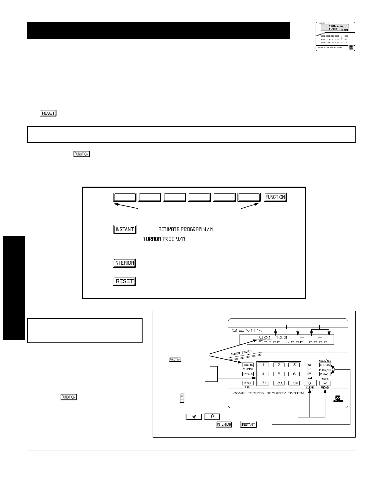
GEM-P1632 Programming Instructions NAPCO Security Systems
WI897B 8/98
Page 38
The User Program Mode is covered in detail in the operating instructions for the keypad in use.
Only Keypad #1 may be used for programming, however this keypad may be located in any area.
The Program Mode cannot be accessed while the communicator is transmitting except during the first three minutes after
power-up.
After entering codes or data, press the save button. Data will not be stored into memory unless this button is pressed.
If the keypad is in the Program Mode and no activity is detected for longer than 4 minutes, a steady tone will sound. Press the
button to silence the sounder and exit the User Program Mode.
If a GEM-RP2ASe2 is used, configure address jumpers as Keypad #1 (see the section of this manual Configuring the GEM-RP2ASe2
Keypad). Use the button to manually scroll the display at the end of each programming line.
NOTE: For ease of programming, it is recommended that a GEM-RP1CAe2 be used as Keypad #1. (A new GEM-RP1CAe2 is auto-
matically configured as Keypad #1.)
1. Press
2. Press
Until
“” (GEM-RP1CAe2) or
“” (GEM-RP2ASe2)
appears on LCD screen.
3. Press
To Enter User Program Mode
4. Press
To Exit User Program Mode when finished
New Panel (Default User Code = 123)
Existing Panel (Any Code with User Program Option Enabled)
Up to 32 User Codes may be programmed.
NOTE: In this mode, only the code is pro-
grammable; the accompanying Area Options
must be programmed in the Dealer Program
Mode (see page 8).
Use the button to place the cursor
over the User Number.
Enter a User Number (01–32) using the
number buttons. The cursor will then
advance to the User Code and read the
existing code, if any.
GEM-RP1CAe2 Keypad (Direct Entry)
USER PROGRAM MODE
Programming User Codes
User Code NOT USED
To Program User Codes
1. Set Cursor Position using
the button.
2. Enter 2-digit User Number
(01-32) directly using
number buttons (0-9).
3. Enter Code (1-6 digits)
directly using number
buttons (0-9).
4. Press the button to save
each code.
NOTE: Press button to clear character at cursor.
To continue press or button.
R
ARMED
STATUS
NEXT/YES
PRIO R/ NO
AREA
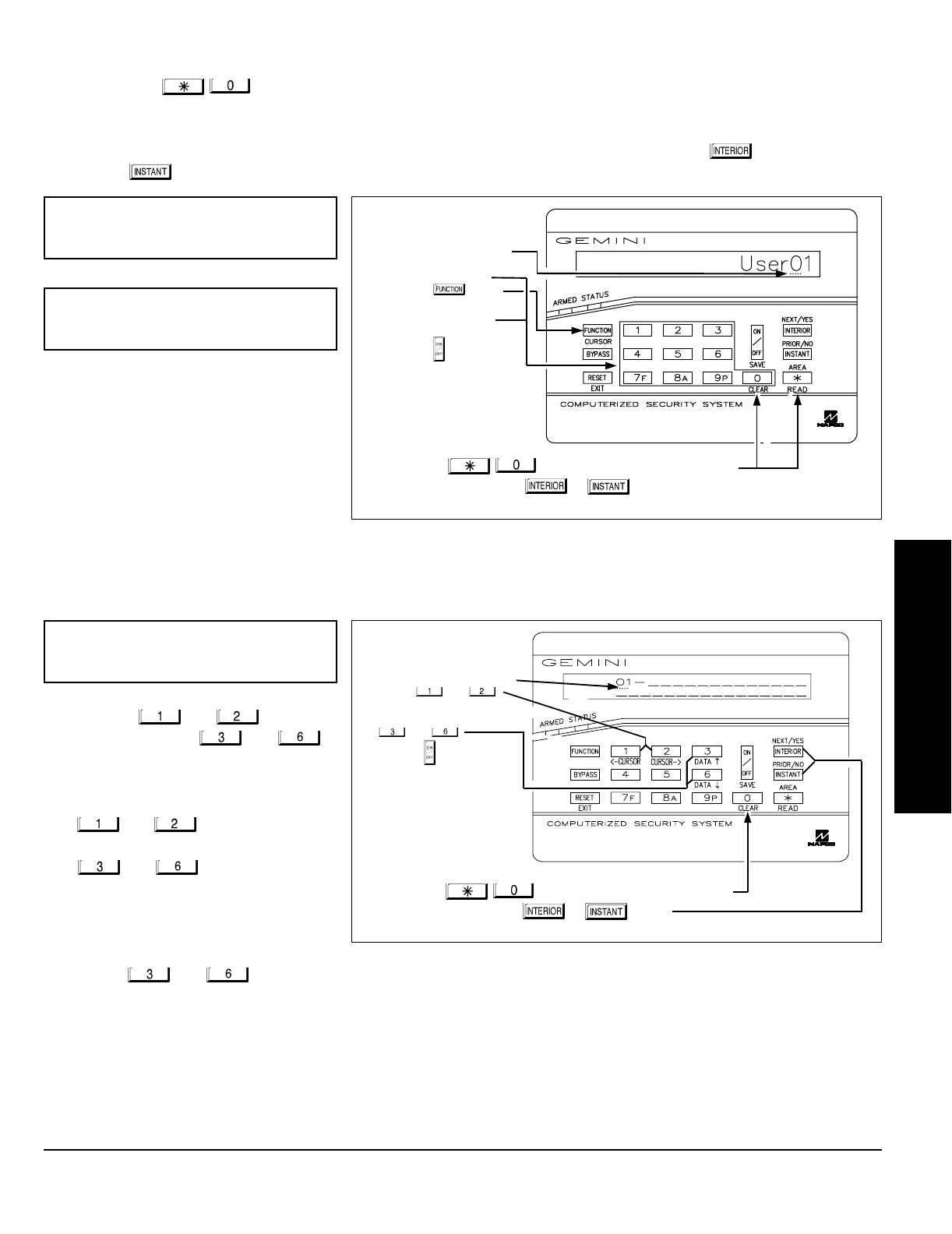
NAPCO Security Systems
GEM-P1632 Programming Instructions
WI897B 8/98
Page 39
Enter an identifying description for each
zone. Buttons and set the
cursor position; buttons and
scroll numbers, letters, punctuation marks,
etc.
Position the cursor over the displayed
Zone Number (i.e., “01”) using buttons
and .
Change the Zone Number using buttons
and .
Position the cursor over the first
character of the description field.
Advancing the cursor between
characters, program a description of up
to two lines for the new zone using
buttons and .
Press the button to save. Advance to the next zone as in Steps 1 and 2 above and repeat this procedure until all zones have
been programmed.
Enter the new User Code using the number buttons (0-9). If an old code is displayed, program over it. To erase the digit at the
cursor, press button.
Press the button to save the code in memory.
Repeat this procedure for each user. To proceed to Zone-Description programming, press the NEXT ( ) button or the
PRIOR ( ) button.
GEM-RP2ASe2 Keypad
(Direct Entry)
USER PROGRAM MODE
Programming User Codes
To Program User Codes
1. Enter 2-digit User Number
(01-32) directly using
number buttons (0-9).
2. Press the button.
3. Enter Code (1-6 digits)
directly using number
buttons (0-9).
4. Press the button to save
each code.
NOTE: Press button to clear character at cursor.
To continue press or button.
Programming Zone Descriptions
To Program Zone Descriptions
1. Set the Cursor Position using
buttons and .
2. Select characters for zone
description using buttons
and .
4. Press the button to save
each descriptor.
NOTE: Press button to clear character at cursor.
To continue press or button.
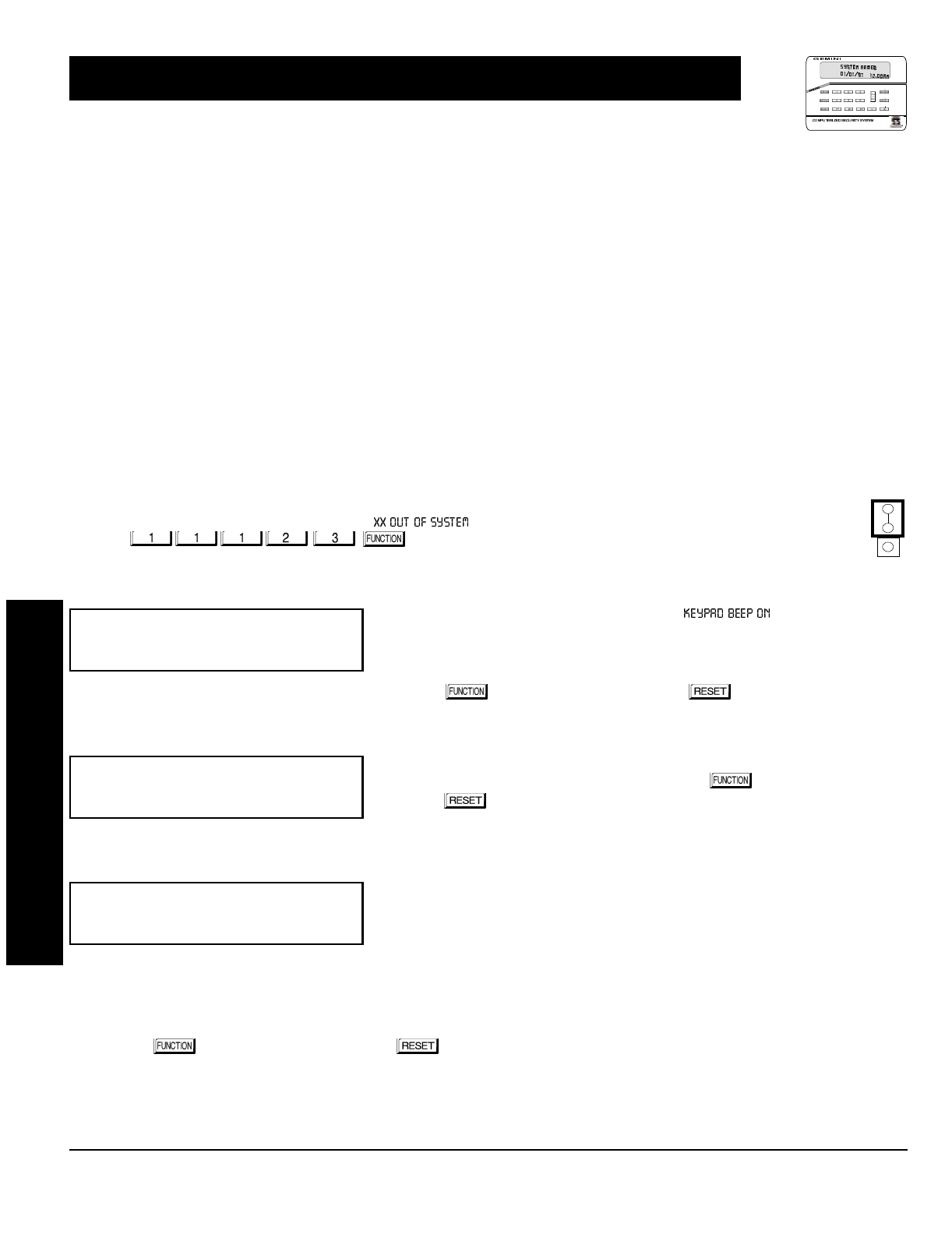
GEM-P1632 Programming Instructions NAPCO Security Systems
WI897B 8/98
Page 40
This section will focus on configuring the GEM-RP1CAe2 and GEM-RP2ASe2 Keypads. If there is more than one keypad in the sys-
tem,
only Keypad No. 1 may be used for programming.
Two types of keypads may be used with the GEM-P1632: the GEM-RP1CAe2 and the GEM-RP2ASe2. Each must be assigned an
address number (1–7) and each requires its own configuration procedure (see CONFIGURING THE KEYPADS, which follows, and
DIRECT ADDRESS KEYPAD AREA OPTIONS). At least 1 keypad must be used; only 1 is required for a single-area Commercial
Burglary installation.
GEM-RP1CAe2 - is a 2-line combination fire/burglary/access keypad capable of supporting 4 EZM zones and a PGM output. A
GEM-RP1CAe2 is recommended for use as Keypad #1.
GEM-RP2ASe2 - is a utility LCD keypad combining several preset LCD words with a limited message line. NOTE: Due to space con-
straints, available messages are abbreviated and will scroll automatically.
A total of up to 7 keypads may be connected to the panel. GEM-RP1CAe2 and GEM-RP2ASe2 keypads may be intermixed but re-
quire different configuration procedures, as described in the following paragraphs.
Configuring the GEM-RP1CAe2 Keypad
Each GEM-RP1CAe2 keypad must be configured for (a) keypad tactile beep; (b) entry sounder; (c) keypad address; (d) compatibility
number; (e) EZM address; and (f) zone response.
To enter the GEM-RP1CAe2 Configuration Mode:
1. Move jumper JP1 (located at the upper-right corner of the control panel board) from Pins 1-2 (top two) to Pins
2-3 (bottom two). NOTE: See Wiring Diagram on page 72.
2. After about 15 seconds, the display will read “ ”, where XX indicates the keypad address.
3. Press and proceed as follows. (Repeat the following procedure
for all keypads.)
Keypad Tactile Beep
Upon entering the Keypad Configuration Mode, “ ” will be displayed,
indicating that the tactile beep, which sounds when any button is pressed, is on. To
turn off the tactile beep, press the button (the button will toggle the tactile
beep on and off).
Press the button to continue or press the button to exit.
Entry Sounder
To turn off the keypad sounder during entry time, press the button (the but-
ton will toggle the tactile beep on and off). Press the button to continue or
press the button to exit.
Keypad Address
If more than one keypad is installed, each must be assigned a unique keypad ad-
dress (that is, no two keypads may be numbered alike):
keypads must be numbered consecutively (missing numbers are not permitted)
only Keypad No. 1 may be used for programming.
To assign the keypad number, proceed as follows:
1. Enter the assigned keypad number 01–07, then press the button to save. A valid number will be acknowledged by a short
beep; an invalid number will be rejected by a long beep.
2. Press the button to continue or press the button to exit.
NORMAL
KEYPAD
CONFIGURE
KEYPAD CONFIGURATION MODE
R
ARMED
STATUS
NEXT/YES
PRIO R/ NO
AREA
NAPCO Security Systems
GEM-P1632 Programming Instructions
WI897B 8/98
Page 41
KEYPAD CONFIGURATION MODE
Compatibility Number (Not Applicable)
THIS FEATURE IS NOT COMPATIBLE WITH THE GEM-P1632 CONTROL
PANEL.
Press the button to continue or press the button to exit.
EZM Address
The keypad's internal EZM (Expansion Zone Module) may be utilized to
provide four additional wired zones. Whether used alone or in conjunction
with optional GEM-EZM series modules or other keypad EZMs, it must be
assigned a unique address (or Group number, see Keypad Programming
Workbook) similar to its keypad address. If no other EZMs are to be used,
designate the keypad as Group “01” at the “” display. In multiple-EZM systems, enter an assigned group
number “01” through “06”. (Each EZM must have a unique assigned group number, starting with “01” and proceeding
consecutively.) Press the button to continue or press the button to exit.
Zone Response
The normal loop response of each keypad expansion zone is 750mS, however the response time of any zone can be
reduced to 50mS as follows.
1. Of the following, circle the number(s) in parentheses associated with the
zone(s) to be changed:
Zone 1=(1); Zone 2=(2); Zone 3=(4); Zone 4=(8)
2. Add up the circled numbers.
3. At the keypad, enter the sum as a two-digit number “01” through “15” on
the display, then press the button.
Example.
Change Zones 2, 3 and 4 to 50mS response.
1. Circle numbers for Zones 2, 3 and 4: (2), (4) and (8).
2. Add up the circled numbers: 2 + 4 + 8 = 14.
3. Enter “14” at the keypad, then press the button.
Press the button to continue or press the button to exit.
Program Control Message (Not Applicable)
THIS FEATURE IS NOT COMPATIBLE WITH THE GEM-P1632 CONTROL
PANEL.
Press the button to continue (the display will loop back through selections, for changes) or press the button
to exit the Keypad Configuration Mode (display will read “ ”). Then replace Jumper JP5 across Pins 1–2
(top two).

GEM-P1632 Programming Instructions NAPCO Security Systems
WI897B 8/98
Page 42
KEYPAD CONFIGURATION MODE
Configuring the GEM-RP2ASe2 Keypad
Up to 7 GEM-RP2ASe2 keypads may be connected to the panel (Keypads 1–7). Each must be configured for a keypad
address. In addition, the keypad may be configured to disable (a) touch pad back light; (b) LCD back light; and (c) entry
sounder. Keypads are configured by the proper selection of jumpers. Refer to the label on the circuit board fishpaper
(LA1390) for jumper locations and a summary of settings.
KEYPAD ADDRESS
If more than one keypad is installed:
Each must be assigned a unique address (that is, no two keypads may be
numbered alike).
Keypads must be addressed consecutively (that is, missing numbers are not
permitted).
Only Keypad No. 1 may be used for programming. (However, for ease of
programming, it is recommended that a GEM-RP1CAe2 be selected as Keypad
#1.)
Assign the keypad address number by selecting Jumpers J1–3 in accor-
dance with the table at left.
*Note: (1) Keypads are factory supplied with no jumpers installed and a as
such are automatically configured as Keypad No. 1. (2) Only one keypad in
the system may be configured as Keypad No. 1, otherwise none will func-
tion.
TOUCH PAD BACK LIGHT
Cut Jumper A to disable touch pad backlighting to conserve 11mA standby current.
LCD BACK LIGHT
Cut Jumper B to disable LCD backlighting.
KEYPAD SOUNDER
Cut Jumper C to disable the sounder. (Do not disable in UL applications.)
KEYPAD
NUMBER
1
2
3
4
5
6
7
123
OFF or
ON* OFF OFF
OFF ON OFF
ON ON OFF
OFF OFF OFF
ON OFF ON
OFF ON ON
ON ON ON
KEYPAD NUMBER
PARK
STORE SPARE
JUMPER AT THIS
POSITION
NAPCO Security Systems, Inc.
333 Bayview Avenue, Amityville, New York 11701
For Sales and Repairs, call toll free: (800) 645-9445
For direct line to Technical Service, call toll free: (800) 645-9440
Internet: http://www.napcosecurity.com
NAPCO Security Systems
GEM-P1632 Programming Instructions
WI897B 8/98
Page 43
Name: Address:
Account Number: Installer:
Zone Doubling?:
Yes No
Area 1:
# of Keypads (1-8) =
Area 1:
# of Zones (1-32) =
NOTE: Area 2 Zones and Keypads are selected in Direct Address Mode. See Zone Options and Keypad Options.
Enter Fire Zones (1-32):
__________ Yes No
2-Wire Fire Zones?:
Zone 7 Yes NoZone 8
Enter Entry/Exit Zones (1-32):
__________
Enter Interior Zones (1-32):
__________
Report all Zones to Central?:
Yes No
Central Station Receiver 1 Telephone Number:
Central Station Receiver 1 Account Number:
Central Station Receiver 1 Format:
blank (•) = Ademco Slow, Silent Knight Slow
2 = Radionics Fast
3 = Silent Knight Fast
4 = Radionics, DCI, Franklin Slow
5 = Universal High Speed
B = SIA
C = Ademco Point ID
E = Pager
User Codes:
USER
#CODE
(up to 6 digits) AREA 1
OPTIONS AREA 2
OPTIONS
1
2
3
4
5
6
7
8
9
10
11
12
13
14
15
16
USER
#CODE
(up to 6 digits) AREA 1
OPTIONS AREA 2
OPTIONS
17
18
19
20
21
22
23
24
25
26
27
28
29
30
31
32
EASY MENU PROGRAMMING WORKSHEETS

GEM-P1632 Programming Instructions NAPCO Security Systems
WI897B 8/98
Page 44
XMTR
#ZONE
#RF ID
(printed on xmtr box) CHECK
SUM # OF
POINTS
1
2
3
4
5
6
7
8
9
10
11
12
13
14
15
16
RF Transmitter Points:
XMTR
#ZONE
#RF ID
(printed on xmtr box) CHECK
SUM # OF
POINTS
17
18
19
20
21
22
23
24
25
26
27
28
29
30
31
32
Key Fob Transmitters:
KEY FOB # AREA RF ID
(printed on xmtr box) CHECK
SUM OPTION
1OPTION
2
1
2
3
4
5
6
7
8
EASY MENU PROGRAMMING WORKSHEETS

NAPCO Security Systems
GEM-P1632 Programming Instructions
WI897B 8/98
Page 45
Zone Descriptions (GEM-RP1CAe2 Keypads Only):
ZN
#
1
2
3
4
5
6
7
8
9
10
11
12
13
14
15
16
17
18
19
20
21
22
23
24
25
26
27
28
29
30
31
32
CHARACTERS AVAILABLE (See below)
1234567891011121314151617181920212223242526272829
Dealer Code:
EASY MENU PROGRAMMING WORKSHEETS
Characters Available for Zone Descriptions
! @ # $ % ^ & * ( ) _ + ! ¦ | { } [ ] ` , . < > ?
1 2 3 4 5 6 7 8 9 0
a b c e d f g h i j k l m n o p q r s t u v w x y z
A B C D E F G H I J K L M N O P Q R S T U V W X Y Z

GEM-P1632 Programming Instructions NAPCO Security Systems
WI897B 8/98
Page 46
PROGRAMMING OPTION PROGRAM MODE ADDRESS LOCATION PAGE NUMBER
3/1 with Extended Restores Direct Address 0171, 0193 & 0215 26
Abort Delay Direct Address 0715 12
AC Fail Report Delay Direct Address 0717 12
Access Control on PGM2 Output Direct Address 0719 22
Alarm Output Timeout Direct Address 0712 23
Auto Bell Test on Arming Direct Address 0719 25
Auto Reset after Burglary Output Timeout Direct Address 0719 25
Automatic Interior Bypass Direct Address 0722 25
Backup Reporting on Telco 2 Direct Address 0429 28
Callback Telephone Number Direct Address 0236-0255 23
Cancel Next Test timer on any Report Direct Address 0394 28
Change Pulse Output to Cadence Direct Address 0719 25
Chime Timeout Direct Address 0716 22
Clear Dealer Program Direct Address 1197 37
Closing Report only on Conditional Close Direct Address 0718 25
Cold Start Direct Address 1198 37
CS Receiver 1, 2 & 3 Telephone Numbers Direct Address 0172-0191, 0194-0213 & 0216-0235 26
CS Receiver 1, 2 & 3 Formats Direct Address 0170, 0192 & 0214 26
CS Telco 1, 2 & 3 Subscriber Event ID Numbers (System) Direct Address 0275-0278, 0295-0298 & 0315-0318 27
CS Telco 1, 2 & 3 Subscriber Event ID Numbers (Area 1) Direct Address 0227-0270, 0287-0290 & 0307-0310 27
CS Telco 1, 2 & 3 Subscriber Event ID Numbers (Area 2) Direct Address 0271-0274, 0291-0294 & 0311-0314 27
CS Telco 1, 2 & 3 Subscriber Opening/Closing ID Numbers (Area 1) Direct Address 0259-0262, 0279-0282 & 0299-0302 27
CS Telco 1, 2 & 3 Subscriber Opening/Closing ID Numbers (Area 2) Direct Address 0263-0266, 0291-0294 & 0303-0306 27
Dealer Code Easy Menu Driven N/A 10
Disable Callback Download Direct Address 0720 25
Disable Closing Reports Direct Address 0392 28
Disable Function Mode Download Direct Address 0720 25
Disable Opening Reports Direct Address 0391 28
Disable Wait for Handshake Direct Address 0394 28
Disable Wait for Silence Direct Address 0394 28
Enable Manager's Mode Direct Address 0719 25
Enable Global Ambush Code Direct Address 0720 25
Enable Auto Arm if not closed Direct Address 0718 25
Enable Line Fault Test Direct Address 0721 25
Enable Residential Fire Direct Address 0720 25
Enable Transmitter Telco 1 Direct Address 0721 25
Enable Transmitter Telco 3 Direct Address 0721 25
Enable Zone Doubling Direct Address 0721 25
Enable Zone Number on Pulse Alarm Direct Address 0171, 0193 & 0215 26
Entry Delay 1 Direct Address 0001 22
Entry Delay 2 Direct Address 0002 22
Exit Delay Direct Address 0000 22
Enable EZM Group Direct Address 0737-0742 30
Global Ambush Code Direct Address 1054 24
Include Select/Group Bypass in Conditional Close/Status Direct Address 0718 25
Interior 1 Normally Bypassed Direct Address 0720 25
Key fob Transmitters Easy Menu Driven N/A 10
Leading Digits for Pager Format Direct Address 0256 & 0257 23
Number of Rings before Pickup Direct Address 1183 23
Opening Report only after Alarm Report Direct Address 0718 25
PGM1 Output Timeout Direct Address 0714 23
PGM2 Output Timeout Direct Address 0710 23
PGM2 Output Access Control Timeout Direct Address 0711 22
PGM2 Output Chirp on Key fob Arming Direct Address 0722 25
PGM2, Don't Clear Output with Arm/Disarm Direct Address 0722 25
Pulsed Alarm Output Timeout Direct Address 0713 23
PROGRAMMING OPTIONS INDEX

NAPCO Security Systems
GEM-P1632 Programming Instructions
WI897B 8/98
Page 47
PROGRAMMING OPTION PROGRAM MODE ADDRESS LOCATION PAGE NUMBER
Reset Day zone with Arm/Disarm only Direct Address 0720 25
RF Transmitter Points Easy Menu Driven N/A 9
Status Report Direct Address 0718 25
Sum check Direct Address 0171, 0193 & 0215 26
Suppress Bypass Reminder when Armed Direct Address 0719 25
Touch-tone Dialing Only Direct Address 0394 28
Touch-tone Dialing w/Rotary Backup Direct Address 0394 28
Two Ring Download Direct Address 0722 25
User Codes Easy Menu Driven N/A 8
User Opening/Closing Telco 1 & 3 (Users 00-32 & 97-99) Direct Address 0430-0449 29
Veriphone Zones over Priority Alarms Direct Address 0722 25
Veriphone Zones trip PGM2 Output Direct Address 0722 25
Zone Descriptors Easy Menu Driven N/A 10
Zones Report Code (Zones 1-32) Direct Address 0358-0389 28
PROGRAMMING OPTIONS INDEX
GEM-P1632 Programming Instructions NAPCO Security Systems
WI897B 8/98
Page 48
Abort Delay (Do not program for UL Applications.)
A reporting delay period that allows cancellation of the central-station report by disarming the control panel. To enable program zones
for
Abort Delay
(Address 0510, 0565, 0620 & 0675) and select
Abort Time Delay
(Address 0715). Also, a
Pre-Alarm Warning
may be
selected for zones (Address 0497, 0552, 0607 & 0662) allowing a keypad indication of alarm with no alarm outputs or central station
reporting for the duration of abort delay time.
NOTE: If Abort Delay is selected for a 24-Hour Zone, the zone must be cleared before disarming the area.
AC Failure; AC-Fail Report Delay
If AC power is removed from the control panel, “ ” will display at the keypad with a flashing “ ” as a
reminder and a pulsing sounder. Press the button to silence the sounder; the “ ” reminder will remain on and “
” will appear in the display. If a User Code is entered within 5 minutes, the panel may be armed successfully. After 5 minutes,
the system trouble will again display.
AC Failure
may be programmed to activate the
Alarm Output
(Address 0450),
Pulsed Alarm Output
(Address 0451),
PGM1 Output
(Address 0452),
PGM2 Output
(Address 0453),
Relay Outputs
(Address 0750-0829) and/or report to a central station by selecting
AC Fail Report Event Telco 1
,
AC Fail Report Restore Telco 1
,
AC Fail Report Event Telco 3
,
AC Fail Report Restore Telco 3
(Address 0454, 0455, 0458 and 0459, respectively). An alarm and/or restore report to the central station will occur immediately unless
an AC Fail Report Delay is programmed (Address 0717). AC Failure is logged immediately upon detection.
Access Control; Access Control (Panel Access) on PGM2 Output; PGM2 Output Access Control Time; Keypad Access;
Access Only; Access Logging
NOTE: The GEM-P1632 has not been evaluated by UL for compliance with UL294 (Access Control Systems).
If Access Control on PGM2 Output (Address 0719) is selected, entering the Access Code (see User Code Programming in Easy
Menu Driven Mode Programming) while disarmed will trip the panel's PGM2 Output. This is commonly used to activate a door strike
for the purposes of remotely unlocking a door. Each keypad is individually selected for Panel Access (Address 0730-0736). Also
program PGM2 Output Access Control Timeout (Address 0711). NOTE: Do not program the PGM2 Output (Address 0454, 0474,
0482, 0503, 0558, 0613 and 0668) as an output on alarm.
Keypad Access is selectable for any keypad 1–7 by selecting the appropriate Area Option of any User Code (see User Code
Programming in Easy Menu Driven Mode Programming) ; select the Panel Access option (Address 0730-0736) for those keypad
numbers (1–7) that are to respond to the User Code. However, if the Access Byte is programmed, the code will no longer function as
an Arm/Disarm Code. Also, if Access Only is programmed for any keypad, that keypad will be dedicated for keypad access. It will then
display “ ” and will no longer be capable of arming or disarming.
Entering a valid code at the keypad will cause a 5-second output on the keypad's PGM line with a pulsing sounder and the display
“” (or other customized message). If Access Logging is programmed, keypad access control will be added to the event
log, by keypad. An RB1000 Relay may be used to activate a door strike. Power to the door strike should be supplied from an
independent source.
Access Number for Outside Line (CS Receiver Telephone Number Access)
Some subscribers will have a telephone system that requires one digit to access an outside line. The first dial tone encountered (prior
to the access number) may have a frequency that is different from that of the accessed dial tone (440Hz). One or more 4-second
Pre-Dial Delay “D”s may be entered before any of the CS Receiver Telephone Numbers (Address 0172-0191, 0194-0213 &
0216-0235) instead of a dial tone with frequency “E”. See Pre-Dial Delay; Telephone Numbers. (Note: The panel features automatic
dial-tone detection and will normally not require any “E”s. To disable this feature, see address 0394.)
If the subscriber's system uses an access number, contact the telephone-equipment supplier to find out if a dial tone other than
440Hz is received prior to dialing the access number. If the communicator must delay before dialing the access number instead of
attempting to recognize the dial tone, find out how many 4-second delays must be programmed.
Alarm on Day Zone See Day Zone
Alarm Outputs (See Wiring Diagram for UL requirements.)
The GEM-P1632 has three outputs: Bell (Burg. & Fire), PGM1 and PGM2. The following table summarizes wiring for signaling an
alarm in typical installations. See Time Selection for timeout durations.
GLOSSARY
OUTPUT WIRING REMARKS
Bell Output (Burg.) 3(+) & 4(–) Single Bell Output; program Alarm Output for Burg (Addr. 0450, 0471, 0479, 0500, 0555, 0610, 0665, 0745)
Bell Output (Pulsed) 3(+) & 4(–) Single Bell Output; program Pulsed Output for Fire (Addr. 0451, 0470, 0478, 0501, 0555, 0611, 0666, 0746)
PGM1 Output 5(+) & 7(-) Programmable Output (Addr. 0452, 0472, 0480, 0502, 0556, 0612, 0667, 0747)
PGM2 Output 5(+) & 8(-) Programmable Output (Addr. 0453, 0474, 0482, 0503, 0557, 0613, 0668, 0749)

NAPCO Security Systems
GEM-P1632 Programming Instructions
WI897B 8/98
Page 49
Alarm Outputs
In UL installations, (1) see Time Selection for timeout requirements; (2) combination residential burglary/fire systems require distinctly
different signals for burglary and fire.
NOTE: For dry contacts, use RB1000 Relay Module (see Wiring Diagram).
Alarm; Alarm Restore Telco 1/Telco 3 See Report Telco 1/Telco 3
Alarm; Alarm Restore Telco 2 See Backup Report on Telco 2
Alarm Verification (Not for use in California.)
An alarm on any Fire Zone programmed for “Fire Alarm Verification” will cause all fire zones to be powered down for 12 seconds. (All
devices must be wired with + power on Terminal 25.) After this time, power is restored and a 4-second power-up time is started.
Thereafter, the zone will be active again. This represents a total processing delay of 16 seconds from the time the alarm is first
detected. If an alarm condition still exists at this time or reoccurs within 2 minutes, an alarm will be initiated, otherwise the zone will
return to its original state. NOTE: A zone programmed for “Fire Alarm Verification” must be programmed as a “Fire Zone” as well.
Ambush (Keypad Ambush)
A 2-digit code that is entered immediately prior to (and as part of) the regular Disarm Code. This will cause a silent report to be sent to
a central station. Thus, should a user be forced to disarm, he can silently signal an emergency while appearing to be merely disarming
the system. The Ambush Zone will automatically report when programmed to report on alarm.
To program
, (a) select “Ambush to Report Event Telco 1/Telco 3” (Address 0475, 0477, 0483, 0485); (b) select “Enable Global
Ambush Code” (Address 0720); enter “Global Ambush Code” (Address 1054); and (d) enter an “Ambush CS Report Code” (0340).
Each keypad is enabled for “Ambush” individually (Address 0730-0736). Inform the user what the Ambush Code is, and that his
Arm/Disarm Code must be entered less than 10 seconds after the Ambush Code for an ambush report to be sent.
Answering Machine Pickup Without Line Seizure See Callback-Method Download.
Anti-Jam Time
If the communicator does not detect a dial tone within 12 seconds, the Anti-Jam feature will be activated. That is, the communicator will
go off line for a 16-second anti-jam interval in order to free the telephone circuit from an incoming call, then make another 12-second
attempt at dial-tone detection. If still unsuccessful, the communicator will again go off line for 16 seconds, then proceed to dial anyway.
Areas; Zone Area 1–Zone Area 2; Priority Area Arming
Although the default program will automatically set up Zones 1 through 8 for Zone Area 1, the panel may be partitioned into two areas.
Every zone must be assigned to at least one area (Address 0526, 0527, 0581, 0582, 0636, 0637, 0691, 0692) to be used. At least one
zone must be assigned to Area 1. If a zone is selected for both areas, that common zone will not arm until both areas are armed. If any
zone disarms, the common zone will disarm.
In a multiple-area system, be sure to also enable
User Codes
by Area.
Keypad Area Assignments
Bell Control (determines which bells an area may silence);
Subscriber Opening/Closing ID Numbers and Event ID Numbers (if reporting);
System Trouble Subscriber ID Number
If “Priority Area Arming” (Address 0743 & 0744) is selected, the Priority Area must be armed before the Arming Area can be armed.
Auto Bell Test on Arming (Required for UL Mercantile installations)
If selected (Address 0719), this will activate the Burglary Output briefly 10 seconds after the area is armed. If the alarm does not
sound, the device may be defective.
Auto-Bypass (Do not program for UL installations.); Auto-Bypass Re-entry
Zones programmed for “Auto-Bypass” (Address 0493, 0548, 0603, 0658) will be bypassed (automatically removed) if in trouble when
arming. A momentary beep will sound at the keypad to warn that the system has been armed without the protection of the auto-
bypassed zone. (Note that the exit/entry door must be closed before arming, otherwise the Exit/Entry Zone will be auto-bypassed.)
Note: A zone in trouble that is not programmed for “Auto-Bypass” will cause an alarm on arming after a 10-second arming delay.
If “Auto-Bypass Re-entry” (Address 0496, 0551, 0606, 0661) is selected, securing a zone that is programmed for Auto-Bypass, while
armed, will cause that zone to re-enter the system in an armed state.
Auto Interior Bypass See Interior Zones by Area
GLOSSARY

GEM-P1632 Programming Instructions NAPCO Security Systems
WI897B 8/98
Page 50
GLOSSARY
Auto-Reset; Auto-Reset After Burglary Output Timeout
If a zone detects an alarm condition and is selected for “Auto-Reset” (Address 0507, 0562, 0617, 0672), it will automatically rearm itself
as soon as the alarm condition is cleared. Auto-Reset may be delayed to occur after the Burglary Output timeout period by selecting
“Auto-Reset After Burglary Output Timeout” (Address 0719) and “Auto-Reset” . Zones that are not programmed for “Auto-Reset” will not
be capable of signaling another alarm until (a) the cause of the alarm has been corrected and (b) the control panel is disarmed. Also
see Swinger Shutdown.
Auxiliary Relay See Alarm Outputs
Backup Report on Telco 2
If “Backup Reporting on Telco 2” (Address 0394) is selected and the communicator does not reach the first telephone number after two
attempts, seven attempts will be made to reach the second telephone number. Enter Subscriber Identification Numbers for Telephone
2 and other information required for Telephone 2. Also program Backup Report on Telco 2. Any zone programmed to report to Telco 1
will backup report to Telco 2. Note: Subscriber Identification Numbers for both Telephones 1 and 2 must be entered, even if they are
the same.
Battery
12Vdc standby power source in the control panel is used to provide backup protection in the event of a power loss. The battery is an
integral part of the system and must be installed, even if ac power is present. Change the battery every 5 years or as required.
Bell Control
In any system, the ability to silence any combination of alarm devices (outputs) initiated from any area. Bell Control must be
programmed for all systems to be able to silence an alarm. For example, in a two-area system, each area could be programmed to
silence only those alarms initiated within its own area; or both areas could be programmed to silence an alarm initiated from either area.
Burglary Output See Alarm Outputs
Bus Failure
Communication failure on the 4-wire bus will cause a system trouble and a report to the central station. Program System Trouble
Reports and Report Codes for the 4-Wire Bus.
Call Waiting See Disable Call Waiting
Callback-Method Download; Answering Machine Pickup Without Line Seizure; Disable Callback Download (Required for UL
installations); 2nd Call Download (Required for UL installations); Disable Function-Mode Download; Number of Rings Before
Pickup
Data may be downloaded remotely to the panel after a programmed number of rings (3 to 15) and a control-panel confirmation call-
back. Program the “Number of Rings” (Address 1183); if not programmed, the panel will pick up after 15 rings.
This method will accommodate an answering machine at the site. “2nd Call Download” (Address 0722) must not be programmed.)
The answering machine will pick up on its programmed number of rings, as usual. Note: The number of rings programmed into the
panel must exceed that of the answering machine.
Program “Disable Callback Download” (Address 0720) to prevent unauthorized downloading to an unattended panel. Program
“Disable Answering Machine Download” to inhibit downloading to a telephone connected to an answering machine. Program “Disable
Function-Mode Download” (Address 0720) to prevent downloading at the keypad.
Cancel Next Test Timer Report on Any Report See Test Timer
Chime (Displays “MONITOR” on GEM-RP2ASe2 Keypads)
This annunciator feature may be used on any zone to sound a tone at the keypad while disarmed when the zone goes into trouble.
Access the ACTIVATE CHIME function (Easy Menu Driven Program Mode) to enable or disable the Chime Mode. This feature is pro-
grammable by zone (Address 0509, 0564, 0619, 0674) and “Chime Timeout” (Address 0716). A time must be programmed for the
chime to function.
Clear Program
Caution: Erases the dealer program. Use this feature to start a new customized default program. Access Address Location 1197, then
press the button.

NAPCO Security Systems
GEM-P1632 Programming Instructions
WI897B 8/98
Page 51
GLOSSARY
Closing Report; Closing Report Only on Conditional Closing; Conditional Closing; Include Selective/Group Bypass In
Conditional Closing/Status; Status Report
On arming, the communicator can transmit a unique Closing Code for each user and a status report that identifies the problem zone
to the central station. Note that Subscriber Identification Numbers and a Closing Code must be entered for any closing report.
Select which users will report closings for each telephone number, even if “Closing Report Only on Conditional Closing” is selected.
Normally, a closing report will consist of the Closing Code and the number of the user that armed. If the user armed with an
auto-bypassed zone (or selective/group bypassed zone if “Include Selective/Group Bypass In Conditional Closing/Status” was
programmed), the Conditional Closing Code will also be sent.
Select “Closing Report Only on Conditional Closing” to report only when arming with an auto-bypassed zone (and selective-
/group-bypassed zone if “Include Selective/Group Bypass in Conditional Closing/Status” is programmed).
Select “Status Report” to send a closing followed by a status report that identifies the problem zone(s). A typical Status Report is
represented by the following example.
Example (4/2 Format). A burglar breaks into a commercial establishment during the night, breaking the window foil on Zone 5. The
Open/Close Subscriber Identification Number is “1234”; the Alarm Code for Zone 5 is “3,5” (Burglary Zone 5); the Subscriber
Identification Number is “6789”; the Closing Code is “C”. The communicator will send the following report to the central station.
When alarm occurs:
“6789 35” – Alarm, Zone 5
Closing Report:
“1234 C1” – Closing, User 1 (User 1 returned, inspected damage & rearmed; the same transmission would occur for User 11, 21, 31,
etc.)
“1234 F5” – Trouble, Zone 5 (zone status at time of closing: Window foil still broken; Zone 5 auto-bypasses, repair required; the same
transmission would occur for Zone 15, 25, 35, etc.)
Cold Start
Caution:
Erases the entire program (codes, schedules, etc.), leaving the panel as it came right out of the box. Access Location 1198,
then press the button.
Data Format
Ask the central station which of these formats to use.
Two-Digit or 4/2 Format. Some central-station receivers require that a four-digit Account Code followed by a two-digit Alarm Code be
sent in each report. Example. In a certain installation, the Alarm Subscriber Number is “1234”; a burglary alarm occurs on Zone 1. The
Alarm Code for Zone 1 is “3”. The communicator will send “1234 31” (Account No. 1234; Alarm, Zone 1). 1400Hz Handshake/Kissoff.
1400Hz Handshake overrides 2300Hz Handshake if both are selected. 2300Hz Handshake/Kissoff. Used with the following receiver
formats: Radionics, DCI & Franklin Slow; Radionics Fast; Sescoa, Vertex, DCI & Franklin Fast; Radionics BFSK. 1400Hz Handshake
overrides 2300Hz Handshake if both are selected.
Zone Number on Pulse Alarm
. If selected, an Alarm Code need not be programmed (the zone number will replace the Alarm Code), however
codes for restore, trouble, etc. are still required. Thus, in the foregoing example, if “E” is the designated Restore Code, and Zone 24 trips and is
restored, the communicator will send “1234 24” (Account No. 1234; Alarm, Zone 24) followed by “1234 E6” (Account No. 1234; Zone 24 Restored).
Single-Digit Event Code Format.
The single digit sent for a particular event can be either the Event Code or the units digit of the zone number.
Sum-Check Format.
Sum Check is a sophisticated data format used to enhance the speed and check the accuracy of the received transmis-
sion. This format should be preferred whenever the central station is capable of receiving it. After transmitting the Subscriber Identification Number
and the Alarm Code, the communicator sends a verifying digit that is the sum of both. The receiver compares the verifying digit with the sum of the
other numbers to check transmission accuracy.
3/1 with Extended Restores.
Some receivers require a three-digit Account Code followed by a single-digit Alarm Code. Example. In another
installation, the Alarm Subscriber Number is “123”; an alarm on Zone 1 is restored. The Restore Code for Zone 1 is “E,1”. The communicator will
send “123 E” (Account No. 123 Restored); followed by “EEE 1” (Restored, Zone 1).
Modem Formats.
Modem formats (SIA, Point ID, Express, 4/3/1, Modem 2) are preset and automatic but require a Type for each zone. Pro-
gram Zone Type as follows: Fire* = “1” (Note: Not for Modem 2 Receivers); Panic = “2”; Burglary = “3”; Holdup = “4”; Gas Alarm = “7”; Heat Alarm =
“8”; Auxiliary Alarm = “A” (Keypad displays “0”); 24-Hour Aux. Alarm = “B”.
Pager Formats.
The control panel has provisions for dialing a pager phone number. The panel will wait for ringing, wait for silence, then send
its data. Caution: Because there is no handshake/kissoff, this feature should only be used for Double Reporting; it may not be used for Backup Re-
porting. Only one report is sent for any call. Pager digits are limited to “0” through “9”. Digits represented by “A” through “F” will be converted to “0”s
for transmission purposes. Pager formats are 10 digits, arranged as illustrated by the following examples.

GEM-P1632 Programming Instructions NAPCO Security Systems
WI897B 8/98
Page 52
GLOSSARY
Alarms, restores, etc. are transmitted in a 3-3-4 arrangement representing Report Code, Descriptor and Account Number.
Example 1. Burglary, Zone 22 (Report Code = “3”.)
Transmits: 003 022 1234, where
003 = Report Code (always two zeros + programmable Report-Code digit, 0–9);
022 = Descriptor (always one zero + 2-digit descriptor, zone number: 01–32);
1234 = Account Number (4 digits, programmable).
Openings, closings, etc. are transmitted in a similar arrangement
Example 2. Closing, User 12 (Closing Code = “8”)
Transmits 008 012 1234, where
008 = Report Code (always two zeros + programmable Opening/Closing digit, 0–9)
012 = Descriptor (always one zero + 2-digit descriptor (user number: 01–32);
1234 = Account Number (4 digits, programmable).
Keypad Report Codes and System Report Codes are transmitted in the same format.
Compatible Receivers. The following receivers are compatible with the GEM-P1632:
FBI CP220. Formats: Ademco Slow; Silent Knight Slow; Silent Knight Fast; Sescoa; Vertex; DCI; Franklin Slow; Franklin Fast; SIA; Radionics
Slow; Radionics Fast; Radionics BFSK; FBI 4/3/1; Universal High Speed.
Ademco 685. Formats: Ademco Slow; Silent Knight Slow; Silent Knight Fast; Sescoa; Vertex; DCI; Franklin Slow; Franklin Fast; Radionics
Slow; Radionics Fast; Radionics BFSK; Universal High Speed; Ademco Point ID; Ademco Express.
Radionics 6500. Formats: Ademco Slow; Silent Knight Slow; Silent Knight Fast; Sescoa; Vertex; DCI; Franklin Slow; Franklin Fast; Radionics
Slow; Radionics Fast; Radionics BFSK; Universal High Speed.
Osborne-Hoffman Quickalert. Formats: Ademco Slow; Silent Knight Slow; Silent Knight Fast; Sescoa; Vertex; DCI; Franklin Slow; Franklin
Fast; SIA; Radionics Slow; Radionics BFSK; Universal High Speed; Ademco Point ID; Ademco Express.
Silent Knight 9000. Formats: Ademco Slow; Silent Knight Slow; Silent Knight Fast; Sescoa; Vertex; DCI; Franklin Slow; Franklin Fast; Radion-
ics Slow; Radionics Fast; Radionics BFSK; Universal High Speed; SIA.
Day Zone(Open; Short); Alarm on Day Zone; Disable Auto-Reset on Day Zone; Reset Day Zone with Arm/Disarm Only; Enable
Watch, Areas 1-2 (By Area)
A Day Zone will give an audible and visual indication at the keypad if there is a problem on the loop while disarmed. Open- and
short-circuit conditions are programmed separately, by zone. This feature may be used to warn of a problem (a break in a window foil,
for example) during the day, when the panel is not normally armed. When the Day Zone is tripped, “ ” and the zone
number(s) will alternately display at the keypad and the sounder will pulse. Press the pressing the button to silence the
sounder and reset the keypad. “ ” will be displayed until the condition is corrected. If Reset Day Zone With Arm/Disarm Only
is programmed, arm and disarm the panel to reset the Day-Zone indication at the keypad.
If Alarm on Day Zone is programmed for a zone, a Day Zone condition will cause the alarm outputs programmed for that zone (sirens,
relays) to activate.
Note: (1) If a zone is programmed for both “Day Zone Open” and “Day Zone Short”, either condition must be reset before the other can
activate. (2) Day Zone Short will not function if No EOL Resistor is also programmed.
Report Trouble or Trouble Restore is programmed in conjunction with Day Zone Open/Day Zone Short and Trouble on Open/Trouble
on Short (the trouble reported will be that programmed under Day Zone Open and/or Day Zone Short).
Note: Do not program a Day Zone for 24-hour protection. The keypad will annunciate as a Day Zone but the panel will transmit an
Alarm Code and a Trouble Code when tripped.
Program Disable Auto-Reset on Day Zone to prevent repeated Day-Zone trips. This will cause the keypad display and sounder to
activate only once in any arm/disarm period.
If Enable Watch is selected (by area), zones programmed for Day Zone can only be activated when ACTIVATE WATCH is accessed.
(See Section 3.) Arming and disarming will turn off the Watch Mode. If “Report Trouble” is selected, a trouble on a Day Zone will be
reported only when the Watch Mode is on.
Dealer Security Code
The factory-programmed Dealer Security Code is “456789”. Use this code to enter the Easy Menu Driven Mode (Dealer Program
Mode) to program (or change) the Dealer Security Code. The Dealer Security Code is needed to enter the Dealer Program Mode, thus
allowing the dealer to program codes, zone features, reporting features and zone descriptions. This code may be changed as
required.
Dial-Tone Detection; Disable Auto Dial-Tone Detection
The panel features automatic dial-tone detection to ensure that a dial tone is present before the communicator dials. To disable this
feature, program an “8” in Location 0429.
When an “E” is programmed before the first digit of an outside telephone number, the communicator dial-tone detection circuit is set
to detect the standard 440Hz dial tone. The “E” is generally entered in the location immediately preceding the telephone number.
It may be necessary to program at least one 4-second pre-dial delay before a dial-tone detection “E”. With certain nonstandard
exchanges, pre-dial delay “D”s may be used without a dial-tone detection “E”. (See Access Number for Outside Line; Pre-Dial Delay;
Telephone Numbers.)

NAPCO Security Systems
GEM-P1632 Programming Instructions
WI897B 8/98
Page 53
Disable Answering Machine Download See Callback-Method Download
Disable Auto-Reset on Day Zone See Day Zone
Disable Auto Status
Non 24-Hour Zones that are open (or shorted) normally display “ ” (while disarmed) followed by the zone number(s) and
description(s). In high-security applications, program Disable Auto Status. Unsecured zones will then be indicated by a “
display. Status may be displayed manually using the DISPLAY STATUS function, however a valid user code will be required.
Disable Auto-Unbypass on Disarming
Normally, manually bypassed zones revert to active (disarmed) zones on disarming. Select this feature to maintain bypassed zones on
disarming until manually unbypassed.
Disable Call Waiting (touch-tone® Dialing Only)
A digital communicator connected to a telephone line with Call Waiting may be disrupted by this feature. However, most lines with Call
Waiting also have Selective Call Waiting, which permits the feature to be turned off by dialing a “*70” just before the telephone number.
A “*” will be dialed by programming a “B”.
If the installation has the Call Waiting feature, be sure that it also has Selective Call Waiting, and confirm the disable code with the
telephone company. Then program this code (“B70”) directly before the phone numbers (after dial-tone detection or pre-dial delay) in
the telephone-number locations. See Telephone Numbers.
Caution: Should the user cancel his Call Waiting service, the communicator will dial a wrong number unless the phone number is
corrected.
Disable Callback Download See Callback-Method Download
Disable Code Required for Easy Bypass See Selective Bypass (Do not program in UL Installations)
Disable Fire Reset (by Area)
Normally, pressing the button will momentarily remove power to the smoke detectors. If “Disable Fire Reset” is selected for any
area, the button will no longer activate the Reset Output so that the integrity of the smoke detector's Alarm Memory feature
(LED indication) will be maintained. Also see Alarm Outputs; Smoke Detectors.
Disable Function-Mode Download See Callback-Method Download
Disable Openings/Closings
Provides the flexibility of disabling openings and/or closings from any area(s).
Disable Wait-for-Handshake/Kissoff
Causes data transmission to start immediately after the telephone number.
Disable Wait-for-Silence (Pager Format)
Causes data transmission to start immediately after the pager telephone number.
Double Reporting See Report Telco 3
“E” Lugs (E5, E15, E19)
E5 - Lug E5 is used for Line Seizure. It is normally at 12V and when the telephone line is seized it goes to approximately 1V DC.
E15 - Lug E15 is used for Armed State. It is normally at 12V and when the system is armed it goes to approximately 1V DC.
E19 - Lug E19 is the Listen in Lug. It is an input and when it is forced low the panel will silence the keypad sounder and bell outputs so
that the Ver-phone can listen to activity at the residence. See Veri-Phone (WI783): Silence All Outputs During Audio Session.Use
Napco Part No. WL1 for field wiring.
Easy Arming
Permits quick arming by simply pressing the button. Each keypad may be individually programmed for Easy Arming (see Keypad
Features). Disarming still requires entry of a valid user code. Do not program Easy Arming in UL installations. If closings are reported,
Easy Arming will report as User 99.
GLOSSARY

GEM-P1632 Programming Instructions NAPCO Security Systems
WI897B 8/98
Page 54
GLOSSARY
Enable Burg Output Warning On Entry
Causes the Burglary Output to “chirp” if the entry door is opened within 60 seconds after exit time has elapsed. This feature may be
useful in cases where a keypad is not within audible range to remind a user to disarm if inadvertently exiting after exit delay has
expired.
Enable Exit Delay Restart See Entry/Exit Delay
Enable Line Fault Test
Enable Line Fault Test will cause the panel to monitor the phone line. A failure will display as “ ”. Program this
system trouble to activate the Burglary Output.
Enable Local Alarm on First Zone “AND” Trip See Zone ANDing (Do not program in UL installations.)
Enable User Code by Area See User Codes/Authority Levels/Access Bytes
Entry/Exit Delay; Entry/Exit 1; Entry/Exit 2; Entry Relay; Enable Exit-Delay Restart
Delays permit exit and entry through the Entry/Exit Zone(s) after the system is armed without setting off an immediate alarm. E ntry
delay allows the user time to enter and disarm the panel. Exit delay allows the user to leave the premises after the panel has been
armed. Unless the keypad has been configured otherwise, the sounder will come on and will pulse during the last 10 seconds of entry
delay to remind the user to disarm.
Two individually-programmable entry-delay times are provided to accommodate different entry zones. If two or more Exit/Entry Zones
are entered in succession, the delay programmed for the last Exit/Entry Zone entered will take precedence over all others. Exit-Delay
time and Entry-Delay time may each be programmed for up to 255 seconds (4 minutes). See Time Selection.
An external relay may be programmed to trip upon entry (see Programming Manual: Relay Event ID Codes, Area Entry Relays), and
remain on for a programmed duration.
If the system has been armed with “Exit-Delay Restart” enabled, when the exit door is opened and then closed, the programmed exit
delay will restart at 60 seconds. Thus, if a long exit delay is programmed, it will be reduced to 60 seconds after exiting, yet still allow
reentry before entry time starts. If re-entry occurs within that 60 seconds, exit delay will restart once again (and only once again) at 60
seconds.
If re-entry occurs within 60 seconds after exit delay has expired, the alarm will sound a 2-second warning (with the entry sounder) to
remind the user to disarm. (Exit-Delay Restart may be useful in reducing false alarms caused by a user who re-enters the premises
shortly after exiting.)
Note: In UL installations, maximum exit delay is 60 seconds; maximum entry delay is 45 seconds. In UL Mercantile installations,
maximum entry delay is 60 seconds.
Entry delay may be cancelled by pressing the button prior to arming, however it will be restored automatically upon disarming.
(When armed with Instant protection, an “I” will appear at the right side of the display.)
Exit/Entry Follower
A zone programmed as an Exit/Entry Follower will ignore detection during the exit delay, and only during entry delay if the Exit/Entry
Zone is entered first. Thus, detection devices (passive infrared detectors, for example) along the path between the keypad and the
exit/entry door will not signal an alarm during exit/entry delay under normal conditions. However, if a device in the Exit/Entry Follower
Zone detects a violation when the exit/entry door has not first been entered, there will be no entry delay and the Exit/Entry Follower
Zone will go into an instant alarm. If the panel is armed with the entry delays cancelled (Instant protection), any violation on the
Exit/Entry Zone or the Exit/Entry Follower Zone will cause an immediate alarm.
Expansion Zones; EZM Type; EZM Tamper See Tamper
Zones 9–32 or 17-32 (with “Zone Doubling” enabled) are expansion zones added to the basic system using expansion zone modules
(EZMs). Any combination of GEM-EZM4 (4 zones), GEM-EZM8 (8 zones) and/or the 4-zone modules integral to each GEM-RP1CAe2
keypad may be used. Refer to the instructions accompanying each module for wiring information.
Regardless of how the modules are arranged, the expansion zones are divided into consecutively-numbered groups of four. Each
4-zone module comprises one group of zones; each 8-zone module comprises two groups. Each group is assigned a number.
EZ Zone Doubling
The control panel zone configuration may be expanded from 8 to 16 zones without the use of EZM Modules. To do so simply select
“Zone Doubling” (Address 0721) and connect zones as shown in Wiring Diagram. The 3.9K EOL resistor must be placed across the
terminals of the higher zone. For proper supervision, the 2.2K EOL resistor must be placed at the end of the loop of the lower zone.
NOTE: If Zone Doubling is to be used, then normally closed devices must be wired to both zones. If Normally open zones for fire or
panic devices are required, then the lower zone (2.2K EOL resistor) must be used and the higher zone (3.9K EOL resistor) must not
be programmed for any area.
NAPCO Security Systems
GEM-P1632 Programming Instructions
WI897B 8/98
Page 55
GLOSSARY
Fire; Keypad Fire
Any zone may be programmed for Fire. Connect normally-open devices across a Fire Zone. (The EOL2.2K end-of-line resistor must
be installed.) A short across the zone will cause a fire alarm, which will be indicated at the keypad by a “ ” LCD display and pulsing
sounder. An open circuit on the Fire Zone will identify a trouble and cause flashing “ ” LCD display and pulsing sounder after a
10-second delay. The sounder may be silenced by pressing the button. The LED will go off within 30 seconds after reset if the
alarm or trouble is cleared. For Smoke-Detector Reset, see Alarm Outputs.
A fire condition that has not been restored will cause the zone number and description to scroll. To reset (acknowledge) the condition,
enter a valid code, then press the button. If Keypad Fire is programmed, pressing both the and buttons at the
same time will sound a fire panic alarm and display “ ” at the keypad. The Keypad Fire function is supplementary
to the hardwired zones. Note: This feature shall not be considered a substitute for listed manual initiating devices.
Include Selective/Group Bypass In Conditional Closing/Status See Closing Report; Interior Zones by Area; Interior Normally
Bypassed; Auto Interior Bypass
Removal of a programmed group of interior zones from the system will permit freedom of movement throughout the premises but still
afford protection from intrusion through armed perimeter zones. Pressing the button prior to arming will select the Interior
Zones, then arm to bypass. The next time the control panel is disarmed, all bypassed zones will automatically revert to non-bypassed
(disarmed) zones. When the button is pressed, the “ ” reminder will come on.
The bypassed zones may be displayed on the keypad (see GEM-RP1CAe2 FUNCTION MODE).
If Interior Normally Bypassed is selected, all Interior Zones will always be inactive. The “ ” reminder will always display,
indicating that only partial protection will be provided upon arming. To temporarily restore interior protection, press the button;
the “ ” reminder will go out upon arming, denoting full protection, however Interior Zones will once again be bypassed the
next time the panel is disarmed.
If “Auto Interior Bypass” is programmed, all Interior Zones will automatically provide protection if the Exit/Entry doors are opened
during exit delay. (Note: Interior Normally Bypassed must be programmed.) If the button is pressed while armed, exit delay will
restart and Exit/Entry doors may be opened to permit someone to exit (while others remain on premises) without causing an alarm.
Jumpers (Refer to Wiring Diagram for UL configuration)
JP1: Keypad Configuration Jumper (top-right corner, above micro shield) is installed across top and center pins for normal operation.
When configuring GEM-RP1CAe2 keypads, move jumper across center and lower pins.
JP3: 2-Wire Fire jumpers. Select Zones 7 and/or 8 for use as either 2-Wire Fire Zones or Burglary Zones. Note: If customizing a
single-area default program, Zone 8 is configured as a 2-Wire Fire Zone. In a two-area default program, Zones 7 and 8 are configured
as 2-Wire Fire Zones common to both areas; be sure to move JP7 Zone-7 jumper to the 2-WF position (see Wiring Diagram).
GEM-RP1CAe2 Keypad Jumpers
Refer to label LA1374 on the circuit board fishpaper for jumper locations and a summary of settings.
JP1: Cut to enable Keypad Tamper.
W1 & W3: Cut both to disable touch pad backlighting.
W2: Cut to disable LCD backlighting.
GEM-RP2ASe2 Keypad Jumpers
Refer to label LA1390 on the circuit board fishpaper for jumper locations and a summary of settings. See Section 3: Configuring the
GEM-RP2ASe2 Keypad for jumper selection.
Key Fob Transmitters
Aux. Output Chirp on Key-Fob Arming
Don't Clear Aux. Relay with Arm/Disarm
Aux. Output Chirp on Key-Fob Arming will cause a 1-second chirp to sound on arming and a 2-second chirp on disarming. Use the
steady output of a siren driver. Do not use a voice siren driver.
Programming a “C as the Key-Fob Aux-1 or Aux-2 option will provide the ability to toggle the Aux. Relay on or off. If there is an Aux.
Relay timeout programmed, it will follow this timeout unless toggled off by the key fob. To provide key-fob-only control, program no
timeout. Program Don't Clear Aux. Relay with Arm/Disarm to prevent a disarm from resetting the Aux. Relay. Key-fob users can report
openings and closings. Key fobs 1–8 report as Users 25–32, respectively.
Keypad Access see Access Control
Keypad Area Assignments
In multiple-area systems, assign an Area Number (“1” or “2”) to each keypad. Note that each address comprises 2 nibbles; enter the
Area Number in the right nibble.

GEM-P1632 Programming Instructions NAPCO Security Systems
WI897B 8/98
Page 56
GLOSSARY
Keypad Features
The following programmed system features will activate only if they have also been enabled at the keypad.
Ambush
Easy Arming
Access Control
Keypad (Police) Panic
Keypad Auxiliary Panic
Keypad Fire Panic
Keypad Panic See Panic Zone
Keypad Sounder on Alarm
If a programmed zone goes into alarm, the keypad sounder will activate and will remain activated until the button is pressed
or the system is disarmed.
Keypad Tamper See Tamper
Keyswitch Arming
The area will arm/disarm when the programmed zone is momentarily shorted (momentary keyswitch). To supervise the keyswitch,
program the zone for Day Zone on Open.
Line-Reversal Module, M278
The Line-Reversal Module allows the panel to be monitored by a central station through leased lines. On alarm, the module reverses
normal line-voltage polarity. For details, refer to the instructions furnished with the module.
Loop Response (750mS required for UL installations)
Loop response is the amount of time in milliseconds (mS) that a normally-closed circuit must remain open, or a normally-open circuit
must remain closed, to trigger an alarm. The slower the loop response, the more immune the system will be to intermittents
(“swingers”). Loop response times for Zones 1 through 8 are programmed into the control panel; Zones 9-16 with “Zone Doubling”
enabled have loop responses the same as their respective 1-8 zones; those for Zones 9 through 32 loop responses are selected in
the respective keypad configuration mode or expansion module jumper. (Refer to keypad instructions and EZM Installation
Instructions.)
Selectable loop-response times for Zones 1–8 are:
750mS (.75 sec.): The slowest loop-response time, recommended for use with magnetic contacts, window foil, etc. Unless
programmed otherwise, loop-response time will be 750mS for all zones.
50mS (.05 sec.): Used for momentary Panic Buttons and area-protection devices, such as photoelectric eyes, passive infrared
sensors, floor mats, etc.
10mS (.01 sec.): An extremely fast loop response used primarily for window bugs.
Low Battery (Required for UL Mercantile installations)
A low-battery system trouble will annunciate at the keypad when the battery terminal voltage drops below normal. This condition may
signal a local sounding device, report to a central station (program Panel Low Bat Report Code), or both. If a battery is installed and
low terminal voltage is detected, a restore will not occur until the battery is recharged to its specified level and passes a dynamic test.
The dynamic test may be initiated manually by pressing the button, or it will be initiated automatically, every four hours, by the
panel.
In wireless installations, when displaying rf transmitter status, a “LoBatt” indication denotes a low-battery condition at the transmitter.
Memory Failure
A User or Dealer Memory error will cause the sounder to pulse, the “ ” reminder to flash, and the display to read “
” or “ ”. Press the button to silence the sounder (“ ” will display, along with the
“SYS/TRBL” reminder). Activate RESET SYSTEM TROUBLE to manually reset the system trouble. A Memory Failure can be
programmed to activate an alarm output and/or report using its associated system Report Code.

NAPCO Security Systems
GEM-P1632 Programming Instructions
WI897B 8/98
Page 57
GLOSSARY
Never Arm (Do not use for primary Burglary protection)
A zone programmed as “Never Arm” cannot go into alarm. If tripped, it will display at the keypad when the DISPLAY STATUS function
is selected. A chime will sound at the keypad while armed or disarmed if Chime is also programmed for that zone, and enabled by
entering a valid time. This feature is suggested for use as a garage-door or driveway monitor, or similar application.
No EOL Resistor
Program for any zone not wired with a 2200W end-of-line resistor (Napco Part No. EOL2.2K). This will disable any zone-short
indication (if programmed, “Day Zone Short” is disabled). If not programmed, an end-of-line resistor must be installed. Note: This
selection is automatically disabled for zones selected as Fire.
Number of Rings Before Pickup See Callback-Method Download
One-Button Arming See Easy Arming
Opening Report; Opening Report Only After Alarm Report (Do not program for UL installations)
Opening and closing reports are generally used in commercial installations. On disarming, the communicator can send an Opening
Code for Users 1–32 (Opening Report), or it may transmit only when the control panel is disarmed after an alarm has been reported
(Opening Report Only After Alarm Report). (Note: Key Fobs 1–8 report as Users 25–32.) Subscriber Identification Numbers and
Opening Codes must be entered for either opening report.
Program Opening Report Only After Alarm Report to report only when disarming after an alarm report. This feature may be used by
the central station to verify that the subscriber has responded and disarmed the panel. If “Opening Report Only After Alarm Report” is
selected, also select “Opening Report” for each user.
Panic Zone; Keypad Aux Panic; Keypad (Police) Panic; Keypad Fire Panic See Fire; Remote Panic
The Panic Zone is always a 24-Hour Zone. Each keypad is individually selectable for keypad panics (see Keypad Features). If
“Keypad Panic” is programmed for a keypad, police panic is activated by simultaneously pressing the and buttons. If
“Keypad Aux.” is programmed, pressing the and buttons simultaneously will trip an auxiliary emergency alarm. If
“Keypad Fire” is programmed, pressing the and buttons at the same time will activate fire panic.
A remote panic button may be connected to a GEM-RP2ASe2 Keypad. Splice the two white wires from the keypad to a normally-open
momentary-contact pushbutton. Additional panic buttons may be wired in parallel with the first. If remote panic will not be used,
insulate both white wires, as a short across them will cause a panic alarm. (In UL installations, remote-panic buttons must be located
within 3 feet of the keypad, with no intervening walls or barriers.
Power-Up Delay
If programmed, power-up will be delayed for 5 minutes to allow devices such as PIRs time to stabilize (warm up). This will prevent
false alarms when ac power is restored after a long power outage and the backup battery is discharged.
Pre-Alarm Warning (Not for UL applications)
Programmable by zone, this feature will cause an alarm to sound only at the keypad for the duration of the programmed abort delay
(see Abort Delay; Time Selection). After the delay has elapsed, the alarm output will activate and a report will be sent. Note: If no
Abort Delay time is programmed, Pre-Alarm Warning time will be 10 seconds.
Pre-Dial Delay
A Pre-Dial Delay may be used whenever a delay is required before dialing. It may be required when programming Dial-Tone
Detection, which causes the communicator to wait before it attempts to detect a dial tone (see Dial-Tone Detection). Certain
telephone exchanges send a nonstandard dial tone that the communicator may not be able to detect. With these nonstandard
exchanges, it is possible to program Pre-Dial Delay rather than Dial-Tone Detection. This will cause the communicator to wait for a
predetermined period of time before dialing rather than look for a nonstandard dial tone.
Contact the telephone-equipment supplier to find out how long a delay is required before dialing. Select “Pre-Dial Delay” by
programming one “D” for each 4-second delay required immediately before the telephone number. Note: In UL installations, do not
program more than one “D” before the telephone number.
See Backup Report on Telco 2; Report Telco 3 (Double or Split Reporting). Also see Access Number for Outside Line; Telephone
Numbers.
Priority Area Arming
Prevents area arming if the alternate Priority Area has not yet been armed.
Priority Zone (Required for all zones in UL installations.)
A zone that will prevent arming if in trouble. If an attempt is made to arm, the sounder will come on and “
” will be displayed for 4 seconds. The keypad may be reset by simply pressing the button. The problem on a Priority Zone must
be corrected before the panel can be armed. Any zone may be selected as a Priority Zone. A zone in trouble that is neither a Priority
Zone nor an Auto-Bypass Zone will cause an alarm on arming.
GEM-P1632 Programming Instructions NAPCO Security Systems
WI897B 8/98
Page 58
GLOSSARY
Priority Zone with Bypass
A Priority Zone that will permit arming if the priority condition is bypassed. If the system is so programmed, the zone will auto-bypass
and (optional) the condition will be reported to a central station.
As above, if an attempt is made to arm, the sounder will come on and “ ” will be displayed. To reset the
keypad, press the button; the display will read “ ”. To arm the panel, press the the button, then enter the User
Code.
Any zone not selected as a Priority Zone may be programmed as a Priority Zone with Bypass.
Pulse Burglary Output See Alarm Outputs
Receiver Format
The communicator can be programmed to transmit to any standard central-station receiver. A receiver format must be entered for
each telephone number used, but a different format may be assigned to each. Refer to Backup Report on Telco 2 and Report Telco 3
to determine whether or not Telephones 2 and/or 3 will be programmed. Call the central station for each telephone number used to
confirm the type of receiver in use. Select the receiver format entry for each telephone number from the following table.
*These formats do not use programmable
codes, but Event ID Codes to identify the type of zone as follows:
1 – Fire
2 – Panic
3 – Burglary
4 – Holdup
7 – Gas Alarm
8 – Heat Alarm
A – Auxiliary Alarm (keypad displays “0”)
B – 24-Hour Auxiliary Alarm
Relay Control (Optional External Relays)
In addition to the three relay outputs (Bell, PGM1 and PGM2) provided on the motherboard, up to 8 external relays can be controlled
from the keypad through the use of the RM3008 Relay Module. The RM3008 is designed for external remote mounting. One module
is needed for the GEM-P1632 Control Panel. Sixteen relay events (Address 0750-0829) can be assigned to any of the 8 available
external relays from Relay Module RM3008. Multiple relay events can drive the same External Relay.
ENTRY RECEIVER FORMAT
blank (•) Ademco, Silent Knight Slow
1 Sescoa, Vertex, DCI, Franklin Fast
2 Radionics Fast
3 Silent Knight Fast
4 Radionics, DCI, Franklin Slow
5 Universal Hi-Speed
8 Radionics BFSK
9 4/3/1*
A Radionics Modem 2*
BSIA*
C Point ID*
DATA
FREQ.
(Hz)
DUTY CYCLE
(ON/OFF) INTERDIGIT
TIME
1900 60/40mS 600mS
1800 30/20 800
1850 13/12 400
1900 40/30 560
1800 60/40 600
1850 30/20 350
Modem formats
D Express (touch-tone 4/2 format)

NAPCO Security Systems
GEM-P1632 Programming Instructions
WI897B 8/98
Page 59
GLOSSARY
Relay Follows Zone
External Relays can be programmed to follow a zone. If values are entered in Time locations, the relay will time out after the
programmed time.
Relay Outputs See Alarm Outputs
Remote Panic See Panic Zone
Report Telco 1; Report Telco 3 (Double or Split Reporting)
Alarms, alarm restores, troubles and trouble restores may be selected individually for each zone. Violation of a zone selected to report
will communicate the code(s) selected for that zone to the central station.
Normally, Report Telco 1 is used to report to the central station. Report Telco 3 is used when certain zones will report to a different
receiver (split reporting); Report Telco 1 and Report Telco 3 are both used on the same zone to report to two receivers successively
(Double Reporting). (Double Reporting requires a successful report to Telco 1 before reporting to Telco 3.) Also see Backup Report
on Telco 2.
Reset Day Zone with Arm/Disarm Only See Day Zone
Reset Relay See Alarm Outputs
Silence All Outputs During Audio Session See Veri-Phone
Single-Digit Format See Data Format
Smoke Detectors
Connect smoke detectors as shown in the diagrams. The “Fire Power” (Terminal 25) is used to reset the smoke detectors.
Two-Wire Smoke Detectors
Two-wire smoke detectors may only be used only on Zones 7 and 8. Up to 10 compatible 2-wire smoke detectors may be wired to
each zone. In Residential applications, program Pulse Burg Output. Program Disable Fire Reset in the applicable area(s).
Zones 7 and 8 have been designed so they can be easily configured as 2-wire smoke detector zones by means of jumpers (JP3)
located above Terminal 21.
1. Program Zones 7 and/or 8 for 2-Wire Smoke Detectors and Fire.
2. If Zone 7 is selected as a 2-Wire Fire Zone, move the left jumper on JP3 from the top two pins (BURG) to the bottom two pins
(2WF).
3. Similarly, if Zone 8 is selected as a 2-Wire Fire Zone, move the right jumper on JP3 from the top two pins (BURG) to the bottom two
pins (2WF).
4. Connect 2-wire smoke detectors to Zones 7 and/or 8 as shown in the GEM-P1632 Installation Instructions (WI808).
Four-Wire Smokes
If installing 4-wire smokes, subtract smoke-detector alarm current from available standby current. See COMPATIBLE UL-LISTED
DEVICES.
Wire 4-wire smokes as shown in the GEM-P1632 Installation Instructions (WI808). Program each zone for Fire. Also program zones
for Pulse Burglary Output, and Disable Fire Reset in the applicable area(s) (System Options). If they are of the self-resetting type,
4-wire smokes may be powered from Terminals 25 and 6.
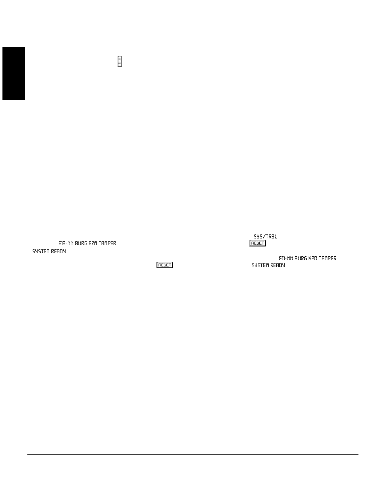
GEM-P1632 Programming Instructions NAPCO Security Systems
WI897B 8/98
Page 60
GLOSSARY
Start Exit Delay After Ringback
When a closing report is successfully received, the central station will acknowledge by returning a kissoff signal. When the kissoff is
received by the communicator, a 2-second ringback tone will sound at the keypad. Start Exit Delay After Ringback will cause the exit
delay to start after the ringback sounds. If this option is chosen and no ringback sounds shortly after the control panel is armed, exit
delay will not start and opening the exit/entry door will cause an instant alarm. To manually start the exit delay, select the START
EXIT TIME function, then press the button to execute.
Note: (1) If this feature is selected, Exit/Entry Follower Zones will not arm until either a ringback sounds or the START EXIT TIME
function is used. (2) If communicator, telephone lines or central-station receiver is out of service, the system will be armed without
communication capability.
Status Report See Closing Report
Subscriber Identification Numbers
If reporting openings and/or closings, program Subscriber Opening/Closing Identification Numbers for each area for each telephone
number used. If reporting events, program Subscriber ID Numbers for each area for each telephone number used. Subscriber ID
numbers must be programmed for each area and telephone number, even if all are the same. Start with the left-most location.
Sum Check See Data Format
Suppress “BYPASSED” Reminder When Armed (Must be enabled in all UL systems)
Program to inhibit the LCD “BYPASSED” display while armed.
Swinger Shutdown (Do not program for UL Installations)
Program for zones with Auto-Reset to only reset twice (3 alarms) until rearmed to prevent “swingers” (intermittents) from causing re-
peated false alarms. See Auto-Reset. The Swinger-Shutdown feature is programmable by zone, but is not applicable to Ambush.
System Troubles (Global and Area)
System troubles may be programmed to report to any telephone number and/or activate any output. Also program Subscriber ID
Numbers, Telephone Numbers, and Report Codes for each system trouble.
Note: RF TROUBLE will report for RF Low Battery, RF Supervisory Failure or GEM-DT Self-Test Failure.
Tamper; EZM Tamper; Keypad Tamper; RF Tamper
Removing the cover of an expansion zone module will cause the sounder to pulse and the “ ” reminder to flash. The keypad
will display “ ”, where “NN” denotes the module number. Press the button to silence the sounder
(“ ” will display). Correct the problem, then select RESET SYSTEM TBL to manually reset the system trouble display.
Removing a keypad from the wall causes a similar system trouble indication. The keypad will display “ ”,
where “NN” denotes the keypad number. Press the button to silence the sounder (“ ” will display). To manually
reset the system trouble, correct the problem then select RESET SYSTEM TBL.
Note: If either of the tamper conditions is not corrected within 5 minutes, the system trouble will again display at the keypad.
A Tamper condition can be programmed to activate the burglary output and/or report using its associated system Report Code.
In wireless installations, when displaying rf transmitter status, a “Tamper” indication denotes that the transmitter case is open.
Telco Fail See Enable Line-Fault Test
Telco Line Test Delay See Enable Line-Fault Test; Time Selection
Telephone Numbers
To report to a central station, Telephone Number 1 (Address 0172-0191) must be programmed. Telephone Number 2 (address
0194-0213) is programmed for Backup Reporting (Address 0394); Telephone Number 3 is programmed for Double or Split Reporting
by selecting “Report Event Telco 3” and “Report Restore Telco 3” in SYSTEM OPTIONS and ZONE OPTIONS.
Private telephone systems may require a Dial-Tone Detection “E” or Pre-Dial Delay “D”, followed by an access number to obtain an
outside line. (See Access Number for Outside Line.)
It should be noted here that the telephone number need not actually start in the first location shown, and may not end in the last. Ex-
tra locations have been provided to allow for one or more prefix digits: a Pre-Dial Delay “D” or a Dial-Tone Detection “E”. What is im-
portant is that the telephone number, with its associated Pre-Dial Delay, Access Number, and Dial-Tone Detection, be wholly con-
tained within that group of locations, and that they be in their proper sequence.
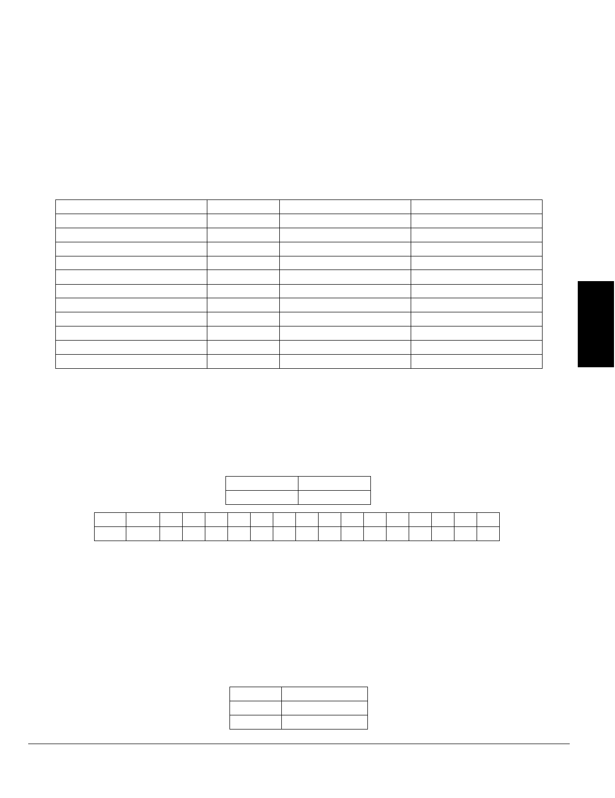
NAPCO Security Systems
GEM-P1632 Programming Instructions
WI897B 8/98
Page 61
GLOSSARY
Test Timer; Cancel Next Test Timer Report on Any Report
The test timer schedule is programmed using Napco's PCD3000 Quickloader Software. If “Test Timer” (Address 0460-0469) is
programmed, an automatic test report will be transmitted to the central station on the scheduled day(s) at the scheduled time. (UL
installations require a report at least every 24 hours.) To report test timer, select Report Test Timer and program a report code.
Program the Test Timer event schedule and reporting time. If “Cancel Next Test Timer Report on Any Report” (Address 0394) is
programmed, any report will cause the next test-timer transmission to be aborted, however subsequent test-timer transmissions will
report as scheduled. Do not program this feature in UL installations.
Timeout
Specifies the length of time that an alarm, alert, or delay will remain active. See Time Selection.
Time Selection
The following times are programmable:
NOT ES:
(1) The output used for Burglary must be at least 4 minutes in Residential UL installations, 15 minutes in Commercial UL installations.
(2) If both locations are left blank, this feature will remain active until the system is disarmed. When both locations are programmed
“F”, maximum time will be 4 hours, 15 minutes (255 minutes). (3) If both locations are left blank, this feature will not activate (timeout
= 0). (4) In UL installations: Maximum Exit Delay = 60 sec; Maximum Entry Delay = 45 sec. (5) If programming locations are left blank,
delay will default to 10 sec. (6) Time in units of disarmed hours (accumulated between armed periods).
Any timeout up to those shown in the foregoing table may be programmed. Note that each of the above times is programmed in two
locations. The first location has an assigned time factor of 16, the second a time factor of 1.
Note: If both programming
locations are left blank, refer to the notes in the Time Selection table for feature timeout.
To select a time up to 15 seconds, 15 minutes, 15 hours, or 15 days, program the respective entry into the second box only; do not
program the first box. To select a time greater than 15 seconds, 15 minutes, 15 hours or 15 days, program both boxes as follows:
1. For the feature selected, choose an appropriate time in units shown (all seconds, minutes, hours, or days — not minutes and
seconds, etc.).
2. Divide the time chosen by 16. Enter the quotient in the 1st BOX and the remainder in the 2nd BOX.
3. Check entries by adding the contents of the 2nd BOX to 16 times the contents of the 1st BOX. (Remember that a “zero” entry
represents 10.)
Example. Program Entry Delay 1 for 1 minutes.
1. Entry Delay 1 is in units of seconds, thus delay time is 90 seconds.
2. Divide by 16: 90/16 = 5 (quotient) + 10 (remainder). Enter the quotient in the 1st BOX and the remainder in the 2nd BOX:
TIME(1) UNITS MAX. PROG. TIME ADDRESS
PGM2 OUTPUT TIMEOUT MIN. UNTIMED(2) 0710
PGM2 OUTPUT ACCESS CONTROL TIME SEC. 4 MIN, 15 SEC (255 SEC) 0711
BURGLARY OUTPUT MIN. UNTIMED(1)(2) 0712
PULSE-BURG OUTPUT MIN. UNTIMED(1)(2) 0713
PGM1 OUTPUT MIN. UNTIMED(2) 0714
ABORT DELAY SEC. 4 MIN, 15 SEC (255 SEC)(3) 0715
CHIME TIME SEC. 63.25 SEC (255 QTR-SEC)(3) 0716
AC-FAIL REPORT DELAY 10 MIN. 42 HR, 30 MIN (2550 MIN) 0717
EXIT DELAY SEC. 4 MIN, 15 SEC (255 SEC)(4) 0000
ENTRY DELAY 1 SEC. 4 MIN, 15 SEC (255 SEC)(4) 0001
ENTRY DELAY 2 SEC. 4 MIN, 15 SEC (255 SEC)(4) 0002
1st BOX 2nd BOX
tx16 tx1
Time t: 0 1 2 3 4 5 6 7 8 9 10 11 12 13 14 15
Entryblank (•)1234567890BCDEF
1st BOX 2nd BOX
50
quotient remainder (“0” for 10)

GEM-P1632 Programming Instructions NAPCO Security Systems
WI897B 8/98
Page 62
GLOSSARY
3. Check entries (remember, a “0” entry = 10): (16x5) + 10 = 90.
Touch-tone Dialing Only; TouchTone Dialing with Rotary Backup
Select “TouchTone Dialing Only” (Address 0394) if the subscriber has TouchTone service. TouchTone dialing is faster than rotary
dialing, but not always as reliable.
For the communicator to use TouchTone on all dial attempts, program TouchTone Dialing Only. To use TouchTone on the first
attempt with subsequent Rotary dial, program TouchTone Dialing with Rotary Backup. TouchTone Dialing Only will override
TouchTone Dialing with Rotary Backup if both are selected. Note that if Backup Reporting is also selected, the communicator will
alternate between TouchTone and rotary dial to reach Telephone 1, then Telephone 2. See Backup Report on Telco 2.
Trouble
An abnormal zone condition (a break in a normally-closed loop; a short on a normally-open loop; or either on an end-of-line-resistor
supervised loop) when disarmed.
Trouble on a Burglary Zone is automatically displayed at the keypad unless Disable Auto Status is programmed. If a Burglary Zone is
in trouble, it will go into alarm about 10 seconds after arming. However, if Auto Bypass is programmed, the keypad will beep upon
arming (does not apply to selective- or group-bypassed zones).
Trouble (open and/or short circuit) on a Day Zone is indicated by a pulsing sounder; display the Day Zone(s) in trouble on the LCD.
Keypad indications are reset by the button unless Reset Day Zone With Arm/Disarm is selected.
Trouble on a Fire Zone will be indicated by the “FIRE/TRBL” reminder and the sounder. An open circuit (trouble) will cause a flashing
“FIRE” display and a pulsing sounder after a 15-second delay. (A short circuit will cause an alarm condition: steady-on “FIRE” display
and pulsing sounder.) The button will silence the sounder. Clear the trouble, then press the the button once again. The
keypad will reset after a brief delay.
Trouble on Open; Trouble on Short; Trouble on Night Open (Not for UL installations)
Trouble on Open will identify an open circuit on a loop as a trouble. Trouble on Short will identify a short circuit as a trouble. Trouble
on Night Open, which will identify an open circuit on a normally-closed zone while armed as a trouble condition (not an alarm), is
intended for use with a Napco Monitor-Series dual-technology sensor. While there will be no indication at the keypad, any of these
trouble conditions can be reported if Report Trouble is programmed as well. See Sensor Watch.
Trouble/Trouble Restore Telco 1/Telco 3 See Report Telco 1/Telco 3
Trouble/Trouble Restore Telco 2 See Backup Report on Telco 2
Two-Digit Format See Data Format
Two-Wire Smoke Detectors See Smoke Detectors
User Codes/Area 1 & 2 Options; User Closing and Opening Reports by Telephone Numbers; Enable User Code by Area
Up to 32 six-digit User Codes are programmable, each with its dedicated Area 1 & Area 2 Options. (Disabled, Arm/Disarm, Arm Only,
Service, Access and User Program.) Refer to Easy Menu Driven Program Mode. If reporting to a central station, program User
Closing and Opening Reports by Telephone Numbers (Address 0440-0459). Note: An Ambush Code should not contain digits used
as the first two digits of any user code.
Veri-Phone™; Silence All Outputs During Audio Session; Veri-Phone Zones Priority Over Alarms; Veri-Phone Zones Trip
PGM2 Output
If Silence All Outputs During Audio Session is selected, all output relays will turn off whenever an active low is applied to control-panel
Lug E19 (Listen In). Connect Veri-Phone Terminal 16 (INHO) to Lug E19. Note: Do not program Keypad Sounder on Alarm for
Listen-In Zones.
If “Veri-Phone Zones Priority Over Alarms” (Address 0722) is programmed and an active low is applied to the panel's Listen-In Lug
(E19), any subsequent alarm reports (except fire alarms) generated during an audio session will be delayed until the end of the
session. (Whenever a listen-in session is in progress, the Veri-Phone will output an active low at its INHO Terminal (16) and Lug E1.)
Program “Veri-Phone Zones Trip PGM2 Output” (Address 0722) to have selectable Listen-In Zones. Connect Veri-Phone Terminal 13
(TRIGL) to control-panel Terminal 8 (PGM2). Program the zone or event for PGM2. Do not use the PGM2 for any other purpose.

NAPCO Security Systems
GEM-P1632 Programming Instructions
WI897B 8/98
Page 63
GLOSSARY
Watch Mode (by Area) See Day Zone
Zone ANDing, Groups 1–2 (Not for UL installations); Enable Local Alarm on First Zone “AND” Trip (Not for UL installations)
Up to two groups of at least two zones each can be “AND”ed (Address 0534-0537, 0589-0592, 0644-0647, 0699-0702), wherein the
system will go into alarm only if any two zones of the group are tripped within a prescribed time. This feature is designed to afford
redundant protection for devices, such as glass break detectors, PIRs, etc., that may show a tendency to false under certain condi-
tions. Program each group for any number of Zones 1–32. All zones in any group must be within the same area. Do not mix 24-Hour
Zones and non-24-Hour Zones within the same group. Do not include a Panic Zone as part of any group.
Note: Any zone that is bypassed or goes into swinger shutdown will automatically disable Zone Anding for the entire group.
If “Enable Local Alarm on First ZoneAND Trip” (Address 0719) is programmed, a trip on any zone of the group will cause an alarm
indication at the keypad only; there will be no communication to the central station.
Zone Area 1–Zone Area 2 See Areas
Zone Number on Pulse Alarm See Data Formats: Two-Digit Format
Zone Type See Data Formats: Modem Formats
2-Wire, 4-Wire Smoke Detectors See Smoke Detectors
4-Wire Bus Failure See Bus Failure
24-Hour Zone
A zone selected for “24-Hour Zone” (Address 0499, 0554, 0609, 0664) that provides protection at all times, whether or not the sys-
tem is armed. If “Alarm Output”, “Pulsed Alarm Output”, “PGM1 Output” , “PGM2 Output” and “Keypad Sounder on Alarm” are not
selected, then the zone is programmed for silent alarm. In this case, the green LED on the keypad will go out if the zone is tripped.
Note: Do not program a Day Zone as a 24-Hour Zone.
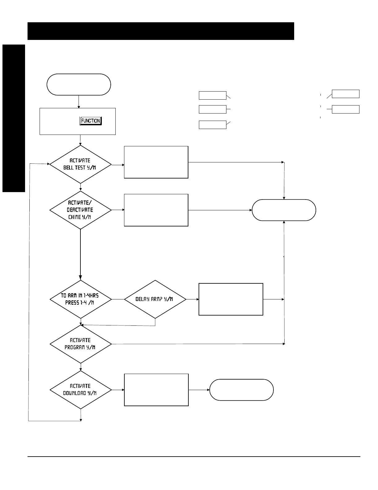
GEM-P1632 Programming Instructions NAPCO Security Systems
WI897B 8/98
Page 64
KEYPAD PROGRAMMING MODES
START FUNCTION
MODE
Keypad Commands
NEXT/YES
PRIOR/NO
AREA
Scroll Down
Scroll Up
Exit
Yes
No
Press
Bell Test Activated
Chime Toggle On/Off Exit Automatically
No
Yes
Yes
System to Arm in
number of hours
entered w/delay
Exit Automatically
Activate Fault Find
Download
Activated
No
No
No
No
Yes
Yes
Yes
Yes
Yes
No
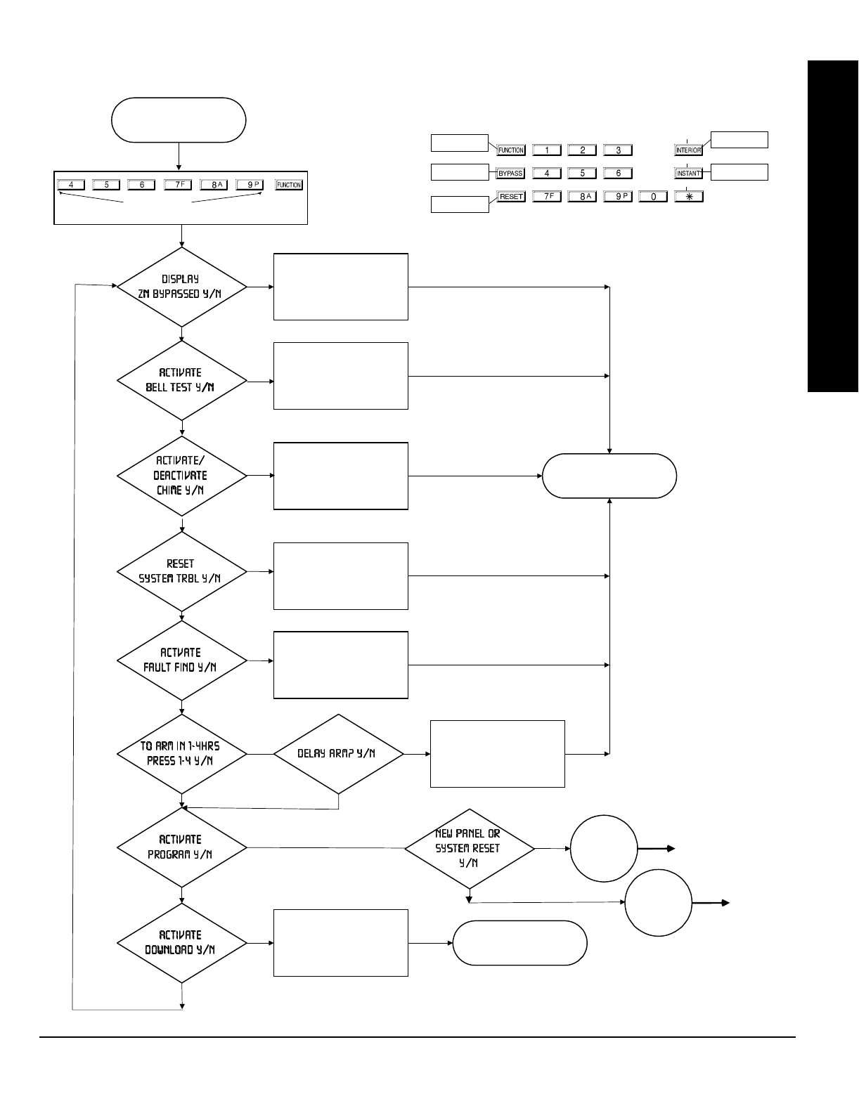
NAPCO Security Systems
GEM-P1632 Programming Instructions
WI897B 8/98
Page 65
KEYPAD PROGRAMMING MODES
System to Arm in
number of hours
entered w/delay
START DEALER
PROGRAM MODE
Dealer Code
Zones Bypassed
Display Activated
Bell Test Activated
Chime Toggle On/Off Exit Automatically
Reset System Trouble
Exit Automatically
Activate Fault Find
Download
Activated
Keypad Commands
No
No
No
No
No
No
No
No
Yes
Yes
Yes
Yes
Yes
Yes
Yes
Yes
NEXT/YES
PRIOR/NO
AREA
Scroll Down
Scroll Up
Exit
Yes
No
Yes
No
See next page.
Go to Easy
Menu Driven
Mode
Yes
No
Go to
Previously
Programmed
Panel
See next
page.

GEM-P1632 Programming Instructions NAPCO Security Systems
WI897B 8/98
Page 66
KEYPAD PROGRAMMING MODES
Keypad Commands
NEXT/YE
S
PRIOR/NO
AREA
Set Cursor
Exit
Yes/
Scroll Down
No/
Scroll Down
Execute
Enter Interior Zone
Numbers in Area 1
Eas
y
Menu Driven
Mode
Enter Fire Zone
Numbers in Area 1
Enter 2-Wire Fire Zone
Numbers in Area 1
Enter Entry/Exit Zone
Numbers in Area 1
Enter Central Station 1
Telephone Number
No
No
Yes
Yes
Enter Number of
Keypads in Area 1
Enter # of Zones
in Area 1
Press (at any time)
Go to Direct
Address
Mode
EXIT
Enter CS Receiver 1
Account Number
Enter CS Receiver 1
Format
Enter RF Xmitter to
Zone Mapping
Enter Keyfob
Area Mapping
Enter User Codes for
both Areas
Enter Zone
Descriptions
Enter Dealer Code
Press (a
g
ain)
Previously
Pro
g
rammed
Panel
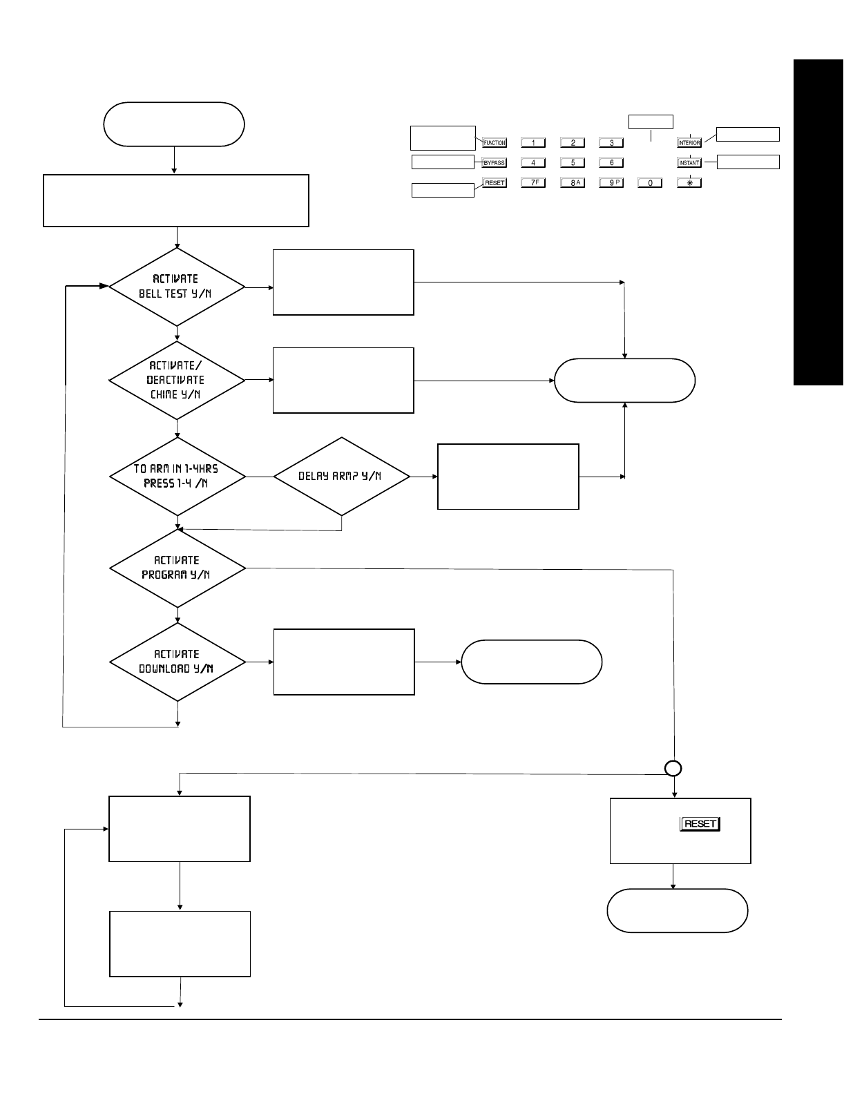
NAPCO Security Systems
GEM-P1632 Programming Instructions
WI897B 8/98
Page 67
KEYPAD PROGRAMMING MODES
START USER
PROGRAM MODE
New Panel: Default User Code (123)
Existing Panel: Any Code with User Program Option Enabled
Bell Test Activated
Chime Toggle On/Off Exit Automatically
No
No
Yes
Yes
System to Arm in
number of hours
entered w/delay
Exit Automatically
Download
Activated
No
No
No
Yes
Yes
Yes
Yes
No
Keypad Commands
NEXT/YES
PRIOR/NO
AREA
Scroll Down/
Set Cursor
Scroll Up
Exit
Yes
No
Execute
Enter User Codes for
both Areas
Enter Zone
Descriptions
Press
(at an
y
time to exit)
EXIT
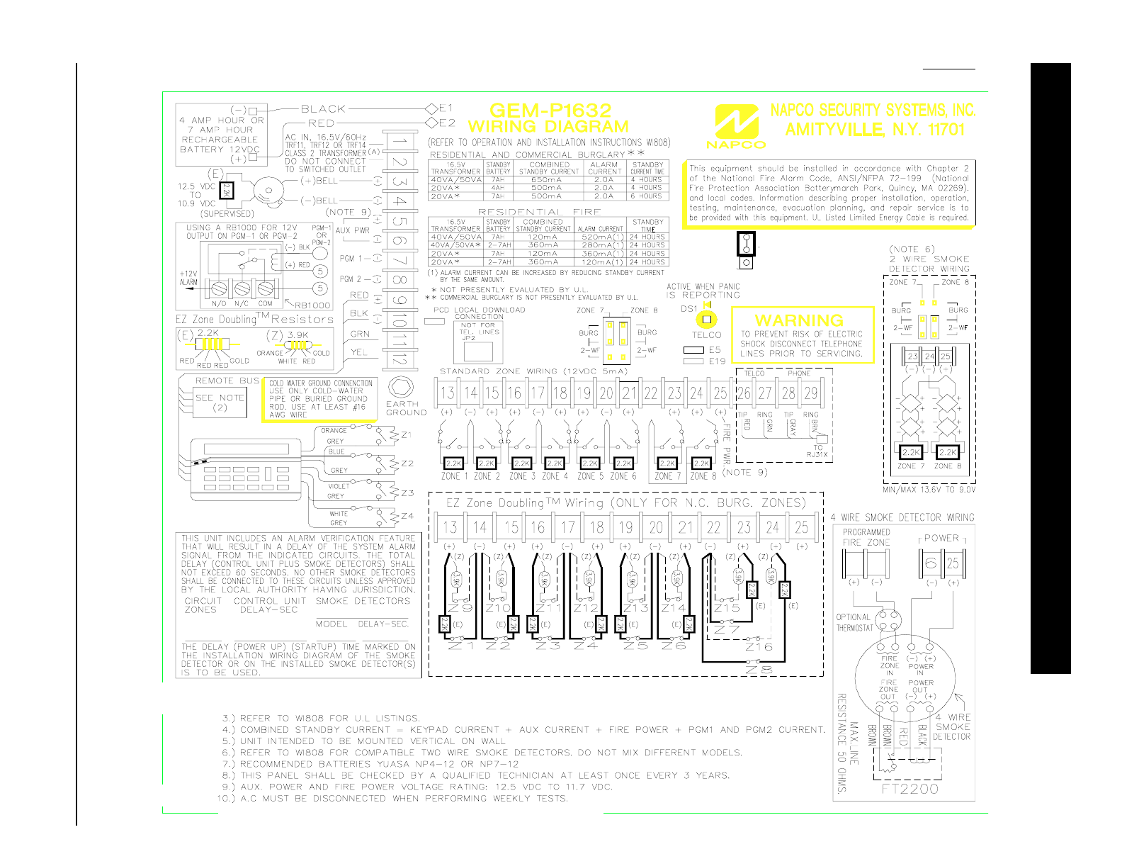
GEM-P1632 Programming Instructions NAPCO Security Systems
WI897B 8/98
Page 68
NORMAL
KEYPAD
CONFIGURE
JP1
JP3
(GEM-RP1CAe2) 2 LINE KEYPAD
NOTES: 1. ) ALARM CURRENT CAN BE INCREASED BY REDUCING STANDBY CURRENT BY THE SAME AMOUNT.
2. ) THE FOLLOWING DEVICES MAY BE PLACE ON THE REMOTE BUS: GEM-RP1CAe2, GEM-RP2ASe2, GEM-EZM816, GEM-X10, GEM-RECV8,
GEM-RECV16, RM3008, GEM-EVA1 AND WIZARD2.
(-)
E15
LA1469B
(E)
(E)
(E)
(E)
6
. BATTERY SHOULD BE REPLACED EVERY 5 YEARS.
11. ) THIS PANEL ONLY SUPPORTS ONE SMOKE DETECTOR IN ALARM FOR EACH ZONE.
(NOTE 7)
