GEM X255_WI1093C.14_INSTALL X255 V40 Installation Manual
User Manual: GEM-X255 v40 Installation Manual AlarmHow.net Library
Open the PDF directly: View PDF ![]() .
.
Page Count: 68

INSTALLATION
INSTRUCTIONS
HARDWIRE WIRELESS
GEM-X255
CONTROL PANEL/COMMUNICATOR
WI1093C 3/04
© Napco 2004
R
For use with "Classic" keypad GEM-RP1CAe2 and with "K Series" keypad GEM-K1CA
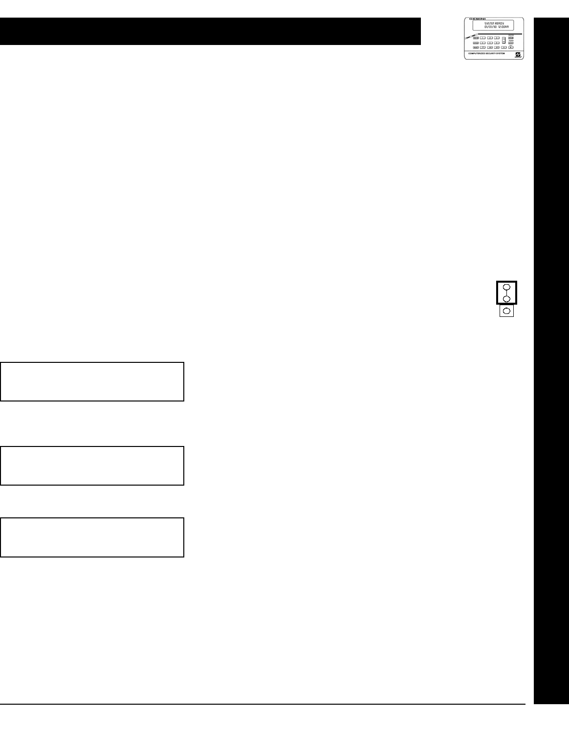
"K Series" GEM-K1CA
GEMINI
SYSTEM READY
01/01/03 12:00 AM
ARMED
COMPUTERIZED SECURITY SYSTEM
STATUS
R 1 2 3
B 4 5 6
C 7 8 9 0
U
NEXT/YES
P
PRIOR/NO
Q
AREA
G
"Classic" GEM-RP1CAe2
GEMINI
SYSTEM READY
01/01/03 12:00 AM
ARMED
COMPUTERIZED SECURITY SYSTEM
STATUS
A 1 2 3
B 4 5 6
C 7 8 9 0
D
NEXT/YES
E
PRIOR/NO
F
AREA
G

CHANGES FROM PREVIOUS EDITION
The following changes have been made to this manual (WI1093C) since the last edition (WI1093B).
This version of the manual reflects the addition of two new NAPCO products:
•The Access Control system (ACM), which provides integrated access control to the burglary alarm functions of the
GEM-X255 control panel.
•The NAPCO NetLink™ system that allows the reporting of alarms over a TCP/IP based (Intranet or Internet) net-
work.
•Page 30, new Keypad messages (System Troubles) added to accommodate the new ACM and NetLink™ systems.
THIS MANUAL INCLUDES FEATURES WHICH ARE ONLY AVAILABLE IN CONTROL PANEL
FIRMWARE VERSION 5 OR LATER.
NAPCO Security Systems, Inc.
333 Bayview Avenue, Amityville, New York 11701
For Sales and Repairs, call toll free: (800) 645-9445
For direct line to Technical Service, call toll free: (800) 645-9440
Internet: http://www.napcosecurity.com
Refer to accompanying GEM-X255 Programming Instructions (WI1092) for programming information.
L NAPCO Security Systems X GEM-X255 Installation Instructions
WI1093C 3/04 !
Page 3
IMPORTANT NOTE
This manual supports the keypad programming of the GEM-X255 control panel with the NAPCO "classic" GEM-
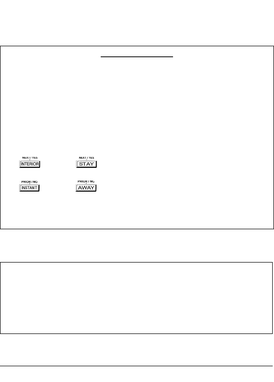
RP1CAe2 keypad as well as the GEM-K1CA "K Series" keypad. The new "K Series" model offers the new STAY and
AWAY buttons with simplified functionality, along with the new MENU and ENTER buttons.
While the instructions in this manual are depicted using the GEM-K1CA keypad, the manual applies to both the "classic"
and the "K Series" keypads.
Program Mode is the same for both keypads--only the button names have changed, as follows:
•The A button and the R button operate identically (in Program Mode) for both keypads.
•The D button and the U button operate identically (in Program Mode) for both keypads.
•The button and the button operate identically (in Program Mode) for both keypads. The words
"NEXT/YES button" are used in this manual.
•The button and the button operate identically (in Program Mode) for both keypads. The words
"PRIOR/NO button" are used in this manual.
!For consistency, it is recommended that all keypads either be all "classic" or all "K Series"--both keypad
types should not be used in one alarm system.
IMPORTANT NOTICE
!GEM-X255 panel version 4 requires the use of the following version keypads:
•GEM-RP1CAe2 Version 8, GEM-K1CA Version 8C
Upon entering program mode, the keypad display will flash the control panel firmware version, followed by
the keypad firmware version:
GEM-RP1CAe2: [048C]
GEM-K1CA: [048C]

X GEM-X255 Installation Instructions L NAPCO Security Systems
WI1093C 3/04
! Page 4
TABLE OF CONTENTS
Refer to accompanying GEM-X255 Programming Instructions (WI1092) for programming information.
CHANGES FROM PREVIOUS EDITION ........................ 2
IMPORTANT NOTE ......................................................... 3
INTRODUCTION .............................................................. 5
General Description ............................................ 5
Features .............................................................. 5
Specifications ...................................................... 7
Ordering Information ........................................... 7
Summary Of UL Requirements ........................... 9
INSTALLATION ............................................................. 10
Mounting ........................................................... 10
Wiring ................................................................ 11
Wireless Systems .............................................. 11
Typical Residential Fire Installation ................... 11
Typical Partitioned Installation .......................... 11
UL Commercial-Burglary Installations ............... 12
Testing The System .......................................... 13
WIRING CONNECTIONS .............................................. 14
Battery ............................................................... 14
Transformer ............ .......................... ................. 1 4
Siren/Bell Alarm Output ..................................... 14
Auxiliary Alarm Output ...................................... 14
Remote Bus ...................................................... 15
Earth Ground ..................................................... 15
Auxiliary Power ................................................. 15
Reset Output ..................................................... 16
Basic Zone Configuration .................................. 16
Expanded Zone Configuration .......................... 16
4-Wire Smoke Detectors ................................... 17
2-Wire Smoke Detectors ................................... 17
Telephone Lines ................................................ 18
KEYPAD CONFIGURATION MODE ............................. 19
Keypad Installation ............................................ 19
Configuring the Keypads ................................... 19
BASIC OPERATION ...................................................... 22
User Codes & Zone Descriptions ...................... 22
Arming and Disarming the System .................... 23
Bypassing Zones ............................................... 25
Alarm Indication ................................................ 26
Function Mode .................................................. 26
Keypad Messages ............................................. 30
GLOSSARY ................................................................... 31
STANDBY-BATTERY CALCULATION WORKSHEET 53
WIRING LEGEND .......................................................... 54
KEYPAD PROGRAMMING MODES ............................. 55
GEM-X255 WIRING DIAGRAM ..................................... 60
CP-01 QUICK REFERENCE CHART-SIA .................... 61
FACTORY DEFAULT DESCRIPTION .......................... 63
STATEMENT FOR CANADIAN MODELS ................... 64
FCC STATEMENT ......................................................... 65
LIMITED WARRANTY ................................................... 68
NOTE: THESE INSTRUCTIONS ARE INTENDED AND WRITTEN FOR PROFESSIONAL INSTALLATION PERSONNEL HAVING SUITABLE
TRAINING, EXPERIENCE AND INSTALLATION EQUIPMENT. IT IS RECOMMENDED THAT AFTER PROGRAMMING, THE ERROR CHECK
UTILITY OF THE PCD3000 (OR PCD-WINDOWS) DOWNLOADER SOFTWARE BE USED TO VERIFY THAT THE CONTROL PANEL PRO-
GRAM CONTAINS NO ERRORS OR CONFLICTS WHICH MAY INHIBIT ITS INTENDED OPERATION.

L NAPCO Security Systems X GEM-X255 Installation Instructions
WI1093C 3/04 !
Page 5
INTRODUCTION
GENERAL DESCRIPTION
NAPCO's Gemini GEM-X255 is a state-of-the-art microcomputer-based burglary and residential fire alarm control panel
of modular design. Integrally an 8-zone panel, it will support up to 255 zones with optional zone expansion modules,
wireless receiver modules and/or GEM-RP1CAe2/GEM-K1CA Keypads. Each panel includes an integral digital commu-
nicator.
The control panel features programmable area partitioning. That is, the system may be divided into up to 8 discrete mul-
tiple-zone areas, each allowing access by only those users programmed for their respective area(s).
Opening Suppression and Closing Suppression, available through Napco Quickloader software, suppress reporting
within programmed “windows of time”. Conversely, Exception Reporting can transmit a “fail to close report” if the panel
is not armed within programmed intervals and, similarly, a “fail to open report” if the panel is not disarmed within pro-
grammed intervals of time. Furthermore, the panel can be programmed to automatically arm either area at any time. A
log containing up to 800 events (accessible through QuickloaderTM software) monitors control-panel activity referenced to
a precision real-time clock. A detailed event history may be displayed at the computer, using NAPCO's PCD-Windows
Quickloader Software.
Keypads feature a liquid-crystal display for messages. In normal use, the LCD shows zone identification and system
status messages. Conventional LEDs and a sounder are also provided for annunciation.
Data may be quickly and easily downloaded to the control panel using a PC-compatible computer with NAPCO's PCD-
Windows Quickloader software and PCI2000 computer interface. Or, the panel may be programmed using the keypad in
its secondary mode of operation. In keypad programming modes (there are two: Dealer and User), the LCD shows
memory address, data values, programming prompts, and the alphanumeric characters required for entering up to 195
user codes and custom zone descriptions.
GEM-X255M
The standard GEM-X255 may be converted to the Mercantile “GEM-X255M” version with the optional H1217 accessory.
The H1217 kit includes the model H217 heavy-duty UL commercial enclosure, two tamper switches and tamper screws.
Note: Do not use Fire Zones in a Mercantile installation.
FEATURES
!Eight end-of-line-resistor burglary zones programmable for Area, Exit/Entry Delay, Interior, Follower, Day Zone,
Chime, Fire options, Sensor Watch, Swinger Shutdown, Zone Anding and a variety of other features.
!Supports up to 96 zones using the keypad (255 with PCD-Windows software) with optional zone-expansion modules
and 4-zone keypads.
!Supports up to 96 individually coded users using the keypad (195 with PCD-Windows software), each with a pro-
grammable authority level.
!Supports three on-board relay outputs and up to 96 external relay outputs.
!Supports four keypad panics: Fire, Police, Auxiliary & Ambush.
!Supports up to 8 independent area partitions.
!Supports up to 8 separate keypad access control stations by up to 195 users.
!Supports up to 64 separately-addressable X-10 devices with the GEM-X10KIT and PC04 interfaces.
!English-language prompts & system status messages.
!User-customized zone descriptions, re-programmable as required.
!Supports 2-wire and 4-wire smoke detectors.
!Reports alarms, restores and troubles by zone.
!255 Event Schedule.
NOTE: Failure to install and program as described in this manual for UL-listed systems voids the listing mark of Under-
writers Laboratories, Inc.

X GEM-X255 Installation Instructions L NAPCO Security Systems
WI1093C 3/04
! Page 6
!800 Event Log.
!Overview Mode permits monitoring and control of total system from one keypad.
!Guard-Tour programmable for start time, tour length, and check points (tour stations).
!Two programmable Entry Delay times.
!Two Interior-Zone groups (when used with GEM-RP1CAe2 / GEM-K1CA keypads).
!Dynamic battery test interrupts charging and places battery under load every four hours.
!Chime by zone; programmable duration.
!Non-volatile RAM retains memory during power losses.
!Quickloader programmable.
!Auto-Download Log.
!Exclusive V.A.L.I.D. feature (Verifying Automatic Line-Integrity Diagnostic) reduces false alarms due to changes in
line resistance.
Communicator Features
!Compatible with all major receiver formats, including BFSK, 4/2, Modem 2, SIA, 4/3/1, 4+2 Express and Point ID.
!Rotary dial, TouchToneTM only, and TouchToneTM with Rotary backup.
!Three 20-digit telephone numbers.
!Backup Reporting; Double Reporting; Split Reporting.
!195 User Codes with Open/Close Reporting by user.
!AC Failure Reporting with programmable report delay.
!Supervised telephone line with programmable delay.
!Pager capability.
!GEM-ACM1D and GEM-2D Access Control Modules provide integrated access control to the burglary alarm functions
of the GEM-X255 control panel.
Keypad Features
!English-language LCD display; LED and sounder annunciators.
!Supports up to fifteen 4-wire keypads.
!Access only capability.
!Provisions for fire, police, auxiliary and ambush panic alarms.
!Integral 4-zone EZM included in each keypad (GEM-RP1CAe2/GEM-K1CA only).
!Communicator Test to Central facilitates testing; Locate, Fault-Find and EZM-Locate diagnostics simplify trouble-
shooting.
!PGM output.
!The NAPCO NetLink™ system allows the reporting of alarms over a TCP/IP based (Intranet or Internet) network
L NAPCO Security Systems X GEM-X255 Installation Instructions
WI1093C 3/04 !
Page 7
SPECIFICATIONS
GEM-X255
Panel Dimensions: 12 3/8" x 13 7/8" x 3 ½" (H x W x D) without cover
Operating Temperature: 0-49°C (32-120°F)
Input Power: 16.5VAC via CLASS 2 Plug-In 40VA or 50VA Transformer
Loop Voltage: 10-13VDC
Loop Current: 2.4mA with 2.2K Ohm end-of-line resistor (Model EOL2.2K); 5mA for 2-wire smoke-detector zones
Loop Resistance: 300 Ohm max.; 50 Ohm for 2-wire smoke-detector zones
Relay Outputs (Burglary; Reset; Aux): Wet, 12Vdc, 1.2A max.; Dry (cut related jumper for dry contacts; see Wiring Dia-
gram), SPDT contacts 24Vdc, 2A, 0.6 PF
Auxiliary Power Output: 12Vdc regulated
Remote Power Output: 12Vdc regulated (for keypads)
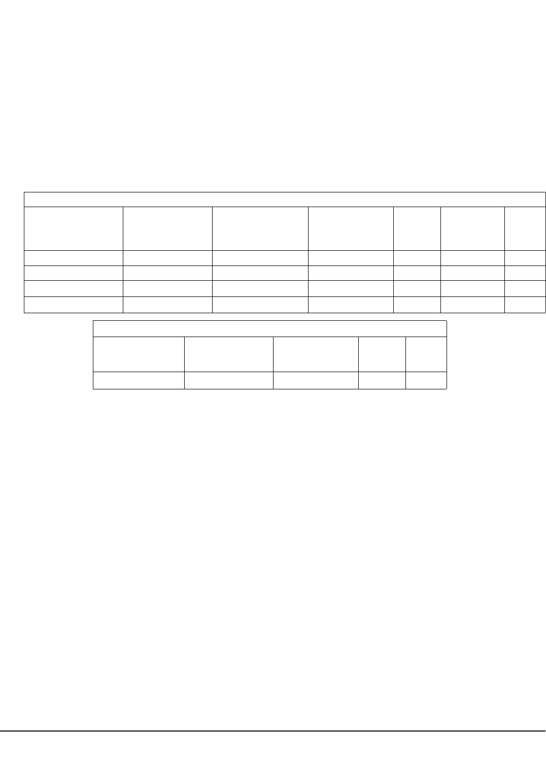
Combined Standby Current (Remote Power + Aux. Power + Reset Relay Power): See following charts.
Notes: (1) With 1 RBAT6 battery, GEM-X255 combined standby current + PS3002 standby current may not exceed 1.2A.
(2) With 2 RBAT6 batteries, GEM-X255 combined standby current + alarm current may not exceed 1.9A.
Standby Time: Residential Fire/Burglary & Commercial Burglary, 24 hours minimum
EZM Module: GEM-EZM8: Input, 50mA (not including PGM output)
PGM Output: 5mA, 12V Special Application
Keypad Current:
GEM-RP1CAe2/GEM-K1CA: 100mA; 35mA if backlighting is disabled (cut W1, W2 & W3)
PGM Output: 5mA, 12V Special Application
Maximum Number of Keypads: 15
Maximum Wiring Length for each run (#22AWG): 1000' divided by total number of keypads and EZMs on run
Keypad Dimensions: 4 ¼" x 5 ¾" x 1" (H x W x D); 11.1cm
ORDERING INFORMATION
System Components
GEM-X255: Residential UL-Listed Burg Control Panel.
GEM-RP1CAe2/GEM-K1CA: 32-Character LCD Burg & Residential Fire Keypad with 4 EOL Resistor Supervised
Zones.
TRANSFORMER RECHARGEABLE
BATTERY
POWER
SUPPLY
GEM-X255 COMBINED
STANDBY CURRENT
GEM-X255
ALARM
CURRENT
PS3002 POWER
SUPPLY
STANDBY
CURRENT
STANDBY
TIME
TRF11 (16.5 VAC, 40 VA) RBAT4 (12 VDC, 4 AH) N/A 750 mA 2.0 A N/A 4 Hours
TRF11 (16.5 VAC, 40 VA) RBAT6 (12 VDC, 6 AH) N/A 750 mA 2.0 A N/A 6 Hours
TRF11 (16.5 VAC, 40 VA) (3) RBAT6 (12 VDC, 6 AH) PS3002 (13.2 VDC, 1.9 A) 750 mA 1.9 A 1.2 A (1) 4 Hours
TRF11 (16.5 VAC, 40 VA) (3) 2 RBAT6 (12 VDC, 6 AH) PS3002 (13.2 VDC, 1.9 A) 750 mA 1.9 A (2) 1.4 A 4 Hours
RESIDENTIAL BURGLARY & COMMERCIAL BURGLARY
TRANSFORMER RECHARGEABLE
BATTERY
GEM-X255
COMBINED
STANDBY CURRENT
GEM-X255
ALARM
CURRENT
STANDBY
TIME
TRF11 (16.5 VAC, 40 VA) RBAT7 (12 VDC, 7 AH) 150 mA 650 mA 24 Hours
RESIDENTIAL FIRE, COMBINATION RESIDENTIAL FIRE & BURGLARY

X GEM-X255 Installation Instructions L NAPCO Security Systems
WI1093C 3/04
! Page 8
OPTIONAL ACCESSORIES AND
PERIPHERALS
EOL130: 2-Wire Fire Zone Resistor, 130W, 3W
EOL2.2K: End-of-Line Resistor Assy., 2.2K
FT2200: End-of-Line Relay/Resistor Supervisory Module
GEM-ACM1D: Access Control Module for door 1
GEM-2D: Access Control Module for door 2 add on PCB
GEM-DT: Wireless Dual-Technology Sensor **
GEM-EZM4: 4-Zone Expansion Zone Module
GEM-EZM8: 8-Zone Expansion Zone Module **
GEM-GB: Wireless Glass-Break Detector **
GEM-KEYF: Key Fob Transmitter **
GEM-HEAT: Wireless Heat Detector **
GEM-PIR: Wireless PIR **
GEM-PIRPET: Wireless Pet Immune Transmitter *
GEM-PRINT: Parallel Printer Interface *
GEM-PXC/50: Proximity card pack (50 cards)
GEM-PXC/100: Proximity card pack (100 cards)
GEM-PX: Proximity Card Reader
GEM-H1326: Proximity Card Reader
GEM-RECV8: Wireless Receiver, 8 Zones **
GEM-RECV16: Wireless Receiver, 16 Zones **
GEM-RECV96: Wireless Receiver, 96 Zones **
GEM-RECV255: Wireless Receiver, 255 Zones **
GEM-RS232KIT: Home Automation Interface *
GEM-SMK: Wireless Smoke Detector **
GEM-TRANS2: Window/Door Transmitter, 2-Point **
GEM-RTRANS: Recessed Window/Door Transmitter
GEM-WP: Waterproof Panic Transmitter **
GEM-X10KIT: X-10 Interface *
GEM-OUT8: 8 output active low output module
H1217: Mercantile Conversion Kit
M278: Line-Reversal Module *
NL-MOD: NetLink™ TCP/IP reporting module
NL-CSRCV: NetLink™ TCP/IP receiver application
NL-MODCONFIG: NetLink™ NL-MOD configuration software
NL-ULBD: NetLink™ Transient protection device
NL-CSRCV/PC: NetLink™ TCP/IP receiver application prein-
stalled in a PC
PCD-Windows: Downloading Software (for Windows) for IBM
PC-Compatible*
PCI2000/3000: Software with Interface for IBM PC-Compatible
Computer
PCI-MINI: Notebook Computer Interface *
PS3002: Power-Supply Module, 13.2VDC, 1.9A
RB1000: Relay Board, single output *
RBAT4: Rechargeable Battery, 12VDC, 4AH
RBAT6: Rechargeable Battery, 12VDC, 6AH
RBAT7: Rechargeable Battery, 12 VDC, 7AH
RBATH1: Dual Battery Harness *
RM3008: Relay Module (in enclosure)
RPB-3: Universal Keypad Mounting Box
TRF11: Transformer, 16VAC/40VA, Class 2
TRF14: Transformer, 16VAC/50VA, Class 2
WL1: Wire Assembly with Lug Connector, 20”
VERI-PHONE: Two-Way Voice/Listen-In Module *
W834-1: Keypad Cable, plug-in (20”)
OI193: User Guide, GEM-RP1CAe2
OI279: User Guide, GEM-K1CA
WI1092: GEM-X255 Programming Manual
* Not investigated by UL.
** Not investigated by UL for commercial applications.
UL LISTINGS
Household Burglar Alarm System Units: UL1023
Household Fire Warning System Units: UL985
Local Burglar Alarm Units and Systems: UL609
Central Station Burglar Alarm Units: UL1610
Police Station Alarm Units: UL365
Security Industry Association (SIA) False Alarm Reduction
Standard CP-01
COMPATIBLE UL-LISTED DEVICES
Refer to the following list of recommended devices.
Bells:
Ademco AD8-12; AD10-12
Amseco MBL-8/12V; MBL-10/12V
Wheelock 46T-G4-12-R*; 46T-G6-12-R; 46T-G10-12-R
Hochiki America AL-VB-1012*; AL-MB-612*
*Not for Household Fire applications (<85dB at 10')
Grade-A Bell:
Ademco AB-12 Bell in Box
Horns:
Wheelock 34T-12-R; MT-12/24; MT4-12/24; MIZ-12
Faraday 6120-0-0-12-DC*
Federal Signal 450E-24
Hochiki America AL-FH-12M*
*Not for Household Fire applications (<85dB at 10')
Mini-Horn:
Federal Signal 460-024-R (red); -W (white); -BG (beige)
Chimes:
Wheelock CH-CF1-12; CH-DF1-12 (both for private-mode sig-
nalling only)
Strobes:
System Sensor SS1215ADA; SS1215ADAB
Wheelock LS12
Strobe/Horns:
Wheelock 7002T-12-W-FR; 7001T-12-W-FR; V7001T-12-W-FR
Gentex SHG-12H
System Sensor MASS1215ADA; MASS1215ADAB
Electronic Signals:
Wheelock ES-BH2-R; ES-DL2-R; ES-EL2-R
Electronic Signal/Strobes:
Wheelock ES-BH2-WH-12DC-HF-R; ES-DL2-WS-12DC-VF-R;
ES-EL2-WS-12DC-HF-R
Bell/Strobes:
Wheelock 46T-G6-12-WS-12-HF-R; 46T-G10-12-WS-12-HF-R
Transformers:
Basler Electric BE116240CAA 40VA; BE116250CAA 50 VA

L NAPCO Security Systems X GEM-X255 Installation Instructions
WI1093C 3/04 !
Page 9
SUMMARY OF UL REQUIREMENTS
Residential
!Recognized Limited-Energy Cable for initiating, indicating and supplementary circuits.
!Initiating loops supervised if longer than 3 feet
!FT2200 End-of-Line Relay for Fire (if using 4-wire smoke detectors)
!Minimum alarm timeout of 5 minutes
!Maximum exit time: 60 seconds
!Maximum entry time: 45 seconds
!Do not program “Swinger Shutdown”, “Auto Arming”, “Selective Bypass”, “Interior (Group) Bypass”, or “50 ms
or 20ms Loop Response”
!“Abort Delay” may not exceed 45 seconds
!Program “Disable Callback Download”
!Automatic dialer may not dial a police station number that has not been dedicated for such service
!System must be tested at least weekly under AC/battery and Battery-Only conditions
!Replace the rechargeable battery at least every 5 years
!If the battery is heavily discharged, replace it or have it tested by a qualified technician
!For silent panic, connect only to UL-listed holdup devices
!All zones must be programmed for “Priority”
!Do not program any zones for “Keyswitch Arming”
!System must be serviced at least once every year
!Residential Fire and Combination Residential Fire & Burglary must program “Residential Fire”
!Keypad Expansion (EZM) Zones are not to be used as fire zones
Compatible Smoke Detectors
2 Wire Smoke Detectors
Manufacturer Model Base
NAPCO FW-2 N/A
Sentrol/ESL 711U, 712U, 701U, 702U,
721U, 721UT, 702RE, 702RU
722U, 731U, 732U
System Sensor 1100, 1151, N/A
1400, 2100, N/A
2100T, 2100S, N/A
2100TS, 2151, N/A
2400, 2400TH N/A
Note: Voltage Rating: 8.5–13.3 VDC
Maximum Number of Detectors: 10
4 Wire Smoke Detectors
Manufacturer Model Base
Gentex 812, 812T, 812P, N/A
812PT, 812PH, N/A
8120, 8120T, N/A
8120P, N/A
8120PTY, 8120-PH N/A
Hochiki SLG-12 w/YBC-RL4-RA base N/A
NAPCO FW-4 N/A
Sentrol/ESL 445AT, 445C, N/A
445CT, 445CR, N/A
445CRT N/A
System Sensor 1112, 2112, N/A
21112T, 211TSRB N/A
1412TH, 2412TH N/A
2312/24T, 1412, N/A
Note: Subtract total smoke-detector alarm current
from available standby current.
UL Compatible Smoke Detectors (Providing UL Recognition or Listing)
Note: Any normally-open devices that do not require power from the control panel may be used (such as
pull stations, waterflow and thermostats), if acceptable to the authority having jurisdiction.

X GEM-X255 Installation Instructions L NAPCO Security Systems
WI1093C 3/04
! Page 10
INSTALLATION
MOUNTING
Control Panel
Choose a mounting location accessible to (a) a continuously-powered AC source, (b) system ground, a steel or copper
ground rod, ideally no further away than 10 feet, and (c) telephone lines (keep telephone wiring away from keypad
wires). Remove appropriate knockouts for cables. Place the control panel at a convenient viewing height and mark the
mounting holes. Attach the enclosure using screws suitable for the mounting surface.
Grounding
Connect the control-panel grounding screw through a No. 16 AWG. or larger wire to a long steel or copper ground rod
driven deeply into the earth. Do not use a gas pipe, plastic pipe or ac ground connections. Make the run as short and
direct as possible, without any sharp bends in the wire.
Tamper Switches
Tamper switches may be installed to prevent opening of the control-panel door or removal of the cabinet from the wall.
Ideally, tamper switches should be connected to a zone that is active at all times, thus it may be necessary to program
that zone as a 24-Hour Zone or Day Zone. When used on a normally-open zone, normally-closed tamper switches
(open when set) should be wired in parallel. On a normally-closed zone, install Napco TPS-2 normally-open tamper
switches (closed when set) in series.
There are two places in the cabinet to mount tamper switches: (1) To prevent cabinet removal from the wall, there are
three mounting holes on the left side of the cabinet, another hole on the back that allows the switch button to contact the
wall. (2) To prevent opening the cabinet door, there are three mounting holes on the right side of the cabinet. When
mounted, the switch button should contact the inside of the door. Be sure to alert the user that opening the enclosure
door will cause a tamper alarm. Note: Each tamper switch is furnished with three machine screws for mounting, and
one self-tapping screw. The sole purpose of the self-tapping screw is to tap the holes for the machine screws; it may be
discarded after use.
Keypad
A keypad should be located near each exit/entry door. The keypad features a handy pull-up reference label. Before
mounting the keypad onto the wall, push the Sliding Label Plate (with label and felt backing affixed and handle facing
forward) down the guides at the rear of the keypad until it snaps into place. Once installed, the Sliding Label Plate can-
not be removed without first removing the keypad from the wall. Note: (1) The keypad fire and panic keys should not be
considered a substitute for a listed manual initiating device, such as a pull box. (2) Each GEM-RP1CAe2/GEM-K1CA
includes provisions for four additional zones. See ADDING EXPANSION ZONES.
If installing onto a double-gang box, insert mounting screws through the two vertical elongated holes on the left side of
the case and into the box. If the box is visible when viewed from the front, adjust the keypad vertically and tighten the
screws. Then, using hardware suitable for the mounting surface, add one or two screws at the right side of the keypad
case directly into the wall to ensure a secure installation. Note: Do not overtighten the screws! Uneven walls may
cause the keypad case to distort.
CAUTION: This equipment generates and uses radio-frequency energy. If not installed using conventional installation
practices for RF devices, it may cause interference to radio and television reception. It has been tested and found to
comply with the limits for a Class A computing device pursuant to Subpart B of Part 15 of FCC Rules, which are de-
signed to provide reasonable protection against such interference. However, there is no guarantee that interference will
not occur in a particular installation. If it has been found to cause interference to radio or television reception, which can
be determined by removing and reapplying AC and battery power to the equipment, the installer should try to correct
the interference by one or more of the following measures: reorient the receiving antenna; connect the power trans-
former to a different outlet so that the control panel and receiver are on different branch circuits; relocate the control
panel with respect to the receiver.
INSTALLATION
L NAPCO Security Systems X GEM-X255 Installation Instructions
WI1093C 3/04 !
Page 11
Wiring
Wire keypad(s), zones, expansion zone modules and output devices as shown on the Wiring Diagram. Note that the
Wiring Diagram contains important information not available elsewhere in this manual.
Adding Expansion Zones
GEM-X255 Series control panels will handle up to 8 zones as is, however this number may be increased to as many as
255 programmable zones using optional expansion zone modules (EZMs).
Wireless Systems (NOT EVALUATED BY U.L. FOR COMMERCIAL APPLICATIONS)
With the addition of at least one GEM-RECV series receiver, the GEM-X255 will support up to 255 wireless transmitters.
The panel can accommodate one to four receivers within the premises, responding to the one with the stronger transmit-
ter signal. If any transmitters are selected for the default program, a GEM-RECV receiver will automatically be pro-
grammed.
The keypad can display the status of any transmitter, indicating the condition of the zone (normal or open) and transmit-
ter troubles (low battery, tamper or supervisory failure), and signal strength of the last transmission. A receiver failure
will be indicated by “E06-NN” (“no response”, with NN representing the receiver number).
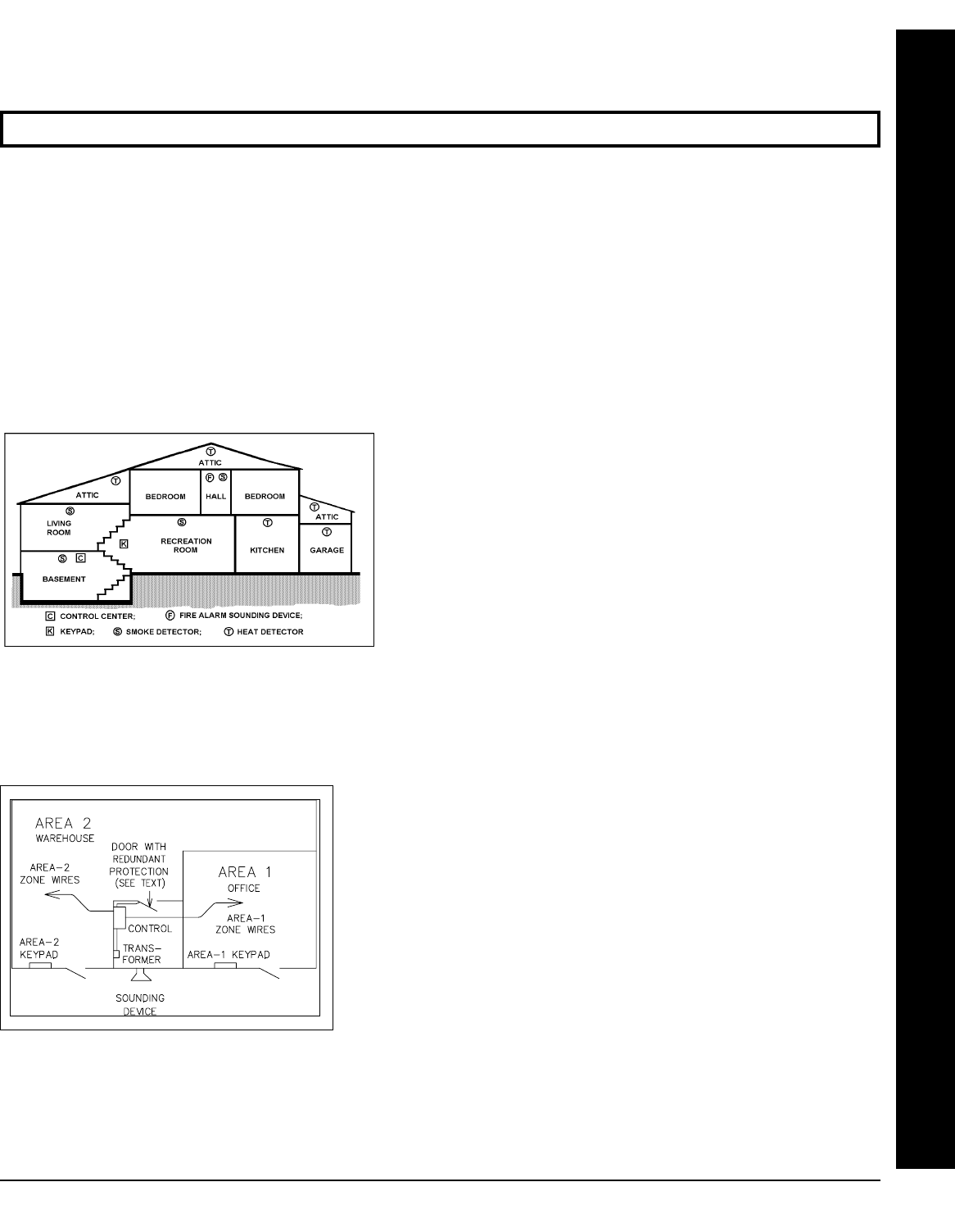
TYPICAL RESIDENTIAL FIRE INSTALLA-
TION (Where permitted by local codes)
At least one smoke detector should be installed directly outside
each sleeping area. If there is more than one floor, additional
smoke detectors should be installed on each level, including the
basement. The living-area and basement smoke detectors
should be installed near the stairway of the next upper level.
For increased protection, additional detectors should be installed
in areas other than those required, such as the dining room, bed-
rooms, utility room, furnace room, and hallways. Heat detectors,
rather than smoke detectors, are recommended in kitchens, at-
tics, and garages due to conditions that may result in false
alarms and improper operation. Large areas and areas with partitions, ceiling beams, doorways, and open joists will re-
quire additional detectors.
Refer to NFPA Standard No. 74 (National Fire Protection Association, Batterymarch Park, Quincy, MA 02269) for addi-
tional information, including proper mounting of detectors.
TYPICAL PARTITIONED INSTALLATION
Described and illustrated here are an example of a partitioned system
with common-area protection of the control-panel room. This system
meets UL requirements for a partitioned installation.
•Both areas must be owned and managed by the same person(s).
•Both areas must be part of one building at one street address.
•The control panel and all wiring protecting each partitioned area
must be confined to the respective area and may not encroach upon the
other area. This requires that the control panel room have redundant
protection; that is (a) multiple sets of door contacts, each wired to a
separate zone and (b) one of those zones programmed for each area.
In order to gain access to this protected area without causing an alarm,
both partitions must be disarmed. In lieu of redundant protection, 24-
Hour Zones may be used. Any zone protecting the control panel and
transformer may not be programmed for bypass.
The sounding device must be placed such that the bell test can be
heard by all partitions. Note: NFPA 74 (Household Fire Warning Equipment) requires that a fire alarm audible device be
installed indoors. The User Program Code is not to be given to anyone except the authority responsible for all partitions.
CAUTION: Do not run telephone wiring near speaker wires; do not run keypad wiring with loop wiring.
INSTALLATION
X GEM-X255 Installation Instructions L NAPCO Security Systems
WI1093C 3/04
! Page 12
UL COMMERCIAL-BURGLARY INSTALLATIONS
The GEM-X255M can be used as part of a UL Central
Station Grade C, B, or A installation. Normally, a digital
communicator is classified as Grade C and may be classi-
fied Grade B if used with the specified Grade-A Local bell
and bell housing. A UL Central Station Grade-A installa-
tion requires the use of a Napco RM3008 Relay Board
and Ademco 7720 Radio System. Refer to the installation
instructions furnished with each component for respective
installation requirements.
For a UL Commercial Grade-A Police Station Connection,
refer to GRADE-A LOCAL MERCANTILE INSTALLA-
TIONS, which follows. Use the M278 Line-Reversal
Monitor to provide basic line security; refer to the instruc-
tions accompanying the M278 for other installation re-
quirements. For UL Commercial safe and vault applica-
tions, use a UL-listed shock sensor suitable for metal en-
closures. Install tamper switches on front and rear of con-
trol-panel enclosure.
Grade-A Local Mercantile Installations
A Grade-A Local Mercantile installation must use at least
a 6.0AH standby battery. Programming must include
Auto Bell Test on Arming. Trouble on Night Open may
not be programmed for any zone. The minimum require-
ments for a listed Grade-A Local system include:
•Low-Battery Annunciation.
•An Ademco AB-12 Bell and Box (12-volt).
•Program Auto Bell Test on Arming.
•A maximum Entrance and Exit Delay of 60 seconds.
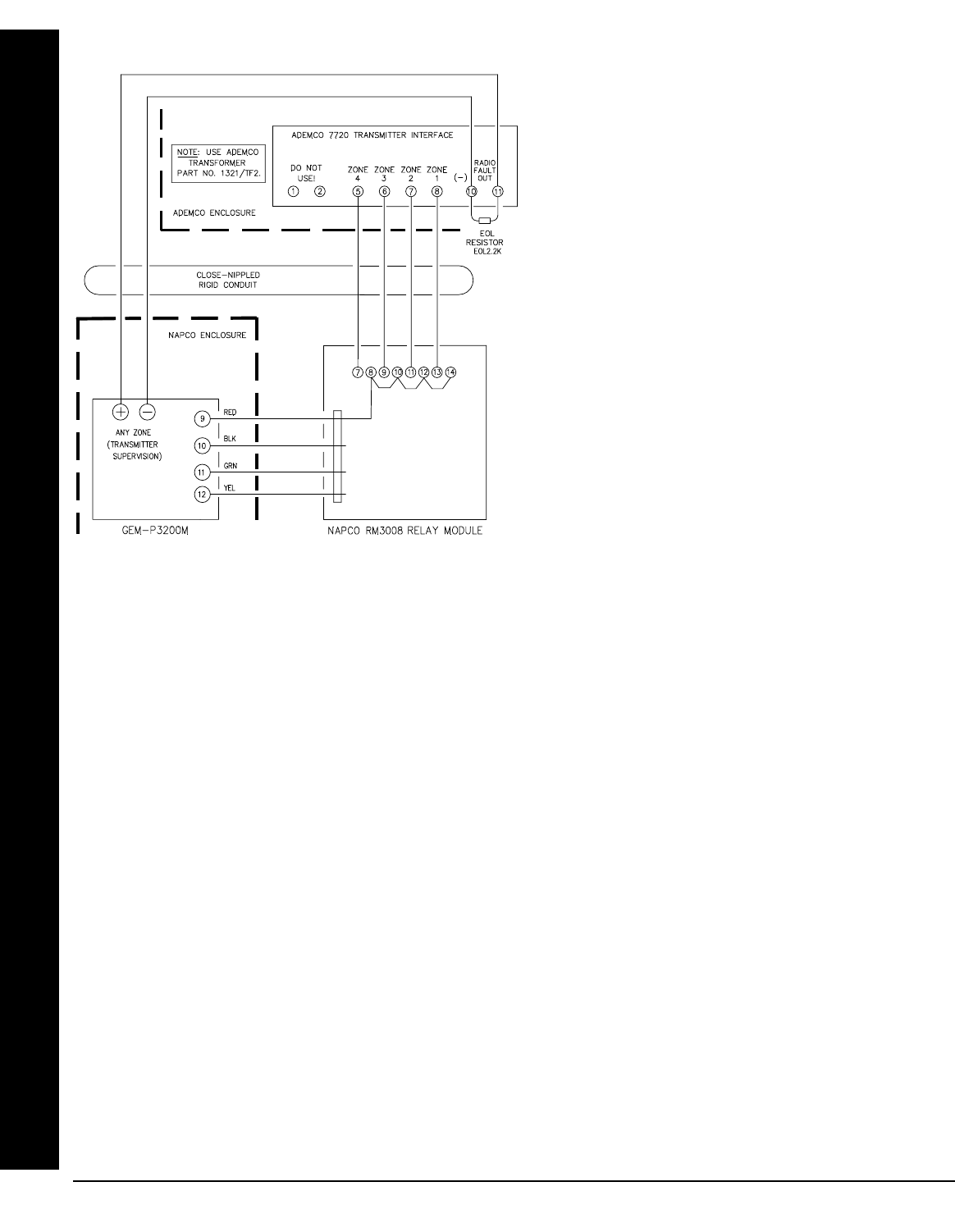
Interfacing to the Ademco 7720 Long-Range Wireless System
The RM3008 may be used to interface the GEM-X255M control panel to the Ademco 7720 transmitter in order to meet
UL Central Station Grade-A or Grade-B requirements by using a digital communicator combined with one-way wireless.
(Normally, a digital communicator is Grade C, and may be Grade B if the specified Grade-A local bell is used.) Refer to
the wiring diagram which follows, and to the instructions furnished with the Napco and Ademco equipment for further in-
formation concerning the DACT, listed compatible receiver and formats, Grade-A local bell and bell housing. Enable
Line Fault Test must be programmed.
Central Station Grade-B Requirements
Wiring to the Ademco 7720 transmitter must be enclosed in rigid conduit when outside walls, or in flexible conduit when
inside walls or above ceilings, for the entire length up to the transmitter room. The transmitter room must be protected
by a UL listed intrusion detection unit that is connected to one of the input channels of the Ademco 7720. Relays must
be programmed to trip the Ademco 7720 for alarms on all protective circuits, including tampers, telco phone failure, 24-
hour test timer, transmitter low battery and ac loss. (See PCD3000 External Relay Control screen). One zone on the
GEM-X255M, programmed as a 24-Hour Zone, must supervise the radio.
Central Station Grade-A Requirements
In addition to Grade-B Requirements (above), one relay on the RM3008 must be programmed to trip the Ademco 7720
when the telephone line fails. Daily openings and closings are required to be transmitted by the Napco panel along with
the 24-hour DACT test signal and DACT trouble conditions.
INSTALLATION

L NAPCO Security Systems X GEM-X255 Installation Instructions
WI1093C 3/04 !
Page 13
TESTING THE SYSTEM
After installation is completed, test the system as follows.
!1. Call the central station to inform them of the test.
!2. Initiate an alarm, preferably on a zone that activates a steady siren, and verify proper signaling.
!3. Wait 5 minutes.
!4. Call the central station to confirm their receipt of a good transmission.
Note: Be sure to test all enabled keypad panics.
Signal Strength Testing/Wireless Systems
To test the operation of wireless transmitters, proceed as follows. (Note: Wireless systems have not been investigated
by UL).
!Fault a point of each transmitter to be tested by faulting the zone.
The transmitter signal strength can be displayed using the DISPLAY RF XMITTER STAT function. Enter a Level 3 User
Code or enter the Dealer Code, press the A button and answer NO until “DISPLAY RF XMITTER STAT” is dis-
played. Press YES (E button) and the Wireless Signal Strength of the wireless zone will be displayed. The Wire-
less Signal Strength will be displayed from 1 to 10 with 10 being the strongest signal and any signal under 3 as unac-
ceptable. Except in the Fault-Find Mode, signal strengths less than 3 will be entered into the system log. Press NEXT
(E button) to step the next zone.
The last received signal strength for each transmission is always stored in memory and can viewed at any time using
this procedure. Signal strength can also be viewed through the PCD-Windows Status Screen.
INSTALLATION

X GEM-X255 Installation Instructions L NAPCO Security Systems
WI1093C 3/04
! Page 14
WIRING CONNECTIONS
AUXILIARY ALARM OUTPUT
Auxiliary Output can be activated depending on the programming options selected (see GEM-
X255 Programming Instructions). Connect the device controlled by the programmable output
between terminal 8 (+) and terminal 14 (-). A programming option “AuxOut Chirp on Key-fob
Arm/Disarm” is available. If selected, an external siren driver can be connected to these termi-
nals.
TRANSFORMER
Connect a 16.5 VAC Transformer to Terminals 1 and 2, using a wire of #18 AWG. or
less at a distance of 15 ft. or less from the control panel. NOTE: Do not connect to a
switched outlet.
AC IN, 16.5V/60HZ VIA
TRF11 OR TRF14
CLASS 2 TRANSFORMER
DO NOT CONNECT TO
SWITCHED OUTLET
1
2
BATTERY
The RED (+) and BLACK (-) flying leads must be connected to
a 12VDC 4, 6 or 7 AH Rechargeable Battery, to serve as
backup power in the event of AC Power Failure. NOTE: To
calculate the available standby time refer to the Standby-
Battery Calculation Worksheet at the back of this manual.
Connect the alarm sounding devices (self-contained sirens, speakers or a mechanical bells) to
terminals 5 (+) and 14 (-). Any self-contained siren requiring a 12 VDC input can be connected.
When connecting a mechanical bell, it must be supervised using a 2.2k Ohm resistor. To con-
nect 8 Ohm Speakers use a Siren Driver with the proper polarity observed. NOTE: Refer to the
Wiring Diagram for alarm current specification, bell supervision and burglary output relay.
Note: In NFPA Household Fire Installations. only a single siren or bell can be used on this bell
circuit.
SIREN/BELL BURG/FIRE ALARM OUTPUT
WIRING CONNECTIONS
4 AH, 6 AH OR 7 AH
RECHARGEABLE
BATTERY 12 VDC
BLACK
RED
(–)
(+) E1
E2
12VDC
L NAPCO Security Systems X GEM-X255 Installation Instructions
WI1093C 3/04 !
Page 15
EARTH GROUND
NOTE: Do not use a gas pipe, plastic
pipe or AC ground connections.
Connect the control panel EARTH GROUND screw through a No. 16 AWG.
or larger wire to a metal cold-water pipe. Do not use a gas pipe, plastic pipe
or AC ground connections. Also, connect the circuit board to the metal enclo-
sure. Connect a wire with a ground lug crimped or soldered onto one end of
the EARTH GROUND screw to the cabinet. NOTE: Grounding connections
should avoid bends in the grounding wire whenever possible.
AUXILIARY POWER
Connect the auxiliary devices (motion detectors, glass breaks, etc.) to Terminals 13 and 14.
Auxiliary Power provides a filtered 12 VDC nominal output which is used for powering auxiliary
devices. NOTE: To calculate the available standby time refer to the Standby-Battery Calculation
Worksheet at the back of this manual.
13
(+)
14
(-)
AUX POWER
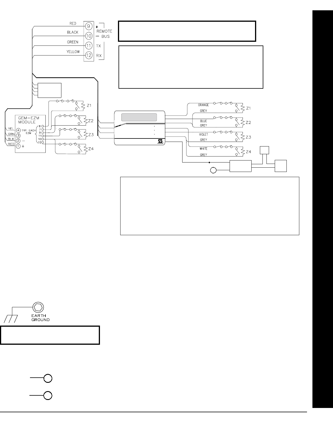
Connect the available devices as shown above to the remote bus terminals (9, 10, 11 & 12). Observe the correct color
wire connections. When connecting a keypads, first configure them accordingly (refer to the Keypad Configuration
Mode at the back of this manual). Keypads should be located near every exit/entry door. Up to 15 keypads may be
connected if the longest cable run from the panel, to the farthest keypad (daisy chained or home-run) is less than 1000
feet. The maximum distance for seven keypads is 300 feet using 22 AWG. wire. NOTE: When running keypad wire,
avoid wiring parallel to other types of wiring that can cause electrical interference.
WIRING CONNECTIONS
REMOTE BUS
Keypad Brown Wire: EZM/PGM Output Options
Select either option with GEM-RP1CAe2/GEM-K1CA keypads.
Option 1. Activates the PGM lug on the corresponding EZM module(s). Lug goes active (low) when
any selected Area is armed.
Option 2. The Access Code will activate the keypad's PGM brown wire while armed or disarmed if
the User Code is programmed for "Access Control on PGM Lug". The Access Code is pro-
grammed as any other User Code but without arm/disarm capability. Note: Options not investi-
gated by UL.
BROWN BLK
RED
GEM-RP1CAe2
(2 LINE LCD KEYPAD)
(EZM/PGM Options 1 or 2)
R
COMPUTERIZED SECURITY SYSTEM
GEMINI
ARMED
STATUS
SYSTEM ARMED
01/01/97 12:00AM
12
4
3
56
7890
A
B
C
DE
F
G
NEXT/YES
PRIOR/NO
AREA
AVAILABLE DEVICES
1. KEYPADS: GEM-RP1CAe2, GEM-K1CA
2. X-10 INTERFACE: GEM-X10
3. WIRED ZONE EXPANDER: GEM-EZM4 & GEM-EZM8
4. WIRELESS RECEIVERS: GEM-RECV8, GEM-RECV16, GEM-RECV96 &
GEM-RECV255
5. RELAY MODULE: RM3008
6. VOICE INTERFACE: GEM-EVA 1
7. TELEPHONE INTERFACE: WIZARD IIe
NOTE: Refer to the EZM Installation Instructions for
specific wiring information.
13
(+)
(–)
(N/O)
(COM)
BLK
RED
External
Power
Supply
Door
Strike
RB1000 Relay
(recommended)
GEM-RECV-8
GEM-RECV-16
GEM-RECV-96
GEM-RECV-255
X GEM-X255 Installation Instructions L NAPCO Security Systems
WI1093C 3/04
! Page 16
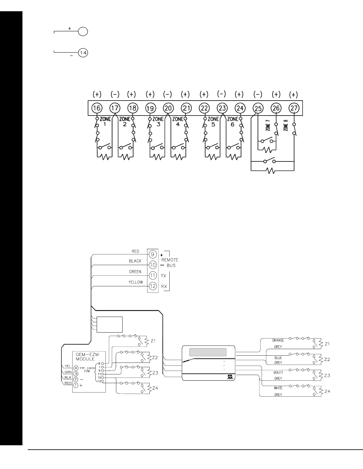
BASIC ZONE CONFIGURATION
The basic zone configuration for the GEM-X255 is 8 zones. Connect as shown above to terminals 16-27. Normally
Closed (N.C.) devices may be wired in series or Normally Open (N.O.) devices may be wired in parallel. Use the 2.2K
Ohm end-of-line (E.O.L.) resistor in each zone, if selected in programming (refer to the GEM-X255 Programming Instruc-
tions WI1092). Zones 1-8 can be selected for a “Fast Loop Response (20 ms or 50 ms)” or a “Normal Loop Response
(750 ms)”. Other zone options include Entry/Exit, Interior, 24 Hour Protection, Trouble, Fire, Instant, Chime, Area Selec-
tion and Relay Output selection.
RESET OUTPUT
Reset Output can be activated depending on the programming options selected (see GEM-
X255 Programming Instructions). Connect the device controlled by the programmable output
between terminal 15 (+) and terminal 14 (-).
15
RESET
OUTPUT
EXPANDED ZONE CONFIGURATION
The GEM-X255 Control Panel may be expanded up to 255 zones. This may be accomplished by adding 88 zones to the
basic 8 zone configuration. Hardwired zone expanders include: GEM-EZM4 (4 additional zones per module), GEM-
EZM8 (8 additional zones per module) and GEM-RP1CAe2/GEM-K1CA Keypad (4 additional zones per keypad). Wire-
less zone expanders include: GEM-RECV8 (8 additional zones per receiver), GEM-RECV16 (16 additional zones per re-
ceiver), GEM-RECV96 (96 additional zones per receiver) and GEM-RECV255 (247 additional zones per receiver). Wire-
less transmitters include: GEM-TRANS2, GEM-KEYF, GEM-SMK, GEM-PIR, GEM-DT and GEM-GB.
Additional Zones are numbered 9-96.
R
COMPUTERIZED SECURITY SYSTEM
GEMINI
ARMED
STATUS
SYSTEM ARMED
01/01/97 12:00AM
12
4
3
56
7890
A
B
C
DE
F
G
NEXT/YES
PRIOR /NO
AREA
GEM-RP1CAe2
(2 LINE LCD KEYPAD)
WIRING CONNECTIONS
GEM-RECV-8
GEM-RECV-16
GEM-RECV-96
GEM-RECV-255
L NAPCO Security Systems X GEM-X255 Installation Instructions
WI1093C 3/04 !
Page 17
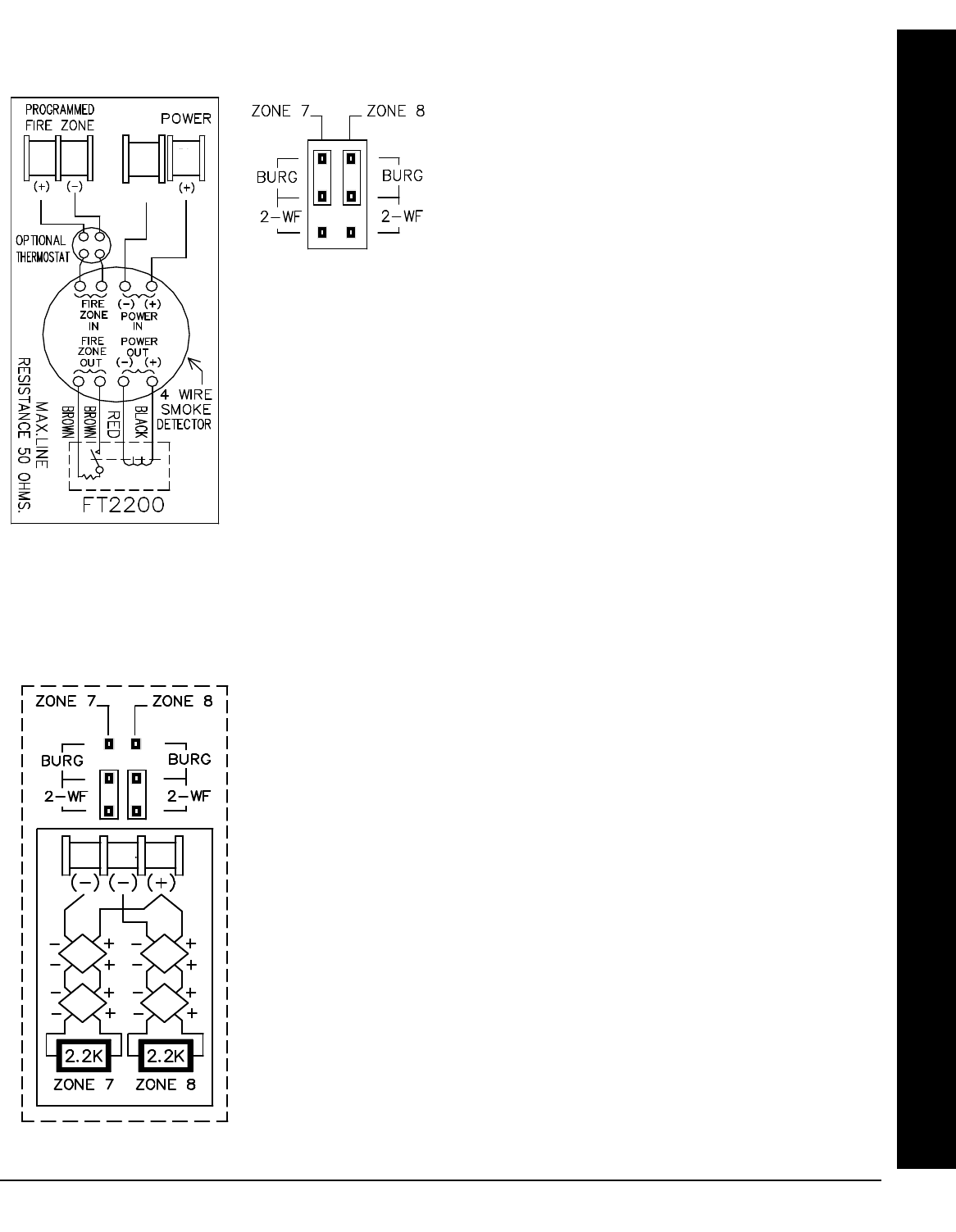
4-WIRE SMOKE DETECTORS
4-WIRE SMOKE DETECTOR WIRING
The GEM-X255 can use conventional 12 VDC 4-wire smoke detectors. To use them,
the select fire zone programming option and do not select 2-wire smoke detector pro-
gramming option for the desired fire zone (refer to the GEM-X255 Programming In-
structions WI1092). Set JP7 to the BURG position as shown, if zones 7 or 8 are to be
used.
Four wire smoke detectors may be connected to any programmed fire zone (1-8) as
shown, within the panel. If external EZMs are used for zones 9-255, then 4-wire smoke
detectors may be connected to any programmed fire zones (9-255). (Do not use in UL
installations. See page 9).
Power must be obtained from terminal 28 (+) and 29 (-). If Fire Alarm Verification is de-
sired to reset the smoke detectors, select this option for the desired fire zone. (Do not
use in UL installations. See page 9).
NOTE: Do not program Fire Alarm Verification in California.
2-WIRE SMOKE
DETECTOR WIRING
Two-wire smoke detectors may be connected to control panel zones 1-8. Zones
7 and 8 may be configured for 2 wire fire through the JP7 jumper settings. To
enable, program the zone(s) as Fire Zones, enable 2-Wire Fire (refer to the
GEM-X255 Programming Instructions WI1092) and set JP7 to the position as
shown. Connect the 2-wire smoke detectors as shown.
Zones 1-6 may be configured for 2-wire Fire with the use of an EOL130 resistor
and the cut of a control panel resistor, as displayed on the next page.
If Fire Alarm Verification is desired to reset the smoke detectors, select this op-
tion for the desired fire zone (zone 7 or 8).
NOTE: Do not program Fire Alarm Verification in California
2-WIRE SMOKE DETECTORS (BASIC CONFIGURATION)
26 27 28
6
(-)
29 28
WIRING CONNECTIONS
X GEM-X255 Installation Instructions L NAPCO Security Systems
WI1093C 3/04
! Page 18
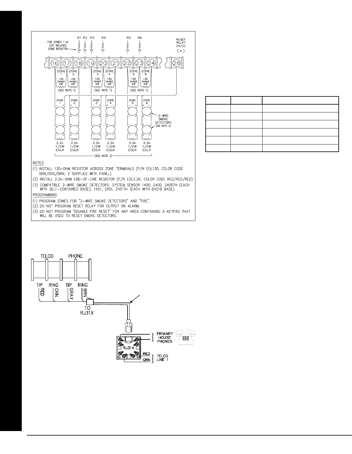
Connect the Model 368 Cord as follows: 30 (RED = Telco Tip), 31 (GREEN = Telco Ring), 32 (GRAY = Home Tip)
and 33 (BROWN = Home Ring). Insert the modular plug into an approved USOCRJ31X jack (or a CA31A jack for
Canadian installations). The Telco Line is used by the control panel to dial the central station and for downloading.
This line should not be connected to party lines or coin operated telephones. If connected to a line with call waiting,
then call waiting interrupt numbers must be programmed into the CS Telephone Numbers (refer to the GEM-X255
Programming Instructions WI1092).
2-WIRE SMOKE DETECTORS (EXPANDED CONFIGURATION)
Where more than two 2-wire smoke detector zones
are required, select any of Zones 1–6 for 2-wire fire
as follows:
1. Program the selected zone(s) (1–6) for 2-Wire
Smoke Detectors and Fire.
2. Cut the lead of the 2700W resistor (color code:
red/violet/red) associated with the selected zone
(s). See following table.
3. Install a 130W resistor (Napco Part No. EOL130;
color code: brown/orange/ brown), 3 watts,
across the two terminals of each selected zone.
4. Wire the positive (+) terminal of the smoke de-
tector to Terminal 28. Wire the negative (–) ter-
minal of the smoke detector to the positive termi-
nal (+) of the zone.
ZONE RESISTOR LOCATION ON BOARD
1 R1 ABOVE TERMINAL 18
2 R2 ABOVE TERMINAL 18/19
3 R3 ABOVE TERMINAL 19
4 R4 ABOVE TERMINAL 20
5 R5 ABOVE TERMINAL 22
6 R6 ABOVE TERMINAL 23
WIRING CONNECTIONS
Connecting 2-wire smoke detectors to zones 1-6
Model 368 Cord
TELEPHONE LINES
30 31 32 33
GRAY
BRN
L NAPCO Security Systems X GEM-X255 Installation Instructions
WI1093C 3/04 !
Page 19
KEYPAD CONFIGURATION MODE
This section will focus on configuring the GEM-RP1CAe2/GEM-K1CA Keypads. If there is more than one keypad in the system, only
Keypad No. 1 may be used for programming.
KEYPAD INSTALLATION
Each keypad must be assigned an address number (1–15) and each requires its own configuration procedure (see CONFIGURING
THE KEYPADS, which follows, and DIRECT ADDRESS KEYPAD AREA OPTIONS). At least 1 keypad must be used; only 1 is re-
quired for a single-area Commercial Burglary installation.
•GEM-RP1CAe2/GEM-K1CA - is a 2-line combination fire/burglary/access keypad capable of supporting 4 EZM zones. A GEM-
RP1CAe2 or GEM-K1CA is recommended for use as Keypad #1.
•
CONFIGURING THE KEYPADS
A total of up to 15 keypads may be connected to the panel. GEM-RP1CAe2/GEM-K1CA keypads may be intermixed but require differ-
ent configuration procedures, as described in the following paragraphs. If you have a GEM-K1CA keypad, please see the "Important
Note" on page 3 regarding the differences between the GEM-RP1CAe2 and the GEM-K1CA keypad buttons. The buttons displayed be-
low will be for the GEM-K1CA keypad.
Configuring the GEM-RP1CAe2/GEM-K1CA Keypad
Each GEM-RP1CAe2/GEM-K1CA keypad must be configured for (a) keypad tactile beep; (b) entry sounder;
(c) keypad address; (d) EZM address; and (e) zone response.
To enter the GEM-RP1CAe2/GEM-K1CA Configuration Mode:
1. Move jumper JP1 (located at the upper center of the control panel board) from Pins 1-2 (top two) to
Pins 2-3 (bottom two). NOTE: See the Wiring Diagram.
2. After about 15 seconds, the display will read “XX OUT OF SYSTEM”, where XX indicates the keypad address.
3. Press 11123 R and proceed as follows. (Repeat the following procedure for all keypads.)
Keypad Tactile Beep
Upon entering the Keypad Configuration Mode, “KEYPAD BEEP ON” will be displayed,
indicating that the tactile beep, which sounds when any button is pressed, is on. To
turn off the tactile beep, press the U button (the U button will toggle the tactile
beep on and off). Press the R button to continue or press the C button
to exit.
Entry Sounder
To turn off the keypad sounder during entry time, press the U button (the U button
will toggle the entry sounder on and off). Press the R button to continue or
press the C button to exit.
Keypad Address
If more than one keypad is installed, each must be assigned a unique keypad ad-
dress (that is, no two keypads may be numbered alike):
!keypads must be numbered consecutively (missing numbers are not permitted)
!only Keypad No. 1 may be used for programming.
To assign the keypad number, proceed as follows:
1. Enter the assigned keypad number 01–15, then press the U button to save. A valid number will be acknowledged by a short
beep; an invalid number will be rejected by a long beep.
2. Press the R button to continue or press the C button to exit.
Keypad Beep
ON
Entry Sounder
ON
Keypad Address
01
NORMAL
KEYPAD
CONFIGURE
ARM ED STATUS
KEYPAD CONFIGURATION MODE

X GEM-X255 Installation Instructions L NAPCO Security Systems
WI1093C 3/04
! Page 20
Compatibility Number
The compatibility number is a 4-digit security code that, if programmed into
both the control panel and each GEM-RP1CAe2/GEM-K1CA keypad, dedi-
cates the keypad to only that panel. That is, (a) similar keypads not having
the correct compatibility number will not operate in the system and (b) a
keypad may not be removed for use on a system with a different compatibility number. Note: If assigning compatibility
numbers, record and store them in a safe place.
While the compatibility number may be changed, the old number must be known in order to program the new number.
Note: If neither the control panel nor the keypad is given a compatibility number, both default to “0000” (thereby main-
taining compatibility).
To program the compatibility number, press the A button until “NEW COMPAT# 0000” is displayed. Enter the 4-digit
compatibility number that is programmed into the panel. Note: If the keypad had been previously programmed for a
compatibility number other than “0000”, the display would read “OLD COMPAT# XXXX”. Enter the existing number before at-
tempting to change it. Press the A button to continue or press the C button to exit.
EZM Address
The keypad's internal EZM (Expansion Zone Module) may be utilized to
provide four additional wired zones. Whether used alone or in conjunction
with optional GEM-EZM series modules or other keypad EZMs, it must be
assigned a unique address (or Group number, see Keypad Programming
Workbook) similar to its keypad address. If no other EZMs are to be used, designate the keypad as Group “01” at the
“EZM ADDRESS 00” display. In multiple-EZM systems, enter an assigned group number “01” through “22”. (Each EZM
must have a unique assigned group number, starting with “01” and proceeding consecutively). Press the A button
to continue or press the C button to exit.
Zone Response
The normal loop response of each keypad expansion zone is 750mS, how-
ever the response time of any zone can be reduced to 50mS as follows.
1. Of the following, circle the number(s) in parentheses associated with the
zone(s) to be changed: Zone 1=(1); Zone 2=(2); Zone 3=(4); Zone 4=(8)
2. Add up the circled numbers.
3. At the keypad, enter the sum as a two-digit number “01” through “15” on the display, then press the J button.
Example. Change Zones 2, 3 and 4 to 50mS response.
1. Circle numbers for Zones 2, 3 and 4: (2), (4) and (8).
2. Add up the circled numbers: 2 + 4 + 8 = 14.
3. Enter “14” at the keypad, then press the J button.
Press the A button to continue or press the C button to exit.
Program Control Message
The Access-Control message normally displays “**ENTER NOW**” however
this display may be changed to any of the following messages as displayed
in the table at right:
Press the A button to continue (the
display will loop back through selections,
for changes) or press the C button to exit the Keypad Configuration Mode
(display will read “01 OUT OF SYSTEM”). Then replace Jumper JP5 across Pins 1–2
(top two).
NEW COMPAT#
0000
EZM ADDRESS
01
ZONE RESPONSE
00
PROG CONTROL
MESSAGE# 1
KEYPAD CONFIGURATION MODE
0 (No Message)
1 **Enter Now**
2 Door Control
3 Gate Control
4 Light Control
5 Control #1
6 Control #2
Program Control Message

L NAPCO Security Systems X GEM-X255 Installation Instructions
WI1093C 3/04 !
Page 21
NAPCO Security Systems, Inc.
333 Bayview Avenue, Amityville, New York 11701
For Sales and Repairs, call toll free: (800) 645-9445
For direct line to Technical Service, call toll free: (800) 645-9440
Internet: http://www.napcosecurity.com
KEYPAD CONFIGURATION MODE
THIS PAGE INTENTIONALLY LEFT BLANK

X GEM-X255 Installation Instructions L NAPCO Security Systems
WI1093C 3/04
! Page 22
BASIC OPERATION
This section provides a brief overview of system operation. For detailed operation, refer to the User's Guide furnished with
the keypad (see page 8 for a complete listing) and to the Keypad Programming Modes at the end of this manual. NOTE: Key-
pad displays shown in this text are for the GEM-RP1CAe2/GEM-K1CA keypads.
USER CODES & ZONE DESCRIPTIONS
(Refer to the GEM-X255 Programming Instructions (WI1092) for a detailed explanation of programming). Up to 96 per-
sonal user codes may be programmed at the keypad (up to 195 with PCD-Windows Download software). NOTE: The Area
Options associated with each User Code may only be programmed in the Dealer Program Mode.
Default User Code.
The first code programmed should replace the default (User 001) code, "001 123 - - ", (1,2,3), which should not be se-
lected as a user code.
Each user should be assigned his own dissimilar code and should be cautioned against divulging his code to anyone else.
Thus should it become necessary to remove a user from the system, that one code may be cancelled without affecting other
codes, and that user would then be prevented from entry. Note: Duplicate User Codes are not allowed by the panel; therefore
a duplicate Code entered in the LCD Window will erase when U is pressed.
Changing or Canceling a User Code
To change any user code, merely program over the existing user code as described in the Programming Instructions.
Similarly, to cancel a user code, blank out each number of the user code.
Arm/Disarm Code (Programmable in Dealer Program Mode only)
An Arm/Disarm Code may be used to arm/disarm the area in which it is programmed. Up to 6 digits may be programmed
or it may be programmed as a two-digit code for the purposes of arming quickly.
Arm-Only Code (Programmable in Dealer Program Mode only)
An Arm-Only Code may only be used to arm the area in which it is programmed; it has no disarm capability. Up to 6 digits
may be programmed or it may be programmed as a two-digit code for the purposes of arming quickly.
Service Code (Programmable in Dealer Program Mode only)
A Service Code is an Arm/Disarm Code that is easily activated when needed, and dormant at other times. Intended for the
occasional or temporary user (repairman, etc.) who would otherwise be denied access to the premises. It may then be used to
arm and disarm just as any other User Code. A Service Code can be armed/disarmed from a disarmed state, but it cannot be
armed/disarmed from an armed state, after another user code has been entered. Up to 6 digits may be programmed or it may
be programmed as a two-digit code for the purposes of quicker arming.
Keypad Access Code (Programmable in Dealer Program Mode only)
Any User Code may have Keypad Access through a door with a striker by programming the keypad's Access Byte (the last
two digits of the code). Program the Keypad Access Byte for the applicable keypads 1 through 8. If the Access Byte is
programmed, that User Code will function only a Remote Access Code and not as an Arm/Disarm Code. Entering the code will
cause a 5-second active-low output on the PGM line with a pulsing sounder at the keypad and "**ENTER NOW**" (or other
customized message) displayed. Note: (1) Keypads may be programmed for access only, eliminating their arm/disarm
function (keypad will then normally display "**ENTER CODE**"). (2) Keypad access may be logged into the event log by keypad.
The Access Code will trip the panel's Aux. Relay while armed or disarmed if the "Access Control on Auxiliary Output" and "Aux.
Output Access Control Time" is programmed. The Access Code is programmed as any other user code but without arm/
disarm capability. Note: These systems have not been investigated by UL for compliance with UL294 (Access Control Sys-
tems).
Ambush Code
The Ambush Code is special user code entered by the user typically to cause a silent report to be sent to the central sta-
tion. Thus, should the user be forced to disarm by an assailant, he can silently signal an emergency while appearing to be
merely disarming the panel. (Check the glossary for programming required to enable this feature). The user can program the
panel with individual Ambush Codes by programming "Enable Ambush in User Assign Code Type".
Zone Descriptions. (GEM-RP1CAe2/GEM-K1CA only)
Zone descriptions follow the Program Code in the normal programming sequence ("001-" will appear in the display). Pro-
gram the description, up to two lines, letter by letter. Buttons 1 and 2 control the position of the cursor. Buttons
BASIC OPERATION

L NAPCO Security Systems X GEM-X255 Installation Instructions
WI1093C 3/04 !
Page 23
G0 will clear the entry at the cursor. When programming zone descriptions, buttons 3 and 6 will scroll
not only through numbers 0-9, but through the alphabet and a series of punctuation marks and symbols as well. (Roughly note
the order in which the letters, numbers and symbols are displayed so that you will be able to determine the proper direction to
scroll, up or down, for fastest access. As familiarity improves, so will programming speed). When the description has been en-
tered and is satisfactory as displayed (e.g. "GARAGE"), you MUST press the U or D button to save it in memory.
To advance to the next zone (or to any other zone, for that matter), position the cursor over the displayed Zone Number, i.
e., "01" using buttons 1 and 2. Change the Zone Number using buttons 3 and 6. Repeat the zone-
description programming procedure for the new zone. Advance to the next zone and repeat until all zones (up to 96 zones)
have been programmed (255 zones can be programmed in PCD-Windows Quickloader download software).
ARMING AND DISARMING THE SYSTEM
In the normal disarmed state, only the green STATUS LED will be on and the display will read "SYSTEM READY". To silence
an alarm, enter any User Code, then press the U or D button. Any valid User Code may be used to arm or disarm; an Arm-
Only Code may only be used to arm.
Arming
!To arm, enter a valid User Code, then press the D button. (For all "Classic GEM-RP keypads)
!To arm, enter a valid User Code, then press the Q button. (For all "K Series" keypads)
(If a wrong code is entered, the keypad will display "INVALID ENTRY / TRY AGAIN"). The green STATUS LED will go off,
the red ARMED LED will go on, and the display will read "PLEASE EXIT IN / XXX SECONDS" ("XXX" representing the pro-
grammed exit-delay time, in seconds). The exit delay will immediately start counting down toward "000", in 10-second decre-
ments, indicating the available time remaining to exit through an exit/entry door.
1. If Exit Delay Restart is enabled, after the panel is armed and the exit door is opened and then closed, exit delay will
restart at 60 seconds. If re-entry occurs within this 60-second interval, the alarm device will sound a 2-second warning
"chirp", if programmed, as an entry reminder to the user to return to the keypad and disarm.
2. (GEM-RP1CAe2/GEM-K1CA keypads only). An "S" in the display (e.g. "EXIT TIME XXX S") will appear as a re-
minder that the system is being armed with the Service Code active. (To turn off the Service Code, disarm, then rearm
using a regular Arm/Disarm Code).
3. If a System Trouble is displayed, there should be an attempt to correct the system trouble (for example by calling an
alarm maintenance or an alarm repairman). If this cannot be done, then press the C button to allow 5 minutes to
access the keypad without the system trouble display. Immediate attention should be provided, when system troubles
are encountered.
4. In commercial applications, if Start Exit Delay After Ringback is programmed, exit delay will not start until the central
station acknowledges receipt by a ringback tone at the keypad. The display will read "PLEASE WAIT" while the control
panel communicates to the central station. If the ringback tone does not sound within about 30 seconds, the START
EXIT TIME function may be used to manually start exit delay.
Disarming
When the exit time has elapsed, the display will read "SYSTEM ARMED". This indicates that upon entering the premises
through an exit/entry door, there will be an entry delay to allow time to disarm the panel. The GEM-RP1CAe2 or GEM-K1CA
display will read "DISARM NOW / XXX SECONDS" ("XXX" representing the programmed entry-delay time, in seconds). The sounder will
come on and the entry delay will immediately start counting down toward "000" in intervals of 10 seconds, indicating the avail-
able time remaining to disarm the panel. (Note: The sounder will "pulse" with the GEM-X255 version 3 and above. The
sounder will sound a "steady" tone with the GEM-X255 version 1B and lower). The sounder will emit a rapid pulsing warning
tone during the final 10 seconds.
To disarm the panel, enter a valid User Code, then press the U or D button.
Arming in AWAY MODE
AWAY MODE provides for full protection of the perimeter and interior zones. Exit/Entry doors are provided with Exit/Entry
delays. A "Classic" (non "K Series") keypad (GEM-RP1CAe2) will display "SYSTEM ARMED", while a "K Series" keypad
(GEM-K1CA) will display "ARMED AWAY." The RED LED will remain ON. With "K Series" keypads such as the GEM-K1CA,
press Q to begin the exit delay process (the exit delay will immediately start counting down toward "000", in 10-second
decrements, indicating the available time remaining to exit through an exit/entry door).
BASIC OPERATION

X GEM-X255 Installation Instructions L NAPCO Security Systems
WI1093C 3/04
! Page 24
Arming in STAY MODE
STAY MODE provides partial protection by allowing free movement within the premises, while still protecting the perimeter
zones. Exit/Entry doors are provided with Exit/Entry delays. A "Classic" series keypad will display "SYSTEM ARMED" with a Bypass
Icon and a RED LED that remains ON, while a GREEN LED blinks. With "K Series" keypads such as the GEM-K1CA, pressing
P bypasses all interior zones simultaneously, and arms the panel in "STAY MODE". The keypad will display "ARMED STAY".
If P is pressed when the panel is already armed in STAY MODE, the panel will enter "Instant Mode" and eliminate the entry
time delay period.
Instant Arming
INSTANT ARMING allows exit/entry zones to immediately go into alarm when violated, with no Exit/Entry time delay. This
feature can be used to provide instant protection while you or someone else is on the premises. With the "Classic" keypads, to
arm "Stay" and obtain Instant Arming, press E and F, then enter your user code and press D. With the "K Series"
keypads, enter your user code and press P. Then press and hold P until keypad beeps Instant Arming will be auto-
matically reset on disarming.
Auto Arming (Not for UL Installations)
AUTO ARM allows the User to automatically arm the system at a specified time of the day and on specific days of the week.
Schedule a specific closing time on any/all day(s) of the week. After a specific Fail-to-Close Window Start Time, if the user has
not Armed the system during the Window Length, and the system has been instructed to "Fail-to-Close' and 'Auto Arm if not
closed at end of Window" then the system will arm, providing a 15 minute warning. CAUTION: If Automatic Interior Bypass/
Easy Exit is selected, panel will Auto Arm in STAY Mode.
Delaying an Auto Arm (Not for UL Installations)
During the 15 minute pulsating sounder warning of an Auto Arm, a User can press the R or A button, until "TO DE-
LAY AUTO ARM / PRESS 1-4 / N" is displayed. Enter the number of hours to delay arming, followed by the U or D button. If
"DELAY AUTO ARM Y/N" is displayed, press the "NEXT/YES" button. The sounder can be silenced by pressing the C button
during the 15 minute interval, but will come back on in the last 1 minute. This feature may be canceled by arming and disarming
the keypad.
EZ Arm (Easy Arm)
EASY ARM provides one button arming for non-security critical premises. Select Easy Arming for each Keypad, with op-
tional reporting of Easy Arm Closings as User 199. Disarming still requires a valid user code.
!To arm, press the D button for "Classic" keypads;
!To arm, press and hold P or Q for 3 seconds for "K Series" keypads.
Keyswitch Arming
KEYSWITCH ARMING allows a zone input to be used to arm/disarm. The area will arm/disarm when the zone is momen-
tarily shorted through a Momentary Switch. An end-of-line resistor must be used. Select Keyswitch Arm to optionally report as
User 200.
Remote Arming (Not for UL Installations)
REMOTE ARMING allows computer software control of arming/disarming of the system for non-security critical installations.
Select Remote Arm to optionally report as User 34.
Priority Arming
A 2-second tone and "CAN'T ARM SYSTEM/ZONE FAULTED" displayed when attempting to arm indicates a priority condition; that is, a
problem exists on at least one zone that has been designated as a Priority Zone, or a system trouble exists. The trouble(s) must
be corrected before the panel can be armed. The display will read "ZONE FAULTED", then automatically scroll through all unsecured
zones. If a system trouble is indicated, it will display the system trouble.
Area Arming/Manager's Mode
In a partitioned system, any of eight secured areas may be armed (or disarmed) from the Manager's Mode (if enabled). The
Manager's Mode, is a low-security mode of operation. It provides quick access to other areas without having to go to another
keypad of another area.
!To arm or disarm the alternate area (for "Classic" keypads):
1. Press a button between 1 and 8 representing the alternate area.
BASIC OPERATION

L NAPCO Security Systems X GEM-X255 Installation Instructions
WI1093C 3/04 !
Page 25
2. Press the G button, then the U or D button.
3. Arm or disarm the selected area using your user code (the user code must be valid for that area).
4. To return the keypad to its "home" area, press the G button, then the U or D button.
Note: If the "home" keypad has been changed to one of the alternate areas and remains unused for more than 5 minutes,
it will revert back to the home area.
!To arm all areas assigned to the user, press 9 G [User Code] U or D.
!To disarm all areas assigned to the user, press 0 G [User Code] U or D.
Overview Mode
To enable or disable Overview, see ACTIVATE OVERVIEW function later in this section. The Overview Mode is a high
security mode of operation requiring a Level-3 User Code with Overview Option, wherein the status of all areas is displayed at
the keypad. When arming, the "home" area remains disarmed. To arm all areas except the "home" area, see Keypad Area
Change, which follows.
In the Overview Mode, "OV(-)" will be displayed, where each dash ("-") represents an area. In programmed areas, the dash
will be replaced by one of the following:
"A" = Area Armed
"B" = Burglary Zone in Alarm
"C" = Check Trouble; Area in Function-Display Mode; Fire Trouble
"F" = Fire Zone in Alarm
"R" = Area Ready (no faulted zones)
"Z" = Zone Fault
In the Overview Mode, all areas may be armed by pressing the 9 G buttons. Note: The User Code must be valid in
that area. Similarly, all areas ("A") may be disarmed by pressing the 0 G buttons. If any zone is not secured, the
system will not arm and the keypad will display "CAN'T ARM SYSTEM / AREA # IN TROUBLE", where "#" represents the area number.
BYPASSING ZONES
Selective Bypass (Bypassing Specific Zones)
A Selective Bypass will bypass a specific zone that has Selective Bypass enabled, by pressing the B button followed
by the zone number. The zone will be unbypassed the next time the system is disarmed.
Security Bypass
Zones programmed for Selective Bypass may be removed from the system prior to arming as follows:
1. Enter a code valid for bypass (Authority Level 1 or higher and Bypass option enabled), then press the B button;
“BYPASS ENABLED” will display.
2. Press the B button, then the zone number (or vice versa) to deactivate that zone.
Note: When the panel is subsequently disarmed, all bypassed zones revert to unbypassed zones (unless Disable Auto-
Unbypass on Disarming is programmed or Interior Zones are programmed normally bypassed).
EZ Bypass (Do not enable in UL applications.)
Enable this feature by programming Disable Code Required for EZ Bypass. Then, zones programmed for Selective By-
pass may be bypassed quickly and easily as follows. Note: This is not a high-security feature.
1. At the “SYSTEM READY” or “ZONE FAULT” display, enter the zone number as a three-digit number (ex., “001”, “015”, etc.).
Zones cannot be bypassed while the panel is armed.
2. Press the B button. To unbypass the zone, press the B button again. Note: Steps 1 and 2 may be re-
versed and this feature will still function.)
Note: If Enable All-Zone-in-Trouble Bypass is programmed, pressing the G and the B buttons simultaneously
will bypass all zones in trouble (except Fire and PIR Zones) that are also programmed for Selective Bypass.
Bypassing Interior Zones
Interior zones allow perimeter zones to be armed while part or all of the active interior remains disarmed. When the P
button is pressed, the “BYPASSED” reminder will come on. Pressing the U button within 10 seconds will bypass the selected in-
terior group without arming, otherwise Interior Bypass will time out and the system will revert to the regular disarmed state. All
zones designated for the selected interior group(s) will be bypassed simultaneously when the system is armed. The alarm con-
ditions will then be stored in the Alarm History Log and the Total Event Log (see HISTORY LOG).
BASIC OPERATION

X GEM-X255 Installation Instructions L NAPCO Security Systems
WI1093C 3/04
! Page 26
ALARM INDICATION
!If programmed to silence an alarm, enter a valid User Code and press the U button.
The keypad must have permission to disarm the alarm (Alarm, Pulse Alarm, Fire Output, Reset Output or Auxiliary Out-
puts) from the specific area. This can be done through the PC Quickloader software, Area Features Screen or Area Bell Con-
trol.
Should a burglary alarm occur, the red ARMED LED will flash, and the display will alternately read "ALARM", then the zones
violated. Disarm the panel; the display will read "ALARM" and will continue to indicate the violated zones until the C button
is pressed or the panel is armed once again.
FUNCTION MODE/DEALER PROGRAM MODE
The keypad can provide a wide assortment of utility functions as summarized in the Keypad Function Mode. The functions
are displayed in a prompting "YES/NO" format. To skip a function, answer NO (press the PRIOR/NO button); to select and exe-
cute a function, answer YES (press the P button or the U button). The complete function list is provided here in its normal
displayed sequence. However, since not all functions are designed for all systems (or intended for all users), only functions
that are applicable and active are displayed. (For example, if no zones are bypassed, "DISPLAY ZN BYPASSED" will not appear).
Furthermore, functions that are intended for use by the installer or servicer will not be displayed. Note: Functions may be
manually scrolled forward or backward using the R and the B buttons, respectively.
To return to normal keypad operation, press the C button. (The keypad will automatically return to its normal operat-
ing mode if no activity is detected for longer than one minute).
Remember: (1) Functions that are not active, not programmed and/or not applicable to the user's authority level will be
suppressed and will not display. (2) Press the PRIOR/NO button to skip a function; press the NEXT/YES button to execute it.
DISPLAY ZN FAULTS
Press the YES button to identify all unsecured zones (within the keypad's area) while disarmed. Press NEXT button to
scroll through the zones. (Zones may be bypassed in this mode by pressing the B button). Manually bypassed zones will
be indicated when displaying status.
DISPLAY ZN BYPASSED
Press YES button to display zones that have been deactivated. Press NEXT button to scroll through the zones.
DISPLAY ZN DIRECTORY
Press YES button to display a list of all programmed zone descriptions in the keypad area. Press NEXT button to scroll
through the zones. To return to the system, press the C button at any time.
ACTIVATE BELL TEST
Press YES button to activate the burg relay output (while disarmed) for about 2 seconds. If the device does not sound, it
may be defective.
DISPLAY PHONE #'S
The panel can function as an auto dialer to any of four programmed telephone numbers. (Telephone numbers must be
programmed through Napco PCD-Windows Quickloader software). Select Telephone #1-4 using NEXT and PRIOR buttons,
then press the U button. Pick up the phone to initiate dialing of the displayed number. (The phone will appear to be discon-
nected while dialing but will return to normal after a few seconds).
DISPLAY SYS TRBL
Press YES button to check trouble (LOW BATTERY, AC POWER LOSS, etc.). Wait for the display to scroll through multi-
ple system troubles, or use the NEXT and PRIOR buttons to manually scroll.
DISPLAY FIRE ALARM
To display Fire Zone(s) in alarm, access DISPLAY FIRE ALARM and scroll through the zones using the NEXT button.
Correct the problem, then press the C button to restore the "SYSTEM READY" condition.
DISPLAY FIRE TRBL
To display Fire Zone(s) in trouble, access DISPLAY FIRE TRBL and scroll through the zones using the NEXT button. Cor-
rect the problem, then press the C button to restore the "SYSTEM READY" condition.
DISPLAY OP/CL
BASIC OPERATION

L NAPCO Security Systems X GEM-X255 Installation Instructions
WI1093C 3/04 !
Page 27
!NAPCO's PCD-Windows Quickloader software offers a comprehensive array of programmable opening and clos-
ing suppression windows, by area, for all days of the week, for both normal and holiday schedules. A two-line dis-
play of the programmed schedule may be read at the keypad. The first line indicates:
!the day of the week
!opening or closing suppression window
!"AUTO", if autoarming
!normal (or delayed) schedule (see below)
To scroll through the days of the week, use the NEXT and PRIOR buttons.
The closing of any suppression window may be delayed up to four hours at the keypad, or the window may be totally dis-
abled, up to one week in advance. Select the DAY/OP/CL schedule using the NEXT and PRIOR buttons. Select the delay (1-
4 hours) or disable using the U button. Note: If the schedule includes autoarming, arming will be delayed accordingly. Also
see Autoarm Function. (Autoarming can be disabled or delayed by area using PCD-Windows software).
ACTIVATE OVERVIEW
This mode provides a system status display of all partitioned areas at a glance. Note: The keypad selected for the Over-
view Mode will remain in that mode. To convert the keypad back to its original use as an area keypad, enter the Function
Mode and access DEACTIVATE OVERVIEW. The display will revert to "SYSTEM READY". Also see Overview Mode.
ACTIVATE CHIME
Press YES button to sound a tone at the keypad when a Chime Zone is violated. The duration of the tone is programma-
ble. To turn off the Chime Mode, press YES button at the DEACTIVATE CHIME function.
ACTIVATE WATCH
This option, if programmed, permits all zones designated as Day Zones to be turned on. When selected, a "W" will appear
in the display (GEM-RP1CAe2 only) as long as the Watch Mode is active. To deactivate the Watch Mode, arm, then disarm.
GUARD TOUR (ON/OFF)
A Guard Tour schedule is programmable through Napco's PCD-Windows Quickloader software. Guard Tour is toggled on
and off by pressing P. When Guard Tour is toggled on, the programmed starting time of the tour will be signalled by all
guard tour keypads pulsing and displaying "Do Guard Tour/ Enter Code". The tour must be started within 10 minutes of the
signal. Entering the Guard-Tour Code at each keypad will silence its sounder and restore its "System Ready" display. Silenc-
ing the last keypad ends the tour. If the tour is not completed within the programmed duration, the panel may be programmed
to report to the central station, trip the burg relay (or one of the 96 external relays), or both (or neither).
RESET SYSTEM TRBL
!System troubles normally latch and display and sound at the keypad. Pressing the C button will silence the
sounder; "SYSTEM READY" will be displayed. Correcting the trouble will clear most system trouble indications, however
the following system troubles require a Level-2 or -3 code for manual reset (enter code; access RESET SYS TRBL
then press the U button).
!EZM Tamper
!Keypad Tamper
!Sensor Watch
!Service Reminder
Note: (1) If a system trouble is not corrected, it will redisplay after 5 minutes. (2) If one or more of the foregoing system
troubles appear during the first 5 minutes after power-up, they will be cleared automatically.
RESET SENSOR MSG
Press YES button to reset a PIR Supervision system trouble.
START EXIT TIME
If the central station ringback signal has not been received within about 30 seconds, a communication problem may exist.
Press YES button to start exit delay manually.
FAULT FIND
This troubleshooting aid will help the installer locate swingers. When accessed, two things occur:
!The loop response of each zone is set for the fastest response time.
!Causing or repairing a fault activates the sounder for about 7 seconds.
Tapping and poking at suspect points, the installer can easily locate swingers by listening for the beep. This eliminates the
BASIC OPERATION

X GEM-X255 Installation Instructions L NAPCO Security Systems
WI1093C 3/04
! Page 28
need of returning to the keypad to visually check after each attempt. Pressing the C button to restore normal operation.
Arming the system automatically cancels the Fault find Mode. Note: When testing wireless systems, the keypad will not beep
if the signal strength is less than 3, but the strength will still be displayed.
ACTIVATE LOCATE
This feature will help the user find zone troubles and indicate when they are repaired. When accessed, the sounder will
come on and the display will read "LOCATE", then scroll through the zones in trouble. As each zone is corrected, the sounder will
stop momentarily, signaling its repair, and the display will indicate the remaining zones in trouble. The sounder and display will
continue in this manner until all zones are repaired, or until the C button is pressed.
EZM ZONE FIND
To find the physical location of an EZM, enter the number of any zone on that EZM, then press the U button. This will
cause the EZM sounder to pulse continuously until silenced. To silence the sounder, press the C button on any keypad.
ACTIVATE DIALER TEST
Press YES to send a digital dialer test code to the central station using the system account number. (Be sure to notify the
central station of the impending test). A successful test will clear a Failure to Communicate system trouble.
The History Log documents the 800 most recent events.
DISPLAY ALARM LOG
Displays most recent alarm events. Line 1 displays event and date. Line 2 displays time, area and zone. To check previ-
ous alarm events, scroll back using the PRIOR button.
DISPLAY TOTAL LOG
Displays most recent events of all types. Line 1 displays event and date. Line 2 displays time and, if applicable, area and
zone or user. To check previous events, scroll back using the PRIOR button.
DISPLAY FIRE LOG
Displays most recent fire events. Line 1 displays event and date. Line 2 displays time, area and zone. To check previous
fire events, scroll back using the PRIOR button.
DISPLAY OP/CL LOG
Displays most recent openings and closings. Line 1 displays event and date. Line 2 displays time, area and user. To
check previous events, scroll back using the PRIOR button.
DISPLAY SYSTEM LOG
Displays most recent system events. Line 1 displays event and date. Line 2 displays time and other pertinent information,
where necessary, depending upon event. To check previous system events, scroll back using the PRIOR button.
TO ARM IN 1-4 HRS. (Not for UL Installations).
Use this function to (a) delay programmed autoarming up to 4 hours, 15 minutes or (b) initiate autoarming in 4 hours, 15
minutes as follows. Note: Autoarming may not be used in UL installations.
At the "AUTOARM IN 1-4HR" display:
For 1 hour, 15 minute delay: press the 1 button, then the U button.
For 2 hour, 15 minute delay: press the 2 button, then the Ubutton.
For 3 hour, 15 minute delay: press the 3 button, then the U button.
For 4 hour, 15 minute delay: press the 4 button, then the U button.
Fifteen minutes prior to arming, the siren will sound a 2-second warning and the keypad will begin a 15-minute countdown
with the sounder pulsing. (The sounder may be silenced by pressing the C button, but it will come back on one minute
before arming). Within this countdown window, arming may be delayed an additional 1 to 4 hours, as above, or autoarming
may be canceled by arming and disarming the panel.
DISPLAY AUTO ARM SCHD (Not for UL Installations)
Press the YES button to display the autoarm schedule programmed by the PCD-Windows software. Use NEXT and
PRIOR button to scroll forward and back through the week. While the programmed schedule cannot be changed at the key-
pad, autoarming may be delayed up to four hours at the keypad, or it may be totally disabled, up to one week in advance. Se-
BASIC OPERATION

L NAPCO Security Systems X GEM-X255 Installation Instructions
WI1093C 3/04 !
Page 29
lect the day using the NEXT and PRIOR buttons. Then select the delay (1-4 hours) or disable using the the U button. Fifteen
minutes prior to autoarming, the siren will sound a 2-second warning and the keypad will begin a 15-minute countdown with the
sounder pulsing. Within this countdown window, arming may be delayed an additional 1 to 4 hours (using TO ARM IN 1-4HRS
function), or autoarming may be canceled by arming and disarming the panel.
ACTIVATE PROGRAM
At Keypad No. 1, press the YES button to activate the User Program (Program-1) Mode or Dealer Program (Program-2)
Mode, depending upon the code entered. Scroll through the programmable functions using NEXT the button and PRIOR the
button. To exit this mode at any time, press CC. Note: Keypad No. 1 may be located in any area.
ACTIVATE DOWNLOAD
Used on-site for remote downloading of a control-panel program from the PCD-Windows. Press the YES button to initiate
the data transfer.
DISPLAY RF XMITTER STAT
Press the YES button to check the status of up to 255 transmitters. The keypad will display:
!zone number (Z01-Z96)
!transmitter ID code number (6 digits)
!point number (PT1-PT4; "9" for unsupervised)
!status of transmitter:
NODATA: transmission not yet received
NORMAL: transmitter's zone normal;
FAULT: transmitter's zone open;
LOBATT: transmitter battery low;
TAMPER: transmitter case open;
S.FAIL: supervisory failure (test transmission not received within programmed time);
!relative signal strength of the last transmission, on a scale of 1-10 (10 being the strongest). ("SS—" indicates trans-
mission not yet received). Note: A signal strength of 3 or less is an indication that reception may be unreliable. In such
cases, the use of an additional receiver located closer to the transmitter is recommended. If two receivers are connected to
the GEM-X255, only the higher signal strength of the two will be displayed.
RELAY CONTROL
Press the YES button to check the status (all on or all off) of up to 8 groups programmed with any combination of up to 96
available external relays. The group number will display with a related description. Scroll through the groups using the NEXT
and PRIOR buttons; change the status of the displayed group by pressing the U button.
BASIC OPERATION

X GEM-X255 Installation Instructions L NAPCO Security Systems
WI1093C 3/04
! Page 30
KEYPAD MESSAGES
The GEM-RP1CAe2/GEM-K1CA Keypad can display the following messages:
SYSTEM READY CW1 - All zones operating; system can be armed. C =
Chime Mode on; W = Watch Mode on; 1-8 = Area.
PLEASE WAIT - Panel reporting to central station on arming. Wait for
ringback signal to exit.
EXIT TIME XXX SI1 - Exit delay in progress. XXX = exit time remaining in
10-second decrements; S = Service Code active; I = arming with
Instant protection; 1-8 = Area.
ENTRY TIME XXX - Entry delay in progress. XXX = entry time remaining
in 10-second decrements.
SYSTEM ARMED SI1 - Panel armed. S = Service Code active; I = arm-
ing with Instant protection; 1-8 = Area.
CHECK STATUS CAW - One or more zones not secured. Display status
for zone description(s). C = Chime Mode on; W = Day Zone Watch
Mode on
CAN'T ARM/ZONES NOT NORMAL - Arming attempted with Priority
Zone in trouble. Secure zone to arm.
DAY ZONE TRBL - Trouble condition on Day Zone, followed by one or
more zone descriptions.
INVALID ENTRY/TRY AGAIN - Wrong code/time/area number entered.
CAN'T ARM SYSTEM - Arming attempted with System Trouble present.
Press C and then arm the system.
ALARM - Alarm condition, followed by one or more zone descriptions.
****FIRE**** - Fire alarm condition, followed by one or more zone descrip-
tions.
FIRE TROUBLE - Trouble condition on a Fire Zone. Press C to
silence the sounder. Correct the trouble, then press C again.
FIRE ALARM - Alarm condition on a Fire Zone. Press C to silence
the sounder. Correct the cause of the alarm, then press C
again.
ZONES BYPASSED - (When Zones Bypassed displayed) Indicates
zones that have been deactivated.
OV(R-) - Overview Mode (Status of up to 8 areas): R=Zone Ready; also,
Z=Zone Fault; A=Armed; B=Burglary Output; F=Fire Alarm; T=Fire
Trouble; C=Check Trouble; Display Mode.
SYSTEM TROUBLE - A System Trouble display will be followed by one
or more of the following error codes:
E01-00 - AC POWER FAIL. Power failure. Check power trans-
former. Check for blown fuse or circuit breaker; general power
outage.
E02-00 - LOW BATTERY. Battery below 11 volts. If not recharged
within 24 hours, replace it.
E03-00 - COMM FAIL. Unsuccessful communication to central sta-
tion. Note: Will also display if panel improperly programmed to
report; i.e., Report Alarm, Report Codes, Subscriber ID Num-
bers, etc. must be programmed.
E04-NN - WL TRBL. Wireless transmitter supervisory failure. NN =
transmitter number.
E05-NN - WL LOBATT. RF transmitter low battery. NN = transmit-
ter number.
E06-NN - RF REC TROUBLE. RF receiver response trouble. NN =
receiver number.
E07-00 - DOWNLOAD FAIL. Download failure.
E08-00 - TELCO LINE1 FAIL. Telephone line failure (system trouble
displays after a programmed delay).
E09-00 - NOT PROGRAMMED. System cold start.
E10-NNN - KEYPAD/ACM TROUBLE. Keypad or ACM response
failure. NNN is keypad number (address).
E11-NNN - KEYPAD/ACM TAMPER. Keypad or ACM cover
opened. NNN is keypad number (address).
E12-NN - BURG EZM TRBL. Expansion zone module failure. NN =
module number.
E13-NN - BURG EZM TAMPER. EZM module cover re moved. NN
= module number.
E14-NN - RELAY BOARD TRBL. Relay board response failure.
NN = relay board number.
E15-NN - WL TAMPER. Transmitter cover removed. NN = trans-
mitter number.
E16-NN - RF REC JAMMED. Receiver jammed. NN = receiver
number.
E17-NN - RF REC TAMPER. Receiver cover removed. NN = re-
ceiver number.
E18-NN - LOBATT KEYFOB. Key fob transmitter low battery. NN =
key fob transmitter number.
E19-00 - USER MEM ERROR. Internal memory error. Select RE-
SET SYSTEM TBL. Press J, then press C.
E20-00 - DEALER MEM ERROR. Same as above.
E22-NN - PIR SENSOR TRBL. No trip detected on PIR Supervision
Zone within programmed Sensor-Watch time. NN = Zone
number. To reset, press YES (E) button at “RESET SEN-
SOR MSG” function display.
E23-00 - BURG BUS FAILED. Failure of 4-wire bus. Check Termi-
nals 11/12.
E24-00 - TIME FOR SERVICE. A service message can be pro-
grammed through the PCD3000 Quickloader (event-schedule
screen) to remind the user to arrange for scheduled mainte-
nance. At the programmed date and time, the keypad
sounder will start to pulse and the display will read “TIME FOR
SERVICE”. This condition will behave as a system trouble and
may be cleared as such, i.e., press C to silence
sounder; access RESET SYSTEM TRBL, then press J.
E25-00 - TCP/IP COMMUNICATIONS. Failure of communications
between the NL-MOD and the TCP/IP based (Intranet or Inter-
net) network.
E27-00 - Printer Failure. Call installing company for service.
E39-00 - RF CAPACITY TRBL. Receiver capacity error.
E40-00 - RF SELF TEST FAIL. Receiver Self-Test error.
E51-00 - Alarm Output Supervisory.
E54-000 - LOW BATT / NO AC. Power failure for ACM #1. Check
power transformer. Check for blown fuse or circuit breaker;
general power outage. Also may indicate battery below 11
volts. If battery not recharged within 24 hours, replace it.
E55-000 - LOW BATT / NO AC. Power failure for ACM #2. Check
power transformer. Check for blown fuse or circuit breaker;
general power outage. Also may indicate battery below 11
volts. If battery not recharged within 24 hours, replace it.
E56-000 - LOW BATT / NO AC. Power failure for ACM #3. Check
power transformer. Check for blown fuse or circuit breaker;
general power outage. Also may indicate battery below 11
volts. If battery not recharged within 24 hours, replace it.
E57-000 - LOW BATT / NO AC. Power failure for ACM #4. Check
power transformer. Check for blown fuse or circuit breaker;
general power outage. Also may indicate battery below 11
volts. If battery not recharged within 24 hours, replace it.
E59-00 - TELEMETRY COMMUNICATIONS. Failure of the inter-
face between the NL-MOD and the control panel.
E66-00 - SERVICE. "Clean Me" warning--Smoke Detector dirty.
Clean detector or call installing company for service.
NN OUT OF SYSTEM - Keypad inoperative. NN = keypad number.
ALARM - (After panel is disarmed) displays zones violated.
FAULT FIND - Fault-find Mode activated.
LOCATE - Locate Mode activated.
KEYPAD MESSAGES

L NAPCO Security Systems X GEM-X255 Installation Instructions
WI1093C 3/04 !
Page 31
GLOSSARY
Note: Displayed messages shown are for the GEM-RP1CAe2 and GEM-K1CA keypads. Refer to the GEM-X255 Programming
Manual (WI1092) for address numbers.
Abort Delay (Do not program for UL Applications.)
An Abort Delay is a delay period that allows cancellation of the central-station report by disarming the control panel before a report is
sent. If Enable CP-01 Limits is enabled, the Abort Delay is 30 seconds, which can be removed, or increased. In addition, if an at-
tempt is made to change the Abort Delay to less than 15 seconds or more than 45 seconds the time will be entered as 30 seconds. If
enable CP-01 Limits is NOT enabled, the factory delay time will be set at 30 seconds, and can be deleted or increased to 255 sec-
onds. Refer to "Enable CP-01 Limits" in this glossary. Enable program zones for Abort Delay and select an Abort Delay Time. Also,
a Pre-Alarm Warning may be selected for zones allowing a keypad indication of alarm with no alarm outputs or central station report-
ing for the duration of abort delay time.
Note: If Abort Delay is selected for a 24-Hour Zone, the zone must be cleared before disarming the area.
AC Failure
AC-Fail Report Delay
If AC power is removed from the control panel, “E01-00 AC POWER FAIL” will display at the keypad with a flashing “SYS/TRBL” reminder
and a pulsing sounder. Press the C button to silence the sounder; the “SYS/TRBL” as a reminder will remain on and “SYSTEM
READY” will appear in the display. If a User Code is entered within 5 minutes, the panel may be armed successfully. After 5 minutes,
the system trouble will again display.
AC Failure may be programmed to activate the burglary output or any external relay, and/or report to a central station (program
Panel AC-Fail Report). An alarm and/or restore report to the central station will occur immediately unless an AC-Fail Report Delay is
programmed (see Time Selection). AC Failure is logged immediately upon detection.
Access Control; Access Control (Panel Access) on Aux Output; Aux Output Access Control Time; Panel Access
NOTE: The GEM-X255 has not been evaluated by UL for compliance with UL294 (Access Control Systems).
The Aux Output can be programmed to activate for a programmable period of time (2 to 254 sec.). This allows it to be used for ac-
cess functions such as opening and closing a garage door, or remotely activating an electric door strike through an RB1000 relay.
This is achieved by programming a new KeyFob option, Access on Aux Output, into the Aux. 1 or Aux. 2 option locations on the Wire-
less KeyFobs screen. This feature also requires a valid time to be entered into the Aux Output Access Control in the Time Selection
Screen.
If Access Control on Aux Output is selected, entering the Access Code (see User Code Programming in Easy Menu Driven Mode
Programming) while disarmed will trip the panel's Aux Output. (This is commonly used to activate a door strike for the purposes of
remotely unlocking a door). Each keypad is individually selected for Panel Access. Also program Aux Output Access Control Time-
out. NOTE: Do not program the Aux Output as an output on alarm. Do not program AuxOut Chirp on Keyfob Arm/Disarm, unless
Select Burg Output for Keyfob Chirp is selected also.
Panel Access is selectable for any keypad 1–7 by selecting the appropriate Area Option of any User Code (see User Code Program-
ming in Easy Menu Driven Mode Programming); select the Panel Access option for those keypad numbers (1–15) that are to respond
to the User Code. However, if the Access Option is programmed, the code will no longer function as an Arm/Disarm Code.
Entering a valid code at the keypad will cause the Aux output on panel to turn on for the programmed time. The RB1000 Relay may
be used to activate a door strike, and power to the door strike should be supplied from an independent power source.
Access, Garage Door Opener Control by KeyFob.
The Auxiliary Output can be programmed to activate by KeyFob, providing access functions such as opening and closing a ga-
rage door, or remotely activating an electric door strike. This is achieved by programming Access on Aux. Output, into the Aux. 1 or
Aux. 2 option locations on the Wireless KeyFobs screen. This feature also requires a valid time to be entered into the Auxiliary Relay
Access Control time in the Time Selection Screen.
Access Number for Outside Line
Some subscribers will have a telephone system that requires one digit to access an outside line. The first dial tone encountered
(prior to the access number) may have a frequency that is different from that of the accessed dial tone (440Hz). One or more 4-
second Pre-Dial Delay “D”s may be entered before the access number instead of a dial tone with frequency “E”. See Pre-Dial Delay;
Telephone Numbers. (Note: The panel features automatic dial-tone detection and will normally not require any “E”s. To disable this
feature, program an “8”).
If the subscriber's system uses an access number, contact the telephone-equipment supplier to find out if a dial tone other than
440Hz is received prior to dialing the access number. If the communicator must delay before dialing the access number instead of
attempting to recognize the dial tone, find out how many 4-second delays must be programmed.
Alarm on Day Zone See Day Zone
Alarm Outputs (See Wiring Diagram for UL requirements.)
The GEM-X255 has three Form-C relay outputs: Burglary, Auxiliary and Reset. Each has a related jumper (B, A,
GLOSSARY

X GEM-X255 Installation Instructions L NAPCO Security Systems
WI1093C 3/04
! Page 32
and C, respectively) that may be cut for dry contacts.
The following table summarizes wiring for signaling an alarm in typical installations. See Time Selection for timeout
duration.
U.L. INSTALLATIONS:
(1) For Residential Fire, cut jumper PS and install jumper JP6.
(2) Combination Residential Burglary/Fire systems require distinctly different signals for burglary and fire; for
Single Bell, program “Burg. Output” for burglary zones and “Pulsed Output” for fire zones.
(3) Aux., Burg. and Reset Relays provide wet contacts (positive voltage on COM, N/C and N/O contacts); for
negative (-) connection.
(4) Cutting the Aux., Burg. or Reset Relay associated jumper will provide Dry Contacts (no voltage on COM, N/
C and N/O contacts); for use with external power supplies and/or loads (see wiring diagram).
(5) Removal of Reset Relay Jumper C will remove power to all smoke detectors, if any are installed.
See Time Selection for timeout requirements.
Alarm; Alarm Restore Telco 1/Telco 3 See Report Telco 1/Telco 3
Alarm; Alarm Restore Telco 2 See Backup Report on Telco 2
Ambush (Keypad Ambush); Ambush Codes
There are two types of Ambush Codes: (1) A 2-digit code (prefix) that is entered immediately prior to (and as part of) the regular
User Code and (2) A separate and unique User Code. Disarming with an Ambush Code will cause a silent report to be sent to a cen-
tral station. Thus, should a user be forced to disarm, he can silently signal an emergency while appearing to be merely disarming the
system. The Ambush Zone will automatically report when programmed to report an alarm.
Ambush Type 1: (a 2-digit prefix code), this type must not be used in a SIA CP-01 compliant system. Enable as follows: (a)
select “Ambush to Report Event Telco 1/Telco 3”; enter “Global Ambush Code”; and (c) enter an “Ambush CS Report Code”.
Each keypad is enabled for “Ambush” individually.
Ambush Type 2: (a separate and unique user code), this type must be used in a SIA CP-01 compliant system. Enable as
follows: In the Easy Menu Driven Program Mode (see WI1092), the menu selection "Enter User Code" is used to program
a user code with a "blank() 5" in the area for which the Ambush Code will be used. Enable all other locations and program
as follows: (a) select “Ambush to Report Event Telco 1/Telco 3”; (b) enter an “Ambush CS Report Code”. Each keypad is
enabled for “Ambush” individually; (c) select "Enable Ambush in User Assignment Code Type". Set User Code Type as Am-
bush.
Be sure to inform the user what their Ambush Code is, and that the Arm/Disarm Code must be entered less than 10 seconds after the
Ambush Code for an ambush report to be sent. When “ENABLE GLOBAL AMBUSH” is selected and no Ambush code has been en-
tered and the keypads have been selected for AMBUSH, then the AMBUSH CODE will default to “99”.
Answer on Ring Number See Callback-Method Download
Answering Machine Pickup Without Line Seizure See Callback-Method Download
OUTPUT
WIRING REMARKS
Fire Lug
E9(-) See Fire Lug
Reset Output
(Smoke Reset)
28(+) & 29(-) To Smoke Power
Relay
OUTPUT NORMAL OPERATING
OUTPUT VOLTAGE
TERMINALS
Bell Output (Burg.)
5(+) & 14(–) (2)
Bell Output (Pulsed) (1)
5(+) & 14(–) (2)
Aux. Relay
8(+) & 14(-)
Reset Relay
(Fire Verification)
28(+) & 14(-)
COM N/C N/O
3 4 5
6 7 8
E22 28 15
WET CONTACT
TERMINALS (3)
JUMPER (4)
B
A
C (5)
GLOSSARY

L NAPCO Security Systems X GEM-X255 Installation Instructions
WI1093C 3/04 !
Page 33
Anti-Jam Time
If the communicator does not detect a dial tone within 12 seconds, the Anti-Jam feature will be activated. That is, the communi-
cator will go off line for a 16-second anti-jam interval in order to free the telephone circuit from an incoming call, then make another
12-second attempt at dial-tone detection. If still unsuccessful, the communicator will again go off line for 16 seconds, then proceed to
dial anyway.
Areas
Zone Area 1-Zone Area 8
Priority Area Arming
Although the default program will automatically set up Zones 1 through 8 for Zone Area 1, the panel may be partitioned into eight
areas. Each zone must be assigned to at least one area. At least one zone must be assigned to Area 1. If a burglary zone is se-
lected for both areas, that common zone will not arm until both areas are armed. If any zone disarms, the common zone will disarm.
In a multiple-area system, be sure to also program:
•Enable User Code by Area (see User Codes/Authority Levels);
•Keypad Area Assignments
•Bell Control (determines which bells an area may silence);
•Subscriber Opening/Closing ID Numbers and Event ID Numbers (if reporting);
•System Trouble Subscriber ID Number
If Priority Area Arming is selected, the Priority Area must be armed before the Arming Area can be armed.
Arm Lug (Lug E4)
Lug E4 (ARM) will go to approximately 1Vdc when all areas in the system are armed. This lug may be used for auxiliary equip-
ment. (For use, refer to the instructions furnished with the device.)
Auto-Bypass (Do not program for UL installations.)
Auto-Bypass Re-entry
Zones programmed for Auto-Bypass will be bypassed (automatically removed) if in trouble when arming. A momentary beep will
sound at the keypad to warn that the system has been armed without the protection of the auto-bypassed zone. (Note that the exit/
entry door must be closed before arming, otherwise the Exit/Entry Zone will be auto-bypassed). Note: A zone in trouble that is not
programmed for Auto-Bypass will cause an alarm on arming after a 10-second arming delay.
If Auto-Bypass Re-entry is selected, securing a zone that is programmed for Auto-Bypass, while armed, will cause that zone to
re-enter the system in an armed state.
Auto Disarm / Rearm Delay
If the panel was auto-disarmed on schedule and a rearm delay is programmed (see Time Selection), the panel will automatically
rearm after the delay if no activity has been detected.
Auto Output Test Upon Arming (Required for UL Mercantile installations.)
This will activate the Burglary Output briefly 10 seconds after the area is armed. If the alarm does not sound, the device may be
defective.
Automatic Interior Bypass / Easy Exit
Convert from Away to Stay based on no egress through exit door. Default is enabled. This feature will cause all Interior-1 Zones
to automatically be bypassed if the Exit/Entry doors are not opened during the exit-delay period. If the U button is pressed while
armed, exit delay will restart and the Exit/Entry doors may be opened to permit someone to exit (while others remain on the premises)
without causing an alarm. This feature must be enabled in CP-01 installations. This feature is enabled in the factory program and it
is also enabled when "Enable CP-01 Features" is selected in the Easy Program Menu.
AUXOUT CHIRP ON KEYFOB ARM/DISARM
If enabled, when arming with a keyfob, the PGM2 output chirps. See also Select Burg Output for Keyfob Chirp. This feature
will cause a 1-chirp indication on arming and 2-chirp indication on disarming. Connect steady input (burglary) of external siren driver
to the panel’s Auxiliary Alarm Output. Note: Do not use an external voice siren driver.
Auto-Reset
Auto-Reset After Burg Output Timeout
If a zone detects an alarm condition and is selected for Auto-Reset, it will automatically rearm itself as soon as the alarm condi-
tion is cleared. Auto-Reset may be delayed to occur after the Burglary Output timeout period by selecting Auto-Reset After Burglary
Output Timeout and Auto-Reset. Zones that are not programmed for Auto-Reset will not be capable of signaling another alarm until
(a) the cause of the alarm has been corrected and (b) the control panel is disarmed. Also see Swinger Shutdown.
Auxiliary Relay See Alarm Outputs
Backup Reporting Telco #1 / Telco #2
If Backup Reporting is selected and the communicator does not reach the first telephone number after two attempts, seven at-
tempts will be made to reach the second telephone number. Enter Subscriber Identification Numbers for Telephone 2 and other infor-
mation required for Telephone 2. Also program Backup Report on Telco 2. Any zone programmed to report to Telco 1 will backup
report to Telco 2. Note: Subscriber Identification Numbers for both Telephones 1 and 2 must be entered, even if they are the same
GLOSSARY

X GEM-X255 Installation Instructions L NAPCO Security Systems
WI1093C 3/04
! Page 34
Battery
12Vdc standby power source in the control panel is used to provide backup protection in the event of a power loss. The battery
is an integral part of the system and must be installed, even if ac power is present. Change the battery every 5 years or as required.
Bell Control
In any system, the ability to silence any combination of alarm devices (outputs) initiated from any area. Bell Control must be pro-
grammed for all systems to be able to silence an alarm. For example, in an 8-area system, each area could be programmed to si-
lence only those alarms initiated within its own area; or any area could be programmed to silence an alarm initiated from another
area.
Blocked View Option for User Codes [BV]
User codes can block another code from being viewed by another user. An unblocked code cannot view a blocked code, but a
blocked code can view all codes. The master user code and the dealer program code can view all codes.
Burglary Lug (Lug E10)
Lug E10 (BURG.) will go to about 1Vdc when the Burglary Output is tripped. This lug is intended for connection to UL-listed de-
vices rated 5mA maximum and capable of operating over the voltage range of 8-13.0Vdc (12V, special application). Use Napco Part
No. WL1 for connection.
Burglary Output See Alarm Outputs
Bus Failure
Communication failure on the 4-wire bus will cause a system trouble and a report to the central station. Program System Trouble
Reports and Report Codes for the 4-Wire Bus.
Call Waiting See Disable Call Waiting
Callback-Method Download
Answer on Ring Number
Answering Machine Pickup Without Line Seizure
Disable Callback Download (Required for UL installations)
Disable Answering Machine Download (Required for UL installations)
Disable Keypad Function-Mode Download
Second Call Answering Machine Override (Program for UL Installations)
Data may be downloaded remotely to the panel after a programmed number of rings (3 to 15) and a control-panel confirmation
callback. Program the number of rings; if not programmed, the panel will pick up after 15 rings.
The feature “2nd Call Answering Machine Override” allows downloading after (1) the panel detects 1 or 2 rings; (2) the panel does not
detect another ring for 8 seconds; (3) the panel detects another ring within the next 22 seconds. At this point, the panel will connect
and allow the panel to communicate with the downloading computer. In this way, the panel overrides the answering machine. The
answering machine will pick up on its programmed number of rings, as usual. Note: The number of rings programmed into the panel
must exceed that of the answering machine. (Disable Answering Machine Download must not be programmed). The panel will then
listen for the signal from the PCD-Windows software and seize the line from the house phones as well as the answering machine and
the connection will subsequently be established.
Program Disable Callback Download to prevent unauthorized downloading to an unattended panel. Program Disable Answering Ma-
chine Download to inhibit downloading to a telephone connected to an answering machine. Program Disable Keypad Function-Mode
Download to prevent downloading at the keypad.
Cancel Next Test Timer Report on Any Report See Test Timer
Cancel; Cancel Code; Cancel Window Duration (Report Cancel Window); Enable Cancel Report to Telco 3
CANCEL is the preventing of a report from being sent by entering a user disarm code. If the area is disarmed during Entry Delay or
the “Pre-Alarm Warning”, then no report will be sent and no messages will be displayed at the keypad. If the area is disarmed during
the Abort-Delay, then an “Alarm Canceled’ will be displayed at the keypad and no report will be sent. If the area is disarmed during or
within the Cancel Window Duration, then an “Attempting to Cancel” will be followed by an “Alarm Canceled” for a successful cancella-
tion. Otherwise, the report had been sent and will be responded appropriately to by the Central Station. Cancel must be provided
with a Central Station Telephone Number, proper Subscriber O/C Report ID Numbers and a valid Cancel Code to Telco 3. A Cancel
Window ("Report Cancel Window") is the duration that the system will attempt to cancel a report, after the report is sent.
Chime
This annunciator feature may be used on any zone to sound a tone at the keypad while disarmed when the zone is faulted. Ac-
cess the ACTIVATE CHIME function to enable or disable the Chime Mode from the keypad. This feature is programmable by zone
and for duration of tone (see Time Selection). A time (in ¼ seconds) must be programmed for the chime to function.
Chime 2
For a distinct pulsating “Chime Zone” tone, program the zone for Chime 2. This feature allows zones to have distinctive annunciator
chime to identify the door(s) or zone(s). “Chime” must be activated on any keypad for all area keypads to chime.
Chime on Lug E4
The E4 Lug can now serve as an output that follows the chime sounder. This can be used where a remote sounder is needed to
follow the keypad sounder. This feature can be found on the Options page of the PCD software, or you can program a 2 in address
2420.
GLOSSARY

L NAPCO Security Systems X GEM-X255 Installation Instructions
WI1093C 3/04 !
Page 35
“Clean MeTM” Smoke Detector Support
A new option "Enable Smoke Detector Dirty Trouble" will enable support of the Sentrol ESL 521 series Smoke Detector
CleanMe self diagnostic feature. The Smoke Detector will signal the control panel when the detector needs to cleaned, or when the
sensitivity falls below an acceptable level; which will cause a report to central station as well as a trouble condition at the keypad.
Clear Program
Caution: Erases the dealer program. Use this feature to start a new customized default program. Access Location 4091, then
press the J or U button.
Closing Report
Closing Report Only on Conditional Close
Conditional Closing
Include Selective/Group Bypass In Conditional Close/Status
Status Report
On arming, the communicator can transmit a unique Closing Code for each user and a status report that identifies the problem
zone to the central station. Note that Subscriber Identification Numbers and a Closing Code must be entered for any closing report.
Select which users will report closings for each telephone number, even if Closing Report Only on Conditional Closing is se-
lected. Normally, a closing report will consist of the Closing Code and the number of the user that armed. If the user armed with an
auto-bypassed zone (or selective/group bypassed zone if Include Selective/Group Bypass In Conditional Closing/Status was pro-
grammed), the Conditional Closing Code will also be sent.
Select Closing Report Only on Conditional Closing to report only when arming with an auto-bypassed zone (and selective- /
group-bypassed zone if Include Selective/Group Bypass in Conditional Closing/Status is programmed).
Select Status Report to send a closing followed by a status report that identifies the problem zone(s). A typical Status Report is
represented by the following example.
Example (4/2 Format). A burglar breaks into a commercial establishment during the night, breaking the window foil on Zone 5.
The Open/Close Subscriber Identification Number is “1234”; the Alarm Code for Zone 5 is “3,5” (Burglary Zone 5); the Subscriber
Identification Number is “6789”; the Closing Code is “C”. The communicator will send the following report to the central station.
When alarm occurs:
”6789 35” - Alarm, Zone 5
Closing Report:
”1234 C1” - Closing, User 1 (User 1 returned, inspected damage & rearmed; the same transmission would occur for User 11, 21,
31, etc.)
”1234 F5” - Trouble, Zone 5 (zone status at time of closing: Window foil still broken; Zone 5 auto-bypasses, repair required; the
same transmission would occur for Zone 15, 25, 35, etc.)
Cold Start
Caution: Erases the entire program (codes, schedules, etc.), leaving the panel as it came right out of the box. Access Location
4093, then press the J or U button.
Data Format
Ask the central station which of these formats to use.
Two-Digit or 4/2 Format. Some central-station receivers require that a four-digit Account Code followed by a two-digit Alarm
Code be sent in each report. Example. In a certain installation, the Alarm Subscriber Number is “1234”; a burglary alarm oc-
curs on Zone 1. The Alarm Code for Zone 1 is “3”. The communicator will send “1234 31” (Account No. 1234; Alarm, Zone
1).
1400Hz Handshake/Kissoff. 1400Hz Handshake overrides 2300Hz Handshake if both are selected.
2300Hz Handshake/Kissoff. Used with the following receiver formats: Radionics, DCI & Franklin Slow; Radionics Fast;
Sescoa, Vertex, DCI & Franklin Fast; Radionics BFSK. 1400Hz Handshake overrides 2300Hz Handshake if both are selected.
Zone Number on Pulse Alarm. If selected, an Alarm Code need not be programmed (the zone number will replace the Alarm
Code), however codes for restore, trouble, etc. are still required. Thus, in the foregoing example, if “E” is the designated Re-
store Code, and Zone 24 trips and is restored, the communicator will send “1234 24” (Account No. 1234; Alarm, Zone 24) fol-
lowed by “1234 E6” (Account No. 1234; Zone 24 Restored).
Single-Digit Event Code Format. The single digit sent for a particular event can be either the Event Code or the units digit of
the zone number.
Sum-Check Format. Sum Check is a sophisticated data format used to enhance the speed and check the accuracy of the re-
ceived transmission. This format should be preferred whenever the central station is capable of receiving it. After transmitting
the Subscriber Identification Number and the Alarm Code, the communicator sends a verifying digit that is the sum of both.
The receiver compares the verifying digit with the sum of the other numbers to check transmission accuracy.
3/1 with Extended Restores. Some receivers require a three-digit Account Code followed by a single-digit Alarm Code. Exam-
ple. In another installation, the Alarm Subscriber Number is “123”; an alarm on Zone 1 is restored. The Restore Code for
Zone 1 is “E,1”. The communicator will send “123 E” (Account No. 123 Restored); followed by “EEE 1” (Restored, Zone 1).
Modem Formats. Modem formats (SIA, Point ID, Express, 4/3/1, Modem 2) are preset and automatic but require a Type for
each zone. Program Zone Type as follows: Fire* = “1” (Note: Not for Modem 2 Receivers); Panic = “2”; Burglary = “3”;
Holdup = “4”; Gas Alarm = “7”; Heat Alarm = “8”; Auxiliary Alarm = “A” (Keypad displays “0”); 24-Hour Aux. Alarm = “B”.
Pager Formats. The control panel has provisions for dialing a pager phone number. The panel will wait for ringing, wait for si-
GLOSSARY

X GEM-X255 Installation Instructions L NAPCO Security Systems
WI1093C 3/04
! Page 36
lence, then send its data. Caution: Because there is no handshake/kissoff, this feature should only be used for Double Re-
porting; it may not be used for Backup Reporting. Only one report is sent for any call. Pager digits are limited to “0” through
“9”. Digits represented by “A” through “F” will be converted to “0”s for transmission purposes. Pager formats are 10 digits, ar-
ranged as illustrated by the following examples.
Alarms, restores, etc. are transmitted in a 3-3-4 arrangement representing Report Code, Descriptor and Account Number.
Example 1. Burglary, Zone 22 (Report Code = “3”.)
Transmits: 003 022 1234, where
003 = Report Code (always two zeros + programmable Report-Code digit, 0–9);
022 = Descriptor (always one zero + 2-digit descriptor, zone number: 01–96);
1234 = Account Number (4 digits, programmable).
Openings, closings, etc. are transmitted in a similar arrangement
Example 2. Closing, User 12 (Closing Code = “8”)
Transmits 008 012 1234, where
008 = Report Code (always two zeros + programmable Opening/Closing digit, 0–9)
012 = Descriptor (always one zero + 2-digit descriptor (user number: 01–96);
1234 = Account Number (4 digits, programmable).
Keypad Report Codes and System Report Codes are transmitted in the same format.
!Pager - Programmable Number of Resends of Report Program the number of resends to allow the panel to send multi-
ple reports of same signal to insure that signal is received by pager.
!Pager - Maximum number of reports per session. Program the maximum number of Pager reports to be sent per ses-
sion.
!Pager (Telco 3) Report Delay Programmable delay of the Telco 3 report (typically used for Pager Reporting) intended to
allow time for central station to to allow to verify alarm report the alarm report.
Compatible Receivers. The following receivers are compatible with the GEM-X255.
•FBI CP220. Formats: Ademco Slow; Silent Knight Slow; Silent Knight Fast; Sescoa; Vertex; DCI; Franklin Slow;
Franklin Fast; SIA; Radionics Slow; Radionics Fast; Radionics BFSK; FBI 4/3/1; Universal High Speed.
•Ademco 685. Formats: Ademco Slow; Silent Knight Slow; Silent Knight Fast; Sescoa; Vertex; DCI; Franklin Slow;
Franklin Fast; Radionics Slow; Radionics Fast; Radionics BFSK; Universal High Speed; Ademco Point ID; Ademco
Express.
•Radionics 6500. Formats: Ademco Slow; Silent Knight Slow; Silent Knight Fast; Sescoa; Vertex; DCI; Franklin Slow;
Franklin Fast; Radionics Slow; Radionics Fast; Radionics BFSK; Universal High Speed; Radionics Modem 2.
•Osborne-Hoffman Quickalert. Formats: Ademco Slow; Silent Knight Slow; Silent Knight Fast; Sescoa; Vertex; DCI;
Franklin Slow; Franklin Fast; SIA; Radionics Slow; Radionics BFSK; Universal High Speed; Ademco Point ID; Ademco
Express.
•Silent Knight 9000. Formats: Ademco Slow; Silent Knight Slow; Silent Knight Fast; Sescoa; Vertex; DCI; Franklin
Slow; Franklin Fast; Radionics Slow; Radionics Fast; Radionics BFSK; Universal High Speed; SIA.
Day Zone(Open; Short)
Alarm on Day Zone
Disable Auto-Reset on Day Zone
Reset Day Zone with Arm/Disarm Only
Enable Watch, Areas 1-8 (By Area)
A Day Zone will give an audible and visual indication at the keypad if there is a problem on the loop while disarmed. Open- and
short-circuit conditions are programmed separately, by zone. This feature may be used to warn of a problem (a break in a window
foil, for example) during the day, when the panel is not normally armed. When the Day Zone is tripped, “DAY ZONE TRBL” and the zone
number(s) will alternately display at the keypad and the sounder will pulse. Press the C button to silence the sounder and reset
the keypad. “ZONE FAULT” will be displayed until the condition is corrected. If Reset Day Zone With Arm/Disarm Only is programmed,
arm and disarm the panel to reset the Day-Zone indication at the keypad.
If Alarm on Day Zone is programmed for a zone, a Day Zone condition will cause the alarm outputs programmed for that zone
(sirens, relays) to activate.
Note: (1) If a zone is programmed for both Day Zone Open and Day Zone Short, either condition must be reset before the other
can activate. (2) Day Zone Short will not function if No EOL Resistor is also programmed.
Report Trouble or Trouble Restore is programmed in conjunction with Day Zone Open/Day Zone Short and Trouble on Open/
Trouble on Short (the trouble reported will be that programmed under Day Zone Open and/or Day Zone Short).
Note: Do not program a Day Zone for 24-hour protection. The keypad will annunciate as a Day Zone but the panel will transmit
an Alarm Code and a Trouble Code when tripped.
Program Disable Auto-Reset on Day Zone to prevent repeated Day-Zone trips. This will cause the keypad display and sounder
to activate only once in any arm/disarm period.
If Enable Watch is selected (by area), zones programmed for Day Zone can only be activated when ACTIVATE WATCH is ac-
cessed. Arming and disarming will turn off the Watch Mode. If Report Trouble is selected, a trouble on a Day Zone will be reported
only when the Watch Mode is on.
Dealer Security Code See Master Security Code
GLOSSARY

L NAPCO Security Systems X GEM-X255 Installation Instructions
WI1093C 3/04 !
Page 37
Dial-Tone Detection
Skip Automatic Dial-Tone Detect
The panel features automatic dial-tone detection to ensure that a dial tone is present before the communicator dials. To skip this
feature, program an “8”.
When an “E” is programmed before the first digit of an outside telephone number, the communicator dial-tone detection circuit is
set to detect the standard 440Hz dial tone. The “E” is generally entered in the location immediately preceding the telephone number.
It may be necessary to program at least one 4-second pre-dial delay before a dial-tone detection “E”. With certain nonstandard
exchanges, pre-dial delay “D”s may be used without a dial-tone detection “E”. (See Access Number for Outside Line; Pre-Dial Delay;
Telephone Numbers.)
Digital Dialer Report Enter/Exit Test Mode
Initiation Report. At the initiation of a test, the control panel sends a message to the central station that a test is in progress. The
"Fault Find" function (a Function Menu selection) is enabled, and normally causes all zones to give a 7-second beep at the keypad(s)
when any zone is faulted or restored. As required by SIA CP-01, Fault Find is expanded with the following features when Digital Di-
aler Report Enter/Exit Test Mode is programmed. This option is programmed when "Enable CP-01 Feature" is selected in the Easy
Program Menu:
•When Fault Find is entered, it reports to Central Station that "Test Mode" is in progress. On completion of the report, a Ring-
Back will be given.
•Fault Find can not be initiated from an armed panel, and all digital dialer reporting is inhibited while in Fault Find.
•Fault Find Central Station Reporting Code is located at address 0907.
•Keypad will display the following warning that the system is in Fault Find: "FAULT FIND RF SIG POWER - - "
•If 24-hour zone is open at end of test, no report is sent (GEM-X255). If a 24-hour zone is tripped and not restored during
Fault Find, when the mode is exited the zone will display as "Faulted" on the keypad display.
•When Fault Find is exited by pressing C, a Fault Find Restore Report will be sent, and upon completion of the report a
Ring-Back will be given.
Digital Dialer Test
Activating the digital dialer test from the Function Menu (ACTIVATE DIALER TEST) will send the programmed report code to the
central station. Program DD TEST for SYSTEM-TROUBLE REPORTS and enter a DD TEST Report Code. Note that in this case
the report code received is not indicative of a system trouble, but is an indication of a successful transmission. Should the transmis-
sion fail, the keypad will display “E03-00 COMM FAIL”. This system trouble may be reset by pressing the C button. Any successful
subsequent report will also clear the system trouble.
Disable Answering Machine Download See Callback-Method Download
Disable Auto-Reset on Day Zone See Day Zone
Disable Zone Fault Scrolling (Auto Status)
Non 24-Hour Zones that are open (or shorted) normally display “ZONE FAULTS” (while disarmed) followed by the zone number(s)
and description(s). In high-security applications, program Disable Zone Fault Scrolling (Auto Status). Unsecured zones will then be
indicated by a “CHECK STATUS” display. Status may be displayed manually using the DISPLAY STATUS function, however a valid user
code will be required.
Disable Auto-Unbypass on Disarming
Normally, manually bypassed zones revert to active (disarmed) zones on disarming. Select this feature to maintain bypassed
zones on disarming until manually unbypassed.
Disable Call Waiting (TouchTone® Dialing Only)
A digital communicator connected to a telephone line with Call Waiting may be disrupted by this feature. However, most lines
with Call Waiting also have Selective Call Waiting, which permits the feature to be turned off by dialing a “*70” just before the tele-
phone number. A “*” will be dialed by programming a “B”.
If the installation has the Call Waiting feature, be sure that it also has Selective Call Waiting, and confirm the disable code with
the telephone company. Then program this code (“B70”) directly before the phone numbers (after dial-tone detection or pre-dial de-
lay) in the telephone-number locations. See Telephone Numbers.
Caution: Should the user cancel his Call Waiting service, the communicator will dial a wrong number unless the phone number
is corrected.
Disable Call Waiting on 1st Attempt
Cancel "*70" after the 1st dial attempt. Default is disabled. When enabled, this option will dial the Central Station telephone number
as it is programmed in the panel. If the first communication is unsuccessful, the next and remaining dial attempts will remove the *
star button (entered as a "B" from the keypad) and the 2 subsequent digits from the Central Station telephone number.
Disable Callback Download See Callback-Method Download
Disable Code Required for EZ Bypass See Selective Bypass (Do not program in UL Installations)
Disable Code Required for Function Mode Level 1
Intended primarily for residential applications, this feature eliminates the user code requirement to access the Function Mode (for
GLOSSARY

X GEM-X255 Installation Instructions L NAPCO Security Systems
WI1093C 3/04
! Page 38
Level-1 Users only), rendering the system more user friendly.
Disable Exit/Entry Urgency Tone
When armed Away, exit is audible, and time is 60 seconds (default). Enabled with "Enable CP-01 Limits" in the EZ Program Menu.
Disable Fire Reset (by Area)
Normally, pressing the C button will momentarily remove power to the smoke detectors. If Disable Fire Reset is selected
for any area, the C button will no longer activate the Reset Output so that the integrity of the smoke detector's Alarm Memory
feature (LED indication) will be maintained. Also see Alarm Outputs; Smoke Detectors.
Disable Handshake on Transmit (All formats)
Causes data transmission to start immediately after the telephone number.
Disable Keypad Function-Mode Download See Callback-Method Download
Disable Openings/Closings
Provides the flexibility of disabling openings and/or closings from any area(s).
Disable Wait-for-Silence (Pager Format)
Causes data transmission to start immediately after the pager telephone number.
Double Reporting See Report Telco 3
Download Security Code See Master Security Code
Download To an Armed Panel
This allows the panel to accept a download even if Armed. However if the programming to be altered effects the arming profile of
the control, such as zone features, it is recommended that the panel be disarmed and then rearmed to allow these changes to be
processed properly. Any program changes such as adding/changing user codes, adding users to an area, or changing Entry/Exit
Delays will be processed properly with the panel armed.
Don’t Clear Aux. Relay with Arm/Disarm
Used in conjunction with Key-Fob Option “C” above to prevent a disarm from resetting the Aux. Relay.
“E” Lugs (E3, E4, E5, E7, E9, E10, E14, E18, E19, E22)
E9 - See Fire Lug
E10 - See Burglary Lug
E19 - See Veri-Phone: Silence All Outputs During Audio Session
E22 - Common terminal for Reset Relay. Use Napco Part No. WL1 for field wiring.
Easy Arming
Permits quick arming by simply pressing the P or Q button for 2 seconds. Each keypad may be individually pro-
grammed for Easy Arming (see Keypad Features). Disarming still requires entry of a valid user code. Do not program Easy Arming
in UL installations. If closings are reported, Easy Arming will report as User 199.
Easy Exit (Not Evaluated by UL)
While armed in the Interior Bypass/Stay Mode, Easy Exit can be initiated by pressing J or U. Easy Exit restarts the Exit delay,
allowing a User to exit an armed premises without disarming and rearming the system.
Easy Setup for RF Only
Removes all EZMs automatically programmed in the menu-driven Keypad Program Mode. This must be the last step in the pro-
gramming menu. Access Location 4090, then press the J or U button.
Enable All-Zone-in-Trouble Bypass
If programmed, all zones in trouble (except Fire and PIR Zones) that are also programmed for Selective Bypass will be bypassed.
Enable Bell On Exit Error
An Exit Error sequence is initiated if an entry/exit zone is violated at the expiration of the Exit Time. An Exit Error is processed
as follows:
1. The local alarm shall immediately sound.
2. The keypad annunciator sounds an Entry Delay.
3. An Entry Delay is initiated.
4. If the alarm system is not Disarmed at the end of the Entry Delay, the Alarm Transmission Sequence is initiated.
5. The Alarm Transmission includes the alarm and an Exit Error.
Enable Burg Output Warning On Entry
Causes the Burglary Output to “chirp” if the entry door is opened within 60 seconds after exit time has elapsed. This feature may
be useful in cases where a keypad is not within audible range to remind a user to disarm if inadvertently exiting after exit delay has
expired.
GLOSSARY

L NAPCO Security Systems X GEM-X255 Installation Instructions
WI1093C 3/04 !
Page 39
Enable CP-01 Limits
When "Enable CP-01 Limits" in address 3905 is enabled, three time limits are enabled as per the SIA CP-01 standards: (1) Exit De-
lay Time: If an attempt is made to change the Exit Delay time to less than 45 seconds the time will be entered as 60 seconds. The
maximum programmable time is 255 seconds; (2) Entry Delay: If an attempt is made to change the Entry Delay time to less than 30
seconds the time will be entered as 30 seconds. The maximum programmable time is 255 seconds; and (3) Abort Delay: If an at-
tempt is made to change the Abort Delay to less than 15 seconds or more than 45 seconds the time will be entered as 30 seconds.
NOTE: In accordance with UL standards, the aggregate of the Entry Delay time and Abort Delay time "window" will not be pro-
grammed to exceed one minute. Note: When "Enable CP-01 Limits" in Address 3905 is enabled, the Exit Delay keypad sounder
(including the Exit Urgency sound during the final 10 seconds of the Exit Delay) is enabled. Note: If "Enable CP-01 Limits" is en-
abled in EZ Programming, any Zone in a Group will only activate an alarm and send a report ONCE. After the Zone has reported, it
will remain in the Group and may still initiate the Zone ANDing sequence.
Enable Exit Delay Restart
This option allows for the following scenario prior to the end of the Exit Time: a violation of an entry/exit zone, a restore, and a sec-
ond violation of an entry/exit zone restarts the Exit Time. The panel does not allow the Exit Time to be restarted more than once.
The default setting for this option is enabled. Restart events are logged.
Enable Local Alarm on First Zone “AND” Trip See Zone ANDing (Do not program in UL installations.)
Enable Point ID Open/Close as Code “402”
Program to send a “402” closing code (for Ademco Point ID modem format) in place of a “401” code.
Enable Reporting to PC Preset
This feature allows a PC computer with Quickloader Software to function as a receiver. If programmed, all alarms sent to Tele-
phone No. 1 will be sent to PC PRESET as well (regardless of whether or not transmissions to Telephone No. 1 were successful).
PC PRESET must be in its Standby mode for this feature to operate.
Enable Set Time/Date Message
In the event of a memory corruption, the loss of the system clock will occur and a message ‘SET TIME / DATE” will be displayed
on the GEM-RP1CAe2 keypad. The message will remain until the Time and Date have been re-programmed.
Enable Telephone Line Fault Test
Telephone Line Test Delay
Enable Line Fault Test will cause the panel to monitor the phone line. A failure will display as “E08-00 TELCO LINE1 FAIL”. Program
this system trouble to activate the Burglary Output.
If a time is entered in Telco Line Test Delay, the line will be tested for the programmed time before a system trouble is activated.
A minimum of 30 seconds is recommended.
Enable User Code by Area See User Codes/Authority Levels/Access Bytes
Entry/Exit Delay
Entry/Exit 1; Entry/Exit 2
Entry Relay
Enable Exit-Delay Restart
Delays permit exit and entry through the Entry/Exit Zone(s) after the system is armed without setting off an immediate alarm.
Entry delay allows the user time to enter and disarm the panel. Exit delay allows the user to leave the premises after the panel has
been armed. Unless the keypad has been configured otherwise, the sounder will come on and will pulse during the last 10 seconds
of entry delay to remind the user to disarm.
Two individually-programmable entry-delay times are provided to accommodate different entry zones. If two or more Exit/Entry
Zones are entered in succession, the delay programmed for the last Exit/Entry Zone entered will take precedence over all others.
Exit-Delay time and Entry-Delay time may each be programmed for up to 255 seconds (4 minutes). See Time Selection.
An external relay may be programmed to trip upon entry (see Programming Manual: Relay Event ID Codes, Area Entry Relays),
and remain on for a programmed duration.
If the system has been armed with Exit-Delay Restart enabled, when the exit door is opened and then closed, the programmed
exit delay will restart at 60 seconds. Thus, if a long exit delay is programmed, it will be reduced to 60 seconds after exiting, yet still
allow reentry before entry time starts. If re-entry occurs within that 60 seconds, exit delay will restart once again (and only once
again) at 60 seconds.
If re-entry occurs within 60 seconds after exit delay has expired, the alarm will sound a 2-second warning (with the entry
sounder) to remind the user to disarm. (Exit-Delay Restart may be useful in reducing false alarms caused by a user who re-enters
the premises shortly after exiting.)
Note: In UL installations, maximum exit delay is 60 seconds; maximum entry delay is 45 seconds. In UL Mercantile installations,
maximum entry delay is 60 seconds.
Entry delay may be canceled by pressing and holding the P button prior to arming, however it will be restored automatically
upon disarming. (When armed with Instant protection, an “I” will appear at the right side of the display.)
Exit/Entry Follower
A zone programmed as an Exit/Entry Follower will ignore detection during the exit delay, and only during entry delay if the Exit/
Entry Zone is entered first. Thus, detection devices (passive infrared detectors, for example) along the path between the keypad and
GLOSSARY

X GEM-X255 Installation Instructions L NAPCO Security Systems
WI1093C 3/04
! Page 40
the exit/entry door will not signal an alarm during exit/entry delay under normal conditions. However, if a device in the Exit/Entry Fol-
lower Zone detects a violation when the exit/entry door has not first been entered, there will be no entry delay and the Exit/Entry Fol-
lower Zone will go into an instant alarm.
If the panel is armed with the entry delays canceled (Instant protection), any violation on the Exit/Entry Zone or the Exit/Entry Fol-
lower Zone will cause an immediate alarm.
Expansion Zones
EZM Type
EZM PGM Armed Terminal Control
EZM Tamper See Tamper
Zones 9–255 are expansion zones added to the basic system using expansion zone modules (EZMs). Any combination of GEM-
EZM4 (4 zones), GEM-EZM8 (8 zones) and/or the 4-zone modules integral to each GEM-RP1CAe2 and GEM-K1CA keypads may be
used. Refer to Section 2: ADDING EXPANSION ZONES and the Wiring Diagram. Also see the instructions accompanying each
module for wiring information.
Regardless of how the modules are arranged, the expansion zones are divided into consecutively-numbered groups of four.
Each 4-zone module comprises one group of 4 zones; each 8-zone module comprises two groups of 4 zones. Each group is as-
signed a number.
For each EZM group, program EZM Type (two nibbles, left and right), as follows: EZM Not Used: leave both nibbles blank ();
Burglary EZM: enter “1” in the right nibble (1).
If EZM PGM Armed Terminal Control is programmed for the EZM module, Terminal 6 on the module will go low when the areas
programmed for that module are armed. This may be used to display area-armed status (for example) on an external LED. Note:
(1) This terminal is intended for connection to UL-listed devices rated 5mA maximum and capable of operating from 8.0–13.0Vdc
(12V, special application). (2) In two-group modules (GEM-EZM8), only the lower of the two groups may be programmed.
Extended Format See Data Format
Fire
Keypad Fire
Any zone may be programmed for Fire. Connect normally-open devices across a Fire Zone. The EOL2.2K end-of-line resistor
must be installed (4-wire smoke detectors require an FT2200 relay instead of a resistor to supervise the power to the detector). A
short across the zone will cause a fire alarm, which will be indicated at the keypad by a “FIRE” LCD display and pulsing sounder. An
open circuit on the Fire Zone will identify a trouble and cause flashing “FIRE” LCD display and pulsing sounder after a 10-second delay.
The sounder may be silenced using the C button. The LED will go off within 30 seconds after reset if the alarm or trouble is
cleared. For Smoke-Detector Reset, see Alarm Outputs.
A fire condition that has not been restored will cause the zone number and description to scroll. To reset (acknowledge) the con-
dition, enter a valid code, then press the C button.
If Keypad Fire is programmed, pressing both the 7 and the G keypad buttons at the same time will sound a fire panic
alarm and display “***FIRE ALARM***” at the keypad. The Keypad Fire function is supplementary to the hardwired zones. Note: This
feature shall not be considered a substitute for listed manual initiating devices.
Fire Verification (Not for use in California.)
Fire Zone programmed for “Fire Alarm Verification” will cause all zones to power down for 12 seconds. (All devices must be
wired with + power on Terminal 28). After this time, power is restored and a 4-second power-up time is started. Thereafter, the zone
will be active again. This represents a total processing delay of 16 seconds from the time the alarm is first detected. If an alarm con-
dition still exists at this time or reoccurs within 2 minutes, an alarm will be initiated, otherwise the zone will return to its original state.
NOTE: A zone programmed for “Fire Alarm Verification” must be programmed as a “Fire Zone” as well.
Fire Output (Lug E9)
Lug E9 (FIRE) will go to about 1Vdc when a Fire Zone programmed for Fire Output is tripped. This lug may be used for auxiliary
equipment. (For use, refer to the instructions furnished with the device). Use Napco Part No. WL1 for connection.
Global System Troubles by Output
System troubles (Low Battery, AC Failure, etc.) can trip any output (Pulsed Burg, Auxiliary, etc.). Note: RF TROUBLE will report
for RF Low Battery, RF Supervisory Failure or GEM-DT Self-Test Failure.
Interior Stay Zones; Interior 1 Normally Bypassed; Automatic Interior Bypass/Easy Exit
(Applies to "GEM-RP" keypads only). Removal of a programmed group of interior (Stay) zones from the system will permit freedom
of movement throughout the premises but still allow protection from intrusion through armed perimeter zones. Pressing E prior
to arming will select the Interior Zones, then arm to bypass. The next time the control panel is disarmed, all bypassed zones will
automatically revert to non-bypassed (disarmed) zones. When E is pressed, the “BYPASS” reminder will come on.
The bypassed zones may be displayed on the keypad (see GEM-RP1CAe2/GEM-K1CA FUNCTION MODE).
If Interior Normally Bypassed is selected, all Interior (STAY) Zones will always be inactive. The “BYPASS” reminder will always display,
indicating that only partial protection will be provided upon arming. To temporarily restore interior protection, press E; the
“BYPASS” reminder will go out upon arming, denoting full protection, however Interior (Stay) Zones will once again be bypassed the
next time the panel is disarmed.
If “Auto Interior Bypass” is programmed, all Interior Zones will automatically be bypassed if the Exit/Entry doors are not opened during
GLOSSARY

L NAPCO Security Systems X GEM-X255 Installation Instructions
WI1093C 3/04 !
Page 41
exit delay. If D is pressed while armed Stay, exit delay will restart and Exit/Entry doors may be opened to permit someone to exit
(while others remain on premises) without causing an alarm.
Interior (STAY) Bypass
(Applies to "GEM-RP" keypads only). “Interior (Stay) bypass” zones allows freedom of movement inside the premises, while still pro-
viding perimeter partial protection, in ARMED STAY mode by pressing E before arming. All zones (including Interior Bypass
Zones) are all protected with full protection, in ARMED AWAY mode, by arming without the perimeter button. The next time the zone
is disarmed, the zone will become a full protected zone. Interior zones can be made to be normally bypassed by enabling "Interior
Normally Bypassed" and to be unbypassed by pressing E. The next time the zone is armed, the zone will become a partially
protected zone.
Jumpers (Refer to Wiring Diagram for UL configuration.)
A: Cut for dry contacts on the Auxiliary Relay.
B: Cut for dry contacts on the Burglary Relay.
C: Cut for dry contacts on the Reset Relay.
D: Cut if using a PS3002 Power-Supply Module.
JP5: Keypad Configuration Jumper (top-right corner, above micro shield) is installed across top and center pins for normal op-
eration. When configuring the GEM-RP1CAe2 and GEM-K1CA keypads, move jumper across center and lower pins.
JP6 & PS: For Residential Fire. See Alarm Outputs.
JP7: 2-Wire Fire jumpers. Select Zones 7 and/or 8 for use as either 2-Wire Fire Zones or Burglary Zones. Note: If customizing
a single-area default program, Zone 8 is configured as a 2-Wire Fire Zone. In a two-area default program, Zones 7 and 8
are configured as 2-Wire Fire Zones common to both areas; be sure to move JP7 Zone-7 jumper to the 2-WF position (see
Wiring Diagram).
Keypad Digital Dialer Test
A Digital Dialer Test (Central Station Comm. Test) can be initiated from the function menu. Press R until “DIGITAL DIALER
TEST Y/N” is displayed and then press [NEXT/YES] to initiate the transmission of a Test Timer signal. Note: Test Timer reporting
codes and Report Test Timer on Telco1 or Telco 3 must be programmed.
Keypad Jumpers: GEM-RP1CAe2 (and GEM-K1CA) (Refer to label LA1374 on the circuit board fishpaper for jumper locations and
a summary of settings)
JP1: Cut to enable Keypad Tamper.
W1 & W3: Cut both to disable touchpad backlighting.
W2: Cut to disable LCD backlighting.
Key Fob Transmitters
AuxOut Chirp on Key-Fob Arm/Disarm
Select Bus Output for Key-Fob Chirp
Disable Aux Out Clear on Disarm
AuxOut Chirp on Key-Fob Arm/Disarm will cause one 50 mS chirp to sound on arming and two 50mS chirps on disarming. Use
the steady output of a siren driver. Do not use a voice siren driver.
Burg Output Chirp on Key-Fob Arming will cause one 50 mS chirp to sound on arming and two 50mS chirps on disarming. Use
the steady output of a siren driver. Do not use a voice siren driver.
Programming a “C as the Key-Fob Aux-1 or Aux-2 option will provide the ability to toggle the Aux. Relay on or off. If there is an
Aux. Relay timeout programmed, it will follow this timeout unless toggled off by the key fob. To provide key-fob-only control, program
no timeout. Program Disable AuxOut Clear on Disarm to prevent a disarm from resetting the Aux. Relay.
Key-fob users can report openings and closings. Key fobs 1–16 report as Users 180–195, respectively.
Keyfob Zone Assignment
Keyfobs can be assigned to zones to allow individual reporting. Each of the 4 keyfob buttons can be assigned to a zone. For
example, On button = point 1; Off button = point 2; A1 = point 3; A2 = point 4. Up to 255 keyfobs can be assigned to the GEM-X255,
providing multiple wireless panic buttons on a system, each reporting to the Central Station or a pager and/or annunciating on a key-
pad the keyfob zone number with description/location. To assign a keyfob to a zone, program the keyfob as you would a transmitter,
entering the keyfob's ID code, check sum and point number at the appropriate zone.
KeyFob or Keypad Garage Door opener control
The Auxiliary Relay can be programmed to activate for a programmable period of time. This allows it to be used for access func-
tions such as opening and closing a garage door. This is achieved through a new KeyFob option, Access control, by programming
( Access on Aux. Output ) into the Aux. 1 or Aux. 2 option locations. Also program the option Access Control on Auxiliary Output ,
and a time into the Auxiliary Output Access Control duration. If an Access Control from the keypad is desired, also program a Panel
Access Code.
KeyFob Disarm Activates Entry Lighting
Disarming with a KeyFob can activate Remote Relays or X-10 Devices by programming the event EntryRelay Area1, or EntryRe-
lay Area2 on the External Relay Control screen. This event will cause the programmed outputs to activate on either a KeyFob Disarm
OR the opening of the Exit Entry zone while the system is armed.
GLOSSARY

X GEM-X255 Installation Instructions L NAPCO Security Systems
WI1093C 3/04
! Page 42
Keypad Access See Access Control
Keypad Area Assignments
In multiple-area systems, assign an Area Number (“1”– “8”) to each keypad.
Keypad Features
The following programmed system features will activate only if they have also been enabled at the keypad.
•Ambush
•Easy Arming
•Access Control
•Keypad (Police) Panic
•Keypad Auxiliary Panic
•Keypad Fire Panic
•Keypad Panic See Panic Zone
Keypad Panic See Panic Zone
Keypad Sounder on Alarm
If a programmed zone goes into alarm, the keypad sounder will activate and will remain activated until the C button is
pressed or the system is disarmed.
Keypad Tamper See Tamper
Keyswitch Arming
The area will arm/disarm when the programmed zone is momentarily shorted (momentary keyswitch). To supervise the key-
switch, program the zone for Day Zone on Open.
Leading Digits for Pager Format
In Pager Format reporting, the message typically begins with 00. With some pager services, this will cause the Pager's Voice
Mail feature to activate. Program these digits to any number desired. Typical Pager report - 003 022 1234, where 3 is the Event, 22
is the zone, and 1234 is the Subscriber ID number.
If the Leading Digits are programmed as 98 (1st digit = Address Location 0520 [!] [9], 2nd digit = Address Location 0521 [!] [8]),
the Pager report will now appear as 983 022 1234.
Line-Reversal Module, M278
The Line-Reversal Module allows the panel to be monitored by a central station through leased lines. On alarm, the module re-
verses normal line-voltage polarity. For details, refer to the instructions furnished with the module.
Logging of Security Bypassed Zones
The panel will log by User, Date, Time, and Zone any zones which are bypassed with the Security Bypass Mode. This is useful
in a system where openings are on 24 hour protection zones and access is only allowed if the zone is Bypassed by an authorized
User, and then Unbypassed when done. A typical application would be a warehouse or shipping terminal where the overhead doors
are programmed for 24 hour protection and must be Bypassed to allow access, and then Unbypassed again.
To activate this feature, DO NOT program Disable Code Required for EZ Bypass is Program BE (Bypass Enable) for each user
who is to have this ability.
To Security Bypass a zone: 1. Enter Arm/ Disarm code * Code must be Bypass Enabled
2. Press the B button. The display will read, “BYPASS ENABLED”.
3. Press the B button, again.
4. Enter the zone #. The display will read, “BYPASSED ZONE #”
5. To bypass another zone, repeat steps 3 and 4.
To Security Unbypass a zone, follow the same procedure. When the zone # is entered (step 4), the display will read
“UNBYPASSED ZONE #”.
To Arm/Disarm the system without altering the state of Bypassed zones, program the option Disable Auto-Unbypass on
Disarming. (Address Location 2417 = [4][!])
!It is not possible to Bypass/Unbypass Zones using the Directory Mode procedure.
!Typically, any zone, other then a fire zone, will automatically be unbypassed when the panel is disarmed. In order to unby-
pass a fire zone, follow procedures 1 through 4. After executing step 4 the display will read - Unbypassed, Zone #.
!When a fire zone is bypassed the panel will go into a fire trouble condition. It will also transmit the fire trouble to the CS, if
programmed to do so.
!Zones 1-9 are entered as 01 - 09.
Loop Response (750mS required for UL installations)
Loop response is the amount of time in milliseconds (mS) that a normally-closed circuit must remain open, or a normally-open
circuit must remain closed, to trigger an alarm. The slower the loop response, the more immune the system will be to intermittents
(“swingers”). Loop response times for Zones 1 through 8 are programmed into the control panel; those for Zones 9 through 255 loop
GLOSSARY

L NAPCO Security Systems X GEM-X255 Installation Instructions
WI1093C 3/04 !
Page 43
responses are selected at the respective keypad configuration mode or expansion module jumper. (Refer to keypad instructions and
EZM Installation Instructions.)
Selectable loop-response times for Zones 1–8 are:
750mS (.75 sec.): The slowest loop-response time, recommended for use with magnetic contacts, window foil, etc. Unless pro-
grammed otherwise, loop-response time will be 750mS for all zones.
50mS (.05 sec.): Used for momentary Panic Buttons and area-protection devices, such as photoelectric eyes, passive infrared
sensors, floor mats, etc.
20mS (.02 sec.): An extremely fast loop response used primarily for window bugs.
Low Battery (Required for UL Mercantile installations)
A low-battery system trouble will annunciate at the keypad when the battery terminal voltage drops below normal. This condition
may signal a local sounding device, report to a central station (program Panel Low Bat Report Code), or both. If a battery is installed
and low terminal voltage is detected, a restore will not occur until the battery is recharged to its specified level and passes a dynamic
test. The dynamic test may be initiated manually by pressing the C button, or it will be initiated automatically, every four hours,
by the panel.
In wireless installations, when displaying RF transmitter status, a “LoBatt” indication denotes a low-battery condition at the trans-
mitter.
Master Security Code
Dealer Security Code
Download Security Code
The factory-programmed Master Security Code (printed on the label affixed to the micro can) is unique and cannot be changed.
Use this code to enter the Dealer Program Mode to program (or change) the Dealer Security Code. If a Dealer Security Code is pro-
grammed, both the Dealer Security Code and the Master Security Code will work. However, should system RAM fail, only the Master
Security Code will work.
The Dealer Security Code is needed to enter the Dealer Program Mode, thus allowing the dealer to program codes, zone fea-
tures, reporting features and zone descriptions (see Programming Manual WI1092). This code may be changed as required.
Important! The label containing the Master Security Code should be removed. Record the code in a secure place for reference
as programming changes cannot be made without it (or the Dealer Security Code).
To change the Dealer Security Code, access the Direct Address Program Mode. Advance to the “PROG” screen, then change
the 6-digit code as required.
The Download Security Code is the six-digit code required to establish connection to the PCD-Windows Software.
Memory Failure
A User or Dealer Memory error will cause the sounder to pulse, the “SYS/TRBL” reminder to flash, and the display to read “E19-00
USER MEM ERROR ” or “E20-00 DEALER MEM ERROR”. Press the C button to silence the sounder (“SYSTEM READY” will display, along with
the “SYS/TRBL” reminder). Activate RESET SYSTEM TROUBLE to manually reset the system trouble. A Memory Failure can be pro-
grammed to activate an alarm output and/or report using its associated system Report Code.
Modem II CS Format
Modem IIe CS Format
The GEM-X255 control supports Radionics Modem II as well as Modem IIe central station reporting format.
Never Arm (Do not use for primary Burglary protection)
A zone programmed as Never Arm cannot go into alarm. If tripped, it will display at the keypad when the DISPLAY STATUS
function is selected. A chime will sound at the keypad while armed or disarmed, if Chime is also programmed for that zone and en-
abled. This feature is suggested for use as a garage-door or driveway monitor, or similar application.
No EOL Resistor
Program for any zone not wired with a 2200 Ohm end-of-line resistor (Napco Part No. EOL2.2K). This will disable any zone-
short indication (if programmed, Day Zone Short is disabled). If not programmed, an end-of-line resistor must be installed. Note:
This selection is automatically disabled for zones selected as Fire. Do not program for UL installations.
One-Button Arming See Easy Arming
Opening Report
Opening Report Only After Alarm Report (Do not program for UL installations)
Opening and closing reports are generally used in commercial installations. On disarming, the communicator can send an Open-
ing Code for Users 1–195 (Opening Report), or it may transmit only when the control panel is disarmed after an alarm has been re-
ported (Opening Report Only After Alarm Report). Subscriber Identification Numbers and Opening Codes must be entered for either
opening report.
Program Opening Report Only After Alarm Report to report only when disarming after an alarm report. This feature may be used
by the central station to verify that the subscriber has responded and disarmed the panel. If Opening Report Only After Alarm Report
is selected, also select Opening Report for each user.
Opening/Closing Reporting for Key-fob Users
Key-Fob users can now report openings and closings.
•GEM-X255: Key Fobs 1-16 report as Users 180-195.
GLOSSARY

X GEM-X255 Installation Instructions L NAPCO Security Systems
WI1093C 3/04
! Page 44
Panics
Keypad Aux Panic
Keypad (Police) Panic
Keypad Fire Panic See Fire
Remote Panic
The Panic Zone is always a 24-Hour Zone. Each keypad is individually selectable for keypad panics (see Keypad Features). If
Keypad Panic is programmed for a keypad, police panic is activated by simultaneously pressing the 9 and G buttons. If
Keypad Aux. is programmed, pressing 8 and G buttons simultaneously will trip an auxiliary emergency alarm. If Keypad
Fire is programmed, pressing 7 and G buttons at the same time will activate fire panic.
Splice the two white wires from the keypad to a normally-open momentary-contact pushbutton. Additional panic buttons may be
wired in parallel with the first. If remote panic will not be used, insulate both white wires, as a short across them will cause a panic
alarm. (In UL installations, remote-panic buttons must be located within 3 feet of the keypad, with no intervening walls or barriers.
Tamper must be enabled on the keypad.
Power-Up Delay
If programmed, power-up will be delayed for 5 minutes to allow devices such as PIRs time to stabilize (warm up). This will prevent
false alarms when ac power is restored after a long power outage and the backup battery is discharged. SIA CP-01 requires you
must program this feature on all zones with sensors.
Pre-Alarm Warning (Not for UL applications)
Programmable by zone, this feature will cause an alarm to sound only at the keypad for the duration of the programmed abort
delay (see Abort Delay; Time Selection). After the delay has elapsed, the alarm output will activate and a report will be sent. Note:
If no Abort Delay time is programmed, Pre-Alarm Warning time will be 10 seconds.
Pre-Dial Delay
A Pre-Dial Delay may be used whenever a delay is required before dialing. It may be required when programming Dial-Tone De-
tection, which causes the communicator to wait before it attempts to detect a dial tone (see Dial-Tone Detection). Certain telephone
exchanges send a nonstandard dial tone that the communicator may not be able to detect. With these nonstandard exchanges, it is
possible to program Pre-Dial Delay rather than Dial-Tone Detection. This will cause the communicator to wait for a predetermined
period of time before dialing rather than look for a nonstandard dial tone.
Contact the telephone-equipment supplier to find out how long a delay is required before dialing. Select Pre-Dial Delay by pro-
gramming one “D” for each 4-second delay required immediately before the telephone number. Note: In UL installations, do not pro-
gram more than one “D” before the telephone number.
See Backup Report on Telco 2; Report Telco 3 (Double or Split Reporting). Also see Access Number for Outside Line; Tele-
phone Numbers.
Priority Area Arming
Prevents area arming if the alternate Priority Area has not yet been armed.
Priority Zone (Required for all zones in UL installations.)
A zone that will prevent arming if in trouble. If an attempt is made to arm, the sounder will come on and “ZONES NOT NORMAL/CAN'T
ARM” will be displayed for 4 seconds. The keypad may be reset by simply pressing the J or U button. The problem on a Priority
Zone must be corrected before the panel can be armed. Any zone may be selected as a Priority Zone. A zone in trouble that is nei-
ther a Priority Zone nor an Auto-Bypass Zone will cause an alarm on arming.
Priority Zone with Bypass
A Priority Zone that will permit arming if the priority condition is bypassed. If the system is so programmed, the zone will auto-
bypass and (optional) the condition will be reported to a central station.
As above, if an attempt is made to arm, the sounder will come on and “ZONES NOT NORMAL/CAN'T ARM” will be displayed. To reset the
keypad, press the J or U button; the display will read “ZONE FAULTS”. To arm the panel, press the C button, then enter the User
Code.
Any zone not selected as a Priority Zone may be programmed as a Priority Zone with Bypass.
PulseBurg (Fire) Output Cadence
The bell output will sound in a Temporal Cadence fashion in the event of a fire alarm. Program all Fire Zones or events to acti-
vate the PulseBurg Output, and program the Option PulseBurg output Cadenced.
Pulse Burglary Output See Alarm Outputs
Receiver Format
The communicator can be programmed to transmit to any standard central-station receiver. A receiver format must be entered
for each telephone number used, but a different format may be assigned to each.
Refer to Backup Report on Telco 2 and Report Telco 3 to determine whether or not Telephones 2 and/or 3 will be programmed.
Call the central station for each telephone number used to confirm the type of receiver in use. Select the receiver format entry for
each telephone number from the following table.
GLOSSARY

L NAPCO Security Systems X GEM-X255 Installation Instructions
WI1093C 3/04 !
Page 45
*These formats do not use programmable codes, but Event ID Codes to identify the type of zone as follows:
1 – Fire
2 – Panic
3 – Burglary
4 – Holdup
7 – Gas Alarm
8 – Heat Alarm
A – Auxiliary Alarm (keypad displays “0”)
B – 24-Hour Auxiliary Alarm
Relay Control (External Relays)
In addition to the three relays provided on the motherboard, up to 96 external relays (8 per RB3008 Relay Module) or X-10 de-
vices (64 per GEM-X10 module) may be controlled from the keypad, by event or by schedule through the use of PCD-Windows
downloading software. Program these outputs to activate by event on PCD-Windows External Relay Control screen, or by schedule
on the Event Scheduler screen.
Relay Follows Zone
External Relays can be programmed to follow an open or shorted zone. On the PCD-Windows External Relay Control screen,
program the External Relay to “follow “ an open zone, or to “follow” a shorted zone.
Relay Outputs See Alarm Outputs
Relay / X-10 Mapping
It is possible to have a relay or X-10 device activate for multiple events, with a maximum of 64 events. This allows the relay or X-
10 device to be activated by multiple events or conditions. This is programmed by assigning or mapping events to relay numbers.
PCD Windows must be used to program Relay/X-10 mapping. Referring to the PCD-Windows External Relay Control screen, the
“Relay / Entry#” column typically indicates the number of the relay which will accept the commands on that line. However, the “Map”
column, which is used to transfer the function defined on that line to a device on another line.
Remote Panic See Panic Zone
Report Digital Dialer Exit Error/Recent Closing
A Recent Closing transmission is sent if an alarm occurs within two (2) minutes after the expiration of the Exit Time. If the user num-
ber is available, it is included in the Recent Closing transmission. Note: Recent Closing transmissions are not sent for fire alarms.
Report Telco 1
Report Telco 3 (Double or Split Reporting)
Alarms, alarm restores, troubles and trouble restores may be selected individually for each zone. Violation of a zone selected to
report will communicate the code(s) selected for that zone to the central station.
Normally, Report Telco 1 is used to report to the central station. Report Telco 3 is used when certain zones will report to a differ-
ent receiver (split reporting); Report Telco 1 and Report Telco 3 are both used on the same zone to report to two receivers succes-
sively (Double Reporting). (Double Reporting requires a successful report to Telco 1 before reporting to Telco 3). Also see Backup
Report on Telco 2.
Reset Day Zone with Arm/Disarm Only See Day Zone
Reset Relay See Alarm Outputs
Resound on Wireless Smoke Low Battery
If a wireless smoke detector low battery is detected, it will re-sound the trouble at the keypad every 4 hours when disarmed and
every 12 hours when armed, until the condition is corrected.
GLOSSARY
ENTRY RECEIVER FORMAT
(blank) Ademco, Silent Knight Slow
1 Sescoa, Vertex, DCI, Franklin
Fast
2 Radionics Fast
3 Silent Knight Fast
4 Radionics, DCI, Franklin
Slow
5 Universal Hi-Speed
8 Radionics BFSK
9 FBI 4/3/1*
A Radionics Modem 2*
B SIA*
C Ademco Point ID*
DATA FREQ. (Hz) DUTY CYCLE
(ON/OFF)
INTERDIGIT TIME
1900 60/40mS 600mS
1800 30/20 800
1850 13/12 400
1900 40/30 560
1800 60/40 600
1850 30/20 350
Modem Formats
D Ademco Express (Touch-tone 4/2 Format)
0 Radionics Modem IIe
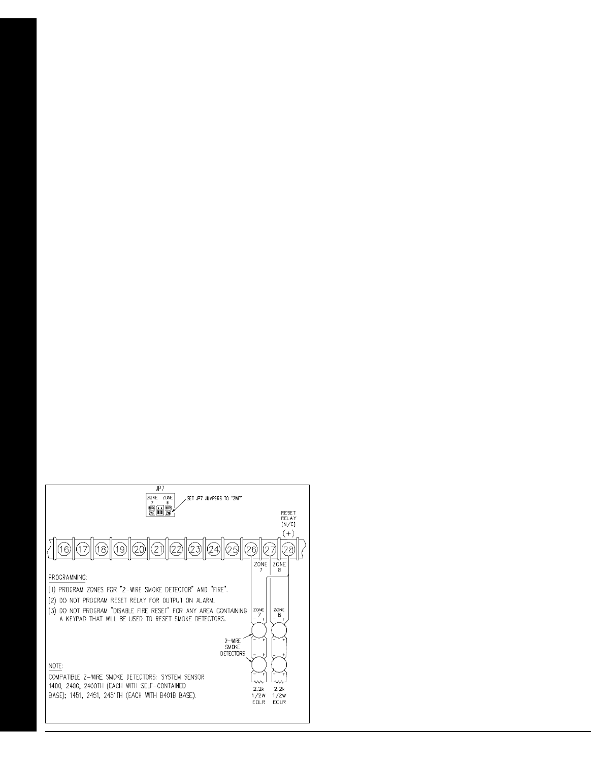
X GEM-X255 Installation Instructions L NAPCO Security Systems
WI1093C 3/04
! Page 46
RF Jam Reporting
RF Receiver Jam will report as RF Receiver Trouble.
Rotary Dialing Only See TouchTone Dialing Only
Second Call Answering Machine Override
If using the PCD-Windows PC downloader Software, the Telco Answering Service can now be disabled. Call the panel, hang up
after one ring by pressing the F10 key. The PCD-Windows will automatically call the panel back and the panel will answer in one
ring. See Callback-Method Download for more information.
Select Burg Output for Keyfob Chirp
This feature is associated with AUXOUT CHIRP ON KEYFOB ARM/DISARM. Normally the chirp on a keyfob arm/disarm is transmit-
ted to the Aux. output. Selecting "SELECT BURG OUTPUT FOR KEYFOB CHIRP" causes the "Burg" to chirp instead of the Aux.
upon remote arming.
Selective Bypass
Disable Code Required for EZ Bypass (Not for UL installations.)
Any or all zones (1–255) programmed for Selective Bypass may be removed from the system, but each must be removed sepa-
rately. Refer to BYPASSING ZONES in Section 3 for operation. Security Bypass: Recommended for commercial applications, re-
quires entry of a valid user code. EZ Bypass: Recommended for residential applications, is selected by programming Disable Code
Entry for EZ Bypass; this will permit bypassing/unbypassing zones without the need of entering a code (see EZ Bypass in Section 3).
Do not program this feature in high-security applications. When one or more zones is bypassed, the “BYPASSED” reminder on the
GEM-RP1CAe2 and GEM-K1CA keypads will display.
Sensor Watch
Program for any zone containing a PIR or dual-technology sensor, floor mats, door contacts, or other device where some activity
is expected. This feature supervises the sensor by verifying that the zone activates before the PIR timer runs out. If no trip is de-
tected within the programmed Sensor-Watch time, a system trouble will result and “E22-NN PIR SENSOR TRBL” will be displayed at the key-
pad, where NN are the zone number(s). Select the RESET SENSOR MSG function to reset this system trouble.
Program the Sensor-Watch PIR timer in Location 4088. Select a value in accordance with the anticipated activity within the cov-
erage area while disarmed. In calculating the Sensor-Watch time, note that only the disarmed hours (the time between armed peri-
ods) are added. In moderate traffic areas, a Sensor-Watch time of perhaps 1 hour may be appropriate, whereas in remote areas, a
time of 8 hours or more may be in order. Supervision time should be calculated for the supervised zone with the least amount of traf-
fic. Up to 255 hours may be programmed (see Time Selection).
Silence All Outputs During Audio Session See Veri-Phone
Silence All Outputs During Audio Session with Lug E19
Whenever an active low is applied to control-panel Lug E19 (Listen-In), all output relays will turn off. Connect Veri-Phone Termi-
nal 16 (INHO) to Lug E19.
Single-Digit Format See Data Format
Smoke Detectors
Connect smoke detectors as shown in the following diagrams. The
normally-closed contacts of the Reset Relay are used to reset the
smoke detectors.
Two-Wire Smoke Detectors: Use Zones 7 and 8.
Zones 7 and 8 have been designed so they can be easily
configured as 2-wire smoke detector zones by means of
jumpers (JP7) located above Terminal 21.
1. If Zone 7 is selected as a 2-Wire Fire Zone, move the left
jumper on JP7 from the top two pins (BURG) to the bottom
two pins (2WF).
2. Similarly, if Zone 8 is selected as a 2-Wire Fire Zone, move
the right jumper on JP7 from the top two pins (BURG) to the
bottom two pins (2WF).
3. Connect 2-wire smoke detectors to Zones 7 and/or 8 as
shown.
Two-Wire Smoke Detectors: Use Zones 1-6.
Additionally, where more than two 2-wire smoke detector zones
are required, select any of Zones 1–6 for 2-wire fire as fol-
lows:
1. Program the selected zone(s) (1–6) for 2-Wire Smoke Detec-
GLOSSARY
Connecting 2-wire smoke detectors to zones 7 & 8
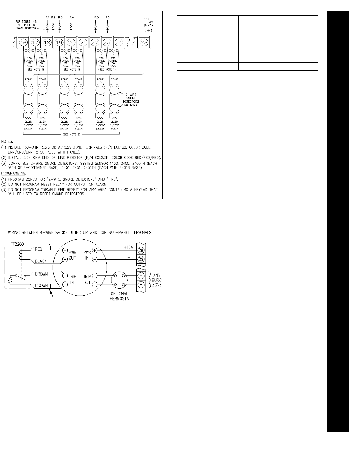
L NAPCO Security Systems X GEM-X255 Installation Instructions
WI1093C 3/04 !
Page 47
tors and Fire.
2. Cut out the 2700Ω resistor (color code: red/violet/red) associ-
ated with the selected zone(s). See table below.
3. Install a 130Ω resistor across the 2 terminals of each zone
used (color code: brown/orange/brown).
4. Wire positive (+) terminal of smoke detector to terminal 28.
Wire negative (-) terminal of smoke detector to positive (+)
terminal of the zone.
Four-Wire Smoke Detectors. If installing 4-wire
smokes, subtract smoke-detector alarm current from
available standby current. See COMPATIBLE UL-
LISTED DEVICES.
Wire 4-wire smokes as shown in the following wiring dia-
gram. Program each zone for Fire. Also program zones
for Pulse Burglary Output, and Disable Fire Reset in the
applicable area(s) (System Options). If they are of the
self-resetting type, 4-wire smokes may be powered from
Terminals 13 and 14 (AUX. PWR.) instead of Terminal 28
and 29, thus freeing the Reset Relay for other uses.
Split Reporting See Report Telco 3
Start Exit Delay After Ringback
When a closing report is successfully received, the central station will acknowledge by returning a kissoff signal. When the kis-
soff is received by the communicator, a 2-second ringback tone will sound at the keypad. Start Exit Delay After Ringback will cause
the exit delay to start after the ringback sounds.
If this option is chosen and no ringback sounds shortly after the control panel is armed, exit delay will not start and opening the
exit/entry door will cause an instant alarm. To manually start the exit delay, select the START EXIT TIME function, then press the J
or U button to execute.
Note: (1) If this feature is selected, Exit/Entry Follower Zones will not arm until either a ringback sounds or the START EXIT
TIME function is used. (2) If communicator, telephone lines or central-station receiver is out of service, the system will be armed with-
out communication capability.
Status Report See Closing Report
Wiring diagram, 4-wire smoke detectors
Additional 4-wire smokes
ZONE RESISTOR LOCATION ON BOARD
1 R1 ABOVE TERMINAL 18
2 R2 ABOVE TERMINAL 18/19
3 R3 ABOVE TERMINAL 19
4 R4 ABOVE TERMINAL 20
5 R5 ABOVE TERMINAL 22
6 R6 ABOVE TERMINAL 23
Connecting 2-wire smoke detectors to zones 1-6
GLOSSARY

X GEM-X255 Installation Instructions L NAPCO Security Systems
WI1093C 3/04
! Page 48
Subscriber Identification Numbers
If reporting openings and/or closings, program Subscriber Opening/Closing Identification Numbers for each area for each tele-
phone number used. If reporting events, program Subscriber ID Numbers for each area for each telephone number used. Sub-
scriber ID numbers must be programmed for each area and telephone number, even if all are the same. Start with the left-most loca-
tion.
Sum Check See Data Format
Supervised Bell Output
When the option Supervised Bell Output is enabled, a 2.2K ohm resistor must be installed across the bell or sounding device ter-
minals. In the event that the Burg Output is cut, or the circuit is opened, an E51-00 FIRE BELL TRBL trouble condition will occur.
Note: Due to the fact that there is a constant loop current flowing through the Burg Output circuit for supervision, some sirens or siren
drivers may emit a low volume hum or buzz if the 2.2K EOL resistor is not installed. If Supervised Bell Output is not required, this can
be eliminated by cutting resistor R207 which is located just to the right of the Burg Output relay adjacent to the Burg Output terminal.
Suppress “BYPASSED” Icon When Armed
Program to inhibit the LCD “BYPASSED” display while armed.
Swinger Shutdown
Swinger Shutdown is a common term used in the burglary alarm industry. It is a feature of an alarm panel that prevents multiple false
alarms from being generated from faulty detectors (or wiring) by limiting the number of alarms a zone may report during a single arm-
ing period. NAPCO has this programmable-by-zone feature named Swinger Shutdown, and has been available on its panels for
years. The SIA False Alarm Reduction standard CP-01 (to which the panel now complies) requires the SIA definition of "swinger
shutdown" on all non-fire zones. Our programmable feature allows three trips per arming period which is unacceptable in CP-01 in-
stallations. Therefore, to reduce confusion, the following defines both definitions of "Swinger Shutdown", namely (1) the NAPCO Pro-
gramming Feature and (2) the CP-01 Requirement:
Swinger Shutdown (NAPCO Programming Feature): Program a zone with this feature to allow only three alarms per arming
period. Auto-Reset must also be programmed for the zone for this feature to work.
Swinger Shutdown (CP-01 Requirement): To meet CP-01, all non-fire zones must not be programmed for Auto-Reset. A zone
not programmed for Auto-Reset will trip only one alarm per arming period. The panel leaves the factory with no zones programmed
for Auto-Reset. If "Enable CP-01 Features" is selected in the Easy Programming menu, all non-fire zones will not be programmed
for Auto-Reset.
System Trouble Audible Automatic Timeout
Inhibit System Trouble Audible
In the event of a System Trouble while the system is disarmed, the keypad will scroll the trouble description in the display and
activate the sounder until [RESET] is pressed. If [RESET] has not been pressed within 10 minutes of the trouble, the sounder will
automatically turn off in 10 minutes.
To disable System Trouble Audible Automatic Timeout , enable Disable System Trouble Audible Timeout in the PCD-WINDOWS
Keypad Features screen. NOTE: If the system were Armed when the trouble occurred, the keypad would display the SYS TBL icon,
but NOT activate the sounder.
For installations where an audible on system trouble is not desired at all, the option, Inhibit System Trouble Audible can be en-
abled. Regardless of the system status, Armed or Disarmed, there will be no keypad sounder at all in the event of a system trouble.
However, the trouble will still scroll in the keypad display until [RESET] is pressed and the SYS TBL icon will display until the trouble
is restored. (Do Not program in UL Installations)
•To disable System Trouble Audible, enable the option disable System Trouble Audible in the PCD-Windows Keypad Features
screen.
Tamper
EZM Tamper
Keypad Tamper
RF Tamper
Removing the cover of an expansion zone module will cause the sounder to pulse and the “SYS/TRBL” reminder to flash. The key-
pad will display “E13-NN BURG EZM TAMPER”, where “NN” denotes the module number. Press the C button to silence the sounder
(“SYSTEM READY” will display). Correct the problem, then select RESET SYSTEM TBL to manually reset the system trouble display.
Removing a keypad from the wall causes a similar system trouble indication. The keypad will display “E11-NN BURG KPD TAMPER”,
where “NN” denotes the keypad number. Press the C button to silence the sounder (“SYSTEM READY” will display). To manually
reset the system trouble, correct the problem then select RESET SYSTEM TBL.
Note: If either of the tamper conditions is not corrected within 5 minutes, the system trouble will again display at the keypad.
A Tamper condition can be programmed to activate the burglary output and/or report using its associated system Report Code.
In wireless installations, when displaying RF transmitter status, a “Tamper” indication denotes that the transmitter case is open.
Telco Fail See Enable Telephone Line-Fault Test
TELCO FAIL ONLY WHEN ARMED
The Telco Line Cut Monitor will only be active when the system is armed.
Telco Line Test Delay See Enable Telephone Line-Fault Test; Time Selection
GLOSSARY

L NAPCO Security Systems X GEM-X255 Installation Instructions
WI1093C 3/04 !
Page 49
Telemetry Trouble
If any device connected to the on-board Serial Port (such as a Home Automation system or AES Radio) fails to respond to a poll
by the control panel, a Telemetry Trouble system trouble will result. On the PCD-Windows System Features screen, enable Teleme-
try Trouble: = XT to report on alarm or activate and output. On the PCD-Windows System Reporting Codes screen, program a re-
porting code for Telemetry Trouble.
Keypad readout will be: E58-00 SERVICE
TELEMETRY TRBL
The event Log will read: TROUBLE: TELEMETRY
TROUBLE RESTORE: TELEMETRY
Keypad programming Address Location 1099 = [!][ ] 4 - Telemetry Trouble
Telemetry Trouble: 8 - Telemetry Fail
Telemetry Failure
If the device connected to the on-board Serial Port (such as a Home Automation system or AES Radio) is not able to carry out its
intended function, it can send a signal to the control panel, and a Telemetry Trouble system trouble will result. On the PCD-Windows
System Features screen, enable Telemetry Failure: = XF to report on alarm or activate and output. On the PCD-Windows System
Reporting Codes screen, program a reporting code for Telemetry Failure.
Keypad readout will be: E59-00 SERVICE
TELEMETRY COMM
The event Log will read: TROUBLE: TELEMETRY FAIL
Trouble Restore: TELEMETRY FAIL
Keypad programming Address Location 1100 = [!][ ] 4 - Telemetry Trouble
Telemetry Failure 8 - Telemetry Fail
Telephone Numbers
Dialing Prefix
To report to a central station, Telephone Number 1 must be programmed. Telephone Number 2 is programmed for Backup Re-
porting; Telephone Number 3 is programmed for Double or Split Reporting.
Private telephone systems may require a Dial-Tone Detection “E” or Pre-Dial Delay “D”, followed by an access number to obtain
an outside line. (See Access Number for Outside Line.)
It should be noted here that the telephone number need not actually start in the first location shown, and may not end in the last.
Extra locations have been provided to allow for one or more prefix digits: a Pre-Dial Delay “D” or a Dial-Tone Detection “E”. What is
important is that the telephone number, with its associated Pre-Dial Delay, Access Number, and Dial-Tone Detection, be wholly con-
tained within that group of locations, and that they be in their proper sequence.
If needed, a Dialing Prefix of up to 20 digits may be programmed. This prefix will be dialed immediately before the programmed
Central Station telephone numbers.
Test Timer
Cancel Next Test Timer Report on Any Report
The test timer schedule is programmed using NAPCO's PCD-Windows Quickloader Software. If Test Timer is programmed, an
automatic test report will be transmitted to the central station on the scheduled day(s) at the scheduled time. (UL installations require
a report at least every 24 hours). To report test timer, select Report Test Timer and program a report code. Program the Test Timer
event schedule and reporting time.
If Cancel Next Test Timer Report on Any Report is programmed, any report will cause the next test-timer transmission to be
aborted, however subsequent test-timer transmissions will report as scheduled. Do not program this feature in UL installations.
Timeout
Specifies the length of time that an alarm, alert, or delay will remain active. Auxiliary Output Access Control Time, Abort-Delay
Time, and Chime Time must be programmed, or the feature will not activate. See Time Selection.
GLOSSARY
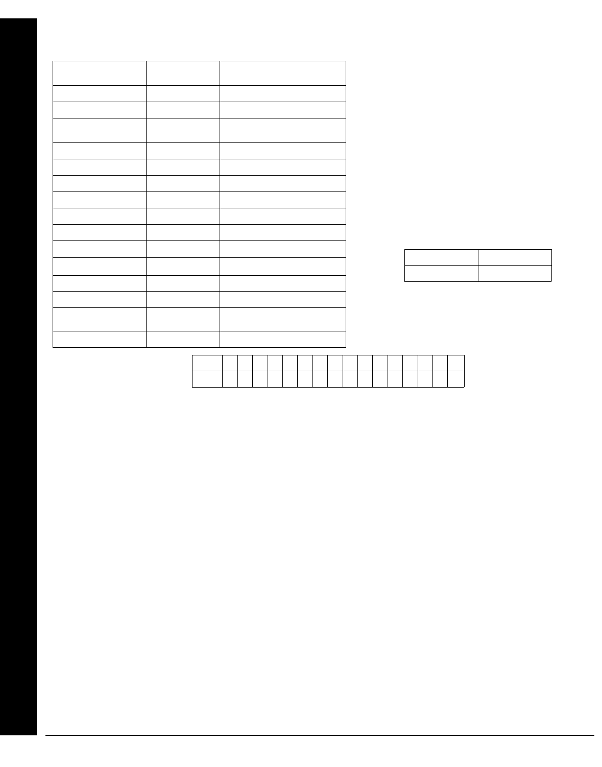
X GEM-X255 Installation Instructions L NAPCO Security Systems
WI1093C 3/04
! Page 50
Time Selection
The following times are programmable:
Any timeout up to those shown in the foregoing table may
be programmed. Note that each of the above times is pro-
grammed in two locations. The first location has an as-
signed time factor of 16, the second a time factor of 1.
*Blank.
Note: If both programming locations are left blank, refer to the notes in the Time Selection table for feature timeout.
To select a time up to 15 seconds, 15 minutes, 15 hours, or 15 days, program the respective entry into the second box only; do
not program the first box. To select a time greater than 15 seconds, 15 minutes, 15 hours or 15 days, program both boxes as follows:
1. For the feature selected, choose an appropriate time in units shown (all seconds, minutes, hours, or days — not minutes
and seconds, etc.).
2. Divide the time chosen by 16. Enter the quotient in the 1st BOX and the remainder in the 2nd BOX.
3. Check entries by adding the contents of the 2nd BOX to 16 times the contents of the 1st BOX. (Remember that a “zero”
entry represents 10.)
Example. Program Entry Delay 1 for 1 minutes.
1. Entry Delay 1 is in units of seconds, thus delay time is 90 seconds.
2. Divide by 16: 90/16 = 5 (quotient) + 10 (remainder).
3. Enter the quotient in the 1st BOX and the remainder in the 2nd BOX
4. Check entries (remember, a “0” entry = 10): (16x5) + 10 = 90
TouchTone Dialing Only
Rotary Dialing Only
TouchTone Dialing with Rotary Backup
Select TouchTone Dialing Only if the subscriber has TouchTone service. TouchTone dialing is faster than rotary dialing, but not
always as reliable.
For the communicator to use TouchTone on all dial attempts, program TouchTone Dialing Only. To use TouchTone on the first
attempt with subsequent Rotary dial, program TouchTone Dialing with Rotary Backup. TouchTone Dialing Only will override Touch-
Tone Dialing with Rotary Backup if both are selected. Note that if Backup Reporting is also selected, the communicator will alternate
between TouchTone and rotary dial to reach Telephone 1, then Telephone 2. See Backup Report on Telco 2.
Trouble
An abnormal zone condition (a break in a normally-closed loop; a short on a normally-open loop; or either on an end-of-line-
resistor supervised loop) when disarmed.
Trouble on a Burglary Zone is automatically displayed at the keypad unless Disable Zone Fault Scrolling (Auto Status) is pro-
grammed. If a Burglary Zone is in trouble, it will go into alarm about 10 seconds after arming. However, if Auto Bypass is pro-
grammed, the keypad will beep upon arming (does not apply to selective- or group-bypassed zones).
GLOSSARY
NOTES: (1) The output used for Burglary must be at least 4 minutes
in Residential UL installations, 15 minutes in Commercial UL instal-
lations. (2) If both locations are left blank, this feature will remain ac-
tive until the system is disarmed. When both locations are pro-
grammed “F”, maximum time will be 4 hours, 15 minutes (255 min-
utes). (3) If both locations are left blank, this feature will not activate
(timeout = 0). (4) In UL installations: Maximum Exit Delay = 60 sec;
Maximum Entry Delay = 45 sec. (5) If programming locations are left
blank, delay will default to 10 sec. (6) Time in units of disarmed hours
(accumulated between armed periods).
TIME
UNITS MAX. PROG. TIME
RESET OUTPUT MIN. UNTIMED (2)
AUXILIARY OUTPUT MIN. UNTIMED (2)
AUXILIARY OUTPUT
ACCESS CONTROL TIME
SEC. 4 MIN, 15 SEC (255 SEC)
BURGLARY OUTPUT MIN. UNTIMED (1)(2)
PULSE-BURG OUTPUT MIN. UNTIMED (1)(2)
FIRE OUTPUT MIN. UNTIMED (2)
ABORT DELAY SEC. 4 MIN, 15 SEC (255 SEC) (3)
CHIME TIME ¼ SEC. 63.25 SEC (255 QTR-SEC) (3)
AC-FAIL REPORT DELAY 10 MIN. 42 HR, 30 MIN (2550 MIN)
EXIT DELAY SEC. 4 MIN, 15 SEC (255 SEC) (4)
ENTRY DELAY 1 SEC. 4 MIN, 15 SEC (255 SEC) (4)
ENTRY DELAY 2 SEC. 4 MIN, 15 SEC (255 SEC) (4)
TELCO LINE-TEST DLY 15 SEC. 4 MIN, 15 SEC (255 SEC) (5)
AUTO DISARM/REARM
DELAY
MIN. 4 HR, 15 MIN (255 MIN)
SENSOR-WATCH TIME DISARMED HOURS 255 HOURS (6)
1st BOX 2nd BOX
tx16 tx1
Time t: 0 1 2 3 4 5 6 7 8 9 10 11 12 13 14 15
Entry: * 1 2 3 4 5 6 7 8 9 0 B C D E F

L NAPCO Security Systems X GEM-X255 Installation Instructions
WI1093C 3/04 !
Page 51
Trouble (open and/or short circuit) on a Day Zone is indicated by a pulsing sounder; display the Day Zone(s) in trouble on the
LCD. Keypad indications are reset by the C button unless Reset Day Zone With Arm/Disarm is selected.
Trouble on a Fire Zone will be indicated by the “FIRE/TRBL” reminder and the sounder. An open circuit (trouble) will cause a flash-
ing “FIRE” display and a pulsing sounder after a 15-second delay. (A short circuit will cause an alarm condition: steady-on “FIRE” dis-
play and pulsing sounder). The C button will silence the sounder. Clear the trouble, then press the C button once again.
The keypad will reset after a brief delay.
Trouble on Open
Trouble on Short
Trouble on Night Open (Not for UL installations)
Trouble on Open will identify an open circuit on a loop as a trouble. Trouble on Short will identify a short circuit as a trouble.
Trouble on Night Open, which will identify an open circuit on a normally-closed zone while armed as a trouble condition (not an
alarm), is intended for use with a Napco Monitor-Series dual-technology sensor. While there will be no indication at the keypad, any
of these trouble conditions can be reported if Report Trouble is programmed as well. See Sensor Watch.
Trouble/Trouble Restore Telco 1/Telco 3 See Report Telco 1/Telco 3
Trouble/Trouble Restore Telco 2 See Backup Report on Telco 2
Two-Digit Format See Data Format
Two-Wire Smoke Detectors See Smoke Detectors
Unvacated Premises: Convert from Away to Stay based on no egress through exit door. Default is enabled. (GEM-X255 panel--
This feature is Automatic Interior Bypass/Easy Exit). The panel uses the existing programmable feature "Auto Interior Bypass". This
feature must be enabled in CP-01 installations. This feature is enabled in the factory program and it is also enabled when "Enable
CP-01 Features" is selected in the Easy Program Menu. (See Address 2421 in the Programming Instructions).
User Codes/Authority Levels/Access Bytes
User Closing and Opening Reports by Telephone Numbers
Enable User Code by Area
Up to 195 six-digit User Codes are programmable, each with its dedicated Authority Level and Access Byte. (The Authority Level
comprises an Option Code). Refer to Programming Manual WI1092 for descriptions of levels and options.
If reporting to a central station, program User Closing and Opening Reports by Telephone Numbers. In multiple-area systems,
program Enable User Code by Area.
Unsupervised Transmitters
(Programmable with PCD-Windows Quickloader Download Software Only) Transmitters can now be unsupervised by program-
ming a “9” in place of point number “1”. NOTE: All points of that transmitter will be unsupervised.
Veri-Phone™
Silence All Outputs During Audio Session
Veri-Phone Zones Priority Over Alarms
Veri-Phone Zones Trip Auxiliary Output
Veri-Phone Zones Trip Fire Output
If Silence All Outputs During Audio Session is selected, all output relays will turn off whenever an active low is applied to control-
panel Lug E19 (Listen In). Connect Veri-Phone Terminal 16 (INHO) to Lug E19. Note: Do not program Keypad Sounder on Alarm
for Listen-In Zones.
If Veri-Phone Zones Priority Over Alarms is programmed and an active low is applied to the panel's Listen-In Lug (E19), any sub-
sequent alarm reports (except fire alarms) generated during an audio session will be delayed until the end of the session. (Whenever
a listen-in session is in progress, the Veri-Phone will output an active low at its INHO Terminal (16) and Lug E1.)
Program Veri-Phone Zones Trip Auxiliary Relay to have selectable Listen-In Zones. Connect Veri-Phone Terminal 14 (TRIGH)
to control-panel Terminal 8 (AUX. N/O). Program the zone or event for Auxiliary Relay. Do not use the Auxiliary Relay for any other
purpose.
Veri-phone Trips Fire Output
To have selectable Listen-In Zones, use the Fire Output to trigger the Veri-Phone. Connect Veri-Phone Terminal 13 (TRIGL) to
control panel Lug E9 (Fire Output). Program the zone or event for Fire Output; do not use the Fire Output for any other purpose.
NOTE: Veri-phone trips Auxiliary Relay and Veri-phone trips Fire Output cannot be enabled together. The Auxiliary Relay can be
used for Keyfob Chirp on arming and disarming.
Watch Mode (by Area) See Day Zone
Wireless Trouble Reporting by Zone All reports of Wireless trouble (Transmitter Low Battery, Transmitter Tamper, Transmitter Su-
pervisory Failure) to central station will identify identifying the zone of the transmitter.
GLOSSARY

X GEM-X255 Installation Instructions L NAPCO Security Systems
WI1093C 3/04
! Page 52
Zone ANDing, Groups 1–8 (Not for UL installations); Enable Local Alarm on First Zone “AND” Trip (Not for UL installations)
Up to 8 groups of at least two zones each can be “AND”ed, wherein the system will go into alarm only if any two zones of the group
are tripped within 2 minutes. This feature is designed to afford redundant protection for devices, such as glass break detectors, PIRs,
etc., that may show a tendency to false under certain conditions. Program each Group for any number of Zones available. All Zones
in any Group must be within the same Area. Do not mix 24-Hour Zones and non-24-Hour Zones within the same Group. Do not in-
clude a Panic Zone as part of any Group. Auto-Reset must be programmed for each Zone ANDing Zone. Note: Any zone that is
bypassed or goes into Swinger Shutdown will automatically disable Zone Anding for the entire Group. If “Enable Local Alarm on First
ZoneAND Trip” (Address 2419) is programmed, a trip on any Zone of the Group will cause an alarm output and alarm display at the
keypad; there will be no communication to the central station. Note: If "Enable CP-01 Limits" is enabled in EZ Programming, any
Zone in a Group will only activate an alarm and send a report ONCE. After the Zone has reported, it will remain in the Group and
may still initiate the Zone ANDing sequence.
Zone Area 1–Zone Area 8 See Areas
Zone Number on Pulse Alarm See Data Formats: Two-Digit Format
Zone Type See Data Formats: Modem Formats
2-Wire, 4-Wire Smoke Detectors See Smoke Detectors
4-Wire Bus Failure See Bus Failure
24-Hour Zone
A zone that provides protection at all times, whether or not the system is armed. If programmed for silent alarm (no Burg Output,
Aux. Output, Fire Output or Keypad Sounder on Alarm programmed) there will not be any indication on the keypad. If an Audible out-
put is programmed, the keypad will flash the red Armed LED and display “ALARM” followed by the zone description.
Note: Do not program a Day Zone as a 24-Hour Zone.
GLOSSARY
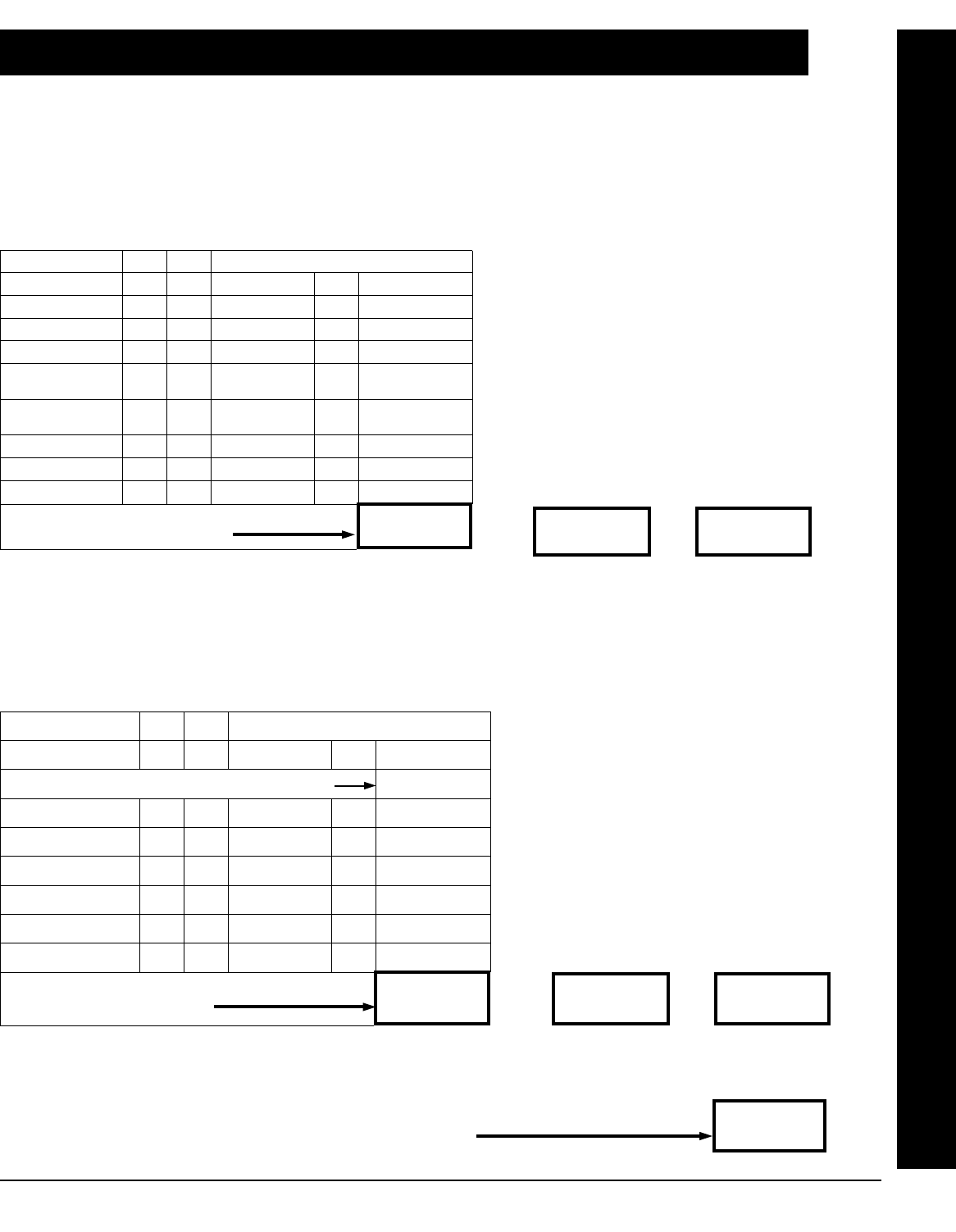
L NAPCO Security Systems X GEM-X255 Installation Instructions
WI1093C 3/04 !
Page 53
STANDBY-BATTERY CALCULATION WORKSHEET
Use the procedure given below to determine the required standby battery capacity in Ampere-Hours (AH). NOTE: It is not totally ac-
curate to merely multiply the combined standby current (in amperes) by the standby time (in hours) to obtain the battery capacity (in
ampere-hours), since other factors (control-panel charging capabilities, temperature, battery condition, etc.) affect battery operation.
The following calculations will yield the theoretical minimum required capacity.
1. STANDBY CURRENT
STANDBY CURRENT (Amps)
DEVICE QTY EACH TOTAL
GEM-X255 1 X 0.120 =
GEM-EZM4/8 X 0.050 =
GEM-EZM8 X 0.050 =
GEM-RP1CAe2/
GEM-K1CA
X 0.100 =
GEM-RP1CAe2/
GEM-K1CA (1) X 0.035 =
RM3008 X 0.040 =
X =
X =
TOTAL STANDBY CURRENT
Amps
(1) Alarm current drawn in alarm.
(2) Alarm Time in Hours. Example: For a 15 minute alarm timeout, Alarm Time =
15/60 = 0.25.
2. ALARM CURRENT
ALARM CURRENT (Amps)
DEVICE QTY EACH TOTAL
TOTAL STANDBY CURRENT (from Box 1, above)
GEM-X255 (1) X 0.120 = 0.120
BELLS X =
STROBES X =
HORNS / STROBES X =
X =
X =
Amps
TOTAL ALARM CURRENT
(1) Backlighting disabled (cut Jumpers W1, W2 & W3).
(4) Standby Time in Hours. (Box 1)
X
Hours
=
AH.
(Standby Time)(4) (Box 2)
X
Hours
=
AH.
(Alarm Time)(2) (Box 3)
MINIMUM REQUIRED BATTERY CAPACITY = BOX 2 + BOX
AH.
STANDBY-BATTERY CALCULATION WORKSHEET

X GEM-X255 Installation Instructions L NAPCO Security Systems
WI1093C 3/04
! Page 54
WIRING LEGEND
Should removal of the circuit board be necessary, use this wiring legend to relocate wire leads to their proper terminals.
Enter wire identification number or color code in WIRE NUMBER column and enter wire function in DESCRIPTION col-
umn (optional).
TERMINAL WIRE NO. DESCRIPTION
1
2
3
4
5
6
7
8
9
10
11
12
13
14
15
16
17
18
19
20
21
22
23
24
25
26
27
28
29
30
31
32
33
WIRING LEGEND
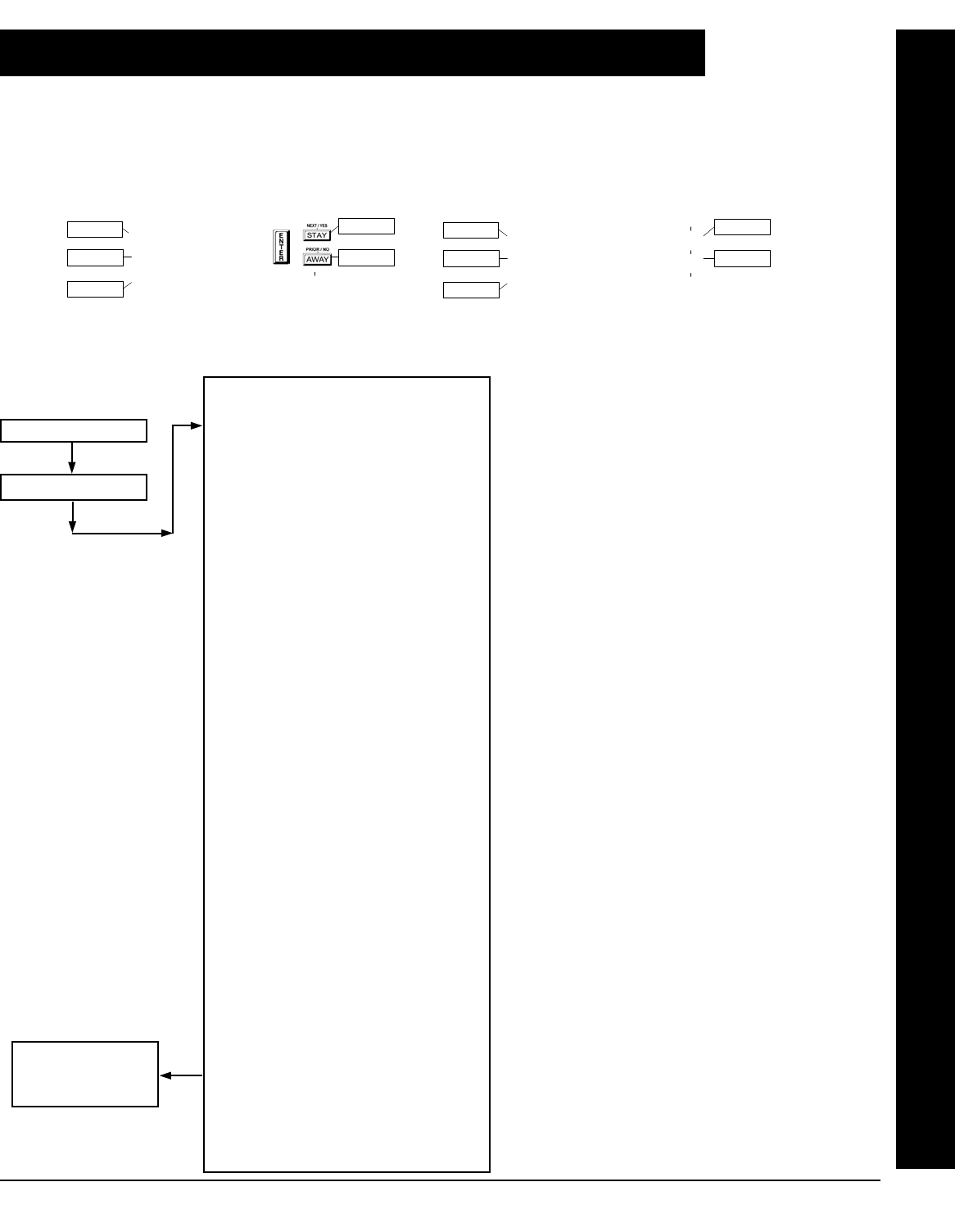
L NAPCO Security Systems X GEM-X255 Installation Instructions
WI1093C 3/04 !
Page 55
KEYPAD PROGRAMMING MODES
Note the following:
1. Functions that are not active, not programmed and/or not applicable to the user’s authority level ("AL") will be
suppressed and will not display at the keypad.
2. The Function Mode uses a real time, filtered display. Many functions may not be displayed until its condition is
satisfied. For example, “DISPLAY ZN FAULTS” will not display unless there is a faulted zone to display.
FUNCTION REQUIRED USER
AUTHORITY LEVEL
DISPLAY ZN FAULTS 1,2,3(A)
DISPLAY ZN BYPASSED 1,2,3(B)
DISPLAY ZN DIRECTORY 1,2,3
ACTIVE BELL TEST 1,2,3
DISPLAY PHONE #’S 1,2,3(C)
DISPLAY SYS TRBL 1,2,3(E)
DISPLAY FIRE ALARM 1,2,3(F)
DISPLAY FIRE TRBL 1,2,3(G)
DISPLAY OP/CL 3(H)
ACTIVATE OVERVIEW 3(I)
ACTIVATE CHIME 1,2,3
ACTIVATE WATCH 2,3(J)
ACTIVATE GUARD TOUR 2,3(K)
RESET SYSTEM TRBL 3(E)
RESET SENSOR MSG 3
START EXIT TIME 1,2,3
ACTIVATE DIALER TEST 3
DISPLAY ALARM LOG 3
DISPLAY TOTAL LOG 3
DISPLAY FIRE LOG 3
DISPLAY OP/CL LOG 3
DISPLAY SYSTEM LOG 3
TO ARM IN 1-4HRS 2,3
DISPLAY AUTO ARM SCHD 3(M)
ACTIVATE PROGRAM 3
ACTIVATE DOWNLOAD 3
DISPLAY RF XMITTER STAT 3(N)
RELAY CONTROL 1,2,3(O)
USER MODE
NOTES:
(A) Displays only with faulted Zones present.
(B) Displays only with bypassed Zones present.
(C) Displays only with "Help Phones" information pro-
grammed (Name and Telephone Number
information).
(E) Displays only with System Troubles present in
the system (for example, AC Fail, etc.).
(F) Displays only with Fire Zones in alarm.
(G) Displays only with Fire Zones in Trouble.
(H) Displays only with scheduled "Auto Arm" and
"Auto Disarm/Rearm" delays programmed.
(I) Will Display either "Activate Overview" or
"Deactivate Overview".
(J) Displays only with a Day Zone present and "Day
Zone Watch by Area" enabled.
(K) Displays only with Guard Tour Schedule and
Guard Tour Timers programmed.
(M) Displays only with "Auto Arm" scheduled.
(N) Displays only with Number of Receivers greater
than zero and an RF Wireless Zone installed.
(O) Displays only with the number of relay boards
greater than zero and with "Relay Group"
programmed.
EASY MENU PROGRAM
MODE
KEYPAD PROGRAMMING MODES
12
43
56
7890
A
B
C
DE
F
G
NEXT/YES
PRIOR/NO
AREA
Scroll Down
Scroll Up
Exit
Yes
No
R
For "K Series" Keypads
12
43
56
7890
A
B
C
DE
F
G
NEXT/YES
PRIOR/NO
AREA
Scroll Down
Scroll Up
Exit
Yes
No
For "Classic" Keypads
Press R button
Enter User Code
Note: Default configura-
tion shown for GEM-K1CA
Keypad.
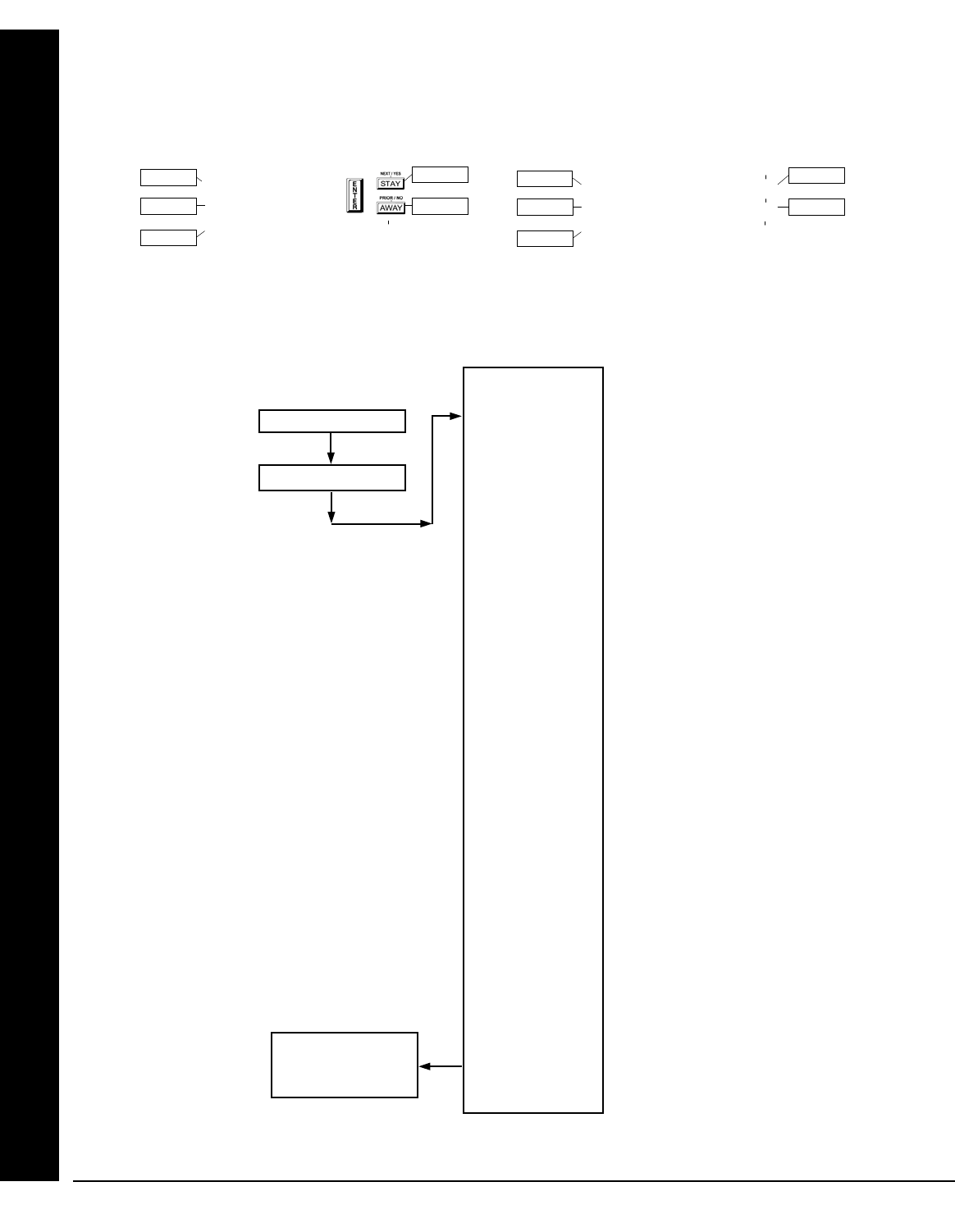
X GEM-X255 Installation Instructions L NAPCO Security Systems
WI1093C 3/04
! Page 56
KEYPAD PROGRAMMING MODES
Note the following:
1. Functions that are not active, not programmed and/or not applicable to the user’s authority level ("AL") will be
suppressed and will not display at the keypad.
2. The Function Mode uses a real time, filtered display. Many functions may not be displayed until its condition is
satisfied. For example, “DISPLAY ZN FAULTS” will not display unless there is a faulted zone to display.
FUNCTION
DISPLAY ZN FAULTS
DISPLAY ZN BYPASSED
DISPLAY ZN DIRECTORY
ACTIVE BELL TEST
DISPLAY PHONE #’S
DISPLAY SYS TRBL
DISPLAY FIRE ALARM
DISPLAY FIRE TRBL
DISPLAY OP/CL
ACTIVATE OVERVIEW
ACTIVATE CHIME
ACTIVATE WATCH
ACTIVATE GUARD TOUR
RESET SYSTEM TRBL
RESET SENSOR MSG
START EXIT TIME
ACTIVATE DIALER TEST
DISPLAY ALARM LOG
DISPLAY TOTAL LOG
DISPLAY FIRE LOG
DISPLAY OP/CL LOG
DISPLAY SYSTEM LOG
TO ARM IN 1-4HRS
DISPLAY AUTO ARM SCHD
ACTIVATE PROGRAM
ACTIVATE DOWNLOAD
DISPLAY RF XMITTER STAT
RELAY CONTROL
DEALER MODE
EASY MENU PROGRAM
MODE
12
43
56
7890
A
B
C
DE
F
G
NEXT/YES
PRIOR/NO
AREA
Scroll Down
Scroll Up
Exit
Yes
No
R
For "K Series" Keypads
12
43
56
7890
A
B
C
DE
F
G
NEXT/YES
PRIOR/NO
AREA
Scroll Down
Scroll Up
Exit
Yes
No
For "Classic" Keypads
Press R button
Enter DEALER Code
Note: Default configura-
tion shown for GEM-K1CA
Keypad.
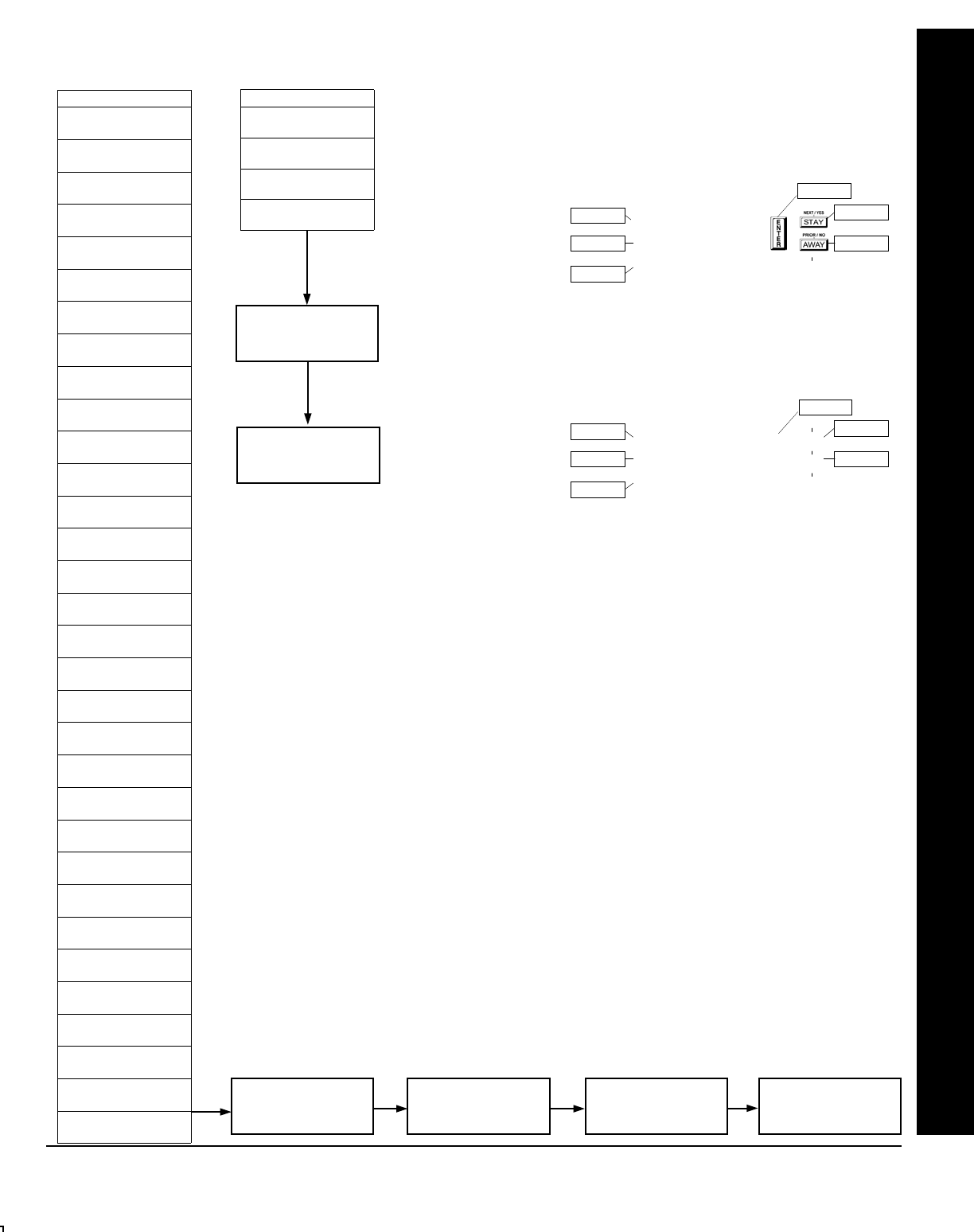
L NAPCO Security Systems X GEM-X255 Installation Instructions
WI1093C 3/04 !
Page 57
KEYPAD PROGRAMMING MODES
EASY MENU PROGRAM MODE
(E) Initial Configuration only; suppressed thereafter
(F) These selections appear if you enter Dealer Mode
(G) These selections appear if you enter Function Mode
(H) Seen during and after initial configuration
Press C button
(at any time)
DIRECT ADDRESS
PROGRAM MODE
FUNCTION(F)
# OF ZNS IN AREA1
ENTER # ZONES 08(E)
# OF ZNS IN AREA2
ENTER # ZONES 00(E)
FIRE ZONES
ENTER ZONE # 00(E)
2-WIRE FIRE ZNS
ENTER ZONE # 00(E)
REPORT ALL ZONES
TO CENTRAL? Y/N (E)
EXIT/ENTRY ZONES
ENTER ZONE # 00(E)
INTERIOR ZONES
ENTER ZONE # 00(E)
24 HOUR ZONES
ENTER ZONE # 00(E)
CHIME ZONES
ENTER ZONE # 00(E)
CHIME 2 ZONES
ENTER ZONE # 00(E)
EXIT/ENTRY 2 ZNS
ENTER ZONE # 00(E)
50MS LOOP ZONES
ENTER ZONE # 00(E)
AUX OUTPUT ZONES
ENTER ZONE # 00(E)
SENSOR WATCH ZNS
ENTER ZONE # 00(E)
KP SNDR ALRM ZNS
ENTER ZONE # 00(E)
AUTO BYP RENT ZN
ENTER ZONE # 00(E)
ENABLE NO EOLR
ZONES Y/N(E)
ENABLE TELCO
LINE TEST? Y/N(E)
ENABLE BURG OUT
CHIRP? Y/N(E)
ENABLE SIA CP-01
Y/N(E)
# AREA 1 KEYPADS
ENTER # KPS 00(H)
# AREA 2 KEYPADS
ENTER # KPS 00(H)
CENTRAL PHONE #(H)
CENTRAL STATION
ACCOUNT # (_ )(H)
SEE WI FOR INFO
RCVR FORMAT (B)(H)
ENTER USER CODE
U001 123 - 9-(H)
ZN# XMIT#+CS P
ZN01- 000000:0-0(H)
KF A XMIT#+CS OP
01-0 000000:0 00(H)
001-(H)
ENTER DATE
(_ / / )(H)
ENTER TIME
(_ : )(H)
DEALER CODE
456789(H)
FUNCTION(G)
ENTER USER CODE
U001 123 - 9-
001-
ENTER DATE
(_ / / )
ENTER TIME
(_ : ) 12
43
56
7890
A
B
C
DE
F
G
NEXT/YES
PRIOR/NO
AREA
Scroll Down
Scroll Up
Exit
Yes
No
R
For "K Series" Keypads
Save
12
43
56
7890
A
B
C
DE
F
G
NEXT/YES
PRIOR/NO
AREA
Scroll Down
Scroll Up
Exit
Yes
No
For "Classic" Keypads
Save
Press C button
(at any time)
Return to
Normal Operation
Press C button
(at any time)
Return to
Normal Operation

X GEM-X255 Installation Instructions L NAPCO Security Systems
WI1093C 3/04
! Page 58
NOTES
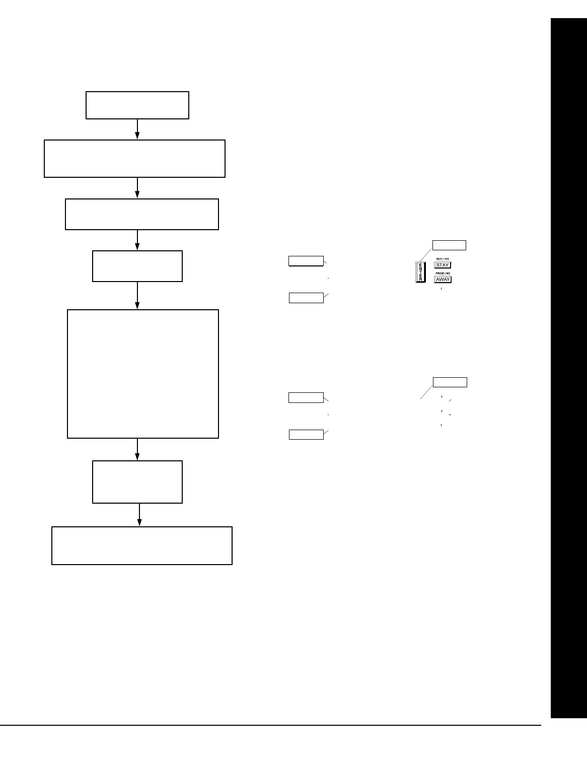
L NAPCO Security Systems X GEM-X255 Installation Instructions
WI1093C 3/04 !
Page 59
KEYPAD PROGRAMMING MODES
KEYPAD CONFIGURATION MODE
Press R button
Enter Factory Code:
11123
Configure:
•Keypad Beep ON/OFF
•Entry Sounder
•Keypad Address 01
•New Compat# 0000 **
•EZM Address 00
•Zone Response 00
•Program Control Message# 1
Press C button
(“01 OUT OF SYSTEM”)
Return Jumper JP5 * from Pins 2-3 to Pins 1-2
(“SYSTEM READY”)
Move Jumper JP5 * from Pins 1-2 to Pins 2-3
(Wait about 15 seconds: “01 OUT OF SYSTEM”)
* JP5 is located at the top-right corner of the circuit board.
** If a Compatibility Number other than “0000” is programmed, “OLD COMPAT# XXXX” is displayed.
GEM-RP1CAe2/GEM-K1CA
KEYPADS
12
43
56
7890
A
B
C
DE
F
G
NEXT/YES
PRIOR/NO
AREA
Scroll Down
Scroll Up
Exit
Yes
No
R
For "K Series" Keypads
Save
Scroll
12
43
56
7890
A
B
C
DE
F
G
NEXT/YES
PRIOR/NO
AREA
Scroll Down
Scroll Up
Exit
Yes
No
For "Classic" Keypads
Save
Scroll
Note: Default configuration shown for GEM-K1CA Keypad.
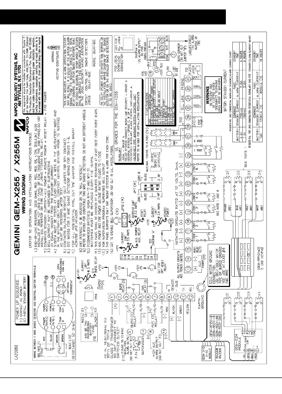
X GEM-X255 Installation Instructions L NAPCO Security Systems
WI1093C 3/04
! Page 60
GEM-X255 WIRING DIAGRAM

L NAPCO Security Systems X GEM-X255 Installation Instructions
WI1093C 3/04 !
Page 61
CP-01 Quick Reference Chart--SIA False Alarm Reduction
Feature Description Programming Address
Location
CP-01 FEATURES are enabled with one global selection in the panel. Enabled in EZ Programming
Exit Delay. Minimum allowed programmable Exit Delay time is 45 seconds. Default is 60 seconds. If an attempt is made to
change the Exit Delay time to less than 45 seconds the time will be entered as 60 seconds. The maximum programmable time
is 255 seconds. The panel uses the existing programmable by zone feature "Entry/ Exit 1" to comply with CP-01. At least one
Entry/Exit zone must be programmed for each area. The factory program enables Zone 1 as Entry/Exit and the option to pro-
gram any zone as Entry/Exit is given in the Easy Program Menu. The existing programmable Entry and Exit delay times are
also used. The factory program sets the Exit Time Delay as 60 seconds and Entry Time Delay as 30 seconds. These same
times are entered when "Enable CP-01 Features" is selected in the Easy Program Menu.
0000 (Pre-existing)
When "Enable CP-01 Limits" (Address 3905, Bit 5) is enabled, the panel will sound an audible egress sequence when it is
armed Away (with interior zones not bypassed). The keypad mini-sounder will beep once every second during the beginning
exit delay and beep rapidly the last 10 seconds of exit delay to indicate exit urgency. If the panel is armed Stay (with interior
zones bypassed) the keypad mini-sounder is silent and the exit time is double the programmed time. If "Enable CP-01 Lim-
its" (Address 3905, Bit 5) is NOT enabled, the panel will NOT sound an audible egress sequence. Note: This feature affects
the operation of "Zone ANDing" as follows: If "Enable CP-01 Limits" is enabled, any Zone in a Group will only activate an alarm
and send a report ONCE. After the Zone has reported, it will remain in the Group and may still initiate the Zone ANDing se-
quence.
3905, Bit 5 (see Note 1)
(3905 ·····6··)*
Enable Exit Delay Restart. This option allows for the following scenario before the end of the Exit Time: a violation of an en-
try/exit zone, a restore, and a second violation of an entry/exit zone restarts the Exit Time. The panel does not allow the Exit
Time to be restarted more than once. The default setting for this option is enabled. Restart is event logged.
3905, Bit 1 (see Note 1)
(3905 ·2······)*
Enable Bell on Exit Error. An Exit Error sequence is initiated if an entry/exit zone is violated at the expiration of the Exit Time.
"Exit Error" Central Station Reporting Code is located at address 0348.
3905, Bit 2 (see Note 1)
(3905 ··3·····)*
Unvacated Premises. Convert from Away to Stay based on no egress through exit door …default is enabled. (GEM-X255
panel--This feature is Automatic Interior Bypass/Easy Exit).
The panel uses the existing programmable feature "Auto Interior Bypass". This feature must be enabled in CP-01 installations.
This feature is enabled in the factory program and it is also enabled when "Enable CP-01 Features" is selected in the Easy
Program Menu.
2421, Bit 0
(2421 1 ·······)*
Report Exit Error/Recent Closing. A Recent Closing transmission is sent if an alarm occurs within two (2) minutes after the
expiration of the Exit Time. If the user number is available, it is included in the Recent Closing transmission. "Recent Close"
Central Station Reporting Code is located at address 0886. Note: Address 3905, bit 2 (Enable Bell on Exit Error) must also be
set to enable this feature.
3905, Bit 3 (see Note 4)
(3905 ···4····)*
Entry Delay. Entry Delay time is 30 second minimum, default is 30 seconds. If an attempt is made to change the Entry Delay
time to less than 30 seconds the time will be entered as 30 seconds. The maximum programmable time is 255 seconds. The
panel uses the existing programmable by zone feature "Entry/ Exit 1" to comply with CP-01. At least one Entry/Exit zone must
be programmed for each area. The factory program enables Zone 1 as Entry/Exit and the option to program any zone as En-
try/Exit is given in the Easy Program Menu. The existing programmable Entry and Exit delay times are also used. The factory
program sets the Exit Time Delay as 60 seconds and Entry Time Delay as 30 seconds. These same times are entered when
"Enable CP-01 Features" is selected in the Easy Program Menu.
0001, 0002
(Pre-existing feature)
Progress Annunciation. Entry urgency annunciation must be different than the alarm mini-sounder. Requires Keypad
Sounder on Alarm on all non-fire zones. Locations 1264, 1364, 1464, 1564, 1664, 1764, 1864, 1964, 2064, 2164.
Feature in EZ Programming
Disarm. The panel will silence the keypad entry delay tones and alarm annunciation on the first press of a keypad
digit for 2.5 seconds.
New Panel Operation
Select Burg Output for Keyfob Chirp. Normally the chirp on a keyfob arm/disarm is transmitted to the Aux. Output. Selecting
"Select Burg Output for Keyfob Chirp" causes the "Bell" to chirp instead of the Aux. on remote Arming.
The panel uses the existing programmable feature "AuxOut Chirp on Keyfob Arm/Disarm" (Address 2421 Bit 3). This fea-
ture must be programmed in a CP-01 installation if a GEM-KEYF is used in the system. The feature is selected in the factory
program and is enabled if "Enable CP-01--Enabled" is selected in the Easy Programming Menu.
2422, Bit 6 (see Note 3)
(2422 ······7·)*
Enable CP-01 Limits. When address 3905 bit 5 is enabled, three time limits are enabled as per the SIA CP-01 standards: (1)
If the Exit Delay time is programmed for less than 45 seconds, the enabled Exit Delay time will be set to 60 seconds; (2) If the
Entry Delay time is programmed for less than 30 seconds, the enabled Entry Delay time will be set to 30 seconds; and (3) If an
attempt is made to change the Abort Delay to less than 15 seconds or more than 45 seconds the time will be entered
as 30 seconds. (4) Enables Exit Delay sounder. (5) Doubles Exit Delay time when arming Stay due to Silent Exit.
3905, Bit 5 (see Note 1)
(3905 ·····6··)*
Abort Window Disarm. The panel will silence the keypad entry delay tones and alarm annunciation on the first press of a
keypad digit for 2.5 seconds. Disarming of the area within the Abort Delay period will cause a cancellation of the Central Station
alarm report.
New Panel/Keypad Feature
Abort Annunciation after Disarming. Default is enabled. If the panel is disarmed during Abort Delay, the keypad will enunci-
ate abort. "Alarm Cancelled" is displayed on keypad LCD for RP1/K1, and "C" in the 7-segment display for the RP3/K3.
New Panel/Keypad Feature
Report Cancel Window. When the system is in alarm and the user disarms in an attempt to Cancel within a maximum of 5
minutes after abort timeout, a Cancel Report will be sent. If Cancel Report is enabled by entering a cancel time, Cancel will
enunciate on the keypad if the system is disarmed during the Cancel Window. The existing programmable option Report Can-
cel Window must be programmed for at least 5 minutes in a CP-01 installation. When "Enable CP-01" Features is selected in
the easy program menu, this time is set to 7 minutes.
Address 4082
Duress Feature. The existing programmable option "Enable Global Ambush" must not be enabled in CP-01 installations. It
is not enabled in the factory program and is not enabled when Enable CP-01 Feature is selected in the Easy Program Menu.
Pre-existing feature

X GEM-X255 Installation Instructions L NAPCO Security Systems
WI1093C 3/04
! Page 62
Duress Code. The panel will not allow duplicate User Codes to be programmed. Every user program code may now be
selected as an Ambush Code for Area 1 or Area 2 by entering a _5 in the Area 1 Options or Area 2 Options respectively.
Note: Keypad(s) must be enabled for Ambush.
New Operation of the Panel
Cross Zoning. Required Option for cross zoning with either programmable time period or specified by manufacturer. De-
fault is disabled. The existing programmable by zone feature "Zone ANDing Groups" are available for the cross zoning
option required by CP-01. This feature is not enabled in the factory program and not enabled when Enable CP-01 Features
are enable in the Easy Program Menu. Cross Zone set time = one (1) minute.
Pre-existing feature
Swinger Shutdown. Zone will only trip once and will not restore automatically. "Auto-Reset" (Addresses 1219, 1319,
1419, 1519, 1619, 1719, 1819, 1919. 2019, 2119) and "Swinger Shutdown" (Addresses 1220, 1320, 1420, 1520, 1620,
1720, 1820, 1920, 2020, 2120) are disabled in order to meet the CP-01 requirement of only one alarm activation per zone
during an arming period. These features are not selected on zones 1-8 in the factory program and are removed from all
zones when "Enable CP-01 Features" is selected in the Easy Program Menu. In a SIA CP-01 installation, these options
must not be selected. Auto-Reset must be programmed for all burglary zones in a UL Installation. See the glossary entry,
"Swinger Shutdown" in this manual.
Pre-existing features
Fire Alarms. Fire Alarm Verification available option on Fire Zones. Default is disabled. The existing programmable option
"Fire Alarm Verification" is available as required by CP-01. This feature is not enabled in the factory program and not en-
abled when "Enable CP-01 Features" is selected in the Easy Program Menu.
Pre-existing feature
Call Waiting. Disable Call Waiting on 1st Attempt. Default is disabled. When enabled, the telephone number must
be programmed with *70 in front of the telephone number. The first attempt will dial with *70 (disabling call waiting).
Subsequent attempts (if first attempt is unsuccessful) will dial without *70. Note: The digits used to disable Call
Waiting may vary with location. Be sure to confirm with local telephone company. Note: Disabling Call Waiting on a
non Call-Waiting line can result in a delay in the connection to Central Station.
3905, Bit 6 (see Note 2)
(3905 ······7·)*
System Test. Test Mode for all zones, the sounders, and communicator. The "Fault Find" function (a Function Menu
selection) is enabled, and normally causes all hardwired zones to give a two second beep at the keypad(s) when any
zone is faulted or restored. As required by SIA CP-01, Fault Find is expanded with the following features when Digi-
tal Dialer Report Enter/Exit Test Mode is programmed. This option is programmed when "Enable CP-01 Feature"
is selected in the Easy Program Menu:
•When Fault Find is entered, it reports to Central Station that "Test Mode" is in progress.
•Fault Find can not be initiated from an armed panel, and all digital dialer reporting in same area is inhibited while in
Fault Find.
•Fault Find Central Station Reporting Code is located at address 0887.
•Keypad will display the following warning that the system is in Fault Find: "FAULT FIND RF SIG POWER - - "
•If a 24-hour zone is tripped and not restored during Fault Find, when the mode is exited the zone will display as
"Faulted" on the keypad display.
•When Fault Find is exited by pressing C, a Fault Find Restore Report will be sent.
Notes:
Note 1: This feature is enabled in the factory program and is enabled when "Enable CP-01 Features" is selected in the Easy Program Menu. This feature
must be enabled in CP-01-compliant installations.
Note 2: This feature is not enabled in the factory program and is not enabled when "Enable CP-01 Features" is selected in the Easy Program Menu.
Note 3: This feature is enabled in the factory program and is enabled when "Enable CP-01 Features" is selected in the Easy Programming Menu. This
feature must be programmed in CP-01-compliant installations if a GEM-KEYF is used in the system.
Note 4: This feature is programmed when "Enable CP-01 Features" is selected in the Easy Programming Menu.
•At least one Exit/Entry zone must be programmed for each area. (SIA CP-01 Specification 4.2.1)
•The GEM-PX255 control panel and at least one GEM-RP1CAe2/GEM-K1CA keypad must be installed.
•The following optional accessories support the SIA False Alarm Reduction (FAR) classification, and may be used if desired: GEM-EZOUT8, GEM-
RB3008, GEM-RM3008, GEM-EZM8, GEM-EZM4/8, GEM-RECV8/16/32, GEM-TRANS2, GEM-PIR, GEM-SMOKE, GEM-HEAT, GEM-KFOB.
•Programming at Installation may be subordinate to other UL requirements for the intended application.
•Un-vacated premises: When the system/partition is armed with AWAY button, the system will arm STAY if no exit. There must be a minimum of one
Stay/Away or Delay Stay/Away zone enrolled on the partition.
•Cross zoning is not recommended for Line security Installations nor is it to be implemented on exit / entry zones.
•There is a Communication Delay of 30 seconds in this control panel. It can be removed, or it can be increased up to 45 seconds at the option of the
end user by consulting with the Installer.
•Do not duplicate any reporting codes. This applies for all communication formats other than SIA sending automatic programmed reporting codes.
•In UL installations, Entry Delay time plus Abort Delay time (total combined times) cannot exceed 60 seconds.
•Enable Exit Delay Restart must be disabled for UL Line Security/Encryption applications.
*Illustrates the LCD display for the GEM-RP1CAe2 and GEM-K1CA keypads.
3905, Bit 4 (see Note 4)
(3905 ····5···)*
Enable Ambush Code Type in User Assignment. There are two types of Ambush Codes: (1) A 2-digit code (prefix)
that is entered immediately prior to (and as part of) the regular User Code and (2) A separate and unique User Code.
Disarming with an Ambush Code will cause a silent report to be sent to a central station. Thus, should a user be
forced to disarm, he can silently signal an emergency while appearing to be merely disarming the system. The Am-
bush Zone will automatically report when programmed to report an alarm.
3905, Bit 7 (see Note 2)
(3905 ·······8)*

L NAPCO Security Systems X GEM-X255 Installation Instructions
WI1093C 3/04 !
Page 63
GEM-X255 FACTORY DEFAULT DESCRIPTION
The Factory Program of the GEM-X255 will change with the release of the new version that complies with Security Industry Asso-
ciation False Alarm Reduction Control Panel-01 Standard (SIA FAR CP-01).
Out of Box Panel Operation (After CP-01 Changes)
The following describes the new panel factory defaults:
With this new SIA CP-01 compliant panels, the Easy Program Menu has been increased to allow several additional features to
be programmed in the Menu, rather than requiring that these features be programmed through the Direct Address programming
method. If you enter Dealer Program Mode, you will be required to first enter Easy Program Mode and answer Easy Program
Mode questions before making any needed changes to the factory program via Direct Address Programming Mode.
Once the panel is removed from its box, you have two choices: (1) Enter Dealer Program Mode in order to allow the EZ Pro-
gram Menu to appear, then answer the questions; (2) Upload the Factory Default Program to PCD-Windows, make desired
changes, and re-download this modified PCD-Windows program back to the panel.
A critical addition to the Easy Program Menu is the question “Enable CP-01 Features? Y/N”. If the answer to this question is
“No” then the following changes to the program occur:
1. All zones (96 using the keypad, 255 using the PCD-Windows software) are programmed for Priority, Selective Bypass,
Alarm Output, Auto Reset and Swinger Shutdown. Only the zones selected by the first EPM question “How many
Zones” are programmed for Area 1.
2. Default User 1 Code = "123" and it is set up to arm Area 1 and be a user program code.
3. Keypad Time/Date Display enabled.
4. All zones are programmed with report codes and as burg/fire alarm types depending on whether they were selected as
fire zones. Zones not selected as fire are burg type.
5. The reporting format is selectable in the Easy Program Mode.
6. Touch Tone with Rotary Back-up is enabled.
7. Exit Delay = 60 seconds.
8. Entry Delay 1 and 2 are both 30 seconds.
9. AC Fail Report Delay is 60 minutes.
10. Alarm and Pulse Alarm time-outs are 15 minutes.
11. Chime is set to 2 seconds.
12. Change Pulse Alarm to Cadence Alarm is enabled.
13. Auto Reset after Alarm Time-Out is enabled.
If the answer to the question “Enable CP-01 Features? Y/N” is “Yes”, then the following changes to the above program occur:
1. Auto Reset and Swinger Shutdown are removed from burg zones.
2. 2421-Bit 3 "AuxOut Chirp on Keyfob Arm/Disarm" is enabled.
3. 2421-Bit 0 "Automatic Interior Bypass/Easy Exit" is enabled.
4. 2422-Bit 6 "Select Burg Output for Keyfob Chirp" is enabled.
5. 3905-Bit 1 "Enable Exit Delay Restart" is enabled.
6. 3905-Bit 2 "Enable Bell on Exit Error" is enabled.
7. 3905-Bit 3 "Report Exit Error/Recent Closing" is enabled.
8. 3905-Bit 4 "Digital Dialer Report Enter/Exit Test Mode" is enabled.
9. 3905-Bit 5 "Enable CP-01 Limits" is enabled.
10. 2406 "Abort Delay" is changed to 30 seconds.
11. 4082 "Report Cancel Window" is set to 7 minutes .
12. 3905-Bit 7 "Enable Ambush Code Type in User Assignment" enabled.
Subsequent entering of the Dealer Program allows only a subset of the Easy Program Menu which does not include the ques-
tion “Enable CP-01 Features” and prevents the existing program from being deleted, but allows the system to be expanded.
The CP-01 Quick Reference Chart (see pages 61-62 of this manual) and the explanation of the Easy Program Question
“Enable CP-01” (above) should be reviewed before installing the panel.
Note: When 3905-5 "Enable CP-01 Limits" is enabled, the Exit Delay keypad sounder (including the Exit Urgency sound during
the final 10 seconds of the Exit Delay) is enabled.

X GEM-X255 Installation Instructions L NAPCO Security Systems
WI1093C 3/04
! Page 64
STATEMENT FOR CANADIAN MODELS
NOTICE: The Canadian Department of Communications label identifies certified equipment. This certification means
that the equipment meets certain telecommunications network protective, operational and safety requirements. The
Department does not guarantee the equipment will operate to the user’s satisfaction.
Before installing this equipment, users should ensure that it is permissible to be connected to the facilities of the local
telecommunications company. The equipment must also be installed using an acceptable method of connection. In
some cases, the company’s inside wiring associated with a single line individual service may be extended by means
of a certified connector assembly (telephone extension cord). The customer should be aware that compliance with
the above conditions may not prevent degradation of service in some situations.
Repairs to certified equipment should be made by an authorized Canadian maintenance facility designated by the
supplier. Any repairs or alterations made by the user to this equipment, or equipment malfunctions, may give the
telecommunications company cause to request the user to disconnect the equipment.
Users should ensure for their own protection that the electrical ground connections of the power utility, telephone
lines and internal metallic water pipe system, if present, are connected together. This precaution may be particularly
important in rural areas.
Caution: Users should not attempt to make such connections themselves, but should contact the appropriate electric
inspection authority, or electrician, as appropriate.
NOTICE: The ringer Equivalence Number (REN) assigned to each terminal device provides an indication of the
maximum number of terminals allowed to be connected to telephone interface. The termination of an interface may
consist of any combination of devices subject only to the requirement that the sum of the Ringer Equivalence Num-
bers of all the devices does not exceed 5.
CSA-LISTED TRANSFORMERS
The following power transformers are CSA-Listed.
Magnetic Consultants: MG1620, MG1630, MG1640, PG1620
Frost: FTC2016, FTC3016, FTC4016
Hammond: BD2F
This digital apparatus does not exceed Class A limits for radio noise emissions from digital apparatus set out in the
Radio Interference Regulations of the Canadian Department of Communications.
Le present appareil numerique n’emet pas de bruits radioelectriques les depassant les limites applicables aux appa-
reils numeriques de Ia classe A prescrites dans le Reglement sur le brouillage radioelectrique edicte par le Ministere
des Communications du Canada.

L NAPCO Security Systems X GEM-X255 Installation Instructions
WI1093C 3/04 !
Page 65
FCC STATEMENT
This equipment generates and uses radio-frequency energy and, if not installed and used properly, that is, in strict ac-
cordance with the manufacturer's instructions, may cause interference to radio and television reception. It has been type
tested and found to comply with the limits for a Class-B computing device in accordance with the specifications in Sub-
part J of Part 15 of FCC Rules, which are designed to provide reasonable protection against such interference in a resi-
dential installation.
However, there is no guarantee that interference will not occur in a particular installation. If this equipment does cause
interference to radio or television reception, which can be determined by turning the equipment off and on, the user is
encouraged to try to correct the interference by one or more of the following measures: reorient the receiving antenna;
relocate the computer with respect to the receiver; move the computer away from the receiver; plug the computer into a
different outlet so that computer and receiver are on different branch circuits.
If necessary, the user should consult the dealer or an experienced radio/television technician for additional suggestions.
The user may find the following booklet prepared by the Federal Communications Commission helpful: "How to Identify
and Resolve Radio-TV Interference Problems". This booklet is available from the U.S. Government Printing Office,
Washington, DC 20402; Stock No. 004-000-00345-4.
CAUTION: This equipment generates and uses radio-frequency energy. If not installed using conventional installation
practices for RF devices, it may cause interference to radio and television reception. It has been tested and found to
comply with the limits for a Class A computing device pursuant to Subpart B of Part 15 of FCC Rules, which are de-
signed to provide reasonable protection against such interference. However, there is no guarantee that interference will
not occur in a particular installation. If it has been found to cause interference to radio or television reception, which can
be determined by removing and reapplying AC and battery power to the equipment, the installer should try to correct
the interference by one or more of the following measures: reorient the receiving antenna; connect the power trans-
former to a different outlet so that the control panel and receiver are on different branch circuits; relocate the control
panel with respect to the receiver.

X GEM-X255 Installation Instructions L NAPCO Security Systems
WI1093C 3/04
! Page 66
Notes:

L NAPCO Security Systems X GEM-X255 Installation Instructions
WI1093C 3/04 !
Page 67
Notes:

X GEM-X255 Installation Instructions L NAPCO Security Systems
WI1093C 3/04
! Page 68
NAPCO SECURITY SYSTEMS, INC. (NAPCO) warrants
its products to be free from manufacturing defects in ma-
terials and workmanship for thirty-six months following
the date of manufacture. NAPCO will, within said period,
at its option, repair or replace any product failing to oper-
ate correctly without charge to the original purchaser or
user.
This warranty shall not apply to any equipment, or any
part thereof, which has been repaired by others, improp-
erly installed, improperly used, abused, altered, dam-
aged, subjected to acts of God, or on which any serial
numbers have been altered, defaced or removed. Seller
will not be responsible for any dismantling or reinstallation
charges.
THERE ARE NO WARRANTIES, EXPRESS OR IM-
PLIED, WHICH EXTEND BEYOND THE DESCRIPTION
ON THE FACE HEREOF. THERE IS NO EXPRESS OR
IMPLIED WARRANTY OF MERCHANTABILITY OR A
WARRANTY OF FITNESS FOR A PARTICULAR PUR-
POSE. ADDITIONALLY, THIS WARRANTY IS IN LIEU
OF ALL OTHER OBLIGATIONS OR LIABILITIES ON
THE PART OF NAPCO.
Any action for breach of warranty, including but not lim-
ited to any implied warranty of merchantability, must be
brought within the six months following the end of the
warranty period.
IN NO CASE SHALL NAPCO BE LIABLE TO ANYONE
FOR ANY CONSEQUENTIAL OR INCIDENTAL DAM-
AGES FOR BREACH OF THIS OR ANY OTHER WAR-
RANTY, EXPRESS OR IMPLIED, EVEN IF THE LOSS
OR DAMAGE IS CAUSED BY THE SELLER'S OWN
NEGLIGENCE OR FAULT.
In case of defect, contact the security professional who
installed and maintains your security system. In order to
exercise the warranty, the product must be returned by
the security professional, shipping costs prepaid and in-
sured to NAPCO. After repair or replacement, NAPCO
assumes the cost of returning products under warranty.
NAPCO shall have no obligation under this warranty, or
otherwise, if the product has been repaired by others, im-
properly installed, improperly used, abused, altered, dam-
aged, subjected to accident, nuisance, flood, fire or acts
of God, or on which any serial numbers have been al-
tered, defaced or removed. NAPCO will not be responsi-
ble for any dismantling, reassembly or reinstallation
charges.
This warranty contains the entire warranty. It is the sole
warranty and any prior agreements or representations,
whether oral or written, are either merged herein or are
expressly cancelled. NAPCO neither assumes, nor au-
thorizes any other person purporting to act on its behalf to
modify, to change, or to assume for it, any other warranty
or liability concerning its products.
In no event shall NAPCO be liable for an amount in ex-
cess of NAPCO's original selling price of the product, for
any loss or damage, whether direct, indirect, incidental,
consequential, or otherwise arising out of any failure of
the product. Seller's warranty, as hereinabove set forth,
shall not be enlarged, diminished or affected by and no
obligation or liability shall arise or grow out of Seller's ren-
dering of technical advice or service in connection with
Buyer's order of the goods furnished hereunder.
NAPCO RECOMMENDS THAT THE ENTIRE SYSTEM
BE COMPLETELY TESTED WEEKLY.
Warning: Despite frequent testing, and due to, but not
limited to, any or all of the following; criminal tampering,
electrical or communications disruption, it is possible for
the system to fail to perform as expected. NAPCO does
not represent that the product/system may not be com-
promised or circumvented; or that the product or system
will prevent any personal injury or property loss by bur-
glary, robbery, fire or otherwise; nor that the product or
system will in all cases provide adequate warning or pro-
tection. A properly installed and maintained alarm may
only reduce risk of burglary, robbery, fire or otherwise but
it is not insurance or a guarantee that these events will
not occur. CONSEQUENTLY, SELLER SHALL HAVE NO
LIABILITY FOR ANY PERSONAL INJURY, PROPERTY
DAMAGE, OR OTHER LOSS BASED ON A CLAIM THE
PRODUCT FAILED TO GIVE WARNING. Therefore, the
installer should in turn advise the consumer to take any
and all precautions for his or her safety including, but not
limited to, fleeing the premises and calling police or fire
department, in order to mitigate the possibilities of harm
and/or damage.
NAPCO is not an insurer of either the property or safety
of the user's family or employees, and limits its liability for
any loss or damage including incidental or consequential
damages to NAPCO's original selling price of the product
regardless of the cause of such loss or damage.
Some states do not allow limitations on how long an im-
plied warranty lasts or do not allow the exclusion or limita-
tion of incidental or consequential damages, or differenti-
ate in their treatment of limitations of liability for ordinary
or gross negligence, so the above limitations or exclu-
sions may not apply to you. This Warranty gives you spe-
cific legal rights and you may also have other rights which
vary from state to state.
NAPCO LIMITED WARRANTY
