ELECTRIC SCOOTER GIO Assembly Instructions
User Manual: ELECTRIC SCOOTER
Open the PDF directly: View PDF ![]() .
.
Page Count: 14
GIO Electric Scooter Assembly Instructions
GIO Electric Scooter Assembly Instructions
06 Italia 500w Electric Scooter Assembly Manual.indd 1 2/7/2014 11:24:55 PM

06 Italia 500w Electric Scooter Assembly Manual.indd 2 2/7/2014 11:24:55 PM
GIO Electric Scooter Assembly Instructions
Page | 1
DO NOT RETURN TO STORE!
Illustrations may not be exact appearance of actual product.
Please contact GIO Customer Care Center @ 1-877-274-0480 for any concern or/and inquiry.
BEFORE ASSEMBLING YOUR GIO ELECTRIC SCOOTER, PLEASE BE SURE YOU HAVE ALL
NECESSARY PARTS.
PLEASE FOLLOW PROPER ASSEMBLY INSTRUCTIONS. IF YOU DO NOT HAVE THE PROPER
PARTS NECESSARY TO ASSEMBLE YOUR SCOOTER, PLEASE DO NOT RETURN THE UNIT TO
THE ORIGINAL PLACE OF PURCHASE
CALL GIO ELECTRIC CUSTOMER SERVICE AT: 1-877-274-0480.
1
06 Italia 500w Electric Scooter Assembly Manual.indd 1 2/7/2014 11:24:55 PM

Page | 2
1Table of Contents
Contents of the box: ..................................................................................................................................... 3
Tools requirement: ....................................................................................................................................... 3
Step 1: Uncrate the scooter and place it on a main kick stand. ................................................................... 3
Step 2: Front wheel installation (Image 1): ................................................................................................... 3
Step 3: Mirrors installation (Image 3): .......................................................................................................... 5
Step 4: Pedals installation: ............................................................................................................................ 5
Option 1: Attached by bolt ....................................................................................................................... 6
Option 2: Attached by snapping – spring ball ........................................................................................... 6
Step 5: Rear storage trunk installation ......................................................................................................... 7
Step 6: Front shocks cover installation (applicable to Italia 500w scooter only): ........................................ 8
Step 7: Battery connection: .......................................................................................................................... 9
Option 1: Lead Acid Battery ...................................................................................................................... 9
Option 2: Lithium Battery ....................................................................................................................... 10
Step 8: Pre-ride adjustment ........................................................................................................................ 10
2
06 Italia 500w Electric Scooter Assembly Manual.indd 2 2/7/2014 11:24:55 PM

GIO Electric Scooter Assembly Instructions
Page | 3
2Contents of the box:
1. Scooter.
2. Rear storage trunk
3. Charger.
4. Rain Cover.
5. U shape lock
6. Mirrors.
7. Pedal cranks.
8. Foot pegs (pedals).
9. Hardware bag (inside the rear storage trunk).
10. Front axle (attached to the front forks).
11. User’s Manual
3Tools requirement:
Utility knife
Wrench: 15mm or 19/32” + 14mm or 17/32” + 12mm or 15/32” + 10mm or 3/8” (you
might use adjustable wrench as well).
Philips and flat screwdrivers
Hammer
Step 1: Uncrate the scooter and place it on a main kick stand.
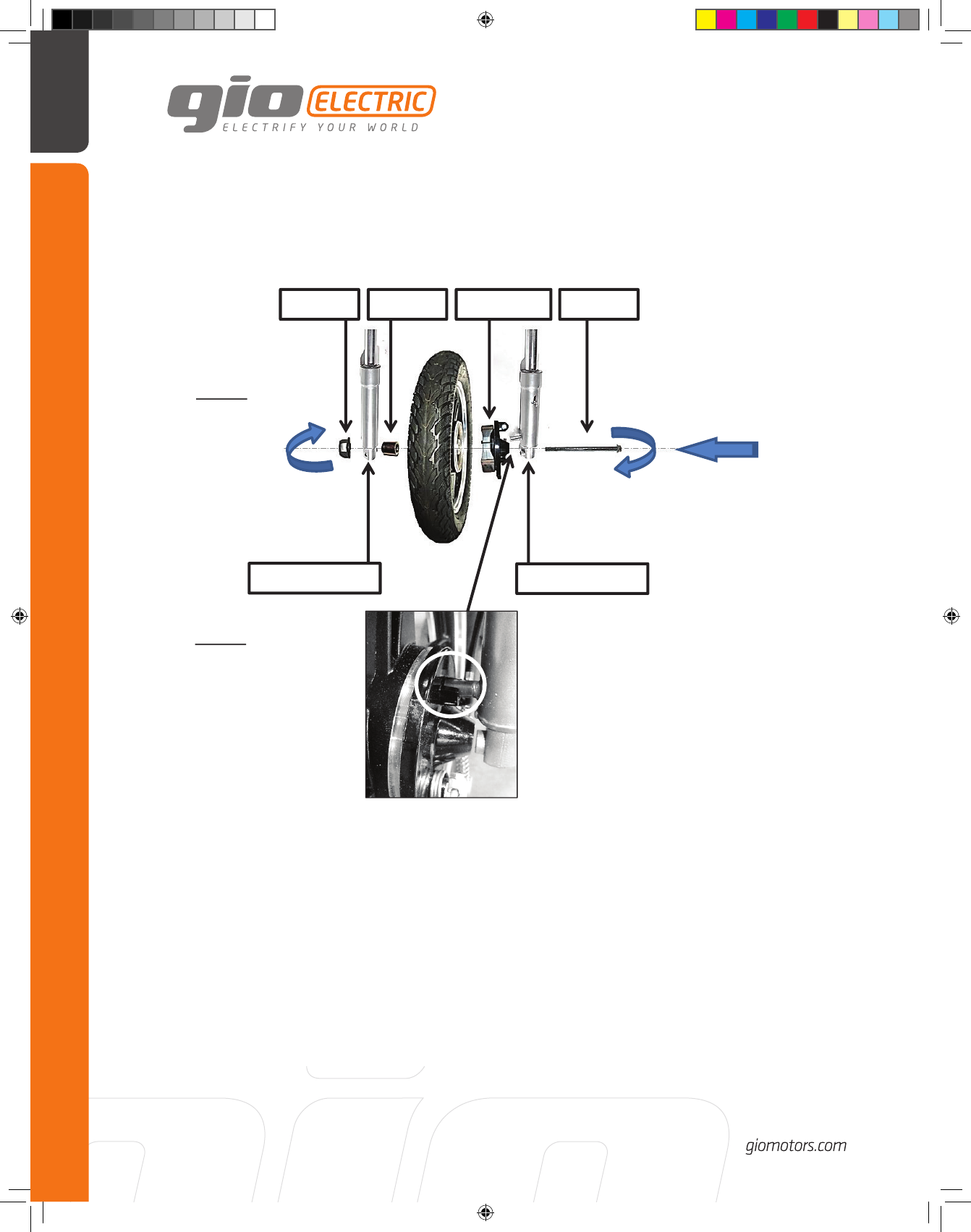
Step 2: Front wheel installation (Image 1):
1. Remove the wooden stand and dispose plastic nut attached to the axle. Use metal
nut included in the hardware bag.
2. Slide the brake shoe (brake drum) assembly into the wheel. Then slide this
assembly between the forks making sure that you position the brake assembly
correctly so that it fits directly into the lug on the left fork tube (Image 2). This
ensures that the brake hub will not spin when the brakes are applied. Then slide the
axle bolt through the left fork and into the brake hub and right through the wheel.
Now it must go through the spacer (attached to the right side handlebar or inside
the hardware bag) that goes on the opposite (right) side between the wheel and
the right fork. Once this is correct, you may carefully tap the bolt (front axle) the
rest of the way through the fork and attach the nut.
3
06 Italia 500w Electric Scooter Assembly Manual.indd 3 2/7/2014 11:24:56 PM
Page | 4
Nut
Spacer
Brake Shoe
Bolt
Right side fork
Left side fork
Image: 1
Image: 2
4
06 Italia 500w Electric Scooter Assembly Manual.indd 4 2/7/2014 11:24:56 PM
GIO Electric Scooter Assembly Instructions
Page | 5
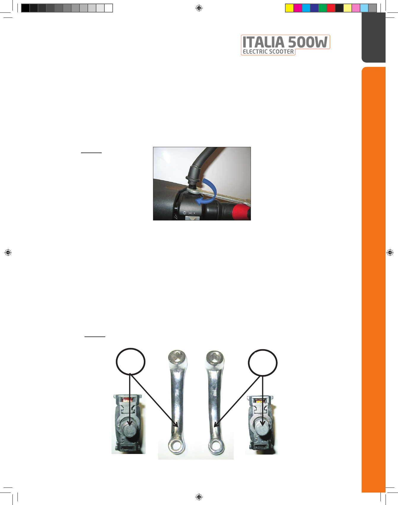
4Step 3: Mirrors installation (Image 3):
Install left and right mirrors making sure they are properly aligned and tightened
with a wrench, while being particularly careful not to scratch the body work. Then
slide the rubber escutcheon (decorative grommet) down to cover the bolt, and
adjust the mirrors so you can see as much as possible behind you. Then
remember to use them constantly.
5Step 4: Pedals installation:
Most laws currently state that in order to be classified as a “Power Assisted Bicycle” or
“e-bike” and thereby not requiring a driver’s license, motorcycle plates, or insurance, e-
bikes must have pedals. So they should be assembled and usable at any time. Each one
has its own thread (left or right hand rotation – stamped on the pedal and crank… see
image 4) so they should be assembled accordantly and always (depending upon
interpretation of the law) either bolted (image 5) or snapped (image 6) on to the pedal
shaft.
Foot pegs (pedals) are foldable. In order to fold them, simply push the pedal inside and
fold. To unfold the pedal, simply pull it back to original position.
Image: 3
Image: 4
L
R
5
06 Italia 500w Electric Scooter Assembly Manual.indd 5 2/7/2014 11:24:56 PM

Page | 6
Option 1: Attached by bolt (Image 5):
Option 2: Attached by spring ball (Image 5):
Option 2: Attached by snapping – spring ball (Image 6):
Image: 5
Pedal shaft
Pedal crank
Bolt
Pedal
Pedal shaft
Pedal crank
Pedal
Image: 6
Make sure the spring ball on the shaft aligned with the hole on the crank
6
06 Italia 500w Electric Scooter Assembly Manual.indd 6 2/7/2014 11:24:56 PM
GIO Electric Scooter Assembly Instructions
Page | 7
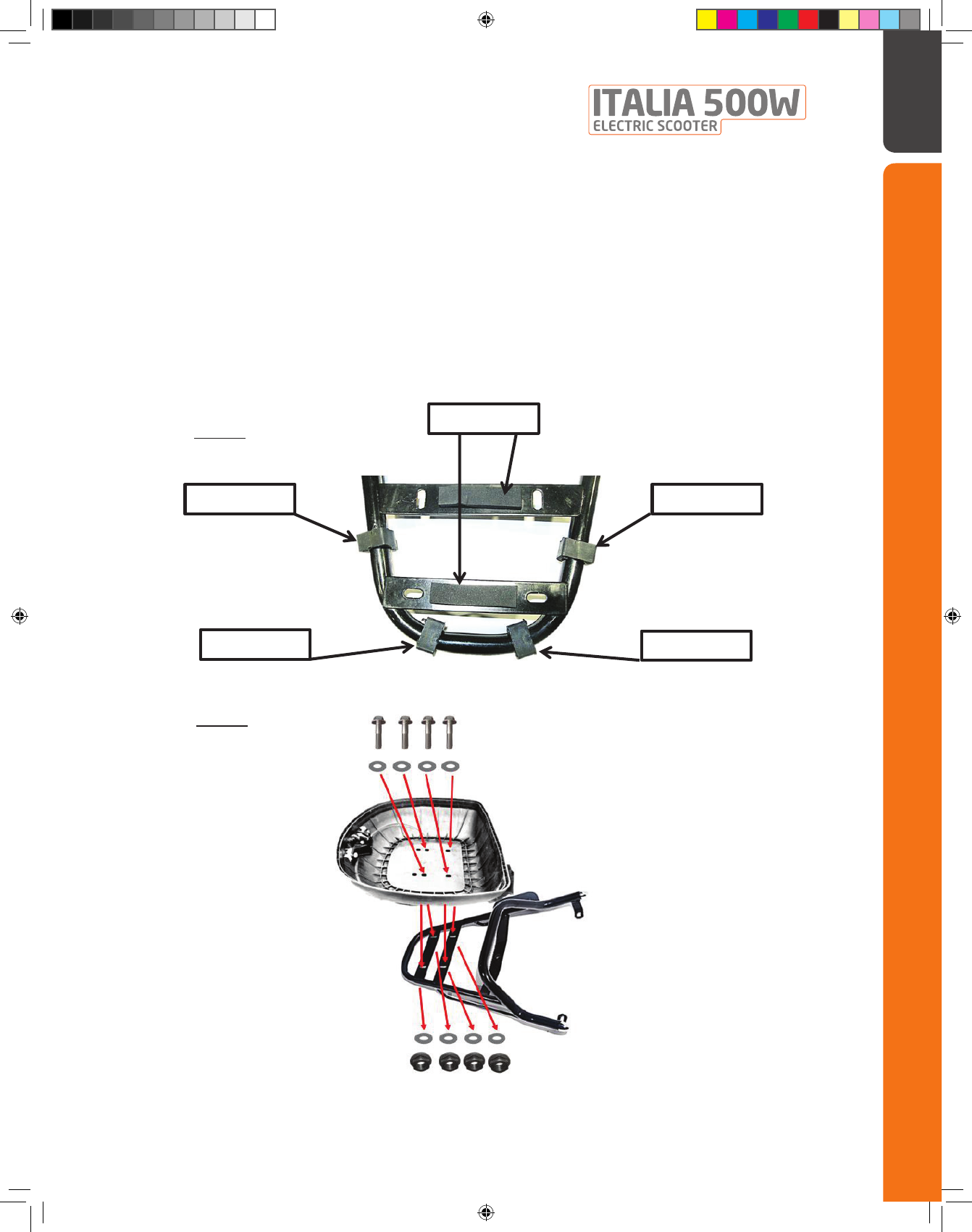
6 Step 5: Rear storage trunk installation
Locate the supplied 4 bolts and 4 nuts, 8 flat washers, 2 flat rubber strips, and 4
round grommets with split ends. The split grommets go on the mount rack
(image 7) with the flat side up. The two flat rubber strips go between the
mounting bolts on the flat sections between them on the mount rack (image 7).
Set the storage box on top of the rack and slide all 4 bolts through the mounting
holes making sure you use one washer on each (image 8). From below, put one
washer and one nut on each bolt and tighten appropriately.
Grommet
Grommet
Grommet
Grommet
Rubber strip
Image: 7
Image: 8
7
06 Italia 500w Electric Scooter Assembly Manual.indd 7 2/7/2014 11:24:56 PM

Page | 8
7 Step 6: Front shocks cover installation (applicable to Italia 500w
scooter only):
Locate the supplied 2 covers located on the front hook and 2 bolts inside the
hardware bag for the front shock cover. Install the covers as shown on image 9.
Front Shocks
Front Shock
Covers
Image: 9
8
06 Italia 500w Electric Scooter Assembly Manual.indd 8 2/7/2014 11:24:56 PM
GIO Electric Scooter Assembly Instructions
Page | 9
8 Step 7: Battery connection:
Most scooters arrive while batteries are disconnected. In order of being able to
use the scooter electrically, batteries should be connected. Below are the
instructions on how the batteries should be connected on each individual model.
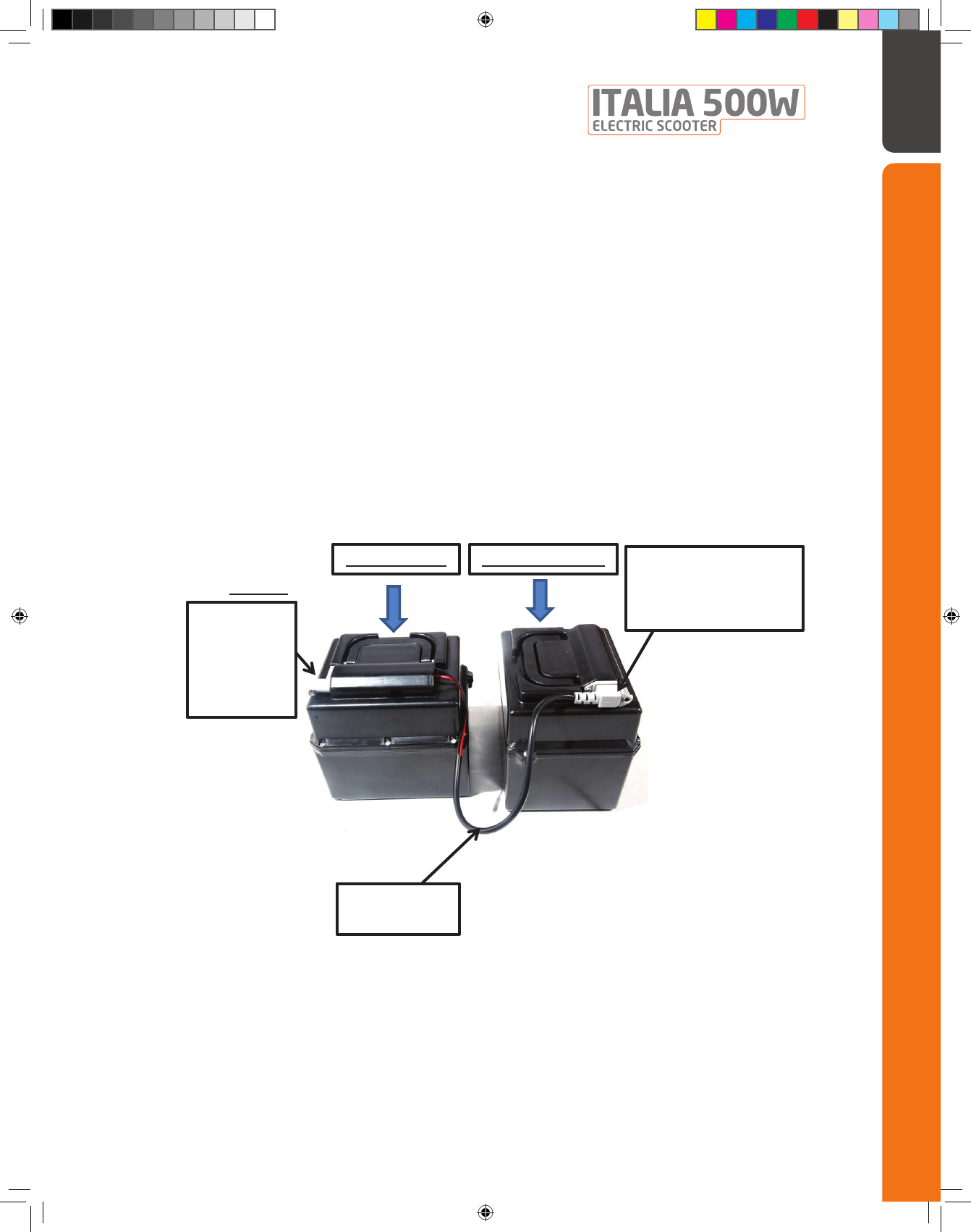
Option 1: Lead Acid Battery (image 10):
1. Lead Acid scooter contains 2 battery packs that each pack contains 2
batteries. The scooter operated by 4 - 12V batteries in total.
Top battery pack must be connected to the bottom battery pack in order to
have 48V power, and the main power cord of the scooter needs to be
connected to the plug on the top pack.
Battery
connection cord
Battery connection plug
*Make sure the plug is
connected properly all
the way in
Main power
cord plug –
connects
between
scooter and
the battery
Image: 10
Top battery pack
Bottom battery pack
9
06 Italia 500w Electric Scooter Assembly Manual.indd 9 2/7/2014 11:24:57 PM
Page | 10
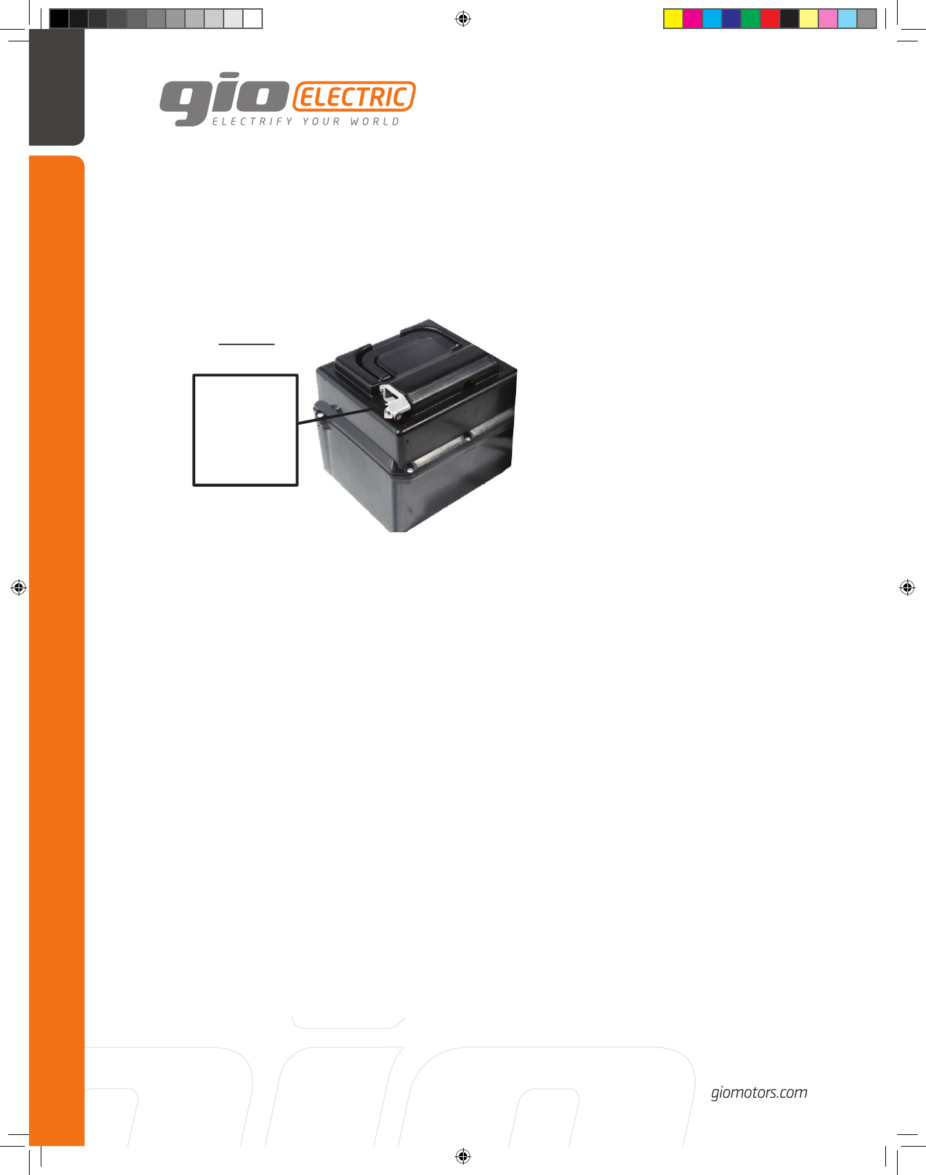
Option 2: Lithium Battery (image 11):
Lithium battery contains 1 pack of 60V or 48V Lithium battery.
Step 8: Pre-ride adjustment – please refer to owner’s manual
Main power
cord plug –
connects
between
scooter and
the battery
Image: 11
10
06 Italia 500w Electric Scooter Assembly Manual.indd 10 2/7/2014 11:24:57 PM

GIO Electric Scooter Assembly Instructions
Page | 19
13 Notes:
11
06 Italia 500w Electric Scooter Assembly Manual.indd 11 2/7/2014 11:24:57 PM
GIO Electric Scooter Assembly Instructions
06 Italia 500w Electric Scooter Assembly Manual.indd 12 2/7/2014 11:25:00 PM
