Description GM8136 ISP Tuning Tool User Guide V1.3
User Manual:
Open the PDF directly: View PDF ![]() .
.
Page Count: 53

GM8136
ISP TUNING TOOL
User Guide
Rev.: 1.3
Issue Date: December 2014

REVISION HISTORY
GM8136 ISP Tuning Tool User Guide
Date
Rev.
From
To
Dec. 2014
1.3
-
Original
Copyright © 2014 Grain Media, Inc.
All Rights Reserved.
Printed in Taiwan 2014
Grain Media and the Grain Media Logo are trademarks of Grain Media, Inc. in Taiwan and/or other countries.
Other company, product and service names may be trademarks or service marks of others.
All information contained in this document is subject to change without notice. The products described in this document are NOT intended for use in
implantation or other life support application where malfunction may result in injury or death to persons . The information contained in this document
does not affect or change Grain Media’s product specification or warranties. Nothing in this document shall operate as an express or implied license
or indemnity under the intellectual property rights of Grain Media or third parties. All information contained in this document was obtained in specific
environments, and is presented as an illustration. The results obtained in other operating environments may vary.
THE INFORMATION CONTAINED IN THIS DOCUMENT IS PROVIDED ON AN “AS IS” BASIS. In no event will Grain Media be liable for damages
arising directly or indirectly from any use of the information contained in this document.
Grain Media, Inc.
5F, No. 5, Li-Hsin Road III, Hsinchu Science Park, Hsinchu City, Taiwan 300, R.O.C.
Grain Media's home page can be found at:
http://www.grain-media.com

GM8136 ISP Tuning Tool User Guide
www.grain-media.com
i
TABLE OF CONTENTS
Chapter 1 Introduction ............................................................................................................................ 1
1.1 Description ................................................................................................................. 2
1.2 Definition..................................................................................................................... 2
1.3 Installation .................................................................................................................. 2
Chapter 2 Getting Started ...................................................................................................................... 3
2.1 GUI Introduction ......................................................................................................... 4
2.1.1 Main Menu ..................................................................................................... 5
2.1.2 Image Information ......................................................................................... 6
2.1.3 Image Quality Analysis Tools......................................................................... 6
2.1.4 Image Display ................................................................................................ 6
2.2 Calibration .................................................................................................................. 7
2.2.1 Device Connection ........................................................................................ 7
2.2.2 Start Calibration ............................................................................................. 9
2.3 Saving Configure ........................................................................................................ 9
Chapter 3 Function Manual .................................................................................................................. 11
3.1 Image Analysis ......................................................................................................... 12
3.1.1 Level Meter .................................................................................................. 12
3.1.2 Average Info ................................................................................................ 13
3.1.3 Vector Scope ............................................................................................... 13
3.1.4 Spatial Noise ............................................................................................... 14
3.1.5 Histogram .................................................................................................... 15
3.1.6 Vignetting..................................................................................................... 16
3.1.7 Temporal Noise ........................................................................................... 17
3.2 Image Calibration ..................................................................................................... 18
3.2.1 User Setting ................................................................................................. 18
3.2.2 Color OB ...................................................................................................... 20
3.2.3 Lens Shading .............................................................................................. 22
3.2.4 Dynamic Range ........................................................................................... 26
3.2.5 Gamma Adjustment ..................................................................................... 32

GM8136 ISP Tuning Tool User Guide
www.grain-media.com
ii
3.2.6 Contrast Enhancement................................................................................ 34
3.2.7 Color Correction .......................................................................................... 35
3.2.8 Color Mapping ............................................................................................. 38
3.2.9 Chroma Suppression................................................................................... 40
3.2.10 Color Interpolation ....................................................................................... 41
3.2.11 Sharpness ................................................................................................... 42
3.2.12 Auto Exposure ............................................................................................. 43
3.2.13 Auto White Balance ..................................................................................... 44
3.2.14 Auto Adjustment .......................................................................................... 46


GM8136 ISP Tuning Tool User Guide
www.grain-media.com
2
1.1 Description
This tuning tool is a highly integrated image adjustment and sensor calibration tool. Users can use this tool
to perform the image quality analysis, sensor calibration, and image preferring adjustment. After tuning
and calibration are completed, the resulting parameters can be saved as the configure file of the Grain
Media Linux ISP driver. The calibration results will be the default settings after GM camera device was
booted.
1.2 Definition
A, CWF, D65
CIE standard illuminants used in light box
ColorChecker
X-Rite ColorChecker Classic chart
GM_IspTool
ISP image quality tuning tool provided by Grain Media.
Grayscale
Gray scale charts such as ITE Gray Scale, Kodak Gray Scale, and so on
isp_demon
A Linux server application provided by Grain Media
It is used to serve commands that come from GM_IspTool.
ROI
Region of interest
SDK
Software development kit provided by Grain Media.
Sensor Configure File
The ISP configure file which was assigned within the booting procedures to load the
default parameters for the specified sensor.
1.3 Installation
This tuning tool can run under Windows 98/2000/XP/7. To install this tool, please double-click on the
“Setup” icon in the CD folder. This starts the installation wizard. After installation, a shortcut to
GM_IspTool, will be placed on the desktop, and an entry “Grain Media” is created on the Windows Start
Menu.
From the Start/Grain Media entry, users can run GM_IspTool or uninstall the software.

GM8136 ISP Tuning Tool User Guide
www.grain-media.com
4
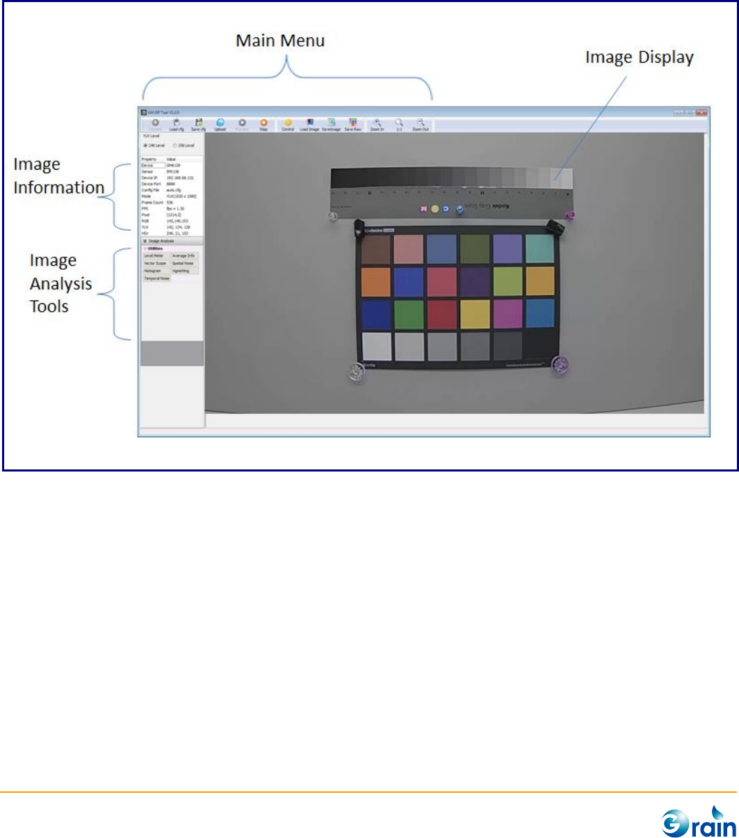
2.1 GUI Introduction
Below is the main window of GM_Isp tool.
GM8136 ISP Tuning Tool User Guide
www.grain-media.com
5
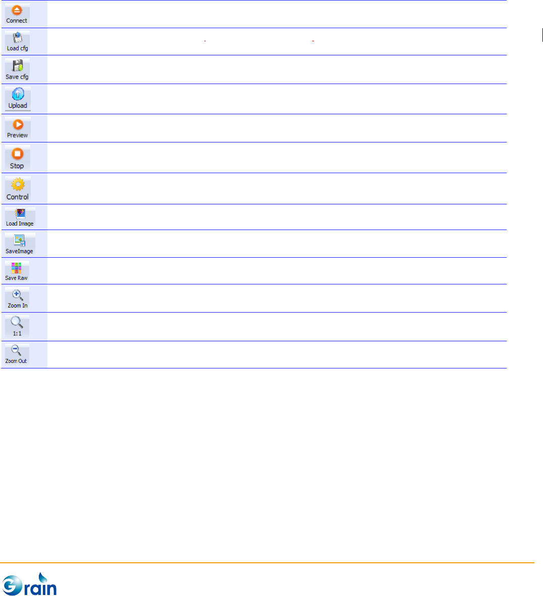
2.1.1 Main Menu
Main Menu provides the interface for involving the main functions of GM_IspTool. These buttons are
explained as follows:
GM_IspTool is designed for all GM camera devices. This button is used to select the target device and try
creating the connection to the target device.
Load the target configuration file which saves the calibration result and apply all parameters to the device. Please
note that the tool will check if the configuration matches to the target device.
Save calibration will result to the configuration file of the destination.
After calibration, users can upload the current configuration into the device to apply all new parameters.
Start image preview process. This process will be auto-created after connecting to the target device.
Pause the preview process
Involve the image calibration window
Load image for off-line image analysis
Save the current image frame to file
Save raw data of the current image frame to file
Scale up the current displayed image. The maximum scaling ration is 400% for both width and height.
Reset the scaled image to 1:1.
Scale down the current displayed image. The minimum scaling ration is 15% for both width and height.

GM8136 ISP Tuning Tool User Guide
www.grain-media.com
6
2.1.2 Image Information
Image information includes:
Device
Current target GM camera device
Sensor
Current sensor device
Device IP
IP address of the target device
Device Port
isp_demon port No. of the target device
Config File
Current target configuration file
Mode
Data type and resolution
Frame Count
Count of frames starting from the connected device
FPS
Frame rate of the preview process
Pixel
The coordinates of a pixel where cursor points to
RGB
RGB value of a pixel where cursor points to
YUV
YUV value of a pixel where cursor points to
HSV
HSV value of a pixel where cursor points to
Zoom
Show current scaling ration
2.1.3 Image Quality Analysis Tools
This area contains several helpful image quality analysis tools and will be explained in the following
sections.
2.1.4 Image Display
This area shows the real-time image captured from the target device. Users can immediately check the
tuning result and perform the image quality analysis by using the real-time image. Also, GM_IspTool can
directly grab the raw image as the calibration material for saving time.
GM8136 ISP Tuning Tool User Guide
www.grain-media.com
7
2.2 Calibration
To do calibration, users first need to connect GM_IspTool to the target device.
2.2.1 Device Connection
The following procedures are used to connect the GM device (Ex.: GM8139) to GM_IspTool:
1. Prepare the target device
(1) Add the module parameters, “usr_func=1 usr_param=1”, before inserting vpd_slave.ko.
Ex.: /sbin/insmod /lib/modules/vpd_slave.ko vpslv_dbglevel=0 ddr0_sz=0 ddr1_sz=0
config_path="/mnt/mtd/" usr_func=1 usr_param=1
(2) Boot GM8139 and run ispd_demon with the following command:
isp_demon [PortNo], PortNo is optional, the default is 8888.
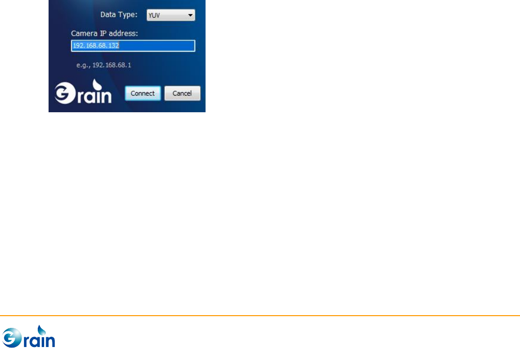
2. Connect GM_IspTool to the target device
(1) Run GM_IspTool, and the connection dialog will be shown. Select Data Type (YUV for RAW data
and Stream for encoded data) and assign the IP address of the target device (e.g.,
192.168.0.105). In the popped dialog, click “Connect”.
(2) When the connection is successful, tool will automatically download the sensor configuration file
from the device and show the file as “auto.cfg”. Users can also click on the “load cfg” button to
load the prepared sensor configuration file from PC as the target configuration file.
GM8136 ISP Tuning Tool User Guide
www.grain-media.com
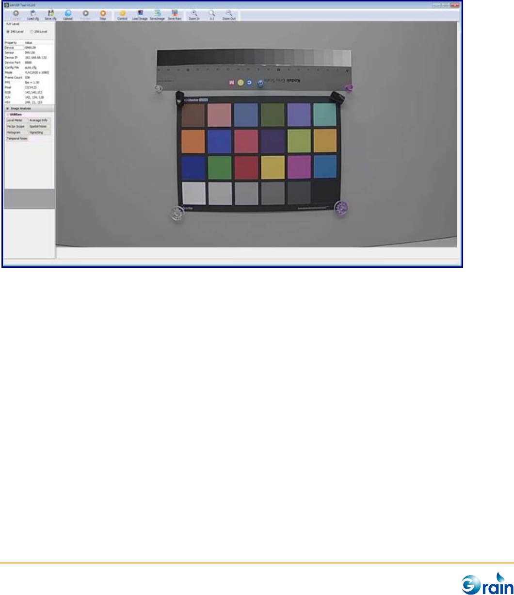
8
If the connection was created successfully, the real-time image will be displayed in the Image Display area
as follows:
If the connection failed, an error message, “ISP device connect fail”, will pop up. Users can confirm the IP
address and Ethernet wire and retry again.
GM8136 ISP Tuning Tool User Guide
www.grain-media.com
9
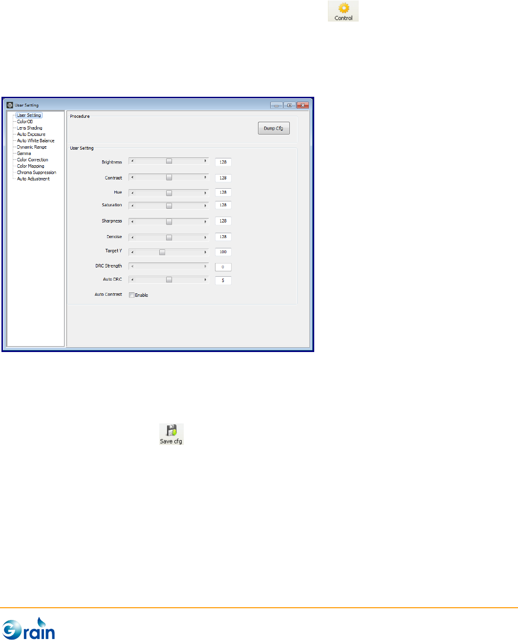
2.2.2 Start Calibration
After the device is connected to GM_IspTool, the “Control” button will be enabled. Clicking on this
button will involve the configure window. This window contains all pages for image adjustment and sensor
calibration. By clicking on the “function list” at the left side, the corresponding page will be shown in the
main panel at the right side.
2.3 Saving Configure
After finishing calibration, users can save the calibration results in two ways:
1. Click the “Save Cfg” button on the menu bar, it will save the full configure including the changed
or unchanged items.
2. Click the “Dump Cfg” button provided on the current page, it will only save the parameters within the
current page. Users can manually revise the sensor configuration file according to the output
parameters.

GM8136 ISP Tuning Tool User Guide
www.grain-media.com
12
3.1 Image Analysis
GM_IspTool provide several useful image analysis tools for users to check the image quality. To use these
utilities, users should mark ROI first and then click the “function” button. The image analysis results will be
displayed on the popped windows. If the image was changed or ROI was re-marked, the analysis results
will be automatically refreshed.
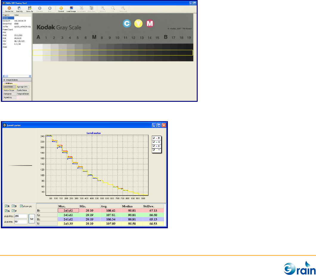
3.1.1 Level Meter
This function was used to analyze the density level of the gray scale. To use “Level Meter”, users should
first draw ROI on the target image; then, click the “Level Meter” button on the Image Analysis panel.
Level Meter chart will be shown as the following:
GM8136 ISP Tuning Tool User Guide
www.grain-media.com
13
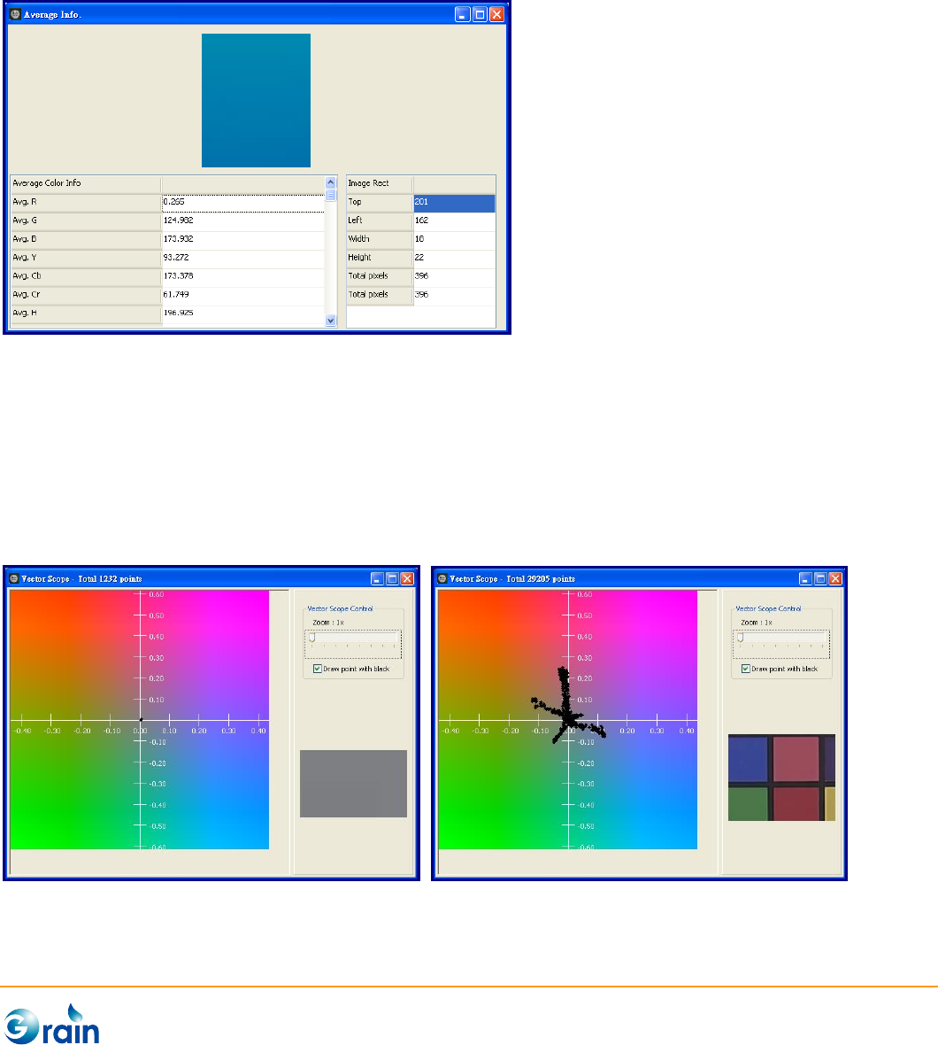
3.1.2 Average Info
This function helps users to get the average color information within ROI. The color information includes
(R, G, B), (Y, Cb, Cr), (H, S, V), and so on.
3.1.3 Vector Scope
The Vector Scope function helps users to check the AWB results. If AWB is correct, the sampled pixels will
be located on the central area (As the left picture). Otherwise, the pixels will apart from the center (As
right picture).
GM8136 ISP Tuning Tool User Guide
www.grain-media.com
14
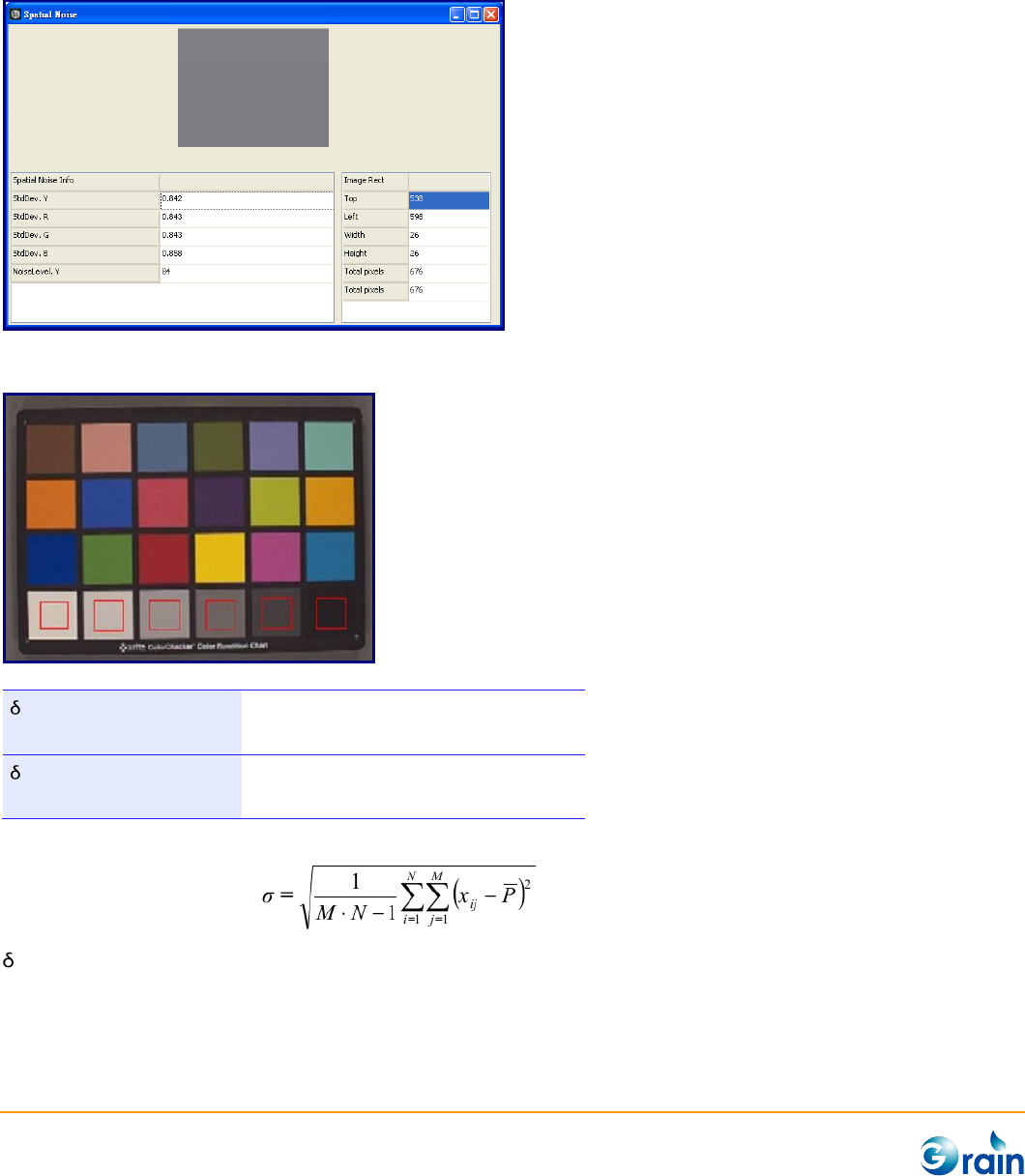
3.1.4 Spatial Noise
This function helps users to measure the noise level of the image by calculating the standard deviation.
A reference minimum requirement for the spatial noise is :
max < 2.7
Light intensity: 30lux
Color temperature: 3000k and 5000k
max < 1.7
Light intensity: 300lux
Color temperature: 3000k and 5000k
(Skype Hardware Certification Specification for allSkype Video Devices V5.0)
Where standard deviation
max is the max. standard deviation of the six grayscale patches.
GM8136 ISP Tuning Tool User Guide
www.grain-media.com
15
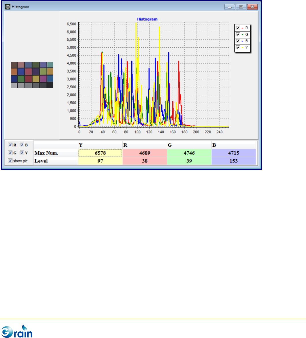
3.1.5 Histogram
This function draws the histogram graph of ROI. Usually, ROI should be set to full image to get the full
histogram information of an image.
GM8136 ISP Tuning Tool User Guide
www.grain-media.com
16
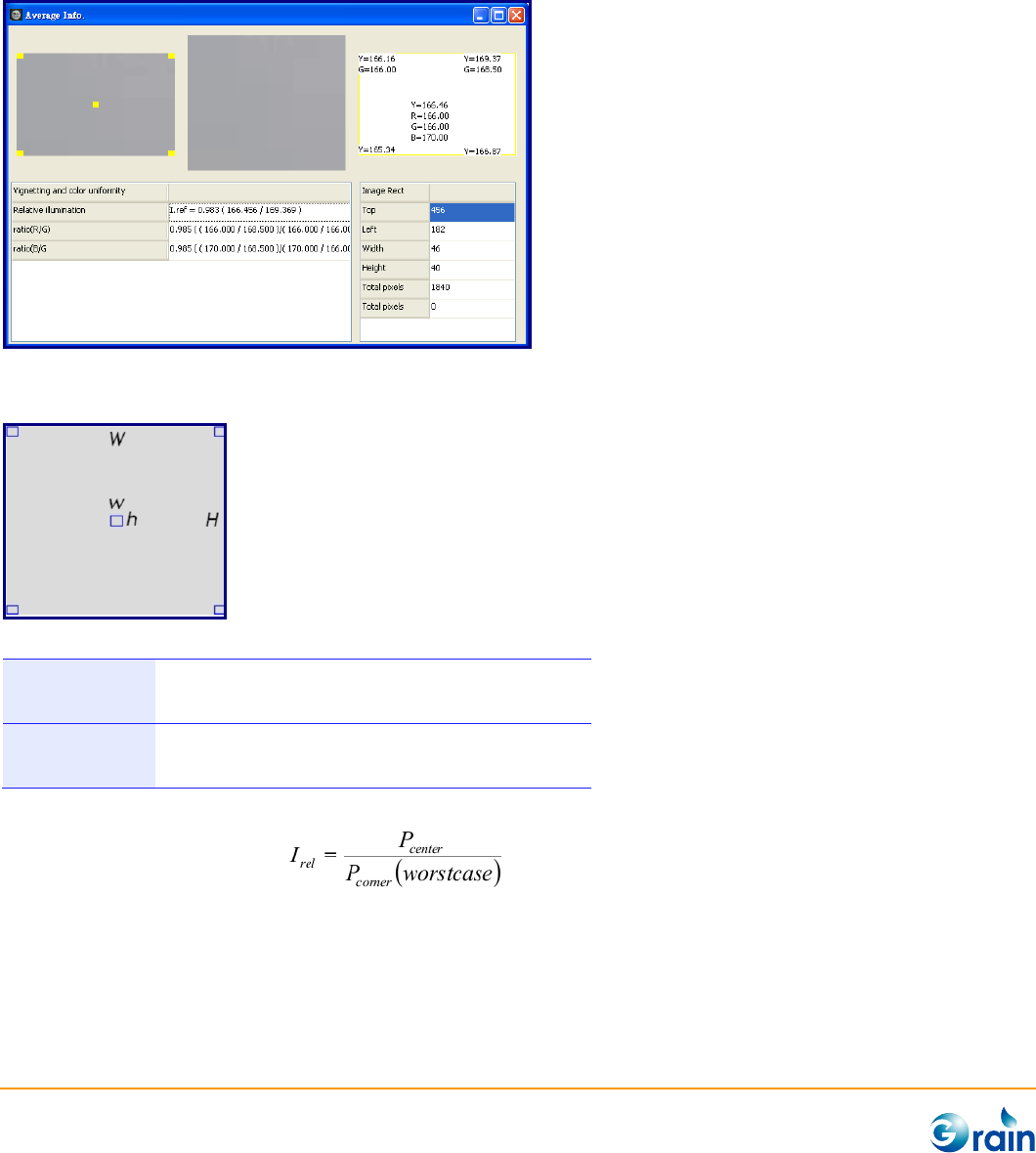
3.1.6 Vignetting
This function helps users to check if the frame will not be significantly darker nor of different colors to the
center. On the other hand, users should check the color uniformity after the lens shading correction.
A reference minimum requirement for light fall off is:
0.9 ≤ Irel ≤ 1.4
Light intensity: 30lux
Color temperature: 3000k and 5000k
0.9 ≤ Irel ≤ 1.4
Light intensity: 300lux
Color temperature: 3000k and 5000k
(Skype Hardware Certification Specification for allSkype Video Devices V5.0)
Where relative illumination
and Pcenter is the average grayscale pixel value of the center of an image and Pcorner is the average
grayscale pixel value of one of the corners.
GM8136 ISP Tuning Tool User Guide
www.grain-media.com
17
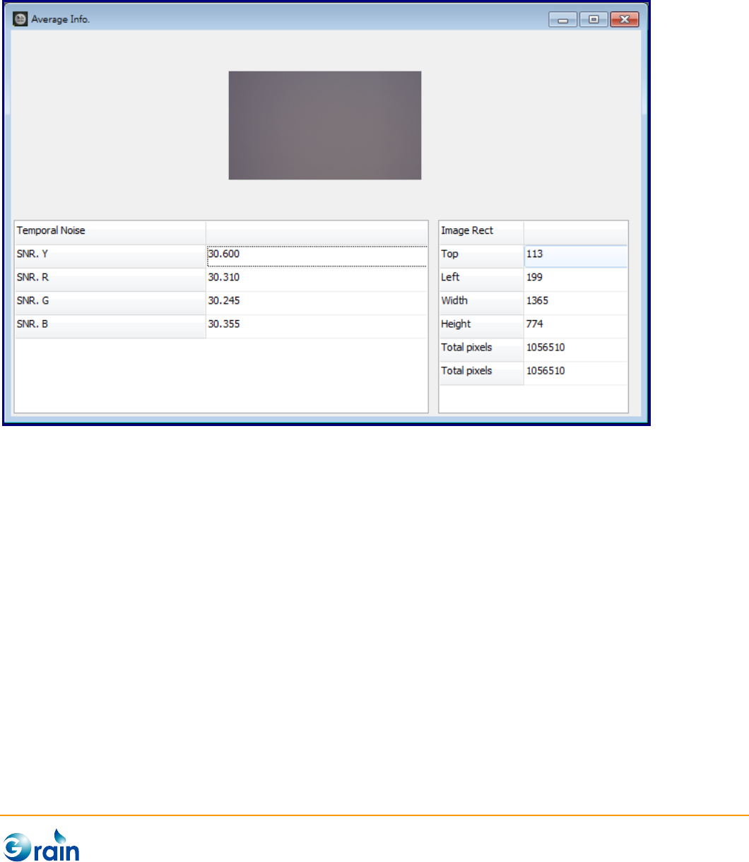
3.1.7 Temporal Noise
This function helps users to measure the temporal noise level of the image by calculating SNR.

GM8136 ISP Tuning Tool User Guide
www.grain-media.com
18
3.2 Image Calibration
Grain Media camera device integrates one high performance ISP, which contains the complex modules for
sensor/lens calibration and image adjustment. GM_IspTool is designed for simplifying and fastening the
tuning procedure.
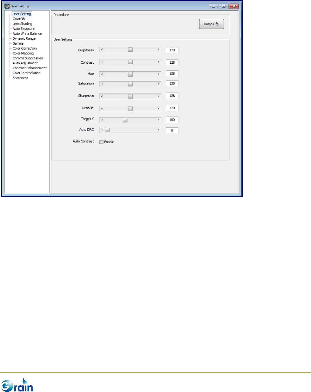
3.2.1 User Setting
This page provides the interface for users to set the general preferred settings:
- Brightness: Adjust the image brightness level
- Contrast: Adjust the image contrast level
- Hue: Adjust the image hue level
- Saturation: Adjust the image color saturation level
- Sharpness: Adjust the image sharpness level
- Denoise: Adjust the image noise reduction level
- Target Y: Adjust the AE target brightness
- Auto DRC: Adjust the Auto DRC strength
- Auto Contrast: Enable or disable the Auto Contrast
- DumpCfg: Dump the parameters of this module in the format of the configuration file. Also, users can
use the “Save Cfg” button on Main Menu to save the full configuration file.
GM8136 ISP Tuning Tool User Guide
www.grain-media.com
19
GM8136 ISP Tuning Tool User Guide
www.grain-media.com
20
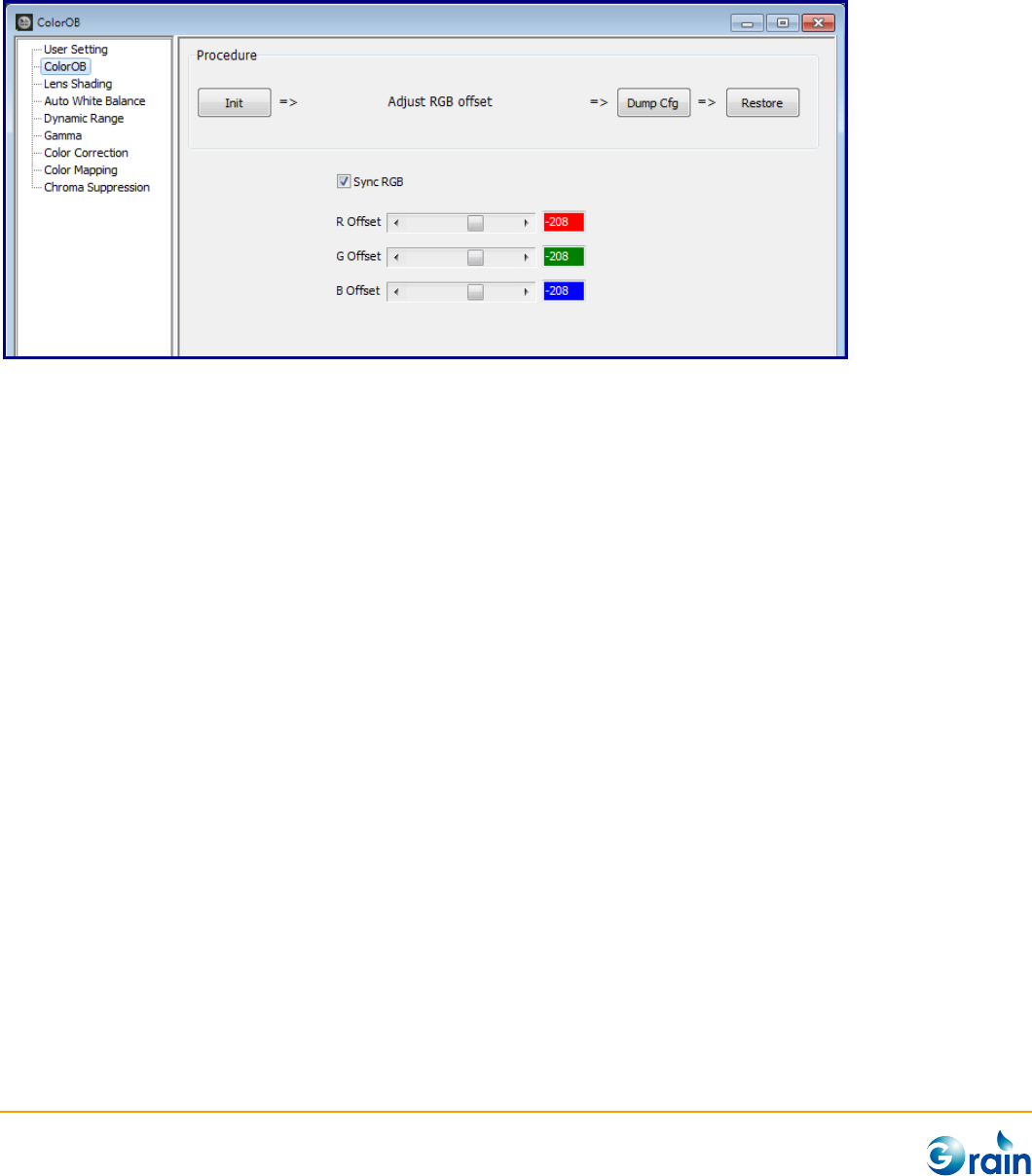
3.2.2 Color OB
This page corrects the black level of the sensor data.
1. Init: Click on this button, it will disable those modules which will affect the calibration accuracy to
confirm the correct results.
2. Adjust RGB offset: Start to set R, G, and B Offsets to ISP
3. DumpCfg: Dump the parameters of this module in the format of the configuration file. Also, users can
use the “Save Cfg” button on Main Menu to save the full configuration file.
4. Restore: Re-enable those modules which were disabled at the Init step
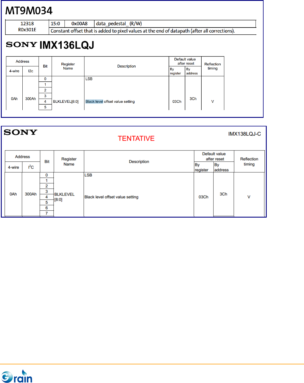
It is recommended checking the setting of the sensor black level before performing the calibration. The
output black level usually could be found in the sensor data sheet. For example, the black level is called
pedestal data in Aptina sensor and is called black level value in Sony sensor. This value should be close
to the black level output by the sensor.
GM8136 ISP Tuning Tool User Guide
www.grain-media.com
21
GM8136 ISP Tuning Tool User Guide
www.grain-media.com
22
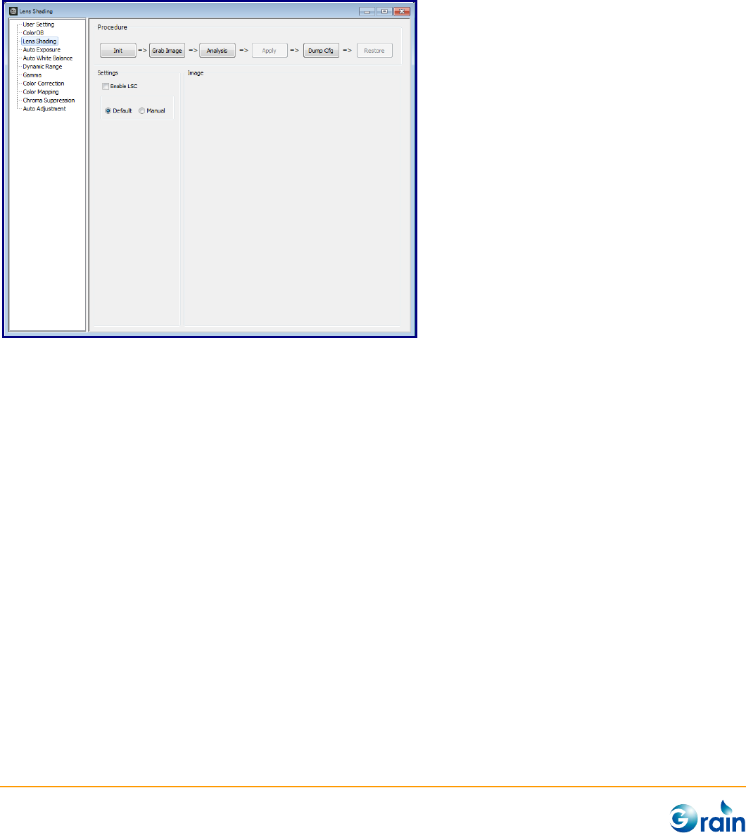
3.2.3 Lens Shading
This page provides the lens shading correction tool, which helps users to auto-generate the parameters for
the Grain Media ISP lens shadding correction module.
To perform the lens shading correction, users can follow the calibration flow indicated on the user interface.
These processes are explained as follows:
1. Init: Click on this button, it will disable those modules which will affect the calibration accuracy to
confirm the correct results.
2. Grab Image: A source image is needed as the calibration reference. This picture should contain
nothing except for the white pattern under uniform light source. If the Grain Media camera device was
connected, users can click the “Grab Image” button to directly grab the image from the device.
3. Analysis: Start auto calibration and generate parameters
4. Apply: Apply the result parameters to ISP
5. DumpCfg: Dump the parameters of this module in the format of the configuration file. Also, users can
use the “Save Cfg” button on Main Menu to save the full configuration file.
6. Restore: Re-enable those modules which were disabled at the Init step
In the Setting group, usesr can choose “Manual” setting to set more professional adjustments if the
calibration result by the default setting is not satisfied.
GM8136 ISP Tuning Tool User Guide
www.grain-media.com
23
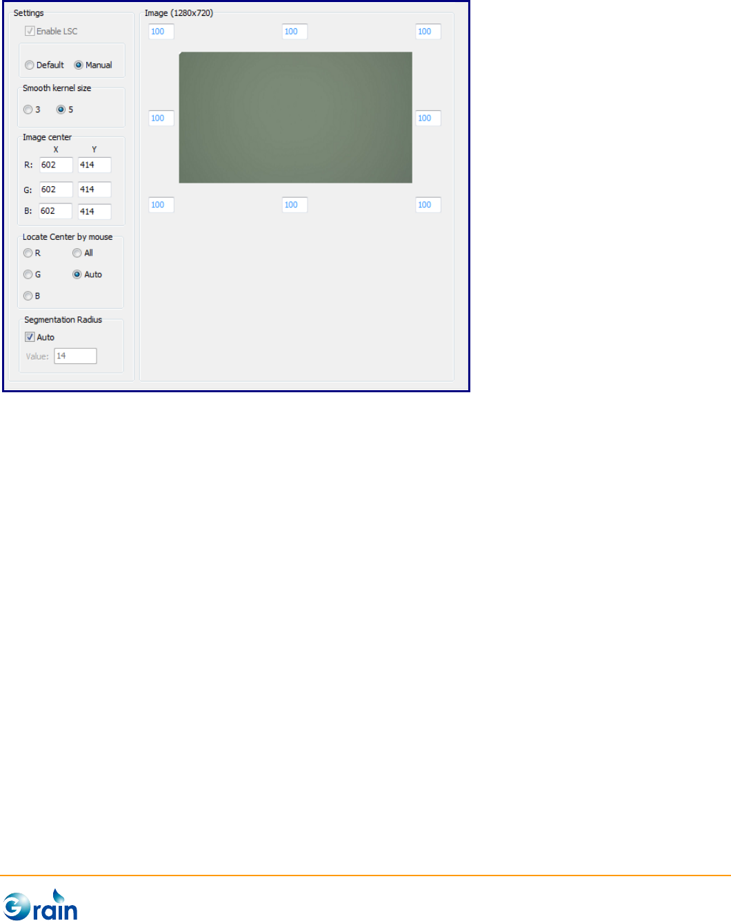
- Enable LSC: The option is uesed to enable or disable Lens shading module in ISP. The checkbox will
be disable after execute Init, and enable after Restore.
- Smooth kernel Size: Adjust the smooth level in the calibration algorithm
- Image Center: If the calibrated lens center is not accurate. Users can manually set the cooridinates
of the lens center of the seperated color channels.
- Locate center by mouse: Users also can manually set the the coordinates by clicking on the
preview image or Auto option.
- Segmentation Radius: The value means sampling segement of each line in 2’s order and please
reference chapter “Lens Shading Correction” of ISP SDK for detail definition. Users can manually set
the the value with unchecked “Auto”, or set the value by algorithm with cheched “Auto”.
- Image (width x height) and Corner Correction %: Preview the grab image and set the
maximum light fall off ratio. If the lens contain serious lens shadding effect, decreasing the value can
reduce the noise on cornor area but the vignetting effect may appears. After executing “Analysis”
button, the simulated result of the lens shading will be shown under “Image”.

GM8136 ISP Tuning Tool User Guide
www.grain-media.com
24

GM8136 ISP Tuning Tool User Guide
www.grain-media.com
25
GM8136 ISP Tuning Tool User Guide
www.grain-media.com
26
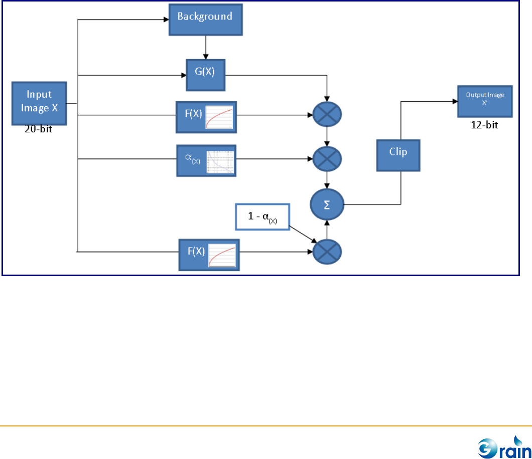
3.2.4 Dynamic Range
Grain Media DRC is a pixel based tone level control which compresses the dynamic range from high bit
width to low bit width. It supports the maximum 20-bit input WDR data and finally outputs 12-bit
processed image data.
The entire image is divided into several blocks for the background information statistic. The DRC algorithm
calculates out the amplifier G(x) of current pixel by measuring the intensity relationship between the
current pixel and the background information. The input image data separates into two paths. One is
transformed by a global tone mapping curve (F(x)), the other is multiplied by amplifier G(x). Finally, the two
data paths are blended according to the weighting function A(x) .
GM8136 ISP Tuning Tool User Guide
www.grain-media.com
27
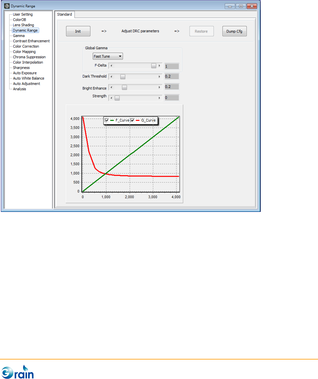
This page is used to calibrate and output the parameters of the Grain Media ISP Dynamic Range module.
The procedures are explained as follows.
1. Init: This button is used to disable those modules, which will affect the calibration accuracy to confirm
the correct results.
2. Adjust DRC paramters: Start to set paramters
3. Restore: Re-enable those modules which were disabled at the Init step.
4. DumpCfg: Dump the parameters of this module in the format of the configuration file. Also, users can
use the “Save Cfg” button on Main Menu to save the full configuration file.
GM8136 ISP Tuning Tool User Guide
www.grain-media.com
28
Strength:Adjust the strength of DRC effect. Please note that, this strength value is only for real time
checking DRC performance and will not be saved into ISP configuration file. For product stage, please use
IOCTL command to manually control the DRC strength.
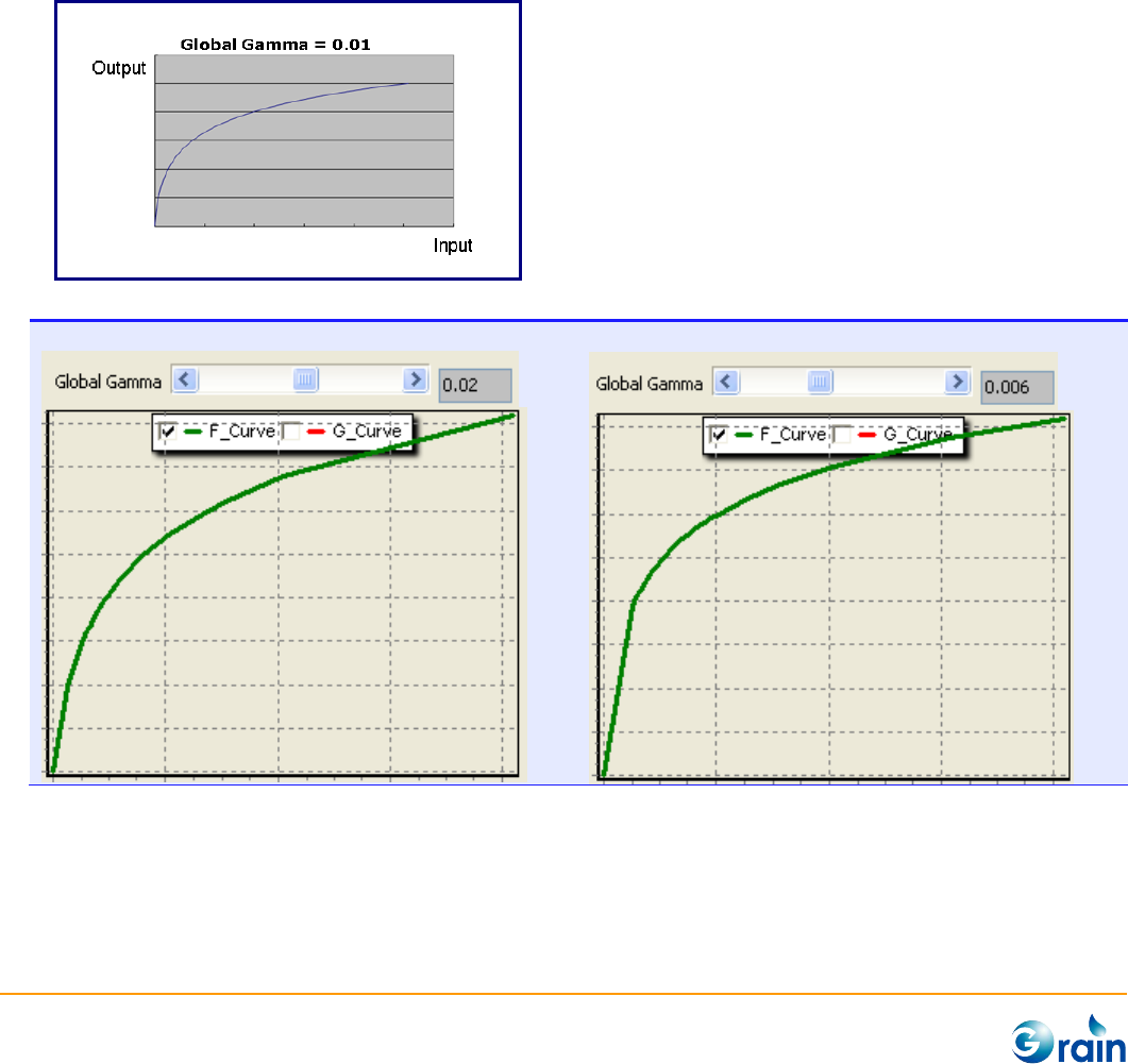
Global Gamma: Users could use two operations to adjust the global tone mapping curve F(x). One is Fast
Tune by adjust F-Delta. This value is recommended setting to 1 for linear sensor. For the WDR sensor, this
value should be in a range of between 0.01 and 0.0001 depending on the bit width of the sensor output
data.
Example: AR0331 WDR mode
F = 0.02
F = 0.006
GM8136 ISP Tuning Tool User Guide
www.grain-media.com
29
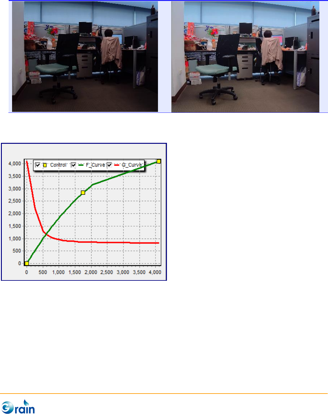
The other operation is Manual Mode. Users can also click on F_curve to create the yellow control points. Or
drag one control point to another to delete. Draging and droping these points can create a more flexible
F_Curve
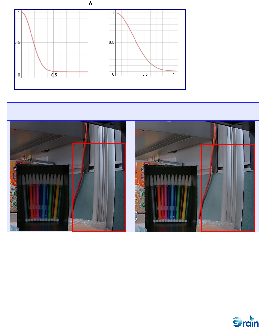
Dark Threshold: A(x) is a weighting curve, which decides the blending ration between the original data
and DRC data. As shown in following figures, the A(x) curve is similar to Gaussian distribution curve, which
gives large weighting for the dark region and gives small weighting for the bright region.
Please note that, the “strength” parameter controls the final strength of the DRC effect, so before
adjusting the parameter please set “strength” to 128 or higher value.
GM8136 ISP Tuning Tool User Guide
www.grain-media.com
30
The “Dark Threshold” acts like .
Dark Threshold = 0.3
Dark Threshold = 0.6
Example: Linear Sensor
Dark Threshold = 0.4
DRC only affect the dark region
Dark Threshold = 1
DRC affect both dark region and middle dark
region.
GM8136 ISP Tuning Tool User Guide
www.grain-media.com
31
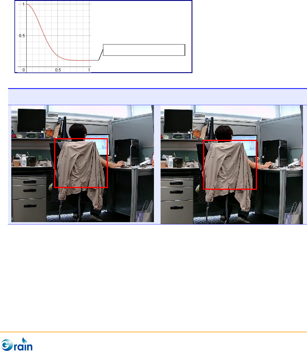
Bright Enhance: Set the minimum weighting for DRC data.
Please note that, the “strength” parameter controls the final strength of the DRC effect, so before
adjusting the parameter please set “strength” to 128 or higher value.
Bright Enhance = 0
DRC only affect dark region
Bright Enhance = 0.5
DRC affect bright region lightly.
Brightness Enhance = 0.1

GM8136 ISP Tuning Tool User Guide
www.grain-media.com
32
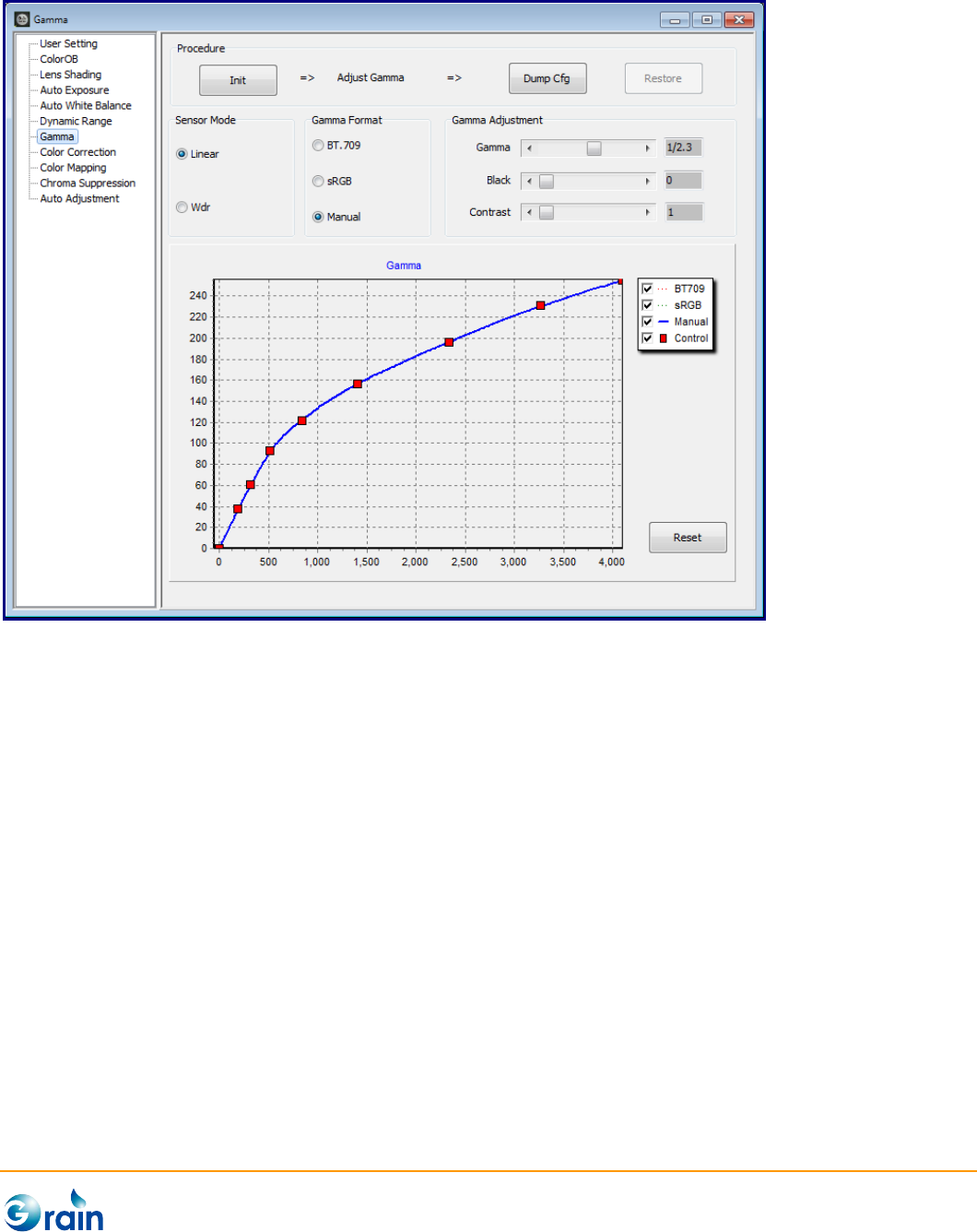
3.2.5 Gamma Adjustment
This page is for gamma adjustment. Since Grain Media ISP supports both general linear sensor and WDR
sensor, and ISP firmware supports dynamic mode changing. Before adjustment, users should first confirm
the current sensor mode.
1. Init: This button is used to disable those modules, which will affect the calibration accuracy to confirm
the correct results.
2. Adjust Gamma: Start to adjust by setting Sensor Mode, Gamma Format, and Gamma Adjustment.
3. Dump Cfg: Dump the parameters of this module in the format of the configuration file. Also, users
can use the “Save Cfg” button on Main Menu to save the full configuration file.
4. Restore: Re-enable those modules which were disabled at the Init step.
GM_IspTool provides two standard gamma formats. One is the BT.709 format, and another is the sRGB
format. Beside these two formats, users can select the manual mode and adjust the “Gamma Adjustment”
scrollbars to achieve the prefered gamma curve.
In the manual gamma mode, users can also click on the gamma curve to create the control points. Or drag
one control point to another to delete. Draging and droping these points can create a more flexible gamma
curve.
GM8136 ISP Tuning Tool User Guide
www.grain-media.com
33
GM8136 ISP Tuning Tool User Guide
www.grain-media.com
34
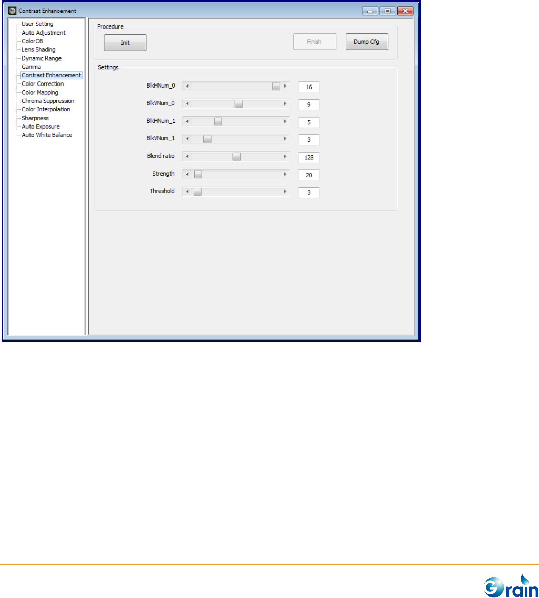
3.2.6 Contrast Enhancement
This page is used to calibrate and output the parameters of the Grain Media ISP Contrast Enhancement
module.
1. Init: This button will disable those modules which will affect the calibration accuracy to confirm the
correct results.
2. Settings: Adjust by setting EdgeDth, FreqTh, and FreqBlend.
3. Finish: Re-enable those modules which were disabled by the Init step.
4. DumpCfg: Dump the parameters of this module in the format of the configuration file. Also, users can
use the “Save Cfg” button on Main Menu to save the full configuration file.
GM8136 ISP Tuning Tool User Guide
www.grain-media.com
35
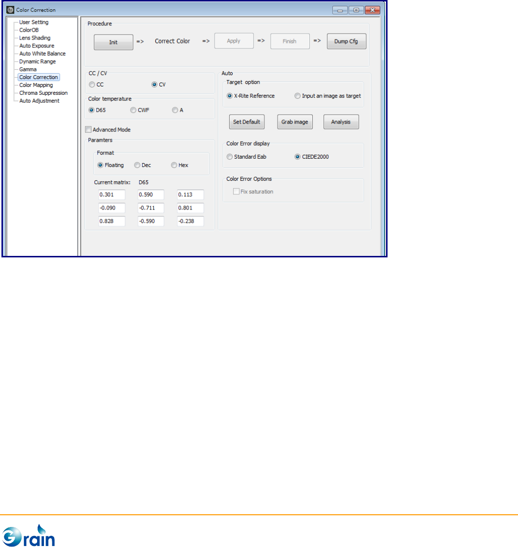
3.2.7 Color Correction
This page is used to calibrate and output the parameters of the Grain Media ISP Color Correction module
for the color accuracy enhancement.
The procedures are explained as follows:
1. Init: This button will disable those modules which will affect the calibration accuracy to confirm the
correct results.
2. Correct Color:
- CC/CV: Select CC or CV as the target matrix to do calibration, where CC indicates the RGB to
RGB matrix and CV indicates the RGB to YUV matris. When users change this option, the
following calibraion steps should be done again.
- Color temperature:The button in the light source group (A, CWF, D65) indicates the target
color temperture. Please sequentially set the color temperature and start to generate paramters
by the following steps.
GM8136 ISP Tuning Tool User Guide
www.grain-media.com
36
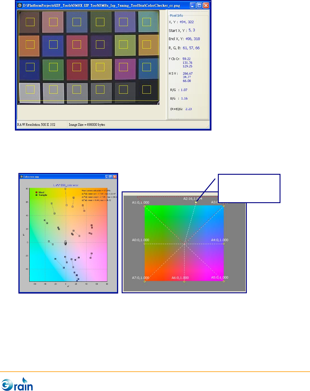
(1) Advanced Mode: When the button is checked, users can skip the “Auto” step and manually
adjust the parameters.
(2) Auto: Select “Target option” and this tool provides the standard X-Rite reference value
(ColorChecker) as the target color. Set Default to initialize color. Grab Image to grab the
images according to the corresponding light source and mark ROI on the grabbed/loaded
image. This tool will then measure the color information as the calibration database.
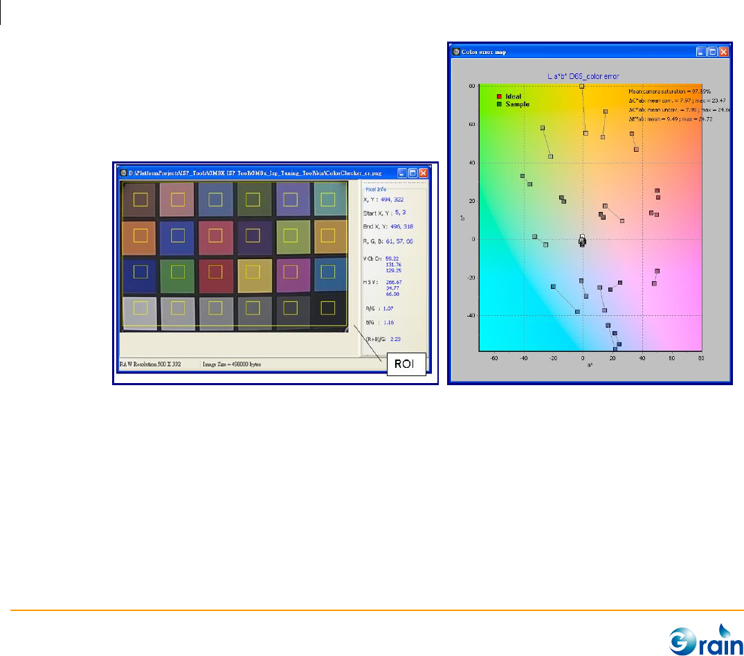
Analysis to start the auto calibration and generate parameters. After calibration has been
done, a color error map graph will be popped up to show the La*b* color error value. Also,
apply the parameters to ISP to review the result.
User can also load a prefered color checher image from a prepared file as the target color by
select “Input an image as target”.
GM8136 ISP Tuning Tool User Guide
www.grain-media.com
37
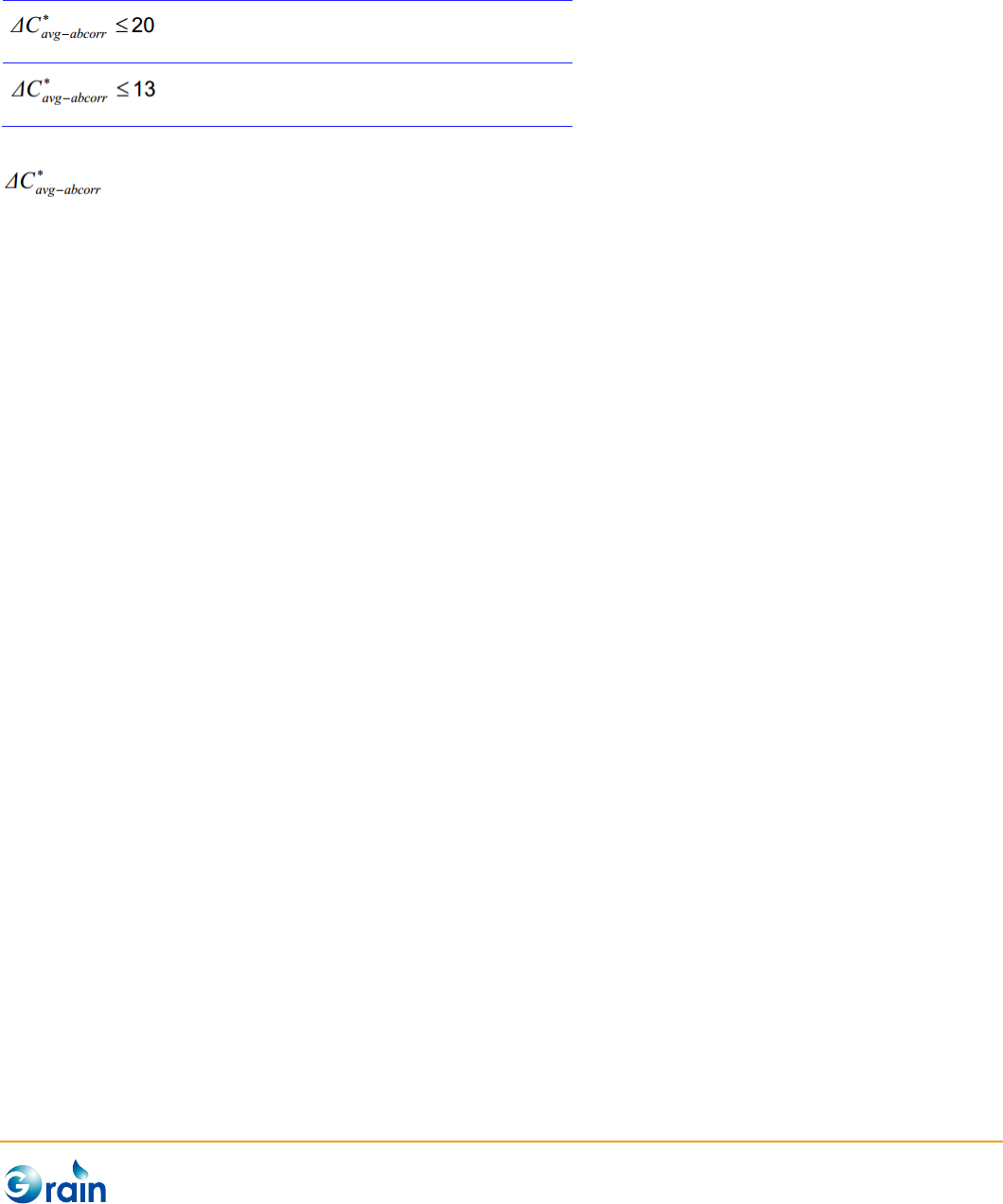
A reference minimum requirement for color accuracy is:
Light intensity: 30lux
Color temperature: 3000k and 5000k
Light intensity: 300lux
Color temperature: 3000k and 5000k
(Skype Hardware Certification Specification for allSkype Video Devices V5.0)
denotes the average chroma compensated color error (Average of all 24 patches).
- Paramters: User can also manually adjust the ouput parameters and switch the paramters
format. Also, apply the parameter to ISP to review the results.
3. Apply: After three color temperaures (D65, CWF, and A lights) are calibrated, users can click the
“Apply” button to apply all CC/CV settings to the device, and click the “Finish” button to check the
color correction results.
4. Finish: Re-enable those modules which were disabled by the Init step.
5. DumpCfg: Dump the parameters of this module in the format of the configuration file. Also, users can
use the “Save Cfg” button on Main Menu to save the full configuration file.
GM8136 ISP Tuning Tool User Guide
www.grain-media.com
38
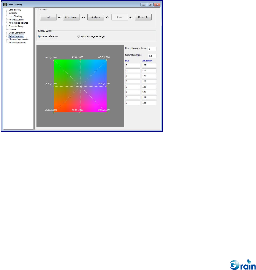
3.2.8 Color Mapping
This page is used to calibrate and output the parameters of the Grain Media ISP Color Mapping module for
the color accuracy enhancement.
The procedures are explained as follows:
1. Select “Target option”: This tool provides the standard X-Rite reference value as the target color.
Users can also load a prefered color checker image as the target color.
2. Init: This button will disable those modules which will affect the calibration accuracy to confirm the
correct results.
3. Grab Image:
- Use Chart: X-Rite ColorChecker
- Light Source: D65
GM8136 ISP Tuning Tool User Guide
www.grain-media.com
39
4. Analysis: Start the auto calibration and generate parameters. When calibration was done, a color
error map graph will be popped up to show the La*b* color error value (Left picture). Users can also
manually adjust the output parameters.
5. Apply: Apply the result parameters to ISP
6. DumpCfg: Dump the parameters of this module in the format of the configuration file. Also, users can
use the “Save Cfg” button on Main Menu to save the full configuration file.
Drag and drop the
controlling points
can adjust the
parameter
immediately.
GM8136 ISP Tuning Tool User Guide
www.grain-media.com
40
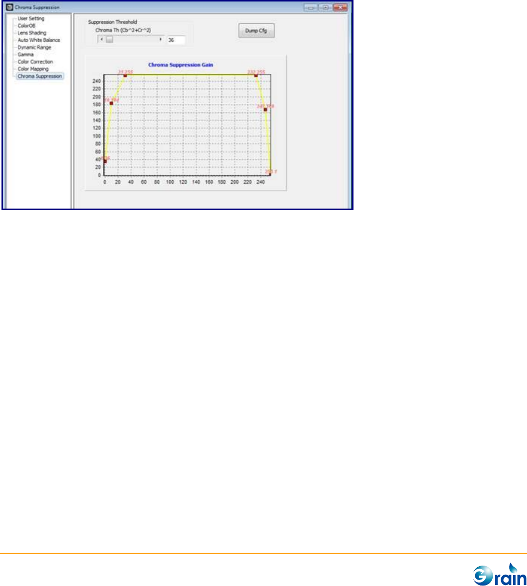
3.2.9 Chroma Suppression
This page is used to calibrate and output the parameters of the Grain Media ISP Chroma Suppression
module. The procedures are explained as follows.
1. Suppression Threshold: Users can immediately adjust the threshold parameter.
2. Chroma Suppression Gain: Users can drag and drop the red controlling points to adjust the
parameter immediately.
3. Global Gamma: Dump the parameters of this module in the format of the configuration file. Also,
users can use the “Save Cfg” button on Main Menu to save the full configuration file.
GM8136 ISP Tuning Tool User Guide
www.grain-media.com
41
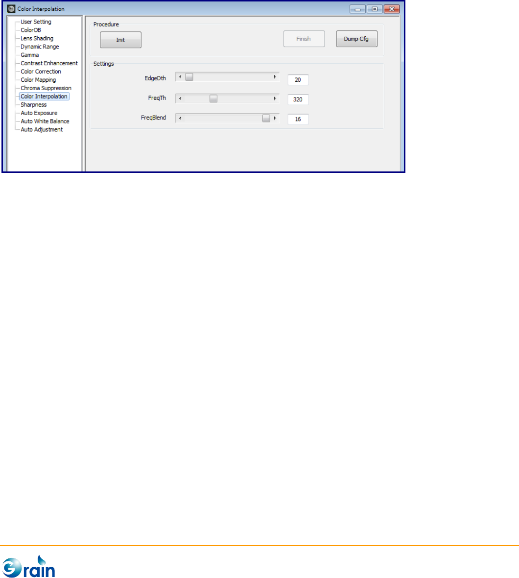
3.2.10 Color Interpolation
This page is used to calibrate and output the parameters of the Grain Media ISP Color Interpolation module.
The procedures are explained as follows.
1. Init: This button is used to disable those modules, which will affect the calibration accuracy to confirm
the correct results.
2. Settings: Adjust by setting EdgeDth, FreqTh, and FreqBlend.
3. Finish: Re-enable those modules which were disabled at the Init step.
4. Dump Cfg: Dump the parameters of this module in the format of the configuration file. Also, users
can use the “Save Cfg” button on Main Menu to save the full configuration file.
GM8136 ISP Tuning Tool User Guide
www.grain-media.com
42
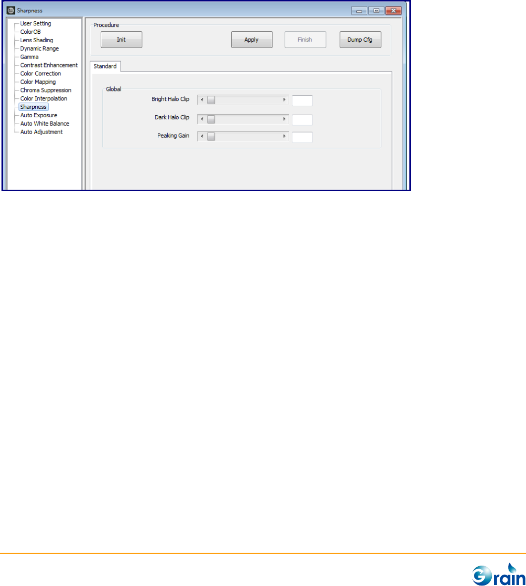
3.2.11 Sharpness
This page is used to calibrate and output the parameters of the Grain Media ISP Sharpeness module. The
procedures are explained as follows.
5. Init: This button is used to disable those modules, which will affect the calibration accuracy to confirm
the correct results.
6. Settings: Adjust by setting Bright Halo Clip, Dark Halo Clip, and Peaking Gain.
7. Finish: Re-enable those modules which were disabled at the Init step.
8. Dump Cfg: Dump the parameters of this module in the format of the configuration file. Also, users
can use the “Save Cfg” button on Main Menu to save the full configuration file.
GM8136 ISP Tuning Tool User Guide
www.grain-media.com
43
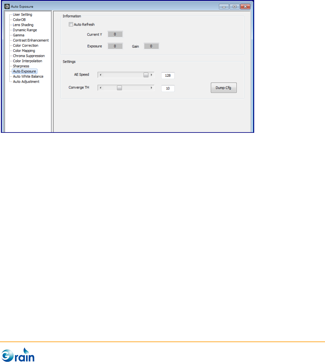
3.2.12 Auto Exposure
This page is used to set and output the parameters of the Grian Media ISP AE module. The procedures are
explained as follows:
- Auto Refresh: Check the button to regularly return the AE metering value, exposure (millisecond),
and sensor gain
- AE Speed: Adjust the AE converge speed
- Converge TH: Adjust the AE converge threshold
- Dump Cfg: Dump the parameters of this module in the format of the configuration file. Also, users
can use the “Save Cfg” button on Main Menu to save the full configuration file.
GM8136 ISP Tuning Tool User Guide
www.grain-media.com
44
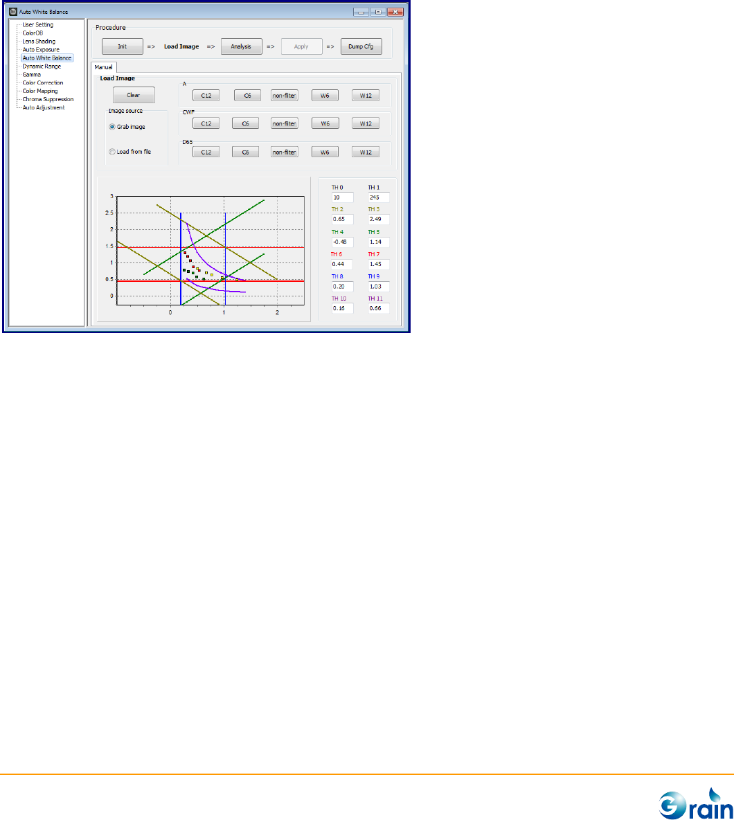
3.2.13 Auto White Balance
This page is used to calibrate and output the parameters of the Grian Media ISP AWB module. The
procedures are explained as follows.
1. Init: This button is used to disable those modules, which will affect the calibration accuracy to confirm
the correct results.
2. Load Image/Grab Image:
- Use Chart: Gray scale chart (ITE, Kodak…)
- Light Source: The buttons in light source group (A, CWF, D65) indicates the target color
temperture and “C”, “W” indicates that Cool or Warm color filters was used.
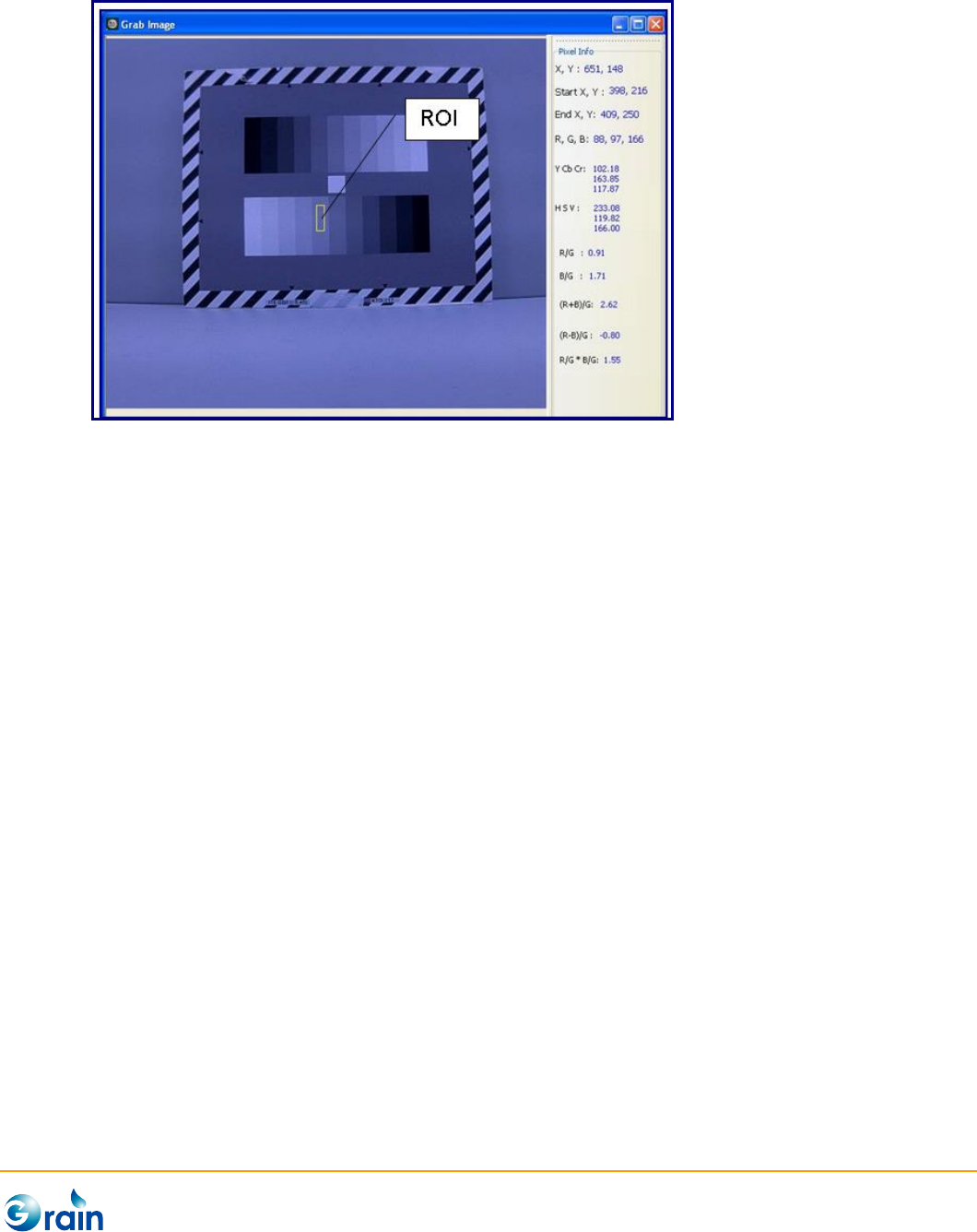
Please sequentially click the buttons in different light source groups to grab/load the images
according to the corresponding light source and mark ROI on the grabbed/loaded image. This
tool will then measure the color information as the calibration database and show the results on
the graphic.
The caption color of the button will become red/green/blue after image has been grabbed/loaded.
GM8136 ISP Tuning Tool User Guide
www.grain-media.com
45
3. Analysis: Start auto calibration and generate parameters
4. Apply: Apply the result parameters to ISP
5. DumpCfg: Dump the parameters of this module in the format of the configuration file. Also, users can
use the “Save Cfg” button on Main Menu to save the full configuration file.
6. Restore: Re-enable those modules which were disabled at the Init step.
Notes:
1. TH0 and TH1 indicate the min. and max. Y thresholds for measuring white point.
2. Users can also manually revise the output parameters or drag and drop the TH2 ~ 11 of chart to adjust the level gate of
the white point. There are two points should be awared before doing adjustment:
- If the level gate was tight, accuracy of AWB will be better, but the AWB parameters should be re-calibrated when lens
was changed.
- If the level gate was loose, the parameters may be adaptable for different lens, but the AWB accuracy will reduce.
GM8136 ISP Tuning Tool User Guide
www.grain-media.com
46
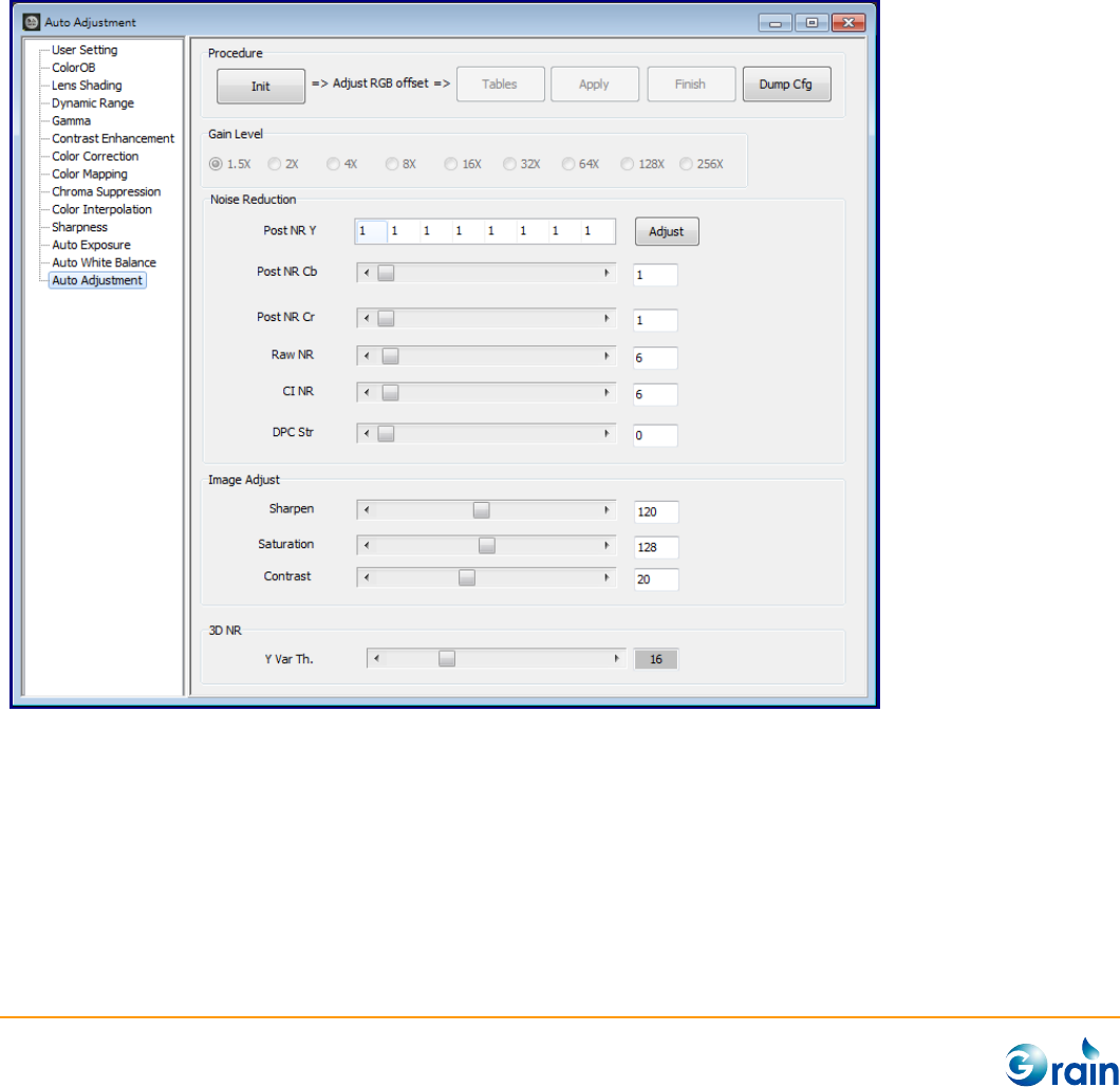
3.2.14 Auto Adjustment
Since change of sensor gain usually companies with noise level variance. In order to get best image quality,
GM ISP firmware will auto adjust several parameters such as noise reduction, sharpness, saturation, etc.
There are 9 pre-defined gain levels in Grain Media ISP driver. User can do adjustment by these 9 levels.
When the current gain is within two levels, firmware will auto interpolated according to these levels.
This page is used to calibrate and output the parameters of the Grain Media ISP Denoise module. The
procedures are explained as follows:
1. Init: This button will get the max gain of current sensor and auto divide the gain levels.
2. Calibration Steps: To get best image quality in different illuminance environment, user should do
adjustment of all the gain levels.
(1) Select Gain Level: Select the gain level will set the maximum gain into ISP driver.
GM8136 ISP Tuning Tool User Guide
www.grain-media.com
47
(2) Adjust illuminance to fit current gain to current gain level. Current gain and current average Y are
displayed on the right side.
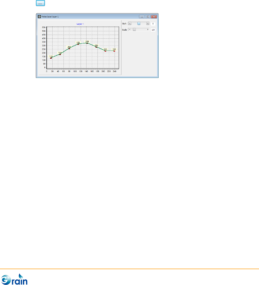
(3) Adjust parameters related to this gain level. The parameters are explained as follows:
Post NR: Post NR is a powerful noise reduction module in YUV domain. Users could execute
for further Noise Level settings.
Raw NR: This will adjust the strength of “Raw Domain Noise Reduction” module.
CI NR: This will adjust the strength of noise reduction module which was combinded in color
interpolation moduel.
DPC: This will adjust the strength of the “Defect Pixel Cancellation” module.
Sharpness: This will adjust the strength of “Sharpness” module.
Saturation: This will will adjust the image saturation. Usually, for chroma noise reduction,
user can reduce saturation under low light condition.
3D NR: This can adjust the strength of “Temporal Noise Reduction” by Luma. The larger
value stands for stonger strength of 3DNR.
3. Apply: After each gain level is calibrated, users can click the “Apply” button to apply all gain level
settings to the device, and click the “Finish” button to check the results.
4. Finish: Re-enable those modules which were disabled by Init step.
5. Dump Cfg: Dump the parameters of this module in the format of the configuration file.
