제품 구입 감사 안내문 GP Editor V4.0 User Manual
User Manual: GP Editor V4.0 User Manual
Open the PDF directly: View PDF ![]() .
.
Page Count: 316 [warning: Documents this large are best viewed by clicking the View PDF Link!]
- 1 Product Overview
- 2 Project
- 3 Screen
- 4 Edit
- 5 Draw
- 5.1 Panel kit/Part
- 5.2 Line
- 5.3 Rectangle
- 5.4 Circle
- 5.5 Text
- 5.6 Bitmap
- 5.7 Numeral Input
- 5.8 ASCII Input
- 5.9 Numeral Display
- 5.10 ASCII Display
- 5.11 Clock
- 5.12 Comment Display
- 5.13 Alarm History
- 5.14 Alarm List
- 5.15 Part Display
- 5.16 Lamp
- 5.17 Panel Meter
- 5.18 Line Graph
- 5.19 Trend Graph
- 5.20 Bar Graph
- 5.21 Statistics Graph
- 5.22 Touch Key
- 5.23 Overlap Screen
- 5.24 Key Window Position
- 6 View
- 7 Communication
- 8 Common
- 9 Appendix
© Copyright Reserved Autonics Co., Ltd. iii
USER MANUAL

ii © Copyright Reserved Autonics Co., Ltd.

Preface
© Copyright Reserved Autonics Co., Ltd. iii
Preface
Thank you very much for selecting Autonics products.
This user manual contains information about the product and its proper use, and should be kept
in a place where it will be easy to access.

User Manual Guide
iv © Copyright Reserved Autonics Co., Ltd.
User Manual Guide
Please familiarize yourself with the information in this manual before using the product.
This manual provides detailed information on the product's features. It does not offer any
guarantee concerning matters beyond the scope of this manual.
This manual may not be edited or reproduced in either part or whole without permission.
A user manual is not provided as part of the product package. Please visit our home-page
(www.autonics.com) to download a copy.
The manual's content may vary depending on changes to the product's software and other
unforeseen developments within Autonics, and is subject to change without prior notice.
Upgrade notice is provided through our homepage.
We contrived to describe this manual more easily and correctly. However, if there are any
corrections or questions, please notify us these on our homepage.
User Manual Symbols
© Copyright Reserved Autonics Co., Ltd. v
User Manual Symbols
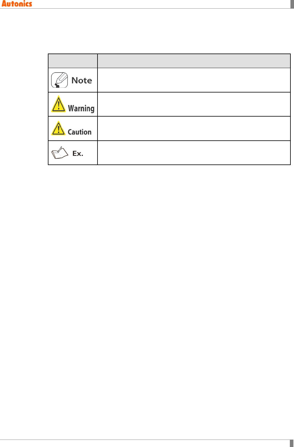
Symbol Description
Supplementary information for a particular feature.
Failure to follow instructions can result in serious injury or death.
Failure to follow instructions can lead to a minor injury or product damage.
An example of the concerned feature's use.
※ The specifications and dimensions of this manual are subject to change without any notice.

Table of Contents
vi © Copyright Reserved Autonics Co., Ltd.
Table of Contents
Preface ............................................................................................................................. iii
User Manual Guide ......................................................................................................... iv
User Manual Symbols ...................................................................................................... v
Table of Contents ............................................................................................................ vi
1 Product Overview ...................................................................................... 13
1.1 Features ............................................................................................................. 13
1.2 System requirements ......................................................................................... 14
1.3 Installation .......................................................................................................... 14
1.4 GP Editor Screen Layout ................................................................................... 19
1.4.1 Menu ........................................................................................................... 20
1.5 Tool .................................................................................................................... 29
1.6 Device ................................................................................................................ 32
2 Project ........................................................................................................ 35
2.1 New Project ....................................................................................................... 35
2.1.1 GP/PLC type .............................................................................................. 36
2.1.2 Project auxiliary property ............................................................................ 37
2.2 Load Project ....................................................................................................... 43
2.3 Save Project ...................................................................................................... 44
2.4 Import Project .................................................................................................... 46
2.4.1 Select tab .................................................................................................... 46
2.4.2 Base tab ..................................................................................................... 47
2.4.3 Window tab ................................................................................................. 49
2.4.4 Part tab ....................................................................................................... 50
2.4.5 Comment tab .............................................................................................. 52
2.5 Print .................................................................................................................... 54
2.5.1 Print procedure ........................................................................................... 54
2.5.2 Created file when printing as file ................................................................ 56
2.6 Option ................................................................................................................ 57
2.6.1 File tab ........................................................................................................ 57
2.6.2 Browse tab.................................................................................................. 58
2.6.3 Communication tab .................................................................................... 59
2.7 Exit ..................................................................................................................... 61
3 Screen ........................................................................................................ 63
3.1 Screen of GP/LP ................................................................................................ 63
3.1.1 Base screen ............................................................................................... 63
3.1.2 Window screen ........................................................................................... 64
3.2 New Screen ....................................................................................................... 67
3.3 Load Screen ...................................................................................................... 68
3.4 Clear Screen ...................................................................................................... 69
3.5 Load and Clear .................................................................................................. 69

Table of Contents
© Copyright Reserved Autonics Co., Ltd. vii
3.6 Save Screen ...................................................................................................... 69
3.7 Save As Screen ................................................................................................. 70
3.8 Screen Copy/Delete ........................................................................................... 71
3.9 Change Size ...................................................................................................... 72
4 Edit ............................................................................................................. 73
4.1 Undo................................................................................................................... 73
4.2 Cut ...................................................................................................................... 73
4.3 Copy ................................................................................................................... 73
4.4 Paste .................................................................................................................. 73
4.5 Successive Copy ............................................................................................... 74
4.6 Delete ................................................................................................................. 76
4.7 Select All ............................................................................................................ 76
4.8 Select Object ...................................................................................................... 76
4.9 Group ................................................................................................................. 78
4.10 Ungroup ............................................................................................................. 78
4.11 Bring Forward/Send Backward .......................................................................... 79
4.12 Replace Device .................................................................................................. 81
4.13 Replace Overlap Screen.................................................................................... 82
4.14 Attribute .............................................................................................................. 82
4.15 Alignment ........................................................................................................... 83
5 Draw ........................................................................................................... 87
5.1 Panel kit/Part ...................................................................................................... 87
5.1.1 Panel kit ...................................................................................................... 87
5.1.2 Part ............................................................................................................. 91
5.2 Line .................................................................................................................... 92
5.2.1 Basic usage ................................................................................................ 92
5.2.2 Property ...................................................................................................... 93
5.3 Rectangle ........................................................................................................... 94
5.3.1 Basic usage ................................................................................................ 94
5.3.2 Property ...................................................................................................... 95
5.4 Circle .................................................................................................................. 96
5.4.1 Basic usage ................................................................................................ 96
5.4.2 Property ...................................................................................................... 97
5.5 Text ..................................................................................................................... 98
5.5.1 Basic usage ................................................................................................ 98
5.5.2 Property ...................................................................................................... 99
5.6 Bitmap .............................................................................................................. 101
5.6.1 Basic usage .............................................................................................. 102
5.6.2 Property .................................................................................................... 103
5.7 Numeral Input .................................................................................................. 104
5.7.1 Basic usage .............................................................................................. 104
5.7.2 Property .................................................................................................... 105
5.7.3 Change numeral ........................................................................................ 111

Table of Contents
viii © Copyright Reserved Autonics Co., Ltd.
5.8 ASCII Input....................................................................................................... 112
5.8.1 Basic usage .............................................................................................. 112
5.8.2 Property .................................................................................................... 113
5.8.3 Change ASCII ........................................................................................... 118
5.9 Numeral Display .............................................................................................. 120
5.9.1 Basic usage .............................................................................................. 120
5.9.2 Property .................................................................................................... 121
5.9.3 Display type and operation ....................................................................... 126
5.10 ASCII Display ................................................................................................... 130
5.10.1 Basic usage .............................................................................................. 130
5.10.2 Property .................................................................................................... 131
5.11 Clock ................................................................................................................ 134
5.11.1 Basic usage .............................................................................................. 134
5.11.2 Property .................................................................................................... 134
5.12 Comment Display ............................................................................................ 137
5.12.1 Basic usage .............................................................................................. 138
5.12.2 Property .................................................................................................... 139
5.13 Alarm History ................................................................................................... 143
5.13.1 Basic operation ......................................................................................... 143
5.13.2 Basic usage .............................................................................................. 143
5.13.3 Property .................................................................................................... 144
5.14 Alarm List ......................................................................................................... 148
5.14.1 Basic usage .............................................................................................. 148
5.14.2 Property .................................................................................................... 149
5.15 Part Display ..................................................................................................... 154
5.15.1 Basic usage .............................................................................................. 156
5.15.2 Property .................................................................................................... 156
5.16 Lamp ................................................................................................................ 160
5.16.1 Basic usage .............................................................................................. 160
5.16.2 Property .................................................................................................... 161
5.17 Panel Meter ..................................................................................................... 164
5.17.1 Basic usage .............................................................................................. 164
5.17.2 Property .................................................................................................... 165
5.18 Line Graph ....................................................................................................... 170
5.18.1 Basic operation ......................................................................................... 170
5.18.2 Basic usage .............................................................................................. 170
5.18.3 Property .................................................................................................... 171
5.19 Trend Graph ..................................................................................................... 176
5.19.1 Basic operation ......................................................................................... 176
5.19.2 Basic usage .............................................................................................. 176
5.19.3 Property .................................................................................................... 177
5.20 Bar Graph ........................................................................................................ 184
5.20.1 Basic operation ......................................................................................... 184
5.20.2 Basic usage .............................................................................................. 184
5.20.3 Property .................................................................................................... 185

Table of Contents
© Copyright Reserved Autonics Co., Ltd. ix
5.21 Statistics Graph ................................................................................................ 190
5.21.1 Basic operation......................................................................................... 190
5.21.2 Basic usage .............................................................................................. 190
5.21.3 Property .................................................................................................... 191
5.22 Touch Key ........................................................................................................ 194
5.22.1 Basic operation......................................................................................... 194
5.22.2 Basic usage .............................................................................................. 198
5.22.3 Property .................................................................................................... 199
5.23 Overlap Screen ................................................................................................ 209
5.24 Key Window Position ....................................................................................... 211
6 View .......................................................................................................... 213
6.1 Preview ............................................................................................................ 213
6.2 Palette .............................................................................................................. 213
6.3 Graphic Library ................................................................................................ 214
6.4 Tag List ............................................................................................................. 215
6.4.1 All tab ....................................................................................................... 215
6.4.2 Numeral display tab.................................................................................. 216
6.5 Device List ....................................................................................................... 219
6.6 Overlap Screen List ......................................................................................... 220
6.7 Status bar ......................................................................................................... 221
6.8 Toolbar ............................................................................................................. 221
6.9 ON Image ......................................................................................................... 221
6.10 Refresh ............................................................................................................ 221
6.11 Option .............................................................................................................. 222
7 Communication ....................................................................................... 223
7.1 Download ......................................................................................................... 224
7.1.1 Download instructions .............................................................................. 224
7.1.2 Property .................................................................................................... 224
7.2 Upload .............................................................................................................. 228
7.2.1 Execution order ........................................................................................ 228
7.2.2 Property .................................................................................................... 229
7.3 Memory ............................................................................................................ 233
7.3.1 Execution order ........................................................................................ 233
7.3.2 Property .................................................................................................... 233
7.4 Check Data ...................................................................................................... 236
7.4.1 Area tab .................................................................................................... 236
7.4.2 Check store memory option tab ............................................................... 237
7.4.3 Level password tab .................................................................................. 238
7.4.4 Common device tab ................................................................................. 239
7.5 GP Firmware Download ................................................................................... 240
7.5.1 Firmware download execution order ........................................................ 240
7.6 Option .............................................................................................................. 242
8 Common .................................................................................................. 243

Table of Contents
x © Copyright Reserved Autonics Co., Ltd.
8.1 Title .................................................................................................................. 243
8.1.1 Project title ................................................................................................ 243
8.1.2 Screen title ............................................................................................... 244
8.2 GP/PLC Type ................................................................................................... 245
8.2.1 PLC connection ........................................................................................ 245
8.2.2 Connecting PLC setting............................................................................ 246
8.2.3 Convert device with changing PLC type .................................................. 247
8.3 Link Device ...................................................................................................... 249
8.4 System Information .......................................................................................... 256
8.4.1 Overview................................................................................................... 256
8.4.2 Read device ............................................................................................. 256
8.4.3 Write device .............................................................................................. 257
8.4.4 GP inner device ........................................................................................ 258
8.5 Switch Screen .................................................................................................. 260
8.5.1 Basic operation ......................................................................................... 260
8.5.2 Property .................................................................................................... 260
8.6 Security ............................................................................................................ 261
8.6.1 Basic usage .............................................................................................. 261
8.6.2 Property .................................................................................................... 263
8.7 Comment ......................................................................................................... 266
8.8 Alarm History ................................................................................................... 269
8.8.1 Alarm history property .............................................................................. 269
8.9 Floating Alarm .................................................................................................. 276
8.9.1 Basic operation ......................................................................................... 276
8.9.2 Property .................................................................................................... 277
8.10 Monitor Status .................................................................................................. 279
8.10.1 Basic action .............................................................................................. 279
8.10.2 Execution order ........................................................................................ 279
8.10.3 Property .................................................................................................... 282
8.11 Recipe .............................................................................................................. 286
8.11.1 Basic operation ......................................................................................... 286
8.11.2 Property .................................................................................................... 288
8.12 Time Action ...................................................................................................... 292
8.12.1 Basic operation ......................................................................................... 292
8.12.2 Property .................................................................................................... 292
8.13 Barcode ............................................................................................................ 294
8.13.1 Basic operation ......................................................................................... 294
8.13.2 Barcode read order .................................................................................. 295
8.13.3 Save ......................................................................................................... 296
8.13.4 Specification of available barcode reader ................................................ 297
8.14 Auxiliary Configuration ..................................................................................... 297
8.14.1 Project ...................................................................................................... 297
8.14.2 Screen ...................................................................................................... 297
9 Appendix .................................................................................................. 301
9.1 USB driver installation ..................................................................................... 301

Table of Contents
© Copyright Reserved Autonics Co., Ltd. xi
9.2 GP Editor runs in Windows 7 operating system .............................................. 309
9.2.1 GP Editor runs as administrator ............................................................... 309
9.2.2 In case of no administrator account (Create administrator account
windows 7) ............................................................................................................ 311
9.2.3 Disable to user account control dialog box .............................................. 313

Table of Contents
xii © Copyright Reserved Autonics Co., Ltd.

1 Product Overview
© Copyright Reserved Autonics Co., Ltd. 13
1 Product Overview
1.1 Features
All data of GP user screen is edited in private software GP Editor. After editing screen data
including forms, arrangement, attribution of tags, download tags to GP/LP, it starts to monitor by
the screen data of GP/LP.
Supports multi-font
It supports windows true type fonts and several bitmap fonts. (It is selectable.)
Convenient user interface
Upgrades firmware of GP/LP
Screen Layout
Title bar, menu, tools, status bar, edit area, non-edit area, preview
Several edit feature (group, alignment, select, draw)
Panel kit/Part library
Panel kit library: Created library by user
Part library: Supplied basic library by GP Editor
Part: Registers several numbers or groups of only figure objects (line, rectangle, circle,
text, BMP)
Supplies diverse image library
Overlap screen for screen edit efficiency and for saving data capacity
Memory
Feature for composing project screen of GP/LP, memory free space, checking firmware
version, and delete the desired screen
Check data
Automatically executes to check data error when download the data to GP/LP
Preview
Shows screen on the device with 100% of enlargement ratio
Supplies help information for program usage
1 Product Overview
14 © Copyright Reserved Autonics Co., Ltd.
1.2 System requirements
Operating system: Windows 98/NT/XP
Item
Minimum specifications
Recommended specification
CPU Pentium 4 or above Pentium Dual Core
Memory 512 MB 1GB
Hard disk 1 GB (Free space) 5GB (Free space)
Resolution 1024
×
768 1280
×
1024
Communication port: RS232 , Serial, USB, Ethernet
1.3 Installation
If GP Editor below V4.0 is installed, delete previous version or designate the other path unlike
previous version.
Series Firmware version
GP-2480 Above V3.00
GP-S Series GP-S044, GP-S057 Above V3.00
GP-S070 Above V1.00
LP-S Series LP-S044 Above V3.00
LP-S070 Above V1.00
1 Product Overview
© Copyright Reserved Autonics Co., Ltd. 15
1st For installing GP Editor, visit our homepage (www.autonics.com) and download GP
Editor program.
Before installing GP Editor, it is recommended to shut down the other programs.
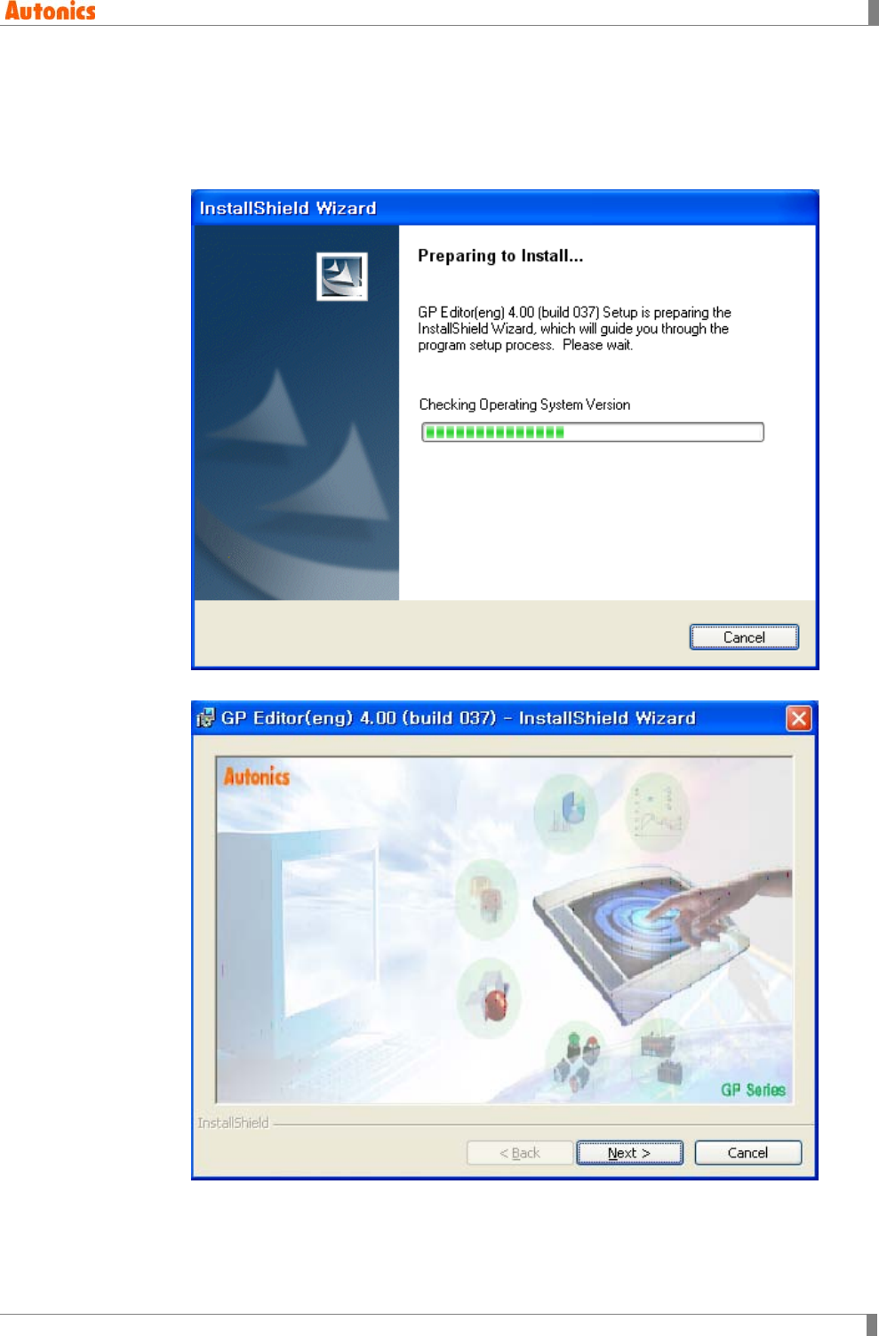
2nd Double-click installation setup file, and installation is start.
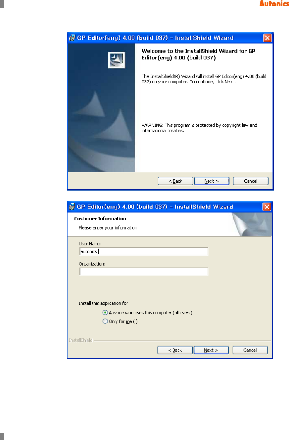
3rd Click ‘Next’ after installshied wizard is ready.
1 Product Overview
16 © Copyright Reserved Autonics Co., Ltd.
4th Click ‘Next’ to continue installation, or ‘Cancle’ to discontinue installation.
5th Enter your information, and click ‘Next’.
1 Product Overview
© Copyright Reserved Autonics Co., Ltd. 17
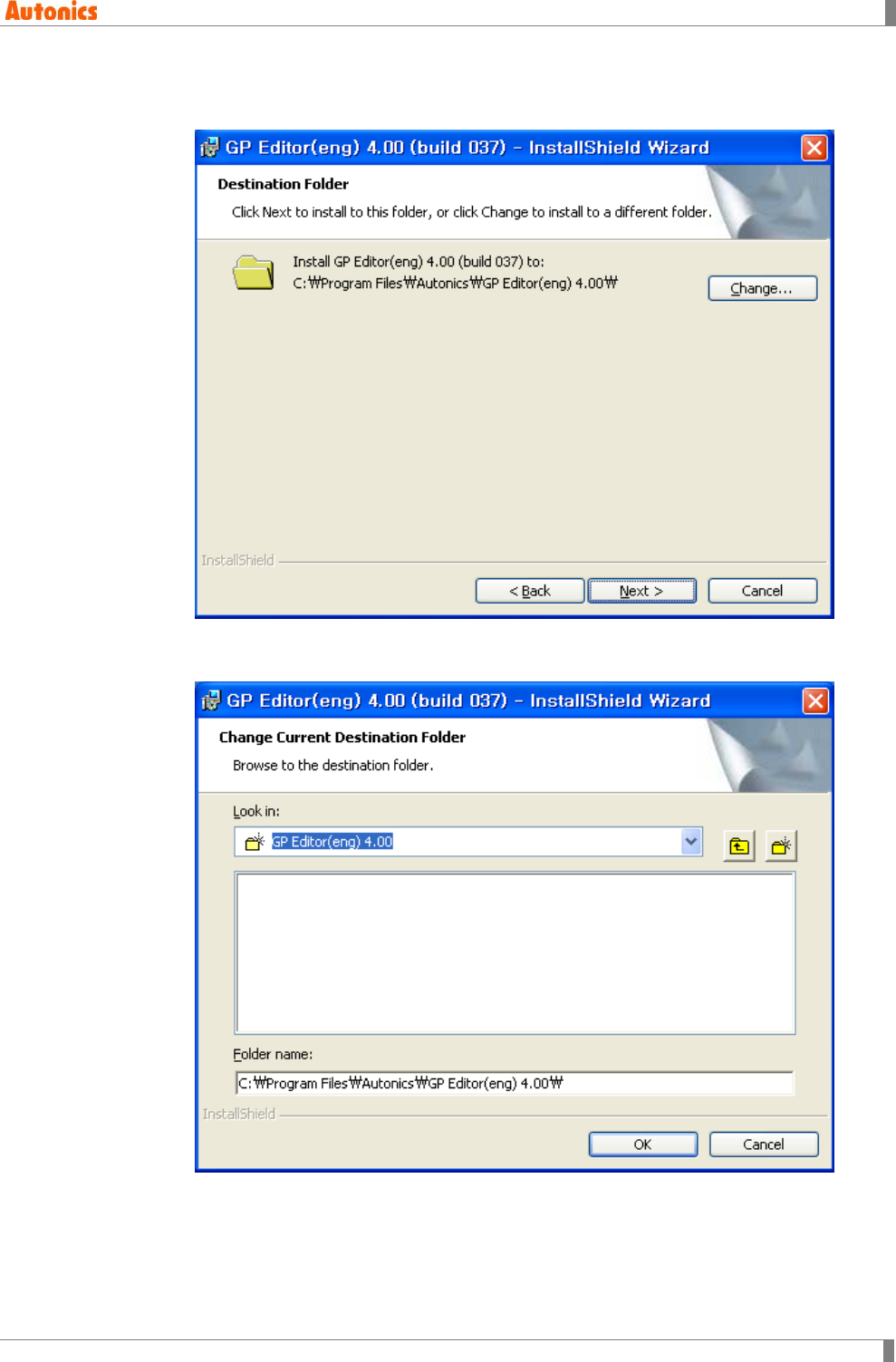
6th Designate installation location, and click ‘Next’. (Default installation path is
C:/Program Files/Autonics/GP Editor 4.0/.)
7th To change the installation location, click ‘Change’ and select the desired folder and
click ‘OK’.
1 Product Overview
18 © Copyright Reserved Autonics Co., Ltd.
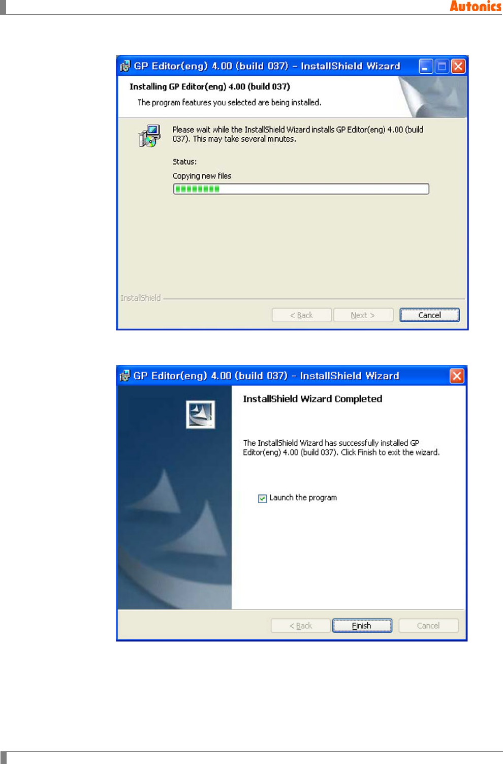
8th Installation starts and you can check installation progress at the same time.
9th After completing installation, click ‘Finish’ and GP Editor runs. If you do not want to
run GP Editor, non-check ‘Launch the program’ and click ‘Finish’.
1 Product Overview
© Copyright Reserved Autonics Co., Ltd. 19
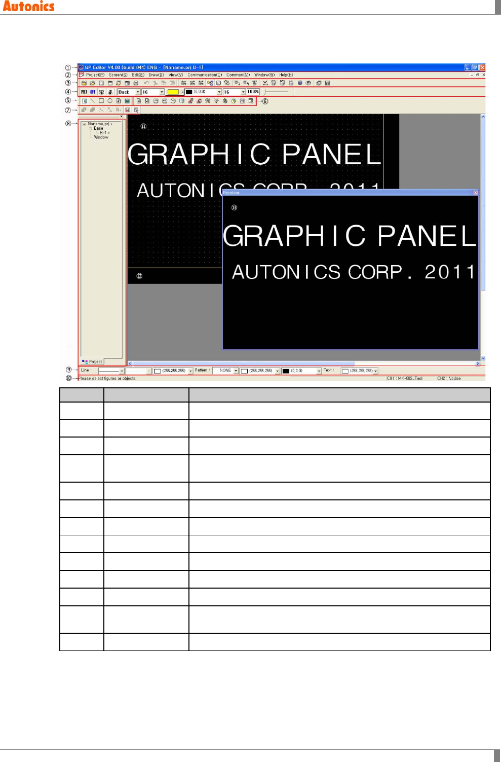
1.4 GP Editor Screen Layout
No.
Name
Description
① Title bar Displays number and title of working screen.
② Menu Menu for all functions
③ System tool Tool for project and screen operation
④ View tool Tool for visual configuration such as tag, background on a edit
screen
⑤ Graphic tool Tool for drawing a graphic figure
⑥ Tag tool Tool for creating tags
⑦ Edit tool Tool for selecting an object, stack order and group
⑧ Work space Displays screen constituting project as a tree
⑨ Drawing tool Tool for configuration of line, pattern and text of graphic objects
⑩ Status bar Displays type/size of selected object, mouse position.
⑪ Edit area Available area designed screen data and downloaded to the device
⑫ Non-edit area Unavailable area with screen data can be arranged as operation
problem
⑬ Preview Shows GP/LP screen with 100% of enlargement ratio.
1 Product Overview
20 © Copyright Reserved Autonics Co., Ltd.
1.4.1 Menu
There are project, screen, edit, draw, view, communication, common, window and help menus.
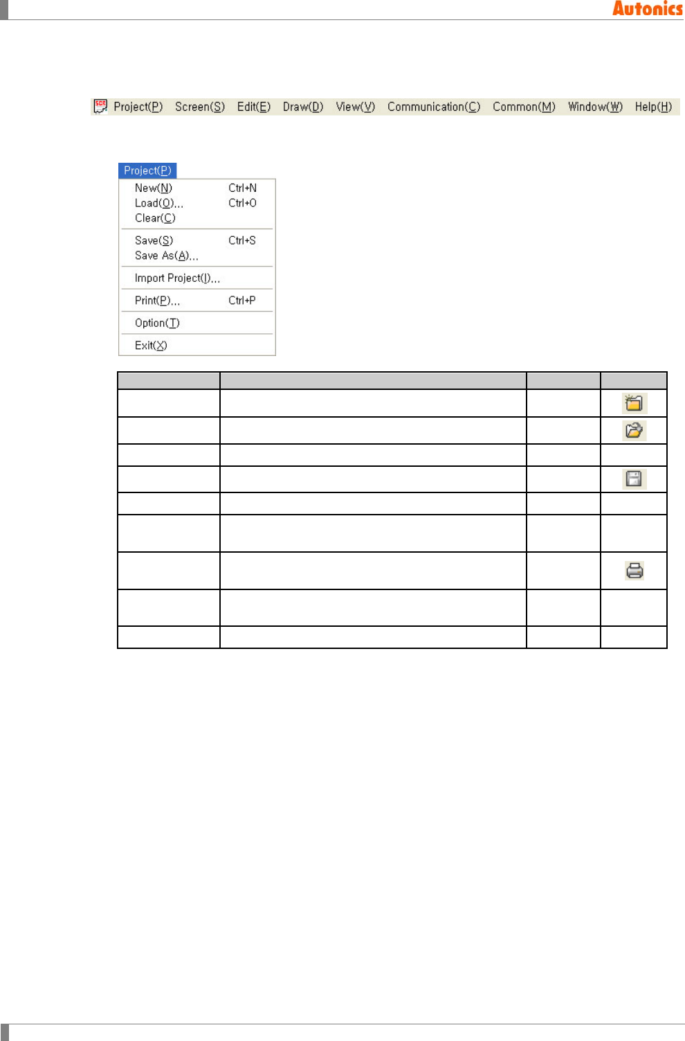
(1) Project
There are for project menus as following.
Menu
Description
Hot key
Icon
New Creates a new project. Ctrl+N
Load Opens saved project Ctrl+O
Clear Closes project
Save Saves project Ctrl+S
Save As Saves project as other name
Import Project Imports base screen, window screen, part,
comment on current project.
Print Prints project (project Information, base screen,
window screen) with printer or as file. Ctrl+P
Option Configure optional items such as save file, toolbar
position, communication configuration.
Exit Exits program Ctrl+X
1 Product Overview
© Copyright Reserved Autonics Co., Ltd. 21
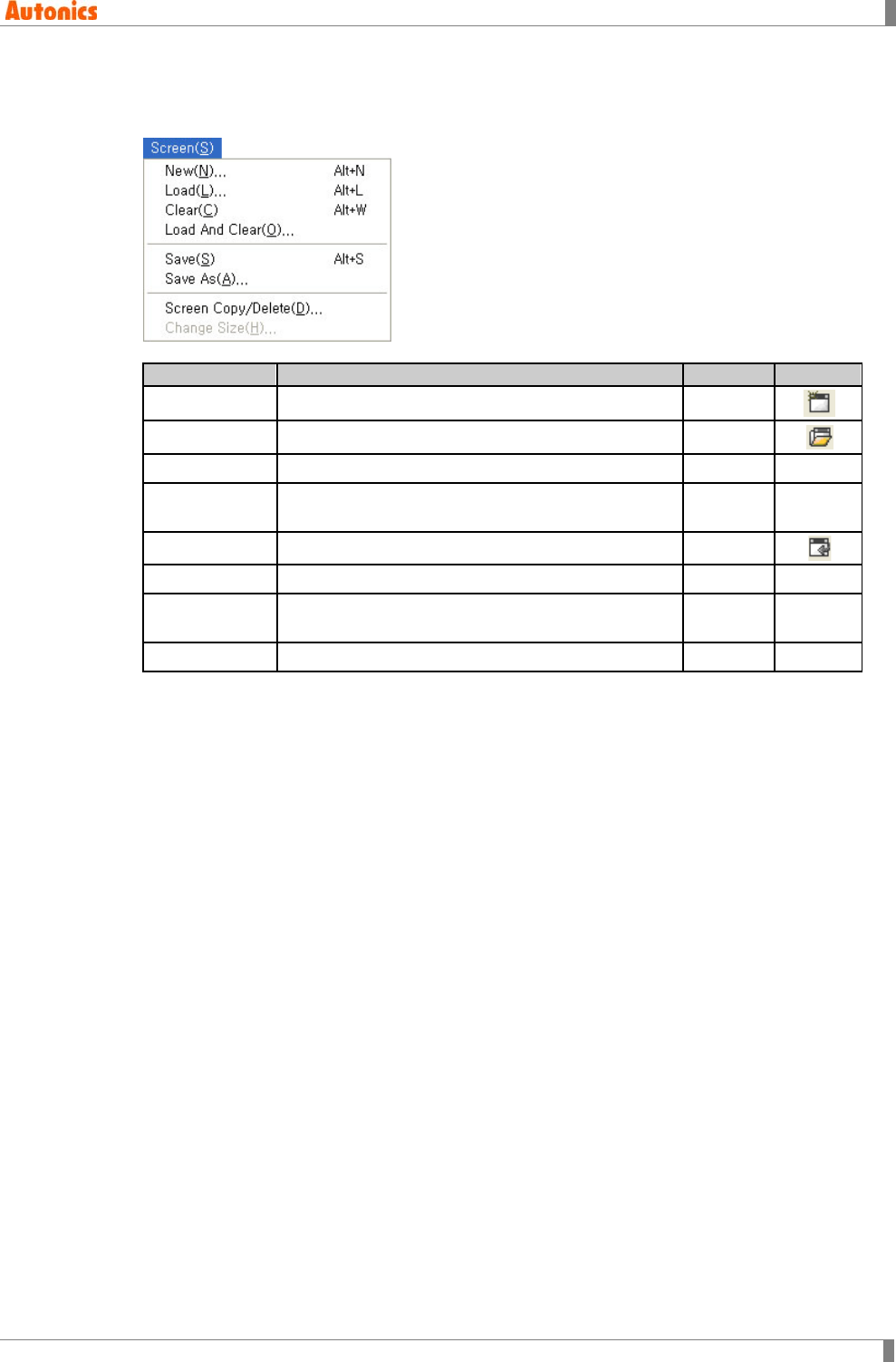
(2) Screen
There are for screen menus as following such as new, load, clear and screen copy/delete,
etc.
Menu
Description
Hot key
Icon
New Creates a new screen Alt+N
Load Loads closed screen of current project Alt+L
Clear Clears screen Alt+W
Load And
Clear Clears and loads screen
Save Saves screen of current project Alt+S
Save As Saves screen as other name
Screen
Copy/Delete Copies/deletes successive screens of project at a
time.
Change Size Adjusts window screen size
1 Product Overview
22 © Copyright Reserved Autonics Co., Ltd.
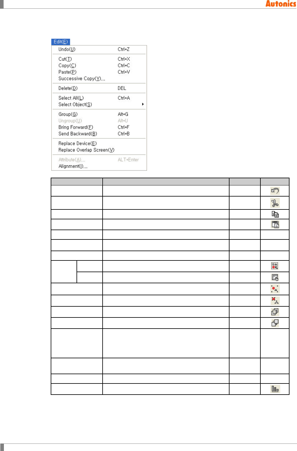
(3) Edit
There are for project edit menu such as undo, cut, copy, etc.
Menu
Description
Hot key
Icon
Undo Undoes movement, delete, size adjustment etc. Ctrl+Z
Cut Cuts selected object and saves it in clip board Ctrl+X
Copy Copies selected object on screen Ctrl+C
Paste Pastes copied or cut objects on screen Ctrl+V
Sucessive Copy Copies selected object successively
Delete Deletes selected object Del
Select All Selects all objects Ctrl+A
Select
Object
Figure Selects figure (Click a mouse or select all)
Tag Selects tag
Group Groups selected objects
Ungroup Disorganizes group
Bring Forward Moves selected object to the forward Ctrl+F
Send Backward Moves selected object to the backward Ctrl+B
Replace Device
Changes device used for tag and it is available
to select applicable range as all project, current
screen, selected object, used device for
common configuration.
Replace Overlap
Screen Changes overlapped screen as other screen
Attribute Edits attribution of selected object
Alignment Aligns screen arrangement of selected object
1 Product Overview
© Copyright Reserved Autonics Co., Ltd. 23
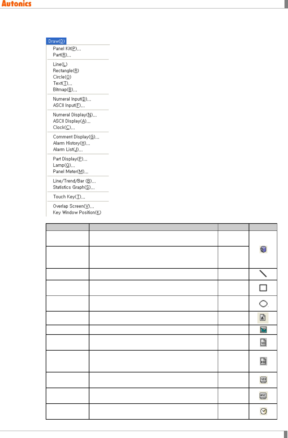
(4) Draw
Draw menu for panel kit, part, line, rectangle, etc is as following.
Menu
Description
Hot key
Icon
Panel Kit Executes for panel kit: panel kit registration,
drawing on screen, save as file, load etc.
Part Registers selected object as part, drawing
registered part on screen, part library operation
etc.
Line Draws lines and configures color and style of line
Rectangle Draws rectangles, and configures color, style of
outline and pattern filled inside of rectangle
Circle Draws circles, and configures color, style of
outline and pattern filled inside of circle
Text Enters text, and configures color and size of text
Bitmap Selects bitmap image and inserts it
Numeral Input Creates numeric input tags and configures value
of designated word device with key window
ASCII Input Creates ASCII input tags and configures value of
designated word device as ASCII code with key
window
Numeral
Display Creates numeric display tag, displays numeric
value saved in PLC device
ASCII Display Creates ASCII display tag, displays ASCII value
saved in PLC device
Clock Creates clock display tag, displays current time or
date
1 Product Overview
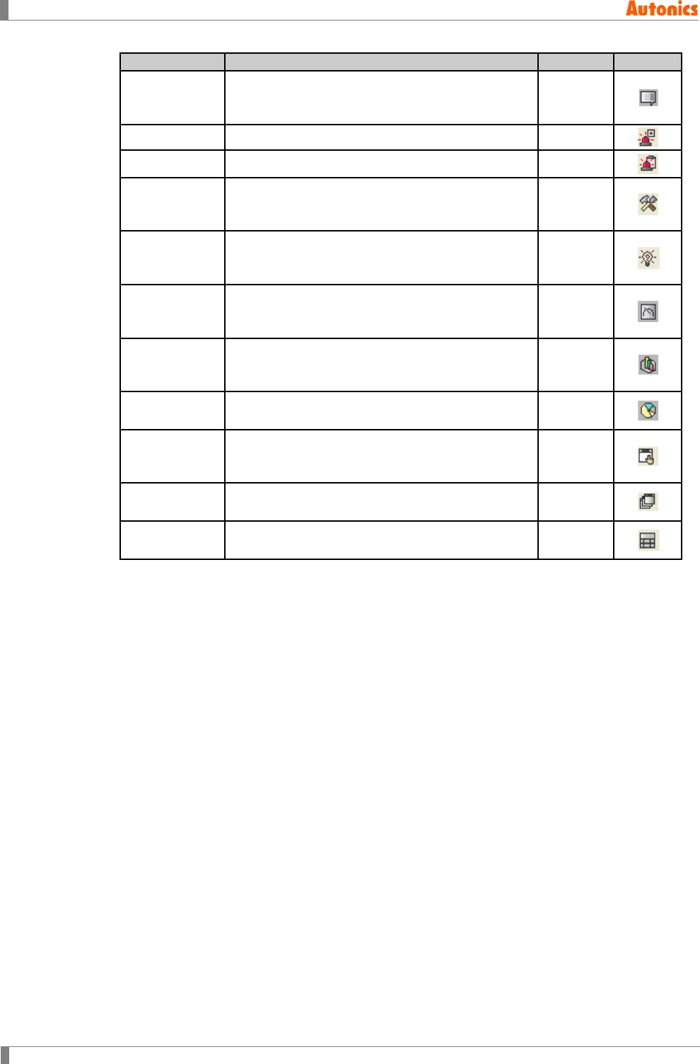
24 © Copyright Reserved Autonics Co., Ltd.
Menu
Description
Hot key
Icon
Comment
Display
Creates comment display tag, displays designated
comment in accordance with change of
designated PLC device value or state
Alarm History Creates alarm history tag, and writes alarm history
Alarm List Creates alarm list tag, and displays alarm list
Part Display Creates part display tag, displays designated part
in accordance with change of designated PLC
device value or state
Lamp Creates lamp tag, displays designated type of
lamp in accordance with ON/OFF of designated
bit device
Panel Meter Creates panel meter tag, and indicates
percentage of max/min. value of designated word
device with meter needle
Line/Trend/Bar Creates line/trend/bar graph tag, displays
designated word device value with line/trend/bar
graph type
Statistics
Graph Creates statistic graph tag, displays percentage of
designated word device value as graph
Touch Key Creates touch key tag, switches screen, operates
bit device, sets word device and executes special
function by pressing touch key
Overlap
Screen Draws overlap screen on the current screen
Key Window
Position Designates the position of key window appeared
when inputting numeric and ASCII as upper left
1 Product Overview
© Copyright Reserved Autonics Co., Ltd. 25
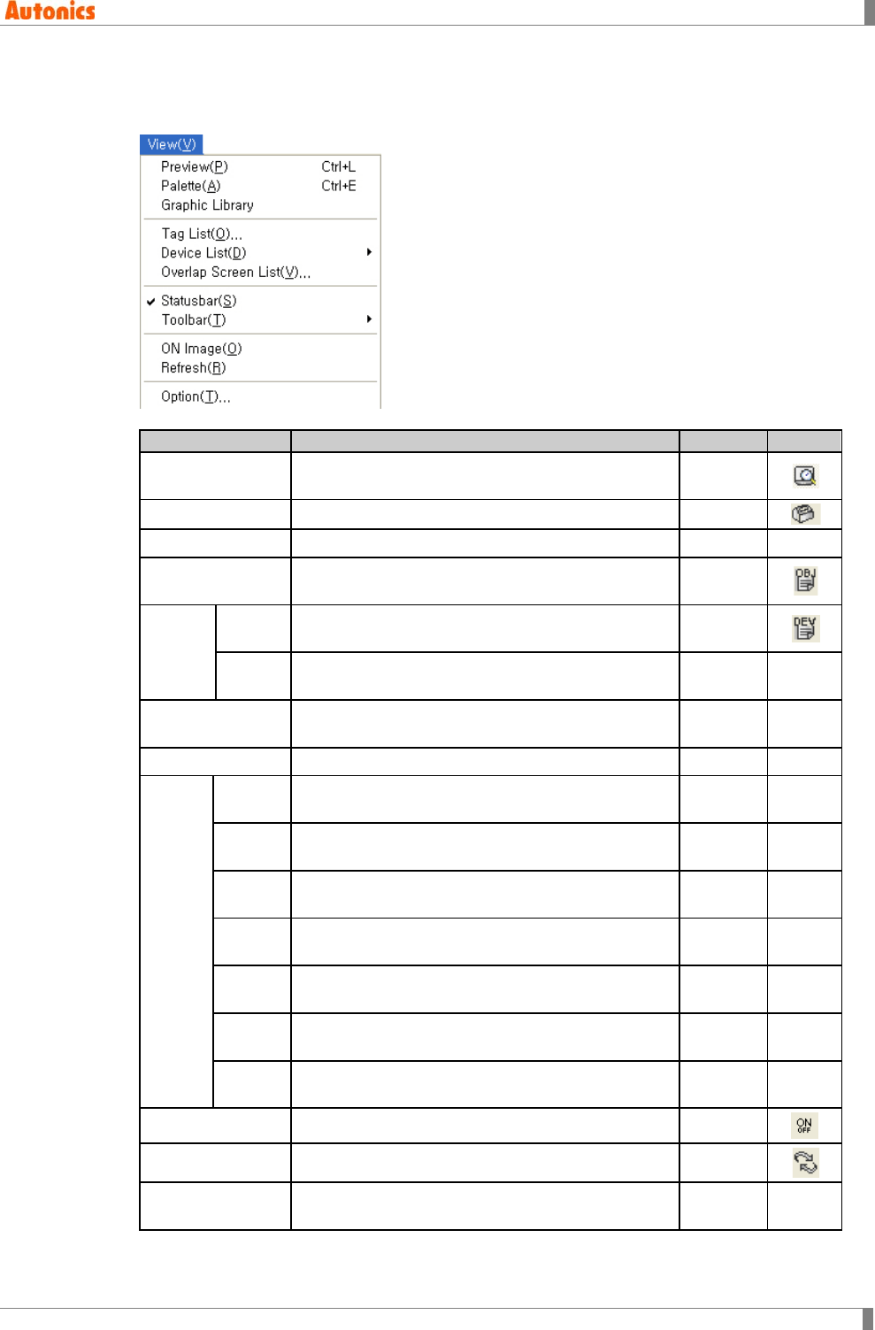
(5) View
View menu is for preview of screen on GP/LP with 100% ratio, and specifying whether to
display toolbar, showing tag/device list.
Menu
Description
Hot key
Icon
Preview Shows screen on the GP/LP with 100% of
enlargement ratio
Palette Displays tools
Graphic Library Select graphic library
Tag List Shows tag list of current screen and edits each
attribution
Device
List
Screen Shows device list used for tag of current screen
and changes it
Project Shows device list used for project of current
screen and changes it
Overlap Screen
List Shows overlapped screen list on current base
screen and changes it
Status bar Displays status bar
Tool
bar
System
Toolbar Displays system tool bar
View
Toolbar Displays view tool bar
Figure
Toolbar Displays figure tool bar
Edit
Toolbar Displays edit tool bar
Tag
Toolbar Displays tag tool bar
Draw
Toolbar Displays draw tool bar
Worksp
acebar Displays work space
ON Image Shows tag as ON status with checking, or as OFF
Refresh Refresh screen
Option Configures arrangement of view option and tool
assembly
1 Product Overview
26 © Copyright Reserved Autonics Co., Ltd.
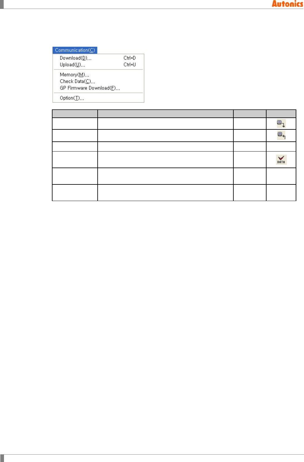
(6) Communication
For communicate with GP Editor and GP/LP, there are for communication menu such as
download, upload, and check data.
Menu
Description
Hot key
Icon
Download Downloads screen data on GP/LP Ctrl+D
Upload Uploads current screen data of GP/LP Ctrl+U
Memory Checks and deletes screen data of GP/LP
Check Data Examines availability of edited data and edits
error object
GP Firmware
Download Downloads the firmware of GP/LP by GP Editor
Option Designates communication option such as port or
baud rate, etc.
1 Product Overview
© Copyright Reserved Autonics Co., Ltd. 27
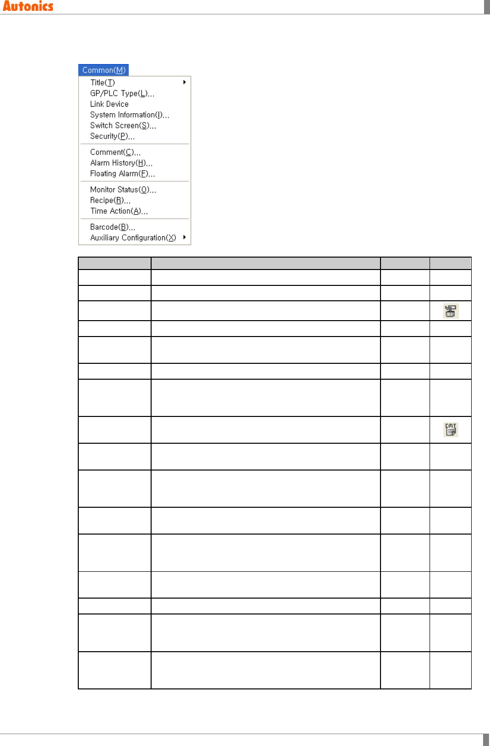
(7) Common
There are GP/LP system common configuration menus.
Menu
Description
Hot key
Icon
Title-Project Edits project title and detail descriptions
Title-Screen Edits screen title and detail descriptions
GP/PLC Type Confirms and changes of connection PLC
Link Device Edits link device configurations
System
Information Checks read device, write device
Switch Screen Designates device for switching screen
Security Designates password for security level, usage of
security for system screen and communication
security
Comment Edits comment using commonly in alarm
history/alarm list/comment display tags
Alarm History Configures monitor device for alarm and observe
period
Floating Alarm Configures the floating alarm: the specified comment
floats from the right to left at bottom of screen when
designated observation device is ON
Monitor Status Configures bit device state or word device value
when specified trigger device has designated status
Recipe Configures the recipe: executes read/write operation
for several word devices when specified trigger
device is ON
Time Action Configures the time action: maintains bit device as
ON state during certain time
Barcode Configures the barcode input
Auxiliary
Configuration-
Project
Configures key window operation, edit direction,
communication, language, buzzer and position of
system access button etc.
Auxiliary
Configuration-
Screen
Configures input focus movement of data input tag,
key window operation, allowance of floating alarm
and security level etc.
1 Product Overview
28 © Copyright Reserved Autonics Co., Ltd.
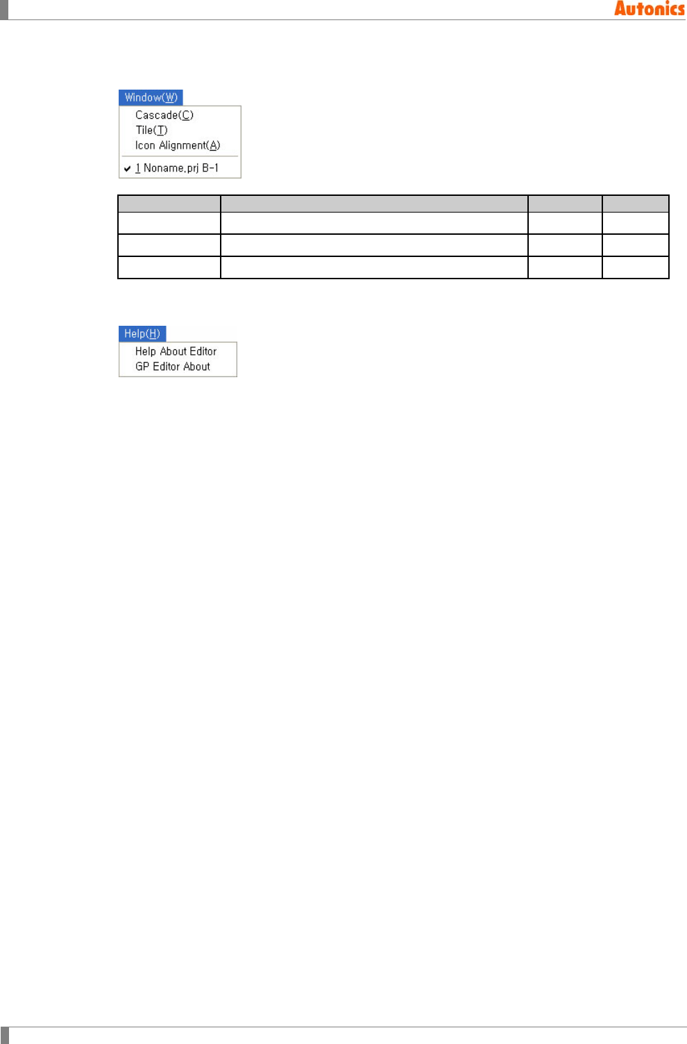
(8) Window
There are for windows alignment of GP Editor.
Menu
Description
Hot key
Icon
Cascade Arranges several screens hierarchically
Tile Arranges several screens as tiles
Icon Alignment Aligns minimized screen icons
(9) Help
Help menu is for GP Editor’s information.
1 Product Overview
© Copyright Reserved Autonics Co., Ltd. 29
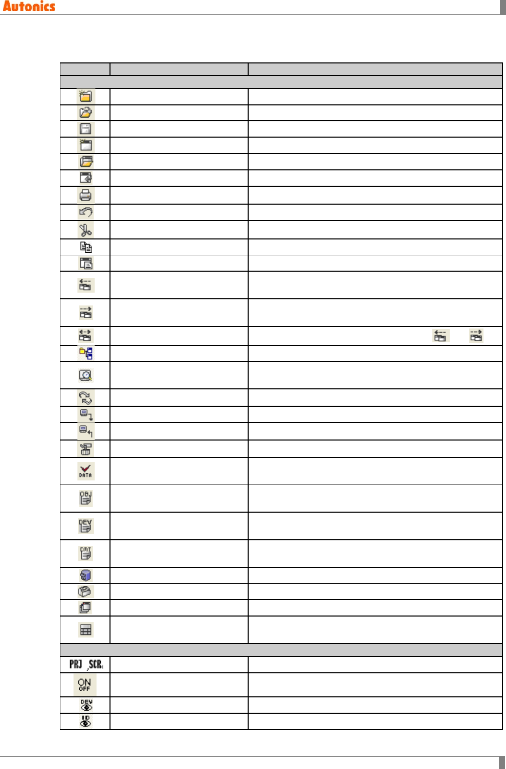
1.5 Tool
Icon
Menu
Description
System tool
Project-New Creates a new project
Project-Load Opens saved project
Project-Save Saves project
Screen-New Creates a new screen
Screen-Load Loads closed screen of current project
Screen-Save Saves screen of current project
Project-Print Prints project
Edit-Undo Undoes movement, delete, size adjustment etc.
Edit-Cut Cuts selected object and saves it in clip board
Edit-Copy Copies selected object on screen
Edit-Paste Pastes copied or cut objects on screen
- Switches the latest number screen before the current
editing screen
- Switches the next number screen after the current
editing screen
- Opens the closed screen when clicking or
View-Toolbar- Workspacebar Displays work space
View-Preview Shows screen on the GP/LP with 100% of enlargement
ratio
View-Refresh Refresh screen
Communication-Download Downloads screen data on GP/LP
Communication-Upload Uploads current screen data of GP/LP
Common-GP/PLC Type Confirms and changes of connection PLC
Communication-Check Data Examines availability of edited data and edits error
object
View-Tag List Shows tag list of current screen and edits each
attribution
View- Device List Shows device list used for tag of current screen and
changes it
Common-Comment Edits comment using commonly in alarm history/alarm
list/comment display tags
Draw-Panel Kit/Part ‘Library’ of panel kit/part dialog box appears
View-Palette Displays tools
Draw-Overlap Screen Draws overlap screen on the current screen
Draw-Key Window Position Designates the position of key window appeared when
inputting numeric and ASCII as upper left
View tool
- Applies view tools to by project or screen
View-ON Image Shows tag as ON state, or as OFF
View-Device List Shows device list used for tag of current screen
View-Tag ID Shows tag ID
1 Product Overview
30 © Copyright Reserved Autonics Co., Ltd.
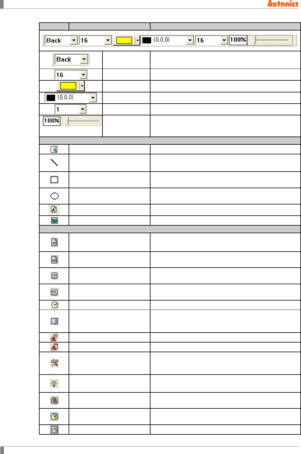
Icon
Menu
Description
- Designates grid display type
- Designates grid interval
- Designates grid color
- Designates background color
- Designates grid snap
- Designates an enlargement ratio
Drawing tool
Alters mouse cursor for selection
Draw-Line Draws lines and configures color and style of line
Draw-Rectangle Draws rectangles, and configures color, style of outline
and pattern filled inside of rectangle
Draw-Circle Draws circles, and configures color, style of outline and
pattern filled inside of circle
Draw-Text Enters text, and configures color and size of text
Draw-Bitmap Selects bitmap image and inserts it
Tag tool
Draw-Numeral Input Creates numeric input tags and configures value of
designated word device with key window
Draw-ASCII Input Creates ASCII input tags and configures value of
designated word device as ASCII code with key window
Draw-Numeral Display Creates numeric display tag, displays numeric value
saved in PLC device
Draw-ASCII Display Creates ASCII display tag, displays ASCII value saved in
PLC device
Draw-Clock Creates clock display tag, displays current time or date
Draw-Comment Display Creates comment display tag, displays designated
comment in accordance with change of designated PLC
device value or state
Draw-Alarm History Creates alarm history tag, and writes alarm history
Draw-Alarm List Creates alarm list tag, and displays alarm list
Draw-Part Display Creates part display tag, displays designated part in
accordance with change of designated PLC device value
or state
Draw-Lamp Creates lamp tag, displays designated type of lamp in
accordance with ON/OFF of designated bit device
Draw-Line/Trend/Bar Creates line/trend/bar graph tag, displays designated
word device value with line/trend/bar graph type
Draw-Statistics Graph Creates statistic graph tag, displays percentage of
designated word device value as graph
Draw-Panel Meter Creates panel meter tag, and indicates percentage of
1 Product Overview
© Copyright Reserved Autonics Co., Ltd. 31
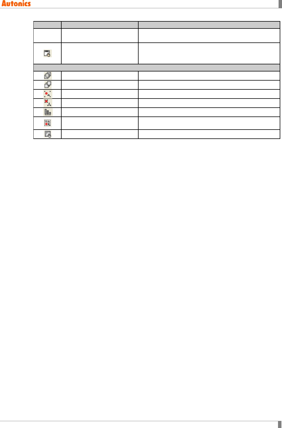
Icon
Menu
Description
max/min. value of designated word device with meter
needle
Draw-Touch Key Creates touch key tag, switches screen, operates bit
device, sets word device and executes special function
by pressing touch key
Edit tool
Edit-Bring Forward Moves selected object to the forward
Edit-Send Backward Moves selected object to the backward
Edit-Group Groups selected objects
Edit-Ungroup Disorganizes group
Edit-Alignment Aligns screen arrangement of selected object
Edit-Select Object-Figure Selects figure (Click it with mouse or select all)
Edit-Select Object-Tag Selects tag
1 Product Overview
32 © Copyright Reserved Autonics Co., Ltd.
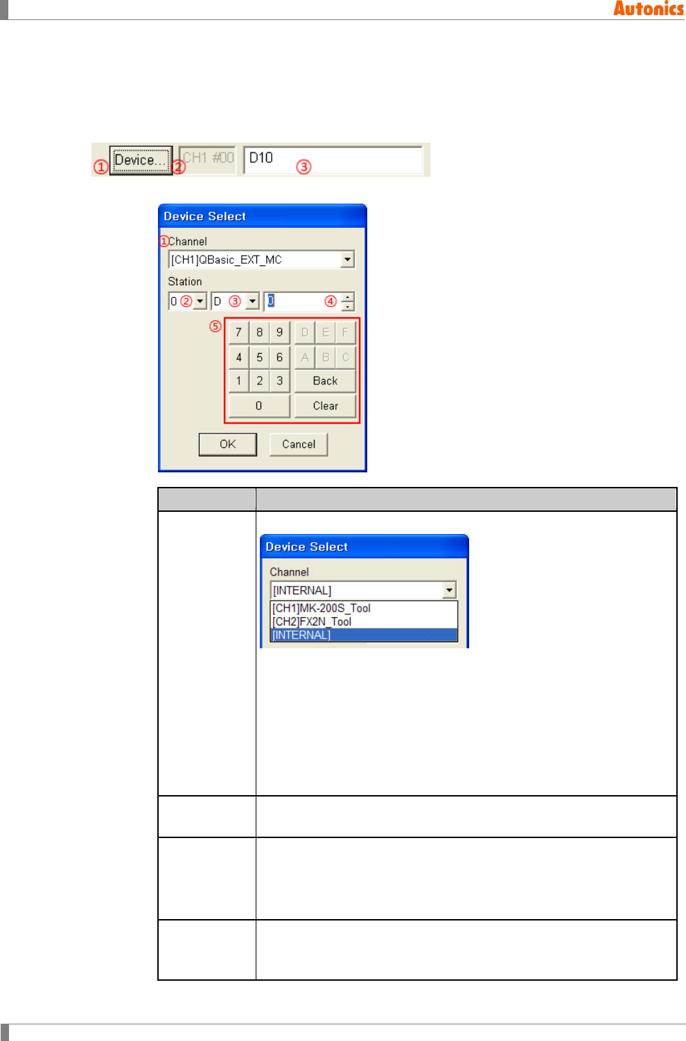
1.6 Device
Tag and common configuration is available for monitoring and setting the device value of the
connected PLC. For selecting the device, ‘Device Select’ dialog box has the following
construction.
① ‘Device Select’ dialog box appears.
Device Select
Description
①Channel
Select the set device channel by pull-down menu.
[CH1]: Select this when using the device for CH1 protocol.
[CH2]: Select this when using the device for CH2 protocol.
[INTERNAL]: Select this when using GP/LP inner device.
Mono type(GP-S044, GP-S057, LP-S044) is able to select only
CH1, INTERNAL. For selecting CH2, link device should be set.
(Refer to ‘8.3 Link Device’ for more information of link device.)
Color type(GP-S070, LP-S070) is able to select CH1, CH2, and
INTERNAL.
②Station Select the station information of the set device by pull-down menu.
(It may not support address depending on the connected device.)
③Device Name
Displays the selectable device by the device of ①. Select the device to
use by pull-down menu.
(The selectable device is different depending on PLC, refer to ‘GP, LP
user manual for communication’.)
④Address
Designate the device address.
(Device address range depends on PLC type. Refer to ‘GP, LP user
manual for communication’.)
1 Product Overview
© Copyright Reserved Autonics Co., Ltd. 33
⑤Key Edits device address with key. By device address form, the related key
is activated.
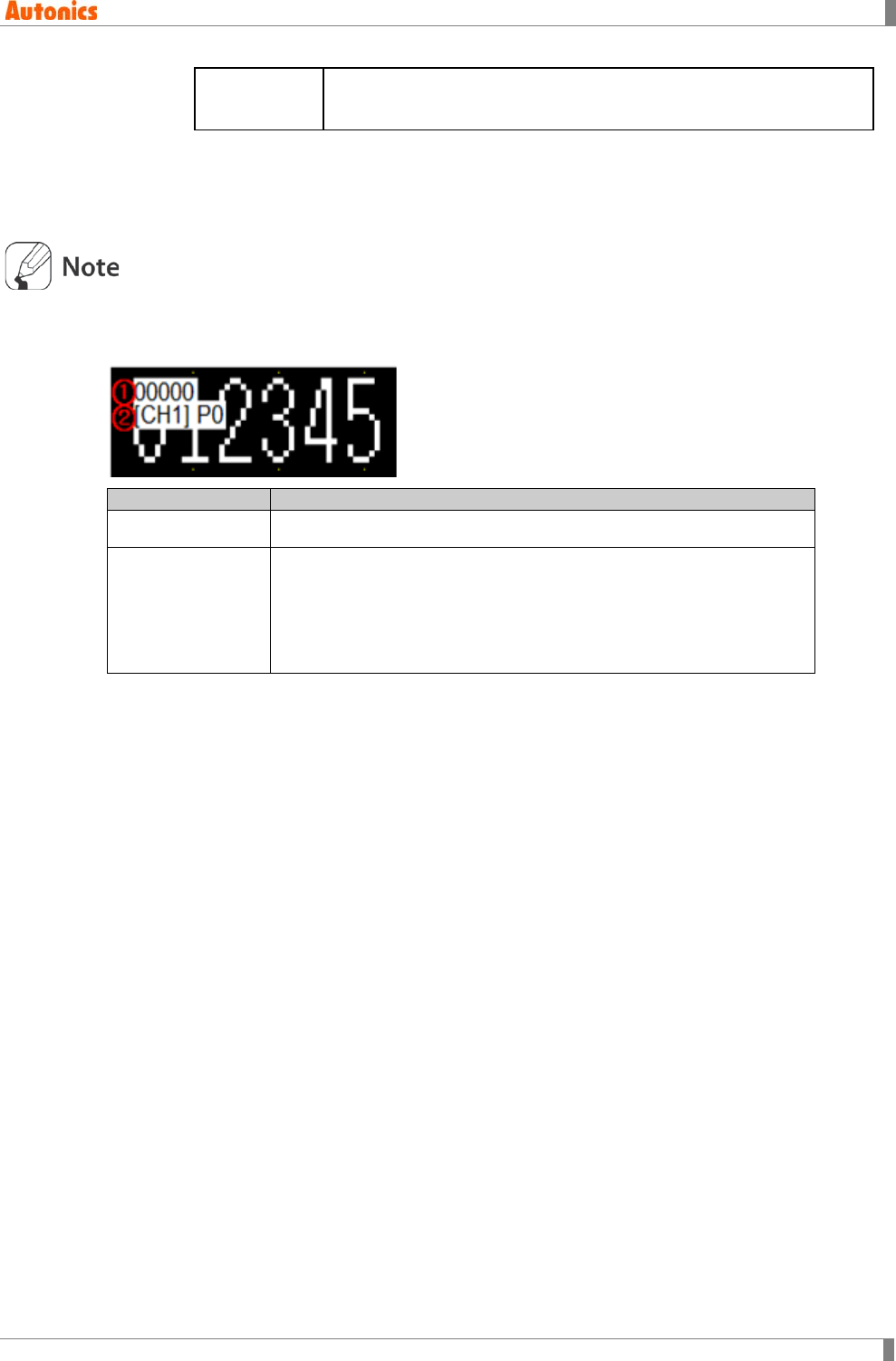
② Indicates the set device channel and address. The indicated address form is
'CH'+Channel number+space +'#' +Address number (3 digit), UB/UW device is not
indicated.
Ex) The address of CH1 is 15: CH1 #015
③ Indicates the set device.
[Device address mark]
Drawn tag is marked with tag ID, channel, and device.
Item
Description
①Tag ID Tag ID which is placed at activated drawing screen.
②Channel, device
Displays set channel and device address.
Channel is marked as [CH1], [CH2], or [INT].
Ex)
In case of [CH1]P0, it displays using CH1 protocol P0 device.
In case of [INT]M0, it displays using GP/LP inner device M0.

1 Product Overview
34 © Copyright Reserved Autonics Co., Ltd.
2 Project
© Copyright Reserved Autonics Co., Ltd. 35
2 Project
This chapter describes to create project, to execute program, to configure project attribution and
manage project including save, open and import.
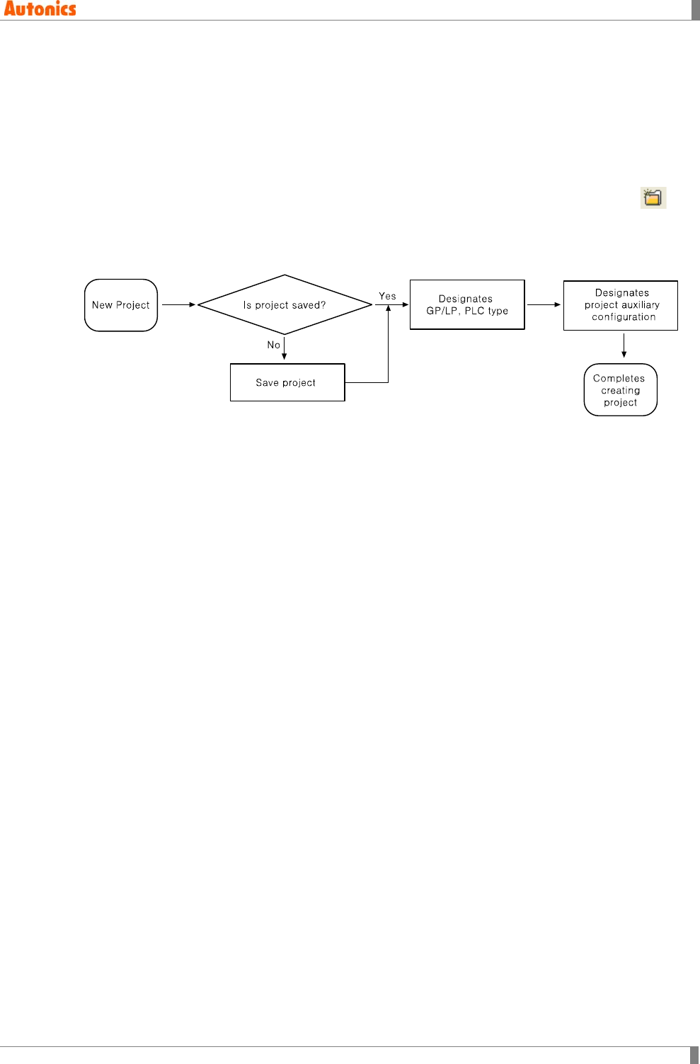
2.1 New Project
You can create new project to select [Project]-[New] of menu, to press Ctrl+N, or to click of
tool bar.
When creating new project, you can designate GP/PLC type and basic configuration including
edit direction, communication, and language as project auxiliary property.
This process is for reducing data writing error providing required items automatically when user
create new project. User should keep this comment to protect from design errors when creating
project and designate type of connection equipment, then, device of connection equipment can
be defined automatically for editing.
2 Project
36 © Copyright Reserved Autonics Co., Ltd.
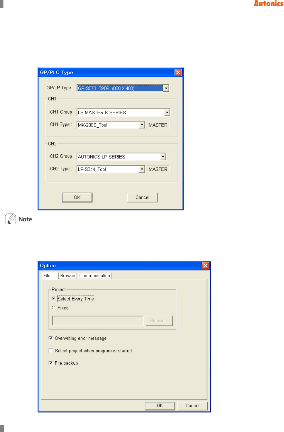
2.1.1 GP/PLC type
When creating a new project, you can designates GP/LP and PLC type on ‘GP/PLC Type’ dialog
box. To operate downloaded screen data on GP Editor, user should designate GP and PLC type
to be used in the editor correctly.
Select [Common]-[GP/PLC Type] of menu to change the designated GP and PLC type.
When starting GP Editor, for not to appear ‘Project Select’ ‘GP/PLC Type’ dialog box:
Select [Project]-[Option] of menu and non-check ‘Select project when program is started’. When
starting GP Editor after this, GP and PLC type is designated automatically as the latest saved
project’s type. ‘Project Select’ and ‘GP/PLC Type’ dialog box does not appear.
2 Project
© Copyright Reserved Autonics Co., Ltd. 37
2.1.2 Project auxiliary property
When creating a new project, ‘Project Auxiliary Property’ dialog box appears automatically after
designating ‘GP/PLC type’ dialog box. Select [Common]-[Auxiliary Configuration]-[Project] of
menu to change project auxiliary property.
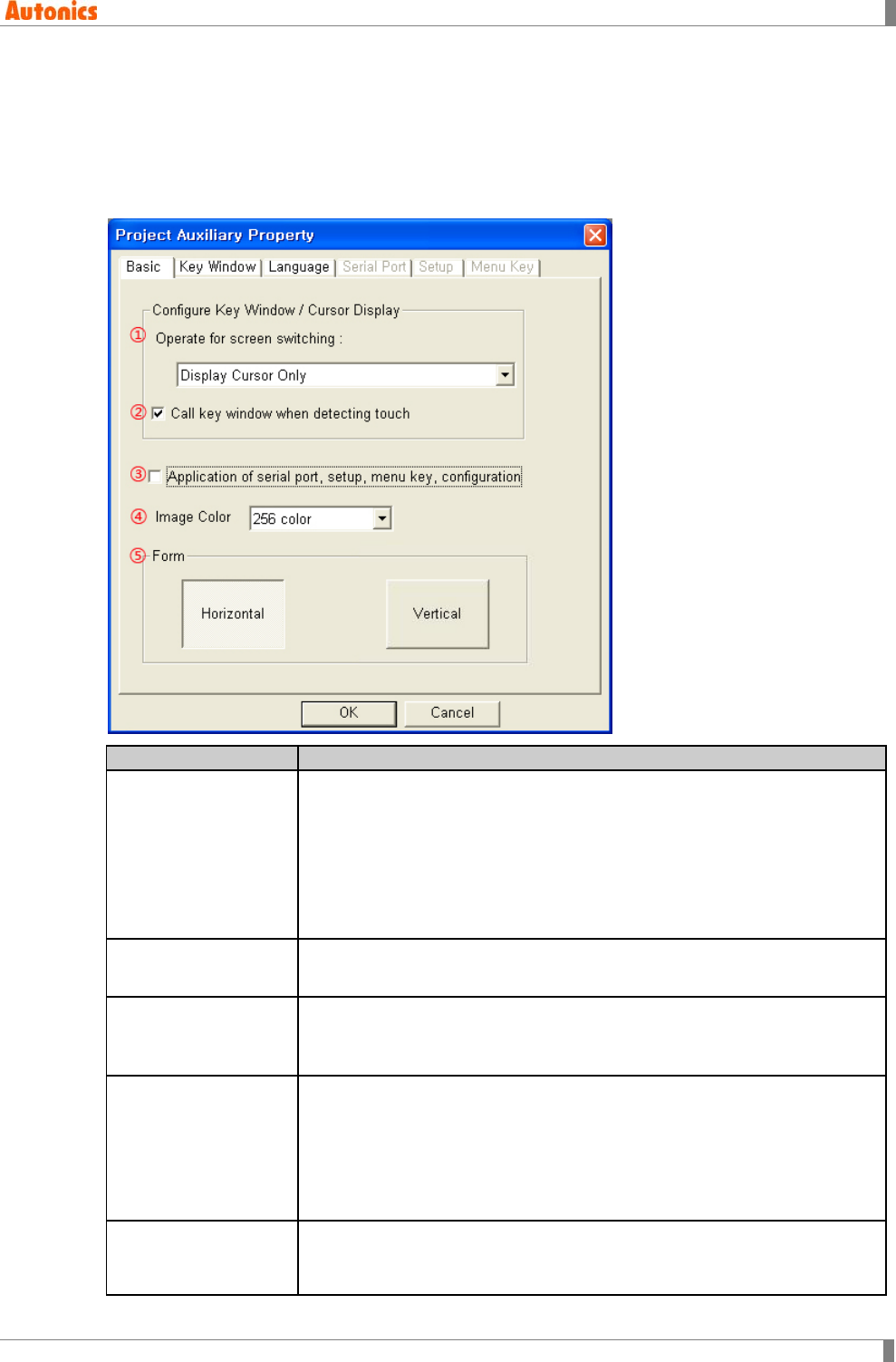
2.1.2.1 Basic tab
Basic
Description
①Operate for screen
switching
Configures key window and cursor display state when changing screen
with key input by pull-down menu.
Do Not Display Cursor And Key Window: Does not display cursor and
key window both when changing screen with key input.
Display Cursor Only: Displays cursor only when changing screen.
Display Cursor And Key Window: Displays cursor and key window
both.
②Call key window
when detecting touch Specifies whether to call key window when detecting touch.
③Application of serial
port, setup, menu key,
configuration
Check to activate ‘Serial Port, Setup, Menu Key’ tab.
④Image Color
Designates the number of image color for project by pull-down menu.
Mono type (GP-S044, GP-S057, LP-S044): 'Image Color' pull-down
menu is non-activated. If the selected image is not mono, it is changed
as mono and registered at project.
Color type(GP-S070, LP-S070): Select mono, 256 color, 16bit color, or
24bit color.
⑤Form
Horizontal: Edit as horizontal direction
Vertical: Edit as vertical direction (Activated only for GP-S044, LP-S044
type)
2 Project
38 © Copyright Reserved Autonics Co., Ltd.
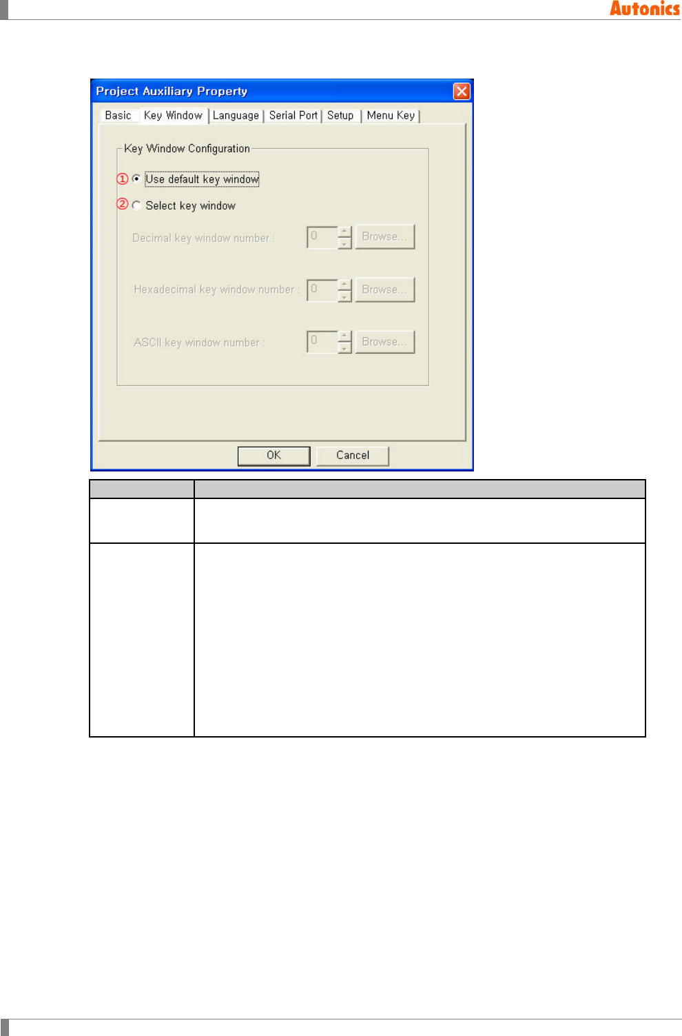
2.1.2.2 Key window tab
Key Window
Description
①Use default
key window Uses default key window supplied system.
②Select key
window
There are three key windows on GP/LP: Decimal key window, Hexadecimal
key window, ASCII key window. Uses user-defined key window. (User
should designate key window separately.)
It is able to select alternating window for each items and has own window
screen number with 0 to 500 of configuration range. When it designated as
0, default key window is used for the item.
Decimal key window number: It is called when it is decimal with
sign/without sign in numeral input tag.
Hexadecimal key window number: It is called when it is hexadecimal in
numeral input tag.
ASCII key window number: It is called in ASCII input tag.
2 Project
© Copyright Reserved Autonics Co., Ltd. 39
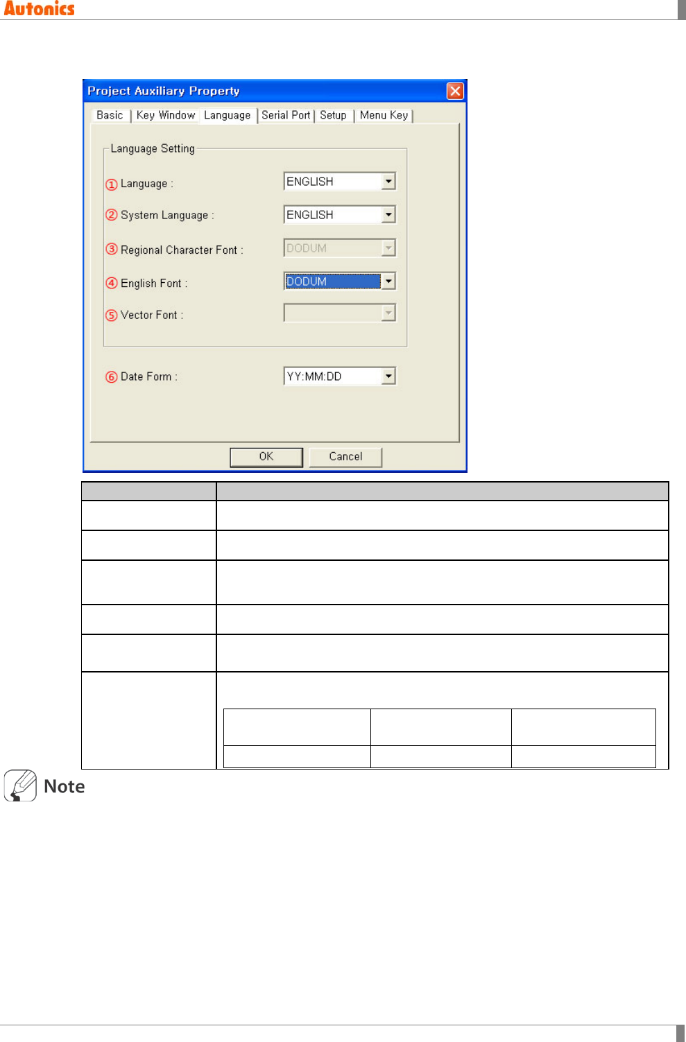
2.1.2.3 Language tab
Language
Description
①Language Configures using language by pull-down menu.
②System language Configures language using in system screen of GP/LP by pull-down menu.
③Regional
Character Font Configures bitmap font of regional character by pull-down menu.
④English Font Configures bitmap font of ASCII character by pull-down menu.
⑤Vector Font Configures vector font by pull-down menu. (Activates only for color
type(GP-S070, LP-S070))
⑥Date Form
Designates the data form from 6 types of date display form for display of
system screen by pull-down menu.
YY(Year):MM(Month):
DD(Day) YY:DD:MM DD:YY:MM
DD:MM:YY MM:DD:YY MM:YY:DD
Configuration of language: The character display in editing on GP Editor and in displays on
GP/LP is displayed according to character code for the designated language.
For editing of text, configure same with language configuration of current operating system.
For example, configure language as Korean in PC using English OS, it is written as English.
It refers to Korean character code and it may displays incorrectly for input text
Configuration of font: If configured font in language tab is different in GP/LP’s one, it is
downloaded together when downloading GP Editor’s data. There are ASCII character font
and regional character font.
2 Project
40 © Copyright Reserved Autonics Co., Ltd.
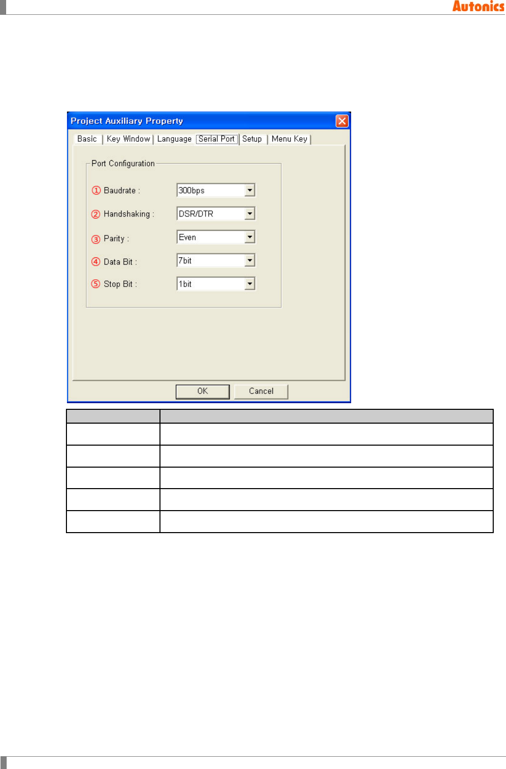
2.1.2.4 Serial port tab
It is configuration of serial connection when connecting main device with editor, barcode reader
and print. It is configuration of CH1 communication port, in [SYSTEM SETTING]-[Connect PLC]
of mono type GP/LP or in [SYSTEM SETTING]-[Environment]- [Serial Communication] of color
type GP/LP.
Serial Port
Setting value
①Baudrate 300, 600, 900, 1200, 2400, 4800, 9600, 19200, 38400, 57600, 115200bps
②Handshaking XON/XOFF, DSR/DTR
③Parity None, Even, Odd
④Data Bit 7, 8 bit
⑤Stop Bit 1, 2 bit
2 Project
© Copyright Reserved Autonics Co., Ltd. 41
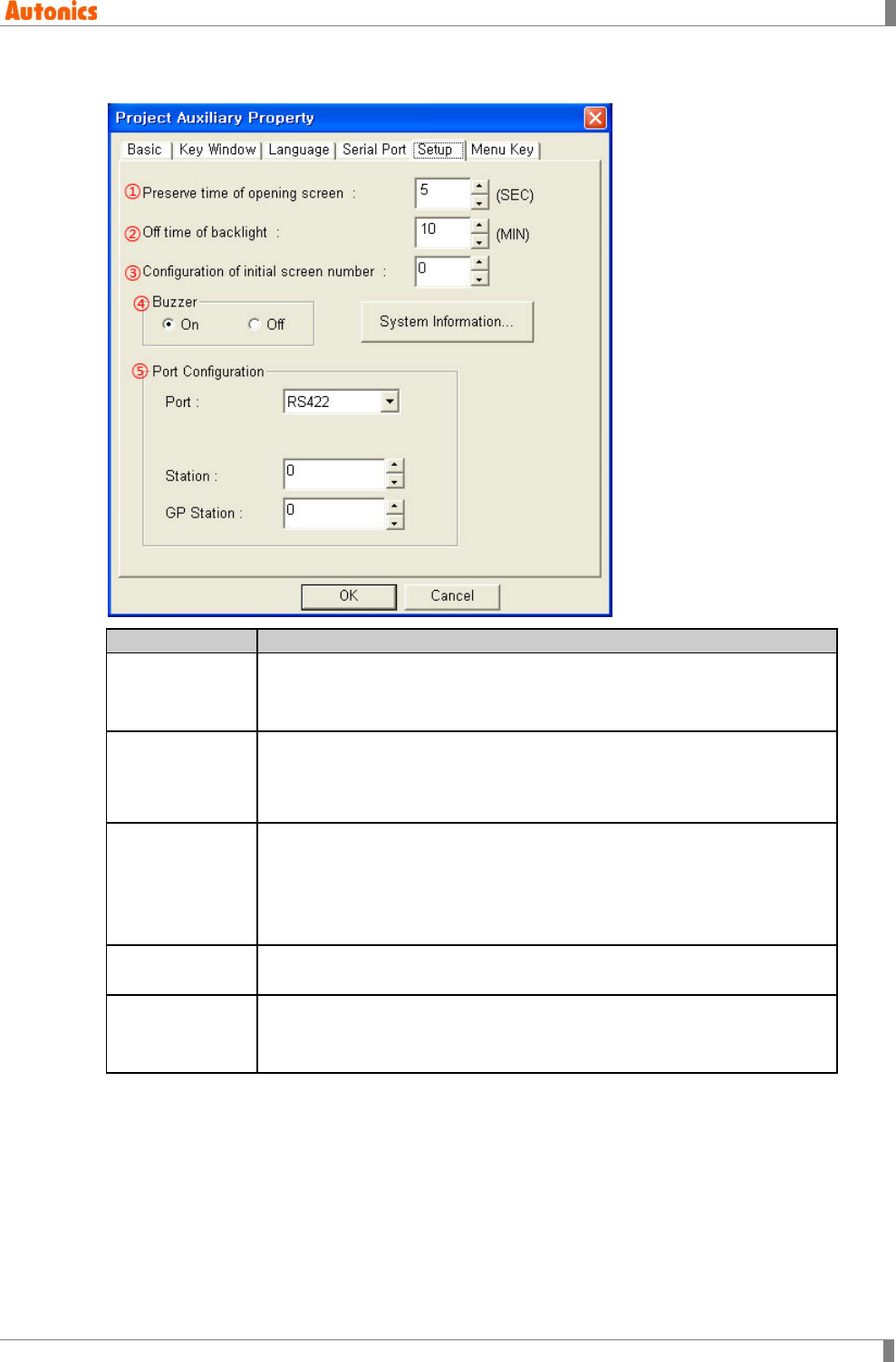
2.1.2.5 Setup tab
Setup
Description
①Preserve time
of opening
screen
When supplying power on GP/LP, it shows basic information (releasing
year, firmware version) as opening screen. It is able to set preserve time
of this screen with range of 0 to 60 sec.
②Off time of
backlight
If there is no touch on screen of GP/LP until off time of backlight, LCD
backlight is OFF. Backlight is ON again when user touches it.
It is able to set as minute unit with range of 0 to 99 min and backlight will
not be OFF when it is configured as 0 min.
③Configuration
of initial screen
number
It designates to use designed user screen as opening screen.
It is able to set 0 to 500 of screen number. If it is designated as 0 or there
is no designated user screen number, it shows basic information
(Releasing year, firmware version) of product for ①preserve time of
opening screen.
④Buzzer It configures to buzzer or not to buzzer when pressing touch key or other
situation.
⑤Port
Configuration
Port: Specifies PLC and connecting port type by pull-down menu.
Station: Designates station of PLC from 0 to 255.
GP Station: Designates station of GP from 0 to 255.
2 Project
42 © Copyright Reserved Autonics Co., Ltd.
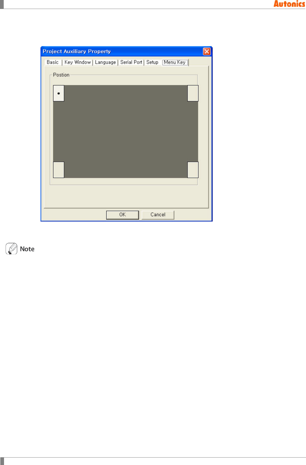
2.1.2.6 Menu key tab
Designates key position to enter system screen of GP/LP.
It is able to designate one point or two points among four corners of GP/LP screen. When
designating two points, press two corners simultaneously to enter system menu.
After supplying power, it is able to enter system menu with touching corner of upper-left (Based
on the horizontal).
2 Project
© Copyright Reserved Autonics Co., Ltd. 43
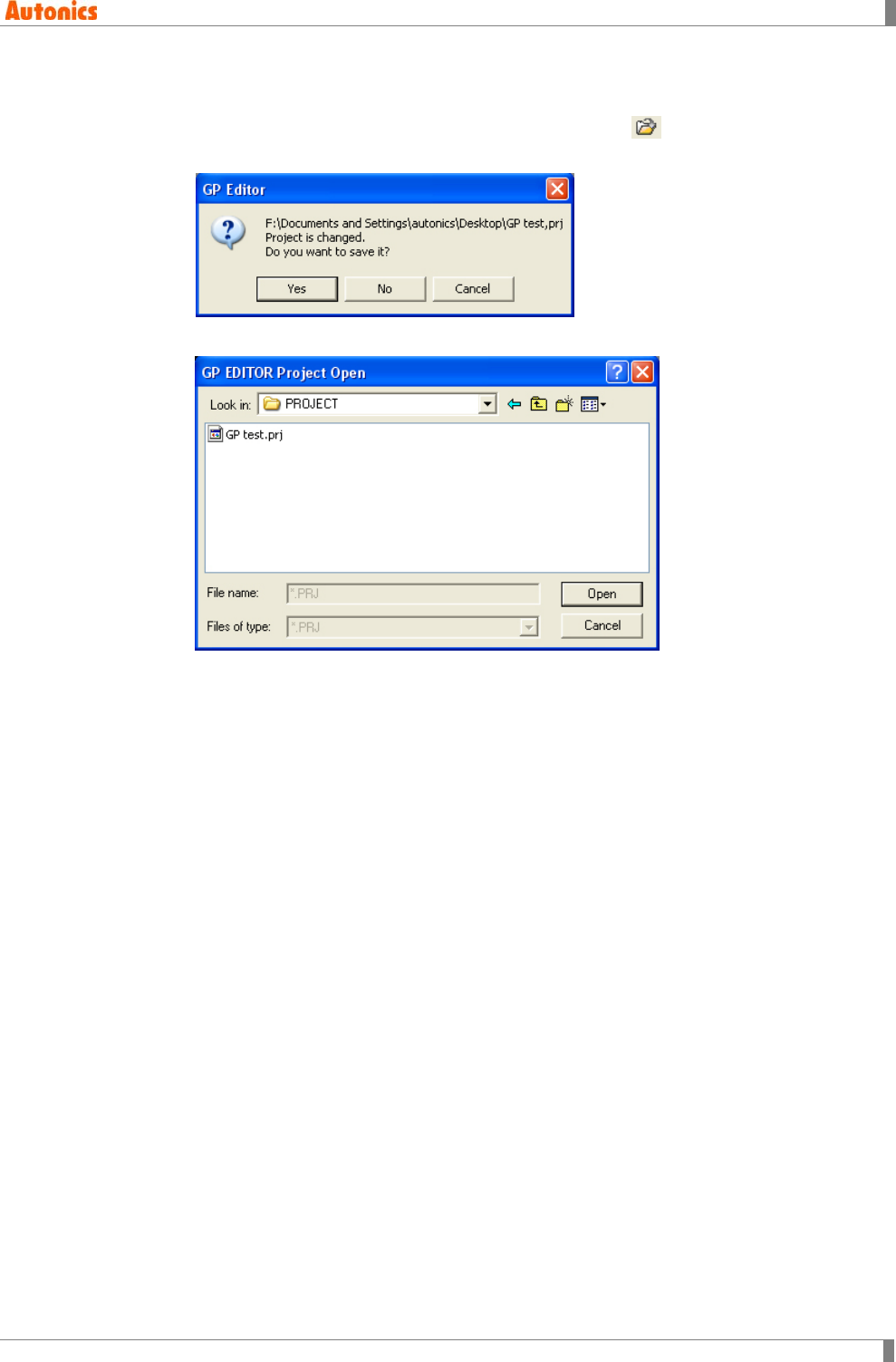
2.2 Load Project
1st Select [Project]-[Load] of menu, press Ctrl+O, or click of tool bar.
If the current project is not saved, the following message appears to save the project.
2nd ‘GP EDITOR Project Open’ dialog box appears.
3rd Designate the path to load project. Click ‘open’ and the selected project is open.
2 Project
44 © Copyright Reserved Autonics Co., Ltd.
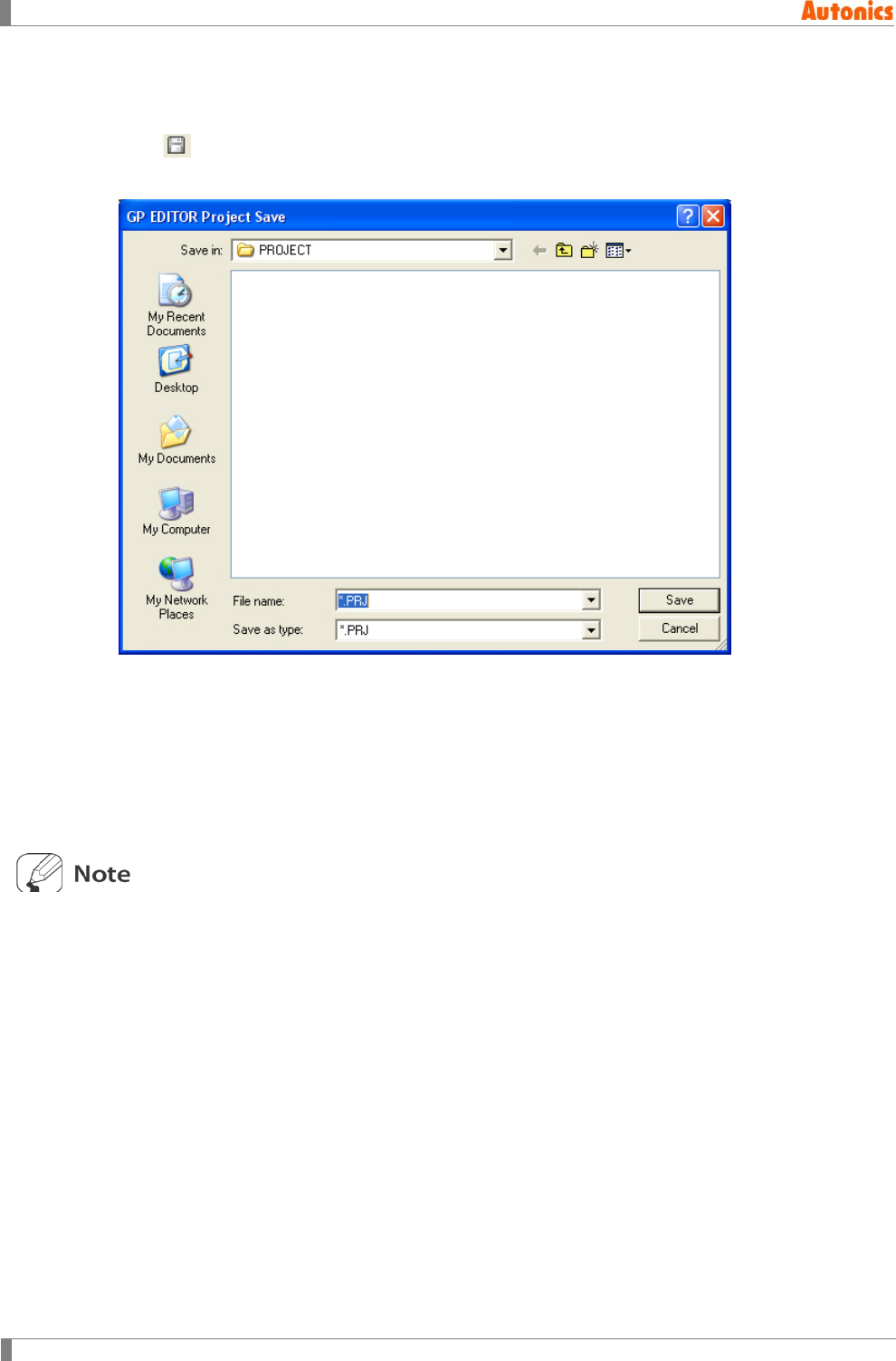
2.3 Save Project
You can save the edited project as a file to select [Project]-[Save] of menu, to press Ctrl+S, or to
click of tool bar.
If you want to save the project to another file name, select [Project]-[Save As] of menu.
[Project]-[Save]
If the project is not saved before, ‘GP EDITOR Project Save’ dialog box appears to
designate file path and save it. If the project is saved before, this dialog box does not
appear and is saved to overwrite on the saved project.
[Project]-[Save As]
‘GP EDITOR Project Save’ dialog box appears to designate file path and save as another
file name.
To save the latest state project when saving project:
Select [Project]-[Option] of menu and ‘Option’ dialog box appears. From ‘File’ tab, check
‘File backup’.
Mono type
It saves project file as ‘Backup.prj’ in the folder which has the project file. It creates
‘Backup’ folder and saves backup the included files of the project in this ‘Backup’ folder.
Color type
‘*_backup.prj’ file is created and is saved backup in the folder which has the project file.
‘*_backup.prj’ file is created separately under the working folder and it is saved.
2 Project
© Copyright Reserved Autonics Co., Ltd. 45
To verify whether to save the project all the time:
Select [Project]-[Option] of menu and ‘Option’ dialog box appears. From ‘File’ tab, check
‘Overwriting error message’.
Whenever you save the project, ‘Project overwrites check’ dialog box appears and verify
whether to save the project.
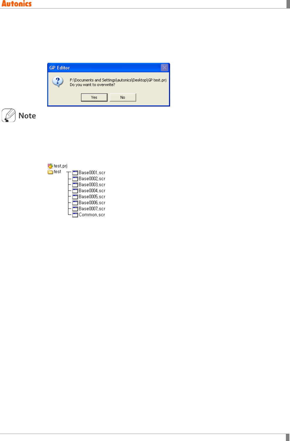
Project file structure of GP/LP type
Mono type
Project file of mono type (GP-S044, GP-S057, LP-S044) is composed of several files as
one project.
The above figure is an example of creating ‘test’ project.
When saving ‘test’ project, ‘test.prj’ project file which is represented whole project and ‘test’
directory are created. ‘test’ directory has several files for screen information, etc of this
project.
For copying project, both ’test.prj’ and ’test’ directory should be copied together.
Color type
Project file of color type(GP-S070, LP-S070) is composed of one file as one project.
2 Project
46 © Copyright Reserved Autonics Co., Ltd.
2.4 Import Project
It registers to editing project importing partial or whole of base, window screen, comment and
part of other project.
Limitation of import project function by GP/LP type: Import project is only able to between same
GP/LP color type of the project. Mono type of project is able to import only mono type project
and Color type of project is able to import only color type project.
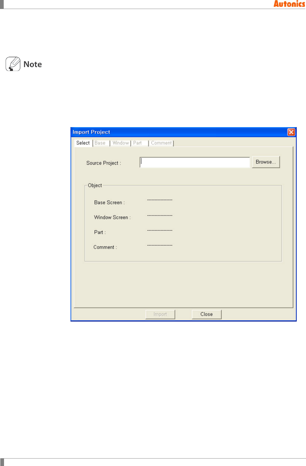
2.4.1 Select tab
1st Select [Project]-[Import Project] of menu, and ‘Import Project’ dialog box appears.
2nd Click ‘Browse’, and ‘GP EDITOR PROJECT OPEN’ dialog box appears.
3rd Select the imported project.
2 Project
© Copyright Reserved Autonics Co., Ltd. 47
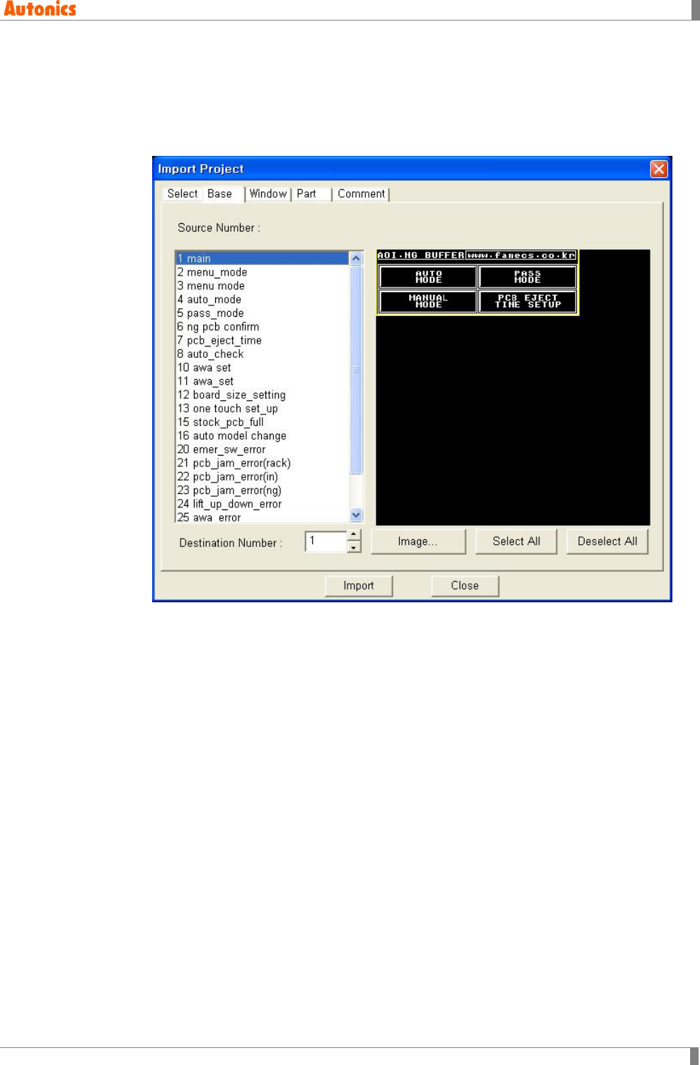
2.4.2 Base tab
1st If the imported project is not selected from ‘Select’ tab, click ‘Browse’ and select the
project.
2nd Move to ‘Base’ tab.
Base screen list of the imported project is specified on‘Source Number’ list box.
Select one base from ‘Source Number’ list box, the base image is displayed on the
left.
3rd From ‘Source Number’ list box, select the base image by clicking, draging, clicking
‘Select All’ or clicking ‘Deselect All’.
[Selecting the screen from ‘Source Number’ list box]
Click ‘Select All’ to select all base screens of ‘Source Number’ list box.
Drag mouse to select several base screens within dragged area.
Click several base screens with press Ctrl key.
Select consecutive base screens with press arrow keys for direction and
Shift key.
4th Designate the desired screen number of current project to be entered the imported
base screen on ‘Destination Number’. Click ‘Image’ and ‘Screen Image’ dialog box
appears and it shows the current project screens. Designate the screen number on
‘Number’.
2 Project
48 © Copyright Reserved Autonics Co., Ltd.
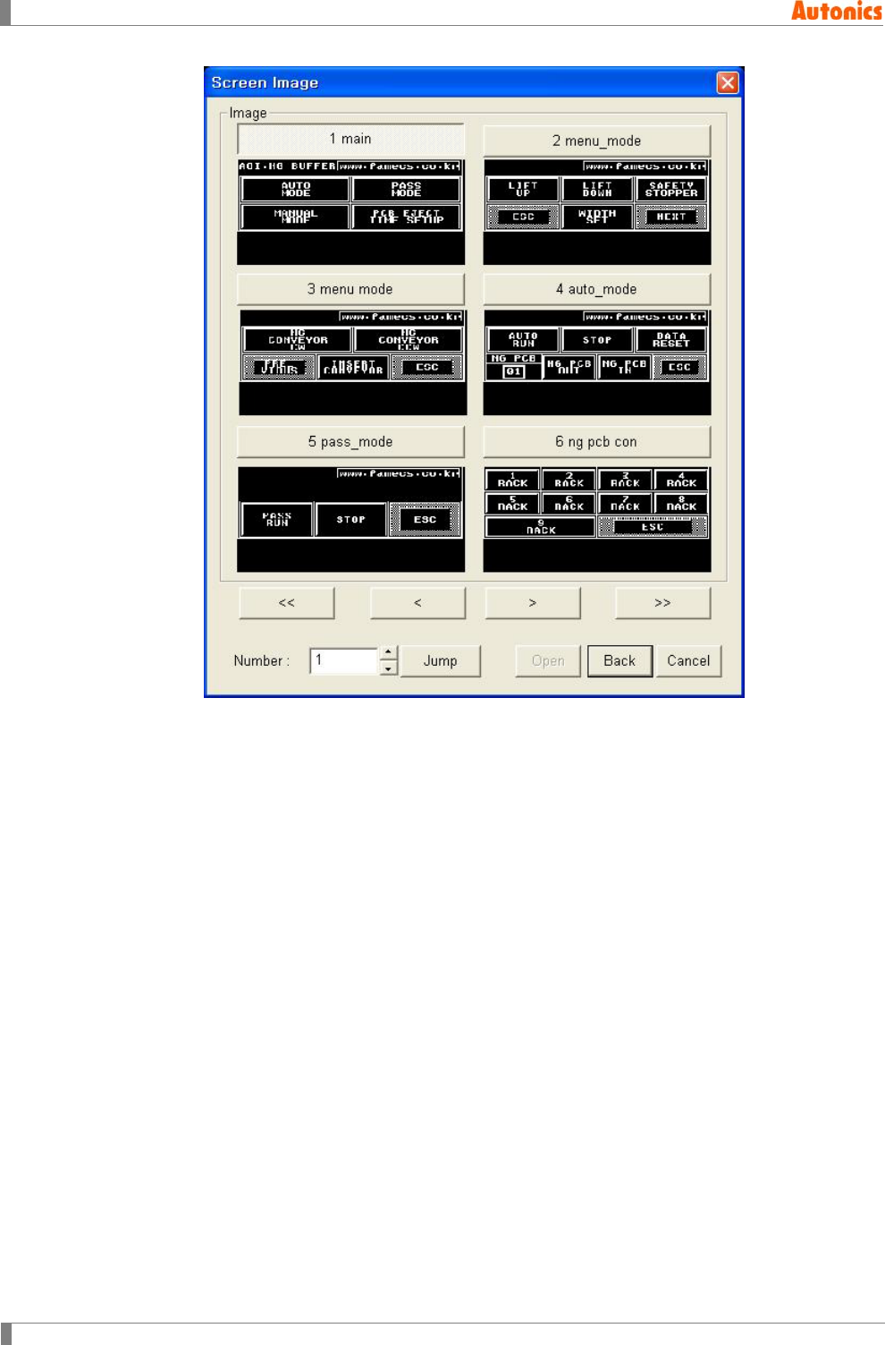
[Operating ‘Screen Image’ dialog box]
Click ‘<<, <, >, >>’ and screen image is changed as one page or
previous/next number of screen as one.
Enter ‘Number’ for the desired screen. Click ‘Jump’, and screen images of
next number are displayed with the number of screen at the head.
Click the screen image or enter ‘Number’ for the desired screen.
Click ‘Back’, and ‘Number’ for the desired screen is entered on ‘Destination
Number’ of ‘Base’ tab.
2 Project
© Copyright Reserved Autonics Co., Ltd. 49
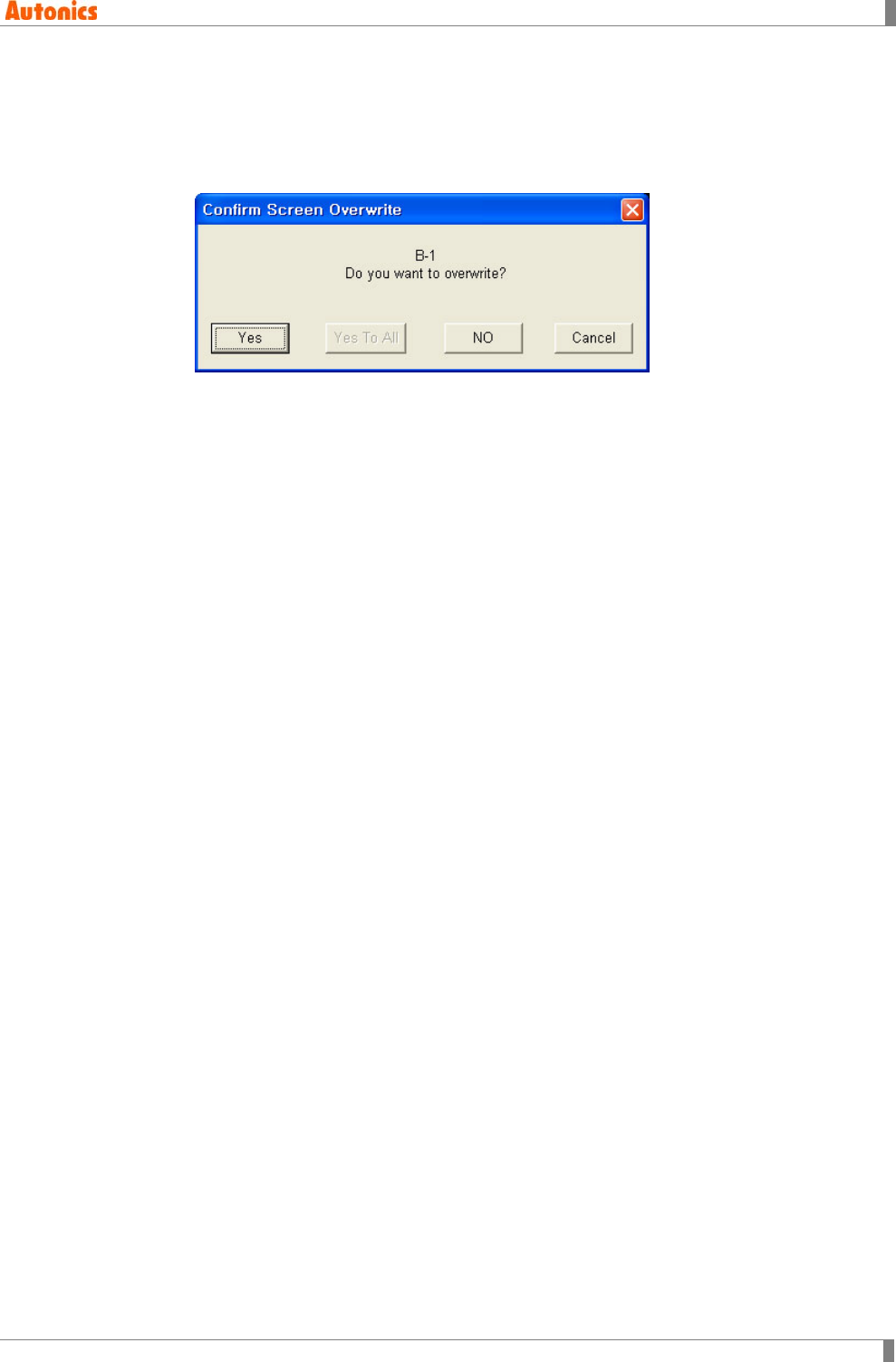
5th Click ‘Import’, and selected base screens in ‘Source Number’ list box are copied in
order from destination number of current project.
If the screen of destination number has already written, ‘Confirm Screen Overwrite’
dialog box appears.
2.4.3 Window tab
It is operated same with base screen.
2 Project
50 © Copyright Reserved Autonics Co., Ltd.
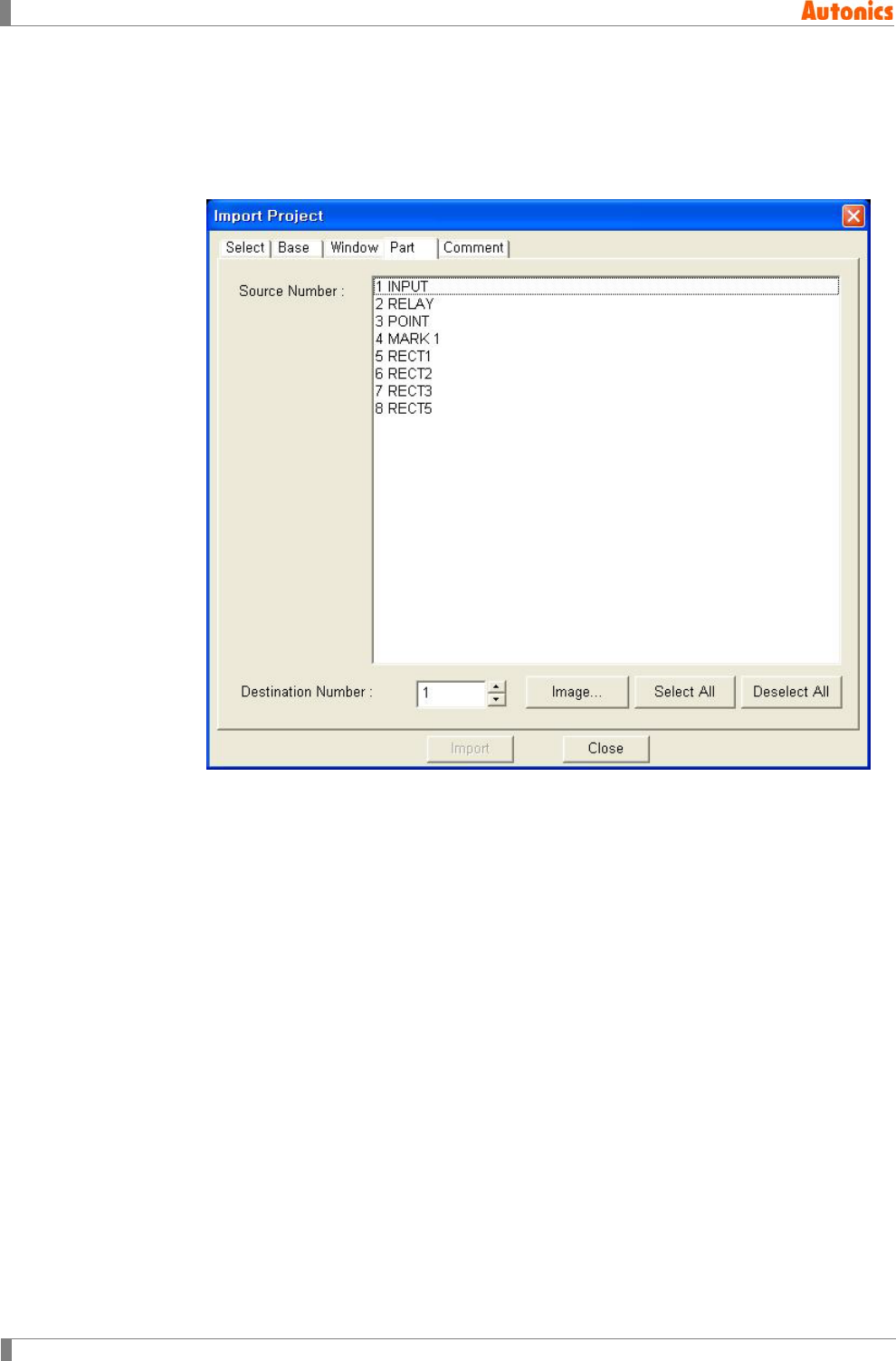
2.4.4 Part tab
1st If the imported project is not selected from ‘Select’ tab, click ‘Browse’ and select the
project.
2nd Move to ‘Part’ tab.
3rd From ‘Source Number’ list box, select the desired part. Selecting and operating the
screen from ‘Source Number’ list box are same as ‘Base’ tab.
4th Designate the desired part number of current project to be entered the imported part
on ‘Destination Number’. Click ‘Image’ and ‘Image Selection’ dialog box appears and
it shows the current project parts.
2 Project
© Copyright Reserved Autonics Co., Ltd. 51
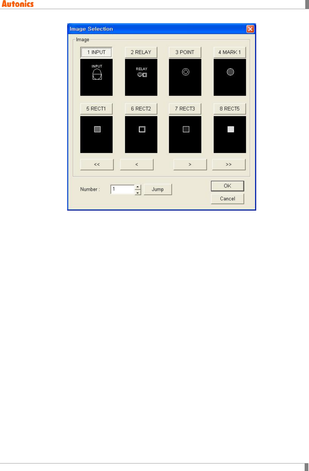
[Operating ‘Image Selection’ dialog box]
Click ‘<<, <, >, >>’, part image is changed as one page or previous/next
number of screen as one.
Enter ‘Number’ for the desired part image. Click ‘Jump’, and the part images
of next number are displayed with the number of part image at the head.
Click the image or enter ‘Number’ for the desired image.
Click ‘OK’, and ‘Number’ for the desired image is entered on ‘Destination
Number’ of ‘Part’ tab.
5th Click ‘Import’, and selected images in ‘Source Number’ list box are copied in order
from destination number of current project.
If the destination number has already parts, ‘Confirm Parts Overwrite’ dialog box
appears.
2 Project
52 © Copyright Reserved Autonics Co., Ltd.
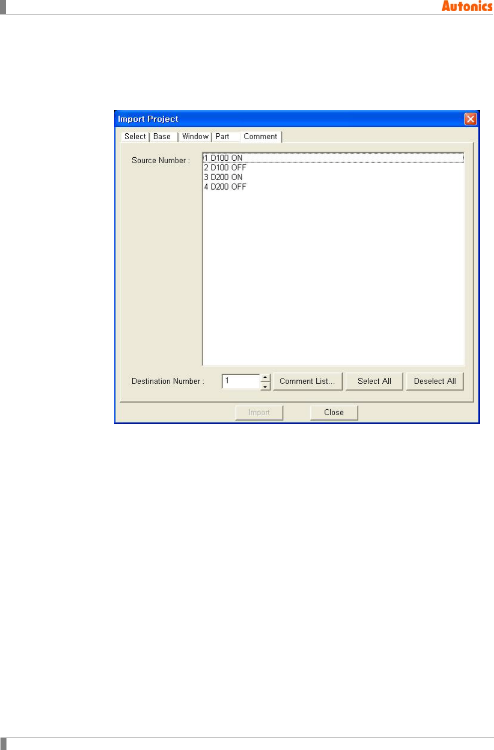
2.4.5 Comment tab
1st If the imported project is not selected from ‘Select’ tab, click ‘Browse’ and select the
project.
2nd Move to ‘Comment’ tab.
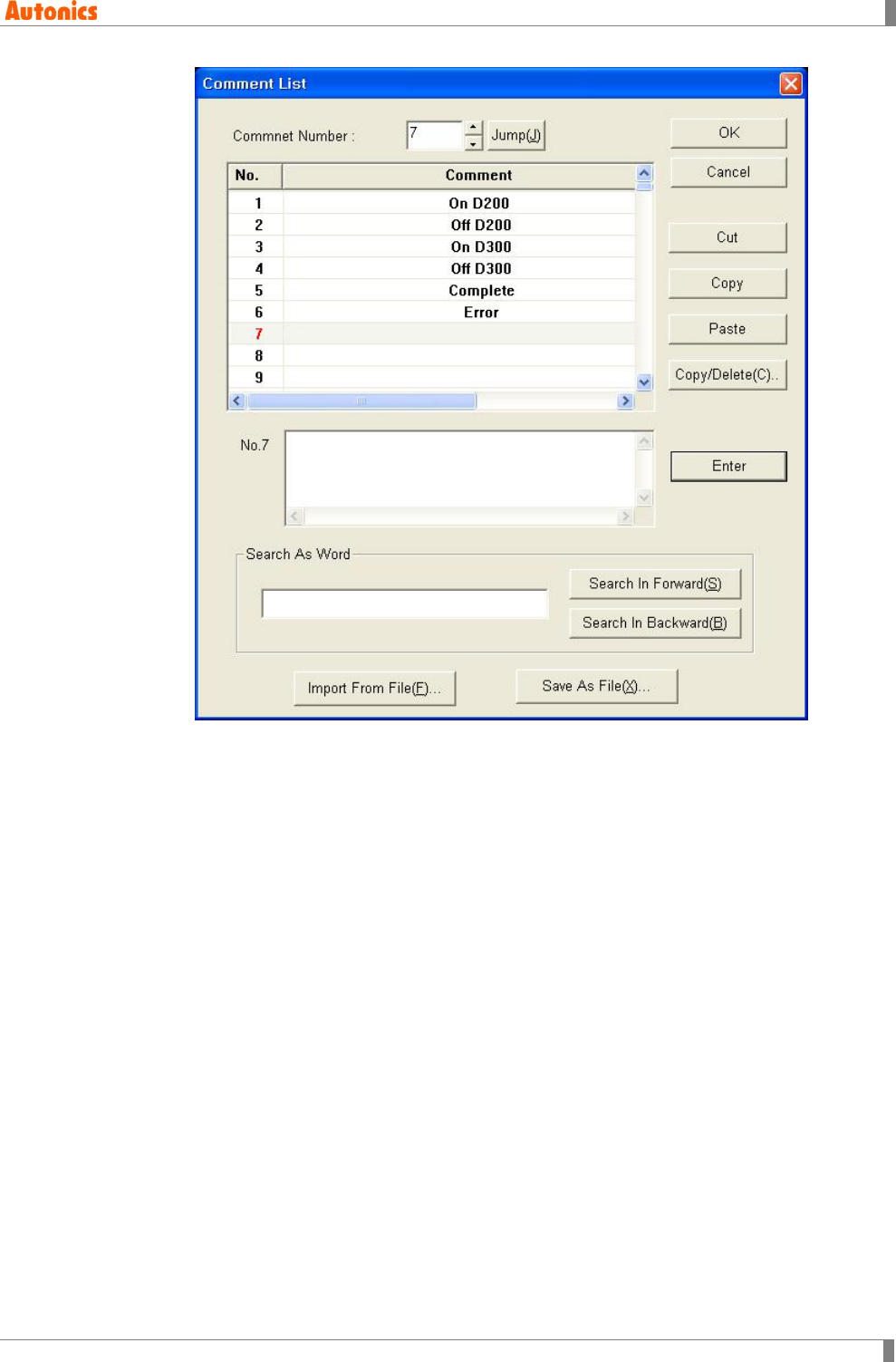
3rd From ‘Source Number’ list box, select the comment.
Designate the desired comment number of curren project to be entered the imported
comment on ‘Destination Number’. Click ‘Comment List’ and ‘Comment List’ dialog
box appears and it shows the current project comments.
2 Project
© Copyright Reserved Autonics Co., Ltd. 53
4th Click ‘Import’, and selected comments in ‘Source Number’ list box are copied in order
from destination number of current project.
If the destination number has already comments, ‘Confirm Comment Overwrite’ dialog
box appears.
2 Project
54 © Copyright Reserved Autonics Co., Ltd.
2.5 Print
It prints image, tag, configuration of tag and device list of screen as print or file.
2.5.1 Print procedure
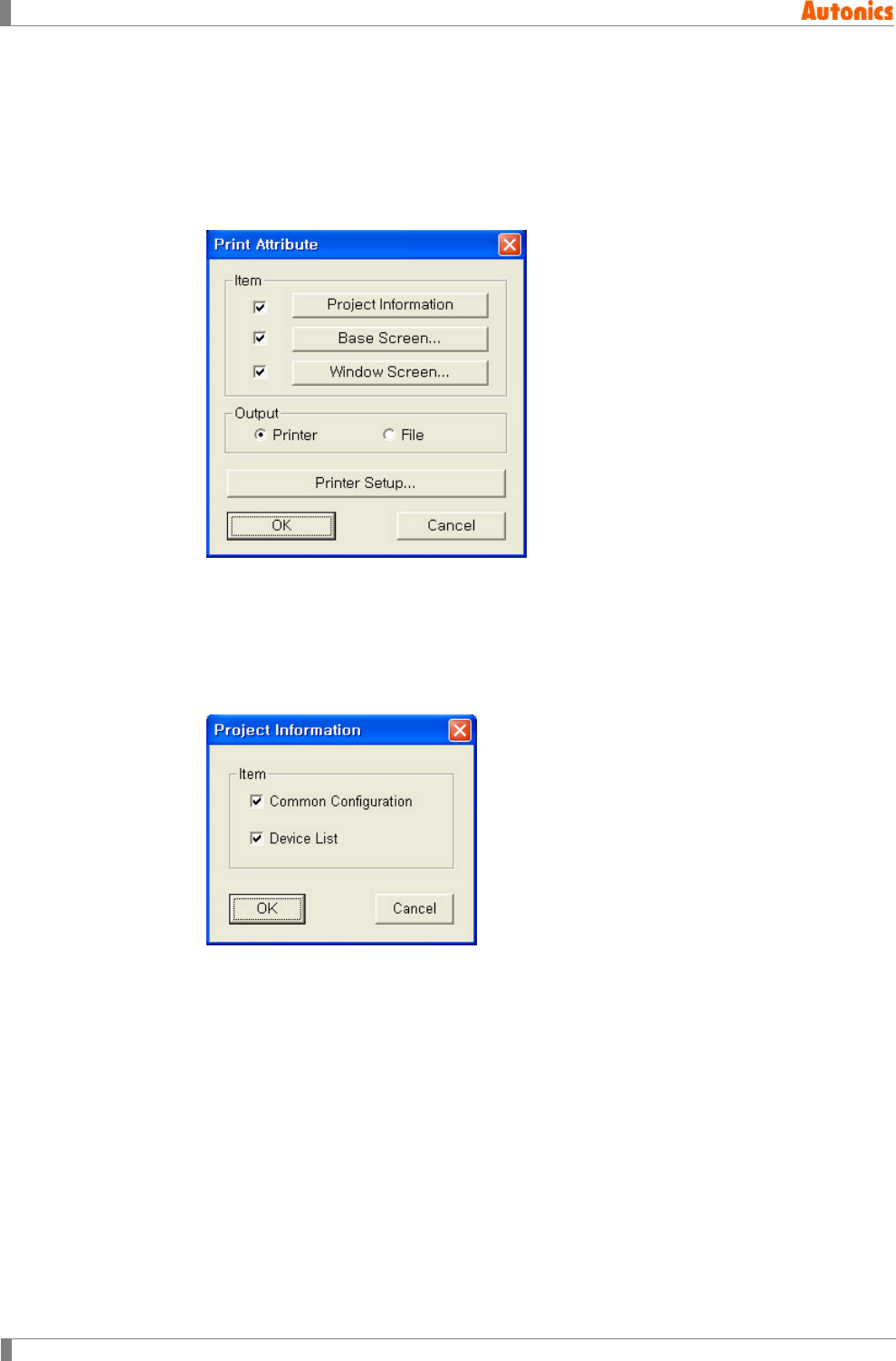
1st Select [Project]-[Print] of menu, ‘Print Attribute’ dialog box appears.
2nd To print with printer, select ‘Printer’ of ‘Output’ box. To print with file, select ‘File’ of
‘Output’ box. ‘Output’ box is activated when project is saved and able to print as file.
3rd To print common configuration and device list of project, check ‘Project Information’
and click this. ‘Project Information’ dialog box appears. Check the desired items to
print ‘Common Configuration’ and ‘Device List’.
2 Project
© Copyright Reserved Autonics Co., Ltd. 55
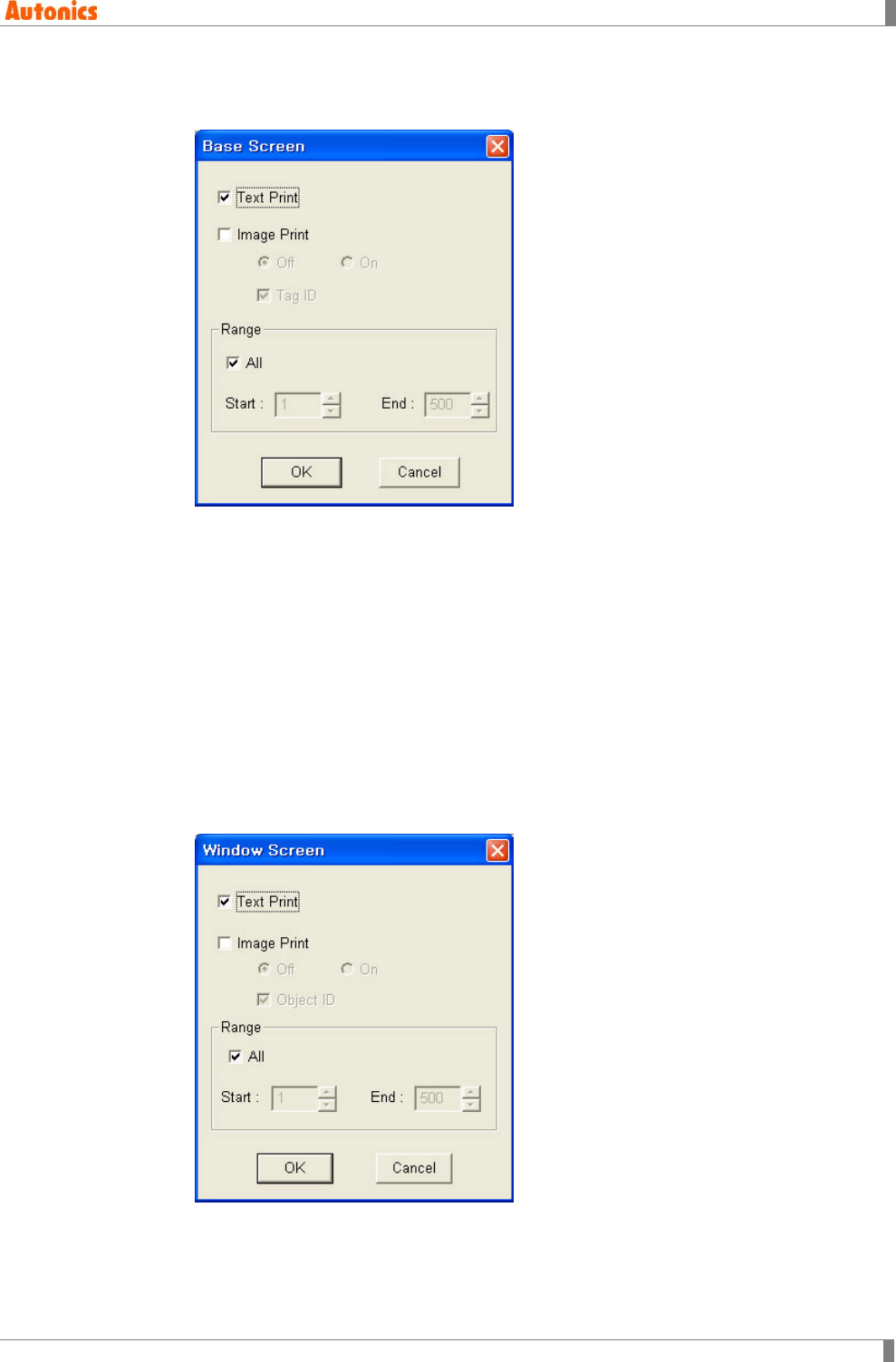
4th To print base screen, check ‘Base Screen’ and click this. ‘Base Screen’ dialog box
appears.
Text Print: Prints the number of base screen, title, and used tag as text.
Image Print: Prints images of base screen. It is saved as bitmap file when it
is print as file.
Off/On: Designate ON or OFF image to print. Select one between Off or On.
Tag ID: Prints tag images with each tag ID.
Range: Check ‘All’ to print all screens of the project. Non-check ‘All’, and
designate the screen start number and end number to print part.
5th To print window screen, check ‘Window Screen’ and click this. ‘Window Screen’
dialog box appears.
The operation of ‘Window Screen’ dialog box is same as the that of ‘Base Screen’
dialog box.
2 Project
56 © Copyright Reserved Autonics Co., Ltd.
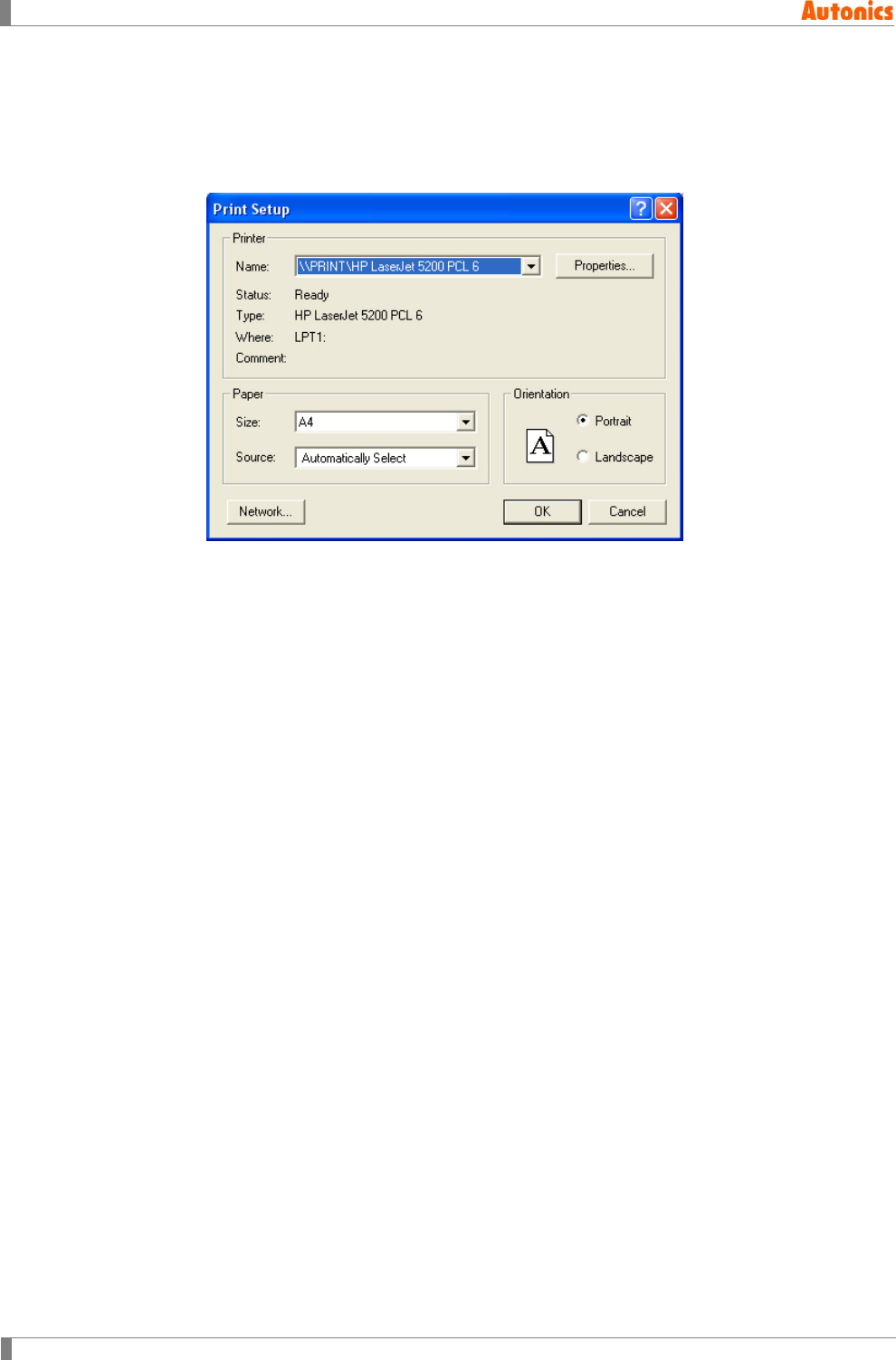
6th If ‘Output’ box of ‘ Print Attribute’ is selected as ‘Printer’, click ‘Printer Setup’ and ‘Print
Setup’ dialog box appears. Select the installed printer, paper, and orientation and
click ‘OK’.
(It is recommended to select A4 size and portrait direction.)
7th Click ‘OK’ of ‘Print Attribute’ dialog box and prints these.
2.5.2 Created file when printing as file
Printing as file, ‘GPDOC’ folder is created in the folder with the current project. Each files and
that of description in ‘GPDOC’ folder is as following.
(For mono type(GP-S044, GP-S057, LP-S044), ‘GPDOC’ folder is created in the folder with the
saved project name folder.)
project.txt: Creates it when ‘Project Information’ of ‘Print Attribute’ dialog box is checked. It
maintains common configuration and device list of project.
BASE1.txt: It is about each base screen in project.
WINDOW1.txt: It is about each window screen in project.
Base1.bmp, Base2.bmp, .... : Image of each base screen
Window1.bmp, Window2.bmp, .... : Image of each window screen
2 Project
© Copyright Reserved Autonics Co., Ltd. 57
2.6 Option
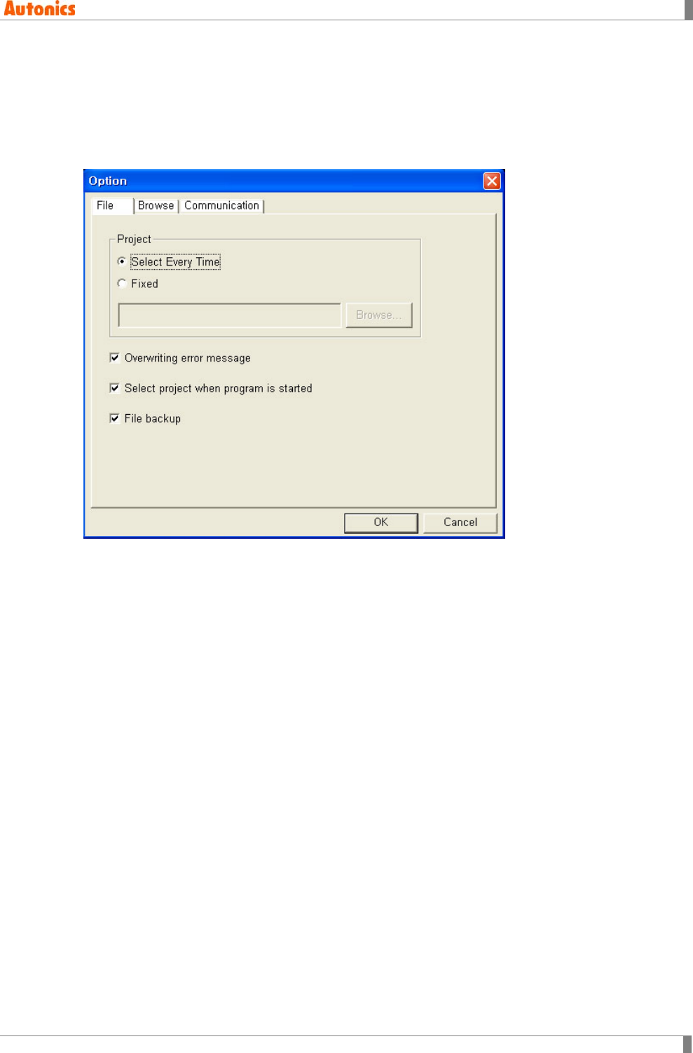
2.6.1 File tab
Check ‘Overwriting error message’, and it verifies whether to save the project whenever you
save the project with ‘Project overwrites check’ dialog box.
Mono type(GP-S044, GP-S057, LP-S044)
Check ‘File backup’, and the backup folder is created under the working folder. Every data
of working folder is copied to the backup folder whenever there are save instructions. It is
able to protect existing data from saving wrong data.
Color type(GP-S070, LP-S070)
Project file of color type (GP-S070, LP-S070) is composed of one file as one project.
Check ‘File backup’ and the backup file is created whenever there are save instructions. It is
‘Project file name+'_backup'.prj’ form.
2 Project
58 © Copyright Reserved Autonics Co., Ltd.
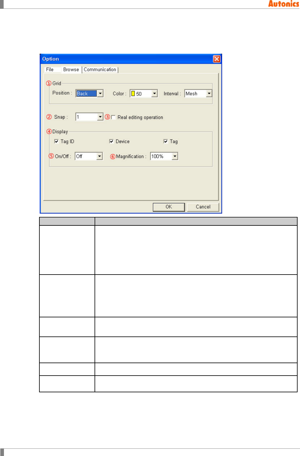
2.6.2 Browse tab
Grid display, screen magnification, snap, tag ID display and device display are for making screen
data efficiently. It is able to configure in ‘Browse’ tab.
Browse
Description
①Grid
Designate grid for indicating arrangement when editing screen by pull-down
menu.
Position: Front=Displays on the tag, Back=Displays under the tag,
None=Does not display
Color: White, black, blue, red, pink, light green, light blue and yellow
Interval: 2, 4, 5, 8, 10, 16, 20, 40, 80, Mesh
②Snap
Designate snap range of screen by pull-down menu.
Range: 1, 2, 4, 5, 8, 10, 16, 20, 40, 80, Mesh
(A mesh indicates same size of resolution of touch switch.)
GP-S057, GP-S070, LP-S070: 20X20
GP-S044, LP-S044:16X20
③Real editing
operation
Check for displaying object as it is when it is moving, or non-check for
displaying only with dotted line.
④Display
Tag ID: Displays tag ID
Device: Displays device name related tag.
Tag: Displays tag content
⑤On/Off Designate ON or OFF image state on edit area by pull-down menu.
⑥Magnification Select magnification ration between 100%, 200%, 300%, or 400% based on
GP/LP screen size by pull-down menu.
2 Project
© Copyright Reserved Autonics Co., Ltd. 59
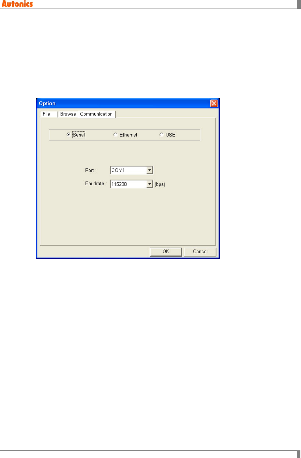
2.6.3 Communication tab
Communication interface and conditions for communication between PC and GP/LP are able to
configure in ‘Communication’ tab.
2.6.3.1 Serial
Communication between PC and GP/LP by serial interface (RS232C, RS422) is available by
selecting ‘Serial’ in ‘Communication’ tab. You should designate communication conditions such
as port and baudrate. Baudrate is designated one of among 9600, 19200, 38400, 57600, 115200
(bps) by pull-down menu.
2 Project
60 © Copyright Reserved Autonics Co., Ltd.
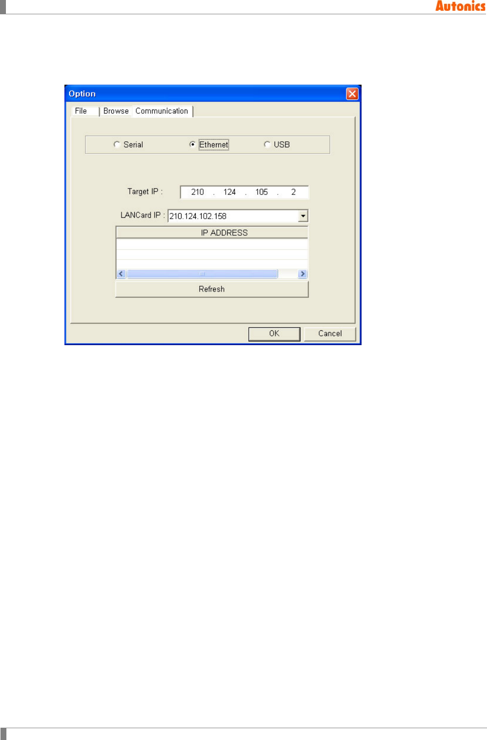
2.6.3.2 Ethernet
Communication between PC and GP/LP by Ethernet interface is available by selecting ‘Ethernet’
in ‘Communication’ tab.
1st Select ‘Ethernet’ and GP/LP list for connected LAN(Local Area Network) is registered
automatically on ‘IP ADDRESS’ list box. If there are not GP/LP list, click ‘Refresh’ and
re-search GP/LP list.
2nd Double-click the desired GP/LP from ‘IP ADDRESS’ list box and the selected IP of
GP/LP is set at ‘Target IP’.
3rd Click ‘OK’ and it communicates by Ethernet with the set ‘Target IP’.
2 Project
© Copyright Reserved Autonics Co., Ltd. 61
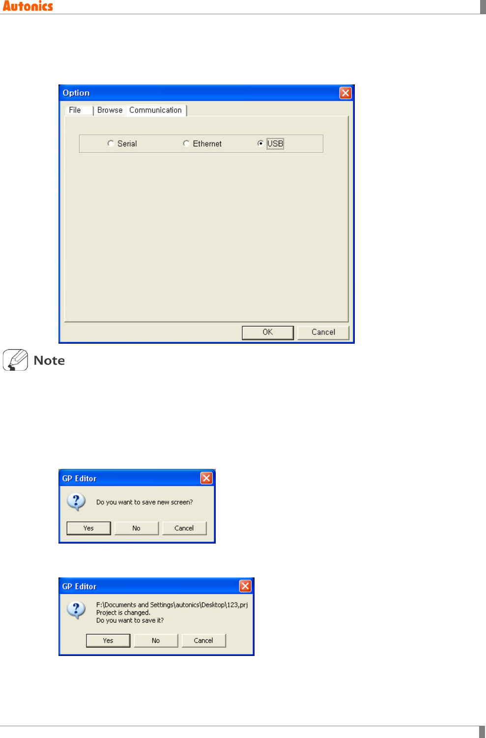
2.6.3.3 USB
Communication between PC and GP/LP by USB interface is available by selecting ‘USB’ in
‘Communication’ tab.
Communication with USB interface is available only after installing ‘GP/LP USB Driver.’
Refer to ’9.1 USB driver installation’ for the details.
2.7 Exit
Select [Project]-[Exit] of menu to edit GP Editor.
If the project is not save before or new screen, it verifies whether to save with the dialog box.
If the project is saved before and there are edited content, the following dialog box appears and
verifies wheter to save and exits GP Editor.

2 Project
62 © Copyright Reserved Autonics Co., Ltd.

3 Screen
© Copyright Reserved Autonics Co., Ltd. 63
3 Screen
3.1 Screen of GP/LP
It describes the operation of screen specification, creating of screen, load, store and copy. The
screen is divided into base screen and window screen. In base screen, it observes arranged
graphic objects. The window screen is able to access when touching input object and it is used
as key pad.
3.1.1 Base screen
Base screen is for monitoring the connected PLC and available to arrange graphic object. Base
screen is downloaded to GP/LP and displays data indication with several method on LCD screen.
The editable base screen depends on the GP/LP model as following.
GP-S044, LP-S044: 240 X 80
GP-S057: 320 X 240
GP-S070, LP-S070: 800 X 480
It is able to design max.500 of base screen with range as 1 to 500.
Each base screen has own screen number. It is controlled by screen number and you can define
and adjust the number on GP Editor. When screen switching touch key is designated, it is
available to switch screen at GP/LP. User-defined data is downloaded to GP/LP and it displays
on the user’s screen.
3 Screen
64 © Copyright Reserved Autonics Co., Ltd.
3.1.2 Window screen
Window screen is called when touching numeric or ASCII input tag. The user-defined window is
called when inputting decimal, hexadecimal number or ASCII.
The editable window screen depends on the GP/LP model as following.
GP-S044, LP-S044: 16X20 to 240X80 dots
GP-S057: 20X20 to 320X240 dots
GP-S070, LP-S070: 20X20 to 800X480 dots
It is able to design max.500 of window screen in GP editor. (Only three screens are downloaded
to GP/LP.)
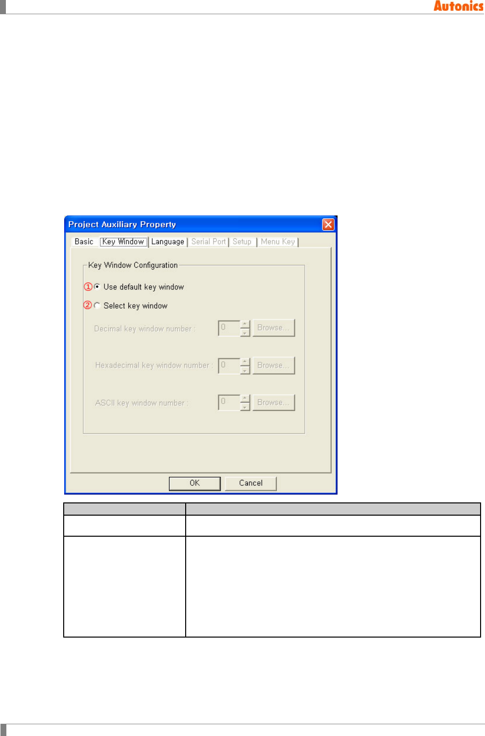
In accordance with designation in ‘Key Window’ tab of ‘Project Auxiliary Property’ dialog box, the
window for input type is decided.
Key Window
Description
①Use default key window Calls system key window which is supplied from GP/LP
②Select key window
Decimal key window number: Designate window screen number
when inputting decimal number
Hexadecimal key window number: Designate window screen
number when inputting hexadecimal number
ASCII key window number: Designate window screen number
when inputting ASCII
If 0 is designated as key window number, the default key window of
GP/LP is called.
3 Screen
© Copyright Reserved Autonics Co., Ltd. 65
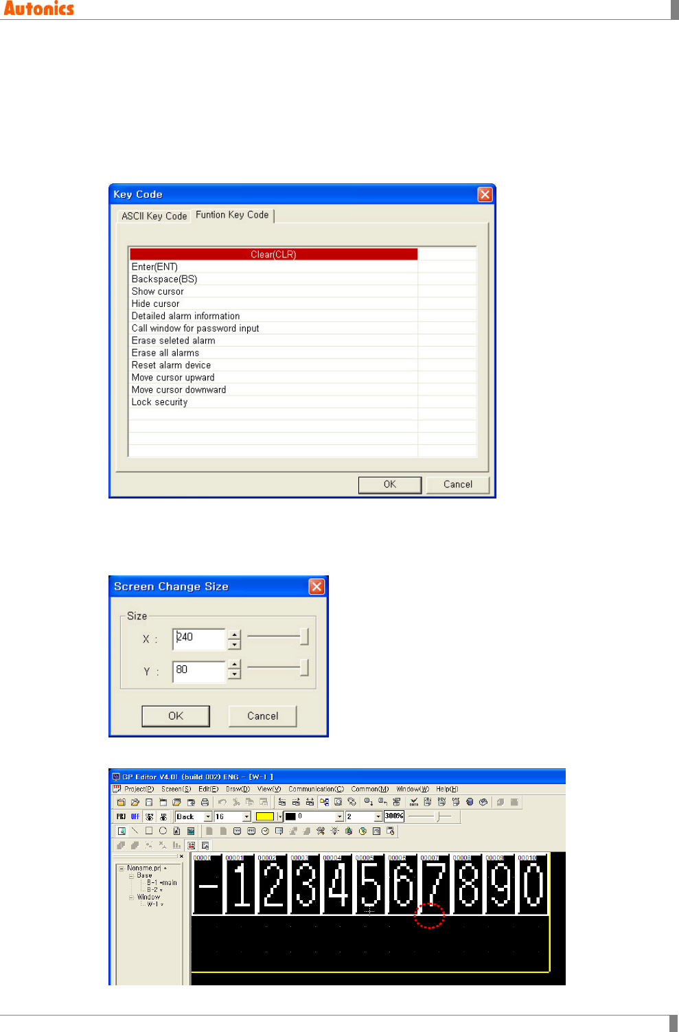
(1) Key window
Key window is called when touching numeric input or ASCII input object.
Key code input function is for inputting data on input object.
Select [Draw]-[Touch Key] of menu, ‘Touchkey property’ dialog box appears. At ‘Action’ tab,
check ‘Key Code’, the spin box is activated. In order to input number or ASCII character,
input the appropriate ASCII code. Click ‘Browse’ and ‘Key Code’ dialog box appears to
select ASCII code. To insert ENT, CLR buttons, select the appropriate ASCII code at
‘Function Key Code’ tab.
(2) Adjustment of window size
Select [Screen]-[Change Size] of menu, ‘Screen Change Size’ dialog box appears. It is able
to change window size adjusting spin box or slide bar. It is activated only when current
editing screen is window.
Or drag bottom-left (Indicated with the red circle) of window by mouse, window size is
changed.
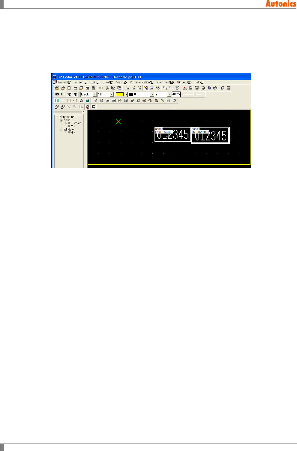
3 Screen
66 © Copyright Reserved Autonics Co., Ltd.
(3) Designate display position of key window
It is able to designate key window position at GP/LP.
At the base screen, select [Draw]-[Key Window Position] of menu, X mark appears with
mouse and you can designate key window position. The key window having top-left of X
mark appears at GP/LP screen.
If window is exceeded screen range based on this point, it is adjusted inside of GP/LP
screen.
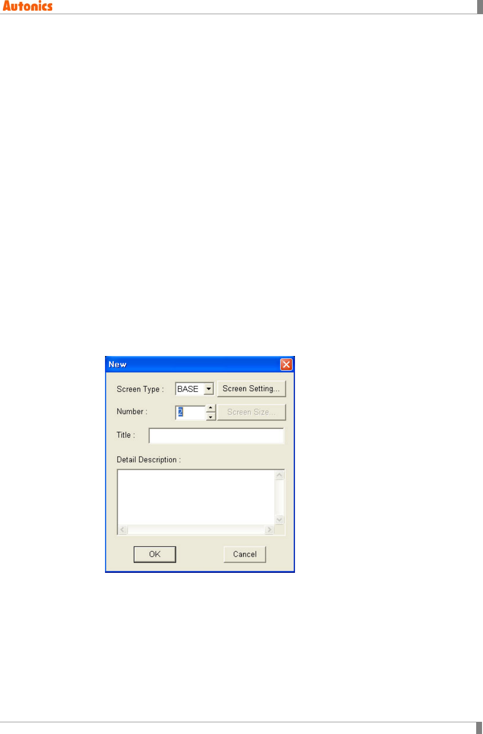
3 Screen
© Copyright Reserved Autonics Co., Ltd. 67
3.2 New Screen
Base screen no.1 is created when project is made.(It does not nessecery to re-make it, except
when it is deleted.)
Refer to the following procedure to create new screen.
1st Select [Screen]-[New] of menu, ‘New’ dialog box appears.
2nd Select ‘BASE’ for creating base screen, or ‘WINDOW’ for creating window screen at
‘Screen Type’ pull-down menu.
3rd Designate screen number at ‘Number’.
4th Enter screen title at ‘Title’.
Title is able to max.32 letters and not necessary to enter. It is information downloaded
on the GP/LP memory.
5th Enter detail description of screen at ‘Detail Description’. It is able to max.512 letters
and not necessary to enter.
6th Click ‘Screen Setting’ when screen type is base, ‘Screen Auxilairy Configuration’
dialog box appears. Designate cursor movement when inputting key window,
background color, and security level.
7th Click ‘Screen Size’ when screen type is windos, ‘Screen Change Size’ dialog box
appears. Designate window screen size.
8th Click ‘OK’, new screen is created.
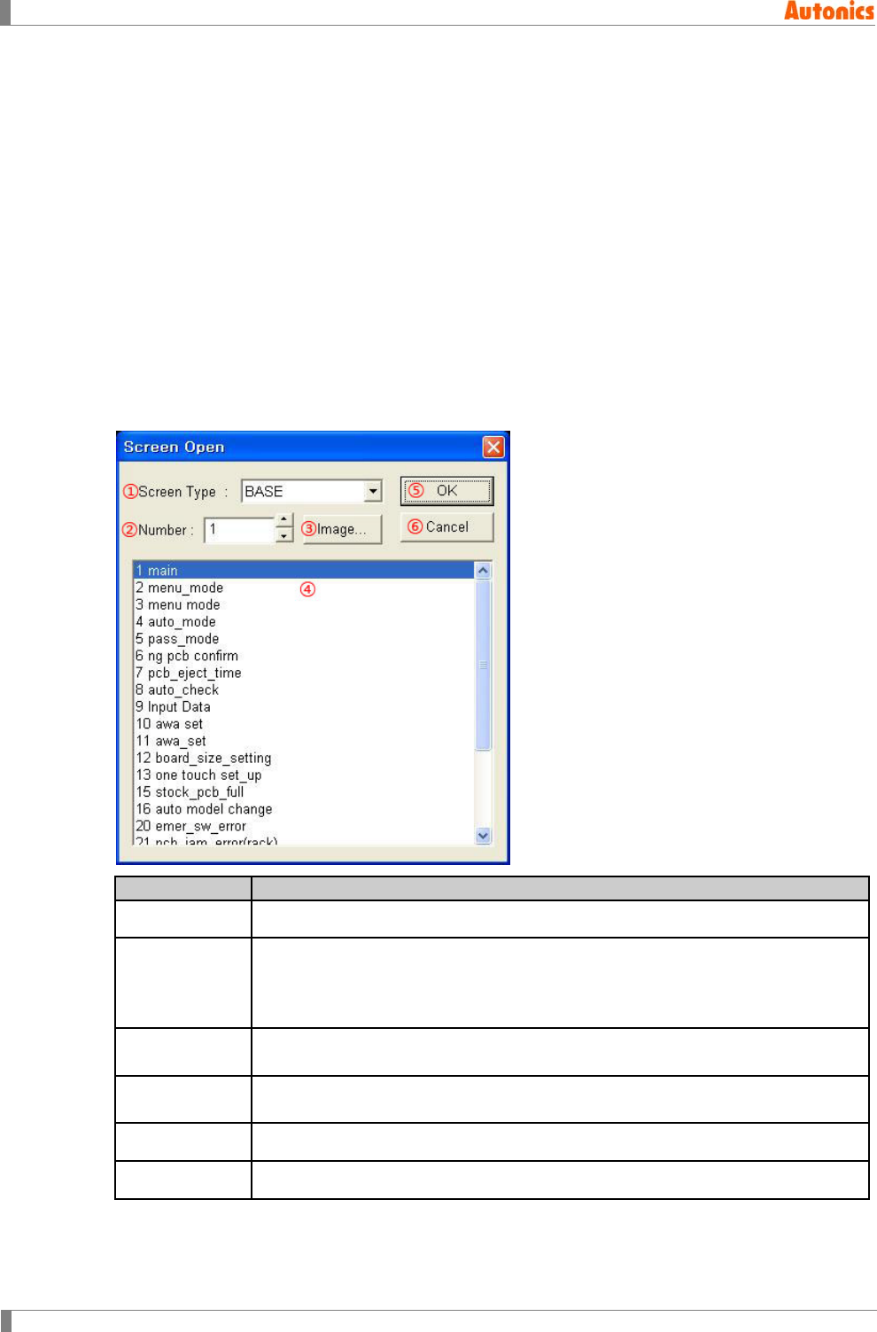
3 Screen
68 © Copyright Reserved Autonics Co., Ltd.
3.3 Load Screen
It load and open the saved screen to edit.
1st Select [Screen]-[Load] of menu, ‘Screen Open’ dialog box appears.
2nd Designate screen type at ‘Screen Type’ pull-down menu. Select ‘BASE’ for opening
base screen, or ‘WINDOW’ for opening window screen. At the below list box, screen
number and titles of project are displayed in order of numbers.
3rd Designate screen number to load at ‘Number’. Click ‘Image’, ‘SCREEN IMAGE’ dialog
box appears and you can check all screen images and select screen number.
4th Click the desired screen at the below list box. You can select the several screens with
dragging or Ctrl key.
5th Click ‘OK’ and the selected screen is loaded.
Screen Open
Description
①Screen Type Select screen type base screen or window screen to be loaded.
②Number
Designate screen number to import.
It is able to designate number inputting by user directly or using spin box. If
screen is saved in a project but closed one, it loads again. If screen is not saved
in a project but closed one, it creates new screen for input number.
③Image ‘SCREEN IMAGE’ dialog box appears. It is able to check all screens of project
and select screen number.
④List box The numbers and titles of project are displayed in order of number. Click and
select the desired screens with dragging or Ctrl key.
⑤OK Loads the selected screen.
⑥Cancel Does not load selected screen and closed ‘Screen Open’ dialog box.
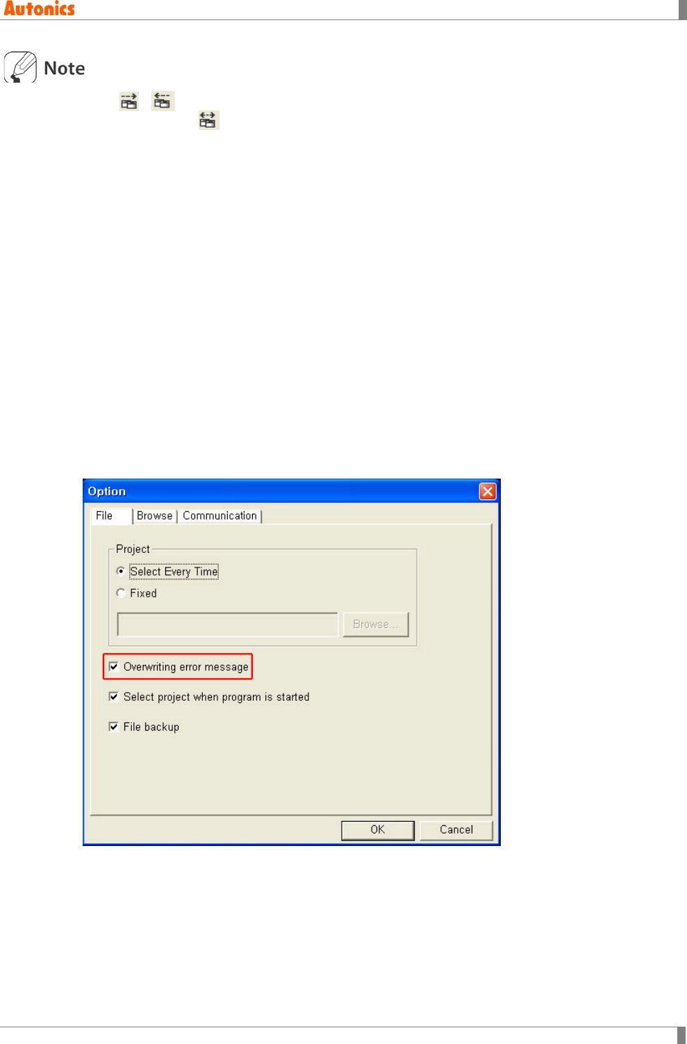
3 Screen
© Copyright Reserved Autonics Co., Ltd. 69
Click , in system tool bar, the lower/higher number of screen than current screen is a
editable object. If is clicked, it opens closed screen and it is a editable object.
3.4 Clear Screen
Click [Screen]-[Clear] of menu, it clears the editing screen. If only one screen is loaded, ‘One
opened screen cannot be closed’ dialog box appears and it cannot be cleared. If editing screen
is not a saved state, the save checking dialog box appears and it is able to save.
[Screen]-[Clear] menu executes not only clearing screen, but also closing the opened screens
for editing. To delete screen, execute ‘Screen Copy/Delete’ instructions.
3.5 Load and Clear
Select [Screen]-[Load and Clear] of menu, it closes the current editing screen and ‘Screen Open’
dialog box appears to load the desired screen.
3.6 Save Screen
Select [Screen]-[Save] of menu, it saves the current editing screen. If there is the saved screen,
overwriting check message appears.
The message appears only when from [Project]-[Option] of menu, check ‘Overwriting error
message’ of ‘Option’ dialog box.
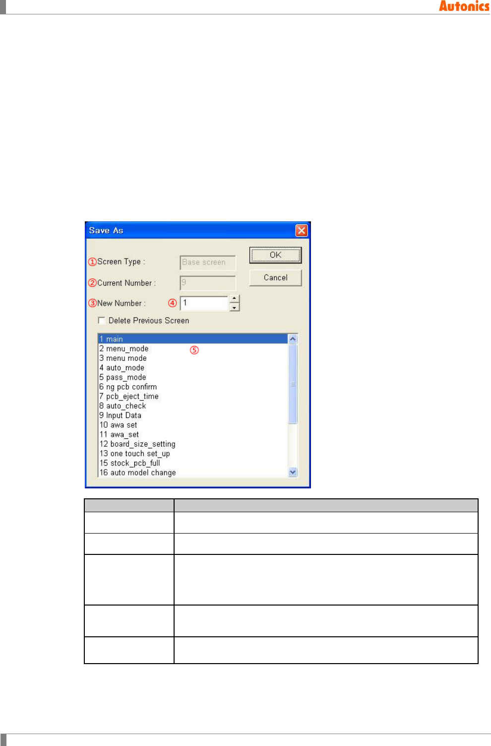
3 Screen
70 © Copyright Reserved Autonics Co., Ltd.
3.7 Save As Screen
It saves the current editing screen as new number of screen.
(1) Operation procedure
1st Select [Screen]-[Save As] of menu, ‘Save As’ dialog box appears.
2nd Designate the new number at ‘New Number’.
3rd To delete existing the current number screen, check ‘Delete Previous Screen’.
4th Click ‘OK’, ‘Screen Title’ dialog box appears.
5th Enter or edit title and detail description of screen, click ‘OK’. It is saved as a new
number screen.
(2) ‘Save As’ dialog box
Save As
Description
①Screen Type Displays screen type (base screen or window screen)
②Current Number Displays editing screen number.
③New Number
New screen number for storing designated number screen in current
number.
It is able to designate number inputting in combo box directly, using
spin box and selecting in list box.
④Delete Previous
Screen
Saves the selected screen as new number screen and deletes
previous number screen
⑤List box Displays screen number and titles of project in order of number. Click
the desired number and it is inputted at ‘New Number’.
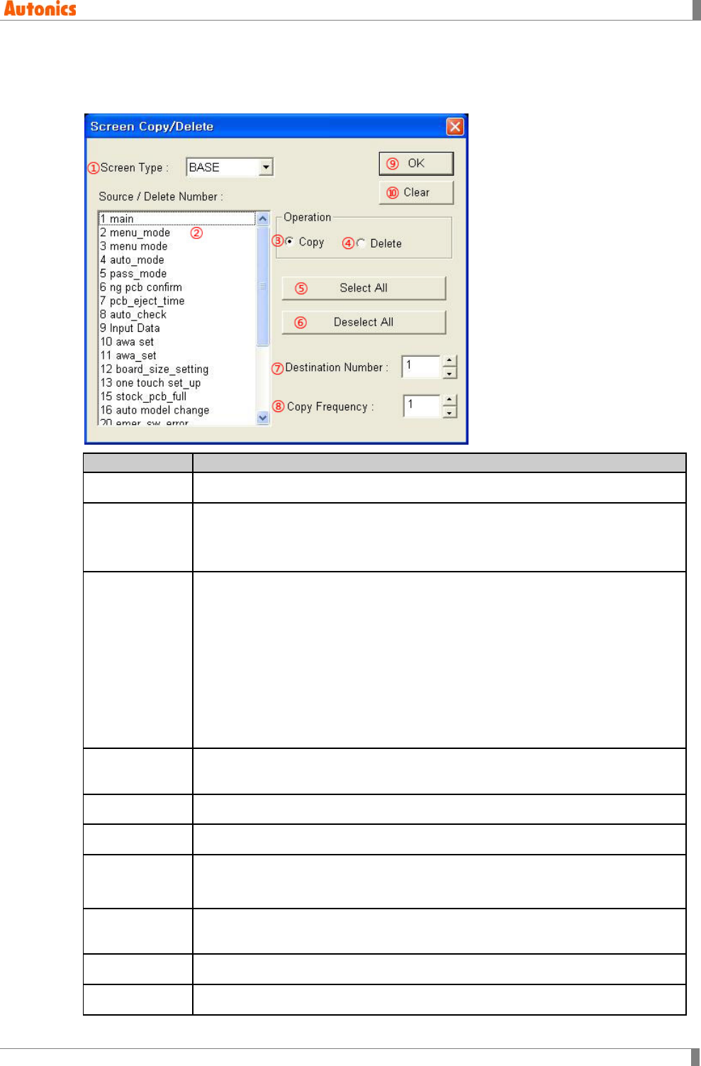
3 Screen
© Copyright Reserved Autonics Co., Ltd. 71
3.8 Screen Copy/Delete
This feature is to delete or copy several screens at once.
Copy/Delete
Description
①Screen Type Select screen type(base screen or window screen) to be copied/deleted.
②Source/Delet
e Number
Displays screens of the project in order of screen number and title. Click the
desired screen to copy or to delete.
You can select successively screens with pressing Shift key and mouse, or
select randomly with pressing Ctrl key and mouse.
③Copy
Copy selected screen in a list to the number of screen inputted in destination
number. Selected screens are copied as many as copy frequencies repeatedly
from the destination number.
Ex)
Selected screen=1,4,5, Destination number=10, Copy frequency=3
Screen#10←Screen#1, Screen#13←Screen#4, Screen#14←Screen#5,
Screen#15←Screen#1, Screen#18←Screen#4, Screen#19←Screen#5,
Screen#20←Screen#1, Screen#23←Screen#4, Screen#24←Screen#5
If there is a written screen already in the destination screen, it shows a overwrite
warning message to cancel copy.
④Delete Deletes all selected screens in list. ⑦Destination number and ⑧Copy
Frequency is not activated.
⑤Select All Selects all items in list box.
⑥Deselect All Deselects all items in list box.
⑦Destination
Number
Designates screen number to paste selected number of screen in list box. If
inputted number of screen is already in the project, overwrite checking message
appears. If the screen does not exist, it creates new screen and copies.
⑧Copy
Frequency
Enters repeat frequency for copy inputted number of screen in a destination
number.
⑨OK Executes screen copy/delete.
⑩Clear Closes ‘Screen Copy/Delete’ dialog box.
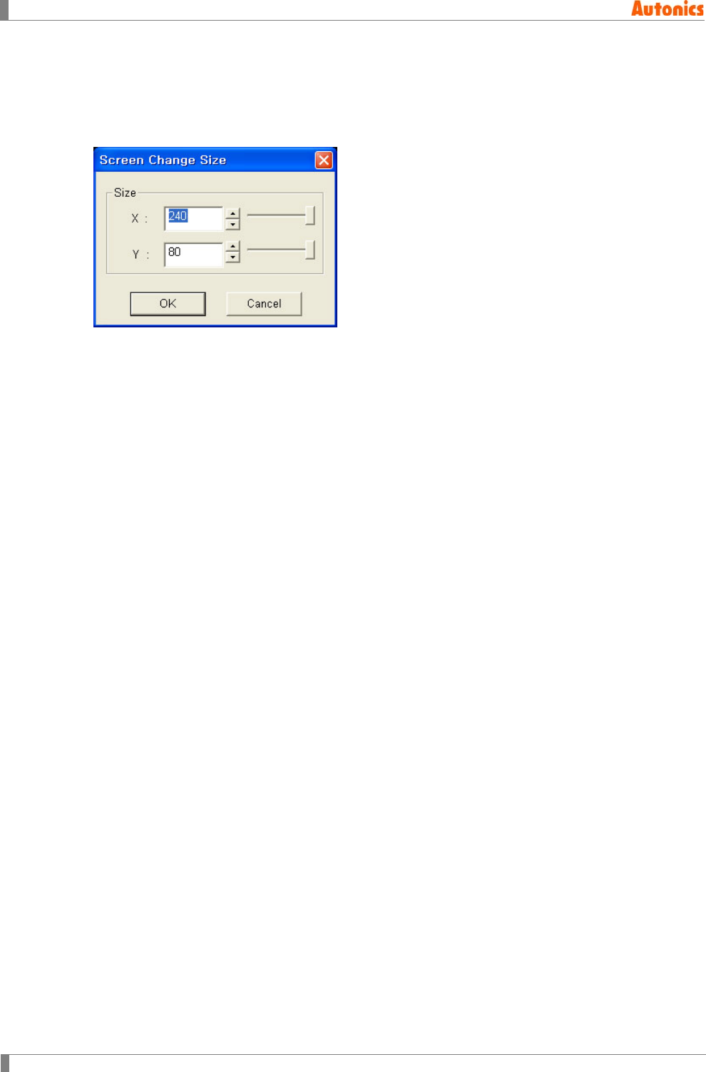
3 Screen
72 © Copyright Reserved Autonics Co., Ltd.
3.9 Change Size
Select [Screen]-[Change Size] of menu, ‘Screen Change Size’ dialog box appears. It is able to
change window size adjusting spin box or slide bar. [Change Size] menu is only activated when
editing screen is window, not base.
4 Edit
© Copyright Reserved Autonics Co., Ltd. 73
4 Edit
In this chapter, it describes basic editing function of GP Editor.
4.1 Undo
It is able to return to the before operation state undoing the previous operation such as deletes
the object on a screen, changes size or position. (It is applied once.)
[Edit]-[Undo] of menu is activated after deleting the object or changing size or position. Click this
or press Ctrl+Z to execute.
It is not able to undo in case of adjusting the size of object having character or changing the
property through the window.
4.2 Cut
Select [Edit]-[Cut] of menu or press Ctrl+X to delete selected object on a screen. Cut object is
copied on a clipboard and paste function is activated after this execution. It is able to arrange cut
objects on a screen again with paste command.
4.3 Copy
It copies selected objects to clipboard. Select [Edit]-[Copy] of menu or press Ctrl+C. It is able to
create objects with same property arranging on a screen with paste command.
4.4 Paste
It pastes copied objects on a clipboard by cut or copy on a screen. Select [Edit]-[Paste] of menu
or press Ctrl+V. It is able to create objects with same property arranging on a screen with paste
command.
Copy and paste is only available at the current project. It is not available to copy or paste the
other project’s tag. To copy or paste the other project’s tag, refer to ‘2.4 Import Project‘.
When pasting the object which can exist only one on a screen into the two objects, or the object
which cannot exist on a screen into existing together, paste instruction is not worked.
Object which can exist only one on a screen: Alarm history, alarm list with scroll option,
trend graph, line graph and key window position mark
Object which cannot exist on a screen: Alarm history, alarm list with scroll option, trend
graph and line graph
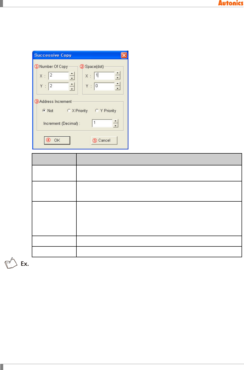
4 Edit
74 © Copyright Reserved Autonics Co., Ltd.
4.5 Successive Copy
It copies selected objects successively and arranges on a screen. Select [Edit]-[Successive
Copy] of menu and ‘Successive Copy’ dialog box appears. Designate number of copy,
space(dot), address increment etc., and click ‘OK’ to execute.
Successive
Copy
Description
①Number Of
Copy
X: Designate the number of objects to copy with horizontal direction.
Y: Designate the number of objects to copy with vertical direction
②Space(dot)
X: Designate the space between objects of horizontal direction as dot
units.
Y: Designate the space between objects of vertical direction as dot units.
③Address
Increment
Not: It does not increase the object address to be copied. The figure
object is fixed as Not.
X Priority: Copies to the horizontal direction increasing object address.
Y Priority: Copies to the vertical direction increasing object address.
Increment (Decimal): Increases the address by designated unit.
④OK Executes to copy and closes the dialog box
⑤Cancel It does not execute to copy and closes the dialog box
If the object configured as D100 is specified at ‘successive copy’ dialog box as following,
Number of copy (X= 4, Y=3), Space(dot) (X=2, Y=3), Address increment (Increment
(Decimal)=1)
The object is copied as following.
Total X× Y=12 of objects are created and adjacent two objects have 2 dots space for horizontal
direction, 3 dots space for vertical direction. In this case for address increment, ‘X Priority’ is
selected, address is increased to the horizontal first (black font). ‘Y Priority’ is selected, address
is increased to the vertical first (italics font).
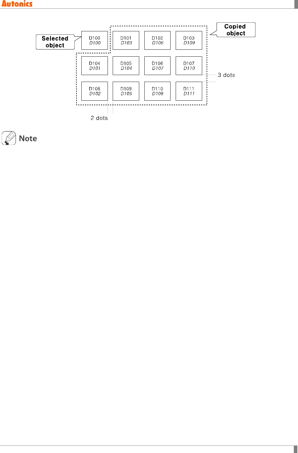
4 Edit
© Copyright Reserved Autonics Co., Ltd. 75
It is applied same when an object or several objects are selected. It is applied to all figures
and tags.
If the object to be copied exceeds the working area, error message appears and this
instruction is not executed.
When successive coping tag with address, if it exceeds address range error message
appears and this instruction is not executed.
When pasting the object which can exist only one on a screen into the two objects, or the
object which cannot exist on a screen into existing together, paste instruction is not worked.
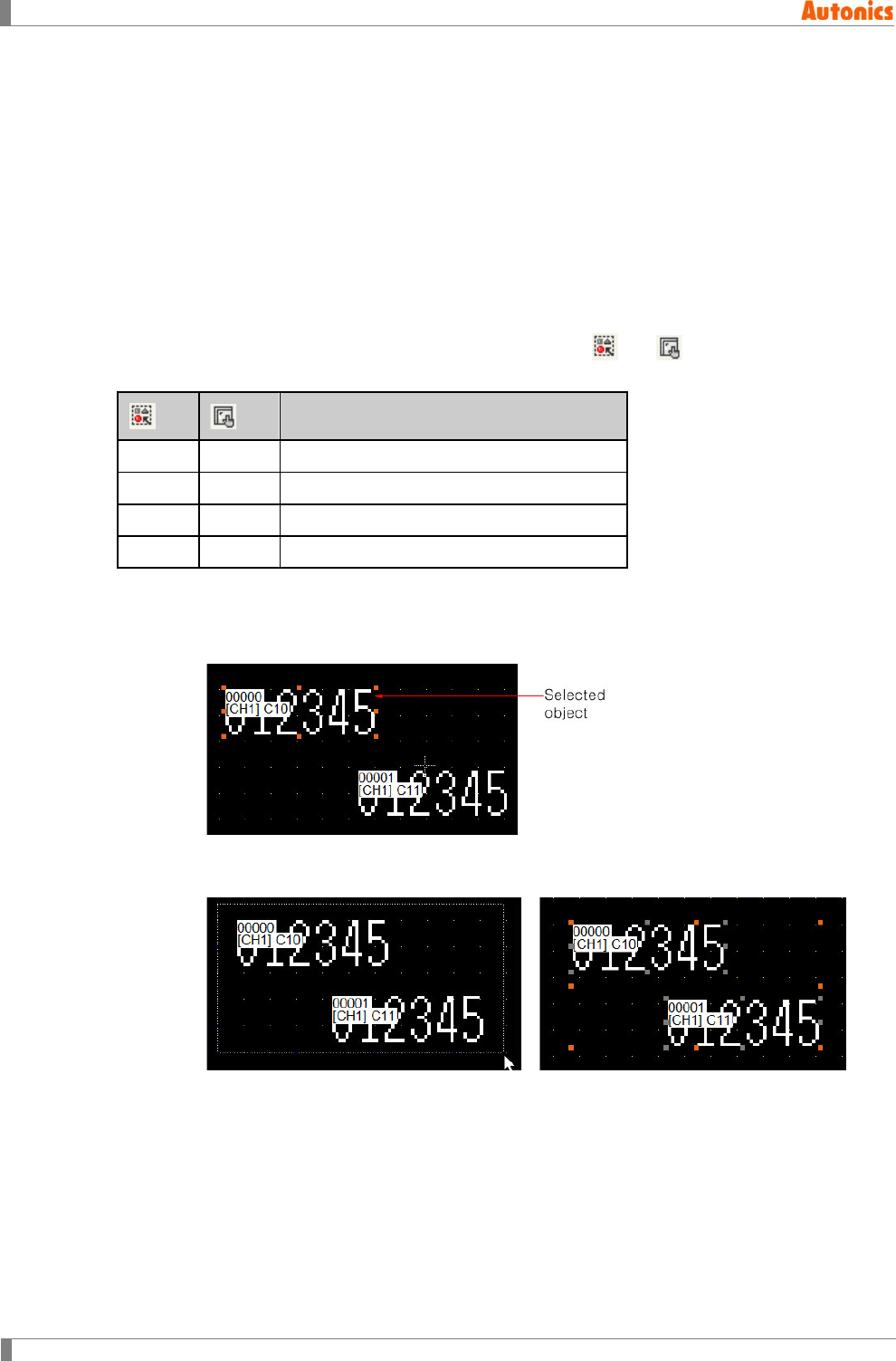
4 Edit
76 © Copyright Reserved Autonics Co., Ltd.
4.6 Delete
It deletes the selected object on a screen.Select [Edit]-[Delete] of menu, or press Delete key. To
return to the deleted object, execute undo instruction.
4.7 Select All
Select [Edit]-[Select All] of menu or press Ctrl+A, all object on a screen are selected. In this case,
the object to be subjected of selection condition is selected.
4.8 Select Object
Select [Edit]-[Select Object]-[Figure]/[Tag] of menu or click or in edit toolbar. It is
useful to separate and edit a figure object or tag only when figure and tag are existed closely.
Selected object
Press Release Selects only figures
Release Press Selects only tags
Press Press Selects all objects
Release Release Does not select any objects
Movement of object
1st Click the object with right mouse button and the object is selected. The selected
object indicates marks for adjusting size as following figure.
2nd Click with left mouse button and drag for the desired area, dotted square is following.
Release the mouse button, inside objects of dotted square are selected.
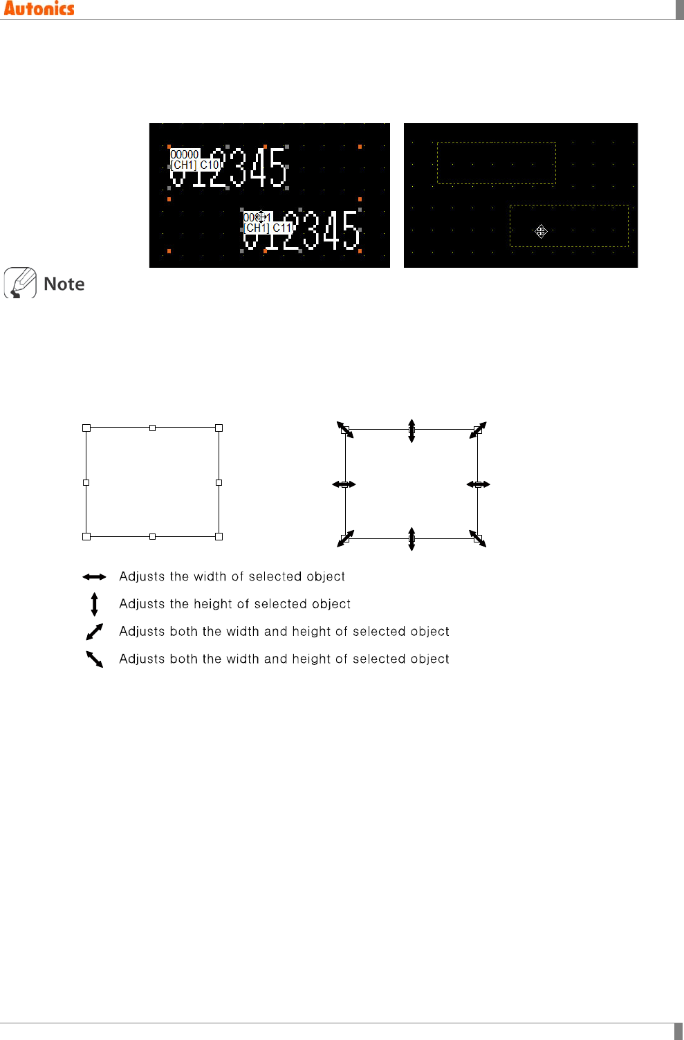
4 Edit
© Copyright Reserved Autonics Co., Ltd. 77
3rd Click the selected object and mouse cursor for movement appears. Drag the cursor,
the dotted line of selected object follows. Release mouse button to the desired
position, the object is moved to that position.
To show the real editing opeation state of object, select [Project]-[Option] of menu, ‘Option’
dialog box appears. At ‘Browse’ tab, check ‘Real editing operation’, and when moving the object,
it shows the real editing operation stauts of object.
The selected object displays mark to adjust size as following figure. There is a mark to adjust on
each summit and side. When moving a cursor to the mark, other shape of cursor is appeared as
second figure.
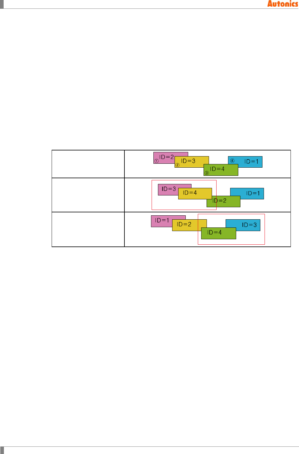
4 Edit
78 © Copyright Reserved Autonics Co., Ltd.
4.9 Group
Select [Edit]-[Group] of menu to group more than 2 objects as one. Existing group can be a
factor of a new other group.
Grouped object is recognized as an object and all functions such as copy, cut, bring forward, or
send backward are applied.
Inner figure and tag property of grouped object is kept continually.
Tag ID is given upper ID automatically than currently designed tag and later designed tag is
arranged on the upper part in turns.
The stacking order of objects in a group is preserved when grouping, but the stacking order
is changed as group objects put on the upper part than not grouped objects. ID is changed
as higher value.
For example, if a tag is grouped with group instruction, the ID of the tag is changed to have
higher value than not grouped other tags. It is applied same to figure object.
Tag arrangement before
grouping
After grouping ①, and ②
After grouping ③ and ④
Group objects are registered on panel kit to use.
The group of figure objects is registered on part library to use.
When group object registered in panel kit and part library is arranged on a screen, it
preserves group information.
When uploading group object on GP/LP screen, it preserves the group information in
download.
It is able to adjust size of figure object.
4.10 Ungroup
Select group object and select [Edit]-[Ungorup] of menu, it separates each object as previous
state.
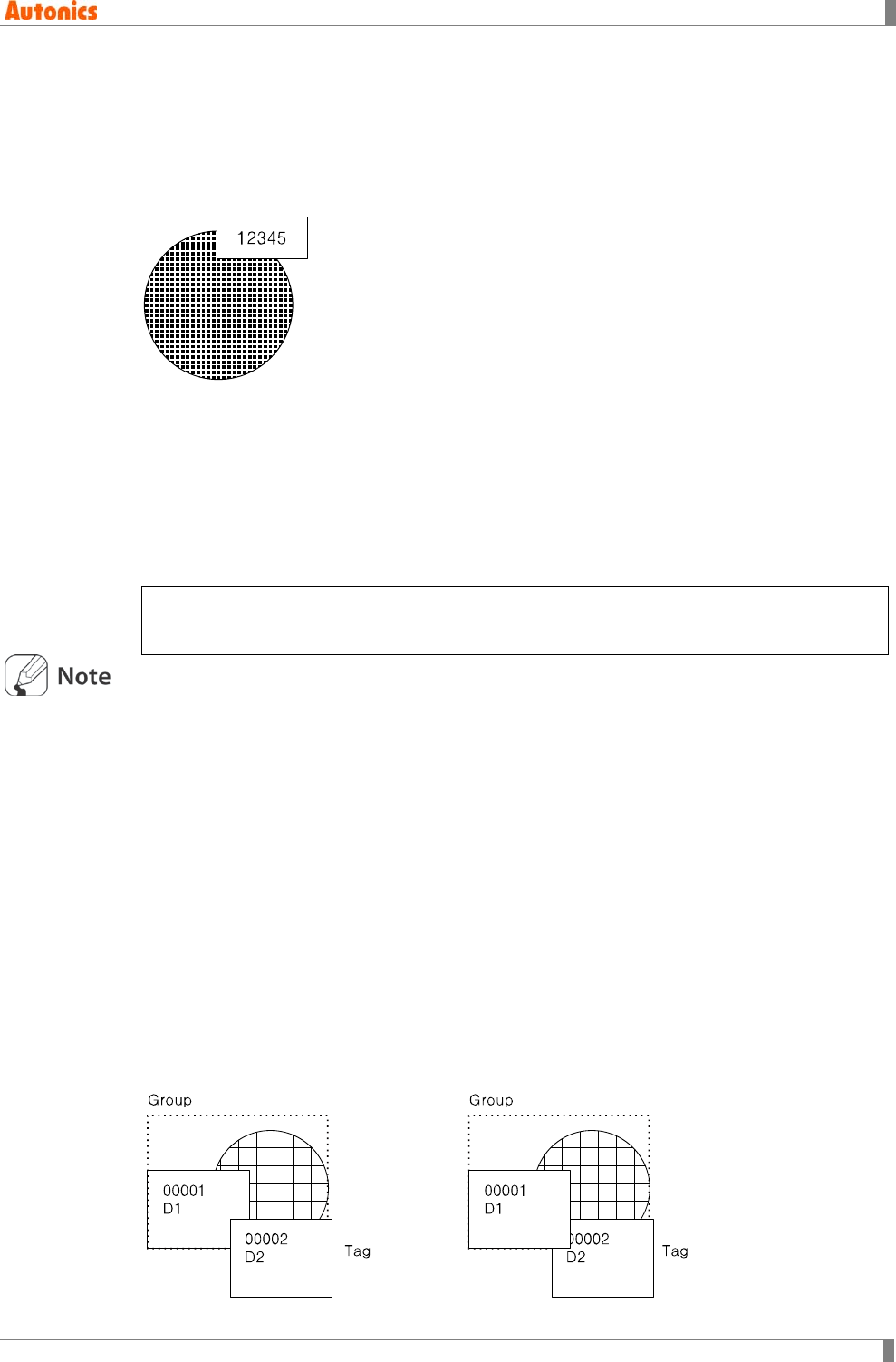
4 Edit
© Copyright Reserved Autonics Co., Ltd. 79
4.11 Bring Forward/Send Backward
Bring forward instruction changes stacking order for the selected object to bring forward. Send
backward instruction changes stacking order for the selected object to send backward.
(1) Figure and tag
Tag has higher priority than figure object, it is always displayed in front of figure.
(2) Figure and figure, tag and tag
The stacking order between figure and figure object, tag and tag is decided as the latest
created one has high priority. The later one is able to hide the previous one.
(3) Overlap screen
Base screen has a higher order than overlapped screen, it is displayed in front of overlap
screen. Figure and tag of base screen are put in front of figure and tag of overlap screen. If
there are more than two overlap screens, later overlapped screen object is on the front.
When there are two overlap screens, it is displayed as following order.
Tag of base screen → Figure of base screen → Tag of overlap screen2 → Figure of overlap
scree2 → Tag of overlap screen1 → Figure of overlap screen1
It is not able to change the order between figure and tag with bring forward, send to
backward instruction.
The stacking order of figure is changed with bring forward instruction; it is put on the front
among figures but it cannot be placed in the front for any tags.
The stacking order of tag is changed with send backward instruction; it is put on the behind
among tags but it is put on the front than any figure.
When executing bring forward, send to backward instruction after selecting several objects,
the stacking order between selected objects is kept and it is put on the front or on the
behind than not selected objects.
If selecting overlap screen and executing send to backward instruction, it is put on the
behind among overlap screens.
The stacking order of group and tag
The order between two is decided by bring forward or send backward instruction. Tag is
placed on the upper than figure regardless with single object of tag or object including tag.
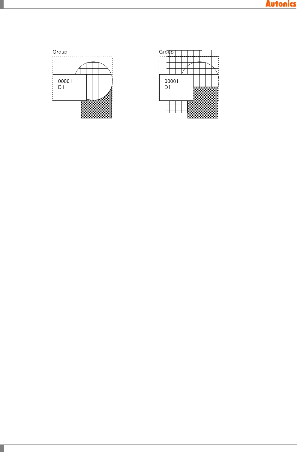
4 Edit
80 © Copyright Reserved Autonics Co., Ltd.
Figure included in a figure or group
The order between two is decided by bring to forward or send to backward instruction,
figure is placed on the lower than tag.
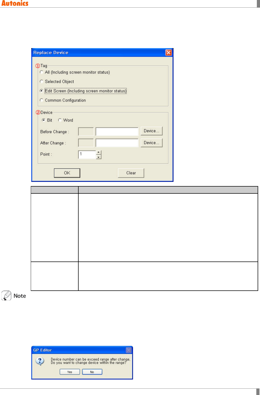
4 Edit
© Copyright Reserved Autonics Co., Ltd. 81
4.12 Replace Device
It is able to replace device using in a project collectively. Select [Edit]-[Replace Device] of menu,
‘Replace Device’ dialog box appears.
Replace Device
Description
①Tag
Designate tag to replace device according to Tag group box.
All (Including screen monitor status): Replaces tag devices on all base
screens in a project. All devices configured about each base screen
designated at ‘Screen’ tab of ‘Monitor Status’ dialog box are replaced.
Selected Object: Replaces selected tag device of the current editing
screen.
Edit Screen (Including screen monitor status): Replaces tag device on a
editing screen. All devices configured about current editing screen
designated at ‘Screen’ tab of ‘Monitor Status’ dialog box are replaced.
Common Configuration: Replaces tag device of common configuration.
②Device
Bit/Word: Select bit or word device
Before Change/After Change: Changes device designated in Before
Change as device designated in After Change.
Point: Designates the number of device to be changed.
Default configuration according to calling ‘Replace Device’ dialog box
When selecting [Edit]-[Replace Device] of menu,
(a) Edit screen as default when there are not selected tags
(b) Selected objects as default when there are selected tags
When lead device and destination device designated point are out of range, the following
message appears and askes change the device within range or not.
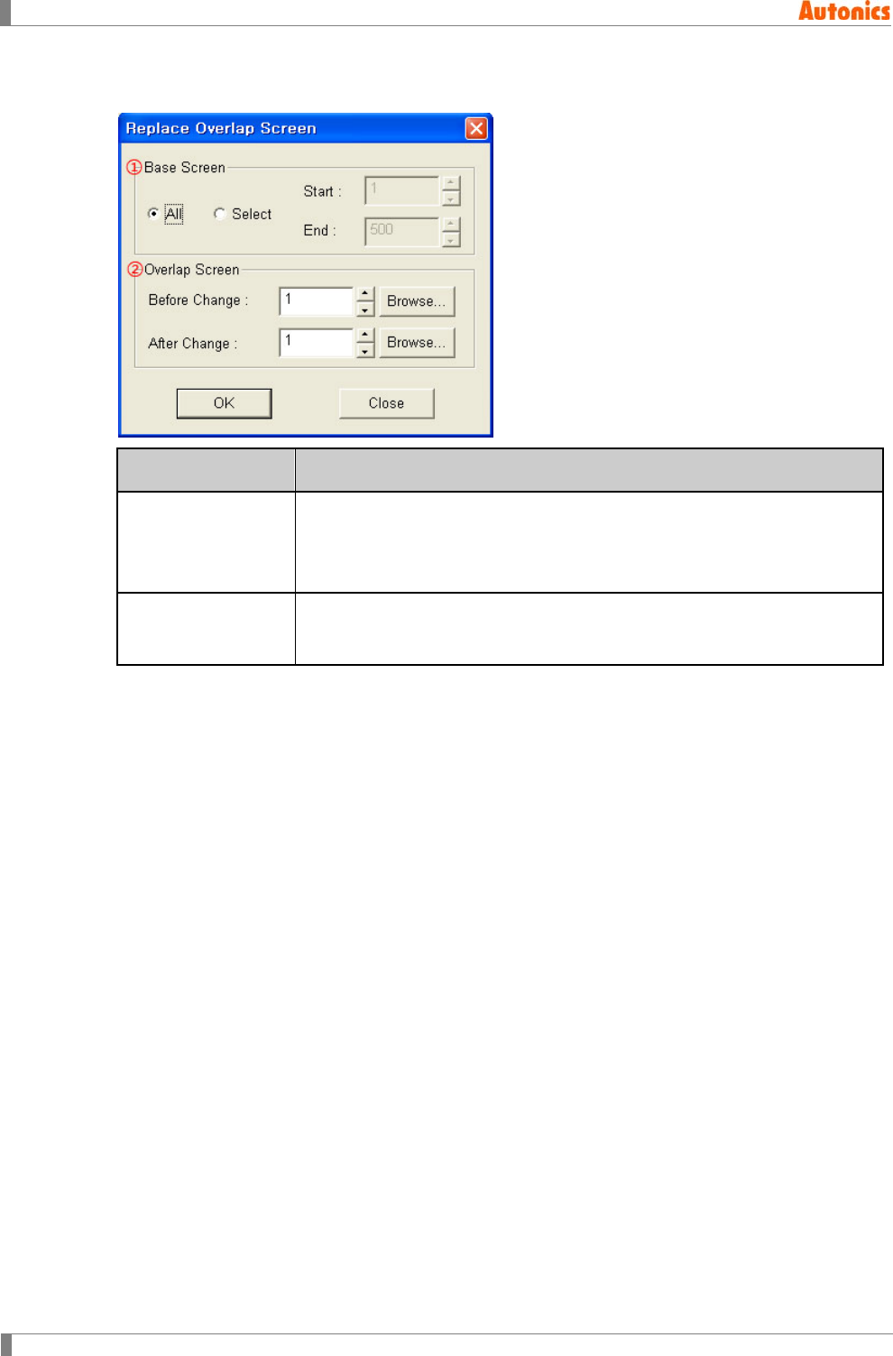
4 Edit
82 © Copyright Reserved Autonics Co., Ltd.
4.13 Replace Overlap Screen
Replace Overlap
Screen
Description
①Base Screen
Designates overlap screen range to replace
All: Replaces overlap screens of all base screens in a project
Select: Replaces the overlap screens of the designated base screens
which has Start to End range in a project
②Overlap Screen Designates overlap screen number to replace
Replaces from Before Change of overlap screen number to After Change
of overlap screen number
4.14 Attribute
Select the object and select [Edit]-[Attribute] of menu, click the object with right mouse button
and pop-up menu appears and select [Attribute], double-click the obejct, or after selecting the
object and press Alt+Enter, and the object ‘Property’ dialog box appears.
If executing attribute instruction when overlap screen is selected, ‘Overlap’ dialog box appears
with the overlap screen selected state.
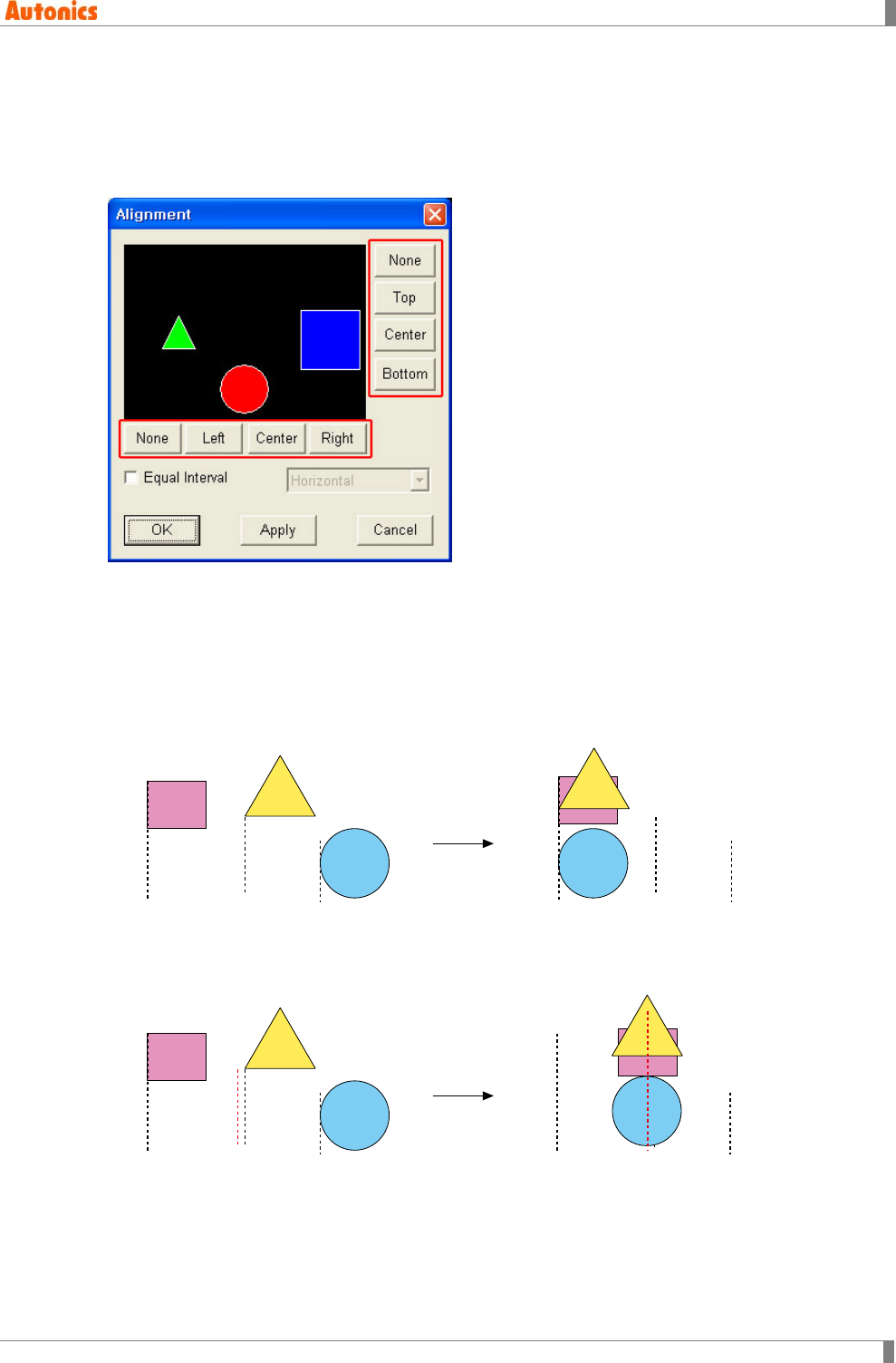
4 Edit
© Copyright Reserved Autonics Co., Ltd. 83
4.15 Alignment
It is useful to arrange objects as up/down/left/right when several objects are on a screen.
Select [Edit]-[Alignment] of menu, and ‘Alignment’ dialog box appears. After the desired
alignment setting and click ‘Apply’ and ‘OK’ to complete alignment.
(1) Horizontal alignment
None
There is no horizontal alignment.
Left
It moves top-left X coordinate of selected all objects to make same as X coordinate of top-
left of leftmost object with horizontal way.
Center
It moves central point X coordinate of selected all objects to make same as an average of
top-left X coordinate of leftmost object and rightmost object with horizontal way.
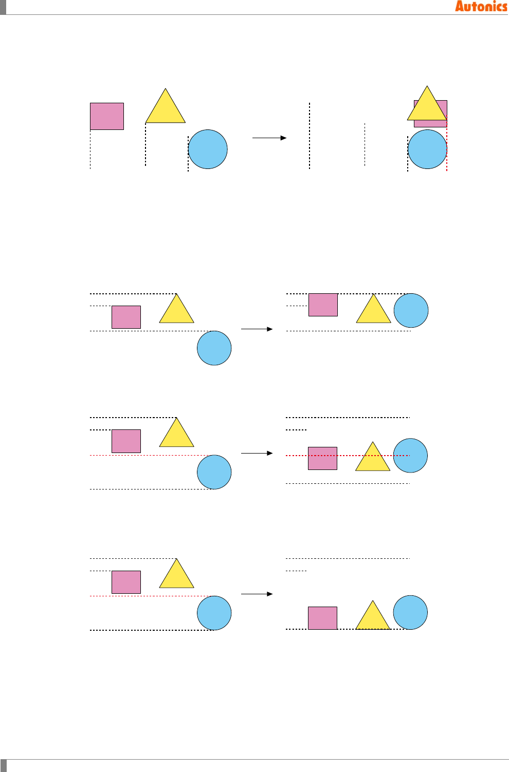
4 Edit
84 © Copyright Reserved Autonics Co., Ltd.
Right
It moves top-right X coordinate of selected all objects to make same as top-right X
coordinate of rightmost object with horizontal way.
(2) Vertical alignment
None
There is no vertical alignment.
Top
It moves top-left Y coordinate of selected all objects to make same as top-left Y coordinate
of topmost object with vertical way.
Center
It moves central point Y coordinate of elected all objects to make same as an average of
top-left Y coordinate of topmost object and bottommost object with vertical way.
Bottom
It moves top-left Y coordinate of selected all objects to make same as top-left Y coordinate
of bottommost object with vertical way.
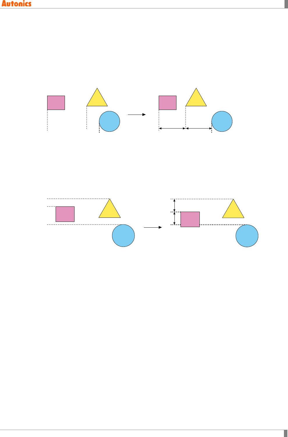
4 Edit
© Copyright Reserved Autonics Co., Ltd. 85
(3) Equal Interval
Horizontal
Leaving objects with left end of X coordinate on leftmost and rightmost among selected
objects, move other objects as horizontal way to make left end of X coordinate of other
objects to position equally between left end of X coordinate of two objects.
If left end of X coordinate among more than 2 objects is same, front part of object is moved
to the right. When right end of X coordinate of moving object is out of the right border, right
end of X coordinate is on a border.
Vertical
Leaving objects with top end of Y coordinate on topmost and bottommost among selected
objects, move other objects as vertical way to make top end of Y coordinate of other objects
to position equally between top end of Y coordinate of two objects.
If left end of Y coordinate among more than 2 objects is same, front part of object is moved
to the bottom. When bottom end of X coordinate of moving object is out of the bottom
border, bottom end of Y coordinate is on a border.

4 Edit
86 © Copyright Reserved Autonics Co., Ltd.
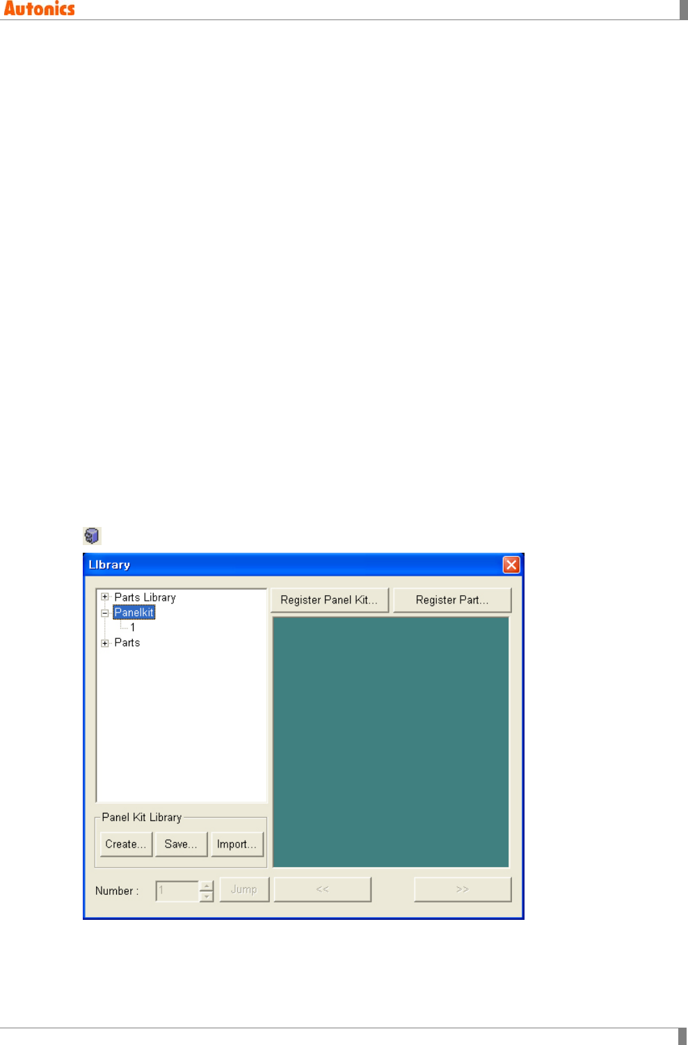
5 Draw
© Copyright Reserved Autonics Co., Ltd. 87
5 Draw
In this chapter, it describes basic operation of tag arrangement on a screen.
5.1 Panel kit/Part
Panel kit/Part library is a library to reuse frequently used figures and tags easily.
There are three types of panel kit/part library.
(1) Panel kit library
Panel kit library is user-made library and able to register frequently used figures and tags as
library part. It is able to make max.50 libraries and to utilize to other projects after making it.
It is able to save as a separate file and loaded saved library to use.
(2) Part library
It is not able to edit because it is a basic library supported by GP Editor.
It is not able to user edit or copy any library and library image in part library but user can
design in panel kit.
(3) Part
It is able to register several numbers or groups of figure object (line, rectangle, circle, text,
BMP) and it is used in part display, lamp, and touch key tag.
It is required to register separately for each project and it can be imported from other project.
All parts are downloaded to GP/LP.
5.1.1 Panel kit
Panel kit ‘Library’ dialog box is modeless dialog box which enable to edit continue. It executesall
operation about panel kit, part library, and part. Select [Draw]-[Panel Kit]/[Part] of menu, or click
in toolbar, Panelkit/Part ‘Library’ dialog box appears.
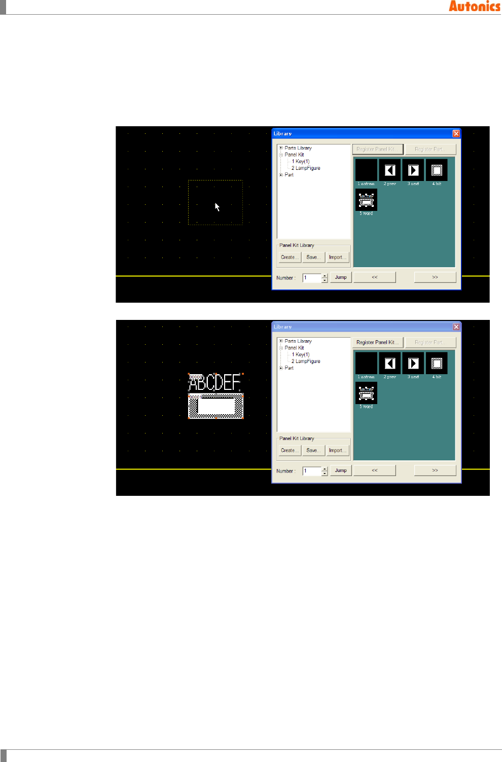
5 Draw
88 © Copyright Reserved Autonics Co., Ltd.
5.1.1.1 Draw
1st At tree view of ‘Library’ dialog box, select parts library, panel kit, or parts and lower
folder. The selected folder library’s items are displayed at image view.
2nd Select the desired item from image view.
3rd Place mouse cursor to edit area. Dotted outline follows mouse cursor.
4th Click mouse button, and the desired panel kit/part item is placed.
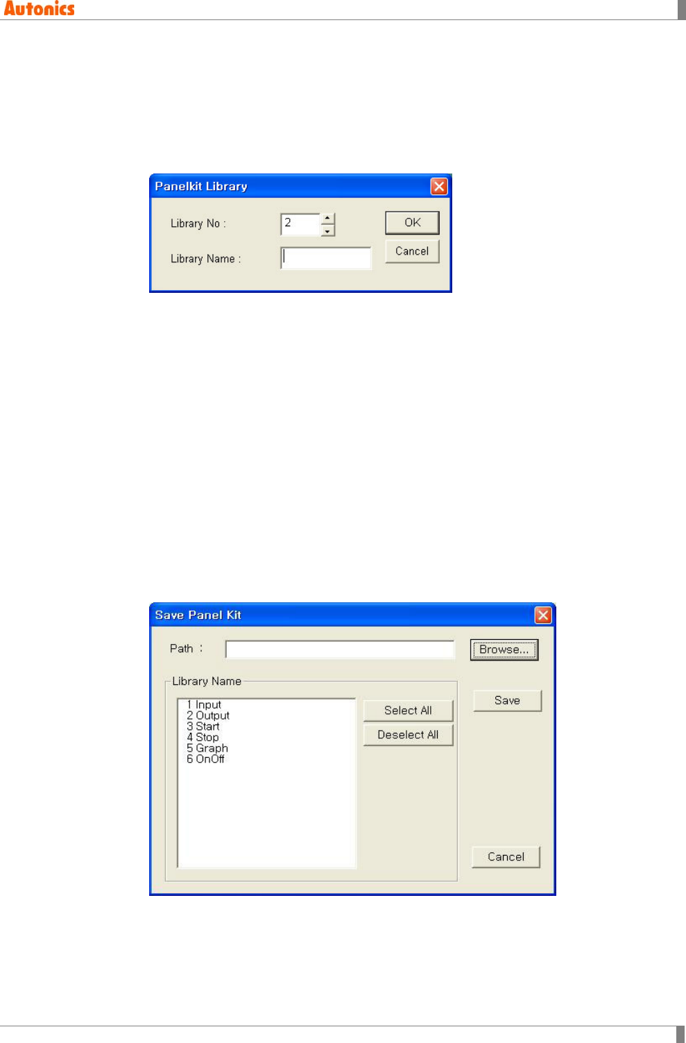
5 Draw
© Copyright Reserved Autonics Co., Ltd. 89
5.1.1.2 Create/Delete
Create
1st Click ‘Create’ of ‘Library’ dialog box, ‘Panelkit Library’ dialog box appears.
2nd Designate library number to ‘Library No.’ and library name to ‘Library Name’ to create
the designated library.
Delete
1st Select the desired library to delete at image view.
2nd Click right mouse button, pop-up menu appears.
3rd Select ‘Delete’ and library is deleted.
5.1.1.3 Save/Import
After panel kit library is registered first, every project can import the library. You can save the
library as file and manage it.
Save
1st Click ‘Save’ at ‘Panel Kit Library’ box of ‘Library’ dialog box.
2nd ‘Save Panel Kit’ dialog box appears. Select the library to save at ‘Library Name’ list
box.
3rd Click ‘Browse’ and designate the path to save.
4th Click ‘Save’ and each library is saved as ‘PKITxx.xml’ file on the designated path.
xx of the next PKIT means the selected library number.
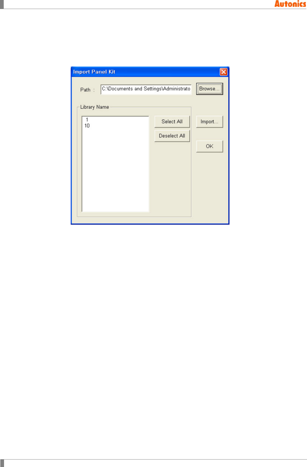
5 Draw
90 © Copyright Reserved Autonics Co., Ltd.
Import
1st Click ‘Import’ at ‘Panel Kit Library’ box of ‘Library’ dialog box.
2nd ‘Import Panel Kit’ dialog box appears. Click ‘Browse’ and designate the path to import
panel kit library.
3rd ‘Library Name’ list box displays the designated panel kit library.
4th Select the library to import at ‘Library Name’ list box, and click ‘Import’.
Every libarary of selected library file is imported to editing screen. After this, you can use the
library.
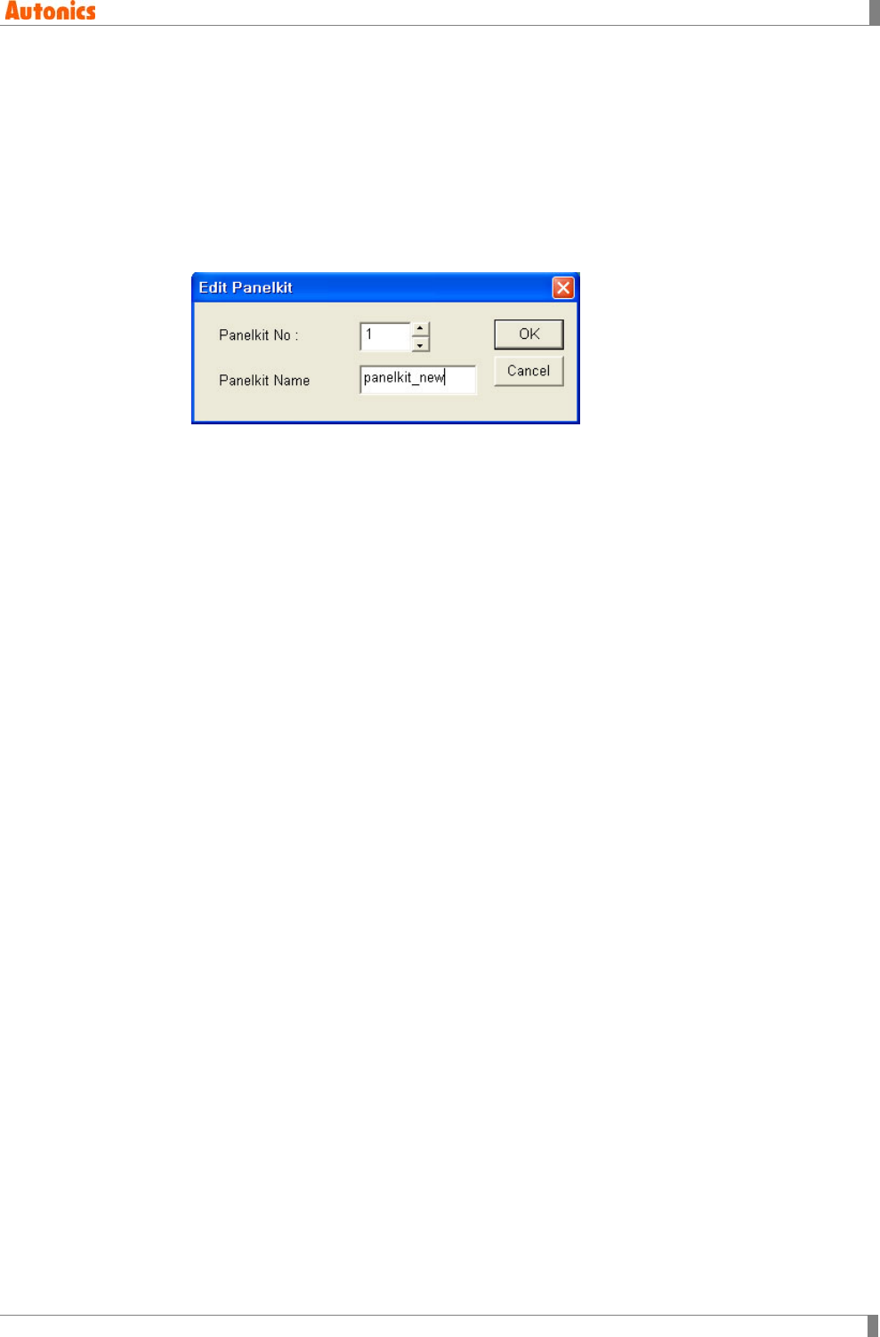
5 Draw
© Copyright Reserved Autonics Co., Ltd. 91
5.1.1.4 Register panel kit/Delete/Copy
Register
Panel kit is able to register as part when several numbers or groups of only figure objects
(line, rectangle, circle, Text, BMP) are selected.
1st Select the object to register as panel kit on edit screen. ‘Register Panel Kit’ is
activated only when there is selected object.
2nd Click ‘Register Panle Kit’ and ‘Edit Panelkit’ dialog box appears.
Panel Kit Number: Panel kit number at the registered library
Panel Kit Name: Panel kit name
3rd Designate panel kit number and name and register it. If there is already the
designated panel kit number, overwrite check message appears.
4th Panel kit is registered.
Delete
1st Select the object at image view.
2nd Click right mouse button, pop-up menu appears and select ‘Delete’.
3rd The object is deleted.
Copy (Register as other name)
1st Select the object at image view.
2nd Click right mouse button, or press Ctrl+C. Pop-up menu appears and select ‘Copy’.
3rd ‘Panelkit Copy’ dialog box appears and select the desired item to copy.
5.1.2 Part
The descriptions of draw, rigister, copy, or delete part are same with those of panel kit. Please
refer to ‘5.1.1 Panel kit’.
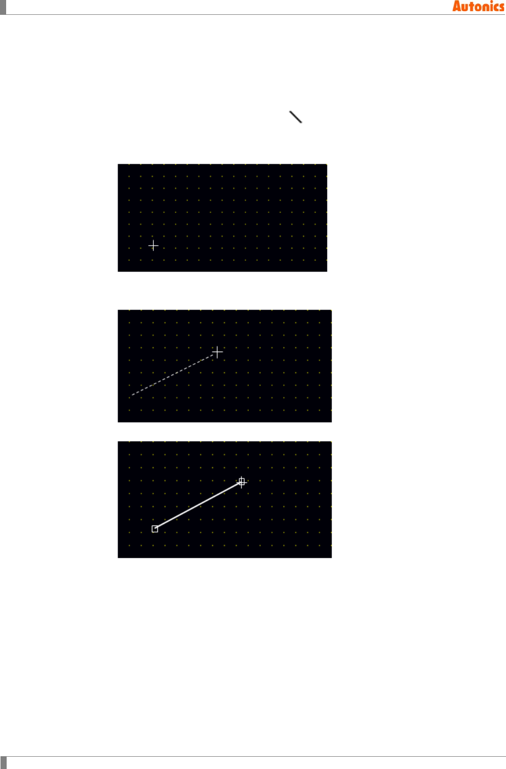
5 Draw
92 © Copyright Reserved Autonics Co., Ltd.
5.2 Line
Draws line with one dot thickness on screen.
5.2.1 Basic usage
1st Select [Draw]-[Line] of menu, or click in toolbar, mouse cursor for drawing mode
appears at edit area.
2nd Place mouse cursor on a start point of straight line and press left mouse button.
3rd Press left mouse button and drag cursor to the end point of the line. A dotted line
appears up to current cursor position.
4th Release mouse button and a line is drawn.
5th For changing color or style of line, double-click the line and ‘Line Property’ dialog box
appears. You can designate the desired color and style.
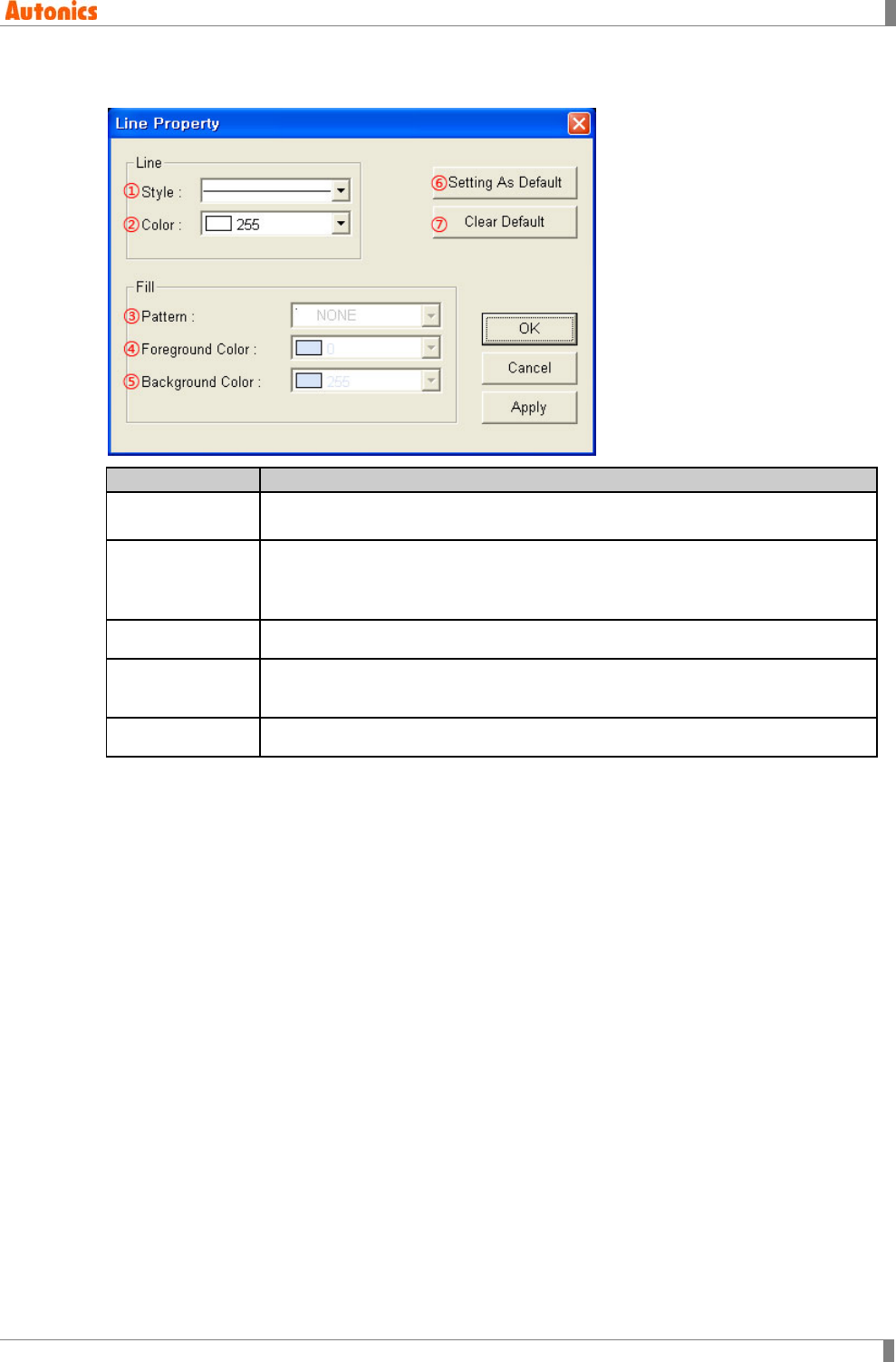
5 Draw
© Copyright Reserved Autonics Co., Ltd. 93
5.2.2 Property
Item
Description
①Style Designate one line style of solid, dotted, broken, dot chain, two dot chains by
pull-down menu.
②Color
Designate line color.
Mono type(GP-S044, GP-S057, LP-S044): White/Black
Color type(GP-S070, LP-S070): 24bit True Color
③ to ⑤ Not used
⑥Setting As
Default Draw next line as currently designated style and color.
⑦Clear Default Draw next line as ①Style: Solid, ②Color: White.
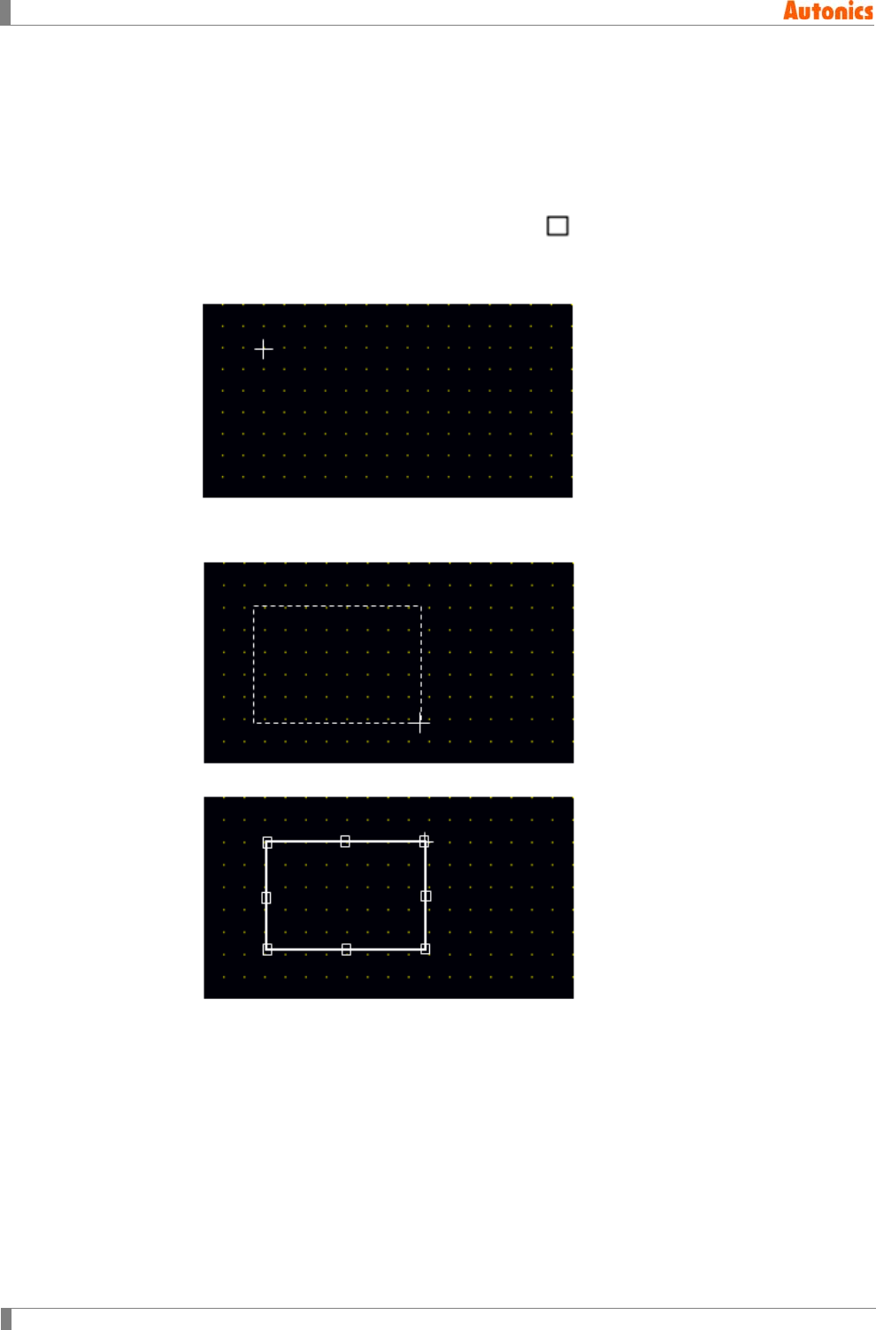
5 Draw
94 © Copyright Reserved Autonics Co., Ltd.
5.3 Rectangle
Draws rectangle with one dot thickness outline on screen. You can change the desired color and
style of outline and designate inside pattern, foreground color, and background color.
5.3.1 Basic usage
1st Select [Draw]-[Rectangle] of menu, or click in toolbar, mouse cursor for drawing
mode appears at edit area.
2nd Place mouse cursor on a edge point of rectangle and press left mouse button.
3rd Press left mouse button and drag cursor to the diagonal edge point of rectangle. A
dotted rectagle appears.
4th Release mouse button and ractangle is drawn.
5th For changing color or style of rectangle, double-click ‘Rectangle Property’ dialog box
appears. You can change the desired color and style of outline and designate inside
pattern, foreground color, and background color.
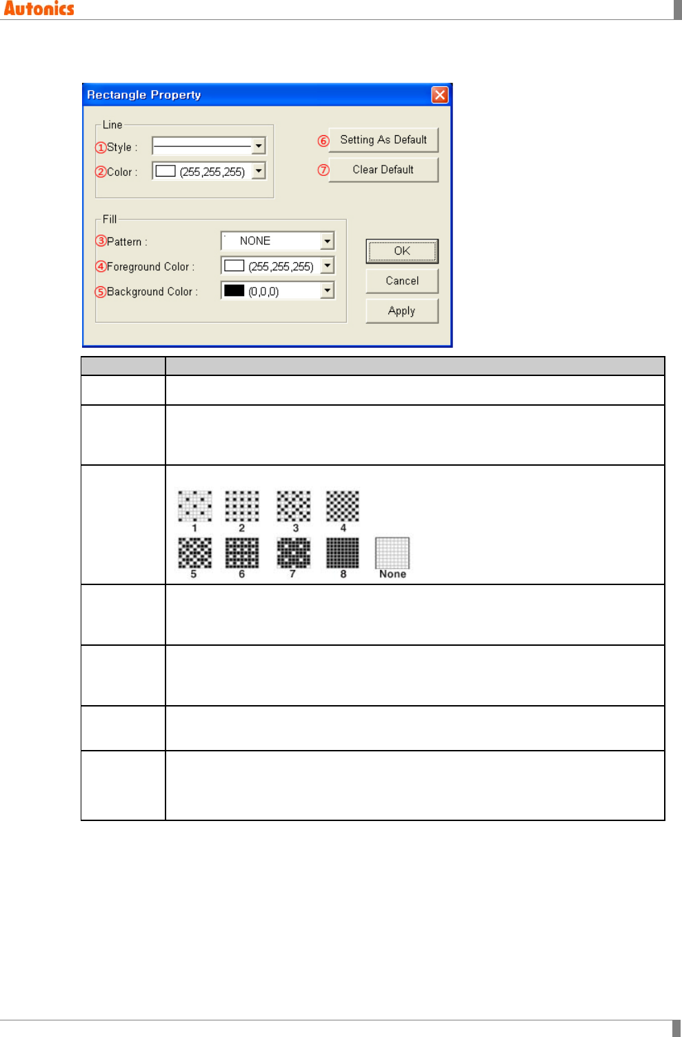
5 Draw
© Copyright Reserved Autonics Co., Ltd. 95
5.3.2 Property
Item
Description
①Style Designate outline style by pull-down menu. Setting range is same with that of line.
②Color
Designate outline color
Mono type(GP-S044, GP-S057, LP-S044): White/Black
Color type(GP-S070, LP-S070): 24bit True Color
③Pattern
Select one pattern of rectangle to fill inside by pull-down menu.
④Foregrou
nd Color
Designate foreground color
Mono type(GP-S044, GP-S057, LP-S044): White/Black
Color type(GP-S070, LP-S070): 24bit True Color
⑤Backgrou
nd Color
Designate background color
Mono type(GP-S044, GP-S057, LP-S044): White/Black
Color type(GP-S070, LP-S070): 24bit True Color
⑥Setting
As Default Draw next rectangles as currently designated settings
⑦Clear
Default
Draw next rectangles as following.
①Style: Solid, ②Color: White, ③Pattern: None, ④Foreground Color: White,
⑤Background Color: Black
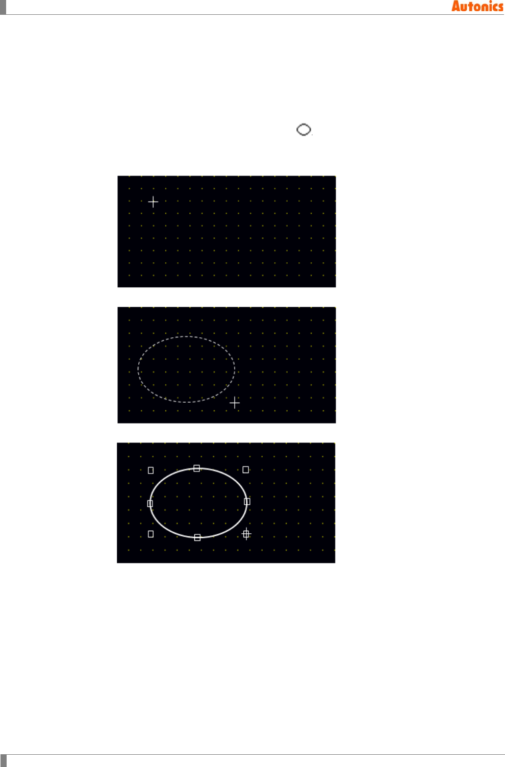
5 Draw
96 © Copyright Reserved Autonics Co., Ltd.
5.4 Circle
Draws circle or oval with one dot thickness outline on screen. You can change the desired color
and style of outline and designate inside pattern, foreground color, and background color.
5.4.1 Basic usage
1st Select [Draw]-[Circle] of menu, or click in toolbar, a mouse cursor for drawing
mode appears at edit area.
2nd Place mouse cursor to the desired area and press left mouse button.
3rd Press left mouse button and drag cursor as the desired size. A dotted circle appears.
4th Release mouse button and a circle is drawn.
5th For changing color or style of circle, double-click the circle and ‘Circle Property’ dialog
box appears. You can change the desired color and style of outline and designate
inside pattern, foreground color, and background color.
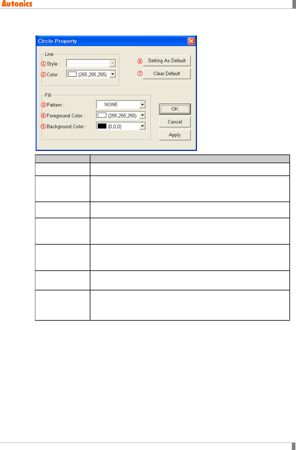
5 Draw
© Copyright Reserved Autonics Co., Ltd. 97
5.4.2 Property
Item
Description
①Style Not used
②Color
Designate outline color
Mono type(GP-S044, GP-S057, LP-S044): White/Black
Color type(GP-S070, LP-S070): 24bit True Color
③Pattern Select one pattern of circle to fill inside by pull-down menu. Setting range is
same with that of rectangle.
④Foreground
Color
Designate foreground color
Mono type(GP-S044, GP-S057, LP-S044): White/Black
Color type(GP-S070, LP-S070): 24bit True Color
⑤Background
Color
Designate background color
Mono type(GP-S044, GP-S057, LP-S044): White/Black
Color type(GP-S070, LP-S070): 24bit True Color
⑥Setting As
Default Draw next circle as currently designated settings
⑦Clear Default
Draw next circle as following
②Color: White, ③Pattern: None, ④Foreground Color: White,
⑤Background Color: Black
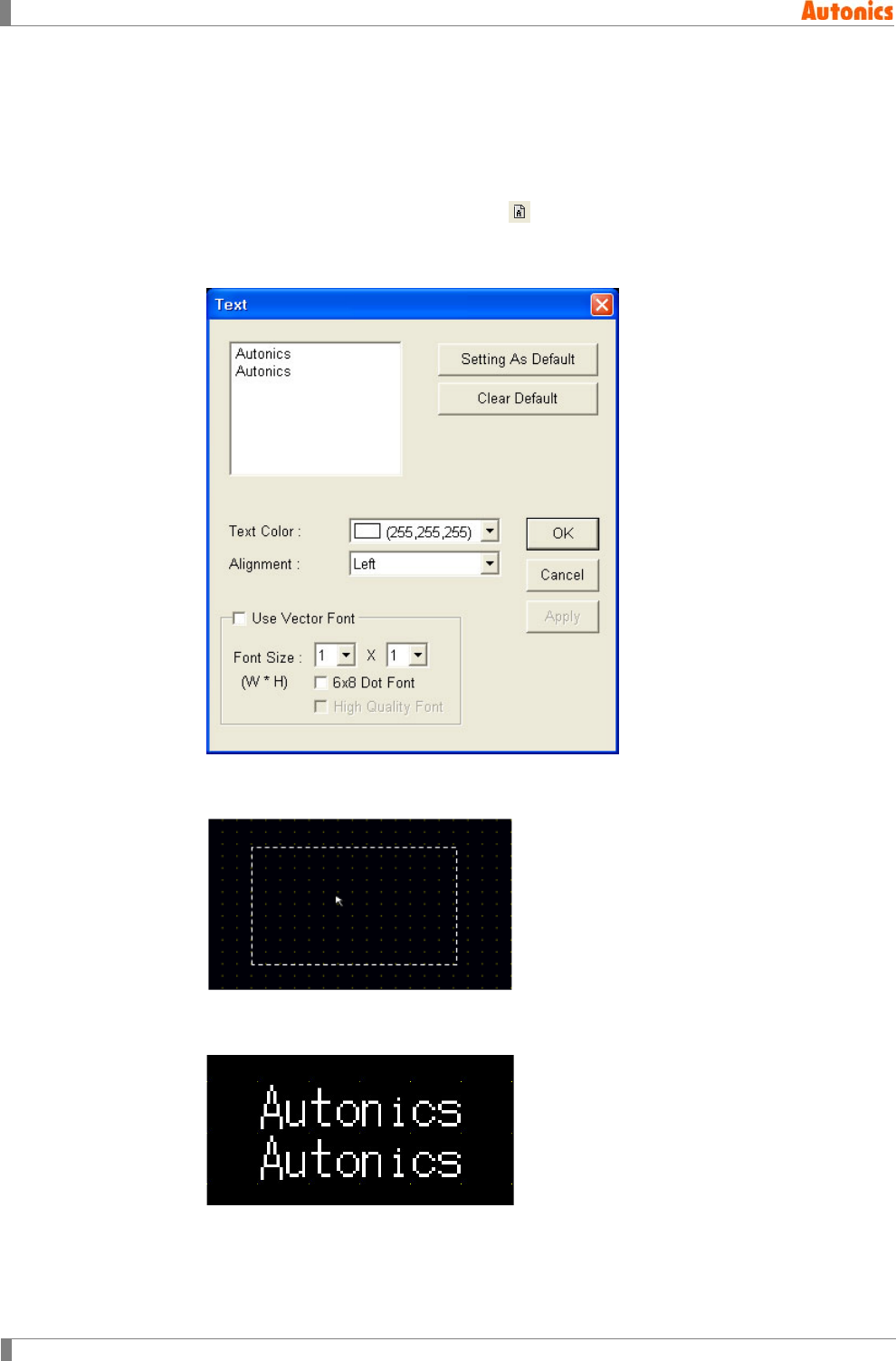
5 Draw
98 © Copyright Reserved Autonics Co., Ltd.
5.5 Text
Displays and arranges the user-defined text on screen.
5.5.1 Basic usage
1st Select [Draw]-[Text] of menu, or click and ‘Text’ dialog box appears.
2nd Register the desired text at ‘Text’ dialog box, and designate text color, and font size,
etc. (Color type supports using vector font.)
3rd Click ‘OK’ and ‘Text’ dialog box is closed. A dotted rectangle follows mouse cursor at
edit area.
4th Place mouse cursor on the desired area, click left mouse button. Text is placed on the
screen.
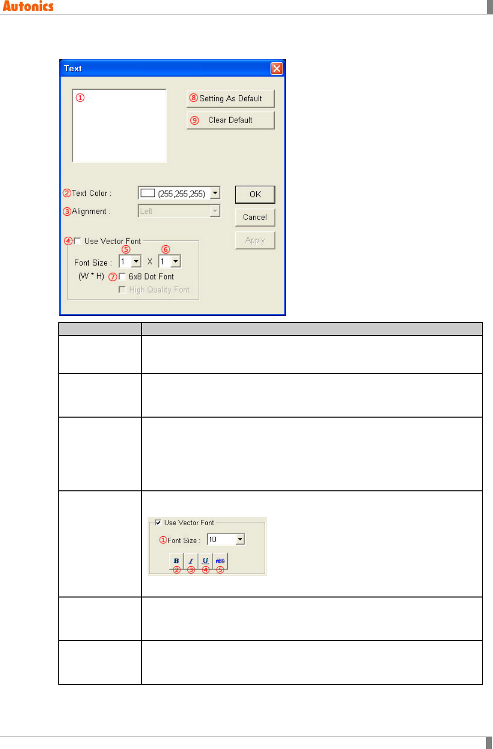
5 Draw
© Copyright Reserved Autonics Co., Ltd. 99
5.5.2 Property
Item
Description
①Text Edit text to display. If width or height text length are out of screen, or changed
width or height font size is out of screen, ‘Out Of Panel Size’ message appears
below this box. Adjust size or text length, and this message disappears.
②Text Color
Designates text color
Mono type(GP-S044, GP-S057, LP-S044): White/Black
Color type(GP-S070, LP-S070): 24bit True Color
③Alignment
Activated only for more than two lines text from ① and designate alignment
type by pull-down menu.
Left: Displays a letter from the left of tag area
Right: Displays a letter from the right of tag area
Center: Displays a letter in a center of tag area.
④Use Vector
Font
Activated only for color type (GP-S070, LP-S070). Non-checking this, it uses
bitmap font. Checking this, it displays as following.
①Font size, ②Bold font, ③Italic font, ④Underline, ⑤Strikethrough
⑤Font Size
(Width)
Designate width font size by pull-down menu.
Default =1, Range: 1, 2, 3, 4, 5, 6, 7, 8
Height font size is 0.5, width font size 1 is only available.
⑥Font Size
(Height)
Designate height font size by pull-down menu.
Default =1, Range: 0.5, 1, 2, 3, 4, 5,6, 7, 8
Width font sizes besides 1 are not available for height font size 0.5.
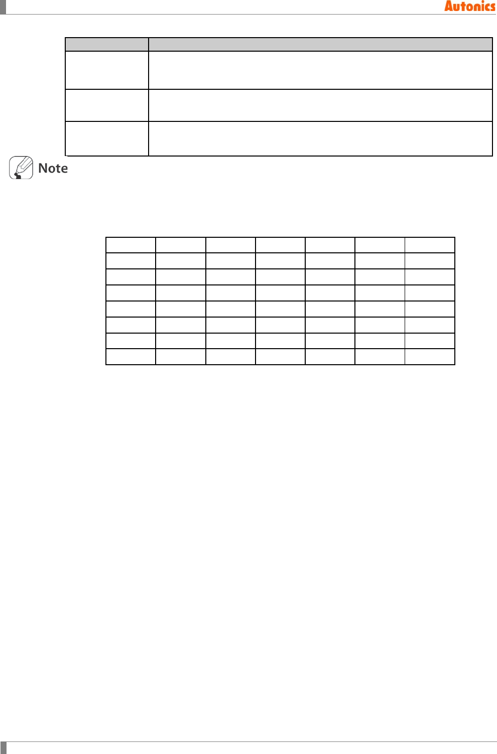
5 Draw
100 © Copyright Reserved Autonics Co., Ltd.
Item
Description
⑦6x8 Dot Font Designate 6x8 dot font.
Only ASCII font has 6x8 dot font. If there is not 6x8 dot font, it displays
rectangles with the desired size and color.
⑧Setting As
Default Draw next text as currently designated settings
⑨Clear Default Draw next text as following
②Text Color: White, ③Alignment: Left, ⑤⑥Font Size: 1x1
Text font size
6X8, 8X8 dot ASCII font
ASCII font and regional character with enlarged 8X16 dot font
8X8 8X16 8X32 8X48 8X64 8X72 8X80
16X8 16X16 16X32 16X48 16X64 16X72 16X80
--- 24X16 24X32 24X48 24X64 24X72 24X80
--- 32X16 32X32 32X48 32X64 32X72 32X80
--- 40X16 40X32 40X48 40X64 40X72 40X80
--- 48X16 48X32 48X48 48X64 48X72 48X80
--- 56X16 56X32 56X48 56X64 56X72 56X80
--- 64X16 64X32 64X48 64X64 64X72 64X80

5 Draw
© Copyright Reserved Autonics Co., Ltd. 101
5.6 Bitmap
Inserts bitmap image on screen. Depends on the number of selected image color and the
designated number of image color from ‘Project Auxiliary Property’ dialog box, it is as following.
You can check the number of image color at [Common]-[Auxiliary Configuration]-[Project].
Mono type(GP-S044, GP-S057, LP-S044)
If selected image is not mono, it converts the image by mono color and inserts it on screen.
Color type(GP-S070, LP-S070)
If the number of selected image color has more than the designated number of image
color, the selected image is converted by the designated number of image color and
insert it on project.
If the number of selected image color less than or same with the designated number of
image color, there are not converting and insert it on project directly.
For using same images to others, it processes to use the image which is already registered
and the basis for same image is image file name, and file size.
To add the image which is already registered after changing the designated number of
image color, regardless the designated number of image color, it uses the image as it is.
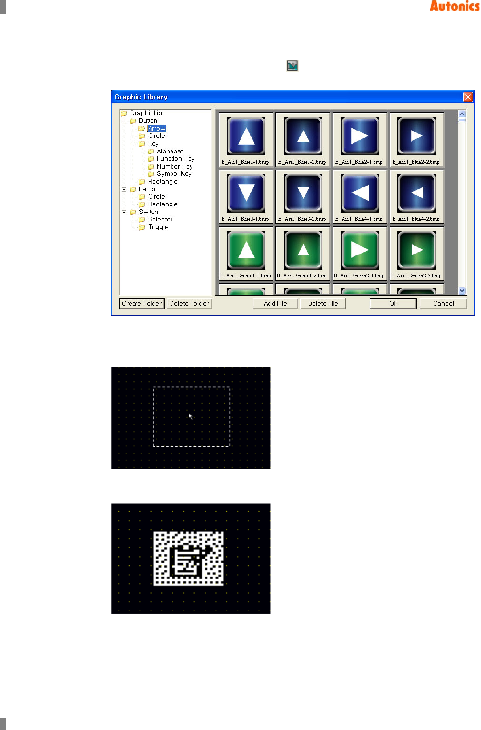
5 Draw
102 © Copyright Reserved Autonics Co., Ltd.
5.6.1 Basic usage
1st Select [Draw]-[Bitmap] of menu, or click in toolbar, ‘Graphic Library’ dialog box
appears.
2nd Select the desired image and click ‘OK’ or double-click the desired image at preview,
and ‘Graphic Libaray’ dialog box is closed. A dotted rectangle follows mouse cursor at
edit area.
3rd Place mouse cursor on the desired area, click left mouse button. Bitmap image is
placed on the screen.
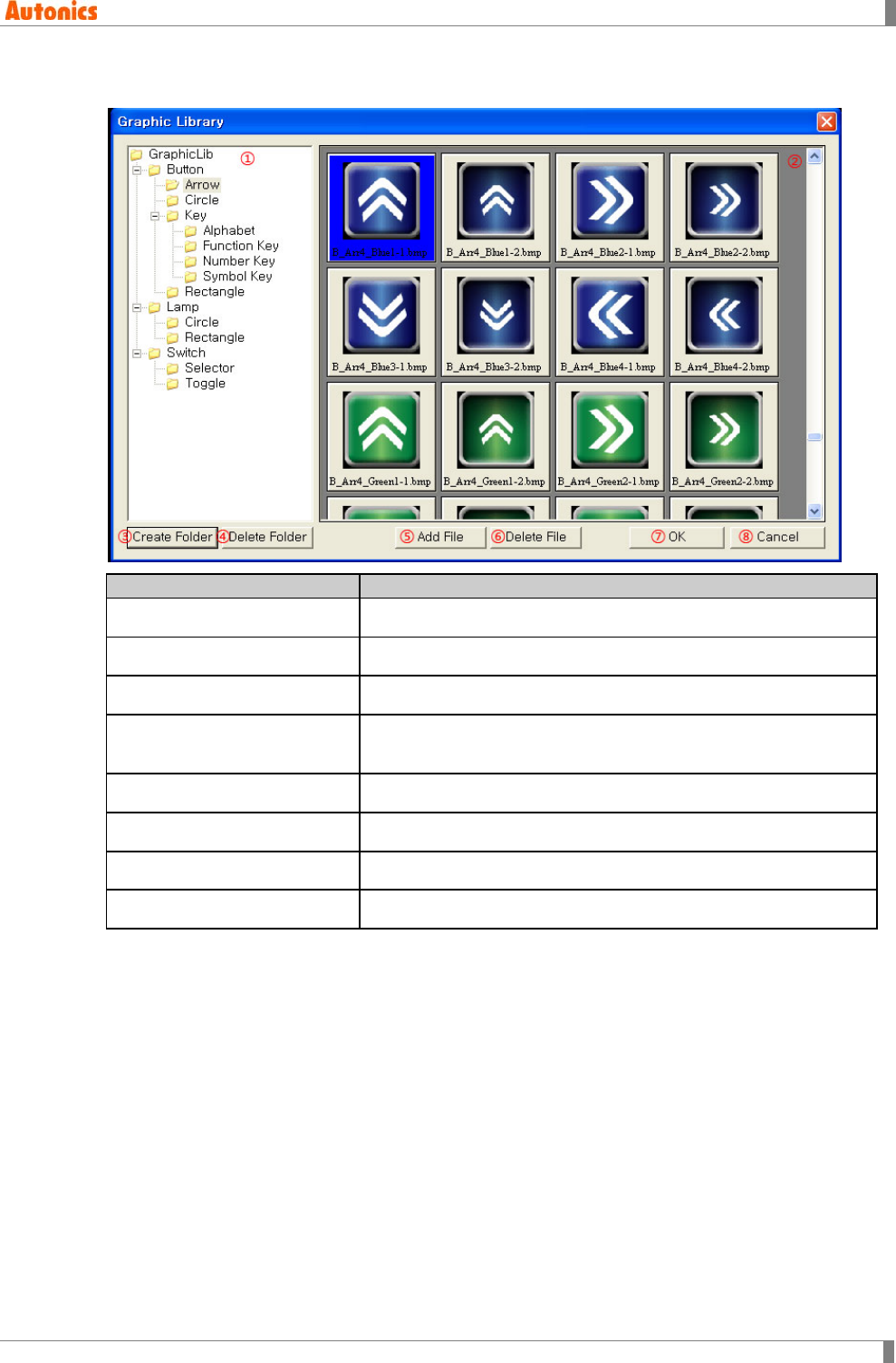
5 Draw
© Copyright Reserved Autonics Co., Ltd. 103
5.6.2 Property
Graphic Library
Description
①Graphic Library Displays data in GraphicLib folder as a tree
②Preview Previews image file from selected folder by ①
③Create Folder Creates subfolder for selected folder by ①
④Delete Folder Deletes selected folder by ①
(Deleted all images in this folder.)
⑤Add File Adds image file in selected folder by ①
⑥Delete File Deletes image file from selected image by ②
⑦OK Uses the selected image file by ②
⑧Cancel Closes ‘Graphic Library’ dialog box
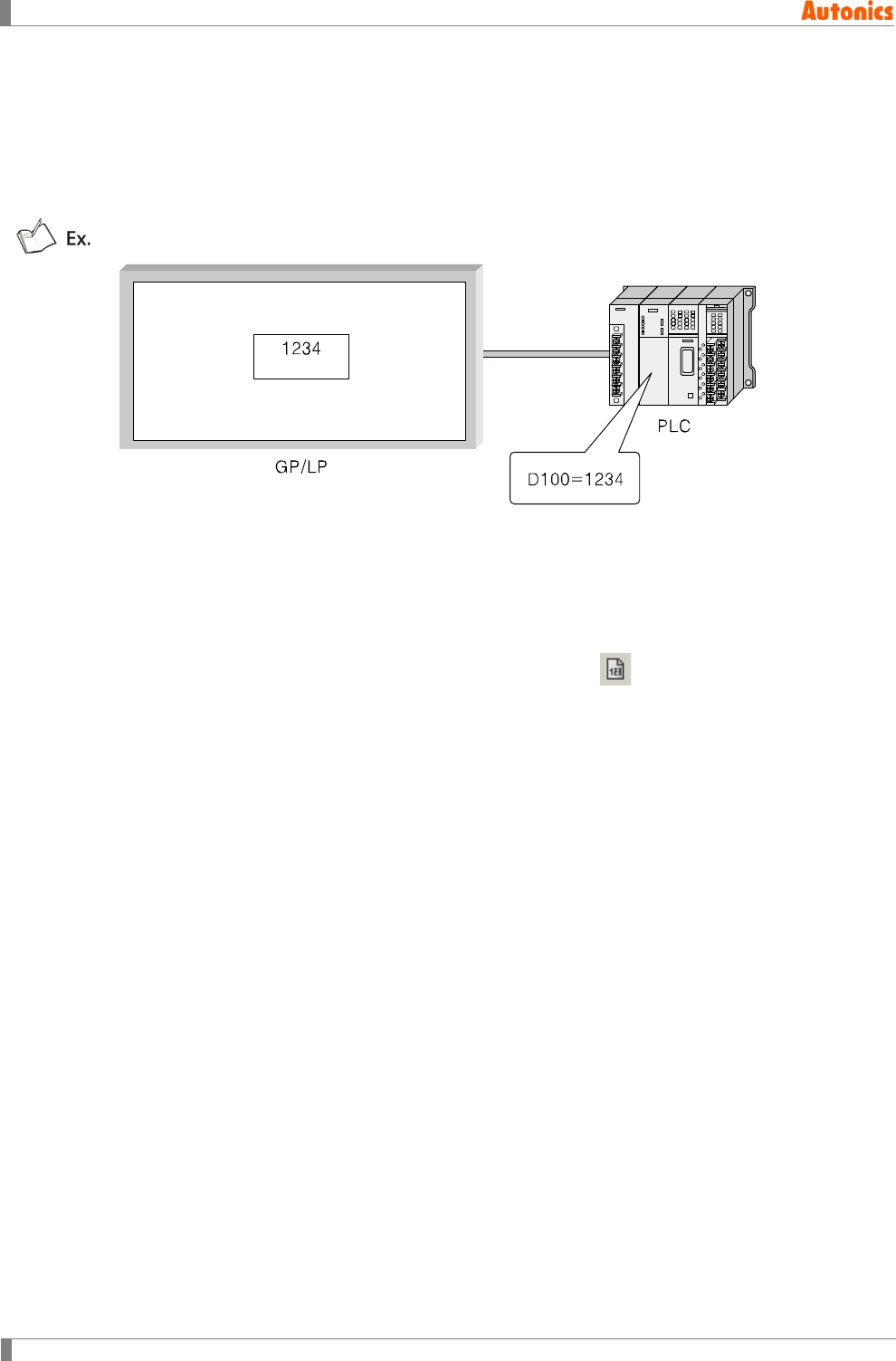
5 Draw
104 © Copyright Reserved Autonics Co., Ltd.
5.7 Numeral Input
Numeral input tag is for inputing numeral to specified device by keywindow on screen or by user-
defined key code of touch key.
If there is no input, it opreates as numeral display. In other words, it displays numeral of specified
device as designated form.
The above example is that numeral input device of PLC is D100, the designated numeral on
GP/LP is 1234.
5.7.1 Basic usage
The following process is for registering numeral input tag.
1st Select [Draw]-[Numernal Input] of menu, or click in toolbar, ‘Numeral Input
Property’ dialog box appears.
2nd Designate device.
3rd Designate device data type.
4th Designate display type and digit, etc in ‘Form’ tab.
5th Click ‘OK’ and ‘Numeral Input Property’ dialog box is closed. A dotted rectangle
follows mouse cursor at edit area.
6th Place mouse cursor on the desired area, click left mouse button. Numernal input is
created on the screen.
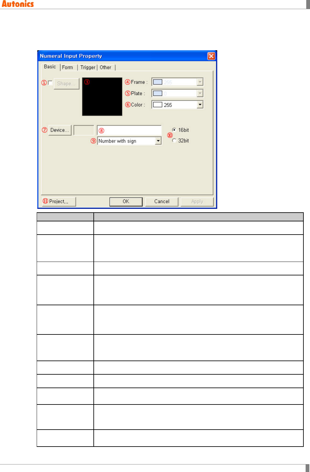
5 Draw
© Copyright Reserved Autonics Co., Ltd. 105
5.7.2 Property
5.7.2.1 Basic tab
Basic
Description
①Shape Designate using shape or not. Check this and no. 1 shape is as default.
②Shape Activated only with checking ①.
Click ‘Shape’ and ‘Image Selection’ dialog box appears. Select the desired
shape.
③Shape Displays the selected shape image
④Frame
Designates frame color. Activated only with checking ①.
Mono type(GP-S044, GP-S057, LP-S044): White/Black
Color type(GP-S070, LP-S070): 24bit True Color
⑤Plate
Designates plate color. Activated only with checking ①.
Mono type(GP-S044, GP-S057, LP-S044): White/Black
Color type(GP-S070, LP-S070): 24bit True Color
⑥Color
Designates text color.
Mono type(GP-S044, GP-S057, LP-S044): White/Black
Color type(GP-S070, LP-S070): 24bit True Color
⑦Device Calls ‘Device Select’ dialog box and designate word device.
⑧Device Input device directly or displays the designated device by ⑦
⑨Data Type Designate device type (Number with sign/Number without sign) by pull-down
menu.
⑩16/32bit
Designate data size for input device
Depending on connected device type, it may use only 32bit. Refer to ‘GP,LP
user manual for communication’.
⑪Project Calls ‘Project Auxiliary Property’ dialog box and select key window, or
designate key window display type.
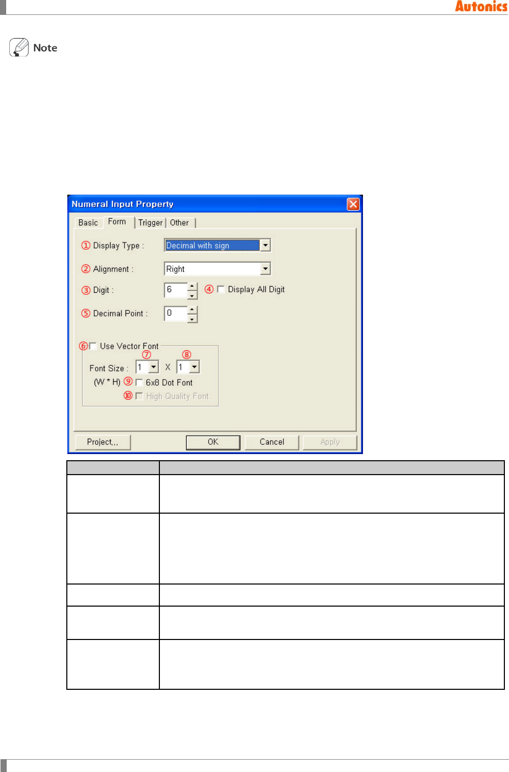
5 Draw
106 © Copyright Reserved Autonics Co., Ltd.
[Input range by device type]
It enters integer with following range by data type.
16bit number with sign: -32768 to 32767
16bit number without sign: 0 to 65535
32bit number with sign: -2147483648 to 2147483647
32bit number without sign: 0 to 4294967295
5.7.2.2 Form tab
Form
Description
①Display Type Designate one from decimal with sign, decimal without sign, hexadecimal,
octal, binary or real number by pull-down menu. Real number is only
available when data size is designated as 32bit in ‘Basic’ tab.
②Alignment
Designate alignment type (left, right, center) by pull-down menu. If text digit is
less than the designated digit, alignment operates.
Left: Displays a letter from the left of tag area
Right: Displays a letter from the right of tag area
Center: Displays a letter in a center of tag area
③Digit Designate digit number. Default is 6 and range is from 1 to 32.
④Display All Digit Displays all digit with 0 for blank when displayed number digit is less than
③Digit. Activated only for ②Alignment as Right.
⑤Decimal Point
Designate decimal point digit. If ①Display Type is decimal with/without sign,
it displays decimal point at designated digit. It is not activated when
①Display Type is hexadecimal or octal.
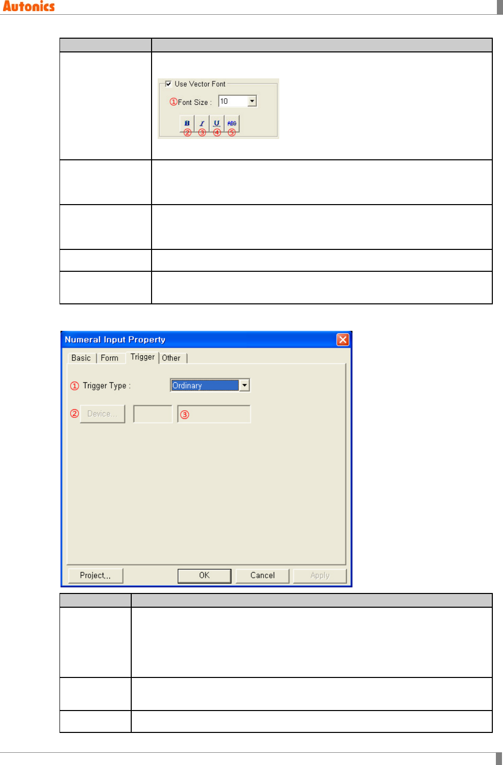
5 Draw
© Copyright Reserved Autonics Co., Ltd. 107
Form
Description
⑥Use Vector Font
Activated only for color type (GP-S070, LP-S070). Non-checking this, it uses
bitmap font. Checking this, it displays as following.
①Font size, ②Bold font, ③Italic font, ④Underline, ⑤Strikethrough
⑦Font Size
(Width)
Designate width font size by pull-down menu.
Default =1, Range: 1,2,4,6,8
Height font size is 0.5, width font size 1 is only available.
⑧Font Size
(Height)
Designate height font size by pull-down menu
Default =1, Range: 0.5,1,2,3,4
Width font sizes besides 1 are not available for height font size 0.5.
⑨6x8 Dot Font Designate 6x8 dot font
⑩High Quality
Font
Displays font with high quality. It is only available when ⑦,⑧Font Size is 4X2
or more.
5.7.2.3 Trigger tab
Trigger
Description
①Trigger
Type
Enables to input numeral when the designated bit device is trigger state. You can
designate trigger function by pull-down menu.
Ordinary: Trigger function is not used.
On: Use ON trigger.
Off: Use OFF trigger.
②Device Calls ‘Device Select’ dialog box and designate trigger device. It is not activated
when ①Trigger Type is ordinary.
③Device Input device directly or displays the designated device by ②

5 Draw
108 © Copyright Reserved Autonics Co., Ltd.
[Project axiliary property and numeral input trigger]
You can check project axiliary property by [Common]-[Auxiliary Configuration]-[Project] of menu.
Checking ‘Call key window when detecting touch’: It calls key window with touching tag
input area and input is available when the trigger condition is satisfied. If the trigger
condition is not satisfied when touching tag input area, buzzer sounds and key window is
not called.
Selecting ‘Display Cursor And Key Window’ at operate for screen switching: If there is not
input tag which is satisfied trigger condition, key window is not called and input is not
available.
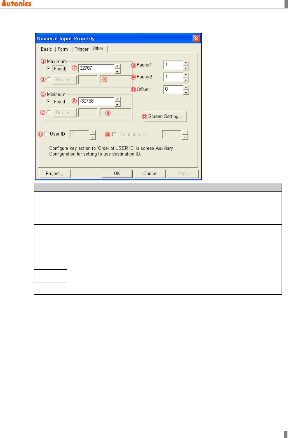
5 Draw
© Copyright Reserved Autonics Co., Ltd. 109
5.7.2.4 Other tab
Other
Description
① to ④
Maximum
Designate maximum value to input
Fixed: Uses the input value in ②.as maximum
Device: Click ‘Device’ and ‘Device Select’ dialog box appears. Designate device
or input it directly in ④. The device is used as maximum.
⑤ to ⑧
Minimum
Designate minimum value to input
Fixed: Uses the input value in ⑥ as minimum.
Device: Click ‘Device’ and ‘Device Select’ dialog box appears. Designate device
or input it directly in ⑧. The device is used as minimum.
⑨Factor1
Defines applied operation the input value.
For further details, refer to ‘5.7.2.5 Operation in numeral input’.
⑩Factor2
⑪Offset
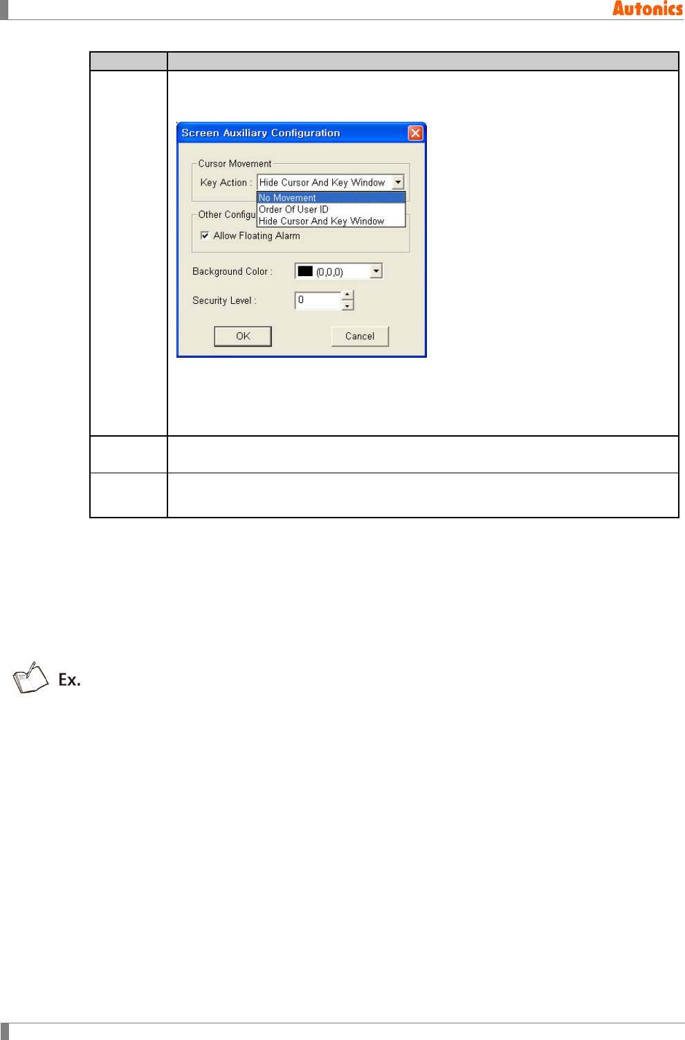
5 Draw
110 © Copyright Reserved Autonics Co., Ltd.
Other
Description
⑫Screen
Setting
Calls ‘Screen Auxiliary Configuration’ dialog box and set about input focus movement.
Focus moves differently depending on selected key action by pull-down menu when
completing numeral input at GP/LP.
No Movement: Input focus does not move.
Order of User ID: Input focus moves to input tag with using the designated ID on
⑭ as user ID.
Hide Cursor And Key Window: Cursor and key window are disappeared.
⑬User ID Characteristic ID for divide numeral inputs on one screen. After inputting tag having
this value as destination ID, input focus returns to this tag.
⑭Destinat
ion ID
After inputting current tag, input focus moves to tag having this value as user ID.
5.7.2.5 Operation in numeral input
The following operation is when input value in key window is Vin, and input value at device is Vdev.
Input value at device Vdev = (Vin -Offset) × Factor2)/Factor1
Display value to numeral input tag= (Vdev × Factor1)/Factor2+Offset
Division operation has quotient.
Factor1=10, Factor2=1, Offset=0, enter 12 in key window,
Input value at device=(1 X (12 - 0)) / 10 = 12 / 10 = 1
Display value to tag=(10 X 1) / 1 + 0 = 10
Factor1=1, Factor2=10, Offset=0, enter 12in key window,
Input value at device=(10 X (12 - 0)) / 1 = 120
Display value to tag=(1 X 120) / 10 + 0 = 12
Factor1=1, Factor2=1, Offset=10, enter 12in key window,
Input value at device=(1 X (12 - 10)) / 1 = 2
Display value to tag=(1 X 2) / 1 + 10 = 12
Factor1=10, Factor2=1, Offset=5, enter 12in key window,
Input value at device= (1 X (12 - 5)) / 10 = 7 / 10 = 0
Display value to tag=(10 X 0) / 1 + 5 = 5
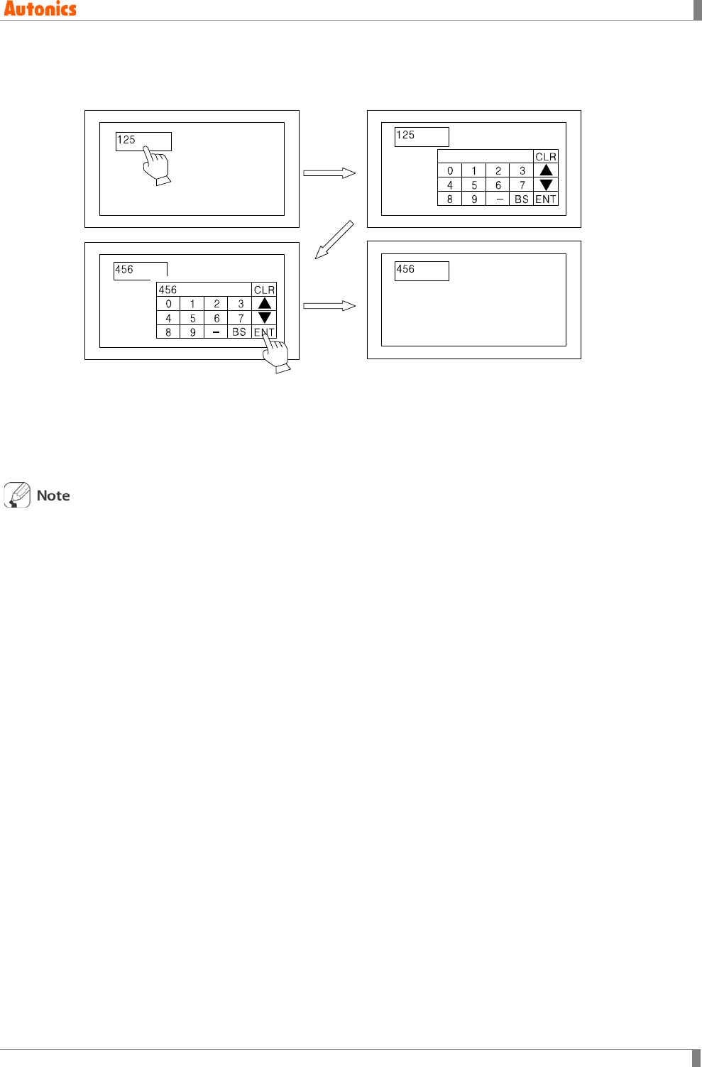
5 Draw
© Copyright Reserved Autonics Co., Ltd. 111
5.7.3 Change numeral
Changing numeral is only available at GP/ LP.
1st Touch screen area which has numeral input tag.
2nd Key window for numeral input appears.
3rd Enter numeral with key window and touch ENT.
4th Key window disappears and input numeral is displayed at numeral input tag.
Calling condition for cursor and key window is disgnated by configure key window/cursor display
group box of ‘Basic’ tab from ‘Project Auxiliary Property’ dialog box. Movement of input focus is
designated by cursor movement box of ‘Screen Auxilairy Configuration’ dialog box.
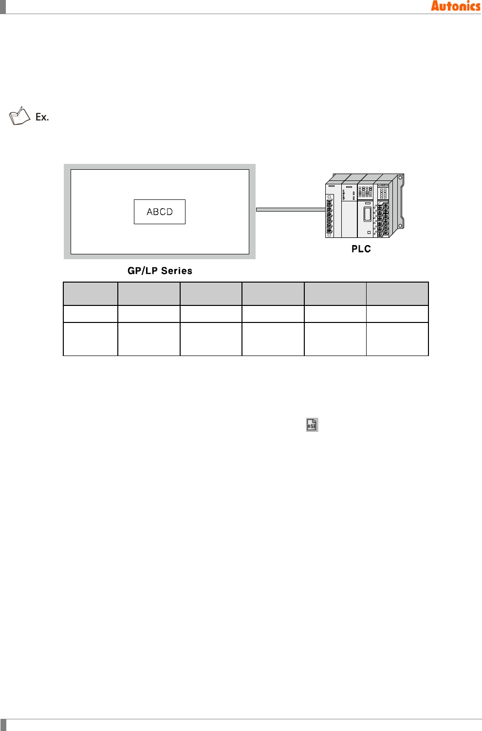
5 Draw
112 © Copyright Reserved Autonics Co., Ltd.
5.8 ASCII Input
ASCII input tag is for inputting character strings to PLC device by key window on screen.
If there is no input, it operates as ASCII display. In other words, it displays character strings of
PLC device as relevant form.
Device value is as below table when ASCII input tag device is D100, ASCII input tag displays
‘ABCD’.
Device
D100
(Lower)
D100
(Upper)
D101
(Lower)
D101
(Upper)
D102
(Upper)
ASCII 41H 42H 43H 44H 0H
Character ‘A’ ‘B’ ‘C’ ‘D’ Completes
character
D102(Upper)=0H is for completing character when inputting ABCD with key window at ASCII
input tag, and touching ENT.
5.8.1 Basic usage
1st Select [Draw]-[ASCII Input] of menu, or click in toolbar, ‘ASCII Input Property’
dialog box appears.
2nd Designate device.
3rd Designate digit in ‘Form’ tab.
4th Click ‘OK’ and ‘ASCII Input Property’ dialog box is closed. A dotted rectangle follows
mouse cursor at edit area.
5th Place mouse cursor on the desired area, click left mouse button. ASCII input tag is
created on the screen.
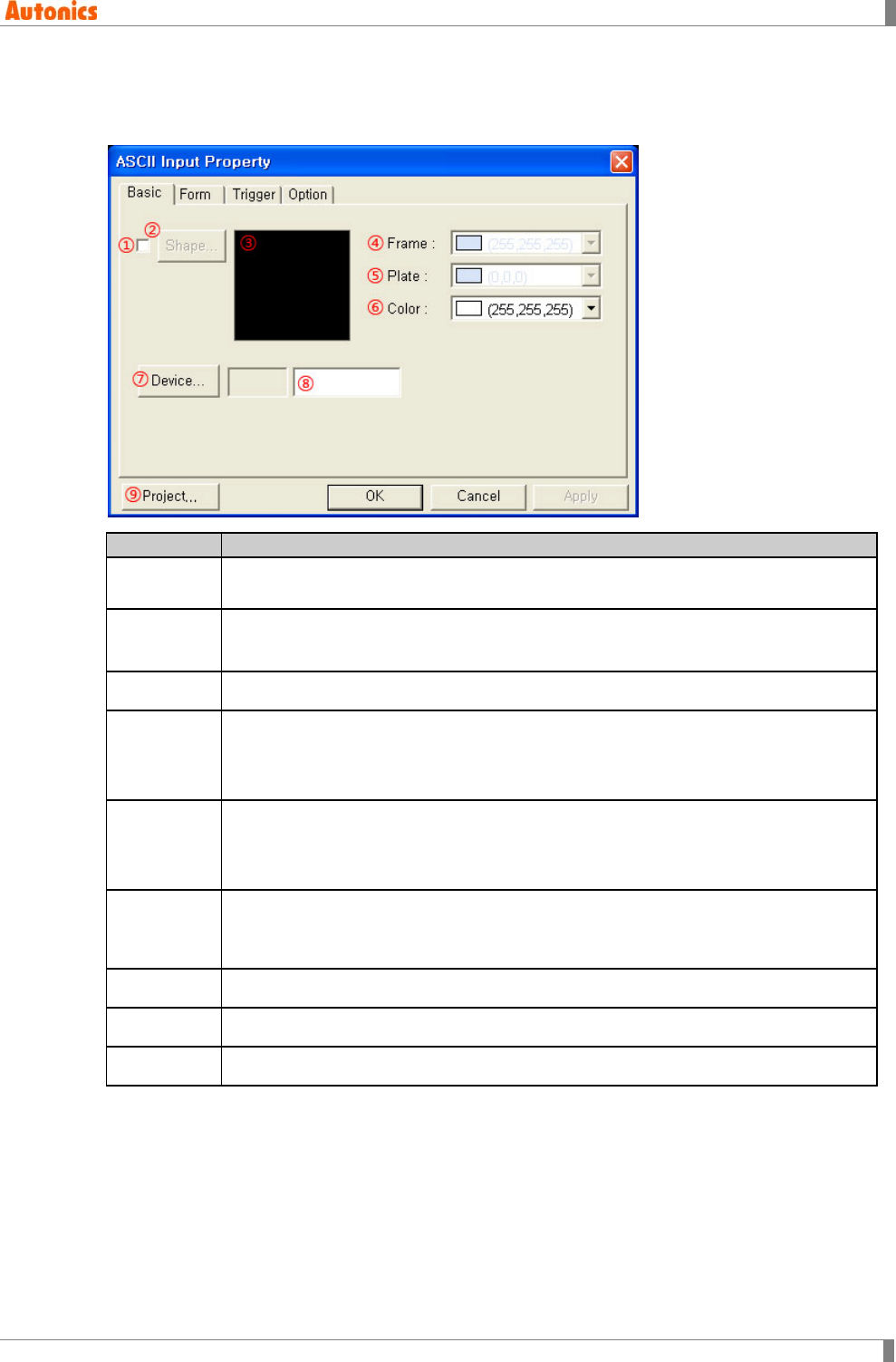
5 Draw
© Copyright Reserved Autonics Co., Ltd. 113
5.8.2 Property
5.8.2.1 Basic tab
Basic
Description
①Shape Designate using shape or not.
Check this and no. 1 shape is as default.
②Shape Activated only with checking ①.
Click ‘Shape’ and ‘Image Selection’ dialog box appears. Select the desired shape.
③Shape Displays the selected shape image.
④Frame
Designates frame color. Activated only with checking ①.
Mono type(GP-S044, GP-S057, LP-S044): White/Black
Color type(GP-S070, LP-S070): 24bit True Color
⑤Plate
Designates plate color. Activated only with checking ①.
Mono type(GP-S044, GP-S057, LP-S044): White/Black
Color type(GP-S070, LP-S070): 24bit True Color
⑥Text
Designates text color.
Mono type(GP-S044, GP-S057, LP-S044): White/Black
Color type(GP-S070, LP-S070): 24bit True Color
⑦Device Calls ‘Device Select’ dialog box and designate monitor device.
⑧Device Input device directly or displays the designated device by ⑦.
⑨Project Calls ‘Project Auxiliary Property’ dialog box and designate about key window.
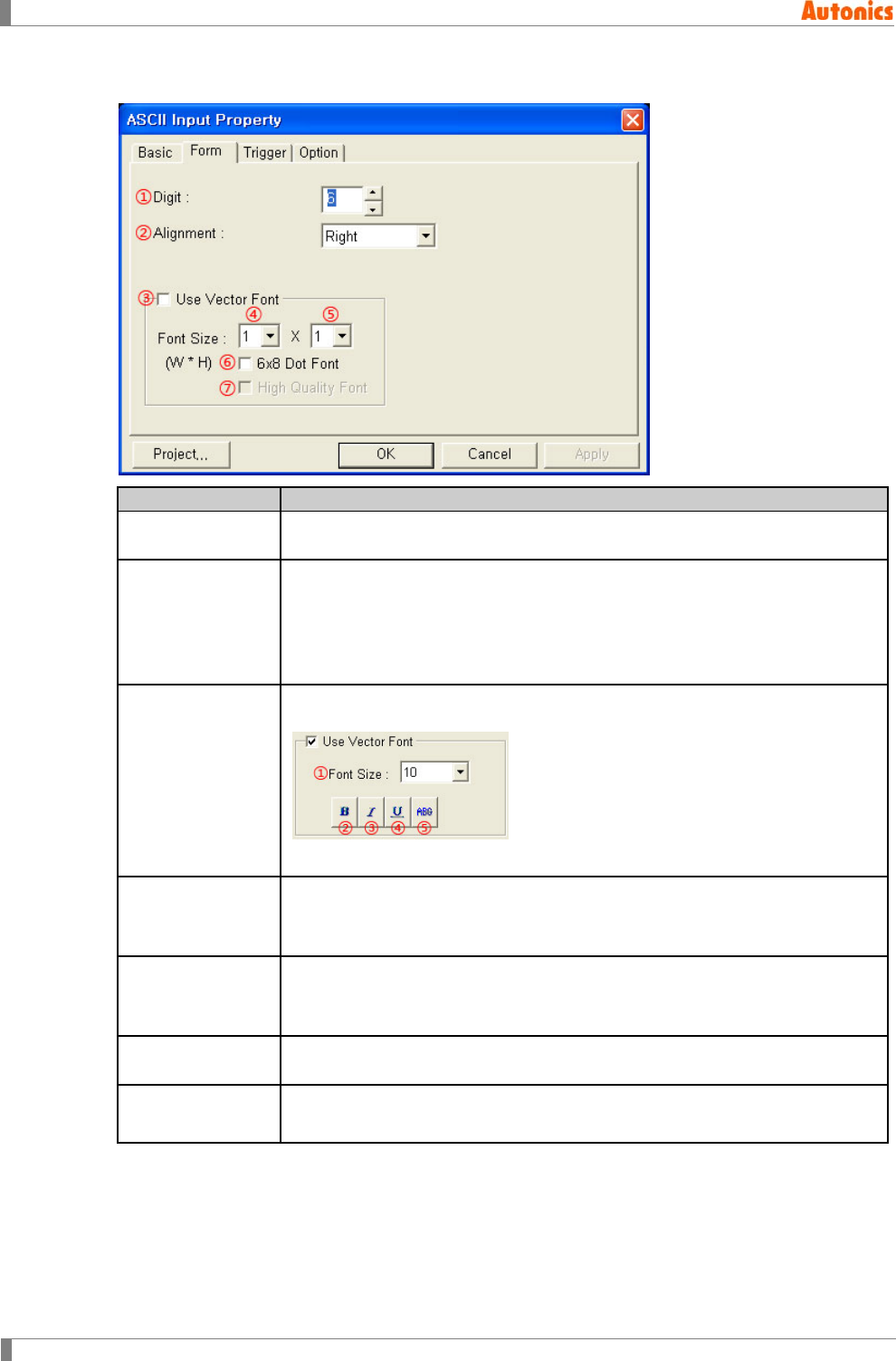
5 Draw
114 © Copyright Reserved Autonics Co., Ltd.
5.8.2.2 Form tab
Form
Description
①Digit Designate character digit number to display. Default is 6 and range is from 2
to 40 by even number.
②Alignment
Designate alignment type (left, right, center) by pull-down menu. If text digit is
less than the designated digit, alignment operates.
Left: Displays a letter from the left of tag area.
Right: Displays a letter from the right of tag area.
Center: Displays a letter in a center of tag area.
③Use Vector Font
Activated only for color type (GP-S070, LP-S070). Non-checking this, it uses
bitmap font. Checking this, it displays as following.
①Font size, ②Bold font, ③Italic font, ④Underline, ⑤Strikethrough
④Font Size(Width)
Designate width font size by pull-down menu.
Default =1, Range: 1,2,4,6,8
Height font size is 0.5, width font size 1 is only available.
⑤Font
Size(Height)
Designate height font size by pull-down menu
Default =1, Range: 0.5,1,2,3,4
Width font sizes besides 1 are not available for height font size 0.5.
⑥6x8 Dot Font Designate 6x8 dot font. Only ASCII font has 6x8 dot font. If there is not 6x8
dot font, it displays rectangles with the desired size and color.
⑦High Quality
Font Not used
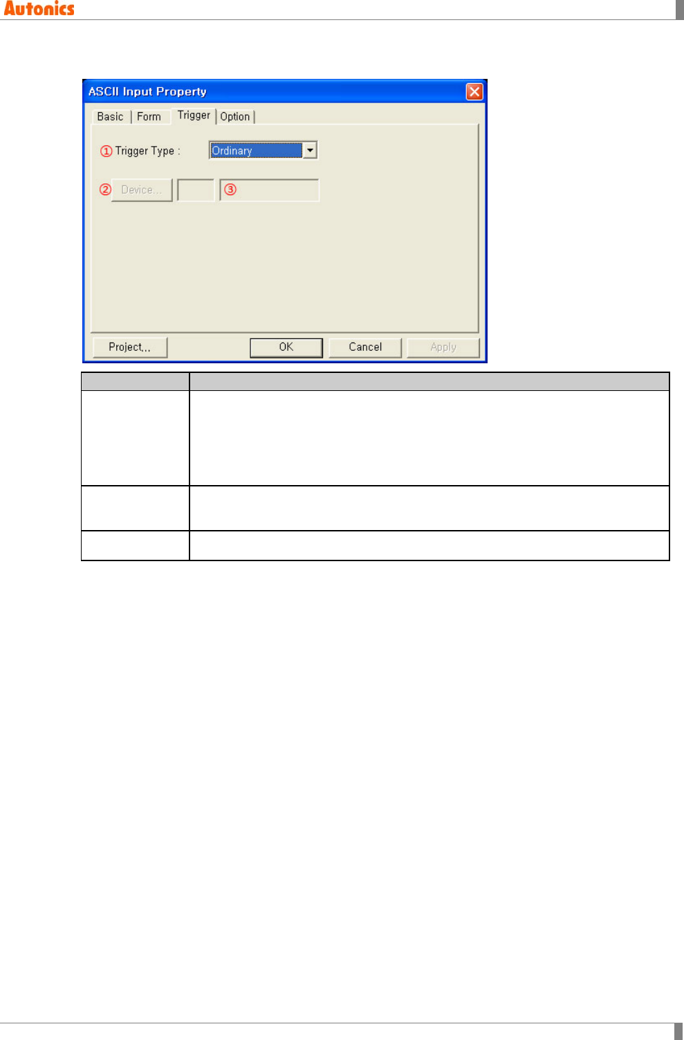
5 Draw
© Copyright Reserved Autonics Co., Ltd. 115
5.8.2.3 Trigger tab
Trigger
Description
①Trigger Type
Enables to input numeral when the designated bit device is trigger state. You
can designate trigger function by pull-down menu.
Ordinary: Trigger function is not used.
On: Use ON trigger.
Off: Use OFF trigger.
②Device Calls ‘Device Select’ dialog box and designate trigger device. It is not activated
when ①Trigger Type is ordinary.
③Device Input device directly or displays the designated device by ②
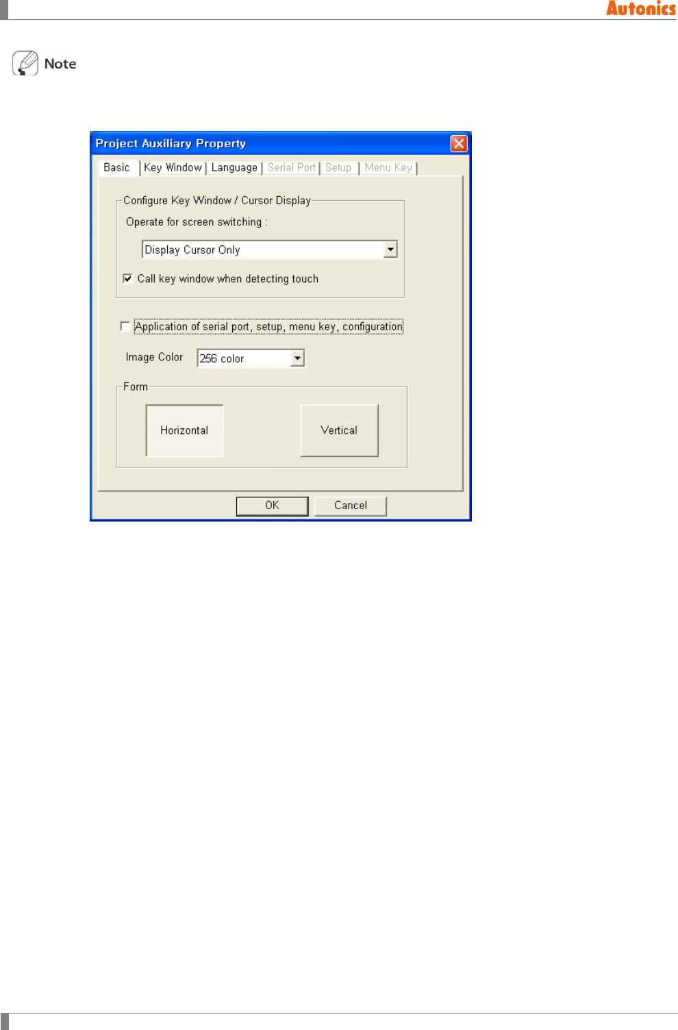
5 Draw
116 © Copyright Reserved Autonics Co., Ltd.
[Project axiliary property and ASCII input trigger]
You can check project axiliary property by [Common]-[Auxiliary Configuration]-[Project] of menu.
Checking ‘Call key window when detecting touch’: It calls key window with touching tag
input area and input is available when the trigger condition is satisfied. If the trigger
condition is not satisfied when touching tag input area, buzzer sounds and key window is
not called.
Selecting ‘Display Cursor And Key Window’ at operate for screen switching: If there are not
input tag which is satisfied trigger condition, key window is not called and input is not
available.
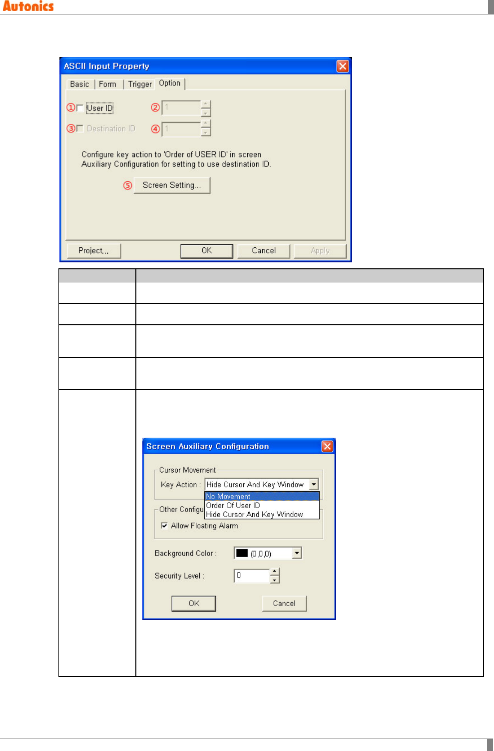
5 Draw
© Copyright Reserved Autonics Co., Ltd. 117
5.8.2.4 Option tab
Option
Description
①User ID Designate to use user ID or not.
②User ID Designate user ID. Range is from 1 to 50.
③Destination
ID
Designate to use destination ID or not. It is activated only when key action is as
order of user ID of ‘Screen Auxiliary Configuration’ dialog box.
④Destination
ID Designate destination ID.
⑤Screen
Setting
Calls ‘Screen Auxiliary Configuration’ dialog box and set about input focus
movement.
Focus moves differently depending on selected key action by pull-down menu
when completing numeral input at GP/LP.
No Movement: Input focus does not move.
Order of User ID: Input focus moves to input tag with using the designated ID
on ⑭ as user ID.
Hide Cursor And Key Window: Cursor and key window are disappeared.
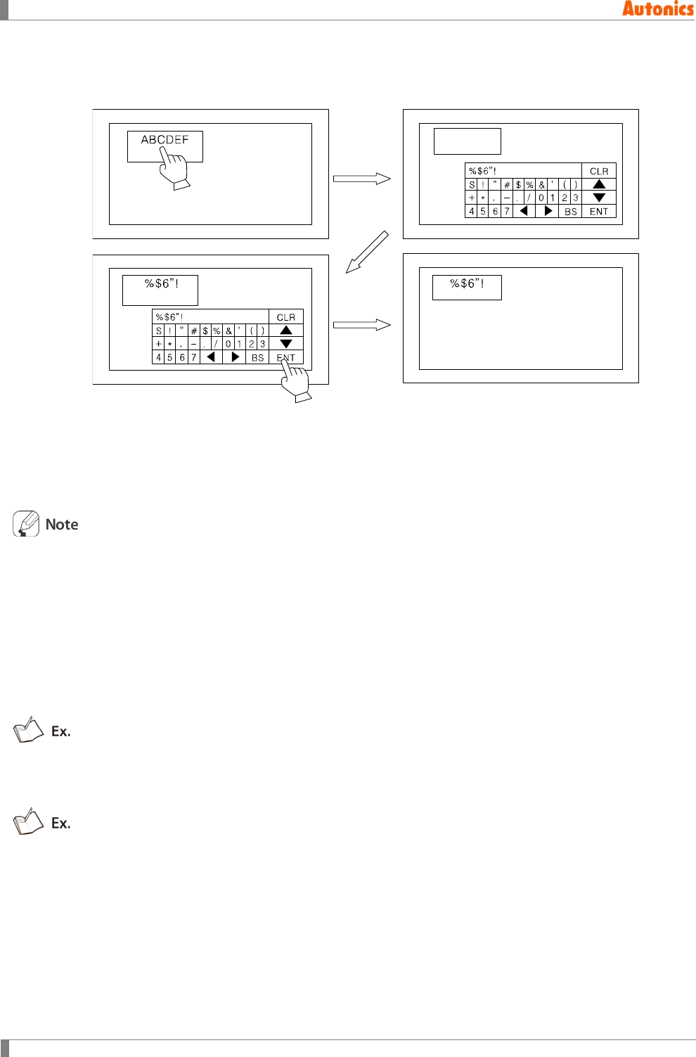
5 Draw
118 © Copyright Reserved Autonics Co., Ltd.
5.8.3 Change ASCII
Changing ASCII is only available at GP/ LP.
1st Touch screen area which has ASCII inpiut tag.
2nd Key window for ASCII input appears.
3rd Enter character with key window and touch ENT.
4th Key window disappears and input character is displayed at ASCII input tag.
Calling condition for cursor and key window is designated by configure key window/cursor
display group box of ‘Basic’ tab from ‘Project Auxiliary Property’ dialog box. Movement of
input focus is designated by cursor movement box of ‘Screen Auxiliary Configuration’ dialog
box.
Displayed character on screen has code for value on specified device.
From specified device, two digits of word device are displayed.
At the same word devices, if lower/upper bytes are each of half-width character (1byte)
code, lower byte is displayed at first.
If device is D100, digit is 6, the related character which is the order of D100(Lower),
D100(Upper), D101(Lower), D101(Upper), D102(Lower), D102(Upper) are displayed. If there is
0 in the middle, the following character is not displayed.
D100(Lower)=41H=’A’, D100(Upper)=42H=’B’, D101(Lower)=43H=’C’, D101(Upper)=00H=’\0’,
D102(Lower)=44H=’E’, D102(Upper)=45H=’F’, it displays ABC.
With designated 6X8 dot font, 2 byte character is displayed as rectangle with designated
font color.
If there are not related character on device or it is not able to display (control character), it
displays as rectangle.

5 Draw
© Copyright Reserved Autonics Co., Ltd. 119
At GP/LP inputting, first input character code is saved in order of lower to upper at lead
address.
At GP/LP inputting, if input character digit is not proper the designated digit and inputting
ENT, the following saved space is filled with 0.
Device =D100, Digit =6, with inputting A, B, C, and ENT;
D100 = 4241H, D101=0043H, D102=0000H
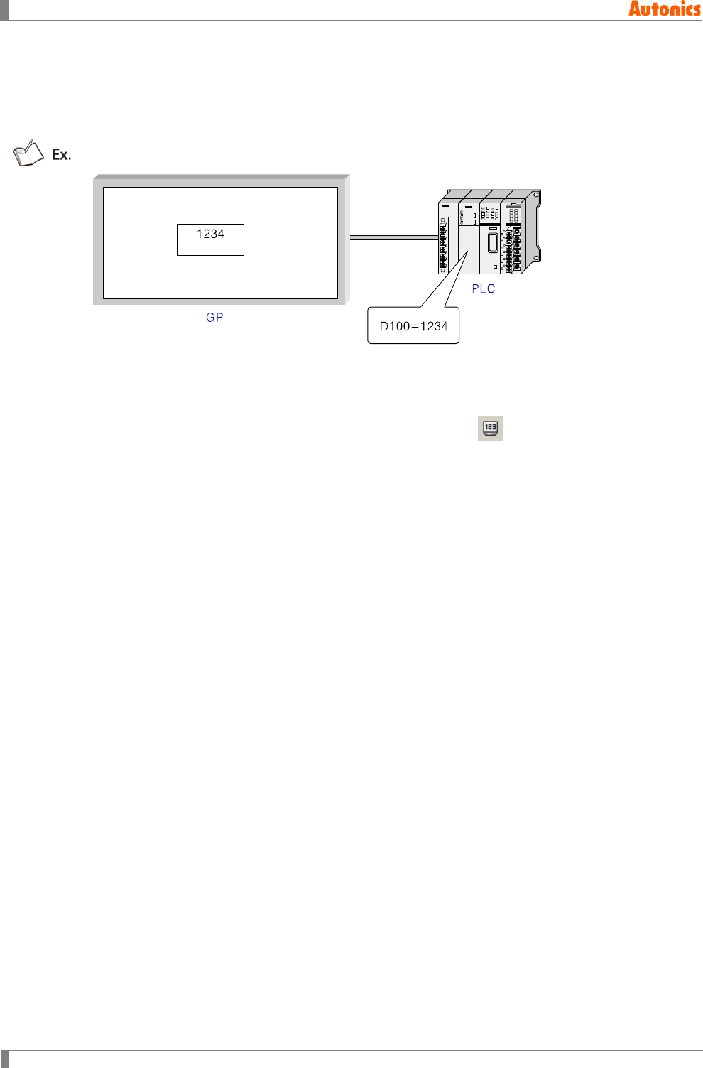
5 Draw
120 © Copyright Reserved Autonics Co., Ltd.
5.9 Numeral Display
Numeral display is for displaying value on specified device as designated numeral type.
It displays user-defined PLC device value as designated numeral type.
The above example is that device is D100, display form is decimal, saved value is 1234.
5.9.1 Basic usage
1st Select [Draw]-[Numeral Display] of menu, or click in toolbar, ‘Numeral Display
Property’ dialog box appears.
2nd Designate device.
3rd Designate device data type. (number with sign/number without sign,16/32bit)
4th Designate display type and digit, etc in ‘Form’ tab.
5th Designate opration in ‘Operation’ tab.
6th Click ‘OK’ and ‘Numeral Display Property’ dialog box is closed. A dotted rectangle
follows mouse cursor at edit area.
7th Place mouse cursor on the desired area, click left mouse button. Numeral display is
created on the screen.
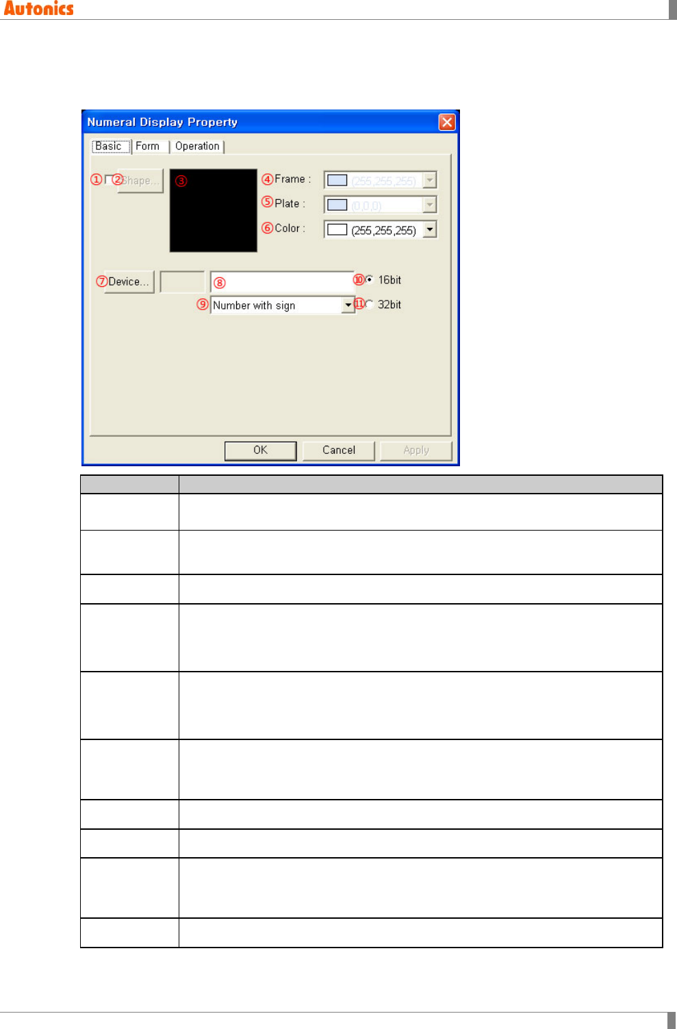
5 Draw
© Copyright Reserved Autonics Co., Ltd. 121
5.9.2 Property
5.9.2.1 Basic tab
Basic
Description
①Shape Designate using shape or not.
Check this and no. 1 shape is as default.
②Shape Activated only with checking ①.
Click ‘Shape’ and ‘Image Selection’ dialog box appears. Select the desired shape.
③Shape Displays the selected shape image
④Frame
Designates frame color. Activated only with checking ①.
Mono type(GP-S044, GP-S057, LP-S044): White/Black
Color type(GP-S070, LP-S070): 24bit True Color
⑤Plate
Designates plate color. Activated only with checking ①.
Mono type(GP-S044, GP-S057, LP-S044): White/Black
Color type(GP-S070, LP-S070): 24bit True Color
⑥Color
Designates text color.
Mono type(GP-S044, GP-S057, LP-S044): White/Black
Color type(GP-S070, LP-S070): 24bit True Color
⑦Device Calls ‘Device Select’ dialog box and designate monitor device.
⑧Device Input device directly or displays the designated device by ⑦
⑨Data Type
Designate device type by pull-down menu.
Number with sign: Processes number with sign reading data
Number without sign: Processes number without sign reading data
⑩16 bit Select this when monitor device is 16 bit word device

5 Draw
122 © Copyright Reserved Autonics Co., Ltd.
Basic
Description
⑪32bit Select this when monitor device is 32bit word device.
Depending on connected device type, it may use only 32bit. Refer to ‘GP,LP user
manual for communication’.
Shape
Designates for frame and plate color is available only with checking ①
Default: Frame=White, Background color=Black, Font color=White
Not using shape with non-checking ① displays tag as transparently and
behind object is also displayed. Using shape with checking ① fills plate
inside with designated color and the tag is opaque.
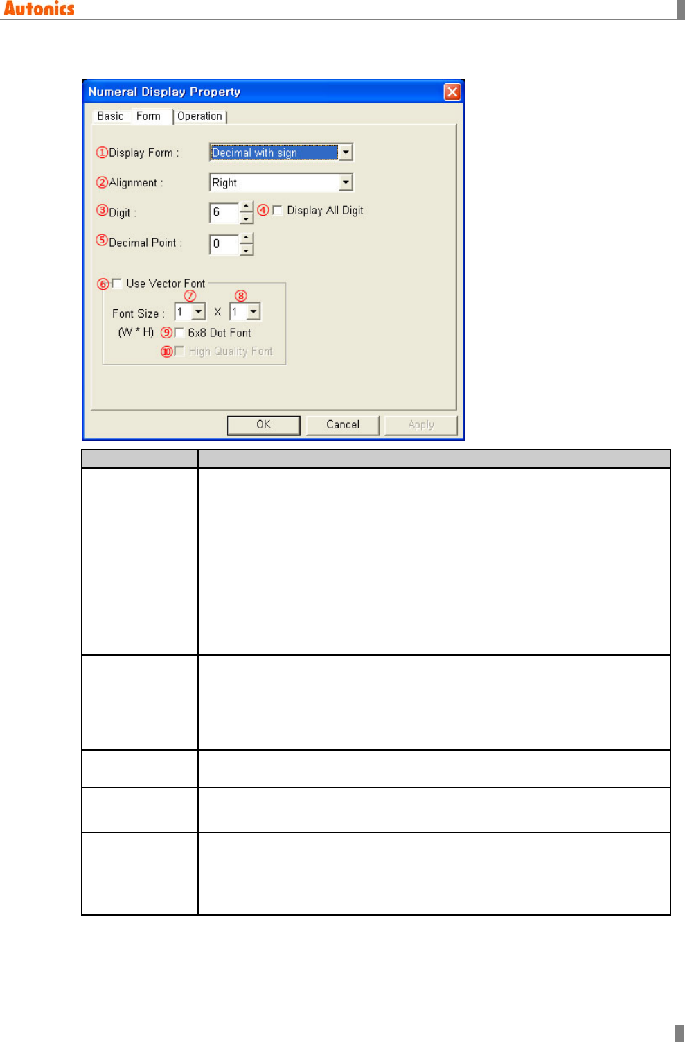
5 Draw
© Copyright Reserved Autonics Co., Ltd. 123
5.9.2.2 Form tab
Form
Description
①Display Type
Designate numeral display form by pull-down menu.
Decimal with sign: Displays number with sign as decimal
Decimal without sign: Displays number without sign as decimal
Hexadecimal: Displays as hexadecimal
Octal: Displays as octal
Binary: Displays as binary
Real number: Displays as real number processing IEEE floating decimal
point number. Real number is only available when data size is designated
as 32bit in ‘basic’ tab.
For further details, refer to ‘5.9.3 Display type and operation’.
②Alignment
Designate alignment type (left, right, center) by pull-down menu. If text digit is
less than the designated digit, alignment operates.
Left: Displays a letter from the left of tag area.
Right: Displays a letter from the right of tag area.
Center: Displays a letter in a center of tag area.
③Digit Designate digit number. When the number (including - . E) is not displayed as
designated type, it is displayed as HHHH... or LLLL....
④Display All
Digit
Displays all digit with 0 for blank when displayed number digit is less than
③Digit. Activated only for ②Alignment as Right.
⑤Decimal Point
Designate decimal point digit. If ①Display Type is decimal with/without sign, it
displays decimal point at designated digit. It is not activated when ①Display
Type is hexadecimal or octal. For further details of real number, refer to
‘5.9.3.4 Real number display of GP/LP’.
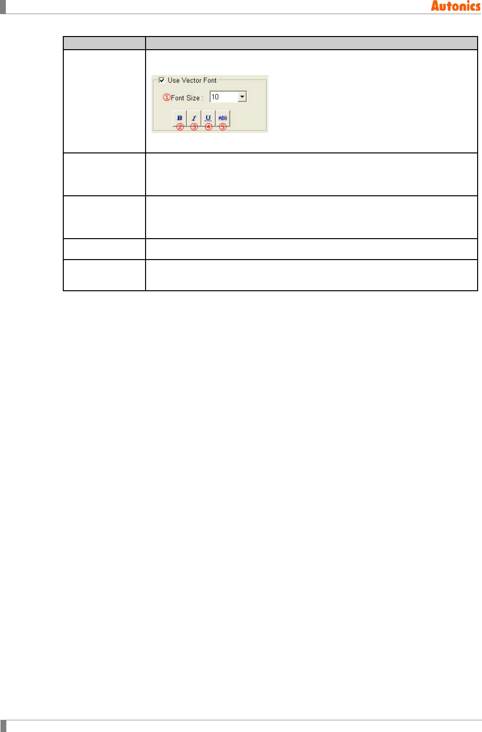
5 Draw
124 © Copyright Reserved Autonics Co., Ltd.
Form
Description
⑥Use Vector
Font
Activated only for color type (GP-S070, LP-S070). Non-checking this, it uses
bitmap font. Checking this, it displays as following.
①Font size, ②Bold font, ③Italic font, ④Underline, ⑤Strikethrough
⑦Font Size
(Width)
Designate width font size by pull-down menu.
Default =1, Range: 1,2,4,6,8
Height font size is 0.5, width font size 1 is only available.
⑧Font Size
(Height)
Designate height font size by pull-down menu
Range: 0.5, 1, 2, 3, 4
Width font sizes besides 1 are not available for height font size 0.5.
⑨6x8 Dot Font Designate 6x8 dot font
⑩High Quality
Font
Displays font with high quality. It is only available when ⑦,⑧Font Size is 4X2
or more.
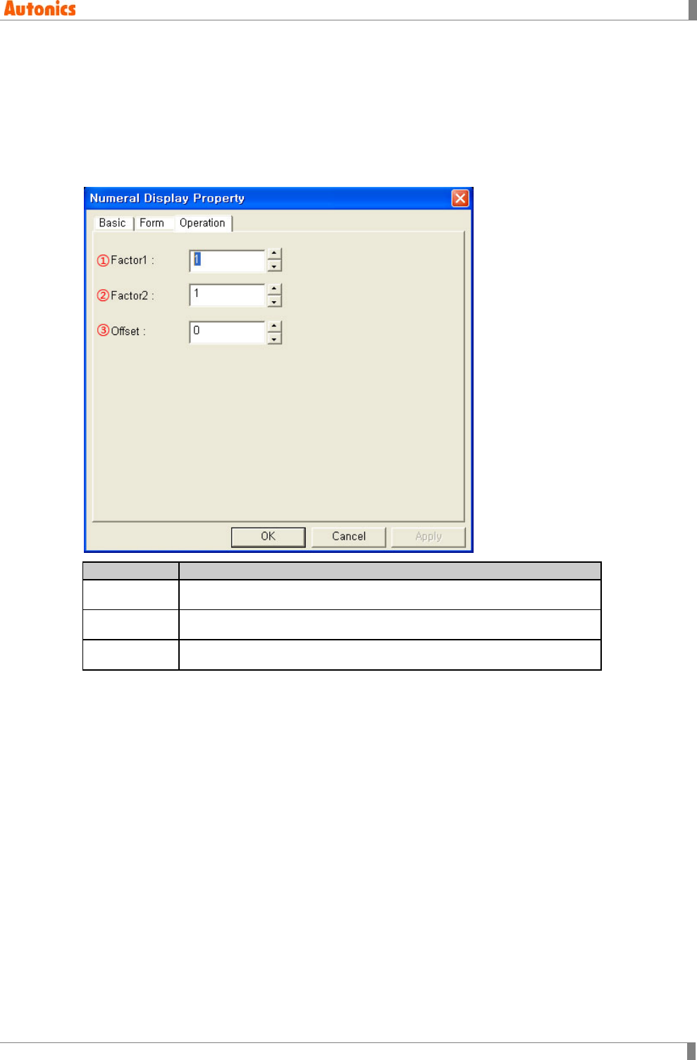
5 Draw
© Copyright Reserved Autonics Co., Ltd. 125
5.9.2.3 Operation tab
Operation tab is not actiaved when display type is real number. Operation executes in order
multiplication, division, and addition.
Device value= V, Display value = (Factor1 x V) /Factor2 + Offset
The range is depending on the designated device type in ‘Basic’ tab and the designated display
type in ‘Form’ tab.
Operation
Description
①Factor 1 Multiplies device value by factor 1.
②Factor 2 Divides device value by factor 2.
③Offset Adds device value to offset.
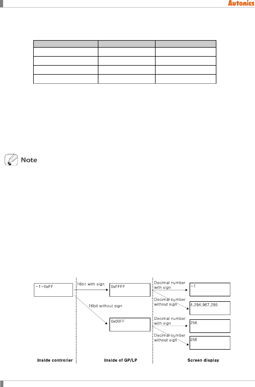
5 Draw
126 © Copyright Reserved Autonics Co., Ltd.
5.9.3 Display type and operation
5.9.3.1 Numeral display range by data type (Unapplied operation)
Data Type
Minimum
Maximum
Decimal with sign 16bit
-32,768
32,767
Decimal without sign 16bit
0
65,535
Decimal with sign 32bit
-2,147,483,648
2,147,483,647
Decimal without sign 32bit
0
4,294,967,295
5.9.3.2 Numeral display process
As following prcess is for when display type is real number.
1st Saves the processed value as the designated data type reading by serial
communication at 32bit memory. Even though the designated device is 16bit in
‘Basic’ device, it saves at 32bit memory of GP/LP.
2nd Executes operation by the designated factor1, factor2, and offset in ‘Operation’ tab.
3rd Displays the designated type on screen.
At 1st process, if the device of controller (PLC) is 32bit with sign/without sign, the value
which is saved at device is saved as it is at 32bit memory of GP/LP.
If the device of controller (PLC) is 16bit with sign/without sign and positive number, the
value which is saved device is saved as it is at lower word for 32bit memory of GP/LP.
Be note that when it is 16bit with sign and negative number. For example, if the saved value
which is processed as number with sign on 16 bit memory of controller is same as negative
number -1, the saved value of controller is two’s complement of -1 as 216-1=65535. When
this value is saved at 32bit GP/LP memory, this is two’s complement for -1 about 32bit as
232-1=4,294,967,295.
Display value is different depending on display type as decimal with sign or decimal without
sign. The operated value which is decimal with sign, it processes 32bit number with sign, or
the operated value which is decimal without sign, it processes 32bit number without sign.
The following figure is that saved value -1 in 16bit memory of controller is saved 32bit GP/LP
memory in accordance with designation of 16bit with/without sign and displayed screen in
accordance with designation of display type as with/without sign.
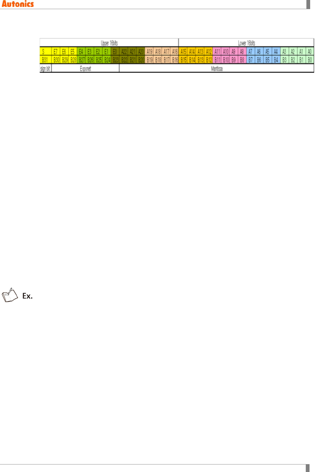
5 Draw
© Copyright Reserved Autonics Co., Ltd. 127
5.9.3.3 32bit floating decimal point type(IEEE Standard 754)
Sign bit: B31; ‘1’ is negative number, ‘0’ is 0 or positive number.
8bit exponent: B23 to B30 or E0 to E7
23bit mantissa: B0 to B22 or A0 to A22
Displayed number
= (1) × (2+ A2 + A2 + A2 ++ A2) × 2()
Display range
Maximum display absolute number: 2(2 2)3.40282346 ×10
Minimum display absolute number: 2 1.175494351 ×10
Displayed number range: 3.402823466 ×10~ + 3.402823466 ×10
If exponent is 0 or 255, it is reserved for an exceptional condition and the above formula is
not applied to this case.
5.9.3.4 Real number display of GP/LP
Real number display has complex processes but also has flexible mark.
The general ruls are as below.
① Positive number does not display ‘+’ sign.
② Exponent part does not display ‘+’ sign.
③ Round off the next of last displayed digit.
The follow examples is that if display number is real number with exponent (e), depending on the
designated display digit, and decimal point digit.
Case 1. Absolute value of display number is bigger than 1. (e>=0)
It displays with fixed decimal point if the designated digit displays with fixed decimal point
type.
If not, it displays with floating decimal point.
Ex 1) Real number=1234.567
(a) Digit= 10, Decimal point digit= 2 ; Displayed number= 1234.56
(b) Digit= 10, Decimal point digit= 6 ; Displayed number= 1234.56700
Ex 2) Real number=12.34567
It displays with fixed decimal point type if the designated digit displays all positive
numbers without respecting accuracy.
(a) Digit= 6, Decimal point digit= 4 ; Displayed number= 12.345
(b) Digit= 4, Decimal point digit= 2 ; Displayed number= 12.3

5 Draw
128 © Copyright Reserved Autonics Co., Ltd.
Ex 3) It displays with floating decimal point if the designated digit does not display
some of positive numbers.
Real number = 1234567.0 =1.234567e+6
(a) Digit= 6, Decimal point digit= 2 ; Displayed number= 1.23E6
(b) Digit= 5, Decimal point digit= 2 ; Displayed number= 1.2E6
Ex 4) Real number= 1234567.0 = 1.234567e + 6
(a) Digit= 6, Decimal point digit= 2 ; Displayed number= 1.23E6
(b) Digit= 5, Decimal point digit= 2 ; Displayed number= 1.2E6
Ex 5) Real number= 1.234567X10+15
Digit= 3, Decimal point digit= 1 ; Displayed number= E15 ; Skips ‘+’ sign
Ex 6) Real number= -1.234567 X 10+15
(a) Digit= 4, Decimal point digit= 2 ; Displayed number= -E15 ; Displays ‘-’
sign
Ex 7) Real number=1.234567e+15; If sign or exponent is not displayed, positive
number displays ‘H’ as many as that digit.
Digit=2, Decimal point digit=0 ; Displayed= HH
Ex 8) Real number=-1.234567e+15 ; ; If sign or exponent is not displayed, negative
number displays ‘L’ as many as that digit.
Digit=3, Decimal point digit=2 ; Displayed= LLL
Case 2. Absolute value of display number is smaller than 1. (e < 0)
It displays with fixed decimal point if absolute value is bigger than 1/1000. (e ≥ -2)
Ex 9) Real number= 0.1234567
(a) Digit= 10, Decimal point digit= 8 ; Displayed number= 0.12345670
(b) Digit= 10, Decimal point digit= 5 ; Displayed number= 0.12345
Ex 10) Real number= 0.01234567
(a) Digit= 10, Decimal point digit= 8 ; Displayed number= 0.01234567
(b) Digit= 10, Decimal point digit= 5 ; Displayed number= 0.01234
It displays with floating decimal point if absolute value is smaller than 1/1000. (e<-2)
(Digit ≤ e + 1)
Ex 11) Real number= 0.001234567
(a) Digit= 10 ; Displayed number= 1.23456E-3
(b) Digit= 6 ; Displayed number= 1.2E-3
(c) Digit= 3 ; Displayed number= E-3
Ex 12) Real number= -1.234567X10⁻¹⁵
(a) Digit= 8 ; Displayed number= -1.2E - 15
(b) Digit= 5 ; Displayed number= -E - 15

5 Draw
© Copyright Reserved Autonics Co., Ltd. 129
If sign or exponent is not displayed with floating decimal point type, it displays ‘0’ as many
as that digit.
Ex 13) Real number= 0.001234567
Digit=2 ; Displayed number= 00
Ex 14) Real number= -1.234567 X10⁻¹⁵
Digit= 4 ; Displayed number= 000
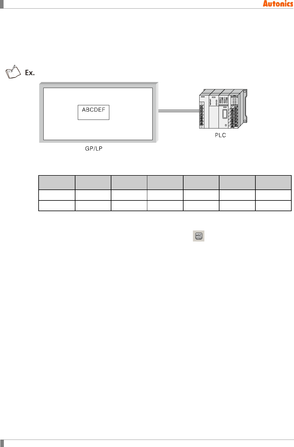
5 Draw
130 © Copyright Reserved Autonics Co., Ltd.
5.10 ASCII Display
ASCII display is for displaying the value of word device as specified character. It is same with
ASCII input tag without input feature.
It displays character strings of PLC device as relevant form.
The below table is for PLC device value when ASCII display tag device is D100, and ASCII input
tag is ‘ABCDEF’.
Device
D100
(Lower)
D100
(Upper)
D101
(Lower)
D101
(Upper)
D102
(Lower)
D102
(Upper)
Value
41H
42H
43H
44H
45H
46H
Character
‘A’
‘B’
‘C’
‘D’
‘E’
‘F’
5.10.1 Basic usage
1st Select [Draw]-[ASCII Display] of menu, or click in toolbar, ‘ASCII Display
Property’ dialog box apppears.
2nd Designate device.
3rd Designate digit in ‘Form’ tab.
4th Click ‘OK’ and ‘ASCII Display Property’ dialog box is closed. A dotted rectangle
follows mouse cursor at edit area.
5th Place mouse cursor on the desired area, click left mouse button. ASCII display tag is
created on the screen.
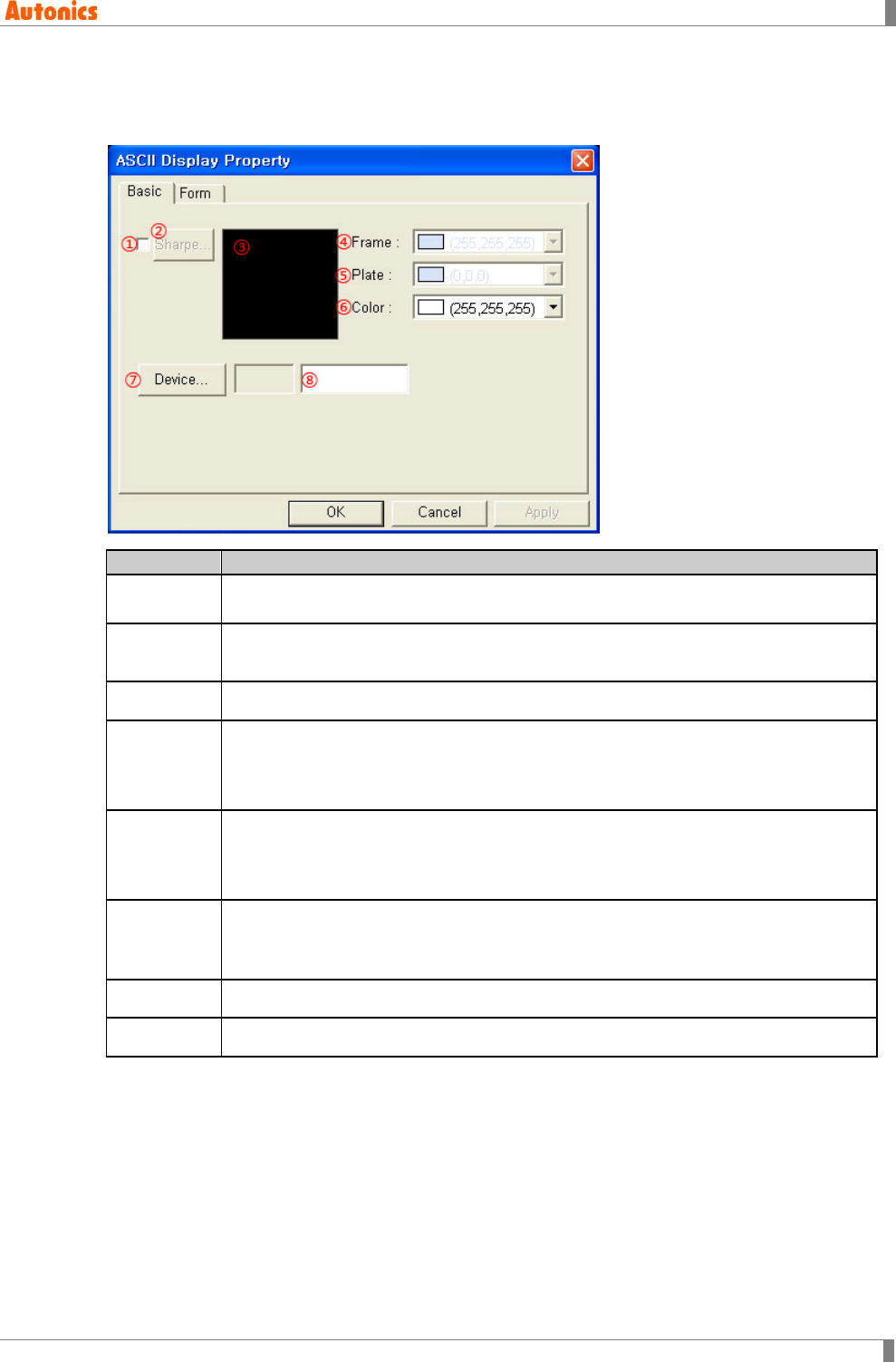
5 Draw
© Copyright Reserved Autonics Co., Ltd. 131
5.10.2 Property
5.10.2.1 Basic tab
Basic
Description
①Shape Designate using shape or not.
Check this and no. 1 shape is as default.
②Shape Activated only with checking ①.
Click ‘Shape’ and ‘Image Selection’ dialog box appears. Select the desired shape.
③Shape Displays the selected shape image
④Frame
Designates frame color. Activated only with checking ①.
Mono type(GP-S044, GP-S057, LP-S044): White/Black
Color type(GP-S070, LP-S070): 24bit True Color
⑤Plate
Designates plate color. Activated only with checking ①.
Mono type(GP-S044, GP-S057, LP-S044): White/Black
Color type(GP-S070, LP-S070): 24bit True Color
⑥Text
Designates text color.
Mono type(GP-S044, GP-S057, LP-S044): White/Black
Color type(GP-S070, LP-S070): 24bit True Color
⑦Device Calls ‘Device Select’ dialog box and designate monitor device.
⑧Device Input device directly or displays the designated device by ⑦
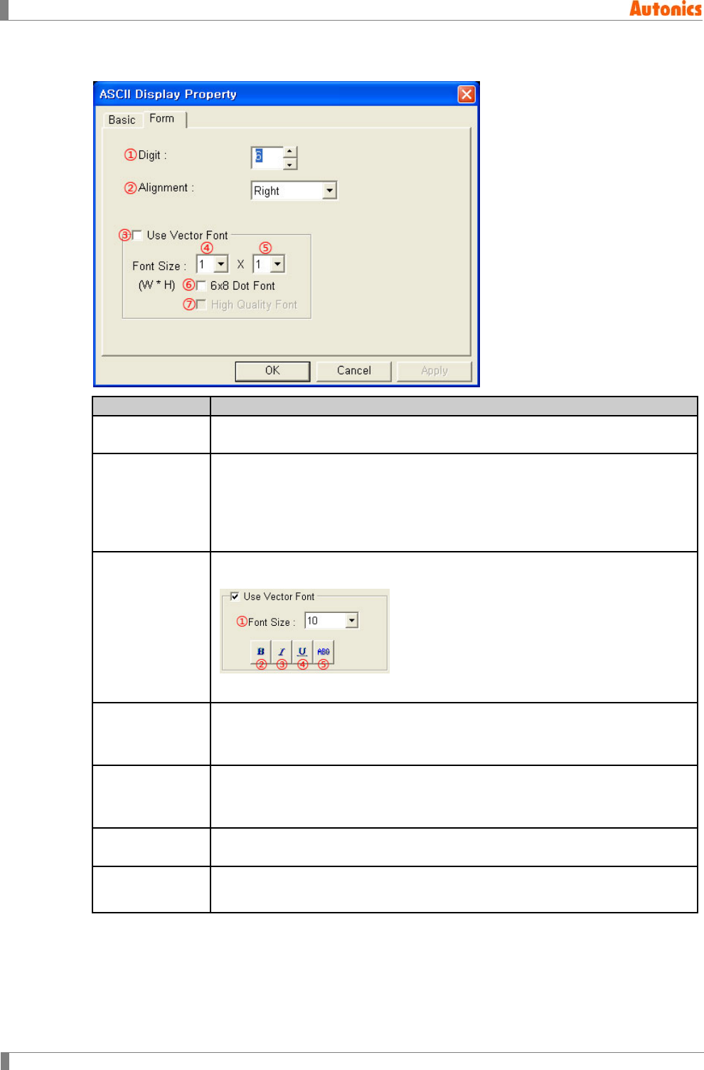
5 Draw
132 © Copyright Reserved Autonics Co., Ltd.
5.10.2.2 Form tab
Form
Description
①Digit Designate character digit number to display. Range is from 2 to 40 by even
number.
②Alignment
Designate alignment type (left, right, center) by pull-down menu. If text digit is
less than the designated digit, alignment operates.
Left: Displays a letter from the left of tag area.
Right: Displays a letter from the right of tag area.
Center: Displays a letter in a center of tag area.
③Use Vector
Font
Activated only for color type (GP-S070, LP-S070). Non-checking this, it uses
bitmap font. Checking this, it displays as following.
①Font size, ②Bold font, ③Italic font, ④Underline, ⑤Strikethrough
④Font Size
(Width)
Designate width font size by pull-down menu.
Range: 1, 2, 4, 6, 8
Height font size is 0.5, width font size 1 is only available.
⑤Font Size
(Height)
Designate height font size by pull-down menu
Range: 0.5, 1, 2, 3, 4
Width font sizes besides 1 are not available for height font size 0.5.
⑥6x8 Dot Font Designate 6x8 dot font. Only ASCII font has 6x8 dot font. If there is not 6x8 dot
font, it displays rectangles with the desired size and color.
⑦High Quality
Font Not used

5 Draw
© Copyright Reserved Autonics Co., Ltd. 133
Displayed character on screen has code for value on specified device.
From specified device, two digits of word device are displayed.
String which has low address device is displayed at first (at left direction).
At the same word devices, if lower/upper bytes are each of half-width character (1byte)
code, lower byte is displayed at first.
If device is D100, digit is 6, the related character which is the order of D100(Lower),
D100(Upper), D101(Lower), D101(Upper), D102(Lower), D102(Upper) are displayed. If there is
0 in the middle, the following character is not displayed.
D100(Lower)=41H=’A’, D100(Upper) =42H=’B’, D101(Lower) =43H=’C’,
D101(Upper) =00H=’\0’, D102(Lower) =44H=’E’, D102(Upper) =45H=’F’, it displays ABC.
With designated 6X8 dot font, 2 byte character is displayed as rectangle with designated font
color.
If there are not related character on device or it is not able to display (control character), it
displays as rectangle.
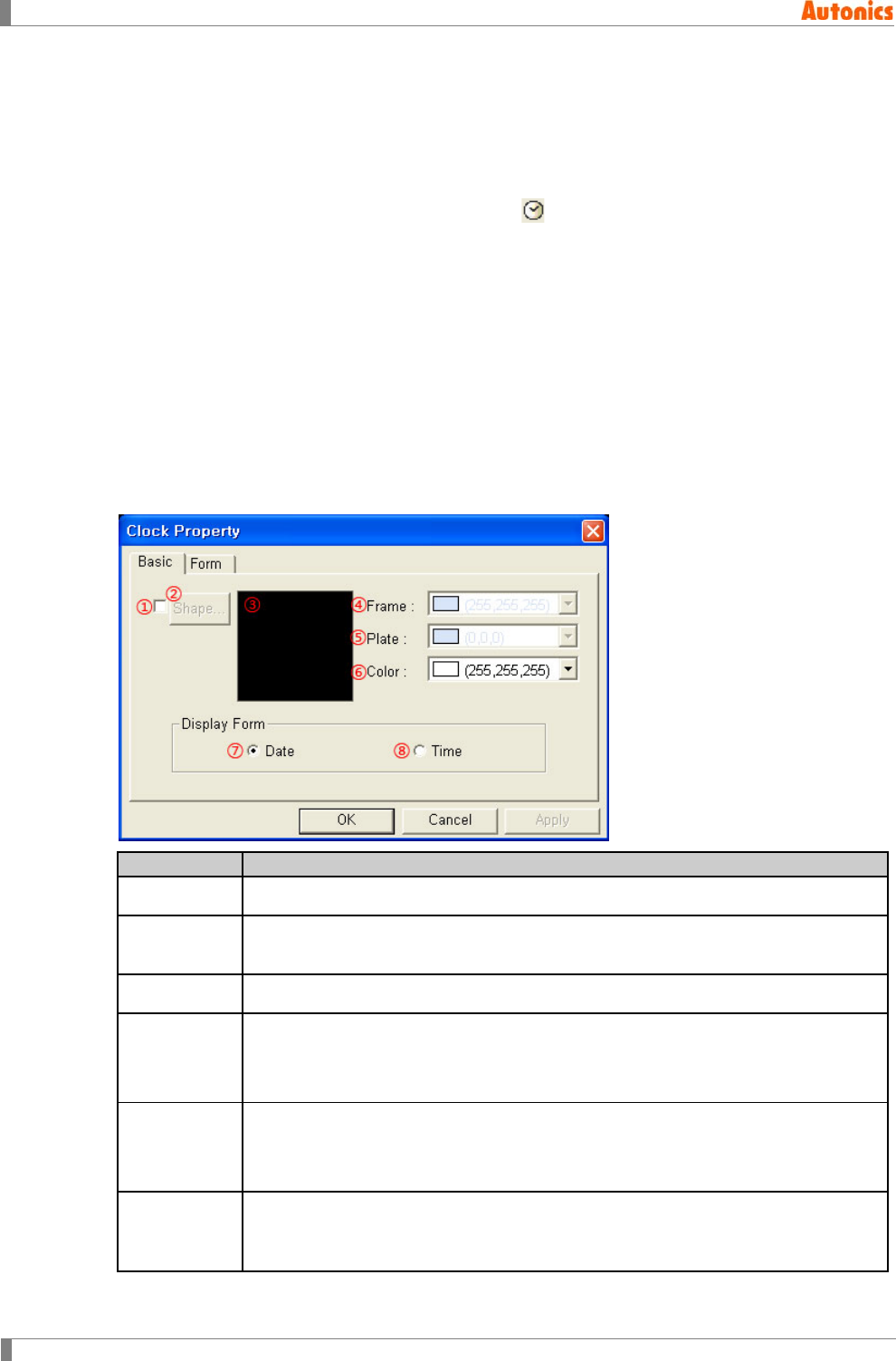
5 Draw
134 © Copyright Reserved Autonics Co., Ltd.
5.11 Clock
Displays time or date by clock of inner GP/LP regardless of controller (PLC) connected GP/LP.
5.11.1 Basic usage
1st Select [Draw]-[Clock] of menu, or click in toolbar, ‘Clock Property’ dialog box
appears.
2nd Select display type(date or time) in ‘Basic’ tab.
3rd Click ‘OK’ and ‘Clock Property’ dialog box is closed. A dotted rectangle follows mouse
cursor at edit area.
4th Place mouse cursor on the desired area, click left mouse button. Clock is placed on
the screen.
5.11.2 Property
5.11.2.1 Basic tab
Basic
Description
①Shape Designate using shape or not. Check this and no. 1 shape is as default.
②Shape Activated only with checking ①.
Click ‘Shape’ and ‘Image Selection’ dialog box appears. Select the desired shape.
③Shape Displays the selected shape image
④Frame
Designate frame color. Activated only with checking ①.
Mono type(GP-S044, GP-S057, LP-S044): White/Black
Color type(GP-S070, LP-S070): 24bit True Color
⑤Plate
Designate plate color. Activated only with checking ①.
Mono type(GP-S044, GP-S057, LP-S044): White/Black
Color type(GP-S070, LP-S070): 24bit True Color
⑥Text
Designate text color.
Mono type(GP-S044, GP-S057, LP-S044): White/Black
Color type(GP-S070, LP-S070): 24bit True Color
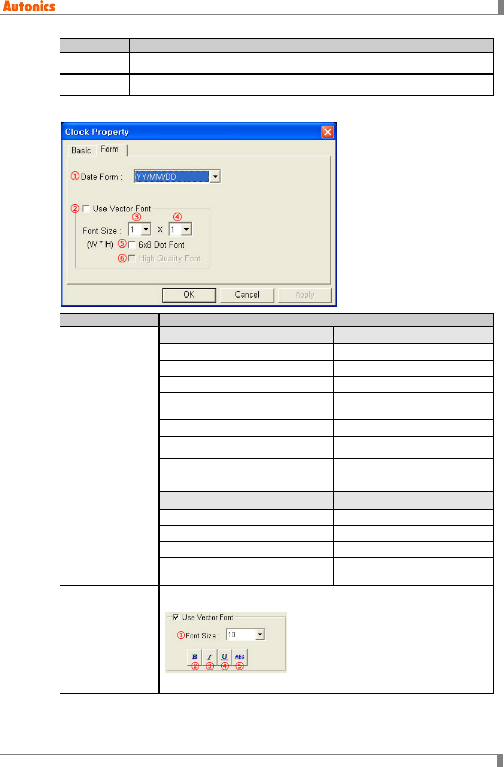
5 Draw
© Copyright Reserved Autonics Co., Ltd. 135
Basic
Description
⑦Date Designate to display current date
⑧Time Designated to display current time
5.11.2.2 Form tab
Form
Description
①Display Type
Display Type: Date Example of display
YY/MM/DD: year/month/day
11/1/13
DD/MM/YY: day/month/year
13/1/11
MM/DD/YY: month/day/year
1/13/11
DD/MM/YYYY(DAY):
day/month/year(a day of week) 13/JAN/2011(MON)
DD/MM/YYYY: day/month/year
13/JAN/2011
YYYY/MM/DD: year/month/day※1 2011/JAN/13
YYYY/MM/DD(DAY):
year/month/day(a day of week)※1 2011/JAN/13(MON)
Display Type: Time
Example of display
24H(HH:MM): hour:minute 22:55
24H(HH:MM:SS): hour:minute:second 22:55:36
12H(HH:MM): hour:minute AM/PM 10:55 PM
12H(HH:MM:SS): hour:minute:second
AM/PM 10:55:36 PM
②Use Vector Font
Activated only for color type (GP-S070, LP-S070). Non-checking this, it
uses bitmap font. Checking this, it displays as following.
①Font size, ②Bold font, ③Italic font, ④Underline, ⑤Strikethrough

5 Draw
136 © Copyright Reserved Autonics Co., Ltd.
Form
Description
③Font Size(Width)
Designate width font size by pull-down menu.
Default =1, Range: 1,2,4,6,8
Height font size is 0.5, width font size 1 is only available.
It is not activated with checking ⑤6x8 Dot Font.
④Font Size(Height)
Designate height font size by pull-down menu
Default =1, Range: 0.5,1,2,3,4
Width font sizes besides 1 are not available for height font size 0.5.
It is not activated with checking ⑤6x8 Dot Font.
⑤6x8 Dot Font Designate 6x8 dot font.
⑤High Quality Font Not used
※1. YYYY/MM/DD and YYYY/MM/DD(DAY) types are supplied by only Color type(GP-S070,
LP-S070) of GP/LP.
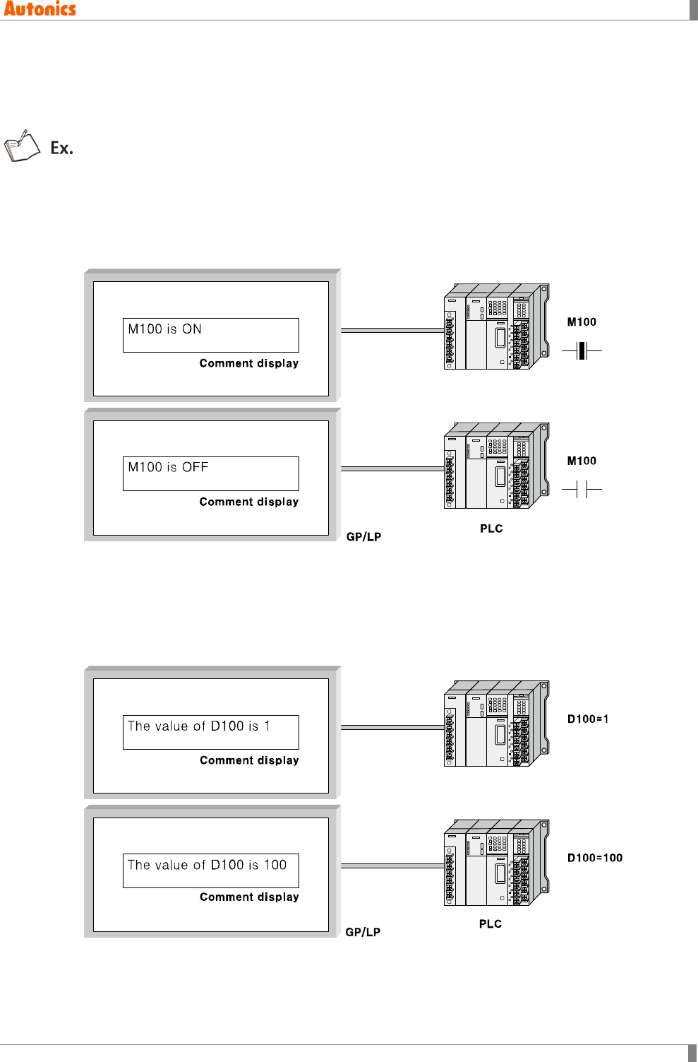
5 Draw
© Copyright Reserved Autonics Co., Ltd. 137
5.12 Comment Display
Comment display feautre is for displaying comment depending on ON/OFF state of the
desigated bit device or the word device value.
Bit action: Displays comment depending ON/OFF state of the designated bit device.
The following features are the example for the action when monitor device is set as M100,
Comment for ON state: M100 is ON.
Comment of OFF state: M100 is OFF.
Word action: Displays comment registered in comment list depending on the designated word
device value.
The following features are the example for the action when monitor device is D100,
Comment No.1 : The value of D100 is 1.
Comment No.100 : The value of D100 is 100.
5 Draw
138 © Copyright Reserved Autonics Co., Ltd.
5.12.1 Basic usage
1st Select [Draw]-[Comment Display] or click in tool bar, ‘Comment Display Property’
dialog box appears.
2nd Select monitor device and bit or word action in ‘Basic’ tab.
3rd Designate comment font size, or etc.
4th In case of bit action, ‘Bit’ tab is actiaved. Designate comment number or enter
comment directly by ON/OFF.
5th In case of word action, ‘Word’ tab is activated. Designate comment number which
related device value.
6th Click ‘OK’ and ‘Comment Display Property’ dialog box is closed. A dotted rectangle
follows mouse cursor at edit area.
7th Place mouse cursor on the desired area, click left mouse button. Comment is placed
on the screen.
Size adjustment: Tag size is decided based on specified comment comparing default font size
and length of comment character.
All characters including 6x8 font, 1x0.5 are reduced/enlarged as a size of configured ASCII
character.
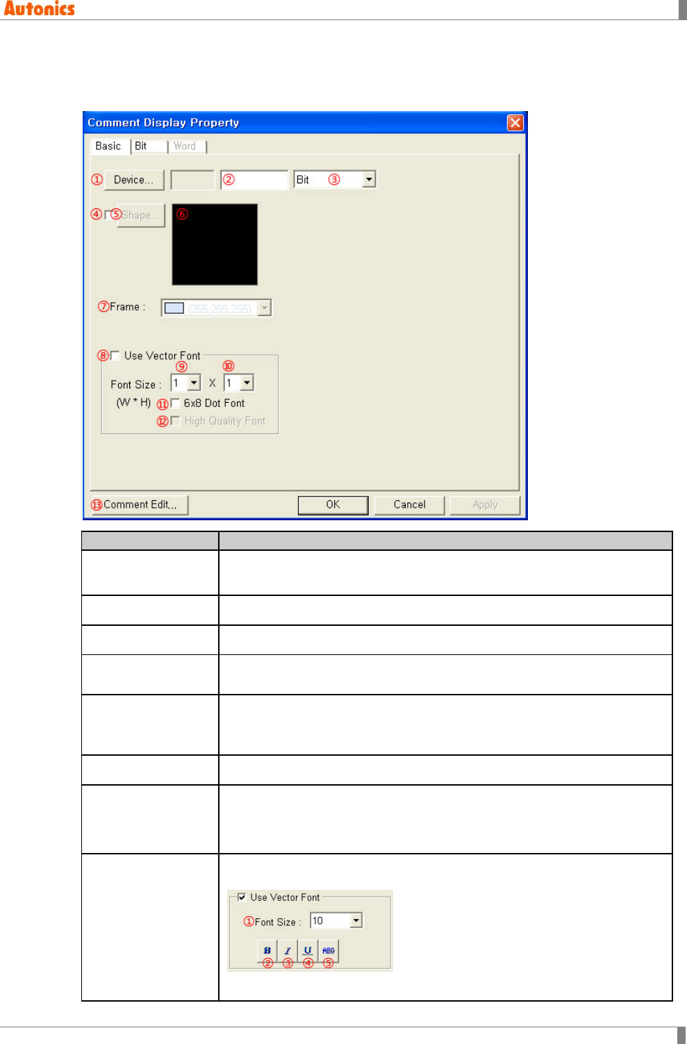
5 Draw
© Copyright Reserved Autonics Co., Ltd. 139
5.12.2 Property
5.12.2.1 Basic tab
Basic
Description
①Device Designate monitor device. Depending on ③ designation (bit or word),
designate bit or word device.
②Device Input device directly or displays the designated device by ①.
③Type Select device type (bit or word) by pull-down menu.
④Shape Designate using shape or not.
Check this and no. 1 shape is as default.
⑤Shape Activated only with checking ④.
Click ‘Shape’ and ‘Image Selection’ dialog box appears. Select the desired
shape.
⑥Shape Displays the selected shape image.
⑦Frame
Designate frame color. Activated only with checking ④.
Mono type(GP-S044, GP-S057, LP-S044): White/Black
Color type(GP-S070, LP-S070): 24bit True Color
⑧Use Vector Font
Activated only for color type (GP-S070, LP-S070). Non-checking this, it
uses bitmap font. Checking this, it displays as following.
①Font size, ②Bold font, ③Italic font, ④Underline, ⑤Strikethrough

5 Draw
140 © Copyright Reserved Autonics Co., Ltd.
Basic
Description
⑨Font Size (Width)
Designate width font size by pull-down menu.
Range: 1,2,4,6,8
Height font size is 0.5, width font size 1 is only available.
⑩Font Size (Height)
Designate height font size by pull-down menu
Default =1, Range: 0.5,1,2,3,4
Width font sizes besides 1 are not available for height font size 0.5.
⑪6x8 Dot Font Designate 6x8 dot font
⑫High Quality Font Not used
⑬Comment Edit Calls ‘Comment List’ dialog box. Check or edit comment. For further
details, refer to ‘8.7 Comment’.
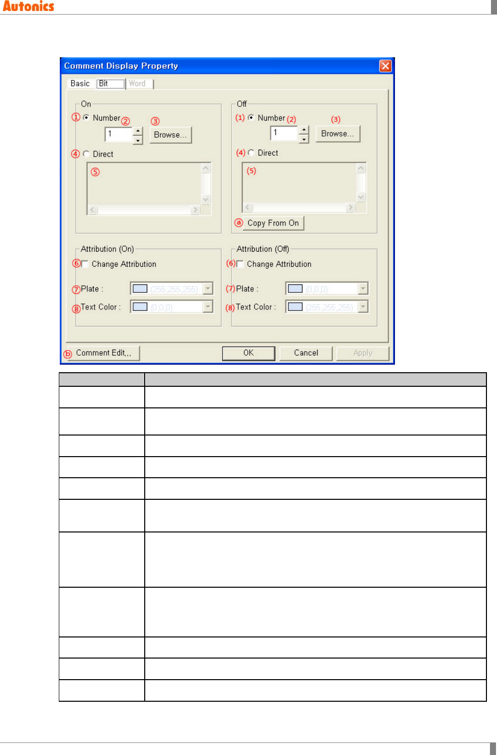
5 Draw
© Copyright Reserved Autonics Co., Ltd. 141
5.12.2.2 Bit tab
Bit
Description
①Number Designate to use registered comment in ② for ON state.
②Number select Designate comment number to display for ON state. Depending on monitor
device state, the designated number comment is displayed.
③Browse Designate comment number to display with arranging comment list.
④Direct Designate to use directly input comment for ON state.
⑤Enter comment Activated only with checking ④. Input comment directly for display.
⑥Change
Attribution Check to change plate, text color from default setting for ON state.
⑦Plate
Designate frame color for ON state. Activated only with checking ‘Shape’ in
‘Basic’ tab.
Mono type(GP-S044, GP-S057, LP-S044): White/Black
Color type(GP-S070, LP-S070): 24bit True Color
⑧Text Color
Designate text color for ON state. Activated only with checking ⑥.
Mono type(GP-S044, GP-S057, LP-S044): White/Black
Color type(GP-S070, LP-S070): 24bit True Color
⑴ to ⑻ Designate same setting with ① to ⑧ for OFF state.
ⓐCopy From ON Copy the designated number or text for ON state to OFF state.
ⓑComment Edit Calls ‘Comment List’ dialog box. Check or edit comment.
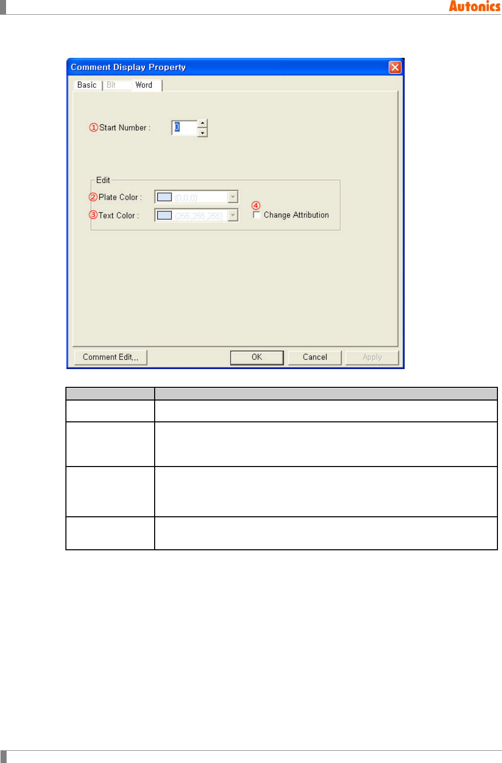
5 Draw
142 © Copyright Reserved Autonics Co., Ltd.
5.12.2.3 Word tab
Word
Description
①Start Number Displays the comment with word device value + start number
②Plate Color
Designates plate color. Activated only with checking ‘Shape’ in ‘Basic’ tab.
Mono type(GP-S044, GP-S057, LP-S044): White/Black
Color type(GP-S070, LP-S070): 24bit True Color
③Text Color
Designate text color for ON state. Activated only with checking ④.
Mono type(GP-S044, GP-S057, LP-S044): White/Black
Color type(GP-S070, LP-S070): 24bit True Color
④Change
Attribution Check to change plate, text color from default setting.
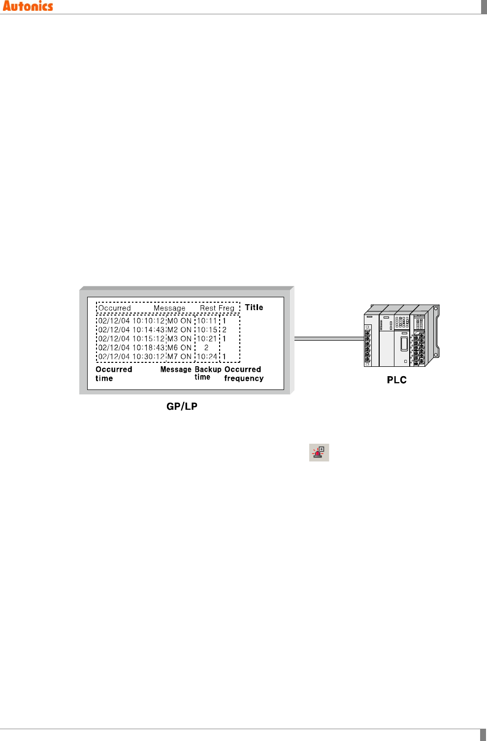
5 Draw
© Copyright Reserved Autonics Co., Ltd. 143
5.13 Alarm History
Alarm history is feature for recording alarm history.
It is able to record occurred time, restored time, the number of frequncy by designating. You can
print alarm list by connecting serial printer, check it by uploadding to PC. Alarm history is the
object which can exist only one on a screen.
5.13.1 Basic operation
Records history for ON/OFF of monitor device state with time information.
Designate observation period, action mode in ‘Alarm History Property’ dialog box from
common configuration, designate alarm history display type in ‘Alarm History Property’
dialog box.
Additional features such as detail screen display, cursor movement for specified history item
selection, item deleting, etc is operated with the touch key which has the specified key code
by each.
Monitor device is 256 of successive bit device, it is able to save up to 1024 of alarms and
up to 32767 of the number of occurred frequency.
5.13.2 Basic usage
1st Select [Draw]-[Alarm History] of menu or click in toolbar. ‘Alarm History
Property’ dialog box appears.
2nd Click ‘Common Configuration’ in ‘Basic’ tab and ‘Alarm History Property’ dialog box
appears.
3rd Designate monitor device, observation period, and mode in ‘Alarm History Property’
dialog box.
4th Designate display type in ‘Alarm History Property’ dialog box.
5th Click ‘OK’ and ‘Alarm History Property’ dialog box is closed. A dotted rectangle
follows mouse cursor at edit area.
6th Place mouse cursor on the desired area, click left mouse button. Alarm history tag is
created on the screen.
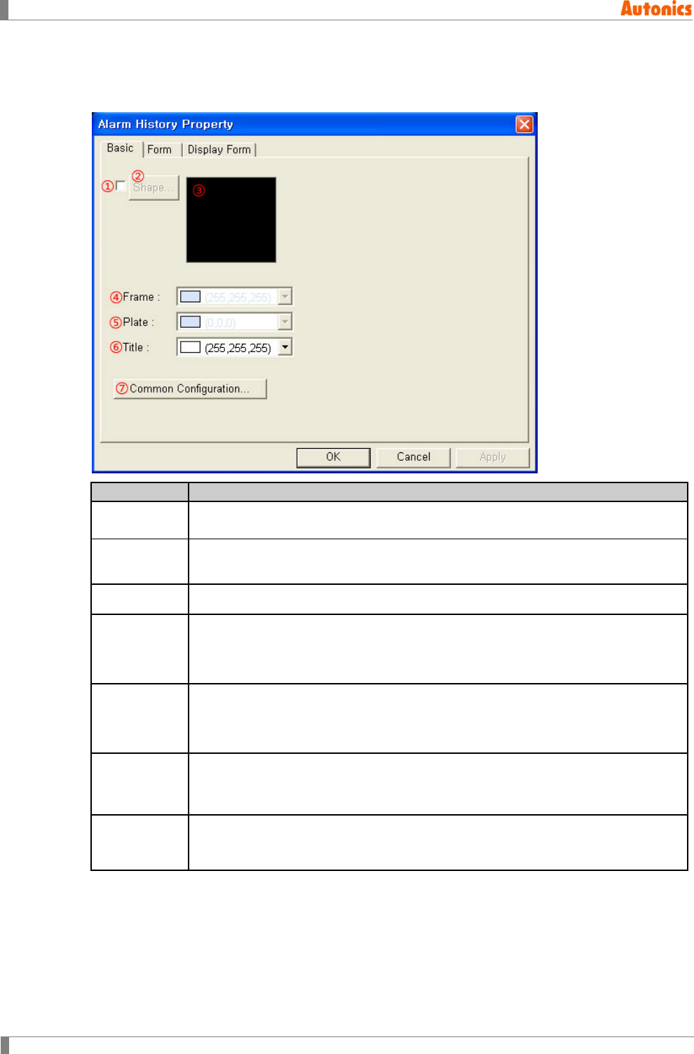
5 Draw
144 © Copyright Reserved Autonics Co., Ltd.
5.13.3 Property
5.13.3.1 Basic tab
Basic
Description
①Shape Designate using shape or not.
Check this and no. 1 shape is as default.
②Shape Activated only with checking ①.
Click ‘Shape’ and ‘Image Selection’ dialog box appears. Select the desired shape.
③Shape Displays the selected shape image
④Frame
Designates frame color. Activated only with checking ①.
Mono type(GP-S044, GP-S057, LP-S044): White/Black
Color type(GP-S070, LP-S070): 24bit True Color
⑤Plate
Designates plate color. Activated only with checking ①.
Mono type(GP-S044, GP-S057, LP-S044): White/Black
Color type(GP-S070, LP-S070): 24bit True Color
⑥Title
Designates title color.
Mono type(GP-S044, GP-S057, LP-S044): White/Black
Color type(GP-S070, LP-S070): 24bit True Color
⑦Common
Configuration
Calls ‘Alarm History Property’ dialog box. Designate the settings about alarm
observation.
For further details, refer to ‘8.8 Alarm History’.
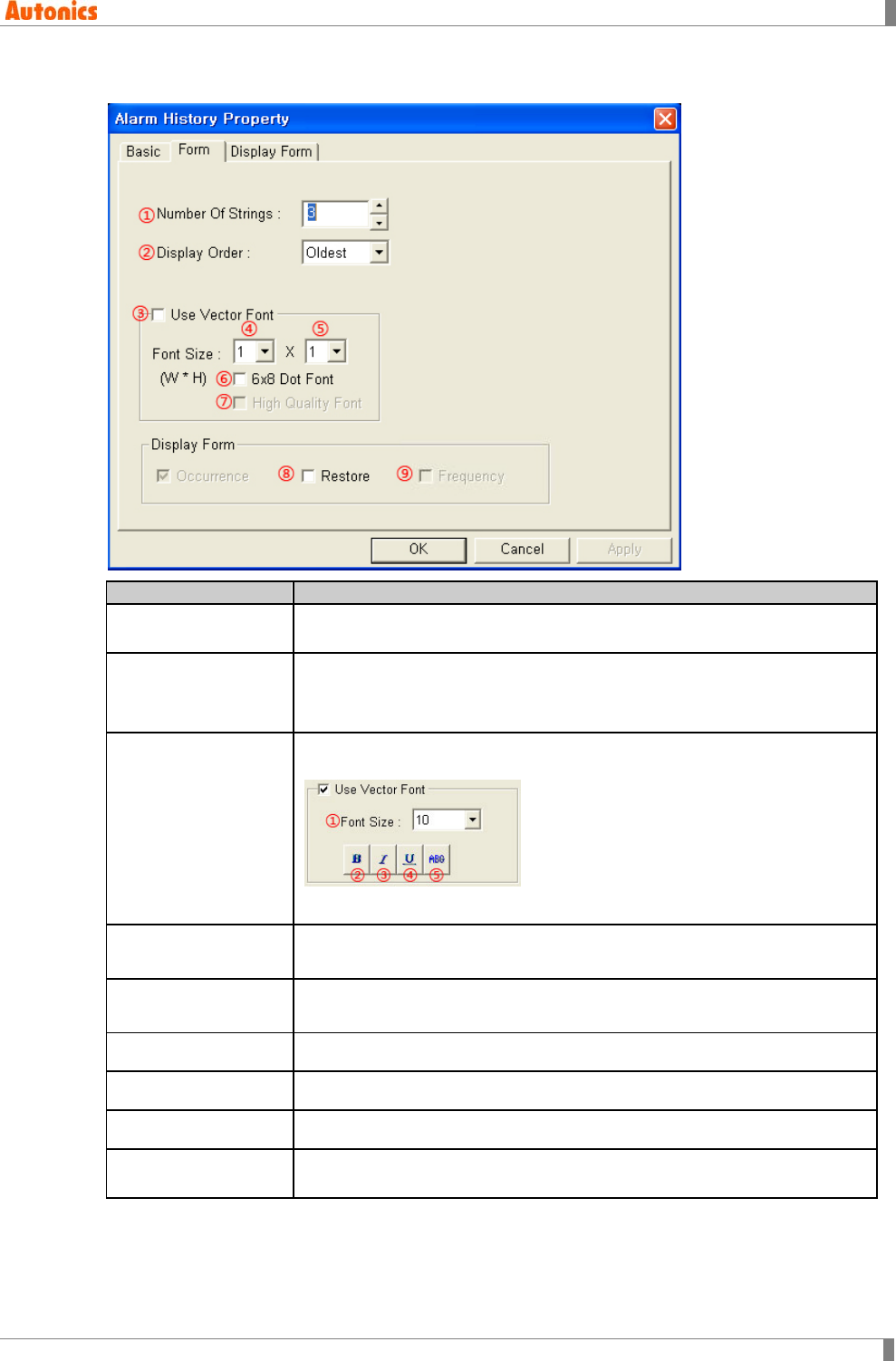
5 Draw
© Copyright Reserved Autonics Co., Ltd. 145
5.13.3.2 Form tab
Form
Description
①Number of Strings Designate the number of alarm item to display. Depending on height font
size, there is limitation the number of item to display.
②Display Order
Designate an order to display alarm history by pull-down menu.
Oldest: Displays older one first.
Latest: Displays recent one first.
③Use Vector Font
Activated only for color type (GP-S070, LP-S070). Non-checking this, it
uses bitmap font. Checking this, it displays as following.
①Font size, ②Bold font, ③Italic font, ④Underline, ⑤Strikethrough
④Font Size(Width) Designate width font size by pull-down menu.
Range: 1,2,3,4,
⑤Font Size(Height) Designate height font size by pull-down menu
Range: 1,2,3,4
⑥6x8 Dot Font Designate 6x8 dot font
⑦High Quality Font Not used
⑧Restore Designate using display restored alarm time or not.
⑨Frequency Designate using the number of frequency or not. Activated only with
‘Cumulation’ mode.
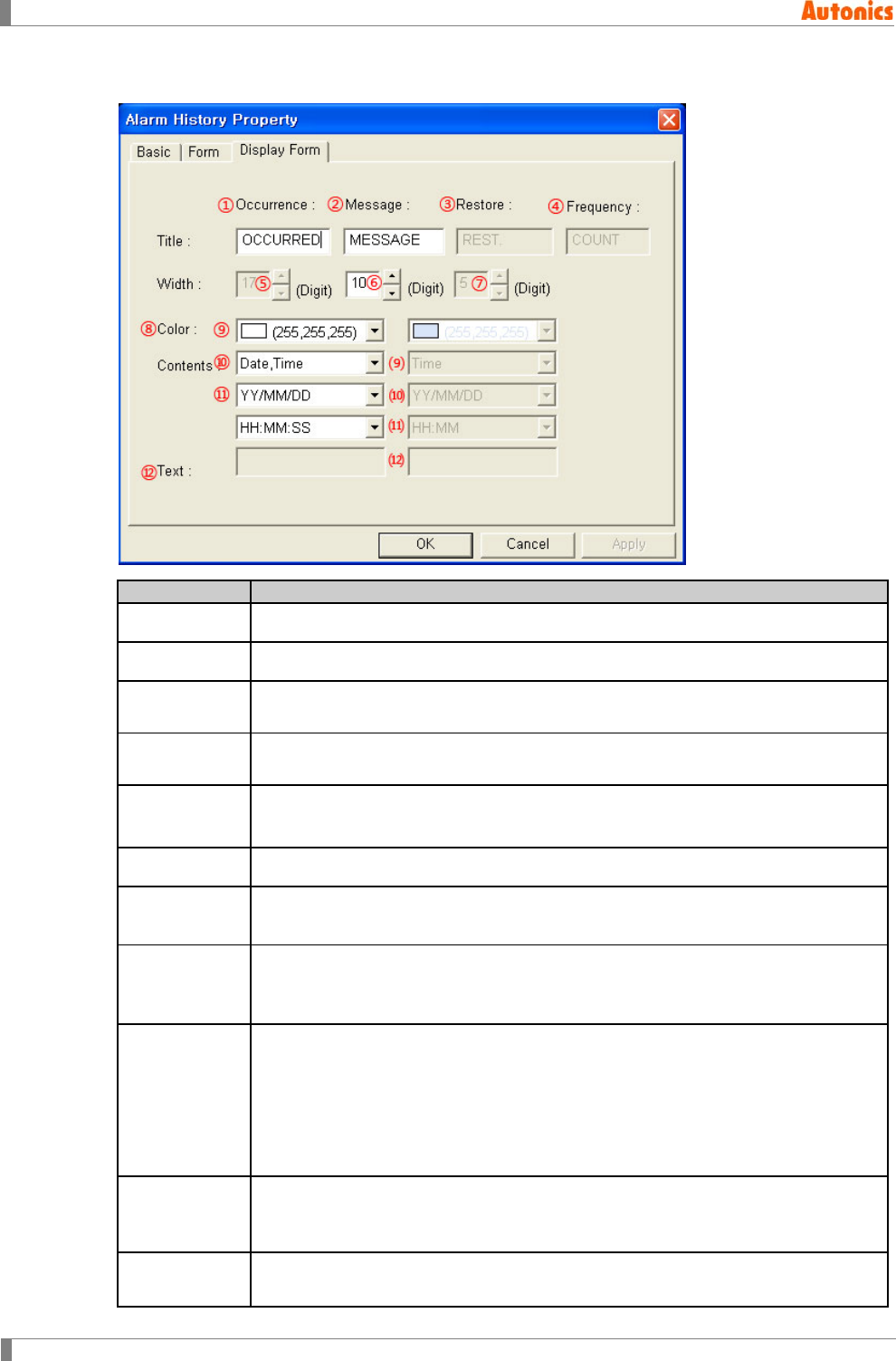
5 Draw
146 © Copyright Reserved Autonics Co., Ltd.
5.13.3.3 Display type tab
Display Form
Description
①Occurrence Designate the row title displaying occurred time.
②Message Designate the row title displaying message.
③Restore Designate the row title displaying restored time.
Activated only with checking ‘Restore’ in display type box of ‘Form’ tab.
④Frequency Designate the row title displaying the number of frequency.
Activated only with checking ‘Frequency’ in display type box of ’Form’ tab.
⑤Width Displays the number of character displaying occurred time.
It is designated by the setting of ⑨.
⑥Width Designate the number of character displaying message.
⑦Width Displays the number of character displaying restored time. It is designated It is
designated by the setting of ⑨.
⑧Color
Designate text color for occurred time.
Mono type(GP-S044, GP-S057, LP-S044): White/Black
Color type(GP-S070, LP-S070): 24bit True Color
⑨Contents
Designate display type for occurred time by pull-down menu.
Date, Time: Displays data and time. Width value is fixed as digit of date
display + digit of current configured time display + 1(space).
Date: Displays data.
Time: Displays time.
String: Displays user-defined text string.
⑩Date Designate date type for displaying by pull-down menu.
Select one of YY(year)/MM(month)/DD(day), MM/DD/YY, DD/MM/YY, or
MM/DD.
⑪Time Designate time type for displaying by pull-down menu.
Select one of HH(hour):MM(minute):SS(second), HH:MM.

5 Draw
© Copyright Reserved Autonics Co., Ltd. 147
Display Form
Description
⑫Text Input text for the part displaying occurred time.
⑼ to ⑿ Activated only with checking ‘Restore’ in display type box of ‘Form’ tab.
Designate same setting with ⑨ to ⑫ about restored time.
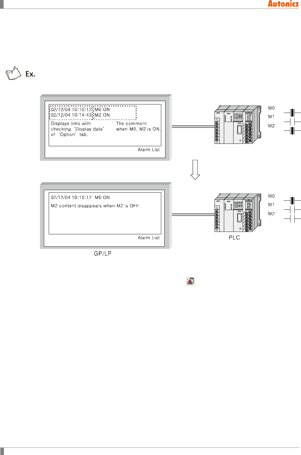
5 Draw
148 © Copyright Reserved Autonics Co., Ltd.
5.14 Alarm List
It displays the specified comment and ON time when the designated monitor bit device is ON.
It has silmilar features to alarm history but alarm list disappears when the specified device is
OFF. Alarm history is displays history list even though the specified device is OFF.
Example of alarm list action when monitor device is M0, M1, and M2.
5.14.1 Basic usage
1st Select [Draw]-[Alarm List] of menu, or click in toolbar. ‘Alarm List Property’
dialog box appears.
2nd Designate shape in ‘Basic’ tab.
3rd Designate the number of device, comment number, etc in ‘Form’ tab.
4th Designate the desired features to display in ‘Option’ tab.
5th Click ‘OK’ and ‘Alarm List Property’ dialog box is closed. A dotted rectangle follows
mouse cursor at edit area.
6th Place mouse cursor on the deisred area, click left mouse button. Alarm list tag is
created.
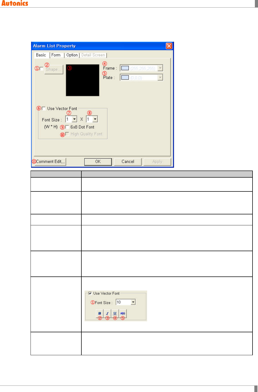
5 Draw
© Copyright Reserved Autonics Co., Ltd. 149
5.14.2 Property
5.14.2.1 Basic tab
Basic
Description
①Shape Designate using shape or not.
Check this and no. 1 shape is as default.
②Shape Activated only with checking ①.
Click ‘Shape’ and ‘Image Selection’ dialog box appears. Select the desired
shape.
③Shape Displays the selected shape image.
④Frame
Designates frame color. Activated only with checking ①.
Mono type(GP-S044, GP-S057, LP-S044): White/Black
Color type(GP-S070, LP-S070): 24bit True Color
⑤Plate
Designates plate color. Activated only with checking ①.
Mono type(GP-S044, GP-S057, LP-S044): White/Black
Color type(GP-S070, LP-S070): 24bit True Color
⑥Use Vector Font
Activated only for color type (GP-S070, LP-S070). Non-checking this, it
uses bitmap font. Checking this, it displays as following.
①Font size, ②Bold font, ③Italic font, ④Underline, ⑤Strikethrough
⑦Font Size(Width)
Designate width font size by pull-down menu.
Range: 1,2,3,4,5,6,7,8
Height font size is 0.5, width font size 1 is only available.
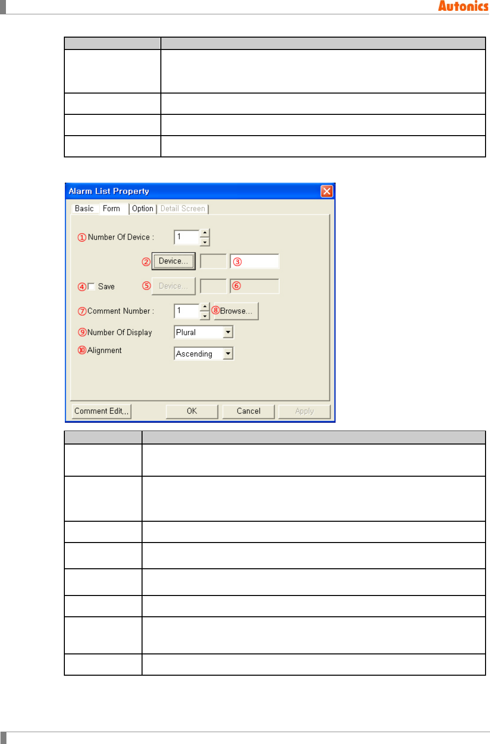
5 Draw
150 © Copyright Reserved Autonics Co., Ltd.
Basic
Description
⑧Font Size(Height)
Designate height font size by pull-down menu
Range: 0.5,1,2,3,4,5,6,7,8
Width font sizes besides 1 are not available for height font size 0.5.
⑨6x8 Dot Font Designate 6x8 dot font.
⑩High Quality Font Not used
⑪Comment Edit Calls ‘Comment List’ dialog box. Check or edit comment.
5.14.2.2 Form tab
Form
Description
①Number of
Device
Designate the number of monitor device related with alarm list.
Range: 1 to 256
②Device
Calls ‘Device Select’ dialog box, and designate device.
From this device, successive bit devices of ① the number are monitor device
of alarm list.
③Device Input device directly or displays the designated device.
④Save Check to save the number of monitor device which is ON state (the number of
occurred alarm) at the specified word device.
⑤Device Calls ‘Device Select’ dialog box and designate word device to save the number
of occurred alarm.
⑥Device Input device directly or displays the designated word device by ①.
⑦Comment
Number
Designate comment number to be displayed when the lead device is ON. Next
device from the lead device corresponds successively with high number of
comment than designated number.
⑧Browse Calls ‘Comment List’ dialog box. Check the desired comment.
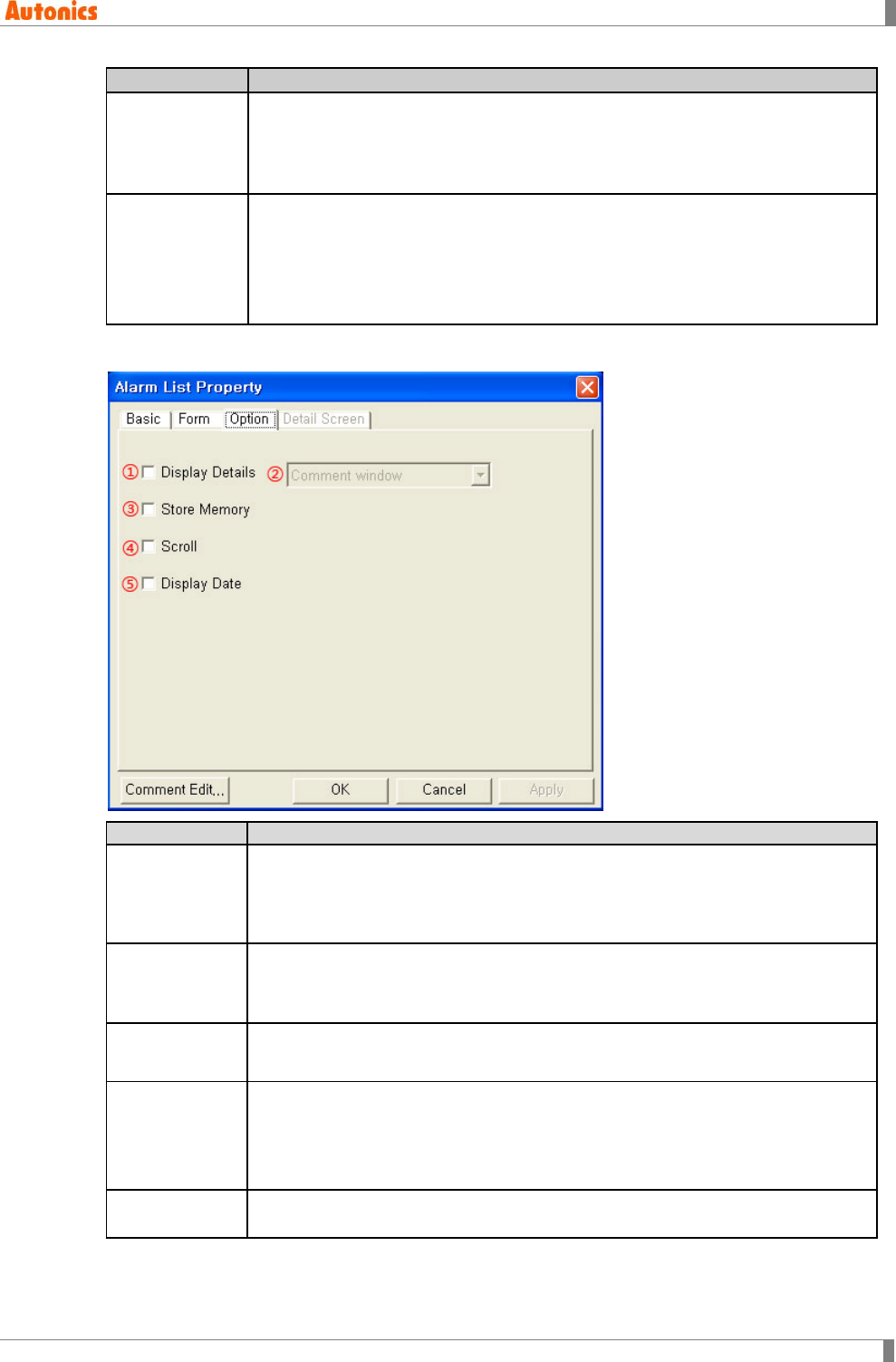
5 Draw
© Copyright Reserved Autonics Co., Ltd. 151
Form
Description
⑨Number Of
Display
Designate using one comment display or more on screen by pull-down menu.
Plural: Displays two or more comments (error message) on screen display
area.
Single: Displays one of the latest alarms.
⑩Alignment
Designate alarm alignment type by pull-down menu.
Ascending: Displays from high number according to bit device number.
Descending: Displays from low number according to bit device number.
Oldest: Displays older one first.
Latest: Displays recent one first.
5.14.2.3 Option tab
Option
Description
①Detail Display
Designate displaying detail display by function key (touch key) or not. Place
cursor on the specified area on alarm list, touch the function key for detail
screen display. Depending on the designation of ②, the related alarm detail is
displayed with window or base screen type.
②Detail Display
Designate screen type of detail display by pull-down menu.
Comment window: Displays details with comment window type.
Base screen: Displays details with base screen type.
③Store
Memory Saves ON date and time of current monitor device in real time.※1
④Scroll
Designate using scroll to check all alarms when there are several alarms and
these are not displayed at one tag area or not. Shows cursor by show cursor
touch key (key code is FFA4h), and scroll it with move cursor upward (FFABh),
move cursor downward (FFACh) touch keys.
Scroll option cannot be placed with alarm history in one screen.
⑤Display Date Designate displaying both date and time with comment all the time or not. With
non-checking this, displays only the comment of the specified bit device.
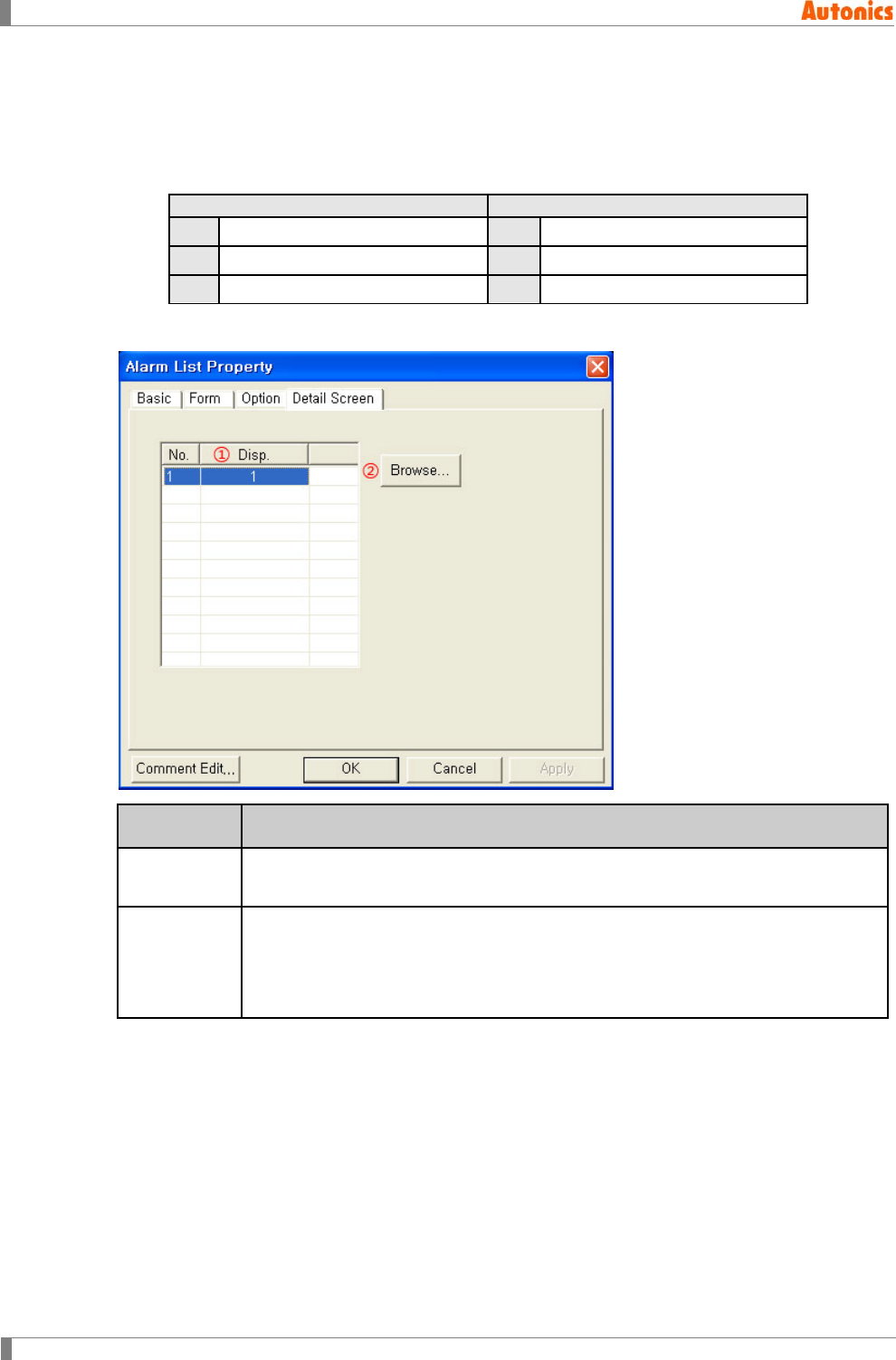
5 Draw
152 © Copyright Reserved Autonics Co., Ltd.
※1. The below alarm list content table is for when to be monitored devices are M0, M1, and M2
and alarm list tag is placed at base screen 1. And for when actual ON time of monitor device
is M0:02/08/08 12:01, M1 : 02/08/08 12:10, M2:02/08/08 12:20 and switching time from
base screen 2 to screen1 is 12:18.
Checking store memory
Non-checking store memory
M0
02/08/08 12:01 M0 error
M0
02/08/08 12:18 M0 error
M1
02/08/08 12:10 M1 error
M1
02/08/08 12:18 M1 error
M2
02/08/08 12:20 M2 error
M2
02/08/08 12:18 M2 error
5.14.2.4 Detail screen tab
Detail
Screen
Description
①Display
Number
After checking ‘Display Details’ and selecting screen type in ‘Option’ tab, displays
detail comment number or base screen number depending on screen type.
②Browse
After checking ‘Display Details’ and selecting screen type in ‘Option’ tab, click this.
In case of ‘Comment window’ screen type, ‘Comment List’ dialog box appears.
Designate comment number.
In case of ‘Base screen’ screen type, ‘Screen Image’ dialog box appears.
Designate the base screen to display details.
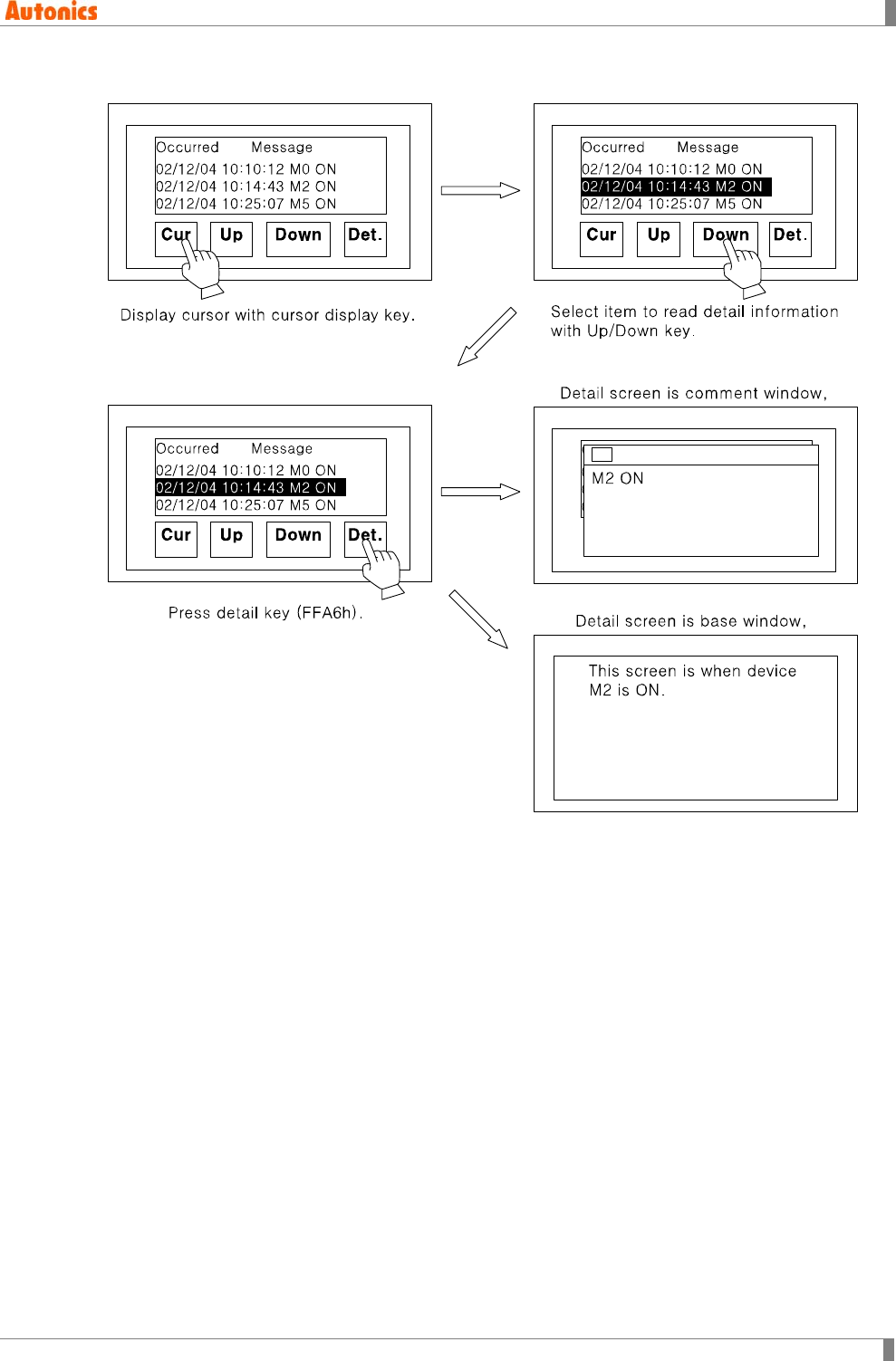
5 Draw
© Copyright Reserved Autonics Co., Ltd. 153
5.14.2.5 Alarm detail information
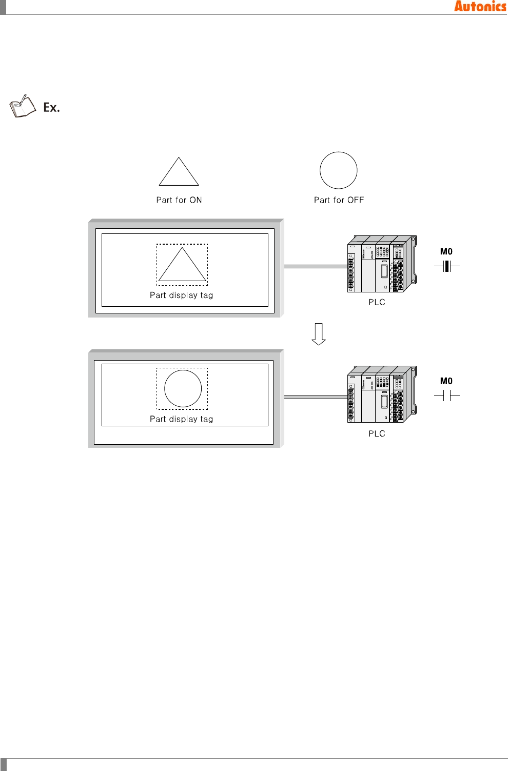
5 Draw
154 © Copyright Reserved Autonics Co., Ltd.
5.15 Part Display
Displays part depending on the designated bit device state, or on the word device value on
screen.
(1) Bit action
It displays the designated part depending on ON/OFF state of bit device.
When using mark option, it shows the specified part with changing from white to the
designated color of foreground and background color according to device state, not
switching part.
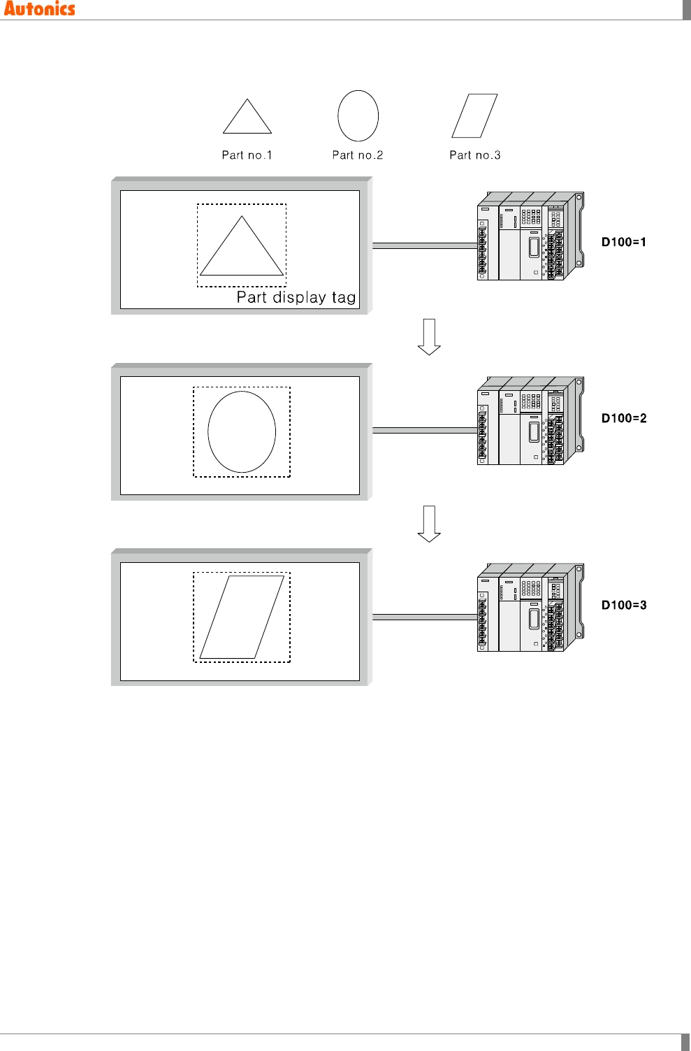
5 Draw
© Copyright Reserved Autonics Co., Ltd. 155
(2) Word action
It displays the part with switching depending on word device value.
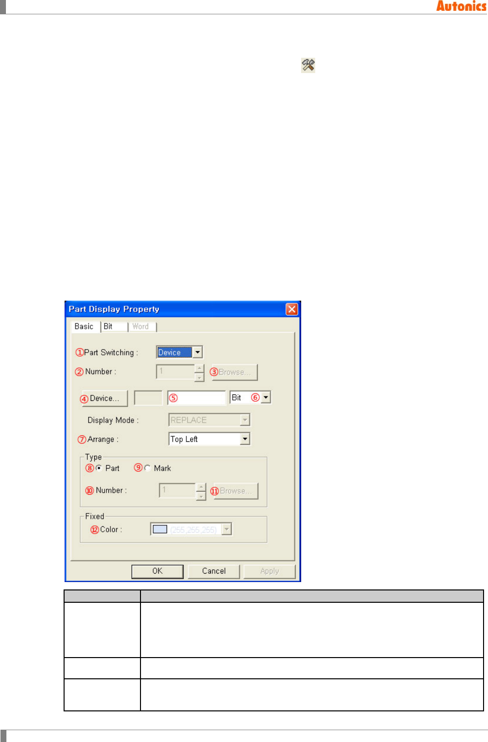
5 Draw
156 © Copyright Reserved Autonics Co., Ltd.
5.15.1 Basic usage
1st Select [Draw]-[Part Display] of menu, click in toolbar. ‘Part Display Property’
dialog box appears.
2nd Designate part switching in ‘Basic’ tab.
3rd In case of device part switching, select ‘Device’. In case of fixed part switching, select
‘Fixed’ and designate part number.
4th In case of bit device, designate part for ON/OFF, color in ‘Bit’ tab.
5th In case of word device, designate start number in ’Word’ tab.
6th Click ‘OK’ and ‘Part Display Property’ dialog box is closed. A dotted rectangle follows
mouse cursor at edit area.
7th Place mouse cursor on the desired area, click left mouse button. Part tag is created
on the screen.
5.15.2 Property
5.15.2.1 Basic tab
Basic
Description
①Part
Switching
Select device or fixed by pull-down menu.
Device: Switching part depending on the specified bit device state or the
word device value.
Fixed: Displays one specified part.
②Number Activated with only when ① is set as ‘Fixed’. Designate part number to display.
③Browse Calls ‘Image Selection’ dialog box and select the part registered at part library.
The selected part number is input at ②.
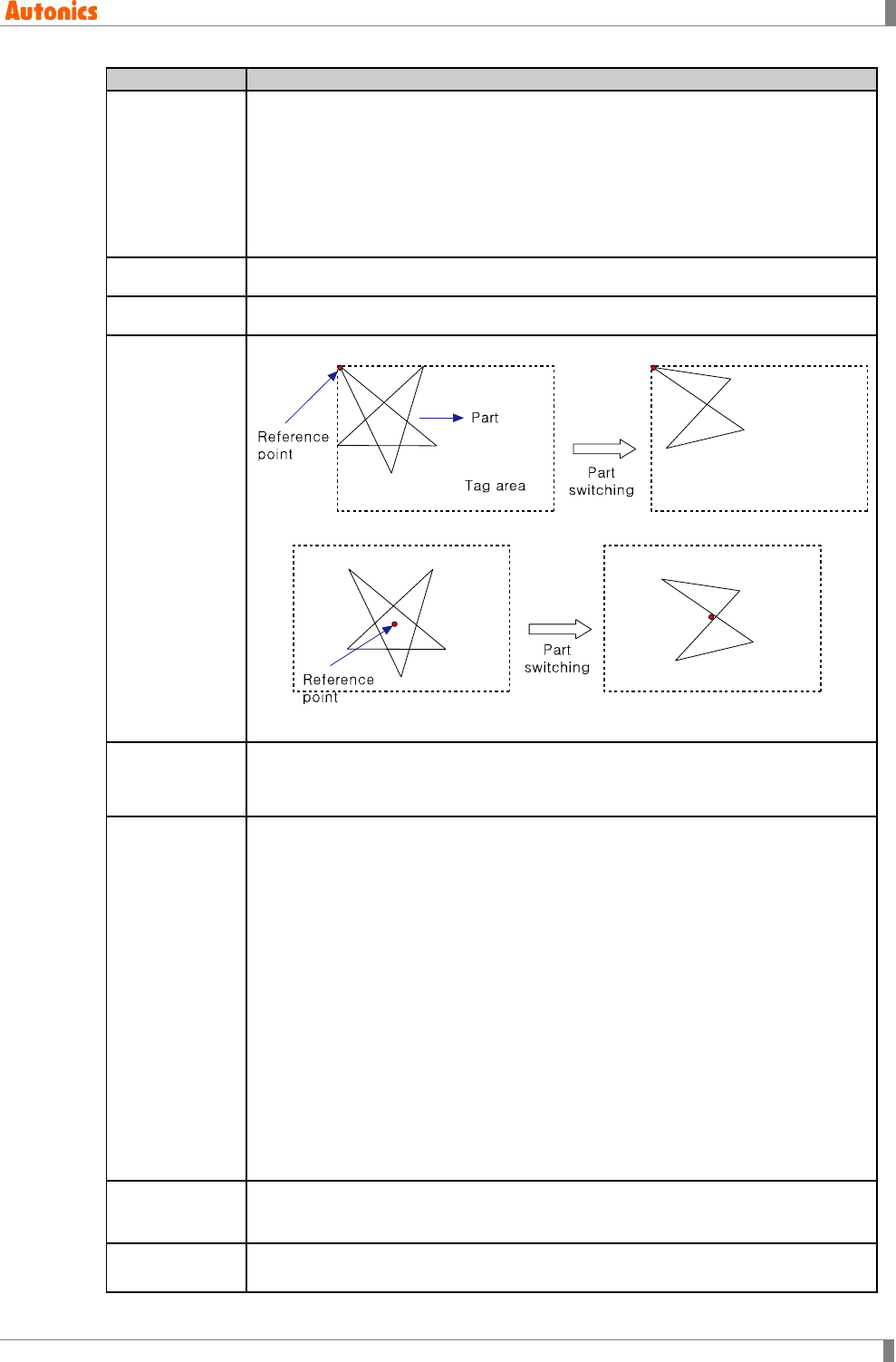
5 Draw
© Copyright Reserved Autonics Co., Ltd. 157
Basic
Description
④Device
Activated with only when ① is set as ‘Device’.
Depending on the designation of ⑥, designate bit/word device.
Bit device: Displays the part which is designated in ‘Bit’ tab depending on
ON/OFF state of the specified bit device.
Word device: Displays the part which is related with part number of the word
device value.
⑤Device Input device directly or displays the designated device.
⑥Data Type Select bit device or word device for part switching by pull-down menu.
⑦Arrange
Top Left: Places top-left point of part in center of tag area.
Center: Places center point of part in center of tag area.
⑧Part
In case of ‘Fixed’ part switching, displays the part designated in ②.
In case of ‘Device’ part switching, displays the part designated at ON/OFF in
‘Bit’ tab.
⑨Mark
Activated only with when the designation of ⑥ is bit device.
In case of ‘Fixed’ part switching,
For mono type(GP-S044, GP-S057, LP-S044), displays mark with switching
from white area of the designated part of ② to designated color of ⑫.
For color type(GP-S070, LP-S070), displays mark with switching from white
foreground area of the designated part of ② to designated color of ⑫.
In case of ‘Device’ part switching,
For mono type(GP-S044, GP-S057, LP-S044), displays mark with switching
from white area of the designated part of ⑩ to designated On/Off color in
‘Bit’ tab.
For color type(GP-S070, LP-S070), displays mark with switching from white
foreground area of the designated part of ⑩ to designated On/Off color in
‘Bit’ tab.
Mono type(GP-S044, GP-S057, LP-S044) uses only white/black. If mart color is
black and background color is black, part is not to be seen.
⑩Number Activated only with when ① part switching is ‘Device’, and checking ⑨.
Designate part to display when using mark option.
⑪Browse Calls ‘Image Selection’ dialog box. Designate the part to display when using
mark option.
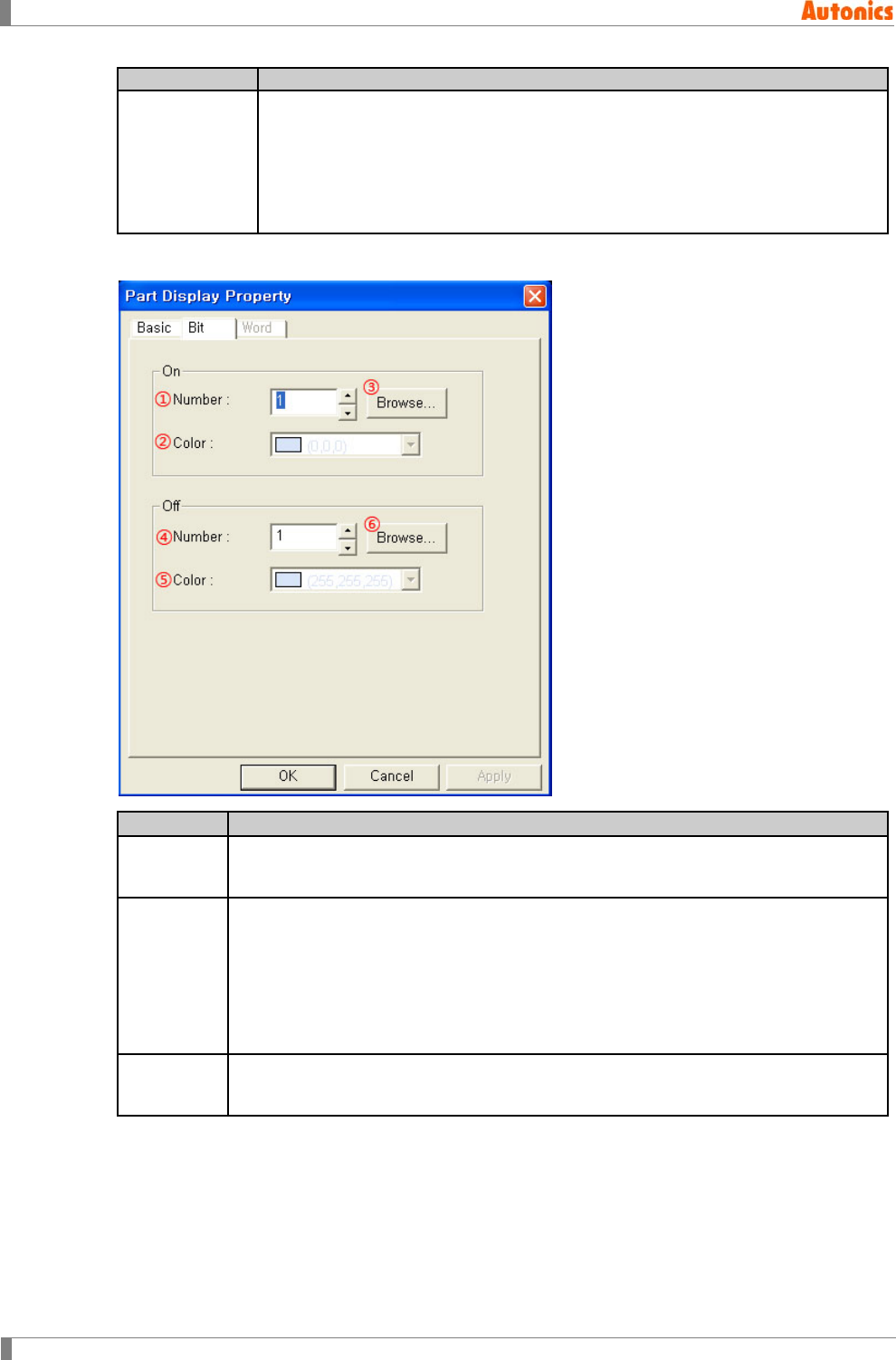
5 Draw
158 © Copyright Reserved Autonics Co., Ltd.
Basic
Description
⑫Color
Activated only with when ① part switching is ‘Fixed’, and checking ⑨. White
area of the designated part of ② is changed to the designated color of this.
If color is same with background color, part is not to be seen.
Mono type(GP-S044, GP-S057, LP-S044): White/Black
Color type(GP-S070, LP-S070): 24bit True Color
5.15.2.2 Bit tab
Bit
Description
①, ④
Number
Designate part number to display for ON/OFF.
Activated only with when ‘Part’ in type box is selected in ‘Basic’ tab.
②, ⑤
Color
Activated only with when ‘Mart’ in type box is selected in ‘Basic’ tab.
Displays the white area of the designated device for ON/OFF to the designated
color of ③, ⑥.
If color is same with background color, part is not to be seen.
Mono type(GP-S044, GP-S057, LP-S044): White/Black
Color type(GP-S070, LP-S070): 24bit True Color
③, ⑥
Browse Calls ‘Image Selection’ dialog box. Designate part number to display for ON/OFF.
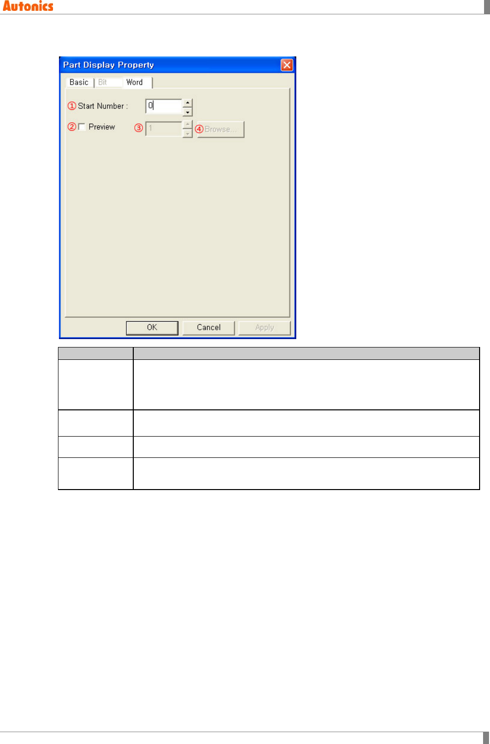
5 Draw
© Copyright Reserved Autonics Co., Ltd. 159
5.15.2.3 Word tab
Word
Description
①Start Number
Designate part number to display when the designated word device is 0.
Displays the part of word device value +start number.
Default is 0 and range is -32768 to 32767. If word device value+start number is
below 0, it does not display anything.
②Preview Designate using part display on edit area or not. Checking this, the part input at
spin box is displayed on edit area. Non-checking this, tag area is only displayed.
③Preview Designate part number to display on edit area.
④Browse Call ‘Image Selection’ dialog box. Select the part registered part library and the
selected part number is input at ③.
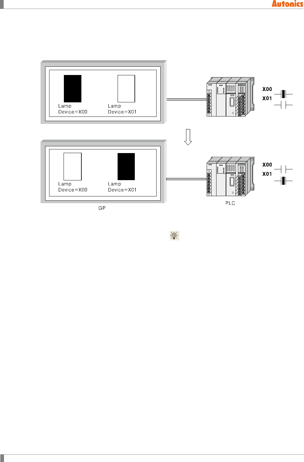
5 Draw
160 © Copyright Reserved Autonics Co., Ltd.
5.16 Lamp
Lamp feature is for lamp to turn ON/OFF depending ON/OFF of bit device.
You can use graph library supported by GP Editor, and user-defined part as lamp shape.
5.16.1 Basic usage
1st Select [Draw]-[Lamp] of menu, click in toolbar. ‘Lamp Property’ dialog box
appears.
2nd Designate lamp shape.
3rd Designate monitor device and other properties.
4th Click ‘OK’ and ‘Lamp Property’ dialog box is closed. A dotted rectangle follows mouse
cursor at edit area.
5th Place mouse cursor on the desired area, click left mouse button. Lamp is created on
the screen. When using basic figure shape lamp which is supplied by GP Editor,
minimum lamp size is 16X16 dots. When using user-defined part shape lamp, it
includes ON/OFF part and its rectangle size is 16X16 and over.
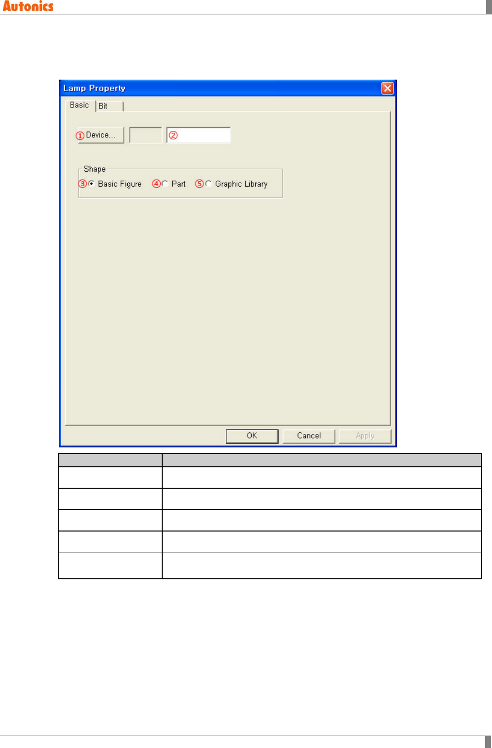
5 Draw
© Copyright Reserved Autonics Co., Ltd. 161
5.16.2 Property
5.16.2.1 Basic tab
Basic
Description
①Device Calls ‘Device Select’ dialog box and designate monitor device.
②Device Input PLC device directly or displays the designated device.
③Basic Figure Uses basic black/white image supported GP Editor as lamp shape.
④Part Uses user-defined part as lamp shape.
⑤Graphic Library Uses bitmap image supported GP Editor and registered image as lamp
shape. (Available only for color type(GP-S070, LP-S070))
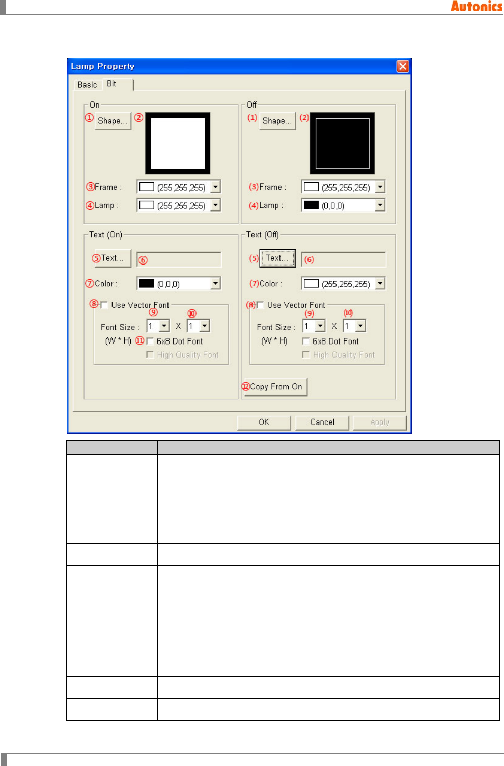
5 Draw
162 © Copyright Reserved Autonics Co., Ltd.
5.16.2.2 Bit tab
Bit
Description
①Shape
Depending on the designation of shape in ‘Basic’ tab, this ① is different.
Basic Figure: Designate lamp shape from listed basic black/white image
supplied by GP Editor.
Part: Designate lamp shape from listed user-defined part.
Graphic Library: Designate lamp shape from listed bitmap image supplied
by GP Editor.
②Shape Displays the selected shape image.
③Frame
Designates frame color for ON. Activated only with when ‘Basic Figure’ is
selected in shape box of ‘Lamp Property’ dialog box.
Mono type(GP-S044, GP-S057, LP-S044): White/Black
Color type(GP-S070, LP-S070): 24bit True Color
④Lamp
Designates lamp color for ON. Activated only with when ‘Basic Figure’ is
selected in shape box of ‘Lamp Property’ dialog box.
Mono type(GP-S044, GP-S057, LP-S044): White/Black
Color type(GP-S070, LP-S070): 24bit True Color
⑤Text※1 Calls ‘Edit Text’ dialog box. Edit text for ON lamp.
⑥Text Displays text for ON lamp.
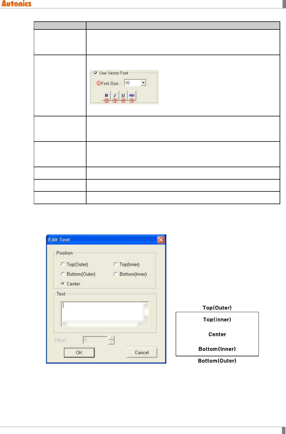
5 Draw
© Copyright Reserved Autonics Co., Ltd. 163
Bit
Description
⑦Color
Designates text color.
Mono type(GP-S044, GP-S057, LP-S044): White/Black
Color type(GP-S070, LP-S070): 24bit True Color
⑧Use Vector Font
Activated only for color type (GP-S070, LP-S070). Non-checking this, it uses
bitmap font. Checking this, it displays as following.
①Font size, ②Bold font, ③Italic font, ④Underline, ⑤Strikethrough
⑨Font Size
(Width)
Designate width font size by pull-down menu.
Range: 1,2,4,6,8
Height font size is 0.5, width font size 1 is only available.
⑩Font Size
(Height)
Designate height font size by pull-down menu
Range: 0.5,1,2,3,4
Width font sizes besides 1 are not available for height font size 0.5.
⑪6x8 Dot Font Designate 6x8 dot font.
⑴ to ⑽ Designate same setting with ① to ⑩ for OFF state.
⑫Copy From On Copy the designated text for ON state to OFF state.
※1. [Text display on lamp]
Click ⑤, ⑸ ‘Text’ and ‘Edit Text’ dialog box appears. You can input the text for lamp and
designate the place.
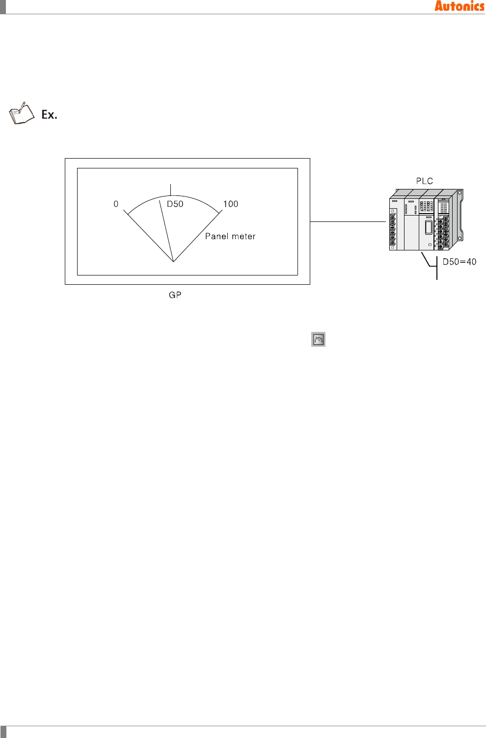
5 Draw
164 © Copyright Reserved Autonics Co., Ltd.
5.17 Panel Meter
Panel meter is displaying the occupyed position of current value of specified word device within
designated maximum/minimum value with needle of panel meter to monitor device value.
The example for when panel meter range is 0 to 100, D50 is 40. The needle of panel meter
indicates the appropriate value for 40.
5.17.1 Basic usage
1st Select [Draw]-[Panel Meter] of menu, or click in toolbar. ‘Panel Meter’ dialog box
appears.
2nd Designated word device for observation in ‘Basic’ tab.
3rd Designate panel meter type, direction for needle in ‘Form’ tab.
4th Designate data type of device, maximum/minimum value.
5th Click ‘OK’ and ‘Panel Meter’ dialog box is closed. A dotted rectangle follows mouse
cursor at edit area.
6th Place mouse cursor on the desired area, click left mouse button. Panel meter is
placed on the screen.
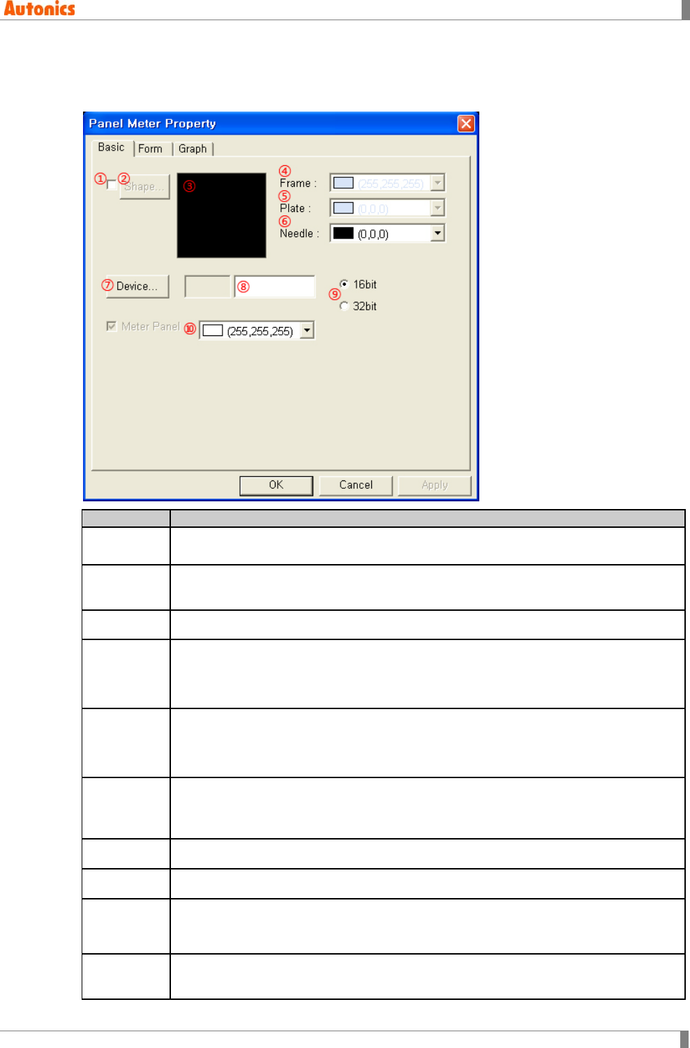
5 Draw
© Copyright Reserved Autonics Co., Ltd. 165
5.17.2 Property
5.17.2.1 Basic tab
Basic
Description
①Shape Designate using shape or not.
Check this and no. 1 shape is as default.
②Shape Activated only with checking ①.
Click ‘Shape’ and ‘Image Selection’ dialog box appears. Select the desired shape.
③Shape Displays the selected shape image
④Frame
Designate frame color. Activated only with checking ①.
Mono type(GP-S044, GP-S057, LP-S044): White/Black
Color type(GP-S070, LP-S070): 24bit True Color
⑤Plate
Designate plate color. Activated only with checking ①.
Mono type(GP-S044, GP-S057, LP-S044): White/Black
Color type(GP-S070, LP-S070): 24bit True Color
⑥Needle
Designate needle color.
Mono type(GP-S044, GP-S057, LP-S044): White/Black
Color type(GP-S070, LP-S070): 24bit True Color
⑦Device Calls ‘Device Select’ dialog box and designate monitor device.
⑧Device Input device directly or displays the designated device by ⑦
⑨Data
Designate data type (16bit or 32bit) of word device.
Depending on connected device type, it may use only 32bit. Refer to ‘GP,LP user
manual for communication’.
⑩Meter
Panel Designate panel meter color.
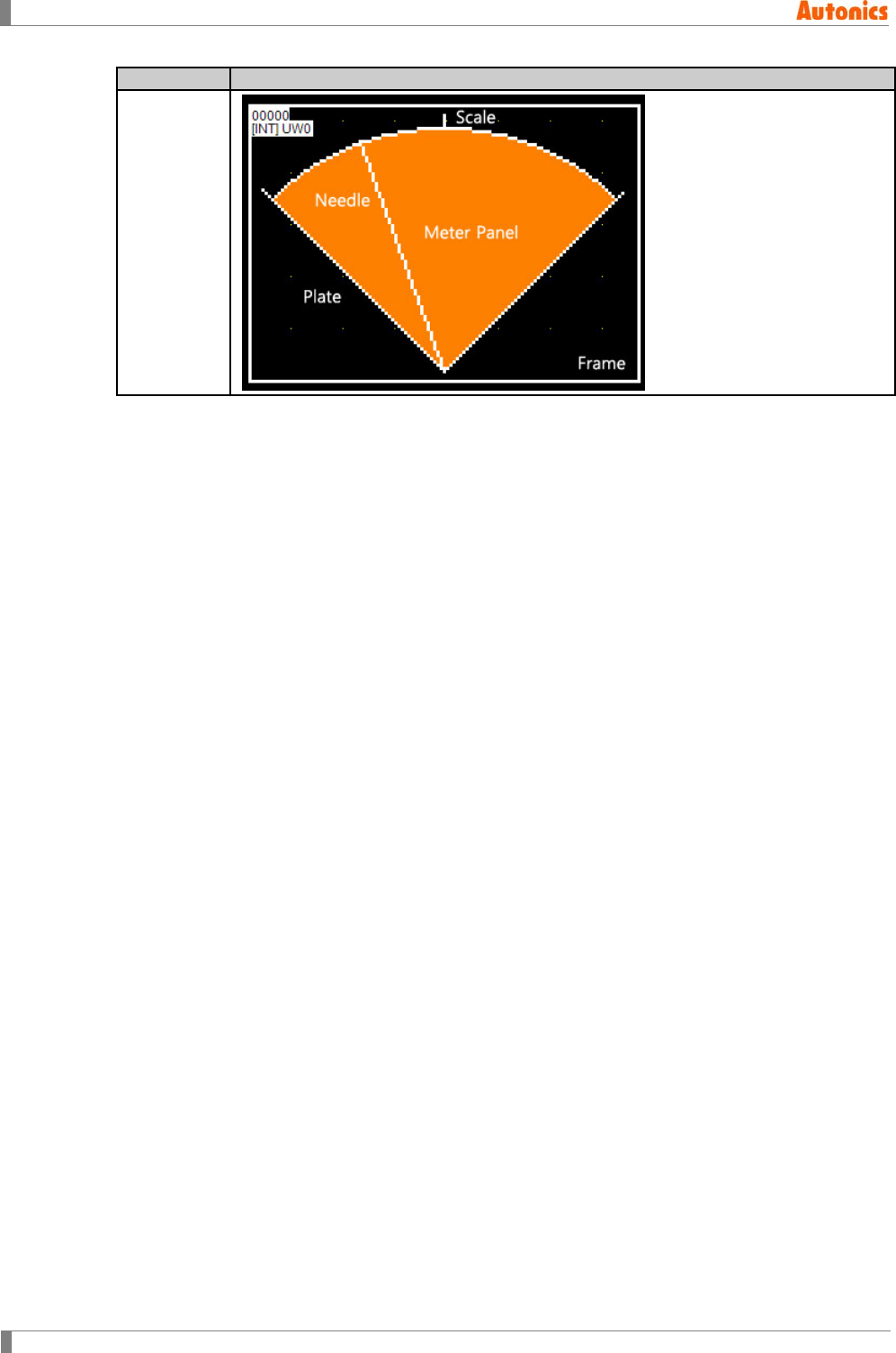
5 Draw
166 © Copyright Reserved Autonics Co., Ltd.
Basic
Description
Component
of panel
meter
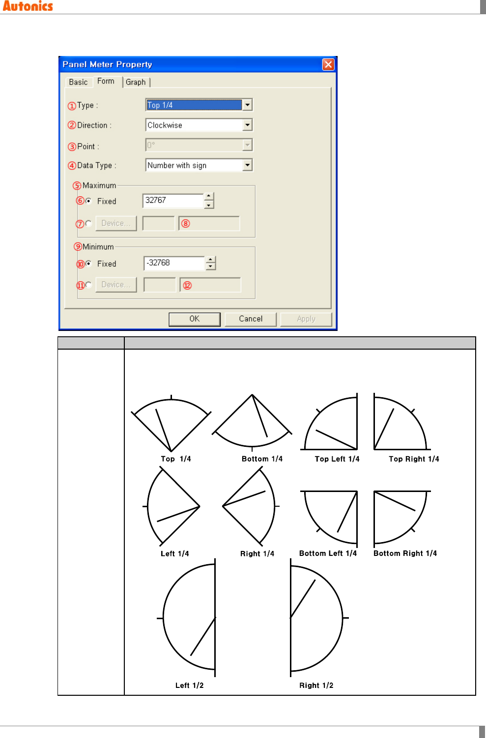
5 Draw
© Copyright Reserved Autonics Co., Ltd. 167
5.17.2.2 Form tab
Form
Description
①Type
Designate panel meter shape by pull-down menu.
Top 1/4, Bottom 1/4, Left 1/4, Right 1/4, Top Right 1/4, Top Left 1/4, Bottom
Left 1/4, Bottom Right 1/4, Top 1/2, Bottom 1/2, Left 1/2, Right 1/2, 3/4, Circle
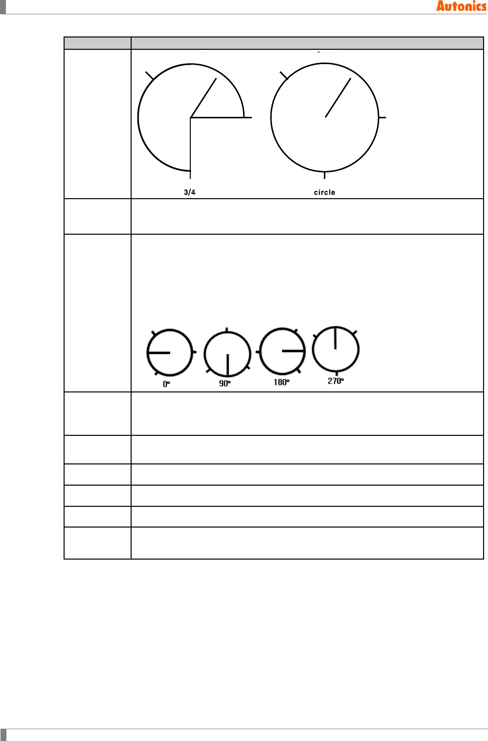
5 Draw
168 © Copyright Reserved Autonics Co., Ltd.
Form
Description
①Type
②Direction Designate moving direction of needle as device value is bigger by pull-down
menu. Select one of clockwise or counter clockwise.
③Point
Activated only with when ①Type is ‘Circle’. Designate the frame position for scale
by pull-down menu.
Range: 0°, 90°, 180°, 270°
The start point of needle designated in a point is +180°. Point=p, Number Of
Scale=N, scale position degree=p, p+360°/N, p+2*360°/N, …, p+(N-1)*360°/N
Shape according to point designation for number of scale is 3
④Data Type
Designate data type of the designated device by pull-down menu.
Number with sign: Processes as number with sign reading device
Number without sign: Processes as number without sign reading device
⑤Maximum
Fixed: Fixed value is maximum value with needle of panel meter.
Not Fixed: Designated word device value is maximum value.
⑥Fixed Designate fixed maximum value.
⑦Device Calls ‘Device Select’ dialog box. Designate maximum device.
⑧Device Input device directly or displays the designated device by ⑦
⑨ to ⑫
Minimum Designate same setting with ⑤ to ⑧ for minimum.
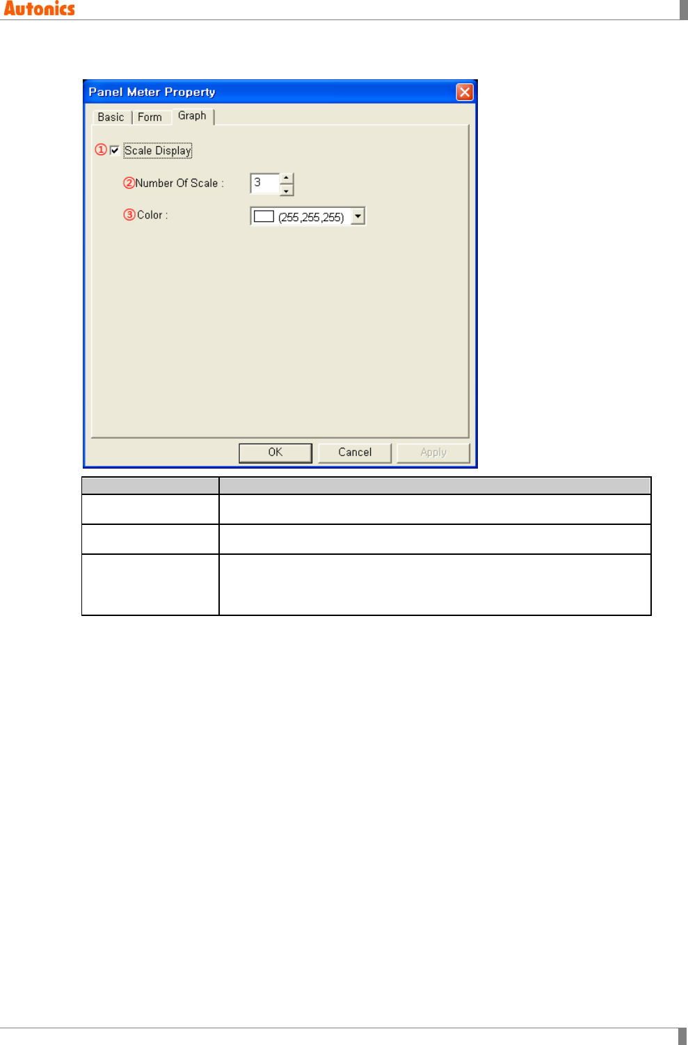
5 Draw
© Copyright Reserved Autonics Co., Ltd. 169
5.17.2.3 Graph tab
Graph
Description
①Scale Display Designate using display scale or not.
②Number of Scale Designate the number of scale.
③Color
Designate scale color.
Mono type(GP-S044, GP-S057, LP-S044): White/Black
Color type(GP-S070, LP-S070): 24bit True Color
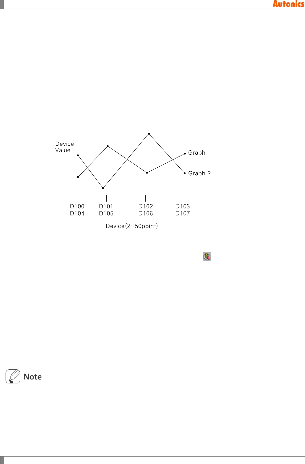
5 Draw
170 © Copyright Reserved Autonics Co., Ltd.
5.18 Line Graph
Line graph displays the designated two or more devices value by broken line.
5.18.1 Basic operation
It displays up to 8 devices with max. 50 points.
It is able to designate maximum/minimum value of graph, the out of range value is not
displayed.
It is able to designate increased direction (right to left or left to right) of line graph on X axis
from lead device.
According to configuration, it may not display specified value.
5.18.2 Basic usage
1st Select [Draw]-[Line/Trend/Bar] of menu, or click in toolbar. ‘Line/Trend/Bar
Property’ dialog box appears.
2nd Select ‘Line’ in graph box of ‘Basic’ tab.
3rd Designate the number of graph and the number of point in ‘Form’ tab.
4th Designate device, data type, and graph style, etc in ‘Monitor Device’ tab.
5th Designate maximum/minimum value of graph in ‘Display Range’ tab.
6th Click ‘OK’ and ‘Line/Trend/Bar Property’ dialog box is closed. A dotted rectangle
follows mouse cursor at edit area.
7th Place mouse cursor on the desired area, click left mouse button. Line graph is
created on the screen.
8th Adjust it to the desired size.
Line graph is the object which can exist only one on a screen and it cannot exist with trend graph
on a screen.

5 Draw
© Copyright Reserved Autonics Co., Ltd. 171
5.18.3 Property
5.18.3.1 Basic tab
Basic
Description
①Graph
Select graph type.
Line: Line graph
Trend: Trend graph
Bar: Bar graph
②Shape Designate using shape or not.
Check this and no. 1 shape is as default.
③Shape Activated only with checking ②.
Click ‘Shape’ and ‘Image Selection’ dialog box appears. Select the desired
shape.
④Shape Displays the selected shape image
⑤Frame
Designates frame color. Activated only with checking ②.
Mono type(GP-S044, GP-S057, LP-S044): White/Black
Color type(GP-S070, LP-S070): 24bit True Color
⑥Plate
Designates plate color. Activated only with checking ②.
Mono type(GP-S044, GP-S057, LP-S044): White/Black
Color type(GP-S070, LP-S070): 24bit True Color
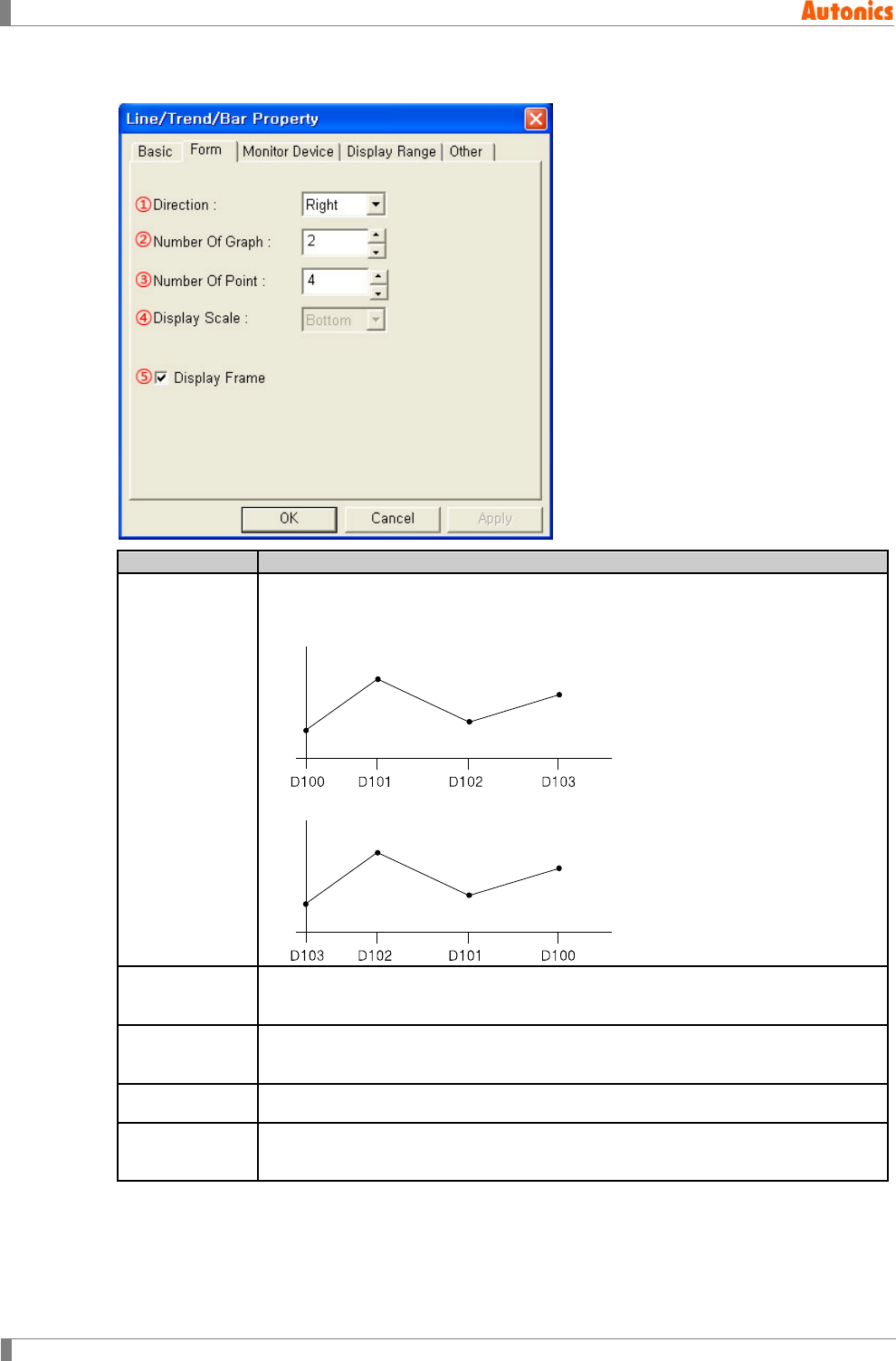
5 Draw
172 © Copyright Reserved Autonics Co., Ltd.
5.18.3.2 Form tab
Form
Description
①Direction
Designate increasing direction (right or left) of device address by pull-down
menu.
Right: Device address increases to right direction on X axis.
Left: Device address increases to left direction on X axis.
②Number Of
Graph Designate the number of line on a line graph. Range is1 to 8.
③Number Of
Point
Designate the number of point on a line up to 50 points. Lead device is
designated in ‘Monitor device’ tab.
④Display Scale Not used
⑤Display
Frame Designate using frame of graph or not.
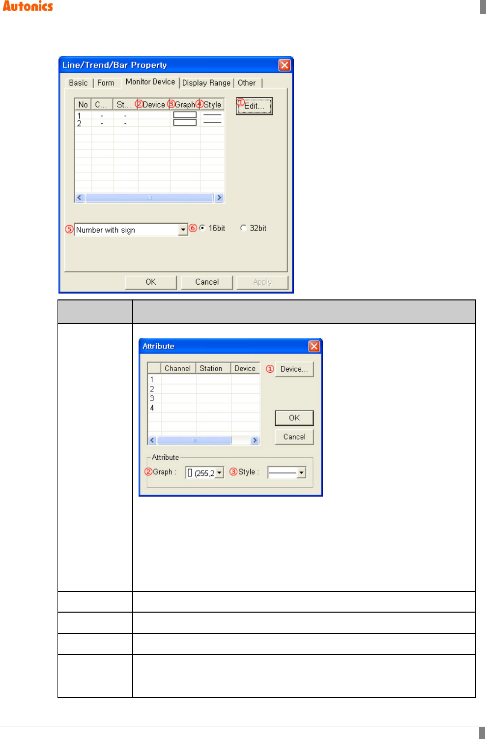
5 Draw
© Copyright Reserved Autonics Co., Ltd. 173
5.18.3.3 Monitor device tab
Monitor
Device
Description
①Edit
Calls ‘Attribute’ dialog box. Designate device, color and style of line.
①Device: Calls ‘Device Select’ dialog box. Designate lead device.
②Graph: Designate line color.
Mono type(GP-S044, GP-S057, LP-S044): White/Black
Color type(GP-S070, LP-S070): 24bit True Color
③Style: Designate one line style of solid, dotted, broken, dot chain, two dot
chain by pull-down menu.
②Device Displays lead device of each line.
③Graph Displays color of each line. Double-click it to edit.
④Style Displays style of each line. Double-click it to edit.
⑤Data Type
Designate data type of monitor device by pull-down menu.
Number with sign: Processes as number with sign reading device
Number without sign: Processes as number without sign reading device
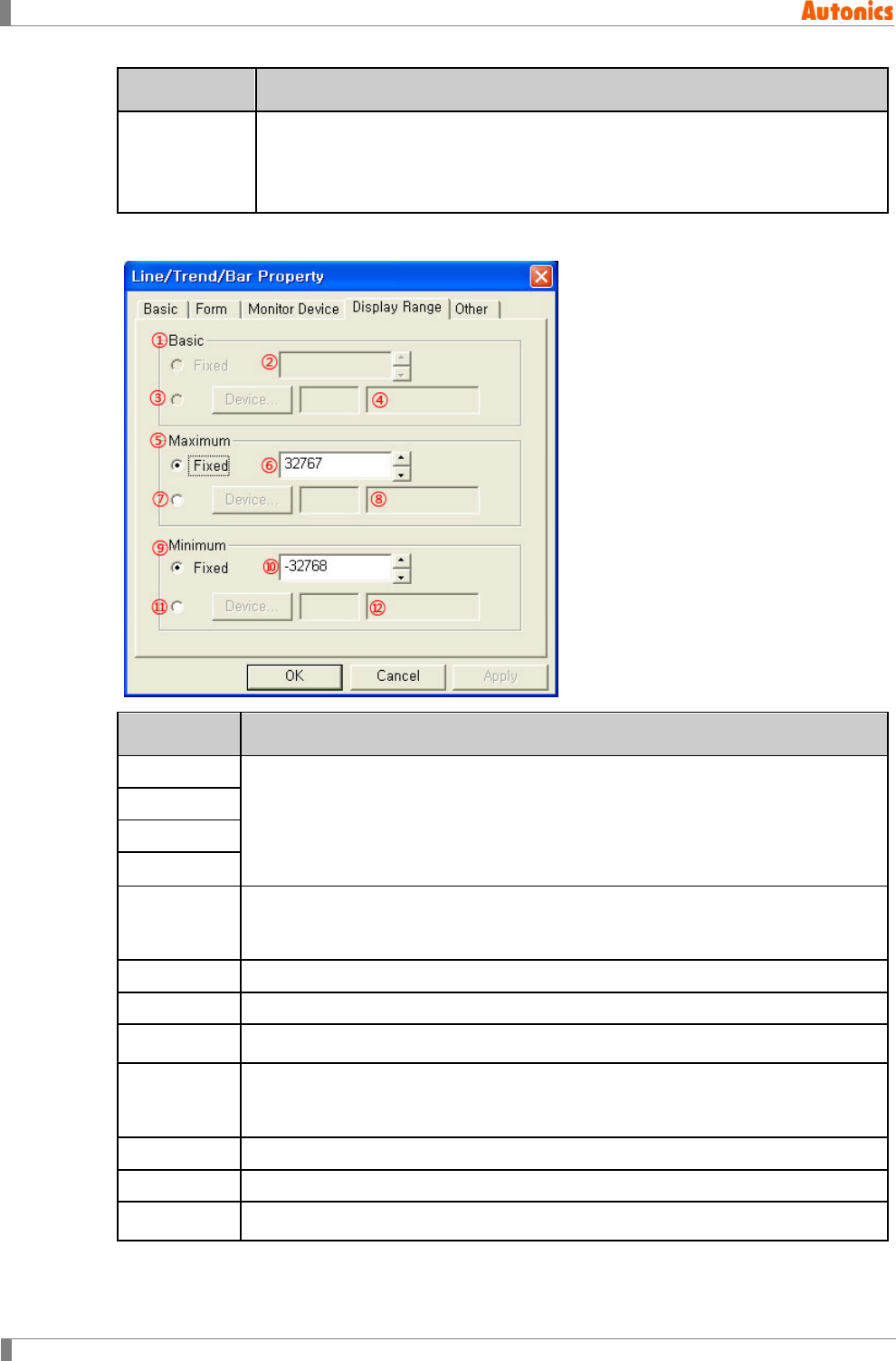
5 Draw
174 © Copyright Reserved Autonics Co., Ltd.
Monitor
Device
Description
⑥Bit
Designate data bit type.
16bit: Single word
32bit: Double word (Address is assigned by double word unit from lead
device)
5.18.3.4 Display range tab
Display
Range
Description
①Basic
Not used
②Fixed
③Device
④Device
⑤Fixed
Fixed: Fixed value is maximum value of graph.
Not Fixed: Designated device value of ⑦ is maximum value. If the value is
changed, maximum value is also changed.
⑥Fixed Designate fixed maximum value.
⑦Device
Calls ‘Device Select’ dialog box. Designate maximum device.
⑧Device Input device directly or displays the designated device by ⑦
⑨Minimum
Fixed: Fixed value is minimum value of graph.
Not Fixed: Designated device value of ⑪ is minimum value. If the value is
changed, minimum value is also changed.
⑩Fixed
Designate fixed minimum value.
⑪Device
Calls ‘Device Select’ dialog box. Designate minimum device.
⑫Device Input device directly or displays the designated device by ⑪.
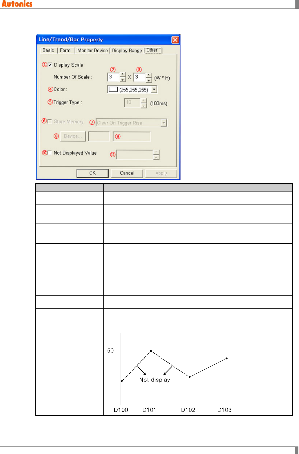
5 Draw
© Copyright Reserved Autonics Co., Ltd. 175
5.18.3.5 Other tab
Other
Description
①Display Scale Designate using display scale or not.
②Number Of Scale
(Width) Designate the number of scale on X axis.
③Number Of Scale
(Height) Designate the number of scale on Y axis.
④Color
Designate scale color.
Mono type(GP-S044, GP-S057, LP-S044): White/Black
Color type(GP-S070, LP-S070): 24bit True Color
⑤ to ⑨ Not used
⑩Not Displayed Value Check not to display the specified value.
⑪Not Displayed Value Designate the specified value not to display.
Not Displayed Value
function
[If not displayed value is 50.]
D101 is 50. The lines between D100 and D101, D101 and D102 are not
displayed.
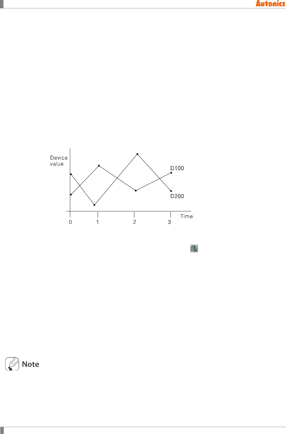
5 Draw
176 © Copyright Reserved Autonics Co., Ltd.
5.19 Trend Graph
Trend graph displays the designated devices according to time by broken line.
5.19.1 Basic operation
X axis is time, Y axis is device value.
It is able to designate maximum/minimum value of graph, the out of range value is not
displayed.
It displays up to 8 devices with max. 50 points.
It is able to designated sampling period by 100ms unit from 100ms to 3600s.
It is able to designate time increased direction.
Even if the other screen is switched by configuration, it continues to sampling and saves
sample data to GP/LP inner memory. When returning to the designated screen, trend graph
displays trends with history using that data.
5.19.2 Basic usage
1st Select [Draw]-[Line/Trend/Bar] of menu, or click in toolbar. ‘Line/Trend/Bar
Property’ dialog box appears.
2nd Select ‘Trend’ in graph box of ‘Basic’ tab.
3rd Designate the number of graph and the number of point in ‘Form’ tab.
4th Designate device, data type, and graph stype, etc in ‘Monitor Device’ tab.
5th Designate maximum/minimum value of graph in ‘Display Range’ tab.
6th Click ‘OK’ and ‘Line/Trend/Bar Property’ dialog box is closed. A dotted rectangle
follows mouse cursor at edit area.
7th Place mouse cursor on the desired area, click left mouse button. Trend graph is
created on the screen.
8th Adjust it to the desired size.
Trend graph is the object which can exist only one on a screen and it cannot exist with line graph
on a screen.
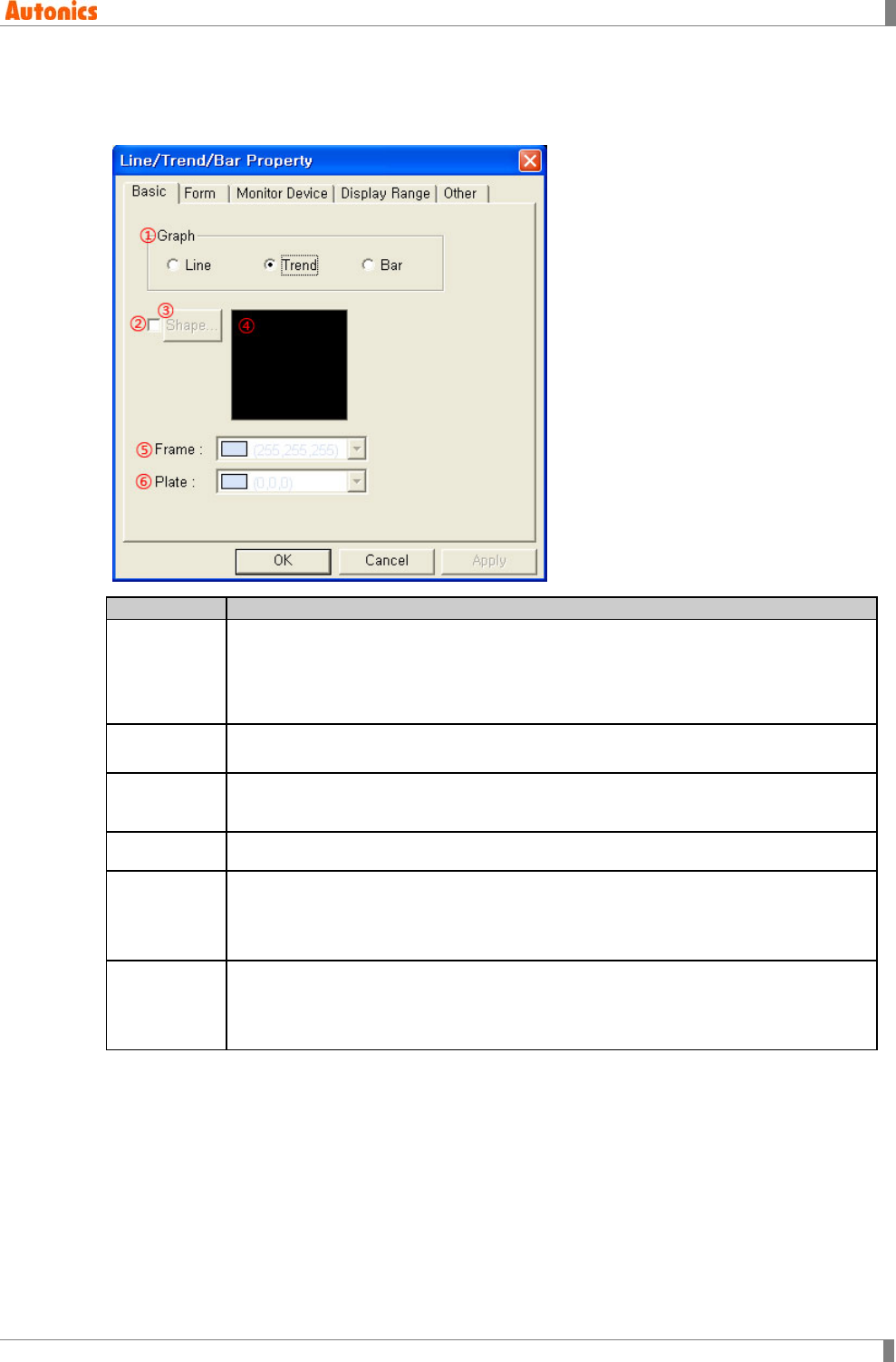
5 Draw
© Copyright Reserved Autonics Co., Ltd. 177
5.19.3 Property
5.19.3.1 Basic tab
Basic
Description
①Graph
Select graph type.
Line: Line graph
Trend: Trend graph
Bar: Bar graph
②Shape Designate using shape or not.
Check this and no. 1 shape is as default.
③Shape Activated only with checking ②.
Click ‘Shape’ and ‘Image Selection’ dialog box appears. Select the desired shape.
④Shape Displays the selected shape image.
⑤Frame
Designates frame color. Activated only with checking ②.
Mono type(GP-S044, GP-S057, LP-S044): White/Black
Color type(GP-S070, LP-S070): 24bit True Color
⑥Plate
Designates plate color. Activated only with checking ②.
Mono type(GP-S044, GP-S057, LP-S044): White/Black
Color type(GP-S070, LP-S070): 24bit True Color
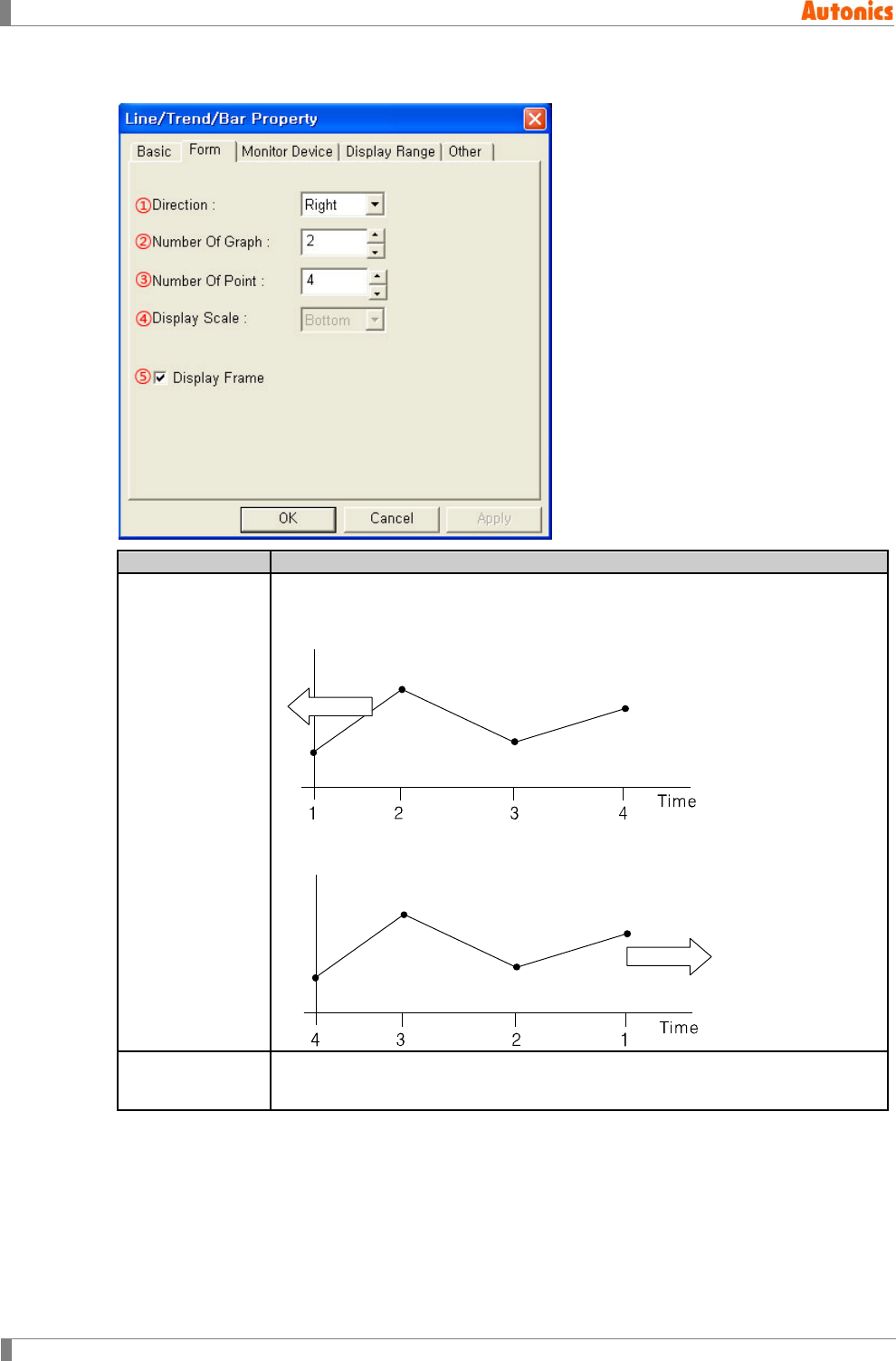
5 Draw
178 © Copyright Reserved Autonics Co., Ltd.
5.19.3.2 Form tab
Form
Description
①Direction
Designate time increasing direction (right or left) on X axis by pull-down menu.
Right: Time increases to right direction on X axis. Graph follows left
direction. The most right point is the latest sample.
Left: Time increases to left direction on X axis. Graph follows right
direction. The most left point is the latest sample.
②Number Of
Graph Designate the number of line on a trend graph. Range is 1 to 8.
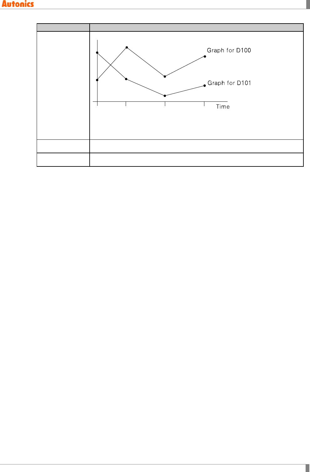
5 Draw
© Copyright Reserved Autonics Co., Ltd. 179
Form
Description
③Number Of
Point
Designate the number of point of sample on a line up to 50 points.
The above example is for trend graph when number of graph=2, number of
point =4, lead device is D100. There are two lines and 4 samples because
number of graph is 2 and number of point is 4. Lead device is designated in
‘Monitor device’ tab.
④Display Scale Not used
⑤Display Frame Designate using frame of graph or not.
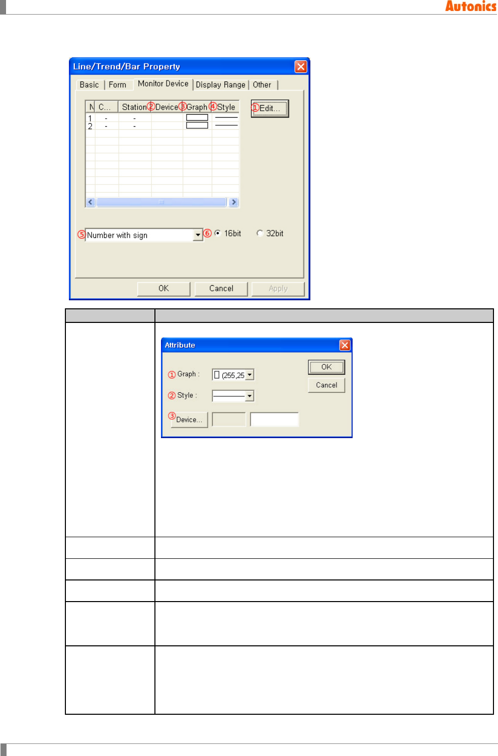
5 Draw
180 © Copyright Reserved Autonics Co., Ltd.
5.19.3.3 Monitor device tab
Monitor Device
Description
①Edit
Calls ‘Attribute’ dialog box. Designate device, color and style of line.
①Graph: Designate line color.
Mono type(GP-S044, GP-S057, LP-S044): White/Black
Color type(GP-S070, LP-S070): 24bit True Color
②Style: Designate one line style of solid, dotted, broken, dot chain, two dot
chain by pull-down menu.
③Device: Calls ‘Device Select’ dialog box. Designate lead device.
②Device Displays lead device of each line.
③Graph Displays color of each line. Double-click it to edit.
④Style Displays style of each line. Double-click it to edit.
⑤Data Type
Designate data type of monitor device by pull-down menu.
Number with sign: Processes as number with sign reading device
Number without sign: Processes as number without sign reading device
⑥Bit
Designate data bit type.
16bit: Single word
32bit: Double word
Depending on connected device type, it may use only 32bit. Refer to ‘GP,LP
user manual for communication’.
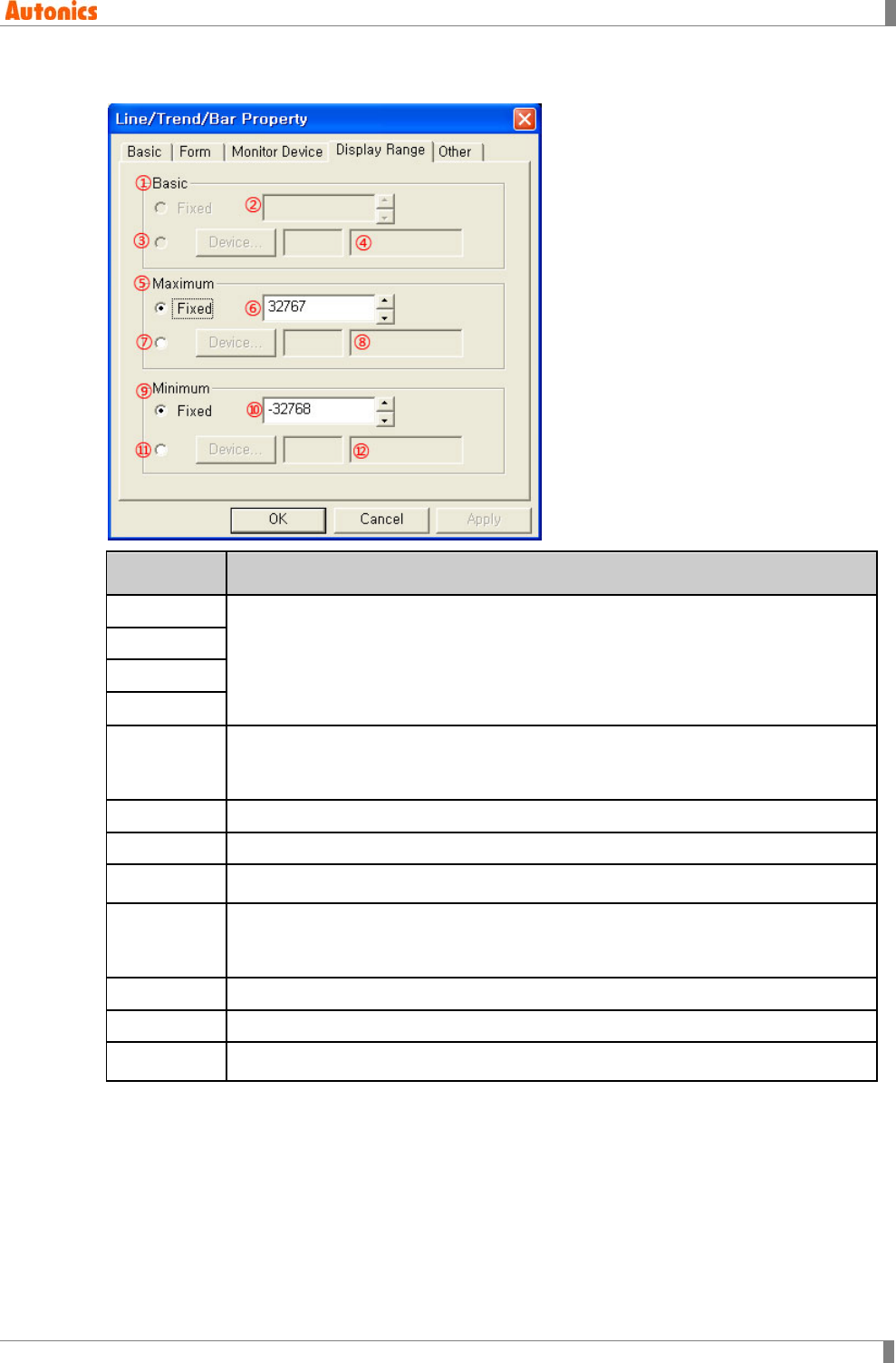
5 Draw
© Copyright Reserved Autonics Co., Ltd. 181
5.19.3.4 Display range tab
Display
Range
Description
①Basic
Not used
②Fixed
③Device
④Device
⑤Maximum
Fixed: Fixed value is maximum value of graph.
Not Fixed: Designated device value of ⑦ is maximum value. If the value is
changed, maximum value is also changed.
⑥Fixed Designate fixed maximum value.
⑦Device Calls ‘Device Select’ dialog box. Designate maximum device.
⑧Device Input device directly or displays the designated device by ⑦
⑨Minimum
Fixed: Fixed value is minimum value of graph.
Not Fixed: Designated device value of ⑪ is minimum value. If the value is
changed, minimum value is also changed.
⑩Fixed Designate fixed minimum value.
⑪Device Calls ‘Device Select’ dialog box. Designate minimum device.
⑫Device Input device directly or displays the designated device by ⑪.
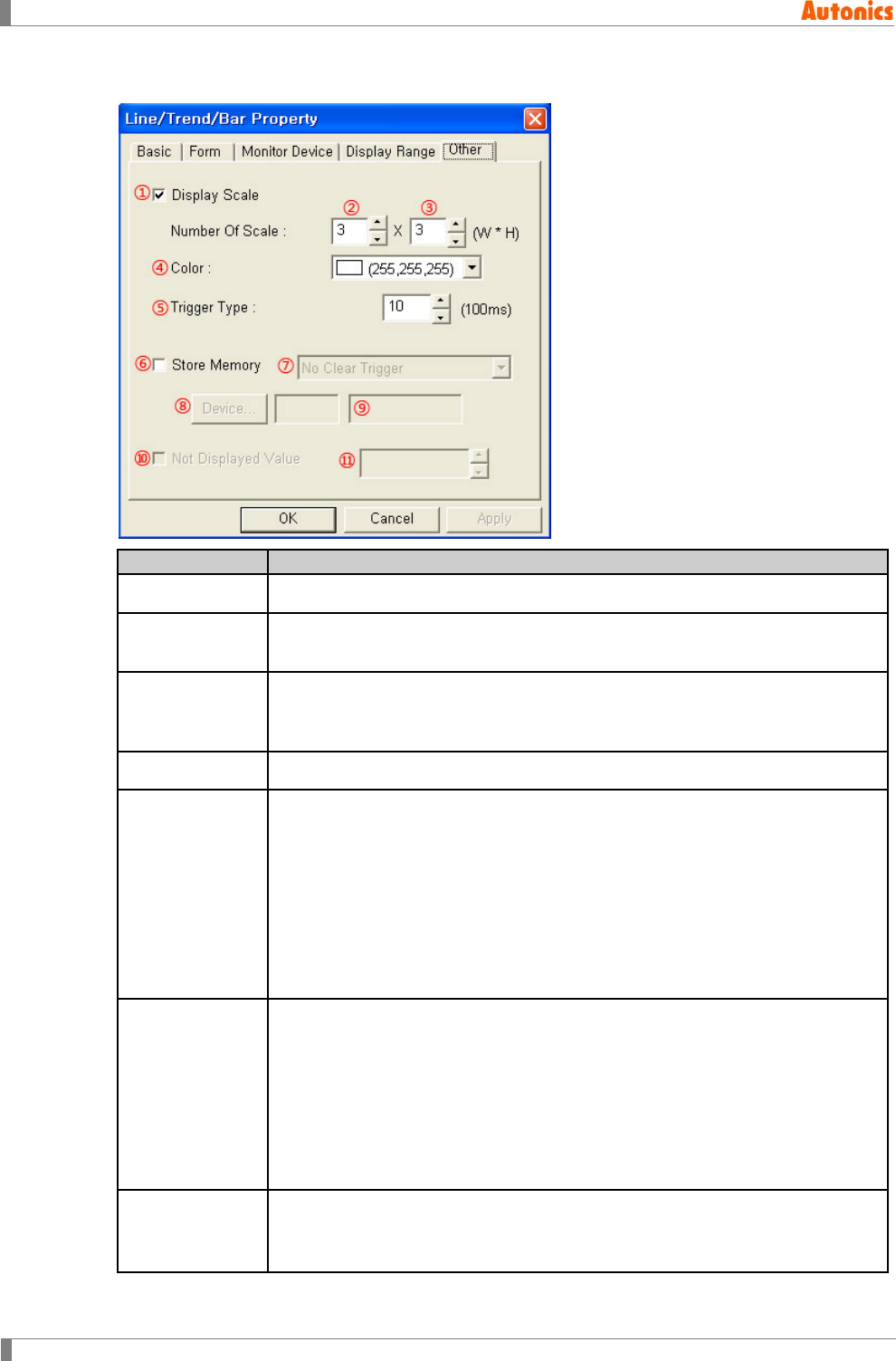
5 Draw
182 © Copyright Reserved Autonics Co., Ltd.
5.19.3.5 Other tab
Other
Description
①Display Scale Designate using display scale on X axis and Y axis or not.
②, ③Number Of
Scale Designate the number of scale on X axis and Y axis.
④Color
Designate scale color.
Mono type(GP-S044, GP-S057, LP-S044): White/Black
Color type(GP-S070, LP-S070): 24bit True Color
⑤Trigger Type Designate sampling period by 100ms unit from 100ms to 3600s.
⑥Store Memory
Non-checking this, when the screen returns from another screen, it does
not save history and draws from the first again.
Checking this, it does sampling continuously with saving history at GP/LP
inner memory when the screen switches to another screen.
Returning to the screen which has trend graph, it displays graph with the
saved data. Even though editing another screen, it seems drawing graph
continuously.
Store memory option is also for ‘alarm list’. You can designate this option
only up to 17.
⑦Store Memory
For store memory function, initializes GP/LP memory.
No Clear Trigger: Not initialize GP/LP inner memory for the specified trend
graph
Clear On Trigger Rise: Makes ⑧Device to activate.
Designate bit device to initialize GP/LP inner memory for the specified trend
graph at rising edge of the device
Clear On Trigger Fall: Initializes GP/LP inner memory for the specified
trend graph at falling edge of the trigger device
⑧Device Activated only with checking ⑥Store Memory and when ⑦Store Memory is
‘Clear On Trigger Rise’ or ‘Clear On Trigger Fall’.
Calls ‘Device Select’ dialog box, and designate trigger device.

5 Draw
© Copyright Reserved Autonics Co., Ltd. 183
Other
Description
⑨Device Input device directly or displays the designated trigger device.
⑩, ⑪ Not
Displayed Value Not used
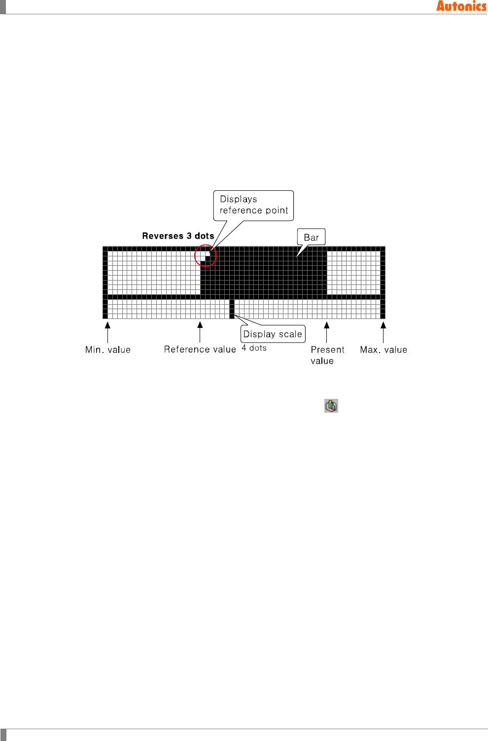
5 Draw
184 © Copyright Reserved Autonics Co., Ltd.
5.20 Bar Graph
Bar graph displays the designated device value by bar.
5.20.1 Basic operation
It displays the value from reference value to current device value with designated
maximum/minimum/reference value by bar.
Minimum size is 16x16 dots.
It displays reference point to be reversed at 3 dots from the opposite of start scale.
It displays a oblique line when device value is out of the maximum/minimum range.
5.20.2 Basic usage
1st Select [Draw]-[Line/Trend/Bar] of menu, or click in toolbar. ‘Line/Trend/Bar
Property’ dialog box appears.
2nd Select ‘Bar’ in graph box of ‘Basic’ tab.
3rd Designate graph direction in ‘Form’ tab.
4th Designate monitor device and data type in ‘Monitor Device’ tab.
5th Designate basic, maximum/minimum value of graph in ‘Display Range’ tab.
6th Click ‘OK’ and ‘Line/Trend/Bar Property’ dialog box is closed. A dotted rectangle
follows mouse cursor at edit area.
7th Place mouse cursor on the desired area, click left mouse button. Bar graph is created
on the screen.
8th Adjust it to the desired size.
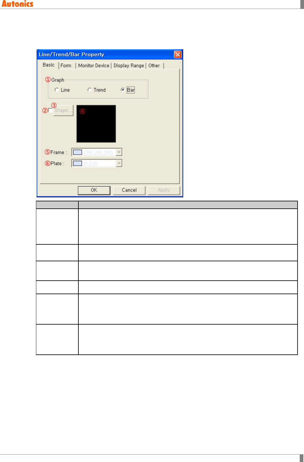
5 Draw
© Copyright Reserved Autonics Co., Ltd. 185
5.20.3 Property
5.20.3.1 Basic tab
Basic
Description
①Graph
Select graph type.
Line: Line graph
Trend: Trend graph
Bar: Bar graph
②Shape Designate using shape or not.
Check this and no. 1 shape is as default.
③Shape Activated only with checking ②.
Click ‘Shape’ and ‘Image Selection’ dialog box appears. Select the desired shape.
④Shape Displays the selected shape image
⑤Frame
Designates frame color. Activated only with checking ②.
Mono type(GP-S044, GP-S057, LP-S044): White/Black
Color type(GP-S070, LP-S070): 24bit True Color
⑥Plate
Designates plate color. Activated only with checking ②.
Mono type(GP-S044, GP-S057, LP-S044): White/Black
Color type(GP-S070, LP-S070): 24bit True Color
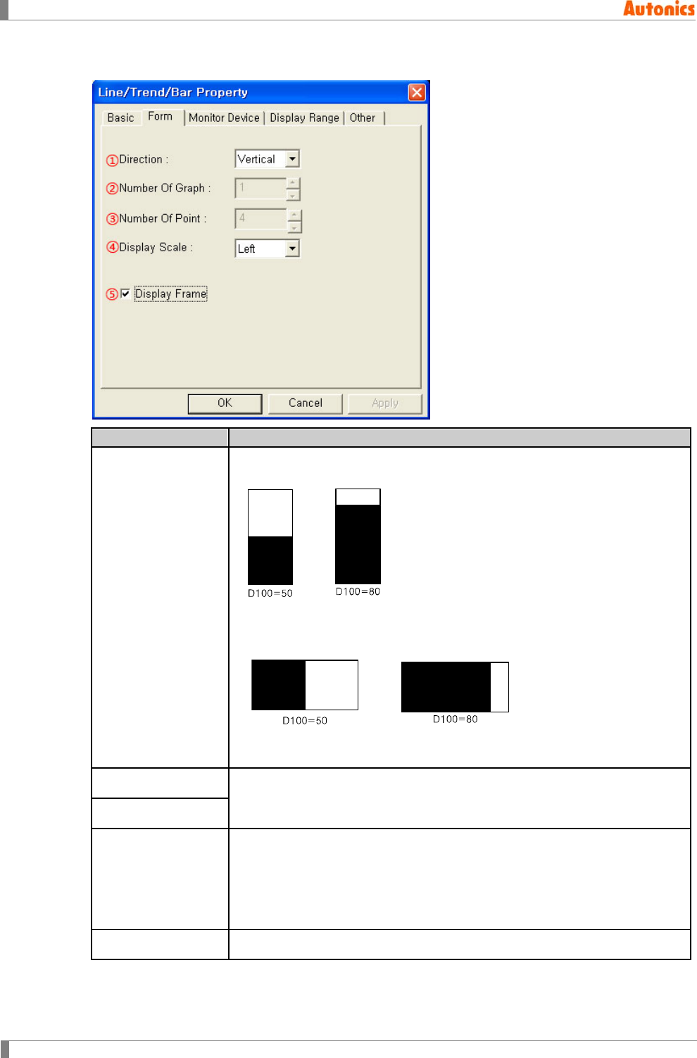
5 Draw
186 © Copyright Reserved Autonics Co., Ltd.
5.20.3.2 Form tab
Form
Description
①Direction
Designate bar graph direction (vertical or horizontal) by pull-down menu.
Vertical: Bar increases to vertical direction.
The above shape examples are, when monitor device is D100 and
direction is vertical, that D100 is 50, D100 is 80.
Horizontal: Bar increases to horizontal direction.
The above shape examples are, when monitor device is D100 and
direction is horizontal, that D100 is 50, D100 is 80.
②Number Of Graph Not used
③Number Of Point
④Display Scale
Designate scale direction by pull-down menu.
Select right or left direction when ①Direction is vertical.
Displays scale at right/left frame.
Select top or bottom direction when ①Direction is horizontal.
Displays scale at top/left frame.
⑤Display Frame Designate using frame of graph or not.
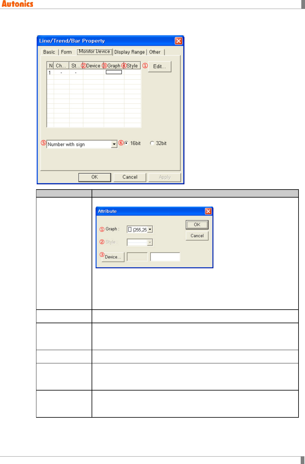
5 Draw
© Copyright Reserved Autonics Co., Ltd. 187
5.20.3.3 Monitor device tab
Monitor Device
Description
①Edit
Calls ‘Attribute’ dialog box. Designate device, color of bar.
①Graph: Designate bar color.
Mono type(GP-S044, GP-S057, LP-S044): White/Black
Color type(GP-S070, LP-S070): 24bit True Color
②Device: Calls ‘Device Select’ dialog box. Designate monitor device.
②Device Displays device of each bar.
③Graph
Displays color of each bar.
Mono type(GP-S044, GP-S057, LP-S044): White/Black
Color type(GP-S070, LP-S070): 24bit True Color
④Style Not used
⑤Data Type
Designate data type of monitor device by pull-down menu.
Number with sign: Processes as number with sign reading device
Number without sign: Processes as number without sign reading device
⑥Bit
Designate data bit type.
16bit: Single word
32bit: Double word
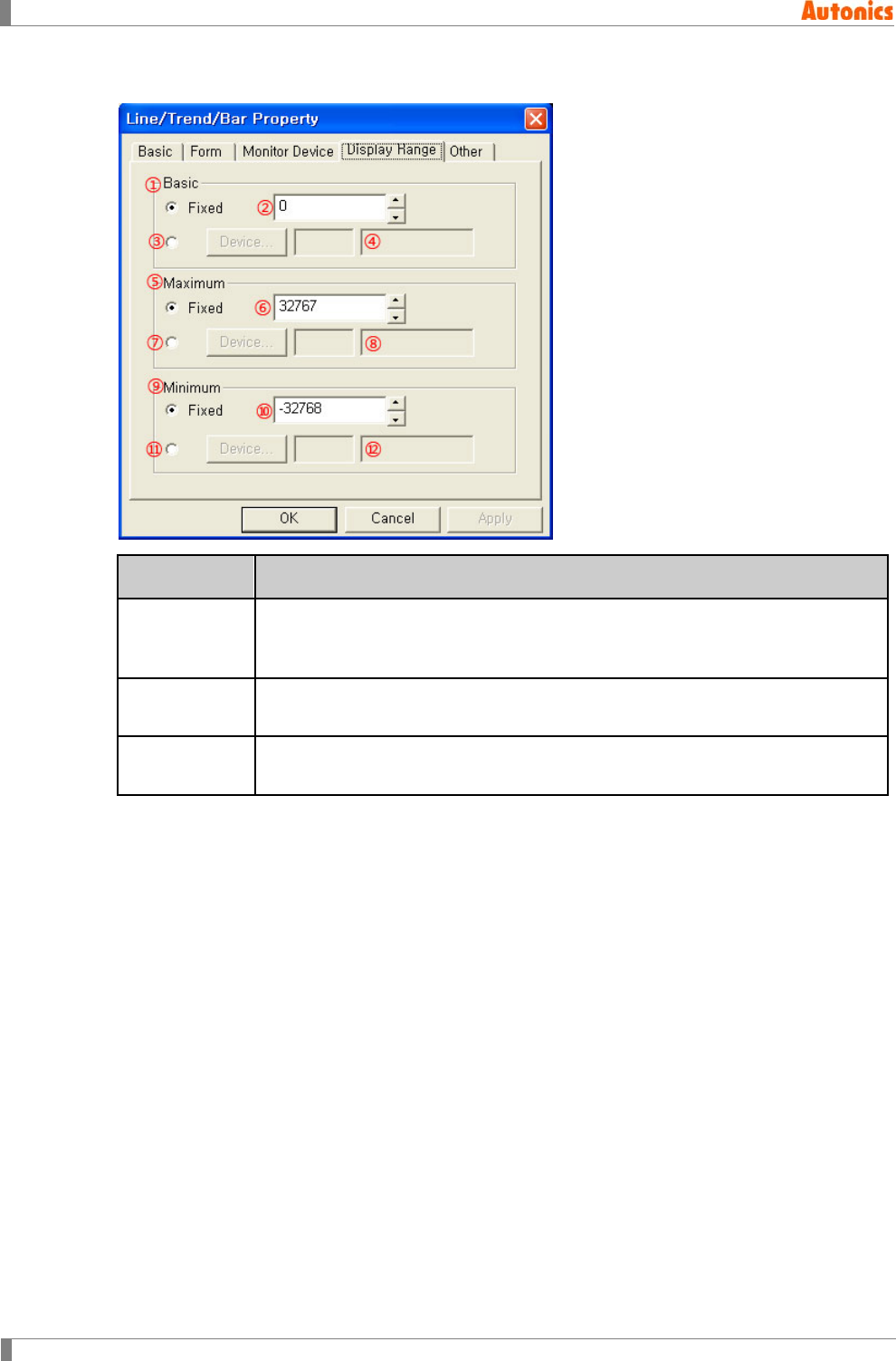
5 Draw
188 © Copyright Reserved Autonics Co., Ltd.
5.20.3.4 Display range tab
Display
Range
Description
① to ④ Basic
Designate reference value.
Fixed: Fixed value is reference value of bar graph.
Not Fixed: Designated device value of ③ is reference value.
⑤ to ⑧
Maximum Designate maximum value.
⑨ to ⑫
Minimum Designate minimum value.
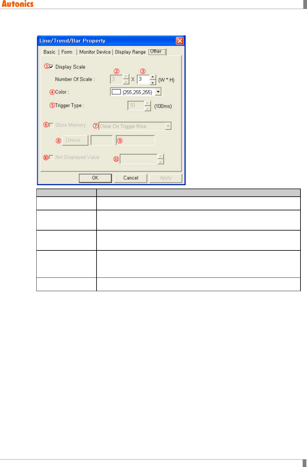
5 Draw
© Copyright Reserved Autonics Co., Ltd. 189
5.20.3.5 Other tab
Other
Description
①Display Scale Designate using display scale or not.
②Number Of Scale
(Width) Activated only with when direction is ‘Horizontal’ in ‘Form’ tab.
Designate the number of scale on bar graph.
③Number Of Scale
(Height) Activated only with when direction is ‘Vertical’ in ‘Form’ tab.
Designate the number of scale on bar graph.
④Color
Designate scale color.
Mono type(GP-S044, GP-S057, LP-S044): White/Black
Color type(GP-S070, LP-S070): 24bit True Color
⑤ to ⑫ Not used
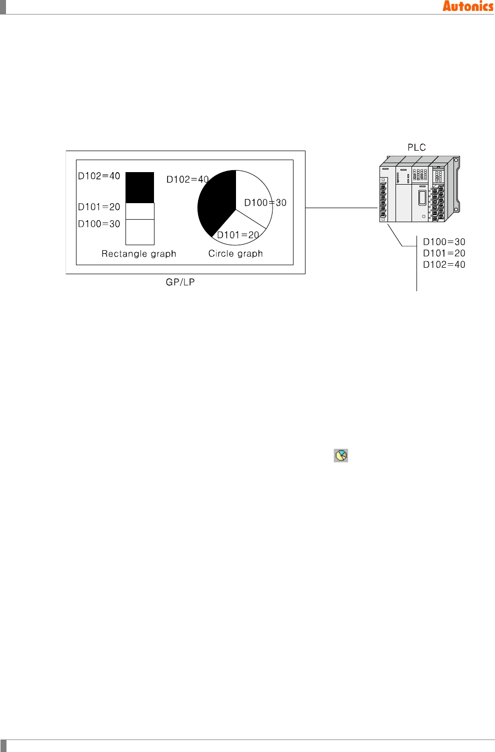
5 Draw
190 © Copyright Reserved Autonics Co., Ltd.
5.21 Statistics Graph
Statistics graph displays more than 2 of value with that ratio.
It is able to display with rectangle or circle graph according to configuration. The statistics graph
is sum total from absoulte value of the designated word device. Each graph area of the devices
is same ratio of absoulte value of the each device. It displays from 2 to 8 devices.
5.21.1 Basic operation
The above figure is rectangle and circle type of statistics graph according to device value when
monitor device is D100, D101, and D102. If D100 is 30, D101 is 20, D102 is 40, the each area of
devices is displayed with the ratio of 30:20:40.
It is able to designate reference direction as top or right for rectangle type of statistics graph. In
case of top direction, the area of from lead device is displayed with from bottom to top direction.
In case of right direction, the area of from lead device is displayed with from left to right direction.
For circle type of statistics graph, the areas of each device have equal radius. Based on the 12
o’clock position, the circle graph displays the sum total of all devices with each ratio to clockwise
direction.
5.21.2 Basic usage
1st Select [Draw]-[Statistics Graph] of menu, or click in toolbar. ‘Statistics Property’
dialog box appears.
2nd Select graph type (rectangle or circle) and designate the number of partition in ‘Basic’
tab.
3rd Designate monitor device and color of each partition, data type in ‘Division’ tab.
4th Click ‘OK’ and ‘Statistics Property’ dialog box is closed. A dotted rectangle follows
mouse cursor at edit area.
5th Place mouse cursor on the desired area, click left mouse button. Statistics graph is
created on the screen.
6th Adjust it to the desired size.
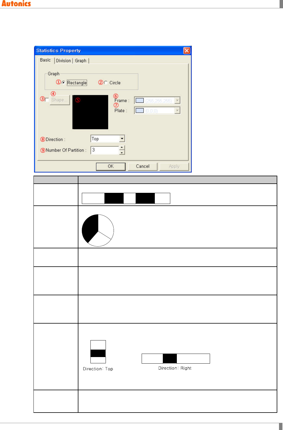
5 Draw
© Copyright Reserved Autonics Co., Ltd. 191
5.21.3 Property
5.21.3.1 Basic tab
Basic
Description
①Rectangle Designate rectangle type graph.
②Circle
Designate circle type graph.
③ to ⑤
Shape Designate shape.
⑥Frame
Designates frame color. Activated only with checking ③.
Mono type(GP-S044, GP-S057, LP-S044): White/Black
Color type(GP-S070, LP-S070): 24bit True Color
⑦Plate
Designates plate color. Activated only with checking ③.
Mono type(GP-S044, GP-S057, LP-S044): White/Black
Color type(GP-S070, LP-S070): 24bit True Color
⑧Direction
Activated only with checking ①Rectangle.
Designate direction as top or right for rectangle graph by pull-down menu.
Top: Places low address device on bottom partition.
Right: Places low address device on left partition.
⑨Number of
Partition
Designate number of partition for graph.
One partition is for one device, it is same as designation of device point to be
used on statistics graph.
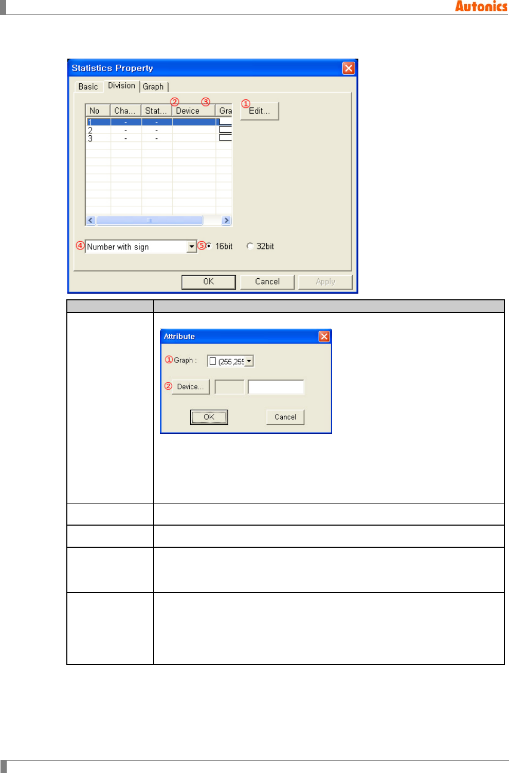
5 Draw
192 © Copyright Reserved Autonics Co., Ltd.
5.21.3.2 Division tab
Division
Description
①Edit
‘Calls ‘Attribute’ dialog box. Designate device, color of partition.
①Graph: Designate partition color.
Mono type(GP-S044, GP-S057, LP-S044): White/Black
Color type(GP-S070, LP-S070): 24bit True Color
②Device: Calls ‘Device Select’ dialog box. Designate monitor device.
②Device Displays device of each partition.
③Graph Displays color of each partition.
④Data Type
Designate data type of monitor device by pull-down menu.
Number with sign: Processes as number with sign reading device
Number without sign: Processes as number without sign reading device
⑤Bit
Designate data bit type.
16bit: Single word
32bit: Double word
If ④Data Type is ‘Number with sign’, it calculates ratio changing the
reference value to absolute value.
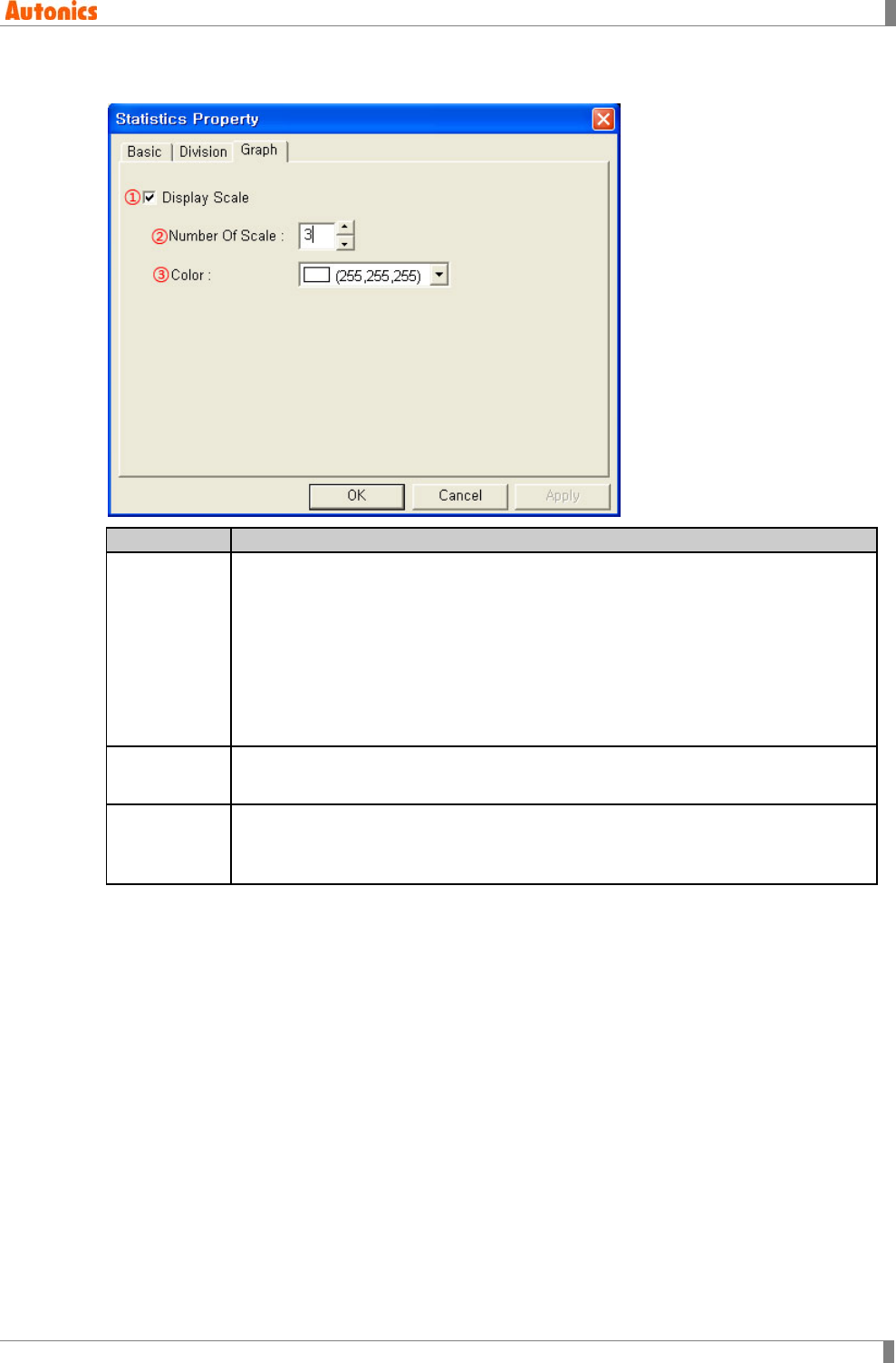
5 Draw
© Copyright Reserved Autonics Co., Ltd. 193
5.21.3.3 Graph tab
Graph
Description
①Display
Scale
Designate using display scale or not. Scale direction is different with the
designation of graph type (rectangle or circle) in ‘Basic’ tab.
In case of rectangle type,
When ‘Direction’ is ‘Right’ in ‘Basic’ tab, scale is displayed on bottom. When
‘Direction’ is ‘Top’ in ‘Basic tab, scale is displayed on left.
In case of circle type,
Based on the 12 o’clock position, scale is displayed with regular intervals for
the designated number of scale on circle circumference.
②Number Of
Scale Designate the number of scale from 2 to 50.
③Color
Designate scale and outline color.
Mono type(GP-S044, GP-S057, LP-S044): White/Black
Color type(GP-S070, LP-S070): 24bit True Color
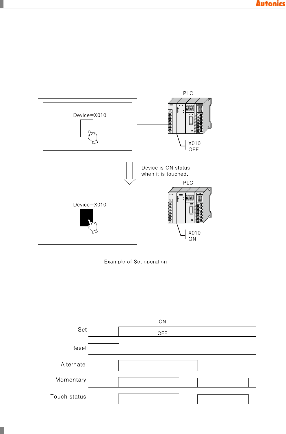
5 Draw
194 © Copyright Reserved Autonics Co., Ltd.
5.22 Touch Key
Touch key executes the defined operation such as bit/word device designatation, screen
switching, specified function with key code when touching screen area of tag arranged.
5.22.1 Basic operation
5.22.1.1 Setting of bit device
Controlls ON/OFF state of PLC bit device with touch.
[Action mode]
Set: Turns ON the designated device when touching.
Reset: Turns OFF the designated device when touching.
Alternate: Alternates the current state of designated device when touching.
Momentary: Maintains momentary ON the designated device only when touching.
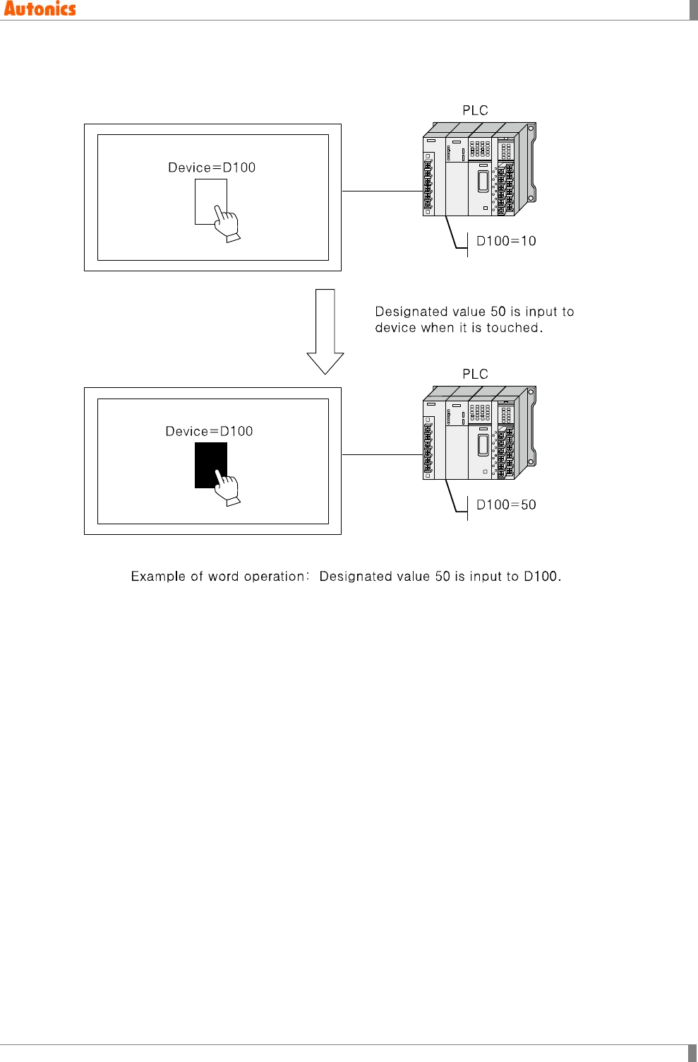
5 Draw
© Copyright Reserved Autonics Co., Ltd. 195
5.22.1.2 Setting of word device
Saves value to word device with touching tag.
It is able to designate 16bit or 32bit word device.
It is able to designate indirectly to be changed device value to the designated word device
by fixed value or adding up fixed value and user-defined device value.
It is able to reset device value.
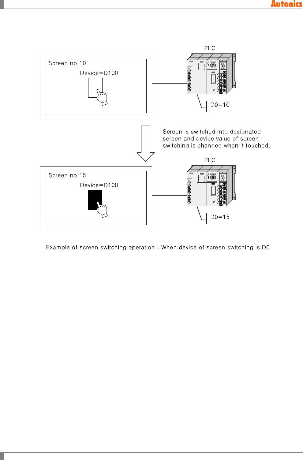
5 Draw
196 © Copyright Reserved Autonics Co., Ltd.
5.22.1.3 Switching screen
Switches screen with touching tag.
There are four action mode for switching screen.
① +1: Moves from current screen to one more number screen
② -1: Moves from current screen number to one less number screen
③ Previous Screen: Moves to previous screen before switching
④ Fixed: Moves to the designated screen
It changes saving device value of base number displaying on GP/LP with touch operation.
Simaultaneously, it is switched as base screen of configuration number with screen designated.
Only one operation is executed for one touch key.
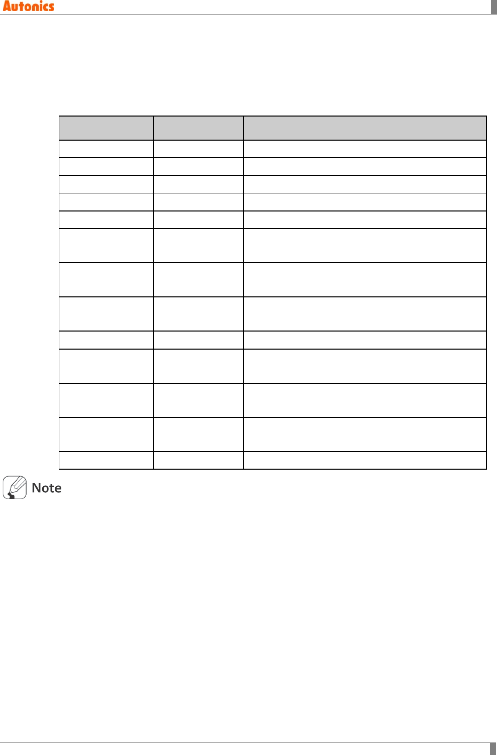
5 Draw
© Copyright Reserved Autonics Co., Ltd. 197
5.22.1.4 Specified function with key code
There are two specified touch functions with key code; ASCII key code, function key code. ASCII
key code is for user-defined key window to input numeral/ASCII at Numeral Input/ASCII Input.
Function key code is for adjust alarm list, alarm history, security function.
For further details are as below.
Key code
(Hexadecimal)
Function Description
FFA1
Clear(CLR)
Clears up to current input in key window
FFA2
Enter (ENT)
Completes to input in key window
FFA3
Backspace(BS)
Deletes the last input character in key window
FFA4
Show cursor
Shows cursor in alarm list/alarm history
FFA5
Hide cursor
Hides cursor in alarm list/alarm history
FFA6 Detailed alarm
information Calls detail screen in alarm list/alarm history
FFA7 Call window for
password input Calls key window for password input
FFA8 Erase selected
alarm Deletes selected alarm in alarm history
FFA9
Erase all alarm
Deletes all restored alarms in alarm history
FFAA Reset alarm
device Resets selected alarm device in alarm history
FFAB Move cursor
upward Moves cursor to upward in alarm list/alarm history
FFAC Move cursor
downward Moves cursor to downward in alarm list/alarm history
FFAD
Lock security
Resets security
Bit/Word action, screen switching functions are designated duplicately at one touch key. Base
switching function is designated at only one touch key.
Processing priority of one touch key action is word setting, bit momentory, bit set, bit reset, bit
alternate, screen switching. If two or more same actions are designated, first designated action
is processed.

5 Draw
198 © Copyright Reserved Autonics Co., Ltd.
5.22.2 Basic usage
1st Select [Draw]-[Touch Key] of menu, or click in toolbar. ’Touchkey Property’ dialog
box appears.
2nd Designate display trigger and touch key shape in ‘Basic’ tab.
3rd Designate shape and text in ‘Form’ tab.
4th Designate bit action, word action, and switching screen, etc. in ‘Action’ tab.
5th Click ‘OK’ and ‘Touchkey Property’ dialog box is closed. A dotted rectangle follows
mouse cursor at edit area.
6th Place mouse cursor on the deisred area, click left mouse button. Touch key is created
on the screen.
Touch recognition range is 16X20 dot size. Mesh of GP Editor is same as one touch switch.
Draw touch key for mesh, it prohibits from activating another adjacent touch key.
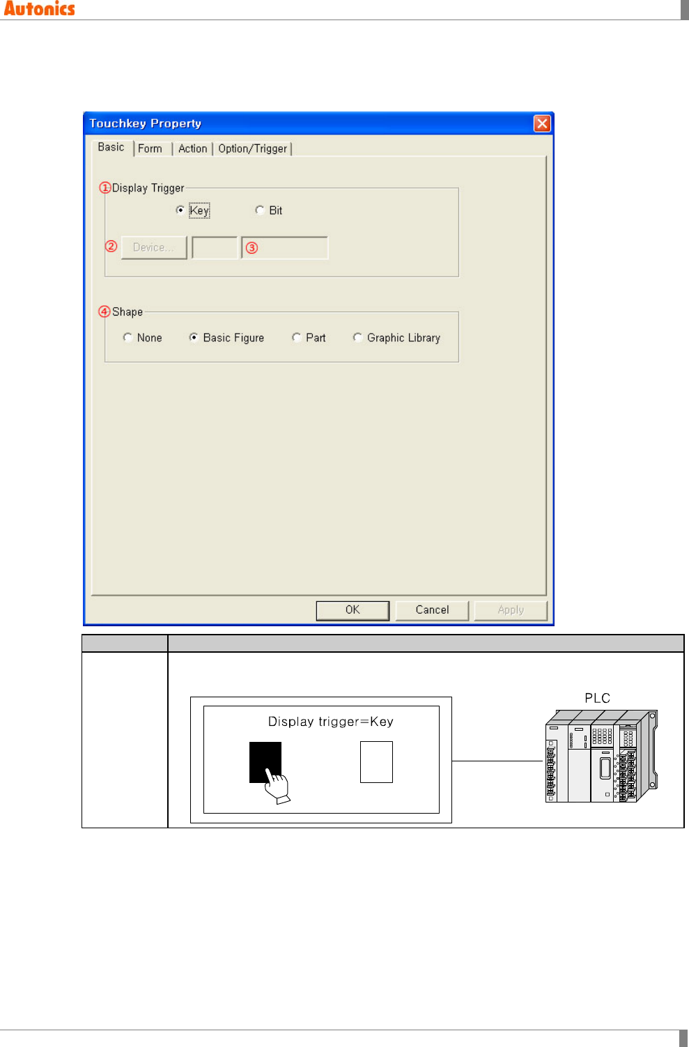
5 Draw
© Copyright Reserved Autonics Co., Ltd. 199
5.22.3 Property
5.22.3.1 Basic tab
Basic
Description
①Display
Trigger
Designate switching condition of touch key shape for ON/OFF.
Key: Displays ON shape with maintaining touch.
5 Draw
200 © Copyright Reserved Autonics Co., Ltd.
Basic
Description
①Display
Trigger
Bit: Depending on ON/OFF state of trigger device(designated at ②), displays
ON/OFF shape. ON/OFF state of the device and touch key is not related.
Irrelevant to this designation, the designated key function in ‘Action’ tab executes
when touching.
②Device Calls ‘Device Select’ dialog box and designate trigger device.
③Device Input device directly or displays the designated device by ②
④Shape
None: Displays outlines of touch area
Basic Figure: Uses black/white image supplied by GP Editor.
Part: Uses user-defined part
Graphic Library: Uses bitmap image supplied by GP Editor and user-defined
image
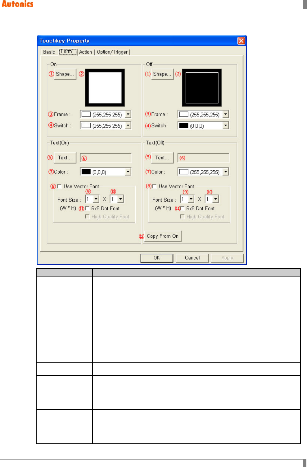
5 Draw
© Copyright Reserved Autonics Co., Ltd. 201
5.22.3.2 Form tab
Form
Description
①Shape
Depending on the designation of shape in ‘Basic’ tab, this ① is different.
None: Not used.
Basic Figure: Click ‘Shape’, ‘Image Selection’ dialog box appears. Select
basic figure supplied by GP Editor.
Part: Click ‘Shape’, ‘Image Selection’ dialog box appears. Select part.
Touch size is minimized including ON/OFF part. If minimized size
including ON/OFF part is smaller than minimized touch key, minimized
touch key is created.
Graphic Library: Click ‘Shape’, ‘Graphic Library’ dialog box appears.
Select the designated image on graphic library.
②Shape Displays the selected shape image
③Frame
Designate frame color for ON. Activated only when shape is ‘Basic Figure’ in
‘Basic’ tab.
Mono type(GP-S044, GP-S057, LP-S044): White/Black
Color type(GP-S070, LP-S070): 24bit True Color
④Switch
Designate switch color for ON. Activated only when shape is ‘Basic Figure’ in
‘Basic’ tab.
Mono type(GP-S044, GP-S057, LP-S044): White/Black
Color type(GP-S070, LP-S070): 24bit True Color
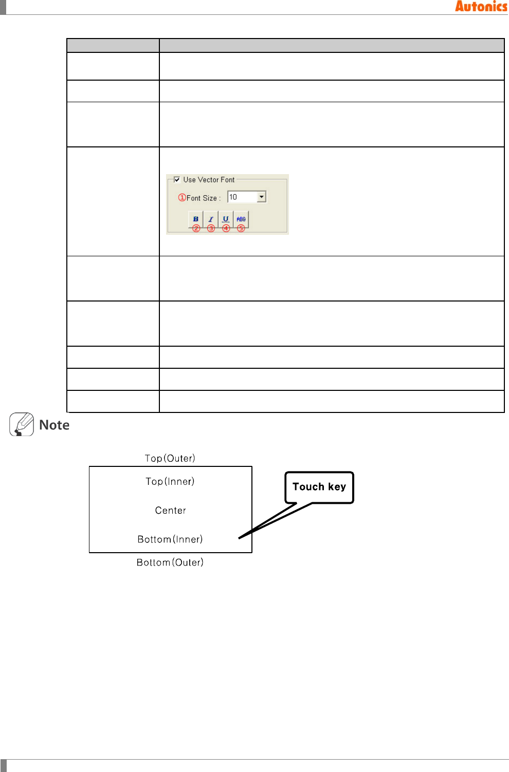
5 Draw
202 © Copyright Reserved Autonics Co., Ltd.
Form
Description
⑤Text※1 Calls ‘Edit Text’ dialog box. Input and edit text for ON shape. Designate text
position. .
⑥Text Displays text on touch key for ON.
⑦Color
Designates text color.
Mono type(GP-S044, GP-S057, LP-S044): White/Black
Color type(GP-S070, LP-S070): 24bit True Color
⑧Use Vector Font
Activated only for color type (GP-S070, LP-S070). Non-checking this, it uses
bitmap font. Checking this, it displays as following.
①Font size, ②Bold font, ③Italic font, ④Underline, ⑤Strikethrough
⑨Font Size
(Width)
Designate width font size by pull-down menu.
Range: 1,2,4,6,8
Height font size is 0.5, width font size 1 is only available.
⑩Font Size
(Height)
Designate height font size by pull-down menu.
Range: 0.5,1,2,3,4
Width font sizes besides 1 are not available for height font size 0.5.
⑪6x8 Dot Font Designate 6x8 dot font.
⑴ to ⑾ Designate same setting with ① to ⑩ for OFF state.
⑫Copy From On Copy the designated text for ON state to OFF state.
※1. Position of text
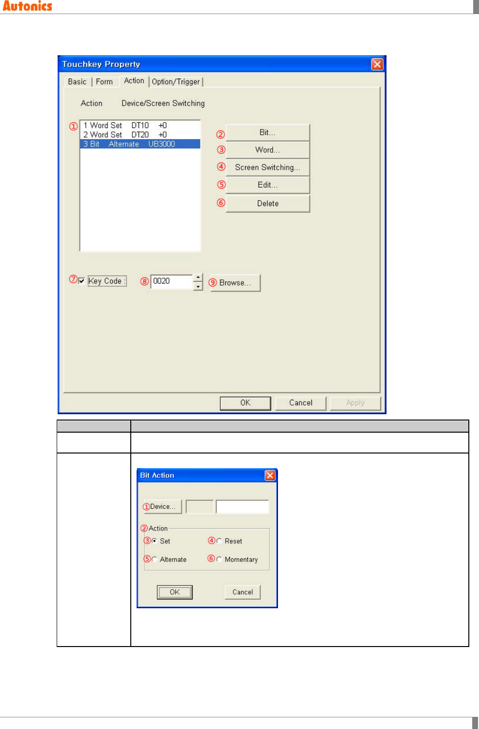
5 Draw
© Copyright Reserved Autonics Co., Ltd. 203
5.22.3.3 Action tab
Action
Description
①Action List Displays the designated touch key action. Double-click the desired item to edit.
②Bit
Calls ‘Bit Action’ dialog box, designate bit action.
①Device: Calls ‘Device Select’ dialog box and designate bit device.
②Action: Designate action of the device with touch.
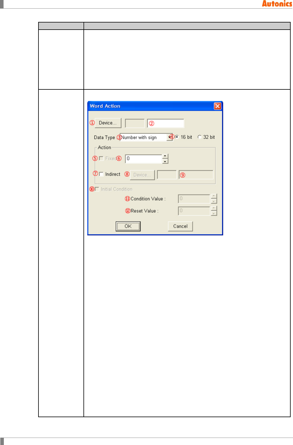
5 Draw
204 © Copyright Reserved Autonics Co., Ltd.
Action
Description
③Set: Sets the device with touch.
④Reset: Resets the device with touch.
⑤Alternate: Alternates the current state ON to OFF or OFF to ON when
touching.
⑥Momentary: Maintains momentary ON only when touching. Releasing touch, it
turns OFF.
③Word
Calls ‘Word Action’ dialog box, designate word action.
①Device: Calls ‘Device Select’ dialog box and designate touch key action
setting device.
②Device: Input device directly or displays the designated device.
③Data Type: Designate data type of the device by pull-down menu.
④Bit: Designate bit size of the device.
⑤Fixed: Check for inputting designated device at ⑥.
⑥Fixed: Designated fixed value for designated device.
⑦Indirect: Check for inputting designated device at ⑨ when ⑤Fixed is not
checked. When ⑤Fixed is checked, adds up fixed value of ⑥ and designated
device value of ⑨ to input the designated device at ②.
⑧Device: Calls ‘Device Select’ dialog box and designate indirect device.
⑨Device: Input device directly or displays the indirect device.
⑩Initial Condition: Resets as initial condition.
⑪Condition Value: Designate initial condition value to reset the designate
device.
⑫Reset Value: Designate reset value.
Depending on connected device type, it may use only 32bit. Refer to ‘GP,LP
user manual for communication’.
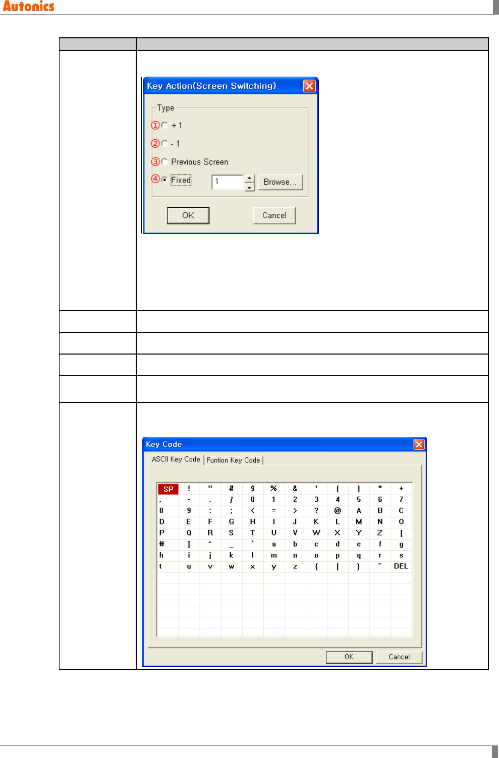
5 Draw
© Copyright Reserved Autonics Co., Ltd. 205
Action
Description
④Screen
Switching
Calls ‘Key Action(Screen Switching)’ dialog box, designate base screen
switching.
①+1: Moves from current screen to one more number screen
②-1: Moves from current screen number to one less number screen
③Previous Screen: Moves to previous screen before switching
④Fixed: Moves to the designated screen
⑤Edit Edits the selected item in ①Action list.
⑥Delete Delete the selected item in ①Action list.
⑦Key Code Executes key code function.
⑧Key Code Input directly key code or displays the designated function key code with
hexadecimal.
⑨Browse
Calls ‘Key Code’ dialog box, creates code for the desired function.
‘ASCII Key Code’ tab※1
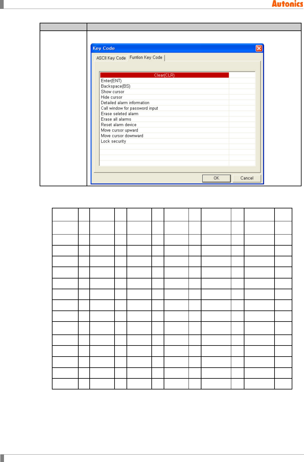
5 Draw
206 © Copyright Reserved Autonics Co., Ltd.
Action
Description
⑨Browse
‘Function Key Code’ tab※2
※1. Arrangement of character in ‘ASCII Key Code’ tab: Real code value on key code editor after
completing input.
0020H SP
0021H ! 0022H “ 0023H # 0024H $ 0025H %
0026H & 0027H ‘ 0028H ( 0029H ) 002AH * 002BH +
002CH , 002DH - 002EH . 002FH / 0030H 0 0031H 1
0032H 2 0033H 3 0034H 4 0035H 5 0036H 6 0037H 7
0038H 8 0039H 9 003AH : 003BH ; 003CH < 003DH =
003EH > 003FH ? 0040H @ 0041H A 0042H B 0043H C
0044H D 0045H E 0046H F 0047H G 0048H H 0049H I
004AH J 004BH K 004CH L 004DH M 004EH N 004FH O
0050H P 0051H Q 0052H R 0053H S 0054H T 0055H U
0056H V 0057H W 0058H X 0059H Y 005AH Z 005BH [
005CH ? 005DH ] 005EH ^ 005FH _ 0060H ‘ 0061H a
0062H b 0063H c 0064H d 0065H e 0066H f 0067H g
0068H h 0069H I 006AH j 006BH k 006CH l 006DH m
006EH n 006FH o 0070H p 0071H q 0072H r 0073H s
0074H t 0075H u 0076H v 0077H w 0078H x 0078H x
0079H y 007AH z 007BH { 007CH | 007DH } 007EH to
5 Draw
© Copyright Reserved Autonics Co., Ltd. 207
※2. ‘Function Key Code’ tab is selected when touching specified touch key by each function
description.
Key code
(Hexadecimal)
Description
Key code
(Hexadecimal)
Description
FFA1
Clear(CLR)
FFA8 Erase selected alarm
FFA2
Enter (ENT)
FFA9 Erase all alarm
FFA3
Backspace(BS)
FFAA Reset alarm device
FFA4
Show cursor
FFAB Move cursor upward
FFA5 Hide cursor FFAC Move cursor
downward
FFA6
Detailed alarm information
FFAD Lock security
FFA7 Call window for password
input
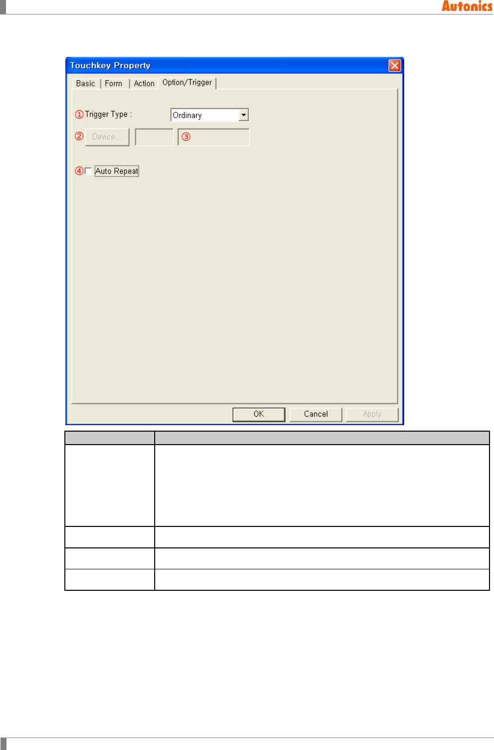
5 Draw
208 © Copyright Reserved Autonics Co., Ltd.
5.22.3.4 Option/Trigger tab
Option/Trigger
Description
①Trigger Type
Designate trigger type by pull-down menu.
Ordinary: Trigger function is not used.
On: Executes touch key function when the device which is designated at
③ is ON.
Off: Executes touch key function when the device which is designated at
③ is OFF.
②Device Calls ‘Device Select’ dialog box. Designate trigger device.
③Device Input device directly or displays the designated device.
④Auto Repeat Executes repeatedly with regular intervals during pressing touch key.
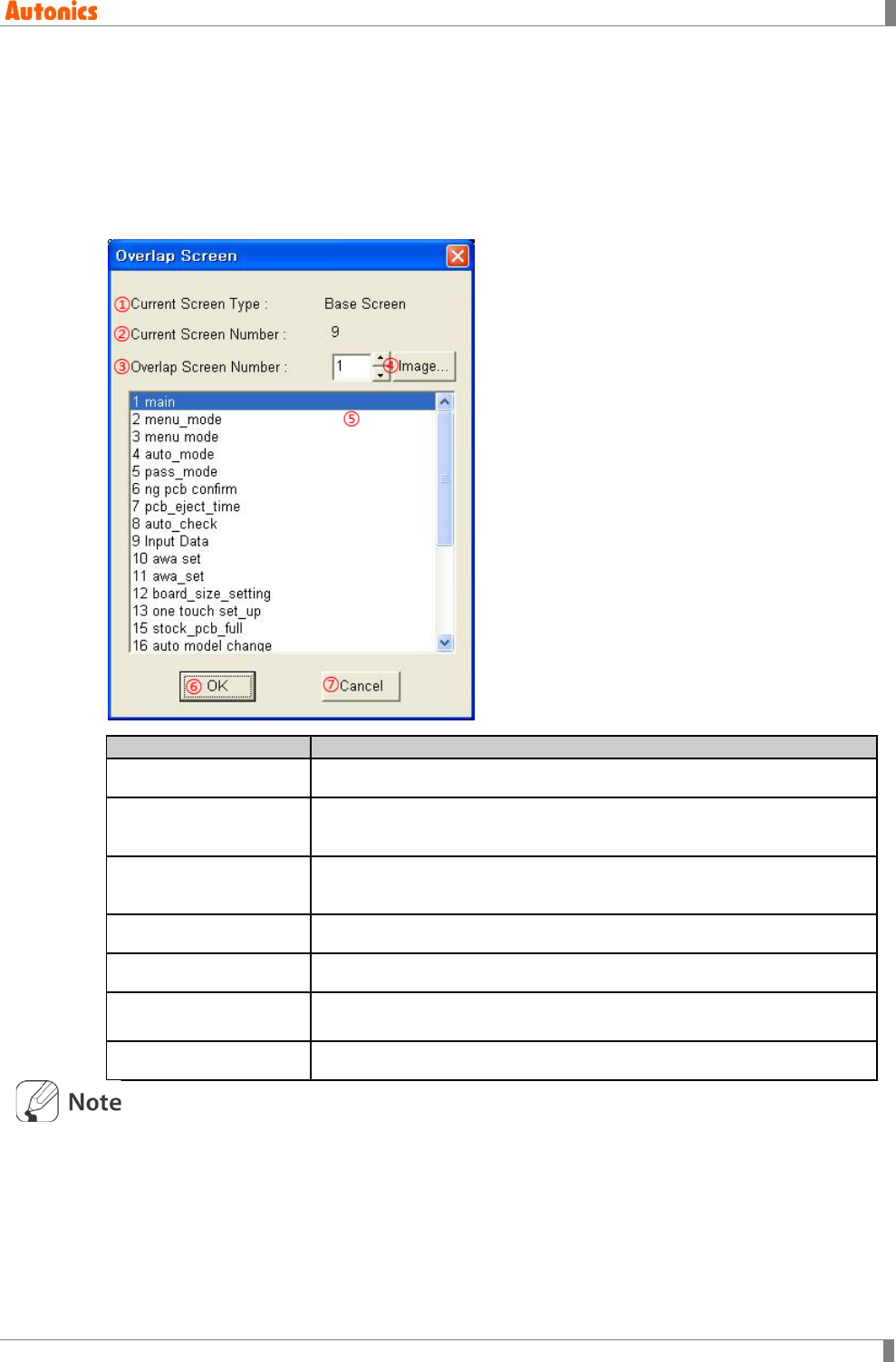
5 Draw
© Copyright Reserved Autonics Co., Ltd. 209
5.23 Overlap Screen
Overlaps the current editing screen to desired screen. It is useful to produce common part
among several screens as an independent screen to write screen data and save data capacity
when using it as overlap screen. For window screen, overlap function is not available.
Select [Draw]-[Overlap Screen], ‘Overlap Screen List’ dialog box appears. Designate the
deseired overlap screen.
Overlap Screen
Description
①Current Screen Type Base screen
②Current Screen
Number Current editing base screen number
③Overlap Screen
Number Base screen number to overlap
④Image Calls ‘Screen Image’ dialog box, check base screen image.
⑤List Box Displays base screen number and title of project.
⑥OK Overlaps designated base screen at overlap screen number and closes
‘Overlap Screen’ dialog box.
⑦Cancel Cancels the designations and closes ‘Overlap Screen’ dialog box.
It is able to overlap only as one step for each screen. When overlapping base screen which
has overlap screen, tags of base screen are only overlapped, tags of overlap screen are not
overlapped again.
It is able to overlap up to 5 screens.
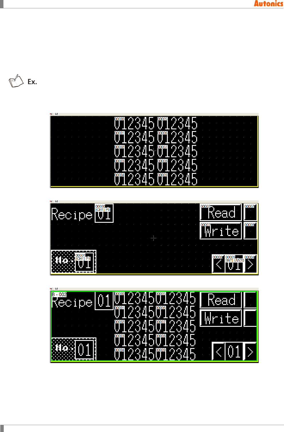
5 Draw
210 © Copyright Reserved Autonics Co., Ltd.
When several screens are overlapped, it is displays as in order to the tags which is placed
on base screen, the tags which is placed on last overlapped screen, …, the tag which is
placed on first overlapped screen.
Configuration of cursor movement and floating alarm is set again according to screen
configuration, user and destination ID of tags configured in overlap screen maintains that
value.
[Example of overlap]
Base screen
Overlap screen
Base screen after overlapping
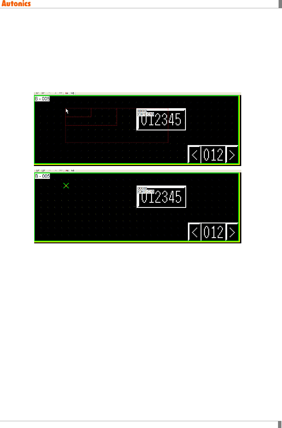
5 Draw
© Copyright Reserved Autonics Co., Ltd. 211
5.24 Key Window Position
It is able to designate key window position for inputting numeral or ASCII input.
Select [Draw]-[Key Window Position], a red dotted rectangle follows mouse cursor at edit area.
This rectangle is an outline of key window position when calling key window. If this rectangle is
out of edit area, key window position is adjusted to show whole key window when calling key
window.
When key window position is designated, all types of key window are displayed as window which
has mark as top-left point.

5 Draw
212 © Copyright Reserved Autonics Co., Ltd.
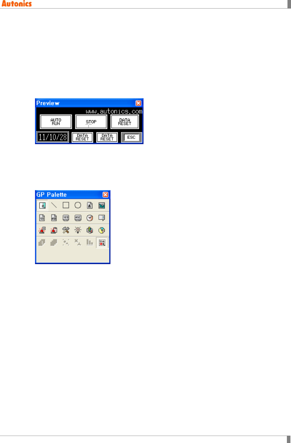
6 View
© Copyright Reserved Autonics Co., Ltd. 213
6 View
It describes tool bar option and view of tag/device list for edit.
6.1 Preview
Preview function is for showing GP/LP screen with 100% of enlargment ratio.
Select [View]-[Preview], ‘Preview’ window appears.
Screen background color is same as GP/LP screen. If white is designated, it shows white
background color. It shows blach background to the designated besides white.
6.2 Palette
GP pallette has tag and draw tools for design.
Select [View]-[Palette] of menu, ‘GP Palette’ window appears. Likewise toolbar, select the
desired tool from palette, design project.
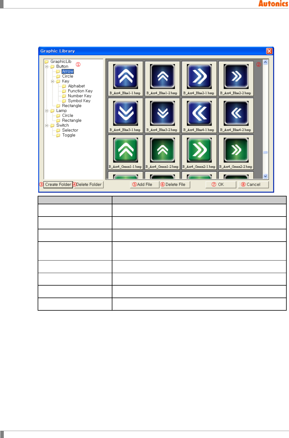
6 View
214 © Copyright Reserved Autonics Co., Ltd.
6.3 Graphic Library
Edits graphic library for bitmap tag, lamp tag, touch key tag.
Graphic Library
Description
①Graphic library tree view Displays image files in GraphicLib folder as a tree.
②Preview Previews image files in the selected folder at ①.
③Create Folder Creates lower folder of the selected folder at ①.
④Delete Folder Deletes the selected folder at ①.
(All image files are deleted in the selected folder.)
⑤Add File Adds image file to the selected folder at ①.
⑥Delete File Deletes selected image file at ②.
⑦OK Completes graphic library editing.
⑧Cancel Cancels graphic library editing.
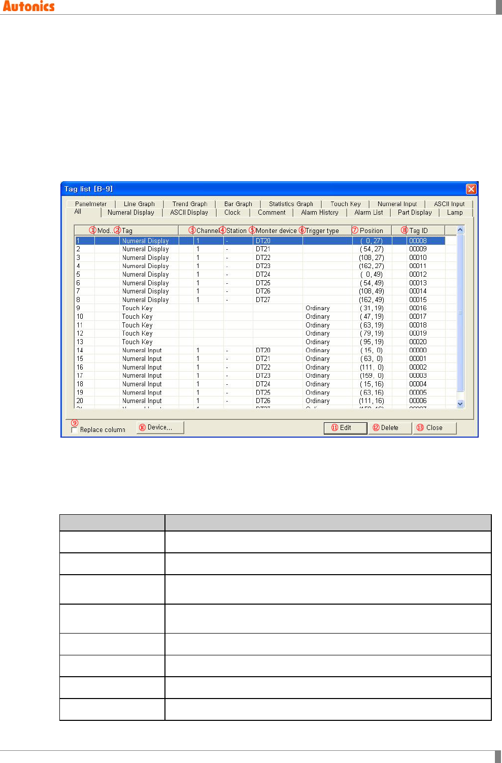
6 View
© Copyright Reserved Autonics Co., Ltd. 215
6.4 Tag List
It displays all tags of current editing screen and is able to edit each main property.
You can check all tags at once, or tags by that type seperately.
Select [View]-[Tag List], ‘Tag list’ dialog box is appeared.
‘All’ tab displays all tags of the screen, the designated device, and position, etc. Such as
‘Numeral Display, ASCII Display’ tab, each tab displays the tag list by each tab name and it able
to edit main property.
6.4.1 All tab
‘All’ tab of ‘Tag List’ dialog box displays all tags arranged in current editing screen with main
attributions as a table.
In case that there is monitor device used for tag, ‘Device’ is activated when selecting the tag and
it is able to edit device address clicking ‘Device’. Edited device displays ‘*’ mart in ‘Modified’ line.
Select the deisred tag and click ‘Edit’ or ‘Delete’, to edit or to delete.
All Description
①Modified Displays '*’ when editing.
②Tag Displays tag name.
③Channel Displays channel number of monitor device on tag.
CH1 is 1, CH2 is 2. UB/UW device is '-'.
④Station Displays station of monitor device on tag.
If there is no station information, displays '-'.
⑤Monitor device Displays monitor device on tag.
⑥Trigger type Displays designated trigger when using trigger.
⑦Position Displays tag position on screen (as top-left point).
⑧Tag ID Displays tag ID.
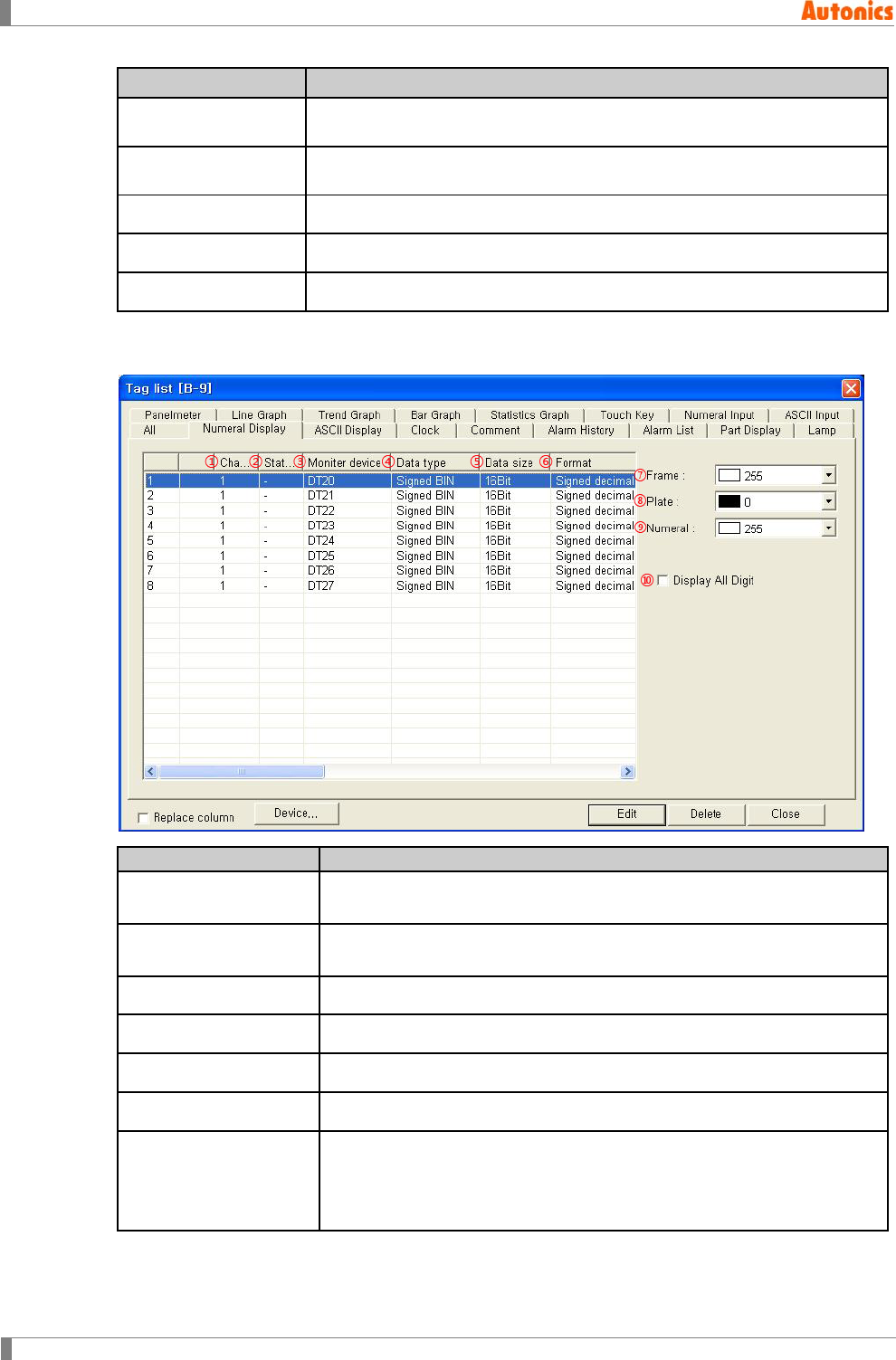
6 View
216 © Copyright Reserved Autonics Co., Ltd.
All Description
⑨Replace column Check ‘Replace column’ and click ‘Device’ to change device. It changes
all devices of monitor device column to new devices.
⑩Device Changes selected device to new device. Click ‘Device Select’ dialog box
appears to designate new device.
⑪Edit Calls the selected tag’s ‘Property’ dialog box to edit property.
⑫Delete Deletes the selected tag on screen.
⑬Close Closes ‘Tag list’ dialog box.
6.4.2 Numeral display tab
Numeral Display
Description
①Channel Displays channel number of monitor device on tag.
CH1 is 1, CH2 is 2. UB/UW device is '-'.
②Station Displays address of monitor device on tag.
If there is no address information, it displays as '-'.
③Monitor device Displays monitor device on tag
④Data type Displays data type of device
⑤Data size Displays data size of device
⑥Format Displays numeral display type.
⑦Frame
Designates frame color. Activated only with when ‘Shape’ is checked in
‘Numeral Display Property’ dialog box.
Mono type(GP-S044, GP-S057, LP-S044): White/Black
Color type(GP-S070, LP-S070): 24bit True Color
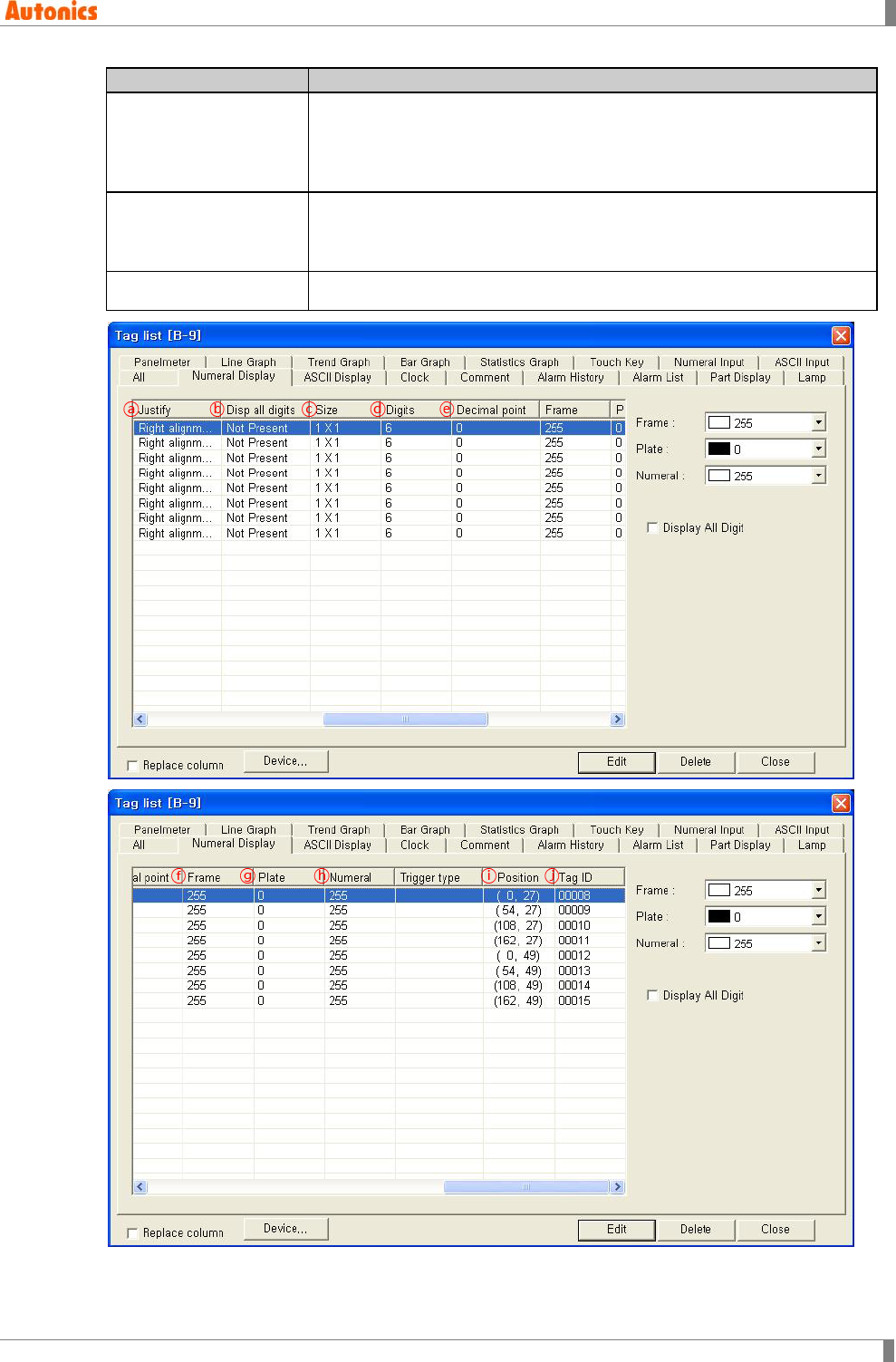
6 View
© Copyright Reserved Autonics Co., Ltd. 217
Numeral Display
Description
⑧Plate
Designates plate color. Activated only with when ‘Shape’ is checked in
‘Numeral Display Property’ dialog box.
Mono type(GP-S044, GP-S057, LP-S044): White/Black
Color type(GP-S070, LP-S070): 24bit True Color
⑨Numeral
Designates numeral color.
Mono type(GP-S044, GP-S057, LP-S044): White/Black
Color type(GP-S070, LP-S070): 24bit True Color
⑩Display All Digit Designate to display all digits option.
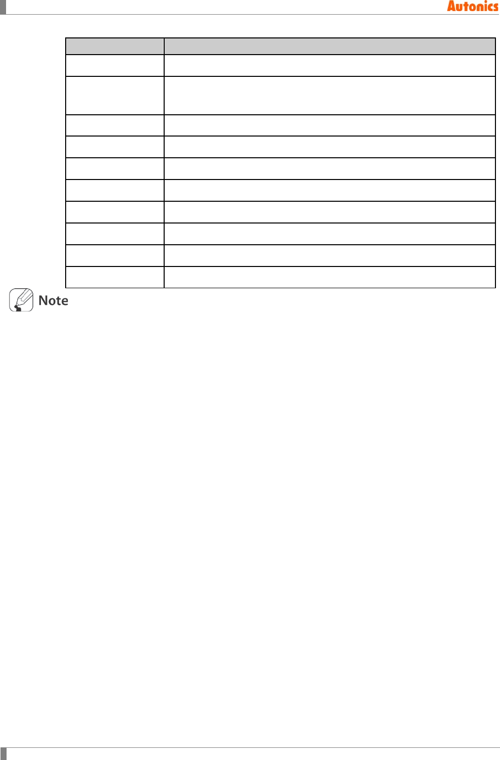
6 View
218 © Copyright Reserved Autonics Co., Ltd.
Numeral Display
Description
ⓐJustify Displays alignment type for displaying numeral
ⓑDisplay all digits Option for displaying all digits. (In case of right alignment, it displays all digit
with 0 for blank) If this option is designated, it displays ‘Present’, otherwise
it displays ‘Not Present’.
ⓒSize Displays font size as width X height on tag.
ⓓDigit Displays digit
ⓔDecimal point Displays decimal point digit
ⓕFrame Displays frame color
ⓖPlate Displays plate color
ⓗNumeral Displays numeral color.
ⓘPosition Displays tag position on screen
ⓙTag ID Displays tag ID
The descriptions of other tabs are same as ‘Numeral Display’ tab’s.
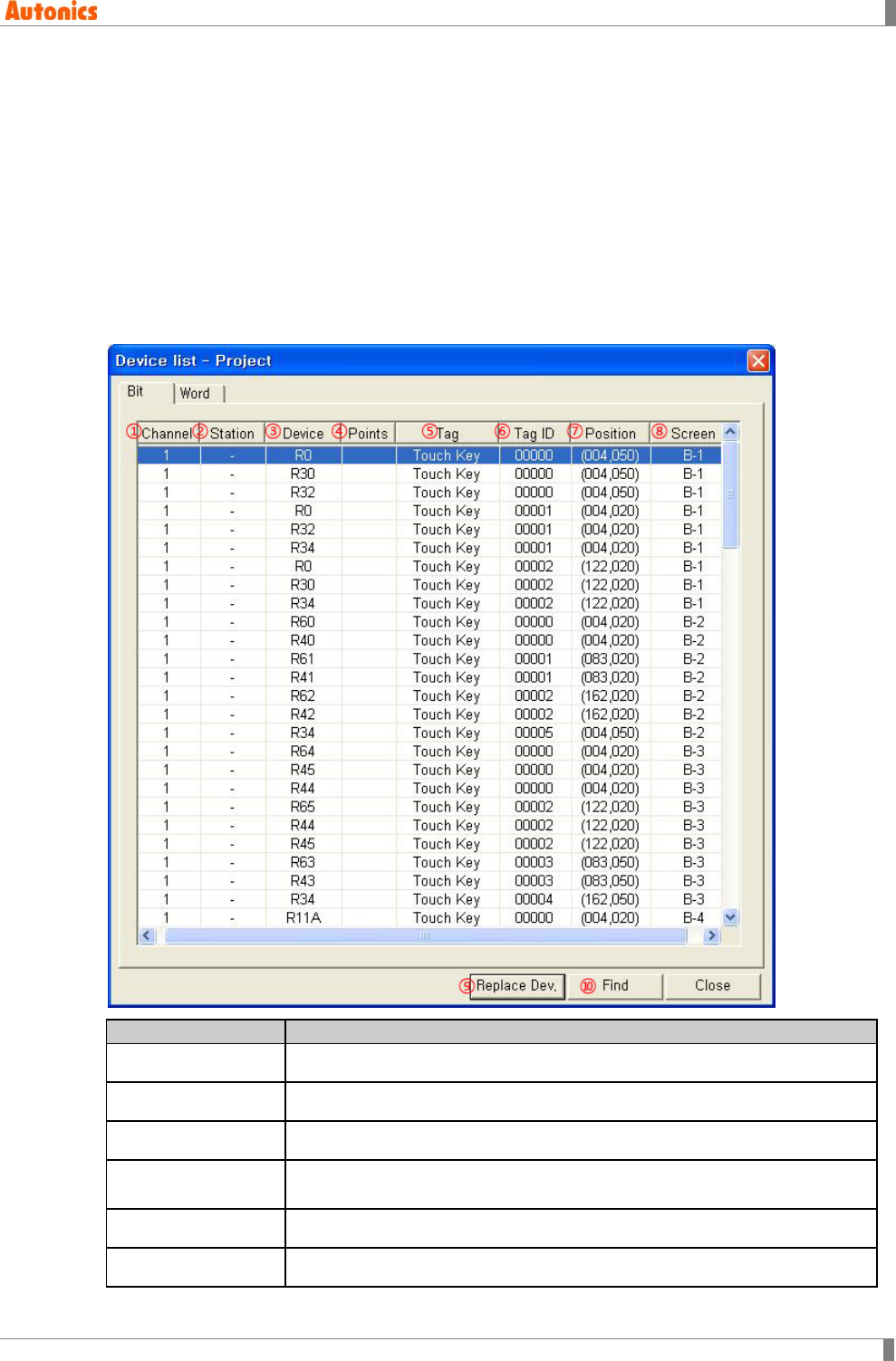
6 View
© Copyright Reserved Autonics Co., Ltd. 219
6.5 Device List
Device list displays used all device for the project of the specified screen.
You can check that which tag has any device and it is useful to correct any errors.
Select [View]-[Device List]-[Screen] of menu to check device list about screen, ‘Device list –
Screen’ dialog box appears.
Select [View]-[Device List]-[Project] of menu to check device list about project, ‘Device list –
Project’ dialog box appears.
Descriptions of ‘Device list – Screen’ is same as those of ‘Device list – Project’ dialog box. The
followings describe ‘Device list – Screen’ dialog box as a representative. Besides that ‘Bit’ tab is
bit device, ‘Word’ tab is word device, the descriptions of each tab are same.
Device list
Description
①Channel Displays channel number of used device
②Station Displays station of used device
③Device Displays used device.
④Points Displays the number of related device when the tag uses several devices
from lead device in order.
⑤Tag Displays tag list of used device.
⑥Tag ID Displays tag ID.
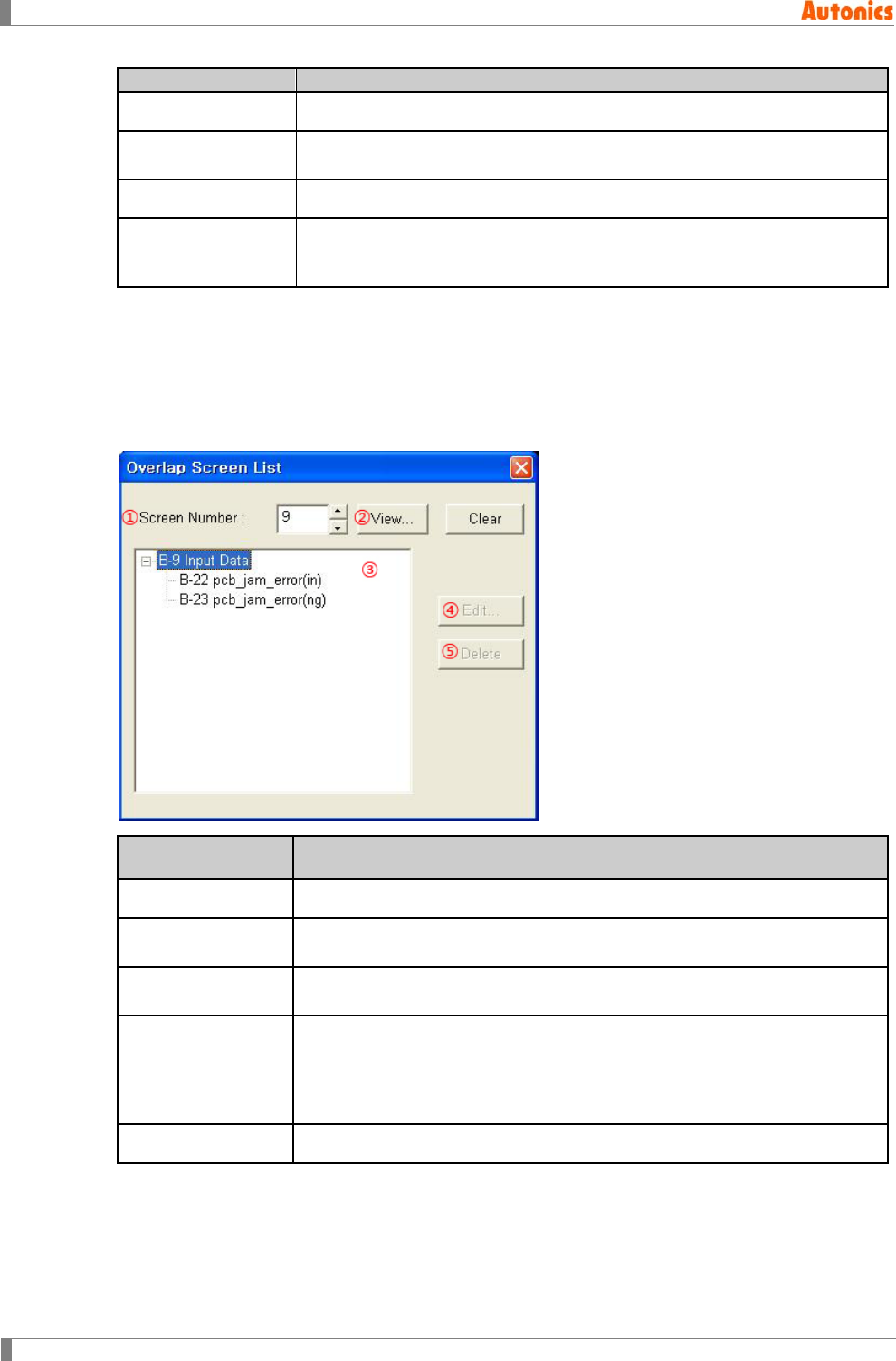
6 View
220 © Copyright Reserved Autonics Co., Ltd.
Device list
Description
⑦Position Displays tag position on screen (as top-left point).
⑧Screen Displays screen number having tag. If the device is designated at common,
it displays common.
⑨Replace Device Calls ‘Replace Device’ dialog box to replace the selected item device.
⑩Find Calls ‘Device Select’ dialog box and input the desired device to find. If there
is same device with input device, it scrolls to the position and shows as the
item is selected.
6.6 Overlap Screen List
Overlap screen creates a new screen by combinating existing screens.
Select [View]–[Overlap Screen List] of menu, ‘Overlap Screen List’ dialog box appears.
You can check the overlapped screen list and edit it.
Overlap Screen
List
Description
①Screen Number Designate base screen to display overlap screen list.
②List Lists base screen image to select the screen which is input at ‘Screen
Number’.
③Tree view Displays overlap screen number and title. The below screen is the latest
overlapped screen.
④Edit
Replaces the selected screen on tree to other screen. Select overlapped
screen number at③Tree view and click ‘Edit’. ‘Overlap Screen’ dialog box is
appears. Input or select the to be overlapped screen number, and click ‘OK’
and ③Tree view is replaced as to be overlapped screen number.
⑤Delete Deletes the selected overlap screen on tree.

6 View
© Copyright Reserved Autonics Co., Ltd. 221
6.7 Status bar
Status bar displays the information of current editting (Selected tag, mouse cursor coordinates,
PLC of CH1/CH2) on the below GP Editor. It is displayed when checking [View]-[Status bar]. If
the specified tag is selected, ‘[…] is selected’ message displays. The others, ‘READY’ message
displays.
6.8 Toolbar
It is able to operate display of specified group of tool in menu or designate in project
configuration. Designate it in ‘Browse’ tab of ‘Option’ dialog from [Project]-[Option] of menu, or
with checking from [View]-[Toolbar].
System toolbar: Designates displaying main toolbar or not.
New project, load project, save project
New screen, load screen, save screen
Cut, copy, paste
Preview, previous screen, next screen, open closed screen, tag list
Download, upload, connect PLC, check data
Device list, comment list, library, palette, refresh
View toolbar: Designates displaying view toolbar or not.
ON/OFF image, Device display, Tag ID display, grid color, background color
Snap, grid interval, grid display type, enlargement ratio
Figure toolbar: Designate displaying figure toolbar or not.
Line, rectangle, circle, text, BMP
Edit toolbar: Designate displaying edit toolbar or not.
Bring forward, send backward, group, ungroup, select object-figure, select object-tag
Tag toolbar: Designate displaying tag toolbar or not.
Draw toolbar: Designate displaying draw toolbar or not.
Line - Style, Color
Pattern - Pattern, foreground color , background color
Text color
Workspace bar: Designate displaying workspace for base, window screen list of project.
6.9 ON Image
Some tag such as lamp, touch key tag, etc are different image for ON/OFF state on screen. In
this case, you can designate ON or OFF state image on screen.
Select [View]-[ON Image] of menu, or click in toolbar.
If [View]-[ON Image] of menu is checked, each tag which is ON state is displayed on edit area.
6.10 Refresh
This feature is to refresh editor screen.
6 View
222 © Copyright Reserved Autonics Co., Ltd.
6.11 Option
Grid display, magnification, snap, tag ID display and device display are for making screen data
efficiently. It is able to configure in ‘Browse’ tab. It is same as [Project]-[Option] of meun.
Option
Description
①Grid
Designate grid for indicating arrangement when editing screen by pull-
down menu.
Position: Front=Displays on the tag, Back=Displays under the tag,
None=Does not display
Color: White, black, blue, red, pink, light green, light blue and yellow
Interval: 2, 4, 5, 8, 10, 16, 20, 40, 80, Mesh
②Snap
Designate snap range of screen by pull-down menu.
Range: 1, 2, 4, 5, 8, 10, 16, 20, 40, 80, Mesh
(A mesh indicates same size of resolution of touch switch.)
GP-S057, GP-S070, LP-S070: 20X20
GP-S044, LP-S044:16X20
③Real editing
operation
Check for displaying object as it is when it is moving, or non-check for
displaying only with dotted line.
④Display
Tag ID: Displays tag ID
Device: Displays device name related tag.
Tag: Displays tag content
⑤On/Off Designate ON or OFF image state on edit area by pull-down menu.
⑥Magnification Select magnification ration between 100%, 200%, 300%, or 400% based
on GP/LP screen size by pull-down menu.
7 Communication
© Copyright Reserved Autonics Co., Ltd. 223
7 Communication
GP Editor and GP/LP communicate with RS232C/RS422 port, Ethernet port, or USB port. (Mono
type(GP-S044, GP-S057, LP-S057) is available only for RS232C/RS422 port.)
Following functions are available by communications between GP Editor and GP/LP.
Download screen data
Downloads the edited project in GP Editor to GP/LP
Upload GP/LP data
Uploads protocol saved in GP/LP to GP Editor
GP/LP memory check
Check memory and delete the desired screen of GP/LP from GP Editor
Firmware download
Upgrade GP/LP software (Firmware upgrade for color type(GP-S070, LP-S070) is available
only by USB Host port.)
For RS232C/RS422 port;
You should designate communication channel as ‘EDITOR’ in [SYSTEM SETTING]-
[Connect PLC] of mono type GP/LP or in [SYSTEM SETTING]-[Environment]-[Serial
Communication] of color type GP/LP. For connecting with GP Editor, designate GP/LP as
data length: 8 bit, stop bit: 1 bit, parity: EVEN, flow control: XON/XOFF. Communication is
available only when both GP Editor and GP/LP have same set baud rate.
For Ethernet port;
You should designate IP Address, Subnet Mask, GateWay at system menu [SYSTEM
SETTING]-[Local Ethernet] in GP/LP.
For USB port;
It does not need additional settings.
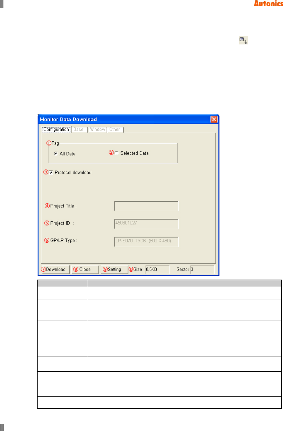
7 Communication
224 © Copyright Reserved Autonics Co., Ltd.
7.1 Download
After editing screen data, select [Communication]-[Download] of menu, or click in toolbar,
‘Monitor Data Download’ dialog box appears. Set data to download and download option, click
‘Download’ to start download.
7.1.1 Download instructions
All existing draw data of GP/LP by each project are deleted.
For LP series, PLC pauses when downloading and it runs again after downloading.
7.1.2 Property
Configuration
Description
①All Data Downloads all existing screen data of current project.
②Selected Data Downloads selected data of current project. When it is selected, ‘Base,
Window, Other’ tabs are activated. Select the desired item to be downloaded
in each tab.
③Protocol
download
Non-checking this, it checking whether there is a device or not and then
downloads the appropriate protocol only when there is not a device to be
downloaded on GP/LP memory.
Checking this, it downloads unconditionally the appropriate protocol even
though there is a device to be downloaded on GP/LP memory.
④Project Title Displays project name. Select [Common]-[Title]-[Project] of menu to edit
project name.
⑤Project ID Displays project ID to be downloaded.
⑥GP/LP Type Displays GP/LP type
⑦Download Starts download
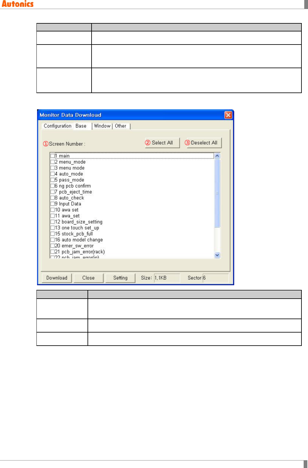
7 Communication
© Copyright Reserved Autonics Co., Ltd. 225
Configuration
Description
⑧Close Closes ‘Monitor Data Download’ dialog box
⑨Setting Designates communication setting between PC and GP/LP. ‘Option’ dialog
box appears. Select [Communication]-[Option] of menu, ‘Option’ dialog box
appears also. In ‘Communication’ tab, designate communication setting.
⑩Size
Displays total screen data of to be downloaded project with Kbyte unit.
Maximum size of one project is up to 512Kbyte.
(For LP series, it cannot over 384Kbyte.)
7.1.2.1 Base tab
Base
Description
①Screen
Number
Displays base screens number and title of the project in order of number.
Downloads only checked screen.
②Selected All Selects all items of the list.
③Deselect All Deselects all items of the list.
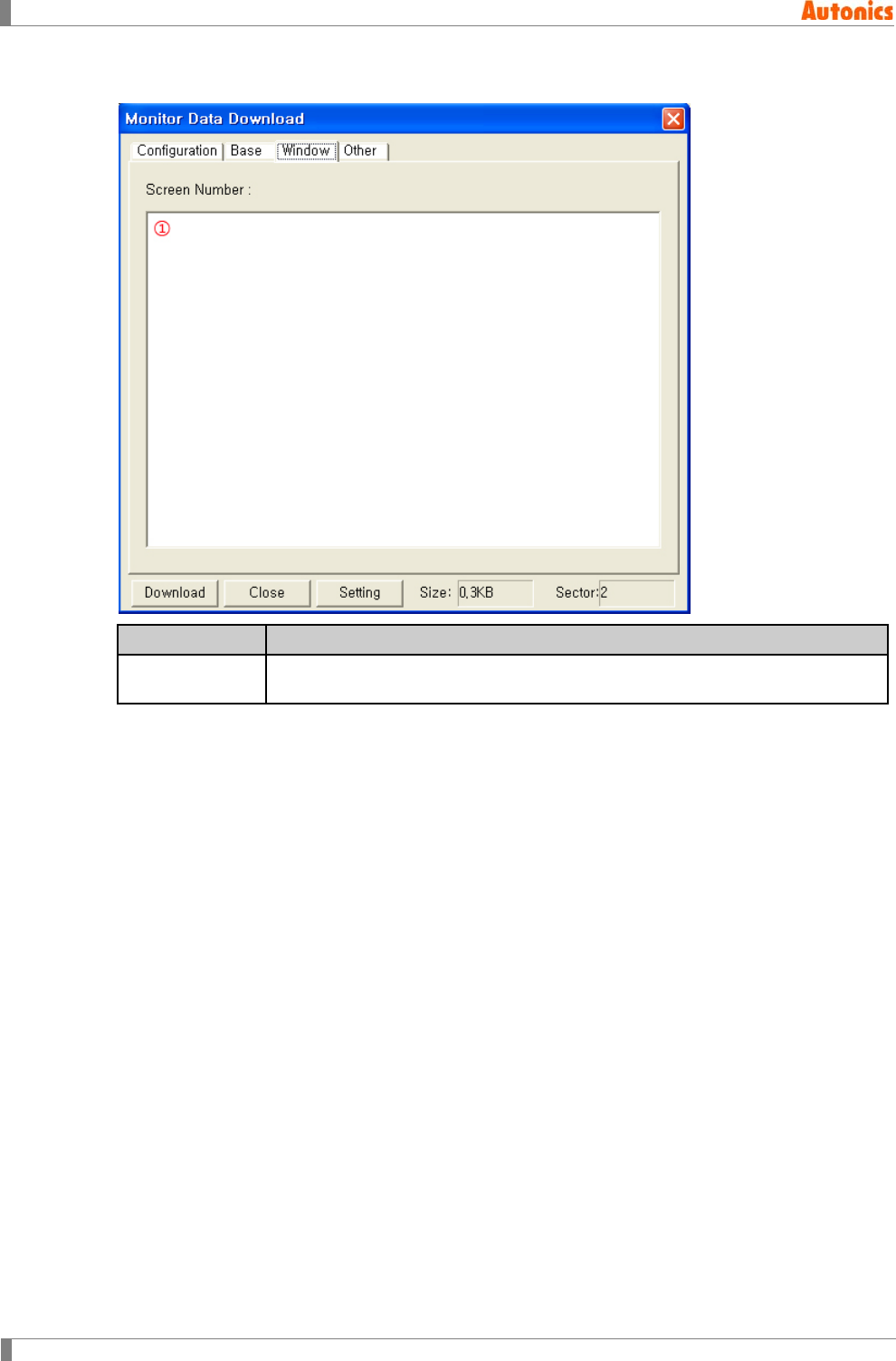
7 Communication
226 © Copyright Reserved Autonics Co., Ltd.
7.1.2.2 Window tab
Window Description
①Screen List Lists the designated window screen by key window at project auxiliary
property. You cannot select the desired item to be downloaded.
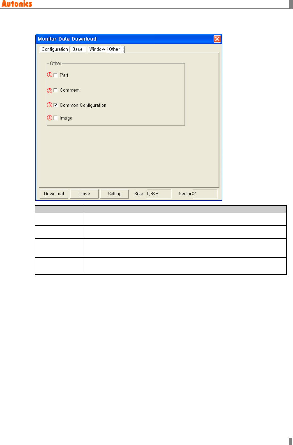
7 Communication
© Copyright Reserved Autonics Co., Ltd. 227
7.1.2.3 Other tab
Other
Description
①Part Downloads all registered parts of the project.
②Comment Downloads all registered comments of the project.
③Common
Configuration Downloads all registered items at common configuration.
④Image Downloads all registered images of the project.
(It is available only for color type (GP-S070, LP-S070).)

7 Communication
228 © Copyright Reserved Autonics Co., Ltd.
7.2 Upload
It uploads monitoring project file in GP/LP to GP Editor. You can upload alarm history list also.
Select [Communication]-[Upload] of menu, or click in toolbar, ‘Monitor Data Upload’ dialog
box appears to desigate about upload and to execute upload.
7.2.1 Execution order
1st Check communication setting for GP Editor and GP/LP.
2nd To upload all data of project, select ‘All Data’ in Tag box.
To upload selected data of project, select ‘Selected Data’ in Tag box, and click ‘Read
Title’. ‘Base, Window, Other’ tabs are actiaved, check the desired item.
To upload alarm history list, check ‘Alarm History(Alarmhistory.txt)’.
To upload alarm frequnecy, check ‘Alarm Frequency(Alarmfrequency.txt)’.
3rd If there is password, enter it to ‘Password’.
4th Click ‘Upload’ and it operates upload.
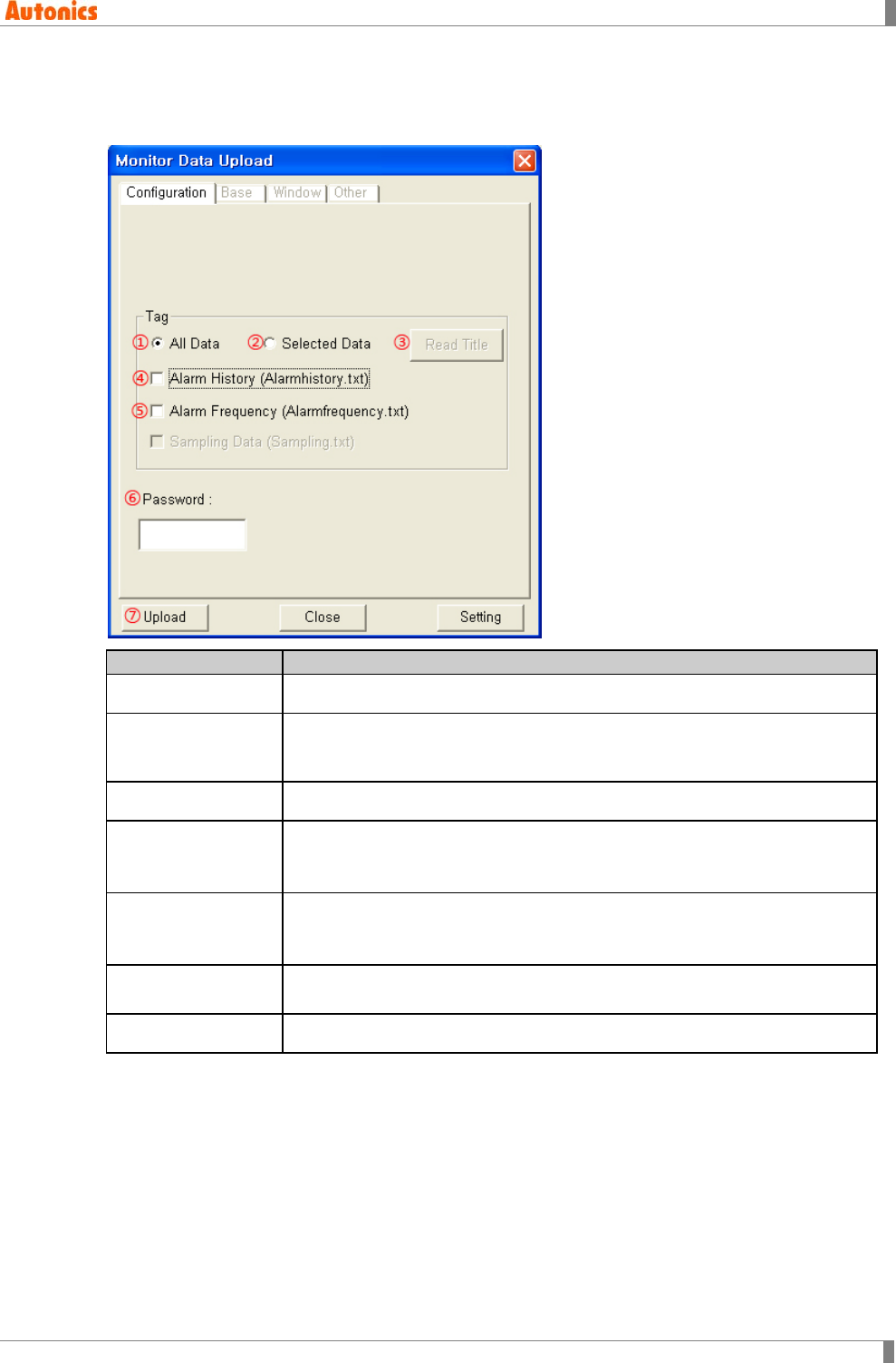
7 Communication
© Copyright Reserved Autonics Co., Ltd. 229
7.2.2 Property
7.2.2.1 Configuration tab
Configuration
Description
①All Data Uploads all screen data.
②Selected Data Uploads selected data of the project. Select this and click ‘Read Title’. It
communicates GP/LP and reads screen information. ‘Base, Window, Other’
tabs are activated, and check the desired item from each tab.
③Read Title Reads base/window screen of GP/LP number and title by communicating.
④Alarm History
Check for uploading alarm history.
It saves at \GP Editor installed folder\Temp\Upload \Project ID\Project
title\AuxInfo as ‘Alarmhistory.txt’ file.
⑤Alarm Frequency
Check for uploading alarm frequency.
It saves at \GP Editor installed folder\Temp\Upload\Project ID\Project
title\AuxInfo as ‘Alarmfrequency.txt’ file.
⑥Password Enter password which is designated at [Common]-[Password] of menu.
Correct password is available to upload.
⑦Upload Executes upload.
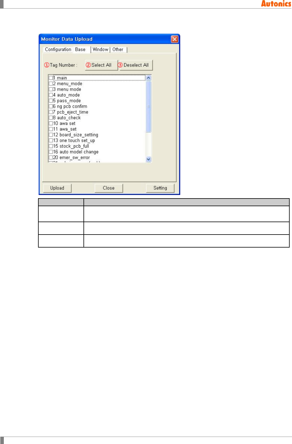
7 Communication
230 © Copyright Reserved Autonics Co., Ltd.
7.2.2.2 Base tab
Base
Description
①Tag Number Displays base screens number and title of GP/LP in order of number. Uploads
only checked screen.
②Select All Select all items of the list.
③Deselect All Deselect all items of the list.
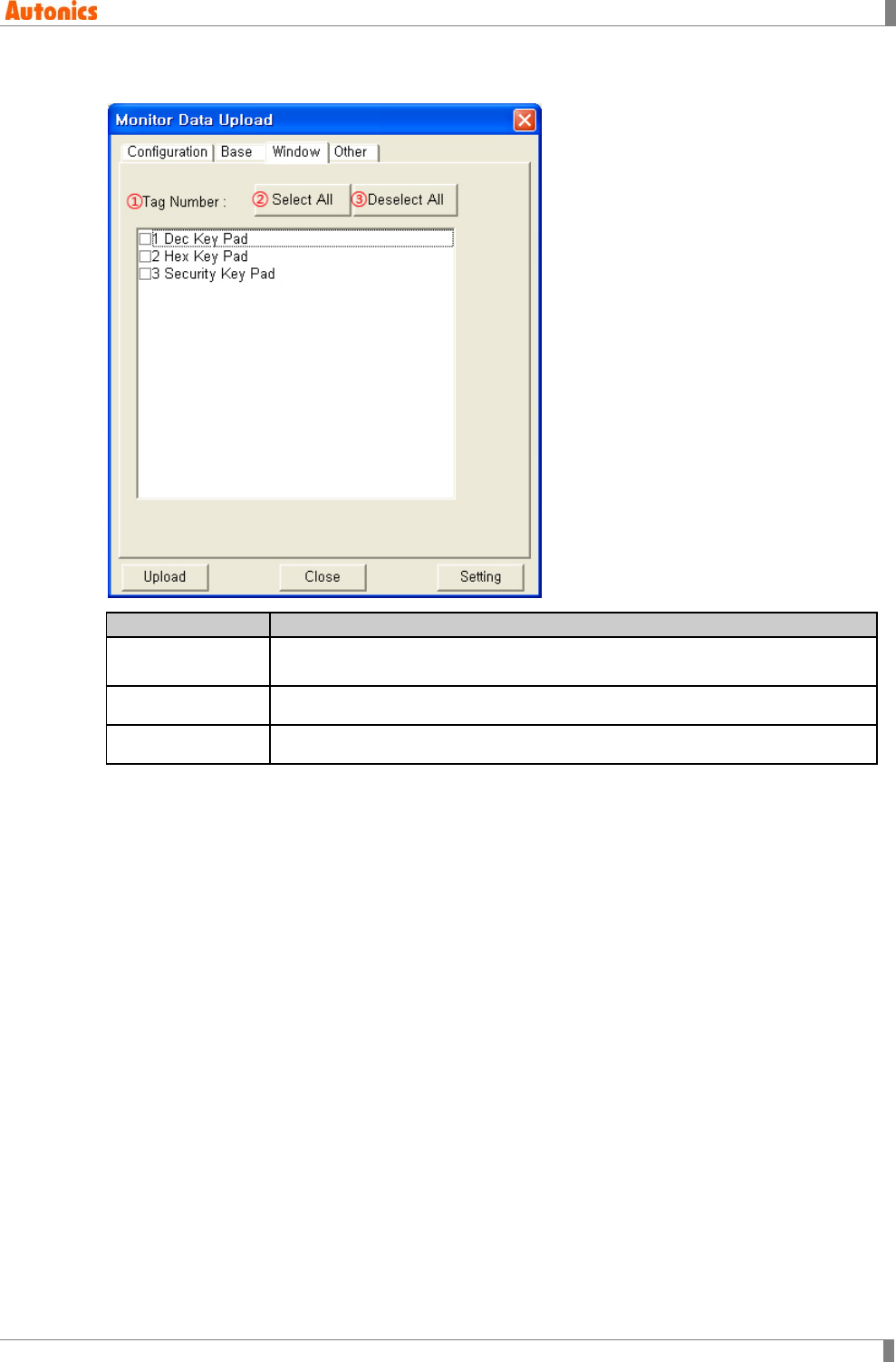
7 Communication
© Copyright Reserved Autonics Co., Ltd. 231
7.2.2.3 Window tab
Window
Description
①Tag Number Displays window screens number and title of GP/LP in order of number.
Uploads only checked screen.
②Select All Selects all items of the list.
③Deselect All Deselects all items of the list.
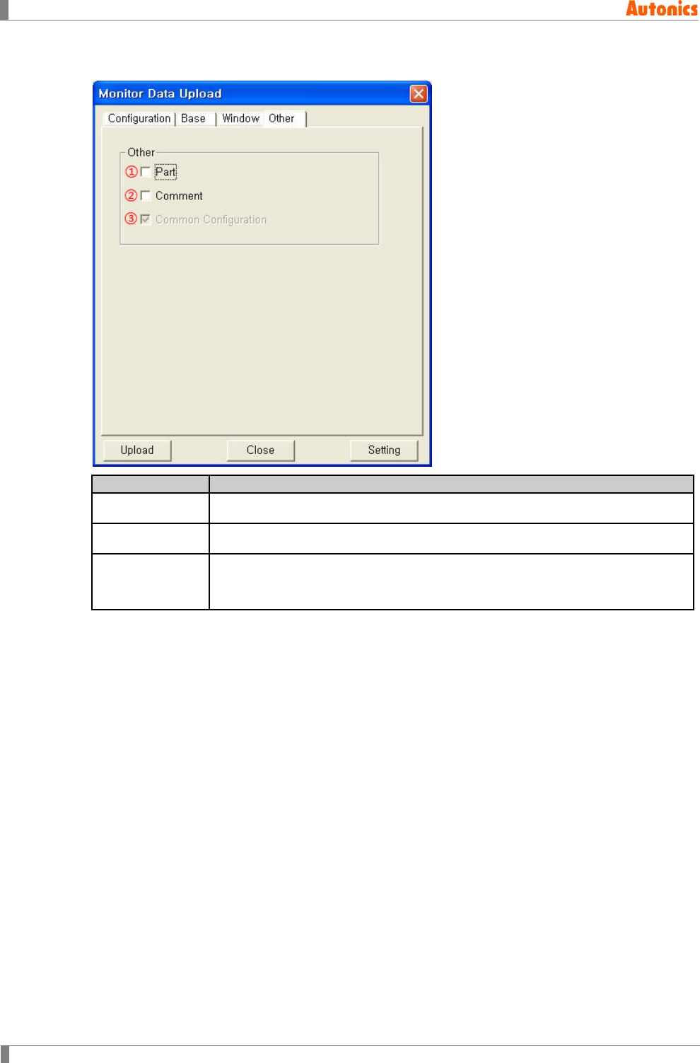
7 Communication
232 © Copyright Reserved Autonics Co., Ltd.
7.2.2.4 Other tab
Other
Description
①Part Uploads all registered parts of the project.
②Comment Uploads all registered comments of the project.
③Common
Configuration
Uploads all registered items at common configuration.
Some configurations which are able to designate at GP/LP such as time action,
project auxiliary setting are uploaded as download setting.
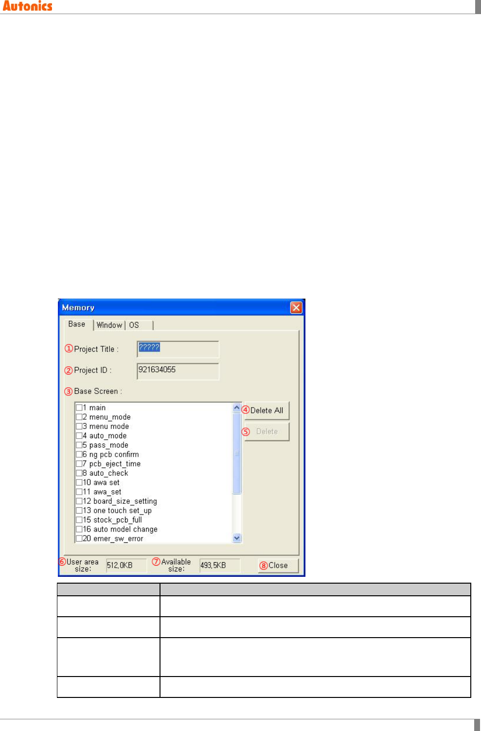
7 Communication
© Copyright Reserved Autonics Co., Ltd. 233
7.3 Memory
This menu is able to check project screens, memory size, firmware version in GP/LP. Also it is
able to delete the desired screen of the project. It is not reading memory to bring all data,
displays main attributions about the project to users.
7.3.1 Execution order
1st Select [Communication]-[Memory] of menu.
2nd ‘Do you want to cancle monitoring and read memeory inforamtion?’ message appears.
3rd If there is password which is designated at [Common]-[Password] of menu, password
dialog box appears. Not correct password cancles the memory instruction.
4th If there is not password which is desiganted at [Common]-[Password] of menu, or
correct password is entered, ‘Memory’ dialog box appears.
5th Execute the desired operation in ‘Memory’ dialog box.
7.3.2 Property
7.3.2.1 Base tab
Base
Description
①Project Title Displays project title in GP/LP.
②Project ID Displays project ID in GP/LP.
③Base Screen Displays base screen list of the project in GP/LP.
Select the desired item and ‘Delete’ is activated. Click ‘Delete’ and it
deletes the selected item in GP/LP memory.
④Delete All Deletes all base screen of GP/LP.
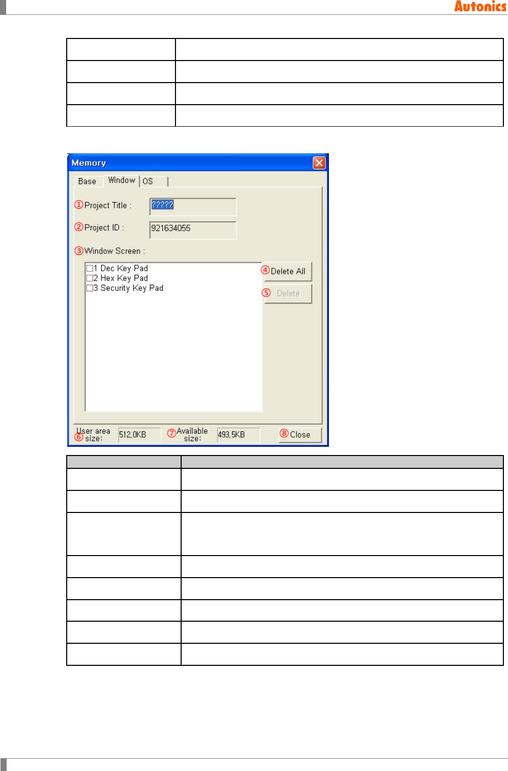
7 Communication
234 © Copyright Reserved Autonics Co., Ltd.
⑤Delete Deletes checked item in list box.
⑥User area size Displays total user area size with byte unit.
⑦Available size Displays available free area size with byte unit.
⑧Close Closes ‘Memory’ dialog box.
7.3.2.2 Window tab
Window
Description
①Project Title Displays project title in GP/LP.
②Project ID Displays project ID in GP/LP.
③Window Screen
Displays window screen list of the project in GP/LP.
Select the desired item and ‘Delete’ is activated. Click ‘Delete’ and it
deletes the selected item in GP/LP memory.
④Delete All Deletes all window screen of GP/LP.
⑤Delete Deletes checked item in list box.
⑥User area size Displays total user area size with byte unit.
⑦Available size Displays available free area size with byte unit.
⑧Close Closes ‘Memory’ dialog box
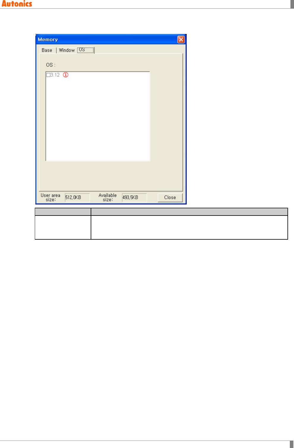
7 Communication
© Copyright Reserved Autonics Co., Ltd. 235
7.3.2.3 OS tab
OS
Description
①List box
Displays firmware version of GP/LP.
Select [Communication]-[GP Firmware Download] of menu and download
upgraded firmware.
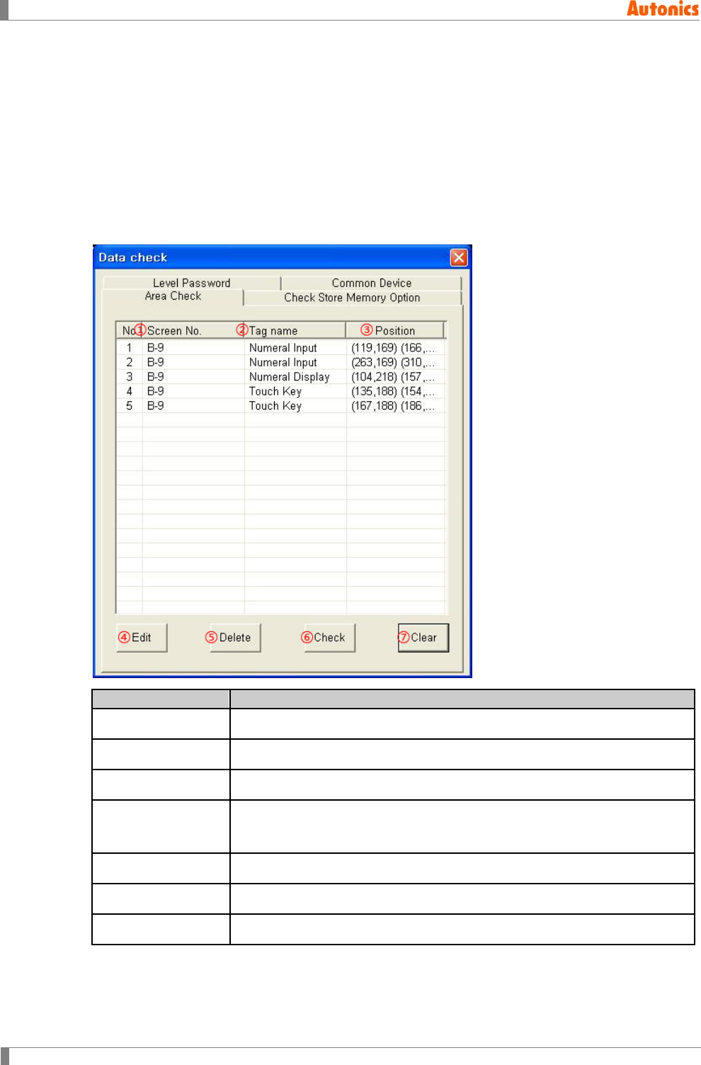
7 Communication
236 © Copyright Reserved Autonics Co., Ltd.
7.4 Check Data
You may create error data when editing screen data in GP Editor. Therefore, GP Editor helps you
to find for correcting and editing error data by checking data. This data checking is operated
automaticaly when downloading data to GP/LP.
If there is error data, ‘Data check’ dialog box appears and lists error list. ‘Data check’ dialog box
is modeless dialog box which enable to edit continue.
7.4.1 Area tab
It checks data and lists the tag which is out of edit area.
Area Check
Description
①Screen No. Displays base or window screen number of the specified tag.
②Tag name Displays the specified tag name.
③Position Displays tag coordinates as ‘(left, top) (right, bottom)’ form.
④Edit Select the desired item to edit and click ‘Edit’. Selected item is displayed
with selected state on the edit area. To double-click the desired item is
same function.
⑤Delete Deletes the selected tag item.
⑥Check Executes data check again.
⑦Clear Closes ‘Data check’ dialog box.
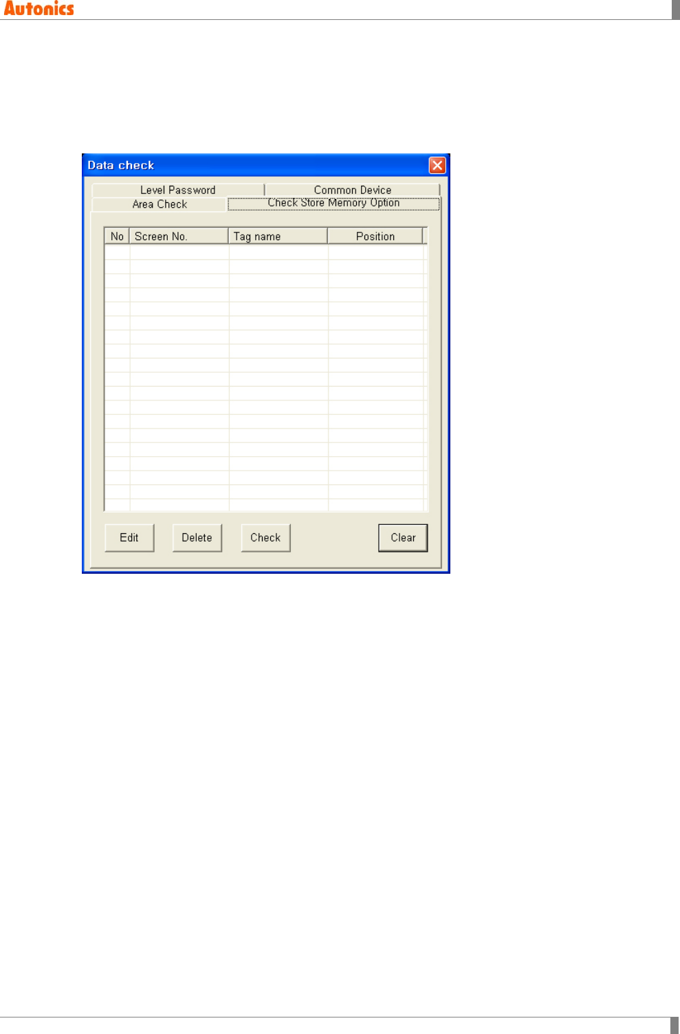
7 Communication
© Copyright Reserved Autonics Co., Ltd. 237
7.4.2 Check store memory option tab
A project should have up to 17 store memory options for alarm list and trend graph. You can
check the number of this option. This tab displays tag list which has store memory option to edit
attributions. The descriptions of ‘Check Store Memory Option’ tab are same as ‘Area Check’
tab’s.
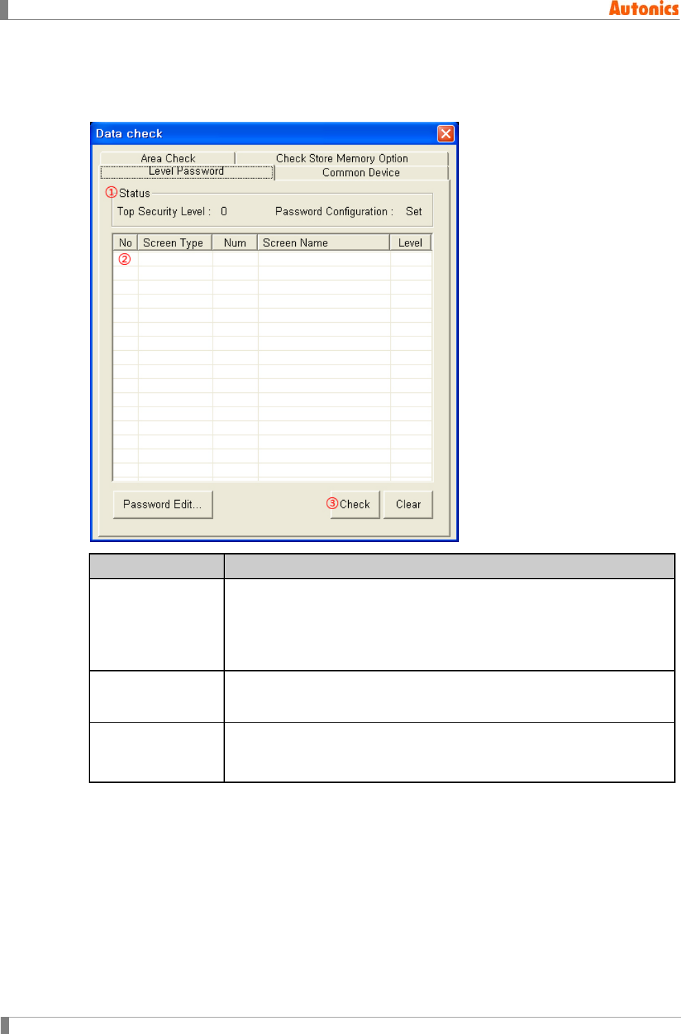
7 Communication
238 © Copyright Reserved Autonics Co., Ltd.
7.4.3 Level password tab
It checks whether password is input for the top security level of base screen with proejct security
level or not.
Level Password Description
①Status
Displays top security level and whether there is set password or not for
editing base screens.
Top Security Level: Top security level among base screens.
Password Configuration: If there is not set password, ‘Not’ is displayed.
If there is set password, ‘Set’ is displayed.
②List Box Displays screen number which is top security level, and the level. Double-
click and ‘Security’ dialog box of [Common]-[Security] of menu appears to
edit security level and password.
③Check
Click this after editing or inputting security level and password, and it
checks for security level again. If there is no error, ‘Password Configuration’
of ①Status displays ‘Set’.
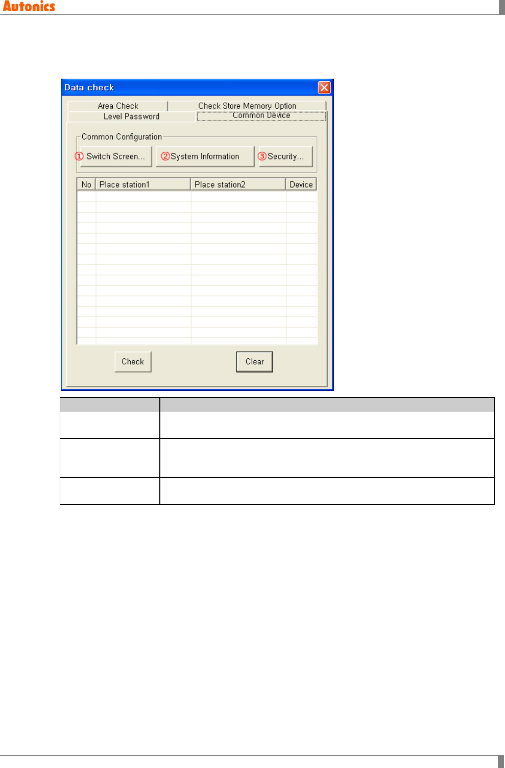
7 Communication
© Copyright Reserved Autonics Co., Ltd. 239
7.4.4 Common device tab
It checks there is same device registred at [Common] menu for the project or not.
Common Device
Description
①Switch Screen Calls ‘Switch Screen’ dialog box from [Common]-[Switch Screen] of menu
to check the used device for switching ‘base screen, overlap window 1, 2’.
②System
Information
Calls ‘System Information’ dialog box from [Common]-[System Information]
of menu to check the device state for communicating between GP/LP and
PLC device.
③Security Calls ‘Security’ dialog box from [Common]-[Security] of menu to check the
device state about security level for project.
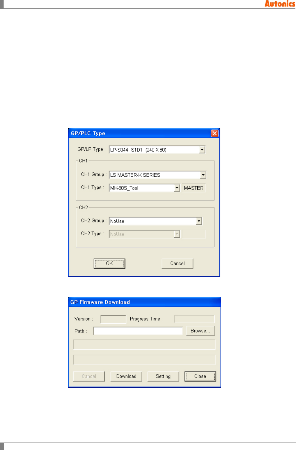
7 Communication
240 © Copyright Reserved Autonics Co., Ltd.
7.5 GP Firmware Download
You can download and upgrade firmware of GP/LP by GP Editor.
7.5.1 Firmware download execution order
7.5.1.1 Mono type
1st Firmware file is different as GP/LP model. Download a firmware file from
www.autonics.com.
2nd You can download only for same firmware GP/LP type with GP/LP type designated at
GP Editor. Select [Common]-[GP/PLC Type] of menu, ‘GP/PLC Type’ dialog box
appears. By pull-down menu, designate to be downloaded GP/LP type.
3rd Select [Communication]-[GP Firmware Download] of menu and ‘GP Firmware
Download’ dialog box appears.
4th Click ‘Browse’ and select firmware file to be downloaded.
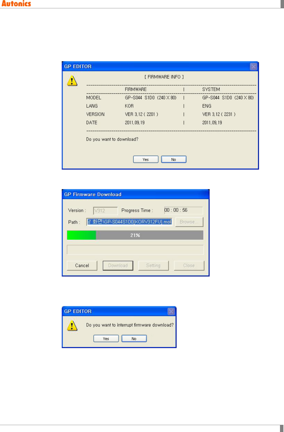
7 Communication
© Copyright Reserved Autonics Co., Ltd. 241
5th Click ‘Download’ and the firmware information dialog box for current GP/LP firmware
appears and askes whether to download or not. If connected GP/LP is not same as
the designated GP/LP type from [Common]-[GP/PLC Type] of menu, error message
appears.
6th Click ‘Yes’ and GP/LP screen displays ’GP FIRMWARE UPGRADE’ message. GP
Editor displays ‘GP Firmware Download’ dialog box and download progresses.
If you want to discontinue download, click ‘Cancle’ and ‘Do you want to interrupt
firmware download?’ message appears. Click ‘Yes’ and it discontinues download. For
discontinuing downlaod, re-start GP/LP.
7th When completing download successively, GP/LP displays ‘UPGRADE OK PLEASE
POWER OFF’ message.
When failing donwload, GP/LP displays ‘UPGRADE NG PLEASE POWER OFF’
message. Re-start GP/LP. GP/LP maintains before firmware version and it does not
affect to GP/LP operation.
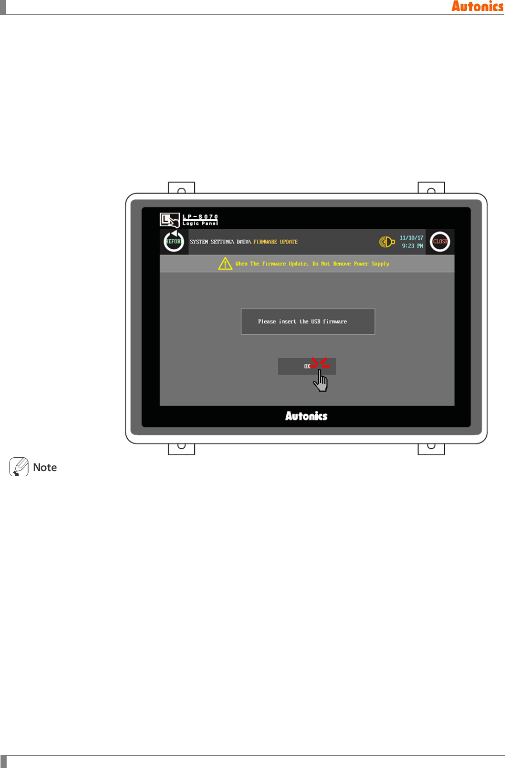
7 Communication
242 © Copyright Reserved Autonics Co., Ltd.
7.5.1.2 Color type
GP Editor does not support firmware upgrade for color type(GP-S070, LP-S070). Firmware
upgrade of color type is available only by USB HOST.
1st Visit our homepage www.autonics.com to download a firmware file and save this file
to USB memory.
2nd Connect USB memory to USB host of GP/LP, and call system setting menu.
3rd Select [DATA]-[FIRMWARE UPDATE].
4th Touch ‘OK’ and it starts firmware update.
After firmware upgrading, all of GP/LP user data are deleted.
Before upgrading firmware, select [Communication]-[Upload] of menu to save the desired data.
7.6 Option
Refer to ‘2.6.3 Communication ’.
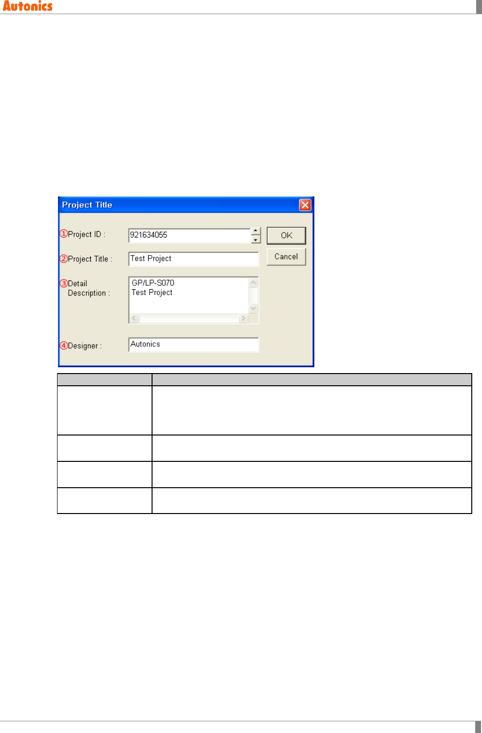
8 Common
© Copyright Reserved Autonics Co., Ltd. 243
8 Common
8.1 Title
You can designate project ID, title, detail description to a project for convenient management of
GP/LP and GP Editor. You can download or upload this information to GP/LP with GP Editor.
Each base or window screen also has title and detail description. You can download or upload
this title to GP/LP with GP Editor. Detail description is not able to download to GP/LP.
Screen title is used for screen list at GP/LP.
8.1.1 Project title
Project Title
Description
①Project ID
Created with project. You can edit this from 1 to 4,294,967,295.
When downloading project without deleting the existing project on GP/LP, if
the existing project ID is not same as to be downloaded project ID, warning
message appears.
②Project Title Edit project title. This may be omitted or up to 32 characters can be
entered.
③Detail Description Edit project detail description. This may be omitted or up to 512 characters
can be entered.
④Designer Edit designer name. This may be omitted or up to 8 characters can be
entered.
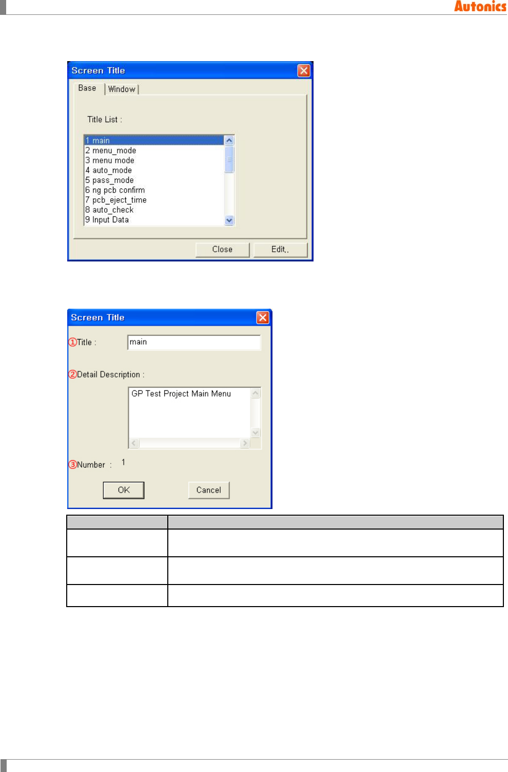
8 Common
244 © Copyright Reserved Autonics Co., Ltd.
8.1.2 Screen title
You can edit title and detail describtion of base or window screen.
Double-click or select to be edited base or window screen and click ‘Edit’ and that base screen’s
‘Screen Title’ dialog box appears.
Screen Title
Description
①Title Edit title of the current screen. This may be omitted or up to 32 characters
can be entered. It is downloaded to real GP/LP memory.
②Detail Description Edit detail description of the current screen. This may be omitted or up to
512 characters can be entered. It is not downloaded to GP/LP.
③Number Displays the current screen number.

8 Common
© Copyright Reserved Autonics Co., Ltd. 245
8.2 GP/PLC Type
You should select the device which is connect with GP/LP when creating project at first. Select
[Common]-[GP/PLC Type] of menu, ‘GP/PLC Type’ dialog box appears to change PLC type of
the current project. When changing GP/PLC type, devices which are designated at project are
automatically or manually changed.
Restriction for changing PLC type:Changing GP/LP model is available only between same color
type model. In other words, before mono type project is able to change only to mono type, color
type project is able to change only to color type.
8.2.1 PLC connection
To opeate correctly downloaded screen data in GP/LP, you should designated right PLC type at
GP Editor.
Whenever creating a new project, ‘GP/PLC Type’ dialog box appears to designate GP/LP and
PLC type.
When starting GP Editor, for not to appear ‘Project Select’ ‘GP/PLC Type’ dialog box; select
[Project]-[Option] of menu and non-check ‘Select project when program is started’. When starting
GP Editor after this, GP and PLC type is designated automatically as the latest saved project’s
type. ‘Project Select’ and ‘GP/PLC Type’ dialog box does not appear. You can change GP/LP
and PLC type in [Common]-[GP/PLC Type] of menu.
Connection for PLC is different by PLC type, refer to ‘GP, LP user manual for
communication’.
Every device such as PLC, etc is available to connect any RS232C or RS422 port.
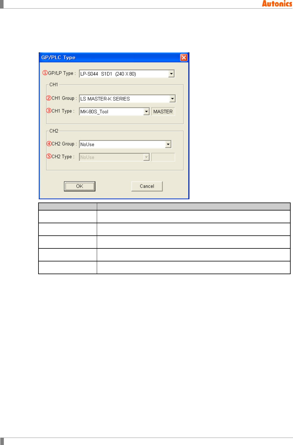
8 Common
246 © Copyright Reserved Autonics Co., Ltd.
8.2.2 Connecting PLC setting
To download data editing in GP Editor to PLC, you should designate connected PLC group, type,
and communication type.
GP/PLC Type
Description
①GP/LP Type Designate GP/LP model type by pull-down menu.
②CH1 Group Designate PLC group of CH1 by pull-down menu.
③CH1 Type Designate PLC type of CH1 for ② by pull-down menu.
④CH2 Group Designate PLC group of CH2 by pull-down menu.
⑤CH2 Type Designate PLC type of CH2 for ④ by pull-down menu.
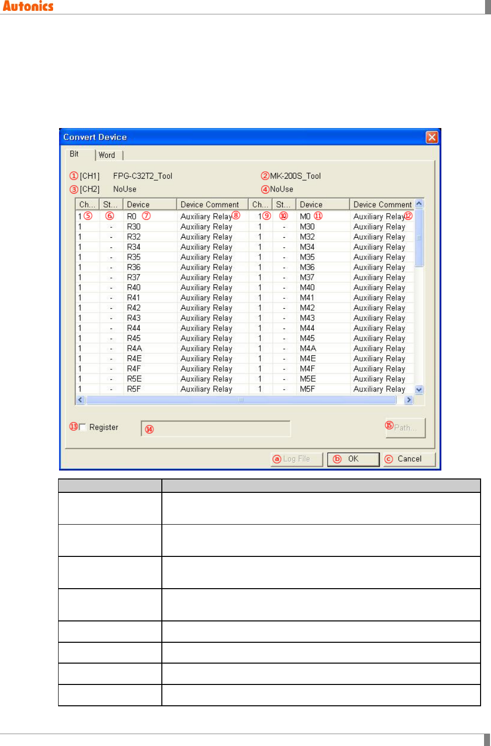
8 Common
© Copyright Reserved Autonics Co., Ltd. 247
8.2.3 Convert device with changing PLC type
After changing PLC type in ‘GP/PLC Type’ dialog box and clicking ‘OK’, ‘Convert Device’ dialog
box appears. The devices of current project (before converting device) are automatically
converted to the device of changed PLC type project(after converting device).
Before converting and after converting devices are listed on ‘Convert Device’ dialog box by bit or
word device. You can manually convert not automatically converted device.
Convert Device
Description
①Before changing
CH1 PLC Displays before changing PLC type of CH1.
②After changing CH1
PLC Displays after changing PLC type of CH1.
③Before changing
CH2 PLC Displays before changing PLC type of CH2.
④After changing CH2
PLC Displays after changing PLC type of CH2.
⑤Channel Displays before converting device channel.
⑥Station Displays before converting device station.
⑦Device Displays the devices of current project (before converting device).
⑧Device Comment Displays device comment for each character of ⑦Device.
8 Common
248 © Copyright Reserved Autonics Co., Ltd.
Convert Device
Description
⑨Channel Displays after converting device channel.
⑩Station Displays after converting device station.
⑪Device
Displays the device of changed PLC type project(after converting device)
which corresponds to ⑦Device.
If there is not corresponded device to ⑦Device, it displays ‘??’.
You can enter and designate the corresponded device.
⑫Device Comment Displays device comment for each character of ⑪Device.
⑬Register
Designate saving changed list on dialog box as file or not.
Checking this, you can designate to be saved file patch with activated ⑭,
⑮.
⑭Path Displays to be saved log file path.
⑮Path... Designate to be saved log file path.
ⓐLog File Saves the list of ‘Convert Device’ dialog box as log file (text).
ⓑOK Converts devices as the list, changes PLC type, and closes ‘Convert
Device’ dialog box.
ⓒCancel Cancels changing PLC type, closes ‘Convert Device’ dialog box.
Example of log file
Bit device convert
Before converting
After converting
[CH1(----)] R0(auxiliary relay) [CH1(----)] M0(auxiliary relay)
[CH1(----)] R1(auxiliary relay) [CH1(----)] M1(auxiliary relay)
[CH1(----)] R2(auxiliary relay) [CH1(----)] M2(auxiliary relay)
[CH1(----)] R3(auxiliary relay) [CH1(----)] M3(auxiliary relay)
Word device convert
Before converting
After converting
[CH1(----)] DT0(data register) [CH1(----)] D0(data register)
[CH1(----)] DT1(data register) [CH1(----)] D1(data register)
[CH1(----)] DT2(data register) [CH1(----)] D2(data register)
[CH1(----)] DT3(data register) [CH1(----)] D3(data register)
[CH1(----)] DT4(data register) [CH1(----)] D4(data register)
[---(----)] UW20(LP word device) [---(----)] UW20(LP word device)
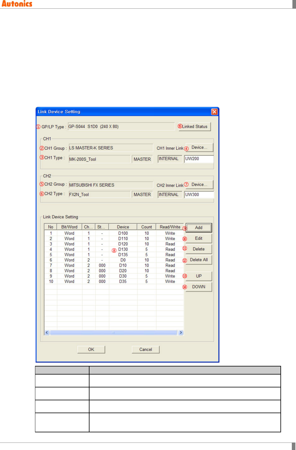
8 Common
© Copyright Reserved Autonics Co., Ltd. 249
8.3 Link Device
Generally GP/LP monitors directly PLC device of CH1. To link PLC device of CH1 and GP/LP
connect device (by saving monitored PLC device value to specified GP/LP connect device), link
devie menu is needed.
Mono type must use link device with CH2 to communicate 1:N.
Color type is able to monitor directly PLC device of each channel (CH1,CH2). Therefore, color
type does not use link device and is able to communicate 1:N without CH1, CH2 division.
However, PLC which supports station is only able to communicate 1:N.
Select [Common]-[Link Device] of menu, ‘Link Device Setting’ dialog box appears.
Link Device
Description
①GP/LP Type Displays GP/LP model type.
②CH1 Group Displays CH1 group.
③CH1 Type Display PLC type of CH1 group.
④CH1 Inner Link
Device Designate lead word address of GP/LP for communication with CH1
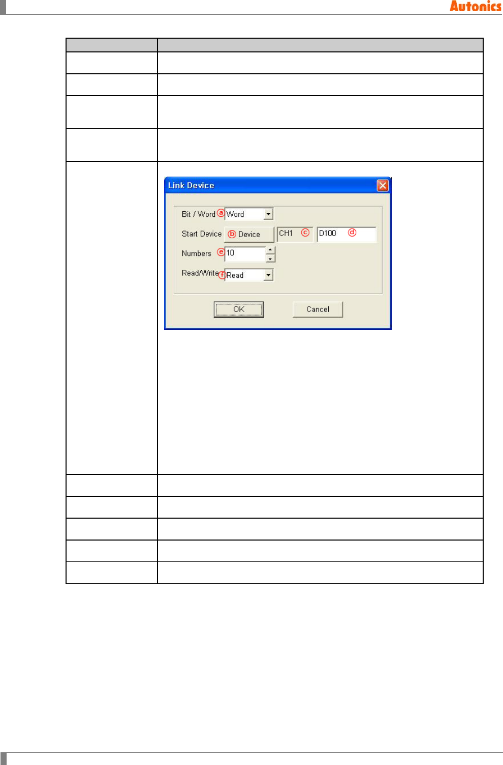
8 Common
250 © Copyright Reserved Autonics Co., Ltd.
Link Device
Description
⑤CH2 Group Displays CH2 group.
⑥CH2 Type Displays PLC type of CH2 group.
⑦CH2 Inner Link
Device Designate lead word address of GP/LP for communication with CH2.
⑧Link Device
Setting Status
Displays bit/word, channel, station, start device, count, read/write of
CH1/CH2 to communicate with GP/LP
⑨Add
Adds link device settings. ‘Link Device’ dialog box appears.
ⓐBit/Word: Select bit/word device of PLC to communicate
ⓑStart Device: Designate start device of PLC to communicate
ⓒStart Device: Displays selected channel at ⓑ
ⓓStart Device: Displays selected device at ⓑ
ⓔNumbers: Designate the number of read/write device from start device
at ⓑ
ⓕRead/Write: Set read/write operation for designated device
Link device information by channel is able to register up to 5.
⑩Edit Edit the selected item on ⑧ among set link device
⑪Delete Delete the selected item on ⑧ among set link device
⑫Delete All Delete all of set link device
⑬UP Moves up the item of set link device.
⑭DOWN Moves down the item of set link device.
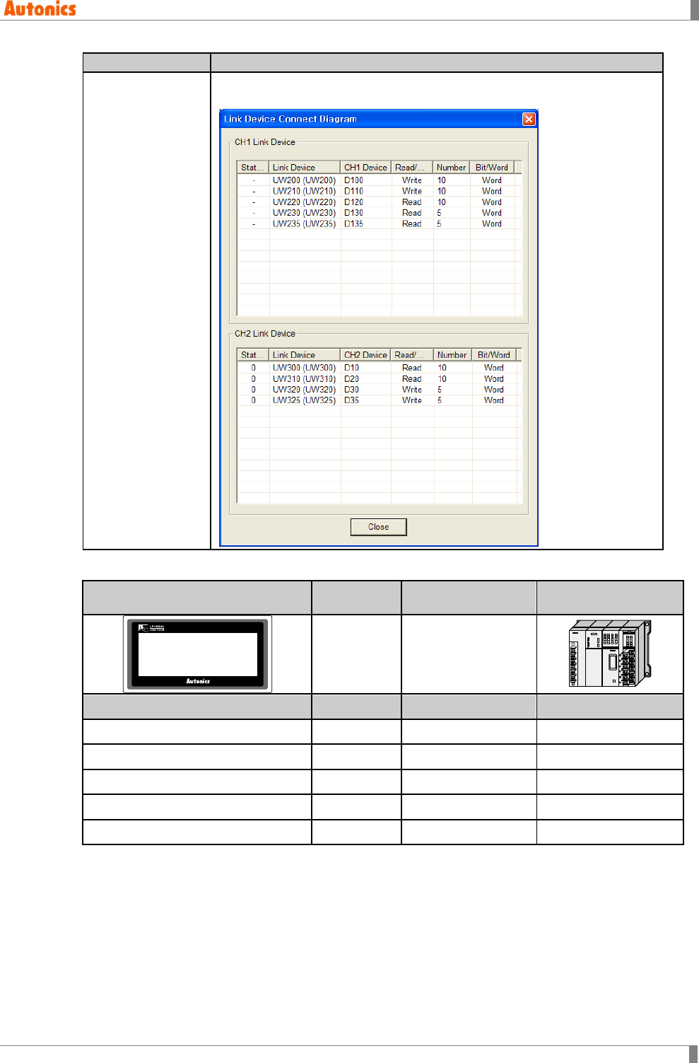
8 Common
© Copyright Reserved Autonics Co., Ltd. 251
Link Device
Description
⑮Linked Status
Displays table for link device setting of set between GP/LP and CH1,
GP/LP and CH2.
GP/LP
CH1
station
Communication
direction
CH1 PLC
GP/LP Series ※1 MK-200S
UW200 to UW209 - (Write) → D100 to D109
UW210 to UW219 - (Write) → D110 to D119
UW220 to UW229 - (Write) → D120 to D129
UW230 to UW234 - (Read) ← D130 to D134
UW235 to UW239 - (Read) ← D135 to D139
※1. Mono type(GP-S044, GP-S057, LP-S044) is able to communicate 1:1 for CH1, and does not
support multi station selection. It is fixed as the station of GP/LP and displays ‘-’.
Color type(GP-S070, LP-S070) is able to communicate 1:1, 1:N for without CH1, CH2
division, and supports multi station selection. It is able to designate station. If PLC of
connected with CH2 does not support station, it displays ‘-’ and 1:N communication does
not execute.
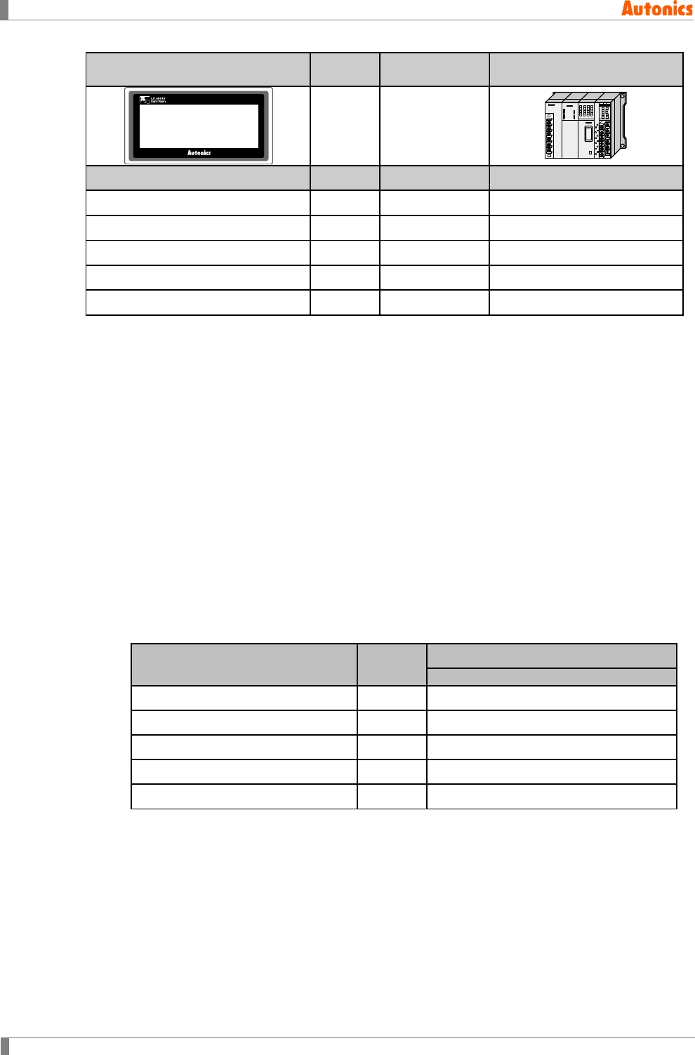
8 Common
252 © Copyright Reserved Autonics Co., Ltd.
GP/LP
CH2
station
Communicati
on direction
CH2 PLC
GP/LP Series ※2
FX-2N
UW300 to UW309 - (Read) ← D0 to D9
UW310 to UW319 - (Read) ← D10 to D19
UW320 to UW329 - (Read) ← D20 to D29
UW330 to UW334 - (Write) → D30 to D34
UW335 to UW339 - (Write) → D35 to D39
※1. Mono type(GP-S044, GP-S057, LP-S044) ) is able to communicate 1:1, 1:N for CH2 and
supports multi station selection. If PLC of connected with CH2 does not support station, , it
displays ‘-’ and 1:N communication does not execute.
Color type(GP-S070, LP-S070) is able to communicate 1:1, 1:N for without CH1, CH2
division, and supports multi station selection. If PLC of connected with CH2 does not
support station, , it displays ‘-’ and 1:N communication does not execute.
In this case, UW(i) is ist GP device, Dk(i) is ist CH1 device.
(1) CH1 GP connect device: UW(i)
Link device setting
Start Device: D1(i), Bit/Word: Word, Numbers: A, Read/Write: Write
Start Device: D2(i), Bit/Word: Word, Numbers: B, Read/Write: Read
Start Device: D3(i), Bit/Word: Word, Numbers: C, Read/Write: Read
Start Device: D4(i), Bit/Word: Word, Numbers: D, Read/Write: Read
Start Device: D5(i), Bit/Word: Word, Numbers: E, Read/Write: Write
GP Device(Word) Data
move CH1
Device
First A units of device from UW (i) → D1(i) to D1(i+A-1)
B units of device from the next ← D2(i) to D2(i+B-1)
C units of device from the next ← D3(i) to D3(i+C-1)
D units of device from the next ← D4(i) to D4(i+D-1)
E units of device from the next → D5(i) to D5(i+E-1)
(2) CH1 GP connect device: UW (i)
Link device setting
Start Device: D1(i), Bit/Word: Word, Numbers: A, Read/Write: Write
Start Device: D2(i), Bit/Word: Bit, Numbers: B, Read/Write: Read
Start Device: D3(i), Bit/Word: Word, Numbers: C, Read/Write: Read
Start Device: D4(i), Bit/Word: Bit, Numbers: D, Read/Write: Read
Start Device: D5(i), Bit/Word: Word, Numbers: E, Read/Write: Write
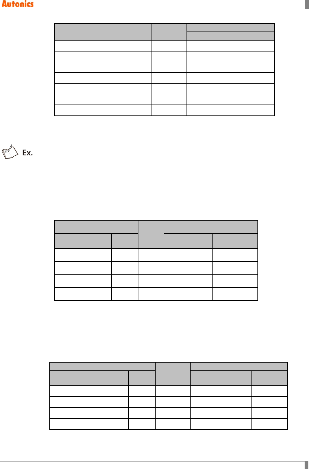
8 Common
© Copyright Reserved Autonics Co., Ltd. 253
GP Device(Word) Data
move
CH1
Device
First A units of device from UW (i) → D1(i) to D1(i+A-1)
[(B+16-1)/16] units of device from
the next ← D2(i) to D2(i+[(B+16-1)/16]-1)
C units of device from the next ← D3(i) to D3(i+C-1)
[(D+16-1)/16] units of device from
the next ← D4(i) to D4(i+[(D+16-1)/16]-1)
E units of device from the next → D5(i) to D5(i+E-1)
GP device is always word. When CH1 link device is set as bit, it is linked as below.
1 to 16 units of CH1 bit device ↔ 1 unit of GP word device
17 to 32 units of CH1 bit device ↔ 2 units of GP word device
CH1 GP connect device: UW(30)
Link device setting
Start Device: K(0), Bit/Word: Word, Numbers: 5, Read/Write: Write
Start Device: M(0), Bit/Word: Word, Numbers: 3, Read/Write: Write
Start Device: D(0), Bit/Word: Word, Numbers: 4, Read/Write: Read
Start Device: D(10), Bit/Word: Word, Numbers: 6, Read/Write: Write
GP Data
move
CH1
Device(Word)
Numb
ers
Device Numbers
UW(30) to UW(34) 5 → K(0) to K(4) Word 5
UW(35) to UW(37) 3 → M(0) to M(2) Word 3
UW(38) to UW(41) 4 ← D(0) to D(3) Word 4
UW(42) to UW(47) 6 → D(10) to D(15) Word 6
CH1 GP connect device: UW(30)
Link device setting
Start Device: K(0), Bit/Word: Word, Numbers: 5, Read/Write: Write
Start Device: M(0), Bit/Word: Word, Numbers: 3, Read/Write: Read
Start Device: P(10), Bit/Word: Bit, Numbers: 20, Read/Write: Read
Start Device: D(10), Bit/Word: Word, Numbers: 6, Read/Write: Write
GP
Data
move
CH1
Device(Word)
Numb
ers
Device Word
UW(30) to UW(34) 5 → K(0) to K(4) Word 5
UW(35) to UW(37) 3 → M(0) to M(2) Word 3
UW(38) 1 ← P(10) to P(13) Bit 4
UW(39) to UW(44) 6 → D(10) to D(15) Word 6
If numbers is set over than usable numbers, maximum range numbers is used.
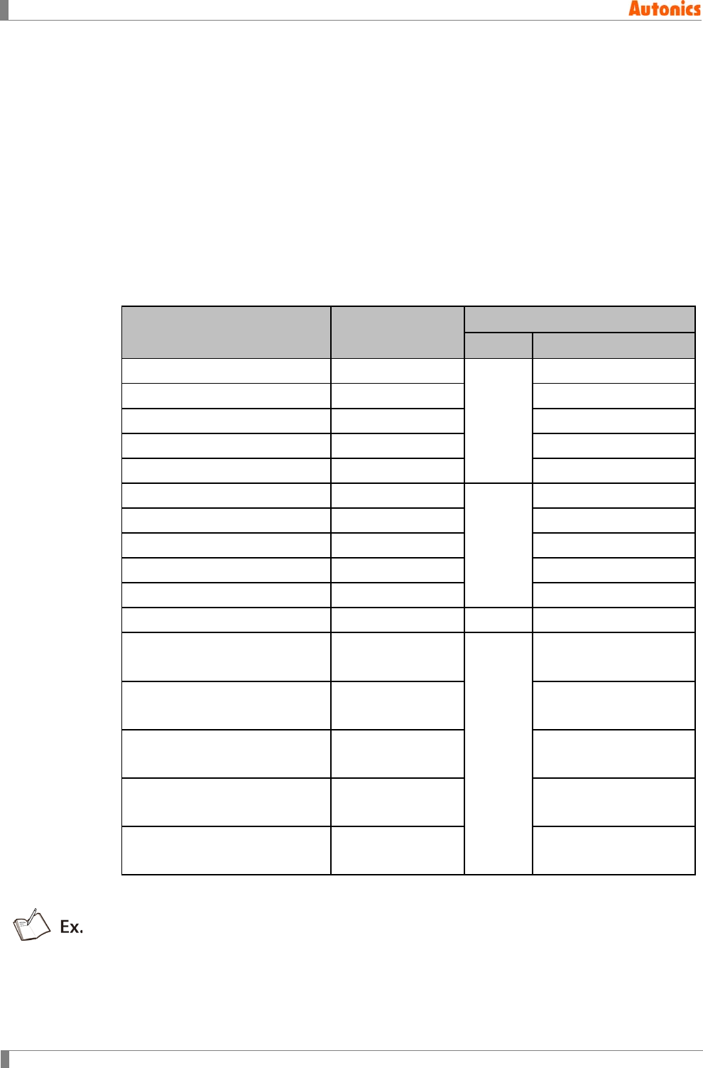
8 Common
254 © Copyright Reserved Autonics Co., Ltd.
CH2 device is monitored indirectly with linked GP device. CH2 link device setting is same as
CH1 data link and is able to connect multi devices and to set several stations.
In this case, D(i) is ist GP device, N_Dk(i) is that station is N, Dk(i) is ist CH2 device.
CH2 GP connect device: D(i)
Set for station and connect device
(3) Station N
Start Device: N_D1(i), Bit/Word: Word, Numbers: AN
Start Device: N-D2(i), Bit/Word: Word, Numbers: BN
Start Device: N-D3(i), Bit/Word: Word, Numbers: CN
Start Device: N-D4(i), Bit/Word: Word, Numbers: DN
Start Device: N-D5(i), Bit/Word: Word, Numbers: EN
GP/LP Device(Word) Data move CH2
Station Device
First A0 units of device from D(i) Read/Write
0
0_D1(i) to 0_D1(i+A0-1)
B0 units of device from the next Read/Write 0_D2(i) to 0_D2(i+B0-1)
C0 units of device from the next Read/Write 0_D3(i) to 0_D3(i+C0-1)
D0 units of device from the next Read/Write 0_D4(i) to 0_D4(i+D0-1)
E0 units of device from the next Read/Write 0_D5(i) to 0_D5(i+E0-1)
A1units of device from the next Read/Write
1
1_D1(i) to 1_D1(i+A1-1)
B1units of device from the next Read/Write 1_D2(i) to 1_D2(i+B1-1)
C1units of device from the next Read/Write 1_D3(i) to 1_D3(i+C1-1)
D1units of device from the next Read/Write 1_D4(i) to 1_D4(i+D1-1)
E1units of device from the next Read/Write 1_D5(i) to 1_D5(i+E1-1)
… … … …
A31units of device from the next Read/Write
31
31_D1(i) to 31_D1(i+A31-
1)
B31units of device from the next Read/Write 31_D2(i) to 31_D2(i+B31-
1)
C31units of device from the next Read/Write 31_D3(i) to 31_D3(i+C31-
1)
D31units of device from the next Read/Write 31_D4(i) to 31_D4(i+D31-
1)
E31units of device from the next Read/Write 31_D5(i) to 31_D5(i+E31-
1)
If Bit/Word setting is Bit, CH1 link device has same link structure as bit’s and communicates
with GP/LP.
- CH2 GP connect device:UW(30)
- Set for station and connect device
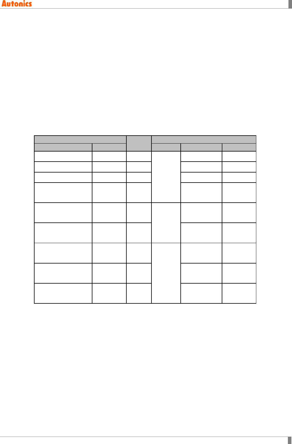
8 Common
© Copyright Reserved Autonics Co., Ltd. 255
(4) Station 1
Start Device: K(0), Bit/Word: Word, Numbers:5, Read/Write: Write
Start Device: M(0), Bit/Word: Bit, Numbers:3, Read/Write: Write
Start Device: D(0), Bit/Word: Word, Numbers:4, Read/Write: Read
Start Device: D(10), Bit/Word: Word, Numbers:6, Read/Write: Write
(5) Station 3
Start Device: K(10), Bit/Word: Bit, Numbers:2, Read/Write: Read
Start Device: M(16), Bit/Word: Word, Numbers:5, Read/Write: Write
(6) Station 11
Start Device: D(20), Bit/Word: Word, Numbers:7, Read/Write: Read
Start Device: D(30), Bit/Word: Word, Numbers:2, Read/Write: Write
Start Device: M(32), Bit/Word: Bit, Numbers:4, Read/Write: Write
GP/LP
Data
move
CH2
Device
Numbers
Station
Device
Numbers
UW(30) to UW(34) 5 →
1
K(0) to K(4) Word 5
UW(35) 1 → M(0) to M(3) Bit 3
UW(36) to UW(39) 4 ← D(0) to D(3) Word 4
UW(40) to UW(45) 6 → D(10) to
D(15) Word 6
UW(46) 1 ←
3
K(10) to
K(11) Bit 2
UW(47) to UW(51) 5 → M(16) to
M(20) Word 5
UW(52) to UW(58) 7 ←
11
D(20) to
D(26) Word 7
UW(59) to UW(61) 2 → D(30) to
D(31) Word 2
UW(62) 1 → M(32) to
M(35) Bit 4
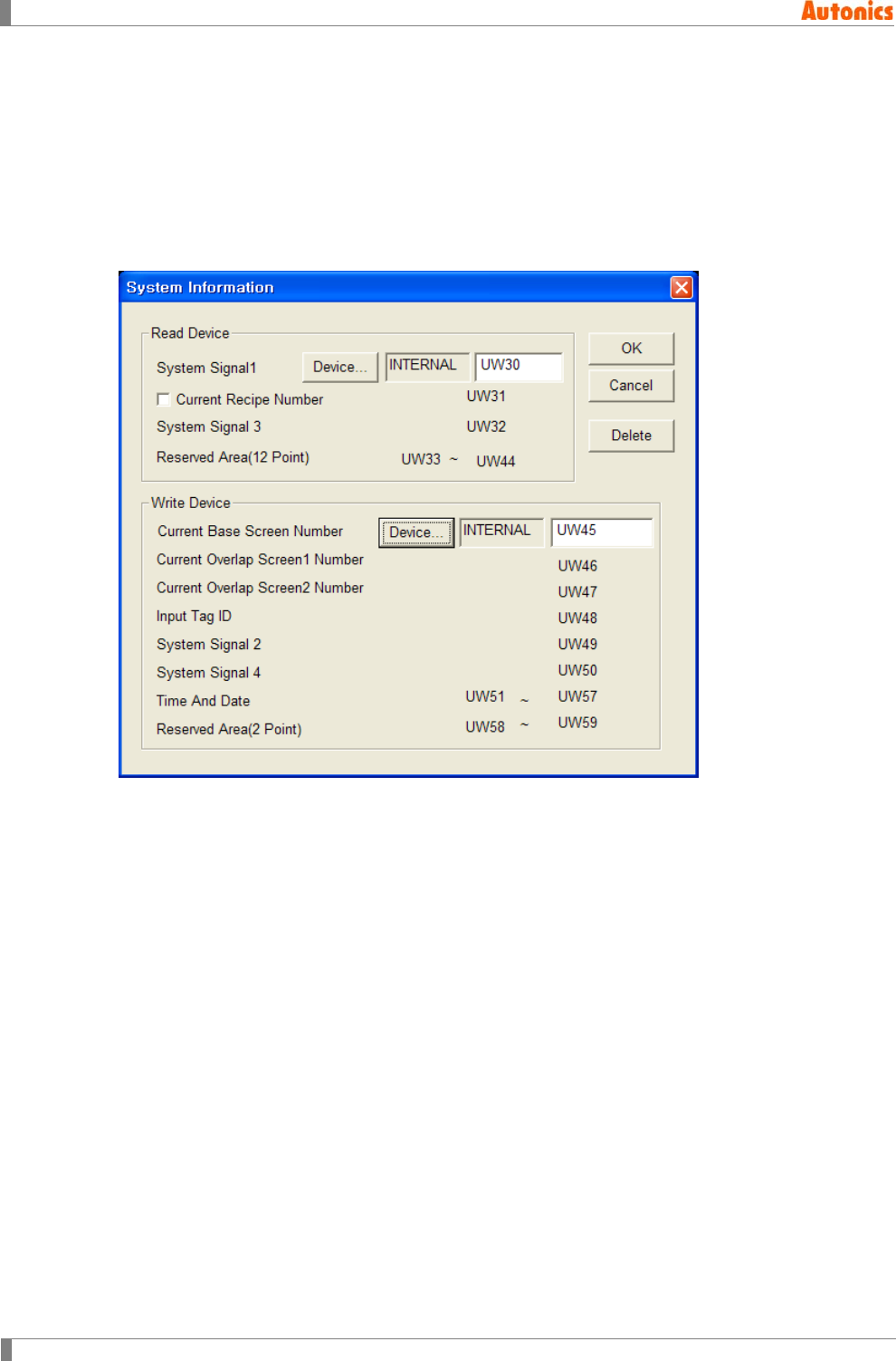
8 Common
256 © Copyright Reserved Autonics Co., Ltd.
8.4 System Information
8.4.1 Overview
It communicates always between read/write device of GP/LP and PLC device designated from
‘System Information’ dialog box of GP Editor. Depending on read device value, it controls GP/LP
operation and depending on write device value, it monitors GP/LP state.
Select [Common]-[System Information] of menu, ‘System Information’ dialog box appears.
8.4.2 Read device
Reads PLC device in GP/LP, controlls GP/L P.
Designate word device from ‘System Information’ dialog box of GP Editor.
(1) System Signal1
Bit 0
It clears all alarm history (history and occurrence) when this bit is OFF→ON. When this
bit is ON→OFF, it does not clear alarm history.
[Common]-[Alarm History] of menu has also same alarm history clear function. ‘Alarm
History Property’ dialog box appears. Check ‘Erase History’ and designate device.
Clear alarm history by setting the designated device which operates independently
without this bit.
Bit 1
Backlight is turned off after when this bit is OFF→ON and designated time in system
setting is passed. Backlight is turned on when this bit is OFF again or you touch the
screen. When this bit is ON state, backlight is operated and it is not operated in OFF
state.
Bit 2
When GP/LP and external device (CH1) is not connected, or there is connection
problem, this bit is ON and displays error message.
8 Common
© Copyright Reserved Autonics Co., Ltd. 257
Bit 3
When GP/LP and external device (CH2) is not connected, or there is connection
problem, this bit is ON and displays error message.
Bit 4
[Disable signal for barcode input] When this bit is ON, it processes current read data
from barcode reader as invalid data.
Bit 5
[Complete signal for barcode input read] When this bit is ON, barcode input read is
completed. Barcode reader is ready to receive new data. It switches complete signal
for barcode input write as OFF when GP/LP→PLC.
Bit 7
When this bit is ON, it switches complete signal for numeral input bit (Bit 4 of system
signal 2) into OFF.
For further details about Bit 4 and Bit 5, refer to ‘8.13 Barcode’.
(2) Current Recipe Number
You can designate recipe number to read and write among several files of recipe. Write
several recipes in recipe and designate recipe number to this device. Send read/write trigger
signal and each operation is occurred.
+1 address of designated word device from ‘System Information’ dialog box of GP Editor is
allotted.
For further details refer to ‘8.11 Recipe’.
(3) System Signal3
Bit 0: Buzzer control
Buzzer is ON for ON state, buzzer is OFF for OFF state.
Bit 4: Backlight control
Backlight is OFF for ON state, backlight is ON for OFF state.
Bit 5: Print control
It starts to print alarm when it is changed as OFF→ON.
(4) Reserved Area(12Point)
It is reserved area to add system signal.
8.4.3 Write device
It monitors GP/LP state with reading GP/LP device of PLC.
(1) Current Base Screen Number. (Write Device)
It writes current screen number of GP/LP.
When you switches screen, this device value is changed as switched screen number.
(2) Current Overlap Screen1 Number (Write Device+1)
It writes overlap window 1 screen number of GP/LP to the designated PLC device from
‘System Information’ dialog box. +1 address of designated word device from ‘System
Information’ dialog box of GP Editor is allotted.
(3) Current Overlap Screen2 Number (Write Device+2)
It writes overlap window 2 screen number of GP/LP to the designated PLC device from
‘System Information’ dialog box. +2 address of designated word device from ‘System
Information’ dialog box of GP Editor is allotted.
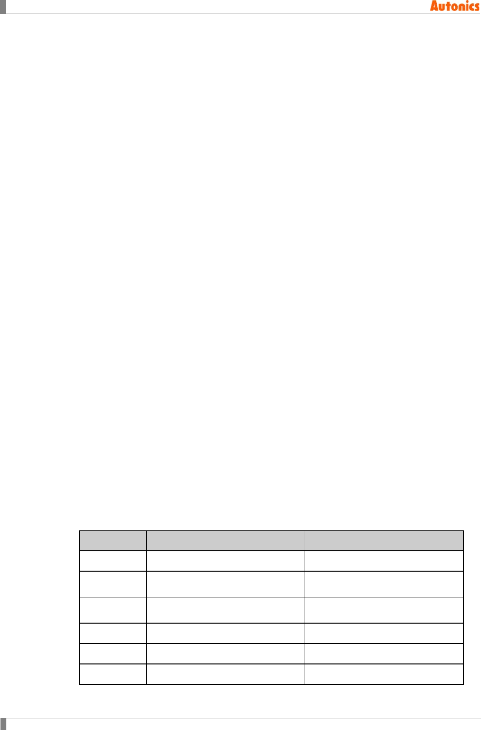
8 Common
258 © Copyright Reserved Autonics Co., Ltd.
(4) Input Tag ID (Write Device+3)
If there is the screen which has numeral input or ASCII input tag, it saves user ID of input
tag which completed input at this device. +3 address of designated word device from
‘System Information’ dialog box of GP Editor is allotted.
(5) System Signal2 (Write Device+4)
Bit 0
This bit is ON when at least one alarm monitor bit is ON. Even if screen is moved and
alarm monitor bit is ON, this bit preserves the state.
Bit 4: ON when numeral input is completed
This bit is ON when for numeral input or ASCII input tag input value is input normally.
It is not reset automatically, you should reset at PLC program separately.
Bit 8: Barcode input signal
This bit is set when barcode input write data from GP/LP to PLC is completed.
Bit C
This bit is set when battery is low reading voltage state of backup battery.
(6) System Signal4 (Write Device+5)
Bit 0: Flag of alarm print (1 for printing, 0 for the other)
Bit 5: 0.5 sec clock
Bit 6: 1 sec clock
Bit 7: 2 sec clock
Bit 8: Communication port 1 frame error
Bit 9: Communication port 1 parity error
Bit A: Communication port 1 overrun error
Bit C: Communication port 2 frame error
Bit D: Communication port 2 parity error
Bit E: Communication port 2 overrun error
(7) Time And Date (7 POINTS)
(8) Reserved Area (2 POINTS)
It is reserved area which user cannot use.
8.4.4 GP inner device
(1) System Information (UW0 to UW29)
When designating the device from ‘System Information’ dialog box of GP Editor, this device
and GP/LP inner device UW0 to UW29 shares same value.
UW area Read area Write area
UW0 Displayed screen number in GP/LP.
UW1 Displayed overlap1 screen number
in GP/LP
UW2 Displayed overlap2 screen number
in GP/LP
UW3 User ID number of input tag
UW4 System signal 2
UW5 System signal 4
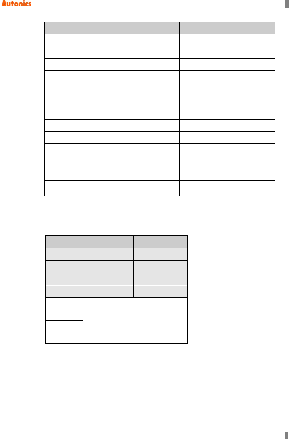
8 Common
© Copyright Reserved Autonics Co., Ltd. 259
UW area Read area Write area
UW6 Clock sec (second)
UW7 Clock min (miniute)
UW8 Clock hour (time)
UW9 Date day (day)_
UW10 Date month (month)
UW11 Date year (year)
UW12 Date a day of week
UW13 Write reserved area
UW14 Write reserved area
UW15 System signal 1
UW16 Current recipe number
UW17 System signal 3
UW18 to
UW29 Read reserved area
(2) UW30 to UW2047
It is used as general data register.
(3) UW2048 to UW6047
It is used as general data registration, however, it is required to notice for using recipe.
UW area Read area Write area
UW30 User area User area
… User area User area
… User area User area
UW2047 User area User area
UW2048
User area(Recipe using area)
…
…
UW6047
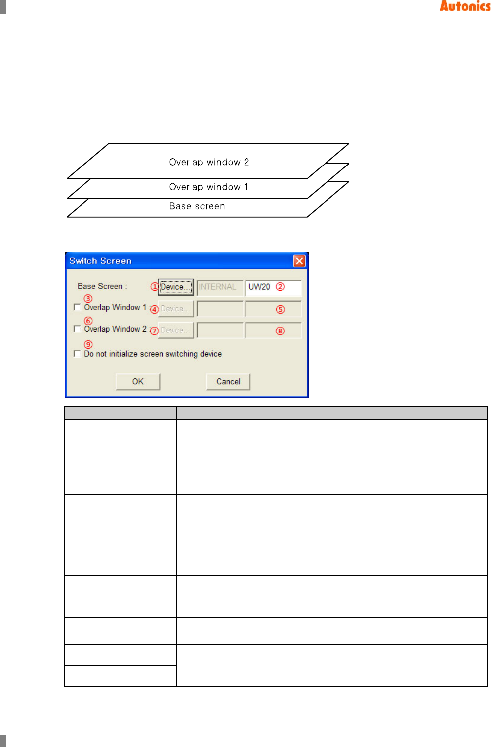
8 Common
260 © Copyright Reserved Autonics Co., Ltd.
8.5 Switch Screen
8.5.1 Basic operation
This function is for that a base screen or overlap screen switches by designated word device
value. For switching a base screen, one device register must be allotted. Therefore data register
is alloted as default. Switching overlap window is available up to two for option, overlap window
1, 2 are overlapped successively on a base screen.
8.5.2 Property
Switch Screen
Description
①Base screen device Calls ‘Device Select’ dialog box to designate device for switching base
screen.
Designated device saves current displayed screen number. If changing
this device value, base screen switches into the changed device base
screen. Data register is allotted as default and you can change it.
GP inner device UW20 is designated as default.
②Device
③Overlap Window 1
Check this for using overlap window 1. The specified base screen is
overlapped depending on the designated word device value.
If both overlap window 1 and 2 are checked, overlap window 2 is
always placed on overlap window1. When it is overlapped, it is affected
on security configuration of the specified screen and it is overlapped
when it is canceled. It displays allowed security level objects and it does
not display over allowed security level object.
④Device Designate word device for switching overlap window 1 screen.
If changing this device value, overlap window 1 screen switches into the
changed device value screen.
⑤Device
⑥Overlap Window 2 Check this for using overlap window2. The specified base screen is
overlapped depending on the designated word device value.
⑦Device Designate word device for switching overlap window 2 screens. If
changing this device value, overlap window 2 screen switches into the
changed device value screen.
⑧Device
8 Common
© Copyright Reserved Autonics Co., Ltd. 261
Switch Screen
Description
⑨Do not initialize
screen switching device
This is for saving basic screen, overlap screen 1,2, and screen number
when downloading data. Designate initializing PLC device value or not.
Checking this, GP/LP maintains the set ②, ⑤, ⑧ Device value when
downloading the set value by GP Editor.
Not-checking this, GP/LP initializes each ②, ⑤, ⑧ Device value to 1,
0, and 0 when downloading the set value by GP Editor.
8.6 Security
Only allowed user can monitor important data and edit it to designate password to each base
screen and system screen. User should input correct password to allow to the desired screen
which has security.
8.6.1 Basic usage
1st From the screen to be set security, select [Common]-[Auxiliary Configuration]-
[Screen] of menu. ‘Screen Auxiliary Property’ dialog box appears. Or click right
mouse button, pop-up menu appears. Select ‘Screen’ and ‘Screen Auxiliary Property’
dialog box appears.
2nd Designate ‘Security Level’ as over 1.
3rd Security level is from 0 to 15. The screen which security level is 0 is available to
anyone without inputting password.
4th Select [Common]-[Security] of menu, ‘Security’ dialog box appears. You can desigate
password by each security level.
5th Double-click the level to be set password or select the level and click ‘Edit’ in
‘Security’ dialog box.
6th ‘Password’ dialog box appears. Input the desired password.
7th Click ‘OK’ and ‘********’ is displayed next to the level to be set password in ‘Level
Password’ box of ‘Security’ dialog box.
8th Click ‘Close’ and complete security setting.
To see the screen which is set security level in GP/LP, the password which is for this security
level or higher level should be inputted and security is released.
For example, if you input password for security level 5, you can edit the screen which have
security level 5 or below. However, you cannot edit the screen which have security level 6 or
higher.
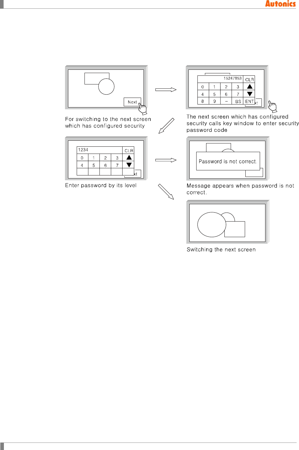
8 Common
262 © Copyright Reserved Autonics Co., Ltd.
(1) Calling key window for inputting password
Touch touch key with function key (FFA6) and key window for inputting password
appears.
When switching into the screen which has higher security level than the released
security level, key window appears automatically.
※1. Password code appears when key window for password is called, it is encoded about the
top level password. When you forgot the password, send this code to Autonics and we will
inform you about the password.
(2) Reset security
Touch touch key with function key (FFAD) and reset security. When switching into the
screen which is released security, input password again.
(3) Security from system setting
You can designate security not to edit important settings from system setting menu in GP/LP.
System setting’s each below menu is able to be set security. If trying to enter the other
menu which is set security, key window for inputting password appears. Input correct
password. If wrong password is inputted, you cannot enter the desired menu.
(4) Overlap for the screen set security
When switching into base screen which has overlap screen, the screens which have higher
security level than the base screen’s level are not displayed. The screen which has same
security level or below level is displayed only.
When designating security level and password in GP Editor as following, it operates with
switching screen in GP/LP.
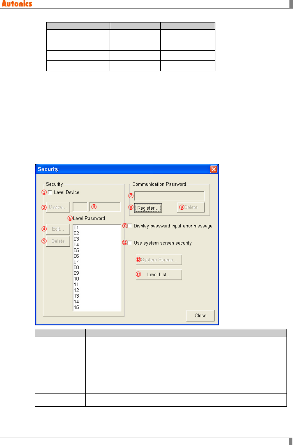
8 Common
© Copyright Reserved Autonics Co., Ltd. 263
Screen
Security level
Password
Base screen 1
0
--
Base screen 2
1
11
Base screen 3
2
22
Base screen 4
3
33
Overlaps base screen 2, 3 to base screen 1 in GP Editor;
If you calls base screen 1 in GP/LP, only base screen is displayed.
Overlaps base screen 2, 4 to base screen 3 in GP Editor:
If you calls base screen 3 in GP/LP, key pad appears automatically. Enter password
for the security level of base screen 3. Base screen 3 which is overlapped base screen
2 is displayed.
(5) Security for upload/memory function
For using upload/memory function of GP Editor, it is able to designate that only allowable
user can use these functions by inputting password.
8.6.2 Property
Security
Description
①Level Device
Check this to use level device which saves currently released top security
level.
Displayed with numeral display on the screen for checking security level of the
current screen.
If security levels from1 to 15 do not have password, this device value is 0. For
example, security level 10 has password, this device value is 10.
②Device Calls ‘Device Select’ dialog box and designate level device.
③Device Input device directly or displays the designated device
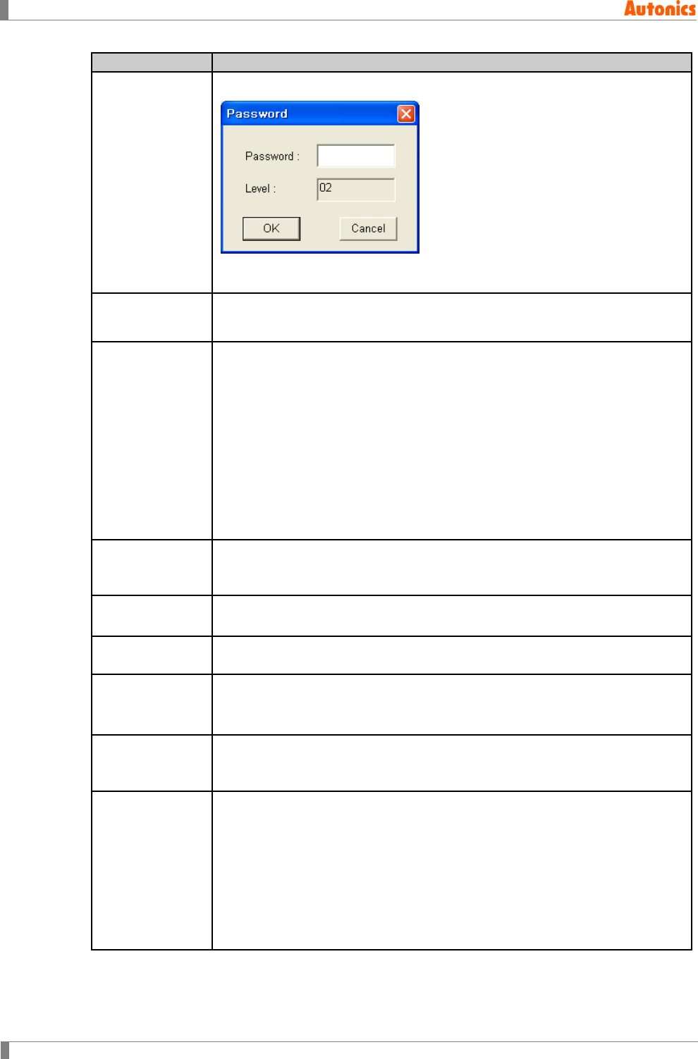
8 Common
264 © Copyright Reserved Autonics Co., Ltd.
Security
Description
④Edit
Calls ‘Password’ dialog box and edit to the selected security level at ⑥.
Password is only numbers within 8 characters.
If there is designated password, input correct password to edit it.
⑤Delete Deletes password of the selected security level at ⑥.
If there is designated password, input correct password to delete it.
⑥Level
Password List
Displays that there is password for each security level from 1 to 15.
If there is password, it displays ‘*******’ regardless of digit at right side of each
level.
Each base screen is able to have security level from 0 to 15 from ‘Security
Auxiliary Configuration’ dialog box. Each password for the level is only
numbers within 8 characters.
Security level 0: You can see the screen which has security level 0
anytime without password.
Security level 1 to 15: You should input password for the security level of
the screen or higher level to see the screen which has security level 1.
Every security is reset when power is resupplied with released security.
⑦Communication
Password
Displays ‘*******’ if there is password for communication.
For using upload/memory function, you should input password. ‘Password
Input’ dialog box Appears automatically.
⑧Register Register password for upload/memory function.
If there is designated password, input correct password to edit it.
⑨Delete Deletes password for communication. If there is designated password, input
correct password to delete it.
⑩Display
password input
error message
Designate displaying password input error message in GP/LP when password
is not correct.
⑪Use system
screen security
Checking this, security function for system screen is set.
Non-checking, this, it does not use security function for system screen.
Therefore security level for system screen is 0.
⑫System Screen
Activated only with checking ⑪Use system screen security. Calls ‘Screen
Auxiliary Property’ dialog box with ‘System Screen’ tab. Select the desired
screen and click ‘Edit’ and ‘Configure Security Level’ dialog box appears to
edit security level.
The default security level of system screen is 15 and you can edit each
system screen’s security level.
If there are not set password for top level from 1 to 15, ‘Level Password’ tab of
‘Data Check’ dialog box at [Communication]-[Check Data] of menu appears to
check.
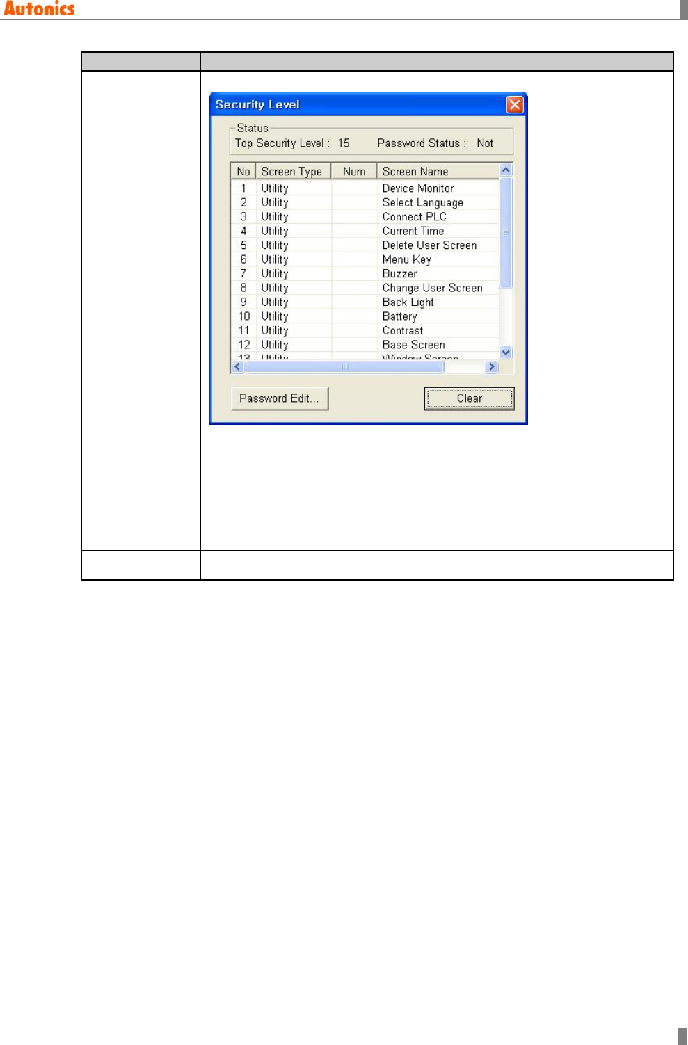
8 Common
© Copyright Reserved Autonics Co., Ltd. 265
Security
Description
⑬Level List
Check that there is password for top security level.
If there is not the base screen which has security level any from 1 to 15,
and ⑪Use system screen security is not checked, it does not use security
function.
If there is the base screen which has security level any from 1 to 15, and
⑪Use system screen security is not checked, only base screen uses
security function. If there is not password for top security level of base
screen, error message appears before downloading.
⑭Close Saves settings and closes ‘Security’ dialog box.
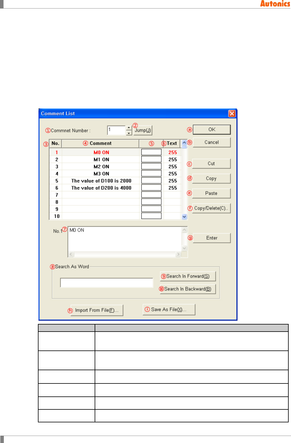
8 Common
266 © Copyright Reserved Autonics Co., Ltd.
8.7 Comment
Commnet is commonly used for alarm history, alarm list, and comment display, etc. Comment
list is for up to 2,000 and every saved list is able to download to GP/LP. Maximum list is 2,000
but be sure that capacity of memory for download has limit. You can check comment at system
menu in GP/LP.
Comment color for alarm history, alarm list, and comment display is not set from each tag, but is
set from comment list.
Comment list is saved as text file, and you can register comment list from comment list of text file.
Select [Common]-[Comment] of menu, ‘Comment List’ dialog box appears. You can edit about
the comment.
Comment List
Description
①Comment
Number Input to jump comment number.
②Jump Jumps to input comment number at ⑥. Jumped comment number is listed
at first to scroll the list.
③No. Displays comment number.
④Comment Displays comment content.
⑤,⑥ Text Color Displays comment text color.
⑦Input Comment Input comment content.
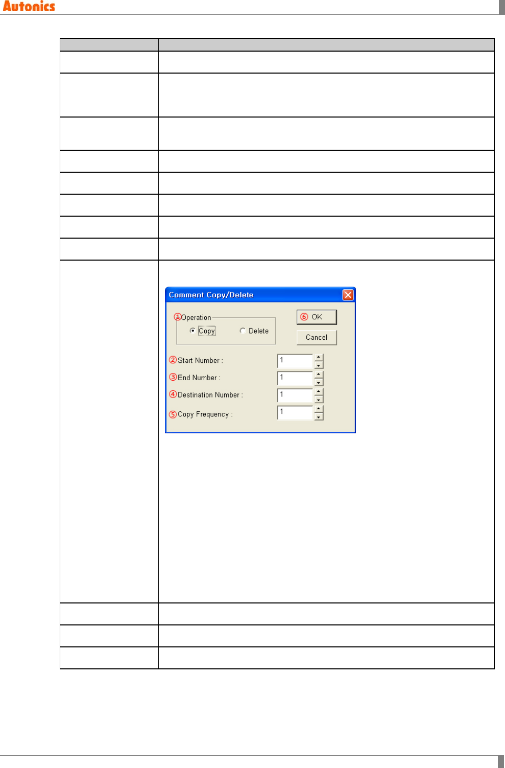
8 Common
© Copyright Reserved Autonics Co., Ltd. 267
Comment List
Description
⑧Search As Word Input the desired comment to search.
⑨Search In
Forward
Search the comment which is same as the input comment at ⑧ with higher
comment number direction than currently selected number. The searched
comment is listed at first to scroll the list.
⑩Search In
Backward
Search the comment which is same as the input comment at ⑧ with below
comment number direction than currently selected number.
ⓐOK Saves current setting, closes ‘Comment List’ dialog box.
ⓑCancel Does not save current setting, closes ‘Comment List’ dialog box.
ⓒCut Cuts selected item.
ⓓCopy Copies selected item.
ⓔPaste Pastes copied or cut selected item.
ⓕCopy/Delete
This function is to copy or delete several comments on the list
subsequently. ‘Comment Copy/Delete’ dialog box appears.
①Operation: Copy, Delete
②Start Number: Start number of to be copied/deleted item.
③End Number: End number of to be copied/deleted item.
④Destination Number: Destination number to be copied.
⑤Copy Frequency: Number of copy frequency
⑥OK: ①Operation is ‘Copy’: Copies comments of from start number to end
number to from destination number comment with the designated copy
frequency subsequently.
①Operation is ‘Delete’: Deletes comments of from start number to end
number.
ⓖEnter Registers input comment content at ⑦ to comment list.
ⓗImport From File Registers comment list from comment list of text file or XML file.
ⓘSave As File Saves comment list as text file or XML file
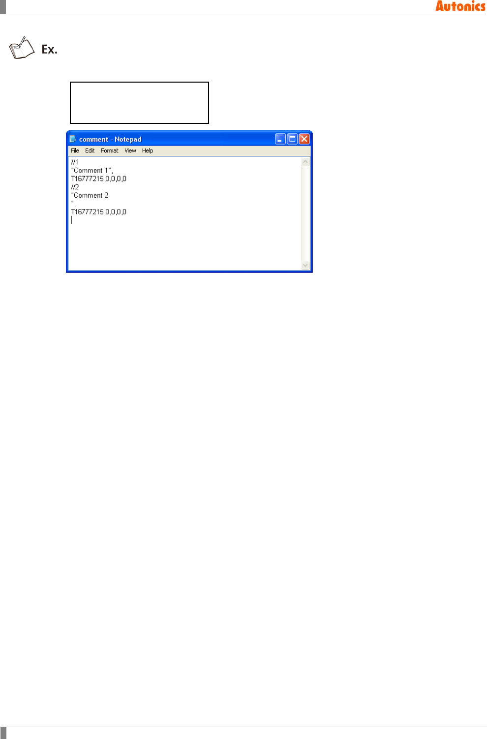
8 Common
268 © Copyright Reserved Autonics Co., Ltd.
When saving comment list, text file form;
//Comment number
’Comment content’,
Color,0,0,0,0
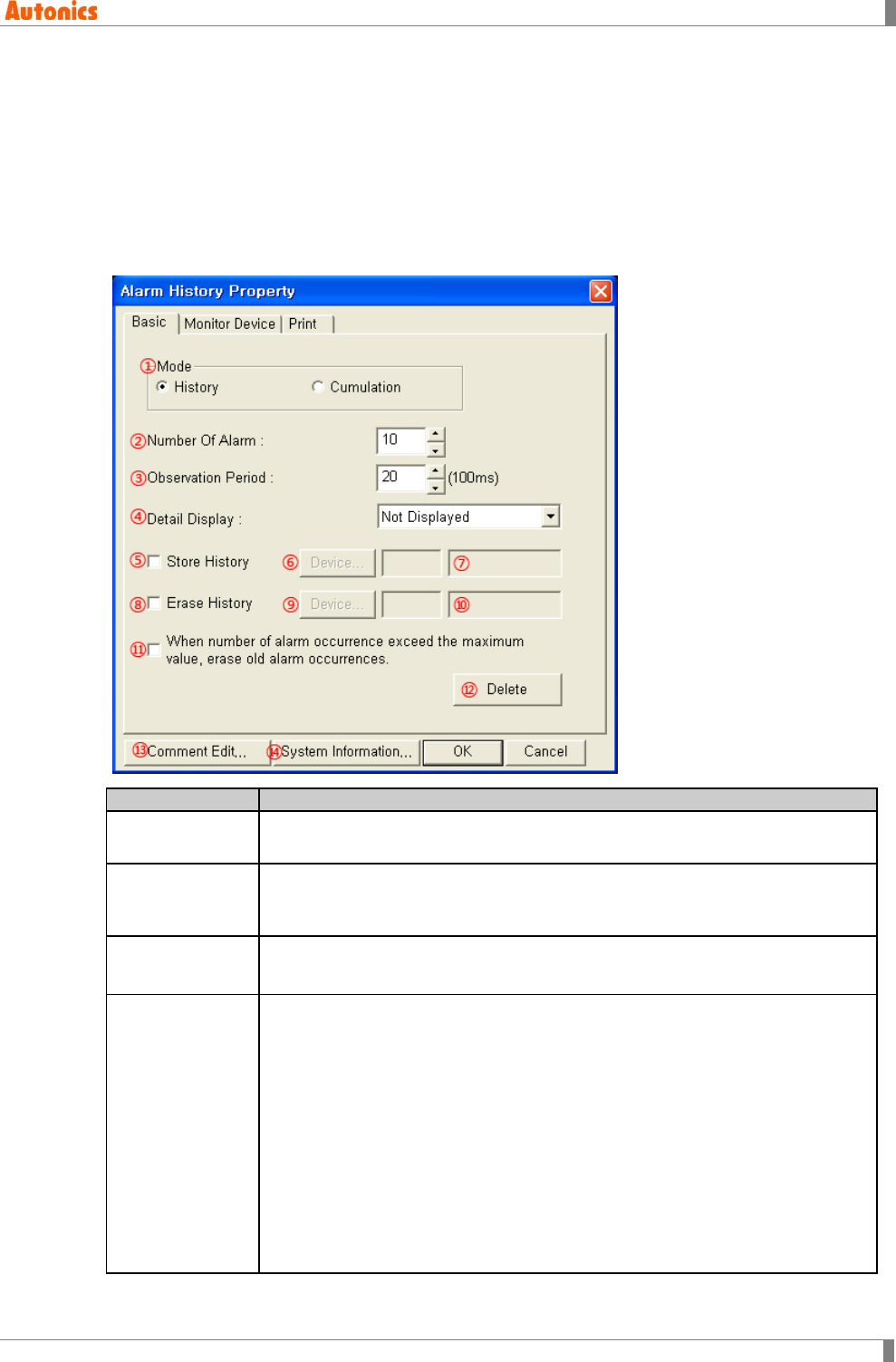
8 Common
© Copyright Reserved Autonics Co., Ltd. 269
8.8 Alarm History
Alarm history is feature for recording alarm history. It is able to record occurred time, restored
time, the number of frequncy by designating. You can print alarm list by connecting serial printer,
check it by uploadding to PC. Alarm history is the object which can exist only one on a screen.
8.8.1 Alarm history property
8.8.1.1 Basic tab
Basic
Description
①Mode
History: Displays the date and time of ON and the specified comment.
Cumulation: Displays history mode content and occurrence frequency.
②Number Of
Alarm
Designate the number of monitored bit device. Range is 1 to 256.
When designating the lead device in ‘Monitor Device’ tab, later bit device is
monitored object.
③Observation
Period
Designate monitor period cycle. Range is 600ms(6) to 80sec(8000) with
100ms interval.
④Detail Display
Designate detail display type by pull-down menu. Displays detail screen with
base or window screen depending on the setting of touch key for detail screen
display with key code FFA6H.
Not Displayed: Does not display detail screen.
Comment Window: Displays detail screen as comment window form
Move alarm history cursor to view detail screen and touch detail screen
view touch key, designated comment window screen appears as window.
The specified alarm’s comment appears at window.
Base Screen: Move alarm history cursor to view detail screen and touch
detail screen view touch key, designated base screen for detail screen
appears. It is able to return to the previous screen after confirming detail
information to place switch touch key for previous screen.
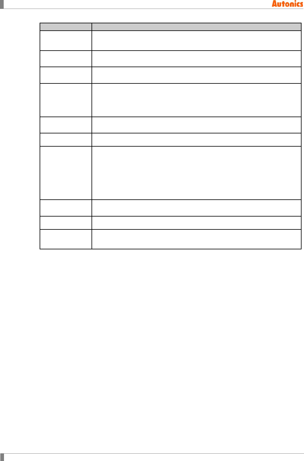
8 Common
270 © Copyright Reserved Autonics Co., Ltd.
Basic
Description
⑤Store History Check this to designate save device for saving the number of current occurring
alarm. Register at ⑦Device not stored alarm of currently occurring alarms.
⑥Device Calls ‘Device Select’ dialog box and designate word device for saving the
number of occurred alarm.
⑦Device Input device directly or displays the designated device for saving the number
of occurred alarm.
⑧Erase History
Designate bit device for deleting alarm history and the number of alarm
frequency. Every alarm history and the number of alarm frequency are deleted
when designated bit device at ⑩ turns ON. During that time, any alarm is not
registered.
⑨Device Calls ‘Device Select’ dialog box and designate device for delete current alarm
list.
⑩Device Input device directly or displays the designated bit device.
⑪When number
of alarm
occurrence
exceed the
maximum value,
erase old alarm
occurrences.
Check this for delete the oldest alarm when alarm history is over 1024 to
register new alarm. Non-checking this, when alarm history is over 1024, it is
not able to register new alarm anymore.
Activated only with history mode, not activated with cumulating mode.
⑫Delete Deletes all designated values at ‘Alarm History Property’ dialog box, sets as
default value and closes this dialog box.
⑬Comment Edit Calls ‘Comment List’ dialog box and edit the registered comment list.
⑭System
Information Calls ‘System Information’ dialog box and edit the information of alarm history
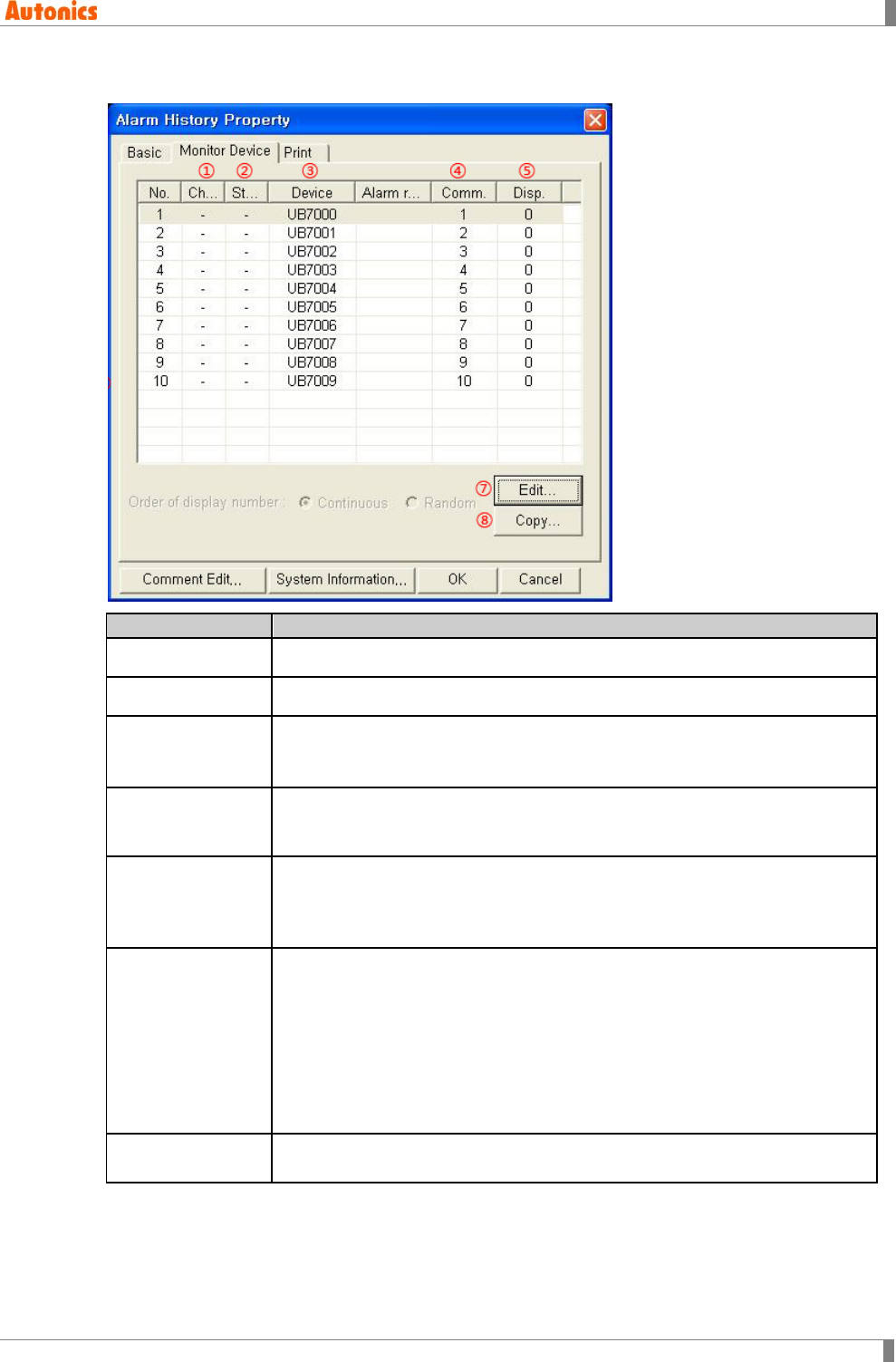
8 Common
© Copyright Reserved Autonics Co., Ltd. 271
8.8.1.2 Monitor device tab
Monitor Device
Description
①Channel Displays monitored bit device channel
②Station Displays monitored bit device station
③Device Displays monitored bit device
Bit devices are displayed by then designated number of bit device in ‘Basic’
tab. Click ‘Edit’ to edit device and comment number of the device.
④Comment Displays to be recorded comment number when alarm occurs (same line
device is ON).Select the desired number and click ‘Comment Edit’ to edit the
comment.
⑤Display
Displays comment number or base screen number for displaying detail
screen.
If detail display of ‘Basic’ tab is ‘Comment Window’, it displays comment
number. If detail display is ‘Base Screen’, it displays base screen number.
⑥Order of display
number
Activated only with when detail display of ‘Basic’ tab is ‘Comment Window’ or
‘Base Screen’.
Designated displaying comment number of base screen number
continuously for detail screen or not.
Continuous: Comment number or base screen number is designated
continuously.
Random: Click ‘Edit’ and designate detail screen/comment number as
desired.
⑦Edit Calls ‘Edit' dialog box to designate monitor device, comment/display number,
and device reset.
8 Common
272 © Copyright Reserved Autonics Co., Ltd.
Monitor Device
Description
Designate lead device for alarm history and ‘Edit’ dialog box appears with all
activated items. When selecting devices of after lead device, only ‘Device
Reset’ item of ‘Edit’ dialog box is activated to set individually. If ‘Order of
display number’ is set as random and selecting devices of after lead device,
‘Device Number’ is also activated to set individually.
①Type: It is fixed as Bit. (It does not support word device.)
②Device: Set lead bit device for monitoring.
③Comment Number: Designate comment number to be displayed. Click
‘View’ and ‘Comment List’ dialog box appears. You can check the registered
comment and designate comment number.
④Display Number: Designate display number at ④Comment. If ‘Detail
Display’ of ‘Basic’ tab is as ‘Comment Window’, this number is for displaying
comment window when touching detail screen touch key. Click ‘Browse’ and
‘Comment List’ dialog box appears to check registered comment and
designate comment number. If ‘Detail Display’ of ‘Basic’ tab is as ‘Base
Screen’, this number is for switched base screen number when touching
detail screen touch key. Click ‘Browse’ and ‘Screen Image’ dialog box
appears to check drawn base screen and designate screen number.
⑤Device Reset: The device which has checked this is reset when touching
the touch key with FFAAH.
⑧Copy
Designates device reset and copies properties of ⑤Display. Calls ‘Copy’
dialog box. Designate source number item and check device reset or display
number to copy that properties at destination number item with copy
frequency.
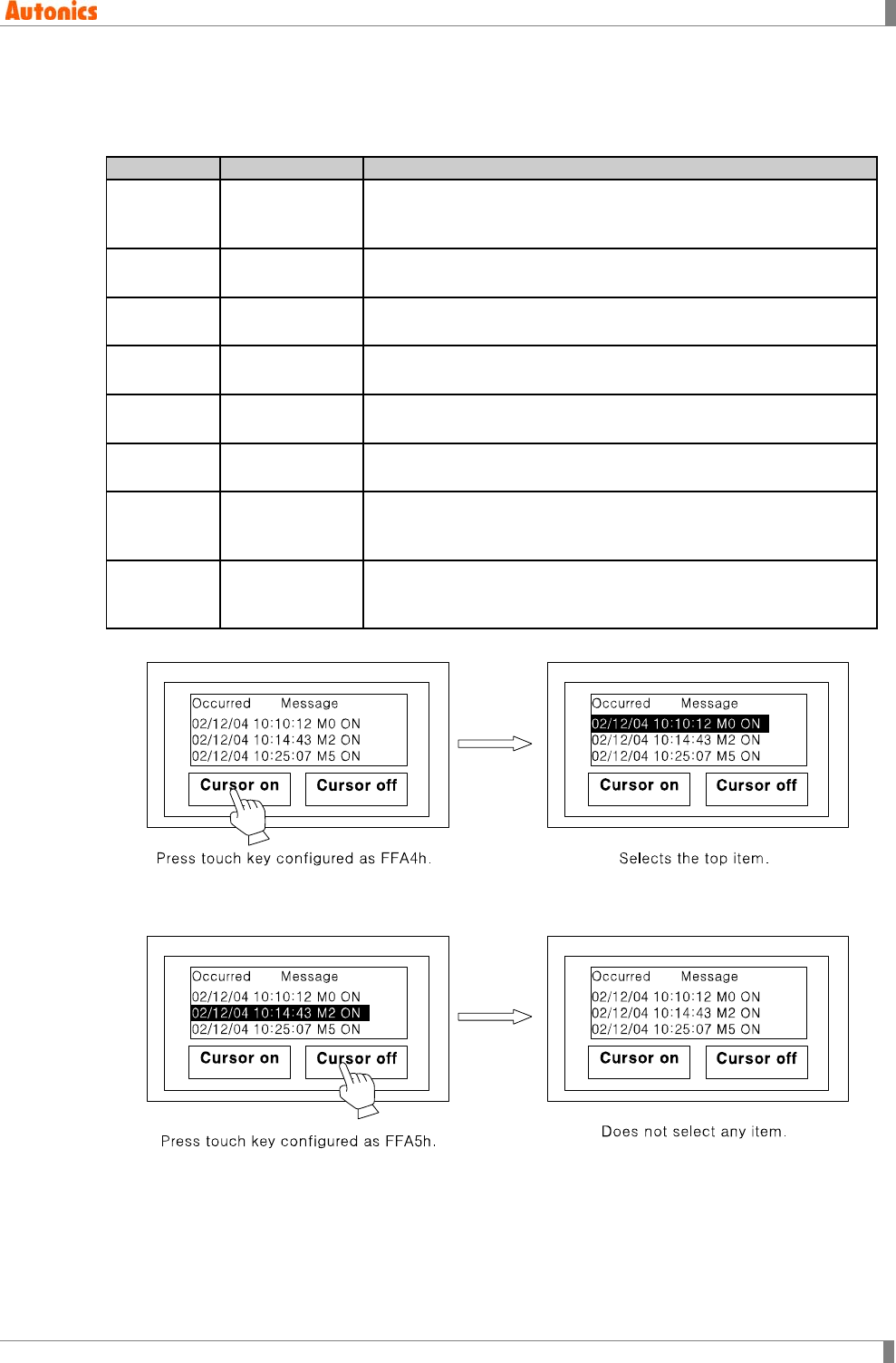
8 Common
© Copyright Reserved Autonics Co., Ltd. 273
8.8.1.3 Touch key for alarm history
Cursor control to select specified line displaying detail information in basic function of alarm
history is used with appropriate key code configuration and arranging on screen.
Key code
Function
Description
FFA4h Show cursor When touching touch key with key code FFA4, it is displayed as
top of alarm list is selected when there is an alarm in alarm list
screen.
FFA5h Hide cursor When touching touch key with key code FFA5, alarm list cursor
does disappeared.
FFABh Move cursor
upward When touching touch key with key code FFAB, upper item of
currently selected is changed as selected state.
FFACh Move cursor
downward When touching touch key with key code FFAC, below item of
currently selected is changed as selected state.
FFA8h Erase the alarm
in cursor When touching touch key with key code FFA8, currently selected
item is deleted.
FFA9h Erase all
restored alarm When touching touch key with key code FFA9, restored alarm list
is deleted.
FFA6h Calls detailed
alarm
information
When touching touch key with key code FFA6, detail screen
[window comment or base screen] of selected item is displayed.
FFAAh Reset device When touching touch key with key code FFAA, if reset device for
monitor device is ON and the specified alarm list item is selected
during listing alarm history, the device is reset.
Show cursor (FFA4h)
Hide cursor (FFA5h)
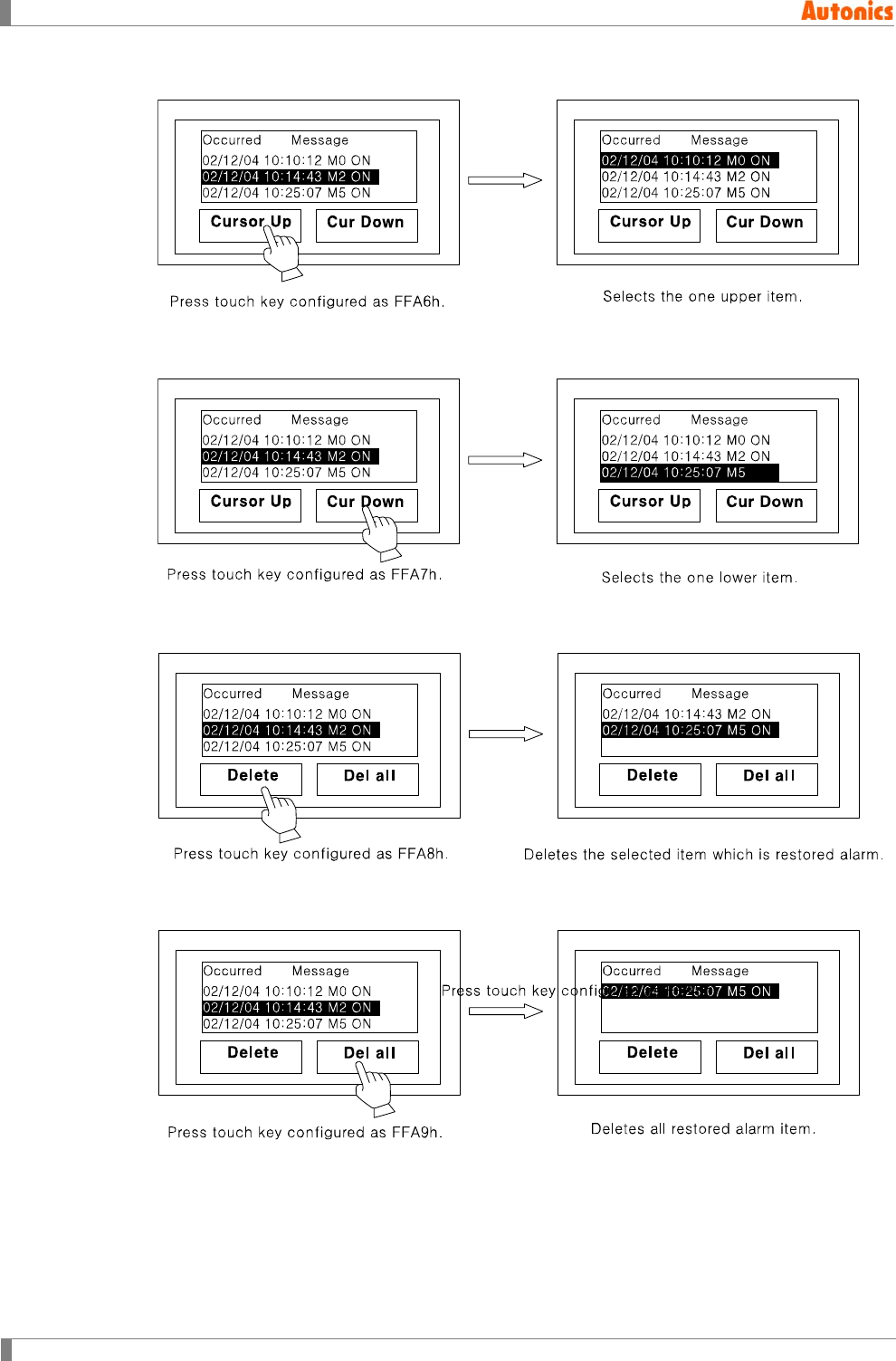
8 Common
274 © Copyright Reserved Autonics Co., Ltd.
Move cursor upward (FFABh)
Move cursor downward (FFACh)
Erase the alarm in cursor(FFA8h)
Erase all restored alarm (FFA9h)
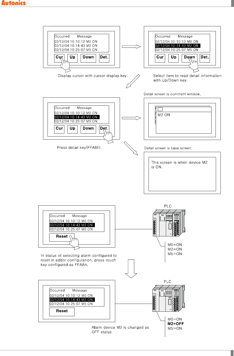
8 Common
© Copyright Reserved Autonics Co., Ltd. 275
Calls detailed alarm information(FFA6h)
Reset device (FFAAh)
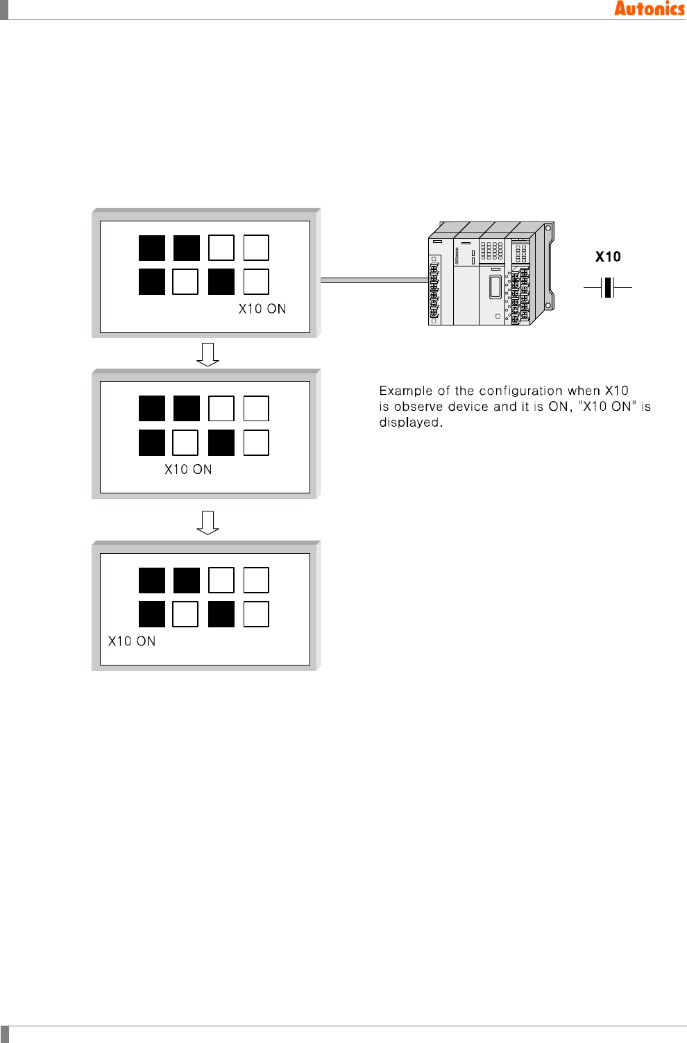
8 Common
276 © Copyright Reserved Autonics Co., Ltd.
8.9 Floating Alarm
8.9.1 Basic operation
When the desiganted alarm device(Bit device) is ON state, the specified comment is displayed
as designated font size moving right to left at the bottom of the screen.
When alarm is released (OFF), comment does disappears. ASCII character with up to 512 is
displayed in a line, it moves as width font size unit and is displayed on a object in screen.
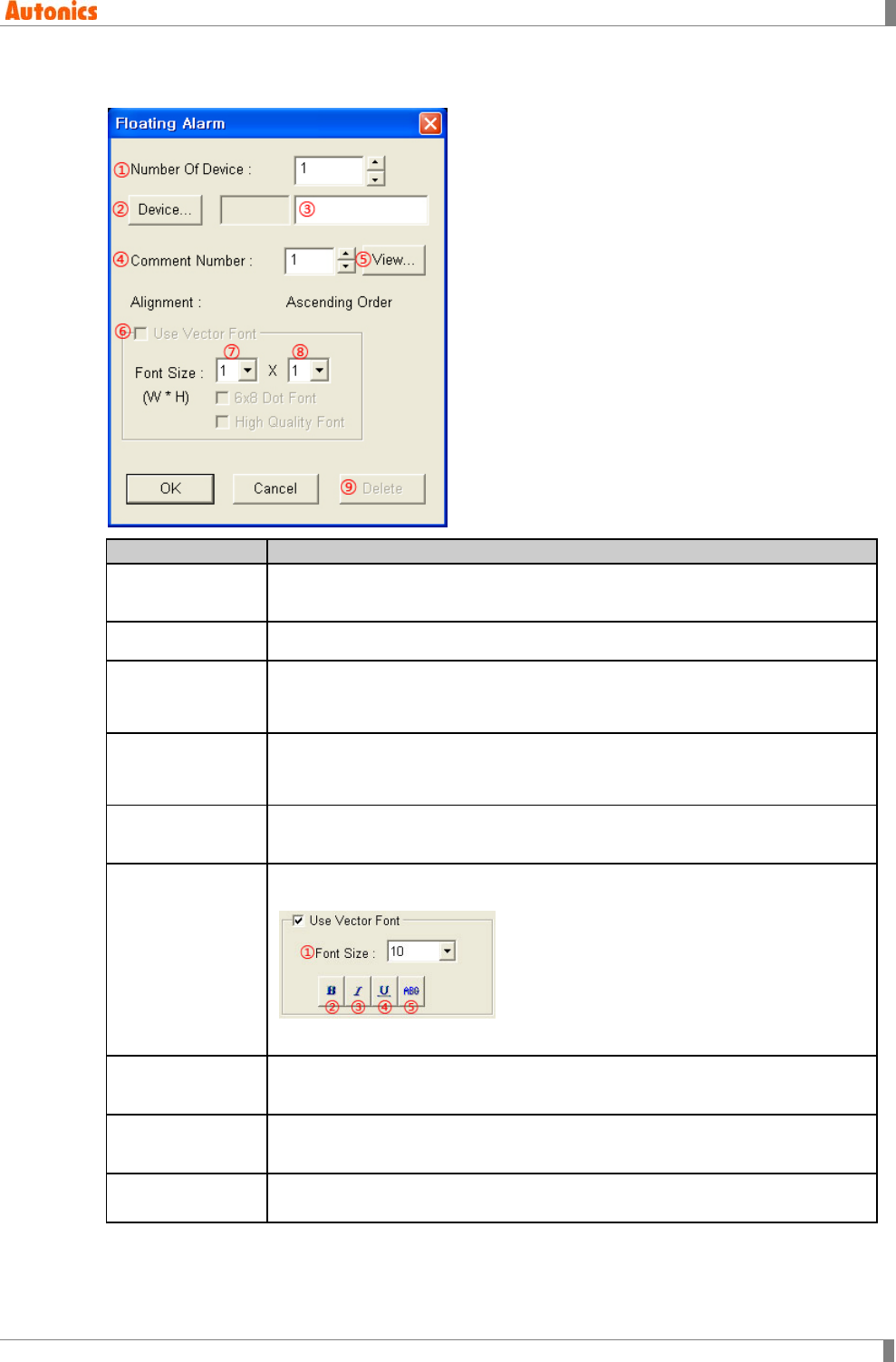
8 Common
© Copyright Reserved Autonics Co., Ltd. 277
8.9.2 Property
Floating Alarm
Description
①Number Of
Device Designate the number of monitored bit device. Range is 1 to 256.
②Device Designate lead device of monitored bit device.
③Device
Input device directly or displays the designated device.
From designated device, devices are subject to monitor as the number of
device.
④Comment
Number
Designate displayed comment number when lead device is ON.
When device is ON, to be displayed comment corresponds in this number
successively.
⑤View Calls ‘Comment List’ dialog box and displays registered comment on project.
Select the desired comment number to be input at ④Comment Number.
⑥Use Vector Font
Activated only for color type (GP-S070, LP-S070). Non-checking this, it uses
bitmap font. Checking this, it displays as following.
①Font size, ②Bold font, ③Italic font, ④Underline, ⑤Strikethrough
⑦Font Size
(Width)
Designate width font size of comment by pull-down menu.
Range: 1,2,3,4,
⑧Font Size
(Height)
Designate height font size of comment by pull-down menu
Range: 1,2,3,4,
⑨Delete Deletes all designated values at ‘Floating Alarm’ dialog box and closes this
dialog box.
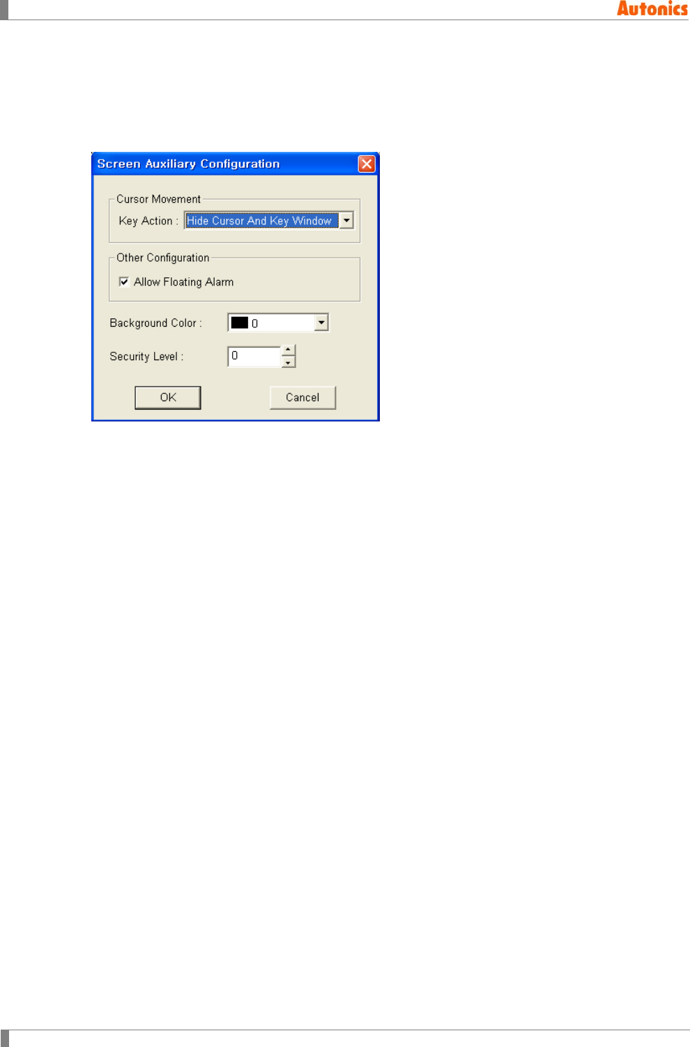
8 Common
278 © Copyright Reserved Autonics Co., Ltd.
8.9.2.1 Allow floating alarm
To operate floating alarm, you should designate it as following. Select [Common]-[Auxiliary
Configuration]-[Screen] and ‘Screen Auxiliary Property’ dialog box appeared. Click ‘Edit’ and
‘Screen Auxiliary Configuration’ dialog box appears. Check ‘Allow Floating Alarm’ to operate
floating alarm.
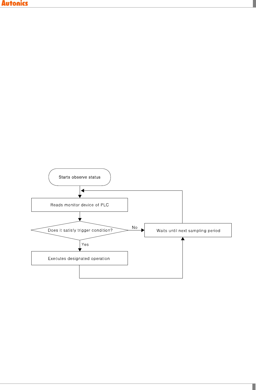
8 Common
© Copyright Reserved Autonics Co., Ltd. 279
8.10 Monitor Status
Monitor status function is to monitor ON/OFF state of designated bit bevice (monitor device).
Depending on that state it turns ON/OFF bit device of PLC or inputs numeral value to specified
word device.
Select [Common]-[Monitor Status] and ‘Monitor Status’ dialog box appears. You can desigate
about monitor status such as monitor device, observe period, and operation for trigger, etc.
However, this menu is activated only with when GP/LP type is set as GP series from ‘GP/PLC
Type’ dialog box of [Common]-[GP/PLC Type]. This menu is not available to LP series.
8.10.1 Basic action
There are two monitor functions to whole project or to the specified screen.
Monitors to project function
Regardless currently displayed screen in GP, monitors the designated monitor device. If it
satisfies trigger conditions, it executes the set operation.
Monitors to screen function
If currently displayed screen in GP is set monitor, monitors the designated monitor device. If
it satisfies trigger conditions, it executes the set operation.
8.10.2 Execution order
1st GP reads monitor device of designated PLC.
2nd Determines whether monitor device satisfies trigger conditions or not. (GP inner)
3rd If it satisfies trigger conditions, sets the specified bit device, or word device value.
(GP→PLC)
4th Waits next sampling cycle.
Repeats 1st to 4th execution.
It it satisfies trigger conditions at the point of previous sampling time, it skips designated
operation for current time. When trigger conditions are lasted during successive sample section,
designated operation executes in the first sample. For momentary action which maintains
momentary ON the device only when it satisfies trigger conditions, device is turned ON from
OFF by PLC program or forced input.
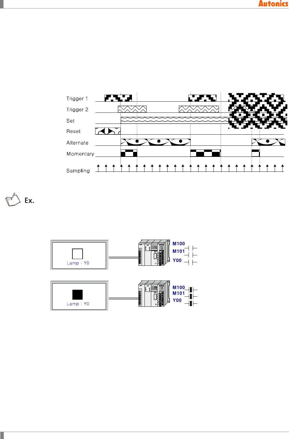
8 Common
280 © Copyright Reserved Autonics Co., Ltd.
8.10.2.1 Action
When monitor device is satisfied trigger condition, action is devided as bit or word.
(1) Bit action
Bit action has four kinds operation.
① Set: Turns ON the device when trigger occurs.
② Reset: Turns OFF the device when trigger occurs.
③ Alternate: Alternates the current state of designated device when trigger occurs.
④ Momentary: Maintains momentary ON the designated device only when trigger occurs.
The above feature is for device state with sampling at set, reset, alternate, momentary
action. Trigger 1, and trigger 2 display two trigger device state. When both is ON, it
satisfies trigger conditions.
Below feature is for the monitor operation to turn ON Y0 device when two bit trigger devices
as M100, M101 is both ON.
GP screen has the lamp for Y0 state. At the first feature, both M100 and M101 are OFF
state, it does not satisfy trigger conditions and the lamp for Y0 does not turn ON. When both
M100 and M101 are ON, it satisfies trigger conditions, and the lamp for Y0 turns ON.
(2) Word action
1) 16 bit word setting: Assigns the value to 16 bit word device.
2) 32bit word setting: Assigns the value to 32 bit word device.
You can designate this as fixed value or as indirect using device.
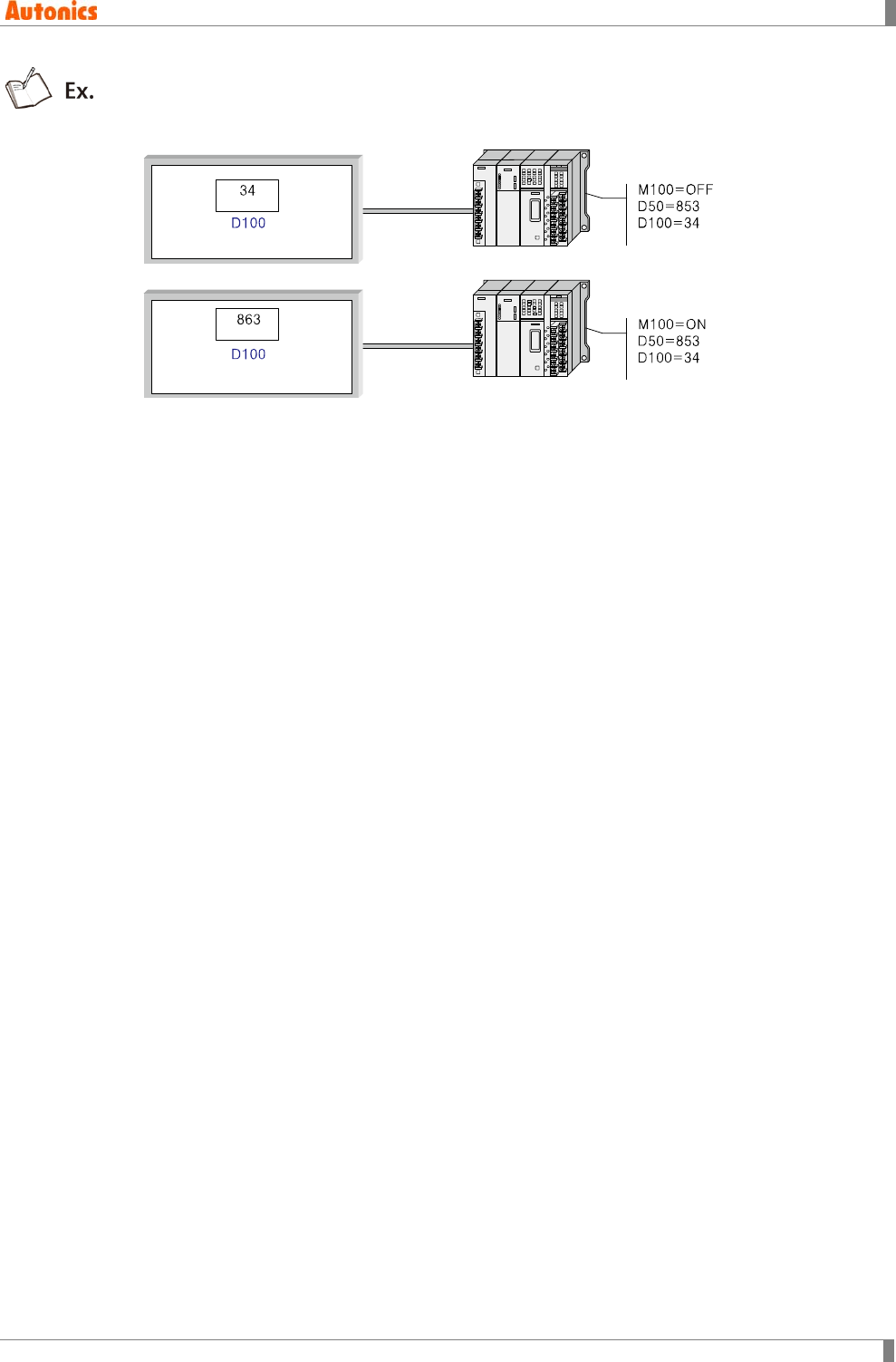
8 Common
© Copyright Reserved Autonics Co., Ltd. 281
Example of setting indirect: In case, designated trigger device as M100(ON), Fixed
value=10, Indirect device=D50 for M100. When M100 in ON, D50 value + 10 is set at D100.
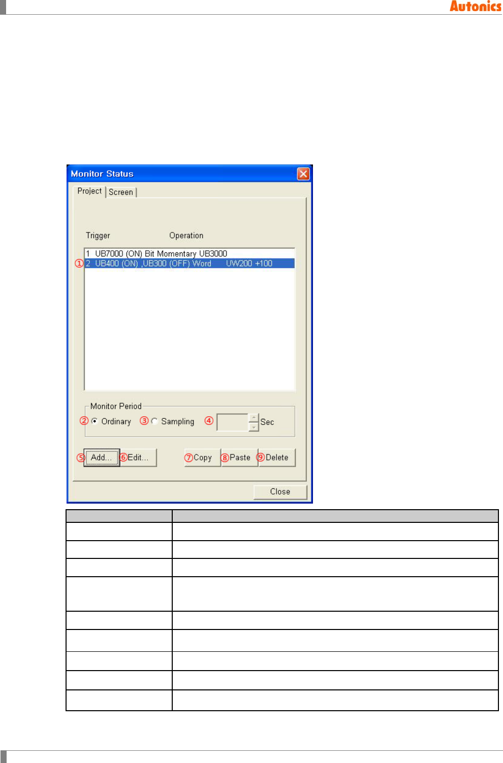
8 Common
282 © Copyright Reserved Autonics Co., Ltd.
8.10.3 Property
When trigger occurs, the number of save device point for monitoring at each project and
screen is 40 by a project, 40 by a screen. Therefore, monitor trigger is total 80.
When designating monitor bit device as screen unit, monitor bit of called overlap screen at
base screen does not operated, designated monitor bit at base screen operates only.
For window screen, state monitor function is not available.
8.10.3.1 Project tab
Project
Description
①Trigger/Operation Displays currently designated trigger/operation.
②Ordinary Operates monitor one time with minimum cycle which is able in system.
③Sampling Operates monitor with user-defined time cycle at ④.
④Sampling Activated only with selected ③.
Default is 1 and range is from 1 to 60 sec by 1 sec.
⑤Add Calls ‘Trigger/Action’ dialog box and add trigger/action up to 40.
⑥Edit Calls ‘Trigger/Action’ dialog box and edit the selected item.
⑦Copy Copy the selected item.
⑧Paste Paste copied item to end number of this list.
⑨Delete Deletes selected trigger/action on the list.
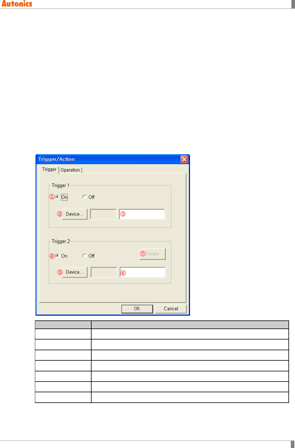
8 Common
© Copyright Reserved Autonics Co., Ltd. 283
8.10.3.2 Screen tab
The descriptions of ‘Screen’ tab is almost same as ‘Project’ tab’s. The designation of ‘Project’ tab
is regardless of GP screen. But the designation about monitor operation of ‘Screen’ tab is for
currently displayed screen in GP. The monitor operation for other screens does not execute.
Therefore, ‘Screen’ tab has ‘Base Screen’ setting.
Base Screen
Designate the base screen number to apply monitor operation. You can select base screen
number to input with spin box or to click ‘View’. ‘Screen Image’ dialog box appears to select
the desired base screen.
8.10.3.3 Trigger tab
Click ‘Add’ or ‘Edit’ in ‘Monitor Status’ dialog box, and ‘Trigger/Action’ dialog box appears. Set the
trigger device and trigger conditions. You can set each individual trigger conditions for two bit
device.
If both trigger 1, 2 are set, it operates the designated function when both conditions are satisfied
at the same time. You should set trigger 1, but setting trigger 2 is not necessary.
Trigger
Description
①Trigger1 Designate trigger state (On or Off) of trigger 1.
②Device Calls ‘Device Select’ dialog box and designate trigger 1 device.
③Device Input device directly or displays the designated trigger 1 device.
④Trigger2 Designate trigger state (On or Off) of trigger 2.
⑤Device Calls ‘Device Select’ dialog box and designate trigger 2 device.
⑥Device Input device directly or displays the designated trigger 2 device.
⑦Device Sets as trigger 2 is not designated.
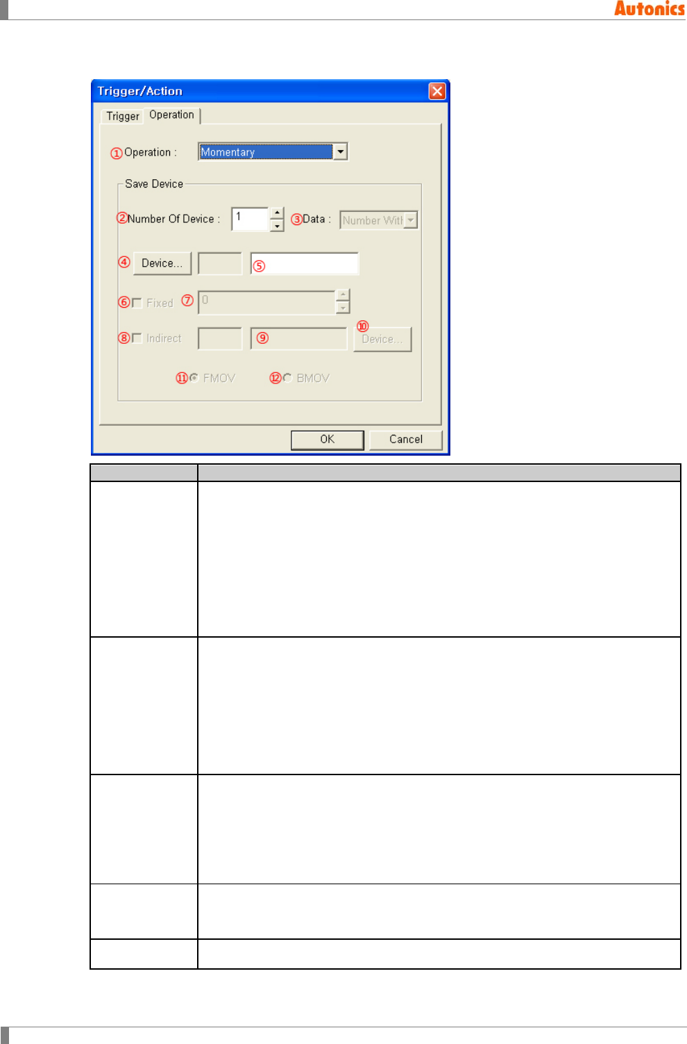
8 Common
284 © Copyright Reserved Autonics Co., Ltd.
8.10.3.4 Operation tab
Operation
Description
①Operation
Designate the operation for occurring trigger by pull-down menu.
Momentary: Maintains momentary ON the bit device only when trigger is
satisfied trigger condition.
Set: Turns ON the bit device when trigger occurs.
Reset: Turns OFF the bit device when trigger occurs.
Alternate: Alternates the current state of the bit device when trigger occurs.
Word Configuration(16bit): Sets the value to 16 bit word device.
Word Configuration(32bit): Sets the value to 32bit word device.
②Number of
Device
Designate the number of device which this setting is applied. From designated
device at ④, designated operation operates as the number of device
continuously.
[Limit the number of device]
Bit device: 40
16bit word device: 20
32bit word device: 10
③Data
Activated only when operation is set ‘Word Configuration(16bit)’ or ‘Word
Configuration(32Bit)’.
Number With Sign: Device value is set as number with sign.
Number Without Sign: Device value is set as number without sign.
For word device, depending on connected device type, it may use only 32bit.
Refer to ‘GP, LP user manual for communication’.
④Device
Designate the device for operation.
If operation is for bit device, ‘Device Select’ dialog box for bit appears, or for
word device, ‘Device Select’ dialog box for word appears.
⑤Device Input device directly or displays the designated device
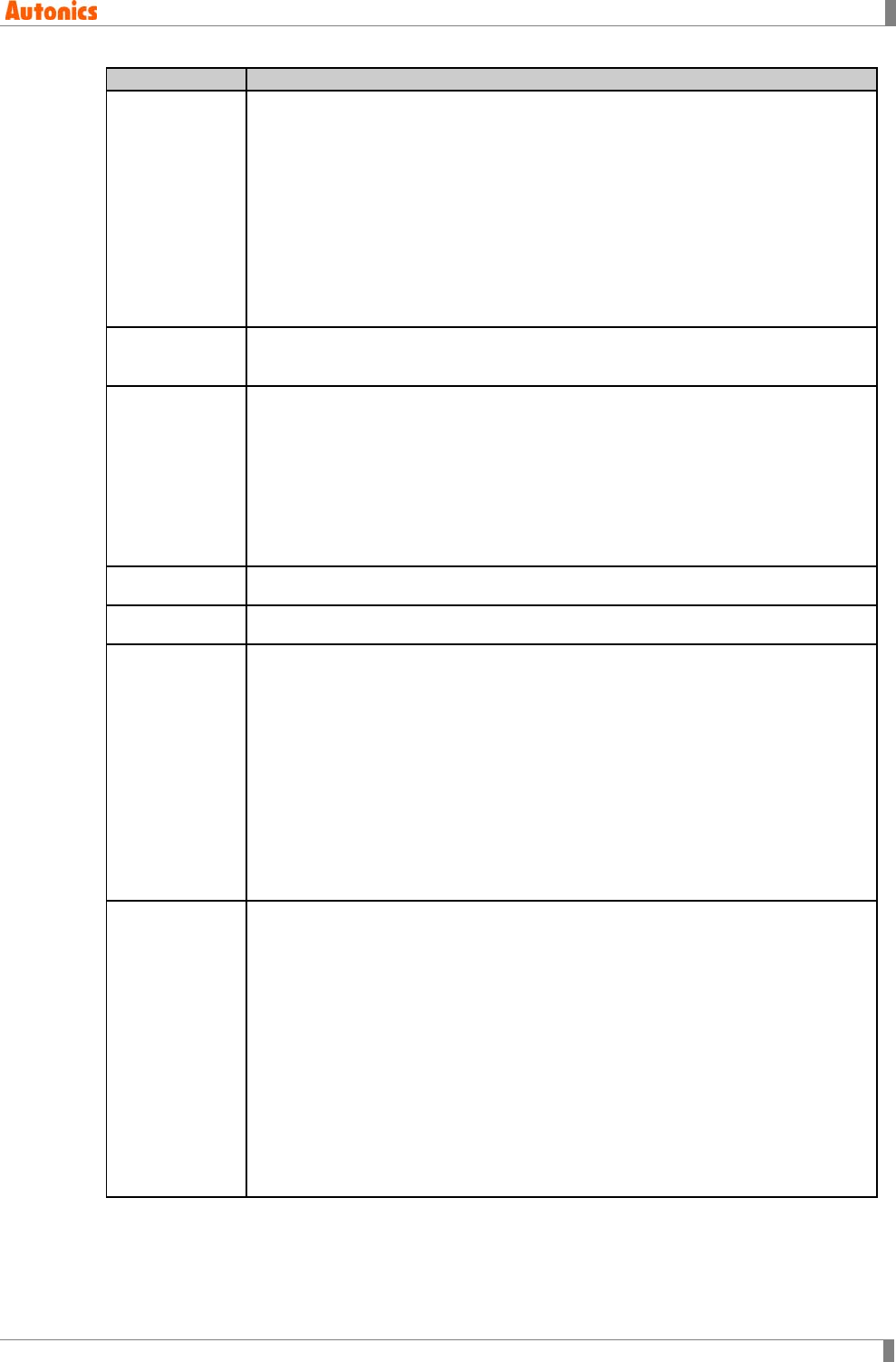
8 Common
© Copyright Reserved Autonics Co., Ltd. 285
Operation
Description
⑥Fixed
Activated only with when operation is for bit device.
Check this to designate specified word device as fixed value when trigger
occurs.
Ex) Set operation for trigger with non-checking ⑧Indirect and setting as
⑤Save device= D100, ⑦Fixed value=64, ②Number of device=4:
D100 ← 64
D101 ← 64
D102 ← 64
D103 ← 64
⑦Fixed Activated only with when operation is for word device and with checking ⑥.
Designate fixed value to be saved at word device when trigger occurs.
⑧Indirect
Activated only with when operation is for word device. Check this to set the
specified word device same as any device value when trigger occurs.
Adds the current value of indirectly designated word device to set fixed value
and saves it at the designated word device.
⑦Fixed+⑨Indirect device value → ⑤Save device
Indirectly designated device’s type depends on operation device type. For
example, save device is designated as 32 bit word device, indirectly designated
device’s type is also set as 32 bit type.
⑨Indirect Input device directly or displays the designated indirect device.
⑩Device Calls ‘Device Select’ dialog box and designate indirect device.
⑪FMOV
Activated only with when operation is for word device and ②Number of Device
is set over than 2.
Adds the current value of indirectly designated device to fixed value and saves
at all save devices.
Ex) ⑦Fixed=100, ⑨Indirect=D100, ⑤Save Device= D200(16bit), ②Number
Of Device =3
Write operation when trigger occurs;
D100 ← The value of 100 +D100
D101 ← The value of 100 +D100
D102 ← The value of 100 +D100
⑫BMOV
Activated only with when operation is for word device and ②Number of Device
is set over than 2.
The operation to add the current value of indirectly designated device to fixed
value and to save at all save devices is same as FMOV. However, BMOV is that
creating serial device as the number of point from indirectly designated device
as lead device.
Ex) ⑦Fixed =100, ⑧Indirect=D100, ⑤Save Device=D200(16Bit), ②Number
Of Device=3
Write operation when trigger occurs;
D200 ← 100(Fixed value)+D100
D201 ← 100(Fixed value)+D101
D202 ← 100(Fixed value)+D102

8 Common
286 © Copyright Reserved Autonics Co., Ltd.
8.11 Recipe
It reads or writes several PLC devices at once.
Read or write is operated by read or write trigger.
This recipe function transmits volumes of data to device with a write operation and saves
volumes of PLC inner device value to recipe area device of GP/LP with a read operation.
GP recipe area device: UW2048 to UW6047
LP recipe area device: UW2048 to UW6047
8.11.1 Basic operation
Select [Common]-[System Information] of menu, ‘System Information’ dialog box appears.
Designate the device for ‘System Signal1’ and check ‘Current Recipe Number’.
Creates each recipe file
You can create recipe file from 1 up to 256. Recipe file name is up to 32 character of ASCII
character and recognition of recipe file in GP/LP is not by recipe file name but recipe file
number. You can designate recipe file name as a convenient.
Designates read/write trigger device
You can designate each read/write trigger. If you do not use recipe read function, you do not
need to designate read trigger. However, you should designate write trigger.
Designates conditions for read/write trigger
You can set ON or OFF. When ON is set, trigger occurs in rising edge of trigger device.
When OFF is set, trigger occurs in falling edge of trigger device.
Designates save device
You can set only 16 bit word device as save device up to 4,000 per one recipe. Except of
first recipe, the number of device and read/write trigger setting of other recipe file are fixed
as the setting of first file’s. You can edit only device and device data type, and device initial
value.
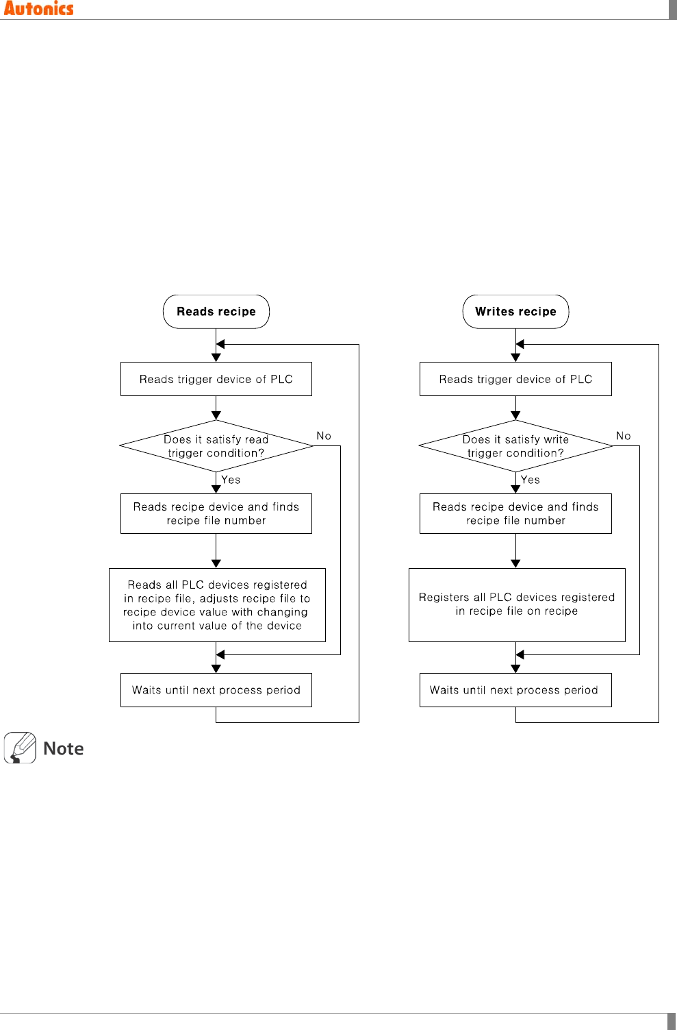
8 Common
© Copyright Reserved Autonics Co., Ltd. 287
8.11.1.1 Execution order
1st Reads read/write device of PLC.
2nd Confirms read/write trigger.
3rd If read/write trigger occurs, it reads recipe device and recipe file number. Operates
read/write operations for the specified file.
(1) Recipe read operation
Reads all of each PLC device registered recipe file and set the specified device value to
recipe area device.
(2) Recipe write operation
Sets all PLC devices registered recipe file to recipe area device as each saved value.
Maximum capacity of memory for recipe function is about 256X4000X(16bit)=2,000kbyte.
However, be aware that actual memory capacity of GP/LP does not meet this when you set
this.
Flash memory is able to be damaged physically when executing write operation more than
regular frequency. It is require not to occurring read trigger frequently by proper PLC
program or other device setting.
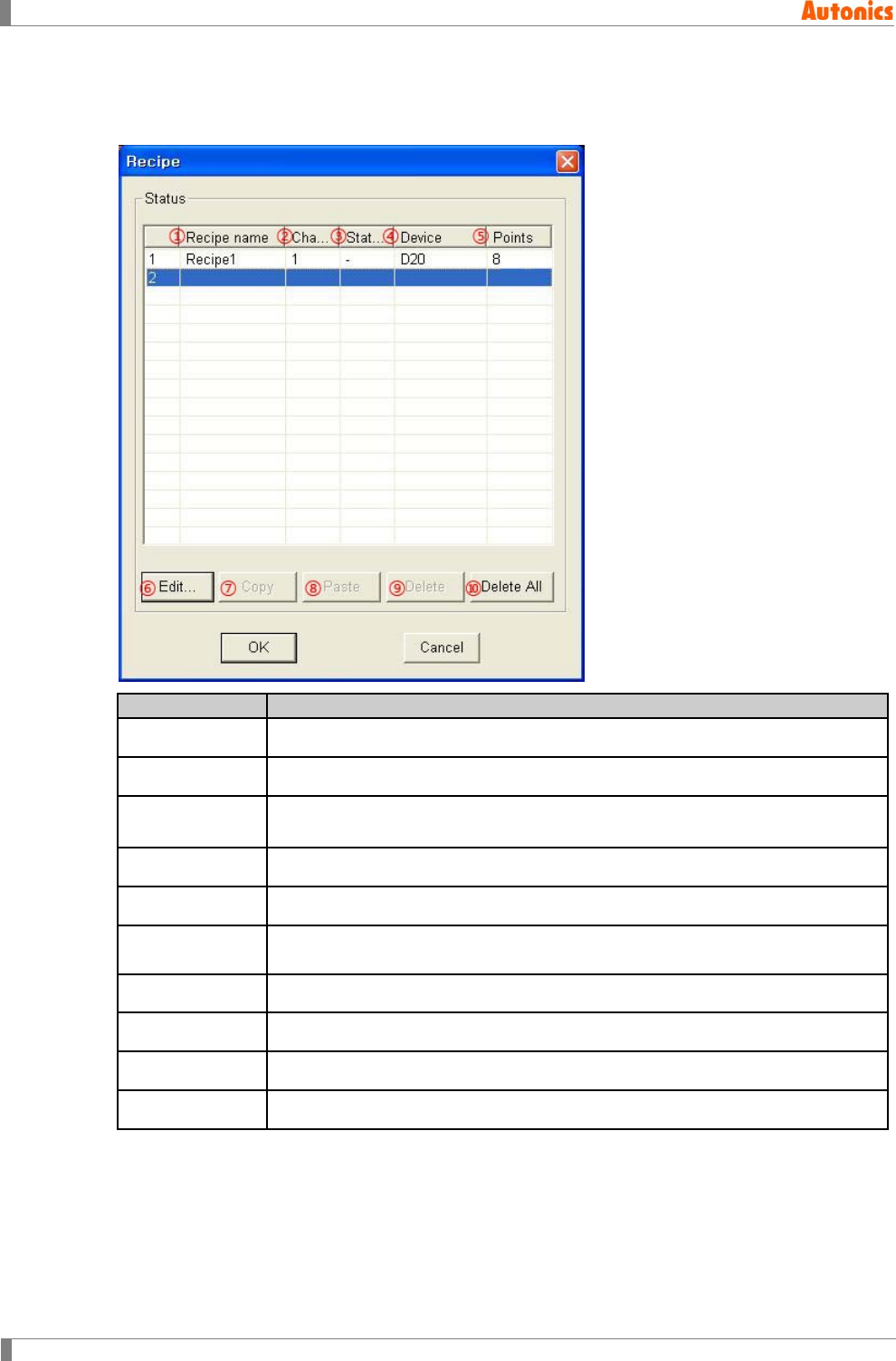
8 Common
288 © Copyright Reserved Autonics Co., Ltd.
8.11.2 Property
8.11.2.1 Recipe dialog box
Recipe
Description
①Recipe name Displays designated recipe name.
②Channel Displays PLC channel for recipe.
③Station Displays PLC station for recipe.
(PLC which does not support station is displayed ‘-’.)
④Device Displays lead device for set recipe.
⑤Points Displays recipe device point of each recipe.
⑥Edit Calls ‘Recipe Property’ dialog box and edit the selected item or create new
recipe.
⑦Copy Copies the selected item.
⑧Paste Pastes copied item on the list box.
⑨Delete Deletes selected item.
⑩Delete All Deletes all recipes on the list box.
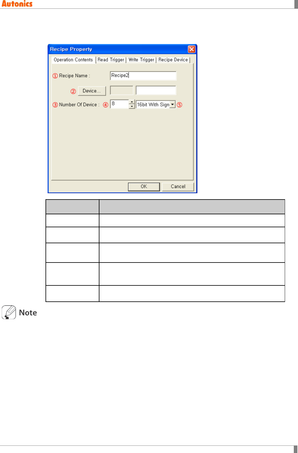
8 Common
© Copyright Reserved Autonics Co., Ltd. 289
8.11.2.2 Recipe property dialog box
(1) Operation contents tab
Operation
Contents
Description
①Recipe Name Input recipe name which is up to 32 character of ASCII character.
②Device Calls ‘Device Select’ dialog box and designate lead word device for
recipe.
③Number Of
Device Input device directly or displays the designated word device.
④Number Of
Device
Designate the number of device. From the designated lead device,
recipe function is operated by series of the devices. Up to 4,000 can
be designated.
⑤Data Type Select data type 16bit With Sign or 16bit Without Sign by pull down
menu.
For word device, depending on connected device type, it may use only 32bit. Refer to ‘G P, L P
user manual for communication’.
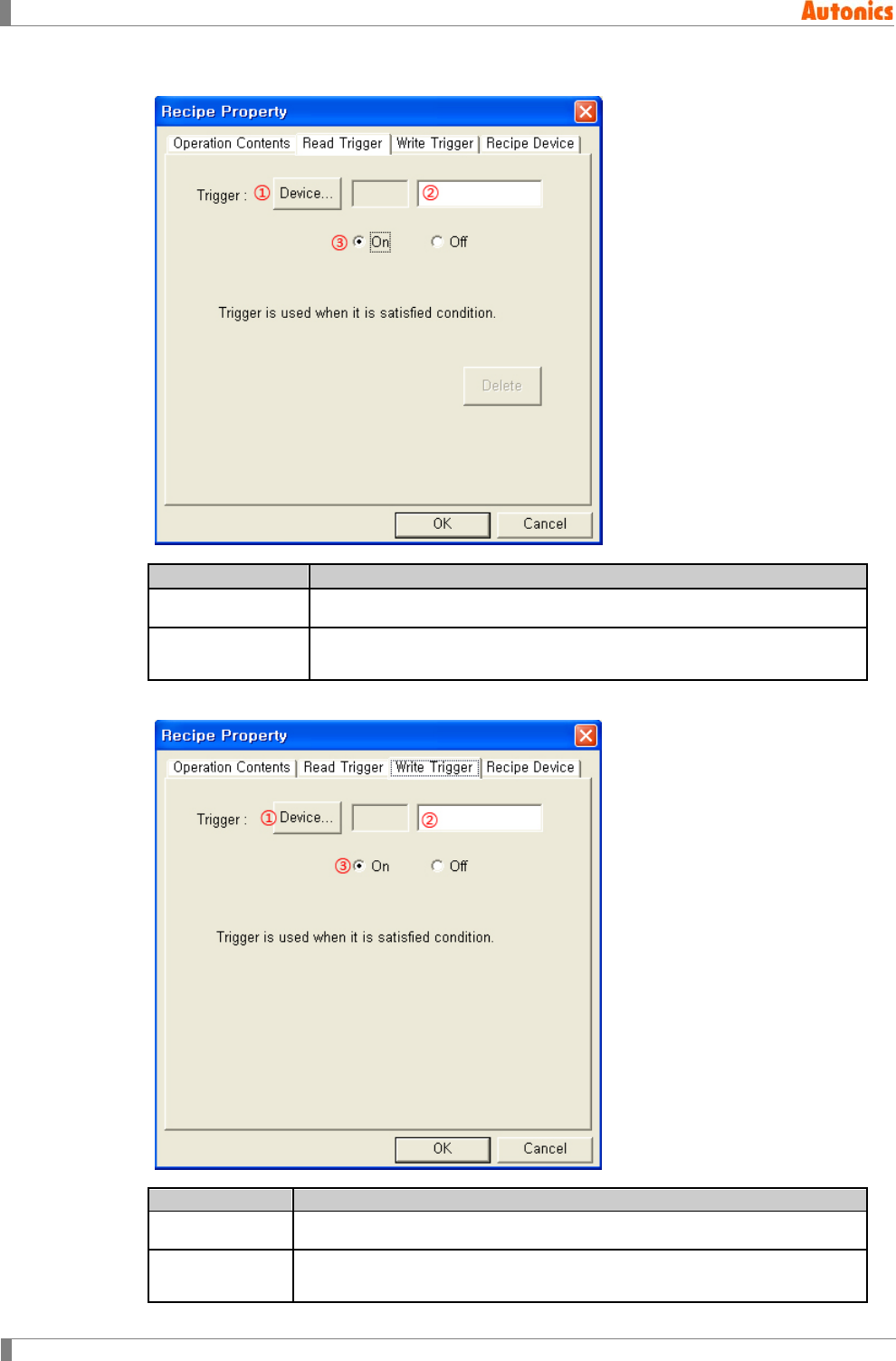
8 Common
290 © Copyright Reserved Autonics Co., Ltd.
(2) Read trigger tab
Read Trigger
Description
①② Device Designate bit device for read trigger.
③Trigger
On: Executes read operation when designated device turns ON.
Off: Executes read operation when designated device turns OFF.
(3) Write trigger tab
Write Trigger
Description
①② Device Designate bit device for write trigger.
③Trigger
On: Executes write operation when designated device turns ON.
Off: Executes write operation when designated device turns OFF.
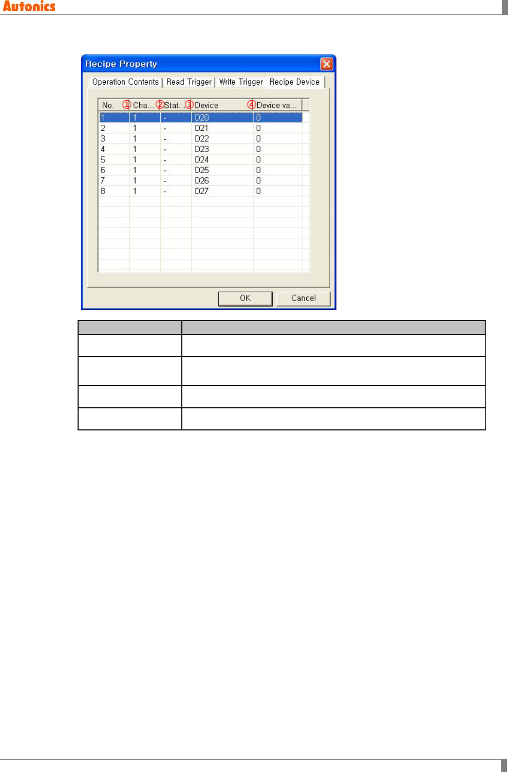
8 Common
© Copyright Reserved Autonics Co., Ltd. 291
(4) Recipe device tab
Recipe Device
Description
①Channel Displays PLC channel for recipe.
②Station Displays PLC station for recipe.
(PLC which does not support station is displayed ‘-’)
③Device Displays lead device for recipe.
④Device value Displays set initial value of recipe area device and edit it.
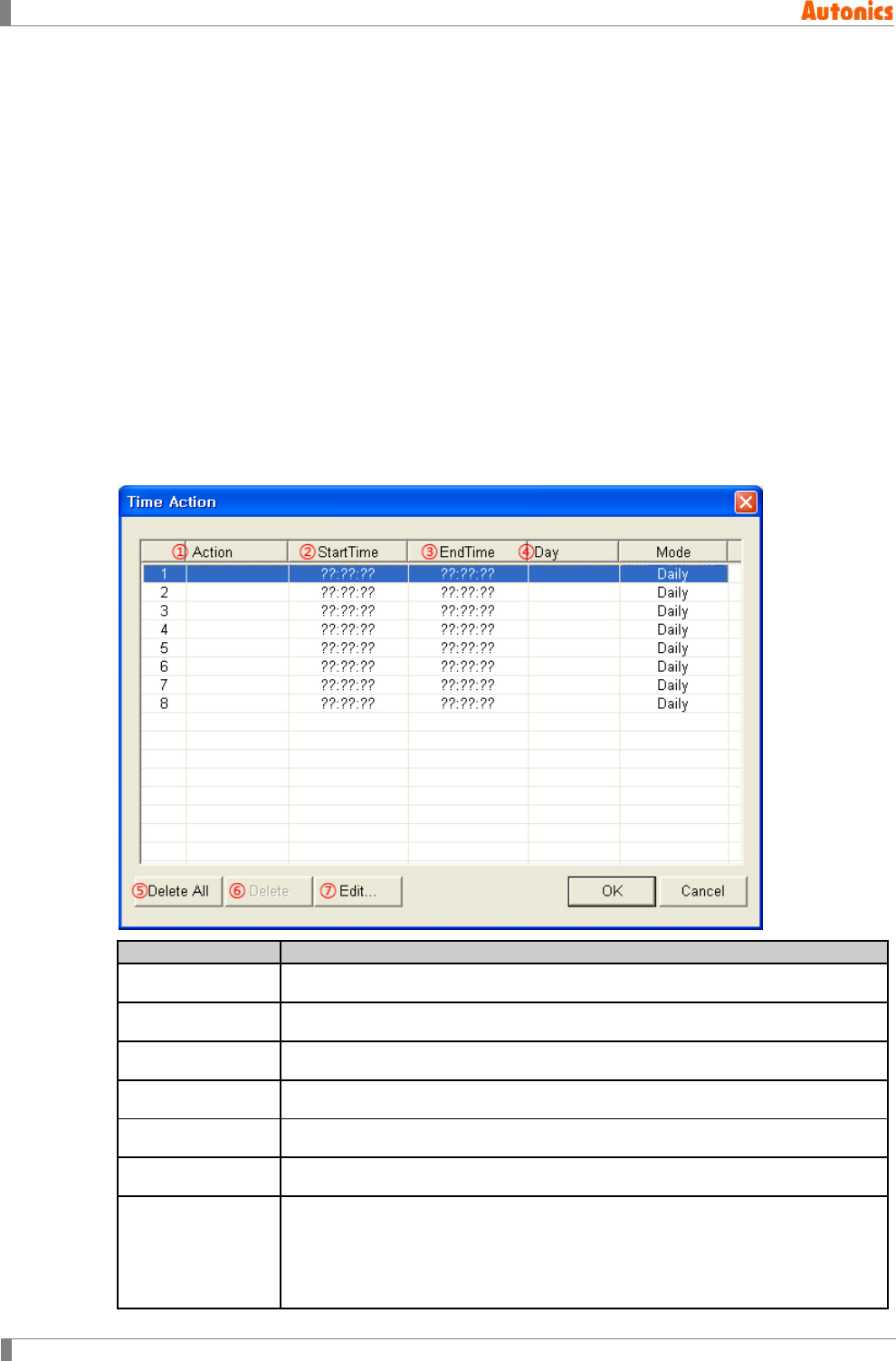
8 Common
292 © Copyright Reserved Autonics Co., Ltd.
8.12 Time Action
This function is for the specified bit device of inner PLC to turn ON/OFF when designated time
and day. You can designate each time action of inner GP/LP by GP Editor, or by from GP/LP
system menu, [Functionality]-[Time Switch]. You can designate bit device up to 8 with
consecutive number.
Designated bit device turns ON when start time, and turns OFF when end time.
8.12.1 Basic operation
Select [Common]-[Time Action] of menu, ‘Time Action’ dialog box appears.
When downloading designated action data from ‘Time Action’ dialog box of GP Editor,
designated items are displayed at GP/LP system meun [Functionality]-[Time Switch]. It is not
able to upload items of GP/LP system menu [Functionality]-[Time Switch] to GP Editor.
8.12.2 Property
8.12.2.1 Time action dialog box
Time Action
Description
①Action Displays designated bit device for time action.
②StartTime Displays start time of each action.
③EndTime Displays end time of each action.
④Day Displays start day of week of each action.
⑤Delete All Deletes all designated items.
⑥Delete Deletes selected item on the list box.
⑦Edit
Calls ‘Time Action Attribute’ dialog box and edit details about each time
action.
Bit device related with action is designated when editing the first item of list
and other items have successive address after the device and they allotted
automatically.
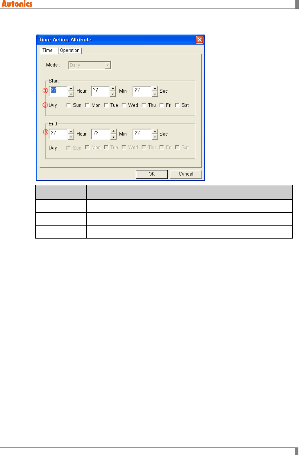
8 Common
© Copyright Reserved Autonics Co., Ltd. 293
8.12.2.2 Time action attribute dialog box
Time Action
Attribute
Description
①Start time Designate start time (hour, minute, second) of action.
②Start day Check start day of week of action.
③End time Designate end time (hour, minute, second) of action.
‘Operation’ tab is for designation bit device for action. It is able to designate lead device for
the first item only.
Designated bit device turns ON when start time of checked day and turns OFF when end
time.
8 Common
294 © Copyright Reserved Autonics Co., Ltd.
8.13 Barcode
It reads data from barcode reader and saves it to PLC.
8.13.1 Basic operation
For barcode reading, you should designate the followings in GP Editor at first.
Designate device and data saving area for barcode reading from [Common]-[Barcode] of
menu.
Designate system signal 1 of system information from [Common]-[System Information] of
menu.
Barcode reading action is controlled by three bits of designated device in system information.
① Limit signal for barcode input[PLC→GP/LP]
Bit4 of word device designated in read device of system inforatmon in GP Editor.
When this bit turns ON, it does not read barcode input.
② Completion signal for barcode read[PLC→GP/LP]
Bit5 of word device designated in read device of system inforatmon in GP Editor.
When this bit turns ON, barcode input signal is OFF and barcode input is prohibited until
this signal is reset.
③ Barcode input signal[GP→PLC]
Bit8 of system signal 2 of system information in GP Editor is alloatted.
This bit turns ON automatically when GP/LP saves all of barcode input values to save
device of PLC.
When completion signal for barcode read is set, this bit is reset.
Limit signal for barcode input and completion signal for barcode read should be controlled by
PLC program.
Barcode information from barcode reader is saved at barcode device. After this, when reading
barcode, it saves same device. You should move read barcode information to other area. Please
create logic for controlling limit signal for barcode input and completion signal.
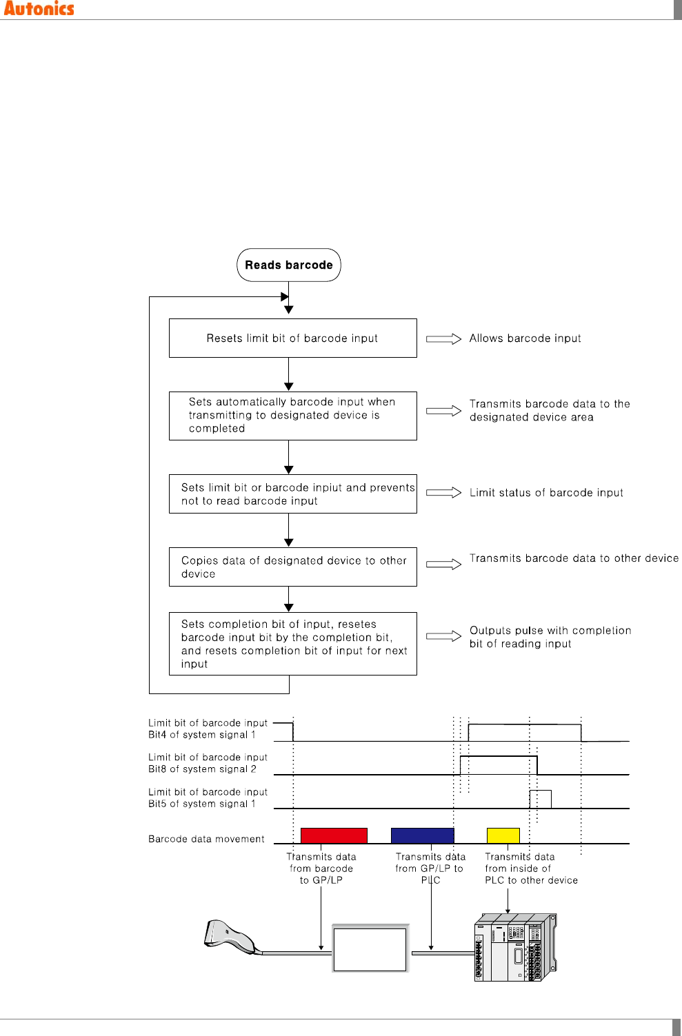
8 Common
© Copyright Reserved Autonics Co., Ltd. 295
8.13.2 Barcode read order
1st Reset limit bit of barcode input and completion bit of barcode read to make readable
state.
2nd Barcode input signal is set when reading barcode.
3rd Set limit bit of barcode input not to read input anymore.
4th Move saved data at barcode device to other area.
5th Set completion bit of barcode and barcode input signal is reset.
6th Repeat 1st to 4th execution.
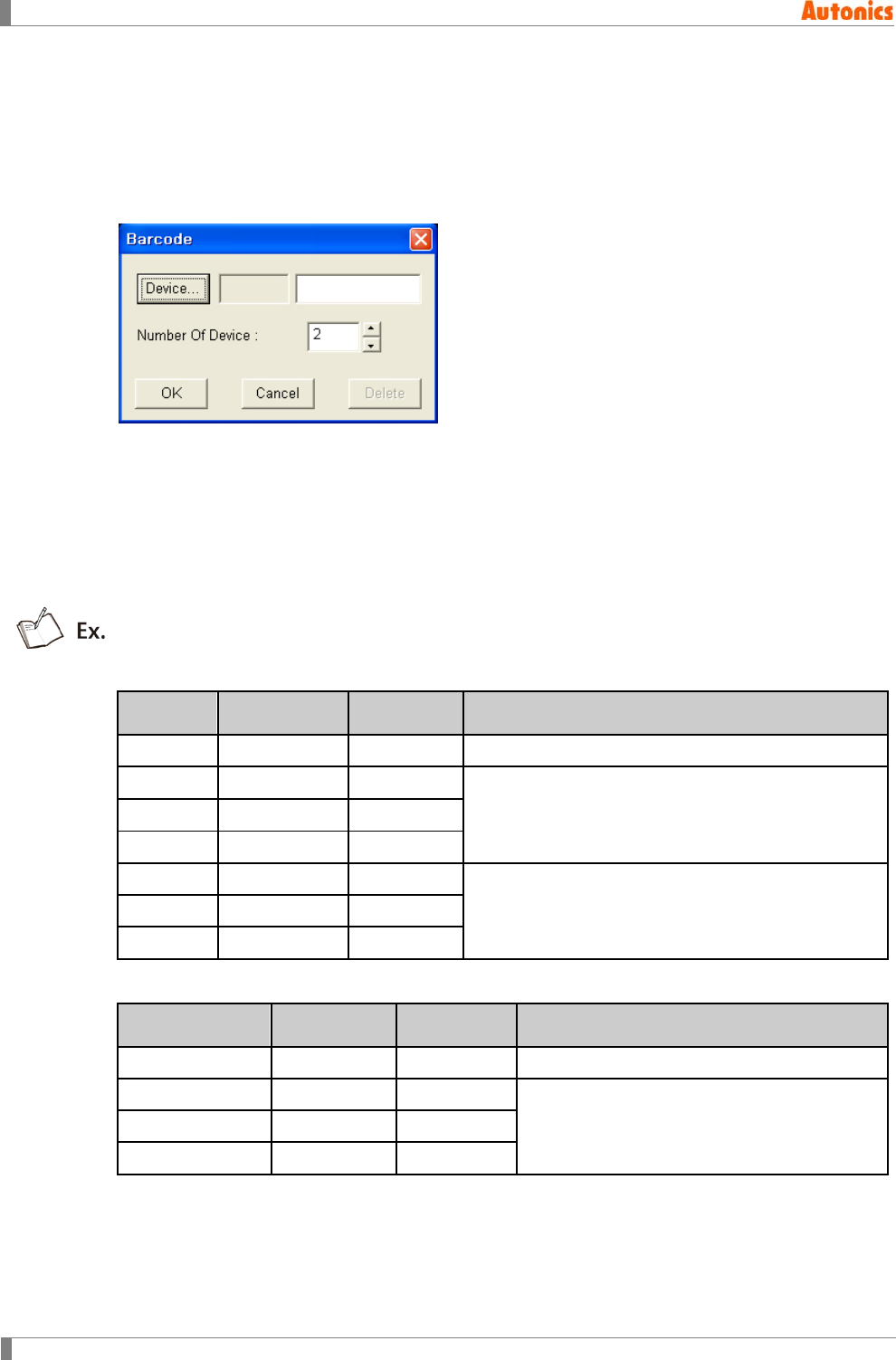
8 Common
296 © Copyright Reserved Autonics Co., Ltd.
8.13.3 Save
Select [Common]-[Barcode] and ‘Barcode’ dialog box appears.
Designate device for saving data from barcode reader.
When designating lead device and device point, successive word register as points including
lead device is used for saving barcode data.
Lead device saves the number of byte (the number of character) and after this devices save
read (ASCII) code.
If data is less than the number of designated device for saving, other area is filled with
20H[SPACE].
If data is more than the number of designated device for saving, it saves data up to
available area and the others are not saved. In this case, lead device saves actual reading.
In case, Barcode=‘1234567’, Device=D100, Number of device= 7;
Device Saved data
ASCII
Character
Description
D100 0007H
The number of read byte.
D101 3231H ‘1’‘2’
Saves data in order of from lower byte to upper byte. D102 3433H ‘3’‘4’
D103 3635H ‘5’‘6’
D104 2037H ‘7’ ’ ’
After last device address is filled with 20H (space).
D105 2020H
D106 2020H
In case, Barcode=‘1234567’, Device=D100, Number of device=4;
Device Saved data
ASCII
Character
Description
D100 0007H The number of read byte.
D101 3231H ‘1’‘2’ Saves data in order of from lower byte to
upper byte.
The other data is not saved.
D102 3433H ‘3’‘4’
D103 3635H ‘5’‘6’
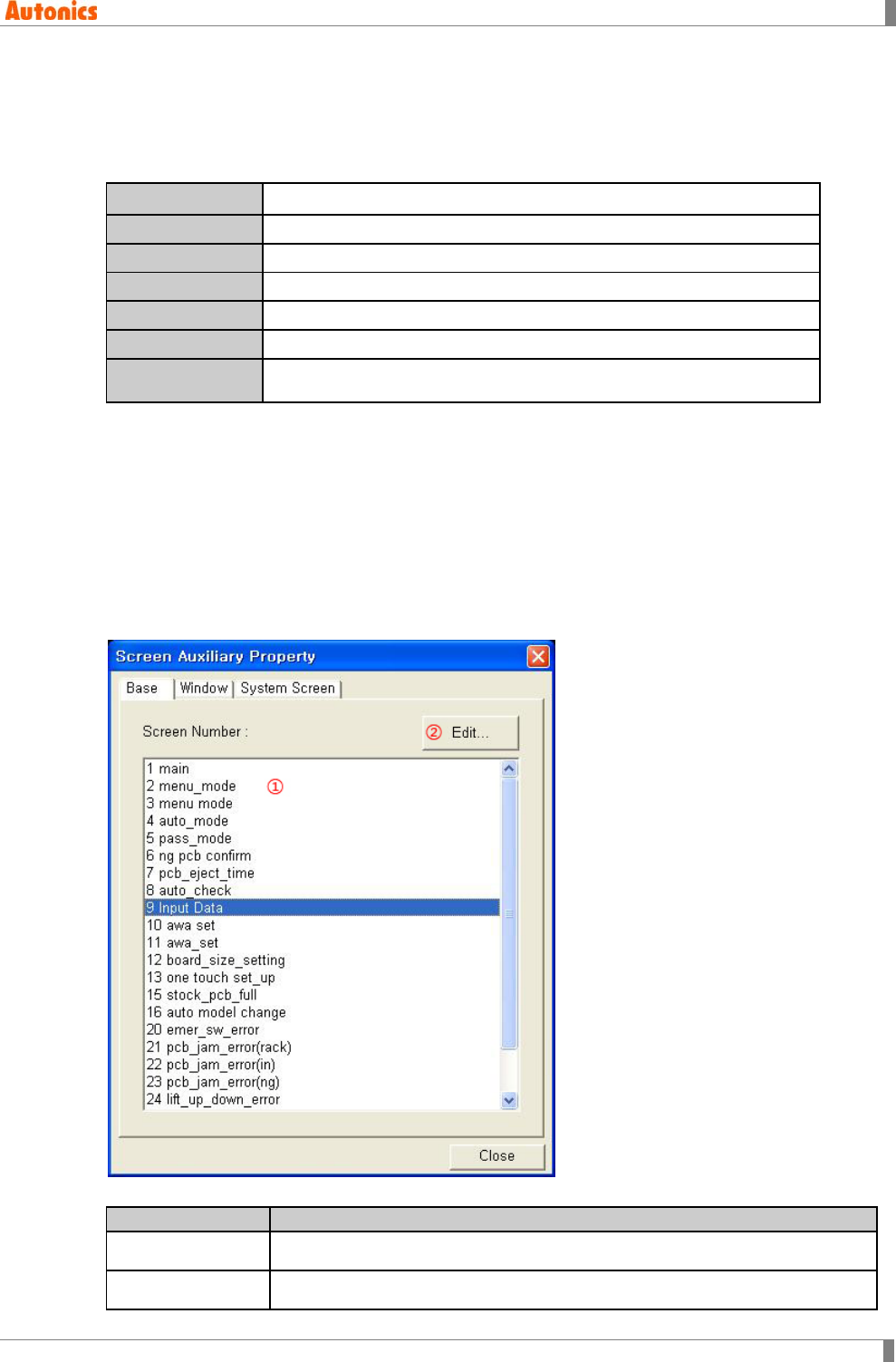
8 Common
© Copyright Reserved Autonics Co., Ltd. 297
8.13.4 Specification of available barcode reader
In order to use barcode reader, you should set connection as ‘Barcode’ from GP/LP system
setting [Environment]-[Serial Communication] and speed, data length, etc also as connected
barcode reader’s specification.
Interface RS232/RS422
Speed
300, 600, 1200, 2400, 4800, 9600, 19200, 38400, 57600 bps
Data length
7, 8 Bit
Stop bit
1, 2 Bit
Parity
ODD, EVEN, NONE
Flow control
XON/XOFF, DSR/DTR, NONE
Communication
format
ASCII character code and exit code CR[0DH] [ASCII data + Exit code]
Interface, and speed are designated same with other serial devices connected with GP/LP.
8.14 Auxiliary Configuration
8.14.1 Project
Refer to ‘2.1.2 Project auxiliary property’.
8.14.2 Screen
Base Description
①Screen Number Displays all base screen of the project as a list.
②Edit Edit the selected base screen at ①.
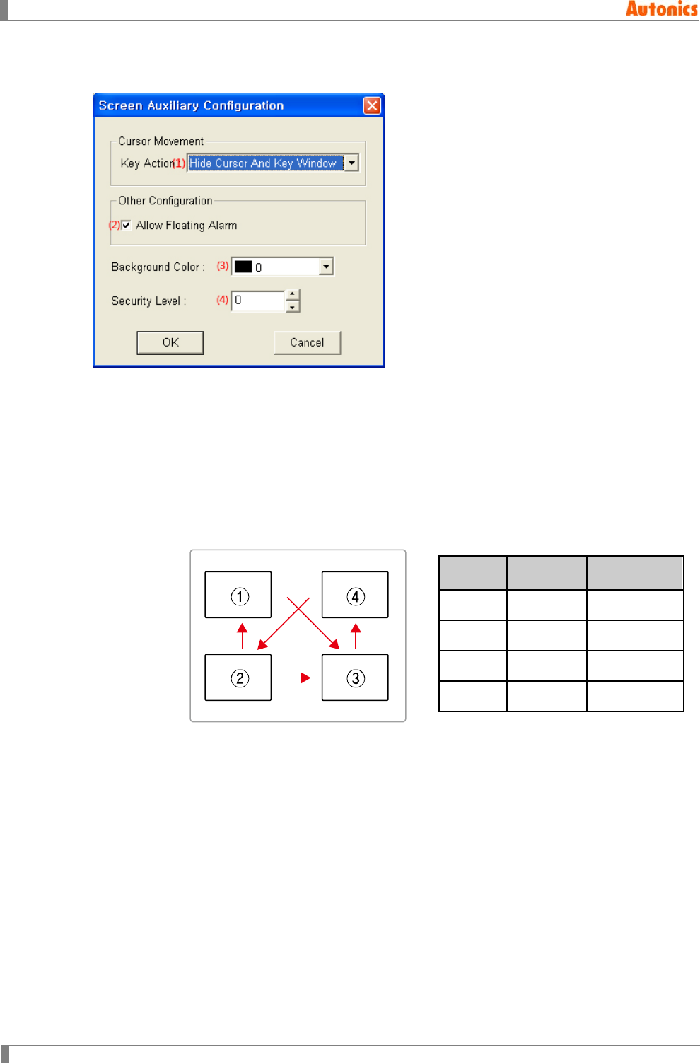
8 Common
298 © Copyright Reserved Autonics Co., Ltd.
You can designate for cursor movement for key action, allowing floating alarm, background color,
and security level of each base screen’s configuration.
(1) Cursor Movement
Designate cursor movement when touching ENT, CLR, UP, or DOWN key window at
numeral input, ASCII input mode by pull-down menu.
No Movement
When touching CLR, ENT key window, key window is not closed and cursor does not
move to other input tag. Even though touching UP or DOWN key window, cursor does
not move to other input tag.
Order Of User ID
When touching ENT, cursor moves in order to designated user ID.
Touching at ①: Repeats ①→③→④→②→③→④→②③④
Touching at ②: Repeats ②→③→④→②③④
Touching at ③: Repeats ③→④→②→③→④→②③④
Touching at ④: Repeats ④→②→③→④→②③④
Hide Cursor And Key Window
When touching CLR/ENT, it hides cursor and key window. If there are designated
user ID and destination ID, cursor moves in accordance with designated value
when touching UP/DONW key window.
(2) Other Configuration
Designate allowing floating alarm function or not. Checking this, the designated comment
floats when designated alarm at ‘Alarm Floating’ dialog box occurs.
Input
tag
User ID
Destination
ID
① 3 1
② 4 1
③ 1 2
④ 2 4

8 Common
© Copyright Reserved Autonics Co., Ltd. 299
(3) Background Color
Designate background color of current editing screen.
Mono type(GP-S044, GP-S057, LP-S044): White/Black
Color type(GP-S070, LP-S070): 24bit True Color
(4) Security Level
Designate security level of current editing screen.
Security level 0 is not designated security state, security level 1 is the lowest and security
level 15 is top level. For further detail, refer to ‘8.6 Security’.

8 Common
300 © Copyright Reserved Autonics Co., Ltd.
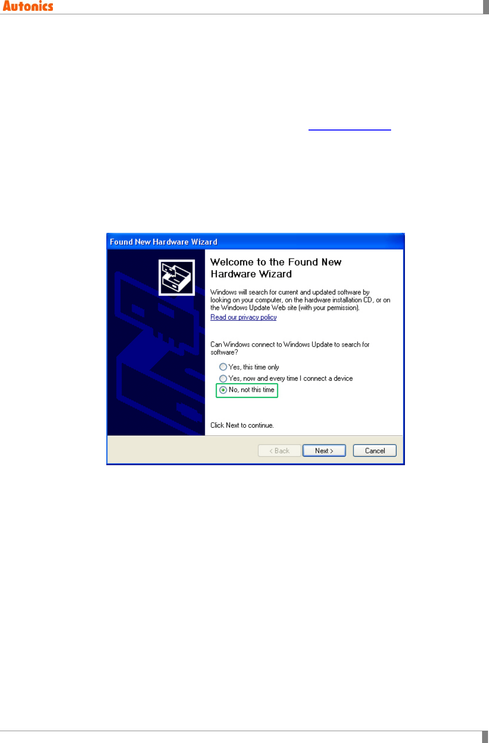
9 Appendix
© Copyright Reserved Autonics Co., Ltd. 301
9 Appendix
9.1 USB driver installation
‘GP/LP USB Driver’ is driver for communication PC and GP/LP by USB cable.
Before installing ‘GP/LP USB Driver’, visit our homepage(www.autonics.com) and download
setup file.
Downloaded zip file name is as following.
GP_LP_Series.inf, GP_LP_Series.sys
(1) Install with found new hardware wizard
1st Connect GP/LP to PC with USB cable and ‘Found New Hardware Wizard’ operates.
2nd Select ‘No, not this time’ and click ‘Next’.
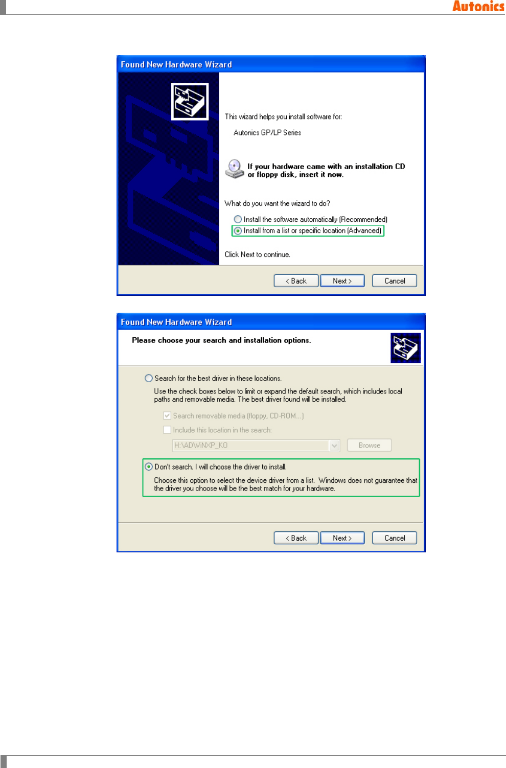
9 Appendix
302 © Copyright Reserved Autonics Co., Ltd.
3rd Select ‘Install from a list or specific location (Advanced)’ and click ‘Next’.
4th Select ‘Don’t search. I will choose the driver to install.’ and click ‘Next’.
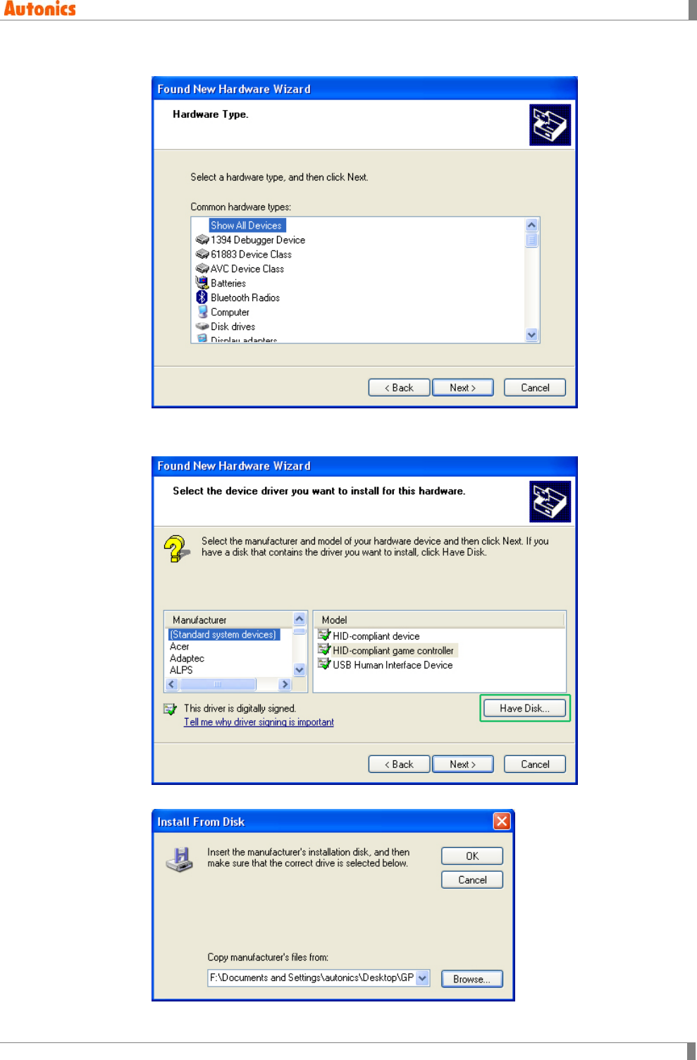
9 Appendix
© Copyright Reserved Autonics Co., Ltd. 303
5th Select ‘Show All Devices’ for common hardware type and click ‘Next’.
6th Select ‘(Standard system devices)’ and ‘HID-compliant game controller’ and
click ’Have Disk’ and ‘Install From Disk’ dialog box appears.
7th Click ‘Browse’ , designate GP/LP USB Driver folder and click ‘OK’.
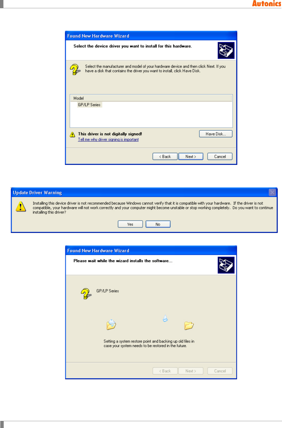
9 Appendix
304 © Copyright Reserved Autonics Co., Ltd.
8th Select ‘GP/LP Series’ as below feature and click ‘Next’.
During installing driver, if following message appears, click ‘Yes’ and continues
installing driver.
9th Processes installing GP/LP USB Driver.
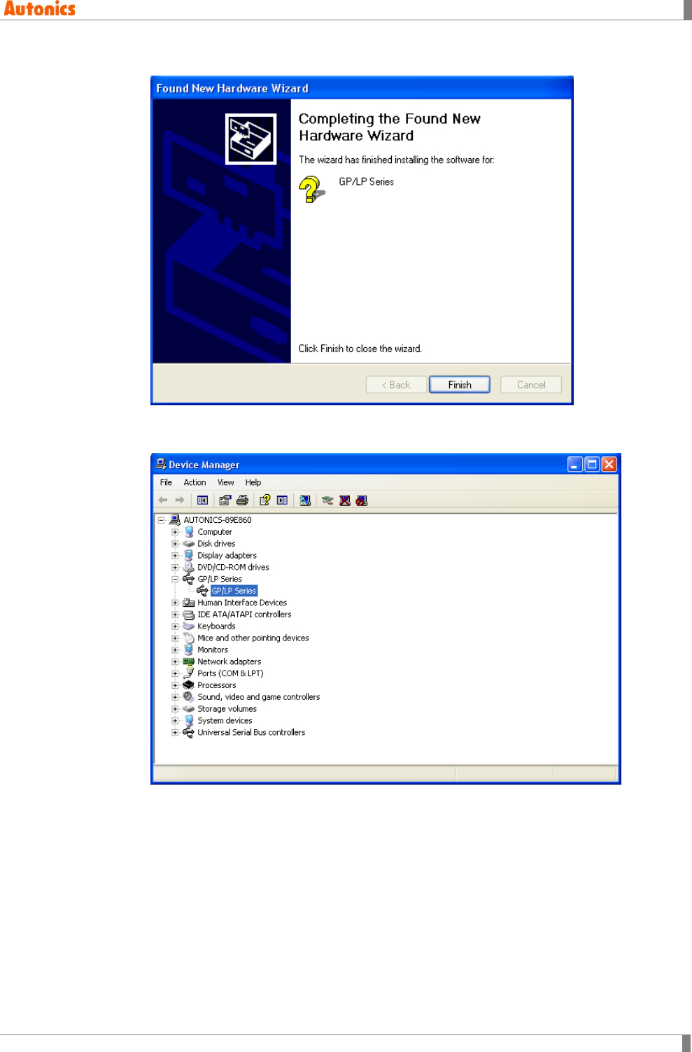
9 Appendix
© Copyright Reserved Autonics Co., Ltd. 305
10th Click ‘Finish’ and comepletes installing driver.
You can check installed driver at [Start]-[Control Panel]-[System]-[Hardware]-[Device
Manager].
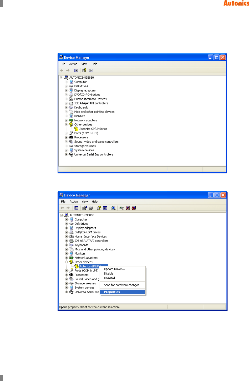
9 Appendix
306 © Copyright Reserved Autonics Co., Ltd.
(2) Install with device manager
1st If ‘Found New Hardware Wizard’ does not operate, you can install USB driver at
[Start]-[Control Panel]-[System]-[Hardware]-[Device Manager].
Uninstalled driver displays ‘?’ as following feature.
2nd Click ‘Autonics GP/LP Series’ with right mouse button and pop-up menu appears.
Select ‘Properties’.
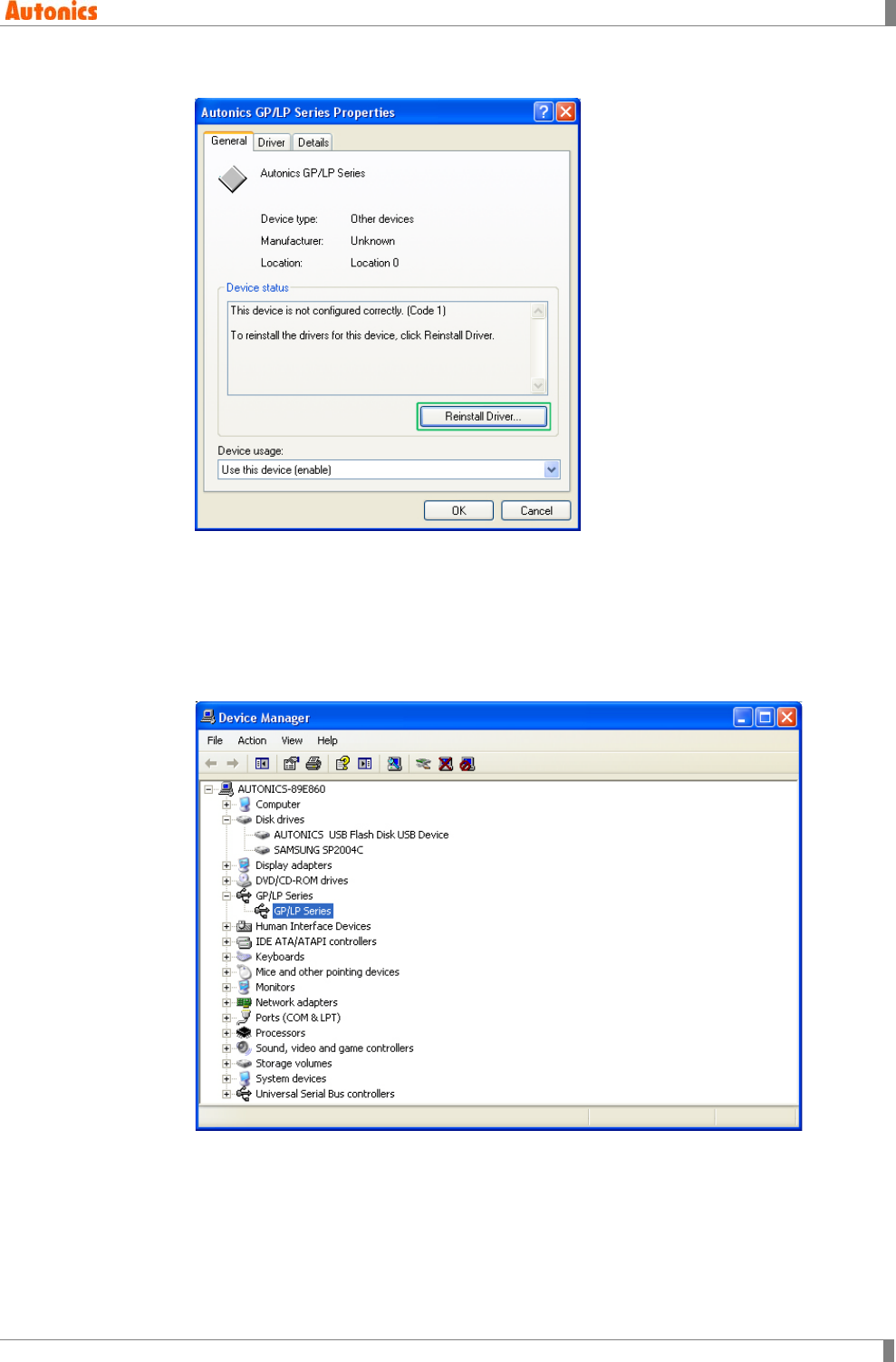
9 Appendix
© Copyright Reserved Autonics Co., Ltd. 307
3rd ‘Autonics GP/LP Series Properties’ dialog box appears. Click ‘Reinstall Driver’.
4th ‘Found New Hardware Wizard’ operates. Next steps are same as ‘(1)Install with found
new hardware wizard’ and please refer this.
5th After installing GP/LP USB driver, you can check installed AUTONICS USB Flash
Disk USB Device as mass storage device and GP/LP Series USB driver at [Device
Manager].
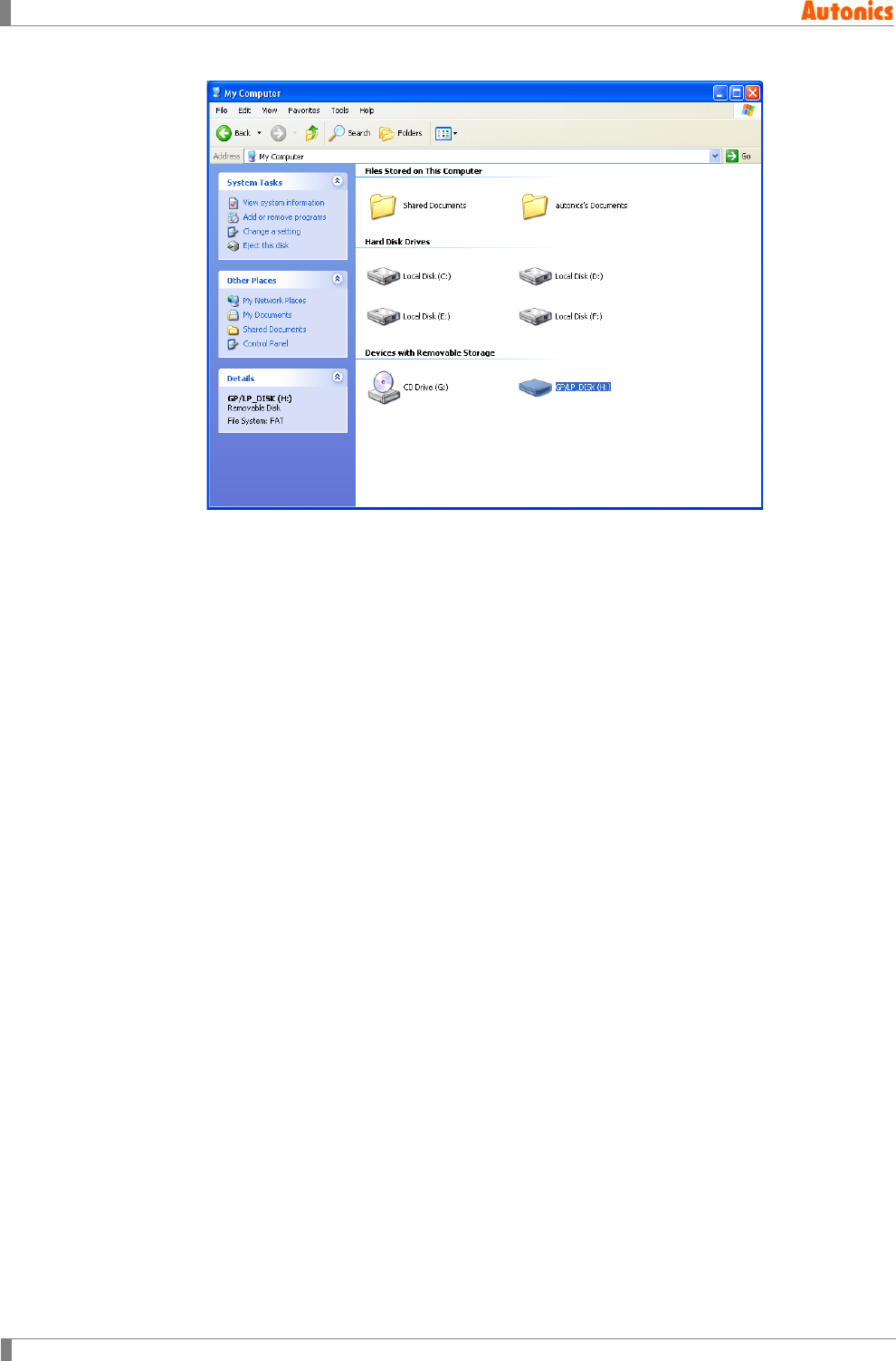
9 Appendix
308 © Copyright Reserved Autonics Co., Ltd.
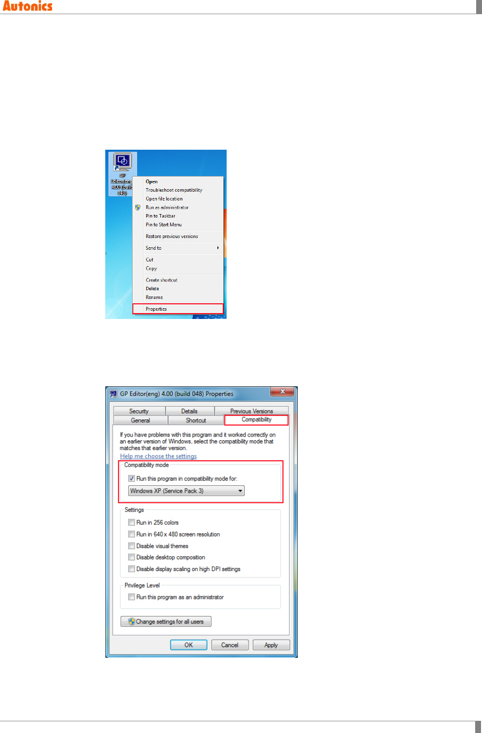
9 Appendix
© Copyright Reserved Autonics Co., Ltd. 309
9.2 GP Editor runs in Windows 7 operating system
To run GP Editor in windows 7 operating system, you need to configurate it as following.
(If an account of Window7 is ‘Adminstrator’, GP Editor runs normally without configuration.)
9.2.1 GP Editor runs as administrator
1st Select ‘GP Editor’ icon and click it with right mouse button and pop-up menu appears.
Select ‘Properties (R)’.
2nd ‘GP Editor Properties’ dialog box appears. Select ‘Compatibility’ tab.
(Check one ‘Compatibility mode’ or ‘Privilege Level’.)
Checking compatibility mode: Check ‘Run this program in compatibility mode for:’ and
select ‘Windows XP (Service Pack 3)’ by below pull down menu and click ‘OK’.
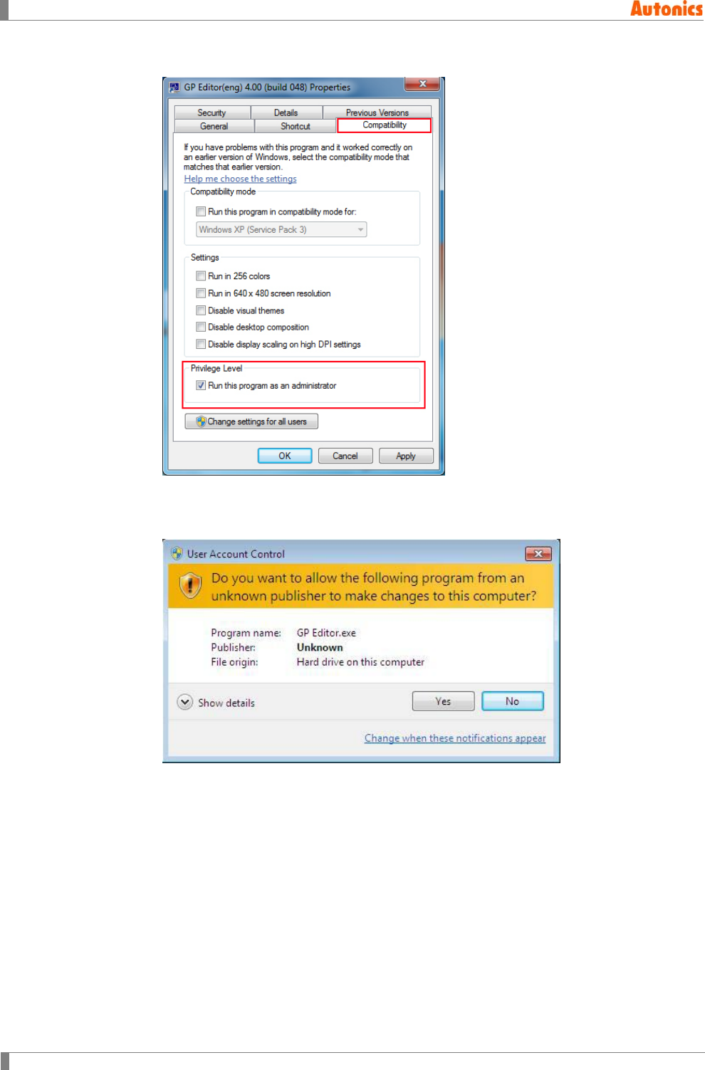
9 Appendix
310 © Copyright Reserved Autonics Co., Ltd.
Checking privilege level: Check ‘Run this program as an administrator’ and click ‘OK’.
3rd Executes GP Editor, ‘User Account Control’ dialog box appears. Click ‘Yes(Y)’ and
GP Editor executes.
To disable ‘User Account Control’ dialog box, refer to ‘9.2.3 Disable to user account
control dialog box’.
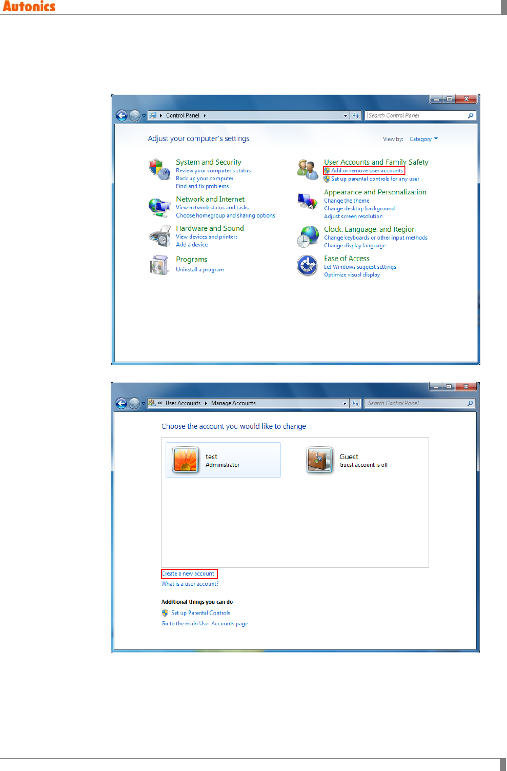
9 Appendix
© Copyright Reserved Autonics Co., Ltd. 311
9.2.2 In case of no administrator account (Create administrator
account windows 7)
1st Select [Start]-[Control Panel]-[Add or remove user accunts].
2nd Click ‘Create a new account’.
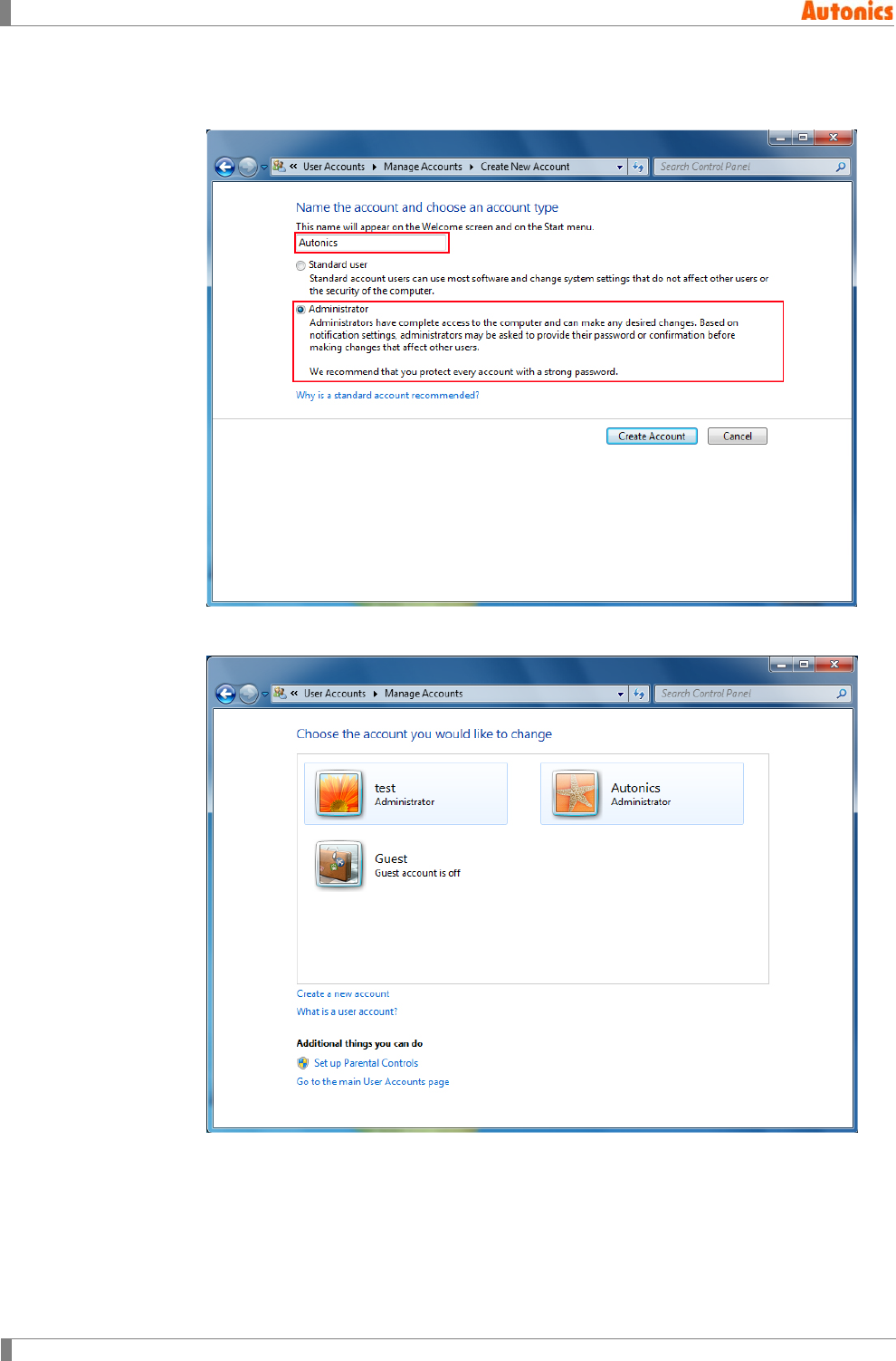
9 Appendix
312 © Copyright Reserved Autonics Co., Ltd.
3rd Enter the desired account name in ‘Name the account and choose an account type’
and select ‘Administrator (A)’ and click ‘Create Account’.
4th It completes creating administrator account.
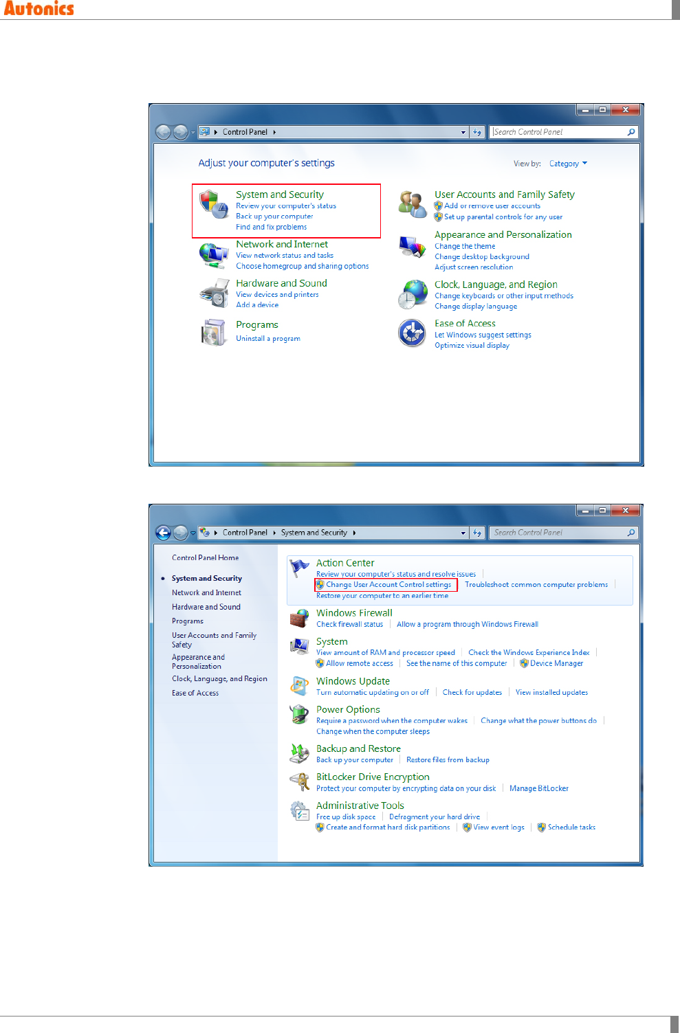
9 Appendix
© Copyright Reserved Autonics Co., Ltd. 313
9.2.3 Disable to user account control dialog box
1st Select [Start]-[Control Panel]-[System and Security].
2nd Click ‘Change User Account Control settings’.
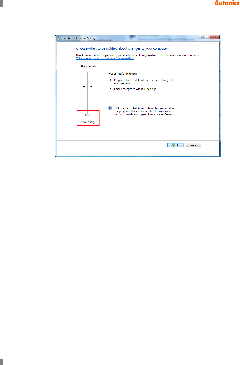
9 Appendix
314 © Copyright Reserved Autonics Co., Ltd.
3rd ‘User Account Control Settings’ dialog box appears. Select as ‘Never notify’ and click
‘OK’.

9 Appendix
© Copyright Reserved Autonics Co., Ltd. 315
9 Appendix
316 © Copyright Reserved Autonics Co., Ltd.
MWA-GPEV4U1-V1.1-1202US
