AT Commands Interface Guide GSM 900, 1900 Developer Rev A
GSM%20Developer%20Guide%20-%20GSM%20AT%20Commands%20-%20Rev%20%20A
User Manual: GSM 900, GSM 1900
Open the PDF directly: View PDF ![]() .
.
Page Count: 244 [warning: Documents this large are best viewed by clicking the View PDF Link!]
- Chapter 1 - Introduction
- Chapter 2 - AT commands Features
- Chapter 3 General be haviors
- Chapter 4 - General Commands
- Manufacturer identification +CGMI
- Request model identification +CGMM
- Request revision identification +CGMR
- Product Serial Number +CGSN
- Select TE character set +CSCS
- Wavecom Phonebook Character Set +WPCS
- Request IMSI +CIMI
- Card Identification +CCID
- Capabilities list +GCAP
- Repeat last command A/
- Power off +CPOF
- Set phone functionality +CFUN
- Phone activity status +CPAS
- Report Mobile Equipment errors +CMEE
- Keypad control +CKPD
- Clock Management +CCLK
- Alarm Management +CALA
- Ring Melody Playback +CRMP
- Ringer Sound Level +CRSL
- Chapter 5 - Call Control commands
- Dial commandD
- Hang-Up command H
- Answer a call A
- Remote disconnection
- Extended error report +CEER
- DTMF signals +VTD, +VTS
- Redial last telephone number ATDL
- Automatic dialing with DTR AT%Dn
- Automatic answer ATS0
- Incoming Call Bearer +CICB
- Single Numbering Scheme +CSNS
- Gain control +VGR, +VGT
- Microphone Mute Control +CMUT
- Speaker & Microphone selection +SPEAKER
- Echo Cancellation +ECHO
- SideTone modification +SIDET
- Initialize Voice Parameters +VIP
- Chapter 6 - Network service commands
- Chapter 7 - Security commands
- Chapter 8 - Phonebook commands
- Chapter 9 - Short Messages commands
- Parameters definition
- Select message service +CSMS
- New Message Acknowledgement +CNMA
- Preferred Message Storage +CPMS
- Preferred Message Format +CMGF
- Save Settings +CSAS
- Restore settings +CRES
- Show text mode parameters +CSDH
- New message indication +CNMI
- Read message +CMGR
- List message +CMGL
- Send message +CMGS
- Write Message to Memory +CMGW
- Send Message From Storage +CMSS
- Set Text Mode Parameters +CSMP
- Delete message +CMGD
- Service center address +CSCA
- Select Cell Broadcast Message Types +CSCB
- Cell Broadcast Message Identifiers +WCBM
- Message status modification +WMSC
- Message overwriting +WMGO
- Unchange SMS Status +WUSS
- Chapter 10 - Supplementary Services Commands
- Call forwarding +CCFC
- Call barring +CLCK
- Modify SS password +CPWD
- Call waiting +CCWA
- Calling line identification restriction +CLIR
- Calling line identification presentation +CLIP
- Connected line identification presentation +COLP
- Advice of charge +CAOC
- Accumulated call meter +CACM
- Accumulated call meter maximum +CAMM
- Price per unit and currency table +CPUC
- Call related supplementary services +CHLD
- List current calls +CLCC
- Supplementary service notifications +CSSN
- Unstructured supplementary service data +CUSD
- Closed user group +CCUG
- Chapter 11 - Data Commands
- Using AT Commands during a data connection
- Bearer type selection +CBST
- Select mode +FCLASS
- Service reporting control +CR
- Cellular result codes +CRC
- DTE-DCE local rate reporting ?ILRR
- Radio link protocol parameters +CRLP
- Others radio link parameters +DOPT
- Select data compression %C
- V42 bis data compression +DS
- V42 bis data compression report +DR
- Select data error correcting mode \N
- Chapter 12 - Fax Commands
- Chapter 13 - Fax Class 2 Commands
- Transmit Data +FDT
- Receive Data +FDR
- Transmit page punctuation +FET
- Page transfer status parameters +FPTS
- Terminate Session +FK
- Page transfer bit order +FBOR
- Buffer size report +FBUF
- Copy quality checking +FCQ
- Capability to receive +FCR
- Current sessions parameters +FDIS
- DCE capabilities parameters +FDCC
- Local ID string +FLID
- Page transfer timeout parameter +FPHCTO
- Fax Class 2 indication messages
- Chapter 14 - V24-V25 commands
- Fixed DTE rate +IPR
- DTE-DCE character framing +ICF
- DTE-DCE local flow control +IFC
- Set DCD signal &C
- Set DTR signal &D
- Set DSR signal &S
- Back to online mode O
- Result code suppression Q
- DCE response format V
- Default configuration Z
- Save configuration &W
- Auto-tests &T
- Echo E
- Restore factory settings &F
- Display configuration &V
- Request identification information I
- Data / Commands Multiplexing +WMUX
- Chapter 15 - Specific AT commands
- Cell environment description +CCED
- Automatic RxLev indication +CCED
- General Indications +WIND
- Analog digital converters measurements +ADC
- Mobile Equipment event reporting +CMER
- Read Language Preference +WLPR
- Write Language Preference +WLPW
- Read GPIO value +WIOR
- Write GPIO value +WIOW
- Input/Output Management +WIOM
- Abort command +WAC
- Play tone +WTONE
- Play DTMF tone +WDTMF
- Wavecom Downloading +WDWL
- Wavecom Voice Rate +WVR
- Data Rate +WDR
- Hardware Version +WHWV
- Date of Production +WDOP
- Wavecom Select Voice Gain +WSVG
- Wavecom Status Request +WSTR
- Wavecom Scan +WSCAN
- Wavecom Ring Indicator Mode +WRIM
- Wavecom 32kHz Power down Mode +W32K
- Wavecom Change Default Melody +WCDM
- Wavecom Software version +WSSW
- Wavecom Custom Character Set +WCCS
- Wavecom LoCK +WLCK
- CPHS command +CPHS
- Unsolicited result: Wavecom Voice Mail Indicator +WVMI
- Wavecom Battery Charge Management +WBCM
- Features Management +WFM
- Commercial Features Management +WCFM
- Wavecom Customer storage mirror +WMIR
- Wavecom Change Default Player +WCDP
- Wavecom CPHS Mail Box Number +WMBN
- Wavecom Open AT control command +WOPEN
- Wavecom Reset +WRST
- Set Standard Tone +WSST
- Wavecom Location +WLOC
- Wavecom Bus Read +WBR
- Wavecom Bus Write +WBW
- Wavecom Bus Management +WBM
- Wavecom Hang-up +WATH
- Write IMEI +WIMEI
- Chapter 16 - SIM TOOLKIT
- Chapter 17 - GPRS commands
- Define PDP Context +CGDCONT
- Quality of Service Profile (Requested) +CGQREQ
- Quality of Service Profile (Minimum acceptable) +CGQMIN
- GPRS attach or detach +CGATT
- PDP context activate or deactivate +CGACT
- Enter data state +CGDATA
- GPRS mobile station class +CGCLASS
- Select service for MO SMS messages +CGSMS
- GPRS event reporting +CGEREP
- GPRS network registration status +CGREG
- Request GPRS IP service 'D'
- Network requested PDP context activation
- Automatic response to a network request for PDP context activation +CGAUTO
- Manual response to a network request for PDP context activation +CGANS
- Show PDP address +CGPADDR
- Cellular result codes +CRC
- Service reporting control +CR
- Extended error report +CEER
- PDP Counters Infos +CGCOUNTERS
- GPRS PARAMETERS CUSTO: +WGPRS
- GPRS-related errors +CME ERROR: <error>
- Specific GPRS Failure Cause for +CEER
- Full AT commands examples
- Chapter 18 - Other AT commands
- Appendix A: Tables
- ME error result code: +CME ERROR: <error>
- Message service failure result code: +CMS ERROR: <er>
- Specific error result codes
- Failure Cause from GSM 04.08 recommendation (+CEER)
- Specific Failure Cause for +CEER
- GSM 04.11 Annex E-2: Mobile originating SM-transfer
- Unsolicited result codes
- Final result codes
- Intermediate result codes
- Parameters storage
- GSM sequences list
- Operator names
- Appendix B: Data / Commands multiplexing protocol
- APPENDIX C: AT Command Examples
- APPENDIX D: ME SIM ToolKit Support
- APPENDIX E: Structure of TERMINAL PROFILE
- APPENDIX F: Command Type and Next Action Indicator.
- APPENDIX G: Coding of Alpha fields in the SIM for UCS2
- APPENDIX H: Specification of Power Down Control via RS232
- APPENDIX I: Conditions for command execution and dependence to SIM

AT Commands
GSM Reference Guide
Wireless Modem Family
Interface Guide

AT Commands Interface User Guide
Multi-Tech Systems, Inc. PN S000293A 2
GSM AT Commands Reference Guide
Products: Wireless Modem Family, including MTCBA-G-F1/F2, MTMMC-G-F1/F2, and MTSMC-G-F1/F2
PN S000293A, Revision A
Copyright
This publication may not be reproduced, in whole or in part, without prior expressed written
permission from Multi-Tech Systems, Inc. All rights reserved. Copyright © 2003, by Multi-Tech
Systems, Inc.
Multi-Tech Systems, Inc. makes no representations or warranties with respect to the contents hereof
and specifically disclaims any implied warranties of merchantability or fitness for any particular
purpose. Furthermore, Multi-Tech Systems, Inc. reserves the right to revise this publication and to
make changes from time to time in the content hereof without obligation of Multi-Tech Systems, Inc.
to notify any person or organization of such revisions or changes.
Revisions
Revision Level Date Description
A07/15/03 Initial release.
Trademarks
The Multi-Tech logo is a trademark of Multi-Tech Systems, Inc.

AT Commands Interface User Guide
Multi-Tech Systems, Inc. PN S000293A 3
Contents
Chapter 1 - Introduction ...............................................................................................................................4
Chapter 2 - AT commands Features ...........................................................................................................5
Chapter 3 General be haviors ......................................................................................................................6
Chapter 4 - General Commands ..................................................................................................................8
Chapter 5 - Call Control commands..........................................................................................................17
Chapter 6 - Network service commands...................................................................................................30
Chapter 7 - Security commands ................................................................................................................38
Chapter 8 - Phonebook commands...........................................................................................................45
Chapter 9 - Short Messages commands...................................................................................................56
Chapter 10 - Supplementary Services Commands..................................................................................74
Chapter 11 - Data Commands....................................................................................................................88
Chapter 12 - Fax Commands......................................................................................................................96
Chapter 13 - Fax Class 2 Commands.....................................................................................................100
Chapter 14 - V24-V25 commands ............................................................................................................107
Chapter 15 - Specific AT commands.......................................................................................................116
Chapter 16 - SIM TOOLKIT .......................................................................................................................157
Chapter 17 - GPRS commands ................................................................................................................172
Chapter 18 - Other AT commands...........................................................................................................196
Appendix A: Tables...................................................................................................................................197
Appendix B: Data / Commands multiplexing protocol..........................................................................219
APPENDIX C: AT Command Examples...................................................................................................221
APPENDIX D: ME SIM ToolKit Support...................................................................................................224
APPENDIX E: Structure of TERMINAL PROFILE ...................................................................................226
APPENDIX F: Command Type and Next Action Indicator. ...................................................................229
APPENDIX G: Coding of Alpha fields in the SIM for UCS2...................................................................230
APPENDIX H: Specification of Power Down Control via RS232 ..........................................................232
APPENDIX I: Conditions for command execution and dependence to SIM .......................................233

Chapter 1 – Introduction
Multi-Tech Systems, Inc. PN S000293A 4
CHAPTER 1 - INTRODUCTION
Scope of this document
This document describes the AT-command based messages exchanged between an application
and the MULTI-TECH products in order to manage GSM related events or services.
Related documents
This interface specification is based on the following recommendations:
[1] ETSI GSM 07.05: Digital cellular telecommunications system (Phase 2);
Use of DTE-DCE interface for Short Message Service (SMS) and Cell Broadcast Service (CBS)
[2] ETSI GSM 07.07: Digital cellular telecommunications system (Phase 2);
AT command set for GSM Mobile Equipment (ME)
[3] ITU-T Recommendation V.25 ter: Serial asynchronous automatic dialing and control
[4] ETSI GSM 03.40: Digital cellular telecommunications system (Phase 2);
Technical implementation of the Short Message Service (SMS) Point-to-Point (PP)
[5] ETSI GSM 03.38: Digital cellular telecommunications system (Phase 2);
Alphabets and language-specific information
[6] ETSI GSM 04.80: Digital cellular telecommunications system (Phase 2):
Mobile radio interface layer 3, Supplementary service specification, Formats and coding
Definitions
The words, “Mobile Station” (MS) or “Mobile Equipment” (ME) are used for mobile terminals
supporting GSM services.
A call from a GSM mobile station to the PSTN is called a “mobile originated call” (MOC) or
“outgoing call”, and a call from a fixed network to a GSM mobile station is called a “mobile
terminated call” (MTC) or “incoming call”.
In this document, the word “product” refers to any Multi-Tech product supporting the AT
commands interface.

Chapter 2 – AT Commands Features
Multi-Tech Systems, Inc. PN S000293A 5
CHAPTER 2 - AT COMMANDS FEATURES
Multi-Tech line settings
A serial link handler is set with the following default values (factory settings): autobaud, 8 bits
data, 1 stop bit, no parity, RTS/CTS flow control. Please use the +IPR, +IFC and +ICF
commands to change these settings.
Command line
Commands always start with AT (which means ATtention) and finish with a <CR> character.
Information responses and result codes
Responses start and end with <CR><LF>, except for the ATV0 DCE response format) and the
ATQ1 (result code suppression) commands.
· If command syntax is incorrect, an ERROR string is returned.
· If command syntax is correct but with some incorrect parameters, the +CME ERROR:
<Err> or +CMS ERROR: <SmsErr> strings are returned with different error codes.
· If the command line has been performed successfully, an OK string is returned.
In some cases, such as “AT+CPIN?” or (unsolicited) incoming events, the product does not
return the OK string as a response.
In the following examples <CR> and <CR><LF> are intentionally omitted.

Chapter 3– General Behaviors
Multi-Tech Systems, Inc. PN S000293A 6
CHAPTER 3 GENERAL BE HAVIORS
SIM Insertion, SIM Removal
SIM card Insertion and Removal procedures are supported. There are software functions relying
on positive reading of the hardware SIM detect pin. This pin state (open/closed) is permanently
monitored.
When the SIM detect pin indicates that a card is present in the SIM connector, the product tries
to set up a logical SIM session. The logical SIM session will be set up or not depending on
whether the detected card is a SIM Card or not. The AT+CPIN? command delivers the following
responses:
· If the SIM detect pin indicates “absent”, the response to AT+CPIN? is “+CME ERROR 10”
(SIM not inserted).
· If the SIM detect pin indicates “present”, and the inserted Card is a SIM Card, the res-
ponse to AT+CPIN? is “+CPIN: xxx” depending on SIM PIN state.
· If the SIM detect pin indicates “present”, and the inserted Card is not a SIM Card, the
response to AT+CPIN? is CME ERROR 10.
· These last two states are not given immediately due to background initialization. Between
the hardware SIM detect pin indicating “present” and the previous results the AT+CPIN?
sends “+CME ERROR: 515” (Please wait, init in progress).
When the SIM detect pin indicates card absence, and if a SIM Card was previously inserted, an
IMSI detach procedure is performed, all user data is removed from the product (Phonebooks,
SMS etc.). The product then switches to emergency mode.

Chapter 3– General Behaviors
Multi-Tech Systems, Inc. PN S000293A 7
Background initialization
After entering the PIN (Personal Identification Number), some SIM user data files are loaded into
the product (Phonebooks, SMS status, etc.). Please be aware that it might take some time to
read a large phonebook.
The AT+CPIN? command response comes just after the PIN is checked. After this response
user data is loaded (in background). This means that some data may not be available just after
PIN entry is confirmed by ’OK’. The reading of phonebooks will then be refused by “+CME
ERROR: 515” or “+CMS ERROR: 515” meaning, “Please wait, service is not available, init in
progress”.
This type of answer may be sent by the product at several points:
· when trying to execute another AT command before the previous one is completed
(before response),
· when switching from ADN to FDN (or FDN to ADN) and trying to read the relevant
phonebook immediately,
· when asking for +CPIN? status immediately after SIM insertion and before the product
has determined if the inserted card is a valid SIM Card.

Chapter 5– Call Control Commands
Multi-Tech Systems, Inc. PN S000293A 8
CHAPTER 4 - GENERAL COMMANDS
Manufacturer identification +CGMI
Description:
This command gives the manufacturer identification.
Syntax:
Command syntax: AT+CGMI
Command Possible responses
AT+CGMI
Note: Get manufacturer identification
WAVECOM MODEM
OK
Note: Command valid, Wavecom modem
Request model identification +CGMM
Description:
This command gets the supported frequency bands. With multi-band products the response may
be a combination of different bands.
Syntax:
Command syntax: AT+CGMM
Command Possible responses
AT+CGMM
Note: Get hardware version
900P
OK
Note: GSM 900 MHz primary band. Other possible answers:
“900E” (extended band), “1800” (DCS), “1900” (PCS) or
“MULTIBAND”
Request revision identification +CGMR
Description:
This command gets the revised software version.
Syntax:
Command syntax: AT+CGMR
Command Possible responses
AT+CGMR
Note: Get software version
310_G250.51 806216 032199 17:04
OK
Note: Software release 3.10, revision 51
generated on the 21st of March 1999

Chapter 5– Call Control Commands
Multi-Tech Systems, Inc. PN S000293A 9
Product Serial Number +CGSN
Description:
This command allows the user application to get the IMEI (International Mobile Equipment
Identity) of the product.
Syntax:
Command syntax: AT+CGSN
Command Possible responses
AT+CGSN
Note: Get the IMEI
012345678901234
OK
Note: IMEI read from EEPROM
AT+CGSN
Note: Get the IMEI +CME ERROR: 22
Note: IMEI not found in EEPROM
Select TE character set +CSCS
Description:
This command informs the ME which character set is used by the TE. The ME can convert each
character of entered or displayed strings. This is used to send, read or write short messages.
See also +WPCS for the phonebooks’ character sets.
Syntax:
Command syntax: AT+CSCS=<Character Set>
Command Possible responses
AT+CSCS=”GSM”
Note: GSM default alphabet OK
Note: Command valid
AT+CSCS=”PCCP437”
Note: PC character set code page 437 OK
Note: Command valid
AT+CSCS=?
Note: Get possible values
+CSCS: ("GSM","PCCP437","CUSTOM","HEX")
OK
Note: Possible values
Defined values:
<Character Set>
“GSM” GSM default alphabet.
“PCCP437” PC character set code page 437.
“CUSTOM” User defined character set (cf. +WCCS command).
“HEX” Hexadecimal mode. No character set used ; the user can read or write
hexadecimal values.

Chapter 5– Call Control Commands
Multi-Tech Systems, Inc. PN S000293A 10
Wavecom Phonebook Character Set +WPCS
Description:
This command informs the ME which character set is used by the TE for the phonebooks. The
ME can convert each character of entered or displayed strings. This is used to read or write
phonebook entries. See also +CSCS for the short messages character sets.
Syntax:
Command syntax: AT+WPCS=<Character Set>
Command Possible responses
AT+WPCS=”TRANSPARENT”
Note: Transparent mode OK
Note: Command valid
AT+WPCS=”CUSTOM”
Note: Custom character set OK
Note: Command valid
AT+WPCS=?
Note: Get possible values
+WPCS: ("TRANSPARENT","HEX","CUSTOM")
OK
Note: Possible values
Defined values:
<Character Set>
“TRANSPARENT” Transparent mode. The strings are displayed and entered as they are
stored in SIM or in ME.
“CUSTOM” User defined character set (cf. +WCCS command).
“HEX” Hexadecimal mode. No character set used ; the user can read or write
hexadecimal values.
Request IMSI +CIMI
Description:
This command reads and identifies the IMSI (International Mobile Subscriber Identity) of the SIM
card. The PIN may need to be entered before reading the IMSI.
Syntax
Command syntax: AT+CIMI
Command Possible responses
AT+CIMI
Note: Read the IMSI 208200120320598
Note: IMSI value (15 digits), starting with MCC (3
digits) / MNC (2 digits, 3 for PCS 1900)

Chapter 5– Call Control Commands
Multi-Tech Systems, Inc. PN S000293A 11
Card Identification +CCID
Description:
This command orders the product to read the EF-CCID file on the SIM card.
Syntax:
Command syntax: AT+CCID
Command Possible responses
AT+CCID
Note: Get card ID +CCID: “123456789AB111213141”
Note: EF-CCID is present, hexadecimal format
AT+CCID?
Note: Get current value + CCID: “123456789AB111213141”
Note: Same result as +CCID
AT+CCID= ?
Note: Get possible value OK
Note: No parameter but this command is valid
If there is no EF-CCID file present on the SIM, the +CCID answer will not be sent, but the OK
message will be returned.
Capabilities list +GCAP
Description:
This command gets the complete list of capabilities.
Syntax:
Command syntax: AT+GCAP
Command Possible responses
AT+GCAP
Note: Get capabilities list
+GCAP: +CGSM +FCLASS
OK
Note: Supports GSM and FAX commands
Repeat last command A/
Description:
This command repeats the previous command. Only the A/ command itself cannot be repeated.
Syntax:
Command syntax: A/
Command Possible responses
A/
Note: Repeat last command

Chapter 5– Call Control Commands
Multi-Tech Systems, Inc. PN S000293A 12
Power off +CPOF
Description:
This specific command stops the GSM software stack as well as the hardware layer. The
AT+CFUN=0 command is equivalent to +CPOF.
Syntax:
Command syntax: AT+CPOF
Command Possible responses
AT+CPOF
Note: Stop GSM stack OK
Note: Command valid
Set phone functionality +CFUN
Description:
This command selects the mobile station’s level of functionality. When the application wants to
stop the product with a power off, or if the application wants to force the product to execute an
IMSI DETACH procedure, then it must send: AT+CFUN=0 (equivalent to AT+CPOF). This
command executes an IMSI DETACH and makes a backup copy of some internal parameters in
SIM and in EEPROM. The SIM card cannot then be accessed. If the mobile equipment is not
powered off by the application after this command has been sent, a re-start command
(AT+CFUN=1) will have to issued to restart the whole GSM registration process. If the mobile
equipment is turned off after this command, then a power on will automatically restart the whole
GSM process. The AT+CFUN=1 command restarts the entire GSM stack and GSM functionality:
a complete software reset is performed. All parameters are reset to their previous values if
AT&W was not used. If you write entries in the phonebook (+CPBW) and then reset the product
directly (AT+CFUN=1, with no previous AT+CFUN=0 command), some entries may not be
written (the SIM task does not have enough time to write entries in the SIM card). In addition, the
OK response will be sent at the last baud rate defined by the +IPR command. With the
autobauding mode the response can be at a different baud rate, it is therefore preferable to save
the defined baud rate with AT&W before directly sending the AT+CFUN=1 command.
Syntax:
Command syntax: AT+CFUN=<functionality level>
Command Possible responses
AT+CFUN?
Note: Ask for current functionality level +CFUN: 1
OK
Note: Full functionality
AT+CFUN=0
Note: Set minimum functionality, IMSI detach procedure OK
Note: Command valid
AT+CFUN=1
Note: Set the full functionality mode with a complete
software reset
OK
Note: Command valid

Chapter 5– Call Control Commands
Multi-Tech Systems, Inc. PN S000293A 13
Phone activity status +CPAS
Description:
This command returns the activity status of the mobile equipment.
Syntax:
Command syntax: AT+CPAS
Command Possible responses
AT+CPAS
Note: Current activity status +CPAS: <pas>
OK
Defined values:
<pas>
0ready (allow commands from TA/TE)
1unavailable (does not allow commands)
2unknown
3ringing (ringer is active)
4call in progress
5asleep (low functionality)
Report Mobile Equipment errors +CMEE
Description:
This command disables or enables the use of the “+CME ERROR: <xxx>” or “+CMS
ERROR:<xxx>” result code instead of simply “ERROR”. See appendix 0 for +CME ERROR
result codes description and appendix 0 for +CMS ERROR result codes.
Syntax:
Command syntax: AT+CMEE=<error reporting flag>
Command Possible responses
AT+CMEE=0
Note: Disable ME error reports, use only « ERROR » OK
AT+CMEE=1
Note: Enable «+CME ERROR: <xxx>» or
«+CMS ERROR: <xxx>»
OK

Chapter 5– Call Control Commands
Multi-Tech Systems, Inc. PN S000293A 14
Keypad control +CKPD
Description:
This command emulates the ME keypad by sending each keystroke as a character in a <keys>
string. The supported GSM sequences are listed in the appendix.
If emulation fails, a +CME ERROR: <err> is returned. If emulation succeeds, the result depends
on the GSM sequence activated: <keys>: string of the following characters (0-9,*,#).
Note: In the case where the FDN phonebook is activated, the sequences concerning “call
forwarding” are allowed only if the entire sequence is written in the FDN.
Syntax:
Command syntax: AT+CKPD=<keys>
Command Possible responses
AT+CKPD=”*#21#”
Note: Check every call forwarding status +CCFC: 0,7
AT+CKPD=”1234”
Note: Sequence not allowed +CME ERROR 3
Clock Management +CCLK
Description:
This command sets or gets the current date and time of the ME real-time clock.
String format for date/time is: “yy/MM/dd,hh:mm:ss”. Valid years are 98 (for 1998) to 97 (for
2097). The seconds field is not mandatory. Default date/time is “98/01/01,00:00:00” (January 1st,
1998 / midnight).
Syntax:
Command syntax: AT+CCLK=<date and time string>
Command Possible responses
AT+CCLK=”00/06/09,17:33:00”
Note: set date to June 9th, 2000, and time to 5:33pm OK
Note: Date/Time stored
AT+CCLK=”00/13/13,12:00:00”
Note: Incorrect month entered +CME ERROR 3
AT+CCLK?
Note: Get current date and time +CCLK: “00/06/09,17:34:23”
Note: current date is June 9th, 2000
current time is 5:34:23 pm

Chapter 5– Call Control Commands
Multi-Tech Systems, Inc. PN S000293A 15
Alarm Management +CALA
Description:
This command sets the alarm date/time in the ME.
String format for alarms: “yy/MM/dd,hh:mm:ss” (see +CCLK).
The maximum number of alarms is 16. Seconds are not taken into account.
Syntax:
Command syntax: AT+CALA=<date and time string> (set alarm)
AT+CALA=””,<index> (delete alarm)
Command Possible responses
AT+CALA=”00/06/09,07:30”
Note: set an alarm for June 9th, 2000 at 7:30 am OK
Note: Alarm stored
AT+CALA=”99/03/05,13:00:00”
Note: set an alarm for March 5th, 1999 at 1:00 pm +CME ERROR 3
Note: Invalid alarm (date/time expired)
AT+CALA?
Note: list all alarms
+CALA: “00/06/08,15:25:00”,0
+CALA: “00/06/09,07:30:00”,1
+CALA: “00/06/10,23:59:00”,2
Note: three alarms are set (index 0, 1, 2)
+CALA: “00/06/08,15:25:00”,0
Note: an alarm occurs (index 0)
AT+CALA=””,2
Note: delete alarm index 2 OK
Note: Alarm index 2 deleted
AT+CALA?
Note: list all alarms +CALA: “00/06/09,07:30:00”,1
Note: Only one alarm (index 1)
Ring Melody Playback +CRMP
Description:
This command allows a melody to be played. All melodies are manufacturer defined. For
incoming voice, data or fax calls, 10 manufacturer-defined melodies can be played back (in a
loop). For an incoming short message, 2 manufacturer-defined sounds can be played back
(once). Melody #1: short beep / Melody #2: long beep.
Note: Loop melodies (for voice/data/fax call) must be stopped by a +CRMP command with
the <index> field set to 0 (example: +CRMP=0,,,0).
When the <volume> parameter is given, this overwrites the <sound level> value of the
+CRSL command. If the <volume> parameter is not given, the <sound level> value of
+CRSL is used as default value.
Syntax:
Command syntax: AT+CRMP=<call type>[,<volume>,<type>,<index>]
Command Possible responses
AT+CRMP=0,7,0,2
Note: Play voice call melody index 2 with volume level 7. OK
Note: Melody Playback.
AT+CRMP=0,,,0
Note: Stop the melody. OK
Note: The melody is stopped.
AT+CRMP=?
Note: supported parameters +CRMP: (0-3),(0-15),0,(0-10)
OK

Chapter 5– Call Control Commands
Multi-Tech Systems, Inc. PN S000293A 16
Defined values:
<call type>
0Incoming voice call
1Incoming data call
2Incoming fax call
3Incoming short message (SMS)
<volume>
0Min volume
6Default volume
15Max volume
<type>
0Manufacturer Defined (default)
<index>
0Stop Melody Playback
1-10 Melody ID for voice/data/fax call type (default: 1)
1-12 Melody ID for short message (default: 1)
Ringer Sound Level +CRSL
Description:
This command sets and gets the sound level of the ringer on incoming calls. The set command
changes the default <volume> value of the +CRMP command.
Syntax:
Command syntax: AT+CRSL=<sound level>
Command Possible responses
AT+CRSL=0
Note: Set volume to Min. OK
Note: Current ring playing with Min. volume.
AT+CRSL=15
Note: Set volume to Max. OK
Note: Current ring playing with Max. volume.
AT+CRSL?
Note: get current ringer
sound level
+CRSL: 15
OK
Note: Current level is 15 (max.)
AT+CRSL=?
Note: supported parameters +CRSL: (0-15)
OK
Defined values:
<sound level>
0Min volume
6Default volume (default)
15 Max volume
Chapter 5– Call Control Commands
Multi-Tech Systems, Inc. PN S000293A 17
CHAPTER 5 - CALL CONTROL COMMANDS
Dial command D
Description:
The ATD command sets a voice, data or fax call. As per GSM 02.30, the dial command also
controls supplementary services.
For a data or a fax call, the application sends the following ASCII string to the product (the
bearer must be previously selected with the +CBST command):
ATD<nb> where <nb> is the destination phone number.
For a voice call, the application sends the following ASCII string to the product: (the bearer may
be selected previously, if not a default bearer is used).
ATD<nb> where <nb> is the destination phone number.
Please note that for an international number, the local international prefix does not need to be
set (usually 00) but does need to be replaced by the ‘+’ character.
Example: to set up a voice call to Wavecom offices from another country, the AT command is:
“ATD+33146290800;”
Note that some countries may have specific numbering rules for their GSM handset numbering.
The response to the ATD command is one of the following:
Verbose
result code Numeric code
(with ATV0 set) Description
OK 0 if the call succeeds, for voice call only
CONNECT
<speed> 10,11,12,13,14,15 if the call succeeds, for data calls only, <speed> takes the
value negotiated by the product.
BUSY 7 If the called party is already in communication
NO ANSWER 8 If no hang up is detected after a fixed network time-out
NO CARRIER 3 Call setup failed or remote user release. Use the AT+CEER
command to know the failure cause
Direct dialing from a phonebook (stored in the SIM card) can be performed with the following
command:
ATD> <index>; to call <index> from the selected phonebook (by the +CPBS command)
ATD> “BILL”; to call “BILL” from the selected phonebook

Chapter 5– Call Control Commands
Multi-Tech Systems, Inc. PN S000293A 18
ATD> mem <index> (mem is “SM","LD","MC","ME","RC","MT" or "SN", see +CPBS
command) allows direct dialing from a phonebook number. Does not function with "ON" mem.
Syntax:
Command syntax: ATD<nb>[<I>][;]
ATD>[<mem>]<index>[<I>][;]
ATD>[<mem>]<name>[<I>][;]
Command Possible responses
AT+CPBS?
Note: Which phonebook is selected ? +CPBS:”SM”,8,10
Note: ADN phonebook is selected,
8 locations are used and 10
locations are available
ATD>SM6;
Note: Call index 6 from AND phonebook OK
Note: Call succeeds
When the FDN phonebook has been locked, only numbers beginning with the digits of FDN
phonebook entries can be called. For example, if “014629” is entered in the FDN phonebook all
the phone numbers beginning with these 6 digits can be called. The CLIR supplementary
service subscription can be overridden for this call only.
“I” means “invocation” (restrict CLI presentation).
“i” means “suppression” (allow CLI presentation).
Control of CUG supplementary service information by “G” or “g” is allowed for this call only. The
index and info values set with the +CCUG command are used. An outgoing call attempt could
be refused if the AOC service is active and credit has expired (NO CARRIER). When trying to
set up an outgoing call while there is an active call, the active call is first put on hold, then the
call set up is carried out. As per GSM 02.30, GSM sequences may be controlled using dial
commands. These sequences can contain “*”, “#”, but “;” is forbidden. If the sequence is not
supported or fails, +CME ERROR: <err> is returned. In the case where the FDN phonebook is
activated, the sequences concerning call forwarding are allowed only if there are written in the
FDN.
Command Possible responses
ATD*#21#
Note: Check any call forwarding status +CCFC: 0,7
Note: No call forwarding
ATD**61*+33146290800**25#
Note: Register call forwarding on no reply, with no reply
timer fixed at 25 s.
OK
Note: done
ATD*2#
Note: Bad sequence +CME ERROR 3

Chapter 5– Call Control Commands
Multi-Tech Systems, Inc. PN S000293A 19
Hang-Up command H
Description:
The ATH (or ATH0) command disconnects the remote user. In the case of multiple calls, all calls
are released (active, on-hold and waiting calls). The specific Wavecom ATH1 command has
been appended to disconnect the current outgoing call, only in dialing or alerting state (ie. ATH1
can be used only after the ATD command, and before its terminal response (OK, NO CARRIER,
...). It can be useful in the case of multiple calls.
Syntax:
Command syntax: ATH
Command Possible responses
ATH
Note: Ask for disconnection OK
Note: Every call, if any, are released
ATH1
Note: Ask for outgoing call disconnection OK
Note: Outgoing call, if any, is released
Answer a call A
Description:
When the product receives a call, it sets the RingInd signal and sends the ASCII “RING” or
“+CRING: <type>” string to the application (+CRING if the cellular result code +CRC is
enabled). Then it waits for the application to accept the call with the ATA command.
Syntax:
Command syntax: ATA
Command Possible responses
RING
Note: Incoming call
ATA
Note: Answer to this incoming call OK
Note: Call accepted
ATH
Note: Disconnect call OK
Note: Call disconnected
Remote disconnection
This message is used by the product to inform the application that an active call has been
released by the remote user.
The product sends “NO CARRIER” to the application and sets the DCD signal.
In addition, for AOC, the product can release the call if credit has expired (release cause 68 with
+CEER command).

Chapter 5– Call Control Commands
Multi-Tech Systems, Inc. PN S000293A 20
Extended error report +CEER
Description:
This command gives the cause of call release when the last call set up (originating or
answering) failed.
Syntax:
Command syntax: AT+CEER
Command Possible responses
ATD123456789;
Note: Outgoing voice call NO CARRIER
Note: Call setup failure
AT+CEER
Note: Ask for reason of release
+CEER: Error <xxx>
OK
Note: <xxx>is the cause information element values from GSM
recommendation 04.08 or specific Call accepted
For the cause information element from GSM Technical Specification 04.08 see chapter 18.4 or
18.5.
“NO CARRIER” indicates that the AT+CEER information is available for failure diagnosis.
DTMF signals +VTD, +VTS
+VTD Description:
The product enables the user application to send DTMF tones over the GSM network. This
command is used to define tone duration (the default value is 300ms). To define this duration,
the application uses: AT+VTD=<n> where <n>*100 gives the duration in ms. If n < 4, tone
duration is 300 ms.
+VTD Syntax:
Command syntax: AT+VTD=<n>
Command Possible responses
AT+VTD=6
Note: To define 600 ms tone duration OK
Note: Command valid
AT+VTD=0
Note: To set the default value OK
+VTS Description:
The product enables the user application to send DTMF tones over the GSM network. This
command enables tones to be transmitted.
To transmit DTMF tones (only when there is an active call), the application uses:
AT+VTS=<Tone> where <Tone> is in {0-9,*,#,A,B,C,D}
+VTS Syntax:

Chapter 5– Call Control Commands
Multi-Tech Systems, Inc. PN S000293A 21
Command syntax: AT+VTS=<Tone>
Command Possible responses
AT+VTS=A OK
Note: Command valid
AT+VTS=11
Note: To set the default value +CME ERROR: 4
Note: If the <Tone> is wrong
AT+VTS=4 +CME ERROR: 3
Note: If there is no communication
Informative example:
To send tone sequence 13#, the application sends:
AT+VTS=1;+VTS=3;+VTS=#
OK
Redial last telephone number ATDL
Description:
This command redials the last number used in the ATD command. The last number dialed is
displayed followed by “;” for voice calls only
Syntax:
Command syntax: ATDL
Command Possible responses
ATDL
Note: Redial last number 0146290800;
OK
Note: Last call was a voice call. Command valid
Automatic dialing with DTR AT%Dn
Description:
This command enables and disables:
· automatic dialing of the phone number stored in the first location of the ADN phonebook,
· automatic sending of the short message (SMS) stored in the first location of the SIM.
The number is dialed when DTR OFF switches ON. The short message is sent when DTR OFF
switches ON.
Syntax:
Command syntax: AT%D<n>[ ;]
Command Possible responses
AT%D1;
Note: Activates DTR number dialing OK
Note: Command has been executed
DTR is OFF
DTR switches ON
Note: The number in the first location of the ADN is
dialed automatically
DTR switches OFF
Note: The product goes on-hook
AT%D2 OK

Chapter 5– Call Control Commands
Multi-Tech Systems, Inc. PN S000293A 22
Note: Activates DTR short message sending Note: Command has been
executed
Defined values:
<n> (0-2)
to enable or disable automatic message transmission or number dialing.
Informs the product that the number is a voice rather than a fax or data number.
AT%D0
Disables automatic DTR number dialing / message transmission.
AT%D1
Enables automatic DTR dialing if DTR switches from OFF to ON; Dials the phone number in the
first location of the ADN phonebook. Voice call.
AT%D1
Activates automatic DTR dialing if DTR switches from OFF to ON; Dials the phone number in
the first location of the ADN phonebook. Data or Fax call.
AT%D2
Activates automatic DTR message transmission if DTR switches from OFF to ON.
Automatic answer ATS0
Description:
This S0 parameter determines and controls the product automatic answering mode.
Syntax:
Command syntax: ATS0=<value>
Command Possible responses
ATS0=2
Note: Automatic answer after 2 rings OK
ATS0?
Note: Current value
002
OK
Note: always 3 characters padded with zeros
ATS0=0
Note: No automatic answer OK
Note: Command valid
All others S-parameters (S6,S7,S8 …) are not implemented.

Chapter 5– Call Control Commands
Multi-Tech Systems, Inc. PN S000293A 23
Incoming Call Bearer +CICB
Description:
This command sets the type of incoming calls when no incoming bearer is given (see +CSNS).
Note: Setting the +CICB command affects the current value of +CSNS.
Syntax:
Command syntax: AT+CICB=<mode>
Command Possible responses
AT+CICB=1
Note: If no incoming bearer, force a fax call OK
Note: Command accepted
AT+CICB=2
Note: If no incoming bearer, force a voice call OK
Note: Command accepted
AT+CICB?
Note: Interrogate value +CICB: 2
Note: Default incoming bearer: voice call
AT+CICB=?
Note: Test command +CICB: (0-2)
Note: Speech, data or fax default incoming bearer
Defined values:
<mode>
0: Data
1: Fax
2: Speech
Single Numbering Scheme +CSNS
Description:
This command selects the bearer to be used when an MT single numbering scheme call is set
up (see +CICB).
Note: Setting the +CSNS command affects the current value of +CICB.
Syntax:
Command syntax: AT+CSNS
Command Possible responses
AT+CSNS=2
Note: force a fax call OK
Note: Command accepted
AT+CSNS=0
Note: force a voice call OK
Note: Command accepted
AT+CSNS?
Note: Interrogate value +CSNS: 0
Note: Default incoming bearer: voice call
AT+CSNS=?
Note: Test command +CSNS: (0,2,4)
Note: Voice, data or fax default incoming bearer
Defined values:
<mode>
0: Voice
2: Fax
4: Data

Chapter 5– Call Control Commands
Multi-Tech Systems, Inc. PN S000293A 24
Gain control +VGR, +VGT
Description:
This command tunes the receive gain of the speaker and the transmit gain of the microphone.
The application sends:
AT+VGR=<val
>
for receive gain AT+VGT=<val>
Controller 1
for transmit gain
Controller 1
AT+VGT=<val>
Controller 2
for transmit gain
Controller 2
0 to 15 +6 db 0 to 31 +30 db 0 +0 db
16 to 31 +4 db 32 to 63 +33 db 1 +0,5 db
32 to 47 +2 db 64 to 95 +36 db 2 +1 db
48 to 63 +0 db 96 to 127 +39 db 3 +1,5 db
64 to 79 -2 db 128 to 159 +42 db … …
80 to 95 -4 db 160 to 191 +45 db 19 +9,5 db
96 to 111 -6 db 192 to 223 +48 db 20 +10 db
112 to 127 -8 db 224 to 255 +51 db 21 (**) +10.5 db
128 to 143 -10 db 22 (**) +11 db
144 to 159 -12 db 23 (**) +11.5 db
160 to 175 -14 db …
176 to 191 -16 db 58 (**) +29 db
192 to 207 -18 db 59 (**) +29.5 db
208 to 223 -20 db 60 (**) +30 db
224 to 255 (*) -22 db 61 +30,5 db
62 +31 db
……
101 +50,5 db
102 to 127 +51 db
128 to 243 -6,5 db
244 -6 db
245 -5,5 db
246 -5 db
……
255 -0,5 db
The gain values listed here are relative, for absolute (electrical) values please refer to the
specific hardware documentation of the module used in the application.
Syntax:
Command syntax: AT+VGR=<Rgain>
AT+VGT=<Tgain>
Command Possible responses
AT+VGR=25 OK
Note: Command valid
AT+VGT=45 OK
Note: Command valid
AT+VGR?
Note: Interrogate value +VGR: 64
Note: Default receive gain
AT+VGR=?
Note: Test command +VGR: (0-255)
Note: Possible values
AT+VGT?
Note: Interrogate value +VGT: 64
Note: Default transmit gain
AT+VGT=?
Note: Test command +VGT: (0-255)
Note: Possible values

Chapter 5– Call Control Commands
Multi-Tech Systems, Inc. PN S000293A 25
Microphone Mute Control +CMUT
Description:
This command mutes the microphone input on the product (for the active microphone set with
the +SPEAKER command). This command is only allowed during a call.
Syntax:
Command syntax: AT+CMUT=<mode>
Command Possible responses
AT+CMUT=?
Note: Test command
+CMUT: (0,1)
OK
Note: Enable / disable mute
AT+CMUT?
Note: Ask for current value
+CMUT: 0
OK
Note: Current value is OFF
AT+CMUT=1
Note: Mute ON (call active) OK
Note: Command valid
AT+CMUT?
Note: Ask for current value
+CMUT: 1
OK
Note: Mute is active (call active)
AT+CMUT=0
Note: Mute OFF (call not active) +CME ERROR:3
Note: Command not valid
Defined values:
<mode>
0: microphone mute off (default value).
1: microphone mute on.
Speaker & Microphone selection +SPEAKER
Description
This specific command selects the speaker and the microphone set.
Syntax:
Command syntax: AT+SPEAKER=<ActiveSpkMic>
Command Possible responses
AT+SPEAKER=0
Note: Speaker ONE and Micro ONE OK
Note: Command valid
AT+SPEAKER? +SPEAKER: 0
OK
Note: Speaker ONE and Micro ONE are active
AT+SPEAKER=? +SPEAKER: (0,1)
OK
Defined values:
<ActiveSpkMic>
0: SPEAKER ONE, MICRO ONE
1: SPEAKER TWO, MICRO TWO

Chapter 5– Call Control Commands
Multi-Tech Systems, Inc. PN S000293A 26
Echo Cancellation +ECHO
Description:
This command enables, disables or configures the Echo Cancellation functions for voice calls (in
rooms, in cars, etc.). It is necessary to tune the Microphone gain (AT+VGT) and the Speaker
gain (AT+VGR) before activating the Echo Cancellation.
Syntax:
Command syntax:
`` AT+ECHO= <mode> [,<AlgoId>,
<Param1>,<Param2>,<Param3>,<Param4>,<Param5>,<Param6>]
Command Possible responses
AT+CMEE=1
Note: Enables the use of result code OK
AT+SPEAKER? + SPEAKER: 0
OK
Note: Speaker ONE and Micro ONE are active
AT+SIDET=0
Note: Deactivate the Sidetone OK
AT+SIDET? +SIDET: 0,0
AT+ECHO?
Note: Read current settings +ECHO: 0,1,0,3,10,7
OK
AT+ECHO=1,1,0,3,10,7
Note: Active Echo cancellation 1 for Mic/Spk one. OK
AT+ECHO?
Note: Read current settings +ECHO: 1,1,0,3,10,7
OK
AT+ECHO=1,3,30,8000,256
Note: Activate the Echo cancellation 3 +CME ERROR: 519
Note: The new algorithm will be activated after a
reset of the product
AT+ECHO?
Note: Read the Echo cancellation settings +ECHO: 3,3,30,8000,256
OK
AT+CFUN=1
Note: Reset the product
OK
AT+ECHO?
Note: Read current settings +ECHO: 1,3,30,8000,256
OK
AT+ECHO=0
Note: Deactivate the Echo Cancellation
OK
Defined values:
<mode>
0: Deactivate Echo
1: Activate Echo
When mode = 1 is choosen, AlgoId is mandatory.
<AlgoId>
1: Echo cancellation 1
3: Echo cancellation 3
To use Echo cancellation 3, the ECHO feature must be activated.
Echo cancellation 1 (4 parameters):
The parameter <Volout> specifies the maximum attenuation of the switch
<Volout>

Chapter 5– Call Control Commands
Multi-Tech Systems, Inc. PN S000293A 27
0: 31 db (default)
1: 29 db
2: 27 db
3: 25 db
…
14: 3 db
15: 1 db
The parameter <Step> specifies the attenuation step between attenuation and no attenuation.
<Step>
0: 1 db
1: 2 db
2: 3 db
3: 4 db (default)
The <PcmThRel> parameter specifies the relative threshold between max and min energy
information.
The allowed range is [ 0 ; 31 ]. (10 by default)
The <PcmThMax > parameter specifies threshold of max energy information.
The allowed range is [ 0 ; 31 ]. (7 by default)
Echo Cancellation 3 (3 parameters):
<AlgoParam> high value leads to high echo attenuation but the full-duplex quality will be less
efficient.
The allowed range is [ 0 ; 63 ]. (30 by default)
<NoiseThres>indicates the noise threshold. Low value leads to high noise attenuation. The
threshold 32767 indicates no noise attenuation. The allowed range is [0 ;32767]. (8000 default)
<NmbTaps> indicates the Number of Taps of the Adaptive Filter. The allowed range is [64
;256]. (256 by default)-64 taps is for short Echo-256 taps is for long Echo.
Read Command: AT+ECHO?
This command returns the current settings of the Echo cancellation.
Returns: +ECHO: <Status>,<AlgoId>, <Param1>,<Param2>, <Param3>, <Param4>,
<Param5>,<Param6>
The number of parameters displayed depends on the algorythm used. For Echo cancellation 1,
4 parameters are displayed, 3 parameters are displayed for Echo cancellation 3.
<Status>
0 Echo Deactivated.
1Echo Activated for Mic/Spk one.
2Echo Activated for Mic/Spk two.
3Reset the product.
Note: You can activate/deactivate the echo cancellation during a call without resetting the
product if the <AlgoId> parameter is not changed.

Chapter 5– Call Control Commands
Multi-Tech Systems, Inc. PN S000293A 28
SideTone modification +SIDET
Description:
This command sets the level of audio feedback in the speaker (microphone feedback in the
speaker).
Syntax:
Command syntax: AT+SIDET=<val1>,<val2>
Command Possible responses
AT+SIDET=1,0 OK
Note: Command valid
AT+SIDET?
Note: Current value +SIDET: 1,0
OK
Note: Command valid
Defined values:
<val1>
0: SideTone is disabled
1: SideTone is enabled
<val2>
0: 0 db
1: - 6 db
2: - 12 db
3: - 18 db
Initialize Voice Parameters +VIP
Description:
This command allows factory settings for voice parameters to be restored from EEPROM.
These voice parameters include:
· Gain control (+VGR & +VGT commands),
· Microphone mute control (+CMUT command),
· Speaker & Microphone selection (+SPEAKER command),
· Echo cancellation (+ECHO command),
· Side tone modification (+SIDET command).

Chapter 5– Call Control Commands
Multi-Tech Systems, Inc. PN S000293A 29
Syntax:
Command syntax: AT+VIP=<n>
<n> =1 Restore all voice parameters.
Command Possible responses
AT+VIP? +VIP: 1
OK
AT+VIP=2
Note: Syntax error +CME ERROR: 3
AT+VIP=1
Note: Restore the factory settings from EEPROM OK
Note: The command has been executed
AT+VIP=1
Note: Restore the factory settings from EEPROM with
the current Echo cancellation algo (different of the
default algo).
CME ERROR: 519
Note: Reset the product to accept the new algo.
AT+VIP=?
Note: List of supported <n>s +VIP: (1)
OK

Chapter 6 – Network Service Commands
Multi-Tech Systems, Inc. PN S000293A 30
CHAPTER 6 - NETWORK SERVICE COMMANDS
Signal Quality +CSQ
Description:
This command determines the received signal strength indication (<rssi>) and the channel bit error
rate (<ber>) with or without a SIM card inserted.
Syntax:
Command syntax: AT+CSQ
Command Possible responses
AT+CSQ +CSQ: <rssi>,<ber>
OK
Note: <rssi> and <ber> as defined below
Defined values:
<rssi>:
0: -113 dBm or less
1: -111 dBm
30: -109 to –53 dBm
31: -51dBm or greater
99: not known or not detectable
<ber>: 0…7: as RXQUAL values in the table GSM 05.08
99: not known or not detectable
Operator selection +COPS
Description:
There are three possible ways of selecting an operator (PLMN):
1)The product is in manual mode. It then tries to find the operator specified by the application
and if found, tries to register.
2)The product is in automatic mode. It then tries to find the home operator and if found, tries to
register. If not found, the product automatically searches for another network.
3)The product enters into manual/automatic mode, and then tries to find an operator as
specified by the application (as in manual mode). If this attempt fails it enters automatic mode.
If this is successful, the operator specified by the application is selected. The mobile equipment
then enters into automatic mode.
Note: The read command returns the current mode and the currently selected operator. In
manual mode, this PLMN may not be the one set by the application (as it is in the
search phase). These commands are not allowed during one communication.

Chapter 6 – Network Service Commands
Multi-Tech Systems, Inc. PN S000293A 31
Syntax:
To force an attempt to select and register on a network, the application must send the following
command:
Command syntax: AT+COPS=<mode>, [<format> [ , <oper> ] ]
Possible responses for AT+COPS=<mode>:
OK (Network is selected with full service)
+CME ERROR: 30 (No network service),
+CME ERROR: 32 (Network not allowed – emergency calls only)
+CME ERROR: 3 (not allowed during one Communication)
+CME ERROR: 4 (Incorrect parameters)
+CME ERROR: 527 (Please wait, and retry your selection later)
+CME ERROR: 528 (Location update failure – emergency calls only)
+CME ERROR: 529 (Selection failure – emergency calls only)
Response syntax for AT+COPS?:
+COPS: <mode> [, <format>, <oper> ]
Response syntax for AT+COPS=?:
+COPS: [list of supported (<stat>, long alphanumeric <oper>, short alphanumeric <oper>s,
numeric <oper>) s]
If an incoming call occurs during a PLMN list request, the operation is aborted
(+CME ERROR: 520) and the unsolicited RING appears
Command Possible responses
AT+COPS?
Note: Ask for current PLMN +COPS: 0,2,20801
OK
Note: Home PLMN is France Telecom Orange
AT+COPS=?
Note: Ask for PLMN list
+COPS: (2,”F Itinéris”,”Itline”,”20801”), (3,”F
SFR”,”SFR”,”20810”)
OK
Note: Home PLMN is France Telecom SFR network has
been detected
AT+COPS=1,2,20810
Note: Ask for registration on SFR network +CME ERROR: 32
Note: Network not allowed – emergency calls only
AT+COPS=1,1,23433
Note: Ask for registration on UK Orange network +CME ERROR: 529
Note: Selection failed – emergency calls only
AT+COPS=0
Note: Ask for registration on home network OK
Note: Succeeded
AT+COPS=3,0
Note: Set <format> to long alphanumeric OK
AT+COPS?
Note: Ask for current PLMN
+COPS: 0,0,”Orange F”
OK
Note: Home PLMN is France Telecom Orange
AT+COPS=2
Note: Ask for deregistration from network OK
Note: Succeeded
AT+COPS?
Note: Ask for current PLMN +COPS: 2
Note: ME is unregistered until <mode>=0 or 1 is selected

Chapter 6 – Network Service Commands
Multi-Tech Systems, Inc. PN S000293A 32
Defined values:
The parameters values are the following ones:
<mode>
0: automatic (default value)
1: manual
2: deregistration ; ME will be unregistered until <mode>=0 or 1 is selected.
3: set only <format> (for read command AT+COPS?)
4: manual / automatic (<oper> shall be present), if manual selection fails, automatic mode is
entered.
<format>: format of <oper> field
<format>
0: long alphanumeric format <oper>
1: short alphanumeric format <oper>
2: numeric <oper> (default value) <stat>: status of <oper>
<stat>
0: unknown
1: available
2: current
3: forbidden
<oper>: operator identifier (MCC/MNC in numeric format only for operator selection)
The long alphanumeric format can be up to 16 characters long (see appendix 0 for operator
names description, field is “Name”). The short alphanumeric format can be up to 8 characters
long.

Chapter 6 – Network Service Commands
Multi-Tech Systems, Inc. PN S000293A 33
Network registration +CREG
Description:
This command determines the registration status of the product.
Syntax:
Command syntax: AT+CREG= <mode>
Response syntax: +CREG: <mode>, <stat> [ ,<lac>,<ci> ] for AT+CREG? Command only
Command Possible responses
AT+CREG? +CREG: <mode>,<stat>
OK
Note: As defined here-above
AT+CREG=0
Note: Disable network registration unsolicited result code OK
Note: Command valid
AT+CREG=1
Note: Enable network registration unsolicited result code OK
Note: Command valid
AT+CREG=2
Note: Enable network registration and location
information unsolicited result code
OK
Note: Command valid
AT+CREG=? +CREG: (0-2)
Note: 0,1,2 <mode> values are supported
Defined values:
<mode>
0: Disable network registration unsolicited result code (default)
1: Enable network registration code result code +CREG: <stat>
2: Enable network registration and location information unsolicited result code +CREG:
<stat>,<lac>,<ci> if there is a change of network cell.
<stat>
0: not registered, ME is not currently searching for a new operator.
1: registered, home network.
2: not registered, ME currently searching for a new operator to register to.
3: registration denied.
4: unknown.
5: registered, roaming.
<lac>: string type; two byte location area code in hexadecimal format (e.g. “00C3” equals 195
in decimal).
<ci>: string type; two byte cell ID in hexadecimal format.

Chapter 6 – Network Service Commands
Multi-Tech Systems, Inc. PN S000293A 34
Read operator name +WOPN
Description:
This specific command returns the operator name in alphanumeric format when given the
numeric format.
Syntax:
Command syntax: AT+WOPN=<format>,<NumOper>
Response syntax: +WOPN: <format>,<AlphaOper>
Command Possible responses
AT+WOPN=?
Note: Test command OK
AT+WOPN=0,20801
Note: Give an operator in numeric format +WOPN: 0,”Orange F”
OK
Note: Alphanumeric answer
AT+WOPN=0,99999
Note: Give a wrong operator +CME ERROR: 22
Note: Not found
Defined values:
<format> is the required format. Only long (0) and short (1) alphanumeric formats are
supported.
<NumOper> is the operator in numeric format.
<AlphaOper> is the operator in long or short alphanumeric format (see appendix 0 for operator
names description)
Selection of Preferred PLMN list +CPLS
Description:
This command selects one PLMN selector with access technology list in the SIM card that is
used by AT+CPOL command.
Syntax:
Command syntax: AT+CPLS= <List>

Chapter 6 – Network Service Commands
Multi-Tech Systems, Inc. PN S000293A 35
Command Possible responses
AT+CPLS?
Note: Ask for selection of the SIM file
+CPLS: 1
OK
Note: EF_OPLMNwAct is selected
AT+CPLS=0
Note: selection of EF_PLMNwAct
Note: if EF_PLMNwAct is not present, EF_PLMNsel will be
selected
AT+CPLS=1
Note: selection of EF_OPLMNwAct +CME ERROR: 3
Note: EF_OPLMNwAct is not present
AT+CPLS=?
Note: Get possible values
+CPLS: (0-2)
OK
Note: The 3 files with Acces technology are present and can
be selected
AT+CPLS=?
Note: Get possible values
+CPLS: (0)
OK
Note: Only EF_PLMNwAct or EF_PLMNsel can be
selected
Defined values:
<List>:
0: User controlled PLMN selector with access technology EF_PLMNwAct
Note: if this file is not found EF_PLMNSel will be selected
1: Operator controlled PLMN selector with access technology EF_OPLMNwAct
2: Home PLMN selector with access technology EF_HPLMNwAct
Preferred operator list +CPOL
Description:
This command edits (or updates) the SIM preferred list of networks. This list is read in the SIM
file selected by the command AT+CPLS.
Syntax:
Command syntax: AT+CPOL=
[<index>] [,<format>[,<oper>[,<GSM_AcT>,<GSMcomp_Act>,<Utran_Act>]]]
The different possibilities are:
· AT+CPOL = <index> to delete an entry.
· AT+CPOL = , <format> to set the format used by the read command (AT+CPOL?).
· AT+CPOL = , <format>, <oper> to put <oper> in the next free location.
· AT+CPOL = <index> , <format> , <oper> to write <oper> in the <format> at the
<index>.
· AT+CPOL = <index>,<format>,<oper>,<GSM_AcT>,<GSMcp_Act>,<Utran_Act>
to write <oper> in the <format> at the <index> precising the acces technology (in the case
of EF_PLMNwact, EF_HPLMNwact or EF_OPLMNwact is present).

Chapter 6 – Network Service Commands
Multi-Tech Systems, Inc. PN S000293A 36
Note: Per default if Acces technology parameters are not given, the GSM access
technology will be choosen.
The supported format are those of the +COPS command.
The length of this list is limited to 85 entries for EF_PLMNsel, and 51 for EF_PLMNwAct,
EF_OPLMNwAct, EF_HPLMNwAct.
Command Possible responses
AT+CPOL?
Note: Ask for preferred list of networks
With only EF_PLMNsel present
+CPOL:1,2,26201
+CPOL: 6,2,20810
OK
Note: Preferred list of networks in numeric format (read in
EF_PLMNsel)
AT+CPOL?
Note: Ask for preferred list of networks
With EF_PLMNwAct selected and present
+CPOL:1,2,26201,1,0,0
+CPOL: 6,2,20810,1,0,0
OK
Note: Preferred list of networks in numeric format (read in
EF_PLMNwAct)
GSM acces technology selected
GSM compact acces technology not selected
Utran acces technology not selected
AT+CPOL=,0
Note: Select long alphanumeric format OK
AT+CPOL?
Note: Ask for preferred list of networks
With only EF_PLMNsel present
+CPOL: 1,0,”D1-TELEKOM”
+CPOL: 6,0,”F SFR”
OK
Note: Preferred list of networks in long alphanumeric
format
AT+CPOL=7,2,20801
Note: Add a network to the list OK

Chapter 6 – Network Service Commands
Multi-Tech Systems, Inc. PN S000293A 37
Command Possible responses
AT+CPOL?
Note: Ask for preferred list of networks
With only EF_PLMNsel present
+CPOL: 1,0,”D1-TELEKOM”
+CPOL: 6,0,”F SFR”
+CPOL: 7,0,”Orange F”
OK
Note: Preferred list of networks in long alphanumeric
format
AT+CPOL=7
Note: Delete 7th location OK
AT+CPOL?
Note: Ask for preferred list of networks
With only EF_PLMNsel present
+CPOL: 1,0,”D1-TELEKOM”
+CPOL: 6,0,”F SFR”
OK
Note: Preferred list of networks in long alphanumeric
format
AT+CPOL=8,2,77777
Note: Add a new network to the list
With only EF_PLMNsel present
OK
AT+CPOL=8,2,77777,0,0,1
Note: Add a new network to the list
With EF_PLMNwact present
OK
Note: Acces technology UTRAN is selected
AT+CPOL=8,2,77777
Note: Add a new network to the list
With EF_PLMNwact present
OK
Note: Per default Acces technology GSM is selected
AT+CPOL?
Note: Ask for preferred list of networks
With only EF_PLMNsel present
+CPOL: 1,0,”D1-TELEKOM”
+CPOL: 6,0,”F SFR”
+CPOL: 8,2,77777”
OK
Note: Preferred list of networks in long alphanumeric
format but 8th entry is unknown so the product edits it in the
numeric format
AT+CPOL=9,0,”Orange F”
Note: Add a new network to the list (text
format)
AT+CPOL?
Note: Ask for preferred list of networks
With only EF_PLMNsel present
+CPOL: 1,0,”D1-TELEKOM”
+CPOL: 6,0,”F SFR”
+CPOL: 8,2,77777”
+CPOL: 9,0,”Orange F”
OK
Note: Preferred list of networks in long alphanumeric
format
Defined values:
<index>: position of the operator record in the sim preferred operator list.
<format>:
0 long alphanumeric format for <oper>
1 short alphanumeric format for <oper>
2 numeric format for <oper>
<oper>: characterstring or integer (see <format>) indicating operator identifier.
<GSM_AcT>: GSM access technology
<GSMcomp_Act>: GSM compact access technology
<Utran_Act>: UTRA access technology
0 access technology not selected
1 access technology selected

Chapter 7 – Security Commands
Multi-Tech Systems, Inc. PN S000293A 38
CHAPTER 7 - SECURITY COMMANDS
Enter PIN +CPIN
Description:
This command enters the ME passwords (CHV1 / CHV2 / PUK1 / PUK2, etc.), that are required
before any ME functionality can be used. CHV1/CHV2 is between 4 and 8 digits long,
PUK1/PUK2 is only 8 digits long. If the user application tries to make an outgoing call before
the SIM PIN code (CHV1) has been confirmed, then the product will refuse the “ATD” command
with a “+CME ERROR: 11” (SIM PIN required). The application is responsible for checking the
PIN after each reset or power on - if the PIN was enabled.
Syntax:
Command syntax: AT+CPIN=<pin>
Command Possible responses
AT+CPIN=1234
Note: Enter PIN OK
Note: PIN code is correct
AT+CPIN=5678
Note: Enter PIN +CME ERROR: 3
Note: Operation not allowed, PIN
previously entered
After 3 unsuccessful attempts to enter the PIN (Personal Identification Number), the PUK
(Personal Unblocking Key) will be required. PUK validation forces the user to enter a new PIN
code as a second parameter and this will be the new PIN code if PUK validation succeeds.
CHV1 is then enabled if PUK1 is correct. The application therefore uses this command:
AT+CPIN=<Puk>,<NewPin>
Command Possible responses
AT+CPIN=00000000,1234
Note: Enter PUK and new PIN +CME ERROR: 16
Note: Incorrect PUK
AT+CPIN=12345678,1234
Note: Enter PUK and new PIN, 2nd attempt OK
Note: PUK correct, new PIN stored
To determine which code must be entered (or not), the following query command can be used:
AT+CPIN?
The possible responses are:
+CPIN: READY ME is not pending for any password
+CPIN: SIM PIN CHV1 is required
+CPIN: SIM PUK PUK1 is required
+CPIN: SIM PIN2 CHV2 is required
+CPIN: SIM PUK2 PUK2 is required
+CPIN: PH-SIM PIN SIM lock (phone-to-SIM) is required
+CPIN: PH-NET PIN Network personnalisation is required
+CME ERROR: <err> SIM failure (13) absent (10) etc…

Chapter 7 – Security Commands
Multi-Tech Systems, Inc. PN S000293A 39
Please note that in this case the mobile equipment does not end its response with the OK string.
The response +CME ERROR: 13 (SIM failure) is returned after 10 unsuccessful PUK attempts.
The SIM card is then out of order and must be replaced by a new one.
Example: 3 failed PIN validations + 1 successful PUK validation
AT+CPIN?
+CPIN: SIM PIN Read the PIN status
The product requires SIM PIN
AT+CPIN=1235
+CME ERROR: 16 First attempt to enter a SIM PIN
Wrong PIN
AT+CPIN=1236
+CME ERROR: 16 Second attempt
Wrong PIN
AT+CPIN=1237
+CME ERROR: 16 Third attempt
Wrong PIN
AT+CPIN?
+CPIN: SIM PUK Read PIN state
The product requires PUK
AT+CPIN=99999999,5678
OK The PUK is entered, the new PIN shall be 5678 PUK validation is
OK. New Pin is 5678
AT+CPIN?
+CPIN: READY Read PIN state
The product is ready
If the user tries to do something which requires PIN2 (CHV2), the product will refuse the action
with a “+CME ERROR: 17” (SIM PIN2 required). The product then waits for SIM PIN2 to be
given. Of course, if SIM PIN2 is blocked, SIM PUK2 is required instead of SIM PIN2.
For example, the product needs PIN2 to write in the fixed dialing phonebook (FDN) , so if SIM
PIN2 authentication has not been performed during the current session, SIM PIN2 is required
Command Possible responses
AT+CPBS=”FD”
Note: Choose FDN OK
AT+CPBW=5,”01290917”,129,”Jacky”
Note: Write in FDN at location 5 +CME ERROR: 17
Note: SIM PIN2 is required
AT+CPIN? SIM PIN2
Note: SIM PIN2 is required
AT+CPIN=5678
Note: Enter SIM PIN2 OK
AT+CPBW=2,”01290917”,129,”Jacky”
Note: Write in FDN at location 5 OK
Note: Now writing in FDN is allowed
Note: Please note that the product only requests PIN2 or PUK2 once. Therefore, if they are
not entered properly, the next +CPIN? command will return “+CPIN: READY”.

Chapter 7 – Security Commands
Multi-Tech Systems, Inc. PN S000293A 40
Enter PIN2 +CPIN2
Description:
This command validates the PIN2 code (CHV2) or the PUK2 code (UNBLOCK CHV2) and
defines a new PIN2 code. Of course, the +CPIN command allows PIN2 or PUK2 codes to be
validated, but only when the last command executed resulted in PIN2 authentication failure.
PIN2 length is between 4 and 8 digits; PUK2 length is 8 digits only.
Syntax:
Command syntax: AT+CPIN2=<pin2>
Command Possible responses
AT+CPIN2=1234
Note: Enter PIN2 OK
Note: PIN2 code is correct
AT+CPIN2=5678
Note: Enter PIN2 +CME ERROR: 3
Note: Operation not allowed, PIN2 previously entered
After 3 unsuccessful attempts, PUK2 will be required. PUK2 validation forces the user to enter a
new PIN2 code as a second parameter and this will be the new PIN2 code if PUK1 validation
succeeds. The application uses this command:
AT+CPIN2=<puk2>,<NewPin2>
Command Possible responses
AT+CPIN2=00000000,1234
Note: Enter PUK2 and new PIN2 +CME ERROR: 16
Note: Incorrect Password (PUK2)
AT+CPIN2=12345678,1234
Note: Enter PUK2 and new PIN2, 2nd attempt OK
Note: PUK2 correct, new PIN2 stored
To determine which code must be entered (or not), the following query command can be used:
AT+CPIN2?
The possible responses are:
+CPIN2: READY No PIN2 is needed
+CPIN2: SIM PIN2 PIN2 is required
+CPIN2: SIM PUK2 PUK2 is required
+CME ERROR: <err> Absent (10) etc…

Chapter 7 – Security Commands
Multi-Tech Systems, Inc. PN S000293A 41
PIN remaining attempt number +CPINC
Description:
This command gets the number of valid attempts for PIN1 (CHV1), PIN2 (CHV2), PUK1
(UNBLOCK CHV1) and PUK2 (UNBLOCK CHV2) identifiers.
Syntax:
Command syntax: AT+CPINC
Response syntax: +CPINC: <n1>,<n2>,<k1>,<k2>
Command Possible responses
AT+CPINC
Note: Get the number of attempts left +CPINC: 2,3,10,10
Note: First CHV1 attempt was a failure
AT+CPINC?
Note: Get current values +CPINC: 2,3,10,10
Note: First attempt was a failure
AT+CPINC=?
Note: Get possible values OK
Defined values
<n1>, <n2> are the attempts left for PIN1, PIN2 (0 = blocked, 3 max)
<k1>, <k2> are the attempts left for PUK1, PUK2 (0 = blocked, 10 max)
For this to work, the card should be present at the time of initialization, otherwise an error will be
sent (+CME ERROR: 10).
Facility lock +CLCK
Description:
This command locks, unlocks or interrogates an ME or network facility <fac>.
Note: Test SIM cards (with MCC=001 & MNC=01) doesn’t check “PS”, “PN”, “PU”, “PP” and
“PC” locks.
Syntax:
Command syntax: AT+CLCK= <fac>,<mode>[,<passwd>[,<class>] ]
Response syntax: +CLCK: <status> [ ,<class1> ]<CR><LF>+CLCK: <status>,<class2> [ … ] ]

Chapter 7 – Security Commands
Multi-Tech Systems, Inc. PN S000293A 42
Command Possible responses
AT+CLCK=”SC”,1,1234
Note: Enable PIN OK
Note: PIN was correct
AT+CLCK?
Note: Read PIN status +CLCK:(“PS”,0),(“SC”,0),(“FD”,0),(“PN“,0),(“PU“,0),(“PP“,0),(“PC“,0)
OK
Note: PIN is enabled, no SIM lock, no network lock, no information on
Call barring
(no longer supported in GSM Technical Specification 07.07)
AT+CLCK=”SC”,0,5555
Note: Disable PIN +CME ERROR: 16
Note: PIN was wrong
AT+CPIN=1234
Note: Enter PIN OK
Note: PIN was good
AT+CLCK=?
Note: Request supported
facilities
+CLCK: (“PS”,”SC”,”AO”,”OI”,”OX”,”AI”,”IR”,”AB”,”AC”,
”FD”,"PN","PU","PP",”PN”)
OK
Note: Supported facilities
AT+CLCK=”PN”,1,12345
678
Note: Activate network
lock
OK
Network lock activated
AR+CLCK=”AO”,1,1234,2
Note: Activate all
outgoing calls barring for
data calls
OK
Note: Call barring is activate
AT+CLCK=”AO”,2
Note: Query BAOC status +CLCK: 1,2
OK
Note: BAOC activate for data calls only
AT+CLCK=”SC”,0,0000
Note: Disable PIN +CME ERROR: 521
Note: PIN deactivation is forbidden with this SIM card
Defined values:
The following <fac> values are supported:
“PS”: SIM lock facility with an 8-digit password.
“SC“: PIN enabled (<mode> = 1) / disabled (<mode> = 0)
“AO”: BAOC (Barr All Outgoing Calls)
“OI” : BOIC (Barr Outgoing International Calls)
“OX”: BOIC-exHC (Barr Outgoing. International Calls except to Home Country)
“AI” : BAIC (Barr All Incoming Calls)
“IR” : BIC-Roam (Barr Inc. When Roaming outside Home Country)
“AB”: All Barring services
“AG”: All outGoing barring services
“AC”: All inComing barring services
“PN”: Network lock with an 8-digit password (NCK).
“PU”: Network Subset lock with an 8-digit password (NSCK).
“PP”: Service Provider lock with an 8-digit password (SPCK).
“PC”: Corporate lock with an 8-digit password (CCK).
“FD”: SIM Fixed Dialing Numbers (FDN) memory feature (PIN2 is required as <password>)
<mode>
0: unlock the facility
1: lock the facility
2: query status

Chapter 7 – Security Commands
Multi-Tech Systems, Inc. PN S000293A 43
<class>: A facility status can be changed for only one class, or for all classes (7 or omitted).
<class>
1: Voice (telephony)
2: Data (apply to all bearer services)
4: Fax (facsimile services)
8: Short Message service
7: Equal to all classes (Default value)
Any attempt to combine different classes will result in activation / deactivation / interrogation of
all classes. Password maximum length is given with the AT+CPWD=? Command.
Note: It will not possible to lock the FDN phonebook if this one is not loaded.

Chapter 7 – Security Commands
Multi-Tech Systems, Inc. PN S000293A 44
Change password +CPWD
Description:
This command changes a password (PIN, call barring, NCK, etc.). The facility values (<fac>) are
the same as for the +CLCK command with a “P2” facility to manage SIM PIN2. For the network
lock (“PN”), unlocking is forbidden after 10 failed attempts to disable (unlock) the network lock
with an incorrect password.
Syntax:
Command syntax: AT+CPWD= <fac>, <oldpwd>, <newpwd>
Command Possible responses
AT+CPWD=?
Note: Possible values +CPWD: (“PS”,8),(“SC”,8),(“AO”,4),(“OI”,4),(“OX”,4),
(“AI”,4),(“IR,4),(“AB”,4),(“AG”,4),(“AC”,4),
(“P2”,8),(“FD”,8),("PN",8),("PU",8),("PP",8), ("PC",8)
OK
Note: CHV1/CHV2 must be on 8 digits maximum (4mn)
For call barring, on 4 digits maximum
AT+CPWD=”SC”,1234,5555
Note: Change PIN OK
Note: PIN was correct
AT+CPWD=”SC”,1234,5555
Note: Change PIN +CME ERROR: 16
Note: PIN was wrong
AT+CPIN=5555
Note: Enter PIN OK
Note: PIN was correct
AT+CPWD=”PN”,12345678,00000000
Note: Change NCK OK
Note: NCK changed for net lock

Chapter 8 – Phonebook Commands
Multi-Tech Systems, Inc. PN S000293A 45
CHAPTER 8 - PHONEBOOK COMMANDS
Select phonebook memory storage +CPBS
Description:
This command selects phonebook memory storage. The available phonebooks are:
“SM”: ADN (SIM phonebook)
“FD”: FDN (SIM Fix Dialing, restricted phonebook)
“ON”: MSISDN (SIM own numbers)
“EN”: EN (SIM emergency number)
“LD”: LND (combined ME and SIM last dialing phonebook)
“MC”: MSD (ME missed calls list)
“ME”: ME (ME phonebook)
“MT”: MT (combined ME and SIM phonebook)
“RC”: LIC (ME received calls list)
“SN”: SDN (Services dialing phonebook)
Syntax:
Command syntax: AT+CPBS
Command Possible responses
AT+CPBS=”SM”
Note: Select ADN phonebook OK
Note: ADN phonebook is selected
AT+CPBS=?
Note: Possible values +CPBS: ("SM","LD","MC","ON","ME","RC","MT","SN")
OK
Note: only “EN” phonebook is not supported with this SIM card.
AT+CPBS?
Note: Status +CPBS:”SM”,10,20
OK
Note: ADN phonebook selected, 10 locations used, 20 locations
available
The ADN phonebook could not be selected as FDN is active.

Chapter 8 – Phonebook Commands
Multi-Tech Systems, Inc. PN S000293A 46
Read phonebook entries +CPBR
Description:
This command returns phonebook entries for a range of locations from the current phonebook
memory storage selected with +CPBS.
Note: For all phonebook read commands (+CPBR, +CPBF, +CPBN, +CPBP, +CNUM), the
TON/NPI MSB of each number is set to 1 (ex: a TON/NPI stored as 17 is displayed as
145).
Syntax:
Command syntax: AT+CPBR
Command Possible responses
AT+CPBR=?
Note: Test command +CPBR: (1-50),20,10
OK
Note: 50 locations (from 1 to 50), max length for phone number is
20 digits, 10 characters max for the text
AT+CPBR=12,14
Note: Read entries from 12 to 14 +CPBR: 12,”112”,129,”Emergency”
+CPBR: 13,”+331290909”,145,”Fred”
+CPBR: 14,”0146290808”,129,”Zazi”
OK
Note: Display locations 12,13,14 with location, number, type
(TON/NPI), Text
AT+CPBR=10
Note: Read entry 10 +CPBR:10,”0146290921”,129,”Rob”
OK
Note: Display location 10
AT+CPBR=11
Note: Read entry 11 (UCS2
format)
+CPBR:11,”0146290921”,129,”8000010002FFFF”
OK
Note: Display location 11
AT+CPBR=52
Note: Read entry 52 (wrong) +CME ERROR: 21
Note: Invalid index
Find phonebook entries +CPBF
Description:
This command returns phonebook entries with alphanumeric fields starting with a given string.
The AT+CPBF= “” command can be used to display all phonebook entries sorted in alphabetical
order. This command is not allowed for "LD", "RC", "MC", "SN" phonebooks and for the “EN”
phonebook, which does not contain alphanumeric fields. It is possible to use this command with
UCS2 strings. If a wrong UCS2 format is entered, the string is considered as an ASCII string.

Chapter 8 – Phonebook Commands
Multi-Tech Systems, Inc. PN S000293A 47
Syntax:
Command syntax: AT+CPBF
Command Possible responses
AT+CPBF=?
Note: Test command +CPBF: 20,10
OK
Note: Max length for phone number is 20
digits, 10 characters for the text
AT+CPBF=“E”
Note: Read entries with “E” +CPBF: 12,”112”,129,”Emergency”
+CPBF: 15,”+331290101”,145,”Eric”
OK
Note: Display locations with text field starting
with “E”
AT+CPBF=”H”
Note: Read entries with “H” +CME ERROR: 22
Note: Entry not found
AT+CPBF=”800001FFFF”
Note: Read entries starting with 0001 UCS2 character +CPBF: 11,
”0146290921”,129,”8000010002FFFF”
OK
Note: Display locations with text field starting
with 0001 UCS2 character
AT+CPBF=”8045C”
Note: Read entries with “8045C” (ASCII format) +CME ERROR: 22
Note: Entry not found. The string has a
wrong UCS2 format, it is therefore
considered as an ASCII string
Write phonebook entry +CPBW
Description:
This command writes a phonebook entry in location number <index> in the current phonebook
memory storage. “RC” and “MC” phonebooks could be only erased by +CPBW. Adding field
and/or modifying field is not allowed for these phonebooks. This command is not allowed for
“EN”, “LD”, “MC”, “RC”, “MT”, and “SN” phonebooks, which can not be written.

Chapter 8 – Phonebook Commands
Multi-Tech Systems, Inc. PN S000293A 48
Syntax:
Command syntax: AT+CPBW=<index>[,<number>[,<type>[,<text>]]]
Command Possible responses
AT+CPBW=?
Note: Test command +CPBW: (1-50),20,(129,145),10
OK
Note: 50 locations, phone number = 20
digits max, TON/NPI of 129 or 145, text
length = 10
AT+CPBW= 3
Note: Erase location 3 OK
Note: Location 3 erased
AT+CPBW=5,”112”,129,”
SOS”
Note: Write at location 5
OK
Note: Location 5 written
AT+CPBW=5,”01290917”
,129,”Jacky”
Note: Overwrite location 5
OK
Note: Location 5 overwritten
AT+CPBW=6,”01292349”
,129,”8000410042”
Note: write location 6
(UCS2 format for the
<text> field)
OK
Note: Location 6 is written
AT+CPBW=,”+33145221
100”,145,”SOS”
Note: Write at the first
location available
OK
Note: First location available is written
AT+CPBW=,”034522110
0”,129,”SOS”
Note: Write at the first
location available
+CME ERROR: 20
Note: Phonebook full
AT+CPBW=57,”112”,129,
”WM”
Note: Write at location 57
(wrong)
+CME ERROR: 21
Note: Invalid index
AT+CPBW=7,”01234567
8901234567890”,129,”W
AVE”
Note: Write at location 7 a
phone number exceeding
the limit (21 digits)
+CME ERROR: 26
Note: Phone number too long
AT+CPBW=7,”01223344
55”,129,”WAVECOM
TEL”
Note: Write at location 7
along text (11 characters)
+CME ERROR: 24
Note: Text too long
AT+CPBW=8,”01292349”
,129,”80xyz”
Note: write location
OK
Note: Location 8 is written. The string
has a wrong UCS2 format, it is
therefore considered as an ASCII string
When the fixed dialing phonebook (FDN) is locked, this command is not allowed. When the FDN
is unlocked, PIN2 is required to write in the FDN phonebook. But if PIN2 authentication has
been performed during the current session, the +CPBW command with FDN is allowed.

Chapter 8 – Phonebook Commands
Multi-Tech Systems, Inc. PN S000293A 49
Command Possible responses
AT+CPBS=”FD”
Note: Choose FDN OK
AT+CPBW=5,”01290917”,129,”Jacky”
Note: Write in FDN at location 5 +CME ERROR: 17
Note: SIM PIN2 is required
AT+CPIN? SIM PIN2
Note: SIM PIN2 is required
AT+CPIN=5678
Note: Enter SIM PIN2 OK
AT+CPBW=5,”01290917”,129,”Jacky”
Note: Write in FDN at location 5 OK
Note: Writing in FDN is now
allowed
Defines values:
<index> integer type value depending on the capacity of the phonebook memory.
<number> phone number in ASCII format.
<type> TON/NPI (Type of address octet in integer format).
Note: for the <type> parameter, all values are allowed from 0 to 255, but the MSB will be set
to 1 in all cases (ex: a <type> value of 17 will be written as 145).
<text> string type.
Note: For the <text> parameter all strings starting with “80” , “81” or “81” are considered in
UCS2 format. See the APPENDIX E (Coding of Alpha fields in the SIM for UCS2).
Note: The +CSCS (Select Character set) command does not affect the format for phonebook
entries.

Chapter 8 – Phonebook Commands
Multi-Tech Systems, Inc. PN S000293A 50
Phonebook phone search +CPBP
Description:
This specific command orders the product to search the phonebook for an item with the same
phone number as that defined in the parameter.
Syntax:
Command syntax: AT+CPBP=<PhoneNumber>
<PhoneNumber> is coded like any GSM 07.07 or GSM 07.05 phone number.
Command Possible responses
AT+CPBP=”+331290101”
Note: Search entries corresponding to this phone
number
+CPBP: 15,”+331290101”,145,”Eric”
OK
Note: Display the entry corresponding to the specified
phone number
AT+CPBP=”+331290101”
Note: Search entries corresponding to this phone
number
+CPBP: 15,”01290101”,129,”Eric”
OK
Note: Display the entry corresponding to the specified
phone number
AT+CPBP=”01290202”
Note: Search entries corresponding to this phone
number
+CPBP: 15,”+331290202”,145,”David”
OK
Note: Display the entry corresponding to the specified
phone number
AT+CPBP=”+331288575”
Note: Search entries corresponding to this phone
number
+CPBP: 15,”+331290101”,145,”8045682344FFFF” (UCS2
format)
OK
Note: Display the entry corresponding to the specified
phone number
AT+CPBP=”0129”
Note: Search entries corresponding to this phone
number
+CME ERROR: 22
Note: Entry not found

Chapter 8 – Phonebook Commands
Multi-Tech Systems, Inc. PN S000293A 51
Move action in phonebook +CPBN
Description:
This specific command instructs the product to make a forward or backward move in the
phonebook (in alphabetical order). This command is not allowed for the “EN” phonebook - which
does not contain alphanumeric fields.
Syntax:
Command syntax: AT+CPBN=<mode>
Command Possible responses
AT+CPBN=?
Note: Test command +CPBN: (0-5)
OK
Note: Possible modes
AT+CPBN=0
Note: Read the first location +CPBN: 15,”+331290101”,145,”Eric”
OK
Note: Display the first location
AT+CPBN=2
Note: Read the next location +CPBN: 5,”+33147658987”,145,”Frank”
OK
Note: Display the second location
AT+CPBN=2
Note: Read the next location +CPBN: 6,”+331290302”,145,”Marc”
OK
Note: Display the third location
AT+CPBN=3
Note: Read the previous location +CPBN: 5,”+33147658987”,145,”Frank”
OK
Note: Display the second location
AT+CPBN=1
Note: Read the last location +CPBN: 6,”+331290302”,145,”Marc”
OK
Note: Display the last location
AT+CPBN=2
Note: Read the next location +CPBP: 15,”+331290101”,145,”Eric”
OK
Note: Display the first location

Chapter 8 – Phonebook Commands
Multi-Tech Systems, Inc. PN S000293A 52
Using mode 4 and 5 with +CPBF command and CPBW:
Command Possible responses
AT+CPBF=”Er”
Note: Find ”Er” in phonebook +CPBF: 15,”+331290101”,145,”Eric”
OK
Note: Display the location
AT+CPBN=2
Note: Read the next location +CPBN: 5,”+33147658987”,145,”Frank”
OK
Note: Display the following location
AT+CPBF=”Er”
Note: Find ”Er” in phonebook +CPBF: 15,”+331290101”,145,”Eric”
OK
Note: Display the location
AT+CPBN=4
Note: Get the last location read +CPBF: 15,”+331290101”,145,”Eric”
OK
Note: Display the last location read
AT+CPBW=,”0146290800”,129,”WM”
Note: Write an item at the first location available OK
Note: No information about this location
AT+CPBN=4
Note: Get the last location read +CPBF: 15,”+331290101”,145,”Eric”
OK
Note: Display the last location read
AT+CPBN=38,”0146290800,129,”WM”
Note: Display the last item written with its location
AT+CPBN=4
Note: Get the last item read AT+CPBN=38,”0146290800,129,”WM”
Note: Now the last item read is the last written item too
AT+CPBF=”800041FFFF”
Note: Find”800041” in phonebook +CPBF: 15,”+3312345”,145,”8000414339FFFF”
OK
Note: Display this location
AT+CPBN=4
Note: Get the last location read +CPBF: 15,”+3312345”,145,”8000414339FFFF”
OK
Note: Display the last location read
Note: The AT+CPBN=5 command is useful after an AT+CPBW command used without a
location.
Defined values:
<mode>
0: First item
1: Last item
2: Next valid item in alphabetical order
3: Previous valid item in alphabetical order
4: Last item read (usable only if a read operation has been performed on the current phonebook
since the end of initialization (+WIND: 4))
5: Last item written (usable only if a write operation has been performed on the current
phonebook since the end of initialization (+WIND: 4))

Chapter 8 – Phonebook Commands
Multi-Tech Systems, Inc. PN S000293A 53
Subscriber number +CNUM
Description:
This command returns the subscriber MSISDN(s). If the subscriber has different MSISDNs for
different services, each MSISDN is returned in a separate line.
Syntax:
Command syntax: AT+CNUM
Response syntax: +CNUM: <alpha1>, <number1>, <type1> <CR><LF> +CNUM: <alpha2>,
<number2>, <type2> ….
Command Possible responses
AT+CNUM
Note: Get MSISDN(s)
+CNUM:”Phone”, “0612345678”,129
+CNUM:”Fax”, “0687654321”,129
+CNUM: “80001002FFFF”, “+0183773”, 145 (UCS2 format)
Note: MSISDNs
AT+CNUM=? OK
Defined values:
<alphax> optional alphanumeric string associated with <numberx>
<numberx> string type phone number with format as specified by <typex>
<typex> type of address byte in integer format
Avoid phonebook init +WAIP
Description:
This specific command allows the initialization of all phonebooks to be inhibited during
subsequent boots.
Syntax:
Command syntax: AT+WAIP=<mode>
Command Possible responses
AT+WAIP?
Note: Current values ?
+WAIP:0
OK
Note: Default value (init phonebooks)
AT+WAIP=?
Note: Possible values ? +WAIP: (0,1)
OK
Note: Disable / enable
AT+WAIP =1
Note: Inhibit initialization of
phonebooks (next boot)
OK
Note: no answer
AT&W
Note: Save modifications in
EEPROM
Caution: The given value should be stored in EEPROM. Therefore, the AT&W command must
be used to save the new <mode> value.

Chapter 8 – Phonebook Commands
Multi-Tech Systems, Inc. PN S000293A 54
Note: No phonebook commands are allowed if +WAIP=1 (after boot). If a phonebook
command is entered, a “+CME ERROR: 3” is returned.
Defined values:
<mode>
0: Normal initialization (with phonebooks)
1: No phonebook initialization
Delete Calls Phonebook +WDCP
Description:
This specific command deletes the calls listed in some phonebooks.
Syntax:
Command syntax: AT+WDCP=<calls phonebook>
Command Possible responses
AT+WDCP? OK
AT+WDCP=?
Note: Possible values ?
+WDCP: ("LD","MC","RC")
OK
Note: Identifiers of the phonebooks
supporting a list of calls
AT+WDCP=”LD”
Note: Delete all the content of Last Dialing phonebook. OK
Note: Last Dialing phonebook is now
empty.
Defined values:
<calls phonebook>
“LD”: SIM (ME extended) Last dialing phonebook
“MC”: ME missed calls list phonebook
“RC”: ME received calls list phonebook
Set Voice Mail Number +CSVM
Description:
This commands sets/gets and enables/disables the voice mail number in memory.
Syntax:
Command syntax: AT+CSVM=<mode>[,<number>[,<type>]]
Command Possible responses
AT+CSVM?
Note: Get mail number
+CSVM: 1,”660”,129
OK
Note: Voice mail number “660” is activated
AT+CSVM=?
Note: Possible values ?
+CSVM: (0-1),(129,145)
OK
Note: activation/deactivation and format 129 & 145 are
supported
AT+CSVM=0,”888”,129
Note: Disable Voice Mail number and change
value to “888”.
OK

Chapter 8 – Phonebook Commands
Multi-Tech Systems, Inc. PN S000293A 55
Defined values:
<mode>
0: Disable the voice mail number
1: Enable the voice mail number
<number>
Phone number in ASCII format.
<type>
TON/NPI (Type of address byte in integer format).
Note: For the <type> parameter, all values are allowed from 0 to 255, but the MSB will be set
to 1 in all cases (ex: a <type> value of 17 will be written as 145).

Chapter 9 – Short Messages Commands
Multi-Tech Systems, Inc. PN S000293A 56
CHAPTER 9 - SHORT MESSAGES COMMANDS
Parameters definition
<da> Destination Address, coded like GSM Technical Specification 03.40 TP-DA
<dcs> Data Coding Scheme, coded like in document [5].
<dt> Discharge Time in string format:
“yy/MM/dd,hh:mm:ss±zz”(Year [00-99], Month [01-12],
Day [01-31], Hour, Minute, Second and Time Zone [quarters of an
hour] )
<fo> First Octet, coded like SMS-SUBMIT first octet in document [4], default value is 17 for
SMS-SUBMIT
<index> Place of storage in memory.
<length> Text mode (+CMGF=1): number of characters PDU mode (+CMGF=0): length of the TP
data unit in octets
<mem1> Memory used to list, read and delete messages (+CMGL, +CMGR and +CMGD).
<mem2> Memory used to write and send messages (+CMGW, +CMSS).
<mid> CBM Message Identifier.
<mr> Message Reference.
<oa> Originator Address.
<pid> Protocol Identifier.
<pdu> For SMS: GSM 04.11 SC address followed by GSM Technical Specification 03.40
TPDU in hexadecimal format, coded as specified in doc [4] For CBS: GSM Technical
Specification 03.41 TPDU in hexadecimal format
<ra> Recipient Address.
<sca> Service Center Address
<scts> Service Center Time Stamp in string format: “yy/MM/dd,hh:mm:ss±zz”
(Year/Month/Day,Hour:Min:Seconds±TimeZone)
<sn> CBM Serial Number
<st> Status of a SMS-STATUS-REPORT
<stat> Status of message in memory.
<tooa> Type-of-Address of <oa>.
<tora> Type-of-Address of <ra>.
<tosca> Type-of-Address of <sca>.
<total1> Number of message locations in <mem1>.
<total2> Number of messages locations in <mem2.
<used1> Total number of messages locations in <mem1>.
<used2> Total number of messages locations in <mem2.
<vp> Validity Period of the short message, default value is 167

Chapter 9 – Short Messages Commands
Multi-Tech Systems, Inc. PN S000293A 57
Select message service +CSMS
Description:
The supported services are originated (SMS-MO) and terminated short message (SMS-MT) +
Cell Broadcast Message (SMS-CB) services.
Syntax:
Command syntax: AT+CSMS=<service>
Command Possible responses
AT+CSMS=0
Note: SMS AT command Phase 2 version 4.7.0
+CSMS: 1,1,1
OK
Note: SMS-MO, SMS-MT and SMS-CB supported
AT+CSMS=1
Note: SMS AT command Phase 2 + +CSMS: 1,1,1
Note: SMS-MO, SMS-MT and SMS-CB supported
AT+CSMS?
Note: Current values ? +CSMS: 0,1,1,1
OK
Note: GSM 03.40 and 03.41 (SMS AT command
Phase 2 version 4.7.0
AT+CSMS=?
Note: Possible services +CSMS: (0,1)
OK
Defined values:
<service>
0: SMS AT commands are compatible with GSM 07.05 Phase 2 version 4.7.0.
1: SMS AT commands are compatible with GSM 07.05 Phase 2 + version .
New Message Acknowledgement +CNMA
Description:
This command allows reception of a new message routed directly to the TE to be
acknowledged.
In TEXT mode, only positive acknowledgement to the network (RP-ACK) is possible. In PDU
mode, either positive (RP-ACK) or negative (RP-ERROR) acknowledgement to the network is
possible. Acknowledge with +CNMA is possible only if the +CSMS parameter is set to 1
(+CSMS=1) when a +CMT or +CDS indication is shown (see +CNMI command). If no
acknowledgement occurs within the network timeout, an RP-ERROR is sent to the network. The
<mt> and <ds> parameters of the +CNMI command are then reset to zero (do not show new
message indication).
Syntax:
Command syntax in text mode:
AT+CNMA
Command syntax in PDU mode:
AT+CNMA [ = <n> [ , <length> [ <CR>
PDU is entered <ctrl-Z / ESC> ] ] ]

Chapter 9 – Short Messages Commands
Multi-Tech Systems, Inc. PN S000293A 58
Note: PDU is entered using <ackpdu> format instead of <pdu> format (e.g.. SMSC address
field is not present).
Example of acknowledgement of a new message in TEXT mode
Command Possible responses
AT+CMGF=1
Note: Set TEXT mode OK
Note: TEXT mode valid
AT+CNMI=2,2,0,0,0
Note: <mt>=2 OK
+CMT: “123456”,”98/10/01,12:30 00+00”,129,4
,32,240, “15379”,129,5<CR><LF>
Received message
Note: message received
AT+CNMA
Note: acknowledge the message received OK
Note: send positive acknowledgement to the network
AT+CNMA
Note: try to acknowledge again +CMS ERROR: 340
Note: no +CNMA acknowledgment expected
Example of acknowledgement of a new message in PDU mode:
Command Possible responses
AT+CMGF=0
Note: Set PDU mode OK
Note: PDU mode valid
+CMT: ,29
07913366003000F1240B913366920547F3000000300341
9404800B506215D42ECFE7E17319
Note: message received
AT+CNMA=2,<length
> <CR>
… Pdu message …
<Ctrl-Z/ESC>
Note: negative
acknowledgement for
the message.
OK
Note: send a negative acknowledgement to the network
(RP-ERROR) with PDU message (<ackpdu> format).
Defined values:
<n>: Type of acknowledgement in PDU mode
0: send RP-ACK without PDU (same as TEXT mode)
1: send RP-ACK with optional PDU message
2: send RP-ERROR with optional PDU message
<length>: Length of the PDU message

Chapter 9 – Short Messages Commands
Multi-Tech Systems, Inc. PN S000293A 59
Preferred Message Storage +CPMS
Description:
This command allows the message storage area to be selected (for reading, writing, etc).
Syntax:
Command syntax: AT+CPMS=<mem1>,[<mem2>]
Command Possible responses
AT+CPMS=?
Note: Possible message storages
+CPMS: ((“SM”,”BM”,”SR”),(“SM”))
OK
Note:
Read, list, delete: SMS, CBM or SMS Status Report
Write, send: SMS
AT+CPMS?
Note: Read
+CPMS: “SM”,3, 10,”SM”,3,10
OK
Note: Read, write…SMS from/to SIM
3 SMS are stored in SIM. 10 is the total memory available in
SIM
AT+CPMS=”AM”
Note: Select false message storage +CMS ERROR: 302
AT+CPMS=”BM”
Note: Select CBM message storage
+CPMS: 2,20,3,10
OK
Note: Read, list, delete CBM from RAM 2 CBM are stored in
RAM
AT+CPMS?
Note: Read
+CPMS: “BM”,2,20,”SM”,3,10
OK
Note:
Read list, delete CBM from RAM
Write SMS to SIM
Defined values:
<mem1>: Memory used to list, read and delete messages. It can be:
-“SM”: SMS message storage in SIM (default)
-“BM”: CBM message storage (in volatile memory).
-“SR”: Status Report message storage (in SIM if the EF-SMR file exists, otherwise in the ME
non volatile memory)
Note: “SR” ME non-volatile memory is cleared when another SIM card is inserted. It is kept,
even after a reset, while the same SIM card is used.
<mem2>: Memory used to write and send messages
- “SM” : SMS message storage in SIM (default).
If the command is correct, the following message indication is sent:
+CPMS: <used1>,<total1>,<used2>,<total2>
When <mem1> is selected, all following +CMGL, +CMGR and +CMGD commands are related
to the type of SMS stored in this memory.

Chapter 9 – Short Messages Commands
Multi-Tech Systems, Inc. PN S000293A 60
Preferred Message Format +CMGF
Description:
The message formats supported are text mode and PDU mode. In PDU mode, a complete SMS
Message including all header information is given as a binary string (in hexadecimal format).
Therefore, only the following set of characters is allowed: {‘0’,’1’,’2’,’3’,’4’,’5’,’6’,’7’,’8’,’9’, ‘A’,
‘B’,’C’,’D’,’E’,’F’}. Each pair or characters are converted to a byte (e.g.: ‘41’ is converted to the
ASCII character ‘A’, whose ASCII code is 0x41 or 65). In Text mode, all commands and
responses are in ASCII characters. The format selected is stored in EEPROM by the +CSAS
command.
Syntax:
Command syntax: AT+CMGF
Command Possible responses
AT+CMGF ?
Note: Current message format
+CMGF: 1
OK
Note: Text mode
AT+CMGF=?
Note: Possible message format
+CMGF: (0-1)
OK
Note: Text or PDU modes are available
Example, sending an SMS Message in PDU mode:
Command Possible responses
AT+CMGF=0
Note: Set PDU mode OK
Note: PDU mode valid
AT+CMGS=14<CR>
0001030691214365000004C9E9340B
Note: Send complete MSG in PDU mode, no SC
address
+CMGS: 4
OK
Note: MSG correctly sent, <mr> is returned
Defined values:
The <pdu> message is composed of the SC address (« 00 means no SC address given, use
default SC address read with +CSCA command) and the TPDU message. In this example, the
length of octets of the TPDU buffer is 14, coded as GSM Technical Specification 03.40 . In this
case the TPDU is: 0x01 0x03 0x06 0x91 0x21 0x43 0x65 0x00 0x00 0x04 0xC9 0xE9 0x34
0x0B, which means regarding GSM 03.40:
<fo> 0x01 (SMS-SUBMIT, no validity period)
<mr> (TP-MR) 0x03 (Message Reference)
<da> (TP-DA) 0x06 0x91 0x21 0x43 0x65 (destination address +123456)
<pid> (TP-PID) 0x00 (Protocol Identifier)
<dcs> (TP-DCS) 0x00 (Data Coding Scheme: 7 bits alphabet)
<length> (TP-UDL) 0x04 (User Data Length, 4 characters of text)
TP-UD 0xC9 0xE9 0x34 0x0B (User Data: ISSY)
TPDU in hexadecimal format must be converted into two ASCII characters, e.g. octet with
hexadecimal value 0x2A is presented to the ME as two characters ‘2’ (ASCII 50) and ‘A’ (ASCII
65).

Chapter 9 – Short Messages Commands
Multi-Tech Systems, Inc. PN S000293A 61
Save Settings +CSAS
Description:
All settings specified by the +CSCA and +CSMP commands are stored in EEPROM if the SIM
card is a Phase 1 card or in the SIM card if it is a Phase 2 SIM card.
Syntax:
Command syntax: AT+CSAS
Command Possible responses
AT+CSAS
Note: Store +CSAS and +CSMP parameters OK
Note: Parameters saved
Restore settings +CRES
Description:
All settings specified in the +CSCA and +CSMP commands are restored from EEPROM if the
SIM card is Phase 1 or from the SIM card if it is a Phase 2 SIM card.
Syntax:
Command syntax: AT+CRES
Command Possible responses
AT+CRES
Note: Restore +CSAS and +CSMP parameters OK
Note: Parameters restored
Show text mode parameters +CSDH
Description:
This command gives additional information on text mode result codes. This information is given
in brackets in the +CMTI, +CMT, +CDS, +CMGR, +CMGL commands.
Syntax:
Command syntax: AT+CSDH
Command Possible responses
AT+CSDH?
Note: Current value +CSDH: 0
OK
Note: Do not show header values

Chapter 9 – Short Messages Commands
Multi-Tech Systems, Inc. PN S000293A 62
New message indication +CNMI
Description:
This command selects the procedure for message reception from the network.
Syntax:
Command syntax: AT+CNMI=<mode>,<mt>,<bm>,<ds>,<bfr>
Command Possible responses
AT+CNMI=2,1,0,0,0
Note: <mt>=1 OK
AT+CMTI: “SM”,1
Note: message received
AT+CNMI=2,2,0,0,0
Note: <mt>=2 OK
+CMT: “123456”,”98/10/01,12:30 00+00”,129,4
,32,240, “15379”,129,5<CR><LF>
message received
Note: message received
AT+CNMI=2,0,0,1,0
Note: <ds>=1 OK
Message to send <ctrl-Z>
Note: Send a message in text
mode
+CMGS: 7
OK
Note: Successful
AT+CMGS=”+33146290800”<CR>
transmission
+CDS: 2, 116, ”+33146290800”, 145,
“98/10/01,12:30:07+04”, “98/10/01 12:30:08+04”,
0
Note: message was correctly delivered
Defined values:
<mode>: controls the processing of unsolicited result codes
Only <mode>=2 is supported.
Any other value for <mode> (0,1 or 3) is accepted (return code will be OK), but the processing
of unsolicited result codes will be the same as with<mode>=2.
<mode>
0: Buffer unsolicited result codes in the TA. If TA result code buffer is full, indications can be
buffered in some other place or the oldest indications may be discarded and replaced with
the new received indications
1: Discard indication and reject new received message unsolicited result codes when TA-TE
link is reserved. Otherwise forward them directly to the TE
2: Buffer unsolicited result codes in the TA when TA-TE link is reserved and flush them to the
TE after reservation. Otherwise forward them directly to the TE
3: Forward unsolicited result codes directly to the TE. TA-TE link specific inband used to
embed result codes and data when TA is in on-line data mode
<mt>: sets the result code indication routing for SMS-DELIVERs. Default is 0.

Chapter 9 – Short Messages Commands
Multi-Tech Systems, Inc. PN S000293A 63
<mt>
0: No SMS-DELIVER indications are routed.
1: SMS-DELIVERs are routed using unsolicited code: +CMTI: “SM”,<index>
2: SMS-DELIVERs (except class 2 messages) are routed using unsolicited code: +CMT:
[<alpha>,] <length> <CR> <LF> <pdu> (PDU mode) or +CMT: <oa>,[<alpha>,] <scts>
[,<tooa>, <fo>, <pid>, <dcs>, <sca>, <tosca>, <length>] <CR><LF><data> (text mode)
3: Class 3 SMS-DELIVERS are routed directly using code in <mt>=2 ; Message of other
classes result in indication <mt>=1
<bm>: set the rules for storing received CBMs (Cell Broadcast Message) types depend on its
coding scheme, the setting of Select CBM Types (+CSCB command) and <bm>. Default is 0.
<bm>
0: No CBM indications are routed to the TE. The CBMs are stored.
1: The CBM is stored and an indication of the memory location is routed to the customer
application using unsolicited result code: +CBMI: “BM”, <index>
2: New CBMs are routed directly to the TE using unsolicited result code. +CBM:
<length><CR><LF><pdu> (PDU mode) or +CBM:<sn>,<mid>,<dcs>,<page>,<pages>(Text
mode) <CR><LF> <data>
3: Class 3 CBMs: as <bm>=2. Other classes CBMs: as <bm>=1.
<ds> for SMS-STATUS-REPORTs. Default is 0.
<ds>
0: No SMS-STATUS-REPORTs are routed.
1: SMS-STATUS-REPORTs are routed using unsolicited code: +CDS: <length> <CR> <LF>
<pdu> (PDU mode) or +CDS: <fo>,<mr>, [<ra>] , [<tora>], <scts>,<dt>,<st> (Text mode)
2: SMS-STATUS-REPORTs are stored and routed using the unsolicited result code: +CDSI:
“SR”,<index>
<bfr> Default is 0.
<bfr>
0: TA buffer of unsolicited result codes defined within this command is flushed to the TE when
<mode> 1…3 is entered (OK response shall be given before flushing the codes)
1: TA buffer of unsolicited result codes defined within this command is cleared when <mode>
1…3 is entered.
Read message +CMGR
Description:
This command allows the application to read stored messages. The messages are read from the
memory selected by +CPMS command.
Syntax:
Command syntax: AT+CMGR=<index>
Response syntax for text mode:
+CMGR:<stat>,<oa>,[<alpha>,] <scts> [,<tooa>,<fo>,
<pid>,<dcs>,<sca>,<tosca>,<length>] <CR><LF> <data> (for SMS-DELIVER only)
+CMGR: <stat>,<da>,[<alpha>,] [,<toda>,<fo>,<pid>,<dcs>, [<vp>], <sca>,
<tosca>,<length>]<CR><LF> <data> (for SMS-SUBMIT only)

Chapter 9 – Short Messages Commands
Multi-Tech Systems, Inc. PN S000293A 64
+CMGR: <stat>,<fo>,<mr>,[<ra>],[<tora>],<scts>,<dt>,<st> (for SMS-STATUS-REPORT only)
Response syntax for PDU mode:
+CMGR: <stat>, [<alpha>] ,<length> <CR><LF> <pdu>
A message read with status “REC UNREAD” will be updated in memory with the status “REC
READ”.
Note: The <stat> parameter for SMS Status Reports is always “READ”.
Example:
Command Possible responses
AT+CMTI: “SM”,1
Note: New message received
AT+CMGR=1
Note: Read the message +CMGR: “REC UNREAD”,”0146290800”,
”98/10/01,18:22:11+00”,<CR><LF>
ABCdefGHI
OK
AT+CMGR=1
Note: Read the message again +CMGR: “REC UNREAD”,”0146290800”,
”98/10/01,18:22:11+00”,<CR><LF>
ABCdefGHI
OK
Note: Message is read now
AT+CMGR=2
Note: Read at a wrong index +CMS ERROR: 321
Note: Error: invalid index
AT+CMGF=0 ;+CMGR=1
Note: In PDU mode
+CMGR: 2,,<length> <CR><LF><pdu>
OK
Note: Message is stored but unsent, no <alpha>field

Chapter 9 – Short Messages Commands
Multi-Tech Systems, Inc. PN S000293A 65
Command Possible responses
AT+CMGF=1;+CPMS=”SR”;+CNMI=,,,2
Reset to text mode, set read memory to “SR”, and allow
storage of further SMS Status Report into “SR” memory
OK
AT+CMSS=3
Send an SMS previously stored
+CMSS: 160
OK
+CDSI: “SR”,1
New SMS Status Report stored in “SR” memory at
index 1
AT+CMGR=1
Read the SMS Status Report
+CMGR: "READ",6,160,
"+33612345678",129,"01/05/31,15:15:09+00",
"01/05/31,15:15:09+00",0
OK
List message +CMGL
Description:
This command allows the application to read stored messages, by indicating the type of the
message to read. The messages are read from the memory selected by the +CPMS command.
Syntax:
Command syntax:AT+CMGL=<stat>
Response syntax for text mode:
+CMGL: <index>,<stat>,<da/oa>[,<alpha>], [<scts>, <tooa/toda>, <length>] <CR><LF><data>
(for SMS-DELIVER and SMS-SUBMIT, may be followed by other
<CR><LF>+CMGL:<index>…)
+CMGL: <index>,<stat>,<fo>,<mr>,[<ra>],[<tora>],<scts>,<dt>,<st> (for SMS-STATUS-
REPORT only, may be followed by other <CR><LF>+CMGL:<index>…)
Response syntax for PDU mode:
+CMGL: <index>,<stat>, [<alpha>], <length> <CR><LF> <pdu> (for SMS-DELIVER, SMS-
SUBMIT and SMS-STATUS-REPORT, may be followed by other <CR><LF>+CMGL:<index>…)

Chapter 9 – Short Messages Commands
Multi-Tech Systems, Inc. PN S000293A 66
Command Possible responses
AT+CMGL=“REC UNREAD”
Note: List unread messages in text mode +CMGL: 1,”REC UNREAD”,”0146290800”,
<CR><LF> Unread message !
+CMGL: 3,”REC UNREAD”, “46290800”, <CR><LF>
Another message unread!
OK
Note: 2 messages are unread, these messages will then have
their status changed to “REC READ” (+CSDH:0)
AT+CMGL=”REC READ”
Note: List read messages in text mode +CMGL: 2,”REC READ”,”0146290800”,
<CR><LF>
Keep cool
OK
AT+CMGL=”STO SENT”
Note: List stored and sent messages in text
mode
OK
Note: No message found
AT+CMGL=1
Note: List read messages in PDU mode +CMGL: 1,1,,26
<CR><LF>
07913366003000F3040B913366920547F4001300119041253
0400741AA8E5A9C5201
OK
Defined values:
<stat> possible values (status of messages in memory):
Text mode
possible values PDU mode
possible values Status of messages in memory
“REC UNREAD” 0 received unread messages
“REC READ” 1 received read messages
“STO UNSENT” 2 stored unsent messages
“STO SENT” 3 stored sent messages
“ALL” 4 all messages
Note: For SMS Status Reports, only “ALL” / 4 and “READ” / 1 values of the <stat> parameter
will list messages ; other values will only return OK.

Chapter 9 – Short Messages Commands
Multi-Tech Systems, Inc. PN S000293A 67
Send message +CMGS
Description:
The <address> field is the address of the terminal to which the message is sent. To send the
message, simply type, <ctrl-Z> character (ASCII 26). The text can contain all existing
characters except <ctrl-Z> and <ESC> (ASCII 27). This command can be aborted using the
<ESC> character when entering text. In PDU mode, only hexadecimal characters are used
(‘0’…’9’,’A’…’F’).
Syntax:
Command syntax in text mode:
AT+CMGS= <da> [ ,<toda> ] <CR>
text is entered <ctrl-Z / ESC >
Command syntax in PDU mode:
AT+CMGS= <length> <CR>
PDU is entered <ctrl-Z / ESC >
Command Possible responses
AT+CMGS=”+33146290800”<CR>
Please call me soon, Fred. <ctrl-Z>
Note: Send a message in text mode
+CMGS: <mr>
OK
Note: Successful transmission
AT+CMGS=<length><CR><pdu><ctrl-Z>
Note: Send a message in PDU mode +CMGS: <mr>
OK
Note: Successful transmission
The message reference, <mr>, which is returned to the application is allocated by the product.
This number begins with 0 and is incremented by one for each outgoing message (successful
and failure cases); it is cyclic on one byte (0 follows 255).
Note: This number is not a storage number. Outgoing messages are not stored.
Write Message to Memory +CMGW
Description:
This command stores a message in memory (either SMS-SUBMIT or SMS-DELIVERS). The
memory location <index> is returned (no choice possible as with phonebooks +CPBW). Text or
PDU is entered as described for the Send Message +CMGS command.
Syntax:
Command syntax in text mode:(<index> is returned in both cases)
AT+CMGW= <oa/da> [,<tooa/toda> [,<stat> ] ] <CR>
enter text <ctrl-Z / ESC>
Command syntax in PDU mode:
AT+CMGW= <length> [,<stat>] <CR>
give PDU <ctrl-Z / ESC>
Response syntax:

Chapter 9 – Short Messages Commands
Multi-Tech Systems, Inc. PN S000293A 68
+CMGW: <index> or +CMS ERROR: <err> if writing fails
Command Possible responses
AT+CMGW=”+33146290800”<CR>
Hello how are you ?<ctrl-Z>
Note: Write a message in text mode
+CMGW: 4
OK
Note: Message stored in index 4
AT+CMGW=<length><CR><pdu><ctrl-Z>
Note: Write a message in PDU mode +CMGW: <index>
OK
Note: Message stored in <index>
Defined values:
Parameter Definition:
<oa/da>: Originating or Destination Address Value in string format.
<tooa/toda>: Type of Originating / Destination Address.
<stat>: Integer type in PDU mode (default 2 for +CMGW), or string type in text mode
(default “STO UNSENT” for +CMGW). Indicates the status of message in
memory. If <stat> is omitted, the stored message is considered as a message to
send.
<stat>
0: “REC UNREAD”
1: “REC READ”
2: “STO UNSENT”
3: “STO SENT”
<length>: Length of the actual data unit in octets
Send Message From Storage +CMSS
Description:
This command sends a message stored at location value <index>.
Syntax:
Command syntax: AT+CMSS=<index>[,<da> [,<toda>] ]
Response syntax:
+CMSS: <mr> or +CMS ERROR: <err> if sending fails
If a new recipient address <da> is given, it will be used instead of the one stored with the
message
Command Possible responses
AT+CMGW=0660123456<CR>
Today is my birthday
Note:
+CMGW: 5
OK
Note:Message stored with index 5
AT+CMSS=5, 0680654321
Note: Send the message 5 to a different destination
number
AT+CMSS:<mr>
OK
Note: Successful transmission
AT+CMSS=5, 0680654321
Note: Send the message 5 to a different destination
number
+CMSS:<mr>
OK
Note: Successful transmission
Chapter 9 – Short Messages Commands
Multi-Tech Systems, Inc. PN S000293A 69
Set Text Mode Parameters +CSMP
Description:
This command selects a value for <vp>, <pid>, and <dcs>.
Syntax:
Command syntax: AT+CSMP=<fo>, <vp>, <pid>,<dcs>
Command Possible responses
AT+CSMP?
Note: current values
+CSMP: 0,0,0,0
OK
Note: No validity period
<dcs>= PCCP437 alphabet (8 bits à 7 bits)
AT+CMPS=17,23,64,244
Note:<vp> = 23 (2 hours, relative format)
<dcs> = GSM 8 bits alphabet
OK
Note: Command correct
Defined values:
The <fo> byte comprises 6 different fields:
B7 B6 B5 b4 b3 b2 b1 b0
RP UDHI SRR VPF RD MTI
RP: Reply Path, not used in text mode.
UDHI: User Data Header Information, b6=1 if the beginning of the User Data field contains a
Header in addition to the short message. This option is not supported in +CSMP
command, but can be used in PDU mode (+CMGS).
SRR: Status Report Request, b5=1 if a status report is requested. This mode is supported.
VPF: Validity Period Format
b4=0 & b3=0 -> <vp> field is not present
b4=1 & b3=0 -> <vp> field is present in relative format
Others formats (absolute & enhanced) are not supported.
RD: Reject Duplicates, b2=1 to instruct the SC to reject an SMS-SUBMIT for an SM still held
in the SC which has the same <mr> and the same <da> as the previously submitted
SM from the same <oa>.
MTI: Message Type Indicator
b1=0 & b0=0 -> SMS-DELIVER (in the direction SC to MS)
b1=0 & b0=1 -> SMS-SUBMIT (in the direction MS to SC)
In text mode <vp> is only coded in “relative” format. The default value is 167 (24 hours). This
means that one octet can describe different values:
VP value Validity period value
0 to 143 (VP + 1) x 5 minutes (up to 12 hours)
144 to 167 12 hours + ( (VP – 143) x 30 minutes )
168 to 196 (VP – 166) x 1 day
197 to 255 (VP – 192) x 1 week
<pid> is used to indicate the higher layer protocol being used or indicates interworking with a
certain type of telematic device. For example, 0x22 is for group 3 telefax, 0x24 is for voice
telephone, 0x25 is for ERMES.

Chapter 9 – Short Messages Commands
Multi-Tech Systems, Inc. PN S000293A 70
<dcs> is used to determine the way the information is encoded. Compressed text is not
supported. Only GSM default alphabet, 8 bit data and UCS2 alphabet are supported.
Delete message +CMGD
Description:
This command deletes one or several messages from preferred message storage (“BM” SMS
CB ‘RAM storage’, “SM” SMSPP storage ‘SIM storage’ or “SR” SMS Status-Report storage).
Syntax:
Command syntax: AT+CMGD=<Index> [,<DelFalg>]
Command Possible responses
+CMTI:”SM”,3
Note: New message received
AT+CMGR=3
Note: Read it +CMGR: “REC UNREAD”,”0146290800”,
“98/10/01,18:19:20+00” <CR><LF>
Message received!
Note: Unread message received from 0146290800 on the 01/10/1998 at
18H19m 20s
AT+CMGD=3
Note: Delete it OK
Note: Message deleted
AT+CMGD=1,0 OK
Note: The message from the preferred message storage at the location 1 is
deleted
AT+CMGD=1,1 OK
Note: All READ messages from the preferred message storage are deleted
AT+CMGD=1,2 OK
Note: All READ messages and SENT mobile originated messages are
deleted
AT+CMGD=1,3 OK
Note: All READ, SENT and UNSENT messages are deleted
AT+CMGD=1,4 OK
Note: All messages are deleted
Defines values
<index>
(1-20) When the preferred message storage is “BM”
Integer type values in the range of location numbers of SIM Message memory
when the preferred message storage is “SM” or “SR”.
<DelFlag>
0Delete message at location <index>.
1Delete All READ messages
2Delete All READ and SENT messages
3Delete All READ, SENT and UNSENT messages
4Delete All messages.
Note: When the preferred message storage is “SR”, as SMS status reports are assumed to
have a “READ” status, if <DelFlag> is greater than 0, all SMS status reports will be
deleted.

Chapter 9 – Short Messages Commands
Multi-Tech Systems, Inc. PN S000293A 71
Service center address +CSCA
Description
This command indicates which service center the message must be sent to. The product has no
default value for this address. If the application tries to send a message without having indicated
the service center address, an error will be generated. Therefore, the application must indicate
the SC address when initializing the SMS. This address is then permanently valid. The
application may change it if necessary.
Syntax:
Command syntax: AT+CSCA
Command Possible responses
AT+CMGS= “+33146290800”<CR>
Hello, how are you?<ctrl-Z>
Note: Send a message
+CMS ERROR: 330
Note: service center unknown
AT+CSCA=”0696741234”
Note: Service center initialization OK
Note:
AT+CMGS=”+33146290800”<CR>
Happy Birthday ! <ctrl-Z>
Note:
+CMGS: 1
OK
Note: Successful transmission
Select Cell Broadcast Message Types +CSCB
Description:
This command selects which types of CBMs are to be received by the ME. This command is
allowed in both PDU and text modes.
Syntax:
Command syntax: AT+CSCB= <mode>, [ <mids>, [ <dcss> ] ]
The <bm> parameter of +CNMI command controls the message indication. Test read command
(AT+CSCB ?) is not supported. The activation of CBM reception (<mode>=0) can select only
specific Message Identifiers (list in <mids>) for specific Languages (list in <dcss>), but the
deactivation stops any reception of CBMs (only AT+CSCB=1 is allowed). Message Identifiers
(<mids> parameter) indicates which type of message identifiers the ME should listen to.
Supported languages (<dcss> parameter) are: 0 for German, 1 for English, 2 for Italian, 3 for
French, 4 for Spanish, 5 for Dutch, 6 for Swedish, 7 for Danish, 8 for Portuguese, 9 for Finnish,
10 for Norwegian, 11 for Greek, 12 for Turkish, 13 for Hungarian, 14 for Polish and 32 for Czech.
Command Possible responses
AT+CSCB=0,”15-17,50,86”,””
Note: Accept SMS-CB types, 15,16,17,50 and 86 in any
language
OK
Note: CBMs can be received
+CBM: 10<CR><LF>
00112233445566778899
Note: CBM length of a received Cell Broadcast message
(SMS-CB), CBM bytes in PDU mode
AT+CSCB=1
Note: Deactivate the reception of CBMs
AOK
Note: CBM reception is completely stopped

Chapter 9 – Short Messages Commands
Multi-Tech Systems, Inc. PN S000293A 72
Cell Broadcast Message Identifiers +WCBM
Description:
This specific command reads the EF-CBMI SIM file.
Note: The EF-CBMI file is not used with the +CSCB command.
The application should read this file (using AT+WCBM ?) and combine the Message Identifiers
with those required by the application.
Syntax:
Command syntax: AT+WCBM= <mids>
Command Possible responses
AT+WCBM=”10,100,1000,10000”
Note: Write 4 messages identifiers in EF-CBMI OK
Note: CBMIs are stored in EF-CBMI
AT+WCBM?
Note: Read the CBMIs in EF-CBMI +WCBM=”10,100,1000,100000”
Note: 4 CBMIs are stored in EF-CBMI
Message status modification +WMSC
Syntax:
Command syntax: AT+WMSC= <loc>, <status>
<loc> location number of the stored message (integer)
<status>new status to be stored, as for +CMGL command:
PDU Mode Text Mode
0 “REC UNREAD”
1 “REC READ”
2 “STO UNSENT”
3 “STO SENT”
Possible responses:
OK if the location is valid
+CMS ERROR: 321 if <loc> is invalid or free
+CMS ERROR: 302 if the new <status> and the previous one are incompatible (1)
Note: The accepted status changes are from READ to NOT READ and vice versa, and from
SENT to NOT SENT and vice versa.
If all the parameters are correct, the product overwrites the whole SMS in SIM. Only the first
byte (Status byte) is changed.

Chapter 9 – Short Messages Commands
Multi-Tech Systems, Inc. PN S000293A 73
Message overwriting +WMGO
Description:
The +CMGW command writes an SMS to the first location available. To write an SMS to a
specified location, the +WMGO command forces the product to write an SMS (with the +CMGW
command) to the location specified with +WMGO, but for just one +CMGW command.
Syntax:
Command syntax: AT+WMGO= <loc>
<loc> location number of the SIM record to write or overwrite
Possible responses:
OK if <loc> is a valid SMS location, for AT+WMGO=? and for
AT+WMGO?
+CMS ERROR: 321 if <loc> is out of the SIM capacity range.
+WMGO: <loc> for AT+WMGO?
On the next AT+CMGW command, the record number used will be the one specified by the
AT+WMGO command. The location is forgotten and, in order to perform a second overwrite,
+WMGO has to be used again. If the external application specifies a free location, and if an
incoming message is received before the AT+CMGW command, the product may store the
incoming message at a location available. This could be the one specified by +WMGO (the
product does not prevent from this). If the user then issues an AT+CMGW command without
changing the AT+WMGO location, the new message will be overwritten. This location number is
not kept over a software reset.
Unchange SMS Status +WUSS
Description:
The +WUSS command changes the SMS Status to UNREAD after +CMGR or +CMGL.
Syntax:
Command syntax: AT+WUSS = <mode>
<mode>: 1 The SMS Status will not change.
<mode>: 0 The SMS Status will change.
Possible responses:
OK

Chapter 10 – Supplementary Services Commands
Multi-Tech Systems, Inc. PN S000293A 74
CHAPTER 10 - SUPPLEMENTARY SERVICES
COMMANDS
Call forwarding +CCFC
Description:
This commands allows control of the "call forwarding" supplementary service.
Syntax:
Command syntax:
AT+CCFC= <reason>, <mode> [, <number> [,<type> [,<class> [,<subaddr> [, <satype> [,<time>
] ] ] ] ] ]
Response syntax:
+CCFC: <status>, <class1> [, <number>, <type> [,<subaddr>, <satype> [,<time> ] ] ] [
<CR><LF>+CCFC: <status>, <class2> [, <number>, <type> [,<subaddr>, <satype> [,<time> ] ] ]
[ … ] ]
Command Possible responses
AT+CCFC=0,3,”0146290800”
Note: Register to an unconditional call forwarding OK
Note: Command valid
AT+CCFC=0,2
Note: Interrogate unconditional call forwarding +CCFC:1,1,”0146290800”,129
Note: Call forwarding active for voice
<CR><LF>+CCFC:1,2,”0146290802”,129
Note: Call forwarding active for data
<CR><LF>+CCFC:1,4,”0146290804”,129
OK
Note: Call forwarding active for fax
AT+CCFC=0,4
Note: Erase unconditional call forwarding OK
Note: Command valid
+CCFC responses are not sorted by <class> parameter, but only by the order of network
response.
Defined values:
<reason>
0 Unconditional
1 Mobile busy
2No reply
3 Not reachable
4 All call forwarding
5 All conditional call forwarding

Chapter 10 – Supplementary Services Commands
Multi-Tech Systems, Inc. PN S000293A 75
<mode>
0 Disable
1 Enable
2 Interrogate
3 Registration
4 Erasure
<class>
1Voice
2Data
3Fax
4 Short Messages
5All classes
Note: The combination of different classes is not supported, it will only result in the activation /
deactivation / status request of all classes (7).
In the case where the FDN phonebook is activated, the registration is restricted to the phone
numbers written in the FDN.
<subaddr> not managed
<satype> not managed
<time> For <reason> = 2 (No reply), 4 (all call forwarding) and 5 (all conditional call
forwarding), time to wait (1 to 30) in seconds before call is forwarded. Default
value is 20.
Call barring +CLCK
Description:
This command allows control of the call barring supplementary service. Locking, unlocking or
querying the status of call barring is possible for all classes or for a specific class.
Syntax:
Command Syntax: AT+CLCK= <fac>, <mode> [, <password> [, <class> ] ]
Response Syntax: (for <mode>=2 and command successful)
+CLCK: <status> [, <class1> [ <CR><LF>+CLCK: <status>, <class2> [… ] ]
Command Possible responses
AT+CLCK=”AO”,1,1234
Note: OK
Note: Command valid
AT+CLCK=”AO”,0,5555
Note: +CME ERROR: 16
Note: Wrong password
AT+CLCK=”AO”,0,1234
Note: OK
Note: Command valid

Chapter 10 – Supplementary Services Commands
Multi-Tech Systems, Inc. PN S000293A 76
<fac>
“AO”, “OI”, “OX” barring for outgoing calls
“AI”, “IR” barring for incoming calls
“AG”, “AC”,”AB” for all calls barring (<mode>=0 only)
<mode>
0: Unlocks the facility
1: Locks the facility
2: Query status
<class>: see description for +CLCK command (Facility lock) or +CCFC (Call forwarding).
A combination of different classes is not supported. It will only result in the activation /
deactivation / status request for all classes (7). The password code is over 4 digits maximum.
Modify SS password +CPWD
Description:
This command changes the supplementary service password.
Syntax:
Command Syntax: AT+CPWD=<fac>,<OldPassword>, <NewPassword>
for <fac> see +CLCK command with only “P2” facility added (SIM PIN2).
Command Possible responses
AT+CPWD=”AO”,1234,5555
Note: Change Call Barring password OK
Note: Password changed
AT+CPWD=”AO”,1234,5555
Note: Change password +CME ERROR: 16
Note: Wrong password
AT+CPWD=”AO”,5555,1234
Note: Change password OK
Note: Password changed
Whatever the facility, the change of password applies to all call barring.
Call waiting +CCWA
Description:
This command controls the call waiting supplementary service. The product will send a +CCWA
unsolicited result code when the call waiting service is enabled.
Syntax:
Command Syntax: AT+CCWA=<n>, [ <mode> [, <class> ] ]
Response Syntax: (for <mode>=2 and command successful)
+CCWA: <status> [, <class1> [ <CR><LF>+CCWA: <status>, <class2>
[ … ] ]
Unsolicited result: +CCWA: <number>, <type>, <class> [ ,<alpha>] (when waiting service
is enabled)

Chapter 10 – Supplementary Services Commands
Multi-Tech Systems, Inc. PN S000293A 77
Command Possible responses
AT+CCWA=1,1,1
Note: Enable call waiting for voice calls OK
Note: Command valid
AT+CCWA=1,2
Note: Interrogate call waiting +CCWA:1,1
OK
Note: Call waiting active for voice calls
+CCWA:”0146290800”,145,1,”FREDDY”
or
+CCWA:”0146290800”,145,1,”8023459678FFFF”
(UCS2 format)
Note: Number and name of the waiting voice call
Note:
AT+CCWA=1,0,7
Note: Erase call waiting OK
Note: Command valid
+CCWA:,,1
Note: voice call waiting (no number)
Defined values:
<n>: result code presentation status in the TA
<n>
0: Disable
1: Enable
<mode>
0: Disable
1: Enable
2: Query status
<class>
1: Voice
2: Data
3: Fax Short
4: Messages
5: All classes
A combination of different classes is not supported. It will only result in the activation /
deactivation / status request for all classes (7).
<alpha>: optional string type alphanumeric representation of <number> corresponding to the
entry found in the ADN or FDN phonebook.

Chapter 10 – Supplementary Services Commands
Multi-Tech Systems, Inc. PN S000293A 78
Calling line identification restriction +CLIR
Description:
This command controls the calling line identification restriction supplementary service.
Syntax:
Command syntax: AT+CLIR=<n>
Response syntax: +CLIR:<n>,<m> (for AT+CLIR ?)
Command Possible responses
AT+CLIR=2
Note: OK
Note: Command valid
AT+CLIR ?
Note: Ask for current functionality +CLIR:<n>,<m>
OK
Note: <n> and <m> as defined here-below
Defined values:
<n>: sets the line ID restriction for outgoing calls
<n>
0: Presentation indicator is used according to the subscription of the CLIR service
1: CLIR invocation
2: CLIR suppression
<m>: shows the subscriber CLIR status in the network
<m>
0: CLIR not provisioned
1: CLIR provisioned in permanent mode
2: Unknown (no network…)
3: CLIR temporary mode presentation restricted
4: CLIR temporary mode presentation allowed
Calling line identification presentation +CLIP
Description:
This command controls the calling line identification presentation supplementary service. When
presentation of the CLI (Calling Line Identification) is enabled (and calling subscriber allows),
+CLIP response is returned after every RING (or +CRING) result code.
Syntax:
Command syntax: AT+CLIP=<n>
Response syntax: +CLIP: <n>,<m> for AT+CLIP?
+CLIP: <number>, <type>[ ,<subaddr>, <satype>, <alpha> ] for an incoming call, after each
RING or +CRING indication

Chapter 10 – Supplementary Services Commands
Multi-Tech Systems, Inc. PN S000293A 79
Command Possible responses
AT+CLIP=1
Note: Enable CLIP OK
Note: CLIP is enabled
AT+CLIP?
Note: Ask for current functionality +CLIP:<n>,<m>
OK
Note: <n> and <m> defined as below
RING
Note: Incoming call
+CLIP: “0146290800”,129,1,,,”FRED”
or
+CLIP: “0146290800”,129,1,,,”8000204212FFFF”
(UCS2 format)
Note: Incoming call with number and name presentation
AT+CLIP=0
Note: Disable CLIP presentation OK
Note: Command valid
Defined values:
<n>: parameter sets/shows the result code presentation in the TA
<n>
0: Disable
1: Enable
<m>: parameter shows the subscriber CLIP service status in the network
<m>
0: CLIP not provisioned
1: CLIP provisioned
2: Unknown (no network…)
Connected line identification presentation +COLP
Description:
This command controls the connected line identification presentation
supplementary service - useful for call forwarding of the connected line.
Syntax:
Command syntax: AT+COLP=<n>
Response syntax: +COLP: <n>,<m> for AT+COLP?
+COLP: <number>,<type> [ ,<subaddr>, <satype>, <alpha> ]
after ATD command, before OK or CONNECT <speed>

Chapter 10 – Supplementary Services Commands
Multi-Tech Systems, Inc. PN S000293A 80
Command Possible responses
AT+COLP=1
Note: Activate COLP OK
Note: Command valid
AT+COLP?
Note: Ask for current functionality +COLP:1,1
OK
Note: COLP is enabled and provisioned
ATD146290928;
Note: Outgoing call +COLP:”0146290928”,129,,,”JOE”
or
+COLP:“0146290800”,129,1,,,”8000204212FFFF”
(UCS2 format)
OK
Note: Connected outgoing line number and name
presentation
AT+COLP=0
Note: Deactivate COLP OK
Note: Command valid
Defined values
<n>: parameter sets/shows the result code presentation status in the TA
<n>
0: Disable
1: Enable
<m>: parameter shows the subscriber COLP service status in the network
<m>
0: COLP not provisioned
1: COLP provisioned
2: Unknown (no network)

Chapter 10 – Supplementary Services Commands
Multi-Tech Systems, Inc. PN S000293A 81
Advice of charge +CAOC
Description:
This refers to the Advice of Charge supplementary service (GSM 02.24 and GSM 02.86) which
enables the subscriber to obtain information on call cost. With <mode>=0, the command returns
the current call meter value (CCM) from the ME. If AOC is supported, the command can also
enable unsolicited event reporting on CCM information. The unsolicited result code +CCCM:
<ccm> is sent when the CCM value changes. Deactivation of unsolicited event reporting is
performed with the same command. If AOC is supported, the Read command indicates whether
unsolicited reporting is activated or not.
Syntax:
Command syntax: AT+CAOC= <mode>
Command Possible responses
AT+CAOC=0
Note: Query CCM value +CAOC: “000A08”
OK
Note: Display Current Call Meter value (CCM=2568)
AT+CAOC=1
Note: Deactivate unsolicited report of CCM value OK
Note: CCM report deactivated
AT+CAOC=2
Note: Activate unsolicited report of CCM value OK
Note: CCM report activated
AT+CAOC ?
Note: Request mode +CAOC:<mode>
OK
Note: Display unsolicited report mode (1 or 2)
AT+CAOC=?
Note: Request supported modes +CAOC: (0-2)
OK
Note: 0,1,2 modes supported
Defined values:
<mode>
0: query CCM value
1: deactivate the unsolicited reporting of CCM value
2: activate the unsolicited reporting of CCM value
<ccm> string type; three bytes of the current call meter value in hexadecimal format (e.g.
“00001E” corresponds to the decimal value 30); value is in home units and bytes are
coded in a similar way as the ACMmax value in SIM
Accumulated call meter +CACM
Description:
This command resets the Advice of Charge for accumulated call meter value in SIM file EFACM.
The ACM contains the total number of home units for both the current and preceding calls. SIM
PIN2 is required to reset the value. If setting fails in an ME error, +CME ERROR: <err> is
returned. The Read command returns the current value of the ACM. The ACM value (entered or
displayed) is in hexadecimal format with 6 digits.
Syntax:
Command syntax: AT+CACM

Chapter 10 – Supplementary Services Commands
Multi-Tech Systems, Inc. PN S000293A 82
Command Possible responses
AT+CACM?
Note: Request ACM value +CACM: “000400”
OK
Note: Display ACM value (ACM=1024)
AT+CACM= 1234
Note: Request ACM reset, real PIN2 is “1234” OK
Note: ACM value is reset
AT+CACM= 0000
Note: Request ACM reset with wrong PIN2 value +CME ERROR: 16
Note: Incorrect password
AT+CACM ?
Note: Request ACM value +CACM: “000000”
OK
Note: Display ACM value (ACM = 0)
Accumulated call meter maximum +CAMM
Description:
The set command sets the Advice of Charge related to accumulated call meter maximum value
in SIM file EFACMmax. ACMmax contains the maximum number of home units the subscriber is
allowed to consume. When ACM (see +CACM) reaches ACMmax, calls are prohibited. SIM
PIN2 is required to set the value. If setting fails in an ME error, +CME ERROR: <err> is
returned.
The Read command returns the current value of ACMmax. The ACMmax value (entered or
displayed) is in hexadecimal format with 6 digits.
Syntax:
Command syntax: AT+CAMM
Command Possible responses
AT+CAMM=”000400”,1234
Note: Request ACMmax update, PIN2 is “1234” OK
Note: ACMmax updated to 1024
AT+CAMM=”000400”,0000
Note: Request ACMmax update, PIN2 is “1234” +CME ERROR: 16
Note: Incorrect password
AT+CAMM ?
Note: Request ACMmax value +CAMM: “000400”
OK
Note: ACMmax = 1024

Chapter 10 – Supplementary Services Commands
Multi-Tech Systems, Inc. PN S000293A 83
Price per unit and currency table +CPUC
Description:
The set command sets the parameters for Advice of Charge related to price per unit and the
currency table in SIM file EFPUCT. PUCT information can be used to convert the home units (as
used in +CAOC, +CACM and +CAMM) into currency units. SIM PIN2 is required to set the
parameters. If setting fails in an ME error, +CME ERROR: <err> is returned.
Syntax:
Command syntax: AT+CPUC
Command Possible responses
AT+CPUC=”FFR”,”0.82”,1234
Note: Request Currency and Price per unit update OK
Note:
AT+CPUC=”FFR”,”0.82”,1111
Note: Request Currency and PPU update (wrong PIN2) + CME ERROR: 16
Note: Incorrect password
AT+CPUC?
Note: Request Currency and Price +CPUC:”FFR”,”0.82”
OK
Note: Currency= “FFR”
Price per unit= “0.82”
Call related supplementary services +CHLD
Description:
This command manages call hold and multiparty conversation (conference call). Calls can be
put on hold, recovered, released or added to a conversation.
Syntax:
Command syntax: AT+CHLD= < n >
Response syntax: +CHLD: (0-4, 11-17, 21-27) for AT+CHLD=?
Defined values
<n>
0: Release all held calls or set User Determined User Busy (UDUB) for a waiting call.
1: Release all active calls (if any exist) and accepts the other (held or waiting) call.
1X: Release a specific call X (active, held or waiting)
2: Place all active calls (if any exist) on hold and accepts the other (held or waiting) call.
2X: Place all active calls on hold except call X with which communication is supported.
3: Adds a held call to the conversation.
4: Connects the two calls and disconnects the subscriber from both calls (Explicit Call
Transfer).

Chapter 10 – Supplementary Services Commands
Multi-Tech Systems, Inc. PN S000293A 84
List current calls +CLCC
Description:
This command returns a list of current calls.
Syntax:
Command syntax: AT+CLCC
Response syntax: OK if no calls are available
+CLCC: <id1>, <dir>, <stat>, <mode>, <mpty> [ ,<number>, <type> [ <alpha> ] ][ <CR><LF>
+CLCC: <id2>, <dir>, <stat>, <mode>, <mpty> [ ,<number>, <type> [ <alpha> ] ] [. . . ] ] ]
Defined values:
<idx> integer type, call identification as described in GSM 02.30
<dir>
0: mobile originated (MO) call
1: mobile terminated (MT) call
<stat> (state of the call):
<stat>
0: active
1: held
2: dialing (MO call)
3: alerting (MO call)
4: incoming (MT call)
5: waiting (MT call)
<mode> (teleservice):
<mode>
0: voice
1: data
2: fax
9: unknown
<mpty>
0: call is not one of multiparty (conference) call parties
1: call is one of multiparty (conference) call parties
<number> string type phone number in format specified by <type>
<type> type of address octet in integer format
<alpha> optional string type alphanumeric representation of <number>
corresponding to the entry found in phonebook. (for UCS2 format see commands
examples +CLIP, +CCWA or +COLP)

Chapter 10 – Supplementary Services Commands
Multi-Tech Systems, Inc. PN S000293A 85
Supplementary service notifications +CSSN
Description:
This command refers to supplementary service related network initiated notifications. When
<n>=1 and a supplementary service notification is received after a mobile originated call setup,
intermediate result code +CSSI:<code1>[,<index>] is sent before any other MO call setup
result codes. When <m>=1 and a supplementary service notification is received during a call,
unsolicited result code +CSSU:<code2>[,<index>[,<number>,<type>]] is sent.
Syntax:
Command syntax: AT+CSSN= <n>, <m>
Response syntax: +CSSN: <n>, <m> for AT+CSSN?
+CSSN: (0-1), (0-1) for AT+CSSN=?
Defined values:
<n> (parameter sets/shows the +CSSI result code presentation status):
0: disable
1: enable
<m> (parameter sets/shows the +CSSU result code presentation status):
0: disable
1: enable
<code1>
4: closed User Group call, with CUG <index>
5: outgoing calls are barred
6: incoming calls are barred
7: CLIR suppression rejected
<code2>
1: closed User Group call, with CUG <index>
2: call has been put on hold (during a voice call, <number> & <type> fields may be present)
3: call has been retrieved (during a voice call, <number> & <type> fields may be present)
4: multiparty call entered (during a voice call, <number> & <type> fields may be present)
5: call on hold has been released (during a voice call)
7: call is being connected (alerting) with the remote party in alerting state in Explicit Call Transfer
operation (during a voice call)
8: call has been connected with the other remote party in Explicit Call Transfer operation (during
a voice call, <number> & <type> fields may be present)
<index> Closed User Group index
<number> String type phone number
<type> Type of address

Chapter 10 – Supplementary Services Commands
Multi-Tech Systems, Inc. PN S000293A 86
Unstructured supplementary service data +CUSD
Description:
The USSD supplementary service is described in GSM 02.90. It is based on sequences of digits
which may be entered by a mobile user with a handset. A sequence entered is sent to the
network which replies with an alphanumerical string, for display only, or for display plus request
for the next sequence.
This command is used to:
· enable or disable the CUSD indication sent to the application by the product when an
incoming USSD is received
· send and receive USSD strings
Syntax:
Command syntax: AT+CUSD = <n> [ ,<str> [ <dcs> ] ]
Defined values:
<n>
0: Disable the result code presentation
1: Enable the result code presentation
2: Cancel session (not applicable to read command response)
In case of enabled presentation, a +CUSD (as direct answer to a send USSD) is then indicated
with:
+CUSD: <m> [,<str>,<dcs> ]
<m>
0: no further user action required (network initiated USSD-Notify, or no further information
needed after mobile initiated operation)
1: further user action required (network initiated USSD-Request, or further information needed
after mobile initiated operation)
2: USSD terminated by network
4: Operation not supported
<str> is network string, converted in the selected character set
<dcs> is the data coding scheme received (GSM TS 03.38).
Syntax To send and receive USSD:
Command syntax: AT+CUSD= <n> [,<str> [,<dcs>]]
Note: The send USSD command needs the user to re-enter the <n> parameter !
Defined values To send and receive USSD:
<str> is the USSD string to be sent.
<dcs> the default alphabet and the UCS2 alphabet are supported.
When the product sends a USSD, an OK response is first returned, the intermediate +CUSD
indication comes subsequently. In case of error, a +CUSD: 4 indication is returned.

Chapter 10 – Supplementary Services Commands
Multi-Tech Systems, Inc. PN S000293A 87
Closed user group +CCUG
Description:
The Closed User Group Supplementary Service enables subscribers to form closed user groups
with restricted access (both access to and from).
The CUG supplementary service is described in GSM 02.85. This service is provided on prior
arrangement with the service provider. Subscription options should be selected at
implementation.
The +CCUG command is used to:
· activate/deactivate the control of CUG information for all following outgoing calls,
· select a CUG index.
· suppress outgoing access (OA). OA allows a member of a CUG to place calls outside the
CUG.
· suppress the preferential CUG. Preferential is the default CUG used by the network when
it does not receive an explicit CUG index.
Syntax:
Command syntax: AT+CCUG = <n> [ ,<index> [ <info> ] ]
Defined values:
<n>
0: Disable CUG mode (default)
1: Enable CUG mode
<index>
0-9: CUG index (0 default),
10: Preferred CUG
<info>
0: No information (default)
1: Suppress OA
2: Suppress preferential CUG
3: Suppress OA and preferential CUG
To activate the control of the CUG information by call, add [G] or [g] to the ATD command. Index
and info values will be used.

Chapter 11 – Data Commands
Multi-Tech Systems, Inc. PN S000293A 88
CHAPTER 11 - DATA COMMANDS
Using AT Commands during a data connection
To use AT Commands during a data connection (such as while the product is in online mode), it
is necessary either to switch to offline mode, or to use the +WMUX command to enable
Commands / Data multiplexing.
Switch from online to offline mode
To switch from online mode to offline mode, the “+++” sequence must be sent. Following this,
the product gets back to offline mode with an “OK” response, and an AT command can be sent.
Note: The “+++” sequence only works with the +ICF command using the following settings:
· 8 data bits, with no parity
· 7 data bits, with even parity
Switch from offline to online mode
See the ATO command description.
Bearer type selection +CBST
Description:
This command applies to both outgoing and incoming data calls. For an outgoing call, the two
parameters (e.g. <speed> and <ce>) apply, whereas for an incoming call, only the <ce>
parameter applies.
Note: For incoming calls, if <ce> is set to T only and the network offers NT only or vice versa,
then the call is released. The former values of 100 and 101 for <ce> are retained for
compatibility purposes but should no longer be used, values 2 and 3 should be used
instead.
Syntax:
Command syntax: AT+CBST= <speed>, <name>, <ce>
Command Possible responses
AT+CBST=?
Note: Test command +CBST: (0-8,65,66,68,70,71),(0),(0-3)
OK
Note: Data 14,4 kbps not supported
AT+CBST=?
Note: Test command +CBST: (0-8,12,14,65,66,68,70,71,75),(0),(0-3)
OK
Note: Data 14,4 kbps not supported
AT+CBST=7,0,1
Note: Ask for a bearer OK
Note: Bearer supported
AT+CBST?
Note: Current values
+CBST:7,0,1
OK
Note: Command valid
AT+CBST=81,0,0
Note: Ask for a bearer +CME ERROR: 4
Note: Bearer not supported

Chapter 11 – Data Commands
Multi-Tech Systems, Inc. PN S000293A 89
Defined values:
No data compression is provided and only asynchronous modem is supported (<name> = 0).
<speed>
0 (default): Autobauding(modem type: none)
1: 300 bps (modem type: V.21)
2: 1200 bps (modem type: V.22)
3: 1200/75 bps (modem type: V.23)
4: 2400 bps (modem type: V.22bis)
5: 2400 bps (modem type: V.26ter)
6: 4800 bps (modem type: V.32)
7: 9600 bps (modem type: V.32)
8: Specific
12: 9600 bps (modem type: V.34)
14(*): 1400 bps (modem type: V.34)
65: 300 bps (modem type: V.110)
66: 1200 bps (modem type: V.110)
68: 2400 bps (modem type: V.110)
70: 4800 bps (modem type: V.110)
71: 9600 bps (modem type: V.110)
75(*): 14400 bps (modem type: V.110)
(*)This speed configures data and fax 14.4 kbps bearers.
<ce>: Connection element
<ce>
0: Transparent only
1(default): Non transparent only
2: Transparent preferred
3: Non transparent preferred
Select mode +FCLASS
Description:
This command puts the product into a particular operating mode (data or fax).
Syntax:
Command syntax: AT+FCLASS= <n>
Command Possible responses
AT+FCLASS=?
Note: Test command +FCLASS: (0,1)
OK
Note: Fax class 2 not supported
AT+FCLASS=?
Note: Test command +FCLASS: (0,1,2)
OK
Note: Fax class 2 supported
AT+FCLASS=0
Note: Data mode requested OK
Note: Command valid
AT+FCLASS=1
Note: Fax class 1 mode requested OK
Note: Command valid
AT+FCLASS?
Note: Current value
+FCLASS: 1
OK
Note: Command valid

Chapter 11 – Data Commands
Multi-Tech Systems, Inc. PN S000293A 90
Defined values:
<n>
0: Data
1: Fax class 1
2: Fax class 2
Service reporting control +CR
Description:
This command enables a more detailed type of service reporting in the case of incoming or
outgoing data calls. Before sending the CONNECT response to the application, the product will
specify the type of data connection that has been set up.
These report types are:
+CR: ASYNC For asynchronous transparent
+CR: REL ASYNC For asynchronous non-transparent
Syntax:
Command syntax: AT+CR
Command Possible responses
AT+CR=0
Note: Extended reports disabled OK
Note: Command valid
AT+CR=1
Note: Extended reports enabled OK
Note: Command valid
Cellular result codes +CRC
Description:
This command gives more detailed ring information for an incoming call (voice or data). Instead
of the string “RING”, an extended string is used to indicate which type of call is ringing (e.g.
+CRING: VOICE).
These extended indications are:
+CRING: ASYNC for asynchronous transparent
+CRING: REL ASYNC for asynchronous non-transparent
+CRING: VOICE for normal speech.
+CRING: FAX for fax calls
Syntax:
Command syntax: AT+CRC
Command Possible responses
AT+CRC=0
Note: Extended reports disabled OK
Note: Command valid
AT+CRC=1
Note: Extended reports enabled OK
Note: Command valid

Chapter 11 – Data Commands
Multi-Tech Systems, Inc. PN S000293A 91
DTE-DCE local rate reporting +ILRR
Description:
This parameter controls whether or not the extended-format “+ILRR:<rate>” information text is
transmitted from the DCE to the DTE. The <rate> reported represents the current (negotiated or
renegotiated) DTE-DCE rate. If enabled, the intermediate result code is transmitted in an
incoming or outgoing data call, after any data compression report, and before any final result
code (CONNECT). <rate> can take the following values: 300, 600, 1200, 2400, 4800, 9600,
19200, 38400, 57600, 115200.
Syntax:
Command syntax: AT+ILRR
Command Possible responses
AT+ILRR=0
Note: Local port rate report disabled OK
Note: Command valid
AT+ILRR=1
Note: Local port rate report enabled OK
Note: Command valid
Radio link protocol parameters +CRLP
Description:
This command changes the radio link protocol parameters used for non transparent data
transmission.
Syntax:
Command syntax: AT+CRLP=<iws>,<mws>,<T1>,<N2>, <ver>
Command Possible responses
AT+CRLP=?
Note: Test command +CRLP: (0-61),(0-61),(40-255),(1,255),(0)
OK
Note: V42bis not supported
AT+CRLP=?
Note: Test command +CRLP: (0-61),(0-61),(40-255),(1,255),(0,1)
OK
Note: V42bis supported
AT+CRLP=61,61,48,6,0
Note: Set new parameters OK
Note: Command valid
AT+CRLP?
Note: Current values AT+CRLP: 61,61,48,6,0
Note: Command valid
Defined values:
This command accepts 5 parameters.
<iws> 0-61: Down window size, (default is 61),
<mws> 0-61: Up window size, (default is 61),
<T1> 40-255: Acknowledgement timer in units of 10ms, (default is 48)
<N2> 1-255: Retransmission attempts, (default is 6),
<ver> 0-1: Version number.
If V42bis is supported the version is 1.
If V42bis is not supported the version is 0

Chapter 11 – Data Commands
Multi-Tech Systems, Inc. PN S000293A 92
Others radio link parameters +DOPT
Description:
This Wavecom command allows some supplementary radio link protocol parameters to be
changed.
Syntax:
Command syntax: AT+DOPT=<reset_allowed>,<dtx_allowed>
Command Possible responses
AT+DOPT=1
Note: Set new parameters OK
Note: Command valid
AT+DOPT+?
Note: Test command (0,1),(0,1)
OK
Note: DTX is supported
AT+DOPT=1,1
Note: Set new parameters OK
Note: Command valid
AT+DOPT?
Note: Current values 1,1
OK
Note: Command valid
Defined values:
<reset_allowed>
0: Data communication is hung up in case of bad radio link.
1 (default): Data communication continues in case of bad radio link (possible loss of data)
< dtx_allowed >
0: Normal mode
1 (default): Economic battery mode (not supported by all networks)
Select data compression %C
Description:
This command enables or disables data compression negotiation if this feature is supported on
the product.
Syntax:
Command syntax: AT%C<n>
Command Possible responses
AT%C0
Note: Command OK
Note: Feature supported
AT%C2
Note: Command OK
Note: V42bis supported
AT%C?
Note: Current value 2
OK
Note: Command valid
Defined values:
<n>
0: no compression (default)
2: V42bis compression if supported

Chapter 11 – Data Commands
Multi-Tech Systems, Inc. PN S000293A 93
V42 bis data compression +DS
Description:
This command enables or disables V.42bis data compression if this feature is supported on the
product.
Syntax:
Command syntax: AT+DS=<dir>,<neg>,<P1>,<P2>
Command Possible responses
AT+DS=?
Note: Test command
+DS: (0-3),(0,1),(512-4096),(6-250)
OK
Note:
AT+DS=3,0,4096,250
Note: Set new parameters
OK
Note: Command valid
AT+DS?
Note: Current values
+DS: 3,0,4096,20
OK
Note: Command valid
Defined values:
Four numeric sub-parameters are accepted:
< dir >: specifies the desired direction(s) of operation of the data compression function; from the
DTE point of view, (default is 3),
<dir>
0: Negotiated … no compression
1: Transmit only
2: Receive only
3: Both directions, accept any direction
< neg >: specifies whether or not the DCE should continue to operate if the desired result is not
obtained, (default is 0),
< neg >
0: Do not disconnect if V.42 bis is not negotiated by the remote DCE as specified in <dir>
1:Disconnect if V.42 bis is not negotiated by the remote DCE as specified in <dir>

Chapter 11 – Data Commands
Multi-Tech Systems, Inc. PN S000293A 94
< P1 >
512-4096: specifies the maximum number of dictionary entries that should be negotiated,
(default is 4096),
< P2 >
6-250: specifies the maximum string length to be negotiated, (default is 250).
V42 bis data compression report +DR
Description:
If this feature is provided by the product,this command determines whether or not the use of
V42bis is given in an incoming or outgoing data call. The intermediate result code represents
current DCE-DCE data compression type. The format of this result code is as follows:
+DR: NONE Data compression is not in use
+DR: V42B Rec. V.42 bis is in use in both directions
+DR: V42B RD Rec. V.42 bis is in use in receive direction only
+DR: V42B TD Rec. V.42 bis is in use in transmit direction only
The +DR intermediate result code, if enabled, is issued before the final result code, before the
+ILRR intermediate report and after the service report control +CR.
Syntax:
Command syntax: AT+DR
Command Possible responses
AT+DR=?
Note: Test command +DR: (0-1)
OK
Note:
AT+DR=1
Note: Reporting enabled OK
Note: Command valid
AT+DR?
Note: Current value +DR: 1
OK
Note: Command valid

Chapter 11 – Data Commands
Multi-Tech Systems, Inc. PN S000293A 95
Select data error correcting mode \N
Description:
If this feature is provided by the product, this command controls the preferred error correcting
mode for a data connection. It can only be used for transparent data transmission. If the V42
feature is provided, the product authorizes LAPM error correction mode. If the MNP2 feature is
provided, the product authorizes MNP error correction mode.
Syntax:
Command syntax: AT\N<n>
Command Possible responses
AT\N0
Note: no error correction OK
AT\N?
Note: Current value 0
OK
Note: Command valid
AT\N4
Note: LAPM error correction selection +CME ERROR: 3
Note: V42 feature is not provided
Defined values:
<n>
0(default): Disables error correction mode
2: Selects an auto reliable mode (LAPM connection, then MNP connection)
4: Selects LAPM error correction mode
5: Selects MNP error correction mode
Note: +E prefixed commands of V.25 ter are not used.

Chapter 12 – Fax Commands
Multi-Tech Systems, Inc. PN S000293A 96
CHAPTER 12 - FAX COMMANDS
The fax service provided by the product is class 1 compatible. However, only the core
commands defined by ITU T.31 are supported. This means that commands such as AT+FAR,
+FCC, etc. are not supported. Autobauding must be enabled to set up the product for fax.
All set commands below return an ERROR response code if they are not issued during
communication.
Transmit speed +FTM
Description:
This command sets the fax transmit speed.
Syntax:
Command syntax: AT+FTM=<speed>
Command Possible responses
AT+FTM=?
Note: Test command (24,48,72,73,74,96,97,98,121,122,145,146)
OK
Note: Fax 14.4 kbps supported
Defined values:
<speed>
24: 2400 bps (modem type: V.27ter)
48: 4800 bps (modem type: V.27ter)
72: 7200 bps (modem type: V.29)
73: 7200 bps (long) (modem type: V.17)
74: 7200 bps (short) (modem type: V.17)
96: 9600 bps (modem type: V.29)
97: 9600 bps (long) (modem type: V.17)
98: 9600 bps (short) (modem type: V.17)
121: 12000 bps (long) (modem type: V.17)
122: 12000 bps (short) (modem type: V.17)
145: 14400 bps (long) (modem type: V.17)
146: 14400 bps (short) (modem type: V.17)

Chapter 12 – Fax Commands
Multi-Tech Systems, Inc. PN S000293A 97
Receive speed +FRM
Description:
This command sets the fax receive speed.
Syntax:
Command syntax: AT+FRM=<speed>
Command Possible responses
AT+FRM=?
Note: Test command (24,48,72,73,74,96,97,98,121,122,145,146)
OK
Note: Fax 14.4 kbps supported
Defined values:
The speed values are identical to those of the +FTM command. See Fax Commands, Defined
values.
HDLC transmit speed +FTH
Description:
This command sets the fax transmit speed, using the HDLC protocol.
Syntax:
Command syntax: AT+FTH=<speed>
Command Possible responses
AT+FTH=?
Note: Test command (3)
OK
Note:
Defined values:
<speed> can only take the value 3, which corresponds to V.21 channels 300 bps.
HDLC receive speed +FRH
Description:
This command sets the fax receive speed, using the HDLC protocol.
Syntax:
Command syntax: AT+FRH=<speed>
Command Possible responses
AT+FRH=?
Note: Test command (3)
OK
Note:
Defined values:

Chapter 12 – Fax Commands
Multi-Tech Systems, Inc. PN S000293A 98
<speed> can only take the value 3, which corresponds to V.21 channels 300 bps.
Stop transmission and wait +FTS
Description:
This command stops transmission for the period specified.
Syntax:
Command syntax: AT+FTS=<n>
Command Possible responses
AT+FTS=?
Note: Test command (0-255)
OK
Note:
AT+FTS=50
Note: Stops transmission and waits for 0.5s OK
Note: Command valid
Defined values:
<n>: silence period (units of 10 ms).
Receive silence +FRS
Description:
This command causes the modem to stop listening to the network and report back to the DTE
after the specified period. It is aborted if any character is received from the application.
Syntax:
Command syntax: AT+FRS=<n>
Command Possible responses
AT+FRS=?
Note: Test command (0-255)
OK
Note:
AT+FRS=50
Note: Stops transmission and waits for 0.5s OK
Note: Command valid
Defined values:
<n> is in units of 10 ms.

Chapter 12 – Fax Commands
Multi-Tech Systems, Inc. PN S000293A 99
Setting up the PC fax application:
The recommended fax application is Delrina WinFax v8.0.
It should be configured as follows (menu Setup/Fax Modem Setup):
· Port: any com
· Model: Generic Class 1 (hardware flow control). A generic class 1 with software flow
control can also be selected.
· Init: default string is suitable for the product
· Reset: default string is suitable for the product
· Maximum Transmit Rate: 9600 baud (if higher rate will be automatically cut back to 9600
baud).
Other settings are of no relevance for the GSM unit. They can be modified.

Chapter 13 – Fax Class 2 Commands
Multi-Tech Systems, Inc. PN S000293A 100
CHAPTER 13 - FAX CLASS 2 COMMANDS
If the feature is supported, the commands +FDT, +FDR, +FET, +FPTS and +FK must be used
during communication only. The other commands, +FBOR, +FBUF, +FCQ, +FCR, +FDCC,
+FDIS, +FLID and +FPHCTO, cannot be used during communication.
Transmit Data +FDT
Description :
This command prefixes data transmission.
Syntax:
Command syntax: AT+FDT
Receive Data +FDR
Description:
This command initiates data reception.
Syntax:
Command syntax: AT+FDR
Transmit page punctuation +FET
Description:
This command punctuates page and document transmission after +FDT commands. It indicates
that the current page is complete, and whether or not there are additional pages to be sent.
Syntax:
Command syntax: AT+FET=<ppm>
Defined values:
<ppm>
0: Another page next, same document
1: Another document next
2: No more pages or documents
3: Another partial page next
4: Another page, procedure interrupt
5: Another document, procedure interrupt
6: All done, procedure interrupt
The remote station should respond with +FPTS:<ppr>

Chapter 13 – Fax Class 2 Commands
Multi-Tech Systems, Inc. PN S000293A 101
Page transfer status parameters +FPTS
Description:
This command sets post page transfer response.
Syntax:
Command syntax: AT+FPTS=<ppr>
Defined values:
<ppm>
1: Page good
2: Page bad ; retrain requested
3: page good ; retrain requested
4: Page bad ; interrupt requested
5: Page good ; interrupt requested
Terminate Session +FK
Description:
This command causes the product to terminate the session.
Syntax:
Command syntax: AT+FK
Page transfer bit order +FBOR
Description:
This command sets the bit order for negotiation and fax page transfer. The order is related to the
bit order or radio link.
Syntax:
Command syntax: AT+FBOR=<n>
Command Possible responses
AT+FBOR=?
Note: Test command (0-3)
OK
Note:
Defined values:
<n> Bit order for negotiation Bit order for page transfer
0(default) Same Same
1 Same Reverse
2 Reverse Same
3 Reverse Reverse

Chapter 13 – Fax Class 2 Commands
Multi-Tech Systems, Inc. PN S000293A 102
Buffer size report +FBUF
Description:
This command requests the size of the exchange buffer between the modem and the fax
application. Only the read command is supported.
Syntax:
Command syntax: AT+FBUF
Command Possible responses
AT+FBUF?
Note: Current value 1024
OK
Note: Command valid
Copy quality checking +FCQ
Description:
This command controls Copy Quality checking for receiving faxes.
Syntax:
Command syntax: AT+FCQ=<n>
Command Possible responses
AT+FCQ=?
Note: Test command (0)
OK
Note:
Capability to receive +FCR
Description:
This commands controls the capability of the modem to accept incoming faxes.
Syntax:
Command syntax: AT+FCR=<n>
Command Possible responses
AT+FCR=?
Note: Test command (0,1)
OK
Note:
Defined values:
<n>
0: The modem will not accept incoming faxes.
1: The modem will accept incoming faxes (default).

Chapter 13 – Fax Class 2 Commands
Multi-Tech Systems, Inc. PN S000293A 103
Current sessions parameters +FDIS
Description:
This command allows the DTE to parameter the capabilities used for the current session.
Syntax:
Command syntax: AT+FDIS=<vr>,<br>,<wd>,<ln>,<df>,<ec>,<bf>,<st>
Command Possible responses
AT+FDIS=?
Note:
0,1),(0-5),(0-2),(0-2),(0-3),(0),(0),(0-7)
OK
Note: Fax ECM not supported
Fax 14,4 kbps supported
(0,1),(0-3),(0-2),(0-2),(0-3),(0),(0),(0-7)
OK
Note: Fax ECM not supported
Fax 14,4 kbps not supported
Defined values:
This command accepts eight numeric parameters (of the T30 standard):
<vr>: Vertical Resolution,
< vr >
0(default): Normal: 98 lpi
1: Fine: 196 lpi
<br>: Bit Rate,
< br >
0: 2400 bps (modem type: V.27 ter)
1: 4800 bps (modem type: V.27 ter)
2: 7200 bps (modem type: V.29)
3: 9600 bps (modem type: V.29, V.17)
4(*): 12000 bps (modem type: V.33, V.17)
5(*): 14400 bps (modem type: V.33, V.17)
(*) Only when product supports 14,4 kbps data feature
If this feature is supported, default is 5, otherwise default is 3.
<wd>: Page Width,
< wd >
0(default): 1728 pixels in 215 mm
1: 2048 pixels in 255 mm
2: 2432 pixels in 303 mm
<ln>: Page Length,
< in >
0: A4, 297 mm
1: B4, 364 mm
2(default): Unlimited
<df>: Data Compression Format,
< df >

Chapter 13 – Fax Class 2 Commands
Multi-Tech Systems, Inc. PN S000293A 104
0(default): 1-D modified huffman
1: 2-D modified read
2: 2-D uncompressed mode
3: 2-D modified modified read
<ec>: Error Correction,
< ec >
0: Disable Fax ECM
1(*): Enable Fax ECM, 64 bytes/frame
2(*): Enable Fax ECM, 256 bytes/frame
(*) Only when product supports fax Error Correction Mode feature
If this feature is supported, default is 2, else default is 0.
<bf>: Binary File Transfer,
Only <bf> set to 0 is supported.
<st>: Scan Time per line,
<st> Description <vr>=0 Description <vr>=1
0(default) 0 ms 0 ms
1 5 ms 5 ms
2 10 ms 5 ms
3 10 ms 10 ms
4 20 ms 10 ms
5 20 ms 20 ms
6 40 ms 20 ms
7 40 ms 40 ms
DCE capabilities parameters +FDCC
Description:
This command allows the DTE to parameter the capabilities used for any session.
Syntax:
Command syntax: AT+FDCC=<vr>,<br>,<wd>,<ln>,<df>,<ec>,<bf>,<st>
Command Possible responses
AT+ FDCC=?
Note: Test command (0,1),(0-5),(0-2),(0-2),(0-3),(0-2),(0),(0-7)
OK
Note: Fax ECM supported
Fax 14,4 kbps supported
(0,1),(0-5),(0-2),(0-2),(0-3),(0),(0),(0-7)
OK
Note: Fax ECM not supported
Fax 14,4 kbps supported
(0,1),(0-3),(0-2),(0-2),(0-3),(0-2),(0),(0-7)
OK
Note: Fax ECM supported
Fax 14,4 kbps not supported
(0,1),(0-3),(0-2),(0-2),(0-3),(0),(0),(0-7)
OK
Note: Fax ECM not supported
Fax 14,4 kbps not supported

Chapter 13 – Fax Class 2 Commands
Multi-Tech Systems, Inc. PN S000293A 105
Defined values:
The parameters and default values are the same as for the +FDIS command (see Current
sessions parameters +FDIS, Defined Values).
Local ID string +FLID
Description:
This command defines the local ID string to be defined.
Syntax:
Command syntax: AT+FLID=”<string>”
The string has a limited size, and accepts any characters between 32 and 127.
Command Possible responses
AT+FLID=?
Note: Test command (20),(32-127)
OK
Page transfer timeout parameter +FPHCTO
Description:
This command sets the period the modem waits for another page before it assumes there are no
more pages and aborts.
Syntax:
Command syntax: AT+FPHCT0=<n> (default is 30)
Command Possible responses
AT+FPHCTO=?
Note: Test command (0-255)
OK
Fax Class 2 indication messages
The following messages are used to indicate DCE Responses. They are used in communication
only.
+FCON:
This response indicates connection with a fax machine.
+FDCS <vr>,<br>,<wd>,<ln>,<df>,<ec>,<bf>,<st>:
This response reports current session capabilities. The parameters are the same than those of
AT+FDIS command (see 0).
+FDIS <vr>,<br>,<wd>,<ln>,<df>,<ec>,<bf>,<st>:
This response reports remote capabilities. The parameters are the same than those of AT+FDIS
command (see 0).
+FCFR:
This response indicates confirmation to receive.
+FTSI “<string>”:
This response reports the received transmit station ID string.
+FCSI “<string>”:
This response reports the received called station ID string.

Chapter 13 – Fax Class 2 Commands
Multi-Tech Systems, Inc. PN S000293A 106
+FPTS <ppr>:
This response reports received page transfer status. The parameter is the same than the one of
AT+FPTS command (see 0).
+FET <ppm>:
This response reports post page message response. The parameter is the same than the one of
AT+FET command (see 0).
+FHNG <cause>:
This response reports the hang-up cause. It indicates that the call has been terminated.
<cause>
0: Normal end of connection.
10: Unspecified transmit phase A error.
20: Unspecified transmit phase B error.
40: Unspecified transmit phase C error.
50: Unspecified transmit phase D error.
70: Unspecified receive phase B error.
90: Unspecified receive phase C error.
100: Unspecified receive phase D error.

Chapter 14 – V24-V25 Commands
Multi-Tech Systems, Inc. PN S000293A 107
CHAPTER 14 - V24-V25 COMMANDS
Fixed DTE rate +IPR
Description:
This commands specifies the data rate at which the DCE will accept commands.
Syntax:
Command syntax: AT+IPR
Command Possible responses
AT+IPR?
Note: +IPR: 9600
OK
Note: Current rate is 9600 bps
AT+IPR=?
Note: +IPR: (0,2400,4800,9600,19200), (300,600,1200,38400,57600,115200)
OK
Note: Possible value (*)
AT+IPR=38400
Note: OK
Note: Disable autobauding and set rate to 38400 bps
AT+IPR=0
Note: OK
Note: Enable autobauding
(*) the first set of values indicates the range of auto-detectable speeds. The second set of values
indicates all possible speeds that can be used by the DCE. Autobauding is supported (operating
from 1200 to 38400 baud). However some constraints have to be taken into account. Any AT
command issued by the DTE must start with both capital ‘A’ and ‘T’ (or ‘/’) or both lower case ‘a’
and ‘t’ (or ‘/’) ; otherwise the DCE may return some garbage characters and become de-synchro-
nized. Should this happen, the DTE simply issues ‘AT\r’ (at 2400 or 4800 bauds) once or twice
or just ‘AT’ (at 9600 bauds) to re-synchronize the modem. the DTE waits for 1ms after receiving
the last character of the AT response (which is always ‘\n’ or 0x0A) to send a new AT command
at either the same rate or a new rate. Should this delay be ignored, the DCE can become de-
synchronised. Once again, sending ’AT\r’ once or twice or just ‘AT’ causes the DCE to recover.
Caution: When starting up, if autobauding is enabled and no AT command has yet been
received, the product sends all unsolicited responses (like RING) at 9600 bauds.
DTE-DCE character framing +ICF
Description:
This command determines the local serial port start-stop (asynchronous) character framing that
the DCE uses.

Chapter 14 – V24-V25 Commands
Multi-Tech Systems, Inc. PN S000293A 108
Syntax:
Command syntax: AT+ICF= <format>[, <parity>]
Command Possible responses
AT+ICF?
Note: +ICF: 3,4
OK
Note: Current values
AT+ICF=?
Note: +ICF: (1-6),(0-4)
OK
Note: Possible values
AT+IPR=38400
Note: OK
Note: Disable autobauding and set rate to 38400 bps
AT+ICF=2,0
Note: OK
Note: New values
Defined values:
<format>
0: Autodetect (not supported)
1: 8 Data 2 Stop (supported)
2: 8 Data 1 Parity 1 Stop (supported)
3: 8 Data 1 Stop (supported)
4: 7 Data 2 Stop (supported)
5: 7 Data 1 Parity 1 Stop (supported)
6: 7 Data 1 Stop (supported)
<parity>
0: Odd (supported)
1: Even (supported)
2: Mark (supported)
3: Space (supported)
4: None (supported)
If <format> is equal to 1,3,4 or 6, <parity> field is ignored. If <format> is equal to 2 or 5, and
<parity> is not given in the command, default value 3 (space) will be used.
Note: Setting a character framing different from 8N1 will disable autobauding (in the case it
was activated). However setting it back to 8N1 will not re-enable autobaud. Setting the
framing to 8N1 will let the autobauding enabled, if it was already enabled (implying
framing was already 8N1).

Chapter 14 – V24-V25 Commands
Multi-Tech Systems, Inc. PN S000293A 109
DTE-DCE local flow control +IFC
Description:
This command is controls the operation of local flow control between the DTE and DCE.
Syntax:
Command syntax: AT+IFC=<DCE_by_DTE>,<DTE_by_DCE>
Command Possible responses
AT+IFC?
Note: +IFC: 2,2
OK
Note: Current values
AT+IFC=?
Note: +IFC: (0,2),(0,2)
OK
Note: Possible values
AT+IFC=0,0
Note: OK
Note: New values
Defined values:
< DCE_by_DTE >
0: none (supported)
1: Xon/Xoff local circuit 103 (not supported)
2: RTS (supported)
3: Xon/Xoff global on circuit 103 (not supported)
Note: When this parameter is set to 2 (DTE invokes flow control through RTS) DCE behaviour
is as follows:
If the DCE has never detected RTS in the high (or ON) condition since startup then it ignores
RTS as it assumes that this signal is not connected. As soon as the DCE detects RTS high the
signal acts on it. Therefore subsequent RTS transition to OFF will prevent the DCE from sending
any further data in both online and offline modes. This behaviour allows the user to use the
default settings (hardware flow control) and leave RTS disconnected. In the case where RTS is
connected and is high at least once, it acts on the DCE.
< DTE_by_DCE >
0: none (supported)
1: Xon/Xoff circuit 104 (not supported)
2: CTS (supported)
When this parameter is set to 0 (none) then CTS is kept high all the time.

Chapter 14 – V24-V25 Commands
Multi-Tech Systems, Inc. PN S000293A 110
Set DCD signal &C
Description:
This commands controls the Data Carrier Detect (DCD) signal.
Syntax:
Command syntax: AT&C
Command Possible responses
AT&C0
Note: DCD always on OK
Note: Command valid
AT&C1
Note: DCD matches state of the remote modem’s data
carrier
OK
Note: Command valid
Set DTR signal &D
Description:
This commands controls the Data Terminal Ready (DTR) signal.
Syntax:
Command syntax: AT&D
Command Possible responses
AT&D0
Note: The DTR signal is ignored OK
Note: Command valid
AT&D1
Note: Modem switches from data to command mode
when DTR switches from ON to OFF
OK
Note: Command valid
AT&D2
Note: Upon DTR switch from ON to OFF, the call is
released
OK
Note: Command valid
Set DSR signal &S
Description:
This commands controls the Data Set Ready (DSR) signal.
Syntax:
Command syntax: AT&S
Command Possible responses
AT&S0
Note: DSR always on OK
Note: Command valid
AT&S1
Note: DSR off in command mode, DSR on in data
mode
OK
Note: Command valid

Chapter 14 – V24-V25 Commands
Multi-Tech Systems, Inc. PN S000293A 111
Back to online mode O
Description:
If a connection has been established and the ME is in command mode, this command allows
you to return to online data mode.
Syntax
Command syntax: ATO
Command Possible responses
ATO
Return from offline mode to online mode OK
Result code suppression Q
Description:
This command determines whether the mobile equipment sends result codes or not
Syntax:
Command syntax: ATQ
Command Possible responses
ATQ0
Note: DCE transmits result codes OK
Note: Command valid
ATQ1
Note: Result codes are
suppressed and not transmitted
(none)
Note: No response
DCE response format V
Description:
This command determines the DCE response format, with or without header characters
<CR><LF>, and with the use of numeric result codes.
V0 V1
Information responses <text><CR><LF> <CR><LF>
<text><CR><LF>
Result codes <numeric code><CR> <CR><LF>
<verbose code><CR><LF>
Syntax:
Command syntax: ATV
Command Possible responses
ATV0
Note: DCE transmits limited headers and trailers and
numeric result codes
0
Note: Command is valid (0 means OK)
ATV1
Note: DCE transmits full headers and trailers and
verbose response text
OK
Note: Command valid

Chapter 14 – V24-V25 Commands
Multi-Tech Systems, Inc. PN S000293A 112
Default configuration Z
Description:
This command restores the configuration profile. Any call is released.
Syntax:
Command syntax: ATZ
Command Possible responses
ATZ
Note: Ok
Note: Command valid
Save configuration &W
Description:
This commands writes the active configuration to a non-volatile memory (EEPROM). Description
of the stored parameters is given in paragraph 18.10
Syntax:
Command syntax: AT&W
Command Possible responses
AT&W
Note: Writes current configuration to EEPROM OK
Note: Command valid
Auto-tests &T
Description:
AT&T0 is used to perform auto-tests. The response will be OK if no software problem is
detected (EEPROM, RAM and ROM checksums), otherwise a simple ERROR response is sent.
AT&T1 is used to close the audio loop and AT&T2 is used to open the audio loop. This is used
to validate the audio loop (microphone to speaker).
Syntax:
Command syntax: AT&T
Command Possible responses
AT&T0
Note: Perform software auto-tests OK
Note: No software problem detected, all checksums are correct
AT&T1
Note: Do the audio loop test (close) OK
Note: Command valid
AT&T2
Note: Stop the audio loop test (open) OK
Note: Command valid

Chapter 14 – V24-V25 Commands
Multi-Tech Systems, Inc. PN S000293A 113
Echo E
Description:
This command determines whether or not the modem echoes characters received by an
external application (DTE).
Syntax:
Command syntax: ATE
Command Possible responses
ATE0
Note: Characters are not echoed OK
Note: Done
ATE1
Note: Characters are echoed OK
Note: Done
Restore factory settings &F
Description:
This command is used to restore the factory settings from EEPROM. It only restores the
parameters that can be found in the Parameters Storage table with column AT&F checked.
Those parameters are restored in RAM and in E2P, overwriting the profile for AT&W.
Syntax:
Command syntax: AT&F
Command Possible responses
AT&F
Note: Ask for restoring the factory settings OK
Note: Done
AT&F0
Note: Ask for restoring the factory settings OK
Note: Done
Display configuration &V
Description:
This command is used to display the modem configuration.
&V
&V0 : Display the modem configuration in RAM.
&V1 : Display the modem configuration in EEPROM.
&V2 : Display the modem factory configuration.
The parameters displayed are the following:
Q, V, S0, S2, S3, S4, S5,
+CR, +CRC, +CMEE, +CBST,
+SPEAKER, +ECHO, &C, &D, %C
+IPR, +ICF, +IFC
Syntax:
Command syntax: AT&V

Chapter 14 – V24-V25 Commands
Multi-Tech Systems, Inc. PN S000293A 114
Command Possible responses
AT&V
Note: Display active parameters in RAM Q:0 V:1 S0:000 S2:043 S3:013 S4:010 S5:008
+CR:0 +CRC:0 +CMEE:0 +CBST:0,0,1
+SPEAKER:0 +ECHO:0,0 &C:1 &D:2 %C:0
+IPR:9600 +ICF:3,4 +IFC:2,2
OK
Note: Done
For Echo the first value corresponds to Echo cancellation 1.
Request identification information I
Description:
This command causes the product to transmit one or more lines of specific information text.
I0 : Display manufacturer followed by model identification. This command is equivalent to
+CGMI and +CGMM.
I3 : Display revision identification (equivalent to +CGMR).
I4 : Display modem configuration in RAM (equivalent to &V0).
I5 : Display modem configuration in EEPROM (equivalent to &V1).
I6 : Display modem data features. This command lists the supported data rates, data modes,
and fax classes.
I7 : Display modem voice features.
If the value is different, an “OK” string will be sent back.
Syntax:
Command syntax: ATI
Command Possible responses
ATI0
Note: Manufacturer and model identifications WAVECOM MODEM
900P
OK
Note: GSM 900 MHz primary band
ATI3
Note: Revision identification 310_G250.51 806216 032199 17:04
OK
Note: Software release 3.10 ,revision 51 generated on the 21st of
March 1999
ATI6
Note: Modem data features DATA RATES:
AUTOBAUD,300,1200,1200/75,2400,4800,9600,14400
DATA MODES: T/NT,ASYNCHRONOUS
FAX CLASS 1,2
OK
Note: Done
ATI7
Note: Modem voice features SPEECH CODINGS: FR,EFR,HR
OK
Note: Done

Chapter 14 – V24-V25 Commands
Multi-Tech Systems, Inc. PN S000293A 115
Data / Commands Multiplexing +WMUX
Description
This command manages the data / AT commands multiplexing mode. See appendix 18.13 for
the Data / Commands multiplexing protocol description.
Syntax
Command syntax AT+WMUX=<mode>
Command Possible responses
AT+WMUX=? +WMUX: (0-1)
OK
AT+WMUX? +WMUX: 0
OK
Data / Commands multiplexing disabled.
AT+WMUX=1
Enable Data / Commands multiplexing. OK
Defined values
<mode>
0: Multiplexing disabled. When the product is online (data communication in progress), no AT
command can be used (default).
1: Multiplexing enabled. Data flows and AT commands are multiplexed while in online mode
(data communication in progress).

Chapter 15 – Specific AT Commands
Multi-Tech Systems, Inc. PN S000293A 116
CHAPTER 15 - SPECIFIC AT COMMANDS
Cell environment description +CCED
Description:
This command retrieves the parameters of the main cell and of up to six neighboring cells.
There are two possible methods for the external application to determine these cell parameters:
on request by the application or automatically by the product every 5 seconds. Automatic mode
is not supported during registration.
Syntax:
Command syntax: AT+CCED=<mode>[, <requested dump>]
Defined values:
<mode>
0: One shot requested
1: Automatic shots requested
2: Stop automatic shots
<requested dump>
1: Main Cell: if the Cell Identity is available MCC, MNC, LAC, CI, BSIC, BCCH Freq
(absolute), RxLev, RxLev Full, RxLev Sub, RxQual, RxQual Full, RxQual Sub,Idle TS if the Cell
Identity is not available MCC, MNC, LAC, BSIC, BCCH Freq (absolute), RxLev, RxLev Full,
RxLev Sub, RxQual, RxQual Full, RxQual Sub,Idle TS
2: Neighbour1 to Neighbour6: if the Cell Identity is available MCC, MNC, LAC, CI, BSIC,
BCCH Freq (absolute), RxLev if the Cell Identity is not available MCC, MNC, LAC,, BSIC,
BCCH Freq (absolute), RxLev
4: Timing Advance
Combination (addition of the values) of the requested dump is supported. In idle mode only
RxLev measurements (on the main cell and on the neighbouring cells) are made. The value of
these RxLev is set in the RxLev Full field for the main cell.
The response will be:
+CCED:<value>, … , <value>
OK
Where <value> is the ASCII string of the values (in decimal form except the LAC and CI values
which are in hexadecimal form) of the parameters. If a field cannot be measured – or has no
sense – the parameter is not filled in (two consecutive commas are then found). If the
<requested dump> parameter is absent, that of the last +CCED command (or 15 by default) will
be used. Values of MCC/MNC are set to 0 in the case of “No service”.

Chapter 15 – Specific AT Commands
Multi-Tech Systems, Inc. PN S000293A 117
Automatic RxLev indication +CCED
Description:
The CCED command has been extended to indicate the received signal strength indication (rssi)
of the main cell. The command principle has not changed.
Syntax:
Command Syntax: AT+CCED=<mode>[, <requested dump>]
Defined values:
<mode>
0: One shot requested
1: Automatic shots requested
2: Stop automatic shots
<requested dump>
8: Main cell RSSI indications (RxLev) from 0 to 31
The response will be a +CSQ response and not a +CCED response. The 07.07 format for +CSQ
is respected. The <ber> is not evaluated by this command, so the <ber> value will always be 99.
+CSQ:<rssi>, 99
OK
This +CSQ response, when automatic shots are selected, is sent every time the <rssi>
measured by the product changes. Automatic shots are supported in idle mode and during
communication. Combination (addition of the values) of the requested dump (1,2,4,8) are
supported but the activation or deactivation of this flow (8) does not affect the other flows. Both
+CCED and +CSQ responses may then be generated. If the <requested dump> parameter is
absent, the last +CCED command parameter (or 15 by default) will be used.
General Indications +WIND
Description:
Multi-Tech has introduced a general mechanism to send unsolicited non-standardized
indications to the application. The identified unsolicited non-standardized indications are:
- indication of a physical change on the SIM detect pin from the connector (meaning SIM
inserted, SIM removed)
- indication during mobile originated call setup that the calling party is ringing.
- Indication of the availability of the product to receive AT commands after boot.
For each of these indications, a “bit flow” has to be indicated.
Syntax:
Command syntax: AT+WIND= <IndLevel >
Defined values:
<IndLevel>
1 (bit-0): Hardware SIM Insert / Remove indications (Rack open/close) or SIM presence
after software reset
2 (bit-1): Calling party alert indication
4 (bit-2): Product is ready to process AT commands (except phonebooks, AOC, SMS), but
still in emergency mode.

Chapter 15 – Specific AT Commands
Multi-Tech Systems, Inc. PN S000293A 118
8 (bit-3): Indication that the product is ready to process all AT commands, at the end of init
or after swapping to ADN in case of FDN configuration
16 (bit-4): Indication that a new call identifier has been created (after an ATD command,
+CCWA indication)
32 (bit-5): Indication that an active, held or waiting call has been released by network or
other party
64 (bit-6): Network service available indication
128 (bit-7): Network lost indication
256 (bit-8): Audio ON indication
512 (bit-9): SIM Phonebooks reload status
1024 (bit-10): Sim phonebooks checksum indication
2048 (bit-11): Interruption indication (only if FTR_INT is activated)
If <IndLevel> is equal to 0 (default value), no unsolicited “+WIND: <IndNb>” will occur.
Combination (addition of the values) is used to allow more than one indication flow.
0 • IndLevel • 4095
The response is OK if the values are in the previous range.
The supported events are:
<event>
0: The SIM presence pin has been detected as “SIM removed” (depending on 0 bit flow)
1: The SIM presence pin has been detected as “SIM inserted”
2: Calling party is alerting
3: Product is ready to process AT commands (except phonebooks, AOC, SMS), at init or
after AT+CFUN=1
4: Product is ready to process all AT commands, end of phonebook init or swap (FDN to
ADN)
5: Call <idx> has been created (after ATD or +CCWA…)
6: Call <idx> has been released, after a NO CARRIER, a +CSSU: 5 indication, or after the
release of a call waiting
7: The network service is available for an emergency call.
8: The network is lost.
9: Audio ON.
10: Show reload status of each SIM phonebook after init phase (after Power-ON or SIM
insertion).
11: Show the checksum of Sim phonebooks after loading them
12: An interruption has occurred
The AT+WIND? command is supported and indicates the <allowed bit flows>. AT+WIND
settings are automatically stored in non volatile memory (EEPROM). This means the &W
command does not need to be used and the selected flows are always activated after boot.
Default value is 0: no flow activated, no indication. AT+WIND=? gives the possible value range
(0-1023)
The unsolicited response will then be:
+WIND: <event> [ ,<idx> ]
<idx>: Call identifier, defined in +CLCC command.
Or for event 10:
+WIND: <event>,<phonebook>,<status>,…,<phonebook>,<status>
<phonebook>: SIM phonebook (“SM”, “FD”, “ON”, “SN”, “EN”)
<status>:

Chapter 15 – Specific AT Commands
Multi-Tech Systems, Inc. PN S000293A 119
0: Not Reloaded from SIM (no change since last init or SIM remove)
1: Reloaded from SIM to internal memory (at least one entry has changed)
Or for event 11:
+WIND: <event>,[“<checksum of SM>”],[“<checksum of FD>”],[“<checksum of
ON>”],[“<checksum of SN>”] ,[“<checksum of EN>”],[“<checksum of LD>”]
<checksum>: 128-bit “fingerprint” of the phonebook.
Note: If the service of the phonebook is not loaded or not present, the checksum is not
displayed and two commas without checksum are displayed (,,).
Analog digital converters measurements +ADC
Description:
This command gets the (DC level * 1024) of ADC A and ADC B (these voltages are coded on 10
bits, see hardware specifications) or the (DC level * 1024) of ADC A, ADC B and ADC C
(voltages coded on 10 bits) depending on the ADC mode. For ADC A, the value returned
includes the resistor bridge. These values are updated every 10 seconds. This command allows
ADC mode to be set. Mode 0 displays the values of the first 2 converters on 10 bits, mode 1 also
displays the values of the 3 converters coded on 10 bits.
Syntax:
Command syntax: AT+ADC
Command Possible responses
AT+ADC=<n>
AT+ADC=0
Note: Select 2 converters (mode 0) OK
Note: 2 converters mode selected
AT+ADC=1
Note: Select 3 converters (mode 1) OK
Note: 3 converters mode selected
AT+ADC=?
Note: Ask for the list of possible values +ADC: (0-1)
Note: possible values 0 or 1
AT+ADC?
Note: Ask for the current values of converters in mode 0
+ADC: 500,412
OK
Note: Adc A, Adc B on 10 bits
AT+ADC?
Note: Ask for the current values of converters in mode 1
+ADC: 712,698,997
OK
Note: Adc A, Adc B, Adc C on 10 bits

Chapter 15 – Specific AT Commands
Multi-Tech Systems, Inc. PN S000293A 120
Mobile Equipment event reporting +CMER
Description:
This command enables or disables sending of unsolicited result codes in the case of a key
press.
Syntax:
Command Syntax: AT+CMER=<mode>,<keyp>,<disp>,<ind>,<bfr>
The parameters <mode>, <disp>, <ind> and <bfr> are not handled.
Defined values:
<keyp> (keypad):
0: No keypad event reporting.
1: Keypad event reporting are routed using unsolicited
code: +CKEV: <key>, <press>
only those key pressings, which are not caused by +CKPD are indicated.
2: Keypad event reporting are routed using unsolicited
code: +CKEV: <key>, <press> all key pressings ar indicated.
Note: As AT software does not manage the emulation of key press, the values 2 and 3 lead to
the same results.
<press>
1: key press
0: key release
<key>: Keyboard map is (5,5)
01234
56789
1
01
11
21
31
4
1
51
61
71
81
9
2
02
12
22
32
4
<key>: Keyboard map is (5,5)
01234
56789
1
01
11
21
31
4
1
51
61
71
81
9
2
02
12
22
32
4

Chapter 15 – Specific AT Commands
Multi-Tech Systems, Inc. PN S000293A 121
Read Language Preference +WLPR
Description:
Read a Language Preference value of EF-LP. The first indices should have the highest priority.
Syntax:
Command syntax: AT+WLPR= <index >
Response syntax: +WLPR: <value>
Command Possible responses
AT+WLPR?
Note: Read command +WLPR: 4
OK
Note: Four language preferences are available in EF-LP
AT+WLPR=1
Note: Read first EF-LP index value +WLPR: 5
OK
Note: Language preference is 5
Write Language Preference +WLPW
Description:
Write a Language Preference value in EF-LP
Syntax:
Command syntax: AT+WLPW=<index >,<value>
Response syntax: OK or +CME ERROR: <err>
Command Possible responses
AT+WLPW=1,5
Note: Write Lang Pref equal to 5 in EF-LP with index 1 OK
Note: EF-LP correctly updated
Example of value for language:
0 German 11Greek
1 English 12Turkish
2 Italian 13 Hungarian
3 French 14 Polish
4 Spanish 32 Czech
5 Dutch 33 Hebrew
6 Swedish 34 Arabic
7 Danish 35 Russian
8 Portuguese 36 Icelandic
9 Finnish
10Norwegian

Chapter 15 – Specific AT Commands
Multi-Tech Systems, Inc. PN S000293A 122
Read GPIO value +WIOR
Description
Read the requested GPI or GPIO pin value.
Note: By default (e.g. after a reset), the I/O ports configuration is set by the +WIOM command.
This command is allowed only on a Gpio not allocated by an Open-AT embedded
application or for I2C soft bus.
Syntax
Command syntax: AT+WIOR=<index>
Response syntax: +WIOR: <value>
Command Possible responses
AT+WIOR=0
Read I/O (number 0) value
+WIOR: 0
OK
GPIO number 0 is reset
Defined values
<index>
Eight I/O ports are available. The <index> value is between 0 and 7.
<value>
0:I/O port number <index> is reset.
1:I/O port number <index> is set.
Write GPIO value +WIOW
Description
Set the requested GPO or GPIO pin value.
Note: By default (after a reset), the I/O ports configuration is set by the +WIOM command.
This command is allowed only on a Gpio not allocated by the Open-AT embedded
application or for I2C soft bus.
Syntax
Command syntax: AT+WIOW=<index >,<value>
Command Possible responses
AT+WIOW=2,0
Reset I/O (number 2)
OK
GPIO value is written
Defined values
<index>
Eight I/O ports are available. The <index> value is between 0 and 7.
<value>
0: I/O port number <index> is reset.
1: I/O port number <index> is set.

Chapter 15 – Specific AT Commands
Multi-Tech Systems, Inc. PN S000293A 123
Input/Output Management +WIOM
Description:
This specific command sets the default GPIOs configuration (input or output) after reset, and
each GPIO default value (if set as an output) after reset.
Note: This command is allowed only on a Gpio not allocated by the Open-AT embedded
application or for I2C soft bus.
Syntax:
Command Syntax AT+WIOM=[<GpioDir>],[<GpioVal>]
Command Possible responses
AT+WIOM? +WIOM: 255,0
OK
On reset, all GPIOs are set to 0, as an output.
AT+WIOM=? +WIOM: (0-255),(0-255)
OK
Range allowed for the parameters.
AT+WIOM=254
Set GPIO 0 as an input, and all others as outputs.
OK
AT+WIOM=,128
Set GPIO 7 default output value to 1.
OK
AT+WIOM? +WIOM: 254,128
OK
Defined values:
<GpioDir>
Bit table parameter.
Allowed range: [0 ; 255],
Default value: 255 (all GPIOs set as outputs).
Each bit gives the corresponding GPIO default direction: 0 for input, 1 for output.
<GpioVal>
Bit table parameter.
Allowed range: [0 ; 255],
Default value: 0 (all GPIOs reset to 0).
Each bit gives the corresponding GPIO default value.
If it is set as an output: 0 for reset, 1 for set.
The GPIOs set as inputs by the <GpioDir> parameter are not affected by the value set by the
<GpioVal> parameter.
Note: <GpioDir> bit values for GPI and GPO are ignored. <GpioVal> bit values for GPI are
ignored.
This table shows the corresponding Module Gpio Pin Names and AT commands numbers .
AT Commands number Wismo Quik Pin Names Wismo Pac Pin Names
0GPIO 0 GPIO 0
1GPO 1 GPI
2 GPO 2 GPIO 2
3 GPI GPIO 3
4 GPIO 4 GPIO 4
5 GPIO 5 GPIO 5
6 (no gpio affected) (no gpio affected)
7(no gpio affected) (no gpio affected)

Chapter 15 – Specific AT Commands
Multi-Tech Systems, Inc. PN S000293A 124
Abort command +WAC
Description:
This command allows SMS, SS and PLMN selection related commands to be aborted.
Syntax:
Command syntax: AT+WAC
Command Syntax Return
AT+WAC
AT+WAC=? OK
AT+WAC? OK
Example:
Command Possible responses
AT+COPS=?
Note: Available PLMN
AT+WAC
Note: Abort the request of PLMN list OK
Note:
Play tone +WTONE
Description:
This command allows a tone to be played on the current speaker or on the buzzer. Frequency,
gain and duration can be set.
Syntax:
Command syntax: AT+WTONE=<mode>[,<dest>,<freq>,<gain>,<duration>]
Response syntax: OK or +CME ERROR: <err>
Command Possible responses
AT+WTONE=1,1,300,9,50
Note: Play a tone OK
Note: Done
AT+WTONE=0
Note: Stop playing OK
Note: Done
AT+WTONE=?
Note: Test command OK
Note: Done
AT+WTONE?
Note: Current value ERROR
Note:
Defined values:
<mode>
0: Stop playing.
1: Play a tone
<dest>: This parameter sets the destination (mandatory if <mode>=1)
<dest>
1: Speaker

Chapter 15 – Specific AT Commands
Multi-Tech Systems, Inc. PN S000293A 125
2: Buzzer
<freq>: This parameter sets tone frequency (in Hz) (mandatory if <mode>=1). If
<dest> is the speaker, the range is between 1Hz and 3999Hz. If <dest> is
the buzzer, the range is between 1Hz and 50000Hz.
<gain> (0-15): This parameter sets the tone gain. The default value is 9.
<gain> Speaker (db) Buzzer (db)
00 -0.25
1 -0.5 -0.5
2-1 -1
3 -1.5 -1.5
4-2 -2
5-3 -3
6-6 -6
7-9 -9
8-12 -12
9-15 -15
10 -18 -18
11 -24 -24
12 -30 -30
13 -36 -40
14 -42 -infinite
15 -infinite -infinite
<duration> (0-50): This parameter sets tone duration (unit of 100 ms). When this parameter is
equal to 0 (default value), the duration is infinite, and the tone can be stopped by
AT+WTONE=0.
Play DTMF tone +WDTMF
Description:
This command allows a DTMF tone to be played on the current speaker. DTMF, gain and
duration can be set. This command is only used to play a DTMF tone. To send a DTMF over the
GSM network, use the +VTS command.
Syntax:
Command syntax: AT+WDTMF=<mode>[,<dtmf>,<gain>,<duration>]
Response syntax: OK or +CME ERROR: <err>
Command Possible responses
AT+WDTMF=1,"*",9,100
Note: Play a DTMF tone OK
Note: Done
AT+WDTMF=0
Note: Stop playing OK
Note: Done
AT+WDTMF=?
Note: Test command +WDTMF: (0-1),(0-9,*,#,A,B,C,D),(0-15),(0-50)
OK
Note: Done
AT+WDTMF?
Note: Current value ERROR
Note:

Chapter 15 – Specific AT Commands
Multi-Tech Systems, Inc. PN S000293A 126
Defined values:
<mode>
0: Stop playing.
1: Play a DTMF tone
<dtmf>: This parameter sets the DTMF to play in {0-9,*,#,A,B,C,D} (mandatory if
<mode>=1)
<gain> (0-15): This parameter sets tone gain. The values are identical to those of the
+WTONE (speaker) command. By default, the value is 9.
<duration> (0-50): This parameter sets the tone duration (unit of 100 ms). When this
parameter is 0 (default value), the duration is infinite, and the DTMF tone
can be stopped by AT+WDTMF=0.
Wavecom Downloading +WDWL
Description:
This command switches the product to download mode.
Downloading is performed using the 1K-XMODEM protocol.
Syntax:
Command syntax: AT+WDWL
Command Possible responses
AT+WDWL
Note: Switch on downloading mode +WDWL: 0
Note: Start the downloading
…
Note: Downloading in progress
AT+CFUN=1
Note: Reset the product at the end
OK
Note:

Chapter 15 – Specific AT Commands
Multi-Tech Systems, Inc. PN S000293A 127
Wavecom Voice Rate +WVR
Description:
This command allows the voice rate for bearer voice to be configured (available for outgoing
calls only).
Syntax:
Command syntax: AT+WVR=<n>
Command Syntax Return
AT+WVR=<n>
AT+WVR=? If Half Rate available.
+WVR: (0,2,3)
If EFR available.
+WVR: (0,1)
If HR and EFR not available
+WVR: (0)
If HR and EFR available
+WVR: (0-5)
AT+WVR? +WVR: <n>
Command Possible responses
AT+WVR=1
Note: Configure voice type FR and EFR OK
Note: Bearer is configured
AT+WVR=6
Syntax error +CME ERROR: 3
Note:
AT+WVR?
Note: Ask the current value +WVR: 1
OK
Note:
OK
Note:
Defined values:
<n>: Voice coding type.
<n>
0: FR
1: FR and EFR
2: FR, HR with HR preferred
3: HR, FR with FR preferred
4: EFR,HR with HR preferred
5: HR,EFR with EFR preferred.

Chapter 15 – Specific AT Commands
Multi-Tech Systems, Inc. PN S000293A 128
Data Rate +WDR
Description:
This command allows the data rate for bearer data to be configured (available for outgoing calls
only).
Syntax:
Command syntax: AT+WDR=<n>
Command Syntax Return
AT+WDR=<n>
AT+WDR=? If Half Rate
available.
+WDR: (0-2)
Else
+WDR: (0)
AT+WDR? +WDR: <n>
Command Possible responses
AT+WDR=1
Note: Configure voice type FR,HR with HR prefered. OK
Note: Bearer is configured
AT+WDR=3
Syntax error +CME ERROR: 3
Note:
AT+WDR?
Note: Ask the current value +WDR: 1
OK
Note:
OK
Note:
Defined values:
<n>: Data coding type.
<n>
0: FR
1: FR, HR with HR preferred
2: HR, FR with FR preferred

Chapter 15 – Specific AT Commands
Multi-Tech Systems, Inc. PN S000293A 129
Hardware Version +WHWV
Description:
This command gets the hardware version.
Syntax:
Command syntax: AT+WHWV
Command Possible responses
AT+WHWV
Note: Request Hardware Version
Hardware Version 4.14
OK
Note: Hardware version is 4.14
AT+WHWV
Note: Request Hardware Version
Hardware Version -.--
OK
Note: No hardware version available
Date of Production +WDOP
Description:
This command gets the date of production. Format of the date is Week/Year.
Syntax:
Command syntax: AT+WDOP
Command Possible responses
AT+WDOP
Note: Request Date of Production
Production date (W/Y): 01/2000
OK
Note: Date of production is WEEK: 01 / YEAR: 2000 (1st
week of year 2000)
AT+WDOP
Note: Request Date of Production
Production date (W/Y): --/----
OK
Note: No date of production available

Chapter 15 – Specific AT Commands
Multi-Tech Systems, Inc. PN S000293A 130
Wavecom Select Voice Gain +WSVG
Description:
The product has 2 voice gain controllers. This specific command allows the microphone gain
controller to be selected.
Syntax:
Command syntax: AT+WSVG = <n>
Command Possible responses
AT+WSVG=<n>
AT+WSVG=0
Note: Select Controller 1 (Default) OK
Note: Controller 1 selected
AT+WSVG=1
Note: Select Controller 2 (Default) OK
Note: Controller 2 selected
AT+WSVG=?
Note: Get the list of possible values +WSVG: (0-1)
Note: possible values 0 or 1
AT+WSVG?
Note: Get the current value +WSVG: 1
Note: Controller 1 is selected
Defined values
<n> Controller
0: Controller 1 (Default)
1: Controller 2
Wavecom Status Request +WSTR
Description:
This command returns some operation status. It can be used to check the state of the
initialization sequence; the different values returned are Not started, Ongoing, Finished.
Syntax:
Command syntax: AT+WSTR=<status>
Response syntax: +WSTR: <status>,<value>
Command Possible responses
AT+WSTR=<status> +WSTR:<status>,<value>
AT+WSTR=1
Note: Select the status 1 (INIT SEQUENCE)
+WSTR: 1,2
OK
Note: Init finished
AT+WSTR=2
Note: Select the status 2 (NETWORK STATUS)
+WSTR: 2,1
OK
Note: The network is available
AT+WSTR=?
Note: Ask the list of possible values
+WSTR: (1-2)
Note: possible values: 1, 2

Chapter 15 – Specific AT Commands
Multi-Tech Systems, Inc. PN S000293A 131
Defined values
<status>1Initialization sequence
<value>
0:Not started
1:On going
2:Finished
<status>2Network status
<value>
0:No network
1:Network available
Wavecom Scan +WSCAN
Description:
This command displays the received signal strength indication (<rssi>) for a specified frequency
(in absolute format). This command is not allowed during communication.
Syntax:
Command syntax: AT+WSCAN=<absolute frequency>
Response syntax: +WSCAN: <rssi>
Command Possible responses
AT+WSCAN=50
Note: Request <rssi> of absolute frequency 50
+WSCAN: 23
OK
Note: <rssi> is 23.
AT+WSCAN=1025
Note: Request power of absolute frequency 1025 CME ERROR: 3
Note: 1025 is not a valid absolute frequency
Defined values
<absolute frequency> frequency in absolute format
<rssi>
0: -113 dBm or less
1: -111 dBm
2...30: -109 to -53 dBm
31: -51dBm or greater
99: not known or not detectable

Chapter 15 – Specific AT Commands
Multi-Tech Systems, Inc. PN S000293A 132
Wavecom Ring Indicator Mode +WRIM
Description:
This command sets or returns the state of the Ring Indicator Mode. In pulse RI mode, an
electrical pulse is sent on the Ring Indicator signal just before sending any unsolicited AT
response in order not to lose AT responses when client tasks are in sleep state. Still in RI mode,
when receiving incoming calls, electrical pulses are sent on the RI signal. In up-down RI mode,
no pulses are sent before unsolicited AT response, and up-down signals are sent when
receiving an incoming call.
Syntax:
Command syntax: AT+WRIM=<n>
Command Possible responses
AT+WRIM=<n>
AT+WRIM=0
Note: Select up-down RI mode
OK
Note: up-down RI mode selected
AT+WRIM=1
Note: Select pulse RI mode
OK
Note: pulse RI mode selected
AT+WRIM=?
Note: Ask the list of possible values
+WRIM: (0-1)
Note: possible values 0 or 1
AT+WRIM?
Note: Ask the current value
+WRIM: 1
Note: current RI mode is pulse RI.
Defined values
<n>
0:up-down RI mode
1:pulse RI mode

Chapter 15 – Specific AT Commands
Multi-Tech Systems, Inc. PN S000293A 133
Wavecom 32kHz Power down Mode +W32K
Description:
This command allows the 32kHz power down mode to be enabled or disabled. When power
down mode is entered, the product uses a 32kHz internal clock during inactivity stages. When
enabled, power down mode is active after 1 to 15 minutes. For additional information on power
down mode, see Specification of Power Down Control via RS232.
Syntax:
Command syntax: AT+W32K=<mode>
Command Possible responses
AT+W32K=1
Note: Enable 32kHz power down mode OK
Note: 32kHz power down mode is enabled
AT+W32K=0
Note: Disable 32kHz power down mode OK
Note: 32kHz power down mode is disabled
Defined values
<mode>
0:Disable 32kHz powerdown mode
1:Enable 32kHz powerdown mode
Wavecom Change Default Melody +WCDM
Description:
This command allows a manufacturer specific melody to be selected. This default melody will be
played for any new incoming voice call, either on the buzzer or on the speaker. If melody 0 is
selected, no melody will be played.
Syntax:
Command syntax: AT+WCDM=<melody>,<player>
Command Possible responses
AT+WCDM=0
Note: Select no melody OK
AT+WCDM=5
Note: Select melody n°5 OK
AT+WCDM?
Note: Indicate the current melody +WCDM: 5,0
OK
Note: Melody n°5 is currently selected, and the buzzer is
selected to play it.
RING
Note: An incoming call occurs, and the melody n°5 is played
on the buzzer.
AT+WCDM=,1
Note: Select the speaker to play the melody on. OK
AT+WCDM? +WCDM: 5,1
OK
Note: Now the speaker is selected to play the melody if an
incoming call occurs.

Chapter 15 – Specific AT Commands
Multi-Tech Systems, Inc. PN S000293A 134
Defined values
<melody>
0: No melody (default)
1…10: Melody 1 to 10
<player>
0: Melody n°<melody> will be played on the buzzer for any new incoming voice call.
(default)
1: Melody n°<melody> will be played on the speaker for any new incoming voice call.
Wavecom Software version +WSSW
Description:
This command displays some internal software reference.
Syntax:
Command syntax: AT+WSSW
Command Possible responses
AT+WSSW
Note: Get Software version A00_00gm.2c 000000008F5DC6EA
OK
Note: internal software information
Wavecom Custom Character Set +WCCS
Description:
This command edits and displays the custom character set tables. The “CUSTOM” mode of
+CSCS and the +WPCS commands use this character set. In this mode, when the user enters a
string, this string is converted into GSM alphabet using the Custom To GSM table. In a similar
way, when the user requests a string display, the string is converted from GSM alphabet using
the GSM To Custom table. In edition mode, the edition session is terminated by <ctrl-Z>, or
aborted by <ESC>. Only hexadecimal characters (‘0’…’9’, ‘A’…’F’) can be used. The number of
characters entered must equal the edition range requested, otherwise the command will
terminate with a “+CME ERROR: 3” result.

Chapter 15 – Specific AT Commands
Multi-Tech Systems, Inc. PN S000293A 135
Syntax:
Command syntax: AT+WCCS=<mode>,<table>,<char 1>[,<char 2>]
Command Possible responses
AT+WCCS=0,0,120,130
Note: Display from character 120 to character 130 of the
Custom To GSM conversion table
+WCCS: 11,
78797A2020202020097E05
OK
Note: 11 characters displayed
AT+WCCS=1,0,115<CR>
20<ctrl-Z>
Note: Edit character 115 of the Custom To GSM
conversion table
OK
Note: Edition successful
AT+WCCS=1,1,0,4<CR>
40A324A5E8<ctrl-Z>
Note: Edit the 5 first characters of the GSM To Custom
conversion table
OK
Note: Edition successful
AT+WCCS=1,1,200
Note: Edit character 200 of GSM To Custom conversion
table
+CME ERROR: 3
Note: Index out of range
Defined values
<mode>
0:Display the table
1:Edit the table
<table>
0:Custom To GSM conversion table
1:GSM To Custom conversion table
<char 1>, <char 2> Character range to display/edit. If only <char 1> is present, only this char
is displayed/edited.
0…127: for GSM To Custom conversion table
0…255: for Custom To GSM conversion table
See section 19.2 for informative examples on phonebooks.

Chapter 15 – Specific AT Commands
Multi-Tech Systems, Inc. PN S000293A 136
Wavecom LoCK +WLCK
Description:
This command allows the ME to be locked on a specific network operator.
Note: Test SIM cards (with MCC=001 & MNC=01) doesn’t check these locks.
Syntax:
Command syntax: AT+WLCK=<fac>,<passwd>,<NetId>[,<GID1>[,GID2]]
[,<CnlType>[,<CnlData>]]
Response syntax: +WLCK: <status>
Command Possible responses
AT+WLCK="PN",12345678,20810
Note: Activate network lock on SFR (208,10) OK
Note: Network lock activated
AT+WLCK="PS",12345678,208105923568974
Note: Activate SIM lock OK
Note: SIM lock activated
AT+WLCK="PU",12345678,2081035
Note: Activate Network Subset lock on SFR (208, 10,
35).
OK
Note: Network Subset lock activated
AT+WLCK="PU",12345678,20810 +CME ERROR: 3
Note: Need 7 digits of IMSI to perform a service
provider lock
AT+WLCK=”PP”,12345678,20810,”E5”
Note: Activate Service Provider lock on SFR (208, 10)
and GID1 (0xE5).
OK
Note: Service Provider lock activated.
AT+WLCK=”PC”,12345678,20810,”E5”,”10”
Note: Activate Corporate lock on SFR (208, 10), GID1
(0xE5) and GID2 (0x10).
OK
Note: Corporate lock activated.
AT+WLCK=”PN”,12345678,20810,0
Note: Activate Network lock on SFR (208, 10) using co-
operative network list from SIM file EFCNL (must be
present in SIM)
OK
Note: Network lock activated on SFR and co-operative
network list present in SIM
AT+WLCK=”PN”,12345678,20801,1,”02F802FFFFFF02
F801FFFFFF”
Note: Activate Network lock on F ORANGE (208, 01)
with manual co-operative network list including SFR
(208, 10) and Bouygues Telecom (208, 20)
OK
Note: Network lock activated on F ORANGE (primary
network), SFR and Bouygues Telecom (co-operative
networks)
The following <fac> values are supported:
“PS”: SIM lock facility with a 8 digits password (PCK).
“PN”: Network lock with a 8 digits password (NCK).
“PU”: Network subset lock with a 8 digits password (NSCK).
“PP”: Service provider lock with a 8 digits password (SPCK).
“PC”: Corporate lock with a 8 digits password (CCK).
<CnlType> Type of lock for co-operative network list (CNL)
0: Automatic (co-operative network list retrieved from EFCNL SIM file)
Note:
EFCNL file must be present in SIM to use automatic mode.
1: Manual (co-operative network list is given in the <CnlData> parameter)
<CnlData> Co-operative network list (hexa string type) using same format as in EFCNL SIM
file (ETSI GSM 11.11 or 3GPP 04.08).
Note: Only if <CnlType> = 1

Chapter 15 – Specific AT Commands
Multi-Tech Systems, Inc. PN S000293A 137
CPHS command +CPHS
Description:
This command is used to activate, deactivate or interrogate a CPHS feature (e.g. Voice Mail
Indicator, Mail Box Number…)
Note: This command may answer +CME ERROR: 3 if the CPHS feature is disabled (cf.
+WFM command), or if the SIM card does not support this CPHS feature.
Syntax
Command syntax: AT+CPHS=<Mode>,<FctId>
Command Possible responses
AT+CPHS=<Mode>,<FctId> OK
+CME ERROR: 3
AT+CPHS?
+CPHS: <FctId1>,<Status><CR<LF>
+CPHS: <FctId2>,<Status><CR<LF>
…
+CPHS: <FctIdn>,<Status><CR<LF>
OK
AT+CPHS=? OK
Defined values:
<Mode>
0: Deactivate a CPHS feature
1: Activate a CPHS feature
2: Interrogate a CPHS status
<FctId>
1: Voice Mail Indicator
2: Mail Box Number
<Status>
0: CPHS feature disabled
1: CPHS feature enabled

Chapter 15 – Specific AT Commands
Multi-Tech Systems, Inc. PN S000293A 138
Unsolicited result: Wavecom Voice Mail Indicator +WVMI
Description:
This unsolicited indication gives the status of the LINE 1, LINE 2, FAX or DATA mailbox.
Syntax: +WVMI: <LineId>,<Status>
Option:
<LineId>
1:Line 1
2:Line 2
3:FAX
4:DATA
<Status>
0:No message waiting.
1: At least one message is waiting
Example
AT+CPHS? Interrogate the status of CPHS functionality
+CPHS: 1,0 The voice mail indicator functionality is deactivated
+CPHS: 2,0 The mail box number functionality is deactivated
OK
AT+CPHS=3,1 Syntax error
+CME ERROR: 3
AT+CPHS=1,1 Activate the voice mail indicator functionality
OK
AT+CPHS? Interrogate the status of CPHS functionality
+CPHS: 1,1 The voice mail indicator functionality is activated
+CPHS: 2,0 The mail box number functionality is deactivated
OK
**** the message box contains 1 message *****
+WVMI: 1,1 A message is waiting on Line 1
***** The message box contains a second message ***
+WVMI: 2,1 A message is waiting on Line 2
AT+CPHS=2,1 Interrogate the status of voice mail indicator
functionality
+WVMI: 1,1 a message is waiting on LINE 1
+WVMI: 2,1 a message is waiting on LINE 2
+WVMI: 3,0 no FAX waiting
+WVMI:4,0 no data waiting
AT+CPHS=1,2 Activate the mail box number functionality
OK
AT+CPHS? Interrogate the status of CPHS functionality
+CPHS: 1,1 The voice mail indicator functionality is activated
+CPHS: 2,1 The mail box number functionality is activated
OK
AT+CPHS=2,2 Query current mail box numbers in SIM
+WMBN: 1,"19254871234",129,1 Mail box number for Line 1
+WMBN: 2,,,0 Mail box number for Line 2
+WMBN: 3,,,0 Mail box number for Fax Line
+WMBN: 4,,,0 Mail box number for Data Line
OK Only Line1 can be updated

Chapter 15 – Specific AT Commands
Multi-Tech Systems, Inc. PN S000293A 139
Wavecom Battery Charge Management +WBCM
Description:
This command manages battery charging (start and stop the charge, enable or disable
unsolicited +WBCI Battery Charge Indications) and sets the battery charge parameters.
Syntax:
Command syntax: AT+WBCM=<Mode>[,[<ChargeInd>][,[<BattLevelMax>],
[<BattLevelMin>],[<TPulseInCharge>],
[<TPulseOutCharge>],[<BattIntRes>]]]
Command Possible responses
AT+WBCM=0
Stop the battery charging. OK
AT+WBCM=1,1
Start the battery charging with charge indications. OK
+WBCI: 2,4060
Unsolicited charge indication: the current battery
voltage is 4.06 V. See +WBCI description.
AT+WBCM=1,0
Start the battery charging without charge
indications.
OK
AT+WBCM=2
Get the battery voltage during the charging. +WBCI: 2,4110
OK
See the description of +WBCI unsolicited response.
The current battery voltage is 4.11 V.
+WBCI: 1
The battery voltage has reached the max level. The
battery is considered as charged and the charging is
stopped.
AT+WBCM? +WBCM: 0,0,4200,3300,100,5000,0
OK
Current values.
AT+WBCM=0,1
Enable the battery charge unsolicited indications
out of charge.
OK
+WBCI: 3,4195
The current battery voltage is 4.195 V.
AT+WBCM=3,0,3800,3000,500,3000,0
Configure the battery charging parameters. OK
AT+WBCM=?
Get the parameters range. +WBCM: (0-3),(0-1),(4000-5000),(2800-3800), (100-
10000),(100-10000),(0-255)
OK
+WBCI: 0
The battery voltage has reached the min level. The
battery is considered as discharged, and the product
is turned off, as for the +CPOF command behavior.

Chapter 15 – Specific AT Commands
Multi-Tech Systems, Inc. PN S000293A 140
Defined values
<Mode>
0: Stop the battery charging (default).
1: Start the battery charging.
2: Get the current battery voltage.
3: Set the battery charge parameters.
Note: When <Mode> equals 0 or 1, only the <ChargeInd> parameter can be set; <Mode> 2
does not allow any additional parameter to be set; <Mode> 3 allows all others
parameters to be set.
<ChargeInd>
0: Disable the battery charge unsolicited indications (default).
1: Enable the battery charge unsolicited indications (see +WBCI description).
<BattLevelMax> Maximum level for the battery voltage. When reached, the battery is
considered as charged. The allowed range is [4000 ; 5000] (in mV, default value is 4200)
<BattLevelMin> Minimum level for the battery voltage. When reached, the battery is
considered as discharged, and the product is turned off (as with the +CPOF command
behavior). The allowed range is [2800 ; 3800] (in mV, default value is 3300)
Note: The <BattLevelMax> and <BattLevelMin> parameters cannot be changed during the
battery charging (when <Mode> = 1).
<TPulseInCharge> Time between pulses for the pulsed charge. The pulse duration lasts one
second. When the battery charging is started with unsolicited charging indications (<ChargeInd>
= 1), +WCBI responses are returned by the ME with a (<Pulse Time> (= 1s) +
TPulseInCharge>) period. The allowed range is [100 ; 10000]. (in ms, default value is 100).
<TPulseOutCharge> Time between +WBCI unsolicited responses, when the battery charge is
stopped with charging indications requested (<ChargeInd> = 1). The allowed range is [100 ;
10000] (in ms, default value is 5000).
<BattIntRes> Battery Internal Resistor. This parameter must be set to have correct values with
+WBCI unsolicited results. The allowed range is [0 ; 255] (in mW, default value is 0)
Note: When the <BattIntRes> parameter is changed, the product must be reset to take the
modification into account.
Unsolicited result: Wavecom Battery Charge Indication +WBCI
Description:
This unsolicited indication returns information about the battery charge (Maximum Level
reached, current battery voltage, etc).
Syntax:
Unsolicited response syntax: +WBCI: <Status>[,<BattLevel>]
Defined values
<Status>

Chapter 15 – Specific AT Commands
Multi-Tech Systems, Inc. PN S000293A 141
0: Minimum battery level reached - the battery is considered as discharged. The product is
turned off (as with the +CPOF command).
1: Maximum battery level reached - the battery is considered as charged. The battery
charging is stopped.
2: Battery currently in charge.
3: Battery currently out of charge.
Note: <Status> 2 and 3 are solicited by the AT+WBCM=2 command, or unsolicited when the
<ChargeInd> parameter of the +WBCM command is set to 1. With these <Status>
values, the <BattLevel> parameter is also present.
<BattLevel> Current battery voltage during or out of the charging.
The possible range is [2800 ; 5000]. (in mV)
Features Management +WFM
Description:
This command allows some features to be enabled or disabled.
Note: After a modification, the changes will be taken into account only after a reset of the
product.
Syntax:
Command syntax AT+WFM=<mode>[,<FtrID>]
Response syntax +WFM: <FtrID>,<status>,<resetFlag>
Command Possible responses
AT+WFM=2,”BI9001800” +WFM: “BI9001800”,1,0
OK
Dual-band mode 900/1800 is enabled
AT+WFM=1,11
Enable the Mono-band 900 mode OK
AT+WFM=0,61 +CME ERROR: 3
<mode> 0 is not allowed on <FtrID> values with 2 digits
AT+WFM=0,”EFR”
Disable the Enhanced Full Rate feature OK

Chapter 15 – Specific AT Commands
Multi-Tech Systems, Inc. PN S000293A 142
Command Possible responses
AT+WFM=2
Interrogate all <FtrID> status +WFM: "MONO900",1,1
+WFM: "MONO1800",0,0
+WFM: "MONO1900",0,0
+WFM: "BI9001800",0,1
+WFM: "BI9001900",0,0
+WFM: "MONO850",0,0
+WFM: "BI8501900",0,0
+WFM: "EFR",0,1
+WFM: "NOHR_NOECHO",0,0
+WFM: "HR",1,0
+WFM: "ECHO",0,0
+WFM: "DTXDATA",1,0
+WFM: "DATA144",1,0
+WFM: "SIM3VONLY",0,0
+WFM: "SIM5VONLY",0,0
+WFM: "SIM3AND5V",1,0
+WFM: "SIMREMOVE",1,0
+WFM: "NOINTERRUPT",0,0
+WFM: "QUICKOFF",0,0
+WFM: "OFFWHENUNPLUG",0,0
+WFM: "INTERRUPT",1,0
+WFM: "SWITCHATT",1,0
+WFM: "CPHS",1,0
+WFM: "SIMSPEEDENH",0,0
+WFM: "LOCA",0,0
OK
The modified features have their <resetFlag> parameter
set to 1
Defined values
<mode>
0: disable feature <FtrID>
1: enable feature <FtrID>
2: interrogate the status of the <FtrID> feature. If the <FtrID> parameter is not used, all
features’ status are listed with several +WFM responses.
<FtrID>
11 or "MONO900": Mono-band mode 900 MHz (def. 0)
12 or "MONO1800": Mono-band mode 1800 MHz (def. 0)
13 or "MONO1900": Mono-band mode 1900 MHz (def. 0)
14 or "BI9001800": Dual-band mode 900/1800 MHz (def. 1)
15 or "BI9001900": Dual-band mode 900/1900 MHz (def. 0)
16 or "MONO850": Mono-band mode 850 MHz (def. 0)
17 or "BI8501900": Dual-band mode 850/1900 MHz (def. 0)
2 or "EFR": Enhanced Full Rate feature (def. 1)
32 or "HR": Half Rate feature (def. 1)

Chapter 15 – Specific AT Commands
Multi-Tech Systems, Inc. PN S000293A 143
33 or "ECHO": Echo Cancel (def. 0)
4 or "DTXDATA": Data with DTX feature (def. 1)
5 or "DATA144": Data 14.4 kbit/s feature (def. 1)
61 or "SIM3VONLY": 3V SIM voltage mode (def. 0)
62 or "SIM5VONLY": 5V SIM voltage mode (def. 0)
63 or "SIM3AND5V": Both 3 and 5V SIM voltage mode (def. 1)
7 or "SIMREMOVE": SIM removal feature (def. 1)
81 or "NOINTERRUPT": No management of interruption (def. 0)
82 or "QUICKOFF": Quick Off mode (def. 0)
83 or "OFFWHENUNPLUG": Off when unplug mode (def. 0)
84 or "INTERRUPT": interruption for customer (def. 1)
9 or "SWITCHATT": Switch Attenuation feature (def. 1)
A or "CPHS": CPHS feature (def. 1)
B or "SIMSPEEDENH" SIM speed enhancement feature (def.0)
C or "LOCA": Location feature (def. 0)
Note: The +WFM response only use alphabetical values for the <FtrID> parameter. For
<FtrID> values with two digits (like 1x, 6x or 8x), the <mode> 0 value is not allowed.
When a « xa » feature is enabled, enabling an other « xb » feature will automatically
disable the « xa » feature. For example, if the "MONO900" feature is enabled, if the
"BI9001800" feature is activated, the "MONO900" feature gets automatically disabled.
Likewise, the "HR" feature and the "ECHO" feature are exclusive. If “NOHR_NOECHO”
is activated, both features “HR” and “ECHO” are disabled.
<status>
0: the <FtrID> feature is disabled
1: the <FtrID> feature is enabled
<resetFlag>
0: the feature has not been modified since the last boot of the product.
1: the feature has been modified since the last boot of the product; the product has to be reset
in order to take the modification into account.
Note: If a feature is reset to its initial value after a modification, the <resetFlag> parameter will
be reset to 0.

Chapter 15 – Specific AT Commands
Multi-Tech Systems, Inc. PN S000293A 144
Commercial Features Management +WCFM
Description:
This command allows Multi-Tech specific features to be enabled or disabled. Disabling a feature
can be done with no restriction, but a password is required to enable one (or more) features.
Note: Once a feature is successfully enabled or disabled, the product needs to be reset to
take the modification into account.
Syntax:
Command syntax AT+WCFM=<mode>,<FtrMask>[,<Password>]
Command Possible responses
AT+WCFM=? OK
AT+WCFM=0,”0A00”
Disable some features OK
AT+WCFM=1,”0003”,”1234567890ABCDEF1234
567890ABCDEF1234567890ABCDEF123456789
0ABCDEF”
Enable features
OK
The features are enabled (the password is correct)
AT+WCFM=1,”0050”,”1234567890ABCDEF1234
567890ABCDEF1234567890ABCDEF123456789
0ABCDEF”
Enable features
+CME ERROR: 3
Incorrect password
Defined values:
<mode>
0: disable some features of <FtrMask>
1: enable some features of <FtrMask>
<FtrMask> 16 bits hexadecimal string (4 characters from 0 to F)
<PassWord> 256 bits hexadecimal string (64 characters from 0 to F)
Wavecom Customer storage mirror +WMIR
Description:
This command makes a mirror copy of the current configuration parameters. In case of memory
problem for the storage, if a customer mirror already exists, this one will be restored. Otherwise,
the Wavecom default mirrored parameters are restored.
Syntax:
Command syntax AT+WMIR
Command Possible responses
AT+WMIR=? OK
AT+WMIR
Build the Customer Mirror OK

Chapter 15 – Specific AT Commands
Multi-Tech Systems, Inc. PN S000293A 145
Wavecom Change Default Player +WCDP
Description:
This command allows the default melody player to be selected.
Syntax:
Command syntax AT+WCDP = <player>
Command Possible responses
AT+WCDP=? +WCDP: (0-1)
OK
AT+WCDP=0
Select the speaker. OK
AT+WCDP? +WCDP: 0
OK
Defined values:
<player>
0:Buzzer
1: Speaker
Wavecom CPHS Mail Box Number +WMBN
Description:
This command sets the different mailbox numbers in SIM. The +CPHS command can be used to
know which mailbox numbers can be updated.
Syntax:
Command syntax AT+WMBN = <LineId>,<number>,<type>
Response syntax (AT+CPHS=2,2)
+WMBN = <LineId>,<number>,<type>,<status>

Chapter 15 – Specific AT Commands
Multi-Tech Systems, Inc. PN S000293A 146
Command Possible responses
AT+WMBN=? OK
AT+WMBN? OK
AT+CPHS=2,2
Get the current Mail Box Numbers in SIM +WMBN: 1,"0123456789",129,1
+WMBN: 2,”9876543210”,129,1
+WMBN: 3,,,0
+WMBN: 4,,,0
OK
AT+WMBN=1,”+33122334455”,145
Set mailbox number for line1. OK
Mailbox number for Line1 is set.
AT+WMBN=2,”0166778899”,129
Set mailbox number for line2. OK
Mailbox number for Line2 is set.
AT+WMBN=3,”0102030405”,129
Set mailbox number for FAX Line. +CME ERROR: 21
Invalid index: Fax Line mailbox number can not be updated
with this SIM card.
AT+CPHS=2,2
Get the current Mail Box Numbers again +WMBN: 1,"+ 33122334455",145,1
+WMBN: 2,”0166778899”,129,1
+WMBN: 3,,,0
+WMBN: 4,,,0
OK
Defined values:
<LineId>
1:Line 1
2:Line 2
3:FAX
4:DATA
<number> Phone number in ASCII format.
<type> TON/NPI (Type of address octet in integer format).
<status> When checked with “AT+CPHS=2,2”, it indicates if the number can be updated or
not:
0: Update is not possible
1: Update is possible

Chapter 15 – Specific AT Commands
Multi-Tech Systems, Inc. PN S000293A 147
Wavecom Open AT control command +WOPEN
Description:
This command starta, stopa and geta information about the current Open AT embedded
application.
Note: This command is only available if the Open AT feature is enabled (cf +WCFM
command).
Syntax :
Command syntax AT+WOPEN=<Mode>
Response syntax +WOPEN: <Mode>[,<IntVersion>[<ExtVersion>]]
Command Possible responses
AT+WOPEN=? +WOPEN: (0-2)
OK
AT+WOPEN? +WOPEN: 0
OK
AT+WOPEN=2
Get the Open-AT library versions. +WOPEN: 2, “AT v1.00”, “AT v1.00”
OK
Open-AT v1.00 library version. An embedded application has been
downloaded on this product.
AT+WOPEN=3 OK
The objects flash are erased
AT+WOPEN=1
Start the embedded application. OK
+WIND: 3
Product reset in order to start the embedded application.
AT+WOPEN = 3 +CME ERROR: 532
the embedded application is activated so the objects flash are not
erased.
AT+WOPEN=0
Stop the embedded application. OK
+WIND: 3
Product reset in order to stop the embedded application.
AT+WOPEN=3 OK
The objects flash are erased
AT+WOPEN? +CME ERROR: 3
The Open AT feature is disabled.
Defined values:
<Mode>
0: Stop the embedded application. If this one was running, the product resets.
1: Start the embedded application. If this one was stopped, the product resets.
2: Get the Open AT library versions.
3: Erase the objects flash of Open-AT embedded application.
Note: (Mode = 3) is only available if Open-AT embedded application is stopped (AT+WOPEN=0).
<IntVersion> Ascii string giving the internal Open AT library version.

Chapter 15 – Specific AT Commands
Multi-Tech Systems, Inc. PN S000293A 148
<ExtVersion> Ascii string giving the external Open AT library version.
Note: If no embedded application is loaded, the <ExtVersion> parameter does not appear.
Wavecom Reset +WRST
Description:
This command allows to reset the module after the time specified by the second parameter.
Syntax:
Command syntax: AT+WRST =<Mode>,<Delay>
Response syntax: +WRST: <Mode>,<Delay>,<RemainTime>
Command Possible responses
AT+WRST=? OK
AT+WRST=0
Disable timer
OK
AT+WRST=1,”001:03”
Enable timer and put delay at 1 hour 3 minutes
OK
AT+WRST? +WRST: 1,”001:03”,”001:01”
OK
Note: Timer activated to reset after 1 hour and 3 minutes.
Actually 1 hour and 1 minute remaining before next reset.
Defined values:
<val1> 0: timer reset is disabled
1: timer reset is enabled
<Delay> specify the time for reset
“000:00”- “168:59”
<RemainTime> time before next reset
“000:00”- “168:59”

Chapter 15 – Specific AT Commands
Multi-Tech Systems, Inc. PN S000293A 149
Set Standard Tone +WSST
Description:
This command sets and gets the sound level of the Standard Tones.
Syntax:
Command syntax: AT+WSST=[<sound level>][,<ring tone level>]
Command Possible responses
AT+WSST=0
Note: Set volume to Max.
OK
AT+WSST=15
Note: Set volume to Min.
OK
AT+WSST=,5
Note: Set ring tone level to 5
OK
AT+WSST?
Note: get current standard tones sound level
+WSST: 15,5
OK
Note: current standard tones level is 15 (min.), and ring tone
level is 5.
AT+WSST=?
Note: supported parameters
+WSST: (0-15),(0-15)
OK
Defined values:
<sound level> 0 Max volume (default)
....
15 Min volume
<ring tone level> 0 Max volume (default)
....
15 Min volume
Wavecom Location +WLOC
Description:
This specific command can be used by the application to retrieve the local information: MCC-
MNC,LAC,CI,Network measurement,BCCH channel list, Timing Advance, Date and Time.
Two ways exist for the external application to know these information: on request of the
application, or automatically by the module every x seconds (x has to be a multiple of 5 different
from 0).
The location feature has to be activated to get information. If the feature is not
activated,”ERROR” is sent. If the data are not valid at the requested time, the network
measurement, BCCH list and Timing Advance cannot be displayed (“,,” is displayed).
Syntax:
Command syntax: AT+WLOC =< mode > [,< time period/dump >]

Chapter 15 – Specific AT Commands
Multi-Tech Systems, Inc. PN S000293A 150
Command Possible responses
AT+WLOC=0
Note: stops the display of local information OK
AT+WLOC=3,255
Note: set the wished information to display (255 ->
complete information)
OK
AT+WLOC=1
Note: displays once the local information
+WLOC: 02f802,0006,7772,f13101b04cf51278
91138e95a846d160,8b49d08d0797c419e272e10889a00000930
2170399020403c1020a03c5020a03,00,010121111349ff
OK
AT+WLOC=2,6
Note: 6 is not a multiple of 5
+CME ERROR:3
AT+WLOC=2,10
Note: displays OK then the current local
information immediately for the first time and then
every 10 seconds.
OK
+WLOC: 02f802,0006,7772,ed3001af4cf492780
b040889c74acc23,8b49d08d0797c419e272e1
0889a000009302160399020503c1020a03c5020
a03,00,010121111354ff
+WLOC: 02f802,0006,7772,f02d01ae4cf41278
4b03c889c846dba5,8b49d08d0797c419e272e10889a0
00009302170399020403c1020a03c5020903,00,0101211
11404ff
…
AT+WLOC=?
The feature “loca” is not activated
+CME ERROR:3
AT+WLOC?
The feature “loca” is not activated
+CME ERROR:3
AT+WLOC=?
The feature “loca” is activated OK
AT+WLOC?
The location is not in mode automatic
The period value is set to 5 seconds
The configuration value is set to 255
+WLOC: 0,5,255
OK
AT+WLOC?
The location is in mode automatic
The period value is set to 10 seconds
The configuration value is set to 20
+WLOC: 1,10,20
OK

Chapter 15 – Specific AT Commands
Multi-Tech Systems, Inc. PN S000293A 151
Defined values:
<mode> 0: Stop automatic shots
1: One shot requested
2: Automatic shots requested (every x seconds)
3: Configuration of the wished information
for mode == 2: <time period> optional parameter – range: 5-255 – in seconds
it has to be a multiple of 5.
default value of time period: 5 seconds
Note: If no time period is given with the command “at+wloc=2”, 5 seconds will be choosen.
The automatic mode for location is saved in EEPROM, so will be taken into account
after an Init (+WLOC:… will be displayed).
for mode == 3: <dump> optional parameter – range: 1-255 (at least 1 bit set to 1).
if bit 0 set to 1: DaT will be given in the response
if bit 1 set to 1: TA will be given in the response
if bit 2 set to 1: BCCH will be given in the response
if bit 3 set to 1: NetMeas will be given in the response
if bit 4 set to 1: CI will be given in the response
if bit 5 set to 1: LAC will be given in the response
if bit 6 set to 1: MNC-MCC will be given in the response
After downloading the EEPROM configuration, the default value of dump =0xFF (all information
given).
The <dump> value set with the command “at+wloc=3,xx” is saved in EEPROM, so will be taken
into account after an Init.
Fields od the response of at+wloc=1 or at+wloc=2:
The format of these fields are as specified in 04.08
MCC-MNC: 3 bytes
LAC: 2 bytes
CI: 2 bytes
Network measurement: 16 bytes (chapter 10.5.2.20)
BCCH channel list: maximum 48 bytes(version V0)
Or 129 bytes (version V1)
Timing Advance: 1 byte
Date and Time: 7 bytes: Date, time and timezone at STLK Format
Fields od the response of at+wloc?:
+wloc: mode, time period, dump
mode: 0: no automatic mode
1: automatic mode
period, dump: see Wavecom Location +WLOC, Defined values.

Chapter 15 – Specific AT Commands
Multi-Tech Systems, Inc. PN S000293A 152
Wavecom Bus Read +WBR
Description:
This command reads a buffer from a specific bus (SPI or I2C Soft).
Note: Bus configuration is set by the +WBM command.
Syntax:
Command syntax: AT+WBR=<BusId>,<Size>[,<Address>[,<Opcode>]]
Response syntax: +WBR:
<Data>
OK
Command Possible responses
AT+WBR=0,9,1,”08C9”
Read 9 bytes from the SPI bus, using SPI_EN chip select,
after have sending the 0xC9 Opcode byte.
+WBR:
0A5F98231012345678
OK
AT+WBR=1,5,”2A”
Read 5 bytes from the I2C Soft bus, at the 0x2A slave
address.
+WBR: 0102030405
OK
Defined values:
< BusId >
0:SPI bus.
1:I2C Soft bus.
<Size>
Size of data to read (max 256 bytes).
<Address>
For SPI bus:
Chip select to use to read data from the SPI bus.
0:No Chip Select. The application should use a GPIO as a Chip Select.
1:SPI_EN Chip Select.
2:SPI_AUX Chip Select.
For I2C Soft bus:
Slave address byte, in hexadecimal characters (default “00”). This is a 7-bits address, shifted
to left from 1 bit, padded with the LSB set to 1 (to read), and sent first on the I2C bus before
performing the reading operation.
Note: This parameter is required for SPI bus, and optional for I2C Soft bus.

Chapter 15 – Specific AT Commands
Multi-Tech Systems, Inc. PN S000293A 153
<Opcode> (for SPI bus only, default “0000”)
Two bytes hexadecimal string are used to send an operation code byte on the SPI bus, before
performing the reading operation. The first byte is the operation code length, in bits (from 1 to 8).
The second byte is the operation code value.
Note: Because the MSB in always sent first, if the length is less than 8 bits, only the most
significant bytes will be sent (example: to send first a bit set to 1, the opcode parameter
must be set to “0180”).
Wavecom Bus Write +WBW
Description:
This command writes a buffer on a specific bus (SPI or I2C).
Note: Bus configuration is set by the +WBM command.
Syntax:
Command syntax: AT+WBW=<BusId>,<Size>[,<Address>]<CR>
> <Data Buffer> <ctrl-Z >
Command Possible responses
AT+WBW=0,10,1<CR>
0123456789ABCDEF0123<ctrl-Z>
Write 10 bytes on the SPI bus, using the SPI_EN
chip select.
OK
Data buffer is written on SPI bus.
AT+WBW=1,5<CR>
0246801234<ctrl-Z>
Write 5 bytes on the I2C Soft bus.
OK
Data buffer is written on I2C Soft
bus.
Defined values:
<BusId>
0:SPI bus.
1:I2C Soft bus.
<Size>
Size of data buffer, in bytes. (max. 256 bytes)
<Address>
For SPI bus:
Chip select to use to write data on the SPI bus.
0:No Chip Select. The application should use a GPIO as a Chip Select.
1:SPI_EN Chip Select.
2:SPI_AUX Chip Select.
For I2C Soft bus:
Slave address byte, in hexadecimal characters (default “00”). This is a 7-bits address, shifted
to left from 1 bit, padded with the LSB set to 0 (to write), and sent first on the I2C bus before
performing the writing operation.
Note: This parameter is required for SPI bus, and optional for I2C Soft bus.

Chapter 15 – Specific AT Commands
Multi-Tech Systems, Inc. PN S000293A 154
<Data Buffer>
Data buffer to write on the specific bus. This parameter must only contain hexadecimal
characters (0-9, A-F), and must be long as twice the <Size> parameter.
Wavecom Bus Management +WBM
Description:
This command manages specific buses (SPI or I2C Soft) with a given configuration.
Syntax:
Command Syntax AT+WBM=<BusId>,<Mode>
[,<Clk Speed / SCL Gpio>[],<Clk Mode / SDA Gpio>]]
Command Possible responses
AT+WBM=0,1,1,3
Open SPI bus with configuration:
Clock Speed: 812 kHz
Clock Mode: 3
OK
AT+WBM=1,1,0,4
Open I2C Soft bus with configuration:
Scl Gpio: 0
Sda Gpio: 4
OK
AT+WBM=0,2 +WBM: 0,1,1,3
OK
AT+WBM=1,0
Close I2C bus. OK
AT+WBM=1,2 +WBM: 0,0,0,4
OK
AT+WBM=1,1
Open I2C Soft bus with the last configuration:
Scl Gpio: 0
Sda Gpio: 4
OK
AT+WBM = 1,2 +WBM: 1,1,0,4
OK
Defined values:
<BusId>
0:SPI bus.
1:I2C bus.
<Mode>
0:close bus.
1: open bus.
2:get bus status.
<Clk Speed / SCL Gpio>
for SPI bus: Clock Speed (default 0)
0: 101Khz.
1: 812Khz.
2: 1625Mhz.

Chapter 15 – Specific AT Commands
Multi-Tech Systems, Inc. PN S000293A 155
3: 325Mhz.
for I2C bus: Scl Gpio (default 0)
The Scl Gpio value is between 0 and 7.
It must be a Gpio (not Gpi or Gpo) and not allocated by an Open-AT embedded
application.
<Clk Mode / SDA Gpio>
for SPI bus: Clock Mode (default 0)
0: the rest state is 0, the data is valid on rising edge.
1: the rest state is 0, the data is valid on falling edge.
2: the rest state is 1, the data is valid on rising edge.
3: the rest state is 1, the data is valid on falling edge.
for I2C Soft bus: Sda Gpio (default 4)
The Sda Gpio value is between 0 and 7.
It must be a Gpio (not Gpi or Gpo) and not allocated by an Open-AT embedded
application.
Notes: If the I2C soft bus is opened, the two used GPIO are not available for the +WIOR ,
+WIOW, +WIOM commands. When the I2C bus is closed, these commands resume the
control of the two GPIO. A bus may not be available to open operation if an Open-AT
embedded application has opened it before. In this case, the +WBM command will return
+CME ERROR: 3.
Wavecom Hang-up +WATH
Description:
This command disconnects the remote user, specifying a release cause and the location. In the
case of multiple calls, all calls are released (active, on-hold and waiting calls).
Syntax:
Command Syntax AT+WATH=<RelCause>,<location>
Command Possible responses
AT+WATH=31
Note: Ask for disconnection with release cause=normal
and location=USER
OK
Note: Every call, if any, are released
AT+WATH=? +WATH: (1-127),(0-5,7,10)
AT+WATH=17,2
Note: Ask for disconnection with release cause=user
busy and location= public network serving the local user
OK
Note: Every call, if any, are released
Defined values:
<RelCause>:
decimal value from 1 to 127
See table “Failure Cause from GSM 04.08 recommendation.”
<location>:
optional parameter (default value =0)
values as defined in 04.08
0 : user

Chapter 15 – Specific AT Commands
Multi-Tech Systems, Inc. PN S000293A 156
1 : private network serving the local user
2 : public network serving the local user
3 : transit network
4 : public network serving the remote user
5 : private network serving the remote user
7 : international network
10: network beyond interworking point
Note: “AT+WATH=0” is the same as “ath.”
Write IMEI +WIMEI
Description:
The download of the IMEI is available through this command. This operation is possible only if
the module contains the default IMEI.
The IMEI can only be downloaded once. No password is needed. If the download is not correct,
only Multi-Tech can reset the IMEI.
Syntax:
Command syntax AT+WIMEI=<IMEI>
Command Possible responses
AT+WIMEI?
Request IMEI +WIMEI: 123456789012345
OK
Note: Default IMEI present in EEPROM
AT+WIMEI=123456789099995
First Download OK
AT+WIMEI=12345
First Download with wrong length of the string +CME ERROR: 24
AT+WIMEI=123456789999996
Try to overwrite an IMEI already downloaded +CME ERROR: 3
AT+WIMEI?
Request IMEI +WIMEI: 123456789099995
OK
Note: IMEI present in EEPROM
AT+WIMEI=? OK
Note: Command valid
Defined values:
<IMEI>
14 or 15 digits as defined by GSM Technical Specification 03.03.

Chapter 16 – SIM ToolKit
Multi-Tech Systems, Inc. PN S000293A 157
CHAPTER 16 - SIM TOOLKIT
Overview of SIM Application ToolKit
Summary
SIM ToolKit, also known as “SIM Application ToolKit,” introduces new functionalities which open
the way to a broad range of value added services. The principle is to allow service providers to
develop new applications (e.g.. for banking, travel, ticket booking, etc.) for subscribers and to
download them into the SIM. This solution allows new services to be accessible to the user by
adding new SIM-based applications without modifying the handset.
Functionality
SIM ToolKit refers to the functionalities described in the GSM Technical specification 11.14. It
introduces about twenty five new commands for the SIM. Three classes of ToolKit functionalities
have been defined, with class 1 offering a subset of commands and class 3 offering the full
range of commands (See the Support of SIM ToolKit Classes table in APPENDIX D).
The SIM Application ToolKit supports:
· profile download
· proactive SIM
· data download into SIM
· menu selection
· call control by SIM
Profile download
The Profile Download instruction is sent by the customer application to the SIM as part of the
initialization. It is used to indicate which SIM Application ToolKit features the customer
application supports. The AT command used for this operation is +STSF (SIM ToolKit Set
Facilities).
Proactive SIM
A proactive SIM provides a mechanism whereby the SIM can ask the customer application to
perform certain actions.
These actions include:
· display menu
· display given text
· get user input
· send a short message
· play the requested tone
· set up a call
· provide location information

Chapter 16 – SIM ToolKit
Multi-Tech Systems, Inc. PN S000293A 158
This mechanism allows SIM applications to generate powerful menu-driven sequences on the
customer application and to use services available in the network.
The commands used for this operation are:
+STIN (SIM ToolKit Indication),
+STGI (SIM ToolKit Get Information),
+STGR (SIM ToolKit Give Response).
Data Download to SIM
Data downloading to the SIM allows (SMS, phonebook…) data or programs (Java applets)
received by SMS or by Cell Broadcast to be transferred directly to the SIM Application. This
feature does not need any AT command. It is transparent to the customer application.
Menu Selection
A set of menu items is supplied by the SIM Application ToolKit. The menu selection command
can then be used to inform the SIM Application which menu item is selected. The commands
used for this operation are +STIN, +STGI and +STGR.
Call control by SIM
The call control mechanism allows the SIM to check all dialed numbers, supplementary service
control strings and USSD strings before connecting to the network. This gives the SIM the ability
to allow, bar or modify the string before the operation starts.
The commands used for this operation are:
+STCR (SIM ToolKit Control Response),
+STGR (SIM ToolKit Give Response).
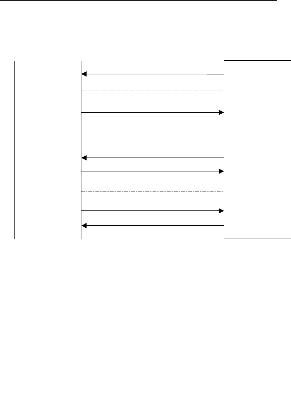
Chapter 16 – SIM ToolKit
Multi-Tech Systems, Inc. PN S000293A 159
Messages exchanged during a SIM ToolKit operation.
The following scheme shows the SIM ToolKit commands and unsolicited results that are
exchanged.
On the first step, the customer application informs the MULTI-TECH product which facilities are
supported. This operation is performed with the +STSF (SIM ToolKit Set Facilities) command,
which also activates or deactivates the SIM ToolKit functionality. On the second step, an
unsolicited result +STIN (SIM ToolKit indication) is sent by the product in order to indicate to the
customer application which command type the SIM Application ToolKit is running. The last SIM
ToolKit indication can be requested by the +STIN? command. On the third step, the customer
application uses the +STGI (SIM ToolKit Get Information) command to get all the information
about the SIM ToolKit command, given by +STIN. On the fourth step, the customer application
uses the +STGR (SIM ToolKit Give Response) to send its response (if any) to the SIM ToolKit
Application. The +STCR (SIM ToolKit Control response) indication is an unsolicited result sent
by the SIM when Call control functionality is activated and before the customer application has
performed any outgoing call, SMS, SS, or USSD.
WAVECOM
Product
Customer
Application
+STSF=X,XXXXXXXX
+STIN=X
+STGI=X
+STGI response
+STGR=X,XXXXXX
STEP 1: Configuration and
STEP 2: SIM sends pro
-
active
STEP 3: Customer application gets all the
Step 4: User response is sent to the SIM.
+STCR:X

Chapter 16 – SIM ToolKit
Multi-Tech Systems, Inc. PN S000293A 160
SIM TOOLKIT COMMANDS
SIM ToolKit Set Facilities (+STSF)
Description
This command allows SIM ToolKit facilities to be activated, deactivated or configured.
Syntax
Command syntax:
+STSF=<mode>[,<config>][,<Timeout>][,<AutoResponse>]
Command Possible responses
+STSF=<Mode>[,<Config>]
[,<Timeout>][,<AutoResponse>] OK
+CME ERROR: <err>
+STSF? +STSF: <Mode>,<Config>,<Timeout>,<Autoresponse>
+STSF=? +STSF: (0-2), (160060C01F - 5FFFFFFF7F),(1-255),(0-1)
OK
Defined values
<mode>
0:Deactivates the SIM ToolKit functionalities.
1:Activates the SIM ToolKit functionalities.
2:Configures the SIM ToolKit functionalities.
<Config>
(160060C01F – 5FFFFFFF7F) (hex format)
<Timeout>
1-255: Timeout for user responses (multiple of 10 seconds).
<Autoresponse>
0:Automatic response is not activated
1:Automatic response is activated
The activation or deactivation of the SIM ToolKit functionalities requires the use of the +CFUN
(Set phone functionality) command to reset the product (this operation is not necessary if PIN is
not entered yet).
The <Config> parameter gives the coding of the TERMINAL PROFILE, precisely the list of SIM
Application ToolKit facilities that are supported by the customer application.
The <Timeout> parameter (multiple of 10 seconds) sets the maximum time the user has for
reacting (to select an item, to input a text, etc).

Chapter 16 – SIM ToolKit
Multi-Tech Systems, Inc. PN S000293A 161
When the <Autoresponse> is activated, the +STIN indication for Play Tone (5), Refresh (7),
Send SS (8), Send SMS (9) or Send USSD (10) is automatically followed by the corresponding
+STGI response.
Note: Some bits are related to the product only and not to the customer application. The
product automatically sets these bits to either 0 or 1 whatever the user enters with the
+STSF command. Those values are given in Appendix D.
Each facility is coded on 1 bit:
· bit = 1: facility is supported by the customer application.
· bit = 0: facility is not supported by the customer application.
Only the first five bytes of the TERMINAL PROFILE (Class 2) can be configured. The other are
set to 0. (See structure of TERMINAL PROFILE in APPENDIX D.)
Error codes
+CME ERROR: 3 Operation not allowed. This error is returned when a wrong parameter is
entered.
Example
AT+CMEE=1 Enable the reporting of mobile equipment errors
OK
AT+WIND=15 Set Wavecom indications
OK
AT+CPAS Query ME Status
+CPAS: 0 ME is ready.
OK
AT+STSF=? Test command SIM ToolKit Set Facilities
+STSF: (0-2), (160060C01F – 5FFFFFFF7F),(1-255)
OK
AT+STSF?
+STSF: 0,”160060C000”,3 No activation of SIM ToolKit functionality
OK
AT+STSF=2,”5FFFFFFF7F” Set all SIM ToolKit facilities (class 3).
OK
AT+STSF=3 Syntax Error
+CME ERROR: 3
AT+STSF=1 Activation of SIM ToolKit functionality
OK
AT+CFUN=1 Reboot Software.
OK
AT+CPIN? Is the ME requiring a password?
+CPIN: SIM PIN Yes, SIM PIN required
AT+CPIN=0000
OK PIN Ok
+WIND: 4 Init phase is complete
AT+STSF?
+STSF: 1,”5FFFFFFF7F”,3 SIM ToolKit functionality activated with all facilities
OK
SIM ToolKit Indication (+STIN))
Unsolicited result
In order to allow the customer application to identify the pro-active command sent via SIM
ToolKit, a mechanism of unsolicited SIM ToolKit indications (+STIN) is implemented.
Syntax: +STIN: <CmdType>
Option: <CmdType>

Chapter 16 – SIM ToolKit
Multi-Tech Systems, Inc. PN S000293A 162
0: Indicates that a ‘Setup Menu’ pro-active command has been sent from the SIM.
1: Indicates that a ‘Display Text’ pro-active command has been sent from the SIM.
2: Indicates that a ‘Get Inkey’ pro-active command has been sent from the SIM.
3: Indicates that a ‘Get Input’ pro-active command has been sent from the SIM.
4: Indicates that a ‘Setup Call’ pro-active command has been sent from the SIM.
5: Indicates that a ‘Play Tone’ pro-active command has been sent from the SIM. (*)
6: Indicates that a ‘Sel Item’ pro-active command has been sent from the SIM.
7: Indicates that a ‘Refresh’ pro-active command has been sent from the SIM. (*)
8: Indicates that a ‘Send SS’ pro-active command has been sent from the SIM. (*)
9: Indicates that a ‘Send SMS’ pro-active command has been sent from the SIM. (*)
10: Indicates that a ‘Send USSD’ pro-active command has been sent from the SIM. (*)
11: Indicates that a ‘SETUP EVENT LIST’ pro-active command has been sent from the
SIM.
98: Indicates the timeout when no response from user.
99: Indicates that a “End Session” has been sent from the SIM.
(*) if the automatic response parameter is activated, this indication is followed by the
corresponding +STGI response.
Last SIM ToolKit indication
The last SIM ToolKit indication sent by the SIM can be requested by the AT+STIN? command.
This command is only usable between the sending of the STIN indication by the SIM (step 2,
Messages exchanged during a SIM ToolKit operation) and the response of the user with the
+STGI command (step 3).
Command syntax: +STIN?
Command Possible responses
+STIN?
Note: Ask for the last SIM ToolKit indication sent
by the SIM
+STIN: 0
OK
Note: the last SIM ToolKit indication was a Setup
Menu
+STGI=0 Note: Display the SIM ToolKit application menu
+STIN?
Note: Ask for the last SIM ToolKit indication sent
by the SIM
+CME ERROR: 4
Note: operation not supported, the +STGI command
has been already used

Chapter 16 – SIM ToolKit
Multi-Tech Systems, Inc. PN S000293A 163
SIM ToolKit Get Information (+STGI)
Description
This command allows to get the information (text to display, Menu information, priorities) of a
pro-active command sent from the SIM. The information is returned only after receiving a SIM
ToolKit indication (+STIN).
Syntax
Command syntax: +STGI=<CmdType>
Command Possible responses
+STGI=<CmdType> See Table 1
+CME ERROR: <err>
+STGI=? +STGI: (0-11)
OK

Chapter 16 – SIM ToolKit
Multi-Tech Systems, Inc. PN S000293A 164
Table 1
Cmd
Type Description Possible responses
0Get information about
‘Setup Menu’ pro-active
command.
+STGI: <Alpha Identifier menu>
+STGI: <Id1>,<NbItems>,<Alpha Id1 Label>,<Help
Info>[,<NextActionId>]<CR><LF>
+STGI: <Id2>,<NbItems>,<Alpha Id2 Label>,<Help
Info>[,<NextActionId>]<CR><LF>
[…]]
No action expected from SIM.
1Get information about
‘Display text’ pro-active
command.
+STGI: <Prior>,<Text>,<ClearMode>
No action expected from SIM.
2Get information about ‘Get
Inkey’ pro-active
command.
+STGI: <Format>,<HelpInfo>[,<TextInfo>]
SIM expects key pressed (+STGR).
3Get information about ‘Get
Input’ pro-active
command.
+STGI: <Format>,<EchoMode>,<SizeMin>,<SizeMax>,
<HelpInfo>[,<TextInfo>]
SIM expects key input (+STGR).
4Get information about
‘Setupt call’ pro-active
command.
+STGI: <Type>,<CalledNb>,<SubAddress>,<Class>
SIM expects user authorization (+STGR).
5Get information about
‘Play Tone’ pro-active
command.
+STGI: <ToneType>[,<TimeUnit>,<TimeInterval>,<TextInfo>]
No action.
6Get information about ‘Sel
Item’ pro-active command.
+STGI: <DefaultItem>, <Alpha Identifier menu><CR><LF>
+STGI: <Id1>,<NbItems>,<Alpha Id1 Label>,<Help
Info>[,<NextActionId>]<CR><LF>
+STGI: <Id2>,<NbItems>,<Alpha Id2 Label>,<Help
Info>[,<NextActionId>]<CR><LF>
[…]]
SIM expects an item choice (+STGR).
7Get information about
‘Refresh’ pro-active
command.
+STGI: <RefreshType>
No action (Refresh done automatically by product).
8Get information about
‘Send SS’ pro-active
command.
+STGI:<TextInfo>
No action (Send SS done automatically by product).
9Get information about
‘Send SMS’ pro-active
command.
+STGI: <TextInfo>
No action (Send SMS done automatically by product).
10 Get information about
‘Send USSD’ pro-active
command.
+STGI: <TextInfo>
No action (Send USSD done automatically by product).
11 Get information about
‘SETUP EVENT LIST’
pro-active command.
+STGI: <Evt>

Chapter 16 – SIM ToolKit
Multi-Tech Systems, Inc. PN S000293A 165
Defined values
Values when CmdType=0 (Setup menu)
<Alpha Idenitifer menu> Alpha identifier of the main menu.
<Idx> (1-255) Menu item Identifier.
<NbItems> (1-255) Number of items in the main menu.
<Alpha Idx Label> Alpha identifier label of items in ASCII format.
<HelpInfo>
0: No help information available.
1: Help information available.
<NextActionId> Contains a pro-active command identifier.(see the table in
APPENDIX E)
Compared to other commands the customer application can always get information
about setup menu after having received the +STIN:0 indication.
Values when CmdType=1 (Display text)
<Prior>
0: Normal priority of display.
1: High priority of display.
<Text> Text to display in ASCII format.
<ClearMode>
0: Clear message after a delay (3 seconds)
1: Wait for user to clear message.
Values when CmdType=2 (Get Inkey)
<Format>
0: Digit (0-9, *, #,and +)
1: SMS alphabet default.
2: UCS2
<HelpInfo>
0: No help information available.
1: Help information available.
<TextInfo> Text information in ASCII format.
Values when CmdType=3 (Get Input)
<Format>
0: Digit (0-9, *, #,and +)
1: SMS alphabet default.
2: UCS2
3: Unpacked format.
4: Packed format.
<EchoMode>
0: Echo off.
1: Echo on.
<SizeMin> (1-255) Minimum length of input.
<SizeMax> (1-255) Maximum length of input.
<HelpInfo>
0: No help information available.
1: Help information available.

Chapter 16 – SIM ToolKit
Multi-Tech Systems, Inc. PN S000293A 166
<TextInfo> Text information in ASCII format.
Values when CmdType=4 (Setup Call)
<Type>
0: Set up call but only if not currently busy on another call.
1: Set up call, putting all other calls (if any) on hold.
2: Set up call, disconnecting all other calls (if any).
<CalledNb> Called party number in ASCII format.
<SubAdress> Called party sub-address in ASCII format.
<Class>
0: Voice call.
1: Data call.
2: Fax call
Values when CmdType=5 (Play tone)
<ToneType>
0: Tone Dial.
1: Tone Busy.
2: Tone Congestion.
3: Tone Radio ack
4: Tone Dropped.
5: Tone Error.
6: Tone Call waiting.
7: Tone Ringing.
8: Tone General beep.
9: Tone Positive beep.
10: Tone Negative beep.
<TimeUnit>
0: Time unit used is minutes.
1: Time unit used is seconds.
2: Time unit used is tenths of seconds.
<TimeInterval> (1-255) Time required expressed in units.
<TextInfo> Text information in ASCII format.
Values when CmdType=6 (Sel Item)
<DefaultItem> (1-255) Default Item Identifier.
<Alpha Idenitifer menu> Alpha identifier of the main menu.
<Idx> (1-255) Identifier items.
<NbItems> (1-255) Number of items in the menu.
<Alpha Idx Label> Alpha identifier label of items in ASCII format.
<HelpInfo>
0: No help information available.
1: Help information available.
<NextActionId> Contains a pro-active command identifier. (see the table in
APPENDIX E)

Chapter 16 – SIM ToolKit
Multi-Tech Systems, Inc. PN S000293A 167
Values when CmdType=7 (Refresh)
<RefreshType>
0: SlM initialization and full file change notification.
1File change notification.
2SIM initialization and file change notification.
3SIM initialization.
4SIM reset.
Values when CmdType=8 (Send SS)
<TextInfo> Text information in ASCII format.
Values when CmdType=9 (Send SMS)
<TextInfo> Text information in ASCII format.
Values when CmdType=10 (Send USSD)
<TextInfo> Text information in ASCII format.
Values when CmdType=11 (Setup Event List)
<Evt>
1: Reporting asked for an ‘Idle Screen’ event.
2: Reporting asked for an ‘User Activity’ event.
3: Reporting asked for ‘Idle Screen’ and ‘User Activity’ events.
4: Cancellation of reporting event.
Rem: For the UCS2 format texts are displayed in Hexa Ascii format. Example: When the SIM
sends a TextString containing 0x00 0x41 the text displayed is “0041”.
Error codes
+ CME ERROR: 3 Operation not allowed. This error is returned when a wrong parameter is
detected.
+CME ERROR: 4 Operation not supported. This error is returned when the user wants to
get information about a SIM ToolKit pro-active command (with SIM ToolKit
functionality not activated.)
+CME ERROR: 518 SIM ToolKit indication not received. This error is returned when the SIM
ToolKit indication (+STIN) has not been received.

Chapter 16 – SIM ToolKit
Multi-Tech Systems, Inc. PN S000293A 168
Example
Initially, all facilities are activated. The PIN is not required and SIM ToolKit functionality is
activated.
AT+CMEE=1 Enable the reporting of mobile equipment errors
OK
AT+WIND=15 Set Wavecom indications
OK
AT+STSF?
+STSF: 1,”5FFFFFFF7F”,3 SIM ToolKit functionality activated with all facilities.
OK
+STIN: 0 The main menu has been sent from the SIM.
AT+STIN?
+STIN: 0
OK
AT+STGI=0 Get information about the main menu
+STGI: ”SIM TOOLKIT MAIN MENU” Main menu contains 3 items.
+STGI: 1,3,”BANK”,0
+STGI: 2,3,”QUIZ”,0
+STGI: 3,3,”WEATHER”,0
OK
AT+STIN?
+CME ERROR: 4
Unsolicited Result: SIM ToolKit Control Response (+STCR)
When the customer application makes an outgoing call or an outgoing SMS and if the call
control facility is activated, CALL CONTROL and SMS CONTROL responses can be identified.
This is also applicable to SS calls.
Syntax: +STCR: <Result>[,<Number>,<MODestAddr>,<TextInfo>]
Option:
<Result>
0:Control response not allowed.
1:Control response with modification.
<Number> Called number, Service Center Address or SS String in ASCII format.
<MODestAddr> MO destination address in ASCII format.
<TextInfo> Text information in ASCII format.
SIM ToolKit Give Response (+STGR)
Description:
This command allows the application/user to select an item in the main menu, or to answer the
following proactive commands:
· GET INKEY Key pressed by the user.
· GET INPUT Message entered by the user.
· SELECT ITEM Selected item.
· SETUP CALL User confirmation.
· DISPLAY TEXT User confirmation to clear the message.
· SETUP EVENT LIST Reporting events.

Chapter 16 – SIM ToolKit
Multi-Tech Systems, Inc. PN S000293A 169
It is also possible to terminate the current proactive command session by sending a Terminal
Response to the SIM, with the following parameters:
· BACKWARD MOVE Process a backward move
· BEYOND CAPABILITIES Command beyond ME capabilities
· UNABLE TO PROCESS ME is currently unable to process command
· NO RESPONSE No response from the user
· END SESSION User abort.
Syntax:
Command syntax: +STGR=<CmdType>[,<Result>,<Data>]
Command Possible responses
+STGR=<CmdType>[,<Result>,<Data>] OK
+CME ERROR: <err>
For GetInput with <Result>=1:
+STGR=3,1<CR>
<Data><Ctrl Z>
OK
+CME ERROR: <err>
For GetInkey with <Result>=1
+STGR=2,1,”<Data>” OK
+CME ERROR: <err>
+STGR=? OK
Defined values
<CmdType>
0: Item selection in the main menu.
1: User confirmation to clear a ‘Disp Text’.
2: Response for a ‘Get Inkey’.
3: Response for a ‘Get Input’.
4: Response for a ‘Setup call’.
6: Response for a ‘Sel Item’.
11 Reponse for a ‘Setup event list’.
95 Backward move
96 Command beyond ME capabilities
97 ME currently unable to process command
98 No response from the user.
99 User abort.
Values when CmdType=0 (Select an item from the main menu)
<Result>
1: Item selected by the user.
2: Help information required by user.
<Data> Contains the item identifier of the item selected by the user.
Values when CmdType=1 (Confirm the display text clearing)
No values.
Values when CmdType=2 (Get Inkey)

Chapter 16 – SIM ToolKit
Multi-Tech Systems, Inc. PN S000293A 170
<Result>
0: Session ended by user.
1: Response given by the user.
2: Help information required by user.
<Data> Contains the key pressed by the user.
Values when CmdType=3 (Get Input)
<Result>
0: Session ended by user.
1: Response given by the user.
2: Help information required by user.
<Data> Contains the string of characters entered by the user.
Note: For Inputs in UCS2 format, the data are entered in ASCII format. Example: For
“8000410042FFFF” entered, the SIM receives 0x00 0x41 0x00 0x42 with UCS2 DCS.
(See the Appendix E about the different UCS2 syntaxes).
Values when CmdType=4 (Setup call)
<Result>
0: User refuses the call.
1: User accepts call.
Values when CmdType=6 (Select Item)
<Result>
0: Session terminated by the user
1: Item selected by the user
2: Help information required by the user
3: Return to the back item
<Data> Contains the item identifier selected by the user
Values when CmdType=11 (Setup Event List)
<Result>
1: Idle screen available.
2: User activity event.
Sending a Terminal Response to the SIM:
Values when CmdType=95 (Backward Move)
Values when CmdType=96 (Command beyond ME capabilities)
Values when CmdType=97 (ME currently unable to process command)
Values when CmdType=98 (No response from the user)
Values when CmdType=99 (SIM ToolKit Session aborting by the user)
No values.
It is possible to send a Terminal Response after the +STIN indication (step 2, of Messages
exchanged during a SIM ToolKit operation), or after the +STGI command (step 3).
Note: For the SETUP MENU Proactive Command, it is only possible to send a Terminal
Response after the +STIN: 0 indication, not after a +STGI=0 request. All of the Terminal
Responses are not possible with all of the Proactive Commands. Compatibility between
available Terminal Responses and Proactive Commands is given in Appendix C, Table
2. If a Terminal Response is attempted during a incompatible Proactive Command
session, a +CME ERROR: 3 will be returned.

Chapter 16 – SIM ToolKit
Multi-Tech Systems, Inc. PN S000293A 171
Possible error codes
+ CME ERROR: 3 Operation not allowed. This error is returned when a wrong parameter is
detected.
+CME ERROR: 4 Operation not supported. This error is returned when the user gives a
response with SIM ToolKit functionality not activated. Or if the SIM ToolKit
indication (+STIN) has not been received.
Example
Initially, all facilities are activated, the PIN is not required and the SIM ToolKit functionality is
activated.
+STIN: 0 The main menu has been sent from the SIM.
AT+STGI=0 Get information about the main menu
+STGI: 1,3,”BANK”,0 The main menu contains 3 items.
+STGI: 2,3,”QUIZ”,0
+STGI: 3,3,”WEATHER”,0
OK
AT+STGR=0,1,1 The item 2 of the main menu has been selected.
OK
+STIN: 6 The Sel item menu has been sent from the SIM.
AT+STGI=6 Get information about the BANK menu
+STGI: 1,”BANK” The BANK menu contains two items.
+STGI: 1,2,”PERSONAL ACCOUNT ENQUIRY”,1
+STGI: 2,2,”NEWS”,0
OK
AT+STGR=6,1,1 Select Item 1.
OK
+STIN: 3 User request to enter Password sent.
AT+STGI=3 Get information about this request.
+STGI: 0,0,4,4,0,”Enter Account Password:’
OK
AT+STGR=3,1<CR> The user enters the Password.
>0000<Ctrl Z>
OK
+STIN:1 A text info has been sent from the SIM.
AT+STGI=1 Get information about this text.
+STGI: 0,”Password correct, please wait for response”,0
OK
+STIN: 9 SIM requests a bank account update from bank server via the network (SEND SMS)
AT+STGI=9 Get all information about the SEND SMS
+STGI: ”Send account balance of user, authorization ok”
OK
********* After a short period of time. ********
+STIN: 5 Transaction is complete: BEEP
+STGI=5 Get information about the Tone
+STGI: 9,1,1
+STIN: 1 Display text indication
AT+STGI=1
+STGI: 0,”Your account balance is 1000 $”,0
OK

Chapter 17 – GPRS Commands
Multi-Tech Systems, Inc. PN S000293A 172
CHAPTER 17 - GPRS COMMANDS
GPRS commands are not available under GSM-only software.
Define PDP Context +CGDCONT
Command Possible responses
+CGDCONT=[<cid> [,<PDP_type> [,<APN>
[,<PDP_addr> [,<d_comp> [,<h_comp>]]]]]]
OK
ERROR
+CGDCONT? +CGDCONT: <cid>, <PDP_type>,
<APN>,<PDP_addr>, <data_comp>,
<head_comp>
[<CR><LF>+CGDCONT: <cid>, <PDP_type>,
<APN>,<PDP_addr>, <data_comp>,
<head_comp>
[...]]
OK
+CGDCONT=? +CGDCONT: (range of supported <cid>s),
<PDP_type>,,,(list of supported <d_comp>s),
(list of supported <h_comp>s)
[<CR><LF>+CGDCONT: (range of supported
<cid>s), <PDP_type>,,,(list of supported
<d_comp>s),(list of supported <h_comp>s)
[...]]
OK
Description:
This command specifies PDP context parameter values for a PDP context identified by the local
context identification parameter, <cid>. Four PDP contexts can be defined through Multi-Tech
software. A special form of the set command, +CGDCONT= <cid> causes the values for context
number <cid> to become undefined. The test command returns values supported as a
compound value. If the MT supports several PDP types, <PDP_type>, the parameter value
ranges for each <PDP_type> are returned on a separate line. The read command returns the
current settings for each defined context. The test command returns values supported as a
compound value. If the MT supports several PDP types, <PDP_type), the parameter value
ranges for each <PDP_type> are returned on a separate line.
Defined values:
<cid>: (PDP Context Identifier) a numeric parameter (1-4) which specifies a particular PDP
context definition. The parameter is local to the TE-MT interface and is used in other PDP
context-related commands.
<PDP_type>: (Packet Data Protocol type) a string parameter which specifies the type of packet
data protocol
· IP Internet Protocol
· PPP Point to Point Protocol

Chapter 17 – GPRS Commands
Multi-Tech Systems, Inc. PN S000293A 173
<APN>: (Access Point Name) a string parameter, which is a logical name that is used to select
the GGSN or the external packet data network. If the value is null or omitted, then the
subscription value will be requested.
<PDP_address>: a string parameter that identifies the MT in the address space applicable to
the PDP. If the value is null or omitted, then a value may be provided by the TE during the PDP
startup procedure or, failing that, a dynamic address will be requested.
The read form of the command will continue to return the null string even if an address has been
allocated during the PDP startup procedure. The allocated address may be read using the
+CGPADDR command.
<d_comp>: a numeric parameter that controls PDP data compression
· 0 - off (default if value is omitted)
· 1 – on
· Other values are reserved.
<h_comp>: a numeric parameter that controls PDP header compression
· 0 - off (default if value is omitted)
· 1 – on
· Other values are reserved.
Notes: At present only one data compression algorithm (V.42bis) is provided in SNDCP. If and
when other algorithms become available, a command will be provided to select one or
more of these.
32 cids are available to specifie 32 PDP contexts but only 11 NSAPI are available for
PDP activation. Due to Wavecom Choice, 4 PDP contexts can be specified with only
one activated at the same time.
Example
AT +CGDCONT=1, "IP", "internet"; +GCDCONT=2, "IP", "abc.com"
OK
AT+CGDCONT=?
+CGDCONT=(1-4),“IP”,,,(0-1),(0-1)
+CGDCONT=(1-4),”PPP”,,,0,0
OK
AT+CGDCONT?
+CGDCONT=1, "IP", "internet",,0,0
+CGDCONT=2, "IP", "abc.com",,0,0
OK

Chapter 17 – GPRS Commands
Multi-Tech Systems, Inc. PN S000293A 174
Quality of Service Profile (Requested) +CGQREQ
Command Possible Response(s)
+CGQREQ=[<cid> [,<precedence > [,<delay>
[,<reliability.> [,<peak> [,<mean>]]]]]] OK
ERROR
+CGQREQ? +CGQREQ: <cid>, <precedence >, <delay>,
<reliability>, <peak>, <mean>
[<CR><LF>+CGQREQ: <cid>, <precedence >,
<delay>, <reliability.>, <peak>, <mean>
[…]]
OK
+CGQREQ=? +CGQREQ: <PDP_type>, (list of supported
<precedence>s), (list of supported
<delay>s), (list of supported
<reliability>s) , (list of supported
<peak>s), (list of supported <mean>s)
[<CR><LF>+CGQREQ: <PDP_type>, (list of
supported <precedence>s), (list of supported
<delay>s), (list of supported
<reliability>s) , (list of supported
<peak>s), (list of supported <mean>s)
[…]]
OK
Description:
This command allows the TE to specify a Quality of Service Profile that is used when the MT
sends an Activate PDP Context Request message to the network.
The set command specifies a profile for the context identified by the local context identification
parameter, <cid>. Since this is the same parameter that is used in the +CGDCONT command,
the +CGQREQ command is effectively an extension to the +CGDCONT command. The QoS
profile consists of a number of parameters, each of which may be set to a separate value.
A special form of the set command, +CGQREQ= <cid>, causes the requested profile for context
number <cid> to become undefined.
The read command returns the current settings for each defined context. The test command
returns values supported as a compound value. If the MT supports several PDP types, the
parameter value ranges for each PDP type are returned on a separate line.
Defined values:
<cid>: a numeric parameter which specifies a particular PDP context definition.
<precedence>: a numeric parameter which specifies the precedence class
<delay>: a numeric parameter which specifies the delay class
<reliability>: a numeric parameter which specifies the reliability class
<peak>: a numeric parameter which specifies the peak throughput class
<mean>: a numeric parameter which specifies the mean throughput class

Chapter 17 – GPRS Commands
Multi-Tech Systems, Inc. PN S000293A 175
If a value is omitted for a particular class then the value is considered to be unspecified.
Precedence
Precedence Precedence
Name Interpretation
0 Subscribed Subscribed by the Nwk / default if value is omitted
1 High priority Service commitments shall be maintained ahead of precedence classes 2 and
3.
2 Normal priority Service commitments shall be maintained ahead of precedence class 3.
3 Low priority Service commitments shall be maintained after precedence classes 1 and 2.
Delay
Delay (maximum values)
SDU size: 128 octets SDU size: 1024 octets
Delay Class Mean
Transfer
Delay
(sec)
95
percentile
Delay
(sec)
Mean
Transfer
Delay
(sec)
95
percentile
Delay
(sec)
0 Subscribed Subscribed by the Nwk / default if value
is omitted
1. (Predictive) < 0.5 < 1.5 < 2 < 7
2. (Predictive) < 5 < 25 < 15 < 75
3. (Predictive) < 50 < 250 < 75 < 375
4. (Best
Effort) Unspecified
Reliabiliy
Reliability
Class GTP Mode LLC Frame
Mode LLC Data
Protection RLC Block
Mode Traffic Type
0 Subscribed Subscribed by the Nwk / default if value is omitted
1 Acknowledged Acknowledged Protected Acknowledged Non real-time traffic, error-
sensitive application that
cannot cope with data loss.
2 Unacknowledged Acknowledged Protected Acknowledged Non real-time traffic, error-
sensitive application that
can cope with infrequent
data loss.
3 Unacknowledged Unacknowledged Protected Acknowledged Non real-time traffic, error-
sensitive application that
can cope with data loss,
GMM/SM, and SMS.
4 Unacknowledged Unacknowledged Protected Unacknowledged Real-time traffic, error-
sensitive application that
can cope with data loss.
5 Unacknowledged Unacknowledged Unprotected Unacknowledged Real-time traffic, error non-
sensitive application that
can cope with data loss.
Note: For real-time traffic, the QoS profile also requires appropriate settings for delay and throughput.

Chapter 17 – GPRS Commands
Multi-Tech Systems, Inc. PN S000293A 176
Peak throughput
Peak Throughput Class Peak Throughput in octets per second
0 Subscribed by the Nwk / default if value is omitted
1 Up to 1 000 (8 kbit/s).
2 Up to 2 000 (16 kbit/s).
3 Up to 4 000 (32 kbit/s).
4 Up to 8 000 (64 kbit/s).
5 Up to 16 000 (128 kbit/s).
6 Up to 32 000 (256 kbit/s).
7 Up to 64 000 (512 kbit/s).
8 Up to 128 000 (1 024 kbit/s).
9 Up to 256 000 (2 048 kbit/s).
Mean throughput
Mean Throughput Class Mean Throughput in octets per hour
0 Subscribed by the Nwk / default if value is omitted
1 100 (~0.22 bit/s).
2 200 (~0.44 bit/s).
3 500 (~1.11 bit/s).
4 1 000 (~2.2 bit/s).
5 2 000 (~4.4 bit/s).
6 5 000 (~11.1 bit/s).
7 10 000 (~22 bit/s).
8 20 000 (~44 bit/s).
9 50 000 (~111 bit/s).
10 100 000 (~0.22 kbit/s).
11 200 000 (~0.44 kbit/s).
12 500 000 (~1.11 kbit/s).
13 1 000 000 (~2.2 kbit/s).
14 2 000 000 (~4.4 kbit/s).
15 5 000 000 (~11.1 kbit/s).
16 10 000 000 (~22 kbit/s).
17 20 000 000 (~44 kbit/s).
18 50 000 000 (~111 kbit/s).
31 Best effort.
Example
AT +CGQREQ=1,1,4,5,2,14
OK
AT+CGQREQ=?
+CGQREG: “IP”, (1-3), (1-4), (1-5), (1-9), (1-31)
+CGQREQ: “PPP”, (1-3), (1-4), (1-5), (1-9), (1-31)
OK
AT+CGQREQ?
+CGQREQ: 1,1,4,5,2,14
OK

Chapter 17 – GPRS Commands
Multi-Tech Systems, Inc. PN S000293A 177
Quality of Service Profile (Minimum acceptable) +CGQMIN
Command Possible Response(s)
+CGQMIN=[<cid> [,<precedence > [,<delay>
[,<reliability.> [,<peak> [,<mean>]]]]]] OK
ERROR
+CGQMIN? +CGQMIN: <cid>, <precedence >, <delay>,
<reliability>, <peak>, <mean>
[<CR><LF>+CGQMIN: <cid>, <precedence >,
<delay>, <reliability.>, <peak>, <mean>
[…]]
OK
+CGQMIN=? +CGQMIN: <PDP_type>, (list of supported
<precedence>s), (list of supported <delay>s),
(list of supported <reliability>s) , (list of
supported <peak>s), (list of supported
<mean>s)
[<CR><LF>+CGQMIN: <PDP_type>, (list of
supported <precedence>s), (list of supported
<delay>s), (list of supported <reliability>s)
, (list of supported <peak>s), (list of
supported <mean>s)
[…]]
OK
Description:
This command allows the TE to specify a minimum acceptable profile which is checked by the
MT against the negotiated profile returned in the Activate PDP Context Accept message.
The set command specifies a profile for the context identified by the local context identification
parameter, <cid>. Since this is the same parameter that is used in the +CGDCONT command,
the +CGQMIN command is effectively an extension to the +CGDCONT command. The QoS
profile consists of a number of parameters, each of which may be set to a separate value.
A special form of the set command, +CGQMIN= <cid> causes the minimum acceptable profile
for context number <cid> to become undefined. In this case no check is made against the
negotiated profile.
The read command returns the current settings for each defined context. The test command
returns values supported as a compound value. If the MT supports several PDP types, the
parameter value ranges for each PDP type are returned on a separate line.
Defined values:
<cid>: a numeric parameter which specifies a particular PDP context .
<precedence>: a numeric parameter which specifies the precedence class.
<delay>: a numeric parameter which specifies the delay class.
<reliability>: a numeric parameter which specifies the reliability class.
<peak>: a numeric parameter which specifies the peak throughput class.
<mean>: a numeric parameter which specifies the mean throughput class.
If a value is omitted for a particular class then this class is not checked.
Example

Chapter 17 – GPRS Commands
Multi-Tech Systems, Inc. PN S000293A 178
AT +CGQMIN=1,1,4,5,2,31
OK
AT+CGQMIN=?
+CGQMIN: “IP”, (1-3), (1-4), (1-5), (1-9), (1-31)
+CGQMIN: “PPP”, (1-3), (1-4), (1-5), (1-9), (1-31)
OK
AT+CGQMIN?
+CGQMIN: 1,1,4,5,2,14
OK
GPRS attach or detach +CGATT
Command Possible Responses
+CGATT= [<state>]OK
ERROR
+CGATT? +CGATT: <state>
OK
+CGATT=? +CGATT: (list of supported <state>s)
OK
Description:
The execution command is used to attach the MT to, or detach the MT from, the GPRS service.
After the command has completed, the MT remains in V.25ter command state. If the MT is
already in the requested state, the command is ignored and the OK response is returned. If the
requested state cannot be achieved, an ERROR or +CME ERROR response is returned.
Extended error responses are enabled by the +CMEE command. Any active PDP contexts will
be automatically deactivated when the attachment state changes to detached. The read
command returns the current GPRS service state. The test command is used for requesting
information on the supported GPRS service states.
Defined values:
<state>: indicates the state of GPRS attachment
· 0 – detached
· 1 – attached
· Other values are reserved and will result in an ERROR response to the execution
command.
Example
AT +CGATT=1
OK

Chapter 17 – GPRS Commands
Multi-Tech Systems, Inc. PN S000293A 179
PDP context activate or deactivate +CGACT
Command Possible Response(s)
+CGACT=[<state> [,<cid>[,<cid>[,…]]]] OK
ERROR
+CGACT? +CGACT: <cid>, <state>
[<CR><LF>+CGACT: <cid>, <state>
[...]]
OK
+CGACT=? +CGACT: (list of supported <state>s)
OK
Description:
The execution command activates or deactivates the specified PDP context (s). After the
command has completed, the MT remains in V.25ter command state. If any PDP context is
already in the requested state, the state for that context remains unchanged. If the requested
state for any specified context cannot be achieved, an ERROR or +CME ERROR response is
returned. Extended error responses are enabled by the +CMEE command.
If the MT is not GPRS attached when the activation form of the command is executed, the MT
first performs a GPRS attach and them attempts to activate the specified contexts. If the attach
fails then the MT responds with ERROR or, if extended error responses are enabled, with the
appropriate failure-to-attach error message.
If no <cid>s are specified the activation form of the command activates the first activable defined
contexts. If no <cid>s are specified the deactivation form of the command deactivates all active
contexts.
One PDP context can be activated through Multi-Tech software at the same time. The read
command returns the current activation states for all the defined PDP contexts. The test
command is used for requesting information on the supported PDP context activation states.
Defined values:
<state>: indicates the state of PDP context activation
· 0 – deactivated
· 1 – activated
· Other values are reserved and will result in an ERROR response to the execution
command.
<cid>: a numeric parameter which specifies a particular PDP context.
Example
AT +CGACT=1,1
OK
AT+CGACT?
+CGACT: 1, 1
OK
AT+CGACT=?
+CGACT: (0-1)
OK
Before a context can be activated, the MT must be attached to the GPRS network by performing
an automatic GPRS attach.

Chapter 17 – GPRS Commands
Multi-Tech Systems, Inc. PN S000293A 180
Enter data state +CGDATA
Command Possible Response(s)
+CGDATA=[<cid>] CONNECT
ERROR
+CGDATA=? +CGDATA:
OK
Description:
The execution command causes the MT to perform whatever actions are necessary to establish
communication between the TE and the network. This may include performing a GPRS attach
and one PDP context activations.
If the cid value is not defined to the MT, the MT will return an ERROR or +CME ERROR
response. Otherwise, the MT issues the intermediate result code CONNECT and enters V.25ter
online data state. GPRS attachment and PDP context activation procedures may take place
prior to or during the PDP startup if they have not already been performed using the +CGATT
and +CGACT commands.
If no <cid> is given, the MT attempts to activate the context with whatever information is
available to the MT. The other context parameters is set to their default values (No APN, default
QOS parameters, dynamic IP address requested). If the activation is successful, data transfer
may proceed. After data transfer is complete, and the layer 2 protocol termination procedure has
completed successfully, the V.25ter command state is re-entered and the MT returns the final
result code OK.
In the event of an erroneous termination or a failure to start up, the V.25ter command state is re-
entered and the MT returns the final result code NO CARRIER or, if enabled, +CME ERROR.
Attach, activate and other errors may be reported.
This command may be used in both normal and modem compatibility modes.
Note: The goal of this command is the same than ATD*99*** so it is recommened to use only
ATD*99***.
Defined Values
<cid>: a numeric parameter which specifies a particular PDP context definition.
Example
AT+CGDATA=?
+CGDATA:
OK
AT +CGDATA=1
CONNECT

Chapter 17 – GPRS Commands
Multi-Tech Systems, Inc. PN S000293A 181
GPRS mobile station class +CGCLASS
Command Possible Response(s)
+CGCLASS= [<class>]OK
ERROR
+CGCLASS? +CGCLASS: <class>
OK
+CGCLASS=? +CGCLASS: (list of supported <class>s)
OK
Description:
The set command is used to set the MT to operate according to the specified GPRS mobile
class. If the requested class is not supported, an ERROR or +CME ERROR response is
returned. The read command returns the current GPRS mobile class. The test command is used
for requesting information on the supported GPRS mobile classes.
Defined Values:
<class>: a string parameter which indicates the GPRS mobile class (in descending order of
functionality)
A class A (highest)
Bclass B
CG class C in GPRS only mode
CC class C in circuit switched only mode (lowest)
Other values are reserved and will result in an ERROR response to the set command.
If the MT is GPRS attached when the set command is issued with a <class> = CC specified, a
GPRS detach request is sent to the network. If the MT is GSM attached when the set command
is issued with a <class> = CG specified, a GSM detach request is sent to the network.
Class A is not supported by Multi-Tech GPRS software.
Note: During switch-On in CG class, the MS always performs an automatic GPRS attach (the
ATTACH-STATUS parameter of +WGPRS is ignored). But if the MS is not already PRS-
attached when switching from B/CC class to CG class, then no automatic GPRS attach
is performed.
Example
AT +CGCLASS=”CG”
OK
To go in GPRS class C mode
AT +CGCLASS=”CC”
OK
To go in GSM mode
AT +CGCLASS=”A”
+CME ERROR: 150
Class chosen not supported.
AT+CGCLASS=?
+CGCLASS: ("CG","CC")
OK
AT+CGCLASS?
+CGCLASS: "CC"
OK

Chapter 17 – GPRS Commands
Multi-Tech Systems, Inc. PN S000293A 182
About the remark:
AT+CGCLASS?
+CGCLASS: “B”
OK
AT+CGATT?
+CGATT: 0
OK
AT+CGCLASS=”CG”
OK
AT+CGATT?
+CGATT: 0
OK
AT+CGATT=1
OK
AT+CPOF
OK
AT+CFUN=1
OK
AT+CGCLASS?
+CGCLASS: “CG”
OK
AT+CGATT?
+CGATT: 1
OK
Select service for MO SMS messages +CGSMS
Command Possible Responses
+CGSMS= [<service>]OK
ERROR
+CGSMS? +CGSMS: <service>
OK
+CGSMS=? +CGSMS: (list of currently available <service>s)
OK
Description:
The set command specifies the service or service preference that the MT will use to send MO
SMS messages.
The read command returns the currently selected service or service preference.
The test command requests information on the currently available services and service
preferences.
Defined values:
<service>: a numeric parameter which indicates the service or service preference to be used
0 GPRS
1 Circuit switched
2 GPRS preferred (use circuit switched if GPRS is not available)
3 Circuit switched preferred (use GPRS if circuit switched not available)
Other values are reserved and will result in an ERROR response to the set command.
Example
AT +CGSMS=0
OK
AT+CGSMS=?
+CGSMS=(0-3)
OK

Chapter 17 – GPRS Commands
Multi-Tech Systems, Inc. PN S000293A 183
GPRS event reporting +CGEREP
Command Possible Responses
+CGEREP=[<mode>] OK
ERROR
+CGEREP? +CGEREP: <mode>
OK
+CGEREP=? +CGEREP: (list of supported <mode>s)
OK
Description:
Set command enables or disables sending of unsolicited result codes, +CGEV: XXX from MT to
TE in the case of certain events occurring in the GPRS MT or the network.
<mode> controls the processing of unsolicited result codes specified within this command.
Read command returns the current mode and buffer settings. Test command returns the modes
and buffer settings supported by the MT as compound values.
Defined values:
<mode>:
0 buffer unsolicited result codes in the MT; if MT result code buffer is full, the oldest ones can be
discarded. No codes are forwarded to the TE.
2 buffer unsolicited result codes in the MT when MT-TE link is reserved (e.g. in on-line data
mode) and flush them to the TE when MT-TE link becomes available; otherwise forward them
directly to the TE
With Multi-Tech's software, a combination of all modes is implemented. When a serial link is
available, indications are forwarded directly to the TE. If a serial link is reserved ( e.g. in on-line
data mode ) or the MT result code buffer is full, the oldest ones can be discarded.
Defined events
The following unsolicited result codes and the corresponding events are defined:
+CGEV: REJECT <PDP_type>, <PDP_addr>
A network request for PDP context activation occurred when the MT was unable to report it to
the TE with a +CRING unsolicited result code and was automatically rejected.
+CGEV: NW REACT <PDP_type>, <PDP_addr>, [<cid>]
The network has requested a context reactivation. The <cid> that was used to reactivate the
context is provided if known to the MT.
+CGEV: NW DEACT <PDP_type>, <PDP_addr>, [<cid>]
The network has forced a context deactivation. The <cid> that was used to activate the context
is provided if known to the MT.
+CGEV: ME DEACT <PDP_type>, <PDP_addr>, [<cid>]
The mobile equipment has forced a context deactivation. The <cid> that was used to activate
the context is provided if known to the MT.
+CGEV: NW DETACH
The network has forced a GPRS detach. This implies that all active contexts have been
deactivated. These are not reported separately.
+CGEV: ME DETACH

Chapter 17 – GPRS Commands
Multi-Tech Systems, Inc. PN S000293A 184
The mobile equipment has forced a GPRS detach. This implies that all active contexts have
been deactivated. These are not reported separately.
+CGEV: NW CLASS <class>
The network has forced a change of MS class. The highest available class is reported.
+CGEV: ME CLASS <class>
The mobile equipment has forced a change of MS class. The highest available class is reported.
GPRS network registration status +CGREG
Command Possible response(s)
+CGREG=[<n>] OK
+CGREG? +CGREG: <n>,<stat>[,<lac>,<ci>]
OK
+CME ERROR: <err>
+CGREG=? +CGREG: (list of supported <n>s)
OK
Description:
The set command controls the presentation of an unsolicited result code +CGREG: <stat> when
<n>=1 and there is a change in the MT's GPRS network registration status, or code +CGREG:
<stat>[,<lac>,<ci>] when <n>=2 and there is a change of the network cell.
The read command returns the status of result code presentation and an integer <stat> which
shows whether the network has currently indicated the registration of the MT. Location
information elements <lac> and <ci> are returned only when <n>=2 and MT is registered in the
network.
Defined values:
<n>:
0 disable network registration unsolicited result code
1 enable network registration unsolicited result code +CGREG: <stat>
2 enable network registration and location information unsolicited result code +CGREG:
<stat>[,<lac>,<ci>]
<stat>:
0 not registered, ME is not currently searching a new operator to register to
1 registered, home network
2 not registered, but ME is currently searching a new operator to register to
3 registration denied
4 unknown
5 registered, roaming
<lac>:
string type; two byte location area code in hexadecimal format.
<ci>:
string type; two byte cell ID in hexadecimal format

Chapter 17 – GPRS Commands
Multi-Tech Systems, Inc. PN S000293A 185
Request GPRS IP service 'D'
Command Possible Responses
D*<GPRS_SC_IP>[***<cid>]# CONNECT
ERROR
Description:
This command causes the MT to perform whatever actions are necessary to establish
communication between the TE and the external PDN. The V.25ter 'D' (Dial) command causes
the MT to enter the V.25ter online data state and, with the TE, to start the specified layer 2
protocol. The MT return CONNECT to confirm acceptance of the command prior to entering the
V.25ter online data state. No further commands may follow on the AT command line.
The detailed behaviour after the online data state has been entered is described briefly in clause
9, for IP, of GSM 07.60. GPRS attachment and PDP context activation procedures may take
place prior to or during the PDP startup if they have not already been performed using the
+CGATT and +CGACT commands.
If <cid> is supported, its usage is the same as in the +CGDATA command. The +CGDCONT,
+CGQREQ, etc. commands may then be used in the modem initialization AT command string to
set values for for PDP type, APN, QoS etc…
If <cid> is not supported or is supported but omitted, the MT attempt to activate the context
using the 'Empty PDP type' (GSM 04.08). (No PDP address or APN is sent in this case and only
one PDP context subscription record is present in the HLR for this subscriber.)
Defined values:
<GPRS_SC_IP>: (GPRS Service Code for IP) a digit string (value 99), which identifies a request
to use the GPRS with IP (PDP types IP and PPP)
<cid>: a digit string which specifies a particular PDP context definition.
Example
ATD*99***1#
CONNECT
ATD*99***2#
ERROR

Chapter 17 – GPRS Commands
Multi-Tech Systems, Inc. PN S000293A 186
Network requested PDP context activation
In this mode of operation, the MT behaves like an answering modem and accepts the normal
V.25ter commands associated with answering a call. If GPRS-specific configuration commands
are required, they may be sent to the MT as part of the modem initialization commands. The
+CGAUTO command is used to select modem compatibility mode.
Automatic response to a network request for PDP context activation 'S0'
The V.25ter 'S0=n' (Automatic answer) command may be used to turn off (n=0) and on (n>0) the
automatic response to a network request for a PDP context activation.When the 'S0=n' (n>0)
command is received, the MT attempt to perform a GPRS attach if it is not already attached.
Failure will result in ERROR being returned to the TE. Subsequently, the MT will announce a
network request for PDP context activation by issuing the unsolicited result code RING to the
TE, followed by the intermediate result code CONNECT. The MT then enters V.25ter online data
state and follows the same procedure as it would after having received a +CGANS=1 with no
<L2P> or <cid> values specified.
Note: The 'S0=n' (n=0) command does not perform an automatic GPRS detach.
Manual acceptance of a network request for PDP context activation 'A'
The V.25ter 'A' (Answer) command may be used to accept a network request for a PDP context
activation announced by the unsolicited result code RING. The MT responds with CONNECT,
enters V.25ter online data state and follows the same procedure as it would after having
received a +CGANS=1 with no <cid> value specified. It is an error to issue the 'A' command
when there is no outstanding network request.
Manual rejection of a network request for PDP context activation 'H'
The V.25ter 'H' or 'H0' (On-hook) command may be used to reject a network request for PDP
context activation announced by the unsolicited result code RING. The MT responds with OK. It
is an error to issue the 'H' command when there is no outstanding network request.
Note: This is an extension to the usage of the 'H' command that is described in ITU-T V.25ter.

Chapter 17 – GPRS Commands
Multi-Tech Systems, Inc. PN S000293A 187
Automatic response to a network request for PDP context
activation +CGAUTO
Command Possible response(s)
+CGAUTO=[<n
>]
OK
ERROR
+CGAUTO? +CGAUTO: <n>
OK
+CGAUTO=? +CGAUTO: (list of supported <n>s)
OK
Description:
The set command disables or enables an automatic positive response (auto-answer) to the
receipt of a Request PDP Context Activation message from the network. It also provides control
over the use of the V.25ter basic commands 'S0', 'A and 'H' for handling network requests for
PDP context activation. The setting does not affect the issuing of the unsolicited result code
RING or +CRING. The test command returns values of <n> supported by the MT as a
compound value.
When the +CGAUTO=0 command is received, the MT will not perform a GPRS detach if it is
attached. Subsequently, when the MT announces a network request for PDP context activation
by issuing the unsolicited result code RING or +CRING, the TE may manually accept or reject
the request by issuing the +CGANS command or may simply ignore the network request.
When the +CGAUTO=1 command is received, the MT will attempt to perform a GPRS attach if it
is not already attached. Failure will result in ERROR or, if enabled, +CME ERROR being
returned to the TE. Subsequently, when the MT announces a network request for PDP context
activation by issuing the unsolicited result code RING or +CRING to the TE, this is followed by
the intermediate result code CONNECT. The MT then enters V.25ter online data state and
follows the same procedure as it would after having received a +CGANS=1 with <cid> values
specified.
Defined values:
<n>:
0 turn off automatic response for GPRS only
1 turn on automatic response for GPRS only
2 modem compatibility mode, GPRS only
3 modem compatibility mode, GPRS and circuit switched calls (default)
For <n> = 0 GPRS network requests are manually accepted or rejected by the +CGANS
command.
For <n> = 1 GPRS network requests are automatically accepted according to the description
above.
For <n> = 2, automatic acceptance of GPRS network requests is controlled by the 'S0'
command. Manual control uses the 'A' and 'H' commands, respectively, to accept and reject
GPRS requests. (+CGANS may also be used.) Incoming circuit switched calls can be neither
manually nor automatically answered.

Chapter 17 – GPRS Commands
Multi-Tech Systems, Inc. PN S000293A 188
For <n> = 3, automatic acceptance of both GPRS network requests and incoming circuit
switched calls is controlled by the 'S0' command. Manual control uses the 'A' and 'H' commands,
respectively, to accept and reject GPRS requests. (+CGANS may also be used.) Circuit
switched calls are handled as described elsewhere in this specification.
Note: In class C GPRS the modem can’t receive GPRS and GSM incoming calls simultaneously.
Example
AT+CGAUTO=?
+CGAUTO: (0-2)
OK
AT+CGAUTO?
+CGAUTO: 2
OK
AT+CGAUTO=0
OK
Manual response to a network request for PDP context
activation +CGANS
Command Possible response(s)
+CGANS=[<response>,
[<cid>]]
OK
ERROR
+CGANS=? +CGANS: (list of supported <response>s),
(list of supported <L2P>s)
OK
Description:
The execution command requests the MT to respond to a network request for GPRS PDP
context activation which has been signalled to the TE by the RING or +CRING: unsolicited result
code. The <response> parameter allows the TE to accept or reject the request.
If <response> is 0, the request is rejected and the MT returns OK to the TE.
If <response> is 1, the following procedure is followed by the MT.
PDP context activation procedures take place prior to or during the PDP startup.
One <cid> may be specified in order to provide the values needed for the context activation
request. During the PDP startup procedure the MT has the PDP type and the PDP address
provided by the network in the Request PDP Context Activation message.
If a <cid> is given his informations must matching with the PDP type and PDP address in the
network request as follows -
The PDP type must match exactly.
The PDP addresses are considered to match if they are identical or if the address in the
context definition is unspecified. If any of this information is in conflict, the command will fail.
The context is activated using the values for PDP type and PDP address provided by the
network, together with the other information found in the PDP context definition. An APN may or
may not be required, depending on the application. If no <cid> is given, the MT will attempt to
activate the context using the values for PDP type and PDP address provided by the network,
together with any other relevant information known to the MT. The other context parameters will
be set to their default values.

Chapter 17 – GPRS Commands
Multi-Tech Systems, Inc. PN S000293A 189
If the activation is successful, data transfer may proceed. After data transfer is complete, and the
layer 2 protocol termination procedure has completed successfully, the V.25ter command state
is re-entered and the MT returns the final result code OK.
In the event of an erroneous termination or a failure to startup, the V.25ter command state is re-
entered and the MT returns the final result code NO CARRIER or, if enabled, +CME ERROR.
Attach, activate and other errors may be reported. It is also an error to issue the +CGANS
command when there is no outstanding network request.
This command may be used in both normal and modem compatibility modes.
Defined values:
<response>: is a numeric parameter which specifies how the request should be responded to.
0 reject the request
1 accept and request that the PDP context be activated
If <response> is omitted it is assumed to be 0. Other values are reserved and will result in the
ERROR response.
<cid>: a numeric parameter which specifies a particular PDP context definition.
Example
+CRING: GPRS "IP", "122.41.74.238"
AT+CGANS=1
CONNECT
AT+CGANS=?
+CGANS= (0-1)
OK

Chapter 17 – GPRS Commands
Multi-Tech Systems, Inc. PN S000293A 190
Show PDP address +CGPADDR
Command Possible response(s)
+CGPADDR=[
<cid>
[,<cid>
[,…]]]
+CGPADDR: <cid>,<PDP_addr>
[<CR><LF>+CGPADDR: <cid>,<PDP_addr>
[...]]
OK
+CGPADDR=? +CGPADDR: (list of defined <cid>s)
OK
Description:
The execution command returns a list of PDP addresses for the specified context identifiers. The
test command returns a list of defined <cid>s.
Defined values:
<cid>: a numeric parameter which specifies a particular PDP context definition. If no <cid> is
specified, the addresses for all defined contexts are returned.
<PDP_address>: a string that identifies the MT in the address space applicable to the PDP. The
address may be static or dynamic. For a static address, it will be the one set by the +CGDCONT
command when the context was defined. For a dynamic address it will be the one assigned
during the last PDP context activation that used the context definition referred to by <cid>.
<PDP_address> is omitted if none is available.
Example
AT+CGPADDR=1
+CGPADDR=1,"107.210.5.4"
OK
AT+CGPADDR=?
+CGAPDDR= (1-32)
OK
AT+CGPADDR
+CGPADDR: 1,
+CGPADDR: 2,"10.3.73.151"
+CGPADDR: 3,
+CGPADDR: 4,

Chapter 17 – GPRS Commands
Multi-Tech Systems, Inc. PN S000293A 191
Cellular result codes +CRC
Description:
This command enables a more detailed ring indication, in case of incoming call (voice or data).
Instead of the string “RING”, an extended string is used to indicate which type of call is ringing
(e.g. +CRING: VOICE).
These extended indications are:
+CRING: ASYNC for asynchronous transparent
+CRING: REL ASYNC for asynchronous non-transparent
+CRING: VOICE for normal speech.
+CRING: FAX for fax calls
New indication for GPRS is:
- GPRS: (GPRS network request for PDP context activation).
If the MT is unable to announce to the TE the network's request (for example it is in V.25ter
online data state) the MT reject the request. No corresponding unsolicited result code is issued
when the MT returns to a command state.
Example
+CRING: GPRS
Service reporting control +CR
Description:
This command enables a more detailed service reporting for incoming or outgoing calls. Before
sending the CONNECT response to the application, the GSM module will precisely define the
type of data connection being established.
These report types are:
+CR: ASYNC For asynchronous transparent
+CR: REL ASYNC For asynchronous non-transparent
New indication for GPRS is: GPRS
Syntax
Command syntax: AT+CR
Command Possible responses
AT+CR=0
Note: Extended reports disabled OK
Note: Command valid
AT+CR=1
Note: Extended reports enabled OK
Note: Command valid
Example
+CR: GPRS

Chapter 17 – GPRS Commands
Multi-Tech Systems, Inc. PN S000293A 192
Extended error report +CEER
Description:
This command gives the reason of the call release when the last call setup (originating or
answering) failed. New indication for GPRS is the reason of the last unsuccessful PDP context
activation and the last GPRS detach or PDP context activation.
Syntax :
Command syntax: AT+CEER
Command Possible Responses
ATD123456789 ;
Note: Outgoing voice call NO CARRIER
Note: Call setup failure
AT+CEER
Note: Ask for reason of release
+CEER: Error <xxx>
OK
Note: <xxx>is the cause information element values form GSM
recommandation 04.08 or specific Call accepted
The cause information element from GSM Technical Specification 04.08 is given below in
chapter 22 for specific GPRS failure causes. The “NO CARRIER” indicates that the AT+CEER
information is available for a failure diagnostic.
PDP Counters Infos +CGCOUNTERS
Description:
This command enables or disables the spontaneous sending of the last PDP deactivated
counters. These counters are related to connection time of a PDP context or data volumes sent
and received during a PDP context life (ie between is activation and deactivation). NOT
IMPLEMENTED IN CURRENT VERSION
Syntax:
Command syntax: AT+CGCOUNTERS
AT+CGCOUNTERS=0
Note: PDP Counters infos disabled OK
Note: Command valid
AT+CGCOUNTERS=1
Note: PDP Counters Infos enabled OK
Note: Command valid
AT+CGCOUNTERS=? +CGCOUNTERS: (0-1)
OK
AT+CGCOUNTERS?
Note: The last PDP counters infos in memory +CGCOUNTERS: <cid>, <PDP Context Time>, <Data IN>, <Data
OUT>
OK
Example
AT+CGCOUNTERS?
+CGCOUNTERS: <1>, <55>, <1520 >, <122>
Defined values:
<PDP Context Time>: duration between the activation and deactivation of the PDP context in
secondes
<Data IN>: data volume received by the MS in Kb
<Data OUT>: data volume sent by the MS in Kb

Chapter 17 – GPRS Commands
Multi-Tech Systems, Inc. PN S000293A 193
GPRS PARAMETERS CUSTO: +WGPRS
Description:
This command modifies some of the GPRS parameters, such as the ATTACH-STATUS (the ME
doesn’t automatically make a GPRS attachment after init: yes/no), the PDP-INIT-STATUS
(activate automatically some define PDP Contexts after init: yes/no) and the use (yes/no) of NAT
(IP address translation on PPP). In addition, this command sets “ACTIVABLE” automatically
after init of some PDP contexts.
Note: The Wismo must be rebooted to activate the new setup.
Syntax:
Command syntax: AT+WGPRS
AT+WGPRS=<mode>,<parameter>,[<cid>] OK
ERROR
AT+WGPRS=? +WGPRS: <mode>, <parameter1>,[<cid>]
[<CR><LF>+WGPRS: <mode>,
<parameter>,[<cid>]
[...]]
OK
AT+WGPRS? +WGPRS:<mode>(list of supported
<parameter>),[(list of supported
<cid>)][<CR><LF>+WGPRS:<mode>(list of supported
<parameter>),[(list of supported <cid>)] [...]]
OK
Defined values:
<mode>: a numeric parameter which specifies a GPRS parameter:
0 - ATTACH-STATUS (the ME don’t make automatically a GPRS attachment after
init)
1 - PDP-INIT-STATUS (activate automatically some define PDP Contexts after init)
2 – Set ACTIVABLE automatically after init a define PDP context
3 – NAT
<parameter>: a numeric parameter that control the <mode>
0 – Off
1 – On
<cid>: (PDP Context Identifier) a numeric parameter (1-32) which specifies a particular PDP
context definition. The parameter is local to the TE-MT interface and is used in other PDP
context-related commands.
Example
AT+WGPRS=2,1,3
OK
AT+WGPRS=?
+WGPRS: (0-3),(0-1),(0-4)
OK
AT+WGPRS?
+WGPRS: 0,0
+WGPRS: 1,0
+WGPRS: 2,1,1
+WGPRS: 2,0,2
+WGPRS: 2,0,3
+WGPRS: 2,0,4

Chapter 17 – GPRS Commands
Multi-Tech Systems, Inc. PN S000293A 194
+WGPRS: 3,1
OK
GPRS-related errors +CME ERROR: <error>
Errors related to a failure to perform an Attach
Numeric Text
103 Illegal MS (#3)
106 Illegal ME (#6)
107 GPRS services not allowed (#7)
111 PLMN not allowed (#11)
112 Location area not allowed (#12)
113 Roaming not allowed in this location area (#13)
(Values in parentheses are GSM Technical Specification 04.08 cause codes.)
Errors related to a failure to Activate a Context
Numeric Text
132 service option not supported (#32)
133 requested service option not subscribed (#33)
134 service option temporarily out of order (#34)
149 PDP authentication failure
533 Missing or Unknown APN
(Values in parentheses are GSM Technical Specification 04.08 cause codes.)
Other GPRS errors
Numeric Text
150 invalid mobile class
148 unspecified GPRS error
Other values in the range 101 - 150 are reserved for use by GPRS
Also all other values below 256 are reserved
Specific GPRS Failure Cause for +CEER
Numeric Text
224 MS requested detach
225 NWK requested Detach
226 Unsuccessful attach cause NO SERVICE
227 Unsuccessful attach cause NO ACCESS
228 Unsuccessful attach cause GPRS SERVICE REFUSED
229 PDP deactivation requested by Nwk
230 PDP deactivation cause LLC link activation failed
231 PDP deactivation cause NWK reactivation with same TI
232 PDP deactivation cause GMM abort
233 PDP deactivation cause LLC or SNDCP failure
234 PDP unsuccessful activation cause GMM error
235 PDP unsuccessful activation cause NWK reject
236 PDP unsuccessful activation cause NO NSAPI available
237 PDP unsuccessful activation cause SM refuse
238 PDP unsuccessful activation cause MMI ignore

Chapter 17 – GPRS Commands
Multi-Tech Systems, Inc. PN S000293A 195
Full AT commands examples
Activation of an IP PDP context
AT +CGDCONT=1, "IP", "internet"; +GCDCONT=2, "IP", "abc.com"
OK
ATD*99***1#
CONNECT
Other example:
AT +CGCLASS=”CG”
OK
+CGREG: 1
AT +CGDCONT=1, "IP", "internet"
OK
AT +CGQREQ=1,1,4,5,2,14
OK
AT +CGQMIN=1,1,4,5,2,14
OK
AT +CGATT=1
OK
AT +CGACT=1,1
OK
//Remark about +CGDATA: the goal of this command is the same than ATD*99*** so, the best will be to use only
//ATD*99***
AT +CGDATA=1
CONNECT
…….
Data transfert
…….
+CGEV: NW DETACH
Network request
AT+CGAUTO=0
OK
+CRING: GPRS "IP", "211.45.89.152"
AT+CGANS=1
CONNECT
…….
Data transfer

Chapter 18 – Other AT Commands
Multi-Tech Systems, Inc. PN S000293A 196
CHAPTER 18 - OTHER AT COMMANDS
V.25 ter recommendation
The commands not listed in this document are not supported. For these commands, the product
will then answer with "ERROR". All modulation control, error control and data compression
commands are not recognized. An "ERROR" string will be returned.
GSM Technical Specification 07.05 recommendation
All the 07.05 commands not described in this manual are not implemented. The product will
answer "ERROR" to these commands.
GSM Technical Specification 07.07 recommendation
All the 07.07 commands not described in this manual are not implemented. The product will
answer "ERROR" to these commands.

Appendix A
Multi-Tech Systems, Inc. PN S000293A 197
APPENDIX A: TABLES
The following tables are listed in Appendix A:
· ME error result code:+CME ERROR: <error>
· Message service failure result code: +CMS ERROR <er>
· Specific error results codes
· Failure Cause from GMS 05.08 recommendation (+CEER)
· Specific Failure Cause for +CEER
· GSM 04.11 Annex E-2: Mobiel originating SM-transfer
· Unsolicited result codes
· 2Final result codes
· Intermediate result codes
· Parameters storage
· GMS sequences list
· Operator names
ME error result code: +CME ERROR: <error>
<error> Meaning Resulting from the following commands
3 Operation not allowed All GSM 07.07 commands (+CME ERROR: 3)
4 Operation not supported All GSM 07.07 commands (+CME ERROR: 4)
5 PH-SIM PIN required (SIM lock) All GSM 07.07 commands (+CME ERROR: 5)
10 SIM not inserted All GSM 07.07 commands (+CME ERROR: 10)
11 SIM PIN required All GSM 07.07 commands (+CME ERROR: 11)
12 SIM PUK required All GSM 07.07 commands (+CME ERROR: 12)
13 SIM failure All GSM 07.07 commands (+CME ERROR: 13)
16 Incorrect password +CACM, +CAMM, +CPUC, +CLCK, +CPWD, +CPIN, +CPIN2
(+CME ERROR: 16)
17 SIM PIN2 required +CPBW (FDN), +CLCK (FDN),
18 SIM PUK2 required +CACM, +CAMM, +CPUC, +CPBW (FDN), +CPIN, +CPIN2,
+CLCK (FDN), +CPWD
20 Memory full +CPBW
21 Invalid index +CPBR, +CPBW, ATD>[mem]index, +WMGO
22 Not found +CPBF, +CPBP, +CPBN, +CGSN, +WOPN,
ATD>[mem]”name”
24 Text string too long +CPBW, +CPIN, +CPIN2, +CLCK, +CPWD
26 Dial string too long +CPBW, ATD, +CCFC
27 Invalid characters in dial string +CPBW
30 No network service +VTS, +COPS=?, +CLCK, +CCFC, +CCWA, +CUSD
32 Network not allowed – emergency calls
only
+COPS
40 Network personalization PIN required
(Network lock)
All GSM 07.07 commands (+CME ERROR: 40)

Appendix A
Multi-Tech Systems, Inc. PN S000293A 198
<error> Meaning Resulting from the following commands
103 Illegal MS (#3) +CGATT
106 Illegal ME (#6) +CGATT
107 GPRS services not allowed (#7) +CGATT
111 PLMN not allowed (#11) +CGATT
112 Location area not allowed (#12) +CGATT
113 Roaming not allowed in this location
area (#13)
+CGATT
132 service option not supported (#32) +CGACT +CGDATA ATD*99
133 requested service option not
subscribed (#33)
+CGACT +CGDATA ATD*99
134 service option temporarily out of order
(#34)
+CGACT +CGDATA ATD*99
149 PDP authentication failure +CGACT +CGDATA ATD*99
150 invalid mobile class +CGCLASS +CGATT
148 unspecified GPRS error All GPRS commands

Appendix A
Multi-Tech Systems, Inc. PN S000293A 199
Message service failure result code: +CMS ERROR: <er>
<er> is defined as below:
<er> Meaning Resulting from the following commands
1 to 127 Error cause values from the GSM
recommendation 04.11 Annex E-2 +CMGS, +CMSS
301 SMS service of ME reserved +CSMS (with +CMS: ERROR 301)
302 Operation not allowed All SMS commands (+CMSS, +CMGL, +CPMS, +CSMP…
303 Operation not supported All SMS commands
304 Invalid PDU mode parameter +CMGS, +CMGW
305 Invalid text mode parameter +CMGS, +CMGW, +CMSS
310 SIM not inserted All SMS commands
311 SIM PIN required All SMS commands
312 PH-SIM PIN required All SMS commands
313 SIM failure All SMS commands
316 SIM PUK required All SMS commands
317 SIM PIN2 required All SMS commands
318 SIM PUK2 required All SMS commands
321 Invalid memory index +CMGR, +CMSS, +CMGD
322 SIM memory full +CMGW
330 SC address unknown +CSCA?, +CMSS, +CMGS
340 no +CNMA acknowledgement
expected
+CNMA
Specific error result codes
<error> Meaning Resulting from the following commands
500 unknown error. All commands
512 MM establishment failure (for SMS). +CMGS, +CMSS (+CMS ERROR: 512)
513 Lower layer failure (for SMS) +CMGS, +CMSS (+CMS ERROR: 513)
514 CP error (for SMS). +CMGS, +CMSS (+CMS ERROR: 514)
515 Please wait, init or command
processing in progress. All commands ( “+CME ERROR: 515” or “+CMS ERROR: 515”)
517 SIM ToolKit facility not supported. +STGI
518 SIM ToolKit indication not received. +STGI
519 Reset the product to activate or
change a new echo cancellation
algo.
+ECHO, +VIP
520 Automatic abort about get plmn list
for an incoming call. +COPS=?
526 PIN deactivation forbidden with this
SIM card. +CLCK
527 Please wait, RR or MM is busy.
Retry your selection later. +COPS
528 Location update failure. Emergency
calls only. +COPS
529 PLMN selection failure. Emergency
calls only. +COPS
531 SMS not sent: the <da> is not in
FDN phonebook, and FDN lock is
enabled. (for SMS)
+CMGS, +CMSS (+CMS ERROR: 531)
532 the embedded application is
activated so the objects flash are not
erased
+WOPEN
533 Missing or Unknown APN ATD*99 +GACT +CGDATA

Appendix A
Multi-Tech Systems, Inc. PN S000293A 200
Failure Cause from GSM 04.08 recommendation (+CEER)
Cause value Diagnostic
1 Unassigned (unallocated) number
3 No route to destination
6 Channel unacceptable
8 Operator determined barring
16 Normal call clearing
17 User busy
18 No user responding
19 User alerting, no answer
21 Call rejected
22 Number changed
26 Non selected user clearing
27 Destination out of order
28 Invalid number format (incomplete number)
29 Facility rejected
30 Response to STATUS ENQUIRY
31 Normal, unspecified
34 No circuit/channel available
38 Network out of order
41 Temporary failure
42 Switching equipment congestion
43 Access information discarded
44 Requested circuit/channel not available
47 Resources unavailable, unspecified
49 Quality of service unavailable
50 Requested facility not subscribed
55 Incoming calls barred with in the CUG
57 Bearer capability not authorized
58 Bearer capability not presently available
63 Service or option not available, unspecified
65 Bearer service not implemented
68 ACM equal to or greater than ACMmax
69 Requested facility not implemented
70 Only restricted digital information bearer capability
is available
79 Service or option not implemented, unspecified
81 Invalid transaction identifier value
87 User not member of CUG
88 Incompatible destination
91 Invalid transit network selection
95 Semantically incorrect message
96 Invalid mandatory information
97 Message type non-existent or not implemented
98 Message type not compatible with protocol state
99 Information element non-existent or not
il d
100 Conditional IE error
101 Message not compatible with protocol state
102 Recovery on timer expiry

Appendix A
Multi-Tech Systems, Inc. PN S000293A 201
Cause value Diagnostic
111 Protocol error, unspecified
127 Interworking, unspecified
224 MS requested detach
238 PDP unsuccessful activation cause MMI ignore
239 NWK requested Detach
240 Unsuccessful attach cause NO SERVICE
241 Unsuccessful attach cause NO ACCESS
242 Unsuccessful attach cause GPRS SERVICE
REFUSED
243 PDP deactivation requested by Nwk
244 PDP deactivation cause LLC link activation failed
245 PDP deactivation cause NWK reactivation with
246 PDP deactivation cause GMM abort
247 PDP deactivation cause LLC or SNDCP failure
248 PDP unsuccessful activation cause GMM error
249 PDP unsuccessful activation cause NWK reject
250 PDP unsuccessful activation cause NO NSAPI
il bl
251 PDP unsuccessful activation cause SM refuse
All other values in the range 0 to 31 shall be treated as cause 31.
All other values in the range 32 to 47 shall be treated as cause 47.
All other values in the range 48 to 63 shall be treated as cause 63.
All other values in the range 64 to 79 shall be treated as cause 79.
All other values in the range 80 to 95 shall be treated as cause 95.
All other values in the range 96 to 111 shall be treated as cause 111.
All other values in the range 112 to 127 shall be treated as cause 127.
Specific Failure Cause for +CEER
240 FDN is active and number is not in FDN
241 Call operation not allowed
252 Call barring on outgoing calls
253 Call barring on incoming calls
254 Call impossible
255 Lower layer failure
GSM 04.11 Annex E-2: Mobile originating SM-transfer
These error causes could appear for SMS commands (+CMGS, +CMSS, +CMGD…)
Cause no 1: "Unassigned (unallocated) number"
This cause indicates that the destination requested by the Mobile Station cannot be reached because, although the
number is in a valid format, it is not currently assigned (allocated).
Cause no 8: "Operator determined barring"
This cause indicates that the MS has tried to send a mobile originating short message when the MS's network operator
or service provider has forbidden such transactions.
Cause no 10: "Call barred"
This cause indicates that the outgoing call barred service applies to the short message service for the called destination.
Cause no 21: "Short message transfer rejected"
This cause indicates that the equipment sending this cause does not wish to accept this short message, although it
could have accepted the short message since the equipment sending this cause is neither busy nor incompatible.
Cause no 27: "Destination out of service"
This cause indicates that the destination indicated by the Mobile Station cannot be reached because the interface to the
destination is not functioning correctly. The term "not functioning correctly" indicates that a signaling message was
unable to be delivered to the remote user; e.g., a physical layer or data link layer failure at the remote user, user
equipment off-line, etc.
Cause no 28: "Unidentified subscriber"
This cause indicates that the subscriber is not registered in the PLMN (e.g.. IMSI not known)
Cause no 29: "Facility rejected"

Appendix A
Multi-Tech Systems, Inc. PN S000293A 202
This cause indicates that the facility requested by the Mobile Station is not supported by the PLMN.
Cause no 30: "Unknown subscriber"
This cause indicates that the subscriber is not registered in the HLR (e.g.. IMSI or directory number is not allocated to a
subscriber).
Cause no 38: "Network out of order"
This cause indicates that the network is not functioning correctly and that the condition is likely to last a relatively long
period of time; e.g., immediately reattempting the short message transfer is not likely to be successful.
Cause no 41: "Temporary failure"
This cause indicates that the network is not functioning correctly and that the condition is not likely to last a long period
of time; e.g., the Mobile Station may wish to try another short message transfer attempt almost immediately.
Cause no 42: "Congestion"
This cause indicates that the short message service cannot be serviced because of high traffic.
Cause no 47: "Resources unavailable, unspecified"
This cause is used to report a resource unavailable event only when no other cause applies.
Cause no 69: "Requested facility not implemented"
This cause indicates that the network is unable to provide the requested short message service.
Cause no 81: "Invalid short message transfer reference value"
This cause indicates that the equipment sending this cause has received a message with a short message reference
which is not currently in use on the MS-network interface.
Cause no 95: "Invalid message, unspecified"
This cause is used to report an invalid message event only when no other cause in the invalid message class applies.
Cause no 96: "Invalid mandatory information"
This cause indicates that the equipment sending this cause has received a message where a mandatory information
element is missing and/or has a content error (the two cases are undistinguishable).
Cause no 97: "Message type non-existent or not implemented"
This cause indicates that the equipment sending this cause has received a message with a message type it does not
recognize either because this is a message not defined or defined but not implemented by the equipment sending this
cause.
Cause no 98: "Message not compatible with short message protocol state"
This cause indicates that the equipment sending this cause has received a message such that the procedures do not
indicate that this is a permissible message to receive while in the short message transfer state.
Cause no 99: "Information element non-existent or not implemented"
This cause indicates that the equipment sending this cause has received a message which includes unrecognized
information elements because the information element identifier is not defined or it is defined but not implemented by the
equipment sending the cause.
However, the information element is not required to be present in the message so that the equipment sends the cause to
process the message.
Cause no 111: "Protocol error, unspecified"
This cause is used to report a protocol error event only when no other cause applies.
Cause no 127: "Interworking, unspecified"
This cause indicates that there has been interworking with a network which does not provide causes for actions it takes;
thus, the precise cause for a message which is being sent cannot be determineed.
All values other than specified should be treated as error Cause No 41

Appendix A
Multi-Tech Systems, Inc. PN S000293A 203
Unsolicited result codes
Verbose result code Numeric (V0 set) Description
+CALA: < time string>,<index> As verbose Alarm notification
+CBM: <length><pdu> (PDU)
or
+CBM:<sn>,<mid>,<dcs>,<page>,<pages>
… (Text mode)
As verbose Cell Broadcast Message directly displayed
+CBMI: “BM”,<index> As verbose Cell Broadcast Message stored in mem at
location <index>
+CCCM: <ccm> As verbose Current Call Meter value
+CCED: <values> As verbose
(specific) Cell Environment Description indication
+CCWA:<number>,<type>, <class>
[,<alpha>] As verbose Call Waiting number
+CDS: <fo>, <mr>… (text mode)
or +CDS: <length>,… (PDU) As verbose SMS status report after sending a SMS
+CDSI: <mem>,<index> As verbose Incoming SMS Status Report after sending a
SMS, stored in <mem> (“SR”) at location
<index>
+CKEV: <keynb> As verbose Key press or release
+CLIP: <number>, <type> [,,,<alpha>] As verbose Incoming Call Presentation
+CMT: <oa>… (text mode)
or +CMT: [<alpha>,]… (PDU) as verbose Incoming message directly displayed
+CMTI: <mem>,<index> as verbose Incoming message stored in <mem> (“SM”)
at location <index>
+CREG: <stat> [,<lac>,<ci>] As verbose Network registration indication
+CRING: <type> As verbose Incoming call type (VOICE, FAX ...)
+CSQ: <RxLev>,99 As verbose Automatic RxLev indication with
AT+CCED=1,8 command
+CSSU: <code2>[<number>,<type>] As verbose Supplementary service notification during a
call
+STIN: <ind> As verbose
(specific) SIM ToolKit Indication
+WIND: <IndicationNb> [,<CallId>] As verbose
(specific) Specific unsolicited indication (SIM
Insert/Remove, End of init, Reset, Alerting,
Call creation/release)
+WVMI: <LineId>,<Status> As verbose
(specific) Voice Mail Indicator notification (cf. +CPHS
command)
+RUI: <UserInfo> As Verbose
(specific) Receive additional User Info on a MT call
setup, or a remote call release
RING 2 Incoming call signal from network
Final result codes
Verbose result code Numeric (V0 set) Description
+CME ERROR: <err> As verbose Error from GSM 07.05 commands
+CMS ERROR: <err> As verbose Error from SMS commands (07.07)
BUSY 7 Busy signal detected
ERROR 4 Command not accepted
NO ANSWER 8 Connection completion timeout
NO CARRIER 3 Connection terminated
OK 0 Acknowledges correct execution of a
command line
RING 2 Incoming call signal from network

Appendix A
Multi-Tech Systems, Inc. PN S000293A 204
Intermediate result codes
Verbose result code Numeric (V0 set) Description
+COLP:<number>,<type> as verbose Outgoing Call Presentation
+CR: <type> as verbose Outgoing Call report control
+ILRR: <rate> as verbose Local TA-TE data rate
CONNECT 300 10 Data connection at 300 bauds
CONNECT 1200 11 Data connection at 1200 bauds
CONNECT 1200/75 12 Data connection at 1200/75 bauds
CONNECT 2400 13 Data connection at 2400 bauds
CONNECT 4800 14 Data connection at 4800 bauds
CONNECT 9600 15 Data connection at 9600 bauds
CONNECT 14400 16 Data connection at 14400 bauds
+CSSI: <code1>[,<index>] As verbose Supplementary service notification during a
call setup
Parameters storage
Parameters storage mode
Command AT&W
(E2P) Command
(E2P) AT+CSAS
(SIM, E2P) AT&F (SIM,
E2P) Default values
General commands
+CSCS XX “PCCP437”
+WPCS XX “TRANSPARENT”
+CMEE XX0
+CRSL X X 6
Call Control commands
%D X X 0
ATS0 X X 0 (no auto-answer)
+CICB X X 2 (speech)
+CSNS X X 0 (voice)
+VGR X X 64 (speaker 1)
32 (speaker 2)
+VGT X X 64 (mic 1 & ctrl 1)
0 (others)
+SPEAKER X X 0 (Spk 1 & Mic 1)
+ECHO XX ,1,0,3,10,7 (Algo ID 1)
,3,30,8000,256 (Algo ID 3)
+SIDET X X 1,1
Network Service commands
+COPS X X X 0,2
+CREG X X 0

Appendix A
Multi-Tech Systems, Inc. PN S000293A 205
Phonebook commands
+WAIP XX0
+CSVM X X 0
Parameters storage mode
Command
AT&
W
(E2
P)
Comma
nd
(E2P)
AT+CS
AS
(SIM,
E2P)
AT&F
(SIM,
E2P) Default values
SMS commands
+CSMS X 0
+CMGF X X 1 (text)
+CSDH X X 0
+CNMI X X 0,1,0,0,0
+CSMP XX
1,167,0,0
+CSCA XSIM dependant
(phase 2)
+WUSS X X 0
Supplementary Services commands
+CCWA X X 0
+CLIP X X 0
+COLP X X 0
+CSSN X X 0,0
+CUSD X X 0
+CCUG X 0,0,0
Data commands
+CBST X X 0,0,1
+CR X X 0
+CRC X X 0
+ILRR X X 0
+CRLP X X 61,61,48,6,1
+DOPT X X 1,1
%C X X 0
+DS X X 3,0,4096,20
+DR X X 0
\N X X 0

Appendix A
Multi-Tech Systems, Inc. PN S000293A 206
Parameters storage mode
Command AT&W
(E2P) Command
(E2P) AT+CSAS
(SIM, E2P) AT&F
(SIM, E2P) Default values
Fax Class 2 commands
+FBOR X X 0
+FCQ X X 0
+FCR X X 1
+FDCC,+FDIS X X 0,5,0,0,2,0,0,0,0
+FPHCTO X X 30
V24 – V25 commands
+IPR
X
9600
+ICF X 3,4
+IFC X 2,2
EX 1
&C X 1
&D X 1
&S X 1
QX X0
VX X1
EX 1
wmux X X 0
S
p
ecific commands
+WIND X X 0
+ADC X X 0
+CMER X X 0
+WIOM X 255,0
+WVR X 5
+WDR X 2
+WSVG X X 0
+WRIM X X 0
+WCDM X X 0,0
+CPHS X X ,0
+WBCM X X 0,0,4200,3300,100,5000
,0
+WOPEN X 0
+WBM X 0,0 for SPI bus
0 4 for I2C Soft bus

Appendix A
Multi-Tech Systems, Inc. PN S000293A 207
Parameters storage mode
Command AT&W
(E2P) Command
(E2P) AT+CSAS
(SIM, E2P) AT&F
(SIM, E2P) Default values
SIM ToolKit commands
+STSF X 0
,
”160060C01F”
,
3
,
0
GSM sequences list
In accordance with GSM Technical Specification 02.30, the product supports the following GSM sequences, which can
be used through the ATD and the +CKPD commands.
Security
**04*OLDPIN*NEWPIN*NEWPIN# Change PIN code
**042*OLDPIN2*NEWPIN2*NEWPIN2# Change PIN2 code
**05*PUK*NEWPIN*NEWPIN# Unlock PIN code
**052*PUK2*NEWPIN2*NEWPIN2# Unlock PIN2 code
*#06# Show the IMEI number
Call forwarding
*SC# Activate
**SC*PhoneNumber# or Register and activate
**SC*PhoneNumber*BS# or
**SC*PhoneNumber*[BS]*T#
*#SC# or *#SC**BS# Check status
#SC# Deactivate
##SC# or ##SC**BS# Unregistered and deactivate
The Service codes (SC) are:
00
2
all call forwarding
00
4all conditional call forwarding
21 call forwarding unconditional
61 call forwarding on no answer
62 call forwarding on not reachable
67 call busy

Appendix A
Multi-Tech Systems, Inc. PN S000293A 208
The Network service codes (BS) are:
N
o
All tele and bearer services
10 All teleservices
11 Telephony
12 All data teleservices
13 Fax services
16 Short Message Services
19 All teleservices except SMS
20 All bearer services
21 All asynchronous services
22 All synchronous services
24 All data circuit synchronous
The Network service codes (BS) continued:
25 All data circuit asynchronous
26 All dedicated packet access
27 All dedicated PAD access
The no reply condition timer (T), is only used for SC = 002, 004 or 61.
Call barring
*SC*Password# or *SC*Password*BS# Activate
*#SC# or *#SC**BS# Check status
#SC*Password# or #SC*Password*BS# Deactivate
**03*330*OLDPWD*NEWPWD*NEWPWD# Change password for call barring
**03**OLDPWD*NEWPWD*NEWPWD#
*03*330*OLDPWD*NEWPWD*NEWPWD#
*03**OLDPWD*NEWPWD*NEWPWD#

Appendix A
Multi-Tech Systems, Inc. PN S000293A 209
The Service codes (SC) are the followings:
33 call barring of outgoing call
330 all barring service (only for deactivation)
331 call barring of outgoing international call
332 call barring of outgoing international calls except to HPLMN
333 all outgoing barring service (only for deactivation)
35 call barring of incoming calls
351 call barring of incoming calls if roaming
353 all incoming barring service (only for deactivation)
The Network service codes (BS) are the same as these of the call forwarding sequences.
Call waiting
*43# Activate
*#43# Check status
#43# Deactivate
Number presentation
*#30# CLIP check status
*#31# CLIR check status
*31#PhoneNumber Invoke CLIR for a voice call
#31#PhoneNumber Suppress CLIR for a voice call
*#76# COLP check status

Appendix A
Multi-Tech Systems, Inc. PN S000293A 210
Operator names
Country
Initials MC
CMNC Preferred Presentation of Country Initials
and Mobile Network Name Abbreviated Mobile
Network Name
A 232 01 A1 A1
A 232 03 A max. max.
A 232 05 One one
A 232 07 A tele.ring telering
AL 276 01 AMC-AL A M C
ALG 603 01 ALG RAMN AMN
AN 344 30 APUA PCS ANTIGUA APUA-PCS
AND 213 03 STA-MOBILAND M-AND
AUS 505 01 Telstra Mnet Telstra
AUS 505 02 YES OPTUS Optus
AUS 505 03 VODAFONE AUS VFONE
AUS 505 08 One.Tel One.Tel
AZE 400 01 AZE-AZERCELL ACELL
AZE 400 02 AZE RBKCELL BKCELL
B 206 01 BEL PROXIMUS PROXI
B 206 10 B mobistar mobi*
BD 470 03 SHEBA SHEBA
BE 206 20 Orange Orange
BG 284 01 M-TEL GSM BG M-TEL
BGD 470 01 BGD-GP GP
BGD 470 02 BGD AKTEL AKTEL
BHR 426 01 BHR M-PLUS M.PLUS
BIH 218 03 BIH-ERONET ERONET
BIH 218 05 GSM-MS1 GSM-MS1
BIH 218 90 PTT-GSMBIH BHGSM
BRU 528 11 BRU-DSTCom DSTCom
BW 276 00 BW MASCOM MASCOM
BW 652 01 BW MASCOM MASCOM
BY 257 01 BY VELCOM VELCOM
CAN 302 37 CAN-MCELL MCELL
CH 228 01 SWISS GSM SWISS
CH 228 02 diAx Swiss diAx
CH 228 03 orange CH orange
CHN 460 00 CMCC CMCC
CHN 460 01 CHN-CUGSM CU-GSM

Appendix A
Multi-Tech Systems, Inc. PN S000293A 211
Country
Initials MC
CMNC Preferred Presentation of Country Initials
and Mobile Network Name Abbreviated Mobile
Network Name
CHU 466 92 Chunghwa CHGHWA
CI 612 03 CI Ivoiris Ivoir
CI 612 05 TELECEL-Cl TELCEL
CL 730 01 CL ENTEL PCS ENTEL
CL 730 10 CL ENTEL PCS ENTEL
CMR 624 02 Mobilis CAM 02
CPV 625 01 CPV MOVEL CMOVEL
CY 280 01 CY CYTAGSM CY-GSM
CZ 230 01 CZ PAEGAS PAEGAS
CZ 230 02 EUROTEL – CZ ET - CZ
D 262 01 D1-TELEKOM T-D1
D 262 02 D2 PRIVAT D2
D 262 03 E-Plus E-Plus
D 262 07 D Interkom Ik
DK 238 01 DK TDK-MOBIL TD MOB
DK 238 02 DK SONOFON SONO
DK 238 20 TELIA DK TELIA
DK 238 30 DK Mobilix #mbix
DO 370 01 Orange orange
E 214 01 E AIRTEL AIRTL
E 214 02 MOVISTAR MSTAR
E 214 03 E AMENA AMENA
E 214 07 MOVISTAR MSTAR
EE 248 01 EE EMT GSM EMT
EE 248 02 EE RLE RLE
EE 248 03 EE Q GSM Q GSM
EGY 602 01 EGY MobiNiL MobiNiL
EGY 602 02 EGY CLICK CLICK
ETH 636 01 ETH-MTN ET-MTN
F 208 01 Orange F Orange
F 208 10 F SFR SFR
F 208 20 BOUYGTEL BYTEL
F 340 01 F AMERIS AMERIS
F 547 20 F-VINI VINI
F 647 10 SFR REUNION SFR RU
FI 244 03 FI TELIA TELIA
FI 244 05 FI RL RL
FI 244 09 FI FINNET FINNET
FI 244 91 FI SONERA SONERA
FIJ 542 01 VODAFONE FIJ VODAFJ

Appendix A
Multi-Tech Systems, Inc. PN S000293A 212
Country
Initials MC
CMNC Preferred Presentation of Country Initials
and Mobile Network Name Abbreviated Mobile
Network Name
GEO 282 02 MAGTI-GEO MAGTI
GH 620 01 GH SPACEFON SPACE
GH 620 02 GH GTGSM GTGSM
GIB 266 01 GIBTEL GSM GIBTEL
GN 611 02 GN LAGUI LAGUI
GEO 282 01 GEO-GEOCELL GCELL
GR 202 01 GR COSMOTE C-OTE
GR 202 05 GR PANAFON PAN
GR 202 10 GR TELESTET TLSTET
H 216 01 H PANNON GSM PANNON
H 216 30 H-WESTEL 900 W-900
H 216 70 Vodafone H-70
HK 454 00 CSL CSL
HK 454 04 HK Orange ORANGE
HK 454 06 HK SMC HKSMC
HK 454 10 NEW WORLD NWPCS
HK 454 12 PEOPLES PEOPLES
HK 454 16 SUNDAY SUNDAY
HR 219 01 HR-CRONET CRON
HR 219 10 HR-VIPNET VIP
I 222 01 I TIM TIM
I 222 10 I OMNITEL OMNI
I 222 88 I WIND I WIND
I 222 98 I BLU BLU
IL 425 01 IL ORANGE ORANGE
INA 404 01 ESSARH ESSARH
INA 404 07 INA TATA TATA
INA 404 10 INA-AIRTL AIRTL
INA 404 11 INA ESSAR ESSAR
INA 404 12 INA – ESCOTEL ESCOTL
INA 404 14 MODICOM INA MODICO
INA 404 15 ESSARU ESSARU
INA 404 20 INA MaxTouch MAXTCH
INA 404 21 BPL MOBILE BPL MOBILE
INA 404 27 BPL MOBILE BPL MOBILE
INA 404 30 INA COMMAND COMMND
INA 404 41 INA RPG RPG
INA 404 42 INA AIRCEL AIRCEL
INA 404 43 BPL MOBILE BPL MOB
INA 404 46 BPL MOBILE BPL MOB
INA 404 60 ESSARR ESSARR

Appendix A
Multi-Tech Systems, Inc. PN S000293A 213
Country
Initials MC
CMNC Preferred Presentation of Country Initials
and Mobile Network Name Abbreviated Mobile
Network Name
IND 404 44 IN-44 SPICE
IND 510 01 IND SAT-C SAT-C
IND 510 10 IND RT-SEL T-SEL
IND 510 11 IND GSM-XL EXCEL
IRL 272 01 IRL Eircell Eircell
IRL 272 02 IRL DIGIFONE DIGI
IS 274 01 IS SIMINN SIMINN
IS 274 02 IS TAL TAL
JOR 416 01 Fastlink FSTLNK
KGZ 437 01 BITEL KGZ BITEL
KHM 456 01 MOBITEL-KHM MT-KHM
KHM 456 02 KHM-SM KHM-SM
KSA 420 01 ALJAWWAL KSA
KSA 420 07 EAE-ALJAWWAL EAE
KT 419 02 KT MTCNet MTC
KT 419 03 KT WATANIYA WATANIYA
KZ 401 01 KZ K-MOBILE K-MOBILE
KZ 401 02 KZ KCELL KCELL
L 270 01 L LUXGSM LUXGSM
L 270 77 L TANGO TANGO
LAO 457 01 LAO GSM LAO GSM
LBR 618 01 LBR OMEGA OMEGA
LSO 651 01 VCL COMMS VCLCOM
LT 246 02 LT BITE GSM BITE
LTU 246 01 OMNITEL LT OMT
LV 247 01 LV LMT GSM LMT
LV 247 02 LV BALTCOM B-COM
M 278 01 VODAFONE MLA VODA M
MAC 455 01 MAC-CTMGSM CTMGSM
MD 259 01 MD VOXTEL VOXTEL
MDG 642 02 MDG-ANTARIS ANTARI
MKD 294 01 MKD-MOBIMAK MOBI-M
MOR 604 00 Meditel MEDITEL
MOR 604 01 MOR IAM IAM
MOZ 643 01 MOZ-mCel mCel
MRU 617 01 CELLPLUS-MRU CELL +
MRU 617 10 EMTEL-MRU EMTEL
MV 472 01 MV DHIMOBILE D-MOBILE
MW 650 01 MW CP 900 CP 900
MW 650 10 CELTEL MW CELTEL
MY 502 12 MY Rmaxis maxis

Appendix A
Multi-Tech Systems, Inc. PN S000293A 214
Country
Initials MC
CMNC Preferred Presentation of Country Initials
and Mobile Network Name Abbreviated Mobile
Network Name
MY 502 13 TMTOUCH TMTOUCH
MY 502 16 MY DIGI 1800 MT18
MY 502 17 MY-ADAM 017 ADAM
MY 502 19 MY CELCOM CELCOM
N 242 01 N Telenor TELENOR
N 242 02 N NetCom GSM N COM
NCL 546 01 NCL MOBILIS MOBNCL
NL 204 04 NL LIBERTEL LIBTEL
NL 204 08 NL KPN NL KPN
NL 204 12 NL TELFORT TELFORT
NL 204 16 Ben NL Ben NL
NL 204 20 Dutchtone Dtone
NZ 530 01 VODAFONE NZ VODA
OMN 422 02 OMAN MOBILE OMAN
P 268 01 P TELECEL TLCL
P 268 03 P OPTIMUS OPTIM
P 268 06 P TMN TMN
PGY 744 01 HOLA PARAGUAY S.A. HPGYSA
PGY 744 01 HOLA PARAGUAY S.A. HPGYSA
PH 515 01 ISLACOM ISLA
PH 515 02 GLOBE PH GLOBE
PH 515 03 PH SMART SMART
PL 260 01 PL-PLUS PLUS
PL 260 02 PL-ERA GSM ERAGSM
PL 260 03 PL-IDEA IDEA
PSE 425 05 JAWWAL-PALESTINE JAWWAL
QAT 427 01 QAT-QATARNET Q-NET
R 635 10 R-CELL RCELL
RA 283 01 RA-ARMGSM ARMMO1
RL 415 01 RL Cellis CLLIS
RL 415 03 RL LibanCell LibCL
RO 226 01 RO CONNEX CONNEX
RO 226 10 RO dialog dialog
RUS 250 01 MTS-RUS MTS
RUS 250 02 NWGSM RUS NWGSM
RUS 250 05 SCS RUS SCS
RUS 250 07 RUS BMT BMT
RUS 250 12 Far East RUS FEast
RUS 250 13 KUGSM KUGSM
RUS 250 17 RUS 17 ERMAK
RUS 250 28 EXTEL RUS EXTEL

Appendix A
Multi-Tech Systems, Inc. PN S000293A 215
Country
Initials MC
CMNC Preferred Presentation of Country Initials
and Mobile Network Name Abbreviated Mobile
Network Name
RUS 250 39 Uraltel UTL
RUS 250 44 NC-GSM NC-GSM
RUS 250 93 - - - - - -
RUS 250 99 BEE L Bee Line
S 240 01 TELIA TELIA
S 240 07 S COMVIQ IQ
S 240 08 EURO EURO
SA 655 01 VodaCom-SA VODA
SA 655 10 MTN-SA MTN
SDN 634 01 SDN MobiTel SD-MOB
SEZ 633 01 SEZ SEYCEL SEYCEL
SEZ 633 10 SEZ AIRTEL AIRTEL
SGP 525 01 ST-GSM-SGP STGSM
SGP 525 02 GSM1800 GSM1800
SGP 525 03 M1-GSM-SGP M1-GSM
SGP 525 05 STARHUB-SGP STARHUB
SI 293 40 SI.MOBIL SI.MOBIL
SI 293 41 SI SI-GSM SI-GSM
SK 231 01 SVK GT SVK GT
SK 231 02 EUROTEL-SK ET-SK
SN 608 01 SN ALIZE ALIZE
SN 608 02 SENTEL SENTEL
SRI 413 02 SRI DIALOG DALOG
SRI 413 03 SRI - CELLTEL CELLTEL
SYR 417 09 SYR MOB SYR MOBILE
SZ 653 10 Swazi-MTN SwaziMTN
TG 615 01 TG-TOGO CELL TGCELL
TH 520 01 TH AIS GSM TH AIS
TH 520 10 TH ORANGE ORANGE
TH 520 18 TH-DTAC DTAC
TH 520 23 TH-HELLO HELLO
TN 605 02 TUNISIE TELECOM TT
TR 286 01 TR RTCELL TCELL
TR 286 02 TR TELSIM TELSIM
TWN 466 01 FarEastone FET
TWN 466 06 TWN TUNTEX TUNTEX
TWN 466 88 KGT-ONLINE KGT
TWN 466 93 Mobitai TW MOB
TWN 466 97 TWN GSM PCC
TWN 466 99 TransAsia
TZ 640 01 Tritel-TZ TRITEL

Appendix A
Multi-Tech Systems, Inc. PN S000293A 216
Country
Initials MC
CMNC Preferred Presentation of Country Initials
and Mobile Network Name Abbreviated Mobile
Network Name
TZ 640 03 ZANTEL-TZ ZANTEL
UA 255 01 UA UMC UMC
UA 255 03 UA-KYIVSTAR UA-KS
UA 255 05 UA-GOLDEN UA-GT
UAE 424 02 UAE ETISALAT ETSLT
UG 641 01 UG CelTel CELTEL
UG 641 10 MTN-UGANDA MTN-UG
UK 234 10 BTCELLNET BTCNET
UK 234 15 UK VODAFONE VODA
UK 234 30 one2one ONE2ONE
UK 234 33 ORANGE ORANGE
UK 234 50 JT GSM JT GSM
UK 234 55 GSY-TEL GSY-TEL
UK 234 58 MANX MANX
UKR 255 02 FLASH-UKR FLASH
USA 310 10 USA MCI ---
USA 310 11 USA Wireless 2000 Telepho WTTCKy
USA 310 12 USA D&E Com ---
USA 310 13 USA MobileTel ---
USA 310 20 USA Sprint ---
USA 310 30 USA PCS PRIME ---
USA 310 31 USA-AERIAL AERIAL
USA 310 40 USA PCS PRIME ---
USA 310 50 USA PCS PRIME ---
USA 310 60 USA PCS PRIME ---
USA 310 70 USA PCS PRIME ---
USA 310 80 USA PCS PRIME ---
USA 310 90 USA PCS PRIME ---
USA 310 100 USA PCS PRIME ---
USA 310 110 USA Wireless 2000 Telepho WTTCKy
USA 310 120 USA PCS PRIME ---
USA 310 130 USA PCS PRIME ---
USA 310 140 USA PCS PRIME ---
USA 310 150 BellSouth Mobility DCS BSMDCS
USA 310 160 USA OMNIPOINT ---
USA 310 170 USA PAC BELL ---
USA 310 180 USA PAC BELL ---
USA 310 190 USA COX ---
USA 310 200 VoiceStream VStream
USA 310 210 VoiceStream VStream
USA 310 220 VoiceStream VStream

Appendix A
Multi-Tech Systems, Inc. PN S000293A 217
Country
Initials MC
CMNC Preferred Presentation of Country Initials
and Mobile Network Name Abbreviated Mobile
Network Name
USA 310 230 VoiceStream VStream
USA 310 240 VoiceStream VStream
USA 310 250 VoiceStream VStream
USA 310 260 VoiceStream VStream
USA 310 270 USA Powertel, Inc. USA27
USA 310 280 USA PowerTel ---
USA 310 290 USA PowerTel ---
USA 310 300 USA Aerial ---
USA 310 310 USA-AERIAL AERIAL
USA 310 320 USA Aerial ---
USA 310 330 USA Aerial ---
USA 310 340 USA Aerial ---
USA 310 350 USA Aerial ---
USA 310 380 USA Pocket ---
USA 310 390 USA Pocket ---
USA 310 400 USA Pocket ---
USA 310 410 USA Pocket ---
USA 310 420 USA Pocket ---
USA 310 430 USA Pocket ---
USA 310 440 USA Pocket ---
USA 310 450 USA Pocket ---
USA 310 460 USA OMNIPOINT ---
USA 310 470 USA OMNIPOINT ---
USA 310 480 USA OMNIPOINT ---
USA 310 490 USA OMNIPOINT ---
USA 310 500 USA OMNIPOINT ---
USA 310 510 USA OMNIPOINT ---
USA 310 520 USA OMNIPOINT ---
USA 310 530 USA OMNIPOINT ---
USA 310 540 USA OMNIPOINT ---
USA 310 550 USA OMNIPOINT ---
USA 310 560 USA OMNIPOINT ---
USA 310 570 USA OMNIPOINT ---
USA 310 580 USA OMNIPOINT ---
USA 310 610 USA OMNIPOINT ---
USA 310 620 USA OMNIPOINT ---
USA 310 630 USA OMNIPOINT ---
USA 310 640 USA Einstein ---
USA 310 660 USA DiGiPH ---
USA 310 670 USA WTTCKy ---
USA 310 680 USA NPI ---

Appendix A
Multi-Tech Systems, Inc. PN S000293A 218
Country
Initials MC
CMNC Preferred Presentation of Country Initials
and Mobile Network Name Abbreviated Mobile
Network Name
USA 310 690 USA Conestoga ---
USA 310 770 Iowa Wireless USA IWS
USA 310 790 USA PinPoint Wireless PnPt
UZB 434 04 UZB DAEWOO DW-GSM
UZB 434 05 UZB CSOCOM COSCOM
VN 452 01 VN Mobi Fone VMS
VN 452 02 VN VINAFONE GPC
VZ 734 01 VZ INFO INFONT
VZ 734 02 DIGITEL DIGITEL
YU 220 01 YU MOBTEL MOBTEL
ZW 648 01 ZW NET*ONE NET*1
Appendix B
Multi-Tech Systems, Inc. PN S000293A 219
APPENDIX B: DATA / COMMANDS MULTIPLEXING
PROTOCOL
Introduction
The Multi-Tech multiplexing protocol operates between a DCE (Data Communication Equipment: the product) and a
DTE (Data Terminal Equipment). It allows a double session over a serial link interface: one for AT commands and one
for DATA communications.
AT+WMUX=1 activates the Multiplexing Mode. With this mode, AT commands and DATA are encapsulated into packets.
The header of these packets allows to recognize whether it is a DATA packet or an AT command packet. AT+WMUX=0
deactivates the Multiplexing Mode and gets the product back to the default mode.
This appendix presents how the multiplexing mode handles the DATA and the AT commands flow. It also describes the
format of DATA packets and AT command packets.
AT command packets
An AT command is encapsulated into a packet with a header which allows to separate it from DATA packets. This
packet is formed by a header (3 bytes), the AT command itself and a checksum (1 byte):
B7 B6 B5 B4 B3 B2 B1 B0
Start pattern Ù 0xAA
AT command length LSB
AT command pattern Ù 0x1D AT command length MSB
AT command
Checksum
The 3 bytes of the header are:
è the first byte (0xAA) is used to identify the packet,
è the second byte represents the 8 LSB (Low Significant Bits) bits of the length of the AT command,
è the third byte is made of 2 parts:
- the 3 LSB bits are the 3 MSB (Most Significant Bits) bits of the length of the AT command,
- the 5 MSB bits (0x1D which equals to 0xE8 with the 3 bits offset) are used to identify an AT command.
The maximum length of an AT command could be 2047 bytes which is greater than all the existing AT commands.
The checksum is the addition (modulo 256) of all the transmitted bytes (header bytes and AT command bytes).
Data packets
Like for AT commands, DATA are encapsulated into packets. These packets are composed of a header (3 bytes), the
data bytes and the checksum (1 byte):
B7 B6 B5 B4 B3 B2 B1 B0
Start pattern Ù 0xDD
Data packet length LSB
Data packet type Data packet length MSB
Data Bytes
Checksum
The 3 bytes of the header are:
è the first byte (0xDD) used to identify the packet,
è the second byte represents the 8 LSB bits of the length of the data field,
è the last byte is made of 2 parts:

Appendix B
Multi-Tech Systems, Inc. PN S000293A 220
- the 3 LSB bits represent the 3 MSB bits of the length of the data field,
- the 5 MSB bits represent the packet type.
Data packets can have different values according to the type of packet:
è 0 – DATA packet: the packet contains the data to transmit on the radio link or received from the radio link,
è 1 – STATUS packet: the packet contains the status of SA, SB, X bits(1) and the break condition coding as follow:
SA SB X BRK RI Spare Spare Spare
- the length of data for the status packet is always equal to 1,
- whenever a status changes (except break), all the status bits are included,
- these bits are off by default (and therefore the bits DTR and RTS), so it is necessary to send a status packet to the
target at the beginning of the multiplexing to start the transmission,
è 2 – READY packet: the packet indicates that the target is ready to receive data:
- no data are transmitted in this packet (so the length is null),
è 3 – BUSY packet: the packet indicates that the target is busy and can not receive data:
- like the ready packet, no data are transmitted,
è other values: currently, these values are not used (reserved for future enhancement).
The checksum is calculated like the AT command packet checksum (addition of all the transmitted bytes including the
header bytes).
Examples
AT command and its answer
When there is no encapsulation the AT command transmitted on the serial link is like this (in ASCII and hexadecimal):
AT\r\n ó 0x41 0x54 0x0D 0x0A
and the answer is like this:
\r\nOK\r\n ó 0x0D 0x0A 0x4F 0x4B 0x0D 0x0A
With the encapsulation in the serial link, the packet transmitted is (in hexadecimal):
0xAA 0x04 0xE8 0x41 0x54 0x0D 0x0A 0x42
and the answer is like this:
0xAA 0x06 0xE8 0x0D 0x0A 0x4F 0x4B 0x0D 0x0A 0x60
Initialization and Data packet
When the Multiplexing Mode is activated (+WMUX=1), the product sends 2 Data packets after the establishment of a
DATA call (after the CONNECT xxxx message): 1 READY Packet and 1 STATUS Packet. To set the different signals to
the right value, it is necessary to send a STATUS packet to the product. Here are some examples of STATUS packets:
0xDD 0x01 0x08 0x40 0x26 óbit RTS is on
to start a data call, all the bits should be on:
0xDD 0x01 0x08 0xC0 0xA6 óbits DTR and RTS are on
Restriction
The autobauding mode is not available when the Multiplexing Mode is activated: the serial link speed must be set to a
fixed rate.
1 These status bits contain the V24 control information:
- SA contains DTR (signal CT108 – from terminal to IWF) and DSR (signal CT107 – from terminal to IWF),
- SB contains RTS (signal CT105 – from terminal to IWF) and DCD (signal CT109 – from IWF to terminal),
- X contains CTS (signal CT106).
For more information, refer to GSM Technical Specification 07.02

Appendix C
Multi-Tech Systems, Inc. PN S000293A 221
APPENDIX C: AT COMMAND EXAMPLES
This appendix gives illustrative examples of the general AT commands used for a
communication.
Examples with the PIN required
Example 1: when the ME is powered off.
AT+CMEE=1 Enable the report mobile equipment errors
OK
AT+CREG=1 Report registration
OK
AT+CPAS Query ME Status
+CPAS: 5 (ME is asleep)
OK
AT+CFUN=1 Set ME to full functionality
OK
AT+COPS=0 Ask for automatic operator selection and registration.
+CME ERROR: 11 SIM PIN required.
AT+CPIN=1234 User entered a wrong PIN
+CME ERROR: 16 Incorrect password.
AT+CPIN=0000
OK PIN Ok
AT+COPS=0 Ask for automatic operator selection and registration.
OK
+CREG:1 Registered on the network
AT+COPS=3,0 Select the long name alphanumeric format.
OK
AT+COPS? Get the operator name
+COPS: 0,0,”I OMNITEL”
OK
Example 2: When the ME has already been powered on.
AT+CMEE=1 Enable the report mobile equipment errors
OK
AT+CPAS Get the ME Status
+CPAS: 0 ME is ready to receive commands
OK
AT+CPIN? Is ME requiring a password?
+CPIN: SIM PIN Yes, SIM PIN required
AT+CPIN=0000
OK PIN Ok
Examples where a voice call is originated.
Example 3: When the ME is powered on and the SIM PIN has been entered.
AT+CMEE=1 Enable the reporting of mobile equipment errors
OK
AT+WIND=63 Ask to display the general indications.
OK
AT+CPIN? Is ME requiring a password?
+CPIN: READY product is ready
ATD0607103543; Make a voice call
+WIND: 5,1 Indication of call
+WIND: 2 Remote party is ringing.
OK Call setup was successful
Conversation…
ATH Release the call
OK

Appendix C
Multi-Tech Systems, Inc. PN S000293A 222
Examples about short messages
Example: Send a short message
AT+CNMI=0,1,1,1,0 SMS-DELIVERs are directly stored, SMS-STATUS-REPORTs are displayed
OK
AT+CSMP=17,169,0,0 SMS-SUBMIT message with a validity period (one day)
OK
AT+CMGF=1 ” ” Text mode to send a Short Message
OK
AT+CSCA=”+33608080706” Set Service Center Address to +33608080706
OK
AT+CMGS=0601290800 Send a SMS-SUBMIT to mobile phone
Product sends a 4 characters sequence: 0x0D 0x0A 0x3E 0x20
This is the first text line Edit first line and press carriage return (<CR>, 0x0D)
This is the last text line Edit last line and send message by pressing <ctrl-Z> (0x1A)
+CMGS: 5 Success: message reference 5 is returned from the SMS Service Center
+CDS: 2,5,”0601290800”,129,”99/05/01 14:15:10+04
” ” ” ” Success: report of successful message delivery received
Example: Read short messages
AT+CMGF=1 Text mode to read Short Messages
AT+CMGL=”ALL” List all stored messages
+CMGL: 1,”REC READ”,”+336290918”,,”99/05/01 14:15:10+04”
This is the first message
+CMGL: 2,”REC UNREAD”,”+336290918”,,”99/05/01 14:19:44+04”
This is the second message
OK
AT+CMGR=1 ” ” Read the first message
+CMGR: ”REC READ”,”+336290918”,,”99/05/01 14:19:44+04”
OK
Examples about Fax class 2
The normal characters are generated DTE. The bold characters are modem generated.
Example: Send a fax class 2
AT+FCLASS=2 Select fax class 2
OK
AT+FLID="LocalFax"
OK
ATD0601234567 Call establishment
+FCON Connection OK
[+FCSI:"RemoteFax"]
+FDIS:0,3,0,2,0,0,0,0
OK
AT+FDT Beginning of the data transfer
+FDCS:0,3,0,2,0,0,0,0
CONNECT
<0x11h> Send carrier
First page data terminated by <0x10h><0x03h>
OK Page transmitted
AT+FET=0 Send another page
+FPTS:1 First page acquitted
OK
AT+FDT
CONNECT
<0x11h> Send carrier
Second page data terminated by <0x10h><0x03h>

Appendix C
Multi-Tech Systems, Inc. PN S000293A 223
OK Page transmitted
AT+FET=2 No more page
+FPTS:1 First page acknowledged
+FHNG:0 Normal end of connection
OK
Example: Receive a fax class 2
AT+FCR=1
OK
AT+FLID="LocalFax"
OK
RING Incoming call
ATA Answer
+FCON Connection OK
[+FTSI:"RemoteFax"]
+FDCS:0,3,0,2,0,0,0,0
OK
AT+FDR
+FCFR
+FDCS:0,3,0,2,0,0,0,0
CONNECT
<0x12h> Receive page carrier
First page data terminated by
<0x10h><0x03h>
OK Page received
+FPTS:1 First page acknowledged
+FET:0 To receive another page
OK
AT+FDR
+FDCS:0,3,0,2,0,0,0,0
CONNECT
<0x12h> Receive page carrier
Second page data terminated by
<0x10h><0x03h>
OK Page received
+FPTS:1 First page acknowledged
+FET:2 No more page to receive
OK
AT+FDR
+FHNG:0 Normal end of connection
OK

Appendix D
Multi-Tech Systems, Inc. PN S000293A 224
APPENDIX D: ME SIM TOOLKIT SUPPORT
TABLE 1 – Support of SIM ToolKit classes
This has been extracted from the GMS Technical Specification 11.14. Classes
Command description 1 2 3
CALL CONTROL X X
CELL BROADCAST DOWNLOAD X X
DISPLAY TEXT X X
EVENT DOWNLOAD
- MT call X
- Call connected X
- Call disconnected X
- Location status X
- User activity X
- Idle screen available X
GET INKEY X X
GET INPUT X X
GET READER STATUS $(MultipleCard)$ Lc
MENU SELECTION X X
MO SHORT MESSAGE CONTROL X
MORE TIME X X
PERFORM CARD APDU $(MultipleCard)$ Lc
PLAY TONE X X
POLLING OFF X X
POLL INTERVAL X X
POWER ON CARD $(MultipleCard)$ Lc
POWER OFF CARD $(MultipleCard)$ Lc
PROVIDE LOCAL INFORMATION X X
REFRESH XXX
RUN AT COMMAND $(AT$) Lc
SELECT ITEM X X
SEND SHORT MESSAGE X X
SEND SS X X
SEND USSD X
SET UP CALL X X
SET UP EVENT LIST X
SET UP IDLE MODE TEXT $(IdleModeText)$ X
SET UP MENU X X
SMS-PP DOWNLOAD X X X
TIMER MANAGEMENT $(Timer)$ Lc
TIMER EXPIRATION $(Timer)$ Lc

Appendix D
Multi-Tech Systems, Inc. PN S000293A 225
TABLE 2 - Compatibility between available Terminal Responses and Proactive Commands
Proactive commands
Terminal
Reponses
Setup
Menu
(0)
Display
Text(1)
Get
Inkey
(2)
Get
Input
(3)
Setup
Call
(4)
Play
Tone
(5)
Select
Item
(6)
Refresh
(7)Send
SS
(8)
Send
SMS
(9)
Send
USSD
(10)
Setup
event
list (11)
Backward
Move
(95)
··· ·
Command
beyond ME
capabilities
(96)
·· ······ ····
ME currently
unable to
process
command (97)
·· ······ ····
No response
from the user
(98)
··· ·
SIM session
terminated by
the user (99)
······
Appendix E
Multi-Tech Systems, Inc. PN S000293A 226
APPENDIX E: STRUCTURE OF TERMINAL
PROFILE
First byte (Download):
Profile download User choice
SMS-PP data download Set by product to 1
Cell Broadcast data download Set by product to 1
Menu selection User choice
'9E XX' response code for SIM data
download error Set by product to 1
Timer expiration Set by product to 0
USSD string data object supported in
Call Control User choice
RFU, bit=0
Second byte (Other):
Command result User choice
Call Control by SIM User choice
Cell identity included in Call Control
by SIM User choice
MO short message control by SIM User choice
Handling of the alpha identifier
according to subclause 9.1.3 User choice
UCS2 Entry supported User choice
UCS2 Display supported User choice
Display of the extension text User choice
Third byte (Proactive SIM):
Proactive SIM: DISPLAY TEXT User choice
Proactive SIM: GET INKEY User choice
Proactive SIM: GET INPUT User choice
Proactive SIM: MORE TIME User choice
Proactive SIM: PLAY TONE User choice
Proactive SIM: POLL INTERVAL Set by product to 1
Proactive SIM: POLLING OFF Set by product to 1
Proactive SIM: REFRESH User choice

Appendix E
Multi-Tech Systems, Inc. PN S000293A 227
Fourth byte (Proactive SIM):
Proactive SIM: SELECT ITEM User choice
Proactive SIM: SEND SHORT
MESSAGE User choice
Proactive SIM: SEND SS User choice
Proactive SIM: SEND USSD User choice
Proactive SIM: SET UP CALL User choice
Proactive SIM: SET UP MENU User choice
Proactive SIM: PROVIDE LOCAL
INFORMATION (MCC, MNC, LAC,
Cell ID & IMEI)
Set by product to 1
Proactive SIM: PROVIDE LOCAL
INFORMATION (NMR) Set by product to 1
Fifth byte (Event driven information):
Proactive SIM: SET UP EVENT LIST Set by product to 1
Event: MT call Set by product to 1
Event: Call connected Set by product to 1
Event: Call disconnected Set by product to 1
Event: Location status Set by product to 1
Event: User activity User choice
Event: Idle screen available User choice
Event: Card reader status Set by product to 0
Sixth byte: (reserved for Event driven information extensions)
RFU, bit = 0
Seventh byte (Multiple card proactive commands) for class "a"
Proactive SIM: POWER ON CARD Set by product to 0
Proactive SIM: POWER OFF CARD Set by product to 0
Proactive SIM: PERFORM CARD APDU Set by product to 0
Proactive SIM: GET READER STATUS Set by product to 0
RFU, bit = 0 Set by product to 0
Eighth byte (Proactive SIM):
Proactive SIM: TIMER
MANAGEMENT (start, stop) Set by product to 1
Proactive SIM: TIMER
MANAGEMENT (get current value) Set by product to 1
Proactive SIM: PROVIDE LOCAL
INFORMATION (date, time and time
zone)
Set by product to 0
Binary choice in GET INKEY Set by product to 0
SET UP IDLE MODE TEXT Set by product to 0
RUN AT COMMAND (e.g.. class "b"
is supported) Set by product to 0
2nd alpha identifier in SET UP CALL Set by product to 0
2nd capability configuration
parameter (see 9.1.6) Set by product to 0

Appendix E
Multi-Tech Systems, Inc. PN S000293A 228
Ninth byte:
Sustained DISPLAY TEXT (see
6.4.1) Set by product to 0
SEND DTMF command (see 6.4.24) Set by product to 0
RFU, bit = 0
RFU, bit = 0
RFU, bit = 0
RFU, bit = 0
RFU, bit = 0
RFU, bit = 0
Subsequent bytes:
RFU, bit = 0

Appendix F
Multi-Tech Systems, Inc. PN S000293A 229
APPENDIX F: COMMAND TYPE AND NEXT ACTION
INDICATOR.
This table has been extracted from the GMS Technical Specification 11.14.
Value Name Used for Type of
Command coding used for Next Action
Indicator coding
'00' - -
'01' REFRESH X
'02' MORE TIME X
'03' POLL INTERVAL X
'04' POLLING OFF X
'05' SET UP EVENT LIST X
'10' SET UP CALL X X
'11' SEND SS X X
'12' SEND USSD X X
'13' SEND SHORT MESSAGE X X
'14' SEND DTMF X
'20' PLAY TONE X X
'21' DISPLAY TEXT X X
'22' GET INKEY X X
'23' GET INPUT X X
'24' SELECT ITEM X X
'25' SET UP MENU X X
'26' PROVIDE LOCAL INFORMATION X
'27' TIMER MANAGEMENT X
'28' SET UP IDLE MODEL TEXT X X
'30' PERFORM CARD APDU class "a" only X X
'31' POWER ON CARD class "a" only X X
'32' POWER OFF CARD class "a" only X X
'33' GET READER STATUS class "a" only X X
'34' RUN AT COMMAND class "b" only X
'81' End of the proactive session not applicable X

Appendix G
Multi-Tech Systems, Inc. PN S000293A 230
APPENDIX G: CODING OF ALPHA FIELDS IN THE
SIM FOR UCS2
The coding can take one of the three following structures. If the ME supports UCS2 coding of alpha fields in the SIM, the
ME shall support all three coding schemes for character sets containing 128 characters or less; for character sets
containing more than 128 characters, the ME shall at least support the first coding scheme. If the alpha field record
contains GSM default alphabet characters only, then none of these schemes shall be used in that record. Within a
record, only one coding scheme, either GSM default alphabet, or one of the three described below, shall be used.
1) If the first octet in the alpha string is '80', then the remaining octets are 16 bit UCS2 characters, with the more
significant octet (MSO) of the UCS2 character coded in the lower numbered octet of the alpha field, and the less
significant octet (LSO) of the UCS2 character is coded in the higher numbered alpha field octet, e.g.. octet 2 of the alpha
field contains the more significant octet (MSO) of the first UCS2 character, and octet 3 of the alpha field contains the less
significant octet (LSO) of the first UCS2 character (as shown below). Unused octets shall be set to 'FF', and if the alpha
field is an even number of octets in length, then the last (unusable) octet shall be set to 'FF'.
Example 1
Octet 1 Octet 2 Octet 3 Octet 4 Octet 5 Octet 6 Octet 7 Octet 8 Octet 9
'80' Ch1MSO Ch1LSO Ch2MSO Ch2LSO Ch3MSO Ch3LSO 'FF' 'FF'
2) If the first octet of the alpha string is set to '81', then the second octet contains a value indicating the number of
characters in the string, and the third octet contains an 8 bit number which defines bits 15 to 8 of a 16 bit base pointer,
where bit 16 is set to zero, and bits 7 to 1 are also set to zero. These sixteen bits constitute a base pointer to a "half-
page" in the UCS2 code space, to be used with some or all of the remaining octets in the string. The fourth and
subsequent octets in the string contain codings as follows; if bit 8 of the octet is set to zero, the remaining 7 bits of the
octet contain a GSM Default Alphabet character, whereas if bit 8 of the octet is set to one, then the remaining seven
bits are an offset value added to the 16 bit base pointer defined earlier, and the resultant 16 bit value is a UCS2 code
point, and completely defines a UCS2 character.
Example 2
Octet 1 Octet 2 Octet 3 Octet 4 Octet 5 Octet 6 Octet 7 Octet 8 Octet 9
'81' '05' '13' '53' '95' 'A6' 'XX' 'FF' 'FF'
In the above example;
- Octet 2 indicates there are 5 characters in the string
- Octet 3 indicates bits 15 to 8 of the base pointer, and indicates a bit pattern of 0hhh hhhh h000 0000 as the 16 bit
base pointer number. Bengali characters for example start at code position 0980 (0000 1001 1000 0000), which is
indicated by the coding '13' in octet 3 (shown by the italicised digits).
- Octet 4 indicates GSM Default Alphabet character ‘53’, e.g.. "S".
- Octet 5 indicates a UCS2 character offset to the base pointer of '15', expressed in binary as follows 001 0101, which,
when added to the base pointer value results in a sixteen bit value of 0000 1001 1001 0101, e.g.. '0995', which is the
Bengali letter KA.
Octet 8 contains the value 'FF', but as the string length is 5, this a valid character in the string, where the bit pattern
111 1111 is added to the base pointer, yielding a sixteen bit value of 0000 1001 1111 1111 for the UCS2 character (e.g..
'09FF').
3) If the first octet of the alpha string is set to '82', then the second octet contains a value indicating the number of
characters in the string, and the third and fourth octets contain a 16 bit number which defines the complete 16 bit
base pointer to a "half-page" in the UCS2 code space, for use with some or all of the remaining octets in the string.
The fifth and subsequent octets in the string contain coding as follows; if bit 8 of the octet is set to zero, the
remaining 7 bits of the octet contain a GSM Default Alphabet character, whereas if bit 8 of the octet is set to one, the
remaining seven bits are an offset value added to the base pointer defined in octets three and four, and the resultant
16 bit value is a UCS2 code point, and defines a UCS2 character.

Appendix G
Multi-Tech Systems, Inc. PN S000293A 231
Example 3
Octet 1 Octet 2 Octet 3 Octet 4 Octet 5 Octet 6 Octet 7 Octet 8 Octet 9
'82' '05' '05' '30' '2D' '82' 'D3' '2D' '31'
In the above example
- Octet 2 indicates there are 5 characters in the string
- Octets 3 and 4 contain a sixteen bit base pointer number of '0530', pointing to the first character of the Armenian
character set.
- Octet 5 contains a GSM Default Alphabet character of '2D', which is a dash "-".
- Octet 6 contains a value '82', which indicates it is an offset of '02' added to the base pointer, resulting in a UCS2
character code of '0532', which represents Armenian character Capital BEN.
- Octet 7 contains a value 'D3', an offset of '53', which when added to the base pointer results in a UCS2 code point of
'0583', representing Armenian Character small PIWR.

Appendix H
Multi-Tech Systems, Inc. PN S000293A 232
APPENDIX H: SPECIFICATION OF POWER DOWN
CONTROL VIA RS232
This appendix aims at describing how the power down mode of the product can be activated and deactivated via the
RS232 serial link. Refer to +W32K to activate or deactivate the power down mode.
In this appendix, the term “DTE” refers to the customer device driving the product, which is referred to as the “DCE”.
The terms referring to the RS232 signals and levels are used according to recommendations V.24 and V.28. However
they are worth at remembering:
DTR is the circuit 108/2, TX is the circuit 103, RX is the circuit 102 and CTS is the circuit 106.
The logical level “HIGH or ON” corresponds to the electrical level of 12 V, whereas the level “LOW or OFF” corresponds
to –12 V.
Basically the activation and deactivation is always initiated from the DTE and is carried out through the handshaking of
DTR and CTS.
The power down mode can be entered only when the DCE is idle, e.g.. when no connection to the network is in
progress.
Into the details:
Whenever the DTE requests the DCE to enter the power down mode, the DTE drops (ON-to-OFF transition) DTR. From
this time on, the DTE must not send any more characters on the TX line e.g.. even the TX FIFO must be empty.
The DCE acknowledges entry in the power down mode by dropping CTS, which can occur at maximum 5s after the DTR
drop. However during that latency period the DTE is prohibited from sending any more AT commands.
AT responses can be sent back to the DTE even if the DCE is in power down mode (actually the DCE exits the power
down mode, sends the AT response and enters back the power down mode). Therefore the DTE can drop DTR just after
sending an AT command and before receiving the AT response.
The DCE is made to exit the power down mode by raising the DTR. DCE is not ready to receive further AT commands
until it raises in turn CTS, which can take up to 2s from the DTR raise.
Here below is a diagram depicting the handshaking:
Description of the stages:
1: the DTE sends an AT command
2: the DTE drops DTR to make the DCE enter the power down mode. Warning: this mode will not really enter until CTS
is dropped (stage 4). The DTE could also have dropped DTR after receiving the AT response (stage 3).
3: the DCE sends back the AT response (if any)
4: the DCE drops CTS and does enter the power down mode.
5: the DCE sends back an unsolicited response (for instance a RING or +SMTI (incoming SMS indication))
6: the DTE wants to reply to that unsolicited response so it causes the DCE to exit the power down mode by raising its
DTR.
7: in turn the DCE acknowledges the exit of the power down mode by raising CTS.
8) & 9) exchange of AT commands/responses.
Note 1): The DTE must not send any AT commands from stage 2 on up to stage 7.
Note 2): During the latency period (between stages 2 and 4) should the DTE want to abort the power down mode, it
raises DTR and should wait for 150us before assessing CTS. If CTS is still high than the DCE has aborted the power
down mode and is ready to receive AT commands.
The 150us wait should get around the race condition between DTR raise and CTS drop.
DTR
CTS
T
X
RX
XXXX
XXXX XXXX XXXX
XXXX
2
4
5
6
7
8
9
1
3

Appendix I
Multi-Tech Systems, Inc. PN S000293A 233
APPENDIX I: CONDITIONS FOR COMMAND
EXECUTION AND DEPENDENCE TO SIM
General commands
AT commands Conditions SIM dependence Intermediate
AT+CGMI None N N
AT+CGMM None N N
AT+CGMR None N N
AT+CGSN None N N
AT+CSCS +WIND: 4 N N
AT+WPCS +WIND: 4 N N
AT+CIMI +WIND: 4 Y N
AT+CCID +WIND: 1 Y N
AT+GCAP None N N
A/ Depends on previous command Depends on prev. command N
AT+CPOF +WIND: 3 without SIM, +WIND: 1
with SIM NN
AT+CFUN None N N
AT+CPAS None N N
AT+CMEE None N N
AT+CKPD Depends of the sequence used Y/N N
AT+CCLK +WIND: 4 Y N
AT+CALA None N Y
AT+CRMP None N N
AT+CRSL None N N
Call Control commands
AT commands Conditions SIM dependence Intermedi
ate
ATD Depends of sequence used Y/N Y
ATH None N N
ATA None N N
AT+CEER +WIND: 4 Y N
AT+VTD None N N
AT+VTS None N N
ATDL None N Y
AT%D None N N
ATS0 None N N
AT+CICB None N N
AT+CSNS None N N
AT+VGR None N N
AT+VGT None N N
AT+CMUT None N N
AT+SPEAKER None N N
AT+ECHO None N N
AT+SIDET None N N
AT+VIP None N N
AT+DUI PIN N N
AT+HUI PIN N N
AT+RUI PIN N N

Appendix I
Multi-Tech Systems, Inc. PN S000293A 234
Network service commands
AT commands Conditions SIM dependence Intermediate
AT+CSQ None N N
AT+COPS +WIND: 4 Y N
AT+CREG None N Y
AT+WOPN None N N
AT+CPOL +WIND: 7 Y Y
Security commands
AT commands Conditions SIM dependence Intermediate
AT+CPIN +WIND: 1 Y N
AT+CPIN2 after PIN entered Y N
AT+CPINC +WIND: 1 Y N
AT+CLCK +WIND: 4 Y N
AT+CPWD +WIND: 4 Y N
Phonebook commands
AT commands Conditions SIM dependence Intermediate
AT+CPBS +WIND: 4 Y N
AT+CPBR +WIND: 4 Y Y
AT+CPBF +WIND: 4 Y Y
AT+CPBW +WIND: 4 Y N
AT+CPBP +WIND: 4 Y Y
AT+CPBN +WIND: 4 Y Y
AT+CNUM +WIND: 4 Y N
AT+WAIP None N N
AT+CSVM +WIND: 4 N N
Short Messages commands
AT commands Conditions SIM dependence Intermediate
AT+CSMS +WIND: 4 Y N
AT+CNMA +WIND: 4 Y N
AT+CPMS +WIND: 4 Y N
AT+CMGF +WIND: 4 Y N
AT+CSAS Y N
AT+CRES Y N
AT+CSDH +WIND: 4 Y N
AT+CNMI +WIND: 4 Y N
AT+CMGR +WIND: 4 Y Y
AT+CMGL +WIND: 4 Y Y
AT+CMGS +WIND: 4 Y N
AT+CMGW +WIND: 4 Y Y
AT+CMSS +WIND: 4 Y N
AT+CSMP +WIND: 4 Y N
AT+CMGD +WIND: 4 Y N
AT+CSCA Y N
AT+CSCB +WIND: 4 Y N
AT+WCBM +WIND: 4 Y N
AT+WMSC +WIND: 4 Y Y
AT+WMGO +WIND: 4 Y N
AT+WUSS None N N

Appendix I
Multi-Tech Systems, Inc. PN S000293A 235
Supplementary Services commands
AT commands Conditions SIM dependence Intermediate
AT+CCFC +WIND: 4 Y N
AT+CLCK +WIND: 4 Y N
AT+CPWD +WIND: 4 Y N
AT+CCWA +WIND: 4 Y N
AT+CLIR +WIND: 4 Y N
AT+CLIP +WIND: 4 Y N
AT+COLP +WIND: 4 Y N
AT+CAOC +WIND: 4 Y Y
AT+CACM +WIND: 4 Y N
AT+CAMM +WIND: 4 Y N
AT+CPUC +WIND: 4 Y N
AT+CHLD +WIND: 4 Y N
AT+CLCC None N N
AT+CSSN None N N
AT+CUSD None N N
AT+CCUG +WIND: 4 Y Y
Data commands
AT commands Conditions SIM dependence Intermediate
AT+CBST None N N
AT+FCLASS None N N
AT+CR None N N
AT+CRC None N N
AT+ILRR +WIND: 4 N N
AT+CRLP None N N
AT+DOPT None N N
AT%C None N N
AT+DS None N N
AT+DR None N N
\N None N N
Fax commands
AT commands Conditions SIM dependence Intermediate
AT+FTM None N N
AT+FRM None N N
AT+FTH None N N
AT+FRH None N N
AT+FTS None N N
AT+FRS None N N

Appendix I
Multi-Tech Systems, Inc. PN S000293A 236
Class 2 Commands
AT commands Conditions SIM dependence Intermediate
AT+FDT None N N
AT+FDR None N N
AT+FET None N N
AT+FPTS None N N
AT+FK None N N
AT+FBOR None N N
AT+FBUF None N N
AT+FCQ None N N
AT+FCR None N N
AT+FDIS None N N
AT+FDCC None N N
AT+FLID None N N
AT+FPHCTO None N N
V24-V25 commands
AT commands Conditions SIM dependence Intermedi
ate
AT+IPR None N N
AT+ICF None N N
AT+IFC None N N
AT&C None N N
AT&D None N N
AT&S None N N
ATO +WIND: 4 N N
ATQ None N N
ATV None N N
ATZ None N N
AT&W None N N
AT&T None N N
ATE None N N
AT&F None N N
AT&V None N N
ATI None N N
AT+WMUX None N N

Appendix I
Multi-Tech Systems, Inc. PN S000293A 237
Specific AT commands
AT commands Conditions SIM dependence Intermediate
AT+CCED None N N
AT+WIND None N N
AT+ADC None N N
AT+CMER None N N
AT+WLPR +WIND: 1 N N
AT+WLPW +WIND: 1 N N
AT+WIOR None N N
AT+WIOW None N N
AT+WIOM None N N
AT+WAC None N N
AT+WTONE None N N
AT+WDTMF None N N
AT+WDWL None N N
AT+WVR None N N
AT+WDR None N N
AT+WHWV None N N
AT+WDOP None N N
AT+WSVG None N N
AT+WSTR None N N
AT+WSCAN None N N
AT+WRIM None N N
AT+W32K None N N
AT+WCDM None N N
AT+WSSW None N N
AT+WCCS +WIND: 4 N N
AT+WLCK None (PIN for auto CNL) N (Y for auto CNL) N
AT+CPHS +WIND: 4 Y N
AT+WBCM None N N
AT+WFM None N N
AT+WCFM None N N
AT+WMIR None N N
AT+WCDP None N N
AT+WMBN PIN Y N
AT+WOPEN None N N
AT+WRST None N N
AT+WSST None N N
AT+WLOC PIN Code Y N
AT+WBR None N N
AT+WBW None N N
AT+WBM None N N
SIM ToolKit commands
AT commands Conditions SIM dependence Intermediate
AT+STSF None N N
AT+STIN +WIND: 4 Y N
AT+STGI +WIND: 4 Y N
AT+STGR +WIND: 4 Y N

Index
Multi-Tech Systems, Inc. PN S000293A 238
Index
- Supplementary Services Commands, 78
%C, 96
&C, 114
&D, 114
&F, 117
&S, 114
&T, 116
&V, 117
&W, 116
(+STIN, 165
+ADC, 123
+CCED, 120, 121
+CEER, 196, 198
failure cause, 205
Failure cause for, 198
+CFUN, 12
+CGACT, 183
+CGANS, 192
+CGATT, 182
+CGAUTO, 191
+CGCLASS, 185
+CGCOUNTERS, 196
+CGDATA, 184
+CGDCONT, 176
+CGEREP, 187
+CGMR, 8
+CGPADDR, 194
+CGQMIN, 181
+CGQREQ, 178
+CGREG, 188
+CGSMS, 186
+CKPD, 14
+CME ERROR, 201
+CME ERROR: <error>, 198
+CMEE, 13
+CMER, 124
+CMS ERROR
Message service failure result code, 203
+CPAS, 13
+CPHS, 141
+CPOF, 12
+CR, 195
+CRC, 94, 195
+CRLP, 95
+DOPT, 96
+DR, 98
+DS, 97
+FBOR, 105
+FBUF, 105
+FCQ, 106
+FCR, 106
+FDCC, 108

Index
Multi-Tech Systems, Inc. PN S000293A 239
+FDIS, 107
+FDR, 104
+FDT, 104
+FET, 104
+FK, 105
+FLID, 109
+FPHCTO, 109
+FPTS, 105
+FRH, 101
+FRM, 101
+FRS, 102
+FTH, 101
+FTM, 100
+FTS, 102
+ICF, 111
+IFC, 113
+IPR, 111
+STCR, 172
+STGI, 167
+STGR, 172
+STSF, 164
+W32K, 137
+WAC, 128
+WATH, 159
+WBCM, 143
+WBM, 158
+WBR, 156
+WBW, 157
+WCCS, 138
+WCDM, 137
+WCDP, 149
+WCFM, 148
+WDOP, 133
+WDR, 132
+WDTMF, 129
+WDWL, 130
+WFM, 145
+WGPRS, 197
+WHWV, 133
+WIMEI, 160
+WIND, 121
+WIOM, 127
+WIOR, 126
+WIOW, 126
+WLCK, 140
+WLOC, 153
+WLPR, 125
+WLPW, 125
+WMBN, 149
+WMIR, 148
+WMUX, 119
+WOPEN, 151
+WRIM, 136
+WRST, 152
+WSCAN, 135
+WSST, 153
+WSSW, 138
+WSTR, 134
+WSVG, 134
+WTONE, 128
+WVMI, 142
+WVR, 131
A/, 11
Abort command +WAC, 128
Accumulated call meter +CACM, 85
Accumulated call meter maximum +CAMM, 86
Advice of charge +CAOC, 85
Alpha fields in the SIM for UCS2
coding, 235
Analog digital converters measurements +ADC, 123
Answer a call A, 20
Appendix A: Tables, 201
AT Command Examples, 225
AT Commands, other
GSM 07.05 recommendation, 200
GSM 07.07 recommendation, 200
V.25 ter recommendation, 200
Automatic answer ATS0, 23
Automatic dialing with DTR AT%Dn, 22
Automatic response to a network request for PDP
context activation +CGAUTO, 191
Automatic RxLev indication +CCED, 121
Auto-tests &T, 116
Avoid phonebook init +WAIP, 56
Back to online mode O, 115
Background initialization, 7
Bearer type selection +CBST, 92
Buffer size report +FBUF, 105
Call barring +CLCK, 79
Call Control commands, 18, 238
Call Control Commands
Answer a call A, 20
Automatic answer ATS0, 23
Automatic dialing with DTR AT%Dn, 22
Dial command D, 18
DTMF signals +VTD, +VTS, 21
Echo Cancellation +ECHO, 28
Extended error report +CEER, 21
Gain control +VGR, +VGT, 26
Hang-Up command H, 20
Incoming Call Bearer +CICB, 24
Initialize Voice Parameters +VIP, 30
Microphone Mute Control +CMUT, 27
Redial last telephone number ATDL, 22
SideTone modification +SIDET, 30
Single Numbering Scheme +CSNS, 24
Speaker & Microphone selection +SPEAKER, 27
Call forwarding +CCFC, 78
Call related supplementary services +CHLD, 87
Call waiting +CCWA, 80
Calling line identification presentation +CLIP, 82
Calling line identification restriction +CLIR, 82

Index
Multi-Tech Systems, Inc. PN S000293A 240
Capability to receive +FCR, 106
Cell Broadcast Message Identifiers +WCBM, 76
Cell environment description +CCED, 120
Cellular result codes +CRC, 94
Cellular result codes +CRC, 195
Change password +CPWD, 47
Class 2 Commands, 241
Closed user group +CCUG, 91
Command line
AT, 5
Command Type and Next Action Indicator, 234
Commercial Features Management +WCFM, 148
Connected line identification presentation +COLP, 83
Copy quality checking +FCQ, 106
CPHS command +CPHS, 141
Current sessions parameters +FDIS, 107
'D', 189
Data / Commands Multiplexing +WMUX, 119
Data / Commands multiplexing protocol, 223
Data commands, 240
Data Commands, 92
Bearer type selection +CBST, 92
Cellular result codes +CRC, 94
DTE-DCE local rate reporting ILRR, 95
Others radio link parameters +DOPT, 96
Radio link protocol parameters +CRLP, 95
Select data compression %C, 96
Select data error correcting mode \N, 99
Select mode +FCLASS, 93
Service reporting control +CR, 94
Using during a data connection, 92
V42 bis data compression +DS, 97
V42 bis data compression report +DR, 98
Data Rate +WDR, 132
Date of Production +WDOP, 133
DCE capabilities parameters +FDCC, 108
DCE response format V, 115
Default configuration Z, 116
Define PDP Context +CGDCONT, 176
Delete Calls Phonebook +WDCP, 57
Delete message +CMGD, 74
Dial command D, 18
Display configuration &V, 117
DTE-DCE character framing +ICF, 111
DTE-DCE local flow control +IFC, 113
DTE-DCE local rate reporting +ILRR, 95
DTMF signals +VTD, +VTS, 21
E, 117
Echo E, 117
Enter data state +CGDATA, 184
Enter PIN +CPIN, 41
Enter PIN2 +CPIN2, 43
Error codes, 165
Extended error report +CEER, 21, 196
Facility lock +CLCK, 44
Fax class 2
examples, 226
Fax Class 2 Commands, 104
Buffer size report +FBUF, 105
Capability to receive +FCR, 106
Copy quality checking +FCQ, 106
Current sessions parameters +FDIS, 107
DCE capabilities parameters +FDCC, 108
Local ID string +FLID, 109
Page transfer bit order +FBOR, 105
Page transfer status parameters +FPTS, 105
Page transfer timeout parameter +FPHCTO, 109
Receive Data +FDR, 104
Terminate Session +FK, 105
Transmit Data +FDT, 104
Transmit page punctuation +FET, 104
Fax Class 2 indication messages, 109
Fax commands, 240
Fax Commands, 100
HDLC receive speed +FRH, 101
HDLC transmit speed +FTH, 101
Receive silence +FRS, 102
Receive speed +FRM, 101
Stop transmission and wait +FTS, 102
Transmit speed +FTM, 100
Features Management +WFM, 145
Find phonebook entries +CPBF, 49
Fixed DTE rate +IPR, 111
Full AT commands examples, 199
Gain control +VGR, +VGT, 26
General Commands
Keypad control +CKPD, 14
General commands, 238
General Commands
+CGMI, 8
+CGMM, 8
Alarm Management +CALA, 15
Capabilities list +GCAP, 11
Card Identification +CCID, 11
Clock Management +CCLK, 14
Phone activity status +CPAS, 13
Phonebook Character Set +WPCS, 10
Power off +CPOF, 12
Repeat last command A/, 11
Report Mobile Equipment errors +CMEE, 13
Request IMSI +CIMI, 10
Request revision identification +CGMR, 8
Ring Melody Playback +CRMP, 15
Ringer Sound Level +CRSL, 17
Select TE character set +CSCS, 9
Set phone functionality +CFUN, 12
General Indications +WIND, 121
GPRS attach or detach +CGATT, 182
GPRS Commands
Automatic response to a network request for PDP
context activation +CGAUTO, 191
Cellular result codes +CRC, 195

Index
Multi-Tech Systems, Inc. PN S000293A 241
Define PDP Context +CGDCONT, 176
Enter data state +CGDATA, 184
Extended error report +CEER, 196
GPRS attach or detach +CGATT, 182
GPRS event reporting +CGEREP, 187
GPRS mobile station class +CGCLASS, 185
GPRS network registration status +CGREG, 188
GPRS PARAMETERS CUSTO: +WGPRS, 197
GPRS-related errors +CME ERROR: <error>, 198
Manual response to a network request for PDP
context activation +CGANS, 192
PDP context activate or deactivate +CGACT, 183
Quality of Service Profile (Minimum acceptable)
+CGQMIN, 181
Quality of Service Profile (Requested) +CGQREQ,
178
Request GPRS IP service 'D', 189
Select service for MO SMS messages +CGSMS, 186
Service reporting control +CR, 195
Show PDP address +CGPADDR, 194
GPRS Commands:PDP Counters Infos
+CGCOUNTERS, 196
GPRS event reporting +CGEREP, 187
GPRS mobile station class +CGCLASS, 185
GPRS network registration status +CGREG, 188
GPRS PARAMETERS CUSTO: +WGPRS, 197
GPRS-related errors +CME ERROR: <error>, 198
GSM 04.08 recommendation
failure cause, 204
GSM 04.11 Annex E-2
mobile originating SM transfer, 205
GSM sequences list, 211
Hang-Up command H, 20
Hardware Version +WHWV, 133
HDLC receive speed +FRH, 101
HDLC transmit speed +FTH, 101
Incoming Call Bearer +CICB, 24
Information responses, result codes, 5
Initialize Voice Parameters +VIP, 30
Input/Output Management +WIOM, 127
Keypad control +CKPD, 14
List current calls +CLCC, 88
List message +CMGL, 69
Local ID string +FLID, 109
Manual response to a network request for PDP context
activation +CGANS, 192
ME SIM ToolKit Support, 228
Message overwriting +WMGO, 77
Message status modification +WMSC, 76
Microphone Mute Control +CMUT, 27
Mobile Equipment event reporting +CMER, 124
Modify SS password +CPWD, 80
Move action in phonebook +CPBN, 54
N, 99
Network registration +CREG, 35
Network requested PDP context activation, 190
Network service commands, 32, 239
Network Service Commands
Network registration +CREG, 35
Preferred operator list +CPOL, 37
Read operator name +WOPN, 36
Selection of Preferred PLMN list +CPLS, 36
Signal Quality +CSQ, 32
Network Service COmmands
Operator selection +COPS, 32
New Message Acknowledgement +CNMA, 60
New message indication +CNMI, 66
O, 115
Operator names, 214
Operator selection +COPS, 32
Others radio link parameters +DOPT, 96
Page transfer bit order +FBOR, 105
Page transfer status parameters +FPTS, 105
Page transfer timeout parameter +FPHCTO, 109
Parameters storage, 208
PC fax application
Setting up, 103
PDP context activate or deactivate +CGACT, 183
PDP Counters Infos +CGCOUNTERS, 196
Phone activity status +CPAS, 13
Phonebook commands, 48, 239
Phonebook Commands
Avoid phonebook init +WAIP, 56
Delete Calls Phonebook +WDCP, 57
Find phonebook entries +CPBF, 49
Move action in phonebook +CPBN, 54
Phonebook phone search +CPBP, 53
Read phonebook entries +CPBR, 49
Select phonebook memory storage +CPBS, 48
Set Voice Mail Number +CSVM, 57
Subscriber number +CNUM, 56
Write phonebook entry +CPBW, 50
Phonebook phone search +CPBP, 53
PIN remaining attempt number +CPINC, 44
Play DTMF tone +WDTMF, 129
Play tone +WTONE, 128
Power off +CPOF, 12
Preferred Message Format +CMGF, 64
Preferred Message Storage +CPMS, 63
Preferred operator list +CPOL, 37
Price per unit and currency table +CPUC, 87
Product Serial Number +CGSN, 9
Q, 115
Quality of Service Profile (Minimum acceptable)
+CGQMIN, 181
Quality of Service Profile (Requested) +CGQREQ, 178
Radio link protocol parameters +CRLP, 95
Read GPIO value +WIOR, 126
Read Language Preference +WLPR, 125
Read message +CMGR, 67
Read operator name +WOPN, 36
Read phonebook entries +CPBR, 49

Index
Multi-Tech Systems, Inc. PN S000293A 242
Receive Data +FDR, 104
Receive silence +FRS, 102
Receive speed +FRM, 101
Redial last telephone number ATDL, 22
Report Mobile Equipment errors +CMEE, 13
Request GPRS IP service 'D', 189
Request identification information I, 118
Request revision identification +CGMR, 8
Restore factory settings &F, 117
Result code suppression Q, 115
Result codes
final, 207
intermediate, 208
unsolicited, 207
RS232
power down control, 237
Save configuration &W, 116
Save Settings +CSAS, 65
Security commands, 41, 239
Security Commands
Change password +CPWD, 47
Enter PIN +CPIN, 41
Enter PIN2 +CPIN2, 43
Facility lock +CLCK, 44
Pin remaining attempt number +CPINC, 44
Select Cell Broadcast Message Types +CSCB, 75
Select data compression %C, 96
Select data error correcting mode \N, 99
Select message service +CSMS, 60
Select mode +FCLASS, 93
Select phonebook memory storage +CPBS, 48
Select service for MO SMS messages +CGSMS, 186
Selection of Preferred PLMN list +CPLS, 36
Send message +CMGS, 71
Send Message From Storage +CMSS, 72
Service center address +CSCA, 75
Service reporting control +CR, 94, 195
Set DCD signal &C, 114
Set DSR signal &S, 114
Set DTR signal &D, 114
Set phone functionality +CFUN, 12
Set Standard Tone +WSST, 153
Set Text Mode Parameters +CSMP, 73
Set Voice Mail Number +CSVM, 57
Short messages
examples, 226
Short Messages commands, 59, 239
Short Messages Commands
Cell Broadcast Message Identifiers +WCBM, 76
Delete message +CMGD, 74
List message +CMGL, 69
Message overwriting +WMGO, 77
Message status modification +WMSC, 76
New Message Acknowledgement +CNMA, 60
New message indication +CNMI, 66
Parameters definition, 59
Preferred Message Format +CMGF, 64
Preferred Message Storage +CPMS, 63
Read message +CMGR, 67
Save Settings +CSAS, 65
Select Cell Broadcast Message Types +CSCB, 75
Select message service +CSMS, 60
Send message +CMGS, 71
Send Message From Storage +CMSS, 72
Service center address +CSCA, 75
Set Text Mode Parameters +CSMP, 73
Show text mode parameters +CSDH, 65
Unchange SMS Status +WUSS, 77
Write Message to Memory +CMGW, 71
Show PDP address +CGPADDR, 194
Show text mode parameters +CSDH, 65
SideTone modification +SIDET, 30
Signal Quality +CSQ, 32
SIM
conditions for command execution and dependence,
238
Insertion, Removal, 6
SIM Application ToolKit
Overview, 161
SIM ToolKit
Error codes, 165
SIM ToolKit commands, 242
SIM ToolKit Commands
SIM ToolKit Set Facilities (+STSF), 164
SIM ToolKit Commands
SIM ToolKit Get Information (+STGI), 167
SIM ToolKit Give Response (+STGR), 172
SIM ToolKit Indication (+STIN), 165
Unsolicited Result: SIM ToolKit Control Response
(+STCR), 172
SIM TOOLKIT COMMANDS, 164
SIM ToolKit Get Information (+STGI), 167
SIM ToolKit Give Response (+STGR), 172
SIM ToolKit Indication (+STIN), 165
SIM ToolKit operation
messages exchanged during, 163
SIM ToolKit Set Facilities (+STSF), 164
Single Numbering Scheme +CSNS, 24
Speaker & Microphone selection +SPEAKER, 27
Specific AT commands, 242
Specific AT Commands
Abort command +WAC, 128
Analog digital converters measurements +ADC, 123
Automatic RxLev indication +CCED, 121
Cell environment description +CCED, 120
Commercial Features Management +WCFM, 148
CPHS command +CPHS, 141
Data Rate +WDR, 132
Date of Production +WDOP, 133
Features Management +WFM, 145
General Indications +WIND, 121
Hardware Version +WHWV, 133

Index
Multi-Tech Systems, Inc. PN S000293A 243
Input/Output Management +WIOM, 127
Mobile Equipment event reporting +CMER, 124
Play DTMF tone +WDTMF, 129
Play tone +WTONE, 128
Read GPIO value +WIOR, 126
Read Language Preference +WLPR, 125
Set Standard Tone +WSST, 153
Unsolicited result: Wavecom Voice Mail Indicator
+WVMI, 142
Wavecom 32kHz Power down Mode +W32K, 137
Wavecom Battery Charge Management +WBCM,
143
Wavecom Bus Management +WBM, 158
Wavecom Bus Read +WBR, 156
Wavecom Bus Write +WBW, 157
Wavecom Change Default Melody +WCDM, 137
Wavecom Change Default Player +WCDP, 149
Wavecom Custom Character Set +WCCS, 138
Wavecom Customer storage mirror +WMIR, 148
Wavecom Downloading +WDWL, 130
Wavecom Hang-up +WATH, 159
Wavecom Location +WLOC, 153
Wavecom LoCK +WLCK, 140
Wavecom Open AT control command +WOPEN,
151
Wavecom Reset +WRST, 152
Wavecom Ring Indicator Mode +WRIM, 136
Wavecom Scan +WSCAN, 135
Wavecom Select Voice Gain +WSVG, 134
Wavecom Software version +WSSW, 138
Wavecom Status Request +WSTR, 134
Wavecom Voice Rate +WVR, 131
Write GPIO value +WIOW, 126
Write IMEI +WIMEI, 160
Write Language Preference +WLPW, 125
Specific AT COmmands
Wavecom CPHS Mail Box Number +WMBN, 149
Specific error result codes, 203
Stop transmission and wait +FTS, 102
Structure of TERMINAL PROFILE, 230
Subscriber number +CNUM, 56
Supplementary service notifications +CSSN, 89
Supplementary Services commands, 240
Supplementary Services Commands
Accumulated call meter +CACM, 85
Accumulated call meter maximum +CAMM, 86
Advice of charge +CAOC, 85
Call barring +CLCK, 79
Call forwarding +CCFC, 78
Call related supplementary services +CHLD, 87
Call waiting +CCWA, 80
Calling line identification presentation +CLIP, 82
Calling line identification restriction +CLIR, 82
Closed user group +CCUG, 91
Connected line identification presentation +COLP,
83
List current calls +CLCC, 88
Modify SS password +CPWD, 80
Price per unit and currency table +CPUC, 87
Supplementary service notifications +CSSN, 89
Unstructured supplementary service data +CUSD,
90
Terminate Session +FK, 105
Transmit Data +FDT, 104
Transmit page punctuation +FET, 104
Transmit speed +FTM, 100
Unchange SMS Status +WUSS, 77
Unsolicited Result: SIM ToolKit Control Response
(+STCR), 172
Unsolicited result: Wavecom Voice Mail Indicator
+WVMI, 142
Unstructured supplementary service data +CUSD, 90
V, 115
V24-25 Commands
Fixed DTE rate +IPR, 111
V24-V25 commands, 111, 241
V24-V25 Commands
Auto-tests &T, 116
Back to online mode O, 115
Data / Commands Multiplexing +WMUX, 119
DCE response format V, 115
Default configuration Z, 116
Display configuration &V, 117
DTE-DCE character framing +ICF, 111
DTE-DCE local flow control +IFC, 113
Echo E, 117
Request identification information I, 118
Restore factory settings &F, 117
Result code suppression Q, 115
Save configuration &W, 116
Set DCD signal &C, 114
Set DSR signal &S, 114
Set DTR signal &D, 114
V42 bis data compression +DS, 97
V42 bis data compression report +DR, 98
Wavecom 32kHz Power down Mode +W32K, 137
Wavecom Battery Charge Management +WBCM, 143
Wavecom Bus Management +WBM, 158
Wavecom Bus Read +WBR, 156
Wavecom Bus Write +WBW, 157
Wavecom Change Default Melody +WCDM, 137
Wavecom Change Default Player +WCDP, 149
Wavecom CPHS Mail Box Number +WMBN, 149
Wavecom Custom Character Set +WCCS, 138
Wavecom Customer storage mirror +WMIR, 148
Wavecom Downloading +WDWL, 130
Wavecom Hang-up +WATH, 159
Wavecom line settings, 5
Wavecom Location +WLOC, 153
Wavecom LoCK +WLCK, 140
Wavecom Open AT control command +WOPEN, 151
Wavecom Reset +WRST, 152

Index
Multi-Tech Systems, Inc. PN S000293A 244
Wavecom Ring Indicator Mode +WRIM, 136
Wavecom Scan +WSCAN, 135
Wavecom Select Voice Gain +WSVG, 134
Wavecom Software version +WSSW, 138
Wavecom Status Request +WSTR, 134
Wavecom Voice Rate +WVR, 131
Write GPIO value +WIOW, 126
Write IMEI +WIMEI, 160
Write Language Preference +WLPW, 125
Write Message to Memory +CMGW, 71
Write phonebook entry +CPBW, 50
Z, 116
+ILRR, 95
