Gear Couplings Catalog
User Manual: GearCouplingsCatalog
Open the PDF directly: View PDF ![]() .
.
Page Count: 78
115
www.lovejoy-inc.com G-
JWJISCJSFMCGHPGDDTSPUJVSDRSLDED
JW
JIS CJ SF MC G HP GD D T SP UJ VSD R SLD ED
115
www.lovejoy-inc.com
JWJISCJSFMCGHPGDDTSPUJVSDRSLDED
JW JIS CJ SF MC
G
HP GD D T SP UJ VSD R SLD ED
G-1
Gear
In This Section:
■■C■Types■–■Continuous■Sleeve
■■Nyflex®■and■Mite®
■■Dentex®■
■■F■Types■–■Flanged■Sleeve
■■R■Types■–■Rigid■Adjustable
■■Coupling■Grease
JW
JISCJSFMCGHPGDDTSPUJVSDRSLDED
JW JIS CJ SF MC G HP GD D T SP UJ VSD R SLD ED
116 630-852-0500
When■using■Lovejoy■products,■you■must■follow■these■instructions■and■take■the■following■precautions.■Failure■
to■do■so■may■cause■the■power■transmission■product■to■break■and■parts■to■be■thrown■with■sufficient■force■to■
cause■severe■injury■or■death.
Refer■to■this■Lovejoy■Catalog■for■proper■selection,■sizing,■horsepower,■torque■range,■and■speed■range■
of■power■transmission■products,■including■elastomeric■elements■for■couplings.■Follow■the■installation■
instructions■included■with■the■product,■and■in■the■individual■product■catalogs■for■proper■installation■of■power■
transmission■products.■Do■not■exceed■catalog■ratings.
During■start■up■and■operation■of■power■transmission■product,■avoid■sudden■shock■loads.■Coupling■assembly■
should■operate■quietly■and■smoothly.■If■coupling■assembly■vibrates■or■makes■beating■sound,■shut■down■
immediately,■and■recheck■alignment.■Shortly■after■initial■operation■and■periodically■thereafter,■where■
applicable,■inspect■coupling■assembly■for:■alignment,■wear■of■elastomeric■element,■bolt■torques,■and■flexing■
elements■for■signs■of■fatigue.■Do■not■operate■coupling■assembly■if■alignment■is■improper,■or■where■applicable,■
if■elastomeric■element■is■damaged,■or■worn■to■less■than■75%■of■its■original■thickness.
Do■not■use■any■of■these■power■transmission■products■for■elevators,■man■lifts,■or■other■devices■that■carry■
people.■If■the■power■transmission■product■fails,■the■lift■device■could■fall■resulting■in■severe■injury■or■death.
For■all■power■transmission■products,■you■must■install■suitable■guards■in■accordance■with■OSHA■and■
American■Society■of■Mechanical■Engineers■Standards.■Do■not■start■power■transmission■product■before■
suitable■guards■are■in■place.■Failure■to■properly■guard■these■products■may■result■in■severe■injury■or■death■
from■personnel■contacting■moving■parts■or■from■parts■being■thrown■from■assembly■in■the■event■the■power■
transmission■product■fails.
If■you■have■any■questions,■contact■the■Lovejoy■Engineering■Department■at■1-630-852-0500.
Safety Warning
G-2
Gear
JWJISCJSFMC
G
HPGDDTSPUJVSDRSLDED
JW JIS CJ SF MC G HP GD D T SP UJ VSD R SLD ED

117
www.lovejoy-inc.com
Table of Contents
Gear
G-3
Overview■.......................................................................................................................................................118■............................G-4
Selection■Process■.........................................................................................................................................126■..........................G-12
Application■Service■Factors■>■Selection■Data■..............................................................................................127■..........................G-13
Gear■Coupling■Selection■Worksheet■............................................................................................................128■..........................G-14
Continuous■Sleeve■>■Cut■Away■....................................................................................................................129■..........................G-15
C■and■CFR■Type■>■Performance■/■Dimensional■Data■...................................................................................130■...................G-16■/■17
CMM■Type■>■Performance■/■Dimensional■Data■............................................................................................132■...................G-18■/■19
CFS■Type■>■Performance■/■Dimensional■Data■.............................................................................................134■...................G-20■/■21
CSPCR■Type■>■Performance■/■Dimensional■Data■........................................................................................136■...................G-22■/■23
CCS■Type■>■Performance■/■Dimensional■Data■.............................................................................................138■...................G-24■/■25
CSHP■Type■>■Performance■/■Dimensional■Data■...........................................................................................140■...................G-26■/■27
Nylex®■and■Mite®■Type■>■Performance■/■Dimensional■Data■........................................................................142■..................■G-28■/■29
Dentex®■Type■>■Performance■/■Dimensional■Data■.......................................................................................144■...................G-30■/■31
C■Universal■Hub■>■Dimensional■Data■...........................................................................................................146■..........................G-32
Flanged■Sleeve■>■Cut■Away■.........................................................................................................................147■..........................G-33
F■Type■>■Performance■/■Dimensional■Data...................................................................................................148■...................G-34■/■35
FFR■Type■>■Performance■/■Dimensional■Data■..............................................................................................150■...................G-36■/■37
FFS■Type■>■Performance■/■Dimensional■Data■..............................................................................................152■...................G-38■/■39
FHD■Type■>■Performance■/■Dimensional■Data■.............................................................................................154■...................G-40■/■41
FHDFR■Type■>■Performance■/■Dimensional■Data.........................................................................................156■...................G-42■/■43
FHDFS■Type■>■Performance■/■Dimensional■Data■.........................................................................................158■...................G-44■/■45
FMM■Mill■Type■>■Performance■/■Dimensional■Data■......................................................................................160■...................G-46■/■47
FMM■Mill■Motor■Type■>■Performance■/■Dimensional■Data■............................................................................162■...................G-48■/■49
FSL■Type■>■Performance■/■Dimensional■Data■..............................................................................................164■...................G-50■/■51
FSXL■Type■>■Performance■/■Dimensional■Data■............................................................................................166■...................G-52■/■53
FSPCR■Type■>■Performance■/■Dimensional■Data.........................................................................................168■...................G-54■/■55
FLEF■Type■>■Performance■/■Dimensional■Data■............................................................................................170■...................G-56■/■57
FRR■Type■>■Performance■/■Dimensional■Data■.............................................................................................172■...................G-58■/■59
FLA■Type■>■Performance■/■Dimensional■Data■..............................................................................................174■...................G-60■/■61
FLAFR■Type■>■Performance■/■Dimensional■Data■.........................................................................................176■...................G-62■/■63
FLAMM■and■FLAMMFR■Type■>■Performance■/■Dimensional■Data■...............................................................178■...................G-64■/■65
FA■Type■>■Performance■/■Dimensional■Data.................................................................................................180■...................G-66■/■67
RA■and■RAHS■Type■>■Performance■/■Dimensional■Data■..............................................................................182■...................G-68■/■69
F■Universal■Hub■and■Puller■Holes■>■Dimensional■Data■................................................................................184■..........................G-70
F■Flange■and■Hub■Gap■Details■>■Dimensional■Data■....................................................................................185■..........................G-71
Continuous■Sleeve■>■Overview■....................................................................................................................186■..........................G-72
Flanged■Sleeve■>■Overview■.........................................................................................................................188■..........................G-74
Standard■Flanged■Sleeve■Maximum■Bores■Inch■/■Metric■>■Dimensional■Data■.............................................190■..........................G-76
Rigid■Hub■Maximum■Bores■–■Interference■Fit■■>■Dimensional■Data■.............................................................191■..........................G-77■
Coupling■Grease■...........................................................................................................................................192■..........................G-78
Running Section
Page No. Page No.
JWJISCJSFMCGHPGDDTSPUJVSDRSLDED
JW JIS CJ SF MC
G
HP GD D T SP UJ VSD R SLD ED
118 630-852-0500
G-4
Gear
Overview
Lovejoy / Sier-Bath Continuous Sleeve and Flanged Sleeve Couplings
Continuous Sleeve Series
Features
■■Simple■and■inexpensive■all■steel■type■of■gear■coupling■constructed■with■a■
single■sleeve■and■2■hubs
■■Comparatively■simple■installation
■■Precision■cut■20°■pressure■angle■gear■teeth■with■minimum■backlash
■■Most■standard■configurations■are■available■as■stock■items
■■Angular■misalignment■of■1/2°■per■gear■mesh■(flex-plane)
■■Sizes■7/8■through■12,■to■accommodate■bore■sizes■up■to■and■including■
12.50■inches
■■Interference■fit■(standard)■and■Clearance■fit■on■bores■are■available
■■Load■Capacities■range■from■2,500■in-lbs■up■to■2,520,000■in-lbs■
■■Designs■for■applications■requiring■horizontal■and■vertical■orientation,■
full-flex,■flex-rigid,■mill-motor,■disengagement,■sliding■hubs,■Shear■Pin,■
floating■shaft,■and■spacers
■■Patented■and■tested■BUNA■N■seal■design■with■reinforced■washers■
bonded■to■the■inside■edges■which■positively■retain■lubricant■and■seal■the■
interior■from■outside■contaminants
■■Reinforced■rubber■seals■with■snap■rings■to■hold■in■lubricant
■■Two■snap■rings■made■of■hardened■spring■steel■which■securely■hold■the■
coupling■together,■are■easy■to■install■or■remove,■yet■withstand■100,000■
pounds■of■end■thrust
■■Inch■and■Metric■bore■sizes■available
Flanged Sleeve Series
Features
■■Patented■Vari-Crown®■tooth■form■for■long■coupling■life
■■Precision■cut■20°■pressure■angle■gear■teeth■with■minimum■backlash
■■All■steel■sleeves■and■hubs■(stainless■steel■available)
■■Designs■for■applications■requiring■horizontal■and■vertical■orientation
■■Most■standard■configurations■are■available■as■stock■items
■■Angular■misalignment■of■1-1/2°■per■gear■mesh■(flex-plane)■up■to■size■5.5,■
3/4°■for■sizes■6■and■above
■■Coupling■sizes■available■through■size■30■to■accommodate■bore■sizes■up■
to■and■including■44■inches
■■Interference■fit■(standard)■and■Clearance■fit■on■bores■are■available
■■Load■capacities■range■from■7,600■in-lbs■up■to■47,269,000■in-lbs
■■Exposed■bolts■standard■on■all■sizes,■shrouded■available■by■request■up■
to■size■6
■■Standard■bolts■supplied■by■Lovejoy■are■treated■to■be■corrosion■resistant
■■Flanged■sleeve■couplings■are■interchangeable■with■industry■standards
■■Piloted■gear■fit■for■higher■speeds■and■less■vibration
■■Labyrinth■all■steel■seal■design■in■FL■series
■■Inch■and■Metric■bore■sizes■available
Standard Types and Sizes
Lovejoy■/■Sier-Bath■couplings■are■stocked■in■an■assortment■of■configurations■
which■include■C■and■F■standard■hubs■and■sleeves,■Mill■Motor■hubs,■Vertical■
style,■Floating■Shaft,■and■Spacer■designs.■Lovejoy’s■superb■engineering■
staff■make■it■possible■to■support■many■additional■coupling■types■such■as■the■
Brakedrum■type,■Sliding■Hub■type,■Shear■Pin■type,■Jordan■type,■and■custom■
lengths■for■non■standard■shaft■separations.■Additional■size■ranges■and■
designs■to■meet■unusual■application■requirements■can■also■be■manufactured■
by■Lovejoy■to■meet■market■demands.■Material■can■range■from■standard■
steel■to■alloy■steel■and■even■stainless■steel.■The■exceptional■simplicity■of■the■
Lovejoy■coupling■design■make■this■all■possible.
Misalignment and End-Float Capability
The■basic■principle■of■Lovejoy■/■Sier-Bath■C■and■F■type■couplings■is■similar■
to■that■of■other■conventional■flexible■gear■couplings.■While■it■is■desirable■to■
align■shafts■as■accurately■as■possible,■the■purpose■of■any■flexible■coupling■
is■to■absorb■probable■angular,■parallel,■and■axial■(end-float)■misalignment.■
Lovejoy/Sier-Bath■couplings■utilize■a■unique■gear■tooth■geometry■developed■
specifically■to■resolve■issues■with■shaft■misalignment■and■accommodate■
from■1/2°■to■1-1/2°■per■gear■mesh■or■flex■plane.■The■hub■teeth■are■fully■
crowned■to■provide■for■a■larger■contact■area■and■lower■stresses■under■
misaligned■conditions.■The■crowned■tooth■design■also■eliminates■most■of■
the■end■loading■that■occurs■on■straight■gear■teeth■under■misalignment.
WARNING
You■must■refer■to■page■G-2■(Page■116)■for■Important■Safety■Instructions■and■
Precautions■for■the■selection■and■use■of■these■products.■Failure■to■follow■the■
instructions■and■precautions■can■result■in■severe■injury■or■death.
JWJISCJSFMC
G
HPGDDTSPUJVSDRSLDED
JW JIS CJ SF MC G HP GD D T SP UJ VSD R SLD ED
119
www.lovejoy-inc.com G-5
Gear
Overview
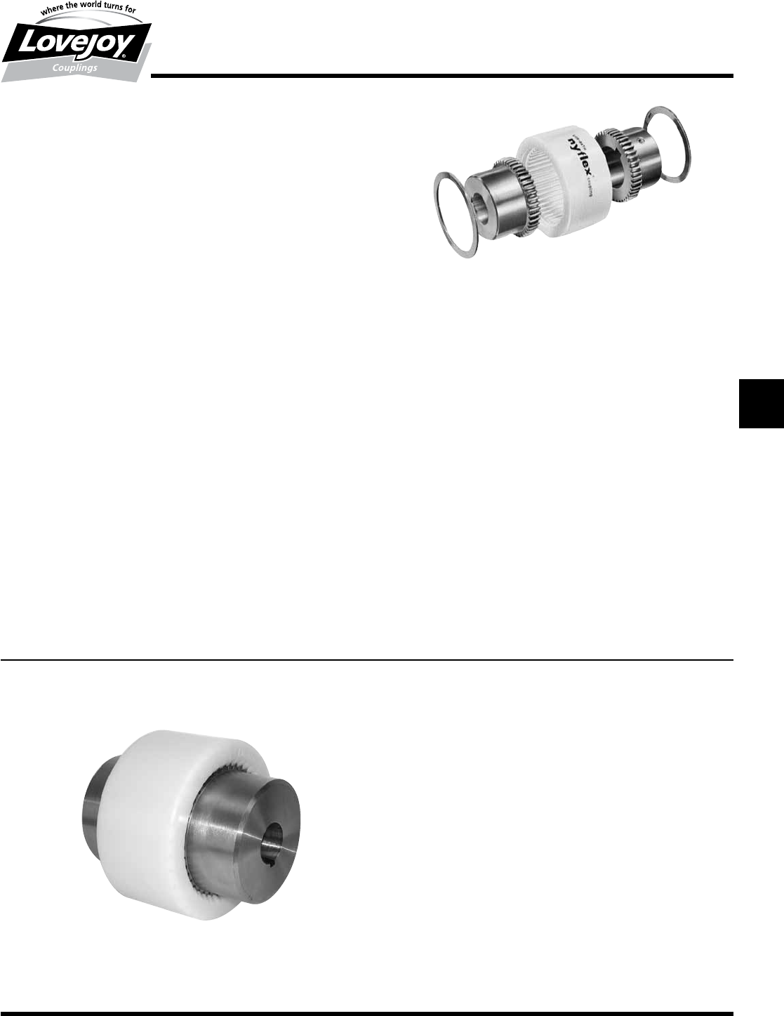
Lovejoy / Sier-Bath Nyflex® and Mite®
Lovejoy■/■Sier-Bath■Nylon■couplings■are■compact■and■require■no■
lubrication.■They■operate■over■a■wide■temperature■range■at■speeds■up■
to■5,000■RPM■and■are■effectively■used■in■applications■such■as■Motor/
Generator■sets,■pump■sets,■and■many■light■to■medium■duty■industrial■
coupling■applications.
No■lubricants■are■ever■required,■eliminating■the■need■for■seals.■The■resilient■
nature■of■the■nylon■material■makes■the■contact■of■the■hubs■and■sleeves■
almost■frictionless.■Since■no■lubrication■is■used,■the■coupling■can■readily■be■
adapted■to■many■applications■including■vertical■and■blind■installations■where■
the■slip-together■components■offer■easy■inspection■and■adjustment.
Operationally,■the■coupling■offers■a■minimum■backlash■solution■that■will■
operate■in■ambient■temperature■environments■from■-40°■to■150°■F.■Nylon■
Sleeve■couplings■have■precision■molded■sleeves■and■hubs■with■no■bolts,■
pins,■flanges,■or■protrusions■to■affect■balance■or■safety.■The■nylon■sleeve■
permits■misalignment■up■to■5°■for■Dentex■and■Nyflex■couplings■and■3°■for■
the■Mite.
When■completely■assembled,■the■Mite■coupling■weighs■less■than■1lb■and■
the■Nyflex■only■3.50■lbs.■Weights■for■Dentex®■couplings■can■be■found■on■
page■G-30.
Features
■■Molded■nylon■sleeve
■■No■internal■frictional■loss■or■heat■buildup
■■Minimum■backlash
■■High■ambient■temperature■allowed
■■Resistance■to■dirt,■moisture,■most■chemicals
■■Low■maintenance■(no■seals,■lubricant,■retainers)
■■High■torque,■low■intertia
■■Standard■bores■are■available
2 Spirolox
Retaining Rings
Sleeve■is■securely■
held■on■the■hubs■
by■these■spring-
steel■retaining■
rings.■They■can■
be■removed■in■
seconds,■yet■they’ll■
withstand■5,000■lbs■
endthrust.
Nylon Sleeve
Resilient,■
lightweight,■
abrasion■and■
corrosion■resistant■
nylon■is■accurately■
molded■to■mesh■
precisely■with■
hubs.■Their■
almost■frictionless■
properties■eliminate■
the■need■for■
lubrication.
2 Hubs
Sintered■iron■is■
standard■in■the■
Nyflex■and■Mite.■
Teeth■are■crowned■
to■provide■greater■
misalignment■
capacity■and■to■
prevent■gouging■
of■Nylon■sleeve.■
Maintain■0.13■inch■
spacing■between■
hubs.
Dentex® / Dentex® FL - The Flexible Coupling
Features
Compensation■of■axial,■radial■and■angular■misalignment■
of■shafts■through■double■cardanic■action
■■Simple■and■easy■assembly
■■High■electrical■insulating■property
■■High■thermal■stability
■■No■maintenance
JWJISCJSFMCGHPGDDTSPUJVSDRSLDED
JW JIS CJ SF MC
G
HP GD D T SP UJ VSD R SLD ED
120 630-852-0500
G-6
Gear
Overview
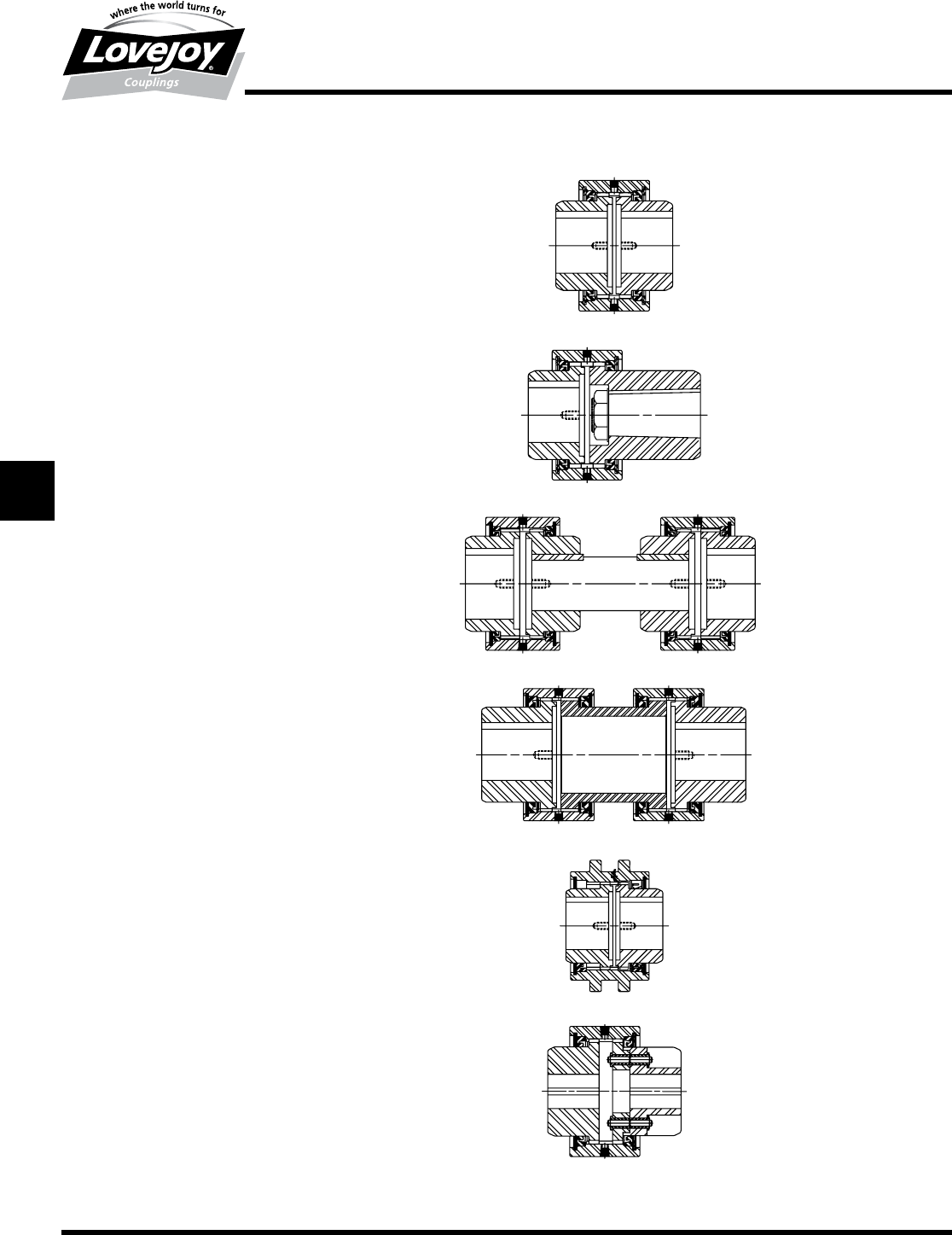
Lovejoy / Sier-Bath Continuous Sleeve
Series Couplings
Standard C Type
■■Basis■for■all■types■of■Lovejoy■/■Sier-Bath■Continuous■Sleeve■
Couplings
■■Low■profile■compact■design■is■easy■to■implement
■■Single■(flex-rigid)■or■double■(flex-flex)■engagement
Mill Motor CMM Type
■■Designed■with■longer■universal■hub■on■one■end■to■accommodate■
straight■or■tapered■shafts
■■Standard■hub■and■sleeve■on■the■other■end
■■Universal■hub■bored■to■customer■specifications
■■Available■with■longer■universal■hubs■on■both■ends
Floating Shaft CFS Type
■■Two■flex-rigid■couplings■connected■by■an■intermediate■shaft
■■Increased■capability■to■accommodate■parallel■misalignment
■■Allows■for■longer■shaft■separations
Spacer CSPCR Type
■■Drop-out■spacer■design■allows■for■ease■of■maintenance■without■
disturbing■the■equipment■mountings■
■■Spacer■has■rigid■teeth■to■mate■with■sleeves■on■each■coupling
■■Increased■capability■to■accommodate■parallel■misalignment
■■Allows■for■longer■shaft■separations
Cut-out Shifter CCS Type
■■Designed■for■quick■disengagement■between■the■driver■and■driven■
equipment
■■Special■seal■in■disengagement■hub■to■prevent■undue■friction■when■
hub■turns■in■sleeve
■■Widely■used■on■dual■drive■operations■and■equipment■operating■in■
tandem
■■Available■with■pins■to■maintain■sleeve■in■engaged■and■disengaged■
positions
■■Shifting■mechanisms■available■upon■request
Shear Pin CSHP Type
■■Designed■to■limit■and■protect■against■excessive■torque■or■sudden■
shock■loads
■■Sheer■pins■designed■and■manufactured■for■predetermined■loads
■■Pins■are■inserted■in■hardened■bushings■to■minimize■wear
■■Easy■to■install■new■pins
■■For■Flanged■FSHP■Style■see■page■G-8
C Type Section Pages G-16 and G-17
CFR Type
CCS Type
Section Pages G-24 and G-25
CMM Type
Section Pages G-18 and G-19
CFS Type
Section Pages G-20 and G-21
CSPCR Type
Section Pages G-22 and G-23
CSHP Type
Section Pages G-26 and G-27
JWJISCJSFMC
G
HPGDDTSPUJVSDRSLDED
JW JIS CJ SF MC G HP GD D T SP UJ VSD R SLD ED
121
www.lovejoy-inc.com G-7
Gear
Overview
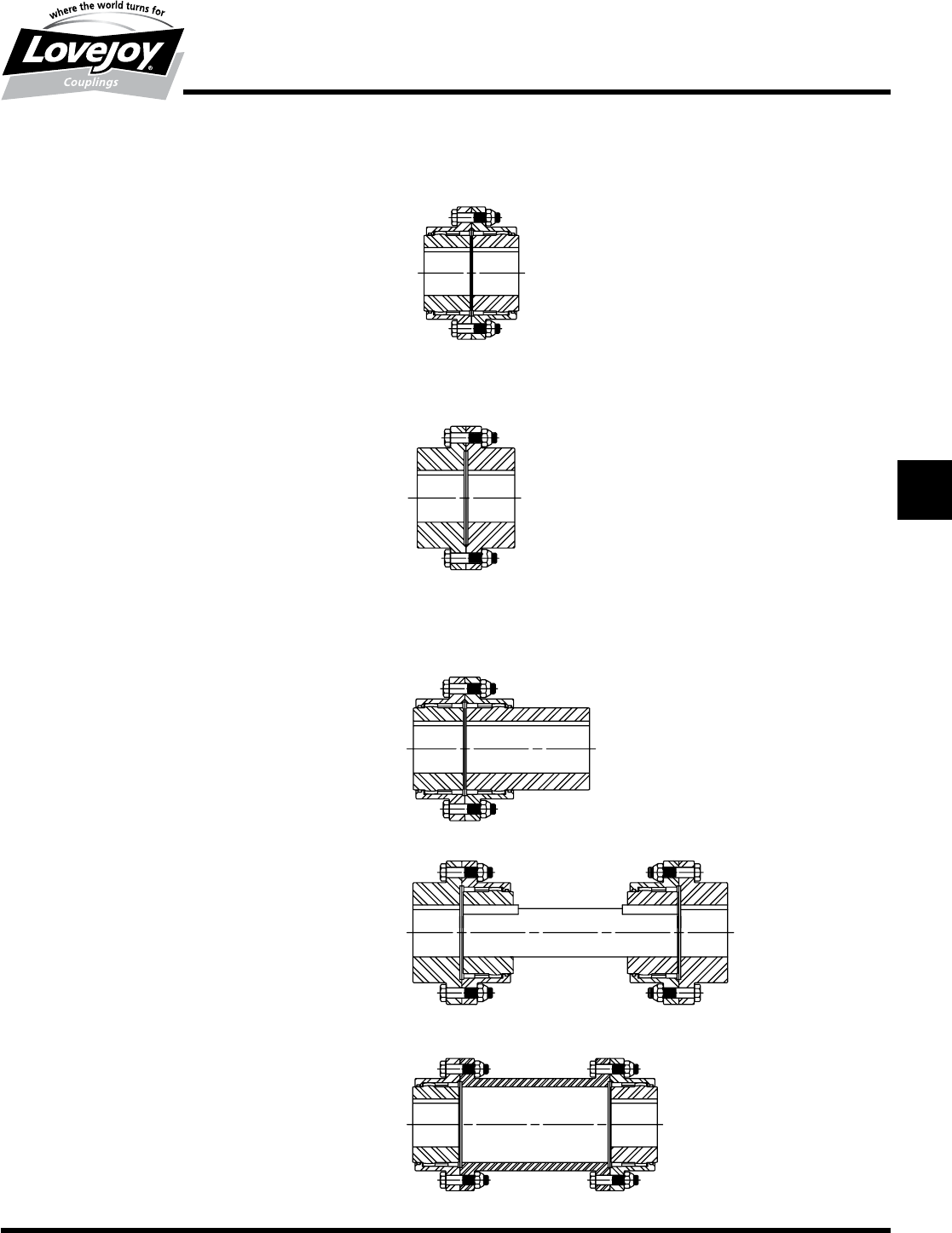
Lovejoy / Sier-Bath Flanged Sleeve Series
Couplings
Standard F Type
■■Double■engagement■(‘F’■flex-flex)■for■parallel■and■angular■
misalignment
■■Single■engagement■(‘FFR’■flex-rigid)■accommodates■angular■
misalignment■only■and■is■ideal■for■floating■shaft■applications
■■Industry■standard■flange■bolt■patterns■
■■FHD■Type■standard■for■sizes■10■through■30■(other■sizes■available■
upon■request)
Rigid-Rigid FRR Type
■■Designed■for■connecting■two■rigidly■mounted■shafts■with■no■
misalignment■capability
Alloy Rigid-Rigid FARR Type
■■Longer■piloted■hubs■maintain■rigidity■and■concentricity
■■Used■for■cantilevered■loads■such■as■gear■boxes■that■hang■off■
conveyor■systems
■■Alloy■steel■available■for■greater■strength■(FARR)
Mill Motor FMM Type
■■First■hub■designed■with■longer■universal■hub■on■one■end■to■
accommodate■straight■or■tapered■shafts
■■Second■hub■bored■to■customer■specifications
■■Standard■design■accommodates■AISE■Mill■Motor■frame■sizes
■■Sleeves■and■second■hub■are■standard
Floating Shaft FFS Type
■■Two■flex-rigid■couplings■connected■by■an■intermediate■shaft
■■Increased■ability■to■accommodate■parallel■misalignment
■■Accommodate■longer■shaft■separations
■■Standard■construction■with■rigid■hubs■on■outboard■(equipment)■
shafts,■flex■on■inboard■(floating)■shaft
■■Rigid■hubs■inboard■(on■floating■shaft)■available■upon■request
Spacer FSPCR Type
■■Drop-out■spacer■design■allows■for■ease■of■maintenance■without■
disturbing■the■equipment■mountings■
■■Lightweight■construction■reduces■load■on■equipment■bearings
F Type Section Pages G-34 and G-35
FFR Type Section Pages G-36 and G-37
FHD Type Section Pages G-40 and G-41
FRR Type Section Pages G-58 and G-59
FARR Type Contact Lovejoy Technical Support
FMM Type Section Pages G-46, G-47,
G-48 and G-49
FFS Type
Section Pages G-38
and G-39
FHDFS Type
Section Pages G-44
and G-45
FSPCR Type
Section Pages G-54 and G-55
JWJISCJSFMCGHPGDDTSPUJVSDRSLDED
JW JIS CJ SF MC
G
HP GD D T SP UJ VSD R SLD ED
122 630-852-0500
G-8
Gear
Overview
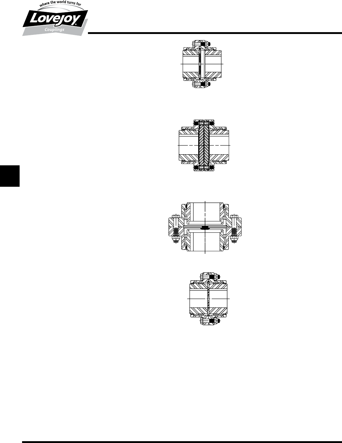
FSL Type Section pages G-50, G-51,
FSLX Type G-52 and G-53
FSHP and FSHPB Type
Contact Lovejoy Technical Support
FV and FVX Type
Contact Lovejoy Technical Support
FLEF Type Section pages G-56 and G-57
Slide FSL and FSLX Types
■■Allows■for■a■predetermined■amount■of■axial■slide
■■Longer■hubs■and■sleeves■available■to■accommodate■additional■
slide■capacity
■■Custom■slide■lengths■available
Shear Pin FSHP and FSHPB Types
■■Designed■to■limit■and■protect■equipment■against■excessive■torque■
or■sudden■shock■loads
■■Shear■pins■designed■and■manufactured■to■shear■at■predetermined■
torque■loads
■■Pins■are■inserted■in■hardened■bushings■to■minimize■wear
■■Easy■to■install■new■pins
■■Available■with■bearing■support■to■maintain■alignment■after■the■pins■
shear
Standard Vertical FVX Type
■■Designed■for■use■with■vertical■shafts
■■Vertical■kit■prevents■shafts■from■contacting■each■other
■■Maintains■ability■to■accommodate■misalignment
■■Available■in■vertical■floating■shaft■design
Limited End Float FLEF Type
■■Designed■for■equipment■with■sleeve■bearings
■■Designed■to■limit■axial■travel■of■the■rotor■in■the■motor■and■prevent■
the■rotor■from■coming■into■contact■and■damaging■sleeve■bearings
JWJISCJSFMC
G
HPGDDTSPUJVSDRSLDED
JW JIS CJ SF MC G HP GD D T SP UJ VSD R SLD ED
123
www.lovejoy-inc.com G-9
Gear
Overview
FLA Type Section Pages G-60 and G-61
FLAFR Type Section Pages G-62 and G-63
FLAMM Type Section Pages G-64 and G-65
FLHD Type Contact Lovejoy
Technical Support
FLHDFR Type Contact Lovejoy
Technical Support
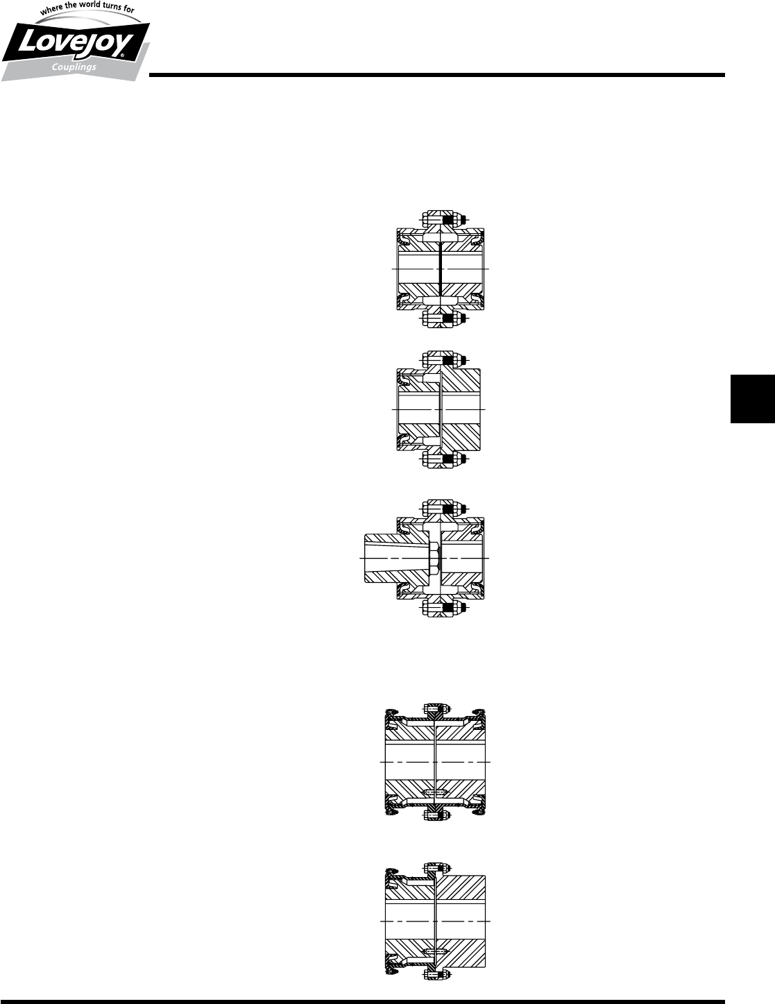
Lovejoy / Sier-Bath All Metal Labyrinth Seal
Series Couplings
■■All■AISI■4140■Alloy■Steel■Design
■■No■rubber■seals■–■metal■labyrinth■design
■■Standard■with■exposed■bolts
■■Fully■interchangeable■with■Industry■standards
■■Ideal■for■higher■temperature■applications
Standard FLA Type
■■Double■engagement■(‘F’■flex-flex)■for■parallel■and■angular■misalignment
■■Industry■standard■flange■bolt■patterns
Single Engagement FLAFR Type
■■Single■engagement■(‘FFR’■flex-rigid)■accommodates■angular■
misalignment■only■and■is■ideal■for■floating■shaft■applications
Mill Motor FLAMM Type
■■First■hub■designed■with■longer■universal■hub■on■one■end■to■
accommodate■straight■or■tapered■shafts
■■Second■hub■bored■to■customer■specifications
■■Standard■design■accommodates■AISE■Mill■Motor■frame■sizes
■■Sleeves■and■second■hub■are■standard
Lovejoy Forged Steel Series
Standard FLHD Type
■■Piloted■Sleeves
■■Exposed■Bolts■Standard
■■Excellent■for■high■torque■at■low■speeds
■■Bore■range■from■7.75■inches■up■to■44.88■inches
■■Torque■capacity■up■to■54,390,000■in-lbs
■■Alloy■Steel■(AISI■4140)■construction■available
Single Engagement FLHDFR Type
■■Capacities■the■same■as■FHD
■■Ideal■for■heavy■duty■floating■shaft■applications
JWJISCJSFMCGHPGDDTSPUJVSDRSLDED
JW JIS CJ SF MC
G
HP GD D T SP UJ VSD R SLD ED
124 630-852-0500
G-10
Gear
Overview
FA Type Section Pages G-66 and G-67
FAFR Type Contact Lovejoy
Technical Support
FAMM Type Contact Lovejoy
Technical Support
Lovejoy Alloy Steel Series Couplings
■■All■alloy■steel■construction
■■■Fully■molded■seals■maintain■lubricant■retention■under■misalignment■
conditions
■■Exposed■bolts■are■standard,■shrouded■bolts■are■optional
Standard FA Type
■■Double■engagement■(‘F’■flex-flex)■for■parallel■and■angular■
misalignment
■■Industry■standard■flange■bolt■patterns■
Single engagement FAFR Type
■■Single■engagement■(‘FFR’■Flex-Rigid)■accommodates■angular■
misalignment■only■and■is■ideal■for■floating■shaft■applications
Mill Motor FAMM Type
■■First■hub■designed■with■longer■universal■hub■on■one■end■to■
accommodate■straight■or■tapered■shafts
■■Second■hub■bored■to■customer■specifications
■■Standard■design■accommodates■AISE■Mill■Motor■frame■sizes
■■Sleeves■and■second■hub■are■standard
Additional Specialty Coupling Types
■■Stainless■Steel
■■Nylon■Sleeves■
■■High■Speed■RAHS■Type
■■Brake■Drum■FBD■and■FBW■Types
■■Insulated■FI■Type
■■Vertical■Floating■Shaft■FVFS■Type
■■F■Style■Cutout■Shifter■FCS■Type
JWJISCJSFMC
G
HPGDDTSPUJVSDRSLDED
JW JIS CJ SF MC G HP GD D T SP UJ VSD R SLD ED
125
www.lovejoy-inc.com G-11
Gear
Overview
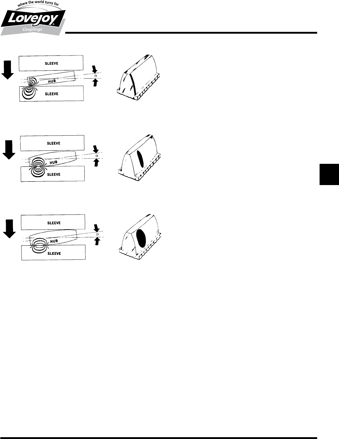
Straight
With■straight■hub■teeth,■there■is■a■high■concentration■of■load■under■
misaligned■conditions.■As■misalignment■increases,■more■of■the■load■is■
carried■by■the■ends■of■the■teeth,■resulting■in■premature■breakdown■and■
coupling■failure.
Conventional Crown
Some■manufacturers■use■a■conventionally■crowned■hub■tooth■known■
by■various■trade■names.■Regardless■of■the■nomenclature,■however,■the■
contour■of■the■tooth■is■a■segment■of■an■arc.■Under■all■operating■conditions,■
equal■or■similar■contact■areas■between■the■hub■teeth■and■the■sleeve■teeth■
exist.
Lovejoy / Sier-Bath Vari-Crown®
The■Sier-Bath■Vari-Crown■tooth■form■has■a■crown■at■the■center■of■the■tooth■
which■is■similar■to■a■conventionally■crowned■tooth■coupling.■However,■
as■soon■as■misalignment■occurs,■the■transmitted■torque■is■carried■on■a■
flattened■area■of■the■hub■tooth■which■is■considerably■broader■and■stronger■
than■the■conventionally■crowned■tooth■form.■Note■the■larger■contact■area■
and■reduced■stress■area■of■the■Vari-Crown■tooth■form.
Vari-Crown® Tooth Form
Patented Vari-Crown® Tooth Form for Long Life
Facts
■■It■can■be■shown1■that■bodies■with■the■smallest■relative■curvature■have■
the■largest■area■of■contact■under■load,■or■specifically,■a■body■with■the■
largest■radius■of■curvature■has■the■largest■area■of■contact■with■another■
body■when■under■load.■More■importantly,■under■a■given■load■the■bodies■
with■the■greater■radii■of■curvature■have■lower■induced■surface■contact■
stresses.
■■Gear■tooth■couplings■have■fewer■teeth■in■contact■as■misalignment■
increases.
Lower Stresses
Lovejoy■/■Sier-Bath’s■solution■to■these■facts■was■the■development■of■the■
patented■Vari-Crown■tooth■form.■The■Vari-Crown■tooth■form■is■a■curve■
with■constantly■changing■radii■of■curvature.■The■tooth■contact■area■
under■misaligned■conditions■has■a■much■larger■radius■of■curvature■than■
conventional■crowning.■The■contact■area■is■larger,■thus■reducing■the■unit■
stress.
Constant Velocity Power Transmission
Lovejoy■/■Sier-Bath■produces■the■Vari-Crown■tooth■form■by■a■generating■
method■maintaining■the■necessary■characteristics■for■conjugate■tooth■action,■
which■are:
1.■Constant■normal■base■pitch■at■any■position■on■the■crowned■teeth.
2.■■Correct■pressure■angle■matching■of■the■normal■to■the■curved■surface■and■
the■sleeve■surface■at■any■position■of■misalignment.
Less Backlash
The■tooth■design■requires■less■backlash■for■a■given■angle■of■misalignment■
than■the■conventional■or■circular■arc■crown.■In■many■applications■this■is■a■
desirable■feature■in■a■gear■tooth■coupling.
Note:■■ n■1■indicates:■Hertz’s■study■of■contact■stresses■of■curved■surfaces.
JWJISCJSFMCGHPGDDTSPUJVSDRSLDED
JW JIS CJ SF MC
G
HP GD D T SP UJ VSD R SLD ED
126 630-852-0500
G-12
Gear
Selection Process
Gear Coupling Selection Process
Selection Example (Flanged Gear Coupling)
Application Data: ■This■sample■application■calls■for■a■coupling■to■connect■the■output■
side■of■a■reducer■gearbox■to■a■dredge■pump.■There■is■a■400■HP■electric■motor,■
running■at■3,600■RPM■driving■the■gearbox■which■has■a■10:1■speed■reduction.■The■
gearbox■has■a■6■inch■diameter■shaft,■the■pump■has■a■6-1/2■inch■diameter■shaft.■There■
is■an■angular■misalignment■potential■of■slightly■more■than■1°.
Step 1: ■■Since■C■Type■gear■couplings■are■only■capable■of■1/2°■misalignment■per■flex■
plane,■the■F■Type■coupling■is■selected.■The■F■Type■coupling■is■capable■of■
accommodating■1-1/2°■per■flex■plane.■Note,■it■is■highly■recommended■that■
couplings■are■installed■at■no■more■than■20%■of■the■allowable■misalignment■
since■the■alignment■often■changes■during■operation.
Step 2: Refer■to■page■G-34■and■G-35■for■Flanged■series■(F■Type)■double■
engagement,■or■flex-flex,■coupling■information.■The■bore■size■and■torque■
should■be■addressed■interactively■when■selecting■a■coupling■size.
Step 3: The■application■service■factor■can■be■found■on■page■G-13.■Application■
service■factors■are■multipliers■assigned■to■assorted■applications■for■the■
purpose■of■guiding■the■coupling■selection■process■to■a■torque■rating■that■will■
prevent■premature■failure■caused■by■the■characteristics■of■that■application.■
For■this■sample■application,■note■that■the■service■factor■for■a■dredge■pump■
application■is■2.0.
Step 4: Calculate■the■torque■requirements■for■the■application■using■the■formula:
Design■Torque■(■in–lbs■)■■=■■HP■x■63025
■ ■ ■■■■■■■■■■■■■■■■■■■■■■■■RPM
or■ ■■■■■■■■■■■■■■■■■■Nm■■=■■(KW■x■9550)
■ ■ ■■■■■■■■■■■■■■■■RPM
Selection■Torque■=■■Application■Torque■■x■■Service■Factor■
In■this■example,■a■gearbox■is■in■use■that■reduces■the■operating■speed■
where■the■coupling■is■being■used■from■3,600■RPM■on■the■input■side■to■360■
RPM■on■the■gearbox■output■side.
Please■note■that■any■speed■decrease■at■the■reducer■(gear■box)■will■cause■an■
increase■in■the■application■torque.
Application■Torque■(■in-lbs■)■■=■■
■■■■■■■■■(HP■x■63025)■■=■■(400■■x■■63025)■■=■■70,028■in-lbs
■■■■■■■■■■■■■■■■RPM■■■■■■■■■■■■■■■■■■■■■■360
Selection■Torque■■=■■Application■Torque■x■Service■Factor■=
■ ■ ■ 70,028■■■x■■■2.0■■■■■■=■140,056■in-lbs
An■F■3.5■coupling■is■rated■at■151,200■in-lbs■and■could■easily■accommodate■
the■torque■requirement,■however,■to■accommodate■the■6-1/2■inch■pump■
shaft■diameter■the■selection■of■an■F■5E■size■coupling■will■be■necessary.■
The■F■5■coupling■is■rated■at■434,700■in-lbs■and■may■seem■to■be■too■
large■or■overrated■for■this■application,■but■the■larger■size■is■necessary■to■
accommodate■the■shaft■size.
Step 5: Confirm■that■the■RPM■is■within■range■specified■for■the■selected■coupling.■The■chart■
shows■the■F■5■has■a■2,500■RPM■maximum■speed■and■this■will■accommodate■the■
360■RPM■speed■requirement■on■the■output■side■of■the■gearbox.
Step 6: Please■refer■to■the■coupling■specifications■on■page■G-34■and■G-35.■■Note■
that■F■5E■couplings■are■manufactured■with■interference■fits■and■exposed■
bolts■as■standard.■When■contacting■your■sales■representative,■the■
description■for■this■coupling■would■be■an■F■5E■gear■coupling■and■include■the■
bore■size,■keyway■information,■and■shaft■separation.■Also,■provide■a■list■of■
any■requirements■that■might■supersede■the■coupling■defaults.
Special Note:■If■the■shaft■separation■is■greater■than■specified■in■the■chart■on■Page■
G-35,■refer■to■the■Floating■shaft■or■Spacer■style■couplings■on■pages■G-39■or■G-55.■If■
the■desired■shaft■separation,■or■BSE,■is■not■listed,■contact■Lovejoy■Technical■Support■
for■assistance.
Please■refer■to■the■Lovejoy■website■for■installation■instructions■and■lubrication■
requirements■for■gear■couplings.
Factors Affecting Selection
The■following■is■a■list■of■the■information■necessary■to■assist■in■making■a■coupling■
selection.■Not■all■of■these■items■will■come■into■play■in■all■selection■processes.■These■
items■include,■but■are■not■limited■to:
Application related:
•■ Application■details
•■ Type■of■motor■and■driven■equipment
•■ Motor■horsepower■or■KW
•■ Operating/coupling■speed
•■ Shaft■sizes■and■separation
•■ Space■and■size■constraints
•■ Environment■(temperature,■chemicals,■etc)
•■ Balance■requirements
•■ Special■modifications
Steps In Selecting A Gear Coupling
Refer■to■the■gear■coupling■specifications■charts■displayed■with■each■type■of■coupling■
throughout■the■Gear■Coupling■Products■section■of■this■catalog.■The■pictures■and■charts■
provide■visualization,■specifications,■and■dimensional■data■for■Lovejoy’s■wide■range■of■gear■
coupling■products.■Typically■start■with■an■F■Type■flanged■gear■coupling■(page■G-34)■or■a■C■
Type■continuous■sleeve■gear■coupling■(page■G-16)■and■proceed■from■there.
Step 1:■■■Review■the■gear■coupling■series■and■type■as■selected■to■ensure■the■selection■
meets■application■requirements.
Step 2:■■■Determine■the■nominal■application■torque■in■in–lbs■by■using■the■following■
formula:
Application■Torque■(■in–lb■)■■■=■■(HP■x■63025)
■■■■■■■■■ ■ ■■■■■■■■■■■■■RPM
or■ ■ ■■■■■■Nm■■=■■(KW■x■9550)
■■■■■■■■■■■■■■■■■■■■■■■■■■■■■■■■■■■■■■■■■■■■■■■■■RPM
Step 3: ■■Review■the■Application■Service■Factor■chart■for■the■service■factor■number■
associated■with■the■application■where■this■coupling■will■be■used.■Multiply■the■
application■torque■by■the■application■service■factor■to■determine■the■total■
torque■required■for■the■coupling■selection.
Step 4:■■■Compare■the■required■total■torque■value■with■the■nominal■torque■capacity■
listed■in■the■Gear■Coupling■Selection■chart■for■the■desired■coupling■type.
Step 5:■■■Check■that■the■maximum■bore■size■and■the■maximum■RPM■of■the■coupling■
type■selected■to■ensure■the■coupling■will■meet■these■application■requirements.
Step 6:■■■Note■any■special■requirements■including■the■BSE■dimension■for■floating■shaft■
and■spacer■types,■shear■pin■torque,■slide■coupling■details,■mill■motor■tapered■
shaft■data,■and■any■other■pertinent■information.
Consult■with■Lovejoy■Technical■support■or■Engineering■for■any■unique■application■
concerns.
JWJISCJSFMC
G
HPGDDTSPUJVSDRSLDED
JW JIS CJ SF MC G HP GD D T SP UJ VSD R SLD ED
127
www.lovejoy-inc.com G-13
Gear
Application Service Factors
Selection Data
Application Service Factors
Agitators
■ Pure■Liquids■............................................1.0
■ Liquids—Variable■Density■.......................1.0
Blowers
■ Centrifugal■...............................................1.0
■ Lobe■........................................................1.2
Can Filling Machines■...................................1.0
Car Dumpers■................................................2.0
Car Pullers, Intermittent Duty■.....................1.5
Compressors
■ Centrifugal■...............................................1.0
■ Reciprocating■..........................................2.2
■ Multi-Cylinder■..........................................2.0
■ Single■Cylinder■........................................2.0
Conveyors,■Uniformly■Loaded■■or■■Fed
■ Assembly■................................................1.2
■ Belt■..........................................................1.2
■ Screw■......................................................1.2
Conveyors,■Heavy■Duty
■ Not■Uniformly
■ Fed■Assembly■.........................................1.5
■ Belt■..........................................................1.5
■ Oven........................................................1.5
■ Reciprocating■..........................................2.0
■ Screw■......................................................1.5
■ Shaker■.....................................................1.5
Cranes and Hoists1
■ Main■Hoists■.............................................2.0
■ Reversing■................................................2.0
■ Skip■Hoists■..............................................2.0
■ Trolley■Drive■............................................2.0
■ Bridge■Drive■............................................2.0
Crushers
■ Ore■..........................................................3.0
■ Stone■.......................................................3.0
Dredges
■ Conveyors■...............................................2.0
■ Cutter■■Head■Drives■................................2.0
■ Maneuvering■Winches■............................2.0
■ Pumps■.....................................................2.0
Fans
■ Centrifugal■...............................................1.0
■ Cooling■Towers■Forced■Draft■..................1.5
Feeders
■ Screw■......................................................1.5
Generators
■ Not■Welding.............................................1.0
■ Welding■...................................................1.5
Hammer Mills■................................................2.0
Laundry Washers
■ Reversing■................................................1.5
Lumber Industry
■ Barkers—Drum■Type■..............................2.0
■ Edger■■Feed■............................................2.0
■ Live■Rolls.................................................2.0
■ Log■Haul—Incline■....................................2.0
■ Log■Haul—Well■Type■..............................2.0■
■ Off■Bearing■Rolls■.....................................2.0
■ Planer■Feed■Chains■..............................1.75
■ Planer■Tilting■Hoist■................................1.75
■ Planer■Floor■Chains■..............................1.75
■ Slab■Conveyor■........................................1.5
■ Sorting■Table■...........................................1.5
■ Trimmer■Feed■..........................................1.5
Machine Tools
■ Bending■Roll■............................................2.0
■ Punch■Press,■Gear■Driven■......................2.0
■ Tapping■Machines■...................................2.0
■ Main■Drives■.............................................1.5
■ Auxiliary■Drives■.......................................1.5
Metal Mills
■ Draw■Bench—Carriage■...........................2.0
■ Draw■Bench—Main■Drive■........................2.0
■ Forming■Machines■..................................2.0
■ Slitters■.....................................................1.5
■ Table■Conveyors
■ ■■■■■Non-Reversing■.................................2.25
■ ■■■■■Reversing■...........................................2.5
■ Wire■Drawing■&
■ ■■■Flattening■Machine■...............................2.0
■ Wire■Winding■Machine■..........................1.75
Metal Rolling Mills
■ Blooming■Mills■........................................■2.5
■ Coilers,■hot■mill........................................2.0
■ Coilers,■cold■mill■......................................1.5
■ Cold■Mills.................................................2.0
■ Cooling■Beds■.........................................1.75
■ Door■Openers■.........................................2.0
■ Draw■Benches■.........................................2.0
■ Edger■Drives■.........................................1.75
■ Feed■Rolls,■Reversing■Mills■....................3.5
■ Furnace■Pushers■.....................................2.5
■ Hot■Mills■..................................................3.0
■ Ingot■Cars■...............................................2.5
■ Kick-outs■.................................................2.5
■ Manipulators■...........................................3.0
■ Merchant■Mills■.........................................3.0
■ Piercers■...................................................3.0
■ Pusher■Rams■..........................................2.5
■ Reel■Drives■...........................................1.75
■ Reel■Drums■.............................................2.0
■ Reelers■....................................................3.0
■ Rod■and■Bar■Mills■....................................3.0
■ Roughing■Mill■Delivery■Table■...................3.0
■ Runout■Tables■.........................................2.5
■ Saws,■hot■&■cold■.....................................2.5
■ Screwdown■Drives■..................................3.0
■ Skelp■Mills■...............................................3.0
■ Slitters■.....................................................3.0
■ Slabing■Mills■..........................................1.75
■ Soaking■Pit■Cover■Drives■........................3.0
■ Straighteners■...........................................2.5
■ Tables,■transfer■■&■runout■........................2.5
■ Thrust■Block■............................................3.0
■ Traction■Drive■..........................................3.0
■ Tube■Conveyor■Rolls■...............................2.5
■ Unscramblers■..........................................2.5
■ Wire■Drawing■........................................1.75
Mills, Rotary Type
■ Ball■........................................................2.25
■ Dryers■&■Coolers■.....................................2.0
■ Hammer■................................................1.75
■ Kilns■........................................................2.0
■ Pebble■&■Rod■..........................................2.0
■ Pug■........................................................1.75
■ Tumbling■Barrels■.....................................2.0
Mixers
■ Concrete■Mixers,■Continuous■..................1.5
■ Concrete■Mixers,■Intermittent■..................2.0
Oil Industry
■ Oil■Well■Pumping.....................................2.0
■ Rotary■Kilns■.............................................2.0
Paper Mills
■ Agitators,■Mixers■.....................................1.5
■ Barker■Auxiliaries,■Hydraulic■...................2.0
■ Barker■Mechanical■..................................2.0
■ Barking■Drum■Spur
■ ■■■■■Gear■Only■...........................................2.0
■ Beater■&■Pulper■.....................................1.75
■ Bleacher■..................................................1.0
■ Calenders■................................................2.0
■ Calenders,■Super■....................................1.5
■ Chippers■..................................................2.5
■ Coaters....................................................1.0
■ Converting■Machines,
■ ■■■except■Cutters,■Platers■.........................1.5
■ Conveyors■...............................................1.5
■ Couch■Roll■............................................1.75
■ Cutters,■Platters■......................................2.0
■ Cylinders■...............................................1.75
■ Disc■Refiners■.........................................1.75
■ Dryers....................................................1.75
■ Felt■Stretcher■........................................1.25
■ Felt■■Whipper■...........................................2.0
■ Jordans■.................................................1.75
■ Line■Shaft■................................................1.5
■ Log■Haul■..................................................2.0
■ Pulp■Grinder■..........................................1.75
■ Press■Roll■................................................2.0
■ Reel■.........................................................1.5
■ Stock■Chests■...........................................1.5
■ Suction■Roll■...........................................1.75
■ Washers■&■Thickeners■............................1.5
■ Winders■...................................................1.5
Printing Presses■...........................................1.5
Pumps
■ Centrifugal■...............................................1.0
■ Reciprocating
■ ■■■Single■Acting■3■or■more
■ ■■■■■■Cylinders■...........................................1.5
■ Double■Acting■2■or■more
■ ■■■■■■Cylinders■...........................................2.0
■ Rotary,■Gear■Type,■Lobe
■ ■■■■■Vane■...................................................1.5
Rubber Industry
■ Mixer■.......................................................2.0
■ Rubber■Calender■.....................................2.0
Screens
■ Rotary,■Stone■or■Gravel■..........................1.5
Steering Gear■...............................................1.0
Stokers■..........................................................1.0
Textile Industry
■ Dryers......................................................1.5
■ Dyeing■Machinery■...................................1.5
Windlass■.......................................................2.0
Notes:■■ n■■1■indicates:■If■people■are■transported,■Lovejoy■does■not■recommend■and■will■not■warranty■the■use■of■the■coupling.
■n■■■Values■contained■in■the■table■should■be■used■as■a■general■guide■and■are■to■be■applied■to■smooth■power■sources■such■as■electric■
motors■and■steam■turbines.
■n■■■For■drives■involving■internal■combustion■engines■add■1.0■to■the■values■listed.
JWJISCJSFMCGHPGDDTSPUJVSDRSLDED
JW JIS CJ SF MC
G
HP GD D T SP UJ VSD R SLD ED
128 630-852-0500
G-14
Gear
Selection Worksheet
Customer Name:____________________________________________________ Contact Name: _____________________________________________
Phone Number:_____________________________________________________ Email Address: ______________________________________________
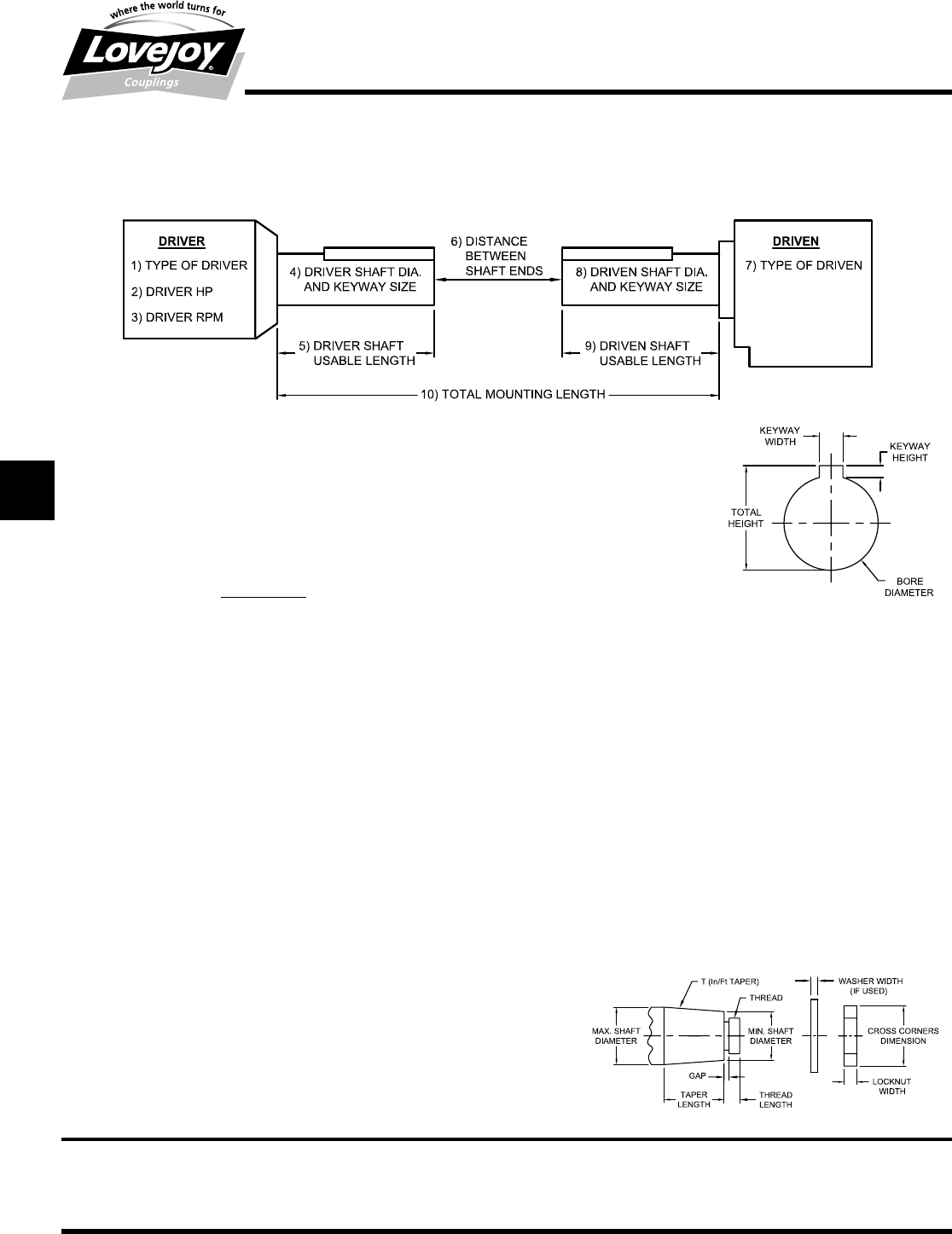
1.■ Type■of■Driver■(Electric■Motor,■Combustion■Engine,■Gearbox,■etc.)■:■___________________
■■ ■ For■combustion■engines,■define■type
■ ■ Gasoline,■Diesel,■Natural■Gas,■etc.■:■■______________■Number■of■cylinders■_______
2.■■ Driver■Horse■Power■:■____________■■■■■■3.■■Driver■or■Gearbox■output■RPM■:■_____________
■ ■ Retrieve■the■Application■Service■Factor■from■Page■G-13■:■______________■then
■ ■ calculate■the■Selection■Torque■using■the■following■formula:
■ ■ Torque■(in-lbs)■■=■■HP■■■x■■■63025■■■x■■Service■Factor■■=■■Selection■Torque■■=■■____________■in-lbs
■ ■■■■ ■■■■■■■■■■■■■■■■■■■■■■■■■■■■■■■■■■■RPM
4.■ Driver■Shaft■Diameter■:■_________■Keyway■size■:■KW■Width■_________■KW■Height■_________■■
■ ■ Specify■Clearance■Fit,■Interference■Fit,■Metric■(P7,■H7,■etc),■Shaft■Locking■Device,■and■Set■Screw■or■No■Set■Screw
5.■ Driver■Usable■Shaft■Length■:■___________■■(Measure■from■the■end■of■the■shaft■to■any■obstruction)
6.■ Distance■between■shaft■ends■(BSE)■:■_______________
7.■ Type■of■Driven■Equipment■:■_______________________________________
8.■ Driven■Shaft■Diameter■:■_________■Keyway■size■:■KW■Weight■_________■KW■Height■_________■■
■ ■ Specify■Clearance■Fit,■Interference■Fit,■Metric■(P7,■H7,■etc),■Shaft■Locking■Device,■and■Set■Screw■or■No■Set■Screw
9.■ Driven■Usable■Shaft■Length■:■___________■■(Measure■from■the■end■of■the■shaft■to■any■obstruction)
10.■ Total■Mounting■Length■:■______________■■(Advise■of■any■obstructions,■walls,■beams,■guards,■pipes,■etc.)
11. ■For■Tapered■Shafts■specify■the■following:
■ ■ Minimum■or■Maximum■Taper■diameter:■_________________________________
■ ■ Taper■Length:■___________■■T■(Taper■Inch■per■Foot)■:■_____________________
■ ■ Gap■or■Hub■Overhang■amount:■_______________________________________
■ ■ Locknut■Width:■___________■■Size■of■nut■cross■corners:■___________________
■ ■ Thread■Size:■_____________■■Thread■Length:■___________________________
■ ■ Washer■Diameter■(if■used)■:■____________■■■Washer■Width:■________________
For additional bore and
keyway information, see the
Engineering Data Section
of the Power Transmission
Products Catalog
Lovejoy, Inc.
World Headquarters
2655 Wisconsin Avenue
Downers Grove, IL 60515
Send this form to:
appleng@lovejoy-inc.com
or fax to: 800-446-0878
JWJISCJSFMC
G
HPGDDTSPUJVSDRSLDED
JW JIS CJ SF MC G HP GD D T SP UJ VSD R SLD ED
129
www.lovejoy-inc.com G-15
Gear
Continuous Sleeve
Cut Away
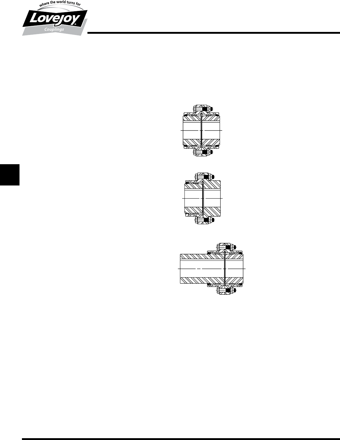
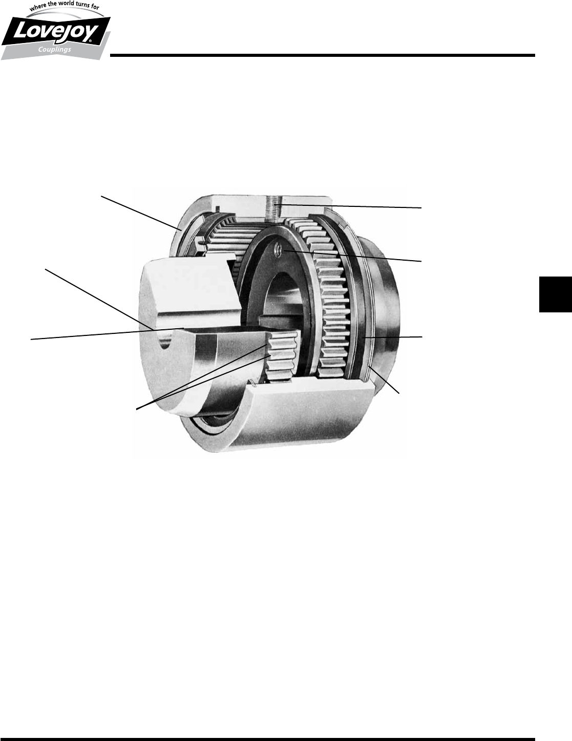
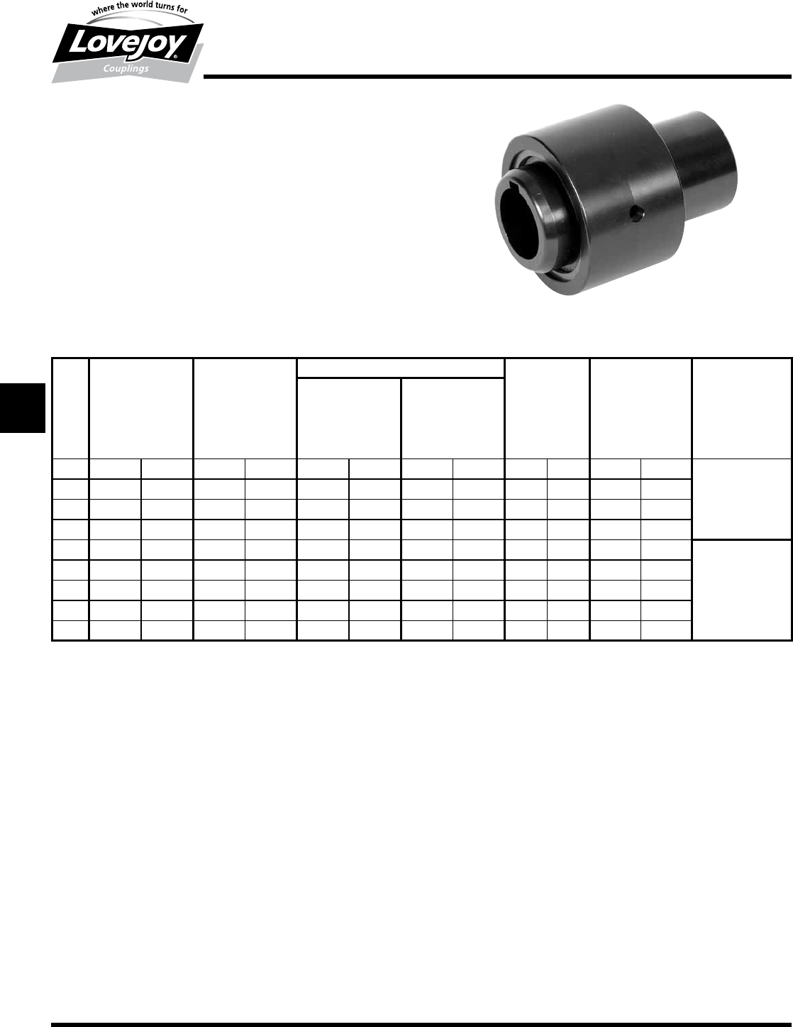
Lovejoy / Sier-Bath Continuous Sleeve Gear Couplings
One-piece■steel■sleeve■Internal■
teeth■run■full■working■length
Steel■hubs
Keyway
Gear■teeth■precision-cut,■evenly■spaced
Lubrication■holes■(2)
Draw-off■holes■(Optional)
Reinforced■rubber■lubrication■■
seals■held■in■by■snap■rings
Oil-hardened■spring■steel■snap■rings■
positioned■by■grooves■in■sleeve
The One-Piece Sleeve Gear Coupling
JWJISCJSFMCGHPGDDTSPUJVSDRSLDED
JW JIS CJ SF MC
G
HP GD D T SP UJ VSD R SLD ED
130 630-852-0500
G-16
Gear
C and CFR Type
Performance Data
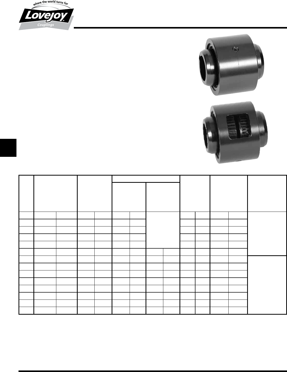
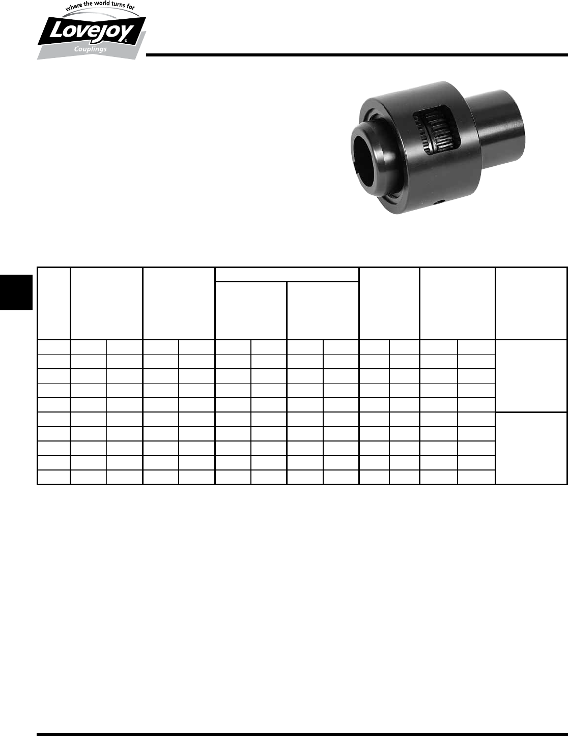
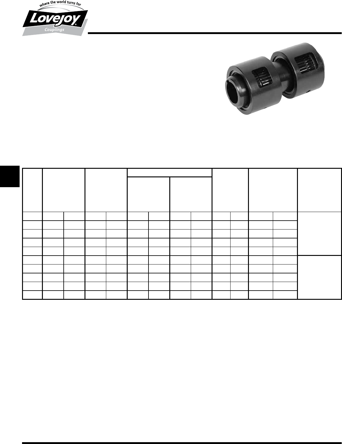
Lovejoy / Sier-Bath Continuous Sleeve Gear Couplings
C Type Flex-Flex Couplings
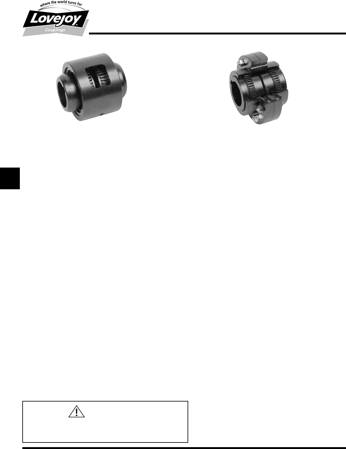
The■C■Type■coupling■consists■of■two■flex■hubs,■one■sleeve■and■one■accessory■kit■
consisting■of■seals■and■snap■rings.
CFR Type Flex-Rigid Couplings
The■CFR■Type■coupling■consist■of■one■flex■hub,■one■rigid■hub,■one■sleeve,■one■
accessory■kit■consisting■of■seals■and■snap■rings.
Features
■■Simple■and■inexpensive■type■of■gear■coupling
■■All■steel■sleves■and■hubs
■■Reinforced■rubber■seals■with■snap■rings■to■hold■lubricant■in■place
■■Available■as■vertical■and■horizontal■couplings
■■Wide■variety■of■special■variations■such■as■full-flex,■flex-rigid■mill■motor
■■Standard■configurations■are■available■of■the■shelf
C - CFR Performance Data
ID1 - ID2
Nominal Maximum Flex & Rigid Flex & Rigid Weight Parallel Angular
Torque Speed Max Bore Rough Stock Misalignment Misalignment
Unbal Bal Bore Degrees
Size in-lb Nm RPM RPM in mm in mm lbs kg in mm
7/8 2,500 300 6,000 18,000 1.25 31
Solid■with■Center
5 2 0.005 0.13
1.5 7,600 900 5,000 15,000 1.63 42 8 4 0.007 0.18 1/2°
220,200 2■300 4,200 12,600 2.13 56 13 6 0.007 0.18 per■Mesh
2.5 30,200 3■400 3,750 11,250 2.63 70 20 9 0.007 0.25
350,400 5■700 3,600 9,000 3.13 84 33 15 0.010 0.30
3.5 88,200 10■000 2,800 8,400 3.63 97 1.25 32 63 29 0.012 0.30
4126,000 14■200 2,400 7,200 4.13 111 1.75 44 91 41 0.012 0.30
4.5 184,000 20■800 2,200 6,600 4.75 130 2.38 60 126 57 0.007 0.18
5270,900 30■600 2,100 6,300 5.75 160 2.88 73 195 89 0.007 0.18 1/4°
6378,000 42■700 2,000 6,000 6.75 186 3.88 99 267 121 0.009 0.23 per■Mesh
7598,500 67■600 1,000 3,000 7.50 200 4.69 119 320 145 0.010 0.25
91,260,000 142■400 800 2,400 9.50 240 5.88 149 520 236 0.011 0.28
11 2,205,000 249■200 600 1,800 11.50 305 7.75 197 925 420 0.013 0.33
12 2,520,000 284■700 550 1,650 12.50 330 9.75 248 1,200 545 0.014 0.36
Ordering Information
■■Application:■Driver■and■Driven.
■■Type■and■size■of■coupling,■horizontal,■vertical■etc.
■■Power:■Motor■horspower■or■torque■requirement.
■■Speed:■Motor■RPM■or■Driven■RPM.
■■Distance■between■shaft■ends■(BSE).
■■Shaft■sizes.
JWJISCJSFMC
G
HPGDDTSPUJVSDRSLDED
JW JIS CJ SF MC G HP GD D T SP UJ VSD R SLD ED
131
www.lovejoy-inc.com G-17
Gear
C and CFR Type
Dimensional Data
Lovejoy / Sier-Bath Continuous Sleeve Gear Couplings
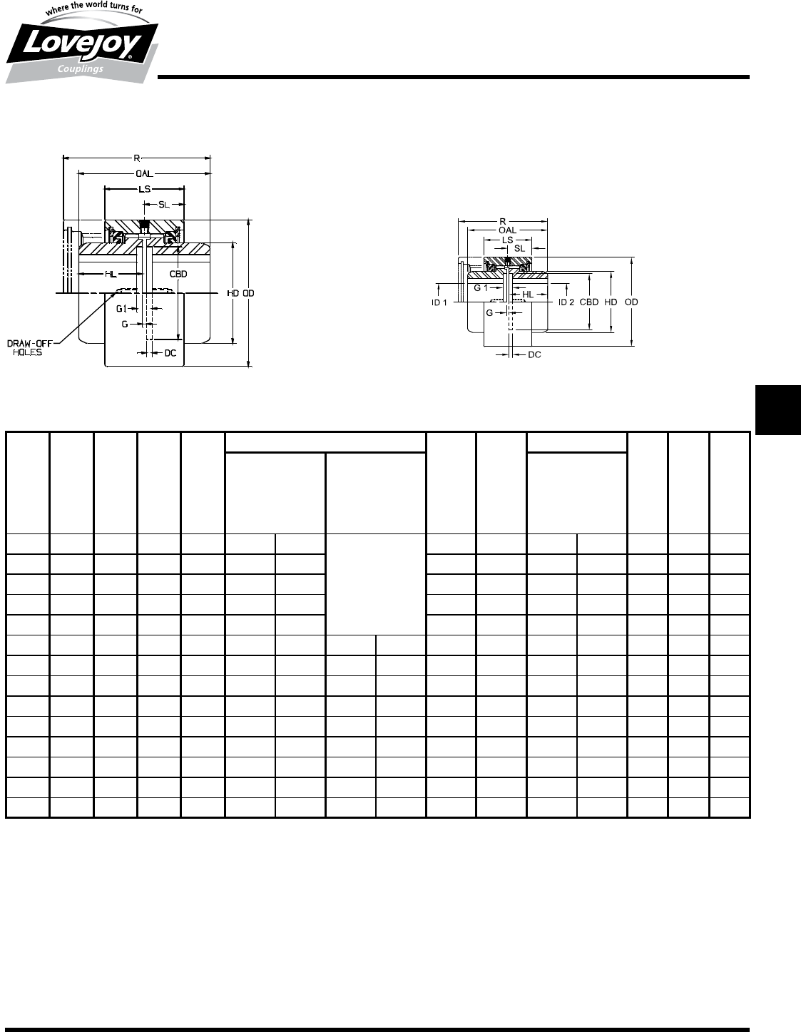
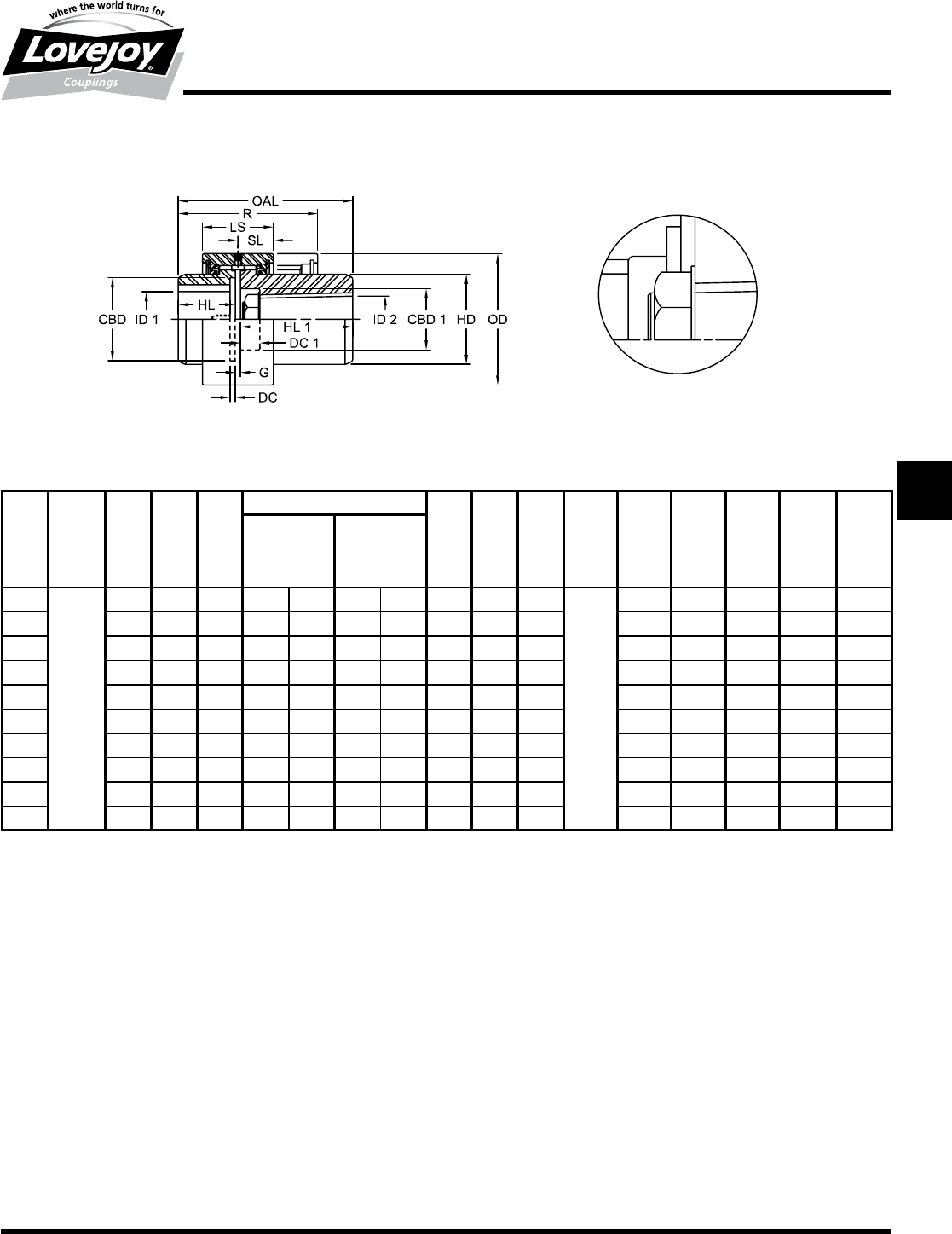
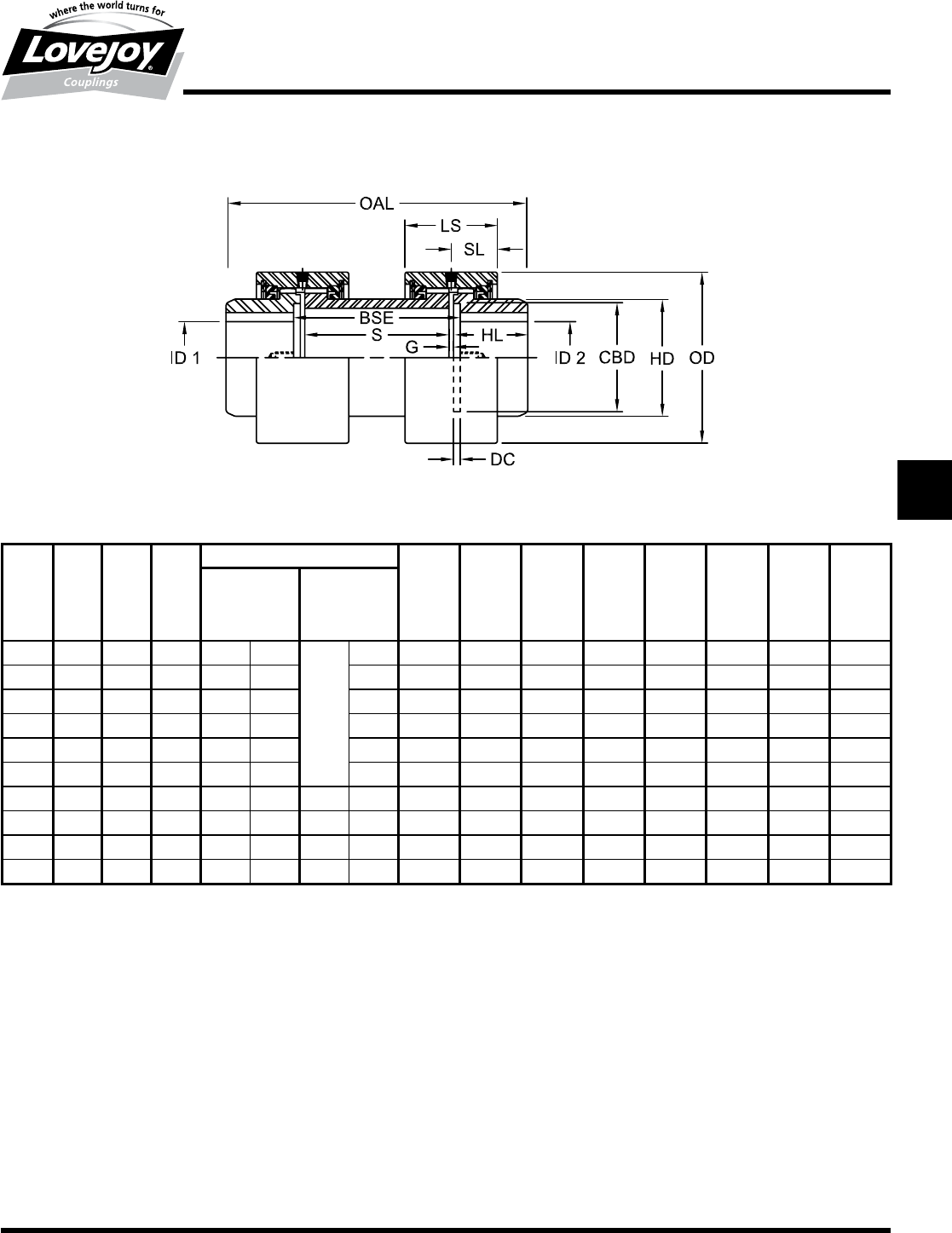
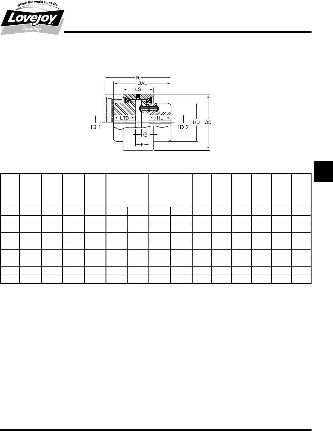
C and CFR Type Couplings
Ordering Information
■■Puller■Holes■are■standard■on■sizes■4■through■12.■
■■Puller■Holes■are■available■for■sizes■7/8■through■3.5■at■an■additional■charge.
■■The■BSE■(distance■Between■Shaft■Ends)■may■vary■between■G■and■G1.
■■Interference■bores■with■no■set■screws■are■standard■unless■otherwise■specified.
■■Inch■bores■and■keyway■tolerances■conform■to■ANSI■/■AGMA■9002-B04.■ ■ ■
■■For■metric■bores■and■keyway■tolerances,■consult■Lovejoy■Engineering■Section.
■■Larger■sizes■are■available,■please■consult■Lovejoy■Technical■Support.
!"#$%&'(ÿ)*+,)--#. /,0#123453677+89
3ÿ/:ÿ3
C and CFR Type Dimensional Data
R OAL LS SL ID1 - ID2 HL DC BSE OD HD CBD
Flex & Rigid Flex & Rigid G G1
Max Bore Rough Stock
Bore
Size in in in in in mm in mm in in in in in in in
7/8 3.75 3.13 2.00 1.00 1.25 31
Solid■with■Center
1.50 0.13 0.13 0.38 3.31 2.00 1.94
1.5 4.59 3.75 2.53 1.27 1.63 42 1.81 0.19 0.13 0.50 3.75 2.38 2.25
24.88 4.25 2.56 1.28 2.13 56 2.06 0.19 0.13 0.50 4.75 3.25 3.00
2.5 5.72 4.75 3.06 1.53 2.63 70 2.25 0.25 0.25 0.75 5.50 3.94 3.75
36.88 5.50 3.75 1.88 3.13 84 2.63 0.25 0.25 0.75 6.63 4.75 4.75
3.5 9.25 8.75 4.00 2.00 3.63 97 1.25 30 4.25 0.25 0.25 0.75 7.50 5.38 5.50
49.50 9.00 4.63 2.31 4.13 111 1.75 44 4.38 0.25 0.25 0.75 8.75 6.25 6.50
4.5 10.38 10.25 4.88 2.44 4.75 130 2.38 60 5.00 0.25 0.25 0.75 9.50 7.25 7.25
512.25 12.25 5.75 2.88 5.75 160 2.88 73 6.00 0.25 0.25 0.75 10.75 8.25 8.12
613.38 13.00 6.50 3.25 6.75 186 3.88 99 6.38 0.25 0.25 0.75 12.25 9.50 9.25
715.38 14.88 7.50 3.75 7.50 200 4.69 119 7.25 0.25 0.38 0.88 14.00 10.50 9.75
919.00 19.00 8.13 4.06 9.50 240 5.88 149 9.25 0.25 0.50 1.00 16.25 12.63 12.25
11 22.50 22.50 8.13 4.06 11.50 305 7.75 197 11.00 0.25 0.50 1.00 19.25 15.63 15.00
12 25.00 25.00 8.38 4.19 12.50 330 9.75 248 12.25 0.25 0.50 1.00 20.50 16.50 16.00
C Type Flex-Flex Coupling CFR Type Flex-Rigid Coupling
JWJISCJSFMCGHPGDDTSPUJVSDRSLDED
JW JIS CJ SF MC
G
HP GD D T SP UJ VSD R SLD ED
132 630-852-0500
G-18
Gear
CMM Type
Performance Data
Lovejoy / Sier-Bath Continuous Sleeve Gear Couplings
Ordering Information
■■Application:■Driver■and■Driven.
■■Type■and■size■of■coupling,■horizontal,■vertical■etc.
■■Power:■Motor■horspower■or■torque■requirement.
■■Speed:■Motor■RPM■or■Driven■RPM.
■■Distance■between■shaft■ends■(BSE).
■■Shaft■sizes.
■■Length■and■taper■per■foot■of■Mill■Motor■shaft.
■■Size■of■nut■to■be■used■on■Mill■Motor■(DC1■and■CBD1).
■■Specify■if■keyways■are■to■be■parallel■to■shaft■axis■or■tapered.
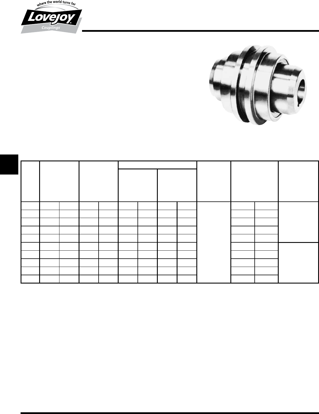
CMM Type Mill Motor Couplings
The■CMM■Type■coupling■consists■of■one■standard■flex■hub,■one
universal■hub,■one■standard■sleeve■and■one■accessary■kit■consisting■
of■seals■and■snap■rings.
Features
■■Specifically■designed■for■mill■motors■with■tapered■bores
■■Universal■hub■counterbored■for■the■nut■on■the■end■of■the■motor■
shaft
■■One■piece■cylindrical■sleeve■for■smoother,■faster,■quieter■and■and■
safer■operation
■■Quick■assembly■and■disassembly
CMM Type Performance Data
ID1 - ID2
Nominal Maximum Speed Max Bore Rough Weight Parallel Max Angular
Torque Unbal Bal Stock Bore Misalignment Misalignment
Degrees
Size in-lb Nm RPM RPM in mm in mm lbs kg in mm
7/8 2,500 300 6,000 18,000 1.25 31 0.44 11 7 3.2 0.005 .13
1.5 7,600 900 5,000 15,000 1.63 42 0.63 16 11 5.0 0.007 .18
220,200 2■300 4,200 12,600 2.13 56 0.73 19 19 8.6 0.007 .18 ■1/2°
2.5 30,200 3■400 3,750 11,250 2.63 70 0.88 22 29 13.0 0.007 .18
350,400 5■700 3,600 9,000 3.13 84 1.19 30 46 21.0 0.010 .25
3.5 88,200 10■000 2,800 8,400 3.63 97 1.25 32 77 35.0 0.012 .30
4126,000 14■200 2,400 7,200 4.13 111 1.75 44 109 49.0 0.012 .30
4.5 184,000 20■800 2,200 6,600 4.75 130 2.38 60 155 70.0 0.007 .18 ■1/4°
5270,000 30■600 2,100 6,300 5.75 160 2.88 73 220 100.0 0.007 .18
6378,000 42■700 2,000 6,000 6.75 186 3.88 99 315 143.0 0.009 .23
JWJISCJSFMC
G
HPGDDTSPUJVSDRSLDED
JW JIS CJ SF MC G HP GD D T SP UJ VSD R SLD ED
133
www.lovejoy-inc.com G-19
Gear
CMM Type
Dimensional Data
Ordering Information
■■HL1■Dimensions■are■the■maximum■lengths■of■Universal■hubs■kept■in■stock■and■altered■to■customer■specifications.■Longer■length■hubs■are■made■to■order.
■■Dimension■CBD1■as■shown■is■the■maximum■safe■counterbore.■Diameter■of■this■counterbore■is■to■customer■specifications.
■■Rough■bore■mill■motor■hubs■are■manufactured■to■HL1■length■with■straight■bores.
■■Puller■Holes■are■standard■on■sizes■4■through■12.
■■Puller■Holes■are■available■for■sizes■7/8■through■3.5■at■an■additional■charge.
■■Interference■bores■with■no■set■screws■are■standard■unless■otherwise■specified.
■■Inch■bores■and■keyway■tolerances■conform■to■ANSI■/■AGMA■9002-B04.
■■For■metric■bores■and■keyway,■consult■Lovejoy■Engineering■Section.
■■Larger■sizes■are■available,■please■consult■Lovejoy■Technical■Support.
Lovejoy / Sier-Bath Continuous Sleeve Gear Couplings
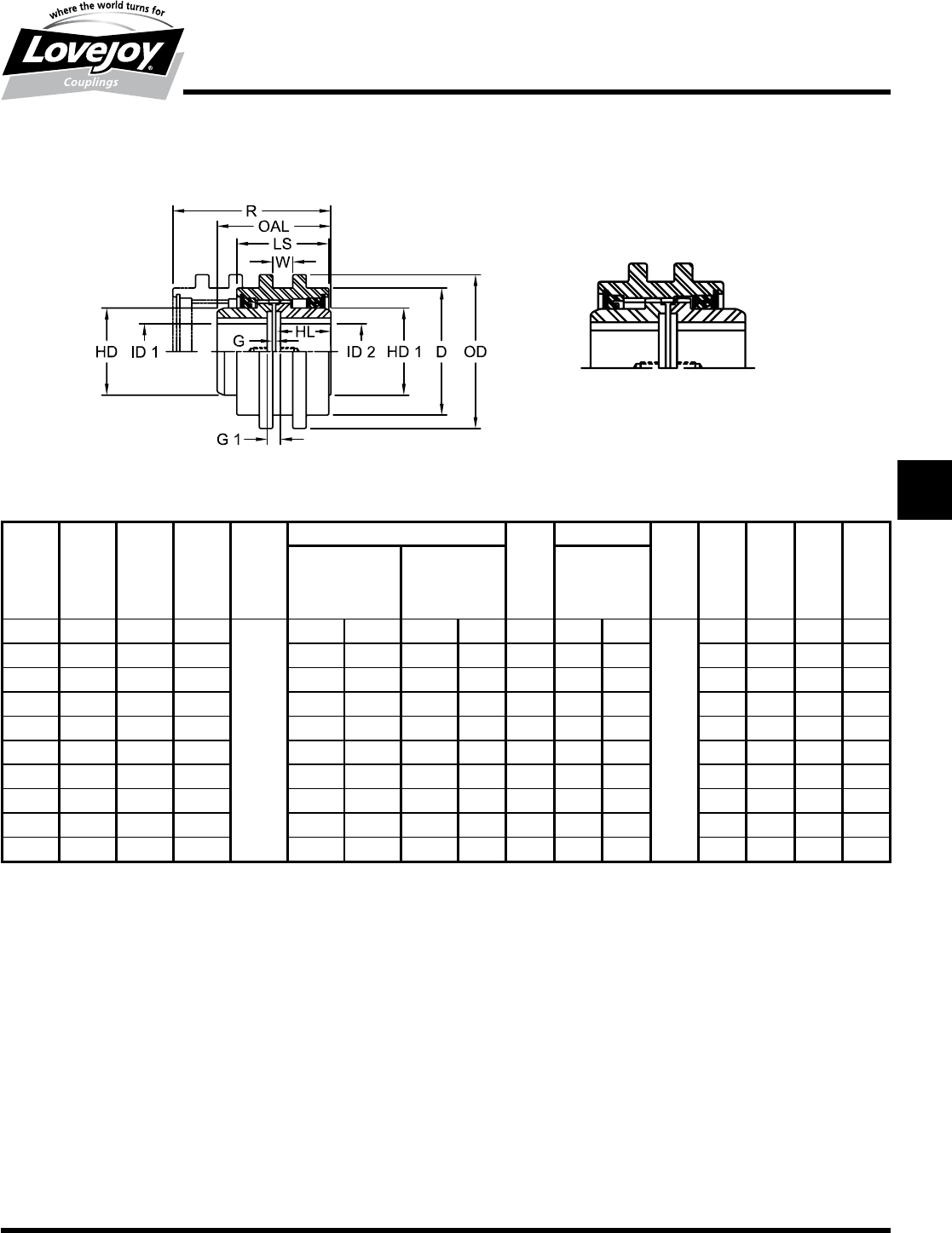
CMM Type Mill Motor Couplings
Standard Type Alternative Type
CMM Type Dimensional Data
OAL R LS SL ID1 - ID2 HL HL1 DC DC1 G OD HD CBD CBD 1
Max Bore Rough
Stock Bore
Size in in in in in mm in mm in in in in in in in in in
7/8
Determined■by■Length■of■Mill■Motor■Hub
3.75 2.00 1.00 1.25 31 0.44 11 1.50 3.75 0.13
Determined■by■Customer■Specifications
0.13 3.31 2.00 1.94 1.63
1.5 4.59 2.53 1.27 1.63 42 0.63 16 1.81 4.00 0.19 0.13 3.75 2.38 2.25 1.88
24.88 2.56 1.28 2.13 56 0.73 19 2.06 4.63 0.19 0.13 4.75 3.25 3.00 2.75
2.5 5.72 3.06 1.53 2.63 70 0.88 22 2.25 5.13 0.25 0.25 5.50 3.94 3.75 3.25
36.88 3.75 1.88 3.13 84 1.19 30 2.63 5.75 0.25 0.25 6.63 4.75 4.75 3.88
3.5 9.25 4.00 2.00 3.63 97 1.25 32 4.25 6.50 0.25 0.25 7.50 5.38 5.50 4.50
49.50 4.63 2.31 4.13 111 1.75 44 4.38 6.63 0.25 0.25 8.75 6.25 6.50 5.13
4.5 10.38 4.88 2.44 4.75 130 2.38 60 5.00 7.75 0.25 0.25 9.50 7.25 7.25 5.50
512.25 5.75 2.88 5.75 160 2.88 73 6.00 7.88 0.25 0.25 10.75 8.25 8.13 6.50
613.38 6.50 3.25 6.75 186 3.88 99 6.38 9.25 0.25 0.25 12.25 9.50 9.25 7.75
JWJISCJSFMCGHPGDDTSPUJVSDRSLDED
JW JIS CJ SF MC
G
HP GD D T SP UJ VSD R SLD ED
134 630-852-0500
G-20
Gear
CFS Type
Performance Data
Ordering Information
■■Application:■Driver■and■Driven.
■■Type■and■size■of■coupling,■horizontal,■vertical■etc.
■■Power:■Motor■horspower■or■torque■requirement.
■■Speed:■Motor■RPM■or■Driven■RPM.
■■Distance■between■shaft■ends■(BSE).
■■Shaft■sizes.
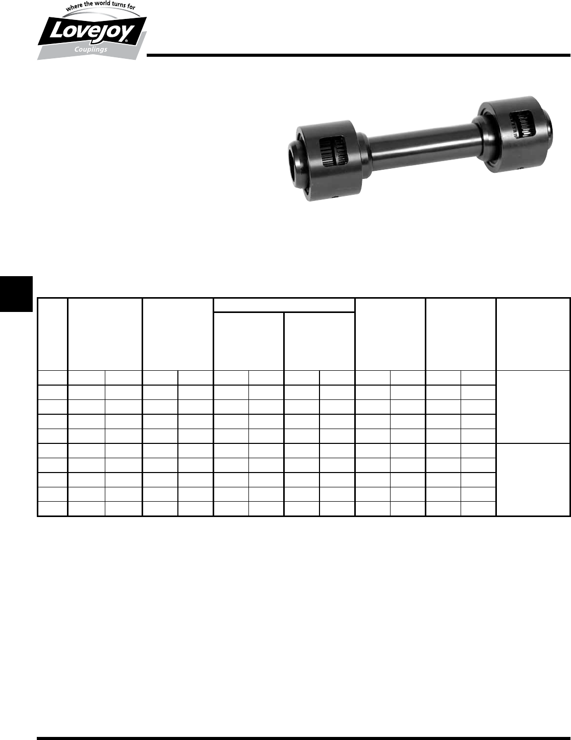
Lovejoy / Sier-Bath Continuous Sleeve Gear Couplings
CFS Type Floating Shaft Coupling
The■CFS■Type■coupling■consists■of■two■flex-rigid■(CFR)■couplings■
with■a■shaft■between■them.■Normally■the■driver■and■driven■ends■
are■rigid■while■the■two■center■hubs■connected■by■the■center■shaft■
are■flexible.■These■hubs■can■be■reversed■if■necessary■without■
sacrificing■ease■of■installation■or■disassembly.
CFS Type Performance Data
ID1 - ID2
Size
Nominal Maximum Flex & Rigid Flex & Rigid Weight Parallel Max Angular
Torque Speed Max Bore Rough Stock Coupling Misalignment Misalignment
Unbal Bal Bore Only Degrees
in-lb Nm RPM RPM in mm in mm lbs kg in mm
7/8 2,500 300 6,000 18,000 1.25 31 0.44 11 10 4.5 0.005 .13
1.5 7,600 900 5,000 15,000 1.63 42 0.63 16 16 7.3 0.007 .18
220,200 2■300 4,200 12,600 2.13 56 0.73 19 26 12.0 0.007 .18 ■1/2°
2.5 30,200 3■400 3,750 11,250 2.63 70 0.88 22 40 18.0 0.007 .18
350,400 5■700 3,600 9,000 3.13 84 1.19 30 66 30.0 0.010 .25
3.5 88,200 10■000 2,800 8,400 3.63 97 1.25 32 126 57.0 0.012 .30
4126,000 14■200 2,400 7,200 4.13 111 1.75 44 182 83.0 0.012 .30
4.5 184,000 20■800 2,200 6,600 4.75 130 2.38 60 252 114.0 0.007 .18 ■1/4°
5270,000 30■600 2,100 6,300 5.75 160 2.88 73 390 177.0 0.007 .18
6378,000 42■700 2,000 6,000 6.75 186 3.88 99 534 242.0 0.009 .23
JWJISCJSFMC
G
HPGDDTSPUJVSDRSLDED
JW JIS CJ SF MC G HP GD D T SP UJ VSD R SLD ED
135
www.lovejoy-inc.com G-21
Gear
CFS Type
Dimensional Data
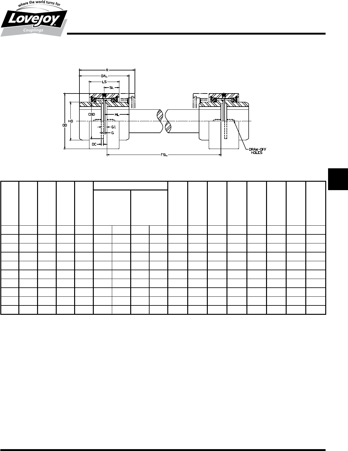
Lovejoy / Sier-Bath Continuous Sleeve Gear Couplings
CFS Type Floating Shaft Couplings
!"#$%&'(ÿ)*+,)--#. /,0#123453677+89
3ÿ/:ÿ3
CFS Type Dimensional Data
R OAL LS SL ID1 - ID2 HL DC BSE G G1 OD HD CBD
Flex & Rigid Flex & Rigid Min
Max Bore Rough Stock
Bore
Size in in in in in mm in mm in in in in in in in in
7/8 3.75 3.13 2.00 1.00 1.25 31 0.44 11 2.00 0.13 3.75 0.13 0.38 3.31 2.00 1.94
1.5 4.59 3.75 2.53 1.27 1.63 42 0.63 16 2.38 0.19 4.63 0.13 0.50 3.75 2.38 2.25
24.88 4.25 2.56 1.28 2.13 56 0.73 19 3.25 0.19 5.13 0.13 0.50 4.75 3.25 3.00
2.5 5.72 4.75 3.06 1.53 2.63 70 0.88 22 3.94 0.25 6.00 0.25 0.75 5.50 3.94 3.75
36.88 5.50 3.75 1.88 3.13 84 1.19 30 4.75 0.25 6.75 0.25 0.75 6.63 4.75 4.75
3.5 9.25 8.75 4.00 2.00 3.63 97 1.25 32 5.38 0.25 9.50 0.25 0.75 7.50 5.38 5.50
49.50 9.00 4.63 2.31 4.13 111 1.75 44 6.25 0.25 9.75 0.25 0.75 8.75 6.25 6.50
4.5 10.38 10.25 4.88 2.44 4.75 130 2.38 60 7.25 0.25 11.00 0.25 0.75 9.50 7.25 7.25
512.25 12.25 5.75 2.88 5.75 160 2.88 73 8.25 0.25 13.00 0.25 0.75 10.75 8.25 8.13
613.38 13.00 6.50 3.25 6.75 186 3.88 99 9.50 0.25 13.75 0.25 0.75 12.25 9.50 9.25
Notes:■■ n■■■FSL■Dimension■is■the■minimum■length■of■the■floating■shaft.
■n■■The■BSE■(distance■Between■Shaft■Ends)■vary■between■G■and■G1.
■n■■Puller■Holes■are■standard■on■sizes■4■through■6.
■n■■Puller■Holes■are■available■for■sizes■7/8■through■3.5■at■an■additional■charge.
■n■■Interference■bores■with■no■set■screws■are■standard■unless■otherwise■specified.
■n■■Inch■bores■and■keyway■tolerances■conform■to■ANSI■/■AGMA■9002-B04.
■n■■For■metric■bores■and■keyway■tolerances,■consult■Lovejoy■Engineering■Section.
■n■■Larger■sizes■are■available,■please■consult■Lovejoy■Technical■Support.
JWJISCJSFMCGHPGDDTSPUJVSDRSLDED
JW JIS CJ SF MC
G
HP GD D T SP UJ VSD R SLD ED
136 630-852-0500
G-22
Gear
CSPCR Type
Performance Data
Lovejoy / Sier-Bath Continuous Sleeve Gear Couplings
CSPCR Type Spacer Couplings
The■CSPCR■Type■coupling■consists■of■two■flex■hubs,■two■sleeves,■one■spacer,■
one■accessory■kit,■two■split■seals■and■two■lock■rings.
Features
■■Easy■removal■of■hubs■without■disturbing■the■mounting■of■connected■units
■■Spacer■teeth■are■rigid■with■a■slight■interference■fit■with■the■mating■flex■hub
■■Split■seals■on■the■spacer
CSPCR Type Performance Data
ID1 - ID2
Size
Nominal Maximum Max Bore Rough Stock Weight Parallel Max Angular
Torque Speed1Bore Couplings Misalignment Misalignment
Unbal Bal Only Degrees
in-lb Nm RPM RPM in mm in mm lbs kg in mm
7/8 2,500 300 6,000 18,000 1.25 31 0.44 11 7 3.2 0.005 .13
1.5 7,600 900 5,000 15,000 1.63 42 0.63 16 11 5.0 0.007 .18
220,200 2■300 4,200 12,600 2.13 56 0.73 19 16 7.3 0.007 .18 1/2°
2.5 30,200 3■400 3,750 11,250 2.63 70 0.88 22 26 12.0 0.007 .18 per■Mesh
350,400 5■700 3,600 9,000 3.13 84 1.19 30 43 20.0 0.010 .25
3.5 88,200 10■000 2,800 8,400 3.63 97 1.25 32 79 36.0 0.012 .30
4126,000 14■200 2,400 7,200 4.13 111 1.75 44 115 52.0 0.012 .30
4.5 184,000 20■800 2,200 6,600 4.75 130 2.38 60 158 72.0 0.007 .18 1/4°
5270,000 30■600 2,100 6,300 5.75 160 2.88 73 248 113.0 0.007 .18 per■mesh
6378,000 42■700 2,000 6,000 6.75 186 3.88 99 340 154.0 0.009 .23
Ordering Information
■■Application:■Driver■and■Driven.
■■Type■and■size■of■coupling,■horizontal,■vertical■etc.
■■Power:■Motor■horspower■or■torque■requirement.
■■Speed:■Motor■RPM■or■Driven■RPM.
■■Distance■between■shaft■ends■(BSE).
■■Shaft■sizes.
Note:■■ n■■■1■indicates:■Maximum■RPM■of■spacer■coupling■determined■by■critical■speed■of■spacer■shaft.
JWJISCJSFMC
G
HPGDDTSPUJVSDRSLDED
JW JIS CJ SF MC G HP GD D T SP UJ VSD R SLD ED
137
www.lovejoy-inc.com G-23
Gear
CSPCR Type
Dimensional Data
Lovejoy / Sier-Bath Continuous Sleeve Gear Couplings
CSPCR Type Spacer Couplings
CSPCR Type Dimensional Data
OAL LS SL ID1 - ID2 BSE S HL G DC OD HD CBD
Min Max Bore Rough Stock Min Min
Bore
Size in in in in mm in mm in in in in in in in in
7/8 6.76 2.00 1.00 1.25 31
All■
Solid
11 4.00 3.50 1.50 0.13 0.13 3.31 2.00 1.94
1.5 7.38 2.53 1.27 1.63 42 16 4.13 3.50 1.81 0.13 0.19 3.75 2.38 2.25
28.51 2.56 1.28 2.13 56 19 4.75 4.13 2.06 0.13 0.19 4.75 3.25 3.00
2.5 9.50 3.06 1.53 2.63 70 22 5.50 4.50 2.25 0.25 0.25 5.50 3.94 3.75
311.01 3.75 1.88 3.13 84 30 6.25 5.25 2.63 0.25 0.25 6.63 4.75 4.75
3.5 15.00 4.00 2.00 3.63 97 32 7.00 6.00 4.25 0.25 0.25 7.50 5.38 5.50
415.89 4.63 2.31 4.13 111 1.75 44 7.63 6.63 4.38 0.25 0.25 8.75 6.25 6.50
4.5 17.38 4.88 2.44 4.75 130 2.38 60 7.88 6.88 5.00 0.25 0.25 9.50 7.25 7.25
520.25 5.75 2.88 5.75 160 2.88 73 8.75 7.75 6.00 0.25 0.25 10.75 8.25 8.13
621.76 6.50 3.25 6.75 186 3.88 99 9.50 8.50 6.38 0.25 0.25 12.25 9.50 9.25
Notes:■■ n■■■Puller■Holes■are■standard■on■sizes■4■through■6.
■n■■Puller■Holes■are■available■for■sizes■7/8■through■3.5■at■an■additional■charge.
■n■■Interference■bores■with■no■set■screws■are■standard■unless■otherwise■specified.
■n■■Inch■bores■and■keyway■tolerances■conform■to■ANSI■/■AGMA■9002-B04.
■n■■For■metric■bores■and■keyway■tolerances,■consult■Lovejoy■Engineering■Section.
■n■■Larger■sizes■are■available,■please■consult■Lovejoy■Technical■Support.
JWJISCJSFMCGHPGDDTSPUJVSDRSLDED
JW JIS CJ SF MC
G
HP GD D T SP UJ VSD R SLD ED
138 630-852-0500
G-24
Gear
CCS Type
Performance Data
Lovejoy / Sier-Bath Continuous Sleeve Gear Couplings
CCS Type Cut-Out Shifter Couplings
The■CCS■Type■coupling■consists■of■two■flex■hubs,■one■special■sleeve■
without■lubrication■holes■and■one■accessory■kit■which■includes■a■special■
seal■for■the■hub■that■disengages■to■elliminate■undue■friction■when■the■
disengaged■hub■is■turning■in■the■sleeve.■Standard■hub■is■hand■packed■
with■grease.
Features
■■Permits■quick■disengagement■of■driver■and■driven■shafts■without■
disassembling■the■coupling
■■Widely■used■on■dual■drives■and■equipment■operated■in■tandem
■■Special■seal■for■disengaging■hub
■■Also■available■with■pins■to■maintain■sleeve■in■both■engaged■and■
disengaged■positions
CCS Type Performance Data
ID1 - ID2
Size
Nominal Maximum Speed Max Bore Rough Weight Parallel Max Angular
Torque Unbal Bal Stock Bore Misalignment Misalignment
Degrees
in-lb Nm RPM RPM in mm in mm lbs kg in mm
7/8 2,500 300 6,000 18,000 1.25 31 0.44 11 ■ ■ 0.005 .13
1.5 7,600 900 5,000 15,000 1.63 42 0.63 16 Weight■ 0.007 .18
220,200 2■300 4,200 12,600 2.13 56 0.73 19 Determined 0.007 .18 ■1/2°
2.5 30,200 3■400 3,750 11,250 2.63 70 0.88 22 by■ 0.007 .18
350,400 5■700 3,600 9,000 3.13 84 1.19 30 W■&■OD 0.010 .25
3.5 88,200 10■000 2,800 8,400 3.63 97 1.25 32 Dimensions 0.012 .30
4126,000 14■200 2,400 7,200 4.13 111 1.75 44 supplied 0.012 .30
4.5 184,000 20■800 2,200 6,600 4.75 130 2.38 60 by■ 0.007 .18 ■1/4°
5270,000 30■600 2,100 6,300 5.75 160 2.88 73 Customer 0.007 .18
6378,000 42■700 2,000 6,000 6.75 186 3.88 99 ■ ■ 0.009 .23
Ordering Information
■■Application:■Driver■and■Driven.
■■Type■and■size■of■coupling,■horizontal,■vertical■etc.
■■Power:■Motor■horspower■or■torque■requirement.
■■Speed:■Motor■RPM■or■Driven■RPM.
■■Distance■between■shaft■ends■(BSE).
■■Shaft■sizes.
■■Dimensions■of■Shifter■Groove■(width■and■outside■diameter).
■■Specify■which■hub■will■be■stationary■when■coupling■is■disengaged.
JWJISCJSFMC
G
HPGDDTSPUJVSDRSLDED
JW JIS CJ SF MC G HP GD D T SP UJ VSD R SLD ED
139
www.lovejoy-inc.com G-25
Gear
CCS Type
Dimensional Data
Lovejoy / Sier-Bath Continuous Sleeve Gear Couplings
CCS Type Cut-Out Shifter Couplings
CCS Type Dimensional Data
R OAL LS W ID1 - ID2 HL BSE OD D HD1 HD T1
Max Bore Rough G G1
Stock Bore
Size in in in in in mm in mm in in in in in in in in
7/8 4.31 3.13 2.56 1.25 31 0.44 11 1.50 0.13 0.38 ■ 3.31 1.985 2.00 0.38
1.5 5.38 3.75 3.31 Per 1.63 42 0.63 16 1.81 0.13 0.50 Per■ 3.75 2.365 2.38 0.63
25.75 4.25 3.44 Cust 2.13 56 0.73 19 2.06 0.13 0.50 Cust 4.75 3.235 3.25 0.56
2.5 6.41 4.75 3.88 Specs 2.63 70 0.88 22 2.25 0.25 0.75 Specs 5.50 3.925 3.94 0.69
37.69 5.50 4.63 3.13 84 1.19 30 2.63 0.25 0.75 ■ 6.63 4.735 4.75 0.75
3.5 9.63 8.75 4.88 3.63 97 1.25 32 4.25 0.25 0.75 ■ 7.50 5.365 5.38 0.81
410.69 9.00 5.81 4.13 111 1.75 44 4.38 0.25 0.75 ■ 8.75 6.235 6.25 1.00
4.5 11.44 10.25 5.94 4.75 130 2.38 60 5.00 0.25 0.75 ■ 9.50 7.235 7.25 1.00
514.00 12.25 7.50 5.75 160 2.88 73 6.00 0.25 0.75 ■ 10.75 8.235 8.25 1.50
615.44 13.00 8.56 6.75 186 3.88 99 6.38 0.25 0.75 ■ 12.25 9.485 9.50 1.88
Notes:■■ n■■1■indicates:■T■is■the■length■of■travel■to■disengage■sleeve.
■n■■The■BSE■(distance■Between■Shaft■Ends)■vary■between■G■and■G1.
n■■Puller■Holes■are■standard■on■sizes■4■through■6.
n■■Puller■Holes■are■available■for■sizes■7/8■through■3.5■at■an■additional■charge.
n■■Interference■bores■with■no■set■screws■are■standard■unless■otherwise■specified.
n■■Inch■bores■and■keyway■tolerances■conform■to■ANSI■/■AGMA■9002-B04.
n■■For■metric■bores■and■keyway■tolerances,■consult■Lovejoy■Engineering■Section.
n■■Larger■sizes■are■available,■please■consult■Lovejoy■Technical■Support.
Disengaged Position
JWJISCJSFMCGHPGDDTSPUJVSDRSLDED
JW JIS CJ SF MC
G
HP GD D T SP UJ VSD R SLD ED
140 630-852-0500
G-26
Gear
CSHP Type
Performance Data
Lovejoy / Sier-Bath Continuous Sleeve Gear Couplings
CSHP Type Shear Pin Couplings
The■CSHP■Type■coupling■consists■of■one■standard■flex■hub,■two■
piece■shear■hub■and■one■set■of■shear■pins,■one■standard■sleeve■
and■accessory■kit.
Features
■■Designed■to■prevent■damage■to■connected■equipment
■■Manufactured■to■shear■at■predetermined■loads■
■■New■Pins■can■be■quickly■inserted
CSHP Type Performance Data
ID1 - ID2
Size
Nominal Maximum Flex or Rigid Shear Hub Weight Parallel Max Angular
Torque Speed Max Bore Max Bore Misalignment Misalignment
Unbal Bal Degrees
in-lb Nm RPM RPM in mm in mm lbs kg in mm
1.5 7,600 900 5,000 15,000 1.63 42 0.938 24 8 4 0.007 .18
220,200 2■300 4,200 12,600 2.13 56 1.500 38 10 5 0.007 .18 ■1/2°
2.5 30,200 3■400 3,750 11,250 2.63 70 1.750 44 15 7 0.007 .18
350,400 5■700 3,600 9,000 3.13 84 2.250 57 23 10 0.010 .25
3.5 88,200 10■000 2,800 8,400 3.63 97 2.625 66 47 21 0.012 .30
4126,000 14■200 2,400 7,200 4.13 111 3.625 92 90 41 0.012 .30
4.5 184,000 20■800 2,200 6,600 4.75 130 4.125 104 112 51 0.007 .18 ■1/4°
5270,000 30■600 2,100 6,300 5.75 160 4.500 114 177 80 0.007 .18
6378,000 42■700 2,000 6,000 6.75 186 5.875 149 250 114 0.009 .23
Ordering Information
■■Application:■Driver■and■Driven.
■■Type■and■size■of■coupling,■horizontal,■vertical■etc.
■■Power:■Motor■horspower■or■torque■requirement.
■■Speed:■Motor■RPM■or■Driven■RPM.
■■Distance■between■shaft■ends■(BSE).
■■Shaft■sizes.
■■Specify■which■is■the■Shear■Pin■hub.
■■Specify■the■required■shear■torque.
JWJISCJSFMC
G
HPGDDTSPUJVSDRSLDED
JW JIS CJ SF MC G HP GD D T SP UJ VSD R SLD ED
141
www.lovejoy-inc.com G-27
Gear
CSHP Type
Dimensional Data
Lovejoy / Sier-Bath Continuous Sleeve Gear Couplings
CSHP Type Spacer Couplings
CSHP Type Dimensional Data
R OAL LS SL ID1 ID2 LTB HL G F OD HD
Flex or Rigid Shear Hub
Max Bore Max Bore
Size in in in in in m in mm in in in in in in
1.5 5.28 4.38 2.53 1.27 1.63 42 0.938 24 1.63 2.25 0.50 1.13 3.75 2.38
25.56 4.88 2.56 1.28 2.13 56 1.500 38 1.88 2.50 0.50 1.13 4.75 3.25
2.5 6.50 5.44 3.06 1.53 2.63 70 1.750 44 2.00 2.69 0.75 1.50 5.50 3.94
37.75 6.38 3.75 1.88 3.13 84 2.250 57 2.38 3.25 0.75 1.63 6.63 4.75
3.5 8.13 8.13 4.00 2.00 3.63 97 2.625 66 4.00 3.38 0.75 1.75 7.50 5.38
49.50 9.00 4.63 2.31 4.13 111 3.625 92 4.13 4.13 0.75 2.00 8.75 6.25
4.5 9.88 9.75 4.88 2.44 4.75 130 4.125 104 4.75 4.25 0.75 2.00 9.50 7.25
511.50 11.50 5.75 2.88 5.75 160 4.500 114 5.75 5.00 0.75 2.25 10.75 8.25
613.13 13.00 6.50 3.25 6.75 186 5.875 149 6.13 6.13 0.75 2.88 12.25 9.50
Notes:■■ n■■Puller■Holes■are■standard■on■sizes■4■through■6.
■n■■Puller■Holes■are■available■for■sizes■1.5■through■3.5■at■an■additional■charge.
n■■Interference■bores■with■no■set■screws■are■standard■unless■otherwise■specified.
n■■Inch■bores■and■keyway■tolerances■conform■to■ANSI■/■AGMA■9002-B04.
n■■For■metric■bores■and■keyway■tolerances,■consult■Lovejoy■Engineering■Section.
n■■Larger■sizes■are■available,■please■consult■Lovejoy■Technical■Support.
JWJISCJSFMCGHPGDDTSPUJVSDRSLDED
JW JIS CJ SF MC
G
HP GD D T SP UJ VSD R SLD ED
142 630-852-0500
G-28
Gear
Nyflex® and Mite® Type
Performance Data
Lovejoy / Sier-Bath Nylon Sleeve Gear Couplings
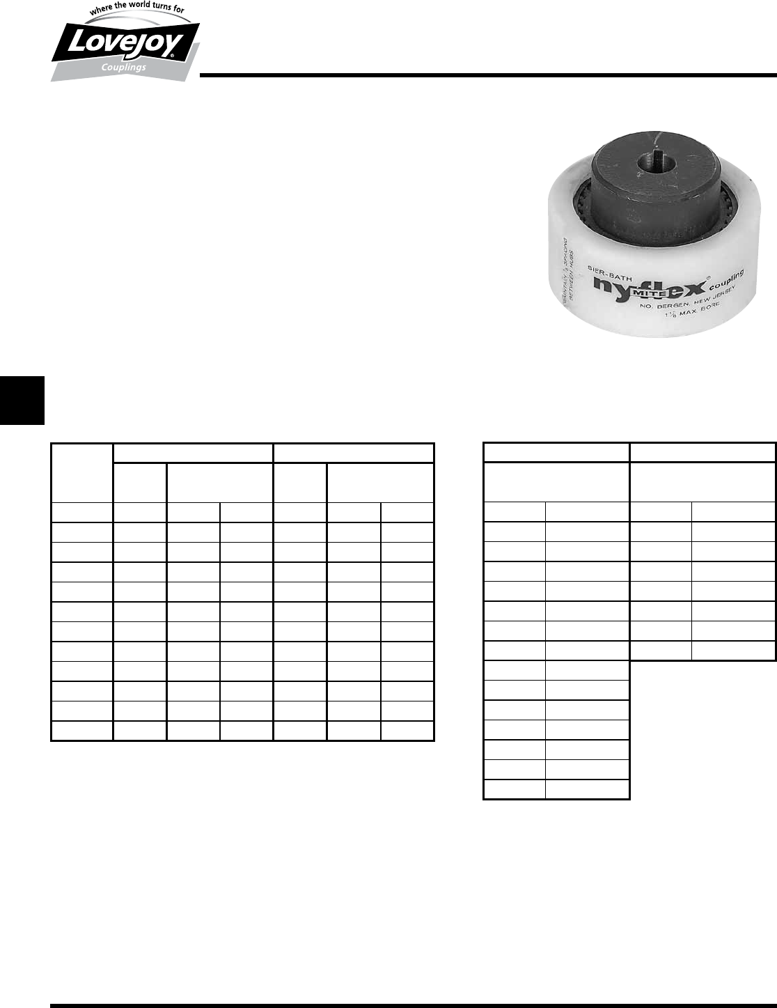
Nyflex® and Mite® Type Couplings
The■Nyflex■and■Mite■coupling■consists■of■two■sintered■iron■flex■hubs,■one■Nylon■sleeve■and■two■
Spiirolox■rings.
Features
■■No■lubrication■required■elliminating■the■need■for■seals
■■Sintered■Iron■hubs■with■crowned■teeth■to■provider■greater■misalignment■and■gouging■of■nylon■
sleeve
■■Resilient,■lightweight,■abrasion■and■corrosion■resistant■nylon■sleeve■accurately■molded■to■mesh■
with■hubs■elliminating■friction■and■need■of■lubrication
■■Center■groove■in■sleeves■readily■permits■their■use■in■vertical■applications■and■for■blind■assembly
■■Securely■held■hubs■and■sleeves■by■spring-steel■retaing■rings■yet■capable■of■easy■removal■and■still■
withstand■a■5,000■lbs■end■thrust
■■Minimum■backlash■operating■in■an■ambient■temperture■environment■of■-40■to■150°■F
Nyflex and Mite Type Performance Data
Nyflex Mite
Speed Torque Torque
RPM HP in-lb Nm HP in Nm
100 2.25 1,420 164 0.60 360 40.7
500 9.50 1,190 135 2.40 307 34.7
1,000 18.00 1,125 127 4.50 285 32.2
1,150 20.30 1,110 125 5.10 282 31.9
1,500 24.00 970 110 6.40 274 30.9
1,750 25.00 900 102 7.50 270 30.5
2,000 26.60 840 95 8.40 267 30.2
2,500 29.80 750 85 11.10 262 29.6
3,000 32.50 680 77 12.10 256 28.9
3,500 35.30 630 76 13.80 254 28.7
4,000 37.50 590 67 17.60 251 28.3
5,000 42.00 530 60 19.40 243 27.4
Nyflex Mite
Bore Keyway Bore Keyway
in in in in
0.375* No■Keyway 0.312** No■Keyway
0.500 1/8■x■1/16 0.500 1/8■x■1/16
0.625 3/16■x■3/32 0.625 3/16■x■3/32
0.750 3/16■x■3/32 0.750 3/16■x■3/32
0.875 3/16■x■3/32 0.875 3/16■x■3/32
0.937 1/4■x■1/8 0.937 1/4■x■1/8
1.000 1/4■x■1/8 1.000 1/4■x■1/8
1.125 1/4■x■1/8 1.125 1/4■x■1/8
1.187 1/4■x■1/8 ■ ■
1.250 1/4■x■1/8 ■ ■
1.312 5/16■x■5/32
1.375 5/16■x■5/32
1.437 3/8■x■3/16
1.500 3/8■x■3/16
1.625 3/8■x■3/16
Ordering Information
■■Application:■Driver■and■Driven.
■■Type■and■size■of■coupling,■horizontal,■vertical■etc.
■■Power:■Motor■horspower■or■torque■requirement.
■■Speed:■Motor■RPM■or■Driven■RPM.
Notes:■■ n■■■Angular■Misalignment:■Nyflex■5°;■Mite■3°.
■n■■■Clearence■fit■bores■standard■through■1.250■inch■bores.
■n■■■Interference■fit■bores■standard■over■1.250■inch■bores.
Notes:■■ n■■■*■indicates:■Rough■Stock■Bore■.375■–■.390■inches.
■n■■■**■indicates:■Rough■Stock■Bore■.312■–■.327■inches.
JWJISCJSFMC
G
HPGDDTSPUJVSDRSLDED
JW JIS CJ SF MC G HP GD D T SP UJ VSD R SLD ED
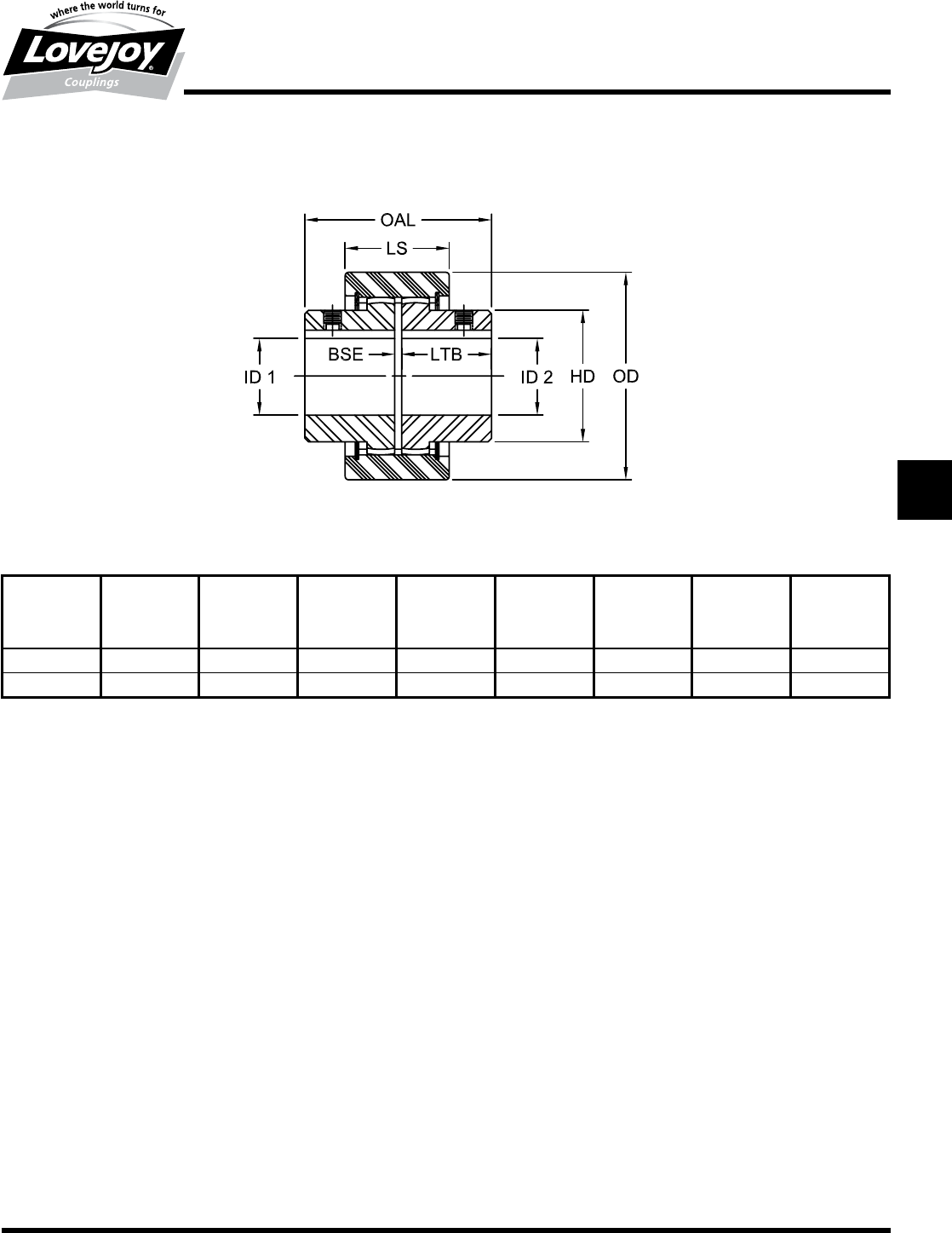
143
www.lovejoy-inc.com G-29
Gear
Nyflex® and Mite® Type
Dimensional Data
Lovejoy / Sier-Bath Nylon Sleeve Gear Couplings
Nyflex® and Mite® Type Couplings
Nyflex and Mite Type Dimensional Data
ID1 - ID2 OAL LS LTB BSE OD HD
Max Bore Weight
Size in in in in in in in lbs
Nyflex 1.625 3.38 1.88 1.63 0.13 3.75 2.38 3.50
Mite 1.125 2.38 1.31 1.13 0.13 2.88 1.75 1.00
Notes:■■ n■■■Clearence■fit■bores■with■set■screw■over■keyway■is■standard■through■1.250■inch■bores.
■n■■■Interference■fit■bores■with■no■set■screw■is■standard■for■bores■over■1.250■inch.
■n■■Bore■and■keyway■tolerances■conform■to■ANSI■/■AGMA■9002-B04.
JWJISCJSFMCGHPGDDTSPUJVSDRSLDED
JW JIS CJ SF MC
G
HP GD D T SP UJ VSD R SLD ED
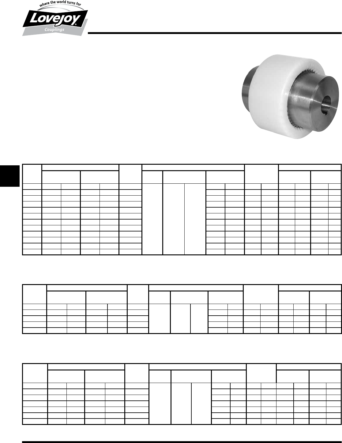
144 630-852-0500
G-30
Gear
Dentex® (Nylon Sleeve Series)
Performance Data
Dentex® Nylon Sleeve Series Flexible Couplings
The■series■is■a■standard■coupling■with■two■hubs,■a■nylon■sleeve,■and■retaining■rings■depending■on■the■model■
selected.■The■coupling■has■a■precision■molded■nylon■sleeve■and■powder■metal■hub■with■no■bolts,■pins,■
flanges,■or■protrusions■that■could■have■an■effect■on■balance■or■operational■safety.■Since■no■lubrication■is■
used,■the■couplings■can■readily■be■adapted■to■many■applications■including■vertical■and■blind■installations.
Features
■■Compact■in■size
■■Maintenance■Free■–■No■Lubrication■required
■■Can■accommodate■axial,■angular,■and■parallel■misalignment
■■Easy■to■assemble
■■Electrically■insulating
■■Can■be■used■in■temperature■ranges■from■-25°■to■80°■C■(optional■140°■C)
■■Nylon■sleeve■has■high■resistance■to■condensation■and■water,■hydrocarbon■based■petroleums,■and■alcohols
■■Not■ideal■for■use■with■acids,■benzyl■based■products,■cresol,■or■glycols
Dentex® B - Series Performance Data
Torque Capacity Max Misalignment Weight1ID1 - ID22
Nominal Maximum Speed Angular Axial Parallel Min Bore Max Bore
Size in-lbs Nm in-lbs Nm RPM Degrees in mm in mm kg lbs in mm in mm
B 14 89 10 177 20 8,000
1°■
Per■
Hub
+/-.039 +/-1
0.012 0.3 0.2 0.4 0.25 6 0.56 14
B 19 142 16 283 32 8,000 0.012 0.3 0.3 0.7 0.38 9 0.75 19
B 24 177 20 354 40 8,000 0.016 0.4 0.3 0.7 0.44 10 0.94 24
B 28 398 45 797 90 8,000 0.016 0.4 0.7 1.6 0.44 10 1.13 28
B 32 531 60 1,062 120 7,000 0.016 0.4 1.0 2.1 0.50 12 1.25 32
B 38 708 80 1,416 160 6,000 0.016 0.4 1.2 2.7 0.56 14 1.38 38
B 42 885 100 1,770 200 5,400 0.016 0.4 1.5 3.3 0.81 20 1.56 42
B 48 1,239 140 2,478 280 5,000 0.016 0.4 1.8 4.0 0.81 20 1.75 48
B 55 2,213 250 4,425 500 4,000 0.016 0.4 3.5 7.6 1.00 25 2.06 55
B 65 3,452 390 6,903 780 3,800 0.024 0.6 5.2 11.4 1.25 32 2.38 65
B 80 6,195 700 12,390 1■400 3,000 0.028 0.7 11.5 25.3 1.19 30 3.00 80
B 100 11,063 1■250 22,125 2■500 2,400 0.031 0.8 20.5 45.2 1.62 40 3.75 100
Notes:■■ n■■■1■indicates:■Weight■is■calculated■using■maximum■bore■and■no■keyway.■
■n■■■2■indicates:■Minimum■and■maximum■bore■sizes■are■given■for■straight■bores.■For■Taper■bores■and■splines,■contact■Lovejoy■Technical■Support.
Notes:■■ n■■■1■indicates:■Weight■is■calculated■using■maximum■bore■and■no■keyway.■
■n■■■2■indicates:■Minimum■and■maximum■bore■sizes■are■given■for■straight■bores.■For■Taper■bores■and■splines,■contact■Lovejoy■Technical■Support.
Notes:■■ n■■■1■indicates:■Weight■is■calculated■using■maximum■bore■and■no■keyway.■
■n■■■2■indicates:■Minimum■and■maximum■bore■sizes■are■given■for■straight■bores.■For■Taper■bores■and■splines,■contact■Lovejoy■Technical■Support.
Dentex® B4R - Series Performance Data
Torque Capacity Max Misalignment Weight 1 ID1 - ID2 2
Nominal Maximum Speed Angular Axial Parallel Min Bore Max Bore
Size in-lbs Nm in-lbs Nm RPM Degrees in mm in mm kg lbs in mm in mm
B4R 32 708 80 1,416 160 7,000
1°■
Per■
Hub
+/-.039 +/-1
0.016 0.4 1.1 2.4 0.50 12 1.25 32
B4R 45 1,239 140 2,478 280 5,000 0.016 0.4 1.5 3.3 0.81 20 1.56 42
B4R 65 3,452 390 6,903 780 3,800 0.024 0.6 5.4 11.9 1.00 25 2.38 65
B4R 80 6,195 700 12,390 1■400 3,000 0.028 0.7 11.7 25.8 1.19 30 3.00 80
B4R 100 11,063 1■250 22,125 2■400 2,400 0.031 0.8 20.8 45.9 1.62 40 3.75 100
Dentex® B3R - Series Performance Data
Torque Capacity Max Misalignment Weight 1 ID1 - ID2 2
Nominal Maximum Speed Angular Axial Parallel Min Bore Max Bore
Size in-lbs Nm in-lbs Nm RPM Degrees in mm in mm kg lbs in mm in mm
B3R 24 177 20 354 40 10,200
1°■
Per■
Hub
+/-.039 +/-1
0.016 0.4 0.3 0.7 0.44 10 0.94 24
B3R 28 398 45 797 90 8,300 0.016 0.4 0.8 1.8 0.44 10 1.13 28
B3R 32 708 80 1,416 160 7,000 0.016 0.4 1.1 2.4 0.50 12 1.25 32
B3R 45 1,239 140 2,478 280 5,000 0.016 0.4 1.5 3.3 0.81 20 1.56 42
B3R 65 3,452 390 6,903 780 3,800 0.024 0.6 5.4 11.9 1.25 32 2.38 65
B3R 80 6,195 700 12,390 1■400 3,000 0.028 0.7 11.6 25.6 1.19 30 3.00 80
B3R 100 11,063 1■250 22,125 2■400 2,400 0.031 0.8 20.7 45.6 1.62 40 3.75 100
JWJISCJSFMC
G
HPGDDTSPUJVSDRSLDED
JW JIS CJ SF MC G HP GD D T SP UJ VSD R SLD ED
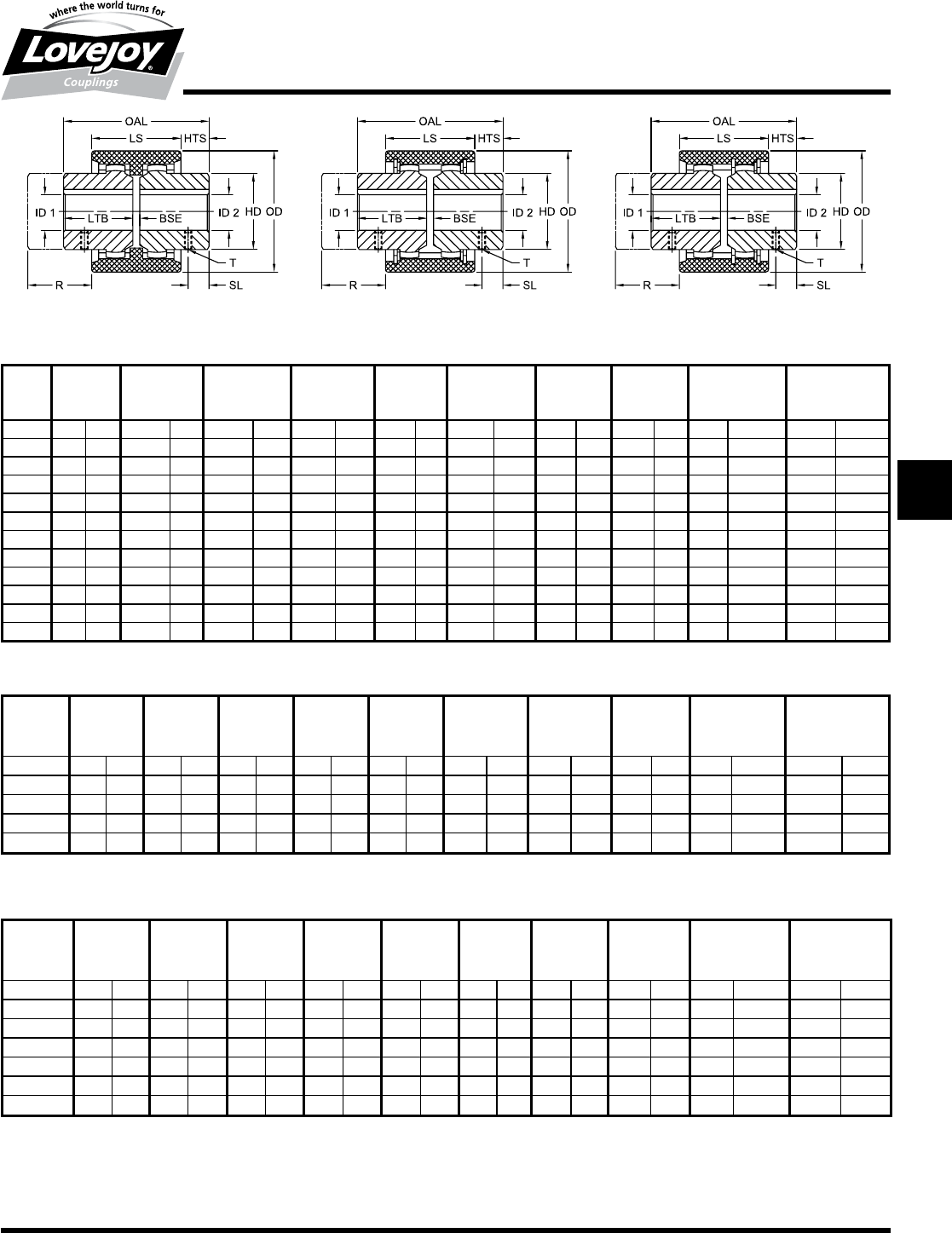
145
www.lovejoy-inc.com G-31
Gear
Dentex® (Nylon Sleeve Series)
Dimensional Data
Dentex® B - Series Dimensional Data
OAL LS HTS LTB BSE OD HD R T - Metric T - Inch
(Clearance) Set Screw Set Screw
Size in mm in mm in mm in mm in mm in mm in mm in mm Size SL (mm) Size SL (in)
B 14 1.97 50 1.46 37 0.26 6.5 0.91 23 0.16 4 1.57 40 0.98 25 0.65 16.5 M5 6 10-24 0.24
B 19 2.13 54 1.46 37 0.28 7.0 0.98 25 0.16 4 1.89 48 1.26 32 0.71 18.0 M5 6 10-24 0.24
B 24 2.20 56 1.61 41 0.30 7.5 1.02 26 0.16 4 2.05 52 1.42 36 0.73 18.5 M5 6 10-24 0.24
B 28 3.31 84 1.81 46 0.75 19.0 1.57 40 0.16 4 2.60 66 1.73 44 0.83 21.0 M8 10 5/16-18 0.39
B 32 3.31 84 1.89 48 0.71 18.0 1.57 40 0.16 4 2.99 76 1.97 50 0.87 22.0 M8 10 5/16-18 0.39
B 38 3.31 84 1.89 48 0.71 18.0 1.57 40 0.16 4 3.27 83 2.28 58 0.87 22.0 M8 10 5/16-18 0.39
B 42 3.46 88 1.97 50 0.75 19.0 1.65 42 0.16 4 3.62 92 2.56 65 0.91 23.0 M8 10 5/16-18 0.39
B 48 4.09 104 1.97 50 1.06 27.0 1.97 50 0.16 4 3.94 100 2.68 68 0.91 23.0 M8 10 5/16-18 0.39
B 55 4.88 124 2.56 65 1.16 29.5 2.36 60 0.16 4 4.92 125 3.27 83 1.20 30.5 M10 20 3/8-16 0.79
B 65 5.67 144 2.83 72 1.42 36.0 2.76 70 0.16 4 5.51 140 3.78 96 1.34 34.0 M10 20 3/8-16 0.79
B 80 7.32 186 3.66 93 1.83 46.5 3.54 90 0.24 6 6.89 175 4.88 124 1.71 43.5 M10 20 3/8-16 0.79
B 100 8.98 228 4.02 102 2.48 63.0 4.33 110 0.31 8 8.27 210 5.98 152 1.85 47.0 M12 30 3/8-16 1.18
Dentex® B4R - Series Dimensional Data
OAL LS HTS LTB BSE OD HD R T - Metric T - Inch
(Clearance) Set Screw Set Screw
Size in mm in mm in mm in mm in mm in mm in mm in mm Size SL (mm) Size SL (in)
B4R 32 3.31 84 2.28 58 0.51 13.0 1.57 40 0.16 4 3.31 84 1.97 50 1.06 27.0 M8 10 5/16-18 0.39
B4R 45 3.46 88 2.36 60 0.55 14.0 1.65 42 0.16 4 3.94 100 2.56 65 1.10 28.0 M8 10 5/16-18 0.39
B4R 65 5.67 144 3.31 84 1.18 30.0 2.76 70 0.16 4 5.51 140 3.78 96 1.57 40.0 M10 20 3/8-16 0.79
B4R 80 7.32 186 3.66 93 1.83 46.5 3.54 90 0.24 6 6.89 175 4.88 124 1.71 43.5 M10 20 3/8-16 0.79
B4R 100 8.98 228 4.02 102 2.48 63.0 4.33 110 0.31 8 8.27 210 5.98 152 1.85 47.0 M12 30 3/8-16 0.79
Dentex® B3R - Series Dimensional Data
OAL LS HTS LTB BSE OD HD R T - Metric T - Inch
(Clearance) Set Screw Set Screw
Size in mm in mm in mm in mm in mm in mm in mm in mm Size SL (mm) Size SL (in)
B3R 24 2.20 56 2.01 51 0.10 2.5 1.02 26 0.16 4 2.28 58 1.42 36 0.93 23.5 M5 6 10-24 0.24
B3R 28 3.31 84 2.20 56 0.55 14.0 1.57 40 0.16 4 2.76 70 1.73 44 1.02 26.0 M8 10 3/8-16 0.39
B3R 32 3.31 84 2.28 58 0.51 13.0 1.57 40 0.16 4 3.31 84 1.97 50 1.06 27.0 M8 10 3/8-16 0.39
B3R 45 3.46 88 2.36 60 0.55 14.0 1.65 42 0.16 4 3.94 100 2.56 65 1.10 28.0 M8 10 3/8-16 0.39
B3R 65 5.67 144 3.31 84 1.18 30.0 2.76 70 0.16 4 5.51 140 3.78 96 1.57 40.0 M10 20 3/8-16 0.39
B3R 80 7.32 186 3.66 93 1.83 46.5 3.54 90 0.24 6 6.89 175 4.88 124 1.71 43.5 M10 20 3/8-16 0.39
B3R 100 8.98 228 4.02 102 2.48 63.0 4.33 110 0.31 8 8.27 210 5.98 152 1.85 47.0 M12 30 3/8-16 0.39
B B4R B3R
Notes:■■ n■■■Inch■bore■and■keyway■tolerances■conform■to■ANSI■/■AGMA■9002-B04.
■n■■■Metric■bores■and■keyway■tolerances■conform■to■ISO■286■and■ANSI■/■AGMA■9112-A04.
JWJISCJSFMCGHPGDDTSPUJVSDRSLDED
JW JIS CJ SF MC
G
HP GD D T SP UJ VSD R SLD ED
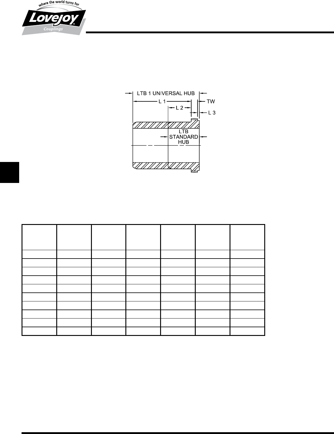
146 630-852-0500
G-32
Gear
C Universal Hub
Dimensional Data
Lovejoy / Sier-Bath Continuous Sleeve Gear Couplings
C Type Universal Hub
C Standard and Universal Hub Dimensions
L1 L2 L3 TW LTB LTB1
STD HUB UNIV HUB
Size in in in in in in
7/8 3.38 1.13 0.13 0.25 1.50 3.75
1.5 3.36 1.17 0.13 0.52 1.81 4.00
24.06 1.50 0.13 0.44 2.06 4.63
2.5 4.39 1.52 0.16 0.58 2.25 5.13
34.89 1.77 0.25 0.61 2.63 5.75
3.5 5.58 3.33 0.25 0.67 4.25 6.50
45.52 3.27 0.25 0.86 4.38 6.63
4.5 6.64 3.89 0.25 0.86 5.00 7.75
56.39 4.52 0.25 1.23 6.00 7.88
67.64 4.52 0.25 1.61 6.38 9.50
JWJISCJSFMC
G
HPGDDTSPUJVSDRSLDED
JW JIS CJ SF MC G HP GD D T SP UJ VSD R SLD ED
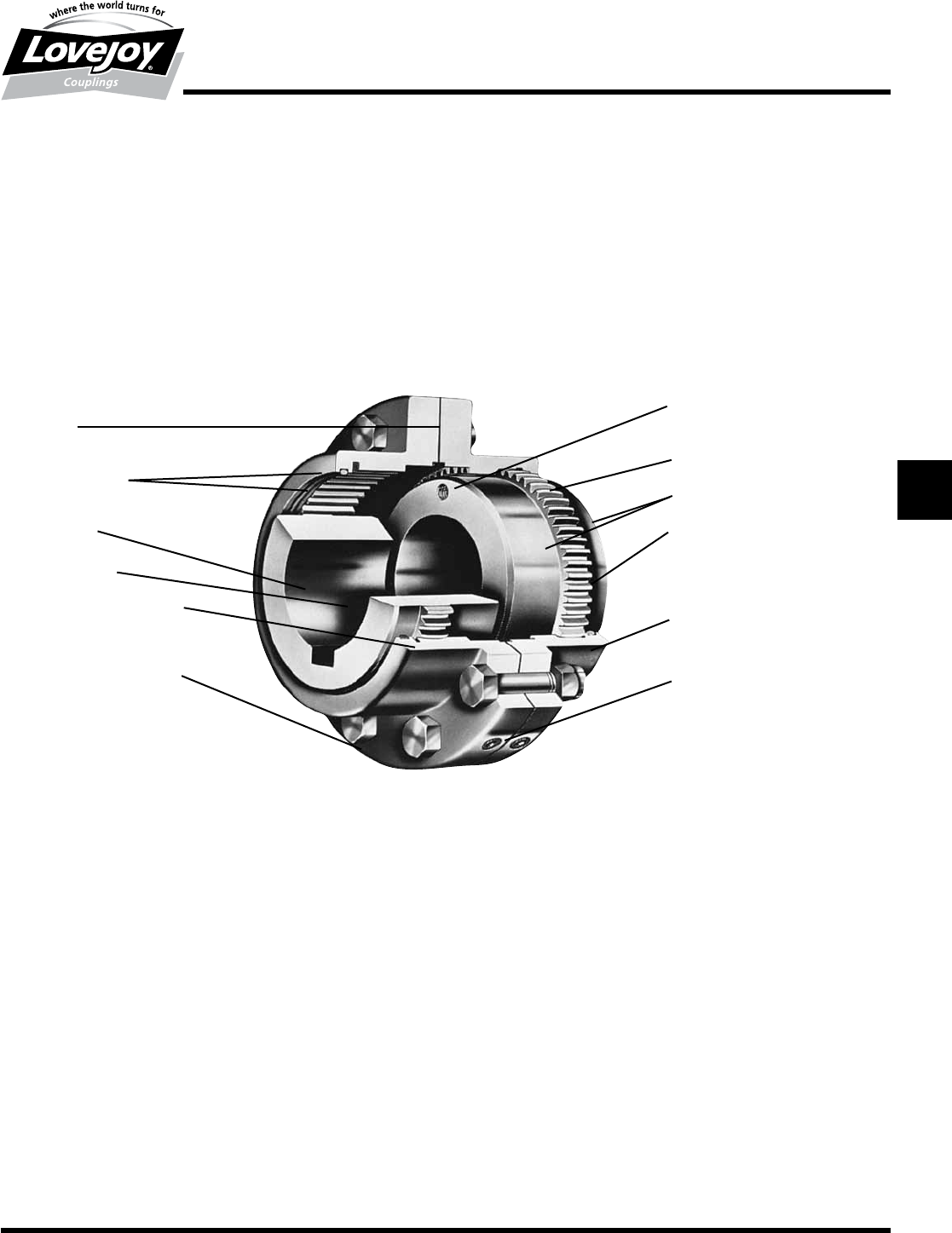
147
www.lovejoy-inc.com G-33
Gear
Flanged Sleeve
Cut Away
Lovejoy / Sier-Bath Flanged Sleeve Gear Couplings
Gasket
Med.■Carbon■Steel■
Hubs■&■Sleeves
Larger■Bore
Capacity
Interference■Fit
One■Piece■Sleeve
Flanges■Available■in■
Both■Shrouded■and■Exposed■
Bolt■Design
Draw-off■Holes■(Optional)
Vari-Crown®■Hub■Teeth■
Both■Hub■Diameters■are■Identical
“O”■Ring■Seals
Major■Diameter■Fit
Heat-Treated■Bolts■
for■High■Strength■Coated■for■
Corrosion■Resistance
Two■Lubrication■Plugs■
in■Each■Half■Sleeve
JWJISCJSFMCGHPGDDTSPUJVSDRSLDED
JW JIS CJ SF MC
G
HP GD D T SP UJ VSD R SLD ED
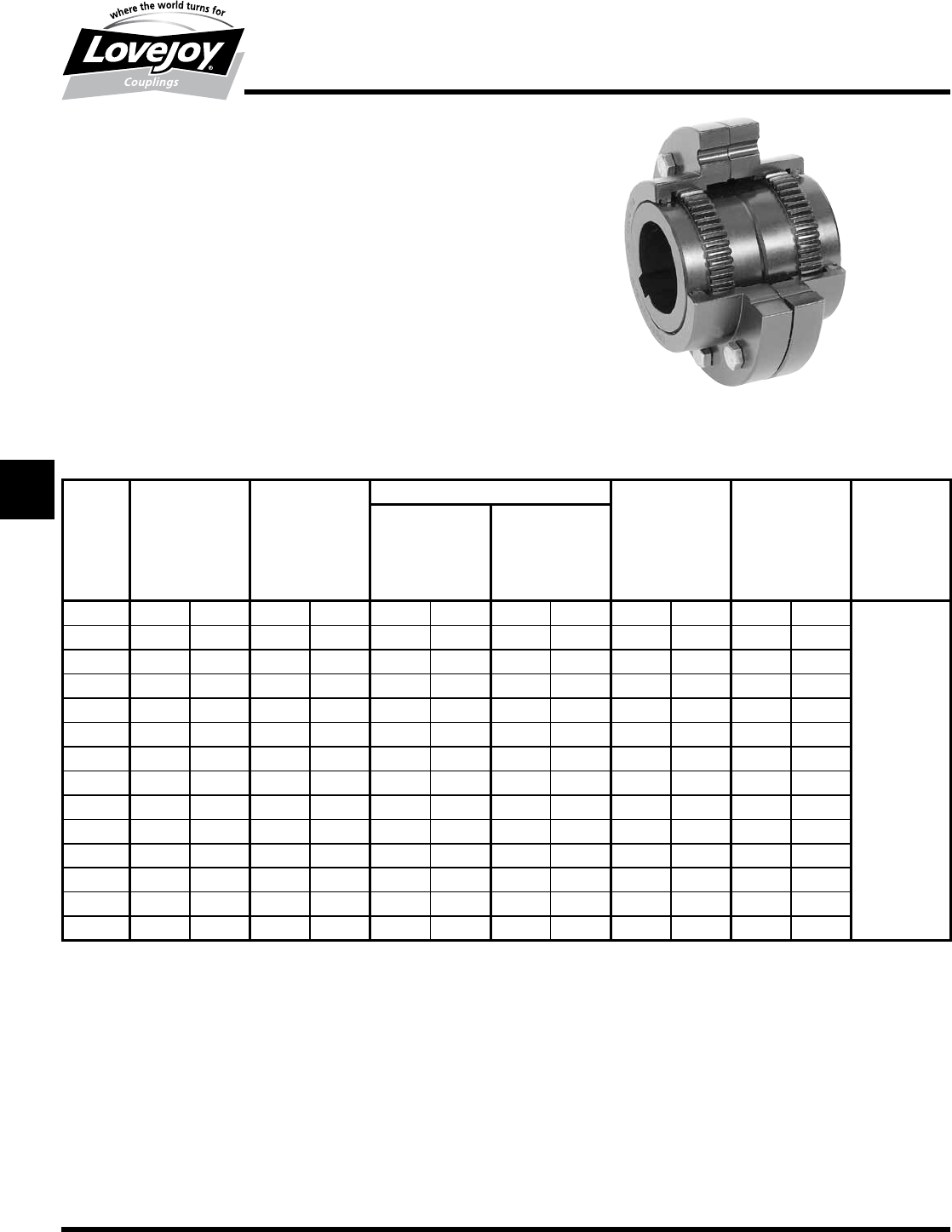
148 630-852-0500
G-34
Gear
F Type
Performance Data
Lovejoy / Sier-Bath Flanged Sleeve Gear Couplings
F Type Flex-Flex Couplings
The■F■Type■coupling■consists■of■two■flex■hubs,■two■sleeves■and■one■accessory■
kit.■This■coupling■is■supplied■with■exposed■bolts■as■standard.■Shrouded■bolts■are■
available■upon■request■through■size■5.5.
Features
■■Patented■Vari-Crown®■tooth■form■for■long■life
■■Standard■20°■pressure■angle
■■Heat■treated■bolts■for■greater■strength
■■Corrosion■resistant■bolts■and■nuts■for■ease■of■maintenance
■■Provides■parallel,■angular■misalignment■and■end■float
■■Flex■Half■coupling■interchangeable■with■industry■standards
F Type Performance Data
Size
ID1 - ID2
Nominal Maximum Max Bore Rough Stock Weight Axial Max Angular
Torque Speed Bore Misalignment Misalignment
Unbal Bal Degrees
in-lb Nm RPM RPM in mm in mm lbs kg in mm
1 7,600 850 6,000 9,000 1.625 42 0.44 11 9 4 0.056 1.4
1.5 18,900 2■140 5,500 8,250 2.125 56 0.69 18 19 9 0.060 1.5
231,500 3■560 5,000 7,500 2.750 73 0.94 24 34 15 0.085 2.2 ■
2.5 56,700 6■410 4,400 6,600 3.250 85 1.44 37 54 25 0.105 2.7
394,500 10■700 4,000 6,000 4.000 107 1.44 37 80 36 0.115 2.9
3.5 151,200 17■100 3,500 5,250 4.625 125 1.81 46 130 59 0.130 3.3 1.5°
4220,500 24■900 3,000 4,500 5.375 145 2.44 62 190 86 0.150 3.8 Per■Gear■Mesh
4.5 302,400 34■200 2,700 4,050 6.000 165 3.00 76 250 114 0.175 4.4 ■
5434,700 49■100 2,500 3,750 6.500 180 3.00 76 380 173 0.200 5.1
5.5 573,300 64■800 2,200 3,300 7.500 200 4.00 101 520 236 0.220 5.6
6749,700 84■700 2,100 3,150 8.250 225 4.00 101 650 295 0.120 3.0
71,008,000 113■900 2,000 3,000 9.500 255 5.00 127 950 431 0.135 3.4
81,323,000 149■500 1,900 2,850 11.500 310 6.00 152 1,560 708 0.160 4.1
91,827,000 206■400 1,800 2,700 12.500 340 7.00 177 2,015 915 0.165 4.2
Ordering Information
■■Application:■Driver■and■Driven.
■■Type■and■size■of■coupling,■horizontal,■vertical■etc.
■■Power:■Motor■horspower■or■torque■requirement.
■■Speed:■Motor■RPM■or■Driven■RPM.
■■Distance■between■shaft■ends■(BSE).
■■Shaft■sizes.
JWJISCJSFMC
G
HPGDDTSPUJVSDRSLDED
JW JIS CJ SF MC G HP GD D T SP UJ VSD R SLD ED
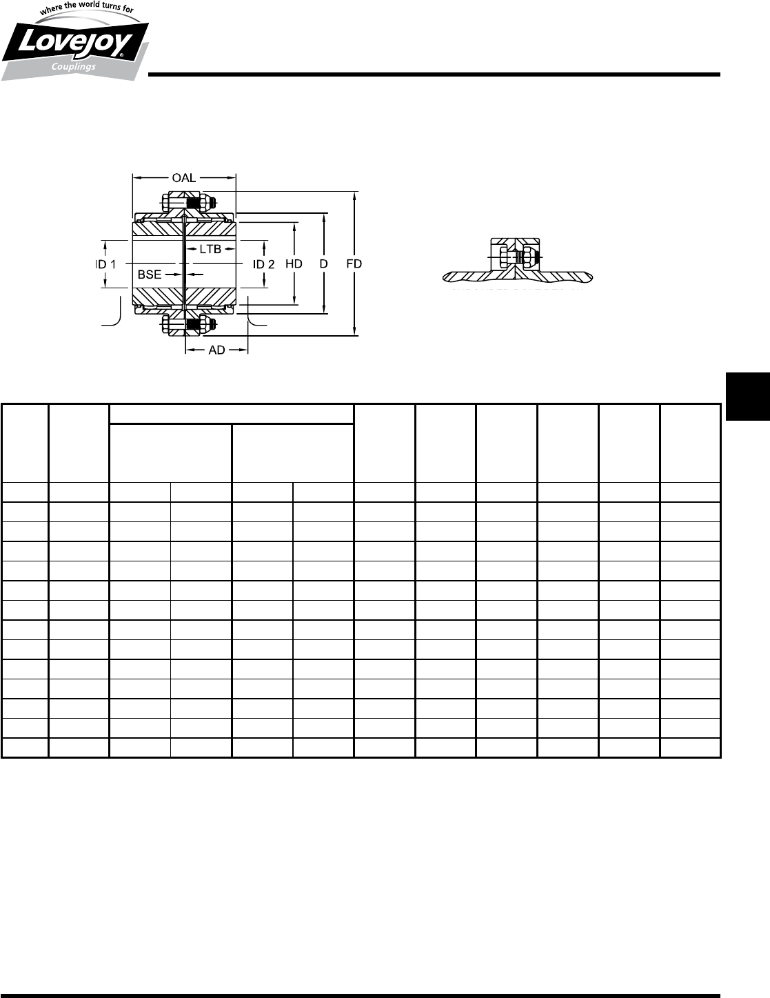
149
www.lovejoy-inc.com G-35
Gear
F Type
Dimensional Data
Lovejoy / Sier-Bath Flanged Sleeve Gear Couplings
F Type Flex-Flex Couplings
Notes:■■ n■■■Exposed■Bolt■Design■is■standard.
■n■■■Shrouded■Bolt■Design■available■upon■request■for■sizes■1■through■5.5.
■n■■■Puller■Holes■are■standard■on■sizes■4■through■9.
■n■■■Puller■Holes■are■available■for■sizes■1■through■3.5■at■an■additional■charge.
■n■■■Interference■bores■with■no■set■screws■are■standard■unless■otherwise■specified.
■n■■■Bore■and■keyway■tolerances■conform■to■ANSI■/■AGMA■9002-B04.
■n■■■For■metric■bores■and■keyway■tolerances,■consult■Lovejoy■Engineering■Section.
F Type Dimensional Data
OAL ID1 - ID2 LTB BSE AD FD D HD
Max Bore Rough Stock
Bore
Size in in mm in mm in in in in in in
13.50 1.625 42 0.44 11 1.69 0.13 2.04 4.56 3.06 2.31
1.5 4.00 2.125 56 0.69 18 1.94 0.13 2.32 6.00 3.97 3.00
25.00 2.750 73 0.94 24 2.44 0.13 2.94 7.00 4.86 4.00
2.5 6.25 3.250 85 1.44 37 3.03 0.19 3.47 8.38 5.84 4.63
37.38 4.000 107 1.44 37 3.59 0.19 3.97 9.44 6.84 5.63
3.5 8.63 4.625 125 1.81 46 4.19 0.25 4.57 11.00 7.91 6.50
49.75 5.375 145 2.44 62 4.75 0.25 5.00 12.50 9.25 7.50
4.5 10.94 6.000 165 3.00 76 5.31 0.31 5.50 13.63 10.38 8.50
512.38 6.500 180 3.00 76 6.03 0.31 6.34 15.31 11.56 9.50
5.5 14.13 7.500 200 4.00 101 6.91 0.31 7.04 16.75 12.72 10.50
615.13 8.250 225 4.00 101 7.41 0.31 8.35 18.00 14.00 11.50
717.75 9.500 255 5.00 127 8.69 0.38 9.82 20.75 15.75 13.00
822.38 11.500 310 6.00 152 11.00 0.38 12.31 23.25 18.34 15.50
923.50 12.500 340 7.00 177 11.50 0.50 13.00 26.00 20.38 17.00
Shrouded bolt design
also available
JWJISCJSFMCGHPGDDTSPUJVSDRSLDED
JW JIS CJ SF MC
G
HP GD D T SP UJ VSD R SLD ED
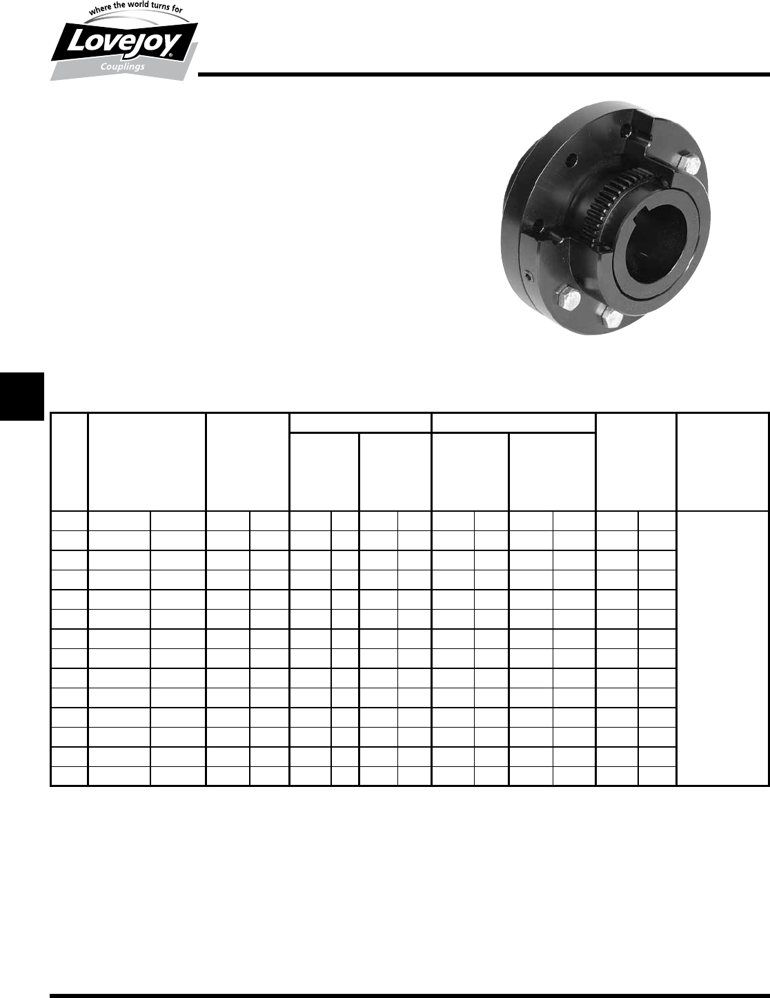
150 630-852-0500
G-36
Gear
FFR Type
Performance Data
Lovejoy / Sier-Bath Flanged Sleeve Gear Couplings
FFR Single Engagement (Flex-Rigid)
The■FRR■Type■coupling■consists■of■one■flex■hub,■one■rigid■hub,■one■sleeve■and■
one■accessory■kit.■This■coupling■is■supplied■with■exposed■bolts■as■standard.■
Shrouded■bolts■are■available■upon■request■through■size■5.5.
Features
■■Patented■Vari-Crown®■tooth■form■on■the■Flex■Hub■for■long■life
■■Standard■20°■pressure■angle
■■Heat■treated■bolts■for■greater■strength
■■Corrosion■resistant■bolts■and■nuts■for■ease■of■maintenance
■■Accommodates■angular■misalignment■only
■■Half■coupling■interchangeable■with■industry■standards
Ordering Information
■■Application:■Driver■and■Driven.
■■Type■and■size■of■coupling,■horizontal,■vertical■etc.
■■Power:■Motor■horspower■or■torque■requirement.
■■Speed:■Motor■RPM■or■Driven■RPM.
■■Distance■between■shaft■ends■(BSE).
■■Shaft■sizes.
FFR Type Performance Data
ID1 ID2
Size
Nominal Maximum Flex Hubs Flex Hubs Rigid Hubs Rigid Hubs Weight Max Angular
Torque Speed Max Bore Rough Stock Max Bore Rough Stock Misalignment
Unbal Bal Bore Bore
in-lb Nm RPM RPM in mm in mm in mm in mm lbs kg Degrees
17,600 850 6,000 9,000 1.625 42 0.44 11 2.125 56 solid solid 9 4
1.5 18,900 2■140 5,500 8,250 2.125 56 0.69 18 2.813 76 solid solid 17 8
231,500 3■560 5,000 7,500 2.750 73 0.94 24 3.500 95 solid solid 34 15
2.5 56,700 6■410 4,400 6,600 3.250 85 1.44 37 4.250 114 solid solid 55 25
394,500 10■700 4,000 6,000 4.000 107 1.44 37 4.875 134 solid solid 86 39 1.5°
3.5 151,200 17■100 3,500 5,250 4.625 125 1.81 46 5.625 150 solid solid 125 61 Per■
4220,500 24■900 3,000 4,500 5.375 145 2.44 62 6.500 176 solid solid 195 89 Gear
4.5 302,400 34■200 2,700 4,050 6.000 165 3.00 76 7.625 202 solid solid 268 122 Mesh
5434,700 49■100 2,500 3,750 6.500 180 3.00 76 8.750 230 4.00 101 394 179
5.5 573,300 64■800 2,200 3,300 7.500 200 4.00 101 9.500 260 4.50 114 526 239
6749,700 84■700 2,100 3,150 8.250 225 4.00 101 10.500 285 5.50 127 687 312
71,008,000 113■900 2,000 3,000 9.500 255 5.00 127 12.000 320 5.75 139 1,017 462
81,323,000 149■500 1,900 2,850 11.500 310 6.00 152 14.000 375 6.50 165 1,609 730
91,827,000 206■400 1,800 2,700 12.500 340 7.00 177 15.500 415 7.50 190 2,128 966
JWJISCJSFMC
G
HPGDDTSPUJVSDRSLDED
JW JIS CJ SF MC G HP GD D T SP UJ VSD R SLD ED
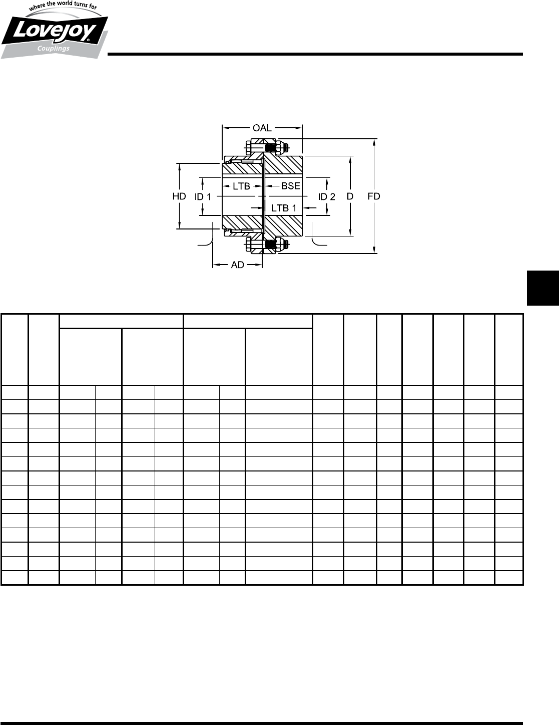
151
www.lovejoy-inc.com G-37
Gear
FFR Type
Dimensional Data
Lovejoy / Sier-Bath Flanged Sleeve Gear Couplings
FFR Type Flex-Rigid Couplings
FFR Type Dimensional Data
OAL ID1 ID2 LTB LTB 1 BSE AD FD D HD
Flex Hubs Flex Hubs Rigid Hubs Rigid Hubs
Max Bore Rough Stock Max Bore Rough Stock
Bore Bore
Size in in mm in mm in mm in mm in in in in in in in
13.41 1.625 42 0.44 11 2.125 56 solid solid 1.69 1.56 0.16 2.19 4.56 3.06 2.31
1.5 3.94 2.125 56 0.69 18 2.813 76 solid solid 1.94 1.84 0.16 2.47 6.00 3.97 3.00
24.88 2.750 73 0.94 24 3.500 95 solid solid 2.44 2.28 0.16 3.10 7.00 4.86 4.00
2.5 6.13 3.250 85 1.44 37 4.250 114 solid solid 3.03 2.91 0.19 3.65 8.38 5.84 4.63
37.19 4.000 107 1.44 37 4.875 134 solid solid 3.59 3.41 0.19 4.15 9.44 6.84 5.63
3.5 8.38 4.625 125 1.81 46 5.625 150 solid solid 4.19 3.97 0.22 4.78 11.00 7.91 6.50
49.50 5.375 145 2.44 62 6.500 176 solid solid 4.75 4.43 0.31 5.31 12.50 9.25 7.50
4.5 10.68 6.000 165 3.00 76 7.625 202 solid solid 5.31 5.03 0.34 5.97 13.63 10.38 8.50
512.06 6.500 180 3.00 76 8.750 230 4.00 101 6.03 5.69 0.34 6.69 15.31 11.56 9.50
5.5 13.40 7.500 200 4.00 101 9.500 260 4.50 114 6.91 6.15 0.34 7.34 16.75 12.72 10.50
615.23 8.250 225 4.00 101 10.500 285 5.50 127 7.41 7.41 0.41 8.78 18.00 14.00 11.50
717.88 9.500 255 5.00 127 12.000 322 5.75 139 8.69 8.69 0.50 10.31 20.75 15.75 13.00
822.50 11.500 310 6.00 152 14.000 375 6.50 165 11.00 11.00 0.50 12.81 23.25 18.34 15.50
923.56 12.500 340 7.00 177 15.500 415 7.50 190 11.50 11.50 0.56 13.56 26.00 20.38 17.00
Notes:■■ n■■■Exposed■Bolt■Design■is■standard.
■n■■■Shrouded■Bolt■Design■available■upon■request■for■sizes■1■through■5.5.
■n■■■Puller■Holes■are■standard■on■sizes■4■through■9.
■n■■■Puller■Holes■are■available■for■sizes■1■through■3.5■at■an■additional■charge.
■n■■■Interference■bores■with■no■set■screws■are■standard■unless■otherwise■specified.
■n■■■Bore■and■keyway■tolerances■conform■to■ANSI■/■AGMA■9002-B04.
■n■■■For■metric■bores■and■keyway■tolerances,■consult■Lovejoy■Engineering■Section.
JWJISCJSFMCGHPGDDTSPUJVSDRSLDED
JW JIS CJ SF MC
G
HP GD D T SP UJ VSD R SLD ED
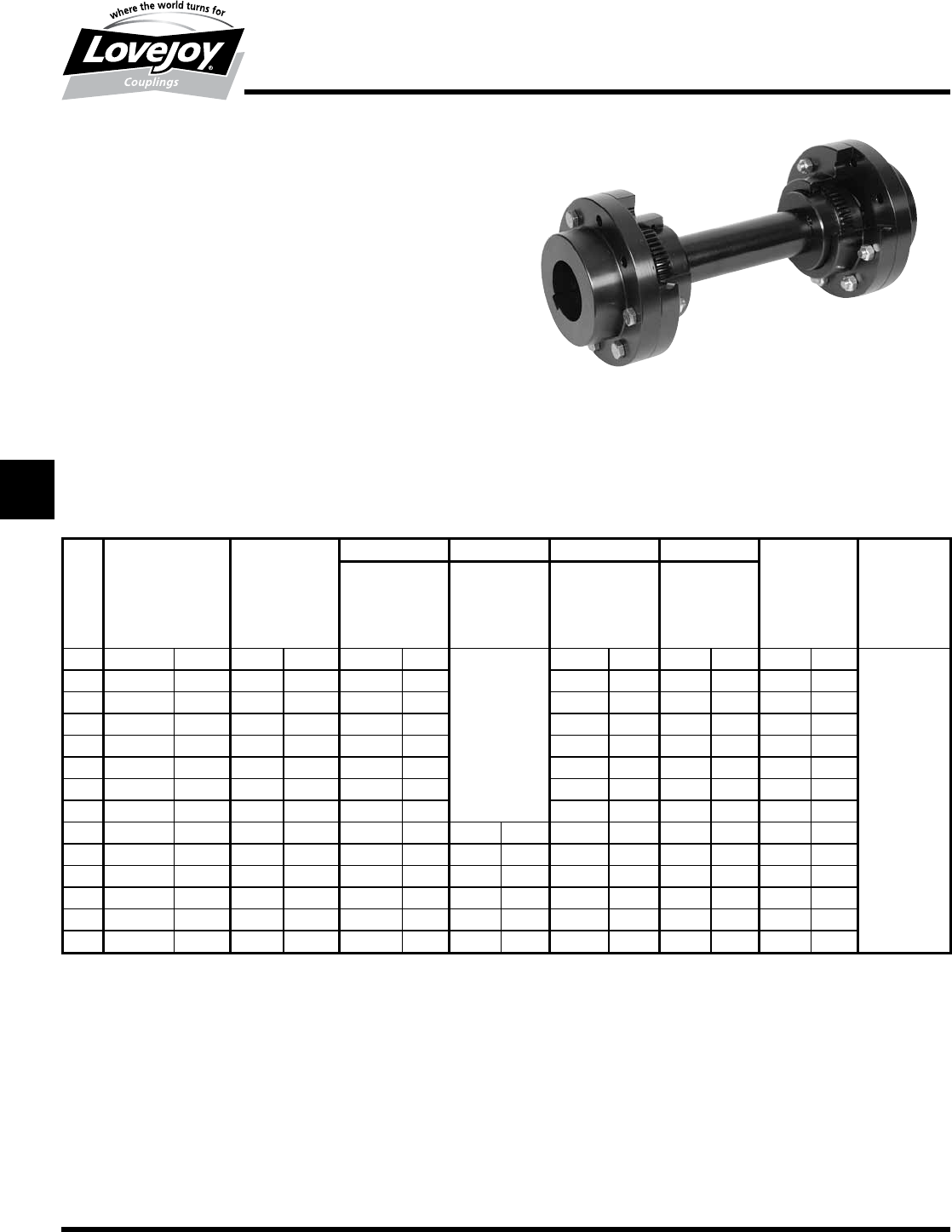
152 630-852-0500
G-38
Gear
FFS Type
Performance Data
Lovejoy / Sier-Bath Flanged Sleeve Gear Couplings
FFS – Floating Shaft Gear Coupling
The■FFS■Type■coupling■consists■of■two■flex-rigid■couplings■and■one■floating■
shaft.■This■coupling■is■supplied■with■rigid■hubs■outboard■unless■otherwise■
specified.■Exposed■bolts■are■standard.■Shrouded■bolts■are■available■upon■
request■tru■sizes■5.5.
Features
■■Patented■Vari-Crown®■tooth■form■on■Flex■Hubs■for■long■life
■■Standard■20°■pressure■angle
■■Heat■treated■bolts■for■greater■strength
■■Corrosion■resistant■bolts■and■nuts■for■ease■of■maintenance
■■Accommodates■angular,■parallel,■and■axial■misalignment
■■Removal■of■center■assembly■allows■for■ease■of■maintenance■without■
repositioning■machinery
■■Rigid■hubs■outboard■allows■for■larger■shaft■diameters
Ordering Information
■■Application:■Driver■and■Driven.
■■Type■and■size■of■coupling,■horizontal,■vertical■etc.
■■Power:■Motor■horspower■or■torque■requirement.
■■Speed:■Motor■RPM■or■Driven■RPM.
■■Distance■between■shaft■ends■(BSE).
■■Equipment■shaft■sizes.
■■Specify■which■hubs■are■to■be■used■on■the■equipment■(Rigid■or■Flex).
■■Rigid■hubs■will■be■used■on■the■equipment■unless■otherwise■specified.
FFS Type Performance Data
Size
ID1 - ID2 ID1 - ID2 ID1 - ID2 ID1 - ID2
Nominal Maximum Rigid Hubs Rigid Hubs Flex Hubs Flex Hubs Weight Angular
Torque Speed1Max Bore Rough Stock Max Bore Rough Stock Misalignment
Unbal Bal Bore Bore Max
in-lb Nm RPM RPM in mm in mm in mm in mm lbs kg Degrees
17,600 850 6,000 9,000 2.125 56
Solid
w/Center
1.625 42 0.44 11 9 4
1.5 18,900 2■140 5,500 8,250 2.813 76 2.125 56 0.69 18 19 9
231,500 3■560 5,000 7,500 3.500 95 2.750 73 0.94 24 34 15 ■
2.5 56,700 6■410 4,400 6,600 4.250 114 3.250 85 1.44 37 54 25
394,500 10■700 4,000 6,000 4.875 134 4.000 107 1.44 37 80 36
3.5 151,200 17■100 3,500 5,250 5.625 150 4.625 125 1.81 46 130 59 1.5°
4220,500 24■900 3,000 4,500 6.500 176 5.375 145 2.44 62 190 86 Per
4.5 302,400 34■200 2,700 4,050 7.625 202 6.000 165 3.00 76 250 114 Gear■
5434,700 49■100 2,500 3,750 8.750 231 4.000 101 6.500 180 3.00 76 380 173 Mesh
5.5 573,300 64■800 2,200 3,300 9.500 260 4.500 114 7.500 200 4.00 101 520 236
6749,700 84■700 2,100 3,150 10.500 288 5.500 127 8.250 225 4.00 101 650 295
71,008,000 113■900 2,000 3,000 12.000 318 5.750 139 9.500 255 5.00 127 950 431
81,323,000 149■500 1,900 2,850 14.000 380 6.500 165 11.500 310 6.00 152 1,560 708
91,827,000 206■400 1,800 2,700 15.500 418 7.500 190 12.500 340 7.00 177 2,015 915
Note:■■ n■■1■indicates:■Maximum■RPM■of■floating■shaft■set■determined■by■critical■speed■of■floating■shaft.
JWJISCJSFMC
G
HPGDDTSPUJVSDRSLDED
JW JIS CJ SF MC G HP GD D T SP UJ VSD R SLD ED
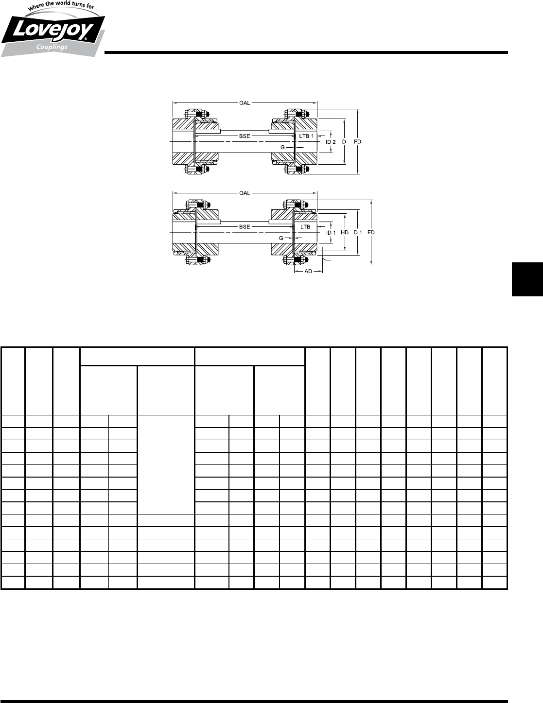
153
www.lovejoy-inc.com G-39
Gear
FFS Type
Dimensional Data
Lovejoy / Sier-Bath Flanged Gear Couplings
FFS Type Floating Shaft Couplings
FFS Type Dimensional Data
OAL BSE ID1 - ID2 ID1 - ID2 LTB 1 LTB G AD FD D D 1 HD
Min Min Rigid Hubs Rigid Hubs Flex Hubs Flex Hubs
Max Bore Rough Stock Max Bore Rough Stock
Bore Bore
Size in in in mm in mm in mm in mm in in in in in in in in
18.07 4.94 2.125 56
Solid
w/Center
1.625 42 0.44 11 1.56 1.69 0.16 2.06 4.56 3.06 3.06 2.31
1.5 9.19 5.50 2.813 76 2.125 56 0.69 18 1.84 1.94 0.16 2.37 6.00 3.97 3.97 3.00
212.06 7.50 3.500 95 2.750 73 0.94 24 2.28 2.44 0.16 2.94 7.00 4.84 4.91 4.00
2.5 14.37 8.56 4.250 114 3.250 85 1.44 37 2.91 3.03 0.19 3.53 8.38 5.84 5.91 4.63
316.69 9.88 4.875 134 4.000 107 1.44 37 3.41 3.59 0.19 3.97 9.44 6.84 6.91 5.63
3.5 19.25 11.31 5.625 150 4.625 125 1.81 46 3.97 4.19 0.22 4.56 11.00 7.91 7.91 6.50
421.82 12.94 6.500 176 5.375 145 2.44 62 4.44 4.75 0.31 5.00 12.50 9.25 9.25 7.50
4.5 24.69 14.63 7.625 202 6.000 165 3.00 76 5.03 5.31 0.34 5.69 13.63 10.38 10.38 8.50
528.07 16.69 8.750 231 4.000 101 6.500 180 3.00 76 5.69 6.03 0.34 6.35 15.31 11.56 11.56 9.50
5.5 30.87 18.56 9.500 260 4.500 114 7.500 200 4.00 101 6.16 6.91 0.34 6.59 16.75 12.72 12.81 10.50
635.37 20.56 10.500 288 5.500 127 8.250 225 4.00 101 7.41 7.41 0.41 8.78 18.00 14.00 14.00 11.50
740.63 23.25 12.000 318 5.750 139 9.500 255 5.00 127 8.69 8.69 0.50 10.31 20.75 15.75 15.75 13.00
849.63 27.63 14.000 380 6.500 165 11.500 310 6.00 152 11.00 11.00 0.50 12.81 23.25 18.34 18.50 15.50
952.13 29.13 15.500 418 7.500 190 12.500 340 7.00 177 11.50 11.50 0.56 13.56 26.00 20.38 20.38 17.00
Notes:■■ n■■■Exposed■Bolt■Design■is■standard.
■n■■■Shrouded■Bolt■Design■available■upon■request■for■sizes■1■through■5.5.
■n■■■Puller■Holes■are■standard■on■sizes■4■through■9.
■n■■■Puller■Holes■are■available■for■sizes■1■through■3.5■at■an■additional■charge.
■n■■■Interference■bores■with■no■set■screws■are■standard■unless■otherwise■specified.
■n■■■Bore■and■keyway■tolerances■conform■to■ANSI■/■AGMA■9002-B04.
■n■■■For■metric■bores■and■keyway■tolerances,■consult■Lovejoy■Engineering■Section.
Rigid Hubs Outboard
Flex Hubs Outboard
Maximum RPM of floating shaft set determined by
critical speed of floating shaft
JWJISCJSFMCGHPGDDTSPUJVSDRSLDED
JW JIS CJ SF MC
G
HP GD D T SP UJ VSD R SLD ED
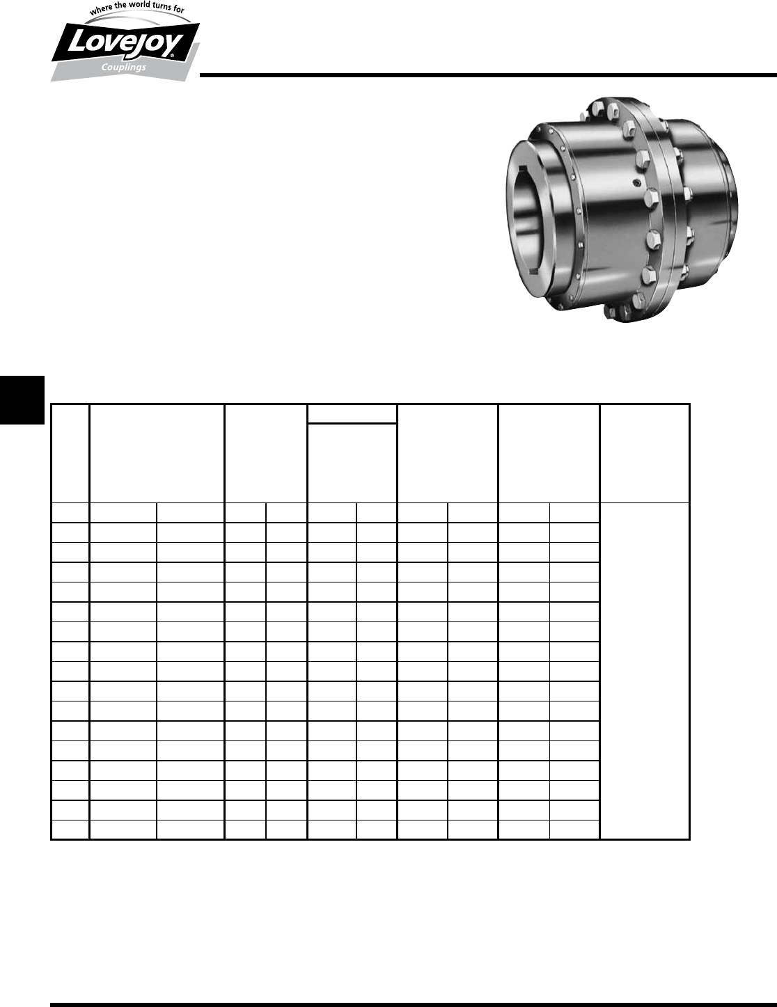
154 630-852-0500
G-40
Gear
FHD Type
Performance Data
Lovejoy / Sier-Bath Heavy Duty Flanged Sleeve Gear Couplings
FHD Type Flex-Flex Couplings
The■FHD■Type■coupling■consists■of■two■flex■hubs,■two■sleeves■with■bolt-on■seal■carriers■and■
one■accessory■kit.■This■coupling■is■supplied■with■exposed■bolts■only.
Features
■■Patented■Vari-Crown®■tooth■form■for■long■life
■■Standard■20°■pressure■angle
■■Heat■treated■bolts■for■greater■strength
■■Corrosion■resistant■bolts■and■nuts■for■ease■of■maintenance
■■Provides■parallel,■angular■misalignment■and■end■float
■■Designed■for■high-torque■low-speed■applications■that■occur■in■mill■operations
FHD Type Performance Data
ID1 - ID2
Nominal Maximum Max Bore Weight Parallel Angular
Size
Torque Speed Standard Misalignment Misalignment
Unbal Bal Keyway Degrees
in-lb Nm RPM RPM in mm lbs kg in mm
71,008,000 110■000 2,000 3,000 9.500 255 950 431 0.135 3.429
0.75°
Per■Gear■Mesh
81,323,500 150■000 1,900 2,850 11.500 310 1,560 708 0.160 4.064
91,827,700 210■000 1,750 2,625 12.500 340 2,015 915 0.165 4.191
10 2,521,000 280■000 1,550 2,325 13.750 355 2,500 1,135 0.180 4.572
11 3,466,000 390■000 1,400 2,100 15.500 410 3,380 1,535 0.205 5.207
12 4,412,000 500■000 1,300 1,950 17.000 435 4,165 1,891 0.210 5.334
13 5,249,000 600■000 1,150 1,725 18.250 480 5,215 2,368 0.230 5.842
14 6,429,000 730■000 1,050 1,575 19.500 — 6,400 2,906 0.255 6.477
15 7,752,000 880■000 900 1,350 21.000 — 7,710 3,500 0.280 7.112
16 9,454,000 1■070■000 800 1,200 22.500 — 9,250 4,200 0.295 7.493
18 12,605,000 1■420■000 550 825 25.500 — 11,890 5,398 0.295 7.493
20 17,017,000 1■920■000 450 675 28.000 — 16,830 7,641 0.280 7.112
22 21,429,000 2■420■000 380 570 31.000 — 21,970 9,974 0.310 7.874
24 26,471,000 2■990■000 325 485 34.000 — 27,735 12,592 0.300 7.620
26 32,773,000 3■700■000 280 420 37.000 — 34,370 15,604 0.300 7.620
28 39,076,000 4■410■000 240 360 40.000 — 40,910 18,573 0.320 8.128
30 47,269,000 5■340■000 220 330 42.000 — 47,470 21,551 0.320 8.128
Ordering Information
■■Application:■Driver■and■Driven.
■■Type■and■size■of■coupling,■horizontal,■vertical■etc.
■■Power:■Motor■horspower■or■torque■requirement.
■■Speed:■Motor■RPM■or■Driven■RPM.
■■Distance■between■shaft■ends■(BSE).
■■Shaft■sizes.
JWJISCJSFMC
G
HPGDDTSPUJVSDRSLDED
JW JIS CJ SF MC G HP GD D T SP UJ VSD R SLD ED
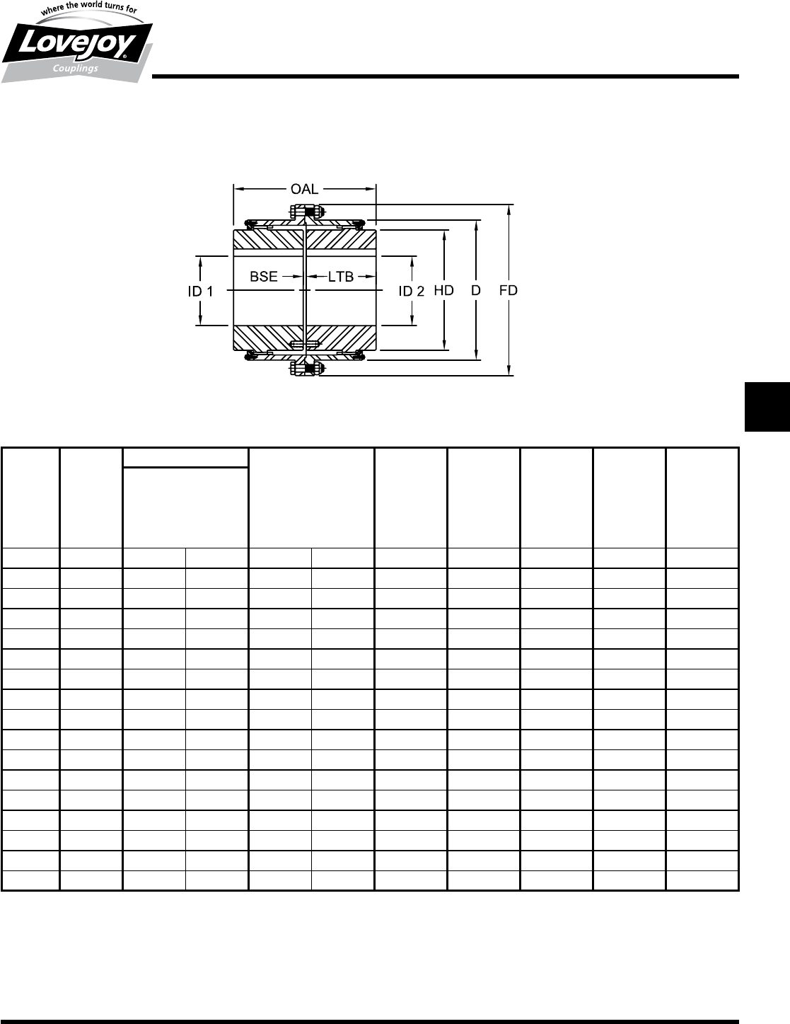
155
www.lovejoy-inc.com G-41
Gear
FHD Type
Dimensional Data
Lovejoy / Sier-Bath Heavy Duty Flanged Sleeve Gear Couplings
FHD Type Flex-Flex Couplings
FHD Type Dimensional Data
OAL ID1 - ID2 LTB BSE FD D HD
Max Bore 1 Rectangular
Standard Keyway
Keyway Width Depth
Size in in mm in in in in in in in
717.76 9.500 255 2.5000 0.8750 8.69 0.38 20.75 15.75 13.00
822.38 11.500 310 3.0000 1.0000 11.00 0.38 23.25 18.34 15.50
923.50 12.500 340 3.0000 1.0000 11.50 0.50 26.00 20.38 17.00
10 24.50 13.750 355 3.5000 1.2500 12.00 0.50 28.00 22.31 18.50
11 26.75 15.500 410 4.0000 1.5000 13.13 0.50 30.50 24.36 21.00
12 28.25 17.000 435 4.0000 1.5000 13.88 0.50 33.00 26.63 22.75
13 30.00 18.250 480 5.0000 1.7500 14.63 0.75 35.75 28.88 24.75
14 31.75 19.500 — 5.0000 1.7500 15.50 0.75 38.00 31.68 26.50
15 33.75 21.000 — 5.0000 1.7500 16.50 0.75 40.50 32.97 28.50
16 35.75 22.500 — 6.0000 2.0000 17.38 1.00 43.00 35.13 30.38
18 37.00 25.500 — 6.0000 2.0000 18.00 1.00 47.25 39.25 34.25
20 43.25 28.000 — 7.0000 2.5000 21.13 1.00 53.50 43.50 38.00
22 47.00 31.000 — 8.0000 2.7500 23.00 1.00 59.00 47.63 41.81
24 50.50 34.000 — 9.0000 3.0000 24.75 1.00 64.25 51.75 45.50
26 54.00 37.000 — 9.0000 3.0000 26.50 1.00 68.50 55.88 49.38
28 55.25 40.000 — 10.0000 3.5000 27.13 1.00 73.75 60.00 53.00
30 56.25 42.000 — 10.0000 3.5000 27.63 1.00 78.00 64.13 57.00
Notes:■■ n■■■Exposed■Bolt■Design■is■standard.
■n■■■Puller■Holes■are■standard.
■n■■■Interference■bores■with■no■set■screws■are■standard■unless■otherwise■specified.
■n■■■Inch■bore■and■keyway■tolerances■conform■to■ANSI■/■AGMA■9002-B04,■for■bores■above■18■inches,■keyways■conform■to■ANSI■B17.1.
■n■■■For■metric■bore■and■keyway■tolerances,■consult■Lovejoy■Engineering■Section.
JWJISCJSFMCGHPGDDTSPUJVSDRSLDED
JW JIS CJ SF MC
G
HP GD D T SP UJ VSD R SLD ED
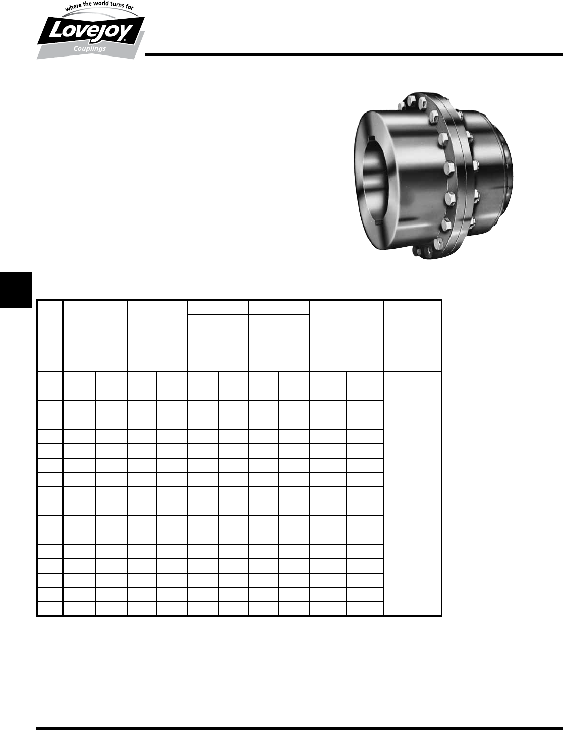
156 630-852-0500
G-42
Gear
FHDFR Type
Performance Data
Lovejoy / Sier-Bath Heavy Duty Flanged Sleeve Gear Couplings
FHDFR Type Flex-Rigid Couplings
The■FHDFR■Type■coupling■consists■of■one■flex■hub,■one■sleeve■
with■bolt-on■seal■carrier,■one■rigid■hub■and■one■accessory■kit.■This■
coupling■is■supplied■with■exposed■bolts■only.
Features
■■Patented■Vari-Crown®■tooth■form■for■long■life
■■Standard■20°■pressure■angle
■■Heat■treated■bolts■for■greater■strength
■■Corrosion■resistant■bolts■and■nuts■for■ease■of■maintenance
■■Provides■parallel,■angular■misalignment■and■end■float
■■Designed■for■high-torque■low-speed■applications■that■occur■in■
mill■operations■
FHDFR Type Performance Data
ID1 ID2
Size
Nominal Maximum Flex Hubs Rigid Hubs Weight Max
Torque Speed Max Bore Max Bore Angular
in-lb Nm Unbal Bal Std Keyway Std Keyway Misalignment
x 1000 RPM RPM in mm in mm lbs kg Degrees
71,008 110 2,000 3,000 9.500 255 12.000 320 1,017 462
0.75°
Per■
Gear■
Mesh
81,324 150 1,900 2,850 11.500 310 14.000 375 1,609 730
91,827 210 1,750 2,625 12.500 340 15.500 415 2,128 966
10 2,521 280 1,550 2,325 13.750 355 17.000 455 2,723 1,236
11 3,466 390 1,400 2,100 15.500 410 18.500 500 3,640 1,653
12 4,412 500 1,300 1,950 17.000 435 20.250 — 4,508 2,047
13 5,249 600 1,150 1,725 18.250 480 22.000 — 5,600 2,542
14 6,429 730 1,050 1,575 19.500 — 23.500 — 6,837 3,104
15 7,752 880 900 1,350 21.000 — 24.250 — 8,244 3,743
16 9,454 1■070 800 1,200 22.500 — 26.000 — 9,848 4,471
18 12,605 1■420 550 825 25.500 — 28.000 — 12,673 5,754
20 17,017 1■920 450 675 28.000 — 31.000 — 18,113 8,223
22 21,429 2■420 380 570 31.000 — 34.000 — 23,671 10,747
24 26,471 2■990 325 485 34.000 — 37.000 — 29,958 13,601
26 32,773 3■700 280 420 37.000 — 40.000 — 37,014 16,845
28 39,076 4■410 240 360 40.000 — 43.000 — 44,012 19,981
30 47,269 5■340 220 330 42.000 — 46.000 — 51,065 23,184
Ordering Information
■■Application:■Driver■and■Driven.
■■Type■and■size■of■coupling,■horizontal,■vertical■etc.
■■Power:■Motor■horspower■or■torque■requirement.
■■Speed:■Motor■RPM■or■Driven■RPM.
■■Distance■between■shaft■ends■(BSE).
■■Shaft■sizes.
JWJISCJSFMC
G
HPGDDTSPUJVSDRSLDED
JW JIS CJ SF MC G HP GD D T SP UJ VSD R SLD ED
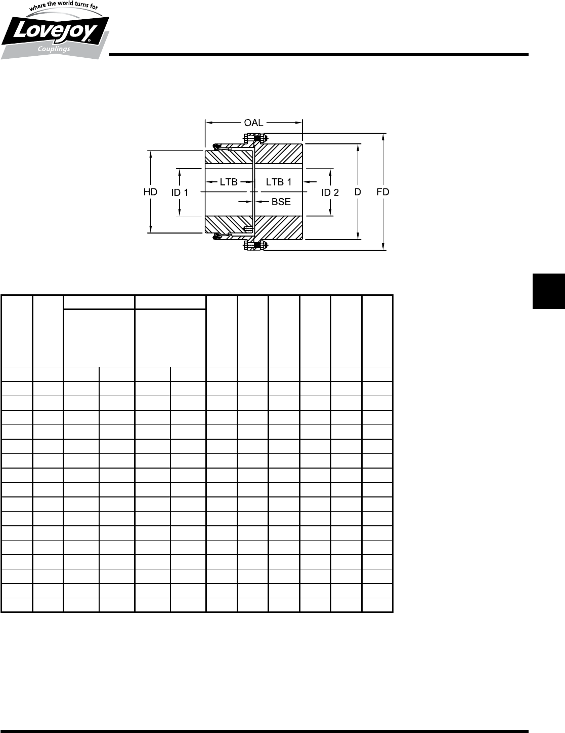
157
www.lovejoy-inc.com G-43
Gear
FHDFR Type
Dimensional Data
FHDFR Type Dimensional Data
OAL ID1 ID2 LTB LTB1 BSE FD D HD
Flex Hubs Rigid Hubs
Max Bore Max Bore
Std Keyway Std Keyway
Size in in mm in mm in in in in in in
717.81 9.500 255 12.000 320 8.69 8.69 0.50 20.75 15.75 13.00
822.50 11.500 310 14.000 375 11.00 11.00 0.50 23.25 18.34 15.50
923.56 12.500 340 15.500 415 11.50 11.50 0.56 26.00 20.38 17.00
10 24.63 13.750 355 17.000 455 12.00 12.00 0.63 28.00 22.31 18.50
11 26.88 15.500 410 18.500 500 13.13 13.13 0.63 30.50 24.36 21.00
12 28.38 17.000 435 20.250 — 13.88 13.88 0.63 33.00 26.63 22.75
13 30.00 18.250 480 22.000 — 14.63 14.63 0.75 33.75 28.88 24.75
14 31.75 19.500 — 23.500 — 15.50 15.50 0.75 38.00 31.00 26.50
15 33.75 21.000 — 24.250 — 16.50 16.50 0.75 40.50 32.97 28.50
16 35.75 22.500 — 26.000 — 17.38 17.38 1.00 43.00 35.13 30.38
18 37.00 25.500 — 28.000 — 18.00 18.00 1.00 47.25 39.25 34.25
20 43.25 28.000 — 31.000 — 21.13 21.13 1.00 53.50 43.50 38.00
22 47.13 31.000 — 34.000 — 23.00 23.00 1.13 59.00 47.63 41.81
24 50.63 34.000 — 37.000 — 24.75 24.75 1.13 64.25 51.75 45.50
26 54.13 37.000 — 40.000 — 26.50 26.50 1.13 68.50 55.88 49.38
28 55.38 40.000 — 43.000 — 27.13 27.13 1.13 73.75 60.00 53.00
30 56.38 42.000 — 46.000 — 27.63 27.63 1.13 78.00 64.13 57.00
Lovejoy / Sier-Bath Heavy Duty Flanged Sleeve Gear Couplings
FHDFR Type Flex-Rigid Couplings
Notes:■■ n■■■Exposed■Bolt■Design■is■standard.
■n■■■Puller■Holes■are■standard.
■n■■■Interference■bores■with■no■set■screws■are■standard■unless■otherwise■specified.
■n■■■Inch■bore■and■keyway■tolerances■conform■to■ANSI■/■AGMA■9002-B04,■for■bores■above■18■inches,■keyways■
are■to■ANSI■B17.1.
■n■■■Metric■bore■and■keyway■tolerances■conform■to■ISO■286■and■ANSI■/■AGMA■9112-A04.
■n■■■Consult■Lovejoy■Technical■Support■for■metric■bores■larger■than■500mm.
JWJISCJSFMCGHPGDDTSPUJVSDRSLDED
JW JIS CJ SF MC
G
HP GD D T SP UJ VSD R SLD ED
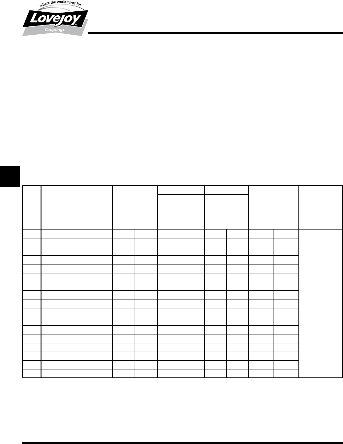
158 630-852-0500
G-44
Gear
FHDFS Type
Performance Data
Lovejoy / Sier-Bath Heavy Duty Flanged Sleeve Gear Couplings
FHDFS Type Floating Shaft Couplings
The■FHDFS■Type■coupling■consists■of■two■flex-rigid■couplings■and■one■floating■shaft.■The■coupling■is■supplied■
with■the■rigid■hubs■outboard■unless■otherwise■specified.■The■coupling■comes■with■exposed■bolts■only.
Features
■■Patented■Vari-Crown®■tooth■form■on■Flex■Hubs■for■long■life
■■Standard■20°■pressure■angle
■■Heat■treated■bolts■for■greater■strength
■■Corrosion■resistant■bolts■and■nuts■for■ease■of■maintenance
■■Accommodates■parallel■and■angular■misalignment
■■Removal■of■center■assembly■allows■forease■of■maintenance■without■repositioning■machinery
■■Rigid■hubs■outboard■allows■for■larger■shaft■diameters
■■Designed■for■high-torque■low-speed■applications■that■occur■in■mill■operations
FHDFS Type Performance Data
ID1 ID2
Size
Nominal Maximum Flex Hubs Rigid Hubs Weight Max Angular
Torque Speed1Max Bore Max Bore Misalignment
Unbal Bal Std Keyway Std Keyway Degrees
in-lb Nm RPM RPM in mm in mm lbs kg
7 1,008,000 113■900 2,000 3,000 9.500 255 12.000 320 1,017 462
8 1,323,000 149■000 1,900 2,850 11.500 310 14.000 375 1,609 730
9 1,827,000 206■400 1,750 2,625 12.500 340 15.500 415 2,128 966 ■
10 2,521,000 280■000 1,550 2,325 13.750 355 17.000 455 2,723 1,236
11 3,500,000 390■000 1,400 2,100 15.500 410 18.500 500 3,640 1,653
12 4,400,000 500■000 1,300 1,950 17.000 435 20.250 — 4,508 2,047 0.75°
13 5,300,000 600■000 1,150 1,725 18.250 480 22.000 — 5,600 2,542 Per■Gear■Mesh
14 6,400,000 730■000 1,050 1,575 19.500 — 23.500 — 6,837 3,104 ■
15 7,700,000 880■000 900 1,350 21.000 — 24.250 — 8,244 3,743
16 9,500,000 1■070■000 800 1,200 22.500 — 26.000 — 9,848 4,471
18 12,600,000 1■420■000 550 825 25.500 — 28.000 — 12,673 5,754
20 17,000,000 1■920■000 450 675 28.000 — 31.000 — 18,113 8,223
22 21,400,000 2■420■000 380 570 31.000 — 34.000 — 23,671 10,747
24 26,500,000 2■990■000 325 488 34.000 — 37.000 — 29,958 13,601
26 32,800,000 3■700■000 280 420 37.000 — 40.000 — 37,104 16,845
28 39,100,000 4■410■000 240 360 40.000 — 43.000 — 44,012 19,981
30 47,300,000 5■340■000 220 330 42.000 — 46.000 — 51,065 23,184
Note:■■ n■■1■indicates:■Maximum■RPM■of■floating■shaft■set■determined■by■critical■speed■of■floating■shaft.
Ordering Information
■■Application:■Driver■and■Driven.
■■Type■and■size■of■coupling,■horizontal,■vertical■etc.
■■Power:■Motor■horspower■or■torque■requirement.
■■Speed:■Motor■RPM■or■Driven■RPM.
■■Distance■between■shaft■ends■(BSE).
■■Connecting■equipment■shaft■sizes.
■■Specify■which■hubs■are■to■be■used■on■the■equipment■(Rigid■or■Flex).
■■Rigid■hubs■will■be■used■on■the■equipment■unless■otherwise■specified.
■■Length■of■floating■shaft■may■affect■max■angular■misalignment.
JWJISCJSFMC
G
HPGDDTSPUJVSDRSLDED
JW JIS CJ SF MC G HP GD D T SP UJ VSD R SLD ED
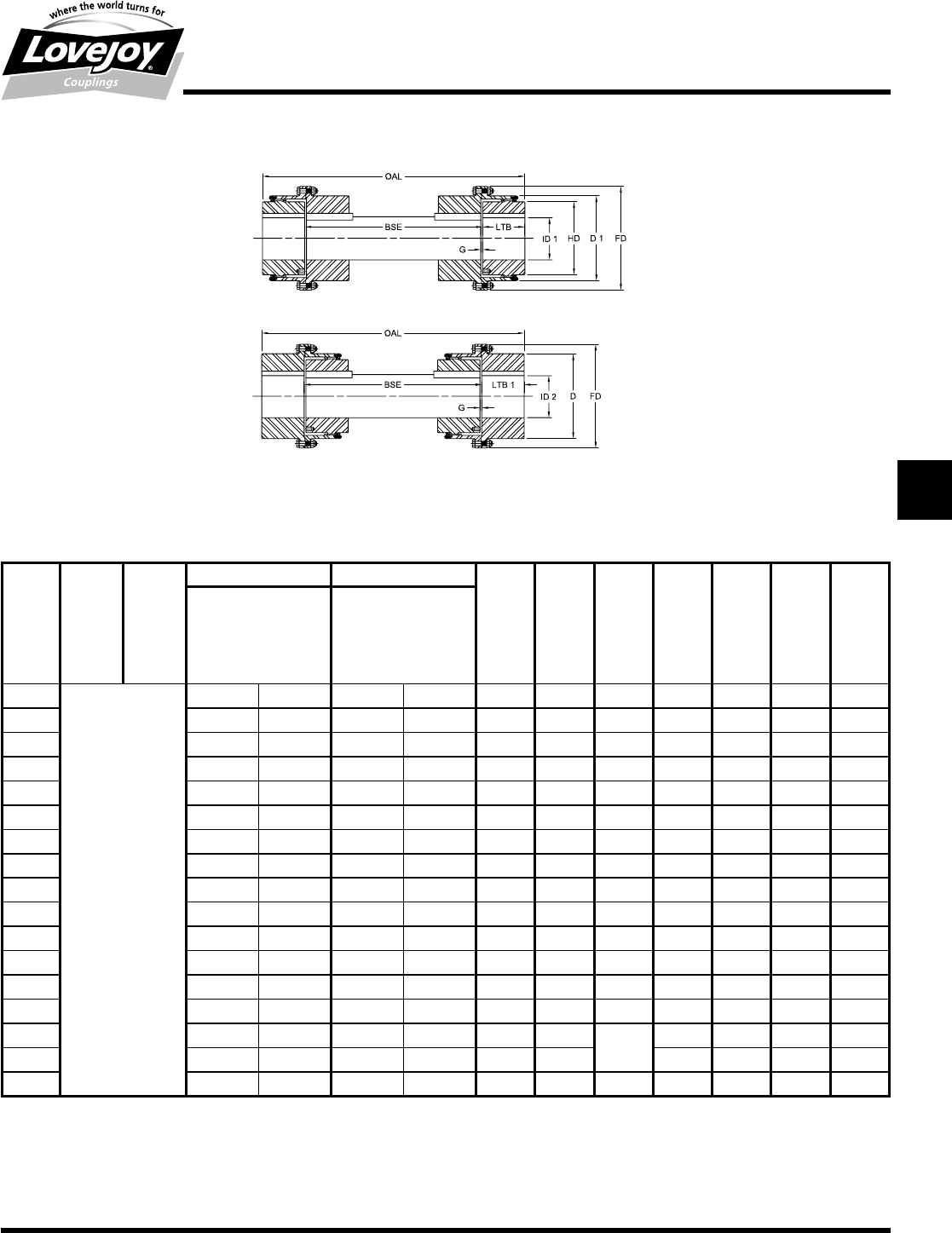
159
www.lovejoy-inc.com G-45
Gear
FHDFS Type
Dimensional Data
Lovejoy / Sier-Bath Heavy Duty Flanged Sleeve Gear Couplings
FHDFS Type Floating Shaft Couplings
FHDFS Type Dimensional Data
OAL BSE ID1 ID2 LTB 1 LTB G FD D D 1 HD
Flex Hubs Rigid Hubs
Max Bore Max Bore
Std Keyway Std Keyway
Size in in in mm in mm in in in in in in in
7■ 9.500 255 12.000 320 8.69 8.69 0.50 20.75 15.75 15.75 13.00
8To■Be■Determined 11.500 310 14.000 375 11.00 11.00 0.50 23.25 18.34 18.50 15.50
9From■Customer■ 12.500 340 15.500 415 11.50 11.50 0.56 26.00 20.38 20.38 17.00
10 Specifications 13.750 355 17.000 455 12.00 12.00 0.63 28.00 22.31 22.38 18.50
11 ■ 15.500 410 18.500 500 13.13 13.13 0.63 30.50 24.36 24.50 21.00
12 ■ 17.000 435 20.250 — 13.88 13.88 0.63 33.00 26.63 26.63 22.75
13 ■ 18.250 480 22.000 — 14.63 14.63 0.75 33.75 28.88 28.88 24.75
14 ■ 19.500 — 23.500 — 15.50 15.50 0.75 38.00 31.00 31.00 26.50
15 ■ 21.000 — 24.250 — 16.50 16.50 0.75 40.50 32.97 33.13 28.50
16 ■ 22.500 — 26.000 — 17.38 17.38 1.00 43.00 35.13 35.13 30.38
18 ■ 25.500 — 28.000 — 18.00 18.00 1.00 47.25 39.25 39.25 34.25
20 ■ 28.000 — 31.000 — 21.13 21.13 1.00 53.50 43.50 43.50 38.00
22 ■ 31.000 — 34.000 — 23.00 23.00 1.13 59.00 47.63 47.63 41.81
24 ■ 34.000 — 37.000 — 24.75 24.75 1.13 64.25 51.75 51.75 45.50
26 37.000 — 40.000 — 26.50 26.50 1.13 68.50 55.88 55.88 49.38
28 40.000 — 43.000 — 27.13 27.13 1.13 73.75 60.00 60.00 53.00
30 42.000 — 46.000 — 27.63 27.63 1.13 78.00 64.13 64.13 57.00
Rigid Hubs Outboard
Flex Hubs Outboard
Maximum RPM of floating shaft set determined by
critical speed of floating shaft
Notes:■■ n■■■Exposed■Bolt■Design■is■standard.
■n■■■Puller■Holes■are■standard.
■n■■■Interference■bores■with■no■set■screws■are■standard■unless■otherwise■specified.
■n■■■Inch■bore■and■keyway■tolerances■conform■to■ANSI■/■AGMA■9002-B04,■for■bores■about■18■inches,■keyways■are■to■ANSI■B17.1.
■n■■■For■metric■bore■and■keyway■tolerances,■consult■Lovejoy■Engineering■Section.
■n■■■Consult■Lovejoy■Technical■Support■for■metric■bores■larger■than■500mm.
JWJISCJSFMCGHPGDDTSPUJVSDRSLDED
JW JIS CJ SF MC
G
HP GD D T SP UJ VSD R SLD ED
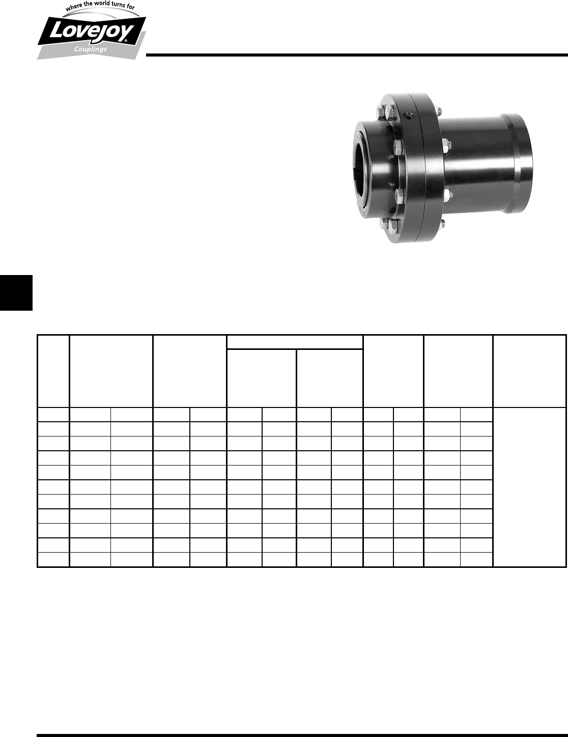
160 630-852-0500
G-46
Gear
FMM Type
Performance Data
Lovejoy / Sier-Bath Flanged Sleeve Gear Couplings
FMM Type Mill Couplings
The■FMM■Type■coupling■consists■of■one■standard■flex■hub,■one■universal■straight■
bored■hub■as■standard,■two■sleeves■and■one■accessory■kit.■This■coupling■is■
supplied■with■exposed■bolts■as■standard.■Shrouded■bolts■are■available■upon■
request■through■size■5.5.
Features
■■Patented■Vari-Crown®■tooth■form■for■long■life
■■Standard■20°■pressure■angle
■■Heat■treated■bolts■for■greater■strength
■■Corrosion■resistant■bolts■and■nuts■for■ease■of■maintenance
■■Provides■parallel,■angular■misalignment■and■end■float
■■Flex■Half■coupling■interchangeable■with■industry■standards
■■Long■Universal■Hub■supplied■to■customer■specifications■with■straight■or■
tapered■bores
FMM Type Performance Data
ID1 - ID2
Size
Nominal Maximum Max Bore Rough Stock Weight Parallel Max Angular
Torque Speed Bore Misalignment Misalignment
Unbal Bal Degrees
in-lb Nm RPM RPM in mm in mm lbs kg in mm
17,600 850 6,000 9,000 1.625 42 0.44 11 12 5 0.056 1.4
■
1.5°
Per■Gear■Mesh
■
1.5 18,900 2■140 5,500 8,250 2.125 56 0.69 18 24 11 0.060 1.5
231,500 3■560 5,000 7,500 2.750 73 0.94 24 45 20 0.085 2.2
2.5 56,700 6■410 4,400 6,600 3.250 85 1.44 37 71 32 0.105 2.7
394,500 10■700 4,000 6,000 4.000 107 1.44 37 104 47 0.115 2.9
3.5 151,200 17■100 3,500 5,250 4.625 125 1.81 46 151 69 0.130 3.3
4220,500 24■900 3,000 4,500 5.375 145 2.44 62 234 86 0.150 3.8
4.5 302,400 34■200 2,700 4,050 6.000 165 3.00 76 310 141 0.175 4.4
5434,700 49■100 2,500 3,750 6.500 180 3.00 76 450 204 0.200 5.1
5.5 573,300 64■800 2,200 3,300 7.500 200 4.00 101 609 276 0.220 5.6
6749,700 84■700 2,100 3,150 8.250 225 4.00 101 764 347 0.120 3.0
Ordering Information
■■Application:■Driver■and■Driven.
■■Type■and■size■of■coupling,■horizontal,■vertical■etc.
■■Power:■Motor■horspower■or■torque■requirement.
■■Speed:■Motor■RPM■or■Driven■RPM.
■■Distance■between■shaft■ends■(BSE).
■■Shaft■sizes.
■■Taper■per■foot■and■length■of■taper■if■tapered■bore■is■required.
■■Specify■counterbore■dimensions■if■desired.
■■Submit■a■drawing■if■available.
JWJISCJSFMC
G
HPGDDTSPUJVSDRSLDED
JW JIS CJ SF MC G HP GD D T SP UJ VSD R SLD ED
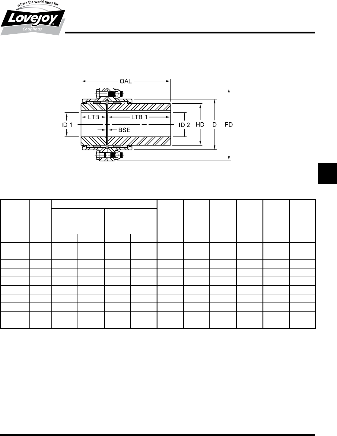
161
www.lovejoy-inc.com G-47
Gear
FMM Type
Dimensional Data
Lovejoy / Sier-Bath Flanged Sleeve Gear Couplings
FMM Type Mill Couplings
FMM Type Dimensional Data
OAL ID1 - ID2 LTB LTB1 BSE FD D HD
Max Bore Rough Stock Max
Bore
Size in in mm in mm in in in in in in
15.81 1.625 42 0.44 11 1.69 4.00 0.13 4.56 3.06 2.31
1.5 6.56 2.125 56 0.69 18 1.94 4.50 0.13 6.00 3.97 3.00
28.06 2.750 73 0.94 24 2.44 5.50 0.13 7.00 4.86 4.00
2.5 9.72 3.250 85 1.44 37 3.03 6.50 0.19 8.38 5.84 4.63
310.78 4.000 107 1.44 37 3.59 7.00 0.19 9.44 6.84 5.63
3.5 11.94 4.625 125 1.81 46 4.19 7.50 0.25 11.00 7.91 6.50
413.25 5.375 145 2.44 62 4.75 8.25 0.25 12.50 9.25 7.50
4.5 14.63 6.000 165 3.00 76 5.31 9.00 0.31 13.63 10.38 8.50
515.84 6.500 180 3.00 76 6.03 9.50 0.31 15.31 11.56 9.50
5.5 17.72 7.500 200 4.00 101 6.91 10.50 0.31 16.75 12.72 10.50
618.97 8.250 225 4.00 101 7.41 11.25 0.31 18.00 14.00 11.50
Notes:■■ n■■■LTB1■Dimensions■are■the■maximum■lengths■of■Universal■Hubs■kept■in■stock■and■altered■to■customer■specifications.■Longer■length■
hubs■are■made■to■order.
■n■■■Exposed■Bolt■Design■is■standard.
■n■■Shrouded■Bolt■Design■available■upon■request■for■sizes■1■through■5.5.
■n■■Puller■Holes■are■standard■on■sizes■4■through■6.
■n■■Puller■Holes■are■available■for■sizes■1■through■3.5■at■an■additional■charge.
■n■■Interference■bores■with■no■set■screws■are■standard■unless■otherwise■specified.
■n■■Inch■bore■and■keyway■tolerances■conform■to■ANSI■/■AGMA■9002-B04.
■n■■■For■metric■bore■and■keyway■tolerances,■consult■Lovejoy■Engineering■Section.
JWJISCJSFMCGHPGDDTSPUJVSDRSLDED
JW JIS CJ SF MC
G
HP GD D T SP UJ VSD R SLD ED
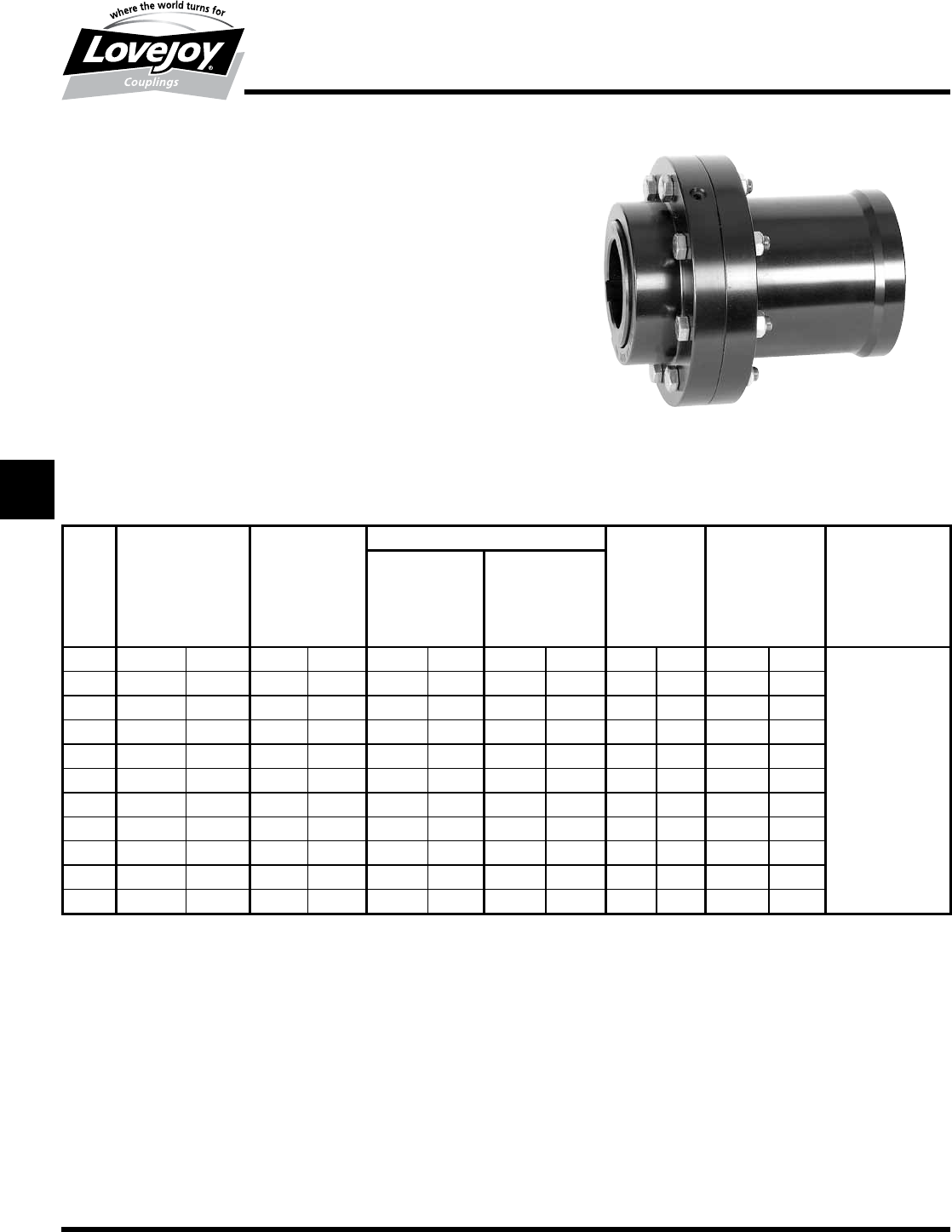
162 630-852-0500
G-48
Gear
FMM Mill Motor Type
Performance Data
Lovejoy / Sier-Bath Flanged Sleeve Gear Couplings
FMM Type Mill Motor Couplings
The■FMM■Type■coupling■consists■of■one■standard■flex■hub,■one■universal■straight■bored■
hub■as■standard,■two■sleeves■and■one■accessory■kit.■This■coupling■is■supplied■with■
exposed■bolts■as■standard.■Shrouded■bolts■are■available■upon■request■through■size■5.5.
Features
■■Patented■Vari-Crown®■tooth■form■for■long■life
■■Standard■20°■pressure■angle
■■Heat■treated■bolts■for■greater■strength
■■Corrosion■resistant■bolts■and■nuts■for■ease■of■maintenance
■■Provides■parallel,■angular■misalignment■and■end■float
■■Flex■Half■coupling■interchangeable■with■industry■standards
■■Long■Universal■Hub■used■for■AISE■Motor■Frames
FMM Type Mill Motor Performance Data
ID1 - ID2
Size
Nominal Maximum Max Bore Rough Stock Weight Parallel Max Angular
Torque Speed Bore Misalignment Misalignment
Unbal Bal Degrees
in-lb Nm RPM RPM in mm in mm lbs kg in mm
17,600 850 6,000 9,000 1.625 42 0.44 11 12 5 0.056 1.4
■
1.5°
Per■Gear■Mesh
■
1.5 18,900 2■140 5,500 8,250 2.125 56 0.69 18 24 11 0.060 1.5
231,500 3■560 5,000 7,500 2.75 73 0.94 24 45 20 0.085 2.2
2.5 56,700 6■410 4,400 6,600 3.25 85 1.44 37 71 32 0.105 2.7
394,500 10■700 4,000 6,000 4.000 107 1.44 37 104 47 0.115 2.9
3.5 151,200 17■100 3,500 5,250 4.625 125 1.81 46 151 69 0.130 3.3
4220,500 24■900 3,000 4,500 5.375 145 2.44 62 234 86 0.150 3.8
4.5 302,400 34■200 2,700 4,050 6.000 165 3.00 76 310 141 0.175 4.4
5434,700 49■100 2,500 3,750 6.500 180 3.00 76 450 204 0.200 5.1
5.5 573,300 64■800 2,200 3,300 7.500 200 4.00 101 609 276 0.220 5.6
6749,700 84■700 2,100 3,150 8.250 225 4.00 101 764 347 0.120 3.0
Ordering Information
■■Application:■Driver■and■Driven.
■■Type■and■size■of■coupling,■horizontal,■vertical■etc.
■■Power:■Motor■horspower■or■torque■requirement.
■■Speed:■Motor■RPM■or■Driven■RPM.
■■Distance■between■shaft■ends■(BSE).
■■Shaft■sizes.
■■Mill■Motor■frame■size.
■■Submit■a■drawing■if■available.
JWJISCJSFMC
G
HPGDDTSPUJVSDRSLDED
JW JIS CJ SF MC G HP GD D T SP UJ VSD R SLD ED
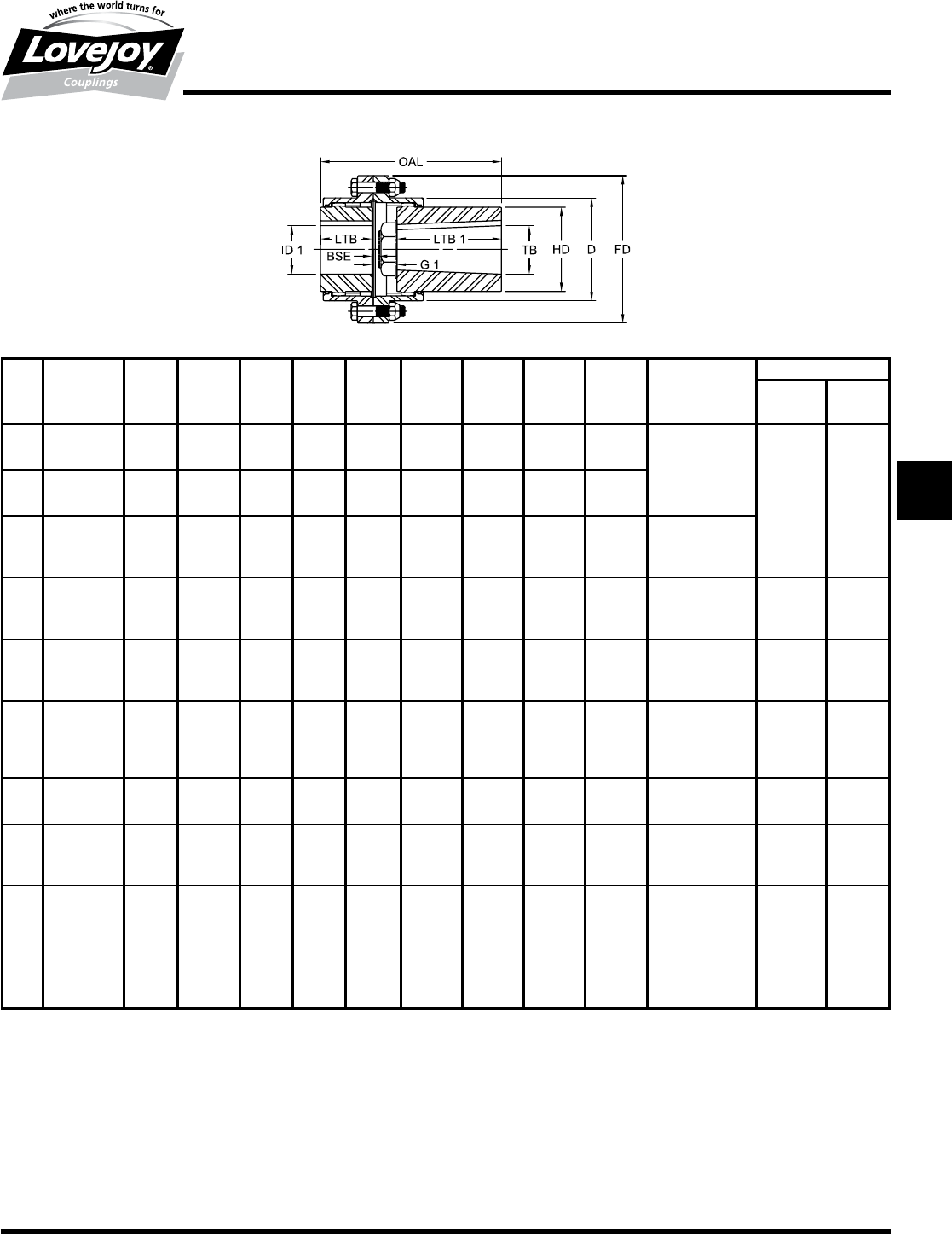
163
www.lovejoy-inc.com G-49
Gear
FMM Mill Motor Type
Dimensional Data
Lovejoy / Sier-Bath Flanged Sleeve Gear Couplings
FMM Type Mill Motor Couplings
FMM Type Mill Motor Dimensional Data
AISE OAL ID1 LTB LTB1 G1 BSE FD D HD TB Mill Motor Hub Kw
Frame W H
Size No in in in in in in in in in in in
1.5
602/802 6.00
2.125 1.94
3.00 1.06■*
0.13 6.00 3.97 3.00
1.7485■-■1.7495 0.50 0.25
603/803 6.56 3.50 1.13■* 1.998■-■1.999 0.50 0.25
604/804 6.56 3.50 1.13■* 1.998■-■1.999 0.50 0.25
2
603/803 7.06
2.750 2.44
3.50 1.13
0.13 7.00 4.86 4.00
1.998■-■1.999 0.50 0.25
604/804 7.06 3.50 1.13 1.998■-■1.999 0.50 0.25
606/806 7.69 4.00 1.25 2.498■-■2.499 0.50 0.25
2.5
603/803 7.72
3.250 3.03
3.50 1.19
0.19 8.38 5.84 4.63
1.998■-■1.999 0.50 0.25
604/804 7.72 3.50 1.19 1.998■-■1.999 0.50 0.25
606/806 8.34 4.00 1.31 2.498■-■2.499 0.50 0.25
608/808 8.34 4.50 1.44 2.998■-■2.999 0.75 0.25
3
606/806 8.91
4.000 3.59
4.00 1.31
0.19 9.44 6.84 5.63
2.498■-■2.499 0.50 0.25
608/808 9.53 4.50 1.44 2.998■-■2.999 0.75 0.25
610/810 9.66 4.50 1.56 3.248■-■3.249 0.75 0.25
612/812 10.28 5.00 1.69 3.623■-■3.624 0.75 0.25
3.5
608/808 10.19
4.625 4.19
4.50 1.50
0.25 11.00 7.91 6.50
2.998■-■2.999 0.75 0.25
610/810 10.31 4.50 1.63 3.248■-■3.249 0.75 0.25
612/812 10.94 5.00 1.75 3.623■-■3.624 0.75 0.25
614/814 11.06 5.00 1.88 4.270■-■4.2485 1.00 0.38
4
610/810 10.88
5.375 4.75
4.50 1.63
0.25 12.50 9.25 7.50
3.248■-■3.249 0.75 0.25
612/812 11.50 5.00 1.75 3.623■-■3.624 0.75 0.25
614/814 11.63 5.00 1.88 4.2470■-■4.2485 1.00 0.38
616/816 12.25 5.50 2.00 4.6220■-■4.6235 1.25 0.38
618/818 12.31 6.00 1.56 4.9970■-■4.9985 1.25 0.50
4.5
614/814 12.25
6.000 5.31
5.00 1.94
0.31 13.63 10.38 8.50
4.2470■-■4.2485 1.00 0.38
616/816 12.88 5.50 2.06 4.6220■-■4.6235 1.25 0.38
618/818 12.94 6.00 1.63 4.9970■-■4.9985 1.25 0.50
5
614/814 12.97
6.500 6.03
5.00 1.94
0.31 15.31 11.56 9.50
4.2470■-■4.2485 1.00 0.38
616/816 13.59 5.50 2.06 4.6220■-■4.6235 1.25 0.38
618/818 13.66 6.00 1.63 4.9970■-■4.9985 1.25 0.50
620 14.84 6.75 2.06 5.8720■-■5.8735 1.50 0.75
5.5
616/816 14.47
7.500 6.91
5.50 2.06
0.31 16.75 12.72 10.50
4.6220■-■4.6235 1.25 0.38
618/818 14.53 6.00 1.63 4.9970■-■4.9985 1.25 0.50
620 15.72 6.75 2.06 5.8720■-■5.8735 1.50 0.75
622 16.84 7.25 2.69 6.2470■-■6.2485 1.50 0.75
6
616/816 14.97
8.250 7.41
5.50 2.06
0.31 18.00 14.00 11.50
4.6220■-■4.6235 1.25 0.38
618/818 15.03 6.00 1.63 4.9970■-■4.9985 1.25 0.50
620 16.22 6.75 2.06 5.8720■-■5.8735 1.50 0.75
622 17.34 7.25 2.69 6.2470■-■6.2485 1.50 0.75
Notes:■■ n■■■*■indicates:■That■a■counterbore■is■required.
■n■■■Bore■taper■is■1-1⁄4■inch■per■foot■on■diameter.
■n■■■Exposed■Bolt■Design■is■standard.
■n■■■Shrouded■Bolt■Design■available■upon■request■for■sizes■1.5■through■5.5.
■n■■■Puller■Holes■are■standard■on■sizes■4■through■6.
■n■■■Puller■Holes■are■available■for■sizes■1.5■through■3.5■at■an■additional■charge.
■n■■■Interference■bores■with■no■set■screws■are■standard■unless■otherwise■specified.
■n■■■Inch■bore■and■keyway■tolerances■conform■to■ANSI■/■AGMA■9002-B04.
■n■■■For■metric■bore■and■keyway■tolerances,■consult■Lovejoy■Engineering■Section.
■n■■■1/4■inch■hub■standoff.
JWJISCJSFMCGHPGDDTSPUJVSDRSLDED
JW JIS CJ SF MC
G
HP GD D T SP UJ VSD R SLD ED
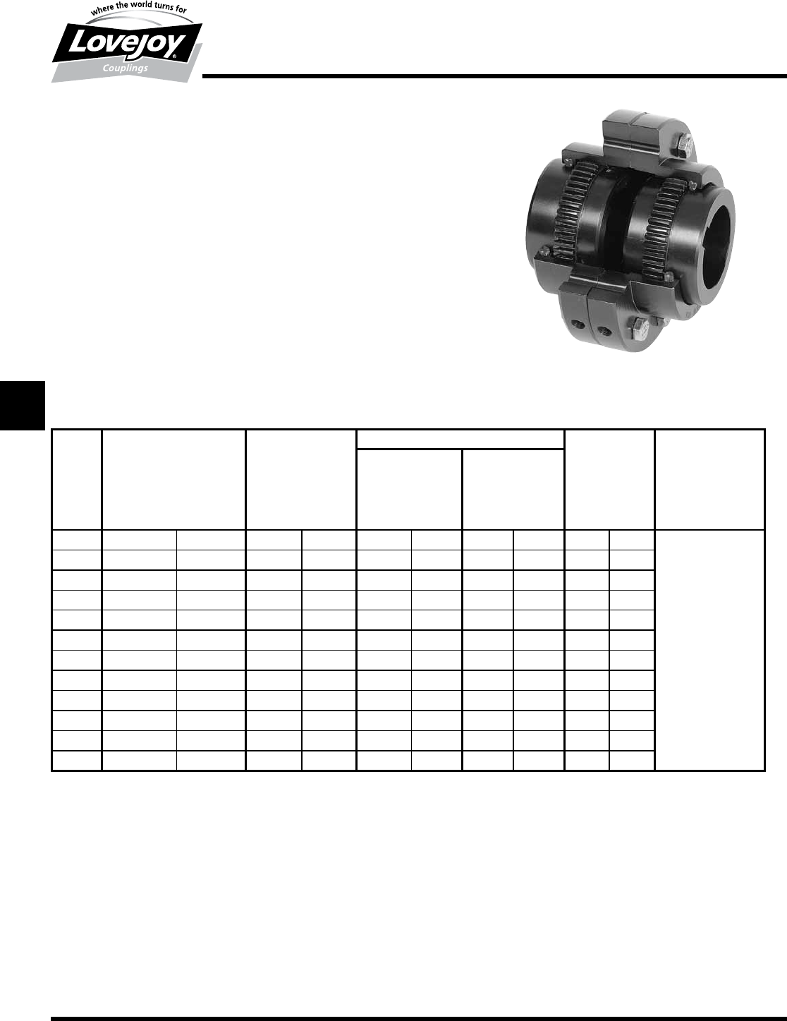
164 630-852-0500
G-50
Gear
FSL Type
Performance Data
Lovejoy / Sier-Bath Flanged Sleeve Gear Couplings
FSL Type Slide Coupling
The■FSL■Type■coupling■consists■of■one■or■two■modified■flex■hubs■depending■on■the■
maximum■slide■required,■two■sleeves,■one■plate■with■lube■holes■and■one■accessory■kit.■
The■coupling■is■supplied■with■exposed■bolts■as■standard.■Shrouded■bolts■are■available■
upon■request■through■size■5.5.
Features
■■Patented■Vari-Crown®■tooth■form■for■long■life
■■Standard■20°■pressure■angle
■■Heat■treated■bolts■for■greater■strength
■■Corrosion■resistant■bolts■and■nuts■for■ease■of■maintenance
■■Assembled■to■suit■a■wide■range■of■axial■movement
■■Plates■with■lube■holes■so■both■halves■of■the■coupling■will■be■adequately■lubricated
FSL Type Performance Data
ID1 - ID2
Size
Nominal Maximum Max Bore Rough Stock Weight Max Angular
Torque Speed Bore Misalignment
Unbal Bal Degrees
in-lb Nm RPM RPM in mm in mm lbs kg
17,600 850 6,000 9,000 1.625 42 0.44 11 9 4
1.5 18,900 2■140 5,500 8,250 2.125 56 0.69 18 19 9
231,500 3■560 5,000 7,500 2.750 73 0.94 24 34 15 ■
2.5 56,700 6■410 4,400 6,600 3.250 85 1.44 37 54 25
394,500 10■700 4,000 6,000 4.000 107 1.44 37 80 36
3.5 151,200 17■100 3,500 5,250 4.625 125 1.81 46 130 59 1.5°
4220,500 24■900 3,000 4,500 5.375 145 2.44 62 190 86 Per■Gear■Mesh
4.5 302,400 34■200 2,700 4,050 6.000 165 3.00 76 250 114 ■
5434,700 49■100 2,500 3,750 6.500 180 3.00 76 380 173
5.5 573,300 64■800 2,200 3,300 7.500 200 4.00 101 520 236
6749,700 84■700 2,100 3,150 8.250 225 4.00 101 650 295
71,008,000 113■900 2,000 3,000 9.500 255 5.75 139 950 431
Ordering Information
■■Application:■Driver■and■Driven.
■■Type■and■size■of■coupling,■horizontal,■vertical■etc.
■■Power:■Motor■horspower■or■torque■requirement.
■■Speed:■Motor■RPM■or■Driven■RPM.
■■Distance■between■shaft■ends■(maximum-minimum■shaft■separation).
■■Shaft■sizes.
■■Amount■of■slide■required.
JWJISCJSFMC
G
HPGDDTSPUJVSDRSLDED
JW JIS CJ SF MC G HP GD D T SP UJ VSD R SLD ED
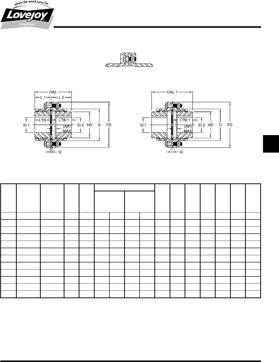
165
www.lovejoy-inc.com G-51
Gear
FSL Type
Dimensional Data
Lovejoy / Sier-Bath Flanged Sleeve Gear Couplings
FSL Type Slide Couplings
FSL Type Dimensional Data
OAL OAL1 L1 L2 ID1 - ID2 LTB LTB1 AP1G FD D HD
One Hub Two Hubs Std Slide Max Bore Rough Stock Std Slide Max Min
Reversed Reversed Hub Half Bore Hub Hub
Size in in in in in mm in mm in in in in in in in
13.81 4.13 1.75 2.06 1.625 42 0.44 11 1.59 1.50 0.41 0.31 4.56 3.06 2.31
1.5 4.25 4.50 2.00 2.25 2.125 56 0.69 18 1.84 1.75 0.34 0.31 6.00 3.97 3.00
25.69 6.38 2.50 3.19 2.750 73 0.94 24 2.34 2.25 0.78 0.31 7.00 4.86 4.00
2.5 7.03 7.81 3.13 3.91 3.250 85 1.44 37 2.94 2.78 0.94 0.38 8.38 5.84 4.63
38.03 8.69 3.69 4.34 4.000 107 1.44 37 3.50 3.13 1.03 0.38 9.44 6.84 5.63
3.5 9.19 9.75 4.31 4.88 4.625 125 1.81 46 4.09 3.59 1.06 0.44 11.00 7.91 6.50
410.44 11.13 4.88 5.56 5.375 145 2.44 62 4.56 3.94 1.31 0.63 12.50 9.25 7.50
4.5 12.00 13.06 5.47 6.53 6.000 165 3.00 76 5.13 4.50 1.69 0.69 13.63 10.38 8.50
513.72 15.06 6.19 7.53 6.500 180 3.00 76 5.84 5.22 1.97 0.69 15.31 11.56 9.50
5.5 15.34 16.56 7.06 8.28 7.500 200 4.00 101 6.72 5.88 2.06 0.69 16.75 12.72 10.50
616.53 17.94 7.56 8.97 8.250 225 4.00 101 7.16 7.09 1.47 0.81 18.00 14.00 11.50
719.06 20.38 8.88 10.19 9.500 255 5.75 139 8.38 7.78 1.91 1.00 20.75 15.75 13.00
1 Hub Reversed
And Modified
2 Hubs Reversed
And Modified
Shrouded Bolt Design
Also Available
Notes:■■ n■■■1■indicates:■AP■Max■=■Maximum■slide■per■coupling■half.
■n■■■Exposed■Bolt■Design■is■standard.
■n■■■Shrouded■Bolt■Design■available■upon■request■for■sizes■1■through■5.5.
■n■■■Puller■Holes■are■standard■on■sizes■4■through■9.
■n■■■Puller■Holes■are■available■for■sizes■1■through■3.5■at■an■additional■charge.
■n■■■Interference■bores■with■no■set■screws■are■standard■unless■otherwise■specified.
■n■■■Inch■bore■and■keyway■tolerances■conform■to■AGMA■9002-B04.
■n■■■For■metric■bore■and■keyway■tolerances,■consult■Lovejoy■Engineering■Section.
JWJISCJSFMCGHPGDDTSPUJVSDRSLDED
JW JIS CJ SF MC
G
HP GD D T SP UJ VSD R SLD ED
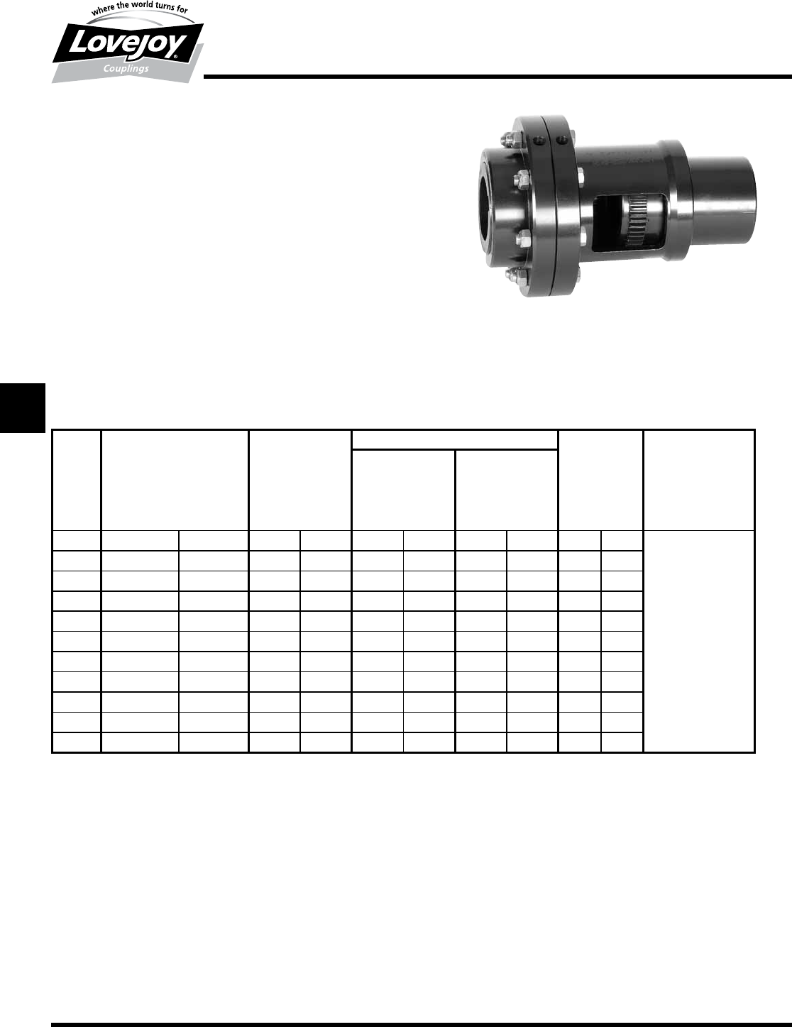
166 630-852-0500
G-52
Gear
FSLX Type
Performance Data
Lovejoy / Sier-Bath Flanged Sleeve Gear Couplings
FSLX Type Long Slide Couplings
The■FSLX■Type■basic■coupling■consists■of■a■standard■flex■half■and■a■custom■
designed■long■slide■half.■The■standard■flex■half■can■be■replaced■by■a■reversed■and■
modified■hub■for■additional■slide■requirement.■These■couplings■are■also■supplied■with■
a■plate■with■lube■holes.■The■coupling■is■supplied■with■exposed■bolts■as■standard.■
Shrouded■bolts■available■upon■request■through■size■5.5.
Features
■■Patented■Vari-Crown®■tooth■form■for■long■life
■■Standard■20°■pressure■angle
■■Heat■treated■bolts■for■greater■strength
■■Corrosion■resistant■bolts■and■nuts■for■ease■of■maintenance
■■Assembled■to■suit■a■wide■range■of■axial■movement
■■Plates■with■lube■holes■so■both■halves■of■the■coupling■will■be■adequately■lubricated
FSLX Type Performance Data
ID1 - ID2
Size
Nominal Maximum Max Bore Rough Stock Weight Max Angular
Torque Speed Bore Misalignment
Unbal Bal Degrees
in-lb Nm RPM RPM in mm in mm lbs kg
1.5 18,900 2■140 5,500 8,250 2.125 56 0.69 18 19 9
231,500 3■560 5,000 7,500 2.750 73 0.94 24 34 15 ■
2.5 56,700 6■410 4,400 6,600 3.250 85 1.44 37 54 25
394,500 10■700 4,000 6,000 4.000 107 1.44 37 80 36
3.5 151,200 17■100 3,500 5,250 4.625 125 1.81 46 130 59 1.5°
4220,500 24■900 3,000 4,500 5.375 145 2.44 62 190 86 Per■Gear■Mesh
4.5 302,400 34■200 2,700 4,050 6.000 165 3.00 76 250 114 ■
5434,700 49■100 2,500 3,750 6.500 180 3.00 76 380 173
5.5 573,300 64■800 2,200 3,300 7.500 200 4.00 101 520 236
6749,700 84■700 2,100 3,150 8.250 225 4.00 101 650 295
71,008,000 113■900 2,000 3,000 9.500 255 5.75 139 950 431
Ordering Information
■■Application:■Driver■and■Driven.
■■Type■and■size■of■coupling,■horizontal,■vertical■etc.
■■Power:■Motor■horspower■or■torque■requirement.
■■Speed:■Motor■RPM■or■Driven■RPM.
■■Distance■between■shaft■ends■(maximum-minimum■shaft■separation).
■■Shaft■sizes.
■■Amount■of■slide■required.
■■HL■Dimension.
■■LTB2■Dimension.
JWJISCJSFMC
G
HPGDDTSPUJVSDRSLDED
JW JIS CJ SF MC G HP GD D T SP UJ VSD R SLD ED
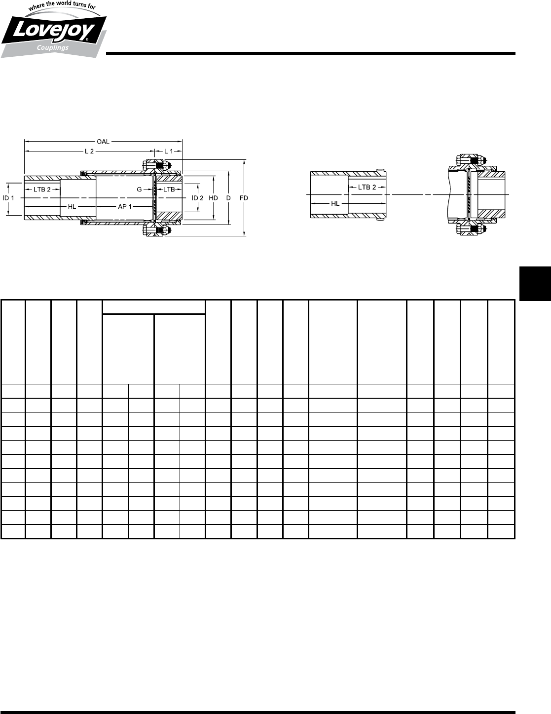
167
www.lovejoy-inc.com G-53
Gear
FSLX Type
Dimensional Data
Lovejoy / Sier-Bath Flanged Sleeve Gear Couplings
FSLX Type Long Slide Couplings
FSLX Type Dimensional Data
OAL L1 L2 ID1 - ID2 LTB LTB2 G AP1 AP2 AP3 HL FD D HD
Std Slide Max Bore Rough Std Slide Min Long Long Slide Long Slide
Hub Half Stock Hub Hub Slide w/one Hub Both Ends
Bore Max Reversed Max
Max
Size in in in in mm in mm in in in in in in in in in in
1.5 10.41 2.00 8.41 2.125 56 0.69 18 1.84 2.19 0.31 3.38 3.72 6.75 4.88 6.00 3.97 3.00
210.88 2.50 8.38 2.750 73 0.94 24 2.34 2.69 0.31 3.31 4.09 6.63 4.91 7.00 4.86 4.00
2.5 13.59 3.13 10.47 3.250 85 1.44 37 2.94 3.28 0.38 4.16 5.09 8.31 6.13 8.83 5.84 4.63
321.72 3.69 18.03 4.000 107 1.44 37 3.50 3.84 0.38 7.78 8.81 15.56 10.06 9.44 6.84 5.63
3.5 22.38 4.31 18.06 4.625 125 1.81 46 4.09 4.44 0.44 7.66 8.72 15.31 10.19 11.00 7.91 6.50
423.00 4.88 18.13 5.375 145 2.44 62 4.56 5.00 0.63 7.50 8.81 15.00 10.31 12.50 9.25 7.50
4.5 23.75 5.47 18.28 6.000 165 3.00 76 5.13 5.56 0.69 7.38 9.06 14.75 10.56 13.63 10.38 8.50
524.16 6.19 17.97 6.500 180 3.00 76 5.84 6.28 0.69 7.06 9.03 14.13 10.56 15.31 11.56 9.50
5.5 25.09 7.06 18.03 7.500 200 4.00 101 6.72 6.88 0.69 6.81 8.88 13.63 10.88 16.75 12.72 10.50
625.66 7.56 18.09 8.250 225 4.00 101 7.16 7.66 0.81 6.81 8.28 13.63 10.88 18.00 14.00 11.50
727.06 8.88 18.19 9.500 255 5.75 139 8.38 8.94 1.00 6.81 8.72 13.63 10.88 20.75 15.75 13.00
Long Slide Half Standard Half Alternate Type hub shaft
contact is deep inside hub
One Hub reversed with
long slide half
Notes:■■ n■■■■Exposed■Bolt■Design■is■standard.
■n■■■Shrouded■Bolt■Design■available■upon■request■for■sizes■1■through■5.5.
■n■■■Puller■Holes■are■standard■on■sizes■4■through■9.
■n■■■Puller■Holes■are■available■for■sizes■1■through■3.5■at■an■additional■charge.
■n■■■Interference■bores■with■no■set■screws■are■standard■unless■otherwise■specified.
■n■■■Inch■bore■and■keyway■tolerances■conform■to■AGMA■9002-B04.
■n■■■For■metric■bore■and■keyway■tolerances,■consult■Lovejoy■Engineering■Section.
JWJISCJSFMCGHPGDDTSPUJVSDRSLDED
JW JIS CJ SF MC
G
HP GD D T SP UJ VSD R SLD ED
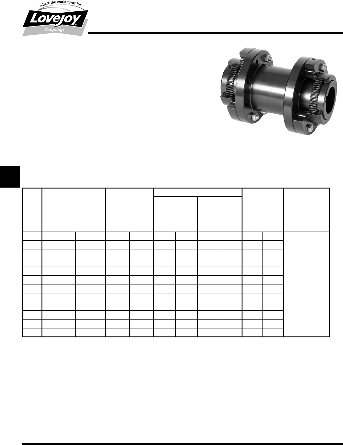
168 630-852-0500
G-54
Gear
FSPCR Type
Performance Data
Lovejoy / Sier-Bath Flanged Sleeve Gear Couplings
FSPCR Type Spacer Couplings
The■FSPCR■Type■coupling■consists■of■two■flex■hubs,■two■sleeves,■one■spacer■and■two■
accessory■kits.■This■coupling■is■supplied■with■exposed■bolts■as■standard.■Shrouded■bolts■are■
available■upon■request■through■size■5.5.
Features
■■Patented■Vari-Crown®■tooth■form■for■long■life
■■Standard■20°■pressure■angle
■■Heat■treated■bolts■for■greater■strength
■■Corrosion■resistant■bolts■and■nuts■for■ease■of■maintenance
■■Provides■parallel,■angular■misalignment■and■end■float
■■Removal■of■spacer■provides■adequate■space■for■the■removal■of■either■coupling■half■
without■moving■the■driver■or■driven■units
Note:■■ n■■1■indicates:■Maximum■RPM■of■spacer■set■determined■by■critical■speed■of■spacer.
FSPCR Type Performance Data
ID1 - ID2
Size
Nominal Maximum Max Bore Rough Stock Weight Max Angular
Torque Speed1Bore Less Misalignment
Unbal Bal Spacer Degrees
in-lb Nm RPM RPM in mm in mm lbs kg
17,600 850 6,000 9,000 1.625 42 0.44 11 9 4
1.5 18,900 2■140 5,500 8,250 2.125 56 0.69 18 19 9
231,500 3■560 5,000 7,500 2.750 73 0.94 24 34 15 ■
2.5 56,700 6■410 4,400 6,600 3.250 85 1.44 37 54 25
394,500 10■700 4,000 6,000 4.000 107 1.44 37 80 36
3.5 151,200 17■100 3,500 5,250 4.625 125 1.81 46 130 59 1.5°
4220,500 24■900 3,000 4,500 5.375 145 2.44 62 190 86 Per■Gear■Mesh
4.5 302,400 34■200 2,700 4,050 6.000 165 3.00 76 250 114 ■
5434,700 49■100 2,500 3,750 6.500 180 3.00 76 380 173
5.5 573,300 64■800 2,200 3,300 7.500 200 4.00 101 520 236
6749,700 84■700 2,100 3,150 8.250 225 4.00 101 650 295
71,008,000 113■900 2,000 3,000 9.500 255 5.00 127 950 431
Ordering Information
■■Application:■Driver■and■Driven.
■■Type■and■size■of■coupling,■horizontal,■vertical■etc.
■■Power:■Motor■horspower■or■torque■requirement.
■■Speed:■Motor■RPM■or■Driven■RPM.
■■Distance■between■shaft■ends■(BSE).
■■Shaft■sizes.
JWJISCJSFMC
G
HPGDDTSPUJVSDRSLDED
JW JIS CJ SF MC G HP GD D T SP UJ VSD R SLD ED
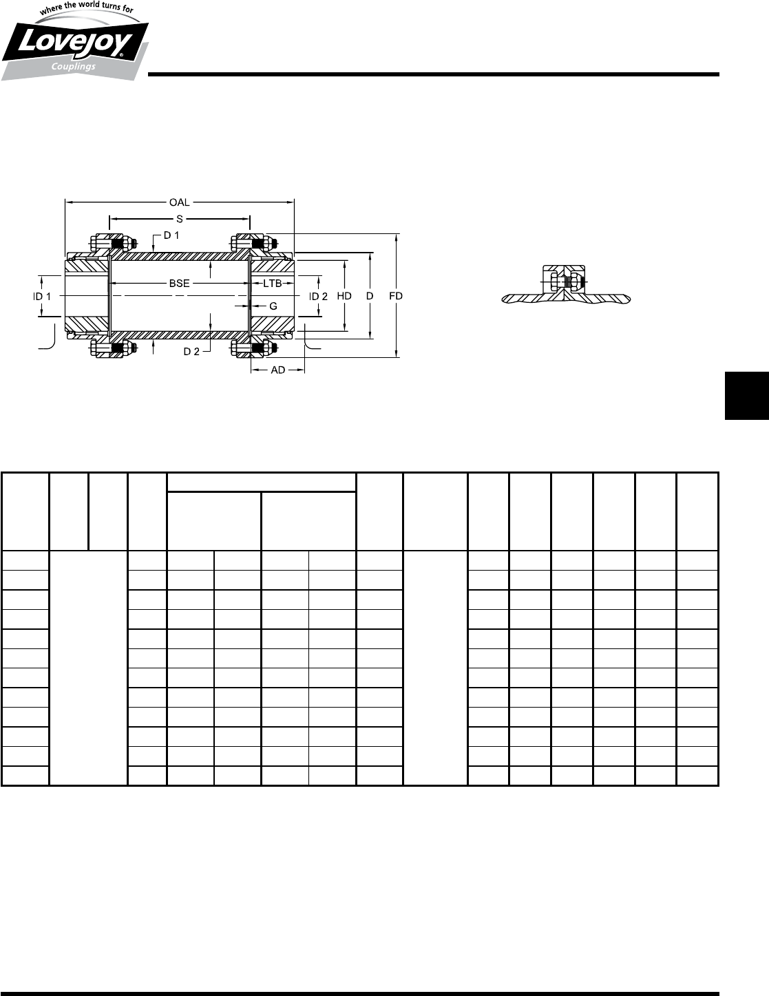
169
www.lovejoy-inc.com G-55
Gear
FSPCR Type
Dimensional Data
Lovejoy / Sier-Bath Flanged Sleeve Gear Couplings
FSPCR Type Spacer Couplings
FSPCR Type Dimensional Data
OAL S AD ID1 - ID2 LTB BSE G FD D HD D1 D2
Max Bore Rough Stock
Bore
Size in in in in mm in mm in in in in in in in in
1■ ■ ■2.04 1.625 42 0.44 11 1.69 ■ 0.06 4.56 3.06 2.31 3.00 2.41
1.5 Determined 2.32 2.125 56 0.69 18 1.94 Determined 0.06 6.00 3.97 3.00 3.75 3.13
2by 2.94 2.750 73 0.94 24 2.44 by 0.06 7.00 4.86 4.00 4.75 4.00
2.5 ■Shaft■ 3.47 3.250 85 1.44 37 3.03 Customer■ 0.09 8.38 5.84 4.63 5.50 4.78
3■Separation 3.97 4.000 107 1.44 37 3.59 Specs 0.09 9.44 6.84 5.63 6.50 5.75
3.5 ■ ■ 4.57■ 4.625 125 1.81 46 4.19 ■ 0.13 11.00 7.91 6.50 7.38 6.63
4■ ■ 5.00■ 5.375 145 2.44 62 4.75 ■ 0.13 12.50 9.25 7.50 8.63 7.75
4.5 ■ ■ 5.50■ 6.000 165 3.00 76 5.31 ■ 0.16 13.63 10.38 8.50 9.38 8.50
5■ ■ 6.34■ 6.500 180 3.00 76 6.03 ■ 0.16 15.31 11.56 9.50 10.38 9.56
5.5 ■ ■ 7.04■ 7.500 200 4.00 101 6.91 ■ 0.16 16.75 12.72 10.50 11.44 10.56
6■ ■ 8.35■ 8.250 225 4.00 101 7.41 ■ 0.16 18.00 14.00 11.50 12.38 11.44
7■ ■ 9.82■ 9.500 255 5.00 127 8.69 ■ 0.19 20.75 15.75 13.00 14.00 13.00
Shrouded bolt design also
available
Notes:■■ n■■■■Exposed■Bolt■Design■is■standard.
■n■■■Shrouded■Bolt■Design■available■upon■request■for■sizes■1■through■5.5.
■n■■■Puller■Holes■are■standard■on■sizes■4■through■9.
■n■■■Puller■Holes■are■available■for■sizes■1■through■3.5■at■an■additional■charge.
■n■■■Interference■bores■with■no■set■screws■are■standard■unless■otherwise■specified.
■n■■■Inch■bore■and■keyway■tolerances■conform■to■AGMA■9002-B04.
■n■■■For■metric■bore■and■keyway■tolerances,■consult■Lovejoy■Engineering■Section.
JWJISCJSFMCGHPGDDTSPUJVSDRSLDED
JW JIS CJ SF MC
G
HP GD D T SP UJ VSD R SLD ED
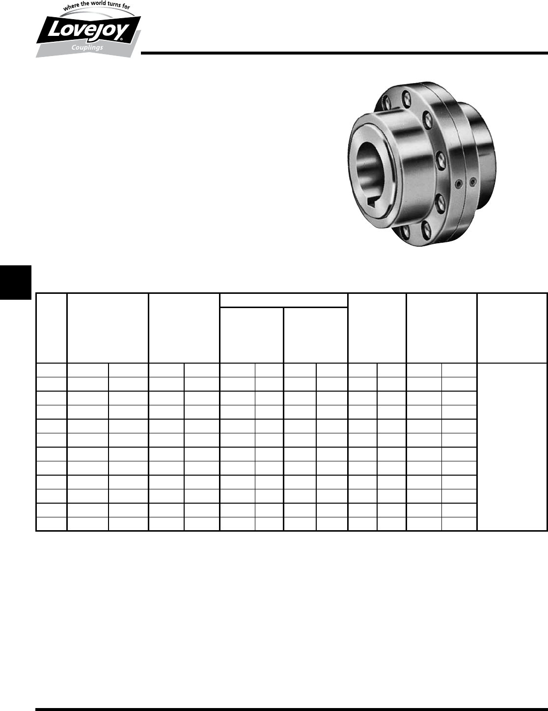
170 630-852-0500
G-56
Gear
FLEF Type
Performance Data
Lovejoy / Sier-Bath Flanged Sleeve Gear Couplings
FLEF Type Limited End Float Couplings
The■FLEF■Type■coupling■consists■of■two■flex■hubs,■two■sleeves,■one■accessory■kit■and■a■
steel■plate■to■limit■the■movement.■This■coupling■is■supplied■with■exposed■bolts■as■standard.■
Shrouded■bolts■are■available■upon■request■through■size■5.5.
Features
■■Patented■Vari-Crown®■tooth■form■for■long■life
■■Standard■20°■pressure■angle
■■Heat■treated■bolts■for■greater■strength
■■Corrosion■resistant■bolts■and■nuts■for■ease■of■maintenance
■■Provides■and■maintains■restriced■end■float■in■sleeve■bearings■and■rotor■systems■where■
thrust■is■not■permitted
■■Optional■flow-through■steel■plate■with■lube■holes■available
FLEF Type Performance Data
ID1 - ID2
Size
Nominal Maximum Max Bore Rough Stock Weight Parallel Max Angular
Torque Speed Bore Misalignment Misalignment
Unbal Bal Degrees
in-lb Nm RPM RPM in mm in mm lbs kg in mm
17,600 850 6,000 9,000 1.625 42 0.44 11 9 4 0.056 1.4
1.5 18,900 2■140 5,500 8,250 2.125 56 0.69 18 19 9 0.060 1.5
231,500 3■560 5,000 7,500 2.750 73 0.94 24 34 15 0.085 2.2 ■
2.5 56,700 6■410 4,400 6,600 3.250 85 1.44 37 54 25 0.105 2.7
394,500 10■700 4,000 6,000 4.000 107 1.44 37 80 36 0.115 2.9
3.5 151,200 17■100 3,500 5,250 4.625 125 1.81 46 130 59 0.130 3.3 1.5°
4220,500 24■900 3,000 4,500 5.375 145 2.44 62 190 86 0.150 3.8 Per■Gear■Mesh
4.5 302,400 34■200 2,700 4,050 6.000 165 3.00 76 250 114 0.175 4.4 ■
5434,700 49■100 2,500 3,750 6.500 180 3.00 76 380 173 0.200 5.1
5.5 573,300 64■800 2,200 3,300 7.500 200 4.00 101 520 236 0.220 5.6
6749,700 84■700 2,100 3,150 8.250 225 4.00 101 650 295 0.120 3.0
71,008,000 113■900 2,000 3,000 9.500 255 5.00 127 950 431 0.135 3.4
Ordering Information
■■Application:■Driver■and■Driven.
■■Type■and■size■of■coupling,■horizontal,■vertical■etc.
■■Power:■Motor■horspower■or■torque■requirement.
■■Speed:■Motor■RPM■or■Driven■RPM.
■■Distance■between■shaft■ends■(BSE).
■■Shaft■sizes.
■■Amount■of■thrust■on■either■or■both■shafts.
■■Submit■a■drawing■if■available.
JWJISCJSFMC
G
HPGDDTSPUJVSDRSLDED
JW JIS CJ SF MC G HP GD D T SP UJ VSD R SLD ED
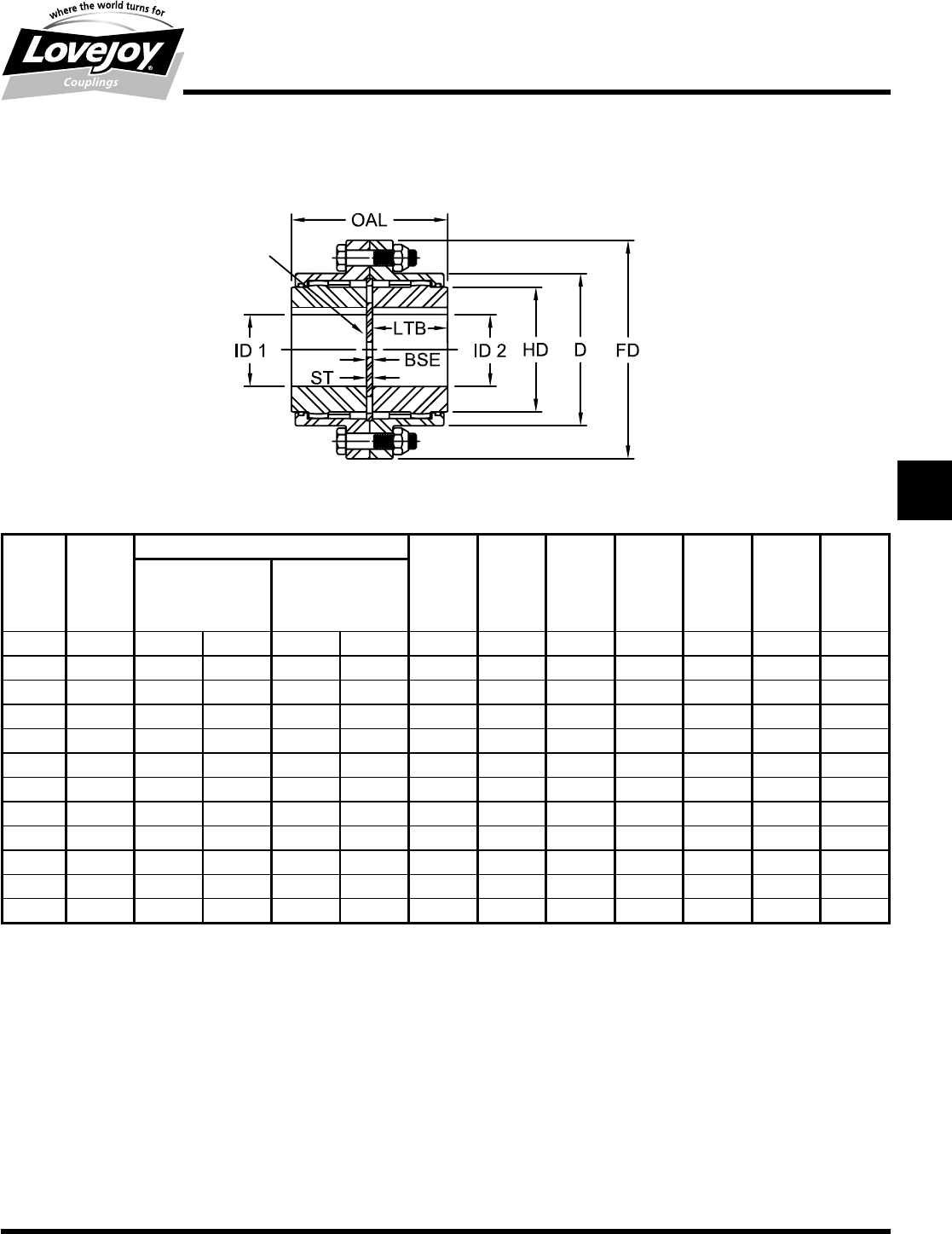
171
www.lovejoy-inc.com G-57
Gear
FLEF Type
Dimensional Data
Lovejoy / Sier-Bath Flanged Sleeve Gear Couplings
FLEF Type Limited End Float Couplings
FLEF Type Dimensional Data
OAL ID1 - ID2 LTB BSE F1ST FD D HD
Max Bore Rough Stock (ref)
Bore
Size in in mm in mm in in in in in in in
13.56 1.625 42 0.44 11 1.69 0.19 0.13 0.13 4.56 3.06 2.31
1.5 4.06 2.125 56 0.69 18 1.94 0.19 0.13 0.13 6.00 3.97 3.00
25.06 2.750 73 0.94 24 2.44 0.19 0.13 0.13 7.00 4.86 4.00
2.5 6.34 3.250 85 1.44 37 3.03 0.28 0.19 0.19 8.38 5.84 4.63
37.47 4.000 107 1.44 37 3.59 0.28 0.19 0.19 9.44 6.84 5.63
3.5 8.69 4.625 125 1.81 46 4.19 0.31 0.25 0.19 11.00 7.91 6.50
49.88 5.375 145 2.44 62 4.75 0.38 0.25 0.25 12.50 9.25 7.50
4.5 11.06 6.000 165 3.00 76 5.31 0.44 0.25 0.31 13.63 10.38 8.50
512.59 6.500 180 3.00 76 6.03 0.53 0.31 0.38 15.31 11.56 9.50
5.5 14.34 7.500 200 4.00 101 6.91 0.53 0.31 0.38 16.75 12.72 10.50
615.28 8.250 225 4.00 101 7.41 0.47 0.31 0.31 18.00 14.00 11.50
717.94 9.500 255 5.00 127 8.69 0.56 0.38 0.38 20.75 15.75 13.00
LEF
PLATE
Notes:■■ n■■1■indicates:■F■is■the■total■end■float.■(May■be■modified.)
■n■■■■Exposed■Bolt■Design■is■standard.
■n■■■Shrouded■Bolt■Design■available■upon■request■for■sizes■1■through■5.5.
■n■■■Puller■Holes■are■standard■on■sizes■4■through■9.
■n■■■Puller■Holes■are■available■for■sizes■1■through■3.5■at■an■additional■charge.
■n■■■Interference■bores■with■no■set■screws■are■standard■unless■otherwise■specified.
■n■■■Inch■bore■and■keyway■tolerances■conform■to■AGMA■9002-B04.
■n■■■For■metric■bore■and■keyway■tolerances,■consult■Lovejoy■Engineering■Section.
JWJISCJSFMCGHPGDDTSPUJVSDRSLDED
JW JIS CJ SF MC
G
HP GD D T SP UJ VSD R SLD ED
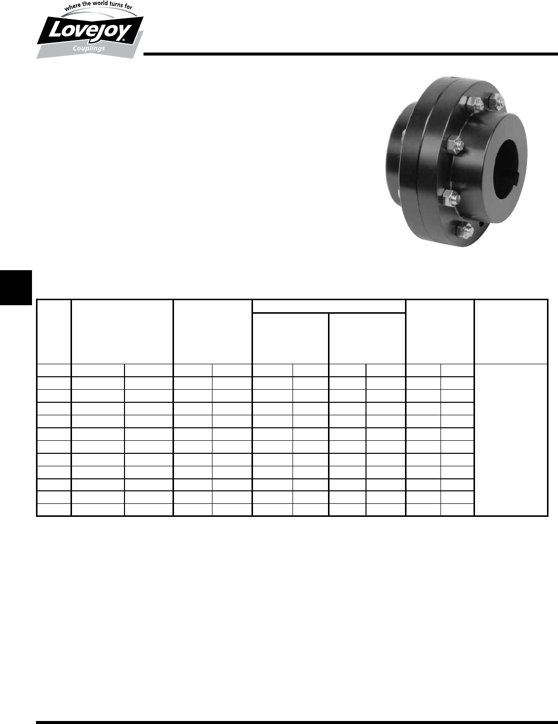
172 630-852-0500
G-58
Gear
FRR Type
Performance Data
Lovejoy / Sier-Bath Flanged Sleeve Gear Couplings
FRR Type Rigid-Rigid Couplings
The■F■Type■coupling■consists■of■two■rigid■hubs■and■one■accessory■kit.■This■coupling■is■supplied■
with■exposed■bolts■as■standard.■Shrouded■bolts■are■available■upon■request■through■size■5.5.
Features
■■All■Steel■construction
■■Torque■capacities■that■exceed■the■mild■steel■shafts■to■be■coupled
■■Heat■treated■bolts■for■greater■strength
■■Corrosion■resistant■bolts■and■nuts■for■ease■of■maintenance
■■Rigid■Half■coupling■interchangeable■with■industry■standards
Ordering Information
■■Application:■Driver■and■Driven.
■■Type■and■size■of■coupling,■horizontal,■vertical■etc.
■■Power:■Motor■horspower■or■torque■requirement.
■■Speed:■Motor■RPM■or■Driven■RPM.
■■Distance■between■shaft■ends■(BSE).
■■Shaft■sizes.
■■Submit■drawing■if■available.
FRR Type Performance Data
ID1 - ID2
Nominal Maximum Max Bore Rough Stock Weight Max Angular
Torque Speed Bore Misalignment
Unbal Bal Degrees
Size in-lb Nm RPM RPM in mm in mm lbs kg
17,600 850 6,000 9,000 2.125 56 solid solid 10 5
1.5 18,900 2■140 5,500 8,250 2.813 76 solid solid 20 9
231,500 3■560 5,000 7,500 3.500 95 solid solid 34 15 ■
2.5 56,700 6■410 4,400 6,600 4.250 114 solid solid 60 27
394,500 10■700 4,000 6,000 4.875 134 solid solid 91 41
3.5 151,200 17■100 3,500 5,250 5.625 150 solid solid 143 65 0°
4220,500 24■900 3,000 4,500 6.500 176 solid solid 211 96 ■
4.5 302,400 34■200 2,700 4,050 7.625 202 solid solid 289 131 ■
5434,700 49■100 2,500 3,750 8.750 230 4.00 101 417 189
5.5 573,300 64■800 2,200 3,300 9.500 260 4.50 114 541 246
6749,700 84■700 2,100 3,150 10.500 285 5.50 127 724 329
71,008,000 113■900 2,000 3,000 12.000 320 5.75 139 1,084 492
JWJISCJSFMC
G
HPGDDTSPUJVSDRSLDED
JW JIS CJ SF MC G HP GD D T SP UJ VSD R SLD ED
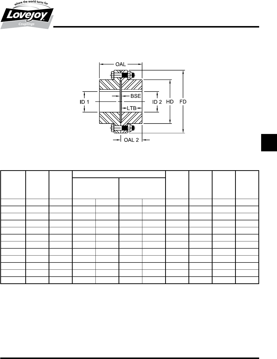
173
www.lovejoy-inc.com G-59
Gear
FRR Type
Dimensional Data
Lovejoy / Sier-Bath Flanged Sleeve Gear Couplings
FRR Type Rigid-Rigid Couplings
FRR Type Dimensional Data
OAL OAL2 ID1 - ID2 LTB BSE FD HD
Max Bore Rough Stock
Bore
Size in in in mm in mm in in in in
13.31 1.66 2.125 56 solid solid 1.56 0.19 4.56 3.06
1.5 3.88 1.94 2.813 76 solid solid 1.84 0.19 6.00 3.97
24.75 2.38 3.500 95 solid solid 2.28 0.19 7.00 4.86
2.5 6.00 3.00 4.250 114 solid solid 2.91 0.19 8.38 5.84
37.00 3.50 4.875 134 solid solid 3.41 0.19 9.44 6.84
3.5 8.13 4.07 5.625 150 solid solid 3.97 0.19 11.00 7.91
49.25 4.63 6.500 176 solid solid 4.44 0.38 12.50 9.25
4.5 10.44 5.22 7.625 202 solid solid 5.03 0.38 13.63 10.38
511.75 5.88 8.750 230 4.00 101 5.69 0.38 15.31 11.56
5.5 12.69 6.35 9.500 260 4.50 114 6.16 0.38 16.75 12.72
614.88 7.44 10.500 285 5.50 127 7.25 0.50 18.00 14.00
717.88 8.94 12.000 320 5.75 139 8.69 0.63 20.75 15.75
Notes:■■ n■■■■Exposed■Bolt■Design■is■standard.
■n■■■Shrouded■Bolt■Design■available■upon■request■for■sizes■1■through■5.5.
■n■■■Puller■Holes■are■standard■on■sizes■4■through■7.
■n■■■Puller■Holes■are■available■for■sizes■1■through■3.5■at■an■additional■charge.
■n■■■Interference■bores■with■no■set■screws■are■standard■unless■otherwise■specified.
■n■■■Inch■bore■and■keyway■tolerances■conform■to■AGMA■9002-B04.
■n■■■For■metric■bore■and■keyway■tolerances,■consult■Lovejoy■Engineering■Section.
JWJISCJSFMCGHPGDDTSPUJVSDRSLDED
JW JIS CJ SF MC
G
HP GD D T SP UJ VSD R SLD ED
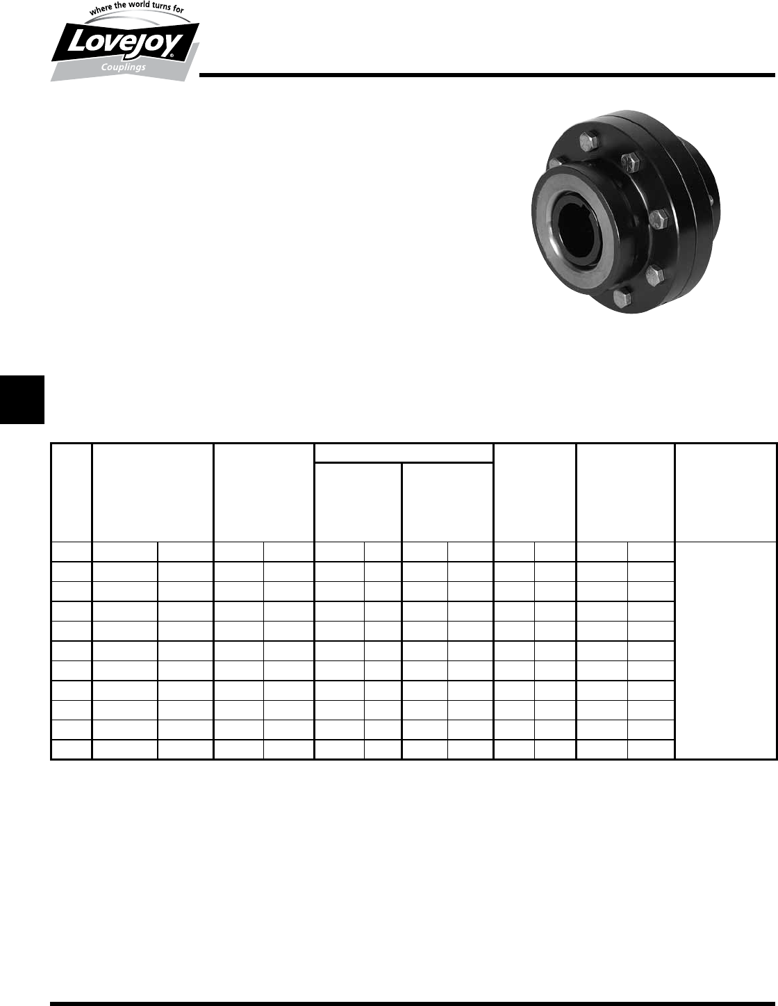
174 630-852-0500
G-60
Gear
FLA Type
Performance Data
Lovejoy / Sier-Bath Flanged Sleeve Gear Couplings
FLA Type Flex-Flex All-Metal Labyrinth Seal Couplings
The■FLA■Type■coupling■consists■of■two■special■flex■hubs,■Two■sleeves■and■one■accessory■kit.■This■
coupling■is■supplied■with■exposed■bolts■as■standard.■Shrouded■bolts■are■available■upon■request■
through■size■5.5.
Features
■■All-Metal■Labyrinth■Seals
■■AISI■4140■Alloy■Steel■Construction
■■Patented■Vari-Crown®■tooth■form■for■long■life
■■Standard■20°■pressure■angle
■■Heat■treated■bolts■for■greater■strength
■■Corrosion■resistant■bolts■and■nuts■for■ease■of■maintenance
■■Provides■parallel,■angular■misalignment■and■end■float
■■Flex■Half■coupling■interchangeable■with■industry■standards
FLA Type Performance Data
ID1 - ID2
Size
Nominal Maximum Max Bore Rough Stock Weight Parallel Max Angular
Torque Speed Standard Bore Misalignment Misalignment
Unbal Bal Keyway Degrees
in-lb Nm RPM RPM in mm in mm lbs kg in mm
1.5 15,000 1■700 12,000 18,000 1.625 41 0.38 9 17.6 8 0.028 0.7
235,500 4■000 9,300 13,950 2.125 53 0.5 12 29.1 13 0.035 0.9 ■
2.5 69,300 7■800 7,900 11,850 2.750 69 0.75 19 50.9 23 0.044 1.1
3118,900 13■400 6,800 10,200 3.125 79 1.13 28 74.4 34 0.052 1.3
3.5 188,500 21■300 6,000 9,000 3.750 95 1.50 38 120 55 0.061 1.5 1.5°
4283,800 32■100 5,260 7,890 4.250 107 1.50 38 185 84 0.700 1.8 Per■Gear■Mesh
4.5 393,800 44■500 4,770 7,155 4.750 120 1.50 38 240 109 0.079 2.0 ■
5551,300 62■300 4,300 6,450 5.500 139 2.50 63 365 166 0.087 2.2
5.5 732,500 82■800 3,880 5,820 5.875 149 3.00 76 435 198 0.096 2.4
6952,500 107■600 3,600 5,400 6.500 165 4.00 101 538 244 0.105 2.7
71,512,500 170■900 3,000 4,500 8.0001203 4.50 114 860 390 0.122 3.1
Ordering Information
■■Application:■Driver■and■Driven.
■■Type■and■size■of■coupling,■horizontal,■vertical■etc.
■■Power:■Motor■horspower■or■torque■requirement.
■■Speed:■Motor■RPM■or■Driven■RPM.
■■Distance■between■shaft■ends■(BSE).
■■Shaft■sizes.
Note:■■ n■■1■Indicates:■Maximum■bore■for■square■keyway.
JWJISCJSFMC
G
HPGDDTSPUJVSDRSLDED
JW JIS CJ SF MC G HP GD D T SP UJ VSD R SLD ED
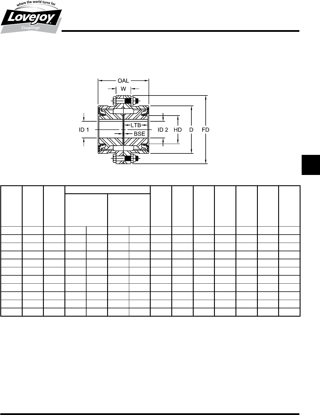
175
www.lovejoy-inc.com G-61
Gear
FLA Type
Dimensional Data
Lovejoy / Sier-Bath Flanged Sleeve Gear Couplings
FLA Type All Metal Labyrinth Seal Couplings
FLA Type Dimensional Data
OAL W ID1 - ID2 LTB BSE FD D HD
Max Bore Rough Stock C/L - C/L Puller
Standard Bore of Teeth* Holes
Keyway
Size in in in mm in mm in in in in in in
1.5 4.19 1.50 1.625 41 0.38 9 1.94 0.13 6.00 3.97 2.19 3.25 1/4-20
25.19 1.50 2.125 53 0.50 12 2.44 0.13 7.00 4.91 2.88 4.00 38-16
2.5 6.44 1.75 2.750 69 0.75 19 3.03 0.19 8.38 5.91 3.63 5.00 1/2-13
37.69 1.75 3.125 79 1.13 28 3.59 0.19 9.44 6.91 4.25 6.00 5/8-11
3.5 8.88 2.25 3.750 95 1.50 38 4.19 0.25 11.00 7.91 5.00 7.00 5/8-11
410.13 2.50 4.250 107 1.50 38 4.75 0.25 12.50 9.25 5.75 8.00 7/8-9
4.5 11.38 2.50 4.750 120 1.50 38 5.31 0.31 13.63 10.38 6.50 9.00 1-8
512.63 3.00 5.500 139 2.50 63 6.03 0.31 15.31 11.56 7.31 10.00 1-8
5.5 14.13 1.88 5.875 149 3.00 76 6.91 0.31 16.75 12.81 8.00 11.00 1-8
615.13 2.00 6.500 165 4.00 101 7.41 0.31 18.00 14.00 8.81 12.00 1-8
717.75 2.25 8.0001203 4.50 114 8.69 0.38 20.75 15.75 10.31 14.00 1■1/4-7
Notes:■■ n■■1■indicates:■Maximum■bore■for■square■keyway.
■n■■■■*■indicates:■Center■line■to■center■line■of■teeth.
■n■■■Exposed■Bolt■Design■is■standard.
■n■■■Shrouded■Bolt■Design■available■upon■request■for■sizes■1■through■5.
■n■■■Puller■Holes■are■standard■on■sizes■4■through■7.
■n■■■Puller■Holes■are■available■for■sizes■1■through■3.5■at■an■additional■charge.
■n■■■Interference■bores■with■no■set■screws■are■standard■unless■otherwise■specified.
■n■■■Inch■bore■and■keyway■tolerances■conform■to■AGMA■9002-B04.
■n■■■For■metric■bore■and■keyway■tolerances,■consult■Lovejoy■Engineering■Section.
JWJISCJSFMCGHPGDDTSPUJVSDRSLDED
JW JIS CJ SF MC
G
HP GD D T SP UJ VSD R SLD ED
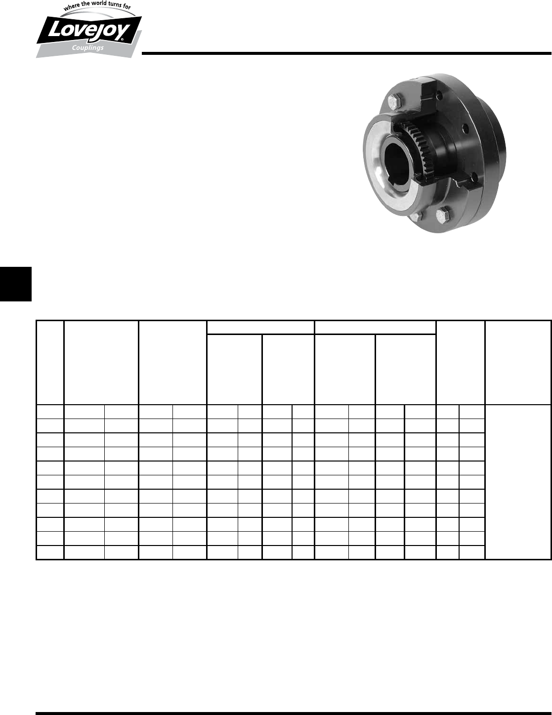
176 630-852-0500
G-62
Gear
FLAFR Type
Performance Data
Lovejoy / Sier-Bath Flanged Sleeve Gear Couplings
FLAFR Type Flex-Rigid All-Metal Labyrinth Seal Couplings
The■FLAFR■Type■coupling■consists■of■one■special■flex■hub,■one■rigid■hub,■one■sleeve■and■one■
accessory■kit.■This■coupling■is■supplied■with■exposed■bolts■as■standard.■Shrouded■bolts■are■
available■upon■request■through■size■5.5.
Features
■■All-metal■labyrinth■seal
■■AISI■4140■alloy■steel■construction■(flex■half)
■■Patented■Vari-Crown®■tooth■form■for■long■life
■■Standard■20°■pressure■angle
■■Heat■treated■bolts■for■greater■strength
■■Corrosion■resistant■bolts■and■nuts■for■ease■of■maintenance
■■Provides■angular■misalignment■only
■■Flex■Half■coupling■interchangeable■with■industry■standards
FLAFR Type Performance Data
ID1 ID2 ID1 ID2
Size
Nominal Maximum Flex Hubs Flex Hubs Rigid Hubs Rigid Hubs Weight Max Angular
Torque Speed Max Bore Rough Stock Max Bore Rough Stock Misalignment
Standard Bore Standard Bore Degrees
Unbal Bal Keyway Keyway
in-lb Nm RPM RPM in mm in mm in mm in mm lbs kg
1.5 15,000 1■700 12,000 18,000 1.625 41 0.38 9 2.813 76 0.75 19 19 8
235,500 4■000 9,300 13,950 2.125 53 0.50 12 3.500 95 1.00 25 31 14
2.5 69,300 7■800 7,900 11,850 2.750 69 0.75 19 4.250 114 1.50 38 55 25
3118,900 13■400 6,800 10,200 3.125 79 1.13 28 4.875 134 1.75 44 83 38 .5°
3.5 188,500 21■300 6,000 9,000 3.750 95 1.50 38 5.625 150 2.50 63 131 60 Per■
4283,800 32■100 5,260 7,890 4.250 107 1.50 38 6.500 176 3.00 76 193 88 Gear
4.5 393,800 44■500 4,770 7,155 4.750 120 1.50 38 7.625 202 3.50 88 258 117 Mesh
5551,300 62■300 4,300 6,450 5.500 139 2.50 63 8.750 230 4.00 101 383 174
5.5 732,500 82■800 3,880 5,820 5.875 149 3.00 76 9.500 260 4.50 114 436 198
6952,500 107■600 3,600 5,400 6.500 165 4.00 101 10.500 285 5.00 127 536 243
71,512,500 170■900 3,000 4,500 8.0001203 4.50 114 12.000 320 5.50 139 851 386
Ordering Information
■■Application:■Driver■and■Driven.
■■Type■and■size■of■coupling,■horizontal,■vertical■etc.
■■Power:■Motor■horspower■or■torque■requirement.
■■Speed:■Motor■RPM■or■Driven■RPM.
■■Distance■between■shaft■ends■(BSE).
■■Shaft■sizes.
Note:■■ n■■1■indicates:■Maximum■bore■for■square■keyway.
JWJISCJSFMC
G
HPGDDTSPUJVSDRSLDED
JW JIS CJ SF MC G HP GD D T SP UJ VSD R SLD ED
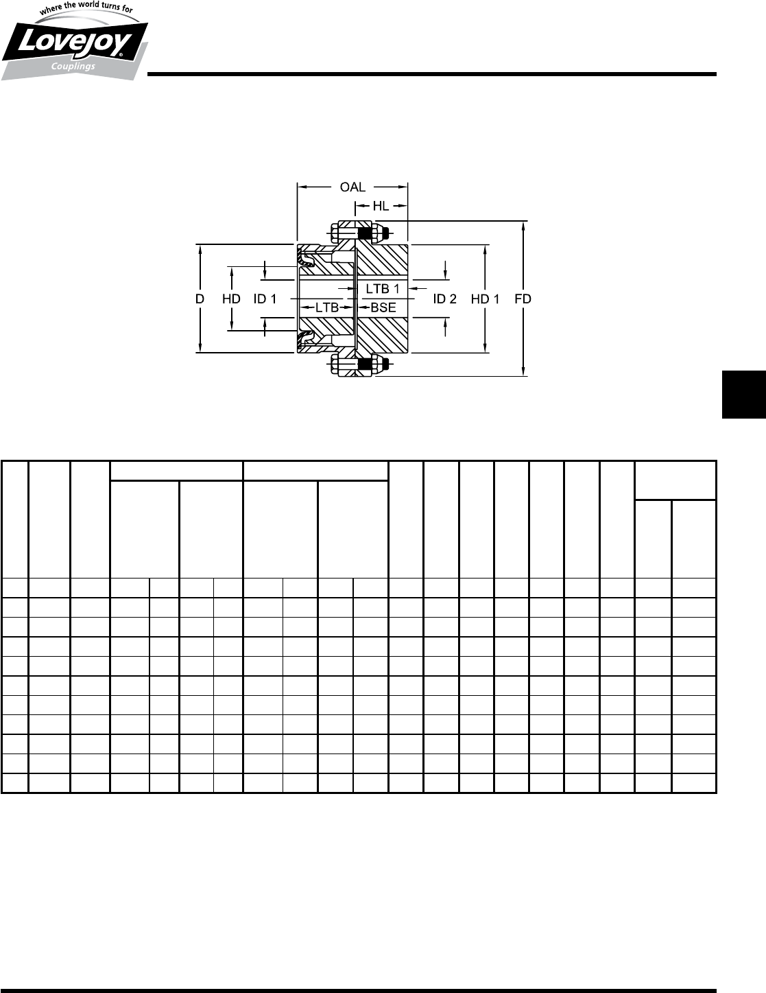
177
www.lovejoy-inc.com G-63
Gear
FLAFR Type
Dimensional Data
Lovejoy / Sier-Bath Flanged Sleeve Gear Couplings
FLAFR Type Flex-Rigid All Metal Labyrinth Seal Couplings
FLAFR Type Dimensional Data
OAL HL ID1 ID2 ID1 ID2 LTB LTB1 BSE FD HD1 HD D
Flex Hubs Flex Hubs Rigid Hubs Rigid Hubs Puller Holes
Max Bore Rough Max Bore Rough Flex Rigid
Standard Stock Standard Stock Hub Hub
Keyway Bore Keyway Bore
Size in in in mm in mm in mm in mm in in in in in in in in in
1.5 4.03 1.94 1.625 41 0.38 9 2.813 76 0.75 19 1.94 1.84 0.16 6.00 3.97 2.19 3.97 1/4-20 None
24.97 2.38 2.125 53 0.50 12 3.500 95 1.00 25 2.44 2.28 0.16 7.00 4.86 2.88 4.91 38-16 5/16-18
2.5 6.22 3.00 2.750 69 0.75 19 4.250 114 1.50 38 3.03 2.91 0.19 8.38 5.84 3.63 5.91 1/2-13 3/8-16
37.41 3.50 3.125 79 1.13 28 4.875 134 1.75 44 3.59 3.41 0.19 9.44 6.84 4.25 6.91 5/8-11 1/2-13
3.5 8.56 4.06 3.750 95 1.50 38 5.625 150 2.50 63 4.19 3.97 0.22 11.00 7.91 5.00 7.91 5/8-11 1/2-13
49.69 4.63 4.250 107 1.50 38 6.500 176 3.00 76 4.75 4.44 0.31 12.50 9.25 5.75 9.25 7/8-9 5/8-11
4.5 10.91 5.22 4.750 120 1.50 38 7.625 202 3.50 88 5.31 5.03 0.34 13.63 10.38 6.50 10.38 1-8 5/8-11
512.19 5.88 5.500 139 2.50 63 8.750 230 4.00 101 6.03 5.69 0.34 15.31 11.56 7.31 11.56 1-8 3/4-10
5.5 13.41 6.34 5.875 149 3.00 76 9.500 260 4.50 114 6.91 6.16 0.34 16.75 12.72 8.00 12.81 1-8 1-8
615.22 7.66 6.500 165 4.00 101 10.500 285 5.00 127 7.41 7.41 0.41 18.00 14.00 8.81 14.00 1-8 1-8
717.88 9.00 8.0001203 4.50 114 12.000 320 5.50 139 8.69 8.69 0.50 20.75 15.75 10.31 15.75 1■1/4-7 1-8
Notes:■■ n■■1■indicates:■Maximum■bore■for■square■keyway.
■n■■■■Exposed■Bolt■Design■is■standard.
■n■■■Shrouded■Bolt■Design■available■upon■request■for■sizes■1■through■5.
■n■■■Puller■Holes■are■standard■on■sizes■4■through■7.
■n■■■Puller■Holes■are■available■for■sizes■1■through■3.5■at■an■additional■charge.
■n■■■Interference■bores■with■no■set■screws■are■standard■unless■otherwise■specified.
■n■■■Inch■bore■and■keyway■tolerances■conform■to■AGMA■9002-B04.
■n■■■For■metric■bore■and■keyway■tolerances,■consult■Lovejoy■Engineering■Section.
JWJISCJSFMCGHPGDDTSPUJVSDRSLDED
JW JIS CJ SF MC
G
HP GD D T SP UJ VSD R SLD ED
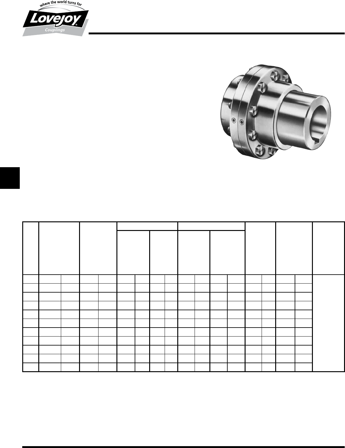
178 630-852-0500
G-64
Gear
FLAMM and FLAMMFR Type
Performance Data
Lovejoy / Sier-Bath Flanged Sleeve Gear Couplings
FLAMM Type Flex-Flex Mill Motor Couplings
The■FLAMM■Type■coupling■consists■of■one■standard■FLA■flex■hub,■one■universal■flex■
hub■bored■to■an■A.I.S.E.■frame■size,■two■sleeves■and■one■accessory■kit.■This■coupling■
is■supplied■with■exposed■bolts■as■standard.■Shrouded■bolts■are■available■upon■request■
through■size■5.5.
FLAMMFR Type Flex-Rigid Mill Motor Couplings
The■FLAMMFR■Type■coupling■consists■of■a■rigid■hub,■one■universal■flex■hub■bored■to■
A.I.S.E.■frame■size,■one■sleeve■and■one■accessory■kit.■This■coupling■is■supplied■with■
exposed■bolts■as■standard.■Shrouded■bolts■are■available■upon■request■through■size■5.5.
Features
■■Patented■Vari-Crown®■tooth■form■for■long■life■on■Flex■Half
■■Standard■20°■pressure■angle
■■Heat■treated■bolts■for■greater■strength
■■Corrosion■resistant■bolts■and■nuts■for■ease■of■maintenance
■■Provides■parallel,■angular■misalignment■and■end■float
■■Flex■Half■coupling■interchangeable■with■industry■standards
■■Long■Universal■Hub■used■for■A.I.S.E.■Motor■Frames
FLAMM and FLAMMFR Type Performance Data
ID1 ID2 ID1 ID2
Size
Nominal Max Flex Hub Flex Hub Rigid Hub Rigid Hub Weight Parallel Max
Torque Speed Max Bore Rough Stock Max Bore Rough Stock Misalignment Angular
Standard Bore Standard Bore FLAMM only Misalignment
Unbal Bal Keyway Keyway Degrees
in-lb Nm RPM RPM in mm in mm in mm in mm lbs kg in mm
1.5 18,900 2■140 5,500 8,250 1.625 41 0.38 9 2.813 76 solid solid 24 11 0.28 0.7
231,500 3■560 5,000 7,500 2.125 53 0.50 12 3.500 95 solid solid 45 20 0.35 0.9
2.5 56,700 6■410 4,400 6,600 2.750 69 0.75 19 4.250 114 solid solid 71 32 0.44 1.1
394,500 10■700 4,000 6,000 3.125 79 1.13 28 4.875 134 solid solid 104 47 0.52 1.3 .5°
3.5 151,200 17■100 3,500 5,250 3.750 95 1.50 38 5.625 150 solid solid 151 69 0.61 1.5 Per■
4220,500 24■900 3,000 4,500 4.250 17 1.50 38 6.500 176 solid solid 234 86 0.70 1.8 Gear
4.5 302,400 34■200 2,700 4,050 4.750 120 1.50 38 7.625 202 solid solid 310 141 0.79 2.0 Mesh
5434,700 49■100 2,500 3,750 5.500 139 2.50 63 8.750 230 4.00 101 450 204 0.87 2.2
5.5 573,300 64■800 2,200 3,300 5.875 149 3.00 76 9.500 260 4.50 114 609 276 0.96 2.4
6749,700 84■700 2,100 3,150 6.500 165 4.00 101 10.500 285 5.50 127 764 347 0.105 2.7
71,008,000 113■900 2,000 3,000 8.0001203 4.50 114 12.000 320 5.75 139 1,212 551 0.122 3.1
Notes:■■ n■■1■indicates:■Maximum■bore■for■square■keyway.
■n■■■Application:■Driver■and■Driven.
n■■■Type■and■size■of■coupling,■horizontal,■vertical■etc.
n■■■Power:■Motor■horspower■or■torque■requirement.
n■■■Speed:■Motor■RPM■or■Driven■RPM.
n■■■Distance■between■shaft■ends■(BSE).
n■■■Shaft■sizes.
n■■■Mill■Motor■frame■size.
n■■■Submit■a■drawing■if■available.
JWJISCJSFMC
G
HPGDDTSPUJVSDRSLDED
JW JIS CJ SF MC G HP GD D T SP UJ VSD R SLD ED
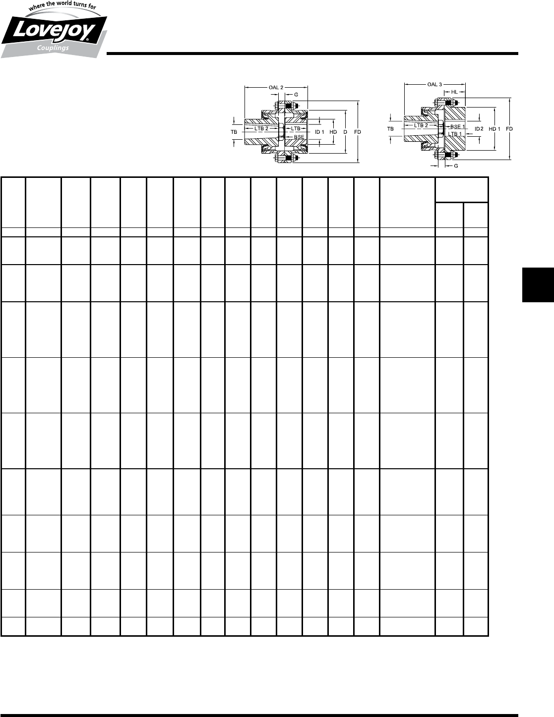
179
www.lovejoy-inc.com G-65
Gear
FLAMM and FLAMMFR Type
Dimensional Data
Lovejoy / Seir-Bath Flanged Sleeve Gear Couplings
FLAMM and FLAMMFR Type
All Metal Labyrinth Seal Mill Motor Couplings
FLAMM and FLAMMFR Type Dimensional Data
OAL 2 OAL 3 LTB LTB1 LTB2 G BSE BSE 1 FD D HD HD 1 TB
AISE Mill Mtr Hub Kw
Frame W H
Size No in in in in in in in in in in in in in in in
1.5 602/802 6.00 5.91 1.94 1.84 3.00 1.06 0.13 0.16 6.00 3.97 2.19 3.97 1.7485■-■1.7495 0.50 0.13
2
602/802 6.50 6.34 3.00 1.06 1.7485■-■1.7495 0.50 0.25
603/803 7.06 6.91 2.44 2.28■ 3.50 1.13 0.13 0.16 7.00 4.91 2.88 4.86 1.998■-■1.999 0.50 0.25
604/804 7.06 6.91 ■ 3.50 1.13 1.998■-■1.999 0.50 0.25
2.5
602/802 7.16 7.03
3.03 ■2.28
3.00 1.13
0.19 0.19 8.38 5.91 3.63 5.84
1.7485■-■1.7495 0.50 0.25
603/803 7.72 7.59 3.50 1.19 1.998■-■1.999 0.50 0.25
604/804 7.72 7.59 3.50 1.19 1.998■-■1.999 0.50 0.25
606/806 8.34 8.22 4.00 1.31 2.498■-■2.499 0.50 0.25
3
602/802 7.72 7.53
3.59 2.91■
3.00 1.13
0.19 0.19 9.44 6.91 4.25 6.84
1.7485■-■1.7495 0.50 0.25
603/803 8.28 8.09 3.50 1.19 1.998■-■1.999 0.50 0.25
604/804 8.28 8.09 3.50 1.19 1.998■-■1.999 0.50 0.25
606/806 8.91 8.72 4.00 1.31 2.498■-■2.499 0.50 0.25
608/808 9.53 9.34 4.50 1.44 2.998■-■2.999 0.75 0.25
610/810 9.66 9.47 4.50 1.56 3.248■-■3.249 0.75 0.25
3.5
603/803 8.88 8.66
4.19 3.97
3.50 1.19
0.25 0.22 11.00 7.91 5.00 7.91
1.998■-■1.999 0.50 0.25
604/804 8.88 8.66 3.50 1.19 1.998■-■1.999 0.50 0.25
606/806 9.50 9.28 4.00 1.31 2.498■-■2.499 0.50 0.25
608/808 10.13 9.91 4.50 1.44 2.998■-■2.999 0.75 0.25
610/810 10.25 10.03 4.50 1.56 3.248■-■3.249 0.75 0.25
612/812 10.94 10.72 5.00 1.75 3.623■-■3.624 0.75 0.25
4
606/806 10.13 9.81
4.75 4.44
4.00 1.38
0.25 0.31 12.50 9.25 5.75■ 9.25
2.498■-■2.499 0.50 0.25
608/808 10.75 10.44 4.50 1.50 2.998■-■2.999 0.75 0.25
610/810 10.88 10.56 4.50 1.63 3.248■-■3.249 0.75 0.25
612/812 11.50 11.19 5.00 1.75 3.623■-■3.624 0.75 0.25
614/814 11.63 11.31 5.00 1.88 4.2470■-■4.2485 1.00 0.38
616/816 12.25 11.94 5.00 2.00 4.6220■-■4.6235 1.25 0.28
4.5
610/810 11.50 11.22
5.31 5.03
4.50 1.69
0.31 0.34 13.63 10.38 6.50 10.38
3.248■-■3.249 0.75 0.25
612/812 12.12 11.84 5.00 1.81 6.623■-■3.624 0.75 0.25
614/814 12.25 11.97 5.00 1.94 4.2470■-■4.2485 1.00 0.38
616/816 12.88 12.59 5.50 2.06 4.6220■-■4.6235 1.25 0.38
618/818 12.94 12.66 6.00 1.63 4.9970■-■4.9985 1.25 0.50
5
612/812 12.84 12.50
6.03 5.69
5.00 1.81
0.31 0.34 15.31 11.56 7.31 11.56
3.623■-■3.624 0.75 0.25
614/814 12.97 12.63 5.00 1.94 4.2470■-■4.2485 1.00 0.38
616/816 13.59 13.25 5.50 2.06 4.6220■-■4.6235 1.25 0.38
618/818 13.66 13.31 6.00 1.63 4.9970■-■4.9985 1.25 0.50
5.5
616/816 14.47 13.72
6.91 6.16
5.50 2.06
0.31 0.34 16.75 12.81 8.00 12.72
4.6220■-■4.6235 1.25 0.38
618/818 14.53 13.78 6.00 1.63 4.9970■-■4.9985 1.25 0.50
620 15.72 14.97 6.75 2.06 5.8720■-■5.8735 1.50 0.75
622 16.84 16.09 7.25 2.69 6.2470■-■6.2485 1.50 0.56
6
620 16.22 16.22
7.41 7.41
6.75 2.06
0.31 0.41 18.00 14.00 8.81 14.00
5.8720■-■5.8735 1.50 0.75
622 17.34 17.34 7.25 2.69 6.2470■-■6.2485 1.50 0.75
624 19.34 19.34 9.25 2.69 6.9970■-■6.9985 1.50 0.50
7622 18.69 18.69 8.69 8.69 7.25 2.75 0.38 0.50 20.75 15.75 10.31 15.75 6.2470■-■6.2485 1.50 0.75
624 20.69 20.69 9.25 2.75 6.9970■-■6.9985 1.50 0.75
Notes:■■ n■■Bore■taper■is■1-1/4■inch■per■foot■on■diameter.
■n■■■Exposed■Bolt■Design■is■standard.
■n■■■Shrouded■Bolt■Design■available■upon■request■for■sizes■1.5■
through■5.
■n■■■Puller■Holes■are■standard■on■sizes■4■through■7.
■n■■■Puller■Holes■are■available■for■sizes■1.5■through■3.5■at■an■additional■charge.
■n■■■Interference■bores■with■no■set■screws■are■standard■unless■
otherwise■specified.
■n■■■Inch■bore■and■keyway■tolerances■conform■to■AGMA■9002-B04.
■n■■■For■metric■bore■and■keyway■tolerances,■consult■Lovejoy■
Engineering■Section.
JWJISCJSFMCGHPGDDTSPUJVSDRSLDED
JW JIS CJ SF MC
G
HP GD D T SP UJ VSD R SLD ED
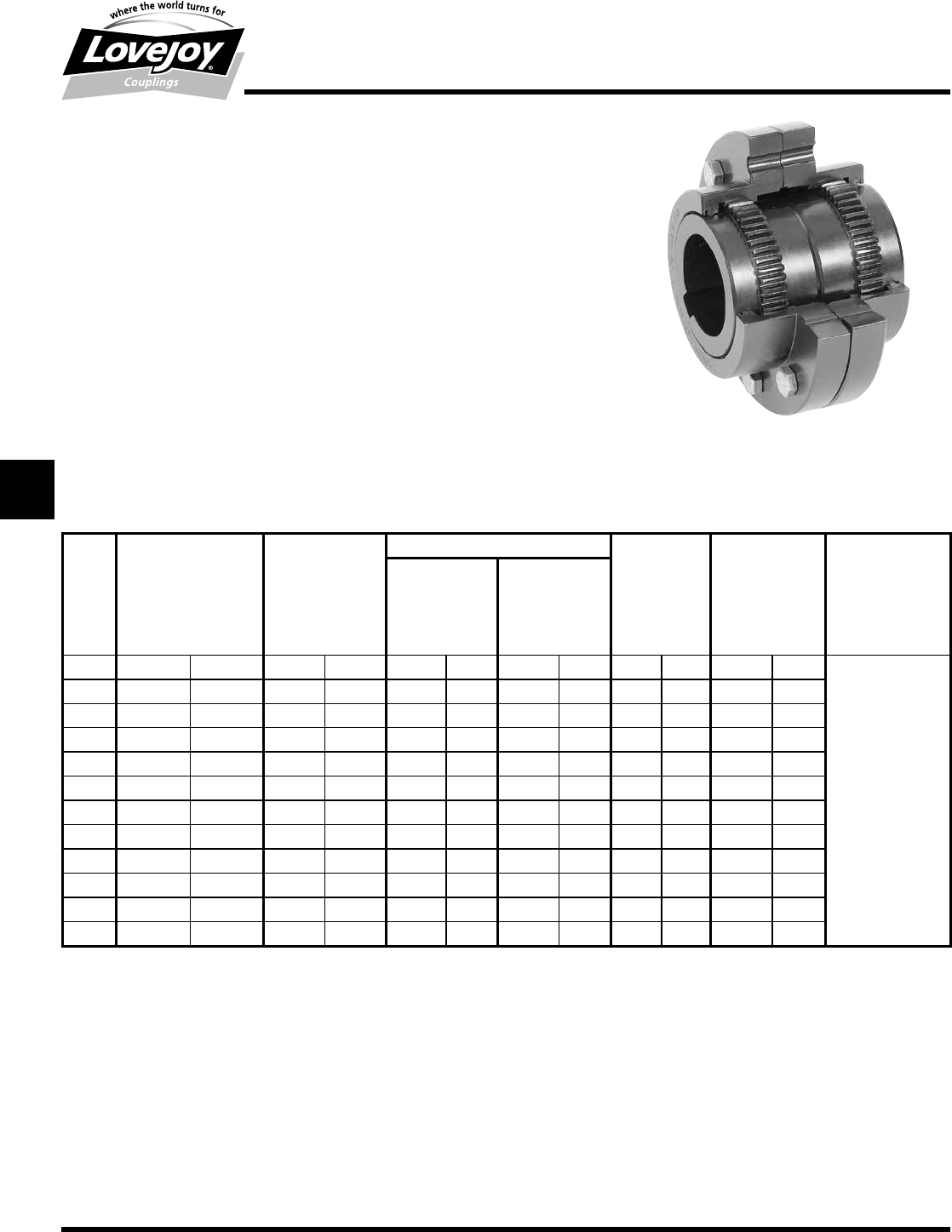
180 630-852-0500
G-66
Gear
FA Type
Performance Data
Lovejoy / Sier-Bath Flanged Sleeve Gear Couplings
FA Type Alloy Steel Flex-Flex Couplings
The■FA■Type■coupling■consists■of■two■flex■hubs,■two■sleeves■and■one■accessory■kit.■This■coupling■
is■supplied■with■exposed■bolts■as■standard.■Shrouded■bolts■are■available■upon■request■through■
size■5.5.
Features
■■Molded■seals■maintain■proper■lubricant■retention■during■misalignment■conditions
■■AISI■4140■Alloy■Steel■Construction
■■Patented■Vari-Crown®■tooth■form■for■long■life
■■Standard■20°■pressure■angle
■■Heat■treated■bolts■for■greater■strength
■■Corrosion■resistant■bolts■and■nuts■for■ease■of■maintenance
■■Provides■parallel,■angular■misalignment■and■end■float
■■Flex■Half■coupling■interchangeable■with■industry■standards
FA Type Performance Data
ID1 - ID2
Size
Nominal Maximum Max Bore Rough Stock Weight Parallel Max Angular
Torque Speed Standard Bore Misalignment Misalignment
Unbal Bal Keyway Degrees
in-lb Nm RPM RPM in mm in mm lbs kg in mm
111,300 1■280 6,000 9,000 1.625 42 0.44 11 9 4 0.056 1.4
1.5 22,700 2■560 5,500 8,250 2.125 56 0.69 18 19 9 0.060 1.5
239,000 4■410 5,000 7,500 2.75 73 0.94 24 34 15 0.085 2.2 ■
2.5 69,300 7■930 4,400 6,600 3.25 88 1.44 37 54 25 0.105 2.7
3118,000 13■300 4,000 6,000 4.000 107 1.44 37 80 36 0.115 2.9
3.5 177,000 20■000 3,500 5,250 4.625 124 1.81 46 130 59 0.130 3.3 1.5°
4263,400 29■760 3,000 4,500 5.375 147 2.44 62 190 86 0.150 3.8 Per■Gear■Mesh
4.5 354,000 40■000 2,700 4,050 6.000 167 3.00 76 250 114 0.175 4.4 ■
5508,600 57■470 2,500 3,750 6.500 176 3.00 76 380 173 0.200 5.1
5.5 670,700 75■790 2,200 3,300 7.500 202 4.00 101 520 236 0.220 5.6
6877,100 99■110 2,100 3,150 8.250 225 4.00 101 650 295 0.120 3.0
71,179,300 1■332■600 2,000 3,000 9.500 255 5.00 127 950 431 0.135 3.4
Ordering Information
■■Application:■Driver■and■Driven.
■■Type■and■size■of■coupling,■horizontal,■vertical■etc.
■■Power:■Motor■horspower■or■torque■requirement.
■■Speed:■Motor■RPM■or■Driven■RPM.
■■Distance■between■shaft■ends■(BSE).
■■Shaft■sizes.
JWJISCJSFMC
G
HPGDDTSPUJVSDRSLDED
JW JIS CJ SF MC G HP GD D T SP UJ VSD R SLD ED
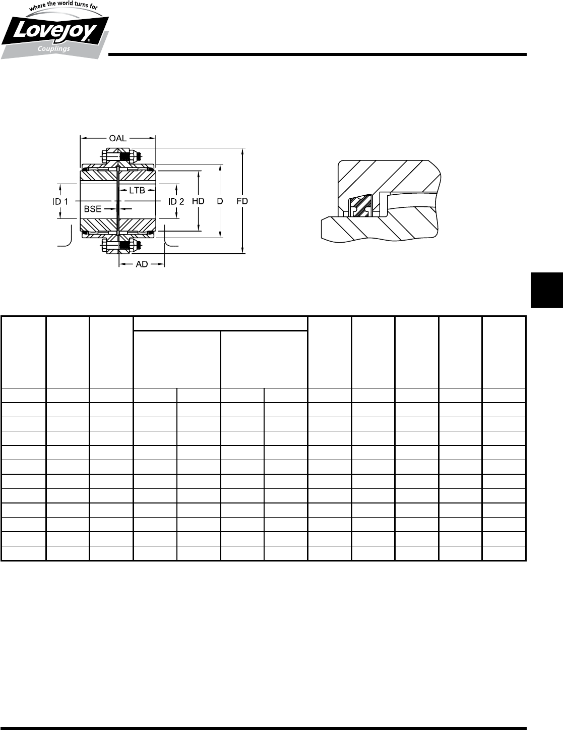
181
www.lovejoy-inc.com G-67
FA Type Dimensional Data
OAL AD ID1 - ID2 LTB BSE FD D HD
Max Bore Rough Stock
Standard Bore
Keyway
Size in in in mm in mm in in in in in
13.50 4.19 1.625 42 0.44 11 1.69 0.13 4.56 3.06 2.31
1.5 4.00 4.75 2.125 56 0.69 18 1.94 0.13 6.00 3.97 3.00
25.00 6.00 2.750 73 0.94 24 2.44 0.13 7.00 4.86 4.00
2.5 6.25 7.13 3.250 88 1.44 37 3.03 0.19 8.38 5.84 4.63
37.38 8.13 4.000 107 1.44 37 3.59 0.19 9.44 6.84 5.63
3.5 8.63 9.38 4.625 124 1.81 46 4.19 0.25 11.00 7.91 6.50
49.75 10.25 5.375 147 2.44 62 4.75 0.25 12.50 9.25 7.50
4.5 10.94 11.50 6.000 167 3.00 76 5.31 0.31 13.63 10.38 8.50
512.38 13.00 6.500 176 3.00 76 6.03 0.31 15.31 11.56 9.50
5.5 14.13 14.38 7.500 202 4.00 101 6.91 0.31 16.75 12.72 10.50
615.13 17.00 8.250 225 4.00 101 7.41 0.31 18.00 14.00 11.50
717.75 20.00 9.500 255 5.00 127 8.69 0.38 20.75 15.75 13.00
Gear
FA Type
Dimensional Data
Lovejoy / Sier-Bath Flanged Sleeve Gear Couplings
FA Type Alloy Steel Couplings
Notes:■■ n■■■■Exposed■Bolt■Design■is■standard.
■n■■■Shrouded■Bolt■Design■available■upon■request■for■sizes■1■through■5.5.
■n■■■Puller■Holes■are■standard■on■sizes■4■through■7.
■n■■■Puller■Holes■are■available■for■sizes■1■through■3.5■at■an■additional■charge.
■n■■■Interference■bores■with■no■set■screws■are■standard■unless■otherwise■specified.
■n■■■Inch■bore■and■keyway■tolerances■conform■to■AGMA■9002-B04.
■n■■■For■metric■bore■and■keyway■tolerances,■consult■Lovejoy■Engineering■Section.
JWJISCJSFMCGHPGDDTSPUJVSDRSLDED
JW JIS CJ SF MC
G
HP GD D T SP UJ VSD R SLD ED
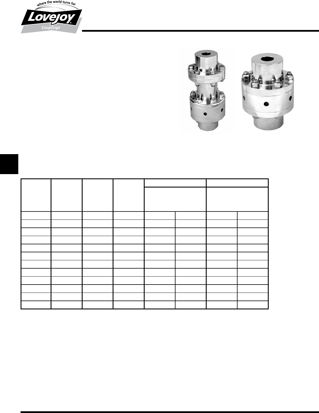
182 630-852-0500
G-68
Gear
RA and RAHS Type
Performance Data
Lovejoy / Sier-Bath Rigid Adjustable Couplings
RA and RAHS Type Rigid Adjustable Couplings
The■RA■and■RAHS■couplings■are■offered■in■two■different■styles.■Type■II■coupling■
consists■of■two■rigid■hubs,■adjusting■nut■and■split■ring■and■split■ring■for■motor■
bub.■Type■IV■coupling■consists■of■two■rigid■hubs,■adjusting■nut,■split■ring■for■
motor■hub■and■spacer.
Features
■■Axial■positioning■of■the■pump■impeller■in■vertical■pump■applications
■■Clearence■fit■bores■allows■for■easy■installation■and■maintenance■for■pump■
and/or■motor
■■Easily■adjustable■for■vertical■clearence
■■Removable■spacer■for■easy■maintenance
■■AISI■1045■Steel
■■Stainless■Steel■coupling■also■available
RA and RAHS Type Performance Data
Motor & Pump Hubs Motor & Pump Hubs
HP/100 Nominal Thrust Min Bore Max Bore
RPM Torque Capacity
Size in-lb lbs in mm in mm
1125 2.7 1,702 4,500 0.44 11 1.125 29
1625 8.0 5,042 11,000 0.63 16 1.625 42
2125 17.9 11,282 31,000 0.73 18 2.125 56
2625 33.8 21,302 31,000 0.88 22 2.625 70
2875 44.4 27,983 31,000 0.88 22 2.875 77
3125 57.0 35,924 41,000 1.19 30 3.125 84
3875 109.0 68,697 73,000 1.25 31 3.875 103
5000 310.0 195,378 160,000 2.38 60 5.000 135
6000 404.0 254,621 300,000 2.88 73 6.000 167
7250 712.0 448,738 300,000 4.00 101 7.250 194
8500 1148.0 723,527 350,000 4.00 101 8.500 225
10500 2164.0 1,363,861 400,000 5.00 127 10.500 276
Ordering Information
■■Application:■Driver■and■Driven.
■■Power:■Motor■horspower■or■torque■requirement.
■■Speed:■Motor■Speed■or■Driven■RPM.
■■Distance■between■shaft■ends■(BSE).
■■Shaft■sizes.
■■Adjusting■nut■threads.
■■Amount■of■trust■on■either■or■both■shafts.
■■Submit■drawing■if■available.
JWJISCJSFMC
G
HPGDDTSPUJVSDRSLDED
JW JIS CJ SF MC G HP GD D T SP UJ VSD R SLD ED
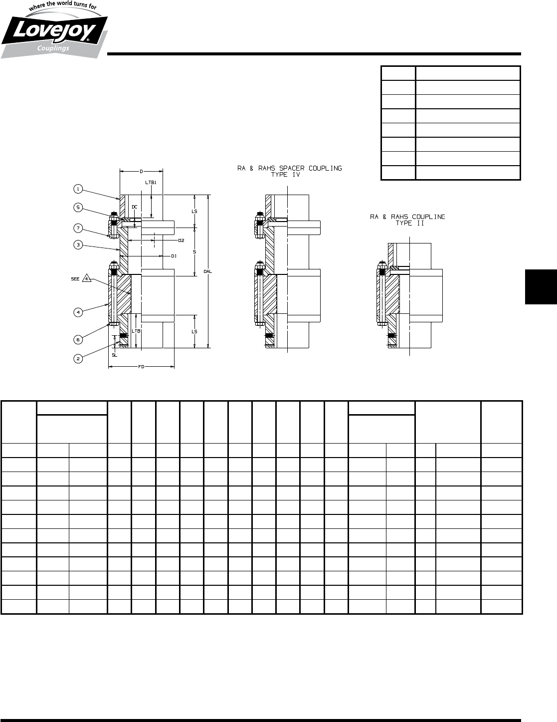
183
www.lovejoy-inc.com G-69
Gear
RA and RAHS Type
Dimensional Data
Lovejoy / Sier-Bath Rigid Adjustable Couplings
RA and RAHS Type Rigid Adjustable Couplings
Item Description
1Upper■Hub■-■Motor
2Lower■hub■-■Pump
3Spacer
4Adjusting■Nut,■Threaded
5Washer,■Split
6RA■and■RAHS■Accessory■Kit
7RA■and■RAHS■Accessory■Kit
RA and RAHS Type Dimensional Data
STD OAL FD D LTB LTB1 LS DC N SL D1 D2 S B.C.
Type II Type IV Std Min BOLTS Dia
Size in in in in in in in in in in in in in in Qty Size in
1125 5.25 9.56 3.00 1.75 2.13 1.11 2.00 0.89 1.25 0.88 1.75 1.25 4.44 1.63 4 1/4■-■28 2.375
1625 6.00 10.31 4.00 2.50 2.38 1.36 2.25 0.89 1.50 0.88 2.50 1.75 4.44 1.75 6 5/16■-■24 3.250
2125 7.13 11.44 5.13 3.13 2.81 1.80 2.69 0.89 1.75 1.00 3.13 2.25 4.44 2.63 6 1/2■-■20 4.250
2625 9.38 13.69 5.88 3.88 3.06 2.05 2.94 0.89 3.50 1.13 3.88 2.75 4.44 2.63 6 1/2■-■20 4.938
2875 10.38 14.69 6.38 4.38 3.56 2.55 3.44 0.89 3.50 1.38 4.38 3.00 4.44 2.88 6 1/2■-■20 5.438
3125 11.50 15.81 6.75 4.63 4.13 3.11 4.00 0.89 3.50 1.63 4.63 3.25 4.44 2.88 8 1/2■-■20 5.813
3875 12.75 17.06 8.94 5.88 4.50 3.48 4.38 0.89 4.00 1.75 5.88 4.00 4.44 3.13 6 3/4■-■16 7.625
5000 15.00 NO■STD 11.75 7.50 6.25 4.63 6.00 1.38 3.00 2.44 7.50 5.13 NO■STD 4.50 8 1■-■14 10.000
6000 20.88 NO■STD 13.25 9.00 9.50 7.63 9.25 1.63 2.38 4.00 9.00 6.13 NO■STD 4.75 10 1■-■14 11.500
7250 25.19 NO■STD 15.00 10.75 11.06 8.81 10.75 1.94 3.69 4.75 10.75 7.38 NO■STD 7.06 14 1■-■14 13.250
7500 33.56 NO■STD 17.25 12.50 15.31 13.06 15.00 1.94 3.56 6.63 12.50 8.63 NO■STD 7.31 12 1-1/8■-■12 15.000
10500 40.94 NO■STD 20.50 15.00 18.69 16.44 18.38 1.94 4.19 8.13 15.00 10.63 NO■STD 8.31 12 1-1/8■-■12 18.000
Notes:■■ n■■■Clearence■fit■bores■with■set■screw■are■standard.
■n■■■RA■couplings■meet■standard■tolerances.
■n■■■Inch■bore■and■keyway■tolerances■conform■to■AINSI■/■AGMA■9002-B04.
■n■■■For■metric■bore■and■keyway■tolerances,■consult■Lovejoy■Engineering■Section.
■n■■■RAHS■couplings■conform■to■API■610■8th■edition■tolerances.
JWJISCJSFMCGHPGDDTSPUJVSDRSLDED
JW JIS CJ SF MC
G
HP GD D T SP UJ VSD R SLD ED
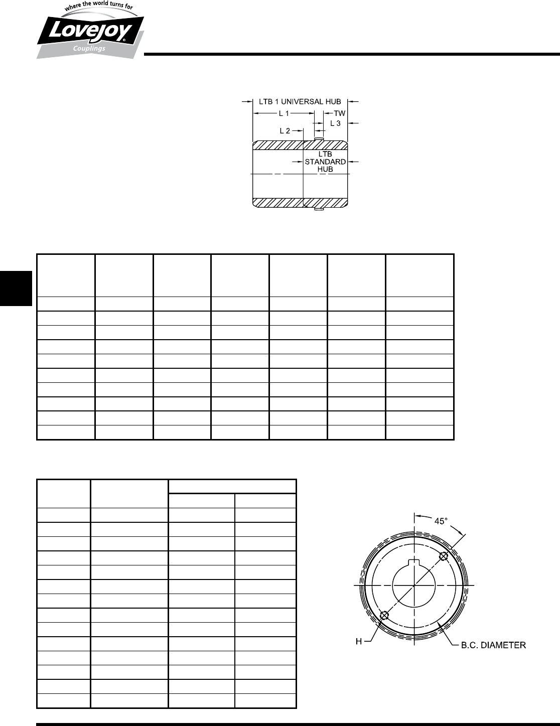
184 630-852-0500
G-70
Gear
F Universal Hub and Puller Holes
Dimensional Data
F Type Standard and Universal Hub Dimensions
L1 L2 L3 TW LTB LTB1
STD UNIV HUB
Size in in in in in in
12.75 0.44 0.75 0.50 1.69 4.00
1.5 3.13 0.56 0.81 0.56 1.94 1.50
23.63 0.56 1.25 0.63 2.44 4.50
2.5 4.22 0.75 1.53 0.75 3.03 6.50
34.44 1.03 1.69 0.88 3.59 7.00
3.5 4.63 1.31 1.88 1.00 4.19 7.50
44.97 1.47 2.16 1.13 4.75 8.25
4.5 5.19 1.50 2.56 1.25 5.31 9.00
55.06 1.59 2.94 1.50 6.03 9.50
5.5 5.56 1.97 3.19 1.75 6.91 10.50
Flex Hubs Puller Bolt Holes
B.C. Diameter Tap Size
Size in UNC Depth
1None None None
1.5 None None None
23.38 5/8■-■18 0.50
2.5 3.94 3/8■-■16 0.56
34.94 1/2■-■13 0.75
3.5 5.56 1/2■-■13 0.75
46.44 5/8■-■11 0.94
4.5 7.38 5/8■-■11 0.94
58.00 3/4■-■10 1.13
5.5 9.00 1■-■8 1.50
69.75 1■-■8 1.50
711.63 1■-■8 1.50
814.00 1■-■8 1.50
915.25 1-1/4■-■7 1.88
Lovejoy / Sier-Bath Flanged Sleeve Gear Couplings
JWJISCJSFMC
G
HPGDDTSPUJVSDRSLDED
JW JIS CJ SF MC G HP GD D T SP UJ VSD R SLD ED
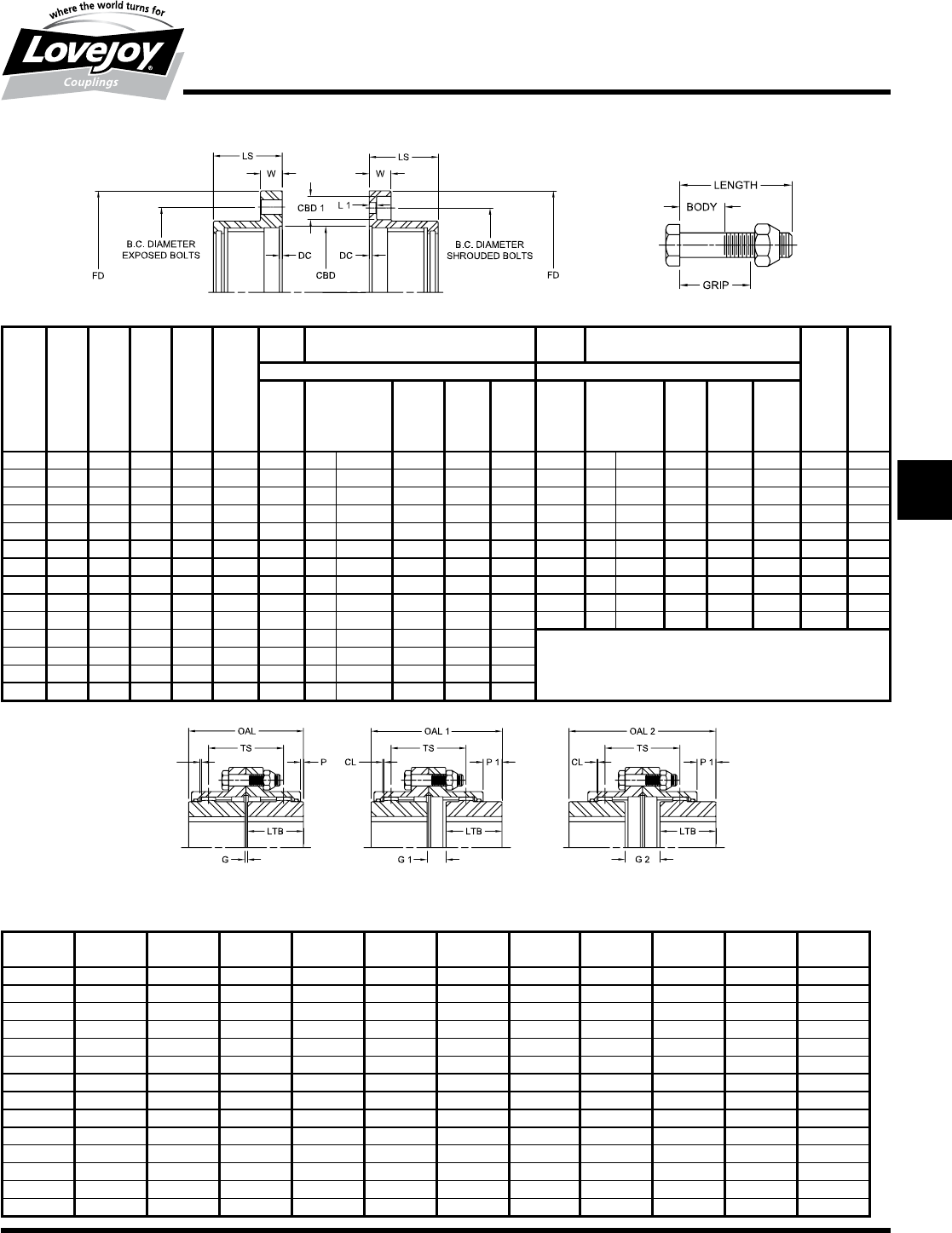
185
www.lovejoy-inc.com G-71
Gear
F Flange and Hub Gap Details
Dimensional Data
Lovejoy / Sier-Bath Flanged Sleeve Gear Couplings
Flange Details
LS W DC FD CBD B.C. B.C. CBD 1 L1
Dia Dia
Exposed Bolts Shrouded Bolts
Bolts Length Min Max Bolts Length Min Max
Body Grip Body Grip
Size in in in in in in Qty Size in in in in Qty Size in in in in in
11.66 0.56 0.09 4.56 2.812 3.750 6 1/4-28 1-1/2 ■3/4 1 3.750 6 1/4-28 ■3/4 ■9/32 ■7/16 0.64 0.25
1.5 1.88 0.75 0.09 6.00 3.562 4.812 8■■ 3/8-24 2■ ■15/16 1-1/4 4.812 8 3/8-24 1 ■9/32 ■7/16 0.81 0.25
22.38 0.75 0.09 7.00 4.562 5.875 6■■ 1/2-20 2-1/4 ■15/16 1-1/4 5.812 10 3/8-24 1 ■9/32 ■7/16 0.81 0.25
2.5 2.88 0.88 0.09 8.38 5.437 7.125 6■■ 5/8-18 2-3/4 ■7/8 1-1/4 7.000 10 ■1/2-20 1-1/8 ■3/8 ■1/2 1.06 0.31
33.31 0.88 0.09 9.44 6.437 8.125 8■■ 5/8-18 2-3/4 ■7/8 1-1/4 8.000 12 1/2-20 1-1/8 ■3/8 ■1/2 1.06 0.31
3.5 3.81 1.13 0.09 11.00 7.375 9.500 8■■ 3/4-16 3-1/4 1■ 1-7/16 9.281 12 5/8-18 1-3/8 ■7/16 ■5/8 1.31 0.38
44.25 1.13 0.19 12.50 8.750 11.000 8■■ 3/4-16 3-1/4 1■ 1-7/16 10.625 14 5/8-18 1-3/8 ■7/16 ■5/8 1.31 0.38
4.5 4.81 1.13 0.19 13.63 9.750 12.000 10■■ 3/4-16 3-1/4 1-1/4 1-7/16 11.750 14 5/8-18 1-3/8 ■7/16 ■5/8 1.31 0.38
55.50 1.50 0.19 15.31 10.750 13.500 8■■ 7/8-14 4-1/4 1-3/4 2-1/4 13.188 14 3/8-16 1-7/8 ■5/8 1 1.56 0.56
5.5 6.00 1.50 0.19 16.75 12.125 14.500 14■■ 7/8-14 4-1/4 1-3/4 2-1/4 14.437 16■■ 3/4-16 1-7/8 ■5/8 1 1.56 0.56
66.69 1.00 0.25 18.00 13.000 15.750 14■■ 7/8-14 3-1/4 ■23/32 1-1/4
EXPOSED■BOLTS■ONLY
77.38 1.13 0.31 20.75 14.625 18.250 16■■ 1-14 3-1/2 ■5/8 1-1/4
88.38 1.31 0.31 23.75 17.750 20.750 16■■ 1-1/8-12 — — —
99.00 1.50 0.31 26.00 19.000 23.250 18■■ 1-1/4-12 — — —
Minimum and Maximum Hub Gaps
OAL OAL1 OAL2 TS CL P P1 LTB G G1 G2
Size in in in in in in in in in in in
13.50 3.81 4.13 2.13 0.06 0.09 0.41 1.69 0.13 0.44 0.75
1.5 4.00 4.25 4.50 2.31 0.06 0.13 0.38 1.94 0.13 0.38 0.63
25.00 5.81 6.38 3.25 0.06 0.13 0.81 2.44 0.13 0.81 1.50
2.5 6.25 7.03 7.81 4.00 0.09 0.25 1.03 3.03 0.19 0.97 1.75
37.38 8.03 8.69 4.44 0.09 0.38 1.03 3.59 0.19 0.84 1.50
3.5 8.63 9.19 9.75 5.00 0.09 0.50 1.06 4.19 0.25 0.81 1.38
49.75 10.44 11.13 5.69 0.13 0.63 1.31 4.75 0.25 0.94 1.63
4.5 10.94 12.00 13.06 6.69 0.13 0.66 1.72 5.31 0.31 1.38 2.44
512.38 13.72 15.06 7.69 0.19 0.69 2.03 6.03 0.31 1.66 3.00
5.5 14.13 15.34 16.56 8.44 0.19 1.06 2.38 6.91 0.31 1.53 2.75
615.13 16.53 17.94 9.13 0.16 0.88 2.28 7.41 0.31 1.72 3.13
717.75 19.06 20.38 10.38 0.19 1.50 2.81 8.69 0.38 1.69 3.00
822.38 23.13 23.88 12.13 0.19 2.81 3.56 11.00 0.38 1.13 1.88
923.50 24.25 25.00 12.75 0.38 2.75 3.50 11.50 0.50 1.25 2.00
Normal Hub Arrangement 1 Hub Reversed 2 Hubs Reversed
JWJISCJSFMCGHPGDDTSPUJVSDRSLDED
JW JIS CJ SF MC
G
HP GD D T SP UJ VSD R SLD ED
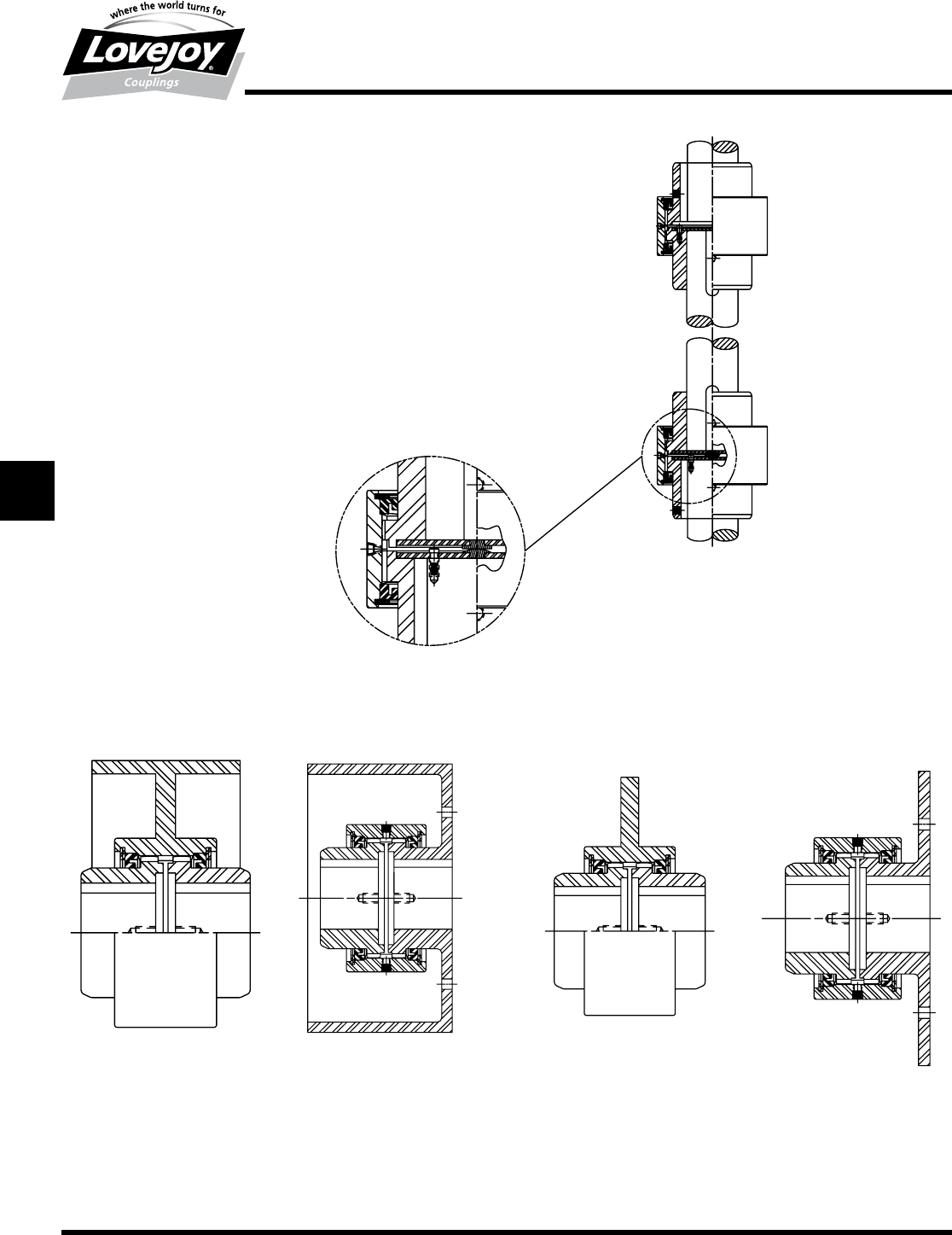
186 630-852-0500
G-72
Gear
Continuous Sleeve
Overview
Lovejoy / Sier-Bath Continuous Sleeve Gear Couplings
Vertical Floating Shaft Type
The■upper■coupling■is■a■Standard■Vertical■Type■coupling.■The■
lower■coupling■has■a■hardened■crowned■button■inserted■in■the■
plate■of■the■lower■hub■and■a■hardened■flat■button■inserted■in■
the■plate■of■the■upper■hub.■The■entire■floating■assembly■rests■
on■these■two■buttons■which■carry■the■weight■of■the■floating■
assembly■thus■maintaining■the■spacing■between■the■two■lower■
hubs■allowing■for■flexibility.■The■hubs■on■the■floating■shaft■are■
flexible■and■the■hubs■of■the■driver■and■driven■shafts■are■rigid.
Brakedrum Type
Two■different■designs■of■brakedrum■couplings■are■illustrated.■One■
shows■the■brakedrum■as■an■intergal■part■of■the■sleeve■and■the■
two■hybs■are■standard.■The■other■design■utilizes■one■standard■
hub■and■a■standard■sleeve■with■the■brakedrum■as■part■of■a■
special■hub.
Brake Disc Type
Two■different■designs■of■brake■disc■couplings■are■illustrated.■One■
shows■the■brake■disc■as■an■intergal■part■of■the■sleeve■and■the■
two■hybs■are■standard.■The■other■design■utilizes■one■standard■
hub■and■a■standard■sleeve■with■the■brakedrum■as■part■of■a■
special■hub.
JWJISCJSFMC
G
HPGDDTSPUJVSDRSLDED
JW JIS CJ SF MC G HP GD D T SP UJ VSD R SLD ED
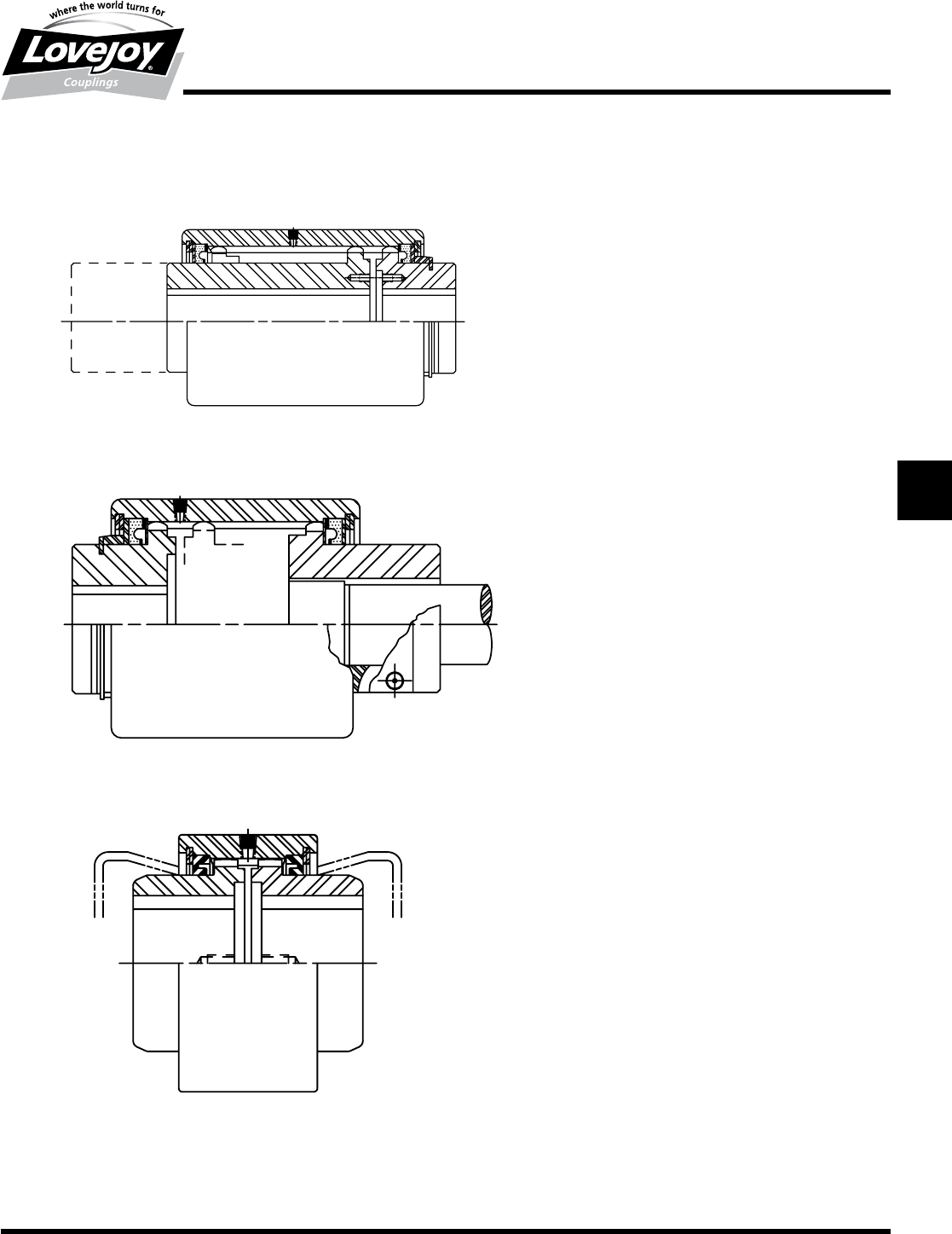
187
www.lovejoy-inc.com G-73
Gear
Continuous Sleeve
Overview
Lovejoy / Sier-Bath Continuous Sleeve Gear Couplings
Sliding Hub Type
The■sleeve■is■longer■than■standard■and■is■designed■to■allow■
for■a■predetermined■amount■of■axial■travel■on■one■shaft.■The■
short■hub■is■secured■to■the■sleeve■by■means■of■a■spacer■
washer■and■snap■ring■which■prevents■travel.■This■type■is■also■
manufactured■to■allow■for■travel■of■both■hubs■in■the■sleeve.■
This■coupling■is■also■available■with■a■rigid■type■short■hub.
Jordan Type
Used■on■Jordan■machines■and■refiners,■this■design■is■similar■
to■the■Sliding■Hub■Type■coupling■except■the■long■hub■is■split■
and■secured■to■the■shaft■with■a■bolt.■This■permits■for■quick■
axial■adjustment■of■the■Jordan■shafts■in■the■hub.
Continuous Lubricated Type
This■coupling■is■adapted■from■our■Standard■Type■coupling,■
except■the■standard■seals■have■been■replaced■with■the■special■
spacer■washers.■These■washers■have■a■snug■fit■in■the■sleeve■
with■sufficient■clearance■on■the■hub■OD■to■allow■for■injection■of■
a■continuous■stream■of■lubricant.
JWJISCJSFMCGHPGDDTSPUJVSDRSLDED
JW JIS CJ SF MC
G
HP GD D T SP UJ VSD R SLD ED
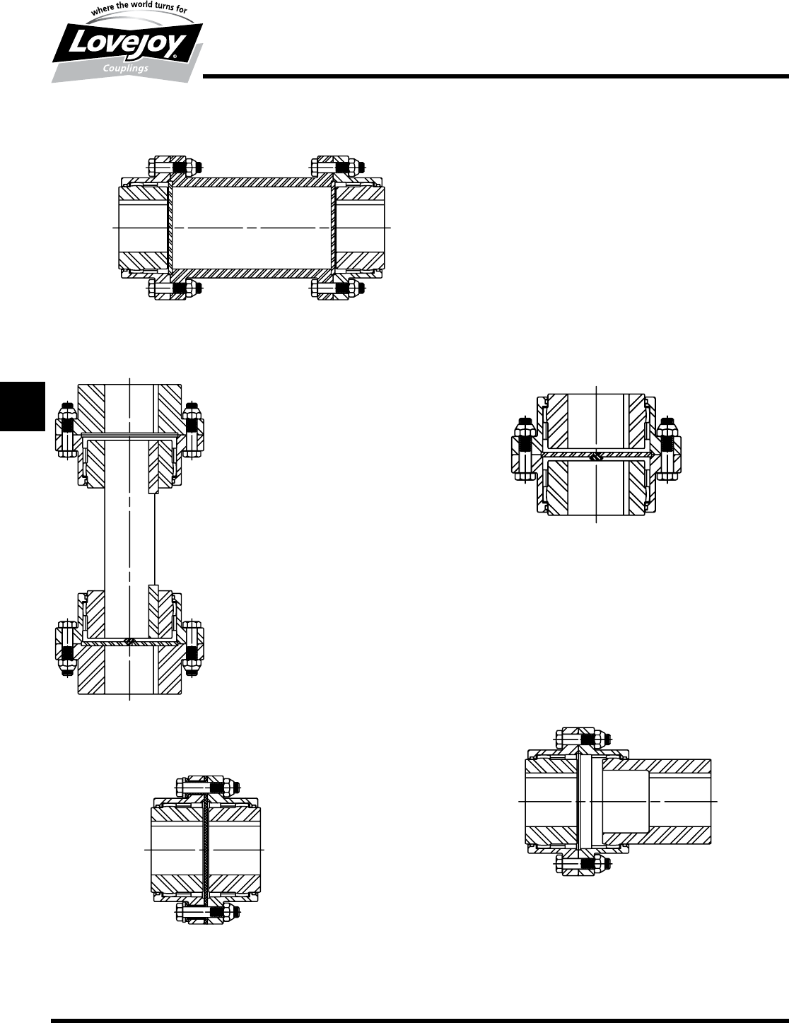
188 630-852-0500
G-74
Gear
Flanged Sleeve
Overview
Lovejoy / Sier-Bath Flanged Sleeve Gear Couplings
Limited End Float Spacer Type
The■addition■of■plates■restricts■axial■travel■to■the■drive■or■driven■
shaft.■The■spacer■makes■it■possible■to■remove■the■hubs■from■either■
shaft■without■disturbing■the■connected■units.
Vertical Type
This■coupling■has■the■same■horsepower,■RPM■and■misalignment■
capabilities■as■the■standard■couplings■of■corresponding■sizes.■A■
plate■with■a■hardened■crowned■button■rests■on■the■lower■shaft■
which■supports■the■weight■of■the■sleeve.
Jordan Type
Used■on■Jordan■machines■and■refiners,■this■design■is■similar■to■the■
slide■type■coupling■except■the■long■hub■is■split■and■secured■to■the■
shaft■with■a■bolt■clamp.■This■permits■quick■axial■adjustment■of■the■
Jordan■shafts■i■this■hub.
Insulated Type
Use■of■a■non-metallic■material■between■flanges■and■around■the■
bolts■prevents■any■stray■currents■from■one■shaft■to■the■other.
Vertical Floating Shaft Type
The■lower■coupling■has■a■hardened■crowned■
button■inserted■in■the■plate■of■the■lower■hub.■
The■entire■floating■assembly■rest■on■the■
button.■Optional■construction■of■the■upper■
coupling■would■be■a■rigid■hub■on■the■floating■
shaft■with■a■flex■half■on■the■top.
JWJISCJSFMC
G
HPGDDTSPUJVSDRSLDED
JW JIS CJ SF MC G HP GD D T SP UJ VSD R SLD ED
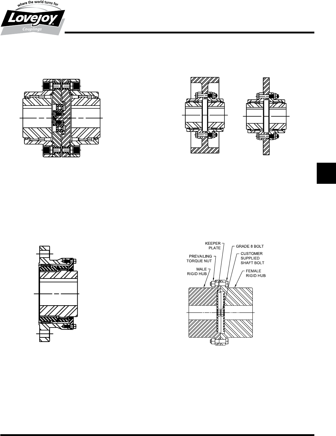
189
www.lovejoy-inc.com G-75
Gear
Flanged Sleeve
Overview
Lovejoy / Sier-Bath Flanged Sleeve Gear Couplings
Engineered Shear Pin Type
Shear■pin■couplings■are■primarily■used■to■limit■transmitted■torque■to■a■
redetermined■load.■THis■in■turn■disconnectes■the■driver■and■driven■shafts■
if■torque■exceeds■the■specified■limits.■They■are■especially■suited■to■protect■
equipment■when■jams■occur.■Components■are■re-useable■after■pins■shear.■
The■coupling■will■retain■lubricant■for■a■short■period■to■allow■equipment■to■be■
shut■down.
Double Engagement Half Gear Type
Both■internal■and■external■teeth■in■a■single■sleeve.■Can■be■bolted■
to■a■rotating■flywheel,■shaft■or■drum■to■connect■driver■or■driven■
machine■with■a■shaft■extension.■This■coupling■has■the■same■
features,■ratings■and■misalignment■capability■as■the■standard■group■
of■couplings.
Brakewheel and Brake Disc Type
Replaceable■brakewheel■and■brake■disc■piloted■on■the■outside■diameter■
of■a■standard■sleeve■and/or■rigid■hub.■Offers■a■choice■of■applying■braking■
effort■to■the■load■or■driving■motor.
Rigid Alloy Steel FARR Type
Male/Female■piloted■rigid■coupling■coupling■with■keeper■plates.■
This■coupling■is■used■when■a■rigid■connection■is■required■between■
the■low■speed■shaft■of■a■gearbox■and■the■head■shaft■of■a■conveyor,■
bucket■elevator,■mixer■or■any■overhung■or■suspended■load.
JWJISCJSFMCGHPGDDTSPUJVSDRSLDED
JW JIS CJ SF MC
G
HP GD D T SP UJ VSD R SLD ED
190 630-852-0500
G-76
Gear
Standard Flanged Sleeve Maximum Bores Inch / Metric
Dimensional Data
Flex Hub Maximum Bores - Interference Fit
Inch Metric
Max 1 Square Keyway Max 1 Rectangular Keyway Max Metric Keyway
Bore Width Depth Bore Width Depth Bore Width Depth
Size in in in in in in mm mm mm
11.625 0.375 0.188 1.750 0.375 0.125 42 12 3.3
1.5 2.125 0.500 0.250 2.250 0.500 0.188 56 16 4.3
22.750 0.625 0.313 2.875 0.750 0.250 73 20 4.9
2.5 3.250 0.750 0.375 3.375 0.875 0.313 85 25 5.4
34.000 1.000 0.500 4.250 1.000 0.375 107 28 6.4
3.5 4.625 1.250 0.625 4.875 1.250 0.438 125 32 7.4
45.375 1.250 0.625 5.625 1.500 0.500 145 36 8.4
4.5 6.000 1.500 0.750 6.500 1.500 0.500 165 40 9.4
56.500 1.500 0.750 7.000 1.750 0.750 180 45 10.4
5.5 7.250 1.750 0.875 7.500 1.750 0.750 200 45 10.4
68.000 2.000 1.000 8.250 2.000 0.750 225 50 11.4
79.000 2.000 1.000 9.500 2.500 0.875 255 56 12.4
811.000 2.500 1.250 11.500 3.000 1.000 310 70 14.4
912.000 3.000 1.500 12.500 3.000 1.000 340 80 15.4
10 13.750 3.500 1.250 355 80 15.4
11 15.500 4.000 1.500 410 90 17.4
12 17.000 4.000 1.500 435 90 17.4
13 18.250 5.000 1.750 480 100 19.5
14 19.500 5.000 1.750
15 21.000 5.000 1.750
16 22.500 6.000 2.000
18 25.500 6.000 2.000
20 28.000 7.000 2.500
22 31.000 8.000 2.750
24 34.000 9.000 3.000
26 37.000 9.000 3.000
28 40.000 10.000 3.500
30 42.000 10.000 3.500
Standard Flanged Sleeve Maximum Bores - Inches and Millimeters
Notes:■■ n■■Rectangular■(reduced)■keyways■preferred■for■bores■above■6-1/2■inches.
■n■■■Maximum■bores■may■be■reduced■for■clearance■fit■bore■applications.
JWJISCJSFMC
G
HPGDDTSPUJVSDRSLDED
JW JIS CJ SF MC G HP GD D T SP UJ VSD R SLD ED
191
www.lovejoy-inc.com G-77
Gear
Rigid Hub Maximum Bores – Interference Fit
Dimensional Data
Rigid Hub Maximum Bores – Interference Fit
Notes:■■ n■■Rectangular■(reduced)■keyways■preferred■for■bores■above■6-1/2■inches.
■n■■■Maximum■bores■may■be■reduced■for■clearance■fit■bore■applications.
Rigid Hub Maximum Bores - Interference Fit
Inch Metric
Max 1 Square Keyway Max 1 Rectangular Keyway Max Metric Keyway
Bore Width Depth Bore Width Depth Bore Width Depth
Size in in in in in in mm mm mm
12.125 0.500 0.250 2.250 0.500 0.188 56 16 4.3
1.5 2.813 0.750 0.375 3.062 0.750 0.250 76 22 5.4
23.500 0.875 0.438 3.750 0.875 0.313 95 25 5.4
2.5 4.250 1.000 0.500 4.500 1.000 0.375 114 32 7.4
34.875 1.250 0.625 5.250 1.250 0.438 134 36 8.4
3.5 5.625 1.500 0.750 5.875 1.500 0.500 150 36 8.4
46.500 1.500 0.750 6.500 1.500 0.500 176 45 10.4
4.5 7.375 1.750 0.875 7.625 2.000 0.750 202 50 11.4
58.375 2.000 1.000 8.750 2.000 0.750 230 50 11.4
5.5 9.250 2.500 1.250 9.500 2.500 0.875 260 56 12.4
610.125 2.500 1.250 10.500 2.500 0.875 285 63 12.4
711.250 3.000 1.500 12.000 3.000 1.000 320 70 14.4
813.500 3.500 1.750 14.000 3.500 1.250 375 80 15.4
915.000 3.500 1.750 15.500 4.000 1.500 415 90 17.4
10 17.000 4.000 1.500 455 100 19.5
11 18.500 5.000 1.750 500 100 19.5
12 20.250 5.000 1.750
13 22.000 5.000 1.750
14 23.500 6.000 2.000
15 24.250 6.000 2.000
16 26.000 6.000 2.000
18 28.000 7.000 2.500
20 31.000 8.000 2.750
22 34.000 8.000 2.750
24 37.000 9.000 3.000
26 40.000 10.000 3.500
28 43.000 11.000 3.750
30 46.000 11.000 3.750
JWJISCJSFMCGHPGDDTSPUJVSDRSLDED
JW JIS CJ SF MC
G
HP GD D T SP UJ VSD R SLD ED
192 630-852-0500
JWJISCJSFMC
G
HPGDDTSPUJVSDRSLDED
JW JIS CJ SF MC G HP GD D T SP UJ VSD R SLD ED
G-78
Gear
Coupling Grease
Why Coupling Grease?
Adequate■lubrication■is■essential■for■satisfactory■gear■coupling■
operation.■Lovejoy■Gear■Coupling■Grease■is■specifically■
designed■for■gear■coupling■applications■to■increase■coupling■
life■while■drastically■reducing■maintenance■time.■Its■high■
viscosity■base■oil■and■tackifier■combine■to■keep■the■grease■in■
place■and■prevent■separation■and■it■is■in■complete■compliance■
with■NSI/AGMA■9001-B97■lubrication■recommendations.
Lovejoy■Coupling■Grease■is■dark■brown■in■color■and■
manufactured■with■a■lithium■soap/polymer■thickener,■which■
has■superior■resistance■to■oil■separation■when■subjected■to■
high■centrifugal■forces■normally■found■in■couplings.■Bearing■
or■general■purpose■greases■tend■to■separate■and■lose■
effectiveness■due■to■high■centrifugal■forces■on■the■various■
ingredients■at■high■rotational■speeds.■These■high■centrifugal■
forces■encountered■in■couplings■separate■the■base■oil■from■
the■thickeners.■Heavy■thickeners,■which■have■no■lubrication■
qualities,■accumulate■in■the■gear■tooth■mesh■area■resulting■
in■premature■coupling■failure.■Lovejoy■Gear■Coupling■Grease■
is■designed■to■highly■resistant■to■centrifugal■separation■of■the■
oil■and■thickener,■which■allows■the■lubricant■to■be■used■for■a■
relatively■long■period■of■time.
One■of■the■secrets■to■the■success■of■Lovejoy■Gear■Coupling■
Grease■is■the■variable■consistency■throughout■the■working■
cycle■of■the■application.■The■consistency■of■our■gear■coupling■
grease■changes■with■the■operating■conditions.■Working■of■the■
lubricant■under■actual■service■conditions■causes■the■grease■
to■become■semi-fluid,■functionally■solash■lubricating■the■wear■
surfaces■of■the■coupling.■As■the■grease■cools,■it■returns■to■the■
original■consistency,■thereby■preventing■leakage.
Lovejoy■Gear■Coupling■Grease■is■available■from■stock■in■14■
oz.■cartridges,■1■lb.■and■5■lb.■cans.
Features
■■Minimizing■of■coupling■wear
■■Resistance■to■water■washing
■■Corrosion■and■rust■protection
■■High■load■carrying■capabilities
■■Extended■relubrication■frequency
■■Use■at■temperatures■up■to■325°■F
■■Staying■in■place■under■high■speeds
■■Resistance■to■centrifugal■separation
■■Reduction■in■down■time■&■maintenance■cost
Lovejoy■Gear■Coupling■Grease■has■a■consistency■which■
overlaps■the■NLGI■grades■0■and■1.■This■grease■is■specially■
formulated■with■a■lithium/polymer■thickener■and■fortified■with■
corrosion,■oxidation,■extreme■pressure,■and■a■effective■rust■
inhibitor■additive■package.
Typical Properties of Lovejoy Gear Coupling Grease
NLGI■Grade 0/1
Appearance Dark■Brown,■Tacky
Lithium■Soap■/■Polymer,■wt% 10.0
Viscosity
■■■■■@■40°■C,■cST >3200
■■■■■@■100°■C,■cSt >50
Penetration.■Dmm
■■■■■Worked,■60x 350
■■■■■Worked,■10,000,■%■Change 10
Dropping■Point,■°■F 320°■(160°■C)
Centrifugal■Oil■Separation,■vol% None
Water■Spray-Off,■wt% >3
Rust■Protection Pass
Timken,■OK■Load,■lbs 40+
Four-Bal■EP
■■■■■Load■Wear■Index,■kgf 68
■■■■■Weld■Point,■kgf 400
Four-Ball■Wear,■mm
■■■■■1■hr,■75°■C,■1200■RPM,■40■kgf 0.4
Guide■to■Usable■Temperature
■■■■■Min,■°■F Below■-20°■(-29°■C)
■■■■■Continuous■Service,■Max,■°■F 250°■(121°■C)
■■■■■Short■Exposure,■Max,■°■F 325°■(163°■C)
