Bba29001 1029A Datasheet.p65 Genelec
User Manual: Genelec 1029a
Open the PDF directly: View PDF ![]() .
.
Page Count: 4
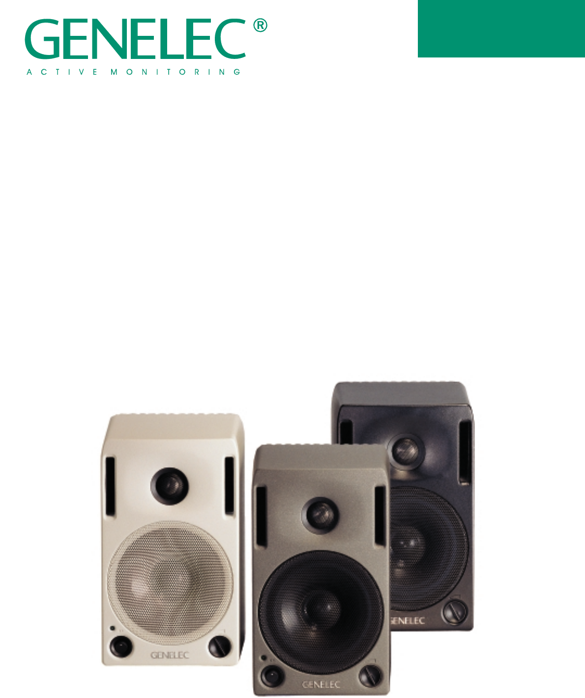
Genelec 1029A
Bi-amplified Monitoring System
1029A
DATA SHEET
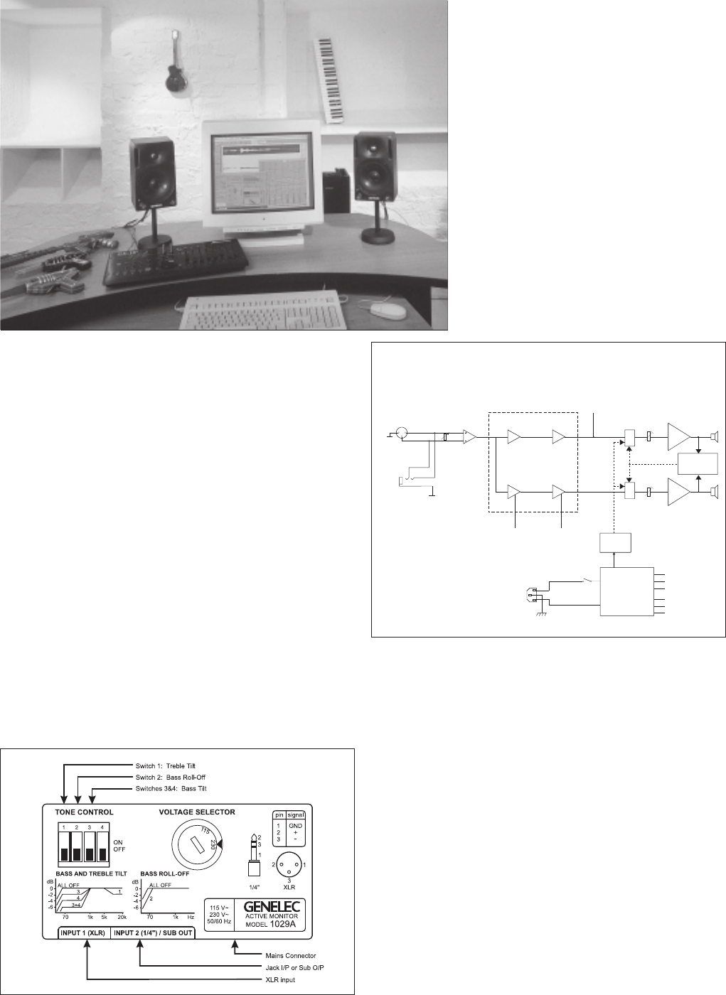
Figure 1: The 1029A back panel, controls and connectors.
1029A Bi-amplified Active Monitoring System1029A Bi-amplified Active Monitoring System
1029A Bi-amplified Active Monitoring System1029A Bi-amplified Active Monitoring System
1029A Bi-amplified Active Monitoring System
Figure 2: Block diagram showing active crossover filters, power
amplifiers and driver units.
SYSTEMSYSTEM
SYSTEMSYSTEM
SYSTEM
The Genelec 1029A is a very com-
pact bi-amplified active monitor
system, which has performance
comparable to much larger sys-
tems. The vented speaker
enclosure contains an amplifica-
tion unit. This unit includes an
active electronic crossover, over-
load protection circuitry and two
power amplifiers, one for each
driver. The system's excellent dis-
persion and precise imaging,
together with its compact size,
make it ideal for near field monitor-
ing, mobile vans, home studios,
multimedia and home theatres.
The Genelec 1029A has been spe-
cially designed to have a sufficient
LF extension (-3dB at 68Hz) for
most monitoring applications.
However if greater SPL's and a
lower cutoff frequency are re-
quired, it can be complemented
with the 1091A subwoofer, which
has a lower cutoff point of 38Hz.
Genelec’s unique Directivity Con-
trol Waveguide (DCW) technol-
ogy is used to provide excellent
stereo imaging and frequency
balance, even in difficult acoustic
environments. Versatile tone con-
trols allow further matching of the
system to its surroundings. A pair
of 1029A's can produce peak
acoustic levels of over 110 dB SPL
at 1m. The speakers may be used
in a vertical or horizontal orienta-
tion.
INTEGRATEDINTEGRATED
INTEGRATEDINTEGRATED
INTEGRATED
CONSTRUCTIONCONSTRUCTION
CONSTRUCTIONCONSTRUCTION
CONSTRUCTION
The 1029A is very easy to set up
and use, the only connections re-
quired are the mains supply and
the line level input.
The integrated design allows the
amplifiers and the drivers to be
calibrated as a single unit, elimi-
nating the effects of component
tolerances and ensuring consist-
ent quality. The rugged cast
aluminium cabinet has rounded
corners and a hard-wearing
painted outer surface.
CROSSOVER FILTERSCROSSOVER FILTERS
CROSSOVER FILTERSCROSSOVER FILTERS
CROSSOVER FILTERS
The amplifier unit contains an ac-
tive crossover, a feature more
commonly used in large and ex-
pensive control room monitors.
This is the ideal method for divid-
ing the input signal between the
driver units. The active crossover
allows the overall response of the
system to be optimized to an ex-
tent impossible with a passive
system. To maintain uniform fre-
quency balance in differing
acoustic environments, special
calibrated controls are included in
the active crossover network.
These controls include treble 'tilt',
bass 'tilt' and bass 'roll-off'
switches.
INPUT CONNECTORSINPUT CONNECTORS
INPUT CONNECTORSINPUT CONNECTORS
INPUT CONNECTORS
The input is made via a balanced
XLR female or a balanced 1/4" jack
socket connector. The two input
connectors offer great flexibility
as they can be used in parallel.
This offers the possibility of hav-
ing two sources connected to the
monitor at the same time. An
additional configuration is using a
single 1029A to monitor a stereo
output. See figures 3 and 4.
The volume control is located on
the front panel. This allows easy
level matching with other audio
equipment.
APPLICATIONSAPPLICATIONS
APPLICATIONSAPPLICATIONS
APPLICATIONS
Near Field MonitoringNear Field Monitoring
Near Field MonitoringNear Field Monitoring
Near Field Monitoring
Audio Video Post ProductionAudio Video Post Production
Audio Video Post ProductionAudio Video Post Production
Audio Video Post Production
Mobile VansMobile Vans
Mobile VansMobile Vans
Mobile Vans
Home TheatersHome Theaters
Home TheatersHome Theaters
Home Theaters
Project / Home StudiosProject / Home Studios
Project / Home StudiosProject / Home Studios
Project / Home Studios
Digital WorkstationsDigital Workstations
Digital WorkstationsDigital Workstations
Digital Workstations
Multimedia Production / PlaybackMultimedia Production / Playback
Multimedia Production / PlaybackMultimedia Production / Playback
Multimedia Production / Playback
Volume
control
BASS
ROLL-OFF
BASS TILT
TREBLE TILT
Treble and Bass
driver protection
circuit
Power Supply
circuits
Start/Stop
Mute
Bass
Treble
T-CAL
B-CAL
Audio
Input
2
3
1
Mains Input
CROSSOVER FILTER
POWER AMPLIFIERSINPUT AMPLIFIER
ON
OFF
XLR
Jack
14
1
/ "
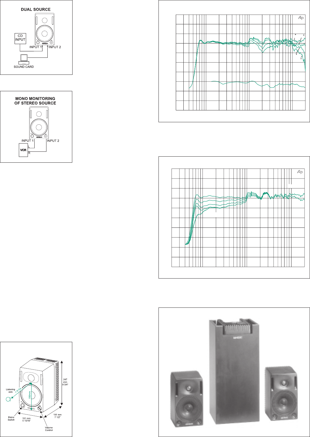
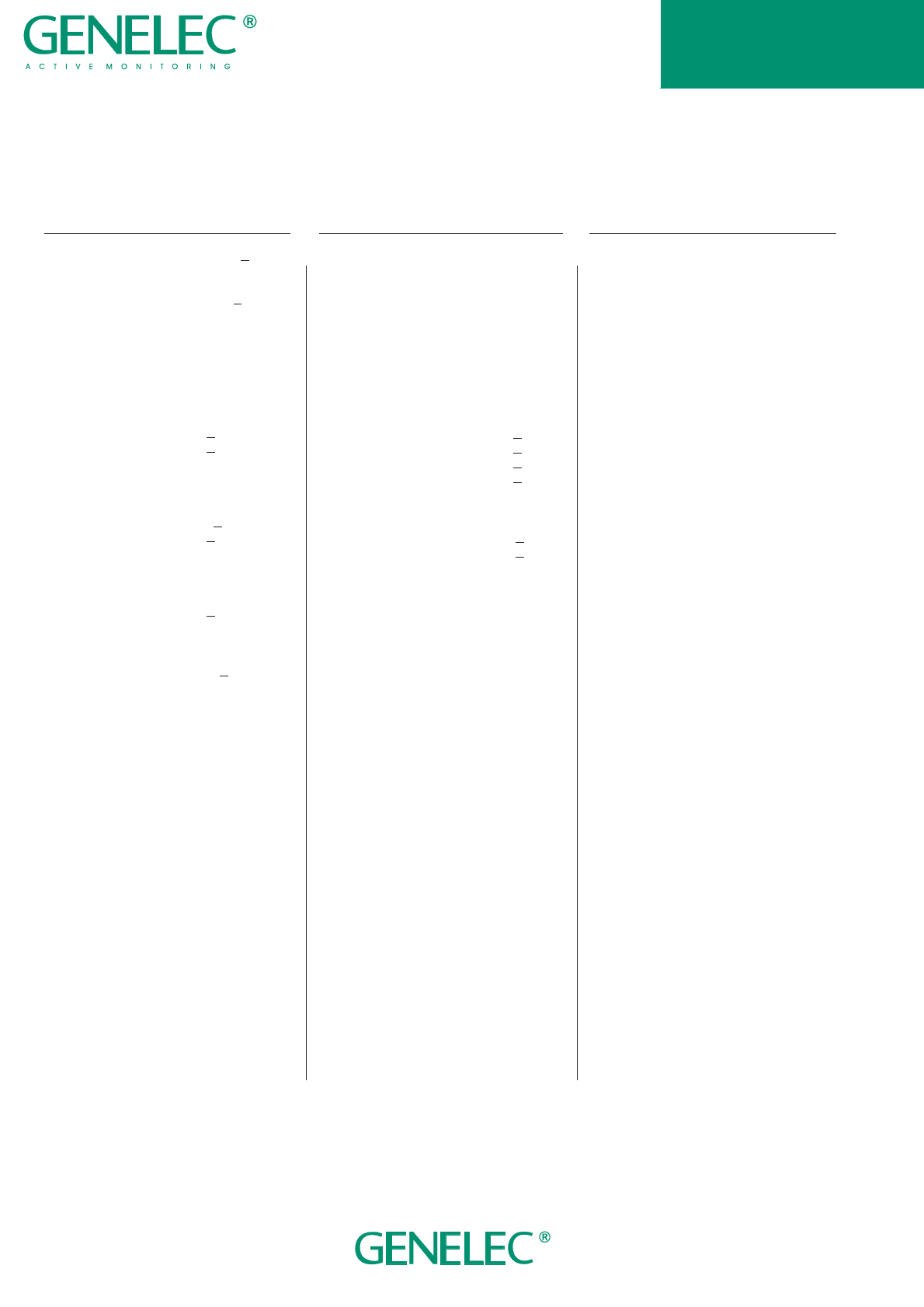
Figure 7: The curves show the effect of the 'bass tilt', 'treble tilt' and 'bass
roll-off' controls on the free field response.
Figure 6: The upper curve group shows the horizontal directivity
characteristics of 1029A measured at 1 m. The lower curve is the total
radiated power response. Uin=-20 dBu.
Figure 8: The 1029As and 1091A subwoofer.
Figure 5: The reference axis lies
between bass and treble drivers.
Figure 4: Using one monitor and a
stereo source.
Figure 3: Using two sources.
AMPLIFIERSAMPLIFIERS
AMPLIFIERSAMPLIFIERS
AMPLIFIERS
The bass and treble amplifiers
produce 40 W of output power
each, with very low THD and IM
distortion values. The amplifiers
are designed to ensure the high-
est subjective sound quality
currently possible. The amplifier
unit also contains a protection cir-
cuit that monitors the output levels
and prevents any damage to the
drivers. This makes the system
immune to overloads and spuri-
ous signals.
DRIVERSDRIVERS
DRIVERSDRIVERS
DRIVERS
A 19 mm (3/4") metal dome tweeter
is loaded by a DCW, and is used
to reproduce the high frequen-
cies. The DCW is integrated into
the one piece cabinet front baffle.
The 130 mm (5") woofer is a bass
cone driver mounted in a 4.5 litre
vented cabinet. The -3 dB fre-
quency is 68 Hz and the low
frequency response extends
down to 65 Hz (-6dB).
Protective grills are positioned in
front of both drivers. Magnetic
shielding is standard on the 1029A.
Shielding is vital for applications
such as video post production,
where stray magnetic fields must
be minimized.
DCW TECHNOLOGYDCW TECHNOLOGY
DCW TECHNOLOGYDCW TECHNOLOGY
DCW TECHNOLOGY
The revolutionary Directivity Con-
trol Waveguide (DCW) technology
is a means of greatly improving
the performance of a direct radi-
ating multi-way loudspeaker
under normal listening conditions.
One of the basic aims is to match
the performance of the drivers in
terms of both frequency response
and directivity. This results in a
smoother overall frequency re-
sponse on and off axis. In addition,
the improved directivity control
causes more direct sound and
less reflected sound to be re-
ceived at the listening position.
This provides improved stereo
imaging and ensures that the sys-
tem is less sensitive to differing
control room acoustics than con-
ventional direct radiator design.
The DCW Technology improves
the drive unit sensitivity by +2 to
+6 dB (depending on the particu-
lar application), thus also
increasing the available system
maximum sound pressure level.
MOUNTINGMOUNTING
MOUNTINGMOUNTING
MOUNTING
There are several possibilities for
mounting the 1029A. On the base
of the monitor is a 3/8" UNC threaded
hole which can accommodate a
standard microphone stand.
There is a provision for an Omni-
mount® size 50 bracket,for which
two M6x10mm screws are re-
quired. Alternatively the speaker
can be hung on M4 screws with
suitable heads by one of the three
keyhole slots on the backpanel.
The speaker can be hung in a
horizontal or vertical position. Fric-
tion pads are provided for
placement on a shelf or a stand.
OPTIONSOPTIONS
OPTIONSOPTIONS
OPTIONS
The 1029A is available in three
colours: black, grey and white.
The driver's protective grilles,
volume and power knobs and
stickers on the back of the loud-
speaker are black regardless of
cabinet colour. Other options in-
clude wall and ceiling mounts,
table stand and soft carrying bag.
Ask your local Genelec dealer for
more details.
AUDIO
PRECISION
1029A
vs
17
AUG
96 10:32:56
55
60
65
70
90
75
95
80
100
85
90
95
100
LEVEL(dBr)
20
100
1k
10k
20k
FREQ(Hz)
0
15
30
45
AUDIO
PRECISION
1029A
vs
23
SEP
96 10:24:33
50
55
60
65
70
75
80
85
90
95
100
LEVEL(dBr)
20
100
1k
10k
20k
FREQ(Hz)
BASS TILT
2+3+4 OFF
3 ON
4 ON
3+4 ON
2+3+4 ON
1 OFF
1 ON
BASS ROLL-OFF
TREBLE TILT
SYSTEMSYSTEM
SYSTEMSYSTEM
SYSTEM
SPECIFICATIONSSPECIFICATIONS
SPECIFICATIONSSPECIFICATIONS
SPECIFICATIONS
Lower cut-off frequency, -3 dB: < 68 Hz
Upper cut-off frequency, -3 dB: > 20 kHz
Free field frequency response of system:
70 Hz - 18 kHz (±2.5 dB)
Maximum short term sine wave acoustic
output on axis in half space, averaged
from 100 Hz to 3 kHz:
@ 1m > 100 dB SPL
@ 0.5m > 106 dB SPL
Maximum long term RMS acoustic output in
same conditions with IEC weighted noise
(limited by driver unit protection circuit):
@ 1m > 98 dB SPL
@ 0.5m > 104 dB SPL
Maximum peak acoustic output per pair on
top of console, @ 1 m from the engineer
with music material:
> 110 dB SPL
Self generated noise level in free field
@ 1 m on axis:
< 10 dB (A)
Harmonic distortion at 85 dB SPL @ 1m on
axis:
Freq: 75...150 Hz <3%
>150 <1%
Drivers:
Bass: 130 mm (5") cone
Treble: 19 mm (3/4")metal dome
Both drivers are
magnetically shielded.
Weight: 5.7 kg (12.5 lb)
Dimensions:
Height: 247 mm (9 3/4")
Width: 151 mm (5 15/16")
Depth: 191 mm (7 1/2")
AMPLIFIERAMPLIFIER
AMPLIFIERAMPLIFIER
AMPLIFIER
SECTIONSECTION
SECTIONSECTION
SECTION
Bass amplifier output power with an
8 Ohm load: 40 W
Treble amplifier output power with an
8 Ohm load: 40 W
Long term output power is limited by
driver unit protection circuitry.
Amplifier system distortion at nominal
output:
THD < 0.08%
SMPTE-IM < 0.08%
CCIF-IM < 0.08%
DIM 100 < 0.08%
Signal to Noise ratio, referred to full output:
Bass > 90 dB
Treble > 90 dB
Mains voltage: 100/200 or 115/230 V
Voltage operating range: ±10%
Power consumption:
Idle 9 VA
Full output 80 VA
CROSSOVERCROSSOVER
CROSSOVERCROSSOVER
CROSSOVER
SECTIONSECTION
SECTIONSECTION
SECTION
Inputs:
Input 1: XLR female,
balanced 10 kOhm
Input 2: 1/4 " Jack socket,
balanced 10 kOhm
Volume control:
Variable from Mute to -6 dBu for
100 dB SPL output @ 1m
Subsonic filter below 68 Hz :
18 dB/octave
1091A Subwoofer output (input 2)
at 100 dB SPL:
-23 dBu into 33 kOhm load.
Ultrasonic filter above 25 kHz:
12 dB/octave
Crossover frequency, Bass/Treble:
3.3 kHz
Crossover acoustical slopes:
24 - 32 dB/octave
Treble tilt control operating range:
from 0 to -2 dB @15 kHz
Bass roll-off control operating in a -6 dB
step @ 85 Hz (to be used in conjunction
with the 1091A subwoofer).
Bass tilt control operating range in -2 dB
steps:
from 0 to -6 dB @ 150 Hz
The 'CAL' position is with all tone controls
set to 'off' and the volume control to maxi-
mum (fully clockwise).
Genelec Oy, Olvitie 5Genelec Oy, Olvitie 5
Genelec Oy, Olvitie 5Genelec Oy, Olvitie 5
Genelec Oy, Olvitie 5
FIN - 74100 IISALMI, FINLANDFIN - 74100 IISALMI, FINLAND
FIN - 74100 IISALMI, FINLANDFIN - 74100 IISALMI, FINLAND
FIN - 74100 IISALMI, FINLAND
Phone:Phone:
Phone:Phone:
Phone: +358 - 17 - 813 311+358 - 17 - 813 311
+358 - 17 - 813 311+358 - 17 - 813 311
+358 - 17 - 813 311
Fax:Fax:
Fax:Fax:
Fax: +358 - 17 - 812 267+358 - 17 - 812 267
+358 - 17 - 812 267+358 - 17 - 812 267
+358 - 17 - 812 267
E-mail:E-mail:
E-mail:E-mail:
E-mail: genelec@genelec.comgenelec@genelec.com
genelec@genelec.comgenelec@genelec.com
genelec@genelec.com
Web:Web:
Web:Web:
Web: http://www.genelec.comhttp://www.genelec.com
http://www.genelec.comhttp://www.genelec.com
http://www.genelec.com
Genelec Inc, 7 Tech CircleGenelec Inc, 7 Tech Circle
Genelec Inc, 7 Tech CircleGenelec Inc, 7 Tech Circle
Genelec Inc, 7 Tech Circle
Natick, MA 01760, USANatick, MA 01760, USA
Natick, MA 01760, USANatick, MA 01760, USA
Natick, MA 01760, USA
Phone:Phone:
Phone:Phone:
Phone: +1+1
+1+1
+1 --
--
-508 - 652 - 0900508 - 652 - 0900
508 - 652 - 0900508 - 652 - 0900
508 - 652 - 0900
Fax:Fax:
Fax:Fax:
Fax: +1+1
+1+1
+1 --
--
-508 - 652 - 0909508 - 652 - 0909
508 - 652 - 0909508 - 652 - 0909
508 - 652 - 0909
E-mail:E-mail:
E-mail:E-mail:
E-mail: genelec@compuserve.comgenelec@compuserve.com
genelec@compuserve.comgenelec@compuserve.com
genelec@compuserve.com
Genelec Document BBA29001 COPYRIGHT GENELEC OY 4.2000Genelec Document BBA29001 COPYRIGHT GENELEC OY 4.2000
Genelec Document BBA29001 COPYRIGHT GENELEC OY 4.2000Genelec Document BBA29001 COPYRIGHT GENELEC OY 4.2000
Genelec Document BBA29001 COPYRIGHT GENELEC OY 4.2000
All data subject to change without prior notice.
1029A
