Optex Genesys 824 Installation Manual
User Manual: Genesys 824 Installation Manual AlarmHow.net Library
Open the PDF directly: View PDF ![]() .
.
Page Count: 22

--.
GENESYS 824
INSTALLER
PROGRAMMING MANUAL
Contents
How to Enter and Move Around Within installers Program Mode
Custom
Zone
Programming, Location 00-46
Communications Programming, Location
48-56B
Entry/Exit De!ays. Output
Cutoffs.
Location
57-58C
PGM Output Options. Location
59-59A
Misc. Reporting Codes. Location
68-72C
Keypads and Partitions. Location 73-738
Signal Routing, Location 75-758
System Features. Location 76-76B
Self Test Times, Location
77-77C
Installers/Duress PIN(s), Location 78-78A
Battery Charging Calculations, Locations 79-79A
Hexadecimal Conversion Chart
Auxiliary Power Information
p.
1
p.
1
p. 4
p. 6
p. 7
p. 8
p. 10
p. 10
p. 11
p. 12
p. 12
p.
13
p.
14
p. 15
11

HOW TO ENTER INSTALLERS PROGRAM MODE
*
\
.
ENTERING PROGRAM MOOE
The installers PIN IS required to access the
Installers
program. The Installers PIN is Preset from the
factory as (9999) and may be changed in Location 78.Care must be taken when changing Installers P!N. If the
code is lost. the
panel
must be returned to the factory.
To enter Program Mode:
Depress
[Installer
PIN] +
[^]
+
[7]. The LCD shculc! now display the abbreviation (PRG.). You are now in
program mode.
MOVING WITHIN INSTALLERS PROGRAM MODE
Once
within the
Installers
program mode. movement is achieved by se!ecting specific Memory Locations
and going to those locations. Each Memory Location is
identified
with a two-digit number. Entering that number at
the (PRG.) prompt will advance you to that specific
locationn
and display any memory within that field.
To access a Sub-Location (example. 56B), enter the two digit location number and press the [^] button
until the appropriate sub-location is displayed. To move back to a previous Sub
Location
within that memory
location. press [STAY].
Once within the field changes can be made by
either:
A) Entering the appropriate two digit
number
or.
B)
toggling on or off status indicators
located
along the top and bottom of the
aisplay. Example: Depressing the
[1]
button willcause the “AWAY” LCD to turn on or off. And pressing
the
[4]
button will cause the “BYPASS” LCD to turn
on
or off.
-When the desired changes are made. simply
deprer
ss
the
[^]
button
to
lock the information in the
EE
prom
and advance to the next memory
field.
-To
exit
a specific Program Location. press the
[#]
button
This
will
exit ycu back
to
the
PRG..
prompt
When
all changes have been completed. depress the
[#]
button
twice to
exit
out of
Installer
Program mode.
CUSTOM ZONE PROGRAMMING
All of the GENESYS 824 zones can be custom prcgrammed to perform any number of specific functions.
For each zone you will be making several decisions about
the
functions it will perform. The choices are as follows.
ZONE
TYPE
*
Check Programming Sheet for
Defaults.
The first two-digit entry defines the Zone
Type
as
well
as the
loop
Type.
The first digit defines the Zone Type
.
The choices are as follows:
0
= ENTRY/EXIT (1)
-
Used for Primary Entry/Exit Delay. Corresponds to programming in Location 57 and Sub
Location 57B.
1
=
ENTRY/EXIT
(2)
-
Used for Secondary Entry/Exit Delay. This designation is used when a special deiay IS
required, Used for applications such as Entranceor Exit through Garages. Gates or Outdoor Detectors.
Corresponds to programming in Location 57A and Sub Location
57C.
2
.
2
=
PERIMETER. INSTANT
-
Used for creating an instant alarm when the system is armed regardless of the mode
selected.
\L.g
= INTERIOR, TYPE
1
-
Used For interior zone(s) which operate as Follower zone(s) in AWAY and STAY modes
and become instant in INSTANT mode.
4 = INTERIOR, TYPE 2
-
Used For interior zone(s)
tihich
operate as Follower zone(s) in AWAY and STAY modes
and are bypassed in INSTANT mode.
*
3
=
INTERIOR, NPE 3
-
Used For interior zone(s) which operate as delay zone(s) in AWAY, STAY and INSTANT
modes.
6
= 24 HOUR ZONE
-
Used For devices which will create an alarm condition whether the alarm is armed or
disarmed. (i.e.. Panic and Hold-Up Buttons)
z = 24 HOUR ZONE, (FIRE)
-
Used For devices such as HearSensors, Waterflow and Smoke Detectors (4 Wire)
which are required to be active whether the alarm is armed or disarmed.
8
= DAY CIRCUIT
-
Used for devices required to transmtt a :rouble Condition in a disarmed state and transmlr an
alarm in the armed state. (i.e.. Window Foil, Alarm Screens. etc.).
LOOP TYPE
-
The second diait defines the Loop Type. The choices are as Follows
0 = NORMALLY OPEN (No E.O.L. Resistor Requires).
1 = NORMALLY CLOSED (No E.O.L. Resistor Required).
2 = NORMALLY OPEN
I
NORMALLY CLOSED
(E.Q.L.
Resistor Required).
3 = NORMALLY OPEN
I
E-0-L.
(Reports trouble on break, alarm on short).
4 = NORMALLY CLOSED
I
E.O.L. (trouble on shorr. alarm on open).
l NOTE: E.O.L. Resistor 2.2K ohm, 112 watt.
Oatex/Morse
oart # 14014649.
Example: IF you have a delay zone on a Front door, :he loop is normally
c!osed
and E.O.L. is
requirec
as
well as trouble reports. The code selected world be
:Q
2)
for the First memory location or “zone type
’
LOOP RESPONSE TIME (Sub Location A)
Loop Response Time
-
amount of time needed For the loop to be in violation before activating an alarm
Time selected in 50 ms. increments. Enter value
g.00
thru
99),
Default (05) = 250 ms,
ALARM COOE (Sub Location 8)
Alarm Code
-
transmitted when zone enters alarm
ccndition.
Enter value (00 thru FF), Default (00) = disabled,
TROUBLE CODE (Sub Location C)
Trouble Code
-
transmitted when zone enters trouble condition. (Note: zone must be programmed to send
trouble codes, see Loop Type).
Enter value (00 thru FF),
jJefauU.jOOI =
-
dlsab
led,
BYPASS CODE (Sub Location D)
Bypass Code
-
transmitted when zone is bypassed and system is armed. (Note: zone must be
programmed for bypass, see Sub Location G).
Enter value (00 thru FF), Default
(001 =
d
isabled,
5L
RESTORAL
CODE (Sub Location
E)
Restoral Code -is transmitted after alarm condition has returned to normal Also
after
trouble condition is
restored to normal.
Enter value (00 thru FF),
D_efaultOOJ
=
disabled,
3

ZONE FEATURES
(Sub.Location
F) Selected by toggling on or off bar type LCD indicators
(Bar On
=
Function Active
[ves]
I Bar Off = Function Inactive [No]
)
1
-
TELE&lONE
OUTPUT, (Away LCD)
-
.._
._
on keypad
disilay.
Activates digital dialer function of Genesys 824. Must be programmed
Yes
If
panel is to
tranSinlt
to central station.
Default
IYes),
*
_
AUDISI&
(Stay LCD)
Enables the steady output bell voltage for each zone. If not selected, zone will be silent (See
Location 58 for bell-cutoff times).
Default (Yes).
3
-
PULSE
BELL,
(Inst LCD)
Activates pulsed
be!l
output for zone.“Audible (Stay LCD)” must’also be selected for proper
operation of this option.
Default
(No).
,
4
-
PGM OUTPUT
i,
(Bypass LCD)
When selected. this zone will activate PGM Output 1 when in alarm state (See Sub Location
58B
for cutoff time).This output is an Open Collector
which
sinks to ground for the amount of time
programmed in Sub Location 58B. Note: When used as alarm output. this feature cannot be used for any
other function. (See Location 59 for other functions).
Default (No)
6
-
PGM OUTPUT 2, (Alarm LCD)
When seles:ed. this zone will activate
PGIM
Output 2 when in alarm state (See Sub Location
58C
for cutoff time). This output is an Open Collector
‘which
sinks to ground for the amount of time
programmed in Sub Location
58C.
Note: When used as alarm output. this feature cannot be used used for any
other function. (See Sub Location 59A for other functions).
->
Default (No).
6 -WALK TEST, (Trbl LCD)
When se!ec!ed. this option allows installer cr end user to walk test the zone for proper functicn.
With this functicn
ac:ive
all zones will scroll on the
LSC)
display. When a zone is violated, that zone will be
removed from the display. When all zones have
‘3%
IIviolated. the keypad will display the word “NONE:‘.
Default (Yes). NOTE. 24 Hour zones, Day zones, and Fire zones are still active in this mode.
3
-
MONITOR, (Fire LCD)
Allows panel to monitor zone activity and lccally annunciate when zone is violated. (See Sub
Location
768
for Monitor Mode Options).
Default (No). NOTE. 24 Hour zones, Day zones, and Fire zones are still active in this mode.
C,
(Blank LCD)8
-
SI
For use with 24 hour audible zones. When the system is disarmed this feature allows for visual
zone annunciation at the keypad and if selected.
ac:ivation
of PRG 1 and 2. In the armed
mod&
this
feature allows for activation of bell output and PRG 1 and 2 if selected.
Default.
(NoL
ZONE
FEATURES
(cont.) (Sub Location G) Se!ected by toggling on or bff bar type LCD indicators on
keypad display.
(Bar On = Function Active
[ves]
I Bar Off = Function Inactive [No]
)
1
-
KEYPAD 1 AUDIBLE (Away LCD)
Enables or disables keypad entry buzzer For this specific keypad.
Default.
fYesL
II
2
-
KEYPAD 2 AUDIBLE, (Stay LCD)
Enables or disables keypad entry buzzer For this specific keypad.
Default.
(Yes),
3
-
KEYPAD 3 AUDIBLE,
(Inst
LCD)
Enables or disables keypad entry buzzer Fcr this specific keypad.
*
Default. (Yes),
4
-
KEYPAD 4 AUDIBLE, (Bypass LCD)
Enables or disables keypad entry buzzer For :his spkcific keypad.
Default.
(YesL
5
-
DISPLAY
ARMEQ,
(Alarm LCD)
With this feature toggled “On”, zone(s) will be displayed on all keypads when in alarm. IF more
than 1 zone is violated. the violated zones will be scrolled numerically. With this Feature toggled “Off’,
zones will
Ils.t
be displayed on any keypad when in aiarm.
Default.
fNoL
5
-
SHUNT Al LOWED, (Trouble LCD)
‘i
When used in conjunction with audible zone. alarm signal will transmit only once before bell cut-
off. IF zone is violated again after bell has reset.
signal
will again only be sent once.
Default.
(No),
7
-
BYPASS ALLOWED, (Fire LCD)
Allows end user to manually sypass zone
of
action is selected
Default. (Yes). ‘NOT TO BE USED ON FIRE ZONES.
8
-
NOT USED. (Blank LCD) For Future Use
COMMUNICATIONS PROGRAMMING
TE1
EPHONF
NUMBFR
l. (Location 48 thru Sub Location
48G)
This will be the primary phone number called by the Genesys 824 For all activity signals. The number is
entered into memory in two-digit segments beginning in Location 48. The
[“I
button must be presged
between each two digit entry. The maximum number of digits allowed is
15
including dial pause and dial
tone detect. Any unused memory locations should te Filled with Hexadecimal F. See below For special
Functions.
Default
FFFI
in all
soaces,
Special Functions (Sequence) (Hex
\/alue)
(Ph. # Options)
Hexadecimal values can be
used for Phone Number and
,_
For Account Number. Phone
number options are valid only
when programming phone
numbers.
Wwl+Pl
= Hex A
=
*
[Away]+fl]
= Hex B = #
[Awayl+M
=
HexC
= 3 Second Pause
(Away]+[3]
= Hex
D
= Dial Tone Detect
Wwl+W
= Hex E
(Away]+(S] = Hex F
5
TELEPHONE NUMBER 2 (Location
50
thru Sub Location
53G)
.
Program in the
sam_e_manner
as Telephone Number 1. This digital output can be used for Backup
Reporting or Redundant Reporting. See Location 75 thru Sub Location 758 for routing options.
Default (FF) in all
soaces,
1*
j:-
3
ACCOUNT NUMBER 1 and 2, (Location 52 thru
Sub
Location 52C)
Genesys 824 is capable of transmitting two separate account numbers when used in Partitioned
applications. Account numbers are entered in two digit increments.
Location 52 and Sub Location 52A will hold the primary account number. Use this number if
only one account number is required.
c
Sub Location
528
and 52C will hold the secondary account number. The secondary account
number is used only with a partitioned system and will transmit for the second partition.
Default (00) in all locations,
RECEIVER FORMAT 1 and 2, (Location 53)
The first digit in this location selects the format for
Te!ephone
Number
1.
The second digit selects the
format for Telephone Number 2. The choices are as follows:
0
=
SiA
Format
-
Security Industry Association approved
trCdnsmission
format. For this format. all
reporting codes are present in the control panel software. To activate, enter any two digit entry other than
00 in desired code locations. For code not to be sent. program 00 in respective location.
A=
IO PPS 4-1 Format
-
This format is a 10 pulse per second (PPS) reporting scheme. Used when a 4
digit account number and a 1 digit event code is required.
2
-
10 PPS 4-l Extended Format
-
This is a 10 pulse per second
(PPSi
reporting format that gives more
reporting capability than 4-l format.
3
-
10 PPS 4-2 Format
-
Simrlar format to 4-l Extended except that reporting is sent as a single round of
information.
,.
.
:-J
NOTF: Following formats are similar to above formats except transmitted at a higher rate of speed. (20
PPS).
4
-
20 PPS 4-l Format
5
-
20 PPS 4-l Extended Format
5
-
20 PPS 4-2 Format
Default
(I
1). both 10 PPS 3-l and
4-l.
ANTI-JAM
TIME
(Sub Location 53A)
The amount of time required for the telephone company to disconnect the phone line after the panel has
released. Enter value in 1 second increments.
Default&
/
r
DIAL
S&ECTIDIAL
ATTEMPTS
(Sub Location 536)
Each digit of this entry determines a different function.
Dial Select (First Digit, 05)
This entry determines if the 824 will dial Rotary or Touch Tone.
[O]
= Rotary, (1 thru
91
=
Touch Tone
Oefault (05).
rotat-v,
6

.
Dial Attempts (Second Digit,
05)
This entry determines the maximum number of dialing attempts the 824 will make on all reporting
functions. The dialer will stop attempting once it
rece
eives the “Kiss-Off’ from the central station.
Default (05). five
attempts,
DELAY
BEFORE
DIALING (Sub Location 53C)
This function allows user to abort alarm transmission by entering a valid PIN number. The 824 will allow
abortion of signal during period of time entered in this location. Value entered
in
seconds.
Default (00). no delav.
DOWNLOAD
PHONE NUMBER (Location 54 thru Sub Location 54G)
This is a security feature which safeguards against unauthorized entry of the programming mode via
downloading software. If the panel receives a call initiated at a PC equipped with the proper software it will
hang-up and call back on this preprogrammed number. This verifies access by the proper authority and
eliminates any improper access.
Default
(FF)
in all spaces.
LOCAL DOWNLOAD PIN
Location
56
and Sub Location
56A)
This PIN works to initiate a download sequence from the 824 rather than from the Download PC. When
this (4 Digit) number is entered. the 824 will dial the number programmed in Location 54 thru Sub Location
54G.
Default
(0000)
ANSWER
ON DOWNLOAD (Sub Location 56B)
When a call is initiated from a PC. this i‘s the number of rings the 824 will wart before it initiates the
sequence described under DOWNLOAD PHONE NUMBER.
Default
(1
2)
ENTRY/EXIT DELAYS, OUTPUT CUTOFFS
ENTRY
DEL
AY
(1)
(Location
57)
This
will be the Entry Delay for any zone
programmedEntry/Exit
(1) in the custom zone programming
section. Selectable in 1 second increments.
Default
(45)
ENTRY DELAY
(2)
(Sub Location 57A)
This will be the
Entry
Delay for any zone programmeo Entry/Exit (2) in the custom zone programming
section.
Selectable
in 1 1 second increments.
Default (45).
EXIT DELAY
(1)
(Sub Location
57B)
This will be the Exit Delay for any zone programmes Entry/Exit (1) in the custom zone programming
section. Selectable in 1 second increments.
Default
(60),
,_.
EXIT DELAY
(2)
(Sub Location 57C)
This will be the Exit Delay for any
zone
programmed Entry/Exit (2) in the custom zone programming
section. Selectable in 1 second increments.
Default
(60)
PRE ALARM
Delay
(Location 58)
This feature allows the keypads to remain silent for a predetermined amount of time during entry delay
This feature adds time to the total entry delay and care should be taken when this feature is utilized.
Selectable in 1 second increments.
It
(00)
no add
itional
delay
.
7

BELL
CUTOFF (Sub Location 58A)
This feature determines the maximum amount of time the Alarm Output will sound when activated. For
this output to activate, the zone being violated
must
be
programmed audible ves. Selectable in 1 minute
increments.
Default
(10).
Note: If programmed (00), a valid PIN will be required in order to reset.
PGM
1 OUTPUT (Sub Location 586)
This feature determines the maximum amount of time the PGM 1 Output will
Function
when activated. For
this output to activate, the zone being violated
must
be programmed PGM 1
Output
ves. Selectable in 1
minute increments.
Default
(00).
Note: If programmed (00), a valid PIN will be required in order to reset.
PGM
2 OUTPUT (Sub Location
58C)
This feature determines the maximum amount of
timea
the PGM 2 Output
will
function when activated. For
this output to activate. the zone being violated must
be
programmed PGM 1
Output
yes
Selectable in 1
minute increments.
Default
(OO),
Note: If programmed (00), a valid PIN will be required in order to reset.
PGM OUTPUT OPTIONS
PGM
(1)
OUTPUT OPTION (Location 59)
This option determines which function will be
perform:
ed by PGM 1 when activated. The choices are as
follows: Default
(99).
disabled,
00
=
Alarm Output
-
Select
if PGM
1
is to be activated
in
conjunction
with Zone Output. Output time corresponds
to PGM 1 Output (Sub Location
58B)
01
= System Status - This option will allow PGM 1
output
when all zones are secured. Output will not be present
if any zone is violated or if the system is armed.
Use this feature if a keyplate is used instead of a keypad
to activate green status LED.
02
-
Ground Start
-
Used for a reporting system where a
g,
v
round
is required on the phone
system
to bring up dial
tone. This will allow for a 2 second ground before any dialing sequence.
03
-
Fail to Communicate
-
Will allow for an output if diale
r
reaches maximum dialing attempts and is
unsuccessful in reaching the central station.
04
-
Follow Entry/Exit
Delay
-
Allows for output during
Entry
and Exit delay times.
05
-
Utility PIN Activation
-
Allows for output when Utility PIN is entered. This will cause an output
hold
for
5
seconds. Refer to Location
-
for Utility PIN.
99
-
Disable PGM 1
-
This disables PGM 1 output.
PGM
(2)
OUTPUT OPTIONS (Sub Location 59A)
This option determines which function will be performed by PGM 2 when activated. The choices are as
follows: Default (99). disabled,

00
-
Alarm Output
-
Select if PGM 2 IS to be activated in conjunction with Zone Output. Output time corresponds
to PGM 2 Output
(SuS’iocation
58C)
-
System Status
-
This option will allow PGM 2 output when system is armed. Output will not be present if
system is disarmed or while in Exit delay mode. Use this feature if a
keyplate
is used instead of a keypad
to activate red armed LED.
p2
-
Not Used
-
For future use.
*
a
-
Fail
to Communicate
-
Will allow for an output if dialer reaches maximum dialing attempts and is
unsuccessful in reaching the central station.
w
-
Follow Entry/Exit Delay
-
Allows for output during Entry and Exit delay times.
0s
-
Utility PIN Activation
-
Allows for output when Utility PIN is entered. This willcause an output hold for 5
seconds. Refer to User Programming Location 2 for Utility PIN.
0s
-
Not Used
-
For future use.
07
-
Ring Back -When this option is selected. this output will activate for 2 seconds after the Open and Close
reports have been “Kissed-Off’ by the Central Station.
99
-
Disable PGM 2
-
This disables PGM 2 output.
MISCELLANEOUS REPORTING CODES
USER
OPEN CODES (Locations 60 thru 63 and their respective Sub Locations)
These codes should be programmed if identification of user disarming of the system is required.
Default
(00)
all disabled.
USER
CLOSING
CODES (Locations 64 thru 67 and their
respective
Sub
Locations)
These codes should be programmed if identification of user arming of the system is required.
Default
(00)
all disabled,
AUT0
ARM CODE (Location 68)
Program this code if you want Auto Arm (see User Programming Location 4) to report to the central
station.
Default (00) disabled,
FAIL TO ARM
CODE
(Sub Location 68A)
This code will be sent if the 824 attempts to Auto Arm and is unsuccessful.
Default (00) disabled.
DURESS CODE (Sub Location
68B)
This code reports to the Central Station when the Duress Code (see Sub Location 788) is
entered
at the
keypad.
Default (00) disabled.
AC
FAILURE
CODE
(Sub Location
68C)
This code will be sent when the AC power is lost.
ult (00) disabled,
AC
RESTORAL
CODE
(Location 69)
This code will be sent when the AC power is restored.
It
(00)
disabled,
9

LOW
BATTERY
CODE
(Sub Location
69A)
This code will be sent when the battery voltage drops to approximately 11.5 Volts.
Default
(00) disabled.
.
BATTERY
RESTORAL
CODE (Sub Location
69B)
This code will be sent when the battery voitage reaches 12 Volts
Default (00) disabled.
BOX
TAMPER CODE (Sub Location 69C)
Entering a code in this field will enable the box tamper feature of the 824 (see Sub Location 76A). Default
(00) disabled
Box
TAMPER
RESTORAL
CODE (Location 70)
This code is sent when the cabinet tamper is reset.
Default (00) disabled
BELL
FAULT CODE (Sub Location 70A)
G-FM (Fire Module) must be used in order to send
Bell
Fault Code. (se-* Location 76). Signal is sent if
fuse is blown or if
bell
wiring is either shorted or opened.
AUXILIARY POWFR FAULT CODE (Sub Location 70B)
This code will be sent to the Central Station if the Auxiliary Power fuse is blown.
Default
(00)
disabled.
KEYPAD FlRE CODE (Sub Location
7OC)
This is the signal that will be sent when the keypad fire buttons are pressed ([STAY] and
[6]
button
pressed simultaneously for 2 or more seconds).
Default (00) disabled.
KEYPAD EMERGENCY CODE (Location 71)
This is the signal that will be sent when the keypac emergency
buttons
are pressed ([INSTANT]: AND
[9]
button pressed simultaneously for 2 or more seconds).
Default (00) disabled.
KEYPAD PANIC CODE (Sub
Location
71A)
This is the signal that will be sent when the keypac
panic
buttons are pressed ([AWAY] and [3] button
pressed simultaneously for 2 or more seconds).
OPFN
RESTORAL
CODE
(Sub Location 718)
This code will be transmitted when the system has been disarmed after an alarm.
Default
(00)
disabled,
2 WIRE SMOKE DETECTOR LOOP CODE, (Sub Location 71C)
This signal will be transmitted when the two-wire Smoke Zone goes into alarm (terminals 25 and 26).
Default (00)
disabled
FlRE TROUBLE CODE (Location 72)
This code is transmitted to the Central Station when the 2 wire smoke detector loop goes into trouble.
Qefault
(00)
disabled,
FIRE RESTORAL
CODE
(Sub Location 72A)
This signal is transmitted to the Central Station when the 2 wire smoke detector loop returns to normal
after an alarm condition.
Default (00) disabled.
10

RESTORAL
CODE
(Sub
Location
72B)
This
signal will be sent to the Central Station after an alarm when the bell reaches the end of its time-out
period. Note: If the zone which created the alarm is not secured when the bell times-out, the signal will be
sent when the zone is secured.
Default
(00)
disabled.
GROUND
FAULT CODE (Sub Location
72C)
This code will be sent to the Central Station only when earth ground is lost on the G-FM (Fire Module).
Default (00) disabled
KEYPADS
EXPANDER
BOARD SELECTOR (Location 73)
AND PARTITIONS
For Expander Boards to be recognized by the 824 panel they must be selected in this field. The choices
for
this
location are
(01),
(02), and (00).
Default
(00) disabled
KEYPAD ACTIVATION and PARTITIONING (Sub Location
73A)
This locations
attributes
are
selected
by toggling on or off bar type LCD indicators on the keypad display.
(Bar On = Function Active
[Yes]
/
Bar Off = Function Inactive [No]
)
11
Away --Keypad
1
(active/inactive)
5
Alarm--- Keypad 1 (partition
1)
2
Stay --Keypad
2
(active/inactive)
6
Trbl--------Keypad2 (partition 1)
3
lnst --Keypad
3
(active/inactive)
7
Fire--Keypad3 (partition 1)
4
Bypass --Keypad
4
(active/inactive) 8 Blank
-
Keypad 4 (partition
1)
BUSS
FAULT CODE (Sub Location
73B)
This code will be sent if their is a trouble on the
Expander
Board Circuit (i.e. the panel cannot see 1 or
more of the installed expansion modules or 1 or more of the
keypads
are addressed the same).
Default
(00)
disabled.
BATTERY CHARGING CALCULATION (Sub Location
73C,
This location tells the control panel the total current
draw
for all peripheral units. Add total current draw of
system. Include Control Panel. Keypad(s) and Aux devices. Use table below to determine proper entry
for this location.
Total Svstem Current in
mA
Digit to
Enter
(Sub
L
ocation
73C)
00to
100mA
91
101
to
200
mA 92
201
to300 mA
93
301
to
400
mA 94
401to
500
mA 95
501
to
600
mA 96
601
to700 mA
97
701
to800
mA 98
801
to900 mA
99
SIGNAL ROUTING
SIGNAL ROUTING OPTIONS Dart 1 (Location 75)
i
This is a 2 digit entry. The first
digit
determines
which
receiver(s) will receive Alarm and Restoral codes.
The second
digit determines
which receiver(s) will receive Open/Close codes. The choices are as
follows:
1111

Q
= Panel will report only to Receiver
#l.#l.
j_j_
= = Panel will report only to Receiver
#2.
2
=
Panel will report to Receiver
#1.
If unsuccessful, panel will attempt to report to Receiver
#2.
3
= Panel will report to Receiver
#1
and Receiver #2.
Default
(00)
report 0nlv to Receiver
#l#l
cc
Note: If partitioning, see Location 76, section 8.
SIGNAL ROUTING OPTIONS
part
2
(Sub Location 75A)
This is a 1 digit entry. This entry determines which receiver(s) will receive
Housekeeping
codes. i.e.
power codes, failure codes, etc. The Choices are as follows:
0
= Panel will report only to Receiver
#1.
1
=
Panel will report only to Receiver #2.
2
= Panel will report to Receiver
#1.
If unsuccessful. panel will attempt to report to Receiver
#2.
3
= Pane! will report to Receiver
#1
and Receiver
#2.
Default
(0)(0)
report onlv to Receiver
#1.
Note: If partitioning, see Location 76, section 8.
COMMUNICATION FAILURE CODE (Sub Location 758) .
The panel will attempt to send this code if it has exhausted its dialing attempts (see memory Sub Location
53B for number of attempts).
Default (00) disabled,
SYSTEM FEATURES
SYSTEM
FEATURES Dart
1
(Location 76)
This location is used to select specific functions for the Genesys
824.
This locations attributes are
selected by toggling on or off bar type LCD
indicators
on the keypad display.
(Bar On
=
Function Active
[Yes]
/
Bar Off = Function Inactive [No]
)
1
-
BELL TEST, (Away LCD)
With this option selected, the bell will
sound
for three seconds when the exit delay expires and the
system arms.
Default (No).
2 - ELL AUDIBLE or BUS FAULT, (Stay LCD)
With this option selected, bell voltage will be present for the amount of time programmed
in
sub
Location 58A or until a valid PIN is entered at the keypad.
Default (No).
3
-
NOT USED. FOR FUTURE USE ONLY. (Inst LCD)
4
-
(G-FM) INSTALLED (Bypass LCD)
With this option ‘selected, the panel will
ccmmunicate
with the ([G-FM], Fire Module) and will
indicate a buss fault if the G-FM fails.
Default
(No).
5 - 50 H7 or 60 Hz (Alarm LCD)
With this option selected, unit will operate on 60 Hz. If this option is not selected, panel will
operate on 50 Hz.
Default (Yes) 60
Hz.
6
-
TELCO FAULT
AUDIBLE
(Trouble LCD)
With this option selected, the keypad will display a visual indication of telephone trouble
(TLM)
and
emit a pulsed audible tone.
Default
(No),
.
.’
7
-
NOT USED. FOR FUTURE USE ONLY. (Fire LCD)
.-._.
8
-
PARTITION SYSTEM (Blank LCD)
With this option selected, the panel can be used as two separate systems. The first half of the
zones will automatically become partition
#I
and the second half of the zones will become partition
#2.
User PIN numbers 1 thru 8 will be assigned to partition
#I
and user PIN numbers 9 thru 16 will be
assigned to partition
#2.
Partition
#I
will always report its information to Receiver
#I
and partition X2 will
always report to Receiver #2. Note: when Partition is selected, Signal Routing (Location 75 and Sub
Location 75A) will be superseded.
c
Default INo).
SYSTEM FEATURES
rlart
2 (Sub Location 76A)
This location is also used to select specific functions for the Genesys 824. This locations attributes are
selected by toggling on or off bar type LCD indicators on the keypad display.
(Bar On = Function Active
Ives]
I Bar Off = Function Inactive [No]
)
1
-
ACKNOWLEDGE REQUIRED for MONITOR MODE, (Away LCD)
With this option selected, Monitor Mode will require,the keypad to be manually reset after each
zone is violated. The keypad may be reset by depressing the [^I button or entering a valid PIN number. If
this option is not se!ected, the keypad will emit a 2 second tone when a zone is violated and display the
zone until it is restored to normal.
Default
I
No),
2
-
BELL OUTPUT for MONITOR MODE, (Stay LCD)
This feature works in conjunction with the previous feature.
Wrth
this option selected, the bell
output will be continuous until the keypad is manually reset. If this ootion is not selected. the bell output
will activate momentarily when monitored zone is violated.
Default (No).
3
-
PGM 1 OUTPUT for MONITOR MODE,
(Inst
LCD)
This feature allows PGM 1 to duplicate the function for Monitor Mode selected above.
Default (No),
4
-
PGM 2 OUTPUT for MONITOR MODE,
(Inst
LCD)
This feature allows PGM 2 to duplicate the function for Monrtor Mode selected above.
Default (No).
NOTE:
IALARMl.
I-TROUBLE].
[FIRE].
AND
[BLANKI
LCD LOCATIONS ARE NOT USED.
SELF TEST TIMES
SELF TEST TIME INTFRVAL [HOURS1 (Location 77)
This memory location determines the hour of the day at which the test signal shall be sent to the Central
Station. The hour must be entered in military time, i.e.
3:OOPM
=
15.
r
Default
(991
disabled.
SELF TEST TIME INTERVAL lMlNUTES1 (Sub Location 77A)
This memory location determines the minute of the hour at which the test signal shall be sent to the
Central Station.
t
(99)
disablea
SELF TEST TIME INTERVAL [DAYS1 (Sub Location 778)
This memory location determines the interval between days at which the test signal shall be sent to the
Central Station.
Default (00) disabled,
13

SELF TEST CODE (Sub Location 77C)
This will be the code sent to the Central Station for Self Test.
Default
(00)
disabled.
INSTALLERS/DURESS
PIN(s)
JNSTALLERS PIN (Location 78)
This is the code used by the Installer to access the Installer Programming Mode. NOTE: Take care when
reprogramming this code.If the code is lost the panel must be returned to Optex/Morse for
Defaulting. Default (9999),
DURESS PIN (Sub Location 78A)
When this PIN is used the Genesys 824 will be armed or disarmed normally and a Duress Code will be
sent to the Central Station. See Sub Location
68B
for Duress Code
Default
(FFFF)
disabled,
NOTE: PINS CANNOT be duplicated under any circumstances If a duplicate is entered in error. the
keypad will enunciate audibly to indicate the PIN has been rejected.
U.L. VERIFICATION INFORMATION
For Grade A Local Mercantile Installations
The Minimum requirements to form a Listed Grade A Local System includes Low Battery Alarm
Annunciation.
BATTERY CHARGING CALCULATIONS
BATTERY CALCULATIONS (Location 79 thru Sub Location 79A)
U.L. requires that the primary power fail signal shall not be transmitted until standby power IS 25
percent depleted and is guaranteed to be sent before the standby power falls to 50 percent. To comply
with this requirement, program (Location 79) with total current draw for the control panel and all installed
modular units. Also program (Sub Location 79A) with the amp hour rating of the battery. These are
calculated as follows:
(First) Subtract the Total Current in
mA
from 1000 and divide this number by 10,
(IOOOmA
-
Total
Current in mA) / 10. Then convert this number into a hexadecimal value using the chart on the following
page. This number is entered in (Location 79).
(Second) Multiply the Amp Hour rating of the standby battery by 10,
(
Battery
Amp Hour Rating X 10).
Then convert this number into a hexadecimal value using the chart on the following page. This number is
entered in (Sub Location 79A).
CURRENT RATING CHART
Control (G-824)
=
1
00mA
Keypad
=
24mA
Fire Module(G-FM)
=
50mA
Bell
85Db. (Wheelock
#46T-G1
O-l 2)
=
125mA
Expansion Board(G-EX)
=
29mA
1414

-
The following worksheet is used to calculate the total Amp Hour draw on the battery
Control
(G-824)
1
OOmA
X
Hours
=
Amp Hours
Keypad (G-KP) 24mA
X
Hours = Amp Hours
Bell
125mA
X 15 Minutes
=
Amp Hours
Fire Module
(G-FM)’
50mA
X
Hours
=
Amp Hours
Control (in Alarm)
1
OOmA
X 15 Minutes
=
Amp Hours
Total
=
‘Amp Hours
l FIRE
MODULE
REQUIRED
FOR COMMERCIAL FIRE APPLICATIONS:
Battery
Part Numbers
RB-121
5
1.5Ah
(minimum for 4
hours)
RB-1226
2.6Ah (alternate for 4
hours)
RB-1280 9.5Ah
(one required for 24
hours)
1515
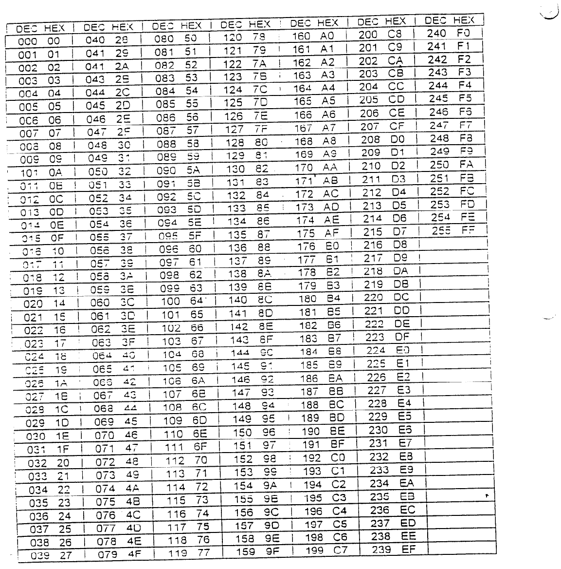
DECIMAL TO
HEXIDECIMAL
CONVERSION
CHART
THIS CHART
CONVERTS
DECIMAL
VALUES
FROM 000 TO 255 INTO 2 DIGIT
HEXIDECIMAL
EQUIVALENTS.
THE T
EST TIMER
INTERNAL
MUST
BE
PROGRAMMED USING THIS CHART.
EXAMPLE.
TEST TIME
PERIOD
OF 1 OAY
is “24 HOURS”,
FIND
24 IN THE OECIMAL COLUMN
AND
READ
THE
HEXIDECIMAL
EQUIVALET
-
24
HOURS
=
18;
72
HOURS
=
48.
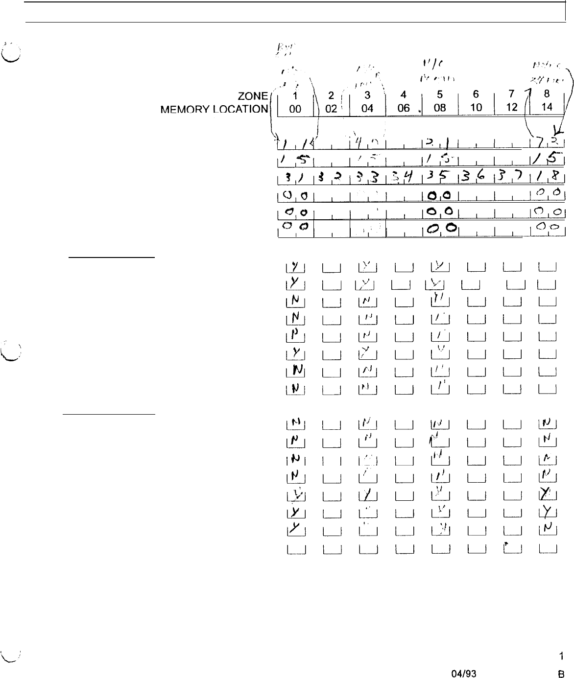
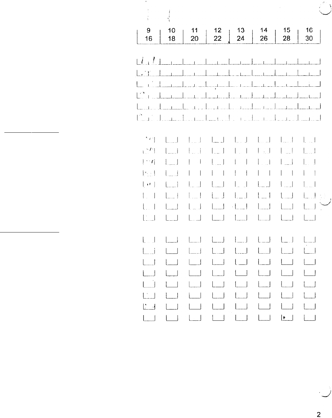
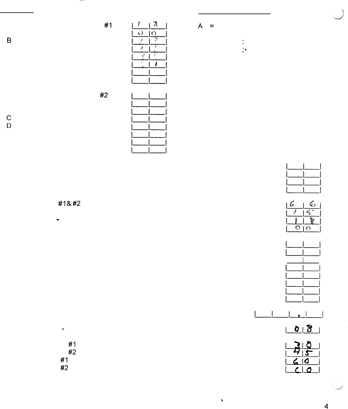
GENESYS 824
-
PROGRAMMING SHEET
,
,
00
OOA
OOB
ooc
OOD
OOE
OOF
OOG
Zone Type
-
Loop Type
Loop Response
Alarm Code
Trouble Code
Bypass Code
Restore Code
ZONE FEATURES (YES = ON, NO = OFF)
1
AWAY-TELEPHONE
2
STAY-AUDIBLE
3
INST
-
PULSE BELL
4
BYPASS
-
PGM 1
5
ALARM
-
PGM 2
6
TRBL
-
WALK TEST
7
FIRE
-
MONITOR
8
BLANK
-
SILENT DAY
ZONE FEATURES (YES = ON, NO = OFF)
1
AWAY
-
KEYPAD 1 AUDIBLE
2
STAY
-
KEYPAD 2 AUDIBLE
3
INST
-
KEYPAD 3 AUDIBLE
4
BYPASS
-
KEYPAD 4 AUDIBLE
5
ALARM
-
DISPLAY ARMED
6
TRBL
-
SHUNT ALLOWED
7
FIRE
-
BYPASS ALLOWED
8
BLANK
-
NOT USED
IyIL_JLLluwuuu
l._?!_l
u
Lx_J
u
I
u
L__J
L__J
lL!_lL_Jwutiuuu
L!!_JL__.JL!_f_Ju~uuu
L!5u!9uLJuuu
pJ,*pJupJ!i”l____lu
L!!!4L_lIuIuuu
L!!!Ju!l!JuL!LJuuu
‘L:
1
04193
3440-0224 Rev. 6
OPTEXMORSE
INC.
12960
BradleyAvenue,Sylmar,
CA91342USA4 818-367-5951
FAX:
818-367-6884
00
OOA
OOB
ooc
OOD
OOE
OOF
OOG
ZONE
MEMORY LOCATION
Zone Type
-
Loop Type
Loop Response
Alarm Code
Trouble Code
Bypass Code
Restore Code
ZONE FEATURES(YES
YES = ON
NO=OFF)
1
AWAY-TELEPHONE
2
STAY-AUDIBLE
3
lNST
-
PULSE BELL
4
BYPASS
-
PGM 1
5
ALARM
-
PGM 2
6
TRBL
-
WALK TEST
7
FIRE
-
MONITOR
8
BLANK
-
SILENT DAY
ZONE FEATURES (YES = ON, NO = OFF)
1
AWAY
-
KEYPAD 1 AUDIBLE
2
STAY
-
KEYPAD 2 AUDIBLE
3
INST
-
KEYPAD 3 AUDIBLE
4
BYPASS
-
KEYPAD 4 AUDIBLE
5
ALARM
-
DISPLAY ARMED
6
TRBL
-
SHUNT ALLOWED
7
FIRE
-
BYPASS ALLOWED
8
BLANK
-
NOT USED
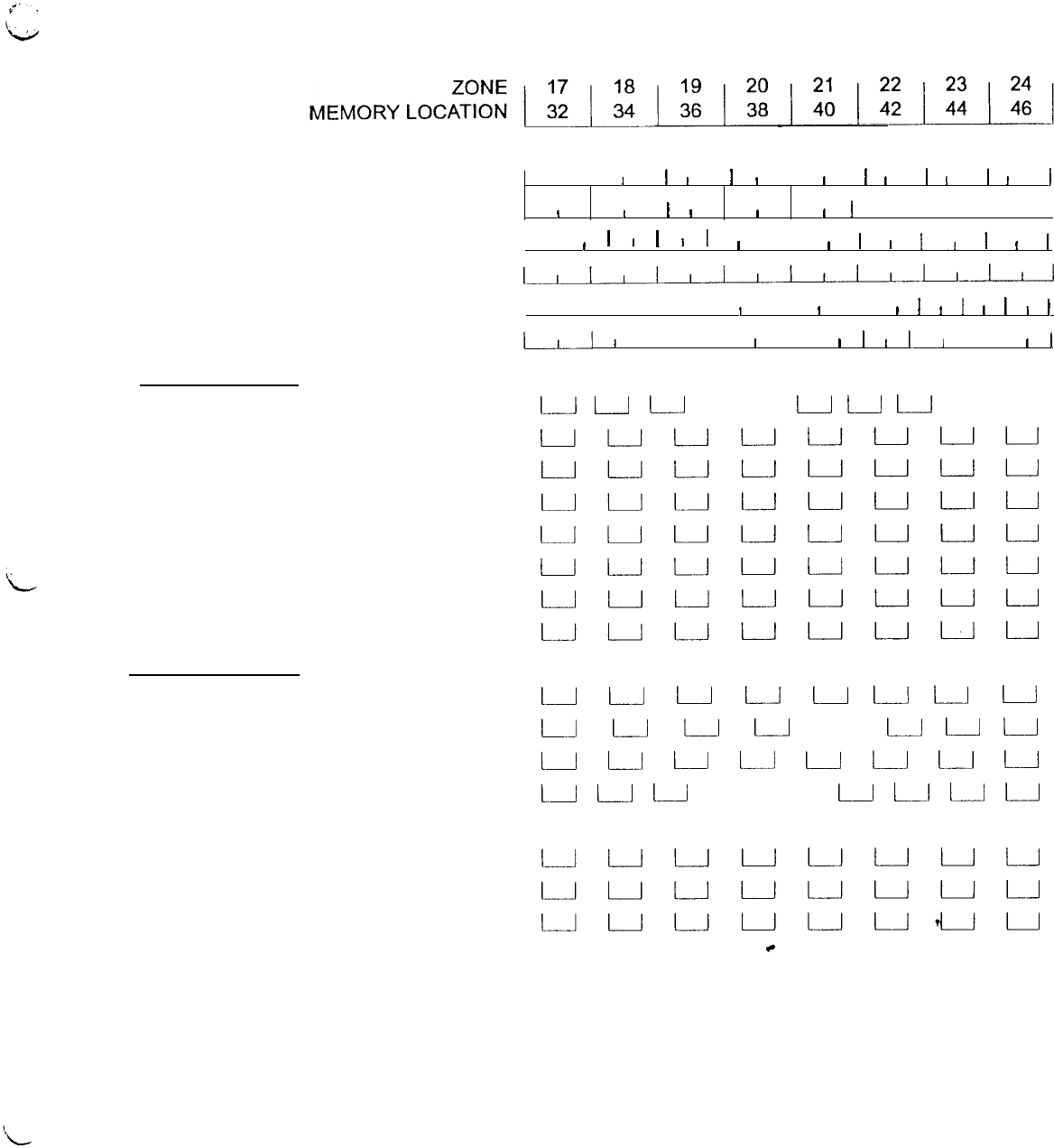
00
00A
OOB
ooc
OOD
OOE
OOF
OOG
Zone Type
-
Loop Type
Loop Response
Alarm Code
Trouble Code
Bypass Code
Restore Code
ZONE FEATURES (YES = ON, NO = OFF)
1
AWAY-TELEPHONE
2
STAY-AUDIBLE
3
INST
-
PULSE BELL
4
BYPASS
-
PGM 1
5
ALARM
-
PGM 2
6
TRBL
-
WALK TEST
7
FIRE
-
MONITOR
8
BLANK
-
SILENT DAY
ZONE FEATURES (YES = ON, NO = OFF)
1
AWAY
-
KEYPAD 1 AUDIBLE
2
STAY
-
KEYPAD 2 AUDIBLE
3
INST
-
KEYPAD 3 AUDIBLE
4
BYPASS
-
KEYPAD 4 AUDIBLE
5
ALARM
-
DISPLAY ARMED
6
TRBL
-
SHUNT ALLOWED
7
FIRE
-
BYPASS ALLOWED
a
BLANK
-
NOT USED
I
I
I
I
I
I
I
I
I
I
I
I
I
I
I
I I
I
II
I
I
I I I I I I
I
I
I
I
I
I
I
I
I
I
l
I
It
l
!
I
L_._~l!L~
I I I I i
I
I
I
I
I
I
I
I
I
I
I
I
III
I
III
I
I
I
I
I
II
I
I
I
L__l
u
u
L-J
I
I1
L-l
ä
uL__Jt__luuuuu
IJL---Juuuuuu
uuuuuuuu
uuuuuuuu
uuuuuuuu
uuuuuuuu
uuuuuuuu
LA
u
u
u
u
L---l
L-J
u
LJ
u
u
u
II
t--J
u
L-J
1Ll
u
u
u
u
u
u
LA
[__I
u
LJ
L-1
LA
LI
u
u
uuuuuuuu
uuIL-Juuuuu
uuuuL_1uuu
uuuuuud_Ju
c
3
MEMORY
--.
LOCATION
48 RECEIVER TELEPHONE
#l
A
6
C
D
E
F
G
50
RECEIVER TELEPHONE #2
A
B
:.
E
F
G
52 ACCOUNT NUMBER 1
A ACCOUNT NUMBER 1
B
ACCOUNT NUMBER 2
C
ACCOUNT NUMBER 2
53
RECEIVER
#I
&
#2 FORMATS
A
ANTI JAM TIME
B
LINE TYPE
-
DIAL ATTEMPTS
C DELAY BEFORE DIALING
54 DOWNLOAD TELEPHONE NUMBER
A
B
C
D
E
F
G
56 LOCAL DOWNLOAD PIN
B
DOWNLOAD
-
NUMBER OF RINGS
57
ENTRY DELAY
#I
-A
ENTRY DELAY #2
B
EXIT DELAY
#l
C
EXIT DELAY #2
TELEPHONE # CHART
,4,
=
l
B = #
c =
:
(3 second pause)
D =
;*
(wait for dial tone)
..J
+p
I
lIZI
1-l-l
_I_I
I_I_I-I-1
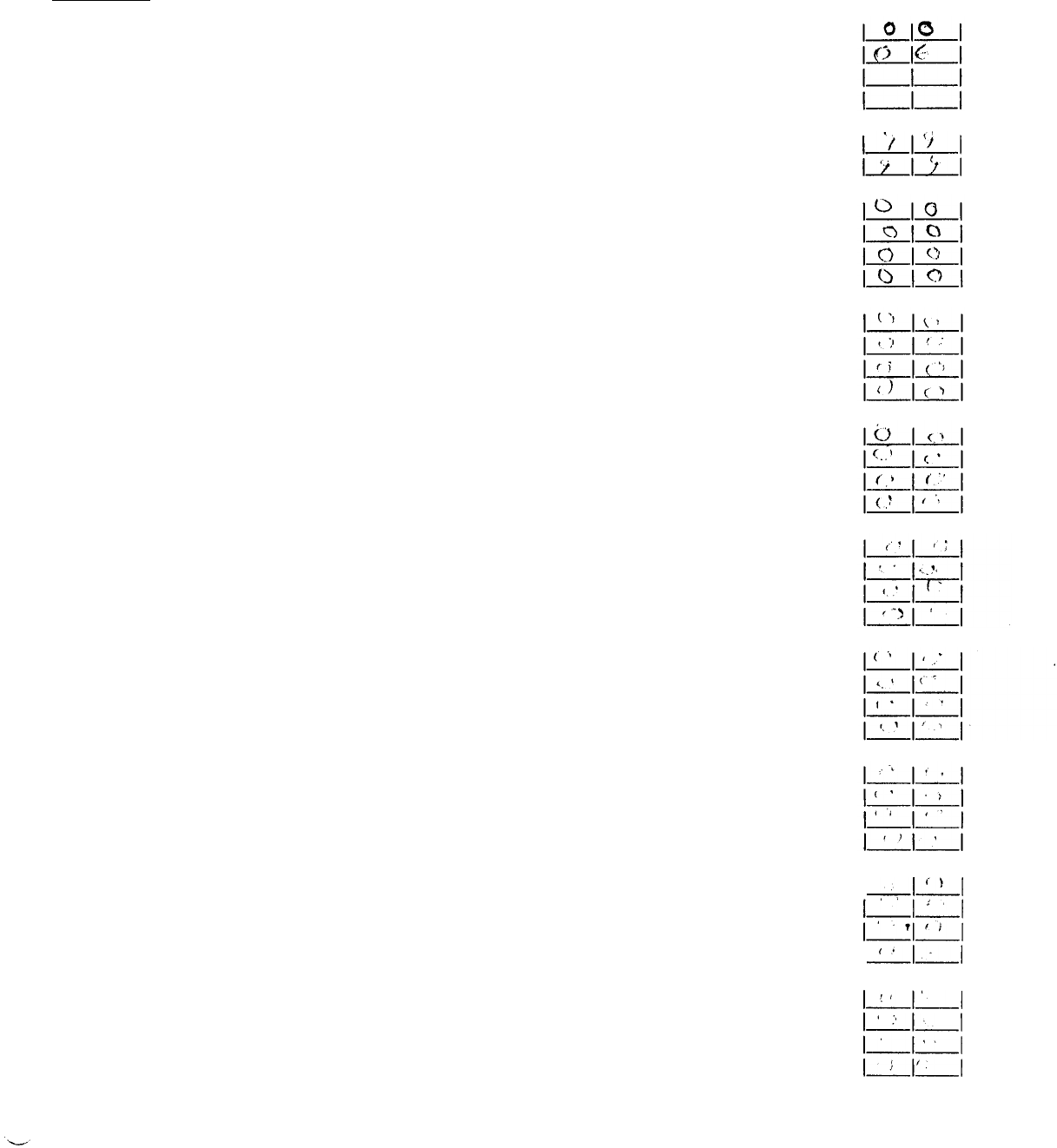
MEMORY
LOCATION
58 PRE-ALARM DELAY
A BELL CUT OFF
B PGM 1 CUT OFF
C
PGM 2 CUT OFF
59
PGM 1 OUTPUT OPTIONS
A
PGM 2 OUTPUT OPTIONS
60
USER NUMBER 1 OPEN REPORT CODE
A
USER NUMBER 2 OPEN REPORT CODE
B
USER NUMBER 3 OPEN REPORT CODE
C
USER NUMBER 4 OPEN REPORT CODE
61
USER NUMBER 5 OPEN REPORT CODE
A
USER NUMBER 6 OPEN REPORT CODE
B
USER NUMBER 7 OPEN REPORT CODE
C
USER NUMBER 8 OPEN REPORT CODE
62
USER NUMBER 9 OPEN REPORT CODE
A
USER NUMBER 10 OPEN REPORT CODE
B
USER NUMBER 11 OPEN REPORT CODE
C
USER NUMBER 12 OPEN REPORT CODE
63
USER NUMBER 13 OPEN REPORT CODE
A
USER NUMBER 14 OPEN REPORT CODE
B
USER NUMBER 15 OPEN REPORT CODE
C
USER NUMBER 16 OPEN REPORT CODE
64
USER NUMBER 1 CLOSE REPORT CODE
A
USER NUMBER 2 CLOSE REPORT CODE
B
USER NUMBER 3 CLOSE REPORT CODE
C
USER NUMBER 4 CLOSE REPORT CODE
65
USER NUMBER 5 CLOSE REPORT CODE
A
USER NUMBER 6 CLOSE REPORT CODE
B
USER NUMBER 7 CLOSE REPORT CODE
C
USER NUMBER 8 CLOSE REPORT CODE
66
USER NUMBER 9 CLOSE REPORT CODE
A
USER NUMBER
10
CLOSE REPORT CODE
B
USER NUMBER 11 CLOSE REPORT CODE
C
USER NUMBER 12 CLOSE REPORT CODE
67
USER NUMBER 13 CLOSE REPORT CODE
A
USER NUMBER 14 CLOSE REPORT CODE
B
USER NUMBER 15 CLOSE REPORT CODE
C
USER NUMBER 16 CLOSE REPORT CODE
ILI’iI
IrILI
I
-l”I
‘-/+.;
I_-
(‘ILI
ILlI’
1-1-1
,
I
l--rl’l
5
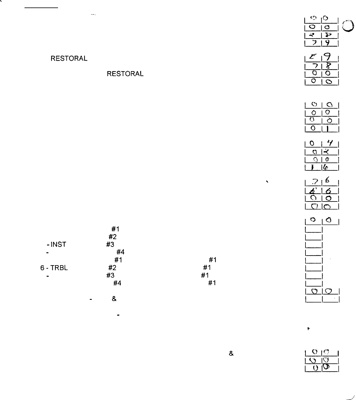
MEMORY
\
LOCATION
68
A
B
C
69
A
B
C
70
A
B
C
71
A
B
C
72
A
B
C
73
A
B
C
74
75
A
B
.-.
AUTO ARM REPORT CODE
FAIL TO AUTO ARM REPORT CODE
DURESS REPORT CODE
AC FAIL REPORT CODE
AC RESTORAL REPORT CODE
LOW BATTERY VOLTAGE REPORT CODE
BATTERY VOLTAGE RESTORAL REPORT CODE
BOX TAMPER REPORT CODE
BOX TAMPER RESTORE CODE
BELL FAULT REPORT CODE
AUXILIARY POWER FAULT REPORT CODE
KEYPAD FIRE REPORT CODE
KEYPAD EMERGENCY REPORT CODE
KEYPAD PANIC REPORT CODE
OPEN RESTORE REPORT CODE
SMOKE DETECTOR LOOP REPORT CODE
FIRE TROUBLE REPORT CODE
FIRE RESTORE REPORT CODE
BELL CIRCUIT RESTORE REPORT CODE
GROUND SUPERVISION FAULT REPORT CODE
NUMBER OF EXPANDER BOARDS INSTALLED
I-AWAY = KEYPAD
#l
ENABLED
2-STAY = KEYPAD #2 ENABLED
3
-
INST = KEYPAD #3 ENABLED
4
-
BYPASS = KEYPAD #4 ENABLED
5-ALARM = KEYPAD
#l
ASSIGNED TO PARTITION
#l
6-TRBL
= KEYPAD #2 ASSIGNED TO PARTITION
#I
7
-
FIRE = KEYPAD #3 ASSIGNED TO PARTITION
#I
8-BLANK = KEYPAD #4 ASSIGNED TO PARTITION
#I
BUSS FAULT REPORT CODE
CHARGE TIME
-
HIGH
&
LOW
(ON = YES, OFF = NO)
(ON = YES, OFF = NO)
(ON = YES, OFF = NO)
(ON = YES, OFF = NO)
(ON = YES, OFF = NO)
(ON = YES, OFF = NO)
(ON = YES, OFF = NO)
(ON = YES, OFF = NO)
EXIT ERROR FEATURE
-
FOR FUTURE USE
RECEIVER REPORTING FOR ALARMS, RESTORES, OPEN
&
CLOSE CODES
I
0
p
I
RECEIVER REPORTING FOR SYSTEM AND FUTURE USE
Ix-p--I
COMMUNICATION FAIL REPORT CODE
IOIEI
6
