Getting Started With Front End Signal Conditioners
User Manual: Getting Started with Front-end Signal Conditioners Manuals | ADInstruments
Open the PDF directly: View PDF ![]() .
.
Page Count: 30
Front-end
Signal Conditioners
Getting Started with

ii
ADInstruments is conscious of the critical safety issues involved when connecting electrical
devices to subjects. We invest signicant resources to ensure that our products are approved
to strict international safety standards, and have our systems tested by independent
certication bodies. In addition, ADInstruments products are designed, manufactured and
serviced under the internationally recognized ISO9001:2008 quality management system.
Statement of Intended Use
All ADInstruments manufactured products are intended for use in teaching and research
applications and environments only. ADInstruments products are NOT intended to
be used as medical devices or in medical environments. at is, no product supplied by
ADInstruments is intended to be used to diagnose, treat, or monitor a subject. Furthermore
no product is intended for the prevention, curing or alleviation of disease, injury or
handicap.
Where a product meets IEC 60601-1 it is under the principle that:
1. it is a more rigorous standard than other standards that could be adopted.
2. it provides the most appropriate safety level for subjects and operators.
e choice to meet IEC 60601-1 is in no way to be interpreted to mean that a product:
1. is a medical device.
2. may be interpreted as a medical device.
3. is safe to be used as a medical device.
Safety and Quality Standards
When used with ADInstruments isolated front-ends, PowerLab systems are safe for
connection to subjects. e Bio Amp and the Isolated Stimulator built into the ML760
PowerLab/4ST, ML860 PowerLab 4/20T, ML865 PowerLab 4/25T, ML818 PowerLab 15T,
ML856 PowerLab 26T and the FE132 Bio Amp, FE135 Dual Bio Amp, FE408 Dual Bio
Amp/Stimulator, FE116 GSR Amp, FE117 BP Amp and FE180 Stimulus Isolator front-
ends, conform to international safety requirements. Specically these are IEC60601-1 and
its addenda (see next page), and various harmonized standards worldwide (CSA601.1 in
Canada and AS/NZS 3200.1 in Australia and New Zealand). In accordance with European
standards they also comply with the electromagnetic compatibility requirements under
EN61326-1, which encompasses the EMC directive.
Quality Management System ISO9001:2008z
ADInstruments manufactures products under a quality system certied as complying with
ISO9001:2008 by an accredited certication body.
Safety Information

iii
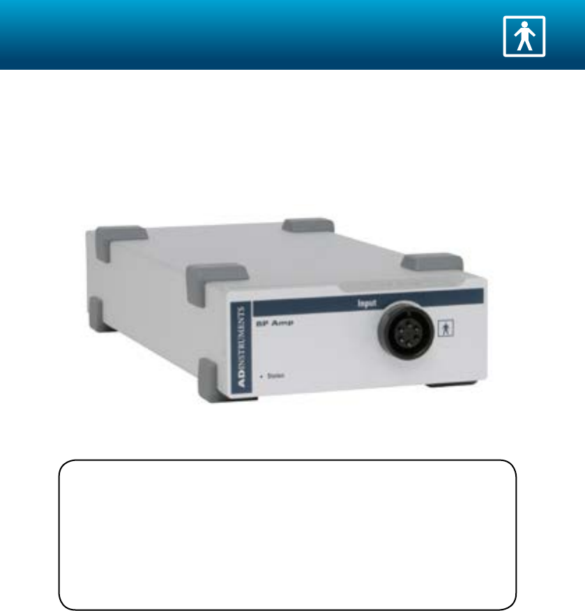
BF (body protected) Symbol
is means that the input connectors are suitable for connection to humans
provided there is no direct electrical connection to the heart.
Warning Symbol
is means that the supplied documentation must be consulted for operating,
cautionary or safety information before using the device.
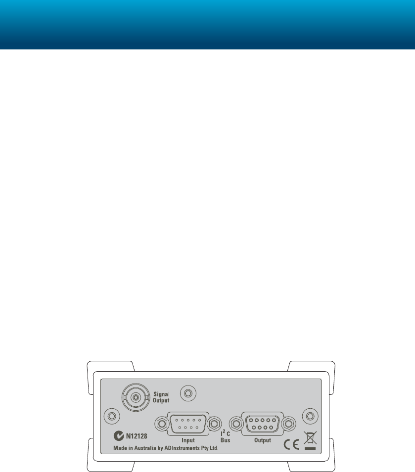
CE Mark
All PowerLab systems and front-end ampliers carry the CE mark and meet
the appropriate EU directives.
UL Mark
ADInstruments isolated preampliers and 35 series PowerLab data acquisition
units meet the standards set by Underwriters Laboratories.
IEC Standard - International Standard - Medical Electrical Equipment
IEC60601-1:1998 General requirements for safety
IEC60601-1-1:1992 Safety requirements for medical electrical systems
EN61326-1:2006 Electrical equipment for measurement, control and laboratory use – EMC
requirements
IEC61010-1ed2.0 Safety requirements for electrical equipment for measurement, control and
laboratory use.
UL Standard - Medical Electrical Equipment
UL 60601-1 Medical Electrical Equipment, Part 1: General Requirements for Safety -
Edition 1
CSA C22.2 NO. 601.1 Medical Electrical Equipment, Part 1: General Requirements for Safety -
Edition 1

4
Safety Information ii
Overview 5
Getting Started 6
Front-ends 8
Animal Bio Amp . . . . . . . . . . . . . . . . . . . . . . . . . . . . . . . . . . . . . . . . . . . . .8
Bio Amp . . . . . . . . . . . . . . . . . . . . . . . . . . . . . . . . . . . . . . . . . . . . . . . . . . .10
BP Amp . . . . . . . . . . . . . . . . . . . . . . . . . . . . . . . . . . . . . . . . . . . . . . . . . . . .12
Bridge Amp . . . . . . . . . . . . . . . . . . . . . . . . . . . . . . . . . . . . . . . . . . . . . . . . . 14
GSR Amp . . . . . . . . . . . . . . . . . . . . . . . . . . . . . . . . . . . . . . . . . . . . . . . . . .16
Neuro Amp EX . . . . . . . . . . . . . . . . . . . . . . . . . . . . . . . . . . . . . . . . . . . . .18
pH Amp . . . . . . . . . . . . . . . . . . . . . . . . . . . . . . . . . . . . . . . . . . . . . . . . . . . .20
Spirometer . . . . . . . . . . . . . . . . . . . . . . . . . . . . . . . . . . . . . . . . . . . . . . . . . .22
Stimulus Isolator . . . . . . . . . . . . . . . . . . . . . . . . . . . . . . . . . . . . . . . . . . . .24
Stimulator HC . . . . . . . . . . . . . . . . . . . . . . . . . . . . . . . . . . . . . . . . . . . . . .26
Warranty & License Agreement 28
Contents
5
Front-ends are ancillary devices connected to the PowerLab recording unit to extend the
system’s capabilities. ey provide additional signal conditioning and other features, and
extend the types of experiments that you can conduct and the data you can record.
• All ADInstruments front-ends are designed to be operated under full soware
control.
• Any front-end feature such as gain or ltering is combined with the appropriate
features of the program and presented as a single set of soware controls.
• No knobs, dials, or switches are needed, although some may be provided for reasons
of convenience or safety.
e PowerLab controls front-ends through an expansion connector called the I2C (“eye-
squared-see”) bus. is makes it very easy to add front-ends to the system or to transfer
them between PowerLabs. Many front-ends can be added to the system by connecting
the I2C sockets in a simple daisy-chain arrangement. In general, each front-end requires a
separate analog input channel of the PowerLab, although the Stimulus Isolator and similar
front-ends use the positive analog output of the PowerLab.
e front-ends are compatible with PowerLab and MacLab hardware and require the
following ADInstruments soware versions or later: LabChart v6, Chart v4 or Scope v3.6.
Visit www.adinstruments.com/downloads/ for Windows and Mac operating system
compatibility. For more information please contact your ADInstruments representative.
Overview
6
Front-ends are used with PowerLabs and ADInstruments programs such as LabChart and
Scope. is section describes the general setup for front-ends. Some front-ends (Isolated
Stimulator, Stimulator HC) have specialized connection requirements. Refer to the Front-
end Owners Guide installed with your soware for further information.
Checking the Front-end
Before connecting the front-end to anything, check it carefully for signs of physical damage.
1. Check that there are no obvious signs of damage to the outside of the front-end
casing.
2. Check that there is no obvious sign of internal damage, such as rattling. Pick up the
front-end, tilt it gently from side to side, and listen for anything that appears to be
loose.
If you have found a problem, contact your ADInstruments representative and describe the
problem. Arrangements can be made to replace or repair the front-end.
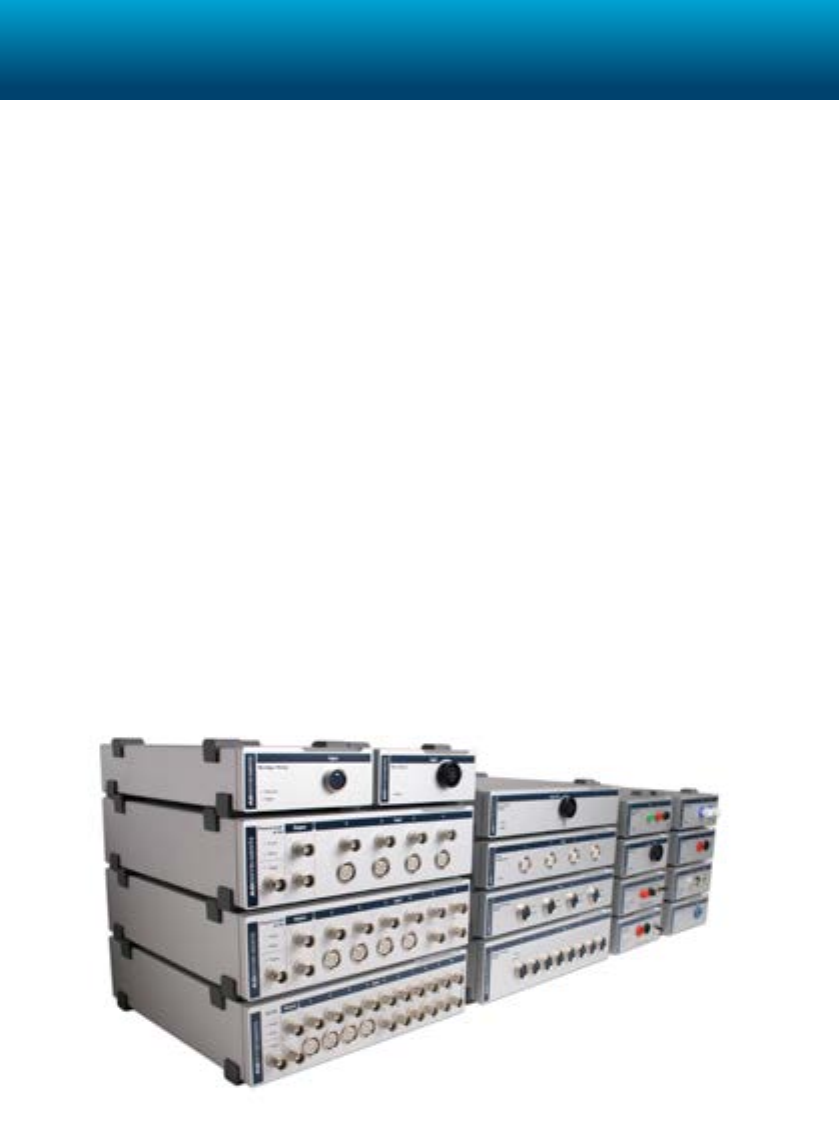
Connecting to the PowerLab
To connect a front-end to the PowerLab, rst ensure that the PowerLab is turned o.
Single Front-ends
Connect the I2C output of the PowerLab to the I2C input of the front-end using the I2C cable
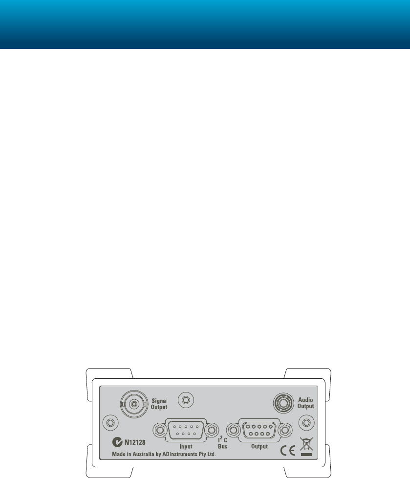
provided. Connect the BNC output of the front-end to an Input channel on the front of the
PowerLab.
Getting Started
7
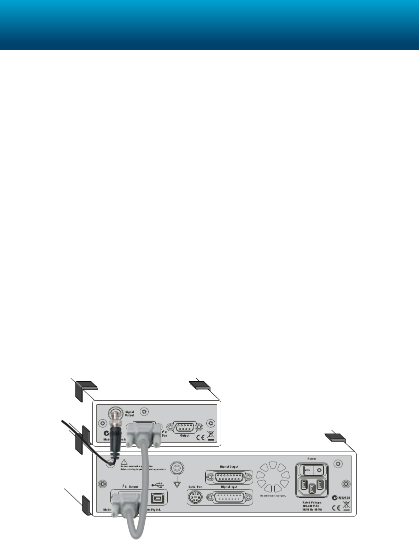
Multiple Front-ends
e number of normal front-ends that can be connected depends on the number of input
channels on the PowerLab, since the BNC cable for each front-end is normally connected to
one of the analog input channels of the PowerLab. e initial front-end should be connected
with the I2C cable. e remainder are daisy-chained via I2C cables, connecting the I2C
output of the last connected front-end to the I2C input of the front-end to be added.
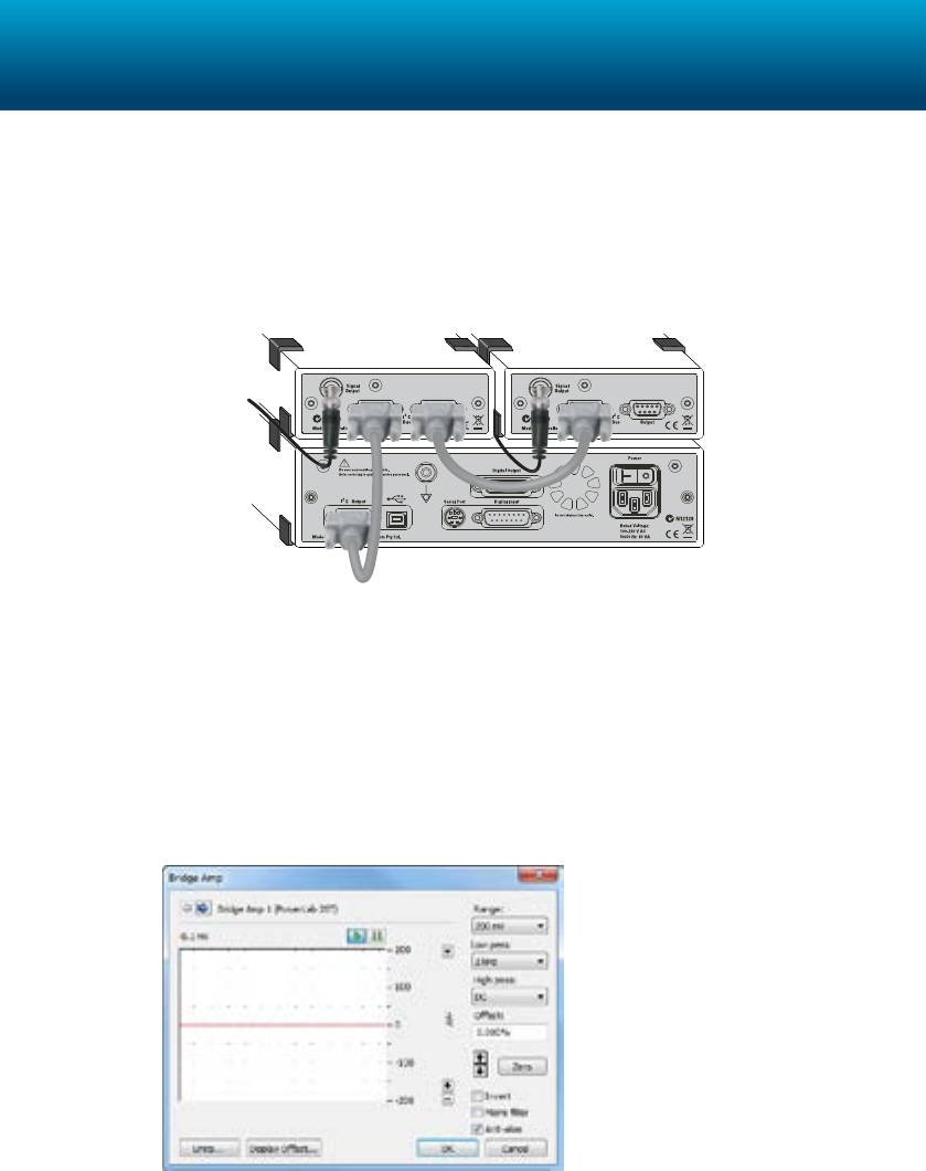
Software Configuration
e functions of the front-end are combined with those of the PowerLab and the program
and presented as a single set of soware controls, replacing the input amplier dialogs or the
Stimulator dialog depending on the front-end connected.
1. Turn on the PowerLab and start LabChart
2. Create a new document
3. Choose the front-end from the Channel Function popup menu.
8
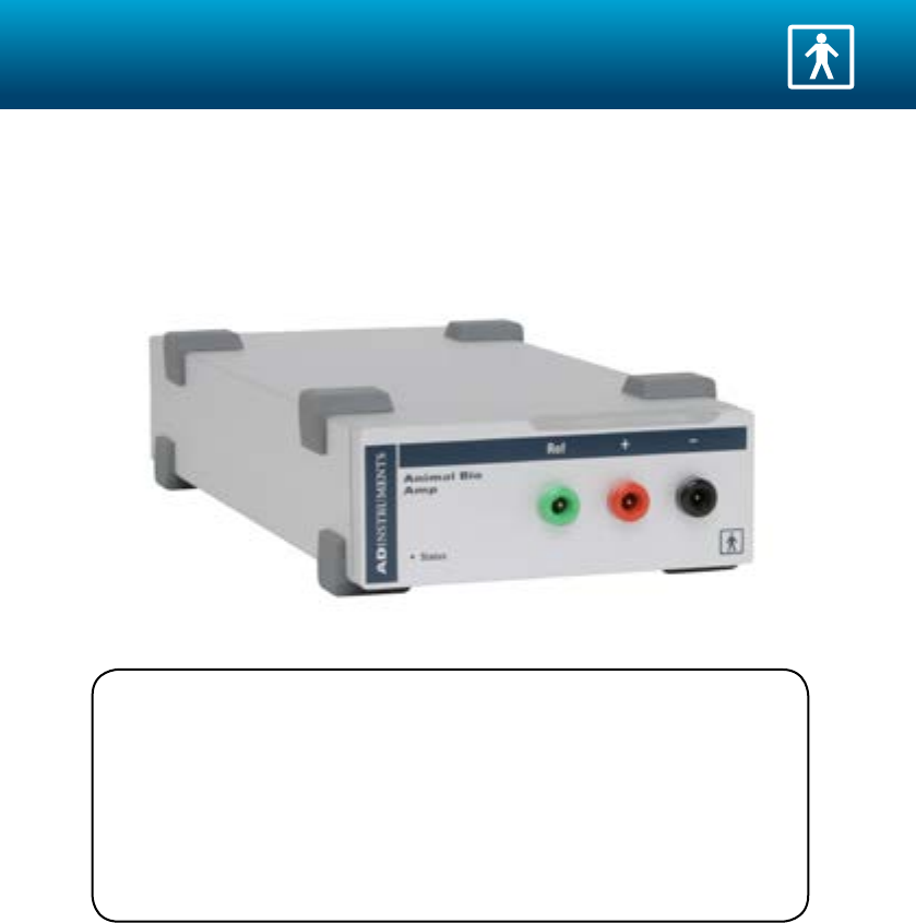
e Animal Bio Amp is a galvanically isolated, high performance, dierential amplier
suitable for the measurement of a wide variety of biological signals in animals and isolated
tissues.
For full usage and specication information see the Front-end Owners Guide installed with
LabChart or available from www.ADInstruments.com.
Related Products
MLA1213 Needle Electrodes for FE136 (3 pk)
MLA1214 Spring Clip Electrodes for FE136 (3 pk)
See www.ADInstruments.com for further information.
Animal Bio Amp
9
Specifications
Product: FE136 Animal Bio Amp
Safety: Approved to IEC 60601-1 Standard (BF rating)
EMC: EN61326-1:2006
Connection type: ree shrouded 1.5 mm male pin sockets
Conguration: Isolated dierential channel with isolated ground reference
Input range: ± 5 µV to ± 100 mV full scale in 14 steps (combined PowerLab
and Bio Amp)
Input impedance: 200 MΩ dierential
Input leakage current: < 3 µArms @ 240 V, 50 Hz
< 2 µArms @ 120 V, 60 Hz
CMRR: > 85 dB (typically, 1–60 Hz)
IMRR: > 130 dB (to true earth, 50–60 Hz)
Noise: 1 Hz to 5 kHz < 1.3 µVrms (< 8 µV peak-to-peak)
0.3 Hz to 1 kHz < 0.6 µVrms
0.1 Hz to 100 Hz < 0.35 µVrms (@ 200 samples/second)
Accuracy: ± 1.5% (all ranges, within Bio Amp)
Non-linearity: < 0.2% within range
DC blocking: ± 1 V
Baseline restore: Automatic
10
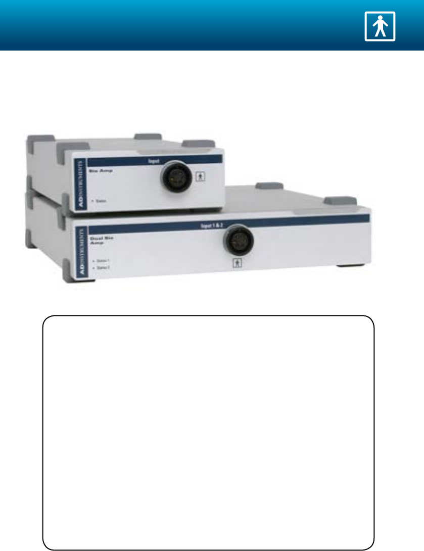
e Bio Amp is a galvanically isolated, high-performance dierential bio amplier
optimized for the measurement of a wide variety of biological signals such as ECG, EEG and
EMG recordings. It is certied and approved for human connection.
For full usage and specication information see the Front-end Owners Guide installed with
LabChart or available from www.ADInstruments.com.
Related Products
MLA700 Reusable ECG Electrodes
MLA710 Chest ECG Electrodes
MLAWBT9 EEG Flat Electrodes
MLA1605 Shielded Lead Wires (5 alligator clip, 25 cm)
MLA1610 Shielded Lead Wires (5 Micro-Hooks)
MLA1203 Needle Electrodes (5) 29 gauge
MLAEC1 EEG Electro-Cap System 1 (medium cap)
MLAEC2 EEG Electro-cap System 2 (large & medium cap)
MLAC14 Adapter Pack (2 mm pin to SAF, 5 pk)
See www.ADInstruments.com for further information.
Bio Amp
11
Specifications
Product: FE132/FE135 Bio Amp
Safety: Approved to IEC 60601-1 Standard (BF rating)
EMC: EN61326-1:2006
Connection type: Six-pin DIN/MS socket to t 3-lead (FE132) Bio Amp cable
(Tronomed D-1340) or 5-Lead (FE135) Bio Amp Cable
(Tronomed D-1540)
Conguration: Isolated dierential channel with isolated ground reference
Input range: ± 5 µV to ± 100 mV full scale in 14 steps (combined PowerLab
and Bio Amp)
Input impedance: 200 MΩ dierential
Input leakage current: < 3 µArms @ 240 V, 50 Hz
< 2 µArms @ 120 V, 60 Hz
CMRR: > 85 dB (typically, 1–60 Hz)
IMRR: > 130 dB (to true earth, 50–60 Hz)
Noise: 1 Hz to 5 kHz < 1.3 µVrms (< 8 µV peak-to-peak)
0.3 Hz to 1 kHz < 0.6 µVrms
0.1 Hz to 100 Hz < 0.35 µVrms (@ 200 samples/second)
Accuracy: ± 1.5% (all ranges, within Bio Amp)
Non-linearity: < 0.2% within range
DC blocking: ± 1 V
Baseline restore: Automatic
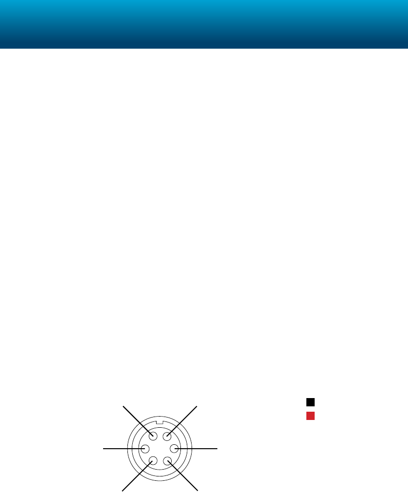
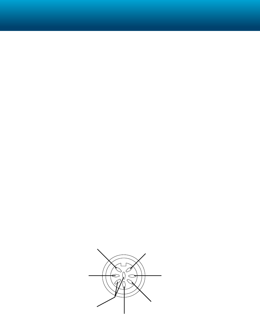
Input pin diagram:
Shield
Reference/Common
Negative input (−)
Positive input (+) CH1 Positive (+)
CH2 Positive (+)
CH2 Negative (−)
Reference/Common Shield
None
None
CH1 Negative (−)
Single Channel
Dual Channel
12
e BP Amp is a galvanically isolated blood pressure amplier that provides pressure
measurements from human and animals using suitable BP transducers. It is certied and
approved for human connection.
Note: For human application the transducer must be cold sterilized prior to use.
For full usage and specication information see the Front-end Owners Guide installed with
LabChart or available from www.ADInstruments.com.
Related Products
MLT0699 Disposable BP Transducer (no stopcock)
MLT0670 Disposable BP Transducer (stopcock)
See www.ADInstruments.com for further information.
BP Amp
13
Specifications
Product: FE117 BP Amp
Safety: Approved to IEC 60601-1 Standard (BF rating)
EMC: EN61326-1:2006
Connection type: 6-pin socket to t 6-pin Utah Medical 650-208 transducer
cable with a 4-pin transducer connection cable
Conguration: Isolated AC Bridge
Input range: 50 to 250 mmHg full scale in 3 steps (combined PowerLab and
BP Amp)
Sensitivity: Correct for 5 µV/V/mmHg transducer standard (~350 Ω
bridge)
Input impedance: > 10 kΩ at 400 Hz AC
Input leakage current: < 3 µArms at 240 V, 50 Hz
< 2 µArms at 120 V, 60 Hz
Frequency response: –3 dB at 50 Hz
Accuracy: ± 2% (± 0.2 mmHg) all points, aer zero correction
Zeroing and oset: Automatic soware-controlled fast zeroing, controlled by
internal 12-bit DAC; resolution = ± 0.2 mmHg (with supplied
transducer)
Excitation: 5 Vrms AC at 400 Hz ± 5%
14
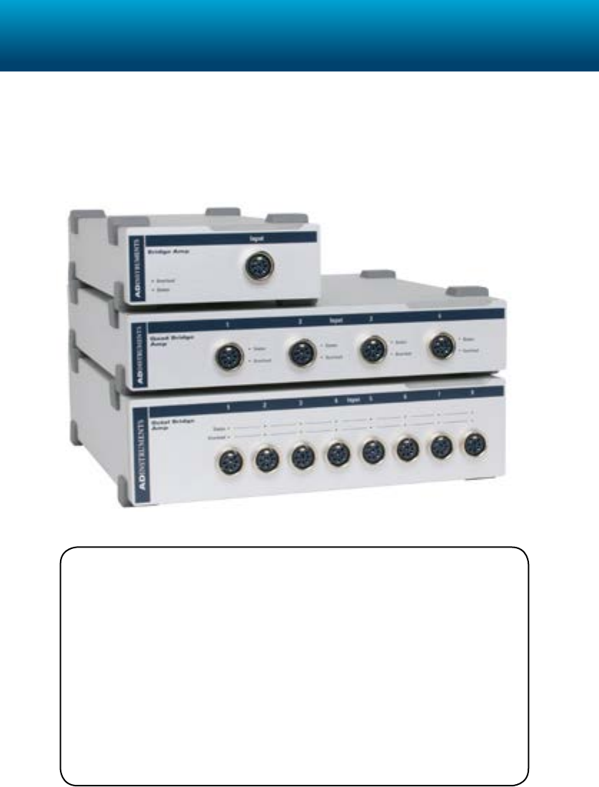
e Bridge Amp is a non-isolated bridge amplier, which provides strain gauge
measurements from most DC bridge transducers, including force transducers, displacement
transducers, pressure transducers and temperature probes. e Bridge Amp is available in
single- (FE221), four- (FE224) or eight-channel (FE228) models.
For full usage and specication information see the Front-end Owners Guide installed with
LabChart or available from www.ADInstruments.com.
Related Products
MLT0420 Force Transducer (20 g)
MLT0402 Force Transducer (2 g)
MLT0015 High Grade Isotonic Transducer
MLT422/D Skin Temperature Probe (DIN, 2 m)
SPR-320 Pressure Catheter (2F, Single, Straight, 140 cm, PU)
See www.ADInstruments.com for further information.
Bridge Amp
15
Specifications
Product: FE221/FE224/FE228 Bridge Amp
EMC: EN61326-1:2006
Connection type: 8-pin DIN socket
Conguration: Dierential
Input range: ± 200 µV to ± 5 V full scale in 14 steps (combined PowerLab
and Bridge Amp)
Input impedance: 2 × 1 MΩ (single-ended) 2 MΩ (dierential)
CMRR (dierential): 100 dB @ 50 Hz (typical)
Noise: < 1 µVrms referred to input at highest gain
Frequency response: –3 dB, 2 kHz maximum at all gains with the low-pass lter o
Accuracy: ± 0.5% (combined PowerLab and Bridge Amp)
Maximum input voltage: ± 10 V
Zeroing circuitry: Soware-controlled, either manual or automatic
Internal osetting range: ± 10 V (1–5 V range)
± 1 V (100–500 mV range)
± 100 mV (0.2–50 mV range)
Internal oset resolution: 16-bit (internal DAC) ± 32 000 steps about 0 V
Excitation voltage range: 0–20 V DC (± 10 V referred to ground), adjusted by external
resistor
Transducer drive current: ± 45 mA maximum
Input pin diagram:
[6] None
[1] Excitation Positive (+)
[5/8] Excitation voltage
programming resistor
[3] Input Positive (+)
[7] Ground
[4] Excitation Negative (−)
[2] Input Negative (−)
16
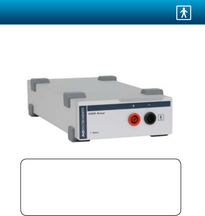
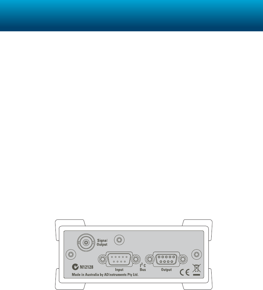
e Galvanic Skin Response amplier with suitable electrodes is designed to measure
the electrical conductance of the skin, which is used as an indication of psychological
or physiological response. It is galvanically isolated for subject safety, and certied and
approved for human connection.
For full usage and specication information see the Front-end Owners Guide installed with
LabChart or available from www.ADInstruments.com.
Related Products
MLT116F GSR Finger Electrodes
MLT117F MRI Safe Bipolar Finger Electrodes (5 m)
See www.ADInstruments.com for further information.
GSR Amp
17
Specifications
Product: FE116 GSR Amp
Safety: Approved to IEC 60601-1 Standard (BF rating)
EMC: EN61326-1:2006
Connection type: 2 × 4 mm shrouded sockets. Custom cable with two shrouded
banana plugs and terminated with two dry, bright-plated,
bipolar electrodes with Velcro attachment strap suitable for
adult ngers
Conguration: Transformer isolation (AC bridge operation)
Input range: 1 to 40 μS full scale in 6 steps (combined PowerLab and GSR
Amp)
Input leakage current: < 3 μArms at 240 V, 50 Hz
< 2 μArms at 120 V, 60 Hz
Frequency response: –3 dB at 1 Hz
Accuracy: ± 5%
Zeroing and oset: Automatic soware-controlled fast zeroing, controlled by
internal 12-bit DAC; ± 0.2 μS resolution
Excitation: Constant-voltage AC excitation (22 mVrms @75 Hz)
Current density: ≤0.5 μA cm–2
18
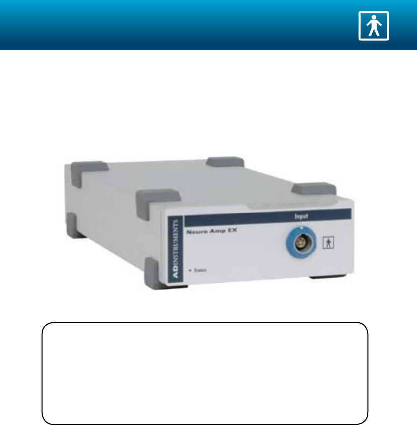
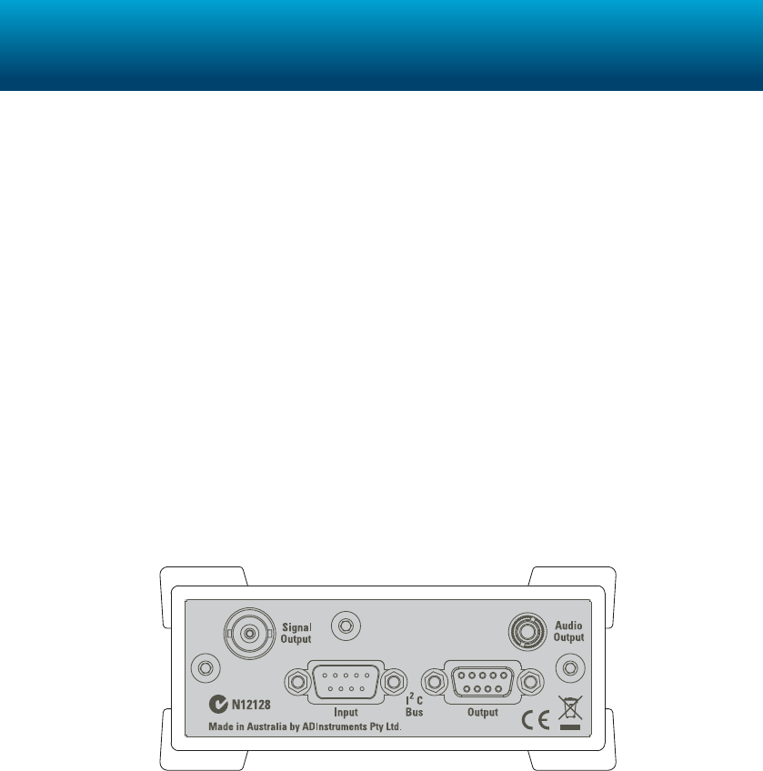
e Neuro Amp EX is a galvanically isolated, low noise and high gain amplier (supplied
with headstage), which is ideal for extracellular recordings requiring a wide bandpass
(0.1–5kHz) and a high signal to noise ratio, especially in microneurography. e device is
certied safe for human connection.
For full usage and specication information see the Front-end Owners Guide installed with
LabChart or available from www.ADInstruments.com.
Related Products
MLT185 Neuro Amp EX Headstage
See www.ADInstruments.com for further information.
Neuro Amp EX
19
Specifications
Product: FE185 Neuro Amp EX
Safety: Approved to IEC 60601-1 Standard (BF rating)
EMC: EN61326-1:2006
Connection type: Five-pin Redel connector
Conguration: One isolated dierential channel with isolated ground
reference
Input range: ± 20 μV to ± 1 mV full scale in 6 steps (combined PowerLab,
Neuro Amp EX front-end and headstage)
Input impedance: 100 MΩ
Low-pass ltering: Fourth-order Bessel lter, ± 3% accuracy.
Frequencies soware-selectable: 1 kHz, 2 kHz, 5 kHz
High-pass ltering: First-order lter, ± 0.25% accuracy.
Frequencies soware-selectable: 100 Hz, 300 Hz, 500 Hz
Notch lter: Second-order lter, –32 dB attenuation; 50 or 60 Hz frequency
(automatic sensing)
20
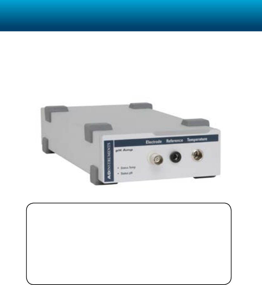
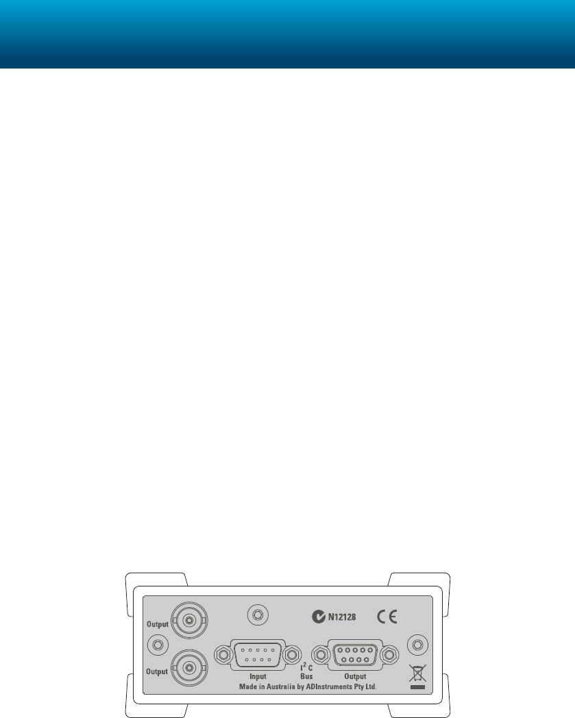
e pH Amp is a non-isolated dual front-end suitable for use with pH, ion-selective and
potentiometric redox electrodes. It can provide pH measurements in the range 0–14,
electrode voltages to 2.0 V and temperature ranging from 0 to 100 °C. It can also be used for
temperature compensated measurements or as an independent temperature sensor.
For full usage and specication information see the Front-end Owners Guide installed with
LabChart or available from www.ADInstruments.com.
Related Products
MLA060 Redox Electrode
MLA042 pH Electrode
MLT5733 pH Electrode - Tu tip for student use
See www.ADInstruments.com for further information.
pH Amp
21
Specifications
Product: FE165 pH Amp
pH Section
Connection type: Insulated BNC socket
Conguration: High impedance, electrometer type
Input Range: ± 200 µV to ± 2 V full scale in 13 steps (combined PowerLab
and pH Amp)
Input impedance: 1013 Ω typical
Noise: < 1 µVrms (< 4 µV p–p) with a bandwidth of DC – 10 Hz
Low pass lter: 10 Hz. (–3 dB frequency)
Low pass lter accuracy: ± 3.0%
Low pass lter type: Bessel (2 pole)
Temperature Section
Connection type: 3 pin mini-audio jack
Conguration 100 Ω platinum RTD (Resistance Temperature Detector)
Output ranges: Range Temperature °C Resolution °C
± 10 V ± 200 0.1
± 5 V ± 100 0.05
± 2 V ± 40 0.02
± 1 V ± 20 0.01
± 500 mV ± 10 0.01
Amplier output: 0 V @ 0 °C, 50 mV/°C (factory set)
Accuracy: ± 0.2 °C
Temp
pH
22
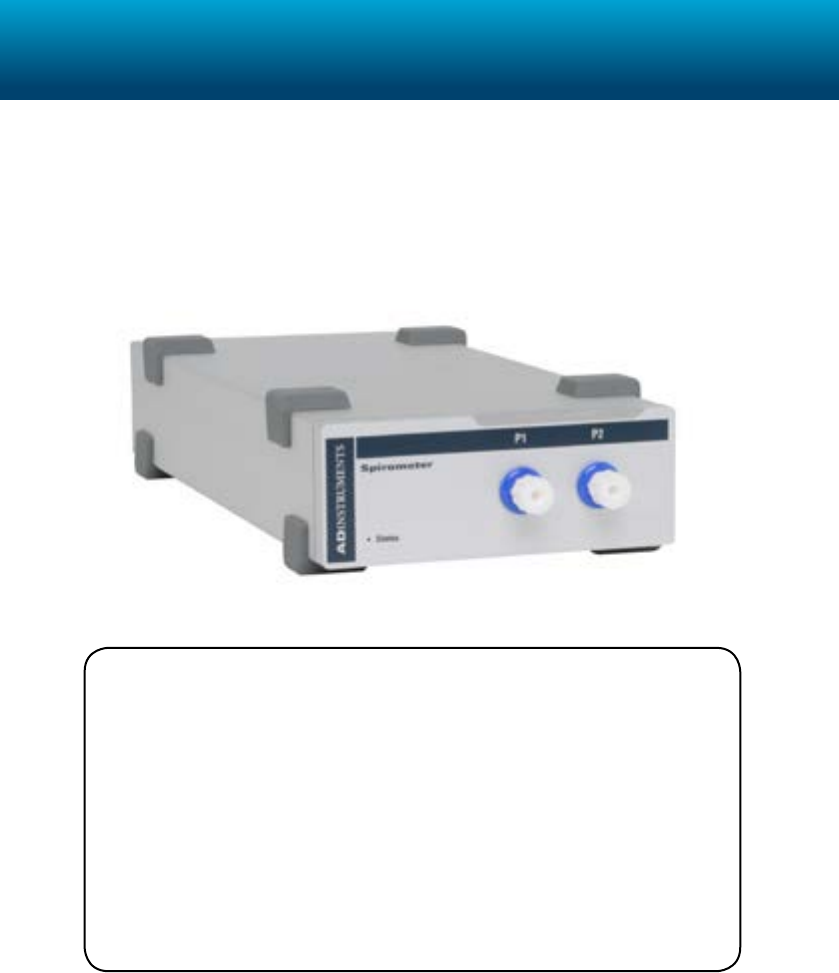
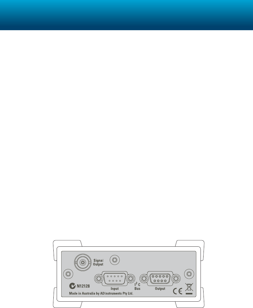
e Spirometer is a precision dierential pressure transducer that measures the respiration
ow rates from humans or animals (using suitable ow head sizes). e Spirometer and
attached ow head function together as a pneumotachometer, with an output signal
proportional to airow.
For full usage and specication information see the Front-end Owners Guide installed with
LabChart or available from www.ADInstruments.com.
Related Products
MLT1000L Respiratory Flow Head 1000 L
MLT300L Respiratory Flow Head 300 L
MLT10L Respiratory Flow Head 10 L
MLT1L Respiratory Flow Head 1 L
MLA5530 Calibration Syringe
See www.ADInstruments.com for further information.
Spirometer
23
Specifications
Product: FE141 Spirometer
EMC: EN61326-1:2006
Connection type: Two female Luer ttings to enable connection to Flow Head
via male Luer ttings and suitable tubing.
Conguration: Dierential pressure input, ± 1" (2.5 cm) H2O (1.9 mmHg,
249Pa)
Input range: ± 20 mV to ± 500 mV full scale in 5 steps (combined PowerLab
and Spirometer)
Pressure sensitivity: 0.5 V per inch (1.27 V per cm) H2O
Amplier noise: < 150 µVrms @ 100 Hz
< 50 µVrms @ 10 Hz
< 35 µVrms @ 1 Hz
Temperature dri: 0.05% of full scale per °C
Warm-up time: ~ 2 minutes
Maximum input pressure: ± 28.1" H2O (7 kPa)
Response time: 1 ms (10–90% full scale) at maximum bandwidth
Linearity: ± 0.5% full scale
Low-pass ltering: 1, 10 or 100 Hz (soware-selectable) using fourth-order Bessel
lter
Max zero pressure oset: < 1% full scale, soware removable
Zero oset correction: Soware removed (up to ± 10% full scale)
24
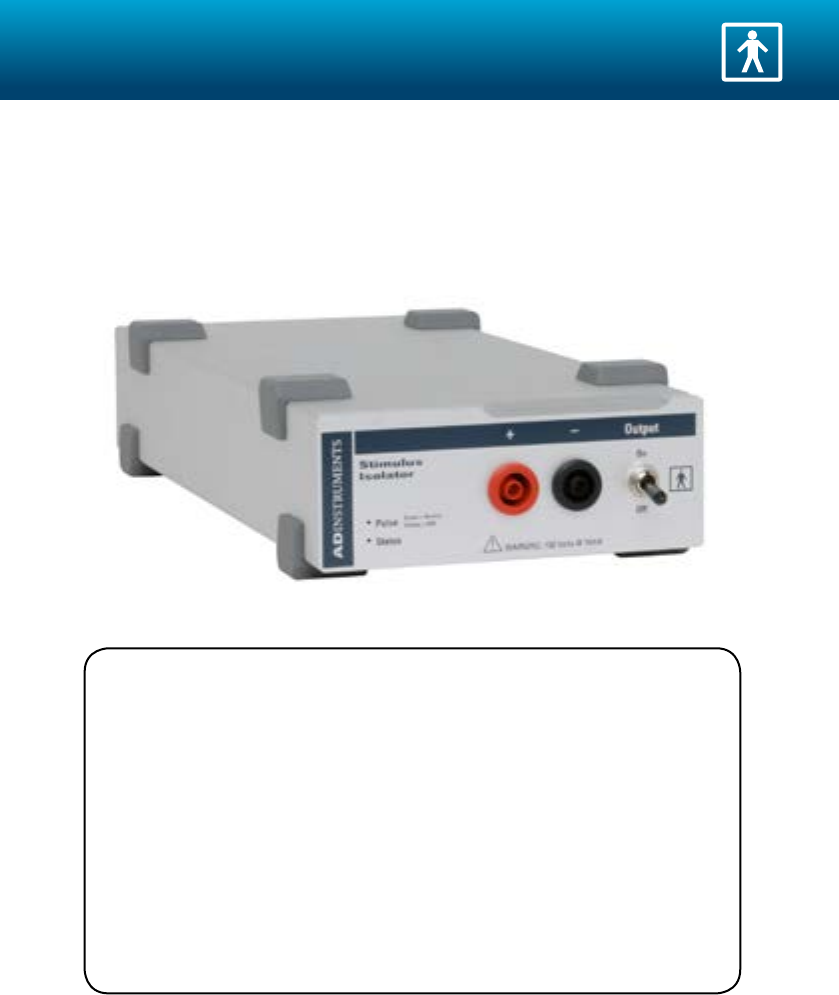
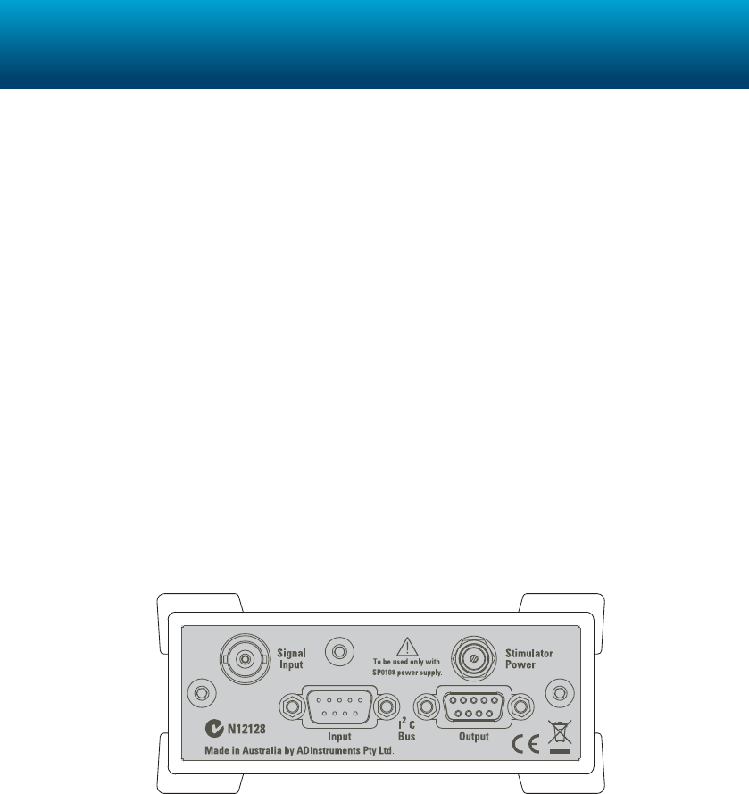
e Stimulus Isolator is a galvanically isolated constant-current stimulator providing a
range of pulse width from 10 µs to 2.56 ms with a maximum current of 10 mA. e unit
provides adjustable pulse amplitude, width, and frequency. It is certied and approved for
human connection.
For full usage and specication information see the Front-end Owners Guide installed with
LabChart or available from www.ADInstruments.com.
Related Products
MLADDB30 Recording Bar Electrode
MLA265 Stimulator Rod with Cable
MLA260 Stimulator Cable (4 mm shrouded to Alligator clip, 50 cm)
MLA260/L Stimulator Cable (4 mm shrouded to Alligator clip, 2 m)
SP0105 Shrouded Connectors (10 red, 10 black)
See www.ADInstruments.com for further information.
Stimulus Isolator
25
Specifications
Product: FE180 Stimulus Isolator
Safety: Approved to IEC 60601-1 Standard (BF rating)
EMC: EN61326-1:2006
Connection type: Two shrouded 4 mm sockets
Conguration: Constant-current stimulator with hardware-limited repetition
rate
Output range: 100 µA, 1 mA, or 10 mA full scale
Resolution: 1% of full scale (1 µA, 10 µA, or 100 µA)
Compliance voltage: 100 V xed
Pulse duration range: 0.01 to 2.56 ms in 0.01 ms steps
Duration accuracy: ± 0.01% +5/–0 µs
Repetition rate: up to 2000 Hz
Safety indicators: A single, multi-color indicator displays the isolated stimulator
status. A green ash indicates delivery of a valid stimulus. A
yellow ash indicates an out-of-compliance condition (OOC)
Safety switch: Isolating On-O switch icks down to disconnect quickly
26
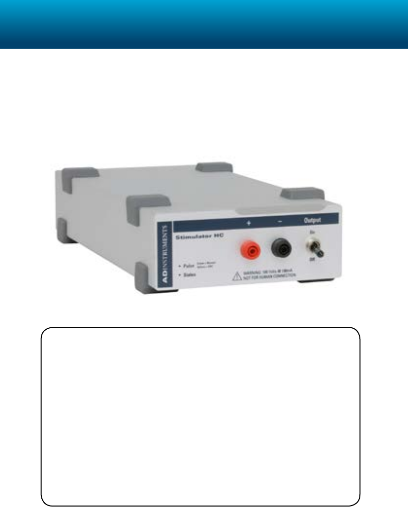
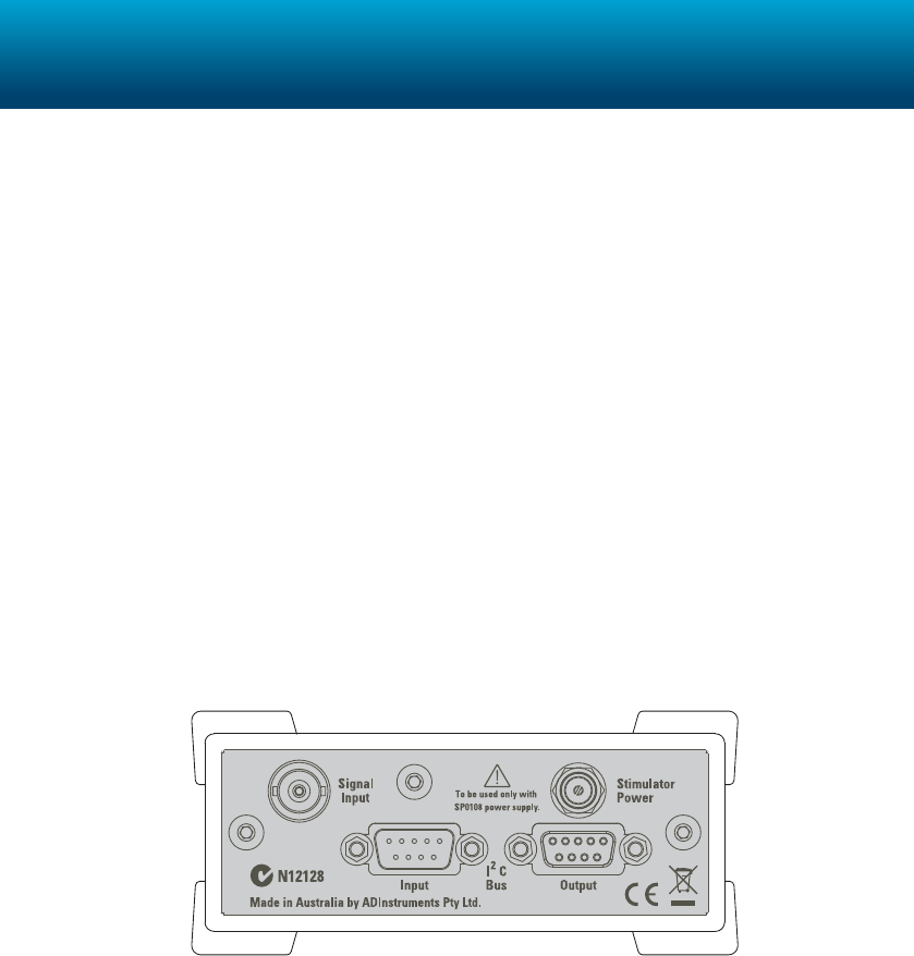
e Stimulator HC is an isolated constant-current stimulator with 100 V compliance
designed to stimulate in vitro isolated nerve, muscle or tissue samples. It provides
adjustable constant-current pulses of 10 microsecond to 4 milliseconds duration, of 0.1 to 30
Hz pulse frequency and up to 100 mA pulse amplitude. It is NOT approved for live subject
connection!
For full usage and specication information see the Front-end Owners Guide installed with
LabChart or available from www.ADInstruments.com.
Related Products
MLAC36 Stimulator HC Leads (2 m)
PTK13 Pharmacology Kit
ML0146/C-V Panlab Four Chamber Organ Bath & ermostat Controller
ML0186/C-V Panlab Eight Chamber Organ Bath & ermostat
Controller
159920-X1/C Radnoti 4 Chamber Tissue-Organ Bath
See www.ADInstruments.com for further information.
Stimulator HC
27
Specifications
Product: FE155 Stimulator HC
Safety: Not For Human Connection
EMC: EN61326-1:2006
Connection type: Two 2 mm touch-proof safety sockets
Conguration: Constant-current stimulator with hardware limited repetition
rate
Output range: 1 mA, 10 mA, 100 mA full scale
Resolution: 1% of full scale (10 µA, 100 µA, or 1 mA)
Compliance voltage: 100 V xed
Pulse duration range: 0.02 to 5.12 ms in 0.02 ms steps
Duration accuracy: ± 0.01% +5/–0 µs
Repetition rate: up to 30 Hz
Safety indicators: A single, multi-color indicator displays the Stimulator HC
status. A green ash indicates delivery of a valid stimulus. A
yellow ash indicates an out-of-compliance condition (OOC).
Safety switch: Isolating On-O switch icks down to disconnect quickly.

28
Extent
This Agreement is between ADInstruments Pty Ltd [‘ADI’] and the purchaser [‘the Purchaser’] of any ADI product — software, hardware or
both — and covers all obligations and liabilities on the part of ADI, the Purchaser, and other users of the product. The Purchaser (or any user)
accepts the terms of this Agreement by using the product. Any changes to this Agreement must be recorded in writing and have ADI’s and the
Purchaser’s consent.
Responsibilities
The Purchaser and any others using any ADI product agree to use it in a sensible manner for purposes for which it is suited, and agree to take
responsibility for their actions and the results of their actions. If problems arise with an ADI product, ADI will make all reasonable efforts to
rectify them. This service may incur a charge, depending on the nature of the problems, and is subject to the other conditions in this Agreement.
Statement of Intended Use
All ADInstruments manufactured products are intended for use in teaching and research applications and environments only. ADInstruments
products are NOT intended to be used as medical devices or in medical environments. That is, no product supplied by ADInstruments is
intended to be used to diagnose, treat, or monitor a subject. Furthermore no product is intended for the prevention, curing or alleviation of
disease, injury or handicap.
Where a product meets IEC 60601-1 it is under the principle that:
1. it is a more rigorous standard than other standards that could be adopted and
2. it provides the most appropriate safety level for subjects and operators.
The choice to meet IEC 60601-1 is in no way to be interpreted to mean that a product:
1. is a medical device;
2. may be interpreted as a medical device;
3. is safe to be used as a medical device
General Limitations
ADI products are produced to high standards, and should perform as described in the supplied documentation. There is a limited hardware
warranty, and technical support is provided for all products. Nevertheless, since ADI products could be affected by external factors (for instance,
the computer system on which they run), absolute performance and reliability cannot be guaranteed. No warranty, either expressed or implied
or statutory, other than that contained in this Agreement, is made in respect to ADI products. The Purchaser therefore assumes all risks as to
the performance and reliability of the products, and the results gained using them. ADI is not responsible for any problems with the computer
system not directly related to ADI products. ADI neither assumes or authorizes any person to assume on its behalf any liability in connection
with the sale, installation, service or use of its products. ADI shall not be held responsible for special, consequential or punitive damages of any
kind arising out of sale, installation service or use of its products.
Hardware Warranty
ADI warrants that PowerLab Data Acquisition Units (PL prefix)1 and Front-ends (FE prefix)2 shall be free from defects in materials and
workmanship for five (5) years from the date of purchase. Other PowerLab Data Acquisition Units3, Front-ends4 and Pods5 shall be free of
defects in material and workmanship for three (3) years from their date of purchase. ADI also warrants that ADI Specialized Data Recorders6
and Instruments7 shall be free of defects in material and workmanship for one (1) year from their date of purchase. If there is such a defect,
ADI will repair or replace the equipment as appropriate, and the duration of the warranty shall be extended by the length of time needed for
repair or replacement.
To obtain service under this warranty, the Purchaser must notify the nearest ADI office, or Authorized Representative, of the defect before the
warranty expires. The ADI or Representative office will advise the Purchaser of the nearest service center address to which the Purchaser must
ship the defective product at his or her own expense. The product should be packed safely, preferably in its original packaging. ADI will pay
return shipping costs.
Hardware Warranty Limitations
This warranty applies only to the hardware specified in this document and used under normal operating conditions and within specification.
Consumables, electrodes and accessories are not covered by this warranty. Third party equipment is covered by the manufacturer’s warranty. It
does not cover hardware modified in any way, subjected to unusual physical, electrical or environmental stress, used with incorrectly wired or
substandard connectors or cables, or with the original identification marks altered. Tampering with or breaking of the Warranty Seal will also
void the warranty. ADI does not warrant that equipment is suitable for any specific purpose, other than that explicitly stated by ADI.
Product Types & Warranty Term
ADI manufactured products covered by five (5) year warranty
1 Data Acquisition Units: PowerLab 35 series with PL prefix
2 Front-ends: ADI Front-end Signal Conditioners with FE prefix.
ADI manufactured products covered by three (3) year warranty
3 Data Acquisition Units: PowerLab 26 series with ML prefix
4 Front-ends: ADI Front-end Signal Conditioners with ML prefix.
5 Pods: The entire range of ADI Pod Signal Conditioners.
ADI manufactured products covered by one (1) year warranty
6 Specialized Data Recorders: Metabolic Systems (e.g. ML240 PowerLab/8M Metabolic System)
Warranty & License Agreement

29
7 Instruments: Blood FlowMeter, Gas Analyzers, NIBP System (excluding transducers), STH Pump Controller.
Third Party Products (Including Transducers)
Products not manufactured by ADI are covered by the manufacturer’s warranty.
Accessories and Consumables
Accessories and Consumables are not covered by any type of warranty.
Software License
The Purchaser has the non-exclusive right to use the supplied ADI software. (The Purchaser’s employees or students, for instance, are entitled to
use it, provided they adhere to this Agreement.) The Purchaser is permitted to make one backup copy of ADI software. Each separate purchase
of a software program, allows the Purchaser to install the software on up to three computers for use with one PowerLab data acquisition unit or
an Authorized Recording Device. That is, the software can be used for analysis purposes on three separate computers, however a single license
can only be used with one PowerLab unit or an Authorized Recording Device to perform data acquisition at any one time. Departmental
(multiple-user) licenses allow the Department to use the program on all computers situated within the Department, even if only one CD is
provided. See the accompanied Software License document for more information.
Controlling Law and Severability
This license shall be governed by the laws of the territory into which the software is sold, or if sold into the United States of America, by the
laws of the State of California.
Technical Support
The Purchaser is entitled to free technical support for any ADI product for one year from its date of purchase. Our technical support staff can
provide advice concerning installation and operation of ADI products. Services outside of this may incur a charge. Technical support staff will
not provide experimental protocols or procedural instructions for conducting experiments. However, information of this type may be provided
in the supplied product documentation, or on ADI web sites.
Inquiries
For additional information or service inquiries please contact the nearest ADInstruments office or Authorized Distributor. For contact details
see www.ADInstruments.com
Copyright © 2011 ADInstruments. All rights reserved. PowerLab, LabChart, LabTutor, LabAuthor, MacLab and ADInstruments are registered
trademarks of ADInstruments Pty Ltd. The names of specific recording units, such as PowerLab 26T, are trademarks of ADInstruments Pty Ltd.
All other trademarks are the property of their respective owners. U-FE/GS-035C

ADINSTRUMENTS.com
