Grayloc Catalog (GLOC 105 11 09 5M) 20
User Manual: 105-20
Open the PDF directly: View PDF ![]() .
.
Page Count: 32

Grayloc®
Product Catalog
Grayloc Products is pleased to offer its products with the products/
services guarantee as set forth in the terms and conditions printed on page 31
of this catalog. These terms and conditions apply to written or oral orders.
The Grayloc product guarantee is only valid when the installation and mainte-
nance instructions on page 30 are followed. For any questions about Grayloc
Products or their selection, installation, use, or service, please contact the
nearest office listed on the back cover for professional assistance and service.
3
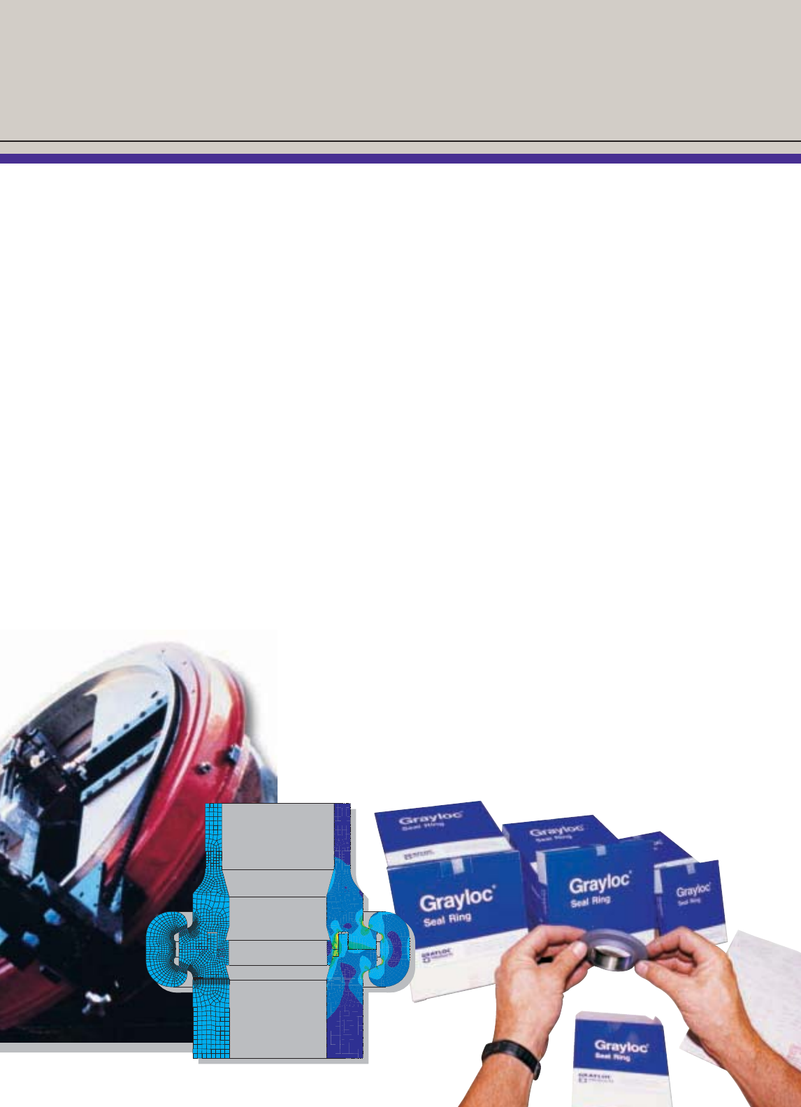
Engineering Services
❖Custom design
❖Finite element analysis
❖Retrofit designs
❖Testing program development
❖Project technical support
❖State of the art metal-to-metal seal designs
Quality Programs
❖ASME Section VIII, Division 1 & 2
❖MIL-I-45208A inspection system requirements
❖ISO 9001
❖Total product materials traceability
❖Complete calibration program, with certifica-
tions, traceable to the National Calibration
Bureau of Standards and Technology
Customer Order Processing
❖Highly trained personnel
❖State of the art machine tools
❖Large raw material inventory
❖Large service oriented finished goods inventory
❖Action team for critical orders
❖Factory trained field service technicians
available 24 hours a day, 7 days a week
❖Packaging and shipment preparation that
exceeds industry standards
❖Project management
Grayloc Products . . . . . . . . . . . . . . . . . . . . . . . . . . . . . . .3
The Grayloc Metal-to-Metal Seal . . . . . . . . . . . . . . . .4
Grayloc Connector Applications . . . . . . . . . . . . . . . . .5
Tension, Compression, Bending . . . . . . . . . . . . . . . . .6
Conserves Space and Weight . . . . . . . . . . . . . . . . . .7
Saves Time and Money . . . . . . . . . . . . . . . . . . . . . . .8
How to Select Grayloc Connectors . . . . . . . . . . . . . . . . .9
Part Numbers/ Dimensions . . . . . . . . . . . . . . . . . . . . . .10
Butt Weld Hubs . . . . . . . . . . . . . . . . . . . . . . . . . . . .10
Blind Hubs . . . . . . . . . . . . . . . . . . . . . . . . . . . . . . . .13
Clamp Assemblies . . . . . . . . . . . . . . . . . . . . . . . . . .16
Seal Rings . . . . . . . . . . . . . . . . . . . . . . . . . . . . . . . .17
Other Products and Piping Accessories . . . . . . . . . . .18
Seal Rings . . . . . . . . . . . . . . . . . . . . . . . . . . . . . . . .18
Heavy-Duty Connectors . . . . . . . . . . . . . . . . . . . . . .19
Hubs . . . . . . . . . . . . . . . . . . . . . . . . . . . . . . . . . . . .20
Fittings . . . . . . . . . . . . . . . . . . . . . . . . . . . . . . . . . . .21
Special Connectors . . . . . . . . . . . . . . . . . . . . . . . . .22
Jacketed Connectors . . . . . . . . . . . . . . . . . . . . . . . .23
Remotely Operated Connectors . . . . . . . . . . . . . . . .24
Grayloc Compact Flanges . . . . . . . . . . . . . . . . . . . .25
Nozzles . . . . . . . . . . . . . . . . . . . . . . . . . . . . . . . . . .26
Thermowells . . . . . . . . . . . . . . . . . . . . . . . . . . . . . . .27
Hinged Vessel Closures . . . . . . . . . . . . . . . . . . . . . .27
Studded Vessel Closures . . . . . . . . . . . . . . . . . . . . .28
Conversion and Torque Requirements . . . . . . . . . . . . .29
API Flange to Grayloc Connector Conversion . . . . . .29
Bolting Torque Required for Grayloc Clamps . . . . . . .29
Installation and Maintenance Instructions . . . . . . . . . .30
Standard Terms and Conditions . . . . . . . . . . . . . . . . . .31
Engineering, Manufacturing and
Sales Locations . . . . . . . . . . . . . . . . . . .Back Cover
Grayloc®Products
Grayloc®Products
Clamp
Seal Ring
Hub
The Grayloc Metal-to-Metal Seal
4
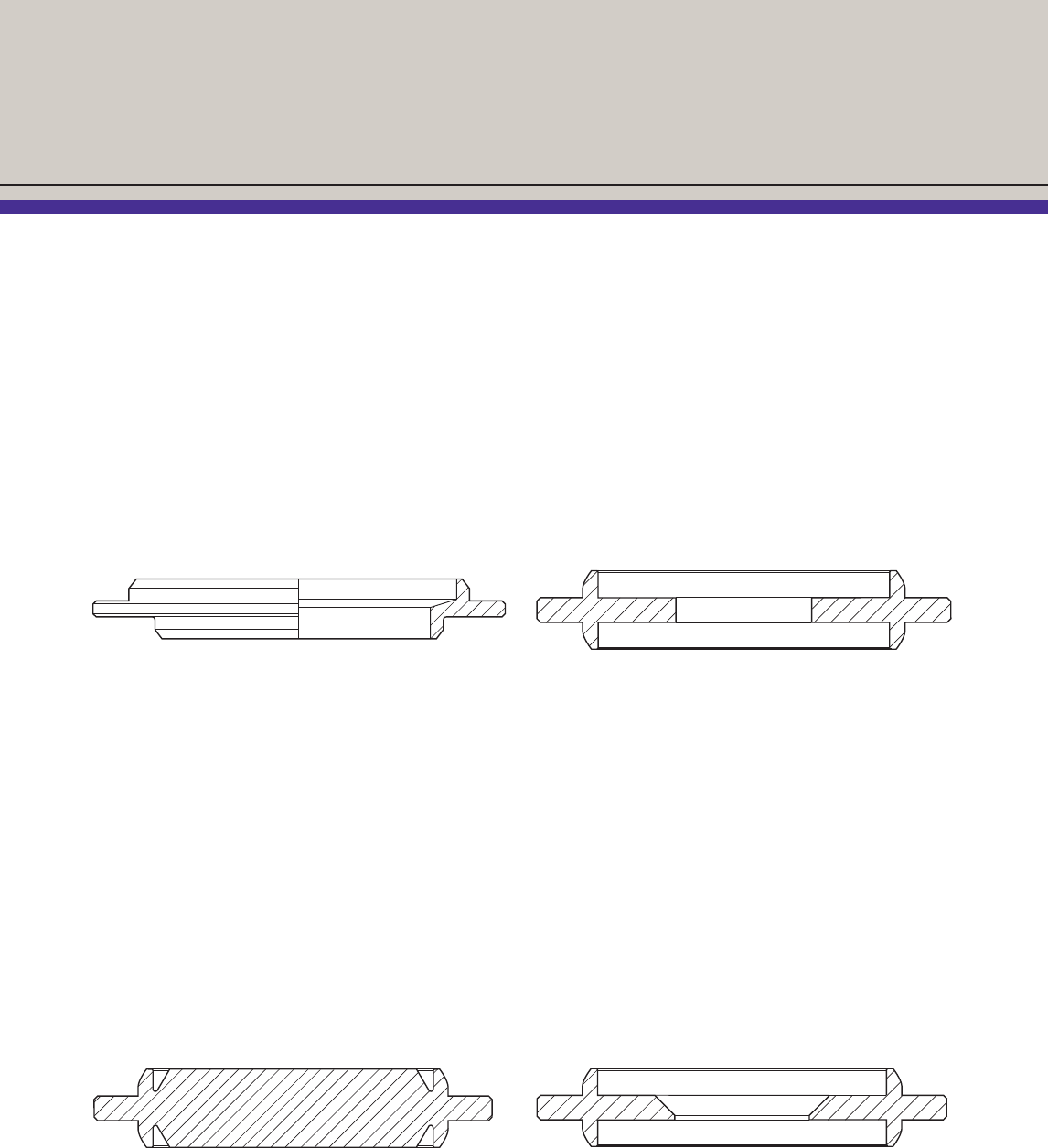
A Grayloc®connector has three
components:
❖Metal Seal Ring — The seal
ring resembles a “T” cross
section. The leg of the “T”
forms a rib that is held by the
hub faces as the connection
is madeup. The two arms
form lip seals that create an
area of sealing surface with
the inner surface of the hub.
Internal pressure works to
reinforce this seal.
❖Two Hubs — The clamp fits
over the two hubs and forces
them against the seal ring
rib. As the hubs are drawn
together by the clamp
assembly, the seal ring lips
deflect against the inner
sealing surfaces of the hubs.
This deflection elastically
loads the lips of the seal ring
against the inner sealing
surface of the hub, forming
a self-energized seal.
❖Clamp Assembly —
Designed to provide nearly
360° clamping contact with
the hubs. A relief notch in
the center of the clamp
segments allow even distri-
bution of makeup forces.
No specific orientation is
required when installed.
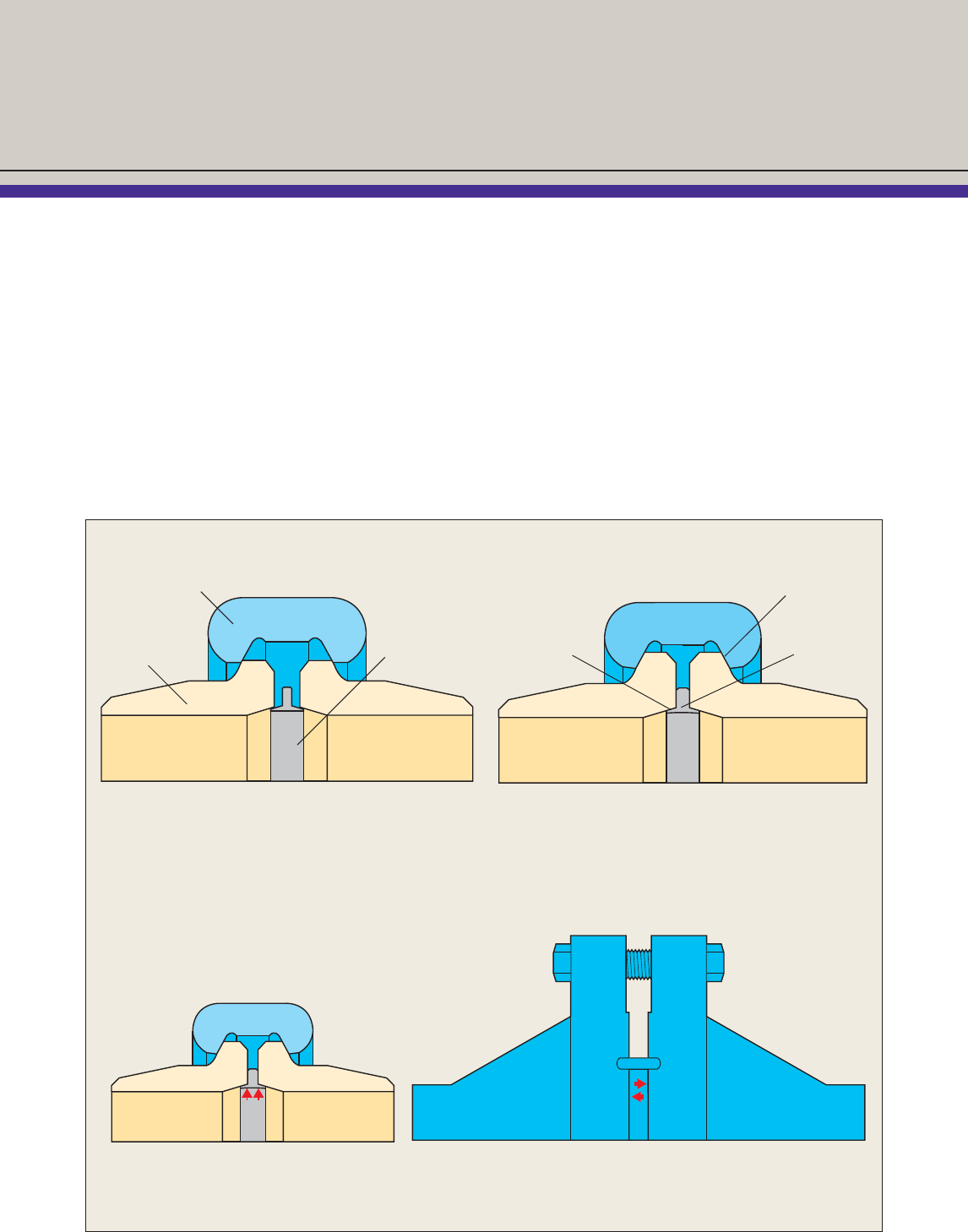
How the Grayloc Connector Seals
Seal Ring
Lip
Clamping
Surface
Rib
Under Pressure:
Grayloc Connector vs. Flange
Rib of the seal ring is clamped between hub faces. Lips of
the seal ring engage inner hub surface in an interference fit
which deflects the lips to achieve a seal.
Pressure acts directly on the flange faces
reducing seal integrity.
Internal pressure energizes the
Grayloc seal lips, reinforcing the seal.
The simplicity, sealing efficiency,
and economy of the Grayloc®
connector benefits a wide
range of industries in various
applications:
❖Petrochemical Industry —
Reactor vessel nozzles,
vessel closures, general
piping/valve ends in petro-
leum refining and chemical
processing plants.
❖Synthetic Fuels, Coal
Gasification, and Coal
Liquefaction —
General piping, vessel
closures, reactor vessels,
and valve ends.
❖Power Industry —
General piping/valve ends,
steam lines, pump inlet/
outlet lines, and chemical
clean out closures.
❖Oil and Gas Production —
Onshore and offshore well-
heads, tees and ells, mani-
folds, chokes, valve ends,
compressors, general piping,
loading risers and pipelines.
❖Marine — Subsea piping
and riser systems, floating
production, storage, offload-
ing (FPSO) vessels, and
tanker loading and unloading
facilities.
❖Aerospace —
Rocket test stands, fuel lines,
hydraulic and pneumatic
piping systems.
❖Food Processing—
Sanitary/general piping
connectors, vessel closures
and valve ends.
❖Environmental —
Hazard waste disposal
and fugitive emissions
containment.
Grayloc Connector Applications
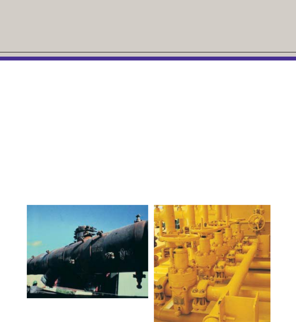
The Office of Coal Research, U.S. Department of the Interior, and the
American Gas Association jointly sponsored a program to develop coal
gasification technology. On this pre-quench tower for raw gas purification,
two Grayloc vessel closures and several smaller Grayloc connectors were
used for pressures of 1,650 psi and temperatures to 650° F.
Photograph courtesy of the Institute of Gas Technology. The use of Grayloc connectors, on a Centex Oil and Gas, Inc. platform
in the Gulf of Mexico, saved 15" of horizontal space on the separator
manifolding of this skid-mounted production unit, and reduced the total
topside platform weight by more than 11 tons.
5
Vibration: 80 to 200 cycles per second under 6,600 psi
High Temperature: Service experience to 1700° F.
Low Temperature: Routine liquefied gas service including liquid
hydrogen and nitrogen to -425° F.
Thermal Shock: Routine service with temperature changes up to
300° F. per hour.
Corrosion: Liquid sodium service at 1200° F.
Zero Leak Rate: 10-6 atm cc/s Helium
6
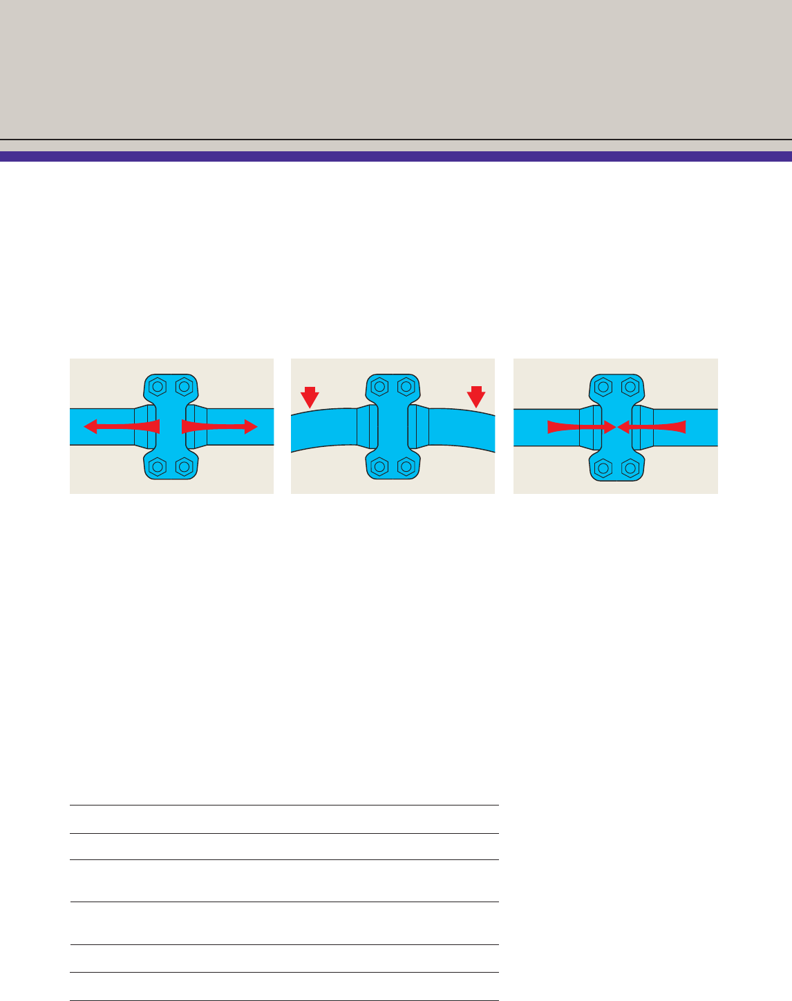
Tension
❖Withstands greater tension
loads than conventional
ANSI flanges
❖In most cases, withstands
more tension loading than
the pipe itself
❖In destructive tests, pipe can
be loaded in tension to failure
without causing the Grayloc
connector to leak
Bending
❖Numerous independent tests
have shown that Grayloc con-
nectors withstand severe
bending loads without leaking
or loosening
❖In one test, 21⁄2" GR 20
Grayloc connector was
welded to 21⁄2" Sch. XX
pipe and subjected to a 2"
cold bend, 36" on center —
connector did not leak and
clamp bolting remained tight
Compression
❖In normal piping applications,
it is not possible to overload
the Grayloc connector or seal
ring in compression
❖When very high compressive
loads occur, the maximum
load on the connector is
determined by the limit of
the pipe
❖In most cases, the area
of the seal ring rib is equal
to or larger than that of
the cross section of
adjoining pipe
Anything the pipe can take, so can the Grayloc Connector
Tension, Compression, Bending
When manufactured from the same material as the pipe, the Grayloc®connector surpasses the
strength of the pipe and that of most other components that may be connected.
The rib of the seal ring prevents the seal lip from being crushed by over-tightening. While it acts as
a positive stop during makeup, the rib also transfers compressive and bending loads from one hub
element to another. The rib bearing area is ample to carry the most severe loading that a piping
system can withstand.
Service Extremes
Vibration, heat, cold and thermal
shock often accompany service
in which Grayloc connectors
are heavily loaded. Grayloc
connectors consistently with-
stand severe situations without
routine maintenance. Special
designs permit maintenance-
free service even under the
extreme conditions shown
in the table.
Examples of Grayloc connector applications in
extreme service conditions
7
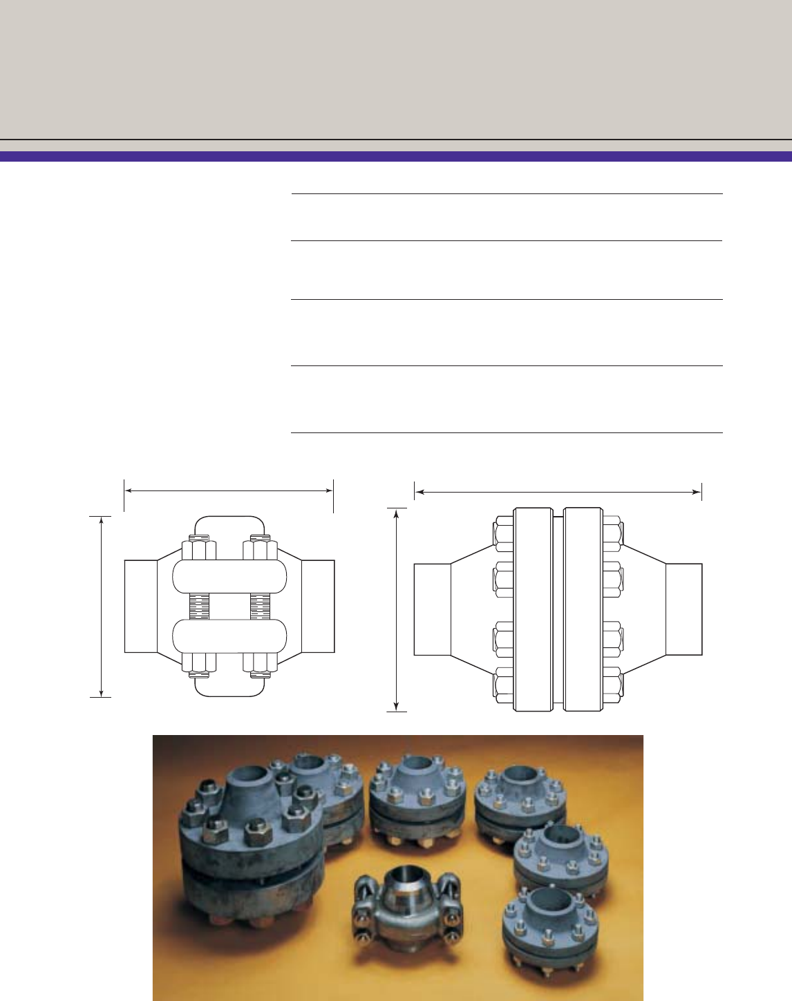
The Grayloc®connector is
significantly lighter and smaller
than a comparably rated ANSI
or API ring joint flange connec-
tion, providing an opportunity
to design lightweight, compact
systems. Close piping and
hookup arrangements can
be easily made as the clamp
completely rotates around
the hub.
❖Smaller diameter
❖Shorter length
❖No bolt holes to align
Conserves Space and Weight
Grayloc vs. Flanges
W.P. Diameter Length Weight
Size Connection (psi) (inches) (inches) (pounds)
3" Grayloc Connector 6,593 6.875 6.750 37
ANSI 1500 Flange 3,705 10.500 9.250 121
API 5000 Flange 5,000 10.500 8.625 92
6" Grayloc Connector 6,359 12.000 9.500 144
ANSI 1500 Flange 3,705 15.500 13.500 407
API 5000 Flange 5,000 15.500 14.250 365
10" Grayloc Connector 5,368 17.625 12.325 415
ANSI 1500 Flange 3,705 23.000 20.000 1100
API 5000 Flange 5,000 23.000 20.875 1032
Length
Diameter
Length
Diameter
8
Saves Time and Money
The Grayloc®connector can
be assembled or disassembled
quicker and easier than a flange
connection. Usually, 3 to 8
Grayloc connectors can be
assembled/disassembled
in the same time as one
flange connection.
❖No bolt holes to align
❖Only 4 bolts to tighten (8 -24
for a conventional flange)
❖Torque required —
as much as 70% lower
than for a RTJ flange
Maintenance is simple with
only four bolts to remove. No
periodic re-tightening of bolts
is required once the connector
is in service.
The necessary inventory of
spare parts is significantly
reduced since the Grayloc
connector is sized according
to pipe size, schedule, and
service. In most instances, only
one Grayloc connector size is
necessary for each pipe size
and seal rings can be reused.
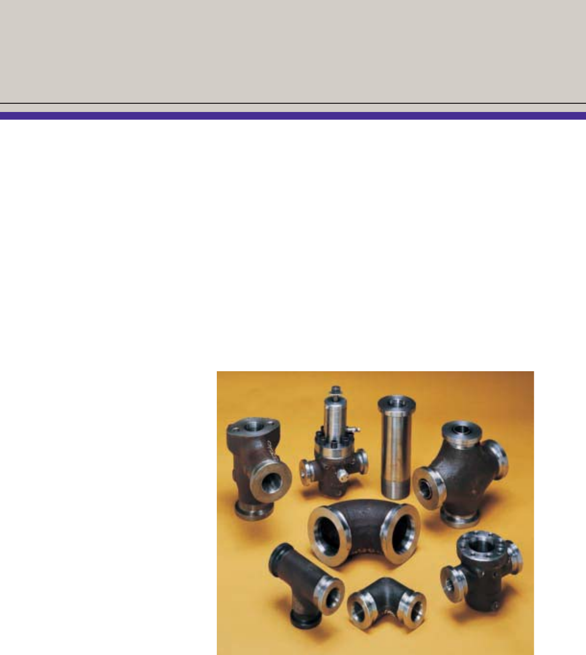
Versatile Design
The standard Grayloc assembly
has two hubs arranged for butt
welding to pipe. However, a
complete line of other piping
components is available for
most pipe sizes and service
conditions.
❖Hubs (socket weld /threaded)
❖Tees and ells
❖Nozzles
Heavy duty connectors for
oilfield and other applications
are available.
Other equipment manufacturers
(valves, pumps, compressors,
vessel, etc.) are licensed to
machine Grayloc hub profile/
seats integral to their products.
Hub Material Selection Chart
ANSI Designation
Group No. Steel Forging
1.1 Carbon (1)A105
A350-LF2
1.2 31⁄2 Ni A350-LF3
1.4 Carbon A350-LF1
1.5 C-1⁄2 Mo A182-F1
1.7 1⁄2 Cr-1⁄2 Mo A182-F2
1.9 1Cr-1⁄2 Mo A182-F12
11⁄4 Cr-1⁄2 Mo A182-F11
1.10 21⁄4 Cr-1Mo A182-F22
1.13 5Cr-1⁄2 Mo A182-F5
A182-F5a
1.14 A182-F9
2.1 18Cr-8Ni A182-F304
A182-F304H
2.2 16Cr-12Ni-2Mo (1)A182-F316
A182-F316H
2.4 18Cr-10Ni-Ti A182-F321
A182-F321H
2.5 18Cr-10Ni-Cb A182-F347
A182-F347H
A182-F348
A182-F348H
2.7 25Cr-20Ni A182-F310
3.5 Alloy 600 B564-N06600
3.6 Alloy 800 B564-N08800
3.8 Alloy C276 B574-N10276
Alloy 625 B564-N06625
Alloy 825 B425-N08825
... Duplex A182-F51
A182-F53
A182-F55
Grayloc®Selection Chart
-20° F. to +700° F.
ANSI Flange Series
600 900 1500 2500 4500
Nominal
Pipe Size Grayloc Size
1⁄21 GR 5 1 GR 5 1 GR 5 1 GR 4 1 GR 4
3⁄41 GR 7 1 GR 7 1 GR 5 1 GR 4 1 GR 4
1 1 GR 11 1 GR 11 1 GR 7 1 GR 5 1 GR 5
11⁄211⁄2GR 14 11⁄2GR 14 11⁄2GR 14 11⁄2GR 11 11⁄2GR 11
2 2 GR 20 2 GR 20 2 GR 20 2 GR 14 2 GR 11
21⁄221⁄2GR 25 21⁄2GR 25 21⁄2GR 25 21⁄2GR 20 21⁄2GR 20
3 3 GR 27 3 GR 27 3 GR 25 3 GR 23 3 GR 20
4 4 GR 40 4 GR 34 4 GR 34 4 GR 31 4 GR 23
5 5 GR 52 5 GR 46 5 GR 46 5 GR 40 5 GR 31
6 6 GR 62 6 GR 62 6 GR 52 6 GR 46 6 GR 34
8 8 GR 82 8 GR 76 8 GR 67 8 GR 52 8 GR 46
10 10 H 97 10 H 94 10 H 84 10 H 72 10 H 62
12 12 M 120 12 M 112 12 M 102 12 M 82 X12 M 72
14 X14 GR 130 X14 GR 120 X14 GR 106
16 X16 GR 140
18 X18 GR 170
20 X20 GR 180
24 X24 GR 220
9
How to Select Grayloc Connectors
Additional sizes available upon request
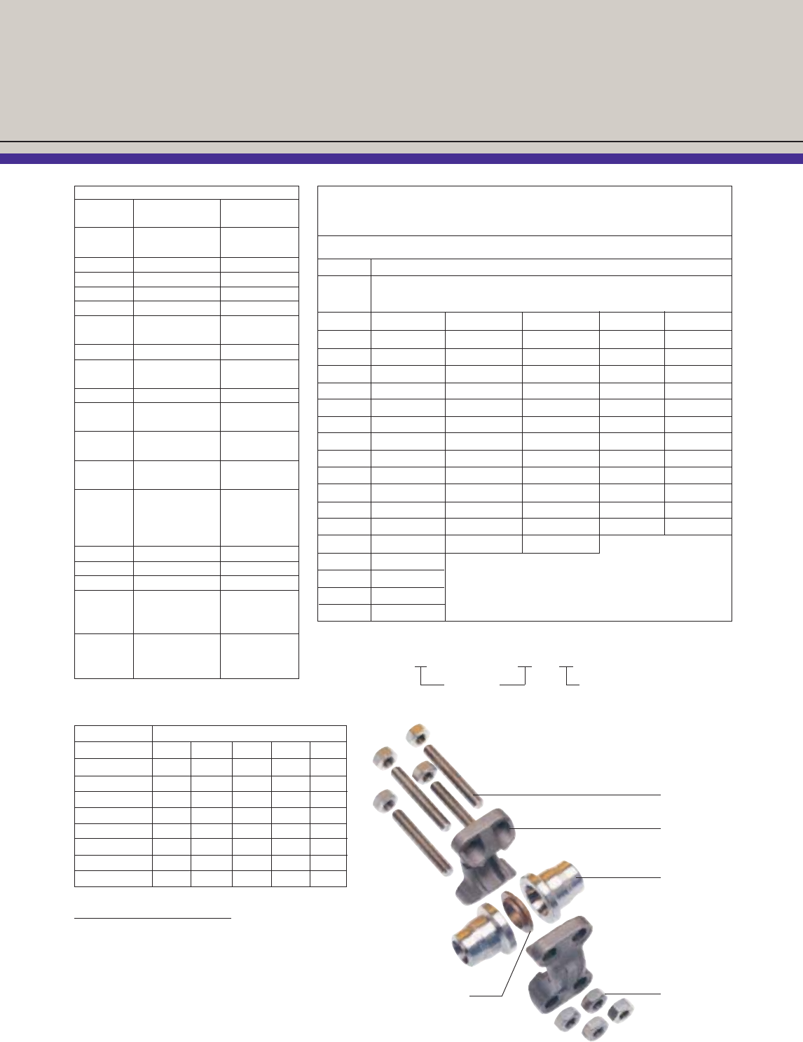
Spherical
Face Nut
All Thread Stud
Clamp
Butt Weld Hub
Seal Ring
Notes to Grayloc Selection Chart:
1.Corrosion allowance: 1/32" for 1" nominal and 1/16" for
larger pipe sizes.
2.Connectors listed in the Grayloc Selection Chart exceed
the ANSI ceiling pressure ratings. Actual ratings are
available upon request.
3.Ratings are based on carbon steel clamps.
ANSI Pressure Ratings Ceiling Values
Temperature, °F 600 900 1500 2500 4500
-20 to 100 1500 2250 3750 6250 11250
200 1500 2250 3750 6250 11250
300 1455 2185 3640 6070 10925
400 1410 2115 3530 5880 10585
500 1330 1995 3325 5540 9965
600 1210 1815 3025 5040 9070
650 1175 1765 2940 4905 8825
700 1135 1705 2840 4730 8515
(1) Standard Grayloc materials referenced in
this catalog.
EXAMPLE
2" ANSI 1500 = 2 GR20 Grayloc
Pipe Size Grayloc Ring Size
Grayloc Clamp Size to Match Pipe ID
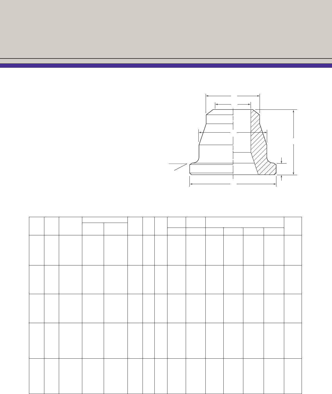
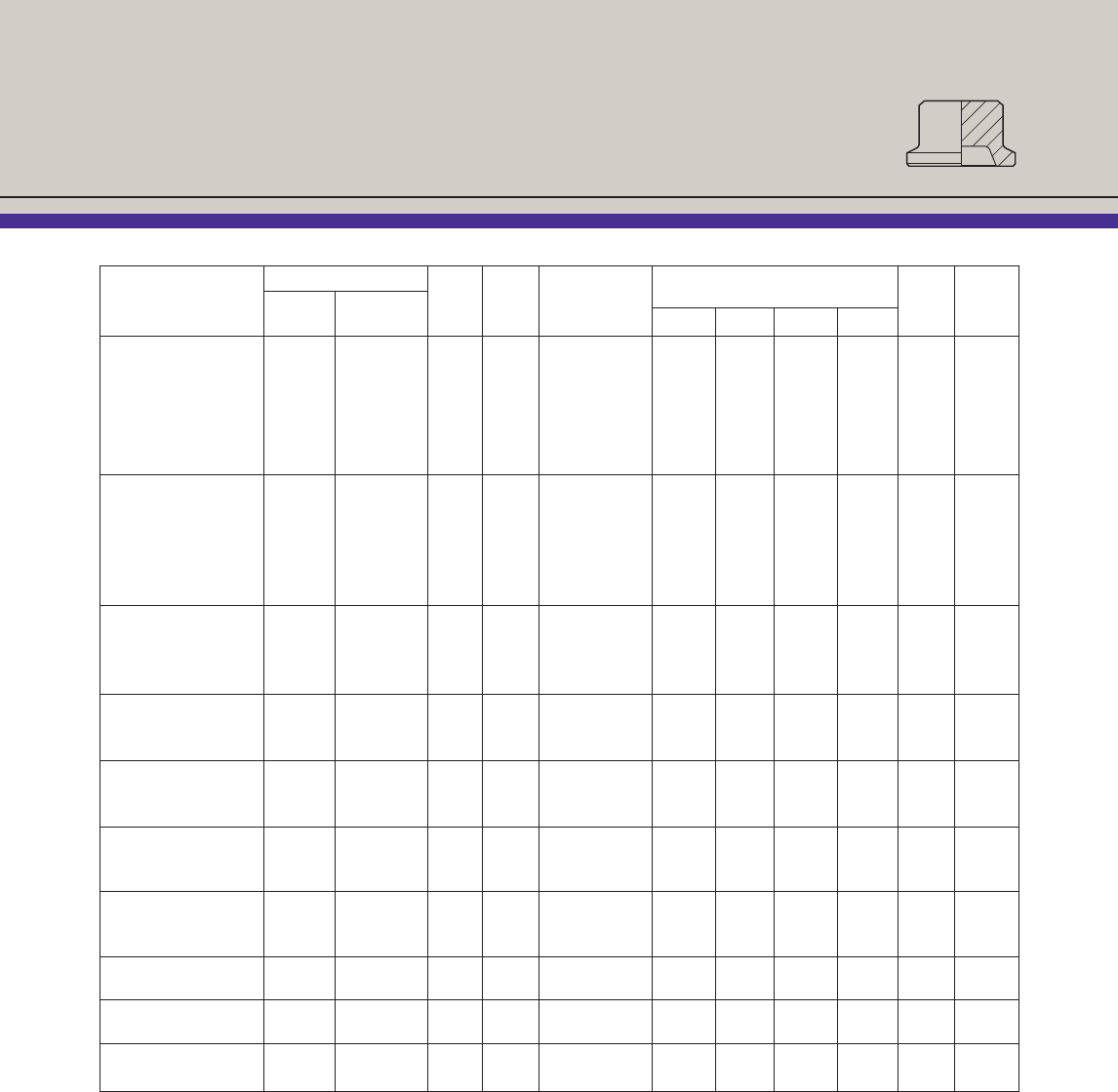
Part Numbers / Dimensions
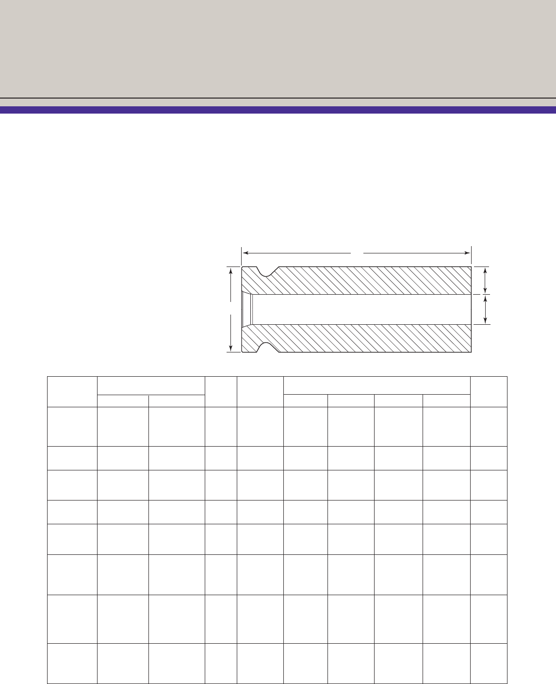
Butt Weld Hubs
Grayloc®hubs are usually made of the same
generic material as the other system components
they connect. Standard hub materials are SA105
carbon steel and SA182-F316 stainless steel, but
they can be manufactured from most machinable
metals, including all of the carbon, low alloy,
austenitic stainless steels, MONEL*, INCONEL*,
titanium and zirconium alloys.
Sealing surfaces on carbon steel and low alloy
steel weld hubs and fittings are protected by
electroless nickel coating. The welding bevel
and all part tolerances are in accordance with
ANSI B16.5.
* MONEL and INCONEL are trademarks of Special Metals Corp.
Nominal Sched. Part Number Approx. Seal Pipe Pipe Depth
Pipe or Hub Carbon Stl. Stainless Stl. Weight Ring Clamp OD ID Dimensions (Inches) of
Size Weight Size SA105 SA182-F316(5) (lb.) Size Size A B C D(1) E F Recess(2)
1⁄240 1 GR5 52192D 55955D 0.68 5 1 0.840 0.622 2.000 1.750 1.500 0.313 ......
80 1 GR5 52193D 53439D 0.68 5 1 0.840 0.546 2.000 1.750 1.500 0.313 ......
160 1 GR4 52194D 53686D 0.67 4 1 0.840 0.466 2.000 1.750 1.500 0.313 ......
XX 1 GR4 52195D 53437D 0.73 4 1 0.840 0.252 2.000 1.750 1.500 0.313 ......
3⁄440 1 GR7 52196D 53440D 0.62 7 1 1.050 0.824 2.000 1.750 1.500 0.313 ......
80 1 GR7 52233D 53218D 0.60 7 1 1.050 0.742 2.000 1.750 1.500 0.313 ......
160 1 GR5 52198D 53442D 0.71 5 1 1.050 0.612 2.000 1.750 1.500 0.313 ......
XX 1 GR4 52199D 53447D 0.76 4 1 1.050 0.434 2.000 1.750 1.500 0.313 ......
1 40 1 GR11 53225D 53231D 0.51 11 1 1.315 1.049 2.000 1.750 1.500 0.313 ......
80 1 GR11 53226D 53232D 0.54 11 1 1.315 0.957 2.000 1.750 1.500 0.313 ......
160 1 GR7 53227D 53233D 0.66 7 1 1.315 0.815 2.000 1.750 1.500 0.313 ......
XX 1 GR5 53228D 53234D 0.78 5 1 1.315 0.599 2.000 1.750 1.500 0.313 ......
11⁄240 11⁄2 GR14 52100D 52813D 1.68 14 11⁄21.900 1.610 3.125 2.375 2.375 0.437 ......
80 11⁄2 GR14 52101D 52814D 1.83 14 11⁄21.900 1.500 3.125 2.375 2.375 0.437 ......
160 11⁄2 GR14 52102D 52815D 2.01 14 11⁄21.900 1.338 3.125 2.375 2.375 0.437 ......
XX 11⁄2 GR14 52103D 52816D 2.15 14 11⁄21.900 1.100 3.125 2.375 2.375 0.437 ......
XX 11⁄2 GR11 52134D 52442D 2.38 11 11⁄21.900 1.100 3.125 2.375 2.375 0.500 ......
2 40 2 GR20 52104D 52821D 2.36 20 2 2.375 2.067 3.625 2.750 2.875 0.437 ......
80 2 GR20 52105D 52822D 2.59 20 2 2.375 1.939 3.625 2.750 2.875 0.437 ......
160 2 GR20 52115D 52823D 2.93 20 2 2.375 1.687 3.625 2.750 2.875 0.437 ......
XX 2 GR14 52113D 52824D 3.40 14 2 2.375 1.503 3.625 2.750 2.875 0.437 ......
XX 2 GR11(3)(4) 52337D 999628D 4.00 11 2 2.375 1.503 3.625 2.812 2.875 0.559 0.059
(1) Length of hub (“D” dimension) may increase when used with wall thickness greater than standard pipe schedules. (2) Depth of seal ring seat recess.
(3) Hub with recessed seal ring seat. (4) Hub ID less than pipe ID. (5) SA479-316/316L may be substituted based on material availability.
(6) Carbon steel hub part numbers with “D” suffix are dual certified to SA105/SA350 LF2. (7) Stainless steel hub part numbers with “D” suffix are dual certified
to SA182 F316/F316L.
A
B
E
D
C
F
25°
10
21⁄240 21⁄2 GR25 52215D 52825D 5.86 25 21⁄2-3 2.875 2.469 5.000 3.250 4.000 0.500 ......
80 21⁄2 GR25 52216D 52826D 6.36 25 21⁄2-3 2.875 2.323 5.000 3.250 4.000 0.500 ......
160 21⁄2 GR20(1) 52218D 52827D 7.16 20 21⁄2-3 2.875 2.125 5.000 3.250 4.000 0.500 ......
XX 21⁄2 GR20 52219D 52828D 7.75 20 21⁄2-3 2.875 1.771 5.000 3.250 4.000 0.500 ......
3 40 3 GR27(4) 52204D 52844D 4.95 27 21⁄2-3 3.500 3.068 5.000 3.250 4.000 0.500 ......
80 3 GR27 52205D 52845D 5.50 27 21⁄2-3 3.500 2.900 5.000 3.250 4.000 0.500 ......
160 3 GR25 52226D 52846D 6.53 25 21⁄2-3 3.500 2.624 5.000 3.250 4.000 0.500 ......
XX 3 GR25 52227D 52847D 7.23 25 21⁄2-3 3.500 2.300 5.000 3.250 4.000 0.500 ......
XX 3 GR23 52247D 53848D 8.00 23 21⁄2-3 3.500 2.300 5.000 3.250 4.000 0.500 ......
XX 3 GR20(4) 52160D 53668D 9.00 20 21⁄2-3 3.500 2.300 5.000 3.250 4.000 0.500 ......
4 40 4 GR40 52302D 52851D 6.97 40 4 4.500 4.026 6.000 3.625 5.000 0.500 ......
80 4 GR40 52303D 52852D 7.80 40 4 4.500 3.826 6.000 3.625 5.000 0.500 ......
120 4 GR34 52418D 55888D 9.39 34 4 4.500 3.624 6.000 3.625 5.000 0.500 ......
160 4 GR34 52311D 52853D 10.13 34 4 4.500 3.438 6.000 3.625 5.000 0.500 ......
XX 4 GR31 52314D 52854D 11.60 31 4 4.500 3.152 6.000 3.625 5.000 0.500 ......
. . . 4 GR27 ...... ...... ...... 27 4 4.500 ...... 6.000 3.625 5.000 0.500 ......
. . . 4 GR25 ...... ...... 15.00 25 4 4.500 ...... 6.000 3.625 5.000 0.500 ......
5 40 5 GR52 52380D 52867D 11.00 52 5 5.563 5.047 7.500 4.375 6.500 0.625 ......
80 5 GR52 52381D 135344D 11.00 52 5 5.563 4.813 7.500 4.375 6.500 0.625 ......
160 5 GR46 52385D 142751D 17.00 46 5 5.563 4.313 7.500 4.375 6.500 0.625 ......
XX 5 GR40 52383D 52870D 21.53 40 5 5.563 4.063 7.500 4.375 6.500 0.625 ......
. . . 5 GR34 ...... ...... 26.00 34 5 5.563 ...... 7.500 4.375 6.500 0.625 ......
. . . 5 GR31 ...... ...... 28.00 31 5 5.563 ...... 7.500 4.375 6.500 0.625 ......
6 40 6 GR62 52400D 52874D 22.00 62 6 6.625 6.065 9.250 4.625 7.750 0.750 ......
80 6 GR62 52401D 52875D 24.17 62 6 6.625 5.761 9.250 4.625 7.750 0.750 ......
160 6 GR52 52413D 52876D 33.19 52 6 6.625 5.187 9.250 4.625 7.750 0.812 ......
XX 6 GR52 52414D 52877D 33.75 52 6 6.625 4.897 9.250 4.625 7.750 0.812 ......
XX 6 GR46(3)(4) 52321D 55891D 37.11 46 6 6.625 4.897 9.250 4.750 7.750 0.934 0.122
. . . 6 GR40(3) ...... ...... 43.00 40 6 6.625 ...... 9.250 4.750 7.750 0.934 0.122
8 40 8 GR82 52405 52878 32.00 82 8 or X8 8.625 7.981 11.500 5.375 10.000 0.750 ......
80 8 GR76 52425G 52882 41.00 76 8 or X8 8.625 7.625 11.500 5.375 10.000 0.750 ......
160 8 GR72 52423G 52880 50.00 72 8 or X8 8.625 6.813 11.500 5.375 10.000 0.750 ......
XX 8 GR72 52422G 52881 50.00 72 8 or X8 8.625 6.875 11.500 5.375 10.000 0.750 ......
XX 8 GR67 H90208-48 H90208-49 52.00 67 8 or X8 8.625 6.875 11.500 5.375 10.000 0.750 ......
. . . 8 GR62 ...... ...... 69.00 62 8 or X8 8.625 ...... 11.500 5.375 10.000 0.750 ......
. . . 8 GR52(3) ...... ...... 78.00 52 8 or X8 8.625 ...... 11.500 5.500 10.000 0.934 0.122
10 40 10H102 52518 52900 55.00 102 10H or X10H 10.750 10.020 13.625 6.000 11.625 1.250 ......
60 10H97 52519 52901 55.00 97 10H or X10H 10.750 9.750 13.625 6.000 11.625 1.250 ......
80 10H97 52520 52902 55.00 97 10H or X10H 10.750 9.562(8) 13.625 6.000 11.625 1.250 ......
160 10H84 52521 52903 89.00 84 10H or X10H 10.750 8.500 13.625 6.000 11.625 1.250 ......
. . . 10H94 ...... ...... 65.00 94 10H or X10H 10.750 ...... 13.625 6.000 11.625 1.250 ......
. . . 10H82 ...... ...... 100 82 10H or X10H 10.750 ...... 13.625 6.000 11.625 1.250 ......
. . . 10H72 ...... ...... 115 72 10H or X10H 10.750 ...... 13.625 6.000 11.625 1.250 ......
. . . 10H62(3) ...... ...... 136 62 10H or X10H 10.750 ...... 13.625 8.000 11.625 1.434 0.184
Nom. Sched. Part Number Approx. Seal Pipe Pipe Depth
Pipe or Hub Carbon Stl. Stainless Stl. Weight Ring Clamp OD ID Dimensions (Inches) of
Size Weight Size SA105 SA182-F316(5) (lb.) Size Size A B C D(1) E F Recess(2)
(1) Length of hub (“D” dimension) may increase when used with wall thickness greater than standard pipe schedules. (2) Depth of seal ring seat recess.
(3) Hub with recessed seal ring seat. (4) Hub ID less than pipe ID. (5) SA479-316/316L may be substituted based on material availability.
(6) Carbon steel hub part numbers with “D” suffix are dual certified to SA105/SA350 LF2. (7) Stainless steel hub part numbers with “D” suffix are dual certified
to SA182 F316/F316L. (8) ID is 9.750 for stainless steel and 9.562 for other steel.
11
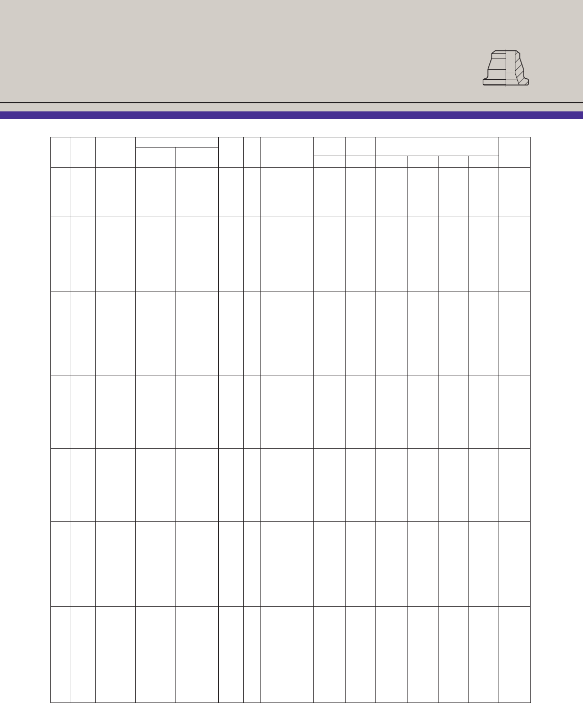
Butt Weld Hubs
12 STD 12M120 52596 52904 70 120 12M or X12M 12.750 12.000 16.000 6.625 14.000 1.375 ......
XS 12M120 52597 52905 70 120 12M or X12M 12.750 11.750 16.000 6.625 14.000 1.375 ......
80 12M112(4) 52598 52906 98 112 12M or X12M 12.750 11.752(8) 16.000 6.625 14.000 1.250 ......
160 12M102 52599G 52907 129 102 12M or X12M 12.750 10.126 16.000 6.625 14.000 1.375 ......
...... 12M82(3) ...... ...... 182 82 12M or X12M 12.750 ...... 16.000 8.000 14.000 1.599 0.184
11 X14GR112 ...... ...... ...... 112 X14 17.250 7.000 15.750 0.687 ......
P112 ...... ...... ...... 112 P or 5P 18.500 7.250 16.500 1.125 ......
12 X14GR120 ...... ...... 202 120 X14 17.250 7.000 15.750 0.812 ......
P120 ...... ...... 153 120 P or 5P 18.500 7.250 16.500 1.250 ......
S120 ...... ...... 271 120 S 21.000 7.875 19.000 1.750 ......
121/2S125 ...... ...... ...... 125 S 21.000 7.875 19.000 1.750 ......
P125 ...... ...... ...... 125 P or 5P 18.500 7.250 16.500 1.250 ......
X14GR125 ...... ....... ...... 125 X14 17.250 7.000 15.750 0.812 ......
13 X14GR130 ...... ...... ...... 130 X14 17.250 7.000 15.750 0.750 ......
P130 ...... ...... ...... 130 P or 5P 18.500 7.250 16.500 1.188 ......
S130 ...... ...... ...... 130 S 21.000 7.875 19.000 1.688 ......
14 X16GR140 ...... ...... ...... 140 X16 19.500 7.750 18.000 0.750 ......
S140 ...... ...... ...... 140 S 21.000 7.875 19.000 1.688 ......
15 X16GR152 ...... ...... ...... 152 X16 19.500 7.750 18.000 0.750 ......
S152 ...... ...... 194 152 S 21.000 7.875 19.000 1.688 ......
16 X18GR160 ...... ...... ...... 160 X18 21.750 8.250 20.250 0.750 ......
U160 ...... ...... 403 160 U 25.000 8.750 23.000 1.625 ......
17 X18GR170 ...... ...... ...... 170 X18 21.750 8.250 20.250 0.750 ......
X20GR170 ...... ...... ...... 170 X20 24.500 8.750 23.000 0.750 ......
18 X20GR180 ...... ...... ...... 180 X20 24.500 8.750 23.000 0.750 ......
U180 ...... ...... 331 180 U 25.000 8.750 23.000 1.625 ......
19 U192 ...... ...... ...... 192 U 25.000 8.750 23.000 1.625 ......
X20GR192 ...... ...... ...... 192 X20 24.500 8.750 23.000 0.750 ......
20 X20GR200 ...... ...... ...... 200 X20 24.500 8.750 23.000 0.750 ......
3V200 ...... ...... 686 200 3V 26.000 9.000 24.000 1.250 ......
3W200 ...... ...... ...... 200 3W 29.500 9.750 27.500 1.250 ......
21 3W215 ...... ...... ...... 215 3W 29.500 9.750 27.500 1.250 ......
X24GR215 ...... ...... ...... 215 X24 29.500 9.750 27.500 1.000 ......
22 3W226 ...... ...... ...... 226 3W 29.500 9.750 27.500 1.250 ......
X24GR226 ...... ...... ...... 226 X24 29.500 9.750 27.500 1.000 ......
23 X24GR232 ...... ...... ...... 232 X24 29.500 9.750 27.500 1.000 ......
24 X24GR240 ...... ...... ...... 240 X24 29.500 9.750 27.500 1.000 ......
Y240 ...... ...... ...... 240 Y 31.250 10.000 29.250 1.625 ......
26 30GR264 ...... ...... ...... 264 30 33.500 10.500 31.500 1.000 ......
29 30GR292 ...... ...... ...... 292 30 33.500 10.500 31.500 1.000 ......
Nom. Sched. Part Number Approx. Seal Pipe Pipe Depth
Pipe or Hub Carbon Stl. Stainless Stl. Weight Ring Clamp OD ID Dimensions (Inches) of
Size Weight Size SA105 SA182-F316(5) (lb.) Size Size A B C D(1) E F Recess(2)
(1) Length of hub (“D” dimension) may increase when used with wall thickness greater than standard pipe schedules. (2) Depth of seal ring seat recess.
(3) Hub with recessed seal ring seat. (4) Hub ID less than pipe ID. (5) SA479-316/316L may be substituted based on material availability.
(6) Carbon steel hub part numbers with “D” suffix are dual certified to SA105/SA350 LF2. (7) Stainless steel hub part numbers with “D” suffix are dual
certified to SA182 F316/F316L. (8) ID is 11.750 for stainless steel and 11.374 for other steel.
12
Butt Weld Hubs
Nominal I.D. Grayloc Sizes and Hub Dimensions for
Large I.D. Applications are Provided Below
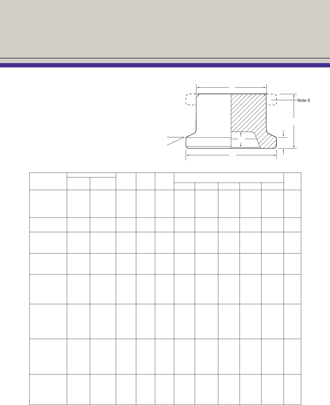
Part Numbers / Dimensions
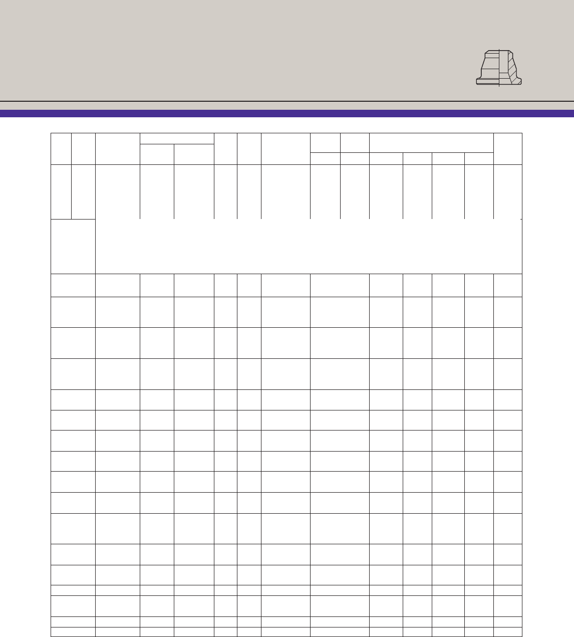
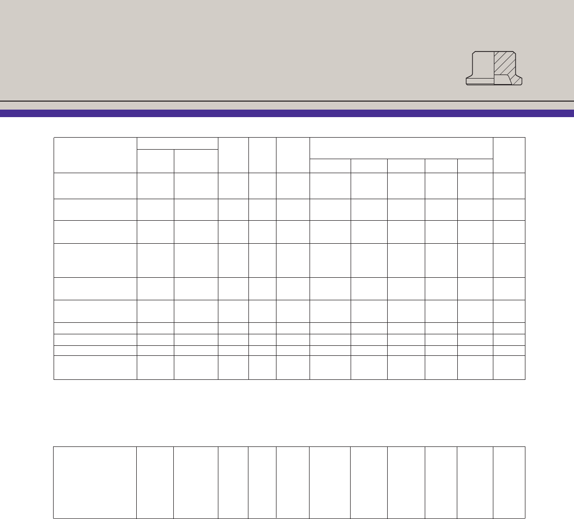
13
Blind Hubs
❖Stocked for standard-sized Grayloc®connectors
❖Full pressure rating of the Grayloc connector
❖Can be used as closures for pressure vessels,
heat exchangers, pumps, compressors, etc.
❖Can be drilled and tapped for instrumentation
❖Can be customized to fit specific requirements
E
D
F
C
G
25°
Part Number Approx. Seal Depth
Carbon Stl. Stainless Stl. Weight Ring Clamp Dimensions (inches) of
Hub Size SA105 SA182-F316(3) (lb.) Size Size C D E F G Recess(1)
1 GR4 58955D 59497D 1.02 4 1 2.000 1.750 1.500 0.313 0.438 ......
1 GR5 58922D 59525D 1.01 5 1 2.000 1.750 1.500 0.313 0.438 ......
1 GR7 58915D 59523D 0.95 7 1 2.000 1.750 1.500 0.313 0.563 ......
1 GR11 59592D 59524D 0.94 11 1 2.000 1.750 1.500 0.313 0.563 ......
11⁄2GR11 59050D 59300D 3.11 11 11⁄23.125 2.125 2.375 0.500 0.563 ......
11⁄2GR14 59000D 59305D 2.82 14 11⁄23.125 2.125 2.375 0.437 0.688 ......
2 GR11(2) 59044D 59366D 3.85 11 2 3.625 1.750 2.875 0.559 0.563 0.059
2 GR14 59053D 59310D 3.96 14 2 3.625 2.000 2.875 0.437 0.688 ......
2 GR20 59002D 59315D 3.63 20 2 3.625 2.000 2.875 0.437 0.688 ......
21⁄2GR20 59022D 59320D 9.61 20 21⁄2-3 5.000 2.500 4.000 0.500 0.688 ......
21⁄2GR23 46180D 59241D 9.39 23 21⁄2-3 5.000 2.500 4.000 0.500 0.688 ......
21⁄2GR25 59020D 59325D 9.15 25 21⁄2-3 5.000 2.500 4.000 0.500 0.688 ......
3 GR20 59022D 59320D 9.61 20 21⁄2-3 5.000 2.500 4.000 0.500 0.688 ......
3 GR23 46180D 95241D 9.39 23 21⁄2-3 5.000 2.500 4.000 0.500 0.688 ......
3 GR25 59020D 59325D 9.15 25 21⁄2-3 5.000 2.500 4.000 0.500 0.688 ......
3 GR27 59006D 59330D 8.32 27 21⁄2-3 5.000 2.500 4.000 0.500 0.938 ......
4 GR25 59028D 59275D 16.59 25 4 6.000 2.875 5.000 0.500 0.688 ......
4 GR27 58879D
H90103-33D
15.80 27 4 6.000 2.875 5.000 0.500 0.938 ......
4 GR31 59024D 59345D 15.57 31 4 6.000 2.875 5.000 0.500 0.938 ......
4 GR34 59060D 59340D 14.90 34 4 6.000 2.875 5.000 0.500 0.938 ......
4 GR40 59010D 59335 9.72 40 4 6.000 2.125 5.000 0.500 1.000 ......
5 GR31 59146D H90154-4 33.83 31 5 7.500 3.500 6.500 0.625 0.938 ......
5 GR34 59147D 59278D 32.00 34 5 7.500 3.500 6.500 0.625 0.938 ......
5 GR40 58261D 59347D 31.78 40 5 7.500 3.500 6.500 0.625 1.000 ......
5 GR46 59148D 134752D 30.00 46 5 7.500 2.875 6.500 0.625 1.125 ......
5 GR52 58992D 134751D 29.00 52 5 7.500 2.875 6.500 0.625 1.000 ......
6 GR40(2) 59149D 95087D 50.00 40 6 9.250 3.375 7.750 0.934 1.000 0.122
6 GR46(2) 59150D 59282D 49.00 46 6 9.250 3.375 7.750 0.934 1.125 0.122
6 GR52 59064D 59350D 47.02 52 6 9.250 3.500 7.750 0.812 1.000 ......
6 GR62 59014D 59349D 35.43 62 6 9.250 2.875 7.750 0.750 1.000 ......
(1) Depth of seal ring recess.
(2) Hub with recessed seal ring seat.
(3) SA479 316/316L may be substituted based on material availability.
(4) Carbon steel hub part numbers with “D” suffix are dual certified to SA105/SA350 LF2.
(5) Stainless steel hub part numbers with “D” suffix are dual certified to SA182 F316/F316L.
(6) Blind hub sizes, 6 GR and larger, are supplied with an integral lifting profile.
Part Number Approx. Seal Depth
Carbon Stl. Stainless Stl. Weight Ring Clamp Dimensions (inches) of
Hub Size SA105 SA182-F316(3) (lb.) Size Size C D E F G Recess(1)
Blind Hubs
14
8 GR52(2) 59152 55891 92 52 8 or X8 11.500 3.875 10.000 0.934 1.000 0.122
8 GR62 59071 59285 92 62 8 or X8 11.500 4.250 10.000 0.750 1.000 ......
8 GR67 ...... ...... 87 67 8 or X8 11.500 4.250 10.000 0.750 1.000 ......
8 GR72 59066 59358 75 72 8 or X8 11.500 3.500 10.000 0.750 1.000 ......
8 GR76 59153 59286 70 76 8 or X8 11.500 3.000 10.000 0.750 1.000 ......
8 GR82 59016 59357 68 82 8 or X8 11.500 3.000 10.000 0.750 1.000 ......
10H62(2) 59157 ...... 155 62 10H or X10H 13.625 4.500 11.625 1.434 1.000 0.184
10H72 59164 ...... 160 72 10H or X10H 13.625 5.000 11.625 1.250 1.000 ......
10H82 58265 ...... 150 82 10H or X10H 13.625 5.000 11.625 1.250 1.000 ......
10H84 59156 H90252-3 150 84 10H or X10H 13.625 4.250 11.625 1.250 1.000 ......
10H94 46269 ...... 110 94 10H or X10H 13.625 3.750 11.625 1.250 1.125 ......
10H97 59154 59287 105 97 10H or X10H 13.625 3.500 11.625 1.250 1.125 ......
12M82(2) 59160 ...... 230 82 12M or X12M 16.000 5.000 14.000 1.559 1.000 0.184
12M102 59159 ...... 240 102 12M or X12M 16.000 5.250 14.000 1.375 1.125 ......
12M112 59176 59292 175 112 12M or X12M 16.000 4.250 14.000 1.250 1.125 ......
12M120 59158 ...... 170 120 12M or X12M 16.000 3.875 14.000 1.375 1.125 .....
X14GR112 ...... ...... 235 112 X14 17.250 4.750 15.750 0.687 1.125 ......
P102 ...... 130037 341 102 P or 5P 18.500 5.750 16.500 1.250 1.125 ......
P112 ...... ...... 340 112 P or 5P 18.500 5.750 16.500 1.125 1.125 ......
X14GR120 ...... ...... 270 120 X14 17.250 4.750 15.750 0.812 1.125 ......
P120 ...... ...... 331 120 P or 5P 18.500 5.000 16.500 1.250 1.125 ......
S120 ...... ...... 595 120 S 21.000 7.500 19.000 1.750 1.125 ......
S125 ...... ...... 510 125 S 21.000 5.500 19.000 1.750 1.125 ......
P125 ...... ...... 325 125 P or 5P 18.500 5.000 16.500 1.250 1.125 ......
X14GR125 ...... ...... 225 125 X14 17.250 4.750 15.750 0.812 1.125 ......
X14GR130 ...... ...... 210 130 X14 17.250 4.125 15.750 0.750 1.250 ......
P130 129669 ...... 283 130 P or 5P 18.500 5.000 16.500 1.188 1.250 ......
S130 ...... ...... 497 130 S 21.000 5.500 19.000 1.688 1.250 ......
X16GR140 ...... ...... 265 140 X16 19.500 4.750 18.000 0.750 1.250 ......
S140 ...... ...... 480 140 S 21.000 5.500 19.000 1.688 1.250 ......
X16GR152 ...... ...... 255 152 X16 19.500 4.375 18.000 0.750 1.500 ......
S152 ...... ...... 423 152 S 21.000 5.500 19.000 1.688 1.500 .....
X18GR160 ...... ...... 347 160 X18 21.750 5.500 20.250 0.750 1.500 ......
U160 ...... ...... 787 160 U 25.000 7.250 23.000 1.625 1.500 ......
(1) Depth of seal ring seat recess.
(2) Hub with recessed seal ring seat.
(3) SA479 316/316L may be substituted based on material availability.
(4) Carbon steel hub part numbers with “D” suffix are dual certified to SA105/SA350 LF2.
(5) Stainless steel hub part numbers with “D” suffix are dual certified to SA182 F316/F316L.
(6) Blind hub sizes, 6 GR and larger, are supplied with an integral lifting profile.
X18GR170 ...... ...... 330 170 X18 21.750 4.750 20.250 0.750 1.500 ......
X20GR170 ...... ...... 554 170 X20 24.500 5.750 23.000 0.750 1.500 ......
X20GR180 ...... ...... 525 180 X20 24.500 5.750 23.000 0.750 1.500 ......
U180 ...... ...... 764 180 U 25.000 7.125 23.000 1.625 1.500 ......
U192 ...... ...... 752 192 U 25.000 7.125 23.000 1.625 1.500 ......
X20GR192 ...... ...... 505 192 X20 24.500 5.125 23.000 0.750 1.500 ......
X20GR200 ...... ...... 185 200 X20 25.500 5.125 23.000 0.750 1.500 ......
3V200 ...... ...... 635 200 3V 26.000 6.125 24.000 1.250 1.500 ......
3W200 ...... ...... 1165 200 3W 29.500 7.250 27.500 1.250 1.500 ......
3W215 ...... ...... 1,165 215 3W 29.500 7.000 27.500 1.250 1.625 ......
X24GR215 ...... ...... 846 215 X24 29.500 6.875 27.500 1.000 1.625 ......
3W226 ...... ...... 1,115 226 3W 29.500 6.750 27.500 1.250 1.625 ......
X24GR226 ...... ...... 830 226 X24 29.500 6.875 27.500 1.000 1.625 ......
X24GR232 ...... ...... 805 232 X24 29.500 6.000 27.500 1.000 1.625 .......
X24GR240 ...... ...... 790 240 X24 29.500 6.000 27.500 1.000 1.625 ......
Y240 ...... ...... 1215 240 Y 31.250 7.125 29.250 1.625 1.625 ......
30GR264 ...... ...... 1,205 264 30 33.500 6.500 31.500 1.000 1.625 ......
30GR292 ...... ...... 785 292 30 33.500 4.750 31.500 1.000 1.625 ......
B20 58954 59410 8 20 B 4.750 2.750 3.750 0.625 0.688 ......
C25 48892 ...... 13 25 C 5.500 2.625 4.500 0.625 0.688 ......
D31 128056 ...... 24 31 D 6.750 3.250 5.750 0.625 0.938 ......
5E40 58261D 59347D 32 40 5E 7.500 3.500 6.500 0.625 1.000 ......
6F40 59149D 95087D 72 40 6F 9.250 3.750 7.750 0.812 1.000 ......
G72 ...... ...... 78 72 G 11.500 3.500 9.500 1.000 1.000 ......
Part Number Approx. Seal Depth
Carbon Stl. Stainless Stl. Weight Ring Clamp Dimensions (inches) of
Hub Size SA105 SA182-F316(3) (lb.) Size Size C D E F G Recess(1)
15
Blind Hubs
Heavy Duty Blind Hubs
(1) Depth of seal ring seat recess.
(2) Hub with recessed seal ring seat.
(3) SA479 316/316L may be substituted based on material availability.
(4) Carbon steel hub part numbers with “D” suffix are dual certified to SA105/SA350 LF2.
(5) Stainless steel hub part numbers with “D” suffix are dual certified to SA182 F316/F316L.
(6) Blind hub sizes, 6 GR and larger, are supplied with an integral lifting profile.
16
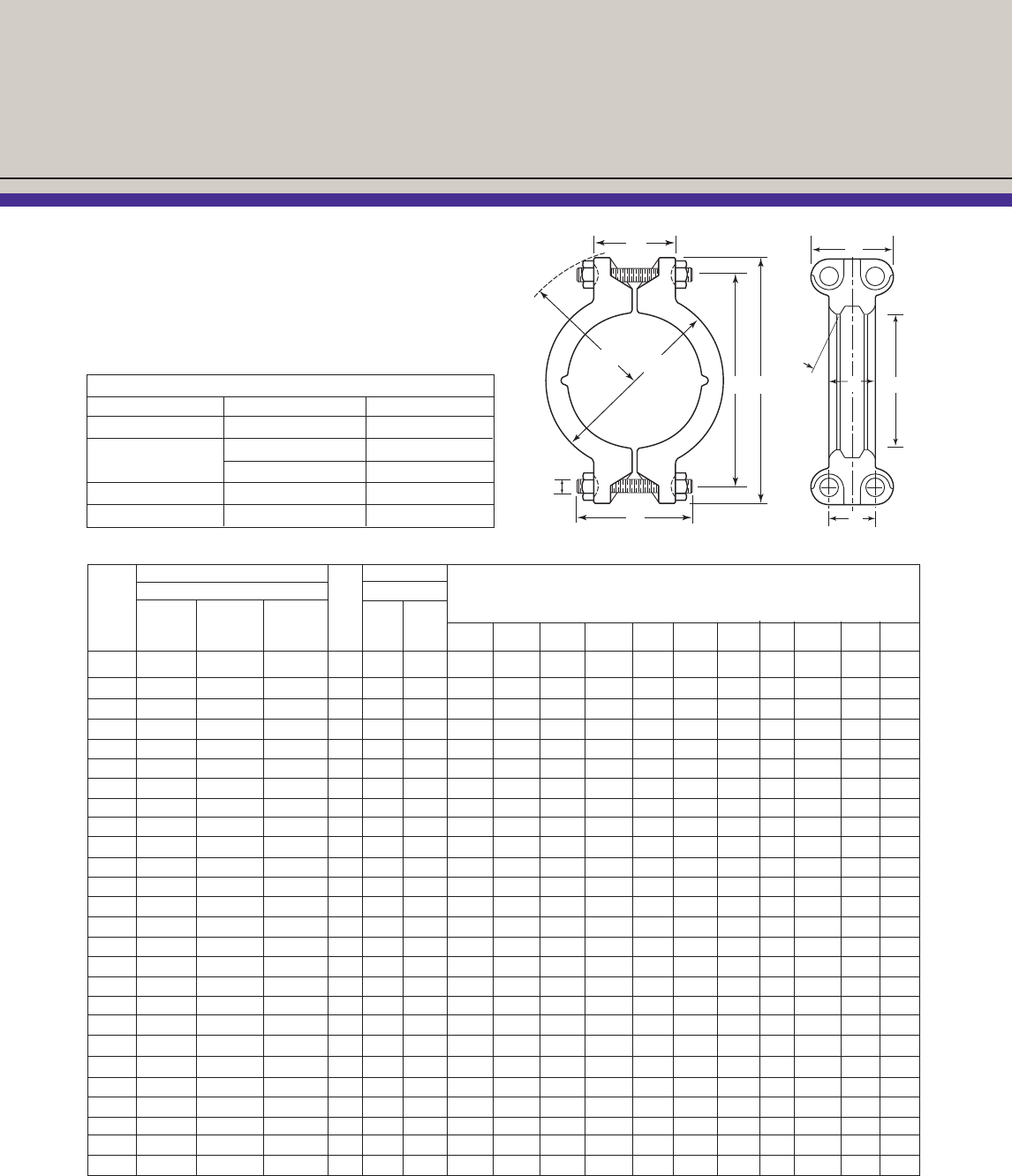
Part Numbers / Dimensions
Clamp Assemblies
Grayloc®connector clamp part numbers with the
WB suffix are complete with bolting. Both clamps
and bolting can be individually purchased if requir-
ed. Refer to page 29 for required bolting torque.
Part Number Part Number
Clamp Assembly w/Bolting Stud w/Nut Dimensions (inches)
Approx.
Clamp Carbon Alloy Stainless Wt. Carbon Stainless
Size Steel Steel Steel (lb.) Steel Steel AB CD EFGHIJK
1 49513WB A90019-5WB 50163WB 3.3 70944 70359 1.687 3.187 2.813 4.250 1.375 2.250 2.625 1⁄23.500 2.313 1.250
11⁄249500WB A90043-1WB 48501WB 9.8 69001 70442 2.687 5.000 4.500 6.500 2.000 3.250 4.000 5⁄85.000 3.125 1.625
2 49501WB A90148-5WB 48502WB 13.5 69002 70443 3.188 5.750 5.062 7.500 2.000 3.625 4.500 3⁄45.250 3.500 1.813
21⁄2-3 49502WB A90413-6WB 48503WB 20.5 69003 70444 4.375 7.500 6.875 9.250 2.375 4.500 5.250 3⁄46.000 3.500 1.813
4 49503WB A90372-4WB 48504WB 31.4 69006 70445 5.375 8.500 8.125 10.500 2.375 5.250 6.000 7⁄87.000 4.063 2.063
5 50214WB 51727WB 161959WB 44.0 69008 70437 6.875 10.250 9.750 12.375 3.000 6.125 7.375 1 8.500 4.438 2.313
6 49508WB A90059-2WB A90059-6WB 68.0 69009 70446 8.375 12.625 12.000 15.000 3.500 6.625 8.750 11⁄89.375 4.813 2.437
8 A90099-1WB A90099-1WB 125600WB 95.0 69010 70447 10.625 15.250 14.500 18.250 3.500 7.500 9.875 11⁄410.500 5.875 2.875
X8(4) 166399WB 166399WB 124202WB 135 69027 70449 10.625 16.250 15.125 19.000 4.125 7.500 10.750 13⁄811.000 6.000 3.250
10H A90444-9WB A90444-9WB 49539WB 230 69028 70448 12.250 18.250 17.625 22.000 5.500 10.000 12.750 15⁄814.125 7.375 3.625
X10H(4) 49133WB ...... 49589WB 325 69033 70438 12.250 19.500 18.250 23.500 6.500 10.000 13.500 13⁄416.000 7.500 3.750
12M H90788-10 H90788-10 49540WB 295 69033 70438 14.625 22.000 20.250 25.750 5.750 10.000 14.500 13⁄416.000 7.500 3.750
X12M(4) 49135WB A90445-2WB 49460WB 500 69035 70482 14.625 23.250 21.500 27.250 7.250 11.000 15.750 2 18.500 8.500 4.500
X14 H90315-11WB A90648-1WB H90315-5WB 252 71763 128545 16.375 22.250 21.375 26.000 5.000 10.875 14.500 15⁄817.000 7.375 3.625
P 49137WB H90847-2WB 50268WB 405 70091 70484 17.125 25.000 23.000 29.000 6.062 10.000 16.000 2 16.500 8.250 4.250
5P 138197WB H90316-10WB ...... 796 69795 ...... 17.125 28.000 25.625 33.000 8.000 12.250 18.625 21⁄220.000 10.500 5.500
S 49139WB H90328-7WB ...... 899 69605 137732 19.687 30.125 27.500 34.625 8.750 12.500 19.750 21⁄222.000 10.500 5.500
X16 A90649-1WB A90649-1WB 11580WB 276 71762 100666 18.625 24.000 23.625 27.750 5.000 13.000 15.625 13⁄419.500 7.625 3.875
U 49142WB H90471-3 49417WB 992 ...... 137732 23.687 33.875 31.250 39.000 8.750 14.000 21.500 21⁄222.000 11.000 5.500
X18 H90287-4 ...... ...... 300
H90136-18
.... 20.875 25.750 25.875 29.500 5.000 14.375 17.500 17⁄821.500 8.000 4.125
3V 49143WB H90883-2 ...... 982 106889 ...... 24.687 35.000 32.937 39.250 8.000 13.000 22.000 21⁄424.000 9.250 5.000
X20 49144WB ...... ...... 384 114791 ...... 23.625 28.312 29.125 32.187 5.000 17.125 18.750 2 24.750 8.500 4.375
X24 H90789-3WB ...... 100667WB 649
H90136-172
...... 28.625 34.250 34.560 38.875 6.250 18.375 22.500 21⁄427.000 9.500 5.000
3W ...... ...... ...... 1131 ...... ...... 28.187 37.000 36.437 41.500 8.000 20.000 23.250 21⁄229.500 11.000 5.500
3Y(5) 23559WB ...... ...... 1500 ...... ...... 29.937 44.000 42.500 48.000 12.687 18.500 33.000 31⁄425.500 14.250 7.500
30(5) 49523WB ...... ...... 625 69026 70483 32.313 40.500 37.875 45.000 5.750 13.250 24.750 21⁄420.750 9.500 5.000
(1) Stud material. SA193-B7; nut material, SA194-GR2 or 2H.
(2) Stud material, SA193-B8, solution treated; nut material, SA194-GR8.
(3) Includes weight of studs and nuts.
(4) X clamp sizes are heavy-duty to uprate connections. Sizes of corresponding hubs and seal rings do not change when X clamps are used.
(5) Available in three-piece, six-bolt construction only.
F
D
B
I
GC
J
E
K
A
H
25°
Clamp Materials
Carbon Steel Alloy Steel Stainless Steel
SA266-GR3 SA193 B7/B7M SA182-F304
SA487-GR 1B, AISI 4140 SA182-F316
2B,4B or 4A SA182-F22 SA351-CF8M
SA217-WCB
(3) (1) (2)
SA217-WC9
Part Number
Carbon Steel - NACE(2) AISI 630 (17-4 PH) SS
-50° to + 350° F(1) -452° to +450°F(1) -452° to +750°F(1) Dimensions (inches)
Seal MoS2with MoS2with Approx.
Ring PTFE Graphite PTFE Graphite Weight
Size Coated Coated Coated Coated (lb.) A C D E F
4 50554N 50586N 51230N 51267N 0.04 0.500 1.000 0.375 0.125 0.125
5 50563N 50587N 51231N 51268N 0.05 0.625 1.094 0.375 0.125 0.125
7 66020N 50588N 51232N 51269N 0.06 0.906 1.375 0.375 0.125 0.125
11 50551N 50589N 51233N 51270N 0.08 1.125 1.734 0.375 0.125 0.125
14 50553N 50591N 51235N 51272N 0.31 1.610 2.625 0.563 0.250 0.156
16 H90026-3 50605N 51205N 66203N 0.41 1.868 2.688 0.625 0.250 0.188
20 50557N 50592N 51236N 51273N 0.50 2.063 3.250 0.750 0.250 0.250
23 50569N 146396N 66175N 51284N 0.54 2.375 3.500 0.750 0.250 0.250
25 50570N 50593N 51237N 51274N 0.70 2.672 4.000 0.750 0.250 0.250
27 50622N 50594N 51238N 51275N 0.70 3.063 4.250 0.750 0.250 0.250
31 50561N 50595N 51239N 51276N 0.76 3.250 4.500 0.750 0.250 0.250
34 50562N 50596N 51240N 51277N 0.89 3.688 5.000 0.750 0.250 0.250
40 66040N 50597N 51241N 51278N 1.28 4.063 5.500 1.000 0.250 0.375
42 151677 H90364-3 103727 51186N 1.35 4.188 6.625 1.000 0.250 0.375
46 66041N 66100N 51245N 66225N 1.58 4.750 6.188 1.000 0.250 0.375
52 50623N 50598N 51242N 51133N 1.65 5.313 6.625 1.000 0.250 0.375
62 50566N 50599N 51243N 51279N 4.00 6.065 7.875 1.375 0.375 0.500
67 H90643-3 H90643-26 H90643-1 H90643-15 4.50 6.875 8.750 1.375 0.375 0.500
72 50567N 50618N 51246N 66242N 4.95 7.250 9.500 1.375 0.375 0.500
76 66042N 166380N 51247N 66226N 5.58 7.750 10.000 1.375 0.375 0.500
82 66043N 142024N 51248N 66227N 5.16 8.250 10.125 1.375 0.375 0.500
84 66044N 66102N 51249N 66228N 6.72 8.500 11.125 1.375 0.375 0.500
87 66057N 50601N 51229N 66244N 6.97 8.875 11.500 1.375 0.375 0.500
91 167659N 66526N A90368-2 ...... 7.10 9.125 13.000 1.375 0.375 0.500
94 66817N ...... 66176N 66229N 7.24 9.500 12.000 1.375 0.375 0.500
97 66046N H90041-4 66177N 66230N 8.00 9.875 12.000 1.375 0.375 0.500
102 50564N 50616N 66178N 51283N 6.08 10.250 12.000 1.375 0.375 0.500
106 50692N ...... ...... 66199N 7.00 10.750 12.625 1.375 0.375 0.500
112 66047N 50584N 66179N 66231N 13.44 11.250 14.125 1.625 0.625 0.500
120 66048N 159280N 66180N 66232N 7.42 12.000 13.875 1.375 0.375 0.500
122 ...... 66791N ...... 66233N 8.00 12.250 14.125 1.375 0.375 0.500
125 ...... ...... ...... ...... 8.50 12.625 14.500 1.375 0.375 0.500
130 66050N 159281N 66182N 66234N 9.00 13.000 15.000 1.500 0.500 0.500
134 66793N ...... 66183N 66235N 10.00 13.500 15.500 1.500 0.500 0.500
137 50568N 50606N 50443N 50440N 10.50 13.875 16.500 1.625 0.625 0.500
140 72691N 159278N 66624N 66198N 11.00 14.000 16.500 1.500 0.500 0.500
144 ...... ...... ...... ...... 12.50 14.500 17.000 1.500 0.500 0.500
152 ...... 66108N 66184N 66236N 14.00 15.250 17.750 1.500 0.500 0.500
160 122371N 159279N 72761N 66246N 15.50 16.000 18.500 1.500 0.500 0.500
162 ...... ...... ...... ...... 15.80 16.250 18.500 1.500 0.500 0.500
164 H90818-1N H90818-2 H90818-3 H90818-4 16.00 16.500 18.750 1.500 0.500 0.500
170 66052N 66109N ...... 66237N 18.00 17.000 19.500 1.750 0.500 0.625
180 170091N 128160N ...... 66599N 19.00 18.000 20.500 1.750 0.500 0.625
182 ...... ...... ...... ...... 19.00 18.250 20.500 1.750 0.500 0.625
192 ...... ...... 66186N 66238N 20.00 19.250 22.000 1.750 0.500 0.625
200 118230N 66530N 66939N 66726N 21.00 20.000 22.750 1.750 0.500 0.625
210 66723N 66114N 50442N 50439N 21.00 21.000 24.000 2.000 0.500 0.750
215 ...... ...... ...... ...... 21.50 21.625 24.125 2.000 0.500 0.750
220 ...... 50982N ...... 72916N 22.00 22.000 25.000 2.000 0.500 0.750
226 ...... ...... ...... ...... 22.50 22.750 25.250 2.000 0.500 0.750
232 ...... ...... ...... ...... 23.75 23.245 26.375 2.000 0.500 0.750
240 ...... ...... ...... ...... 24.00 24.000 27.250 2.000 0.500 0.750
244 ...... 66115N 50441N 66249N 25.00 24.500 27.750 2.000 0.500 0.750
17
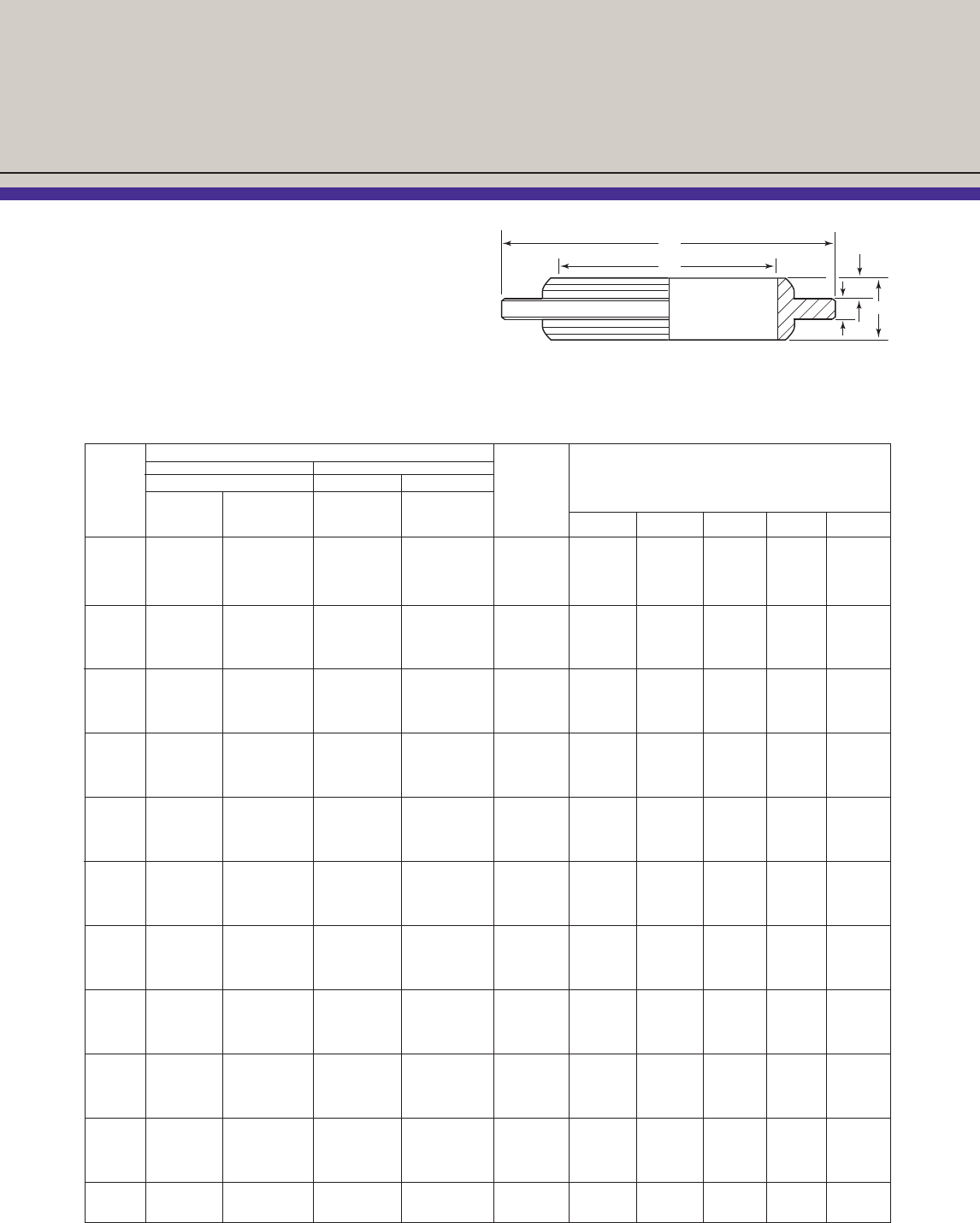
Part Numbers / Dimensions
Seal Rings
Grayloc®seal rings are available in a number
of carefully selected materials and are coated
to provide lubrication during makeup. For appli-
cations greater than 750° F., consult Grayloc
Products for proper selection of materials and
coatings. Seal rings manufactured from materials
or coatings other than those named may be
furnished to meet specific service conditions.
(1) Temperature is a major factor in the selection of the proper seal ring, but consideration also must be given to the effect the flow medium will have on the
material and coating selected.
(2) Grayloc seal rings are certified to NACE MR-01-75.
C
A
D
E
F
Other Products and Piping Accessories
Seal Rings
Transition Seal Rings
In normal piping applications, the same Grayloc®
clamps are used for all schedules of a given
size pipe. The ring, however, can vary with the
schedule of pipe. Transition rings can be special
ordered to connect hubs of the same size that
have different ring seats. Transition hubs (reduc-
ing and enlarging) are recommended when
designing transition piping.
Blind Seal Rings
❖Are used for isolating sections of pipe and
in-line blind service
❖ Pressure ratings available upon request
❖Suitable for many normal operating conditions
❖High pressure applications should be
evaluated by Grayloc Products
Restriction Seal Rings
❖Are used in restriction service to reduce flow
❖Excellent and quick means of installing restric-
tion plates into lines with Grayloc connectors
❖Provides pressure drop or regulates flow where
precise metering is not required
Orifice Seal Rings
❖Meets the requirements of American Gas
Association (A.G.A.)
❖Can be manufactured with replaceable
orifice plates
❖Integral orifice plate design
18
Transition Seal Ring
Blind Seal Ring
Restriction Seal Ring
Orifice Seal Ring
Other Products and Piping Accessories
19
❖Can be furnished for piping
systems of high strength
material (X-52, HY-100, T-1)
to comply with API standards
for service up to 30,000 psi
❖Contact a Grayloc Products
representative for additional
information on applications,
sizes, and materials
Heavy Duty Butt Weld Hubs
Seal Dimensions (inches) Approx.
Hub Ring Clamp Hub I.D. Wt.
Size Size Size A C D(1) E F (lb.)
B 20 20 B 2.062 4.750 3.250 3.750 0.625 10.0
C 25 25 C 2.672 5.500 3.500 4.500 0.625 13.5
D 31 31 D 3.250 6.750 4.000 5.750 0.625 22.5
E 40 40 E 4.062 7.500 4.375 6.500 0.625 28.0
F 40 40 F or XF 4.062 9.250 4.625 7.750 0.812 45.5
G 72 72 G or XG 7.250 11.500 5.375 9.500 1.000 50.0
Heavy Duty Clamps
Part Number
Carbon Steel Dimensions (inches) Approx.
Clamp A1S1 1045 Studs Wt.
Size Q & T w/Nuts(2) A B C D E F G H I J K (lb.)(1)
B 50209G 69007 4.125 7.250 6.875 9.000 2.875 5.000 5.500 0.875 6.750 3.750 2.000 27.00
C A90090-1(3) 69006 4.875 8.000 7.750 10.000 3.000 5.250 6.000 0.875 7.000 4.062 2.062 29.95
D A90037-1(3) 69008 6.125 9.562 9.000 11.750 3.000 5.750 7.000 1.000 8.500 4.437 2.312 42.51
E 51727(3) 69008 6.875 10.250 9.750 12.375 3.000 6.125 7.375 1.000 8.500 4.437 2.312 52.00
F A90059-2(3) 69009 8.375 12.625 12.000 15.000 3.500 6.625 8.750 1.125 9.375 4.812 2.437 73.00
XF H90662-1(3) 71548 8.375 12.625 12.875 15.000 4.000 8.375 9.125 1.125 11.750 4.812 2.437 86.00
G 123218(3) 69027 10.125 16.000 14.750 18.750 4.500 7.000 10.625 1.375 11.000 6.000 3.125 133.0
XG H90759-4(3) 136609 10.125 16.000 15.625 19.125 5.125 9.250 11.125 1.375 13.250 6.000 3.125 190.0
A
E
D
F
C
25°
D
B
I
H
F
C
G
KE
A
J
25°
For oilfield applications or when
pressure ratings exceed those
of common ANSI flanges and
standard Grayloc®connectors
(refer to page 29 for API flange
to Grayloc connector conversion
chart).
(1) Hub length may increase when used with wall thickness in excess of standard pipe schedules.
(1) Includes weight of studs and nuts. (2) Stud material - SA193-B7; nut material - SA194-GR2 or 2H.
(3) Clamp material - SA193 B7.
Heavy-Duty
Connectors
20
Other Products and Piping Accessories
Since Grayloc®connectors are
very versatile, they can be
used in many diverse applica-
tions. Some applications are
suggested in the following
examples. Special applications
may require custom design.
Contact the nearest Grayloc
Products representative for
special product assistance.
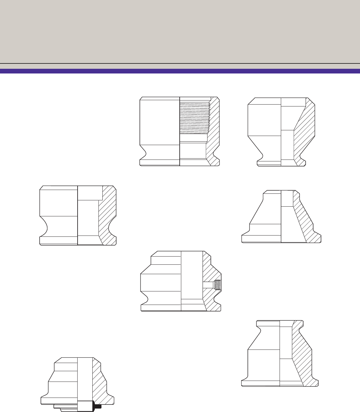
Socket Weld Hubs
❖Designed for socket welding
to standard and special pipe
sizes
❖Female socket weld ends and
male pin-type socket weld
ends are available
❖Socket weld hub lengths
are the same as the “D”
dimensions for butt
weld hubs
Streamline Bore Hubs
❖Unobstructed bore design
❖Manufactured for sanitary
processes
Threaded Hubs
❖N.P.T. threads in accordance
with Screw-Thread Standards
in Federal Services H-28
Handbook
❖External threads and
industrial or customer
standards are available
Pressure-Tapped Hubs
❖Used for instrumentation,
chemical injection, flushing
or sampling.
❖Eliminates the problem of
drilling and tapping after the
system is assembled
❖Can be threaded to customer
specification, e.g., N.P.T.
and MC
Reducing Hubs
❖Joins pipe of one diameter
to pipe, vessel nozzles,
or similar fittings of a
different diameter
❖Eliminates the need for
concentric reducers
Adapters
❖Used to join different-sized
Grayloc hubs already fabri-
cated to the pipe
❖Equivalent of concentric re-
ducers in a welded system
Enlarging Hubs
21
Other Products and Piping Accessories
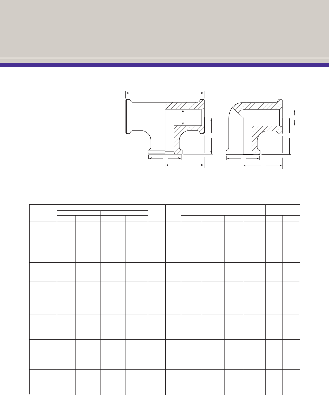
Fittings
To reduce space and make
complicated piping assemblies
easier to install and maintain,
a full line of Grayloc®tees and
ells are available.
❖Manufactured from closed
die/block forgings and
castings
❖Minimum centerline-to-face
dimensions
❖Crosses are available
upon request
Part Number (2) Seal Approx.
Hub Tee Ell Ring Clamp Dimensions (inches) Weight (lb.)
Size SA105 SA182-F316 SA105 SA182-F316 Size Size A B C D Tee Ell
1 GR 4 54791 54795 54798 54804 4 1 0.500 3.000 2.000 6.000 3.5 2.5
1 GR 5 54792 54796 151698 54805 5 1 0.625 3.000 2.000 6.000 3.5 2.5
1 GR 7 54793 54412 H90284-7 54414 7 1 0.906 3.000 2.000 6.000 3.0 2.0
1 GR 11 54794 54797 54801 54807 11 1 1.125 3.000 2.000 6.000 3.0 2.0
11⁄2GR 11 54169 54241 54106 54153 11 11⁄21.125 4.000 3.125 8.000 19 12
11⁄2GR 14 54173 54242 54107 54156 14 11⁄21.610 4.000 3.125 8.000 17 10
2 GR 11(1) 54355 54367 54377 54386 11 2 1.125 4.063 3.625 8.125 20 13
2 GR 14 54178 54243 54114 54162 14 2 1.610 4.000 3.625 8.000 18 11
2 GR 20 54179 54244 54117 54129 20 2 2.063 4.000 3.625 8.000 16 10
21⁄2GR 20 54180 54245 54118 54163 20 21⁄2-3 2.063 5.375 5.000 10.750 65 33
21⁄2GR 25 54196 54246 54119 54145 25 21⁄2-3 2.672 5.375 5.000 10.750 53 26
3 GR 20 54180 54245 54118 54163 20 21⁄2-3 2.063 5.375 5.000 10.750 65 33
3 GR 25 54196 54246 54119 54145 25 21⁄2-3 2.672 5.375 5.000 10.750 53 26
3 GR 27 54197 54247 54122 54146 27 21⁄2-3 3.063 5.375 5.000 10.750 45 21
4 GR 25 54360 54369 54379 54388 25 4 2.672 6.000 6.000 12.000 78 45
4 GR 31 54356 54354 H90635-1 54168 31 4 3.250 6.000 6.000 12.000 65 40
4 GR 34 54357 54316 54126 154033 34 4 3.688 6.000 6.000 12.000 55 35
4 GR 40 54358 54352 54125 54174 40 4 4.063 6.000 6.000 12.000 40 30
5 GR 31 54940 54370 54380 54389 31 5 3.250 8.000 7.500 16.000 200 160
5 GR 34 54941 54371 54381 54390 34 5 3.688 8.000 7.500 16.000 185 150
5 GR 40 147274 54233 54123 54147 40 5 4.063 8.000 7.500 16.000 175 140
5 GR 46 54942 54372 54382 54391 46 5 4.750 8.000 7.500 16.000 145 120
5 GR 52 54232 54373 54144 54213 52 5 5.313 8.000 7.500 16.000 120 90
6 GR 40(1) 54943 54375 54384 54393 40 6 4.063 9.125 9.250 18.250 335 275
6 GR 46(1) 54944 54376 54385 54394 46 6 4.750 9.125 9.250 18.250 300 250
6 GR 52 54203 54253 H90284-6 54181 52 6 5.313 9.000 9.250 18.000 275 230
6 GR 62 54206 54254 54130 54182 62 6 6.063 9.000 9.250 18.000 230 190
(1) Hub with recessed seal ring seat.
(2) For small quantity orders, items may be furnished from block forgings instead of contoured forged profiles as shown above. Part numbers for block
shaped tees/ells may be different than those shown above.
A
D
B
C
B
A
B
B
C
Other Products and Piping Accessories
22
Special Connectors
Shrouded Bore Connector
The Grayloc®seal ring can be protected in
environments where thermal cycling occurs
and in erosive service. To achieve this protection,
non-erosion rings are recommended to shroud
the bore. The shroud consists of two insertable
pieces usually made from similar material as the
hub. However, it can also be machined integral to
the hub, which eliminates the insertable ring.
Insulating Connector
Grayloc insulating connectors are used in piping
systems to prevent galvanic action or where it is
necessary to electrically isolate one section of
pipe. Grayloc clamps and seal rings are selective-
ly coated with a specialty polymer coating. The
connectors are tested before shipment to assure
a minimum resistance of 200 megohms at 500
volts DC.
Orifice Union
Designed to accommodate “flange-type” pressure
taps and universal-type orifice plates.
❖Orifice plate held in position by hold down
screws
❖“Flange-type” pressure taps, perpendicular to
the bore, are drilled directly into hubs
❖Pressure taps are usually 1/2" N.P.T., but can
vary in size and type according to customer
specifications
❖Only the orifice plate is exposed to the flow
The Grayloc seal ring and orifice plate can be
manufactured as an integral unit assuring a leak-
free seal in conjunction with a quick disconnect
measuring device.
Shrouded Bore Connector
Shroud
Insulating Connector
Seal Ring
Entirely Coated
Inside Clamp
Profile Coated
Orifice Union
Orifice Seal Ring
Other Products and Piping Accessories
23
Non Flow-Through Jacketed Connector
Jacket Pipe
Jacketed Connectors
Flow-Through
Jacketed Connector
❖Unobstructed (Streamline)
bore design
❖Provides in-line passage of
the jacket fluid through the
connector
❖Metal seal for core pipe pre-
vents contamination of fluid or
leakage to the atmosphere
❖External jacket seal is formed
by a face seal gasket
❖Uniform heat transfer
Non Flow-Through
Jacketed Connector
Grayloc non flow-through con-
nectors are designed to accomo-
date both core and jacket piping.
These connectors can be used
with jumper piping or double pipe
heat exchangers. A streamline
bore is also a standard for these
connectors.
Face Gasket
Butt weld Jacketed
Flow-Through Hub
Bolting
Grayloc
Seal Ring
Alignment Pin
Clamp
Flow-Through Jacketed Connector
Core Pipe
Streamline
Bore Design
Streamline
Bore Design
24
Other Products and Piping Accessories
Remotely Operated
The Grayloc®remotely oper-
ated connector is a field-proven
mechanical connector used
in hazardous environments,
personnel restricted areas,
and automated (batch-type)
operations. Like the standard
Grayloc connector, the remotely
operated connector has metal-
to-metal seal integrity.
Operation
❖Simple, reliable trunnion and
screw mechanism
❖Single drive screw adaptable
to different power drives
❖Self-supporting base plate
❖Retained seal ring
❖Can be manually operated
Design Technology
❖Zero leak rate (10-6 atm
cc/s Helium)
❖Quick disconnect, opens /
closes in seconds
❖Compatible with hydraulic,
pneumatic, or electric power
❖Unitized design
Pipe O.D.
Pipe I.D.
Top View Side View
Connectors
25
Other Products and Piping Accessories
Grayloc®Compact
❖Smaller and lighter than
standard ANSI/API flange
❖Using the self-energizing
seal ring, the flange has a
higher tolerance to vibration,
temperature extremes,
and external loading
❖Off-the-shelf studs and nuts
❖The rating of a flanged con-
nection can be upgraded if
a Grayloc seat is machined
in the face and bore of the
connection to accept the
Grayloc seal ring
Pipe
18" - 1500 Class GCF weldneck
O.D. 31"
Weight 680 lbs.
18" - 1500 Class ANSI weldneck
O.D. 36"
Weight 1625 lbs.
Grayloc Seal Ring
Grayloc Compact Flange (GCF)
Flanges
26
Other Products and Piping Accessories
❖For corrosive environments, seats and nozzle bores can be
protected with weld-deposited overlays or liners
❖Sealing surfaces of standard carbon and low alloy steel nozzles
are protected by electroless nickel coating
❖Standard lengths and sizes are listed in the following chart, other
configurations are available based on application.
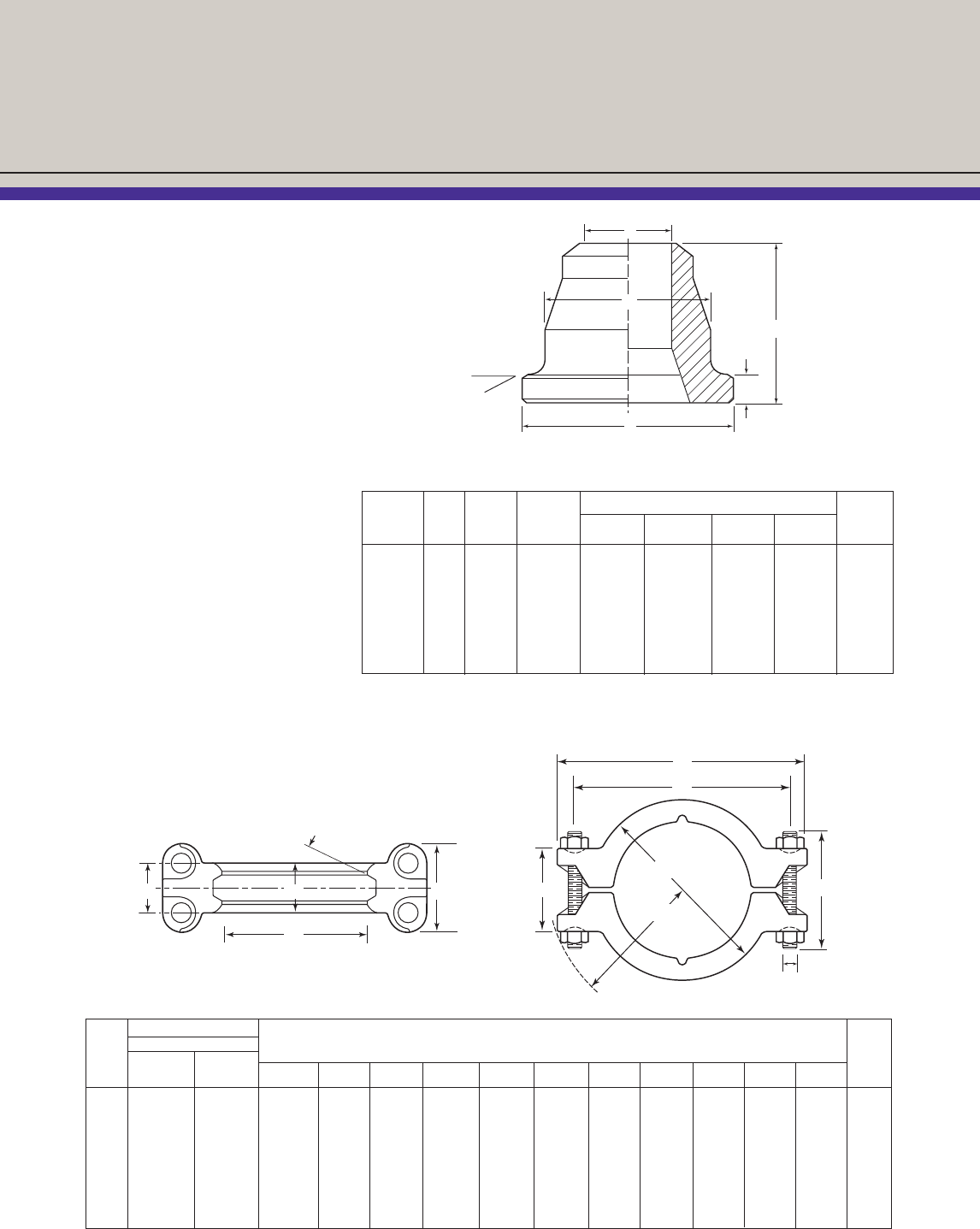
Nozzles
Grayloc®nozzles are designed
for pressure vessels that require
longer nozzle projections.
❖Manufactured with extra wall
thickness to allow welding
directly to the vessel with no
additional reinforcement
❖Stub end may be saddled
or otherwise machined to
match the contour of the
vessel wall
❖Available in most
machinable materials
Approx.
Connector Part Number Ring Clamp Dimensions (inches) Weight
Size SA105 SA182-F316(2) Size Size A B(3) C T (lb.)
1 GR4 54938 100757 4 1 0.500 9.000 2.000 0.750 14
1 GR5 54423 H90389-3 5 1 0.625 9.000 2.000 0.688 13
1 GR7 54848 ...... 7 1 0.906 9.000 2.000 0.547 12
1 GR11 54447 54624 11 1 1.125 9.000 2.000 0.438 11
11⁄2GR11(1) 54450 54650 11 11⁄21.125 9.000 3.125 1.000 17
11⁄2GR14 54451 ...... 14 11⁄21.610 9.000 3.125 0.758 15
2 GR11 54486 54630 11 2 1.125 9.059 3.625 1.250 24
2 GR14 54454 54605 14 2 1.610 9.000 3.625 1.007 21
2 GR20 54453 54629 20 2 2.063 9.000 3.625 0.781 18
21⁄2GR20 54928 54632 20 21⁄2-3 2.063 9.000 5.000 1.468 55
21⁄2GR25 54458 54631 25 21⁄2-3 2.672 9.000 5.000 1.164 48
3 GR20 54928 54632 20 21⁄2-3 2.063 9.000 5.000 1.468 55
3 GR25 54458 54631 25 21⁄2-3 2.672 9.000 5.000 1.164 48
3 GR27 54457 54904 27 21⁄2-3 3.063 9.000 5.000 0.968 41
4 GR25 54489 54635 25 4 2.672 12.000 6.000 1.664 78
4 GR31 54461 54636 31 4 3.250 12.000 6.000 1.375 68
4 GR34 54460 54911 34 4 3.688 12.000 6.000 1.156 60
4 GR40 54459 54973 40 4 4.063 12.000 6.000 0.968 52
5 GR31 ...... ...... 31 5 3.250 12.000 7.500 2.125 122
5 GR34 ...... ...... 34 5 3.688 12.000 7.500 1.906 113
5 GR40 ...... ...... 40 5 4.063 12.000 7.500 1.718 106
5 GR46 ...... ...... 46 5 4.750 12.000 7.500 1.375 90
5 GR52 ...... ...... 52 5 5.313 12.000 7.500 1.093 75
6 GR40(1) ...... ...... 40 6 4.063 12.125 9.250 2.593 184
6 GR46(1) ...... ...... 46 6 4.750 12.125 9.250 2.250 168
6 GR52 54463 56121 52 6 5.313 12.000 9.250 1.968 153
6 GR62 ...... ...... 62 6 6.063 12.000 9.250 1.593 130
(1) Hub with recessed seal ring seat. (2) SA479TP316 may be substituted based on material availability.
(3) Nozzle lengths can be supplied based on customer requirements.
C
B
T
A
27
Other Products and Piping Accessories
Thermowells
Grayloc®thermowell one-piece,
solid construction assemblies
are smaller and lighter than
flanged thermowell assemblies.
Metal-to-metal sealing makes
Grayloc thermowell assemblies
capable of higher pressures
and temperatures.
Hinged Vessel
Closures
Grayloc hinged closures are
used as manways on pressure
vessels in many industrial
applications. They have all the
design features of the basic
Grayloc connector plus the
advantage of fixed mounting
onto the vessel.
❖Effective, dependable, conve-
nient, simple makeup
❖Clamp hanger assembly
supports the clamp segments
that remain in position
around the outside of the
nozzle when fully open
❖Blind hub can be hinged
vertically or horizontally for
maximum accessibility
❖Blind hub swings easily into
position with no alignment
or lifting of heavy parts
❖Seal ring is retained with
either the blind hub or nozzle
to protect its sealing surfaces
when the closure is open
❖Manufactured to conform
to the requirements of ASME
Codes, Sections I and VIII
❖If required, complete design
evaluations, ASME Code
stamping, ASME partial data
report and detailed stress
analysis can be furnished
Hinged Vessel Closure
Thermowell
Thermowell
Hub / Nozzle
Seal Ring Clamp
Vessel
Top View
Handle
Closed position
Blind hub/hinge pin assembly Open position
Other Products and Piping Accessories
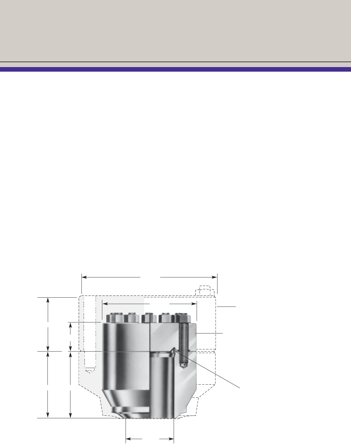
Studded Vessel
Closures
Grayloc®studded vessel
closures offer cost savings and
design advantages for manu-
facturers of pressure vessels,
pump, and heat exchangers.
❖Sizes range from 8" to 60"
in diameter and from 1,000
to 32,000 psi operating
pressure
❖Variations in diameter, size,
and spacing of studs on stan-
dard sizes can be specified,
as well as other closure sizes
and pressure ratings that
require special design
❖Typical studded vessel
closure materials include
SA105, SA350 LF2, SA182
F22 and SA182 F316.
Closures are designed base
on the adjoining pressure
vessel material
❖Seal surfaces of unlined
closures are protected from
oxidation by electroless
nickel plating unless other-
wise specified
❖Corrosion-resistant liners
and protective weld overlays
are available
❖Studs through 4" are furnish-
ed with heavy-duty nuts, and
larger studs are furnished
with sleeve nuts
❖In some applications, stud
tensioners are not required
❖Unless specified otherwise,
closures comply with the
ASME Boiler and Pressure
Vessel Code, Section VIIl
and can be designed in
accordance with Section I
or customer-specified
requirements
❖Seal ring is recessed to ease
assembly and prevent dam-
age from overtightening
❖Varied weld end preparation
available to suit fabrication
requirements
28
Design: Type: Delta Seal Gasket
Weight: Approx. 6800 lbs.
Bolting: (16) 23⁄4" bolts
Design: Type: Grayloc Studded Closure
Weight: Approx. 2700 lbs.
Bolting: (12) 23⁄4" bolts
Grayloc Seal Ring
57⁄8"
21"
27" O.D.
12"
21"
16" I.D.
35" O.D.
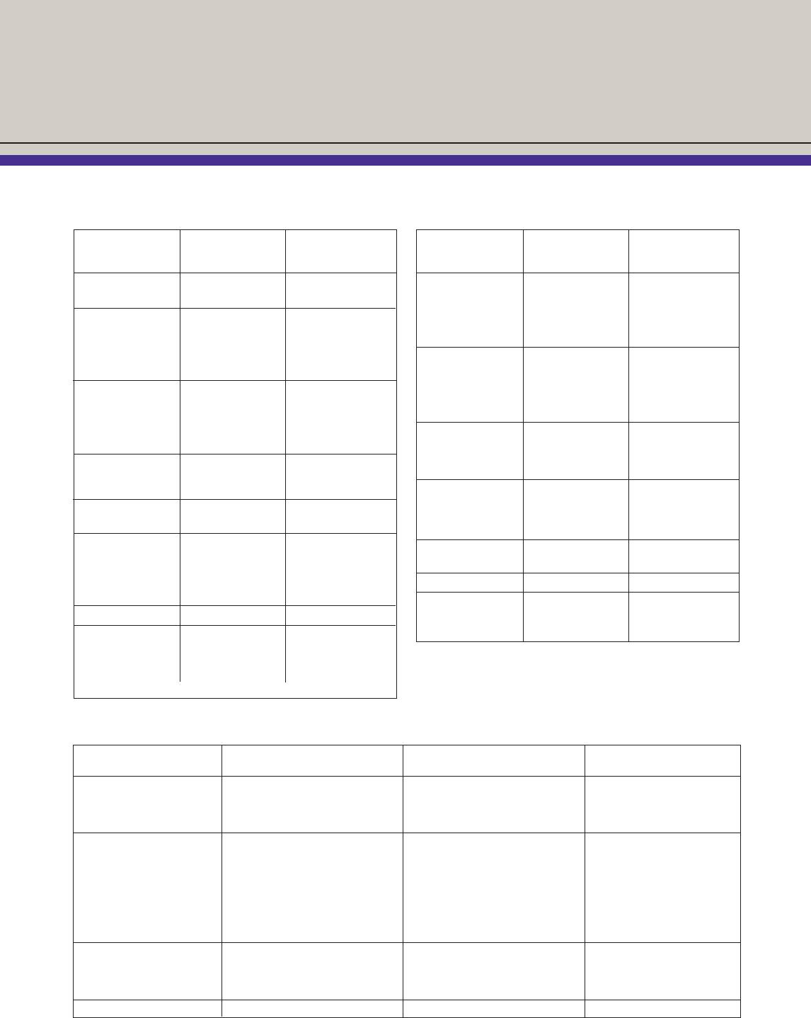
Conversion and Torque Requirements
Nominal Size & Bore Maximun Corresponding
of API Flange Working Pressure Grayloc
(inches) (psi) Connector
113⁄16 10,000-6BX B16
15,000-6BX B16
21⁄16 2,000-6B B20
3,000-6B B20
5,000-6B B20
10,000-6BX B20
15,000-6BX B20
29⁄16 2,000-6B C25
3,000-6B C25
5,000-6B C25
10,000-6BX C25
15,000-6BX C25
31⁄82,000-6B D31
3,000-6B D31
5,000-6B D31
31⁄16 10,000-6BX D27
15,000-6BX D27
41⁄16 2,000-6B E40
3,000-6B E40
5,000-6B E40
10,000-6BX F40R
15,000-6BX F40R
51⁄810,000-BX F52
71⁄16 2,000-6B G72
3,000-6B G72
5,000-6B 10H72R
10,000-6BX 10H72R
15,000-6BX X12M72R
API Flange to Grayloc
®
Connector Conversion
Bolting Torque Required for Grayloc Clamps*
Nominal Size & Bore Maximun Corresponding
of API Flange Working Pressure Grayloc
(inches) (psi) Connector
9 2,000-6B 10H91
3,000-6B 10H91
5,000-6B 10H91
10,000-6BX 12M91
15,000-6BX X12M91
11 2,000-6B 12M112
3,000-6B 12M112
5,000-6B 12M112
10,000-6BX S112
15,000-6BX *
135⁄82,000-6B R137
3,000-6B R137
5,000-BX S137
10,000-6BX 5V137
163⁄42,000-6B T170
3,000-6B V170
5,000-6BX 3V170
10,000-6BX *
183⁄45,000-6BX *
10,000-6BX *
203⁄43,000-6B V210
211⁄42,000-6B *
5,000-6BX *
10,000-6BX *
Stud Bolt Stud Bolt Average
Size Length (inches) Clamp Size Torque (ft.-lb.)
1⁄2-13UNC-2 31⁄2117
5⁄8-11UNC-2 5 11⁄235
3⁄4-10UNC-2 51⁄4, 6 2, 21⁄2, 3 55
7⁄8-9UNC-2 7, 63⁄44, C, B 90
1-8UNC-2 81⁄25, D, E 140
11⁄8-8N-2 93⁄86, F 205
11⁄4-8N-2 101⁄28 290
11⁄8-8N-2 113⁄4XF 330
13⁄8-8N-2 11 X8, G, XG 390
15⁄8-8N-2 141⁄4, 141⁄8, 17 H, 10H, X14 630
13⁄4-8N-2 16, 191⁄2X10H, 12M, X16 870
17⁄8-8N-2 211⁄2X18 1170
2-8N-2 161⁄2, 181⁄2, 243⁄4P, X12M, X20 1300
21⁄4-8N-2 27, 203⁄4, 24 X24, 30, 3V 1870
21⁄2-8N-2 22, 31, 291⁄2, 20 S, U, 32, 36, 3W, 5P 2570
23⁄4-8N-2 283⁄4Y 3500
31⁄4-8N-2 351⁄240 7100
* Please consult Grayloc Products for special Grayloc sizing.
Abbreviations: R, recessed seal ring seat.
* Applies to two-piece, four-bolt clamps.
29
Notes: 1. 2,000-5,000 psi use 60 ksi minimum yield material for hub.
2. 10,000-15,000 psi use 75 ksi minimum yield material for hub.
3. 80 ksi minimum yield material required for clamp.

30
Installation and Maintenance Instructions
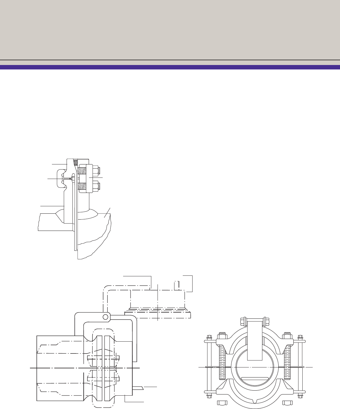
General Information
A complete Grayloc®connector consists of two hubs, one
seal ring, one set of clamps, stud bolts, and spherical-
faced nuts.
Grayloc hubs are furnished with hub protectors that should
be removed only when the hubs are being welded in place,
stress relieved, or when the connection is being assembled.
Fabrication
Grayloc hubs may be fabricated to piping or other compo-
nent equipment by established welding procedures. Initial fit
up and alignment tolerances normally used in the fabrication
of ANSI flanges are also acceptable for the Grayloc hub.
During welding, care should be taken to protect the hub
seat from damage such as scratching and weld spatter.
When required, stress relieving of carbon and low alloy steel
hubs should be done in compliance with applicable industry
codes and requirements. Seats that are nickel-coated must
be clean prior to being placed in the furnace.
Before Assembly
The Grayloc seal ring does not seat until the connection
is fully tightened; therefore, a small clearance, or standoff,
between the ring rib and hub face should be observed when
the ring is placed into a mating hub. If no standoff is present,
use a new seal ring.
Clean all lubricants and foreign matter from the hub seating
surfaces before installation. Use a non-abrasive material to
clean the seal rings of all foreign matter. Normally, all seal
rings have a coating or plating (cadmium, PTFE, MoS2)
which acts as a lubricant during make-up. In some applica-
tions where uncoated/unplated seal rings are used, a light
film of clean lubricant is recommended.
When applying lubricant, take special care to ensure that
no solid or foreign particles are present in the lubricant.
Also, take care to prevent mechanical damage to the seal
ring and the hub sealing surfaces.
Before assembly, the hubs must be aligned to allow engage-
ment of the seal ring lips to the hub sealing surfaces. This
will ensure proper engagement of the hub and clamp seg-
ments. For misaligned systems, it is acceptable to apply
external loads to the mating piping (using jacks, come-
alongs, etc.) to align the hubs prior to assembly.
Assembly
1. Align the hubs so that the seal ring can be installed
between the hubs.
2. Install the seal ring in the sealing surface of the hubs.
The seal ring should rock slightly; i.e., the seal ring rib
should not be able to firmly contact the hub face. If it
does not rock, use a new seal ring.
3. Install the clamps around the hubs. Apply lubrication to
the hub-clamp contact area to reduce friction; this will
aid assembly.
4. Insert the stud bolts into the bolt holes of the clamp ears.
Install the nuts, ensuring that the spherical surfaces of the
nuts and the clamp are in proper position for mating.
Lubrication of the bolting and the spherical faces of the
nuts and the clamp is recommended.
5. Tighten the bolting in a criss-cross pattern (i.e., bolt #1,
#3, #2, #4) to keep the spacing between the clamp
halves approximately equal.
6. To properly preload the Grayloc connector against gasket
loads, fluid pressure loading, thermal shock loading, and
normal pipe reaction loads, the torque values in the table
on page 29 are recommended. Note that torque wrench-
es are not required, but are recommended for large bolt
sizes (15⁄8" and larger) to ensure that the minimum
preload values are met. Assembly should include jarring
the clamps during the bolting procedures, i.e., a sound
blow to the back of the clamp with a soft hammer (torque,
jar, torque, jar, etc.) until bolt torque does not change
after jarring.
7. At full make-up, the hub faces will shoulder flush against
the seal ring rib. The seal ring rib will prevent overtorquing
from causing seal damage, but to prevent permanent
damage from distortion to the other components of the
connection, the maximum torque applied to the connec-
tion should not be more than twice the values shown in
the table. For extreme misalignment and/or extreme pip-
ing loads, torque values 11⁄2to 2 times the table values
are recommended. Lubricated bolting should be used to
assemble the Grayloc connector.
Disassembly
Before disassembling the Grayloc connector, bleed all
pressure from the line. When removing the clamp, first
loosen the bolting and the clamp set from the hubs to allow
the safe release of any trapped pressure. Then, remove the
bolting completely.
Maintenance
Special maintenance is not required for a Grayloc connector
that has been properly assembled. However, when disas-
sembling a connector, check the seal ring for standoff prior
to reassembly and visually inspect the hub seats for unifor-
mity and freedom from burrs and deep scratches. These
irregularities on ring seal surfaces could cause leakage.
Remove scale, rust, burrs, or deep scratches from a ring
seat by lightly polishing with a fine steel wool or crocus
cloth around the seat circumference to ensure uniform
blending-in of the reworked area. Never lap the hub seat
with the seal ring; this practice will damage both the ring
and the seat and prevent an effective seal.
The connector should not be tightened while under pressure
loading or severe mechanical loads. Do not weld on Grayloc
clamps, bolting or seal rings without consulting Grayloc
Products.
All components of the Grayloc assembly should be obtained
only from Grayloc Products or one of its authorized
licensees. Do not substitute non-Grayloc brand parts in
Grayloc connectors. Substituting of parts other than Grayloc
brand components voids all warranties.

31
Standard Terms and Conditions
STANDARD TERMS AND CONDITIONS
FOR SALES AGREEMENTS APPLICABLE TO PRODUCTS/SERVICES
SUPPLIED BY GRAYLOC PRODUCTS, L.L.C. (“GRAYLOC”) TO PURCHASER
1. Acceptance
1.1 Acceptance of any offer to sell by GRAYLOC is limited to Purchaser completely and exclusively accepting all terms and condi-
tions hereof ("Terms"). This Agreement constitutes the entire agreement between the parties and takes precedence over any
and all previous verbal or written arrangements in connection with this Agreement. Any deletions, modifications, alterations of
or additions to the Terms, to be binding, shall be in writing and signed by an authorized representative of GRAYLOC and the
Purchaser. Without limiting the foregoing, it is expressly acknowledged that any Purchaser document received is for order
identification convenience only. Any and all provisions on the face or reverse side of any purchase order, or service order,
which Purchaser may send to GRAYLOC in connection herewith are expressly objected to by GRAYLOC and waived by
Purchaser and made inapplicable to any such purchase, unless both parties expressly agree in writing to include any such
terms and conditions in this Agreement.
1.2 Purchaser's acceptance is hereby expressly limited to the Terms, and acceptance of any part of the products covered hereun-
der shall be deemed to constitute such acceptance. (If this order constitutes an acceptance of an offer, such acceptance is
expressly made conditional on Purchaser's assent to the Terms and any additional or different terms contained herein, and
acceptance of any part of the products covered hereunder shall be deemed to constitute such assent.) GRAYLOC may pro-
vide the products from its affiliated company, in which event these Terms will apply. Purchaser may not assign this
Agreement without the prior written consent of GRAYLOC.
1.3 For any item of GRAYLOC equipment leased to Purchaser, GRAYLOC’s Standard Terms and Conditions of Equipment Lease
shall apply, which terms and conditions are incorporated herein by reference.
2. Limited Warranties
GRAYLOC hereby warrants that all products manufactured by GRAYLOC are free of defects of material and workmanship for a peri-
od of twelve (12) months from the date shipped, providing that the products are used in the service specified and are properly
installed, used and maintained and not altered after initial delivery, corrosion and erosion and normal wear and tear excepted.
Purchaser shall give written notice to GRAYLOC of any defects within thirty (30) days of their discovery by Purchaser, within said
twelve (12) month period, with a report detailing failure and defects. GRAYLOC reserves the right to require prepaid return of the
allegedly defective product to establish a warranty claim. GRAYLOC will, at its option, repair any product found defective during the
warranty period without charge, replace the product F.O.B. manufacturing facility, or refund the purchase price paid for the products
upon return to GRAYLOC. GRAYLOC shall not be responsible for retrieving or removing defective items (whether manufactured by
GRAYLOC or not), or any part thereof, or for reinstalling the same when repaired or replaced, or for any cost incurred in connection
with such retrieval, removal or reinstallation. In the case of items or parts not wholly of GRAYLOC's manufacture, but supplied by
GRAYLOC, GRAYLOC's liability shall be limited to assisting Purchaser in enforcing the warranty of the manufacturer of the items or
parts. GRAYLOC will not be responsible for repairs made by other than GRAYLOC without prior written consent. This warranty is
EXCLUSIVE AND, EXCEPT AS STATED HEREIN, GRAYLOC MAKES NO EXPRESS OR IMPLIED WARRANTIES AS TO ANY
MATTER WHATSOEVER, INCLUDING, WITHOUT LIMITATION, THE WARRANTY OF MERCHANTABILITY AND FITNESS FOR A
PARTICULAR USE, WHICH EXCEED THE FOREGOING WARRANTY. PURCHASER'S SOLE REMEDY AND GRAYLOC'S SOLE
OBLIGATION ARISING OUT OF OR IN CONNECTION WITH DEFECTS IN MATERIALS, WORKMANSHIP OR SERVICES, WHICH
ARE BASED ON WARRANTY, CONTRACT NEGLIGENCE, STRICT LIABILITY OR OTHERWISE, SHALL BE THOSE STATED IN
THIS SECTION. The Purchaser acknowledges that any affirmation of fact or promise made by GRAYLOC shall not be deemed to
create an express warranty, that Purchaser is not relying on GRAYLOC's skill or judgment in selecting or furnishing a system suitable
for any particular purpose, and there are no warranties which extend beyond the description on the face hereof.
3. Liability
3.1 Mutual Indemnities. GRAYLOC agrees to defend, indemnify, release and hold Purchaser Group harmless from and against
all costs, damages, losses, fines, penalties, expenses (including court costs and reasonable attorney’s fees) and liabilities
(except for Environmental Liabilities) arising out of claims, demands, or causes of action brought by any person or entity for
bodily injury to or death of, any employee of GRAYLOC or contractor, subcontractor, agent, invitee, parent, co-owner, co-ven-
turer, co-lessor, partner, subsidiary, or affiliate of GRAYLOC, or for damage to or loss of property owned or leased (except
property leased to Purchaser) by GRAYLOC (“Grayloc Group”), which injury, death, damage, liability, claim, demand or loss
arises out of or is incidental to the performance of this Agreement, REGARDLESS OF WHETHER CAUSED BY THE NEGLI-
GENCE, IN ANY FORM, OR FAULT, OR STRICT LIABILITY OF ANY MEMBER OF PURCHASER GROUP, OR ANY
OTHER PERSON NATURAL OR OTHERWISE, AND/OR THE UNSEAWORTHINESS OF ANY VESSEL, ANY DEFECT IN
ANY PREMISES OR VESSEL WHETHER PRE-EXISTING THIS CONTRACT OR NOT AND WHETHER SUCH DAMAGES,
LOSSES, INJURIES, LIABILITIES, CLAIMS OR DEMANDS ARISE FROM TORT, CONTRACT, QUASI-CONTRACT OR
OTHERWISE. Purchaser agrees to defend, indemnify, release and hold GRAYLOC Group, harmless from and against all
costs, damages, losses, fines, penalties, expenses (including court costs and reasonable attorney’s fees) and liabilities arising
out of claims, demands, fines, penalties or causes of action brought by any person or entity for bodily injury to or death of, any
employee of Purchaser, contractor (other than GRAYLOC), subcontractor, agent, invitee, parent, co-owner, co-venturer, co-
lessor, partner, subsidiary or affiliate of Purchaser (“Purchaser Group”), or for damage to or loss of property owned or leased
by Purchaser Group, which injury, death, damage, liability, claim, demand or loss arises out of or is incidental to the perfor-
mance of this Agreement, REGARDLESS OF WHETHER CAUSED BY THE NEGLIGENCE, IN ANY FORM, OR FAULT, OR
STRICT LIABILITY OF ANY MEMBER OF GRAYLOC, OR ANY OTHER PERSON NATURAL OR OTHERWISE AND/OR
THE UNSEAWORTHINESS OF ANY VESSEL, ANY DEFECT IN ANY PREMISES OR VESSEL WHETHER PRE-EXISTING
THIS CONTRACT OR NOT AND WHETHER SUCH DAMAGES, LOSSES, INJURIES, LIABILITIES, CLAIMS OR DEMANDS
ARISE FROM TORT, CONTRACT, QUASI-CONTRACT OR OTHERWISE. To the extent that the laws of the State of Texas
are applied to this Agreement, the parties agree that the foregoing indemnity obligations shall be supported by equal amounts
of insurance, or qualified self-insurance maintained by GRAYLOC and Purchaser, respectively, which shall be greater than the
amounts of insurance set forth in Article 4.
The indemnification provided hereunder shall be effective to the maximum extent permitted by applicable law. The parties agree that
in the event any law is enacted in any state, the laws of which are applied to this Agreement that limits in any way the extent to which
indemnification may be provided to an indemnitee, then this Agreement shall automatically be amended to provide that the indemnifi-
cation provided hereunder shall extend to the maximum extent permitted by applicable law.
3.2 Environmental Liability. Notwithstanding any other provision(s) contained in this Agreement and specifically in this Article 3,
Purchaser assumes sole responsibility for and shall defend, indemnify and hold GRAYLOC harmless from and against any
and all claims, demands, suits, judgments, damages, losses, fines, penalties and causes of action of every nature, kind and
character for damage to or loss of the hole, including the casing and all pipe and tubulars and equipment and tools therein,
loss of or impairment of any property right in and to any oil, gas, water or other mineral substance, for all spills, leakage,
blowouts, above or below ground, or uncontrolled flow(s) of oil, gas and water and all other substances, including the dam-
ages caused by said leakage or uncontrolled flow(s) of oil, gas, water and all other substances, including the control and
removal thereof, pollution and/or contamination, costs of removal of debris or damage to or loss of the well, damage to or loss
of the reservoir, damage to or loss of the production and/or formations (the “ Environmental Liabilities”) REGARDLESS OF
WHETHER CAUSED BY THE NEGLIGENCE, IN ANY FORM, OR FAULT, OR STRICT LIABILITY OR ABSOLUTE LIABILI-
TY OF ANY MEMBER OF GRAYLOC GROUP, OR ANY OTHER PERSON NATURAL OR OTHERWISE AND/OR THE
UNSEAWORTHINESS OF ANY VESSEL, ANY DEFECT IN ANY PREMISES OR VESSEL WHETHER PRE-EXISTING THIS
CONTRACT OR NOT AND WHETHER SUCH DAMAGES, LOSSES, LIABILITIES, CLAIMS OR DEMANDS ARISE FROM
TORT, CONTRACT, QUASI-CONTRACT OR OTHERWISE.
3.3 Incidental and Consequential Damages. Notwithstanding anything to the contrary in this Agreement, in no event shall either
party hereto be liable for any liquidated, special, incidental or consequential damages of any type, including, but not limited to,
loss of business, loss of profits, costs of capital or costs connected with interruption of operation, loss of use or loss of produc-
tion, including, but not limited to delayed production, from any cause whatsoever.
3.4 Limitation of Liability. Notwithstanding anything to the contrary in this Agreement, except for liabilities governed by the laws of
the State of Texas arising from the mutual indemnity obligations of the parties under Article 3.1 hereinabove, GRAYLOC’s
total liability, in tort, contract or otherwise, to Purchaser Group, under or relating in any way to this Agreement or to any mate-
rials, equipment or services provided hereunder shall in no event exceed a single aggregate limit equal to the Agreement
price.
4. Insurance
Purchaser agrees to procure and maintain, at their sole expense, policies of insurance, or qualified self- insurance, no less than the
following minimum limits:
Workers Compensation Statutory
Employer’s Liability $1,000,000 per occurrence
Comprehensive General Liability Combined Single Limit for Bodily Injury and Property Damage of
$1,000,000 per occurrence.
Automobile Liability Combined Single Limit for Bodily Injury and Property Damage of
$1,000,000 per occurrence
Umbrella Coverage $3,000,000 limit per occurrence
All such policies shall name GRAYLOC as additional insured, excepting Workers’ Compensation.. Purchaser, on request, shall fur-
nish GRAYLOC insurance certificates evidencing the aforementioned minimum limits of insurance and additional insured status of
Grayloc. Such insurance certificates shall state that insurers shall give GRAYLOC thirty (30) days’ written notice in the event of can-
cellation of the aforementioned insurance policies. Purchaser shall arrange for any insurance covering the liabilities under Section 3
to be extended to include waivers of subrogation.
5. Price and Payment
5.1 All products are priced in U.S. dollars, unless otherwise stated, and will be invoiced upon shipment. Net payment is due within
thirty (30) days after invoice date. Interest charges at eighteen percent (18%) per annum (or at maximum lawful rate) will be
applicable to delinquent accounts unpaid after due date. Prices quoted are subject to change without notice if not accepted
within thirty (30) days, unless specifically stated otherwise.
5.2 Unless otherwise quoted, Purchaser will pay, in addition to the purchase price of the products, all charges for export, packing
and processing, insurance and transportation, and the price of products does not include personnel or equipment required to
install the products.
6. Transportation
Unless otherwise specified in GRAYLOC's sales quotation, transportation charges, including transportation documents and contracts
with carriers, shall be based upon the point of manufacture and shall be paid by Purchaser.
7. Delivery and Title
7.1 Point of Delivery. GRAYLOC agrees to deliver the equipment to Purchaser ex-works (GRAYLOC manufacturing facility)
unless otherwise agreed in writing for an order. Risk of loss of the equipment shall pass to Purchaser upon delivery. Title to
the equipment shall pass when the full purchase price for the equipment has been received by GRAYLOC. GRAYLOC shall
maintain a purchase money security interest in the equipment for any portion of the purchase price not paid at the time of
delivery and shall retain this interest until GRAYLOC has received the full purchase price for the equipment.
7.2 Delivery Dates. Delivery dates shall be interpreted as estimates. Delivery commitments are given as accurately as information
permits, and reasonable efforts will be made to make deliveries as scheduled. All shipping dates are based upon receipt of
complete orders, performance of routine quality control and Purchaser's inspection/testing requirements which, if the normal
production sequence is affected, will be considered as extending shipping dates appropriately. GRAYLOC assumes no liabili-
ty for damage arising out of failure to deliver materials as scheduled.
8. Cancellation or Rescheduling of Orders
8.1 Orders once placed and accepted, may be canceled only with GRAYLOC's written consent and upon terms which will save
GRAYLOC from loss. No products may be returned for credit, warranty claim or adjustment without the written consent of
authorized GRAYLOC employees.
8.2 GRAYLOC may, but is not obligated to, accept a written request by Purchaser to delay shipment of the products. If resched-
uling is accepted by GRAYLOC, Purchaser shall pay any additional costs incurred by the delay and the price for the balance
of the order shall be adjusted to reflect prices and costs in effect at time of actual shipment.
9. Taxes, Licenses or Other Charges
9.1 All taxes or other charges imposed by law on the sale or production of goods or the performance of services under this
Agreement, including, but not limited to, those from all governmental authorities, as well as all foreign taxes, surcharges, cus-
toms duties, consular fees, assessments or other applicable charges, if any, shall be borne by the Purchaser, unless the law
specifically provides that such payment must be borne by GRAYLOC. Purchaser shall pay for and hold GRAYLOC harmless
from all such governmental charges.
9.2 Purchaser shall, at its own expense, obtain all licenses, permissions or authorizations to use, purchase, export or import the
products, as may be required by any governmental authority. The procurement of consular fees for legalizing invoices, stamp-
ing Bills of Lading or other such documents and declarations required by the law of any country or destination, are not includ-
ed in quotations or selling prices. Although it is not GRAYLOC's policy to make such arrangements, if instructed by the
Purchaser and agreed to in writing by GRAYLOC, GRAYLOC will make arrangements for any consular documents and decla-
rations needed, as agents of the Purchaser. GRAYLOC assumes no liability whatsoever as a result of making such arrange-
ments and all costs and liability shall be borne by the Purchaser.
10. Services
Upon the request of the Purchaser, GRAYLOC will provide appropriate services and/or technical information, as available, regarding
the products and their uses, and will use reasonable efforts to provide personnel to assist the Purchaser in effecting field installations.
The Purchaser acknowledges that any such information, service or assistance so provided, whether with or without charge, shall be
in an advisory capacity only. The Purchaser further agrees that GRAYLOC assumes no liability for any damage or loss at any loca-
tion arising out of, resulting from or caused, in whole or in part, by any information, service, advice or assistance provided by GRAY-
LOC, its agents, assigns, employees or subcontractors.
11. Packaging/Insurance
11.1 When obligated to do so in the specifications, GRAYLOC shall attempt to pack and prepare all shipments in such a manner as
to prevent breakage, rust or deterioration in transit. GRAYLOC does not, however, guarantee against such damage and the
risk of any damage to the products in transit shall be borne by the Purchaser at all times.
11.2 Unless requested by the Purchaser and agreed to in writing by GRAYLOC, no shipments are insured by GRAYLOC against
damage or loss in transit and GRAYLOC assumes no liability whatsoever in regard to the obtaining of such insurance.
12. Changes and Modifications in Design
GRAYLOC hereby reserves the right to change or modify the specification and construction of any of its products without incurring
any obligation to furnish or install such changes or modifications on products previously or subsequently sold.
13. Patent Warranties
The Purchaser acknowledges that GRAYLOC does not warrant that any of the materials, equipment or apparatus sold by it, if used
or sold in combination with any other equipment, or used in Purchaser's methods or processes, will not, by virtue of such combination
or use, infringe patents of others, and GRAYLOC shall not be liable for any patent infringement arising from or by reason of any such
use or sale. On any item sold by GRAYLOC, but specified or designed and/or manufactured by others, GRAYLOC shall endeavor,
for protection of Purchaser, to obtain the most advantageous patent guarantee, which shall run directly to Purchaser, with
GRAYLOC's liability limited to rendering to Purchaser reasonable assistance in enforcing such guarantees. Further, GRAYLOC shall
not be liable for the use or sale of any material, equipment or apparatus specially made, in whole or in part, to the Purchaser's design
specifications and, in such instances, all patent liabilities shall be borne by the Purchaser. If an injunction is issued enjoining use of
products designed by GRAYLOC, GRAYLOC, at its own expense, shall either procure for Purchaser the right to continue to use such
products, design and specify non-infringing products, or design and specify modifications so that the product becomes non-infringing,
as GRAYLOC's sole and limited obligation for patent infringement.
14. Shortages
Subject to Paragraphs 7.1, 11.1 and 11.2, all claims regarding shortages in any shipment must be made within thirty (30) days from
the receipt of such shipment, and must be accompanied by the packing list or lists covering the shipment.
15. Force Majeure
Neither GRAYLOC nor Purchaser shall be liable for any delay or inability in performing obligations hereunder, or interfering with pro-
duction or receipt of goods as herein contemplated, if the delay, inability or interference is due to causes (such as acts of God, war,
resurrection, riot, blockade, earthquake, fire, cyclone, flood, storm of unusual severity, strike, delay of carrier, interruption in utilities,
fuel shortage, embargo, walkout or other labor disturbance, interference of civil or military authority, governmental orders or regula-
tions, or other cause, whether similar or dissimilar) beyond the reasonable control of the party affected, exercising ordinary diligence.
The party so delayed, prevented or interfered with shall be excused from making or taking deliveries to the extent of such delay, pre-
vention or interference (excluding the obligation to pay monies owed), provided prompt written notice is given to the other party.
16. Governing Law
16.1 This Agreement shall be governed and construed in accordance with the General Maritime Law of the United States of
America, not including however any of its conflicts of law rules or other provisions which would direct the application of or refer
to any other body of law(s), or the law of any other jurisdiction, or the laws of any state of the United States. Alternatively, and
only in the event that the General Maritime Law of the United States of America is deemed to not apply, this Agreement, shall
be construed in accordance with the laws of the State of Texas.
16.2 The parties agree that, if the United Nations Convention on International Sale of Goods 1988 (CISG), as amended from time
to time, is applicable to this Agreement, the utilization of the CISG is excluded.
16.3 The invalidity, in whole or in part, of the Terms, or any provision or any part thereof, shall not affect the validity or enforceabili-
ty of any other terms or provisions.
16.4 The right of GRAYLOC to require strict performance of the Terms shall not be affected by any prior waiver or course of dealing.
16.5 Should any governmental law, regulation, ruling and/or policy (including, but not limited to, import/export restrictions, license
requests, exchange controls or requirements, or any document for certifications or information which may tend to discriminate
or favor GRAYLOC's customers) effectively prohibit or restrict GRAYLOC or its affiliates from delivering products or services,
or restrict GRAYLOC or its affiliates from receiving or remitting currency payments or the equivalent thereof, in full payment for
products/services, then GRAYLOC or its affiliates shall not be liable for any damages. GRAYLOC shall endeavor to promptly
notify Purchaser of any known restrictions or prohibitions.
16.6 In the event of termination, cancellation or avoidance of this Agreement, the terms and conditions pertaining to warranty limita-
tions and disclaimers, indemnities, environmental liability, disclaimer of consequential damages, and limitations of liability, shall
remain in full force and effect.
For further information on the Grayloc®connector and related products, please contact the nearest
Grayloc Products engineering, manufacturing and sales locations:
In addition to the locations listed above, Grayloc products are sold through licensed agent/distributors throughout the world. Contact the appropriate regional sales headquarters for further information.
Western Hemisphere Eastern Hemisphere
Hydropark, Tern Place
Houston, Texas 77041-2411 Denmore Road, Bridge of Don
U.S.A. Aberdeen, Scotland AB23 8JX
Tel: 713-466-8853 Tel: (44) 1224 222790
Fax: 713-937-2335 Fax: (44) 1224 222780
Copyright © 2002 by Grayloc Products. All Rights Reserved. GLOC-105 / 11-09 / 5M
Middle East
Unit No FZS1-BG04
Jebel Ali Free Zone
Dubai, U. A.E.
Tel +971 (0) 4 886 1980
Fax +971 (0) 4 886 1766
11835 Charles Road
