G1183/1276 Manual Grizzly G1183 Sander
G1183/G1276 Grizzly-G1183-Sander
User Manual: Grizzly-G1183-Sander Igor's of metalworking and electrical manuals
Open the PDF directly: View PDF ![]() .
.
Page Count: 34

COMBINATION SANDER
MODEL G1183/G1276
INSTRUCTION MANUAL
COPYRIGHT © 1989 BY GRIZZLY IMPORTS, INC.
WARNING: NO PORTION OF THIS MANUAL MAY BE REPRODUCED IN ANY SHAPE
OR FORM WITHOUT THE WRITTEN APPROVAL OF GRIZZLY IMPORTS, INC.
REVISED APRIL, 1999. PRINTED IN U.S.A.


G1183/1276 Combination Sander -1-
TABLE OF CONTENTS PAGE
1. SAFETY RULES
SAFETY RULES FOR POWER TOOLS . . . . . . . . . . . . . . . . . . . . . . . . . . . . . . . .2-3
ADDITIONAL SAFETY INSTRUCTIONS FOR THE SANDER . . . . . . . . . . . . . . . . .4
2. CIRCUIT REQUIREMENTS
110/220V OPERATION . . . . . . . . . . . . . . . . . . . . . . . . . . . . . . . . . . . . . . . . . . . . . .5
GROUNDING . . . . . . . . . . . . . . . . . . . . . . . . . . . . . . . . . . . . . . . . . . . . . . . . . . . . .5
FUSING . . . . . . . . . . . . . . . . . . . . . . . . . . . . . . . . . . . . . . . . . . . . . . . . . . . . . . . . . .5
EXTENSION CORDS . . . . . . . . . . . . . . . . . . . . . . . . . . . . . . . . . . . . . . . . . . . . . . .6
WIRING DIAGRAM . . . . . . . . . . . . . . . . . . . . . . . . . . . . . . . . . . . . . . . . . . . . . . . . .6
3. GENERAL INFORMATION
COMMENTARY . . . . . . . . . . . . . . . . . . . . . . . . . . . . . . . . . . . . . . . . . . . . . . . . . . . .7
UNPACKING . . . . . . . . . . . . . . . . . . . . . . . . . . . . . . . . . . . . . . . . . . . . . . . . . . . . . .8
PIECE INVENTORY . . . . . . . . . . . . . . . . . . . . . . . . . . . . . . . . . . . . . . . . . . . . . . . .8
CLEAN UP . . . . . . . . . . . . . . . . . . . . . . . . . . . . . . . . . . . . . . . . . . . . . . . . . . . . . . .9
SITE CONSIDERATIONS . . . . . . . . . . . . . . . . . . . . . . . . . . . . . . . . . . . . . . . . . . . .9
4. ASSEMBLY
ASSEMBLY BASICS . . . . . . . . . . . . . . . . . . . . . . . . . . . . . . . . . . . . . . . . . . . . . . .10
BELT TABLE . . . . . . . . . . . . . . . . . . . . . . . . . . . . . . . . . . . . . . . . . . . . . . . . . . . . .10
DISC TABLE . . . . . . . . . . . . . . . . . . . . . . . . . . . . . . . . . . . . . . . . . . . . . . . . . . . . .11
BELT LEVER . . . . . . . . . . . . . . . . . . . . . . . . . . . . . . . . . . . . . . . . . . . . . . . . . . . . .11
5. ADJUSTMENTS
TABLES . . . . . . . . . . . . . . . . . . . . . . . . . . . . . . . . . . . . . . . . . . . . . . . . . . . . . . . . .12
POSITIVE STOPS . . . . . . . . . . . . . . . . . . . . . . . . . . . . . . . . . . . . . . . . . . . . . .12-13
BELT PLATEN . . . . . . . . . . . . . . . . . . . . . . . . . . . . . . . . . . . . . . . . . . . . . . . . . . . .13
DISC GUARD . . . . . . . . . . . . . . . . . . . . . . . . . . . . . . . . . . . . . . . . . . . . . . . . . . . .14
BELT ARM MOVEMENT . . . . . . . . . . . . . . . . . . . . . . . . . . . . . . . . . . . . . . . . . . . .14
BELT INSTALLATION . . . . . . . . . . . . . . . . . . . . . . . . . . . . . . . . . . . . . . . . . . . . . .15
BELT TRACKING . . . . . . . . . . . . . . . . . . . . . . . . . . . . . . . . . . . . . . . . . . . . . . .15-16
6. OPERATIONS
TABLE TILT . . . . . . . . . . . . . . . . . . . . . . . . . . . . . . . . . . . . . . . . . . . . . . . . . . . . . .17
DISC SANDING . . . . . . . . . . . . . . . . . . . . . . . . . . . . . . . . . . . . . . . . . . . . . . . . . . .18
SURFACE SANDING . . . . . . . . . . . . . . . . . . . . . . . . . . . . . . . . . . . . . . . . . . . . . . .18
BEVEL SANDING . . . . . . . . . . . . . . . . . . . . . . . . . . . . . . . . . . . . . . . . . . . . . . . . .19
MITER SANDING . . . . . . . . . . . . . . . . . . . . . . . . . . . . . . . . . . . . . . . . . . . . . . . . .19
7. MAINTENANCE . . . . . . . . . . . . . . . . . . . . . . . . . . . . . . . . . . . . . . . . . . . . . . . . . . . . . .20
8. CLOSURE . . . . . . . . . . . . . . . . . . . . . . . . . . . . . . . . . . . . . . . . . . . . . . . . . . . . . . . . . .22
WIRING DIAGRAM . . . . . . . . . . . . . . . . . . . . . . . . . . . . . . . . . . . . . . . . . . . . . . . . . . . . . . .23
MACHINE DATA . . . . . . . . . . . . . . . . . . . . . . . . . . . . . . . . . . . . . . . . . . . . . . . . . . . . . .24-25
PARTS DIAGRAMS/PARTS LISTS . . . . . . . . . . . . . . . . . . . . . . . . . . . . . . . . . . . . . . . .26-29
WARRANTY . . . . . . . . . . . . . . . . . . . . . . . . . . . . . . . . . . . . . . . . . . . . . . . . . . . . . . . . . . . .30
-2- G1183/1276 Combination Sander
SECTION 1: SAFETY
Safety Instructions For Power Tools
5. KEEP CHILDREN AND VISITORS
AWAY. All children and visitors should be
kept a safe distance from work area.
6. MAKE WORK SHOP CHILD PROOF with
padlocks, master switches, or by removing
starter keys.
7. DON’T FORCE TOOL. It will do the job
better and safer at the rate for which it was
designed.
8. USE RIGHT TOOL. Don’t force tool or
attachment to do a job for which it was not
designed.
1. KEEP GUARDS IN PLACE and in working
order.
2. REMOVE ADJUSTING KEYS AND
WRENCHES. Form habit of checking to
see that keys and adjusting wrenches are
removed from tool before turning on.
3. KEEP WORK AREA CLEAN. Cluttered
areas and benches invite accidents.
4. DON’T USE IN DANGEROUS ENVIRON-
MENT. Don’t use power tools in damp or
wet locations, or where any flammable or
noxious fumes may exist. Keep work area
well lighted.
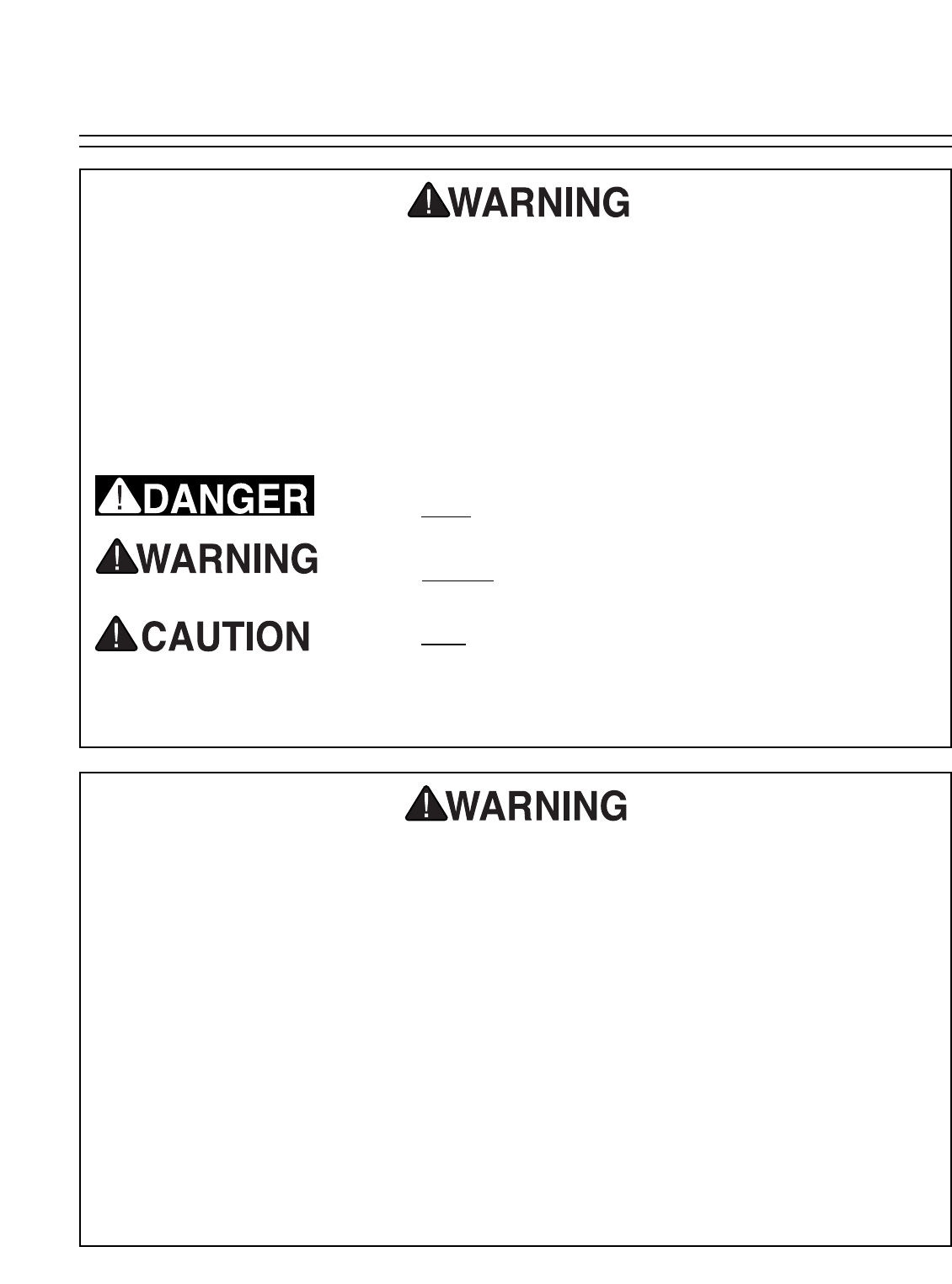
For Your Own Safety Read Instruction
Manual Before Operating This Equipment
Indicates an imminently hazardous situation which, if not
avoided, WILL result in death or serious injury.
Indicates a potentially hazardous situation which, if not
avoided, COULD result in death or serious injury.
Indicates a potentially hazardous situation which, if not
avoided, MAY result in minor or moderate injury. It may also
be used to alert against unsafe practices.
This symbol is used to alert the user to useful information
about proper operation of the equipment.
The purpose of safety symbols is to attract your attention to possible hazardous conditions.
This manual uses a series of symbols and signal words which are intended to convey the level
of importance of the safety messages. The progression of symbols is described below.
Remember that safety messages by themselves do not eliminate danger and are not a substi-
tute for proper accident prevention measures.
NOTICE
G1183/1276 Combination Sander -3-
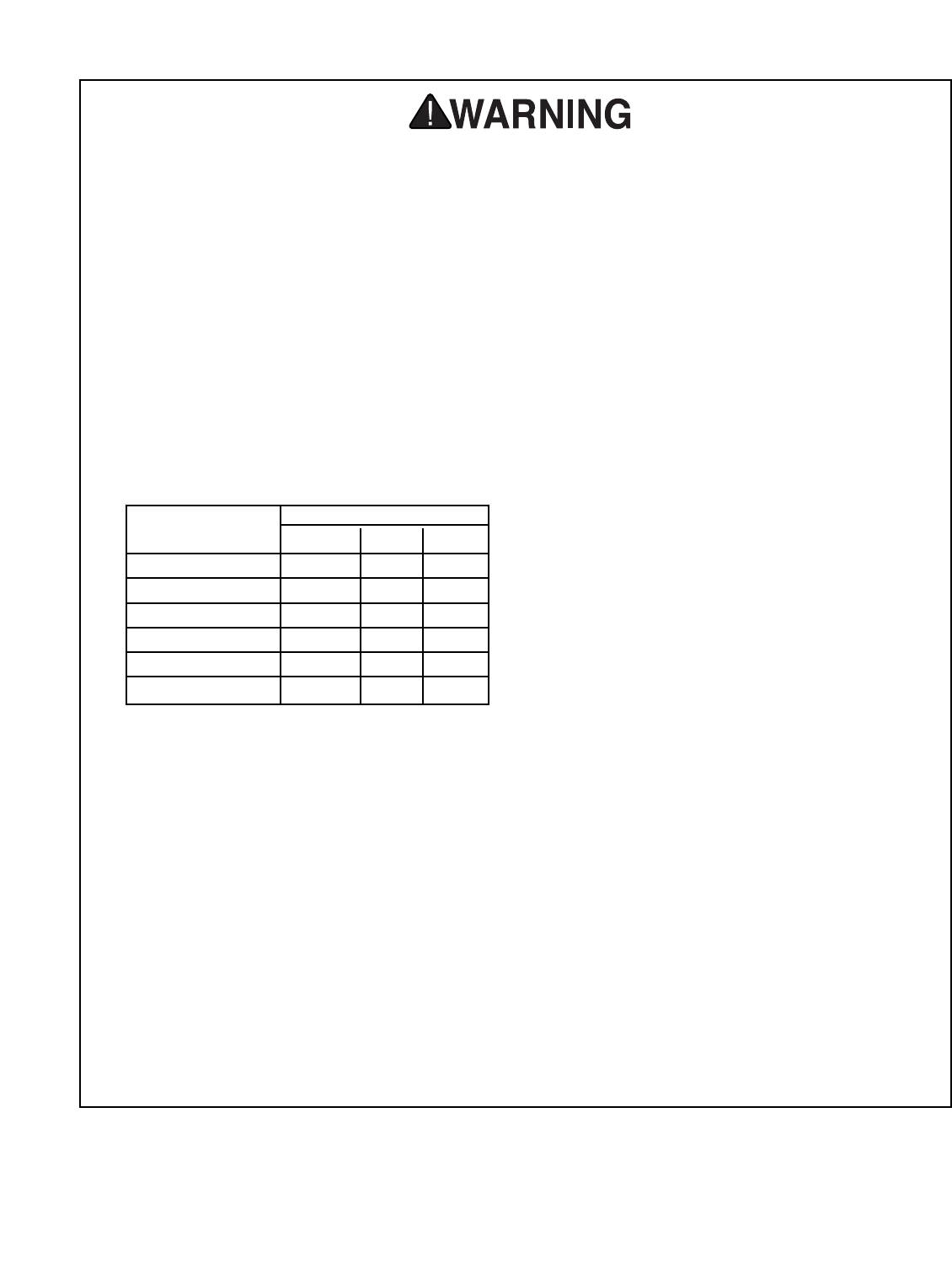
9. USE PROPER EXTENSION CORD. Make
sure your extension cord is in good condi-
tion. Conductor size should be in accor-
dance with the chart below. The amperage
rating should be listed on the motor or tool
nameplate. An undersized cord will cause a
drop in line voltage resulting in loss of
power and overheating. Your extension
cord must also contain a ground wire and
plug pin. Always repair or replace exten-
sion cords if they become damaged.
Minimum Gauge for Extension Cords
10. WEAR PROPER APPAREL. Do not wear
loose clothing, gloves, neckties, rings,
bracelets, or other jewelry which may get
caught in moving parts. Non-slip footwear
is recommended. Wear protective hair cov-
ering to contain long hair.
11. ALWAYS USE SAFETY GLASSES. Also
use face or dust mask if cutting operation is
dusty. Everyday eyeglasses only have
impact resistant lenses, they are NOT safe-
ty glasses.
12. SECURE WORK. Use clamps or a vise to
hold work when practical. It’s safer than
using your hand and frees both hands to
operate tool.
LENGTH
AMP RATING 25ft 50ft 100ft
0-6 18 16 16
7-10 18 16 14
11-12 16 16 14
13-16 14 12 12
17-20 12 12 10
21-30 10 10 No
Safety Instructions For Power Tools
13. DON’T OVERREACH. Keep proper foot-
ing and balance at all times.
14. MAINTAIN TOOLS WITH CARE. Keep
tools sharp and clean for best and safest
performance. Follow instructions for lubri-
cating and changing accessories.
15. DISCONNECT TOOLS before servicing
and changing accessories, such as blades,
bits, cutters, and the like.
16. REDUCE THE RISK OF UNINTENTION-
AL STARTING. Make sure switch is in off
position before plugging in.
17. USE RECOMMENDED ACCESSORIES.
Consult the owner’s manual for recom-
mended accessories. The use of improper
accessories may cause risk of injury.
18. CHECK DAMAGED PARTS. Before fur-
ther use of the tool, a guard or other part
that is damaged should be carefully
checked to determine that it will operate
properly and perform its intended function.
Check for alignment of moving parts, bind-
ing of moving parts, breakage of parts,
mounting, and any other conditions that
may affect its operation. A guard or other
part that is damaged should be properly
repaired or replaced.
19. NEVER LEAVE TOOL RUNNING UNAT-
TENDED. TURN POWER OFF. Don’t
leave tool until it comes to a complete stop.
-4- G1183/1276 Combination Sander
Additional Safety Instructions For The Sander
1. Be aware of belt or disc rotation direction
when sanding.
2. Keep fingertips away from moving parts.
3. Never use excessive force when sanding.
Doing so greatly increases the chance of
personal injury, mechanical damage, or
damage to your workpiece.
4. Always feed your work AGAINST the
direction of rotation.
5. DO NOT operate the sander if the disc or
belt are damaged or badly worn. Portions
of sandpaper could be ejected from the
sander.
6. Even if you have a reliable method of dust
collection, use a dust mask or respirator
when sanding. Use eye and hearing pro-
tection as well.
7. DO NOT sand material when you doubt its
stability or integrity. Inspect all materials
carefully for foreign objects like nails and
staples.
8. When disc sanding, feed material into the
portion of the disc spinning DOWN toward
the table.
9. Habits – good and bad – are hard to break.
Develop good habits in your shop and
safety will become second-nature to you.
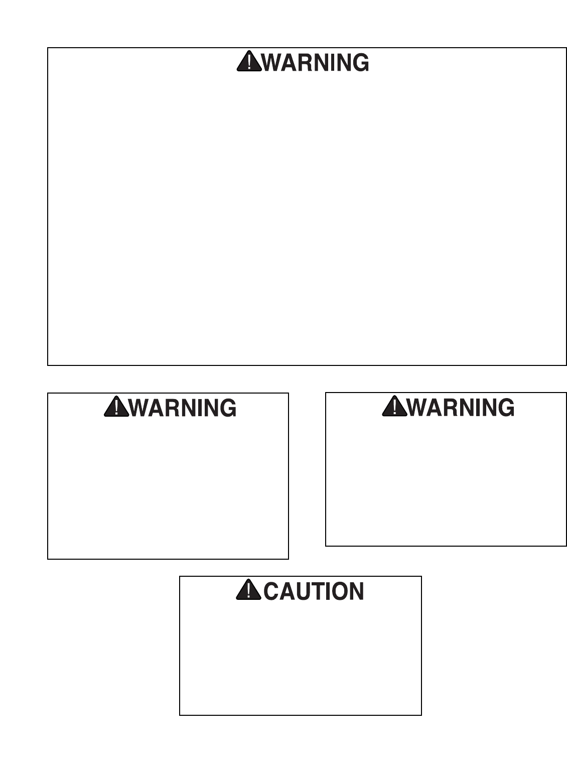
Operating this equipment has the potential
to propel debris into the air which can
cause eye injury. Always wear safety glass-
es or goggles when operating equipment.
Everyday glasses or reading glasses only
have impact resistant lenses, they are not
safety glasses. Be certain the safety glass-
es you wear meet the appropriate stan-
dards of the American National Standards
Institute (ANSI).
Like all power tools, there is danger asso-
ciated with the Model G1183/1276
Combination Sander. Accidents are fre-
quently caused by lack of familiarity or fail-
ure to pay attention. Use this tool with
respect and caution to lessen the possibil-
ity of operator injury. If normal safety pre-
cautions are overlooked or ignored, seri-
ous personal injury may occur.
No list of safety guidelines can be complete.
Every shop environment is different. Always
consider safety first, as it applies to your
individual working conditions. Use this and
other machinery with caution and respect.
Failure to do so could result in serious per-
sonal injury, damage to equipment or poor
work results.

G1183/1276 Combination Sander -5-
110/220V Operation
SECTION 2: CIRCUIT REQUIREMENTS
The 1 HP motor will draw 12 amps at 110V and 6
amps at 220V. A 15-amp fuse or circuit breaker
should be used when fusing this combination
sander. Circuits rated any higher are not ade-
quate to protect the motor from power surges. If
you operate this sander on any circuit that is
already close to capacity, it might trip the breaker
or blow the fuse. However, if an unusual load
does not exist, and the circuit protection is still
activated, you should have the circuit inspected
by a qualified electrician.
Fusing
Grounding
This equipment must be grounded. Verify
that any existing electrical outlet and circuit
you intend to plug into is actually ground-
ed. If it is not, it will be necessary to run a
separate 12 A.W.G. copper grounding wire
from the outlet to a known ground. Under
no circumstances should the grounding pin
from any three-pronged plug be removed.
Serious injury may occur.
In the event of an electrical short, grounding
reduces the risk of electric shock by providing a
path of least resistance to disperse electric cur-
rent. This tool is equipped with a power cord hav-
ing an equipment-grounding conductor. See
Figure 1. The outlet must be properly installed
and grounded in accordance with all local codes
and ordinances.
The Model G1183/1276 is prewired for 110V, sin-
gle phase operation. Figure 1 depicts the typical
grounded receptacle which should be used. This
machine can be rewired to operate at 220V, how-
ever a different plug will need to be installed.
Figure 2 shows a typical 220V plug. A wiring dia-
gram is provided at the back of the manual to
show the two wiring configurations.
Figure 1. 110V Grounded Plug Configuration.
Figure 2. 220V Grounded Plug Configuration.
-6- G1183/1276 Combination Sander
If you find it necessary to use an extension cord
with the Model G1183/1276, make sure the cord
is rated Hard Service (grade S) or better. Refer to
the chart in the standard safety instructions to
determine the minimum gauge for the extension
cord. The extension cord must also contain a
ground wire and plug pin. Always repair or
replace extension cords when they become worn
or damaged.
Extension Cords
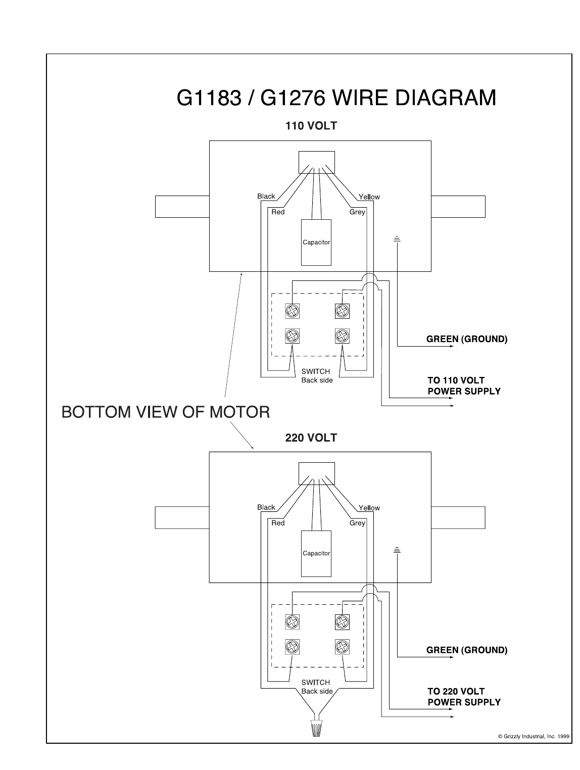
Your G1183/1276 machine comes pre-wired for
110 volt operation. A wiring diagram is provided
at the back of this manual should it be necessary
to repair or revise the wiring. Always utilize a
qualified electrician when doing any electrical
work on this equipment.
Wiring Diagram
We have covered some basic electrical
requirements for the safe operation of your
Sander. These requirements are not neces-
sarily comprehensive. You must be sure
that your particular electrical configuration
complies with local and state codes.
Ensure compliance by checking with your
local municipality or a licensed electrician.

G1183/1276 Combination Sander -7-
SECTION 3: GENERAL INFORMATION
Grizzly Industrial, Inc. is proud to offer the Model
G1183 6" x 48" – 12" Disc Combination Sander
and its slower-speed version, the Model G1276.
This saw is a part of Grizzly’s growing family of
fine woodworking machinery. When used accord-
ing to the guidelines set forth in this manual, you
can expect years of trouble-free, enjoyable oper-
ation, and proof of Grizzly’s commitment to cus-
tomer satisfaction.
The Model G1183 and Model G1276 feature
heavy-duty cast-iron bodies and tilting tables, and
powerful 1 HP single-phase motors. The Model
G1183 provides 3,450 R.P.M. disc rotation and a
5,000 F.P.M. belt speed. The Model G1276 pro-
duces a 1,725 R.P.M. disc rotation and a 2,500
F.P.M. belt speed. Both have 3" dust ports
attached. These sanders come prewired and
ready to operate at 110V.
Both offer a wide 6" belt surface for fast stock
removal and a 12" disc for convenient shaping.
Fully-adjustable tables allow sanding at a variety
of angles.
We are also pleased to provide this manual with
the G1183 and G1276. This instruction manual
was written to guide you through assembly,
review safety considerations, and cover general
operating procedures. It represents our latest
effort to produce the best documentation possi-
ble. If you have any criticisms that you feel we
should pay attention to in our next printing, please
write to us at the address shown to the right.
Most importantly, we stand behind our machines.
We have an excellent service department at your
disposal should the need arise. If you have any
service questions or parts requests, please call or
write to us at the location listed below.
Grizzly Industrial, Inc.
1203 Lycoming Mall Circle
Muncy, PA 17756
Phone: (570) 546-9663
Fax: (800) 438-5901
E-Mail: techsupport@grizzly.com
Web Site: www.grizzly.com
To comment on this manual write to:
Grizzly Industrial, Inc.
C⁄OTechnical Documentation
P.O. Box 2069
Bellingham, WA 98227-2069
The specifications, drawings and photographs
represent the G1183 and G1276 as supplied
when the manual was created. Due to our policy
of continuous improvement, some features of this
machine may vary from that portrayed in this
manual.
Commentary
To operate this, or any power tool, safely
and efficiently, it is essential to become as
familiar with its characteristics as possible.
The time you invest before you begin to use
your Model G1183/1276 will be time well
spent. DO NOT operate this machine until
you are completely familiar with the con-
tents of this manual. Make sure you read
and understand all of the safety proce-
dures. If you do not understand something,
DO NOT operate the machine.
-8- G1183/1276 Combination Sander
Unpacking
The Combination Sander is shipped from the fac-
tory in a carefully packed carton. If you find the
machine to be damaged after you’ve signed for
delivery and the truck and driver are already
gone, you will need to file a freight claim with the
carrier. Save the containers and all packing mate-
rials for inspection by the carrier or their agent.
Without the packing materials, filing a freight
claim can be difficult. If you need advice regard-
ing this situation, please call us.
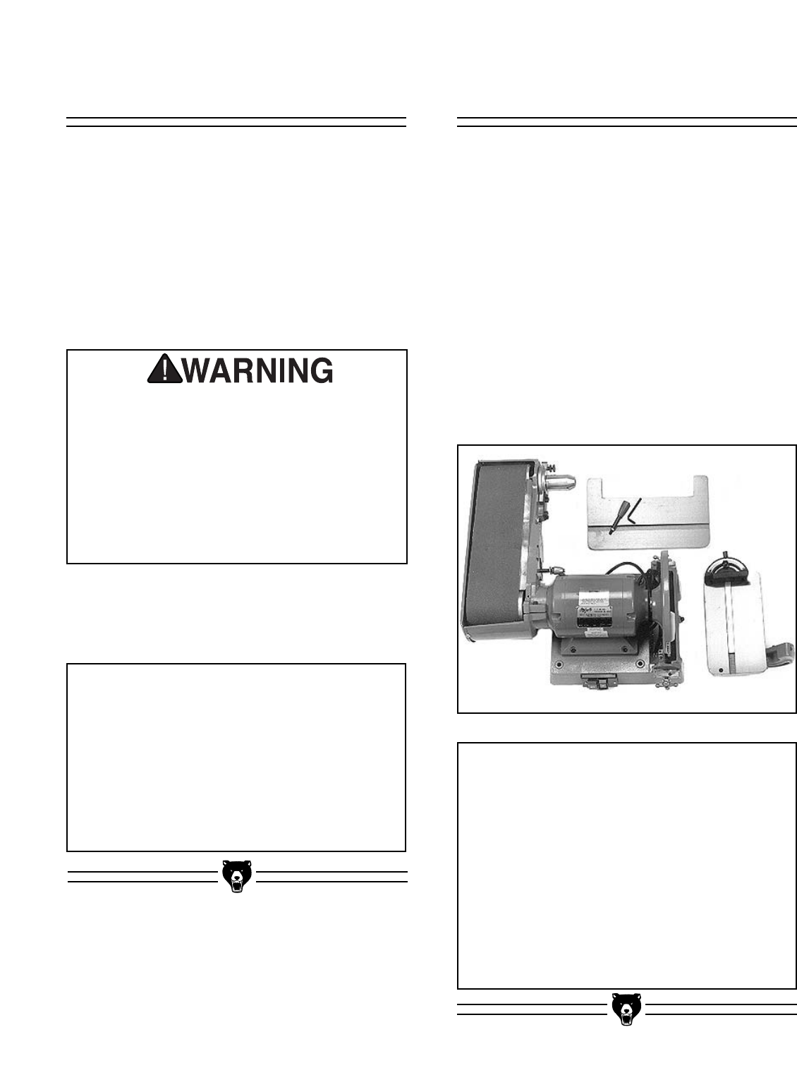
Piece Inventory
With all the parts removed from the container,
you should have components as listed below and
shown in Figure 3:
• Motor Body and Belt Assembly
• Disc Table
• Belt Table
• Allen®Wrench
• Miter Gauge
• Handle
If anything is missing, call or write to the appro-
priate service department listed in the General
Information section. If anything is damaged,
please follow the procedures described to the left.
NOTICE
Please keep all packaging materials until
you are satisfied that the machine is in
good condition. Should you need to file a
freight claim, the carrier’s agent will require
inspection of those materials. Settling a
claim can be difficult if packaging is not
available.
NOTICE
Ensure that the Model G1183/G1276 is
located on a flat, level surface. This will
maximize the stability of the machine and
ensure that adjustments are accurate. For
conditions where permanent mounting is
possible, we recommend bolting the
Combination Sander to your bench top or
work table. This type of mounting will mini-
mize vibration and provide a more stable
work environment.
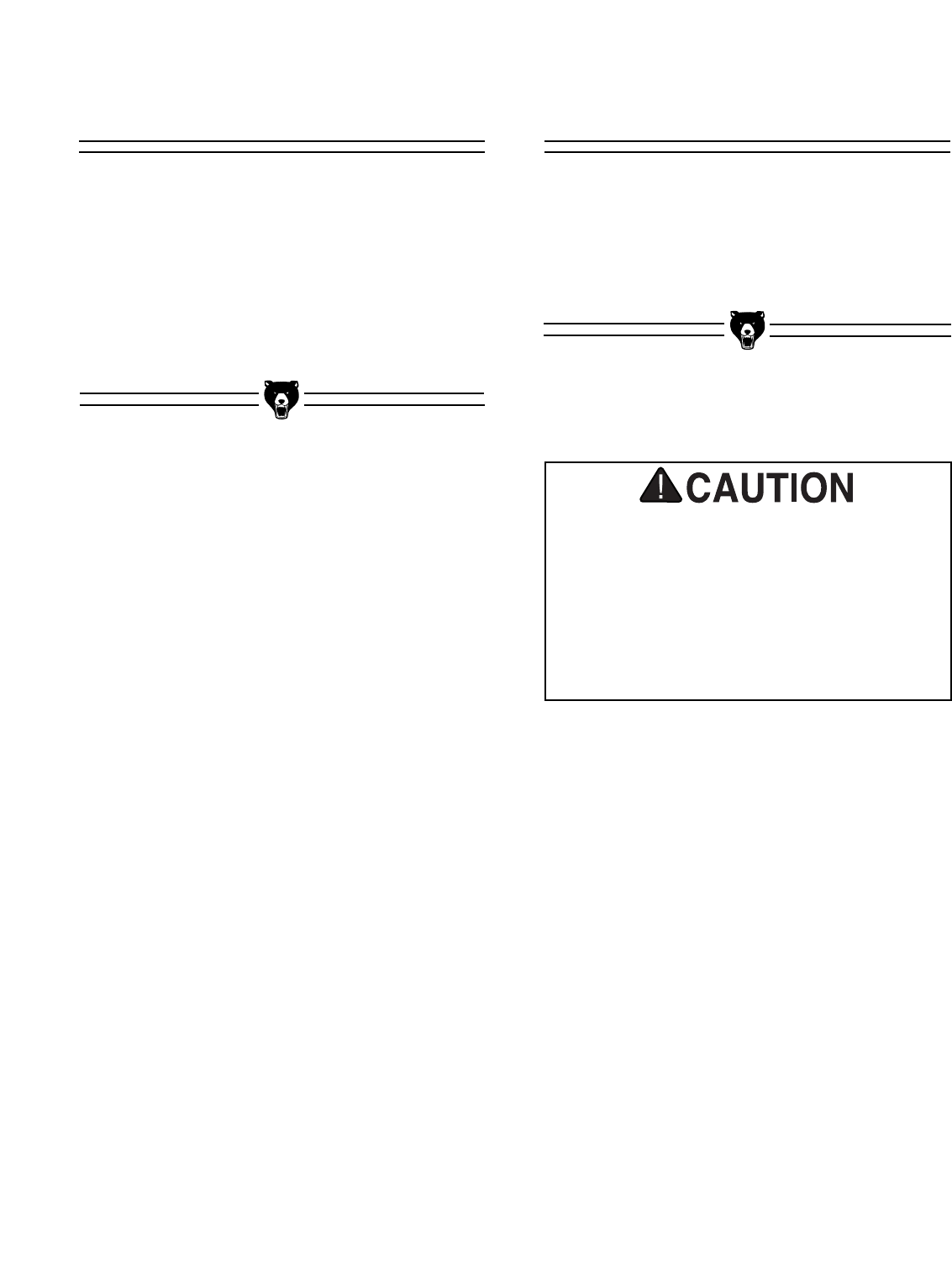
The G1183/1276 is a fairly heavy machine
(155 lbs.). DO NOT over-exert yourself while
unpacking or moving your machine – get
assistance. In the event that your Combination
Sander must be moved up or down a flight of
stairs, be sure that the stairs are capable of
supporting the combined weight of people and
the machine. Serious personal injury may
occur.
When you are completely satisfied with the con-
dition of your shipment, you should inventory its
parts.
Figure 3. Combination sander components.
G1183/1276 Combination Sander -9-
Clean Up
The unpainted surfaces are coated with a waxy
oil to protect it from corrosion during shipment.
Remove this protective coating with a solvent
cleaner or citrus-based degreaser. Avoid chlo-
rine-based solvents as they may damage painted
surfaces should they come in contact. Always fol-
low the usage instructions on the product you
choose for clean up.
Many of the solvents commonly used to
clean machinery can be highly flammable,
and toxic when inhaled or ingested. Always
work in well-ventilated areas far from
potential ignition sources when dealing
with solvents. Use care when disposing of
waste rags and towels to be sure they do
not create fire or environmental hazards.
Keep children and animals safely away
when cleaning and assembling this
machine.
Do not use gasoline or other petroleum-
based solvents to remove this protective
coating. These products generally have low
flash points which makes them extremely
flammable. A risk of explosion and burning
exists if these products are used. Serious
personal injury may occur.
Site Considerations
Make your shop “child safe”. Ensure that
your workplace is inaccessible to young-
sters by closing and locking all entrances
when you are away. Never allow visitors in
your shop when assembling, adjusting or
operating equipment.
All die-cut metal parts have a sharp edge
(called “flashing”) on them after they are
formed. This is generally removed at the
factory. Sometimes a bit of flashing might
escape inspection, and the sharp edge may
cause cuts or lacerations when handled.
Please examine the edges of all die-cut
metal parts and file or sand the edge to
remove the flashing before handling.
BENCH LOAD
The G1183/1276 Combination Sander repre-
sents a moderately large weight load in a small
footprint. Most commercial or home shop bench-
es should be sufficient to carry the weight of the
machine. If you question the strength of your
workbench, you can opt to reinforce it, or consid-
er placing the sander on a freestanding bench
such as Shop Fox®Deluxe Tool Table.
WORKING CLEARANCES
Working clearances can be thought of as the dis-
tances between machines and obstacles that
allow safe operation of every machine without
limitation. Consider existing and anticipated
machine needs, size of material to be processed
through each machine, and space for auxiliary
stands and/or work tables. Also consider the rel-
ative position of each machine to one another for
efficient material handling. Be sure to allow your-
self sufficient room to safely run your machines in
any foreseeable operation.
LIGHTING AND OUTLETS
Lighting should be bright enough to eliminate
shadow and prevent eye strain. Electrical circuits
should be dedicated or large enough to handle
combined motor amp loads. Outlets should be
located near each machine so power or exten-
sion cords are not obstructing high-traffic areas.
Be sure to observe local electrical codes for prop-
er installation of new lighting, outlets, or circuits.
-10- G1183/1276 Combination Sander
SECTION 4: ASSEMBLY
Assembly Basics
Belt Table
The belt table adjusts to allow you to sand your
work at angles from -30° up to 45°. To make
assembly easier, we recommend you mount the
Combination Sander on a table or bench before
assembling. Four bolt holes are included on the
sander’s base for mounting.
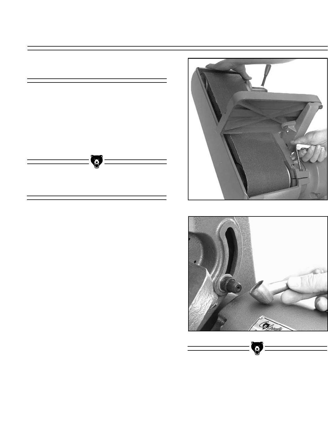
To attach the belt table:
1. Swing the belt assembly to its vertical posi-
tion by loosening the 6mm Allen® capscrew
shown in Figure 4. Tighten capscrew to
hold the belt assembly in this position.
2. Remove the lock handle assembly and the
threaded stud from the belt housing using a
large flat bladed screwdriver.
3. Line up the belt table trunnion with the slot
in the belt assembly bracket. Reinstall the
threaded stud, then install the flat washer,
toothed nut, lock handle, lock washer and
bolt, as shown in Figure 5. Make sure the
handle is installed so the table can be loos-
ened and tightened without interfering with
other components. The belt table’s tight fit
is deliberate. Placing the table in position is
easier if you swing the belt table so the 45°
positive stop bolt is located over the gap in
the motor casting cover.
Figure 4. Attaching belt table.
Figure 5. Installing lock handle.
Most of your Combination Sander has been
assembled at the factory. There are several sim-
ple steps to follow to complete the assembly.
A few common tools will be required for assem-
bly: Screwdrivers - medium and large straight
blade or Phillips®, Allen® wrenches - 2mm, 3mm,
6mm and open end wrenches - 8mm and 10mm.
G1183/1276 Combination Sander -11-
Disc Table
The disc table adjusts to allow you to sand your
work at angles from -20° up to 45°. To install the
disc table:
1. Loosen the two star knobs at either end of
the disc table base until they reach the
ends of their threaded rods.
2. Move the sliding rails and the washers to
allow enough room for the table to be
installed.
3. Flip the 90° stop block out of position.
4. Install table securely between the two slid-
ing rails as shown in Figure 6.
5. Tighten star knobs to secure the table in
position.
Figure 6. Attaching disc table.
Belt Lever
The belt lever is used for releasing the tension on
the idler pulley for belt installation. To attach the
belt lever:
1. Thread the belt lever onto the loosen/tighten
collar and secure with the checknut. See
Figure 7.
Figure 7. Attaching belt lever.
Belt Lever
Loosen/Tighten Collar
DO NOT attempt to operate this machine
before completing the assembly and adjust-
ment instructions. Be sure that the switch is
off and the cord is disconnected from the
power source at all times until assembly
and adjustment are complete and you have
reviewed all safety guidelines. Serious
injury could occur.
NOTICE
After all parts have been assembled, dou-
ble-check the entire machine to make sure
all fasteners are tight.
-12- G1183/1276 Combination Sander
SECTION 5: ADJUSTMENTS
Proper adjustment of the Combination Sander is
essential to ensure its optimum performance. The
adjustments covered in this section are easily
accomplished.
Tables
Tables should be square in both planes to exe-
cute precise work. Procedures for accomplishing
this are described below.
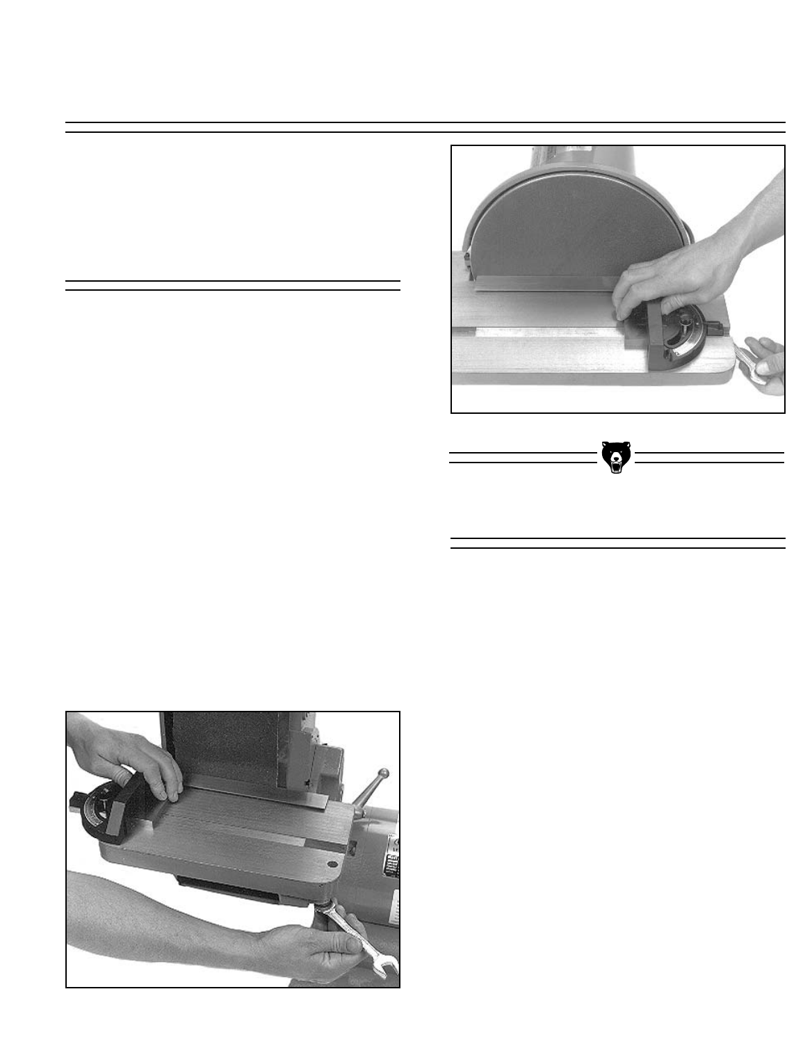
1. Adjust the miter gauge to 90°. You can use
it as a reference point from which to make
other adjustments.
2. Place the miter gauge in the table slot and,
with a high-quality machinist’s or combina-
tion square against the face of the miter
gauge, check the tables for squareness
against the sanding surfaces. See Figures
8 and 9.
3. If either table is out of square, loosen the
bolts that attach the table to the trunnion
and adjust the table until it is square to the
disc or belt. Tighten the table and re-
inspect results.
Figure 8. Squaring belt table.
Figure 9. Squaring disc table.
Positive Stops
Positive stops are used to move the tables to dif-
ferent positions quickly, without measurement.
The belt table has two positive stops (one at 45°
and one at 90°) and the disc table has one (at
90°).
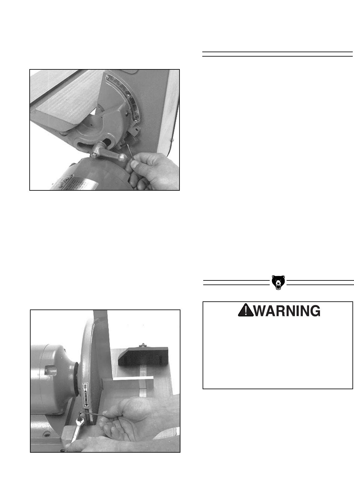
To Adjust the Belt Table Positive Stops:
1. Loosen the lock handle.
2. Flip block into the 90° position.
3. Use a square to verify the accuracy to the
stop.
4. If the stop is engaged and the table isn’t
quite perpendicular to the belt, adjust the
stop by turning the setscrew in or out as
needed. See Figure 10.
5. Flip the block back to its former position,
then back to 90° to double-check accuracy.
-13-
Figure 11. Adjusting disc table stops.
G1183/1276 Combination Sander
6. Repeat this procedure with the 45° stop.
You’ll need a known 45° angle, such as a
speed square or the head of a combination
square to check accuracy.
Figure 10. Adjusting belt table stops.
To Adjust the Disc Table Positive Stops:
1. Loosen both star knobs.
2. Flip block over table.
3. Loosen check nut.
4. Place accurate square on table and against
disc as shown in Figure 11.
5. Make fine adjustments by turning the
setscrew in or out. Secure the checknut.
Belt Platen
DO NOT attempt to operate this machine
before completing the assembly and adjust-
ment instructions. Be sure that the switch is
off and the cord is disconnected from the
power source at all times until assembly
and adjustment are complete and you have
reviewed all safety guidelines. Serious
injury could occur.
The belt platen should be adjusted out far enough
so it is flush with, or slightly higher than the upper
roller. The rollers are slightly crowned, that is they
are higher in the center than at the edges. This
crowning helps the belt to stay centralized on the
rollers. The adjustment of the platen to the roller
should be done at the high point, or center, of the
roller.
1. Loosen the cap screw on the side of the
belt housing with a 6mm Allen®wrench.
This frees the in and out movement of the
belt platen
2. Use a straightedge positioned in the center
of the platen which extends over the upper
roller. Adjust the belt platen in and out until
the straightedge is just barely lifted off of
the idler roller.
3. Tighten cap screw.
See the section on Belt Installation/Tracking for
more information on adjusting the rollers for prop-
er tracking.
-14- G1183/1276 Combination Sander
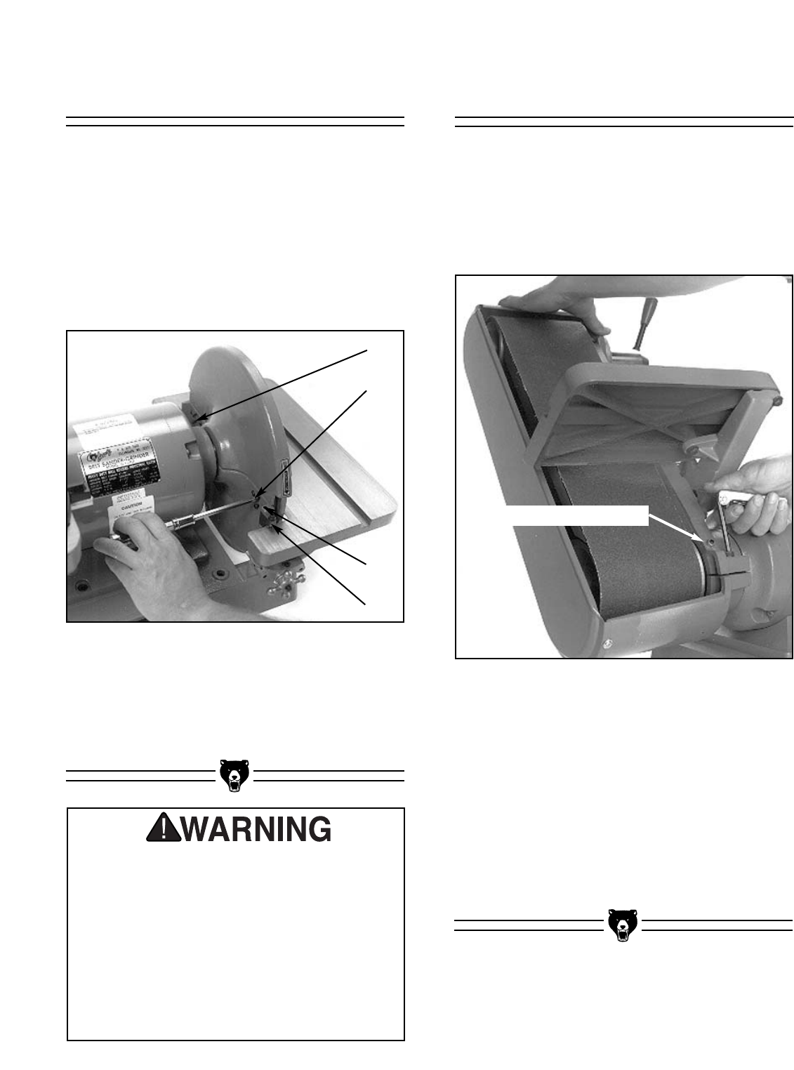
1. Loosen the two screws (A and B) shown in
Figure 12. These screws hold the guard in
place.
2. Adjust the two vertically-aligned screws (C
and D in Figure 12) so the guard is upright
and not touching the disc. The top screw
moves the guard toward the disc and the
bottom screw moves it away from the disc.
Disc Guard
Figure 12. Adjusting disc guard.
A
B
C
D
3. Rotate the disc by hand to see if the disc
scrapes against the guard; repeat Steps 1
and 2, if needed.
4. Tighten screws C and D to secure guard.
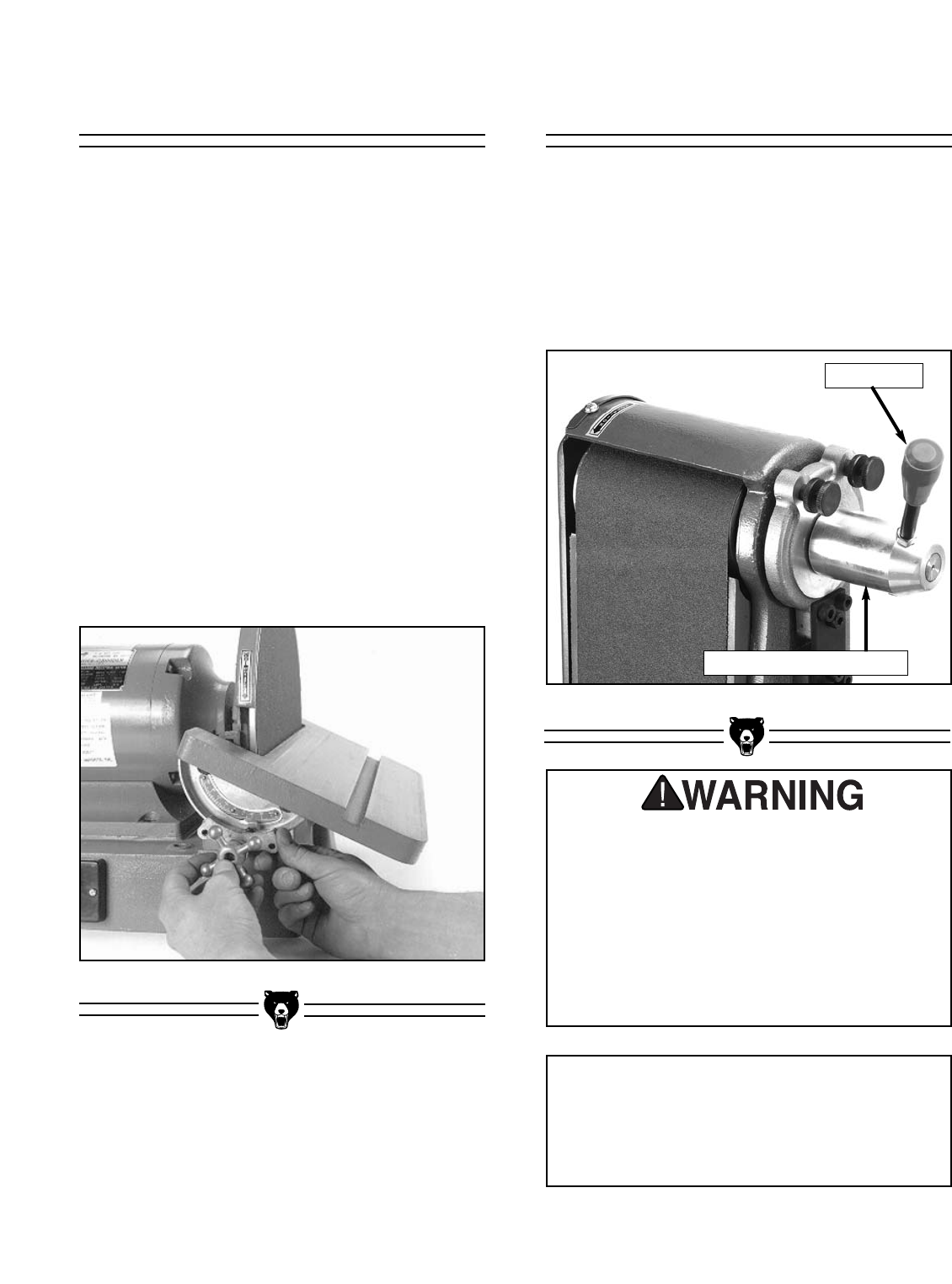
Belt Arm Movement
The 6" x 48" Belt Arm can be locked at any angle
between horizontal and vertical for a variety of
sanding applications.
1. Loosen the locking bolt as shown in Figure
13.
Figure 13. Loosening belt arm locking bolt.
2. Grab the top of the belt arm housing and
move the belt arm to the desired position.
3. Tighten the locking bolt.
The setscrew/checknut combination shown in
Figure 13 acts as a stop for the rotation of the belt
arm. If it ever becomes necessary to remove the
belt arm from the motor, be sure to remove this
setscrew to allow the arm housing to be slipped
of the motor mounting.
Operating this equipment has the potential
to propel debris into the air which can
cause eye injury. Always wear safety glass-
es or goggles when operating equipment.
Everyday glasses or reading glasses only
have impact resistant lenses, they are not
safety glasses. Be certain the safety glass-
es you wear meet the appropriate stan-
dards of the American National Standards
Institute (ANSI).
Rotation Stop Setscrew
G1183/1276 Combination Sander -15-
Belt Installation Belt Tracking
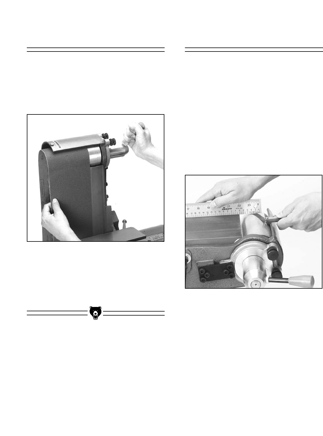
The 6'' x 48'' sanding belt is easily installed. First
remove the belt guard by loosening the four com-
bination-head screws. Pull down on the spring
loaded belt tensioning lever which lowers the
upper roller and allows the belt to be slid off of the
two rollers. See Figure 14.
2. You should see a gap between the straight
edge and roller. Measure this with a feeler
gauge.
3. Repeat step 1 and 2 with the straight edge
positioned at the opposite edge of the plat-
en.
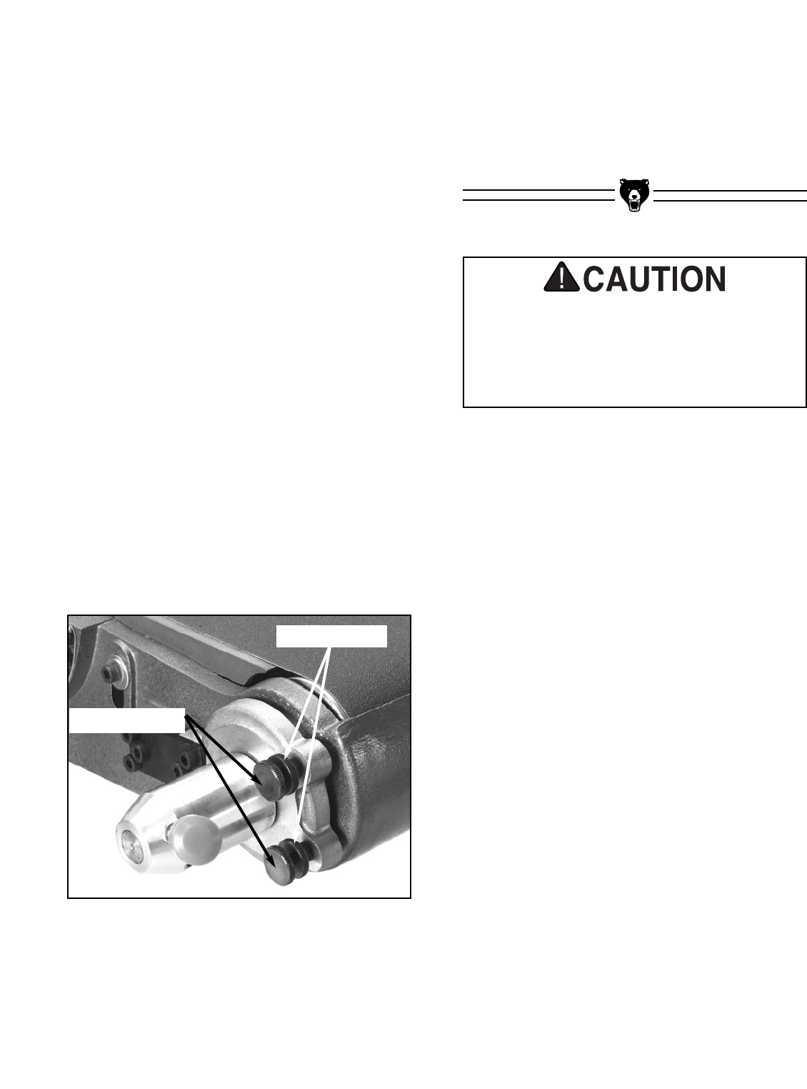
4. The difference in the measurements is the
amount of "twist" in the belt. Reduce the
twist by adjusting one of the two tracking
knobs. See Figure 16. If the "out-board"
end (or the end furthest from the tracking
adjustment side) of the roller measures
greater than the "in-board" side, tighten the
right hand tracking knob.
Tracking adjustment is conducted as follows:
1. Insure that the upper roller is parallel to the
platen (there is no adjustment for the lower
roller). This adjustment is easier to accom-
plish with the belt removed. Remember that
the roller is crowned, and a rough align-
ment of the roller to the platen was already
described in the section entitled Belt
Platen. To determine parallelism for proper
tracking, measure at a point approximately
.5'' from the ends of the roller. Use a
straight edge on top of the platen and
extend it over the roller. See Figure 15.
Figure 14. Installing sanding belt.
The new belt will have a rotation arrow on the
backing. Make certain the belt is placed onto the
rollers in the proper orientation. There is a rota-
tion label on the housing indicating the direction.
Pull the lever down and slide the new belt onto
the rollers and center it.
Figure 15. Measuring platen to roller parallelism.
-16- G1183/1276 Combination Sander
9. Test the tracking by cycling the machine on
and off very quickly. See if the belt stays
centered during this test cycle. If the belt
doesn’t remain centered on the rollers, it
must be adjusted further.
Figure 16. Belt arm adjuster knobs.
5. With the straightedge along the edge which
is low, loosen the knurled locking nut and
turn the tracking knob while watching the
gap change between the straight edge and
the roller. Make small changes and check
for a change in gap on the opposite side.
6. When the gap has been equalized between
the two sides, make sure the center of the
roller, or the crown, is still approximately
flush or just slightly above the platen sur-
face. Lock the adjustment knobs with the
locking knobs.
7. Reinstall the belt. Move the belt by hand
(DO NOT turn on the power). If the belt
tracks to one side or the other, adjust the
idler roller slightly by backing off the locking
knobs and turning the knurled adjustment
screws in or out. See Figure 16. Make very
small adjustments and move the belt by
hand for a few revolutions to test the result.
Keep readjusting until you are satisfied the
belt is tracking properly when moved by
hand.
8. Lock the adjustment in place by tightening
the knurled lock knobs on both adjusters.
Moving sanding discs and belts are danger-
ously abrasive. Use extreme caution when
working near sanding surfaces. Failure to
exercise care while sanding could result in
severe injury.
Tracking Knobs
Locking Knobs
G1183/1276 Combination Sander -17-
SECTION 6: OPERATIONS
The aluminum disc accepts 12" diameter cloth or
paper-backed PSA sanding discs. The belt
sander requires a 6" x 48" sanding belt. For disc
or belt sanding, we recommend a 100-grit (medi-
um) material for general sanding chores, a 60-grit
(coarse) material for rough work, and a 150-grit
(fine) surface for finish work. See the current
Grizzly catalog for prices and ordering informa-
tion.
Please review all safety rules for sanders and all
power tools before attempting operation. The
hints listed below are also worth your considera-
tion:
1. When using the table for beveled sanding
operations, try to keep an open table angle
(90˚ or more). This eliminates the risk of
getting the workpiece jammed between the
disc (or vertical belt) and the table.
2. The surface feet per minute of the spinning
disc increases as you move from the center
to the rim.
3.When belt sanding, sand with the grain of
the wood.
4. Do not over-sand soft woods such as bass
wood or pine.
5. Choose the correct sanding grit for the job.
6. Do not use the sander as a replacement for
a bandsaw or a planer. It is designed for fin-
ish work, not rough dimensioning.
7. Keep your workpiece moving across the
face of the disc or belt to prevent grooves
or ruts in the surface you’re sanding.
The belt table can be adjusted from -30˚ to 45˚
and the disc table can go from -20˚ to 45˚ relative
to the plane of the sanding surface. Both tables
have positive stop blocks which will quickly posi-
tion the table at the 90˚ and 45˚ angles. To adjust
the tilt it is sometimes necessary to swing the
stop block out of the way, move the table, swing
the block back in, then contact the stop block. If
angles other than the preset are desired, swing
the stop out of the way and use the angle scale or
a bevel gauge to set to the position needed. Lock
the handle (on the belt table) or the star knob (on
the disc table) firmly in position.
Whenever possible, sand with an open angle
where there is plenty of clearance between the
belt and the table. This will avoid getting the work-
piece trapped between the sanding surface and
the table.
Table Tilt
-18- G1183/1276 Combination Sander
Operating this equipment has the potential
to propel debris into the air which can
cause eye injury. Always wear safety glass-
es or goggles when operating equipment.
Everyday glasses or reading glasses only
have impact resistant lenses, they are not
safety glasses. Be certain the safety glass-
es you wear meet the appropriate stan-
dards of the American National Standards
Institute (ANSI).
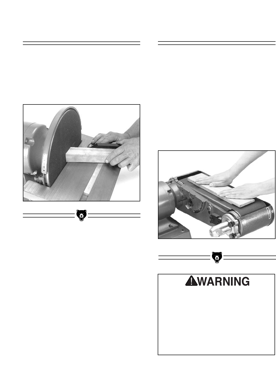
Surface Sanding
To remove a large amount of material quickly
from a large surface area, use the belt arm in its
horizontal position.
1. Turn the sander on and let it reach its full
working speed.
2. Place the workpiece flat on the belt. Be
sure to hold the work securely with both
hands. Place one hand at the end of the
workpiece to feed it against the rotation of
the belt. Place the other hand lightly on top
of the workpiece to ensure adequate stock
removal. See Figure 18.
Figure 18. Surface sanding.
Disc Sanding
1. Loosen table lock knob and tilt work table to
desired angle. Tighten lock knob.
2. Use miter gauge to guide work into position.
3. Ease workpiece into the half of the disc that
spins down toward the table. See Figure 17.
Figure 17. Disc sanding.
G1183/1276 Combination Sander -19-
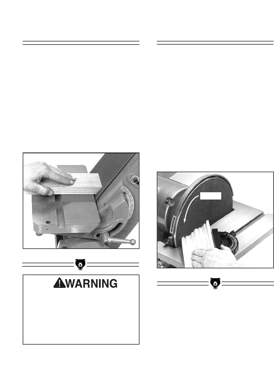
Bevel Sanding
When bevel sanding, be sure to re-position the
work table so it is at a maximum of 1/16" away from
the disc or belt.
1. Hold workpiece against miter gauge to
keep piece square to the disc or belt.
2. Move workpiece against sanding surface
width to ensure even abrasion. Use even,
but firm, pressure.
3. When using the belt arm for bevel sanding,
you will have greater control over your work
if you tilt the belt arm and maintain the table
at level. See Figure 19.
Figure 19. Bevel sanding.
DO NOT attempt to operate this machine
before completing the assembly and adjust-
ment instructions. Be sure that the switch is
off and the cord is disconnected from the
power source at all times until assembly
and adjustment are complete and you have
reviewed all safety guidelines. Serious
injury could occur.
Miter Sanding
The most efficient way to get a perfect miter is to
cut the workpiece slightly long and sand it to the
desired dimension. Miter sanding can be done on
either the belt or the disc.
1. Loosen the knob on the miter gauge and
adjust the angle to the desired point.
Tighten the knob.
2. Slide the miter gauge into its slot and use it
to hold your workpiece in position. The
miter gauge can be used in either direction
in the slot to achieve the proper relation of
the workpiece to the disc.
3. With light, but firm pressure, push the work-
piece slowly into the downspin side of the
rotating disc. See Figure 20.
Figure 20. Mitering with gauge reversed.
Rotation
-20- G1183/1276 Combination Sander
SECTION 7: MAINTENANCE
Tables
The tables and other non-painted surfaces on the
Model G1183 and G1276 should be protected
against rust and pitting. Wiping the sander clean
after every use ensures that moisture from wood
dust isn’t allowed to trap moisture against bare
metal surfaces.
Some woodworkers recommend using automo-
tive paste wax on exposed steel and cast iron
surfaces. The wax provides a layer of protection,
as well as reducing friction between lumber and
the table, making cuts faster and smoother. Avoid
waxes that contain silicone or other synthetic
ingredients. These materials can find their way
into lumber that’s being worked, and can make
staining and finishing difficult. If you use paste
wax, make sure that it’s 100% Carnauba wax.
The Combination Sander is ruggedly constructed
to provide years of dependable service. To
ensure that you enjoy maximum performance
and longevity, we suggest the following routine
maintenance:
1. Check all fasteners for tightness before
each use. Tighten when necessary.
2. Keep the Combination Sander clean for
maximum efficiency and heat dissipation.
Wipe away accumulated sanding dust and
grime after each use.
3. Inspect sanding disc and belt for excessive
wear and damage. Replace if necessary.
4. Inspect switches and cord periodically for
wear or damage. Replace if necessary.
5. Bearings are sealed and permanently lubri-
cated, so no lubrication is needed. Check
for wear periodically and replace when
worn. Increased motor noise and vibration
are both indicators of bearing wear.
6. Inspect roller drive bearings for wear.
Replace if needed.
General
DO NOT make adjustments or attempt any
maintenance procedures while this
machine is running. Ensure that the switch
is off, power is disconnected and all mov-
ing parts have stopped before making
adjustments. Failure to do so could result
in serious operator injury.

G1183/1276 Combination Sander -21-
NOTES
-22- G1183/1276 Combination Sander
The following pages contain general machine
data, part diagrams/lists, troubleshooting guide
and Warranty/Return information for your Model
G1183/1276 Combination Sander.
If you need parts or help in assembling your
machine, or if you need operational information,
we encourage you to call our Service
Department. Our trained service technicians will
be glad to help you.
If you have comments dealing specifically with
this manual, please write to our Bellingham,
Washington location using the address in Section
3: General Information. The specifications, draw-
ings, and photographs illustrated in this manual
represent the Model G1183/1276 as supplied
when the manual was prepared. However, due to
Grizzly’s policy of continuous improvement,
changes may be made at any time with no oblig-
ation on the part of Grizzly. Whenever possible,
though, we send manual updates to all owners of
a particular tool or machine. Should you receive
one, add the new information to this manual and
keep it for reference.
We have included some important safety mea-
sures that are essential to this machine’s opera-
tion. While most safety measures are generally
universal, Grizzly reminds you that each work-
shop is different and safety rules should be con-
sidered as they apply to your specific situation.
We recommend you keep a copy of our current
catalog for complete information regarding
Grizzly's warranty and return policy. If you need
additional technical information relating to this
machine, or if you need general assistance or
replacement parts, please contact the Service
Department listed in Section 3: General
Information.
Additional information sources are necessary to
realize the full potential of this machine. Trade
journals, woodworking magazines, and your local
library are good places to start.
SECTION 8: CLOSURE
The Model G1183/1276 was specifically
designed for wood sanding. DO NOT MODIFY
AND/OR USE THIS MACHINE FOR ANY
OTHER PURPOSE. Modifications or
improper use of this tool will void the war-
ranty. If you are confused about any aspect of
this machine, DO NOT use it until you have
answered all your questions. Serious person-
al injury may occur.
Like all power tools, there is danger associ-
ated with this machine. Accidents are fre-
quently caused by lack of familiarity or fail-
ure to pay attention. Use this tool with
respect and caution to lessen the possibili-
ty of operator injury. If normal safety pre-
cautions are overlooked or ignored, seri-
ous personal injury may occur.
G1183/1276 Combination Sander -23-

-24- G1183/1276 Combination Sander
Customer Service #: (570) 326-3806 • To Order Call: (800) 523-4777 • Fax #: (800) 438-5901
GRIZZLY MODEL G1183 COMBINATION SANDER
MACHINE DATA
SHEET
Design Type.................................................................................................... Bench Model
Overall Dimensions:
Height (Belt arm horizontal) ..................................................................................141⁄2"
Height (Belt arm vertical) ......................................................................................291⁄2"
Width......................................................................................................................161⁄2"
Length....................................................................................................................321⁄2"
Table (Belt) ....................................................................................................7" x 121⁄2"
Table (Disc) ....................................................................................................7" x 161⁄2"
Arbor Size (Disc) ......................................................................................................3⁄4"
Dust Port ....................................................................................................................3"
Weight ..............................................................................................................155 lbs.
Box Size......................................................................................30" L x 28" W x 17" H
Footprint ......................................................................................................161⁄2" x 14"
Specifications:
Sanding Belt......................................................................................................6" x 48"
Sanding Belt Speed ......................................................................................5000 FPM
Aluminum Disc..........................................................................................12" Diameter
Aluminum Disc Speed ..................................................................................3450 RPM
Miter Gauge Groove..........................................................................................3⁄8" x 3⁄4"
Miter Gauge ..........................................................Die Cast Aluminum / Aluminum Bar
Table Tilt Range (Belt) ................................................................................-30° To 45°
Table Tilt Range (Disc) ..............................................................................-20° To 45°
Table Positive Stops (Belt) ......................................................................................90°
Table Positive Stops (Disc) ........................................................................45° and 90°
Belt Tension Method ....................................................................Quick-Release Lever
Construction:
Base ......................................................................................................Cast Aluminum
Tables .............................................................................................. Ground Cast Iron
Motor:
Type ............................................................................TEFC Capacitor Start Induction
Horsepower............................................................................................................1 HP
Phase ⁄ Voltage ................................................................ Single Phase ⁄ 110V ⁄ 220V
Prewired ................................................................................................................110V
Amps ....................................................................................................................12 ⁄ 6
Cycle and RPM ............................................................................60 Hertz ⁄ 3450 RPM
Switch ........................................................................................................Push Button
Power Transfer ..........................................................................................Direct Drive
Bearings ..................................................................Shielded, Permanently Lubricated
Specifications, while deemed accurate, are not guaranteed.
REVISED 4/99

G1183/1276 Combination Sander -25-
Customer Service #: (570) 326-3806 • To Order Call: (800) 523-4777 • Fax #: (800) 438-5901
GRIZZLY MODEL G1276 COMBINATION SANDER
MACHINE DATA
SHEET
Design Type ....................................................................................................Bench Model
Overall Dimensions:
Height (Belt arm horizontal) ..................................................................................141⁄2"
Height (Belt arm vertical) ......................................................................................291⁄2"
Width......................................................................................................................161⁄2"
Length....................................................................................................................321⁄2"
Table (Belt) ....................................................................................................7" x 121⁄2"
Table (Disc) ....................................................................................................7" x 161⁄2"
Dust Port ....................................................................................................................3"
Arbor Size..................................................................................................................3⁄4"
Weight ..............................................................................................................155 lbs.
Footprint ..........................................................................................................17" x 14"
Box Size......................................................................................30" L x 28" W x 17" H
Specifications:
Sanding Belt......................................................................................................6" x 48"
Sanding Belt Speed ......................................................................................2500 FPM
Aluminum Disc..........................................................................................12" Diameter
Aluminum Disc Speed ..................................................................................1725 RPM
Roller Drive........................................................................................6201 Ball Bearing
Miter Gauge Groove..........................................................................................3⁄8" x 3⁄4"
Miter Gauge ..........................................................Die Cast Aluminum / Aluminum Bar
Table Tilt Range (Belt) ................................................................................-30° to 45°
Table Tilt Range (Disc) ................................................................................-20° to 45°
Table Positive Stops (Belt) ......................................................................................90°
Table Positive Stops (Disc) ........................................................................45° and 90°
Belt Tension Method ....................................................................Quick-Release Lever
Construction:
Base ......................................................................................................Cast Aluminum
Tables ................................................................................................Ground Cast Iron
Motor:
Type ............................................................................TEFC Capacitor Start Induction
Horsepower............................................................................................................1 HP
Phase ⁄ Voltage................................................................ Single Phase ⁄ 110V ⁄ 220V
Amps ..........................................................................................12@110V ⁄ 6 @ 220V
Prewired ................................................................................................................110V
Cycle and RPM ............................................................................60 Hertz ⁄ 1725 RPM
Switch ........................................................................................................Push Button
Power Transfer ..........................................................................................Direct Drive
Bearings ..................................................................Shielded, Permanently Lubricated
Specifications, while deemed accurate, are not guaranteed.
REVISED 4/99
-26- G1183/1276 Combination Sander
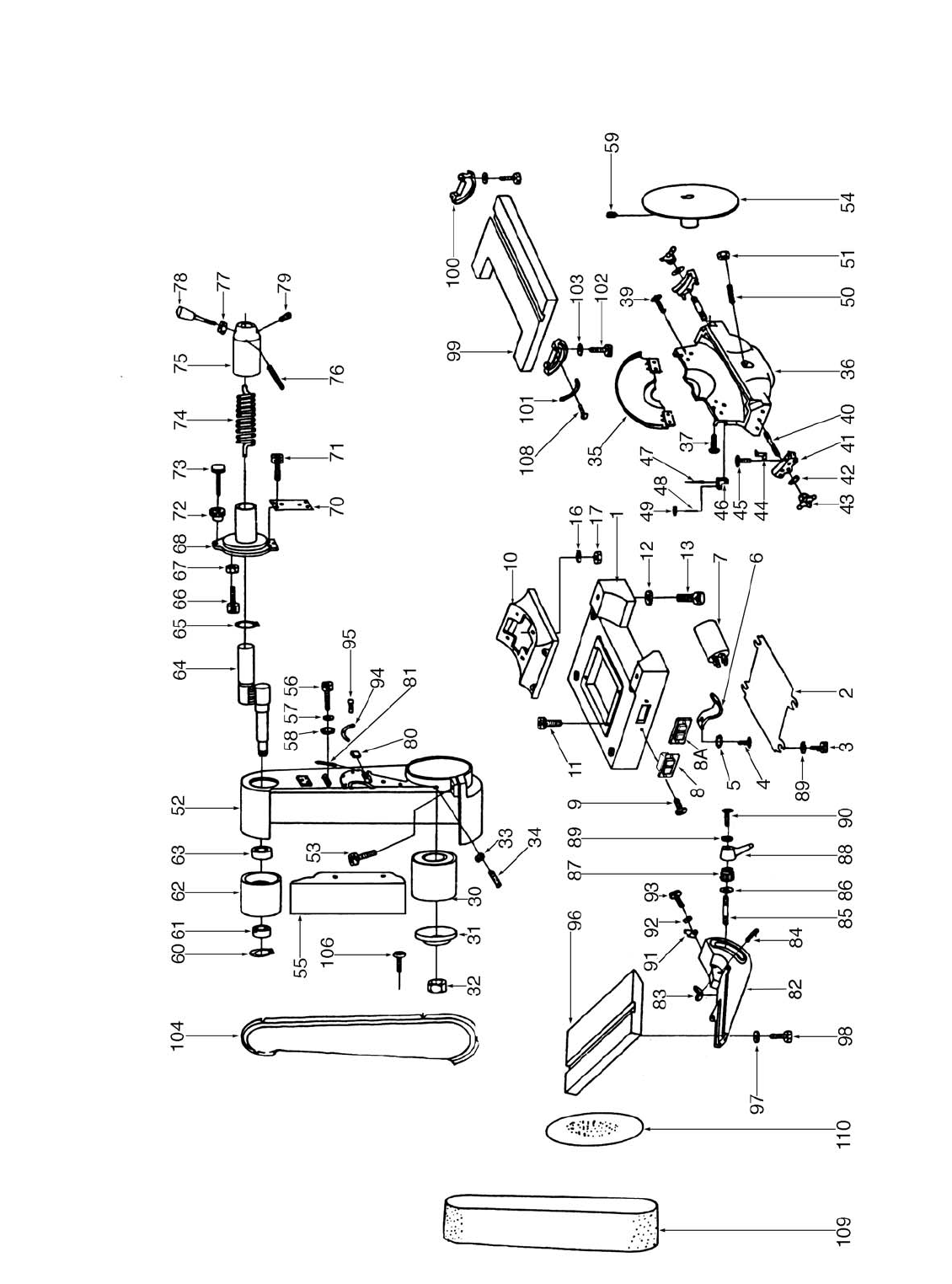
MAIN UNIT PARTS DIAGRAM

G1183/1276 Combination Sander -27-
PARTS LIST
001 P1183001 STAND
002 P1183002 BASE PLATE
003 PB17M HEX BOLT M8-1.25 X 16mm
004 P1183004 COVER SCREW
005 PW03 FLAT WASHER #10
006 P1183006 COVER LOCK
007 PC400B CAPACITOR-BIG OD
008 P1019090A SWITCH
008A P1019090B PLASTIC SWITCH COVER
009 P1183009 SWITCH SCREW
010 P1183010 MOTOR BASE
011 PSB11M CAP SCREW M8-1.25 x 16mm
012 PLW05 LOCK WASHER 7⁄16"
013 PSB13 CAP SCREW 7⁄16"-14 x 11⁄4"
014 P1183014 STATOR HOUSING
015 PB07 HEX BOLT 5/16"-18 x 3/4"
016 PLW01 LOCK WASHER 5⁄16"
017 PN02 HEX NUT 5⁄16"-18
018 P1183018 STATOR
019 P1183019 SHAFT
020 PK13M KEY 5 x 5 x 70 mm
021 PK12M KEY 5 x 5 x 30 mm
022 P6206 BALL BEARING 6206
023 P1183023 RIGHT CASTING COVER
024 PS19 PHLP HD SCR 1⁄4"-20 x 1"
025 PLW02 LOCK WASHER 1⁄4"
026 P6206 BALL BEARING 6206
027 P1183027 LEFT CASTING COVER
028 PCP004 CONTACT PLT, LG, INT PT
029 P1183029 CENTRIFUGAL SWITCH
030 P1183030 LOWER WHEEL
031 P1183031 FLANGE
032 P1183032 1"-8 LH HEX NUT
033 PN01M HEX NUT M6-1.0 mm
034 PSS12M SET SCREW M6-1.0 x 25mm
035 P1183035 DISC GUARD
036 P1183036 BASE
037 PS06 PHLP HD SCR 10-24 x 3⁄8"
039 PS06 PHLP HD SCR 10-24 x 3⁄8"
040 P1183040 STUD
041 P1183041 SLIDING RAIL
042 PW04 FLAT WASHER 7⁄16"
043 P1183043 STAR KNOB
044 P1183044 POINTER
045 P1183045 SPECIAL SCREW
046 P1183046 BLOCK
047 PRP32M ROLL PIN 6 x 40mm
048 PSS12M SETSCREW M6-1.0 x 25mm
049 PN01M HEX NUT M6-1.0
050 PSS18 SETSCREW
5⁄16"-18 x 3⁄4"
051 PN02 HEX NUT 5⁄16"-18
052 P1183052 BELT HOUSING CASTING
053 PSB12M CAP SCREW M8-1.25 x 40mm
054 P1183054 ALUMINUM DISC
055 P1183055 PLATEN
056 PSB13M CAP SCREW M8-1.25 x 30mm
057 PW07 FLAT WASHER 5⁄16"
058 PW04 FLAT WASHER 7⁄16"
059 PSS01M SET SCREW M6-1.0 x 10mm
060 PR05M EXT RETAINING RING 15mm
061 P6202` BALL BEARING 6202
062 P1183062 UPPER WHEEL
063 P6203 BALL BEARING 6203
064 P1183064 SHAFT
065 PR10M EXT RETAINING RING 22mm
066 PSB01M CAP SCREW M6-1.0 x 16
067 PN01M HEX NUT M6-1.0
REF# PART# DESCRIPTION REF# PART# DESCRIPTION

-28- G1183/1276 Combination Sander
NOTES
G1183/1276 Combination Sander -29-
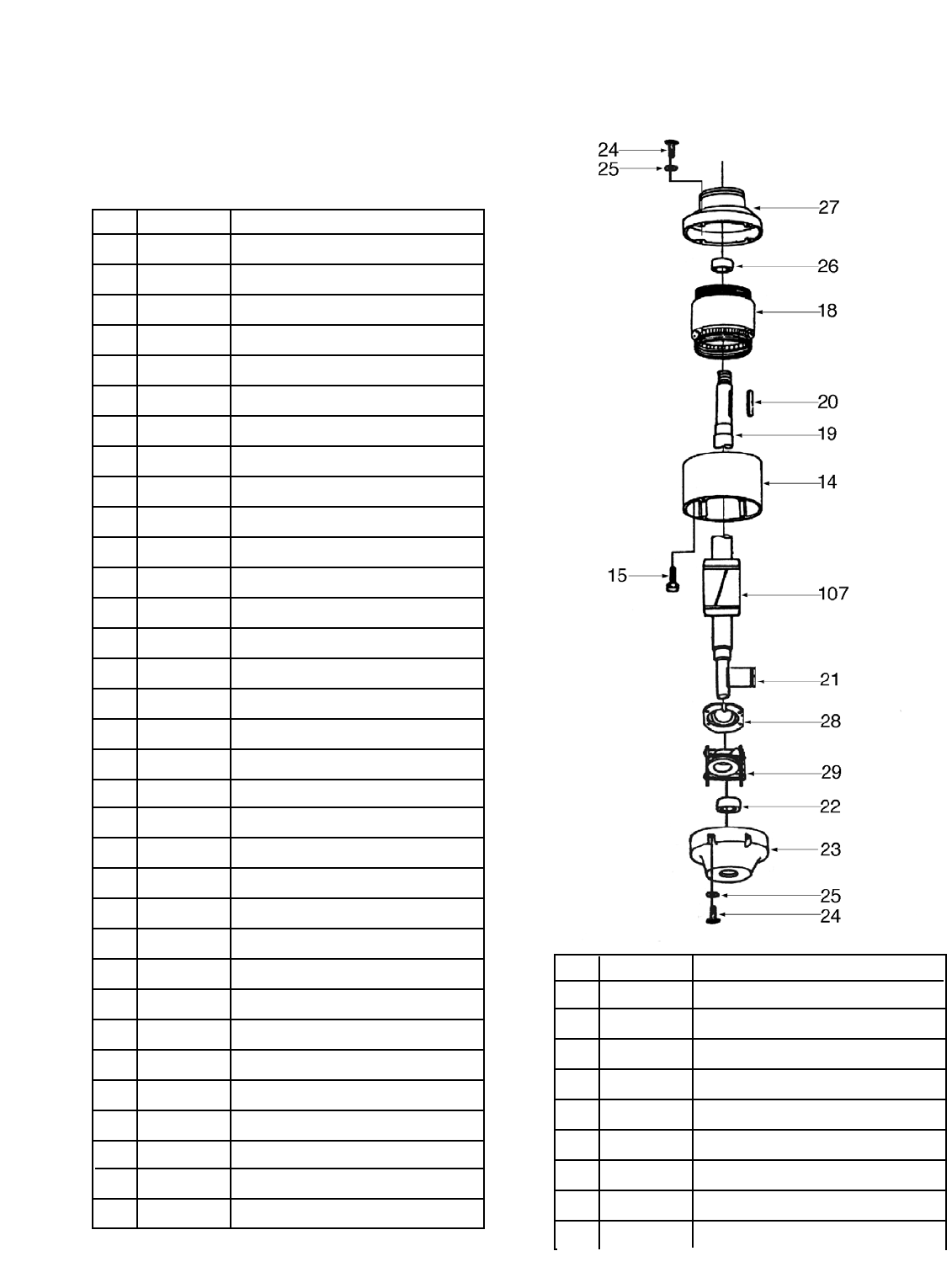
MOTOR UNIT PARTS DIAGRAM
068 P1183068 COVER
070 P1183070 PLATE
071 PSB14M CAP SCREW M8-1.25 x 20
072 P1183072 KNURLED CHECK NUT
073 P1183073 KNURLED BOLT
074 P1183074 SPRING
075 P1183075 LEVER HOLDER
076 PRP33M ROLL PIN 6 x 50mm
077 PN08 HEX NUT 3⁄8"-16
078 P1183078 IDLER PULLEY LEVER
079 PSS01M SETSCREW M6-1.0 x 10mm
080 P1183080 BLOCK
081 PRP33M ROLL PIN 6 x 50
082 P1183082 TRUNNION
083 P1183083 SLIDE
084 PRP19M ROLL PIN 4 x 14mm
085 P1183085 STUD
086 PW04 FLAT WASHER 7⁄16"
087 P1183087 TOOTHED NUT
088 P1024039 LOCK HANDLE
089 PLW02 LOCK WASHER 1⁄4"
090 PB02 HEX BOLT 1⁄4"-20 x 5⁄8"
091 P1183044 POINTER
092 PW03 FLAT WASHER #10
093 PS18 PHLP HD SCR 10-24 1⁄4"
094 P1183094 DEGREE SCALE
095 P1183108 RIVET
096 P1183096 BELT SANDER TABLE
097 PW07 FLAT WASHER 5⁄16"
098 PB07 HEX BOLT 5⁄16"-18 x 3⁄4"
099 P1183099 DISC SANDER TABLE
100 P1183100 DEGREE SLIDE
101 P1183101 DEGREE SCALE
102 PB07 HEX BOLT 5⁄16"-18 x 3⁄4"
REF# PART# DESCRIPTION
103 PW07 FLAT WASHER 5⁄16"
104 P1183104 BELT GUARD
106 P1183106 SPECIAL SCREW
107 P1183019 SHAFT
108 P1183108 RIVET
109 G1215 SANDING BELT 6" x 48" 100GT
110 G1221 SANDING DISC 12" 100 GT
112 P1183112 MOTOR FAN
113 P1183113 COMPLETE MOTOR 3450 RPM
113 P1276113 COMPLETE MOTOR 1720 RPM

-30- G1183/1276 Combination Sander
Grizzly Industrial, Inc. warrants every product it sells for a period of 1 year to the original purchaser from
the date of purchase. This warranty does not apply to defects due directly or indirectly to misuse, abuse,
negligence, accidents, repairs or alterations or lack of maintenance. This is Grizzly’s sole written warranty
and any and all warranties that may be implied by law, including any merchantability or fitness, for any par-
ticular purpose, are hereby limited to the duration of this written warranty. We do not warrant or represent
that the merchandise complies with the provisions of any law or acts unless the manufacturer so warrants.
In no event shall Grizzly’s liability under this warranty exceed the purchase price paid for the product and
any legal actions brought against Grizzly shall be tried in the State of Washington, County of Whatcom.
We shall in no event be liable for death, injuries to persons or property or for incidental, contingent, spe-
cial, or consequential damages arising from the use of our products.
To take advantage of this warranty, contact us by mail or phone and give us all the details. We will then
issue you a “Return Number’’, which must be clearly posted on the outside as well as the inside of the car-
ton. We will not accept any item back without this number. Proof of purchase must accompany the mer-
chandise.
The manufacturers reserve the right to change specifications at any time because they constantly strive to
achieve better quality equipment. We make every effort to ensure that our products meet high quality and
durability standards and we hope you never need to use this warranty.
Please feel free to write or call us if you have any questions about the machine or the manual.
Thank you again for your business and continued support. We hope to serve you again soon.
WARRANTY AND RETURNS

G1183/1276 Combination Sander
CUT ALONG DOTTED LINE
10. Which benchtop tools do you own? Check all that apply.
___1" x 42" Belt Sander ___6" - 8" Grinder
___5" - 8" Drill Press ___Mini Lathe
___8" Table Saw ___10" - 12" Thickness Planer
___8" - 10" Bandsaw ___Scroll Saw
___Disc/Belt Sander ___Spindle/Belt Sander
___Mini Jointer
___Other__________________________________________________
11. How many of the machines checked above are Grizzly? ____________
12. Which portable/hand held power tools do you own? Check all that apply.
___Belt Sander ___Orbital Sander
___Biscuit Joiner ___Palm Sander
___Circular Saw ___Portable Planer
___Detail Sander ___Saber Saw
___Drill/Driver ___Reciprocating Saw
___Miter Saw ___Router
___Other__________________________________________________
13. What machines/supplies would you like Grizzly Industrial to carry?
___12" Table Saw ___Radial Arm Saw
___12" Jointer ___Panel Saw
___Combination Planer/Jointer ___Brass Hardware
___Paint & Finishing Supplies ___Lumber
___Contractor’s Supplies
___Other__________________________________________________
14. What new accessories would you like Grizzly Industrial to carry?
___Builders Hardware ___Hand Tools
___Fasteners ___Wood Components
___Other__________________________________________________
15. What other companies do you purchase your tools and supplies from?
__________________________________________________________
__________________________________________________________
16. Do you think your purchase represents good value?
___Yes ___No
17. Would you recommend Grizzly Industrial to a friend?
___Yes ___No
18. Would you allow us to use your name as a reference for Grizzly customers
in your area? Note: We never use names more than three times.
___Yes ___No
19. Comments:_________________________________________________
__________________________________________________________
__________________________________________________________
__________________________________________________________
__________________________________________________________
1. How did you learn about us?
___Advertisement ___Friend
___Catalog ___Card Deck
___World Wide Web
___Other__________________________________________________
2. Which of the following magazines do you subscribe to.
___American Woodworker ___Practical Homeowner
___Cabinetmaker ___Shop Notes
___Family Handyman ___Today’s Homeowner
___Fine Homebuilding ___WOOD
___Fine Woodworking ___Wooden Boat
___Home Handyman ___Woodshop News
___Journal of Light Construction ___Woodsmith
___Old House Journal ___Woodwork
___Popular Mechanics ___Woodworker
___Popular Science ___Woodworker’s Journal
___Popular Woodworking ___Workbench
___Other__________________________________________________
3. Which of the following woodworking/remodeling shows do you watch?
___Backyard America ___The New Yankee Workshop
___Home Time ___This Old House
___The American Woodworker ___Woodwright’s Shop
___Other__________________________________________________
4. What is your annual household income?
___$20,000-$29,999 ___$60,000-$69,999
___$30,000-$39,999 ___$70,000-$79,999
___$40,000-$49,999 ___$80,000-$89,999
___$50,000-$59,999 ___$90,000 +
5. What is your age group?
___20-29 ___50-59
___30-39 ___60-69
___40-49 ___70 +
6. How long have you been a woodworker?
___0 - 2 Years ___8 - 20 Years
___2 - 8 Years ___20+ Years
7. How would you rank your woodworking skills?
___Simple ___Advanced
___Intermediate ___Master Craftsman
8. What stationary woodworking tools do you own? Check all that apply.
___Air Compressor ___Panel Saw
___Band Saw ___Planer
___Drill Press ___Power Feeder
___Drum Sander ___Radial Arm Saw
___Dust Collector ___Shaper
___Horizontal Boring Machine ___Spindle Sander
___Jointer ___Table Saw
___Lathe ___Vacuum Veneer Press
___Mortiser ___Wide Belt Sander
___Other__________________________________________________
9. How many of your woodworking machines are Grizzly? _____________
Name ____________________________________________________________________________________
Street ____________________________________________________________________________________
City ______________________________________________________________State________Zip_________
Phone Number_______________________E-Mail_______________________FAX________________________
MODEL # ______________________________Order #______________________________________________
The following information is given on a voluntary basis. It will be used for marketing purposes to help us develop better products and services. Of
course, all information is strictly confidential.
WARRANTY CARD

FOLD ALONG DOTTED LINE
FOLD ALONG DOTTED LINE
GRIZZLY INDUSTRIAL, INC.
P.O. BOX 2069
BELLINGHAM, WA 98227-2069
Name_______________________________
Street_______________________________
City______________State______Zip______
Send a Grizzly Catalog to a friend:
TAPE ALONG EDGES--PLEASE DO NOT STAPLE
