Pressure Booster Pumps 0907 Grundfos Data Booklet SP
User Manual: Pressure Booster Pumps 0907
Open the PDF directly: View PDF ![]() .
.
Page Count: 100
- General data
- Submersible pumps
- Submersible motors
- Performance curves/ Technical data
- Technical data
- 1 x 220 V, submersible motors
- 1 x 230 V, submersible motors
- 3 x 220 V, submersible motors (SF 1.0)
- 3 x 220 V, submersible rewindable motors
- 3 x 380 V, submersible motors
- 3 x 380 V, submersible rewindable motors
- 3 x 380 V, submersible motors, MS6 T60
- 3 x 460 V, submersible motors
- 3 x 460 V, submersible rewindable motors
- 3 x 460 V, submersible industrial motors
- Accessories
- Energy consumption
- Cable sizing
- Table of head losses
- Further product documentation
GRUNDFOS DATA BOOKLET
SP A, SP
Submersible pumps, motors and accessories
60 Hz

2
Contents
General data
Performance range 3
Applications 4
Type key 4
Pumped liquids 4
Operating conditions 4
Curve conditions 4
Pump range 5
Motor range 5
Motor protection and controllers 5
Submersible pumps
Features and benefits 6
Material specification 8
Submersible motors
Features and benefits 9
Shaft seal 11
Material specification for MS motors 12
Material specification for MMS motors 14
Performance curves/
Technical data
SP 1A 16
SP 2A 18
SP 2A 20
SP 5A 22
SP 8A 24
SP 14A 26
SP 17 28
SP 30 33
SP 46 38
SP 60 43
SP 77 48
SP 125 58
SP 160 63
SP 215 68
Technical data
1 x 220 V, submersible motors 73
1 x 230 V, submersible motors 73
3 x 220 V, submersible motors (SF 1.0) 73
3 x 220 V, submersible rewindable motors 74
3 x 380 V, submersible motors 74
3 x 380 V, submersible rewindable motors 75
3 x 380 V, submersible motors, MS6 T60 75
3 x 460 V, submersible motors 76
3 x 460 V, submersible rewindable motors 77
3 x 460 V, submersible industrial motors 77
Accessories
MP 204 78
Control functions 81
G100 gateway for communication with Grundfos
products 84
Connecting pieces 86
Cable termination kit with plug 87
Cable termination kit, type KM 87
Cable termination kit, type M0 to M6 87
Submersible drop cable 88
Zinc anodes 88
Flow sleeves 89
SA-SPM 5 control boxes 89
Pt100 90
Energy consumption
Energy consumption of submersible pumps 91
Cable sizing
Cables 92
Table of head losses
Head losses in ordinary water pipes 96
Head losses in plastic pipes 97
Further product documentation
WebCAPS 98
WinCAPS 99
3
SP A, SP
General data
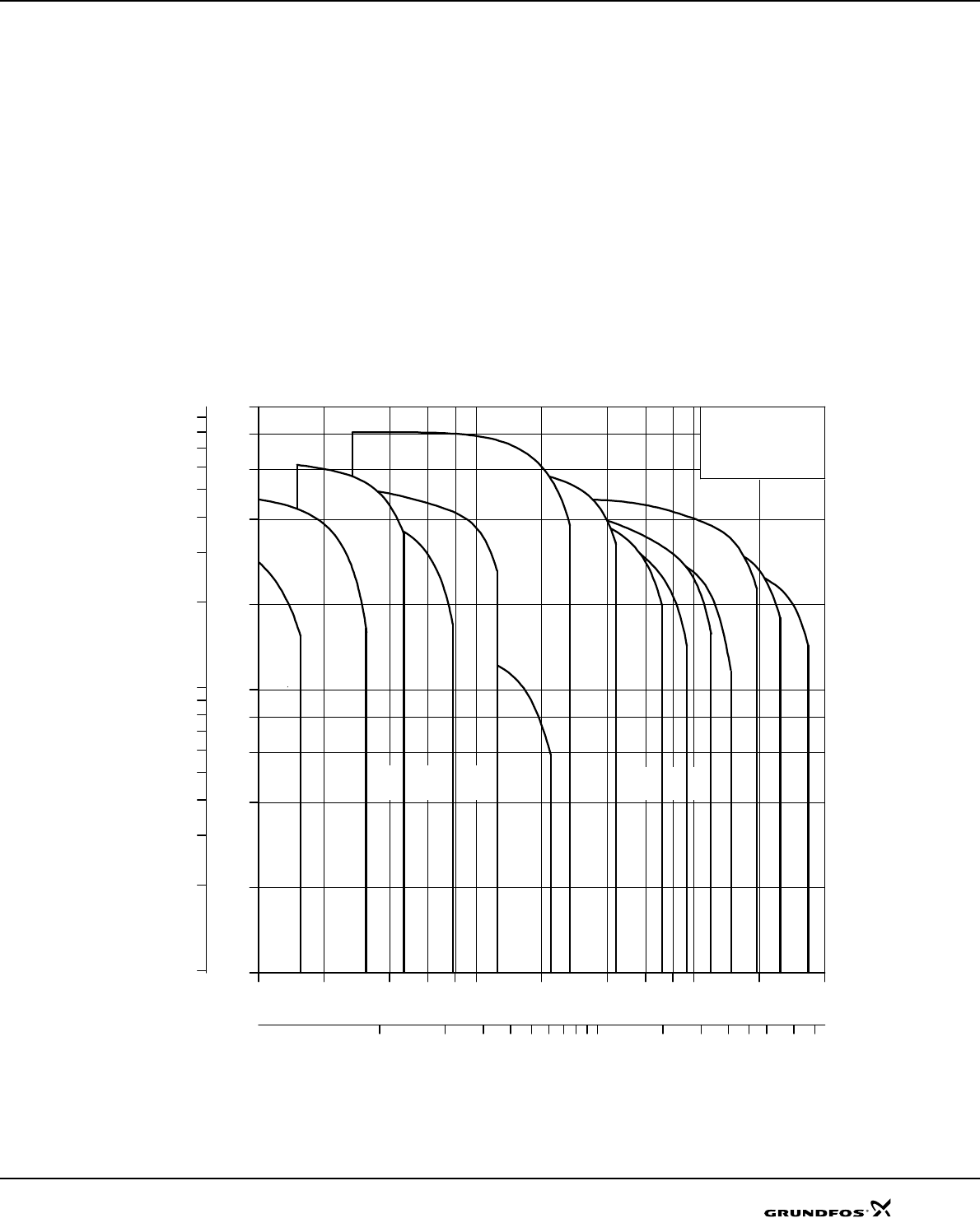
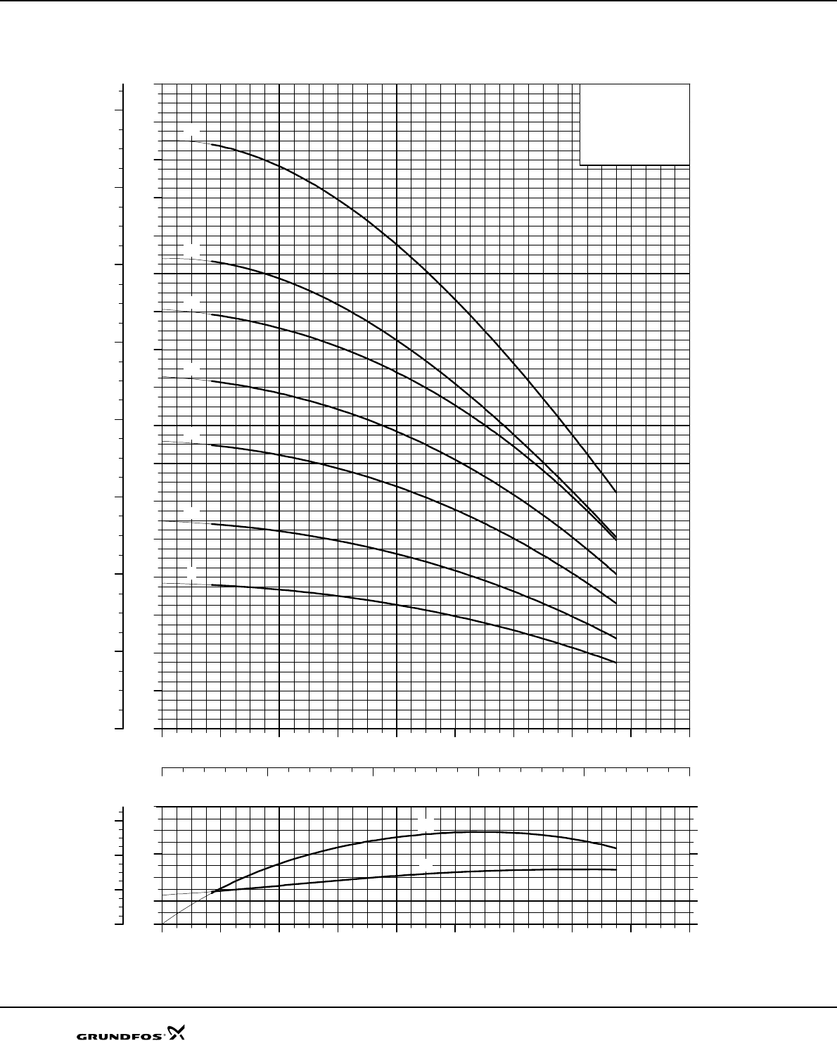
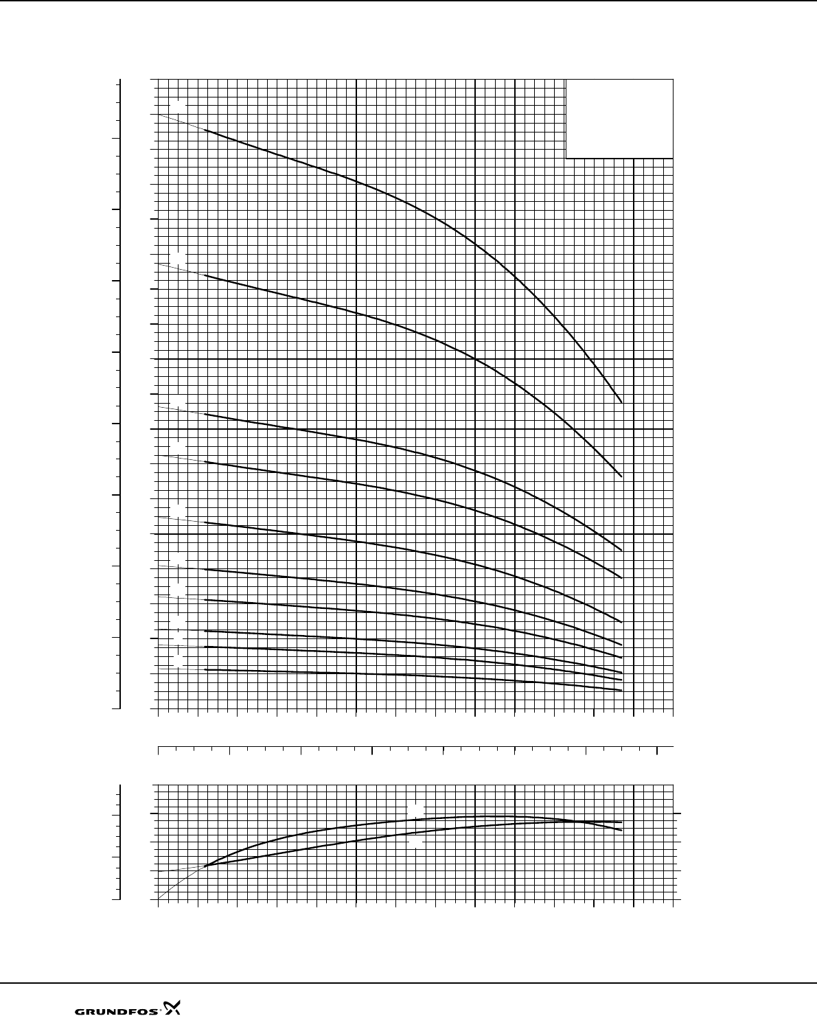
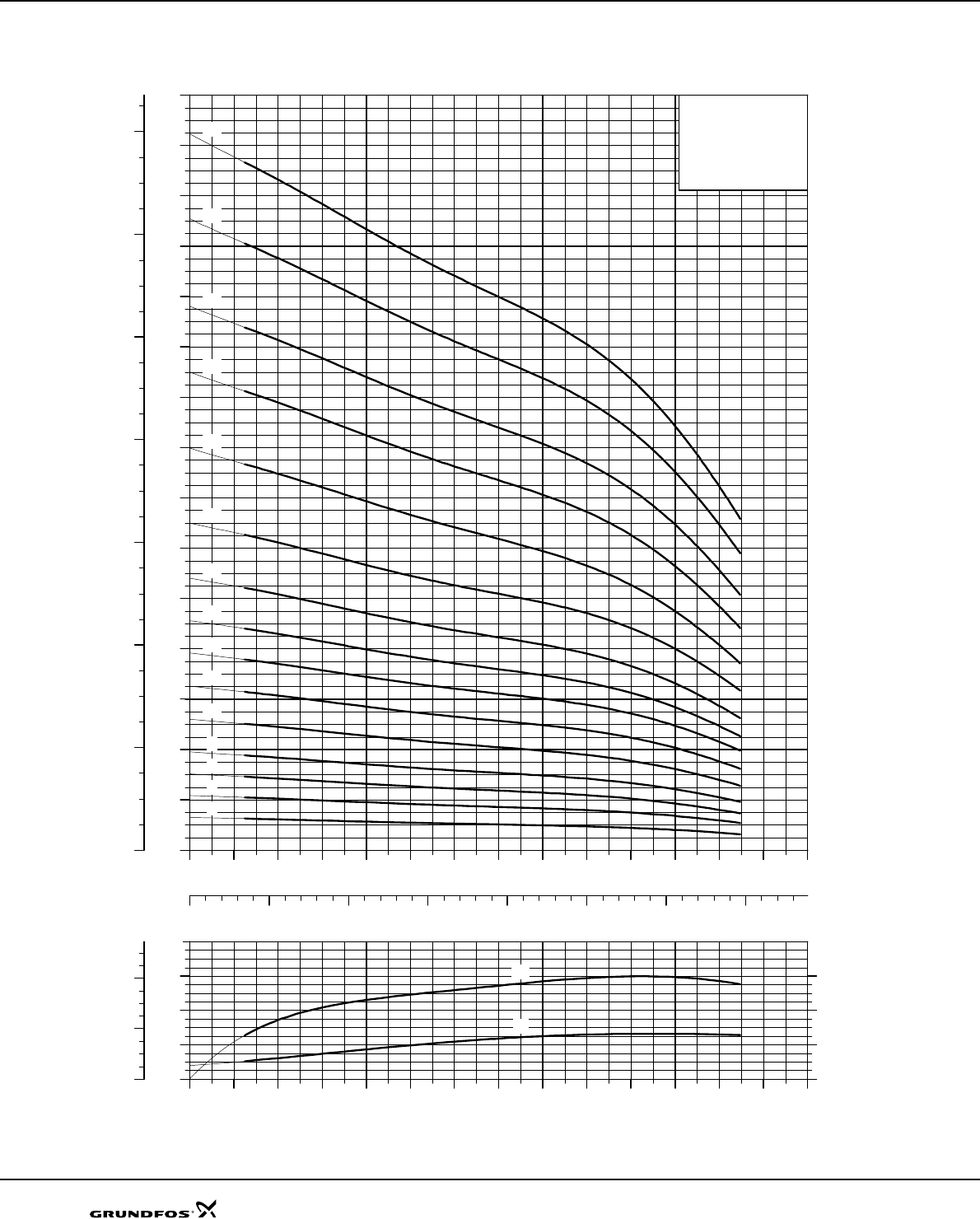
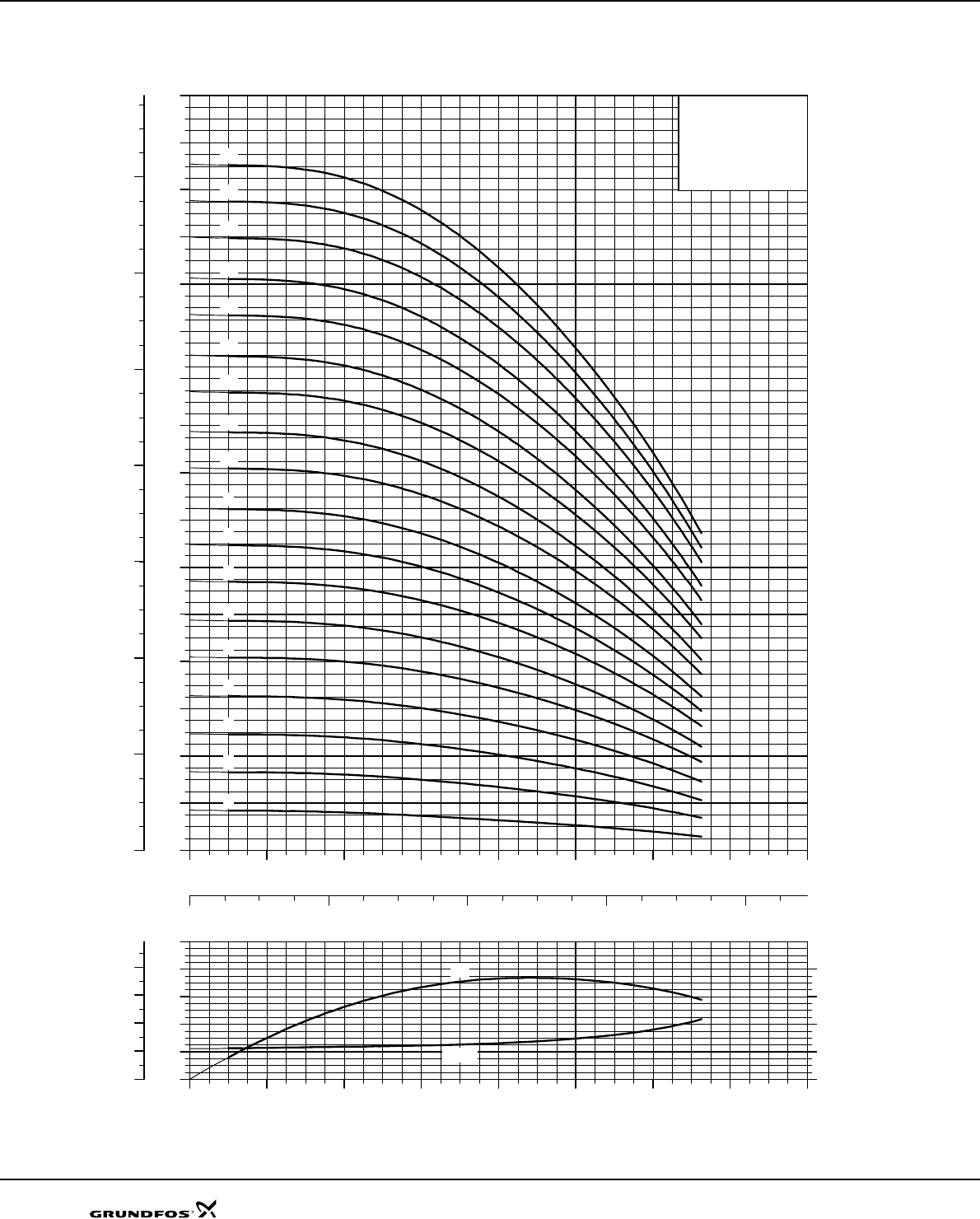
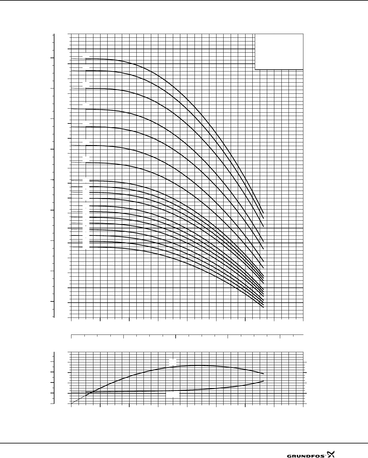
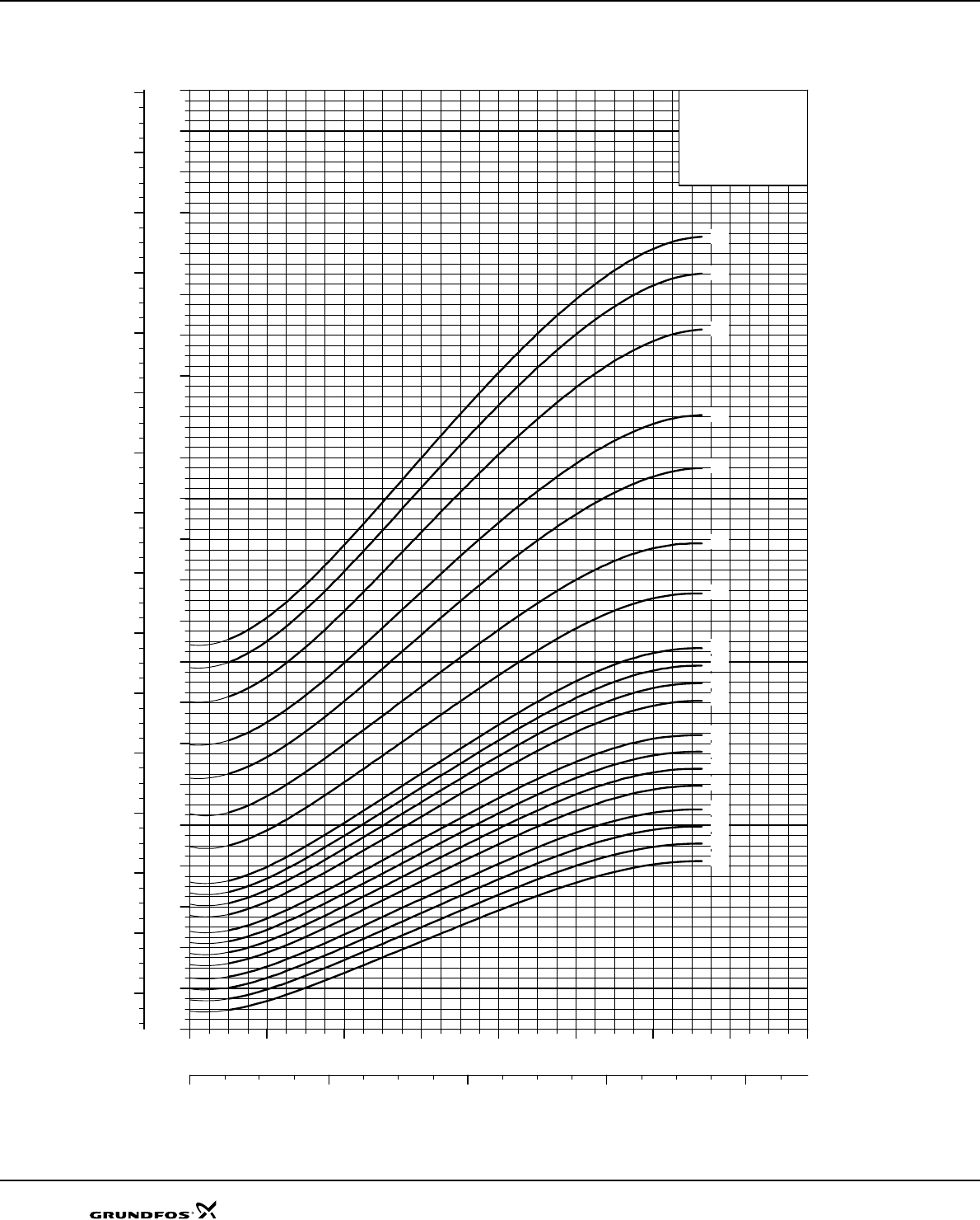
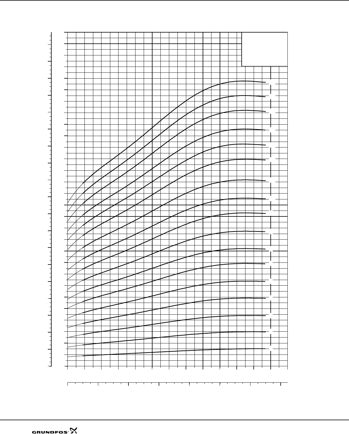
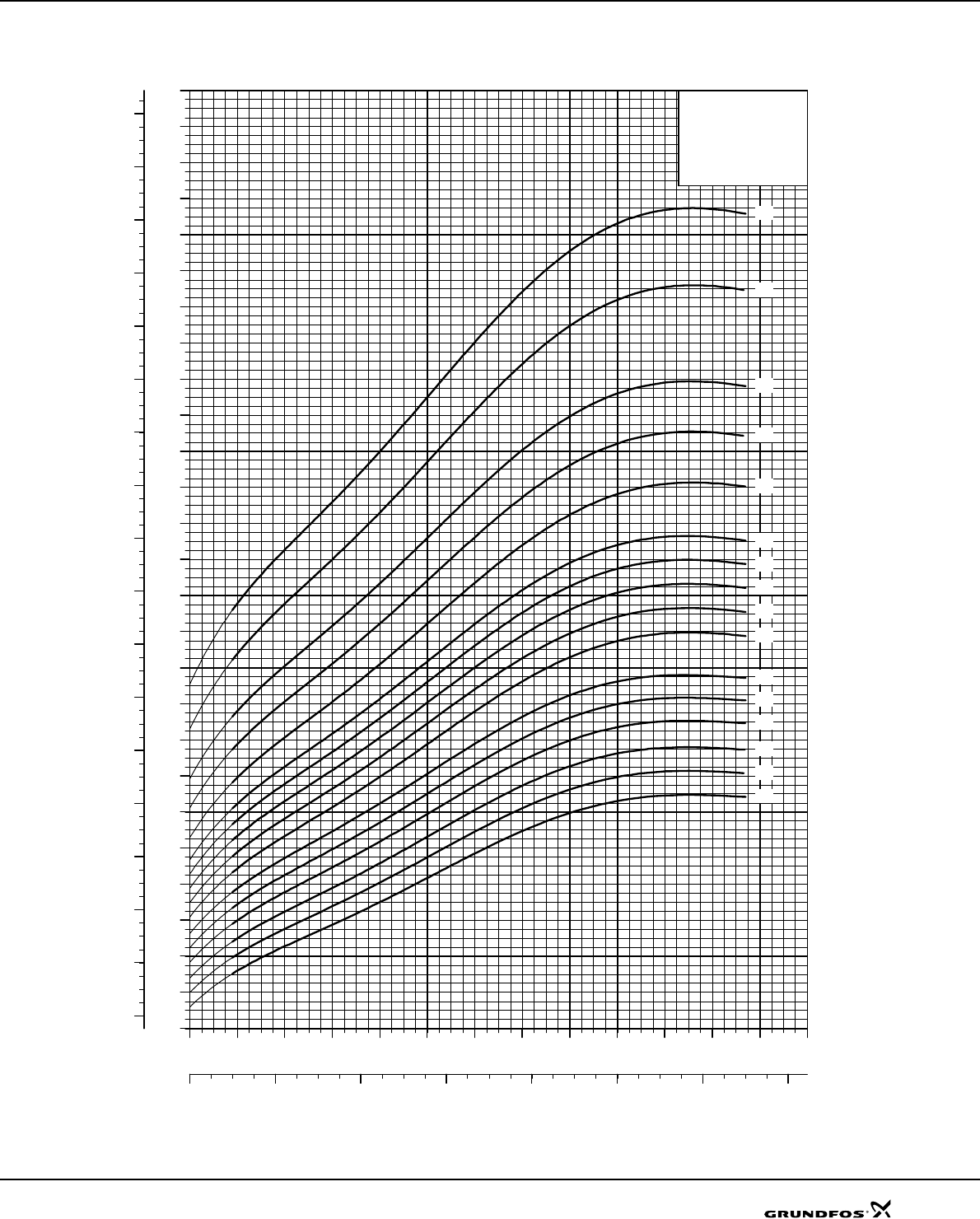
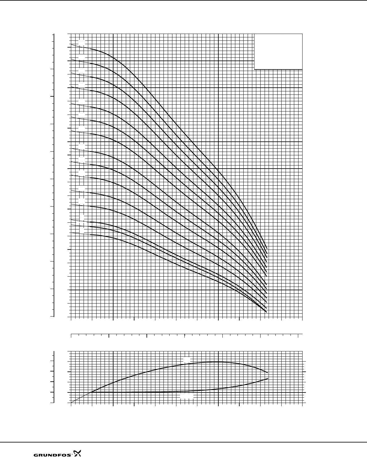
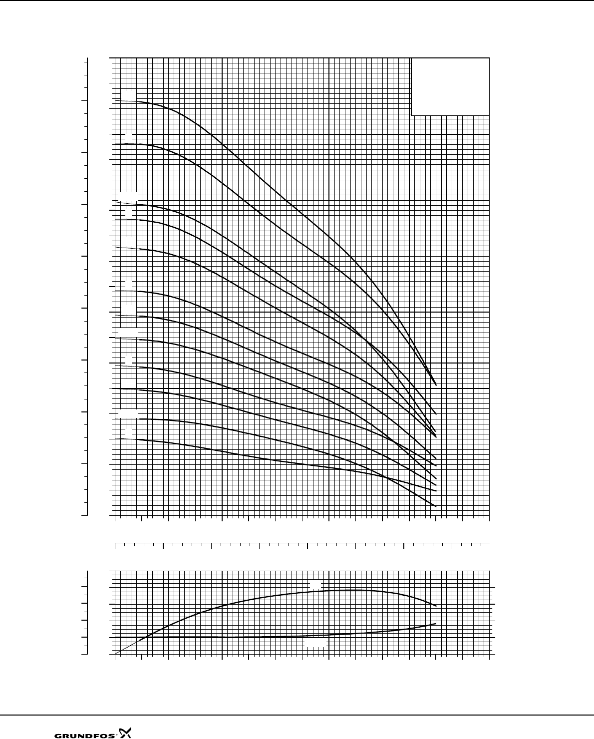
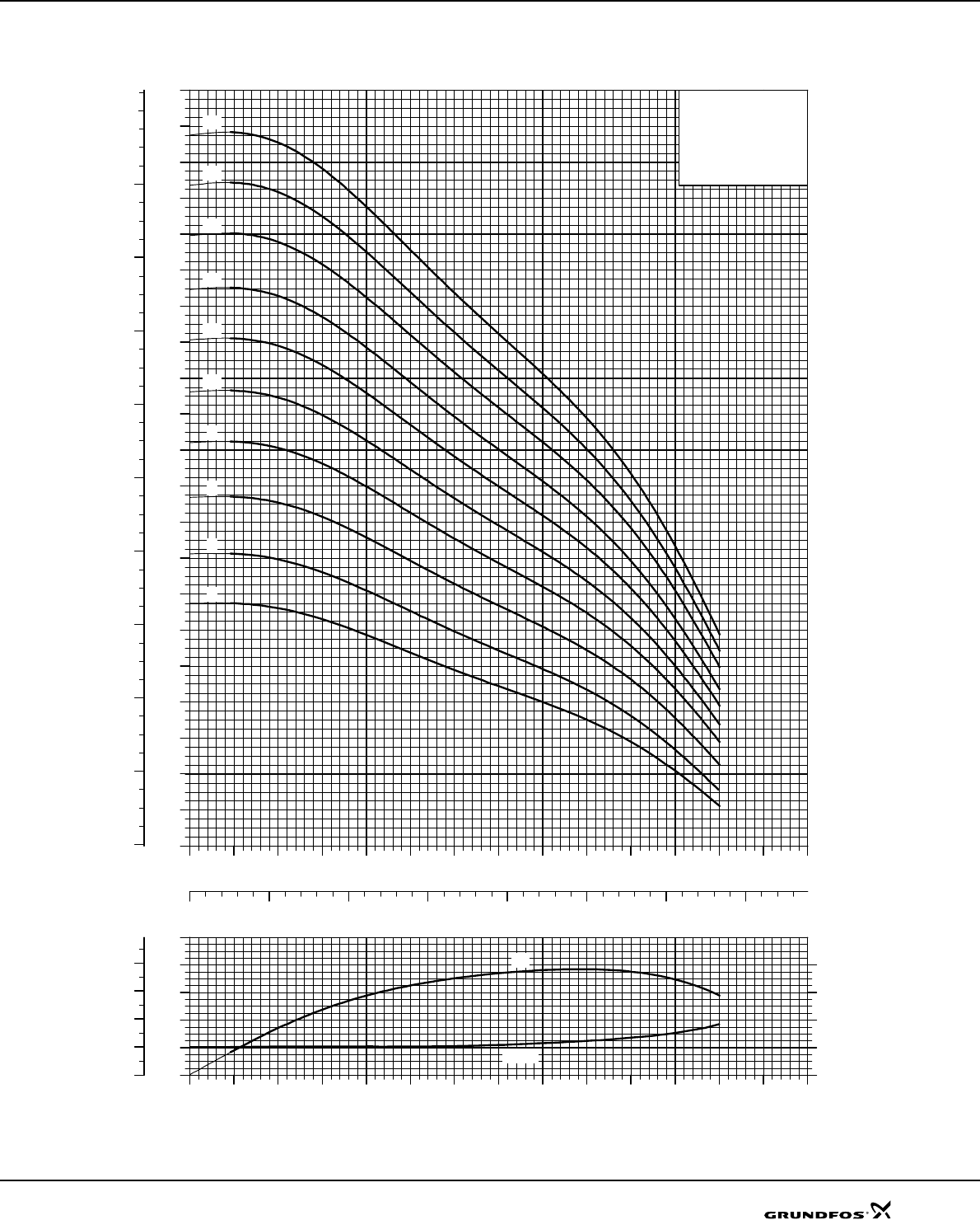
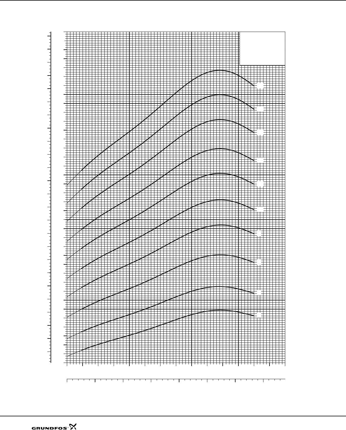
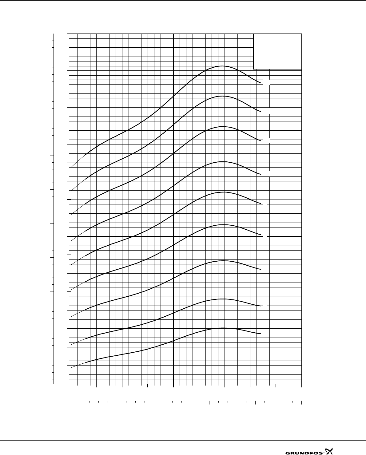
Performance range
TM00 7574 0707
1 2 4 6 8 10 20 40 60 80 100 200 400
Q [m³/h]
10
20
40
60
80
100
200
400
600
800
H
[m]
100100
200
300
400
500
600
700
800
900
10001000
2000
3000
4000
5000
6000
7000
8000
[kPa]
p
11 2 3 4 5 6 7 8 91010 20 30 40 50 60 80 100100
Q [l/s]
SP
60 Hz, SF 1.15
SP 125
SP 160
SP 77
SP 60
SP 17
SP 215
SP 14A
SP 8A
SP 5A
SP 3A
SP 2A
SP 1A
SP 30
SP 46
SP 95
4
General data SP A, SP
Applications
The SPA and SP pumps are suitable for the following
applications:
• raw water supply
• irrigation systems
• groundwater lowering
• pressure boosting
• fountain applications
• mining applications
• off-shore applications.
Type key
Pumped liquids
Clean, thin, non-aggressive liquids without solid
particles or fibres.
The special SP A-N and SP-N versions made of
stainless steel to DIN W.-Nr. 1.4401 and SP A-R and
SP-R versions made of stainless steel to DIN W.-Nr.
1.4539 are available for applications involving
aggressive liquids.
Operating conditions
Flow rate, Q: 0.1-335 m3/h.
Head, H: Maximum 810 m.
Maximum liquid temperature
Note: For MMS 6000, 37 kW, MMS 8000, 110 kW, and
MMS 10000, 170 kW, the maximum liquid temperature
is 5 °C lower than the values stated in the table above.
For MMS 10000, 190 kW the temperature is 10 °C
lower.
Operating pressure
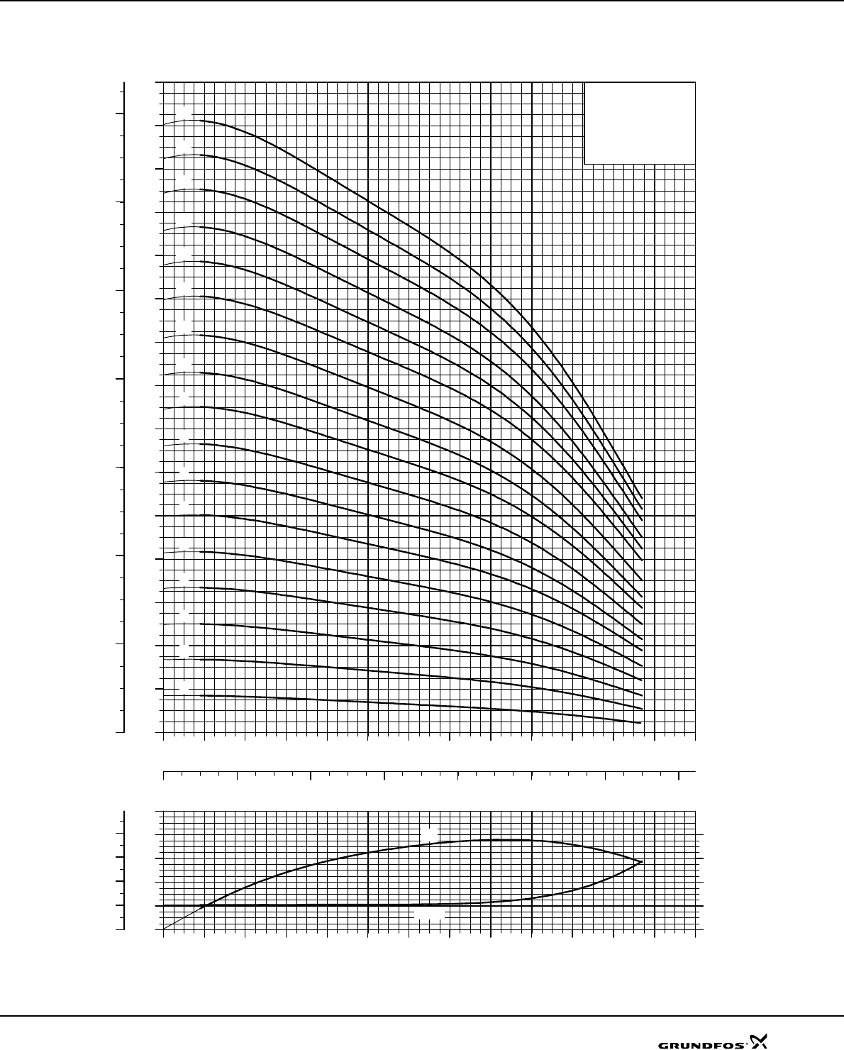
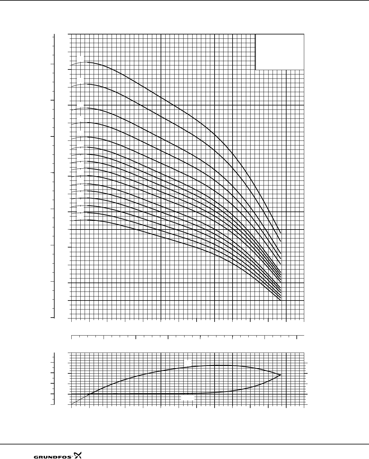
Curve conditions
The conditions below apply to the curves shown on
pages 16-72:
General
• Curve tolerances according to ISO 9906, Annex A.
• The performance curves show pump performance
at actual speed, cf. standard motor range.
The speeds of the motors are approximately these:
4" motors: n = 3470 min-1
6" motors: n = 3460 min-1
8" to 10" motors: n = 3525 min-1
• The measurements were made with airless water at
a temperature of 20 °C. The curves apply to a
kinematic viscosity of 1 mm2/s (1 cSt). When
pumping liquids with a density higher than that of
water, use motors with correspondingly higher
outputs.
• The bold curves indicate the recommended
performance range.
• The performance curves are inclusive of possible
losses such as non-return valve loss.
SP A curves
•Q/H: The curves are inclusive of valve and inlet
losses at the actual speed.
•Power curve: P2 shows pump power input at the
actual speed for each individual pump size.
•Efficiency curve: Eta shows pump stage efficiency.
SP curves
•Q/H: The curves are inclusive of valve and inlet
losses at the actual speed.
Operation without non-return valve will increase the
actual head at rated performance by 0.5 to 1.0 m.
•NPSH: The curve is inclusive of pressure loss in the
suction interconnector and shows required inlet
pressure.
•Power curve: P2 shows pump power input at the
actual speed of each individual pump size.
•Efficiency curve: Eta shows pump stage efficiency.
If Eta for the actual pump size is needed, please
consult WinCAPS or WebCAPS.
Example SP 95 - 5 - A B N
Type range (SP A, SP)
Rated flow rate in m3/h
Number of impellers
First reduced-diameter impeller (A, B or C)
Second reduced-diameter impeller (A, B or C)
Stainless steel parts of material
= DIN W.-Nr. 1.4301
N = DIN W.-Nr. 1.4401
R = DIN W.-Nr. 1.4539
Motor
Installation
Flow velocity
past motor Vertical Horizontal
Grundfos MS 4"and
MS6 T30-versions 0.15 m/s 30°C 30°C
Grundfos 4" MS
industry versions 0.15 m/s 60°C 60°C
Grundfos MS6
T60-versions 1.0 m/s 60°C 60°C
Grundfos MMS 6" to
12" rewindable with
PVC in the windings
0.15 m/s 25°C 25°C
0.50 m/s 30°C 30°C
Grundfos MMS 6" to
12" rewindable with
PE/PA in the wind-
ings
0.15 m/s 40°C 40°C
0.50 m/s 45°C 45°C
Motor Maximum operating pressure
Grundfos MS
4" and 6"
6 MPa (60 bar)
Grundfos MMS
6" to 10"
rewindable

5
General data SP A, SP
Pump range
Figures in brackets ( ) indicate connection for pumps with sleeve.
Motor range
Direct-on-line starting is recommended up to 75 kW.
Soft starter or autotransformer is recommended above 75 kW.
Motors with star/delta are available from 5.5 kW.
Motor protection and controllers
Motor protection of single-phase motors, see "Technical data" on page 73.
Type SP 1A SP 2A SP 3A SP 5A SP 8A SP 14A SP 17 SP 30 SP 46 SP 60 SP 77 SP 95 SP 125 SP 160 SP 215
Steel: DIN 1.4301
AISI 304 zzzzz zzzzzzz z z z
Steel: DIN 1.4401
AISI 316 z z z z zzzzzz z z z
Steel: DIN 1.4539
AISI 904L z z zzzzzz z z z
Connection
Rp 1¼ 1¼
(R 1¼) 1¼ 1½
(R 1½) 2
(R 2) 22½
(R 3) 3
(R 3)
3
4
(R 4)
3
4 55 6 6 6
NPT 1" 1¼" 1¼" 1½" 2" 2" 3"
(3" ) 3"
(3")
3"
4"
(4")
3"
4" 5" 5" 6" 6" 6"
Flange connection:
Grundfos flange 5" 5" 6" 6" 6"
Motor output [kW] 0.25 0.37 0.55 0.75 1.1 1.5 2.2 3.0 3.7 4.0 5.5 7.5 9.2 11 13 15 18.5 22 26 30 37 45 55 63 75 92 110 132 147 170 190
Single-phase zzzzzzz
Three-phase z z z z z z z z z z z zzzz z zzzzzzzzz zzzzz
Industrial motor and
MS6 T60-versions zzzzzzzzzz z z
Rewindable motor z z z zzzz z zzzzzzzzz zzzzz
Steel: DIN 1.4301
AISI 304 zzzzzzzzzzzzzzzzzzzz
Steel: DIN 1.4301
and cast iron z z z z zzzz z zzzzzzzzz zzzzz
Steel: DIN 1.4401
AISI 316 z z z zzzz z zzzzzzzzz zzzzz
Steel: DIN 1.4539
AISI 904L z z z z z z z z z zzzz z zzzzzzzzz z
Built-in temperature
transmitter in motor z zzzzzzzzzzzz z zzz
Motor output
[kW] 0.37 0.55 0.75 1.1 1.5 2.2 3.0 3.7 4.0 5.5 7.5 9.2 11 13 15 18.5 22 26 30 37 45 55 63 75 92 110 132 147 170 190
MP 204 z z z zzzzzzzzzzzz z zzzzzzzzz zzzzz
Pt100 zzzzzzzz z zzzzzzzzz zzzzz
Zinc anode zzzzzzzzzzzz z zzzzzzzzz zzzzz
Vertical flow
sleeve z z z zzzzzzzzzzzz z zzzzzzzzz zzzzz
Horizontal flow
sleeve z z z zzzz zzzzzzz z zzz
SA-SPM z z z zzzzz
R100 z z z zzzzzzzzzzzz z zzzzzzzzz zzzzz
RS-485 communi-
cation module z z z zzzzzzzzzzzz z zzzzzzzzz zzzzz
G100 z z z zzzzzzzzzzzz z zzzzzzzzz zzzzz
SP A, SP
6
Submersible pumps
Features and benefits
A wide pump range
Grundfos offers energy-efficient submersible pumps
ranging from 1 to 335 m3/h. The pump range consists
of many pump sizes - and each pump size is available
with an optional number of stages to match any duty
point.
High pump efficiency
Often pump efficiency is a neglected factor compared
to the price. However, the observant user will notice
that price variations are without importance to water
supply economics compared to the importance of pump
and motor efficiencies.
Example
When pumping 200 m3/h at a head of 100 m for a period
of 10 years, EURO 60,000 will be saved if a pump/
motor having a 10 % higher efficiency is chosen and the
price is EURO 0.10 per kWh.
Material and pumped liquids
Grundfos offers a complete range of pumps and motors
which as standard are made completely of stainless
steel to DIN W.-Nr. 1.4301 (AISI 304). This ensures
good wear resistance and a reduced risk of corrosion
when pumping ordinary cold water with a minor chloride
content.
A pump range made of upgraded stainless steel is
available for more aggressive liquids:
SP N: DIN W.-Nr. 1.4401 (AISI 316)
SP R: DIN W.-Nr. 1.4539 (AISI 904L)
Alternatively, a complete range of zinc anodes for
cathodic protection is available, see page 88. For
example this may be advisable for sea water
applications.
For slightly polluted liquids containing for example oil,
Grundfos offers a complete range of stainless steel
SP NE pumps to DIN W.-Nr. 1.4401 (AISI 316) with all
rubber parts made of FKM.
Low installation costs
Stainless steel means low weight facilitating the
handling of pumps and resulting in low equipment costs
and reduced installation and service time.
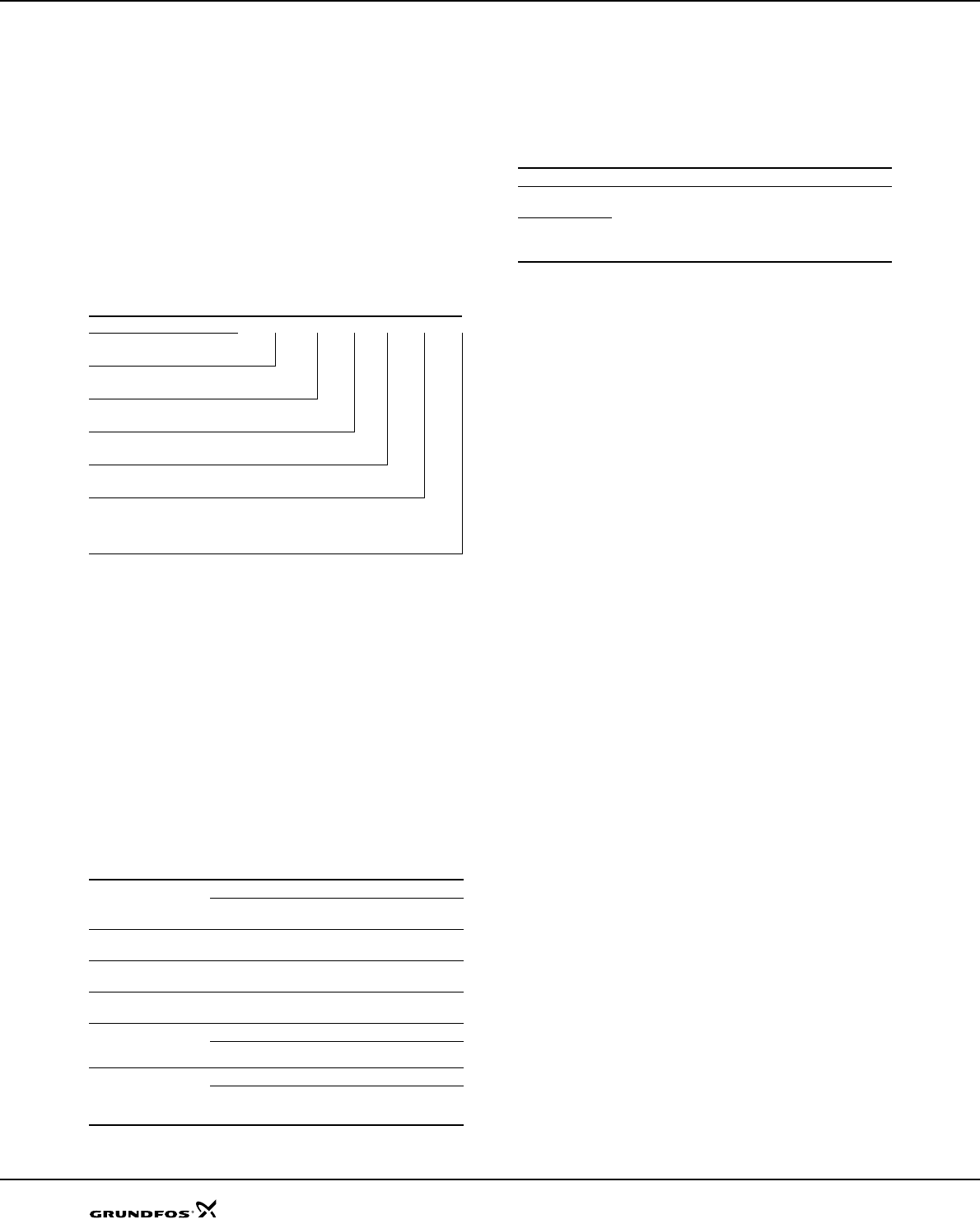
Fig. 1 Pump/motor efficiencies in relation to flow
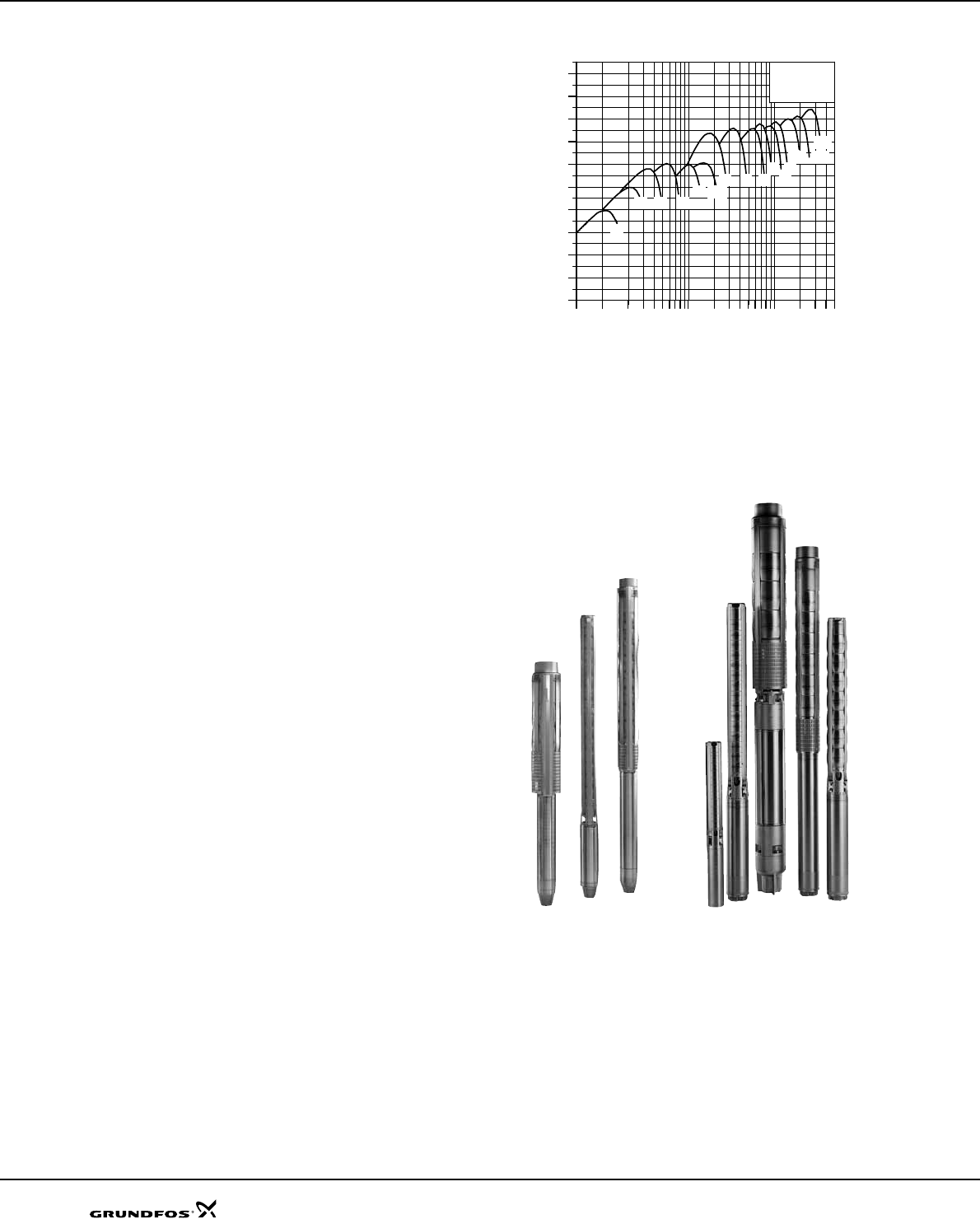
Fig. 2 Various SP pumps
TM00 7575 2598Gr6389 - GrA4019
0 11 2 3 4 6 91010 20 40 100100 200 500
Q [m³/h]
0
10
20
30
40
50
60
70
80
90
[%]
Eta 60 HZ
17 30 46
60 95
125 160
215
77
2A 3A 5A 8A14A
1A
0.5 60
7
Submersible pumps SP A, SP
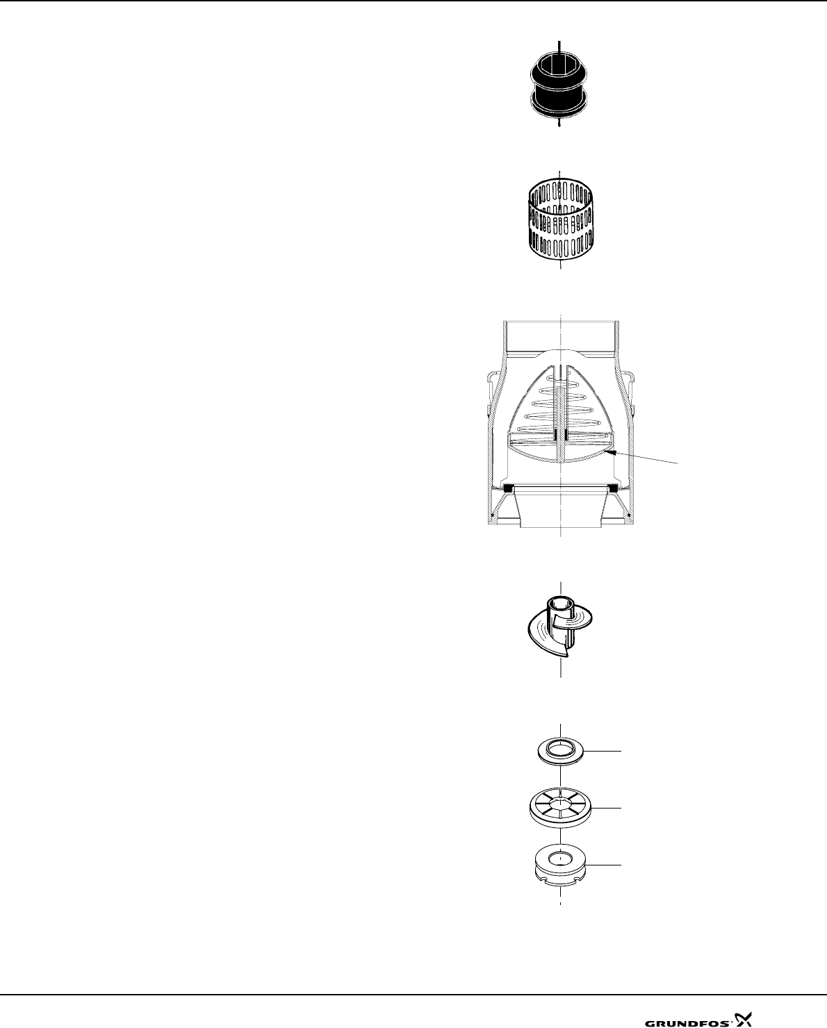
Bearings with sand channels
All bearings are water-lubricated and have a squared
shape enabling sand particles, if any, to leave the pump
together with the pumped liquid.
Inlet strainer
The inlet strainer prevents particles over a certain size
from entering the pump.
Non-return valve
All pumps are equipped with a reliable non-return valve
in the vale casing preventing back flow in connection
with pump stoppage.
Furthermore, the short closing time of the non-return
valve means that the risk of destructive water hammer
is reduced to a minimum.
The valve casing is designed for optimum hydraulic
properties to minimize the pressure loss across the
valve and thus to contribute to the high efficiency of the
pump.
Priming screw
All Grundfos 4" pumps are fitted with a priming screw.
Consequently, dry running is prevented, because the
priming screw will make sure that pump bearings are
always lubricated.
Due to the semi-axial impellers of large SP pumps this
priming is provided automatically.
However, it applies to all pump types that if the water
table is lowered to a level below the pump inlet neither
pump nor motor will be protected against dry running.
Stop ring
The stop ring prevents damage to the pump during
transport and in case of up-thrust in connection with
start-up.
The stop ring, which is designed as a thrust bearing,
limits axial movements of the pump shaft.
Example: SP 77
The stationary part of the stop ring (A) is secured in the
upper intermediate chamber.
The rotating part (B) is fitted above the split cone (C).
Fig. 3 Bearing
Fig. 4 Inlet strainer
Fig. 5 Non-return valve
Fig. 6 Priming screw
Fig. 7 Stop ring (rotating and stationary part) and the
split cone
TM00 7301 1096TM00 7302 1096TM01 2499 1798TM00 7304 1096TM01 3327 3898
Valve flap
A
B
C
8
Submersible pumps SP A, SP
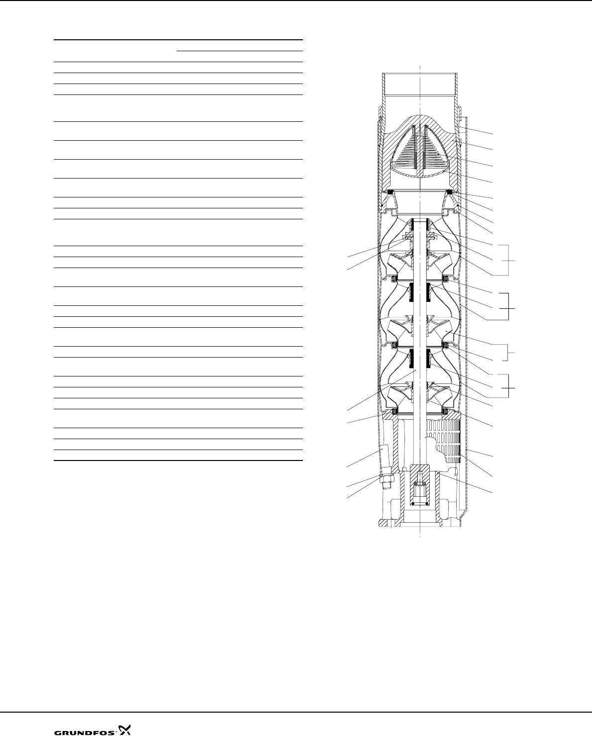
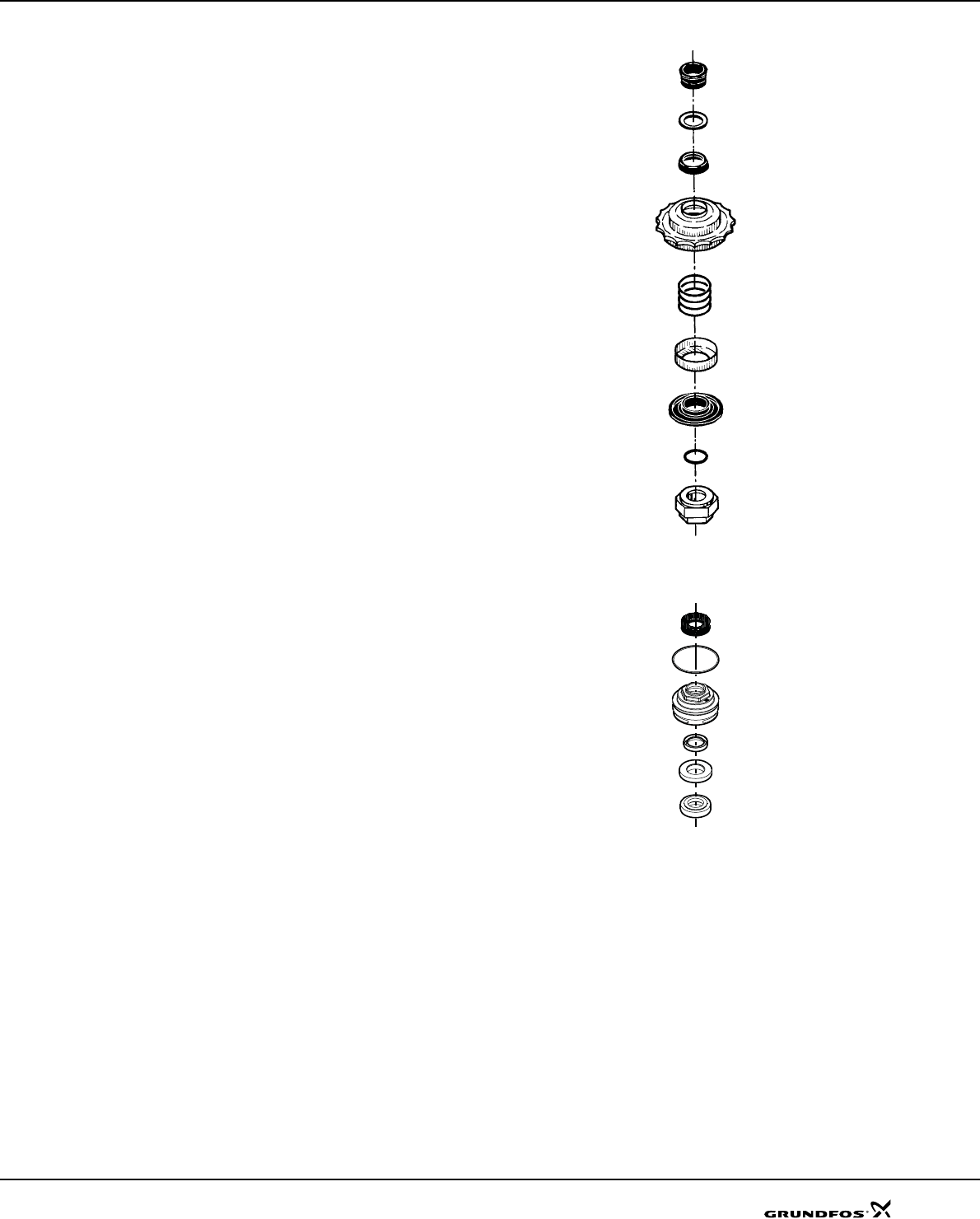
Material specification
Fig. 8 SP 77
Pos. Component Materials Standard N-version R-version
DIN W.-Nr. / AISI
1 Valve casing Stainless steel 1.4301/304 1.4401/316 1.4539/904L
1d O-ring NBR
2 Valve cup Stainless steel 1.4301/304 1.4401/316 1.4539/904L
3 Valve seat Standard/
N- version: NBR
R-version: FKM
3a Lower valve
seat retainer Stainless steel 1.4308 1.4408/316 1.4517
3b Upper valve
seat retainer Stainless steel 1.4301/304 1.4401/316 1.4539/904L
4Top
chamber Stainless steel 1.4301/304 1.4401/316 1.4539/904L
6Upper
bearing Stainless steel/
NBR 1.4401/304 1.4401/316 1.4539/904L
7 Neck ring NBR/PPS
8 Bearing NBR
8a Washer for
stop ring
Carbon/ graphite
HY22 in PTFE
mass
8b Stop ring Stainless steel 1.4401/316 1.4401/316 1.4539/904L
9 Chamber Stainless steel 1.4301/304 1.4401/316 1.4539/904L
11 Split cone
nut Stainless steel 1.4301/304 1.4401/316 1.4539/904L
11c Nut for stop
ring Stainless steel 1.4401/316 1.4401/316 1.4539/904L
12 Split cone Stainless steel 1.4301/304 1.4401/316 1.4539/904L
13 Impeller Stainless steel 1.4301/304 1.4401/316 1.4539/904L
14 Suction in-
terconnector Stainless steel 1.4308 1.4408/316 1.4517
15 Strainer Stainless steel 1.4301/304 1.4401/316 1.4539/904L
16 Shaft
complete Stainless steel 1.4057/431 1.4460/329 1.4460/329
17 Strap Stainless steel 1.4301/304 1.4401/316 1.4539/904L
18 Cable guard Stainless steel 1.4301/304 1.4401/316 1.4539/904L
19 Nut for strap Stainless steel 1.4301/304 1.4401/316 1.4539/904L
39 Spring for
valve cup Stainless steel 1.4301/304 1.4401/316 1.4462/
SAF 2205
70 Valve guide Stainless steel 1.4301/304 1.4401/316 1.4539/904L
71 Washer Stainless steel 1.4401/316 1.4401/316 1.4539/904L
72 Wear ring Stainless steel 1.4301/304 1.4401/316 1.4539/904L
TM01 2359 2301
8a
11c
17
19
71
7
15
8b
14
18
12
4
6
13
72
11
3a
1d
3b
2
39
70
1
3
16
89
7
7
89
9
SP A, SP
Submersible motors
Features and benefits
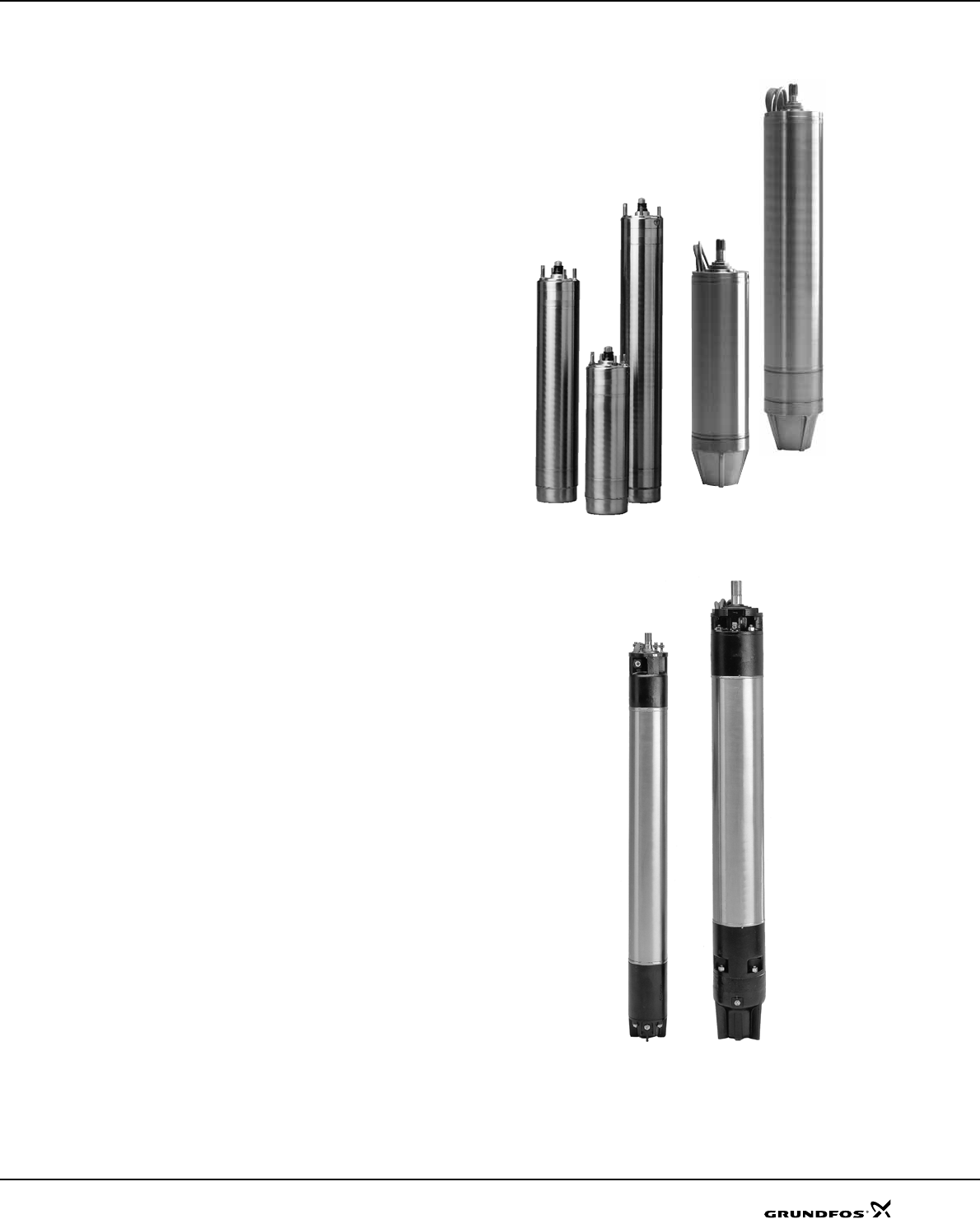
A complete motor range
Grundfos offers a complete submersible motor range in
different voltages:
Submersible motors, MS:
• 4" motors, single-phase up to 3.7 kW:
– 2-wire
– 3-wire
– PSC (permanent split capacitor)
• 4" motors, three-phase up to 7.5 kW
• 6" motors, three-phase from 5.5 kW to 30 kW
Submersible, rewindable motors, MMS:
• 6" motors, three-phase from 3.7 kW up to 37 kW
• 8" motors, three-phase from 22 kW up to 110 kW
• 10" motors, three-phase from 75 kW up to 190 kW
High motor efficiency
Within the area of high motor efficiency Grundfos is a
market leader.
Rewindable motors
The 2-pole Grundfos MMS submersible motors are all
easy to rewind. The windings of the stator are made of
a special water-proof wire of pure electrolytic copper
sheathed with special non-hydroscopic thermoplastic
material. The fine dielectric properties of this material
allow direct contact between the windings and the liquid
for efficient cooling of the windings.
Industrial motors and MS6 T60-versions
For heavy-duty applications Grundfos offers a complete
motor range of industrial motors with up to 5 % higher
efficiency than that of Grundfos' standard motors. The
industrial motors are available in sizes as from 2.2 kW
up to 22 kW. The cooling of the motor is very efficient
due to the large motor surface. The efficient cooling
makes it possible to increase the liquid temperature to
60 °C at a minimum flow of 0.15 m/s past the motor. The
industrial motors are for customers who value low
operating costs and long life higher than price.
Grundfos industrial motors are developed for difficult
operating conditions. These motors will stand a higher
thermal load than standard motors and thus have a
longer life when subjected to high load. This applies
whether the high load is caused by bad power supply,
hot water, bad cooling conditions, high pump load etc.
Please note that heavy-duty motors are longer than
motors for standard conditions.
Fig. 9 MS motors
Fig. 10 MMS motors
TM00 7305 1096 - GrA4011 - GrA4013TM01 7873 4799
10
Submersible motors SP A, SP
Overtemperature protection
Accessories for protection against overtemperature are
available for both Grundfos MS and MMS submersible
motors. When the temperature becomes too high, the
protection device will cut out and damage to the pump
and motor be avoided.
Restart of the motor after cut-out can be achieved in
two ways:
• manual restart or
• automatic restart.
Automatic restart means that the MP 204 attempts to
restart the motor after 15 min. If the first attempt is not
successful, restarting will be reattempted at 30-minute
intervals.
MS
The Grundfos MS submersible motors except MS 402
are available with a built-in Tempcon temperature
transmitter for protection against overtemperature. By
means of the transmitter it is possible to read out and/
or monitor the motor temperature via an MP 204 or a
PR 5714 relay.
The Grundfos MS6 submersible motors can be fitted
with a Pt100. The Pt100 is fitted in the motor and
connected directly to the MP 204 or monitored by the
PR 5714 relay.
MMS
For the protection of the Grundfos MMS submersible
motors against overtemperature Grundfos offers the
Pt100 temperature sensor as an optional extra.
The Pt100 is fitted in the motor and connected directly
to the MP 204 or monitored by the PR 5714 relay.
Protection against upthrust
In case of a very low counter pressure in connection
with start-up there is a risk that the entire chamber
stack may rise. This is called upthrust. Upthrust may
damage both pump and motor. Therefore both
Grundfos pumps and motors are protected against
upthrust as standard, preventing upthrust from
occurring in the critical start-up phase. The protection
consists of either a built-in stop ring or hydraulic
balancing.
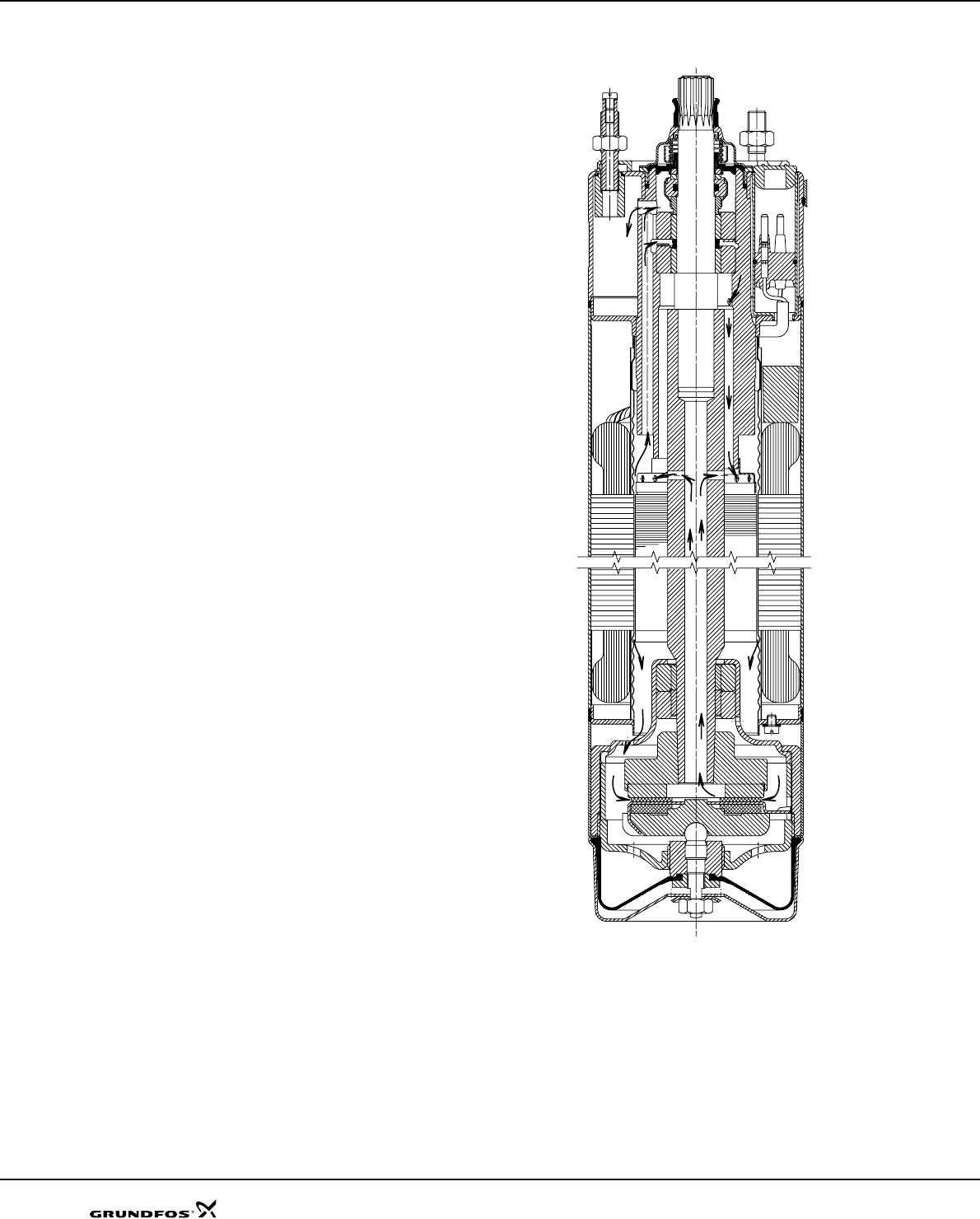
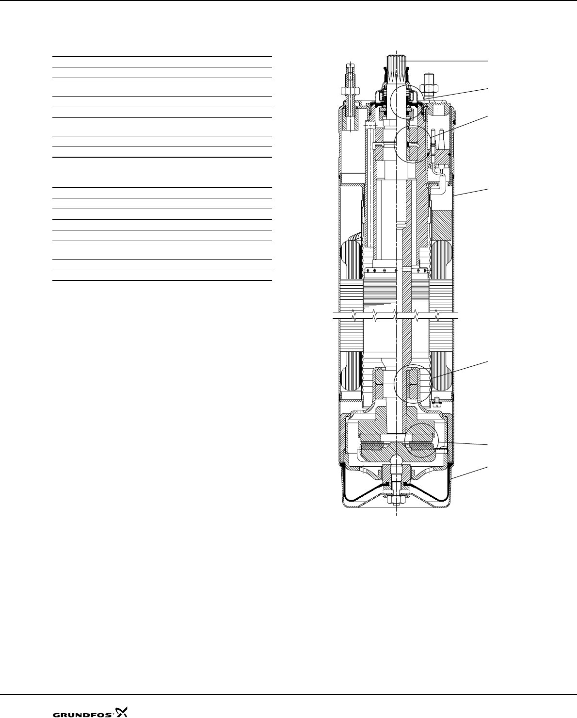
Built-in cooling chambers
In all Grundfos MS submersible motors an efficient
cooling is ensured by cooling chambers at the top and
at the bottom of the motor, and by an internal circulation
of motor liquid. See fig. 11. As long as the required flow
velocity past the motor is maintained (see "Operating
conditions" page 4) cooling of the motor will be efficient.
Fig. 11 MS 4000
TM00 5698 0996
11
Submersible motors SP A, SP
Lightning protection
The smallest Grundfos submersible motors, i.e. of the
type MS 402, are all insulated in order to minimize the
risk of motor burnout caused by stroke of lightning.
Reduced risk of short-circuit
The embedded stator winding in the Grundfos MS
submersible motor is hermetically enclosed in stainless
steel. The result is high mechanical stability and
optimum cooling. Also, this eliminates the risk of short-
circuit of the windings caused by condensed water.
Shaft seal
MS 402
The shaft seal is of the lip seal type characterized by
low friction against the rotor shaft.
The choice of rubber offers good wear resistance, good
elasticity and resistance to particles. The rubber
material is approved for use in drinking water.
MS 4000, MS6
The material is ceramic/tungsten carbide providing
optimum sealing, optimum wear resistance and long
life.
The spring loaded shaft seal is designed with a large
surface and a sand shield. The result is a minimum
exchange of pumped and motor liquids and no
penetration of particles. Motors, version R, are supplied
with a SiC/SiC shaft seal according to DIN 24960.
Other combinations are available request.
MMS rewindable motors
The standard shaft seal is a ceramic/carbon
mechanical shaft seal. The shaft seal is replaceable.
The material features good wear resistance and
resistance to particles.
Together with the shaft seal housing, the sand shield
forms a labyrinth seal, which during normal operating
conditions prevents penetration of sand particles into
the shaft seal.
On request, motors can be supplied with a SiC/SiC seal
according to DIN 24960.
Fig. 12 Shaft seal, MS 4000
Fig. 13 Shaft seal, MS6
TM00 7306 2100TM03 9225 3607
12
Submersible motors SP A, SP
Material specification for MS motors
MS 402 and MS 4000 submersible motors
R-version motor
Fig. 14 MS 4000
Pos. Part MS 402 MS 4000
1 Shaft EN 1.4057 EN 1.4057
2 Shaft seal NBR Tungsten carbide/
ceramic
3 Motor sleeve EN 1.4301 EN 1.4301
4 Motor end shield EN 1.4301
5 Radial bearing Ceramic Ceramic/
tungsten carbide
6 Axial bearing Ceramic/carbon Ceramic/carbon
Rubber parts NBR NBR
Pos. Part MS 4000
1 Shaft EN 1.4462
2 Shaft seal NBR/ceramic
3 Motor sleeve EN 1.4539
4 Motor end shield EN 1.4539
5 Radial bearing Ceramic/
tungsten carbide
6 Thrust bearing Ceramic/carbon
Rubber parts NBR
TM00 7865 2196
2
5
5
6
4
3
1
13
Submersible motors SP A, SP
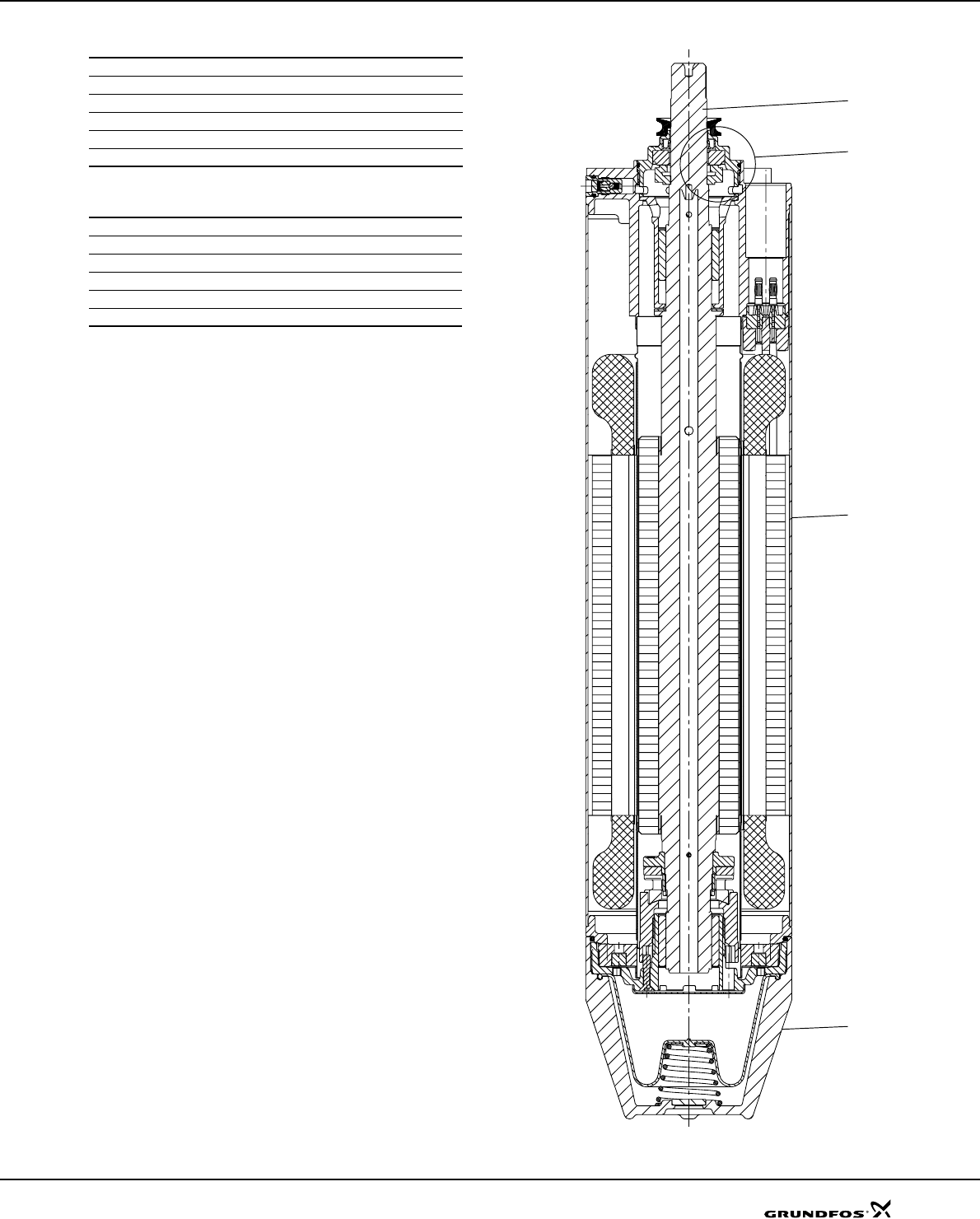
Material specification for MS6 motors
R-version motor
Fig. 15 MS6
Pos. Part MS6
202 Shaft with rotor EN 1.4462
2 Shaft seal Ceramic/carbon
3 Motor sleeve EN 1.4301
4 Motor end cover EN 1.4308
Rubber parts NBR/FKM
Pos. Part MS6
1 Shaft EN 1.4462
2 Shaft seal SiC/SiC
3 Motor sleeve EN 1.4539
4 Motor end cover EN 1.4517
Rubber parts FKM
TM03 9226 3607
1
2
3
4
14
Submersible motors SP A, SP
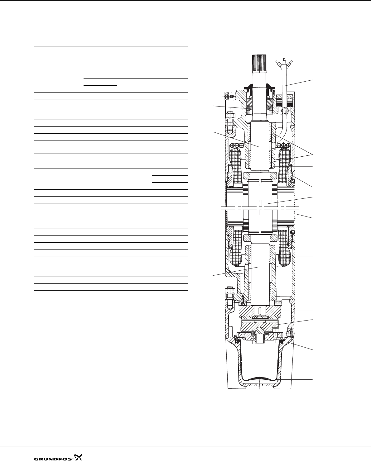
Material specification for MMS
motors
Submersible rewindable motors
N- and R-versions of MMS motors
* Only MMS 6000 and MMS 8000 are available in R-versions
Fig. 16 MMS 10000
Pos. Component Material DIN/EN
202 Shaft Steel 1.0533
202a Shaft ends Stainless steel 1.4460
203/
206
Thrust bearing
Stationary/
rotating part
6" 3.7 - 15 kW Hardened steel/
EPDM
6" 18.5 - 37 kW Ceramic/carbon
8"-10"
204 Bearing bush 6"-10" Carbon
205 Bearing housing, upper Cast iron EN-JL1040
212 Diaphragm CR
213 Motor end shield Cast iron EN-JL1040
218 Motor sleeve Stainless steel 1.4301
220 Motor cable EPDM
226 Shaft seal Ceramic/carbon
235 Intermediate housing Cast iron EN-JL1040
236 Bearing housing, lower Cast iron EN-JL1040
Pos. Component Material
Version
NR*
DIN/EN DIN/EN
202 Shaft Steel 1.0533 1.0533
202a Shaft ends Stainless steel 1.4460 1.4462
203/
206
Thrust bearing
Stationary/
rotating part
6" 3.7 - 15 kW Hardened steel/
EPDM
6" 18.5 - 37 kW Ceramic/carbon
8"-10"
204 Bearing bush 6"-10" Carbon
205 Bearing housing, upper Stainless steel 1.4401 1.4539
212 Diaphragm CR
213 Motor end shield Stainless steel 1.4401 1.4539
218 Motor sleeve Stainless steel 1.4401 1.4539
220 Motor cable EPDM
226 Shaft seal Ceramic/carbon
235 Intermediate housing Stainless steel 1.4401 1.4539
236 Bearing housing, lower Stainless steel 1.4401 1.4539
TM01 4985 0404
220
204
205
235
202
218
236
206
203
213
212
202a
202a
226

15
16
Performance curves/
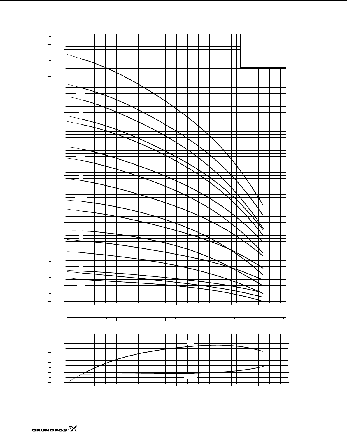
Technical data
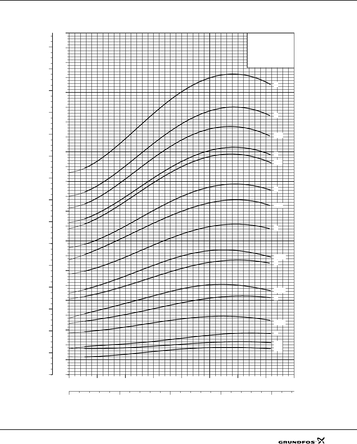
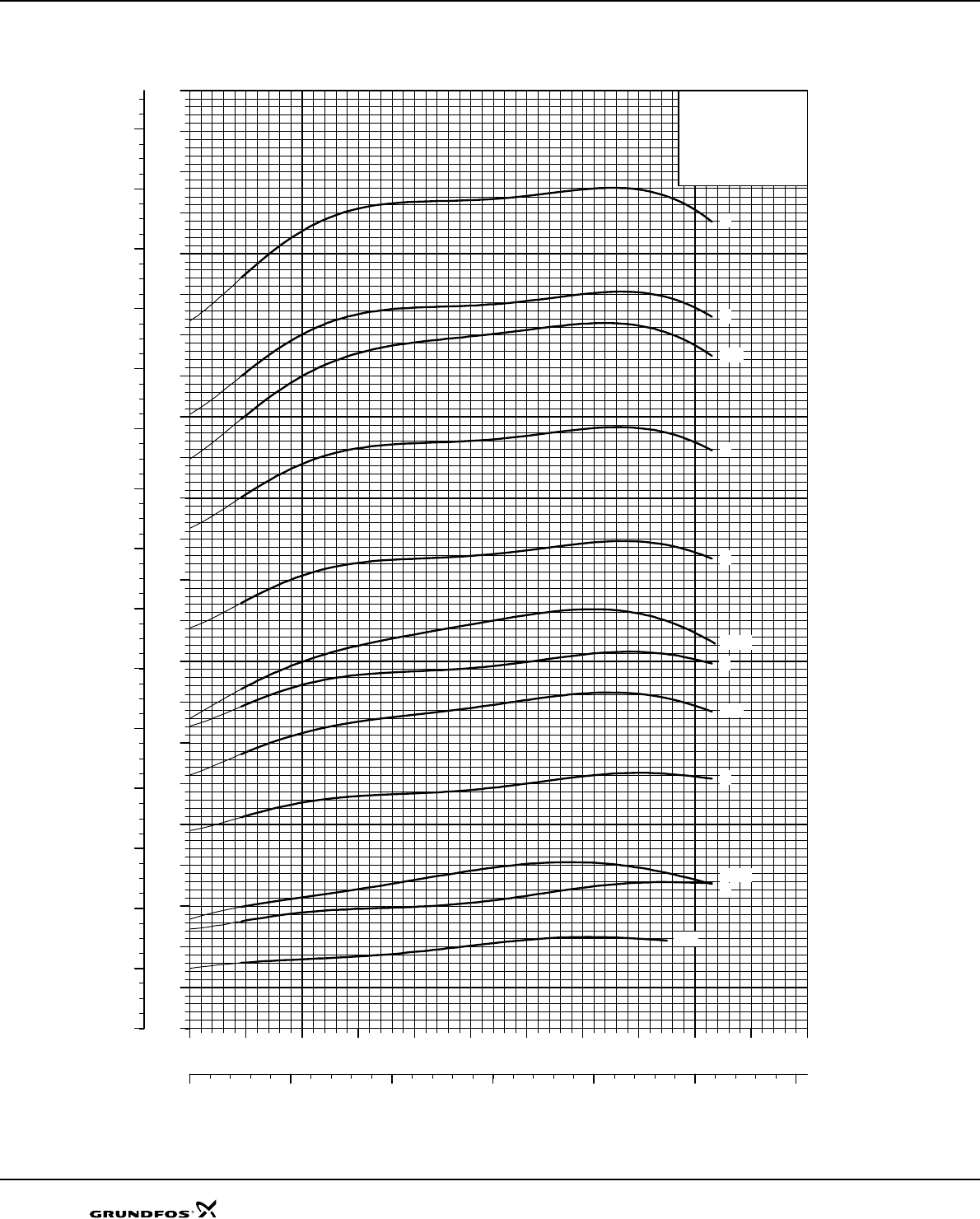
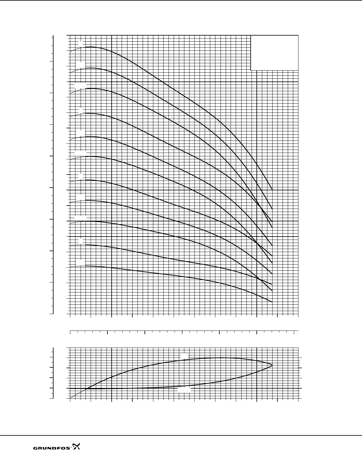
SP 1A
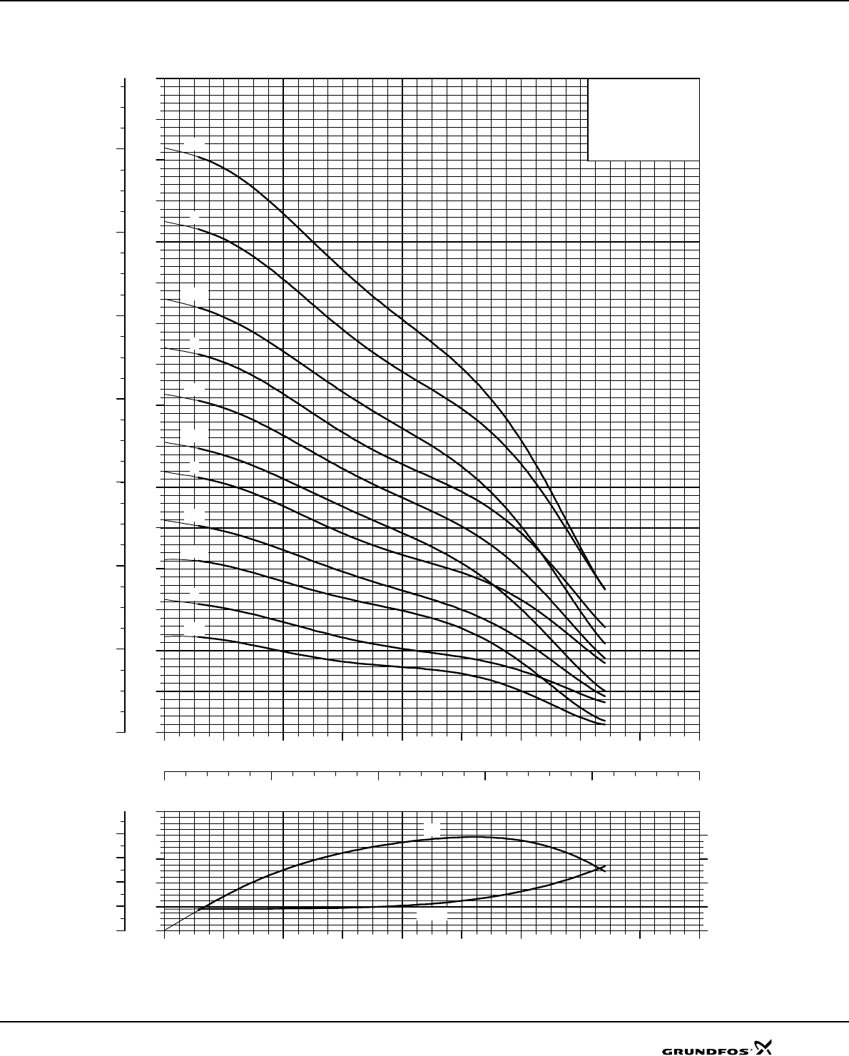
Explanation of efficiency curve, please see "Curve conditions" on page 4.
TM01 3419 1802
0.0 0.2 0.4 0.6 0.8 1.0 1.2 1.4 1.6
Q [m³/h]
0.00
0.02
0.04
0.06
0.08
P2
[kW]
0
10
20
30
40
Eta
[%]
0.00
0.04
0.08
P2
[hp]
Eta
P2
0.0 0.2 0.4 0.6 0.8 1.0 1.2 1.4 1.6
Q [m³/h]
0
20
40
60
80
100
120
140
160
180
200
220
240
260
280
300
320
H
[m]
0
400
800
1200
1600
2000
2400
2800
p
[kPa]
0.0 0.1 0.2 0.3 0.4
Q [l/s]
SP 1A
ISO 9906 Annex A
60 Hz, SF 1.15
-13
-22
-18
-26
-39
-31
-9
SP 1A
17
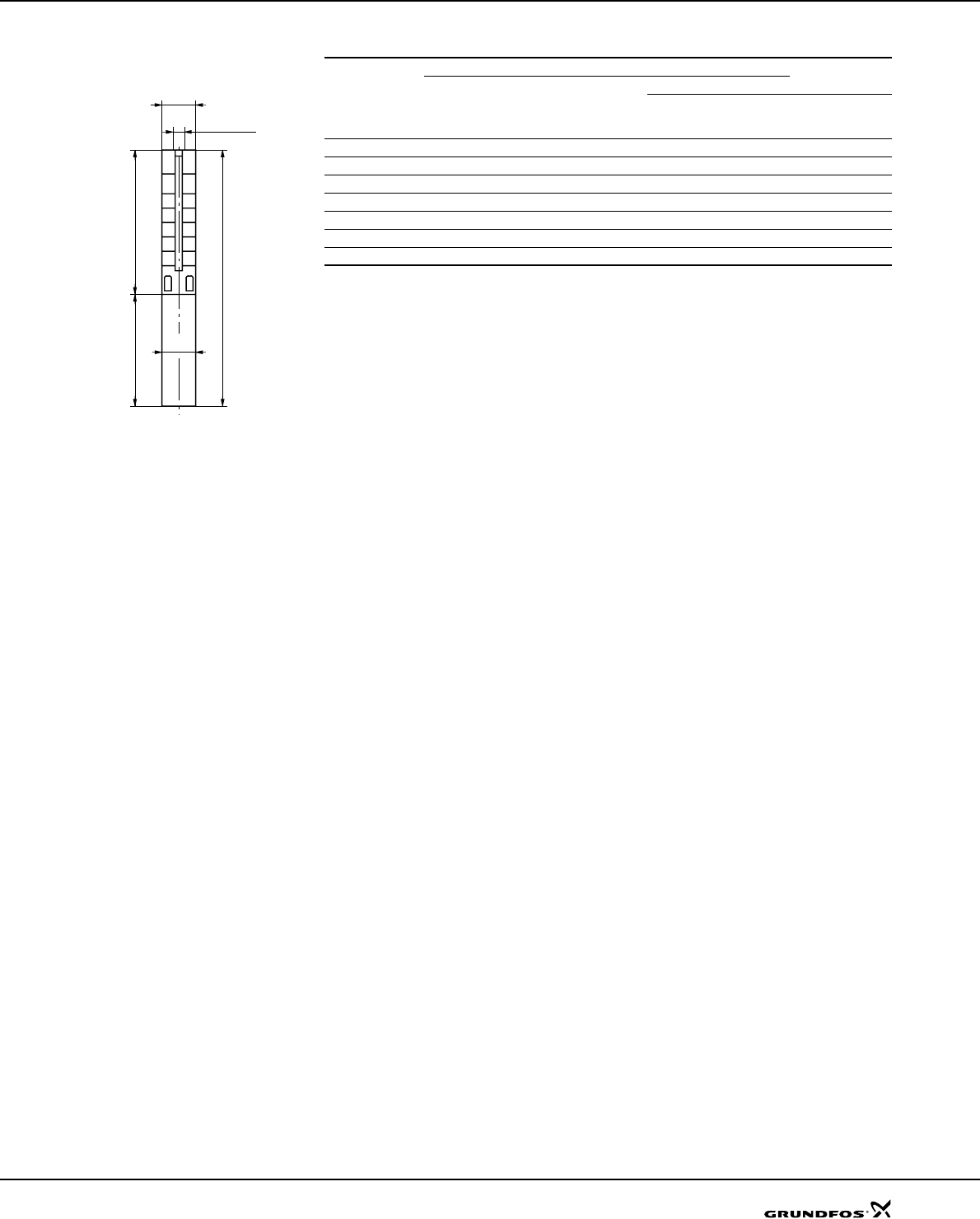
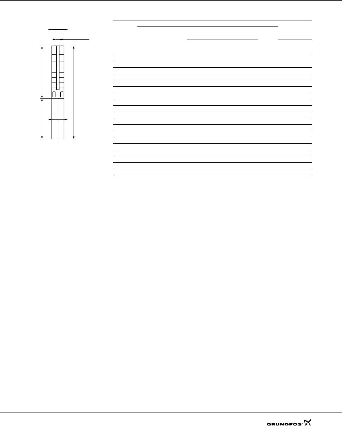
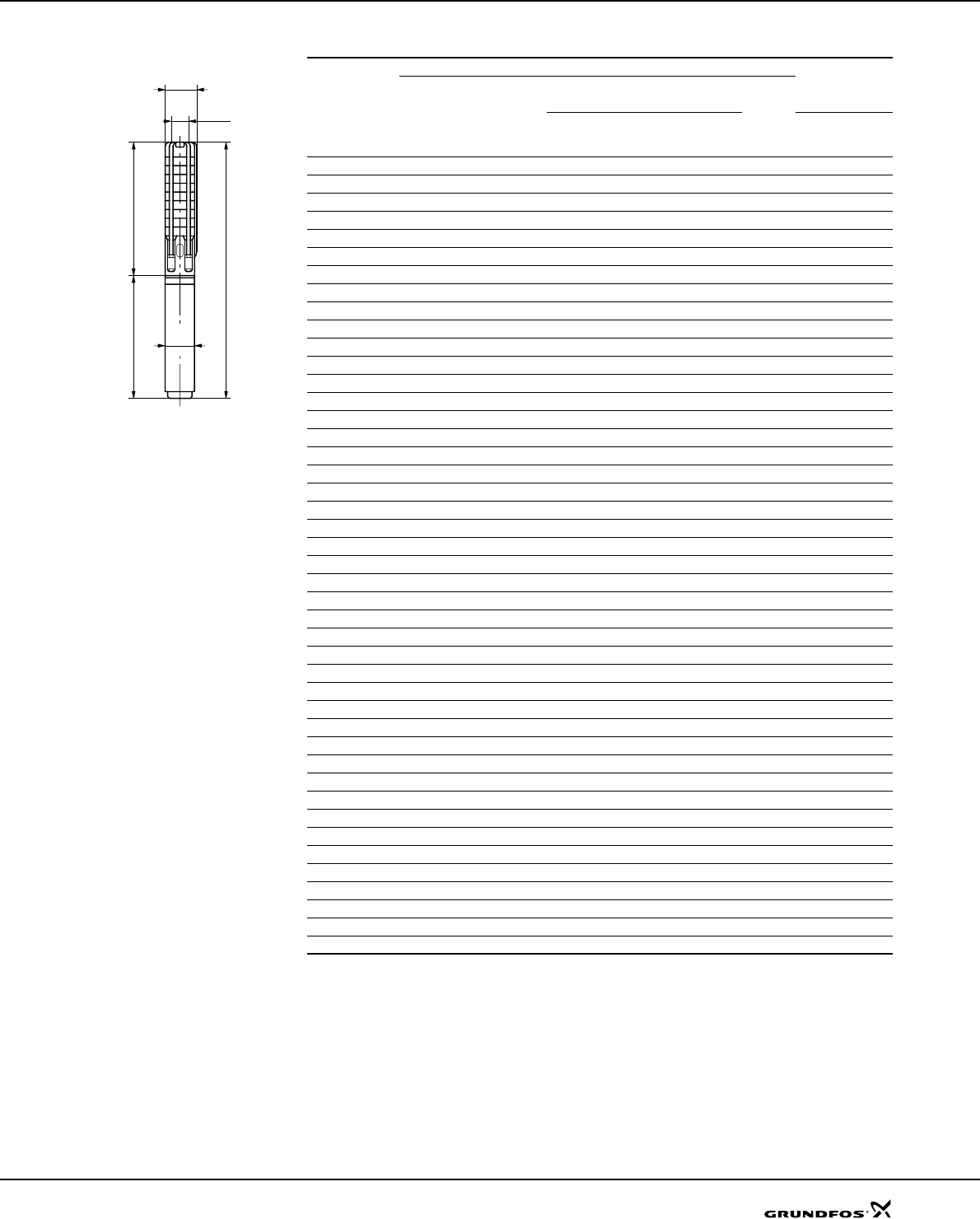
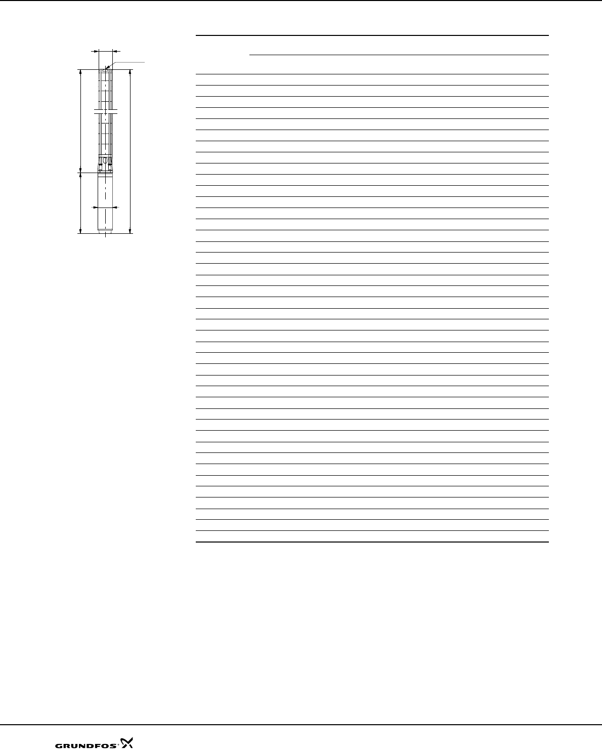
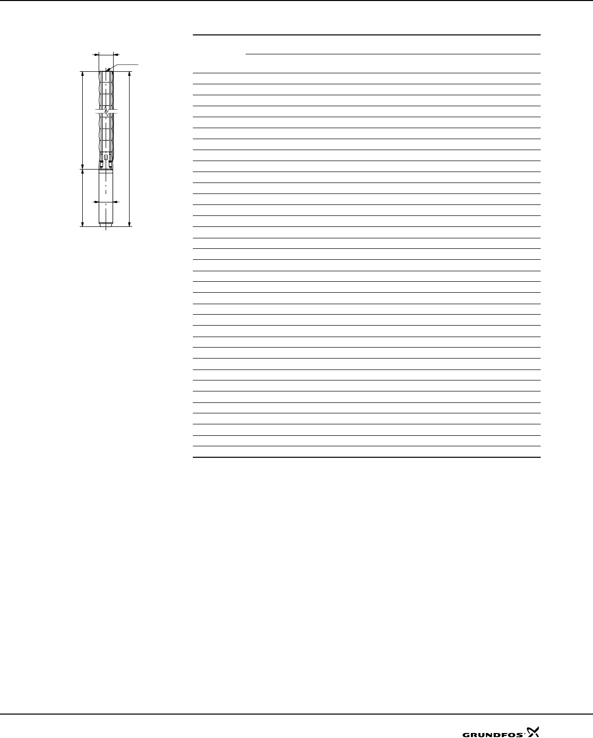
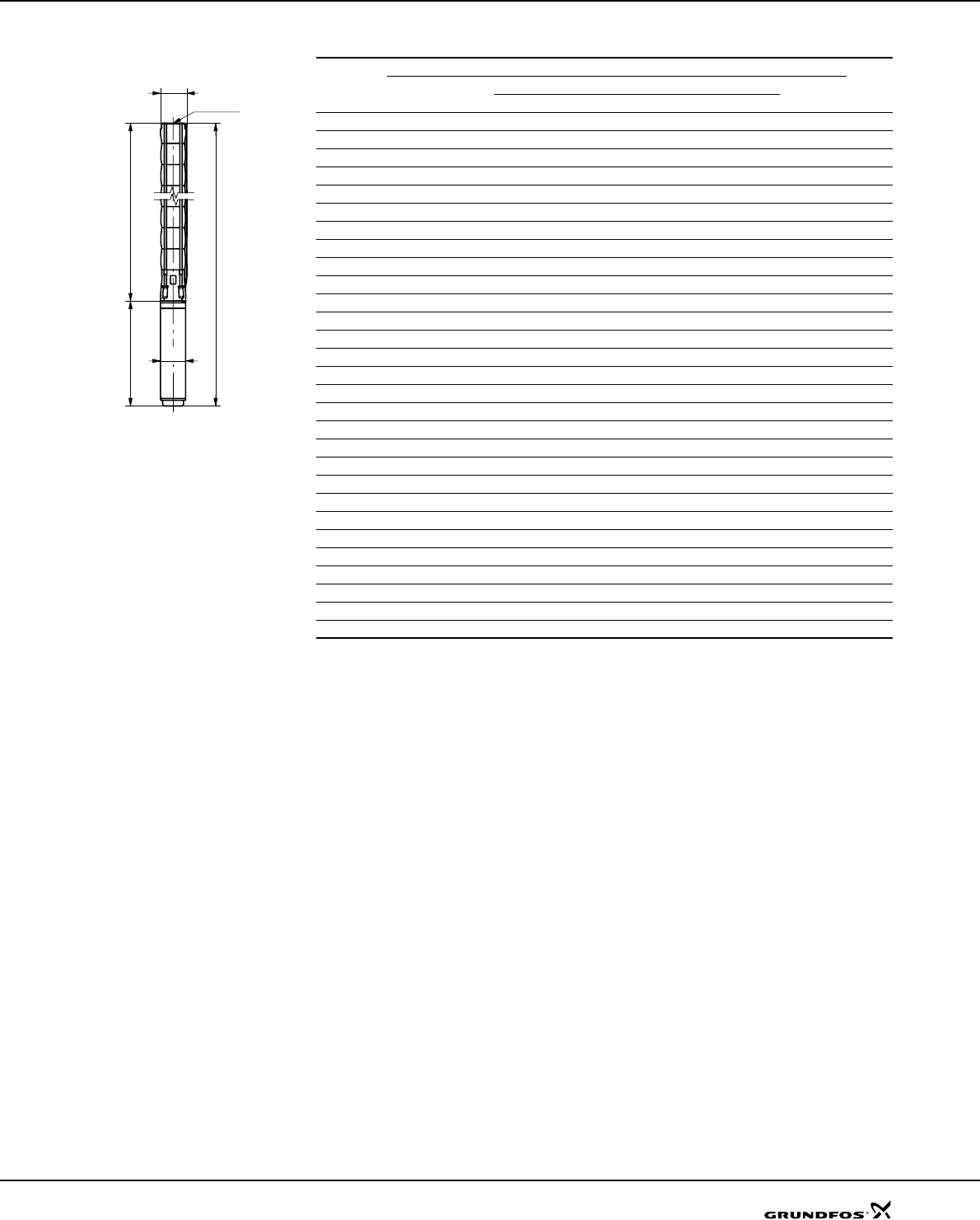
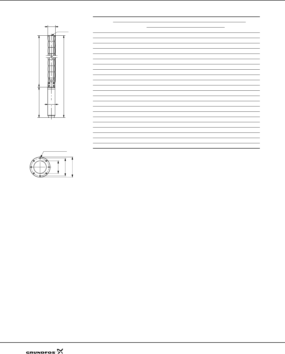
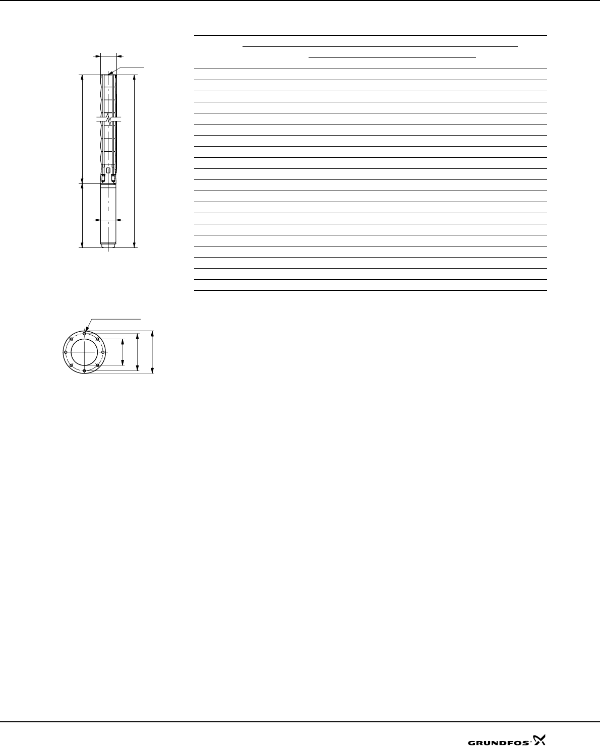
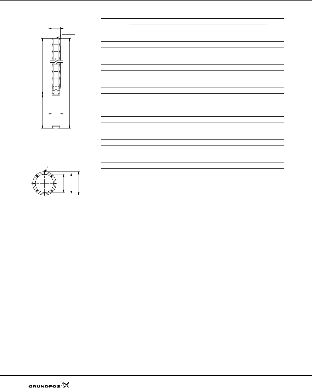
Dimensions and weights
TM00 0955 1196
Pump type
Motor Dimensions [mm] Net weight [kg]
Type Power [kW] C
BA
3 x 220 V
3 x 380 V
3 x 460 V
3 x 220 V
3 x 380 V
3 x 460 V
3 x 220 V
3 x 380 V
3 x 460 V
SP 1A-9 MS 402 0.37 344 226 570 9
SP 1A-13 MS 402 0.37 428 226 654 10
SP 1A-18 MS 402 0.55 533 241 774 12
SP 1A-22 MS 402 0.75 617 276 893 14
SP 1A-26 MS 402 1.1 701 306 1007 16
SP 1A-31 MS 402 1.1 851 306 1157 22
SP 1A-39 MS 402 1.5 1019 346 1365 26
101 mm = Maximum diameter of pump
inclusive of cable guard and motor.
A
B C
101
95
Rp 1 1/4
SP 1A
Technical data
18
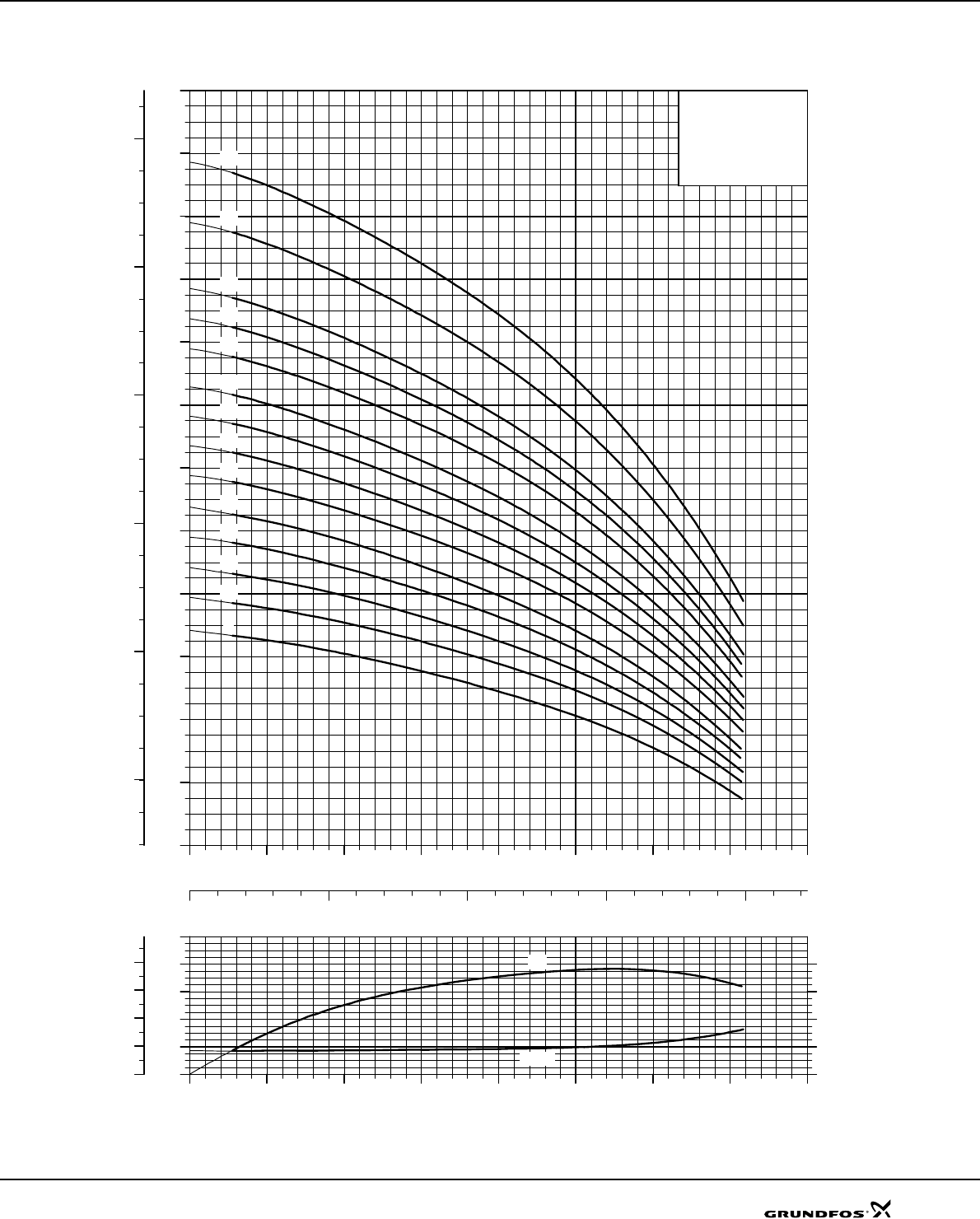
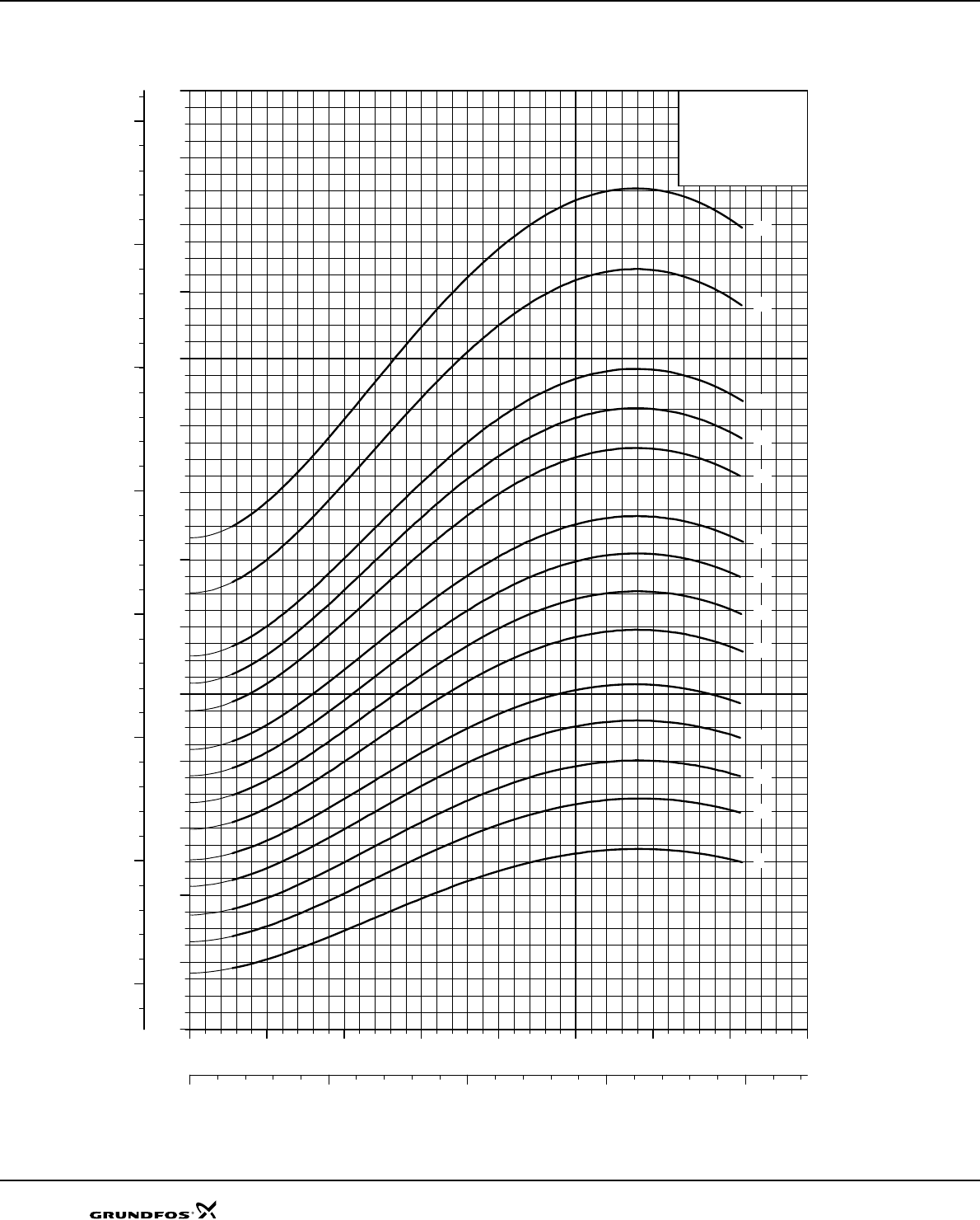
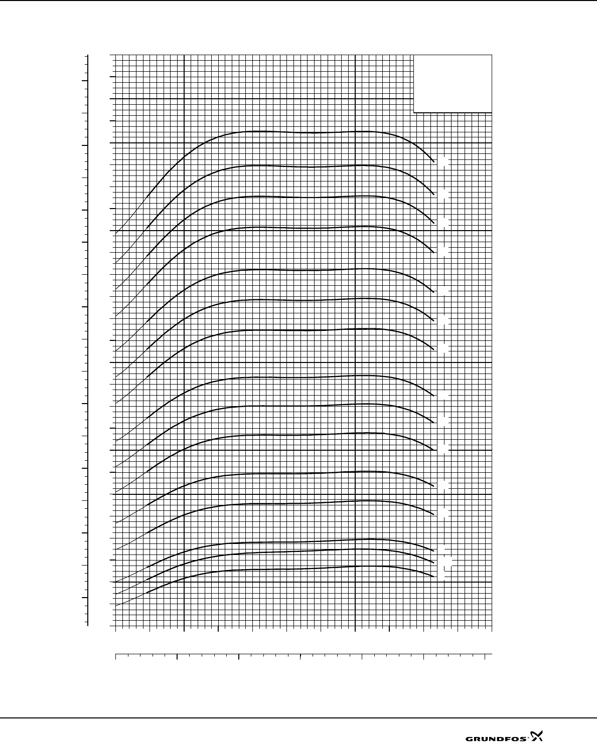
SP 2A
Explanation of efficiency curve, please see "Curve conditions" on page 4.
TM01 3420 1802
0.0 0.4 0.8 1.2 1.6 2.0 2.4 2.8 3.2
Q [m³/h]
0.00
0.04
0.08
0.12
P2
[kW]
0
20
40
60
Eta
[%]
0.00
0.08
0.16
P2
[hp]
P2
Eta
0.0 0.4 0.8 1.2 1.6 2.0 2.4 2.8 3.2
Q [m³/h]
0
40
80
120
160
200
240
280
320
360
400
440
480
520
H
[m]
0
800
1600
2400
3200
4000
4800
p
[kPa]
0.0 0.2 0.4 0.6 0.8
Q [l/s]
SP 2A
ISO 9906 Annex A
60 Hz, SF 1.15
-12
-15
-21
-27
-34
-48
-58
-6
-9
Performance curves SP 2A
19
Dimensions and weights
TM00 0955 1196
Pump type
Motor Dimensions [mm] Net weight [kg]
Type Power
[kW] C
BA
1x220V 3x220V
3x380V
3x460V 1x220V 3x220V
3x380V
3x460V 1x220V 3x220V
3x380V
3x460V
SP 2A-6 MS 402 0.25 281 256 537 10
SP 2A-6 MS 402 0.37 281 226 507 9
SP 2A-9 MS 402 0.37 344 276 226 620 570 12 9
SP 2A-12 MS 402 0.55 407 291 241 698 648 13 11
SP 2A-15 MS 402 0.75 470 306 276 776 746 14 13
SP 2A-21 MS 402 1.1 596 346 306 942 902 17 15
SP 2A-27 MS 402 1.5 722 346 1068 18
SP 2A-34 MS 4000 2.2 914 453 1367 30
SP 2A-48 MS 4000 4.0 1208 573 1781 39
SP 2A-58 MS 4000 4.0 1597 573 2170 50
101 mm = Maximum diameter of pump
inclusive of cable guard and motor.
SP 2A-58 are mounted in sleeve for
R 1¼ connection and with max.
diameter 108 mm.
A
B C
101
95
Rp 1 1/4
Technical data SP 2A
20
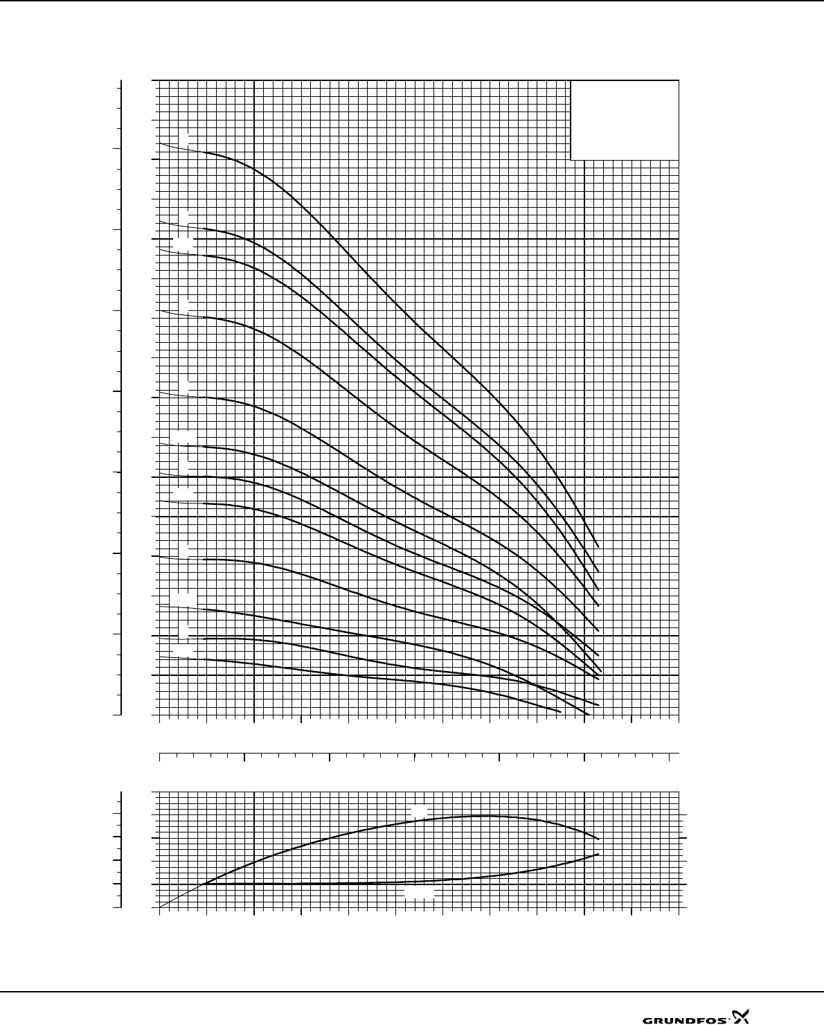
SP 2A
Explanation of efficiency curve, please see "Curve conditions" on page 4.
TM01 3421 1802
0.0 0.4 0.8 1.2 1.6 2.0 2.4 2.8 3.2 3.6 4.0 4.4
Q [m³/h]
0.00
0.04
0.08
0.12
P2
[kW]
0
20
40
60
Eta
[%]
0.00
0.08
0.16
P2
[hp]
Eta
P2
0.0 0.4 0.8 1.2 1.6 2.0 2.4 2.8 3.2 3.6 4.0 4.4
Q [m³/h]
0
40
80
120
160
200
240
280
320
360
400
440
480
520
560
600
640
680
H
[m]
0
800
1600
2400
3200
4000
4800
5600
6400
p
[kPa]
0.0 0.2 0.4 0.6 0.8 1.0 1.2
Q [l/s]
SP 3A
ISO 9906 Annex A
60 Hz, SF 1.15
-75
-56
-38
-32
-24
-18
-14
-10
-8
-5
Performance curves SP 3A
21
Dimensions and weights
TM00 8521 3196
Pump type
Motor Dimensions [mm] Net weight
[kg]
Type Power
[kW] C
BA
DE
1x220V 3x220V
3x380V
3x460V 1x220V 3x220V
3x380V
3x460V 1x220V 3x220V
3x380V
3x460V
SP 3A-5 MS 402 0.37 260 256 226 516 486 95 101 11 8
SP 3A-5N MS 4000R 0.75 305 398 703 95 101 17
SP 3A-8 MS 402 0.55 323 291 241 614 564 95 101 12 10
SP 3A-8N MS 4000R 0.75 368 398 766 95 101 18
SP 3A-10 MS 402 0.75 365 306 276 671 641 95 101 13 12
SP 3A-10N MS 4000R 0.75 410 398 808 95 101 19
SP 3A-14 MS 402 1.1 449 346 306 795 755 95 101 15 14
SP 3A-14N MS 4000R 1.1 494 413 907 95 101 21
SP 3A-18 MS 402 1.5 533 346 879 95 101 16
SP 3A-18N MS 4000R 1.5 578 413 991 95 101 23
SP 3A-24 MS 4000 2.2 659 453 1112 95 101 23
SP 3A-24N MS 4000R 2.2 704 453 1157 95 101 27
SP 3A-32 MS 4000 3.0 872 493 1365 95 101 30
SP 3A-32N MS 4000R 3.0 872 493 1365 95 101 30
SP 3A-38 MS 4000 4.0 998 573 1571 95 101 36
SP 3A-56 and SP 3A-75 are mounted in
sleeve for R 1¼ connection.
SP 3A-38N MS 4000R 4.0 998 573 1571 95 101 36
SP 3A-56 MS 4000 5.5 1747 673 2420 95 101 65
SP 3A-56 MS6 5.5 1747 565 2312 138 140 75
SP 3A-75 MS6 7.5 2146 590 2736 138 140 86
E = Maximum diameter of pump inclusive of cable guard and motor.
A
B C
E
D
Rp 1 1/4
SP 3A
Technical data
22
SP 5A
Explanation of efficiency curve, please see "Curve conditions" on page 4.
TM01 3422 1802
0.0 0.8 1.6 2.4 3.2 4.0 4.8 5.6 6.4 7.2
Q [m³/h]
0.00
0.08
0.16
0.24
P2
[kW]
0
20
40
60
Eta
[%]
0.00
0.16
0.32
P2
[hp]
P2
Eta
0.0 0.8 1.6 2.4 3.2 4.0 4.8 5.6 6.4 7.2
Q [m³/h]
0
40
80
120
160
200
240
280
320
360
400
440
480
H
[m]
0
800
1600
2400
3200
4000
4800
p
[kPa]
0.0 0.4 0.8 1.2 1.6 2.0
Q [l/s]
SP 5A
ISO 9906 Annex A
60 Hz, SF 1.15
-52
-39
-26
-21
-15
-11
-9
-7
-5
-3
Performance curves SP 5A
23
Dimensions and weights
TM00 0956 1196
Pump type
Motor Dimensions [mm]
Net weight [kg]
Type Powe
[kW] C
BA
DE
1x220V 3x220V
3x380V
3x460V 1x220V 3x220V
3x380V
3x460V 1x220V 3x220V
3x380V
3x460V
SP 5A-3 MS 402 0.37 219 276 226 495 445 95 101 10 8
SP 5A-3N MS 4000R 0.75 263 398 661 95 101 17
SP 5A-5 MS 402 0.55 261 291 241 552 502 95 101 11 9
SP 5A-5N MS 4000R 0.75 305 398 703 95 101 17
SP 5A-7 MS 402 0.75 303 306 276 609 579 95 101 12 11
SP 5A-7N MS 4000R 0.75 347 398 745 95 101 18
SP 5A-9 MS 402 1.1 345 346 306 691 651 95 101 14 13
SP 5A-9N MS 4000R 1.1 389 413 802 95 101 20
SP 5A-11 MS 402 1.5 387 346 733 95 101 15
SP 5A-11N MS 4000R 1.5 431 413 844 95 101 20
SP 5A-15 MS 4000 2.2 471 453 924 95 101 21
SP 5A-15N MS 4000R 2.2 515 453 968 95 101 24
SP 5A-21 MS 4000 3.0 597 493 1090 95 101 23
SP 5A-21N MS 4000R 3.0 641 493 1134 95 101 26
SP 5A-26 MS 4000 4.0 702 573 1275 95 101 29
SP 5A-52 are mounted in sleeve for R
1½ connection.
SP 5A-26N MS 4000R 4.0 746 573 1319 95 101 32
SP 5A-39 MS 4000 5.5 1019 673 1692 95 101 41
SP 5A-39N MS 4000R 5.5 1019 673 1692 95 101 41
SP 5A-39 MS6 5.5 1081 565 1646 143 138 55
SP 5A-39N MS6R 5.5 1081 565 1646 143 138 55
SP 5A-52 MS6 7.5 1663 590 2253 143 140 74
E = Maximum diameter of pump inclusive of cable guard and motor.
A
B C
E
D
Rp 1 1/2
Technical data SP 5A
24
SP 8A
Explanation of efficiency curve, please see "Curve conditions" on page 4.
TM01 3423 1802
012345678910 11 12
Q [m³/h]
0.0
0.2
0.4
0.6
P2
[kW]
0
20
40
60
Eta
[%]
0.0
0.4
0.8
P2
[hp]
P2
Eta
012345678910 11 12
Q [m³/h]
0
40
80
120
160
200
240
280
320
360
400
440
480
520
560
H
[m]
0
800
1600
2400
3200
4000
4800
5600
p
[kPa]
0.0 0.5 1.0 1.5 2.0 2.5 3.0 3.5
Q [l/s]
SP 8A
ISO 9906 Annex A
60 Hz, SF 1.15
-66
-58
-50
-44
-37
-30
-25
-21
-18
-15
-12
-9
-7
-5
-3
Performance curves SP 8A
25
Dimensions and weights
TM00 0957 1196
Pump type
Motor Dimensions [mm]
Net weight [kg]
Type Power
[kW] C
BA
DE
1x220V 3x220V
3x380V
3x460V 1x220V 3x220V
3x380V
3x460V 1x220V 3x220V
3x380V
3x460V
SP 8A-3 MS 402 0.55 325 291 241 616 566 95 101 13 11
SP 8A-3N MS 4000R 0.75 325 398 723 95 101 18
SP 8A-3R MS 4000R 0.75 325 398 723 95 101 18
SP 8A-5 MS 402 1.1 409 346 306 755 715 95 101 16 15
SP 8A-5N MS 4000R 1.1 409 413 822 95 101 20
SP 8A-5R MS 4000R 1.1 409 413 822 95 101 20
SP 8A-7 MS 402 1.5 493 346 839 95 101 17
SP 8A-7N MS 4000R 1.5 493 413 906 95 101 21
SP 8A-7R MS 4000R 1.5 493 413 906 95 101 21
SP 8A-9 MS 4000 2.2 577 453 1030 95 101 24
SP 8A-9N MS 4000R 2.2 577 453 1030 95 101 24
SP 8A-9R MS 4000R 2.2 577 453 1030 95 101 24
SP 8A-12 MS 4000 3.0 703 493 1196 95 101 26
SP 8A-12N MS 4000R 3.0 703 493 1196 95 101 26
SP 8A-12R MS 4000R 3.0 703 493 1196 95 101 26
SP 8A-58(N) to SP 8A-66(N) are
mounted in sleeve for R 2 connection.
SP 8A-15 MS 4000 4.0 829 573 1402 95 101 32
SP 8A-15N MS 4000R 4.0 829 573 1402 95 101 32
SP 8A-15R MS 4000R 4.0 829 573 1402 95 101 32
SP 8A-18 MS 4000 5.5 955 673 1628 95 101 38
SP 8A-18N MS 4000R 5.5 955 673 1628 95 101 38
SP 8A-21 MS 4000 5.5 1081 673 1754 95 101 40
SP 8A-21N MS 4000R 5.5 1081 673 1754 95 101 40
SP 8A-25 MS 4000 5.5 1249 673 1922 95 101 42
SP 8A-25N MS 4000R 5.5 1249 673 1922 95 101 42
SP 8A-30 MS 4000 7.5 1459 773 2232 95 101 50
SP 8A-30N MS 4000R 7.5 1459 773 2232 95 101 50
SP 8A-18 MS6 5.5 1017 565 1582 143 138 50
SP 8A-18N MS6R 5.5 1017 565 1582 143 138 50
SP 8A-21 MS6 5.5 1143 565 1708 143 138 51
SP 8A-21N MS6R 5.5 1143 565 1708 143 138 51
SP 8A-25 MS6 5.5 1311 565 1876 143 138 53
SP 8A-25N MS6R 5.5 1311 565 1876 143 138 53
SP 8A-30 MS6 7.5 1521 590 2111 143 138 59
SP 8A-30N MS6R 7.5 1521 590 2111 143 138 59
SP 8A-37 MS6 9.2 1815 610 2425 143 138 69
SP 8A-37N MS6R 9.2 1815 610 2425 143 138 69
SP 8A-44 MS6 11.0 2109 708 2817 143 138 75
SP 8A-44N MS6R 11.0 2109 708 2817 143 138 75
SP 8A-50 MS6 13.0 2677 738 3415 143 140 103
SP 8A-50N MS6R 13.0 2677 738 3415 143 140 103
SP 8A-58 MS6 15.0 3013 783 3796 143 140 114
SP 8A-58N MS6R 15.0 3013 783 3796 143 140 114
SP 8A-66 MS6 15.0 3349 783 4132 143 140 121
SP 8A-66N MS6R 15.0 3349 783 4132 143 140 121
E = Maximum diameter of pump inclusive of cable guard and motor.
A
B C
E
Rp 2
D
Technical data SP 8A
26
SP 14A
Explanation of efficiency curve, please see "Curve conditions" on page 4.
TM01 3424 1802
0 2 4 6 8 10 12 14 16 18 20
Q [m³/h]
0.0
0.2
0.4
0.6
P2
[kW]
0
20
40
60
Eta
[%]
0.0
0.4
0.8
P2
[hp]
P2
Eta
0 2 4 6 8 10 12 14 16 18 20
Q [m³/h]
0
10
20
30
40
50
60
70
80
90
100
110
120
130
140
150
H
[m]
0
200
400
600
800
1000
1200
1400
p
[kPa]
0123456
Q [l/s]
SP 14A
ISO 9906 Annex A
60 Hz, SF 1.15
-16
-12
-8
-5
-3
Performance curves SP 14A
27
Dimensions and weights
TM00 0957 1196
Pump type
Motor Dimensions [mm] Net weight
[kg]
Type Power [kW] C
BA
DE
3x220V
3x380V
3x460V
3x220V
3x380V
3x460V
3x220V
3x380V
3x460V
SP 14A-3 MS 402 1.5 380 346 726 95 101 16
SP 14A-5 MS 4000 2.2 510 453 963 95 101 23
SP 14A-8 MS 402 4.0 705 573 1278 95 101 30
SP 14A-12 MS 4000 5.5 965 673 1638 95 101 37
SP 14A-16 MS 4000 7.5 1225 773 1998 95 101 50
SP 14A-12 MS6 5.5 1027 565 1592 143 138 48
SP 14A-16 MS6 7.5 1287 590 1877 143 138 54
E = Maximum diameter of pump inclusive of cable guard and motor.
A
B C
E
Rp 2
D
Technical data SP 14A
28
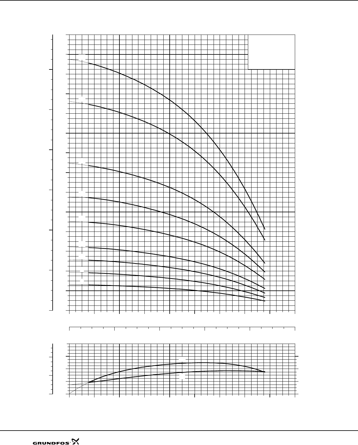
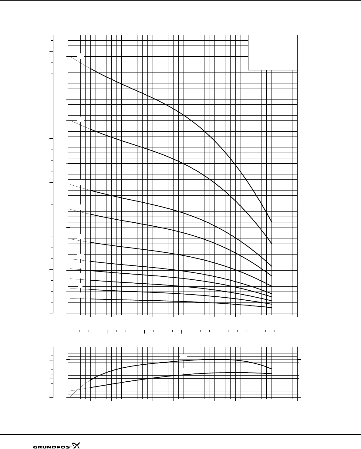
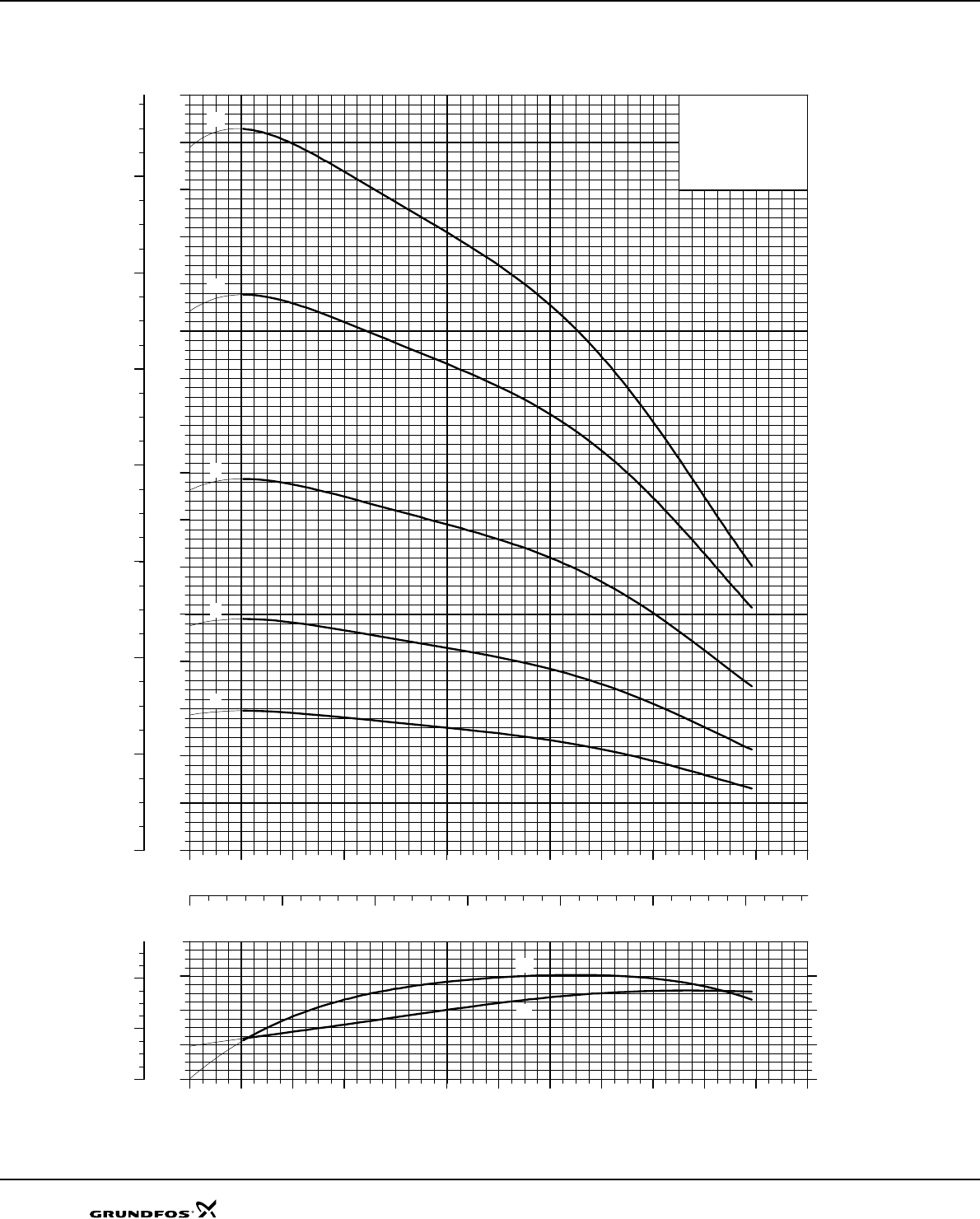
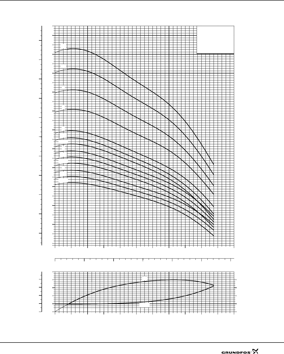
SP 17
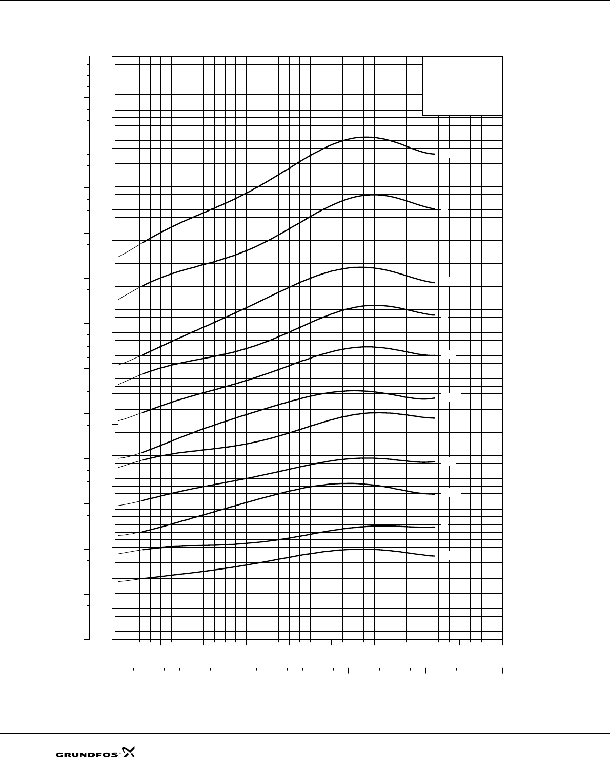
Explanation of efficiency curve, please see "Curve conditions" on page 4.
TM01 3309 1802
0 4 8 12 16 20 24 28
Q [m³/h]
0
20
40
60
80
100
120
140
160
180
200
220
240
260
280
300
H
[m]
0 2 4 6 8
Q [l/s]
0
400
800
1200
1600
2000
2400
2800
[kPa]
p
SP 17
60 Hz, SF 1.15
ISO 9906 Annex A
-18
-17
-16
-15
-14
-13
-12
-11
-10
-9
-8
-7
-6
-5
-4
-3
-2
-1
0 4 8 12 16 20 24 28
Q [m³/h]
0
4
8
12
16
[m]
H
0
20
40
60
80
[%]
Eta
0
40
80
120
160
[kPa]
p
NPSH
Eta
Performance curves SP 17
29
Explanation of efficiency curve, please see "Curve conditions" on page 4.
TM01 3310 1802
0 4 8 12 16 20 24 28
Q [m³/h]
120
160
200
240
280
320
360
400
440
480
520
560
600
640
680
720
760
800
840
H
[m]
0 2 4 6 8
Q [l/s]
1600
2400
3200
4000
4800
5600
6400
7200
8000
[kPa]
p
SP 17
60 Hz, SF 1.15
ISO 9906 Annex A
-42
-45
-48
-50
-39
-36
-33
-30
-29
-28
-27
-26
-25
-24
-23
-22
-21
-20
-19
0 4 8 12 16 20 24 28
Q [m³/h]
0
4
8
12
16
[m]
H
0
20
40
60
80
[%]
Eta
0
40
80
120
160
[kPa]
p
NPSH
Eta
Performance curves SP 17
30
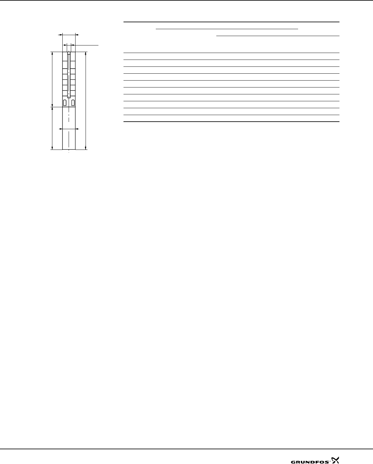
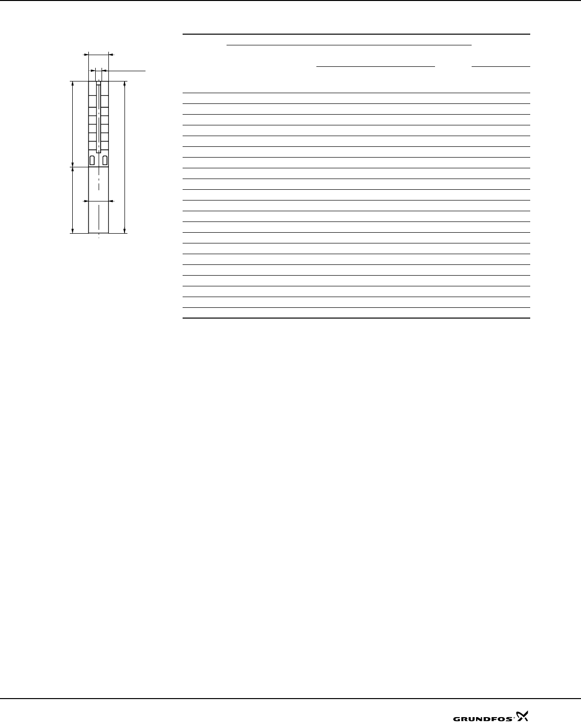
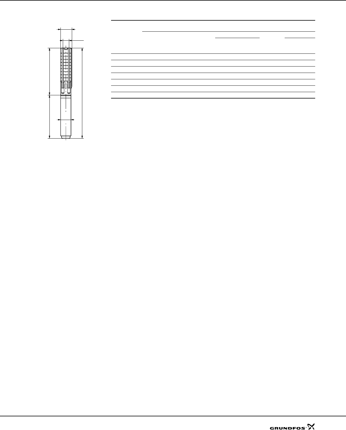
Dimensions and weights
TM01 2435 1798
Pump type
Motor Dimensions [mm] Net weight
[kg]
Type Power
[kW] CBADE*E**
SP 17-1 MS 4000 1.1 314 413 727 95 131 18
SP 17-2 MS 4000 2.2 374 454 828 95 131 22
SP 17-3 MS 4000 3 435 494 929 95 131 24
SP 17-4 MS 4000 4 495 574 1069 95 131 29
SP 17-5 MS 4000 5.5 556 674 1230 95 131 35
SP 17-6 MS 4000 5.5 616 674 1290 95 131 36
SP 17-7 MS 4000 7.5 677 773 1450 95 131 43
SP 17-8 MS 4000 7.5 737 773 1510 95 131 44
SP 17-9 MS 4000 7.5 798 773 1571 95 131 45
SP 17-5 MS6 5.5 572 565 1137 143 142 47
SP 17-6 MS6 5.5 632 565 1197 143 142 48
SP 17-7 MS6 7.5 693 590 1283 143 142 50
SP 17-8 MS6 7.5 753 590 1343 143 142 51
SP 17-9 MS6 7.5 814 590 1404 143 142 52
SP 17-10 MS6 9.2 874 610 1484 143 142 59
SP 17-33 to SP 17-50 are mounted in
sleeve for R 3 connection.
SP 17-11 MS6 9.2 935 610 1545 143 142 60
SP 17-12 MS6 11 995 708 1703 143 142 64
SP 17-13 MS6 11 1056 708 1764 143 142 65
SP 17-14 MS6 13 1116 738 1854 143 142 69
SP 17-15 MS6 13 1177 738 1915 143 142 71
SP 17-16 MS6 15 1237 783 2020 143 142 76
SP 17-17 MS6 15 1298 783 2081 143 142 77
SP 17-18 MS6 15 1358 783 2141 143 142 78
SP 17-19 MS6 18.5 1419 838 2257 143 142 85
SP 17-20 MS6 18.5 1479 838 2317 143 142 87
SP 17-21 MS6 18.5 1540 838 2378 143 142 88
SP 17-22 MS6 18.5 1600 838 2438 143 142 89
SP 17-23 MS6 22 1661 903 2564 143 142 96
SP 17-24 MS6 22 1721 903 2624 143 142 97
SP 17-25 MS6 22 1782 903 2685 143 142 99
SP 17-26 MS6 22 1842 903 2745 143 142 100
SP 17-27 MS6 26 1903 968 2871 143 142 106
SP 17-28 MS6 26 1963 968 2931 143 142 107
SP 17-29 MS6 26 2024 968 2992 143 142 108
SP 17-30 MS6 26 2084 968 3052 143 142 110
SP 17-33 MS6 30 2513 1023 3536 143 175 155
SP 17-36 MS6 30 2694 1023 3717 143 175 160
SP 17-39 MMS 6000 37 2876 1425 4301 136 175 203
SP 17-42 MMS 6000 37 3057 1425 4482 144 175 181 208
SP 17-45 MMS 8000 45 3188 1270 4458 192 192 192 276
SP 17-48 MMS 8000 45 3369 1270 4639 192 192 192 281
SP 17-50 MMS 8000 45 3490 1270 4760 192 192 192 285
* Maximum diameter of pump with one motor cable.
** Maximum diameter of pump with two motor cables.
The pump types above are also available in N- and R-versions (R-versions up to and including SP 17-30), see
page 5 for further details.
Dimensions as above.
Other types of connection are possible by means of connecting flanges, see page 86.
Rp 2 1/2
A
B C
D
E
Technical data SP 17
32
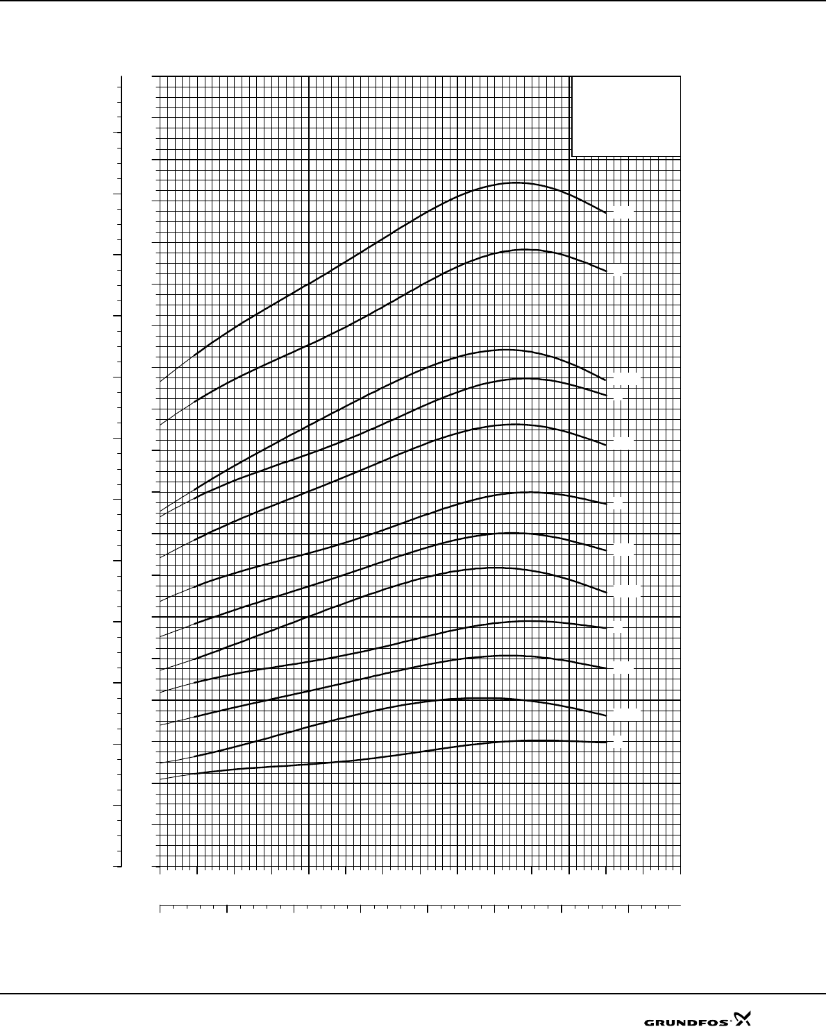
Explanation of efficiency curve, please see "Curve conditions" on page 4.
TM01 9243 1802
0 4 8 12 16 20 24 28
Q [m³/h]
10
12
14
16
18
20
22
24
26
28
30
32
34
36
38
40
42
44
46
48
50
52
54
[kW]
P2
0 2 4 6 8
Q [l/s]
16
20
24
28
32
36
40
44
48
52
56
60
64
68
72
[hp]
P2
SP 17
60 Hz, SF 1.15
ISO 9906 Annex A
-42
-45
-48
-50
-39
-36
-33
-30
-29
-28
-27
-26
-25
-24
-23
-22
-21
-20
-19
Power curves SP 17
33
SP 30
Explanation of efficiency curve, please see “Curve conditions" on page 4.
TM01 3311 1802
0 4 8 12 16 20 24 28 32 36 40 44
Q [m³/h]
0
20
40
60
80
100
120
140
160
180
200
220
240
260
280
H
[m]
0 2 4 6 8 10 12
Q [l/s]
0
400
800
1200
1600
2000
2400
2800
[kPa]
p
SP 30
60 Hz, SF 1.15
ISO 9906 Annex A
-17
-16
-15
-14
-13
-12
-11
-10
-9
-8
-7
-6
-5
-4
-3
-2
-1
0 4 8 12 16 20 24 28 32 36 40 44
Q [m³/h]
0
4
8
12
16
[m]
H
0
20
40
60
80
[%]
Eta
0
40
80
120
160
[kPa]
p
NPSH
Eta
Performance curves SP 30
34
Explanation of efficiency curve, please see “Curve conditions" on page 4.
TM01 3312 1802
0 4 8 12 16 20 24 28 32 36 40 44
Q [m³/h]
80
120
160
200
240
280
320
360
400
440
480
520
560
600
640
680
H
[m]
0 2 4 6 8 10 12
Q [l/s]
800
1600
2400
3200
4000
4800
5600
6400
[kPa]
p
SP 30
60 Hz, SF 1.15
ISO 9906 Annex A
-39
-36
-33
-31
-29
-28
-27
-26
-25
-24
-23
-22
-21
-20
-19
-18
0 4 8 12 16 20 24 28 32 36 40 44
Q [m³/h]
0
4
8
12
16
[m]
H
0
20
40
60
80
[%]
Eta
0
40
80
120
160
[kPa]
p
NPSH
Eta
Performance curves SP 30
35
Dimensions and weights
TM00 0960 1196
Pump type
Motor Dimensions [mm] Net weight
[kg]
Type Power
[kW] CBADE*E**
SP 30-1 MS 4000 1.5 349 413 762 95 131 21
SP 30-2 MS 4000 3 445 494 939 95 131 24
SP 30-3 MS 4000 4 541 574 1115 95 131 29
SP 30-4 MS 4000 5.5 637 674 1311 95 131 36
SP 30-5 MS 4000 7.5 733 773 1506 95 131 43
SP 30-4 MS6 5.5 653 565 1218 143 142 142 47
SP 30-5 MS6 7.5 749 590 1339 143 142 142 50
SP 30-6 MS6 9.2 845 610 1455 143 142 142 57
SP 30-7 MS6 9.2 941 610 1551 143 142 142 59
SP 30-8 MS6 11 1037 708 1745 143 142 142 63
SP 30-9 MS6 13 1133 738 1871 143 142 142 68
SP 30-10 MS6 13 1229 738 1967 143 142 142 70
SP 30-11 MS6 15 1325 783 2108 143 142 142 75
SP 30-12 MS6 18.5 1421 838 2259 143 142 142 83
SP 30-13 MS6 18.5 1517 838 2355 143 142 142 84
SP 30-29 to SP 30-39 are mounted
in sleeve for R 3 connection.
SP 30-14 MS6 18.5 1613 838 2451 143 142 142 86
SP 30-15 MS6 22 1709 903 2612 143 142 142 94
SP 30-16 MS6 22 1805 903 2708 143 142 142 95
SP 30-17 MS6 22 1901 903 2804 143 142 142 97
SP 30-18 MS6 26 1997 968 2965 143 142 142 104
SP 30-19 MS6 26 2093 968 3061 143 142 142 106
SP 30-20 MS6 26 2189 968 3157 143 142 142 108
SP 30-21 MS6 30 2285 1023 3308 143 144 145 117
SP 30-22 MS6 30 2381 1023 3404 143 144 145 119
SP 30-23 MS6 30 2477 1023 3500 143 144 145 121
SP 30-24 MMS 6000 37 2573 1425 3998 144 175 175 170
SP 30-25 MMS 6000 37 2669 1425 4094 144 175 175 171
SP 30-26 MMS 6000 37 2765 1425 4190 144 175 175 173
SP 30-27 MMS 6000 37 2861 1425 4286 144 175 175 175
SP 30-28 MMS 6000 37 2957 1425 4382 144 175 175 176
SP 30-29 MMS 8000 45 3249 1270 4519 192 192 192 280
SP 30-31 MMS 8000 45 3441 1270 4711 192 192 192 285
SP 30-33 MMS 8000 45 3633 1270 4903 192 192 192 290
SP 30-36 MMS 8000 55 3921 1350 5271 192 192 192 313
SP 30-39 MMS 8000 55 4209 1350 5559 192 192 192 322
* Maximum diameter of pump with one motor cable.
** Maximum diameter of pump with two motor cables.
The pump types above are also available in N and R-versions (R-versions up to and including SP 30-28), see
page 5 for further details.
Dimensions as above.
Other types of connection are possible by means of connecting pieces, see page 86.
A
B C
E
D
Rp 3
Technical data SP 30
36
Explanation of efficiency curve, please see “Curve conditions" on page 4.
TM01 2266 1802
0 4 8 12 16 20 24 28 32 36 40 44
Q [m³/h]
0
1
2
3
4
5
6
7
8
9
10
11
12
13
14
15
16
17
18
19
20
21
22
23
24
25
26
27
[kW]
P2
0 2 4 6 8 10 12
Q [l/s]
0
2
4
6
8
10
12
14
16
18
20
22
24
26
28
30
32
34
36
[hp]
P2
SP 30
60 Hz, SF 1.15
ISO 9906 Annex A
-17
-16
-15
-14
-13
-12
-11
-10
-9
-8
-7
-6
-5
-4
-3
-2
-1
Power curves SP 30
37
Explanation of efficiency curve, please see “Curve conditions" on page 4.
TM01 9244 1802
0 4 8 12 16 20 24 28 32 36 40 44
Q [m³/h]
14
16
18
20
22
24
26
28
30
32
34
36
38
40
42
44
46
48
50
52
54
56
58
60
62
64
[kW]
P2
0 2 4 6 8 10 12
Q [l/s]
20
24
28
32
36
40
44
48
52
56
60
64
68
72
76
80
84
[hp]
P2
SP 30
60 Hz, SF 1.15
ISO 9906 Annex A
-39
-36
-33
-31
-29
-28
-27
-26
-25
-24
-23
-22
-21
-20
-19
-18
Power curves SP 30
38
SP 46
Explanation of efficiency curve, please see “Curve conditions" on page 4.
TM01 3313 1802
010 20 30 40 50 60 70
Q [m³/h]
0
10
20
30
40
50
60
70
80
90
100
110
120
130
140
150
160
H
[m]
0 5 10 15 20
Q [l/s]
0
200
400
600
800
1000
1200
1400
[kPa]
p
SP 46
60 Hz, SF 1.15
ISO 9906 Annex A
-8
-7
-7-C
-6
-6-A
-5
-5-C
-4
-4-BC
-3
-3-BB
-2
-2-AB
-1
-1-A
-1-B
010 20 30 40 50 60 70
Q [m³/h]
0
4
8
12
16
[m]
H
0
20
40
60
80
[%]
Eta
0
40
80
120
160
[kPa]
p
NPSH
Eta
Performance curves SP 46
39
Explanation of efficiency curve, please see “Curve conditions" on page 4.
TM01 3314 1802
010 20 30 40 50 60 70
Q [m³/h]
40
80
120
160
200
240
280
320
360
400
440
480
H
[m]
0 5 10 15 20
Q [l/s]
800
1600
2400
3200
4000
4800
[kPa]
p
SP 46
60 Hz, SF 1.15
ISO 9906 Annex A
-24
-22
-20
-19
-18
-17
-16
-15
-14
-13
-12
-11
-10
-9
010 20 30 40 50 60 70
Q [m³/h]
0
4
8
12
16
[m]
H
0
20
40
60
80
[%]
Eta
0
40
80
120
160
[kPa]
p
NPSH
Eta
Performance curves SP 46
40
Dimensions and weights
TM00 0961 1196
Pump type
Motor Dimensions [mm] Net
weight
[kg]
Type Power
[kW]
Rp 3 connection Rp 4 connection BD
A C E* E** A C E* E**
SP 46-1-B MS 4000 1.5 780 367 146 148 783 370 146 148 413 95 20
SP 46-1-B MS 402 1.5 713 367 146 148 716 370 146 148 346 95 16
SP 46-1-A MS 4000 2.2 821 367 146 148 824 370 146 148 454 95 22
SP 46-1 MS 4000 3 861 367 146 148 864 370 146 148 494 95 23
SP 46-2-AB MS 4000 4.0 974 480 146 148 977 483 146 148 494 95 25
SP 46-2 MS 4000 5.5 1154 480 146 148 1157 483 146 148 674 95 34
SP 46-3-BB MS 4000 5.5 1267 593 146 148 1267 593 146 148 674 95 37
SP 46-3 MS 4000 7.5 1367 593 149 152 1370 596 149 152 774 95 42
SP 46-3 MS6 7.5 1199 609 149 152 1202 612 149 152 590 143 49
SP 46-4-BC MS6 7.5 1312 722 149 152 1315 725 149 152 590 143 52
SP 46-4 MS6 9.2 1332 722 149 152 1335 725 149 152 610 143 57
SP 46-5-C MS6 11 1543 835 149 152 1546 838 149 152 708 143 63
SP 46-5 MS6 13 1573 835 149 152 1576 838 149 152 738 143 66
SP 46-6-A MS6 13 1686 948 149 152 1689 951 149 152 738 143 68
SP 46-6 MS6 15 1731 948 149 152 1734 951 149 152 783 143 72
SP 46-7-C MS6 15 1844 1061 149 152 1847 1064 149 152 783 143 75
SP 46-7 MS6 18.5 1899 1061 149 152 1902 1064 149 152 838 143 80
SP 46-8 MS6 18.5 2012 1174 149 152 2015 1177 149 152 838 143 83
SP 46-20 to SP 46-24 are mounted in
sleeve for R 4 connection.
SP 46-9 MS6 22 2190 1287 149 152 2193 1290 149 152 903 143 91
SP 46-10 MS6 22 2303 1400 149 152 2306 1403 149 152 903 143 94
SP 46-11 MS6 26 2481 1513 149 152 2484 1516 149 152 968 143 102
SP 46-12 MS6 30 2649 1626 149 152 2652 1629 149 152 1023 143 112
SP 46-13 MS6 30 2762 1739 149 152 2765 1742 149 152 1023 143 115
SP 46-14 MMS 6000 37 3357 1932 149 152 3360 1935 149 152 1425 138 168
SP 46-15 MMS 6000 37 3470 2045 149 152 3473 2048 149 152 1425 138 170
SP 46-16 MMS 6000 37 3583 2158 149 152 3586 2161 149 152 1425 138 173
SP 46-17 MMS 6000 37 3696 2271 149 152 3699 2274 149 152 1425 138 175
SP 46-18 MMS 8000 45 3603 2333 192 192 3606 2336 192 192 1270 192 228
SP 46-19 MMS 8000 45 3717 2446 192 192 3719 2449 192 192 1270 192 231
SP 46-20 MMS 8000 45 3829 2559 192 192 3832 2562 192 192 1270 192 234
SP 46-22 MMS 8000 55 4298 2948 193 195 4301 2951 193 195 1350 192 281
SP 46-24 MMS 8000 55 4527 3177 193 195 1350 192 287
* Maximum diameter of pump with one motor cable.
** Maximum diameter of pump with two motor cables.
The pump types above are also available in N and R-versions (R-versions up to and including SP 46-17), see
page 5 for further details.
Dimensions as above.
Other types of connection are possible by means of connecting pieces, see page 86.
A
B C
E
D
Rp 3
Rp 4
Technical data SP 46
41
Explanation of efficiency curve, please see “Curve conditions" on page 4.
TM00 7515 1802
010 20 30 40 50 60 70
Q [m³/h]
0
1
2
3
4
5
6
7
8
9
10
11
12
13
14
15
16
17
18
19
20
21
22
[kW]
P2
0 5 10 15 20
Q [l/s]
0
2
4
6
8
10
12
14
16
18
20
22
24
26
28
30
[hp]
P2
SP 46
60 Hz, SF 1.15
ISO 9906 Annex A
-8
-7
-7-C
-6
-6-A
-5
-5-C
-4
-4-BC
-3
-3-BB
-2
-2-AB
-1
-1-A
-1-B
Power curves SP 46
43
SP 60
Explanation of efficiency curve, please see “Curve conditions" on page 4.
TM01 3315 1802
010 20 30 40 50 60 70 80 90
Q [m³/h]
0
10
20
30
40
50
60
70
80
90
100
110
120
130
140
150
H
[m]
0 5 10 15 20 25
Q [l/s]
0
200
400
600
800
1000
1200
1400
[kPa]
p
SP 60
60 Hz, SF 1.15
ISO 9906 Annex A
-7
-6
-6-B
-5
-4
-4-AA
-3
-3-A
-2
-2-BB
-1
-1-B
010 20 30 40 50 60 70 80 90
Q [m³/h]
0
4
8
12
16
[m]
H
0
20
40
60
80
[%]
Eta
0
40
80
120
160
[kPa]
p
NPSH
Eta
Performance curves SP 60
44
Explanation of efficiency curve, please see “Curve conditions" on page 4.
TM01 3316 1802
010 20 30 40 50 60 70 80 90
Q [m³/h]
40
60
80
100
120
140
160
180
200
220
240
260
280
300
320
340
360
380
400
420
440
H
[m]
0 5 10 15 20 25
Q [l/s]
400
800
1200
1600
2000
2400
2800
3200
3600
4000
[kPa]
p
SP 60
60 Hz, SF 1.15
ISO 9906 Annex A
-19
-20
-21
-18
-17
-16
-15
-14
-13
-12
-11
-10
-9
-9-B
-8
010 20 30 40 50 60 70 80 90
Q [m³/h]
0
4
8
12
16
[m]
H
0
20
40
60
80
[%]
Eta
0
40
80
120
160
[kPa]
p
NPSH
Eta
Performance curves SP 60
45
Dimensions and weights
TM00 0961 1196
Pump type
Motor Dimensions [mm] Net
weight
[kg]
Type Power
[kW]
Rp 3 connection Rp 4 connection BD
A C E* E** A C E* E**
SP 60-1-B MS 4000 2.2 821 367 146 148 824 370 146 148 454 95 22
SP 60-1-A MS 4000 3.7 864 370 146 148 494 95 23
SP 60-1 MS 4000 4.0 941 367 146 148 944 370 146 148 574 95 27
SP 60-2-BB MS 4000 4.0 974 480 146 148 977 483 146 148 494 95 25
SP 60-2 MS 4000 5.5 1154 480 146 148 1157 483 146 148 674 95 34
SP 60-3-A MS 4000 7.5 1367 593 146 148 1370 596 146 148 774 95 39
SP 60-3-A MS6 7.5 1199 609 152 156 1202 612 152 156 590 143 49
SP 60-3 MS6 9.2 1219 609 152 156 1219 612 152 156 610 143 55
SP 60-4-AA MS6 9.2 1332 722 152 156 1335 725 152 156 610 143 57
SP 60-4 MS6 11 1430 722 152 156 1433 725 152 156 708 143 60
SP 60-5 MS6 13 1573 835 152 156 1573 838 152 156 738 143 66
SP 60-6-B MS6 15 1731 948 152 156 1734 951 152 156 783 143 72
SP 60-6 MS6 18.5 1786 948 152 156 1789 951 152 156 838 143 78
SP 60-7 MS6 18.5 1899 1061 152 156 1902 1064 152 156 838 143 80
SP 60-8 MS6 22 2077 1174 152 156 2080 1177 152 156 903 143 89
SP 60-9-B MS6 22 2190 1287 152 156 2193 1290 152 156 903 143 91
SP 60-9 MS6 26 2255 1287 152 156 2258 1290 152 156 968 143 97
SP 60-10 MS6 26 2368 1400 152 156 2371 1403 152 156 968 143 100
SP 60-19 to SP 60-21 are
mounted in sleeve for R 4
connection.
SP 60-11 MS6 30 2536 1513 152 156 2539 1516 152 156 1023 143 110
SP 60-12 MMS 6000 37 3131 1706 152 156 3134 1709 152 156 1425 138 163
SP 60-13 MMS 6000 37 3244 1819 152 156 3247 1822 152 156 1425 138 165
SP 60-14 MMS 6000 37 3360 1935 152 156 1425 138 168
SP 60-15 MMS 8000 45 3267 1997 192 192 1270 192 221
SP 60-16 MMS 8000 45 3380 2110 192 192 1270 192 223
SP 60-17 MMS 8000 45 3493 2223 192 192 1270 192 226
SP 60-18 MMS 8000 55 3686 2336 192 192 1350 192 243
SP 60-19 MMS 8000 55 3962 2612 193 195 1350 192 272
SP 60-20 MMS 8000 55 4075 2725 193 195 1350 192 275
SP 60-21 MMS 8000 63 4328 2838 193 195 1490 192 304
* Maximum diameter of pump with one motor cable.
** Maximum diameter of pump with two motor cables.
The pump types above are also available in N and R-versions (R-version up to and including SP 60-18), see page
5 for further details.
Dimensions as above.
Other types of connection are possible by means of connecting pieces, see page 86.
A
B C
E
D
Rp 3
Rp 4
Technical data SP 60
46
Explanation of efficiency curve, please see “Curve conditions" on page 4.
TM00 8054 1802
010 20 30 40 50 60 70 80 90
Q [m³/h]
0
1
2
3
4
5
6
7
8
9
10
11
12
13
14
15
16
17
18
19
20
21
22
[kW]
P2
0 5 10 15 20 25
Q [l/s]
0
2
4
6
8
10
12
14
16
18
20
22
24
26
28
30
[hp]
P2
SP 60
60 Hz, SF 1.15
ISO 9906 Annex A
-7
-6
-6-B
-5
-4
-4-AA
-3
-3-A
-2
-2-BB
-1
-1-B
Power curves SP 60
47
Explanation of efficiency curve, please see “Curve conditions" on page 4.
TM01 9246 1802
010 20 30 40 50 60 70 80 90
Q [m³/h]
18
20
22
24
26
28
30
32
34
36
38
40
42
44
46
48
50
52
54
56
58
60
62
64
66
68
[kW]
P2
0 5 10 15 20 25
Q [l/s]
28
32
36
40
44
48
52
56
60
64
68
72
76
80
84
88
92
[hp]
P2
SP 60
60 Hz, SF 1.15
ISO 9906 Annex A
-19
-20
-21
-18
-17
-16
-15
-14
-13
-12
-11
-10
-9
-9-B
-8
Power curves SP 60
48
SP 77
Explanation of efficiency curve, please see “Curve conditions" on page 4.
TM01 3317 1802
010 20 30 40 50 60 70 80 90 100 110 120
Q [m³/h]
0
10
20
30
40
50
60
70
80
90
100
110
120
130
140
150
160
170
H
[m]
0 5 10 15 20 25 30 35
Q [l/s]
0
200
400
600
800
1000
1200
1400
1600
[kPa]
p
SP 77
60 Hz, SF 1.15
ISO 9906 Annex A
-6-B
-5
-5-BB
-4
-4-B
-3
-3-A
-3-AA
-2
-2-A
-2-BA
-1
010 20 30 40 50 60 70 80 90 100 110 120
Q [m³/h]
0
4
8
12
16
[m]
H
0
20
40
60
80
[%]
Eta
0
40
80
120
160
[kPa]
p
NPSH
Eta
Performance curves SP 77
49
Explanation of efficiency curve, please see “Curve conditions" on page 4.
TM01 3318 1802
010 20 30 40 50 60 70 80 90 100 110 120
Q [m³/h]
40
60
80
100
120
140
160
180
200
220
240
260
280
300
320
340
360
380
400
420
440
H
[m]
0 5 10 15 20 25 30 35
Q [l/s]
400
800
1200
1600
2000
2400
2800
3200
3600
4000
[kPa]
p
SP 77
60 Hz, SF 1.15
ISO 9906 Annex A
-14
-15
-13
-12
-11
-10
-9
-8
-7
-6
010 20 30 40 50 60 70 80 90 100 110 120
Q [m³/h]
0
4
8
12
16
[m]
H
0
20
40
60
80
[%]
Eta
0
40
80
120
160
[kPa]
p
NPSH
Eta
Performance curves SP 77
50
Dimensions and weights
TM00 7872 2196
Pump type
Motor Dimensions [mm] Net
weight
[kg]
Type Power
[kW]
Rp 5 connection 5" Grundfos flange BD
ACE*E**ACE*E**
SP 77-1 MS6 5.5 1183 618 178 186 1183 618 200 200 565 143 55
SP 77-2-BA MS6 7.5 1336 746 178 186 1336 746 200 200 590 143 63
SP 77-2-A MS6 9.2 1356 746 178 186 1356 746 200 200 610 143 69
SP 77-2 MS6 11 1454 746 178 186 1454 746 200 200 708 143 71
SP 77-3-AA MS6 13 1612 874 178 186 1612 874 200 200 738 143 78
SP 77-3-A MS6 15 1657 874 178 186 1657 874 200 200 783 143 82
SP 77-3 MS6 18.5 1712 874 178 186 1712 874 200 200 838 143 87
SP 77-4-B MS6 18.5 1840 1002 178 186 1840 1002 200 200 838 143 91
SP 77-4 MS6 22 1905 1002 178 186 1905 1002 200 200 903 143 97
SP 77-5-BB MS6 22 2033 1130 178 186 2033 1130 200 200 903 143 101
SP 77-5 MS6 26 2098 1130 178 186 2098 1130 200 200 968 143 106
SP 77-6-B MS6 30 2281 1258 178 186 2281 1258 200 200 1023 143 118
SP 77-6 MMS 6000 37 2683 1258 178 186 2683 1258 200 200 1425 138 166
SP 77-7 MMS 6000 37 2811 1386 178 186 2811 1386 200 200 1425 138 169
SP 77-8 MMS 8000 45 2798 1528 200 204 2798 1528 205 205 1270 192 225
SP 77-9 MMS 8000 55 3006 1656 200 204 3006 1656 205 205 1350 192 244
SP 77-10 MMS 8000 55 3134 1784 200 204 3134 1784 205 205 1350 192 248
SP 77-11 MMS 8000 63 3402 1912 200 204 3402 1912 205 205 1490 192 277
SP 77-12 MMS 8000 63 3530 2040 200 204 1490 192 281
SP 77-13 MMS 8000 75 3758 2168 200 204 1590 192 304
SP 77-14 MMS 8000 92 4426 2596 200 202 1830 192 361
TM00 7323 1798
SP 77-15 MMS 8000 92 4554 2724 200 202 1830 192 365
* Maximum diameter of pump with one motor cable.
** Maximum diameter of pump with two motor cables.
The pump types above are also available in N-version, see page 5 for further details.
Dimensions as above.
Other types of connection are possible by means of connecting pieces, see page 86.
A
B C
E
D
Rp 5
8 x ø15
ø125
ø175
ø200
Technical data SP 77
51
Explanation of efficiency curve, please see “Curve conditions" on page 4.
TM0 7450 1802
010 20 30 40 50 60 70 80 90 100 110 120
Q [m³/h]
0
2
4
6
8
10
12
14
16
18
20
22
24
26
28
30
32
34
36
[kW]
P2
0 5 10 15 20 25 30 35
Q [l/s]
0
4
8
12
16
20
24
28
32
36
40
44
48
[hp]
P2
SP 77
60 Hz, SF 1.15
ISO 9906 Annex A
-6-B
-5
-5-BB
-4
-4-B
-3
-3-A
-3-AA
-2
-2-A
-2-BA
-1
Power curves SP 77
52
Explanation of efficiency curve, please see “Curve conditions" on page 4.
TM01 9247 1802
010 20 30 40 50 60 70 80 90 100 110 120
Q [m³/h]
24
26
28
30
32
34
36
38
40
42
44
46
48
50
52
54
56
58
60
62
64
66
68
70
72
74
76
78
80
82
84
86
88
90
92
94
[kW]
P2
0 5 10 15 20 25 30 35
Q [l/s]
36
40
44
48
52
56
60
64
68
72
76
80
84
88
92
96
100
104
108
112
116
120
124
128
[hp]
P2
SP 77
60 Hz, SF 1.15
ISO 9906 Annex A
-14
-15
-13
-12
-11
-10
-9
-8
-7
-6
Power curves SP 77
53
SP 95
Explanation of efficiency curve, please see “Curve conditions" on page 4.
TM01 3319 1802
020 40 60 80 100 120 140
Q [m³/h]
0
10
20
30
40
50
60
70
80
90
100
110
120
130
140
150
H
[m]
010 20 30 40
Q [l/s]
0
200
400
600
800
1000
1200
1400
[kPa]
p
SP 95
60 Hz, SF 1.15
ISO 9906 Annex A
-5-B
-4
-4-AB
-3
-3-B
-3-BB
-2
-2-AB
-2-B
-1
-1-A
020 40 60 80 100 120 140
Q [m³/h]
0
4
8
12
16
[m]
H
0
20
40
60
80
[%]
Eta
0
40
80
120
160
[kPa]
p
NPSH
Eta
Performance curves SP 95

54
Explanation of efficiency curve, please see “Curve conditions" on page 4.
TM01 3320 1802
020 40 60 80 100 120 140
Q [m³/h]
40
60
80
100
120
140
160
180
200
220
240
260
280
300
320
340
360
380
400
H
[m]
010 20 30 40
Q [l/s]
400
800
1200
1600
2000
2400
2800
3200
3600
[kPa]
p
SP 95
60 Hz, SF 1.15
ISO 9906 Annex A
-13
-12
-11
-10
-9
-8
-7
-6
-5
020 40 60 80 100 120 140
Q [m³/h]
0
4
8
12
16
[m]
H
0
20
40
60
80
[%]
Eta
0
40
80
120
160
[kPa]
p
NPSH
Eta
Performance curves SP 95
55
Dimensions and weights
TM00 7872 2196
Pump type
Motor Dimensions [mm] Net
weight
[kg]
Type Power
[kW]
Rp 5 connection 5" Grundfos flange BD
A C E* E** A C E* E**
SP 95-1-A MS6 5.5 1183 618 179 183 1183 618 200 200 565 143 55
SP 95-1 MS6 7.5 1208 618 179 183 1208 618 200 200 590 143 59
SP 95-2-AB MS6 9.2 1356 746 179 183 1356 746 200 200 610 143 69
SP 95-2-B MS6 11 1454 746 179 183 1454 746 200 200 708 143 71
SP 95-2 MS6 13 1484 746 179 183 1484 746 200 200 738 143 74
SP 95-3-BB MS6 15 1657 874 179 183 1657 874 200 200 783 143 82
SP 95-3-B MS6 18.5 1712 874 179 183 1712 874 200 200 838 143 87
SP 95-3 MS6 22 1777 874 179 183 1777 874 200 200 903 143 93
SP 95-4-AB MS6 22 1905 1002 179 183 1905 1002 200 200 903 143 97
SP 95-4 MS6 26 1970 1002 179 183 1970 1002 200 200 968 143 103
SP 95-5-B MS6 30 2153 1130 179 183 2153 1130 200 200 1023 143 114
SP 95-5 MMS 6000 37 2555 1130 179 183 2555 1130 200 200 1425 138 162
SP 95-6 MMS 6000 37 2683 1258 179 183 2683 1258 200 200 1425 138 166
SP 95-7 MMS 8000 45 2670 1400 205 205 2670 1400 200 202 1270 192 221
SP 95-8 MMS 8000 55 2878 1528 205 205 2878 1528 200 202 1350 192 240
SP 95-9 MMS 8000 63 3146 1656 205 205 3146 1656 200 202 1490 192 270
SP 95-10 MMS 8000 63 3274 1784 205 205 3274 1784 200 202 1490 192 274
SP 95-11 MMS 8000 75 3502 1912 205 205 1590 192 296
SP 95-12 MMS 8000 92 3870 2040 205 205 1830 192 346
SP 95-13 MMS 8000 92 3998 2168 205 205 1830 192 350
* Maximum diameter of pump with one motor cable.
TM00 7323 1798
** Maximum diameter of pump with two motor cables.
The pump types above are also available in R and N-version, see page 5 for further details.
Dimensions as above
Other types of connection are possible by means of connecting pieces, see page 86.
A
B C
E
D
Rp 5
8 x ø15
ø125
ø175
ø200
Technical data SP 95
56
Explanation of efficiency curve, please see “Curve conditions" on page 4.
TM00 8458 1802
020 40 60 80 100 120 140
Q [m³/h]
0
2
4
6
8
10
12
14
16
18
20
22
24
26
28
30
32
34
36
[kW]
P2
010 20 30 40
Q [l/s]
0
4
8
12
16
20
24
28
32
36
40
44
48
[hp]
P2
SP 95
60 Hz, SF 1.15
ISO 9906 Annex A
-5-B
-4
-4-AB
-3
-3-B
-3-BB
-2
-2-AB
-2-B
-1
-1-A
Power curves SP 95
58
SP 125
Explanation of efficiency curve, please see “Curve conditions" on page 4.
TM01 3321 1802
020 40 60 80 100 120 140 160 180
Q [m³/h]
0
10
20
30
40
50
60
70
80
90
100
110
120
130
140
150
160
170
H
[m]
010 20 30 40 50
Q [l/s]
0
200
400
600
800
1000
1200
1400
1600
[kPa]
p
SP 125
60 Hz, SF 1.15
ISO 9906 Annex A
-4
-4-A
-4-AA
-3
-3-A
-3-AA
-2
-2-A
-2-AA
-1
-1-A
020 40 60 80 100 120 140 160 180
Q [m³/h]
0
4
8
12
16
[m]
H
0
20
40
60
80
[%]
Eta
0
40
80
120
160
[kPa]
p
NPSH
Eta
Performance curves SP 125
59
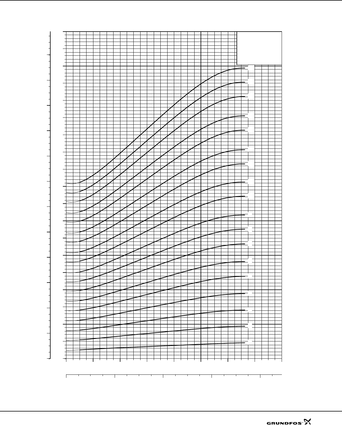
Explanation of efficiency curve, please see “Curve conditions" on page 4.
TM01 3322 0707
020 40 60 80 100 120 140 160 180
Q [m³/h]
56
60
80
100
120
140
160
180
200
220
240
260
280
300
320
340
360
380
400
420
440
460
480
H
[m]
010 20 30 40 50
Q [l/s]
800
1200
1600
2000
2400
2800
3200
3600
4000
4400
4800
[kPa]
p
SP 125
60 Hz, SF 1.15
ISO 9906 Annex A
-11
-10
-8
-9
-7
-7-A
-7-AA
-6
-6-A
-6-AA
-5
-5-A
-5-AA
020 40 60 80 100 120 140 160 180
Q [m³/h]
0
4
8
12
16
[m]
H
0
20
40
60
80
[%]
Eta
0
40
80
120
160
[kPa]
p
NPSH
Eta
Performance curves SP 125
60
Dimensions and weights
TM00 8760 3596
Pump type
Motor Dimensions [mm] Net
weight
[kg]
Type Power
[kW]
Rp 6 connection 6" Grundfos flange BD
ACE*E**ACE*E**
SP 125-1-A MS6 11 1360 652 211 215 1360 652 222 226 708 143 81
SP 125-1 MS6 18.5 1520 652 211 215 1520 652 222 226 838 143 93
SP 125-2-AA MS6 22 1710 807 211 215 1710 807 222 226 903 143 105
SP 125-2-A MS6 26 1775 807 211 215 1775 807 222 226 968 143 111
SP 125-2 MS6 30 1830 807 211 215 1830 807 222 226 1023 143 119
SP 125-3-AA MMS 6000 37 2388 963 211 215 2388 963 222 226 1425 138 172
SP 125-3-A MMS 6000 37 2388 963 211 215 2388 963 222 226 1425 138 172
SP 125-3 MMS 8000 45 2233 963 213 219 2233 963 229 232 1270 192 226
SP 125-4-AA MMS 8000 55 2468 1118 213 219 2468 1118 229 232 1350 192 247
SP 125-4-A MMS 8000 55 2468 1118 213 219 2468 1118 229 232 1350 192 247
SP 125-4 MMS 8000 63 2608 1118 213 219 2608 1118 229 232 1490 192 273
SP 125-5-AA MMS 8000 75 2864 1274 213 219 1590 192 296
SP 125-5-A MMS 8000 75 2864 1274 213 219 1590 192 296
SP 125-5 MMS 8000 75 2864 1274 213 219 1590 192 296
SP 125-6-AA MMS 8000 75 3019 1429 213 219 1590 192 302
SP 125-6-A MMS 8000 92 3259 1429 213 219 1830 192 348
SP 125-6 MMS 8000 92 3259 1429 213 219 1830 192 348
SP 125-7-AA MMS 8000 92 3415 1585 213 219 1830 192 354
SP 125-7-A MMS 8000 92 3415 1585 213 219 1830 192 354
SP 125-7 MMS 8000 110 3645 1585 213 219 2060 192 404
SP 125-8 MMS 10000 132 3962 2092 237 237 1870 237 532
TM00 7324 1798
SP 125-9 MMS 10000 132 4118 2248 237 237 1870 237 538
SP 125-10 MMS 10000 147 4473 2403 237 237 2070 237 609
SP 125-11 MMS 10000 170 4779 2559 237 237 2220 237 655
* Maximum diameter of pump with one motor cable.
** Maximum diameter of pump with two motor cables.
The pump types above are also available in N- and R-versions up to and including SP 125-7, see page 5
for further details.
Dimensions as above.
Other types of connection are possible by means of connecting pieces, see page 86.
A
B C
E
D
Rp 6
8 x ø15
ø170
ø196
ø220
Technical data SP 125
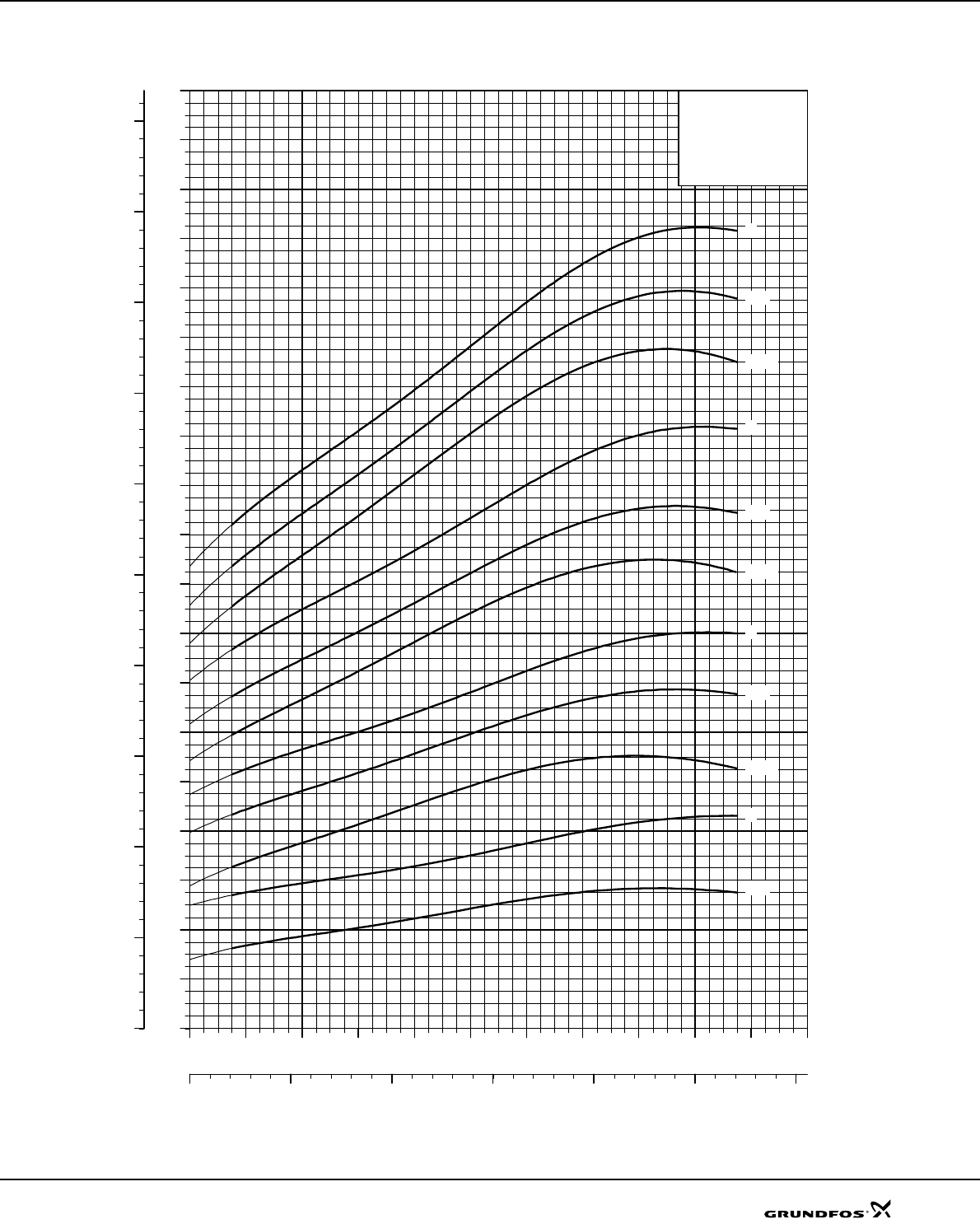
61
Explanation of efficiency curve, please see “Curve conditions" on page 4.
TM00 7634 1802
020 40 60 80 100 120 140 160 180
Q [m³/h]
0
4
8
12
16
20
24
28
32
36
40
44
48
52
56
60
64
68
72
[kW]
P2
010 20 30 40 50
Q [l/s]
0
10
20
30
40
50
60
70
80
90
[hp]
P2
SP 125
60 Hz, SF 1.15
ISO 9906 Annex A
-4
-4-A
-4-AA
-3
-3-A
-3-AA
-2
-2-A
-2-AA
-1
-1-A
Power curves SP 125
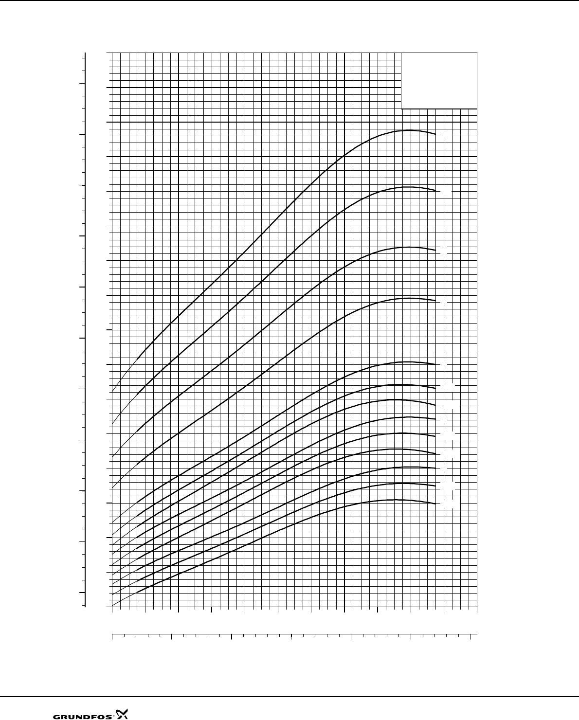
62
Explanation of efficiency curve, please see “Curve conditions" on page 4.
TM01 9249 0707
020 40 60 80 100 120 140 160 180
Q [m³/h]
40
50
60
70
80
90
100
110
120
130
140
150
160
170
180
190
[kW]
P2
010 20 30 40 50
Q [l/s]
60
80
100
120
140
160
180
200
220
240
260
[hp]
P2
SP 125
60 Hz, SF 1.15
ISO 9906 Annex A
-10
-11
-8
-9
-7
-7-A
-7-AA
-6
-6-A
-6-AA
-5
-5-A
-5-AA
Power curves SP 125

63
SP 160
Explanation of efficiency curve, please see “Curve conditions" on page 4.
TM01 3323 1802
020 40 60 80 100 120 140 160 180 200 220 240
Q [m³/h]
0
10
20
30
40
50
60
70
80
90
100
110
120
130
140
150
H
[m]
010 20 30 40 50 60 70
Q [l/s]
0
200
400
600
800
1000
1200
1400
[kPa]
p
SP 160
60 Hz, SF 1.15
ISO 9906 Annex A
-3
-3-A
-3-AA
-2
-2-A
-2-AA
-1
-1-A
020 40 60 80 100 120 140 160 180 200 220 240
Q [m³/h]
0
4
8
12
16
[m]
H
0
20
40
60
80
[%]
Eta
0
40
80
120
160
[kPa]
p
NPSH
Eta
Performance curves SP 160
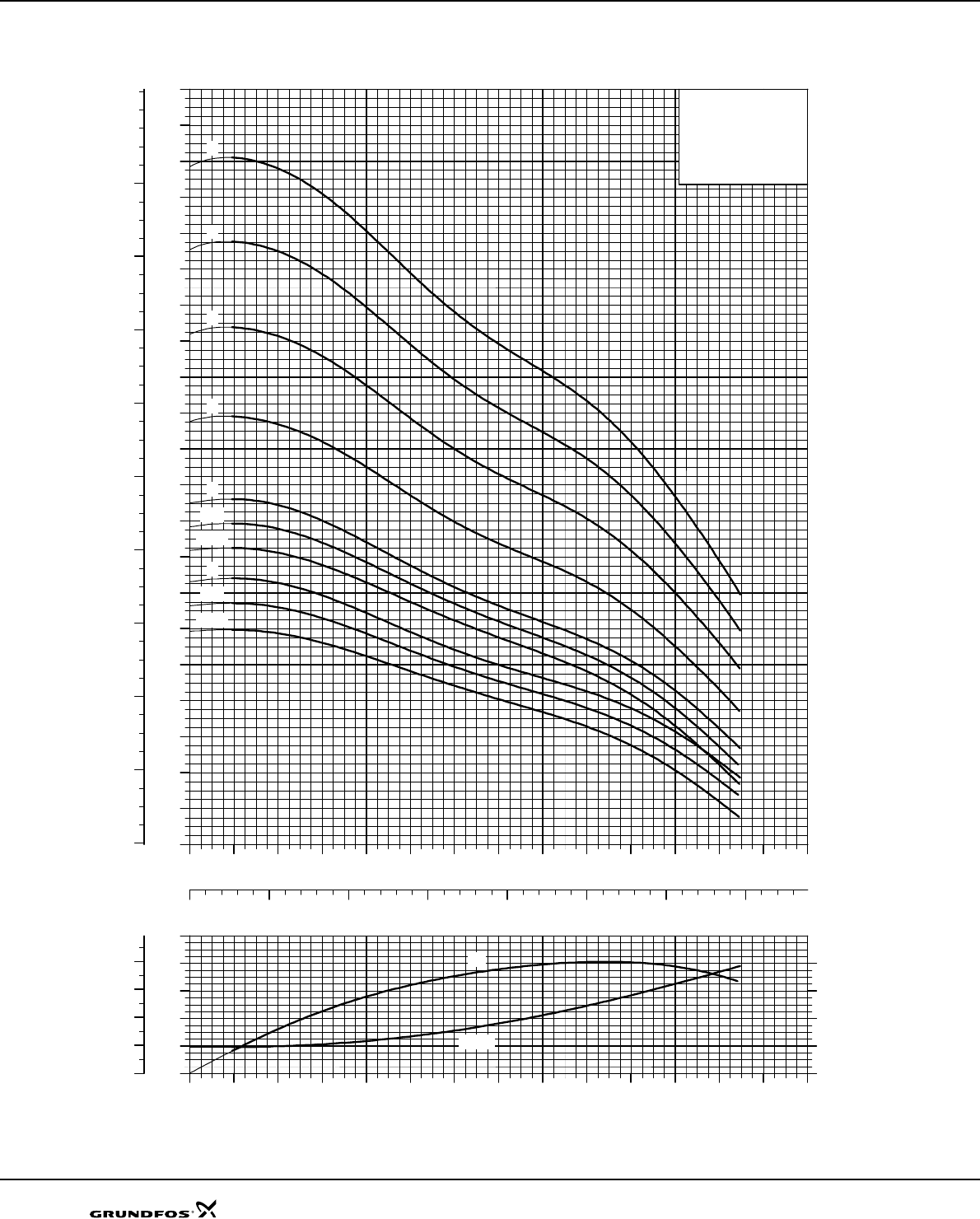
64
Explanation of efficiency curve, please see “Curve conditions" on page 4.
TM01 3324 0707
020 40 60 80 100 120 140 160 180 200 220 240
Q [m³/h]
40
60
80
100
120
140
160
180
200
220
240
260
280
300
320
340
360
380
400
420
440
H
[m]
010 20 30 40 50 60 70
Q [l/s]
400
800
1200
1600
2000
2400
2800
3200
3600
4000
[kPa]
p
SP 160
60 Hz, SF 1.15
ISO 9906 Annex A
-6
-7
-8
-9
-5
-5-A
-5-AA
-4
-4-AA
-4-A
020 40 60 80 100 120 140 160 180 200 220 240
Q [m³/h]
0
4
8
12
16
[m]
H
0
20
40
60
80
[%]
Eta
0
40
80
120
160
[kPa]
p
NPSH
Eta
Performance curves SP 160
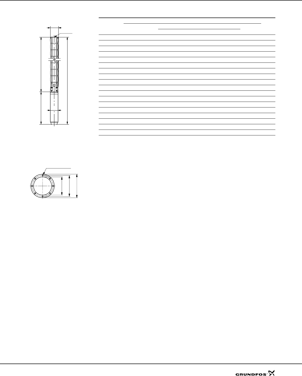
65
Dimensions and weights
TM00 8760 3596
Pump type
Motor Dimensions [mm] Net
weight
[kg]
Type Power
[kW]
Rp 6 connection 6" Grundfos flange BD
A C E* E** A C E* E**
SP 160-1-A MS6 15 1435 652 211 215 1435 652 222 226 143 138 88
SP 160-1 MS6 22 1555 652 211 215 1555 652 222 226 143 138 99
SP 160-2-AA MS6 26 1775 807 211 215 1775 807 222 226 143 138 111
SP 160-2-A MMS 6000 37 2232 807 211 215 2232 807 222 226 1425 138 166
SP 160-2 MMS 6000 37 2232 807 211 215 2232 807 222 226 1425 138 166
SP 160-3-AA MMS 8000 45 2233 963 213 219 2233 963 229 232 1270 192 226
SP 160-3-A MMS 8000 55 2313 963 213 219 2313 963 229 232 1350 192 241
SP 160-3 MMS 8000 55 2313 963 213 219 2313 963 229 232 1350 192 241
SP 160-4-AA MMS 8000 63 2608 1118 213 219 1490 192 271
SP 160-4-A MMS 8000 75 2708 1118 213 219 1590 192 290
SP 160-4 MMS 8000 75 2708 1118 213 219 1590 192 290
SP 160-5-AA MMS 8000 92 3104 1274 213 219 1830 192 342
SP 160-5-A MMS 8000 92 3104 1274 213 219 1830 192 342
SP 160-5 MMS 8000 92 3104 1274 213 219 1830 192 342
SP 160-6 MMS 8000 110 3789 1729 213 219 2060 192 408
SP 160-7 MMS 10000 132 3807 1937 237 237 1870 237 526
SP 160-8 MMS 10000 147 4162 2092 237 237 2070 237 597
SP 160-9 MMS 10000 170 4468 2248 237 237 2220 237 643
* Maximum diameter of pump with one motor cable.
** Maximum diameter of pump with two motor cables.
The pump types above are also available in N- and R-versions up to and including SP 160-6, see page 5
for further details.
Dimensions as above.
TM00 7324 1798
Other types of connection are possible by means of connecting pieces, see page 86.
A
B C
E
D
Rp 6
8 x ø15
ø170
ø196
ø220
Technical data SP 160
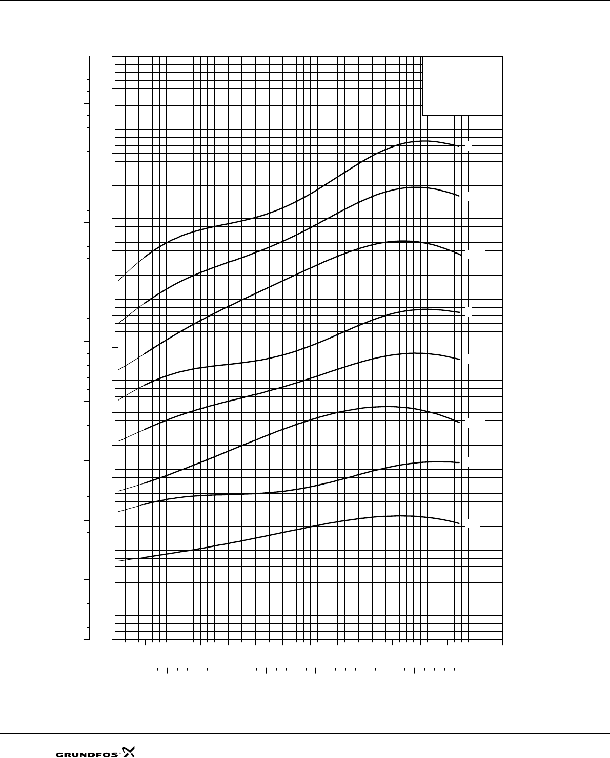
66
Explanation of efficiency curve, please see “Curve conditions" on page 4.
TM00 7688 1802
020 40 60 80 100 120 140 160 180 200 220 240
Q [m³/h]
0
4
8
12
16
20
24
28
32
36
40
44
48
52
56
60
64
68
[kW]
P2
010 20 30 40 50 60 70
Q [l/s]
0
10
20
30
40
50
60
70
80
90
[hp]
P2
SP 160
60 Hz, SF 1.15
ISO 9906 Annex A
-3
-3-A
-3-AA
-2
-2-A
-2-AA
-1
-1-A
Power curves SP 160
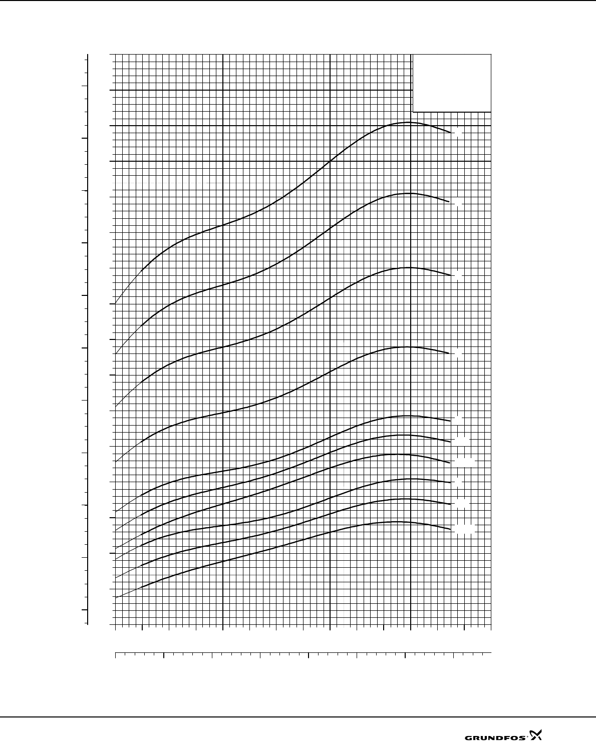
67
Explanation of efficiency curve, please see “Curve conditions" on page 4.
TM01 9250 0707
020 40 60 80 100 120 140 160 180 200 220 240
Q [m³/h]
40
50
60
70
80
90
100
110
120
130
140
150
160
170
180
190
[kW]
P2
010 20 30 40 50 60 70
Q [l/s]
60
80
100
120
140
160
180
200
220
240
260
[hp]
P2
SP 160
60 Hz, SF 1.15
ISO 9906 Annex A
-6
-7
-8
-9
-5
-5-A
-5-AA
-4
-4-A
-4-AA
Power curves SP 160
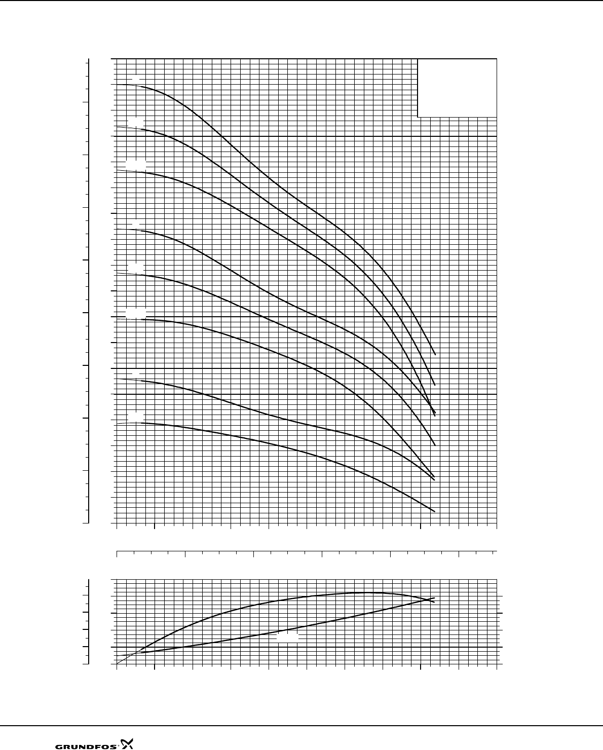
68
SP 215
Explanation of efficiency curve, please see “Curve conditions" on page 4.
TM01 3325 1802
040 80 120 160 200 240 280 320
Q [m³/h]
0
10
20
30
40
50
60
70
80
90
100
110
120
130
140
150
160
170
H
[m]
020 40 60 80 100
Q [l/s]
0
200
400
600
800
1000
1200
1400
1600
[kPa]
p
SP 215
60 Hz, SF 1.15
ISO 9906 Annex A
-3
-3-A
-3-AA
-2
-2-A
-2-AA
-1
-1-A
040 80 120 160 200 240 280 320
Q [m³/h]
0
4
8
12
16
[m]
H
0
20
40
60
80
[%]
Eta
0
40
80
120
160
[kPa]
p
NPSH
Eta
Performance curves SP 215
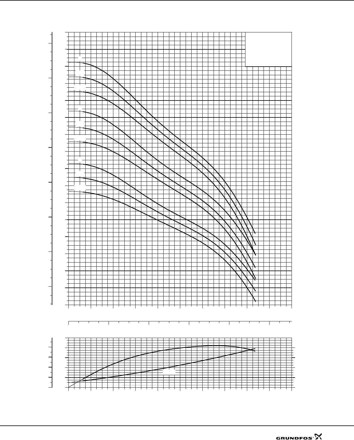
69
Explanation of efficiency curve, please see “Curve conditions" on page 4.
TM01 3326 0707
040 80 120 160 200 240 280 320
Q [m³/h]
60
80
100
120
140
160
180
200
220
240
260
280
300
320
340
360
H
[m]
020 40 60 80 100
Q [l/s]
800
1200
1600
2000
2400
2800
3200
[kPa]
p
SP 215
60 Hz, SF 1.15
ISO 9906 Annex A
-6
-6-A
-6-AA
-5
-5-A
-5-AA
-4
-4-A
-4-AA
040 80 120 160 200 240 280 320
Q [m³/h]
0
4
8
12
16
[m]
H
0
20
40
60
80
[%]
Eta
0
40
80
120
160
[kPa]
p
NPSH
Eta
Performance curves SP 215
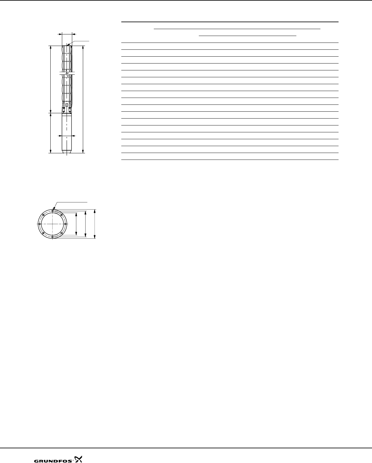
70
Dimensions and weights
TM00 8760 3596
Pump type
Motor Dimensions [mm] Net
weight
[kg]
Type Power
[kW]
Rp 6 connection 6" Grundfos flange BD
A C E* E** A C E* E**
SP 215-1-A MS6 22 1693 790 236 239 1693 790 241 247 903 143 106
SP 215-1 MS6 30 1813 790 236 239 1813 790 241 247 1023 143 120
SP 215-2-AA MMS 8000 45 2236 966 239 244 2236 966 241 247 1270 192 231
SP 215-2-A MMS 8000 55 2316 966 239 244 2316 966 241 247 1350 192 246
SP 215-2 MMS 8000 63 2456 966 239 244 2456 966 241 247 1490 192 272
SP 215-3-AA MMS 8000 75 2732 1142 239 244 2732 1142 241 247 1590 192 301
SP 215-3-A MMS 8000 92 2972 1142 239 244 2972 1142 241 247 1830 192 347
SP 215-3 MMS 8000 92 2972 1142 239 244 2972 1142 241 247 1830 192 347
SP 215-4-AA MMS 8000 110 3378 1318 239 244 3378 1318 241 247 2060 192 407
SP 215-4-A MMS 8000 110 3378 1318 239 244 3378 1318 241 247 2060 192 407
SP 215-4 MMS 8000 110 3378 1318 239 244 3378 1318 241 247 2060 192 407
SP 215-5-AA MMS 10000 132 3364 1494 250 254 1870 237 519
SP 215-5-A MMS 10000 132 3364 1494 250 254 1870 237 519
SP 215-5 MMS 10000 147 3564 1494 250 254 2070 237 584
SP 215-6-AA MMS 10000 170 3890 1670 250 254 2220 237 634
SP 215-6-A MMS 10000 170 3890 1670 250 254 2220 237 634
SP 215-6 MMS 10000 170 3890 1670 250 254 2220 237 634
* Maximum diameter of pump with one motor cable.
** Maximum diameter of pump with two motor cables.
The pump types above are also available in R and N-versions up to and including SP 215-4, see page 5 for fur-
ther details.
Dimensions as above.
TM00 7324 1798
Other types of connection are possible by means of connecting pieces, see page 86.
A
B C
E
D
Rp 6
8 x ø15
ø170
ø196
ø220
Technical data SP 215
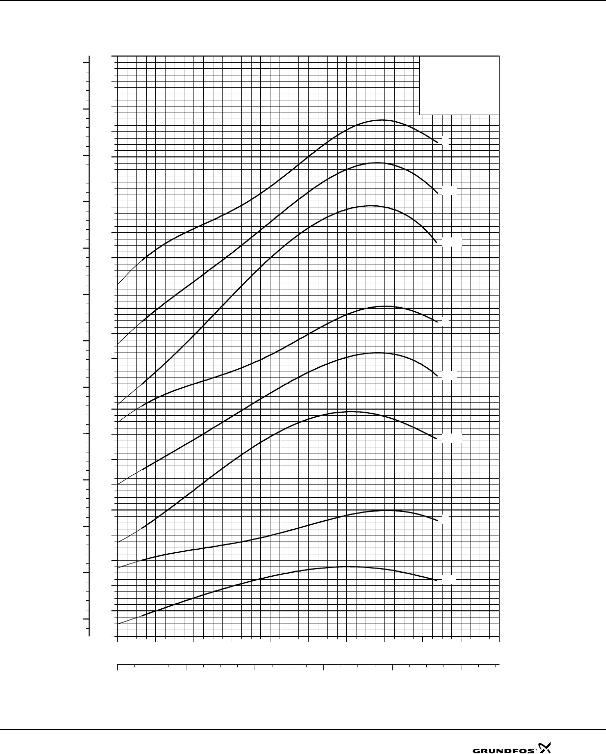
71
Explanation of efficiency curve, please see “Curve conditions" on page 4.
TM00 7627 1802
040 80 120 160 200 240 280 320
Q [m³/h]
12
16
20
24
28
32
36
40
44
48
52
56
60
64
68
72
76
80
84
88
92
96
100
[kW]
P2
020 40 60 80 100
Q [l/s]
20
30
40
50
60
70
80
90
100
110
120
130
[hp]
P2
SP 215
60 Hz, SF 1.15
ISO 9906 Annex A
-3
-3-A
-3-AA
-2
-2-A
-2-AA
-1
-1-1
Power curves SP 215
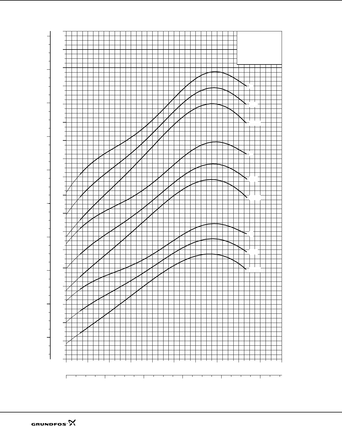
72
Explanation of efficiency curve, please see “Curve conditions" on page 4.
TM01 9251 0707
040 80 120 160 200 240 280 320
Q [m³/h]
64
72
80
88
96
104
112
120
128
136
144
152
160
168
176
184
192
200
[kW]
P2
020 40 60 80 100
Q [l/s]
100
120
140
160
180
200
220
240
260
[hp]
P2
SP 215
60 Hz, SF 1.15
ISO 9906 Annex A
-6
-6-A
-6-AA
-5
-5-A
-5-AA
-4
-4-A
-4-AA
Power curves SP 215
73
SP A, SP
Technical data
1 x 220 V, submersible motors
* Applies to 2- and 3-wire motors.
** Applies to 2-wire motors.
MS 402 2-wire motors incorporate motor protection and can therefore be connected directly to the mains.
1 x 230 V, submersible motors
MS 4000 3-wire motors comes as CSCR versions and do not incorporate motor protection, the motor is connected via a Grundfos SA-SPM 5 control box.
3 x 220 V, submersible motors (SF 1.0)
Electrical data Dimensions
Type
Motor Full-
load
current
In [A]
Motor efficiency [%] Power factor Control box for
3-wire Length
[mm] Weight
[kg]
Size Power
[kW] Power
[hp] η 50% η 75% η 100% Cos ϕ
50% Cos ϕ
75% Cos ϕ
100%
MS 402 4" 0.25 0.33 4.40 39.0 49.0 54.0 0.48 0.51 0.64 3.0* SA-SPM 5 256 6.8
MS 402 4" 0.37 0.5 5.90 43.0 52.5 56.0 0.46 0.54 0.62 3.6* SA-SPM 5 256 6.8
MS 402 4" 0.55 0.75 8.00 42.5 51.0 57.0 0.47 0.56 0.63 3.7* SA-SPM 5 291 8.2
MS 402 4" 0.75 1.0 9.60 47.0 55.5 60.0 0.50 0.60 0.70 3.8* SA-SPM 5 306 8.9
MS 402 4" 1.1 1.5 11.5 53.5 62.0 67.0 0.60 0.73 0.82 4.0* SA-SPM 5 346 10.5
MS 402 4" 1.1 1.5 13.1 88.0 0.63 4.4** 346 10.5
Electrical data Dimensions
Type
Motor Full-
load
current
In [A]
Motor efficiency [%] Power factor Control box for
3-wire Length
[mm] Weight
[kg]
Size Power
[kW] Power
[hp] η 50% η 75% η 100% Cos ϕ
50% Cos ϕ
75% Cos ϕ
100%
MS 4000 4" 1.5 2.0 13.2 0.53 0.56 0.57 0.7 0.8 0.86 4.3* SA-SPM 5 496 17.0
MS 4000 4" 2.2 3.0 17.0 0.61 0.63 0.62 0.85 0.92 0.94 4.7* SA-SPM 5 576 20.5
MS 4000 4" 3.7 5.0 27.5 0.58 0.63 0.66 0.89 0.94 0.96 4.3* SA-SPM 5 676 25.5
Electrical data Dimensions
Type
Motor Full-
load
current
In [A]
Motor efficiency [%] Power factor Length
[mm] Weight
[kg]
Size Power
[kW] Power
[hp] η 50% η 75% η 100% Cos ϕ
50% Cos ϕ
75% Cos ϕ
100%
MS 402 4" 0.37 0.5 3.30 57.5 65.0 68.0 0.52 0.63 0.72 5.0 226 5.5
MS 402 4" 0.55 0.75 4.80 58.0 65.5 68.0 0.47 0.59 0.70 4.8 241 6.3
MS 402 4" 0.75 1.0 5.65 61.0 67.5 71.0 0.50 0.63 0.73 5.0 276 7.7
MS 4000R 4" 0.75 1.0 4.60 70.5 72.0 71.1 0.81 0.86 0.88 3.9 398 13.0
MS 402 4" 1.1 1.5 7.60 65.0 71.0 73.5 0.50 0.67 0.72 5.5 306 8.9
MS 4000R 4" 1.1 1.5 6.10 71.4 74.7 74.8 0.73 0.82 0.86 4.6 413 14.0
MS 402 4" 1.5 2.0 9.10 67.0 73.0 75.5 0.54 0.67 0.75 5.5 346 10.5
MS 4000R 4" 1.5 2.0 8.20 73.0 74.8 74.5 0.67 0.78 0.85 4.1 413 14.0
MS 4000 (R) 4" 2.2 3.0 11.4 73.9 76.6 77.2 0.58 0.71 0.80 4.7 453 16.0
MS 4000 (R) 4" 3.0 4.0 14.8 76.9 79.0 78.3 0.60 0.74 0.82 4.7 493 17.0
MS 4000 (R) 4" 4.0 5.5 19.0 77.6 79.7 79.2 0.68 0.79 0.85 5.4 573 21.0
MS 4000 (R) 4" 5.5 7.5 25.0 80.0 80.5 78.0 0.67 0.80 0.87 5.1 673 26.0
MS6 (R) 6" 5.5 7.5 21.8 77.8 81.9 83.2 0.72 0.80 0.84 6.3 565 38
MS6 (R) 6" 7.5 10 29.0 78.6 82.6 83.9 0.72 0.80 0.84 6.2 610 43
MS6 (R) 6" 9.2 12.5 35.5 79.2 83.0 84.1 0.72 0.80 0.84 5.9 635 46
MS6 (R) 6" 11 15 42.5 79.8 83.4 84.4 0.72 0.82 0.86 5.6 738 53
MS6 (R) 6" 13 17.5 50.0 80.0 83.6 84.7 0.72 0.82 0.86 5.9 783 58
MS6 (R) 6" 15 20 58.0 79.7 83.6 84.9 0.72 0.80 0.84 6.4 838 64
MS6 (R) 6" 18.5 25 71.5 79.8 83.4 84.5 0.72 0.80 0.86 6.5 903 71
MS6 (R) 6" 22 30 84.5 79.7 83.6 85.0 0.74 0.82 0.86 7.0 1023 84
Ist
In
-------
Ist
In
-------
Ist
In
-------

74
Technical data SP A, SP
3 x 220 V, submersible rewindable motors
3 x 380 V, submersible motors
Electrical data Dimensions
Type
Motor Full-load
current
In [A]
Motor efficiency [%] Power factor Length
[mm] Weight
[kg]
Size Power
[kW] Power
[hp] η 50% η 75% η 100% Cos ϕ 50% Cos ϕ 75% Cos ϕ 100%
MMS 6000 (N) 6" 3.7 5.0 19.6 66 72 74 0.68 0.76 0.80 4.3 630 45
MMS 6000 (N) 6" 5.5 7.5 27.5 74 77 75 0.72 0.80 0.83 3.8 660 48
MMS 6000 (N) 6" 7.5 10 37.0 77 79 77 0.73 0.81 0.84 3.5 690 50
MMS 6000 (N) 6" 9.2 12.5 45.0 74 77 76 0.74 0.82 0.85 3.5 720 55
MMS 6000 (N) 6" 11 15 51.5 79 81 79 0.77 0.84 0.86 3.5 780 60
MMS 6000 (N) 6" 13 17.5 60.5 80 82 80 0.78 0.82 0.85 3.6 915 72
MMS 6000 (N) 6" 15 20 69.0 79 82 81 0.82 0.86 0.86 3.5 975 78
MMS 6000 (N) 6" 18.5 25 81.0 82 84 83 0.85 0.88 0.88 4.6 1085 90
MMS 6000 (N) 6" 22 30 96.0 82 84 84 0.84 0.88 0.88 4.9 1195 100
MMS 6000 (N) 6" 26 35 114 83 85 83 0.77 0.84 0.87 4.4 1315 115
MMS 6000 (N) 6" 30 40 130 84 85 84 0.77 0.84 0.87 4.4 1425 125
MMS 6000 (-N, -R) 6" 37 50 166 83 85 84 0.68 0.88 0.84 4.8 1425 125
MMS 8000 (-N, -R) 8" 22 30 102 75 79 80 0.80 0.85 0.86 4.4 1010 126
MMS 8000 (-N, -R) 8" 26 35 118 75 79 80 0.82 0.87 0.87 4.3 1050 134
MMS 8000 (-N, -R) 8" 30 40 134 77 81 82 0.77 0.84 0.87 5.2 1110 146
MMS 8000 (-N, -R) 8" 37 50 164 78 82 82 0.77 0.84 0.86 5.0 1160 156
MMS 8000 (-N, -R) 8" 45 60 192 80 84 85 0.75 0.83 0.86 5.7 1270 177
MMS 8000 (-N, -R) 8" 55 75 232 82 85 85 0.79 0.86 0.88 5.3 1350 192
MMS 8000 (-N, -R) 8" 63 85 265 83 85 85 0.84 0.89 0.90 4.8 1490 218
MMS 8000 (-N, -R) 8" 75 100 315 83 86 85 0.85 0.89 0.90 4.8 1590 237
MMS 10000 (N) 10" 75 100 320 83 85 84 0.83 0.87 0.88 4.7 1400 280
MMS 10000 (N) 10" 92 125 395 82 85 85 0.77 0.84 0.87 4.9 1500 330
MMS 10000 (N) 10" 110 150 470 82 85 85 0.85 0.88 0.89 4.5 1690 385
MMS 10000 (N) 10" 132 180 570 82 85 84 0.86 0.89 0.89 4.2 1870 435
Electrical data Dimensions
Type
Motor Full
load
current
In [A]
Motor efficiency [%] Power factor Length
[mm] Weight
[kg]
Size Power
[kW] Power
[hp] η 50% η 75% η 100% Cos ϕ
50% Cos ϕ
75% Cos ϕ
100%
MS 402 4" 0.37 0.5 1.90 57.0 67.0 69.0 0.52 0.64 0.72 5.0 226 5.5
MS 402 4" 0.55 0.75 2.80 58.0 65.5 69.0 0.47 0.59 0.70 4.8 241 6.3
MS 402 4" 0.75 1.0 3.25 61.0 67.0 71.0 0.50 0.63 0.73 5.0 276 7.7
MS 4000R 4" 0.75 1.0 2.65 68.8 71.3 71.3 0.77 0.83 0.87 4.2 398 13.0
MS 402 4" 1.1 1.5 4.40 65.0 72.0 72.0 0.49 0.62 0.72 5.5 306 8.9
MS 4000R 4" 1.1 1.5 3.65 72.9 74.8 74.4 0.68 0.79 0.85 4.9 413 14.0
MS 402 4" 1.5 2.0 5.25 67.5 73.0 76.0 0.53 0.67 0.75 5.5 346 10.5
MS 4000R 4" 1.5 2.0 4.90 72.0 74.5 75.2 0.60 0.73 0.82 4.5 413 14.0
MS 4000 (R) 4" 2.2 3.0 7.00 70.0 75.0 76.2 0.52 0.66 0.75 4.9 453 16.0
MS 4000 (R) 4" 3.0 4.0 9.10 73.4 77.3 78.0 0.54 0.68 0.78 4.9 493 17.0
MS 4000 (R) 4" 4.0 5.5 11.4 77.1 79.8 79.9 0.60 0.74 0.82 5.7 573 21.0
MS 4000 (R) 4" 5.5 7.5 15.2 79.5 80.7 81.0 0.60 0.74 0.82 5.3 673 26.0
MS6 (R) 6" 5.5 7.5 14.2 80.4 82.9 82.8 0.78 0.84 0.86 4.9 565 38
MS6 (R) 6" 7.5 10 19.2 81.1 83.6 83.5 0.78 0.84 0.86 5.0 590 41
MS6 (R) 6" 9.2 12.5 23.6 81.2 83.8 83.9 0.74 0.82 0.86 5.1 610 43
MS6 (R) 6" 11 15 28.5 81.1 83.9 84.1 0.72 0.80 0.86 5.1 708 49
MS6 (R) 6" 13 17.5 34.0 80.8 83.7 84.1 0.70 0.80 0.84 5.0 738 53
MS6 (R) 6" 15 20 38.5 81.7 84.4 84.8 0.72 0.82 0.86 5.2 783 58
MS6 (R) 6" 18.5 25 47.0 82.3 84.8 84.9 0.74 0.82 0.86 5.2 838 64
MS6 (R) 6" 22 30 55.5 82.3 84.7 84.8 0.74 0.82 0.86 5.4 903 71
MS6 (R) 6" 26 35 65.5 82.6 84.9 85.0 0.76 0.84 0.86 5.5 968 78
MS6 (R) 6" 30 40 76.0 82.4 84.9 85.0 0.74 0.82 0.86 5.7 1023 84
Ist
In
-------
Ist
In
-------

75
Technical data SP A, SP
3 x 380 V, submersible rewindable motors
3 x 380 V, submersible motors, MS6 T60
Electrical data Dimensions
Type
Motor Full-load
current
In [A]
Motor efficiency [%] Power factor Length
[mm] Weight
[kg]
Size Power
[kW] Power
[hp] η 50% η 75% η 100% Cos ϕ 50% Cos ϕ 75% Cos ϕ 100%
MMS 6000 (N) 6" 3.7 5.0 11.4 66 72 74 0.69 0.77 0.80 4.2 630 45
MMS 6000 (N) 6" 5.5 7.5 16.0 74 77 75 0.72 0.80 0.83 3.8 660 48
MMS 6000 (N) 6" 7.5 10 21.4 77 79 77 0.73 0.81 0.84 3.5 690 50
MMS 6000 (N) 6" 9.2 12.5 26.0 74 78 76 0.75 0.82 0.85 3.5 720 55
MMS 6000 (N) 6" 11 15 29.5 79 81 79 0.77 0.84 0.86 3.6 780 60
MMS 6000 (N) 6" 13 17.5 35.0 80 82 80 0.75 0.82 0.85 3.7 915 72
MMS 6000 (N) 6" 15 20 40.5 79 82 80 0.78 0.84 0.86 3.5 975 78
MMS 6000 (N) 6" 18.5 25 46.5 82 85 83 0.79 0.85 0.87 4.7 1085 90
MMS 6000 (N) 6" 22 30 55.5 83 85 84 0.78 0.85 0.87 4.9 1195 100
MMS 6000 (N) 6" 26 35 65.5 84 85 84 0.78 0.85 0.87 4.6 1315 115
MMS 6000 (N) 6" 30 40 75.5 84 85 84 0.76 0.84 0.87 4.7 1425 125
MMS 6000 (-N, -R) 6" 37 50 94.5 84 85 83 0.76 0.84 0.87 4.5 1425 125
MMS 8000 (-N, -R) 8" 22 30 59.0 75 79 80 0.80 0.85 0.86 4.4 1010 126
MMS 8000 (-N, -R) 8" 26 35 69.0 75 79 80 0.81 0.86 0.87 4.4 1050 134
MMS 8000 (-N, -R) 8" 30 40 77.0 77 81 82 0.78 0.84 0.87 5.1 1110 146
MMS 8000 (-N, -R) 8" 37 50 94.0 79 83 83 0.79 0.85 0.87 4.9 1160 156
MMS 8000 (-N, -R) 8" 45 60 110 81 85 85 0.80 0.86 0.88 5.5 1270 177
MMS 8000 (-N, -R) 8" 55 75 132 82 85 86 0.83 0.88 0.89 5.0 1350 192
MMS 8000 (-N, -R) 8" 63 85 152 83 85 85 0.81 0.87 0.89 5.3 1490 218
MMS 8000 (-N, -R) 8" 75 100 182 84 86 85 0.86 0.89 0.90 4.7 1590 237
MMS 8000 (-N, -R) 8" 92 125 220 85 87 86 0.85 089 0.90 4.8 1830 283
MMS 8000 (-N, -R) 8" 110 150 260 83 86 86 0.84 0.89 0.90 5.0 2060 333
MMS 10000 (N) 10" 75 100 182 82 85 86 0.81 0.86 0.88 5.0 1400 280
MMS 10000 (N) 10" 92 125 224 82 86 87 0.77 0.84 0.87 5.1 1500 330
MMS 10000 (N) 10" 110 150 265 83 86 87 0.84 0.88 0.89 4.7 1690 385
MMS 10000 (N) 10" 132 180 315 84 86 87 0.84 0.88 0.89 4.8 1870 435
MMS 10000 (N) 10" 147 200 355 83 86 87 0.78 0.85 0.87 5.6 2070 500
MMS 10000 (N) 10" 170 230 415 83 86 87 0.75 0.83 0.86 5.4 2220 540
MMS 10000 (N) 10" 190 260 475 82 86 87 0.69 0.79 0.85 5.7 2400 580
Electrical data Dimensions
Type
Motor Full-
load
current
In [A]
Motor efficiency [%] Power factor Length
[mm] Weight
[kg]
Size Power
[kW] Power
[hp] η 50% η 75% η 100% Cos ϕ
50% Cos ϕ
75% Cos ϕ
100%
MS6 (R)T60 6" 4 5.5 10.4 79.1 82.2 82.6 0.76 0.82 0.86 5.0 535 35
MS6 (R)T60 6" 5.5 7.5 14.2 80.0 83.0 83.4 0.76 0.84 0.86 5.4 565 38
MS6 (R)T60 6" 7.5 10.0 19.2 80.5 83.4 83.7 0.78 0.84 0.86 5.2 610 43
MS6 (R)T60 6" 9.2 12.5 23.6 80.6 83.7 84.3 0.74 0.82 0.86 5.3 635 46
MS6 (R)T60 6" 11.0 15.0 28.0 81.0 83.9 84.2 0.74 0.82 0.86 5.0 738 53
MS6 (R)T60 6" 13.0 17.5 32.5 81.5 84.3 84.7 0.76 0.84 0.86 5.2 783 58
MS6 (R)T60 6" 15.0 20.0 37.5 81.7 84.4 84.7 0.78 0.84 0.86 5.3 838 64
MS6 (R)T60 6" 18.5 25.0 46.5 81.8 84.6 85.1 0.76 0.84 0.86 5.7 903 71
MS6 (R)T60 6" 22.0 30.0 55.0 81.9 84.6 85.0 0.78 0.86 0.88 5.8 1023 84
Ist
In
-------
Ist
In
-------

76
Technical data SP A, SP
3 x 460 V, submersible motors
Electrical data Dimensions
Type
Motor Full
load
current
In [A]
Motor efficiency [%] Power factor Length
[mm] Weight
[kg]
Size Power
[kW] Power
[hp] η 50% η 75% η 100% Cos ϕ
50% Cos ϕ
75% Cos ϕ
100%
MS 402 4" 0.37 0.5 1.60 58.0 65.0 68.5 0.51 0.64 0.73 5.0 226 5.5
MS 402 4" 0.55 0.75 2.30 58.5 65.5 68.5 0.47 0.59 0.69 4.8 241 6.3
MS 402 4" 0.75 1.0 2.70 61.5 67.0 71.0 0.50 0.63 0.73 5.0 276 7.7
MS 4000R 4" 0.75 1.0 2.20 68.0 71.2 71.3 0.76 0.83 0.87 4.5 398 13.0
MS 402 4" 1.1 1.5 3.65 64.5 70.5 73.5 0.49 0.62 0.72 5.5 306 8.9
MS 4000R 4" 1.1 1.5 3.00 72.0 74.5 75.0 0.69 0.79 0.85 5.0 413 14.0
MS 402 4" 1.5 2.0 4.35 68.0 72.5 75.5 0.54 0.66 0.76 5.5 346 10.5
MS 4000R 4" 1.5 2.0 4.05 71.0 74.5 75.2 0.60 0.73 0.82 4.4 413 14.0
MS 4000 (R) 4" 2.2 3.0 5.80 70.0 75.0 76.2 0.52 0.65 0.75 4.8 453 16.0
MS 4000 (R) 4" 3.0 4.0 7.50 73.4 77.3 78.0 0.54 0.68 0.78 4.9 493 17.0
MS 4000 (R) 4" 4.0 5.5 9.45 77.1 79.8 80.0 0.60 0.74 0.82 5.7 573 21.0
MS 4000 (R) 4" 5.5 7.5 12.6 79.5 80.7 81.0 0.60 0.74 0.82 5.3 673 26.0
MS 4000 (R) 4" 7.5 10 18.0 78.5 80.7 80.6 0.56 0.69 0.79 5.2 773 31.0
MS6 (R) 6" 5.5 7.5 11.6 80.6 82.9 82.7 0.80 0.84 0.86 4.7 565 38
MS6 (R) 6" 7.5 10 15.8 81.1 83.4 83.2 0.78 0.84 0.86 4.9 590 41
MS6 (R) 6" 9.2 12.5 19.4 81.4 83.8 83.7 0.76 0.84 0.86 5.0 610 43
MS6 (R) 6" 11 15 23.4 81.1 83.9 84.2 0.72 0.80 0.84 5.1 708 49
MS6 (R) 6" 13 17.5 28.0 81.1 84.0 84.3 0.70 0.80 0.84 5.0 738 53
MS6 (R) 6" 15 20 31.5 81.6 84.3 84.6 0.72 0.82 0.86 5.1 783 58
MS6 (R) 6" 18.5 25 39.0 82.1 84.7 85.0 0.72 0.82 0.86 5.3 838 64
MS6 (R) 6" 22 30 46.0 82.3 84.8 85.0 0.74 0.82 0.86 5.4 903 71
MS6 (R) 6" 26 35 54.5 82.2 84.8 85.1 0.72 0.82 0.86 5.7 968 78
MS6 (R) 6" 30 40 63.0 82.2 84.8 85.1 0.72 0.80 0.86 5.9 1023 84
Ist
In
-------

77
Technical data SP A, SP
3 x 460 V, submersible rewindable motors
3 x 460 V, submersible industrial motors
Electrical data Dimensions
Type
Motor Full-load
current
In [A]
Motor efficiency [%] Power factor Length
[mm] Weight
[kg]
Size Power
[kW] Power
[hp] η 50% η 75% η 100% Cos ϕ 50% Cos ϕ 75% Cos ϕ 100%
MMS 6000 (N) 6" 3.7 5.0 9.75 64 69 70 0.63 0.74 0.80 4.2 630 45
MMS 6000 (N) 6" 5.5 7.5 13.8 73 76 74 0.63 0.74 0.80 4.0 660 48
MMS 6000 (N) 6" 7.5 10 18.0 77 79 78 0.61 0.73 0.79 3.8 690 50
MMS 6000 (N) 6" 9.2 12.5 22.0 74 77 77 0.65 0.76 0.81 3.7 720 55
MMS 6000 (N) 6" 11 15 25.5 78 80 79 0.65 0.76 0.82 3.8 780 60
MMS 6000 (N) 6" 13 17.5 29.5 80 82 80 0.65 0.76 0.82 4.0 915 72
MMS 6000 (N) 6" 15 20 33.5 80 82 81 0.68 0.78 0.83 4.0 975 78
MMS 6000 (N) 6" 18.5 25 39.0 83 85 85 0.65 0.77 0.83 5.5 1085 90
MMS 6000 (N) 6" 22 30 46.0 85 85 85 0.67 0.78 0.83 5.6 1195 100
MMS 6000 (N) 6" 26 35 54.5 84 86 84 0.69 0.80 0.85 5.0 1315 115
MMS 6000 (N) 6" 30 40 62.5 85 86 85 0.68 0.79 0.85 5.1 1425 125
MMS 6000 (-N, -R) 6" 37 50 79.0 84 85 84 0.65 0.75 0.83 4.7 1425 125
MMS 8000 (-N, -R) 8" 22 30 48.5 75 79 81 0.73 0.81 0.84 5.3 1010 126
MMS 8000 (-N, -R) 8" 26 35 56.5 76 80 81 0.77 0.83 0.86 5.1 1050 134
MMS 8000 (-N, -R) 8" 30 40 64.0 78 82 83 0.74 0.82 0.85 5.8 1110 146
MMS 8000 (-N, -R) 8" 37 50 78.0 80 83 84 0.74 0.82 0.85 5.5 1160 156
MMS 8000 (-N, -R) 8" 45 60 92.5 82 85 86 0.71 0.80 0.85 6.4 1270 177
MMS 8000 (-N, -R) 8" 55 75 112 82 85 86 0.73 0.82 0.86 5.8 1350 192
MMS 8000 (-N, -R) 8" 63 85 126 83 86 86 0.72 0.82 0.86 6.0 1490 218
MMS 8000 (-N, -R) 8" 75 100 150 84 86 87 0.72 0.82 0.86 5.7 1590 237
MMS 8000 (-N, -R) 8" 92 125 184 85 87 87 0.74 0.83 0.87 6.0 1830 283
MMS 8000 (-N, -R) 8" 110 150 220 84 86 86 0.75 0.83 0.87 5.8 2060 333
MMS 10000 (N) 10" 75 100 154 81 85 87 0.72 0.80 0.84 5.7 1400 280
MMS 10000 (N) 10" 92 125 190 82 86 87 0.69 0.78 0.83 5.5 1500 330
MMS 10000 (N) 10" 110 150 224 82 86 88 0.72 0.80 0.84 5.8 1690 385
MMS 10000 (N) 10" 132 180 265 83 86 88 0.73 0.82 0.85 5.7 1870 435
MMS 10000 (N) 10" 147 200 305 82 86 87 0.66 0.77 0.82 6.2 2070 500
MMS 10000 (N) 10" 170 230 355 82 86 87 0.66 0.76 0.82 5.9 2220 540
MMS 10000 (N) 10" 190 260 405 82 85 87 0.62 0.73 0.79 6.1 2400 580
Electrical data Dimensions
Type
Motor Full-
load
current
In [A]
Motor efficiency [%] Power factor Length
[mm] Weight
[kg]
Size Power
[kW] Power
[hp] η 50% η 75% η 100% Cos ϕ
50% Cos ϕ
75% Cos ϕ
100%
MS 4000 4" 2.2 3.0 5.70 72.4 76.3 77.8 0.62 0.74 0.81 5.3 493 17
MS 4000 4" 3.0 4.0 7.55 75.2 78.6 80.3 0.61 0.74 0.81 5.6 573 21
MS 4000 4" 3.7 5.0 9.05 75.4 79.0 79.6 0.68 0.79 0.83 5.7 673 26
MS 4000 4" 4.0 5.5 9.55 75.9 78.8 80.0 0.69 0.70 0.85 5.3 673 26
MS 4000 4" 5.5 7.5 13.8 76.2 79.9 81.3 0.55 0.68 0.77 5.5 773 31
Ist
In
-------
Ist
In
-------
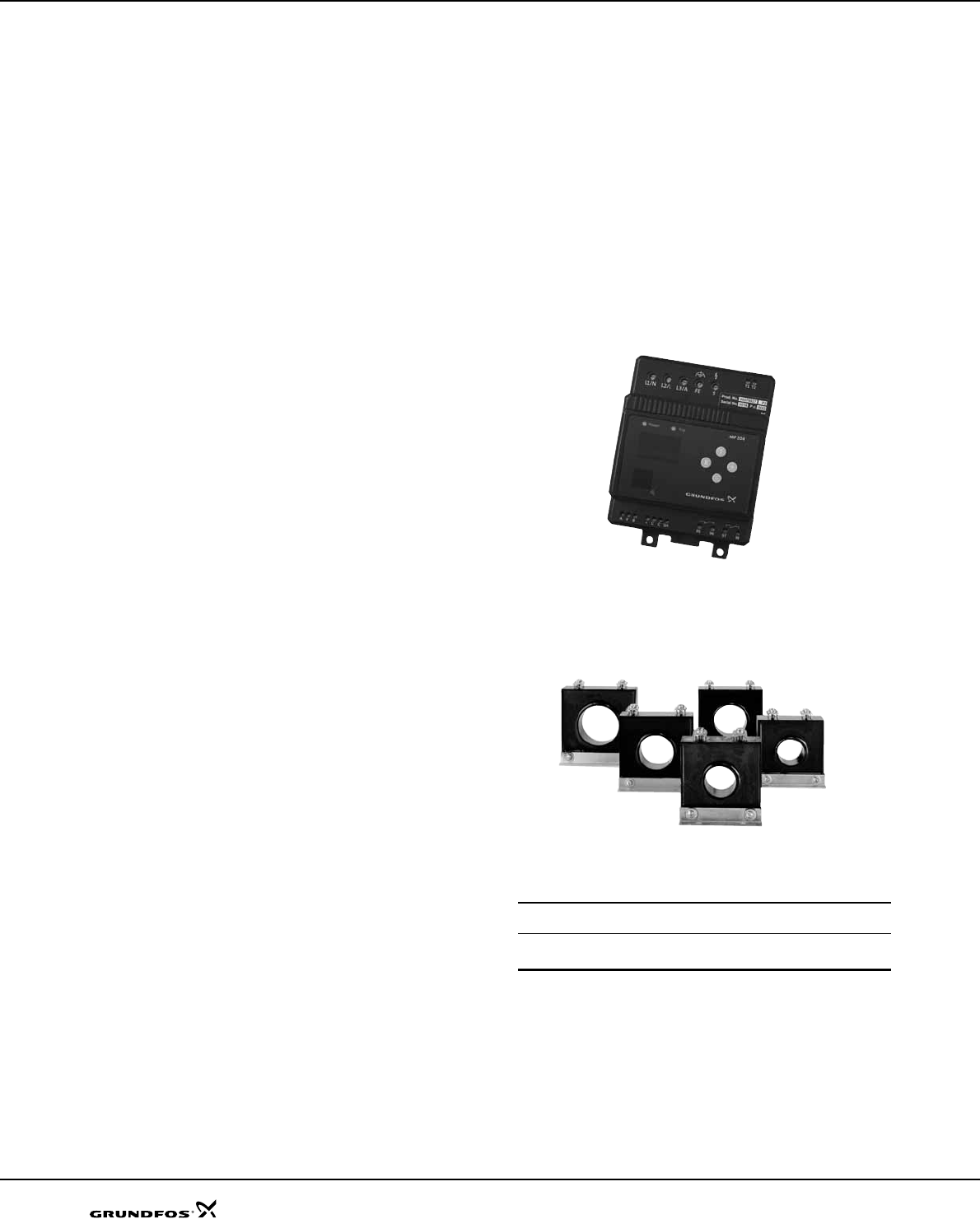
SP A, SP
78
Accessories
MP 204
The MP 204 is an electronic motor protector, designed
for the protection of an asynchronous motor or a pump.
The motor protector consists of:
• a cabinet incorporating transformers and electronics
• a control panel with operating buttons and display
for reading of data.
The MP 204 operates with two sets of limits:
• a set of warning limits and
• a set of trip limits.
If one or more of the warning limits are exceeded, the
motor continues to run, but the warnings will appear in
the MP 204 display.
Some values only have a warning limit.
The warning can also be read out by means of the
Grundfos R100 remote control.
If one of the trip limits is exceeded, the trip relay will
stop the motor. At the same time, the signal relay is
operating to indicate that the limit has been exceeded.
Applications
The MP 204 can be used as a stand-alone motor
protector.
The MP 204 can be monitored via a Grundfos GENIbus.
The power supply to the MP 204 is in parallel with the
supply to the motor. Motor currents up to 120 A are
passed directly through the MP 204. The MP 204
protects the motor primarily by measuring the motor
current by means of a true RMS measurement. The
MP 204 disconnects the contactor if, for example, the
current exceeds the preset value.
Secondarily, the motor is protected via temperature
measuring by a Tempcon sensor, a Pt100/Pt1000
sensor and a PTC sensor/thermal switch.
The MP 204 is designed for single- and three-phase
motors. In single-phase motors, the starting and run
capacitors are also measured. Cos ϕ is measured in
both single- and three-phase systems.
Benefits
The MP 204 offers these benefits:
• Suitable for both single- and three-phase motors
• Dry-running protection
• Overload protection
• Very high accuracy
• Made for submersible pumps.
The MP 204 - many monitoring options
The MP 204 monitors the following parameters:
• Insulation resistance before start-up
• Temperature (Tempcon, Pt sensor and PTC/thermal
switch)
• Overload/underload
• Overvoltage/undervoltage
• Phase sequence
• Phase failure
• Power factor
• Power consumption
• Harmonic distortion
• Operating hours and number of starts.
Fig. 17 MP 204
Fig. 18 Single-turn transformers
Product numbers
TM03 1471 2205TM03 2033 3505
Product Product
number
MP 204 96079927
R100 625333
Five sizes of single-turn transformers, 120-999 A.
Note: Monitoring of motor temperature is not possible when
single-turn transformers are used.

79
Accessories SP A, SP
Functions
• Phase-sequence monitoring
• Indication of current or temperature (user selection)
• Indication of temperature in °C or °F (user selection)
• 4-digit, 7-segment display
• Setting and status reading with the R100
• Setting and status reading via the GENIbus.
Tripping conditions
•Overload
• Underload (dry running)
• Temperature (Tempcon sensor, PTC/thermal switch
and Pt sensor)
• Phase failure
• Phase sequence
•Overvoltage
• Undervoltage
• Power factor (cos ϕ)
• Current unbalance.
Warnings
•Overload
• Underload
• Temperature (Tempcon and Pt sensor)
•Overvoltage
• Undervoltage
• Power factor (cos ϕ)
Note: In connection with single- and three-phase
connection.
• Run capacitor (single-phase operation)
• Starting capacitor (single-phase operation)
• Loss of communication in network
• Harmonic distortion.
Learning function
• Phase sequence (three-phase operation)
• Run capacitor (single-phase operation)
• Starting capacitor (single-phase operation)
• Identification and measurement of Pt100/Pt1000
sensor circuit.
External current transformers
When fitted with external current transformers, the
MP 204 unit can handle currents from 120 to 999 A.
Grundfos can supply approved current transformers
from stock (200/5A, 300/5A, 500/5A, 750/5A, 1000/5A).
Remote control R100
The R100 remote control from Grundfos allows for
wireless infrared remote control of your MP 204 unit.
With the R100, you get access to a full range of options
such as factory setting adjustment, service and fault
finding.
Ready for bus communication
The MP 204 allows for monitoring and communication
via GENIbus - a Grundfos-designed bus for exchange
of pump data, alarms, status information, and setpoints.
This enables users to connect the MP 204 to, for
instance, SCADA systems.

80
Accessories SP A, SP
Technical data - MP 204
Enclosure class IP 20
Ambient temperature –20 °C to +60 °C
Relative air humidity 99%
Voltage range 100-480 VAC
Current range 3-999 A
Frequency 50 to 60 Hz
IEC trip class 1-45
Special Grundfos trip class 0.1 to 30 s
Voltage variation –25 %/+15 % of nominal voltage
Approvals EN 60947, EN 60335, UL/CSA 508
Marking CE, cUL, C-tick
Consumption Max. 5 W
Plastic type Black PC / ABS
Measuring range Accuracy Resolution
Current without external current transformers 3-120 A ±1 % 0.1 A
Current with external current transformers 120-999 A ±1 % 1 A
Phase-to-phase voltage 80-610 VAC ±1 % 1 V
Frequency 47-63 Hz ±1 % 0.5 Hz
Power 0-1 MW ±2 % 1 W
Power factor 0-0.99 ±2 % 0.01
Energy consumption 0-4x10⁹ kWh ±5 % 1 kWh
IO 112 Description Product number
The IO 112 is a measuring module and a 1-channel protection unit for use in con-
nection with the MP 204 motor protection unit. The module can be used for pro-
tection of pump against other factors than the electrical conditions, for instance
dry-running. It can also be used as a stand-alone protection module.
The IO 112 interface has three inputs for measured values one potentiometer for
setting of limits indicator lights indicating the
• measured value of the input
• value of the limit set
• alarm source
• pump status.
Electrical data:
• Supply voltage: 24 VAC ±10% 50/60 Hz or 24 VDC ±10%
• Supply current: Min. 2.4 A; max. 8 A
• Power consumption:Max. 5 W
Ambient temperature: –25°C to +65°C
• Enclosure class: IP 20
96651601

81
Accessories SP A, SP
Control functions
This table describes the protection provided by MP 204.
Control parameters Function Problem Advantages
Temperature
MS
The motor temperature is measured by
means of the built-in Tempcon temperature
transmitter and a signal is sent to MP 204 via
the phase leads. In MP 204 the measured
temperature is compared with the factory-set
value (75 °C).
MMS
The motor temperature is measured by
means of the Pt100. The signal is sent to the
MP 204 where the measured temperature is
compared with the factory-set value.
Temperature protection requires a
submersible motor with a Pt100.
The motor temperature must be monitored
during frequency converter operation.
Overload, frequent starts/
stops, operation against
blocked discharge pipe,
insufficient flow velocity
past the motor.
Longer motor life,
safe operating
conditions, service
indication.
Overvoltage/ under-
voltage
If the set trip value is exceeded, the motor will
stop.
The installation is close to
a transformer. The mains
do not absorb load
variations.
Important installation
parameter,
possibility of
improving operating
conditions.
Overload
The motor power input is measured on each
of the three phases. The registered power
input is an average of these three values. If
the factory-set value is exceeded, the motor
will stop.
Incorrect sizing of pump/
motor, voltage supply
failure, defective cable,
blocking, wear or
corrosion.
Longer pump life,
safe operating
conditions, service
indication.
Underload
(dry running)
The motor power input is measured on each
of the three phases. The registered power
input is an average of these three values. If
the average value is lower than the factory-
set value, the motor will stop.
Pump exposed to dry
running or underload, for
example caused by wear.
Traditional dry-
running protection is
no longer necessary,
no extra cables.
Current unbalance
The power input of the motor is measured on
each of the three phases.
Mains load is uneven,
incipient motor defect,
phase voltages diverging.
Motor protection
against overload,
service indication.
Phase sequence
MP 204 and motor are installed so that the
phase sequence corresponds to correct
direction of rotation. MP 204 monitors
changes in the phase sequence.
Two phases are wrongly
connected.
Ensures correct
pump performance.
Phase failure MP 204 checks the phases connected, phase
failure will cause an alarm.
Phase failure Indication of phase
failure, and alarm.
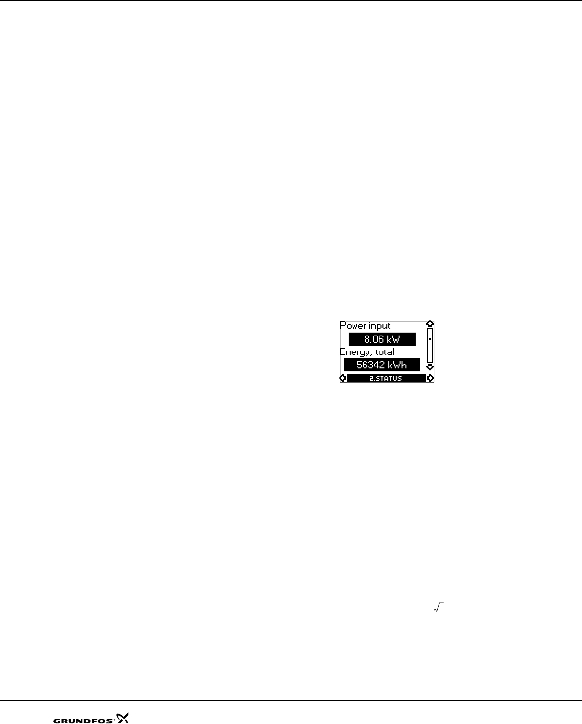
82
Accessories SP A, SP
R100 menus
0. GENERAL
See the operating instructions for the R100.
1. OPERATION
• Operating mode
• Actual trip
• Actual warning 1
• Actual warning 2
• Alarm log 1
• Alarm log 2
• Alarm log 3
• Alarm log 4
• Alarm log 5.
2. STATUS
Display of
• Supply overview
• Average current
• Average voltage
• Tempcon sensor
• Pt100/Pt1000 sensor
•Power input and energy consumption (described
in the following)
• Energy trip counter
• Phase sequence
• Current unbalance
• Operating hours and number of starts
• Trip counter of hours and starts
• Starting capacitor
• Run capacitor
• Insulation resistance
•Cos ϕ
• Harmonic distortion.
3. LIMITS
Display and setting of warning and trip limits.
• Tempcon sensor
• Pt sensor
• Tripping current
• Current warning
• Nominal voltage
• Voltage limits
• Current unbalance
• Starting capacitor
• Run capacitor
• Insulation resistance
•Cos ϕ trip
•Cos ϕ warning.
4. INSTALLATION
Setting and display of
• Supply mains
•Trip class (described in the following)
• Trip delay
• External current transformers
• Power-on delay
• Restarting (described in the following)
• Automatic restarting (described in the following)
• Tempcon sensor
•Pt sensor
• Insulation resistance measurement
• PTC/thermal switch
• Resetting of trip counters
• Service interval
• Number of automatic restarts
• Units/display
• MP 204 display
• GENIbus ID number
• Learning function.
Power input and energy consumption
Actual input power and motor energy consumption.
The energy consumption is an accumulated value
which cannot be reset.
The power is calculated like this:
Uaverage
UL1 L2–UL2 L3–UL3 L1–
++
3
-------------------------------------------------------------------------------------- V[]=
Iaverage
IL1 IL2 IL3
++
3
--------------------------------------- A[]=
ϕcos average
ϕcos L1 ϕcos L2 ϕcos L3
++
3
----------------------------------------------------------------------------[]=
PU
average Iaverage
×3×ϕcos average
×()W[]=
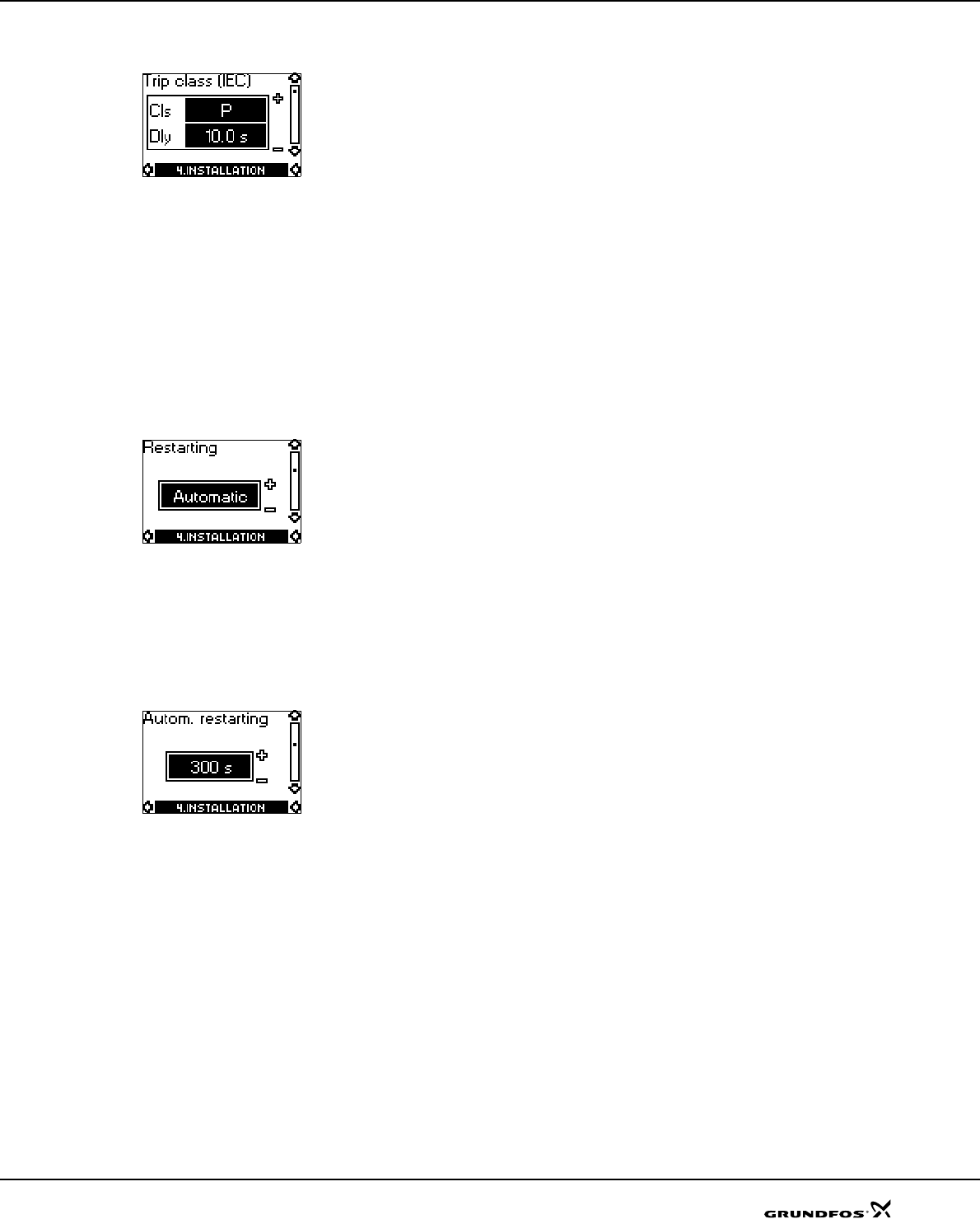
83
Accessories SP A, SP
Trip class
Line 1: Select IEC trip class (1 to 45).
If manual indication of trip delay in the case of overload
is required, select trip class "P".
Factory setting:
• Cls (trip class): P.
Line 2: Select trip delay.
Factory setting:
• Dly (trip delay): 10 s.
Restarting
Set whether restarting after tripping is to be
•Automatic (factory setting)
•Manual.
Setting of time, see section "Automatic restarting".
Automatic restarting
Set the time after which the MP 204 is to attempt
automatic restarting of motor after cut-out.
The time runs from the moment when the value which
triggered the fault has returned to normal.
Factory setting:
• 300 s.
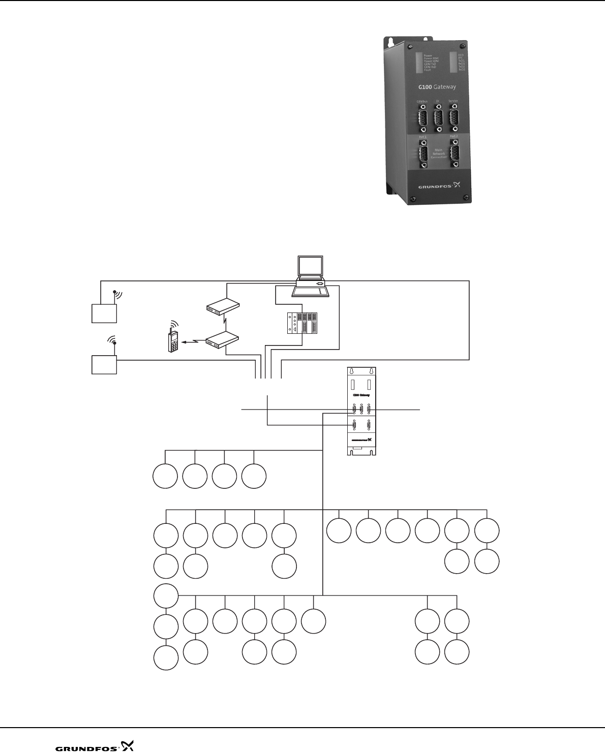
84
Accessories SP A, SP
G100 gateway for communication
with Grundfos products
The G100 offers a wide selection of options for
integration of Grundfos products provided with
GENIbus interface into main control and monitoring
systems.
The G100 enables a pump installation to meet future
demands for optimum pump operation in terms of
reliability, operating costs, centralization and
automation.
Fig. 19 G100
Fig. 20 Examples of G100 applications
GR5940
TM03 9224 3607
Port 1
Main
Network
Connection
POWER
POWER MNC
POWER GENI
GENI TxD
GENI RxD
FAULT
DCD
RTS
TxD1
RxD1
TxD2
RxD2
Port 2
Genibus DI Service
MP 204
Hydro IO 351
Pump SQE
Sen-
sors
MP 204
IO 351
Sen-
sors
Pump
MP 204
Pump
Wastewater
Industry
RS-232
Service
port for PC
PROFIBUS-DP
Direct
PLC
Modem
Radio
Radio
4 digital inputs
Water supply
GENIbus
MP 204
CU 300 DME E-
pump
Pump SQE
Water treatment
E-
pump
Hydro
MPC
UPE
Heating
TPE UPS
MGE
CU 300 Multi-E
Multi-E
IO 351
SMS
Central management system
Main network
MAGNA
IO 351
Sen-
sors
sors
Sen-
MPC
MP 204
Pump
IO112
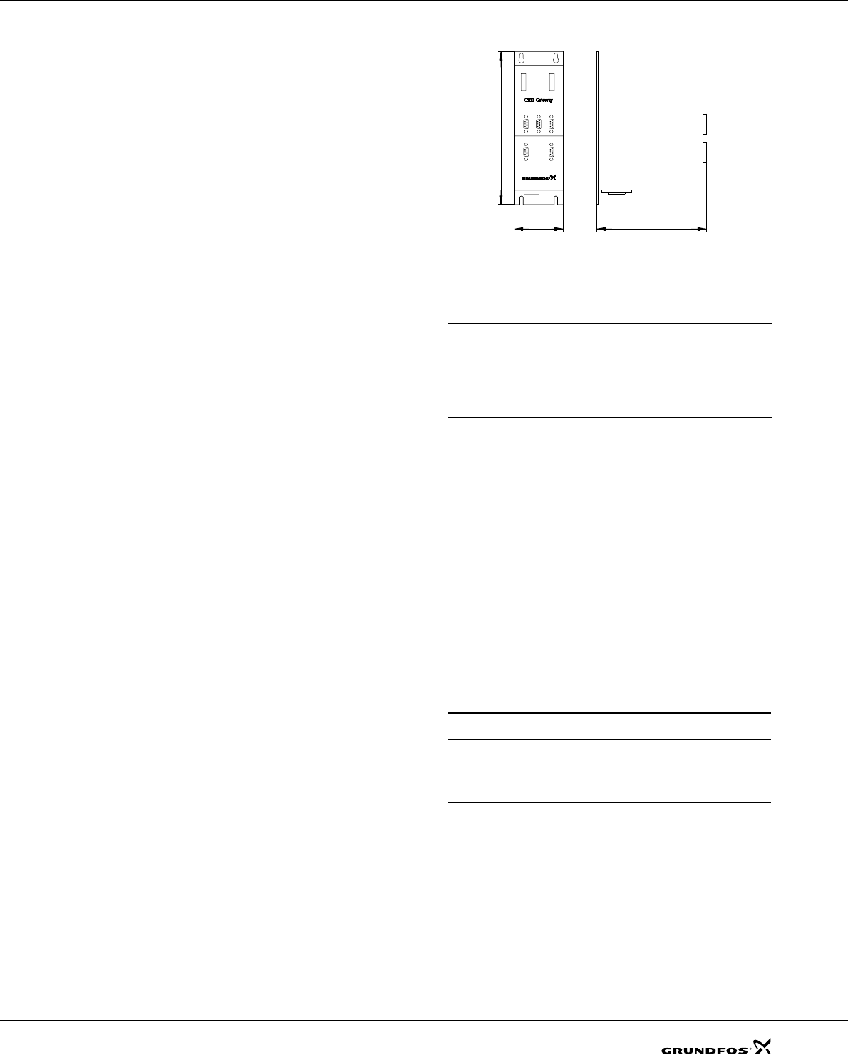
85
Accessories SP A, SP
Product description
The G100 Gateway enables communication of
operating data, such as measured values and
setpoints, between Grundfos products with GENIbus
interface and a main network for control and
monitoring.
As indicated in the illustration on page 84, the G100 is
suitable for use in applications such as water supply,
water treatment, wastewater, building automation and
industry.
Common to above applications is that downtime is
usually costly, and extra investments are therefore
often made to achieve maximum reliability by
monitoring selected operating variables.
The day-to-day operation, such as starting and
stopping of pumps and changing of setpoints, can also
be effected from the main system by communication
with the G100. In addition, the G100 can be set up to
send event-controlled status indications such as alarms
via the SMS to mobile phones, and to make automatic
alarm call-backs to a central management system.
Data logging
Besides the possibility of data communication, the
G100 offers logging of up to 350,000 time-stamped
data. The logged data can be transmitted to the main
system or a PC for further analysis in a spreadsheet or
similar program.
For the data logging, the "PC Tool G100 Data Log"
software tool is used. The tool is part of the PC Tool
G100 package, which is supplied with the G100.
Other features
• Four digital inputs.
• Stop of all pumps in case of failing communication
with the management system (optional).
• Access code for modem communication (optional).
• Alarm log.
Installation
Installation of the G100 is effected by the system
integrator. The G100 is connected to the GENIbus as
well as to the main network. All units on the GENIbus
can thus be controlled from a central management
system on the main network.
The "G100 Support Files" CD-ROM supplied with the
G100 contains examples of programs to be used when
the G100 is connected to the various main network
systems. Included is also a description of the data
points available in Grundfos products with GENIbus
interface.
The "PC Tool G100" software tool included can be used
for the installation and use of G100.
Fig. 21 Dimensional sketch
Technical data
Overview of protocols
Other possible connections
Accessories
• PC Tool G100 package (supplied with the product)
• G100 Support Files CD-ROM (supplied with
product)
Product numbers
* CD-ROM with G100 Support Files included.
TM01 0621 1102
Main system Software protocol
PROFIBUS-DP DP
Radio Satt Control COMLI/Modbus
Modem Satt Control COMLI/Modbus
PLC Satt Control COMLI/Modbus
GSM mobile phone SMS, UCP
GENIbus RS-485: Connection of up to 32 units.
Service port RS-232: For direct connection to a PC
or via radio modem.
Digital inputs: 4.
Voltage supply: 1 x 110-240 V, 50/60 Hz.
Ambient temperature: In operation: –20 °C to +60 °C.
Enclosure class: IP 20.
Weight: 1.8 kg.
Product Product
number
G100 with Profibus-DP expansion board* 96411135
G100 with Radio/Modem/PLC expansion board* 96411136
G100 Basic Version* 96411137
PC Tool G100 package 96415783
73 mm 165 mm
227 mm
Port 1
Main
Network
Connection
POWER
POWER MNC
POWER GENI
GENI TxD
GENI RxD
FAULT
DCD
RTS
TxD1
RxD1
TxD2
RxD2
Port 2
Genibus DI Service
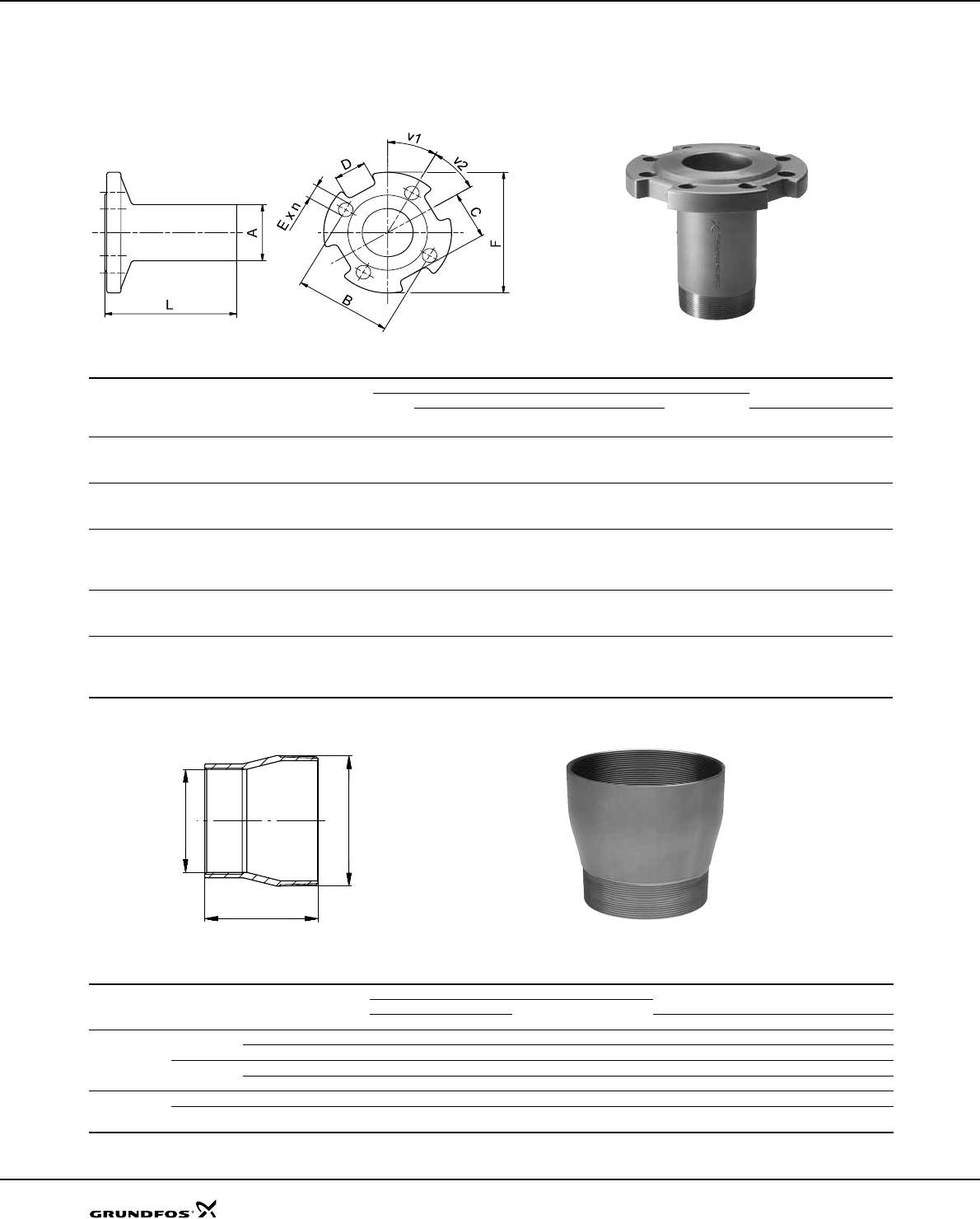
86
Accessories SP A, SP
Connecting pieces
The tables below show the range of connecting pieces for connection of thread-to-flange and thread-to-thread.
Thread-to-flange
Fig. 22 Dimensional sketch and photo of the connecting pieces thread-to-flange
Thread-to- thread
Fig. 23 Dimensional sketch and photo of connecting piece thread-to-thread
TM01 2396 2506 - GrA2552
Type Pump outlet Connecting piece
Thread-to-flange Product number
ADimensions [mm] V1 V2 n
BCDE FL DIN W.-Nr.
1.4308 DIN W.-Nr.
1.4517
SP 17 Rp 2.5
R 2½ → DN 50 PN 16/40 R 2½ 125 65 40 ø19 ø165 170 60 90 4 120125 120911
R 2½ → DN 65 PN 16/40 R 2½ 145 71 30 ø19 ø185 170 22.5 45 8 120126 120910
R 2½ → DN 80 PN 16/40 R 2½ 160 82.5 40 ø19 ø200 170 22.5 45 8 120127 120909
SP 30 Rp 3
R 3 → DN 65 PN 16/40 R 3 145 71 30 ø19 ø185 170 22.5 45 8 130187 130920
R 3 → DN 80 PN 16/40 R 3 160 82.5 40 ø19 ø200 170 22.5 45 8 130188 130921
R 3 → DN 100 PN 16/40 R 3 180/190 100 40 ø19/ø23 ø235 170 22.5 45 8 130189 130922
SP 46
SP 60 Rp 3
Rp 4
R 3 → DN 65 PN 16 R 3 145 71 30 ø19 ø185 170 22.5 45 8 130187 130920
R 3 → DN 80 PN 16 R 3 160 82.5 40 ø19 ø200 170 22.5 45 8 130188 130921
R 3 → DN 100 PN 16 R 3 180/190 100 40 ø19/ø23 ø235 170 22.5 45 8 130189 130922
R 4 → DN 100 PN 16 R 4 180/190 100 40 ø19/ø23 ø235 180 22.5 45 8 140071 140577
SP 77
SP 95 Rp 5
R 5 → DN 100 PN 16/40 R 5 180/190 82 35 ø19/ø23 ø235 195 22.5 45 8 160148 160646
R 5 → DN 125 PN 16/40 R 5 210/220 99 37 ø19/ø28 ø270 195 22.5 45 8 160149 160647
R 5 → DN 150 PN 16/40 R 5 240/250 115 36 ø23/ø28 ø300 195 22.5 45 8 160150 160648
SP 125
SP 160
SP 215 Rp 6
R 6 → DN 125 PN 16/40 R 6 210/220 99 36 ø19/ø28 ø270 195 22.5 45 8 170159 170596
R 6 → DN 150 PN 16/40 R 6 240 114 36 ø23/ø28 ø300 195 22.5 45 8 170160 170597
R 6 → DN 200 PN 16 R 6 295 134 36 ø23 ø340 195 15 30 12 170161 170598
R 6 → DN 200 PN 40 R 6 320 151 36 ø31 ø375 200 15 30 12 170162 170599
TM01 2397 1698 - GrA2555
L
B
A
Type Pump
outlet Connecting piece
Dimensions Product number
Thread-to-thread L [mm]
A B DIN W.-Nr. 1.4301 DIN W.-Nr. 1.4401
SP 77
SP 95
Rp 5 R 5 → Rp 4 R 5 Rp 4 121 190063 190585
R 5 → Rp 6 R 5 Rp 6 150 190069 190591
NPT 5 NPT 5→ NPT 4 NPT 5 NPT 4 121 190064 190586
NPT 5→ NPT 6 NPT 5 NPT 6 150 190070 190592
SP 125
SP 160
SP 215
Rp 6 R 6 → Rp 5 R 6 Rp 5 150 200130 200640
NPT 6 NPT 6→ NPT 5 NPT 6 NPT 5 150 200135 200645
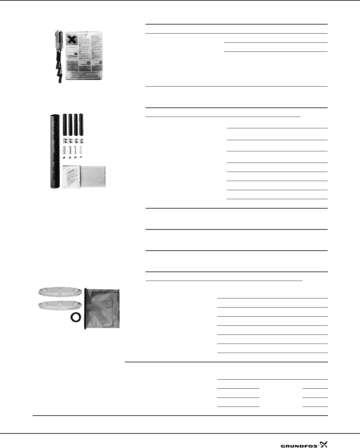
87
Accessories SP A, SP
Cable termination kit with plug
Cable termination kit, type KM
Cable termination kit, type M0 to M6
TM00 7883 2296
Description Version Prod. no.
For watertight joining of motor cable
and submersible drop cable in an
acrylic tube filled with resin. Used for
both single and multi-core cables dur-
ing installation of submersible pumps.
24 hours of hardening is required.
MS 402 and MS 4000 up to 7.5 kW:
For cables up to 4 x 2.5 mm2799901
For cables up to 4 x 6 mm2799902
TM00 7885 2296
Description Version
Prod. no.
For watertight shrink-joining of motor
cable and submersible drop cable.
Enables the joining of:
• cables of equal size.
• cables of different sizes.
• a cable lead and a single-lead.
The joint is ready for use after a few min-
utes and requires no long hardening time
as do resin joints.
The joint cannot be separated.
Motor cable [mm2]Number
of leads
Flat cable 1.5 - 6.0
1.5 - 4.0 3
4116251
Flat cable 6 - 10
10 - 16 4
3116252
Flat cable 16 - 25 3
4116255
3 single leads 1.5 - 6.0 3 116253
3 single leads 10 - 25 3 116254
4 single leads 1.5 - 4.0 4 116257
4 single leads 6 - 16 4 116258
Single lead 35 - 120 1 116256
For watertight joining of motor cable and
submersible drop cable.
By means of shrink-screw-glue casting
Screw-
shrinking
6 - 50
19 - 95
35 - 185
70 - 240
4
96636867
96636868
96637278
96637279
Reduce from 3 or 4 to one as from drop
cable to single leads Reducer-
shrinking
10 - 50
10 - 50
16 - 70
16 - 70
3
4
3
4
96637318
96637330
96637331
96637332
Description Version
Prod. no.
For watertight shrink-joining of motor
cable and submersible drop cable.
Type Diameter of
cable joint
[mm2]
Fit cables with
outer diameter of
M0 ø40 ø6 to ø15 ID8903
M1 ø46 ø9 to ø23 ID8904
TM00 7884 2296
M2 ø52 ø17 to ø31 ID8905
M3 ø77 ø26 to ø44 ID8906
M4 ø97 ø29 to ø55 91070700
M5 ø110 ø40 to ø62 96496918
M6 ø144 ø50 to ø80 96496919
Accessories for cable kit, type M0-6
Screw connectors only
Diameter of the
lead
[mm2]
Number of
connectors Prod. no.
6 - 50
4
96626021
19 - 95 96626022
35 - 185 96626023
70 - 240 96626028

88
Accessories SP A, SP
Submersible drop cable
Zinc anodes
Application
Cathodic protection by means of zinc can be used for
corrosion protection of SP pumps in chloride-containing
liquids such as brackish water and seawater.
Sacrificial anodes are placed on the outside of the
pump and motor as protection against corrosion.
The number of anodes required depends on the pump
and motor in question.
Please contact Grundfos for further details.
Liquid temperatures
Seawater: Up to 35 °C.
Brackish water (min. 1500 g/m3 chloride): Up to 35 °C.
Anode life
The zinc anodes have a life of one to four years,
depending on operating conditions (temperature, flow
and chloride content).
Product numbers of zinc anodes
TM00 7882 2296
Description
Suitable for
• continuous application in groundwater and po-
table water (approved for potable applications)
• connection of electrical equipment such as
submersible motors
• installation depths up to 500 metres and aver-
age loads.
Insulation and sheath are made of special EPR-
based elastomer materials adapted to applica-
tions in water.
Maximum permissible water temperature: 60 °C.
Maximum permissible lead service temperature:
90 °C.
Further cable sizes are available on request.
Number of
leads and
nominal cross
section
[mm2]
Outer
diameter
Min./Max.
[mm2]
Weight
[kg/m] Product
no.
1 x 25
1 x 35
1 x 50
1 x 70
1 x 95
1 x 120
1 x 150
1 x 185
3 x 25
4G1.5
4G2.5
4G4.0
4G6.0
4G10
4G16
4G25
4G35
4G50
4G70
12.5 / 16.5
14.0 / 18.5
16.5 / 21.0
18.5 / 23.5
21.0 / 26.5
23.5 / 28.5
26.0 / 31.5
27.5 / 34.5
26.5 / 34.0
10.5 / 13.5
12.5 / 15.5
14.5 / 18.0
16.5 / 22.0
22.5 / 24.5
26.5 / 28.5
32.0 / 34.0
33.0 / 42.5
38.0 / 48.5
43.0 / 54.5
0.410
0.560
0.740
1.000
1.300
1.650
2.000
2.500
1.450
0.190
0.280
0.390
0.520
0.950
1.400
1.950
2.700
3.600
4.900
ID4072
ID4073
ID4074
ID4075
ID4076
ID4077
ID4078
ID4079
ID4062
ID4063
ID4064
ID4065
ID4066
ID4067
ID4068
ID4069
96432949
96432950
96432951
Zinc anodes for pumps
Product
number
Used for pump type
SP 1A to
SP 14A
SP 17
SP 30
SP 46
SP 60
SP 77
SP 95
SP 125
SP 160
SP 215
96421444 z
96421445 zzzz
96421447 zz
96421448 z
96421449 z
96421450 zzz
Zinc anodes for motors
4" motors 6" motors 8" motors 10" motors
96421444 96421446 96421450 96564808
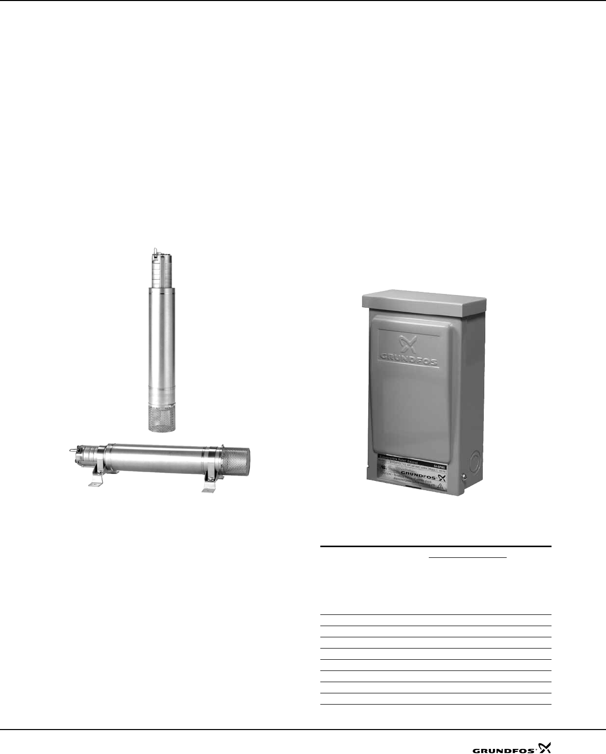
89
Accessories SP A, SP
Flow sleeves
Grundfos offers a complete range of stainless steel flow
sleeves for both vertical and horizontal operation. Flow
sleeves are recommended for all applications in which
motor cooling is insufficient. The result is a general
extension of motor life. Flow sleeves are to be fitted in
these cases:
• If the submersible pump is exposed to high thermal
load like current unbalance, dry running, overload,
high ambient temperature, bad cooling conditions.
• If aggressive liquids are pumped, since corrosion is
doubled for every 10 °C the temperature rises.
• If sedimentation or deposits occur around and/or on
the motor.
Note: More information about accessories is available
on request.
Fig. 24 Flow sleeves
SA-SPM 5 control boxes
Application
SA-SPM 5 control boxes are used as starting units for
single-phase, 3-wire motors, types MS 402B with power
input lower than or equal to 1.1 kW (1.5 hp).
SA-SPM 5 is available in two versions, standard and
DeLuxe. The standard version incorporates a motor -
protective circuit breaker and thus protects the motor
against overload. The DeLuxe version is identical to the
standard version with the following addition a motor
contactor is included for connection and disconnection
of the power supply.
Technical data
Enclosure class: IP 42.
Ambient temperature:–20 °C to 60 °C.
Relative humidity: Maximum 95 %, normal non-
aggressive atmosphere.
Fig. 25 SA-SPM 5 control box
Product numbers
TM01 0751 2197 - TM01 0750 2197
TM03 8150 0607
Product
Description
Product
number
1 x 220-230 V
1.1 kW (1.5 hp)
1.5 kW (2.0 hp)
2.2 kW (3.0 hp)
3.7 kW (5.0 hp)
SA-SPM 5 (Standard version) zz 91126212
SA-SPM 5 (DeLuxe version) zz 91126213
SA-SPM 5 (Standard version) zz 91126214
SA-SPM 5 (DeLuxe version) zz 91126215
SA-SPM 5 (Standard version) zz91126216
SA-SPM 5 (DeLuxe version) zz91126217
SA-SPM 5 (Standard version) zz91126218
SA-SPM 5 (DeLuxe version) zz91126219
90
Accessories SP A, SP
Pt100
The Pt100 sensor offers these features:
• Continuous monitoring of the motor temperature
• Protection against too high motor temperature.
Protecting the motor against too high motor
temperature is the simplest and cheapest way of
avoiding that motor lifetime is reduced. Pt100 ensures
that operating conditions are not exceeded and
indicates when it is time for service of the motor.
Monitoring and protection by means of Pt100 require
the following parts:
• Pt100 sensor
• Relay, type PR 5714
• Cable.
The PR 5714 relay is fitted with a Pt100 module. For
both relays the following temperature limits are preset
on delivery:
• 60 °C warning limit
• 75 °C stop limit.
Technical data
Relay type
PR 5714
Enclosure class IP 65 (mounted in a control panel)
Ambient temperature –20 °C to +60 °C
Relative humidity 95 % (condensating)
Voltage variation • 1 x 24-230 VAC ±10 %, 50 - 60 Hz.
• 24-250 VDC ±20 %.
Approvals UL, DNV
Mark CE
Pt100 sensor with/without PR 5714 relay and cable Cable length
[m] PR 5714 Product number
MS6 MMS 6000, MMS 8000 MMS 10000, MMS 12000
20 Yes 96408953 96494596 96437287
40 Yes 96408681 96494597 96437288
60 Yes 96408954 96494598 96437289
80 Yes 96408955 96494599 96437290
100 Yes 96408956 96494610 96437291
20 No 96658626 96658629 96658633
40 No 96658627 96658630 96658634
60 No 96658628 96658631 96658635
80 No 96658637 96658632 96658636
100 No 96658638 96658639 96658640
PR 5714 relay Voltage Product number
24-230 VAC, 50/60 Hz / 24-250 VDC 96621274
Pt100 sensor including cable Cable length
Product number
MS6
MMS 6000
MMS 8000
MMS 10000
MMS 12000
20 m 96408957 96437784
40 m 96408684 96437785
60 m 96408958 96437786
80 m 96408959 96437787
100 m 96408960 96437788
Staybolts for Pt100 Description Product number
Bolt KIT for Pt100 (for MS6) 96611899

91
SP A, SP
Energy consumption
Energy consumption of
submersible pumps
The percentage distribution of service life costs of a
submersible pump for water supply is:
5 % initial costs (pump)
85 % operating costs / energy consumption
10 % maintenance costs.
It is obvious that the highest savings can be achieved
within energy consumption!
The annual energy consumption, E, of a submersible
pump can be calculated as follows:
E = c x h x P1 (EURO)
c = specific energy price (EURO/kWh)
h = operating hours/year (hours)
P1= power input of the submersible pump (kW).
Example: Calculation of the annual energy
consumption of the submersible pump, type SP 125-3.
SP 125-3 with MS 8000, 45 kW, 3 x 460 V, 60 Hz.
Duty point:
Flow rate: Q = 120 m3/h
Total head: H = 102 m
Specific energy price:c = EURO 0.1/kWh
(consisting of day and night rate)
Operating hours/year: h = 3200.
Q= m
3/h
H= m
Density ρ= kg/dm3 (assumed 1)
367 = conversion factor
η motor = (example 84.5 %, in equation 0.845)
η pump = (not to be confused with the stage
efficiency curve).
By showing the P2/Q curve we make it easier for you to
calculate the energy consumption.
P2 = 26 kW (power requirement of SP 125-3 pump at
120 m3/h, from curve P2 / Q on page 61).
Calculation of motor efficiency at duty point
As standard the SP 125-3 is equipped with a 45 kW
MS6 motor.
At duty point (Q = 120 m3/h) the pump requires 44 kW,
thus:
a motor load of 87 % (44 kW / 45 kW) and a power
reserve of 2 %.
From the table on page 73 the motor efficiency can be
read as:
84.6 % at a load of 75 %. (η 75 %)
85.6 % at a load of 100 %. (η 100 %)
The interpolated value in this example is
η motor = 85.1 %, η motor = 0.851.
E = 0.1 EURO/kWh x 3200 h x 51.7 kW.
The annual energy costs amount to EURO 16544.
The pay-off time, A, (months) is calculated as follows:
Cable sizing
In order to obtain an economical duty of the pump the
voltage drop should be low.
Today large water works already size cables for a
maximum voltage drop of 1 %).
The hydraulic resistance in the discharge pipe should
be as low as possible.
P1QH×ρ×
367 η
pump
×η
motor
×
------------------------------------------------------------- in kW=
P1
P2
η
motor
-------------------=
P144
0.851
---------------51.7 kW==
APurchase price of energy efficiency pump–
Energy savings/year
----------------------------------------------------------------------------------------------------------------------------------- 12×=

SP A, SP
92
Cable sizing
Cables
Grundfos offers submersible drop cables for all
applications: 3-core cable, 4-core cable, single leads.
Cables for Grundfos 4" submersible motors are
available with or without plugs. The submersible drop
cable is chosen according to application and type of
installation.
Standard version: Max. liquid temperature +60 °C.
Hot water version: Max. liquid temperature +70 °C,
for short periods up to +90 °C (for MS only).
Tables indicating cable dimension in borehole
The tables indicate the maximum length of drop cables
in metres from motor starter to pump at direct-on-line
starting at different cable dimensions.
If star/delta starting is used the current will be reduced
by (I x 0.58), meaning that the cable length may be
longer (L x 1.73) than indicated in the tables.
If for example the operating current is 10 % lower than
the full-load current, the cable may be 10 % longer than
indicated in the tables.
The calculation of the cable length is based on a
maximum voltage drop of 1 % to 3 % of the rated
voltage and a water temperature of maximum 30 °C.
In order to minimize operating losses the cable cross
section may be increased compared to what is
indicated in the tables. This is economical only if the
borehole provides the necessary space, and if the
operational time of the pump is long, especially if the
operating voltage is below the rated voltage.
The table values are calculated on the basis of the
formula:
Max. cable length of a single-phase submersible pump:
Max. cable length of a three-phase submersible pump:
where
U = Rated voltage [V]
ΔU = Voltage drop [%]
I = Rated current of the motor [A]
q = Cross-section of submersible drop cable [mm2]
XL = Inductive resistance: 0.078 x 10⁻³ [Ω/m]
cosϕ= Power factor
sinϕ=
ρ =Specific resistance: 0.02 [Ω mm2/m]
Example
Motor size: 30 kW, MMS 8000
Rated current: 64.0 A
Rated voltage: 3 x 460 V, 60 Hz
Starting method: Direct-on-line
Power factor: cosϕ = 0.85
Voltage drop: 3 %
Cross-section: 16 mm2
sinϕ:0.53
L = 113 m
Cable dimensions at 1 x 220 V, 60 Hz
Maximum cable length in metres from motor starter to pump.
3
3
Motor kW In [A] 1.5 mm22.5 mm24 mm26 mm210 mm2
4"
0.25 3.3 96 159 254 379 624
0.37 4.4 73 121 192 286 472
0.55 6.6 48 80 127 189 311
0.75 7.7 37 62 98 147 243
1.1 9.0 30 50 79 118 196
LUΔU×
I2×100 ϕcos ρ
q
--- ϕsin XL
×+×
⎝⎠
⎛⎞
××
----------------------------------------------------------------------------------------------------m[]=
LUΔU×
I1.73100×ϕcos ρ
q
--- ϕsin XL
×+×
⎝⎠
⎛⎞
××
------------------------------------------------------------------------------------------------------------ m[]=
1ϕcos2
–
L460 3×
64.0 1.73×100×0.85 0.02
16
-----------
×0.53 0.078×10⁻³
×+
⎝⎠
⎛⎞
×
-------------------------------------------------------------------------------------------------------------------------------------------------------=

93
Cable sizing SP A, SP
Cable dimensions at 3 x 460 V, 60 Hz, DOL
Voltage drop: 1 %
At particularly favourable heat dissipation conditions.
Maximum cable length in metres from motor starter to pump.
Motor kW In [A] Cosϕ 100% Dimensions [mm2]
1.5 2.5 4 6 10 16 25 35 50 70 95 120 150 185 240 300
4" 0.37 1.6 0.73 170 282 448 668
4" 0.55 2.3 0.69 125 207 329 490 804
4" 0.75 2.7 0.73 101 167 266 396 650
4" 1.1 3.65 0.72 75 125 199 296 487 763
4" 1.5 4.35 0.76 60 100 159 236 389 610 927
4" 2.2 5.8 0.75 46 76 120 179 295 463 703 954
4" 3.0 7.5 0.78 34 56 90 134 220 346 526 716 981
4" 4.0 9.45 0.82 26 43 68 101 167 263 401 548 754
4" 5.5 12.6 0.82 19 32 51 76 125 197 301 411 566 756 970
4" 7.5 18 0.79 14 23 37 55 91 143 217 296 406 539 689 822 963
6" 5.5 13.2 0.76 20 33 52 78 128 201 305 415 567 751 955
6" 7.5 17 0.79 15 25 39 58 96 151 230 313 429 571 730 870
6" 9.2 21.4 0.8 19 31 46 75 119 181 246 338 451 577 689 809 931
6" 11 24.5 0.82 16 26 39 64 101 155 211 291 389 499 598 704 813 959
6" 13 29 0.81 22 33 55 87 132 180 248 330 423 507 596 687 809 918
6" 15 33 0.82 19 29 48 75 115 157 216 289 370 444 523 604 712 810
6" 18.5 41 0.8 24 39 62 94 129 177 235 301 360 422 486 571 647
6" 22 46.5 0.83 34 53 81 110 152 204 262 314 370 429 507 578
6" 26 55.5 0.83 28 44 68 92 127 171 219 263 310 359 425 484
6" 30 64 0.85 38 58 79 109 146 189 227 269 312 371 424
6" 37 81.5 0.79 48 65 90 119 152 182 213 245 287 324
8" 22 48.5 0.84 32 50 77 105 145 194 250 300 355 411 488 557
8" 26 56.5 0.86 27 42 65 88 122 165 213 257 304 354 422 484
8" 30 64 0.85 38 58 79 109 146 189 227 269 312 371 424
8" 37 78 0.85 31 47 65 89 120 155 186 220 256 304 348
8" 45 92.5 0.85 40 55 75 101 130 157 186 216 257 294
8" 55 112 0.86 45 62 83 107 129 154 179 213 244
8" 63 126 0.86 55 74 95 115 136 159 189 217
8" 75 150 0.86 46 62 80 97 115 133 159 182
8" 92 184 0.87 50 65 79 93 109 130 150
8" 110 220 0.87 54 66 78 91 109 125
10" 75 154 0.84 61 79 95 112 130 154 175
10" 92 190 0.83 50 64 77 91 105 124 141
10" 110 224 0.84 54 65 77 89 106 121
10" 132 265 0.85 55 65 75 90 103
10" 147 305 0.82 57 65 77 88
10" 170 355 0.82 56 66 75
10" 190 405 0.79 58 65
Max.current for cable [A]18.5 25 34 43 60 80 101 126 153 196 238 276 319 364 430 497

94
Cable sizing SP A, SP
Cable dimensions at 3 x 460 V, 60 Hz, DOL
Voltage drop: 3 %
At particularly favourable heat dissipation conditions.
Maximum cable length in metres from motor starter to pump.
Motor kW In [A] Cosϕ 100% Dimensions [mm2]
1.5 2.5 4 6 10 16 25 35 50 70 95 120 150 185 240 300
4" 0.37 1.6 0.73 509 845
4" 0.55 2.3 0.69 374 621 988
4" 0.75 2.7 0.73 302 501 797
4" 1.1 3.65 0.72 226 375 597 889
4" 1.5 4.35 0.76 180 299 476 709
4" 2.2 5.8 0.75 137 227 361 538 885
4" 3.0 7.5 0.78 102 169 269 401 660
4" 4.0 9.45 0.82 77 128 203 303 500 788
4" 5.5 12.6 0.82 58 96 153 228 375 591 903
4" 7.5 18 0.79 42 70 111 165 272 428 651 887
6" 5.5 13.2 0.76 59 98 157 234 384 603 916
6" 7.5 17 0.79 44 74 117 175 288 453 689 939
6" 9.2 21.4 0.8 58 92 137 226 356 542 739
6" 11 24.5 0.82 49 78 117 193 304 464 634 873
6" 13 29 0.81 67 100 165 260 396 540 743 991
6" 15 33 0.82 58 87 143 226 345 470 648 866
6" 18.5 41 0.8 72 118 186 283 386 530 706 903
6" 22 46.5 0.83 101 159 242 331 456 611 785 942
6" 26 55.5 0.83 84 133 203 277 382 512 658 789 931
6" 30 64 0.85 113 173 236 327 438 566 681 806 936
6 37 81.5 0.79 144 196 269 357 457 545 638 734 860 973
8" 22 48.5 0.84 95 150 230 315 434 582 750 901
8" 26 56.5 0.86 80 126 194 265 367 494 639 770 913
8" 30 64 0.85 113 173 236 327 438 566 681 806 936
8" 37 78 0.85 93 142 194 268 360 464 559 661 768 913
8" 45 92.5 0.85 119 164 226 303 391 471 558 648 770 881
8" 55 112 0.86 134 185 249 322 388 461 536 638 732
8" 63 126 0.86 165 221 286 345 409 476 567 651
8" 75 150 0.86 138 186 241 290 344 400 477 547
8" 92 184 0.87 151 195 236 280 327 390 449
8" 110 220 0.87 163 197 234 273 326 375
10" 75 154 0.84 183 236 284 335 389 461 526
10" 92 190 0.83 149 192 231 272 315 372 424
10" 110 224 0.84 162 195 230 267 317 362
10" 132 265 0.85 165 195 226 269 308
10" 147 305 0.82 170 196 231 263
10" 170 355 0.82 168 199 226
10" 190 405 0.79 173 196
Max.current for cable [A]18.5 25 34 43 60 80 101 126 153 196 238 276 319 364 430 497

95
Cable sizing SP A, SP
Dimensioning of cable
Calculation of the cross-section of the cable
Formula designations
U = Rated voltage [V]
ΔU = Voltage drop [%]
I = Rated current of the motor [A]
q = Cross-section [mm2]
XL = Inductive resistance 0.078 x 10⁻³ [Ω/m]
cosϕ = Power factor
sinϕ =
L = Length of cable [m]
Δp = Power loss [W]
ρ = 1/χ
Materials of cable:
Copper: χ = 52 m/Ω x mm2
Aluminium: χ = 35 m/Ω x mm2
For calculation of the cross-section of the submersible
drop cable, use the following formula:
DOL
Star-delta
The values of the rated current (I) and the power fac-
tor (cosϕ) can be read in the tables on pages 73-77.
Calculation of the power loss
For calculation of the power loss in the submersible
drop cable, use the following formula:
Example:
Motor size: 45 kW, MMS 8000
Rated current: In = 92.5 A
Voltage: 3 x 460 V, 60 Hz
Starting method: Direct-on-line
Required cable length: 200 m
Power factor: Cos ϕ100 %= 0.85
Water temperature: 30 °C
Cable selection:
Choice A: 3 x 150 mm2
Choice B: 3 x 185 mm2
Calculation of power loss
Choice A:
Choice B:
Savings
Operating hours/year: h = 4000.
Annual saving (A):
By choosing the cable size 3 x 185 mm2 instead of 3 x
150 mm2, an annual saving of 520 kWh is achieved.
Operating time: 10 years
Saving after 10 years (A10):
The saving in amount must be calculated in the local
currency.
1
ϕ
cos2
–
ql 1.73 100×L×ρ×cosϕ××
UΔU l 1.73×100×L×XLϕsin××()–×
-----------------------------------------------------------------------------------------------------------------=
ql 100×L×ρ×cosϕ×
UΔU l 1.73×100×L×XL
×ϕsin×()–×
-----------------------------------------------------------------------------------------------------------------=
Δp3Lρ× l2
×× q
------------------------------------
=
ΔpA3L×ρ×l2
×
q
------------------------------------=
ΔpA3200×0.02×92.52
×
150
-------------------------------------------------------------=
ΔpA685 W=
ΔpB3200×0.02×92.52
×
185
-------------------------------------------------------------=
ΔpB555 W=
AΔρAΔρB
–()h×685 W 555 W–()4000×520000 Wh 520 kWh====
A10 A10×520 10×5200 kWh===

SP A, SP
96
Table of head losses
Head losses in ordinary water pipes
Upper figures indicate the velocity of water in m/sec.
Lower figures indicate head loss in metres per 100 metres of straight pipes.
The table is calculated in accordance with H. Lang's new
formula a = 0.02 and for a water temperature of 10 °C. The head loss in bends, slide valves, T-pieces and non-return valves is
equivalent to the metres of straight pipes stated in the last two lines of the
table. To find the head loss in foot valves multiply the loss in T-pieces by
two.
Quantity of water Head losses in ordinary water pipes
m3/h Litres/min. Litres/sec. Nominal pipe diameter in inches and internal diameter in [mm]
½"
15.75 ¾"
21.25 1"
27.00 1¼"
35.75 1½"
41.25 2"
52.50 2½"
68.00 3"
80.25 3½"
92.50 4"
105.0 5"
130.0 6"
155.5
0.6 10 0.16 0.855
9.910 0.470
2.407 0.292
0.784
0.9 15 0.25 1.282
20.11 0.705
4.862 0.438
1.570 0.249
0.416
1.2 20 0.33 1.710
33.53 0.940
8.035 0.584
2.588 0.331
0.677 0.249
0.346
1.5 25 0.42 2.138
49.93 1.174
11.91 0.730
3.834 0.415
1.004 0.312
0.510
1.8 30 0.50 2.565
69.34 1.409
16.50 0.876
5.277 0.498
1.379 0.374
0.700 0.231
0.223
2.1 35 0.58 2.993
91.54 1.644
21.75 1.022
6.949 0.581
1.811 0.436
0.914 0.269
0.291
2.4 40 0.67 1.879
27.66 1.168
8.820 0.664
2.290 0.499
1.160 0.308
0.368
3.0 50 0.83 2.349
41.40 1.460
13.14 0.830
3.403 0.623
1.719 0.385
0.544 0.229
0.159
3.6 60 1.00 2.819
57.74 1.751
18.28 0.996
4.718 0.748
2.375 0.462
0.751 0.275
0.218
4.2 70 1.12 3.288
76.49 2.043
24.18 1.162
6.231 0.873
3.132 0.539
0.988 0.321
0.287 0.231
0.131
4.8 80 1.33 2.335
30.87 1.328
7.940 0.997
3.988 0.616
1.254 0.367
0.363 0.263
6.164
5.4 90 1.50 2.627
38.30 1.494
9.828 1.122
4.927 0.693
1.551 0.413
0.449 0.269
0.203
6.0 100 1.67 2.919
46.49 1.660
11.90 1.247
5.972 0.770
1.875 0.459
0.542 0.329
0.244 0.248
0.124
7.5 125 2.08 3.649
70.41 2.075
17.93 1.558
8.967 0.962
2.802 0.574
0.809 0.412
0.365 0.310
0.185 0.241
0.101
9.0 150 2.50 2.490
25.11 1.870
12.53 1.154
3.903 0.668
1.124 0.494
0.506 0.372
0.256 0.289
0.140
10.5 175 2.92 2.904
33.32 2.182
16.66 1.347
5.179 0.803
1.488 0.576
0.670 0.434
0.338 0.337
0.184
12 200 3.33 3.319
42.75 2.493
21.36 1.539
6.624 0.918
1.901 0.659
0.855 0.496
0.431 0.385
0.234 0.251
0.084
15 250 4.17 4.149
64.86 3.117
32.32 1.924
10.03 1.147
2.860 0.823
1.282 0.620
0.646 0.481
0.350 0.314
0.126
18 300 5.00 3.740
45.52 2.309
14.04 1.377
4.009 0.988
1.792 0.744
0.903 0.577
0.488 0.377
0.175 0.263
0.074
24 400 6.67 4.987
78.17 3.078
24.04 1.836
6.828 1.317
3.053 0.992
1.530 0.770
0.829 0.502
0.294 0.351
0.124
30 500 8.33 3.848
36.71 2.295
10.40 1.647
4.622 1.240
2.315 0.962
1.254 0.628
0.445 0.439
0.187
36 600 10.0 4.618
51.84 2.753
14.62 1.976
6.505 1.488
3.261 1.155
1.757 0.753
0.623 0.526
0.260
42 700 11.7 3.212
19.52 2.306
8.693 1.736
4.356 1.347
2.345 0.879
0.831 0.614
0.347
48 800 13.3 3.671
25.20 2.635
11.18 1.984
5.582 1.540
3.009 1.005
1.066 0.702
0.445
54 900 15.0 4.130
31.51 2.964
13.97 2.232
6.983 1.732
3.762 1.130
1.328 0.790
0.555
60 1000 16.7 4.589
38.43 3.294
17.06 2.480
8.521 1.925
4.595 1.256
1.616 0.877
0.674
75 1250 20.8 4.117
26.10 3.100
13.00 2.406
7.010 1.570
2.458 1.097
1.027
90 1500 25.0 4.941
36.97 3.720
18.42 2.887
9.892 1.883
3.468 1.316
1.444
105 1750 29.2 4.340
24.76 3.368
13.30 2.197
4.665 1.535
1.934
120 2000 33.3 4.960
31.94 3.850
17.16 2.511
5.995 1.754
2.496
150 2500 41.7 4.812
26.26 3.139
9.216 2.193
3.807
180 3000 50.0 3.767
13.05 2.632
5.417
240 4000 66.7 5.023
22.72 3.509
8.926
300 5000 83.3 4.386
14.42
90 ° bends; slide valves 1.0 1.0 1.1 1.2 1.3 1.4 1.5 1.6 1.6 1.7 2.0 2.5
T-pieces, non-return valves 4.0 4.0 4.0 5.0 5.0 5.0 6.0 6.0 6.0 7.0 8.0 9.0

97
Table of head losses SP A, SP
Head losses in plastic pipes
Upper figures indicate the velocity of water in m/sec.
Lower figures indicate head loss in metres per 100 metres of straight pipes.
The table is based on a nomogram.
Roughness: K = 0.01 mm.
Water temperature: t = 10 °C.
Quantity of water PELM/PEH PN 10
m3/h Litres/min. Litres/sec. PELM PEH
25
20.4 32
26.2 40
32.6 50
40.8 63
51.4 75
61.4 90
73.6 110
90.0 125
102.2 140
114.6 160
130.8 180
147.2
0.6 10 0.16 0.49
1.8 0.30
0.66 0.19
0.27 0.12
0.085
0.9 15 0.25 0.76
4.0 0.46
1.14 0.3
0.6 0.19
0.18 0.12
0.63
1.2 20 0.33 1.0
6.4 0.61
2.2 0.39
0.9 0.25
0.28 0.16
0.11
1.5 25 0.42 1.3
10.0 0.78
3.5 0.5
1.4 0.32
0.43 0.2
0.17 0.14
0.074
1.8 30 0.50 1.53
13.0 0.93
4.6 0.6
1.9 0.38
0.57 0.24
0.22 0.17
0.092
2.1 35 0.58 1.77
16.0 1.08
6.0 0.69
2.0 0.44
0.70 0.28
0.27 0.2
0.12
2.4 40 0.67 2.05
22.0 1.24
7.5 0.80
3.3 0.51
0.93 0.32
0.35 0.23
0.16 0.16
0.063
3.0 50 0.83 2.54
37.0 1.54
11.0 0.99
4.8 0.63
1.40 0.4
0.50 0.28
0.22 0.2
0.09
3.6 60 1.00 3.06
43.0 1.85
15.0 1.2
6.5 0.76
1.90 0.48
0.70 0.34
0.32 0.24
0.13 0.16
0.050
4.2 70 1.12 3.43
50.0 2.08
18.0 1.34
8.0 0.86
2.50 0.54
0.83 0.38
0.38 0.26
0.17 0.18
0.068
4.8 80 1.33 2.47
25.0 1.59
10.5 1.02
3.00 0.64
1.20 0.45
0.50 0.31
0.22 0.2
0.084
5.4 90 1.50 2.78
30.0 1.8
12.0 1.15
3.50 0.72
1.30 0.51
0.57 0.35
0.26 0.24
0.092 0.18
0.05
6.0 100 1.67 3.1
39.0 2.0
16.0 1.28
4.6 0.8
1.80 0.56
0.73 0.39
0.30 0.26
0.12 0.2
0.07
7.5 125 2.08 3.86
50.0 2.49
24.0 1.59
6.6 1.00
2.50 0.70
1.10 0.49
0.50 0.33
0.18 0.25
0.10 0.20
0.055
9.0 150 2.50 3.00
33.0 1.91
8.6 1.20
3.5 0.84
1.40 0.59
0.63 0.39
0.24 0.30
0.13 0.24
0.075
10.5 175 2.92 3.5
38.0 2.23
11.0 1.41
4.3 0.99
1.80 0.69
0.78 0.46
0.30 0.36
0.18 0.28
0.09
12 200 3.33 3.99
50.0 2.55
14.0 1.60
5.5 1.12
2.40 0.78
1.0 0.52
0.40 0.41
0.22 0.32
0.12 0.25
0.065
15 250 4.17 3.19
21.0 2.01
8.0 1.41
3.70 0.98
1.50 0.66
0.57 0.51
0.34 0.40
0.18 0.31
0.105 0.25
0.06
18 300 5.00 3.82
28.0 2.41
10.5 1.69
4.60 1.18
1.95 0.78
0.77 0.61
0.45 0.48
0.25 0.37
0.13 0.29
0.085
24 400 6.67 3.21
19.0 2.25
8.0 1.57
3.60 1.05
1.40 0.81
0.78 0.65
0.44 0.50
0.23 0.39
0.15
30 500 8.33 4.01
28.0 2.81
11.5 1.96
5.0 1.31
2.0 1.02
1.20 0.81
0.63 0.62
0.33 0.49
0.21
36 600 10.0 4.82
37.0 3.38
15.0 2.35
6.6 1.57
2.60 1.22
1.50 0.97
0.82 0.74
0.45 0.59
0.28
42 700 11.7 5.64
47.0 3.95
24.0 2.75
8.0 1.84
3.50 1.43
1.90 1.13
1.10 0.87
0.60 0.69
0.40
48 800 13.3 4.49
26.0 3.13
11.0 2.09
4.5 1.62
2.60 1.29
1.40 0.99
0.81 0.78
0.48
54 900 15.0 5.07
33.0 3.53
13.5 2.36
5.5 1.83
3.20 1.45
1.70 1.12
0.95 0.08
0.58
60 1000 16.7 5.64
40.0 3.93
16.0 2.63
6.7 2.04
3.90 1.62
2.2 1.24
1.2 0.96
0.75
75 1250 20.8 4.89
25.0 3.27
9.0 2.54
5.0 2.02
3.0 1.55
1.6 1.22
0.95
90 1500 25.0 5.88
33.0 3.93
13.0 3.05
8.0 2.42
4.1 1.86
2.3 1.47
1.40
105 1750 29.2 6.86
44.0 4.59
17.5 3.56
9.7 2.83
5.7 2.17
3.2 1.72
1.9
120 2000 33.3 5.23
23.0 4.06
13.0 3.23
7.0 2.48
4.0 1.96
2.4
150 2500 41.7 6.55
34.0 5.08
18.0 4.04
10.5 3.10
6.0 2.45
3.5
180 3000 50.0 7.86
45.0 6.1
27.0 4.85
14.0 3.72
7.6 2.94
4.4
240 4000 66.7 8.13
43.0 6.47
24.0 4.96
13.0 3.92
7.5
300 5000 83.3 8.08
33.0 6.2
18.0 4.89
11.0
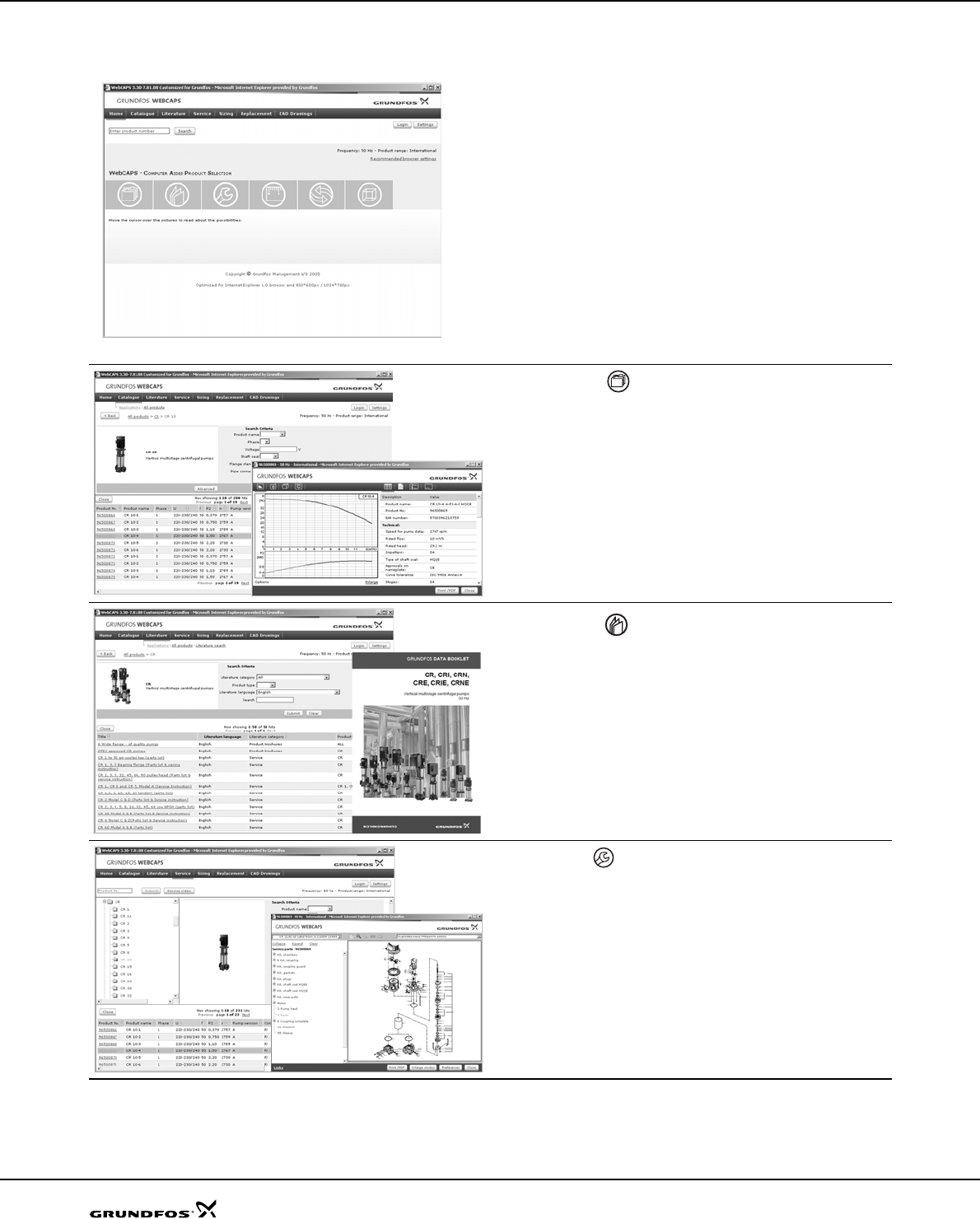
SP A, SP
98
Further product documentation
WebCAPS
WebCAPS is a Web-based Computer Aided Product
Selection program available on www.grundfos.com.
WebCAPS contains detailed information on more than
185,000 Grundfos products in more than 20 languages.
In WebCAPS, all information is divided into 6 sections:
• Catalogue
• Literature
• Service
• Sizing
• Replacement
• CAD drawings.
Catalogue
This section is based on fields of application and pump types, and
contains
• technical data
• curves (QH, Eta, P1, P2, etc) which can be adapted to the den-
sity and viscosity of the pumped liquid and show the number of
pumps in operation
• product photos
• dimensional drawings
• wiring diagrams
• quotation texts, etc.
Literature
In this section you can access all the latest documents of a given
pump, such as
• data booklets
• installation and operating instructions
• service documentation, such as Service kit catalogue and
Service kit instructions
• quick guides
• product brochures.
Service
This section contains an easy-to-use interactive service catalogue.
Here you can find and identify service parts of both existing and dis-
continued Grundfos pumps.
Furthermore, this section contains service videos showing you how
to replace service parts.
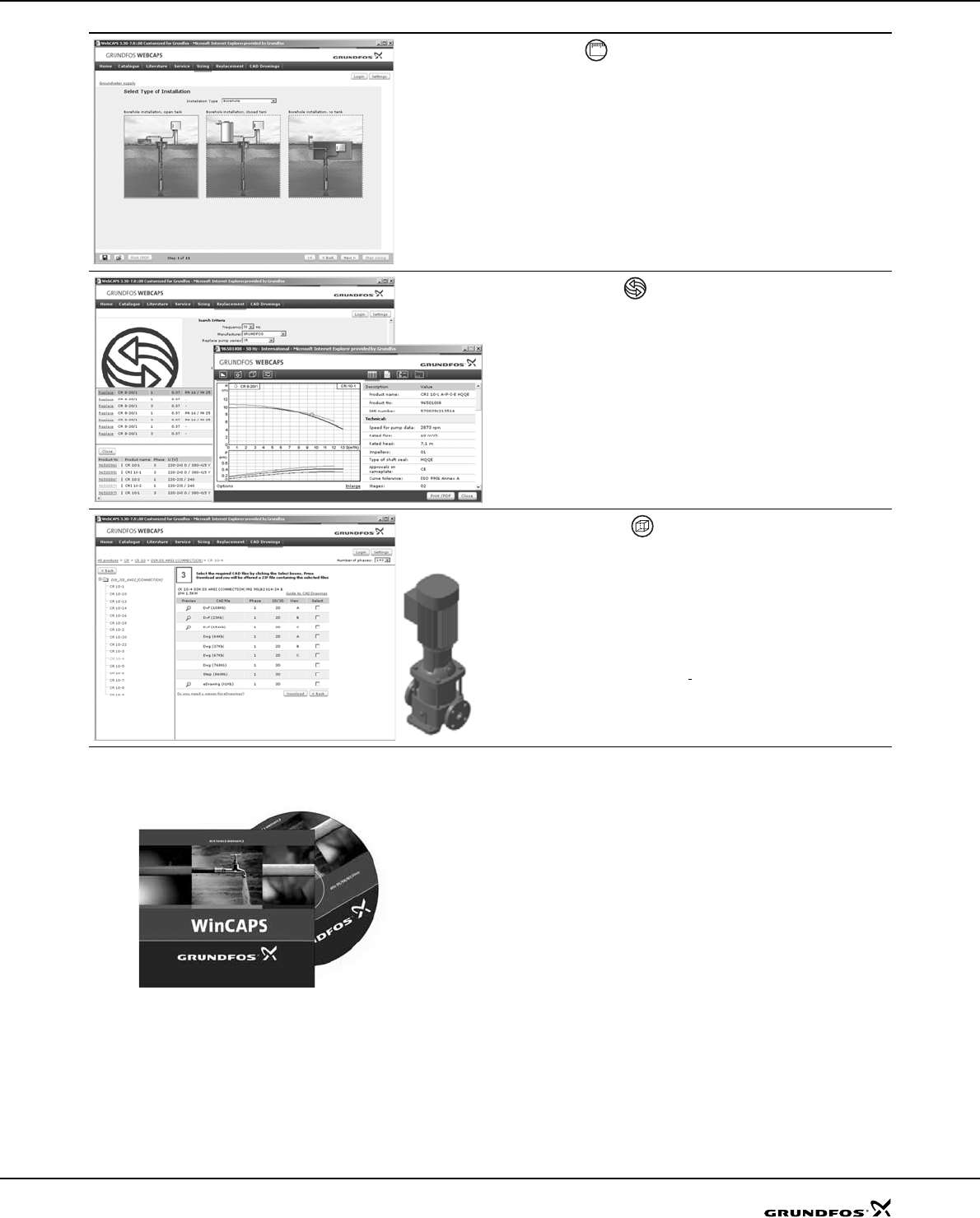
99
Further product documentation SP A, SP
WinCAPS
Fig. 26 WinCAPS CD-ROM
WinCAPS is a Windows-based Computer Aided
Product Selection program containing detailed informa-
tion on more than 185,000 Grundfos products in more
than 20 languages.
The program contains the same features and functions
as WebCAPS, but is an ideal solution if no Internet
connection is available.
WinCAPS is available on CD-ROM and updated once a
year.
Sizing
This section is based on different fields of application and installa-
tion examples, and gives easy step-by-step instructions in how to
• select the most suitable and efficient pump for your installation
• carry out advanced calculations based on energy consumption,
payback periods, load profiles, life cycle costs, etc.
• analyse your selected pump via the built-in life cycle cost tool
• determine the flow velocity in wastewater applications, etc.
Replacement
In this section you find a guide to selecting and comparing replace-
ment data of an installed pump in order to replace the pump with a
more efficient Grundfos pump.
The section contains replacement data of a wide range of pumps
produced by other manufacturers than Grundfos.
Based on an easy step-by-step guide, you can compare Grundfos
pumps with the one you have installed on your site. When you have
specified the installed pump, the guide will suggest a number of
Grundfos pumps which can improve both comfort and efficiency.
CAD drawings
In this section it is possible to download two-dimensional (2D) and
three-dimensional (3D) CAD drawings of most Grundfos pumps.
These formats are available in WebCAPS:
Two-dimensional drawings:
• .dxf, wireframe drawings
• .dwg, wireframe drawings.
Three-dimensional drawings:
• .dwg, wireframe drawings (without surfaces)
• .stp, solid drawings (with surfaces)
• .eprt, E-drawings.
01

www.grundfos.com
V7013316 0907 GB
Repl. V7013316 0307 Subject to alterations.
Being responsible is our foundation
Thinking ahead makes it possible
Innovation is the essence
GRUNDFOS A/S . DK-8850 Bjerringbro . Denmark
Telephone: +45 87 50 14 00
