OpenEnterprise Field Tools Quick Start Guide (D301703X412) Guia De Inicio Rapido Herramientas Camp Open Enterprise
User Manual: Guia-de-Inicio-Rapido Herramientas-de-Camp-OpenEnterprise
Open the PDF directly: View PDF ![]() .
.
Page Count: 68
- COV
- TOC
- CH1
- CH2
- CH3
- Chapter 3 – Communication Setup
- 3.1 Using OE Field Tools to Establish a Connection
- 3.1.1 Before You Begin
- 3.1.2 Starting OE Field Tools and Logging In
- 3.1.3 Changing the Password
- 3.1.4 Defining Users
- 3.1.5 Connections List
- 3.1.6 Starting an Existing Connection
- 3.1.7 Creating a New Connection to a Device (Controller/Flow Computer)
- 3.1.8 Communication Timeout on Distributed RTU™ Network
- 3.1.9 Making a Direct Connection
- 3.1.10 Active Connection pane
- 3.1.11 Saving Connections / Importing Connections
- 3.2 Launching ROCLINK
- 3.3 Launching TechView
- 3.4 Identifying HART Devices
- 3.5 Refreshing the HART Device Status
- 3.6 Launching AMS Device Configurator
- 3.7 Adding a HART Device Type
- 3.8 Launching the AMS Wireless SNAP-ON
- 3.1 Using OE Field Tools to Establish a Connection
- Chapter 3 – Communication Setup
- CH4
- APA
- Appendix A – Troubleshooting Tips
- Field Tools won’t start due to not being licensed
- “Unlicensed – License file not found” message in License Manager
- “Failed to connect to Comm Manager” message appears.
- Permissions problems with AMS Device Configurator
- Unable to Update the Network ID and Join Key in AMS Device Configurator
- Cannot Restore Communication with Device after Communication Failure is Fixed
- Communication Problem Causing Truncated Messages
- Eltima “FAILURE: Access is denied” Message
- AMS Services is not Starting
- AMS Wireless SNAP- ON Failure - Missing Icons in Trees
- AMS Wireless SNAP-ON Defaults
- Appendix A – Troubleshooting Tips
- RCV

Remote Automation Solutions
Part Number D301703X412
December 2014
OpenEnterprise™ Field Tools 1.0
Quick Start Guide

IMPORTANT! READ INSTRUCTIONS BEFORE STARTING!
Be sure that these instructions are carefully read and understood before any operation is attempted. Improper
use of this device in some applications may result in damage or injury. The user is urged to keep this book filed
in a convenient location for future reference.
These instructions may not cover all details or variations in equipment or cover every possible situation to be
met in connection with installation, operation or maintenance. Should problems arise that are not covered
sufficiently in the text, the purchaser is advised to contact Emerson Process Management, Remote Automation
Solutions for further information.
EQUIPMENT APPLICATION WARNING
The customer should note that a failure of this instrument or system, for whatever reason, may leave an
operating process without protection. Depending upon the application, this could result in possible damage to
property or injury to persons. It is suggested that the purchaser review the need for additional backup
equipment or provide alternate means of protection such as alarm devices, output limiting, fail-safe valves,
relief valves, emergency shutoffs, emergency switches, etc. If additional information is required, the purchaser
is advised to contact Remote Automation Solutions.
RETURNED EQUIPMENT WARNING
When returning any equipment to Remote Automation Solutions for repairs or evaluation, please note the
following: The party sending such materials is responsible to ensure that the materials returned to Remote
Automation Solutions are clean to safe levels, as such levels are defined and/or determined by applicable
federal, state and/or local law regulations or codes. Such party agrees to indemnify Remote Automation
Solutions and save Remote Automation Solutions harmless from any liability or damage which Remote
Automation Solutions may incur or suffer due to such party's failure to so act.
ELECTRICAL GROUNDING
Metal enclosures and exposed metal parts of electrical instruments must be grounded in accordance with
OSHA rules and regulations pertaining to "Design Safety Standards for Electrical Systems," 29 CFR, Part 1910,
Subpart S, dated: April 16, 1981 (OSHA rulings are in agreement with the National Electrical Code).
The grounding requirement is also applicable to mechanical or pneumatic instruments that include electrically
operated devices such as lights, switches, relays, alarms, or chart drives.
EQUIPMENT DAMAGE FROM ELECTROSTATIC DISCHARGE VOLTAGE
This product contains sensitive electronic components that can be damaged by exposure to an electrostatic
discharge (ESD) voltage. Depending on the magnitude and duration of the ESD, this can result in erratic
operation or complete failure of the equipment. Read supplemental document S14006 for proper care and
handling of ESD-sensitive components.

OpenEnterprise™ Field Tools Quick Start Guide
Issued Dec-2014 Contents iii
Contents
Chapter 1 – Introduction 1-1
1.1What is OpenEnterprise™ Field Tools? .................................................................................... 1-1
1.1.1AMS Device Configurator .............................................................................................. 1-1
Chapter 2 – Installation and Licensing 2-1
2.1Minimum System Requirements ............................................................................................... 2-1
2.2Before You Begin ...................................................................................................................... 2-1
2.2.1Disabling User Account Control (UAC) in Windows 7 .................................................. 2-2
2.3Installing Field Tools ................................................................................................................. 2-4
2.3.1Special Notes for TechView Users ............................................................................... 2-7
2.4Licensing the Software .............................................................................................................. 2-8
2.4.1Starting License Manager and Licensing Field Tools ................................................... 2-8
2.4.2Re-Assigning a License to another PC (Park License) ............................................... 2-13
2.4.3Viewing the Licenses Available Under your License Id .............................................. 2-15
2.4.4Get Upgrade / Include Upgrade .................................................................................. 2-15
2.4.5Generate a Report of License Information .................................................................. 2-15
Chapter 3 – Communication Setup 3-1
3.1Using OE Field Tools to Establish a Connection ...................................................................... 3-1
3.1.1Before You Begin .......................................................................................................... 3-1
3.1.2Starting OE Field Tools and Logging In ........................................................................ 3-2
3.1.3Changing the Password ................................................................................................ 3-3
3.1.4Defining Users ............................................................................................................... 3-3
3.1.5Connections List ............................................................................................................ 3-5
3.1.6Starting an Existing Connection .................................................................................... 3-7
3.1.7Creating a New Connection to a Device (Controller/Flow Computer) .......................... 3-7
3.1.8Communication Timeout on Distributed RTU™ Network ........................................... 3-12
3.1.9Making a Direct Connection ........................................................................................ 3-13
3.1.10Active Connection pane .............................................................................................. 3-13
3.1.11Saving Connections / Importing Connections ............................................................. 3-14
3.2Launching ROCLINK ............................................................................................................... 3-15
3.3Launching TechView ............................................................................................................... 3-15
3.4Identifying HART Devices ....................................................................................................... 3-16
3.5Refreshing the HART Device Status ....................................................................................... 3-16
3.6Launching AMS Device Configurator ...................................................................................... 3-17
3.7Adding a HART Device Type .................................................................................................. 3-18
3.8Launching the AMS Wireless SNAP-ON ................................................................................ 3-18
Chapter 4 – Using AMS Device Configurator Software 4-1
4.1Connecting Directly to the HART or WirelessHART Device ..................................................... 4-2
4.1.1Before You Begin .......................................................................................................... 4-2
4.1.2Smart Wireless THUM™ Adapter and Field Tools ....................................................... 4-2
4.1.3Establishing the Connection.......................................................................................... 4-3
4.2Setting the Long Tag ................................................................................................................. 4-8
4.3Setting the Network ID and Join Key ...................................................................................... 4-10
Appendix A – Troubleshooting Tips A-1

OpenEnterprise™ Field Tools Quick Start Guide
iv Contents Issued Dec-2014
Field Tools won’t start due to not being licensed .................................................................... A-1
“Unlicensed – License file not found” message in License Manager ...................................... A-1
“Failed to connect to Comm Manager” message appears. ..................................................... A-1
Permissions problems with AMS Device Configurator ............................................................ A-2
Unable to Update the Network ID and Join Key in AMS Device Configurator ........................ A-5
Cannot Restore Communication with Device after Communication Failure is Fixed .............. A-5
Communication Problem Causing Truncated Messages ........................................................ A-6
Eltima “FAILURE: Access is denied” Message ....................................................................... A-8
AMS Services is not Starting ................................................................................................... A-8
AMS Wireless SNAP-ON Failure - Missing Icons in Trees ..................................................... A-9
AMS Wireless SNAP-ON Defaults .......................................................................................... A-9

OpenEnterprise™ Field Tools Quick Start Guide
Issued Dec-2014 Introduction 1-1
Chapter 1 – Introduction
This manual provides a brief introduction to OpenEnterprise™ (OE)
Field Tools and covers software installation, licensing and initial
communications setup.
For full details on using the Field Tools software, please refer to the
online help included in each component application.
In This Chapter
1.1What is OpenEnterprise™ Field Tools? .......................................... 1-1
1.1.1AMS Device Configurator ..................................................... 1-1
1.1 What is OpenEnterprise™ Field Tools?
OE Field Tools provides a single integrated package for connecting with
ROC, FloBoss, and ControlWave devices to configure communications
with Highway Addressable Remote Transducer (HART®) and
WirelessHART devices. A field technician uses Field Tools software
running on a laptop PC to establish communications with a
controller/flow computer and launch AMS Device Configurator for that
controller.
Field Tools supports either a direct serial connection or an IP connection
to a single controller at any one time. You establish communications
with the controller using Field Tools’ New Connection wizard.
Once communications are active, you can launch AMS Device
Configurator to view and configure field instrumentation connected to
the controller or flow computer.
In addition, if you have separately installed configuration tools for the
controller (ROCLINK or TechView) you can launch them through the
Field Tools connection to configure any ROC, FloBoss, ControlWave,
or Network 3000 device the tools routinely support.
1.1.1 AMS Device Configurator
AMS Device Configurator, which is included in Field Tools, provides a
special subset of functionality from Emerson’s Asset Optimization
AMS Device Manager software suite.
AMS Device Configurator communicates with wired HART devices or
IEC 62591 (WirelessHART) devices. Table 1-1 shows the minimum
recommended controller firmware revisions for full AMS compatibility.

OpenEnterprise™ Field Tools Quick Start Guide
1-2 Introduction Issued Dec-2014
Table 1- 1 Firmware Versions Required for Full AMS Compatibility
Controller/Flow
Computer Firmware Version
ROC 809/827 3.60 (or newer)
FloBoss 107 1.70 (or newer)
ControlWave Micro 5.71 (or newer)
Notes:
IEC 62591 module firmware must be 1.10 (or newer)
HART module (Series 2) firmware must be 1.15 (or newer)
TechView software must be version 5.9 Patch A (or newer)
(Patch A installed with Field Tools)
ROCLINK software must be version 2.40 (or newer)

OpenEnterprise™ Field Tools Quick Start Guide
Issued Dec-2014 Installation and Licensing 2-1
Chapter 2 – Installation and Licensing
This chapter covers installation and licensing of Field Tools software.
In This Chapter
2.1Minimum System Requirements ...................................................... 2-1
2.2Before You Begin ............................................................................. 2-1
2.2.1Disabling User Account Control (UAC) in Windows 7 .......... 2-2
2.3Installing Field Tools ........................................................................ 2-4
2.3.1Special Notes for TechView Users ....................................... 2-7
2.4Licensing the Software .................................................................... 2-8
2.4.1Starting License Manager and Licensing Field Tools .......... 2-8
2.4.2Re-Assigning a License to another PC (Park License) ...... 2-13
2.4.3Viewing the Licenses Available Under your License Id ..... 2-15
2.4.4Get Upgrade / Include Upgrade ......................................... 2-15
2.4.5Generate a Report of License Information ......................... 2-15
2.1 Minimum System Requirements
For optimal performance, we recommend that your laptop PC meet the
following minimum requirements:
Intel® Core™2 Duo CPU at 2.00 GHz
4 GB RAM
2.5 GB available hard disk space to install the full software package
Windows 7 for either 32-bit or 64-bit (Service Pack 1)
USB port (for HART modem)
2.2 Before You Begin
Caution AMS Device Configurator is incompatible with AMS Device Manager;
they cannot reside on the same computer.
Field Tools cannot reside on a computer running any components of
OpenEnterprise 2.x, OpenEnterprise 3.x, or OpenEnterprise
Client/Server software.
TechView and other components of BSI_Config cannot be installed on a
computer running OpenBSI Network Edition.
AMS Device Configurator functions only with controllers which have
firmware supporting wired HART or IEC62591 (Wireless HART). See
Section 1.1.1 AMS Device Configurator for details.
You must have administrative privileges to install Field Tools.
You must disable User Account Control (UAC) prior to the
installation (you can re-enable it after the installation). See Section
2.2.1.
As part of the installation both Eltima and MACTek® device
software are installed automatically. Depending upon your
permissions, Windows may require you to confirm these
installations before the installation can proceed.
OpenEnterprise™ Field Tools Quick Start Guide
2-2 Installation and Licensing Issued Dec-2014
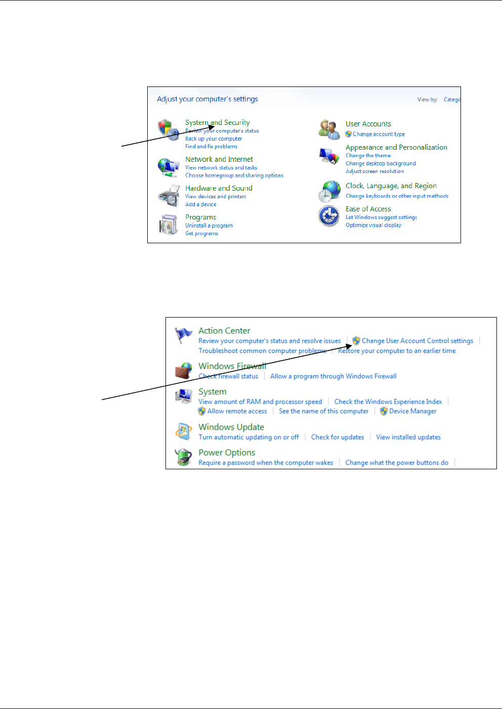
2.2.1 Disabling User Account Control (UAC) in Windows 7
1. Click Start > Control Panel to open the Windows Control Panel.
2. Click System and Security.
Figure 2-1. Control Panel
3. Click Change User Account Control settings (located under
Action Center).
Figure 2-2. Change User Account Control Settings
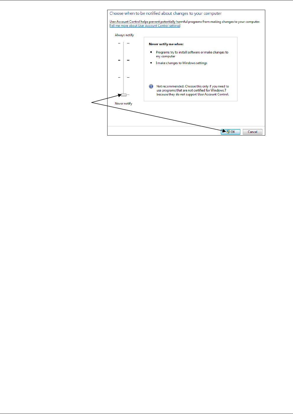
4. Drag the sliding control down to Never notify and click OK.
Click
System and
Security
Click Change
User Account
Control
settings
OpenEnterprise™ Field Tools Quick Start Guide
Issued Dec-2014 Installation and Licensing 2-3
Figure 2-3. Changing User Account Control
Drag the sliding
control to Never
Notify then click
OK.

OpenEnterprise™ Field Tools Quick Start Guide
2-4 Installation and Licensing Issued Dec-2014
2.3 Installing Field Tools
Insert the installation DVD-ROM in your DVD drive. The OpenEnterprise™
Field Tools introduction screen opens. Links for accessing documentation on
the DVD as well as web resources for software licensing and support appear at
the bottom of the introduction screen.
Notes:
If, for any reason, the auto-start doesn’t run right-click on
SETUP.EXE in the root of the DVD and choose Run as
administrator.
You should only install from the DVD drive (drive D:); extracting
files and loading from the desktop or other methods can cause an
incorrect installation.
Figure 2-4. Field Tools Introduction screen
1. Click Install Field Tools.
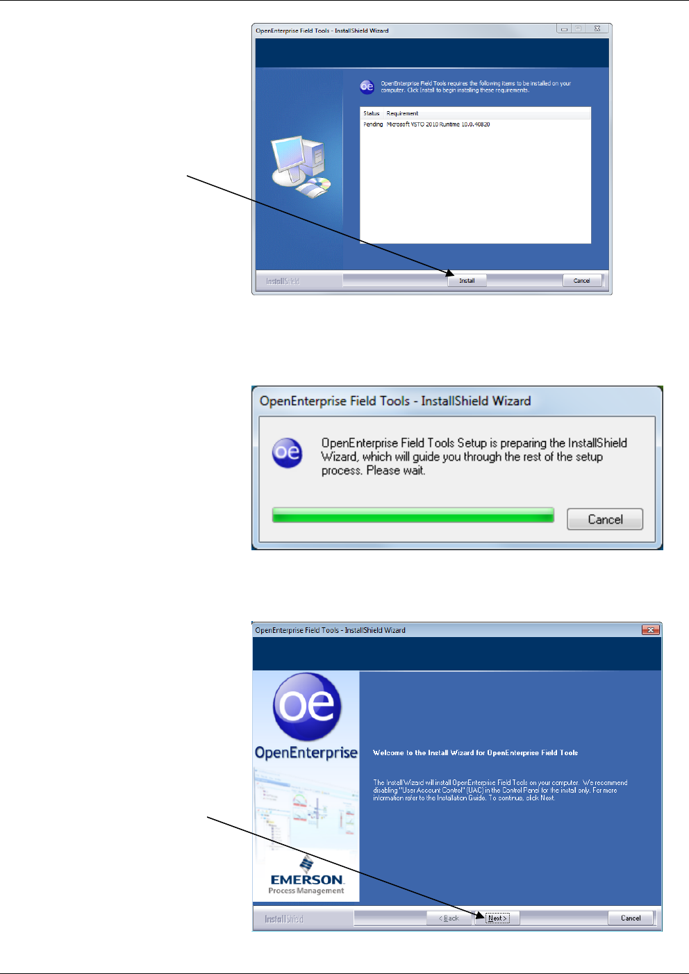
2. The installation process starts and checks whether certain necessary
software components exist on the laptop, and if they are not present,
the installation process prompts you to install them. Click Install.
This process may take several minutes. Some of the installations
may require a reboot before you resume the Field Tools installation.
Click here
OpenEnterprise™ Field Tools Quick Start Guide
Issued Dec-2014 Installation and Licensing 2-5
Figure 2-5. InstallShield Wizard
3. Once installation of the required components finishes, the
OpenEnterprise Field Tools installation wizard starts:
Figure 2-6. InstallShield Wizard
4. Click Next.
Figure 2-7. Installer Welcome screen
Click Install
Click Next.
OpenEnterprise™ Field Tools Quick Start Guide
2-6 Installation and Licensing Issued Dec-2014
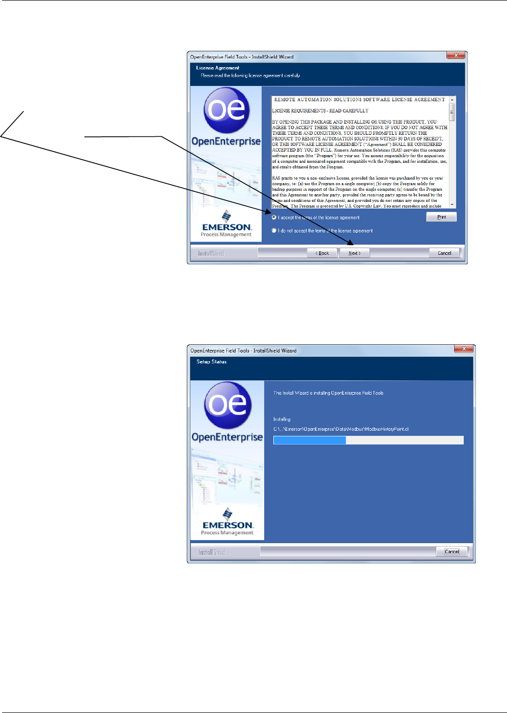
To proceed with the installation, click I accept the terms of the
license agreement and then click Next.
Figure 2-8. License Agreement screen
5. The installation proceeds. The installer program periodically reports
which components are being installed. This may take several
minutes:
Figure 2-9. Setup Status screen
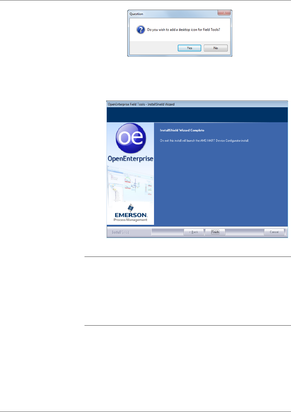
6. You’ll be prompted to decide whether you want the installer to
create a Field Tools desktop icon; click Yes if you want to start
Field Tools from the desktop.
Click I accept the terms of
the license agreement then
click Next.
OpenEnterprise™ Field Tools Quick Start Guide
Issued Dec-2014 Installation and Licensing 2-7
7. AMS Device Configurator is the last component in the Field Tools
installation process. When you click Finish, the AMS Device Configurator
installation process begins. Installation of AMS Device Configurator takes
several minutes and prompts you to reboot after which it resumes the
installation.
Figure 2-10. InstallShield Wizard Finish page
Notes:
Do not install AMS Wireless SNAP-ON before you install AMS
Device Configurator. Always install AMS Device Configurator
first.
After AMS Device Configurator installation completes, if you want
to install the AMS Wireless SNAP-ON, return to the Field Tools
Introduction screen (Figure 2-4) and choose Install Wireless Snap-
on.
2.3.1 Special Notes for TechView Users
If you have the OpenBSI 5.9 version of TechView installed prior to
installing Field Tools 1.0, the Field Tools installation automatically
updates your TechView.exe file to version 5.9 Patch A. If you
subsequently reinstall OpenBSI 5.9, you’ll need to manually copy the
5.9 Patch A version of TechView.exe to the proper installation path on
your PC. If you used the default installation paths, you can use the
following examples, assuming your PC hard disk is the C drive:

OpenEnterprise™ Field Tools Quick Start Guide
2-8 Installation and Licensing Issued Dec-2014
For 64-bit OpenBSI Users:
Copy C:\program files (x86)\emerson\openenterprise\bin\TechView.exe
C:\program files (x86)\bristol\openbsi\
For 32-bit OpenBSI Users:
Copy C:\program files\emerson\openenterprise\bin\TechView.exe
C:\program files\bristol\openbsi\
2.4 Licensing the Software
After the initial installation, Field Tools software functions for a 30-day
demo period.
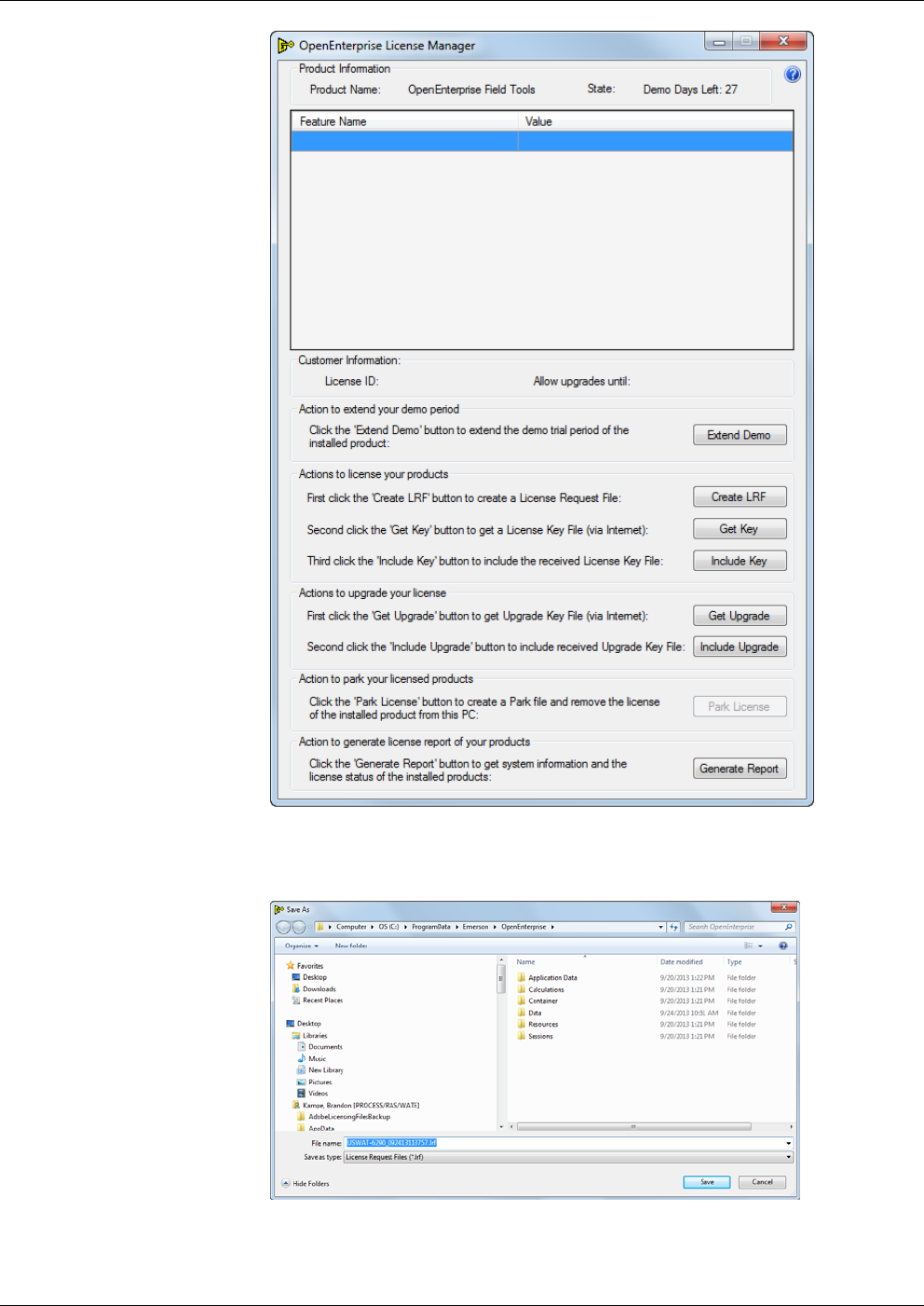
The License Manager software displays the number of days remaining
in the demo period as the Demo Days Left entry in the State field. To
use Field Tools beyond the trial period you must license the software
(see Section 2.4.1).
Notes:
To license the software, you must have installed it and you must
have an active Internet connection.
Start and leave the License Manager software running throughout
the entire licensing process. The licensing process must be
performed in a single uninterrupted session.
You need your License ID and Password to complete the process;
you should have received these with the software DVD.
After you’ve licensed the software on a particular PC, if you decide you
want to re-assign the license to a different PC, you can temporarily
“park” the license on the License Registration website prior to re-
assigning it (see Section 2.4.2).
2.4.1 Starting License Manager and Licensing Field Tools
1. Either click Help > Licensing from the menu bar in Field Tools, or
click Start > Programs > Emerson OpenEnterprise > Licensing
> License Manager.
OpenEnterprise™ Field Tools Quick Start Guide
Issued Dec-2014 Installation and Licensing 2-9
Figure 2-11. OpenEnterprise License Manager
2. Click the Create LRF button to generate a License Request File.
Figure 2-12. Saving the LRF File
OpenEnterprise™ Field Tools Quick Start Guide
2-10 Installation and Licensing Issued Dec-2014
Click Save and make note of the location where you store the file
because you’ll need it later.
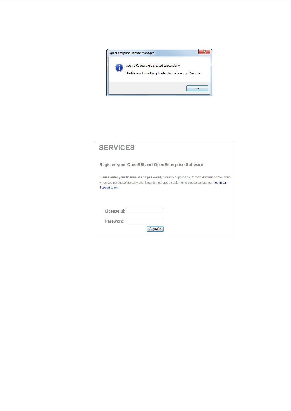
3. A message box notifies you when the LRF file is complete. Click
OK to proceed.
Figure 2-13. LRF Created Successfully
4. Now click Get Key in the License Manager to go to the software
registration page of the Emerson Remote Automation Solutions
website.
Figure 2-14. Signing on to the Website
5. Enter your License Id and Password, then click Sign-On.
OpenEnterprise™ Field Tools Quick Start Guide
Issued Dec-2014 Installation and Licensing 2-11
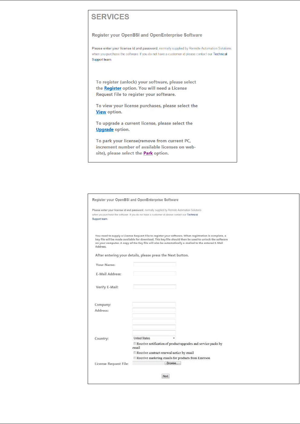
Figure 2-15. Registration Page Options
6. Click the Register option.
Figure 2-16. Entering Your Information
7. Enter your name in the Your Name field; and enter your e-mail
address in both the E-Mail Address and Verify E-Mail fields. This
OpenEnterprise™ Field Tools Quick Start Guide
2-12 Installation and Licensing Issued Dec-2014
is the address to which the website sends your key file. Enter your
Company Address in the fields provided.
8. Scroll down to specify your Country and specify your preferences
about receiving notifications of product updates, service packs,
contract renewals, and marketing announcements by e-mail.
9. Use the Browse button to locate the License Request File you
created in Step 2 and then click Next to open the Unlock page.
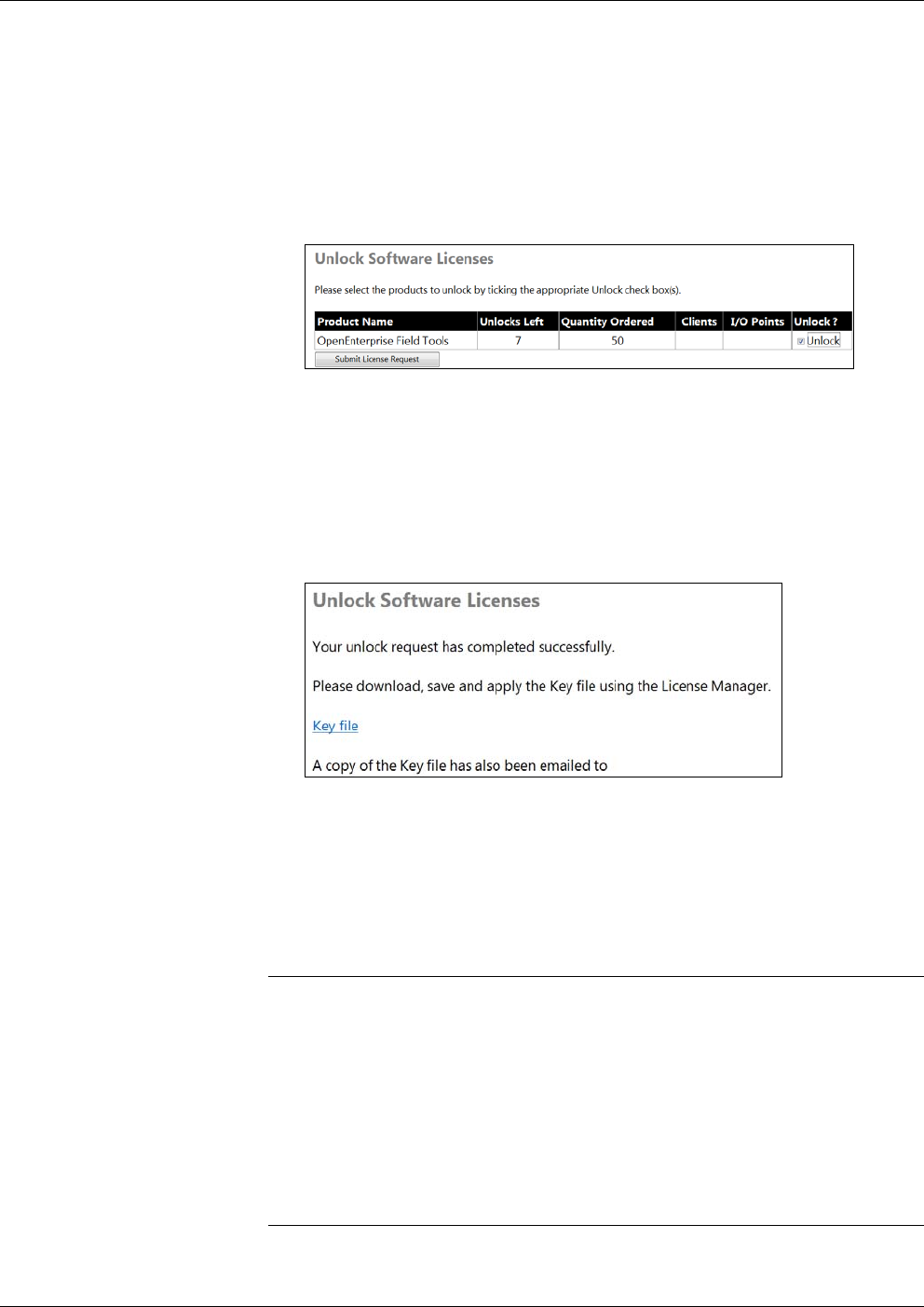
Figure 2-17. Unlock Software Licenses
10. The Unlock Software Licenses page shows a list of licenses
purchased under your License Id. If the Unlocks Left entry for
OpenEnterprise Field Tools is greater than zero, you can request one
of the available licenses. Check the Unlock box on the
OpenEnterprise Field Tools line and then click Submit License
Request.
Figure 2-18. Unlocking the License
11. At this point, the website e-mails your key file to the address you
specified in Step 7 along with a separate notification e-mail. You
can check your e-mail for a copy of the key file and save it for the
next step. Alternatively, you can click Key file to open the key file
in a window; click File > Save As to save your key file.
Notes:
If you use Microsoft® Internet Explorer 9, it automatically saves
your key file with a .TXT extension. License Manager handles the
.TXT extension; do not change the extension or the file may become
unusable.
If you right-click on the Key File link and select the Save Target as
context menu item, the key file is saved with an .XML extension.
The e-mailed key file has an extension of .KEY.
License Manager handles .KEY, .TXT, and .XML extensions.
12. Click Include Key in the License Manager. Browse to the location
of your key file and click Open to apply the key file. The State field
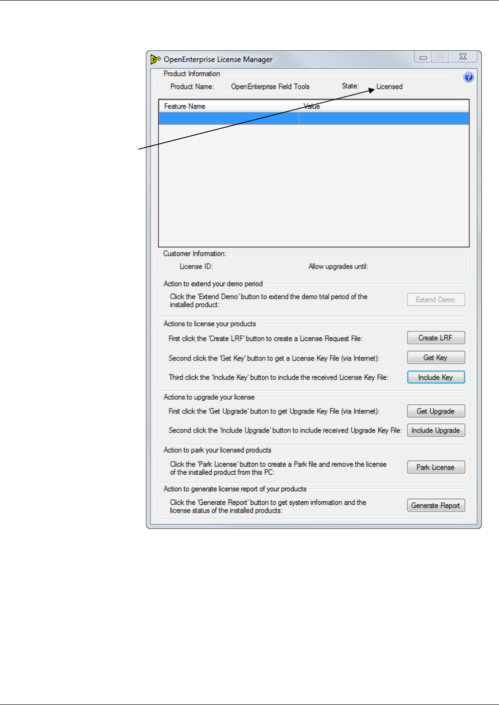
OpenEnterprise™ Field Tools Quick Start Guide
Issued Dec-2014 Installation and Licensing 2-13
for Field Tools in the License Manager now shows Licensed.
You’re done!
Figure 2-19. Licensed Field Tools Software
2.4.2 Re-Assigning a License to another PC (Park License)
If you license Field Tools on a particular PC and then decide you want
to re-assign the Field Tools license to a different PC, you can remove
the license from the first PC and then temporarily “park the license” on
the License Registration website. This restores the license to your total
number of purchased licenses, and you can then assign it to the new PC
through the normal license registration procedure.
Product is licensed
OpenEnterprise™ Field Tools Quick Start Guide
2-14 Installation and Licensing Issued Dec-2014
Note: Once you park a license (which removes it from the original PC)
you cannot assign a new license to that same PC without first
contacting our Technical Support personnel for codes to
restore the demo period for that PC. The technical support phone
number in the U.S. is: 1-800-537-9313; for international
numbers use this link: http://www2.emersonprocess.com/en-
US/brands/remote/systems_and_software/supportnet/support_contacts/
Pages/support_contacts.aspx Alternatively, log into SupportNet at
this link:
http://www3.emersonprocess.com/remote/support/support_login.html
1. To start the License Manager, either click Help > Licensing from
the menu bar in Field Tools, or click Start > Programs > Emerson
OpenEnterprise > Licensing > License Manager.
2. Click Park License and save the PRK file. Make note of the
location because you need to access the file in a later step.
3. Click Get Key to go to the License Registration website.
4. Enter your License Id and Password and then click Sign-On.
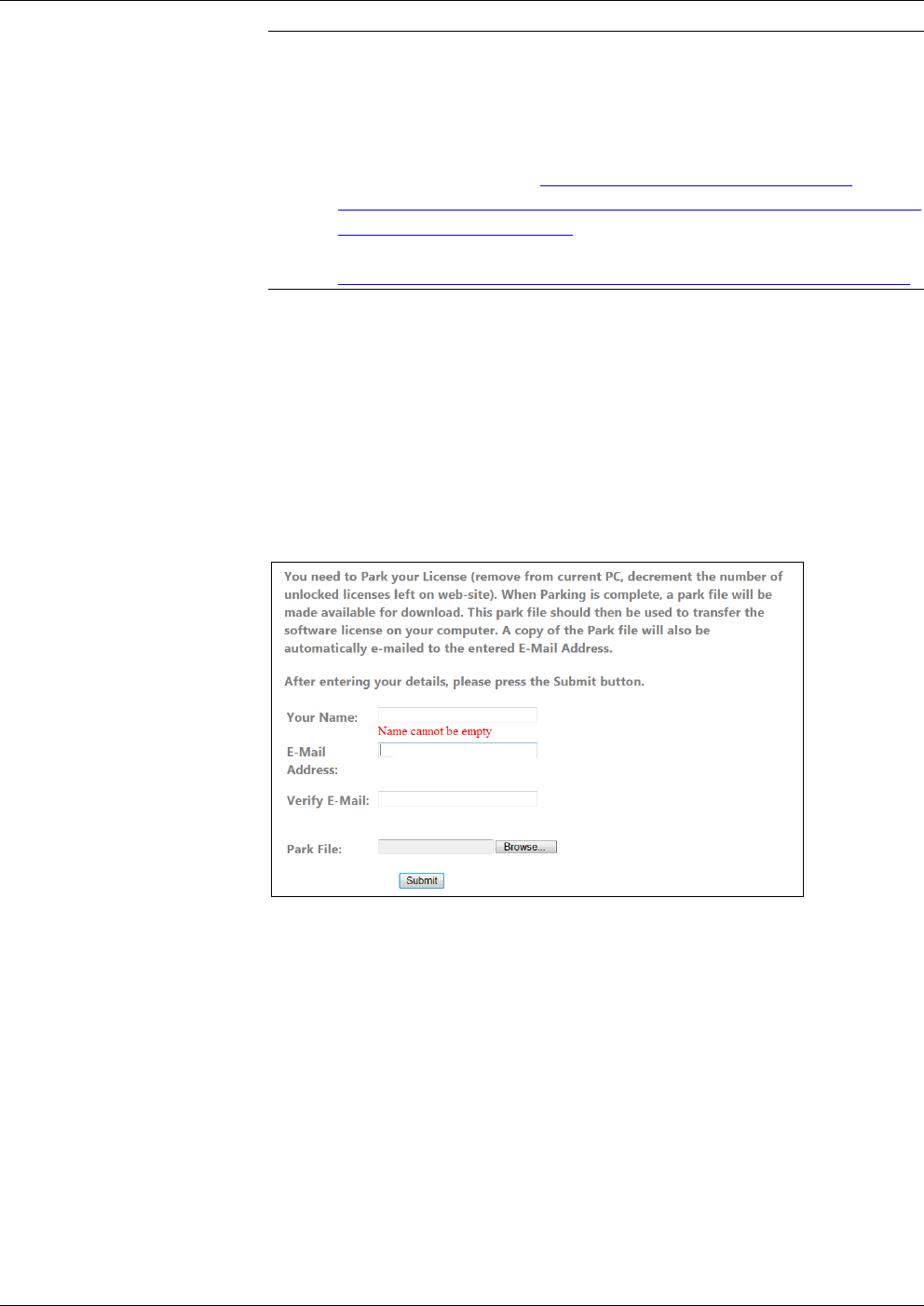
5. Click the Park option; this removes the license from the current PC.
Figure 2-20. Parking a License
6. Enter your name in the Your Name field; and enter your e-mail
address in both the E-Mail Address and Verify E-Mail fields. This
is the address to which the licensing website sends your key file.
7. Use the Browse button to locate the Park File you created in Step 2.
8. Click Submit. When the website accepts the park file, it shows the
message Park File Operation Completed Successfully.
9. Exit the License Manager. You can now re-assign the license to a
different PC by following the licensing procedure on the new PC.
(See Section 2.4.1.)
OpenEnterprise™ Field Tools Quick Start Guide
Issued Dec-2014 Installation and Licensing 2-15
2.4.3 Viewing the Licenses Available Under your License Id
If you want to see which licenses have been purchased under your
License Id and which ones are available to be unlocked and used, you
can view this on the License Registration website.
1. To start the License Manager, either click Help > Licensing from
the menu bar in Field Tools, or click Start > Programs > Emerson
OpenEnterprise > Licensing > License Manager.
2. Click Get Key to go to the License Registration website.
3. Enter your License Id and Password and then click Sign-On.
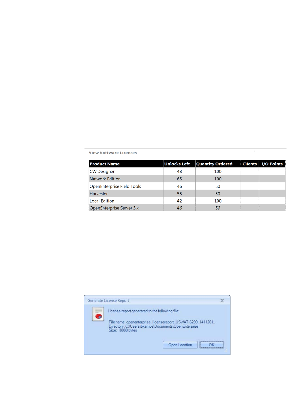
4. On the Services page, click View to see a table of licenses purchased
using your License Id. The Unlocks Left column displays the
number of licenses available for use. To unlock one of the licenses,
follow the procedure in Section 2.4.1.
Figure 2-21. Viewing Available Licenses
2.4.4 Get Upgrade / Include Upgrade
These features are not yet available for Field Tools. (Reserved for
future use.)
2.4.5 Generate a Report of License Information
To see which OpenEnterprise features are installed on your computer,
click the Generate Report button.
Click OK to open the license report:
OpenEnterprise™ Field Tools Quick Start Guide
2-16 Installation and Licensing Issued Dec-2014
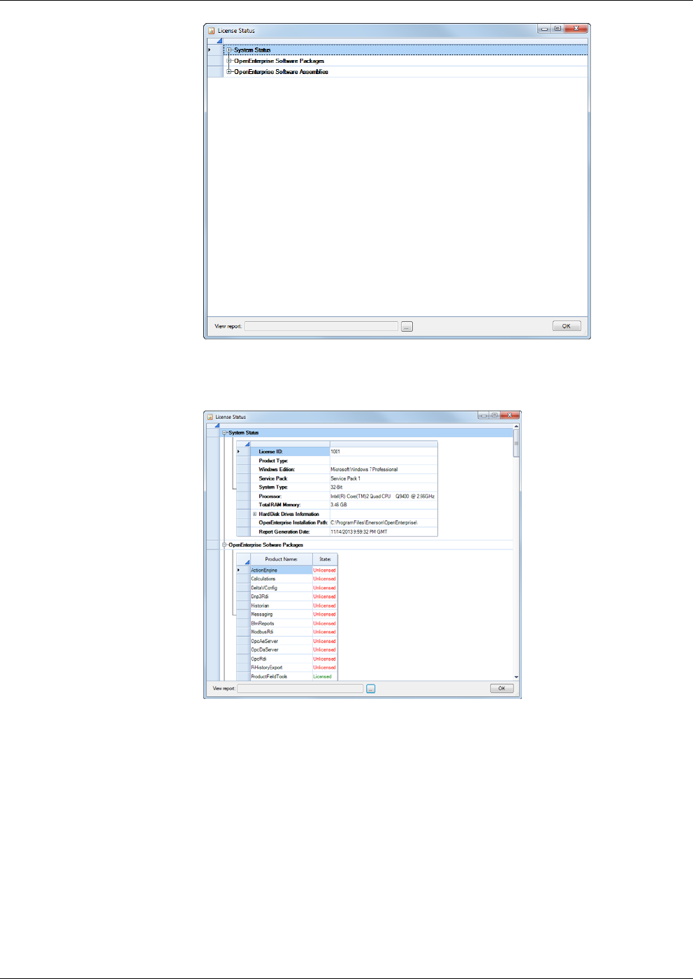
Figure 2-22. License Status – Tree Items Hidden
Click the plus “+” icons to expand the tree and view items.
Figure 2-23. License Status
Use the scroll bar to view system information and the list of installed
OE components.
Optionally, you can click the […] button to open the location of the raw
XML file; you can double-click the file to view the XML.
Click OK to exit.

OpenEnterprise™ Field Tools Quick Start Guide
Issued Dec-2014 Communication Setup 3-1
Chapter 3 – Communication Setup
This chapter covers initial communication setup with OE Field Tools.
In This Chapter
3.1Using OE Field Tools to Establish a Connection ............................. 3-1
3.1.1Before You Begin ................................................................. 3-1
3.1.2Starting OE Field Tools and Logging In ............................... 3-2
3.1.3Changing the Password ....................................................... 3-3
3.1.4Defining Users ...................................................................... 3-3
3.1.5Connections List ................................................................... 3-5
3.1.6Starting an Existing Connection ........................................... 3-7
3.1.7Creating a New Connection to a Device (Controller/Flow
Computer) ........................................................................... 3-7
3.1.8Communication Timeout on Distributed RTU Network ...... 3-12
3.1.9Making a Direct Connection ............................................... 3-13
3.1.10Active Connection pane ..................................................... 3-13
3.1.11Saving Connections / Importing Connections .................... 3-14
3.2Launching ROCLINK ..................................................................... 3-15
3.3Launching TechView ..................................................................... 3-15
3.4Identifying HART Devices .............................................................. 3-16
3.5Refreshing the HART Device Status ............................................. 3-16
3.6Launching AMS Device Configurator ............................................ 3-17
3.7Adding a HART Device Type ......................................................... 3-18
3.8Launching the AMS Wireless SNAP-ON ....................................... 3-18
3.1 Using OE Field Tools to Establish a Connection
OE Field Tools can communicate with a controller or flow computer
using either a direct serial connection or through an IP network.
3.1.1 Before You Begin
For IP connections, connect the laptop to the same IP network which
includes the controller or flow computer.
For serial connections, you would typically connect a serial cable
between the laptop computer and a serial port on the controller or
flow computer. Other options for serial connections could include a
radio or modem.
Note: When using OE Field Tools for serial communication, you
must plug into the Local Port. For ControlWave-series units,
this is a port for which you’ve set the _Pn_LOCAL_PORT
system variable TRUE in the ControlWave project running in
the unit. Local ports answer to requests sent to a BSAP local
address of 1 which is what Field Tools requests. For Network
3000, this is a BSAP slave or pseudo-slave port. For a ROC
and FloBoss, the Local Port is a specific port (the LOI port)
which answers to the address of 240 and a group number of
240.
For ControlWave/Network 3000 devices only, you need to know
which TechView session (*.TVS) file is appropriate for your device
OpenEnterprise Field Tools™ Quick Start Guide
3-2 Communication Setup Issued Dec-2014
so you can specify it when you establish your connection. If you
installed TechView, a set of default TVS files resides on your hard
disk in your \openbsi installation path. The New Connection wizard
opens that folder first when you specify your TVS file. For example,
there is a CWaveEFM.TVS file to support the ControlWave EFM, a
CWaveGFC.TVS file to support the ControlWave GFC, and so on.
If you have a customized application with a customized TVS file,
you should place it in that folder. For ControlWave devices, you
also optionally specify the ControlWave project associated with the
field device.
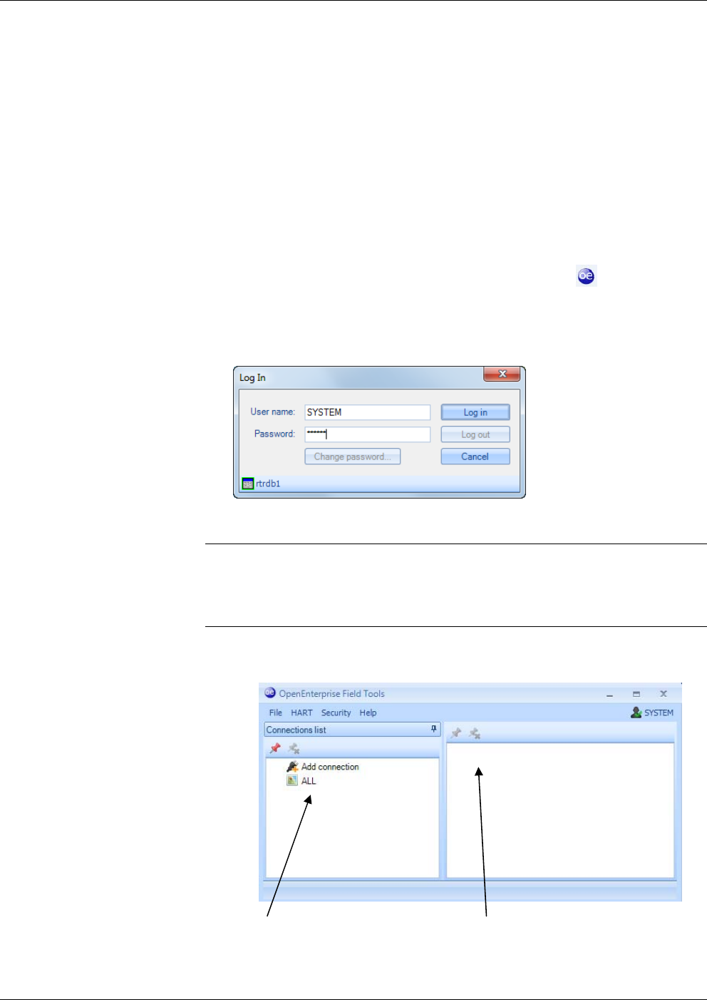
3.1.2 Starting OE Field Tools and Logging In
1. Start OE Field Tools either from the desktop icon or click:
Start>Programs> Emerson OpenEnterprise > Field Tools.
In the Log In dialog box, enter your User name and Password and
click Log in.
Figure 3-1. Log In dialog box
Note: The very first time you log in, use SYSTEM for the User name
and leave the Password field blank. Once you’ve logged in with
these defaults, Field Tools prompts you to change your
password. See Section 3.1.3.
2. The Field Tools main screen opens. Use it to establish a connection
with the controller / flow computer.
Figure 3-2. Field Tools Main Screen
Connections list pane Active connection pane
OpenEnterprise™ Field Tools Quick Start Guide
Issued Dec-2014 Communication Setup 3-3
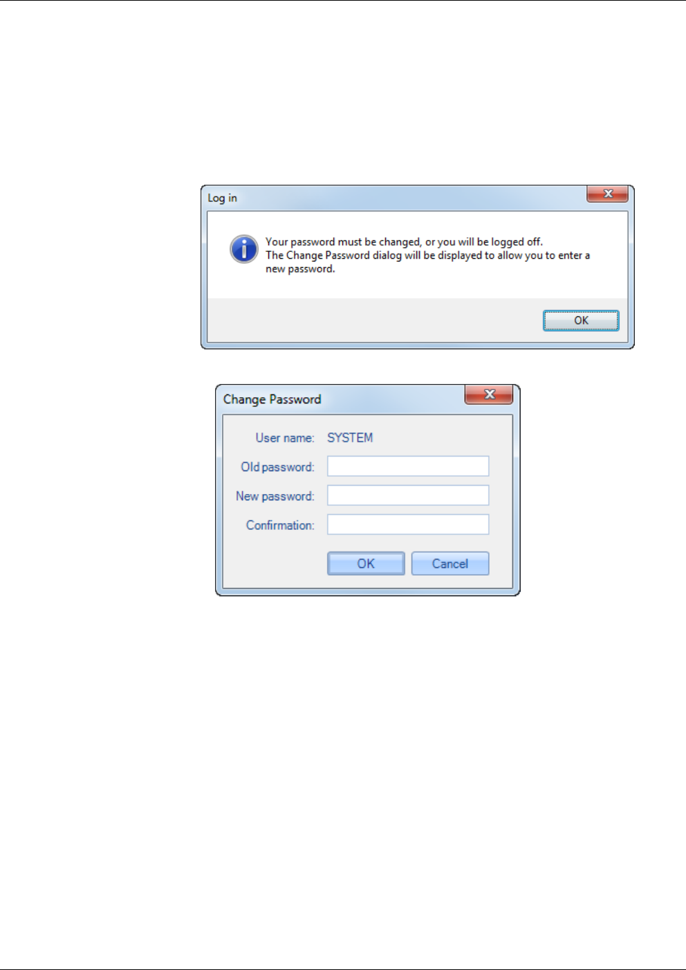
3.1.3 Changing the Password
You can also change the password for the currently logged on user at
any time by clicking Security > Change password from the menu bar.
This opens the Change Password dialog box.
The very first time you start Field Tools, the default password for the
SYSTEM account is blank, and Field Tools forces you to define a new
password; click OK to open the Change Password dialog box.
Figure 3-3 Change Password dialog box
In the Change Password dialog box, enter the current password in the
Old password field, then enter the new password in both the New
password and Confirmation fields, then click OK. Your password is
now changed.
3.1.4 Defining Users
You can define the Field Tools users on this PC by clicking Security >
User management from the menu bar. This opens the User
Management dialog box.
The User Management dialog box lets you define Field Tools users, and
also configure RTU login credentials for them.

OpenEnterprise Field Tools™ Quick Start Guide
3-4 Communication Setup Issued Dec-2014
Figure 3-4. User Management dialog box
Adding a User 1. Click Add User.
2
. Enter a User Name for the user.
Note: Usernames are case-insensitive and are stored in the database
as lowercase.
3
. Enter their password in the Password and Confirm Password
field.
4
. Click Create.
F
igure 3-5 Add New User dialog box
Deleting a User 1. Click the name of the user you want to delete.
2
. Click Delete User.
3
. Click Yes when prompted to confirm the deletion.
Assigning RTU
Login Credentials
1. Click the name of the user for which you want to define RTU login
credentials.
2
. Enter a Username and Password for the accessing the particular
RTU type(s).
Note: For the ROC/FloBoss, usernames for RTU access cannot
exceed 3 characters and the default is “LOI”.
3
. Click Ok.
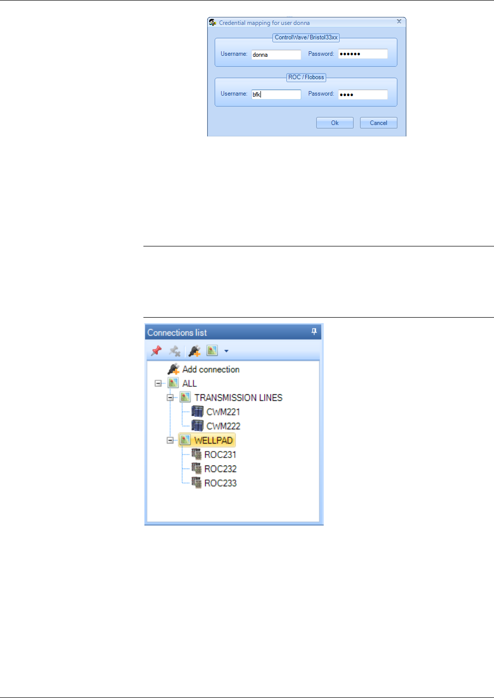
OpenEnterprise™ Field Tools Quick Start Guide
Issued Dec-2014 Communication Setup 3-5
Figure 3-6. – Credential Mapping dialog box
3.1.5 Connections List
The left pane of the Field Tools main screen displays the Connections
list tree. This shows connections you’ve previously saved or used, and
also lets you create new connections.
Note: Although you can have many connections in the Connections list,
only one can be active at any one time. The active connection is
highlighted in a green box . When you activate a connection
from the Connections list, you’ll be prompted to terminate any
connection already in use.
Figure 3-7. Connections List
OpenEnterprise Field Tools™ Quick Start Guide
3-6 Communication Setup Issued Dec-2014
Table 3-1. Icons Used in Connections List Pane and Context Menus
Icon Description
Identifies a previously configured connection to a ROC, DL8000, or
FloBoss. The name of the device appears next to the icon. Double-
click the icon to re-start the connection.
Identifies a previously configured connection to a ControlWave or
Network 3000 (33xx) controller. The name of the device appears next
to the icon. Double-click the icon to re-start the connection.
Site - A site is just a name underneath which you can group one or
more connections. It could represent a geographical area, a
department, or any other logical grouping you need. The Connections
list comes with a default site name called “ALL” which you can
rename and/or add additional sites underneath. Although you can
rename it, you cannot delete the “ALL” site; you can delete other sites
if they have no devices underneath.
Add Connection – Click to launch the New Connection wizard. You
can find this icon in the Connections list toolbar and in the
Connections list tree, and in the context menu when you right click on
a site.
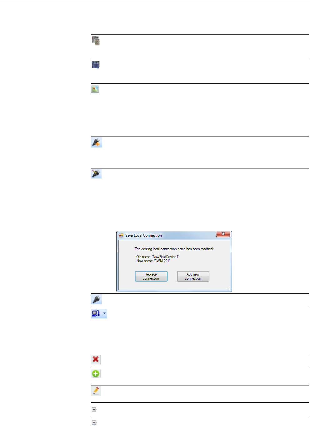
Edit Connection – Click to change the connection parameters for the
selected connection.
Note: If you change the connection name, when you save, Field
Tools prompts you to decide whether you want to save the
connection as a new connection under the new name (Add new
connection), or to just rename the existing connection (Replace
connection).
Note: You cannot edit an active connection.
Connect - Click to activate the selected connection.
Direct Connect – This toolbar icon appears when you position the
cursor on the Add Connection icon in the Connections list tree. When
you click the Direct Connect icon, you select the type of device from
options presented, and Field Tools attempts to make a local serial
connection by sequentially trying each serial port using the default
settings for that device type.
Delete – Click to delete the selected connection or site.
Add Site – Click this context menu item to add a site underneath the
currently selected site.
Rename Site – Click this context menu item to call up the Modify Site
dialog box and rename the currently selected site.
Expand branch – Click to expand this branch of the Connections tree.
Hide branch – Click to hide the portion of the Connections tree
underneath.
OpenEnterprise™ Field Tools Quick Start Guide
Issued Dec-2014 Communication Setup 3-7
Icon Description
Apply Pin –Click to display only the portion of the tree below the
current position of the cursor. This is useful if you have a large
Connections list tree with many items and you only want to see a
portion of it.
Remove Pin – Click to turn off the Apply Pin option and display the
entire Connections list tree.
Click this toolbar icon to launch ROCLINK for the selected
connection. (ROCLINK must have been installed previously).
Click this toolbar icon to launch TechView for the selected
connection. (TechView must have been installed previously).
3.1.6 Starting an Existing Connection
If you have previously established connections from this laptop, Field
Tools displays them in the Connections list pane. (See Figure 3-7.)
To activate a connection, double-click on its icon and Field Tools
activates that connection.
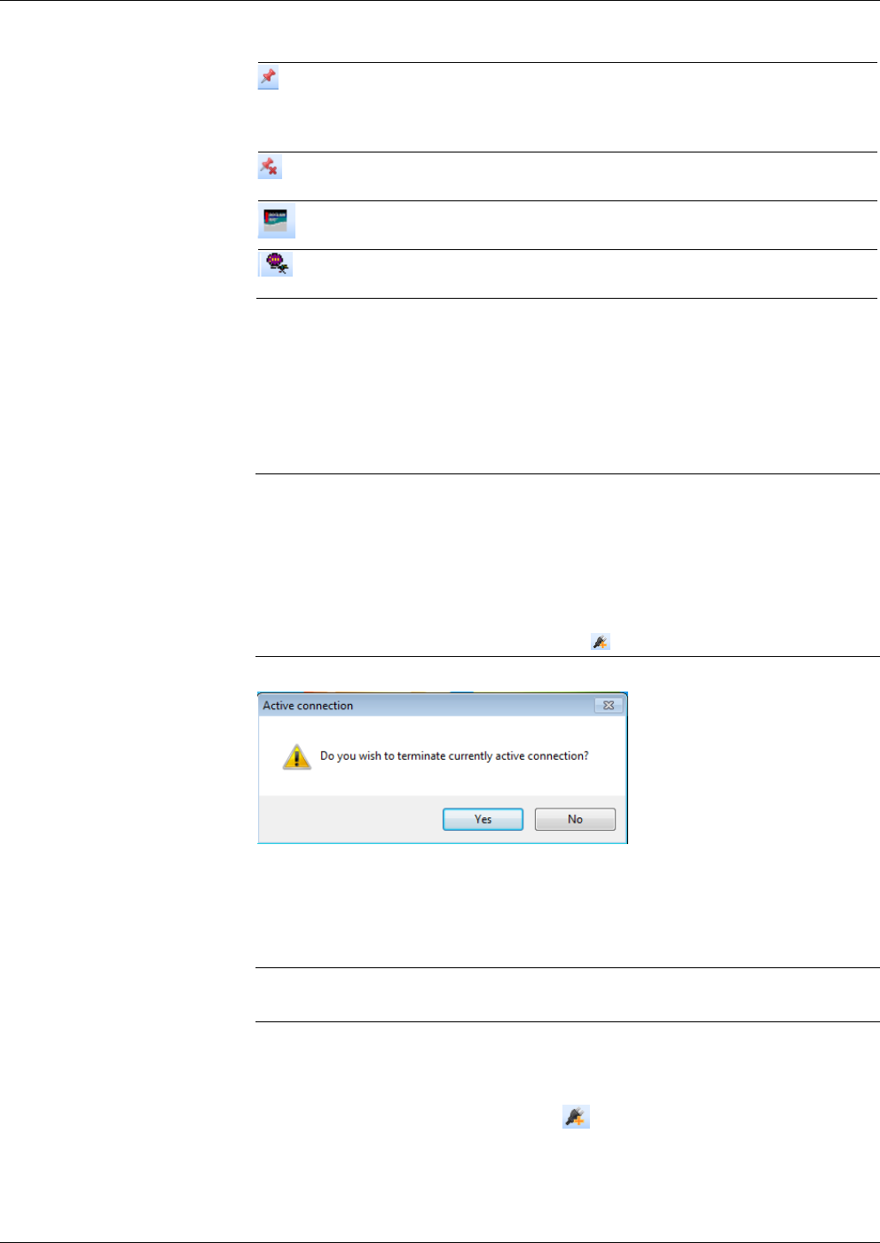
Notes:
If a connection is already active, Field Tools prompts you to
terminate the existing connection; click Yes to terminate the
previous connection and activate the new one you just selected. (See
Figure 3-8.)
If you do not want to use one of the previously defined connections,
just click the Add Connection icon to define a new connection.
Figure 3-8. Prompt to Terminate an Existing Connection
3.1.7 Creating a New Connection to a Device (Controller/Flow
Computer)
Note: To create a direct serial connection to a HART device, go to
Chapter 4.
1. If the connection for the controller/flow computer you want to
communicate with already exists in the Connections list just double-
click on it. If no previous connection exists to this device, double-
click the Add connection icon in the Connections pane toolbar
(or click File > Add connection…). This opens the New
Connection wizard.
OpenEnterprise Field Tools™ Quick Start Guide
3-8 Communication Setup Issued Dec-2014
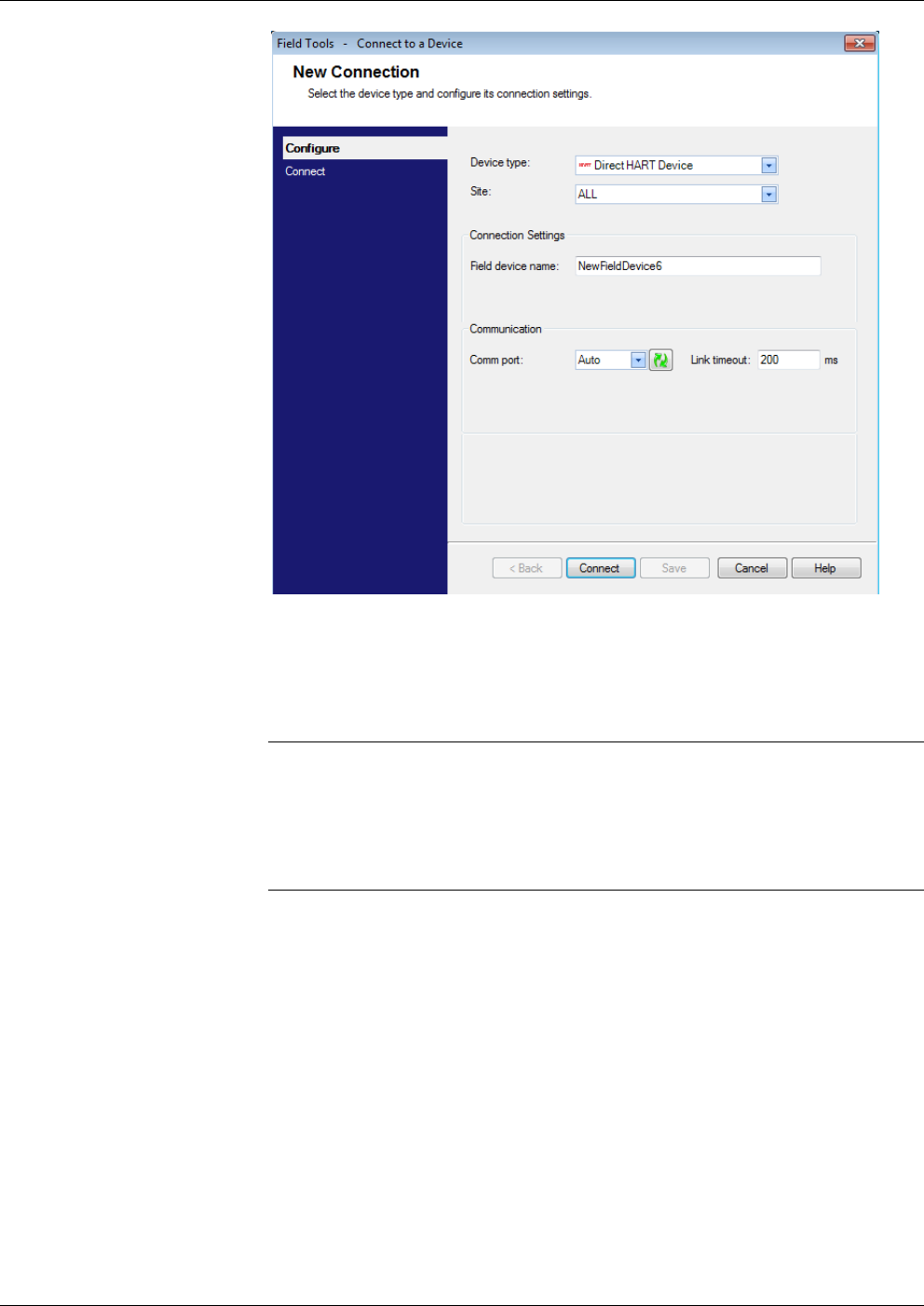
Figure 3-9. New Connection
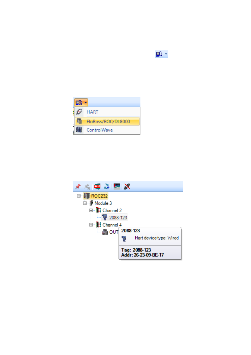
2. Select the type of device to which you want to connect in the Device
type field. The choices are: FloBoss/ROC/DL8000,
ControlWave/33xx, or Direct HART Device.
Notes:
The fields displayed on the screen vary depending on your chosen
Device type. For information on Direct HART Device see Chapter
4.
33xx” refers to Network 3000 devices.
3. If you’ve defined sites select the desired Site; otherwise use the
default of ALL. (Sites are just a way to organize the devices in the
tree; they could represent geographical areas, departments, or any
other organizational meaning you want.) For more information on
working with sites, see the online help.
4. Specify the name of the field device in the Field device name field.
5. For an RTU or flow computer, if you want to define a default
username/password combination for this device click RTU
Credentials in the New Connection page (see Figure 3-11 or Figure
3-12) to open the RTU Credentials dialog box (see Figure 3-10). In
the RTU Credentials dialog box, enter a valid Username and
Password combination for access to this controller / flow computer,
and re-enter the password in the Verify Password field; this
username/password combination will be used for this controller/flow
OpenEnterprise™ Field Tools Quick Start Guide
Issued Dec-2014 Communication Setup 3-9
computer throughout this Field Tools session. If you want to use this
username / password combination as the default for this RTU for all
subsequent connection sessions check the Save as default box.
Click OK to finish and close the dialog box.
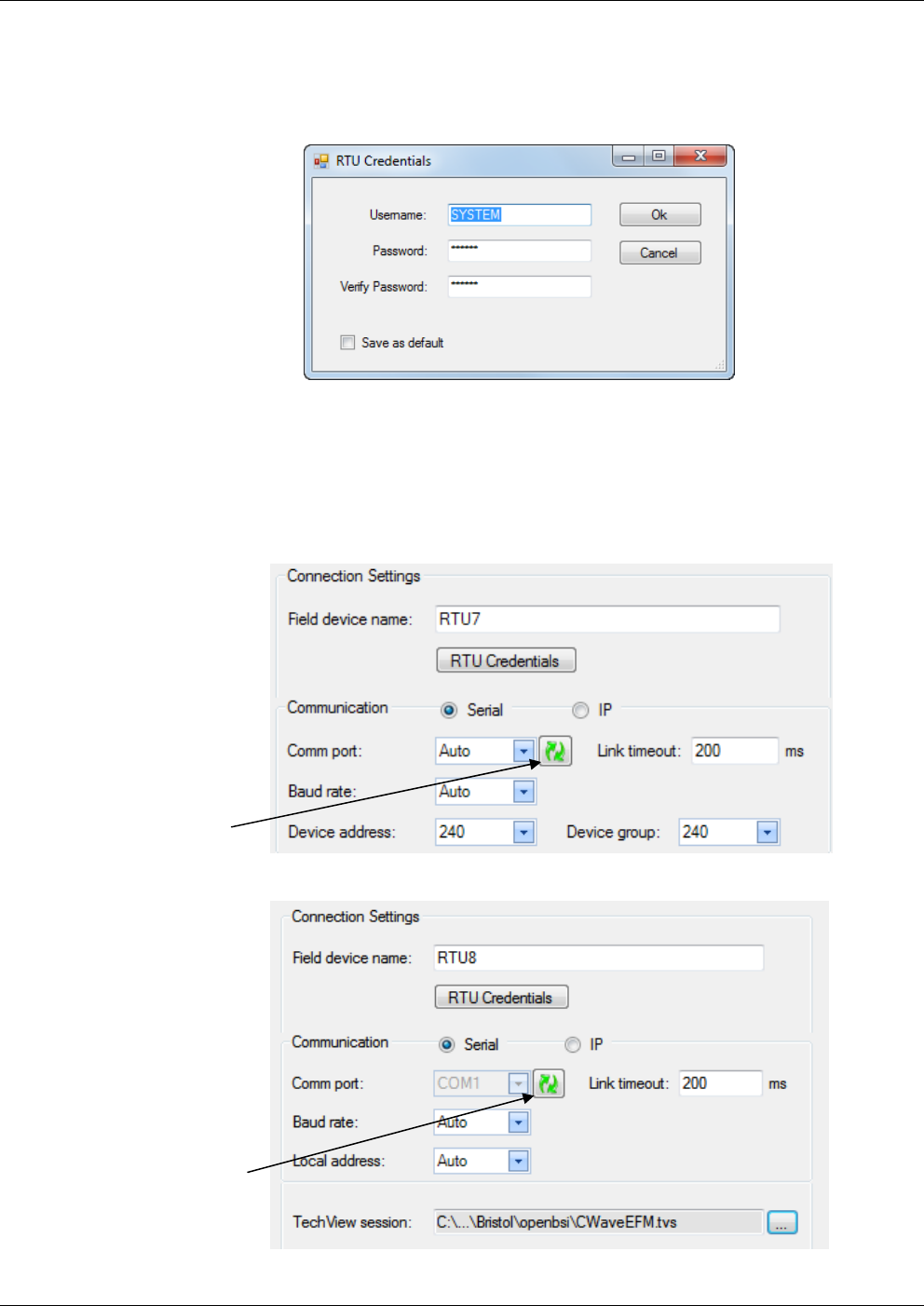
Figure 3-10. RTU Credentials dialog box
6. Using the buttons, select the type of connection, either Serial or IP.
Proceed to Step 7 for serial communication; skip to Step 8 for IP
communication.
7. For serial communication:
Figure 3-11. Serial Connection Settings - ROC/FloBoss
Figure 3-12. Serial Connection Settings – ControlWave/33xx
Refresh button
Refresh button

OpenEnterprise Field Tools™ Quick Start Guide
3-10 Communication Setup Issued Dec-2014
Select the PC communication port in the Comm port drop down
menu, otherwise leave it at the Auto default which causes the
New Connection Wizard to cycle through the various ports until
it finds the correct one. You can refresh the port selections by
clicking the refresh button.
Specify the Link Timeout for this connection. That is the period
of time (in milliseconds) Field Tools waits for a response from
the RTU or flow computer before declaring a communication
failure. If you enter 0 Field Tools uses a default of 200
milliseconds. If the RTU is a ROC/FloBoss in a Distributed
RTU™ Network, see Section 3.1.8.
If you know the baud rate for communicating with the field
device, you can specify it in the Baud rate drop-down field,
otherwise leave it at the Auto default which causes the New
Connection Wizard to cycle through various baud rates until it
finds the correct one. The supported baud rates are: 9600, 19200,
38400, 57600 and 115200.
For ROC/FloBoss units only: Specify the Device address and
Device group. These range from 0 to 255. Normally you should
leave these both at 240 which are for local connections on the
LOI port.
For ControlWave/Network 3000 units only: If you are not
connected to the local port or BSAP slave port (as specified in
the ControlWave project or ACCOL load, respectively) but you
know the BSAP local address for the field device, you can
specify it in the Local Address drop-down field, otherwise leave
it at the Auto default which causes the New Connection Wizard
to try each address in the range (1 to 127) until it finds the
correct one. Use the […] button to specify the TechView session
file you want to use with this controller / flow computer. The
TechView session file must reside on this laptop PC.
Note: The Auto options are useful if you do not know the
communication port, baud rate, or (for ControlWave/33xx only)
the local address. If you leave all of these fields at Auto,
however, it could take considerable time to establish the
connection since the system must successively try each port,
each of the five supported baud rates, and for ControlWave/33xx
each of 127 possible local addresses.
The maximum number of connection attempts if all fields are
left at Auto for a ROC/FloBoss is (# of serial ports) * 5.
The maximum number of connection attempts if all fields are
left at Auto for a ControlWave/33xx is (# of serial ports) * 635.
When you’ve completed this step, go to Step 9.
8. For IP communication:
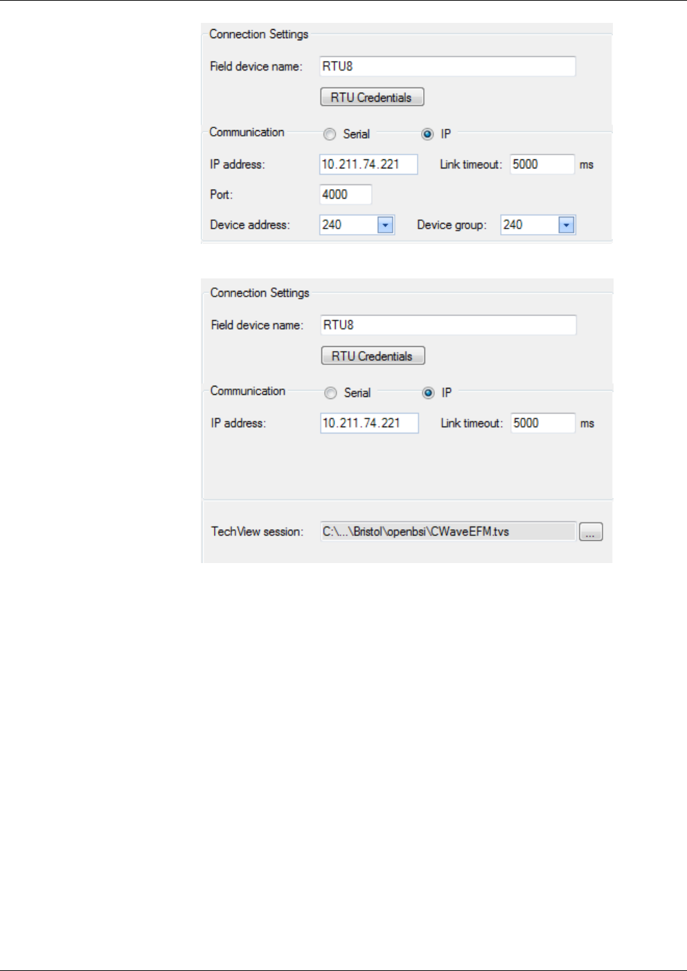
OpenEnterprise™ Field Tools Quick Start Guide
Issued Dec-2014 Communication Setup 3-11
Figure 3-13. IP Connection Settings – ROC/FloBoss
Figure 3-14. IP Connection Settings – ControlWave/33xx
Specify the IP address of the RTU. Position your cursor in the
left-most digit position of the IP address field, enter the value
for that position and use the tab key to move to the next position
and so on until you enter the complete IP address.
Specify the Link Timeout for this connection. That is the period
of time (in milliseconds) Field Tools waits for a response from
the RTU or flow computer before declaring a communication
failure. If you enter 0 Field Tools uses a default of 5000
milliseconds. If the RTU is a ROC/FloBoss in a Distributed
RTU™ Network, see Section 3.1.8.
For ROC/FloBoss units only: Specify the Port (socket) number.
The default is 4000. Specify the Device address and Device
group. These range from 0 to 255. Normally you should leave
these both at 240 which are for local connections on the LOI
port.
For ControlWave/Network 3000 units only: Use the […] buttons
to specify the TechView session file. The TechView session file
must reside on this laptop PC.
OpenEnterprise Field Tools™ Quick Start Guide
3-12 Communication Setup Issued Dec-2014
Note: If you make an invalid entry in one of the New Connection
wizard fields, a warning icon blinks, and you must correct the
invalid entry.
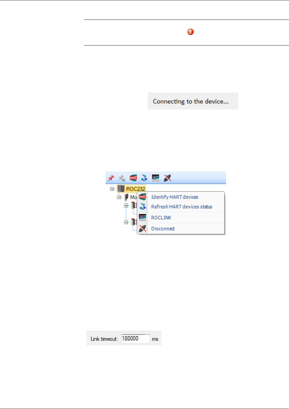
9. If you don’t want to activate the connection right now, but just want
to save your configuration entries, you can click Save; this saves
your entries in the Connection list, and exits the wizard. If you want
to connect right now, click Connect and the wizard attempts to
establish the connection.
Figure 3-15. Connection in progress
10. If the connection is successful, the Active connection pane of the
Field Tools main screen displays an icon for the newly connected
device and its toolbar populates with icons appropriate to the device
type. You can right-click on the device to launch associated
configuration tools (if they’ve been installed previously).
Figure 3-16. Launching Tools
3.1.8 Communication Timeout on Distributed RTU™ Network
If you are using Field Tools’ AMS Device Configurator to communicate
with a device on a ROC/FloBoss Distributed RTU™ Network, you may
need to increase the link timeout to allow enough time for data to reach
the device below the distributed RTU node, and for its response to come
back through Field Tools.
You set the link timeout (in milliseconds) when configuring connection
settings.
Besides changing the timeout here, you must also manually edit AMS
Device Configurator’s initialization file FMS.INI located in the
C:\Windows folder. In the [RAS Network] section of the file, specify a
corresponding timeout (in seconds):
HighLatencyTimeoutSeconds=180
LowLatencyTimeoutSeconds=180
OpenEnterprise™ Field Tools Quick Start Guide
Issued Dec-2014 Communication Setup 3-13
3.1.9 Making a Direct Connection
The term direct connection refers to a direct serial connection to a
device. (For HART devices, see Chapter 4 for information on the
HART USB interface and configure that before you make a direct
connection.)
The Direct Connect toolbar icon appears when you position the
cursor on the Add Connection icon in the Connections list tree. When
you click the Direct Connect icon, you select the type of device from
options presented, and Field Tools attempts to establish a local serial
connection by sequentially trying each serial port using the default
settings for that device type.
3.1.10 Active Connection pane
The Active Connection pane shows details for the currently active
connection, and allows you to launch AMS Device Configurator and
other installed configuration tools for use with the device(s) on that
current connection.
Figure 3-17. Active Connection Pane
To see information about a device (RTU, flow computer, HART device)
move the cursor over that device and a small status box opens that
shows details based on the type of device. This could include its
address, or certain status information.
To launch a tool associated with the device, right-click on the device
icon. See Section 3.1.11 through Section 3.6 for more information.
OpenEnterprise Field Tools™ Quick Start Guide
3-14 Communication Setup Issued Dec-2014
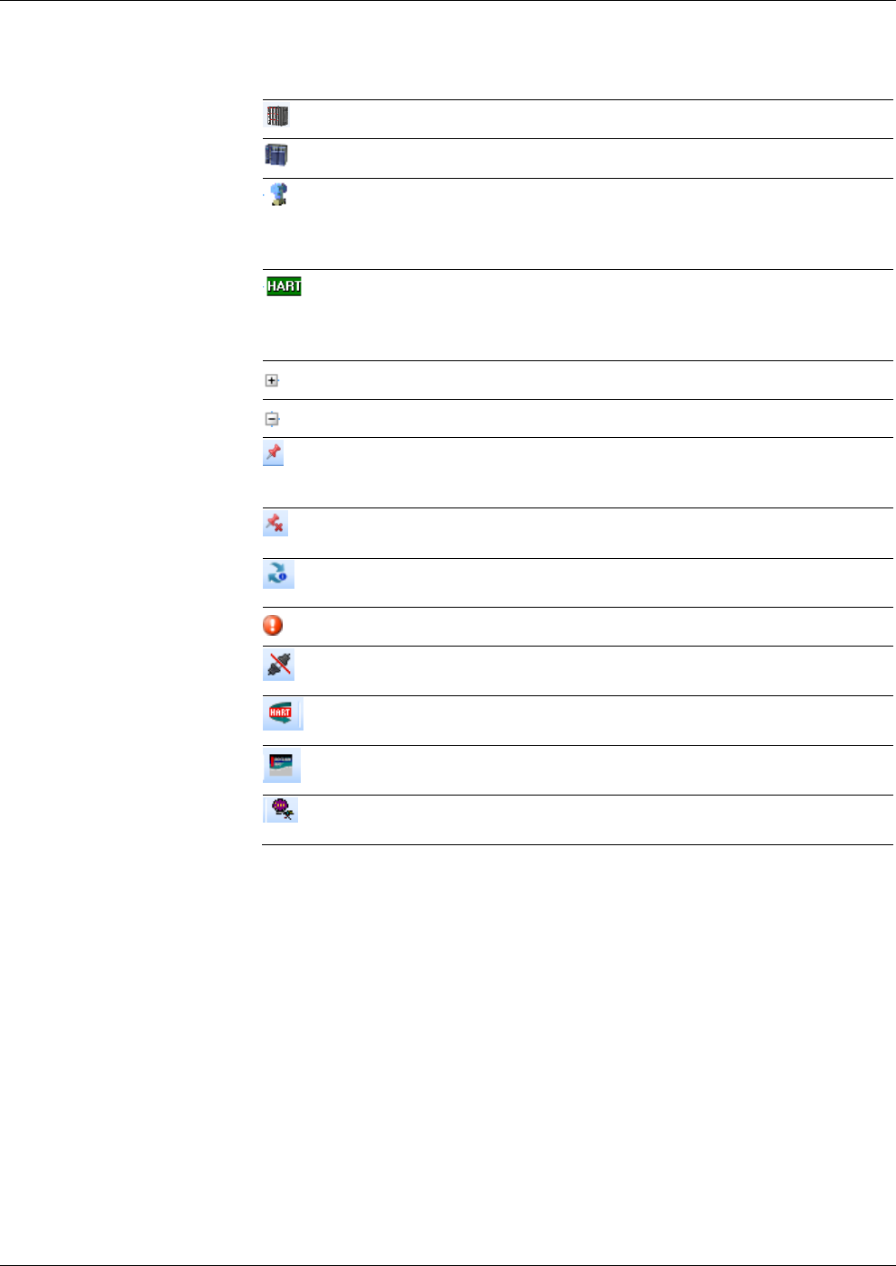
Table 3-2. Icons Used in Active Connection Pane
Icon Description
ROC or FloBoss controller
ControlWave or Network 3000 (33xx) controller connection
Device icon(s). Note: The device icons are supplied through the
device descriptor (DD) files for the device; therefore depending upon
the type of HART or WirelessHART devices you see, you will see
different device icons.
HART device. A green generic HART device icon displays if the
device has a conditional icon, but has not been scanned. A scan of
the device and a refresh of the hierarchy in Field Tools should display
the proper device icon.
Expand branch – click on this to expand this branch of the tree.
Hide branch – click on this to hide the portion of the tree underneath.
Apply Pin –Click this to display only the portion of the tree below the
current position of the cursor. This is useful if you have a large tree
with many items and you only want to see a portion of it.
Remove Pin – Click here to turn off the Apply Pin option and display
the entire tree.
Refresh HART devices status. Updates the status for HART devices
in the Active Connection pane.
Failure – Indicates some sort of failure associated with this device.
Terminate Connection – Click here to shutdown the active
connection. Field Tools prompts you to confirm this action.
Click this to identify HART and WirelessHARTdevices; AMS Device
Configurator runs and auto-detects these devices.
Click this to launch ROCLINK. (ROCLINK must have been installed
previously.)
Click this to launch TechView. (TechView must have been installed
previously.)
3.1.11 Saving Connections / Importing Connections
If you have configured a group of connections, you can save the
connection configuration details in an XML file. You can then transfer
that XML file to another PC/laptop running Field Tools, so that you
don’t need to re-create the connections on that PC, you can just click on
them to start the connection.
Saving
Connections Right-click on the name of a site (or ALL) if you don’t have other sites,
and click Site > Export connection data.
Specify a filename for the XML file.
Importing
Connections Right-click on the name of a site (or ALL) if you don’t have other sites,
and click Site > Import connection data. Navigate to the XML file that
contains the connection information and click Ok.
OpenEnterprise™ Field Tools Quick Start Guide
Issued Dec-2014 Communication Setup 3-15
3.2 Launching ROCLINK
Note: ROCLINK (the ROC and FloBoss configuration tool) is not
included in Field Tools installer; you must have purchased and
installed it separately in order to launch it from within Field
Tools.
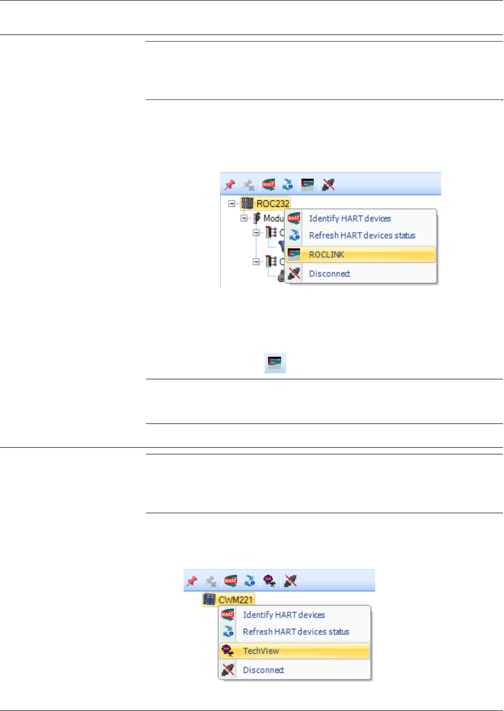
To launch ROCLINK configuration software, either:
Right-click on the icon for the ROC or FloBoss device and choose
ROCLINK from the pop-up menu.
Figure 3-18. Launching ROCLINK
-or-
Left-click on the icon for the ROC or FloBoss device and then click
the ROCLINK icon .
Note: Once you establish communications using ROCLINK, do not
change communication connection parameters within the
ROCLINK software because this interferes with OE Field Tools.
3.3 Launching TechView
Note: TechView (the ControlWave and Network 3000 configuration
tool) is not included in Field Tools installer; you must have
installed it separately in order to launch it from within Field
Tools.
To launch TechView configuration software, either:
Right-click on the icon for the ControlWave/33xx device and choose
TechView from the pop-up menu.
Figure 3-19. Launching TechView
OpenEnterprise Field Tools™ Quick Start Guide
3-16 Communication Setup Issued Dec-2014
-or-
Left-click on the icon for the ControlWave device and then click the
TechView icon .
Note: Once you establish communications using TechView, do not
change communication connection parameters within the
TechView software because this interferes with OE Field Tools.
3.4 Identifying HART Devices
If you have HART or WirelessHART devices connected below your
ControlWave/ROC/FloBoss field device they are automatically
identified when you first establish your connection. If you add an
additional device, you can do the following:
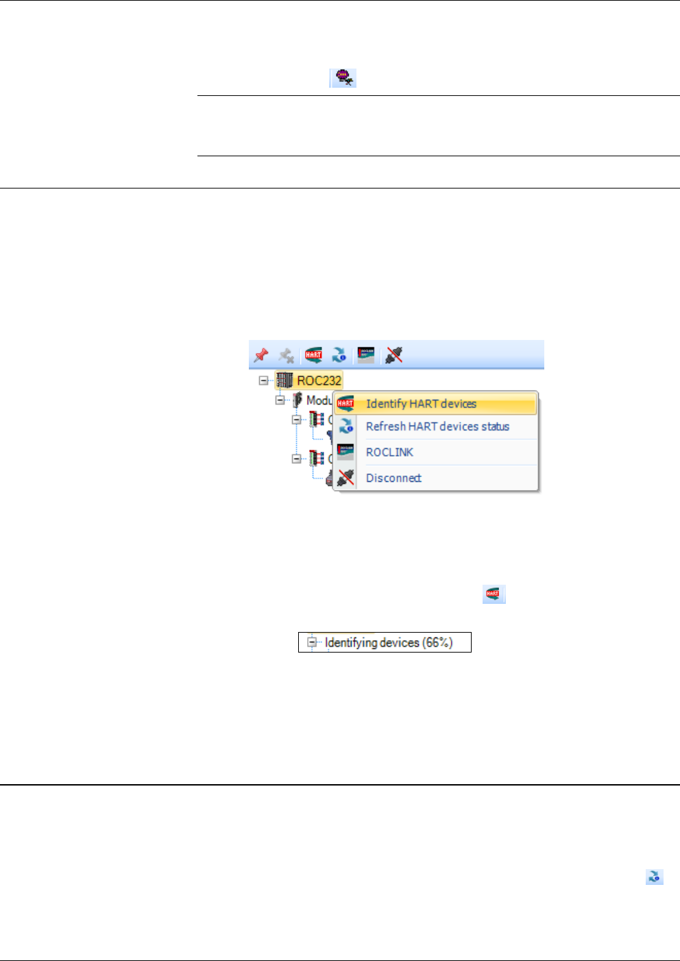
Right-click on the icon for the controller or flow computer to which
the HART devices are attached and choose Identify HART devices
from the pop-up menu.
Figure 3-20. Identifying HART Devices
-or-
Left-click on the icon for the controller or flow computer and then
click the Identify HART Devices icon .
In either case, the software performs an auto-discovery operation to
add the various HART devices to the project tree. As long as the text
“Identifying Devices” remains visible, the auto-discovery is still in
progress.
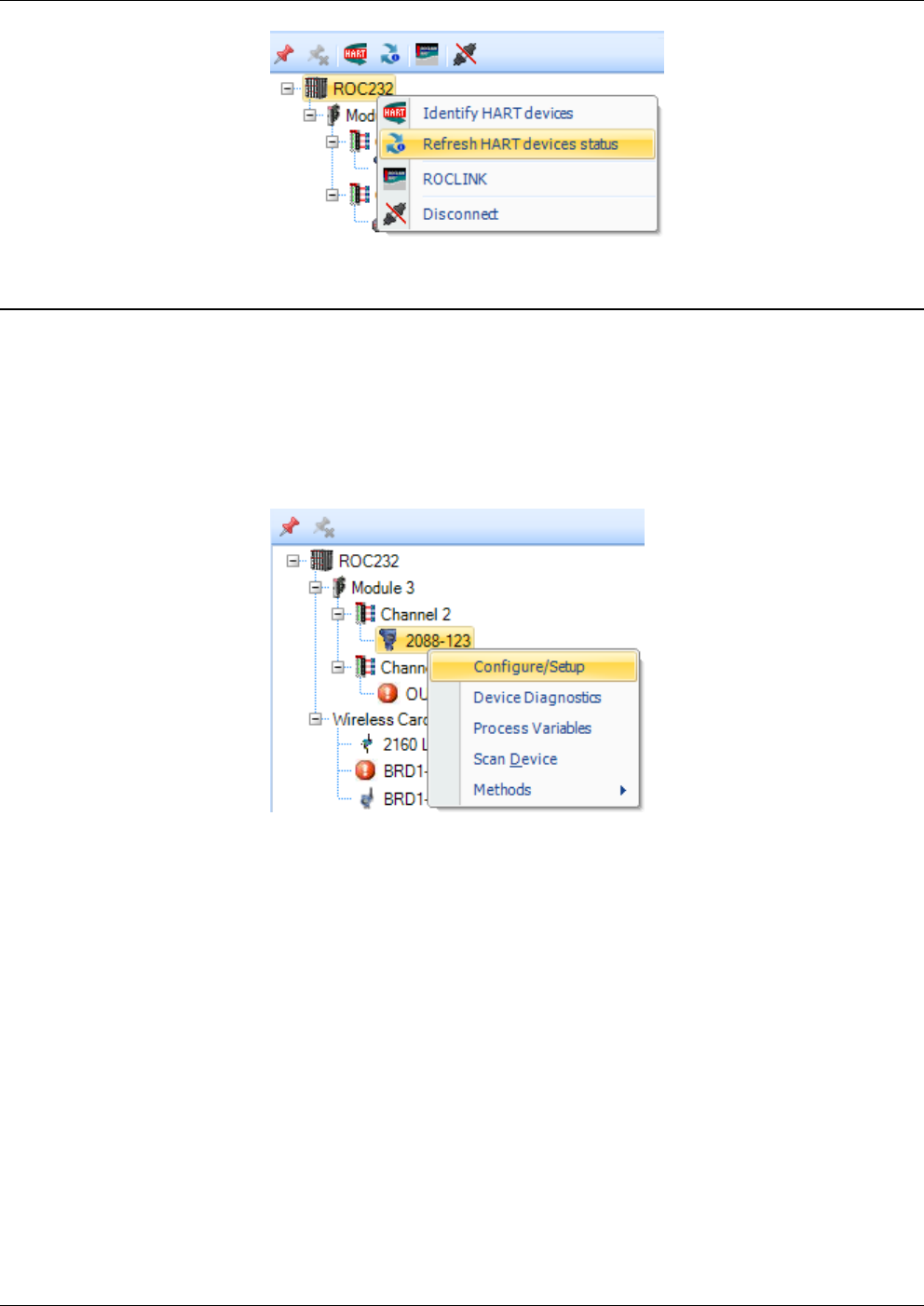
3.5 Refreshing the HART Device Status
To refresh the status of HART devices in the Active pane tree, right-
click on the icon for the controller or flow computer to which the HART
devices are attached and choose Refresh HART devices status from
the pop-up menu. Alternatively, left click on the icon for the controller
or flow computer, then click the Refresh HART devices status icon .
OpenEnterprise™ Field Tools Quick Start Guide
Issued Dec-2014 Communication Setup 3-17
3.6 Launching AMS Device Configurator
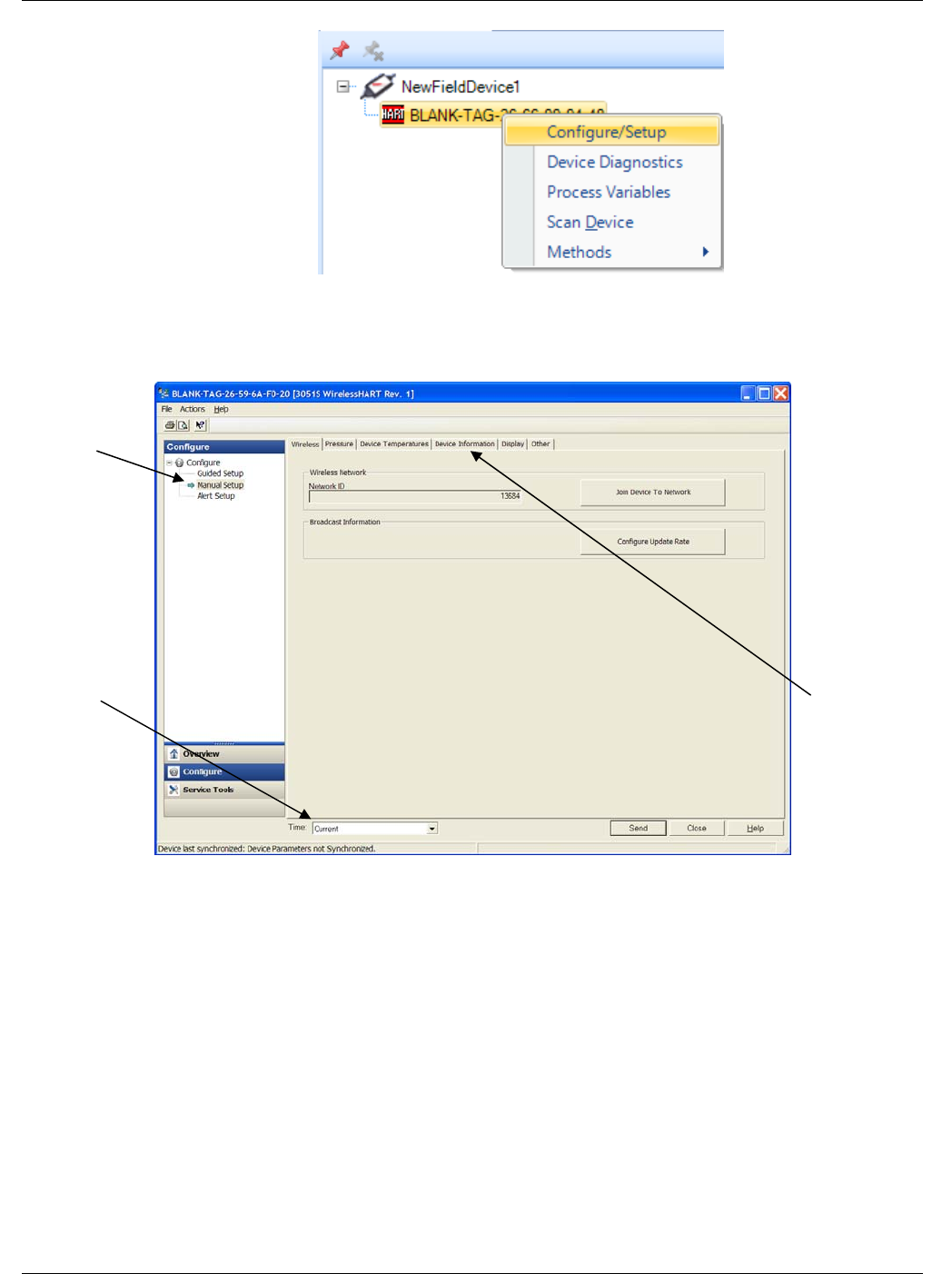
Once a HART device exists in the project tree, you can right-click on its
icon to launch features in the AMS Device Configurator software.
Select Configure/Setup from the HART context menu to configure the
HART device.
Alternatively, you can bring up the Configure/Setup item (the first item
in the menu) by just double-clicking on the icon for the HART device.
Figure 3-21. AMS Device Configurator options
The HART Device context menu items Configure/Setup, Device
Diagnostics and Process Variables open up an AMS Device
Configurator Device Window. The Scan Device and Methods items
will be different depending on the device type and may open a dialog
for a specific function like Scan Device which will launch the Scan
Manager. For more information consult the AMS Device Configurator
online help.
OpenEnterprise Field Tools™ Quick Start Guide
3-18 Communication Setup Issued Dec-2014
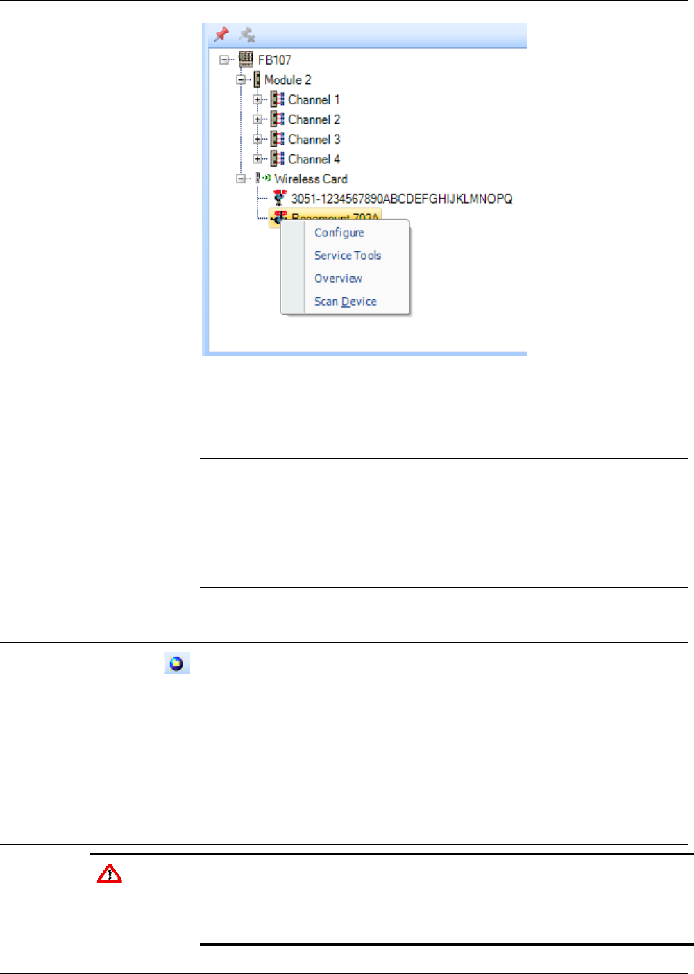
Figure 3-22. HART Device Context Menu
These HART Device context menu items will open up a Device
Dashboard in AMS Device Configurator
Notes:
These devices organize key information at your fingertips and allow you
to quickly act on alerts. For these devices:
Process Variables view is identified as Overview.
The Device Diagnostics view is identified as Service Tools.
The Configure/Setup view is identified as Configure.
3.7 Adding a HART Device Type
If you have a HART device with a device descriptor (DD) unknown to
the system, you can add that device type. You must know the location o
f
the DD file to proceed.
Click HART > Add HART device type.
Refer to the online help in the AMS Device Configurator for more
information on adding the HART device type.
3.8 Launching the AMS Wireless SNAP-ON
Caution The default parameters in AMS Wireless SNAP-ON are set to work optimally
with approximately 10 devices. If, in the ControlWave environment, you
experience challenges or need to manage more devices, contact Remote
Automation Solutions Technical Support for information on setting the
appropriate parameter values.
OpenEnterprise™ Field Tools Quick Start Guide
Issued Dec-2014 Communication Setup 3-19
If you have it installed, you can launch the AMS Wireless SNAP-ON
software provided that AMS Device Configurator is running.
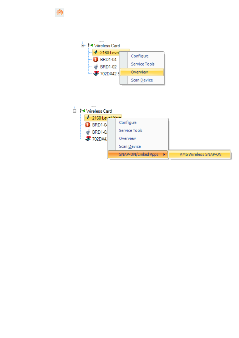
1. In the Active connection pane, click on the wireless device and call
up an AMS menu, such as the Overview display:
2. Once the AMS menu is retrieved, right click on the wireless device
and click SNAP-ON/Linked Apps > AMS Wireless SNAP-ON.
This page is intentionally left blank

OpenEnterprise™ Field Tools Quick Start Guide
Issued Dec-2014 Setting the Network ID, Join Key, Long Tag 4-1
Chapter 4 – Using AMS Device Configurator Software
OpenEnterprise Field Tools’ AMS Device Configurator software works
with both wired HART and WirelessHART devices.
Before you can include a WirelessHART device in your network, you
must configure the long tag name, network ID, and join key parameters.
You can accomplish this using either a hand-held Rosemount 375/475
Field Communicator, or by using AMS Device Configurator software
and a HART modem. This chapter describes the method using the AMS
Device Configurator software and a HART modem.
Field Tools’ AMS Device Configurator can communicate with HART
and WirelessHART devices devices by sending messages through an
RTU (ControlWave, ROC, FloBoss) provided that the RTU supports the
necessary hardware modules needed for this communication. AMS
Device Configurator can also communicate directly with the HART and
WirelessHART devices if the laptop running Field Tools connects to the
device using a HART modem.
Note: The instructions in this chapter only apply to selected HART and
WirelessHART devices manufactured by Rosemount. If you
have WirelessHART devices from a different manufacturer
that you want to include in your WirelessHART network, the
configuration will be different. Refer to the device
manufacturer for information on configuring these devices. For
AMS Device Configurator functions beyond setting the Long
Tag, Network ID, and Join Key, consult the AMS Device
Configurator online help.
In This Chapter
4.1Connecting Directly to the HART or WirelessHART Device ............ 4-2
4.1.1Before You Begin ................................................................. 4-2
4.1.2Smart Wireless THUM™ Adapter and Field Tools ............... 4-2
4.1.3Establishing the Connection ................................................. 4-3
4.2Setting the Long Tag ....................................................................... 4-8
4.3Setting the Network ID and Join Key ............................................. 4-10

OpenEnterprise Field Tools™ Quick Start Guide
4-2 Setting the Network ID, Join Key, Long Tag Issued Dec-2014
4.1 Connecting Directly to the HART or WirelessHART Device
To use AMS Device Configurator software to connect directly to a
HART or WirelessHART device that doesn’t yet belong to a network,
you need a HART modem.
Emerson Remote Automation Solutions recommends the MACTek®
Viator USB HART® Interface. This is the only HART modem Emerson
Remote Automation Solutions supports and has tested.
4.1.1 Before You Begin
The Field Tools installation installs MACTek Viator drivers. If you
need to reinstall them for any reason, run the Setup.exe appropriate
for your operating system (in either the MACTek Drivers 32bit or
64bit folders on the Field Tools installation DVD). Once installed,
see the MACTek Viator USB HART® Interface Users’ Manual and
the Viator help/readme files for more information. These are
installed on your hard disk in the \program files\MACTek
VIATOR Utility\documentation\ folder.
These instructions assume you have a working HART or
WirelessHART device.
If you have a wired HART device for which you want wireless
connectivity through a Rosemount Smart Wireless THUM™
Adapter, review Section 4.1.2 Smart Wireless THUM™ Adapter and
Field Tools.
4.1.2 Smart Wireless THUM™ Adapter and Field Tools
You can use a Rosemount Smart Wireless THUM™ Adapter to provide
wireless connectivity to a wired HART device. If you want to use Field
Tools either to configure the device or to set the network ID, join key,
or long tag in the THUM, you need to:
1. Connect the THUM to the wired HART device.
2. Connect the Viator USB HART interface that connects to Field
Tools to the same 20 mA current source used by the THUM.
Refer to the Bench Top Configuration section in the following
Rosemount document for information on wiring the HART USB
interface to the THUM:
Smart Wireless THUM™ Adapter Quick Installation
Guide,00825-0100-4075, Rev DA, July 2011
Notes: If using an IEC 62591 module in a ROC/FloBoss or
ControlWave device to communicate with wireless devices, both
the THUM and the HART device may be detected by the Smart
Wireless Field Link and included in the Active List, however, it
is only necessary to commission the HART device, not the
THUM adapter.

OpenEnterprise™ Field Tools Quick Start Guide
Issued Dec-2014 Setting the Network ID, Join Key, Long Tag 4-3
4.1.3 Establishing the Connection
1. Connect the USB end of the Viator USB HART interface to the
USB port on your Field Tools laptop PC.
Figure 4-1. Connect Viator USB HART Interface to an open USB Port
2. Connect the other end of the Viator USB HART interface (two test
clips) across the HART or WirelessHART device.
Note: You may find it easier to remove the battery from the HART
or WirelessHART device in order to see the connection
points better. After you connect the clips, re-connect the
battery.
a. To use the test clip, press down on the button at the bottom of
the clip holder to push the test clip out beyond the shield.
Figure 4-2. Test Clip Covered by Shield (left) and Pressing Button to push Clip Out (right)
b. Connect both clips to the communication connectors on the
wireless device.
Shield
Button Test Clip Press the
button to
expose the test
clip
OpenEnterprise Field Tools™ Quick Start Guide
4-4 Setting the Network ID, Join Key, Long Tag Issued Dec-2014
Figure 4-3. Both Test Clips Connected to the Wireless Device
c. If you disconnected the battery to attach the test clips, re-connect
it now.
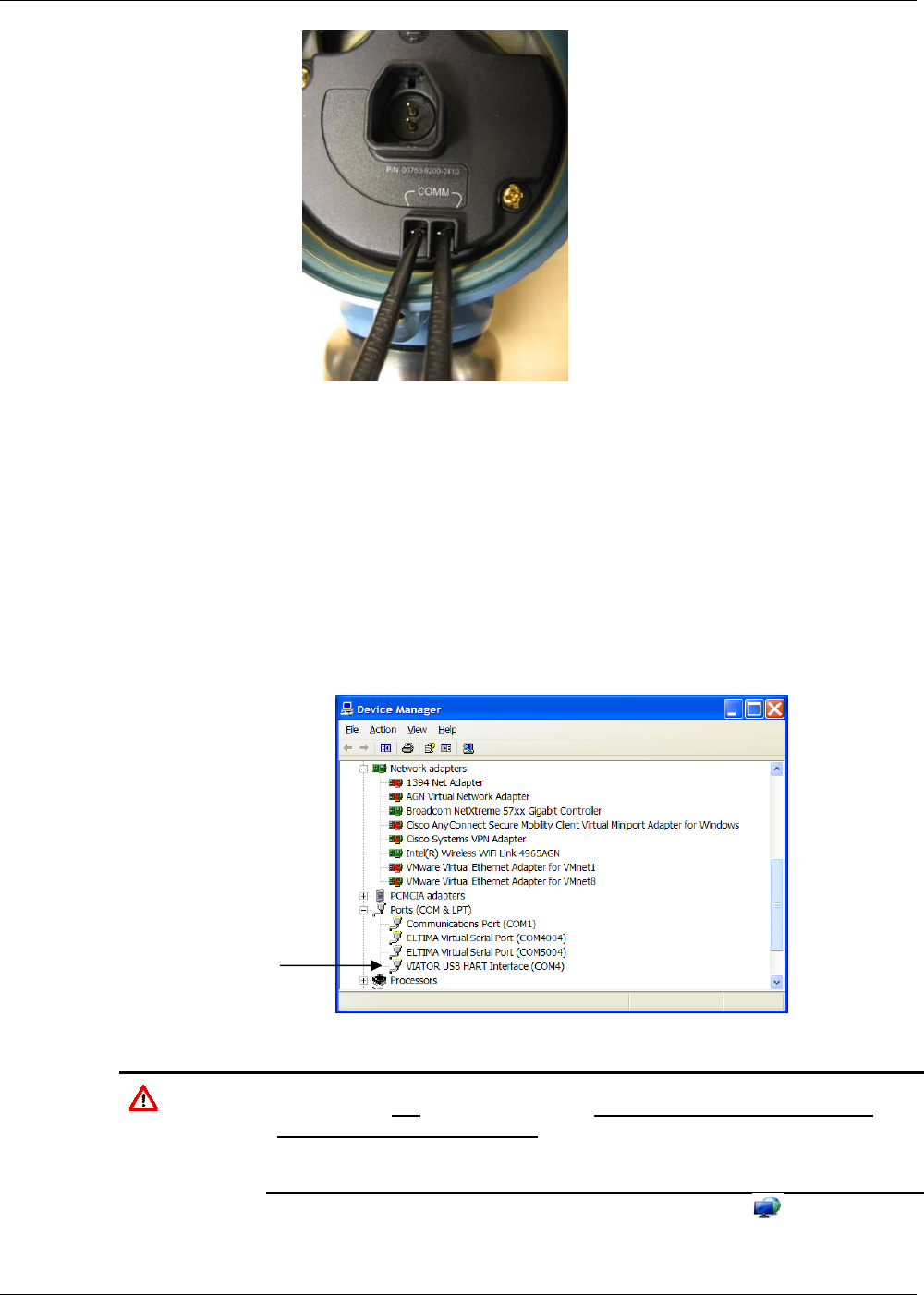
3. You must now verify that there is a COM number associated with
the Viator USB HART interface on the laptop that runs your Field
Tools software:
For Windows 7 users, you can find this out by opening
Windows™ Control Panel and choosing System & Security >
System > Device Manager > Ports and looking for Viator
USB.
Figure 4-4. Viator USB HART Interface in Windows Device Manager
Caution If you cannot locate the Viator USB device under the ports item, its
drivers were not installed correctly. STOP. Do not proceed to Step 4
until you correct this problem – a connection will not be possible until
you resolve this issue. Consult the Viator documentation for more
information.
4. Start OE Field Tools either from the desktop icon or click:
Start>Programs> Emerson OpenEnterprise > Field Tools.
Viator USB HART
Interface installed
(
COM4
)
OpenEnterprise™ Field Tools Quick Start Guide
Issued Dec-2014 Setting the Network ID, Join Key, Long Tag 4-5
5. Log in using a valid username/password combination.
6. Click the Add Connection icon in the toolbar, or double-click
the Add Connection icon in the Connections list or just click File >
Add Connection… (You can also click the Add Connection icon,
and then choose the Direct Connect icon and select HART
from the menu, in which case you would skip steps 7 through 9.)
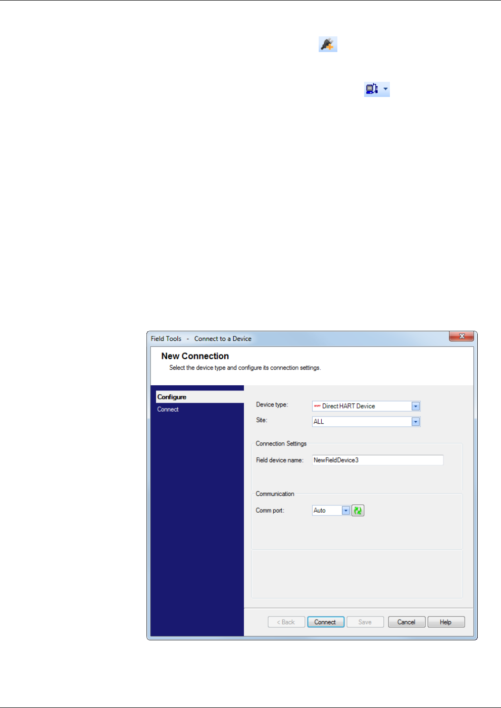
7. In the New Connection wizard, leave the Device type at Direct
HART Device.
8. Choose the Site you want to associate with the
HART/WirelessHART device.
9. Enter a name for the HART/WirelessHART device in the Field
device name field.
10. Specify the Comm port used for the Viator USB HART Interface.
If there is only one serial port; this option is grayed out. If there are
multiple serial ports but you don’t select one and instead choose
Auto, during the connection attempt, Field Tools sequentially tries
each port for a pre-defined number of passes, sending a “Device
Identify” message.
11. Click Connect.
Figure 4-5. Connection Selection
12. You will see the message “Connecting to the device…”
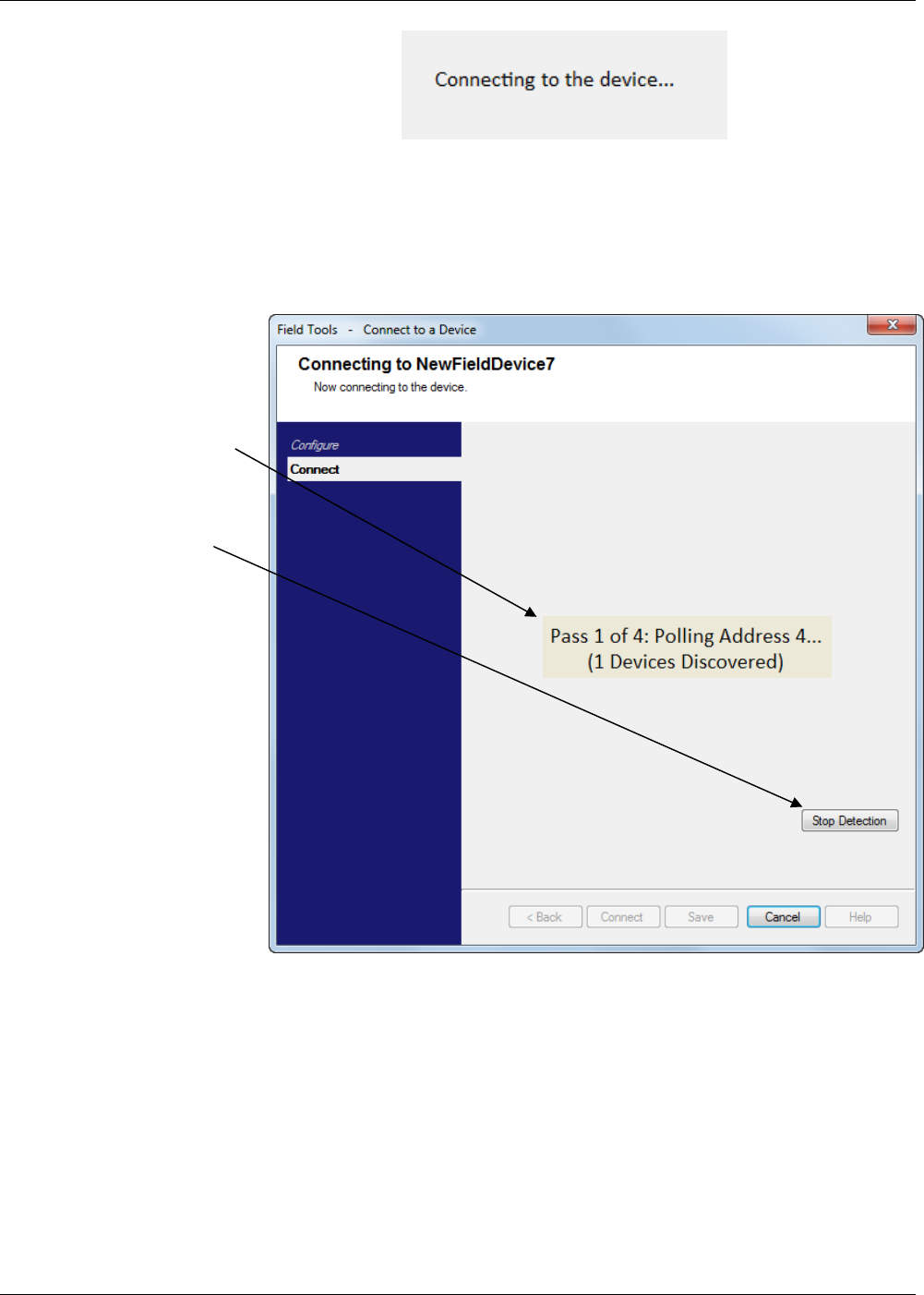
OpenEnterprise Field Tools™ Quick Start Guide
4-6 Setting the Network ID, Join Key, Long Tag Issued Dec-2014
The software then begins polling for the HART or WirelessHART
device at all possible addresses. The software makes up to four
search passes to discover the device before declaring failure. Once it
discovers a device, click Stop Detection and then click Next.
Figure 4-6. Stop Detection Once It Discovers a Device
13. Once Field Tools shows icons for HART and/or WirelessHART
devices in the Active Connection tree, right-click on the icon for the
desired device and choose Configure/Setup from the pop-up menu.
Click Stop
Detection
Once a device
has been
discovered…
OpenEnterprise™ Field Tools Quick Start Guide
Issued Dec-2014 Setting the Network ID, Join Key, Long Tag 4-7
Figure 4-7. Configuring the HART Device
14. This starts AMS Device Configurator software. On the Wireless tab,
click Manual Setup.
Figure 4-8. Manual Setup
15. Make sure the Time field shows Current since we need to
communicate with the live device. If it’s anything else, change it to
Current.
16. Now click the Device Information tab and see Section 4.2 for
information on setting the long tag.
Click Manual
Setup
Make sure
this is always
Current Go to the
Device
Information
tab to set the
Long Tag
OpenEnterprise Field Tools™ Quick Start Guide
4-8 Setting the Network ID, Join Key, Long Tag Issued Dec-2014
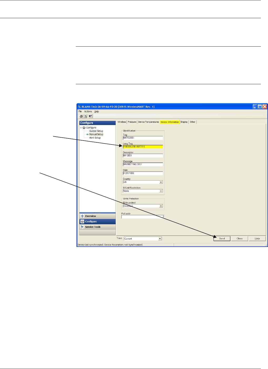
4.2 Setting the Long Tag
To use WirelessHART devices with ROC or ControlWave devices, you
must configure them with long tag names. The long tag name for the
device can be up to 32 characters long.
Note: You will need to know the long tag you set here later during
configuration / commissioning in ROCLINK or ControlWave
Designer. See the IEC62591 Wireless Interface Manual specific
to your RTU/flow computer (ROC or ControlWave) for more
information on that subject.
1. On the Device Configuration tab, enter the long tag name in the
Long Tag field and click Send.
Figure 4-9. Setting the Long Tab
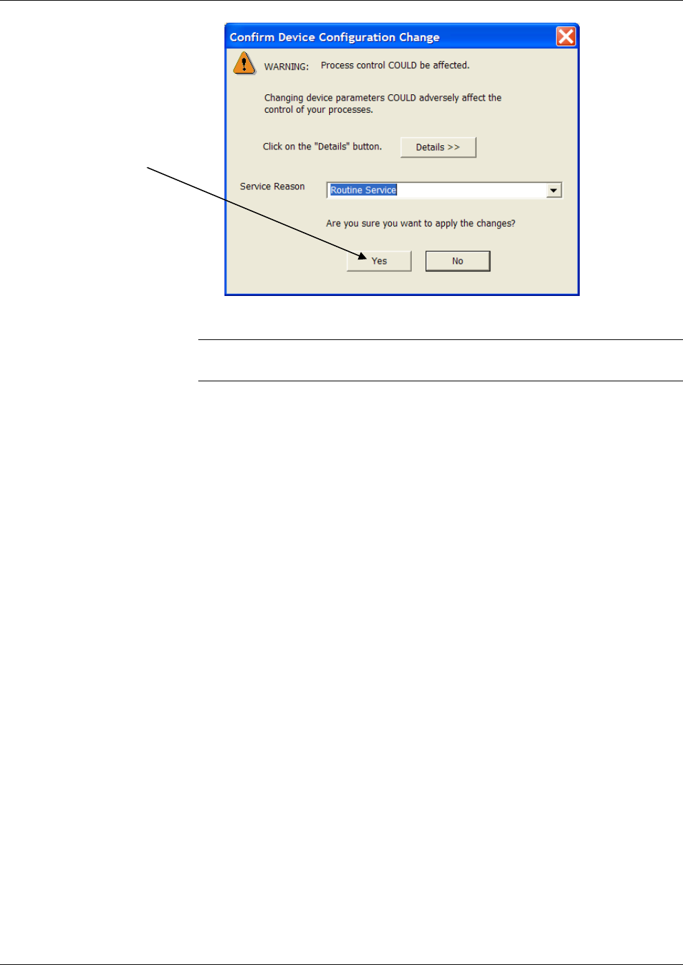
2. The software prompts you to confirm the update to the device. Click
Yes to proceed and update the tag in the device.
Set the Long
Tag here. You
can enter up to
32 characters.
When you’re
done, click
Send.
OpenEnterprise™ Field Tools Quick Start Guide
Issued Dec-2014 Setting the Network ID, Join Key, Long Tag 4-9
Figure 4-10. Confirm the Change
Note: The title bar does not update with the long tag until the next time
you start the Configurator with this device.
Click Yes
OpenEnterprise Field Tools™ Quick Start Guide
4-10 Setting the Network ID, Join Key, Long Tag Issued Dec-2014
4.3 Setting the Network ID and Join Key
After you establish a connection with the WirelessHART device and
enter manual configuration mode within AMS Device Configurator
software (described in Section 4.1) you can set the Network ID and Join
Key.
A Network ID defines one logical grouping of WirelessHART devices,
all of which send their information to one Field Link.
Note: A Network ID or Join Key cannot be all zeros (such as 0000).
The Join Key is the password that allows a device to access its defined
network. During configuration, you also provide the device with its
network-specific Join Key.
Note: You will need to know the Network ID and Join Key you set
here later during configuration and commissioning in ROCLINK
or ControlWave Designer. See the IEC62591 Wireless Interface
Manual specific to your RTU/flow computer (ROC or
ControlWave) for more information on that subject.
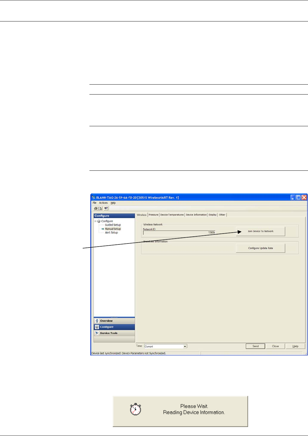
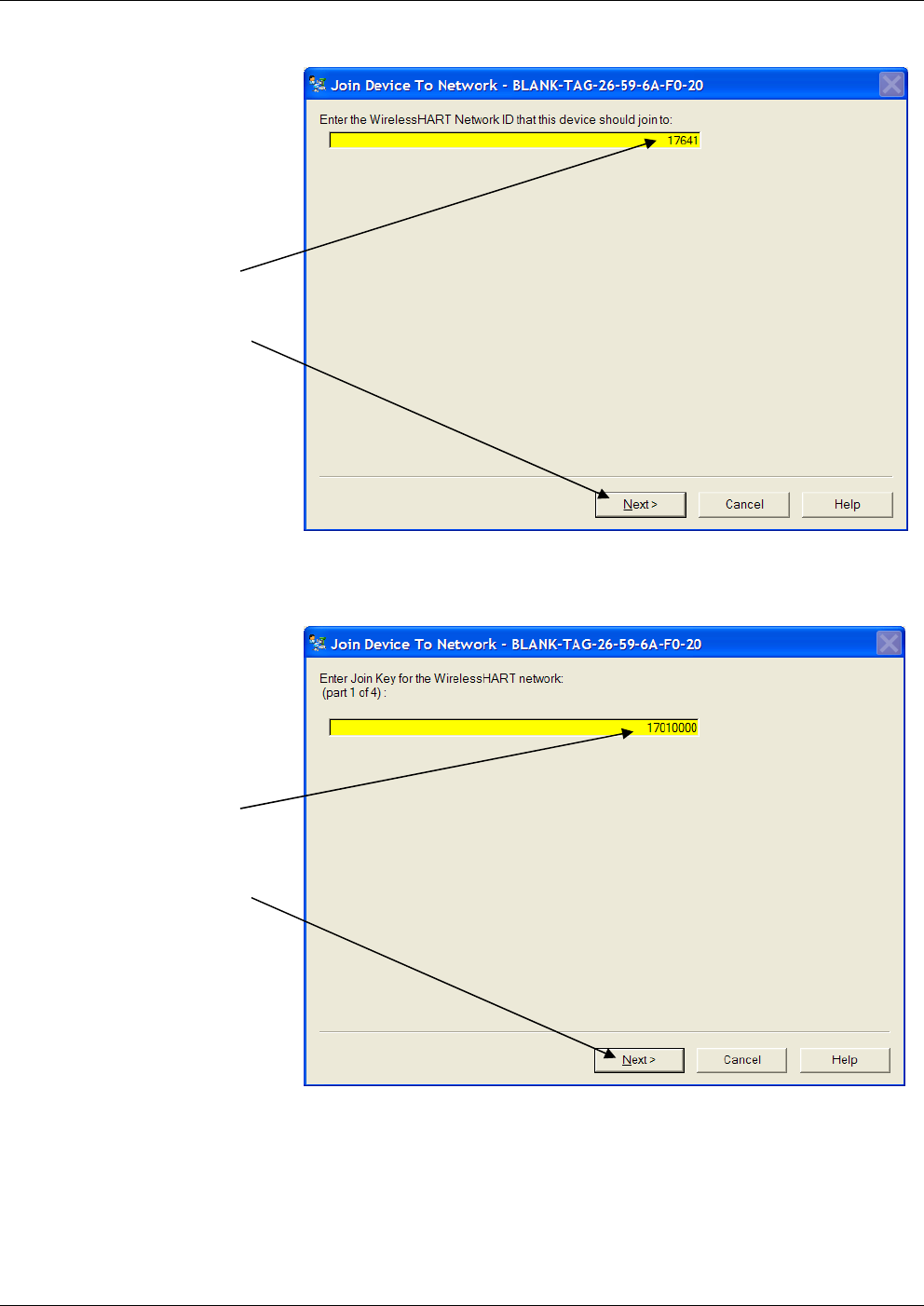
1. The Network ID field on the Wireless tab shows the Network ID.
To set a new Network ID, click Join Device to Network.
Figure 4-11. Network ID
You’ll need to wait for a moment while the software communicates
with the device.
Click Join
Device To
Network
OpenEnterprise™ Field Tools Quick Start Guide
Issued Dec-2014 Setting the Network ID, Join Key, Long Tag 4-11
2. Enter the Network ID in the highlighted field and then click Next.
Figure 4-12. Entering the Network ID
3. Enter the first of four parts of the Join Key and then click Next.
Figure 4-13. Entering the First Part of the Join Key
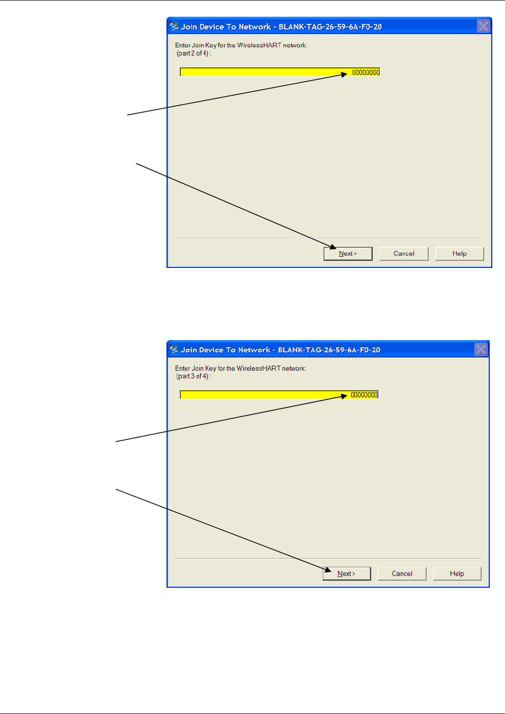
4. Enter the second of four parts of the Join Key and then click Next.
Enter the
Network ID,
and then
click Next
Enter the
1st part of
the Join
Key and
then click
Next
OpenEnterprise Field Tools™ Quick Start Guide
4-12 Setting the Network ID, Join Key, Long Tag Issued Dec-2014
Figure 4-14. Entering the Second Part of the Join Key
5. Enter the third of four parts of the Join Key, then click Next.
Figure 4-15. Entering the Third Part of the Join Key
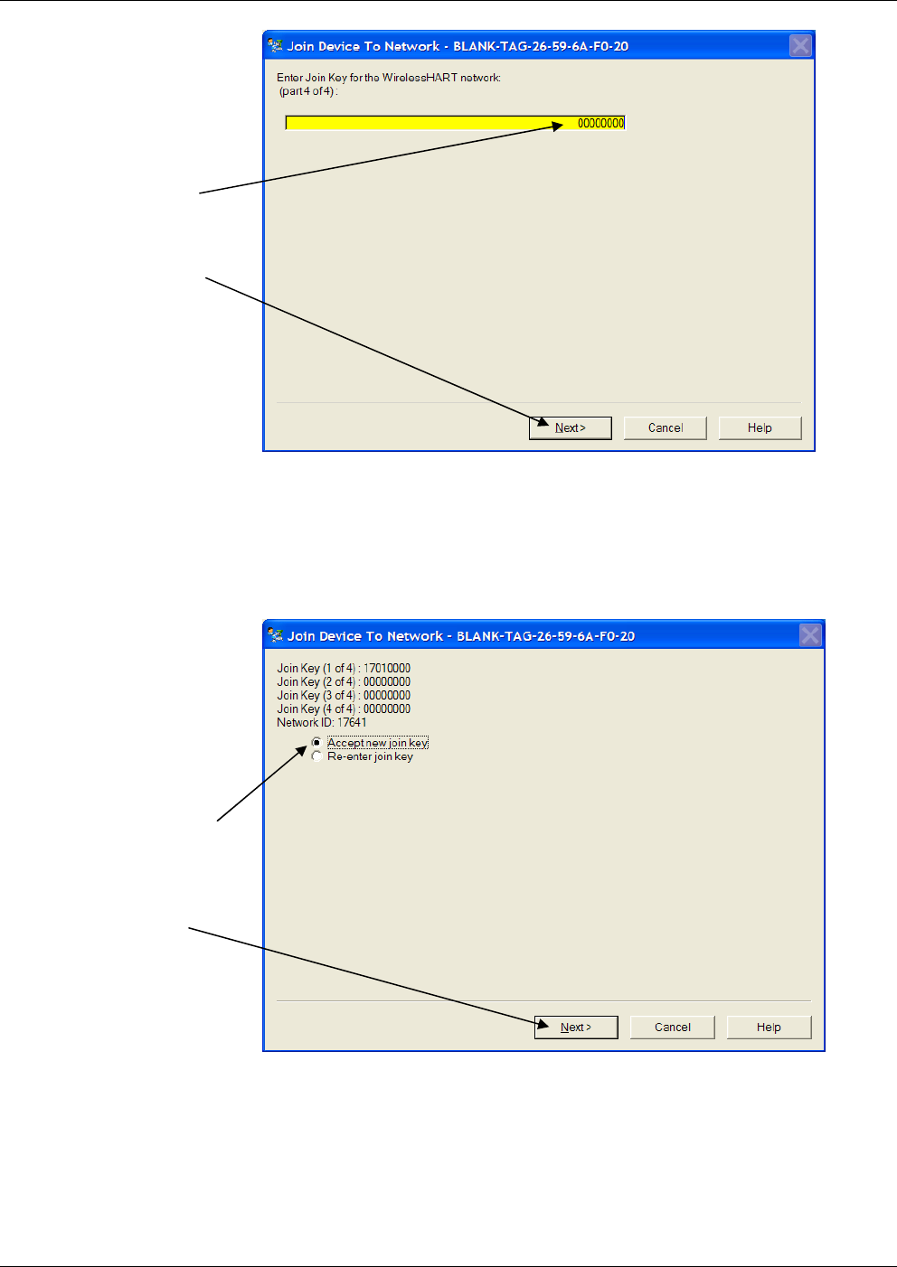
6. Enter the fourth of four parts of the Join Key and then click Next.
Enter the
3rd part of
the Join
Key and
then click
Next
Enter the
2nd part of
the Join
Key and
then click
Next
OpenEnterprise™ Field Tools Quick Start Guide
Issued Dec-2014 Setting the Network ID, Join Key, Long Tag 4-13
Figure 4-16. Entering the Fourth Part of the Join Key
7. Check to see that you entered the Network ID and Join Key
correctly. If you did click Next. If you made a typo or need to
change what you entered, select Re-enter join key and click Next to
go back to Step 2.
Figure 4-17. Confirm the Network ID and Join Key
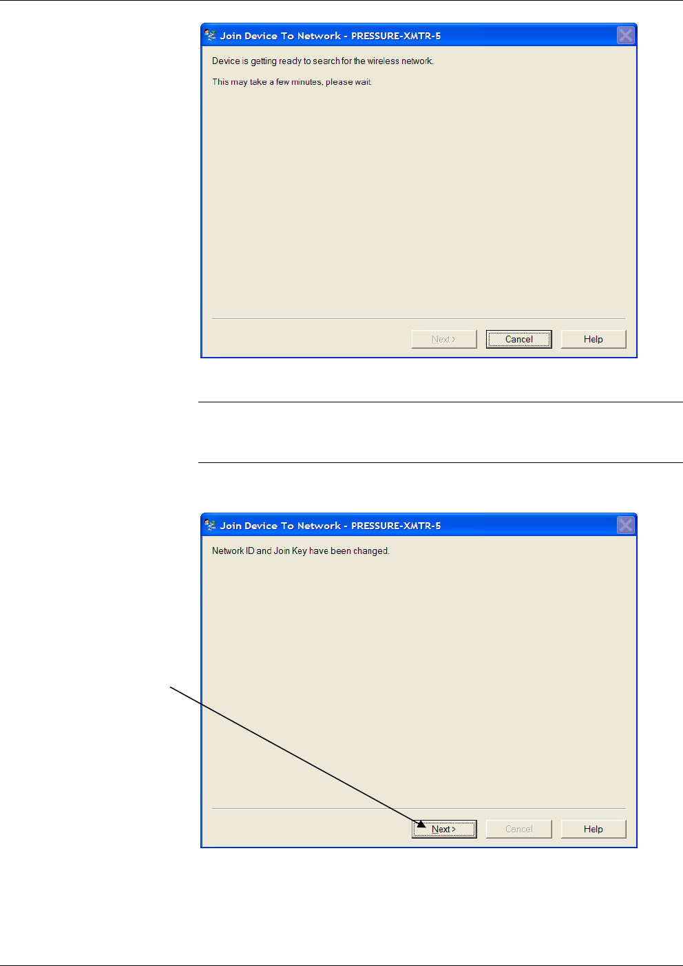
8. The following screen opens; you may need to wait a few minutes.
Enter the
4th part of
the Join
Key, then
click Next
If the
Network ID
and Join
Key are
correct,
accept it
and click
Next
OpenEnterprise Field Tools™ Quick Start Guide
4-14 Setting the Network ID, Join Key, Long Tag Issued Dec-2014
Figure 4-18. Device Searching for Network
Note: If you receive an error message saying that you cannot update the
Network ID and Join Key at this time, see the troubleshooting
information in Appendix A.
9. The following message confirms the update to the Network ID and
Join Key; click Next.
Figure 4-19. Network ID and Join Key Updated
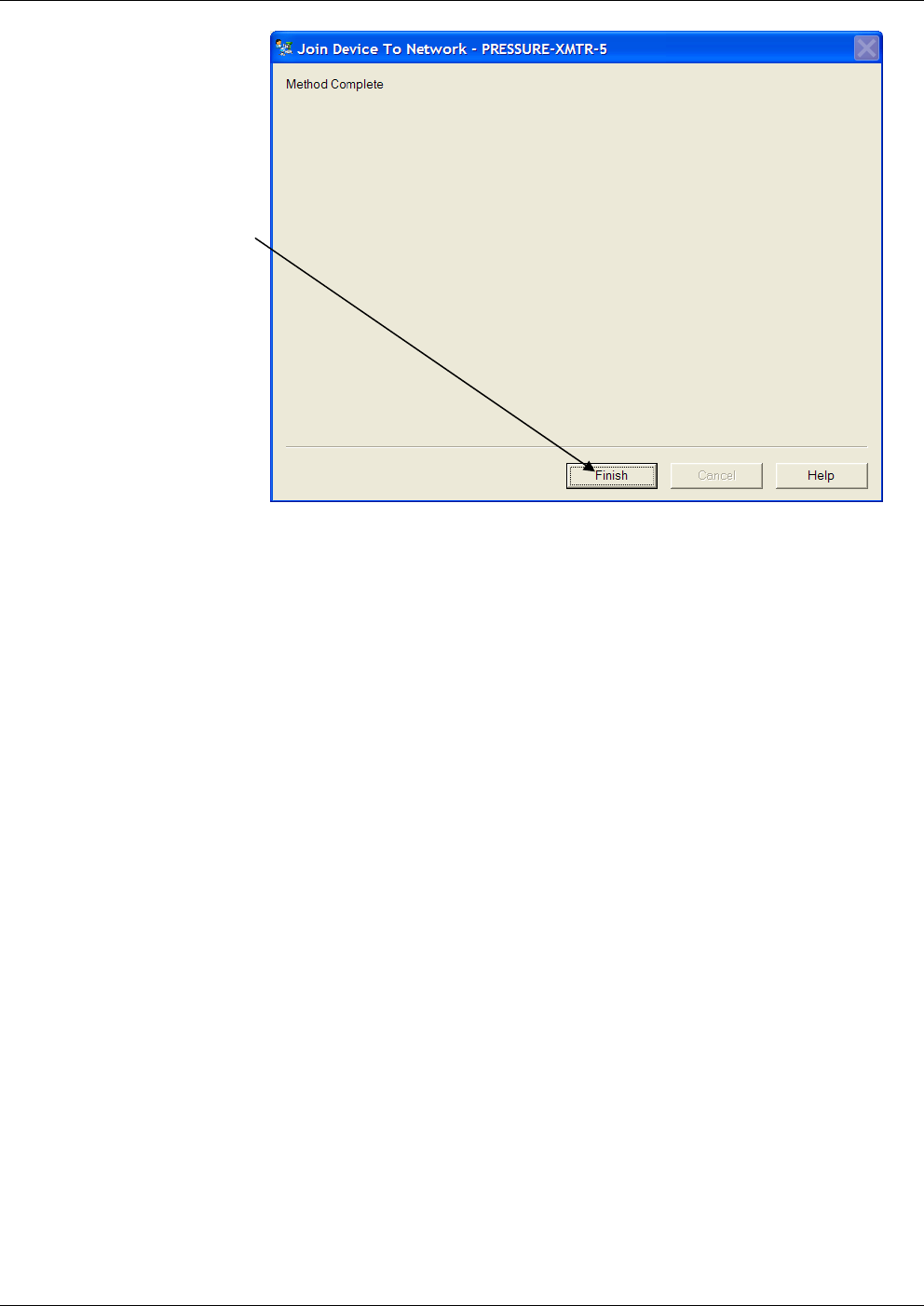
10. Click Finish. You can now exit the AMS Device Configurator
software.
Click Next
OpenEnterprise™ Field Tools Quick Start Guide
Issued Dec-2014 Setting the Network ID, Join Key, Long Tag 4-15
Figure 4-20. Update Finished
Click Finish
This page is intentionally left blank
OpenEnterprise™ Field Tools Quick Start Guide
Issued Dec-2014 Troubleshooting Tips A-1
Appendix A – Troubleshooting Tips
The following are some common problems that may occur, and
procedures for resolving them.
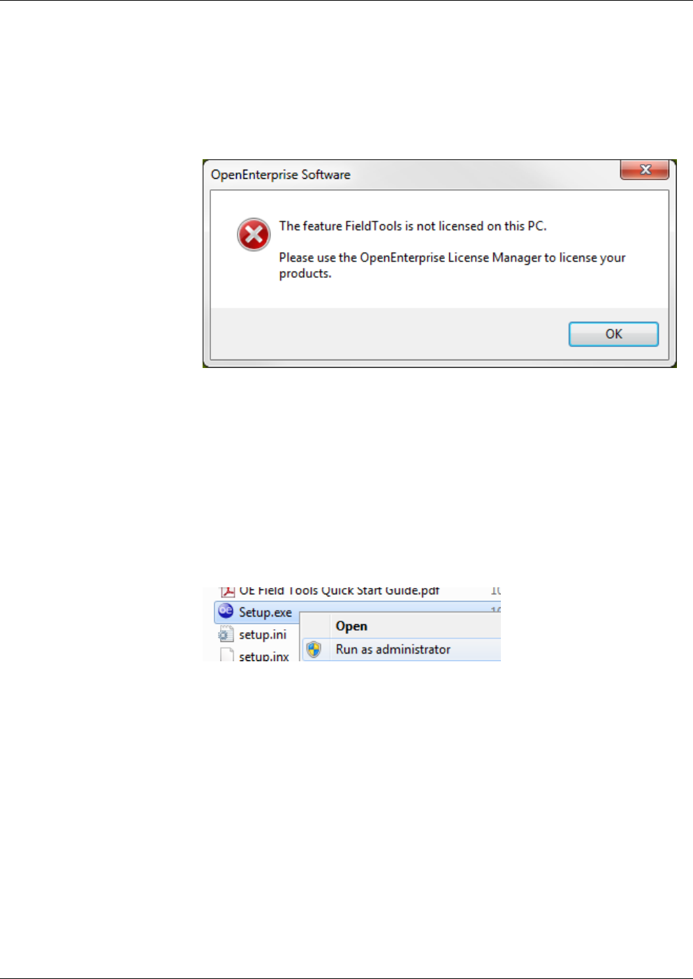
Field Tools won’t start due to not being licensed
Run the License Manager software as discussed in Section 2.4.
“Unlicensed – License file not found” message in License Manager
This can occur if there was a problem during software installation.
1. From the Windows™ Control Panel, uninstall OE Field Tools.
2. To begin the reinstallation, ensure you’ve disabled UAC control.
Insert the OE Field Tools software DVD in your DVD drive, and
browse to the root directory using Windows Explorer.
3. Right-click on Setup.exe and choose Run as administrator.
4. Follow the instructions in Chapter 2 for installation and licensing.
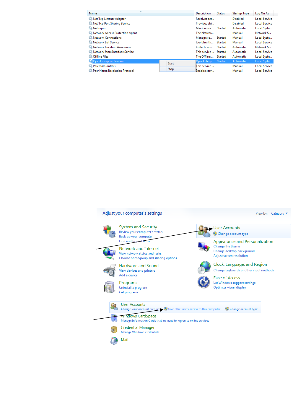
“Failed to connect to Comm Manager” message appears.
You may see this message if something disrupts a communications
connection. Stop and re-start the OpenEnterprise session using these
steps:
1. In Windows Control Panel, double-click Administrative Tools.
2. Double-click Services.
OpenEnterprise Field Tools™ Quick Start Guide
A-2 Troubleshooting Tips Issued Dec-2014
3. Right-click on the OpenEnterprise Session, and choose Stop from
the menu.
4. Right-click on it again, and choose Start from the menu.
Permissions problems with AMS Device Configurator
Certain FieldTool functions require special access rights on your PC.
All Field Tools users (including Administrator users) on the PC must
belong to the AMSDeviceManager group. Normally the system adds
standard users automatically during installation. If you need to add one
or more users after installation, you can add them manually:
These instructions reflect Windows 7:
1. Select User Accounts in the Windows control panel, then choose
Give other users access to this computer.
2. In the User Accounts dialog box, click the Advanced tab, then from
the Advanced tab, click the Advanced button.
Select User
Accounts
Select Give
other users
access to this
computer
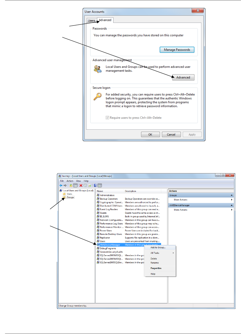
OpenEnterprise™ Field Tools Quick Start Guide
Issued Dec-2014 Troubleshooting Tips A-3
3. In the Local Users and Groups page, click on the Groups folder to
show the groups, then right-click on the AMSDeviceManager group
and select Add to Group from the pop-up menu.
Select the Advanced
tab, then click the
Advanced button.
Click on the Groups
folder, then right-
click on the
AMSDeviceManager
group and select Add
to Group from the
pop-up menu.
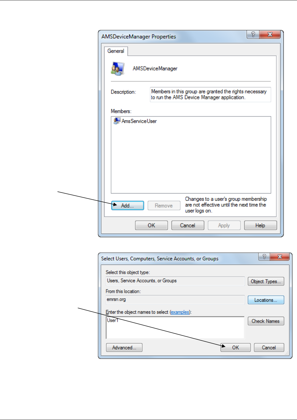
OpenEnterprise Field Tools™ Quick Start Guide
A-4 Troubleshooting Tips Issued Dec-2014
4. In the AMSDeviceManager Properties dialog box, click the Add
button.
5. Enter the name of the user you want to add and click OK.
Click on the Add
button.
Enter the name of
the user you want
to add, then click
OK.
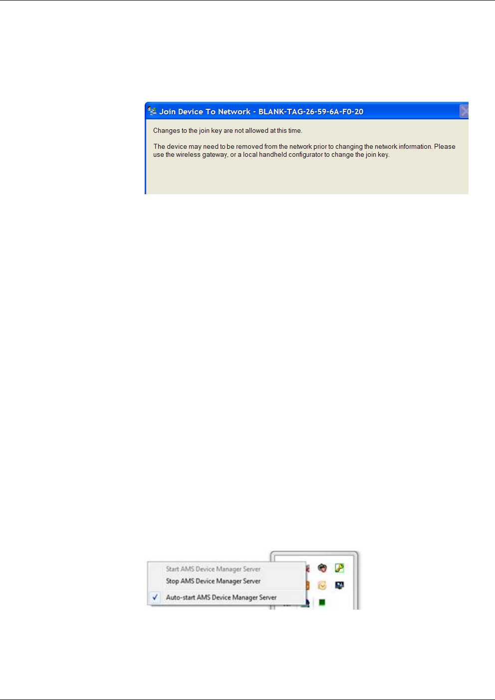
OpenEnterprise™ Field Tools Quick Start Guide
Issued Dec-2014 Troubleshooting Tips A-5
Unable to Update the Network ID and Join Key in AMS Device
Configurator
If you see the following screen when you attempt to update the Network
ID and Join Key, it means that the update failed. Click Next and then on
the Method Complete screen, click Finish.
Changes Not Allowed at this Time
A typical reason for the update to fail is that the device already belongs
to an existing network and so it rejects the update. To try the update
again:
1. Physically disconnect the battery from the wireless device, and leave
it unconnected for at least one minute. This temporarily removes the
device from its existing network.
2. Re-connect the battery, and immediately re-establish a new
communication connection to begin the update process again. You
must do this before the wireless device re-connects to its existing
network.
Cannot Restore Communication with Device after Communication
Failure is Fixed
When a communication failure with a device occurs, AMS Device
Configurator uses archived data for that device and does not try to
communicate with it.
If, when the communication failure is fixed, communications cannot be
restored because AMS Device Configurator still uses archived data, you
can delete the archived data to force AMS Device Configurator to
communicate and obtain current data. To do this:
1. Stop AMS Device Manager Server.
2. Go to the \AMS\Bin folder and double-click on the DelDev.exe
utility. Leave the password field blank in the User Login dialog box;
just click OK.
3. In the Remove Device screen delete the previous device data from
the archive.
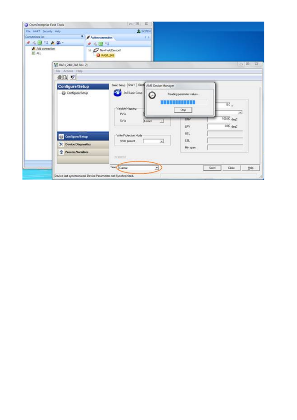
OpenEnterprise Field Tools™ Quick Start Guide
A-6 Troubleshooting Tips Issued Dec-2014
4. Restart AMS server and verify that data shown is current:
Communication Problem Causing Truncated Messages
If you use RTS/CTS with radios, and encounter a problem where Field
Tools can transmit, but RTUs are unable to respond, it could be related
to PC port configuration in Windows which results in messages being
truncated.
If this problem occurs follow these steps:
1. Double-click the System icon in the Windows Control Panel. The
System Properties dialog box opens.
2. Click the Device Manager button:
3. Expand the “Ports (COM & LPT)” selection. This displays a list of
ports.
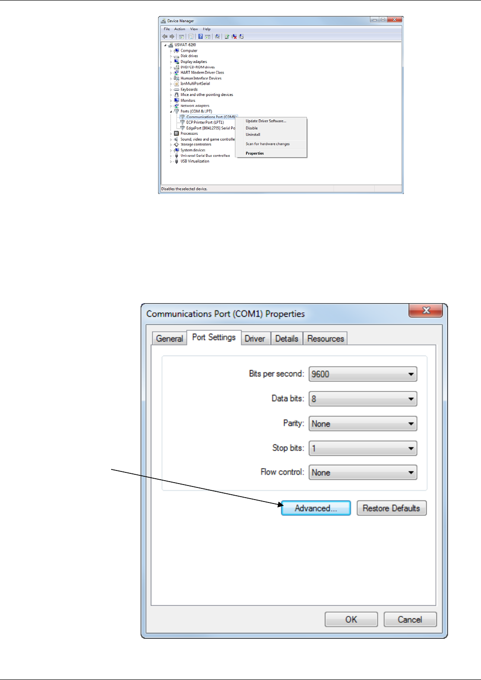
OpenEnterprise™ Field Tools Quick Start Guide
Issued Dec-2014 Troubleshooting Tips A-7
List of Ports in Device Manager
4. Right-click once on the port used for Field Tools communications
and choose Properties from the pop-up menu.
5. The Communication Port Properties dialog box opens; click the
Port Settings tab, then click the Advanced push button to call up
the Advanced Port Settings dialog box.
Communication Port Properties dialog box
Click here
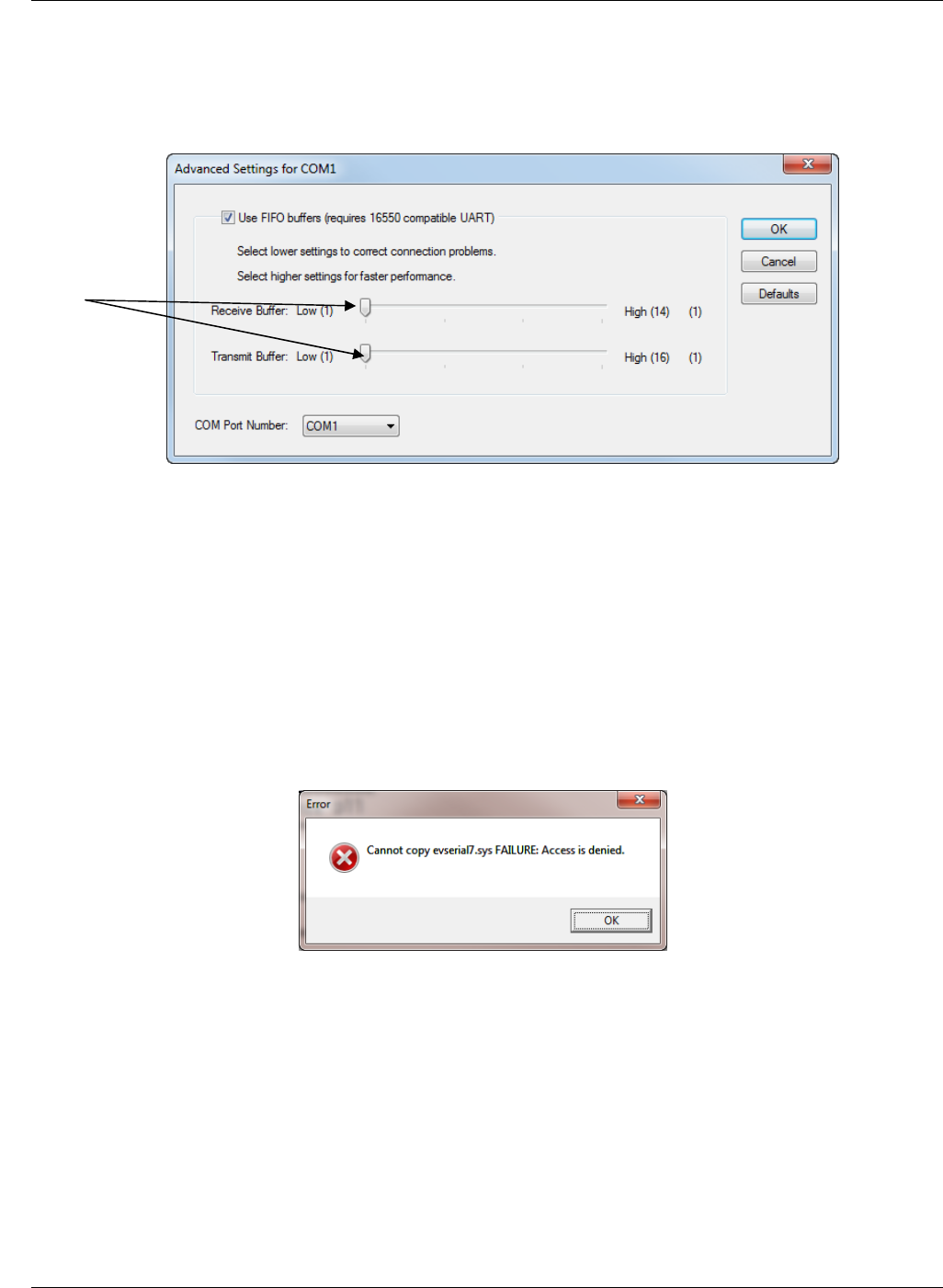
OpenEnterprise Field Tools™ Quick Start Guide
A-8 Troubleshooting Tips Issued Dec-2014
6. In the Advanced Port Settings dialog box, drag the Receive Buffer
and Transmit Buffer slide bars to the low end of their ranges, and
click OK.
Editing the Advanced Settings for the Port
7. Then choose OK in the Communication Port Properties dialog box,
and exit the device manager and control panel to save the settings.
8. Reboot your PC for the new settings to take effect.
Eltima “FAILURE: Access is denied” Message
You may see this message during installation if Eltima software had
already been installed. This is not an issue. Click OK to allow the
installation to continue.
AMS Services is not Starting
One possible cause of AMS services not starting could be if Microsoft®
.NET software is not functioning properly. Check the Windows Event
Log. If you see the message:
“System.ServiceModel.Diagnostics.TraceUtility threw an exception”
in the Event Log, try uninstalling Microsoft .NET 4.5, then reinstall it
with all security patches and updates using Windows Update.
Drag the
Receive
Buffer and
Transmit
Buffer slide
bars to the
low end of
their ranges.
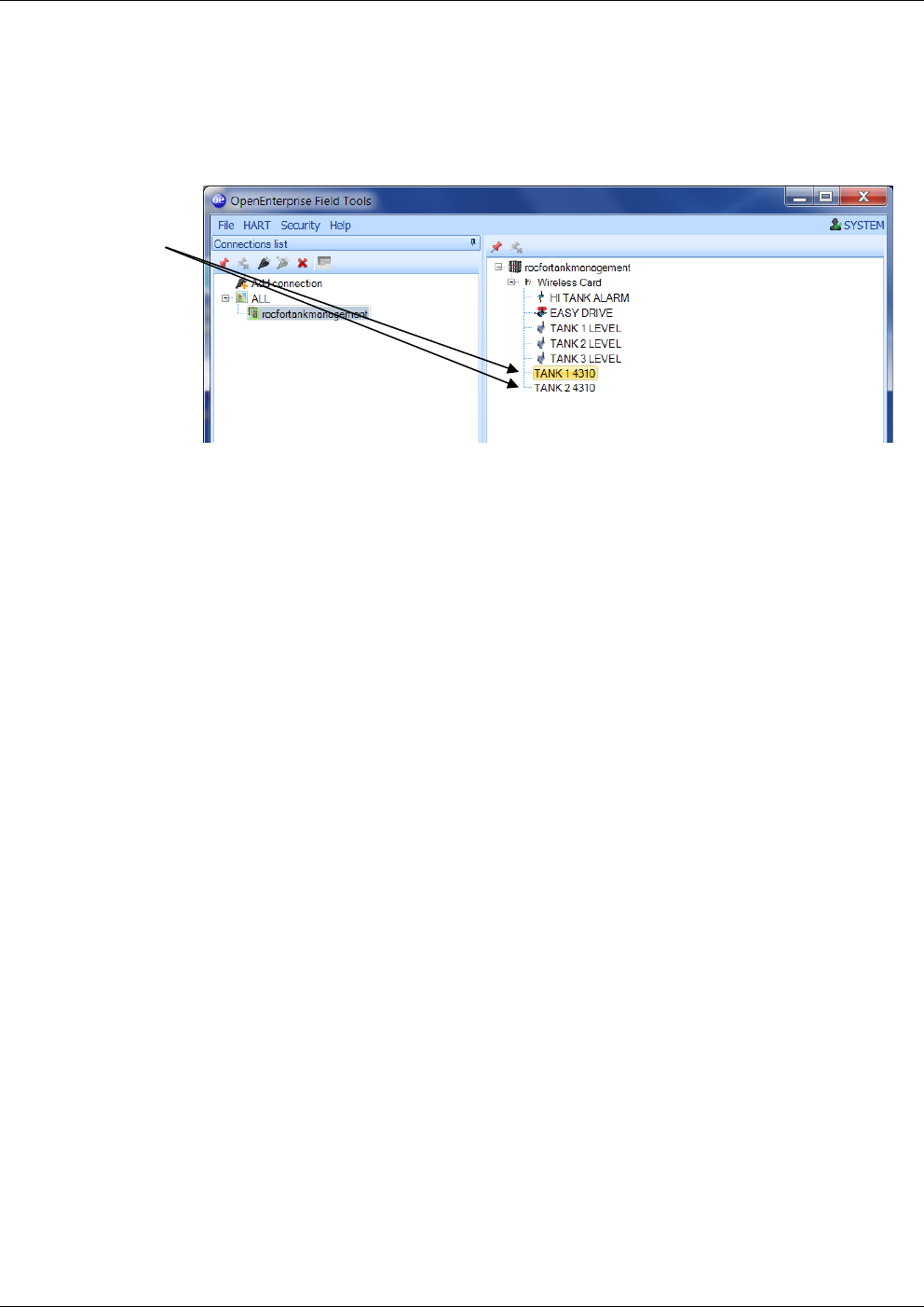
OpenEnterprise™ Field Tools Quick Start Guide
Issued Dec-2014 Troubleshooting Tips A-9
AMS Wireless SNAP-ON Failure - Missing Icons in Trees
If the Active Connection pane includes devices for which a label is
displayed with no icon, this can indicate that the device descriptor (DD)
was not properly loaded. This can cause a failure of the AMS Wireless
SNAP-ON.
If this happens, you can load the device descriptor. See Section 3.7 –
Adding a HART Device Type.
AMS Wireless SNAP-ON Defaults
The default parameters in AMS Wireless SNAP-ON are set to work
optimally with approximately 10 devices. If, in the ControlWave
environment, you experience challenges or need to manage more
devices, contact Remote Automation Solutions Technical Support for
information on setting the appropriate parameter values.
Devices
without icons
may not
have device
descriptor
(DD) loaded.

OpenEnterprise Field Tools Quick Start Guide (Dec-2014)
Headquarters:
Emerson Process Management
Remote Automation Solutions
6005 Rogerdale Road
Houston, TX 77072 U.S.A.
T +1 281 879 2699 | F +1 281 988 4445
www.EmersonProcess.com/Remote
© 2014 Remote Automation Solutions, a business unit of Emerson Process Management.
All rights reserved.
Remote Automation Solutions, a business unit of Emerson Process Management, shall not
be liable for technical or editorial errors in this manual or omissions from this manual.
REMOTE AUTOMATION SOLUTIONS MAKES NO WARRANTIES, EXPRESSED OR
IMPLIED, INCLUDING THE IMPLIED WARRANTIES OF MERCHANTABILITY AND
FITNESS FOR A PARTICULAR PURPOSE WITH RESPECT TO THIS MANUAL AND, IN
NO EVENT SHALL REMOTE AUTOMATION SOLUTIONS BE LIABLE FOR ANY
INCIDENTAL, PUNITIVE, SPECIAL OR CONSEQUENTIAL DAMAGES INCLUDING, BUT
NOT LIMITED TO, LOSS OF PRODUCTION, LOSS OF PROFITS, LOSS OF REVENUE
OR USE AND COSTS INCURRED INCLUDING WITHOUT LIMITATION FOR CAPITAL,
FUEL AND POWER, AND CLAIMS OF THIRD PARTIES.
Emerson Process Management Ltd, Remote Automation Solutions (UK), is a wholly owned
subsidiary of Emerson Electric Co. doing business as Remote Automation Solutions, a
business unit of Emerson Process Management. FloBoss, ROCLINK, ControlWave,
Helicoid, and OpenEnterprise are trademarks of Remote Automation Solutions. AMS,
PlantWeb, and the PlantWeb logo are marks owned by one of the companies in the
Emerson Process Management business unit of Emerson Electric Co. Emerson Process
Management, Emerson and the Emerson logo are trademarks and service marks of the
Emerson Electric Co. All other marks are property of their respective owners.
The contents of this publication are presented for informational purposes only. While every
effort has been made to ensure informational accuracy, they are not to be construed as
warranties or guarantees, express or implied, regarding the products or services described
herein or their use or applicability. Remote Automation Solutions reserves the right to modif
y
or improve the designs or specifications of such products at any time without notice. All
sales are governed by Remote Automation Solutions’ terms and conditions which are
available upon request. Remote Automation Solutions does not assume responsibility for
the selection, use or maintenance of any product. Responsibility for proper selection, use
and maintenance of any Remote Automation Solutions product remains solely with the
purchaser and end-user.
Europe:
Emerson Process Management
Remote Automation Solutions
Emerson House
Unit 8, Waterfront Business Park
Dudley Road, Brierly Hill
Dudley UK DY5 1LX
T +44 1384 487200 | F +44 1384 487258
www.EmersonProcess.com/Remote
North American/Latin America:
Emerson Process Management
Remote Automation Solutions
6005 Rogerdale Road
Houston TX USA 77072
T +1 281 879 2699 | F +1 281 988 4445
www.EmersonProcess.com/Remote
Middle East/Africa:
Emerson Process Management
Remote Automation Solutions
Emerson FZE
P.O. Box 17033
Jebel Ali Free Zone – South 2
Dubai U.A.E.
T +971 4 8118100 | F +971 4 8865465
www.EmersonProcess.com/Remote
Asia-Pacific:
Emerson Process Management
Remote Automation Solutions
1 Pandan Crescent
Singapore 128461
T +65 6777 8211| F +65 6777 0947
www.EmersonProcess.com/Remote
Remote Automation Solutions
