Guide To Computer Network Security (3rd Edition) Joseph Migga Kizza Springer
User Manual:
Open the PDF directly: View PDF ![]() .
.
Page Count: 550 [warning: Documents this large are best viewed by clicking the View PDF Link!]
- Preface to Third Edition
- Contents
- Part I: Introduction to Computer Network Security
- 1: Computer Network Fundamentals
- 2: Computer Network Security Fundamentals
- Part II: Security Issues and Challenges in the Traditional Computer Network
- 3: Security Motives and Threats to Computer Networks
- 3.1 Introduction
- 3.2 Sources of Security Threats
- 3.2.1 Design Philosophy
- 3.2.2 Weaknesses in Network Infrastructure and Communication Protocols
- 3.2.3 Rapid Growth of Cyberspace
- 3.2.4 The Growth of the Hacker Community
- 3.2.5 Vulnerability in Operating System Protocol
- 3.2.6 The Invisible Security Threat: The Insider Effect
- 3.2.7 Social Engineering
- 3.2.8 Physical Theft
- 3.3 Security Threat Motives
- 3.4 Security Threat Management
- 3.5 Security Threat Correlation
- 3.6 Security Threat Awareness
- References
- 4: Introduction to Computer Network Vulnerabilities
- 4.1 Definition
- 4.2 Sources of Vulnerabilities
- 4.3 Vulnerability Assessment
- References
- 5: Cyber Crimes and Hackers
- 6: Scripting and Security in Computer Networks and Web Browsers
- 7: Security Assessment, Analysis, and Assurance
- 7.1 Introduction
- 7.2 System Security Policy
- 7.3 Building a Security Policy
- 7.4 Security Requirements Specification
- 7.5 Threat Identification
- 7.6 Threat Analysis
- 7.7 Vulnerability Identification and Assessment
- 7.8 Security Certification
- 7.9 Security Monitoring and Auditing
- 7.10 Products and Services
- References
- 3: Security Motives and Threats to Computer Networks
- Part III: Dealing with Computer Network Security Challenges
- 8: Disaster Management
- 9: Access Control and Authorization
- 10: Authentication
- 10.1 Definition
- 10.2 Multiple Factors and Effectiveness of Authentication
- 10.3 Authentication Elements
- 10.4 Types of Authentication
- 10.5 Authentication Methods
- 10.6 Developing an Authentication Policy
- References
- 11: Cryptography
- 12: Firewalls
- 12.1 Definition
- 12.2 Types of Firewalls
- 12.3 Configuration and Implementation of a Firewall
- 12.4 The Demilitarized Zone (DMZ)
- 12.5 Improving Security Through the Firewall
- 12.6 Firewall Forensics
- 12.7 Firewall Services and Limitations
- References
- 13: System Intrusion Detection and Prevention
- 13.1 Definition
- 13.2 Intrusion Detection
- 13.3 Intrusion Detection Systems (IDSs)
- 13.4 Types of Intrusion Detection Systems
- 13.4.1 Network-Based Intrusion Detection Systems (NIDSs)
- 13.4.2 Host-Based Intrusion Detection Systems (HIDS)
- 13.4.3 The Hybrid Intrusion Detection System
- 13.5 The Changing Nature of IDS Tools
- 13.6 Other Types of Intrusion Detection Systems
- 13.7 Response to System Intrusion
- 13.8 Challenges to Intrusion Detection Systems
- 13.9 Implementing an Intrusion Detection System
- 13.10 Intrusion Prevention Systems (IPSs)
- 13.11 Intrusion Detection Tools
- References
- 14: Computer and Network Forensics
- 15: Virus and Content Filtering
- 16: Standardization and Security Criteria: Security Evaluation of Computer Products
- 17: Computer Network Security Protocols
- 17.1 Introduction
- 17.2 Application Level Security
- 17.3 Security in the Transport Layer
- 17.4 Security in the Network Layer
- 17.5 Security in the Link Layer and over LANS
- References
- 18: Security in Wireless Networks and Devices
- 18.1 Introduction
- 18.2 Types of Wireless Broadband Networks
- 18.3 Development of Cellular Technology
- 18.4 Other Features of Mobile Cellular Technology
- 18.5 Security Vulnerabilities in Cellular Wireless Networks
- 18.5.1 WLANs Security Concerns
- 18.5.1.1 Identity in WLANs
- 18.5.1.2 Lack of Access Control Mechanism
- 18.5.1.3 Lack of Authentication Mechanism in 802.11
- 18.5.1.4 Lack of a WEP Key Management Protocol
- 18.5.1.5 War-Driving, War-Walking, War-Flying, and War-Chalking
- 18.5.1.6 Insertion Attacks
- 18.5.1.7 Interception and Monitoring Wireless Traffic Attacks
- 18.5.1.8 AP and Client Misconfigurations and Attack
- 18.5.1.9 SNMP Community Words
- 18.5.1.10 Client Side Security Risk
- 18.5.1.11 Risks Due to Installation
- 18.5.1.12 Jamming
- 18.5.1.13 Client-to-Client Attacks
- 18.5.1.14 Parasitic Grids
- 18.5.2 Best Practices for Wi-Fi Security
- 18.5.1 WLANs Security Concerns
- References
- 19: Security in Sensor Networks
- 19.1 Introduction
- 19.2 The Growth of Sensor Networks
- 19.3 Design Factors in Sensor Networks
- 19.4 Security in Sensor Networks
- 19.5 Security Mechanisms and Best Practices for Sensor Networks
- 19.6 Trends in Sensor Network Security Research
- References
- 20: Other Efforts to Secure Data in Computer Networks
- Part IV: Elastic Extension Beyond the Traditional Computer Network: Virtualization, Cloud Computing and Mobile Systems
- 21: Cloud Computing and Related Security Issues
- 21.1 Introduction
- 21.2 Cloud Computing Infrastructure Characteristics
- 21.3 Cloud Computing Service Models
- 21.4 Cloud Computing Deployment Models
- 21.5 Virtualization and Cloud Computing
- 21.6 Benefits of Cloud Computing
- 21.7 Cloud Computing, Power Consumption, and Environmental Issues
- 21.8 Cloud Computing Security, Reliability, Availability, and Compliance Issues
- References
- 22: Virtualization Security
- 22.1 Introduction
- 22.2 History of Virtualization
- 22.3 Virtualization Terminologies
- 22.4 Types of Computing System Virtualization
- 22.5 The Benefits of Virtualization
- 22.5.1 Reduction of Server Sprawl
- 22.5.2 Conservation of Energy
- 22.5.3 Reduced IT Management Costs
- 22.5.4 Better Disaster Recovery Management
- 22.5.5 Software Development Testing and Verification
- 22.5.6 Isolation of Legacy Applications
- 22.5.7 Cross-Platform Support
- 22.5.8 Minimizing Hardware Costs
- 22.5.9 Faster Server Provisioning
- 22.5.10 Better Load Balancing
- 22.5.11 Reduce the Data Center Footprint
- 22.5.12 Increase Uptime
- 22.5.13 Isolate Applications
- 22.5.14 Extend the Life of Older Applications
- 22.6 Virtualization Infrastructure Security
- References
- 23: Mobile Systems and Corresponding Intractable Security Issues
- 21: Cloud Computing and Related Security Issues
- Part V: Securing the Last Frontiers – The Home Front
- Part VI: Hands-on Projects
- 25: Projects
- 25.1 Introduction
- 25.2 Part I: Weekly/Biweekly Laboratory Assignments
- 25.3 Part II: Semester Projects
- 25.4 The Following Tools Are Used to Enhance Security in Web Applications
- 25.5 Part III: Research Projects
- 25.5.1 Consensus Defense
- 25.5.2 Specialized Security
- 25.5.3 Protecting an Extended Network
- 25.5.4 Automated Vulnerability Reporting
- 25.5.5 Turn-Key Product for Network Security Testing
- 25.5.6 The Role of Local Networks in the Defense of the National Critical Infrastructure
- 25.5.7 Enterprise VPN Security
- 25.5.8 Perimeter Security
- 25.5.9 Enterprise Security
- 25.5.10 Password Security: Investigating the Weaknesses
- 25.6 Case Studies
- 25: Projects
- Index

Computer Communications and Networks
JosephMiggaKizza
Guide to
Computer
Network
Security
Third Edition

Computer Communications and Networks
The Computer Communications and Networks series is a range of textbooks,
monographs and handbooks. It sets out to provide students, researchers, and non-
specialists alike with a sure grounding in current knowledge, together with
comprehensible access to the latest developments in computer communications and
networking.
Emphasis is placed on clear and explanatory styles that support a tutorial approach,
so that even the most complex of topics is presented in a lucid and intelligible
manner.
More information about this series at
http://www.springer.com/series/4198

Joseph Migga Kizza
Guide to Computer
Network Security
Third Edition
Joseph Migga Kizza
Department of Computer Science
University of Tennessee
Chattanooga , TN , USA
Series Editor
A.J. Sammes
Centre for Forensic Computing
Cranfi eld University, Shrivenham campus
Swindon, UK
ISSN 1617-7975
Computer Communications and Networks
ISBN 978-1-4471-6653-5 ISBN 978-1-4471-6654-2 (eBook)
DOI 10.1007/978-1-4471-6654-2
Library of Congress Control Number: 2014959827
Springer London Heidelberg New York Dordrecht
© Springer-Verlag London 2009, 2013, 2015
This work is subject to copyright. All rights are reserved by the Publisher, whether the whole or part of
the material is concerned, specifi cally the rights of translation, reprinting, reuse of illustrations, recitation,
broadcasting, reproduction on microfi lms or in any other physical way, and transmission or information
storage and retrieval, electronic adaptation, computer software, or by similar or dissimilar methodology
now known or hereafter developed.
The use of general descriptive names, registered names, trademarks, service marks, etc. in this publication
does not imply, even in the absence of a specifi c statement, that such names are exempt from the relevant
protective laws and regulations and therefore free for general use.
The publisher, the authors and the editors are safe to assume that the advice and information in this book
are believed to be true and accurate at the date of publication. Neither the publisher nor the authors or the
editors give a warranty, express or implied, with respect to the material contained herein or for any errors
or omissions that may have been made.
Printed on acid-free paper
Springer-Verlag London Ltd. is part of Springer Science+Business Media (www.springer.com)

v
Preface to Third Edition
The second edition of this book came out barely 2 years ago and we are again in
need of a new and improved third edition. This rapid turnaround of editions of a
successful book like this is indicative of the rapidly changing technology landscape.
To keep a promise we made to our readers in the fi rst edition of keeping the book
materials as up to date as possible, we have now embarked on this third edition.
First, recall that in the second edition, we introduced to the reader the concept of a
changing traditional Computer Network as we knew it when the fi rst edition of this
book came out. That network with a nicely “demarcated” and heavily defended
perimeter wall and well guarded access points has been going into a transformation
as a result of new technologies. Changes have occurred, as we pointed out in the
second edition, within and outside the network we call the “traditional computer
network”, at the server and most importantly at the boundaries. A virtualized and
elastic network with rapid extensions at will is taking its place to meet the growing
needs of users. The new technologies driving this change, for now, are system
resource virtualization, the evolving cloud computing models and a growing and
unpredictable mobile computing technology creating platforms that demand new
extensions, on the fl y and at will, to the traditional computer network. Secondly, the
rapidly merging computing and telecommunication technologies, we started dis-
cussing in the fi rst and through the second editions, are rapidly destroying the tradi-
tional computer network as mobile and home devices are slowly becoming part of
the enterprise and at the same time remaining in their traditional public commons,
thus creating unpredictable and un-defendable enterprise and home networks. When
you think of a small mobile device now able to connect to a private enterprise net-
work under the BYOD policies and the same device is able to be used as a home
network device and at the same time remains connected to networks in public com-
mons, you start to get an image of the “ anywhere and everywhere ” computing net-
work, a global sprawl of networks within networks and indeed networks on demand.
The ubiquitous nature of these new computing networks is creating new and
uncharted territories with security nightmares. What is more worrying is that along
with the sprawl, we are getting all types of characters joining amass in the new but
rapidly changing technological “ecosystem”, for lack of a better word.
For these reasons, we need to remain vigilant with better, if not advanced, com-
puter and information security protocols and best practices because the frequency of

vi
computing and mobile systems attacks and the vulnerability of these systems will
likely not decline, rather they are likely to increase. More efforts in developing adaptive
and scalable security protocols and best practices and massive awareness, therefore,
are needed to meet this growing challenge and bring the public to a level where they
can be active and safe participants in the brave new worlds of computing.
This guide is a comprehensive volume touching not only on every major topic in
computing and information security and assurance, but also has gone beyond the
security of computer networks as we used to know them, to embrace new and more
agile mobile systems and new online social networks that are interweaving into our
everyday fabric, if not already. We bring into our ongoing discussion on computer
Network security, a broader view of the new wireless and mobile systems and online
social networks. As with previous editions, it is intended to bring massive security
awareness and education to the security realities of our time, a time when billions of
people from the remotest place on earth to the most cosmopolitan world cities are
using the smartest, smallest, and more powerful mobile devices loaded with the
most fascinating and worrisome functionalities ever known to interconnect via a
mesh of elastic computing networks. We highlight security issues and concerns in
these public commons and private bedrooms the globe over.
The volume is venturing into and exposing all sorts of known security problems,
vulnerabilities and the dangers likely to be encountered by the users of these devices.
In its own way, it is a pathfi nder as it initiates a conversation towards developing
better algorithms, protocols, and best practices that will enhance security of systems
in the public commons, private and enterprise offi ces and living rooms and bed-
rooms where these devices are used. It does this comprehensively in fi ve parts and
25 chapters. Part I gives the reader an understanding of the working and security
situation of the traditional computer networks. Part II builds on this knowledge and
exposes the reader to the prevailing security situation based on a constant security
threat. It surveys several security threats. Part III, the largest, forms the core of the
guide and presents to the reader most of the best practices and solutions that are
currently in use. Part IV goes beyond the traditional computer network as we used
to know it to cover new systems and technologies that have seamlessly and stealth-
lessy extended the boundaries of the traditional computer network. Systems and
technologies like virtualization, cloud computing and mobile systems are intro-
duced and discussed. A new Part V ventures into the last mile as we look at the new
security quagmire of the home computing environment and the growing home
hotspots. Part VI, the last part, consists of projects.
As usual, in summary, the guide attempts to achieve the following objectives:
• Educate the public about computer security in the traditional computer
network.
• Educate the public about the evolving computing ecosystem created by the erod-
ing boundaries between the enterprise network, the home network and the rap-
idly growing public-commons-based social networks all extending the
functionalities of the traditional computer network.
Preface to Third Edition

vii
• Alert the public to the magnitude of the vulnerabilities, weaknesses and loop-
holes inherent in the traditional computer network and now resident in the new
computing ecosystem.
• Bring to the public attention effective security solutions and best practice, expert
opinions on those solutions, and the possibility of ad hoc solutions
• Look at the roles legislation, regulation, and enforcement play in securing the
new computing ecosystem.
• Finally, initiate a debate on developing effective and comprehensive security
algorithms, protocols, and best practices for new computing ecosystem.
Since the guide covers a wide variety of security topics, algorithms, solutions,
and best practices, it is intended to be both a teaching and a reference tool for those
interested in learning about the security of evolving computing ecosystem. Learn
about available techniques to prevent attacks on these systems. The depth and thor-
ough discussion and analysis of most of the security issues of the traditional com-
puter network and the extending technologies and systems, together with the
discussion of security algorithms, and solutions given, make the guide a unique
reference source of ideas for computer network and data security personnel, net-
work security policy makers, and those reading for leisure. In addition, the guide
provokes the reader by raising valid legislative, legal, social, technical and ethical
security issues, including the increasingly diminishing line between individual pri-
vacy and the need for collective and individual security in the new computing
ecosystem.
The guide targets college students in computer science, information science,
technology studies, library sciences, engineering, and to a lesser extent students in
the arts and sciences who are interested in information technology. In addition, stu-
dents in information management sciences will fi nd the guide particularly helpful.
Practitioners, especially those working in data and information-intensive areas, will
likewise fi nd the guide a good reference source. It will also be valuable to those
interested in any aspect of information security and assurance and those simply
wanting to become cyberspace literates.
Book Resources
There are two types of exercises at the end of chapter: easy and quickly workable
exercises whose responses can be easily spotted from the proceeding text; and more
thought provoking advanced exercises whose responses may require research out-
side the content of this book. Also Chap. 25 is devoted to lab exercises. There are
three types of lab exercises: weekly or bi-weekly assignments that can be done eas-
ily with either reading or using readily available software and hardware tools;
slightly harder semester-long projects that may require extensive time, collabora-
tion, and some research to fi nish them successfully; and hard open-research projects
that require a lot of thinking, take a lot of time, and require extensive research. Links
are provided below for Cryptographic and Mobile security hands-on projects from
Preface to Third Edition

viii
two successful National Science Foundation (NSF) funded workshops at the
author’s university.
• Teaching Cryptography Using Hands-on Labs and Case Studies – http://web2.
utc.edu/~djy471/cryptography/crypto.htm
• Capacity Building Through Curriculum and Faculty Development on Mobile
Security – http://www.utc.edu/faculty/li-yang/mobilesecurity.php
We have tried as much as possible, throughout the guide, to use open source
software tools. This has two consequences to it: one, it makes the guide affordable
keeping in mind the escalating proprietary software prices; and two, it makes the
content and related software tools last longer because the content and corresponding
exercises and labs are not based on one particular proprietary software tool that can
go out anytime.
Instructor Support Materials
As you consider using this book, you may need to know that we have developed
materials to help you with your course. The help materials for both instructors and
students cover the following areas:
• Syllabus . There is a suggested syllabus for the instructor.
• Instructor PowerPoint slides . These are detailed enough to help the instructor,
especially those teaching the course for the fi rst time.
• Answers to selected exercises at the end of each chapter.
• Laboratory . Since network security is a hands-on course, students need to spend
a considerable amount of time on scheduled laboratory exercises. The last chap-
ter of the book contains several laboratory exercises and projects. The book
resource center contains several more and updates. Also as we stated above, links
are also included at the author’s website for Cryptographic hands-on project
from two successful National Science Foundation (NSF) funded workshops at
the author’s university.
These materials can be found at the publisher’s website at http://www.springer.
com/978-1-4471-6653-5 and at the author’s website at http://www.utc.edu/Faculty/
Joseph-Kizza/
Chattanooga, TN, USA Joseph Migga Kizza
June, 2014
Preface to Third Edition

ix
Contents
Part I Introduction to Computer Network Security
1 Computer Network Fundamentals ........................................................ 3
1.1 Introduction .................................................................................. 3
1.2 Computer Network Models .......................................................... 4
1.3 Computer Network Types ............................................................ 5
1.3.1 Local Area Networks (LANs) ...................................... 6
1.3.2 Wide Area Networks (WANs) ...................................... 6
1.3.3 Metropolitan Area Networks (MANs) ......................... 6
1.4 Data Communication Media Technology .................................... 7
1.4.1 Transmission Technology ............................................. 7
1.4.2 Transmission Media ..................................................... 10
1.5 Network Topology ........................................................................ 13
1.5.1 Mesh ............................................................................. 13
1.5.2 Tree ............................................................................... 14
1.5.3 Bus ................................................................................ 14
1.5.4 Star ................................................................................ 15
1.5.5 Ring .............................................................................. 15
1.6 Network Connectivity and Protocols ........................................... 17
1.6.1 Open System Interconnection (OSI)
Protocol Suite ............................................................... 18
1.6.2 Transport Control Protocol/Internet Protocol
(TCP/IP) Model ............................................................ 19
1.7 Network Services ......................................................................... 22
1.7.1 Connection Services ..................................................... 23
1.7.2 Network Switching Services ........................................ 24
1.8 Network Connecting Devices ....................................................... 26
1.8.1 LAN Connecting Devices ............................................ 26
1.8.2 Internetworking Devices .............................................. 30

x
1.9 Network Technologies .................................................................. 34
1.9.1 LAN Technologies ....................................................... 34
1.9.2 WAN Technologies ....................................................... 36
1.9.3 Wireless LANs ............................................................. 38
1.10 Conclusion.................................................................................... 39
References ................................................................................................. 40
2 Computer Network Security Fundamentals ........................................ 41
2.1 Introduction .................................................................................. 41
2.1.1 Computer Security........................................................ 43
2.1.2 Network Security .......................................................... 43
2.1.3 Information Security .................................................... 43
2.2 Securing the Computer Network .................................................. 44
2.2.1 Hardware ...................................................................... 44
2.2.2 Software ....................................................................... 44
2.3 Forms of Protection ...................................................................... 44
2.3.1 Access Control ............................................................. 45
2.3.2 Authentication .............................................................. 46
2.3.3 Confi dentiality .............................................................. 46
2.3.4 Integrity ........................................................................ 47
2.3.5 Nonrepudiation ............................................................. 47
2.4 Security Standards ........................................................................ 48
2.4.1 Security Standards Based on Type
of Service/Industry ....................................................... 49
2.4.2 Security Standards Based on Size/Implementation ...... 52
2.4.3 Security Standards Based on Interests ......................... 52
2.4.4 Security Best Practices ................................................. 53
References ................................................................................................. 57
Part II Security Issues and Challenges in the Traditional
Computer Network
3 Security Motives and Threats to Computer Networks ........................ 61
3.1 Introduction .................................................................................. 61
3.2 Sources of Security Threats ......................................................... 62
3.2.1 Design Philosophy ........................................................ 62
3.2.2 Weaknesses in Network Infrastructure
and Communication Protocols ..................................... 63
3.2.3 Rapid Growth of Cyberspace ....................................... 66
3.2.4 The Growth of the Hacker Community ........................ 67
3.2.5 Vulnerability in Operating System Protocol ................ 77
3.2.6 The Invisible Security Threat: The Insider Effect ........ 77
3.2.7 Social Engineering ....................................................... 78
3.2.8 Physical Theft ............................................................... 78
Contents

xi
3.3 Security Threat Motives ............................................................... 78
3.3.1 Terrorism ...................................................................... 79
3.3.2 Military Espionage ....................................................... 79
3.3.3 Economic Espionage .................................................... 79
3.3.4 Targeting the National Information Infrastructure ....... 80
3.3.5 Vendetta/Revenge ......................................................... 80
3.3.6 Hate (National Origin, Gender, and Race) ................... 81
3.3.7 Notoriety....................................................................... 81
3.3.8 Greed ........................................................................... 81
3.3.9 Ignorance ...................................................................... 81
3.4 Security Threat Management ....................................................... 81
3.4.1 Risk Assessment ........................................................... 82
3.4.2 Forensic Analysis ......................................................... 82
3.5 Security Threat Correlation .......................................................... 82
3.5.1 Threat Information Quality .......................................... 83
3.6 Security Threat Awareness ........................................................... 83
References ................................................................................................. 85
4 Introduction to Computer Network Vulnerabilities ............................ 87
4.1 Defi nition...................................................................................... 87
4.2 Sources of Vulnerabilities ............................................................ 87
4.2.1 Design Flaws ................................................................ 88
4.2.2 Poor Security Management .......................................... 91
4.2.3 Incorrect Implementation ............................................. 92
4.2.4 Internet Technology Vulnerability ................................ 93
4.2.5 Changing Nature of Hacker Technologies
and Activities ................................................................ 96
4.2.6 Diffi culty of Fixing Vulnerable Systems ...................... 97
4.2.7 Limits of Effectiveness of Reactive Solutions.............. 98
4.2.8 Social Engineering ....................................................... 99
4.3 Vulnerability Assessment ............................................................. 100
4.3.1 Vulnerability Assessment Services ............................... 101
4.3.2 Advantages of Vulnerability Assessment Services ....... 102
References ................................................................................................. 103
5 Cyber Crimes and Hackers .................................................................... 105
5.1 Introduction .................................................................................. 105
5.2 Cyber Crimes ............................................................................... 106
5.2.1 Ways of Executing Cyber Crimes ................................ 107
5.2.2 Cyber Criminals ........................................................... 109
5.3 Hackers ......................................................................................... 110
5.3.1 History of Hacking ....................................................... 110
5.3.2 Types of Hackers .......................................................... 113
5.3.3 Hacker Motives ............................................................ 116
5.3.4 Hacking Topologies ...................................................... 119
Contents

xii
5.3.5 Hackers’ Tools of System Exploitation ........................ 123
5.3.6 Types of Attacks ........................................................... 126
5.4 Dealing with the Rising Tide of Cyber Crimes ............................ 127
5.4.1 Prevention ..................................................................... 127
5.4.2 Detection ...................................................................... 128
5.4.3 Recovery ....................................................................... 128
5.5 Conclusion.................................................................................... 128
References ................................................................................................. 129
6 Scripting and Security in Computer Networks
and Web Browsers ................................................................................... 131
6.1 Introduction .................................................................................. 131
6.2 Scripting ....................................................................................... 131
6.3 Scripting Languages ..................................................................... 132
6.3.1 Server-Side Scripting Languages ................................. 132
6.3.2 Client-Side Scripting Languages .................................. 133
6.4 Scripting in Computer Network ................................................... 134
6.4.1 Introduction to the Common Gateway
Interface (CGI) ............................................................. 135
6.4.2 Server-Side Scripting: The CGI Interface .................... 137
6.5 Computer Network Scripts and Security ...................................... 139
6.5.1 CGI Script Security ...................................................... 139
6.5.2 JavaScript and VBScript Security ................................ 141
6.5.3 Web Scripts Security .................................................... 142
6.6 Dealing with the Script Security Problems .................................. 142
References ................................................................................................. 143
7 Security Assessment, Analysis, and Assurance ..................................... 145
7.1 Introduction .................................................................................. 145
7.2 System Security Policy ................................................................ 147
7.3 Building a Security Policy ........................................................... 149
7.3.1 Security Policy Access Rights Matrix .......................... 149
7.3.2 Policy and Procedures .................................................. 151
7.4 Security Requirements Specifi cation ........................................... 155
7.5 Threat Identifi cation ..................................................................... 156
7.5.1 Human Factors ............................................................. 156
7.5.2 Natural Disasters .......................................................... 157
7.5.3 Infrastructure Failures .................................................. 157
7.6 Threat Analysis............................................................................. 159
7.6.1 Approaches to Security Threat Analysis ...................... 160
7.7 Vulnerability Identifi cation and Assessment ................................ 161
7.7.1 Hardware ...................................................................... 161
7.7.2 Software ....................................................................... 162
7.7.3 Humanware .................................................................. 163
7.7.4 Policies, Procedures, and Practices .............................. 163
Contents

xiii
7.8 Security Certifi cation ................................................................... 164
7.8.1 Phases of a Certifi cation Process .................................. 165
7.8.2 Benefi ts of Security Certifi cation ................................. 165
7.9 Security Monitoring and Auditing ............................................... 166
7.9.1 Monitoring Tools .......................................................... 166
7.9.2 Type of Data Gathered ................................................. 167
7.9.3 Analyzed Information .................................................. 167
7.9.4 Auditing ........................................................................ 168
7.10 Products and Services .................................................................. 168
References ................................................................................................. 169
Part III Dealing with Computer Network Security Challenges
8 Disaster Management ............................................................................. 173
8.1 Introduction .................................................................................. 173
8.1.1 Categories of Disasters ................................................. 174
8.2 Disaster Prevention ...................................................................... 175
8.3 Disaster Response ........................................................................ 177
8.4 Disaster Recovery ........................................................................ 177
8.4.1 Planning for a Disaster Recovery ................................. 178
8.4.2 Procedures of Recovery ................................................ 179
8.5 Make Your Business Disaster Ready ............................................ 181
8.5.1 Always Be Ready for a Disaster................................... 181
8.5.2 Always Backup Media ................................................. 182
8.5.3 Risk Assessment ........................................................... 182
8.6 Resources for Disaster Planning and Recovery ........................... 182
8.6.1 Local Disaster Resources ............................................. 182
References ................................................................................................. 184
9 Access Control and Authorization ......................................................... 185
9.1 Defi nitions .................................................................................... 185
9.2 Access Rights ............................................................................... 186
9.2.1 Access Control Techniques and Technologies ............. 187
9.3 Access Control Systems ............................................................... 192
9.3.1 Physical Access Control ............................................... 192
9.3.2 Access Cards ................................................................ 192
9.3.3 Electronic Surveillance ................................................ 193
9.3.4 Biometrics .................................................................... 194
9.3.5 Event Monitoring ......................................................... 197
9.4 Authorization................................................................................ 197
9.4.1 Authorization Mechanisms .......................................... 198
9.5 Types of Authorization Systems ................................................... 199
9.5.1 Centralized ................................................................... 199
9.5.2 Decentralized ................................................................ 199
9.5.3 Implicit ......................................................................... 200
9.5.4 Explicit ......................................................................... 200
Contents

xiv
9.6 Authorization Principles............................................................... 200
9.6.1 Least Privileges ............................................................ 201
9.6.2 Separation of Duties ..................................................... 201
9.7 Authorization Granularity ............................................................ 201
9.7.1 Fine Grain Authorization .............................................. 202
9.7.2 Coarse Grain Authorization .......................................... 202
9.8 Web Access and Authorization ..................................................... 202
References ................................................................................................. 204
10 Authentication ......................................................................................... 205
10.1 Defi nition...................................................................................... 205
10.2 Multiple Factors and Effectiveness of Authentication ................. 206
10.3 Authentication Elements .............................................................. 208
10.3.1 Person or Group Seeking Authentication ..................... 208
10.3.2 Distinguishing Characteristics for Authentication ....... 209
10.3.3 The Authenticator ......................................................... 209
10.3.4 The Authentication Mechanism ................................... 209
10.3.5 Access Control Mechanism .......................................... 210
10.4 Types of Authentication ............................................................... 210
10.4.1 Nonrepudiable Authentication...................................... 210
10.4.2 Repudiable Authentication ........................................... 211
10.5 Authentication Methods ............................................................... 211
10.5.1 Password Authentication .............................................. 212
10.5.2 Public-Key Authentication ........................................... 214
10.5.3 Remote Authentication ................................................. 218
10.5.4 Anonymous Authentication .......................................... 219
10.5.5 Digital Signature-Based Authentication ....................... 220
10.5.6 Wireless Authentication ............................................... 220
10.6 Developing an Authentication Policy ........................................... 221
References ................................................................................................. 223
11 Cryptography .......................................................................................... 225
11.1 Defi nition...................................................................................... 225
11.1.1 Block Ciphers ............................................................... 227
11.2 Symmetric Encryption ................................................................. 228
11.2.1 Symmetric Encryption Algorithms............................... 229
11.2.2 Problems with Symmetric Encryption ......................... 231
11.3 Public-Key Encryption ................................................................. 232
11.3.1 Public-Key Encryption Algorithms .............................. 234
11.3.2 Problems with Public-Key Encryption ......................... 234
11.3.3 Public-Key Encryption Services .................................. 235
11.4 Enhancing Security: Combining Symmetric
and Public- Key Encryptions ......................................................... 235
Contents

xv
11.5 Key Management: Generation, Transportation,
and Distribution ............................................................................ 235
11.5.1 The Key Exchange Problem ......................................... 236
11.5.2 Key Distribution Centers (KDCs) ................................ 237
11.5.3 Public-Key Management .............................................. 238
11.5.4 Key Escrow .................................................................. 242
11.6 Public-Key Infrastructure (PKI) ................................................... 242
11.6.1 Certifi cates .................................................................... 243
11.6.2 Certifi cate Authority ..................................................... 243
11.6.3 Registration Authority (RA) ......................................... 243
11.6.4 Lightweight Directory Access Protocols (LDAP) ........ 244
11.6.5 Role of Cryptography in Communication .................... 244
11.7 Hash Function .............................................................................. 244
11.8 Digital Signatures ......................................................................... 245
References ................................................................................................. 247
12 Firewalls ................................................................................................... 249
12.1 Defi nition...................................................................................... 249
12.2 Types of Firewalls ........................................................................ 252
12.2.1 Packet Inspection Firewalls .......................................... 253
12.2.2 Application Proxy Server: Filtering
Based on Known Services ............................................ 258
12.2.3 Virtual Private Network (VPN) Firewalls .................... 261
12.2.4 Small Offi ce or Home (SOHO) Firewalls .................... 263
12.3 Confi guration and Implementation of a Firewall ......................... 263
12.4 The Demilitarized Zone (DMZ) ................................................... 265
12.4.1 Scalability and Increasing Security in a DMZ ............. 267
12.5 Improving Security Through the Firewall .................................... 267
12.6 Firewall Forensics ........................................................................ 269
12.7 Firewall Services and Limitations ................................................ 269
12.7.1 Firewall Services .......................................................... 269
12.7.2 Limitations of Firewalls ............................................... 270
References ................................................................................................. 271
13 System Intrusion Detection and Prevention ......................................... 273
13.1 Defi nition...................................................................................... 273
13.2 Intrusion Detection ....................................................................... 273
13.2.1 The System Intrusion Process ...................................... 274
13.2.2 The Dangers of System Intrusions ............................... 275
13.3 Intrusion Detection Systems (IDSs) ............................................. 276
13.3.1 Anomaly Detection ...................................................... 277
13.3.2 Misuse Detection .......................................................... 279
13.4 Types of Intrusion Detection Systems .......................................... 280
13.4.1 Network-Based Intrusion Detection
Systems (NIDSs) .......................................................... 280
Contents

xvi
13.4.2 Host-Based Intrusion Detection Systems (HIDS) ........ 285
13.4.3 The Hybrid Intrusion Detection System....................... 287
13.5 The Changing Nature of IDS Tools .............................................. 287
13.6 Other Types of Intrusion Detection Systems ................................ 288
13.6.1 System Integrity Verifi ers (SIVs) ................................. 288
13.6.2 Log File Monitors (LFM) ............................................. 288
13.6.3 Honeypots ..................................................................... 288
13.7 Response to System Intrusion ...................................................... 290
13.7.1 Incident Response Team ............................................... 290
13.7.2 IDS Logs as Evidence .................................................. 291
13.8 Challenges to Intrusion Detection Systems.................................. 291
13.8.1 Deploying IDS in Switched Environments .................. 292
13.9 Implementing an Intrusion Detection System .............................. 292
13.10 Intrusion Prevention Systems (IPSs) ............................................ 293
13.10.1 Network-Based Intrusion Prevention
Systems (NIPSs) ........................................................... 293
13.10.2 Host-Based Intrusion Prevention Systems (HIPSs) ..... 295
13.11 Intrusion Detection Tools ............................................................. 295
References ................................................................................................. 298
14 Computer and Network Forensics ......................................................... 299
14.1 Defi nition...................................................................................... 299
14.2 Computer Forensics ..................................................................... 300
14.2.1 History of Computer Forensics .................................... 301
14.2.2 Elements of Computer Forensics ................................. 301
14.2.3 Investigative Procedures ............................................... 302
14.2.4 Analysis of Evidence .................................................... 309
14.3 Network Forensics........................................................................ 315
14.3.1 Intrusion Analysis ......................................................... 316
14.3.2 Damage Assessment ..................................................... 320
14.4 Forensics Tools ............................................................................. 321
14.4.1 Computer Forensics Tools ............................................ 321
14.4.2 Network Forensics Tools .............................................. 323
References ................................................................................................. 324
15 Virus and Content Filtering ................................................................... 325
15.1 Defi nitions .................................................................................... 325
15.2 Scanning, Filtering, and Blocking ................................................ 325
15.2.1 Content Scanning ......................................................... 326
15.2.2 Inclusion Filtering ........................................................ 326
15.2.3 Exclusion Filtering ....................................................... 327
15.2.4 Other Types of Content Filtering .................................. 327
15.2.5 Location of Content Filters .......................................... 329
15.3 Virus Filtering .............................................................................. 330
15.3.1 Viruses .......................................................................... 330
Contents

xvii
15.4 Content Filtering .......................................................................... 337
15.4.1 Application-Level Filtering .......................................... 337
15.4.2 Packet-Level Filtering and Blocking ............................ 339
15.4.3 Filtered Material ........................................................... 340
15.5 Spam ............................................................................................. 341
References ................................................................................................. 343
16 Standardization and Security Criteria: Security
Evaluation of Computer Products ......................................................... 345
16.1 Introduction .................................................................................. 345
16.2 Product Standardization ............................................................... 346
16.2.1 Need for Standardization of (Security) Products ......... 346
16.2.2 Common Computer Product Standards ........................ 347
16.3 Security Evaluations ..................................................................... 348
16.3.1 Purpose of Security Evaluation .................................... 348
16.3.2 Security Evaluation Criteria ......................................... 348
16.3.3 Basic Elements of an Evaluation .................................. 349
16.3.4 Outcome/Benefi ts ......................................................... 349
16.4 Major Security Evaluation Criteria .............................................. 351
16.4.1 Common Criteria (CC) ................................................. 351
16.4.2 FIPS .............................................................................. 352
16.4.3 The Orange Book /TCSEC ............................................ 352
16.4.4 Information Technology Security Evaluation
Criteria (ITSEC) ........................................................... 355
16.4.5 The Trusted Network Interpretation (TNI):
The Red Book ............................................................... 355
16.5 Does Evaluation Mean Security? ................................................. 356
References ................................................................................................. 357
17 Computer Network Security Protocols ................................................. 359
17.1 Introduction .................................................................................. 359
17.2 Application Level Security ........................................................... 360
17.2.1 Pretty Good Privacy (PGP) .......................................... 360
17.2.2 Secure/Multipurpose Internet Mail Extension
(S/MIME) ..................................................................... 362
17.2.3 Secure HTTP (S-HTTP) ............................................... 363
17.2.4 Hypertext Transfer Protocol over Secure
Socket Layer (HTTPS) ................................................. 366
17.2.5 Secure Electronic Transactions (SET).......................... 367
17.2.6 Kerberos ....................................................................... 369
17.3 Security in the Transport Layer .................................................... 371
17.3.1 Secure Socket Layer (SSL) .......................................... 372
17.3.2 Transport Layer Security (TLS) ................................... 375
17.4 Security in the Network Layer ..................................................... 376
17.4.1 Internet Protocol Security (IPSec)................................ 376
17.4.2 Virtual Private Networks (VPN) .................................. 380
Contents

xviii
17.5 Security in the Link Layer and over LANS ................................. 384
17.5.1 Point-to-Point Protocol (PPP) ...................................... 385
17.5.2 Remote Authentication Dial-In User Service
(RADIUS) .................................................................... 386
17.5.3 Terminal Access Controller Access Control
System (TACACS+) ..................................................... 387
References ................................................................................................. 388
18 Security in Wireless Networks and Devices .......................................... 391
18.1 Introduction .................................................................................. 391
18.2 Types of Wireless Broadband Networks ...................................... 392
18.2.1 Wireless Personal Area Network (WPAN) ................... 392
18.2.2 Wireless Local Area Networks (WLAN) (Wi-Fi) ........ 394
18.2.3 WiMAX LAN ............................................................... 395
18.2.4 Mobile Cellular Network ............................................. 401
18.3 Development of Cellular Technology .......................................... 405
18.3.1 First Generation ............................................................ 405
18.3.2 Second Generation ....................................................... 405
18.3.3 Third Generation .......................................................... 406
18.3.4 Fourth Generation: 4G/LTE ......................................... 407
18.4 Other Features of Mobile Cellular Technology ............................ 407
18.4.1 Universality .................................................................. 407
18.4.2 Flexibility ..................................................................... 408
18.4.3 Quality of Service (QoS) .............................................. 408
18.4.4 Service Richness .......................................................... 408
18.4.5 Mobile Cellular Security Protocol Stack ...................... 408
18.5 Security Vulnerabilities in Cellular Wireless Networks ............... 411
18.5.1 WLANs Security Concerns .......................................... 411
18.5.2 Best Practices for Wi-Fi Security ................................. 416
References ................................................................................................. 419
19 Security in Sensor Networks .................................................................. 421
19.1 Introduction .................................................................................. 421
19.2 The Growth of Sensor Networks .................................................. 422
19.3 Design Factors in Sensor Networks ............................................. 423
19.3.1 Routing ......................................................................... 424
19.3.2 Power Consumption ..................................................... 426
19.3.3 Fault Tolerance ............................................................. 426
19.3.4 Scalability ..................................................................... 426
19.3.5 Production Costs .......................................................... 426
19.3.6 Nature of Hardware Deployed ..................................... 426
19.3.7 Topology of Sensor Networks ...................................... 427
19.3.8 Transmission Media ..................................................... 427
19.4 Security in Sensor Networks ........................................................ 427
19.4.1 Security Challenges ...................................................... 427
19.4.2 Sensor Network Vulnerabilities and Attacks ................ 428
19.4.3 Securing Sensor Networks ........................................... 430
Contents

xix
19.5 Security Mechanisms and Best Practices for
Sensor Networks .......................................................................... 431
19.6 Trends in Sensor Network Security Research .............................. 432
19.6.1 Cryptography ................................................................ 432
19.6.2 Key Management ......................................................... 433
19.6.3 Confi dentiality, Authentication, and Freshness ............ 434
19.6.4 Resilience to Capture ................................................... 434
References ................................................................................................. 435
20 Other Efforts to Secure Data in Computer Networks ......................... 437
20.1 Introduction .................................................................................. 437
20.2 Legislation .................................................................................... 437
20.3 Regulation .................................................................................... 438
20.4 Self-Regulation ............................................................................ 438
20.4.1 Hardware-Based Self-Regulation ................................. 439
20.4.2 Software-Based Self-Regulation .................................. 439
20.5 Education...................................................................................... 440
20.5.1 Focused Education ....................................................... 441
20.5.2 Mass Education ............................................................ 441
20.6 Reporting Centers......................................................................... 442
20.7 Market Forces ............................................................................... 442
20.8 Activism ....................................................................................... 443
20.8.1 Advocacy ...................................................................... 443
20.8.2 Hotlines ........................................................................ 443
References ................................................................................................. 445
Part IV Elastic Extension Beyond the Traditional Computer
Network: Virtualization, Cloud Computing
and Mobile Systems
21 Cloud Computing and Related Security Issues .................................... 449
21.1 Introduction .................................................................................. 449
21.2 Cloud Computing Infrastructure Characteristics ......................... 450
21.3 Cloud Computing Service Models ............................................... 452
21.3.1 Three Features of SaaS Applications ........................... 453
21.4 Cloud Computing Deployment Models ....................................... 453
21.5 Virtualization and Cloud Computing ........................................... 454
21.6 Benefi ts of Cloud Computing....................................................... 455
21.7 Cloud Computing, Power Consumption,
and Environmental Issues ............................................................. 457
21.8 Cloud Computing Security, Reliability, Availability,
and Compliance Issues ................................................................. 458
21.8.1 Cloud Computing Actors, Their Roles,
and Responsibilities...................................................... 459
21.8.2 Security of Data and Applications in the Cloud ........... 461
Contents

xx
21.8.3 Security of Data in Transition: Cloud Security Best
Practices ....................................................................... 467
21.8.4 Service-Level Agreements (SLAs) ............................... 468
21.8.5 Data Encryption............................................................ 468
21.8.6 Web Access Points Security ......................................... 468
21.8.7 Compliance................................................................... 468
References ................................................................................................. 471
22 Virtualization Security ........................................................................... 473
22.1 Introduction .................................................................................. 473
22.2 History of Virtualization ............................................................... 474
22.3 Virtualization Terminologies ........................................................ 475
22.3.1 Host CPU/Guest CPU .................................................. 475
22.3.2 Host OS/Guest OS ........................................................ 475
22.3.3 Hypervisor .................................................................... 475
22.3.4 Emulation ..................................................................... 476
22.4 Types of Computing System Virtualization ................................. 476
22.4.1 Platform Virtualization ................................................. 476
22.4.2 Network Virtualization ................................................. 479
22.4.3 Storage Virtualization ................................................... 484
22.4.4 Application Virtualization ............................................ 484
22.5 The Benefi ts of Virtualization ...................................................... 484
22.5.1 Reduction of Server Sprawl ......................................... 484
22.5.2 Conservation of Energy ................................................ 485
22.5.3 Reduced IT Management Costs ................................... 485
22.5.4 Better Disaster Recovery Management ........................ 485
22.5.5 Software Development Testing and Verifi cation .......... 485
22.5.6 Isolation of Legacy Applications .................................. 485
22.5.7 Cross-Platform Support ................................................ 486
22.5.8 Minimizing Hardware Costs ........................................ 486
22.5.9 Faster Server Provisioning ........................................... 486
22.5.10 Better Load Balancing .................................................. 486
22.5.11 Reduce the Data Center Footprint ................................ 486
22.5.12 Increase Uptime............................................................ 487
22.5.13 Isolate Applications ...................................................... 487
22.5.14 Extend the Life of Older Applications ......................... 487
22.6 Virtualization Infrastructure Security ........................................... 487
22.6.1 Hypervisor Security...................................................... 488
22.6.2 Securing Communications Between Desktop
and Virtual Infrastructure ............................................. 488
22.6.3 Security of Communication Between
Virtual Machines .......................................................... 489
22.6.4 Threats and Vulnerabilities Originating
from a VM .................................................................... 489
References ................................................................................................. 490
Contents

xxi
23 Mobile Systems and Corresponding Intractable Security Issues ....... 491
23.1 Introduction .................................................................................. 491
23.2 Current Major Mobile Operating Systems ................................... 492
23.2.1 Android......................................................................... 492
23.2.2 iOS................................................................................ 493
23.2.3 Windows Phone 7.5 ...................................................... 494
23.2.4 Bada (Samsung) ........................................................... 494
23.2.5 BlackBerry OS/RIM ..................................................... 495
23.2.6 Symbian ........................................................................ 496
23.3 The Security in the Mobile Ecosystems ....................................... 496
23.3.1 Application-Based Threats ........................................... 497
23.3.2 Web-Based Threats ....................................................... 498
23.3.3 Network Threats ........................................................... 498
23.3.4 Physical Threats ........................................................... 499
23.3.5 Operating System–Based Threats ................................ 499
23.4 General Mobile Devices Attack Types ......................................... 500
23.4.1 Denial of Service (DDoS) ............................................ 500
23.4.2 Phone Hacking ............................................................. 500
23.4.3 Mobile Malware/Virus ................................................. 501
23.4.4 Spyware ........................................................................ 501
23.4.5 Exploit .......................................................................... 501
23.4.6 Everything Blue ............................................................ 501
23.4.7 Phishing ........................................................................ 502
23.4.8 Smishing ....................................................................... 503
23.4.9 Vishing ......................................................................... 503
23.5 Mitigation of Mobile Devices Attacks ......................................... 503
23.5.1 Mobile Device Encryption ........................................... 504
23.5.2 Mobile Remote Wiping ................................................ 505
23.5.3 Mobile Passcode Policy................................................ 505
23.6 Users Role in Securing Mobile Devices ...................................... 506
References ................................................................................................. 506
Part V Securing the Last Frontiers – The Home Front
24 Conquering the Last Frontier in the Digital Invasion:
The Home Front ...................................................................................... 511
24.1 Introduction .................................................................................. 511
24.2 The Changing Home Network and Hot Spots .............................. 512
24.2.1 Cable LAN ................................................................... 512
24.2.2 Wireless Home Networks ............................................. 513
24.2.3 Types of Broadband Internet Connections ................... 516
24.2.4 Smart Home Devices .................................................... 516
24.3 Data and Activities in the Home LAN ......................................... 517
24.3.1 Work Data..................................................................... 517
24.3.2 Social Media Data ........................................................ 517
Contents

xxii
24.3.3 Banking and Investment Data ...................................... 518
24.3.4 Health Devices ............................................................. 518
24.3.5 Home Monitoring and Security Devices ...................... 518
24.4 Threats to the Home and Home LAN .......................................... 519
24.4.1 Most Common Threats to Homes and Home LANs .... 519
24.4.2 Actions to Safeguard the Family LAN ......................... 520
24.4.3 Using Encryption to Protect the Family LAN .............. 521
24.4.4 Protecting the Family LAN with
Known Protocols .......................................................... 522
References ................................................................................................. 524
Part VI Hands-on Projects
25 Projects ..................................................................................................... 527
25.1 Introduction .................................................................................. 527
25.2 Part I: Weekly/Biweekly Laboratory Assignments ...................... 527
25.2.1 Laboratory # 1 .............................................................. 528
25.2.2 Laboratory # 2 .............................................................. 528
25.2.3 Laboratory # 3 .............................................................. 528
25.2.4 Laboratory # 4 .............................................................. 529
25.2.5 Laboratory # 5 .............................................................. 529
25.2.6 Laboratory # 6 .............................................................. 530
25.2.7 Laboratory # 7 .............................................................. 530
25.2.8 Laboratory # 8 .............................................................. 530
25.2.9 Laboratory # 9 .............................................................. 530
25.2.10 Laboratory # 10 ............................................................ 530
25.3 Part II: Semester Projects ............................................................. 531
25.3.1 Intrusion Detection Systems......................................... 531
25.3.2 Scanning Tools for System Vulnerabilities................... 533
25.4 The Following Tools Are Used to Enhance Security
in Web Applications ..................................................................... 534
25.4.1 Public Key Infrastructure ............................................. 534
25.5 Part III: Research Projects ............................................................ 535
25.5.1 Consensus Defense ....................................................... 535
25.5.2 Specialized Security ..................................................... 535
25.5.3 Protecting an Extended Network .................................. 535
25.5.4 Automated Vulnerability Reporting ............................. 535
25.5.5 Turn-Key Product for Network Security Testing ......... 536
25.5.6 The Role of Local Networks in the Defense
of the National Critical Infrastructure .......................... 536
25.5.7 Enterprise VPN Security .............................................. 536
25.5.8 Perimeter Security ........................................................ 536
25.5.9 Enterprise Security ....................................................... 537
25.5.10 Password Security: Investigating the Weaknesses ........ 537
25.6 Case Studies ................................................................................. 537
Index ................................................................................................................. 539
Contents

P a r t I
Introduction to Computer Network Security

3
© Springer-Verlag London 2015
J.M. Kizza, Guide to Computer Network Security, Computer Communications
and Networks, DOI 10.1007/978-1-4471-6654-2_1
1
Computer Network Fundamentals
1.1 Introduction
The basic ideas in all types of communication are that there must be three ingredients
for the communication to be effective. First, there must be two entities, dubbed a
sender and a receiver. These two must have something they need to share. Second,
there must be a medium through which the sharable item is channeled. This is the
transmission medium. Finally, there must be an agreed-on set of communication rules
or protocols. These three apply to every category or structure of communication.
In this chapter, we will focus on these three components in a computer network.
But what is a computer network? The reader should be aware that our use of the
phrase computer network , from now on, will refer to the traditional computer net-
work. A computer network is a distributed system consisting of loosely coupled
computers and other devices. Any two of these devices, which we will from now on
refer to as network elements or transmitting elements without loss of generality, can
communicate with each other through a communication medium. In order for these
connected devices to be considered a communicating network, there must be a set
of communicating rules or protocols each device in the network must follow to
communicate with another device in the network. The resulting combination
consisting of hardware and software is a computer communication network or
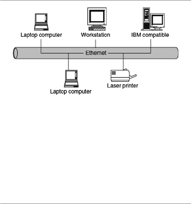
computer network in short. Figure 1.1 shows a computer network.
The hardware component is made of network elements consisting of a collection
of nodes that include the end systems commonly called hosts and intermediate
switching elements that include hubs, bridges, routers, and gateways that, without
loss of generality, we will call network elements.
Network elements may own resources individually, that is, locally or globally.
Network software consists of all application programs and network protocols that
are used to synchronize, coordinate, and bring about the sharing and exchange of
data among the network elements. Network software also makes the sharing of
expensive resources in the network possible. Network elements, network software,
and users all work together so that individual users can exchange messages and
4
share resources on other systems that are not readily available locally. The network
elements, together with their resources, may be of diverse hardware technologies
and the software may be as different as possible, but the whole combination must
work together in unison.
Internetworking technology enables multiple, diverse underlying hardware tech-
nologies and different software regimes to interconnect heterogeneous networks
and bring them to communicate smoothly. The smooth working of any computer
communication network is achieved through the low-level mechanisms provided by
the network elements and high-level communication facilities provided by the soft-
ware running on the communicating elements. Before we discuss the working of
these networks, let us fi rst look at the different types of networks.
1.2 Computer Network Models
There are several confi guration models that form a computer network. The most
common of these are the centralized and distributed models. In a centralized model,
several computers and devices are interconnected and can talk to each other.
However, there is only one central computer, called the master, through which all
correspondence must take place. Dependent computers, called surrogates, may have
reduced local resources, such as memory, and sharable global resources are
controlled by the master at the center. Unlike the centralized model, however, the
distributed network consists of loosely coupled computers interconnected by a
communication network consisting of connecting elements and communication
channels. The computers themselves may own their resources locally or may request
resources from a remote computer. These computers are known by a string of
names, including host, client, or node. If a host has resources that other hosts need,
then that host is known as a server. Communication and sharing of resources are not
controlled by the central computer but are arranged between any two
Fig. 1.1 A computer network
1 Computer Network Fundamentals
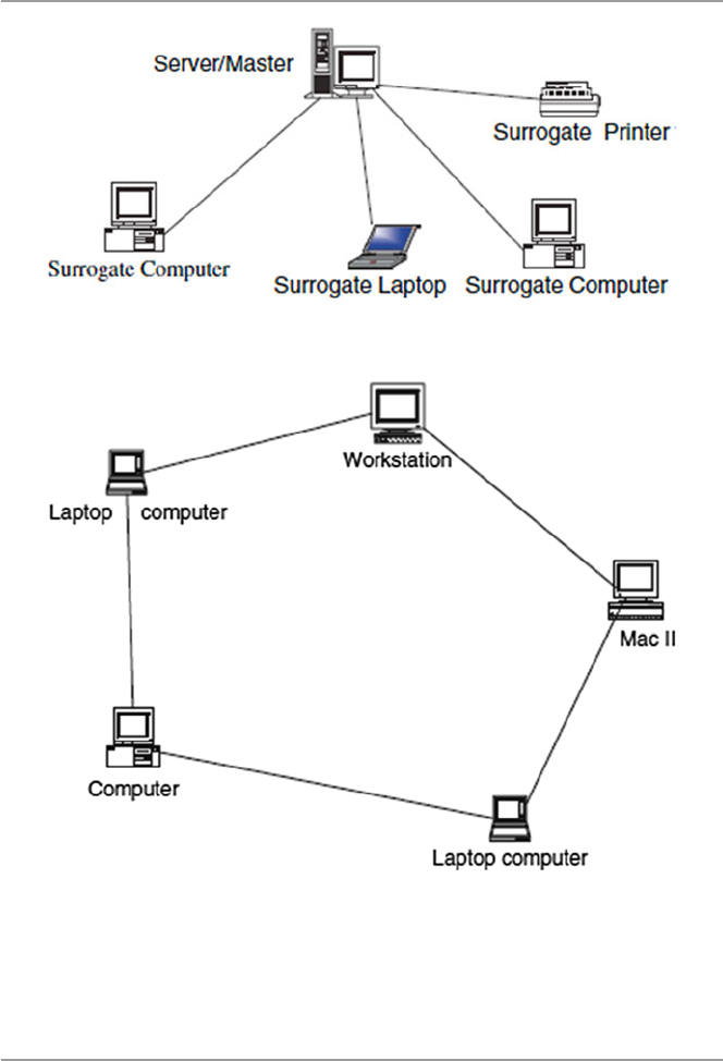
5
communicating elements in the network. Figures 1.2 and 1.3 show a centralized
network model and a distributed network model, respectively.
1.3 Computer Network Types
Computer networks come in different sizes. Each network is a cluster of network
elements and their resources. The size of the cluster determines the network type.
There are, in general, two main network types: the local area network (LAN) and
wide area network (WAN).
Fig. 1.2 A centralized network model
Fig. 1.3 A distributed network model
1.3 Computer Network Types
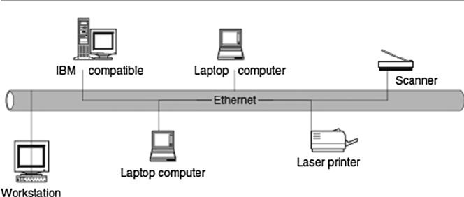
6
1.3.1 Local Area Networks (LANs)
A computer network with two or more computers or clusters of network and their
resources connected by a communication medium sharing communication proto-
cols and confi ned in a small geographical area, such as a building fl oor, a building,
or a few adjacent buildings, is called a local area network (LAN). The advantage of
a LAN is that all network elements are close together so the communication links
maintain a higher speed of data movement. Also, because of the proximity of the
communicating elements, high-cost and high-quality communicating elements can
be used to deliver better service and high reliability. Figure 1.4 shows a LAN
network.
1.3.2 Wide Area Networks (WANs)
A wide area network (WAN), on the other hand, is a network made up of one or more
clusters of network elements and their resources, but instead of being confi ned to a
small area, the elements of the clusters or the clusters themselves are scattered over
a wide geographical area as in a region of a country or across the whole country,
several countries, or the entire globe like the Internet. Some advantages of a WAN
include distributing services to a wider community and availability of a wide array of
both hardware and software resources that may not be available in a LAN. However,
because of the large geographical areas covered by WANs, communication media are
slow and often unreliable. Figure 1.5 shows a WAN network.
1.3.3 Metropolitan Area Networks (MANs)
Between the LAN and WAN, there is also a middle network called the metropolitan
area network (MAN) because it covers a slightly wider area than the LAN but not
so wide as to be considered a WAN. Civic networks that cover a city or part of a city
Fig. 1.4 A LAN network
1 Computer Network Fundamentals
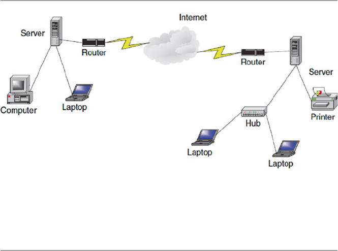
7
are a good example of a MAN. MANs are rarely talked about because they are quiet
often overshadowed by cousin LAN to the left and cousin WAN to the right.
1.4 Data Communication Media Technology
The performance of a network type depends greatly on the transmission technology
and media used in the network. Let us look at these two.
1.4.1 Transmission Technology
The media through which information has to be transmitted determine the signal to
be used. Some media permit only analog signals. Some allow both analog and digi-
tal. Therefore, depending on the media type involved and other considerations, the
input data can be represented as either digital or analog signal. In an analog format,
data is sent as continuous electromagnetic waves on an interval representing things
such as voice and video and propagated over a variety of media that may include
copper wires, twisted coaxial pair or cable, fi ber optics, or wireless. We will discuss
these media soon. In a digital format, on the other hand, data is sent as a digital
signal, a sequence of voltage pulses that can be represented as a stream of binary
bits. Both analog and digital data can be propagated and many times represented as
either analog or digital.
Transmission itself is the propagation and processing of data signals between
network elements. The concept of representation of data for transmission, either as
analog or digital signal, is called an encoding scheme. Encoded data is then trans-
mitted over a suitable transmission medium that connects all network elements.
There are two encoding schemes, analog and digital. Analog encoding propagates
analog signals representing analog data such as sound waves and voice data. Digital
Fig. 1.5 A WAN network
1.4 Data Communication Media Technology

8
encoding, on the other hand, propagates digital signals representing either an analog
or a digital signal representing digital data of binary streams by two voltage levels.
Since our interest in this book is in digital networks, we will focus on the encoding
of digital data.
1.4.1.1 Analog Encoding of Digital Data
Recall that digital information is in the form of 1s or 0s. To send this information
over some analog medium such as the telephone line, for example, which has lim-
ited bandwidth, digital data needs to be encoded using modulation and demodula-
tion to produce analog signals. The encoding uses a continuous oscillating wave,
usually a sine wave, with a constant frequency signal called a carrier signal. The
carrier has three modulation characteristics: amplitude , frequency , and phase shift.
The scheme then uses a modem , a modulation–demodulation pair, to modulate and
demodulate the data signal based on any one of the three carrier characteristics or a
combination. The resulting wave is between a range of frequencies on both sides of
the carrier as shown below [ 1 ]:
• Amplitude modulation represents each binary value by a different amplitude of
the carrier frequency. The absence of or low carrier frequency may represent a 0,
and any other frequency then represents a 1. But this is a rather ineffi cient modu-
lation technique and is therefore used only at low frequencies up to 1,200 bps in
voice grade lines.
• Frequency modulation also represents the two binary values by two different
frequencies close to the frequency of the underlying carrier. Higher frequencies
represent a 1 and low frequencies represent a 0. The scheme is less susceptible to
errors.
• Phase shift modulation changes the timing of the carrier wave, shifting the carrier
phase to encode the data. A 1 is encoded as a change in phase by 180°, and a 0
may be encoded as a 0 change in phase of a carrier signal. This is the most effi -
cient scheme of the three, and it can reach a transmission rate of up to 9,600 bps.
1.4.1.2 Digital Encoding of Digital Data
In this encoding scheme, which offers the most common and easiest way to transmit
digital signals, two binary digits are used to represent two different voltages. Within
a computer, these voltages are commonly 0 and 5 V. Another procedure uses two
representation codes: nonreturn to zero level (NRZ-L) , in which negative voltage
represents binary one and positive voltage represents binary zero, and nonreturn to
zero , invert on ones (NRZ-I). See Figs. 1.6 and 1.7 for an example of these two
codes. In NRZ-L, whenever a 1 occurs, a transition from one voltage level to another
is used to signal the information. One problem with NRZ signaling techniques is the
requirement of a perfect synchronization between the receiver and transmitter
clocks. This is, however, reduced by sending a separate clock signal. There are yet
other representations such as the Manchester and differential Manchester, which
encode clock information along with the data.
1 Computer Network Fundamentals

9
One may wonder why go through the hassle of digital encoding and transmis-
sion. There are several advantages over its cousin, analog encoding. These include
the following:
• Plummeting costs of digital circuitry.
• More effi cient integration of voice, video, text, and image.
• Reduction of noise and other signal impairment because of use of repeaters.
• Capacity of channels is utilized best with digital techniques.
• Better encryption and hence better security than in analog transmission.
1.4.1.3 Multiplexing of Transmission Signals
Quite often during the transmission of data over a network medium, the volume of
transmitted data may far exceed the capacity of the medium. Whenever this hap-
pens, it may be possible to make multiple signal carriers share a transmission
medium. This is referred to as multiplexing. There are two ways in which multiplex-
ing can be achieved: time-division multiplexing (TMD) and frequency-division
multiplexing (FDM).
In FDM, all data channels are fi rst converted to analog form. Since a number of
signals can be carried on a carrier, each analog signal is then modulated by a sepa-
rate and different carrier frequency, and this makes it possible to recover during the
demultiplexing process. The frequencies are then bundled on the carrier. At the
receiving end, the demultiplexer can select the desired carrier signal and use it to
extract the data signal for that channel in such a way that the bandwidths do not
overlap. FDM has an advantage of supporting full-duplex communication.
Fig. 1.6 NRZ-L N, nonreturn to zero level representation code
Fig. 1.7 NRZ-I, nonreturn to zero invert on ones representation code
1.4 Data Communication Media Technology

10
TDM, on the other hand, works by dividing the channel into time slots that are
allocated to the data streams before they are transmitted. At both ends of the transmis-
sion, if the sender and receiver agree on the time-slot assignments, then the receiver
can easily recover and reconstruct the original data streams. So multiple digital signals
can be carried on one carrier by interleaving portions of each signal in time.
1.4.2 Transmission Media
As we have observed above, in any form of communication, there must be a medium
through which the communication can take place. So network elements in a network
need a medium in order to communicate. No network can function without a transmis-
sion medium because there would be no connection between the transmitting ele-
ments. The transmission medium plays a vital role in the performance of the network.
In total, characteristic quality, dependability, and overall performance of a network
depend heavily on its transmission medium. The transmission medium also deter-
mines a network’s capacity in realizing the expected network traffi c, reliability for the
network’s availability, size of the network in terms of the distance covered, and the
transmission rate. Network transmission media can be either wired or wireless.
1.4.2.1 Wired Transmission Media
Wired transmission media are used in fi xed networks physically connecting every
network element. There are different types of physical media, the most common of
which are copper wires, twisted pair, coaxial cables, and optical fi bers.
Copper wires have been traditionally used in communication because of their
low resistance to electrical currents that allows signals to travel even further. But
copper wires suffer interference from electromagnetic energy in the environment,
and because of this, they must always be insulated.
Twisted pair is a pair of wires consisting of insulated copper wire each wrapped
around the other, forming frequent and numerous twists. Together, the twisted, insu-
lated copper wires act as a full-duplex communication link. The twisting of the
wires reduces the sensitivity of the cable to electromagnetic interference and also
reduces the radiation of radio-frequency noises that may interfere with nearby
cables and electronic components. To increase the capacity of the transmitting
medium, more than one pair of the twisted wires may be bundled together in a pro-
tective coating. Because twisted pairs were far less expensive, were easy to install,
and had a high quality of voice data, they were widely used in telephone networks.
However, because they are poor in upward scalability in transmission rate, distance,
and bandwidth in LANs, twisted pair technology has been abandoned in favor of
other technologies. Figure 1.8 shows a twisted pair.
Coaxial cables are dual-conductor cables with a shared inner conductor in the core
of the cable protected by an insulation layer and the outer conductor surrounding the
insulation. These cables are called coaxial because they share the inner conductor. The
inner core conductor is usually made of solid copper wire but at times can also be made
up of stranded wire. The outer conductor commonly made of braided wires, but
1 Computer Network Fundamentals
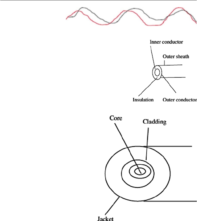
11
sometimes made of metallic foil or both, forms a protective tube around the inner
conductor. This outer conductor is also further protected by another outer coating
called the sheath. Figure 1.9 shows a coaxial cable. Coaxial cables are commonly used
in television transmissions. Unlike twisted pairs, coaxial cables can be used over long
distances. There are two types of coaxial cables: thinnet , a light and fl exible cabling
medium that is inexpensive and easy to install, and the thicknet , which is thicker and
harder to break and can carry more signals through a longer distance than thinnet.
Optical fi ber is a small medium made up of glass and plastics and conducts an
optical ray. This is the most ideal cable for data transmission because it can accom-
modate extremely high bandwidths and has few problems with electromagnetic
interference that coaxial cables suffer from. It can also support cabling for several
kilometers. The two disadvantages of fi ber-optic cables, however, are cost and
installation diffi culty. As shown in Fig. 1.10 , a simple optical fi ber has a central core
Fig. 1.8 Twisted pair
Fig. 1.9 Coaxial cable
Fig. 1.10 Optical fi ber
1.4 Data Communication Media Technology

12
made up of thin fi bers of glass or plastics. The fi bers are protected by a glass or
plastic coating called a cladding. The cladding, though made up of the same materi-
als as the core, has different properties that give it the capacity to refl ect back the
core rays that tangentially hit on it. The cladding itself is encased in a plastic jacket.
The jacket protects the inner fi ber from external abuses such as bending and abra-
sions. Optical fi ber cables transmit data signals by fi rst converting them into light
signals. The transmitted light is emitted at the source from either a light-emitting
diode (LED) or an injection laser diode (ILD). At the receiving end, the emitted rays
are received by a photo detector that converts them back to the original form.
1.4.2.2 Wireless Communication
Wireless communication and wireless networks have evolved as a result of rapid
development in communication technologies, computing, and people’s need for
mobility. Wireless networks fall in one of the following three categories depending
on distance as follows:
• Restricted Proximity Network : This network involves local area networks (LANs)
with a mixture of fi xed and wireless devices.
• Intermediate/Extended Network : This wireless network is actually made up of
two fi xed LAN components joined together by a wireless component. The bridge
may be connecting LANs in two nearby buildings or even further.
• Mobile Network : This is a fully wireless network connecting two network ele-
ments. One of these elements is usually a mobile unit that connects to the home
network (fi xed) using cellular or satellite technology.
These three types of wireless networks are connected using basic media such as
infrared, laser beam, narrowband and spread-spectrum radio, microwave, and satel-
lite communication [ 2 ].
Infrared : During an infrared transmission, one network element remotely emits
and transmits pulses of infrared light that carry coded instructions to the receiving
network element. As long as there is no object to stop the transmitted light, the
receiver gets the instruction. Infrared is best used effectively in a small confi ned
area, within 100 ft, for example, a television remote communicating with the televi-
sion set. In a confi ned area such as this, infrared is relatively fast and can support
high bandwidths of up to 10 Mbps.
High-Frequency Radio : During a radio communication, high-frequency electro-
magnetic radio waves or radio frequency commonly referred to as RF transmissions
are generated by the transmitter and are picked up by the receiver. Because the range
of radio-frequency band is greater than that of infrared, mobile computing elements
can communicate over a limited area without both transmitter and receiver being
placed along a direct line of sight; the signal can bounce off light walls, buildings,
and atmospheric objects. RF transmissions are very good for long distances when
combined with satellites to refract the radio waves.
Microwave : Microwaves are a higher-frequency version of radio waves but
whose transmissions, unlike those of the radio, can be focused in a single direction.
1 Computer Network Fundamentals
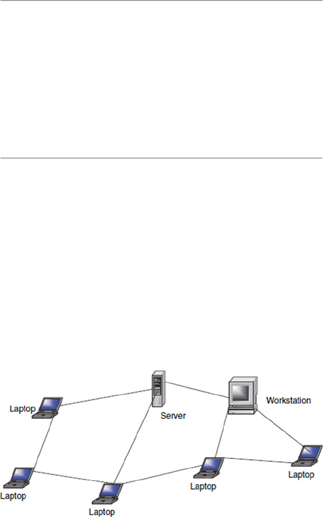
13
Microwave transmissions use a pair of parabolic antennas that produce and receive
narrow but highly directional signals. To be sensitive to signals, both the transmit-
ting and receiving antennas must focus within a narrow area. Because of this, both
the transmitting and receiving antennas must be carefully adjusted to align the trans-
mitted signal to the receiver. Microwave communication has two forms: terrestrial,
when it is near ground, and satellite microwave. The frequencies and technologies
employed by these two forms are similar but with notably distinct differences.
Laser : Laser light can be used to carry data for several thousand yards through
air and optical fi bers. But this is possible only if there are no obstacles in the line of
sight. Lasers can be used in many of the same situations as microwaves, and like
microwaves, laser beams must be refracted when used over long distances.
1.5 Network Topology
Computer networks, whether LANs, MANs, or WANs, are constructed based on a
topology. There are several topologies including the following popular ones.
1.5.1 Mesh
A mesh topology allows multiple access links between network elements, unlike
other types of topologies. The multiplicity of access links between the network ele-
ments offers an advantage in network reliability because whenever one network
element fails, the network does not cease operations; it simply fi nds a bypass to the
failed element and the network continues to function. Mesh topology is most often
applied in MAN networks. Figure 1.11 shows a mesh network.
Fig. 1.11 Mesh network
1.5 Network Topology
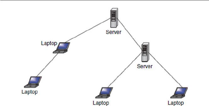
14
1.5.2 Tree
A more common type of network topology is the tree topology. In the tree topology,
network elements are put in a hierarchical structure in which the most predominant
element is called the root of the tree, and all other elements in the network share a
child–parent relationship. As in ordinary, though inverted trees, there are no closed
loops. So dealing with failures of network elements presents complications depend-
ing on the position of the failed element in the structure. For example, in a deeply
rooted tree, if the root element fails, the network automatically ruptures and splits
into two parts. The two parts cannot communicate with each other. The functioning
of the network as a unit is, therefore, fatally curtailed. Figure 1.12 shows a network
using a tree topology.
1.5.3 Bus
A more popular topology, especially for LANs, is the bus topology. Elements in a
network using a bus topology always share a bus and, therefore, have equal access
to all LAN resources. Every network element has full-duplex connections to the
transmitting medium which allows every element on the bus to send and receive
data. Because each computing element is directly attached to the transmitting
medium, a transmission from any one element propagates through the entire length
of the medium in either direction and therefore can be received by all elements in
the network. Because of this, precautions need to be taken to make sure that trans-
missions intended for one element can be received by that element and no other
element. The network must also use a mechanism that handles disputes in case two
or more elements try to transmit at the same time. The mechanism deals with the
likely collision of signals and brings a quick recovery from such a collision. It is
also necessary to create fairness in the network so that all other elements can trans-
mit when they need to do so. See Fig. 1.13 .
Fig. 1.12 Tree topology
1 Computer Network Fundamentals
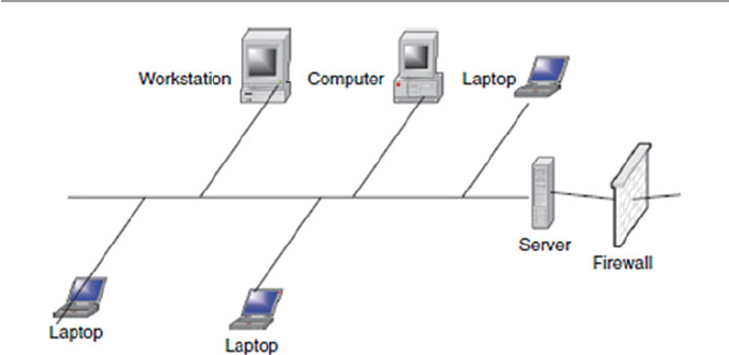
15
A collision control mechanism must also improve effi ciency in the network using
a bus topology by allowing only one element in the network to have control of the
bus at any one time. This network element is then called the bus master and other
elements are considered to be its slaves. This requirement prevents collision from
occurring in the network as elements in the network try to seize the bus at the same
time. A bus topology is commonly used by LANs.
1.5.4 Star
Another very popular topology, especially in LAN network technologies, is a star
topology. A star topology is characterized by a central prominent node that connects
to every other element in the network. So all the elements in the network are con-
nected to a central element. Every network element in a star topology is connected
pairwise in a point-to-point manner through the central element, and communica-
tion between any pair of elements must go through this central element. The central
element or node can either operate in a broadcast fashion, in which case information
from one element is broadcast to all connected elements, or transmit as a switching
device in which the incoming data is transmitted only to one element, the nearest
element enroute to the destination. The biggest disadvantage to the star topology in
networks is that the failure of the central element results in the failure of the entire
network. Figure 1.14 shows a star topology.
1.5.5 Ring
Finally, another popular network topology is the ring topology. In this topology,
each computing element in a network using a ring topology is directly connected to
the transmitting medium via a unidirectional connection so that information put on
the transmission medium can reach all computing elements in the network through
Fig. 1.13 Bus topology
1.5 Network Topology
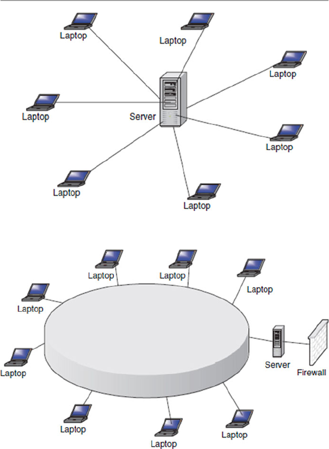
16
a mechanism of taking turns in sending information around the ring. Figure 1.15
shows a ring topology network. The taking of turns in passing information is man-
aged through a token system. A token is a system-wide piece of information that
guarantees the current owner to be the bus master. As long as it owns the token, no
other network element is allowed to transmit on the bus. When an element currently
Fig. 1.15 Ring topology network
Fig. 1.14 Star topology
1 Computer Network Fundamentals
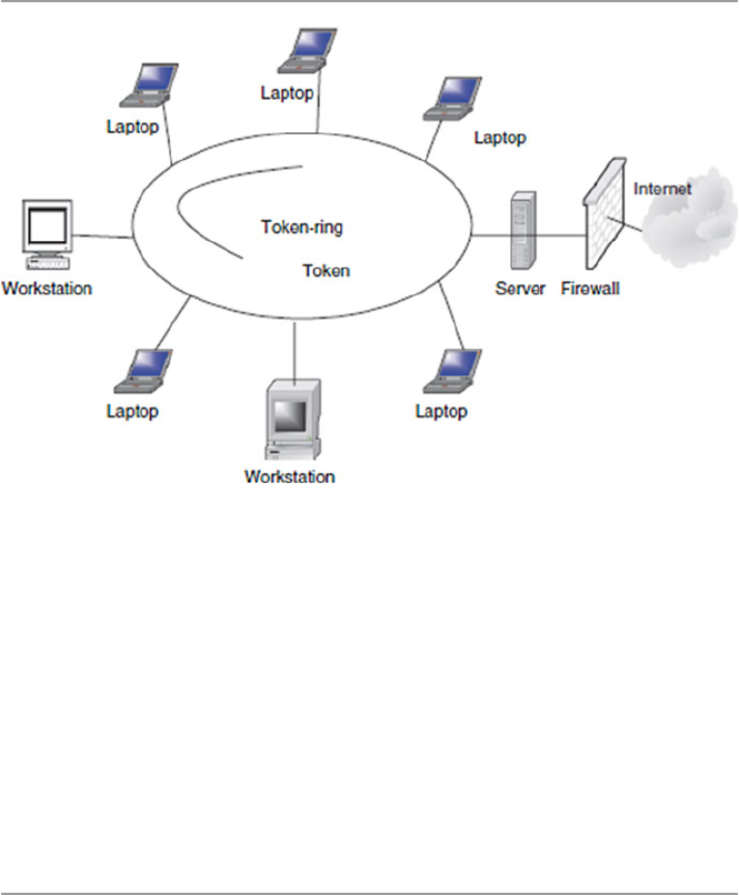
17
sending information and holding the token has fi nished, it passes the token down-
stream to its nearest neighbor. The token system is a good management system of
collision and fairness.
There are variants of a ring topology collectively called hub hybrids combining
either a star with a bus or a stretched star as shown in Fig. 1.16 .
Although network topologies are important in LANs, the choice of a topology
depends on a number of other factors, including the type of transmission medium,
reliability of the network, the size of the network, and its anticipated future growth.
Recently, the most popular LAN topologies have been the bus, star, and ring topolo-
gies. The most popular bus- and star-based LAN topology is the Ethernet, and the
most popular ring-based LAN topology is the token ring.
1.6 Network Connectivity and Protocols
In the early days of computing, computers were used as stand-alone machines, and
all work that needed cross-computing was done manually. Files were moved on
disks from computer to computer. There was, therefore, a need for cross-computing
where more than one computer should talk to others and vice versa.
A new movement was, therefore, born. It was called the open system movement ,
which called for computer hardware and software manufacturers to come up with a
way for this to happen. But to make this possible, standardization of equipment and
software was needed. To help in this effort and streamline computer communica-
tion, the International Organization for Standardization (ISO) developed the Open
System Interconnection (OSI) model. The OSI is an open architecture model that
Fig. 1.16 Token ring hub
1.6 Network Connectivity and Protocols

18
functions as the network communication protocol standard, although it is not the
most widely used one. The Transport Control Protocol/Internet Protocol (TCP/IP)
model, a rival model to OSI, is the most widely used. Both OSI and TCP/IP models
use two protocol stacks, one at the source element and the other at the destination
element.
1.6.1 Open System Interconnection (OSI) Protocol Suite
The development of the OSI model was based on the secure premise that a com-
munication task over a network can be broken into seven layers, where each layer
represents a different portion of the task. Different layers of the protocol provide
different services and ensure that each layer can communicate only with its own
neighboring layers. That is, the protocols in each layer are based on the protocols of
the previous layers.
Starting from the top of the protocol stack, tasks and information move down
from the top layers until they reach the bottom layer where they are sent out over the
network media from the source system to the destination. At the destination, the task
or information rises back up through the layers until it reaches the top. Each layer is
designed to accept work from the layer above it and to pass work down to the layer
below it and vice versa. To ease interlayer communication, the interfaces between
the layers are standardized. However, each layer remains independent and can be
designed independently, and each layer’s functionality should not affect the func-
tionalities of other layers above and below it.
Table 1.1 shows an OSI model consisting of seven layers and the descriptions of
the services provided in each layer.
In peer-to-peer communication, the two communicating computers can initiate
and receive tasks and data. The task and data initiated from each computer starts
from the top in the application layer of the protocol stack on each computer. The
tasks and data then move down from the top layers until they reach the bottom layer,
where they are sent out over the network media from the source system to the des-
tination. At the destination, the task and data rise back up through the layers until
the top. Each layer is designed to accept work from the layer above it and pass work
down to the layer below it. As data passes from layer to layer of the sender machine,
Table 1.1 ISO protocol
layers and corresponding
services
Layer number Protocol
7 Application
6 Presentation
5 Session
4 Transport
3 Network
2 Data link
1 Physical
1 Computer Network Fundamentals
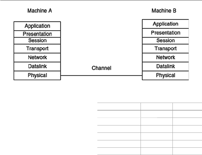
19
layer headers are appended to the data, causing the datagram to grow larger. Each
layer header contains information for that layer’s peer on the remote system. That
information may indicate how to route the packet through the network or what
should be done to the packet as it is handed back up the layers on the recipient
computer.
Figure 1.17 shows a logical communication model between two peer computers
using the ISO model. Table 1.2 shows the datagram with added header information
as it moves through the layers. Although the development of the OSI model was
intended to offer a standard for all other proprietary models and it was as encom-
passing of all existing models as possible, it never really replaced many of those
rival models it was intended to replace. In fact it is this “all-in-one” concept that led
to market failure because it became too complex. Its late arrival on the market also
prevented its much anticipated interoperability across networks.
1.6.2 Transport Control Protocol/Internet Protocol
( TCP/IP) Model
Among the OSI rivals was the TCP/IP, which was far less complex and more histori-
cally established by the time the OSI came on the market. The TCP/IP model does
not exactly match the OSI model. For example, it has two to three fewer levels than
the seven layers of the OSI model. It was developed for the US Department of
Defense Advanced Research Projects Agency (DARPA); but over the years, it has
Fig. 1.17 ISO logical peer communication model
Table 1.2 OSI datagrams
seen in each layer with
header added
No header Data Application
H1 Data Presentation
H2 Data Session
H3 Data Transport
H4 Data Network
H5 Data Data Link
No header Data Physical
1.6 Network Connectivity and Protocols

20
seen a phenomenal growth in popularity, and it is now the de facto standard for the
Internet and many intranets. It consists of two major protocols: the Transmission
Control Protocol (TCP) and the Internet Protocol (IP), hence the TCP/IP designa-
tion. Table 1.3 shows the layers and protocols in each layer.
Since TCP/IP is the most widely used in most network protocol suites by the
Internet and many intranets, let us focus on its layers here.
1.6.2.1 Application Layer
This layer, very similar to the application layer in the OSI model, provides the user
interface with resources rich in application functions. It supports all network appli-
cations and includes many protocols on a data structure consisting of bit streams as
shown in Fig. 1.18 .
Table 1.3 TCP/IP protocol layers
Layer Delivery unit Protocols
Application Message Handles all higher-level protocols including File Transfer
Protocol (FTP), Name Server Protocol (NSP), Simple Mail
Transfer Protocol (SMTP), Simple Network Management
Protocol (SNMP), HTTP, Remote fi le access (telnet), Remote
fi le server (NFS), Name Resolution (DNS), HTTP, TFTP,
SNMP, DHCP, DNS, BOOTP
Combines application, session, and presentation layers of the
OSI model
Handles all high-level protocols
Transport Segment Handles transport protocols including Transmission Control
Protocol (TCP), User Datagram Protocol (UDP)
Network Datagram Contains the following protocols: Internet Protocol (IP),
Internet Control Message Protocol (ICMP), Internet Group
Management Protocol (IGMP)
Supports transmitting source packets from any network on the
internetwork and makes sure they arrive at the destination
independent of the path and networks they took to reach there
Best path determination and packet switching occur at this
layer
Data link Frame Contains protocols that require IP packet to cross a physical
link from one device to another directly connected device
It included the following networks
WAN – wide area network
LAN – local area network
Physical Bit stream All network card drivers
Fig. 1.18 Application layer data frame
1 Computer Network Fundamentals
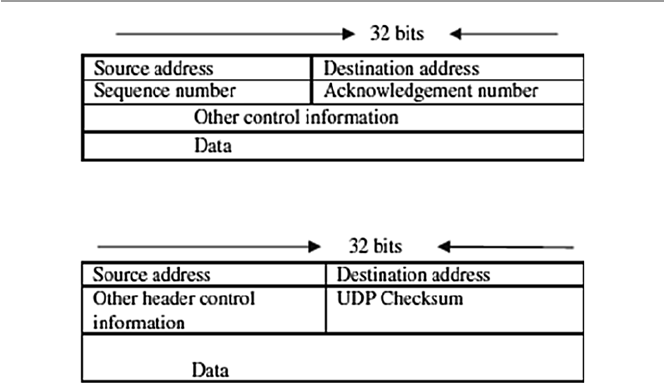
21
1.6.2.2 Transport Layer
This layer, again similar to the OSI model session layer, is slightly removed from
the user and is hidden from the user. Its main purpose is to transport application
layer messages that include application layer protocols in their headers between the
host and the server. For the Internet network, the transport layer has two standard
protocols: Transport Control Protocol (TCP) and User Datagram Protocol (UDP).
TCP provides a connection-oriented service, and it guarantees the delivery of all
application layer packets to their destination. This guarantee is based on two mecha-
nisms: congestion control that throttles the transmission rate of the source element
when there is traffi c congestion in the network and the fl ow control mechanism that
tries to match sender and receiver speeds to synchronize the fl ow rate and reduce the
packet drop rate. While TCP offers guarantees of delivery of the application layer
packets, UDP, on the other hand, offers no such guarantees. It provides a no-frill
connectionless service with just delivery and no acknowledgments. But it is much
more effi cient and a protocol of choice for real-time data such as streaming video
and music. Transport layer delivers transport layer packets and protocols to the net-
work layer. Figure 1.19 shows the TCP data structure, and Fig. 1.20 shows the UDP
data structure.
1.6.2.3 Network Layer
This layer moves packets, now called datagrams, from router to router along the
path from a source host to the destination host. It supports a number of protocols
including the Internet Protocol (IP), Internet Control Message Protocol (ICMP),
and Internet Group Management Protocol (IGMP). The IP Protocol is the most
widely used network layer protocol. IP uses header information from the transport
layer protocols that include datagram source and destination port numbers from IP
addresses, and other TCP header and IP information, to move datagrams from router
Fig. 1.19 A TCP data structure
Fig. 1.20 A UDP data structure
1.6 Network Connectivity and Protocols
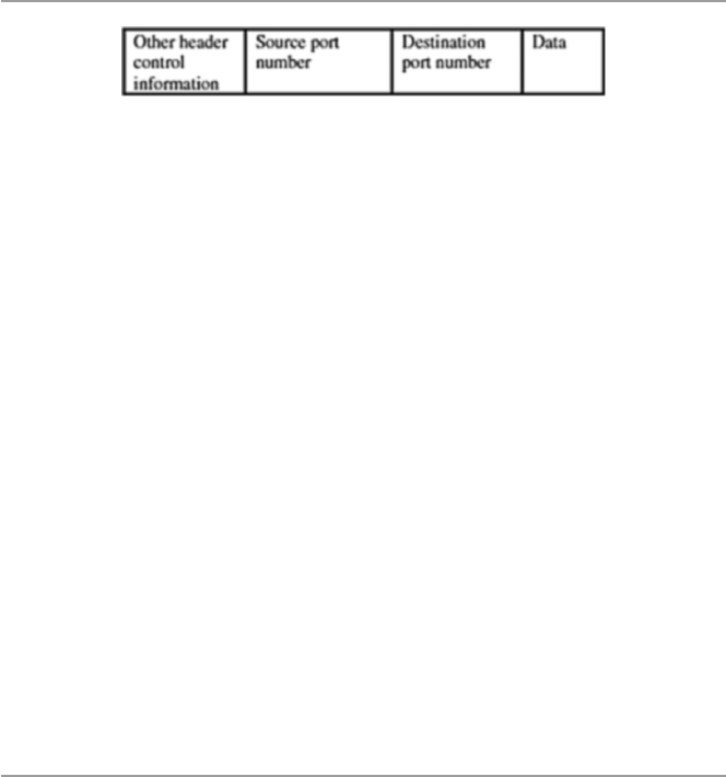
22
to router through the network. Best routes are found in the network by using routing
algorithms. Figure 1.21 shows the IP datagram structure.
The standard IP address has been the so-called IPv4, a 32-bit addressing scheme.
But with the rapid growth of the Internet, there was fear of running out of addresses,
so IPv6, a new 64-bit addressing scheme, was created. The network layer conveys
the network layer protocols to the data link layer.
1.6.2.4 Data Link Layer
This layer provides the network with services that move packets from one packet
switch like a router to the next over connecting links. This layer also offers reliable
delivery of network layer packets over links. It is at the lowest level of communica-
tion, and it includes the network interface card (NIC) and operating system (OS)
protocols. The protocols in this layer include Ethernet, asynchronous transfer mode
(ATM), and others such as frame relay. The data link layer protocol unit, the frame ,
may be moved over links from source to destination by different link layer protocols
at different links along the way.
1.6.2.5 Physical Layer
This layer is responsible for literally moving data link datagrams bit by bit over the
links and between the network elements. The protocols here depend on and use the
characteristics of the link medium and the signals on the medium.
1.7 Network Services
For a communication network to work effectively, data in the network must be able
to move from one network element to another. This can only happen if the network
services to move such data work. For data networks, these services fall into two
categories:
• Connection services to facilitate the exchange of data between the two network
communicating end systems with as little data loss as possible and in as little
time as possible
• Switching services to facilitate the movement of data from host to host across the
length and width of the network mesh of hosts, hubs, bridges, routers, and
gateways
Fig. 1.21 An IP datagram structure
1 Computer Network Fundamentals

23
1.7.1 Connection Services
How do we get the network transmitting elements to exchange data over the
network? Two types of connection services are used: the connected-oriented and
connectionless services.
1.7.1.1 Connected-Oriented Services
With a connection-oriented service, before a client can send packets with real data
to the server, there must be a three-way handshake. We will defi ne this three-way
handshake in later chapters. But the purpose of a three-way handshake is to estab-
lish a session before the actual communication can begin. Establishing a session
before data is moved creates a path of virtual links between the end systems through
a network and, therefore, guarantees the reservation and establishment of fi xed
communication channels and other resources needed for the exchange of data before
any data is exchanged and as long as the channels are needed. For example, this
happens whenever we place telephone calls; before we exchange words, the chan-
nels are reserved and established for the duration. Because this technique guaran-
tees that data will arrive in the same order it was sent in, it is considered to be
reliable. In short, the service offers the following:
• Acknowledgments of all data exchanges between the end systems
• Flow control in the network during the exchange
• Congestion control in the network during the exchange
Depending on the type of physical connections in place and the services required
by the systems that are communicating, connection-oriented methods may be
implemented in the data link layers or in the transport layers of the protocol stack,
although the trend now is to implement it more at the transport layer. For example,
TCP is a connection-oriented transport protocol in the transport layer. Other network
technologies that are connection oriented include the frame relay and ATMs.
1.7.1.2 Connectionless Service
In a connectionless service, there is no handshaking to establish a session between
the communicating end systems, no fl ow control, and no congestion control in the
network. This means that a client can start communicating with a server without
warning or inquiry for readiness; it simply sends streams of packets, called data-
grams, from its sending port to the server’s connection port in single point-to-point
transmissions with no relationship established between the packets and between the
end systems. There are advantages and of course disadvantages to this type of con-
nection service. In brief, the connection is faster because there is no handshaking
which can sometimes be time consuming, and it offers periodic burst transfers with
large quantities of data, and in addition, it has a simple protocol. However, this
1.7 Network Services

24
service offers minimum functions and has no safeguards and guarantees to the
sender since there is no prior control information and no acknowledgment. In addi-
tion, the service does not have the reliability of the connection-oriented method and
offers no error handling and no packets ordering; in addition, each packet self-iden-
tifi es that leads to long headers, and fi nally, there is no predefi ned order in the arrival
of packets.
Like the connection-oriented method, this service can operate both at the data
link and transport layers. For example, UDP, a connectionless service, operates at
the transport layer.
1.7.2 Network Switching Services
Before we discuss communication protocols, let us take a detour and briefl y discuss
data transfer by a switching element. This is a technique by which data is moved
from host to host across the length and width of the network mesh of hosts, hubs,
bridges, routers, and gateways. This technique is referred to as data switching. The
type of data switching technique used by a network determines how messages are
transmitted between the two communicating elements and across that network. There
are two types of data switching techniques: circuit switching and packet switching.
1.7.2.1 Circuit Switching
In circuit switching networks, one must reserve all the resources before setting up a
physical communication channel needed for communication. The physical connec-
tion, once established, is then used exclusively by the two end systems, usually
subscribers, for the duration of the communication. The main feature of such a con-
nection is that it provides a fi xed data rate channel and both subscribers must oper-
ate at this rate. For example, in a telephone communication network, a connected
line is reserved between the two points before the users can start using the service.
One issue of debate on circuit switching is the perceived waste of resources during
the so-called silent periods when the connection is fully in force but not being used
by the parties. This situation occurs when, for example, during a telephone network
session, a telephone receiver is not hung up after use, leaving the connection still
established. During this period, while no one is utilizing the session, the session line
is still open.
1.7.2.2 Packet Switching
Packet switching networks, on the other hand, do not require any resources to be
reserved before a communication session begins. These networks, however, require
the sending host to assemble all data streams to be transmitted into packets. If a
message is large, it is broken into several packets. Packet headers contain the source
and the destination network addresses of the two communicating end systems. Then
each of the packets is sent on the communication links and across packet switches
(routers). On receipt of each packet, the router inspects the destination address con-
tained in the packet. Using its own routing table, each router then forwards the
1 Computer Network Fundamentals
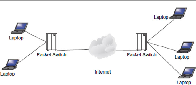
25
packet on the appropriate link at the maximum available bit rate. As each packet is
received at each intermediate router, it is forwarded on the appropriate link inter-
spersed with other packets being forwarded on that link. Each router checks the
destination address, if it is the owner of the packet; it then reassembles the packets
into the fi nal message. Figure 1.22 shows the role of routers in packet switching
networks.
Packet switches are considered to be store-and-forward transmitters, meaning
that they must receive the entire packet before the packet is retransmitted or switched
on to the next switch.
Because there is no predefi ned route for these packets, there can be unpredictably
long delays before the full message can be reassembled. In addition, the network
may not dependably deliver all the packets to the intended destination. To ensure
that the network has a reliably fast transit time, a fi xed maximum length of time is
allowed for each packet. Packet switching networks suffer from a few problems,
including the following:
• The rate of transmission of a packet between two switching elements depends on
the maximum rate of transmission of the link joining them and on the switches
themselves.
• Momentary delays are always introduced whenever the switch is waiting for a
full packet. The longer the packet, the longer the delay.
• Each switching element has a fi nite buffer for the packets. It is thus possible for
a packet to arrive only to fi nd the buffer full with other packets. Whenever this
happens, the newly arrived packet is not stored but gets lost, a process called
packet dropping. In peak times, servers may drop a large number of packets.
Congestion control techniques use the rate of packet drop as one measure of traf-
fi c congestion in a network.
Packet switching networks are commonly referred to as packet networks for
obvious reasons. They are also called asynchronous networks, and in such networks,
packets are ideal because there is a sharing of the bandwidth, and of course, this
Fig. 1.22 Packet switching networks
1.7 Network Services

26
avoids the hassle of making reservations for any anticipated transmission. There are
two types of packet switching networks:
• Virtual circuit network in which a packet route is planned, and it becomes a logi-
cal connection before a packet is released.
• Datagram network , which is the focus of this book.
1.8 Network Connecting Devices
Before we discuss network connecting devices, let us revisit the network infrastruc-
ture. We have defi ned a network as a mesh of network elements, commonly referred
to as network nodes , connected together by conducting media. These network nodes
can be either at the ends of the mesh, in which case they are commonly known as
clients, or in the middle of the network as transmitting elements. In a small network
such as a LAN, the nodes are connected together via special connecting and con-
ducting devices that take network traffi c from one node and pass it on to the next
node. If the network is big Internetwork (large networks of networks like WANs and
LANs), these networks are connected to other special intermediate networking
devices so that the Internet functions as a single large network.
Now let us look at network connecting devices and focus on two types of devices:
those used in networks (small networks such as LANs) and those used in
internetworks.
1.8.1 LAN Connecting Devices
Because LANs are small networks, connecting devices in LANs are less powerful
with limited capabilities. There are hubs, repeaters, bridges, and switches.
1.8.1.1 A Hub
This is the simplest in the family of network connecting devices since it connects
the LAN components with identical protocols. It takes in imports and retransmits
them verbatim. It can be used to switch both digital and analog data. In each node,
presetting must be done to prepare for the formatting of the incoming data. For
example, if the incoming data is in digital format, the hub must pass it on as packets;
however, if the incoming data is analog, then the hub passes as a signal. There are
two types of hubs: simple and multiple port hubs, as shown in Figs. 1.23 and 1.24 .
Multiple port hubs may support more than one computer up to its number of ports
and may be used to plan for the network expansion as more computers are added at
a later time.
Network hubs are designed to work with network adapters and cables and can
typically run at either 10 or 100 Mbps; some hubs can run at both speeds. To con-
nect computers with differing speeds, it is better to use hubs that run at both speeds
10/100 Mbps.
1 Computer Network Fundamentals
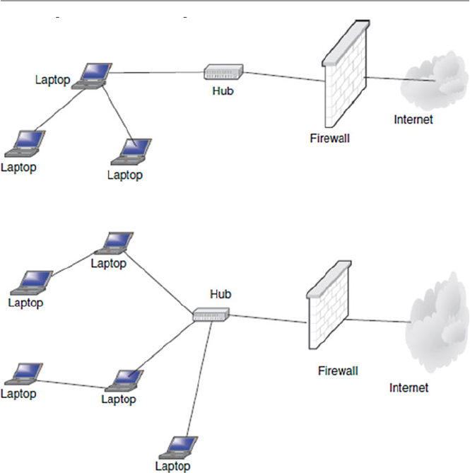
27
1.8.1.2 A Repeater
A network repeater is a low-level local communication device at the physical layer
of the network that receives network signals, amplifi es them to restore them to full
strength, and then retransmits them to another node in the network. Repeaters are
used in a network for several purposes including countering the attenuation that
occurs when signals travel long distances and extending the length of the LAN
above the specifi ed maximum. Since they work at the lowest network stack layer,
they are less intelligent than their counterparts such as bridges, switches, routers,
and gateways in the upper layers of the network stack. See Fig. 1.25 .
1.8.1.3 A Bridge
A bridge is like a repeater but differs in that a repeater amplifi es electrical signals
because it is deployed at the physical layer; a bridge is deployed at the data link and
therefore amplifi es digital signals. It digitally copies frames. It permits frames from
one part of a LAN or a different LAN with different technology to move to another
Fig. 1.23 A simple hub
Fig. 1.24 Multi-ported hubs
1.8 Network Connecting Devices
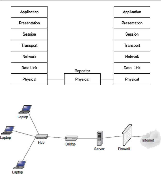
28
part or another LAN. However, in fi ltering and isolating a frame from one network
to another or another part of the same network, the bridge will not move a damaged
frame from one end of the network to the other. As it fi lters the data packets, the
bridge makes no modifi cations to the format and content of the incoming data. A
bridge fi lters the frames to determine whether a frame should be forwarded or
dropped. All “noise” (collisions, faulty wiring, power surges, etc.) packets are not
transmitted.
The bridge fi lters and forwards frames on the network using a dynamic bridge
table. The bridge table, which is initially empty, maintains the LAN addresses for
each computer in the LAN and the addresses of each bridge interface that connects
the LAN to other LANs. Bridges, like hubs, can be either simple or multi-ported.
Figure 1.26 shows a simple bridge, Fig. 1.27 shows a multi-ported bridge, and
Fig. 1.28 shows the position of the bridge in an OSI protocol stack.
Fig. 1.25 A repeater in an OSI model
Fig. 1.26 Simple bridge
1 Computer Network Fundamentals
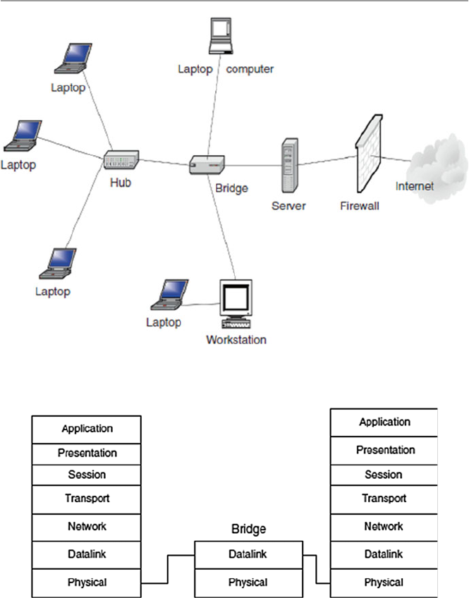
29
1.8.1.4 A Switch
A switch is a network device that connects segments of a network or two small
networks such as Ethernet or token ring LANs. Like the bridge, it also fi lters and
forwards frames on the network with the help of a dynamic table. This point-to-
point approach allows the switch to connect multiple pairs of segments at a time,
allowing more than one computer to transmit data at a time, thus giving them a high
performance over their cousins, the bridges.
Fig. 1.27 Multi-ported bridge
Fig. 1.28 Position of a bridge in an OSI protocol stack
1.8 Network Connecting Devices
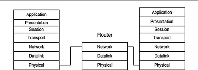
30
1.8.2 Internetworking Devices
Internetworking devices connect together smaller networks, like several LANs cre-
ating much larger networks such as the Internet. Let us look at two of these connec-
tors: the router and the gateway.
1.8.2.1 Routers
Routers are general-purpose devices that interconnect two or more heterogeneous
networks represented by IP subnets or unnumbered point-to-point lines. They are
usually dedicated special-purpose computers with separate input and output inter-
faces for each connected network. They are implemented at the network layer in the
protocol stack. Figure 1.29 shows the position of the router in the OSI protocol
stack.
According to RFC 1812, a router performs the following functions [ 3 ]:
• Conforms to specifi c Internet Protocols specifi ed in the 1812 document, includ-
ing the Internet Protocol (IP), Internet Control Message Protocol (ICMP), and
others as necessary.
• Connects to two or more packet networks. For each connected network, the
router must implement the functions required by that network because it is a
member of that network. These functions typically include the following:
– Encapsulating and decapsulating the IP datagrams with the connected net-
work framing. For example, if the connected network is an Ethernet LAN, an
Ethernet header and checksum must be attached.
– Sending and receiving IP datagrams up to the maximum size supported by
that network; this size is the network’s maximum transmission unit or MTU.
– Translating the IP destination address into an appropriate network-level
address for the connected network. These are the Ethernet hardware addresses
on the NIC, for Ethernet cards, if needed. Each network addresses the router
as a member computer of its own network. This means that each router is a
member of each network it connects to. It, therefore, has a network host
address for that network and an interface address for each network it is con-
nected to. Because of this rather strange characteristic, each router interface
Fig. 1.29 Router in the OSI protocol stack
1 Computer Network Fundamentals

31
has its own address resolution protocol (ARP) module, its LAN address (net-
work card address), and its own Internet Protocol (IP) address.
– Responding to network fl ow control and error indications, if any.
• Receives and forwards Internet datagrams. Important issues in this process are
buffer management, congestion control, and fairness. To do this, the router must:
– Recognize error conditions and generate ICMP error and information mes-
sages as required.
– Drop datagrams whose time-to-live fi elds have reached zero.
– Fragment datagrams when necessary to fi t into the maximum transmission
unit (MTU) of the next network.
• Chooses a next-hop destination for each IP datagram based on the information in
its routing database.
• Usually supports an interior gateway protocol (IGP) to carry out distributed rout-
ing and reachability algorithms with the other routers in the same autonomous
system. In addition, some routers will need to support an exterior gateway proto-
col (EGP) to exchange topological information with other autonomous systems.
• Provides network management and system support facilities, including loading,
debugging, status reporting, exception reporting, and control.
Forwarding an IP datagram from one network across a router requires the router
to choose the address and relevant interface of the next-hop router or for the fi nal
hop if it is the destination host. The next-hop router is always in the next network of
which the router is also a member. The choice of the next-hop router, called for-
warding , depends on the entries in the routing table within the router.
Routers are smarter than bridges in that the router with the use of a router table
has some knowledge of possible routes a packet could take from its source to its
destination. Once it fi nds the destination, it determines the best, fastest, and most
effi cient way of routing the package. The routing table, like in the bridge and switch,
grows dynamically as activities in the network develop. On receipt of a packet, the
router removes the packet headers and trailers and analyzes the IP header by deter-
mining the source and destination addresses and data type and noting the arrival
time. It also updates the router table with new addresses if not already in the table.
The IP header and arrival time information is entered in the routing table. If a router
encounters an address it cannot understand, it drops the package. Let us explain the
working of a router by an example using Fig. 1.30 .
In Fig. 1.30 , suppose host A in LAN1 tries to send a packet to host B in LAN2.
Both host A and host B have two addresses: the LAN (host) address and the IP
address. The translation between host LAN addresses and IP addresses is done by
the ARP, and data is retrieved or built into the ARP table, similar to Table 1.4 . Notice
also that the router has two network interfaces: interface 1 for LAN1 and interface
2 for LAN2 for the connection to a larger network such as the Internet. Each inter-
face has a LAN (host) address for the network the interface connects on and a cor-
responding IP address. As we will see later in the chapter, host A sends a packet to
router 1 at time 10:01 that includes, among other things, both its addresses, message
type, and destination IP address of host B. The packet is received at interface 1 of
1.8 Network Connecting Devices
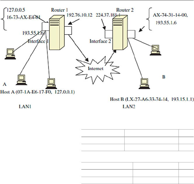
32
the router; the router reads the packet and builds row 1 of the routing table as shown
in Table 1.5 .
The router notices that the packet has to go to network 193.55.1.***, where ***
are digits 0–9, and it has knowledge that this network is connected on interface 2. It
forwards the packet to interface 2. Now, interface 2 with its own ARP may know
host B. If it does, then it forwards the packet and updates the routing table with the
inclusion of row 2. What happens when the ARP at the router interface 1 cannot
determine the next network? That is, if it has no knowledge of the presence of net-
work 193.55.1.***, it will then ask for help from a gateway. Let us now discuss how
IP chooses a gateway to use when delivering a datagram to a remote network.
1.8.2.2 Gateways
Gateways are more versatile devices than routers. They perform protocol conver-
sion between different types of networks, architectures, or applications and serve as
translators and interpreters for network computers that communicate in different
protocols and operate in dissimilar networks, for example, OSI and TCP/IP. Because
the networks are different with different technologies, each network has its own
routing algorithms, protocols, domain name servers, and network administration
Fig. 1.30 Working of a router
Table 1.4 ARP table for
LAN1 IP address LAN address Time
127.0.0.5 16-73-AX-E4-01 10:00
127.76.1.12 07-1A-EB-17-F6 10:03
Table 1.5 Routing table for
interface 1 Address Interface Time
127.0.0.1 1 10:01
192.76.1.12 2 10:03
1 Computer Network Fundamentals
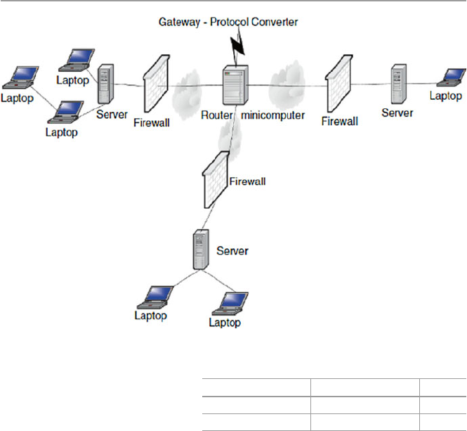
33
procedures and policies. Gateways perform all of the functions of a router and more.
The gateway functionality that does the translation between different network tech-
nologies and algorithms is called a protocol converter. Figure 1.31 shows the posi-
tion of a gateway in a network.
Gateways services include packet format and/or size conversion, protocol con-
version, data translation, terminal emulation, and multiplexing. Since gateways per-
form a more complicated task of protocol conversion, they operate more slowly and
handle fewer devices.
Let us now see how a packet can be routed through a gateway or several gate-
ways before it reaches its destination. We have seen that if a router gets a datagram,
it checks the destination address and fi nds that it is not on the local network. It,
therefore, sends it to the default gateway. The default gateway now searches its table
for the destination address. In case the default gateway recognizes that the destina-
tion address is not on any of the networks it is connected to directly, it has to fi nd yet
another gateway to forward it through.
The routing information the server uses for this is in a gateway routing table link-
ing networks to gateways that reach them. The table starts with the network entry
0.0.0.0, a catch-all entry, for default routes. All packets to an unknown network are
sent through the default route. Table
1.6 shows the gateway routing table.
Fig. 1.31 Position of a gateway
Table 1.6 A gateway
routing table Network Gateway Interface
0.0.0.0 192.133.1.1 1
127.123.0.1 198.24.0.1 2
1.8 Network Connecting Devices

34
The choice between a router, a bridge, and a gateway is a balance between
functionality and speed. Gateways, as we have indicated, perform a variety of
functions; however, because of this variety of functions, gateways may become
bottlenecks within a network because they are slow.
Routing tables may be built either manually for small LANs or by using software
called routing daemons for larger networks.
1.9 Network Technologies
Earlier in this chapter, we indicated that computer networks are basically classifi ed
according to their sizes with the local area networks (LANs) covering smaller areas
and the bigger ones covering wider areas (WANs). In this last section of the chapter,
let us look at a few network technologies in each one of these categories.
1.9.1 LAN Technologies
Recall our defi nition of a LAN at the beginning of this chapter. We defi ned a LAN
to be a small data communication network that consists of a variety of machines that
are all part of the network and cover a geographically small area such as one building
or one fl oor. Also, a LAN is usually owned by an individual or a single entity such
as an organization. According to IEEE 802.3 Committee on LAN Standardization,
a LAN must be a moderately sized and geographically shared peer-to- peer
communication network broadcasting information for all on the network to hear via
a common physical medium on a point-to-point basis with no intermediate switch-
ing element required. Many common network technologies today fall into this
category including the popular Ethernet, the widely used token ring/IEEE 805.2,
and the fi ber distributed data interface (FDDI).
1.9.1.1 Star-Based Ethernet (IEEE 802.3) LAN
Ethernet technology is the most widely used of all LAN technologies, and it has been
standardized by the IEEE 802.3 Committee on Standards. The IEEE 802.3 standards
defi ne the medium access control (MAC) layer and the physical layer. The Ethernet
MAC is a carrier sense multiple access with collision detection (CSMA/CD) system.
With CSMA, any network node that wants to transmit must listen fi rst to the medium
to make sure that there is no other node already transmitting. This is called the carrier
sensing of the medium. If there is already a node using the medium, then the element
that was intending to transmit waits; otherwise, it transmits. In case two or more ele-
ments are trying to transmit at the same time, a collision will occur and the integrity
of the data for all is compromised. However, the element may not know this. So it
waits for an acknowledgment from the receiving node. The waiting period varies,
taking into account maximum round trip propagation delay and other unexpected
delays. If no acknowledgment is received during that time, the element then assumes
that a collision has occurred and the transmission was unsuccessful and therefore it
1 Computer Network Fundamentals

35
must retransmit. If more collisions were to happen, then the element must now
double the delay time and so on. After a collision, when the two elements are in delay
period, the medium may be idle and this may lead to ineffi ciency. To correct this situ-
ation, the elements, instead of just going into the delay mode, must continue to listen
onto the medium as they transmit. In this case, they will not only be doing carrier
sensing but also detecting a collision that leads to CSMA/CD. According to Stallings,
the CSMA/CD scheme follows the following algorithm [
1 ]:
• If the medium is idle, transmit.
• If the medium is busy, continue to listen until idle; then transmit immediately.
• If collision is detected, transmit jamming signal for “collision warning” to all
other network elements.
• After jamming the signal, wait random time units and attempt to transmit.
A number of Ethernet LANs are based on the IEEE 802.3 standards, including:
• 10 BASE-X (where X = 2, 5, T and F; T, twisted pair, and F, fi ber optics)
• 100 BASE-T (where the T options include T4, TX, and FX)
• 1,000 BASE-T (where T options include LX, SX, T, and CX)
The basic Ethernet transmission structure is a frame, and it is shown in Fig.
1.32 .
The source and destination fi elds contain 6-byte LAN addresses of the form
xx-xx- xx-xx-xx-xx, where x is a hexadecimal integer. The error detection fi eld is 4
bytes of bits used for error detection, usually using the cyclic redundancy check
(CRC) algorithm, in which the source and destination elements synchronize the
values of these bits.
1.9.1.2 Token Ring/IEEE 805.2
Token ring LANs based on IEEE 805.2 are also used widely in commercial and
small industrial networks, although not as popular as Ethernet. The standard uses a
frame called a token that circulates around the network so that all network nodes
have equal access to it. As we have seen previously, token ring technology employs
a mechanism that involves passing the token around the network so that all network
elements have equal access to it.
Whenever a network element wants to transmit, it waits for the token on the ring
to make its way to the element’s connection point on the ring. When the token
arrives at this point, the element grabs it and changes one bit of the token that
becomes the start bit in the data frame the element will be transmitting. The element
then inserts data, addressing information and other fi elds, and then releases the
Fig. 1.32 An Ethernet frame structure
1.9 Network Technologies

36
payload onto the ring. It then waits for the token to make a round and come back.
The receiving host must recognize the destination MAC address within the frame as
its own. Upon receipt, the host identifi es the last fi eld indicating the recognition of
the MAC address as its own. The frame contents are then copied by the host, and the
frame is put back in circulation. On reaching the network element that still owns the
token, the element withdraws the token and a new token is put on the ring for another
network element that may need to transmit.
Because of its round-robin nature, the token ring technique gives each network
element a fair chance of transmitting if it wants to. However, if the token ever gets
lost, the network business is halted. Figure
1.33 shows the structure of a token data
frame, and Fig. 1.16 shows the token ring structure.
Like Ethernet, the token ring has a variety of technologies based on the transmis-
sion rates.
1.9.1.3 Other LAN Technologies
In addition to those we have discussed earlier, several other LAN technologies are
in use, including the following:
• Asynchronous transfer mode (ATM) with the goal of transporting real-time
voice, video, text, e-mail, and graphic data. ATM offers a full array of network
services that make it a rival of the Internet network.
• Fiber distributed data interface (FDDI) is a dual-ring network that uses a token
ring scheme with many similarities to the original token ring technology.
• AppleTalk, the popular Mac users’ LAN.
1.9.2 WAN Technologies
As we defi ned it earlier, WANs are data networks like LANs but they cover a wider
geographical area. Because of their sizes, WANs traditionally provide fewer ser-
vices to customers than LANs. Several networks fall into this category, including
the integrated services digital network (ISDN), X.25, frame relay, and the popular
Internet.
1.9.2.1 Integrated Services Digital Network (ISDN)
ISDN is a system of digital phone connections that allows data to be transmitted
simultaneously across the world using end-to-end digital connectivity. It is a net-
work that supports the transmission of video, voice, and data. Because the
Fig. 1.33 A token data frame
1 Computer Network Fundamentals

37
transmission of these varieties of data, including graphics, usually puts widely
differing demands on the communication network, service integration for these
networks is an important advantage to make them more appealing. The ISDN stan-
dards specify that subscribers must be provided with:
• Basic rate interface (BRI) services of two full-duplex 64-kbps B channels, the
bearer channels, and one full-duplex 16-kbps D channel, the data channel. One
B channel is used for digital voice and the other for applications such as data
transmission. The D channel is used for telemetry and for exchanging network
control information. This rate is for individual users.
• Primary rate interface (PRI) services consisting of 23 64-kbps B channels and
one 64-kbps D channel. This rate is for all large users.
BRI can be accessed only if the customer subscribes to an ISDN phone line and
is within 18,000 ft (about 3.4 miles or 5.5 km) of the telephone company central
offi ce. Otherwise, expensive repeater devices are required that may include ISDN
terminal adapters and ISDN routers.
1.9.2.2 X.25
X.25 is the International Telecommunication Union (ITU) protocol developed in
1993 to bring interoperability to a variety of many data communication wide area
networks (WANs), known as public networks , owned by private companies, organi-
zations, and government agencies. By doing so, X.25 describes how data passes into
and out of public data communications networks.
X.25 is a connection-oriented and packet-switched data network protocol with
three levels corresponding to the bottom three layers of the OSI model as follows:
the physical level corresponds to the OSI physical layer, the link level corresponds
to OSI data link layer, and the packet level corresponds to the OSI network layer.
In full operation, the X.25 networks allow remote devices known as data termi-
nal equipment (DTE) to communicate with each other across high-speed digital
links, known as data circuit-terminating equipment (DCE), without the expense of
individual leased lines. The communication is initiated by the user at a DTE setting
up calls using standardized addresses. The calls are established over virtual circuits,
which are logical connections between the originating and destination addresses.
On receipt, the called users can accept, clear, or redirect the call to a third party.
The virtual connections we mentioned above are of the following two types [ 4 ]:
• Switched virtual circuits (SVCs) – SVCs are very much like telephone calls; a
connection is established, data is transferred, and then the connection is released.
Each DTE on the network is given a unique DTE address that can be used much
like a telephone number.
• Permanent virtual circuits (PVCs) – A PVC is similar to a leased line in that the
connection is always present. The logical connection is established permanently
by the packet-switched network administration. Therefore, data may always be
sent without any call setup.
1.9 Network Technologies

38
Both of these circuits are used extensively, but since user equipment and
network systems supported both X.25 PVCs and X.25 SVCs, most users prefer
the SVCs since they enable the user devices to set up and tear down connections
as required.
Because X.25 is a reliable data communications with a capability over a wide
range of quality of transmission facilities, it provides advantages over other WAN
technologies, for example:
• Unlike frame relay and ATM technologies that depend on the use of high-quality
digital transmission facilities, X.25 can operate over either analog or digital
facilities.
• In comparison with TCP/IP, one fi nds that TCP/IP has only end-to-end error
checking and fl ow control, while X.25 is error checked from network element to
network element.
X.25 networks are in use throughout the world by large organizations with
widely dispersed and communication-intensive operations in sectors such as fi nance,
insurance, transportation, utilities, and retail.
1.9.2.3 Other WAN Technologies
The following are other WAN technologies that we would like to discuss but cannot
include because of space limitations:
• Frame relay is a packet-switched network with the ability to multiplex many
logical data conversions over a single connection. It provides fl exible effi cient
channel bandwidth using digital and fi ber-optic transmission. It has many similar
characteristics to X.25 network except in format and functionality.
• Point-to-point protocol (PPP) is the Internet standard for transmission of IP
packets over serial lines. The point-to-point link provides a single, preestablished
communications path from the ending element through a carrier network, such as
a telephone company, to a remote network. These links can carry datagram or
data stream transmissions.
• xDirect service line (xDSL) is a technology that provides an inexpensive, yet
very fast connection to the Internet.
• Switched multi-megabit data service (SMDS) is a connectionless service operat-
ing in the range of 1.5–100 Mbps; any SMDS station can send a frame to any
other station on the same network.
• Asynchronous transfer mode (ATM) is already discussed as a LAN technology.
1.9.3 Wireless LANs
The rapid advances, miniaturization, and the popularity of wireless technology have
opened a new component of LAN technology. The mobility and relocation of work-
ers has forced companies to move into new wireless technologies with emphasis on
1 Computer Network Fundamentals

39
wireless networks extending the local LAN into a wireless LAN. There are basically
four types of wireless LANs [ 1 ]:
• LAN extension is a quick wireless extension to an existing LAN to accommodate
new changes in space and mobile units.
• Cross-building interconnection establishes links across buildings between both
wireless and wired LANs.
• Nomadic access establishes a link between a LAN and a mobile wireless com-
munication device such as a laptop computer.
• Ad hoc networking is a peer-to-peer network temporarily set up to meet some
immediate need. It usually consists of laptops, handheld devices, PCs, and other
communication devices.
• Personal area networks (PANs) that include the popular Bluetooth networks.
There are several wireless IEEE 802.11-based LAN types, including:
• Infrared
• Spread spectrum
• Narrowband microwave
Wireless technology is discussed in further detail in Chap. 17 .
1.10 Conclusion
We have developed the theory of computer networks and discussed the topologies,
standards, and technologies of these networks. Because we were limited by space,
we could not discuss a number of interesting and widely used technologies both
in LAN and WAN areas. However, our limited discussion of these technologies
should give the reader an understanding and scope of the changes that are talking
place in network technologies. We hope that the trend will keep the convergence
of the LAN, WAN, and wireless technologies on track so that the alarming num-
ber of different technologies is reduced and basic international standards are
established.
Exercises
1. What is a communication protocol?
2. Why do we need communication protocols?
3. List the major protocols discussed in this chapter.
4. In addition to ISO and TCP/IP, what are the other models?
5. Discuss two LAN technologies that are not Ethernet or token ring.
6. Why is Ethernet technology more appealing to users than the rest of the LAN
technologies?
7. What do you think are the weak points of TCP/IP?
8. Discuss the pros and cons of the four LAN technologies.
1.10 Conclusion

40
9. List four WAN technologies.
10. What technologies are found in MANs? Which of the technologies listed in 8
and 9 can be used in MANs?
Advanced Exercises
1. X.25 and TCP/IP are very similar but there are differences. Discuss these
differences.
2. Discuss the reasons why ISDN failed to catch on as WAN technology.
3. Why is it diffi cult to establish permanent standards for a technology like WAN
or LAN?
4. Many people see Bluetooth as a personal wireless network (PAN). Why is this
so? What standard does Bluetooth use?
5. Some people think that Bluetooth is a magic technology that is going to change
the world. Read about Bluetooth and discuss this assertion.
6. Discuss the future of wireless LANs.
7. What is a wireless WAN? What kind of technology can be used in it? Is this the
wave of the future?
8. With the future in mind, compare and contrast ATMs and ISDN technologies.
9. Do you foresee a fusion between LAN, MAN, and WAN technologies in the
future? Support your response.
10. Network technology is in transition. Discuss the direction of network
technology.
References
1. Stallings W (2000) Local and metropolitan area network. Prentice Hall, Upper Saddle River
2. Comar DE (2000) Internetworking with TCP/IP: principles, protocols, and architecture, 4th edn.
Prentice-Hall, Upper Saddle River
3. RFC (1812) Requirements for IP version 4 routers.
http://www.cis.ohio-state.edu/cgi-bin/rfc/
rfc1812.html#sec-2.2.3
4. Sangoma Technologies. http://www.sangoma.com/x25.htm
1 Computer Network Fundamentals

41
© Springer-Verlag London 2015
J.M. Kizza, Guide to Computer Network Security, Computer Communications
and Networks, DOI 10.1007/978-1-4471-6654-2_2
2
Computer Network Security
Fundamentals
2.1 Introduction
Before we talk about network security, we need to understand in general terms what
security is. Security is a continuous process of protecting an object from unauthor-
ized access. It is a state of being or feeling protected from harm. That object in that
state may be a person, an organization such as a business, or property such as a
computer system or a fi le. Security comes from secure which means, according to
Webster Dictionary , a state of being free from care, anxiety, or fear [ 1 ].
An object can be in a physical state of security or a theoretical state of security.
In a physical state, a facility is secure if it is protected by a barrier like a fence, has
secure areas both inside and outside, and can resist penetration by intruders. This
state of security can be guaranteed if the following four protection mechanisms are
in place: deterrence, prevention, detection, and response [ 1 , 2 ].
• Deterrence is usually the fi rst line of defense against intruders who may try to
gain access. It works by creating an atmosphere intended to frighten intruders.
Sometimes this may involve warnings of severe consequences if security is
breached.
• Prevention is the process of trying to stop intruders from gaining access to the
resources of the system. Barriers include fi rewalls, demilitarized zones (DMZs),
and the use of access items like keys, access cards, biometrics, and others to
allow only authorized users to use and access a facility.
• Detection occurs when the intruder has succeeded or is in the process of gaining
access to the system. Signals from the detection process include alerts to the
existence of an intruder. Sometimes these alerts can be real time or stored for
further analysis by the security personnel.
• Response is an aftereffect mechanism that tries to respond to the failure of the
fi rst three mechanisms. It works by trying to stop and/or prevent future damage
or access to a facility.

42
The areas outside the protected system can be secured by wire and wall fencing,
mounted noise or vibration sensors, security lighting, closed-circuit television
(CCTV), buried seismic sensors, or different photoelectric and microwave systems
[ 1 ]. Inside the system, security can be enhanced by using electronic barriers such as
fi rewalls and passwords.
Digital barriers – commonly known as fi rewalls, discussed in detail in Chap. 12 –
can be used. Firewalls are hardware or software tools used to isolate the sensitive
portions of an information system facility from the outside world and limit the
potential damage by a malicious intruder.
A theoretical state of security, commonly known as pseudosecurity or security
through obscurity (STO), is a false hope of security. Many believe that an object can
be secure as long as nobody outside the core implementation group has knowledge
about its existence. This security is often referred to as “bunk mentality” security.
This is virtual security in the sense that it is not physically implemented like build-
ing walls, issuing passwords, or putting up a fi rewall, but it is effectively based
solely on a philosophy. The philosophy itself relies on a need to know basis, imply-
ing that a person is not dangerous as long as that person doesn’t have knowledge
that could affect the security of the system like a network, for example. In real sys-
tems where this security philosophy is used, security is assured through a presump-
tion that only those with responsibility and who are trustworthy can use the system
and nobody else needs to know. So, in effect, the philosophy is based on the trust of
those involved assuming that they will never leave. If they do, then that means the
end of security for that system.
There are several examples where STO has been successfully used. These include
Coca-Cola, KFC, and other companies that have, for generations, kept their secret
recipes secure based on a few trusted employees. But the overall STO is a fallacy
that has been used by many software producers when they hide their codes. Many
times, STO hides system vulnerabilities and weaknesses. This was demonstrated
vividly in Matt Blaze’s 1994 discovery of a fl aw in the Escrowed Encryption
Standard (Clipper) that could be used to circumvent law enforcement monitoring.
Blaze’s discovery allowed easier access to secure communication through the
Clipper technology than was previously possible, without access to keys [ 3 ]. The
belief that secrecy can make the system more secure is just that, a belief – a myth in
fact. Unfortunately, the software industry still believes this myth.
Although its usefulness has declined as the computing environment has changed
to large open systems, new networking programming and network protocols, and as
the computing power available to the average person has increased, the philosophy
is in fact still favored by many agencies, including the military, many government
agencies, and private businesses.
In either security state, many objects can be thought of as being secure if such a
state, a condition, or a process is afforded to them. Because there are many of these
objects, we are going to focus on the security of a few of these object models. These
will be a computer, a computer network, and information.
2 Computer Network Security Fundamentals

43
2.1.1 Computer Security
This is a study, which is a branch of computer science, focusing on creating a secure
environment for the use of computers. It is a focus on the “behavior of users,” if you
will, required and the protocols in order to create a secure environment for anyone
using computers. This fi eld, therefore, involves four areas of interest: the study of
computer ethics, the development of both software and hardware protocols, and the
development of best practices. It is a complex fi eld of study involving detailed
mathematical designs of cryptographic protocols. We are not focusing on this in
this book.
2.1.2 Network Security
As we saw in Chap. 1 , computer networks are distributed networks of computers
that are either strongly connected meaning that they share a lot of resources
from one central computer or loosely connected, meaning that they share only
those resources that can make the network work. When we talk about computer
network security, our focus object model has now changed. It is no longer one
computer but a network. So computer network security is a broader study of
computer security. It is still a branch of computer science, but a lot broader than
that of computer security. It involves creating an environment in which a
computer network, including all its resources, which are many; all the data in it
both in storage and in transit; and all its users, is secure. Because it is wider than
computer security, this is a more complex fi eld of study than computer security
involving more detailed mathematical designs of cryptographic, communica-
tion, transport, and exchange protocols and best practices. This book focuses on
this fi eld of study.
2.1.3 Information Security
Information security is even a bigger fi eld of study including computer and
computer network security. This study is found in a variety of disciplines,
including computer science, business management, information studies, and
engineering. It involves the creation of a state in which information and data are
secure. In this model, information or data is either in motion through the
communication channels or in storage in databases on server. This, therefore,
involves the study of not only more detailed mathematical designs of crypto-
graphic, communication, transport, and exchange protocols and best practices
but also the state of both data and information in motion. We are not discussing
these in this book.
2.1 Introduction

44
2.2 Securing the Computer Network
Creating security in the computer network model we are embarking on in this book
means creating secure environments for a variety of resources. In this model, a
resource is secure, based on the above defi nition, if that resource is protected from
both internal and external unauthorized access. These resources, physical or not,
are objects. Ensuring the security of an object means protecting the object from
unauthorized access both from within the object and externally. In short, we protect
objects. System objects are either tangible or nontangible. In a computer network
model, the tangible objects are the hardware resources in the system, and the
intangible object is the information and data in the system, both in transition and
static in storage.
2.2.1 Hardware
Protecting hardware resources include protecting:
• End-user objects that include the user interface hardware components such as all
client system input components, including a keyboard, mouse, touch screen,
light pens, and others
• Network objects like fi rewalls, hubs, switches, routers, and gateways which are
vulnerable to hackers
• Network communication channels to prevent eavesdroppers from intercepting
network communications
2.2.2 Software
Protecting software resources includes protecting hardware-based software, oper-
ating systems, server protocols, browsers, application software, and intellectual
property stored on network storage disks and databases. It also involves protecting
client software such as investment portfolios, fi nancial data, real estate records,
images or pictures, and other personal fi les commonly stored on home and business
computers.
2.3 Forms of Protection
Now, we know what model objects are or need to be protected. Let us briefl y,
keep details for later, survey ways and forms of protecting these objects. Prevention
of unauthorized access to system resources is achieved through a number of
services that include access control, authentication, confi dentiality, integrity, and
nonrepudiation.
2 Computer Network Security Fundamentals

45
2.3.1 Access Control
This is a service the system uses, together with a user pre-provided identifi cation
information such as a password, to determine who uses what of its services. Let us
look at some forms of access control based on hardware and software.
2.3.1.1 Hardware Access Control Systems
Rapid advances in technology have resulted in effi cient access control tools that are
open and fl exible while at the same time ensuring reasonable precautions against
risks. Access control tools falling in this category include the following:
• Access terminal. Terminal access points have become very sophisticated, and now
they not only carry out user identifi cation but also verify access rights, control
access points, and communicate with host computers. These activities can be done
in a variety of ways including fi ngerprint verifi cation and real-time anti-break- in
sensors. Network technology has made it possible for these units to be connected
to a monitoring network or remain in a stand-alone off-line mode.
• Visual event monitoring. This is a combination of many technologies into one
very useful and rapidly growing form of access control using a variety of
real- time technologies including video and audio signals, aerial photographs,
and global positioning system (GPS) technology to identify locations.
• Identifi cation cards. Sometimes called proximity cards, these cards have become
very common these days as a means of access control in buildings, fi nancial
institutions, and other restricted areas. The cards come in a variety of forms,
including magnetic, bar coded, contact chip, and a combination of these.
• Biometric identifi cation. This is perhaps the fastest growing form of control access
tool today. Some of the most popular forms include fi ngerprint, iris, and voice
recognition. However, fi ngerprint recognition offers a higher level of security.
• Video surveillance. This is a replacement of CCTV of yester year, and it is
gaining popularity as an access control tool. With fast networking technologies
and digital cameras, images can now be taken and analyzed very quickly and
action taken in minutes.
2.3.1.2 Software Access Control Systems
Software access control falls into two types: point of access monitoring and remote
monitoring. In point of access (POA), personal activities can be monitored by a
PC-based application. The application can even be connected to a network or to a
designated machine or machines. The application collects and stores access events
and other events connected to the system operation and download access rights to
access terminals.
In remote mode, the terminals can be linked in a variety of ways, including
the use of modems, telephone lines, and all forms of wireless connections. Such
terminals may, sometimes if needed, have an automatic calling at preset times if
desired or have an attendant to report regularly.
2.3 Forms of Protection

46
2.3.2 Authentication
Authentication is a service used to identify a user. User identity, especially of remote
users, is diffi cult because many users, especially those intending to cause harm, may
masquerade as the legitimate users when they actually are not. This service provides
a system with the capability to verify that a user is the very one he or she claims to
be based on what the user is, knows, and has.
Physically, we can authenticate users or user surrogates based on checking one
or more of the following user items [ 2 ]:
• User name (sometimes screen name)
• Password
• Retinal images : The user looks into an electronic device that maps his or her eye
retina image; the system then compares this map with a similar map stored on the
system.
• Fingerprints : The user presses on or sometimes inserts a particular fi nger into a
device that makes a copy of the user fi ngerprint and then compares it with a simi-
lar image on the system user fi le.
• Physical location : The physical location of the system initiating an entry request is
checked to ensure that a request is actually originating from a known and authorized
location. In networks, to check the authenticity of a client’s location a network or
Internet protocol (IP) address of the client machine is compared with the one on the
system user fi le. This method is used mostly in addition to other security measures
because it alone cannot guarantee security. If used alone, it provides access to the
requested system to anybody who has access to the client machine.
• Identity cards : Increasingly, cards are being used as authenticating documents.
Whoever is the carrier of the card gains access to the requested system. As is the
case with physical location authentication, card authentication is usually used as
a second-level authentication tool because whoever has access to the card auto-
matically can gain access to the requested system.
2.3.3 Confidentiality
The confi dentiality service protects system data and information from unauthorized
disclosure. When data leave one extreme of a system such as a client’s computer in
a network, it ventures out into a nontrusting environment. So, the recipient of that
data may not fully trust that no third party like a cryptanalysis or a man-in-the
middle has eavesdropped on the data. This service uses encryption algorithms to
ensure that nothing of the sort happened while the data was in the wild.
Encryption protects the communications channel from sniffers. Sniffers are
programs written for and installed on the communication channels to eavesdrop on
network traffi c, examining all traffi c on selected network segments. Sniffers are easy
to write and install and diffi cult to detect. The encryption process uses an encryption
2 Computer Network Security Fundamentals

47
algorithm and key to transform data at the source, called plaintext ; turn it into an
encrypted form called ciphertext , usually unintelligible form; and fi nally recover it at
the sink. The encryption algorithm can either be symmetric or asymmetric . Symmetric
encryption or secret key encryption, as it is usually called, uses a common key and the
same cryptographic algorithm to scramble and unscramble the message. Asymmetric
encryption commonly known as public-key encryption uses two different keys: a public
key known by all and a private key known by only the sender and the receiver. Both
the sender and the receiver each has a pair of these keys, one public and one private.
To encrypt a message, a sender uses the receiver’s public key which was published.
Upon receipt, the recipient of the message decrypts it with his or her private key.
2.3.4 Integrity
The integrity service protects data against active threats such as those that may alter
it. Just like data confi dentiality, data in transition between the sending and receiving
parties is susceptible to many threats from hackers, eavesdroppers, and cryptanalysts
whose goal is to intercept the data and alter it based on their motives. This service,
through encryption and hashing algorithms , ensures that the integrity of the
transient data is intact. A hash function takes an input message M and creates a code
from it. The code is commonly referred to as a hash or a message digest. A one-way
hash function is used to create a signature of the message – just like a human
fi ngerprint. The hash function is, therefore, used to provide the message’s integrity
and authenticity. The signature is then attached to the message before it is sent by
the sender to the recipient.
2.3.5 Nonrepudiation
This is a security service that provides proof of origin and delivery of service and/
or information. In real life, it is possible that the sender may deny the ownership of
the exchanged digital data that originated from him or her. This service, through
digital signature and encryption algorithms, ensures that digital data may not be
repudiated by providing proof of origin that is diffi cult to deny. A digital signature
is a cryptographic mechanism that is the electronic equivalent of a written signature
to authenticate a piece of data as to the identity of the sender.
We have to be careful here because the term “nonrepudiation” has two meanings,
one in the legal world and the other in the cryptotechnical world. Adrian McCullagh
and William Caelli defi ne “nonrepudiation” in a cryptotechnical way as follows [ 4 ]:
• In authentication, a service that provides proof of the integrity and origin of data,
both in a forgery-proof relationship, which can be verifi ed by any third party at
any time
• In authentication, an authentication that with high assurance can be asserted to
be genuine and that cannot subsequently be refuted
2.3 Forms of Protection

48
However, in the legal world, there is always a basis for repudiation. This basis,
again according to Adrian McCullagh, can be as follows:
• The signature is a forgery.
• The signature is not a forgery but was obtained via:
– Unconscionable conduct by a party to a transaction
– Fraud instigated by a third party
– Undue infl uence exerted by a third party
We will use the cryptotechnical defi nition throughout the book. To achieve
nonrepudiation, users and application environments require a nonrepudiation
service to collect, maintain, and make available the irrefutable evidence. The best
services for nonrepudiation are digital signatures and encryption. These services
offer trust by generating unforgettable evidence of transactions that can be used for
dispute resolution after the fact.
2.4 Security Standards
The computer network model also suffers from the standardization problem. Security
protocols, solutions, and best practices that can secure the computer network model
come in many different types and use different technologies resulting in incom-
patibility of interfaces (more in Chap. 16 ), less interoperability, and uniformity among
the many system resources with differing technologies within the system and between
systems. System managers, security chiefs, and experts, therefore, choose or prefer
standards, if no de facto standard exists, that are based on service, industry, size, or
mission. The type of service offered by an organization determines the types of secu-
rity standards used. Like service, the nature of the industry an organization is in also
determines the types of services offered by the system, which in turn determines the
type of standards to adopt. The size of an organization also determines what type of
standards to adopt. In relatively small establishments, the ease of implementation
and running of the system infl uence the standards to be adopted. Finally, the mission
of the establishment also determines the types of standards used. For example,
government agencies have a mission that differs from that of a university. These two
organizations, therefore, may choose different standards. We are, therefore, going to
discuss security standards along these divisions. Before we do that, however, let us
look at the bodies and organizations behind the formulation, development, and
maintenance of these standards. These bodies fall into the following categories:
• International organizations such as the Internet Engineering Task Force (IETF), the
Institute of Electronic and Electric Engineers (IEEE), the International Standards
Organization (ISO), and the International Telecommunications Union (ITU)
• Multinational organizations like the European Committee for Standardization
(CEN), the Commission of European Union (CEU), and the European
Telecommunications Standards Institute (ETSI)
2 Computer Network Security Fundamentals

49
• National governmental organizations like the National Institute of Standards and
Technology (NIST), the American National Standards Institute (ANSI), and the
Canadian Standards Council (CSC)
• Sector-specifi c organizations such as the European Committee for Banking
Standards (ECBS), the European Computer Manufacturers Association (ECMA),
and the Institute of Electronic and Electric Engineers (IEEE)
• Industry standards such as the RSA, the Open Group (OSF+X/Open), the Object
Management Group (OMG), the World Wide Web Consortium (W3C)), and the
Organization for the Advancement of Structured Information Standards (OASIS)
• Other sources of standards in security and cryptography
Each one of these organizations has a set of standards. Table 2.1 shows some of
these standards. In the table, x is any digit between 0 and 9.
2.4.1 Security Standards Based on Type of Service/Industry
System and security managers and users may choose a security standard to use
based on the type of industry they are in and what type of services that industry
provides. Table 2.2 shows some of these services and the corresponding security
standards that can be used for these services.
Let us now give some details of some of these standards.
2.4.1.1 Public-Key Cryptography Standards (PKCS)
In order to provide a basis and a catalyst for interoperable security based on
public- key cryptographic techniques, the Public-Key Cryptography Standards
(PKCS) were established. These are recent security standards, fi rst published in
Table 2.1 Organizations and their standards
Organization Standards
IETF IPSec, XML Signature XPath Filter2, X.509, Kerberos, S/MIME
ISO ISO 7498–2:1989 Information processing systems – Open Systems
Interconnection, ISO/IEC 979x, ISO/IEC 997, ISO/IEC 1011x, ISO/IEC 11xx,
ISO/IEC DTR 13xxx, ISO/IEC DTR 14xxx
ITU X.2xx, X.5xx, X.7xx, X.80x,
ECBS TR-40x
ECMA ECMA-13x, ECMA-20x
NIST X3 Information Processing, X9.xx Financial, X12.xx Electronic Data Exchange
IEEE P1363 Standard Specifi cations, For Public-Key Cryptography, IEEE 802.xx,
IEEE P802.11 g, Wireless LAN Medium Access Control (MAC) and Physical
Layer (PHY) Specifi cations
RSA PKCS #x – Public-Key Cryptographic Standard
W3C XML Encryption, XML Signature, exXensible Key Management Specifi cation
(XKMS)
2.4 Security Standards

50
1991 following discussions of a small group of early adopters of public-key
technology. Since their establishment, they have become the basis for many formal
standards and are implemented widely.
In general, PKCS are security specifi cations produced by RSA Laboratories in
cooperation with secure systems developers worldwide for the purpose of acceler-
ating the deployment of public-key cryptography. In fact, worldwide contributions
from the PKCS series have become part of many formal and de facto standards,
including ANSI X9 documents, PKIX, SET, S/MIME, and SSL.
2.4.1.2 The Standards for Interoperable Secure MIME (S/MIME)
S/MIME ( Secure Multipurpose Internet Mail Extensions ) is a specifi cation for
secure electronic messaging. It came to address a growing problem of e-mail inter-
ception and forgery at the time of increasing digital communication. So, in 1995,
several software vendors got together and created the S/MIME specifi cation with
the goal of making it easy to secure messages from prying eyes.
It works by building a security layer on top of the industry standard MIME pro-
tocol based on PKCS. The use of PKCS avails the user of S/MIME with immediate
privacy, data integrity, and authentication of an e-mail package. This has given the
Table 2.2 Security standards based on services
Area of application Service Security standard
Internet security Network authentication Kerberos
Secure TCP/IP communications
over the Internet
IPSec
Privacy-enhanced electronic mail S/MIME, PGP
Public-key cryptography standards 3-DES, DSA, RSA, MD-5, SHA-1,
PKCS
Secure hypertext transfer protocol S-HTTP
Authentication of directory users X.509/ISO/IEC 9594–8:2000:
Security protocol for privacy
on Internet/transport security
SSL, TLS, SET
Digital signature
and encryption
Advanced encryption standard/PKI/
digital certifi cates, XML digital
signatures
X509, RSA BSAFE SecurXML-C,
DES, AES, DSS/DSA, EESSI,
ISO 9xxx, ISO, SHA/ SHS, XML
Digital Signatures (XMLD- SIG),
XML Encryption (XMLENC),
XML Key Management
Specifi cation (XKMS)
Login and
authentication
Authentication of user’s right
to use system or network
resources
SAML, Liberty Alliance, FIPS 112
Firewall and
system security
Security of local, wide, and
metropolitan area networks
Secure Data Exchange (SDE)
protocol for IEEE 802,
ISO/IEC 10164
2 Computer Network Security Fundamentals

51
standard a wide appeal, leading to S/MIME moving beyond just e-mail. Already
vendor software warehouses, including Microsoft, Lotus, Banyan, and other online
electronic commerce services, are using S/MIME.
2.4.1.3 Federal Information Processing Standards (FIPS)
Federal Information Processing Standards (FIPS) are National Institute of Standards
and Technology (NIST)-approved standards for advanced encryption. These are US
federal government standards and guidelines in a variety of areas in data processing.
They are recommended by NIST to be used by US government organizations and
others in the private sector to protect sensitive information. They range from FIPS
31 issued in 1974 to current FIPS 198.
2.4.1.4 Secure Sockets Layer (SSL)
SSL is an encryption standard for most Web transactions. In fact, it is becoming the
most popular type of e-commerce encryption. Most conventional intranet and
extranet applications would typically require a combination of security mechanisms
that include:
• Encryption
• Authentication
• Access control
SSL provides the encryption component implemented within the TCP/IP protocol.
Developed by Netscape Communications, SSL provides secure Web client and
server communications, including encryption, authentication, and integrity checking
for a TCP/IP connection.
2.4.1.5 Web Services Security Standards
In order for Web transactions such as e-commerce to really take off, customers will
need to see an open architectural model backed up by a standard-based security
framework. Security players, including standards organizations, must provide
that open model and a framework that is interoperable, that is, as vendor-neutral as
possible, and able to resolve critical, often sensitive, issues related to security. The
security framework must also include Web interoperability standards for access
control, provisioning, biometrics, and digital rights.
To meet the challenges of Web security, two industry rival standards companies
are developing new standards for XML digital signatures that include XML
Encryption, XML Signature, and exXensible Key Management Specifi cation
(XKMS) by the World Wide Web Consortium (W3C) and BSAFE SecurXML-C
software development kit (SDK) for implementing XML digital signatures by rival
RSA Security. In addition, RSA also offers a SAML Specifi cation (Security
Assertion Markup Language), an XML framework for exchanging authentication
and authorization information. It is designed to enable secure single sign-on across
portals within and across organizations.
2.4 Security Standards

52
2.4.2 Security Standards Based on Size/Implementation
If the network is small or it is a small organization such as a university, for example,
security standards can be spelled out as either the organization’s security policy or
its best practices on the security of the system, including the physical security of
equipment, system software, and application software.
• Physical security. This emphasizes the need for security of computers running
the Web servers and how these machines should be kept physically secured in a
locked area. Standards are also needed for backup storage media like tapes and
removable disks.
• Operating systems. The emphasis here is on privileges and number of accounts,
and security standards are set based on these. For example, the number of users
with most privileged access like root in UNIX or Administrator in NT should be
kept to a minimum. Set standards for privileged users. Keep to a minimum the
number of user accounts on the system. State the number of services offered to
clients computers by the server, keeping them to a minimum. Set a standard for
authentication such as user passwords and for applying security patches.
• System logs. Logs always contain sensitive information such as dates and times
of user access. Logs containing sensitive information should be accessible only
to authorized staff and should not be publicly accessible. Set a standard on who
and when logs should be viewed and analyzed.
• Data security. Set a standard for dealing with fi les that contain sensitive data. For
example, fi les containing sensitive data should be encrypted wherever possible
using strong encryption or should be transferred as soon as possible and practical
to a secured system not providing public services.
As an example, Table 2.3 shows how such standards may be set.
2.4.3 Security Standards Based on Interests
In many cases, institutions and government agencies choose to pick a security standard
based solely on the interest of the institution or the country. Table 2.4 below shows
some security standards based on interest, and the subsections following the table also
show security best practices and security standards based more on national interests.
Table 2.3 Best security practices for a small organization
Application area Security standards
Operating systems Unix, Linux, Windows, etc.
Virus protection Norton
Email PGP, S/MIME
Firewalls
Telnet and FTP terminal applications SSH (secure shell)
2 Computer Network Security Fundamentals

53
2.4.3.1 British Standard 799 (BS 7799)
The BS 7799 standard outlines a code of practice for information security manage-
ment that further helps to determine how to secure network systems. It puts forward
a common framework that enables companies to develop, implement, and measure
effective security management practice and provide confi dence in intercompany
trading. BS 7799 was fi rst written in 1993, but it was not offi cially published until
1995, and it was published as an international standard BS ISO/IEC 17799:2000 in
December 2000.
2.4.3.2 Orange Book
This is the US Department of Defense Trusted Computer System Evaluation Criteria
(DOD-5200.28-STD) standard known as the Orange Book . For a long time, it has
been the de facto standard for computer security used in government and industry,
but as we will see in Chap. 15 , other standards have now been developed to either
supplement it or replace it. First published in 1983, its security levels are referred to
as “Rainbow Series.”
2.4.3.3 Homeland National Security Awareness
After the September 11, 2001, attack on the United States, the government created
a new cabinet department of Homeland Security to be in charge of all national
security issues. The Homeland Security department created a security advisory
system made up of fi ve levels ranging from green (for low security) to red (severe)
for heightened security. Figure 2.1 shows these levels.
2.4.4 Security Best Practices
As you noticed from our discussion, there is a rich repertoire of standards security
tools on the system and information security landscape because as technology
evolves, the security situation becomes more complex, and it grows more so every
day. With these changes, however, some trends and approaches to security remain
the same. One of these constants is having a sound strategy of dealing with the
changing security landscape. Developing such a security strategy involves keeping
an eye on the reality of the changing technology scene and rapidly increasing
security threats. To keep abreast of all these changes, security experts and security
managers must know how and what to protect and what controls to put in place and
at what time. It takes security management, planning, policy development, and the
design of security procedures. It’s important to remember and defi nitely understand
that there is no procedure, policy, or technology, however much you like it and trust
Table 2.4 Interest-based security standards
Area of application Service Security standard
Banking Security within banking IT systems ISO 8730, ISO 8732, ISO/TR 17944
Financial Security of fi nancial services ANSI X9.x, ANSI X9.xx
2.4 Security Standards
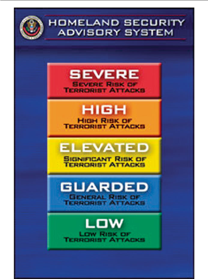
54
it, that will ever be 100 %, so it is important for and company, preferably to have a
designated security person, a security program offi cer, and chief security offi cer
(CSO), under the chief information offi cer (CIO), to be responsible for the security
best practices. Here are some examples of best practices:
Commonly Accepted Security Practices and Regulations ( CASPR ): Developed
by the CASPR Project, this effort aims to provide a set of best practices that can be
Fig. 2.1 Department of Homeland Security Awareness Levels [ 7 ]
2 Computer Network Security Fundamentals

55
universally applied to any organization regardless of industry, size, or mission. Such
best practices would, for example, come from the world’s experts in information
security. CASPR distills the knowledge into a series of papers and publishes them
so they are freely available on the Internet to everyone. The project covers a wide area,
including operating system and system security, network and telecommunication
security, access control and authentication, infosecurity management, infosecurity
auditing and assessment, infosecurity logging and monitoring, application security,
application and system development, and investigations and forensics. In order to
distribute their papers freely, the founders of CASPR use the open source movement
as a guide, and they release the papers under the GNU Free Document License to
make sure they and any derivatives remain freely available.
Control Objectives for Information and ( Related ) Technology ( COBIT ): Developed
by IT auditors and made available through the Information Systems Audit and
Control Association, COBIT provides a framework for assessing a security program.
COBIT is an open standard for control of information technology. The IT Governance
Institute has, together with the worldwide industry experts, analysts, and academics,
developed new defi nitions for COBIT that consist of maturity models, critical
success factors (CSFs), key goal indicators (KGIs), and key performance indicators
(KPIs). COBIT was designed to help three distinct audiences [ 5 ]:
• Management who need to balance risk and control investment in an often
unpredictable IT environment
• Users who need to obtain assurance on the security and controls of the IT services
upon which they depend to deliver their products and services to internal and
external customers
• Auditors who can use it to substantiate their opinions and/or provide advice to
management on internal controls
Operationally Critical Threat , Asset , and Vulnerability Evaluation ( OCTAVE )
by Carnegie Mellon’s CERT Coordination Center: OCTAVE is an approach for
self- directed information security risk evaluations that [ 6 ].
• Puts organizations in charge
• Balances critical information assets, business needs, threats, and vulnerabilities
• Measures the organization against known or accepted good security practices
• Establishes an organization-wide protection strategy and information security
risk mitigation plans
In short, it provides measures based on accepted best practices for evaluating
security programs. It does this in three phases:
• First, it determines information assets that must be protected.
• Evaluates the technology infrastructure to determine if it can protect those assets
and how vulnerable it is and defi nes the risks to critical assets.
• Uses good security practices and establishes an organization-wide protection
strategy and mitigation plans for specifi c risks to critical assets.
2.4 Security Standards

56
General Best Practices – Matthew Putvinski, in his article “IT Security Series
Part 1: Information Security Best Practices” [ 7 ], discusses under the following
general categories:
• Chief information security offi cer or designate – establish the need for a security
designated offi cer to oversee security-related issues in the enterprise because the
lack of a person responsible for security in any organization means the organiza-
tion does not give information security priority.
• Ender user – the security guidelines here must be contained in the organization’s
security policy of what the organization’s end users must and must not do as far
as dealing with organization’s information in general and computing services in
particular. As we move into miniature mobile devices and if a policy is to use a
bring your own device (BYOD), specifi c data handling policies must be in place.
• Software updates and patches – specifi c guidelines in the organization security
policy book must specifi cally take a stance on how the organization will use
software security patches and upgrades and the frequency of updates.
• Vendor management – if the organization is using software provided by third
party individuals or organizations as vendors, care must be taken to ensure that
any organization’s confi dential information provided to vendors to help identify
a suitable software tool is well documented and indicate to who.
• Physical Security – this is squarely a security policy issue specifi cally spelling
out the physical specifi cation required to safeguard the organization’s informa-
tion and data. These include access to offi ces and digital equipment, when and
where information is stored and when and where information is destroyed. We
will discuss more of this in the coming chapters.
• The following guidelines are also a security policy issues:
– Data classifi cation and retention
– Password requirements and guidelines
– Wireless networking
– Mobile device usage and access
– Employee awareness training
– Incident response
Exercises
1. What is security and Information security? What is the difference?
2. It has been stated that security is a continuous process; what are the states in
this process?
3. What are the differences between symmetric and asymmetric key systems?
4. What is PKI? Why is it so important in information security?
5. What is the difference between authentication and nonrepudiation?
6. Why is there a dispute between digital nonrepudiation and legal nonrepudiation?
7. Virtual security seems to work in some systems. Why is this so? Can you apply
it in a network environment? Support your response.
8. Security best practices are security guidelines and policies aimed at enhancing
system security. Can they work without known and proven security mechanisms?
2 Computer Network Security Fundamentals

57
9. Does information confi dentiality infer information integrity? Explain your
response.
10. What are the best security mechanisms to ensure information confi dentiality?
Advanced Exercises
1. In the chapter, we have classifi ed security standards based on industry, size, and
mission. What other classifi cations can you make and why?
2. Most of the encryption standards that are being used such as RSA and DES
have not been formally proven to be safe. Why then do we take them to be
secure – what evidence do we have?
3. IPSec provides security at the network layer. What other security mechanism is
applicable at the network layer? Do network layer security solutions offer
better security?
4. Discuss two security mechanisms applied at the application layer. Are they
safer than those applied at the lower network layer? Support your response.
5. Are there security mechanisms applicable at transport layer? Is it safer?
6. Discuss the diffi culties encountered in enforcing security best practices.
7. Some security experts do not believe in security policies. Do you? Why or
why not?
8. Security standards are changing daily. Is it wise to pick a security standard
then? Why or why not?
9. If you are an enterprise security chief, how would you go about choosing a
security best practice? Is it good security policy to always use a best security
practice? What are the benefi ts of using a best practice?
10. Why it is important to have a security plan despite the various views of security
experts concerning its importance?
R e f e r e n c e s
1. Kizza JM (2003) Social and ethical issues in the information age, 2nd edn. Springer, New York
2. Scherphier A CS596 client-server programming security. http://www.sdsu.edu/cs596/security.
html
3. Mercuri R, Peter N (2003) Security by obscurity. Commun ACM 46(11):160
4. McCullagh A, Caelli W Non-repudiation in the digital environment . http://www.fi rstmonday.dk/
issues/issue5_8/mccullagh/index.html#author
5. CobiT a practical toolkit for IT governance.
http://www.ncc.co.uk/ncc/myitadviser/archive/
issue8/business_processes.cfm
6. OCTAVE: information security risk evaluation. http://www.cert.org/octave/
7. Putvinski M IT security series part 1: information security best practices.
http://www.cor-
poratecomplianceinsights.com/information-security-best-practices
References

Part II
Security Issues and Challenges
in the Traditional Computer Network

61
© Springer-Verlag London 2015
J.M. Kizza, Guide to Computer Network Security, Computer Communications
and Networks, DOI 10.1007/978-1-4471-6654-2_3
3
Security Motives and Threats
to Computer Networks
3.1 Introduction
In February, 2002, the Internet security watch group CERT Coordination Center
fi rst disclosed to the global audience that global networks, including the Internet,
phone systems, and the electrical power grid, are vulnerable to attack because of
weakness in programming in a small but key network component. The component,
an Abstract Syntax Notation One, or ASN.1, is a communication protocol used
widely in the Simple Network Management Protocol (SNMP).
There was a widespread fear among government, networking manufacturers,
security researchers, and IT executives because the component is vital in many
communication grids, including national critical infrastructures such as parts of the
Internet, phone systems, and the electrical power grid. These networks were vulner-
able to disruptive buffer overfl ow and malformed packet attacks.
This example illustrates but one of the many potential incidents that can cause
widespread fear and panic among government, networking manufacturers, security
researchers, and IT executives when they think of the consequences of what might
happen to the global networks.
The number of threats is rising daily, yet the time window to deal with them is
rapidly shrinking. Hacker tools are becoming more sophisticated and powerful.
Currently, the average time between the point at which a vulnerability is announced
and when it is actually deployed in the wild is getting shorter and shorter.
Traditionally, security has been defi ned as a process to prevent unauthorized
access, use, alteration, theft, or physical damage to an object through maintaining
high confi dentiality and integrity of information about the object and making infor-
mation about the object available whenever needed. However, there is a common
fallacy, taken for granted by many, that a perfect state of security can be achieved;
they are wrong. There is nothing like a secure state of any object, tangible or not,
because no such object can ever be in a perfectly secure state and still be useful. An
object is secure if the process can maintain its highest intrinsic value. Since the
intrinsic value of an object depends on a number of factors, both internal and

62
external to the object during a given time frame, an object is secure if the object
assumes its maximum intrinsic value under all possible conditions. The process of
security, therefore, strives to maintain the maximum intrinsic value of the object at
all times.
Information is an object. Although it is an intangible object, its intrinsic value
can be maintained in a high state, thus ensuring that it is secure. Since our focus in
this book is on global computer network security, we will view the security of this
global network as composed of two types of objects: the tangible objects such as the
servers, clients, and communication channels and the intangible object such as
information that is stored on servers and clients and that moves through the
communication channels.
Ensuring the security of the global computer networks requires maintaining the
highest intrinsic value of both the tangible objects and information – the intangible
one. Because of both internal and external forces, it is not easy to maintain the high-
est level of the intrinsic value of an object. These forces constitute a security threat
to the object. For the global computer network, the security threat is directed to the
tangible and the intangible objects that make up the global infrastructure such as
servers, clients, communication channels, fi les, and information.
The threat itself comes in many forms, including viruses, worms, distributed
denial of services, and electronic bombs, and derives many motives, including
revenge, personal gains, hate, and joy rides, to name but a few.
3.2 Sources of Security Threats
The security threat to computer systems springs from a number of factors that
include weaknesses in the network infrastructure and communication protocols that
create an appetite and a challenge to the hacker mind, the rapid growth of cyber-
space into a vital global communication and business network on which interna-
tional commerce and business transactions are increasingly being performed and
many national critical infrastructures are being connected, the growth of the hacker
community whose members are usually experts at gaining unauthorized access into
systems that run not only companies and governments but also critical national
infrastructures, the vulnerability in operating system protocols whose services run
the computers that run the communication network, the insider effect resulting from
workers who steal and sell company databases and the mailing lists or even confi -
dential business documents, social engineering, physical theft from within the orga-
nizations of things such as laptop and handheld computers with powerful
communication technology and more potentially sensitive information, and security
as a moving target.
3.2.1 Design Philosophy
Although the design philosophy on which both the computer network infrastructure
and communication protocols were built has tremendously boosted its cyberspace
3 Security Motives and Threats to Computer Networks

63
development, the same design philosophy has been a constant source of the many
ills plaguing cyberspace. The growth of the Internet and cyberspace in general was
based on an open architecture work in progress philosophy. This philosophy
attracted the brightest minds to get their hands dirty and contribute to the infrastruc-
ture and protocols. With many contributing their best ideas for free, the Internet
grew in leaps and bounds. This philosophy also helped the spirit of individualism
and adventurism, both of which have driven the growth of the computer industry
and underscored the rapid and sometimes motivated growth of cyberspace.
Because the philosophy was not based on clear blueprints, new developments
and additions came about as reactions to the shortfalls and changing needs of a
developing infrastructure. The lack of a comprehensive blueprint and the demand-
driven design and development of protocols are causing the ever present weak
points and loopholes in the underlying computer network infrastructure and
protocols.
In addition to the philosophy, the developers of the network infrastructure and
protocols also followed a policy to create an interface that is as user-friendly,
effi cient, and transparent as possible so that all users of all education levels can use
it unaware of the working of the networks and therefore are not concerned with the
details.
The designers of the communication network infrastructure thought it was better
this way if the system is to serve as many people as possible. Making the interface
this easy and far removed from the details, though, has its own downside in that the
user never cares about and pays very little attention to the security of the system.
Like a magnet, the policy has attracted all sorts of people who exploit the net-
work’s vulnerable and weak points in search of a challenge, adventurism, fun, and
all forms of personal gratifi cation.
3.2.2 Weaknesses in Network Infrastructure
and Communication Protocols
Compounding problems created by the design philosophy and policy are the weak-
nesses in the communication protocols. The Internet is a packet network that works
by breaking the data to be transmitted into small individually addressed packets that
are downloaded on the network’s mesh of switching elements. Each individual
packet fi nds its way through the network with no predetermined route, and the pack-
ets are reassembled to form the original message by the receiving element. To work
successfully, packet networks need a strong trust relationship that must exist among
the transmitting elements.
As packets are disassembled, transmitted, and reassembled, the security of each
individual packet and the intermediary transmitting elements must be guaranteed.
This is not always the case in the current protocols of cyberspace. There are areas
where, through port scans, determined users have managed to intrude, penetrate,
fool, and intercept the packets.
The two main communication protocols on each server in the network, UDP and
TCP, use port numbers to identify higher-layer services. Each higher-layer service
3.2 Sources of Security Threats
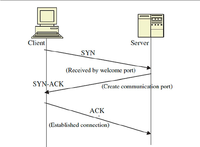
64
on a client uses a unique port number to request a service from the server, and each
server uses a port number to identify the service needed by a client. The cardinal
rule of a secure communication protocol in a server is never to leave any port open
in the absence of a useful service. If no such service is offered, its port should never
be open. Even if the service is offered by the server, its port should never be left
open unless it is legitimately in use.
In the initial communication between a client and a server, the client addresses
the server via a port number in a process called a three-way handshake . The three-
way handshake, when successful, establishes a TCP virtual connection between the
server and the client. This virtual connection is required before any communication
between the two can begin. The process begins by a client/host sending a TCP seg-
ment with the synchronize (SYN) fl ag set; the server/host responds with a segment
that has the acknowledge valid (ACK) and SYN fl ags set, and the fi rst host responds
with a segment that has only the ACK fl ag set. This exchange is shown in Fig. 3.1 .
The three-way handshake suffers from a half-open socket problem when the server
trusts the client that originated the handshake and leaves its port door open for fur-
ther communication from the client.
As long as the half-open port remains open, an intruder can enter the system
because while one port remains open, the server can still entertain other three-way
handshakes from other clients that want to communicate with it. Several half-open
ports can lead to network security exploits including both TCP/IP and UDP: Internet
Protocol spoofi ng (IP spoofi ng), in which IP addresses of the source element in the
Fig. 3.1 A three-way handshake
3 Security Motives and Threats to Computer Networks

65
data packets are altered and replaced with bogus addresses, and SYN fl ooding
where the server is overwhelmed by spoofed packets sent to it.
In addition to the three-way handshake, ports are used widely in network com-
munication. There are well-known ports used by processes that offer services. For
example, ports 0 through 1023 are used widely by system processes and other
highly privileged programs. This means that if access to these ports is compro-
mised, the intruder can get access to the whole system. Intruders fi nd open ports via
port scans. The two examples below from G-Lock Software illustrate how a port
scan can be made [ 1 ]:
• TCP connect ( ) scanning is the most basic form of TCP scanning. An attacker’s
host is directed to issue a connect ( ) system call to a list of selected ports on the
target machine. If any of these ports is listening, connect ( ) system call will
succeed; otherwise, the port is unreachable and the service is unavailable.
• UDP Internet Control Message Protocol (ICMP) port unreachable scanning is
one of the few UDP scans. Recall from Chap. 1 that UDP is a connectionless
protocol; so, it is harder to scan than TCP because UDP ports are not required to
respond to probes. Most implementations generate an ICMP port – unreachable
error when an intruder sends a packet to a closed UDP port. When this response
does not come, the intruder has found an active port.
In addition to port number weaknesses usually identifi able via port scans, both
TCP and UDP suffer from other weaknesses.
Packet transmissions between network elements can be intercepted, and their
contents altered such as in initial sequence number attack . Sequence numbers are
integer numbers assigned to each transmitted packet, indicating their order of arrival
at the receiving element. Upon receipt of the packets, the receiving element acknowl-
edges it in a two-way communication session during which both the transmitting
elements talk to each other simultaneously in full duplex.
In the initial sequence number attack, the attacker intercepts the communication
session between two or more communicating elements and then guesses the next
sequence number in a communication session. The intruder then slips the spoofed
IP addresses into the packets transmitted to the server. The server sends an acknowl-
edgment to the spoofed clients. Infrastructure vulnerability attacks also include
session attacks, packet sniffi ng, buffer overfl ow, and session hijacking. These
attacks are discussed in later chapters.
The infrastructure attacks we have discussed so far are of the penetration type
where the intruder physically enters the system infrastructure, either at the transmit-
ting element or in the transmitting channel levels, and alters the content of packets.
In the next set of infrastructure attacks, a different approach of vulnerability
exploitation is used. This is the distributed denial of services (DDoS).
The DDoS attacks are attacks that are generally classifi ed as nuisance attacks in
the sense that they simply interrupt the services of the system. System interruption
can be as serious as destroying a computer’s hard disk or as simple as using up all
the available memory of the system. DDoS attacks come in many forms, but the
3.2 Sources of Security Threats

66
most common are the following: smurfi ng, ICMP protocol, and ping of death
attacks.
The “smurf” attack utilizes the broken down trust relationship created by IP
spoofi ng. An offending element sends a large amount of spoofed ping packets
containing the victim’s IP address as the source address. Ping traffi c, also called
Protocol Overview Internet Control Message Protocol (ICMP) in the Internet com-
munity, is used to report out-of-band messages related to network operation or
mis- operation such as a host or entire portion of the network being unreachable,
owing to some type of failure. The pings are then directed to a large number of
network subnets, a subnet being a small independent network such as a LAN. If all
the subnets reply to the victim address, the victim element receives a high rate of
requests from the spoofed addresses as a result and the element begins buffering
these packets. When the requests come at a rate exceeding the capacity of the queue,
the element generates ICMP Source Quench messages meant to slow down the
sending rate. These messages are then sent, supposedly, to the legitimate sender of
the requests. If the sender is legitimate, it will heed the requests and slow down the
rate of packet transmission. However, in cases of spoofed addresses, no action is
taken because all sender addresses are bogus. The situation in the network can easily
deteriorate further if each routing device itself takes part in smurfi ng.
We have outlined a small part of a list of several hundred types of known infra-
structure vulnerabilities that are often used by hackers to either penetrate systems
and destroy, alter, or introduce foreign data into the system or disable the system
through port scanning and DDoS. Although for these known vulnerabilities, equip-
ment manufacturers and software producers have done a considerable job of issuing
patches as soon as a loophole or a vulnerability is known, quite often, as was
demonstrated in the Code Red fi asco, not all network administrators adhere to the
advisories issued to them.
Furthermore, new vulnerabilities are being discovered almost everyday either by
hackers in an attempt to show their skills by exposing these vulnerabilities or by
users of new hardware or software such as what happened with the Microsoft
Windows IIS in the case of the Code Red worm. Also, the fact that most of these
exploits use known vulnerabilities is indicative of our abilities in patching known
vulnerabilities even if the solutions are provided.
3.2.3 Rapid Growth of Cyberspace
There is always a security problem in numbers. Since its beginning as ARPANET in
the early 1960s, the Internet has experienced phenomenal growth, especially in the
last 10 years. There was an explosion in the number of users, which in turn ignited
an explosion in the number of connected computers.
Just less than 20 years ago in 1985, the Internet had fewer than 2,000 computers
connected, and the corresponding number of users was in the mere tens of thousands.
However, by 2001, the fi gure has jumped to about 109 million hosts, according to
Tony Rutkowski at the Center for Next Generation Internet, an Internet Software
Consortium. This number represents a signifi cant new benchmark for the number of
3 Security Motives and Threats to Computer Networks

67
Internet hosts. At a reported current annual growth rate of 51 % over the past 2 years,
this shows continued strong exponential growth, with an estimated growth of up to
one billion hosts if the same growth rate is sustained [ 2 ].
This is a tremendous growth by all accounts. As it grew, it brought in more and
more users with varying ethical standards, added more services, and created more
responsibilities. By the turn of the century, many countries found their national criti-
cal infrastructures fi rmly intertwined in the global network. An interdependence
between humans and computers and between nations on the global network has
been created that has led to a critical need to protect the massive amount of informa-
tion stored on these network computers. The ease of use of and access to the Internet
and large quantities of personal, business, and military data stored on the Internet
was slowly turning into a massive security threat not only to individuals and busi-
ness interests but also to national defenses.
As more and more people enjoyed the potential of the Internet, more and more
people with dubious motives were also drawn to the Internet because of its enor-
mous wealth of everything they were looking for. Such individuals have posed a
potential risk to the information content of the Internet, and such a security threat
has to be dealt with.
Statistics from the security company Symantec show that Internet attack activity
is currently growing by about 64 % per year. The same statistics show that during
the fi rst 6 months of 2002, companies connected to the Internet were attacked, on
average, 32 times per week compared to only 25 times per week in the last 6 months
of 2001. Symantec reports between 400 and 500 new viruses every month and about
250 vulnerabilities in computer programs [ 3 ].
In fact, the rate at which the Internet is growing is becoming the greatest security
threat ever. Security experts are locked in a deadly race with these malicious hackers
that at the moment looks like a losing battle with the security community.
3.2.4 The Growth of the Hacker Community
Although other factors contributed signifi cantly to the security threat, in the general
public view, the number one contributor to the security threat of computer and tele-
communication networks more than anything else is the growth of the hacker com-
munity. Hackers have managed to bring this threat into news headlines and people’s
living rooms through the ever-increasing and sometimes devastating attacks on
computer and telecommunication systems using viruses, worms, DDoS, and other
security attacks.
Until recently most hacker communities worked underground forming groups
global like some in Table 3.1 . Today, hackers are no longer considered as bad to
computer networks as it used to be, and now hackers are being used by governments
and organization to do the opposite of what they were supposed to be doing, defend-
ing national critical networks and hardening company networks. Increasingly,
hacker groups and individuals are being used in clandestined campaigns of attack-
ing other nations. So hacker groups and individuals are no longer as much under the
cloud of suspicion as causing mayhem to computer networks and many are now in
3.2 Sources of Security Threats

68
the open. In fact hacker Web sites like www.hacker.org with messages like “The
hacker explores the intersection of art and science in an insatiable quest to under-
stand and shape the world around him. We guide you on this journey,” are legiti-
mately popping up everywhere.
However, for long, the general public, computer users, policy makers, parents,
and law makers have watched in bewilderment and awe as the threat to their indi-
vidual and national security has grown to alarming levels as the sizes of the global
networks have grown and national critical infrastructures have become more and
more integrated into this global network. In some cases, the fear from these attacks
reached hysterical proportions, as demonstrated in the following major attacks that
we have rightly called the big “bungs.”
3.2.4.1 The Big “Bungs”
The Internet Worm
On November 2, 1988, Robert T. Morris, Jr., a computer science graduate student at
Cornell University, using a computer at MIT, released what he thought was a benign
Table 3.1 Global hacker groups
A Harford Hackerspace Port7Alliance
Anontune Helith Pumping Station: One
Anonymous Honker Union R
C The Humble Guys Red Hacker Alliance
Chaos Computer Club I S
Cyberwarfare in the People’s
Republic of China
Infonomicon Securax
D IPhone Dev Team T
Decocidio L Team Elite
Digital DawgPound L0pht TeaMp0isoN
G Level Seven TESO
Gay Nigger Association of America London Hackspace The 414s
Genocide2600 LulzSec The Shmoo Group
Global kOS LulzRaft The Unknowns
(hacking group)
GlobalHell M Titan Rain
Goatse Security Malicious Security TOG (hackerspace)
H Milw0rm U
HacDC Moonlight Maze UGNazi
Hack Canada N UXu
Hacker Dojo Network Crack Program Hacker
(NCPH) Group
W
Hacktivismo P W00w00
Hackweiser P.H.I.R.M. World of Hell
Phone Losers of America
Reference source: http://en.wikipedia.org/wiki/Category:Hacker_groups
3 Security Motives and Threats to Computer Networks

69
experimental, self-replicating, and self-propagating program on the MIT computer
network. Unfortunately, he did not debug the program well before running it. He
soon realized his mistake when the program he thought was benign went out of
control. The program started replicating itself and at the same time infecting more
computers on the network at a faster rate than he had anticipated. There was a bug
in his program. The program attacked many machines at MIT and very quickly went
beyond the campus to infect other computers around the country. Unable to stop his
own program from spreading, he sought a friend’s help. He and his friend tried
unsuccessfully to send an anonymous message from Harvard over the network,
instructing programmers how to kill the program – now a worm – and prevent its
reinfection of other computers. The worm spread like wildfi re to infect some 6,000
networked computers, a whopping number in proportion to the 1988 size of the
Internet, clogging government and university systems. In about 12 h, programmers
in affected locations around the country succeeded in stopping the worm from
spreading further. It was reported that Morris took advantage of a hole in the debug
mode of the Unix sendmail program. Unix then was a popular operating system that
was running thousands of computers on university campuses around the country.
Sendmail runs on Unix to handle e-mail delivery.
Morris was apprehended a few days later, taken to court, sentenced to 3 years
probation with a $10,000 fi ne and 400 h of community service, and dismissed from
Cornell. Morris’s worm came to be known as the Internet worm. The estimated cost
of the Internet worm varies from $53,000 to as high as $96 million, although the
exact fi gure will never be known [ 4 ].
Michelangelo Virus
The world fi rst heard of the Michelangelo virus in 1991. The virus affected only PCs
running MS-DOS 2.xx and higher versions. Although it overwhelmingly affected
PCs running DOS operating systems, it also affected PCs running other operating
systems such as UNIX, OS/2, and Novell. It affected computers by infecting fl oppy
disk boot sectors and hard disk master boot records. Once in the boot sectors of the
bootable disk, the virus then installed itself in memory from where it would infect
the partition table of any other disk on the computer, whether a fl oppy or a hard disk.
For several years, a rumor was rife, more so many believe, as a scare tactic by
antivirus software manufactures that the virus is to be triggered on March 6 of every
year to commemorate the birth date of the famous Italian painter. But in real terms,
the actual impact of the virus was rare. However, because of the widespread public-
ity it received, the Michelangelo virus became one of the most disastrous viruses
ever, with damages into millions of dollars.
Pathogen, Queeg, and Smeg Viruses
Between 1993 and April 1994, Christopher Pile, a 26-year-old resident of Devon in
Britain, commonly known as the “Black Baron” in the hacker community, wrote
three computer viruses: Pathogen, Queeg , and Smeg all named after expressions
used in the British Sci-Fi comedy “Red Dwarf.” He used Smeg to camoufl age both
Pathogen and Queeg . The camoufl age of the two programs prevented most known
3.2 Sources of Security Threats

70
antivirus software from detecting the viruses. Pile wrote the Smeg in such a way that
others could also write their own viruses and use Smeg to camoufl age them. This
meant that the Smeg could be used as a locomotive engine to spread all sorts of
viruses. Because of this, Pile’s viruses were extremely deadly at that time. Pile used
a variety of ways to distribute his deadly software, usually through bulletin boards
and freely downloadable Internet software used by thousands in cyberspace.
Pile was arrested on May 26, 1995. He was charged with 11 counts that included
the creation and release of these viruses that caused modifi cation and destruction of
computer data, inciting others to create computer viruses. He pleaded guilty to 10 of
the 11 counts and was sentenced to 18 months in prison.
Pile’s case was in fact not the fi rst one as far as creating and distributing com-
puter viruses was concerned. In October 1992, three Cornell University students
were each sentenced to several hundred hours of community service for creating
and disseminating a computer virus. However, Pile’s case was signifi cant in that it
was the fi rst widely covered and published computer crime case that ended in a jail
sentence [ 5 ].
Melissa Virus
On March 26, 1999, the global network of computers was greeted with a new virus
named Melissa. Melissa was created by David Smith, a 29-year-old New Jersey
computer programmer. It was later learned that he named the virus after a Florida
stripper.
The Melissa virus was released from an “alt.sex” newsgroup using the America
OnLine (AOL) account of Scott Steinmetz, whose username was “skyroket.”
However, Steinmetz, the owner of the AOL account who lived in the western US
state of Washington, denied any knowledge of the virus, let alone knowing anybody
else using his account. It looked like Smith hacked his account to disguise his tracks.
The virus, which spreads via a combination of Microsoft’s Outlook and Word
programs, takes advantage of Word documents to act as surrogates and the users’
e-mail address book entries to propagate it. The virus then mailed itself to each
entry in the address book in either the original Word document named “list.doc” or
in a future Word document carrying it after the infection. It was estimated that
Melissa affected more than 100,000 e-mail users and caused $80 million in dam-
ages during its rampage.
The Y2K Bug
From 1997 to December 31, 1999, the world was gripped by apprehension over one
of the greatest myths and misnomers in the history. This was never a bug, a software
bug as we know it, but a myth shrouded in the following story. Decades ago, because
of memory storage restrictions and expanse of time, computer designers and pro-
grammers together made a business decision. They decided to represent the date
fi eld by two digits such as “89” and “93” instead of the usual four digits such as
“1956.” The purpose was noble, but the price was humongous.
The bug, therefore, is as follows: On New Year’s Eve of 1999, when world clocks
were supposed to change over from 31/12/99 to 01/01/00 at 12:00 midnight, many
3 Security Motives and Threats to Computer Networks

71
computers, especially the older ones, were supposed not to know which year it was
since it would be represented by “00.” Many, of course, believed that computers
would then assume anything from year “0000” to “1900,” and this would be
catastrophic.
Because the people who knew much were unconvinced about the bug, it was
known by numerous names to suit the believer. Among the names were the follow-
ing: millennium bug, Y2K computer bug, Y2K, Y2K problem, Y2K crisis, Y2K bug,
and many others.
The good news is that the year 2000 came and went with very few incidents of
one of the most feared computer bugs of our time.
The Goodtimes E-mail Virus
Yet another virus hoax, the Goodtimes virus , was humorous, but it ended up being a
chain e-mail annoying every one in its path because of the huge amount of “e-mail
virus alerts” it generated. Its humor is embedded in the following prose: Goodtimes
will rewrite your hard drive. Not only that, but it will also scramble any disks that
are even close to your computer. It will recalibrate your refrigerator’s coolness
setting so all your ice cream melts. It will demagnetize the strips on all your credit
cards, make a mess of the tracking on your television, and use subspace fi eld
harmonics to scratch any CD you try to play.
It will give your ex-girlfriend your new phone number. It will mix Kool-Aid into
your fi sh tank. It will drink all your beer and leave its socks out on the coffee table
when company is coming over. It will put a dead kitten in the back pocket of your
good suit pants and hide your car keys when you are running late for work.
Goodtimes will make you fall in love with a penguin. It will give you nightmares
about circus midgets. It will pour sugar in your gas tank and shave off both your
eyebrows while dating your current girlfriend behind your back and billing the
dinner and hotel room to your Visa card.
It will seduce your grandmother. It does not matter if she is dead. Such is the
power of Goodtimes; it reaches out beyond the grave to sully those things we hold
most dear.
It moves your car randomly around parking lots so you can’t fi nd it. It will kick
your dog. It will leave libidinous messages on your boss’s voice mail in your voice!
It is insidious and subtle. It is dangerous and terrifying to behold. It is also a rather
interesting shade of mauve.
Goodtimes will give you Dutch Elm disease. It will leave the toilet seat up. It will
make a batch of methamphetamine in your bathtub and then leave bacon cooking on
the stove while it goes out to chase gradeschoolers with your new snowblower.
Distributed Denial of Service (DDoS)
February 7, 2000, a month after the Y2K bug scare and Goodtimes hoax, the world
woke up to the real thing. This was not a hoax or a myth. On this day, a 16-year-old
Canadian hacker nicknamed “Mafi aboy” launched his distributed denial-of-service
(DDoS) attack. Using the Internet’s infrastructure weaknesses and tools, he
unleashed a barrage of remotely coordinated blitz of GB(s) IP packet requests from
3.2 Sources of Security Threats
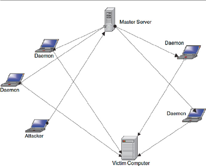
72
selected, sometimes unsuspecting victim servers which, in a coordinated fashion,
bombarded and fl ooded and eventually overcame and knocked out Yahoo servers for
a period of about 3 h. Within 2 days, while technicians at Yahoo and law enforce-
ment agencies were struggling to identify the source of the attacker, on February 9,
2000, Mafi aboy struck again, this time bombarding servers at eBay, Amazon, Buy.
com, ZDNet, CNN, E*Trade, and MSN.
The DDoS attack employs a network consisting of a master computer responsi-
ble for directing the attacks, the “innocent” computers commonly known as “dae-
mons” used by the master as intermediaries in the attack, and the victim computer – a
selected computer to be attacked. Figure 3.2 shows how this works.
After the network has been selected, the hacker instructs the master node to fur-
ther instruct each daemon in its network to send several authentication requests to
the selected network nodes, fi lling up their request buffers. All requests have false
return addresses; so, the victim nodes can’t fi nd the user when they try to send back
the authentication approval. As the nodes wait for acknowledgments, sometimes
even before they close the connections, they are again and again bombarded with
more requests. When the rate of requests exceeds the speed at which the victim node
can take requests, the nodes are overwhelmed and brought down.
The primary objective of a DDoS attack is multifaceted, including fl ooding a
network to prevent legitimate network traffi c from going through the network,
Fig. 3.2 The working of a DDoS attack
3 Security Motives and Threats to Computer Networks

73
disrupting network connections to prevent access to services between network
nodes, preventing a particular individual network node from accessing either all
network services or specifi ed network services, and disrupting network services to
either a specifi c part of the network or selected victim machines on the network.
The Canadian judge stated that although the act was done by an adolescent, the
motivation of the attack was undeniable and had a criminal intent. He, therefore,
sentenced the Mafi aboy, whose real name was withheld because he was under age,
to serve 8 months in a youth detention center and 1 year of probation after his
release from the detention center. He was also ordered to donate $250 to charity.
Love Bug Virus
On April 28, 2000, Onel de Guzman, a dropout from AMA computer college in
Manila, Philippines, released a computer virus onto the global computer network.
The virus was fi rst uploaded to the global networks via a popular Internet Relay
Chat program using Impact, an Internet ISP. It was then uploaded to Sky Internet’s
servers, another ISP in Manila, and it quickly spread to global networks, fi rst in Asia
and then Europe. In Asia, it hit a number of companies hard, including the Dow
Jones Newswire and the Asian Wall Street Journal . In Europe, it left thousands of
victims that included big companies and parliaments. In Denmark, it hit TV2 chan-
nel and the Danish parliament, and in Britain, the House of Commons fell victim
too. Within 12 h of release, it was on the North American continent, where the US
Senate computer system was among the victims [ 6 ].
It spread via Microsoft Outlook e-mail systems as surrogates. It used a rather
sinister approach by tricking the user to open an e-mail presumably from someone
the user knew (because the e-mail usually came from an address book of someone
the user knew). The e-mail, as seen in Fig. 3.3 , requests the user to check the
attached “Love Letter.” The attachment fi le was in fact a Visual Basic script, which
contained the virus payload. The virus then became harmful when the user opened
the attachment. Once the fi le was opened, the virus copied itself to two critical sys-
tem directories and then added triggers to the Windows registry to ensure that it ran
every time the computer was rebooted. The virus then replicated itself, destroying
system fi les including Web development such as “.js” and “.css,” multimedia fi les
such as JPEG and MP3, searched for log-in names and passwords in the user’s
address book, and then mailed itself again [ 6 ].
De Guzman was tracked down within hours of the release of the virus. Security
offi cials, using a Caller ID of the phone number and ISP used by de Guzman, were
led to an apartment in the poor part of Manila where de Guzman lived.
The virus devastated global computer networks, and it was estimated that it
caused losses ranging between $7 and $20 billion [ 7 ].
Palm Virus
In August 2000, the actual palm virus was released under the name of Liberty Trojan
horse, the fi rst known malicious program targeting the Palm OS. The Liberty Trojan
horse duped some people into downloading a program that erased data.
3.2 Sources of Security Threats

74
Another palm virus shortly followed Palm Liberty. On September 21, 2000,
McAfee.com and F-Secure, two of the big antivirus companies, fi rst discovered a
really destructive palm virus they called Palm OS/Phage. When Palm OS/Phage is
executed, the screen is fi lled with a dark gray box, and the application is terminated.
The virus then replicates itself to other Palm OS applications.
Wireless device viruses have not been widespread, thanks to the fact that the
majority of Palm OS users do not download programs directly from the Web but via
their desktop and then sync to their palm. Because of this, they have virus protection
available to them at either their ISP’s Internet gateway, at the desktop, or at their
corporation.
The appearance of a palm virus in cyberspace raises many concerns about the
security of cyberspace because PDAs are diffi cult to check for viruses as they are
not hooked up to a main corporate network. PDAs are moving as users move, mak-
ing virus tracking and scanning diffi cult.
Anna Kournikova Virus
On February 12, 2001, global computer networks were hit again by a new virus,
Anna Kournikova, named after the Russian tennis star. The virus was released by
20-year-old Dutchman Jan de Wit, commonly known in the hacker underworld
community as “OnTheFly.” The virus, like the I LOVE YOU virus before it, was a
mass-mailing type. Written in Visual Basic scripting language, the virus spreads by
mailing itself, disguised as a JPEG fi le named Anna Kournikov , through Microsoft
Windows, Outlook, and other e-mail programs on the Internet.
Fig. 3.3 The love bug monitor display
3 Security Motives and Threats to Computer Networks
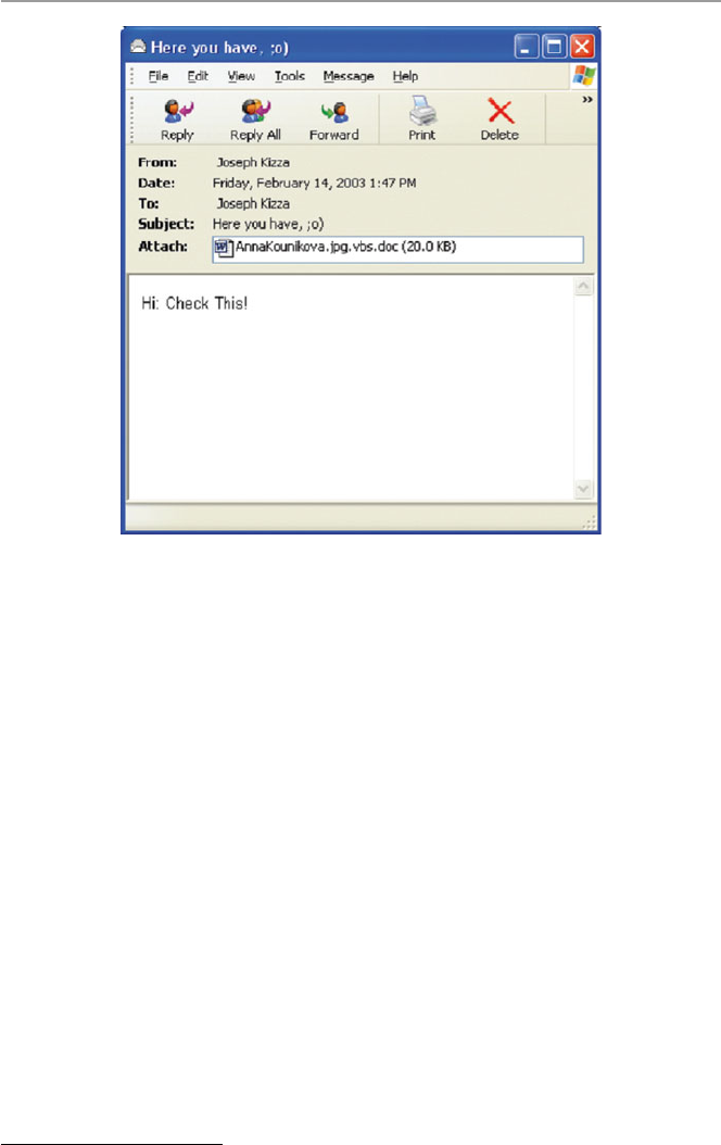
75
The subject line of mail containing the virus bears the following: “Here ya
have;0),” “Here you are;-),” or “here you go;-).” Once opened, Visual Basic script
copies itself to a Windows directory as “AnnaKournikova.jpg.vbs.” It then mails
itself to all entries in the user’s Microsoft Outlook e-mail address book. Figure 3.4
shows the Anna Kournikov monitor screen display.
Spreading at twice the speed of the notorious “I LOVE YOU” bug, Anna quickly
circumvented the globe.
Security experts believe Anna was of the type commonly referred to as a “virus
creation kit,” “a do-it-yourself program kit” that potentially makes everyone able to
create a malicious code.
Code Red: “For one moment last week, the Internet stood still.”
1
The Code Red worm was fi rst released on July 12, 2001, from Foshan University in
China, and it was detected the next day July 13 by senior security engineer Ken
Eichman. However, when detected, it was not taken seriously until 4 days later when
engineers at eEye Digital cracked the worm code and named it “Code Red” after
staying awake with “Code Red”-labeled Mountain Dew [ 8 ]. By this time, the worm
had started to spread, though slowly. Then on July 19, according to Rob Lemos, it is
1 Lemos, Rob. “Code Red: Virulent worm calls into doubt our ability to protect the Net,” CNET
News.com, July 27, 2001.
Fig. 3.4 Anna Kournikov monitor display
3.2 Sources of Security Threats

76
believed that someone modifi ed the worm, fi xing a problem with its random-number
generator. The new worm started to spread like wildfi re spreading, leaping from
15,000 infections that morning to almost 350,000 infections by 5 p.m. PDT [ 8 ].
The worm was able to infect computers because it used a security hole, discov-
ered a month before, in computers using Microsoft’s Internet Information Server
(IIS) in the Windows NT4 and Windows 2000 Index Services. The hole, known as
the Index Server ISAPI vulnerability, allowed the intruder to take control of a secu-
rity vulnerability in these systems, resulting in one of the several outcomes, includ-
ing Web site defacement and installation of denial-of-service tools. The following
Web defacement – HELLO! Welcome to http://www.worm.com ! Hacked By
Chinese! – usually resulted. The Web defacement was done by the worm connecting
to TCP port 80 on a randomly chosen host. If the connection was successful, the
attacking host sent a crafted HTTP GET request to the victim, attempting to exploit
a buffer overfl ow in the Indexing Service [ 9 ].
Because Code Red was self-propagating, the victim computer would then send
the same exploit (HTTP GET request) to another set of randomly chosen hosts.
Although Microsoft issued a patch when the security hole was discovered, not
many servers were patched before Code Red hit. Because of the large number of IIS
serves on the Internet, Code Red found the going easy and at its peak, it hit up to
300,000 servers. But Code Red did not do as much damage as feared; because of its
own design fl aw, the worm was quickly brought under control.
SQL Worm
On Saturday, January 25, 2003, the global communication network was hit by the
SQL Worm. The worm, which some refer to as the “SQL Slammer,” spreads to
computers that are running Microsoft SQL Server with a blank SQL administrator
password. Once in the system, it copies fi les to the infected computer and changes
the SQL administrator password to a string of four random characters.
The vulnerability exploited by the slammer warm preexisted in the Microsoft
SQL Server 2000 and in fact was discovered 6 months prior to the attack. When the
vulnerability was discovered, Microsoft offered a free patch to fi x the problem;
however, the word never got around to all users of the server software.
The worm spread rapidly in networks across Asia, Europe, and the United States
and Canada, shutting down businesses and government systems. However, its
effects were not very serious because of its own weaknesses that included its inabil-
ity to affect secure servers and its ease of detection.
Hackers View Eight Million Visa/MasterCard, Discover, and American
Express Accounts
On Monday, February 17, 2003, the two major credit card companies, Visa and
MasterCard, reported a major infi ltration into a third-party payment card processor
by a hacker who gained access to more than fi ve million Visa and MasterCard
accounts throughout the United States. Card information exposed included card
numbers and personal information that included social security numbers and credit
limits.
3 Security Motives and Threats to Computer Networks

77
The fl ood of the hacker victims increased by two on Tuesday, February 18, 2003,
when both Discover Financial Services and American Express reported that they
were also victims of the same hacker who breached the security system of a com-
pany that processes transactions on behalf of merchants.
While MasterCard and Visa had earlier reported that around 2.2 million and 3.4 million
of their own cards were, respectively, affected, Discover and American Express would
not disclose how many accounts were involved. It is estimated, however, that the number
of affected accounts in the security breach was as high as eight million.
3.2.5 Vulnerability in Operating System Protocol
One area that offers the greatest security threat to global computer systems is the
area of software errors, especially network operating systems errors. An operating
system plays a vital role not only in the smooth running of the computer system in
controlling and providing vital services but by playing a crucial role in the security
of the system in providing access to vital system resources. A vulnerable operating
system can allow an attacker to take over a computer system and do anything that
any authorized super user can do, such as changing fi les, installing and running
software, or reformatting the hard drive.
Every OS comes with some security vulnerabilities. In fact many security vul-
nerabilities are OS specifi c. Hacker look for OS-identifying information like fi le
extensions for exploits.
3.2.6 The Invisible Security Threat: The Insider Effect
Quite often, news media reports show that in cases of violent crimes such as murder,
one is more likely to be attacked by someone one does not know. However, real
offi cial police and court records show otherwise. This is also the case in network
security. Research data from many reputable agencies consistently show that the
greatest threat to security in any enterprise is the guy down the hall.
In 1997, the accounting fi rm Ernst & Young interviewed 4,226 IT managers and
professionals from around the world about the security of their networks. From the
responses, 75 % of the managers indicated that they believed authorized users and
employees represent a threat to the security of their systems. Forty-two percent of
the Ernst & Young respondents reported they had experienced external malicious
attacks in the past year, while 43 % reported malicious acts from employees [ 10 ].
The inside threat to organizational security comes from one of its own, an
untrustworthy member of the organization. This “insider threat” is a person possibly
who has privileged access to classifi ed, sensitive, or propriety data, who uses this
unique opportunity to remove information from the organization and transfer to
unauthorized outsider users.
According to Jack Strauss, president and CEO of SafeCorp, a professional
information security consultancy in Dayton, Ohio, company insiders intentionally
3.2 Sources of Security Threats

78
or accidentally misusing information pose the greatest information security threat to
today’s Internet-centric businesses. Strauss believes that it is a mistake for company
security chiefs to neglect to lock the back door to the building, to encrypt sensitive
data on their laptops, or not to revoke access privileges when employees leave the
company [ 11 ].
3.2.7 Social Engineering
Besides the security threat from the insiders themselves who knowingly and will-
ingly are part of the security threat, the insider effect can also involve insiders
unknowingly being part of the security threat through the power of social engineer-
ing . Social engineering consists of an array of methods an intruder such as a hacker,
both from within and outside the organization, can use to gain system authorization
through masquerading as an authorized user of the network. Social engineering can
be carried out using a variety of methods, including physically impersonating an
individual known to have access to the system, online, telephone, and even by writ-
ing. The infamous hacker Kevin Mitnick used social engineering extensively to
break into some of the nation’s most secure networks with a combination of his
incredible solid computer hacking and social engineering skills to coax information,
such as passwords, out of people.
3.2.8 Physical Theft
As the demand for information by businesses to stay competitive and nations to
remain strong heats up, laptop computer and PDA theft is on the rise. There is a
whole list of incidents involving laptop computer theft such as the reported disap-
pearance of a laptop used to log incidents of covert nuclear proliferation from a
sixth-fl oor room in the headquarters of the US State Department in January 2000. In
March of the same year, a British accountant working for the MI5, a British national
spy agency, had his laptop computer snatched from between his legs while waiting
for a train at London’s Paddington Station. In December 1999, someone stole a
laptop from the car of Bono, lead singer for the megaband U2; it contained months
of crucial work on song lyrics. And according to the computer-insurance fi rm
Safeware, some 319,000 laptops were stolen in 1999, at a total cost of more than
$800 million for the hardware alone [ 12 ]. Thousands of company executive laptops
and PDA disappear every year with years of company secrets.
3.3 Security Threat Motives
Although we have seen that security threats can originate from natural disasters and
unintentional human activities, the bulk of cyberspace threats and then attacks origi-
nate from humans caused by illegal or criminal acts from either insiders or outsid-
ers, recreational hackers, and criminals. The FBI’s foreign counterintelligence
3 Security Motives and Threats to Computer Networks

79
mission has broadly categorized security threats based on terrorism, military
espionage, economic espionage, that targeting the National Information
Infrastructure, vendetta and revenge, and hate [ 13 ].
3.3.1 Terrorism
Our increasing dependence on computers and computer communication has opened
up the can of worms, which we now know as electronic terrorism. Electronic terror-
ism is used to attack military installations, banking, and many other targets of inter-
est based on politics, religion, and probably hate. Those who are using this new
brand of terrorism are a new breed of hackers, who no longer hold the view of
cracking systems as an intellectual exercise but as a way of gaining from the action.
The “new” hacker is a cracker who knows and is aware of the value of information
that he or she is trying to obtain or compromise. But cyberterrorism is not only
about obtaining information; it is also about instilling fear and doubt and compro-
mising the integrity of the data.
Some of these hackers have a mission, usually foreign power sponsored or for-
eign power coordinated that, according to the FBI, may result in violent acts, dan-
gerous to human life, that are a violation of the criminal laws of the targeted nation
or organization and are intended to intimidate or coerce people so as to infl uence the
policy.
3.3.2 Military Espionage
For generations, countries have been competing for supremacy of one form or
another. During the Cold War, countries competed for military spheres. After it
ended, the espionage turf changed from military aim to gaining access to highly
classifi ed commercial information that would not only let them know what other
countries are doing but also might give them either a military or commercial advan-
tage without their spending a great deal of money on the effort. It is not surprising,
therefore, that the spread of the Internet has given a boost and a new lease on life to
a dying Cold War profession. Our high dependency on computers in the national
military and commercial establishments has given espionage a new fertile ground.
Electronic espionage has many advantages over its old-fashion, trench-coated, sun-
glassed, and gloved Hitchcock-style cousin. For example, it is less expensive to
implement, it can gain access into places that would be inaccessible to human spies,
it saves embarrassment in case of failed or botched attempts, and it can be carried
out at a place and time of choice.
3.3.3 Economic Espionage
The end of the Cold War was supposed to bring to an end spirited and intensive mili-
tary espionage. However, in the wake of the end of the Cold War, the United States,
3.3 Security Threat Motives

80
as a leading military, economic, and information superpower, found itself a constant
target of another kind of espionage, economic espionage. In its pure form, economic
espionage targets economic trade secrets which, according to the 1996 US Economic
Espionage Act, are defi ned as all forms and types of fi nancial, business, scientifi c,
technical, economic, or engineering information and all types of intellectual prop-
erty including patterns, plans, compilations, program devices, formulas, designs,
prototypes, methods, techniques, processes, procedures, programs, and/or codes,
whether tangible or not, stored or not, and compiled or not [ 14 ]. To enforce this act
and prevent computer attacks targeting American commercial interests, US Federal
Law authorizes law enforcement agencies to use wiretaps and other surveillance
means to curb computer-supported information espionage.
3.3.4 Targeting the National Information Infrastructure
The threat may be foreign power sponsored or foreign power coordinated, directed
at a target country, corporation, establishments, or persons. It may target specifi c
facilities, personnel, information, or computer, cable, satellite, or telecommunica-
tion systems that are associated with the National Information Infrastructure.
Activities may include the following [ 15 ]:
• Denial or disruption of computer, cable, satellite, or telecommunication services
• Unauthorized monitoring of computer, cable, satellite, or telecommunication
systems
• Unauthorized disclosure of proprietary or classifi ed information stored within or
communicated through computer, cable, satellite, or telecommunication systems
• Unauthorized modifi cation or destruction of computer programming codes,
computer network databases, stored information, or computer capabilities
• Manipulation of computer, cable, satellite, or telecommunication services result-
ing in fraud, fi nancial loss, or other federal criminal violations
3.3.5 Vendetta/Revenge
There are many causes that lead to vendettas. The demonstrations at the last World
Trade Organization (WTO) in Seattle, Washington, and subsequent demonstrations
at the meetings in Washington, DC, of both the World Bank and the International
Monetary Fund are indicative of the growing discontent of the masses who are
unhappy with big business, multinationals, big governments, and a million others.
This discontent is driving a new breed of wild, rebellious, young people to hit back
at systems that they see as not solving world problems and benefi ting all of man-
kind. These mass computer attacks are increasingly being used as paybacks for
what the attacker or attackers consider to be injustices done that need to be avenged.
However, most vendetta attacks are for mundane reasons such as a promotion
3 Security Motives and Threats to Computer Networks

81
denied, a boyfriend or girlfriend taken, an ex-spouse given child custody, and other
situations that may involve family and intimacy issues.
3.3.6 Hate (National Origin, Gender, and Race)
Hate as a motive of security threat originates from and is always based on an indi-
vidual or individuals with a serious dislike of another person or group of persons
based on a string of human attributes that may include national origin, gender, race,
or mundane ones such as the manner of speech one uses. Then incensed, by one or
all of these attributes, the attackers contemplate and threaten and sometimes carry
out attacks of vengeance often rooted in ignorance.
3.3.7 Notoriety
Many, especially young, hackers try to break into a system to prove their compe-
tence and sometimes to show off to their friends that they are intelligent or superhu-
man in order to gain respect among their peers.
3.3.8 Greed
Many intruders into company systems do so to gain fi nancially from their acts.
3.3.9 Ignorance
This takes many forms, but quite often it happens when a novice in computer secu-
rity stumbles on an exploit or vulnerability and without knowing or understanding
it uses it to attack other systems.
3.4 Security Threat Management
Security threat management is a technique used to monitor an organization’s critical
security systems in real time to review reports from the monitoring sensors such as
the intrusion detection systems, fi rewall, and other scanning sensors. These reviews
help to reduce false positives from the sensors, develop quick response techniques
for threat containment and assessment, correlate and escalate false positives across
multiple sensors or platforms, and develop intuitive analytical, forensic, and man-
agement reports.
As the workplace gets more electronic and critical company information fi nds its
way out of the manila envelopes and brown folders into online electronic databases,
security management has become a full-time job for system administrators. While
3.4 Security Threat Management

82
the number of dubious users is on the rise, the number of reported criminal incidents
is skyrocketing, and the reported response time between a threat and a real attack is
down to 20 min or less [ 15 ]. To secure company resources, security managers have
to do real-time management. Real-time management requires access to real-time
data from all network sensors.
Among the techniques used for security threat management are risk assessment
and forensic analysis.
3.4.1 Risk Assessment
Even if there are several security threats all targeting the same resource, each threat
will cause a different risk and each will need a different risk assessment. Some will
have low risk, while others will have the opposite. It is important for the response
team to study the risks as sensor data come in and decide which threat to deal with
fi rst.
3.4.2 Forensic Analysis
Forensic analysis is done after a threat has been identifi ed and contained. After con-
tainment, the response team can launch the forensic analysis tools to interact with
the dynamic report displays that have come from the sensors during the duration of
the threat or attack if the threat results in an attack. The data on which forensic
analysis should be performed must be kept in a secure state to preserve the evidence.
It must be stored and transferred, if this is needed, with the greatest care, and the
analysis must be done with the utmost professionalism possible if the results of the
forensic analysis are to stand in court.
3.5 Security Threat Correlation
As we have noted in the previous section, the interval time between the fi rst occur-
rence of the threat and the start of the real attack has now been reduced about
20 min. This is putting enormous pressure on organizations’ security teams to cor-
respondingly reduce the turnaround time, the time between the start of an incident
and the receipt of the fi rst reports of the incident from the sensors. The shorter the
turnaround time, the quicker the response to an incident in progress. In fact, if the
incident is caught at an early start, an organization can be saved from a great deal of
damage.
Threat correlation, therefore, is the technique designed to reduce the turnaround
time by monitoring all network sensor data and then use that data to quickly analyze
and discriminate between real threats and false positives. In fact, threat correlation
helps in:
3 Security Motives and Threats to Computer Networks

83
• Reducing false positives because if we get the sensor data early enough, analyze
it, and detect false positives, we can quickly retune the sensors so that future false
positives are reduced.
• Reducing false negatives; similarly by getting early sensor reports, we can ana-
lyze it, study where false negatives are coming from, and retune the sensors to
reveal more details.
• Verifying sensor performance and availability; by getting early reports we can
quickly check on all sensors to make sure that they are performing as needed.
3.5.1 Threat Information Quality
The quality of data coming from the sensor logs depends on several factors
including:
• Collection – when data is collected, it must be analyzed. The collection techniques
specify where the data is to be analyzed. To reduce on bandwidth and data compres-
sion problems, before data is transported to a central location for analysis, some
analysis is usually done at the sensor and then reports are brought to the central
location. But this kind of distributed computation may not work well in all cases.
• Consolidation – given that the goal of correlation is to pull data out of the sen-
sors, analyze it, correlate it, and deliver timely and accurate reports to the
response teams, and also given the amount of data generated by the sensors and
further the limitation to bandwidth, it is important to fi nd good techniques to
fi lter out relevant data and consolidate sensor data either through compression or
aggregation so that analysis is done on only real and active threats.
• Correlation – again given the goals of correlation, if the chosen technique of data
collection is to use a central database, then a good data mining scheme must be
used for appropriate queries on the database that will result in outputs that will
realize the goals of correlation. However, many data mining techniques have
problems.
3.6 Security Threat Awareness
Security threat awareness is meant to bring widespread and massive attention of the
population to the security threat. Once people come to know of the threat, it is hoped
that they will become more careful, more alert, and more responsible in what they
do. They will also be more likely to follow security guidelines. A good example of
how massive awareness can be planned and brought about is the efforts of the new
US Department of Homeland Security. The department was formed after the
September 11, 2001, attack on the United States to bring maximum national aware-
ness to the security problems facing not only the country but also every individual.
The idea is to make everyone proactive to security. Figure 3.5 shows some of the
efforts of the Department of Homeland Security for massive security awareness.
3.6 Security Threat Awareness
84
Exercises
1. Although we discussed several sources of security threats, we did not exhaust
all. There are many such sources. Name and discuss fi ve.
2. We pointed out that the design philosophy of the Internet infrastructure was
partly to blame for the weaknesses and hence a source of security threats. Do
you think a different philosophy would have been better? Comment on your
answer.
3. Give a detailed account of why the three-way handshake is a security threat.
4. In the chapter, we gave two examples of how a port scan can be a threat to secu-
rity. Give three more examples of port scans that can lead to system security
compromise.
Fig. 3.5 Department of homeland security efforts for massive security awareness [ 16 ]
3 Security Motives and Threats to Computer Networks

85
5. Comment on the rapid growth of the Internet as a contributing factor to the
security threat of cyberspace. What is the responsible factor in this growth? Is
it people or the number of computers?
6. There seems to have been an increase in the number of reported virus and worm
attacks on computer networks. Is this really a sign of an increase, more report-
ing, or more security awareness on the part of the individual? Comment on each
of these factors.
7. Social engineering has been frequently cited as a source of network security
threat. Discuss the different elements within social engineering that contribute
to this assertion.
8. In the chapter, we gave just a few of the many motives for security threat.
Discuss fi ve more, giving details of why there are motives.
9. Outline and discuss the factors that infl uence threat information quality.
10. Discuss the role of data mining techniques in the quality of threat information.
Advanced Exercises
1. Research the effects of industrial espionage and write a detailed account of a
profi le of a person who sells and buys industrial secrets. What type of industrial
secrets is likely to be traded?
2. The main reasons behind the development of the National Strategy to Secure
Cyberspace were the realization that we are increasingly dependent on the com-
puter networks, the major components of the national critical infrastructure are
dependent on computer networks, and our enemies have the capabilities to dis-
rupt and affect any of the infrastructure components at will. Study the National
Information Infrastructure, the weaknesses inherent in the system, and suggest
ways to harden it.
3. Study and suggest the best ways to defend the national critical infrastructure
from potential attackers.
4. We indicated in the text that the best ways to manage security threats is to do an
extensive risk assessment and more forensic analysis. Discuss how reducing the
turnaround time can assist you in both risk assessment and forensic analysis.
What are the inputs into the forensic analysis model? What forensic tools are you
likely to use? How do you suggest to deal with the evidence?
5. Do research on intrusion detection and fi rewall sensor false positives and false
negatives. Write an executive report on the best ways to deal with both of these
unwanted reports.
References
1. G-Lock Software. TCP and UDP port scanning examples. http://www.glocksoft.com/tcpudp-
scan.htm
2. Rutkowski T, Internet survey reaches 109 million host level. Center for next generation inter-
net.
http://www.ngi.org/trends/TrendsPR0102.txt
3. Battling the net security threat, Saturday, 9 Nov 2002, 08:15 GMT.
http://news.bbc.co.uk/2/hi/
technology/2386113.stm
References

86
4. Derived in part from a letter by Severo M. Ornstein, Commun ACM, June 1989, 32 (6)
5. Virus writer Christopher Pile (Black Barron) sent to jail for 18 Months Wednesday 15
November 1995.
http://www.gps.jussieu.fr/comp/VirusWriter.html
6. Hopper I Destructive ‘I LOVE YOU’ Computer virus strikes worldwide. CNN Interactive
Technology.
http://www.cnn.com/2000/TECH/computing/05/04/iloveyou/
7. Former student: bug may have been spread accidentally. CNN Interactive.
http://www.cnn.
com/2000/ASIANOWsoutheast/05/11/iloveyou.02/
8. National security threat list. http://rf-web.tamu.edu/security/SECGUIDE/T1threat/Nstl.htm
9. CERT® Advisory CA-2001–19 ‘Code Red’ Worm exploiting buffer overfl ow In IIS indexing
service DLL.
http://www.cert.org/advisories/CA-2001–19.html
10. “Is IT Safe?” InfoTrac. Tennessee electronic library. HP Professional, December 1997, 1(12),
14–20
11. Insider abuse of information is biggest security threat, SafeCop says. InfoTrac. Tennessee
electronic library. Business wire. 10 Nov 2000, p 1
12. Hollows P, Security threat correlation: the next battlefi eld. eSecurityPlanetcom.
http://www.
esecurityplanet.com/views/article.php/10752_1501001
13. Awareness of National Security Issues and Response [ANSIR]. FBI’s Intelligence resource
program.
http://www.fas.org/irp/ops/ci/ansir.htm
14. Grosso A (2000) The economic espionage ACT: touring the minefi elds. Commun ACM
43(8):15–18
15. ThreatManager™ – the real-time security threat management suite.
http://www.open.com/
responsenetworks/products/threatmanager/threatmanager.htm?ISR1
16. Department of homeland security. http://www.dohs.gov/
3 Security Motives and Threats to Computer Networks

87
© Springer-Verlag London 2015
J.M. Kizza, Guide to Computer Network Security, Computer Communications
and Networks, DOI 10.1007/978-1-4471-6654-2_4
4
Introduction to Computer Network
Vulnerabilities
4.1 Definition
System vulnerabilities are weaknesses in the software or hardware on a server or a
client that can be exploited by a determined intruder to gain access to or shut down
a network. Donald Pipkin defi nes system vulnerability as a condition, a weakness of
or an absence of security procedure, or technical, physical, or other controls that
could be exploited by a threat [ 1 ].
Vulnerabilities exist not only in hardware and software that constitute a com-
puter system but also in policies and procedures, especially security policies and
procedures, that are used in a computer network system and in users and employees
of the computer network systems. Since vulnerabilities can be found in so many
areas in a network system, one can say that a security vulnerability is indeed
anything in a computer network that has the potential to cause or be exploited for an
advantage. Now that we know what vulnerabilities are, let us look at their possible
sources.
4.2 Sources of Vulnerabilities
The frequency of attacks in the last several years and the speed and spread of these
attacks indicate serious security vulnerability problems in our network systems.
There is no defi nitive list of all possible sources of these system vulnerabilities.
Many scholars and indeed many security incident reporting agencies – such as
Bugtraq, the mailing list for vulnerabilities; CERT/CC, the US Computer Emergency
Response Team; NTBugtraq, the mailing list for Windows security; RUS-CERT, the
Germany Computer Emergency Response Team; and US DOE-CIAC, the US
Department of Energy Computer Incident Adversary Capability – have called atten-
tion to not only one but multiple factors that contribute to these security problems and
pose obstacles to the security solutions. Among the most frequently mentioned sources
of security vulnerability problems in computer networks are design fl aws, poor

88
security management, incorrect implementation, Internet technology vulnerability,
the nature of intruder activity, the diffi culty of fi xing vulnerable systems, the limits
of effectiveness of reactive solutions, and social engineering [ 2 ].
4.2.1 Design Flaws
The two major components of a computer system, hardware and software, quite
often have design fl aws. Hardware systems are less susceptible to design fl aws than
their software counterparts owing to less complexity, which makes them easier to
test; limited number of possible inputs and expected outcomes, again making it easy
to test and verify; and the long history of hardware engineering. But even with all
these factors backing up hardware engineering, because of complexity in the new
computer systems, design fl aws are still common.
But the biggest problems in system security vulnerability are due to software
design fl aws. A number of factors cause software design fl aws, including overlook-
ing security issues all together. However, three major factors contribute a great deal
to software design fl aws: human factors, software complexity, and trustworthy soft-
ware sources [ 3 ].
4.2.1.1 Human Factors
In the human factor category, poor software performance can be a result of the
following:
1 . Memory lapses and attentional failures: For example, someone was supposed to
have removed or added a line of code, tested, or verifi ed, but did not because of
simple forgetfulness.
2 . Rush to fi nish: The result of pressure, most often from management, to get the
product on the market either to cut development costs or to meet a client deadline
can cause problems.
3 . Overconfi dence and use of nonstandard or untested algorithms: Before algo-
rithms are fully tested by peers, they are put into the product line because they
seem to have worked on a few test runs.
4 . Malice: Software developers, like any other professionals, have malicious
people in their ranks. Bugs, viruses, and worms have been known to be embedded
and downloaded in software, as is the case with Trojan horse software, which boots
itself at a timed location. As we will see in Sect. 8.4 , malice has traditionally
been used for vendetta, personal gain (especially monetary), and just irrespon-
sible amusement. Although it is possible to safeguard against other types of
human errors, it is very diffi cult to prevent malice.
5 . Complacency: When either an individual or a software producer has signifi cant
experience in software development, it is easy to overlook certain testing and
other error control measures in those parts of software that were tested previ-
ously in a similar or related product, forgetting that no one software product can
conform to all requirements in all environments.
4 Introduction to Computer Network Vulnerabilities

89
4.2.1.2 Software Complexity
Both software professionals and nonprofessionals who use software know the
differences between software programming and hardware engineering. In these
differences underlie many of the causes of software failure and poor performance.
Consider the following:
1 . Complexity: Unlike hardwired programming in which it is easy to exhaust the
possible outcomes on a given set of input sequences, in software programming a
similar program may present billions of possible outcomes on the same input
sequence. Therefore, in software programming, one can never be sure of all the
possibilities on any given input sequence.
2 . Diffi cult testing: There will never be a complete set of test programs to check
software exhaustively for all bugs for a given input sequence.
3 . Ease of programming: The fact that software programming is easy to learn
encourages many people with little formal training and education in the fi eld to
start developing programs, but many are not knowledgeable about good pro-
gramming practices or able to check for errors.
4 . Misunderstanding of basic design specifi cations: This affects the subsequent
design phases including coding, documenting, and testing. It also results in
improper and ambiguous specifi cations of major components of the software and
in ill-chosen and poorly defi ned internal program structures.
4.2.1.3 Trustworthy Software Sources
There are thousands of software sources for the millions of software products on
the market today. However, if we were required to name well-known software
producers, very few of us would succeed in naming more than a handful. Yet we
buy software products every day without even ever minding their sources. Most
importantly, we do not care about the quality of that software, the honesty of the
anonymous programmer, and of course its reliability as long as it does what we
want it to do.
Even if we want to trace the authorship of the software product, it is impossible
because software companies are closed within months of their opening. Chances are
when a software product is 2 years old, its producer is likely to be out of business.
In addition to the diffi culties in tracing the producers of software who go out of
business as fast as they come in, there is also fear that such software may not even
have been tested at all.
The growth of the Internet and the escalating costs of software production have
led many small in-house software developers to use the marketplace as a giant testing
laboratory through the use of beta testing, shareware, and freeware. Shareware and
freeware have a high potential of bringing hostile code into trusted systems.
For some strange reason, the more popular the software product gets, the less it
is tested. As software products make market inroads, their producers start thinking
of producing new versions and releases with little to no testing of current versions.
This leads to the growth of what is called a common genesis software product,
where all its versions and releases are based on a common code. If such a code has
4.2 Sources of Vulnerabilities

90
not been fully tested, which is normally the case, then errors are carried through
from version to version and from release to release.
In the last several years, we have witnessed the growth of the open-source move-
ment. It has been praised as a novel idea to break the monopoly and price gauging
by big software producers and most important as a timely solution to poor software
testing. Those opposed to the movement have criticized it for being a source of
untrusted and many times untested software. Despite the wails of the critics, major
open-source products such as Linux operating system have turned out with few
security fl aws; still there are fears that hackers can look at the code and perhaps fi nd
a way to cause mischief or steal information.
There has been a rise recently in Trojan horses inserted into open-source code.
In fact security experts are not recommending running readily available programs
such as MD5 hashes to ensure that code hasn’t been altered. Using MD5 hashes and
similar programs such as MD4, SHA, and SHA-1 continually compares codes
generated by “healthy” software to hashes of programs in the fi eld, thus exposing
the Trojans. According to the recent CERT advisory, crackers are increasingly
inserting Trojans into the source code for tcpdump, a utility that monitors network
traffi c, and libpcap, a packet capture library tool [ 4 ].
However, according to the recent study by the Aberdeen Group, open-source
software now accounts for more than half of all security advisories published in the
past year by the Computer Emergency Response Team (CERT). Also according to
industry study reports, open-source software commonly used in Linux, Unix, and
network routing equipment accounted for 16 of the 29 security advisories during the
fi rst 10 months of 2002, and there is an upswing in new virus and Trojan horse
warnings for Unix, Linux, Mac OSX, and open-source software [ 4 ].
4.2.1.4 Software Reuse, Reengineering, and Outlived Design
New developments in software engineering are spearheading new developments
such as software reuse and software reengineering. Software reuse is the integration
and use of software assets from a previously developed system. It is the process in
which old or updated software such as library, component, requirements and design
documents, and design patterns is used along with new software.
Both software reengineering and reuse are hailed for cutting down on the esca-
lating development and testing costs. They have brought effi ciency by reducing
time spent designing or coding, popularized standardization, and led to common
“look and feel” between applications. They have made debugging easier through
use of thoroughly tested designs and code.
However, both software techniques have the potential to introduce security fl aws
in systems. Among some of the security fl aws that have been introduced into pro-
gramming is fi rst the mismatch where reused requirements specifi cations and
designs may not completely match the real situation at hand and nonfunctional
characteristics of code may not match those of the intended recipient. Second, when
using object programming, it is important to remember that objects are defi ned with
certain attributes, and any new application using objects defi ned in terms of the old
ones will inherit all their attributes.
4 Introduction to Computer Network Vulnerabilities

91
In Chap. 4 , we discussed many security problems associated with script pro-
gramming. Yet there is now momentum in script programming to bring more
dynamism into Web programming. Scripting suffers from a list of problems including
inadequate searching and/or browsing mechanisms before any interaction between
the script code and the server or client software, side effects from software assets that
are too large or too small for the projected interface, and undocumented interfaces.
4.2.2 Poor Security Management
Security management is both a technical and an administrative security process that
involves security policies and controls that the organization decides to put in place to
provide the required level of protection. In addition, it also involves security monitor-
ing and evaluation of the effectiveness of those policies. The most effective way to
meet these goals is to implement security risk assessment through a security policy
and secure access to network resources through the use of fi rewalls and strong cryp-
tography. These and others offer the security required for the different information
systems in the organization in terms of integrity, confi dentiality, and availability of
that information. Security management by itself is a complex process; however, if it
is not well organized, it can result in a security nightmare for the organization.
Poor security management is a result of little control over security implementa-
tion, administration, and monitoring. It is a failure in having solid control of the
security situation of the organization when the security administrator does not know
who is setting the organization’s security policy and administering security compli-
ance and who manages system security confi gurations and is in charge of security
event and incident handling.
In addition to the disarray in the security administration, implementation, and
monitoring, a poor security administration team may even lack a plan for the wireless
component of the network. As we will see in Chap. 17 , the rapid growth of wireless
communication has brought with it serious security problems. There are so many
things that can go wrong with security if security administration is poor. Unless the
organization has a solid security administration team with a sound security policy
and secure security implementation, the organization’s security may be compro-
mised. An organization’s system security is as good as its security policy and its
access control policies and procedures and their implementation.
Good security management is made up of a number of implementable security
components that include risk management, information security policies and proce-
dures, standards, guidelines, information classifi cation, security monitoring, and
security education. These core components serve to protect the organization’s
resources.
• A risk analysis will identify these assets, discover the threats that put them at
risk, and estimate the possible damage and potential loss a company could endure
if any of these threats become real. The results of the risk analysis help manage-
ment construct a budget with the necessary funds to protect the recognized assets
4.2 Sources of Vulnerabilities

92
from their identifi ed threats and develop applicable security policies that provide
direction for security activities. Security education takes this information to each
and every employee.
• Security policies and procedures to create, implement, and enforce security
issues that may include people and technology.
• Standards and guidelines to fi nd ways, including automated solution for creating,
updating, and tracking compliance of security policies across the organization.
• Information classifi cation to manage the search, identifi cation, and reduction of
system vulnerabilities by establishing security confi gurations.
• Security monitoring to prevent and detect intrusions, consolidate event logs for
future log and trend analysis, manage security events in real time, manage
parameter security including multiple fi rewall reporting systems, and analyze
security events enterprise wide.
• Security education to bring security awareness to every employee of the organi-
zation and teach them their individual security responsibility.
4.2.3 Incorrect Implementation
Incorrect implantation very often is a result of incompatible interfaces. Two product
modules can be deployed and work together only if they are compatible. That means
that the module must be additive, that is, the environment of the interface needs to
remain intact. An incompatible interface, on the other hand, means that the intro-
duction of the module has changed the existing interface in such a way that existing
references to the interface can fail or behave incorrectly.
This defi nition means that the things we do on the many system interfaces can
result in incompatibility that results in bad or incomplete implementation. For
example, ordinary addition of a software or even an addition or removal of an
argument to an existing software module may cause an imbalanced interface. This
interface sensitivity tells us that it is possible because of interposition that the
addition of a simple thing like a symbol or an additional condition can result in an
incompatible interface, leading the new symbol or condition to confl ict with all
applications that have been without problems.
To put the interface concept into a wide system framework, consider a system-
wide integration of both hardware and software components with differing tech-
nologies with no standards. No information system products, whether hardware or
software, are based on a standard that the industry has to follow. Because of this,
manufacturers and consumers must contend with the constant problems of system
compatibility. Because of the vast number of variables in information systems,
especially network systems, involving both hardware and software, it is not possible
to test or verify all combinations of hardware and software. Consider, for example,
that there are no standards in the software industry. Software systems involve different
models based on platforms and manufacturer. Products are heterogeneous both
semantically and syntactically.
4 Introduction to Computer Network Vulnerabilities

93
When two or more software modules are to interface one another in the sense that
one may feed into the other or one may use the outputs of the other, incompatibility
conditions may result from such an interaction. Unless there are methodologies and
algorithms for checking for interface compatibility, errors are transmitted from one
module into another. For example, consider a typical interface created by a method
call between software modules. Such an interface always makes assumptions about
the environment having the necessary availability constraints. If such availability
constraints are not checked before the modules are allowed to pass parameters via
method calls, errors may result.
Incompatibility in system interfaces may be cause by a variety of conditions
usually created by things such as
• Too much detail
• Not enough understanding of the underlying parameters
• Poor communication during design
• Selecting the software or hardware modules before understanding the receiving
software
• Ignoring integration issues
• Error in manual entry
Many security problems result from the incorrect implementation of both hard-
ware and software. In fact, system reliability in both software and hardware is based
on correct implementation, as is the security of the system.
4.2.4 Internet Technology Vulnerability
In Sect. 4.2.1 , we discussed design fl aws in technology systems as one of the leading
causes of system vulnerabilities. In fact we pointed out that systems are composed
of software, hardware, and humanware. There are problems in each one of these
components. Since the humanware component is infl uenced by the technology in
the software and hardware, we will not discuss this any further.
The fact that computer and telecommunication technologies have developed
at such an amazing and frightening speed and people have overwhelmingly
embraced both of them has caused security experts to worry about the side effects
of these booming technologies. There were reasons to worry. Internet technology
has been and continues to be vulnerable. There have been reports of all sorts of
loopholes, weaknesses, and gaping holes in both software and hardware
technologies.
According to Table 4.1 , the number of reported system vulnerabilities has been
on the rise from 3 in 1989 to 1,113 in 2011, a 26.81 % growth, and this is only what
is reported to the National Vulnerability Database (NVD), a division of the National
Institute of Standards and Technology (NIST) within the US Department of
Commerce. There is agreement among security experts that what is reported is the
4.2 Sources of Vulnerabilities

94
tip of the iceberg. Many vulnerabilities are discovered and, for various reasons, are
not reported.
Because these technologies are used by many who are not security experts (in
fact the majority of users are not security literate), one can say that many vulnera-
bilities are observed and probably not reported because those who observe them do
not have the knowledge to classify what has been observed as a vulnerability. Even
if they do, they may not know how and where to report.
No one knows how many of these vulnerabilities are there in both software and
hardware. The assumption is that there are thousands. As history has shown us, a
few are always discovered every day by hackers. Although the list spans both
Table 4.1 Vulnerability
statistical data Year # of vulns % of total
1989 3 100.00
1990 8 72.73
1991 12 80.00
1992 9 69.23
1993 8 61.54
1994 2 8.00
1995 2 8.00
1996 8 10.67
1997 11 4.37
1998 5 2.03
1999 19 2.13
2000 47 4.61
2001 239 14.25
2002 298 13.82
2003 318 20.83
2004 497 20.28
2005 831 16.85
2006 948 14.35
2007 1,025 15.74
2008 953 16.92
2009 983 17.15
2010 1,348 29.06
2011 1,113 26.81
2012 88 4.24
Reference Source: National Vulnerability Database Version 2.2,
http://web.nvd.nist.gov/view/vuln/statistics- results?cves=on&
query=&cwe_id=&pub_date_start_month=11&pub_date_start_
year=2011&pub_date_end_month=-1&pub_date_end_year=-
1&mod_date_start_month=-1&mod_date_start_year=-1&mod_
date_end_month=-1&mod_date_end_year=-1&cvss_sev_
base=&cvss_av=&cvss_ac=&cvss_au=&cvss_c=&cvss_
i=&cvss_a=&uscert_ta=on&uscert_vn=on&oval_query=on
4 Introduction to Computer Network Vulnerabilities

95
hardware and software, the problem is more prevalent with software. In fact, software
vulnerabilities can be put into four categories:
• Operating system vulnerabilities: Operating systems are the main sources of all
reported system vulnerabilities. Going by the SANS (SysAdmin, Audit, Network,
Security) Institute, a cooperative research and education organization serving
security professionals, auditors, system administrators, and network administrators,
together with the Common Weakness Enumeration (CWE), a community-
developed dictionary of weaknesses of software types, has been issuing lists
annually: “CWE/SANS Top 25 Most Dangerous Software Errors,” popular
operating systems cause many of the vulnerabilities. This is always so because
hackers tend to take the easiest route by exploiting the best-known fl aws with the
most effective and widely known and available attack tools.
• Port-based vulnerabilities : Besides operating systems, network service ports take
second place in sourcing system vulnerabilities. For system administrators,
knowing the list of most vulnerable ports can go a long way to help enhance
system security by blocking those known ports at the fi rewall. Such an operation,
though not comprehensive, adds an extra layer of security to the network. In fact
it is advisable that in addition to blocking and deny-everything fi ltering, security
administrators should also monitor all ports including the blocked ones for
intruders who entered the system by some other means. For the most common
vulnerable port numbers, the reader is referred to the latest SANS at: http://www.
sans.org/ .
• Application software-based errors
• System protocol software such as client and server browser
To help in the hunt for and fi ght against system vulnerabilities, SANS, in coop-
eration with the Common Weakness Enumeration (CWE), a community- developed
dictionary of weaknesses of software types, has been issuing lists annually: “CWE/
SANS Top 25 Most Dangerous Software Errors.
In addition to highlighting the need for system administrators to patch the most
common vulnerabilities, we hope this will also help many organizations that lack
the resources to train security personnel to have a choice of focusing on either the
most current or the most persistent vulnerability. One would wonder why a vulner-
ability would remain among the most common year after year, while there are
advisories on it and patches for it. The answer is not very far-fetched, but simple:
system administrators do not correct many of these fl aws because they simply do
not know which vulnerabilities are most dangerous; they are too busy to correct
them all or they do not know how to correct them safely.
Although these vulnerabilities are cited, many of them year after year, as the
most common vulnerabilities, there are traditionally thousands of vulnerabilities
that hackers often use to attack systems. Because they are so numerous and new
ones being discovered every day, many system administrators may be overwhelmed,
which may lead to loss of focus on the need to ensure that all systems are protected
against the most common attacks.
4.2 Sources of Vulnerabilities

96
Let us take stock of what we have said so far. Lots and lots of system vulnerabilities
have been observed and documented by SANS and CWE in their series, “CWE/
SANS Top 25 Most Dangerous Software Errors.” However, there is a stubborn
persistence of a number of vulnerabilities making the list year after year. This obser-
vation, together with the nature of software, as we have explored in Sect. 4.2.1 ,
means it is possible that what has been observed so far is a very small fraction of a
potential sea of vulnerabilities; many of them probably will never be discovered
because software will ever be subjected to either unexpected input sequences or
operated in unexpected environments.
Besides the inherently embedded vulnerabilities resulting from fl awed designs,
there are also vulnerabilities introduced in the operating environments as a result of
incorrect implementations by operators. The products may not have weaknesses
initially, but such weaknesses may be introduced as a result of bad or careless instal-
lations. For example, quite often products are shipped to customers with security
features disabled, forcing the technology users to go through the diffi cult and error-
prone process of properly enabling the security features by oneself.
4.2.5 Changing Nature of Hacker Technologies and Activities
It is ironic that as “useful” technology develops, so does the “bad” technology.
What we call useful technology is the development in all computer and telecom-
munication technologies that are driving the Internet, telecommunication, and the
Web. “Bad” technology is the technology that system intruders are using to attack
systems. Unfortunately these technologies are all developing in tandem. In fact,
there are times when it looks like hacker technologies are developing faster than
the rest of the technologies. One thing is clear, though: hacker technology is
fl ourishing.
Although it used to take intelligence, determination, enthusiasm, and persever-
ance to become a hacker, it now requires a good search engine, time, a little bit of
knowledge of what to do, and owning a computer. There are thousands of hacker
Web sites with the latest in script technologies and hundreds of recipe books and
sources on how to put together an impact virus or a worm and how to upload it.
The ease of availability of these hacker tools; the ability of hackers to disguise
their identities and locations; the automation of attack technology which further
distances the attacker from the attack; the fact that attackers can go unidentifi ed,
limiting the fear of prosecution; and the ease of hacker knowledge acquisition have
put a new twist in the art of hacking, making it seem easy and hence attracting more
and younger disciples.
Besides the ease of becoming a hacker and acquiring hacker tools, because of the
Internet sprawl, hacker impact has become overwhelming, impressive, and more
destructive in shorter times than ever before. Take, for example, recent virus
incidents such as the “I Love You,” “Code Red,” “Slammer,” and the “Blaster”
worms’ spread. These worms and viruses probably spread around the world
much faster than the human cold virus and the dreaded severe acute respiratory
syndrome (SARS).
4 Introduction to Computer Network Vulnerabilities

97
What these incidents have demonstrated is that the turnaround time, the time a
virus is fi rst launched in the wild and the time it is fi rst cited as affecting the system,
is becoming incredibly shorter. Both the turnaround time and the speed at which the
virus or a worm spreads reduce the response time, the time a security incident is fi rst
cited in the system and the time an effective response to the incident should have
been initiated. When the response time is very short, security experts do not have
enough time to respond to a security incident effectively. In a broader framework,
when the turnaround time is very short, system security experts who develop patches
do not have enough time to reverse engineer and analyze the attack in order to
produce counter-immunization codes. It has been and it is still the case in many
security incidents for antivirus companies to take hours and sometime days, such as
in the case of the Code Red virus, to come up with an effective cure. However, even
after a patch is developed, it takes time before it is fi ltered down to the system
managers. Meantime, the damage has already been done, and it is multiplying.
Likewise, system administrators and users have little time to protect their systems.
4.2.6 Difficulty of Fixing Vulnerable Systems
In his testimony to the Subcommittee on Government Effi ciency, Financial
Management, and Intergovernmental Relations of the US House Committee on
Government Reform, Richard D. Pethia, Director, CERT Centers, pointed out the
diffi culty in fi xing known system vulnerabilities as one of the sources of system
vulnerabilities. His concern was based on a number of factors, including the ever-
rising number of system vulnerabilities and the ability of system administrators to
cope with the number of patches issued for these vulnerabilities. As the number of
vulnerabilities rises, system and network administrators face a diffi cult situation.
They are challenged with keeping up with all the systems they have and all the
patches released for those systems. Patches can be diffi cult to apply and might even
have unexpected side effects as a result of compatibility issues [ 2 ].
Besides the problem of keeping abreast of the number of vulnerabilities and the
corresponding patches, there are also logistic problems between the time at which a
vendor releases a security patch and the time at which a system administrator fi xes
the vulnerable computer system. There are several factors affecting the quick fi xing
of patches. Sometimes, it is the logistics of the distribution of patches. Many ven-
dors disseminate the patches on their Web sites; others send e-mail alerts. However,
sometimes busy systems administrators do not get around to these e-mails and secu-
rity alerts until sometime after. Sometimes, it can be months or years before the
patches are implemented on a majority of the vulnerable computers.
Many system administrators are facing the same chronic problems: the never-
ending system maintenance, limited resources, and highly demanding management.
Under these conditions, the ever-increasing security system complexity, increasing
system vulnerabilities, and the fact that many administrators do not fully understand
the security risks, system administrators neither give security a high enough priority
nor assign adequate resources. Exacerbating the problem is the fact that the demand
for skilled system administrators far exceeds the supply [ 2 ].
4.2 Sources of Vulnerabilities

98
4.2.7 Limits of Effectiveness of Reactive Solutions
Data from Table 4.1 shows a growing number of system attacks reported.
However, given that just a small percentage of all attacks is reported, this table
indicates a serious growing system security problem. As we have pointed out
earlier, hacker technology is becoming more readily available, easier to get and
assemble, more complex, and their effects are more far-reaching. All these indi-
cate that urgent action is needed to fi nd an effective solution to this monstrous
problem.
The security community, including scrupulous vendors, have come up with
various solutions, some good and others not. In fact, in an unexpected reversal of
fortunes, one of the new security problems is to fi nd a “good” solution from among
thousands of solutions and to fi nd an “expert” security option from the many differ-
ent views.
Are we reaching the limits of our efforts, as a community, to come up with a few
good and effective solutions to this security problem? There are many signs to sup-
port an affi rmative answer to this question. It is clear that we are reaching the limits
of effectiveness of our reactive solutions. Richard D. Pethia gives the following
reasons [ 2 ]:
• The number of vulnerabilities in commercial off-the-shelf software is now at the
level that it is virtually impossible for any but the best resourced organizations to
keep up with the vulnerability fi xes.
• The Internet now connects more than 109,000,000 computers and con-
tinues to grow at a rapid pace. At any point in time, there are hundreds of
thousands of connected computers that are vulnerable to one form of attack
or another.
• Attack technology has now advanced to the point where it is easy for attackers to
take advantage of these vulnerable machines and harness them together to launch
high-powered attacks.
• Many attacks are now fully automated, thus reducing the turnaround time even
further as they spread around cyberspace.
• The attack technology has become increasingly complex and in some cases
intentionally stealthy, thus reducing the turnaround time and increasing the time
it takes to discover and analyze the attack mechanisms in order to produce
antidotes.
• Internet users have become increasingly dependent on the Internet and now use
it for many critical applications so that a relatively minor attack has the potential
to cause huge damages.
Without being overly pessimistic, these factors, taken together, indicate that
there is a high probability that more attacks are likely and since they are getting
more complex and attacking more computers, they are likely to cause signifi cant
devastating economic losses and service disruptions.
4 Introduction to Computer Network Vulnerabilities

99
4.2.8 Social Engineering
According to John Palumbo, social engineering is an outside hacker’s use of psycho-
logical tricks on legitimate users of a computer system in order to gain the information
(usernames and passwords) one needs to gain access to the system [ 5 ].
Many have classifi ed social engineering as a diversion, in the process of system
attack, on people’s intelligence to utilize two human weaknesses: fi rst, no one wants
to be considered ignorant and second is human trust. Ironically, these are two weak-
nesses that have made social engineering diffi cult to fi ght because no one wants to
admit falling for it. This has made social engineering a critical system security hole.
Many hackers have and continue to use it to get into protected systems. Kevin
Mitnick, the notorious hacker, used it successfully and was arguably one of the most
ingenious hackers of our time; he was defi nitely very gifted with his ability to
socially engineer just about anybody [ 5 ].
Hackers use many approaches to social engineering, including the following [ 6 ]:
• Telephone . This is the most classic approach, in which hackers call up a targeted
individual in a position of authority or relevance and initiate a conversation with
the goal of gradually pulling information out of the target. This is done mostly to
help desks and main telephone switchboards. Caller ID cannot help because
hackers can bypass it through tricks and the target truly believes that the hacker
is actually calling from inside the corporation.
• Online . Hackers are harvesting a boom of vital information online from careless
users. The reliance on and excessive use of the Internet has resulted in people
having several online accounts. Currently an average user has about four to fi ve
accounts including one for home use, one for work, and an additional one or two
for social or professional organizations. With many accounts, as probably any
reader may concur, one is bound to forget some passwords, especially the least
used ones. To overcome this problem, users mistakenly use one password on
several accounts. Hackers know this and they regularly target these individuals
with clever baits such as telling them they won lotteries or were fi nalists in
sweepstakes, where computers select winners, or they have won a specifi c
number of prizes in a lotto, where they were computer selected. However, in
order to get the award, the user must fi ll in an online form, usually Web based,
and this transmits the password to the hacker. Hackers have used hundreds of
tricks on unsuspecting users in order for them to surrender their passwords.
• Dumpster diving is now a growing technique of information theft not only in
social engineering but more so in identity theft. The technique, also known as
trashing, involves an information theft scavenging through individual and com-
pany dumpsters for information. Large and critical information can be dug out of
dumpsters and trash cans. Dumpster diving can recover from dumpsters and
trash cans individual social security numbers, bank accounts, individual vital
records, and a whole list of personal and work-related information that gives the
hackers the exact keys they need to unlock the network.
4.2 Sources of Vulnerabilities

100
• In person is the oldest of the information-stealing techniques that predates
computers. It involves a person physically walking into an organization’s offi ces
and casually checking out note boards, trash diving into bathroom trash cans and
company hallway dumpsters, and eating lunches together and initiating con-
versations with employees. In big companies, this can be done only on a few
occasions before trusted friendships develop. From such friendships, informa-
tion can be passed unconsciously.
• Snail mail is done in several ways and is not limited only to social engineering
but has also been used in identity theft and a number of other crimes. It has been
in the news recently because of identity theft. It is done in two ways: the hacker
picks a victim and goes to the post offi ce and puts in a change of address form to
a new box number. This gives the hacker a way to intercept all snail mail of the
victim. From the intercepted mail, the hacker can gather a great deal of informa-
tion that may include the victim’s bank and credit card account numbers and
access control codes and pins by claiming to have forgotten his or her password
or pin and requesting a reissue in the mail. In another form, the hacker drops a
bogus survey in the victim’s mailbox offering baits of cash award for completing
a “few simple” questions and mailing them in. The questions, in fact, request far
more than simple information from an unsuspecting victim.
• Impersonation is also an old trick played on unsuspecting victims by criminals
for a number of goodies. These days the goodies are information. Impersonation
is generally acting out a victim’s character role. It involves the hacker playing a
role and passing himself or herself as the victim. In the role, the thief or hacker
can then get into legitimate contacts that lead to the needed information. In large
organizations with hundreds or thousands of employees scattered around the
globe, it is very easy to impersonate a vice president or a chief operations offi cer.
Since most employees always want to look good to their bosses, they will end up
supplying the requested information to the imposter.
Overall, social engineering is a cheap but rather threatening security problem
that is very diffi cult to deal with.
4.3 Vulnerability Assessment
Vulnerability assessment is a process that works on a system to identify, track, and
manage the repair of vulnerabilities on the system. The assortment of items that are
checked by this process in a system under review varies depending on the organiza-
tion. It may include all desktops, servers, routers, and fi rewalls. Most vulnerability
assessment services will provide system administrators with:
• Network mapping and system fi ngerprinting of all known vulnerabilities
• A complete vulnerability analysis and ranking of all exploitable weaknesses based
on potential impact and likelihood of occurrence for all services on each host
• Prioritized list of misconfi gurations
4 Introduction to Computer Network Vulnerabilities

101
In addition, at the end of the process, a fi nal report is always produced detailing
the fi ndings and the best way to go about overcoming such vulnerabilities. This
report consists of prioritized recommendations for mitigating or eliminating
weaknesses, and based on an organization’s operational schedule, it also contains
recommendations of further reassessments of the system within given time intervals
or on a regular basis.
4.3.1 Vulnerability Assessment Services
Due to the massive growth of the number of companies and organizations owning
their own networks, the growth of vulnerability monitoring technologies, the
increase in network intrusions and attacks with viruses, and the worldwide pub-
licity of such attacks, there is a growing number of companies offering system
vulnerability services. These services, targeting the internals and perimeter of the
system, Web-based applications, and providing a baseline to measure subsequent
attacks against, include scanning, assessment and penetration testing, and applica-
tion assessment.
4.3.1.1 Vulnerability Scanning
Vulnerability scanning services provide a comprehensive security review of the
system, including both the perimeter and system internals. The aim of this kind of
scanning is to spot critical vulnerabilities and gaps in the system’s security prac-
tices. Comprehensive system scanning usually results in a number of both false
positives and negatives. It is the job of the system administrator to fi nd ways of
dealing with these false positives and negatives. The fi nal report produced after each
scan consists of strategic advice and prioritized recommendations to ensure that
critical holes are addressed fi rst. System scanning can be scheduled, depending on
the level of the requested scan, by the system user or the service provider, to run
automatically and report by either automated or periodic e-mail to a designated user.
The scans can also be stored on a secure server for future review.
4.3.1.2 Vulnerability Assessment and Penetration Testing
This phase of vulnerability assessment is a hands-on testing of a system for identifi ed
and unidentifi ed vulnerabilities. All known hacking techniques and tools are tested
during this phase to reproduce real-world attack scenarios. One of the outcomes of
these real-life testings is that new and sometimes obscure vulnerabilities are found,
processes and procedures of attack are identifi ed, and sources and severity of vulner-
abilities are categorized and prioritized based on the user-provided risks.
4.3.1.3 Application Assessment
As Web applications become more widespread and more entrenched into
e- commerce and all other commercial and business areas, applications are slowly
becoming the main interface between the user and the network. The increased
demands on applications have resulted into new directions in automation and
4.3 Vulnerability Assessment

102
dynamism of these applications. As we saw in Chap. 6 , scripting in Web applications,
for example, has opened a new security paradigm in system administration. Many
organizations have gotten sense of these dangers and are making substantial progress
in protecting their systems from attacks via Web-based applications. Assessing the
security of system applications is, therefore, becoming a special skills requirement
needed to secure critical systems.
4.3.2 Advantages of Vulnerability Assessment Services
Vulnerability online services have many advantages for system administrators.
They can, and actually always do, provide and develop signatures and updates for
new vulnerabilities and automatically include them in the next scan. This eliminates
the need for the system administrator to schedule periodic updates.
Reports from these services are very detailed not only on the vulnerabilities,
sources of vulnerabilities, and existence of false positives, but they also focus on
vulnerability identifi cation and provide more information on system confi guration
that may not be readily available to system administrators. This information alone
goes a long way in providing additional security awareness to security experts about
additional avenues whereby systems may be attacked. The reports are then encrypted
and stored in secure databases accessible only with the proper user credentials. This
is because these reports contain critically vital data on the security of the system and
they could, therefore, be a pot of gold for hackers if found. This additional care and
awareness adds security to the system.
Probably, the best advantage to an overworked and many times resource-strapped
system administrator is the automated and regularly scheduled scan of all network
resources. They provide, in addition, a badly needed third-party “security eye,” thus
helping the administrator to provide an objective yet independent security evalua-
tion of the system.
Exercises
1. What is a vulnerability? What do you understand by a system vulnerability?
2. Discuss four sources of system vulnerabilities.
3. What are the best ways to identify system vulnerabilities?
4. What is innovative misuse? What role does it play in the search for solutions to
system vulnerability?
5. What is incomplete implementation? Is it possible to deal with incomplete
implementation as a way of dealing with system vulnerabilities? In other words,
is it possible to completely deal with incomplete implementation?
6. What is social engineering? Why is it such a big issue yet so cheap to perform?
Is it possible to completely deal with it? Why or why not?
7. Some have described social engineering as being perpetuated by our internal
fears. Discuss those fears.
8. What is the role of software security testing in the process of fi nding solutions
to system vulnerabilities?
4 Introduction to Computer Network Vulnerabilities

103
9. Some have sounded an apocalyptic voice as far as fi nding solutions to system
vulnerabilities. Should we take them seriously? Support your response.
10. What is innovative misuse? What role does it play in the search for solutions to
system vulnerabilities?
Advanced Exercises
1. Why are vulnerabilities diffi cult to predict?
2. Discuss the sources of system vulnerabilities.
3. Is it possible to locate all vulnerabilities in a network? In other words, can one
make an authoritative list of those vulnerabilities? Defend your response.
4. Why are design fl aws such a big issue in the study of vulnerability?
5. Part of the problem in design fl aws involves issues associated with software
verifi cation and validation (V&V). What is the role of V&V in system
vulnerability?
References
1. Pipkin D (2000) Information security: protecting the global enterprise. Prentice Hall PTR,
Upper Saddle River
2. Pethia RD, Information technology—essential but vulnerable: how prepared are we for attacks?
http://www.cert.org/congressional_testimony/Pethia_testimony_Sep26.html
3. Kizza JM (2003) Ethical and social issues in the information age, 2nd edn. Springer, New York
4. Hurley J, Hemmendinger E, Open source and Linux: 2002 poster children for security problems.
http://www.aberdeen.com/ab_abstracts/2002/11/11020005.htm
5. Palumbo J, Social engineering: what is it, why is so little said about it and what can be done?
SANS.
http://www.sans.org/rr/social/social.php
6. Granger S. Social engineering fundamentals, part I: hacker tactics.
http://www.securityfocus.
com/infocus/1527
References

105
© Springer-Verlag London 2015
J.M. Kizza, Guide to Computer Network Security, Computer Communications
and Networks, DOI 10.1007/978-1-4471-6654-2_5
5
Cyber Crimes and Hackers
5.1 Introduction
The greatest threats to the security, privacy, and reliability of computer networks
and other related information systems in general are cyber crimes committed by
cyber criminals, but most importantly hackers. Judging by the damage caused by
past cyber criminal and hacker attacks to computer networks in businesses, govern-
ments, and individuals, resulting in inconvenience and loss of productivity and
credibility, one cannot fail to see that there is a growing community demand to
software and hardware companies to create more secure products that can be used
to identify threats and vulnerabilities, to fi x problems, and to deliver security
solutions.
The rise of the hacker factor; the unprecedented and phenomenal growth of the
Internet; the latest developments in globalization, hardware miniaturization, and
wireless and mobile technology; the mushrooming of connected computer net-
works, and the society’s ever-growing appetite for and dependency on computers
have all greatly increased the threats both the hacker and cyber crimes pose to the
global communication and computer networks. Both these factors are creating seri-
ous social, ethical, legal, political, and cultural problems. These problems involve,
among others, identity theft, hacking, electronic fraud, intellectual property theft,
and national critical infrastructure attacks and are generating heated debates on
fi nding effective ways to deal with them, if not stop them.
Industry and governments around the globe are responding to these threats
through a variety of approaches and collaborations such as:
• Formation of organizations, such as the Information Sharing and Analysis
Centers (ISACs).
• Getting together of industry portals and ISPs on how to deal with distributed
denial of service attacks including the establishment of Computer Emergency
Response Teams (CERTs).

106
• Increasing the use of sophisticated tools and services by companies to deal with
network vulnerabilities. Such tools include the formation of Private Sector
Security Organizations (PSSOs) such as SecurityFocus, Bugtraq, and the
International Chamber of Commerce’s Cybercrime Unit.
• Setting up national strategies similar to the US National Strategy to Secure
Cyberspace , an umbrella initiative of all initiatives from various sectors of the
national critical infrastructure grid and the Council of Europe Convention on
Cybercrimes.
5.2 Cyber Crimes
According to the director of the US National Infrastructure Protection Center
(NIPC), cyber crimes present the greatest danger to e-commerce and the general
public in general [ 1 ]. The threat of crime using the Internet is real and growing, and
it is likely to be the scourge of the twenty-fi rst century. A cyber crime is a crime like
any other crime, except that in this case, the illegal act must involve a connected
computing system either as an object of a crime, an instrument used to commit a
crime, or a repository of evidence related to a crime. Alternatively, one can defi ne a
cyber crime as an act of unauthorized intervention into the working of the telecom-
munication networks and/or the sanctioning of an authorized access to the resources
of the computing elements in a network that leads to a threat to the system’s infra-
structure or life or that causes signifi cant property loss.
Because of the variations in jurisdiction boundaries, cyber acts are defi ned as
illegal in different ways depending on the communities in those boundaries.
Communities defi ne acts to be illegal if such acts fall within the domains of that
community’s commission of crimes that a legislature of a state or a nation has speci-
fi ed and approved. Both the International Convention of Cyber Crimes and the
European Convention on Cyber Crimes have outlined the list of these crimes to
include the following:
• Unlawful access to information
• Illegal interception of information
• Unlawful use of telecommunication equipment
• Forgery with the use of computer measures
• Intrusions of the public switched and packet network
• Network integrity violations
• Privacy violations
• Industrial espionage
• Pirated computer software
• Fraud using a computing system
• Internet/e-mail abuse
• Using computers or computer technology to commit murder, terrorism, pornog-
raphy, and hacking
5 Cyber Crimes and Hackers

107
5.2.1 Ways of Executing Cyber Crimes
Because for any crime to be classifi ed as a cyber crime, it must be committed with
the help of a computing resource, as defi ned above, cyber crimes are executed in one
of the two ways: penetration and denial-of-service attacks.
5.2.1.1 Penetration
A penetration cyber attack is a successful unauthorized access to a protected system
resource, or a successful unauthorized access to an automated system, or a success-
ful act of bypassing the security mechanisms of a computing system [ 2 ]. A penetra-
tion cyber attack can also be defi ned as any attack that violates the integrity and
confi dentiality of a computing system’s host.
However defi ned, a penetration cyber attack involves breaking into a computing
system and using known security vulnerabilities to gain access to any cyberspace
resource. With full penetration, an intruder has full access to all that computing
system’s resources. Full penetration, therefore, allows an intruder to alter data fi les,
change data, plant viruses, or install damaging Trojan horse programs into the com-
puting system. It is also possible for intruders, especially if the victim computer is
on a computer network, to use it as a launching pad to attack other network resources.
Penetration attacks can be local, where the intruder gains access to a computer on a
LAN on which the program is run, or global on a WAN such as the Internet, where
an attack can originate thousands of miles from the victim computer.
5.2.1.2 Distributed Denial of Service (DDoS)
A denial of service is an interruption of service resulting from system unavailability
or destruction. It prevents any part of a target system from functioning as planned.
This includes any action that causes unauthorized destruction, modifi cation, or
delay of service. Denial of service can also be caused by intentional degradation or
blocking of computer or network resources [ 2 ]. These denial-of-service attacks,
commonly known as distributed denial-of-service (DDoS) attacks, are a new form
of cyber attacks. They target computers connected to the Internet. They are not pen-
etration attacks, and therefore, they do not change, alter, destroy, or modify system
resources. However, they affect the system through diminishing the system’s ability
to function; hence, they are capable of degrading the system’s performance eventu-
ally bringing a system down without destroying its resources.
According to the Economist [ 3 ], the software tools used to carry out DDoS fi rst
came to light in the summer of 1999, and the fi rst security specialists conference to
discuss how to deal with them was held in November of the same year. Since then,
there has been a growing trend in DDoS attacks mainly as a result of the growing
number, sizes, and scope of computer networks which increase fi rst an attacker’s
accessibility to networks and second the number of victims. But at the same time,
as the victim base and sizes of computer networks have increased, there have been
no to little efforts to implement spoof prevention fi lters or any other preventive
action. In particular, security managers have implemented little, if any, system pro-
tection against these attacks.
5.2 Cyber Crimes

108
Like penetration electronic attacks (e-attacks), DDoS attacks can also be either
local, where they can shut down LAN computers, or global, originating thousands
of miles away on the Internet, as was the case in the Canadian-generated DDoS
attacks. Attacks in this category include the following:
• IP spoofi ng is forging of an IP packet address. In particular, a source address in
the IP packet is forged. Since network routers use packet destination address to
route packets in the network, the only time a source address is used is by the
destination host to respond back to the source host. So forging the source IP
address causes the responses to be misdirected, thus creating problems in the
network. Many network attacks are a result of IP spoofi ng.
• SYN fl ooding: In Chap. 3 , we discussed a three-way handshake used by the TCP
protocols to initiate a connection between two network elements. During the
handshake, the port door is left half open. An SYN fl ooding attack is fl ooding the
target system with so many connection requests coming from spoofed source
addresses that the victim server cannot complete because of the bogus source
addresses. In the process, all its memory gets hogged up and the victim is thus
overwhelmed by these requests and can be brought down.
• Smurf attack: In this attack, the intruder sends a large number of spoofed ICMP
Echo requests to broadcast IP addresses. Hosts on the broadcast multicast IP
network, say, respond to these bogus requests with reply ICMP Echo. This may
signifi cantly multiply the reply ICMP Echos to the hosts with spoofed addresses.
• Buffer overfl ow is an attack in which the attacker fl oods a carefully chosen fi eld
such as an address fi eld with more characters than it can accommodate. These
excessive characters, in malicious cases, are actually executable code, which the
attacker can execute to cause havoc in the system, effectively giving the attacker
control of the system. Because anyone with little knowledge of the system can
use this kind of attack, buffer overfl ow has become one of the most serious
classes of security threats.
• Ping of death: A system attacker sends IP packets that are larger than the 65,536
bytes allowed by the IP protocol. Many operating systems, including network
operating systems, cannot handle these oversized packets; so, they freeze and
eventually crash.
• Land.c attack: The land.c program sends TCP SYN packets whose source and
destination IP addresses and port numbers are those of the victim’s.
• Teardrop.c attack uses a program that causes fragmentation of a TCP packet. It
exploits a reassembly and causes the victim system to crash or hang.
• Sequence number sniffi ng: In this attack, the intruder takes advantage of the
predictability of sequence numbers used in TCP implementations. The attacker
then uses a sniffed next sequence number to establish legitimacy.
Motives of DDoS Attack
DDoS attacks are not like penetration attacks where the intruders expect to gain
from such attacks; they are simply a nuisance to the system. As we pointed out
5 Cyber Crimes and Hackers

109
earlier, since these attacks do not penetrate systems, they do not affect the integrity
of the resources other than deny access to them. This means that the intruders do not
expect to get many material gains as would be expected from penetration attacks.
So, because of this, most DDoS attacks are generated with very specifi c goals.
Among them are:
• Preventing others from using a network connection with such attacks as Smurf,
UDP, and ping fl ood attacks
• Preventing others from using a host or a service by severely impairing or dis-
abling such a host or its IP stack with suck attacks as Land , Teardrop , Bonk ,
Boink , SYN fl ooding , and ping of death
• Notoriety for computer savvy individuals who want to prove their ability and
competence in order to gain publicity.
5.2.2 Cyber Criminals
Who are the cyber criminals? They are ordinary users of cyberspace with a mes-
sage. As the number of users swells, the number of criminals among them also
increases at almost the same rate. A number of studies have identifi ed the following
groups as the most likely sources of cyber crimes [ 4 ]:
• Insiders: for a long time, system attacks were limited to in-house employee-
generated attacks to systems and theft of company property. In fact, disgruntled
insiders are a major source of computer crimes because they do not need a great
deal of knowledge about the victim computer system. In many cases, such insid-
ers use the system everyday. This allows them to gain unrestricted access to the
computer system, thus causing damage to the system and/or data. The 1999
Computer Security Institute/FBI report notes that 55 % of respondents reported
malicious activity by insiders [ 5 ].
• Hackers: Hackers are actually computer enthusiasts who know a lot about com-
puters and computer networks and use this knowledge with a criminal intent.
Since the mid-1980s, computer network hacking has been on the rise mostly
because of the widespread use of the Internet.
• Criminal groups: A number of cyber crimes are carried out by criminal groups
for different motives ranging from settling scores to pure thievery. For example,
such criminal groups with hacking abilities have broken into credit card compa-
nies to steal thousands of credit card numbers (see Chap. 3 ).
• Disgruntled ex-employees: Many studies have shown that disgruntled ex-
employees also pose a serious threat to organizations as sources of cyber crimes
targeting their former employers for a number of employee–employer issues that
led to the separation. In some cases, ex-employees simply use their knowledge of
the system to attack the organization for purely fi nancial gains.
• Economic espionage spies: The growth of cyberspace and e-commerce and the
forces of globalization have created a new source of crime syndicates, the
5.2 Cyber Crimes

110
organized economic spies that plow the Internet looking for company secrets.
As the price tag for original research skyrockets and competition in the market
place becomes global, companies around the globe are ready to pay any amount
for stolen commercial, marketing, and industrial secrets.
5.3 Hackers
The word hacker has changed meaning over the years as technology changed.
Currently, the word has two opposite meanings. One defi nition talks of a computer
enthusiast as an individual who enjoys exploring the details of computers and how
to stretch their capabilities, as opposed to most users who prefer to learn only the
minimum necessary. The opposite defi nition talks of a malicious or inquisitive med-
dler who tries to discover information by poking around [ 2 ].
Before acquiring its current derogatory meaning, the term hacking is used to
mean expert writing and modifi cation of computer programs. Hackers were consid-
ered people who were highly knowledgeable about computing; they were consid-
ered computer experts who could make the computer do all the wonders through
programming. Today, however, hacking refers to a process of gaining unauthorized
access into a computer system for a variety of purposes, including the stealing and
altering of data and electronic demonstrations. For some time now, hacking as a
political or social demonstration has been used during international crises. During a
crisis period, hacking attacks and other Internet security breaches usually spike in
part because of sentiments over the crisis. For example, during the two Iraq wars,
there were elevated levels of hacker activities. According to the Atlanta-based
Internet Security Systems, around the start of the fi rst Iraq war, there was a sharp
increase of about 37 % from the fourth quarter of the year before, the largest quar-
terly spike the company has ever recorded [ 1 ].
5.3.1 History of Hacking
The history of hacking has taken as many twists and turns as the word hacking itself
has. One can say that the history of hacking actually began with the invention of the
telephone in 1876 by Alexander Graham Bell. For it was this one invention that
made internetworking possible. There is agreement among computer historians that
the term hack was born at MIT. According to Slatalla, in the 1960s, MIT geeks had
an insatiable curiosity about how things worked. However, in those days of colossal
mainframe computers, “it was very expensive to run those slow-moving hunks of
metal; programmers had limited access to the dinosaurs. So, the smarter ones cre-
ated what they called “hacks” – programming shortcuts – to complete computing
tasks more quickly. Sometimes their shortcuts were more elegant than the original
program” [ 6 ].
Although many early hack activities had motives, many took them to be either
highly admirable acts by expert computer enthusiasts or elaborate practical jokes,
5 Cyber Crimes and Hackers

111
including the fi rst recorded hack activity in 1969 by Joe Engressia, commonly
known as “The Whistler.” Engressia, the grandfather of phone phreaking , was born
blind and had a high pitch which he used to his advantage. He used to whistle into
the phones and could whistle perfectly any tone he wanted. He discovered phreak-
ing while listening to the error messages caused by his calling of unconnected num-
bers. While listening to these messages, he used to whistle into the phone and quite
often got cut off. After getting cut off numerous times, he phoned AT&T to inquire
why when he whistled a tune into the phone receiver, he was cut off. He was sur-
prised by an explanation on the working of the 2600-Hz tone by a phone company
engineer. Joe learned how to phreak. It is said that phreakers across the world used
to call Joe to tune their “blue boxes” [ 7 ].
By 1971 a Vietnam veteran, John Draper, commonly known as “Captain Crunch,”
took this practical whistling joke further and discovered that using a free toy whistle
from a cereal box to carefully blow into the receiver of a telephone produces the
precise tone of 2,600 Hz needed to make free long-distance phone calls [ 8 ]. With
this act, “phreaking,” a cousin of hacking, was born and it entered our language.
Three distinct terms began to emerge: hacker, cracker, and phreaker. Those who
wanted the word hack to remain pure and innocent preferred to be called hackers ,
those who break into computer systems were called crackers , and those targeting
phones came to be known as phreakers . Following Captain Crunch’s instructions,
Al Gilbertson (not his real name) created the famous little “blue box.” Gilbertson’s
box was essentially a super telephone operator because it gave anyone who used it
free access to any telephone exchange. In the late 1971, Ron Anderson published an
article on the existence and working of this little blue box in Esquire magazine. Its
publication created an explosive growth in the use of blue boxes and an initiation of
a new class of kids into phreaking [ 9 ].
With the start of a limited national computer network by ARPNET, in the 1970s,
a limited form of a system of break-in from outsiders started appearing. Through the
1970s, a number of developments gave impetus to the hacking movement. The fi rst
of these developments was the fi rst publication of the Youth International Party Line
newsletter by activist Abbie Hoffman, in which he erroneously advocated for free
phone calls by stating that phone calls are part of an unlimited reservoir and phreak-
ing did not hurt anybody and therefore should be free. The newsletter, whose name
was later changed to TAP , for Technical Assistance Program, by Hoffman’s publish-
ing partner, Al Bell, continued to publish complex technical details on how to make
free calls [ 6 ].
The second was the creation of the bulletin boards. Throughout the 1970s, the
hacker movement, although becoming more active, remained splinted. This came to
an end in 1978 when two guys from Chicago, Randy Seuss and Ward Christiansen,
created the fi rst personal-computer bulletin-board system (BBS).
The third development was the debut of the personal computer (PC). In 1981,
when IBM joined the PC wars, a new front in hacking was opened. The PCs brought
the computing power to more people because they were cheap, easy to program, and
somehow more portable. On the back of the PC was the movie “WarGames” in
1983. The science fi ction movie watched by millions glamorized and popularized
5.3 Hackers

112
hacking. The 1980s saw tremendous hacker activities with the formation of gang- like
hacking groups. Notorious individuals devised hacking names such as Kevin
Mitnick (“The Condor”), Lewis De Payne (“Roscoe”), Ian Murphy (“Captain zap”),
Bill Landreth (“The Cracker”), “Lex Luther” (founder of the Legion of Doom),
Chris Goggans (“Erik Bloodaxe”), Mark Abene (“Phiber Optik”), Adam Grant
(“The Urvile”), Franklin Darden (“The Leftist”), Robert Riggs (“The Prophet”),
Loyd Blankenship (“The Mentor”), Todd Lawrence (“The Marauder”), Scott Chasin
(“Doc Holiday”), Bruce Fancher (“Death Lord”), Patrick K. Kroupa (“Lord
Digital”), James Salsman (“Karl Marx”), Steven G. Steinberg (“Frank Drake”), and
“Professor Falken” [ 10 ].
The notorious hacking groups of the 1970s and 1980s included the “414- Club,”
the “Legion of Doom,” the “Chaos Computer Club” based in Germany,
“NuPrometheus League,” and the “Atlanta Three.” All these groups were targeting
either phone companies where they would get free phone calls or computer systems
to steal credit card and individual user account numbers.
During this period, a number of hacker publications were founded including The
Hacker Quarterly and Hacker’zine. In addition, bulletin boards were created,
including “The Phoenix Fortress” and “Plovernet.” These forums gave the hacker
community a clearing house to share and trade hacking ideas.
Hacker activities became so worrisome that the FBI started active tracking and
arrests, including the arrest, the fi rst one, of Ian Murphy (Captain Zap) in 1981 fol-
lowed by the arrest of Kevin Mitnick in the same year. It is also during this period
that the hacker culture and activities went global with reported hacker attacks and
activities from Australia, Germany, Argentina, and the United States. Ever since, we
have been on a wild ride.
The fi rst headline-making hacking incident that used a virus and got national and
indeed global headlines took place in 1988 when a Cornell graduate student created
a computer virus that crashed 6,000 computers and effectively shut down the
Internet for 2 days [ 11 ]. Robert Morris’s action forced the US government to form
the federal Computer Emergency Response Team (CERT) to investigate similar and
related attacks on the nation’s computer networks. The law enforcement agencies
started to actively follow the comings and goings of the activities of the Internet and
sometimes eavesdropped on communication networks traffi c. This did not sit well
with some activists, who formed the Electronic Frontier Foundation in 1990 to
defend the rights of those investigated for alleged computer hacking.
The 1990s saw heightened hacking activities and serious computer network
“near” meltdowns, including the 1991 expectation without incident of the
“Michelangelo” virus that was expected to crash computers on March 6, 1992, the
artist’s 517th birthday. In 1995, the notorious, self-styled hacker Kevin Mitnick was
fi rst arrested by the FBI on charges of computer fraud that involved the stealing of
thousands of credit card numbers. In the second half of the 1990s, hacking activities
increased considerably, including the 1998 Solar Sunrise, a series of attacks target-
ing Pentagon computers that led the Pentagon to establish round-the-clock, online
guard duty at major military computer sites, and a coordinated attacker on Pentagon
5 Cyber Crimes and Hackers

113
computers by Ehud Tenebaum, an Israeli teenager known as “The Analyzer,” and an
American teen. The close of the twentieth century saw the heightened anxiety in the
computing and computer user communities of both the millennium bug and the
ever-rising rate of computer network break-ins. So, in 1999, President Clinton
announced a $1.46 billion initiative to improve government computer security. The
plan would establish a network of intrusion detection monitors for certain federal
agencies and encourage the private sector to do the same [ 8 ]. The year 2000 probably
saw the most costly and most powerful computer network attacks that included the
“Mellisa,” the “Love Bug,” the “Killer Resume,” and a number of devastating DDoS
attacks. The following year, 2001, the elusive “Code Red” virus was released. The
future of viruses is as unpredictable as the kinds of viruses themselves.
The period since 1980 saw a rapid growth of hacking up to present. As we
observed in Sect. 3.2.4 , until recently most hacker communities worked under-
ground forming groups global like those listed in Table 3.1 . Today, hackers are no
longer considered as bad to computer networks as it used to be, and now hackers are
being used by governments and organization to do the opposite of what they were
supposed to be doing, defending national critical networks and hardening company
networks. In fact hacker Web sites are growing.
5.3.2 Types of Hackers
There are several subsects of hackers based on hacking philosophies. The biggest
subsects are crackers, hacktivists, and cyberterrorists.
5.3.2.1 Crackers
A cracker is one who breaks security on a system. Crackers are hardcore hackers
characterized more as professional security breakers and thieves. The term was
recently coined only in the mid-1980s by purist hackers who wanted to differentiate
themselves from individuals with criminal motives whose sole purpose is to sneak
through security systems. Purist hackers were concerned that journalists were mis-
using the term “hacker.” They were worried that the mass media failed to understand
the distinction between computer enthusiasts and computer criminals, calling both
hackers. The distinction has, however, failed; so, the two terms hack and crack are
still being often used interchangeably.
Even though the public still does not see the difference between hackers and
crackers, purist hackers are still arguing that there is a big difference between what
they do and what crackers do. For example, they say cyberterrorists, cyber vandals,
and all criminal hackers are not hackers but crackers by the above defi nition.
There is a movement now of reformed crackers who are turning their hacking
knowledge into legitimate use, forming enterprises to work for and with cyberse-
curity companies and sometimes law enforcement agencies to fi nd and patch
potential security breaches before their former counterparts can take advantage of
them.
5.3 Hackers

114
5.3.2.2 Hacktivists
Hacktivism is a marriage between pure hacking and activism. Hacktivists are
conscious hackers with a cause. They grew out of the old phreakers. Hacktivists
carry out their activism in an electronic form in hope of highlighting what they con-
sider noble causes such as institutional unethical or criminal actions and political
and other causes. Hacktivism also includes acts of civil disobedience using cyber-
space. The tactics used in hacktivism change with the time and the technology. Just
as in the real world where activists use different approaches to get the message
across, in cyberspace, hacktivists also use several approaches including automated
e-mail bombs, Web defacing, virtual sit-ins, and computer viruses and worms [ 12 ].
Automated E-mail Bomb : E-mail bombs are used for a number of mainly activist
issues such as social and political, electronic, and civil demonstrations but can also
and has been used in a number of cases for coursing, revenge, and harassment of
individuals or organizations. The method of approach here is to choose a selection
of individuals or organizations and bombard them with thousands of automated
e-mails, which usually results in jamming and clogging the recipient’s mailbox.
If several individuals are targeted on the same server, the bombardment may end up
disabling the mail server. Political electronic demonstrations were used in a number
of global confl icts including the Kosovo and Iraq wars. And economic and social
demonstrations took place to electronically and physically picket the new world
economic order as was represented by the World Bank and the International
Monetary Fund (IMF) sitting in Seattle, Washington, and Washington, DC, in the
United States and in Prague, Hungary, and Genoa, Italy.
Web Defacing : The other attention getter for the hacktivist is Web defacing. It is
a favorite form of hacktivism for nearly all causes, political, social, or economic.
With this approach, the hacktivists penetrate into the Web server and replace the
selected site’s content and links with whatever they want the viewers to see. Some
of this may be political, social, or economic messages. Another approach similar to
Web defacing is to use the domain name service (DNS) to change the DNS server
content so that the victim’s domain name resolves to a carefully selected IP address
of a site where the hackers have their content they want the viewers to see.
One contributing factor to Web defacing is the simplicity of doing it. There is
detailed information for free on the Web outlining the bugs and vulnerabilities in
both the Web software and Web server protocols. There is also information that
details what exploits are needed to penetrate a Web server and deface a victim’s Web
site. Defacing technology has, like all other technologies, been developing fast.
It used to be that a hacker who wanted to deface a Web site would, remotely or
otherwise, break into the server that held the Web pages, gaining the access required
to edit the Web page, then alter the page. Breaking into a Web server would be
achieved through a remote exploit; for example, that would give the attacker access
to the system. The hacktivist would then sniff connections between computers to
access remote systems.
Newer scripts and Web server vulnerabilities now allow hackers to gain remote
access to Web sites on Web servers without gaining prior access to the server. This
is so because vulnerabilities and newer scripts utilize bugs that overwrite or append
5 Cyber Crimes and Hackers

115
to the existing page without ever gaining a valid log-in and password combination
or any other form of legitimate access. As such, the attacker can only overwrite or
append to fi les on the system.
Since a wide variety of Web sites offer both hacking and security scripts and
utilities required to commit these acts, it is only a matter of minutes before scripts
are written and Web sites are selected and a victim is hit.
As an example, in November 2001, a Web defacing duo calling themselves
Sm0ked Crew defaced The New York Times site. Sm0ked Crew had earlier hit the
Web sites of big name technology giants such as Hewlett-Packard, Compaq
Computer, Gateway, Intel, AltaVista, and Disney’s Go.com [ 13 ].
On the political front, in April 2003, during the second Iraq war, hundred of sites
were defaced by both antiwar and pro-war hackers and hacktivists; among them
were a temporary defacement of the White House’s Web site and an attempt to shut
down British Prime Minister Tony Blair’s offi cial site. In addition to defacing of
Web sites, at least nine viruses or “denial-of-service” attacks cropped up in the
weeks leading to war [ 1 ].
Virtual Sit-Ins : A virtual sit-in or a blockade is the cousin of a physical sit-in or
blockade. These are actions of civil concern about an issue, whether social, eco-
nomic, or political. It is a way to call public attention to that issue. The process
works through disruption of normal operation of a victim site and denying or pre-
venting access to the site. This is done by the hacktivists generating thousands of
digital messages directed at the site either directly or through surrogates. In many of
these civil disobedience cases, demonstrating hacktivists set up many automated
sites that generate automatic messages directed to the victim site. Although dated,
let us look at two typical virtual sit-in incidents. On April 20, 2001, a group calling
itself the Electrohippies Collective had a planned virtual sit-in of Web sites associ-
ated with the Free Trade Area of the Americas (FTAA) conference. The sit-in, which
started at 00.00 UTC, was to object to the FTAA conference and the entire FTAA
process by generating an electronic record of public pressure through the server logs
of the organizations concerned. Figure 5.1 shows a logo of an activist group against
global warming.
On February 7, 2002, during the annual meeting of the World Economic Forum
(WEF) in New York City, more than 160,000 demonstrators, organized by among
others, Ricardo Dominguez, co-founder of the Electronic Disturbance Theater
(EDT), went online to stage a “virtual sit-in” at the WEF home page. Using
Fig. 5.1 A logo of an activist
group to stop global warming
5.3 Hackers

116
downloaded software tools that constantly reloaded the target Web sites, the
protestors replicated a denial-of-service attack on the site on the fi rst day of the
conference, and by 10:00 AM of that day, the WEF site had collapsed and remained
down until late night of the next day [ 14 ].
5.3.2.3 Computer Viruses and Worms
Perhaps, the most widely used and easiest method of hacktivists is sending viruses
and worms. Both viruses and worms are forms of malicious code, although the
worm code may be less dangerous. Other differences include the fact that worms
are usually more autonomous and can spread on their own once delivered as
needed, while a virus can only propagate piggybacked on or embedded into
another code. We will give a more detailed discussion of both viruses and worms
in Chap. 14 .
5.3.2.4 Cyberterrorists
Based on motives, cyberterrorists can be divided into two categories: the terrorists
and information warfare planners.
Terrorists. The World Trade Center attack in 2001 brought home the realization
and the potential for a terrorist attack on not only organizations’ digital infrastructure
but also a potential for an attack on the national critical infrastructure. Cyberterrorists
who are terrorists have many motives, ranging from political, economic, religious,
to personal. Most often, the techniques of their terror are through intimidation,
coercion, or actual destruction of the target.
Information Warfare Planners. This involves war planners to threaten attacking
a target by disrupting the target’s essential services by electronically controlling and
manipulating information across computer networks or destroying the information
infrastructure.
5.3.3 Hacker Motives
Since the hacker world is closed to nonhackers and no hacker likes to discuss one’s
secrets with nonmembers of the hacker community, it is extremely diffi cult to
accurately list all the hacker motives. From studies of attacked systems and some
writing from former hackers who are willing to speak out, we learn quite a lot about
this rather secretive community. For example, we have learned that hackers’ motives
can be put in two categories: those of the collective hacker community and those of
individual members. As a group, hackers like to interact with others on bulletin
boards, through electronic mail, and in person. They are curious about new tech-
nologies, adventurous to control new technologies, and they have a desire and are
willing to stimulate their intellect through learning from other hackers in order to be
accepted in more prestigious hacker communities. Most important, they have a
common dislike for and resistance to authority.
5 Cyber Crimes and Hackers

117
Most of these collective motives are refl ected in the hacker ethic. According to
Steven Levy, the hacker ethic has the following six tenets [ 1 ]:
• Access to computers and anything that might teach you something about the way
the world works should be unlimited and total. Always yield to the hands-on
imperative!
• All information should be free.
• Mistrust authority and promote decentralization.
• Hackers should be judged by their hacking, not bogus criteria such as degrees,
age, race, or position.
• You can create art and beauty on a computer.
• Computers can change your life for the better.
Collective hacker motives can also be refl ected in the following three additional
principles ( Doctor Crash, 1986) [ 10 ]:
• Hackers reject the notion that “businesses” are the only groups entitled to access
and use modern technology.
• Hacking is a major weapon in the fi ght against encroaching computer
technology.
• The high cost of computing equipment is beyond the means of most hackers,
which results in the perception that hacking and phreaking are the only recourse
to spreading computer literacy to the masses.
Apart from collective motives, individual hackers, just as any other computer
system users, have their own personal motives that drive their actions. Among these
are the following [ 15 ]:
Vendetta and/or Revenge : Although a typical hacking incident is usually nonfi -
nancial and is, according to hacker profi les, for recognition and fame, there are
some incidents, especially from older hackers, that are for reasons that are only
mundane, such as a promotion denied, a boyfriend or girlfriend taken, an ex-spouse
given child custody, and other situations that may involve family and intimacy
issues. These may result in hacker-generated attack targeting the individual or the
company that is the cause of the displeasure. Also, social, political, and religious
issues, especially issues of passion, can drive rebellions in people that usually lead
to revenge cyber attacks. These mass computer attacks are also increasingly being
used as paybacks for what the attacker or attackers consider to be injustices done
that need to be avenged.
Jokes, Hoaxes, and Pranks : Even though it is extremely unlikely that serious
hackers can start cyber attacks just for jokes, hoaxes, or pranks, there are less serious
ones who can and have done so. Hoaxes are scare alerts started by one or more mali-
cious people and are passed on by innocent users who think that they are helping the
community by spreading the warning. Most hoaxes are viruses and worms, although
5.3 Hackers

118
there are hoaxes that are computer-related folklore stories and urban legends or true
stories sent out as text messages. Although many virus hoaxes are false scares, there
are some that may have some truth about them, but that often become greatly
exaggerated, such as “The Good Times” and “The Great Salmon.” Virus hoaxes
infect mailing lists, bulletin boards, and Usenet newsgroups. Worried system
administrators sometimes contribute to this scare by posting dire warnings to their
employees that become hoaxes themselves.
The most common hoax has been and still is that of the presence of a virus.
Almost every few weeks, there is always a virus hoax of a virus, and the creator of
such a hoax sometimes goes on to give remove remedies which, if one is not careful,
results in removing vital computer systems’ programs such as operating systems
and boot programs. Pranks usually appear as scare messages, usually in the form of
mass e-mail warnings of serious problems on a certain issue. Innocent people usu-
ally read such e-mails and get worried. If it is a health issue, innocent people end up
calling their physicians or going into hospitals because of a prank.
Jokes, on the other hand, are not very common for a number of reasons: fi rst, it
is diffi cult to create a good joke for a mass of people such as the numbers of people
in cyberspace, and second, it is diffi cult to create a clear joke that many people will
appreciate.
Terrorism : Although cyberterrorism has been going on at a low level, very few
people were concerned about it until after September 11, 2001, with the attack on the
World Trade Center. Ever since, there has been a high degree of awareness, thanks to
the Department of Homeland Security. We now realize that with globalization, we
live in a networked world and that there is a growing dependence on computer
networks. Our critical national infrastructure and large fi nancial and business systems
are interconnected and interdependent on each other. Targeting any point in the
national network infrastructure may result in serious disruption of the working of
these systems and may lead to a national disaster. The potential for electronic warfare
is real, and national defense, fi nancial, transportation, water, and power grid systems
are susceptible to an electronic attack unless and until the nation is prepared for it.
Political and Military Espionage : The growth of the global network of comput-
ers, with the dependence and intertwining of both commercial and defense-related
business information systems, is creating fertile ground for both political and
military espionage. Cyberspace is making the collection, evaluation, analysis, inte-
gration, and interpretation of information from around the global easy and fast.
Modern espionage focuses on military, policy, and decision-making information.
For example, military superiority cannot be attained only with advanced and power-
ful weaponry unless one controls the information that brings about the interaction
and coordination between the central control, ships and aircrafts that launch the
weapon, and the guidance system on the weapon. Military information to run these
kinds of weapons is as important as the weapons themselves. So, having such
advanced weaponry comes with a heavy price of safeguarding the information on
the development and working of such systems. Nations are investing heavily in
acquiring military secrets for such weaponry and governments’ policies issues. The
increase in both political and military espionage has led to a boom in
5 Cyber Crimes and Hackers

119
counterintelligence in which nations and private businesses are paying to train peo-
ple that will counter the fl ow of information to the highest bidder.
Business Espionage : One of the effects of globalization and the interdependence
of fi nancial, marketing, and global commerce has been the rise in the efforts to steal
and market business, commerce, and marketing information. As businesses become
global and world markets become one global bazaar, the marketplace for business
ideas and market strategies is becoming very highly competitive and intense. This
high competition and the expense involved have led to an easier way out: business
espionage. In fact, business information espionage is one of the most lucrative
careers today. Cyber sleuths are targeting employees using a variety of techniques,
including system break-ins, social engineering, sniffi ng, electronic surveillance of
company executive electronic communications, and company employee chat rooms
for information. Many companies now boast competitive or business intelligence
units, sometimes disguised as marketing intelligence or research but actually doing
business espionage. Likewise, business counterintelligence is also on the rise.
Hatred : The Internet communication medium is a paradox. It is the medium that
has brought nations and races together. Yet it is the same medium that is being used
to separate nations and races through hatred. The global communication networks
have given a new medium to homegrown cottage industry of hate that used only to
circulate through fl iers and words of mouth. These hate groups have embraced the
Internet and have gone global. Hackers who hate others based on a string of human
attributes that may include national origin, gender, race, or mundane ones such as
the manner of speech one uses can target carefully selected systems where the vic-
tim is and carry out attacks of vengeance often rooted in ignorance.
Personal Gain/Fame/Fun/Notoriety : Serious hackers are usually profi led as
reclusive. Sometimes, the need to get out of this isolation and to look and be normal
and fi t in drives them to try and accomplish feats that will bring them that sought
after fame and notoriety, especially within their hacker communities. However, such
fame and notoriety are often gained through feats of accomplishments of some chal-
lenging tasks. Such a task may be and quite often does involve breaking into a
revered system.
Ignorance : Although they are profi led as super-intelligent with a great love for
computers, they still fall victim to what many people fall victims to – ignorance.
They make decisions with no or little information. They target the wrong system
and the wrong person. At times also such acts usually occur as a result of individuals
authorized or not, but ignorant of the workings of the system stumbling upon weak-
nesses or performing forbidden acts that result in system resource modifi cation or
destruction.
5.3.4 Hacking Topologies
We pointed out earlier that hackers are often computer enthusiasts with a very good
understanding of the working of computers and computer networks. They use this
knowledge to plan their system attacks. Seasoned hackers plan their attacks well in
5.3 Hackers

120
advance and their attacks do not affect unmarked members of the system. To get to
this kind of precision, they usually use specifi c attack patterns of topologies. Using
these topologies, hackers can select to target one victim among a sea of network
hosts, a subnet of a LAN, or a global network. The attack pattern, the topology, is
affected by the following factors and network confi guration:
• Equipment availability – this is more important if the victim is just one host. The
underlying equipment to bring about an attack on only one host and not affect
others must be available. Otherwise, an attack is not possible.
• Internet access availability – similarly, it is imperative that a selected victim host
or network be reachable. To be reachable, the host or subnet confi guration must
avail options for connecting to the Internet.
• The environment of the network – depending on the environment where the vic-
tim host or subnet or full network is, care must be taken to isolate the target unit
so that nothing else is affected.
• Security regime – it is essential for the hacker to determine what type of defenses
is deployed around the victim unit. If the defenses are likely to present unusual
obstacles, then a different topology that may make the attack a little easier may
be selected.
The pattern chosen, therefore, is primarily based on the type of victim(s), motive,
location, method of delivery, and a few other things. There are four of these pat-
terns: one-to-one, one-to-many, many-to-many, and many-to-one [ 15 ].
5.3.4.1 One-to-One
These hacker attacks originate from one attacker and are targeted to a known victim.
They are personalized attacks where the attacker knows the victim, and sometimes
the victim may know the attacker. One-to-one attacks are characterized by the fol-
lowing motives:
• Hate : This is when the attacker causes physical, psychological, or fi nancial dam-
age to the victim because of the victim’s race, nationality, gender, or any other
social attributes. In most of these attacks, the victim is innocent.
• Vendetta : This is when the attacker believes he or she is the victim paying back
for a wrong committed or an opportunity denied.
• Personal gain : This is when the attacker is driven by personal motives, usually
fi nancial gain. Such attacks include theft of personal information from the vic-
tim, for ransom, or for sale.
• Joke : This is when the attacker, without any malicious intentions, simply wants
to send a joke to the victim. Most times, such jokes end up degrading and/or
dehumanizing the victim.
• Business espionage : This is when the victim is usually a business competitor.
Such attacks involve the stealing of business data, market plans, product blue-
prints, market analyses, and other data that have fi nancial and business strategic
and competitive advantages ( Figs. 5.2 and 5.3 ).
5 Cyber Crimes and Hackers
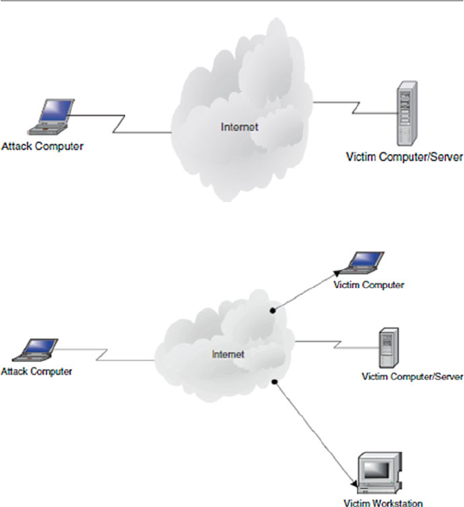
121
5.3.4.2 One-to-Many
These attacks are fueled by anonymity. In most cases, the attacker does not know
any of the victims. Moreover, in all cases, the attackers will, at least that is what they
assume, remain anonymous to the victims. This topography has been the technique
of choice in the last 2–3 years because it is one of the easiest to carry out. The
motives that drive attackers to use this technique are as follows:
• Hate : There is hate when the attacker may specifi cally select a cross section of a
type of people he or she wants to hurt and deliver the payload to the most visible
location where such people have access. Examples of attacks using this tech-
nique include a number of e-mail attacks that have been sent to colleges and
churches that are predominantly of one ethnic group.
Fig. 5.2 Shows a one-to-one topology
Fig. 5.3 Shows a one-to-many topology
5.3 Hackers

122
• Personal satisfaction occurs when the hacker gets fun/satisfaction from other
peoples’ suffering. Examples include all the recent e-mail attacks such as the
“Love Bug,” “Killer Resume,” and “Melissa.”
• Jokes/hoaxes are involved when the attacker is playing jokes or wants to
intimidate people.
5.3.4.3 Many-to-One
These attacks so far have been rare, but they have recently picked up momentum as
the DDoS attacks have once again gained favor in the hacker community. In a many-
to- one attack technique, the attacker starts the attack by using one host to spoof
other hosts, the secondary victims, which are then used as the new source of an
avalanche of attacks on a selected victim. These types of attacks need a high degree
of coordination and, therefore, may require advanced planning and a good under-
standing of the infrastructure of the network. They also require a very well-executed
selection process in choosing the secondary victims and then eventually the fi nal
victim. Attacks in this category are driven by:
• Personal vendetta : There is personal vendetta when the attacker may want to cre-
ate the maximum possible effect, usually damage, to the selected victim site.
• Hate is involved when the attacker may select a site for no other reasons than
hate and bombard it in order to bring it down or destroy it.
• Terrorism : Attackers using this technique may also be driven by the need to
infl ict as much terror as possible. Terrorism may be related to or part of crimes
like drug traffi cking, theft where the aim is to destroy evidence after a successful
attack, or even political terrorism.
• Attention and fame : In some extreme circumstances, what motivates this topog-
raphy may be just a need for personal attention or fame. This may be the case if
the targeted site is deemed to be a challenge or a hated site (Fig. 5.4 ).
5.3.4.4 Many-to-Many
As in the previous topography, attacks using this topography are rare; however,
there has been an increase recently in reported attacks using this technique. For
example, in some of the recent DDoS cases, there has been a select group of sites
chosen by the attackers as secondary victims. These are then used to bombard
another select group of victims. The numbers involved in each group may vary from
a few to several thousands. As was the case in the previous many-to-one topography,
attackers using this technique need a good understanding of the network infrastruc-
ture and a good and precise selection process to pick the secondary victims and
eventually selecting the fi nal pool of victims. Attacks utilizing this topology are
mostly driven by a number of motives including:
• Attention and fame are sought when the attacker seeks publicity resulting from a
successful attack.
5 Cyber Crimes and Hackers
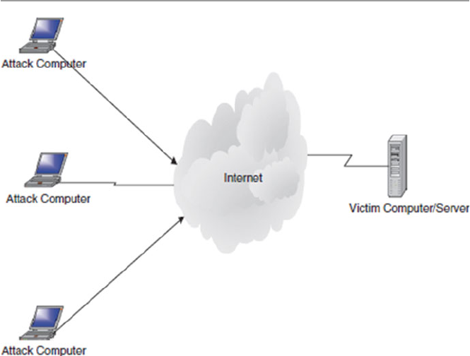
123
Fig. 5.4 Shows a many-to-one topology
• Terrorism : Terrorism is usually driven by a desire to destroy something; this may
be a computer system or a site that may belong to fi nancial institutions, public
safety systems, or a defense and communication infrastructure. Terrorism has
many faces including drug traffi cking, political and fi nancial terrorism, and the
usual international terrorism driven by international politics.
• Fun/hoax : This type of attack technique may also be driven by personal gratifi ca-
tion in getting famous and having fun (Fig. 5.5 ).
5.3.5 Hackers’ Tools of System Exploitation
Earlier on, we discussed how hacking uses two types of attacking systems: DDoS
and penetration. In the DDoS, there are a variety of ways of denying access to the
system resources, and we have already discussed those. Let us now look at the most
widely used methods in system penetration attacks. System penetration is the most
widely used method of hacker attacks. Once in, a hacker has a wide variety of
choices, including viruses, worms, and sniffers [ 15 ].
5.3.5.1 Viruses
Let us start by giving a brief description of a computer virus and defer a more
detailed description of it until Chap. 14 . A computer virus is a program that infects
a chosen system resource such as a fi le and may even spread within the system and
5.3 Hackers
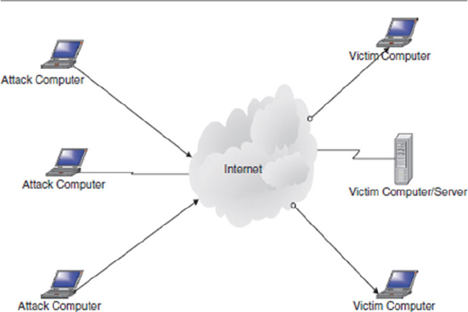
124
beyond. Hackers have used various types of viruses in the past as tools, including
memory/resident, error-generating, program destroyers, system crushers, time theft,
hardware destroyers, Trojans, time bombs, trapdoors, and hoaxes. Let us give a brief
description of each and differ a more detailed study of each until Chap. 14 .
Memory/Resident Virus : This is more insidious, diffi cult to detect, fast spreading,
and extremely diffi cult to eradicate and one of the most damaging computer viruses
that hackers use to attack the central storage part of a computer system. Once in
memory, the virus is able to attack any other program or data in the system. As we
will see in Chap. 14 , they are of two types: transient , the category that includes
viruses that are active only when the infl icted program is executing, and resident , a
brand that attaches itself, via a surrogate software, to a portion of memory and
remains active long after the surrogate program has fi nished executing. Examples of
memory resident viruses include all boot sector viruses such as the Israel virus [ 16 ].
Error-Generating Virus : Hackers are fond of sending viruses that are diffi cult to
discover and yet are fast moving. Such viruses are deployed in executable code.
Every time the software is executed, errors are generated. The errors vary from
“hard” logical errors, resulting in complete system shut down, to simple “soft” logi-
cal errors which may cause simple momentary blimps of the screen.
Data and Program Destroyers : These are serious software destroyers that attach
themselves to a software and then use it as a conduit or surrogate for growth, repli-
cation, and as a launch pad for later attacks to this and other programs and data.
Once attached to a software, they attack any data or program that the software may
come in contact with, sometimes altering the contents, deleting, or completely
destroying those contents.
System Crusher : Hackers use system crusher viruses to completely disable the
system. This can be done in a number of ways. One way is to destroy the system
Fig. 5.5 Shows a many-to-many topology
5 Cyber Crimes and Hackers

125
programs such as operating system, compilers, loaders, linkers, and others. Another
approach is to self-replicate until the system is overwhelmed and crashes.
Computer Time Theft Virus : Hackers use this type of virus to steal system time
either by fi rst becoming a legitimate user of the system or by preventing other legiti-
mate users from using the system by fi rst creating a number of system interruptions.
This effectively puts other programs scheduled to run into indefi nite wait queues.
The intruder then gains the highest priority, like a superuser with full access to all
system resources. With this approach, system intrusion is very diffi cult to detect.
Hardware Destroyers : Although not very common, these killer viruses are used
by hackers to selectively destroy a system device by embedding the virus into device
microinstructions or “mic” such as bios and device drivers. Once embedded into the
mic, they may alter it in such ways that may cause the devices to move into positions
that normally result in physical damage. For example, there are viruses that are
known to lock up keyboards, disable mice, and cause disk read/write heads to move
to nonexisting sectors on the disk, thus causing the disk to crash.
Trojans : These are a class of viruses that hackers hide, just as in the Greek Trojan
Horse legend, into trusted programs such as compilers, editors, and other commonly
used programs.
Logic/Time Bombs : Logic bombs are timed and commonly used type of virus to
penetrate system, embedding themselves in the system’s software and lying in wait
until a trigger goes off. Trigger events can vary in type depending on the motive of
the virus. Most triggers are timed events. There are various types of these viruses
including Columbus Day, Valentine’s Day, Jerusalem-D, and the Michelangelo,
which was meant to activate on Michelangelo’s 517 birthday anniversary.
Trapdoors : Probably, these are some of the most used virus tools by hackers.
They fi nd their way into the system through weak points and loopholes that are
found through system scans. Quite often, software manufacturers, during software
development and testing, intentionally leave trapdoors in their products, usually
undocumented, as secret entry points into the programs so that modifi cation can be
done on the programs at a later date. Trapdoors are also used by programmers as
testing points. As is always the case, trapdoors can also be exploited by malicious
people, including programmers themselves. In a trapdoor attack, an intruder may
deposit virus-infected data fi le on a system instead of actually removing, copying,
or destroying the existing data fi les.
Hoaxes : Very common form of viruses, they most often do not originate from
hackers but from system users. Though not physically harmful, hoaxes can be a
disturbing type of nuisance to system users.
5.3.5.2 Worm
A worm is very similar to a virus. In fact, their differences are few. They are both
automated attacks, both self-generate or replicate new copies as they spread, and
both can damage any resource they attack. The main difference between them, how-
ever, is that while viruses always hide in software as surrogates, worms are stand-
alone programs.
Hackers have been using worms as frequently as they have been using viruses to
attack computer systems.
5.3 Hackers

126
5.3.5.3 Sniffer
A sniffer is a software script that sniffs around the target system looking for
passwords and other specifi c information that usually lead to identifi cation of
system exploits. Hackers use sniffers extensively for this purpose.
5.3.6 Types of Attacks
Whatever their motives, hackers have a variety of techniques in their arsenal to carry
out their goals. Let us look at some of them here.
Social Engineering : This involves fooling the victim for fun and profi t. Social
engineering depends on trusting that employees will fall for cheap hacker “tricks”
such as calling or e-mailing them masquerading as a system administrator, for
example, and getting their passwords which eventually lets in the intruder. Social
engineering is very hard to protect against. The only way to prevent it is through
employee education and employee awareness.
Impersonation is stealing access rights of authorized users. There are many ways
an attacker such as a hacker can impersonate a legitimate user. For example, a
hacker can capture a user telnet session using a network sniffer such as tcpdump or
nitsniff. The hacker can then later log-in as a legitimate user with the stolen log-in
access rights of the victim.
Exploits : This involves exploiting a hole in software or operating systems. As is
usually the case, many software products are brought on the market either through
a rush to fi nish or lack of testing, with gaping loopholes. Badly written software is
very common even in large software projects such as operating systems. Hackers
quite often scan network hosts for exploits and use them to enter systems.
Transitive trust exploits host-to-host or network-to-network trust. Either through
client–server three-way handshake or server-to-server next-hop relationships, there
is always a trust relationship between two network hosts during any transmission.
This trust relationship is quite often compromised by hackers in a variety of ways.
For example, an attacker can easily do an IP spoof or a sequence number attack
between two transmitting elements and gets away with information that compro-
mises the security of the two communicating elements.
Data Attacks: Script programming has not only brought new dynamism into Web
development, but it has also brought a danger of hostile code into systems through
scripts. Current scripts can run on both the server, where they traditionally used to
run, and also on the client. In doing so, scripts can allow an intruder to deposit hos-
tile code into the system, including Trojans, worms, or viruses. We will discuss
scripts in detail in the next chapter.
Infrastructure Weaknesses : Some of the greatest network infrastructure weak-
nesses are found in the communication protocols. Many hackers, by virtue of their
knowledge of the network infrastructure, take advantage of these loopholes and use
them as gateways to attack systems. Many times, whenever a loophole is found in
the protocols, patches are soon made available, but not many system administrators
5 Cyber Crimes and Hackers

127
follow through with patching the security holes. Hackers start by scanning systems
to fi nd those unpatched holes. In fact, most of the system attacks from hackers use
known vulnerabilities that should have been patched.
Denial of Service : This is a favorite attack technique for many hackers, espe-
cially hacktivists. It consists of preventing the system from being used as planned
through overwhelming the servers with traffi c. The victim server is selected and
then bombarded with packets with spoofed IP addresses. Many times, innocent
hosts are forced to take part in the bombardment of the victim to increase the traffi c
on the victim until the victim is overwhelmed and eventually fails.
Active Wiretap : In an active wiretap, messages are intercepted during transmis-
sion. When the interception happens, two things may take place: First, the data in
the intercepted package may be compromised by introduction of new data such as
change of source or destination IP address or the change in the packet sequence
numbers. Second, data may not be changed but copied to be used later such as in the
scanning and sniffi ng of packets. In either case, the confi dentiality of data is com-
promised and the security of the network is put at risk.
5.4 Dealing with the Rising Tide of Cyber Crimes
Most system attacks take place before even experienced security experts have
advance knowledge of them. Most of the security solutions are best practices as we
have so far seen, and we will continue to discuss them as either preventive or reac-
tive. An effective plan must consist of three components: prevention, detection, and
analysis and response.
5.4.1 Prevention
Prevention is probably the best system security policy, but only if we know what to
prevent the systems from. It has been and it continues to be an uphill battle for the
security community to be able to predict what type of attack will occur the next time
around. Although prevention is the best approach to system security, the future of
system security cannot and should not rely on the guesses of a few security people,
who have and will continue to get it wrong sometimes. In the few bright spots in the
protection of systems through prevention has been the fact that most of the attack
signatures are repeat signatures. Although it is diffi cult and we are constantly chas-
ing the hackers who are always ahead of us, we still need to do something. Among
those possible approaches are the following:
• A security policy
• Risk management
• Perimeter security
• Encryption
5.4 Dealing with the Rising Tide of Cyber Crimes

128
• Legislation
• Self-regulation
• Mass education
We will discuss all these in detail in the chapters that follow.
5.4.2 Detection
In case prevention fails, the next best strategy should be early detection. Detecting
cyber crimes before they occur constitutes a 24-h monitoring system to alert secu-
rity personnel whenever something unusual (something with a non-normal pattern,
different from the usual pattern of traffi c in and around the system) occurs. Detection
systems must continuously capture, analyze, and report on the daily happenings in
and around the network. In capturing, analyzing, and reporting, several techniques
are used, including intrusion detection, vulnerability scanning, virus detection, and
other ad hoc methods. We will look at these in the coming chapters.
5.4.3 Recovery
Whether or not prevention or detection solutions were deployed on the system, if a
security incident has occurred on a system, a recovery plan, as spelled out in the
security plan, must be followed.
5.5 Conclusion
Dealing with rising cyber crimes in general and hacker activities in particular, in this
fast-moving computer communication revolution in which everyone is likely to be
affected, is a major challenge not only to the people in the security community but
for all of us. We must devise means that will stop the growth, stop the spiral, and
protect the systems from attacks. But this fi ght is already cut out for us and it may
be tough in that we are chasing the enemy who seems, on many occasions, to know
more than we do and is constantly ahead of us.
Preventing cyber crimes requires an enormous amount of effort and planning.
The goal is to have advance information before an attack occurs. However, the chal-
lenge is to get this advance information. Also getting this information in advance
does not help very much unless we can quickly analyze it and plan an appropriate
response in time to prevent the systems from being adversely affected. In real life,
however, there is no such thing as the luxury of advance information before an
attack.
5 Cyber Crimes and Hackers

129
Exercises
1. Defi ne the following terms:
(i) Hacker
(ii) Hacktivist
(iii) Cracker
2. Why is hacking a big threat to system security?
3. What is the best way to deal with hacking?
4. Discuss the politics of dealing with hacktivism.
5. Following the history of hacking, can you say that hacking is getting under
control? Why or why not?
6. What kind of legislation can be effective to prevent hacking?
7. List and discuss the types of hacker crimes.
8. Discuss the major sources of computer crimes.
9. Why is crime reporting so low in major industries?
10. Insider abuse is a major crime category. Discuss ways to solve it.
Advanced Exercises
1. Devise a plan to compute the cost of computer crime.
2. What major crimes would you include in the preceding study?
3. From your study, identify the most expensive attacks.
4. Devise techniques to study the problem of non-reporting. Estimate the costs
associated with it.
5. Study the reporting patterns of computer crimes reported by industry. Which
industry reports best?
References
1. Cybercrime threat “real and growing”. http://news.bbc.co.uk/2/hi/science/nature/978163.stm
2. Glossary of vulnerability testing terminology. http://www.ee.oulu.fi /research/ouspg/sage/
glossary/
3. Anatomy of an attack. The Economist, 19–25 February 2000
4. Kizza JM (2003) Social and ethical issues in the information age, 2nd edn. Springer, New York
5. Freeh LJ, FBI congressional report on cybercrime.
http://www.fbi.gov/congress00/
cyber021600.htm
6. Slatalla M, A brief history of hacking. http://tlc.discovery.com/convergence/hackers/articles/
history.html
7. Phone phreaking: the telecommunications underground. http://telephonetribute.com/phone-
phreaking.html
8. Timeline of hacking. http://fyi.cnn.com/fyi/interactive/school.tools/timelines/1999/computer.
hacking/frameset.exclude.html
9. Rosenbaum R, Secrets of the little blue box.
http://www.webcrunchers.com/crunch/esqart.
html
10. The complete history of hacking. http://www.wbglinks.net/pages/history/
11. Denning PJ (1990) Computers under attack: intruders, worms and viruses. ACM Press,
New York
References

130
12. Denning D, Activism, hacktivism, and cyberterrorisim: the internet as a tool or infl uencing
foreign policy. http://www.nautilus.og/info-policy/workshop/papers/denning.html
13. Lemos R, Online vandals smoke New York Times site CNET News.com.
http://news.com.
com/2009–1001–252754.html
14. Shachtman N, Hacktivists stage virtual sit-in at WEF Web site AlterNet.
http://www.alternet.
org/story.html?StoryID=12374
15. Kizza JM (2001) Computer network security and cyber ethics. McFarland, North Calorina
16. Forchet K (1994) Computer security management . Boyd & Frasher Publishing, Danvers
5 Cyber Crimes and Hackers

131
© Springer-Verlag London 2015
J.M. Kizza, Guide to Computer Network Security, Computer Communications
and Networks, DOI 10.1007/978-1-4471-6654-2_6
6
Scripting and Security in Computer
Networks and Web Browsers
6.1 Introduction
The rapid growth of the Internet and its ability to offer services have made it the
fastest-growing medium of communication today. Today’s and tomorrow’s business
transactions involving financial data, product development and marketing, storage
of sensitive company information, and the creation, dissemination, sharing, and
storing of information are and will continue to be made online, most specifically on
the Web. The automation and dynamic growth of an interactive Web has created a
huge demand for a new type of Web programming to meet the growing demand of
millions of Web services from users around the world. Some services and requests
are tedious and others are complex, yet the rate of growth of the number of requests,
the amount of services requested in terms of bandwidth, and the quality of informa-
tion requested warrant a technology to automate the process. Script technology
came in timely to the rescue. Scripting is a powerful automation technology on the
Internet that makes the Web highly interactive.
Scripting technology is making the Web interactive and automated as Web servers
accept inputs from users and respond to user inputs. While scripting is making the
Internet and, in particular, the Web alive and productive, it also introduces a huge
security problem to an already security-burdened cyberspace. Hostile scripts embed-
ded in Web pages, as well as HTML-formatted e-mail, attachments, and applets,
introduce a new security paradigm in cyberspace security. In particular, security
problems are introduced in two areas: at the server and at the client. Before we look
at the security at both of these points, let us first understand the scripting standard.
6.2 Scripting
A program script is a logical sequence of line commands which causes the computer
to accomplish some task. Many times we refer to such code as macros or batch files
because they can be executed without user interaction. A script language is a

132
programming language through which you can write scripts. Scripts can be written
in any programming language or a special language as long as they are surrogated
by another program to interpret and execute them on the fly by a program unlike
compiled programs which are run by the computer operating system.
Because scripts are usually small programs, written with a specific purpose in
mind to perform tasks very quickly and easily, many times in constrained and
embedded environments with abstracted performance and safety, unlike general-
purpose programs written in general-purpose programming languages, are not in
most cases full-featured programs, but tend to be “glue” programs that they hold
together other pieces of software.
Therefore, scripting languages are not your general-purpose programming lan-
guages. Their syntax, features, library, etc., are focused more around accomplishing
small tasks quickly. The scripts can be either application scripts, if they are executed
by an application program surrogate like Microsoft spreadsheet, or command line
scripts if they are executed from a command line like the Windows or Unix/Linux
command line.
6.3 Scripting Languages
CGI scripts can be written in any programming language. Because of the need for
quick execution of the scripts both at the server and in the client browsers and the
need of not storing source code at the server, it is getting more and more convenient
to use scripting languages that are interpretable instead of languages that are com-
piled like C and C++. The most common scripting languages include:
•JavaScript
•Perl
•Tcl/Tk
•Python
•VBA
•Windows Script Host
•Others including specific mobile device scripting languages
There are basically two categories of scripting languages, those whose scripts are
on the server side of the client–server programming model and those whose scripts
are on the client side.
6.3.1 Server-Side Scripting Languages
Ever since the debut of the World Wide Web and the development of HTML to
specify and present information, there has been a realization that HTML documents
are too static.
6 Scripting and Security in Computer Networks and Web Browsers

133
There was a need to put dynamism into HTTP so that the interaction between the
client and the server would become dynamic. This problem was easy to solve
because the hardware on which Web server software runs has processing power and
many applications such as e-mail, database manipulation, or calendaring are already
installed and ripe for utilization [1]. The CGI concept was born.
Among the many sever-side scripting languages are PERL, PHP, ColdFusion,
ASP, MySQL, Java servlets, and MivaScript.
6.3.1.1 Perl Scripts
Practical Extraction and Report Language (Perl) is an interpretable programming
language that is also portable. It is used extensively in Web programming to make
text processing interactive and dynamic. Developed in 1986 by Larry Wall, the lan-
guage has become very popular. Although it is an interpreted language, unlike C and
C++, Perl has many features and basic constructs and variables similar to C and
C++. However, unlike C and C++, Perl has no pointers and defined data types.
One of the security advantages of Perl over C, say, is that Perl does not use point-
ers where a programmer can misuse a pointer and access unauthorized data. Perl
also introduces a gateway into Internet programming between the client and the
server. This gateway is a security gatekeeper scrutinizing all incoming data into the
server to prevent malicious code and data into the server. Perl does this by denying
programs written in Perl from writing to a variable, whereby this variable can cor-
rupt other variables.
Perl also has a version called Taintperl that always checks data dependencies to
prevent system commands from allowing untrusted data or code into the server.
6.3.1.2 PHP
PHP (Hypertext Preprocessor) is a widely used general-purpose scripting language
that is especially suited for Web development and can be embedded into HTML. It
is an open-source language suited for Web development, and this makes it very
popular.
Just like Perl, PHP code is executed on the server and the client just receives the
results of running a PHP script on the server. With PHP, you can do just about any-
thing other CGI program can do, such as collect form data, generate dynamic page
content, or send and receive cookies.
6.3.2 Client-Side Scripting Languages
The World Wide Web (WWW) created the romance of representing portable infor-
mation from a wide range of applications for a global audience. This was accom-
plished by the HyperText Markup Language (HTML), a simple markup language
that revolutionized document representation on the Internet. But for a while, HTML
documents were static. The scripting specifications were developed to extend
HTML and make it more dynamic and interactive. Client-side scripting of HTML
documents and objects embedded within HTML documents has been developed to
6.3 Scripting Languages

134
bring dynamism and automation of user documents. Scripts including JavaScript
and VBScript are being used widely to automate client processes.
For a long time, during the development of CGI programming, programmers
noticed that much of what CGI does, such as maintaining a state, filling out forms,
error checking, or performing numeric calculation, can be handled on the client’s
side. Quite often, the client computer has quite a bit of CPU power idle, while the
server is being bombarded with hundreds or thousands of CGI requests for the mun-
dane jobs above. The programmers saw it justifiable to shift the burden to the client,
and this led to the birth of client-side scripting
Among the many client-side scripting languages are DTML/CSS, Java,
JavaScript, and VBScript.
6.3.2.1 JavaScripts
JavaScript is a programming that performs client-side scripting, making Web pages
more interactive. Client-side scripting means that the code works only on the user’s
computer, not on the server-side. It was developed by Sun Microsystems to bridge
the gap between Web designers who needed a dynamic and interactive Web environ-
ment and Java programmers. It is an interpretable language like Perl. That means
the interpreter in the browser is all that is needed for a JavaSrcipt to be executed by
the client and it will run. JavaScript’s ability to run scripts on the client’s browser
makes the client able to run interactive Web scripts that do not need a server. This
feature makes creating JavaScript scripts easy because they are simply embedded
into any HTML code. It has, therefore, become the de facto standard for enhancing
and adding functionality to Web pages.
This convenience, however, creates a security threat because when a browser can
execute a JavaScript at any time, it means that hostile code can be injected into the
script and the browser would run it from any client. This problem can be fixed only
if browsers can let an executing script perform a limited number of commands. In
addition, scripts run from a browser can introduce into the client systems program-
ming errors in the coding of the script itself, which may lead to a security threat in
the system itself.
6.3.2.2 VBScript
Based on part on the popularity of the Visual Basic programming language and on
the need to have a scripting language to counter JavaScript, Microsoft developed
VBScript (V and B for Visual Basic). VBScript has a syntax similar to the Visual
Basic programming language syntax. Since VBScript is based on Microsoft Visual
Basic, and unlike JavaScript which can run in many browsers, VBScript interpreter
is supported only in the Microsoft Internet Explore.
6.4 Scripting in Computer Network
The use of scripting in computer network started when network administrators
released that one of the best ways to tame the growing mountain of tasks required to
have a well-functioning network was to use scripting and take advantage of the
6 Scripting and Security in Computer Networks and Web Browsers

135
automated natured of execution of scripts via surrogate programs. This cut down on
the need for attention for many sometimes repeated tasks, in the running of a system
network.
According to Allen Rouse [2], scripting lets you automate various network
administration tasks, such as those that are performed every day or even several
times a day and those performed widely throughout the network like log-in scripts
and modification to the registry scripts in a widely distributed network of servers.
There are many functions in a daily administration of a network that are performed
by scripts including [2]:
•Machine startup
•Machine shutdown
•User log-in and log out
•Scripting basic TCP/IP networking on clients, including comparisons of GUI
and command-line tools to analogous scripting techniques
•Extending these scripting techniques to remote and multiple computers
•IP address allocation with DHCP and static IP addresses
•DNS client management
•WINS client management
•TCP/IP filtering, Internetwork Packet Exchange (IPX), and other network
protocols
•Managing system time and network settings in the registry
•Addition of new clients to a network
•Client–server information exchange
With all these tasks taken over by scripting, you may notice the tremendous
advantages scripting brings to the table for system administration in time savings,
network consistence, and flexibility.
By every account, scripting is on the rise with the changing technologies. There
is tremendous enthusiasm for growth in the four traditional areas of scripting that
include:
•System administration
•Graphical user interface (GUI)
•Internet information exchange (CGI) and the growing popularity of the browser
•Application and component frameworks like ActiveX and others
We will focus on the Internet information exchange in this chapter.
6.4.1 Introduction to the Common Gateway Interface (CGI)
One of the most essential useful areas in network performance when scripting plays
a vital role is in the network client–server information exchange. This is done via a
Common Gateway Interface or CGI. CGI is a standard to specify a data format that
servers, browsers, and programs must use in order to exchange information.
6.4 Scripting in Computer Network

136
A program written in any language that uses this standard to exchange data between
a Web server and a client’s browser is a CGI script. In other words, a CGI script is
an external gateway program to interface with information servers such as HTTP or
Web servers and client browsers. CGI scripts are great in that they allow the Web
servers to be dynamic and interactive with the client browser as the server receives
and accepts user inputs and responds to them in a measured and relevant way to
satisfy the user. Without CGI, the information the users would get from an informa-
tion server would not be packaged based on the request but based on how it is stored
on the server.
CGI programs are of two types: those written in programming languages such as
C/C++ and Fortran that can be compiled to produce an executable module stored on
the server and scripts written in scripting languages such as PERL, Java, and Unix
shell. For these CGI scripts, no associated source code needs to be stored by the
information server as is the case in CGI programs. CGI scripts written in scripting
languages are not complied like those in nonscripting languages. Instead, they are
text code which is interpreted by the interpreter on the information server or in the
browser and run right away. The advantage to this is you can copy your script with
little or no changes to any machine with the same interpreter and it will run. In addi-
tion, the scripts are easier to debug, modify, and maintain than a typical compiled
program.
Both CGI programs and scripts, when executed at the information server, help
organize information for both the server and the client. For example, the server may
want to retrieve information entered by the visitors and use it to package a suitable
output for the clients. In addition, GCI may be used to dynamically set field descrip-
tions on a form and in real-time inform the user on what data has been entered and
yet to be entered. At the end, the form may even be returned to the user for proof-
reading before it is submitted.
CGI scripts go beyond dynamic form filling to automating a broad range of ser-
vices in search engines and directories and taking on mundane jobs such as making
download available, granting access rights to users, and order confirmation.
As we pointed out earlier, CGI scripts can be written in any programming lan-
guage that an information server can execute. Many of these languages include
script languages such as Perl, JavaScript, TCL, Applescript, Unix shell, and
VBScript and nonscript languages such as C/C++, Fortran, and Visual Basic. There
is dynamism in the languages themselves; so, we may have new languages in the
near future.
6.4.1.1 CGI Scripts in a Three-Way Handshake
As we discussed in Chap. 3, the communication between a server and a client opens
with the same etiquette we use when we meet a stranger. First, a trust relationship
must be established before any requests are made. This can be done in a number of
ways. Some people start with a formal “Hello, I’m …,” and then, “I need …” upon
which the stranger says “Hello, I’m …” and then, “Sure I can …” Others carry it
further to hugs, kisses, and all other ways people use to break the ice. If the stranger
is ready for a request, then this information is passed back to you in a form of an
6 Scripting and Security in Computer Networks and Web Browsers

137
acknowledgment to your first embrace. However, if the stranger is not ready to talk
to you, there is usually no acknowledgment of your initial advances and no further
communication may follow until the stranger’s acknowledgment comes through. At
this point, the stranger puts out a welcome mat and leaves the door open for you to
come in and start business. Now, it is up to the initiator of the communication to
start full communication.
When computers are communicating, they follow these etiquette patterns and
protocols, and we call this procedure a handshake. In fact, for computers it is called
a three-way handshake. A three-way handshake starts with the client sending a
packet, called a SYN (short for synchronization), which contains both the client and
server addresses together with some initial information for introductions. Upon
receipt of this packet by the server’s welcome open door, called a port, the server
creates a communication socket with the same port number such as the client
requested through which future communication with the client will go. After creat-
ing the communication socket, the server puts the socket in queue and informs the
client by sending an acknowledgment called a SYN-ACK. The server’s communica-
tion socket will remain open and in queue waiting for an ACK from the client and
data packets thereafter. The socket door remains half-open until the server sends the
client an ACK packet signaling full communication. During this time, however, the
server can welcome many more clients that want to communicate, and communica-
tion sockets will be opened for each.
The CGI script is a server-side language that resides on the server side, and it
receives the client’s SYN request for a service. The script then executes and lets the
server and client start to communicate directly. In this position, the script is able to
dynamically receive and pass data between the client and server. The client browser
has no idea that the server is executing a script. When the server receives the script’s
output, it then adds the necessary protocol data and sends the packet or packets back
to the client’s browser. Figure 6.1 shows the position of a CGI script in a three-way
handshake.
The CGI scripts reside on the server side, in fact on the computer on which the
server is, because a user on a client machine cannot execute the script in a browser
on the server; one can view only the output of the script after it executes on the
server and transmits the output using a browser on the client machine the user is on.
6.4.2 Server-Side Scripting: The CGI Interface
In the previous section, we stated that the CGI script is on the server side of the
relationship between the client and the server. The scripts are stored on the server
and are executed by the server to respond to the client demands. There is, therefore,
an interface that separates the server and the script. This interface, as shown in
Fig. 6.2, consists of information from the server supplied to the script that includes
input variables extracted from an HTTP header from the client and information
from the script back to the server. Output information from the server to the script
and from the script to the server is passed through environment variables and
6.4 Scripting in Computer Network
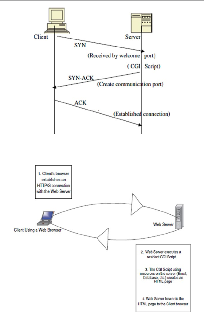
138
Fig. 6.1 The position of a CGI script in a three-way handshake
Fig. 6.2 A client CGI script interface
6 Scripting and Security in Computer Networks and Web Browsers

139
through script command lines. Command line inputs instruct a script to do certain
tasks such as search and query.
6.5 Computer Network Scripts and Security
As we have pointed out above, by all accounts, scripting is on the rise with the
changing technologies. There is tremendous enthusiasm for growth n the four tradi-
tional areas of scripting that include:
•System administration
•Graphical user interface (GUI)
•Internet information exchange (CGI) and the growing popularity of the browser
•Application and component frameworks like ActiveX and others
As scripting grows, so will its associated security problems. Hackers are con-
stantly developing and testing a repertoire of their own scripts that will compromise
other scripts wherever they are on the Web, in the computer network system, or in
applications. The most common of such hacker techniques today include Web cross
site scripting or XSS or CSS. Cross site scripting allows attackers of Web sites to
embed malicious scripts into dynamic unsuspecting Web and network scripts.
Although this is a threat to most scripts, we will focus our script security discussion
on the CGI scripts.
6.5.1 CGI Script Security
To an information server, the CGI script is like an open window to a private house
where passersby can enter the house to request services. It is an open gateway that
allows anyone anywhere to run an executable program on your server and even send
their own programs to run on your server. An open window like this on a server is
not the safest thing to have, and security issues are involved. But since CGI scripting
is the fastest-growing component of the Internet, it is a problem we have to contend
with and meet head on. CGI scripts present security problems to cyberspace in
several ways including:
•Program development: During program development, CGI scripts are written in
high level programming language and complied before being executed or they
are written in a scripting language and they are interpreted before they are exe-
cuted. In either way, programming is more difficult than composing documents
with HTML, for example. Because of the programming complexity and owing to
lack of program development discipline, errors introduced into the program are
difficult to find, especially in noncompiled scripts.
6.5 Computer Network Scripts and Security

140
•Transient nature of execution: When CGI scripts come into the server, they run
as separate processes from that of the host server. Although this is good because
it isolates the server from most script errors, the imported scripts may introduce
hostile code into the server.
•Cross-pollination: The hostile code introduced into the server by a transient
script can propagate into other server applications and can even be re-transmitted
to other servers by a script bouncing off this server or originating from this
server.
•Resource-guzzling: Scripts that are resource intensive could cause a security
problem to a server with limited resources.
•Remote execution: Since servers can send CGI scripts to execute on surrogate
servers, both the sending and receiving servers are left open to hostile code usu-
ally transmitted by the script.
In all these situations, a security threat occurs when someone breaks into a script.
Broken scripts are extremely dangerous.
Kris Jamsa gives the following security threats that can happen to a broken script [4]:
•Giving an attacker access to the system’s password file for decryption.
•Mailing a map of the system which gives the attacker more time offline to ana-
lyze the system’s vulnerabilities
•Starting a login server on a high port and telneting in.
•Beginning a distributed denial-of-service attack against the server.
•Erasing or altering the server’s log files.
•In addition to these others, the following security threats are also possible [5]:
– Malicious code provided by one client for another client: This can happen, for
example, in sites that host discussion groups where one client can embed
malicious HTML tags in a message intended for another client. According to
the Computer Emergency Response Team (CERT), an attacker might post a
message like
Hello message board. This is a message. < SCRIPT > malicious code</
SCRIPT > This is the end of my message.
When a victim with scripts enabled in his or her browser reads this message,
the malicious code may be executed unexpectedly. Many different scripting
tags that can be embedded in this way include < SCRIPT>, <OBJECT>, <
APPLET>, and < EMBED >.
– Malicious code sent inadvertently by a client: When a client sends malicious
data intended to be used only by itself. This occurs when the client relies on
an untrustworthy source of information when submitting a request. To explain
this case, CERT gives the following example. An attacker may construct a
malicious link such as [5]:
<A HREF = “http://example.com/comment.cgi? mycom-ment = <SCRIPT >
malicious code</SCRIPT>” > Click here </A>
6 Scripting and Security in Computer Networks and Web Browsers

141
When an unsuspecting user clicks on this link, the URL sent to example.com
includes the malicious code. If the Web server sends a page back to the user
including the value of mycomment, the malicious code may be executed unex-
pectedly on the client.
All these security threats point at one security problem with scripts: They all let
in unsecured data.
6.5.1.1 Server-Side Script Security
A server-side script, whether compiled or interpreted, and its interpreter is included
in a Web server as a module or executed as a separate CGI binary. It can access files,
execute commands, and open network connections on the server. These capabilities
make server-side scripts a security threat because they make anything run on the
Web server unsecure by default. PHP is no exception to this problem; it is just like
Perl and C. For example, PHP, like other server-side scripts, was designed to allow
user-level access to the file system, but it is entirely possible that a PHP script can
allow a user to read system files such as/etc/passwd which gives the user access to
all passwords and the ability to modify network connections and change device
entries in/dev/or COM1, configuration files/etc/files, and .ini files.
Since databases have become an integral part of daily computing in a networked
world and large databases are stored on network servers, they become easy prey to
hostile code. To retrieve or to store any information in a database, nowadays you
need to connect to the database, send a legitimate query, fetch the result, and close
the connection all using a query language, the Structured Query Language (SQL).
An attacker can create or alter SQL commands to inject hostile data and code, or to
override valuable ones, or even to execute dangerous system-level commands on the
database host.
6.5.2 JavaScript and VBScript Security
Recall that using all client-side scripts like JavaScript and VBScript that execute in
the browser can compromise the security of the user system. These scripts create
hidden frames on Web sites so that as a user navigates a Web site, the scripts running
in the browser can store information from the user for short-time use, just like a
cookie. The hidden frame is an area of the Web page that is invisible to the user but
remains in place for the script to use. Data stored in these hidden frames can be used
by multiple Web pages during the user session or later. Also, when a user visits a
Web site, the user may not be aware that there are scripts executing at the Web site.
Hackers can use these loopholes to threaten the security of the user system.
There are several ways of dealing with these problems including
•Limit browser functions and operations of the browser scripts so that the script,
for example, cannot write on or read from the user’s disk.
6.5 Computer Network Scripts and Security

142
•Make it difficult for others to read the scripts.
•Put the script in an external file and reference the file only from the document
that uses it.
6.5.3 Web Scripts Security
Our discussion of script security issues above has centered on CGI scripts stored
and executed on the server. However, as the automation of the Web goes into over-
drive, there are now thousands of Web scripts doing a variety of web services from
form filling to information gathering. Most of these scripts either transient or reside
on Web servers. Because of their popularity and widespread use, most client and
server Web browsers today have the capability to interpret scripts embedded in Web
pages downloaded from a Web server. Such scripts may be written in a variety of
scripting languages. In addition, most browsers are installed with the capability to
run scripts enabled by default.
6.6 Dealing with the Script Security Problems
The love of Web automation is not likely to change soon and the future of a dynamic
Web is here to stay. In addition, more and more programs written for the Web are
interacting with networked clients and servers, raising the fear of a possibility that
clients and servers may be attacked by these programs using embedded scripts to
gain unauthorized access.
It is, therefore, necessary to be aware of the following:
•Script command line statements: Scripting languages such as PERL, PHP, and
the Bourne shell pass information needed to perform tasks through command
line statements which are then executed by an interpreter. This can be very
dangerous.
•Clients may use special characters in input strings to confuse other clients, serv-
ers, or scripts.
•Problems with server side include user-created documents in NCSA HTTPd that
provide simple information, such as current date, the file’s last modification date,
and the size or last modification of other files, to clients on the fly. Sometimes
this information can provide a powerful interface to CGI. In an unfortunate situ-
ation, server-side scripts are a security risk because they let clients execute dan-
gerous commands on the server.
We summarize the three concerns above in two good solutions: one is to use only
the data from a CGI, only if it will not harm the system; and the second is to check
all data into or out of the script to make sure that it is safe.
6 Scripting and Security in Computer Networks and Web Browsers

143
Exercises
1. How did CGI revolutionize Web programming?
2. What are the differences between client-side and server-side scripting? Is one
better than the other?
3. In terms of security, is client-side scripting better than server-side scripting?
Why or why not?
4. Suggest ways to improve script security threats.
5. Why was VBScript not very popular?
6. The biggest script security threat has always been the acceptance of untrusted
data. What is the best way for scripts to accept data and preserve the trust?
Advance Exercises
1. The most common CGI function is to fill in forms, the processing script actually
takes the data input by the Web surfer and sends it as e-mail to the form admin-
istrator. Discuss the different ways such a process can fall victim to an attacker.
2. CGI is also used in discussions allowing users to talk to the customer and back.
CGI helps in creating an ongoing dialog between multiple clients. Discuss the
security implications of dialogs like this.
3. CGI is often used to manage extensive databases. Databases store sensitive infor-
mation. Discuss security measures you can use to safeguard the databases.
References
1. Sol S Server-side scripting. http://www.wdvl.com/Authoring/Scripting/WebWare/Server/
2. Rouse A, Understanding the role of scripting in network administration. http://www.techrepub-
lic.com/article/understand-the-role-of-scripting-in-network-administration/
Additional References
3. The World Wide Web Security FAQ. http://www.w3.org/Security/Faq/wwwsf4.html
4. Jamsa K (2002) Hacker proof: the ultimate guide to network security, 2nd edn. Thomason
Delmar Learning, Las Vegas
5. CERT® Advisory CA-2000–02 Malicious HTML tags embedded in client web requests. http://
www.cert.org/advisories/CA-2000–02.html
References

145
© Springer-Verlag London 2015
J.M. Kizza, Guide to Computer Network Security, Computer Communications
and Networks, DOI 10.1007/978-1-4471-6654-2_7
7
Security Assessment, Analysis,
and Assurance
7.1 Introduction
The rapid development in both computer and telecommunication technologies has
resulted in massive interconnectivity and interoperability of systems. The world is
getting more and more interconnected every day. Most major organization systems
are interconnected to other systems through networks. The bigger the networks, the
bigger the security problems involving the system resources on these networks.
Many companies, businesses, and institutions whose systems work in coordination
and collaboration with other systems as they share each others’ resources and com-
municate with each other face a constant security threat to these systems, yet the
collaboration must go on.
The risks and potential of someone intruding into these systems for sabotage, van-
dalism, and resource theft are high. For security assurance of networked systems, such
risks must be assessed to determine the adequacy of existing security measures and
safeguards and also to determine if improvement in the existing measures is needed.
Such an assessment process consists of a comprehensive and continuous analysis of
the security threat risk to the system that involves an auditing of the system, assessing
the vulnerabilities of the system, and maintaining a creditable security policy and a
vigorous regime for the installation of patches and security updates. In addition, there
must also be a standard process to minimize the risks associated with nonstandard
security implementations across shared infrastructures and end systems.
The process to achieve all these and more consists of several tasks including a
system security policy, security requirements specifi cation, identifi cation of threat
and threat analysis, vulnerability assessment, security certifi cation, and the monitor-
ing of vulnerabilities and auditing. The completion of these tasks marks a comple-
tion of a security milestone on the road to a system’s security assurance. These tasks
are shown in Table 7.1 below.
Security is a process. Security assurance is a continuous security state of the
security process. The process, illustrated in Table 7.1 and depicted in Fig. 7.1 , starts
with a thorough system security policy, whose components are used for system
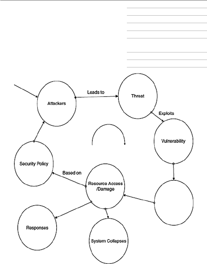
146
requirement specifi cations. The security requirement specifi cations are then used to
identify threats to the system resources. An analysis of these identifi ed threats per
resource is then done. The vulnerabilities identifi ed by the threats are then assessed,
and if the security measures taken are good enough, they are then certifi ed, along
with the security staff.
After certifi cation, the fi nal component of the security process is the auditing and
monitoring phase. This phase may reveal more security problems which require revis-
iting the security policy that makes the process start to repeat itself. That security cycle
process is security assurance. The process of security assurance is shown in Fig. 7.1 .
Table 7.1 System security
process System security policy
Security requirements specifi cation
Threat identifi cation
Threat analysis
Vulnerability identifi cation and
assessment
Security certifi cation
Security monitoring and auditing
Fig. 7.1 System security assurance cycle
7 Security Assessment, Analysis, and Assurance

147
7.2 System Security Policy
To a system administrator, the security of the organization’s system is very impor-
tant. For any organization system, there must be somebody to say no when the no
needs to be said. The no must be said because the administrator wants to limit the
number of network computers, resources, and capabilities people have been using
to ensure the security of the system. One way of doing this in fairness to all is
through the implementation of a set of policies, procedures, and guidelines that tell
all employees and business partners what constitutes acceptable and unacceptable
use of the organization’s computer system. The security policy also spells out what
resources need to be protected and how organization can protect such resources. A
security policy is a living set of policies and procedures that impact and potentially
limit the freedoms and of course levels of individual security responsibilities of all
users. Such a structure is essential to an organization’s security. Having said that,
however, let us qualify our last statement. There are as many opinions on the useful-
ness of security policies in the overall system security picture as there are security
experts. However, security policies are still important in the security plan of a sys-
tem. It is important for several reasons including:
• Firewall installations: If a functioning fi rewall is to be confi gured, its rule base
must be based on a sound security policy.
• User discipline: All users in the organization who connect to a network such as
the Internet, through a fi rewall, say, must conform to the security policy.
Without a strong security policy that every employee must conform to, the orga-
nization may suffer from data loss, employee time loss, and productivity loss all
because employees may spend time fi xing holes, repairing vulnerabilities, and
recovering lost or compromised data among other things.
A security policy covers a wide variety of topics and serves several important
purposes in the system security cycle. Constructing a security policy is like building
a house; it needs a lot of different components that must fi t together. The security
policy is built in stages, and each stage adds value to the overall product, making it
unique for the organization. To be successful, a security policy must:
• Have the backing of the organization top management.
• Involve everyone in the organization by explicitly stating the role everyone will
play and the responsibilities of everyone in the security of the organization.
• Precisely describe a clear vision of a secure environment stating what needs to be
protected and the reasons for it.
• Set priorities and costs of what needs to be protected.
• Be a good teaching tool for everyone in the organization about security and what
needs to be protected, why, and how it is to be protected.
• Set boundaries on what constitutes appropriate and inappropriate behavior as far
as security and privacy of the organization resources are concerned.
7.2 System Security Policy

148
• Create a security clearing house and authority.
• Be fl exible enough to adapt to new changes.
• Be consistently implemented throughout the organization.
To achieve these subgoals, a carefully chosen set of basic steps must be followed
to construct a viable implementable and useful security policy.
According to Jasma, the core fi ve steps are the following [ 1 , 2 ]:
• Determine the resources that must be protected, and for each resource, draw a
profi le of its characteristics. Such resources should include physical, logical, net-
work, and system assets. A table of these items ordered in importance should be
developed.
• For each identifi ed resource, determine from whom you must protect.
• For each identifi able resource, determine the type of threat and the likelihood of
such a threat. For each threat, identify the security risk and construct an ordered
table for these based on importance. Such risks may include:
– Denial of service
– Disclosure or modifi cation of information
– Unauthorized access
• For each identifi able resource, determine what measures will protect it the best
and from whom.
• Develop a policy team consisting of at least one member from senior administra-
tion, legal staff, employees, member of IT department, and an editor or writer to
help with drafting the policy.
• Determine what needs to be audited. Programs such as Tripwire perform audits
on both Unix and Windows systems. Audit security events on servers and fi re-
walls and also on selected network hosts. For example, the following logs can be
audited:
– Log fi les for all selected network hosts, including servers and fi rewalls
– Object accesses
• Defi ne acceptable use of system resources such as:
– E-mail
– News
– W e b
• Consider how to deal with each of the following:
– Encryption
– Password
– Key creation and distributions
– Wireless devices that connect on the organization’s network
• Provide for remote access to accommodate workers on the road and those
working from home and also business partners who may need to connect through
a virtual private network (VPN).
From all this information, develop two structures, one describing the access
rights of users to the resources identifi ed and the other structure describing user
7 Security Assessment, Analysis, and Assurance

149
responsibilities in ensuring security for a given resource. Finally, schedule a time to
review these structures regularly.
7.3 Building a Security Policy
Several issues, including the security policy access matrix, need to be constructed
fi rst before others can fi t in place. So let us start with that.
7.3.1 Security Policy Access Rights Matrix
The fi rst consideration in building a security policy is to construct a security policy
access rights matrix M = {S, R}, where S = {set of all user groups, some groups may
have one element} and R = {set of system resources}. For example, R = {network
hosts, switches, routers, fi rewalls, access servers, databases, fi les, e-mail, Web site,
remote access point, etc.}. And S = [{administrator}, {support technicians}, {human
resource users}, {marketing users}, etc.}].
For each element rj of R, develop a set of policies Pj. For example, create poli-
cies for the following members of R:
• E-mail and Web access (SNMP, DNS, NTP, WWW, NNTP, SMTP)
• Hardware access (logon passwords/usernames)
• Databases (fi le access/data backup)
• Wireless devices (access point logon/authentication/access control)
• Laptops’ use and connection to organization’s network
• Remote access (Telnet, FTP)
For each element si of S, develop a set of responsibilities Ni. For example, create
responsibilities for the following members of S:
• Who distributes system resources access rights/remote access/wireless access?
• Who creates accounts/remote access accounts?
• Who talks to the press?
• Who calls law enforcement?
• Who informs management of incidents and at what level?
• Who releases and what data?
• Who follows on a detected security incident?
Once all access rights and responsibilities have been assigned, the matrix M is
fully fi lled, and the policy is now slowly taking shape. Up to this point, an entry in
M = {[ si , rj ]} means that user from group si can use any of the rights in group rj for
the resource j. See Fig. 7.2 .
A structure L = {S, R}, similar to M, for responsibilities can also be constructed.
After constructing these two structures, the security policy is now taking shape, but
7.3 Building a Security Policy
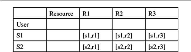
150
it is far from done. Several other security issues need to be taken care of, including
those described in the following sections [ 3 ]:
7.3.1.1 Logical Access Restriction to the System Resources
Logical access restriction to system resources involves the following:
• Restricting access to equipment and network segments using:
– Preventive controls that uniquely identify every authorized user (via estab-
lished access control mechanisms such as passwords) and deny others.
– Detective controls that log and report activities of users, both authorized and
intruders. This may employ the use of intrusion detection systems, system
scans, and other activity loggers. The logs are reported to a responsible party
for action.
• Creating boundaries between network segments:
– To control the fl ow of traffi c between different cabled segments such as sub-
nets by using IP address fi lters to deny access of specifi c subnets by IP
addresses from nontrusted hosts.
– Permit or deny access based on subnet addresses, if possible.
• Selecting a suitable routing policy to determine how traffi c is controlled between
subnets.
7.3.1.2 Physical Security of Resources and Site Environment
Establish physical security of all system resources by:
• Safeguarding physical infrastructure including media and path of physical
cabling. Make sure that intruders cannot eavesdrop between lines by using detec-
tors such as time domain refl ectometer for coaxial cable and optical splitter using
an optical time domain refl ectometer for fi ber optics.
• Safeguarding site environment. Make sure it is as safe as you can make it from
security threats due to:
– Fire (prevention/protection/detection)
– Water
– Electric power surges
– Temperature/humidity
Fig. 7.2 Security policy access rights matrix M
7 Security Assessment, Analysis, and Assurance

151
– Natural disasters
– Magnetic fi elds
7.3.1.3 Cryptographic Restrictions
We have defi ned a computer and also a network system as consisting of hardware,
software, and users. The security of an organization’s network, therefore, does not
stop only at securing software such as the application software like browsers on the
network hosts. It also includes data in storage in the network, that is, at network
servers, and also data in motion within the network.
Ensuring this kind of software and data requires strong cryptographic techniques.
So an organization’s security policy must include a consideration of cryptographic
algorithms to ensure data integrity. The best way to ensure as best as possible that
traffi c on the network is valid is through the following:
• Supported services, such as fi rewalls, relying on the TCP, UDP, ICMP, and IP
headers, and TCP and UDP source and destination port numbers of individual
packets to allow or deny the packet.
• Authentication of all data traversing the network, including traffi c specifi c to the
operations of a secure network infrastructure such as updating of routing tables
• Checksum to protect against the injection of spurious packets from an intruder
and, in combination with sequence number techniques, protects against replay
attacks.
• Software not related to work will not be used on any computer that is part of the
network.
• All software images and operating systems should use a checksum verifi cation
scheme before installation to confi rm their integrity between sending and receiv-
ing devices.
• Encryption of routing tables and all data that pose the greatest risk based on the
outcome of the risk assessment procedure in which data is classifi ed according to
its security sensitivity. For example, in an enterprise, consider the following:
– All data dealing with employee salary and benefi ts
– All data on product development
– All data on sales, etc.
• Also pay attention to the local network address translation (NAT) – a system
used to help network administrators with large pools of hosts from renumbering
them when they all come on the Internet.
• Encrypt the backups making sure that they will be decrypted when needed.
7.3.2 Policy and Procedures
No security policy is complete without a section on policy and procedures. In fact,
several issues are covered under policy and procedures. Among the items in this
7.3 Building a Security Policy

152
section are a list of common attacks for technicians to be aware of, education of
users, equipment use, equipment acquisition, software standards and acquisition,
and incident handling and reporting.
7.3.2.1 Common Attacks and Possible Deterrents
Some of the most common deterrents to common attacks include the following:
• Developing a policy to insulate internal hosts (hosts behind a fi rewall) from a list
of common attacks.
• Developing a policy to safeguard Web servers, FTP servers, and e-mail servers,
which of these are at most risk because even though they are behind a fi rewall,
any host, even those inside the network, can misuse them. You are generally bet-
ter off putting those exposed service providers on a demilitarized zone (DMZ)
network.
• Installing a honey port.
The following list provides an example of some items in an infrastructure and
data integrity security policy:
7.3.2.2 Staff
• Recruit employees for positions in the implementation and operation of the net-
work infrastructure who are capable and whose background has been checked.
• Have all personnel involved in the implementation and supporting the network
infrastructure must attend a security seminar for awareness.
• Instruct all employees concerned to store all backups in a dedicated locked area.
7.3.2.3 Equipment Certification
To be sure that quality equipments are used, make every effort to ensure that:
• All new equipment to be added to the infrastructure should adhere to specifi ed
security requirements.
• Each site of the infrastructure should decide which security features and func-
tionalities are necessary to support the security policy.
• The following are good guidelines:
– All infrastructure equipment must pass the acquisition certifi cation process
before purchase.
– All new images and confi gurations must be modeled in a test facility before
deployment.
– All major scheduled network outages and interruptions of services must be
announced to those who will be affected well ahead of time.
• Use of Portable Tools
– Since the use of portable tools such as laptops always pose some security
risks, develop guidelines for the kinds of data allowed to reside on hard drives
of portable tools and how that data should be protected.
7 Security Assessment, Analysis, and Assurance

153
7.3.2.4 Audit Trails and Legal Evidence
Prepare for possible legal action by:
• Keeping logs of traffi c patterns and noting any deviations from normal behavior
found. Such deviations are the fi rst clues to security problems.
• Keeping the collected data locally to the resource until an event is fi nished, after
which it may be taken, according to established means involving encryption, to
a secure location.
• Securing audit data on location and in backups.
7.3.2.5 Privacy Concerns
There are two areas of concern with audit trail logs:
• Privacy issue of the data collected on users
• Knowledge of an intrusive behavior of others including employees of the
organization
7.3.2.6 Security Awareness Training
The strength of a security policy lies in its emphasis on both employee and user
training. The policy must stress that:
• Users of computers and computer networks must be made aware of the security
ramifi cations caused by certain actions. The training should be provided to all
personnel.
• Training should be focused and involve all types of security that are needed in the
organization, the internal control techniques that will meet the security require-
ments of the organization, and how to maintain the security attained.
• Employees with network security responsibilities must be taught security tech-
niques probably beyond those of the general public, methodologies for evaluat-
ing threats and vulnerabilities to be able to use them to defend the organization’s
security, the ability to select and implement security controls, and a thorough
understanding of the importance of what is at risk if security is not maintained.
• Before connecting to a LAN to the organization’s backbone, provide those
responsible for the organization’s security with documentation on network infra-
structure layout, rules, and guidelines on controlled software downloads. Pay
attention to the training given to those who will be in charge of issuing
passwords.
• Social engineering.
– Train employees not to believe anyone who calls/e-mails them to do some-
thing that might compromise security.
– Before giving any information, employees must positively identify who they
are dealing with.
7.3 Building a Security Policy

154
7.3.2.7 Incident Handling
The security of an organization’s network depends on what the security plan says
should be done to handle a security incident. If the response is fast and effective, the
losses may be none to minimum. However, if the response is bungled and slow, the
losses may be heavy. Make sure that the security plan is clear and effective.
• Build an incident response team as a centralized core group, whose members are
drawn from across the organization, who must be knowledgeable, and well
rounded with a correct mix of technical, communication, and political skills. The
team should be the main contact point in case of a security incident and respon-
sible for keeping up to date with the latest threats and incidents, notifying others
of the incident, assessing the damage and impact of the incident, fi nding out how
to minimize the loss, avoid further exploitation of the same vulnerability, and
making plans and efforts to recover from the incident.
• Detect incidents by looking for signs of a security breach in the usual suspects
and beyond. Look for abnormal signs from accounting reports, focus on signs of
data modifi cation and deletion, check out complaints of poor system perfor-
mance, pay attention to strange traffi c patterns, and unusual times of system use,
and pick interest in large numbers of failed login attempts.
• Assess the damage by checking and analyzing all traffi c logs for abnormal
behavior, especially on network perimeter access points such as Internet access
or dial-in access. Pay particular attention when verifying infrastructure device
checksum or operating system checksum on critical servers to see whether oper-
ating system software has been compromised or if confi guration changes in
infrastructure devices such as servers have occurred to ensure that no one has
tampered with them. Make sure to check the sensitive data to see whether it has
been assessed or changed and traffi c logs for unusually large traffi c streams from
a single source or streams going to a single destination, passwords on critical
systems to ensure that they have not been modifi ed, and any new or unknown
devices on the network for abnormal activities.
• Report and Alert
– Establish a systematic approach for reporting incidents and subsequently
notifying affected areas.
– Essential communication mechanisms include a monitored central phone,
e-mail, pager, or other quick communication devices.
– Establish clearly whom to alert fi rst and who should be on the list of people to
alert next.
– Decide on how much information to give each member on the list.
– Find ways to minimize negative exposure, especially where it requires work-
ing with agents to protect evidence.
• Respond to the incident to try to restore the system back to its pre-incident status.
Sometimes it may require shutting down the system; if this is necessary, then do
so but keep accurate documentation and a log book of all activities during the
incident so that that data can be used later to analyze any causes and effects.
• Recover from an incident.
7 Security Assessment, Analysis, and Assurance

155
– Make a postmortem analysis of what happened, how it happened, and what
steps need to be taken to prevent similar incidents in the future.
– Develop a formal report with proper chronological sequence of events to be
presented to management.
– Make sure not to overreact by turning your system into a fortress.
7.4 Security Requirements Specification
Security requirements specifi cation derives directly from the security policy docu-
ment. The specifi cations are details of the security characteristics of every individ-
ual and system resource involved. For details on individual users and system
resources, see the security access matrix. These security requirements are estab-
lished after a process of careful study of the proposed system that starts with a
brainstorming session to establish and maintain a skeleton basis of a basket of core
security requirements by all users. The brainstorming session is then followed by
establishing a common understanding and agreement on the core requirements for
all involved. For each requirement in the core, we then determine what we need and
how far to go to acquire and maintain it, and fi nally for each core requirement, we
estimate the time and cost for its implementation.
From the security policy access right matrix, two main entries in the matrix, the
user and the resources, determine the security requirements specifi cations as fol-
lows [ 4 ]:
• For the user: Include user name, location, and phone number of the responsible
system owner and data/application owner. Also determine the range of security
clearance levels, the set of formal access approvals, and the need-to-know of
users of the system.
– Personnel security levels: Set the range of security clearance levels, the set of
formal access approvals, and the need-to-know of users of the system
• For the resources: Include the resource type, document any special physical pro-
tection requirements that are unique to the system, and brief description of a
secure operating system environment in use. If the resource is data, then include
the following also:
– Classifi cation level: top secret, secret, and confi dential; and categories of data,
restricted and formally restricted
– Any special access programs for the data
– Any special formal access approval necessary for access to the data
– Any special handling instructions
– Any need-to-know restrictions on users
– Any sensitive classifi cation or lack of
After the generation of the security requirements for each user and system
resource in the security policy access matrix, a new security requirements matrix,
Table 7.2 , is drawn.
7.4 Security Requirements Specifi cation

156
7.5 Threat Identification
To understand system threats and deal with them, we fi rst need to be able to identify
them. Threat identifi cation is a process that defi nes and points out the source of the
threat and categorizes it as either a person or an event. For each system component
whose security requirements have been identifi ed, as shown in Fig. 4.4 , also identify
the security threats to it. The security threats to any system component can be delib-
erate or nondeliberate. A threat is deliberate if the act is done with the intention to
breach the security of an object. There are many types of threats under this category,
as we saw in Chap. 3 . Nondeliberate threats, however, are acts and situations that,
although they have the potential to cause harm to an object, were not intended. As
we saw in Chap. 3 , the sources of threats are many and varied including human fac-
tors, natural disasters, and infrastructure failures.
7.5.1 Human Factors
Human factors are those acts that result from human perception and physical capa-
bilities and may contribute increased risks to the system. Among such factors are
the following [ 5 ]:
• Communication – Communication between system users and personnel may
present risk challenges based on understanding of policies and user guidelines,
terminology used by the system, and interpersonal communication skills, and
languages.
• Human–machine interface – Many users may fi nd a challenge in some of the
system interfaces. How the individual using such interfaces handles and uses
them may cause a security threat to the system. The problem is more so when
there is a degree of automation in the interface.
Table 7.2 Listing of system security requirements
System components (resources and content) Security requirements
Network client Sign-on and authentication of user
Secure directory for user ID and passwords
Secure client software
Secure session manager to manage the session
Network server Secure software to access the server
Secure client software to access the server
Content/data Data authentication
Secure data on server
Secure data on client
7 Security Assessment, Analysis, and Assurance

157
• Data design, analysis, and interpretation – Whenever there is more than one per-
son, there is always a chance of misinterpretation of data and designs. So if there
is any system data that needs to be analyzed and interpreted, there is always a
likelihood of someone misinterpreting it or using a wrong design.
• New tools and technologies – Whenever a system has tools and technologies that
are new to users, there is always a risk in the use of those tools and technologies.
Also long-term exposure to such tools may cause signifi cant neuromusculoskel-
etal adaptation with signifi cant consequences on their use.
• Workload and user capacity – Users in many systems become victims of the
workload and job capacity; this may, if not adjusted, cause risk to systems.
Attributes of the task such as event rate, noise, uncertainty, criticality, and com-
plexity that affect human mental and physical behavior may have an effect on the
effort required for users to complete their assigned tasks.
• Work environment – As many workers know, the work environment greatly
affects the human mental and physical capacity in areas of perception, judgment,
and endurance. The factors that affect the working environment include things
such as lighting, noise, workstations, and spatial confi guration.
• Training – Training of system personnel and also users creates a safer user envi-
ronment than that of systems with untrained users and personnel. Trained users
will know when and how certain equipment and technologies can be used safely.
• Performance – A safe system is a system where the users and personnel get
maximum performance from the system and from the personnel. Effi cient and
successful completion of all critical tasks on the system hinges on the system
personnel and users maintaining required physical, perceptual, and social
capabilities.
7.5.2 Natural Disasters
There is a long list of natural acts that are sources of security threats. These include
earthquakes, fi res, fl oods, hurricanes, tornados, lightning, and many others.
Although natural disasters cannot be anticipated, we can plan for them. There are
several ways to plan for the natural disaster threats. These include creating up-to-
date backups stored at different locations that can be quickly retrieved and set up
and having a comprehensive recovery plan. Recovery plans should be implemented
rapidly.
7.5.3 Infrastructure Failures
System infrastructures are composed of hardware, software, and humanware. Any
of these may fail the system anytime without warning.
7.5 Threat Identifi cation

158
7.5.3.1 Hardware Failures
The long time computers have been in use has resulted in more reliable products
than ever before. But still, hardware failures are common due to wear and tear and
age. The operating environment also contributes greatly to hardware failures. For
example, a hostile environment due to high temperatures and moisture and dust
always results in hardware failures. There are several approaches to overcome hard-
ware threats, including redundancy, where there is always a standby similar system
to kick in whenever there is an unplanned stoppage of the functioning system.
Another way of overcoming hardware failure threats is to have a monitoring system
where two or more hardware units constantly monitor each other and report to oth-
ers whenever one of them fails. In addition, advances in hardware technology have
led to the development of self-healing hardware units whenever a system detects its
component performance, and if one component shows signs of failure, the unit
quickly disables the component and re-routes or reassigns the functions of the fail-
ing component and also reports the failing component to all others in the unit.
7.5.3.2 Software Failures
Probably the greatest security threat, when everything is considered, is from soft-
ware. The history of computing is littered with examples of costly catastrophes of
failed software projects and potential software failures and errors such as the mil-
lennium scare. Failure or poor performance of a software product can be attributed
to a variety of causes, most notably human error, the nature of software itself, and
the environment in which software is produced and used.
Both software professionals and nonprofessionals who use software know the
differences between software programming and hardware engineering. It is in these
differences that lie many of the causes of software failure and poor performance.
Consider the following [ 6 ]:
• Complexity : Unlike hardwired programming in which it is easy to exhaust the
possible outcomes on a given set of input sequences, in software programming a
similar program may present billions of possible outcomes on the same input
sequence. Therefore, in software programming, one can never be sure of all the
possibilities on any given input sequence.
• Diffi cult testing : There will never be a complete set of test programs to check
software exhaustively for all bugs for a given input sequence.
• Ease of programming : The fact that software programming is easy to learn
encourages many people with little formal training and education in the fi eld to
start developing programs, but many are not knowledgeable about good pro-
gramming practices or able to check for errors.
• Misunderstanding of basic design specifi cations : This affects the subsequent
design phases including coding, documenting, and testing. It also results in
improper and ambiguous specifi cations of major components of the software and
in ill-chosen and poorly defi ned internal program structures.
• Software evolution : It is almost an accepted practice in software development
that software products that grow out from one version or release to another are
7 Security Assessment, Analysis, and Assurance

159
made by just additions of new features without an overhaul of the original ver-
sion for errors and bugs. This is always a problem because there are many incom-
patibilities that can cause problems, including different programmers with
different design styles from those of the original programmers, different software
modules, usually newer, that may have differing interfaces, and different expec-
tations and applications that may far exceed the capabilities of the original ver-
sion. All these have led to major fl aws in software that can be exploited and have
been exploited by hackers.
• Changing management styles : Quite often organizations change management,
and the new management comes in with a different focus and different agenda
that may require changes that may affect the software used by the organization in
order to accommodate the new changes. Because of time and cost considerations,
many times the changes are made in-house. Introducing such changes into exist-
ing software may introduce new fl aws and bugs or may reactivate existing but
dormant errors.
7.5.3.3 Humanware Failures
The human component in the computer systems is considerable and plays a vital
role in the security of the system. While inputs to and sometimes outputs from hard-
ware components can be predicted and also in many cases software bugs once found
can be fi xed and the problem forgiven, the human component in a computer system
is so unpredictable and so unreliable that the inputs to the system from the human
component may never be trusted, a major source of system threat. The human link
in the computing system has been known to be a source of many malicious acts that
directly affect the security of the system. Such malicious acts include hacking into
systems and creating software that threaten the security of systems. In later chap-
ters, we will talk more about these activities.
7.6 Threat Analysis
A working computer system with numerous resources is always a target of many
security threats. A threat is the combination of an asset such as a system resource, a
vulnerability, or an exploit that can be used by a hacker to gain access to the system.
Although every system resource has value, there are those with more intrinsic value
than others. Such resources, given a system vulnerability that can let in an intruder,
attract system intruders more than their counterparts with limited intrinsic value.
Security threat analysis is a technique used to identify these resources and to focus
on them. In general, system security threat analysis is a process that involves ongo-
ing testing and evaluation of the security of a system’s resources to continuously
and critically evaluate their security from the perspective of a malicious intruder and
then use the information from these evaluations to increase the overall system’s
security.
7.6 Threat Analysis

160
The process of security threat analysis involves the following:
• Determining those resources with higher intrinsic value, prioritizing them, and
focusing on that list as defense mechanisms are being considered.
• Documenting why the chosen resources need to be protected in the hierarchy
they are put in.
• Determining who causes what threat to whose resources.
• Identifying known and plausible vulnerabilities for each identifi ed resource in
the system. Known vulnerabilities, of course, are much easier to deal with than
vulnerabilities that are purely speculative.
• Identifying necessary security services/mechanisms to counter the vulnerability
• Increasing the overall system security by focusing on identifi ed resources.
7.6.1 Approaches to Security Threat Analysis
There are several approaches to security threat analysis, but we will consider two of
them here: the simple threat analysis by calculating annualized loss expectancies
(ALEs) and attack trees.
7.6.1.1 Threat Analysis by Annualized Loss Expectancies
Before we defi ne annualized loss expectancies, let us defi ne the terms from which
ALE is derived. For a resource identifi ed as having a high threat risk, the cost of
replacing or restoring that resource if it is attacked is its single loss expectancy cost.
The security threat is a resource’s vulnerability. So if the vulnerability is likely to
occur a certain number of times (based on past occurrences), then the vulnerability’s
expected annual rate of occurrence (EAO) can be computed.
Then multiplying these two terms gives us the vulnerability’s annualized loss
expectancy as [ 7 ]
Annualizedlossexpectancy singlelossexpectALEfora resource
()
=aancy
annualrateof occurrences
cost
expected
()
×
()
.
The reader is referred to a good example in Mich Bauer’s paper: “Paranoid
Penguin: Practical Threat Analysis and Risk Management.” Linux Journal , Issue
93, March 2003.
7.6.1.2 Schneier’s Attack Tree Method
Schneier approaches the calculation of risk analysis using a tree model he called an
attack tree . An attack tree is a visual representation of possible attacks against a
given target. The root of the attack forms the goal of the attack. The internal node
from the leaves form the necessary subgoals an attacker must take in order to reach
the goal, in this case the root.
The attack tree then grows as subgoals necessary to reach the root node are added
depending on the attack goal. This step is repeated as necessary to achieve the level
7 Security Assessment, Analysis, and Assurance

161
of detail and complexity with which you wish to examine the attack. If the attacker
must pass through several subgoals in order to reach the goal, then the path in the
tree from the leaves to the root is long and probably more complex.
Each leaf and corresponding subgoals are quantifi ed with a cost estimate that
may represent the cost of achieving that leaf’s goal via the subgoals. The cheapest
path in the tree from a leaf to the root determines the most likely attack path and
probably the riskiest.
7.7 Vulnerability Identification and Assessment
A security vulnerability is a weakness in the system that may result in creating a
security condition that may lead to a threat. The condition may be an absence of or
inadequate security procedures and physical and security controls in the system.
Although vulnerabilities are diffi cult to predict, no system is secure unless its vul-
nerabilities are known. Therefore, in order to protect a computer system, we need to
be able to identify the vulnerabilities in the system and assess the dangers faced as
a result of these vulnerabilities. No system can face any security threat unless it has
a vulnerability from which a security incident may originate. However, it is
extremely diffi cult to identify all system vulnerabilities before a security incident
occurs. In fact, many system vulnerabilities are known only after a security incident
has occurred. However, once one vulnerability has been identifi ed, it is common to
fi nd it in many other components of the system. The search for system vulnerabili-
ties should focus on system hardware, software, and also humanware as we have
seen so far. In addition, system vulnerabilities also exist in system security policies
and procedures.
7.7.1 Hardware
Although hardware may not be the main culprit in sourcing system vulnerabilities,
it boasts a number of them originating mainly from design fl ows, imbedded pro-
grams, and assembling of systems. Modern computer and telecommunication sys-
tems carry an impressive amount of microprograms imbedded in the system. These
programs control many functions in the hardware component.
However, hardware vulnerabilities are very diffi cult to identify, and even after
they are identifi ed, they are very diffi cult to fi x for a number of reasons. One reason
is cost; it may be very expensive to fi x imbedded microprograms in a hardware
component. Second, even if a vulnerability is inexpensive and easy to fi x, the exper-
tise to fi x it may not be there. Third, it may be easy to fi x, but the component
required to fi x it may not be compatible and interoperable with the bigger hardware.
Fourth, even if it is cheap, easy to fi x, and compatible enough, it may not be of prior-
ity because of the effort it takes to fi x.
7.7 Vulnerability Identifi cation and Assessment

162
7.7.2 Software
Vulnerabilities in software can be found in a variety of areas in the system. In par-
ticular, vulnerabilities can be found in system software, application software, and
control software.
7.7.2.1 System Software
System software includes most of the software used by the system to function.
Among such software is the operating system that is at the core of the running of the
computer system. In fact the vulnerabilities found in operating systems are the most
serious vulnerabilities in computer systems. Most of the major operating systems
have suffered from vulnerabilities, and intruders always target operating systems as
they search for vulnerabilities. This is due to the complexity of the software used to
develop operating systems and also the growing multitude of functions the operat-
ing system must perform. As we will discuss later, since the operating system con-
trols all the major functions of the system, access to the system through the operating
system gives the intruders unlimited access to the system. The more popular an
operating system gets, the greater the number of attacks directed to it. All the recent
operating systems such as Unix, Linux, Mac OS, Windows, and especially Windows
NT have been major targets for intruders to exploit an ever-growing list of vulner-
abilities that are found daily.
7.7.2.2 Application Software
Probably, the largest number of vulnerabilities is thought to be sourced from appli-
cation software. There are several reasons for this. First, application software can be
and indeed has been written by anybody with a minimum understanding of pro-
gramming etiquettes. In fact, most of the application software on the market is writ-
ten by people without formal training in software development. Second, most of the
application software is never fully tested before it is uploaded on the market, mak-
ing it a potential security threat. Finally, because software produced by independent
producers is usually small and targeted, many system managers and security chiefs
do not pay enough attention to the dangers produced by this type of software in
terms of interface compatibility and interoperability. By ignoring such potential
sources of system vulnerabilities, the system managers are exposing their systems
to dangers of this software. Also security technologies are developing a lot faster
than the rate at which independent software producers can include them in their
software. In addition, since software is usually used for several years during that
period, new developments in API and security tools tend to make the software more
of a security threat. And as more reusable software becomes commonly used, more
fl aws in the libraries of such code are propagated into more user code. Unfortunately
more and more software producers are outsourcing modules from independent
sources, which adds to the fl aws in software because the testing of these outsourced
modules is not uniform.
7 Security Assessment, Analysis, and Assurance

163
7.7.2.3 Control Software
Among the control software are system and communication protocols and device
drivers. Communication control protocols are at the core of digital and analog
devices. Any weaknesses in these protocols expose the data in the communication
channels of the network infrastructure. In fact, the open architecture policies of the
major communication protocol models have been a major source of vulnerabilities
in computer communication. Most of the recent attacks on the Internet and other
communication networks have been a result of the vulnerabilities in these commu-
nication protocols. Once identifi ed, these vulnerabilities have proven diffi cult to fi x
for a number of reasons. First, it has been expensive in some quarters to fi x these
vulnerabilities because of lack of expertise. Second, although patches have on many
occasions been issued immediately after a vulnerability has been identifi ed, in most
cases, the patching of the vulnerability has not been at the rate the vulnerabilities
have been discovered, leading to a situation where most of the current network
attacks are using the same vulnerabilities that have been discovered, sometimes
years back and patches issued. Third, because of the open nature of the communica-
tion protocols and as new functional modules are added onto the existing infrastruc-
ture, the interoperability has been far from desirable.
7.7.3 Humanware
In Sect. 4.5.1 , we discussed the human role in the security of computer systems. We
want to add to that list the role social engineering plays in system security. Social
engineering, as we saw in Chap. 3 , is the ability of one to achieve one’s stated goal,
legally or otherwise, through the use of persuasion or misrepresentation. Because
there are many ways of doing this, it is extremely diffi cult to prepare people not to
fall for sweet-talkers and masqueraders. Among the many approaches to social
engineering are techniques that play on people’s vulnerability to sympathy, empa-
thy, admiration, and intimidation. Hackers and intruders using social engineering
exploit people’s politeness and willingness to help.
7.7.4 Policies, Procedures, and Practices
The starting point for organization security is a sound security policy and a set of
security procedures. Policies are written descriptions of the security precautions
that everyone using the system must follow. They have been called the building
blocks of an organization’s security. Procedures on the other hand are defi nitions
spelling out how to implement the policies for a specifi c system or technology.
Finally, practices are day-to-day operations to implement the procedures. Practices
are implemented based on the environment, resources, and capabilities available at
the site.
Many organizations do not have written policies or procedures or anything that
is directly related to information security. In addition to security policies and
7.7 Vulnerability Identifi cation and Assessment

164
procedures, security concerns can also be found in personnel policies and physical
security procedures, for example, the protocols for accessing buildings and intel-
lectual property statements.
The effectiveness of an organization’s security policies and procedures must be
measured against those in the same industry. Security policies and procedures are
useless if they are applied to an industry where they are ineffective. When compared
to a similar industry, weaknesses should be noted in quality, conformity, and
comprehensiveness.
7.7.4.1 Quality
A policy or procedure has quality if it addresses all industry issues it is supposed to
address. In addition to addressing all issues, policies and procedures are also tested
on their applicability, that is, they are being specifi c enough in order to be effective.
They are judged effective if they address all issues and protect system information.
7.7.4.2 Conformity
Conformity is a measure of the level of compliance based on the security policies
and procedures. The measure includes how the policies or procedures are being
interpreted, implemented, and followed. If the level is not good, then a security
threat exists in the system. Besides measuring the level of compliancy, conformity
also measures the effectiveness of the policies and procedures in all areas of the
organization. A policy presents a security threat if it is not fully implemented or not
implemented at all or not observed in certain parts of the organization.
7.7.4.3 Comprehensiveness
If the organization’s security is required in a variety of forms such as physical and
electronic, then the organization’s security policy and procedures must effectively
address all of them. In addition, all phases of security must be addressed including
inspection, protection, detection, reaction, and refl ection. If one phase is not effec-
tively addressed or not addressed at all, then a security threat may exist in the sys-
tem. Comprehensiveness also means that the policies and procedures must be
widely and equitably applied to all parts of the system. And the policies and proce-
dures must address all known sources of threats which may include physical, natu-
ral, or human.
7.8 Security Certification
Certifi cation is the technical evaluation of the effectiveness of a system or an indi-
vidual for security features. The defenses of a system are not dependent solely on
secure technology in use, but they also depend on the effectiveness of staffi ng and
training. A well-trained and profi cient human component makes a good comple-
ment to the security of the system, and the system as a whole can withstand and
react to intrusion and malicious code. Certifi cation of a system or an individual
attempts to achieve the following objectives, that the system [ 5 ]:
7 Security Assessment, Analysis, and Assurance

165
• Employs a set of structured verifi cation techniques and verifi cation procedures
during the system life cycle
• Demonstrates that the security controls of the system are implemented correctly
and effectively
• Identifi es risks to confi dentiality, integrity, and availability of information and
resources
7.8.1 Phases of a Certification Process
For the certifi cation process to run smoothly, the following phases must be under-
taken [ 5 ]:
• Developing a security plan to provide an overview of the system security require-
ments. The plan, as we have seen above, describes existing or planned security
requirements and ways to meet them. In addition, the plan delineates responsi-
bilities and expected behavior of individuals who access the system. The plan
should be updated as frequently as possible.
• Testing and evaluation must be done, and it includes the verifi cation and verifi ca-
tion procedures to demonstrate that the implementation of the network meets the
security requirements specifi ed in the security plan.
• Risk assessment to determine threats and vulnerabilities in the system, propose
and evaluate the effectiveness of various security controls, calculate trade-offs
associated with the security controls, and determine the residual risk associated
with a candidate set of security controls.
• Certifi cation to evaluate and verify that the system has been implemented as
described in the security policy and that the specifi ed security controls are in
place and operating properly. This provides an overview of the security status of
the system and brings together all of the information necessary for the organiza-
tion to make an informed and risk-conscious decision.
7.8.2 Benefits of Security Certification
In security, certifi cation is important and has several benefi ts including:
• Consistency and comparability
• Availability of complete and reliable technical information leading to better
understanding of complex systems and associated security risks and
vulnerabilities
7.8 Security Certifi cation

166
7.9 Security Monitoring and Auditing
Security monitoring is an essential step in security assurance for a system. To set up
continuous security monitoring, controls are put in place to monitor whether a
secure system environment is maintained. The security personnel and sometimes
management then use these controls to determine whether any more steps need to
be taken to secure the systems. The focus of the monitoring controls may depend on
the system manager and what is deemed important for the system security, but in
general control focuses on violation and exception reports that help the security
personnel to determine quickly the status of security in the system and what needs
to be done if the system is being or has been compromised.
Although monitoring decisions are made by the security administrator, what
should be monitored and the amount of information logged are usually determined
by either management or the security administrator. Also what should be included
in the report and the details to be included to convey the best overall understanding
of the security status of the system must be decided by the security administrator. It
is not good and in fact it is resource wasting to log too much information without
being able to analyze it properly. Let us now focus on tools used to monitor, type of
data gathered, and information analyzed from the data.
7.9.1 Monitoring Tools
There are several tools that can be used to monitor the performance of a system. The
monitoring tool, once selected and installed, should be able to gather vital informa-
tion on system statistics, analyze it, and display it graphically or otherwise. In more
modern systems, especially in intrusion detection tools, the monitor can also be
confi gured to alert system administrators when certain events occur. Most modern
operating systems such as Microsoft Windows, Unix, Linux, Mac OS, and others
have built-in performance monitors. In addition, there is a long list of independent
security and system performance monitors that monitor, among other things, real-
time performance monitoring and warehousing of event logs, real-time or delayed
alerts to management, and customized performance reports that may include the
history of the event and customized formats to allow quick legal proceedings and
forensics analysis.
A variety of system monitoring tools are available, the majority of which fall into
one of the following categories:
• System performance: This category includes most operating system performance
loggers.
• Network security: This includes all IDS, fi rewalls, and other types of event
loggers.
• Network performance and diagnosis: These are for monitoring all network per-
formance activities.
7 Security Assessment, Analysis, and Assurance

167
• Networking links: To monitor the wiring in a network.
• Dynamic IP and DNS event logger.
• Remote control and fi le sharing applications event logger.
• File transfer tools.
7.9.2 Type of Data Gathered
Because of the large number of events that take place in a computer system, the
choice of what event to monitor can be diffi cult. Most event loggers are preset to
monitor events based on the set conditions. For example, for workstations and serv-
ers, the monitor observes system performance, including CPU performance, mem-
ory usage, disk usage, applications, system, security, DNS server, directory service,
and File Replication Service. In addition, the monitor may also receive syslog mes-
sages from other computers, routers, and fi rewalls on a network. In a network envi-
ronment, the logger may generate notifi cations that include e-mail, network popup,
pager, syslog forwarding, or broadcast messages, to users or system administrator in
real time following preset specifi ed criteria. Further, the logger may support real-
time registration of new logs, edit existing log registrations, and delete log
registrations.
7.9.3 Analyzed Information
The purpose of a system monitoring tool is to capture vital system data, analyze it,
and present it to the user in a timely manner and in a form in which it makes sense.
The logged data is then formatted and put into a form that the user can utilize.
Several of these report formats are as follows:
• Alert is a critical security control that helps in reporting monitored system data
in real time. Real time actually depends on a specifi ed time frame. Time frames
vary from, say, once a week to a few seconds. Once the alerts are selected and
criteria to monitor are set, the alert tools track certain events and warn systems
administrators when they occur.
• Chart is a graphic object that correlates performance to a selected object within
a time frame. Most modern operating systems have Event Viewer that draws
charts of the collected data.
• Log is the opposite of alerting in that it allows the system to capture data in a fi le
and save it for later viewing and analysis. However, alerting generates a signal
that it sends to the administrator based on the alert time intervals. Log informa-
tion may also be used in a chart. Again most modern operating systems have log
view tools.
• Report is a more detailed and inclusive form of system logs. Log reports provide
statistics about the system’s resources and how each of the selected system
7.9 Security Monitoring and Auditing

168
resource is being used and by whom. This information also includes how many
processes are using each resource, who owns the process, and when he or she is
using the resource. The timing of the generation of the report can be set, and the
recipients of the report can also be listed.
7.9.4 Auditing
Auditing is another tool in the security assessment and assurance of a computer
system and network. Unlike monitoring, auditing is more durable and not ongoing,
and therefore, it is expensive and time consuming. Like monitoring, auditing mea-
sures the system against a predefi ned set of criteria, noting any changes that occur.
The criteria are chosen in such a way that changes should indicate possible security
breaches.
A full and comprehensive audit should include the following steps:
• Review all aspects of the system’s stated criteria.
• Review all threats identifi ed.
• Choose a frequency of audits whether daily, weekly, or monthly.
• Review practices to ensure compliance to written guidelines.
7.10 Products and Services
A number of products and services are on the market for security assessment and
audit. Hundreds of companies are competing for a market share with a multitude of
products. These products fall under the following categories:
• Auditing tools
• Vulnerability assessment
• Penetration testing tools
• Forensics tools
• Log analysis tools
• Other assessment toolkits
Exercises
1. What is security assessment? Why is it important?
2. Discuss the necessary steps in analyzing the security state of an enterprise.
3. What is security assurance? How does it help in enterprise security?
4. What is security monitoring? Is it essential for enterprise security?
5. What is security auditing? Why is it necessary for system security?
7 Security Assessment, Analysis, and Assurance

169
6. What are the differences between security monitoring and auditing? Which is
better?
7. What is risk? What is the purpose of calculating risk when analyzing security?
8. Give two ways in which risk can be calculated. Which is better?
9. What is social engineering? Why do security experts worry about social engi-
neering? What is the best way to deal with social engineering?
10. Humanware is a cause of security threat. Discuss why this is so.
Advanced Exercises
1. Discuss any security surveillance system.
2. Discuss a good security auditing system.
3. Compare or discuss the differences between any two security systems.
4. Discuss human error or human factors as a major security threat.
5. What is the best way to deal with the security threat due to human factors?
References
1. Jamsa K (2002) Hacker proof: the ultimate guide to network security, 2nd edn. Onword Press,
Albany
2. Holden G (2004) Guide to fi rewalls and network security: intrusion detection and VPNs. Delmar
Thomson Learning, Boston
3. Kaeo M (1999) Designing network security: a practical guide to creating secure network infra-
structure. Macmillan Technical Publishing, Indianapolis
4. Guidelines for the development of security plans for classifi ed computer systems.
http://cio.doe.
gov/ITReform/sqse/download/secplngd.doc
5. Ross R, The development of standardized certifi cation and accreditation guidelines and provider
organizations.
http://csrc.nist.gov/sec-cert/CA-workshop-fi ac2002-bw.pdf
6. Kizza JM (2002) Ethical and social issues in the information age, 2nd edn. Springer, New York
7. Bauer M (2003) Paranoid penguin: practical threat analysis and risk management. Linux J. 93.
March, 2003, p 9
Additional References
8. Security architecture and patterns, KPMG. http://www.issa-oc.org/html/1
9. Threat analysis and vulnerability assessments.
http://www.primatech.com/consulting/services/
threat_analysis_and_vulnerability_assessments.htm
References

Part III
Dealing with Computer Network Security
Challenges

173
© Springer-Verlag London 2015
J.M. Kizza, Guide to Computer Network Security, Computer Communications
and Networks, DOI 10.1007/978-1-4471-6654-2_8
8
Disaster Management
8.1 Introduction
Webster ’ s Dictionary defi nes disaster as a sudden misfortune, a catastrophe that
affects society [ 1 ]. It is the effect of a hazardous event caused by either man or
nature. Man-made disasters are those disasters that involve a human element
like intent, error, or negligence. Natural disasters are those caused by the forces of
nature like hurricanes, tornados, and tsunamis. Disasters, natural or man-made,
may cause great devastation to society and the environment. For example, the
2006 tsunami in Southeast Asia caused both huge human losses and environment
destruction. The effects of a disaster may be short lived, or long lasting. Most disas-
ters, both man- made and natural, have long-lasting effects. To mitigate disaster
effects on society and businesses, disaster management skills are needed.
In information technology, disaster situations are big security problems to the
enterprise information systems that must be handled with skills just like other
security problems we have discussed so far in this book. To understand how this is
a very big security problem for a modern society, one has to understand the working
of a modern business entity. Modern businesses have moved away from the
typewriter and manila folders to desktops and large databases to process and store
business day-to-day data and transactions. This growing use of computers in
businesses, the ever-increasing speed of data transmission, and the forces of globa-
lization all have forced businesses into a new digitized global corner that demands
high-speed data access to meet the demands of the technology savvy customers in a
highly competitive global environment. In response, high volume and high-speed
databases have been set up.
For the business to remain competitive and probably ahead of the competitors, all
business systems must remain online and in service 24/7. No modern business can
afford a disaster to happen to its online systems. Failing to achieve that level of
service would mean the failure of the business. Thousands of businesses close or
lose millions of dollars every year depending on the level of attention they give to
their online systems and failing to protect them against disasters like fi re, power

174
outage, theft, equipment failure, viruses, hackers, and human errors. No business
can succeed in today’s environment without plans to deal with disasters. The
September 11, 2001, attack on New York fi nancial district was an eye-opener to
many businesses to be prepared for disasters. For a quick recovery of these enter-
prises, good disaster management principles are needed.
Also as company databases grew in size and complexity and the demand for
their online fast access grew, the need for the protection of business-critical and
irreplaceable company data is also growing in tandem. These developments are
forcing business information system managers to focus on disaster prevention,
response, and recovery. The importance of disaster planning and recovery can be
born by the fact that 93 % of the companies that did not have their data backed up
properly when a disaster struck went out of business, according to DataSafe, Inc.,
one of the leading companies involved with data backup services [ 2 ].
The goal of this chapter, therefore, is to treat disaster management as a major
information systems’ security problem and start a discussion of ways, tools, and
best practices of dealing with disasters and mitigating their long-term effects on
business information systems. We will break the discussion into three parts: disaster
prevention, response, and recovery.
8.1.1 Categories of Disasters
Before we do that, however, let us look at the categories of disasters that can affect
business information systems [ 3 ].
8.1.1.1 Natural Disasters: Due to Forces of Nature
• Tsunami
• Tornados
• Hurricanes (same as tsunami)
• Cyclone (same as tsunami)
• Flood
• Snowstorm
• Landslides
• Drought
• Earthquake
• Electrical storms
• Snowslides
• Fire
8.1.1.2 Human-Caused Disasters
• Terrorism
• Sabotage
• Theft
• Viruses
8 Disaster Management

175
• Worms
• Hostile code
• War
• Theft
• Arson
• Loss of:
– Power supply (both electric and gas). This can result in a large number of
related failures like cooling system and machines.
– Communications links.
– Data.
• Cyber crime (many types)
8.2 Disaster Prevention
Disaster prevention is a proactive process consisting of a set of control strategies to
ensure that a disaster does not happen. The controls may be people, mechanical,
or digital sensing devices. Times and technology have improved both disaster pre-
vention and recovery strategies. The elements of effective disaster prevention are
the early detection of abnormal conditions and notifi cation of persons capable of
dealing with the pending crisis, for example, if you have a temperature detector to
report on an air-conditioning failure as soon as the temperature starts to rise or a fi re
detector to gracefully power-down all computing equipment before fi re systems
discharge. By detecting and treating minor problems early, major problems can
be avoided.
Every system, big and small, needs a disaster prevention plan because the cost of
not having one is overwhelming. According to Intra Computer, Inc., a disaster pre-
vention and recovery company, in one of its surveys, 16 % of those responding to
the survey reported that a system-stopping event caused by environmental condi-
tions occurred at least six times annually, and 12 % of respondents put the minimum
estimated dollar cost of each of these incidents at over $50,000 [ 4 ]. Also according
to DataSafe, Inc. [ 2 ], thousands of businesses lose millions of dollars worth of infor-
mation due to disasters like fi re, power outage, theft, equipment failure, and even
simple operator mistakes.
In past years, system disaster prevention depended entirely upon an on-site
person’s ability to detect and diagnose irregular conditions based on experience.
This experience was based on one’s knowledge and ability to analyze conditions
created by unusual events such as high temperature, presence of smoke, water,
and interruption in power to equipment that could lead to the likely corruption or
destruction of the enterprise’s information system’s resources including active
data fi les.
Technology has, however, through intelligent monitoring devices, helped and
improved the process of disaster prevention. Monitoring devices nowadays are
capable of quickly responding to unusual and irregular conditions caused by a disaster
8.2 Disaster Prevention

176
event. The monitoring devices, in case of an enterprise information system, monitor
a variety of conditions from a given list. The list includes [ 4 ]:
• Temperature
• Humidity
• Water
• Smoke/fi re
• Air fl ow
• AC power quality
• UPS AC/battery mode
• Personnel access security
• Halon triggering state
• State of in-place security/alarm systems
• Hidden conditions undetectable by security personnel
– In air-conditioning ducts
– Under raised fl oors
– Inside computer chassis
During the monitoring process, if and when an event occurs that meets any one
of the conditions being monitored, an immediate action is triggered. The choice of
action taken is also predetermined by the system manager and is selected from a
long list that includes [ 4 ]:
• Activating local or remote alarms indicators like sirens, bells, light signals, and
synthesized voice.
• Taking over control of the affected resource to isolate it, cut it off from the supply
line, or maintain the declining supply line. The supply line may be power, water,
fuel, and a number of other things.
• Interfacing with existing or cutting off from existing security system as dictated
by the event.
• Sending a signal to designated personnel. Among the designated personnel are
[ 4 ]:
– System users
– Site managers
– Security personnel
– Maintenance personnel
– Service bureaus and Alarm Co. central offi ces
– Authorities at remote sites
• Gracefully degrading the system by terminating normal operations, closing and
protecting data fi les, and disconnecting AC power from protected equipment.
After one or more of the actions above have been taken, the system will then wait
for a response. The response usually comes from the human component. Let us
discuss this in the next section.
8 Disaster Management

177
8.3 Disaster Response
As we pointed out earlier in this chapter, the rapid development in computer and
information technology and the ever-growing society’s dependence on computers
and computer technology have created an environment where business-critical
information, irreplaceable business data, and transactions are totally dependent and
are stored on computer systems. This being the case makes a response to a disaster
vital and of critical importance. Disaster response is a set strategies used to respond
to both the short-term and long-term needs of the affected community. In dealing
with business information system disasters, the strategies involve quick and timely
response to the disaster prevention system (DPS) signals with directed action. The
essential steps in disaster response include:
• Restoring services
• Identifying high-risk system resources
Six factors govern a quick disaster response. According to Walter Guerry Green [ 5 ]:
• Nature and extent of the destruction or risk in case the disaster occurs. This is
based on either prior or a quick assessment of the situation.
• The environment of the disaster. The environment determines the kind of
response needed. Take a quick inventory of what is in the room or rooms where
the systems are. Make a note of how the chosen action to meet the needs is going
to be carried out successfully.
• Make note of the available resources. The degree and effectiveness of the
response to the disaster are going to depend on the available resources on the
ground that can be used to increase and enhance the success rate of the chosen
response.
• Time available to carry out the chosen response action. Time is so important in
the operation that it determines how much action can be taken and how much
effort is needed to control the disaster.
• Understanding of the effective policy. Every chosen action taken must fall within
the jurisdiction of the company policy.
The degree of success in observing this success determines the effectives of the
disaster recovery efforts.
8.4 Disaster Recovery
The value of a good disaster recovery plan is its ability to react to the threat shifty
and effi ciently. In order for this to happen, there must be an informed staff, disaster
suppliers, and planned procedures. These three make up the disaster recovery plan.
Every system manager must be aware and confi dent with the system’s disaster
8.4 Disaster Recovery

178
recovery plan. The plan must not only be on the books and shelved but must be
rehearsed several times a year. For example, since the September 11, 2001 attack on
the World Trade Center, companies learned the value of off-site storage of data. And
since then, rehearsed procedures for retrieving archived data media from off-site
facilities are common. There are several other outsourced options to disaster recovery
in addition to the in-house one we have so far discussed. These include maintenance
contracts and services that offer from routine planned disaster testing to full extended
warranty services, stand-by services that usually do only the storage and recovery of
your data services and delivery very quickly, and distributed architectures that are
companies that sell you the software that stores your data on their network and
you can move it back and forth at a moment’s notice. All these, when used
effectively, help to continue business as usual in the hours during and immediately
following a disaster.
8.4.1 Planning for a Disaster Recovery
Disaster recovery planning is a delicate process that must be handled with care. It
involves risk assessment, developing, documenting, implementing, testing, and
maintaining a disaster recovery plan [ 6 ]. For starters, the plan must be teamwork of
several chosen people that form a committee – the Disaster Recovery Committee.
The committee should include at least one person from management, information
technology, record management, and building maintenance. This committee is
charged with deciding on the what, how, when, and who are needed to provide a
good solid recovery that your company will be proud of. Such a plan must sustain
critical business functions. The planning process, therefore, must start with steps
that identify and document those functions and other key elements in the recovery
process. According to [ 7 ], these steps include:
• Identifying and prioritizing the disaster
• Identifying and prioritizing business-critical systems and functions
• Identifying business-critical resources and performing impact analysis
• Developing a notifi cation plan
• Developing a damage assessment plan
• Designating a disaster recovery site
• Developing a plan to recover critical functions at the disaster recovery site
• Identifying and documenting security controls
• Designating responsibilities
Because disasters do not happen at a particular time in a given month of a known
year, they are unplanned and unpredictable. This makes disaster recovery planning
an ongoing, dynamic process that continues throughout the information system’s
life cycle.
8 Disaster Management

179
8.4.1.1 Disaster Recovery Committee
This committee is responsible for developing the disaster recovery plan. The commit-
tee must represent every function or unit of the business to ensure that all essential
business information and resources are not left out. Before the committee starts its
job, members must all be trained in disaster recovery. Each member of this commit-
tee is assigned responsibilities for key activities identifi ed and duties outlined within
their departments and as defi ned within the disaster recovery plan. The committee
is also responsible for bringing awareness to the rest of the employees.
8.4.2 Procedures of Recovery
The procedures followed in disaster management and recovery are systematic steps
taken in order to mitigate the damage due to the disaster. These steps are followed
based on the rankings (above) of the nature of the disaster and the critical value of
the items involved.
8.4.2.1 Identifying and Prioritizing the Disaster
These may be put in three levels: low, medium, and high:
• Low-level disasters may be local accidents like:
– Human errors
– High temperature in room
– Server failure
• Medium-level disasters may be less local including:
– Virus attack
– Long power failures – may be a day long
– Server crush (Web, mail)
• High-level disasters – this level includes the most devastating disasters like:
– Earthquakes
– Hurricanes
– Big fi re
– Terrorism
8.4.2.2 Identifying Critical Resources
The ranking of critical assets may be based on the dollar amount spent on acquir-
ing the item or on the utility of the item. Some examples of these critical assets
include [ 2 ]:
• Servers, workstations, and peripherals
• Applications and data
• Media and output
• Telecommunication connections
• Physical infrastructure (e.g., electrical power, environmental controls)
• Personnel
8.4 Disaster Recovery

180
Rank them in three levels:
• Low level – these include:
– Printer paper, printer cartridges, media
– Pens, chairs, etc.
• Medium level – these include relatively costly items:
– All peripherals
– Switches
– Workstations
– Physical infrastructures
• High level – these include valued items and high ticket items like:
– Servers
– Disks (RAID)/application data
– Workstations
– Personnel
8.4.2.3 Developing a Notification Plan
This requires identifi cations of all those to be informed. This can also be done based
on the previous levels of the disaster and the level of critical resources. This plan is
represented into a matrix form below.
Low
level – disaster
Medium
level – disaster High level – disaster
Level 1 – critical assets System adm. System adm. System adm., management, law
enforcement, the media
Level 2 – critical assets System adm. System adm.,
management
System adm., management, law
enforcement, the media
Level 3 – critical assets System adm. System adm.,
management
System adm., management, law
enforcement, the media
For each cell in the matrix, chose an acceptable method of transmitting the infor-
mation to be transmitted. Determine how much information needs to be transmitted
and when it should be transmitted. For each group of people to be informed, choose
a representative person. For example, for management, who should be informed, the
vice president for information or the chief executive offi cer?
Keep in mind that prompt notifi cation can reduce the disaster’s effects on the
information system because it gives you time to take mitigating actions.
8.4.2.4 Training of Employees
Since disaster handling is a continuous process in the life cycle of an enterprise
system, the training of employees about possible disasters and what each one has to
do is desirable. However, the training of the select people on the Disaster Recovery
Committee is critical. Plan ahead of time how this training is to be carried out. There
8 Disaster Management

181
are several ways of doing this in a work environment depending on the number of
people to be trained:
• Professional seminars for all those on the Disaster Recovery Committee
• Special-in-house education programs for all those on the Disaster Recovery
Committee, heads of departments, and everybody else
The choice of the type of training also requires to determine who will be con-
ducting the training and who is responsible for the arranging the training. Somebody
responsible for training could be somebody well trained to do that if available in-
house or by using a vendor to come on the component premises or by sending
people to vendor-designated sites.
8.4.2.5 Priorities for the Restoration of Essential Functions
One of the most critical and vital bit of information in disaster planning is to priori-
tize the order of critical resources as they come back online. Follow that order
because it was chosen by the Disaster Recovery Committee for a reason.
8.5 Make Your Business Disaster Ready
In the introduction, we talked about the importance of a recovery plan for a busi-
ness. In fact, the statistics we quoted indicate that almost 90 % of all companies that
did not have a disaster recovery plan did not survive are indicative of the importance
of a business disaster recovery plan. Also in the introduction, we indicated that
disaster planning is an ongoing process that never ends. This means that for your
company to remain in business and remain competitive, the disaster recovery plan
must be in place and must keep changing to meet the developing new technologies.
Among the things to help you refresh your evolving business disaster plan are being
disaster ready all the time, making periodic drills of checking the storage media to
make sure that they are already ready for the big one to happen, for those working
with databases, working with a base-function script for the capability of your inter-
faces, and always periodically doing a risk assessment for the disaster.
8.5.1 Always Be Ready for a Disaster
Because disasters can happen at any time and while some customers will under-
stand, the majority will not wait for you to learn the tricks of handling a disaster.
They will move to your competitor. Always be prepared for the big one by doing
the following [ 3 ]:
• Periodically check and test your backup and recovery procedures thoroughly to
ensure that you have the required backups to recover from various failures, that
your procedures are clearly defi ned and documented, and that they can be exe-
cuted smoothly and quickly by any qualifi ed operator.
8.5 Make Your Business Disaster Ready

182
• Always secure, keep, and periodically check and review all system logs and
transaction logs. This will help you to backtrack if you have to and to fi nd any-
thing you might have missed out.
8.5.2 Always Backup Media
There is no better way to deal with a disaster than having a backup. We have been
told since we were kids to keep a copy of everything important. You are doing the
same thing here. In a computing system environment, also consider:
• A schedule to revisit the saved materials
• Whether to store at a location but in a different place or in a different location
• A chart of which data needs to be stored, where it is to be stored, and for how long
8.5.3 Risk Assessment
Using a matrix model consisting of all types of disasters that can happen to your
system in a row and the all system resources that you think has value in the column.
Each entry in the matrix cell is potential risks to the organization which could result
to the resource in case of the disaster in that row occurring. This matrix model must
have been done by the Disaster Planning Committee. There are tools on the market
to help you achieve this, including COBRA [ 3 ].
8.6 Resources for Disaster Planning and Recovery
As businesses begin to see disasters as a huge security problem to the day-to-day
running of the business, there is going to be a high demand for tools and services
from vendors to manage disasters. These resources follow into two categories:
public agency-based and vendor-based resources. Also whether public- or private-
based resources, these can be obtained quickly because they are local or they may
take time because they are some distance off. Always start with local resources
when you need them.
8.6.1 Local Disaster Resources
These resources can be freely obtained locally:
• Police
• Civil defense
• Fire department
• Ambulatory services
8 Disaster Management

183
These resources can be obtained on the business premises:
• Paper
• Fire extinguisher
• Small capacity tapes and disks
These resources can be obtained from vendors (online or offl ine):
• Specialized computer equipment
• Specialized software tools like COBRA
Exercises
1. List as many of the emergency agencies in your community.
2. Of these listed in (1) above which are dealing with information security.
3. We pointed out that the development of a good disaster recovery plan requires
risk assessment. Design a matrix for the risk assessment of your security lab.
4. Using your security lab as your fi ctitious company, develop a disaster plan for
the lab.
5. Study vendor tools in disaster recovery. Write about fi ve of them, listing their
merits and costs involved.
6. Study and develop a list of companies offering disaster recovery services in your
area or state. Write about fi ve, listing their merits and fees charged.
7. Based on your plan in (4) above, develop a rescue plan for the lab by developing
a list of tools needed by the lab for disaster recovery, when needed.
Advanced Exercises: Case Studies
1. Check to see if your university has a disaster plan ( http://palimpsest.stanford.
edu/bytopic/disasters/plans/ ). Prepare a disaster plan for your university. Note
that it should have the major headings as follows: (1) Introduction, (2) Emergency
Procedures, (3) Response Plan, (4) Recovery Procedures, (5) Other Emergencies,
and (6) Local Supplies.
2. Form a committee, whose size depends on the size of your college. Empower the
committee to develop a disaster recovery plan for the college.
3. Consider the following company. HHR is a company involved with retail
advertising. Major national chains use it to host their online catalogs. Every
day, HHR gets about 5,000 hits. It has four departments (human resources,
accounting, advertising, IT) and employs about 2,000 people nationally. The
company is just getting started with disaster recovery, and they have hired you
to do it for them. Write a 2-page document to the CEO of HHR selling your
services.
4. Draw a plan of how you will go about setting up a Disaster Recovery Committee,
indicating who will be in it and why. Also send a memo to the committee mem-
bers telling them about the fi rst organizing meeting and list out the items to be
discussed by the committee.
5. Develop a disaster recovery plan for HHR.
8.6 Resources for Disaster Planning and Recovery

184
References
1. Allee JG (ed) Webster’s Dictionary. 1998. Literary Press, London, 1958
2. DataSafe, Inc., What is disaster planning? http://www.amarillodatasafe.com/abstracts.htm
3. The disaster recovery guide, 2002. http://www.disaster-recovery-guide.com/risk.htm
4. Intra Computer, Inc., Elements of an effective disaster prevention system.
http://www.intra-
comp.com/page5.html
5. Green WG (2001) Command and control of disaster operations. Universal Publishers, Inc/
uPUBLISH.com
6. Erbschloe M (2003) Guide to disaster recovery. Course Technology, Boston
7. USAID (2006) Disaster recovery planning procedures and guidelines. http://www.usaid.gov/
policy/ads/500/545mal.pdf
8 Disaster Management

185
© Springer-Verlag London 2015
J.M. Kizza, Guide to Computer Network Security, Computer Communications
and Networks, DOI 10.1007/978-1-4471-6654-2_9
9
Access Control and Authorization
9.1 Definitions
Access control is a process to determine “Who does what to what,” based on a policy.
One of the system administrator’s biggest problems, which can soon turn into a
nightmare if it is not well handled, is controlling access of who gets in and out of the
system and who uses what resources, when, and in what amounts. Access control is
restricting this access to a system or system resources based on something other
than the identity of the user. For example, we can allow or deny access to a system’s
resources based on the name or address of the machine requesting a document.
Access control is one of the major cornerstones of system security. It is essential
to determine how access control protection can be provided to each of the system
resources. To do this, a good access control and access protection policy is needed.
According to Raymond Panko, such a policy has benefi ts including the following [ 1 ]:
• It focuses the organization’s attention on security issues, and probably, this
attention results in resource allocation toward system security.
• It helps in confi guring appropriate security for each system resource based on
role and importance in the system.
• It allows system auditing and testing.
As cyberspace expands and the forces of globalization push e-commerce to the
forefront of business and commercial transactions, the need for secure transactions
has propelled access control to a position among the top security requirements,
which also include authorization and authentication. In this chapter, we are going to
discuss access control and authorization; authentication will be discussed in the
next chapter.
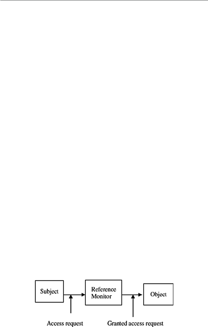
186
9.2 Access Rights
To provide authorization, and later as we will see authentication, system administra-
tors must manage a large number of system user accounts and permissions associ-
ated with those accounts. The permissions control user access to each system
resource. So, user A who wants to access resource R must have permission to access
that resource based on any one of the following modes: read, write, modify, update,
append, and delete. Access control regimes and programs, through validation of
passwords and access mode permissions, let system users get access to the needed
system resources in a specifi ed access mode.
Access control consists of four elements: subjects, objects, operations, and a
reference monitor. In the normal operation, seen in Fig. 9.1 , the subject, for example, a
user, initiates an access request for a specifi ed system resource, usually a passive
object in the system such as a Web resource. The request goes to the reference
monitor. The job of the reference monitor is to check on the hierarchy of rules that
specify certain restrictions. A set of such rules is called an access control list (ACL).
The access control hierarchy is based on the URL path for Web access or the fi le
path for a fi le access such as in a directory. When a request for access is made, the
monitor or server goes in turn through each ACL rule, continuing until it encounters
a rule that prevents it from continuing and results in a request rejection or comes to
the last rule for that resource, resulting into access right being it granted.
Subjects are system users and groups of users, while objects are fi les and
resources such as memory, printers, and scanners including computers in a network.
An access operation comes in many forms including Web access, server access,
memory access, and method calls. Whenever a subject requests to access an object,
an access mode must be specifi ed. There are two access modes: observe and alter.
In the observe mode, the subject may only look at the content of the object; in the
alter mode, the subject may change the content of the object. The observe mode is
the typical read in which a client process may request a server to read from a fi le.
Access rights refer to the user’s ability to access a system resource. There are
four access rights: execute , read , append , and write. The user is cautioned not to
confuse access rights and access modes. The difference lies in the fact that you can
perform any access right within each access mode. Figure 9.2 shows how this can
be done. Note that according to the last column in Fig. 9.2 , there are X marks in
Fig. 9.1 Access control administration
9 Access Control and Authorization

187
both rows because in order to write, one must observe fi rst before altering. This
prevents the operating system from opening the fi le twice, one for the read and
another for a write.
Access rights can be set individually on each system resource for each individual
user and group. It is possible for a user to belong to a few groups and enjoy those
groups’ rights. However, user access rights always take precedence over group
access rights regardless of where the group rights are applied. If there are inherited
group access rights, they take precedence over user default access rights. A user has
default rights when the user has no assigned individual or group rights from root
down to the folder in question. In the cascading of access rights application, user
access rights that are closest to the resource being checked by the monitor take
precedence over access rights assignments that are farther away.
We have so far discussed access rights to resources. The question that still
remains to be answered is, Who sets these rights? The owner of the resource sets the
access rights to the resource. In a global system, the operating systems own all
system resources and therefore set the access rights to those resources. However, the
operating system allows folders and fi le owners to set and revoke access rights.
9.2.1 Access Control Techniques and Technologies
Because a system, especially a network system, may have thousands of users and
resources, the management of access rights for every user per every object may
become complex. Several control techniques and technologies have been developed
to deal with this problem; they include access control matrix, capability tables,
access control lists, role-based access control, rule-based access control, restricted
interfaces, and content-dependent access control.
Many of the techniques and technologies we are going to discuss below are new in
response to the growth of cyberspace and the widespread use of networking. These
new techniques and technologies have necessitated new approaches to system access
control. For a long time, access control was used with user- or group- based access
control lists, normally based in operating systems. However, with Web-based network
applications, this approach is no longer fl exible enough because it does not scale in the
new environment. Thus, most Web-based systems employ newer techniques and tech-
nologies such as role-based and rule-based access control, where access rights are
based on specifi c user attributes such as their role, rank, or organization unit.
Fig. 9.2 Access modes and
access rights (Gollman [
2 ] )
9.2 Access Rights

188
9.2.1.1 Access Control Matrix
All the information needed for access control administration can be put into a matrix
with rows representing the subjects or groups of subjects and columns representing
the objects. The access that the subject or a group of subjects is permitted to the
object is shown in the body of the matrix. For example, in the matrix shown in
Fig. 9.2 , user A has permission to write in fi le R4. One feature of the access control
matrix is its sparseness. Because the matrix is so sparse, storage consideration
becomes an issue, and it is better to store the matrix as a list.
9.2.1.2 Access Control Lists
In the access control lists (ACLs), groups with access rights to an object are stored
in association to the object. If you look at the access matrix shown in Fig. 9.2 , each
object has a list of access rights associated with it. In this case, each object is associ-
ated with all the access rights in the column. For example, the ACL for the matrix
shown in Fig. 9.3 is shown in Fig. 9.4 .
ACLs are very fi tting for operating systems as they manage access to objects [ 2 ].
9.2.1.3 Access Control Capability
A capability specifi es that “the subject may do operation O on object X.”
Unlike the ACLs, where the storage of access rights between objects and sub-
jects is based on columns in the access control matrix, capabilities access control
storage is based on the rows. This means that every subject is given a capability, a
forgery-proof token that specifi es the subject’s access rights [ 2 ].
From the access matrix shown in Fig. 9.3 , we can construct a capability as shown
in Fig. 9.5 .
9.2.1.4 Role-Based Access Control
The changing size and technology of computer and communication networks are
creating complex and challenging problems in the security management of these
large networked systems. Such administration is not only becoming complex as
technology changes and more people join the networks, but it is also becoming
Fig. 9.3 Access matrix
9 Access Control and Authorization
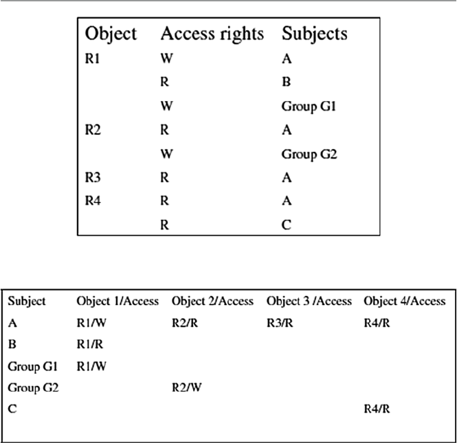
189
extremely costly and prone to error when it is solely based on access control lists for
each user on the system individually.
System security in role-based access control (RBAC) is based on roles assigned
to each user in an organization. For example, one can take on a role as a chief execu-
tive offi cer, a chief information offi cer, or a chief security offi cer. A user may be
assigned one or more roles, and each role is assigned one or more privileges that are
permitted to users in that role. Access decisions are then based on the roles that
individual users have as part of an organization. The process of defi ning roles should
be based on a thorough analysis of how an organization operates and should include
input from a wide spectrum of users in an organization.
Access rights are grouped by role name, and the use of resources is restricted to
individuals authorized to assume the associated role. A good example to illustrate
the role names and system users who may assume more than one role and play those
roles while observing an organization’s security policy is the following given in the
NIST/ITL Bulletin, of December 1995. “Within a hospital system the role of doctor
can include operations to perform diagnosis, prescribe medication, and order
Fig. 9.4 Access control list (ACL)
Fig. 9.5 Access control capability lists
9.2 Access Rights

190
laboratory tests, and the role of researcher can be limited to gathering anonymous
clinical information for studies” [ 3 ].
Accordingly, users are granted membership into roles based on their competen-
cies and responsibilities in the organization. The types of operations that a user is
permitted to perform in the role he or she assumes are based on that user’s role. User
roles are constantly changing as the user changes responsibilities and functions in
the organizations, and these roles can be revoked. Role associations can be estab-
lished when new operations are instituted, and old operations can be deleted as
organizational functions change and evolve. This simplifi es the administration and
management of privileges; roles can be updated without updating the privileges for
every user on an individual basis.
Like other types of access control, RBAC is also based on the concept of least
privilege that requires identifying the user’s job functions, determining the mini-
mum set of privileges required to perform that function, and restricting the user to a
domain with those privileges and nothing more. When a user is assigned a role, that
user becomes associated with that role, which means that user can perform a certain
and specifi c number of privileges in that role. Although the role may be associated
with many privileges, individual users associated with that role may not be given
more privileges than are necessary to perform their jobs.
Although this is a new technology, it is becoming very popular and attracting
increasing attention, particularly for commercial applications, because of its potential
for reducing the complexity and cost of security administration in large networked
applications.
9.2.1.5 Rule-Based Access Control
Like other access control regimes, rule-based access control (RBAC), also known as
policy-based access control (PBAC), is based on the least privileged concept. It is
also based on policies that can be algorithmically expressed. RBAC is a multipart
process, where one process assigns roles to users just like in the role-based access
control techniques discussed above. The second process assigns privileges to the
assigned roles based on a predefi ned policy. Another process is used to identify and
authenticate the users allowed to access the resources.
It is based on a set of rules that determine users’ access rights to resources within
an organization’s system. For example, organizations routinely set policies on the
access to the organizations Web sites on the organizations’ intranet or Internet.
Many organizations, for example, limit the scope and amount, sometimes the times,
employees, based on their ranks and roles, can retrieve from the site. Such limits
may be specifi ed based on the number of documents that can be downloaded by an
employee during a certain time period and on the limit of which part of the Web site
such an employee can access.
The role of ACLs has been diminishing because ACLs are ineffective in enforc-
ing policy. When using ACLs to enforce a policy, there is usually no distinction
between the policy description and the enforcement mechanism (the policy is essen-
tially defi ned by the set of ACLs associated with all the resources on the network).
Having a policy being implicitly defi ned by a set of ACLs makes the management
9 Access Control and Authorization

191
of the policy ineffi cient, error prone, and hardly scalable up to large enterprises with
large numbers of employees and resources. In particular, every time an employee
leaves a company or even just changes his or her role within the company, an
exhaustive search of all ACLs must be performed on all servers, so that user privi-
leges are modifi ed accordingly.
In contrast with ACLs, policy-based access control makes a strict distinction
between the formal statement of the policy and its enforcement. It makes rules
explicit, and instead of concealing them in ACLs, it makes the policy easier to man-
age and modify. Its advantage is based on the fact that it administers the concept of
least privilege justly because each user can be tied to a role which in turn can be tied
to a well-defi ned list of privileges required for specifi c tasks in the role. In addition,
the roles can be moved around easily and delegated without explicitly de-allocating
a user’s access privileges [ 4 ].
9.2.1.6 Restricted Interfaces
As the commercial Internet grows in popularity, more and more organizations and
individuals are putting their data into organization and individual databases and
restricting access to it. It is estimated that 88 % of all cyberspace data is restricted
data or what is called hidden data [ 5 ].
For the user to get access to restricted data, the user has to go via an interface.
Any outside party access to restricted data requires a special access request, which
many times requires fi lling in an online form. The interfaces restrict the amount and
quality of data that can be retrieved based on fi lter and retrieval rules. In many cases,
the restrictions and fi lters are instituted by content owners to protect the integrity
and proprietary aspects of their data. The Web site itself and the browser must work
in cooperation to overcome the over-restriction of some interfaces. Where this is
impossible, hidden data is never retrievable.
9.2.1.7 Content-Dependent Access Control
In content-dependent access control, the decision is based on the value of the attri-
bute of the object under consideration. Content-dependent access control is very
expensive to administer because it involves a great deal of overhead resulting from
the need to scan the resource when access is to be determined. The higher the level
of granularity, the more expensive it gets. It is also extremely labor intensive.
9.2.1.8 Other Access Control Techniques and Technologies
Other access control techniques and technologies include those by the US
Department of Defense (DoD) that include discretionary access control (DAC),
mandatory access control (MAC), context-based access control (CBAC), view-
based access control (VBAC), and user-based access control (UBAC).
DAC permits the granting and revoking of access control privileges to be left to
the discretion of the individual users. A DAC mechanism departs a little bit from
many traditional access control mechanisms where the users do not own the infor-
mation to which they are allowed access. In DAC, users own the information and are
allowed to grant or revoke access to any of the objects under their control.
9.2 Access Rights

192
Mandatory access control (MAC), according to DoD, is “a means of restricting
access to objects based on the sensitivity (as represented by a label) of the informa-
tion contained in the objects and the formal authorization (i.e., clearance) of sub-
jects to access information of such sensitivity.” [ 3 ].
Context-based access control (CBAC) makes a decision to allow access to a
system resource based not only on who the user is, which resource it is, and its
content, but also on its history, which involves the sequence of events that preceded
the access attempt.
View -based access control (VBAC), unlike other notions of access control which
usually relate to tangible objects such as fi les, directories, and printers, takes the
system resource itself as a collection of sub-resources, which are the views. This
allows all users to access the same resource based on the view they have of the
resource. It makes an assumption that the authentication of the source has been done
by the authentication module.
User-based access control (UBAC), also known as identity-based access control
(IBAC), is a technique that requires a system administrator to defi ne permissions for
each user based on the individual’s needs. For a system with many users, this
technique may become labor intensive because the administrator is supposed
to know precisely what access each and every user needs and confi gure and
update permissions.
9.3 Access Control Systems
In Sect. 2.3.1 , we briefl y discussed system access control as part of the survey of
system security services. The discussion then was centered on both hardware
and software access control regimes. Let us now look at these services in a more
detailed form.
9.3.1 Physical Access Control
Although most accesses to an organization systems are expected to originate from
remote sites and therefore access the system via the network access points, in a
limited number of cases, system access can come from intruders physically gaining
access to the system itself, where they can install password-cracking programs.
Studies have shown that a great majority of system break-ins originate from inside
the organization. Access to this group of users who have access to the physical
premises of the system must be appropriate.
9.3.2 Access Cards
Cards as access control devices have been in use for some time now. Access cards
are perhaps the most widely used form of access control system worldwide. Initially,
9 Access Control and Authorization

193
cards were used exclusively for visual identifi cation of the bearer. However, with
advanced digital technology, cards with magnetic strips and later with embedded
microchips are now very common identifi cation devices. Many companies require
their employees to carry identity cards or identity badges with a photograph of the
card holder or a magnetic strip for quick identifi cation. Most hotels now have done
away with metal keys in favor of magnet stripe keys. Access cards are used in most
e-commerce transactions, in payment systems, and in services such as health and
education. These types of identifi cation are also known as electronic keys.
Access control systems based on an embedded microprocessor, known as smart
cards, have a number of advantages including the ability to do more advanced and
sophisticated authentication because of the added processing power, storing large
quantities of data, usually personal data, and smaller sizes. Smart cards also have
exceptional reliability and extended life cycle because the chip is usually encased in
tamper-resistant materials like stainless steel. The cards, in addition, may have
built-in unique security identifi er numbers called personal identifi cation numbers
(PINs) to prevent information falsifi cation and imitations.
A cousin of the smart card is the proximity card. Proximity cards are modern,
prestigious, and easy-to-use personal identifi ers. Like magnetic and smart cards,
proximity cards also have a great deal of embedded personal information. However,
proximity cards have advantages the other cards do not have. They can be used in
extreme conditions and still last long periods of time. They can also be read from a
distance such as in parking lots where drivers can fl ash the card toward the reader
while in a car and the reader still reads the card through the car window glass.
9.3.3 Electronic Surveillance
Electronic surveillance consists of a number of captures such as video recordings,
system logs, keystroke and application monitors, screen-capture software com-
monly known as activity monitors, and network packet sniffers.
Video recordings capture the activities at selected access points. Increasingly
these video cameras are now connected to computers and actually a Web, a process
commonly now referred to as webcam surveillance. Webcam surveillance consists
of a mounted video camera, sometimes very small and embedded into some object,
camera software, and an Internet connection to form a closed-circuit monitoring
system. Many of these cameras are now motion-activated, and they record video
footage shot from vantage points at the selected points. For access control, the
selected points are system access points. The video footage can be viewed live or
stored for later viewing. These captures can also be broadcast over the Internet or
transmitted to a dedicated location or sent by e-mail.
Keystroke monitors are software or hardware products that record every charac-
ter typed on keyboards. Software-based keystroke monitors capture the signals that
move between keyboard and computer as they are generated by all human–com-
puter interaction activities that include the applications ran, chats, and e-mails sent
and received. The captures are then sent live onto a closed-circuit recording system
9.3 Access Control Systems

194
that stores them to a fi le for future review or sends them by e-mail to a remote
location or user. Trojan horse spyware such as Back Orifi ce and Netbus are good
examples of software-based monitoring tools [ 6 ].
Packet sniffers work at a network level to sniff at network packets as they move
between nodes. Depending on the motives for setting them, they can motive all
packets, selected packets, or node-originating and node-bound traffi c. Based on the
analysis, they can monitor e-mail messages, Web browser usage, node usage, traffi c
into a node, nature of traffi c, and how often a user accesses a particular server, appli-
cation, or network [ 6 ].
9.3.4 Biometrics
Biometric technology, based on human attributes, something you are, aims to con-
fi rm a person’s identity by scanning a physical characteristic such as a fi ngerprint,
voice, eye movement, facial recognition, and others. Biometrics came into use
because we tend to forget something we have. We forget passwords, keys, and cards.
Biometric has been and continues to be a catch-all and buzz word for all security
control techniques that involve human attributes. It has probably been one of the
oldest access control techniques. However, during the past several years and with
heightened security, biometric technology has become increasingly popular. The
technology, which can be used to permit access to a network or a building, has
become an increasingly reliable, convenient, and cost-effective means of security.
Current technology has made biometric access control much more practical than
it has ever been in the past. Now, a new generation of low-cost yet accurate fi nger-
print readers is available for most mobile applications so that screening stations can
be put up in a few minutes. Although biometrics is one of those security control
techniques that have been in use the longest, it does not have standards as yet. There
is an array of services on the market for biometric devices to fi t every form of secu-
rity access control.
Technological advances have resulted in smaller, high-quality, more accurate,
and more reliable devices. Improvements in biometrics are essential because bad
biometric security can lull system and network administrators into a false sense of
safety. In addition, it can also lock out a legitimate user and admit an intruder. So,
care must be taken when procuring biometric devices.
Before a biometric technique can be used as an access control technique for the
system, each user of the system fi rst has his or her biometric data scanned by a
biometric reader, processed to extract a few critical features, and then those few
features stored in a database as the user’s template. When a user requests access to
a system resource and that user must be authenticated, the biometric readers verify
customers’ identities by scanning their physical attributes, such as fi ngerprints,
again. A match is sought by checking them against prints of the same attributes
previously registered and stored in the database.
One of the advantages that has made biometrics increasingly popular is that
while other methods of access control such as authentication and encryption are
9 Access Control and Authorization

195
crucial to network security and provide a secure way to exchange information, they
are still expensive and diffi cult to design for a comprehensive security system. Other
access control techniques such as passwords, while inexpensive to implement, are
easy to forget and easy to guess by unauthorized people if they are simple and too
complex to be of any use if they are complex.
9.3.4.1 Fingerprint Readers
Fingerprint recognition technology is perhaps one of the oldest biometric technolo-
gies. Fingerprint readers have been around for probably hundreds of years. These
readers fall into two categories: mice with embedded sensors and stand-alone units.
Mice are the latest 3D imaging developments and are threatening the stand-alone
because they can play a dual role; they can be used on a desktop and also as network
authentication stations. This is leading to the bundling of fi ngerprint recognition
devices with smart cards or some other security token.
Although fi ngerprint technology is improving with current technology, making it
possible to make a positive identifi cation in a few seconds, fi ngerprint identifi cation
is susceptible to precision problems. Many fi ngerprints can result in false positives
due to oil and skin problems on the subject’s fi nger. Also, many of the latest fi nger-
print readers can be defeated by photos of fi ngerprints and 3D fi ngers from latent
prints such as prints left on glass and other objects [ 1 ].
9.3.4.2 Voice Recognition
Although voice recognition technology is a biometric that is supposed to authen-
ticate the user based on what the use is, voice imprint is based on something the
user does, itself based on who the user is. Voice recognition has been around
for years; however, its real-life application has been slow because of the diffi -
culties in deployment. In order for voiceprint technology to work successfully,
it needs to be deployed by fi rst developing the front end to capture the input
voice and connect it to the back-end systems which process the input and do the
recognition.
The front end of the voiceprint authentication technology works much the same
as other biometric technologies, by creating a digital representation of a person’s
voice using a set of sophisticated algorithms. Those attributes are stored in a data-
base, part of the back end, which is prompted to make a match against the user’s
voice when the online system is accessed.
To set it up initially, each user is required to record and leave his or her voice-
print, which is stored in the system’s database to be activated whenever the user
requests access to the protected facility through a physical system input. The user
is then prompted to speak into a computer’s microphone to verify his or her
identity.
Current systems use two servers to perform these functions. The fi rst server runs
the front-end system and the second server then stores the database and does the
processing for a recognition from the input server.
Voice recognition is not a safe authentication technique because it can be fooled
by the types of recording.
9.3 Access Control Systems

196
9.3.4.3 Hand Geometry
Hand geometry is an authentication technology that uses the geometric shape of the
hand to identify a user. The technique works by measuring and then analyzing the
shape and physical features of a user’s hand, such as fi nger length and width and
palm width. Like fi ngerprints, this technique also uses a reader. To initiate the
device, all users’ hands are read and measured, and the statistics are stored in a
database for future recognition. To activate the system, the user places the palm of
his or her hand on the surface of the reader. Readers usually have features that guide
the user’s hand on the surface. Once on the surface, the hand, guided by the guiding
features, is properly aligned for the reader to read off the hand’s attributes. The
reader is hooked to a computer, usually a server, with an application that provides a
live visual feedback of the top view and the side view of the hand. Hand features are
then taken as the defi ning feature vector of the user’s hand and are then compared
with the user features stored in the database.
Although hand geometry is simple, human hands are not unique; therefore,
individual hand features are not descriptive enough for proper identifi cation.
The technique must be used in conjunction with other methods of authentication.
9.3.4.4 Iris Scan
The human iris is the colored part of the human eye and is far more complex and
probably more precise than a human fi ngerprint; thus, it is a good candidate for
authentication. According to Panko, iris authentication is the gold standard of all
biometric authentications [ 1 ]. Iris scan technology, unlike the retinal scan, does not
have a long history. In fact, the idea of using iris patterns for personal identifi cation
was fi rst mooted in 1936 by ophthalmologist Frank Burch. By the mid-1980s, the
idea was still a science fi ction appearing only in James Bond fi lms. The technology
came into full use in the 1990s [ 7 ].
Iris technology is an authentication technology that uses either regular or infra-
red light into the eye of the user to scan and analyze the features that exist in the
colored tissue surrounding the pupil of the user’s eye. Like the previous biometric
technologies, iris technology also starts off by taking samples of the user eye fea-
tures using a conventional closed-circuit digital (CCD) or video camera that can
work through glasses and contacts. The camera scans the tissue around the pupils
for analysis features. Close to 200 features can be extracted from this tissue sur-
rounding the pupil and used in the analysis. The tissue gives the appearance of
dividing the iris in a radial fashion. The most important of these characteristics in
the tissue is the trabecular meshwork visible characteristic. Other extracted visible
characteristics include rings, furrows, freckles, and the corona.
The fi rst readings are stored in a database. Whenever a user wants access to a
secure system, he or she looks in an iris reader. Modern iris readers can read a user’s
eye up to 2 ft away. Verifi cation time is short, and it is getting shorter. Currently it
stands at about 5 s, although the user will need to look into the device only for a
couple moments. Like in other eye scans, precautions must be taken to prevent a
wrong person’s eyes from fooling the system. This is done by varying the light
shone into the eye, and then pupil dilations are recorded.
9 Access Control and Authorization

197
The use of iris scans for authentication is becoming popular, although it is a
young technology. Its potential application areas include law enforcement agencies
and probably border patrol and airports. There is also potential use in the fi nancial
sector, especially in banking.
9.3.5 Event Monitoring
Event monitoring is a cousin of electronic monitoring in which the focus is on
specifi c events of interest. Activities of interest can be monitored by video cam-
era, webcam, digital or serial sensors, or a human eye. All products we discussed
in Sects. 9.3.3 and 9.3.4.2 can be used to capture screenshots, monitor Internet
activity, and report a computer’s use, keystroke by keystroke, and human voice,
including human movement. The activities recorded based on selected events
can be stored, broadcast on the Internet, or sent by e-mail to a selected remote
location or user.
9.4 Authorization
This is the determination of whether a user has permission to access, read, modify,
insert, or delete certain data or to execute certain programs. In particular, it is a set
of access rights and access privileges granted to a user to benefi t from a particular
system resource. Authorization is also commonly referred to as access permissions,
and it determines the privileges a user has on a system and what the user should be
allowed to do to the resource. Access permissions are normally specifi ed by a list of
possibilities. For example, Unix allows the list {read, write, execute} as the list of
possibilities for a user or group of users on a Unix fi le.
We have seen above that access control consists of defi ning an access policy for
each system resource. The enforcement of each one of these access policies is what
is called authorization. It is one thing to have a policy in place, but however good a
policy is, without good enforcement, the policy serves no purpose. The implementa-
tion of mechanisms to control access to system resources is, therefore, a must for an
effective access control regime.
The process of authorization itself has traditionally been composed of two sepa-
rate processes: authentication, which we are going to discuss in the next chapter,
and access control. To get a good picture, let us put them together. In brief authen-
tication deals with ascertaining that the user is who he or she claims he or she is.
Access control then deals with a more refi ned problem of being able to fi nd out
“what a specifi c user can do to a certain resource.” So authorization techniques such
as the traditional centralized access control use ACL as a dominant mechanism to
create user lists and user access rights to the requested resource. However, in more
modern and distributed system environments, authorization takes a different
approach from this. In fact, the traditional separation of authorization process into
authentication and access control also does not apply [ 8 ].
9.4 Authorization

198
As with access control, authorization has three components: a set of objects we
will designate as O, a set of subjects designed as S, and a set of access permissions
designated as S. The authorization rule is a function f that takes the triple (s, o, a),
where s ∈ S, o ∈ O, a ∈ A and maps then into a binary value T , where T = {true,
false} as f: S × O × A → (True, False). When the value of the function f is true, this
signals that the request for subject s to gain access to object o has been granted at
authorization level a.
The modern authentication process is decentralized to allow more system inde-
pendence and to give network services providers more control over system resource
access. This is also the case in yet more distributed systems, since in such systems,
it is hard and sometimes impossible to manage all users and resources in one central
location. In addition, many servers actually do not need to know who the user is in
order to provide services.
The capability mechanism so central in the traditional process, however, still
plays a central role here, providing for decentralization of authorization through
providing credentials to users or applications whenever it receives requests for
resource access. Each user or application keeps a collection of capabilities, one for
each resource they have access to, which they must present in order to use the
requested resource. Since every recourse maintains its own access control policy
and complete proof of compliance between the policy and credentials collected
from the user or application, the server receiving the request need not consult a
centralized ACL for authorization [ 8 ].
9.4.1 Authorization Mechanisms
Authorization mechanisms, especially those in database management systems
(DBMSs), can be classifi ed into two main categories: discretionary and mandatory.
9.4.1.1 Discretionary Authorization
This is a mechanism that grants access privileges to users based on control
policies that govern the access of subjects to objects using the subjects’ identity
and authorization rules, discussed in Sect. 9.4 above. These mechanisms are
discretionary in that they allow subjects to grant other users authorization to
access the data. They are highly fl exible, making them suitable for a large variety
of application domains.
However, the same characteristics that make them fl exible also make them
vulnerable to malicious attacks, such as Trojan horses embedded in application
programs. The reason is that discretionary authorization models do not impose any
control on how information is propagated, and once used, they have been accessed
by users authorized to do so.
But in many practical situations, discretionary policies are preferred since they
offer a better trade-off between security and applicability. For this reason, in this
chapter, we focus on discretionary access control mechanisms. We refer the reader
to [ 4 ] for details on mandatory access control mechanisms.
9 Access Control and Authorization

199
9.4.1.2 Mandatory Access Control
Mandatory policies, unlike the discretionary ones seen above, ensure a high
degree of protection in that they prevent any illegal fl ow of information through
the enforcement of multilevel security by classifying the data and users into
various security classes. They are, therefore, suitable for contexts that require struc-
tured but graded levels of security such as the military. However, mandatory policies
have the drawback of being too rigid in that they require a strict classifi cation of
subjects and objects in security levels and are therefore applicable only to very few
environments [ 4 ].
9.5 Types of Authorization Systems
Before the creation of decentralized authorization systems, authorization was
controlled from one central location. Operating system authorization, for example,
was centrally controlled before the advent of network operating systems (NOSs).
The birth of computer networks and therefore NOS created the decentralized autho-
rization systems.
9.5.1 Centralized
Traditionally, every resource used to do its own local authorizations and maintained
its own authorization database to associate authorizations to users. But this led to
several implementation problems. For example, different resources and different
software applied different rules to determine authorization for the same subject on
an object. This led to the centralized authorization policy. In centralized authoriza-
tion, only one central authorization unit grants and delegates access to system
resources. This means that any process or program that needs access to any system
resource has to request from the one omniscient central authority. Centralized
authorization services allow you to set up generalized policies that control who gets
access to resources across multiple platforms. For example, it is possible to set an
authorization to a company’s Web portal in such a way that authorization is based
on either functions or titles. Those with such functions could control their organiza-
tion’s specially designated component of the portal, while others without functions
access the general portal. This system is very easy and inexpensive to operate. A
single database available to all applications gives a better more and consistent view
of security. It also simplifi es the process of adding, modifying, and deleting autho-
rizations. All original operating systems have been using this authorization approach.
9.5.2 Decentralized
This differs from the centralized system in that the subjects own the objects they
have created and are therefore responsible for their security, which is locally
9.5 Types of Authorization Systems

200
maintained. This means that each system resource maintains its own authorization
process and maintains its own database of authorizations associated with all sub-
jects authorized to access the resource. Each subject also possesses all possible
rights to access every resource associated with it. Each subject may, however, del-
egate access rights to its objects to another subject. Because of these characteristics,
decentralized authorization is found to be very fl exible and easily adaptable to par-
ticular requirements of individual subjects. However, this access rights delegation
may lead to the problem of cascading, and cyclic authorization may arise.
9.5.3 Implicit
In implicit authorization, the subject is authorized to use a requested system resource
indirectly because the objects in the system are referenced in terms of other objects.
That means that in order for a subject to access a requested object, the access must
go through an access of a primary object. Using the mathematical set theoretical
representation we presented earlier, in a given set of sets ( s,o,a ), a user s is implicitly
given a type a authorization on all the objects of o. Take, for example, a request to
use a Web page; the page may have links connected to other documents. The user
who requests for authorization to use the Web has also indirect authorization to
access all the pages linked to the authorized original page. This is, therefore, a level
of authorization called granularity. We are going to discuss this later. Notice that a
single authorization here enables a number of privileges.
9.5.4 Explicit
Explicit authorization is the opposite of the implicit. It explicitly stores all authori-
zations for all system objects whose access has been requested. Again in a mathe-
matical representation seen earlier, for every request for access to object o from
subject s that is grantable, the triple set ( s,o,a ) is stored. All others are not stored.
Recall from the last chapter that one of the problems of access control was to store
a large but sparse matrix of access rights. This technique of storing only authorized
triples greatly reduces the storage requirements. However, although simple, the
technique still stores authorizations whether needed or not, which wastes storage.
9.6 Authorization Principles
The prime object of authorization is system security achieved through the controlled
access to the system resources. The authorization process, together with access con-
trol discussed earlier, through the use of authorization data structures, clearly defi ne
who uses what system resources and what resources can and cannot be used. The
authorization process, therefore, offers undeniable security to the system through
the protection of its resources. System resources are protected through principles
9 Access Control and Authorization

201
such as least privileges and separation of duties, which eventually results in increased
accountability that leads to increased system security.
9.6.1 Least Privileges
The principle of least privileges requires that the subject be granted authorizations
based on its needs. Least privileges principle is itself based on two other principles:
less rights and less risk. The basic idea behind these principles is that security is
improved if subjects using system resources are given no more privileges than the
minimum they require to perform the tasks that they are intended to perform and in
the minimum amount of time required to perform the tasks. The least privileges
principle has the ability, if followed, to reduce the risks of unauthorized accesses to
the system.
9.6.2 Separation of Duties
The principle of separation of duties breaks down the process of authorization into
basic steps and requires that for every request for authorization from a subject to a
system resource, each step be given different privileges. It requires that each
different key step in a process requires different privileges for different individual
subjects. This division of labor, not only in the authorization process of one indi-
vidual request but also between individual subjects, stipulates not only that one
subject should never be given a blanket authorization to do all the requested func-
tions but also that no one individual request to an object should be granted blanket
access rights to an object. This hierarchical or granular authorization distributes
responsibilities and creates accountability because no one subject is responsible for
large processes where responsibility and accountability may slack. For example,
authorization to administer a Web server or an e-mail server can be granted to one
person without granting him or her administrative rights to other parts of the
organization system.
9.7 Authorization Granularity
We have used the concept of granularity in the last section without offi cially defi n-
ing it. Let us do so here. Granularity in access authorization means the level of
details an authorizing process requires to limit and separate privileges. Because a
single authorization may enable a number of privileges or a privilege may require
multiple authorizations, when requests come into the authorizing process from
subjects requiring access to system resources, the authorizing authority must pay
attention and separate these two authorization privileges. These two issues may
complicate the authorization process. Granularity, therefore, should be defi ned on
functions [ 9 ].
9.7 Authorization Granularity

202
9.7.1 Fine Grain Authorization
As we discussed above, granularity of authorizations should not be based on either
authorization requests or on granted privileges but on functions performed. Fine
grain granularity defi nes very specifi c functions that individually defi ne specifi c
tasks. This means that each authorization request is broken up into small, but specifi c
tasks and each one of these tasks is assigned a function.
9.7.2 Coarse Grain Authorization
Coarse grain granularity is different from fi ne grain granularity in that here only the
basic ability to interact with resources is focused on. Then all lower detail tasks
within the large functions are ignored. These abilities can be enforced by the operating
system without concern for the applications. In fact, it is this type of authorization
that is enforced by most operating systems. For example, most operating systems
have the following abilities or functions: delete, modify, read, write, and create.
Subject requests for access authorization must then be put into one of these major
functions or abilities.
9.8 Web Access and Authorization
The growth of the Internet and e-commerce has made Web application the fastest
growing client–server application model and the mainstay of the Internet.
Accordingly, Web servers have also become the main targets for intruder break-ins.
So, controlling access to Web-based resources has naturally become an administra-
tive nightmare.
The Web infrastructure supports a distributed authorizing structure based on
node-naming structures, where each node is known by an URL and information to
be retrieved from it is accessible through protocols such as HTTP. Under this
structure, authorization is based on an access control list (ACL). In a distributed
environment such as this, each server node needs to either know its potential clients
or there must be an authorizing server that other servers must consult before request
authorization. However, both of these approaches present problems for the Web
authorization because the former approach presents a client administration problem
when the client population changes at a fast rate. The latter approach presents a
potential performance bottleneck as the processing of a node request depends on the
performance and availability of the authorization server [ 10 ].
In a fully functioning distributed Web authorization process, a coordinated
authorization approach is required that grants access not only to requested
document but also to all other documents linked to it. But by this writing, this
is not the case.
Whether using the present authorization model or those to come, every effort
must be used to control access to Web servers and minimize unauthorized access to
9 Access Control and Authorization

203
them. In addition to access control and authorization, here are the other tips for
securing servers [ 11 ]:
• Web servers should not run any other services with the exception of a carefully
confi gured anonymous FTP.
• Periodic security scans by a trusted third party should be scheduled to identify
system security weaknesses.
• Minimize system risk by never running the Web server as “root” or “administra-
tor.” Server processes should be run from a new account with no other privileges
on the machine.
• For shared fi le system such as AFS or NFS, give the Web server only “read only”
access, or separately mount a “read only” data disk.
Exercises
1. Differentiate between access and authorization.
2. What are the benefi ts of authorization?
3. Why is it diffi cult to implement distributed authorization?
4. Discuss the merits and demerits of centralized and decentralized
authorization.
5. Compare the authorization model used by the network operating systems
(NOS) to that used by the old stand-alone operating systems.
6. List and discuss the most common access privileges in a computing system.
7. Discuss the three components of a global access model.
8. Physical access to resources is essential and must be the most restricted. Why?
9. Discuss four access methods, giving the weaknesses of each.
10. Discuss the many ways in which access can be abused.
Advanced Exercises
1. Is it possible to implement full distributed authorization? What will be
involved?
2. Web authorization is central to the security of all Web applications. What is the
best way to safeguard all Web applications and at the same time make Web
access reliable and fast?
3. Consider an environment where each that server does its own authorization. If an
access request is made to a document that has extended links and one of the links
request is denied, should the whole document request be denied? Why or why
not?
4. Discuss the benefi ts and problems resulting from the “least privileged” principle
often used in access control.
5. Discuss the concept of global privilege. Does it work well in a distributed autho-
rization or centralized authorization?
6. With the principle of “least privileged,” is it possible to have too much authoriza-
tion? What happens when there is too much authorization?
9.8 Web Access and Authorization

204
References
1. Panko RR (2004) Corporate computer and network security. Prentice-Hall, Upper Saddle
River
2. Gollman D (2000) Computer security. Wiley, New York
3. An introduction to role-based access control. NIST/ITL Bulletin, December, 1995. http://csrc.
nist.gov/rbac/NIST-ITL-RBAC-bulletin.html
4. Differentiating between access control terms. http://secinf.net/uplarticle/2/Access_
Control_WP.pdf
5. Byers S, Freire J, Silva C. Effi cient acquisition of web data through restricted query interfaces.
AT&T Labs-Research.
http://www10.org/cdrom/posters/p1051/
6. Bannan K (2002) Watching you, Watching me PCs are turning informant. Whose side are they
on? PC Magazine, July 1, 2002.
http://www.pcmag.com/article2/0,4149,342208,00.asp
7. Iris scan. http://ctl.ncsc.dni.us/biomet%20web/BMIris.html
8. NASA World Wide Web best practices 2000–2001 draft version 2.0. http://nasa-wbp.larc.nasa.
gov/devel/4.0/4_4.html
9. Pipkin D (2000) Information security: protecting the global enterprise. Prentice-Hall, Upper
Saddle River
10. Kahan J (1995) A distributed authorization model for WWW, May 1995.
http://www.isoc.org/
HMP/PAPER/107/html/paper.html . 6 May 2003
11. NASA World Wide Web best practices 2000–2001 draft version 2.0. 8/20/2000.
http://nasa-
wbp.larc.nasa.gov/devel/4.0/4_4.html . 6 May 2003
9 Access Control and Authorization

205
© Springer-Verlag London 2015
J.M. Kizza, Guide to Computer Network Security, Computer Communications
and Networks, DOI 10.1007/978-1-4471-6654-2_10
10
Authentication
10.1 Definition
Authentication is the process of validating the identity of someone or something.
It uses information provided to the authenticator to determine whether someone or
something is in fact who or what it is declared to be. In private and public computing
systems, for example, in computer networks, the process of authentication com-
monly involves someone, usually the user, using a password provided by the system
administrator to log-on. The user’s possession of a password is meant to guarantee
that the user is authentic. It means that at some previous time, the user requested,
from the system administrator, and the administrator assigned and/or registered a
self-selected password.
The user presents this password to the log-on to prove that he or she knows
something no one else could know.
Generally, authentication requires the presentation of credentials or items of
value to really prove the claim of who you are. The items of value or credential are
based on several unique factors that show something you know, something you
have, or something you are [ 1 ]:
• Something you know: This may be something you mentally possess. This could
be a password, a secret word known by the user and the authenticator. Although
this is inexpensive administratively, it is prone to people’s memory lapses and
other weaknesses including secure storage of the password fi les by the system
administrators. The user may use the same password on all system log-ons or
may change it periodically, which is recommended. Examples using this factor
include passwords, passphrases, and personal identifi cation numbers (PINs).
• Something you have: This may be any form of issued or acquired self-
identifi cation such as:
– SecurID
– CryptoCard
– ActivCard

206
– SafeWord
– Many other forms of cards and tags
This form is slightly safer than something you know because it is hard to abuse
individual physical identifi cations. For example, it is harder to lose a smart card than
to remember the card number.
• Something you are: This is being a naturally acquired physical characteristic
such as voice, fi ngerprint, iris pattern, and other biometrics discussed in Chap. 7 .
Although biometrics are very easy to use, this ease of use can be offset by the
expenses of purchasing biometric readers. Examples of items used in this factor
include fi ngerprints, retinal patterns, DNA patterns, and hand geometry.
In addition to the top three factors, another factor, though indirect, also plays a
part in authentication.
• Somewhere you are: This usually is based on either physical or logical location
of the user. The use, for example, may be on a terminal that can be used to access
certain resources.
In general, authentication takes one of the following three forms [ 2 ]:
• Basic authentication involving a server. The server maintains a user fi le of either
passwords and usernames or some other useful piece of authenticating informa-
tion. This information is always examined before authorization is granted. This
is the most common way computer network systems authenticate users. It has
several weaknesses though, including forgetting and misplacing authenticating
information such as passwords.
• Challenge–response , in which the server or any other authenticating system gen-
erates a challenge to the host requesting for authentication and expects a response.
We will discuss challenge–response in Sect. 10.5.1.3 .
• Centralized authentication , in which a central server authenticates users on the
network and in addition also authorizes and audits them. These three processes
are done based on server action. If the authentication process is successful, the
client seeking authentication is then authorized to use the requested system
resources. However, if the authentication process fails, the authorization is
denied. The process of auditing is done by the server to record all information
from these activities and store it for future use.
10.2 Multiple Factors and Effectiveness of Authentication
For an authentication mechanism to be considered effective, it must uniquely and in a
forgery-proof manner identify an individual. The factors above do so in varying degrees
depending on how they are combined. Each factor if used alone to authenticate users is
10 Authentication

207
effective enough to authenticate a user; however, these systems’ authentication may
be more vulnerable to compromise the authenticator. For example, both factors
“authentication by knowledge” and “authentication by ownership” in factors 1 and 2
above require a person to be associated with something by knowledge or acquisition.
Notice that the user is not required to be physically attached to the authentication
information. Possession of something that is not physically attached to the user can
result in that authentication information getting lost, stolen, or otherwise compro-
mised. For example, information by knowledge can be duplicated through user
negligence or somebody else learning it without the user knowing. It can also be
acquired through possible guessing, repeated attempts, or through brute force by
using automated mathematical exhaustive search techniques.
Similarly “authentication by ownership” suffers from a set of problems that
make it not so effective. For example, although items in this category have their
major strength in the diffi culty of duplication, such objects also require more effort
to guard from theft; they can be made using special equipment or procedures [ 3 ].
Although the third factor, “authentication by characteristic,” is much stronger
than the fi rst two, it suffers from high costs incurred to acquire and build effective
peripherals that can obtain a complete enough sample of a characteristic to entirely
distinguish one individual from another. It requires readers with more advanced
features and functions to read, analyze, and completely discriminate and distinguish
one’s physical features. Readers with these functions are often very expensive and
require highly trained personnel and other operating expenses.
As the Internet becomes widely used in everyday transactions including
e- commerce, a stronger form of authentication that differs from the traditional user-
name password authentication is needed to safeguard system resources from the
potentially hostile environment of the “bad” Internet. The “bad” Internet consists of
wide array of “untrusted” public and private clients, including civic networks and
public kiosks and cafes. In addition to these, it also includes commonly available
software that allows an intruder to easily sniff, snoop, and steal network log-on
passwords as they are exchanged in the traditional authentication schemes.
To address this, an effective authentication scheme with multiple methods is pre-
ferred. Systems using two or more methods can result in greater system security.
For better assurance, combinations may be made of the form:
This process of piggybacking authentication factors is one of the popular strate-
gies now used widely for overcoming the limitations of a specifi c authentication
factor by supplementing it with another factor. This technique of improving authen-
tication assurance is referred to as multifactor authentication.
Although it is common to combine two or more authentication items from two or
more factors as shown in Fig. 10.1 , it is also possible to combine two or more items
from the same authentication factor class. For example, one can combine an iris
pattern and a fi ngerprint. There are generally two motives for taking this action [ 4 ]:
• The need to improve usability and accuracy. Combining items from different
authenticating factors improves the accuracy of the authentication process. It may
also lead to reduction in the false rejection rate of legitimate users.
10.2 Multiple Factors and Effectiveness of Authentication

208
• To improve the authentication process’ integrity by reducing the effect of certain
items in some factors that are prone to vulnerabilities that weaken it. The combining
technique, therefore, reduces the risk of false negatives where, for example, an
impersonating user can succeed in accessing the system.
The discussion above provides one very important element of authentication:
that different mechanisms provide different levels of authentication effectiveness.
Choosing the most effective authentication, therefore, depends on the technology
used and also on the degree of trust placed on that technology. Generally, trust is a
fi rm belief or confi dence one has in someone or something. Trust is manifested in
attributes such as honesty, reliability, integrity, justice, and others. Since authoriza-
tion comes after approval of identity, that is, after authentication, an organizational
framework spelling out an authorization policy based on authentication is a trust
model. Organizations use trust model to create authentication groups. For example,
a group of company executives may be put in a different authentication process than
a group consisting of parking attendants. These authentication and authorization
groupings are based on the company’s trust model.
10.3 Authentication Elements
An authentication process as described above is based on fi ve different elements:
the person or group of people seeking authentication, distinguishing characteristics
from that person or group presented for authentication, the authenticator, the authen-
ticating mechanism to verify the presence of the authenticating characteristics, and
the access control mechanism to accept or deny authentication.
10.3.1 Person or Group Seeking Authentication
These are usually users who seek access to a system either individually or as a
group. If individually, they must be prepared to present to the authenticator evidence
to support the claim that they are actually authorized to use the requested system
resource. They may present any one of the basic factors discussed in Sect. 10.1 .
Similarly as a group, the group again must present to the authenticator evidence that
any one member of the group is authorized to use the system based on a trust model.
Fig. 10.1 Authentication
factor combinations
10 Authentication

209
10.3.2 Distinguishing Characteristics for Authentication
The second authentication element is the distinguishing characteristics from the
user to the authenticator. In Sect. 10.1 , we already discussed these characteristics
and grouped them into four factors that include something you know, something
you have, something you are, and a weaker one somewhere you are. In each of these
factors, there are items that a user can present to the authenticator for authorization
to use the system. Some of these items may not completely authenticate the user,
and we have pointed out in Sect. 10.2 that a combination of items from different
factors and trust may be used to strengthen the authentication and create better
assurances.
10.3.3 The Authenticator
The job of the authenticator is to positively and sometimes automatically identify
the user and indicate whether that user is authorized to access the requested
system resource. The authenticator achieves application for authentication by
prompting for user credentials when an authentication request is issued. The
authenticator then collects the information and passes it over to the authentication
mechanism.
The authenticator can be a user-designated server, a virtual private network
(VPN), fi rewall, a local area network (LAN) server, an enterprise-wide dedicated
server, independent authentication service, or some other form of global identity
service. Whatever is being used as an authenticator must perform an authentication
process that must result in some outcome value such as a token that is used in the
authentication process to determine information about the authenticated user at a
later time. A note of caution to the reader is that some authors call this token the
authenticator. Because there is no standard on these tokens adhered to by all authen-
ticating schemes, the format of the token varies from vendor to vendor.
10.3.4 The Authentication Mechanism
The authentication mechanism consists of three parts that work together to verify
the presence of the authenticating characteristics provided by the user. The three
parts are the input, the transportation system, and the verifi er. They are linked with
the appropriate technologies. An input component acts as the interface between the
user and the authentication system. In a distributed environment, this could be a
computer keyboard, card reader, video camera, telephone, or similar device. The
captured user-identifying items need to be taken to a place where they are scruti-
nized, analyzed, and accepted or rejected. But in order for these items to reach this
point, they have to be transported. The transport portion of the system is, therefore,
responsible for passing data between the input component and the element that can
confi rm a person’s identity. In modern day authenticating systems, this information
10.3 Authentication Elements

210
is transported over a network, where it can be protected by protocols like Kerberos
or sent in plaintext [ 4 ].
The last component of the authentication system is the verifi cation component,
which is actually the access control mechanism in the next section.
10.3.5 Access Control Mechanism
We discussed access control and the working of the access control mechanism in
Chap. 8 . Let us briefl y review the role of the access control mechanism in the
authentication process. User-identifying and user-authenticating information is
passed to access control from the transport component. Here, this information must
be validated against the information in its database. The database may reside on a
dedicated authentication server, if the system operates in a network, or stored in a
fi le on a local medium. The access control mechanism then cross-checks the two
pieces of information for a match. If a match is detected, the access control system
then issues temporary credentials authorizing the user to access the desired system
resource.
10.4 Types of Authentication
In Sect. 10.1 , we identifi ed three factors that are used in the positive authentication
of a user. We also pointed out in the previous section that while these factors are in
themselves good, there are items in some that suffer from vulnerabilities. Table 10.1
illustrates the shortcomings of user identity characteristics from the factors that
suffer from these vulnerabilities.
From Table 10.1 , one can put the factors into two categories: nonrepudiable and
repudiable authentication. Other types of authentication include user, client, and
session authentication.
10.4.1 Nonrepudiable Authentication
Nonrepudiable authentication involves all items in factor 3. Recall that factor three
consists of items that involve some type of characteristics and whose proof of origin
cannot be denied. The biometrics used in factor 3, which include iris patterns,
retinal images, and hand geometry, have these characteristics. Biometrics can
Table 10.1 Authentication factors and their vulnerabilities (Ratha et al. [ 16 ])
Number Factor Examples Vulnerabilities
1 What you know Password, PIN Can be forgotten, guessed, duplicated
2 What you have Token, ID card, keys Can be lost, stolen, duplicated
3 What you are Iris, voiceprint, fi ngerprint Nonrepudiable
10 Authentication

211
positively verify the identity of the individual. In our discussion of biometrics in
Chap. 8 , we pointed out that biometric characteristics cannot be forgotten, lost,
stolen, guessed, or modifi ed by an intruder. They, therefore, present a very reliable
form of access control and authorization. It is also important to note that contempo-
rary applications of biometric authorization are automated, which further eliminates
human errors in verifi cation. As technology improves and our understanding of the
human anatomy increases, newer and more sensitive and accurate biometrics will be
developed.
Next to biometrics as nonrepudiable authentication items are undeniable and
confi rmer digital signatures. These signatures, developed by Chaum and van
Antwerpen, are signatures that cannot be verifi ed without the help of a signer and
cannot with non-negligible probability be denied by the signer. Signer legitimacy is
established through a confi rmation or denial protocol [ 5 ]. Many undeniable digital
signatures are based on Rivest, Shamir, and Adleman (RSA) structure and technology,
which gives them provable security that makes the forgery of undeniable signatures
as hard as forging standard RSA signatures.
Confi rmer signatures [ 6 , 7 ] are a type of undeniable signatures, where signatures
may also be further verifi ed by an entity called the confi rmer designated by the signer.
Lastly, there are chameleon signatures, a type of undeniable signatures in which
the validity of the content is based on the trust of the signer’s commitment to the
contents of the signed document. But in addition, they do not allow the recipient of
the signature to disclose the contents of the signed information to any third party
without the signer’s consent [ 5 ].
10.4.2 Repudiable Authentication
In our discussion of authentication factors in Sect. 10.2 , we pointed out that the fi rst
two factors, “what you know” and “what you have,” are factors that can present
problems to the authenticator because the information presented can be unreliable.
It can be unreliable because such factors suffer from several well-known problems
including the fact that possessions can be lost, forged, or easily duplicated. Also
knowledge can be forgotten and taken together, knowledge and possessions can be
shared or stolen. Repudiation is, therefore, easy. Before the development of items in
factor 3, in particular the biometrics, authorization, and authentication methods
relied only on possessions and knowledge.
10.5 Authentication Methods
Different authentication methods are used based on different authentication algorithms.
These authentication methods can be combined or used separately, depending on
the level of functionality and security needed. Among such methods are password
authentication, public-key authentication, anonymous authentication, remote
authentication, and certifi cate-based authentication.
10.5 Authentication Methods

212
10.5.1 Password Authentication
The password authentication methods are the oldest and the easiest to implement.
They are usually set up by default in many systems. Sometimes, these methods
can be interactive using the newer keyboard-interactive authentication. Password
authentication includes reusable passwords, one-time passwords, challenge–response
passwords, and combined approach passwords.
10.5.1.1 Reusable Passwords
There are two types of authentication in reusable password authentication: user and
client authentication.
• User authentication. This is the most commonly used type of authentication, and
it is probably the most familiar to most users. It is always initiated by the user,
who sends a request to the server for authentication and authorization for use of a
specifi ed system resource. On receipt of the request, the server prompts the user
for a username and password. On submission of these, the server checks for a
match against copies in its database. Based on the match, authorization is granted.
• Client authentication. Normally, the user requests for authentication and then
authorization by the server to use a system or a specifi ed number of system
resources. Authenticating users does not mean the user is free to use any system
resource the user wants. Authentication must establish user authorization to use
the requested resources in the amount requested and no more. This type of
authentication is called client authentication. It establishes users’ identities and
controlled access to system resources.
Because these types of authentication are the most widely used authentication
methods, they are the most abused. They are also very unreliable because users
forget them, they write them down, they let others use them, and, most importantly,
they are easy to guess because users choose simple passwords. They are also sus-
ceptible to cracking and snooping. In addition, they fall prey to today’s powerful
computers, which can crack them with brute force through exhaustive search.
10.5.1.2 One-Time Passwords
One-time password authentication is also known as session authentication. Unlike
reusable passwords that can be used over extended periods of time, one-time pass-
words are used once and disposed of. They are randomly generated using powerful
random number generators. This reduces the chances of their being guessed. In
many cases they are encrypted, then issued to reduce their being intercepted if they
are sent in the clear. There are several schemes of one-time passwords. The most
common of these schemes are S/Key and token.
• S/Key password is a one-time password generation scheme defi ned in RFC 1760
and is based on MD4 and MD5 encryption algorithms. It was designed to
fi ght against replay attacks where, for example, in a login session, an intruder
10 Authentication

213
eavesdrops on the network login session and gets the password and user ID for
the legitimate user. Its protocol is based on a client–server model in which the
client initiates the S/Key exchange by sending the fi rst packet to which the server
responds with an ACK and a sequence number. Refer to Chap. 1 for this. The
client then responds to the server by generating a one-time password and passes
it to the server for verifi cation. The server verifi es the password by passing it
through a hash function and compares the hash digest to the stored value for a
match.
• Token password is a password generation scheme that requires the use of a special
card such as a smart card. According to Kaeo, the scheme is based on two
schemes: challenge–response and time synchronous [ 8 ]. We are going to discuss
challenge–response in Sect. 10.5.1.3 . In a time-synchronous scheme, an algo-
rithm executes both in the token and on the server and outputs are compared for
a match. These numbers, however, change with time.
Although they are generally safer, one-time passwords have several diffi culties
including synchronization problems that may be caused by lapsed time between the
time stamp in the password and the system time. Once these two times are out of
phase, the password cannot be used. Also synchronization problems may arise when
the one-time password is issued based on either a system or user. If it is based on the
user, the user must be contacted before use to activate the password.
10.5.1.3 Challenge–Response Passwords
In Sect. 10.1 , we briefl y talked about challenge–response authentication as another
form of relatively common form of authentication. Challenge–response, as a pass-
word authentication process, is a handshake authentication process in which the
authenticator issues a challenge to the user seeking authentication. The user must
provide a correct response in order to be authenticated. The challenge may take
many forms depending on the system. In some systems, it is in the form of a message
indicating “unauthorized access” and requesting a password. In other systems, it may
be a simple request for a password, a number, a digest, or a nonce (a server-specifi ed
data string that may be uniquely generated each time a server generates a 401 server
error). The person seeking authentication must respond to the system challenge.
Nowadays, responses are by a one-way function using a password token, commonly
referred to as asynchronous tokens. When the server receives the user response, it
checks to be sure the password is correct. If so, the user is authenticated. If not or if
for any other reason the network does not want to accept the password, the request
is denied.
Challenge–response authentication is used mostly in distributed systems. Though
becoming popular, challenge–response authentication is facing challenges as a
result of weaknesses that include user interaction and trial-and-error attacks. The
problem with user interaction involves the ability of the user to locate the challenge
over usually clattered screens. The user then must quickly type in a response. If a
longer than anticipated time elapses, the request may be denied. Based on the degree
of security needed, sometimes the user has to remember the long response or
10.5 Authentication Methods

214
sometimes is forced to write it down, and fi nally the user must transcribe the
response and type it in. This is potentially error prone. Some vendors have tried to
cushion the user from remembering and typing long strings by automating most of
the process either by cut and paste of the challenge and responses or through a low-
level automated process where the user response is limited to minimum yes/no
responses.
In trial-and-error attacks, the intruders may respond to the challenge with a
spirited barrage of trial responses hoping to hit the correct response. With powerful
computers set to automatically generate responses in a given time frame, it is
potentially possible for the intruder to hit on a correct response within the given
time frame.
Also of interest is to remember that in its simplest form, challenge–responses
that use passwords can be abused because passwords are comparatively easy to
steal. And if transmitted in the clear, passwords can also be intercepted. However,
this situation is slightly better in the nonce or digest authentication, the more
sophisticated of the two forms of scheme, because the password is not sent in the
clear over the network. It is encrypted which enhances security, although not fully
hack- proof protection.
10.5.1.4 Combined Approach Authentication
Although basic authentication which uses either names or names and passwords is
the most widely used authentication scheme, it is prudent not to rely on just basic
authentication. Passwords are often transmitted in the clear from the user to the
authentication agent, which leaves the passwords open to interception by hackers.
To enhance the security of authentication, it is better sometimes to combine several
schemes. One of the most secure authentication methods is to use a random
challenge–response exchange using digital signatures. When the user attempts to
make a connection, the authentication system, a server or a fi rewall, sends a random
string back as a challenge. The random string is signed using the user’s private key
and sent back as a response. The authenticating server or fi rewall can then use
the user’s public key to verify that the user is indeed the holder of the associated
private key [ 9 ].
10.5.2 Public-Key Authentication
As we discussed in Sect. 2.3.2 and we will later see in the next chapter, the process
of public-key authentication requires each user of the scheme to fi rst generate a pair
of keys and store each in a fi le. Each key is usually between 1024 and 2048 bits in
length. Public–private key pairs are typically created using a key generation utility.
As we will discuss the next chapter, the pair will consist of a user’s public and pri-
vate key pair. The server knows the user’s public key because it is published widely.
However, only the user has the private key.
Pubic key systems are used by authentication systems to enhance system secu-
rity. The centralized authentication server, commonly known as the access control
10 Authentication

215
server (ACS), is in charge of authentication that uses public-key systems. When a
user tries to access an ACS, it looks up the user’s public keys and uses it to send a
challenge to the user. The server expects a response to the challenge where the user
must use his or her private key. If the user then signs the response using his or her
private key, he or she is authenticated as legitimate.
To enhance public-key security, the private key never leaves the user’s machine
and, therefore, cannot be stolen or guessed like a password can. In addition, the
private key has a passphrase associated with it; so even if the private key is stolen,
the attacker must still guess the passphrase in order to gain access. The ACS is
used in several authentication schemes including SSL, Kerberos, and MD5
authentication.
10.5.2.1 Secure Sockets Layer (SSL) Authentication
Secure Sockets Layer (SSL) is an industry standard protocol designed by Netscape
Communications Corporation for securing network connections. SSL provides
authentication, encryption, and data integrity using public-key infrastructure (PKI).
SSL authentication, being cryptographic based, uses a public/private key pair that
must be generated before the process can begin. Communicating elements acquire
verifi cation certifi cates from a certifi cate authority (CA).
A certifi cate authority is a trusted third party, between any two communicating elements
such as network servers, that certifi es that the other two or more entities involved in the
intercommunication, including individual users, databases, administrators, clients, servers,
are who they say they are. The certifi cate authority certifi es each user by verifying each
user’s identity and grants a certifi cate, signing it with the certifi cate authority’s private
key. Upon verifi cation, the certifi cate authority then publishes its own certifi cate which
includes its public key. Each network entity, server, database, and others gets a list of
certifi cates from all the trusted CAs and it consults this list every time there is a com-
municating user entity that needs authentication. With the CA’s issued certifi cate, the
CA guarantees that anything digitally signed using that certifi cate is legal. As we will
see in the next chapter, sometimes it is possible to also get a private key along with the
certifi cate, if the user does not want to generate the corresponding private key from the
certifi cate. As e-commerce picks up momentum, there is an increasing need for a number
of creditable companies to sign up as CAs. And indeed many are signing up. If the
trend continues, it is likely that the use of digital certifi cates issued and verifi ed by a CA
as part of a public key infrastructure (PKI) is likely to become a standard for future
e-commerce.
These certifi cates are signed by calculating a checksum over the certifi cate and
encrypting the checksum and other information using the private key of a signing
certifi cate. User certifi cates can be created and signed by a signing certifi cate which
can be used in the SSL protocol for authentication purposes. The following steps are
needed for an SSL authentication [ 10 ]:
• The user initiates a connection to the server by using SSL.
• SSL performs the handshake between client and server.
• If the handshake is successful, the server verifi es that the user has the appropriate
authorization to access the resource.
10.5 Authentication Methods

216
The SSL handshake consists of the following steps [ 10 ]:
• The client and server establish which authenticating algorithm to use.
• The server sends its certifi cate to the client. The client verifi es that the server’s
certifi cate was signed by a trusted CA. Similarly, if client authentication is
required, the client sends its own certifi cate to the server. The server verifi es that
the client’s certifi cate was signed by a trusted CA.
• The client and server exchange key material using public-key cryptography (see
more of this in the next chapter), and from this material, they each generate a session
key. All subsequent communication between client and server is encrypted and
decrypted by using this set of session keys and the negotiated cipher suite.
It is also possible to authenticate using a two-way SSL authentication, a form of
mutual authentication. In two-way SSL authentication, both the client and server
must present a certifi cate before the connection is established between them.
10.5.2.2 Kerberos Authentication
Kerberos is a network authentication protocol developed at the Massachusetts
Institute of Technology (MIT) and designed to provide strong authentication for
client/server applications by using PKI technology. See RFC 1510 for more details
on Kerberos. It was designed to authenticate users’ requests to the server.
In his paper “The Moron’s Guide to Kerberos,” Brian Tung, using satire, com-
pares the authentication by Kerberos to that of an individual using a driver’s license
issued by the Department of Motor Vehicles (DMV). He observes that in each case,
personal identity consists of a name and an address and some other information,
such as a birth date. In addition, there may be some restrictions on what the named
person can do; for instance, he or she may be required to wear corrective lenses
while driving. Finally, the identifi cation has a limited lifetime, represented by the
expiration date on the card.
He compares this real-life case to the working of Kerberos. Kerberos typically is
used when a user on a network is attempting to make use of a network service and
the service wants assurance that the user is who he says he is. To that end, just like
a merchant would want you to present your driver’s license issued by the DMV
before he or she issues you with a ticket for the needed service, the Kerberos user
gets a ticket that is issued by the Kerberos authentication server (AS). The service
then examines the ticket to verify the identity of the user. If all checks out, then the
user is issued an access ticket [ 11 ].
According to Barkley [ 12 ], there are fi ve players involved in the Kerberos
authentication process: the user, the client who acts on behalf of the user, the key
distribution center, the ticket-granting service, and the server providing the requested
service. The role of the key distribution center, as we will see in the coming chapter
and also Chap. 16 , is to play a trusted third party between the two communicating
elements, the client and the server. The server, commonly known as the “Kerberos
server” is actually the key distribution center, or the KDC for short. The KDC imple-
ments the authentication service (AS) and the ticket-granting service (TGS).
10 Authentication

217
When a user wants a service, the user provides the client with a password. The
client then talks to the authentication service to get a ticket-granting ticket. This
ticket is encrypted with the user’s password or with a session key provided by the
AS. The client then uses this ticket to talk to the ticket-granting service to verify
the user’s identity using the ticket-granting ticket. The TGS then issues a ticket
for the desired service.
The ticket consists of the
• Requested servername
• Clientname
• Address of the client
• Time the ticket was issued
• Lifetime of the ticket
• Session key to be used between the client and the server
• Some other fi elds
The ticket is encrypted using the server’s secret key and thus cannot be correctly
decrypted by the user.
In addition to the ticket, the user must also present to the server an authenticator
which consists of the:
• Clientname
• Address
• Current time
• Some other fi elds
The authenticator is encrypted by the client using the session key shared with the
server. The authenticator provides a time validation for the credentials.
A user seeking server authentication must then present to the server both the
ticket and the authenticator. If the server can properly decrypt both the ticket, when
it is presented by the client, and the client’s authenticator encrypted using the
session key contained in the ticket, the server can have confi dence that the user is
who he or she claims to be [ 12 ].
The KDC has a copy of every password and/or secret key associated with every
user and server and it issues ticket-granting tickets so users do not have to enter in
their passwords every time they wish to connect to a Kerberized service or keep a
copy of their password around. If the ticket-granting ticket is compromised, an
attacker can only masquerade as a user until the ticket expires [ 13 ].
Since the KDC stores all user and server secret keys and passwords, it must be
well secured and must have stringent access control mechanism. If the secret key
database is penetrated, a great deal of damage can occur.
10.5.2.3 MD5 for Authentication
In the previous chapter, we discussed MD5 as one of the standard encryption algo-
rithms in use today. Beyond encryption, MD5 can be used in authentication. In fact,
10.5 Authentication Methods

218
the authentication process using MD5 is very simple. Each user has a fi le containing
a set of keys that are used as input into an MD5 hash. The information being
supplied to the authenticating server, such as passwords, has its MD5 checksum
calculated using these keys and is then transferred to the authenticating server along
with the MD5 hash result. The authenticating server then gets user identity infor-
mation such as password, obtains the user’s set of keys from a key fi le, and then
calculates the MD5 hash value. If the two are in agreement, authentication is suc-
cessful [ 11 ].
10.5.3 Remote Authentication
Remote authentication is used to authenticate users who dial in to the ACS from a
remote host. This can be done in several ways, including using secure remote pro-
cedure call (RPC), dial-up, and Remote Authentication Dial-In User Services
(RADIUS) authentication.
10.5.3.1 Secure RPC Authentication
There are many services, especially Internet services, in which the client may not
want to identify itself to the server, and the server may not require any identifi cation
from the client. Services falling in this category, like the Network File System
(NFS), require stronger security than the other services. Remote procedure call
(RPC) authentication provides that degree of security. Since the RPC authentication
subsystem package is open-ended, different forms and multiple types of authentica-
tion can be used by RPC including:
• NULL Authentication
• Unix Authentication
• Data Encryption Standard (DES) Authentication
• DES Authentication Protocol
• Diffi e–Hellman Encryption
Servers providing the call services require that users be authenticated for every
RPC call keys to servers and clients using any encryption standard.
10.5.3.2 Dial-In Authentication
As in remote calls, passwords are required in dial-in connections. Point-to-point
(PPP) is the most common of all dial-in connections, usually over serial lines or
ISDN. An authentication process must precede any successful login. Dial-in authen-
tication services authenticate the peer device, not the user of the device. There
are several dial-in authentication mechanisms. PPP authentication mechanisms, for
example, include the Password Authentication Protocol (PAP), the Challenge
Handshake Authentication Protocol (CHAP), and the Extensible Authentication
Protocol (EAP) [ 8 ].
10 Authentication

219
• The PAP allows the peer to establish identity to the authenticator in a two-way
handshake to establish the link. The link is used to send to the authenticator an
initial packet containing the peer name and password. The authenticator responds
with authenticate-ACK if everything checks out and the authentication process is
complete. PAP is a simple authentication process that sends the peer authentica-
tion credentials to the authenticator in the clear, where they can be intercepted by
the eavesdropper.
• The CHAP is employed periodically to verify any user who uses a three-way
handshake. Like PAP, it uses the handshake to initialize a link. After establishing
the link, CHAP requires the peer seeking authentication and the authenticator
share a secret text that is never actually sent over the links. The secret is estab-
lished through a challenge–response. The authenticator fi rst sends a challenge
consisting of an identifi er, a random number, and a host name of the peer or user.
The peer responds to the challenge by using a one-way hash to calculate a value;
the secret is the input to the hash. The peer then sends to the authenticator an
encrypted identifi cation, the output of the hash, the random number, and the peer
name or username. The authenticator verifi es these by performing the same
encryption and authenticates the peer, if everything checks out. It is possible for
a relay attack on a CHAP authentication. So steps must be taken to safeguard the
passing of the passwords.
• Extensible protocol supports multiple authentication mechanisms. Like all other
PPP authentication mechanisms, a link is fi rst established. The authenticator then
fi rst sends a request or requests, with a type fi eld to indicate what is being
requested, to the peer seeking authentication. The peer responds with a packet,
with a type fi eld, as requested. The authenticator then verifi es the content of the
packet and grants or denies authentication. EAP is more fl exible as it provides a
capability for new technologies to be tried.
10.5.3.3 RADIUS
Remote Authentication Dial-In User Services (RADIUS) is a common user proto-
col that provides user dial-up to the ACS which does the user authentication.
Because all information from the remote host travels in the clear, RADIUS is
considered to be vulnerable to attacks and therefore not secure. We will discuss
RADIUS in detail in Chap. 17 .
10.5.4 Anonymous Authentication
Not all users who seek authentication to use system resources always want to use
operations that modify entries or access protected attributes or entries that generally
require client authentication. Clients who do not intend to perform any of these
operations typically use anonymous authentication. Mostly these users are not
indigenous users in a sense that they do not have membership to the system they
want access to. In order to give them access to some system resources, for example,
10.5 Authentication Methods

220
to a company Web site, these users, usually customers, are given access to the
resources via a special “anonymous” account. System services that are used by
many users who are not indigenous, such as the World Wide Web service or the FTP
service, must include an anonymous account to process anonymous requests. For
example, Windows Internet Information Services (IIS) creates the anonymous
account for Web services, IUSR_ machinename, during its setup. By default, all
Web client requests use this account, and clients are given access to Web content
when they use it. You can enable both anonymous log-on access and authenticated
access at the same time [ 14 ].
10.5.5 Digital Signature-Based Authentication
Digital signature-based authentication is yet another authentication technique that
does not require passwords and usernames. A digital signature is a cryptographic
scheme used by the message recipient and any third party to verify the sender’s
identity and/or message on authenticity. It consists of an electronic signature that
uses public-key infrastructure (PKI) to verify the identity of the sender of a message
or of the signer of a document. The scheme may include a number of algorithms and
functions including the digital signature algorithm (DSA), Elliptic Curve Digital
Signature and Algorithm (ECDSA), account authority digital signature, authentica-
tion function, and signing function [ 6 , 7 ].
The idea of a digital signature is basically the same as that of a handwritten sig-
nature, to authenticate the signer. It is used to authenticate the fact that what has
been promised by a signature can’t be taken back later. Like a paper signature, the
digital signature creates a legal and psychological link between the signer of the
message and the message.
As we will discuss in detail in the next chapter, since digital signatures use PKI,
both a public key and a private key must be acquired in order to use the scheme. The
private key is kept and used by the signer to sign documents. The person who veri-
fi es the document then uses the signer’s corresponding public key to make sure the
signer is who he or she claims to be. With keys, the user sends the authentication
request to the ACS. Upon receipt of the request, the server uses its private key to
decrypt the request. Again, as we will discuss in Chap. 10 , both these keys are only
mathematically related, so knowing the public key to verify the signer’s signature
does not require knowledge of the signer’s private key. Many times, it is very diffi cult
to compute one key from the knowledge of the other.
10.5.6 Wireless Authentication
Because of the growing use of wireless technology and its current low security,
there is a growing need for wireless network authentication for mobile devices as
they connect to fi xed network as well as mobile networks. The IEEE 802.1X,
through its Extensible Authentication Protocol (WEP), has built in authentication
10 Authentication

221
for mobile unit users. This authentication requires Wi-Fi mobile units to authenticate
with network operating systems such as Windows XP.
10.6 Developing an Authentication Policy
Although in many organizations, the type of authentication used is not part of the
security policy, which means that the rank and fi le of the users in the organization
do not have a say in what authentication policy is used, it is becoming increasingly
popular nowadays to involve as wide a spectrum of users as possible in as much
detail of security as possible.
This means an early involvement of most users in the development of the
authentication policy. Sometimes it even requires input from business and IT repre-
sentative communities that do business with the organization. This is sometimes key
to ensuring acceptance and compliance by those communities. Paul Brooke lists the
following steps as necessary for a good authentication policy [ 15 ]:
• List and categorize the resources that need to be accessed, whether these resources
are data or systems. Categorize them by their business sensitivity and criticality.
• Defi ne the requirements for access to each of the above categories taking into
account both the value of the resource in the category as well as the method of
access (such as LAN, Internet, or dial-up). For example, as Brooke notes, com-
mon internal resources, such as e-mail or fi le and print systems, might require
that the single-factor authentication included in the operating system is suffi cient
as long as the access is via the Internal LAN.
• Set requirements for passwords and IDs. Every authentication policy should
clearly state requirements for the following:
– ID format : authentication policies should strive to employ as universal an ID
format as possible to make the management of IDs and passwords much easier.
– Complexity : whether to require nonalphabetic characters or not in the
passwords.
– Length : stating the minimum and maximum password lengths.
– Aging : stating the frequency in changing passwords.
– Reuse : how frequently a password can be reused.
– Administrative access : whether there will be special requirements for super-
user passwords.
– Defaults : to allow default passwords for vendors and other special interest
users.
– Guest and shared accounts : to decide if guest accounts will be used. If so, are
there any special administration, password, or authentication requirements?
– Storage : required storage for passwords. This is important for the storage of
encrypted or hashed passwords.
– Transmission : to decide on the requirements for transmission of passwords; is
clear-text transmission of passwords during authentication or is encryption
required?
10.6 Developing an Authentication Policy

222
– Replication : to decide on the requirements for replication of password
databases; how often must it occur, and are there any special requirements for
transmission?
• Create and implement processes for the management of authentication systems.
• Communicate policies and procedures to all concerned in the organizations and
outside it. The creation of policies and procedures has no value unless the com-
munity regulated by them is made aware. Compliance cannot be expected if
people are not conscious of the requirements.
Exercises
1. Authentication is based on three factors. List the factors and discuss why each
one determines which type of authentication to use.
2. Making an authentication policy must be a well kept secret to ensure the secu-
rity of the intended system. Why then is it so important that a security policy
include an authentication policy that involves as many as possible? What kind
of people must be left out?
3. In RPC authentication, why it is necessary that each client request that server
services be authenticated by the authentication server?
4. The Kerberos authentication process actually involves two tickets. Explain the
need for each ticket and why only one ticket cannot be used.
5. Discuss in detail the role played by each one of the fi ve players in a Kerberos
authentication process.
6. There are many compelling reasons why a system that must implement security
to the maximum must give anonymous authentication to a class of users. Detail
fi ve of these reasons.
7. Does anonymous authentication compromise the security of systems for the
advantages of a few services?
8. Discuss the role of certifi cate authentication in e-commerce.
9. Many predict that the future of e-commerce is pegged on the successful imple-
mentation of authentication. Discuss.
10. Discuss the role of public-key authentication in the growth of e-commerce.
Advanced Exercises
1. Research and discuss the much talked about role of public-key authentication in
the future of e-commerce. Is the role of PKI in authentication exaggerated?
2. Study the dial-in authentication mechanisms. What mechanisms (discuss fi ve)
can be used in EAP?
3. Discuss the benefi ts of enhancement of basic authentication with a cryptographic
scheme such as Kerberos, SSL, and others. Give specifi c examples.
4. Authentication using certifi cates, although considered safe, suffers from
weaknesses. Discuss these weaknesses using specifi c examples.
5. Kerberos and SSL are additional layers to enhance authentication. Detail how
these enhancements are achieved in both cases.
10 Authentication

223
References
1. Pipkin DL (2000) Information security: protecting the global enterprise. Prentice Hall, Upper
Saddle River
2. Holden G (2004) Guide to fi rewalls and network security: intrusion detection and VPNs.
Thomason Learning, Boston
3. The Rainbow Books (1983) National Computer Security Center. http://www.fas.org/irp/nsa/
rainbow/tg017.htm
4. Marshall B (2002) Consider your options for authentication.
http://www.ins.com/down-
loads/publications/bMarshall_issa_password_article_062002.pdf
5. Cryptography Research Group – Projects. http://www.research.ibm.com/security/projects
html
6. Galbraith S, Wenbo Mao (2003) Invisibility and anonymity of undeniable and consumer sig-
natures.
http://www-uk.hpl.hp.com/people/wm/papers/InAnRSA.pdf
7. Glossary of terms. http://www.asuretee.com/developers/authentication-terms.shtm
8. Kaeo M (1999) Designing network security: a practical guide to creating a secure network
infrastructure. Cisco Press, Indianapolis
9. Digital Signature Authentication. http://www.cequrux.com/support/fi rewall/node29.htm
10. Confi guring SSL Authentication. Oracle advance security administrator’s guide release 8.1.5.
A677–01
http://www.csee.umbc.edu/help/oracle8/network.815/a67766/09_ssl.htm
11. Brian T (2005) The Moron’s guide to Kerberos http://www.isi.edu/~brian/security/kerberos
html
12. Barkley J (1994) Robust authentication procedures. http://csrc.nist.gov/publications/nist-
pubs/800–7/node166.html
13. General information on Kerberos. http://www.cmf.nrl.navy.mil/CCS/people/kenh/kerberos-
faq.html#tgttgs
14. Certifi cate Authentication.
http://www.ssh.com/support/documentation/online/ssh/admin-
guide/32/Certifi cate_Authentication-2.html
15. Brooke P (2011) Setting the stage for authentication network computing.
http://www.network-
computing.com/1211/1211ws22.html
16. Ratha NK, Connell JH, Bolle RM (2001) Secure fi ngerprint-based authentication for lotus
notes.
http://www.research.ibm.com/ecvg/pubs/ratha-notes.pdf
References

225
© Springer-Verlag London 2015
J.M. Kizza, Guide to Computer Network Security, Computer Communications
and Networks, DOI 10.1007/978-1-4471-6654-2_11
11
Cryptography
11.1 Definition
So much has been said and so much has been gained; thousands of lives have been
lost, and empires have fallen because a secret was not kept. Efforts to keep secrets
have been made by humans probably since the beginning of humanity itself. Long
ago, humans discovered the essence of secrecy. The art of keeping secrets resulted
in victories in wars and in growth of mighty empires. Powerful rulers learned to
keep secrets and pass information without interception; that was the beginning of
cryptography. Although the basic concepts of cryptography predate the Greeks, the
present word cryptography , used to describe the art of secret communication, comes
from the Greek meaning “secret writing.” From its rather simple beginnings, cryp-
tography has grown in tandem with technology, and its importance has also simi-
larly grown. Just as in its early days, good cryptographic prowess still wins wars.
As we get dragged more and more into the new information society, the kind of
face-to-face and paper-traceable communication that characterized the nondigital
communication before the information revolution, the kind of communication that
guaranteed personal privacy and security, is increasingly becoming redefi ned into
the new information society where faceless digital communication regimes are
guaranteeing neither information and personal security nor personal privacy.
Centuries old and trusted global transactions and commercial systems that guaran-
teed business exchange and payment systems are being eroded and replaced with
diffi cult to trust and easily counterfeitable electronic systems. The technological
and communication revolution has further resulted in massive global surveillance of
millions of individuals and many times innocent ones by either their governments or
private companies; the fi ght for personal privacy has never been any more fi erce,
and the integrity and confi dentiality of data have become more urgent than ever
before. The security and trust of digital transaction systems have become of critical
importance as more and more organizations and businesses join the e-commerce
train. The very future of global commerce is at stake in this new information society
unless and until the security of e-commerce can be guaranteed.

226
Cryptography is being increasingly used to fi ght off this massive invasion of
individual privacy and security, to guarantee data integrity and confi dentiality, and
to bring trust in global e-commerce. Cryptography has become the main tool for
providing the needed digital security in the modern digital communication medium
that far exceeds the kind of security that was offered by any medium before it. It
guarantees authorization, authentication, integrity, confi dentiality, and nonrepudia-
tion in all communications and data exchanges in the new information society.
Table 11.1 shows how cryptography guarantees these security services through fi ve
basic mechanisms that include symmetric encryption, public-key encryption, hash-
ing, digital signatures, and certifi cates.
A cryptographic system consists of four essential components [ 1 ]:
• Plaintext – the original message to be sent
• Cryptographic system (cryptosystem) or a cipher – consisting of mathematical
encryption and decryption algorithms
• Ciphertext – the result of applying an encryption algorithm to the original mes-
sage before it is sent to the recipient
• Key – a string of bits used by the two mathematical algorithms in encrypting and
decrypting processes
A cipher or a cryptosystem is a pair of invertible functions, one for encrypting or
enciphering and the other for decrypting or deciphering. The word cipher has its
origin in an Arabic word sifr , meaning empty or zero. The encryption process uses
the cryptographic algorithm, known as the encryption algorithm, and a selected key
to transform the plaintext data into an encrypted form called ciphertext, usually
unintelligible form. The ciphertext can then be transmitted across the communica-
tion channels to the intended destination.
A cipher can either be a stream cipher or a block cipher. Stream ciphers rely on
a key derivation function to generate a key stream. The key and an algorithm are
then applied to each bit, one at a time. Even though stream ciphers are faster and
smaller to implement, they have an important security gap. If the same key stream
is used, certain types of attacks may cause the information to be revealed. Block
ciphers, on the other hand, break a message up into chunks and combine a key with
Table 11.1 Modern cryptographic security services
Security services Cryptographic mechanism to achieve the service
Confi dentiality Symmetric encryption
Authentication Digital signatures and digital certifi cates
Integrity Decryption of digital signature with a public key to obtain the message
digest. The message is hashed to create a second digest. If the digests are
identical, the message is authentic and the signer’s identity is proven
Nonrepudiation Digital signatures of a hashed message then encrypting the result with
the private key of the sender, thus binding the digital signature to the
message being sent
Nonreplay Encryption, hashing, and digital signature
11 Cr yptography

227
each chunk, for example, 64 or 128 bits of text. Since most modern ciphers are
block ciphers, let us look at those in more details.
11.1.1 Block Ciphers
Block ciphers operate on combinations of blocks of plaintext and ciphertext. The
block size is usually 64 bits, but operating on blocks of 64 bits (8 bytes) is not
always useful and may be vulnerable to simple cryptanalysis attacks. This is so
because the same plaintext always produces the same ciphertext. Such block encryp-
tion is especially vulnerable to replay attacks. To solve this problem, it is common
to apply the ciphertext from the previous encrypted block to the next block in a
sequence into a combination resulting into a fi nal ciphertext stream. Also to prevent
identical messages encrypted on the same day from producing identical ciphertext,
an initialization vector derived from a random number generator is combined with
the text in the fi rst block and the key. This ensures that all subsequent blocks result
in ciphertext that doesn’t match that of the fi rst encrypting.
Several block cipher combination modes of operation are in use today. The most
common ones are described below [ 2 ]:
• Electronic Codebook (ECB) mode – this is the simplest block cipher mode of
operation in which one block of plaintext always produces the same block of
ciphertext. This weakness makes it easy for the cryptanalysts to break the code
and easily decrypt that ciphertext block whenever it appears in a message. This
vulnerability is greatest at the beginning and end of messages, where well-
defi ned headers and footers contain common information about the sender,
receiver, and date.
• Block chaining (CBC) mode is a mode of operation for a block cipher that uses
what is known as an initialization vector (IV) of a certain length. One of its key
characteristics is that it uses a chaining mechanism that causes the decryption of
a block of ciphertext to depend on all the preceding ciphertext blocks. As a result,
the entire validity of all preceding blocks is contained in the immediately previ-
ous ciphertext block. A single bit error in a ciphertext block affects the decryp-
tion of all subsequent blocks. Rearrangement of the order of the ciphertext blocks
causes decryption to become corrupted. Basically, in cipher block chaining, each
plaintext block is XORed (exclusive ORed) with the immediately previous
ciphertext block and then encrypted.
• Cipher feedback (CFB) is similar to the previous CBC in that the following data
is combined with the previous data so that identical patterns in the plaintext
result in different patterns in the ciphertext. However, the difference between
CBC and CFB is that in CFB, data is encrypted a byte at a time and each byte is
encrypted along with the previous 7 bytes of ciphertext.
• Output feedback (OFB) is a mode similar to CFB in that it permits encryption of
differing block sizes but has the key difference that the output of the encryption
block function is the feedback, not the ciphertext. The XOR value of each
11.1 Defi nition

228
plaintext block is created independently of both the plaintext and ciphertext.
Also like CFB, OFB uses an initialization vector (IV), and changing the IV in the
same plaintext block results in different ciphertext streams. It has no chaining
dependencies. One problem with it is that the plaintext can be easily altered.
While cryptography is the art of keeping messages secret, cryptanalysis is the art
of breaking cipher codes and retrieving the plaintext from the ciphertext without
knowing the proper key. The process of cryptanalysis involves a cryptanalyst study-
ing the ciphertext for patterns that can lead to the recovery of either the key or the
plaintext. Ciphertexts can also be cracked by an intruder through the process of
guessing the key.
This is an exhaustive trial-and-error technique which with patience or luck, which-
ever works fi rst, may lead to the key. Although this seems to be diffi cult, with today’s
fast computers, this approach is becoming widely used by hackers than ever before.
The power of cryptography lies in the degree of diffi culty in cracking the cipher-
text back into plaintext after it has been transmitted through either protected or
unprotected channels. The beauty of a strong encryption algorithm is that the
ciphertext can be transmitted across naked channels without fear of interception and
recovery of the original plaintext. The decryption process also uses a key and a
decryption algorithm to recover the plaintext from the ciphertext. The hallmark of a
good cryptographic system is that the security of the whole system does not depend
on either the encryption or decryption algorithms but rather on the secrecy of the
key. This means that the encryption algorithm may be known and used several times
and by many people as long as the key is kept a secret. This further means that the
best way to crack an encryption is to get hold of the key.
Key-based encryption algorithm can either be symmetric, also commonly known
as conventional encryption, or asymmetric, also known as public-key encryption.
Symmetric algorithms are actually secret key based, where both the encryption and
decryption algorithms use this same key for encryption and decryption. Asymmetric
or public-key algorithms, unlike symmetric ones, use a different key for encryption
and decryption, and the decryption key cannot be derived from the encryption key.
11.2 Symmetric Encryption
Symmetric encryption or secret-key encryption, as it is usually called, uses a com-
mon key and the same cryptographic algorithm to scramble and unscramble the
message as shown in Figs. 11.1 and 11.2 . The transmitted fi nal ciphertext stream is
usually a chained combination of blocks of the plaintext, the secret key, and the
ciphertext.
The security of the transmitted data depends on the assumption that eavesdrop-
pers and cryptanalysts with no knowledge of the key are unable to read the message.
However, for a symmetric encryption scheme to work, the key must be shared
between the sender and the receiver. The sharing is usually done through passing the
key from the sender to the receiver. This presents a problem in many different ways,
11 Cr yptography
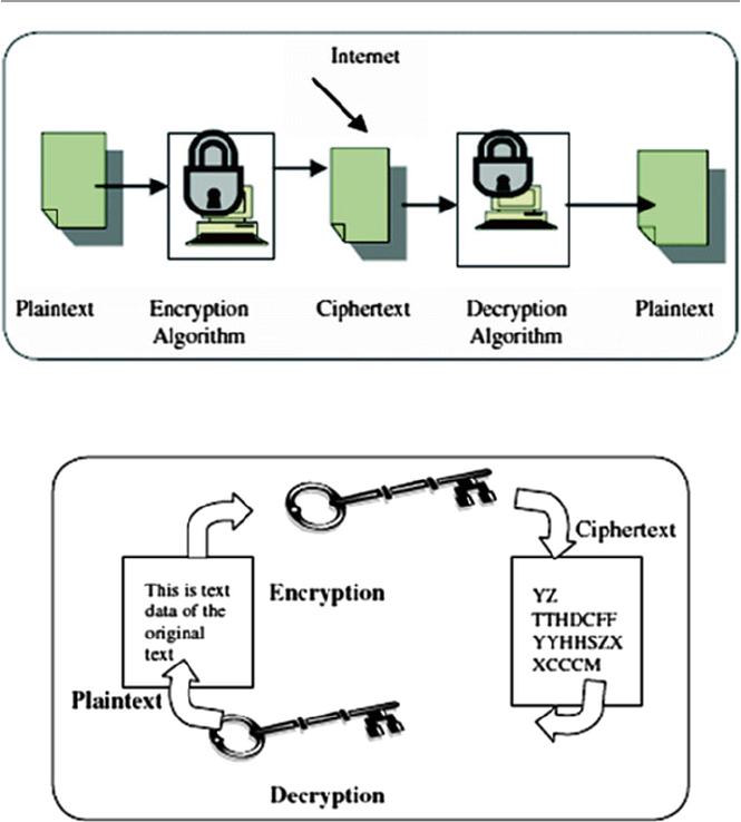
229
as we will see in Sect. 11.2.2 . The question which arises is how to keep the key
secure while being transported from the sender to the receiver.
Symmetric algorithms are faster than their counterparts, the public-key
algorithms.
11.2.1 Symmetric Encryption Algorithms
The most widely used symmetric encryption method in the United States is the
block ciphers Triple Data Encryption Standard (3DES). 3DES developed from the
original and now cracked DES uses a 64-bit key consisting of 56 effective key bits
Fig. 11.1 Symmetric encryption
Fig. 11.2 Encryption and decryption with symmetric cryptography
11. 2 Symmetric Encr yption
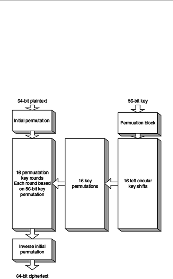
230
and 8 parity bits. 3DES encrypts the data in 8-byte chunks, passing it through 16
different iterations consisting of complex shifting, exclusive ORing, substitution,
and expansion of the key along with the 64-bit data blocks. Figure
11.3 shows how
3DES works.
Although 3DES is complicated and complex, and therefore secure, it suffers
from several drawbacks including the length of its key fi xed at 56 bits plus 8 bits of
parity. The limited key length is making it possible for the ever-increasing speed of
newer computers to render it useless as it is possible to compute all possible combi-
nations in the range 0–2
56 – 1.
Because of this, the National Institute of Standards and Technology (NIST) has
presented the Advanced Encryption Standard (AES), which is expected to replace
DES. AES is Advanced Encryption Standard whose algorithm was decided to be
Rijndael, developed by two Belgian researchers, Joan Daemen and Vincent Rijmen.
Fig. 11.3 DES algorithm
11 Cr yptography

231
Several other symmetric encryption algorithms in use today include International
Data Encryption Algorithm (IDEA), Blowfi sh, Rivest Cipher 4 (RC4), RC5, and
CAST-128. See Table 11.2 for symmetric key algorithms.
11.2.2 Problems with Symmetric Encryption
As we pointed out earlier, symmetric encryption, although fast, suffers from several
problems in the modern digital communication environment. These are a direct
result of the nature of symmetric encryption. Perhaps the biggest problem is that a
single key must be shared in pairs of each sender and receiver. In a distributed envi-
ronment with large numbers of combination pairs involved in many-to-one com-
munication topology, it is diffi cult for the one recipient to keep so many keys in
order to support all communication.
In addition to the key distribution problem above, the size of the communication
space presents problems. Because of the massive potential number of individuals
who can carry on communication in many-to-one, one-to-many, and many-to-many
topologies supported by the Internet, for example, the secret-key cryptography, if
strictly used, requires billions of secret key pairs to be created, shared, and stored.
This can be a nightmare! Large numbers of potential correspondents in the many-
to- one, one-to-many, and many-to-many communication topologies may cause
symmetric encryption to fail because of its requirement of prior relationships with
the parties to establish the communication protocols like the setting up of and acqui-
sition of the secret key.
Besides the problems discussed above and as a result of them, the following
additional problems are also observable:
• The integrity of data can be compromised because the receiver cannot verify that
the message has not been altered before receipt.
• It is possible for the sender to repudiate the message because there are no mechanisms
for the receiver to make sure that the message has been sent by the claimed sender.
• The method does not give a way to ensure secrecy even if the encryption process
is compromised.
• The secret key may not be changed frequently enough to ensure confi dentiality.
Table 11.2 Symmetric key
algorithms Algorithm Strength Features (key length)
3DES Strong 64, 112, 168
AES Strong 128, 192, 256
IDEA Strong 64, 128
Blowfi sh Weak 32–448
RC4 Weak
RC5 Strong 32, 64, 128
BEST Strong
CAST- 128 Strong 32, 128
11. 2 Symmetric Encr yption
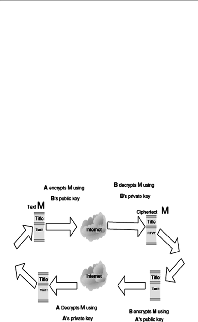
232
11.3 Public-Key Encryption
Since the symmetric encryption scheme suffered from all those problems we have
just discussed above, there was a need for a more modern cryptographic scheme to
address these fl aws. The answers came from two people: Martin Hellman and
Whitfi eld Diffi e, who developed a method that seemed to solve at least the fi rst two
problems and probably all four by guaranteeing secure communication without the
need for a secret key. Their scheme, consisting of mathematical algorithms, led to
what is known as a public-key encryption (PKE).
Public-key encryption , commonly known asymmetric encryption, uses two dif-
ferent keys, a public key known to all and a private key known only to the sender
and the receiver. Both the sender and the receiver own a pair of keys, one public and
the other a closely guarded private one. To encrypt a message from sender A to
receiver B, as shown in Fig. 11.4 , both A and B must create their own pairs of keys.
Then A and B publicize their public keys – anybody can acquire them. When A has
to send a message M to B, A uses B’s public key to encrypt M. On receipt of M, B
then uses his or her private key to decrypt the message M. As long as only B, the
recipient, has access to the private key, then A, the sender, is assured that only B, the
recipient, can decrypt the message. This ensures data confi dentiality. Data integrity
is also ensured because for data to be modifi ed by an attacker, it requires the attacker
to have B’s, the recipient’s, private key. Data confi dentiality and integrity in public-
key encryption are also guaranteed in Fig. 11.4 .
Fig. 11.4 Public-key encryption with data integrity and confi dentiality
11 Cr yptography
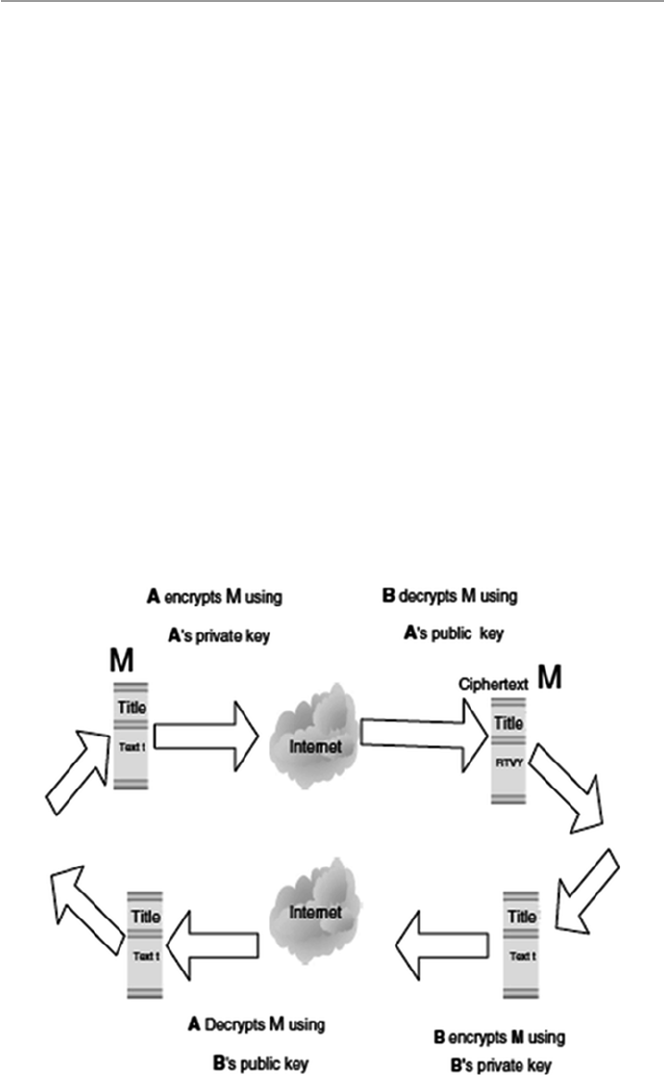
233
As can be seen, ensuring data confi dentiality and integrity does not prevent a
third party, unknown to both communicating parties, from pretending to be A, the
sender. This is possible because anyone can get A’s, the sender’s public key. This
weakness must, therefore, be addressed, and the way to do so is through guarantee-
ing of sender nonrepudiation and user authentication. This is done as follows: after
both A and B have created their own pairs of keys and exchanged the public-key
pair, A, the sender, then encrypts the message to be sent to B, the recipient, using the
sender’s private key. Upon receipt of the encrypted message, B, the recipient, then
uses A’s, the sender’s public key to encrypt the message. The return route is also
similar. This is illustrated in Fig. 11.5 . Authentication of users is ensured because
only the sender and recipient have access to their private keys. And unless their keys
have been compromised, both cannot deny or repudiate sending the messages.
To ensure all four aspects of security, that is, data confi dentiality and integrity
and authentication and nonrepudiation of users, a double encryption is required as
illustrated in Fig. 11.6 .
The core of public-key encryption is that no secret key is passed between two
communicating parties. This means that this approach can support all communica-
tion topologies including one to one, one to many, many to many, and many to one,
and along with it, several to thousands of people can communicate with one party
without exchange of keys. This makes it suitable for Internet communication and
electronic commerce applications. Its other advantage is that it solves the chronic
Fig. 11.5 Authentication and nonrepudiation
11.3 Public-Key Encryption
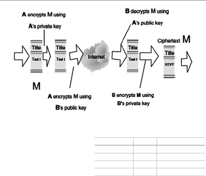
234
repudiation problem experienced by symmetric encryption. This problem is solved,
especially in large groups, by the use of digital signatures and certifi cates.
The various cryptographic algorithms used in this scheme rely on the degree of
computational diffi culty encountered as an attempt is made to recover the keys.
These algorithms, as we will see in Sect. 11.4 , should be labor intensive, and the
amount and diffi culty involved should, and actually always, increase with the key
length. The longer the key, the more diffi cult and the longer it should take to guess
the key, usually the private key.
11.3.1 Public-Key Encryption Algorithms
Various algorithms exist for public-key encryption including RSA, DSA, PGP, and
ElGamal. Table 11.3 shows the features of such algorithms.
11.3.2 Problems with Public-Key Encryption
Although public-key encryption seems to have solved the major chronic encryption
problems of key exchange and message repudiation, it still has its own problems.
The biggest problem for public-key cryptographic scheme is speed. Public-key
algorithms are extremely slow compared to symmetric algorithms. This is because
Fig. 11.6 Ensuring data confi dentiality and integrity and user authentication and nonrepudiation
Table 11.3 Public-key
algorithms Algorithm Strength Features (key length)
RSA Strong 768, 1024
ElGamal Strong 768, 1024
DSA Strong 512 to 1024
Diffi e–Hellman Strong 768, 1024
11 Cr yptography

235
public-key calculations take longer than symmetric key calculations since they
involve the use of exponentiation of very large numbers which in turn take longer to
compute. For example, the fastest public-key cryptographic algorithm such as RSA
is still far slower than any typical symmetric algorithm. This makes these algo-
rithms and the public-key scheme less desirable for use in cases of long messages.
In addition to speed, public-key encryption algorithms have a potential to suffer
from the man-in-the-middle attack. The man-in-the-middle attack is a well-known
attack, especially in the network community where an attacker sniffs packets off a
communication channel, modifi es them, and inserts them back on to the channel. In
case of an encryption channel attack, the intruder convinces one of the correspon-
dents that the intruder is the legitimate communication partner.
11.3.3 Public-Key Encryption Services
As it strives to solve the fl aws that have plagued other encryption schemes, public-
key encryption scheme offers the following services:
• Secrecy which makes it extremely diffi cult for an intruder who is able to intercept
the ciphertext to be able to determine its corresponding plaintext. See Fig. 11.4 .
• Authenticity which makes it possible for the recipient to validate the source of a
message. See Fig. 11.4 .
• Integrity which makes it possible to ensure that the message sent cannot be modi-
fi ed in any way during transmission. See Fig. 11.5 .
• Nonrepudiation which makes it possible to ensure that the sender of the message
cannot later turn around and disown the transmitted message. See Fig. 11.5 .
11.4 Enhancing Security: Combining Symmetric and Public-
Key Encryptions
As we noted in Sect. 11.2.2 , symmetric algorithms, although faster than public-key
algorithms, are beset with a number of problems. Similarly, public-key encryption also
suffers slowness and the potential of the “man-in-the-middle” attack. To address these
concerns and to preserve both effi ciency and privacy of the communication channel
and increase the performance of the system, a hybrid cryptosystem that uses the best
of both and at the same time mitigating the worst in each system is widely used.
11.5 Key Management: Generation, Transportation,
and Distribution
One would have thought that the development of advanced technologies would
already have solved the chronic problem of exchanging a secret key between two
communicating entities. However, one must seriously think that technology is
11.5 Key Management: Generation, Transportation, and Distribution

236
created by humans and humans are part of any technology. But humans also
naturally form the weakest links in any technology. They are very unpredictable
in what they are likely to do and why they do what they do. Key exchange in
cryptographic technologies would not have been a problem, but because of
humans, it is.
In a small communication network based on a one-to-one communication topol-
ogy, the key exchange probably would not be such a problem. However, in modern
large networks that support many-to-one, many-to-many, and one-to-many com-
munication topologies, the creation, distribution, and security of millions of keys
boil down to a nightmare.
11.5.1 The Key Exchange Problem
In Sect. 11.2.2 , we saw that although symmetric encryption is commonly used due
to its historical position in cryptography and its speed, it suffers from a serious
problem of how to safely and secretly deliver a secret key from the sender to the
recipient. This problem forms the basis for the key exchange problem. The key
exchange problem involves [ 2 ] the following:
• Ensuring that keys are exchanged so that the sender and receiver can perform
encryption and decryption
• Ensuring that an eavesdropper or outside party cannot break the code
• Ensuring the receiver that a message was encrypted by the sender
The strength of an encryption algorithm lies in its key distribution techniques.
Poor key distribution techniques create an ideal environment for a man-in-the-
middle attack. The key exchange problem, therefore, highlights the need for strong
key distribution techniques. Even though the key exchange problem is more promi-
nent in the symmetric encryption cryptographic methods, and it is basically solved
by the public-key cryptographic methods, some key exchange problems still remain
in public-key cryptographic methods. For example, symmetric key encryption
requires the two communicating parties to agree upon their secret key ahead of time
before communicating, and public-key encryption suffers from the diffi culty of
securely obtaining the public key of the recipient. However, both of these problems
can be solved using a trusted third party or an intermediary. For symmetric key
cryptography, the trusted intermediary is called a key distribution center (KDC). For
public-key cryptography, the trusted and scalable intermediary is called a certifi cate
authority (CA). See the side bar in Sect. 9.5.2.2 for a defi nition of a certifi cate
authority.
Another method relies on users to distribute and track each other’s keys and trust
in an informal, distributed fashion. This has been popularized as a viable alternative
by the PGP software which calls the model the Web of trust [ 2 ].
11 Cr yptography
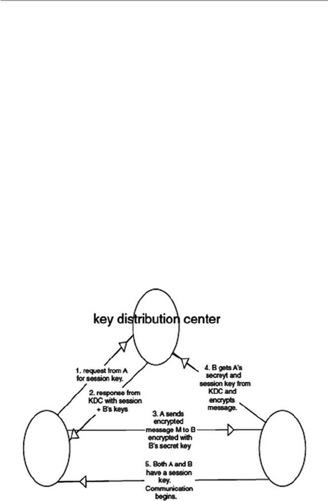
237
11.5.2 Key Distribution Centers (KDCs)
A key distribution center (KDC) is a single, trusted network entity with which all
network communicating elements must establish a shared secret key. It requires all
communicating elements to have a shared secret key with which they can commu-
nicate with the KDC confi dentially. However, this requirement still presents a prob-
lem of distributing this shared key. The KDC does not create or generate keys for the
communicating elements; it only stores and distributes keys. The creation of keys
must be done somewhere else. Diffi e–Hellman is the commonly used algorithm to
create secret keys, and it provides the way to distribute these keys between the two
communicating parties. But since the Diffi e–Hellman exchange suffers from the
man-in-the middle attacks, it is best used with a public-key encryption algorithm to
ensure authentication and integrity. Since all network communicating elements con-
fi dentially share their secret keys with the KDC, it distributes these keys secretly to
the corresponding partners in the communication upon request. Any network ele-
ment that wants to communicate with any other element in the network using sym-
metric encryption schemes uses the KDC to obtain the shared keys needed for that
communication. Figure 11.7 shows the working of the KDC.
Stallings [ 3 ] has a very good scenario which describes the working of the KDC,
and he describes this working as follows. First, both the message sender A and the
message receiver B must have a secret key they each share with the KDC. A initiates
the communication process by sending a request to the KDC for a session key and
Fig. 11.7 The working of a KDC
11.5 Key Management: Generation, Transportation, and Distribution

238
B’s secret key. The KDC responds to this request by sending a two-part packet to
A. The fi rst part to be sent to A consists of A’s request to the KDC, B’s secret key,
and a session key. The second part, to be sent to B, consists of A’s identity and a
copy of the session key given to A. Since the packet is to be sent to A, it is encrypted
by the secret key the KDC shares with A. When A receives the packet, A then gets
out B’s secret key and encrypts the message together with B’s part of the packet
with B’s secret key and sends it to B. On receipt, B uses the secret key B shares with
the KDC to decrypt the package from A to recover the session key. Now the session
key has been distributed to both A and B. After a few housekeeping and authentica-
tion handshake, communication can begin.
The KDC has several disadvantages including the following:
• The two network communicating elements must belong to the same KDC.
• Security becomes a problem because a central authority having access to keys is
vulnerable to penetration. Because of the concentration of trust, a single security
breach on the KDC would compromise the entire system.
• In large networks that handle all communication topologies, the KDC then
becomes a bottleneck since each pair of users needing a key must access a central
node at least once. Also the failure of the central authority could disrupt the key
distribution system [ 4 ].
In large networks with varying communication topologies where network com-
municating elements cannot belong to the same KDC, key distribution may become
a real problem. Such problems are solved by the public-key infrastructure (PKI). We
will discuss PKI in Sect. 11.6 .
11.5.3 Public-Key Management
Because there was a problem with both authenticity and integrity in the distribution
of public keys, there was a need to fi nd a solution to this problem. In fact, according
to Stallings [ 3 ], there were two problems: the distribution of the public keys and the
use of public-key encryption to distribute the secret key. For the distribution of pub-
lic keys, there were several solutions including the following:
• Public announcements where any user can broadcast their public keys or send
them to selected individuals.
• Public directory which is maintained by a trusted authority. The directory is usu-
ally dynamic to accommodate additions and deletions.
• Certifi cate authority (CA) to distribute certifi cates to each communicating ele-
ment. Each communicating element in a network or system communicates
securely with the CA to register its public key with the CA. Since public keys are
already in the public arena, the registration may be done using a variety of tech-
niques including the postal service.
11 Cr yptography

239
11.5.3.1 Certificate Authority (CA)
The CA then certifi es that a public key belongs to a particular entity. The entity may
be a person or a server in a network. The certifi ed public key, if one can safely trust
the CA that certifi ed the key, can then be used with confi dence. Certifying a key by
the CA actually binds that key to a particular network communicating element
which validates that element. In a wide area network such as the Internet, CAs are
equivalent to the digital world’s passport offi ces because they issue digital certifi -
cates and validate the holder’s identity and authority. Just as the passport in the real
world has embedded information about you, the certifi cate issued by the CAs has an
individual’s or an organization’s public key along with other identifying informa-
tion embedded in it and then cryptographically time-stamped, signed, and tamper-
proof sealed. It can then be used to verify the integrity of the data within it and to
validate this data whenever it is presented. A CA has the following roles [ 5 ]:
• It authenticates a communicating element to the other communicating parties
that that element is what it says it is. However, one can trust the identity associ-
ated with a public key only to the extent that one can trust a CA and its identity
verifi cation techniques.
• Once the CA verifi es the identity of the entity, the CA creates a digital certifi cate
that binds the public key of the element to the identity. The certifi cate contains
the public key and other identifying information about the owner of the public
key (e.g., a human name or an IP address). The certifi cate is digitally signed by
the CA.
Since CA verifi es the validity of the communicating elements’ certifi cates, it is in
charge of enrolling, distributing, and revoking certifi cates. Because certifi cates are
issued by many different CAs, much of the format of certifi cates has been defi ned
to ensure validity, manageability, and consistence in the scheme.
To lessen the activities of the CA and therefore improve on the performance of
the CA, users who acquire certifi cates become responsible for managing their own
certifi cates. In doing so, any user who initiates a communication must provide his
or her certifi cate and other identifying information such as a date and random num-
ber and send it to the recipient together with a request for the recipient’s certifi cate.
Upon receipt of these documents, the recipient sends his or her certifi cate. Each
party then validates each other’s certifi cate, and upon approval by either party, com-
munication begins.
During the validation process, each user may periodically check the CA’s lists of
certifi cates which have become invalid before their expiration dates due to key com-
promise or administrative reasons. Since this may require online access to the CA’s
central facility, this may sometimes create a bottleneck.
11.5.3.2 Digital Certificates
A digital certifi cate is a digitally signed message used to attest to the validity of the
public key of a communicating element. As we pointed out, digital certifi cates must
11.5 Key Management: Generation, Transportation, and Distribution

240
adhere to a format. Most digital certifi cates follow the International
Telecommunication Union (ITU-T) X.509 standard. According to RFC 1422, the
X.509 digital certifi cate has the following fi elds as shown in Table 11.4 and in a
sample in Fig. 11.8 .
In modern communication, the use of certifi cates has become common and vital
to the security of such communications. For example, in a network environment, in
order to encrypt transmissions to your server, the client requires the server’s public
key. The integrity of that key is vital to the security of the subsequent sessions. If a
third party, for example, were to intercept the communication and replace the legiti-
mate key with his or her own public key, that man-in-the-middle could view all
traffi c or even modify the data in transit. Neither the client nor the server would
detect the intrusion.
So to prevent this, the client demands from the server, and the server sends the
public key in a certifi cate signed by a certifi cate authority. The client checks the
digital signature. If the signature is valid, the client knows that the CA has certifi ed
that this is the server’s authentic certifi cate, not a certifi cate forged by a man-in-the-
middle. It is important that the CA be a trusted third party in order to provide mean-
ingful authentication.
As we close the discussion on digital certifi cates, let us look at how it compares
with a digital signature in authentication. In Sect. 11.6 , we discussed the role of
digital signatures in authenticating messages and identifying users in public-key
encryption. But digital signatures alone cannot authenticate any message and iden-
tify a user without a mechanism to authenticate the public key, a role played by the
digital certifi cate. Similarly, a digital certifi cate alone cannot authenticate a message
or identify a user without a digital signature. So in order to get a full authentication
of a message and identify the user, one needs both the digital signature and digital
certifi cate, both of them working together.
Several companies now offer digital certifi cates – that means they are function-
ing as CAs. Among those are VeriSign, American Express, Netscape, US Postal
Service, and CyberTrust.
Table 11.4 The ITU-T X.509 digital certifi cate format [ 6 ]
Field Purpose
Version number Most certifi cates use X.509 version 3
Serial number Unique number set by a CA
Issuer Name of the CA
Subject-issued certifi cate Name of the receiver of the certifi cate
Validity period Period in which the certifi cate will be valid
Public-key algorithm information of the subject
of the certifi cate
Algorithm used to sign the certifi cate with
digital signature
Digital signature of the issuing authority Digital signature of the certifi cate signed by
the CA
Public key Public key of the subject
11 Cr yptography
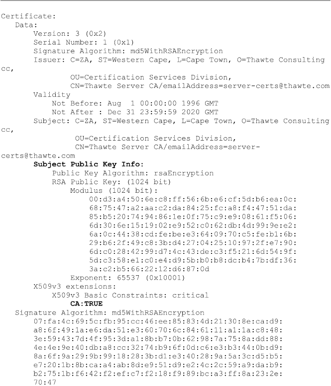
241
11.5.3.3 Using a Private Certificate Authority
If a business is running its own intranet, it is a security imperative that the security
administrator chooses either a public CA or a private CA. It is also possible for the
security administrator to create his or her own CA. If one decides to do this, then
care must be taken in doing so. One should consider the following steps [ 7 ]:
• Consultation with a security expert before building is essential.
• Do all the CA work off-line.
Fig. 11.8 Sample X.509 certifi cates (Image source: http://en.wikipedia.org/wiki/X.509 )
11.5 Key Management: Generation, Transportation, and Distribution

242
• Because it plays a crucial role in the security of the network, it is important that
access, both physical and electronic, to the in-house CA must be highly restricted.
• Protect the CA from all types of surveillance.
• Require users to generate key pairs of adequate sizes, preferably 1024 bit.
If the decision is not to use an in-house CA, then it is important to be careful in
choosing a good trusted CA.
11.5.4 Key Escrow
Key escrow is a scheme in which a copy of the secret key is entrusted to a third
party. This is similar to entrusting a copy of the key to your house or car to a trusted
friend. In itself, it is not a bad idea because you can genuinely lose the key or lock
it inside the house or car. So in case of loss of the main key, a copy can always be
retrieved from the friend. For private arrangements such as this, the idea of a key
escrow is great. However, in a public communication network like the Internet, the
idea is not so good. Key escrow began because as the Internet becomes more acces-
sible, wrong characters and criminals joined in with vices such as money launder-
ing, gambling pornography, and drugs. The US government, at least in public, found
it necessary to rein in on organized crime on the Internet. The way to do it, as it was
seen at that time, was through a key escrow program, and it was hence born.
Since it was fi rst proposed by government, the key escrow program raised a
heated debate between those who feel that the program of key escrow is putting
individual privacy at risk and those who argue that law enforcement offi cials must
be given the technological ability and sometimes advantage to fi ght organized crime
on the Internet.
The key escrow debate was crystallized by the Clipper chip. The Clipper chip,
funded by the US government, was intended to protect private online and telecom-
munication communications while at the same time permitting government agents
to obtain the keys upon presentation of legal warrant. The government appointed
two government agencies to act as the escrow bodies. These agencies were the NIST
and the Treasury Department.
The opposition to the Clipper chip was so strong that government was forced to
opt for its use to be voluntary.
11.6 Public-Key Infrastructure (PKI)
We saw in Sect. 11.5.2 that in large networks with varying communication topologies
where network communicating elements cannot belong to the same KDC, key distri-
bution becomes a real problem. These problems are solved when a public-key infra-
structure (PKI) is used instead of KDCs to provide trusted and effi cient key and
certifi cate management. What then is this PKI? Merike Kaeo, quoting the Internet
X.509 Public Key Infrastructure PKIX, defi nes public-key infrastructure (PKI) as the
11 Cr yptography

243
set of hardware, software, people, policies, and procedures needed to create, manage,
store, distribute, and revoke certifi cates based on public-key cryptography [ 2 ]. PKI
automate all these activities. PKI works best when there is a large mass of users.
Under such circumstances, it creates and distributes digital certifi cates widely to
many users in a trusted manner. It is made up of four major pieces: the certifi cates that
represent the authentication token, the CA that holds the ultimate decision on subject
authentication, the registration authority (RA) that accepts and processes certifi cate
signing requests on behalf of end users, and the Lightweight Directory Access
Protocol (LDAP) directories that hold publicly available certifi cate information [ 8 ].
11.6.1 Certificates
We defi ned certifi cates in Sect. 11.5.3.1 as the cryptographic proof that the public
key they contain is indeed the one that corresponds to the identity stamped on the
same certifi cate. The validation of the identity of the public key on the certifi cate is
made by the CA that signs the certifi cate before it is issued to the user. Let us note
here for emphasis that public keys are distributed through digital certifi cates. The
X.509v3 certifi cate format, as we noted in Sect. 11.5.3.1 , has nine fi elds. The fi rst
seven make up the body of the certifi cate. Any change in these fi elds may cause the
certifi cate to become invalid. If a certifi cate becomes invalid, the CA must revoke it.
The CA then keeps and periodically updates the certifi cate revocation list (CRL).
End users are, therefore, required to frequently check on the CRL.
11.6.2 Certificate Authority
CAs are vital in PKI technology to authoritatively associate a public-key signature
with an alleged identity by signing certifi cates that support the PKI. Although the
CAs play an important role in the PKI technology, they must be kept off-line and
used only to issue certifi cates to a select number of smaller certifi cation entities.
These entities perform most of the day-to-day certifi cate creation and signature
verifi cation.
Since the CAs are off-line and given their role in the PKI technology, there must
be adequate security for the system on which they are stored so that their integrity
is maintained. In addition, the medium containing the CA’s secret key itself should
be kept separate from the CA host in a highly secure location. Finally, all procedures
that involve the handling of the CA private key should be performed by two or more
operators to ensure accountability in the event of a discrepancy.
11.6.3 Registration Authority (RA)
The RAs accept and process certifi cate signing requests from users. Thus, they cre-
ate the binding among public keys, certifi cate holders, and other attributes.
11.6 Public-Key Infrastructure (PKI)

244
11.6.4 Lightweight Directory Access Protocols (LDAP)
These are repositories that store and make available certifi cates and certifi cate revo-
cation lists (CRLs). Developed at the University of Michigan, the LDAP was meant
to make the access to X.509 directories easier. Other ways of distributing digital
certifi cates are by FTP and HTTP.
11.6.5 Role of Cryptography in Communication
From our discussion so far, you should by now have come to the conclusion that
cryptography is a vital component in modern communication and that public-key
technology, in particular, is widely used and is becoming more and more acknowl-
edged as one of the best ways to secure many applications in e-commerce, e-mail,
and VPNs.
11.7 Hash Function
In the previous sections, we have seen how both symmetric and public-key encryp-
tions are used to ensure data confi dentiality and integrity and also user authentica-
tion and nonrepudiation, especially when the two methods are combined. Another
way to provide data integrity and authenticity is to use hash functions.
A hash function is a mathematical function that takes an input message M of a
given length and creates a unique fi xed-length output code. The code, usually a 128-
bit or a 160-bit stream, is commonly referred to as a hash or a message digest. A
one-way hash function, a variant of the hash function, is used to create a signature
or fi ngerprint of the message – just like a human fi ngerprint. On input of a message,
the hash function compresses the bits of a message to a fi xed-size hash value in a
way that distributes the possible messages evenly among the possible hash values.
Using the same hash function on the same message always results in the same mes-
sage digest. Different messages always hash to different message digests.
A cryptographic hash function does this in a way that makes it extremely diffi cult
to come up with two or more messages that would hash to a particular hash value. It
is conjectured that the probability of coming up with two messages hashing on the
same message digest is of the order of 2
64 and that of coming up with any message
hashing on a given message digest is of the order of 2
128 [ 9 ].
In ensuring data integrity and authenticity, both the sender and the recipient per-
form the same hash computation using the same hash function on the message
before the message is sent and after it has been received. If the two computations of
the same hash function on the same message produce the same value, then the mes-
sage has not been tampered with during transmission.
There are various standard hash functions of message digest length including the
160-bit (SHA-1 and MD5) and 128-bit streams (RSA, MD2, and MD4). Message
digest hash algorithms MD2, MD4, and MD5 are credited to Ron Rivest, while
11 Cr yptography

245
Secure Hash Algorithm (SHA) was developed by the NIST. The most popular of
these hash algorithms are SHA and MD5. Table 11.5 shows some more details of
these algorithms.
11.8 Digital Signatures
While we use the hash functions to ensure the integrity and authenticity of the mes-
sage, we need a technique to establish the authenticity and integrity of each message
and each user so that we ensure the nonrepudiation of the users. This is achieved by
the use of a digital signature.
A digital signature is defi ned as an encrypted message digest, by the private key of
the sender, appended to a document to analogously authenticate it, just like the hand-
written signature appended on a written document that authenticates it. Just like in the
handwritten form, a digital signature is used to confi rm the identity of the sender and
the integrity of the document. It establishes the nonrepudiation of the sender.
Digital signatures are formed using a combination of public-key encryption and
one-way secure hash function according to the following steps [ 10 ]:
• The sender of the message uses the message digest function to produce a message
authentication code (MAC).
• This MAC is then encrypted using the private-key and the public-key encryption
algorithm. This encrypted MAC is attached to the message as the digital
signature.
The message is then sent to the receiver. Upon receipt of the message, the recipi-
ent then uses his or her public key to decrypt the digital signature. First, the recipient
must verify that the message indeed came from the expected sender. This step veri-
fi es the sender’s signature. It is done via the following steps [ 2 ]:
• The recipient separates the received message into two: the original document and
the digital signature.
• Using the sender’s public key, the recipient then decrypts the digital signature
which results in the original MAC.
Table 11.5 Standard hash
algorithms Algorithm
Digest
length (bits)
Features (key
length)
SHA-1 160 512
MD5 160 512
HMAC-MD5 Version of
MD5
512 (key version
of MD5)
HMAC-
SHA- 1
Version of
SHA-1
512 (key version
of SHA-1)
PIPEND 160 128
11.8 Digital Signatures
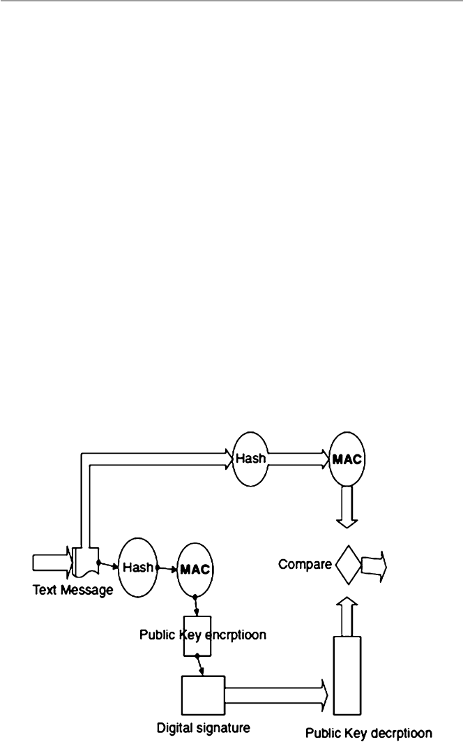
246
• The recipient then uses the original document and inputs it to the hash function
to produce a new MAC.
• The new MAC is compared with the MAC from the sender for a match.
If these numbers compare, then the message was received unaltered, the data
integrity is assured, and the authenticity of the sender is proven. See Fig. 11.9 for
the working of a digital signature verifi cation.
Because digital signatures are derived from the message as a digest which is then
encrypted, they cannot be separated from the messages they are derived from and
remain valid.
Since digital signatures are used to authenticate the messages and identify the
senders of those messages, they can be used in a variety of areas where such double
confi rmation is needed. Anything that can be digitized can be digitally signed. This
means that digital signatures can be used with any kind of message, whether it is
encrypted or not, to establish the authenticity of the sender and that the message
arrived intact. However, digital signatures cannot be used to provide the confi denti-
ality of the message content.
Among the most common digital signature algorithms in use today are the
Digital Signature Standard (DSS) proposed by NIST and based on the ElGamal
public-key algorithm and RSA. DSS is faster than RSA.
Although digital signatures are popular, they are not the only method of authen-
ticating the validity of the sender and the integrity of the message. Because they are
very complex, other less complex methods are also in use, especially in the network
Fig. 11.9 Verifying a digital signature in message authentication
11 Cr yptography

247
community. Such methods include the cyclic redundancy checking (CRC). In CRC,
a digital message is repeatedly divided until a remainder is derived. The remainder,
the divisor, along with the message is then transmitted to the recipient. Upon receipt,
the recipient would execute the same division process looking for the same remain-
der. Where the remainder is the same, the recipient is assured that the message has
not been tampered with during transmission.
Exercises
1. Discuss the basic components of cryptography.
2. Discuss the weaknesses of symmetric encryption.
3. Discuss the weaknesses of public-key encryption.
4. Why is a hybrid cryptosystem preferred over symmetric and public-key encryp-
tion systems?
5. Why is PKI so vital in modern communications?
6. Discuss the role of digital signatures in modern communication.
7. Some say that with the development of systems such as IPSec, the role the CAs
play in modern communication will diminish and eventually cease. Comment
on this statement.
8. In a modern communication network, what are the limitations of a tree-
structured CA system? Why is it necessary?
9. Discuss the limitations of a KDC system in modern communication.
10. Discuss the future of PKI.
Advanced Exercises
1. Discuss the differences between digital certifi cates and digital signatures in
authentication.
2. Discuss the role and function of a PKI.
3. Describe the sequence of steps a sender of a message takes when sending the
message with a digital signature. What steps does the receiver of such a message
take to recover the message?
4. Compare and contrast the problems and benefi ts of KDC and PKI.
5. Describe the message authentication process using:
(a) Symmetric encryption
(b) Public-key encryption
(c) Hash function
References
1. Stein LD (1998) Web security: a step-by-step reference guide. Addison-Wesley, Boston
2. Kaeo M (1999) Designing network security. Cisco Press, Indianapolis
3. Stallings W (1999) Cryptography and network security: principles and practice, 2nd edn.
Prentice Hall, Upper Saddle River
4. Frame Technology. http://www.cs.nps.navy.mil/curricula/tracks/security/notes/chap05_33.html
5. Key Distribution and Certifi cation.
http://cosmos.kaist.ac.kr/cs441/text/keydist.htm
6. Panko RR (2004) Corporate computer security. Prentice Hall, Upper Saddle River
References

248
7. Certifi cates and Certifi cate Authorities.
http://www-no.ucsd.edu/oldsecurity/Ca.html
8. Ram Honta J, Keeping PKI under lock and key. NetworkMagazine.com.
http://www.network-
magazine.com/article/NMG20001004S0015
9. Documentation on cryptography: message digests and digital signatures.
http://pgp.rasip.fer.
hr/pgpdoc2/pgpd2_50.html
10. Public Key Digital Signatures. http://www.sei.cmu.edu/str/descriptions/pkds_body.html
11 Cr yptography

249
© Springer-Verlag London 2015
J.M. Kizza, Guide to Computer Network Security, Computer Communications
and Networks, DOI 10.1007/978-1-4471-6654-2_12
12
Firewalls
12.1 Definition
The rapid growth of the Internet has led to a corresponding growth of both users and
activities in cyberspace. Unfortunately, not all these users and their activities are
reputable; thus, the Internet has been increasingly, at least to many individuals and
businesses, turning into a “bad Internet.” Bad people are plowing the Internet with
evil activities that include, among other things, intrusion into company and indi-
vidual systems looking for company data and individual information that erodes
privacy and security. There has, therefore, been a need to protect company systems
and now individual devices, keeping them from those “bad users” out on the “bad
Internet.” As companies build private networks and decide to connect them onto the
Internet, network security has become one of the most important concerns network
system administrators face. In fact, these network administrators are facing threats
from two fronts: the external Internet and the internal users within the company
network. So network system administrators must be able to find ways to restrict
access to the company network or sections of the network from both the “bad
Internet” outside and from unscrupulous inside users.
Such security mechanisms are based on a firewall. A firewall is a hardware, soft-
ware, or a combination of both that monitors and filters traffic packets that attempt
to either enter or leave the protected private network. It is a tool that separates a
protected network or part of a network, and now increasingly a user PC, from an
unprotected network – the “bad network” like the Internet. In many cases, the “bad
network” may even be part of the company network. By definition, a “firewall” is a
tool that provides a filter of both incoming and outgoing packets. Most firewalls
perform two basic security functions:
•Packet filtering based on accept or deny policy that is itself based on rules of the
security policy.
•Application proxy gateways that provide services to the inside users and at the
same time protect each individual host from the “bad” outside users.
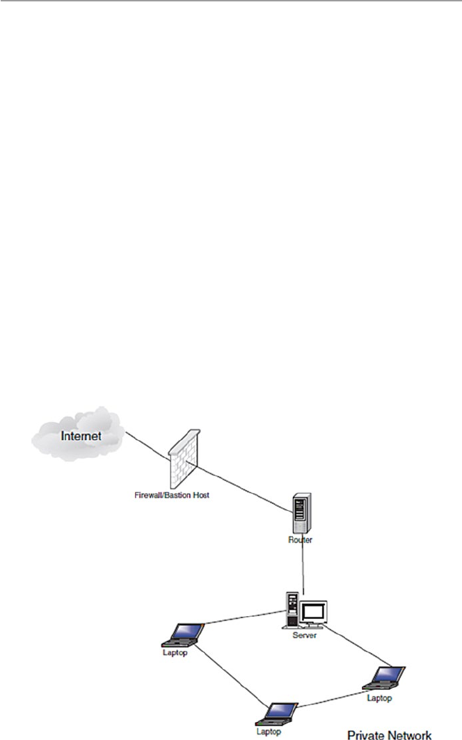
250
By denying a packet, the firewall actually drops the packet. In modern firewalls,
the firewall logs are stored into log files, and the most urgent or dangerous ones are
reported to the system administrator. This reporting is slowly becoming real time.
We will discuss this shortly.
In its simplest form, a firewall can be implemented by any device or tool that
connects a network or an individual PC to the Internet. For example, an Ethernet
bridge or a modem that connects to the “bad network” can be set as a firewall. Most
firewall products actually offer much more as they actively filter packets from and
into the organization network according to certain established criteria based on the
company security policy. Most organization firewalls are bastion host, although
there are variations in the way this is set up. A bastion host is one computer on the
organization network with bare essential services, designated and strongly fortified
to withstand attacks. This computer is then placed in a location where it acts as a
gateway or a choke point for all communication into or out of the organization net-
work to the “bad network.” This means that every computer behind the bastion host
must access the “bad network” or networks through this bastion host. Figure 12.1
shows the position of a bastion host in an organization network.
For most organizations, a firewall is a network perimeter security, a first line of
defense of the organization’s network that is expected to police both network traffic
inflow and outflow. This perimeter security defense varies with the perimeter of the
network. For example, if the organization has an extranet, an extended network
consisting of two or more LAN clusters, or the organization has a virtual private
Fig. 12.1 Bastion host between a private network and the “bad network”
12 Firewalls
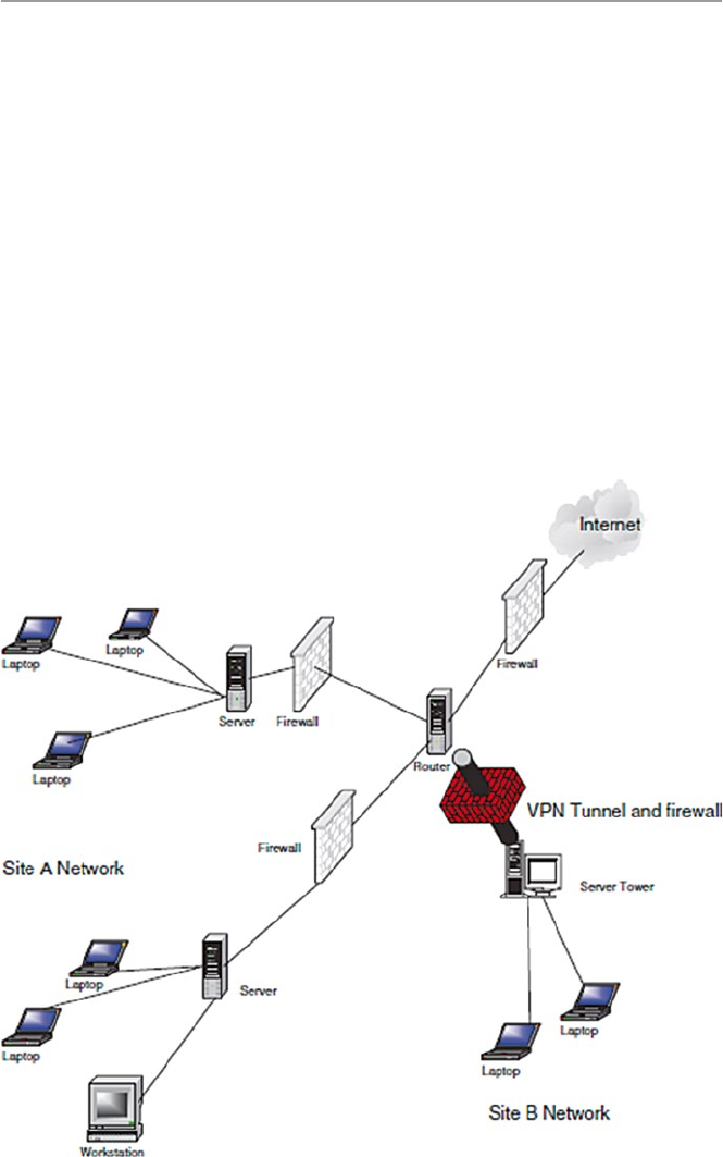
251
network (VPN) (see Chap. 16), then the perimeter of the organization’s network is
difficult to define. In this case, then each component of the network should have its
own firewall. See Fig. 12.2.
As we pointed out earlier, the accept/deny policy used in firewalls is based on an
organization’s security policy. The security policies most commonly used by orga-
nizations vary ranging from completely disallowing some traffic to allowing some
of the traffic or all the traffic. These policies are consolidated into two commonly
used firewall security policies [1]:
•Deny-everything-not-specifically-allowed which sets the firewall in such a way
that it denies all traffic and services except a few that are added as the organiza-
tion’s needs develop
•Allow-everything-not-specifically-denied which lets in all the traffic and services
except those on the “forbidden” list which is developed as the organization’s
dislikes grow
Fig. 12.2 Firewalls in a changing parameter security
12.1 Definition

252
Based on these policies, the following design goals are derived:
•All traffic into and out of the protected network must pass through the firewall.
•Only authorized traffic, as defined by the organizational security policy, in and
out of the protected network, will be allowed to pass.
•The firewall must be immune to penetration by use of a trusted system with
secure operating system.
When these policies and goals are implemented in a firewall, then the firewall is
supposed to [1]:
•Prevent intruders from entering and interfering with the operations of the organi-
zation’s network. This is done through restricting which packets can enter the
network based on IP addresses or port numbers.
Prevent intruders from deleting or modifying information either stored or in
motion within the organization’s network.
•Prevent intruders from acquiring proprietary organization information.
•Prevent insiders from misusing the organization’s resources by restricting unau-
thorized access to system resources.
•Provide authentication, although care must be taken because additional services
to the firewall may make it less efficient.
•Provide endpoints to the VPN.
12.2 Types of Firewalls
Firewalls are used very widely to offer network security services. This has resulted
in a large repertoire of firewalls. To understand the many different types of firewalls,
we need only look at the kind of security services firewalls offer at different layers
of the TCP/IP protocol stack.
As Table 12.1 shows, firewalls can be set up to offer security services to many
TCP/IP layers. The many types of firewalls are classified based on the network layer
it offers services in and the types of services offered.
Table 12.1 Firewall services based on network protocol layers
Layer Firewall services
Application Application-level gateways, encryption, SOCKS proxy server
Transport Packet filtering (TCP, UDP, ICMP)
Network NAT, IP filtering
Data link MAC address filtering
Physical May not be available
12 Firewalls

253
The first type is the packet inspection or filtering router. This type of firewall
uses a set of rules to determine whether to forward or block individual packets. A
packet inspection router could be a simple machine with multiple network inter-
faces or a sophisticated one with multiple functionalities. The second type is the
application inspection or proxy server. The proxy server is based on specific
application daemons to provide authentication and to forward packets. The third
type is the authentication and virtual private networks (VPN). A VPN is an
encrypted link in a private network running on a public network. The fourth firewall
type is the small office or home (SOHO) firewall, and the fifth is the network address
translation (NAT).
12.2.1 Packet Inspection Firewalls
Packet filter firewalls, the first type of firewalls, are routers that inspect the contents
of the source or destination addresses and ports of incoming or outgoing TCP, UDP,
and ICMP packets being sent between networks and accept or reject the packet
based on the specific packet policies set in the organization’s security policy. Recall
that a router is a machine that forwards packets between two or more networks. A
packet inspection router, therefore, working at the network level, is programmed to
compare each packet to a list of rules set from the organization’s security policy,
before deciding if it should be forwarded or not. Data is allowed to leave the system
only if the firewall rules allow it.
To decide whether a packet should be passed on, delayed for further inspection,
or dropped, the firewall looks through its set of rules for a rule that matches the
contents of the packet’s headers. If the rule matches, then the action to deny or allow
is taken; otherwise, an alternate action of sending an ICMP message back to the
originator is taken.
Two types of packet filtering are used during packet inspection: static or stateless
filtering in which a packet is filtered in isolation of the context it is in and stateful
filtering in which a packet is filtered actually based on the context the packet is in.
The trend now for most inspection firewalls is to use stateful filtering.
The static or stateless filtering is a full-duplex communication bastion server
allowing two-way communication based on strict filtering rules. Each datagram
entering the server either from the “bad” network outside the company network or
from within the network is examined based on the preset filtering rules. The rules
apply only to the information contained in the packet, and anything else like the
state of the connection between the client and the server are ignored.
The stateful filtering is also a full-duplex communication bastion server.
However, unlike the straight packet filtering firewall, this filters every datagram
entering the server both from within and outside the network based on the context
which requires a more complex set of criteria and restrictions. For each packet, the
firewall examines the date and state of connection between the client and the server.
Because this type of filtering pays attention to the data payload of each packet, it is,
therefore, more useful and of course more complex. Examination of the data part of
12.2 Types of Firewalls

254
the packet makes it useful in detecting questionable data such as attachments and
data from hosts not directly connected to the server. Requests from or to third-party
hosts and server to server are strictly inspected against the rule base and logged by
the firewall.
Whether static or stateful, the rules a filtering server follows are defined based on
the organization’s network security policy, and they are based on the following
information in the packet [2, 3]:
•Source address. All outgoing packets must have a source address internal to the
network. Inbound packets must never have source addresses that are internal.
•Destination address. Similarly, all outgoing packets must not have a destination
address internal to the network. Any inbound packet must have a destination
address that is internal to the network.
•TCP or UDP source and destination port number.
•ICMP message type.
•Payload data type.
•Connection initialization and datagram using TCP ACK bit.
According to Niels Provos [4] and as Table 12.1 shows, packet inspection based
on IP addresses, port numbers, ACK, and sequence numbers; on TCP, UDP, and
ICMP headers; and on applications may occur at any one of the following TCP/IP
and ISO stack layers:
•The link layer provides physical addressing of devices on the same network.
Firewalls operating on the link layer usually drop packets based on the media
access control (MAC) addresses of communicating hosts.
•The network layer contains the Internet Protocol (IP) headers that support
addressing across networks. IP headers are inspected.
•The transport layer contains TCP, UDP, and ICMP headers and provides data-
flows between hosts. Most firewalls operate at the network and transport layer
and inspect these headers.
•The application layer contains application-specific protocols like HTTP, FTP,
and SET. Inspection of application-specific protocols can be computationally
expensive because more data needs to be inspected.
Let us now look at the different ways of implementing the filtering firewall based
on IP address, TCP/UDP port numbers, and sequence numbers and ACK filtering.
12.2.1.1 IP Address Filtering
IP address filtering rules are used to control traffic into and out of the network
through the filtering of both source and destination IP addresses. Since, in a stateless
filter, no record is kept, the filter does not remember any packet that has passed
through it. This is a weakness that can be exploited by hackers to do IP spoofing.
Table 12.2 shows rules that filter based on IP destination, and Fig. 12.3 shows a
TCP, UDP, and port number filtering firewall.
12 Firewalls
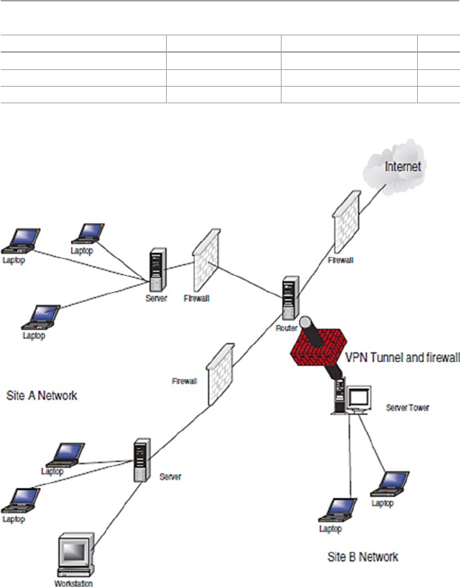
255
12.2.1.2 TCP and UDP Port Filtering
Although IP address header filtering works very well, it may not give the system
administrator enough flexibility to allow users from a trusted network to access
specific services from a server located in the “bad network” and vice versa. For
example, we may not want users from the “bad network” to Telnet into any trusted
network host, but the administrator may want to let them access the Web services
that are on the same or another machine. To leave a selective but restricted access to
Table 12.2 Destination IP filtering
Application protocol Source IP Destination IP Action
HTTP Any 198.124.1.0 Allow
Telnet Any 198.213.1.1 Deny
FTP Any 198.142.0.2 Allow
Fig. 12.3 TCP, UDP, and port number filtering firewall
12.2 Types of Firewalls

256
that machine, the administrator has to be able to set filters according to the TCP or
UDP port numbers in conjunction with the IP address filters. Table 12.3 illustrates
the filtering rules based on TCP and UDP port number filtering.
Unfortunately, as Eric Hall [5] points out, there are several problems with this
approach. First, it is not easy to know what port numbers the servers that you are
trying to access are running on. As Hall observes, modern-day servers such as HTTP
and Gopher are completely configurable in this manner, allowing the user to run
them on any port of choice. If this type of filtering is implemented, then the network
users will not be able to access those sites that do not use the “standard” port num-
bers prescribed. In addition to not being able to pinpoint to a “standard” port num-
ber, there is also a potential of some of the incoming response packets coming from
an intruder port 80.
12.2.1.3 Packet Filtering Based on Initial Sequence Numbers (ISN)
and Acknowledgement (ACK) Bits
A fundamental notion in the design and reliability of the TCP protocol is a sequence
number. Every TCP connection begins with a three-way handshaking sequence that
establishes specific parameters of the connection. The connection parameters
include informing the other host of the sequence numbers to be used. The client
initiates the three-way handshake connection request not only by setting the syn-
chronization (SYN) flag but also by indicating the initial sequence number (ISN)
that it will start with, in addressing data bytes, the octets. This ISN is placed in the
sequence number field.
Upon receipt of each octet, the server responds by setting the header flags SYN
and ACK; it also sets its ISN in the sequence number field of the response, and it
updates the sequence number of the next octet of data it expects from the client.
The acknowledgment is cumulative so that an acknowledgment of sequence
number n indicates that all octets up to but not including n have been received. This
mechanism is good for duplicate detection in the presence of retransmission that
may be caused by replays. Generally, the numbering of octets within a packet is that
the first data octet immediately following the header is the lowest numbered, and the
following octets are numbered consecutively. For the connection to be maintained,
every subsequent TCP packet in an exchange must have its octets’ ACK bits set for
the connection to be maintained. So the ACK bit indicates whether a packet is
requesting a connection or a connection has been made. Packets with 0 in the ACK
field are requesting for connections, while those with a 1 have ongoing connections.
A firewall can be configured to allow packets with ACK bit 1 to access only
Table 12.3 Filtering rules based on TCP and UDP destination port numbers
Application Protocol Destination port number Action
HTTP TCP 80 Allow
SSL UDP 443 Deny
Telnet TCP 23 Allow
12 Firewalls

257
specified ports and only in designated directions since hackers can insert a false
ACK bit of 1 into a packet. This makes the host think that a connection is ongoing.
Table 12.4 shows the rules to set the ACK field.
Access control can be implemented by monitoring these ACK bits. Using these
ACK bits, one can limit the types of incoming data to only response packets. This
means that a remote system or a hacker cannot initiate a TCP connection at all but
can only respond to packets that have been sent to it.
However, as Hall notes, this mechanism is not hacker proof since monitoring
TCP packets for the ACK bit doesn’t help at all with UDP packets, as they don’t
have any ACK bit. Also there are some TCP connections such as FTP that initi-
ate connections. Such applications then cannot work across a firewall based on
ACK bits.
12.2.1.4 Problems with Packet Filtering Firewalls
Although packet filtering, especially when it includes a combination of other prefer-
ences, can be effective, it, however, suffers from a variety of problems including the
following:
•UDP port filtering. UDP was designed for unreliable transmissions that do not
require or benefit from negotiated connections such as broadcasts, routing
protocols, and advertise services. Because it is unreliable, it does not have an
ACK bit; therefore, an administrator cannot filter it based on that. Also an admin-
istrator cannot control where the UDP packet was originated. One solution for
UDP filtering is to deny all incoming UDP connections but allow all outgoing
UDP packets. Of course, this policy may cause problems to some network
users because there are some services that use UDP such as NFS, NTP, DNS,
WINS, NetBIOS-over-TCP/IP, and NetWare/IP and client applications such as
Archie and IRC. Such a solution may limit access to these services for those
network users.
•Packet filter routers do not normally control other vulnerabilities such as SYN
flood and other types of host flooding.
•Packet filtering does not control traffic on VPN.
•Filtering, especially on old firewalls, does not hide IP addresses of hosts on the
network inside the filter but lets them go through as outgoing packets where an
intruder can get them and target the hosts.
•They do not do any checking on the legitimacy of the protocols inside the
packet.
Table 12.4 Rules for filtering based on ACK field bit
Sequence number IP destination address Port number ACK Action
15 198.123.0.1 80 0 Deny
16 198.024.1.1 80 1 Allow
12.2 Types of Firewalls

258
12.2.2 Application Proxy Server: Filtering
Based on Known Services
Instead of setting filtering based on IP addresses, port numbers, and sequence num-
bers, which may block some services from users within the protected network try-
ing to access specific services, it is possible to filter traffic based on popular services
in the organization. Define the filters so that only packets from well-known and
popularly used services are allowed into the organization network, and reject any
packets that are not from specific applications. Such firewall servers are known as
proxy servers.
A proxy server, sometimes just an application firewall, is a machine server that
sits between a client application and the server offering the services the client appli-
cation may want. It behaves as a server to the client and as a client to the server,
hence a proxy, providing a higher level of filtering than the packet filter server by
examining individual application packet data streams. As each incoming data
stream is examined, an appropriate application proxy, a program, similar to normal
system daemons, is generated by the server for that particular application. The
proxy inspects the data stream and makes a decision of either to forward, drop, or
refer for further inspection. Each one of these special servers is called a proxy
server. Because each application proxy is able to filter traffic based on an applica-
tion, it is able to log and control all incoming and outgoing traffic and therefore offer
a higher level of security and flexibility in accepting additional security functions
like user-level authentication, end-to-end encryption, intelligent logging, informa-
tion hiding, and access restriction based on service types [1].
A proxy firewall works by first intercepting a request from a host on the internal
network and then passing it on to its destination, usually the Internet. But before
passing it on, the proxy replaces the IP source address in the packet with its own IP
address and then passes it on. On receipt of packet from an external network, the
proxy inspects the packet, replaces its own IP destination address in the packet with
that of the internal host, and passes it on to the internal host. The internal host does
not suspect that the packet is from a proxy. Figure 12.4 shows a dual-homed proxy
server. Modern proxy firewalls provide three basic operations [6]:
•Host IP Address Hiding – When the host inside the trusted network sends an
application request to the firewall and the firewall allows the request through to
the outside Internet, a sniffer just outside the firewall may sniff the packet and it
will reveal the source IP address. The host then may be a potential victim for
attack. In IP address hiding, the firewall adds to the host packet its own IP header,
so that the sniffer will only see the firewall’s IP address. So application firewalls
then hide source IP addresses of hosts in the trusted network.
•Header destruction is an automatic protection that some application firewalls use
to destroy outgoing packet TCP, UDP, and IP headers and replace them with its
own headers so that a sniffer outside the firewall will see only the firewall’s IP
address. In fact, this action stops all types of TCP, UDP, and IP header attacks.
12 Firewalls
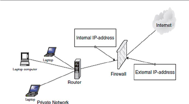
259
•Protocol enforcement. Since it is common in packet inspection firewalls to allow
packets through based on common port numbers, hackers have exploited this by
port spoofing where they penetrate a protected network host using commonly
used and easily allowed port numbers. With an application proxy firewall, this is
not easy to do because each proxy acts as a server to each host, and since it deals
with only one application, it is able to stop any port spoofing activities.
An example of a proxy server is a Web application firewall server. Popular Web
applications are filtered based on their port numbers as below.
•HTTP (port 80)
•FTP (port 20 and 21)
•SSL (port 443)
•Gopher (port 70)
•Telnet (port 23)
•Mail (port 25)
For newer application firewall, the following proxies are also included: HTTP/
Secure HTTP, FTP, SSL, Gopher, e-mail, Telnet, and others. This works for both
incoming and outgoing requests.
Proxy firewalls fall into two types: application and SOCKS proxies [7, 8].
12.2.2.1 Application Proxy
Application-level proxies automate the filtering and forwarding processes for the
client. The client application initiates the process by contacting the firewall. The
daemon proxy on the firewall picks up the request, processes it, and, if it is accept-
able, connects it to the server in the “bad network” (the outside world). If there is
any response, it then waits and returns the data to the client application.
Fig. 12.4 A dual-homed proxy server
12.2 Types of Firewalls

260
As we pointed out earlier, application-level proxies offer a higher level of secu-
rity because in handling all the communications, they can log every detail of the
process, including all URLs visited and files downloaded. They can also be used as
virus scans, where possible, and language filters for inappropriate content. At login,
they can authenticate applications as well as users through a detailed authentication
mechanism that includes a one-time password. Also since users do not have direct
access to the server, it makes it harder for the intruder to install backdoors around
the security system.
Traditional filter firewalls work at a network level to address network access
control and block unauthorized network-level requests and access into the network.
Because of the popularity of application-level services such as e-mail and Web
access, application proxy firewalls have become very popular to address application
layer security by enforcing requests within application sessions. For example, a
Web application firewall specifically protects the Web application communication
Web protocol.
There are two models followed in designing an application firewall: a positive
security model, which enforces positive behavior, and a negative security model,
which blocks recognized attacks [9].
Positive Security Model
A positive security model enforces positive behavior by learning the application
logic and then building a security policy of valid known requests as a user inter-
acts with the application. According to Bar-Har, the approach has the following
steps [9]:
•The initial policy contains a list of valid starting conditions which the user’s
initial request must match before the user’s session policy is created.
•The application firewall examines the requested services in detail. For example,
if it is a Web page download, the page links and drop-down menus and form
fields are examined before a policy of all allowable requests that can be made
during the user’s session is built.
•User requests are verified as valid before being passed to the server. Requests not
recognized by the policy are blocked as invalid requests.
•The session policy is destroyed when the user session terminates. A new policy
is created for each new session.
Negative Security Model
Unlike the positive model which creates a policy based on user behavior, a negative
security model is based on a predefined database of “unacceptable” signatures. The
approach again according to Bar-Har is as follows [9]:
•Create a database of known attack signatures.
•Recognized attacks are blocked, and unknown requests (good or bad) are
assumed to be valid and passed to the server for processing.
•All users share the same static policy.
12 Firewalls
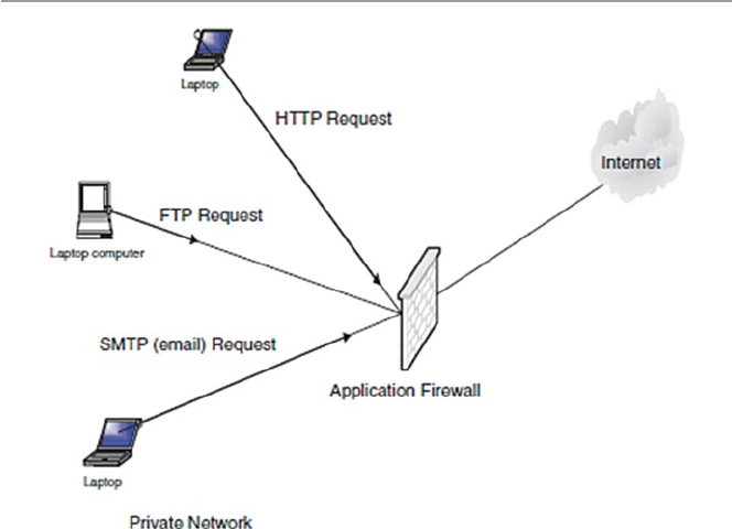
261
Application firewalls work in real time to address security threats before they
reach either the application server or the private network.
12.2.2.2 SOCKS Proxy
A SOCKS proxy is a circuit-level daemon server that has limited capabilities in a
sense that it can only allow network packets that originate from nonprohibited
sources without looking at the content of the packet itself. It does this by working
like a switchboard operator who cross-wires connections through the system to
another outside connection without minding the content of the connection but pays
attention only to the legality of the connection. Another way to describe SOCKS
servers is to say that these are firewall servers that deal with applications that have
protocol behaviors that cannot be filtered. Although they let through virtually all
packets, they still provide core protection for application firewalls such as IP hiding
and header destruction.
They are faster than application-level proxies because they do not open up the
packets, and although they cannot provide for user authentication, they can record
and trace the activities of each user as to where he or she is connected to. Figure 12.5
shows a proxy server.
12.2.3 Virtual Private Network (VPN) Firewalls
A VPN, as we will see in Chap. 16, is a cryptographic system including Point-to-
Point Tunneling Protocol (PPTP), Layer 2 Tunneling Protocol (L2TP), and IPSec
Fig. 12.5 A proxy firewall server
12.2 Types of Firewalls
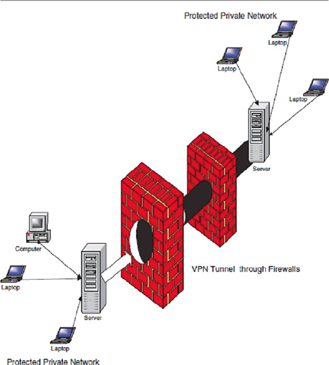
262
that carry Point-to-Point Protocol (PPP) frames across an Internet with multiple
data links with added security. VPNs can be created using a single remote computer
connecting on to a trusted network or connecting two corporate network sites. In
either case and at both ends of the tunnels, a VPN server can also act as a firewall
server. Most firewall servers, however, provide VPN protection which runs in paral-
lel with other authentication and inspection regimes on the server. Each packet
arriving at a firewall is then passed through an inspection and authentication module
or a VPN module. See Fig. 12.6.
The advantages of a VPN over non-VPN connections like standard Internet con-
nections are as follows:
•VPN technology encrypts its connections.
•Connections are limited to only machines with specified IP addresses.
Fig. 12.6 VPN connections and firewalls
12 Firewalls
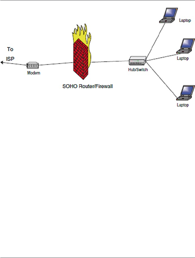
263
12.2.4 Small Office or Home (SOHO) Firewalls
A SOHO firewall is a relatively small firewall that connects a few personal comput-
ers via a hub, switch, a bridge, or even a router on one side and connecting to a
broadband modem like DSL or cable on the other. See Fig. 12.7. The configuration
can be in a small office or a home.
In a functioning network, every host is assigned an IP address. In a fixed network
where these addresses are static, it is easy for a hacker to get hold of a host and use it
to stage attacks on other hosts within and outside the network. To prevent this from
happening, a NAT filter can be used. It hides all inside host TCP/IP information. A
NAT firewall actually functions as a proxy server by hiding identities of all internal
hosts and making requests on behalf of all internal hosts on the network. This means
that to an outside host, all the internal hosts have one public IP address, that of the NAT.
When the NAT receives a request from an internal host, it replaces the host’s IP
address with its own IP address. Inward bound packets all have the NAT’s IP address
as their destination address. Figure 12.8 shows the position of a NAT firewall.
12.3 Configuration and Implementation of a Firewall
There are actually two approaches to configuring a firewall to suit the needs of an
organization. One approach is to start from nothing and make the necessary infor-
mation gathering to establish the needs and requirements of the organization. This
is a time-consuming approach and probably more expensive. The other approach is
what many organizations do and take a short cut and install a vendor firewall already
loaded with features. The administrator then chooses the features that best meet the
established needs and requirements of the organization.
Fig. 12.7 A SOHO firewall
12.3 Configuration and Implementation of a Firewall
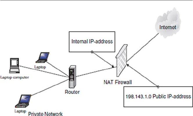
264
Whether the organization is doing an in-house design of its own firewall or buy-
ing it off-the-shelf, the following issues must be addressed first [10]:
•Technical Capacity – Whether large or small, organizations embarking on instal-
lation of firewalls need some form of technical capacity. Such capacity may be
outsourced if it suits the organization.
•Security Review – Before an organization can install a firewall, there must be
security mechanisms based on a security policy to produce a prioritized list of
security objectives.
•Auditing Requirements – Based on the security policy, auditing frequency, and
what must be in the audit. For example, the degree of logging needed and the
details that are cost-effective and thorough. The details included guidelines for
recordings, especially if the organization has plans of pursuing security incidents
in courts of law.
•Filtering and Performance Requirements – Decide on the acceptable trade-off
between security and performance for the organization. Then use this trade-off to
set the level of filtering that meets that balance.
•Authentication – If authentication for outbound sessions is required, then install
it and make sure that users are able to change their passwords.
•Remote Access – If accept remote access is to be allowed, include the require-
ments for authentication and encryption of those sessions. Also consider using
VPN to encrypt the session. Many firewalls come with a VPN rolled in.
•Application and Network Requirements – Decide on the type of network traffic
to be supported, whether network address translation (NAT), static routing, or
dynamic routing are needed and whether masquerading a block of internal
addresses is sufficient instead of NAT. As Fennelly [10] puts it, a poor
Fig. 12.8 A NAT firewall
12 Firewalls

265
understanding of the requirements can lead to implementing a complicated
architecture that might not be necessary.
•Decide on the Protocol for the Firewall – Finally, the type of protocols and ser-
vices (proxies) the firewall will work with must be decided on. The decision is
actually based on the type of services that will be offered in the organization
network.
12.4 The Demilitarized Zone (DMZ)
A DMZ is a segment of a network or a network between the protected network and
the “bad external network.” It is also commonly referred to as a service network.
The purpose of a DMZ on an organization network is to provide some insulation
and extra security to servers that provide the organization services for protocols
such as HTTP/SHTTP, FTP, DNS, and SMTP to the general public. There are dif-
ferent setups for these servers. One such setup is to make these servers actually
bastion hosts so that there is a secure access to them from the internal protected
network to allow limited access. Although there are restrictions on accesses from
the outside network, such restrictions are not as restrained as those from within the
protected network. This enables customers from the outside to access the organiza-
tion’s services on the DMZ servers.
Note that all machines in the DMZ area have a great degree of exposure from
both external and internal users. Therefore, these machines have the greatest poten-
tial for attacks. This implies that these machines must be protected from both exter-
nal and internal misuse. They are therefore fenced off by firewalls positioned on
each side of the DMZ. See Fig. 12.9 for the positioning of DMZ servers.
According to Joseph M. Adams [11], the outer firewall should be a simple
screening firewall just to block certain protocols but let others through that are
allowed in the DMZ. For example, it should allow protocols such as FTP, HTTP/
SHTTP, SMTP, and DNS while denying other selected protocols and address signa-
tures. This selective restriction is important not only to machines in the DMZ but
also to the internal protected network because once an intruder manages to penetrate
the machines in the DMZ, it is that easy to enter the protected internal network. For
example, if DMZ servers are not protected, then an intruder can easily penetrate
them. The internal firewall, however, should be more restrictive in order to more
protect the internal network from outside intruders. It should deny even access to
these protocols from entering the internal network.
Beyond the stated advantage of separating the heavily public accessed servers
from the protected network, thus limiting the potential for outside intruders into the
network, there are other DMZ advantages. According to Chuck Semeria [12], DMZs
offer the following additional advantages to an organization:
•The main advantage for a DMZ is the creation of three layers of protection that
segregate the protected network. So in order for an intruder to penetrate the
12.4 The Demilitarized Zone (DMZ)
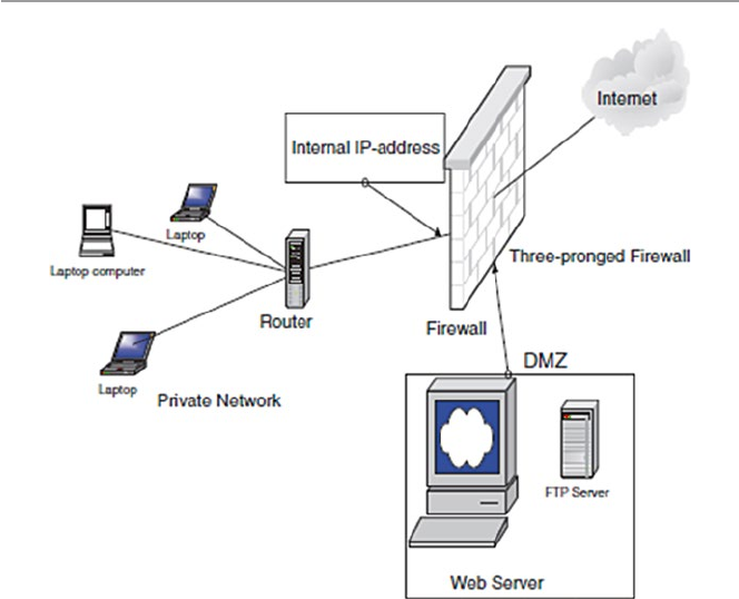
266
protected network, he or she must crack three separate routers: the outside fire-
wall router, the bastion firewall, and the inside firewall router devices.
•Since the outside router advertises the DMZ network only to the Internet, sys-
tems on the Internet do not have routes to the protected private network. This
allows the network manager to ensure that the private network is “invisible” and
that only selected systems on the DMZ are known to the Internet via routing
table and DNS information exchanges.
•Since the inside router advertises the DMZ network only to the private network,
systems on the private network do not have direct routes to the Internet. This
guarantees that inside users must access the Internet via the proxy services resid-
ing on the bastion host.
•Since the DMZ network is a different network from the private network, a net-
work address translator (NAT) can be installed on the bastion host to eliminate
the need to renumber or resubnet the private network.
The DMZ also has disadvantages including the following:
•Depending on how much segregation is required, the complexity of DMZ may
increase.
•The cost of maintaining a fully functional DMZ can also be high again depend-
ing on the number of functionalities and services offered in the DMZ.
Fig. 12.9 Placing of Web, DNS, FTP, and SMTP servers in the DMZ
12 Firewalls

267
12.4.1 Scalability and Increasing Security in a DMZ
Although the DMZ is a restricted access area that is meant to allow outside access
to the limited and often selected resources of an organization, DMZ security is still
a concern to system administrators. As we pointed out earlier, the penetration of the
DMZ may very well result in the penetration of the protected internal network by
the intruder, exploiting the trust relationships between the vulnerable host in the
DMZ and those in the protected internal network.
According to Marcus Ranum and Matt Curtin [13], the security in the DMZ can
be increased and the DMZ scaled by the creation of several “security zones.” This
can be done by having a number of different networks within the DMZ. Each zone
could offer one or more services. For example, one zone could offer services such
as mail, news, and host DNS. Another zone could handle the organization’s Web
needs.
Zoning the DMZ and putting hosts with similar levels of risk on networks linked
to these zones in the DMZ help to minimize the effect of intrusion into the network
because if an intruder breaks into the Web server in one zone, he or she may not be
able to break into other zones, thus reducing the risks.
12.5 Improving Security Through the Firewall
The firewall shown in Fig. 12.9 is sometimes referred to as a three-pronged firewall
or a tri-homed firewall because it connects to three different networks: the external
network that connects to the Internet, the DMZ-screened subnet, and the internal
protected network. Because it is three-pronged, it, therefore, requires three different
network cards.
Because three-pronged firewalls use a single device and they use only a single set
of rules, they are usually complex. Such a set of rules can be complex and lengthy.
In addition, the firewall can be a weak point into the protected network since it pro-
vides only a single entry point into two networks: the DMZ network and the internal
network. If it is breached, it opens up the internal network. Because of this, it is
usually better for added security to use two firewalls as in Fig. 12.10.
Other configurations of firewalls depend on the structure of the network. For
example, in a set up with multiple networks, several firewalls may be used, one per
network. Security in a protected network can further be improved by using encryp-
tion in the firewalls. Upon receipt of a request, the firewall encrypts the request and
sends it on to the receiving firewall or server which decrypts it and offers the
service.
Firewalls can also be equipped with intrusion detection systems (IDS). Many
newer firewalls now have IDS software built into them. Some firewalls can be
fenced by IDS sensors as shown in Fig. 12.11.
12.5 Improving Security Through the Firewall
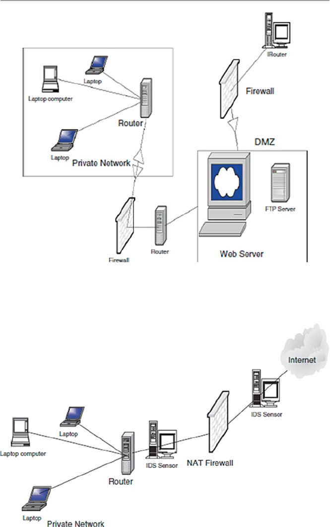
268
Fig. 12.11 Firewalls with IDS sensors
Fig. 12.10 Two firewalls in a network with a DMZ
12 Firewalls

269
12.6 Firewall Forensics
Since port numbers are one of the keys used by most firewalls, let us start firewall foren-
sics by looking at port numbers. A port number is an integer number between 1 and
65535 which identifies to the server what function a client computer wants to be per-
formed. By port numbering, network hosts are able to distinguish one TCP and UDP
service from another at a given IP address. This way, one server machine can provide
many different services without conflicts among the incoming and outgoing data.
According to Robert Graham [14], port numbers are divided into three ranges:
•The well-known ports are those from 0 through 1023. These are tightly bound to
services, and usually, traffic on these ports clearly indicates the protocol for that
service. For example, port 80 virtually always indicates HTTP traffic.
•The registered ports are those from 1024 through 49151. These are loosely
bound to services, which means that while there are numerous services bound to
these ports, these ports are likewise used for many other purposes that have noth-
ing to do with the official server.
•The dynamic and/or private ports are those from 49152 through 65535. In the-
ory, no service should be assigned to these ports.
In reality, machines start assigning dynamic ports starting at 1024. There is also
strangeness, such as Sun starting their RPC ports at 32768 [14].
Using port numbers and in a clear and concise document, Robert Graham
explains what many of us see in firewall logs. His document is intended for both
security experts and home users of personal firewalls. The full text of the article can
be found here: http://www.robertgraham.com/pubs/firewall-seen.html. We encour-
age the reader to carefully read this document for a full understanding of and putting
sense in what a firewall outputs.
12.7 Firewall Services and Limitations
As technology improves, firewall services have widened far beyond old strict filter-
ing to embrace services that were originally done by internal servers. For example,
firewalls can scan for viruses and offer services such as FTP, DNS, and SMTP.
12.7.1 Firewall Services
The broad range of services offered by the firewall is based on the following access
controls [4]:
•Service control – where the firewall may filter traffic on the basis of IP
addresses, TCP, UDP, port numbers, and DNS and FTP protocols in addition to
12.7 Firewall Services and Limitations

270
providing proxy software that receives and interprets each service request
before passing it on
•Direction control – where permission for traffic flow is determined from the
direction of the requests
•User control – where access is granted based on which user is attempting to
access the internal protected network, which may also be used on incoming
traffic
•Behavior control – in which access is granted based on how particular services
are used, for example, filtering e-mail to eliminate spam
12.7.2 Limitations of Firewalls
Given all the firewall popularity, firewalls are still taken as just the first line of
defense of the protected network because they do not assure total security of the
network. Firewalls suffer from limitations, and these limitations and other weak-
nesses have led to the development of other technologies. In fact, there is a talk now
that the development of IPSec technology is soon going to make firewall technology
obsolete. We may have to wait and see. Some of the current firewall limitations are
[14] as follows:
•Firewalls cannot protect against a threat that bypasses it, such as a dial-in using
a mobile host.
•Firewalls do not provide data integrity because it is not possible, especially in
large networks, to have the firewall examine each and every incoming and outgoing
data packet for anything.
•Firewalls cannot ensure data confidentiality because, even though newer fire-
walls include encryption tools, it is not easy to use these tools. It can only work
if the receiver of the packet also has the same firewall.
•Firewalls do not protect against internal threats.
•Firewalls cannot protect against transfer of virus-infected programs or files.
Exercises
1. Discuss the differences between a firewall and a packet filter.
2. Give reasons why firewalls do not give total security.
3. Discuss the advantages of using an application-level firewall over a network-
level firewall.
4. Show how data protocols such as TCP, UDP, and ICMP can be implemented in
a firewall and give the type of firewall best suited for each of these protocols.
5. What are circuit-level firewalls? How are they different from network-level
firewalls?
6. Discuss the limitations of firewalls. How do modern firewalls differ from the
old ones in dealing with these limitations?
7. How would you design a firewall that would let Internet-based users upload
files to a protected internal network server?
12 Firewalls

271
8. Discuss the risks to the protected internal network as a result of a DMZ.
9. What is a bastion router? How different is it from a firewall?
10. Search and discuss as many services and protocols as possible offered by a
modern firewall.
Advanced Exercises
1. Many companies now offer either trial or free personal firewalls. Using the
following companies, search for a download, and install a personal firewall.
The companies are Deerfield.com, McAfee, Network Ice, Symantec, Tiny
Software, and Zone Labs.
2. Design a security plan for a small (medium) company and use that plan to con-
figure a firewall. Install the firewall – use some firewalls from #1 above.
3. Zoning the DMZ has resulted in streamlining and improving security in both the
DMZ and the protected internal network. Consider how you would zone the
DMZ that has servers for the following services and protocols: HTTP/SHTTP,
FTP, ICMP, Telnet, TCP, UDP, Whois, and finger. Install the clusters in the DMZ.
4. Research the differences between IPSec and firewalls. Why is it that some people
are saying that IPSec will soon make firewalls obsolete?
5. Discuss the best ways of protecting an internal network using firewalls from the
following attacks:
•SMTP server hijacking
•Bugs in operating systems
•ICMP redirect bombs
•Denial of service
•Exploiting bugs in applications
References
1. Kizza JM (2002) Computer network security and cyber ethics. McFarland Publishers, Jefferson
2. Karose J, Ross K (2000) Computer networking: a top-down approach featuring the Internet.
Addison-Wesley, Boston
3. Holden G (2004) A guide to firewalls and network security: intrusion detection and VPNs.
Thomson Learning, Clifton Park
4. Provos N (2011) Firewall. http://www.win.tue.nl/henkvt/provos-firewall.pdf
5. Hall E (2002) Internet firewall essentials. http://secinf.net/firewalls_and_VPN/Internet_
Firewall_Essentials.html
6. Panko RR (2004) Corporate computer and network security. Prentice Hall, Upper Saddle River
7. Stein LD (1998) Web security: a step-by-step reference guide. Addison-Wesley, Reading
8. Grennan M (2000) Firewall and proxy server HOWTO. http://www.tldp.org/HOWTO/
Firewall- HOWTO.html
9. Bar-Gad I (2002) Web firewalls. Network World, 06/03/02. http://www.nwfusion.com/news/
tech/2002/0603tech.html
10. Fennelly C (2002) Building your firewall, Part 1. http://secinf.net/firewalls_and_VPN/
Building_your_firewall_Part_1.html
11. Adams JM (2001) FTP Server Security Strategy for the DMZ, June 5, 2001. http://www.mscs.
mu.edu/~hnguye/Security2002/Homeworks/assign4/DMZ.pdf
References

272
12. Semeria C, Internet firewalls and security a technology overview. http://www.patentsform.us/
patents/5987611.html
13. Ranum MJ, Curtin M (2009) Internet firewalls: frequently asked questions. http://www.inter-
hack.net/pubs/fwfaq/#SECTION00040000000000000000
14. Graham R (2000) Firewall forensics (what am I seeing?). http://www.robertgraham.com/pubs/
firewall- seen.html
12 Firewalls

273
© Springer-Verlag London 2015
J.M. Kizza, Guide to Computer Network Security, Computer Communications
and Networks, DOI 10.1007/978-1-4471-6654-2_13
13
System Intrusion Detection
and Prevention
13.1 Definition
The psychology and politics of ownership have historically dictated that individuals
and groups tend to protect valuable resources. This grew out of the fact that once a
resource has been judged to have value, no matter how much protection given to it,
there is always a potential that the security provided for the resource will at some
point fail. This notion has driven the concept of system security and defined the
disciplines of computer and computer network security. Computer network security
is made up of three principles: prevention, detection, and response. Although these
three are fundamental ingredients of security, most resources have been devoted to
detection and prevention because if we are able to detect all security threats and
prevent them, then there is no need for response.
Intrusion detection is a technique of detecting unauthorized access to a computer
system or a computer network. An intrusion into a system is an attempt by an
outsider to the system to illegally gain access to the system. Intrusion prevention, on
the other hand, is the art of preventing an unauthorized access of a system’s
resources. The two processes are related in a sense that while intrusion detection
passively detects system intrusions, intrusion prevention actively filters network
traffic to prevent intrusion attempts. For the rest of the chapter, let us focus on these
two processes.
13.2 Intrusion Detection
The notion of intrusion detection in computer networks is a new phenomenon born,
according to many, from a 1980 James Anderson’s paper, Computer Security Threat
Monitoring and Surveillance. In that paper, Anderson noted that computer audit
trails contained vital information that could be valuable in tracking misuse and
understanding user behavior. The paper, therefore, introduced the concept of

274
“detecting” misuse and specific user events and has prompted the development of
intrusion detection systems.
An intrusion is a deliberate unauthorized attempt, successful or not, to break
into, access, manipulate, or misuse some valuable property and where the misuse
may result into or render the property unreliable or unusable. The person who
intrudes is an intruder.
Aurobindo Sundaram [1] divides intrusions into six types as follows:
•Attempted break-ins, which are detected by atypical behavior profiles or viola-
tions of security constraints. An intrusion detection system for this type is called
anomaly-based IDS.
•Masquerade attacks, which are detected by atypical behavior profiles or
violations of security constraints. These intrusions are also detected using
anomaly- based IDS.
•Penetrations of the security control system, which are detected by monitoring for
specific patterns of activity.
•Leakage, which is detected by atypical use of system resources.
•Denial of service, which is detected by atypical use of system resources.
•Malicious use, which is detected by atypical behavior profiles, violations of
security constraints, or use of special privileges.
13.2.1 The System Intrusion Process
The intrusion process into a system includes a number of stages that start with the
identification of the target, followed by reconnaissance that produces as much infor-
mation about the target as possible. After enough information is collected about the
target and weak points are mapped, the next job is to gain access into the system and
finally the actual use of the resources of the system. Let us look at each one of these
stages.
13.2.1.1 Reconnaissance
Reconnaissance is the process of gathering information about the target system and
the details of its workings and weak points. Hackers rarely attack an organization
network before they have gathered enough information about the targeted network.
They gather information about the type of information used in the network, where
it is stored, how it is stored, and the weak entry points to that information. They do
the reconnaissance through system scanning for vulnerabilities.
Although vulnerability assessment is not intrusion, it is part of the intrusion pro-
cess in that it proceeds the intrusion itself. Vulnerability assessment is an automated
process in which a scanning program sends network traffic to all computers or
selected computers in the network and expects receiving return traffic that will
indicate whether those computers have known vulnerabilities. These vulnerabilities
may include weaknesses in operating systems, application software, and protocols.
13 System Intrusion Detection and Prevention

275
Through the years and as technology improved, vulnerability assessment itself
has gone through several generations, including using code or script downloaded
from the Internet or freely distributed that was compiled and executed for specific
hardware or platforms.
Once they have identified the target system’s vulnerability, then they just go in
for a kill.
13.2.1.2 Physical Intrusion
Besides scanning the network for information that will eventually enable intruders
to illegally enter an organization network, intruders also can enter an organization
network masquerading as legitimate users. They do this through a number of ways
ranging from acquiring special administrative privileges to low-privilege user
accounts on the system. If the system doesn’t have the latest security patches, it may
not be difficult for the hacker to acquire these privileges. The intruder can also
acquire remote access privileges.
13.2.1.3 Denial of Service
Denial-of-service (DoS) attacks are where the intruder attempts to crash a service
(or the machine), overload network links, overload the CPU, or fill up the disk. The
intruder is not trying to gain information but to simply act as a vandal to prevent you
from making use of your machine.
Common Denial-of-Service Attacks
•Ping of death sends an invalid fragment, which starts before the end of packet but
extends past the end of the packet.
•SYN flood sends a TCP SYN packet, which starts connections, very fast, leaving
the victim waiting to complete a huge number of connections, causing it to run
out of resources and dropping legitimate connections.
•Land/Latierra sends a forged SYN packet with identical source/destination
address/port so that the system goes into an infinite loop trying to complete the
TCP connection.
•WinNuke sends an OOB/URG data on a TCP connection to port 139 (NetBIOS
Session/SMB), which causes the Windows system to hang.
13.2.2 The Dangers of System Intrusions
The dangers of system intrusion manifests are many including the following:
•Loss of personal data that may be stored on a computer. Personal data loss means
a lot and means different things to different people depending on the intrinsic
value attached to the actual data lost or accessed. Most alarming in personal data
loss is that the way digital information is lost is not the same as the loss of physical
data. In physical data loss, you know that if it gets stolen, then somebody has it
13.2 Intrusion Detection

276
so you may take precautions. For example, you may report to the police and call
the credit card issuers. However, this is not the same with digital loss because in
digital loss you may even never know that your data was lost. The intruders may
break into the system and copy your data and you never know. The damage,
therefore, from digital personal data loss may be far greater.
•Compromised privacy. These days more and more people are keeping a lot
more of their personal data online either through use of credit or debit cards;
in addition, most of the information about an individual is stored online by
companies and government organizations. When a system storing this kind of
data is compromised, a lot of individual data gets compromised. This is
because a lot of personal data is kept on individuals by organizations. For
example, a mortgage company can keep information on your financial credit
rating, social security number, bank account numbers, and a lot more. Once
such an organization’s network is compromised, there is much information on
individuals that is compromised, and the privacy of those individuals is com-
promised as well.
•Legal liability. If your organization network has personal information of the
customer and it gets broken into, thus compromising personal information that you
stored, you are potentially liable for damages caused by a hacker either breaking
into your network or using your computers to break into other systems. For example,
if a hacker does two- or three-level hacking using your network or a computer on
your network, you can be held liable. A two-level hacking involves a hacker
breaking into your network and using it to launch an attack on another network.
13.3 Intrusion Detection Systems (IDSs)
An intrusion detection system (IDS) is a system used to detect unauthorized
intrusions into computer systems and networks. Intrusion detection as a technol-
ogy is not new; it has been used for generations to defend valuable resources.
Kings, emperors, and nobles who had wealth used it in rather an interesting
way. They built castles and palaces on tops of mountains and sharp cliffs with
observation towers to provide them with a clear overview of the lands below
where they could detect any attempted intrusion ahead of time and defend them-
selves. Empires and kingdoms grew and collapsed based on how well intrusions
from the enemies surrounding them could be detected. In fact, according to the
Greek legend of the Trojan horse, the people of Crete were defeated by the
Greeks because the Greeks managed to penetrate the heavily guarded gates of the
city walls.
Through the years, intrusion detection has been used by individuals and com-
panies in a variety of ways including erecting ways and fences around valuable
resources with sentry boxes to watch the activities surrounding the premises
of the resource. Individuals have used dogs, flood lights, electronic fences,
and closed- circuit television and other watchful gadgets to be able to detect
intrusions.
13 System Intrusion Detection and Prevention

277
As technology has developed, a whole new industry based on intrusion detection
has sprung up. Security firms are cropping up everywhere to offer individual and
property security – to be a watchful eye so that the property owner can sleep or take
a vacation in peace. These new systems have been made to configure changes, com-
pare user actions against known attack scenarios, and be able to predict changes in
activities that indicate and can lead to suspicious activities.
In Sect. 13.2, we outlined six subdivisions of system intrusions. These six can
now be put into three models of intrusion detection mechanisms: anomaly-based
detection, signature-based detection, and hybrid detection. In anomaly-based detec-
tion, also known as behavior-based detection, the focus is to detect the behavior that
is not normal or behavior that is not consistent with normal behavior. Theoretically,
this type of detection requires a list of what is normal behavior. In most environ-
ments, this is not possible, however. In real-life models, the list is determined from
either historical or empirical data. However, neither historical nor empirical data
represent all possible acceptable behavior. So a list has got to be continuously
updated as new behavior patterns not on the list appear and are classified as
acceptable or normal behavior. The danger with this model is to have unacceptable
behavior included within the training data and later be accepted as normal behavior.
Behavior-based intrusion detections, therefore, are also considered as rule-based
detection because they use rules, usually developed by experts, to be able to deter-
mine unacceptable behavior.
In signature-based detection, also known as misuse-based detection, the focus is
on the signature of known activities. This model also requires a list of all known
unacceptable actions or misuse signatures. Since there are an infinite number of
things that can be classified as misuse, it is not possible to put all these on the list
and still keep it manageable. So only a limited number of things must be on the list.
To do this and therefore be able to manage the list, we categorize the list into three
broad activities:
•Unauthorized access
•Unauthorized modification
•Denial of service
Using these classifications, it is then possible to have a controlled list of misuse
whose signatures can be determined. The problem with this model, though, is that it
can detect only previously known attacks.
Because of the difficulties with both the anomaly-based and signature-based
detections, a hybrid model is being developed. Much research is now focusing on
this hybrid model [1].
13.3.1 Anomaly Detection
Anomaly-based systems are “learning” systems in a sense that they work by con-
tinuously creating “norms” of activities. These norms are then later used to detect
13.3 Intrusion Detection Systems (IDSs)

278
anomalies that might indicate an intrusion. Anomaly detection compares observed
activity against expected normal usage profiles “leaned.” The profiles may be
developed for users, groups of users, applications, or system resource usage.
In anomaly detection, it is assumed that all intrusive activities are necessarily
anomalous. This happens in real life too, where most “bad” activities are anoma-
lous, and we can, therefore, be able to character profile the “bad elements” in society.
The anomaly detection concept, therefore, will create, for every guarded system, a
corresponding database of “normal” profiles. Any activity on the system is checked
against these profiles and is deemed acceptable or not based on the presence of such
activity in the profile database.
Typical areas of interest are threshold monitoring, user work profiling, group
work profiling, resource profiling, executable profiling, static work profiling, adap-
tive work profiling, and adaptive rule base profiling.
Anonymous behaviors are detected when the identification engine takes observed
activities and compares them to the rule-based profiles for significant deviations.
The profiles are commonly for individual users, groups of users, system resource
usages, and a collection of others as discussed below [2]:
•Individual profile is a collection of common activities a user is expected to do
and with little deviation from the expected norm. This may cover specific user
events such as the time being longer than usual usage, recent changes in user
work patterns, and significant or irregular user requests.
•Group profile. This is a profile that covers a group of users with a common work
pattern, resource requests and usage, and historic activities. It is expected that
each individual user in the group follows the group activity patterns.
•Resource profile. This includes the monitoring of the use patterns of the system
resources such as applications, accounts, storage media, protocols, communications
ports, and a list of many others the system manager may wish to include. It is
expected, depending on the rule-based profile, that common uses will not deviate
significantly from these rules.
•Other profiles. These include executable profiles that monitor how executable
programs use the system resources. This, for example, may be used to monitor
strange deviations of an executable program if it has an embedded Trojan
worm or a trapdoor virus. In addition to executable profiles, there are also the
following profiles: work profile which includes monitoring the ports, static
profile whose job is to monitor other profiles periodically updating them so
that those profiles cannot slowly expand to sneak in intruder behavior, and a
variation of the work profile called the adaptive profile which monitors work
profiles, automatically updating them to reflect recent upsurges in usage.
Finally, there is also the adoptive rule-based profile which monitors historic
usage patterns of all other profiles and uses them to make updates to the
rule base [3].
Besides being embarrassing and time consuming, the concept also has other
problems. As pointed out by Sundaram [1], if we consider that the set of intrusive
13 System Intrusion Detection and Prevention

279
activities only intersects the set of anomalous activities instead of being exactly the
same, then two problems arise:
•Anomalous activities that are not intrusive are classified as intrusive.
•Intrusive activities that are not anomalous result in false negatives, that is, events
are not flagged intrusive, though they actually are.
Anomaly detection systems are also computationally expensive because of
the overhead of keeping track of, and possibly updating, several system profile
metrics.
13.3.2 Misuse Detection
Unlike anomaly detection where we labeled every intrusive activity anomalous, the
misuse detection concept assumes that each intrusive activity is representable by a
unique pattern or a signature so that slight variations of the same activity produce a
new signature and therefore can also be detected. Misuse detection systems are
therefore commonly known as signature systems. They work by looking for a spe-
cific signature on a system. Identification engines perform well by monitoring these
patterns of known misuse of system resources. These patterns, once observed, are
compared to those in the rule base that describe “bad” or “undesirable” usage of
resources. To achieve this, a knowledge database and a rule engine must be developed
to work together. Misuse pattern analysis is best done by expert systems, model-
based reasoning, or neural networks.
Two major problems arise out of this concept:
•The system cannot detect unknown attacks with unmapped and unarchived
signatures.
•The system cannot predict new attacks and will, therefore, be responding after an
attack has occurred. This means that the system will never detect a new attack.
In a computer network environment, intrusion detection is based on the fact that
software used in all cyber attacks often leave a characteristic signature. This
signature is used by the detection system, and the information gathered is used to
determine the nature of the attack. At each different level of network investigative
work, there is a different technique of network traffic information gathering, analysis,
and reporting. Intrusion detection operates on already gathered and processed
network traffic data. It is usually taken that the anomalies noticed from the analysis
of this data would lead to distinguishing between an intruder and a legitimate user
of the network. The anomalies resulting from the traffic analyses are actually large
and noticeable deviations from historical patterns of usage. Identification systems
are supposed to identify three categories of users: legitimate users, legitimate users
performing unauthorized activities, and of course intruders who have illegally
acquired the required identification and authentication.
13.3 Intrusion Detection Systems (IDSs)

280
13.4 Types of Intrusion Detection Systems
Intrusion detection systems are also classified based on their monitoring
scope. There are those that monitor only a small area and those that can monitor
a wide area. Those that monitor a wide area are known as network-based intru-
sion detection, and those that have a limited scope are known as host-based
detections.
13.4.1 Network-Based Intrusion Detection Systems (NIDSs)
Network-based intrusion detection systems have the whole network as the monitoring
scope. They monitor the traffic on the network to detect intrusions. They are respon-
sible for detecting anomalous, inappropriate, or other data that may be considered
unauthorized and harmful occurring on a network. There are striking differences
between NIDS and firewalls. Recall from Chap. 11 that firewalls are configured to
allow or deny access to a particular service or host based on a set of rules. Only
when the traffic matches an acceptable pattern is it permitted to proceed regardless
of what the packet contains. An NIDS also captures and inspects every packet that
is destined to the network regardless of whether it is permitted or not. If the packet
signature based on the contents of the packet is not among the acceptable signa-
tures, then an alert is generated.
There are several ways an NIDS may be run. It can either be run as an indepen-
dent stand-alone machine where it promiscuously watches over all network traffic
or it can just monitor itself as the target machine to watch over its own traffic. For
example, in this mode, it can watch itself to see if somebody is attempting a SYN
flood or a TCP port scan.
While NIDSs can be very effective in capturing all incoming network traffic, it is
possible that an attacker can evade this detection by exploiting ambiguities in the
traffic stream as seen by the NIDS. Mark Handley, Vern Paxson, and Christian
Kreibich list the sources of these exploitable ambiguities as follows [4]:
•Many NIDSs do not have complete analysis capabilities to analyze a full range
of behavior that can be exposed by the user and allowed by a particular protocol.
The attacker can also evade the NIDS: even if the NIDS does perform analysis
for the protocol.
•Since NIDSs are far removed from individual hosts, they do not have full
knowledge of each host’s protocol implementation. This knowledge is essential
for the NIDS to be able to determine how the host may treat a given sequence of
packets if different implementations interpret the same stream of packets in
different ways.
•Again, since NIDSs do not have a full picture of the network topology between
the NIDS and the hosts, the NIDS may be unable to determine whether a given
packet will even be seen by the hosts.
13 System Intrusion Detection and Prevention
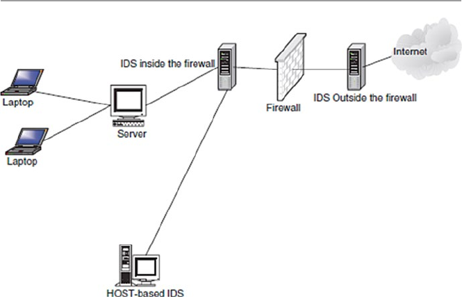
281
13.4.1.1 Architecture of a Network-Based Intrusion Detection
An intrusion detection system consists of several parts that must work together to
produce an alert. The functioning of these parts may be either sequential or some-
times parallel [5, 6]. The parts are shown in Fig. 13.1.
Network Tap/Load Balancer
The network tap, or the load balancer as it is also known, gathers data from the network
and distributes it to all network sensors. It can be a software agent that runs from the
sensor or hardware, such as a router. The load balancer or tap is an important compo-
nent of the intrusion detection system because all traffic into the network goes through
it and it also prevents packet loss in high-bandwidth networks. Certain types of taps
have limitations in selected environments such as switched networks. In networks
where there are no load balancers, sensors must be placed in such a way that they are
responsible for traffic entering the network in their respective sub-network.
Network Sensor/Monitoring
The network sensor or monitor is a computer program that runs on dedicated
machines or network devices on mission-critical segments. In networks with a load
balancer, the sensors receive traffic from the balancer. In other networks without a
load balancer, the sensors receive live traffic from the network and separate it
between suspicious and normal traffic. A sensor can be implemented as an agent on
a mission-critical destination machine in a network. They are either anomaly based or
signature based. Promiscuous mode sensors, which are sensors that detect anything
that seems like a possible attempt at intrusion, run on dedicated machines.
Fig. 13.1 The architecture of a network-based intrusion detection system
13.4 Types of Intrusion Detection Systems

282
Analyzer
The analyzer determines the threat level based on the nature and threat of the suspi-
cious traffic. It receives data from the sensors. The traffic is then classified as either
safe or an attack. Several layers of monitoring may be done where the primary layer
determines the threat severity and secondary layers then determine the scope, intent,
and frequency of the threat.
Alert Notifier
It contacts the security officer responsible for handling incidents whenever a threat
is severe enough according to the organization’s security policy. Standard capabili-
ties include on-screen alerts, audible alerts, paging, and e-mail. Most systems also
provide SNMP so that an administrator can be notified. Frequent alerts for seemingly
trivial threats must be avoided because they result in a high rate of false positives.
It must also be noted that not reporting frequently enough because the sensors are
set in such a way that they ignore a number of threats, many of them being real,
result in false negatives which results in the intrusion detection system providing
misleading sense of security.
Because the performance of the intrusion detection system depends on the balancing
of both false positives and false negatives, it is important to use intrusion detection
systems that are adjustable and can, therefore, offer balancing capabilities.
Command Console/Manager
The role of the command console or manager is to act as the central command
authority for controlling the entire system. It can be used to manage threats by
routing incoming network data to either a firewall or to the load balancer or straight
to routers. It can be accessed remotely so the system may be controlled from any
location. It is typically a dedicated machine with a set of tools for setting policy and
processing collected alarms. On the console, there is an assessment manager, a
target manager, and an alert manager. The console has its own detection engine and
database of detected alerts, for scheduled operations and data mining.
Response Subsystem
The response subsystem provides the capabilities to take action based on threats to
the target systems. These responses can be automatically generated or initiated by
the system operator. Common responses include reconfiguring a router or a firewall
and shutting down a connection.
Database
The database is the knowledge repository for all that the intrusion detection system
has observed. This can include both behavioral and misuse statistics. These statis-
tics are necessary to model historical behavior patterns that can be useful during
damage assessment or other investigative tasks. Useful information need not nec-
essarily be indicative of misuse. The behavioral statistics help in developing the
patterns for the individual, and the misuse statistics aid in detecting attempts at
intrusion.
13 System Intrusion Detection and Prevention

283
13.4.1.2 Placement of IDS Sensors
The position to place network IDS sensors actually depends on several factors,
including the topology of the internal network to be protected, the kind of security
policy the organization is following, and the types of security practices in effect. For
example, you want to place sensors in places where intrusions are most likely to
pass. These are the network “weak” points. However, it is normal practice to place
IDS sensors in the following areas [6]:
•Inside the DMZ. We saw in Chap. 11 that the DMZ is perhaps the most ideal
place to put any detection system because almost all attacks enter the protected
internal network through the DMZ. IDS sensors are, therefore, commonly
placed outside of the organization’s network’s first firewall in the DMZ. The
IDS sensors in the DMZ can be enhanced by putting them into zoned areas.
Another good location for IDS sensors is inside each firewall. This approach
gives the sensors more protection, making them less vulnerable to coordinated
attacks. In cases where the network perimeter does not use a DMZ, the ideal
locations then may include any entry/exit points such as on both sides of the
firewall, dial-up servers, and on links to any collaborative networks. These
links tend to be low bandwidth (T1 speeds) and are usually the entry point of
an external attack.
•Between the firewall and the Internet. This is a frequent area of unauthorized
activity. This position allows the NIDS to “see” all Internet traffic as it comes
into the network. This location, however, needs a good appliance and sensors
that can withstand the high volume of traffic.
•Behind the network front firewall. This is a good position; however, most of the
bad network traffic has already been stopped by the firewall. It handles all the
bad traffic that manages to get through the firewall.
•Inside the network. Commonly placed in strategic points and used to “see” seg-
ments of the network. Network segments like these are usually the suspected
weak areas of the network. The problem with this approach, however, is that the
sensors may not be able to cover all the targets it is supposed to. Also it may
cause the degradation of the network performance.
Figure 13.2 shows the various places where ID sensors can be deployed.
13.4.1.3 Advantages of Network-Based Intrusion Detection Systems
Although both NIDSs and HIDSs (Sect. 13.4.2) have different focuses, areas of
deployment, and deployment requirements, using NIDS has the following advan-
tages [7]:
•Ability to detect attacks that a host-based system would miss because NIDSs
monitor network traffic at a transport layer. At this level, the NIDSs are able to
look at not only the packet addresses but also packet port numbers from the
packet headers. HIDSs which monitor traffic at a lower link layer packets may
fail to detect some types of attack.
13.4 Types of Intrusion Detection Systems
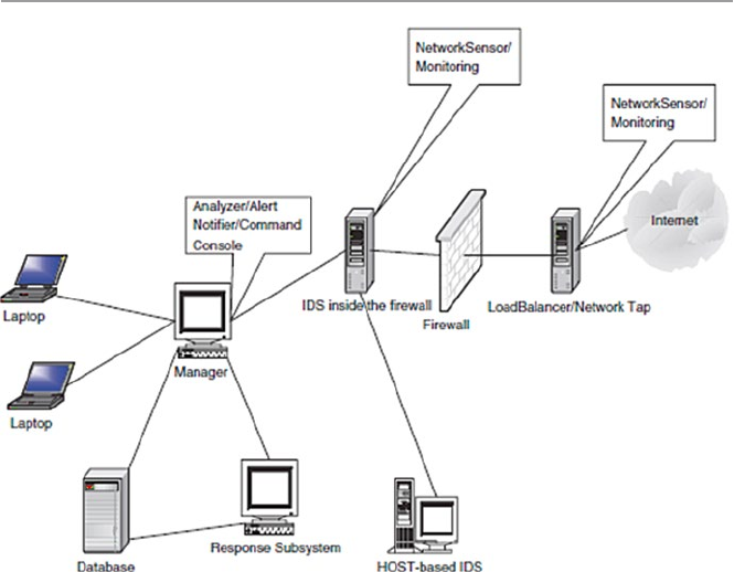
284
•Difficulty to remove evidence. Because NIDSs are on dedicated machines that
are routinely protected, it is more difficult for an attack to remove the evidence
than it is with HIDSs which are near or at the attacker’s desk. Also, since NIDSs
use live network traffic and it is this traffic that is captured by NIDSs when there
is an attack, this also makes it difficult for an attacker to remove evidence.
•Real-time detection and response. Because the NIDSs are at the most opportune
and strategic entry points in the network, they are able to detect foreign intrusions
into the network in real time and report as quickly as possible to the administrator
for a quick and appropriate response. Real-time notification, which many
NIDSs have now, allows for a quick and appropriate response and can even let
the administrators allow the intruder more time as they do more and targeted
surveillance.
•Ability to detect unsuccessful attacks and malicious intent. Because the HIDSs
are inside the protected internal network, they never come into contact with
many types of attack since such attacks are many times stopped by the outside
firewall. NIDSs, especially those in the DMZ, come across these attacks (those
that escape the first firewall) that are later rejected by the inner firewall and
those targeting the DMZ services that have been let in by the outer firewall.
Besides showing these attacks, NIDSs can also record the frequency of these
attacks.
Fig. 13.2 The various places of placing the IDS sensors
13 System Intrusion Detection and Prevention

285
13.4.1.4 Disadvantages of NIDS
Although NIDS are very well suited to monitor all the networks coming into the
network, they have limitations [8]:
•Blind spots. Deployed at the borders of an organization network, NIDS are blind
to the whole inside network. As sensors are placed in designated spots, espe-
cially in switched networks, NIDS have blind spots – sometimes whole network
segments they cannot see.
•Encrypted data. One of the major weaknesses of NIDS is on encrypted data.
They have no capabilities to decrypt encrypted data. Although they can scan
unencrypted parts of the packet such as headers, they are useless to the rest of the
package.
13.4.2 Host-Based Intrusion Detection Systems (HIDS)
Recent studies have shown that the problem of organization information misuse is
not confined only to the “bad” outsiders, but the problem is more rampant within
organizations. To tackle this problem, security experts have turned to inspection of
systems within an organization network. This local inspection of systems is called
host-based intrusion detection systems (HIDS).
Host-based intrusion detection is the technique of detecting malicious activities
on a single computer. A host-based intrusion detection system is, therefore, deployed
on a single target computer, and it uses software that monitors operating system
specific logs, including system, event, and security logs on Windows systems and
syslog in Unix environments to monitor sudden changes in these logs. When a
change is detected in any of these files, the HIDS compares the new log entry with
its configured attack signatures to see if there is a match. If a match is detected, then
this signals the presence of an illegitimate activity.
Although HIDSs are deployable on a single computer, they can also be put
on a remote host, or they can be deployed on a segment of a network to monitor
a section of the segment. The data gathered, which sometimes can be over-
whelming, is then compared with the rules in the organization’s security policy.
The biggest problem with HIDSs is that given the amount of data logs generated, the
analysis of such raw data can put significant overhead not only on the processing
power needed to analyze this data but also on the security staff needed to review
the data.
Host sensors can also use user-level processes to check key system files and
executables to periodically calculate their checksum and report changes in the
checksum.
13.4.2.1 Advantages of Host-Based Intrusion Detection Systems
HIDSs are new kids on the intrusion detection block. They came into widespread
in use in the early and mid-1980s when there was a realization after studies
showed that a large number of illegal and illegitimate activities in organization
13.4 Types of Intrusion Detection Systems

286
networks actually originated from within the employees. Over the succeeding
years as technology advanced, the HIDS technology has also advanced in tandem.
More and more organizations are discovering the benefits of HIDSs on their
overall security. Besides being faster than their cousins the NIDSs, because they
are dealing with less traffic, they offer additional advantages including the
following [7]:
•Ability to verify success or failure of an attack quickly – because they log con-
tinuing events that have actually occurred, they have information that is more
accurate and less prone to false positives than their cousins, the NIDSs. This
information can accurately infer whether an attack was successful or not quickly
and a response can be started early. In this role, they complement the NIDSs, not
as an early warning but as a verification system.
•Low-level monitoring. Because they monitor at a local host, they are able to
“see” low-level local activities such as file accesses, changes to file permis-
sions, attempts to install new executables or attempts to access privileged
services, changes to key system files and executables, and attempts to overwrite
vital system files or to install Trojan horses or backdoors. These low-level
activities can be detected very quickly, and the reporting is quick and timely
to give the administrator time for an appropriate response. Some of these
low-level attacks are so small and far less intensive such that no NIDS can
detect them.
•Near real-time detection and response. HIDSs have the ability to detect minute
activities at the target hosts and report them to the administrator very quickly at
a rate near real time. This is possible because the operating system can recognize
the event before any IDS can, in which case, an intruder can be detected and
stopped before substantial damage is done.
•Ability to deal with encrypted and switched environments – Large networks
are routinely switch-chopped into many but smaller network segments. Each
one of these smaller networks is then tagged with a NIDS. In a heavily
switched network, it can be difficult to determine where to deploy a network-
based IDS to achieve sufficient network coverage. This problem can be solved
by the use of traffic mirroring and administrative ports on switches, but not as
effective. HIDS provides this needed greater visibility into these switched
environments by residing on as many critical hosts as needed. In addition,
because the operating systems see incoming traffic after encryption has
already been de-encrypted, HIDSs that monitor the operating systems can
deal with these encryptions better than NIDSs, which sometimes may not
even deal with them at all.
•Cost-effectiveness. Because no additional hardware is needed to install HIDS,
there may be great organization savings. This compares favorably with the big
costs of installing NIDS which require dedicated and expensive servers. In fact,
in large networks that are switch-chopped which require a large number of
NIDSs per segment, this cost can add up.
13 System Intrusion Detection and Prevention

287
13.4.2.2 Disadvantages of HIDS
Like their cousin the NIDS, HIDSs have limitations in what they can do. These
limitations include the following [8]:
•Myopic viewpoint. Since they are deployed at a host, they have a very limited
view of the network.
•Since they are close to users, they are more susceptible to illegal tampering.
13.4.3 The Hybrid Intrusion Detection System
We have noted in both Sects. 13.4.1 and 13.4.2 that there was a need for both NIDS
and HIDS, each patrolling its own area of the network for unwanted and illegal
network traffic. We have also noted the advantages of not using one over the other
but of using one to complement the other. In fact, if anything, after reading
Sects. 13.4.1.3 and 13.4.2.1, one comes out with an appreciation of how comple-
mentary these two intrusion detection systems are. Both bring to the security of the
network their own strengths and weaknesses that nicely complement and augment
the security of the network.
However, we also know and have noted in Sect. 13.4.1.4 that NIDS have been
historically unable to work successfully in switched and encrypted networks, and as
we have also noted in Sect. 13.4.2.2, both HIDS and HIDS have not been successful
in high-speed networks – networks whose speeds exceed 100 Mbps. This raises the
question of a hybrid system that contains all the things that each system has and
those that each system misses, a system with both components. Having both com-
ponents provides greater flexibility in their deployment options.
Hybrids are new and need a great deal of support to gain on their two cousins.
However, their success will depend to a great extent on how well the interface
receives and distributes the incidents and integrates the reporting structure between
the different types of sensors in the HIDS and NIDS spheres. Also the interface
should be able to smartly and intelligently gather and report data from the network
or systems being monitored.
The interface is so important and critical because it receives data, collects analysis
from the respective component, coordinates and correlates the interpretation of this
data, and reports it. It represents a complex and unified environment for tracking,
reporting, and reviewing events.
13.5 The Changing Nature of IDS Tools
Although ID systems are assumed, though wrongly, by management and many in
the network community that they protect network systems from outside intruders,
recent studies have shown that the majority of system intrusions actually come from
insiders. So newer IDS tools are focusing on this issue. Also, since the human mind
13.5 The Changing Nature of IDS Tools

288
is the most complicated and unpredictable machine ever, as new IDS tools are being
built to counter systems intrusion, new attack patterns are being developed to take
this human behavior unpredictability into account. To keep abreast of all these
changes, ID systems must be changing constantly.
As all these changes are taking place, the primary focus of ID systems has been
on a network as a unit where they collect network packet data by watching network
packet traffic and then analyzing it based on network protocol patterns “norms,”
“normal” network traffic signatures, and network traffic anomalies built in the rule
base. But since networks are getting larger, traffic heavier, and local networks more
splintered, it is becoming more and more difficult for the ID system to “see” all
traffic on a switched network such as an Ethernet. This has led to a new approach to
looking closer at the host. So in general, ID systems fall into two categories: host
based and network based.
13.6 Other Types of Intrusion Detection Systems
Although NIDS and HIDS and their hybrids are the most widely used tools in
network intrusion detection, there are others that are less used but more targeting
and therefore more specialized. Because many of these tools are so specialized,
many are still not considered as being intrusion detection systems but rather intru-
sion detection add-ons or tools.
13.6.1 System Integrity Verifiers (SIVs)
System integrity verifiers (SIVs) monitor critical files in a system, such as system
files, to find whether an intruder has changed them. They can also detect other system
components’ data; for example, they detect when a normal user somehow acquires
root/administrator level privileges. In addition, they also monitor system registries
in order to find well-known signatures [9].
13.6.2 Log File Monitors (LFM)
Log file monitors (LFMs) first create a record of log files generated by network ser-
vices. Then they monitor this record, just like NIDS, looking for system trends, ten-
dencies, and patterns in the log files that would suggest that an intruder is attacking.
13.6.3 Honeypots
A honeypot is a system designed to look like something that an intruder can hack.
They are built for many purposes, but the overriding one is to deceive attackers and
learn about their tools and methods. Honeypots are also add-on/tools that are not
13 System Intrusion Detection and Prevention
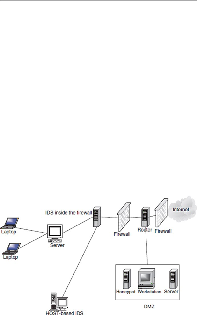
289
strictly sniffer-based intrusion detection systems like HIDS and NIDS. However,
they are good deception systems that protect the network in much the same way as
HIDS and NIDS. Since the goal for a honeypot is to deceive intruders and learn
from them without compromising the security of the network, then it is important to
find a strategic place for the honeypot.
To many, the best location to achieve this goal is in the DMZ for those networks
with DMZs or behind the network firewall if the private network does not have a
DMZ. The firewall location is ideal because of the following [5]:
•Most firewalls log all traffic going through it; hence, this becomes a good way to
track all activities of the intruders. By reviewing the firewall logs, we can determine
how the intruders are probing the honeypot and what they are looking for.
•Most firewalls have some alerting capability, which means that with a few additions
to the firewall rule base, we can get timely alerts. Since the honeypot is built in
such a way that no one is supposed to connect to it, any packets sent to it are most
likely from intruders probing the system. And if there is any outgoing traffic
coming from the honeypot, then the honeypot is most likely compromised.
•The firewall can control incoming and outgoing traffic. This means that the
intruders can find, probe, and exploit our honeypot, but they cannot compromise
other systems.
So any firewall dedicated as a honeypot can do as long as it can control and log
traffic going through it. If no firewall is used, then dedicate any machine either in
the DMZ or behind a firewall for the purpose of logging all attempted accesses.
Figure 13.3 shows the positioning of a honeypot.
Fig. 13.3 The positioning of a honeypot
13.6 Other Types of Intrusion Detection Systems

290
Honeypots come in a variety of capabilities from the simplest monitoring one to
two intruder activities to the most powerful monitoring many intruder activities.
The simplest honeypot is a port monitor which is a simple socket-based program
that opens up a listening port. The program can listen to any designed port. For
example, NukeNabber, for Windows, listens on ports typically scanned for by hack-
ers. It then alerts the administrator whenever such designated ports are being
scanned. The second type of honeypot is the deception system, which, instead of
listening quietly on a port, interacts with the intruder, responding to him or her as if
it were a real server with that port number. Most deception systems implement only
as much of the protocol machine as necessary to trap 90 % of the attacks against the
protocol [9]. The next type of honeypot is the multiprotocol deception system which
offers most of the commonly hacked protocols in a single toolkit. Finally, there is a
full system that goes beyond what the deception systems do to incorporate the abil-
ity to alert the system administrator on any exceptional condition. Other more com-
plex honeypots combine a full system with NIDSs to supplement the internal
logging [9].
13.6.3.1 Advantages of Honeypots
Perhaps one would wonder why a system administrator would go through the pain
of setting up, maintaining, and daily responding to honeypots. There are advantages
to having honeypots on a network. They include the following [9]:
•Since NIDSs have difficulties distinguishing between hostile and nonhostile
activities, honeypots are more suited to digging out hostile intrusions because
isolated honeypots should not normally be accessed. So if they are accessed at
all, such accesses are unwanted intrusions, and they should be reported.
•A honeypot can attract would-be hackers into the trap by providing a banner that
looks like a system that can easily be hacked.
13.7 Response to System Intrusion
A good intrusion detection system alert should produce a corresponding response.
The type of response is relative to the type of attack. Some attacks do not require
responses; others require a precautionary response. Yet others need a rapid and
forceful response. For the most part, a good response must consist of preplanned
defensive measures that include an incident response team and ways to collect IDS
logs for future use and for evidence when needed.
13.7.1 Incident Response Team
An incident response team (IRT) is a primary and centralized group of dedicated
people charged with the responsibility of being the first contact team whenever
13 System Intrusion Detection and Prevention

291
an incidence occurs. According to Innella [6], an IRT must have the following
responsibilities:
•Keeping up to date with the latest threats and incidents
•Being the main point of contact for incident reporting
•Notifying others whenever an incident occurs
•Assessing the damage and impact of every incident
•Finding out how to avoid exploitation of the same vulnerability
•Recovering from the incident
•In handling an incident, the team must carefully do the following:
– Prioritize the actions based on the organization’s security policy but taking
into account the following order:
Human life and people’s safety
Most sensitive or classified data
Costly data and files
Preventing damage to systems
Minimizing the destruction to systems
– Assess incident damage. This is through doing a thorough check on all the
following: system log statistics, infrastructure and operating system checksum,
system configuration changes, and changes in classified and sensitive data,
traffic logs, and password files.
– Alert and report the incident to relevant parties. These may include law
enforcement agencies, incident reporting centers, company executives,
employees, and sometimes the public.
– Recovering from incident. This involves making a postmortem analysis of all
that went on. This postmortem report should include steps to take in case of
similar incidents in the future.
13.7.2 IDS Logs as Evidence
First and foremost, IDS logs can be kept as a way to protect the organization in
case of legal proceedings. Some people tend to view IDS as a form of wiretap.
If sensors to monitor the internal network are to be deployed, verify that there is
a published policy explicitly stating that the use of the network is consent to
monitoring.
13.8 Challenges to Intrusion Detection Systems
While IDS technology has come a long way and there is an exciting future for
it as the marriage between it and artificial intelligence takes hold, it faces many
challenges. Although there are IDS challenges in many areas, more serious challenges
are faced in deploying IDSs in switched environments.
13.8 Challenges to Intrusion Detection Systems

292
13.8.1 Deploying IDS in Switched Environments
There is a particularly hard challenge faced by organizations trying to deploy IDS
in their networks. Network-based IDS sensors must be deployed in areas where they
can “see” network traffic packets. However, in switched networks, this is not pos-
sible because by their very nature, sensors in switched networks are shielded from
most of the network traffic. Sensors are allowed to “see” traffic only from specified
components of the network.
One way to handle this situation has traditionally been to attach a network sensor
to a mirror port on the switch. But port mirroring, in addition to putting an overhead
on the port, gets unworkable when there is an increase in traffic on that port because
overloading one port with traffic from other ports may cause the port to bulk and
miss some traffic.
Several solutions have been used recently including the following [8]:
•Tapping. This involves deploying a line of passive taps that administrators can
tap into to listen in on Ethernet connections; by sending “copies” of the frames
to a second switch with dedicated IDS sensor, overloading a port can be avoided.
•By using standard Cisco access control lists (ACL) in a Cisco appliance that
includes a Cisco Secure IDS, one can tag certain frames for inspection.
•Among other issues still limiting IDS technology are [2]:
•False alarms. Though the tools have come a long way and are slowly gaining
acceptance as they gain widespread use, they still produce a significant number
of both false positives and negatives.
•The technology is not yet ready to handle a large-scale attack. Because of its very
nature, it has to literally scan every packet, every contact point, and every traffic
pattern in the network. For larger networks and in a large-scale attack, it is not
possible that the technology can be relied on to keep working with acceptable
quality and grace.
•Unless there is a breakthrough today, the technology in its current state cannot
handle very fast and large quantities of traffic efficiently.
•Probably the biggest challenge is the IDS’s perceived and sometimes exagger-
ated capabilities. The technology, while good, is not the cure of all computer
network ills that it is pumped up to be. It is just like any other good security tool.
13.9 Implementing an Intrusion Detection System
An effective IDS does not stand alone. It must be supported by a number of other
systems. Among the things to consider, in addition to the IDS, in setting up a good
IDS for the company network are the following [9]:
•Operating systems. A good operating system that has logging and auditing
features. Most of the modern operating systems including Windows, Unix, and
13 System Intrusion Detection and Prevention

293
other variants of Unix have these features. These features can be used to monitor
security critical resources.
•Services. All applications on servers such as Web servers, e-mail servers, and
databases should include logging/auditing features as well.
•Firewalls. As we discussed in Chap. 11, a good firewall should have some
network intrusion detection capabilities. Set those features.
•Network management platform. Whenever network management services such
as OpenView are used, make sure that they do have tools to help in setting up
alerts on suspicious activity.
13.10 Intrusion Prevention Systems (IPSs)
Although IDS have been one of the cornerstones of network security, they have
covered only one component of the total network security picture. They have been
and they are a passive component which only detects and reports without preventing.
A promising new model of intrusion is developing and picking up momentum. It is
the intrusion prevention system (IPS), which according to Andrew Yee [10] is to
prevent attacks. Like their counterparts, the IDS, IPS fall into two categories: net-
work based and host based.
13.10.1 Network-Based Intrusion Prevention Systems (NIPSs)
Because NIDSs are passively detecting intrusions into the network without pre-
venting them from entering the networks, many organizations in recent times
have been bundling up IDS and firewalls to create a model that can detect and
then prevent.
The bundle works as follows. The IDS fronts the network with a firewall behind
it. On the detection of an attack, the IDS then goes into the prevention mode by
altering the firewall access control rules on the firewall. The action may result in the
attack being blocked based on all the access control regimes administered by the
firewall. The IDS can also affect prevention through the TCP resets; TCP utilizes
the RST (reset) bit in the TCP header for resetting a TCP connection, usually sent
as a response request to a nonexistent connection [10]. But this kind of bundling is
both expensive and complex, especially to an untrained security team. The model
suffers from latency – the time it takes for the IDS to either modify the firewall
rules or issue a TCP reset command. This period of time is critical in the success of
an attack.
To respond to this need, a new technology, the IPS, is making its way into
the network security arena to address this latency issue. It does this by both the
intrusion detection system inline with the firewall. Like in NIDS, NIPS architec-
ture varies from product to product, but there is a basic underlying structure to all.
These include traffic normalizer, system service scanner, detection engine, and
traffic shaper [10].
13.10 Intrusion Prevention Systems (IPSs)

294
13.10.1.1 Traffic Normalizer
The normalizer is in the line of network traffic to intercept traffic, resolving the
traffic that has abnormalities before it sends it on. As it normalizes traffic, it may
come to a point where it will discard the packet that does not conform to the set
security policy criteria like if the packet has a bad checksum. It also does further
activities of the firewall, thus blocking traffic based on the criteria that would
normally be put in a firewall. The normalizer also may hold packet fragments and
reassemble them into a packet based on its knowledge of the target system. The
knowledge of the target system is provided from a reference table built by the
system service scanner.
13.10.1.2 The Detection Engine
The detection engine handles all pattern matching that is not handled by the nor-
malizer. These are patterns that are not based on protocol states.
13.10.1.3 Traffic Shaper
Before traffic leaves the NIPS, it must go through the traffic shaper for classi-
fication and flow management. The shaper classifies traffic protocol, although
this may change in the future to include classification based on user and
applications.
13.10.1.4 NIPS Benefits
In his extensive and thorough article Network Intrusions: From Detection to
Prevention, Andre Lee gives the following NIPS benefits [10]:
•Zero latency prevention. Without the NIDS and firewall bundle, NIPSs reduce
this latency drastically by providing the notification within one hardwired cir-
cuitry instead of two.
•Effective network hygiene. Since many attacks are recycle attacks whose signa-
tures are known, NIPS remove these packets quickly, although it does not do
much effective anomaly analysis that is done by the NIDS.
•Simplified management. Because the would-be bundle of a NIDS and firewall
are all packaged into one hardware, it reduces storage space and of course overall
management.
•Although it has all these advantages, NIPSs suffer from a number of problems
including the following [10]:
– Production readiness. This occurs because the technology is new and has not
gotten the field testing it needs to prove effectiveness in every test.
– High availability. This occurs because it is inline, and on the first contact with
network traffic, it may not be able to withstand high traffic availability and
tolerance needed by all first and head-on network devices.
– Detection effectiveness. It has not yet been tested for effectiveness of detec-
tion, and it does not every stop everything, falling short like NIDS.
13 System Intrusion Detection and Prevention

295
13.10.2 Host-Based Intrusion Prevention Systems (HIPSs)
Like its cousin, the NIDSs, NIPSs also have corresponding HIPS based on one host.
Most HIPSs work by sand-boxing, a process of restricting the definition of accept-
able behavior rules used on HIPSs. HIPS prevention occurs at the agent residing at
the host. The agent intercepts system calls or system messages by utilizing dynamic
linked libraries (dll) substitution. The substitution is accomplished by injecting
existing system dlls with vendor stub dlls that perform the interception. So function
calls made to system dlls actually perform a jump to vendor stub code where then
the bad calls are processed, evaluated, and dealt with. Most vendor stubs are kernel
drivers that provide system interception at the kernel level because processes system
calls can be intercepted easily.
13.10.2.1 HIPS Benefits
Again like their cousins the HIDS, HIPS have benefits that include the following [10]:
•Effective context-based prevention. HIPS are the only solution to prevention of
attacks that require simulation context. HIPS agents reside on the protected host,
have complete context of the environment, and are therefore more capable of
dealing with such attacks.
•Effective against zero-day attacks. Since HIPS use sand-boxing method to deal with
attacks, they can define acceptable parameters application or operating system
service behavior to enable the agent to prevent any malicious attack on the host.
•Although they have good benefits, HIPS also have disadvantages based on limi-
tations that hamper their rapid adoption. Among these limitations are [10]:
•Deployment challenge. As we discussed in the HIDS, there are difficulties in
deploying the remote agents on each and every host. These hosts need updating
and are susceptible to tampering.
•Difficulty of effective sandbox configuration. It can be a challenge to define
effective and nonrestrictive parameters on hosts.
•Lack of effective prevention. Because with the use of sand-boxing, HIPS cannot
use any standard prevention like signature prevention.
13.11 Intrusion Detection Tools
Intrusion detection tools work best when used after vulnerability scans have been per-
formed. They then stand watch. Table 13.1 displays several ID tools currently in use.
All network-based intrusion detection tools can provide recon (reconnaissance)
probes in addition to port and host scans. As monitoring tools, they give informa-
tion on:
•Hundreds of thousands of network connections
•External break-in attempts
13.11 Intrusion Detection Tools

296
•Internal scans
•Misuse patterns of confidential data
•Unencrypted remote logins or Web sessions
•Unusual or potentially troublesome observed network traffic
•All this information is gathered by these tools monitoring network components
and services that include the following:
– Servers for:
Mail
FTP
Web activities
– DNS, RADIUS, and others
– TCP/IP ports
– Routers, bridges, and other WAN connection
– Drive Space
– Event log entries
– File modes and existence
– File contents
In addition to the tools in Table 13.1, several other commercial and freeware IDS
and scanning tools can be deployed on a network to gather these probes. The most
common are the following:
•Flow tools. A software package for collecting and processing NetFlow data from
Cisco and Juniper routers
Table 13.1 Some current ID tools
Knowledge-
based IDS Behavior-based IDS
Origin IDS name SA STA STATE HB NB
AIDE
PCI OSSEC X
Osiris X
Samhain
AlienVault OSSIM X X
SourceForge Sguil X X
ArcSight ESM X X X
Symtrex, Inc. SNARE X X X
US Air Force ASIM X X X
Snare BackLog for Solaris
SECSI project, France ORCHIDS X X X
Software. Informer Net Ranger X X
SRI International Emerald X X X
UC Davis GrIDS X X X
WindowsItPro Kane Security Monitor X X
SA signature analysis, STA state transition analysis, HB host based, NB network based
13 System Intrusion Detection and Prevention

297
•Tripwire. Monitors the status of individual files and determines whether they
were changed.
•TCPdump. A freeware and one of the most popular IDS tool created by National
Research Group.
•Snort. Another freeware and popular intrusion detection system that alerts and
reassembles the TCPdump format.
•Portsentry. A port scan detector that shuts down attacking hosts, denying them
access to any network host while notifying administrators.
•Dragon IDS. Developed by Enterasys – a Cabletron Company, it is a popular
commercial IDS.
•TCP Wrappers. Logs connection attempts against protected services and evaluates
them against an access control list before accepting the connection.
•RealSecure. By IBM Internet Security Systems. Very popular IDS.
•Shadow. The oldest IDS tool. It is also a freeware.
•NetProwler. An old intrusion detection tool that prevents network intrusions
through network probing, system misuse, and other malicious activities by users.
Network Auditor gives the power to determine exactly what hardware and soft-
ware is installed on the network and checks this for faults or changes.
Exercises
1. Are IDSs similar to firewalls?
2. Why are system intrusions dangerous?
3. Discuss the best approaches to implementing an effective IDS.
4. Can system intrusions be stopped? Support your response.
5. For a system without a DMZ, where is the best area in the network to install a
honeypot?
6. Why are honeypots important to a network? Discuss the disadvantages of
having a honeypot in the network.
7. Discuss three approaches of acquiring information needed to penetrate a
network.
8. Discuss ways a system administrator can reduce system scanning by hackers.
9. Discuss the benefits of system scanning.
10. Discuss as many effective ways of responding to a system intrusion as possible.
What are the best? Most implementable? Most cost effective?
Advanced Exercises
1. Snort is a software-based real-time network intrusion detection system
developed by Martin Roesch. It is a good IDS that can be used to notify an
administrator of a potential intrusion attempt. Download and install Snort
and start using it.
2. The effectiveness of an IDS varies with the tools used. Research and develop a
matrix of good and effective IDS tools.
3. If possible, discuss the best ways to combine a firewall and a honeypot. Implement
this combination and comment on its effectiveness.
13.11 Intrusion Detection Tools

298
4. Intrusion detection hybrids are getting better. Research the products on the
market and comment on them as far as their interfaces are concerned.
5. Discuss how exploits can be used to penetrate a network. Research and list 10
different common exploits.
References
1. Sundaram A (n.d.) An introduction to intrusion detection, ACM Crossroads: Student Magazine.
Electronic publication. http://www.acm.org/crossroads/xrds2–4/intrus.html
2. Kizza JM (2002) Computer network security and cyber ethics. McFarlans Publishers, Jefferson
3. Bauer KR (n.d.) AINT misbehaving: a taxonomy of anti-intrusion techniques. http://www.
sans.org/newlook/resources/IDFQA/aint.htm
4. Handley M, Paxson V, Kreibich C (n.d.) Network intrusion detection: evasion, traffic nor-
malization, and end-to-end protocol semantics. http://www.icir.org/vern/papers/normusenix-
sec- 01-html/norm.html
5. Proctor P (2001) The practical intrusion detection handbook. Prentice Hall, Upper Saddle
River
6. Innella P (n.d.) The evolution of intrusion detection systems. Tetrad Digital Integrity, LC.
http://www.securityfocus.com/infocus/1514
7. Mullins M (2002) Implementing a network intrusion detection system. 16 May 2002. http://
www.zdnet.com.au/itmanager/technology/story/0,2000029587,20265285,00.htm
8. Central Texas LAN Association Network- vs Host-Based Intrusion Detection. http://www.ctla.
org/newsletter/1999/0999nl.pdf
9. Panko RR (2004) Corporate computer and network security. Prentice Hall, Upper Saddle River
10. Yee A (2003) Network intrusions: from detection to prevention. Int J Inf Assur Prof 8(1)
13 System Intrusion Detection and Prevention

299
© Springer-Verlag London 2015
J.M. Kizza, Guide to Computer Network Security, Computer Communications
and Networks, DOI 10.1007/978-1-4471-6654-2_14
14
Computer and Network Forensics
14.1 Definition
The proliferation of computer technology, including wireless technology and tele-
communication, the plummeting prices of these technologies, the miniaturization of
computing and telecommunication devices, and globalization forces have all
together contributed to our ever growing dependence on computer technology. This
growing dependence has been a bonanza to computer criminals who have seen this
as the best medium to carry out their missions. In fact, Richard Rubin [ 1 ] has called
this new environment a tempting environment to cyber criminals, and he gives seven
compelling reasons that cause such temptations. They are as follows:
• Speed. Both computer and telecommunication technology have greatly increased
the speed of transmission of digital data, which means that one can violate com-
mon decency concerning transmission of such data speedily and not get caught
in the act. Also, the act is over before one has time to analyze its consequences
and one’s guilt.
• Privacy and anonymity. There is a human weakness that if no one is a witness to
an act one has committed, then there is less to no guilt on the doer’s part. Privacy
and anonymity, both of which can be easily attained using this new technology,
support this weakness enabling one to create what can be called “moral distanc-
ing” from one’s actions.
• Nature of medium. The nature of storage and transmission of digital information
in the digital age is different in many aspects from that of the Gutenberg-print
era. The electronic medium of the digital age permits one to steal information
without actually removing it. This virtual ability to remove and leave the original
“untouched” is a great temptation, creating an impression that nothing has been
stolen.
• Aesthetic attraction. Humanity is endowed with a competitive zeal to achieve far
and beyond our limitations. So we naturally get an adrenaline high whenever we
accomplish a feat that seems to break down the efforts of our opponents or the

300
walls of the unknown. It is this high that brings about a sense of accomplishment
and creative pride whenever not so well-known creative individuals come up
with elegant solutions to technological problems. This fascination and a sense of
accomplishment create an exhilaration among criminals that mitigates the value
and the importance of the information attacked and justifi es the action itself.
• Increased availability of potential victims. There is a sense of amusement and
ease to know that with just a few key strokes, one’s message and action can be
seen and consequently felt over wide areas and by millions of people. This sense
unfortunately can very easily turn into evil feelings as soon as one realizes the
power he or she has over millions of invisible and unsuspecting people.
• International scope. The global reach of cyberspace creates an appetite for
greater monetary, economic, and political powers. The ability to cover the globe
in a short time and to infl uence an entire global community can make a believer
out of a nonbeliever.
• Enormous powers. The international reach, the speed, and the distancing of one-
self from the act endow enormous powers to an individual which may lead to
criminal activities.
There are reasons to believe Rubin because the rate of computer crime is on the
rise. Fighting such rising crimes is a formidable task. It includes education, legisla-
tion, regulation, enforcement through policing, and forensics. In both computer
forensics and network, the battle starts in the technical realms of investigative sci-
ence that require the knowledge or skills to identify, track, and prosecute the cyber-
criminal. But before we discuss network forensics, which some call Internet
forensics, let us start by looking at computer forensics. We will come back to net-
work forensics in Sect. 14.3 .
14.2 Computer Forensics
By defi nition, computer forensics is the application of forensic science techniques
to computer-based material. This involves the extraction, documentation, examina-
tion, preservation, analysis, evaluation, and interpretation of computer-based mate-
rial to provide relevant and valid information as evidence in civil, criminal,
administrative, and other cases. In general, computer forensics investigates what
can be retrieved from the computer’s storage media such as hard disk and other
disks. In Sect. 14.3 , we will contrast it with network forensics. Because we are deal-
ing with computer-based materials in computer forensic science, the focus is on the
computer, fi rst as a tool and as a victim of the crime. The computer as a tool in the
crime is merely a role player, for example, as a communication tool, if the crime is
committed using a computer network or as a storage facility where the bounty is
stored on the computer fi les. As a victim, the computer is now the target of the
attack, and it becomes the focus of the forensic investigation. In either case, the
computer is central to the investigations because nearly all forensic cases will
involve extracting and investigating data that is retrieved from the disks of the
computer, both fi xed and movable, and all its parts.
14 Computer and Network Forensics

301
14.2.1 History of Computer Forensics
The history of computer forensics is tied up in the history of forensic science.
According to Hal Berghel [ 2 ], the art of forensic science is actually derived from
forensic medicine, an already recognized medical specialty. Forensic medicine’s
focus was autopsy examination to establish the cause of death. Although computers
were in full use by the 1970s, mainly in big organizations and businesses such as
banks and insurance companies, crimes involving computers as tools and as victims
were very rare. One of the fi rst recorded computer crimes during that time period
was based on “interest rounding.” Interest rounding was a round-robin policy used
by banks to fairly distribute truncated fl oating point interest on depositors’ accounts.
The banks would round a depositor’s interest points to a full cent. Anything less
than a cent would be moved to the next account in a round-robin fashion.
Programmers, however, saw this as a source of ill-gotten wealth. They estab-
lished an account to which they moved this less than a cent interest. With big banks
with many depositors, this would add up. Because these programmers, like all com-
puter criminals of the time, were highly educated, all computer crimes of the period
were “white-collar” crimes. Law enforcement agencies of the time did not know
enough about these types of computer crimes. Even the tools to gather evidence
were not available. In a few cases where tools were available, they were often home-
made [ 3 ].
It was not until the mid-1980s that some computer forensic tools such as XTree
Gold and Norton Disk Editor became available. With these tools, investigators were
able to recognize fi le types and were able to extract data on DOS-based disks. The
1990s saw heightened activities in computer crime and forensic investigations. The
decade also produced an assortment of fi ne forensic tools that included the Forensic
Toolkit.
Although the development of computer forensics started slow, it has now evolved
as technology developed to where we are today. The increasing use of computers by
law enforcement investigators and prosecutors and, as noted earlier, the widespread
and rampant increase in computer-related crimes have led to the development of
computer forensics. The primary focus and methodology, although still embedded
in the basic physical forensics, have been tracing and locating computer hardware,
recovering hidden data from the digital storage media, identifying and recovering
hidden data, decrypting fi les, decomposing data, cracking passwords, and bypass-
ing normal operating systems security controls and permissions [ 4 ].
14.2.2 Elements of Computer Forensics
There are three key elements in any forensic investigations: the material itself, its
relevance to the case in question, and the validity of any observations/conclusions
reached by the examiner. Since computer forensics is very similar to ordinary physical
forensics, these elements remain the same in computer forensics.
14.2 Computer Forensics

302
14.2.2.1 The Material
In both roles the computer plays in forensic science, the cases we have given above,
the materials involved are both electronic and physical. Physical material investiga-
tion falls within the realms of the traditional police investigations where fi les and
manila envelopes and boxes are all examined. The electronic form data is a little
trickier to deal with. It may be data that does exist in hard copy, such as e-mail text,
e-mail headers, e-mail fi le attachments, electronic calendars, Web site log fi les, and
browser information. It may be deleted documents that must be recovered and
reconstructed because deleted data does not necessarily disappear. Even when the
reference to the deleted fi le is removed from the computer’s directory, the bits that
make up the fi le often remain on the hard drive until they are overwritten by new
data. Beside deleted data, data also may be encrypted or password protected, making
it more diffi cult to get in its original form.
If the computer is the focus of the investigation, then information from all system
components is part of the required data. For example, network nodes and stand-
alone personal computer operating systems create a great deal of administrative,
management, and control information that is vital in the investigation.
14.2.2.2 Relevance
Once the existence of the material has been established, the next important step is to
make sure that the material is relevant. The relevancy of the material will depend on
the requesting agency, the nature of the request, and the type of the case in question.
The requesting agencies are usually one of the following:
• The victim
• Government
• Insurance companies
• The courts
• Private business
• Law enforcement
• Private individuals
We will talk more about relevancy when we discuss analysis of evidence.
14.2.2.3 Validity
The question of validity of data is tied up with the relevance of data. It is also based
on the process of authentication of data. We are going to discuss this next.
14.2.3 Investigative Procedures
Both computer and network forensic (Sect. 14.3 ) methodologies consist of three
basic components that Kruse and Heiser [ 5 ] both call the three As of computer
forensics investigations. These are as follows: acquiring the evidence, taking care to
14 Computer and Network Forensics

303
make sure that the integrity of the data is preserved; authenticating the validity of
the extracted data – this involves making sure that the extracted data is as valid as
the original; and analyzing the data while keeping its integrity.
14.2.3.1 Looking for Evidence
As Kruse puts it, when dealing with computer forensics, the only thing to be sure of
is uncertainty. So the investigator should be prepared for diffi culties in searching for
bits of evidence data from a haystack. The evidence usually falls into the following
categories:
• Impressions: This includes fi ngerprints, tool marks, footwear marks, and other
types of impressions and marks.
• Bioforensics: This includes blood, body fl uids, hair, nail scrapings, and blood
stain patterns.
• Infoforensics: This includes binary data fi xed in any medium such as on CDs,
memory, and fl oppies.
• Trace evidence: This includes residues of things used in the committing of a
crime like arson accelerant, paint, glass, and fi bers.
• Material evidence: This includes physical materials such as folders, letters, and
scraps of papers.
As you start, decide on what the focus of the investigation is. At the start,
decide on:
• What you have to work with: This may include written and technical policies,
permissions, billing statements, and system application and device logs.
• What you want to monitor: Includes employer and employee rights, Internet
e-mail, and chat room tracking.
Deciding what to focus on requires the investigator to make a case assessment
that identifi es the case requirements. To do this, the investigator must establish the
following [ 3 ]:
• Situation – gives the environment of the case
• Nature of the case – broadly states the nature of the case
• Specifi cs about the case – states out what the case is about
• Types of evidence to look for – stating physical and electronic data and the mate-
rials to be collected and examined
• Operating system in use at the time of the incident
• Known disk formats at the time of the incident
• Location of evidence both physical and electronic
Once this information is collected, the investigation may start creating the profi le
of the culprit. At this point, you need to decide whether to let the suspect systems
14.2 Computer Forensics

304
identifi ed above run for a normal day, run periodically, or be pulled altogether if
such actions will help the evidence gathering stage. Pulling the plug means that you
will make copies of the computer content and work with the copies while keeping
the original intact. Make sure that the system is disconnected and that all that may
be affected by the disconnection such volatile data is preserved before the discon-
nection. Make duplication and imaging of all the drives immediately, and ensure
that the system remains in its “frozen” state without being used during the
investigation.
One advantage of pulling the plug is to “freeze” the evidence and prevent it from
being contaminated with either new use or modifi cations or alterations. Also freez-
ing the system prevents errors committed after the reported incident and before a
full investigation is completed. However, freezing the system may result in several
problems, including the destruction of any evidence of any ongoing processes.
On the other hand, working with a live system has its share of problems. For
example, the intruder may anticipate a “live” investigation that involves an investi-
gator working with a system still in operation. If the intruder anticipates such action,
then he or she may alter the evidence wherever the evidence is well ahead of the
investigator, thus compromising the validity of the evidence.
Whether you use a “live” system or a “frozen” one, you must be careful in the use
of the software, both investigative and system software. Be careful and weigh the
benefi ts of using software found on the system or new software. A number of forensic
investigators prefer not to use any software found on the system for fear of using
compromised software. Instead they use new software on the copy system, including
system software. Another variation used by some investigators is to verify the
software found on the system and then use it after. Each of these methods has
advantages and disadvantages, and one has to be careful to choose what best serves
the particular situation under review.
14.2.3.2 Handling Evidence
The integrity of the evidence builds the validity of such evidence and consequently
wins or loses a case under investigation because it is this evidence that is used in the
case to establish the facts upon which the merits, or lack of, are based. It is, there-
fore, quite important and instructive that extreme care must be taken when handling
forensic evidence. Data handling includes extraction and the establishment of a
chain of custody. The chain of custody itself involves packaging, storage, and trans-
portation. These three form the sequence of events along the way from the extrac-
tion point to the court room. This sequence of events is traceable if one answers the
following questions:
• Who extracted the evidence and how?
• Who packaged it?
• Who stored it, how, and where?
• Who transported it?
14 Computer and Network Forensics

305
The answers to these questions are derived from the following information [ 3 ]:
• Case:
– Case number – a number assigned to the case to uniquely identify the case
– Investigator – name of the investigator and company affi liation
– Nature of the case – a brief description of the case
• Equipment involved:
– For all computing equipment, carefully describe the equipment including the
maker, vendor, model, and serial number.
• Evidence:
– Location where it is recorded
– Who recorded it
– Time and date of recording
This information may be fi lled in a form called the chain-of-evidence form.
14.2.3.3 Evidence Recovery
The process of evidence extraction can be easy or complicated depending on the
nature of the incident and the type of computer or network upon which the incident
took place. The million-dollar question in evidence extraction is: What do I extract
and what do I leave behind? To answer this question, remember that if you are in an
area extracting data and you remove what you think is suffi cient evidence only to
come back for more, you may fi nd that what you left behind is of no value anymore,
a big loss. So the rule of thumb is extract and collect as much as you can so that the
return trip is never needed.
What are the candidates for evidence extraction? There are many, including
hardware such as computers, printers, scanners, and network connectors such as
modems, routers, and hubs. Software items include systems programs and logs,
application software, and special user software. Documentation such as scrap paper
and anything printed within the vicinity are also candidates and so are materials
such as backup tapes and disks, CDs, cassettes, fl oppy and hard disks, and all types
of logs.
In fact, according to Sammes and Jenkinson [ 6 ], an investigator should start the
job only when the following items are at hand:
• An adequate forensic toolkit which may be a complete forensic computer
workstation:
• A search kit
• Search and evidence forms and sketch plan sheets
• Evidence bag
• Still, digital, and video cameras
• Disk boxes
• Mobile phone
• Blank fl oppy disks
• A fl ashlight
14.2 Computer Forensics

306
• Bit-stream imaging tool
• Evidence container
With these at hand, the investigator then starts to gather evidence by performing
the following steps [ 3 ]:
• Arrange for interviews with all parties involved in the case. This gives the
investigator a chance to collect more evidence and materials that might help the
case.
• Fill out the evidence form.
• Copy the digital evidence disk by making a bit-stream copy or bit-by-bit copy of
the original disk. This type of disk copying is different from a simple disk copy
which cannot copy deleted fi les or e-mail messages and cannot recover fi le frag-
ments. Bit-stream copying then creates a bit-stream image. As we will see in
Sect. 14.4 , there are several tools on the market to do this. Digital evidence can
be acquired in three ways:
– Creating a bit stream of disk-to-image fi le of the disk. This is the most com-
monly used approach
– Making a bit-stream disk to disk used in cases that a bit-by-bit imaging cannot
be done due to errors.
– Making a sparse data copy of a fi le or folder.
Always let the size of the disk, the duration you have to keep the disk, and the
time you have for data acquisition determine which extraction method to use. For
large original source disks, it may be necessary to compress the evidence or the
copy. Computer forensic compress tools are of two types: lossless compression
which does not discard data when it compresses a fi le and lossy compression which
loses data but keeps the quality of the data upon recovery. Only lossless compres-
sion tools such as WinZip or PKZip are acceptable in computer forensics. Other
lossless tools that compress large fi les include EnCase and SafeBack. Compressed
data should always have MD5, SHA-1 hash, or cyclic redundancy check (CRC)
done on the compressed data for security after storage and transportation.
For every item of the evidence extracted, assign a unique identifi cation number.
Also for each item, write a brief description of what you think it is and where it was
recovered. You may also include the date and time it was extracted and by whom. It
is also helpful, where possible, to keep a record of the evidence scene either by tak-
ing a picture or by video. In fact where possible, it is better to video tape the whole
process including individual items. This creates an additional copy, a video copy, of
the evidence. After all the evidence has been collected and identifi ed and catego-
rized, it must be stored in a good clean container that is clearly labeled and safely
stored. It is important to store the evidence at the most secure place possible that is
environmentally friendly to the media on which the evidence is stored. For example,
the place must be clean and dry. If the evidence was videotaped, the video must be
stored in an area where video recordings can last the longest. Where it requires
seizure of items, care must be taken to make sure that evidence is not destroyed. If
14 Computer and Network Forensics

307
it requires dismantling the evidence object for easy moving and transportation, it is
prudent that there be an identical reconstruction. Every electronic media item seized
must be taken for examination.
When there is a need to deal with an unknown password, several approaches can
be used. These include second guessing , the use of back doors , an undocumented
key sequence that can be made available by manufacturers, and the use of a back up .
And fi nally the investigator has to fi nd a way of dealing with encrypted evidence.
If the encrypting algorithm is weak, there are always ways and software to break
such encryptions. However, if the algorithms are of a strong type, this may be a
problem. These problems are likely to be encountered in encrypted e-mails, data
fi les on hard drives, and hard disk partitions. Several products are available to deal
with these situations [ 6 ]:
• For encrypted e-mails – use PGP
• For encrypted hidden fi les – use Encrypted Magic Folders ( http://www.pc-magic.
com/des.htm ).
• For hard drive encrypted fi les – use BestCrypt ( http://www.jetico.com/
encryption- bestcrypt/ ). Others are: IDEA, Blowfi sh, DES, Triple-DES, and
CAST.
14.2.3.4 Preserving Evidence
There is no one standard way for securing evidence. Each piece of evidence, pack-
ing, and storage are taken on a case-by-case basis. Packaging the evidence is not
enough to preserve its integrity. Extra storage measures must be taken to preserve
the evidence for a long time if necessary. One of the challenges in preserving digital
evidence is its ability to disappear so fast. In taking measures to preserve evidence,
therefore, this fact must be taken into account. Evidence preservation starts at the
evidence extraction stage by securing the evidence scene from onlookers and other
interested parties. If possible, allow only those involved in the extraction to view it.
Several techniques are used including the following:
• Catalogue and package evidence in a secure and strong antistatic, well-padded,
and labeled evidence bag that can be secured by tape and zippers. Make sure that
the packaging environment keeps the evidence uncontaminated by cold, hot, or
wet conditions in the storage bag.
• Back up the original data including doing a disk imaging of all suspected media.
Care must be taken especially when copying a disk to another disk; it is possible
that the checksum of the destination disk always results in a different value than
a checksum of the original disk. According to Symantec, the difference is due to
differences in disk geometry between the source and destination disks [ 7 ]. Since
Ghost, a Norton forensic product, does not create an exact duplicate of a disk but
only recreates the partition information as needed and copies the contents of the
fi les, investigators using Ghost for forensic duplication must be careful as it does
not provide a true bit-to-bit copy of the original.
14.2 Computer Forensics

308
• Document and time-stamp , including the date, all the steps performed in relation
to the investigation, giving as many details as possible, however insignifi cant the
steps are. Note all network connections before and during the investigation.
• Implement a credible control access system to make sure that those handling the
evidence are the only ones authorized to handle the evidence.
• Secure your data by encryptions, if possible. Encryption is very important in
forensic science because it is used by both the investigator and the suspect. It is
most commonly used by the suspect to hide content and by the investigator to
ensure the confi dentiality of the evidence. The integrity of the evidence is main-
tained when it has not been altered in any way. Encryption technology can also
verify the integrity of the evidence at the point of use. Investigators must check
to see that the encrypted system under examination has a key recovery system. It
makes the job of the investigators ten times as more diffi cult if they encounter
encrypted evidence. Data can become intercepted during transit.
• Preserve the evidence as much as possible by not adding or removing software,
using only trusted tools, not using programs that use the evidence media.
• If possible, validate and/or authenticate your data by using standards, such as
Kerberos, and using digital certifi cates, biometrics, or timestamping. All these
technologies are used in authentication, validation, and verifi cation. The time
when an object was signed always affects its trustworthiness because an expired
or a revoked certifi cate is worthless. Timestamping is useful when collecting
evidence because it provides incontestable proof that the digital evidence was in
existence at a specifi c time and date and has not been changed since that date.
In addition to timestamping, the images of the hard drives and any volatile data
saved before “freezing” the system, the following can also be time-stamped [ 5 ]:
• Ongoing collection of suspect activities including log fi les, sniffer outputs, and
output from intrusion detection system
• Output from any reports or searches performed on a suspect machine, including
all fi les and their associated access times
• Daily typed copies of investigator’s notes
Note, however, that criminals can use all these same tools against investigators.
14.2.3.5 Transporting Evidence
Where it is necessary to transport the evidence either for safer security, more space,
or to court, great care must be taken to safeguard the integrity of the evidence you
have painstakingly collected and labored to keep safe and valid. Keep in mind that
transportation pitfalls can be found across the transportation channel from the start-
ing point all the way to the destination. Be aware that containers can be opened
midway even from trusted individuals. So fi nd the most secure, trusted, and verifi ed
way to transport the evidence. This may include constant and around-the-clock
monitoring and frequent checks including signatures of all those handling the
evidence along the way. The goal is to maintain a chain of custody to protect the
14 Computer and Network Forensics

309
integrity of the evidence and to make it diffi cult for anybody to deny the evidence
because it was tempered with.
Since during transportation the integrity of data may be affected, it is important
to use strong data-hiding techniques such as encryptions, steganography, password-
protected documents, and other ways. Data hiding, a form of steganography, embeds
data into digital media for the purpose of identifi cation and annotation. Several
constraints, however, affect this process: the quantity of data to be hidden, the need
for invariance of this data under conditions where a “host” signal is subject to
distortions, and the degree to which the data must be immune to interception,
modifi cation, or removal by a third party [ 8 ].
One of the important goals of data hiding in digital media in general and com-
puter forensics in particular is to provide assurance of content integrity. Therefore,
to ensure content integrity, the hidden data must stay hidden in a host signal even if
that signal is subjected to degrading manipulation such as fi ltering, resampling,
cropping, or lossy data compression.
Since data can be compromised during transit, there are ways to test these
changes. Among these are the use of parity bits, redundancy checks used by com-
munication protocols, and checksums. Even though these work, unfortunately they
can all fall prey to deliberate attempts by hackers using simple utilities that can
render them all useless. To detect deliberate attempts at data during transmission, a
better technique is a cryptographic form of checksum called a hash function.
Applying a hash function to data results in a hash value or a message digest . A
robust hash algorithm such as MD5 and SHA-1 can deliver a computationally infea-
sible test of data integrity. Hash algorithms are used by examiners in two ways: to
positively verify that data has been altered by comparing digests taken before and
after the incident and to verify that evidence have not been altered.
Another way to safeguard evidence in transition, if it has to be moved either as a
digital medium carried by somebody or electronically transferred, is data compres-
sion. As we have seen in Sect. 14.2.3.4 , data compression can be used to reduce the
size of data objects such as fi les. Since compression is a weak form of encryption, a
compressed fi le can be further encrypted for more security.
14.2.4 Analysis of Evidence
After dealing with the extraction of evidence, the identifi cation, storage, and trans-
portation, there now remains the most important and most time-consuming part of
computer and network forensic science, that of analysis. As Kruse et al. noted, the
most important piece of advice in forensics is “don’t take anything for granted.”
Forensic evidence analysis is painstakingly slow and should be thorough. The pro-
cess of analyzing evidence done by investigators to identify patterns of activity, fi le
signature anomalies, unusual behaviors, fi le transfers, and several other trends to
either support or reject the case is the most crucial and time consuming in forensic
investigation and should depend on the nature of the investigation and amount of
data extracted. For example, nonlitigation cases may not involve as much care as the
14.2 Computer Forensics

310
care needed for litigation ones because in litigation cases, there must be enough
evidence of good quality to fend off the defense. According to Kruse, the following
things should not be taken for granted [ 5 ]:
• Examine shortcuts, Internet, Recycle Bins, and the Registry.
• Review the latest release of the system software with an eye on new methods of
data hiding.
• Check every data tape, fl oppy disk, CD-ROM, DVD, and fl ash memory found
during evidence extraction.
• Look in books, manuals, under keyboards, on the monitor, and everywhere where
people usually hide passwords and other pertinent information.
• Double-check the analysis.
• Reexamine every fi le and folder, log fi les, and print spool.
• Recover any encrypted or archived fi le.
Once the evidence has been acquired and carefully preserved, then the analysis
process begins. Make sure that all evidence is received at the examination center.
All items must be in sealed evidence bags. An external examination of all items
must be done before the internal examinations can begin. For disks and other record-
able media, an imaging of each must be done. Currently tools to do this job include
DriveSpy, EnCase, CaptureIt, FTKExplorer, and dd to name a few.
It is normal to start with the hard drives with the following [ 9 ]:
• Hard drive physical analysis – seeking information of partitions, damaged sectors,
and any data outside of the partitions
• Hard drive logical analysis – seeking information on active fi le metadata, context
of information, fi le paths, fi le sizes, and fi le signatures
• Additional hard drive analysis – looking for active fi les, fi le system residues,
erased fi les, electronic communications, and peripheral devices
After dealing with the hard drives, continue with other peripherals, documenta-
tion, and every other component that is relevant to the incident. The tools most used
in this endeavor are discussed in Sect. 14.4 . It is also important to note here that the
amount of work done and sometimes the quality of the analysis done may depend
on the platform you use. Forensic investigators are religiously devoted to their oper-
ating systems, but it is advisable to use whatever makes you comfortable.
The analysis itself should not be constrained, it should take any direction and any
form. Specifi cally it should focus on devices and on the storage media. Although we
prefer the analysis to be loose and fl owing, keeping close to the following guide-
lines is helpful [ 3 ]:
• Clearly know what you are looking for.
• Have a specifi c format for classifying data.
• Have and keep tools for data reconstruction.
• Request or demand for cooperation from agencies and departments, especially
where you have to ask for help in evidence protection.
14 Computer and Network Forensics

311
• Use only recently wiped media like disks as target media to store evidence. There
are several tools to clean wipe a disk.
• Inventory the hardware and software on the suspect system because all may be
part of the investigation.
• On the suspect system, remove the hard drive(s), noting the time and date in the
system’s CMOS.
• On the image disk:
– List and check all directories, folders, and fi les.
– Examine the contents of each. Where tools are needed to recover passwords
and fi les, acquire such tools.
– Note where every item found on the disk(s) was found and identify every
executable, noting its function(s).
14.2.4.1 Data Hiding
While analyzing evidence data, it is very important to pay particular attention to
data hiding. There are many ways data can be hidden in a fi le system including the
following.
Deleted Files
Deleted fi les can be recovered manually using hex editor. When a fi le on a Windows
platform is deleted, the fi rst character of the directory entry is changed to a sigma
character – hex value of E5. The operating system takes this sigma to indicate that
the entry should not be displayed because the fi le has been deleted. The entry in the
File Allocation Table (FAT) is also changed to zero, indicating unused sectors and
therefore available to the operating system for allocation.
Similarly, MS-DOS does not remove data in clusters of fi les declared as deleted.
It merely marks them as available for reallocation. It is, therefore, quite possible to
recover a fi le that has been deleted, provided the clusters of the fi le have not been
reused. DOS programs such as UNERASE and UNDELETE try to recover such
fi les. But Norton Disk Editor is more effective.
Note that the operating system does not do anything to the data in these sectors
until reallocating the sectors to another fi le. The data in the sectors are then over-
written. Before that, http://www.intergov.org/public_information/general_informa-
tion/latest_web_stats.html data in these sectors can be reconstructed.
Hidden Files
Data hiding is one of the most challenging aspects of forensic analysis. With spe-
cial software, it is possible to mark a partition “hidden” such that the operating
system will no longer access it. Other hidden areas can be created by setting parti-
tion tables to start at head 0, sector 1 of a cylinder, and the fi rst sector of the parti-
tion proper – the boot record, to start at head 1, sector 1 of the cylinder. The
consequence of this is that there will invariably be a number of unused sectors at
the beginning of each partition, between the partition table sector and the boot
record sector [ 6 ].
14.2 Computer Forensics

312
In addition to these hidden areas, operating systems also hide fi les and fi lenames
from users. Files and fi lenames, especially system fi les, are purposely hidden
from users because we want the users not to be able to access those fi les from their
regular display list. The fi lenames of system programs are usually hidden because
average users do not have to know them and those who know them do not need to
have them listed. When they need to see them they can always list them.
Every operating system has a way of hiding and displaying hidden fi les. For
example, Linux has a very simple way of “hiding” a fi le. Creating a fi le with an
added a period to the front of the fi lename which defi nes to Linux that the fi lename
is “hidden” makes it hidden. To display Linux hidden fi les, add the - a fl ag (display
all fi lenames) to the ls (list) command like “ls – a.” This displays all of fi les in the
current directory whether hidden or not. Similarly Unix does not display any fi les or
directories that begin with the dot (.) character. Such fi les can be displayed by either
the Show Hidden Files option or the -a switch of the ls command.
Because of these cases, it is therefore always prudent to assume that the candi-
date system has hidden fi les and data. Hidden data is always a clue for investiga-
tors to dig deeper. There are a number of ways to hide data including encryption,
compression, codes, steganography, and using invisible names, obscure names,
misleading names, and invisible names. We will discuss these throughout this
chapter.
Slack Space
This is unused space in a disk cluster. Both DOS and Windows fi le systems use
fi xed-size clusters. During space allocation, even if the actual data being stored
require less storage than the cluster size, an entire cluster is reserved for the fi le.
Sometimes this leaves large swaths of used space called slack space . When a fi le is
copied, its slack space is not copied. It is not possible to eliminate all slack space
without changing the partition size of the hard disk or without deleting or compress-
ing many small fi les into a larger one. Short of eliminating these wasted spaces, it is
good to have software tools to examine this slack space, fi nd out how big it is, and
what is hidden in it. If this is not done, there is a risk of slack space containing
remnants of hostile code or hidden confi dential fi les.
Bad Blocks
A bad track is an area of the hard disk that is not reliable for data storage. It is pos-
sible to map a number of disk tracks as “bad tracks.” These tracks are then put into
a bad track table that lists any areas of the hard disk that should not be used. These
“bad tracks” listed on the table are then aliased to good tracks. This makes the oper-
ating system avoid the areas of the disk that cannot be read or written. An area that
has been marked as “bad” by the controller may well be good and could store hid-
den data. Or a good sector could be used to store incriminating data and then be
marked as bad. A lot of data can be hidden this way in the bad sectors by the sus-
pect. Never format a disk before you explore all the bad blocks because formatting
a disk deletes any data that may be on the disk.
14 Computer and Network Forensics

313
Steganography Utilities
Steganography is the art of hiding information in ways that prevent its detection.
Steganography, an ancient craft, has seen a rebirth with the onset of computer
technology with computer-based steganographic techniques that embed informa-
tion in the form of text, binary fi les, or images by putting a message within a
larger one in such a way that others cannot discern the presence or contents of the
hidden message. The goal of steganography is to avoid drawing suspicion to the
transmission of a hidden message. This is, therefore, a threat to forensic analysts
as they now must consider a much broader scope of information for analysis and
investigation. Steganalysis uses utilities that discover and render useless such
covert messages.
Password-Cracking Software
This is software that once planted on a user’s iserver tries to make any cryptosys-
tems untrustworthy or useless by discovering weak algorithms, wrong implementa-
tion, or application of cryptalgorithms and human factor.
NTFS Streams
In NTFS (Windows NT File System), a fi le object is implemented as a series of
streams. Streams are an NTFS mechanism allowing the association and linking of
new data objects with a fi le. However, the NT NTFS has an undocumented feature
that is referred to by different names, including alternate data streams, multiple data
streams on the Microsoft TechNet CD, named data streams, and forked data streams.
Whatever name it is called, this feature of NTFS is not viewable to ordinary NT
tools. That means that data hidden in these streams are not viewable by GUI-based
programs and Window Explorer, for example. It is, however, easy to write in these
streams using Windows Notepad. If this happens, however, then File Explorer has
no mechanism to enumerate these additional streams. Therefore, they remain hid-
den to the observer. This is a security nightmare because these streams can be
exploited by attackers for such things as Denial of Service and virus attacks. Also
many network users can store data on an NT server that administrators are not aware
of and cannot control.
Codes and Compression
There are two techniques combined here. Coding is a technique where characters of
the data are systematically substituted by other characters. This technique can be
used by system users to hide vital or malicious data. Data compression on the other
hand is a way of reducing the size of data object like a fi le. This technique is also
increasingly being used by suspects to hide data. Forensic investigators must fi nd a
way to decipher coded or compressed evidence. Uncompressing compressed data
can reveal to investigators whether evidence is encrypted or not. To deal with all
these, it is imperative that a forensic investigator acquires forensic tools that can
decompress, decrypt, decode, crack passwords, and tools to uncover hidden data.
We will survey these tools in Sect. 14.4 .
14.2 Computer Forensics

314
Forensic analysis is done to positively identify the perpetrator and the method he
or she is using or used to commit the act, to determine network vulnerabilities that
allowed the perpetrator to gain access into the system, to conduct a damage assess-
ment of the victimized network, and to preserve the evidence for judicial action, if
it is necessary. These objectives which drive the analysis are similar in many ways
to those set for physical forensics. So computer forensics examiners should and
must develop the same level of standards and acceptable practices as those adhered
to by physical investigators.
14.2.4.2 Operating System-Based Evidence Analysis
Most forensic analysis tools are developed for particular platforms. Indeed many
forensic investigators prefer to work on specifi c platforms than on others. Let us
briefl y look at forensic analysis based on the following platforms:
Microsoft-Based File Systems (FAT8, FAT16, FAT 32, and VFAT)
Because most computer forensic tools so far are developed for Microsoft fi le systems,
we will start with that. According to Bill Nelson et al., an investigator performing
forensic analysis on a Microsoft fi le system must do the following [ 3 ]:
• Run an antivirus program scan for all fi les on the forensic workstation before
connecting for a disk-to-disk bit-stream imaging.
• Run an antivirus scan again after connecting the copied disk-to-disk bit-stream
image disk to all drives including the copied drive unless the copied volumes
were imaged by EnCase or SaveSet.
• Examine fully the copied suspect disk noting all boot fi les in the root.
• Recover all deleted fi les, saving them to a specifi ed secure location.
• Acquire evidence from FAT.
• Process and analyze all recovered evidence.
NTFS File System
Use tools such as DriveSpy to analyze evidence just like in FAT File Systems.
Unix and Linux File Systems
Although forensic tools for Linux are still few, the recent surge in Linux use has led
to the development of new tools, including some freeware such as the Coroner’s
Toolkit (TCT) and the Sleuth Kit (TSK). These tools and most GUI tools can also
analyze Unix. These include EnCase, FTK, and iLook. Because most Unix and
Linux systems are used as servers, investigators, according to Nelson et al., must
use a live system. When dealing with live systems, the fi rst task for the investigator
is to preserve any data from all system activities that are stored in volatile memory.
This saves the state of all running processes, including those running in the back-
ground. These activities include the following [ 3 ]:
• Console messages
• Running processes
14 Computer and Network Forensics

315
• Network connections
• System memories
• Swap space
Macintosh File System
All system running Mac OS9X or later versions use the same forensic tools such as
Unix, Linux, and Windows. However, for older MAC systems, it is better to use
tools like Expert Witness, EnCase, and iLook.
14.3 Network Forensics
In Sect. 14.2 , we gave a defi nition for computer forensics that network forensics
contrasts. Unlike computer forensics that retrieves information from the computer’s
disks, network forensics, in addition, retrieves information on which network ports
were used to access the network. Dealing with network forensics, therefore, implies
taking the problems of computer forensics and multiplying them one hundred times,
a thousand times, and sometimes a million times over. Some of the things we do in
computer forensics cannot be done in network forensics. For example, it is easy to
take an image of a hard drive when we are dealing with one or two computers.
However, when you are dealing with a network with 5,000 nodes, it is not feasible.
There are other differences. Network forensics, as Berghel observed, is different
from computer forensics in several areas, although it grew out of it. And its primary
objective, to apprehend the criminal, is the same. There are several differences that
separate the two including the following:
• Unlike computer forensics where the investigator and the person being investi-
gated, in many cases the criminals, are on two different levels with the investiga-
tor supposedly on a higher level of knowledge of the system, the network
investigator and the adversary are at the same skills level.
• In many cases, the investigator and the adversary use the same tools: one to cause
the incident and the other to investigate the incident. In fact, many of the network
security tools on the market today, including NetScanTools Pro, Traceroute, and
Port Probe, used to gain information on the network confi gurations, can be used
by both the investigator and the criminal. As Berghel puts it, the difference
between them is on the ethics level, not the skills level.
• While computer forensics, as we have seen in Sect. 14.3 , deals with the extrac-
tion, preservation, identifi cation, documentation, and analysis, and it still follows
well-defi ned procedures springing from law enforcement for acquiring, providing
chain of custody, authenticating, and interpretation, network forensics on the
other hand has nothing to investigate unless steps were in place (like packet
fi lters, fi rewalls, and intrusion detection systems) prior to the incident.
However, even if network forensics does not have a lot to go after, there are
established procedures to deal with both intrusive and non-intrusive incidents. For
intrusive incidents, an analysis needs to be done.
14.3 Network Forensics

316
14.3.1 Intrusion Analysis
Network intrusions can be diffi cult to detect let alone analyze. A port scan can take
place without a quick detection, and more seriously a stealthy attack to a crucial
system resource may be hidden by a simple innocent port scan. If an organization
overlooks these simple incidents, it may lead to serious security problems. An intru-
sion analysis is essential to deal with these simple incidents and more serious ones
like backdoors that can make reentry easy for an intruder, a program intentionally
left behind to capture proprietary data for corporate espionage, or a program in wait-
ing before launching a denial-of-service attack.
The biggest danger to network security is pretending that an intrusion will never
occur. As we noted in Sect. 10.3 , hackers are always ahead of the game, they inten-
tionally leave benign or not easily detectable tools behind on systems that they want
to eventually attack. Unless intrusion analysis is used, none of these may be detected.
So the purpose of intrusion analysis is to seek answers to the following questions:
• Who gained entry?
• Where did they go?
• How did they do it?
• What did they do once into the network?
• When did it happen?
• Why the chosen network?
• Can it be prevented in future?
• What do we learn from the incident?
Answers to these questions help us to learn exactly what happened, determine
the intruder motives, prepare an appropriate response, and make sure it doesn’t
happen again. A thorough intrusion analysis requires a team of knowledgeable
people who will analyze all network information to determine the location of evi-
dence data. Such evidence data can reside in any one location of the network,
including appliances and service fi les that are fundamental to the running of the
network like [ 9 ]:
• Routers and fi rewalls
• FTP and DNS server fi les
• Intrusion detection systems monitor log fi les
• System log fi les including security, system, remote access, and applications
• Exchange servers
• Servers’ hard drives
Intrusion analysis involves gathering and analyzing data from all these network
points. It also consists of the following services [ 2 ]:
• Incident response plan
• Incident response
14 Computer and Network Forensics

317
• Technical analysis of intrusion data
• Reverse engineering of attacker tools (reverse hacking)
All results of the analysis must be redirected to an external safe and secure place.
On systems such as Unix and Linux servers, the intrusion investigators must
examine system log fi les to identify accounts used during the penetration.
Investigators must also examine [ 3 ]:
• All running processes
• All network connections
• All deleted fi les
• All background processes
• File system
• Memory status
• Contents of each swap
• Backup media
• All fi les created or modifi ed during the incident.
These help the investigator to reconstruct the system in order to be able to deter-
mine what happened.
14.3.1.1 Incident Response Plan
The incident response plan should be based on one of the three philosophies: watch
and warn, repair and report, and pursue and prosecute. In watch and warn, a moni-
toring and reporting system is set up to notify a responsible party when an incident
occurs. This is usually a simple monitoring and reporting system with no actions
taken beyond notifi cations. Some of these systems have now become real-time
monitoring and reporting systems. The repair and report philosophy aims at bring-
ing the system back to normal running as soon as possible. This is achieved through
a quick identifi cation of the intrusion, repairing all identifi ed vulnerability, or block-
ing the attack and quickly reporting the incident to the responsible party. Finally the
pursue and prosecute philosophy involves monitoring for incidents, collection of
evidence if an attack occurs, and reporting beyond technical staff that involves law
enforcement and court charges.
The response plan should also outline the procedures to be taken and indicate the
training needed. Under the procedures, everyone should know what he or she should
do. The procedures should also indicate what level of priorities should receive the
greatest level of attention. The response plan is important to an investigator because
if the plan is good and it is followed, it should have documented the circumstances
that may have caused the incident and what type of response was immediately
taken. For example, were the machines “frozen”? When and by whom? What imme-
diate information about the attack and the attacker was known, who knew about it,
and what was done immediately? What procedures were taken to deal with remote
systems and connections to public networks? Disconnecting from the network can
isolate the systems and keep the attackers from entering or sometimes exiting the
14.3 Network Forensics

318
network. However, severing all connections may not only disrupt the services, it
may also destroy the evidence. Communication is important, and there should be
one designated person to handle all communication, especially to the public. Finally
response plan information also consists of documentation of the activities on the
system and networks as well as system confi guration information before the
incident. It also consists of support information such as a list of contacts and
their responses, documentation on the uses of tools, and by whom is also included
[ 10 ]. Since different circumstances require different responses, the investigator
needs to know what response was taken and have all the documentation of whatever
was done.
14.3.1.2 Incident Response
Incident response is part of the security plan that must be executed whenever an
incident occurs. Two items are important to an investigator in the incident response.
These are incident notifi cation and incident containment. In incident notifi cation,
what the investigator wants to know are as follows: Who knew fi rst and what were
the fi rst responses? Who was notifi ed in the process and what were the responses?
It is common that the fi rst person to notice the incident always deals with it. Usually
employees “see” the incident in progress fi rst and inform the “techs” that the
machines are running “funny” or slow. Incident notifi cation procedures need to be
built into the operating incident plan. The work of the response team may also be of
interest to the investigator. The response team should get clear and precise informa-
tion, and it should consist of people with the knowledge and skills needed to handle
security incidents. It is this expertise that the investigator needs to tap into. Finally,
since the reporting procedures require management to know immediately, the inves-
tigator may be interested in that trail of information. Also the response team may
have information, preliminary at fi rst but may improve later, of the extent of the
attack. Usually they know who was affected and what actions were taken on their
machines and tools. Also note if law enforcement agencies were contacted and what
type of information was given.
Incident containment is required to stop the incident if possible but more so to
minimize the effects of the incident. Rapid response is critical in today’s automated
attacks that are able to scan systems, locate vulnerabilities, and penetrate them with
lightning speed and with limited human intervention. Incident containment is
important to the investigator because it contains efforts taken to deny access to the
system and the number of affected systems. The containment plan consists of the
following response items: determination of affected systems, denying the attacker
access to systems, elimination of rogue processes, and regaining control [ 10 ]. The
documentation in each of these should provide the investigator with a trove of good
information. The investigators should be particularly interested in the plan’s regain-
ing of control because valuable evidence clues may be lost. To regain control means
to bring the system back to the state it was in before the incident. The fi rst effort in
regaining control is to lock out the attacker. This is important because, when discov-
ered, the attacker may try to destroy as much of the evidence as possible. Blocking
the attacker’s access may be achieved by blocking access at the fi rewall or a
14 Computer and Network Forensics

319
complete disconnection of the system. Actions that follow may include change of
passwords, disabling of services, removal of backdoors, if those can be found, and
monitoring of activities. In addition, if no further legal actions are required, the
sanitation of the system may be required. However, if further legal recourse is
anticipated, then this may be avoided for some time to allow the investigator to
recover the evidence. After the evidence has been collected, then the rebuilding of
the system involving the use of backups, applying security patches, and reloading
of data begins. Since attacks can originate either from outside or internally, incident
containment plans must be handled with care and secrecy in case the suspect is in
the house.
14.3.1.3 Technical Analysis of the Intrusions
The most diffi cult, time consuming, and technically challenging part of network
forensics is the technical analysis of intrusions and intrusion data. Typically, unlike
computer forensics where most of the evidence may reside on the victim machine,
in network forensics, evidence does not reside on one hard drive or one machine; it
may require to search many disks and many network computers. As we pointed out
earlier, the investigator must have almost the same skills as the suspect and many
times may use the same tools. In any case, as we discussed in Sect. 14.3.1 , in any
suspected incident occurring in a network environment, we may need to analyze the
following network information to determine the location of pertinent information.
One of the most important and crucial source of logs on the Internet is the
ISP. Since ISPs deal with lots of dial-up customers, each customer dialing in must
be authenticated before a call is dynamically assigned an IP address by the Dynamic
Host Confi guration Protocol (DHCP) server. This IP address is associated with a
DNS, thus allowing reverse lookup. The authentication is done by the Remote
Authentication Dial-In User Service (RADIUS). However, RADIUS does not only
authenticate calls, it also maintains records that can be used to track down a suspect
[ 5 ]. RADIUS information includes IP address assigned, connection time, telephone
number used from a caller ID, and login name. ISPs maintain these logs for some
time, sometimes up to a year, before purging them. However, investigators should
not take this information as always valid. It can and it has been changed before. But
as Kruse points out, the value of ISP information is to have the telephone number,
date, and time of the incident. This can be followed by a subpoena.
Other good sources of investigator information are e-mail and new postings.
Both these services offer good tracking attributes like:
• Store-and-forward architecture that moves messages of printable characters from
network node to network node in a next-hop framework
• Human-readable message headers that contain the path between sender and
receiver
This information is useful to an investigator. For example, all e-mail servers have
the ability to maintain a logging information. Let us look at this closely. E-mail
programs, called clients, are based on application-level protocols. There are several
14.3 Network Forensics

320
of these protocols, including: Post Offi ce Protocol (POP), Internet Mail Access
Protocol (IMAP), Microsoft’s Mail API (MAPI), and HTTP for Web-based mail.
All outgoing e-mails use a different protocol called Simple Mail Transfer Protocol
(SMTP). Unlike incoming protocols above used to receive e-mails, outgoing proto-
col SMTP does not require authentication. The SMTP at the client sends e-mail
messages to the STMP at the mail server or at the ISP, which then relays e-mail
messages to their destinations without any authentication. However, to give such
e-mails some degree of trust, authentication protocols such as PGP or S/MIME
(Secure Multipurpose Internet Mail Extensions) are used on top of STMP. SMTP
servers, however, maintain logging information which is more reliable than mail
headers and may be useful to an investigator.
Another good source of information for forensic investigators is Usenet, a huge
distributed news bulletin board consisting of thousands of news topics beautifully
arranged. Throughout the news network are thousands of news servers running
Network News Transfer Protocol (NNTP). In the header of each message news
body, there is a path that forms the crest of the investigation. One can trace every
NNTP host that the message has traversed in reverse chronological order. Also like
mail servers, NNTP may or may not accept postings from nonmembers.
Finally, enormous amount of data can be gotten from monitoring systems like
fi rewalls, intrusion detection systems, and operating system logs.
14.3.1.4 Reverse Hacking
Reverse engineering, commonly known as reverse hacking, is literally taking an
offending package, breaking it up, and using it to try and trace the source of the
attack. Antivirus writers have long used the technique by capturing the virus signa-
ture, usually a traffi c package, breaking it up, and studying the patterns which then
lead to an antivirus.
14.3.2 Damage Assessment
It has been diffi cult so far to effectively assess damage caused by system attacks.
For the investigator, if the damage assessment report is available, it can provide a
trove of badly needed information. It shows how widespread the damage was, who
was affected, and to what extent. Further it shows what data, system, services, and
privileges were compromised. It is also from this report that the length of the inci-
dent can be established and the causes, vulnerability exploited, safeguards bypassed,
and detection avoided. From this report, one can also be able to determine if the
attack was manual or automated. If the source of the attack is indicated in the report,
then one can use it to trace network connections which may lead to other directions
of the investigation.
To achieve a detailed report of an intrusion detection, the investigator must carry
out a postmortem of the system by analyzing and examining the following [ 3 ]:
• System registry, memory, and caches. To achieve this, the investigator can use dd
for Linux and Unix systems.
14 Computer and Network Forensics

321
• Network state to access computer networks accesses and connections. Here
Netstat can be used.
• Current running processes to access the number of active processes. Use ps for
both Unix and Linux.
• Data acquisition of all unencrypted data. This can be done using MD5 and
SHA-1 on all fi les and directories. Then store this data in a secure place.
14.4 Forensics Tools
Let us end this chapter by looking at the tools of the trade for forensic investiga-
tors. Like a hunter, forensic investigators rely on their tools. They succeed or fail
based on their tools. Because of this, it is important that the investigators make
sure that their tools are not only trusted but also that they work before they start
the job.
Always try the tools on something before they are fully deployed for work. Make
sure that the tools do exactly what you want them to do.
Following Hal Berghel’s observations on differentiating computer forensics
from network forensics, we are going to split the tools into two. In Sect. 14.4.1 , we
will discuss tools used mainly in computer forensics, and in Sect. 14.4.2 we will
look at those used in network forensics.
Having done that, however, we do not want to look naive as if we do not know
that the two disciplines are actually intertwined. Network forensics, for all its
knowledge-level requirements and tools sharing between the suspects and investi-
gators, is still very much anchored in computer forensics. Many of the tools, as we
will see, are therefore used in both areas without a thought.
In addition, despite the latest call for their separation, which in many areas is still
academic, many still treat the two areas as one. In fact, much of the current writing
on the market has yet to differentiate the two. However, efforts are on to try and dif-
ferentiate the two for better services.
14.4.1 Computer Forensics Tools
In Sect. 14.3 , we indicated that computer forensics, as an established science,
has been in use for some time. As it grow, it developed major tasks that must
be performed to complete the job. A forensics tool must have at least one of
these functionalities. Many major forensics tools have all of the functional-
ities below:
• Acquisition – where the main task is making copy of the original suspect medium
with the intention of preserving the integrity of the evidence. Copying can be
done in a number of ways including physical, logical, and remote. In doing the
acquisition, care must be taken to understand the fi le formats and also to do a
thorough job of preservation and validation.
14.4 Forensics Tools

322
• Validation and discrimination – these two issues are very important in digital
forensics because the case are won or lost based on how well these two were
performed. Validation is very important to preserve the integrity and reliability of
the evidence. Discrimination is also important because it establishes the rele-
vance of the evidence through search and sort.
• Extraction – is another critical task in forensics investigation because, through it,
we recover the evidence which makes up the case. To extract evidence from an
evidence medium, one can use any of the following tasks: data viewing, decrypting
(when the evidence is found to be encrypted), decompressing (when the evidence
was compressed), keyword search, and bookmarking.
• Reconstruction – is a process of recreating what happened during the crime pro-
cess. It is important to note here that before any reconstruction is made, a copy
or two of the original evidence medium must have been made. This reconstruc-
tion process requires a few subtasks including disk-to-disk copy, image-to-disk
copy, partition-to-partition copy, and image-to-partition copy.
• Reporting – no digital forensics case is done until a fi nal report is written. So this
task involves generating a fi nal report.
Forensics tools are either software based or hardware based [ 5 ].
14.4.1.1 Software-Based Forensics Tools
Most, if not all, major forensics tools have the capabilities to all these major tasks.
Most of the current major tools are software based. Currently, the major commercial
forensics tools are:
• EnCase – by Guidance Software ( http://www.guidancesoftware.com/ )
• FTK (Forensics Toolkit) – by AccessData ( http://accessdata.com/products/
computer- forensics/ftk )
• ProDiscover – by ProDiscover Forensics ( http://www.techpathways.com/prodis-
coverdft.htm ) ( Table 14.1 ).
14.4.1.2 Hardware-Based Forensics Tools
Although most forensic tools are software based, there is an ample supply of
hardware- based forensic tools. Hardware tools are based on a workstation that can
be stationary, portable, or lightweight. Lightweight workstations are based on lap-
tops. The choice of the type of workstation an investigator uses is determined by the
Table 14.1 Functionalities of major forensics tools
ProDiscover FTK EnCase
Acquisition
Validation and discrimination
Extraction
Reconstruction
Reporting
14 Computer and Network Forensics

323
nature of the investigation and the environment of the incident location. There are
fully confi gured turn-key workstations that can be bought or the investigator can
build his or her own. Hardware-based tools also include write blockers that allow
investigators to remove and reconnect a disk drive on a system without having to
shut the system down. These tools connect to the computer using Firewire, USB, or
SCSI controllers.
14.4.2 Network Forensics Tools
Like in computer forensics, after collecting information as evidence, the next big
decision is the analysis tools that are needed to analyze. This job is a lot easier if the
system you are investigating was built up by you. Depending on the platform, you
can start with tcpdump and the strings command. TCPdump will display individual
packets or fi lter a few packets out of a large data set, and the string command gives
a transcript of the information that passed over the network. Similarly Snort allows
the investigator to defi ne particular conditions that generate alarms or traps.
However, the job is not so easy if the investigator does not have any knowledge
of the system. In this case, he or she is likely to depend on commercial tools. The
forensic investigator’s ability to analyze will always be limited by the capabilities of
the system. Most commercial forensics tools perform continuous network monitor-
ing based on observed data from internal and external sources. Monitoring exam-
ines the fl ow of packets into and out of every port in the network. With this blanket
monitoring, it is possible to learn a lot about individual users and what they are
doing and with whom. While analysis of individual traffi c fl ows is essential to a
complete understanding of network usage, with real-time monitoring on the way,
network monitoring is going to require signifi cant amounts of resources. One of the
benefi ts of monitoring is the early warning intelligence-gathering technique some-
times called recon probes . A standard forensic tool such as TCPdump can provide
the investigator with these probes. The probes can also come from other network
monitoring tools such as fi rewalls and host-based and network-based intrusion
detection systems.
Exercises
1. In your opinion, is computer forensics a viable tool in the fi ght against the cyber
crime epidemic?
2. Discuss the diffi culties faced by cyber crime investigators.
3. Differentiate between computer and network forensics.
4. Discuss the limitations of computer forensics in the fi ght against cyber crimes.
5. Many of the diffi culties of collecting digital evidence stem from its ability to
dry up so fast and the inability of investigators to move fast enough before the
evidence disappears. Suggest ways investigators might use to solve this
problem.
6. Handling forensic evidence in cyber crime situations must be done very care-
fully. Discuss the many pitfalls that an investigator must be aware of.
14.4 Forensics Tools

324
7. One of the methods used in extracting computer forensics evidence is to freeze
the computer. While this is considered a good approach by many people, there
are those who think it is shoddy work. Discuss the merits and demerits of com-
puter “freezing.”
8. It is so much easier to extract evidence from a computer than from a network.
Discuss the diffi culties faced by investigators collecting evidence from a
network.
9. Encryption can be used both ways: by the criminals to safeguard their data and
by the investigators to safeguard their fi ndings. Discuss the diffi culties investi-
gators face when dealing with encrypted evidence.
10. Discuss the many ways cyber criminals and other computer and network users
may use to frustrate investigators.
Advanced Exercises
1. Hal Berghel meticulously distinguishes between computer forensics and net-
work forensics by giving examples of the so-called “dual usage” network secu-
rity tools. Study four such tools and demonstrate their “dual usage.”
2. Discuss, by giving extensive examples, the claim put forward by Berghel that
computer forensics investigators and network forensics investigators have simi-
lar levels of skills.
3. It has been stated on many occasions that “reverse hacking” is a good policy for
network security. Defi ne “reverse hacking” and discuss the stated opinion.
4. Study the new techniques of digital reconstruction and show how these new tech-
niques are improving the fortunes of both computer and network forensics.
5. Discuss the future of both computer and network forensics in view of the obser-
vation that network forensics is but a small science soon to be forgotten.
References
1. Rubin R (1996) More distancing and the use of information: the seven temptations. In: Social
and ethical effects of the computer revolution. McFarland & Company, Jefferson
2. Intrusion analysis. http://www.crucialsecurity.com/intrusionanalysis.html
3. Nelson B, Amelia P, Frank E, Chris S (2004) Guide to computer forensics and investigations.
Course Technologies, Boston
4. Berghel H (2003) The discipline of internet forensics. Commun ACM 46(8):15–20
5. Kruse W II, Jay GH (2002) Computer forensics: incident response essentials. Addison-Wesley,
Reading
6. Sammes T, Brian J (2000) Forensic computing: a practitioner’s guide. Springer, London
7. Symantec knowledge base. http://service2.symantec.com/SUPPORT/ghost.nsf/
8. Bender W, Gruhl D, Morimoto N, Lu A (1996) Techniques for data hiding. IBM Syst J
35:3–4
9. TekTron (n.d.) Computer forensics. http://www.tektronsolutions.com/computerforensics.htm
10. Pipkin DL (2000) Information security: protecting the global enterprise. Prentice Hall PTR,
Upper Saddle River
14 Computer and Network Forensics

325
© Springer-Verlag London 2015
J.M. Kizza, Guide to Computer Network Security, Computer Communications
and Networks, DOI 10.1007/978-1-4471-6654-2_15
15
Virus and Content Filtering
15.1 Definitions
As the size of global computer networks expands and the use of the Internet skyrockets,
the security issues do manifest themselves not only in the security of computer
networks but also in individual user security on individual PCs connected to the
Internet either via an organization’s gateway or an Internet service provider (ISP).
The security of every user, therefore, is paramount whether the user is a member of
an organization network or a user of a home PC via an independent ISP. In either
case, the effort is focused on protecting not only the data but also the user.
The most effective way to protect such a user and the data is through content
fi ltering. Content fi ltering is a process of removing unwanted, objectionable, and
harmful content before it enters the user network or the user PC. The fi ltering pro-
cess can be located in several locations including on a user’s PC, on a server within
an organization, as a service provided by an ISP or by means of a third-party site
that provides the basis of a closed community.
In their report to the Australian Government on Content Filtering, Paul Greenfi eld
et al. [ 1 ] divide the process of content fi ltering into two approaches: inclusion
fi ltering and exclusion fi ltering.
15.2 Scanning, Filtering, and Blocking
Scanning is a systematic process of sweeping through a collection of data looking
for a specifi c pattern. In a network environment, the scanning process may involve
a program that sweeps through thousands of IP addresses looking a particular IP
address string or a string that represents vulnerability or a string that represents a
vulnerable port number. Filtering, on the other hand, is a process of using a com-
puter program to stop an Internet browser on a computer from being able to load
certain Web pages based upon predetermined criteria such as IP addresses. Blocking,
like fi ltering, is also a process of preventing certain types of information from being

326
viewed on a computer’s screen or stored on a computer’s disk. In this section, we are
going to look at these three processes and see how they are used in computer
networks and personal computers as a way to enhance security.
15.2.1 Content Scanning
All Internet content inbound into and outbound from either an organization’s network,
an ISP gateway, or a user PC is always scanned before it is fi ltered. So scanning is
very important in content fi ltering. Let us look at the ways scanning is done on the
content of the Internet, either inbound or outbound. There are two forms of scan-
ning: pattern-based and heuristic scanning.
15.2.1.1 Pattern-Based Scanning
In pattern-based scanning, all content coming into or leaving the network, an ISP
gateway, or user PC is scanned and checked against a list of patterns or defi nitions,
supplied and kept up to date by the vendor. The technique involves simply comparing
the contents, which can be done in several ways as we saw in Sect. 11.2.1 . Nearly
all antivirus software packages work this way. This approach can, however, be slow
and resource intensive.
15.2.1.2 Heuristic Scanning
Heuristics scanning is done by looking at a section of code and determining what it
is doing, then deciding, whether the behavior exhibited by the code is unwanted,
harmful like a virus, or otherwise malicious. This approach to scanning is complex
because it involves modeling the behavior of code and comparing that abstract
model to a rule set. The rule set is kept in a rule database on the machine, and the
database is updated by the vendor. Because of the checking and cross-checking, this
approach takes more time, and it is also resource intensive, if not more than the
previous one. Theoretically heuristics has several advantages over pattern-based
scanning including better effi ciency and accuracy. It can, potentially, detect viruses
that haven’t been written yet.
15.2.2 Inclusion Filtering
Inclusion fi ltering is based on the existence of an inclusion list. The inclusion list is
a permitted access list – a “white list” probably vetted and compiled by a third party.
Anything on this list is allowable. The list could be a list of URL for allowable
Web sites, for example; it could be a list of allowable words, or it could be a list of
allowable packet signatures for allowable packets. The nature of the list is deter-
mined by the security policy of the organization or a committee of a community. As
Greenfi eld noted, this type of fi ltering can be 100 % effective – assuming the person
or organization that has compiled the white list shares the same set of values as the
Internet user.
15 Virus and Content Filtering

327
But the inclusion list approach, despite its effectiveness, has several drawbacks
including the following:
• The diffi culty to come up with a globally accepted set of criteria. This is a direct
result of the nature of the Internet as a mosaic of a multitude of differing cultures,
religions, and political affi liations. In this case, it is almost impossible to come
up with a truly accepted global set of moral guidelines.
• The size of the inclusion list. As more and more acceptable items become
available and qualify to be added on the list, there is a potential for the list to
grow out of control.
• Diffi culty of fi nding a central authority to manage the list. In fact, this is one of the
most diffi cult aspect of the inclusion list approach to content fi ltering. For example,
even though we have been suffering from virus attacks for years, there is no one
authoritative list managed by a central authority that contains all the virus signa-
tures that have ever been produced. There are currently highly inclusive lists
managed by either private antivirus companies or publicly supported reporting
agencies such as the Computer Emergency Reporting Team (CERT) Center.
15.2.3 Exclusion Filtering
Another approach to content fi ltering is the use of an exclusion list. This is the oppo-
site of the inclusion list process we have discussed previously. An exclusion list is
actually a “blacklist” of all unwanted, objectionable, and harmful content. The list
may contain URLs of sites, words, signatures of packets, and patterns of words and
phrases. This is a more common form of fi ltering than inclusion fi ltering because it
deals with manageable lists. Also it does not pre-assume that everything is bad until
proven otherwise.
However, it suffers from a list that may lack constant updates and a list that is not
comprehensive enough. In fact, we see these weaknesses in the virus area. No one
will ever have a fully exhaustive list of all known virus signatures, and antivirus
companies are constantly ever updating their master lists of virus signatures.
15.2.4 Other Types of Content Filtering
In the previous two sections, we have discussed the two approaches to content fi lter-
ing. In each one of these approaches, a list is produced. The list could be made up
of URLs, words (keyword), phrases, packet signatures, profi le, image analysis, and
several other things. Let us now look at the details of content fi ltering based on these
items [ 1 ].
15.2.4.1 URL Filtering
With this approach, content into or out of a network is fi ltered based on the URL.
It is the most popular form of content filtering, especially in terms of denial
15.2 Scanning, Filtering, and Blocking

328
of access to the targeted site. One of the advantages of URL filtering is its
ability to discriminate and carefully choose a site but leave the IP address of the
machine that hosts functioning and therefore providing other services to the
network or PC.
Because of the low level of and fi ne-tuning involved in URL fi ltering, many
details of the set up and format of the target are needed in order to be able to provide
the required degree of effectiveness. In addition, because of the low-level details
needed, when there are changes in the fi les in the URL, these changes must be cor-
respondingly affected in the fi lter.
15.2.4.2 Keyword Filtering
Keyword fi ltering requires that all the inbound or outbound content be scanned, and
every syntactically correct word scanned is compared with words either on the
inclusive – white list or exclusive blacklist depending on the fi ltering regime used.
Although it is the oldest and probably still popular, it suffers from several draw-
backs including the following:
• It is text based, which means that it fails to check all other forms of data like
images.
• It is syntactically based, meaning that it will block words with prefi xes or suf-
fi xes that syntactically look like the forbidden words, ignoring the semantics of
the surrounding text.
15.2.4.3 Packet Filtering
As we discussed in Chap. 1 , network traffi c moves between network nodes based on
a packet, as an addressable unit, with two IP addresses: the source address and the
destination addresses. Throughout this book, we have discussed the different ways
these addresses are used in transporting data. As we saw in Chap. 11 , content is
blocked based on these IP addresses. Because of this approach, if content is blocked
or denied access based on IP addresses, this means that no content can come from
or go to the machine whose address is in the block rules. This kind of blocking is
indiscriminate because it blocks a machine based on its addresses, not content,
which means that a machine may have other good services, but they are all blocked.
As we discussed in Sect. 11.2 , packet fi ltering can also be done based on other con-
tents of a packet such as port numbers and sequence numbers.
15.2.4.4 Profile Filtering
The use of artifi cial intelligence in content fi ltering is resulting into a new brand of
content fi lters based on the characteristics of the text “seen” so far and the learning
cycles “repeats” done to discriminate all further text from this source. However,
because of the complexity of the process and the time involved and needed for the
fi lters to “learn,” this method, so far, has not gained popularity. In the preprocessing
phase, it needs to fetch some parts of the document and scan it – either text based or
content based, in order to “learn.” This may take time.
15 Virus and Content Filtering

329
15.2.4.5 Image Analysis Filtering
Ever since the debut of the World Wide Web with its multimedia content,
Internet traffi c in other formats different from text has been increasing. Audio
and video contents are increasing daily. To accommodate these other formats
and be able to fi lter based on them, new approaches had to be found. Among
these approaches is the one based on analyzed images. Although new, this
approach is already facing problems of preloading images for analysis, high
bandwidth making it extremely slow, and syntactic fi ltering making it indis-
criminate semantically.
15.2.5 Location of Content Filters
At the beginning of the chapter, we stated that there are four best locations to install
content fi lters. These four locations include, fi rst and foremost, the user’s PC, at the
ISP as the main gateway to and from the Internet to the user PC, at the organization
server, and fi nally by the third-party machine. Let us briefl y look at each one of
these locations.
15.2.5.1 Filtering on the End User’s Computer
At this location, the user is the master of his or her destiny. Using software installed
on the user machine, the user can set blocking rules and blocking lists that are
expressive of his or her likes and dislikes. Because this location makes the user the
focus of the fi ltering, the user is also responsible for updating the blocking rules and
lists. In addition, the user is responsible for providing the security needed to safe-
guard the blocking rules and lists from unauthorized modifi cations.
15.2.5.2 Filtering at the ISPs Computer
Unlike fi ltering at the user PC, fi ltering at the ISP removes the responsibility of
managing the fi ltering rules from the user and lists and places it with the ISP. It also
enhances the security of these items from unauthorized local changes. However, it
removes a great deal of local control and the ability to affect minute details that
express the user’s needs.
Because this is a centralized fi ltering, it has several advantages over the others.
First, it offers more security because the ISP can make more resources available
than the user would. Second, the ISP can dedicate complete machines, called proxy
servers, to do the fi ltering, thus freeing other machines and making the process
faster. Finally, the ISP can have more detailed lists and databases of these lists than
a user.
In Sect. 11.2.2 , we discussed the use of proxy servers and fi lters as fi rewalls. So
we have a basic understanding of the working of proxy servers. The proxy servers
are installed in such a way that all traffi c to and from the ISP must go through this
proxy server to be able to access the Internet. A proxy fi lter can be confi gured to
block a selected service.
15.2 Scanning, Filtering, and Blocking

330
15.2.5.3 Filtering by an Organization Server
To serve the interest of an organization, content fi ltering can also be done at a
dedicated server at an organization. Just like at the ISP, the organization’s system
administrator can dedicate a server to fi ltering content into and out of the organiza-
tion. All inbound and outbound traffi c must go through the fi lters. Like ISP fi ltering,
this is centralized fi ltering, and it offers a high degree of security because the fi ltering
rules and lists are centrally controlled.
15.2.5.4 Filtering by a Third Party
For organizations and individuals that are unable to do their own fi ltering, the third-
party approach offers a secure good alternative. Both inbound and outbound traffi c
on the user and organization gateways are channeled through the third-party fi lters.
The third party may use proxy servers like the ISPs or just dedicated servers like
organization servers. Third-party fi lters offer a high degree of security and a variety
of fi ltering options.
15.3 Virus Filtering
Our discussion of viruses started in Chap. 3 , where we introduced viruses as a threat
to system security. We discussed the big virus incidents that have hit the Internet
causing huge losses. In Sect. 5.3.5 , we looked at viruses as hackers’ tools. Although
we did not specifi cally defi ne the virus, we discussed several types of viruses and
worms that hackers use to attack systems. Now we are ready to defi ne a computer
virus on our way to fi ltering it.
15.3.1 Viruses
A computer virus is a self-propagating computer program designed to alter or
destroy a computer system resource. The term virus is derived from a Latin word
virus which means poison. For generations, even before the birth of modern medi-
cine, the term had remained mostly in medical circles, meaning a foreign agent
injecting itself in a living body, feeding on it to grow and multiply. As it reproduces
itself in the new environment, it spreads throughout the victim’s body slowly, dis-
abling the body’s natural resistance to foreign objects, weakening the body’s ability
to perform needed life functions, and eventually causing serious, sometimes fatal,
effects to the body.
Computer viruses also parallel the natural viruses. However, instead of using the
living body, they use software (executable code) to attach themselves, grow, repro-
duce, and spread in the new environment. Executing the surrogate program starts
them off, and they spread in the new environment, attacking major system resources
that sometimes include the surrogate software itself, data, and sometimes hardware,
weakening the capacity of these resources to perform the needed functions and
eventually bringing the system down.
15 Virus and Content Filtering

331
The word virus was fi rst assigned a nonbiological meaning in the 1972 science
fi ction stories about the G.O.D. machine that were compiled into a book When
Harlie Was One by David Gerrold (Ballantine Books, First Edition, New York, NY,
1972). Later association of the term with a real-world computer program was by
Fred Cohen, then a graduate student at the University of Southern California. Cohen
wrote fi ve programs, actually viruses, to run on a VAX 11/750 running Unix, not to
alter or destroy any computer resources but for class demonstration. During the
demonstration, each virus obtained full control of the system within an hour [ 2 ].
From that simple and harmless beginning, computer viruses have been on the rise.
Computer viruses are so far the most prevalent, most devastating, and the most
widely used form of computer system attack. And of all types of systems attacks, it is
the fastest growing. As we reported in Chap. 2 , Symantec reports that on the average
there are between 400 and 500 new viruses per month [ 3 ]. The virus is, so far, the
most popular form of computer system attack because of the following factors:
• Ease of generation. Considering all other types of system attacks, viruses are
the easiest to generate because the majority of them are generated from com-
puter code. The writing of computer code has been becoming easier every
passing day because, fi rst, programming languages are becoming easier to
learn and develop programs; second, there are more readily available virus
code fl oating around on the Internet; and fi nally, there is plenty of help for
would-be virus developers in terms of material and physical support. Material
support in form of how-to manuals and turn-key virus programs is readily
available free on the Internet.
• Scope of reach. Because of the high degree of interconnection of global computers,
the speed at which viruses are spread is getting faster and faster. The speed at
which the “Code Red” virus spread from the Philippines through Asia to Europe
to North American attests to this. Within a few days of release, Code Red had the
global networks under its grip.
• Self-propagating nature of viruses. The new viruses now are far more dangerous
than their counterparts several years ago. New viruses self-propagate, which gives
them the ability to move fast and create more havoc faster. One of the reasons that
the Code Red virus was able to move so fast was that it was self-propagating.
• Mutating viruses. The new viruses are not only self-propagating, which gives them
speed, but they are also mutating which gives them a double punch of delaying
quick eradication and consuming great resources and therefore destroying more
in their wake, fulfi lling the intended goals of the developers.
• Diffi cult to apprehend the developer. As the Code Red virus demonstrated, owing
to legal and other limitations, it is getting more and more diffi cult to apprehend
the culprits. This in itself is giving encouragement to would-be virus developers
that they can really get way with impunity.
15.3.1.1 Virus Infection/Penetration
There are three ways viruses infect computer systems and are transmitted: boot
sector, macro penetration, and parasites [ 4 ].
15.3 Virus Filtering

332
Boot Sector Penetration
Although not very common nowadays, boot sectors are still being used somehow to
incubate viruses. A boot sector is usually the fi rst sector on every disk. In a boot disk,
the sector contains a chunk of code that powers up a computer. In a non- bootable
disk, the sector contains a File Allocation Table (FAT), which is automatically
loaded fi rst into computer memory to create a roadmap of the type and contents of
the disk for the computer to access the disk. Viruses imbedded in this sector are
assured of automatic loading into the computer memory.
Macros Penetration
Since macros are small language programs that can execute only after imbedding
themselves into surrogate programs, their penetration is quite effective. The rising
popularity in the use of script in Web programming is resulting in macro virus
penetration as one of the fastest forms of virus transmission.
Parasites
These are viruses that do not necessarily hide in the boot sector nor use an incubator
like the macros, but attach themselves to a healthy executable program and wait for
any event where such a program is executed. These days, due to the spread of the
Internet, this method of penetration is the most widely used and the most effective.
Examples of parasite virus include Friday the 13th, Michelangelo, SoBig, and the
Blaster viruses.
Once a computer attack is launched, most often a virus attack, the attacking
agent scans the victim system looking for a healthy body for a surrogate. If it is
found, the attacking agent tests to see if it has already been infected. Viruses do not
like to infect themselves, hence wasting their energy. If an uninfected body is found,
then the virus attaches itself to it to grow, multiply, and wait for a trigger event to
start its mission. The mission itself has three components:
• To look further for more healthy environments for faster growth, thus spreading
more
• To attach itself to any newly found body
• Once embedded, either to stay in the active mode ready to go at any trigger event
or to lie dormant until a specifi c event occurs
15.3.1.2 Sources of Virus Infections
Computer viruses, just like biological viruses, have many infection sources. Again
like biological viruses, these sources are infected fi rst either from fi rst contact with
a newly released virus or a repeat virus. One interesting fact about computer virus
attacks, again following their cousins the biological viruses, is that a majority of
them are repeat attacks. So like in human medicine, a certain type of proven medica-
tions is routinely used to fi ght them off. Similarly with computer viruses, the same
antivirus software is routinely used to fi ght many of the repeat viruses. Of late,
however, even known viruses have been mutating, making antivirus companies
work harder to fi nd the code necessary to eliminate the mutating virus.
15 Virus and Content Filtering

333
Of the known viruses, there are mainly four infection sources: movable computer
disks such as fl oppies, zips, and tapes; Internet downloadable software such as beta
software, shareware, and freeware; e-mail and e-mail attachments; and platform-
free executable applets and scripts. It is important to note that just like biological
viruses, infections are caused by coming in close contact with an infected body.
Likewise in computer viruses, viruses are caught from close contact with infected
bodies – system resources. So the most frequently infected bodies that can be
sources of viruses are as follows [ 4 ]:
• Movable computer disks: Although movable computer disks like fl oppies, zips,
and tapes used to be the most common way of sourcing and transmitting viruses,
new Internet technologies have caused this to decline. Viruses sourced from
movable computer disks are either boot viruses or disk viruses.
• Boot viruses: These viruses attack boot sectors on both hard and fl oppy disks.
Disk sectors are small areas on a disk that the hardware reads in single chunks.
For DOS formatted disks, sectors are commonly 512 bytes in length. Disk sec-
tors, although invisible to normal programs, are vital for the correct operation of
computer systems because they form chunks of data the computer uses. A boot
sector is the fi rst disk sector or fi rst sector on disk or diskette that an operating
system is aware of. It is called a boot sector because it contains an executable
program the computer executes every time the computer is powered up. Because
of its central role in the operations of computer systems, the boot sector is very
vulnerable to virus attack, and viruses use it as a launching pad to attack other
parts of the computer system. Viruses like this sector because from it, they can
spread very fast from computer to computer, booting from that same disk. Boot
viruses can also infect other disks left in the disk drive of an infected computer.
• Disk viruses: Whenever viruses do not use the boot sector, they embed themselves,
as macros, in disk data or software. A macro is a small program embedded in
another program and executes when that program, the surrogate program, executes.
Macro viruses mostly infect data and document fi les, templates, spreadsheets,
and database fi les
• Internet Downloadable Software: Historically, it used to be that computer viruses
were actually hand carried. People carried viruses on their fl oppy disks whenever
they transferred these infected disks from one computer to the other. Those were
the good old days before the Internet and the concept of downloads. The advent
of the Internet created a new communication and virus transmission channel.
In fact, the Internet is now the leading and fastest virus transmission channel
there is. Internet downloads, bulletin boards, and shareware are the actual vehicles
that carry the deadly virus across the seas in a blink of an eye.
• E-mail attachments: As recent mega virus attacks such as the “Code Red,”
“SoBig,” and the “Blaster” have demonstrated, no computer connected to the
Internet is safe any longer. E-mail attachments are the fastest growing virus
transmission method today. With more than one half of all today’s Internet traffi c
made up of e-mails, and millions of e-mails being exchanged a day going through
millions of other computers, the e-mail communication is the most potent
15.3 Virus Filtering

334
channel of infecting computers with viruses. Incidentally straight texted e-mails,
these are e-mails without attachments, are free from viruses. Since attachment-
free e-mails are pure texts, not executables, they cannot transport viruses. Viruses,
as we have already seen, are executable programs or document macros that can
be embedded into other executables or application documents.
• Platform-free executable applets and scripts: Dynamism has made Web applica-
tion very popular these days. Web dynamism has been brought about by the birth
of scripting languages such as Java, Pearl, and C/C ++. As we discussed in Chap.
6 , the Common Gateway Interface (CGI) scripts let developers create interactive
Web scripts that process and respond to user inputs on both the client side and the
server side. Both CGI scripts, which most often execute on the server side, and
JavaScript and VBScript that execute within the user’s browser on the client side
create loopholes in both the server and the client to let in viruses. One way of
doing this is through a hacker gaining access to a site and then changing or
replacing the script fi le. The hacker can also lay a “man-in-the-middle” attack
by breaking in a current session between the client browser and the server. By
doing so, the hacker can then change the message the client is sending to the
server script.
15.3.1.3 Types of Viruses
Just like living viruses, there are several types of digital (computer) viruses, and
there are new brands almost every the other day. We will give two classifi cations of
computer viruses based on transmission and outcomes [ 4 , 5 ].
Virus Classification Based on Transmission
• Trojan horse viruses : These viruses are labeled Trojan horse viruses because
just like in the old myth in which the Greeks, as enemies of Troy, used a large
wooden horse to hide in and enter the city of Troy, these viruses use the tricks
these legendary Greeks used. During transmission, they hide into trusted com-
mon programs such as compilers, editors, and other commonly used programs.
Once they are safely into the target program, they become alive whenever the
program executes.
• Polymorphic viruses : These viruses are literally those that change form. Before a
polymorphic virus replicates itself, it must change itself into some other form in
order to avoid detection. This means that if the virus detector had known the
signature for it, this signature then changes. Modern virus generators have
learned to hide the virus signatures from antivirus software by encrypting the
virus signatures and then transforming them. These mutations are giving virus
hunters a really hard time. The most notorious mutating virus was the “Code
Red” virus which mutated into almost a different form every the other day,
throwing virus hunters off track.
• Stealth virus : Just like the polymorphic virus uses mutation to distract its hunters
from its track, a stealth virus makes modifi cations to the target fi les and the system’s
boot record, and then it hides these modifi cations. It hides these modifi cations by
interjecting itself between the application programs the operating system must
15 Virus and Content Filtering

335
report to and the operating system itself. In this position, it receives the operating
system reports and falsifi es them as they are being sent to the programs. In this
case, therefore, the programs and the antivirus detector would not be able to
detect its presence. Once it is ready to strike, then it does so. Jasma [ 5 ] gives two
types of stealth viruses: the size stealth which injects itself into a program and
then falsifi es its size and the read stealth which intercepts requests to read
infected boot records or fi les and provides falsifi ed readings, thus making its
presence unknown.
• Retro virus : A retro virus is an antivirus fi ghter. It works by attacking antivirus
software on the target machine so that it can either disable it or bypass it. In fact,
that is why it is sometimes called an anti-antivirus program. Other retroviruses
focus on disabling the database of integrity information in the integrity-checking
software, another member of the antivirus family.
• Multipartite virus : Is a multifaceted virus that is able to attack the target com-
puter from several fronts. It is able to attack the boot record and all boot sectors
of disks including fl oppies, and it is also able to attack executable fi les. Because
of this, it was nicknamed multipartite .
• Armored virus : Probably the name is fi tting because this virus works in the target
computer by fi rst protecting itself so that it is more diffi cult to detect, trace, disas-
semble, or understand its signature. It gets the coat or armor by using an outer
layer of protective coat that cannot easily be penetrated by antivirus software.
Other forms of this virus work by not using a protective coat but by hiding from
antivirus software.
• Companion virus : This is a smarter virus that works by creating companions
with executables. Then it piggybacks on the executable fi le and produces its own
extension based on the executable fi le. By so doing, every time the executable
software is launched, it always executes fi rst.
• Phage virus : This virus parallels and is named after its biological counterpart
that replaces an infected cell with itself. The computer counterpart also replaces
the executable code with its own code. Because of its ability to do this, and just
like its biological cousin, it is very destructive and dangerous. It destroys every
executable program it comes into contact with.
Virus Classifications Based on Outcomes
• Error-generating virus : Error-generating viruses lunch themselves most often in
executable software. Once embedded, they attack the software to cause the soft-
ware to generate errors.
• Data and program destroyers : These are viruses that attach themselves to a
software and then use it as a conduit or surrogate for growth and replication
and as a launch pad for later attacks and destruction to this and other programs
and data.
• System crusher : These, as their name suggests, are the most deadly viruses. Once
introduced in a computer system, they completely disable the system.
• Computer time theft virus : These viruses are not harmful in any way to system
software and data. Users use them to steal system time.
15.3 Virus Filtering

336
• Hardware destroyers : While most viruses are known to alter or destroy data and
programs, there are a few that literally attack and destroy system hardware.
These viruses are commonly known as “ killer viruses .” Many of these viruses
work by attaching themselves to micro-instructions, or “mic,” such as bios and
device drivers.
• Logic/time bombs : Logic bombs are viruses that penetrate the system, embedding
themselves in the system’s software, using it as a conduit, and waiting to attack
once a trigger goes off.
15.3.1.4 How Viruses Work
In Sects. 15.3.1.2 and 15.3.1.3 , we discussed how computers get infected with
viruses and how these viruses are transmitted. We pointed out that the viruses are
usually contracted from an infected computer resource and then passed on. We dis-
cussed those most likely resources to be infected and from which viruses are passed
on. We have also pointed out in other parts of this chapter that over time, the meth-
ods of virus transmission have actually multiplied. In the beginning, viruses used to
be transmitted manually by users moving disks and other infected materials from
one victim to another. Since the birth of the Internet, this method has, however, been
relegated to the last position among the popular methods of virus transmission.
Let us look at how the Internet has transformed virus transmission by focusing
on two types of viruses that form the biggest part of virus infection within the
network environment. These are the macro virus and the fi le virus. Of the two, the
macro viruses have the fastest growing rate of infection in networks. This is a result
of several factors including the following:
• Big software warehouses innocently intend to provide their users with the fl exi-
bility of expanding their off-the-shelf products capabilities and functionalities by
including macro facilities in these products. For example, popular Microsoft
products include these macros [ 5 ]. Using these macro facilities, able users can
create their own macros to automate common tasks, for example. But as we saw
in Sect. 15.3.1.1 , these macros are becoming a vehicle for virus infection and
transmission.
• Microprogramming languages are now built into popular applications. These
microprogramming languages are getting more and more powerful and are now
packing more features. They can be used to build macros to perform a variety of
functions. For example, Microsoft Visual Basic for Applications (VBA) is such a
language that is found in a number of Microsoft popular applications including
PowerPoint, Excel, and Word. Again as we pointed out in Sect. 15.3.1.1 , this
creates ready vehicles to carry viruses.
The problem with these macros is that they introduce loopholes in these popular
Internet applications. For example, VBA can be used by hackers to defi ne viral code
within the applications. Other macros that are not built using programming and
scripting languages are included in applications can be used by hackers as easily.
The fact that macros behave as executable code within the applications is very
15 Virus and Content Filtering

337
attractive to hackers to use it and introduce viral code into the computer and hence
into the network.
Next to macros in applications software in network transmission capabilities are
fi le viruses. File viruses may be any of the types we have already discussed that
attack system or user fi les. File viruses present as much danger to a network as the
macro viruses as long as the infected computer is attached to a network. Notice that
we would have nothing to say if a computer is not attached to any network. In fact,
the safest computers are disconnected computers in bankers.
15.3.1.5 Antivirus Technologies
There are four types of viruses that antivirus technologies are targeting. These are
“in-the-wild” viruses that are active viruses detected daily on users’ computers all
over the world, macro viruses, polymorphic viruses, and standard viruses.
The “in-the-wild” viruses are collected and published annually in the WildList
(a list of those viruses currently spreading throughout a diverse user population).
Although it should not be taken as the list of “most common viruses,” in recent
times, the list has been used as the basis for in-the-wild virus testing and certifi ca-
tion of antivirus products by a number of antivirus software-producing companies.
Additionally, a virus collection based upon the WildList is being used by many
antivirus product testers as the defi nitive guide to the viruses found in the real world
and thus to standardize the naming of common viruses. For the archives and current
list of the WildList , see The WildList – (c) 1993–2003 by Joe Wells – http://www.
wildlist.org .
The other three types of viruses – the macro viruses, polymorphic viruses, and
standard viruses – have already been discussed in various parts of this chapter.
Antivirus technologies are tested for their ability to detect all types of viruses in all
these modes.
15.4 Content Filtering
As we noted in Sect. 11.2.1 , content fi ltering takes place at two levels: at the appli-
cation level where the fi ltering is based on URL which may, for example, result in
blocking a selected Web page or an FTP site, and fi ltering at the network level based
on packet fi ltering which may require routers to examine the IP address of the every
incoming or outgoing traffi c packet. The packet are fi rst captured, and then their IP
address both source and destination, port numbers, or sequence numbers are then
compared with those on either the black or white list.
15.4.1 Application-Level Filtering
Recall in Sects. 11.2.1 and 15.2.4 that application-level fi ltering is based on several
things that make up the blocking criteria, including URL, keyword, and pattern.
Application fi ltering can also be located at a variety of areas including at the user’s
15.4 Content Filtering

338
PC, at the network gateway, at a third party’s server, and at an ISP. In each one of
these locations, quite an effective fi ltering regime can be implemented successfully.
We discussed that when applying application-level fi ltering at either the network or
at the ISP, a dedicated proxy server may be used. The proxy then prevents inbound
or outbound fl ow of content based on the fi ltering rules in the proxy. With each
request from the user or client, the proxy server compares the clients’ requests with
a supplied “blacklist” of Web sites, FTP sites, or newsgroups. If the URL is on the
blacklist, then effective or selective blocking is done by the proxy server. Besides
blocking data fl owing into or out of the network or user computer, the proxy also
may store ( cache ) frequently accessed materials. However, the effectiveness of
application-level blocking using proxy servers is limited as a result of the following
technical and nontechnical factors [ 6 ]:
15.4.1.1 Technical Issues
• The use of translation services in requests can result in requested content from
unwanted servers and sites : If a user requests for content from a specifi ed server
or site and if the requested content cannot be found at this site, the translation
service operated by the request can generate requests to secondary sites for the
content. In such cases then, the content returned may not be from the specifi ed
server unless secondary requests are specifi cally blocked.
• The domain name server can be bypassed : Since a user’s request for a site access
can be processed based on either a domain name or the IP address of the server,
a blacklist that contains the domain names only without their corresponding IP
addresses can, therefore, be bypassed. This usually results in several diffi culties,
including not processing requests whose IP addresses cannot be found on the
blacklists and doubling of the size of the blacklist if both domain names and
equivalent IP addresses are used for every server on the list.
• The reliability of the proxy server may be a problem : The use of a single proxy
server for all incoming and outgoing fi ltering may cause “bottleneck” problems
that include reduced speed, some applications failing to work with specifi c servers,
and loss of service should the server were to collapse.
15.4.1.2 Nontechnical Issues
• ISPs problems : ISPs involved into the fi ltering process may face several prob-
lems, including the added burden of fi nancially setting up, maintaining, and
administering the additional proxy servers, supporting and maintaining reluctant
clients that are forced to use these servers, and meeting and playing a role of a
moral arbiter for their clients, the role they may fi nd diffi cult to please all their
clients in. In addition to these problems, ISPs are also faced with the problems
that include the creation or updating and hosting blacklists that will satisfy all
their clients or creating, updating, and distributing blacklists in a secure manner
to all their clients.
• The costs of creating and maintaining a blacklist : There is an associated high
cost of creating and maintaining a blacklist. The associated costs are high because
the blacklist creation, maintenance, and updates involve highly charged local
15 Virus and Content Filtering

339
politics and a high degree of understanding in order to meet the complex nature
of the list that will meet the basic requirements that cover a mosaic of cultures,
religions, and political views of the users. In addition to these costs, there are also
the costs of security of the list. Blacklists are high target objects and prime targets
for hackers and intruders.
15.4.2 Packet-Level Filtering and Blocking
In Chap. 2 , we saw that every network packet has both source and destination IP
addresses to enable the TCP protocol to transport the packet through the network
successfully and to also report failures. In packet-level fi ltering and blocking, the
fi ltering entity has a blacklist consisting of “forbidden” or “bad” IP addresses. The
blocking and fi ltering processes then work by comparing all incoming and outgoing
packet IP addresses against the IP addresses on the supplied blacklist. However, the
effectiveness of packet-level blocking is limited by both technical and nontechnical
problems [ 6 ]:
15.4.2.1 Technical Issues
• Packet-level blocking is indiscriminate : Blocking based on an IP address of a
victim server means that no one from within the protected network will be able
to reach the server. This means that any service offered by that server will never
be used by the users in the protected network or on the protected user computer.
If the intent was to block one Web site, this approach ends up placing the whole
server out of reach of all users in the protected server or the user PC. One
approach to lessen the blow of packet-level fi ltering to the protected network or
user PC is the use of port numbers that can selectively block or unblock the
services on the victim server. However, this process can affect the performance
of the proxy server.
• Routers can easily be circumvented : Schemes such as tunneling , where an IP
packet is contained inside another IP packet, are commonly used, particularly in
the implementation of virtual private networks for distributed organizations and
the expansion of IPv4 to IPv6: one can very easily circumvent the inside victim
IP address by enveloping it into a new IP address which is then used in the trans-
fer of the encased packet. Upon arrival at the destination, the encased packet is
then extracted by the receiver to recreate the original message.
• Blacklisted IP addresses are constantly changing : It is very easy to determine
that a server has been blacklisted just by looking at and comparing server
accesses. Once it is determined that a server has been blacklisted, a deter-
mined owner can very easily change the IP address of the server. This has
been done many times over. Because of this and other IP address changes due
to new servers coming online and older ones being decommissioned, there is
a serious need for blacklist updates. The costs associated with these constant
changes can be high.
• The use of nonstandard port numbers : Although it is not very common, there are
many applications that do not use standard port numbers. The use of such non-
15.4 Content Filtering

340
standard port numbers may fool the server fi lter, and the blocked port number
may go through the fi lter. This, in addition to other fi ltering issues, when imple-
menting a fi rewall may complicate the fi rewall as well.
15.4.2.2 Nontechnical Issues
• Increased operational costs and ISP administrative problems : As we saw in the
application-level blocking, there are signifi cant cost increments associated with
the creation, maintenance, and distribution of blacklists. In addition, the ISPs
are made to be moral arbiters and supervisors and must carefully navigate the
cultural, religious, and political confl icts of their clients in order to maintain an
acceptable blacklist.
15.4.3 Filtered Material
The list of fi ltered items varies from user to user, community to community, and
organization to organization. It is almost impossible, due to confl icting religious,
cultural, and political beliefs, to come up with a common morality upon which a list
like a “blacklist” can be based. Lack of such a common basis has created a mosaic
of spheres of interests based on religion, culture, and politics. This has caused
groups in communities to come together and craft a list of objectionable materials
that can be universally accepted. The list we give below is a collection of many
objectionable materials that we have collected from a variety of sources. This list
includes the following items [ 6 , 7 ]:
• Nudity is defi ned differently in different cultures. However, in many cultures, it
means the complete absence of clothing or exposure of certain living human
body parts.
• Mature content is differently defi ned and lacks universal acceptance. However,
in many cultures, it refers to material that has been publicly classifi ed as bad and
corrupting to minors. The material may be crude or vulgar language or gestures
or actions.
• Sex : Verbal and graphic descriptions and depictions of all sexual acts and any
erotic material as classifi ed by a community based on their culture, religion, and
politics.
• Gambling : There are many forms of gambling, again based on community stan-
dards. These forms include physical and online gambling and game batting.
• Violence/profanity : Physical display and depictions of all acts that cause or infl ict
physical and psychological human pain including murder, rape, and torture.
• Gross depiction : Any graphic images, descriptive or otherwise, that are crude,
vulgar and grossly defi cient in civility and behavior.
• Drug/drug culture and use : Graphic images, descriptive or not, that advocate any
form of illegal use of and encouraging usage of any recreational drugs, including
tobacco and alcohol advertising.
• Intolerance/discrimination : Advocating prejudice and denigration of others’
race, religion, gender, disability or handicap, and nationality.
15 Virus and Content Filtering

341
• Satanic or cult : Satanic materials that include among others all graphic images
descriptive or otherwise that contain sublime messages that may lead to devil
worship, an affi nity for evil, or wickedness.
• Crime : Encouragement of, use of tools for, or advice on carrying out universally
criminal acts that include bomb making and hacking.
• Tastelessness : Excretory functions, tasteless humor, graphic images taken out of
acceptable norms, and extreme forms of body modifi cation, including cutting,
branding, and genital piercing.
• Terrorism/militant/extremists : Graphic images in any form that advocate
extremely aggressive and combatant behaviors or advocacy of lawlessness.
15.5 Spam
It may be diffi cult to defi ne spam. Some people want to defi ne it as unsolicited com-
mercial e-mail. This may not fully defi ne spam because there are times when we get
wanted and indeed desired unsolicited e-mails and we feel happy to get them. Others
defi ne spam as automated commercial e-mail. But there are many e-mails that are
unsolicited and sometimes automated that are not commercial in nature. Take, for
example, the many e-mails you get from actually worthy causes but unsolicited and
sometimes annoying. So to cover all these bases and hit a balance, we defi ne spam
as unsolicited automated e-mail .
Because Internet use is more than 60 % e-mail, spamming affects a large num-
ber of Internet users. There are several ways we can fi ght spam including the
following:
• Limit e-mail addresses posted in a public electronic place . E-mail addresses usu-
ally posted at the bottom of personal Web pages are sure targets of spammers.
Spammers have almost perfected a method of cruising the Internet hunting for
and harvesting these addresses. If you must put personal e-mail on a personal
Web page, fi nd a way of disguising it. Also opt out of job, professional, and
member directories that place member e-mail addresses online.
• Refrain from fi lling out online forms that require e-mail addresses . Always avoid,
if you can, supplying e-mail addresses when fi lling any kind of forms, including
online forms that ask for them. Supply e-mail addresses to forms only when
replies are to be done online.
• Use e-mail addresses that are not easy to guess . Yes, passwords can be successfully
guessed, and now spammers are also at it trying to guess e-mail addresses. The
easiest way to do this is to start with sending mails to addresses with short stem
personal fi elds on common ISPs such as AOL, Yahoo, and Hotmail, fi elds like
tim@aol, tim26@aol, joe@hotmail, and so on.
• Practice using multiple e-mail addresses . Always use several e-mail addresses
and use one address for strictly personal business. When fi lling forms for nonse-
rious personal business and pleasure, use a different e-mail address. In fact, it is
always easy to determine who sells your e-mail address this way. By noting
15.5 Spam

342
which address was used on which form and to whom, one can also easily track
what sites are causing spam. These days there are also one-time disposable
e-mail addresses one can easily get and use with little effort.
• Spam fi ltering . Always use spam fi lters at either the network level or application
level to block unwanted e-mails. In either case, the spam is prevented from
reaching the user by the fi lter. We will discuss this more in Sect. 15.3 . While this
approach has its problems, as we will see, it can cut down tremendously the
amount of spam a user receives. Many ISPs are now offering spam fi lters.
• Spam laws . The outcry caused by spamming has led many national and local govern-
ments to pass spam laws. In Europe, the European Union’s digital privacy rules
passed and are in force; these rules require companies to get consent before sending
e-mail, tracking personal data on the Web, or pin-pointing caller’s location via
satellite-linked mobile phones. The same rules also limit companies’ ability to use
cookies and other approaches that gather user information [ 8 ]. In the United States,
efforts are being made to enact spam laws both at federal and state levels.
– Federal spam law: The senate approved a do-not-spam list and ban on sending
unsolicited commercial e-mail using a false return address or misleading sub-
ject line [ 8 ].
– State spam laws. All states have some form of spam laws on the books.
The European Union, leading the pack of anti-spam legislators, has passed a
digital privacy law that requires companies to seek users’ consent before sending
e-mails, tracking personal data on the Web, and pointing callers’ location using
satellite-linked cell phones unless it is done by the police or emergency services [ 9 ].
Other European countries have enacted spam laws with varying success, and these
laws can be viewed at: http://www.spamlaws.com/eu.html .
In the United States, the recently passed Controlling the Assault of Non-Solicited
Pornography and Marketing Act of 2003 , or the CAN-SPAM Act of 2003 , tries to
regulate interstate commerce by imposing limitations and penalties on the transmis-
sion of unsolicited commercial electronic mail via the Internet. In addition to the
federal law, many states have much stronger anti-spam legislations.
In general, however, good and strong anti-spam legislations are, it is extremely
diffi cult and expensive to enforce.
Besides the United States, the EU, and European countries, several other coun-
tries outside Europe, including Australia, Canada, Japan, Russia, Brazil, and India,
have or are in the process of enacted spam laws. This is an indication that there is a
global movement to fi ght spam.
Exercises
1. What are the major differences between a boot virus and a macro virus. Which
is more dangerous to a computer system?
2. List and briefl y discuss three most common sources of virus infections.
3. In this chapter, we did not discuss the likely sources of computer viruses.
Discuss four most likely sources of computer viruses.
4. Why is antivirus software always developed after the virus has strake?
15 Virus and Content Filtering

343
5. Describe the similarities between biological viruses and computer viruses.
6. What are the diffi culties faced by a community that wants to fi lters the Internet
content?
7. Describe how a virus is moved on the Internet.
8. Why it is that viruses are more dangerous on peer-to-peer networks than in
client–server networks?
9. Study and discuss the virus infection rate in peer-to-peer, client–server, and the
Internet.
10. Why do macros have the highest infection rate in network virus transmission?
Advanced Exercises
1. Research and develop a comprehensive list of the current known viruses.
2. Research, fi nd, and study a virus code. Write an antivirus for that code.
3. Look at a popular application such as PowerPoint or Excel. Find and disable the
micros. How do you enable them again?
4. Discuss and develop a policy for dealing with viruses.
5. What is a virus “in the wild”? Research and draw an estimate of all viruses in the
wild. How do you justify your number?
References
1. Greenfi eld P, McCrea P, Ran S (n.d.) Access prevention techniques for internet content fi ltering.
http://www.noie.gov.au/publications/index.html
2. Forcht K (1994) Computer security management. Boyd & Fraser Publishing, Danvers
3. Battling the net security threat (2002) http://www.news.bbc.co.uk/2/hi/technology/2386113.stm
4. Kizza JM (2002) Computer network security and cyber ethics. McFarland and Company,
Jefferson
5. Jasma K (2002) Hacker proof: the ultimate guide to network security, 2nd edn. OnWord Press,
Albany
6. Blocking on the internet: a technical perspective. http://www.cmis.csiro.au/Reports/blocking.pdf
7. Kizza JM (1998) Civilizing the internet: global concerns and efforts towards regulation.
McFarland & Company, Jefferson
8. The Associated Press (2003) Anti-spam law goes into force in Europe. Chattanooga Times- Free
Press. Saturday, November 1, 2003. C5
9. The Associated Press (2003) Anti-spam law goes into force in Europe. Chattanooga Times Free
Press. C5, Saturday, November 1, 2003
References

345
© Springer-Verlag London 2015
J.M. Kizza, Guide to Computer Network Security, Computer Communications
and Networks, DOI 10.1007/978-1-4471-6654-2_16
16
Standardization and Security Criteria:
Security Evaluation of Computer
Products
16.1 Introduction
The rapid growth of information technology (IT), our growing dependence on it,
and the corresponding skyrocketing security problems arising from it have all
created a high demand for comprehensive security mechanisms, and best practices
to mitigate these security problems. Solutions on two fronts are sought for. First,
well- implemented mechanisms and best practices are needed for fundamental
security issues like cryptography, authentication, access control, and audit. Second,
comprehensive security mechanisms are also needed for all security products so that
consumers are assured of products and systems that meet their business security
needs. The response to this high demand for security products has been an ava-
lanche of products of all types, capabilities, varying price ranges, effectiveness, and
quality. You name a product and you get a fl ood from vendors. As the marketplace
for security products get saturated, competing product vendors and manufacturers
started making all sorts of claims about their products in order to gain a market
niche. In this kind of environment then, how can a customer shop for the right
secure product, what security measures should be used, and how does one evaluate
the security claims made by the vendors? Along the way, making a choice of a good
effective security product for your system or business has become a new security
problem we want to focus on in this chapter.
Buying computer products, even without the thousands of overzerous vendors
and manufacturers fi ghting to make a buck, has never been easy because of the
complexity of computer products to the ordinary person. One cannot always rely on
the words of the manufacturers and those of the product vendors to ascertain the
suitability and reliability of the products. This is currently the case in both computer
hardware and software products. It is a new computer security problem all computer
product buyers must grapple with and computer network managers must try to miti-
gate as they acquire new computer products.
There are several approaches to deal with this new security problem, but we will
discuss two here: standardization and security evaluation of products. Since

346
standardization leads into security evaluation, meaning that product security evaluation
is done based on established standards, we will start with standardization.
16.2 Product Standardization
A standard is a document that establishes uniform engineering or technical specifi ca-
tions, criteria, methods, processes, or practices. Some standards are mandatory, while
others are voluntary [ 1 ]. Standardization is then a process of agreeing on these stan-
dards. The process itself is governed by a steering committee that consists of represen-
tatives from the different engineering and technical areas with interests in the product
whose standard is sought. The committee is responsible for drafting the standard legal
and technical document, from product specifi cations, establishing processes by which
the draft standards are reviewed and accepted by the interested community.
Theoretically, the process itself sounds easy and consists of several stages through
which the product specifi cations must undergo. First, the specifi cations undergo a period
of development and several iterations of review by the interested engineering or technical
community, and the revisions are made based on members’ experiences. These revisions
are then adopted by the steering committee as draft standards. But as Bradner [ 2 ] observes,
in practice, the process is more complicated, due to (1) the diffi culty of creating specifi ca-
tions of high technical quality, (2) the need to consider the interests of all of the affected
parties, (3) the importance of establishing widespread community consensus, and (4) the
diffi culty of evaluating the utility of a particular specifi cation for the community.
In any case, the goals of this process are to create standards that [ 2 ]:
• Are technically excellent
• Have prior implementation and testing
• Are clear, concise, and easily understood documentation
• Foster openness a fairness
16.2.1 Need for Standardization of (Security) Products
Whenever a product is designed to be used by or on another product, the interfaces
of the two products must agree to meet and talk to each other every time these two
products are connected to each other. What this is saying is that interface specifi ca-
tion is the protocol language these two products talk, enabling them to understand
each other. If there are confl icts in the specifi cation language, the two will never
understand each other and they will never communicate.
Products and indeed computer products are produced by many different compa-
nies with varying technical and fi nancial capabilities based on different technical
design philosophies. But however varied the product market place may be, the
interface specifi cations for products meant to interconnect must be compatible.
Standardization reduces the confl icts in the interface specifi cations. In other
words, standardization is needed to enforce conformity in the product interface
specifi cations for those products that are meant to interconnect.
16 Standardization and Security Criteria: Security Evaluation of Computer Products

347
According to Rebecca T. Mercuri [ 3 ], standards provide a neutral ground in
which methodologies are established that advance the interest of manufacturers as
well as consumers while providing assurances of safety and reliability of the prod-
ucts. Currently, the computer industry has a large variety of standards covering
every aspect of the industry.
Standards are used in setting up of product security testing procedures, the pass-
ing of which results in a certifi cation of the product. However, as Mercuri notes,
certifi cation alone does not guarantee security. There are cases where it is only a
sign of compliance. Because of this and other reasons, many of the major product
security testing bodies and governments have a collection of standards that best test
the security of a product. These standards are called criteria. Many of the criteria we
are going to look at have several tiers or levels where each level is supposed to cer-
tify one or more requirements by the product.
16.2.2 Common Computer Product Standards
The rapid growth of computer technology has resulted into a mushrooming of stan-
dards organizations that have created thousands of computer-related standards for
the certifi cation of the thousands of computer products manufactured by hundreds
of different manufacturers. Among the many standards organizations that devel-
oped the most common standards used by the computer industry today are the
following [ 4 ]:
Standards organization Standards developed
American National Standards Institute
(ANSI)
Has a lot of American and international standards.
See
http://webstore.ansi.org/sdo.aspx
British Standards Institute (BSI) BS XXX: year title where XXX is the number of
the standard (many)
Institute of Electrical and Electronic
Engineers Standards Association
(IEEE-SA)
Has thousands of standards. See
http://www.ieee.
org/web/publications/subscriptions/prod/
standards_overview.html
International Organization for
Standardization (ISO)
Has developed over 17,000 international
standards on a variety of subjects with about
1,100 new ISO standards published every year
http://www.iso.org/iso/iso_catalogue.htm
National Institute of Standards and
Technology (NIST)
Supports over 1,300 different standards. See
http://ts.nist.gov/MeasurementServices/
ReferenceMaterials/PROGRAM_INFO.cfm
Organization for the Advancement of
Structured Information Standards (OASIS)
Has a long list of standards. See
http://www.
oasisopen.org/specs/index.php
Underwriters Laboratories (UL) Has developed more than 1,000 standards for
safety. See
http://www.ul.com/info/standard.htm
World Wide Web Consortium (W3C) W3C creates primarily Web standards and
guidelines designed to ensure long-term growth
for the Web. See
http://www.w3.org/
16.2 Product Standardization

348
16.3 Security Evaluations
Security evaluation of computer products by independent and impartial bodies cre-
ates and provides security assurance to the customers of the product. The job of the
security evaluators is to provide an accurate assessment of the strength of the secu-
rity mechanisms in the product and systems based upon a criterion [ 5 ]. Based on
these evaluations, an acceptable level of confi dence in the product or system is
established for the customer.
The process of product security evaluation for certifi cation consists of two com-
ponents: the criteria against which the evaluations are performed and the schemes
or methodologies which govern how and who can perform such security evalua-
tions [ 5 ]. There are several criteria and methods used internationally, and we are
going to discuss some in the following sections. The process of security evaluation,
based on criteria, consists of a series of tests based on a set of levels where each
level may test for a specifi c set of standards. The process itself starts by establishing
the following [ 1 ]:
• Purpose
• Criteria
• Structure/elements
• Outcome/benefi t
16.3.1 Purpose of Security Evaluation
Based on the Orange Book , a security assessment of a computer product is done for [ 1 ]:
• Certifi cation – to certify that a given product meets the stated security criteria
and therefore is suitable for a stated application. Currently, there is a variety of
security certifying bodies of various computer products. This independent evalu-
ation provides the buyer of the product added confi dence in the product.
• Accreditation – to decide whether a given computer product, usually certifi ed,
meets stated criteria for and is suitable to be used in a given application. Again,
there are currently several fi rms that offer accreditations to students after they
use and get examined for their profi ciency in the use of a certifi ed product.
• Evaluation – to assess whether the product meets the security requirements and
criteria for the stated security properties as claimed.
• Potential market benefi t, if any for the product – if the product passes the certifi -
cation, it may have a big market potential.
16.3.2 Security Evaluation Criteria
As we have discussed earlier, security evaluation criteria are a collection of security
standards that defi ne several degrees of rigor acceptable at each testing level of
16 Standardization and Security Criteria: Security Evaluation of Computer Products

349
security in the certifi cation of a computer product. Security evaluation criteria also
may defi ne the formal requirements the product needs to meet at each assurance
level. Each security evaluation criterion consists of several assurance levels with
specifi c security categories in each level. See the Orange Book (TCSEC) criteria
assurance levels in Sect. 16.4.3 .
Before any product evaluation is done, the product evaluator must state the eval-
uation criteria to be used in the process in order to produce the desired result. By
stating the evaluation criteria, the evaluator directly states the assurance levels and
categories in each assurance level that the product must meet. The result of a prod-
uct evaluation is the statement whether the product under review meets the stated
assurance levels in each evaluation criteria category. The Trusted Computer System
Evaluation Criteria widely used today all have their origin and their assurance levels
based on the Trusted Computer System Evaluation Criteria (TCSEC) in Sect. 16.4.3 .
16.3.3 Basic Elements of an Evaluation
The structure of an effective evaluation process, whether product oriented or pro-
cess oriented, must consider the following basic elements:
• Functionality: because acceptance of a computer security product depends on
what and how much it can do. If the product has limited utility and in fact if it
does not have the needed functionalities, then it is of no value. So the number of
functionalities the product has or can perform enhances the product’s
acceptability.
• Effectiveness: After assuring that the product has enough functionalities to meet
the needs of the buyer, the next key question is always whether the product meets
the effectiveness threshold set by the buyer in all functionality areas. If the prod-
uct has all the needed functionalities, but these functionalities are not effective
enough, then the product cannot guarantee the needed security, and therefore, the
product is of no value to the buyer.
• Assurance: To give the buyer enough confi dence in the product, the buyer must
be given an assurance, a guarantee, that the product will meet nearly all, if not
exceed, the minimum stated security requirements. Short of this kind of assur-
ance, the product may not be of much value to the buyer.
16.3.4 Outcome/Benefits
The goal of any product producer and security evaluator is to have a product that
gives the buyer the best outcome and benefi ts within a chosen standard or criteria.
The product outcome may not come within a short time, but it is essential that even-
tually the buyers see the security benefi ts. Although the process to the outcome for
both the evaluator and the buyer may be different, the goal must always be the same,
a great product. For example, to the product evaluator, it is important to minimize
16.3 Security Evaluations

350
the expenses on the evaluation process without cutting the stated value of the evalu-
ation. That is to say that keeping costs down should not produce mediocre out-
comes. However, to the buyer, the process of evaluation of a software product for
security requirements must ultimately result in the best product ever in enhancing
the security of the system where the product is going to be deployed. The process of
evaluation is worth the money if the product resulting from it meets all buyer
requirements and better if it exceeds them.
The evaluation process itself can be done using either a standard or criteria. The
choice of what to use is usually determined by the size of the product. Mostly, small
products are evaluated using standards, while big ones are evaluated using criteria.
For example, a computer mouse I am using is evaluated and certifi ed by the stan-
dards developed by the Underwriters Laboratories, Inc., and the mouse has an insig-
nia UL in a circle. If you check your computer, you may notice that each component
is probably certifi ed by a different standard.
Let us now look at the evaluation process itself. The evaluation of a product can
take one of the following directions [ 1 ]:
• Product oriented: This is an investigative process to thoroughly examine and test
every state security criteria and determine to what extent the product meets these
stated criteria in a variety of situations. Because covering all testable confi gura-
tions may require an exhaustive testing of the product, which is unthinkable in
software testing, for example, a variety of representative testing must be chosen.
This, however, indicates that the testing of software products, especially in secu-
rity, depends heavily on the situation the software product is deployed in. One
has to pay special attention to the various topologies in which the product is
tested in and whether those topologies are exhaustive enough for the product to
be acceptable.
• Process oriented: This is an audit process that assesses the developmental pro-
cess of the product and the documentation done along the way, looking for secu-
rity loopholes and other security vulnerabilities. The goal is to assess how a
product was developed without any reference to the product itself. Unlike
product- oriented testing which tends to be very expensive and time consuming,
process-oriented testing is cheap and takes less time. However, it may not be the
best approach in security testing because its outcomes are not very valuable and
reliable. One has to evaluate each evaluation scheme on its own merit.
Whatever direction of evaluation is chosen, the product security evaluation pro-
cesses can take the following steps [ 1 ]:
• Proposal review: where the product is submitted by the vendor for consideration
for a review. The market analysis of the product is performed by the evaluator [in
the United States, it is usually the Trusted Product Evaluation Program (TPEP)
within the National Security Agency (NSA)] based on this proposal.
• Technical assessment: After the initial assessment, the product goes into the
technical assessment (TA) stage where the design of the product is put under
review. Documentation from the vendor is important at this stage.
16 Standardization and Security Criteria: Security Evaluation of Computer Products

351
• Advice: From the preliminary technical review, advice is provided to the vendor
to aid the vendor in producing a product and supporting documentation that is
capable of being evaluated against a chosen criterion.
• Intensive preliminary technical review: an independent assessment by the evalu-
ator to determine if the product is ready for evaluation. This stage can be done as
the vendor’s site and evaluators become familiar with the product.
• Evaluation is a comprehensive technical analysis of every aspect of the product.
Rigorous testing of every component of the product is done. At the end, if the
product passes all the tests, it is awarded an Evaluated Products List (EPL) entry.
• Rating Maintenance Phase provides a mechanism for the vendor to maintain the
criteria rating of the product. If security changes are needed to be made, the ven-
dor makes them during this phase. At the end of the phase, a full approval of the
product is recommended. The rating is then assigned to the product.
16.4 Major Security Evaluation Criteria
The best way product manufacturers and vendors can demonstrate to their custom-
ers the high level of security their products have is through a security evaluation
criteria. Through security evaluation, independent but accredited organizations can
provide assurance to product customers of the security of product. These evalua-
tions, based on specifi ed criteria, serve to establish an acceptable level of confi dence
for product customers. Consequently, there are two important components of prod-
uct security evaluations: the criteria against which the evaluations are performed
and the schemes or methodologies which govern how and by whom such evalua-
tions can be offi cially performed [ 6 ].
There are now several broadly accepted security evaluation criteria to choose
from. However, this is a recent phenomenon. Before that, there were small national
criteria without widely used and accepted standard criteria. In every European
country and the United States, each had its own small criteria. But by the mid-
1980s, the European countries abandoned their individual national criteria to form
the combined Information Technology Security Evaluation Criteria (ITSEC) (see
Sect. 16.4.4 ) to join the United States’ TCSEC that had been in use since the 1960s.
Following the merger, an international criteria board fi nally introduced a widely
accepted International Standards Organization (ISO)-based Common Criteria (CC).
Let us look at a number of these criteria over time.
16.4.1 Common Criteria (CC)
The Common Criteria (CC) is a joint effort between nations to develop a single
framework of mutually recognized evaluation criteria. It is referred to as the
Harmonized Criteria, a multinational successor to the TCSEC and ITSEC that com-
bined the best aspects of ITSEC, TCSEC, and CTCPEC (Canadian Criteria) and the
US Federal Criteria (FC). It was internationally accepted and fi nalized as an ISO
16.4 Major Security Evaluation Criteria

352
15408 standard and has been embraced by most countries around the world as the
de facto security evaluation criteria. Common Criteria version 2.3 (CC v2.3) con-
sists of three parts:
• Introduction and general model
• Security functional requirements
• Security assurance requirements
Based on these parts, CC v2.3 awards successfully evaluated products’ one of the
eight evaluation assurance level (EAL) ratings from EAL 0 (lowest) to EAL 7 (high-
est). For more information on CC v2.3, see http://www.commoncriteriaportal.org/
thecc.html .
16.4.2 FIPS
Information technology (IT) product manufacturers always claim that their products
offer the desired security for whatever purpose. This claim is diffi cult to prove espe-
cially for smaller businesses. IT customers, including the government, in need of
protecting sensitive data need to have a minimum level of assurance that a product
will attain a certain level of required security. In addition to this, legislative restric-
tions may require certain types of technology, such as cryptography and access
control, to be in all products used by either government or specifi c businesses. In
this case, therefore, those products need to be tested and validated before they are
acquired.
Under needs like these, the Information Technology Management Reform Act
(Public Law 104–106) requires that the Secretary of Commerce approves standards
and guidelines that are developed by the National Institute of Standards and
Technology (NIST) for federal computer systems. NIST’s standards and guidelines
are issued as Federal Information Processing Standards (FIPS) for government-
wide use. NIST develops FIPS when there are compelling federal government
requirements such as for security and interoperability and there are no acceptable
industry standards or solutions.
Under these standards and guidelines, products are validated against FIPS at
ranging security levels from lowest to the highest. The testing and validation of
products against the FIPS criteria may be performed by NIST and CSE approved
and accredited certifi cation laboratories. Level 2 is the highest level of validation
pursued by software vendors, while level 4 is generally only attempted by hardware
vendors. For more information, see http://www.itl.nist.gov/fi pspubs/ .
16.4.3 The Orange Book /TCSEC
Most of the security criteria and standards in product security evaluation have their
basis in the Trusted Computer System Evaluation Criteria (TCSEC), the fi rst
16 Standardization and Security Criteria: Security Evaluation of Computer Products
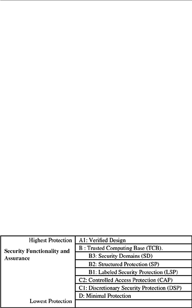
353
collection of standards used to grade or rate the security of computer system prod-
ucts. The TCSEC has come to be a standard commonly referred to as the Orange
Book because of its orange cover. The criteria were developed with three objectives
in mind [ 7 ]:
• To provide users with a yardstick with which to assess the degree of trust that can
be placed in computer systems for the secure processing of classifi ed or other
sensitive information
• To provide guidance to manufacturers as to what to build into their new, widely
available trusted commercial products in order to satisfy trust requirements for
sensitive applications
• To provide a basis for specifying security requirements in acquisition specifi cations
The criteria also address two types of requirements:
• Specifi c security feature requirements
• Assurance requirements
The criteria met these objectives and requirements through four broad hierarchi-
cal divisions of enhanced assurance levels. These divisions, as seen in Fig. 16.1 ,
labeled D for minimum protect, C for discretionary protection or need-to-know pro-
tection, B for mandatory protection, and A for verifi ed protection are detailed as
follows [ 1 , 7 ]:
• Class D, Minimal Protection: a division containing one class reserved for sys-
tems that have been evaluated but that fail to meet the requirements for a higher
evaluation class.
• Class C:
– C1, Discretionary Security Protection (DSP): This is intended for systems in
environments where cooperating users process data at the same level of integ-
rity. Discretionary access control (DAC) based on individual users or groups of
Fig. 16.1 The TCSEC/ Orange Book class levels
16.4 Major Security Evaluation Criteria

354
users enabled them to securely share access to objects between users and groups
of users after user identifi cation and authentication. This makes it impossible
for other users from accidentally getting access to unauthorized data.
– C2, Controlled Access Protection (CAP) is a system that makes users account-
able for their actions. DAC is enforced at a higher granularity level than C1.
Subjects with information of another subject must not get access rights to an
object which makes users accountable for their actions through log-in and
auditing procedures.
• Class B: The notion of a security-relevant portion of a system is called a trusted
computing base (TCB). A TCB that preserves the integrity of the sensitivity
labels and uses them to enforce a set of mandatory access control rules is a major
requirement in this division.
– B1, Labeled Security Protection (LSP): This is intended for systems dealing
with classifi ed data. Each system has all the requirements in C2 and in addi-
tion has an informal requirement of the security policy model, data labels for
subjects and objects whose integrity must be strictly guarded, and mandatory
access control over all subjects and objects.
– B2, Structured Protection (SP): to add security requirements to the design of
the system, thus increasing security assurance. It also requires the TCB to be
based on a security policy. The TCB interface must be well defi ned to be sub-
jected to a more thorough testing and complete review. In addition, it strength-
ens authentication mechanism, trusted facility management provided and
confi guration management imposed. Overall systems with B2 certifi cation
are supposed to be resistant to penetration.
– B3, Security Domains (SD): to ensure a high resistance to penetration of sys-
tems. It requires a security administrator and an auditing mechanism to moni-
tor the occurrence or accumulation of security-relevant events. Such events
must always trigger an automatic warning. In addition, a trusted recovery
must be in place.
• Class A1, Verifi ed Protection: This division is characterized by the use of formal
security verifi cation methods to ensure that the mandatory and discretionary
security controls employed in the system can effectively protect classifi ed or
other sensitive information stored or processed by the system. Extensive docu-
mentation is required to demonstrate that the TCB meets the security require-
ments in all aspects of design, development, and implementation.
Most evaluating programs in use today still use or refer to TCSEC criteria.
Among these programs are [ 3 ]:
• The Trusted Product Evaluation Program (TPEP). TPEP is a program with which
the US Department of Defense’s National Computer Security Center (NCSC)
evaluates computer systems.
• The Trust Technology Assessment Program (TTAP). TTAP is a joint program of
the US National Security Agency (NSA) and the National Institute of Standards
and Technology (NIST). TTAP evaluates off-the-shelf products. It establishes,
16 Standardization and Security Criteria: Security Evaluation of Computer Products

355
accredits, and oversees commercial evaluation laboratories focusing on products
with features and assurances characterized by TCSEC B1 and lower level of trust
(see Sect. 15.3.1 for details).
• The Rating Maintenance Phase (RAMP) Program was established to provide a
mechanism to extend the previous TCSEC rating to a new version of a previously
evaluated computer system product. RAMP seeks to reduce evaluation time and
effort required to maintain a rating by using the personnel involved in the main-
tenance of the product to manage the change process and perform security analy-
sis. Thus, the burden of proof for RAMP efforts lies with those responsible for
system maintenance (i.e., the vendor or TEF) other than with an evaluation team.
• The Trusted Network Interpretation (TNI) of the TCSEC, also referred to as The
Red Book , is a restating of the requirements of the TCSEC in a network
context.
• The Trusted Database Interpretation (TDI) of the TCSEC is similar to the Trusted
Network Interpretation (TNI) in that it decomposes a system into smaller inde-
pendent parts that can be easily evaluated. It differs from the TNI in that the para-
digm for this decomposition is the evaluation of an application running on an
already evaluated system. The reader is also referred to http://www.radium.ncsc.
mil/tpep/library/rainbow/5200.28-STD.html#HDR4 for an extensive coverage
of the standard criteria.
16.4.4 Information Technology Security Evaluation Criteria
(ITSEC)
While the US Orange Book criteria were developed in 1967, the Europeans did not
defi ne unifi ed valuation criteria well until the 1980s when the United Kingdom,
Germany, France, and the Netherlands harmonized their national criteria into a
European Information Security Evaluation Criteria (ITSEC). Since then, they have
been updated and the current issue is Version 1.2, published in 1991 followed
2 years later by its user manual, the IT Security Evaluation Manual (ITSEM), which
specifi es the methodology to be followed when carrying out ITSEC evaluations.
ITSEC was developed because the Europeans thought that the Orange Book was too
rigid. ITSEC was meant to provide a framework for security evaluations that would
lead to accommodate new future security requirements. It puts much more emphasis
on integrity and availability. For more information on ITSEC, see http://www.
radium.ncsc.mil/tpep/library/non-US/ITSEC-12.html .
16.4.5 The Trusted Network Interpretation (TNI): The Red Book
The Trusted Network Interpretation (TNI) of the TCSEC, also referred to as The
Red Book , is a restating of the requirements of the TCSEC in a network context. It
attempted to address network security issues. It is seen by many as a link between
16.4 Major Security Evaluation Criteria

356
The Red Book and new criteria that came after. Some of the shortfalls of the Orange
Book that The Red Book tries to address include the distinction between two types
of computer networks [ 7 ]:
• Networks of independent components with different jurisdictions and manage-
ment policies
• Centralized networks with single accreditation authority and policy
While the Orange Book addresses only the fi rst type, the second type presents many
security problems that The Red Book tries to address. The evaluations of network
systems, distributed or homogeneous, are often made directly against the TCSEC
without reference to the TNI. TNI component ratings specify the evaluated class as
well as which of the four basic security services the evaluated component provides.
NTI security services can be found at: http://www.radium.ncsc.mil/tpep/library/
rainbow/NCSC-TG-005.html
16.5 Does Evaluation Mean Security?
As we noted in Sect. 16.4 , the security evaluation of a product based on a criterion
does not mean that the product is assured of security. No security evaluation of any
product can guarantee such security. However, an evaluated product can demon-
strate certain security mechanisms and features based on the security criteria used
and demonstrate assurances that the product does have certain security parameters
to counter many of the threats listed under the criteria.
The development of new security standards and criteria will no doubt continue to
result in better ways of security evaluations and certifi cation of computer products
and will therefore enhance the computer systems’ security. However, as Mercuri
observes, product certifi cation should not create a false sense of security.
Exercises
1. The US Federal Criteria drafted in the early 1990s were never approved. Study
the criteria and give reasons why they were not developed.
2. One advantage of process-oriented security evaluation is that it is cheap. Find
other reasons why it is popular. Why, despite its popularity, is it not reliable?
3. For small computer product buyers, it is not easy to apply and use these stan-
dard criteria. Study the criteria and suggest reasons why this is so.
4. Nearly all criteria were publicly developed; suggest reasons why? Is it possible
for individuals to develop commercially accepted criteria?
5. There are evaluated computer products on the market. Find out how one fi nds
out whether a computer product has a security evaluation.
6. If you have a computer product, how do you get it evaluated? Does the evalua-
tion help a product in the marketplace? Why or why not?
7. Every country participating in the computer product security evaluation has a
list of evaluated products. Find out how to fi nd this list. Does the ISO keep a
global list of evaluated products?
16 Standardization and Security Criteria: Security Evaluation of Computer Products

357
8. Why is the product rated as B2/B3/A1 better than that rated C2/B1, or is it?
9. Study the rating divisions of TCSEC and show how product ratings can be
interpreted.
10. What does it mean to say that a product is CC or TCSEC compliant?
Advanced Exercises
1. Research and fi nd out if there are any widely used computer product security
evaluation criteria.
2. Using the product evaluation list for computer products, determine the ratings
for the following products: DOS, Windows NT, 98, XP, Unix, and Linux.
3. Study the history of the development of computer product security evaluation
and suggest the reasons that led to the development of ISO-based CC.
4. Study and give the effects of ISO on a criterion. Does ISO affi liation have any
impact on the success of a criterion?
5. Does the rapid development of computer technology put any strain on the exist-
ing criteria for updates?
6. Study and compare TCSEC, ITSEC, and CC assurance levels.
7. Trace the evolution of the security evaluation criteria.
8. Discuss how standards infl uence the security evaluation criteria.
References
1. Wikipedia, http://en.wikipedia.org/wiki/Open_standard
2. Bradner S (1996) FRC 2026: the internet standards process—Revision 3. Network Working
Group.
http://www.ietf.org/rfc/rfc2026.txt
3. Mercuri R (2003) Standards insecurity . Commun ACM 46(12):21–25
4. Computer Security Evaluation FAQ (2014) Version 2.1. http://www.faqs.org/faqs/computer-
security/evaluations/
5. An Oracle White Paper. Computer security criteria: security evaluations and assessment, July
2001.
http://otndnld.oracle.co.jp/deploy/security/pdf/en/seceval_wp.pdf
6. Oracle Technology Network. Security evaluations. http://www.oracle.com/technology/deploy/
security/seceval/index.html
7. Department of Defense Standards (1985) Trusted computer system evaluation criteria.
http://
www.radium.ncsc.mil/tpep/library/rainbow/5200.28-STD.html
References

359
© Springer-Verlag London 2015
J.M. Kizza, Guide to Computer Network Security, Computer Communications
and Networks, DOI 10.1007/978-1-4471-6654-2_17
17
Computer Network Security Protocols
17.1 Introduction
The rapid growth of the Internet and corresponding Internet communities have
fueled a rapid growth of both individual and business communications leading to
the growth of e-mail and e-commerce. In fact, studies now show that the majority of
the Internet communication content is e-mail content. The direct result of this has
been the growing concern and sometimes demand for security and privacy in elec-
tronic communication and e-commerce. Security and privacy are essential if indi-
vidual communication is to continue and e-commerce is to thrive in cyberspace. The
call and desire for security and privacy have led to the advent of several proposals
for security protocols and standards. Among these are Secure Socket Layer (SSL)
and Transport Layer Security (TLS) Protocols, secure IP (IPSec), Secure HTTP
(S-HTTP), secure e-mail (PGP and S/MIME), DNDSEC, SSH, and others. Before we
proceed with the discussion of these and others, we want to warn the reader of the
need for a firm understanding of the network protocol stack; otherwise go back and
look over the material in Chap. 1 before continuing. We will discuss these protocols
and standards within the framework of the network protocol stack as follows:
•Application level security – PGP, S/MIME, S-HTTP, HTTPS, SET, and
KERBEROS
•Transport level security – SSL and TLS
•Network level security – IPSec and VPNs
•Link level security – PPP and RADIUS

360
17.2 Application Level Security
All the protocols in this section are application layer protocols, which means that
they reside on both ends of the communication link. They are all communication
protocols ranging from simple text to multimedia including graphics, video,
audio, and so on. In the last 10 years, there has been almost an explosion in the
use of electronic communication, both mail and multimedia content, that has
resulted in booming e-commerce and almost unmanageable personal e-mails,
much of it private or intended to be private anyway, especially e-mails. Along with
this explosion, there has been a growing demand for confidentiality and authenticity
of private communications. To meet these demands, several schemes have been
developed to offer both confidentiality and authentication of these communications.
We will look at four of them here, all in the application layer of the network stack.
There are PGP and Secure/Multipurpose Internet Mail Extension (S/MIME),
S-HTTP, HTTPS, and Secure Electronic Transaction (SET) standard. These four
protocols and the standards are shown in the application layer of the network
stack in Fig. 17.1.
17.2.1 Pretty Good Privacy (PGP)
The importance of sensitive communication cannot be underestimated. Sensitive
information, whether in motion in communication channels or in storage, must be
protected as much as possible. The best way, so far, to protect such information is to
encrypt it. In fact, the security that the old snail mail offered was based on a seemingly
protective mechanism similar to encryption when messages were wrapped and
enclosed in envelopes. There was, therefore, more security during the days of snail
mail because it took more time and effort for someone to open somebody’s mail.
First, one had to get access to it, which was no small task. Then one had to steam the
envelope in order to open it and seal it later so that it looks unopened after. There
were more chances of being caught doing so. Well, electronic communication has
made it easy to intercept and read messages in the clear.
So encryption of e-mails and any other forms of communication is vital for the
security, confidentiality, and privacy of everyone. This is where PGP comes in and
this is why PGP is so popular today. In fact, currently PGP is one of the popular
encryption and digital signatures schemes in personal communication.
Fig. 17.1 Application layer security protocols and standard
17 Computer Network Security Protocols

361
Pretty Good Privacy (PGP), developed by Phil Zimmermann, is a public-key cryp-
tosystem. As we saw in Chap. 9, in public-key encryption, one key is kept secret and
the other key is made public. Secure communication with the receiving party (with a
secret key) is achieved by encrypting the message to be sent using the recipient’s pub-
lic key. This message then can be decrypted only using the recipient’s secret key.
PGP works by creating a circle of trust among its users. In the circle of trust,
users, starting with two, form a key ring of public key/name pairs kept by each user.
Joining this “trust club” means trusting and using the keys on somebody’s key ring.
Unlike the standard PKI infrastructure, this circle of trust has a built-in weakness
that can be penetrated by an intruder. However, since PGP can be used to sign
messages, the presence of its digital signature is used to verify the authenticity of a
document or file. This goes a long way in ensuring that an e-mail message or file just
downloaded from the Internet is both secure and untampered with.
PGP is regarded as hard encryption, which is impossible to crack in the foresee-
able future. Its strength is based on algorithms that have survived extensive public
review and are already considered by many to be secure. Among these algorithms
are RSA which PGP uses for encryption; DSS and Diffie–Hellman for public-key
encryption; CAST-128, IDEA, and 3DES for conventional encryption; and SHA-1
for hashing. The actual operation of PGP is based on five services: authentication,
confidentiality, compression, e-mail compatibility, and segmentation [1].
17.2.1.1 Authentication
PGP provides authentication via a digital signature scheme. The hash code (MAC)
is created using a combination of SHA-1 and RSA to provide an effective digital
signature. It can also create an alternative signature using DSS and SHA-1. The
signatures are then attached to the message or file before sending. PGP, in addition,
supports unattached digital signatures. In this case, the signature may be sent sepa-
rately from the message.
17.2.1.2 Confidentiality
PGP provides confidentiality by encrypting messages before transmission. PGP
encrypts messages for transmission and storage using conventional encryption
schemes such as CAST-128, IDEA, and 3DES. In each case, a 64-bit cipher
feedback mode is used. As in all cases of encryption, there is always a problem of
key distribution; so PGP uses a conventional key once. This means for each message
to be sent, the sender mints a brand new 128-bit session key for the message. The
session key is encrypted with RSA or Diffie–Hellman using the recipient’s public
key; the message is encrypted using CAST-128 or IDEA or 3DES together with the
session key. The combo is transmitted to the recipient. Upon receipt, the receiver
uses RSA with his or her private key to encrypt and recover the session key which
is used to recover the message. See Fig. 17.8.
17.2.1.3 Compression
PGP compresses the message after applying the signature and before encryption.
The idea is to save space.
17.2 Application Level Security

362
17.2.1.4 E-mail Compatibility
As we have seen above, PGP encrypts a message together with the signature
(if not sent separately) resulting into a stream of arbitrary 8-bit octets. But since
many e-mail systems permit only the use of blocks consisting of ASCII text, PGP
accommodates this by converting the raw 8-bit binary streams into streams of
printable ASCII characters using a radix-64 conversion scheme. On receipt, the
block is converted back from radix-64 format to binary. If the message is encrypted,
then a session key is recovered and used to decrypt the message. The result is then
decompressed. If there is a signature, it has to be recovered by recovering the
transmitted hash code and comparing it to the receiver’s calculated hash before
acceptance.
17.2.1.5 Segmentation
To accommodate e-mail size restrictions, PGP automatically segments e-mail
messages that are too long. However, the segmentation is done after all the house-
keeping is done on the message, just before transmitting it. So the session key
and signature appear only once at the beginning of the first segment transmitted.
At receipt, the receiving PGP strips off all e-mail headers and reassembles the
original mail.
PGP’s popularity and use have so far turned out to be less than anticipated
because of two reasons: first, its development and commercial distribution after
Zimmermann sold it to Network Associates, which later sold it to another company,
did not do well; second, its open source cousin, the OpenPGP, encountered market
problems including the problem of ease of use. Both OpenPGP and commercial
PGP are difficult to use because it is not built into many e-mail clients. This implies
that any two communicating users who want to encrypt their e-mail using PGP
have to manually download and install PGP, a challenge and an inconvenience to
many users.
17.2.2 Secure/Multipurpose Internet Mail Extension (S/MIME)
Secure/Multipurpose Internet Mail Extension (S/MIME) extends the protocols of
Multipurpose Internet Mail Extensions (MIME) by adding digital signatures and
encryption to them. To understand S/MIME, let us first make a brief digression and
look at MIME. MIME is a technical specification of communication protocols that
describes the transfer of multimedia data including pictures, audio, and video. The
MIME protocol messages are described in RFC 1521; a reader with further interest
in MIME should consult RFC 1521. Because Web contents such as files consist of
hyperlinks that are themselves linked onto other hyperlinks, any e-mail must
describe this kind of interlinkage. That is what a MIME server does whenever a
client requests for a Web document. When the Web server sends the requested file
to the client’s browser, it adds a MIME header to the document and transmits it [2].
This means, therefore, that such Internet e-mail messages consist of two parts: the
header and the body.
17 Computer Network Security Protocols

363
Within the header, two types of information are included: MIME type and subtype.
The MIME type describes the general file type of the transmitted content type such
as image, text, audio, application, and others. The subtype carries the specific file
type such as jpeg or gif, tiff, and so on. For further information on the structure of a
MIME header, please refer to RFC 822. The body may be unstructured or it may be
in MIME format which defines how the body of an e-mail message is structured.
What is notable here is that MIME does not provide any security services.
S/MIME was then developed to add security services that have been missing.
It adds two cryptographic elements: encryption and digital signatures [1].
17.2.2.1 Encryption
S/MIME supports three public-key algorithms to encrypt session keys for transmis-
sion with the message. These include Diffie–Hellman as the preferred algorithm,
RSA for both signature and session keys, and triple DES.
17.2.2.2 Digital Signatures
To create a digital signature, S/MIME uses a hash function of either 160-bit SHA-1
or MD5 to create message digests. To encrypt the message digests to form a digital
signature, it uses either DSS or RSA.
17.2.3 Secure HTTP (S-HTTP)
Secure HTTP (S-HTTP) extends the Hypertext Transfer Protocol (HTTP). When
HTTP was developed, it was developed for a Web that was simple, that did not have
dynamic graphics, and that did not require, at that time, hard encryption for end-to- end
transactions that have since developed. As the Web became popular for businesses,
users realized that current HTTP protocols needed more cryptographic and graphic
improvements if it were to remain the e-commerce backbone it had become.
Responding to this growing need for security, the Internet Engineering Task
Force called for proposals that will develop Web protocols, probably based on
current HTTP, to address these needs. In 1994, such protocol was developed by
Enterprise Integration Technologies (EIT). IET’s protocols were, indeed, extensions
of the HTTP protocols. S-HHTP extended HTTP protocols by extending HTTP’s
instructions and added security facilities using encryptions and support for digital
signatures. Each S-HTTP file is either encrypted, contains a digital certificate, or
both. S-HTTP design provides for secure communications, primarily commercial
transactions, between a HTTP client and a server. It does this through a wide variety
of mechanisms to provide for confidentiality, authentication, and integrity while
separating policy from mechanism. The system is not tied to any particular crypto-
graphic system, key infrastructure, or cryptographic format [3].
HTTP messages contain two parts: the header and the body of the message. The
header contains instructions to the recipients (browser and server) on how to process
the message’s body. For example, if the message body is of the type like MIME,
Text, or HTML, instructions must be given to display this message accordingly.
17.2 Application Level Security

364
In the normal HTTP protocol, for a client to retrieve information (text-based message)
from a server, a client-based browser uses HTTP to send a request message to the
server that specifies the desired resource. The server, in response, sends a message
to the client that contains the requested message. During the transfer transaction,
both the client browser and the server use the information contained in the HTTP
header to negotiate formats they will use to transfer the requested information. Both
the server and client browser may retain the connection as long as it is needed;
otherwise the browser may send message to the server to close it.
The S-HTTP protocol extends this negotiation between the client browser and
the server to include the negotiation for security matters. Hence, S-HTTP uses addi-
tional headers for message encryption, digital certificates, and authentication in
the HTTP format which contains additional instructions on how to decrypt the
message body. Tables 17.1 and 17.2 show header instructions for both HTTP and
S-HTTP. The HTTP headers are encapsulated into the S-HTTP headers. The headers
give a variety of options that can be chosen from as a client browser and the server
negotiates for information exchange. All headers in S-HTTP are optional, except
“Content Type” and “Content-Privacy-Domain.”
Table 17.1 S-HTTP protocol headers
S-HTTP header Purpose Options
Content-Privacy- Domain For compatibility with
PEM-based secure HTTP
RSA’s PKCS-7 (Public-Key
Cryptography Standard 7,
“Cryptographic Message Syntax
Standard,” RFC-1421 style PEM,
and PGP 2.6 format
Content-transfer- encoding Explains how the content
of the message is encoded
7, 8 bits
Content Type Standard header HTTP
Prearranged-Key- Info Information about the keys
used in the encapsulation
DEK (data exchange key) used
to encrypt this message
Table 17.2 HTTP headers
HTTP header Purpose Options
Security scheme Mandatory, specifies protocol name and version S-HTTP/1.1
Encryption identity Identity names the entity for which a message is
encrypted. Permits return encryption under public
key without others signing first
DN-1485 and
Kerberos
Certificate info Allows a sender to send a public-key certificate
in a message
PKCS-7, PEM
Key assign (exchange) The message used for actual key exchanges Krb-4, Krb-5
(Kerberos)
Nonces Session identifiers, used to indicate the freshness
of a session
17 Computer Network Security Protocols

365
To offer flexibility, during the negotiation between the client browser and the
server, for the cryptographic enhancements to be used, the client and server must
agree on four parts: property, value, direction, and strength. If agents are unable to
discover a common set of algorithms, appropriate actions are then taken. Adam
Shostack [2] gives the following example as a negotiation line:
SHTTP-Key-Exchange-Algorithms: recv-required = RSA, Kerb-5
This means that messages received by this machine are required to use Kerberos
5 or RSA encryption to exchange keys. The choices for the (recv-required) modes
are (recv || orig)-(optional || required || refused). Where key lengths specifications
are necessary in case of variable key length ciphers, this is then specifically referred
to as cipher[length], or cipher[L1-L2], where the length of key is length, or in the
case of L1-L2, is between L1 and L2, inclusive [2].
Other headers in the S-HTTP negotiations could be [2, 3]:
•S-HTTP-Privacy-Domains
•S-HTTP-Certificate-Types
•S-HTTP-Key-Exchange-Algorithms
•S-HTTP-Signature-Algorithms
•S-HTTP-Message-Digest-Algorithms
•S-HTTP-Symmetric-Content-Algorithms
•S-HTTP-Symmetric-Header-Algorithms
•S-HTTP-Privacy-Enhancements
•Your-Key-Pattern
We refer a reader interested in more details of these negotiations to Adam
Shostack’s paper.
We had pointed out earlier that S-HTTP extends HTTP by adding message
encryption, digital signature, and message and sender authentication. Let us see
how these are incorporated into HTTP to get S-HTTP.
17.2.3.1 Cryptographic Algorithm for S-HTTP
S-HTTP uses a symmetric key cryptosystem in the negotiations that prearranges
symmetric session keys and a challenge – response mechanism between communi-
cating parties. Before the server can communicate with the client browser, both must
agree upon an encryption key. Normally the process would go as follows: The
client’s browser would request the server for a page. Along with this request, the
browser lists encryption schemes it supports and also includes its public key. Upon
receipt of the request, the server responds to the client browser by sending a list of
encryption schemes it also supports. The server may, in addition, send the browser a
session key encrypted by the client’s browser’s public key, now that it has it. If the
client’s browser does not get a session key from the server, it then sends a message to
the server encrypted with the server’s public key. The message may contain a session
key or a value the server can use to generate a session key for the communication.
17.2 Application Level Security

366
Upon the receipt of the page/message from the server, the client’s browser, if
possible, matches the decryption schemes in the S-HTTP headers (recall this was
part of the negotiations before the transfer), which include session keys, and then
decrypts the message [3]. In HTTP transactions, once the page has been delivered
to the client’s browser, the server would disconnect. However, with S-HTTP,
the connection remains until the client browser requests the server to do so. This
is helpful because the client’s browser encrypts each transmission with this
session key.
Cryptographic technologies used by S-HTTP include Privacy Enhanced Mail
(PEM), Pretty Good Privacy (PGP), and Public-Key Cryptography Standard 7
(PKGS-7). Although S-HTTP uses encryption facilities, non-S-HTTP browsers can
still communicate with an S-HTTP server. This is made possible because S-HTTP
does not require that the user preestablishes public keys in order to participate in a
secure transaction. A request for secure transactions with an S-HTTP server must
originate from the client browser. See Fig. 17.1.
Because a server can deal with multiple requests from clients browsers, S-HTTP
supports multiple encryptions by supporting two transfer mechanisms: one that uses
public-key exchange, usually referred to as in-band, and one that uses a third party
Public-Key Authority (PKA) that provides session keys using public keys for both
clients and servers.
17.2.3.2 Digital Signatures for S-HTTP
S-HTTP uses SignedData or SignedAndEnvelopedData signature enhancement of
PKCS-7 [3]. S-HTTP allows both certificates from a certificate authority (CA)
and a self-signed certificate (usually not verified by a third party). If the server
requires a digital certificate from the client’s browser, the browser must attach a
certificate then.
17.2.3.3 Message and Sender Authentication in S-HTTP
S-HHTP uses an authentication scheme that produces a MAC. The MAC is actually
a digital signature computed from a hash function on the document using a shared
secret code.
17.2.4 Hypertext Transfer Protocol over Secure
Socket Layer (HTTPS)
HTTPS is the use of Secure Socket Layer (SSL) as a sublayer under the regular
HTTP in the application layer. It is also referred to as Hypertext Transfer Protocol
over Secure Socket Layer (HTTPS) or HTTP over SSL, in short. HTTPS is a Web
protocol developed by Netscape, and it is built into its browser to encrypt and
decrypt user page requests as well as the pages that are returned by the Web server.
HTTPS uses port 443 instead of HTTP port 80 in its interactions with the lower
layer, TCP/IP. Probably to understand well how this works, the reader should first
go over Sect. 17.3.1, where SSL is discussed.
17 Computer Network Security Protocols

367
17.2.5 Secure Electronic Transactions (SET)
SET is a cryptographic protocol developed by a group of companies that included
Visa, Microsoft, IBM, RSA, Netscape, MasterCard, and others. It is a highly spe-
cialized system with complex specifications contained in three books with book one
dealing with the business description, book two a programmer’s guide, and book
three giving the formal protocol description. Book one spells out the business
requirements that include the following [1]:
•Confidentiality of payment and ordering information
•Integrity of all transmitted data
•Authentication of all card holders
•Authenticating that a merchant can accept card transactions based on relation-
ship with financial institution
•Ensuring the best security practices and protection of all legitimate parties in the
transaction
•Creating protocols that neither depend on transport security mechanism nor pre-
vent their use
•Facilitating and encouraging interoperability among software and network
providers
Online credit and debit card activities that must meet those requirements may
include one or more of the following: cardholder registration, merchant registration,
purchase request, payment authorization, funds transfer, credits reversals, and debit
cards. For each transaction, SET provides the following services: authentication,
confidentiality, message integrity, and linkage [1, 4].
17.2.5.1 Authentication
Authentication is a service used to authenticate every one in the transacting party
that includes the customer, the merchant, the bank that issued the customer’s card,
and the merchant’s bank, using X.509v3 digital signatures.
17.2.5.2 Confidentiality
Confidentiality is a result of encrypting all aspects of the transaction to prevent intruders
from gaining access to any component of the transaction. SET uses DES for this.
17.2.5.3 Message Integrity
Again this is a result of encryption to prevent any kind of modification to the data
such as personal data and payment instructions involved in the transaction. SET
uses SHA-1 hash codes used in the digital signatures.
17.2.5.4 Linkage
Linkage allows the first party in the transaction to verify that the attachment is
correct without reading the contents of the attachment. This helps a great deal in
keeping the confidentiality of the contents.
17.2 Application Level Security

368
SET uses public-key encryption and signed certificates to establish the identity
of every one involved in the transaction and to allow every correspondence between
them to be private.
The SET protocols involved in a transaction have several representations, but
every one of those representations has the following basic facts: the actors and the
purchase–authorization–payment control flow.
The actors involved in every transaction are as follows [1]:
•The buyer – usually the cardholder.
•The merchant – fellow with the merchandise the buyer is interested in.
•The merchant bank – the financial institution that handles the merchant’s finan-
cial transactions.
•The customer bank – usually the bank that issues the card to the customer. This
bank also authorizes electronic payments to the merchant account upon authori-
zation of payment request from the customer. This bank may sometimes set up
another entity and charge it with payment authorizations.
•Certificate authority (CA) – that issues X.509v3 certificates to the customer and
merchant.
Purchase–Authorization–Payment Control Flow. This flow is initiated by the
customer placing a purchase order to the merchant and is concluded by the customer
bank sending a payment statement to the customer. The key cryptographic authen-
tication element in SET is the dual signature. The dual signature links two messages
(payment information and order information) intended for two different recipients,
the merchant getting merchandise information and the customer bank getting pay-
ment information. The dual signature keeps the two bits of information separate
letting the intended party see only the part they are authorized to see. The customer
creates a dual signature by hashing the merchandise information and also payment
information using SHA-1, concatenates the two, hashes them again, and encrypts
the result using his or her private key before sending them to the merchant. For more
details on dual signatures, the reader is referred to Cryptography and Network
Security: Principles and Practice, Second Edition, by William Stallings. Let us now
look at the purchase–authorization–payment control flow [1, 4]:
•Customer initiates the transaction by sending to the merchant a purchase order
and payment information together with a dual signature.
•The merchant, happy to receive an order from the customer, strips off the merchant
information, verifies customer purchase order using his or her certificate key, and
forwards the payment information to his or her bank.
•The merchant bank forwards the payment information from the customer to the
customer bank.
•The customer bank, using the customer’s certificate key, checks and authorizes
the payments and informs the merchant’s bank.
•The merchant’s bank passes the authorization to the merchant, who releases the
merchandise to the customer.
•The customer bank bills the customer.
17 Computer Network Security Protocols

369
17.2.6 Kerberos
Kerberos is a network authentication protocol. It is designed to allow users, clients
and servers, authenticate themselves to each other. This mutual authentication is
done using secret-key cryptography. Using secret-key encryption, or as it is com-
monly known conventional encryption, a client can prove its identity to a server
across an insecure network connection. Similarly, a server can also identify itself
across the same insecure network connection. Communication between the client
and the server can be secure after the client and server have used Kerberos to prove
their identities. From this point on, subsequent communication between the two can
be encrypted to ensure privacy and data integrity.
In his paper The Moron’s Guide to Kerberos, Version 1.2.2, Brian Tung [5], in a
simple but interesting example, likens the real-life self-authentication we always do
with the presentation of driver licenses on demand, to that of Kerberos.
Kerberos client–server authentication requirements are as follows [2]:
•Security – that Kerberos is strong enough to stop potential eavesdroppers from
finding it to be a weak link.
•Reliability – that Kerberos is highly reliable, employing a distributed server
architecture where one server is able to back up another. This means that Kerberos
system is fail safe, meaning graceful degradation, if it happens.
•Transparency – that users are not aware that authentication is taking place beyond
providing passwords.
•Scalability – that Kerberos systems accept and support new clients and servers.
To meet these requirements, Kerberos designers proposed a third-party-trusted
authentication service to arbitrate between the client and server in their mutual
authentication. Figure 17.2 shows the interaction between the three parties.
The actual Kerberos authentication process is rather complex, probably more
complex than all the protocols we have seen so far in this chapter. So to help the
reader grasp the concept, we are going to follow what many writers on Kerberos
have done, go via an example and Fig. 17.2. And here we go [2]:
On a Kerberos network, suppose user A wants to access a document on server
B. Both principals in the transaction do not trust each other. So the server must
demand assurances that A is who he or she says he or she is. So just like in real life,
when you are seeking a service from demands that you show proof of what you
claim you are by pulling out a drivers license with a picture of you on it, Kerberos
also demands proof. In Kerberos, however, A must present a ticket to B. The ticket
is issued by a Kerberos authentication server (AS). Both A and B trust the AS. So
A anticipating that B will demand proof works on it by digitally signing the request
to access the document held by B with A’s private key and encrypting the request
with B’s public key. A then sends the encrypted request to AS, the trusted server.
Upon receipt of the request, AS verifies that it is A who sent the request by analyzing
A’s digital signature. It also checks A’s access rights to the requested document. AS
has those lists for all the servers in the Kerberos system. AS then mints a ticket that
contains a session key and B’s access information, uses A’s public key to encrypt it,
17.2 Application Level Security
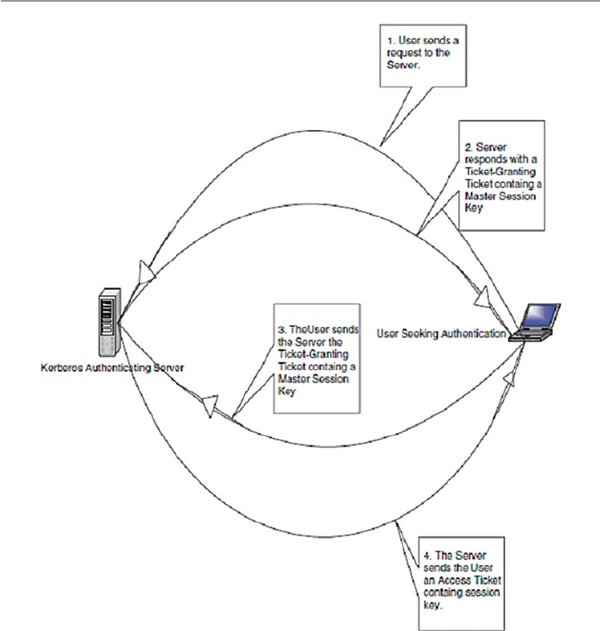
370
and sends it to A. In addition, AS mints a similar ticket for B which contains the
same information as that of A. The ticket is transmitted to B. Now AS’s job is almost
done after connecting both A and B. They are now on their own. After the connection,
both A and B compare their tickets for a match. If the tickets match, the AS has done
its job, and A and B start communicating as A accesses the requested document on
B. At the end of the session, B informs AS to recede the ticket for this session. Now
if A wants to communicate with B again for whatever request, a new ticket for the
session is needed.
17.2.6.1 Ticket-Granting Ticket
The Kerberos system may have more than one AS. While this method works well, it
is not secure. This is so because the ticket stays in use for some time and is,
Fig. 17.2 Kerberos authentication system
17 Computer Network Security Protocols

371
therefore, susceptible to hacking. To tackle this problem, Kerberos systems use
another approach that is more secure. This second approach uses the first approach
as the basis. An authentication process goes as follows:
A, in need of accessing a document on server B, sends an access request text in
the clear to AS for a ticket-granting ticket, which is a master ticket for the log-in
process with B. AS, using a shared secret such as a password, verifies A and sends
A a ticket-granting ticket. A then uses this ticket-granting ticket instead of A’s
public key to send to AS for a ticket for any resource from any server A wants. To
send the ticket to A, the AS encrypts it with a master session key contained in the
ticket- granting ticket.
When a company has distributed its computing by having Kerberos networks in
two separate areas, there are ways to handle situations like this. One Kerberos
system in one network can authenticate a user in another Kerberos network. Each
Kerberos AS operates in a defined area of the network called a realm. To extend the
Kerberos’ authentication across realms, an inter-realm key is needed that allows
clients authenticated by an AS in one realm to use that authentication in another
realm. Realms sharing inter-realm keys can communicate.
Kerberos can run on top of an operating system. In fact it is a default protocol in
Windows 2000 and later versions of Windows. In a non-native environment,
Kerberos must be “kerberized” by making server and client software make calls to
Kerberos library.
17.3 Security in the Transport Layer
Unlike the last five protocols we have been discussing in the previous section, in
this section we look at protocols that are a little deeper in the network infrastructure.
They are at the level below the application layer. In fact they are at the transport
layer. Although several protocols are found in this layer, we are only going to
discuss two: Secure Socket Layer (SSL) and Transport Layer Security (TLS).
Currently, however, these two are no longer considered as two separate protocols
but one under the name SSL/TLS, after the SSL standardization was passed over
to IETF, by the Netscape consortium, and Internet Engineering Task Force (IETF)
renamed it TLS. Figure 17.3 shows the position of these protocols in the network
protocol stack.
Fig. 17.3 Transport layer security protocols and standards
17.3 Security in the Transport Layer

372
17.3.1 Secure Socket Layer (SSL)
SSL is a widely used general-purpose cryptographic system used in the two major
Internet browsers: Netscape and Explorer. It was designed to provide an encrypted
end-to-end data path between a client and a server regardless of platform or
OS. Secure and authenticated services are provided through data encryption, server
authentication, message integrity, and client authentication for a TCP connection
through HTTP, LDAP, or POP3 application layers. It was originally developed by
Netscape Communications and it first appeared in a Netscape Navigator browser in
1994. The year 1994 was an interesting year for Internet security because during the
same year, a rival security scheme to SSL, the S-HTTP, was launched. Both systems
were designed for Web-based commerce. Both allow for the exchange of multiple
messages between two processes and use similar cryptographic schemes such as
digital envelopes, signed certificates, and message digest.
Although these two Web giants had much in common, there are some differences
in design goals, implementation, and acceptance. First, S-HTTP was designed to
work with only Web protocols. Because SSL is at a lower level in the network stack
than S-HTTP, it can work in many other network protocols. Second, in terms of
implementation, since SSL is again at a lower level than S-HTTP, it is implemented
as a replacement for the sockets API to be used by applications requiring secure
communications. On the other hand, S-HTTP has its data passed in named text
fields in the HTTP header. Finally in terms of distribution and acceptance, history
has not been so good to S-HTTP. While SSL was released in a free mass circulating
browser, the Netscape Navigator, S-HTTP was released in a much smaller and
restricted NCSA Mosaic. This unfortunate choice doomed the fortunes of S-HTTP.
17.3.1.1 SSL Objectives and Architecture
The stated SSL objectives were to secure and authenticate data paths between
servers and clients. These objectives were to be achieved through several services
that included data encryption, server and client authentication, and message
integrity [6]:
•Data encryption – to protect data in transport between the client and the server
from interception and could be read only by the intended recipient.
•Server and client authentication – the SSL protocol uses standard public-key
encryption to authenticate the communicating parties to each other.
•Message integrity – achieved through the use of session keys so that data cannot
be either intentionally or unintentionally tampered with.
These services offer reliable end-to-end secure services to Internet TCP connections
and are based on an SSL architecture consisting of two layers: the top layer, just
below the application layer, that consists of three protocols, namely, the SSL hand-
shake protocol, the SSL change cipher specs protocol, and the SSL alert protocol.
Below these protocols is the second SSL layer, the SSL record protocol layer, just
above the TCP layer. See Fig. 17.4.
17 Computer Network Security Protocols
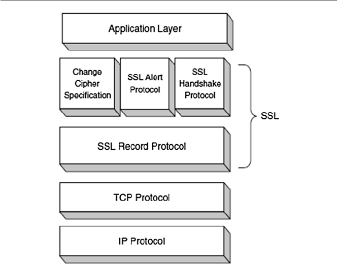
373
17.3.1.2 The SSL Handshake
Before any TCP connection between a client and a server, both running under SSL,
is established, there must be almost a process similar to a three-way handshake we
discussed in Sect. 3.2.2. This get-to-know-you process is similarly called the SSL
handshake. During the handshake, the client and server perform the following
tasks [7]:
•Establish a cipher suite to use between them.
•Provide mandatory server authentication through the server sending its cer-
tificate to the client to verify that the server’s certificate was signed by a
trusted CA.
•Provide optional client authentication, if required, through the client sending
its own certificate to the server to verify that the client’s certificate was signed
by a trusted CA. The CA may not be the same CA who signed the client’s
certificate. CAs may come from a list of trusted CAs. The reason for making
this step optional was a result of realization that since few customers are
willing, know how, or care to get digital certificates, requiring them to do this
would amount to locking a huge number of customers out of the system which
would not make business sense. This, however, presents some weaknesses to
the system.
Fig. 17.4 The SSL protocol stack
17.3 Security in the Transport Layer

374
•Exchange key information using public-key cryptography, after mutual authenti-
cation, that leads to the client generating a session key (usually a random number)
which, with the negotiated cipher, is used in all subsequent encryption or decryp-
tion. The customer encrypts the session key using the public key of the merchant
server (from the merchant’s certificate). The server recovers the session key by
decrypting it using its private key. This symmetric key, which now both parties
have, is used in all subsequent communication.
17.3.1.3 SSL Change Cipher Specs Protocol
The SSL change cipher specs protocol consists of an exchange of a single message
in a byte with a value of 1 being exchanged, using the SSL record protocol (see
Sect. 17.3.1.4), between the server and client. The bit is exchanged to establish a
pending session state to be copied into the current state, thus defining a new set of
protocols as the new agreed on session state.
17.3.1.4 SSL Alert Protocol
The SSL alert protocol, which also runs over the SSL record protocol, is used by the
two parties to convey session warning messages associated with data exchange and
functioning of the protocol. The warnings are used to indicate session problems
ranging from unknown certificate, revoked certificate, and expired certificate to fatal
error messages that can cause immediate termination of the SSL connection. Each
message in the alert protocol sits within two bytes, with the first byte taking a value
of (1) for a warning and (2) for a fatal error. The second byte of the message con-
tains one of the defined error codes that may occur during an SSL communication
session [6]. For further working of these error codes, see [6].
17.3.1.5 SSL Record Protocol
The SSL record protocol provides SSL connections two services: confidentiality
and message integrity [2]:
•Confidentiality is attained when the handshake protocol provides a shared secret
key used in the conventional encryption of SSL messages.
•Message integrity is attained when the handshake defines a secret shared key
used to form a message authentication code (MAC).
In providing these services, the SSL record protocol takes an application
message to be transmitted and fragments the data that needs to be sent, compresses
it, adds a MAC, encrypts it together with the MAC, adds an SSL header, and trans-
mits it under the TCP protocol. The return trip undoes these steps. The received data
is decrypted, verified, and decompressed before it is forwarded to higher layers. The
record header that is added to each data portion contains two elementary pieces of
information, namely, the length of the record and the length of the data block added
to the original data. See Fig. 17.5.
The MAC, computed from a hash algorithm such as MD5 or SHA-1 as MAC =
Hash function [secret key, primary data, padding, sequence number], is used to
17 Computer Network Security Protocols
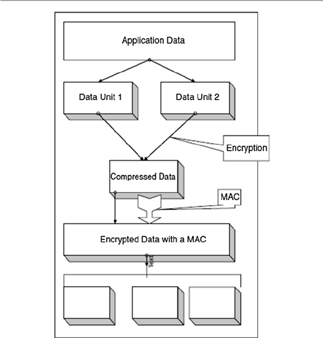
375
verify the integrity of the message included in the transmitted record. The verification
is done by the receiving party computing its own value of the MAC and comparing
it with that received. If the two values match, this means that data has not been
modified during the transmission over the network.
SSL protocols are widely used in all Web applications and any other TCP con-
nections. Although they are mostly used for Web applications, they are gaining
ground in e-mail applications also.
17.3.2 Transport Layer Security (TLS)
Transport Layer Security (TLS) is the result of the 1996 Internet Engineering Task
Force (IETF) attempt at standardization of a secure method to communicate over
the Web. The 1999 outcome of that attempt was released as RFC 2246 spelling out a
Fig. 17.5 SSL record protocol operation process
17.3 Security in the Transport Layer

376
new protocol – the Transport Layer Security or TLS. TLS was charged with providing
security and data integrity at the transport layer between two applications. TLS
version 1.0 was an evolved SSL 3.0. So, as we pointed out earlier, TLS is the suc-
cessor to SSL 3.0. Frequently, the new standard is referred to as SSL/TLS.
Since then, however, the following additional features have been added [6]:
•Interoperability – ability to exchange TLS parameters by either party, with no
need for one party to know the other’s TLS implementation details
•Expandability – to plan for future expansions and accommodation of new
protocols
17.4 Security in the Network Layer
In the previous section, we discussed protocols in the transport part of the stack that
are being used to address Internet communication security. In this section, we are
going one layer down to the Network layer and also look at the protocols and prob-
ably standards that address Internet communication security. In this layer, we will
address IPSec and VPN technologies shown in Fig. 17.6.
17.4.1 Internet Protocol Security (IPSec)
IPSec is a suite of authentication and encryption protocols developed by the Internet
Engineering Task Force (IETF) and designed to address the inherent lack of security
for IP-based networks. IPSec, unlike other protocols we have discussed so far, is a
very complex set of protocols described in a number of RFCs including RFC 2401
and 2411. It runs transparently to transport layer and application layer protocols
which do not see it. Although it was designed to run in the new version of the
Internet Protocol, IP Version 6 (IPv6), it has also successfully run in the older IPv4
as well. IPSec sets out to offer protection by providing the following services at the
network layer:
•Access control – to prevent an unauthorized access to the resource.
•Connectionless integrity – to give an assurance that the traffic received has not
been modified in any way.
•Confidentiality – to ensure that Internet traffic is not examined by nonauthorized
parties. This requires all IP datagrams to have their data field, TCP, UDP, ICMP,
or any other datagram data field segment, encrypted.
Fig. 17.6 Network layer
security protocols and
standards
17 Computer Network Security Protocols
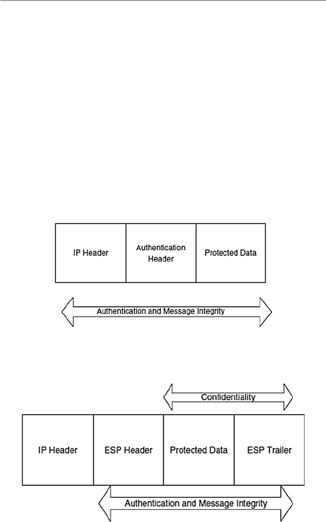
377
•Authentication – particularly source authentication so that when a destination
host receives an IP datagram, with a particular IP source address, it is possible to
be sure that the IP datagram was indeed generated by the host with the source IP
address. This prevents spoofed IP addresses.
•Replay protection – to guarantee that each packet exchanged between two parties
is different.
IPSec protocol achieves these two objectives by dividing the protocol suite into
two main protocols: Authentication Header (AH) protocol and the Encapsulation
Security Payload (ESP) protocol [8]. The AH protocol provides source authentication
and data integrity but no confidentiality. The ESP protocol provides authentication,
data integrity, and confidentiality. Any datagram from a source must be secured
with either AH or ESP. Figures 17.7 and 17.8 show both IPSec’s ESP and AH
protections.
Fig. 17.7 IPSec’s AH protocol protection
Fig. 17.8 IPSEc’s ESP protocol protection
17.4 Security in the Network Layer

378
17.4.1.1 Authentication Header (AH)
AH protocol provides source authentication and data integrity but not confidentiality.
This is done by a source that wants to send a datagram first establishing an SA,
through which the source can send the datagram. A source datagram includes an AH
inserted between the original IP datagram data and the IP header to shield the data
field which is now encapsulated as a standard IP datagram. See Fig. 17.4. Upon
receipt of the IP datagram, the destination host notices the AH and processes it using
the AH protocol. Intermediate hosts such as routers, however, do their usual job of
examining every datagram for the destination IP address and then forwarding it on.
17.4.1.2 Encapsulation Security Payload (ESP)
Unlike the AH protocol, ESP protocol provides source authentication, data integrity,
and confidentiality. This has made ESP the most commonly used IPSec header.
Similar to AH, ESP begins with the source host establishing an AS which it uses to
send secure datagrams to the destination. Datagrams are secured by ESP by
surrounding their original IP datagrams with a new header and trailer fields all
encapsulated into a new IP datagram. See Fig. 17.5. Confidentiality is provided by
DES_CBC encryption. Next to the ESP trailer field on the datagram is the ESP
Authentication Data field.
17.4.1.3 Security Associations
In order to perform the security services that IPSec provides, IPSec must first get as
much information as possible on the security arrangement of the two communicating
hosts. Such security arrangements are called security associations (SAs). A security
association is a unidirectional security arrangement defining a set of items and pro-
cedures that must be shared between the two communicating entities in order to
protect the communication process.
Recall from Chap. 1 that in the usual network IP connections, the network layer
IP is connectionless. However, with security associations, IPSec creates logical
connection-oriented channels at the network layer. This logical connection-oriented
channel is created by a security agreement established between the two hosts stating
specific algorithms to be used by the sending party to ensure confidentiality (with
ESP), authentication, message integrity, and anti-replay protection.
Since each AS establishes a unidirectional channel, for a full duplex communica-
tion between two parties, two SAs must be established. An SA is defined by three
parameters [2, 9]:
•Security Parameter Index (SPI) – a 32-bit connection identifier of the SA. For
each association between a source and destination host, there is one SPI that is
used by all datagrams in the connection to provide information to the receiving
device on how to process the incoming traffic.
•IP Destination Address – address of a destination host.
•A Security Protocol (AH or ESP) to be used and specifying if traffic is to be
provided with integrity and secrecy. The protocol also defines the key size, key
lifetime, and the cryptographic algorithms.
17 Computer Network Security Protocols
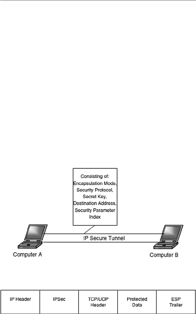
379
•Secret key – which defines the keys to be used.
•Encapsulation mode – defining how encapsulation headers are created and
which parts of the header and user traffic are protected during the communica-
tion process.
Figure 17.9 shows the general concept of a security association.
17.4.1.4 Transport and Tunnel Modes
The security associations discussed above are implemented in two modes: trans-
port and tunnel. This means that IPSec is operating in two modes. Let us look at
these [2].
Transport Mode
Transport mode provides host-to-host protection to higher-layer protocols in the
communication between two hosts in both IPv4 and IPv6. In IPv4, this area is the
area beyond the IP address as shown in Fig. 17.10. In IPv6, the new extension to
IPv4, the protection includes the upper protocols, the IP address, and any IPv6
header extensions as shown in Fig. 17.7. The IP addresses of the two IPSec hosts
are in the clear because they are needed in routing the datagram through the
network.
Fig. 17.9 A general concept of IPSec’s security association
Fig. 17.10 IPSec’s transport mode
17.4 Security in the Network Layer
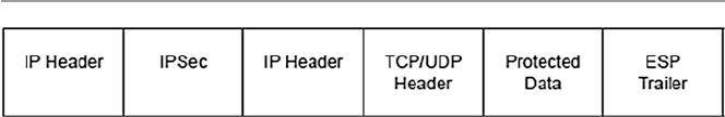
380
Tunnel Mode
Tunnel mode offers protection to the entire IP datagram both in AH and ESP
between two IPSec gateways. This is possible because of the added new IP header
in both IPv4 and IPv6 as shown in Fig. 17.11. Between the two gateways, the data-
gram is secure and the original IP address is also secure. However, beyond the
gateways, the datagram may not be secure. Such protection is created when the first
IPSec gateway encapsulates the datagram including its IP address into a new shield
datagram with a new IP address of the receiving IPSec gateway. At the receiving
gateway, the new datagram is unwrapped and brought back to the original datagram.
This datagram, based on its original IP address, can be passed on further by the
receiving gateway, but from this point on unprotected.
17.4.1.5 Other IPSec Issues
Any IPSec compliant system must support single DES, MD5, and SHA-1 as an
absolute minimum; this ensures that a basic level of interworking is possible with
two IPSec compliant units at each end of the link. Since IPSec sits between the
network and transport layers, the best place for its implementation is mainly in
hardware.
17.4.2 Virtual Private Networks (VPN)
A VPN is a private data network that makes use of the public telecommunication
infrastructure, such as the Internet, by adding security procedures over the unsecure
communication channels. The security procedures that involve encryption are
achieved through the use of a tunneling protocol. There are two types of VPNs:
remote access which lets single users connect to the protected company network
and site to site which supports connections between two protected company networks.
In either mode, VPN technology gives a company the facilities of expensive private
leased lines at much lower cost by using the shared public infrastructure like the
Internet. See Fig. 17.12.
Figure 17.8 shows two components of a VPN [10]:
•Two terminators which are either software or hardware. These perform encryption,
decryption, and authentication services. They also encapsulate the information.
•A tunnel – connecting the endpoints. The tunnel is a secure communication link
between the endpoints and networks such as the Internet. In fact this tunnel is
virtually created by the endpoints.
Fig. 17.11 IPSec’s tunnel mode
17 Computer Network Security Protocols
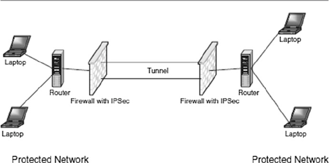
381
VPN technology must do the following activities:
•IP encapsulation – this involves enclosing TCP/IP data packets within another
packet with an IP address of either a firewall or a server that acts as a VPN
endpoint. This encapsulation of host IP address helps in hiding the host.
•Encryption – is done on the data part of the packet. Just like in SSL, the encryp-
tion can be done either in transport mode which encrypts its data at the time of
generation or tunnel mode which encrypts and decrypts data during transmission
encrypting both data and header.
•Authentication – involves creating an encryption domain which includes authen-
ticating computers and data packets by use for public encryption.
VPN technology is not new; phone companies have provided private shared
resources for voice messages for over a decade. However, its extension to making it
possible to have the same protected sharing of public resources for data is new.
Today, VPNs are being used for both extranets and wide-area intranets. Probably
owing to cost savings, the popularity of VPNs by companies has been phenomenal.
17.4.2.1 Types of VPNs
The security of VPN technologies falls into three types: trusted VPNs, secure VPNs,
and hybrid VPNs.
Trusted VPNs
As we have noted above, before the Internet, VPN technology consisted of one or
more circuits leased from a communications provider. Each leased circuit acted
like a single wire in a network that was controlled by a customer who could use
these leased circuits in the same way that he or she used physical cables in his or
her local network. So this legacy VPN provided customer privacy to the extent
that the communications provider assured the customer that no one else would use
Fig. 17.12 Virtual Private Network (VPN) model
17.4 Security in the Network Layer

382
the same circuit. Although leased circuits ran through one or more communications
switches, making them susceptible to security compromises, a customer trusted
the VPN provider to safeguard his or her privacy and security by maintaining the
integrity of the circuits. This security based on trust resulted into what is now
called trusted VPNs.
Trusted VPN technology comes in many types. The most common of these
types are what is referred to as layer 2 and layer 3 VPNs. Layer 2 VPNs include:
ATM circuits, frame relay circuits, and transport of layer 2 frames over
Multiprotocol Layer Switching (MPLS). Layer 3 VPNs include MPLS with con-
strained distribution of routing information through Border Gateway Protocol
(BGP) [11].
Because the security of trusted VPNs depends only on the goodwill of the pro-
vider, the provider must go an extra mile to assure the customers of the security
responsibility requirements they must expect. Among these security requirements
are the following [11]:
•No one other than the trusted VPN provider can affect the creation or modifica-
tion of a path in the VPN. Since the whole trust and value of trusted VPN security
ride on the sincerity of the provider, no one other than the provider can change
any part of the VPN.
•No one other than the trusted VPN provider can change data, inject data, or
delete data on a path in the VPN. To enhance the trust of the customer, a trusted
VPN should secure not only a path but also the data that flows along that path.
Since this path can be one of the shared paths by the customers of the provider,
each customer’s path itself must be specific to the VPN and no one other than the
trusted provider can affect the data on that path.
•The routing and addressing used in a trusted VPN must be established before the
VPN is created. The customer must know what is expected of the customer and
what is expected of the service provider so that they can plan for maintaining the
network that they are purchasing.
Secure VPNs
Since the Internet is a popular public communication medium for almost everything
from private communication to businesses and the trusted VPN actually offers only
virtual security, security concerns in VPN have become urgent. To address these
concerns, vendors have started creating protocols that would allow traffic to be
encrypted at the edge of one network or at the originating computer, moved over the
Internet like any other data, and then decrypted when it reaches the corporate network
or a receiving computer. This way it looks like encrypted traffic has traveled through
a tunnel between the two networks. Between the source and the destination points,
although the data is in the clear and even an attacker can see the traffic, still one
cannot read it and one cannot change the traffic without the changes being seen by
the receiving party and therefore rejected. Networks that are constructed using
encryption are called secure VPNs.
17 Computer Network Security Protocols

383
Although secure VPNs are more secure than trusted VPNs, they too require assurance
to the customer just like trusted VPNs. These requirements are as follows [11]:
•All traffic on the secure VPN must be encrypted and authenticated. In order for
VPNs to be secure, there must be authentication and encryption. The data is
encrypted at the sending network and decrypted at the receiving network.
•The security properties of the VPN must be agreed to by all parties in the VPN.
Every tunnel in a secure VPN connects two endpoints who must agree on the
security properties before the start of data transmission.
•No one outside the VPN can affect the security properties of the VPN. To make it
difficult for an attacker, VPN security properties must not be changed by anyone
outside the VPN.
Hybrid VPNs
Hybrid VPN is the newest type of VPN technologies that substitutes the Internet for
the telephone system as the underlying structure for communications. The trusted
VPN components of the new VPN still do not offer security, but they give customers
a way to easily create network segments for wide area networks (WANs). On the
other hand, the secure VPN components can be controlled from a single place and
often come with guaranteed quality of service (QoS) from the provider.
Because of the inherited weaknesses from both components that make up this
new hybrid VPN, a number of security requirements must be adhered to. Among the
requirements is to clearly mark the address boundaries of the secure VPN within the
trusted VPN because in hybrid VPNs, the secure VPN segments can run as subsets
of the trusted VPN and vice versa. Under these circumstances, the hybrid VPN is
secure only in the parts that are based on secure VPNs.
VPN Tunneling Technology
Old VPN firewalls used to come loaded with software that constructed the tunnel.
However, with new developments in tunneling technology, this is no longer the case. Let
us now look at some different technologies that can be used to construct VPN tunnels:
•IPSec with encryption used in either tunnel or transport modes. Since IPSec can-
not authenticate users, IPSec alone is not good in some host-to-network VPN
[10]. However, this is usually overcome by supplementing IPSec with other
authentication methods such as Kerberos. In combination with Internet Key
Exchange (IKE) which provides a trusted public-key exchange, IPSec is used to
encrypt data between networks and between hosts and networks. According to
Hoden, the sequence of events in the process of establishing an IPSec/IKE VPN
connection goes as follows:
– The host/gateway at one end of a VPN sends a request to the host/gateway at
the other end to establish a VPN connection.
– The remote host/gateway generates a random number and sends a copy of it
to the requesting host/gateway
17.4 Security in the Network Layer
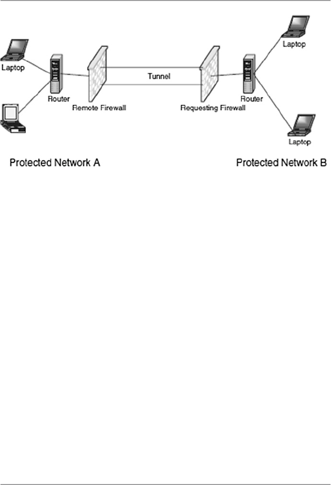
384
– The requesting host/gateway, using this random number, encrypts its pre- shared
key it got from the IKE (shared with the remote host/gateway) and sends it
back to the remote host/gateway.
– The remote host/gateway also uses its random number and decrypts its pre-
shared key and compares the two keys for a match. If there is a match with
anyone of its keys on the keyring, then it decrypts the public key using this
pre-shared key and sends the public key to the requesting host/gateway.
– Finally, the requesting host/gateway uses the public key to establish the IPSec
security association (SA) between the remote host/gateway and itself. This
exchange establishes the VPN connection. See Fig. 17.13.
•Point-to-Point Tunneling Protocol (PPTP). This is a Microsoft-based dial-up
protocol used by remote users seeking a VPN connection with a network. It is an
older technology with limited use.
•Layer 2 Tunneling Protocol [L2TP inside IPSec (see RFC 3193)]. This is an exten-
sion of PPP, a dial-up technology. Unlike PPTP which uses Microsoft dial- up
encryption, L2TP uses IPSec in providing secure authentication of remote access.
L2TP makes a host connect to a modem and then it makes a PPP to the data packets
to a host/gateway where it is unpacked and forwarded to the intended host.
•PPP over SSL and PPP over SSH. These are Unix-based protocols for constructing
VPNs.
17.5 Security in the Link Layer and over LANS
Finally, our progressive survey of security protocols and standards in the network
security stack ends with a look at the security protocols and standards in the data
link layer. In this layer, although there are several protocols including those applied
Fig. 17.13 Establishing a VPN using IPSec and IKE
17 Computer Network Security Protocols

385
in the LAN technology, we will look at only two: PPP and RADIUS. Figure 17.14
shows the position of these protocols in the stack.
17.5.1 Point-to-Point Protocol (PPP)
This is an old protocol because early Internet users used to dial into the Internet
using a modem and PPP. It is a protocol limited to a single data link. Each call in
went directly to the remote access service (RAS) whose job was to authenticate the
calls as they came in.
A PPP communication begins with a handshake which involves a negotiation
between the client and the RAS to settle the transmission and security issues before
the transfer of data could begin. This negotiation is done using the Link Control
Protocol (LCP). Since PPP does not require authentication, the negotiation may
result in an agreement to authenticate or not to authenticate.
17.5.1.1 PPP Authentication
If authentication is the choice, then several authentication protocols can be used.
Among these are Password Authentication Protocol (PAP), Challenge-Handshake
Authentication Protocol (CHAP), and Extensible Authentication Protocol (EAP),
among others [12].
•Password Authentication Protocol (PAP) requires the applicant to repeatedly
send to the server authentication request messages, consisting of a username and
password, until a response is received or the link is terminated. However, this
information is sent in the clear.
•Challenge-Handshake Authentication Protocol (CHAP) works on a “shared
secret” basis where the server sends to the client a challenge message and waits
for a response from the client. Upon receipt of the challenge, the client adds on a
secret message, hashes both, and sends the result back to the server. The server
also adds a secret message to the challenge, hashes with an agreed-upon
algorithm, and then compares the results. Authentication of the client results if
there is a match. To harden the authentication process, the server periodically
authenticates the client.
•Extensible Authentication Protocol (EAP) is open ended, allowing users to select
from among a list of authentication options.
Fig. 17.14 Data link layer security protocols and standards
17.5 Security in the Link Layer and over LANS

386
17.5.1.2 PPP Confidentiality
During the negotiations, the client and server must agree on the encryption that
must be used. IETF has recommended two such encryptions that include DES
and 3DES.
17.5.2 Remote Authentication Dial-In User Service (RADIUS)
RADIUS is a server for remote user authentication and accounting. It is one of a
class of Internet dial-in security protocols that include Password Authentication
Protocol (PAP) and Challenge-Handshake Authentication Protocol (CHAP).
Although it is mainly used by Internet service providers (ISPs) to provide authenti-
cation and accounting for remote users, it can be used also in private networks to
centralize authentication and accounting services on the network for all dial-in con-
nections for service. A number of organizations are having their employees work off
site, and many of these employees may require to dial-in for services. Vendors and
contractors may need to dial-in for information and specifications. RADIUS is a
good tool for all these types of off-site authentication and accounting.
Let us look at RADIUS’s main components: authentication and accounting
protocols.
17.5.2.1 Authentication Protocols
Upon contact with the RADIUS server, a user is authenticated from the data sup-
plied by the user to the server either directly by answering the terminal server’s
log-in/password prompts or using PAP or CHAP protocols. The user’s personal data
can also be obtained from one of the following places [13]:
•System database: The user’s log-in ID and password are stored in the password
database on the server.
•Internal database: The user’s log-in ID and password can also be encrypted by
either MD5 or DES hash and then stored in the internal RADIUS database.
•SQL authentication: The user’s details can also be stored in an SQL database.
17.5.2.2 Accounting Protocols
RADIUS has three built-in accounting schemes: Unix accounting, detailed accounting,
and SQL accounting.
17.5.2.3 Key Features of RADIUS
RADIUS has several features including [14]:
•Client–server model: In client–server model, the client is responsible for passing
user information to designated RADIUS servers and then acting on the response
which is returned. RADIUS servers, on their part, are responsible for receiving
user connection requests, authenticating the user, and then returning all configu-
ration information necessary for the client to deliver service to the user.
17 Computer Network Security Protocols

387
•Network security: All correspondence between the client and RADIUS server is
authenticated through the use of a shared secret, which is never sent over the net-
work. User passwords are sent encrypted between the client and RADIUS server.
•Flexible authentication mechanisms: The RADIUS server can support a variety
of methods to authenticate a user. When it is provided with the username and the
original password given by the user, it can support PPP PAP or CHAP, Unix
log- in, and other authentication mechanisms.
•Extensible protocol: RADIUS is a fully extensible system. It supports two exten-
sion languages: the built-in rewrite language and scheme. Based on RFC 2138,
all transactions are comprised of variable length Attribute–Length–Value 3
tuples. New attribute values can be added without disturbing existing implemen-
tations of the protocol.
17.5.3 Terminal Access Controller Access Control
System (TACACS+)
This protocol commonly referred to as “tac-plus” is a commonly used method of
authentication protocol. Developed by Cisco Systems, TACACS+ is a strong pro-
tocol for dial-up and it offers the following [10]:
•Authentication – arbitrary length and content authentication exchange which
allows many authentication mechanisms to be used with it.
•Authorization.
•Auditing – a recording of what a user has been doing and in TACASCS+, it
serves two purposes:
– To account for services used
– To audit for security services
TACACS+ has a “+” sign because Cisco has extended it several times and has
derivatives that include the following:
•TACACS – the original TACACS, which offers combined authentication and
authorization
•XTACACS, which separated authentication, authorization, and accounting.
•TACACS+, which is XTACACS plus extensions of control and accounting
attributes.
Exercises
1. PGP has been a very successful communication protocol. Why is this so? What
features brought it that success?
2. Discuss five benefits of IPSec as a security protocol.
3. Discuss the differences between the transport mode and the tunnel mode of
IPSec. Is one mode better than the other? Under what conditions would you use
one over the other?
17.5 Security in the Link Layer and over LANS

388
4. Study the IPv4 and IPv6 and discuss the differences between them? By the
mid- 1990s, it was thought that IPv6 was destined to be a replacement of IPv4 in
less than 5 years. What happened? Is there a future for IPv6?
5. Discuss the differences between RADIUS, as a remote authentication protocol,
and Kerberos when using realms.
6. What are Kerberos authentication path? How do they solve the problem of
remote authentication?
7. The Kerberos system has several bugs that pose potential security risks. Study
the Kerberos ticketing service and discuss these bugs.
8. The Kerberos system is built on the principle that only a limited number of
machines on any network can possibly be secure. Discuss the validity of this
statement.
9. Investigate how Netscape Navigator and Internet Explorer implemented SSL
technology.
10. Study both SSL and S-HTTP. Show that these two protocols have a lot in
common. However, the two protocols have some differences. Discuss these
differences. Discuss what caused the decline in the use of S-HTTP.
Advanced Exercises
1. X.509 is a good security protocol. Study X.509 and discuss how it differs from
S-HTTP and IPSec.
2. SSL3.0 has been transformed into TLS 1.0. Study the TLS protocol specifications
and show how all are met by SSL. There are some differences in the protocol
specifications of the two. Describe these differences.
3. S/MIME and PGP are sister protocols; they share a lot. Study the two protocols
and discuss the qualities they share. Also look at the differences between them.
Why is PGP more successful? Or is it?
4. Study the SET protocols and one other payment system protocol such as
Dig- Cash. What sets SET above the others? Is SET hacker proof? What problems
does SET face that may prevent its becoming a standard as desired by Netscape?
5. Both S/MIME and PGP are on track for standardization by the IETF. In your
judgment, which one of the two is likely to become the standard and why?
References
1. Stallings W (1999) Cryptography and network security: principles and practice, 2nd edn.
Prentice Hall, Upper Saddle River
2. Shostack A (1995) An overview of S-HTTP. http://www.homeport.org/~adam/shttp.html
3. Jasma K (2002) Hacker proof: the ultimate guide to network security, 2nd edn. OnWord Press,
Albany
4. Stein L (1998) Web security: a step-by-step reference guide. Addison-Wesley, Reading
5. Tung B (1996) The Moron’s guide to Kerberos, version 1.2.2. http://www.isi.edu/~brian/secu-
rity/kerberos.html
6. Onyszko T (2002) Secure socket layer: authentication, access control and encryption.
WindowSecurity.com. http://www.windowsecurity.com/articles/Secure_Socket_Layer.html
17 Computer Network Security Protocols

389
7. Allen Jones, SSL Demystified: the SSL encryption method in IIS. http://www.windowswebso-
lutions.com/Articles/Index.cfm?ArticleID = 16047
8. Kurose J, Keith WR (2003) Computer networking: a top-down approach featuring the Internet.
Addison-Wesley, Reading
9. Black U (2000) Internet security protocols: protecting IP traffic. Prentice Hall, Upper Saddle
River
10. Hoden G (2004) Guide to firewalls and network security: intrusion detection and VPNs.
Thomson Delmar Learning, Clifton Park
11. VPN Consortium, VPN technologies: definitions are requirements, January 2003. http://vpnc.org
12. Panko R (2004) Corporate computer and network security. Prentice Hall, Upper Saddle River
13. Radius. http://www.gnu.org/software/radius/radius.html#TOCintroduction
14. RFC 2138. http://www.faqs.org/rfcs/rfc2138.html
References

391
© Springer-Verlag London 2015
J.M. Kizza, Guide to Computer Network Security, Computer Communications
and Networks, DOI 10.1007/978-1-4471-6654-2_18
18
Security in Wireless Networks
and Devices
18.1 Introduction
It is not feasible to discuss security in wireless networks without a thorough
understanding of the working of wireless devices and networks. In fact, as we fi rst
set out to teach the computer network infrastructure in Chap. 1 in order to teach
network security, we are going, in the fi rst parts of this chapter, to discuss the
wireless network infrastructure. As was the case in Chap. 1 , it is not easy to discuss
a network infrastructure in a few paragraphs and expect a reader to feel comfortable
enough to deal with the security issues based on the infrastructure. So, although we
are promising the reader to be brief, our discussion of the wireless infrastructure
may seem long to some readers and sometimes confusing to others. Bear with us as
we dispose of the necessary theory for a good understanding of wireless security.
Wireless technology started in 1946 as we will see later in the wireless evolution
section. The rapid technological developments of the last 20 years have seen wire-
less technology as one of the fastest developing technologies of the communication
industry. Because of its ability and potential to make us perform tasks while on the
go and bring communication in areas where it would be impossible with the tradi-
tional wired communication, wireless technology has been embraced by millions.
There are varying predictions all pointing to a phenomenal growth of the wireless
technology industry.
To meet these demands and expectations, a comprehensive communication
infrastructure based on several types of wireless network technologies has been
developed. See Fig. 18.1 . These technologies are based on the following IEEE stan-
dards shown in Table 18.1 .
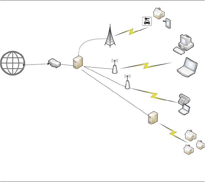
392
18.2 Types of Wireless Broadband Networks
Among the most popular of these networks, at the time of this writing, are shown in
Table 18.1 and are discussed more in Chap. 24 as they play a signifi cant role in
home networking [ 1 ]:
All these different types of wireless networks offer some degree of broadband
(the Internet connection speed) with varying speeds. The connection medium also
varies starting with DSL, cable wireless, fi ber, cellular, and others. The broader the
broadband, the greater the capacity of information and data carried. A wireless
network type is categorized by the technology used, the coverage area, and the
speed of the network connection.
18.2.1 Wireless Personal Area Network (WPAN)
Wireless PANs or WPANs are small networks, based on IEEE standard 802.15.4 of
2005, and IrDa Cable replacement for peripherals. See Table 18.1 . As we will
discuss in Chap. 24 , they operate within a range of between 10 and 100 m with a
transfer rate of 250 kbit/s. WPANs focus on low-cost, low-speed ubiquitous
communication between devices within the range. Devices using this standard,
like mobile phones, computers, GPS receivers, digital cameras, and video game
Mobile Devices and Smart
automobiles
Smart Homes
Sever/Router
Car
Mobile
device
Access point
WiMax Access Point
Router
Cell Tower
Fiber optic
Fiber optic
Fiber optic
Server/Firewall
Mobile Office
Fig. 18.1 A typical wireless broadband network
18 Security in Wireless Networks and Devices

393
Table 18.1 Wireless technology standards
Type Wireless PAN Wireless LAN Wireless MAN Mobile cellular (see Table
18.2 )
Wireless WAM
(LTE) (not yet
deployed)
Standard IEEE 802.11 IEEE 802.15 IEEE 802.16 GSM, IS-95, UMTS, CDMA2000, LTE IEEE 802.20
Technology Bluetooth Wireless fi delity
(Wi-Fi)
WiMAX (Worldwide
Interoperability for
Microwave Access)
Global System for Mobile Comm. (GSM), General
Packet Radio Service (GPRS), cdmaOne, CDMA2000,
Evolution-Data Optimized (EV-DO), Enhanced Data
Rates for GSM Evolution (EDGE), Universal Mobile
Telecommunications System (UMTS), Digital
Enhanced Cordless Telecommunications (DECT),
Digital AMPS (IS-136/TDMA), and Integrated Digital
Enhanced Network (iDEN)
LTE (Long- Term
Evolution)
Coverage
area
3–330 ft
(10–100 meters)
1/3 of a mile
(500 m)
Up to 70 miles 1⁄2 mile–25 miles Over 70 miles
Speed/s 250 kbit/s 50 Mbps 75 Mbp/s 50-MHz NMT, GSM 900 (900 MHz), GSM 1800
(1.8 GHz), UMTS,(2.1 GHz) GSM (800 MHz)
100 Mbps
18.2 Types of Wireless Broadband Networks

394
consoles, can exchange data and information using the network layers based on the
OSI model, although only the lower layers, the physical and MAC layers, are
defi ned in the standard. The most common of this technology are Bluetooth and
radio- frequency identifi cation (RFID). See more details of this in Chap. 24 .
18.2.2 Wireless Local Area Networks (WLAN) (Wi-Fi)
As you will see in more details in Chap. 24 , this type of wireless network technology
is an extension of the WPAN technology, stretching the coverage range up to one third
of a mile. The technology allows electronic devices to exchange data or connect to the
Internet using 2.4-GHz UHF and 5-GHz SHF radio waves. Wi-Fi is probably the pre-
mier local area network (LAN) technology for high-speed Internet access for mobile
devices like laptops, smartphones, tablets, and smart TV sets for video transfer. Wi-Fi
technology is based on the IEEE 802.11 standard. We will see more of this in Chap. 24 .
Table 18.2 Cellular network standards
Cellular network standards
0G (radio telephones) MTS, MTA, MTB, MTC, IMTS, MTD, AMTS,
OLT, autoradiopuhelin
1G AMPS family AMPS (TIA/EIA/IS-3, ANSI/TIA/EIA-553) •
N-AMPS (TIA/EIA/IS-91) • TACS • ETACS
Others NMT • Hicap • Mobitex • DataTAC
2G GGSM/3GPP family GSM • CSD
3GPP2 family cdmaOne (TIA/EIA/IS-95 and ANSI-J-STD 008)
AMPS family D-AMPS (IS-54 and IS-136)
Others CDPD • iDEN • PDC • PHS
2G (transitional)
(2.5G, 2.75G)
GSM/3GPP family HSCSD • GPRS • EDGE/EGPRS (UWC-136)
3GPP2 family CDMA2000 1X (TIA/EIA/IS-2000) • 1X
Advanced
Others WiDEN
3G (IMT-2000) 3GPP family UMTS (UTRAN) • WCDMA-FDD • WCDMA-
TDD • UTRA-TDD LCR. (TD-SCDMA)
3GPP2 family CDMA2000 1xEV-DO Release 0 (TIA/IS-856)
3G (transitional)
(3.5G, 3.75G, 3.9G)
3GPP family HSPA • HSPA+ • LTE (E-UTRA)
3GPP2 family CDMA2000 1xEV-DO Revision A (TIA/EIA/
IS-856-A) • EV-DO Revision B (TIA/EIA/
IS-856-B) • DO Advanced
IEEE family Mobile WiMAX (IEEE 802.16e) • Flash-OFDM
• IEEE 802.20
4G (IMT-Advanced) 3GPP family LTE Advanced (E-UTRA)
IEEE family WiMAX-Advanced (IEEE 802.16 m)
5G Research concept, not under formal
development
From: http://en.wikipedia.org/wiki/Preferred_roaming_list
18 Security in Wireless Networks and Devices
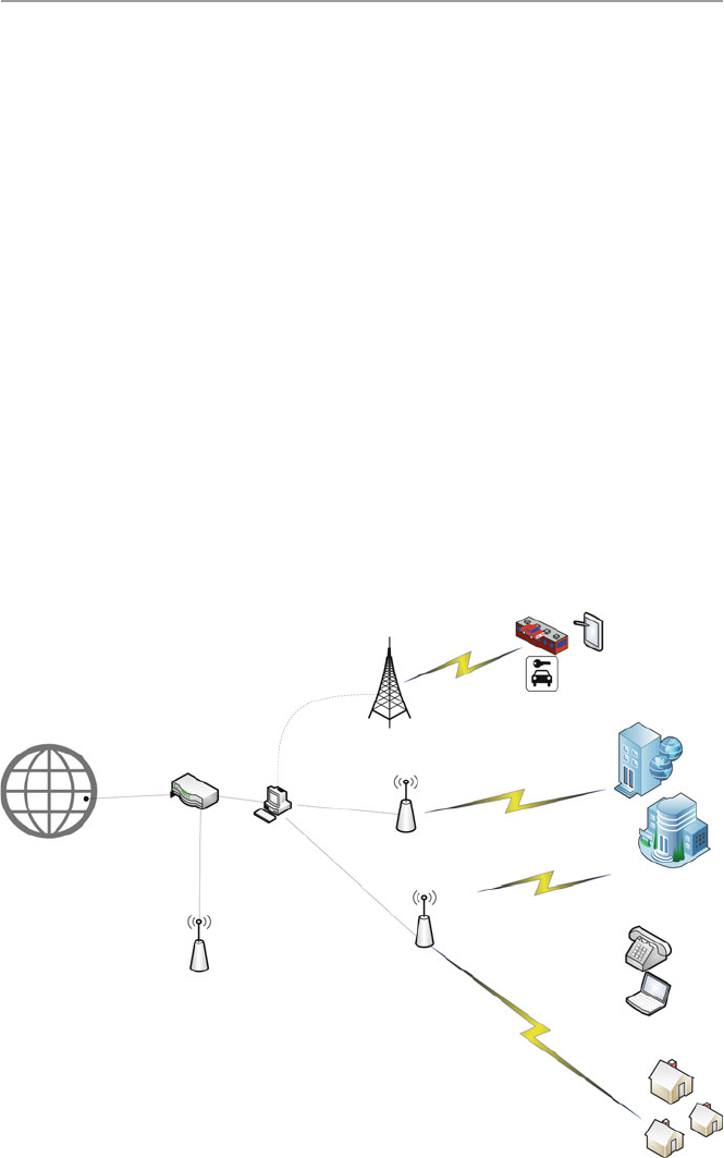
395
Mobile Devices and Smart
automobiles
Smart Homes
Internet
Sever/Router
Car
Smart train
Mobile
device
Access point
WiMax Access Point
Router
Cell Tower
Access Point
Fiber optic
Fiber optic
Fiber optic
Fiber optic
Enterprise Office
Fig. 18.2 Deployment of WiMAX
18.2.3 WiMAX LAN
WiMAX (Worldwide Interoperability for Microwave Access) is another limited
area wireless communications technology based on IEEE 802.16 standard (2001)
that includes IEEE 802.16d for fi xed wireless and IEEE 802.16e for mobile wire-
less. Because of this, it functions in three modes – fi xed, portable, and mobile.
These modes help to extend the range of coverage than limited Wi-Fi technology
functionalities. It provides high-speed, wide area coverage of up to 40 miles, high-
quality and high-capacity delivery with data rates reaching up to 75 megabits per
second (Mb/s), and a number of wireless signaling options ranging anywhere from
the 2-GHz range up to 66 GHz, with up to 1 Gbit/s for fi xed stations. As we will see
in Chap. 24 , because of that range, WiMAX can be installed either by a service
provider as base stations or as small receivers installed by clients to connect to the
base station. The WiMAX base station then sends and receives data to and from a
WiMAX-enabled router, which would then send the data to the different devices in
the home LAN. WiMAX is based on the IEEE 802.16 standard.
WiMAX architecture allows multiple implementation options for a given func-
tional entity and achieves interoperability among many functional entities as seen in
Fig. 18.1 . See also Fig. 18.2 for WiMAX deployment.
18.2 Types of Wireless Broadband Networks

396
18.2.3.1 Overview and Evolution of WiMAX
Responding to the increasing demands for mobile broadband access to multimedia
and Internet application and services, the IEEE Standards Board established the
IEEE 802.16 Working Group (WS) in 1999. The specifi c goals for the WS were to
interface standards for wireless metropolitan area networks (WMAN) as an exten-
sion of the successful WLAN or Wi-Fi. The interface standards developed focused
on medium access control (MAC) and the physical layer (PHY). The initial versions
of the IEEE 802.16 a/d focused on fi xed wireless applications. But later versions of
the 802.16-2005 (16e) included many functionalities to support enhanced quality of
service (QoS) and mobility. Those specifi cations made the WiMAX deployment
shown in Fig. 18.2 possible. The IEEE 802.16 Working Group is currently working
on the next-generation standards supporting LTE technology.
Current WiMAX networks can communicate from base stations (BS) to end user
with non-line of sight (NLOS), whether it is mobile or fi xed.
18.2.3.2 Protocol Layers of WiMAX
The IEEE 802.16 Working Group adopted for the IEEE 802.16 standard the Open
Systems Interconnection (OSI) as a reference model. Recall from Chap. 1 that in the
OSI model, protocols are implemented in layers. In fact, as you recall, there are
seven layers as shown in Fig. 18.3 .
Although the IEEE 802.16 standard uses the OSI protocol stack with several
layers, the standard defi nes only the two layers the PHY and the data link layer. The
data link layer is further subdivided into the logical link layer and the medium
access layer. WiMAX standard uses mostly two- layered protocols the MAC and
PHY layers. The MAC layer is subdivided into three sub-layers, the convergence
sub-layer, the common part sub-layer, and the security sub-layer as shown in
Fig. 18.4 .
Application Layer
Presentation Layer
Session Layer
Transport Layer
Network Layer
Data Link Layer
Physical Layer (PHY)
Fig. 18.3 OSI layers
implemented in the IEEE
802.16 standard
Data Link Layer
·Logical Link Control Layer (LLC)
·Medium Access Layer (MAC)
oConvergence sub-layer(CS)
oCommon part sub-layer (CPS)
oSecurity sub-layer
Physical Layer (PHY)
Fig. 18.4 The functional
OSI layers implemented in
the IEEE 802.16 standard
18 Security in Wireless Networks and Devices

397
The MAC convergence sub-layer (CS) maps the transport-layer-specifi c traffi c
to a MAC in a fl exible way to effi ciently carry any traffi c type. This means that it
adapts one or more transmission mediums, such as radio packet or circuit data
transmission, to one or more alternative transmission formats such as ATM or IP
data transmission. This is possible because it has two types of higher layers, the
asynchronous transfer mode (ATM) and the packet to handle higher-layer proto-
cols like IP v4 or v6 IP v6. In addition, CS also handles the following action
services [ 2 ]:
• Handles the quality of service (QoS) management mechanism
• Processing the higher-layer PDUs (information that is delivered as a unit among
peer entities of a network and that may contain control information, such as
address information, or user data), based on the classifi cation
• An optional PHS (payload header suppression), the process of suppressing
repetitive parts of payload headers at the sender and restoring these headers at
the receiver
• Delivering CS PDUs to the appropriate MAC SAP (service access point)
(an identifying label for network endpoints used in Open Systems Interconnection
(OSI) networking) and receiving CS PDUs from the peer entity
The MAC common part sub-layer (CPS) represents the core of the MAC protocol
and is responsible for bandwidth allocation, connection establishment, and mainte-
nance of the connection between the two sides. It receives data from various CSs,
through the MAC SAP, classifi ed to particular MAC connections. It also includes
many procedures of different types like frame construction, multiple access,
bandwidth demands and allocation, scheduling, radio resource management, QoS
management, etc. [ 2 ].
The MAC security layer provides authenticating and encrypting information
including key exchange over the communication link in WiMAX. Let us now dis-
cuss this in further details.
18.2.3.3 WiMAX Security Protocols
In Fig. 18.2 , we provided the differences between WiMAX and Wi-Fi. These
differences, which indicate superior performance of WiMAX over Wi-Fi in delivering
high-speed connectivity over long distances, are making WiMAX increasingly more
attractive to Internet and telecommunication service providers. With the growing
popularity of the technology driven by the increasing range of coverage and higher
frequencies, as indicated in the list below and in Table 18.3 , there was a need for
more robust security protocols to protect the users of the technology.
• 802.16.1-2001 (10–63 GHz, line of sight, up to 134 Mbit/s)
• 802.16.2 (minimizing interference between coexisting WMANs)
• 802.16a-2003 (2–11 Ghz, mesh, non-line of sight)
• 802.16b-2004 (5–6 Ghz)
• 802.16c (detailed system profi les)
18.2 Types of Wireless Broadband Networks

398
• 802.16e-2005 (mobile wireless MAN) – called mobile WiMAX
• 802.16-2009 to current – Air Interface for Fixed and Mobile Broadband Wireless
Access System
• 802.16m, in progress , data rates of 100 Mbit/s (mobile) and 1 Gbit/s (fi xed) (4G)
To address this, the Working Group of the IEEE 802.16 designed several security
protocols to safeguard and protect both the users and providers. The evolving secu-
rity architecture followed the following fi ve components [ 3 ]:
• Security Associations – A context to maintain the security state relevant to a con-
nection between a base station (BS) and a subscriber station (SS)
• Certifi cate Profi le – X.509 to identify communication parties to each other
• PKM Authorization – Authorization protocol to distribute an authorization token
to an authorized SS
• Privacy and Key Management – A protocol to rekey the security association (SA)
• Encryption – Payload fi eld encryption using the Data Encryption Standard (DES)
algorithm in the Cipher Block Chaining (CBC) mode of operation in 802.16d
(DES-CBC) and Advanced Encryption Standard-Counter Cipher Block Chaining
Message Authentication Code (AES-CCM) in 802.16e
Security associations, certifi cate profi les, PKI authorizations, and privacy key
management are all used to form the standard’s authentication protocol . For exam-
ple, the X.509 certifi cate is used in the authentication for uniquely identifying the
subscribers and providers. An X.509 certifi cate offers security in two ways:
• By verifying a person’s identity to make sure that the person really is who they
say they are – using the X.509 certifi cate .
• Sending the person who owns the certifi cate-encrypted data that only they can be
able to decrypt and read – using the Data Encryption Standard (DES) algorithm
in the Cipher Block Chaining (CBC) mode of operation in 802.16d (DES-CBC)
and Advanced Encryption Standard-Counter with Cipher Block Chaining- Message
Authentication Code (AES-CCM) in 802.16e
Table 18.3 WiMAX vs. Wi-Fi
Functionality WiMAX Wi-Fi
Application Broadband Internet (multiuser – single tower
connecting many users)
Wireless LAN, Internet
Range 50 km 100 m
Frequency range 2–11 GHz 2.4 GHz
Network type MAN LAN
Data range 70 Mbps 30–50 Mbps
Modulation QAM DSSS
Propagation NLOS (non-line of sight) LOS (line of sight)
Mobility Yes No
18 Security in Wireless Networks and Devices

399
X.509 certifi cate, however, was not enough for comprehensive authentication.
For example, it was found that there was a fl aw in the authentication mechanism of
the original IEEE 802.16 standard’s privacy and key management (PKM) protocol
in that there was no requirement for base station (BS) or service provider authenti-
cation, thus making WiMAX networks based on the original IEEE 802.16 standard
susceptible to man-in-the-middle attacks [ 4 ]. This weakness, however, has been
addressed in the IEEE 802.16e, with the addition of the Extensible Authentication
Protocol (EAP) to the IEEE 802.16e.
Extensible Authentication Protocol (1999) (EAP) is an authentication framework
used in network access authentication in dial-up, virtual private network (VPN),
802.1X wireless, and 802.1X wired technologies using Network Policy Server
(NPS), Routing and Remote Access Service (RRAS), or both. It consists of many
authentication protocols including EAP-MD5, EAP-POTP, EAP-GTC, EAP- TLS,
EAP-IKEv2, EAP-SIM, and EAP-AKA. Its commonly used protocols are EAP-TLS,
EAP-SIM, EAP-AKA, LEAP, and EAP-TTLS.
EAP includes password-based authentication methods and more secure
public- key infrastructure certifi cate. It also includes Protected EAP (PEAP) and is
extensible because it allows developers to create new authentication types that can
plug into existing EAP deployment.
The Encryption Protocol
As Table 18.4 shows, the 802.16d used 3DES for authorization key (AK), DES for
traffi c encryption key (TEK), and the X.509 authentication certifi cate. It also
employed the Data Encryption Standard (DES) algorithm in the Cipher Block
Chaining (CBC) encryption as part of its MAC protocol. However, neither the MAC
Table 18.4 The security and functional evolvement of the IEEE 802.16 standard
Standard
Publication
year Range Frequency Goals Security
802.16 2002 10–66 GHz Original standard, line
of sight, fi xed–fi xed
point wireless
None
802.16a 2003 2–11 GHz Added non-line-of-
sight extension. Now
supplanted by the
802.16d variant
None
802.16d 2004 2–11 GHz Supports fi xed and
nomadic access in
line-of-sight and
non-line-of-sight
environments
3DES for authorization
key (AK), DES for
traffi c encryption key
(TEK), X.509
10–66 GHz
802.16e 2006 2–6 GHz Optimized for
dynamic mobile radio
channels, provides
support for handoffs
and roaming
AES-CCM Extensible
Authentication Protocol
(EAP)
18.2 Types of Wireless Broadband Networks

400
header nor the packet cyclic redundancy check (CRC) is encrypted, thus leading to
the 802.16d not providing for data authenticity.
With the 802.16e amendment, support for the Advanced Encryption Standard-
Counter with Cipher Block Chaining-Message Authentication Code (AES-CCM) is
available, providing strong support for confi dentiality of data traffi c. However, like
in the standard 802.11 specifi cation, management frames are not encrypted, thus
allowing an attacker to collect information about subscribers in the area and other
potentially sensitive network characteristics.
WiMAX Threats
Although WiMAX is secure, especially 802.16e, there are several potential attacks
that can work around the present security protocols including [ 4 ]:
• Rogue base stations
• DoS attacks
• Man-in-the-middle attacks
• Network manipulation with spoofed management frames
This means that more work needs to be done to realize a more secure WiMAX
standard.
The physical layer in all digital communications performs functions of encoding
and decoding signals, preamble generation and removal, and bit transmission and
reception. It encodes and decodes data and signals in such a way that the conversion fi ts
the physical transmission medium characteristics such as copper, radio, or optical.
It also coordinates the transmission and reception of these physical signals on the
medium between two or more communicating entities. In addition to coordinating
transmission of data between physical entities, it also receives data for transmission
from the upper layer and converts it into physical format suitable for transmission
through a network, such as frames and bursts. The upper layer provides the physical
layer with the necessary data and control (e.g., maximum packet size) to allow
conversion to a format suitable for transmission on a specifi c network type and
transmission line.
WiMAX physical layer can operate in about fi ve different specifi cations for
licensed and unlicensed frequency bands as specifi ed below [ 5 ]:
• SC – Single-carrier modulation, to support line of sight (LOS) with high data rates
• SCa – Single-carrier air interface modulation
• HUMAN – High-speed unlicensed
• OFDM – Orthogonal frequency-division multiplexing (OFDM) for both line of
sight (LOS) and non-line of sight (NOLOS) in encoding digital data on multiple
carrier frequencies. OFDM has developed into a popular scheme for wideband
digital communication, whether wireless or over copper wires, and is used in
applications such as digital television and audio broadcasting, DSL Internet
access, wireless networks, powerline networks, and 4G mobile communications.
18 Security in Wireless Networks and Devices

401
• OFDMA – Orthogonal frequency-division multiple access (OFDMA) for
both line of sight (LOS) and non-line of sight (NOLOS) is a multi-user
version of the popular orthogonal frequency-division multiplexing (OFDM)
digital modulation scheme. Multiple access is achieved in OFDMA by
assigning subsets of subcarriers to individual users as shown in the illustra-
tion below.
Any one of these will be used in the system. For example, fi xed WiMAX uses
OFDM type of physical layer and mobile WiMAX uses OFDMA type.
18.2.4 Mobile Cellular Network
A mobile cellular network is a radio network distributed over land through cells
where each cell includes a fi xed location transceiver known as base station (BS).
These cells together provide radio coverage over larger geographical areas. User
equipment called SS or MS such as mobile phones, laptops, and other mobile
devices is able to communicate even if the devices are either fi xed or moving through
cells during transmission.
Cellular networks give subscribers advanced features over alternative solutions,
including increased capacity, small battery power usage, a larger geographical
coverage area, and reduced interference from other signals. The technologies in this
category are cellular based having a broad coverage over large areas, such as cities
or countries, and indeed worldwide via multiple satellite systems or antenna sites
looked after by service providers (ISPs).
18.2.4.1 Mobile Cellular Network Technologies
There are several and different cellular technologies as shown in Tables 18.1
and 18.2 , including:
• Global System for Mobile Communications (GSM)
• General Packet Radio Service (GPRS)
• cdmaOne
• CDMA2000
• Evolution-Data Optimized (EV-DO)
• Enhanced Data Rates for GSM Evolution (EDGE)
• Universal Mobile Telecommunications System (UMTS)
• Digital Enhanced Cordless Telecommunications (DECT)
• Digital AMPS (IS-136/TDMA)
• Integrated Digital Enhanced Network (iDEN)
They include most cellular technologies, like CDPD and Cellular 2G, 2.5G, 3G,
and LTE or 4G. Because LTE is a newer technology, its communication protocols
are based on Internet Protocol (IP). Because of this, it offers a variety of
18.2 Types of Wireless Broadband Networks

402
communication protocols that the older technologies could not offer including VoIP
and other IP-based services. LTE can theoretically support downloads at 300 Mbps
or more based on experimental trials.
18.2.4.2 Mobile Cellular Communication Network Infrastructure
As we pointed out above, in its simplest form, wireless technology is based on a
concept of a cell. That is why wireless communication is sometimes referred to as
cellular communication. Cellular technology is the underlying technology for mobile
telephones, personal communication systems, wireless Internet, and wireless Web
applications. In fact, wireless telecommunications is one of the fastest growing tech-
nologies in telecommunication today. Personal communications devices (PCD) are
increasing in popularity as various wireless networks are growing.
The cell concept is based on the current cellular technology that transmits analog
voice on dedicated bandwidth. This bandwidth is split into several segments perma-
nently assigned to small geographical regions called cells. This has led to the tiling
of the whole communication landscape with small cells of roughly 10 square miles
or less depending on the density of cellular phones in the geographical cell. See
Fig. 18.5 . Each cell has, at its center, a communication tower called the base station
(BS) which the communication devices use to send and receive data. See also
Fig. 18.6 . The BS receives and sends data usually via a satellite. Each BS operates
two types of channels:
• The control channel which is used in the exchange when setting up and maintain-
ing calls
• The traffi c channel to carry voice/data
The satellite routes the data signal to a second communication unit, the Mobile
Telephone Switching Offi ce (MTSO). The MTSO, usually some distance off the
Fig. 18.5 Tessellation of the cellular landscape with hexagon cell units
18 Security in Wireless Networks and Devices
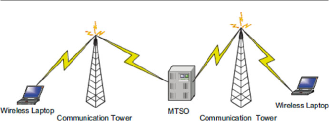
403
origination cell, may connect to a land-based wired communication infrastructure
for the wired receiver or to another MTSO or to a nearest BS for the wireless device
receiver.
An enabled wireless device such as a cellular phone must be constantly in con-
tact with the provider. This continuous contact with the provider is done through the
cell device constantly listening to its provider’s unique system identifi cation code
(SID) via the cell base stations. If the device moves from one cell to another, the
current tower must hand over the device to the next tower and so on; so the continuous
listening continues unabated. As long as the moving device is able to listen to the
SID, it is in the provider’s service area, and it can, therefore, originate and transmit
calls. In order to do this, however, the moving device must identify itself to the
provider. This is done through its own unique SID assigned to the device by the
provider. Every call originating from the mobile device must be checked against a
database of valid device’s SIDs to make sure that the transmitting device is a legiti-
mate device for the provider.
The mobile unit, usually a cell phone, may originate a call by selecting the stron-
gest setup idle frequency channel from among its surrounding cells by examining
information in the channel from the selected BS. Then using the reverse of this
frequency channel, it sends the called number to the BS. The BS then sends the signal
to the MTSO. As we saw earlier, the MTSO attempts to complete the connection by
sending the signal, called a page call, to a select number of BSs via a land- based
wired MTSO or another wireless MTSO, depending on the called number. The
receiving BS broadcasts the page call on all its assigned channels. The receiving
unit, if active, recognizes its number on the setup channel being monitored and
responds to the nearest BS which sends the signal to its MTSO. The MTSO may
backtrack the routes or select new ones to the call initiating MTSO which selects a
channel and notifi es the BS which notifi es its calling unit. See Fig. 18.6 for details
of this exchange.
During the call period, several things may happen including the following:
• Call block which happens when channel capacity is low due to high unit density
in the cell. This means that at this moment, all traffi c channels are being used.
Fig. 18.6 Initiating and receiving wireless calls
18.2 Types of Wireless Broadband Networks

404
• Call termination when one of the two users hangs up.
• Call drop which happens when there is high interference in the communication
channel or weak signals in the area of the mobile unit. Signal strength in an
area must be regulated by the provider to make sure that the signal is not
too weak for calls to be dropped or too strong to cause interference from
signals from neighboring cells. Signal strength depends on a number of factors,
including human- generated noise, nature, distance, and other signal propaga-
tion effects.
• Handoff when a BS changes assignment of a unit to another BS. This happens
when the mobile unit is in motion such as in a moving car and the car moves from
one cell unit to another adjacent cell unit.
• As customers use the allocated channels in a cell, traffi c may build up, leading to
sometimes serious frequency channel shortages in the cell to handle all the calls
either originating or coming into the cell.
• The capacity of the communication channels within the cell is controlled by
channel allocation rules. This capacity can be increased per cell by adding com-
plexity and relaxing these channel allocation rules. Cell channel capacity can be
expanded through [ 6 ]:
• Cell splitting: By creating smaller geographical cells, better use can be made
of the existing channels allocation. Usually cells have between 5- and 10-mile
radius. Smaller cells may have about 2-mile radius. Attention must be paid
for a minimum cell radius. It is possible to reach this minimum because as
cells become smaller, power levels must be reduced to keep the signals within
the cells, and also, there is an increase in the complexity resulting from more
frequent handoffs as calls enter and leave the cells in higher numbers and
high interferences due to smaller cells. Cell splitting can lead to microcelling,
which is a concept of creating very small cells within the minimum limits
called microcells which are small tessellations of a bigger cell and making
BS antennas smaller and putting them on top of buildings and lamp posts.
This happens often in large cities. Another version of microcelling is cell
sectoring which also subdivides the original cell into small sectors and allo-
cates a fi xed number of frequency channels to each sector. The new sectors
still share the BS, but direction antennas face the BS to direct calls to and
from the sector.
• Allocation of new channels: Once all free channels are used up, additional
frequency channels may be added to meet the demand.
• Frequency borrowing: This calls for literally taking frequency channels from
adjacent cells with redundant unused channels. Sometimes frequency channels
from less congested adjacent cells can be dynamically allocated to congested
cells.
Alternative multiple access architectures: The transition from analog to digital
transmission is also signifi cantly increasing the capacity.
18 Security in Wireless Networks and Devices

405
18.3 Development of Cellular Technology
In the United States, the development of wireless cellular communication began in
1946 when AT&T introduced the mobile telephone service (MTS).
However, this was preceded by the pre-cellular wireless communication that
began in the early 1920s with the development of mobile radio systems using
amplitude modulation (AM). Through the 1940s, their use became very popular,
especially in police and other security and emergency communications. The chan-
nel capacity quickly became saturated as the number of users grew.
The actual cellular wireless communication started in 1946 when AT&T developed
its fi rst mobile communications service in St. Louis using a single powerful trans-
mitter to radiate a frequency-modulated (FM) wave in an area with a radius of
50 miles. The popularity of this mode of communication forced the Federal
Communications Commission (FCC) in 1950 to split the one 120-kHz channel that
had been used into two equal 60-kHz channels to double its capacity. This led to an
unprecedented increase in the number of users, so that by 1962, the technology had
attracted up to 1.4 million users. Since then, the technology has gone through three
generations.
18.3.1 First Generation
In the fi rst generation, phones were very large and were based on analog technology.
The most known technology of this era was based on a 1971 Bell Labs proposal to
the FCC for a new analog cellular FM telecommunication system. The proposal
gave rise to Advanced Mobile Phone Service (AMPS) cellular standard. Along with
other cellular radio systems developed in other countries, all using FM for speech
and frequency-division multiplexing (FDM) as the access technique, they formed
the fi rst generation of cellular technology. These systems became very popular,
resulting in high levels of use. Although they are still in use today, their limited,
uncoordinated, and independently chosen frequency band selections led to the
development of the second-generation digital cellular technology.
18.3.2 Second Generation
Second-generation systems overcame most of the limitations of the fi rst generation
and improved on others. They offered higher-quality signals, greater capacity, better
voice quality, and more effi cient spectrum utilization through provision of several
channels per cell and allowing dynamic sharing of these channels between users via
multiplexing both TDMA and CDMA (seen in Chap. 1 ) and digital modulation
techniques. Since they were backward compatible, they could use the same frequency
range and signaling as their analog predecessors and therefore could receive and
18.3 Development of Cellular Technology

406
place calls on the fi rst-generation analog network. In fact, 10 % of the second-
generation digital network is allocated to analog traffi c. Also second-generation
systems introduced encryption techniques, using digitized control and user traffi c,
to prevent unauthorized intrusions such as eavesdropping into the communication
channels. The digitalization of traffi c streams also led to the development and
inclusion into the systems of error detection and correction mechanisms. These
second- generation systems included the following [ 7 ]:
• IS-54 ( USA ): Interim Standard-54 (1991) was designed to support large cities
that had reached saturation within the analog system. It uses TDMA to increase
capacity in the AMPS spectrum allocation.
• IS-95 ( USA ): Interim Standard-95 (1994) operated in the dual mode (CDMA/
AMPS) in the same spectrum allocation as AMPS. It is the most widely used
second-generation CDMA.
• GSM ( Europe ): The Global System for Mobile Communications (GSM) (1990)
is a pan-European, open digital standard accepted by the European
Telecommunications Standards Institute (ETSI) and now very popular all over
the world. As an open standard, it allowed interoperability of mobile phones in
all European countries. It has a greater capacity/voice quality than the previous
analog standard.
• PDC ( Japan ): The Personal Digital Communications (PDC) (1991) is similar to
IS-54 and also uses TDMA technology.
• PHS ( Japan ): The Personal Handyphone System (PHS) (1995) uses smaller
cells, therefore leading to a dense network of antennas each with a range of
100–200 m, which allows lower-power and less-expensive handsets to be used.
It also allows 32-kbit/s digital data transmission. Because of all these advantages
and its compaction, it has been very successful in Japan.
With digital cellular systems, usage of phones increased, and as people became
more mobile and new possibilities emerged for using the phones for data transfer
such as uploading and downloading information from the Internet and sending
video and audio data streams, a stage was set for a new generation that would require
high-speed data transfer capabilities. But owing to unexpected problems, including
higher development costs and a downturn in the global economy, the rollout of the
third-generation (3G) cellular systems has proven to be slow.
18.3.3 Third Generation
In general, the third-generation cellular technology, known as (3G), was aiming to
offer high-speed wireless communications to support multimedia, data, video, and
voice using a single, unifi ed standard incorporating the second-generation digital
wireless architectures. The 3G standard was set to allow existing wireless infra-
structure to continue to be employed after carrier transition as they offer increased
capacities of at least 144 Kbps for full mobility, 384 Kbps for limited mobility in
18 Security in Wireless Networks and Devices

407
micro- and macro-cellular environments, and 2 Mbps for low mobility application
[ 8 ]. These goals could be achieved following these specifi c objectives: universality,
bandwidth, fl exibility, quality of service, and service richness [ 6 , 7 ].
18.3.4 Fourth Generation: 4G/LTE
Like WiMAX, 4G/LTE (fourth generation/Long-Term Evolution) is a new and
emerging technology for high-speed mobile broadband Internet service. Both
WiMAX and LTE appear to have similar goals for enabling worldwide wireless data
network connectivity for cell phones, laptops, and other computing devices. But
wireless providers and industry vendors have not addressed them equally. Many
prefer one over the other or both, depending on how these technologies benefi t their
businesses. It is so far likely that neither technology is expected to replace Wi-Fi
home networks and hot spots.
In general, the fourth generation commonly known as 4G/LTE (fourth genera-
tion/Long-Term Evolution) is the next stage in mobile network development and
provides users with much faster data speeds than 3G is able to. LTE was fi rst pro-
posed in Japan in 2004, the LTE standard was fi nalized in December 2008, and the
fi rst publicly available LTE service was launched in Europe in 2009 and North
America in 2010. The LTE specifi cation provides downlink peak rates of 300 Mbit/s,
uplink peak rates of 75 Mbit/s, and QoS provisions permitting a transfer latency of
less than 5 ms in the radio access network [ 5 ].
18.4 Other Features of Mobile Cellular Technology
Besides the evolution of the mobile cellular technology, a number of other features
were also developing including the following.
18.4.1 Universality
Universality is one of the driving forces behind modern communication involving
universal personal communications services (PCSs), personal communication net-
works (PSNs), and universal communications access. It requires achieving the
following:
• A high degree of commonality of design worldwide
• Global compatibility of services within 3G wireless and fi xed networks
• Service availability from multiple providers in any single coverage area
• Service reception on any terminal in any network based on a unique personal
number
• Ability to economically provide service over a wide range of user densities and
coverage areas
18.4 Other Features of Mobile Cellular Technology

408
18.4.2 Flexibility
Flexibility requires:
• A framework for the continuing expansion of mobile network services and
access to fi xed network facilities
• A modular structure that will allow the system to start from a simple confi gura-
tion and grow as needed in size and complexity
• Optimal spectrum usage for services, despite their differing demands for data
rates, symmetry, channel quality, and delay
• Terminals that can adapt to varying demands for delay and transmission quality
• New charging mechanisms that allow trade-offs of data vs. time
• Accommodation of a variety of terminals including the pocket-sized terminal
18.4.3 Quality of Service (QoS)
This requires quality comparable to that of a fi xed network.
18.4.4 Service Richness
It involves:
• Integration of cellular, cordless, satellite, and paging systems
• Support for both packet- and circuit-switched services (e.g., IP traffi c and video
conference)
• Support for multiple, simultaneous connections (e.g., Web browsing and voice)
• Availability of a range of voice and non-voice services
• Effi cient use of the radio spectrum at an acceptable cost
• An open architecture to facilitate technological upgrades of different applications
When the International Telecommunication Union Radiocommunication
Standardization Sector (ITU-R), a body responsible for radio technology stan-
dardization, called for 3G proposals in 1998, responses to develop the standards
came from the following national Standards Development Organizations (SDO):
ETSI (Europe), ARIB (Japan), TIA and TIPI (USA), TTA (Korea), and one from
China [ 8 ].
18.4.5 Mobile Cellular Security Protocol Stack
In Sect. 18.2.3.2 , we discussed the protocol stack of WiMAX. We want to extend
this discussion to broadly cover all cellular wireless communication networks that
also include WiMAX.
18 Security in Wireless Networks and Devices
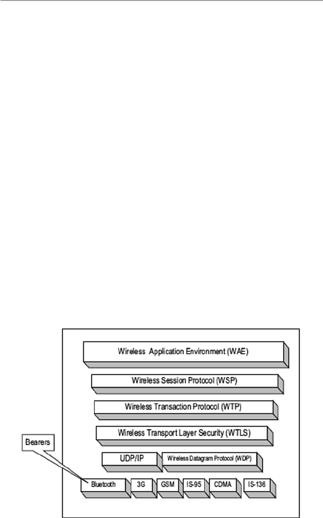
409
18.4.5.1 Mobile Cellular Wireless Application Protocol (WAP)
The cellular wireless communication protocol (WAP) stack was dictated by the
mobility of users and their need to have access to information services, including
the Internet and the Web. WAP works with all wireless technologies such as GSM,
CDMA, and TDMA and is based on Internet technologies such as XML, HTML, IP,
and HTTP. Although the technology is facing limitations dictated by size of the
devices, bandwidth, and speed, the technology has received wide acceptance in the
mobile world. WAP technology includes the fl owing facilities [ 6 ]:
• Programming facilities based on WWW programming model
• Wireless Markup Language (WML) similar to XML
• A wireless browser
• A wireless communications protocol stack – see Fig. 18.7
• A wireless telephony applications (WTA) framework
• A number of other protocols and modules
To understand the working of WAP, one has to understand the WAP programming
model which is based on three elements: the client, the gateway, and the original
server as depicted in Fig. 18.8 .
In the WAP model, HTTP is placed and is used between the gateway and the
original server to transfer content. The gateway component is actually a proxy
server for the wireless domain.
It provides services that process, convert, and encode content from the Internet to
a more compact format to fi t on wireless devices. On a reverse service, it decodes
and converts information from wireless devices that are compact to fi t the Internet
architecture infrastructure. See Fig. 18.9 .
Fig. 18.7 The WAP protocol stack
18.4 Other Features of Mobile Cellular Technology
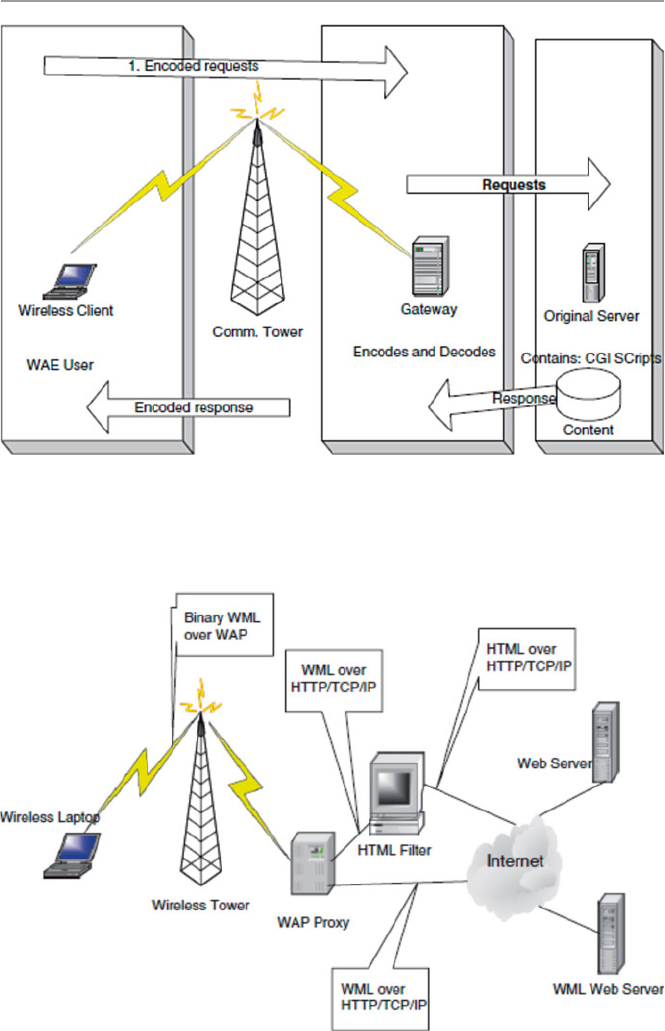
410
Fig. 18.9 The WAP architecture infrastructure
Fig. 18.8 The WAP programming model
18 Security in Wireless Networks and Devices

411
18.5 Security Vulnerabilities in Cellular Wireless Networks
In Chap. 19 , we will discuss security in wireless sensor networks, a more specifi c
type of wireless network. In this chapter, we are discussing security in a general
wireless network. As the wireless revolution rages on and more and more organiza-
tions and individuals are adapting wireless technology for their communication
needs, the technology itself and the speed are barely keeping pace with the demand.
The Wi-Fi craze has been driven by the seemingly many Wi-Fi advantages over its
cousin the fi xed LAN. Such advantages include the following [ 9 ]:
• Affordability: Although Wi-Fi networks are still more expensive compared to
their cousins the fi xed LANs, yet given the advantage of mobility they offer and
the plummeting prices for devices using wireless technology such as laptops and
personal digital assistants, the technology has become more affordable, espe-
cially to large companies that need it more.
• The ease of network connections without having to “plug-in” and without using
expensive network gurus for network setups.
• Increasing employee productivity by organizations and businesses by having
employees remain productive even when on the road. End users, regardless of
where they are either in the offi ce facility or outside, are not very far from an
untethered computing device.
• WLAN technology does not need licenses to use.
As newer standards such as the IEEE 802.11 g are poised to deliver 5 times the
speed of the current IEEE 80211b which currently is delivering about 11 Mbps of
bandwidth, there is increasing concern and closer scrutiny regarding the security of
wireless technology in general and WLANs in particular. WLANs need to not only
provide users the freedom and mobility which are so crucial for their popularity but
also the privacy and security of all users and the information on these networks.
18.5.1 WLANs Security Concerns
As Russ Housely and William Arbaugh state in their paper Security Problems in
802.11-Based Networks [ 10 ], one of the goals of WLAN standard was to provide
security and privacy that were “wired equivalent,” and to meet these goals, the
designers of the standard implemented several security mechanisms to provide con-
fi dentiality, authentication, and access control. The “wired equivalent” concept for
the IEEE 802.11 WLAN standard was to defi ne authentication and encryption based
on the Wired Equivalent Privacy (WEP) algorithm. This WEP algorithm defi nes the
use of a 40-bit secret key for authentication and encryption. But all these mecha-
nisms failed to work fully as intended.
Attacks by hackers and others on the WLAN have been documented. Although
sometimes exaggerated, there is a genuine security concern. Hackers armed with
laptops, WLAN cards, and beam antennas are cruising the highways and city streets,
18.5 Security Vulnerabilities in Cellular Wireless Networks

412
industrial boulevards, and residential streets, sometimes called “war drives,” accessing
both public and private WLANs with impunity [ 11 ].
Wireless networks are inherently insecure. This problem is compounded by the
untraceable hackers who use invisible links to victimize WLANs and the increasing
number of fusions between LANs and WLANs, thus adding more access points (the
weak points) to the perimeters of secure networks.
As a result, the WLAN found itself facing severe privacy and security problems
including the following [ 10 , 12 , 13 ].
18.5.1.1 Identity in WLANs
Identity is a very important component of security mechanism. The WLAN pro-
tocol contains a media access control (MAC) protocol layer in its protocol stack.
The WLAN standard uses the MAC address of the WLAN card as its form of
identity for both devices and users. Although in the early versions of the WLAN
device drivers this MAC address was not changeable, in the newer open-source
device drivers, this is changeable, creating a situation for malicious intruders to
masquerade as valid users. In addition, WLAN uses a service set identifi er (SSID)
as a device identifi er (name) in a network. As a confi gurable identifi cation for a
network device, it allows clients to communicate with the appropriate BS. With
proper confi guration, only clients confi gured with the same SSID as the BS can
communicate with the BS. So SSIDs are shared passwords between BSs and
clients. Each BS comes with a default SSID, but attackers can use these SSIDs to
penetrate a BS. As we will see later, turning off SSID broadcasts cannot stop
hackers from getting to these SSIDs.
18.5.1.2 Lack of Access Control Mechanism
The WLAN standard does not include any access control mechanism. To deal with
this seemingly overlooked security loophole in the standard, many users and ven-
dors have used a MAC-address-based access control list (ACL), already discussed
in Chap. 8 . When ACL is used on MAC addresses, the lists consist of MAC addresses
indicating what resources each specifi c to MAC address are permitted to use. As we
have indicated earlier, the MAC address can be changed by an intruder. So on inter-
ception of a valid MAC address by an intruder and subsequently changing and
renaming his or her WLAN cards, he or she is now a legitimate client of the WLAN
and his or her MAC address now appears in the ACL. Another form of widely used
access control is the “closed network” approach in which the client presents to the
access point (AP), also commonly known as the base station, a secret known only to
the AP and the client. For WLAN users, the secret is always the network name. But
given the nature of WLAN broadcast, this name is broadcast in the clear and any
eavesdropper or sniffer can get the network name.
18.5.1.3 Lack of Authentication Mechanism in 802.11
802.11 supports two authentication services: open systems and shared key. The type
of authentication to be used is controlled by the authentication type parameter. The
open system type is a default null authentication algorithm consisting of a two-step
18 Security in Wireless Networks and Devices

413
process that starts with the access point demanding from the client an identity fol-
lowed by authentication of almost every request from the client. With the shared key
authentication type, a client is authenticated with a challenge and response. The
present 802.11 requires the client to request for authentication using a secure chan-
nel that is independent of the standard. The WEP algorithm currently provides the
WLAN standard with this encryption based on 40-bit and 104-bit secret keys. The
clients request for authentication using these secret keys generated by WEP. The AP
concatenates the secret key with a 14-bit quality known as an initialization vector
(IV), producing a seed to the pseudorandom number generator. The random number
generator produces a key sequence which is then combined with the message text
and concatenated with the integrity check value (ICV). The comb {IV, message text,
ICV} is put in an IEEE 802.11 data frame which is then sent to the client requesting
authentication as the challenge. The client must then encrypt the challenge packet
with the right key. If the client has the wrong key or no key at all, then authentication
fails and the client cannot be allowed to associate with this access point [ 12 ].
However, several research outcomes have shown that this shared key authentication
is fl awed. It can be broken by a hacker who successfully detects both the clear text
and the challenge from the station encrypted with WEP key. There is another type
of WEP key that is not secure either. This key, called the “static” key, is a 40-bit or
128-bit key statically defi ned by the system administrator on an access point and all
clients corresponding with this access point. The use of this type of key requires the
administrator to manually enter the key to all access points and all clients on the
LAN. The key can be lost by a device. This causes a security problem. The admin-
istrator, in this case, must change all the keys.
18.5.1.4 Lack of a WEP Key Management Protocol
As we have noted above, the IEEE 802.11 WLAN standard does not have an encryp-
tion and authentication mechanism of its own. This mechanism is provided to the
standard by the WEP. So the lack of a WEP key management protocol on the stan-
dard is another serious limitation of the security services offered by the standard. As
noted by Arun Ayyagari and Tom Fout, the current IEEE 802.11 security options of
using WEP for access control also do not scale well in large infrastructure network
mode, in ad hoc, and in network mode. The problem is compounded further by the
lack of Inter-Access Point Protocol (IAPP) in a network with roaming stations and
clients [ 12 ]. In addition to the above more structural problems, the WLAN also suf-
fers from the following topographical problems:
• First, data is transmitted through WLANs through broadcasts of radio waves
over the air. Because radio waves radiate in all directions and travel through
walls that make ceilings and fl oors, transmitted data may be captured by anyone
with a receiver in radio range of the access point. Using directional antennas,
anyone who wants to eavesdrop on communications can do so. This further
means that intruders can also inject into the WLAN foreign packets. Because of
this, as we will see shortly, the access points have fallen prey to war-drivers,
war- walkers, war-fl yers, and war-chalkers [ 14 ].
18.5 Security Vulnerabilities in Cellular Wireless Networks

414
• Second, WLAN introduced mobility in traditional LANs. This means that the
boundaries of WLANs are constantly changing as well as the APs of mobile
computing devices like laptops, personal assistants, and palms, as mobile nodes
of the WLANs are everywhere. Perhaps the inability of a WLAN to control
access to these APs by intruders is one of the greatest security threats to WLAN
security. Let us give several examples to illustrate this.
Let us look at an extensive list of the security risks to the Wi-Fi. The majority of
these security risks fall among the following fi ve major categories:
• Insertion attacks
• Interception and monitoring wireless traffi c
• Misconfi guration
• Jamming
• Client-to-client attacks
Most of these can be found at the Wireless LAN Security FAQ site at www.iss.
net/WLAN-FAQ.php [ 15 ].
18.5.1.5 War-Driving, War-Walking, War-Flying,
and War-Chalking
Based on the movie “War Games,” war-walking, war-driving, war-fl ying, and
war- chalking all refer to the modes of transportation for going around and identifying
various access points. As pointed out by Beyers et al. [ 14 ], war-walking, war- driving,
and war-fl ying have resulted in identifying large numbers of wide open unsecure
access points in both cities and countryside.
18.5.1.6 Insertion Attacks
These result from trusted employees or smart intruders placing unauthorized devices
on the wireless network without going through a security process and review. There
are several types of these including the following:
• Plug-in unauthorized clients, in which an attacker tries to connect a wireless
client, typically a laptop or PDA, to a base station without authorization. Base
stations can be confi gured to require a password before clients can access. If there
is no password, an intruder can connect to the internal network by connecting a
client to the base station.
• Plug-in unauthorized renegade base station, in which an internal employee adds
his or her own wireless capabilities to the organization network by plugging a
base station into the LAN.
18.5.1.7 Interception and Monitoring Wireless Traffic Attacks
This is a carry-over from LANs. These intercepts and monitoring attacks are sniff
and capture, session hijacking, broadcast monitoring, arpspoof monitoring, and
18 Security in Wireless Networks and Devices

415
hijacking. In arpspoof monitoring, an attacker using the arpspoof technique can
trick the network into passing sensitive data from the backbone of the subnet and
routing it through the attacker’s wireless client. This provides the attacker both
access to sensitive data that normally would not be sent over wireless and an oppor-
tunity to hijack TCP sessions. Further intercepts and monitoring attacks include
hijacking SSL (Secure Sockets Layer) and SSH (Secure Shell) connections. In addi-
tion, an attacker can also intercept wireless communication by using a base station
clone (evil twin) by tricking legitimate wireless clients to connect to the attacker’s
honeypot network by placing an unauthorized base station with a stronger signal
within close proximity of the wireless clients that mimics a legitimate base station.
This may cause unaware users to attempt to log into the attacker’s honeypot servers.
With false log-in prompts, the user unknowingly can give away sensitive data such
as passwords.
18.5.1.8 AP and Client Misconfigurations and Attack
Base stations out of the box from the factory are confi gured in the least secure mode
or not confi gured at all. System administrators are left with the task of confi guring
them to their best needs. This is not always the case. Studies have shown that some
system administrators confi gure base stations and others do not. In these studies,
each vendor and system administrator had different implementation security risks.
For example, each of the base station models came with default server set IDs
(SSIDs). Lucent, as one of the three base station manufacturers, has secure access
mode which requires the SSID of both the client and base station to match. By
default, this security option is turned off at shipping. In the nonsecure access mode,
clients can connect to the base station using the confi gured SSID, a blank SSID, and
the SSID confi gured as “any.” If not carefully confi gured, an attacker can use these
default SSIDs to attempt to penetrate base stations that are still in their default con-
fi guration unless such base stations are confi gured right. Also, most base stations
today are confi gured with SSID that acts as a single key or password that is shared
with all connecting wireless clients. This server set ID suffers from the same problems
as the original SSID.
Additionally, a base station SSID can be obtained by a brute force dictionary attack
by trying every possible password. Most companies and people confi gure most
passwords to be simple to remember and therefore easy to guess. Once the intruder
guesses the SSID, one can gain access through the base station. There are many
other ways that SSIDs can be compromised ranging from disgruntled employees to
social engineering methods.
18.5.1.9 SNMP Community Words
Many of the wireless base stations that deploy the Simple Network Management
Protocol (SNMP) may fall victim to community word attacks. If the community
word such as “public” is not properly confi gured, an intruder can read and poten-
tially write sensitive information and data on the base station. If SNMP agents are
enabled on the wireless clients, the same risk applies to them as well.
18.5 Security Vulnerabilities in Cellular Wireless Networks

416
18.5.1.10 Client Side Security Risk
Clients connecting to the base station store sensitive information for authenticating
and communicating to the base station. For example, Cisco client software stores
the SSID in the Windows registry, and it stores the WEP key in the fi rmware. Lucent/
Cabletron client software stores the SSID and WEP-encrypted information in the
Windows registry as well. Finally, 3Com client software also stores the SSID and
WEP in the Windows registry. If the client is not properly confi gured, access to this
information by a hacker is easy.
18.5.1.11 Risks Due to Installation
By default, all installations are optimized for the quickest confi guration to enable
users to successfully install out-of-the-box products.
18.5.1.12 Jamming
Jamming leading to denial-of-service attacks can also be carried out in wireless
networks. For example, an attacker with the proper equipment and tools can easily fl ood
the 2.4-GHz frequency so that the signal-to-noise ratio drops so low that the wireless
network ceases to function. Sometimes non-malicious intents like the use of cordless
phones, baby monitors, and other devices such as Bluetooth that operate on 2.4-GHz
frequency can disrupt a wireless network because there are so many in this band .
18.5.1.13 Client-to-Client Attacks
Two wireless clients can talk directly to each other bypassing the base station. Because
of this, each client must protect itself from other clients. For example, when a wireless
client such as a laptop or desktop is running TCP/IP services like a Web server or fi le
sharing, communicating with an attacker is vulnerable to this attacker exploiting any
misconfi gurations or vulnerabilities on the client. Similarly, a wireless client can fl ood
other wireless clients with bogus packets, creating a denial-of-service attack. Finally,
a wireless client can infect other wireless clients; this threat is called a hybrid threat .
18.5.1.14 Parasitic Grids
Parasitic grids are actually self-styled free “metro” wireless networks that provide
attackers and intruders completely untraceable anonymous access. Trying to locate
and trace attackers using the parasitic grid becomes an impossible task, for example,
something similar to hot spots , although hot spots are not maliciously used. Hot spots
are Wi-Fi access point areas provided by businesses to give their customers access to
the Internet. Hot spots are becoming very popular as more and more companies such
as Starbucks, McDonalds, and start-ups try to attract younger customers. They are
also being deployed at airports, hotels, and restaurants for the same reasons.
18.5.2 Best Practices for Wi-Fi Security
Although the reliance of WLAN on SSID, open or shared key, static, or MAC
authentication defi nitely offers some degree of security, there is more that needs to
18 Security in Wireless Networks and Devices

417
be done to secure WLANs. Even though best security practices for WLANs are
meant to address unique security issues, specifi cally suited for wireless technology,
they must also fi t within the existing organization security architecture. Any secure
WLAN solution must address the following issues, some of which have been dis-
cussed in the preceding section [ 9 ]:
• 802.1X authentication standards
• WEP key management
• User and session authentication
• Access point authentication
• Detection of rogue access points
• Unicast key management
• Client session accounting records
• Mitigation of network attacks
• WLAN management
• Operating system support
In addition to addressing those issues, it must also include the following basic
and minimum set of routine but low-level steps [ 15 ]:
• Turn on basic WEP for all access points.
• Create a list of MAC addresses that are allowed to access the WLAN.
• Use dynamic encryption key exchange methods as implemented by various secu-
rity vendors.
• Keep software and patches on all access points and clients updated.
• Create access point passwords that cannot be guessed easily.
• Change the SSID on the access point, and block the SSID broadcast feature.
• Minimize radio wave leakage outside the facility housing the WLAN through
access point placement and antenna selection.
• For large organizations that value data, strong protection mechanisms
must be put in place. Such mechanisms may include Kerberos or RADIUS,
end-to-end encryption, password protection, user identifi cation, virtual pri-
vate networks (VPN), Secure Sockets Layer (SSL), and fi rewalls. All these
are implementable.
• Change the default SSID and password protection drives and folders.
Realize, however, that these are basic and many things change. They just assure
you of minimum security.
Exercises
1. List the devices that can be used in a wireless network. How are they connected
to form a wireless network?
2. Infrared devices exchange beams of light to communicate. Is this the method
used in wireless communication? Explain how a communication link between
two wireless devices is established.
18.5 Security Vulnerabilities in Cellular Wireless Networks

418
3. Bluetooth devices communicate using radio waves. What are the differences
between Bluetooth technology and 802.11? What are the weaknesses in
Bluetooth technology compared to 802.11?
4. We have discussed at length the problems found in the 802.11 technology in
assuring privacy and authentication. Suppose you are in charge of a LAN and
you want to add a few access points to allow a limited use of wireless devices.
How would you go about setting this network up?
5. Unlike infrared wireless devices, Bluetooth technology uses radio waves to
communicate. What are the advantages of Bluetooth over these devices and
also over 802.11 technology?
6. Study and discuss the reasons why WEP never realized its stated objectives.
What are those objectives?
7. How does WPA, the new stopgap measure to plug the loopholes in WEP,
go about solving the problems of WEP? Why is the technology considered a
short- term technology? What long-term technology is being considered?
8. Study the security mechanisms in the new 802.11i and discuss how these mech-
anisms will solve the security problems of Wi-Fi.
9. One of the weakest points of WLAN is the access points. Discuss the most
effective ways to close this weak point in the WLAN technology.
10. Many security experts have said that the biggest security problem in wireless
technology is not to use security technology at all. Study this problem. Carry
out a limited research and try to quantify the problem.
11. Looking at Table 18.4 , WiMAX security has been going through rapid changes
with the Working Group of the IEEE 802.16 designing several security proto-
cols to safeguard and protect both users and providers. Have these changes
improved security in WiMAX? Why or why not?
Advanced Exercises
1. Some have likened the alphabet used in the 802.11 standard to an alphabet soup
of confusion. Study the history of lettering in the 802.11 and how it is supposed
to improve security. Does it work?
2. Suppose you are in charge of information security in a large organization where
the value of data justifi es strong protection in the hybrid network resulting from
both LAN and WLAN. What are these additional security measures, and how
would you go about implementing them?
3. Study and discuss how and in what type of wireless network or hybrid each one
of the following methods enhances the security of the chosen network: RADIUS,
Kerberos, end-to-end encryption, password protection, user identifi cation, virtual
private network (VPN), Secure Sockets Layer (SSL), and fi rewalls.
4. The IEEE 802.11 Task Group i (TGi) is developing new WLAN security pro-
tocols named TKIP and CCMP. CCMP is envisioned to supersede WEP and
TKIP. Research and study these efforts and comment on the progress.
18 Security in Wireless Networks and Devices

419
5. It has been given different names, based on the movie War Games . Some have
called it war-driving, others war-walking. Whatever the name, AP scanning is
becoming a hobby and a lucrative source of data from the high proliferation of
wireless cards and mobile computing devices. There is a serious moral and ethical
dilemma associated with the “sport.” Research and discuss such dilemma and
propose solutions, if any.
6. We saw that LTE provides downlink peak of rates of 300 Mbit/s, uplink peak
rates of 75 Mbit/s, and QoS provisions permitting a transfer latency of less than
5 ms in the radio access network. Why is LTE not currently accepted by all?
What is preventing this?
R eferences
1. “Types of wireless Networks”. Computer Networking Notes.com. http://computernetworking-
notes.com/wireless-networking-on-cisco-router/types-of-wireless-networks.html
2. Nuaymi L (2007) WiMAX-technology for broadband wireless access. ENST Bretagne, Wiley,
France, Paris
3. Mohammed El-Gammal, Overview of WiMAX security. https://courses.cs.washington.edu/…/
el-gammal
4. Wright J (2006) WiMAX security issues. NetworkWorld, December 11, 2006.
http://www.
networkworld.com/article/2301883/network-securityimax-security-issues/network-security/
wimax-security-issues.html
5. Wikipedia. http://en.wikipedia.org/wiki/LTE_(telecommunication )
6. Stallings W (2002) Wireless communication and networking. Prentice Hall, Upper Saddle
River
7. Ritchie C, Sutton R, Taylor C, Warneke B (n.d.) The dynamics of standards creation in the
global wireless telecommunications markets . http://www.sims.berkeley.edu/courses/is224/
s99/GroupD/project1/paper1.html
8. Nicopolitidis P, Papadimitriou GI, Obaidat MS, Pomportsis AS (2003) Third generation and
beyond wireless systems: exploring the capabilities of increased data transmission rates.
Commun ACM 46(8)
9. Cisco Aironet Wireless LAN Security Overview. http://www.cisco.com/warp/public/cc/pd/
witc/ao350ap/prodlit/a350w_ov.htm
10. Housely R, Arbaugh W (2003) Security problems in 802.11-based networks. Commun ACM
46(5)
11. Keizer G (2003) WLAN security neglected, study shows. TechWeb News, June 27, 2003 .
http://www.techweb.com/wire/story/TWB20030627S006
12. Ayyagari A, Tom F, Making IEEE 802.11 networks enterprise-ready. Microsoft Development.
http://www.microsoft.com/os/
13. Klaus C (2001) WLAN security FAQ. http://www.ouah.org/wlan-security.html
14. Byers S, Dave K (2003) 802.11b access point mapping. Commun ACM 46(5)
15. Cox J (n.d.) WLAN security: users face complex challenges.
http://www.newsfactor.com/perl/
story/22066.html
References

421
© Springer-Verlag London 2015
J.M. Kizza, Guide to Computer Network Security, Computer Communications
and Networks, DOI 10.1007/978-1-4471-6654-2_19
19
Security in Sensor Networks
19.1 Introduction
The rapid development of wireless technology in the last few years has created new
interest in low-cost wireless sensor networks. Wireless sensor networks (WSNs) or
just sensor networks are grids or networks made of spatially distributed autonomous
but cooperating tiny devices called sensors all of which have sensing capabilities
that are used to detect, monitor, and track physical or environmental conditions,
such as temperature, sound, vibration, pressure, motion, or pollutants, at different
locations [ 1 ]. A sensor, similar to that in Fig. 19.1 , is a small device that produces a
measurable response to a change in a physical condition. Sensor nodes can be inde-
pendently used to measure a physical quantity and to convert it into a signal that can
be read by an observer or by an instrument [ 1 ]. The network may consist of just a
few or thousands of tiny, mostly immobile, usually, randomly deployed nodes, cov-
ering a small or large geographical area. In many cases, sensor networks do not
require predetermined positioning when they are randomly deployed making them
viable for inaccessible terrains where they can quickly self-organize and form a
network on the fl y.
The use of sensors to monitor physical or environmental conditions is not new.
Sensors have been used in both mechanical and electrical systems for a long time.
However, what is new and exciting is that the new sensor nodes are now fi tted with
onboard tiny processors forming a new class of sensors that have the ability to par-
tially process the collected data before sending it to the fusing node or base station.
The sensor nodes now also have sophisticated protocols that help in reducing the
costs of communications among sensors and can implement complex power saving
modes of operations depending on the environment and the state of the network [ 2 ].
The accuracy of the data gathered has also greatly improved.
These recent advances have opened up the potential for WSN. According to
David Culler et al. [ 3 ], wireless sensor networks could advance many scientifi c
pursuits while providing a vehicle for enhancing various forms of productivity,
including manufacturing, agriculture, construction, and transportation. In the
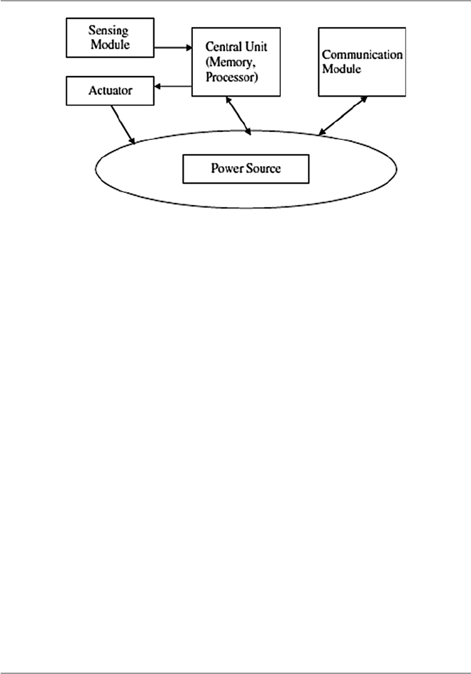
422
military, they are good for command and control, intelligence, and surveillance. In
health, they are benefi cial in monitoring patients; in commercial application, they
can be used in managing inventory, monitoring production lines and product qual-
ity, and monitoring areas prone to disasters [ 4 ]. New technologies are creating more
powerful and yet smaller devices. This miniaturization trend is leading us to ubiqui-
tous computing capacities that are exponentially faster and cheaper with each pass-
ing day. With these developments, researchers are refocusing and developing
techniques that use this miniaturization process to build radios and exceptionally
small mechanical structures like sense fi elds and forces in physical environments
that could only be imagined just a few years ago. Culler et al. believe that these
inexpensive, low-power communication devices can be deployed throughout a
physical space, providing dense sensing close to physical phenomena, processing
and communicating this information, and coordinating actions with other nodes
including a base station [ 3 ].
However, as wireless sensor networks with vast potential of applications unfold
and their role in dealing with sensitive data increases, the security of these networks
have become one of the most pressing issues in further development of these net-
works. This chapter gives a general discussion of the challenges and limitations of
WSNs and how these challenges and limitations contribute to the security problems
faced by the sensor network. We survey several interesting security approaches
aimed at enhancing security, and we conclude by considering several potential
future directions for security solutions.
19.2 The Growth of Sensor Networks
WSNs have evolved slowly from simple point-to-point networks with simple inter-
face protocols providing for sensing and control information and analog signal pro-
viding a single dimension of measurement to the current large number and
Fig. 19.1 A wireless sensor node
19 Security in Sensor Networks

423
sophisticated wireless sensor nodes networks. The development of the microproces-
sor boasted the sensor node with increased onboard intelligence and processing
capabilities, thus providing it with different computing capabilities. The sensor
node is now a microprocessor chip with a sensor on board. The increased intelli-
gence in the node and the development of digital standards such as RS-232, RS-422,
and RS-485 gave impetus to the creation of numerous sensor networking schemes
[ 5 ]. In addition, the popularization of the microcontrollers and the development of
BIT-BUS, a fi eld bus developed by Intel to interconnect stand-alone control units
and terminals, thus making them able to interchange data telegrams, further
improved the sensor node communications capabilities, thus bringing the dream of
sensor networks closer [ 5 ].
Another outstanding development that further made the road to fully functioning
sensor networks possible was the development of the Manufacturing Automation
Protocol (MAP) by General Motors to reduce the cost of integrating various net-
working schemes into a plant-wide system. As Jay Warrior observes, this further
resulted in the development of the Manufacturing Messaging Specifi cation (MMS),
a specifi cation that made it possible for the networked nodes to exchange real-time
data and supervisory control information [ 5 ]. With the development of other com-
munication protocols that allowed simultaneous analog and digital communication
for smart instruments, the sensor network, as we know it today, was born. Currently,
there is a whole spectrum of different sensor network protocols for the many differ-
ent types of sensor networks in use today.
19.3 Design Factors in Sensor Networks
Several factors infl uence the design philosophy of sensor networks. Among these
factors are fi rst whether the nodes are stationary or moving and whether the network
is deterministic or self-organizing. Most sensor network applications use stationary
nodes. However, there are a good number of applications that use mobile nodes. In
this case, therefore, the network is bound to use more energy because of the need to
track the moving node and the increase in bandwidth requirements for periodic
reporting which increases traffi c. In a deterministic topology, the positions of the
nodes and the routes in the network are predetermined and the nodes are manually
placed. In a self-organizing topology, node positions are random and the routes are
also random and unreliable. Routing in these networks, therefore, becomes the main
design concern. Also since self-organizing sensor networks demand a lot of energy,
direct routing is not desirable and multi-hop routing is more energy effi cient.
However, multi-hop requires considerable routing management techniques. In addi-
tion to routing and energy, other factors also infl uence the design philosophy of
sensor networks [ 4 ]:
19.3 Design Factors in Sensor Networks
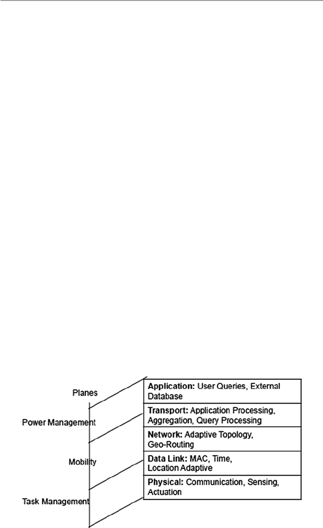
424
19.3.1 Routing
Communication in wireless sensor networks, like in traditional network communi-
cation, is based on a protocol stack with several layers as seen in Fig. 19.2 . This
stack also combines power and routing awareness, integrates data with networking
protocols, communicates power effi ciently through the wireless medium, and pro-
motes cooperation between nodes [ 4 ]. To achieve all these, the stack consists of fi ve
layers and three management planes, and these are physical layer, data link layer,
transport layer, application layer, power management plane, mobility management
plane, and task management plane. This stack is different from those of the tradi-
tional networks made of nonsensor nodes like the TCP/IP and the ISO’s OSI:
• Physical layer – is responsible for several tasks including frequency selection,
carrier frequency generation, signal detection, modulation, and data encryption.
• Data link layer – is responsible for a number of tasks including multiplexing of
data streams, data frame detection, medium access, and error control.
• Network layer – is responsible for network routing. Routing in sensor networks,
unlike in the traditional networks, is infl uenced by the following [ 4 ]:
– Power effi ciency as an important consideration
– Sensor networks being mostly data centric
– Data aggregation being useful only when it does not hinder the collaborative
efforts of the sensor nodes
– An ideal sensor network having attribute-based addressing and location
awareness
• Transport layer – not yet in place. Because, unlike traditional networks, proto-
cols like TCP where the end-to-end communication schemes are possible, here
there is no global addressing. The development of global addressing schemes is
still a challenge.
• Application layer – also not available. Although there are many application areas
for sensor networks, application layer protocols are yet to be developed.
Fig. 19.2 Sensor network protocol stack
19 Security in Sensor Networks

425
Based on the above discussion, therefore, sensor networks are largely still multi-
hop wireless networks whose nodes can be either a host or a router, forwarding
packets to other nodes in the network. In many sensor networks, the information
collected from a large number of sensors is either lightly proceeded locally at the
node or transmitted unproceeded to the base station or other sensors using one of the
three routing techniques: one-to-many, many-to-one, and one-to-one/point-to-point.
However, the two most fundamental communication primitives are broadcast (one-
to- many) and point-to-point (one-to-one).
Broadcast Communication. The broadcast packet routing technique is used
extensively in wireless sensor networks due to the large number of sensor nodes in
any wireless sensor network. Broadcasting, as a means of node communication, is
highly desirable in this environment because of the limited signal range for each
node. In the broadcast mode, the node that initiates the broadcast of a packet is
referred to as the source or sender node and all others as receivers. The receivers of
broadcast packet then forward the packet to their nearest adjacent neighbors which
causes the packet to move throughout the network, enabling all network nodes to
eventually receive the broadcast packet.
Point - to - Point Communication. Though not common, point-to-point routing is
still important for many applications in wireless sensor networks, including games
based on wireless sensor networks and data-centric storage where nodes store infor-
mation about the detected events using the geographic location as the key. Point-to-
point routing can also be used to send data from the detection node to the storage
node [ 6 ].
19.3.1.1 Routing Protocols
There are several routing protocols in use today for sensor networks, including data-
centric, hierarchical, and location-based [ 7 ].
Data - Centric Routing . Because the sensor network may have thousands of nodes
which are randomly deployed, it is inconceivable to have network-wide external
addressing and network-layer-managed routing protocols found in traditional net-
works. In data-centric routing, the sink node, desiring data, sends out an attribute-
based query to the surrounding nodes in the region. The attributes in the query
specify the desired properties of the data. The sink then waits for the data [ 7 ]. If
each node were to send out data to other nodes in the region, there would result a
considerable redundancy of data and an ineffi cient use of scarce energy. For these
reasons, data-centric routing techniques are more resource effi cient. Common data-
centric routing protocols include sensor protocols for information via negotiation
(SPIN) and directed diffusion [ 7 ].
Hierarchical Routing . Hierarchical routing involves multi-hop communication
and the aggregation and fusion of data within clusters of nodes in order to decrease
the number of transmitted messages to the sink nodes which leads to conservation
of energy. There are several hierarchical protocols in use today, including LEACH,
PEGASIS, TEEN, and APTEEN [ 8 ].
Location - Based Routing . In location-based routing, each node maintains a loca-
tion list consisting of location information for a number of nodes in a region of a
19.3 Design Factors in Sensor Networks

426
sensor network. Each node periodically updates its location list by receiving infor-
mation about locations and location lists of all its direct neighbors. It also, in turn,
sends its location and location list to all its adjacent nodes. This keeps the location
list of all nodes in the region current and up to date.
19.3.2 Power Consumption
Most sensor networks are entirely self-organizing and operate with extremely lim-
ited energy and computational resources. Because most nodes may be either in inac-
cessible environments, replenishing them with new power may be almost impossible.
The life of a sensor node, therefore, may be in question, and it may not be able to
transmit critical data when desired. The functionality of the network, therefore,
depends on the consumption rate of energy by node units.
19.3.3 Fault Tolerance
If a sensor network is to face any one sensor node failure, we would like the network
to be able to sustain all its functionalities. That is to say that the sensor network
should be as reliable as possible and continue to function as much as possible in
light of the failed node.
19.3.4 Scalability
We want to have a network such that the addition of more nodes to the network does
not have any diverse effects to the functionality of the network.
19.3.5 Production Costs
Wireless sensor networks most often use large numbers of sensor nodes. The unit
cost of each individual sensor node plays a crucial role in determining the overall
costs of the entire sensor network. We would like a well-functioning network hav-
ing a least per unit cost for individual nodes.
19.3.6 Nature of Hardware Deployed
A sensor node consists of four basic parts: the sensing unit, the processing unit, the
transceiver unit, and the power unit. All these units must be packaged in a very
small, match-box-sized package. In addition, all these units and the overall sensor
node must consume very low power.
19 Security in Sensor Networks

427
19.3.7 Topology of Sensor Networks
Because a normal sensor network may contain thousands of sensor nodes deployed
randomly throughout the fi eld of observation, the wireless sensor network resulting
may have uneven densities depending on how the nodes were deployed. Nodes can
be deployed by dropping them from a plane, carefully placing them, or dropping by
artillery. Also not every deployed sensor may work as expected. So the topology of
the resulting network may determine the functionality of the wireless sensor
network.
19.3.8 Transmission Media
In a wireless sensor network, the nodes are linked by a wireless medium. The
medium could be by radio-like RF and Bluetooth, infrared, or optical waves. Both
infrared and optical links require no obstructions like objects in the line of sight.
The functionality of the network may depend on these media.
19.4 Security in Sensor Networks
Modern wireless sensor networks many times consist of hundreds to thousands of
inexpensive wireless nodes, each with some computational power and sensing capa-
bility and usually operating in random unsupervised environments. The sensors in
the network act as “sources” as they detect environmental events either continu-
ously or intermittently whenever the occurrence of the event triggers the signal
detection process. The data picketed up is either lightly processed locally by the
node and then sent off or just sent off to the “sink” node or a base station. This kind
of environment presents several security challenges.
19.4.1 Security Challenges
The most pressing of these challenges include the following:
19.4.1.1 Aggregation
Data aggregation in sensor networks is the process of gathering data from different
sensor “source” nodes and expressing it in a summary form before it is sent off to a
“sink” node or to a base station. There are two types of data aggregation: in - stream
aggregation, which occurs over a single stream, generally over a time window, and
multi - stream aggregation, which occurs across the values of multiple streams, either
at the same time or over a time window. Data aggregation is essential in sensor net-
works because as it combines data from different “source” nodes, it eliminates
redundancy, thus minimizing the number of transmissions and hence saving energy.
In fact, signifi cant energy gains are possible with data aggregation. The gains are
19.4 Security in Sensor Networks

428
greatest when the number of sources is large and when the sources are located rela-
tively close to each other and far from the sink [ 9 ]. However, as sensor network
applications expand to include increasingly sensitive measurements of everyday
life, preserving data accuracy, effi ciency, and privacy becomes an increasingly
important concern as this is diffi cult to do with many current data aggregation
techniques.
19.4.1.2 Node Capture/Node Deployment
Node compromise is a situation where a sensor node can be completely captured
and manipulated by the adversary [ 10 ]. The conditions for node compromise are
made possible as a result of sensor nodes in a wireless sensor network being ran-
domly deployed many times in inaccessible or hostile environments. Usually these
nodes are also unsupervised and unattended. In this kind of environments, nodes are
undefendable and easy to compromise or totally captured by an adversary. There are
several ways to capture a sensor node. One approach is the physical capture where
an adversary can physically capture the node because of the node being in a hostile
or unprotected environment. In another approach, software is used. Software-based
capture occurs when an attacker uses software like a virus to capture a node.
19.4.1.3 Energy Consumption
Sensor networks are mostly and entirely self-organizing and operate with extremely
limited energy and computational resources. Conservation of energy by sensor
nodes results in minimizing their transmit power in order to maintain acceptable
connectivity. This may prevent the network from maintaining the security solution
like good cryptographic algorithms needed to protect critical data.
19.4.1.4 Large Numbers of Nodes/Communication Challenges
Because modern wireless sensor networks consist of hundreds to thousands of inex-
pensive wireless nodes, this large number of nodes presents a challenge of guaran-
teeing a secure, reliable, sometimes ad hoc communication among sensor nodes or
groups of sensor nodes which sometimes can be mobile units. For example, since
sensor nodes are typically battery-driven, large numbers of them in a network make
it a challenge to fi nd and replace or recharge batteries.
19.4.2 Sensor Network Vulnerabilities and Attacks
Because of these limitations and the high dependency on the physical environment
of deployment, sensor networks pose unique challenges that traditional security
techniques like secrecy, authentication, privacy, cryptography, robustness to denial-
of- service attacks used in traditional networks cannot be applied directly [ 11 ]. This
means that existing security mechanism fi t for traditional networks cannot be used
whole sale in sensor networks. Yet there are no comprehensive security mechanisms
and best practices for sensor networks. One of the reasons why traditional network
security mechanisms and best practices fail with sensor networks is because many
19 Security in Sensor Networks

429
of these security mechanisms and best practices are taken and viewed as stand-
alone. To achieve any semblance of desired security in a sensor network, these secu-
rity mechanisms and best practices must be a part of and be embedded into every
design aspect of the sensor network, including the communication protocols and
deployment topologies. For example, we cannot talk about the security of a sensor
network if that network lacks secure routing protocols. Secure routing protocols are
essential security entities in sensor networks because a compromised routing proto-
col compromises the network nodes and a single compromised network sensor node
completely compromises the entire network. Current sensor network routing proto-
cols suffer from many security vulnerabilities as we will see shortly.
We have established that sensor networks have a number of issues that separate
them from traditional networks. Among these are the vulnerability of sensor nodes
to physical compromise, signifi cant power and processing constraints, aggregation
of node outputs, and compromising individual nodes. Physical vulnerability includes
physical node access and compromise or local eavesdropping. Power and process-
ing constraints prevent sensor networks from running good security encryptions.
And aggregation of output may grossly obscure the effects of a malicious attack
from spreading throughout the network.
Sensor network adversaries target and exploit these weaknesses and other net-
work loopholes embedded within these limitations. Let us look at some of these
next.
19.4.2.1 Attacks
There are several attack types, including eavesdropping , disruption , hijacking , and
rushing [ 12 , 13 ]:
Eavesdropping . Here, the attacker (eavesdropper) aims to determine the aggregate
data that is being output by either the node or the sensor network. The attacker
captures the message from the network traffi c either by listening for some time
to the network traffi c transmitted by the nodes or directly compromising the
nodes. There are two types of eavesdropping:
• Passive : The attacker’s presence on the network remains unknown to the sen-
sor nodes and uses only the broadcast medium to eavesdrop on all messages.
• Active : The attacker actively attempts to discern information by sending que-
ries to sensors or aggregation points or by attacking sensor nodes.
Disruption . The intent of the attacker here is to disrupt the sensor’s working. It is
usually done in two ways:
• Semantically : where the attacker injects messages, corrupts data, or changes
values in order to render the aggregated data corrupt or useless. Examples of
this type of attacks includes [ 14 ] the following:
– Routing loop : where an attacker injects malicious routing information that
causes other nodes to form a routing loop, causing all packets injected into
this loop to go round in circles and eventually resulting into wasting pre-
cious communication and battery resources
19.4 Security in Sensor Networks

430
– General DoS attacks : where an attacker injects malicious information or
alters the routing setup messages which end up preventing the routing pro-
tocol from functioning correctly
– Sybil attack : where a malicious node infl uenced by an attacker creates mul-
tiple fake identities to perform desired attacks on the network
– Blackhole attack : where a malicious node infl uenced by the attacker adver-
tises a short distance to all destinations, thus attracting traffi c destined to
those destinations into the backhole
– Wormhole attack : where two nodes are caused to use an out-of-band chan-
nel to forward traffi c between each other, enabling them to mount several
other attacks along the way
• Physically : where the attacker tries to upsets sensor readings by directly
manipulating the environment. For example, generating heat in the vicinity of
sensors may result in erroneous values being reported.
Hijacking . In this case, the attacker attempts to alter the aggregated output of an
application on several network sensor nodes.
Rushing attack : According to YihChun Hu et al. [ 13 ], in an on-demand protocol, a
node needing a route to a destination fl oods the network with ROUTE REQUEST
packets in an attempt to fi nd a route to the destination. To limit the overhead of
this fl ood, each node typically forwards only one ROUTE REQUEST originating
from any Route Discovery. In fact, all existing on-demand routing protocols,
such as AODV, DSR, LAR, AODV, and others, only forward the REQUEST that
arrives fi rst from each Route Discovery. In the rushing attack, the attacker
exploits this property of the operation of Route Discovery. The rushing attack is
a very powerful attack that results in denial of service, and it easy to perform by
an attacker.
19.4.3 Securing Sensor Networks
The choice of a good security mechanism for wireless sensor networks depends on
network application and environmental conditions. It also depends on other factors
like sensor node processor performance, memory capacity, and energy. While in
traditional networks, standard security requirements, such as availability, confi den-
tiality, integrity, authentication, and nonrepudiation, are suffi cient for security, in
sensor networks, special security requirements, such as message freshness, intru-
sion detection, and intrusion tolerance, are necessary in addition.
19.4.3.1 Necessary Conditions for a Secure Sensor Network
Any security solution to sensor networks must preserve the confi dentiality, integrity,
authentication, and nonreplay of data within the network [ 14 , 15 ].
Data Confi dentiality . Confi dentiality of data in a sensor network is achievable
only if those with access to network data are authorized to do so. Under no circum-
stances should sensor readings leak outside the network. The standard approach for
19 Security in Sensor Networks

431
preventing this from happening is to use encryption. This requires the use of a secret
key that only intended receivers possess.
Data Integrity . The integrity of data in any network means that data in that net-
work is genuine, undiluted without authorization. This implies that data between the
sender and the receiver is unaltered in transit by an adversary.
Data Authentication . The process of authentication of both network data and
users is very important in preserving network data integrity and preventing unau-
thorized access to the network. Without authenticating mechanisms in place, an
attacker can easily access the network and inject dangerous messages without the
receivers of the new altered data knowing and making sure that the data being used
originates from a malicious source.
Data Freshness / Nonreplay . Adrian Perrig et al. [ 15 ] defi ne sensor network data
freshness to mean recent data which for a sensor network would ensure that no
adversary replayed old messages. There are two types of freshness: weak freshness,
which provides partial message ordering, but carries no delay information, and
strong freshness, which provides a total order on a request–response pair and allows
for delay estimation. Weak freshness is required by sensor measurements, while
strong freshness is useful for time synchronization within the network [ 15 ].
These conditions are essential for the security of sensor networks. The problem
that remains is how to ensure that these conditions hold throughout the wireless sen-
sor network. This is still a big challenge and a problem for current research in sensor
networks.
19.5 Security Mechanisms and Best Practices
for Sensor Networks
We cannot ensure the confi dentiality, integrity, authentication, and freshness of data
in sensor networks without paying attention to the following issues particular to
sensor networks:
• Data aggregation . Aggregation is generally consensus-based compromise,
where missing readings from one or a few nodes may not signifi cantly affect the
overall system. Data aggregation is used in sensor networks to reduce energy
consumption. With aggregation, however, raw data items from sensor nodes are
invisible to the base station throwing in doubt the authenticity of the aggregated
data. Without securing the data aggregation process, a compromised sensor node
may forge an aggregation value and mislead the base station into trusting a false
reading.
• Antijamming – attackers can cause denial of service by jamming the base station
or any other sensor node in the network. Attackers can also jam sensor radio
frequencies. Protocols and services must be in place to stop this from
happening.
• Access control – is a process of granting user the access right to the sensor net-
work resources. It is essential to have an effective and effi cient access control
19.5 Security Mechanisms and Best Practices for Sensor Networks

432
mechanisms, especially via a base station to authenticate user requests to get
access to the network resources.
• Key management – key management is crucial in supporting the basic security
tenants like authentication and encryption in sensor networks. As the number of
applications for sensor networks grows, an effective key management scheme is
required.
• Link layer encryption – most widely used encryption schemes in sensor networks
today involve the use of predistribution of key broadcasts by sensor nodes to
thousands of sensors for pairwise exchange of information. But this scheme does
not square well with known sensor network security problems like node compro-
mise, low network connectivity, and a large communication overhead. However,
a link-layer key management scheme can mitigate these problems and therefore
be more effi cient.
• Data replication – is the process of storing the same data on several sensor net-
work nodes which created enough redundancy which in turn improves on reli-
ability and availability and hence security.
• Resilience to node capture – one of the most challenging issues facing sensor
networks is that of node capture. Online traditional networks can get high physi-
cal security; however, sensor networks are usually deployed in environments
with limited physical security if any.
19.6 Trends in Sensor Network Security Research
Although we have outlined the diffi culties in making a sensor network secure due to
inherent limitations, it is, however, possible to design security protocols that are
specifi c for a particular security issue. This is the direction that current sensor net-
work security research is taking [ 15 ].
19.6.1 Cryptography
There are several cryptographic approaches being used to secure sensor networks.
One of the fi rst tasks in setting up a sensor network is to establish cryptographic
system with secure keys for secure communication. It is important to be able to
encrypt and authenticate messages sent between sensor nodes. However, doing this
requires prior agreement between the communicating nodes on keys for performing
encryption and authentication. Due to resource constraints in sensor nodes, includ-
ing limited computational power, many key agreement schemes like trusted-server,
public-key, and key predistribution used in traditional networks are just not appli-
cable in sensor networks. Also predistribution of secret keys for all pairs of nodes is
not viable due to the large amount of memory this requires when the network size is
large. Although over the years, efforts have been made to propose several approaches
to do this, the inherent limited computational power of sensor nodes and the huge
19 Security in Sensor Networks

433
numbers of network nodes are making public-key cryptographic primitives too
expensive in terms of system overhead in key establishment [ 16 ]. Modern research
has tried to handle the key establishment and management problem network-wide
by use of a shared unique symmetric key between pairs of nodes. However, this also
does not scale well as the number of nodes grows [ 16 ].
19.6.2 Key Management
Because of sensor node deployment and other sensor network limitations like lim-
ited computation capabilities, it is not possible to use key management as usually
done in traditional networks where there may be a relationship in key sharing among
members of the network. Because of these diffi culties in sensor networks, if there
were to be a single shared key, a compromise of just one node, may be through
capture, would lay the entire network bare. A new framework of key exchange is
needed. Eschenauer and Gligor [ 17 ] fi rst proposed a framework of key exchange
where a sensor randomly chooses m keys from the key pool with n keys before the
deployment. After the node is deployed, it then contacts all its immediate neighbors
to see if it shares any key with them. What must be noted in this solution is the non-
involvement of the base station in this key management framework. Several exten-
sions of this framework have been developed including the following [ 18 ]:
• The q - composite random key predistribution framework – where two nodes share
a common key hashed from q common keys. This approach adds more strength
to the above approach. Because now an intruder would need to capture commu-
nication from more nodes in order to be able to compute a shared key.
• Multi - key reinforcement framework – where a message from a node is partitioned
into several fragments and each fragment is routed through a separate secure
path. Its advantages are balanced by its high overhead.
• Random - pairwise framework – where in the pre-deployment phase, N unique
identities are generated for each network node. Each node identity is matched up
with other m randomly selected distinct node identities, and a unique pairwise
key is generated for each pair of nodes. The new key and the pair of node identi-
ties are stored on both key rings. After deployment, the nodes then broadcast
their identities to their neighbors.
Other frameworks include a localized encryption and authentication protocol
(LEAP) by Zhu et al. [ 19 ]. Under LEAP, it is observed that there are different types
of messages in a sensor networks. This leads to the use of four keys: individual,
group, cluster, and pairwise key [ 18 ].
19.6 Trends in Sensor Network Security Research

434
19.6.3 Confidentiality, Authentication, and Freshness
It is common knowledge to all security professionals that the use of strong crypto-
graphic techniques strengthens the security of communication. In sensor networks,
like in traditional networks, this is also the case. During authentication in sensor
networks, the sending node, using a shared key with the receiving node, computes a
message authentication code (MAC) on the message about to be transmitted using a
known hash function. The receiving node, upon receipt of the message, applies the
shared key and the same hash function to the message to generate a new MAC. If
this MAC agrees with the sender node’s MAC, then the message has not been tem-
pered with and the receiving node knows that the message has been sent by the
sending node since it is only this sending node that shares the key with the receiving
node. Several studies including [ 15 ] SPINS have used this approach; SPINS has two
building blocks: Secure Network Encryption Protocol (SNED) providing data con-
fi dentiality, a two-part data authentication, and data freshness, and micro-Timed,
Effi cient, Streaming, Loss-tolerant Authentication (µTESLA) which provides
authentication to node streaming broadcasts. In addition to SPINS, TinySec [ 20 ]
which also supports message confi dentiality, integrity, and authentication in wireless
sensor networks also uses this approach. There are several other works on message
confi dentiality, authentication, and integrity, including that of Perrig et al. [ 15 ].
19.6.4 Resilience to Capture
While sensor networks, because of their size and deployment, are ideal for informa-
tion gathering and environmental monitoring, node compromise poses a very seri-
ous security problem in these networks. While existing ad hoc security solutions
can address a few security problems, on a limited number of nodes in a network,
many of these solutions cannot scale up when the numbers of nodes in the network
grows. Also when the node number is high and typically these nodes are unat-
tended, they are prone to node compromise.
To overcome this problem, Yang et al. [ 20 ] have proposed a novel location-based
key management solution through two techniques in which they bind symmetric
secret keys to geographic locations and then assign those location-bound keys to
sensor nodes based on the nodes’ deployed locations. There are two approaches to
this scheme: location-binding keys and location-based keys. In both of these
approaches, the network terrain is divided into a grid where each cell on the grid is
associated with multiple keys. Each node in a grid stores one key for each of its
local neighboring cells and a few randomly selected remote cells. Any genuine real
event must be validated by multiple keys bound to the specifi c location of that event.
This requirement rules out any bogus event which might be a result of an attacker
obtaining multiple keys from some compromised nodes because such event cannot
combine all necessary keys to make the event genuine.
19 Security in Sensor Networks

435
Exercises
1. Sensor networks are different from traditional networks. Discuss fi ve reasons
why.
2. Wireless sensor networks are different from wireless ad hoc networks. Discuss
by giving reasons why this is so.
3. It is diffi cult to implement security mechanisms that are proven to work in tradi-
tional networks, even in wireless ad hoc networks in sensor networks. Why is
this the case?
4. Discuss several ways to prevent node capture in sensor networks.
5. Encryption is very diffi cult to implement in sensor networks. However, there
have been several papers exploring limited ways of doing this. Look for one or
two papers and discuss what approaches are being used.
Advanced Exercises
1. Since sensor networks are severely constrained by resources, can the deployment
of sensor networks under a single administrative domain make it easier to secure
these networks?
2. Based on question 1 above, can introducing redundancy or scaling the network
help in creating secure sensor networks?
3. Again based on 1 above, is it possible to continue operating a sensor network
with a selected number of sensors taken out? Is it possible to identify those
nodes?
4. Devise ways (some cryptographic) of securing wireless communication links
against eavesdropping, tampering, traffi c analysis, and denial of service.
5. Is it possible to design an asymmetric encryption protocol with all computations
based on the base station?
References
1. Wikipedia. http://en.wikipedia.org/wiki/Sensor
2. Seapahn M, Koushanfar F, Potkonjak M, Srivastava MB, Coverage problems in wireless ad-
hoc sensor networks.
http://www.ece.rice.edu/~fk1/papers/Infocom_coverage_01.pdf
3. David C, Estrin D, Mani SM (2004) Overview of sensor networks. Computer 32:41–50.
http://
www.archrock.com/downloads/resources/IEEE-overview-2004.pdf
4. Akyildiz IF, Su W, Sankarasubramaniam Y, Cayirci A (2002) A survey on sensor networks.
IEEE Commun Mag 40:102–114
5. Jay W, Smart sensor networks of the future. DA systems. http://archives.sensorsmag.com/
articles/0397/net_mar/main.shtml
6. Ortiz J, Moon D, Baker CR, Location service for point-to-point routing in wireless sensor
networks.
http://www.cs.berkeley.edu/~jortiz/papers/cs268_ortiz_moon_baker.pdf
7. Sure A, Iyengar SS, Cho E (2006) Ecoinformatics using wireless sensor networks: an over-
view. Ecol Inform 1:287–293
8. Subramanian NVK, Survey on energy-aware routing and routing protocols for sensor networks .
http://archives.cs.iastate.edu/documents/disk0/00/00/05/19/00000519– 00/energy_sr.pdf
References

436
9. Krishnamachari B, Estrin D, Wicker S, The impact of data aggregation in wireless sensor
networks. http://lecs.cs.ucla.edu/Publications/papers/krishnamacharib_aggregation.pdf
10. De P, Liu Y, Das SK, Modeling node compromise spread in wireless sensor networks using
epidemic theory. In: Proceedings of the 2006 international symposium on a World of Wireless,
Mobile and Multimedia Networks (WoWMoM’06).
http://delivery.acm.org/10.1145/1140000
/1139411/25930237.pdf?key1=1139411&key2=1877208021&coll=ACM&dl=ACM&CFID=
63535215&CFTOKEN=62146412
11. Stankovic JA, Research challenges for wireless sensor networks.
http://doi.acm.
org/10.1145/1121776.1121780
12. Anand M, Ives Z, Lee I, Quantifying eavesdropping vulnerability in sensor networks. In:
Proceedings of the 2nd international workshop on data management for sensor networks. ACM
international conference proceeding series, vol 96.
http://delivery.acm.
org/10.1145/1090000/1080887/p3-anand.pdf?key1=1080887&key2=9635208021&coll=AC
M&dl=ACM&CFID=63535215&CFTOKEN=62146412
13. Hu YC, Perrig A, Johnson DB, Rushing attacks and defense in wireless ad hoc network routing
protocols.
http://www.monarch.cs.rice.edu/monarch-papers/wise03.pdf
14. Perrig A, Secure routing in sensor networks. http://www.cylab.cmu.edu/default.aspx?id=1985
15. Perrig A, Szewczyk R, Wen V, Culler D, Tygar JD, SPINS: security protocols for sensor net-
works.
http://www.ece.cmu.edu/~adrian/projects/mc2001/mc2001.pdf
16. Perrig A, Stankovic J, Wagner D (2004) Security in wireless sensor networks. Commun ACM
47(6):53–57
17. Eschenauer L, Gligor VD (2002) A key-management scheme for distributed sensor networks.
In: ACM conference on computer and communications security
18. Sabbah E, Majeed A, Kyoung-Don K, Liu K, Abu-Ghazaleh N (2006) An application-driven
perspective on wireless sensor network security. Q2SWinet’06, October 2, 2006
19. Zhu S, Setia S, Jajodia S (2003) LEAP: effi cient security mechanisms for large-scale distrib-
uted sensor networks. In: The 10th ACM conference on computer and communication security
(CCS’03)
20. Karlof C, Sastry N, Wagner D (2004) TinySec: a link layer security architecture for wireless
sensor networks. In: ACM SenSys
19 Security in Sensor Networks

437
© Springer-Verlag London 2015
J.M. Kizza, Guide to Computer Network Security, Computer Communications
and Networks, DOI 10.1007/978-1-4471-6654-2_20
20
Other Efforts to Secure Data
in Computer Networks
20.1 Introduction
The rapid advances in computer technology, the plummeting prices of information
processing and indexing devices, and the development of sprawling global networks
have all made the generation, collection, processing, indexing, and storage of infor-
mation easy. Massive information is created, processed, and moved around on a
daily basis. The value of information has skyrocketed, and information has all of a
sudden become a valuable asset for individuals, businesses, and nations. The secu-
rity of nations has come to depend on computer networks that very few can defend
effectively. Our own individual privacy and security have come to depend on the
whims of the kid next door.
Protection of information, on which we have come to depend so much, has been
a major challenge since the birth of the Internet. The widespread adoption of com-
puter technology for business, organization, and government operations has made
the problem of protecting critical personal, business, and national assets more
urgent. When these assets are attacked, damaged, or threatened, our own individual,
business, and more importantly national security are at stake.
The problem of protecting these assets is becoming a personal, business, and
national priority that must involve everyone. Efforts and ways must be sought to this
end. But getting this massive public involvement will require massive public efforts
on several fronts including legislation, regulation, education, and activism. In this
chapter, we examine these efforts.
20.2 Legislation
As the Internet Web grows, Internet activities increase, e-commerce booms, and
globalization spreads wider, citizens of every nation infuriated by what they see as
the “bad” Internet are putting enormous and growing pressures on their national
legislatures and other lawmaking bodies to enact laws that would curb cyberspace

438
activities in ways that they feel best serve their interests. The citizens’ cause has
been joined by special interest groups representing a variety of causes such as envi-
ronmental protection, free speech, intellectual property rights, privacy, censorship,
and security.
Already this has started happening in countries such as the United States, United
Kingdom, Germany, France, China, and Singapore, and the list grows every passing
day. In all these countries, laws, some good, many repressive, are being enacted to
put limits on activities in cyberspace. The recent upsurge of illegal cyberspace activ-
ities such as the much publicized distributed denial of service and the headline-
making e-mail attacks have fueled calls from around the world for legislative actions
to be taken to stop such activities. Yet it is not clear and probably unlikely that such
actions will at best stop and in the least arrest the escalating rate of illegal activities
in cyberspace. Given the number of cyberspace legislations we presently have in
place and the seemingly escalating illegal cyberspace incidents, it looks like the
patchwork of legislation will not in any meaningful way put a stop to these mali-
cious activities in the near future. If anything, such activities are likely to continue
unabated unless and until long-term plans are in place. Such efforts and plans should
include fi rst and foremost ethical education.
Besides purely legislative processes which are more public, there are also private
initiatives that work either in conjunction with public judicial systems and law
enforcement agencies or work through workplace forces. Examples abound of large
companies, especially high technology companies such as software, telecommuni-
cations, and Internet providers coming together to lobby their national legislatures to
enact laws to protect their interests. Such companies are also forming consortiums of
some form or partnerships to create and implement private control techniques.
20.3 Regulation
As the debate between the freedom of speech advocates and children’s rights cru-
saders heats up, governments around the world are being forced to revisit, amend,
and legislate new policies, charters, statutes, and acts. As we will see in detail in the
next section, this has been one of the most popular and, to politicians, the most vis-
ible means of dealing with the “runaway” cyberspace. Legislative efforts are being
backed by judicial and law enforcement machinery. In almost every industrialized
and many developing countries, large numbers of new regulations are being added
to the books. Many outdated laws and acts are being revisited, retooled, and brought
back in service.
20.4 Self-Regulation
There are several reasons why self-regulation as a technique of cyberspace policing
is appealing to a good cross section of people around the globe. One reason, sup-
ported mostly by the free-speech advocates, is to send a clear signal to governments
20 Other Efforts to Secure Data in Computer Networks

439
around the world, that the cyberspace and its users are willing to self-regulate, rather
than have the heavy hand of government decide what is or is not acceptable to them.
Second, there is realization that although legislation and enforcement can go a
long way in helping to curb cyber crimes, they are not going to perform the magic
bullet that will eventually eradicate cyber crimes. It should be taken as one of a
combination of measures that must be carried out together. Probably, one of the
most effective prevention techniques is to give users enough autonomy to self-
regulate themselves, each taking on the responsibility to the degree and level of
control and regulation that best suits his or her needs and environment. This self-
regulation cyberspace can be done through two approaches: hardware and
software.
20.4.1 Hardware-Based Self-Regulation
There is a wide array of hardware tools to monitor and police cyberspace to a degree
suited for each individual user of cyberspace. Among the tools are those individu-
ally set to control access, authorization, and authentication. Such hardware tools fall
mainly in six areas, namely,
• Prevention : Prevention is intended to restrict access to information on the system
resources such as disks on network hosts and network servers using technologies
that permit only authorized people to the designated areas. Such technologies
include, for example, fi rewalls.
• Protection : Protection is meant to routinely identify, evaluate, and update system
security requirements to make them suitable, comprehensive, and effective.
• Detection : This involves deploying an early warning monitoring system for early
discovery of security breaches both planned and in progress. This category
includes all intrusion detection systems (IDS).
• Limitation : This is intended to cut the losses suffered in cases of failed security.
• Reaction : To analyze all possible security lapses and plan relevant remedial
efforts for a better security system based on observed failures.
• Recovery : To recover what has been lost as quickly and effi ciently as possible
and update contingent recovery plans.
20.4.2 Software-Based Self-Regulation
Unlike hardware solutions which are few and very specialized, software solutions
are many and varied in their approaches to cyberspace monitoring and control. They
are also far less threatening and therefore more user friendly because they are closer
to the user. This means that they can either be installed by the user on the user’s
computer or by a network system administrator on a network server. If installed by
the user, the user can set the parameters for the level of control needed. At a network
20.4 Self-Regulation

440
level, whether using a fi rewall or specifi c software package, controls are set based
on general user consensus. Software controls fall into three categories [ 1 ]:
• Rating programs : Rating programs rate cyberspace content based on a selected
set of criteria. Among such criteria are violence, language, and sex content.
Software rating labels enable cyberspace content providers to place voluntary
labels on their products according to a set of criteria. However, these labels are
not uniform for the whole industry; they depend on a rating company. There are
many rating companies, including Cyber Patrol, Cyber Sitter, Net Nanny, and
Surf Watch, all claiming to provide a simple yet effective rating system for Web
sites to protect children and free speech of everyone who publishes in cyber-
space. These labels are then used by the fi ltering program on the user’s computer
or server.
• Filtering programs : Filtering software blocks documents and Web sites that con-
tain materials designated on a fi lter list, usually bad words and URLs. They
always examine each Web document header looking for matching labels to those
on the “bad” list. Filters are either client based, in which a fi lter is installed on a
user’s computer, or server based, in which they are centrally located and main-
tained. Server-based fi lters offer better security because they are not easy to tam-
per with. Even though fi ltering software has become very popular, it still has
serious problems and drawbacks such as inaccuracies in labeling, restriction on
unrated material, and just deliberate exclusion of certain Web sites by an indi-
vidual or individuals.
• Blocking : As we discussed in Chap. 14 , blocking software works by denying
access to all except those on a “good” list. Blocking software works best only if
all Web materials are rated. But as we all know, with hundreds of thousands of
Web sites submitted every day, it is impossible to rate all materials on the Internet,
at least at the moment.
20.5 Education
Perhaps one of the most viable tools to prevent and curb illegal cyberspace activities
is through mass education. Mass education involves teaching as many people as
possible the values of security, responsible use of computer technology, how to
handle security incidents, how to recover from security incidents, how to deal with
the evidence if legal actions are to be followed, and how to report security incidents.
Although mass education is good, it has its problems including the length of time it
takes to bear fruits. There are many people still not convinced that education alone
can do the job. To these people, there is no time; if action is to be taken, then the
time to do so is now. However, we are still convinced that the teaching of ethical use
of computer technology, as long as it takes, always results in better security mea-
sures than what else we have discussed so far. For without ethics and moral values,
whatever trap we make, one of use will eventually make a better trap. Without the
20 Other Efforts to Secure Data in Computer Networks

441
teaching of morality and ethics, especially to the young, there is likely to be no
break in the problems of computer and network security. Along these lines, there-
fore, education should be approached on two fronts: focused and mass education.
20.5.1 Focused Education
Focused education targets groups of the population, for example, children in
schools, professionals, and certain religious and interest groups. For this purpose,
focused education can be subdivided into formal education and occasional
education.
Private companies are also conducting focused education. For example, there are
a number of private companies conducting certifi cation courses in security. These
companies include Computer Science Institute (CSI), Cisco, Microsoft, SANS
Institute, and others.
20.5.1.1 Formal Education
Formal education targets the whole length of the education spectrum from kinder-
garten through college. The focus and contact, however, should differ depending on
the selected level. For example, in elementary education, while it is appropriate to
educate children about the dangers of information misuse and computer ethics in
general, the content and the delivery of that content are measured for that level. In
high schools where there is more maturity and more exploratory minds, the content
and the delivery system get more focused and more forceful. This approach changes
in colleges because here the students are more focused on their majors and the
intended education should refl ect this.
20.5.1.2 Occasional Education
Teaching morality, ethics, computer security, and responsible use of information
and information technology should be life-long processes just like teaching respon-
sible use of a gun to a soldier. This responsibility should be and is usually passed on
to the professions.
There are a variety of ways professions enforce this education to their members.
For many traditional professions, this is done through introduction and enforcement
of professional codes, guidelines, and cannons. Other professions supplement their
codes with a requirement of in-service training sessions and refresher courses. Quite
a number of professions require licensing as a means of ensuring continuing educa-
tion of its members. It is through these approaches of education that information
security awareness and solutions should be channeled.
20.5.2 Mass Education
The purpose of mass education is to involve as many people as possible with limited
resources and maximum effect. The methods to achieve this are usually through
20.5 Education

442
community involvement through community-based activities such as charity walks
and other sports-related activities. Using an army of volunteers to organize local,
regional, and national activities, the approach similar to that of common causes such
as AIDS, cancer, and other life-threatening diseases can bring quick and very effec-
tive awareness which leads to unprecedented education.
20.6 Reporting Centers
The recent skyrocketing rise in cyber crimes has prompted public authorities look-
ing after the welfare of the general public to open up cyber crime reporting
centers.
The purpose of these centers is to collect all relevant information on cyber attacks
and make that information available to the general public. The centers also function
as the fi rst point of contact whenever one suspects or is electronically attacked.
Centers also act as advice-giving centers for those who want to learn more about the
measures that must be taken to prevent, detect, and recover from attacks, and in a
limited capacity, these centers offer security education.
In the United States, there are several federally supported and private reporting
centers, including NIST Computer Security Resource Clearinghouse, Federal
Computer Incident Response Capacity, Center for Education and Research in
Information Assurance and Security, Carnegie Mellon Emergency Response Team,
the FedCIRC Center, and the National Infrastructure Protection Center [ 2 ]. These
centers fall into two categories:
• Nonlaw enforcement to collect, index, and advise the population of all aspects of
cyber attacks including prevention, detection, and survivability.
• Law enforcement centers to act as the nation’s clearing house for computer
crimes, linking up directly with other national and international Computer
Emergency Response Teams to monitor and assess potential threats. In addition,
law enforcement centers may provide training for local law enforcement offi cials
and in cooperation with private industry and international law enforcement
agencies.
20.7 Market Forces
The rapid rise in cyber crimes has also prompted collaboration between private
industry and government agencies to work together to warn the public of the dan-
gers of cyber crimes and outline steps to take to remove the vulnerabilities, thereby
lessening chances of being attacked. Both major software and hardware manufac-
turers have been very active and prompt in posting, sending, and widely distributing
advisories, vulnerability patches, and antivirus software whenever their products are
hit. Cisco, a major Internet infrastructure network device manufacturer, for exam-
ple, has been calling and e-mailing its customers worldwide, mainly Internet service
20 Other Efforts to Secure Data in Computer Networks

443
providers (ISPs), notifying them of the possibilities of cyber attacks that target
Cisco’s products. It also informs its customers of software patches that could be
used to resist or repair those attacks. It has also assisted in the dissemination of vital
information to the general public through its Web sites concerning those attacks and
how to prevent and recover from them.
On the software front, Microsoft, the most affected target in the software arena, has
similarly been active posting, calling, and e-mailing its customers with the vital and
necessary information on how to prevent and recover from attacks targeting its prod-
ucts. Besides the private sector, public sector reporting centers have also been active
sending advisories of impending attacks and techniques to recover from attacks.
20.8 Activism
Beyond those awareness and mass education techniques discussed above, there are
others widely used although less effective. They fall under the activism umbrella
because they are organized and driven by the users. They include the following:
20.8.1 Advocacy
This is a mass education strategy that has been used since the beginning of human-
ity. Advocacy groups work with the public, corporations, and governments to
enhance public education through awareness of the use. It is a blanket mass educa-
tion campaign in which a message is passed through mass campaigns, magazines,
and electronic publications, as well as support of public events and mass communi-
cation media like television, radio, and now the Internet.
Advocacy is intended to make people part of the intended message. For example,
during the struggles for the voting rights in the United States, women’s groups and
minorities designed and carried out massive advocacy campaigns that were meant
to involve all women who eventually became part of the movement. Similarly, in the
minority voting rights struggles, the goal was to involve all minorities whose rights
had been trodden upon. The purpose of advocacy is to consequently organize, build,
and train so that there is a permanent and vibrant structure that people can be part
of. By involving as many people as possible including the intended audience in the
campaigns, the advocacy strategy brings awareness which leads to more pressure on
lawmakers and everyone else responsible. The pressure brought about by mass
awareness usually results in some form of action, most times the desired action.
20.8.2 Hotlines
Hotlines is a technique that makes the general public take the initiative to observe,
notice, and report incidents. In fact, as we will see in the next chapter, the National
Strategy for the Security of Cyberspace (NSSC), in one of its priorities, advocates
this very strategy to make the ordinary users get involved in not only their personal
20.8 Activism

444
security but also that of their community and the nation as a whole. In many cases,
the strategy is to set up hotline channels through which individuals who observe a
computer security incident can report it to the selected reporting agency for action.
Whenever a report is made, any technique that works can be applied. In many coun-
tries, such agencies may include their ISPs and law enforcement agencies.
Exercises
1. Do you think education can protect cyberspace from criminal activities? Defend
your response.
2. Looking at the array of education initiatives and different types of programs
and the state of security in cyberspace, do you think education can advance/
improve system security?
3. The effects of education are not seen in a few years. In fact, education benefi ts
may show 20–30 years later. However, security needs are for real and for now.
Should we keep educating?
4. Choose three hardware solutions used in self-regulation and discuss how they
are deployed and how they work.
5. Choose three software solutions based on self-regulation. Study the solutions
and discuss how they work.
6. Study the various forms of activism. Comment on the effectiveness of each.
7. Software rating, although helpful in bringing awareness to concerned individu-
als, has not been successful. Discuss why.
8. Both blocking software and fi ltering software, although slightly more popular
than rating software, suffer from a variety of problems. Discuss these problems
and suggest solutions.
9. Given that worldwide a small percentage of people have college education, but
in some countries, more than half of the people use computers and get access to
cyberspace, propose a way to get your education message to those people who
may not have enough education to understand the computer lingo. Discuss how
much of the computer lingo is a problem in mass education.
10. Information security awareness and education are effective if people do under-
stand the lingo used. Computer technology has generated a basket of words that
make it diffi cult for an average computer user to benefi t fully from either vendor
education or specialized education. Suggest ways to deal with the ever-
expanding basket in computer and information security.
Advanced Exercises
1. Study fi ve countries with strong laws on cyberspace activities, and comment on
these laws’ effectiveness.
2. One of the problems of cyberspace regulation is the hindrance to hot pursuit of
cyber criminals. Hot pursuit laws prevent law enforcement offi cers from cross-
ing jurisdictional boundaries without court permissions. However, digital evi-
dence does not give you that much time to collect court permits. Discuss these
problems and suggest ways to overcome them.
20 Other Efforts to Secure Data in Computer Networks

445
3. Study the big market players, both hardware and software, and discuss their
efforts in bringing security awareness to their customers. Are they being noble or
responding to pressure?
4. As a follow-up to question #3 above, if there was more competition on the mar-
ket, do you think there would be more security responsibility? Why or why not?
5. If possible, propose a unique education security solution that is not among those
discussed. Give reasons why your solution might succeed where others have
fallen short.
References
1. Evolving the high performance computing and communications initiative to support the nation’s
information infrastructure.
http://www.nap.edu/readingroom/books/hpcc/contents.html
2. High performance and communications implementation plan. National Coordination Offi ce for
Computing, Information, and Communications Interagency Working Group on Information
Technology Research and Development.
http://www.ccic.gov/pubs/imp99/ip99–00.pdf
References

Part IV
Elastic Extension Beyond the Traditional
Computer Network: Virtualization, Cloud
Computing and Mobile Systems

449
© Springer-Verlag London 2015
J.M. Kizza, Guide to Computer Network Security, Computer Communications
and Networks, DOI 10.1007/978-1-4471-6654-2_21
21
Cloud Computing and Related
Security Issues
21.1 Introduction
Cloud computing as a technology is difficult to define because it is evolving without
a clear start point and no clear prediction of its future course. Even though this is the
case, one can say that it is a continuous evolution of a computer network technology
going beyond the client–server technology. It is a technology extending the realms
of a computer network, creating an environment that offers scalability, better utiliza-
tion of hardware, on-demand applications and storage, and lower costs over the long
run through the creation of virtual servers cloned from existing instances each offer-
ing near instantaneous increase in performance, allowing companies to react quickly
and dynamically to emerging demands. The “cloud” or “cloud solution,” as the
technology is commonly referred to, can either be hosted on-site by the company or
off-site such as Microsoft’s SkyDrive and Samsung’s S-Cloud.
The cloud technology seems to be in flax; hence, it may be one of the founda-
tions of the next generation of computing. Keep watching! It may be in that in the
next few years, a grid of a few cloud infrastructures may provide computing for
millions of users. This is a broader view of cloud computing. Cloud computing
technology consists of and rests on a number of sound, fundamental, and proven
technologies including virtualization, service-oriented architectures, distributed
computing, grid computing, broadband networks, software as a service, browser as
a platform, free and open-source software, autonomic systems, Web application
frameworks, and service-level agreements [1]. We will discuss many of these tech-
nologies in depth in this chapter.
First let us start by trying to give a broad but specific view of the technology,
what it is composed of and how it works. We will start by a more specific definition
given by the National Institute of Standards and Technology (NIST). According to
NIST [1], cloud computing is a model for enabling ubiquitous, convenient, on-
demand network access to a shared pool of configurable computing resources like
networks, servers, storage, applications, and services that can be rapidly provisioned
and released with minimal management effort or service provider interaction. So for
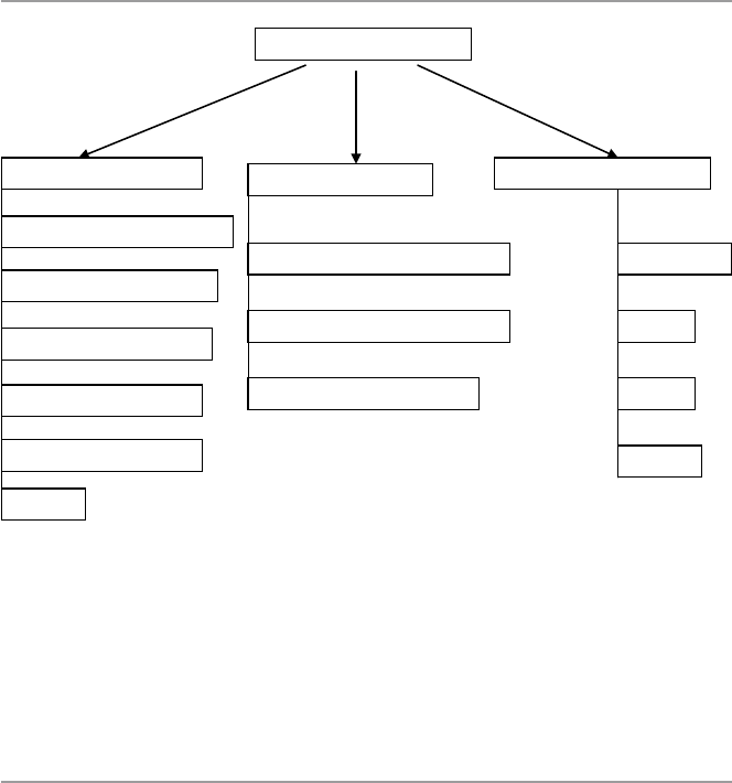
450
the remainder of this chapter, we are going to focus on this model of computing and
discuss its benefits and security concerns. This computing model as shown in
Fig. 21.1 is composed of a number of essential characteristics, three service models,
and four deployment models.
21.2 Cloud Computing Infrastructure Characteristics
Traditionally data center computing models were mainly based on a client–server
model architecture and design, relying firmly a three-tier architecture design that
included access, distribution, and core switches connecting relatively few clients
and meeting limited client needs compared to today’s cloud services models. In
most cases, each server was dedicated to either single or limited applications and
had IP addresses and media access control addresses. This static nature of the appli-
cation environment worked well and lent itself to manual processes for server
deployment or redeployment. According to both Jim Metzler and Steve Taylor of
Network World [2], they primarily used a spanning tree protocol to avoid loops. But
because of the dramatic advances in the previous years in virtualization technology,
distributed computing, rapid improvements, and access to high-speed Internet have
all dramatically changed the staid nature of the data center. Today’s data center,
providing cloud services, is but staid, it is bursting with activities and services with
distinctly new characteristics that differentiate it from traditional cousin. For
Cloud Deployment ModelsCloud Characteristics Cloud Service Model
Ubiquitous Network Access
Measured service
On-demand self-service
Rapid elasticity
Resource pooling
Infrastructure as a Service (IaaS)
Software as a Service (SaaS)
Platform as a Service (PaaS)
Hybrid
Public
Private
Community
Cloud Computing Model
Others
Fig. 21.1 Broad view of a cloud computing model
21 Cloud Computing and Related Security Issues

451
example, its services are now on demand, by the minute or the hour; it is elastic,
because users can have as much or as little of a service as they want at any given
time; and the service is fully managed by the provider, that is, the consumer needs
nothing but a personal computer and Internet access. Let us now briefly look at each
one of these characteristics:
Ubiquitous network access
Like in the previous section on on-demand self-service, the advances and use of
virtualization technology and the availability and access to high-speed Internet
have also helped to change the nature of access to the computing services sought
by customers and the increase in the number of services a customer can select
from. With more choice also came the high specialization and quality of services
that a customer can expert.
Measured service
Because cloud services are flexible, on-demand, and are elastic, it is important, therefore,
for these services to be metered. The concept of metered services allows customers to
get what they want in the required amounts at the time they want the service. One of
the most popular characteristics of cloud computing technology is measured or
metered service for most, if not all, of the cloud services including storage, process-
ing, bandwidth, and active user accounts. This pick-what-you-can-afford-pay-for
principle based on metering results in an automatic control and optimization of cloud
technology resource use based on the type of service and these statistics can be
reported as needed, thus providing transparency for both the provider and consumer.
On-demand self-service
With the rapid and unprecedented use of virtualization technology and the avail-
ability and access to high-speed Internet, the traditional and all other models of
acquisition of computing services that demanded perpetual ownership of soft-
ware or computing hardware and long contracts with employees that helped to
use the service, the need for redundancy, and outsourcing of services all dimin-
ished and turned into a more flexible model where consumers of computing ser-
vices were no longer restricted to having one of the rigid traditional models of
either ownership, outsources, or boxed services. Now, a consumer is able to not
only automatically provision any computing services and capabilities as needed
but also can determine the time and how long to use the provisioned services.
Rapid elasticity
Computing service elasticity means the ability to resize and dynamically scale the
virtualized resources at hand such as servers, processors, operating systems, and
others to meet the customer’s on-demand needs. The provider must make sure
that there are resources at hand that must meet elastic capabilities to ensure that
end users’ requests are continually and promptly met. Amazon’s EC2 is a good
example of a Web service interface that allows the customer to obtain and con-
figure capacity with minimal effort.
Resource pooling
Increased flexibility, access, and ease of use usually lead to high and varied demands
of services from customers. To meet these new demands, providers usually respond
21.2 Cloud Computing Infrastructure Characteristics

452
by offering a variety of and polling of system resources and services. As noted in
the NIST report, the provider’s computing resources are pooled to serve multiple
consumers using a multi-tenant model, with different physical and virtual resources
dynamically assigned and reassigned according to consumer demand.
Others
There are other characteristics common to cloud computing beyond the five we have
discussed above. Among these are:
•Massive scale – that the cloud offers the resources at a massive scale on
demand.
•Virtualization – in fact this is the linchpin of the cloud technology. The cloud
is possible because of virtualization of the fundamental functionalities of the
physical machine.
•Free software – or near-free software as needed from the cloud.
•Autonomic computing – in a sense that you scale computing resources at a
time you want them on the fly.
•Multi-tenancy – because of cloud’s massive scale and easy access of those
resources, cloud computing can accommodate a large number of users at a time.
21.3 Cloud Computing Service Models
Infrastructure as a Service (IaaS). The process of providing the customer with the
ability and capability to manage and control, via a Web-based virtual server instance
API, system resources such as starting, stopping, accessing, and configuring the
virtual servers, operating systems, applications, storage, processing, and other fun-
damental computing resources is referred to as infrastructure as a service (IaaS). In
doing all these, however, the consumer does not have access nor control the under-
lying physical cloud infrastructure.
Platform as a Service (PaaS). This is a set of software and product development
tools hosted on the provider’s infrastructure and accessible to the customer via a
Web-based virtual server instance API. Through this instance, the customer can cre-
ate applications on the provider’s platform over the Internet. Accessing the platform
via the Web-based virtual instance API protects the resources because the customer
cannot manage or control the underlying physical cloud infrastructure including
network, servers, operating systems, or storage.
Software as a Service (SaaS). Ever since the beginning of computing software,
over the years, the key issue that has driven software development has been the issue
of the cost of software. Trying to control the cost of software has resulted into soft-
ware going through several models. The first model was the home-developed soft-
ware where software users developed their own software based on their needs and
they owned everything and were responsible for updates and management of it. In
the second model, the traditional software model was based on packaged software
where the customer acquired a more general-purpose software from the provider
with a license held by the provider and the provider being responsible for the updates,
21 Cloud Computing and Related Security Issues

453
while the customer is responsible for its management. However, sometimes, soft-
ware producers provide additional support services, the so-called premium support,
usually for additional fees. Model three was the open-source model led by a free
software movement starting around the late 1980s. By the late 1980, free software
turned into open source with the creation of the Open Source Initiative (OSI). Under
the name “open source,” some for-profit companies offering free software started to
change the model from a purely free software to some form of payment to support
the updates of the software. The open-source software model transformed the cost of
software remarkably. Model Four consisted of software outsourcing.
The outsourcing model was in response to the escalating cost of software associated
with software management. The component of software management in the overall
cost of software was slowly surpassing all the costs of other components of software
including licensing and updates. In Model Four, however, software is still licensed
from the software company on a perpetual basis; support fees are still paid. However,
the software producer takes on the responsibility of the management of that software.
Software Model Five is software as a service (SaaS). Under this model, there is
a different way of purchasing. Under SaaS, there is the elimination of the upfront
license fee. All software applications are retained by the provider, and the customer
has access to all applications of choice from the provider via various client devices
through either a thin client interface, such as a Web browser, a Web portal, or a vir-
tual server instance API. The cloud user’s responsibilities and actual activities in the
use of and operations of the requested cloud services are limited to user-specific
application configuration settings, leaving the management and control of the
underlying cloud infrastructure including network, servers, operating systems, stor-
age, or even individual application capabilities to the cloud provider.
21.3.1 Three Features of SaaS Applications
In particular, software as a service has the following features:
•Scalability – in that it can handle growing amounts of work in a graceful manner.
•Multi-tenancy – in that one application instance may be serving hundreds of
companies. This is different from the client–server model from which the cloud
computing model grows out in which each customer is provisioned their own
server running one instance.
•Metadata-driven configurability – customers can configure their application
through metadvata.
21.4 Cloud Computing Deployment Models
There are three cloud deployment models which are actually cloud types. These are
the public, private, and the hybrid models.
21.4 Cloud Computing Deployment Models

454
Public clouds – the public clouds provide access to computing resources for the
general public over the Internet, allowing customers to self-provision resources
typically via a Web service interface on a pay-as-you-go basis. One of the bene-
fits of public clouds is to offer large pools of scalable resources on a temporary
basis without the need for capital investment in infrastructure by the user.
Private cloud – unlike public clouds, private clouds give users immediate access to
computing resources hosted within an organization’s infrastructure and prem-
ises. Users, who are usually in some form of a relationship with the cloud owner,
choose and scale collections of resources drawn from the private cloud, typically
via Web service interface, just as with a public cloud. Also the private cloud is
deployed within and uses the organization’s existing resources and is always
behind the organization’s firewall subject to the organization’s physical, elec-
tronic, and procedural security measures. In this case, therefore, private clouds
offer a higher degree of security.
Hybrid cloud – a hybrid cloud combines the computing resources of both the public
and private clouds.
21.5 Virtualization and Cloud Computing
In this chapter, we are going to discuss virtualization in depth so here we are only
defining the concept and showing its role in cloud computing. Virtualization is a
process of creating something in effect and performance but not in reality – hence
virtual. In computing, virtualization can be used on both software and hardware. In
software virtualization has been used in operating systems where the underlying
operating systems creates a number of virtual operating systems, not only clones of
itself but even others, to run on the underlying machine and perform tasks at a
higher performance level. In hardware, virtualization is being used to create new
resources like servers, storage devices, and others. The potential power of virtual-
ization is substantially increasing the performance of computing systems such as
hardware and software through division of the underlying physical computing
resources into many equally powerful virtual machines, thus scaling up the perfor-
mance and creating elasticity of many computing system. With virtualization, com-
putation and applications can be moved easily from physical to virtual machines.
This transfer of computation and applications from one machine to another both
physical and virtual is not truly a new idea. The client–server computing model is
an example of this. But while in the client–server model the applications running on
the servers are managed by the service providers, in cloud computing model, com-
putations and application may scale out to many other servers owned by the cloud
provider. This is possible through the power of virtualization. Virtualization is a
fundamental feature in cloud computing. Virtualization allows applications from
different customers to run on different virtual machines, hence providing separation
and protection.
21 Cloud Computing and Related Security Issues

45521.6 Benefits of Cloud Computing
21.6 Benefits of Cloud Computing
Cloud computing as a model of computing is very exciting and has tremendous
benefits for those who dare to use it. It is not only exciting when you come to learn
it, but it also has an array of benefits including but not limited to leveraging on a
massive scale, homogeneity, virtualization, low-cost software, service orientation,
and advanced security technologies.
Reduced Cost. The biggest gain from all cloud computing benefits to a company
perhaps lies in cost savings. Whether it is a small-, medium-, or large-scale
manufacturing business, there are essential cost benefits in using a cloud model for
most of the company’s computing needs. The biggest issue here is the fact that
cloud computing is operated remotely off company premises except a few devices
needed for accessing the cloud resources via a Web portal. This means that company
personnel can do the same amount of work on fewer computers by having higher
utilization, save on not housing data centers on premises, save on personnel for run-
ning the data center, and save on expenses that would normally be essential for
running a data center on the premises. There is documentary evidence to support
these views from industry experts. In the words of Greg Papadopoulos, CTO, Sun
Microsystems CTO [3], hosting providers bring “brutal efficiency” for utilization,
power, security, service levels, and idea-to-deploy time. George Reese, founder
Valtira anden Stratus, states that using cloud infrastructures saves 18–29 % before
considering that you no longer need to buy for peak capacity [3]. And according to
Dan Farber, Editor in Chief CNET News, we are at the beginning of the age of plan-
etary computing where billions of people will be wirelessly interconnected, and the
only way to achieve that kind of massive scale usage is by massive scale, brutally
efficient cloud-based infrastructure [3]. And finally there are savings on power con-
sumption since there are few computers on the premises. Currently, servers are used
at only 15 % of their capacity in many companies, and 80 % of enterprise software
expenditure is on installation and maintenance of software. The use of cloud appli-
cations can reduce these costs from 50 % to 90 % [3].
Automatic Updates. Our economy is now an online economy because most of, if
not all, businesses are now online and depend on software applications for day-to-
day services. Software is continuously changing, and as business functionalities
change, software need to be changed or updated. The cost of software updates and
management has always been on the rise, usually surpassing the cost of new soft-
ware. For companies to stay competitive and in many cases afloat, they must be
consistently updating and changing software. The business of software updates and
software management and licensing is a big drain on company resources. So having
automatic updates and management from the cloud provider can be a great relief to
any company. But updates are not limited to only software. Also not worrying about
hardware updates is cost effective for companies.
Green Benefits of Cloud Computing. Although cloud computing energy con-
sumption has caused a vigorous debate and this debate is continuing, pitting those

456
claiming that cloud computing is gobbling up resources because large cloud and
social networking sites need daily megawatts of power to feed insatiable computing
needs and those who claim that the computing model is indeed saving power from
millions of servers left idling daily and consuming more power. We will discuss this
more in the coming sections. For now, we think that there are indeed savings in
power consumption by cloud computing.
Remote Access. With a Web portal access to the cloud, company employees may
be able to work while they are on the road, home, or in the office. This is of great
benefit to the company so that there is no downtime because somebody is not in the
office.
Disaster Relief. Many companies live in constant fear disasters occurring when
they have company vital data stored on premises. No one likes to be a victim of
large-scale catastrophes such as devastating hurricanes, earthquakes, fires, and of
course terrorist attacks. Such misfortunes can create havoc to the companies’ vital
data and disrupt operations even if there were limited physical damage. Additionally,
there are smaller disasters like computer crashes and power outages that can also
wreak havoc on a company’s vital data. While this is possible, there are many com-
panies, especially small ones, that may not even have any disaster recovery plan and
some who have it may not be able to execute it effectively. This fear can be over-
come with investments in cloud technology. Company’s vital backup data can be
safely stored on secure data centers on the cloud instead of in the company’s server
room.
Self-Service Provisioning. Cloud computing allows users to deploy their own
virtual sets of computing resources like servers, network, storage, and others, as
needed without the delays, competency, and complications typically involved in
physical resource acquisition, installation, and management. The cloud owners,
irrespective of their physical location, not only can provide all the computing
resources your organization needs but also have the necessary capacity needed to
monitor, manage, and respond to the organization’s daily and hour by hour infra-
structure, software, and platform requirements.
Scalability. Because of the minute by minute monitoring capability of cloud
computing of an organization’s computing needs and the ability to increase or
reduce the required resources as the demand increases or decreases, cloud comput-
ing offers the best infrastructure, platform, and software scalability that cannot be
matched in any owned computing facility.
Reliability and Fault Tolerance. Because the cloud provider, with qualified pro-
fessionals and experience, monitors the computing requirements of a client com-
pany and can easily scale to demand, cloud computing offers a high degree of
reliability and fault tolerance.
Ease of Use. To attract more customers, cloud providers have and must make the
user interface easy so that customers can scale into the cloud with the least effort.
Skills and Proficiency. Some of the most sought-after assets from a cloud pro-
vider are professionalism and a vast skills set provided to the customers. Companies,
especially small ones, would pay a high price to get an employee with the skills set,
efficiency, proficiency, and experience found with cloud center staff.
21 Cloud Computing and Related Security Issues

457
Response Time. Depending on the bandwidth at the company Web portal, cloud
computing services normally have speed because the computing resources provided
are modern and powerful to be able to accommodate large number of users.
Mobility. Because of Web portal interface to the cloud, cloud computing
essentially is a mobile computing platform, allowing the users to access their
applications.
Increased Storage. Storage is the main function of cloud computing. Because of
this, it is cheap and readily scalable to need.
Other Benefits. Other benefits beyond those we discussed above include provid-
ing a high quality of service (QoS), well-defined and stable industry standard API,
and on-demand availability of computing resources based on “at hand” financial
constraints.
Security. We are going to discuss this more in the coming section. Cloud comput-
ing, because of its individual virtual machines created per use, has already a built-in
security provision. In addition to these built-in provisions due to virtualization, the
cloud model also offers a strong authentication regime at the browser interface gate-
way, a security mechanism that is individually and quickly set up and torn down as
needed and a strong validation and verification scheme that is expensive to deploy
at an individual client–server model.
21.7 Cloud Computing, Power Consumption,
and Environmental Issues
As we briefly discussed in the last section, there is a heated debate on-going pitting
those claiming that cloud computing is gobbling up resources as large cloud and
social networking sites need daily megawatts of power to feed insatiable computing
needs and those who claim that the computing model is indeed saving power from
millions of servers left idling daily and consuming more power. Let us not interject
ourselves into the debate.
In the paper “Make IT Green: Cloud Computing and its Contribution to Climate
Change,” [4] Greenpeace called attention to the growing, power-hungry data center
footprint, citing estimates that cloud computer sites could consume up to 622.6 bil-
lion kWh (kilowatts per hour) of power and also that the quintessential cloud com-
puting devices, like the smartphones including Apple iPad and the Androids offering
online access to the cloud and social networks, can contribute to a much larger
carbon footprint of the information technology sector than previously estimated.
Greenpeace has supporters in their camp, and these supporters are professionals
adding weight to the debate. For example, in his paper “The Environmental Cost of
Cloud Computing: Assessing Power Use and Impacts,” Jonathan Koomey [5], pro-
fessor of civil and environmental engineering at Stanford University, claims that by
2009, the cloud was responsible for 1–2 % of the world’s electricity use. All major
cloud providers including the Google, Facebook, Amazon, Yahoo, Microsoft, Apple,
and others are involved in one way or the other in deals with power producers to
provide them with enormous amounts of power to run the data centers. For example,
21.7 Cloud Computing, Power Consumption, and Environmental Issues

458
in 2010, Facebook signed an agreement with Pacific Corp, a utility provider in the
northwest, to provide power for its Oregon data center. This did not go well with
Greenpeace because Pacific Corp gets most of its energy from coal-fired power sta-
tions, the known largest source of greenhouse gas emissions in the United States.
In their climate projection for year 2020 report entitled “SMART 2020: Enabling
the Low Carbon Economy in the Information Age,” [5] the Climate Group and the
Global e-Sustainability Initiative (GeSI) noted the growth of 9.5 % a year in ICT
electricity consumption and GHG emissions. Projections like these are adding fuel
to the debate about cloud computing technology and the environment.
The other side of the debate is no less vigorous. They are holding the view that
because cloud computing technology makes companies share pooled resources and
facilities, this is indeed helping to contain the expected degradation of the environ-
ment resulting from the projected, relentless, and viral growth of information tech-
nology device use as projected in the Climate Group and the Global e-Sustainability
Initiative (GeSI) 2007 report entitled “SMART 2020: Enabling the Low Carbon
Economy in the Information Age” [5]. In that report it is projected that:
•PC ownership will quadruple between 2007 and 2020 to four billion devices, and
emissions will double over the same period, with laptops overtaking desktops as
the main source of global ICT emissions expected to reach 22 % mark.
•Mobile phone ownership will almost double to nearly five billion accounts by
2020, but emissions will only grow by 4 %.
•Broadband uptake will treble to almost 900 million accounts over the same
period, with emissions doubling over the entire telecoms infrastructure.
In the same report, the group makes a compelling case for ICT’s significant
potential to deliver climate and energy solutions, estimating that ICT technologies
could cut 7.8 GtCO2 of global greenhouse gas emissions by 2020, a 15 % reduction.
We concur with this report in saying that new innovations in cloud computing tech-
nologies together with increased awareness and use of renewable energy can make
cloud technology a greener technology and make it use less power.
21.8 Cloud Computing Security, Reliability, Availability,
and Compliance Issues
The cloud computing model as we know it today did not start overnight. The process
has taken years moving through seven software models beginning with in- house
software, licensed software normally referred to as the traditional model, open
source, outsourcing, hybrid, software as a service, and finally the Internet model, the
last two being part of the cloud computing model. When one carefully examines the
cloud servicing model, one does not fail to notice the backward compatibilities or
the carryovers of many of the attributes that characterized software through all the
models. While this brings the benefits of each one of those software models, but also
21 Cloud Computing and Related Security Issues

459
many, if not all, of the software complexity and security issues in those models were
carried over into the cloud computing model. Because of this, our first thought was
to discuss the security issues in the cloud computing model through the prism of
these models. It is tempting, but we are going to follow a different path while keep-
ing the reader rooted into the different software models. Security is and continues to
be a top issue in the cloud computing model. The other three related issues are per-
formance, compliance, and availability. We will discuss all four in this section, but
since security is the number one issue, we will address it first.
We want to start the discussion of cloud computing security by paraphrasing
Greg Papadopoulos, CTO of Sun Microsystems, who said that cloud users normally
“trust” cloud service providers with their data like they trust banks with their money.
This means that they expect the three issues of security, availability, and perfor-
mance to be of little concern to them as they are with their banks [3]. To give a fair
discussion of the security of anything, one has to focus on two things, that is, the
actors and their roles in the process you are interested in securing and the applica-
tion or data in play. The application or data is thought of in relation to the state it is
in at any one time. For example, the states for both data and application can be either
in motion between the remote hosts and the service provider’s hypervisors and serv-
ers or in the static state when it is stored at remote hosts, usually on the customer’s
premises or in the service provider’s servers. The kind of security needed in either
one of these two states is different.
21.8.1 Cloud Computing Actors, Their Roles, and Responsibilities
In the cloud computing model, the main players are the cloud provider, the customer
who is the data owner and who seeks cloud services from the cloud provider and the
user who may or may not be the owner of the data stored in the cloud. The first two
players have delegated responsibilities to all who work on their behalf. To fully
understand these delegated responsibilities assigned to each one of these, we need
to look at first the marginal security concerns resulting from the peripheral system
access control that always results in easiest breach of security for any system, usu-
ally through compromising user accounts via weak passwords. This problem is
broad affecting both local and outsourced cloud solutions. Addressing this and all
other administrative and use security concern requires companies offering and using
cloud solutions to design an access control regime that covers and requires every
user, local or remote, to abide by these access policies including the peripheral ones
like the generation and storage of user passwords. Additionally, employees need to
be informed of the danger of picking easy passwords and to understand the danger
of writing a password down or divulging a password to anyone. Access control
administration is so important that cloud providers spend large amounts of resources
to design a strong access control regimes. For example, let us look at the access
control of the three major cloud providers, namely, Amazon Web Services (AWS),
Microsoft Windows Azure, and Rackspace.
21.8 Cloud Computing Security, Reliability, Availability, and Compliance Issues

460
21.8.1.1 Amazon Web Services
With Amazon Web Services (AWS) EC2 and S3, one can remotely self-provision
what they want seamlessly. This kind of easiness, while great, created a set of secu-
rity problems unless there is a strong access control regime in place. For Amazon,
the solution is through use of Amazon Identity and Access Management (IAM).
This allows the account owner to create multiple accounts for other authorized users
on a single Amazon account. Then as usual, each user is then assigned permissions
on the main account, accessible via user id and passwords based on the user’s role
and responsibility in the customer’s company. Based on the traditional access con-
trol, fine-grained security can be attained for all service users.
21.8.1.2 Microsoft Windows Azure
Microsoft Azure on the other hand uses a home-grown Azure Platform AppFabric
Access Control Service (ACS) to manage user access security. Key features of ACS
include [6]:
•Integrates with Windows Identity Foundation (WIF) and tooling
•Out-of-the-box support for popular Web identity providers including Windows
Live ID, Google, Yahoo, and Facebook
•Out-of-the-box support for Active Directory Federation Services 2.0
•Support for OAuth 2.0 (draft 13), WS-Trust, and WS-Federation protocols
•Support for the SAML 1.1, SAML 2.0, and Simple Web Token (SWT) token
formats
•Integrated and customizable Home Realm Discovery that allows users to choose
their identity provider
•An OData-based management service that provides programmatic access to ACS
configuration
•A Web Portal that allows administrative access to ACS configuration
ACS works in several models including single sign-on, federating identities
across security realms and role-based access control. For example, in the single-log-
on model, the client log-on will be as follows [7]:
•The client authenticates with ACS.
•ACS creates a token and returns it to the client.
•The client passes the token to the server.
•The server verifies the token and authorizes functionality.
21.8.1.3 Rackspace
In Rackspace, client authentication is done by the Cloud Authentication Service,
also known as Auth. Auth allows each client needing authentication to obtain an
authentication token and a list of regional service endpoints to the various services
available in the cloud. Users must authenticate with their credentials, but once
21 Cloud Computing and Related Security Issues

461
authenticated, they can create/delete containers and objects within that account.
Since the Cloud Files system is designed to be used by many different customers,
each user account is the user’s portion of the Cloud Files system. Each client authen-
tication is provided via a ReST (see below) interface which requires two headers,
X-Auth-User and X-Auth-Key or X-Auth-Token, with values for the username and
API Access Key, respectively. Clients obtain this token, along with the Cloud Servers
API URL, by first using the Rackspace Cloud Authentication Service [16].
Request: ReST
To authenticate, client provides the following in x-headers:
•Username as X-Auth-User x-header
•API access key (from the Rackspace Cloud Control Panel in client Account API
Access section) as X-Auth-Key
Response
Upon successful authentication, an HTTP status 204 is returned with the X-Storage-
Url, X-CDN-Management-Url, and X-Auth-Token headers. Any 2xx response is a
good response. For example, a 202 response means the request has been accepted.
Also, additional x-headers may be returned. These additional headers are related to
other Rackspace services and can be ignored. An HTTP status of 401 (unauthor-
ized) is returned upon authentication failure. All subsequent container/object opera-
tions against Cloud Files should be made against the URI specified in X-Storage-Url
or X-CDN-Management-Url and must include the X-Auth-Token header [16].
After these exchanges, the client is ready to use the cloud.
21.8.2 Security of Data and Applications in the Cloud
Let us next look at the security of data and applications in the cloud. To do this, we
need to focus first on the security and role of the hypervisor and then the servers on
which user services are based. A hypervisor also called virtual machine manager
(VMM) is one of the many hardware virtualization techniques allowing multiple
operating systems, termed guests, to run concurrently on a host computer. The hyper-
visor is piggybacked on a kernel program, itself running on the core physical machine
running as the physical server. The hypervisor presents to the guest operating sys-
tems a virtual operating platform and manages the execution of the guest operating
systems. Multiple instances of a variety of operating systems may share the virtual-
ized hardware resources. Hypervisors are very commonly installed on server hard-
ware, with the function of running guest operating systems, that themselves act as
servers. The security of the hypervisor therefore involves the security of the underly-
ing kernel program and the underlying physical machine, the physical server, and the
individual virtual operating systems and their anchoring virtual machines.
21.8 Cloud Computing Security, Reliability, Availability, and Compliance Issues

462
21.8.2.1 Hypervisor Security
The key feature of the cloud computing model is the concept of virtualization. We
covered virtualization in the previous chapter. It is this virtualization that gives the
cloud the near-instant scalability and versatility that makes cloud computing so
desirable a computing solution by companies and individuals. The core of virtual-
ization in cloud computing is the easy process of minting of virtual machines on
demand by the hypervisor. The hypervisor allocates resources to each virtual
machine it creates, and it also handles the deletion of virtual machines. Since each
virtual machine is initiated by an instance, the hypervisor is a bidirectional conduit
into and out of every virtual machine. The compromise of either, therefore, creates
a danger to the other. However, most hypervisors are constructed in such a way that
there is a separation between the environments of the sandboxes (the virtual
machines) and the hypervisor. There is just one hypervisor, which services all vir-
tual sandboxes, each running a guest operating system. The hypervisor runs as part
of the native monolithic operating system, side-by-side with the device drivers, file
system, and network stack, completely in kernel space. So, one of the biggest secu-
rity concerns with a hypervisor is the establishment of covert channels by an
intruder. If an intruder succeeds in establishing a covert channel, either by modify-
ing file contents or through timing, it is possible for information to leak from one
virtual machine instance to another [8].
Also since the hypervisor is the controller of all virtual machines, it, therefore,
becomes the single point of failure in any cloud computing architecture. That is, if
an intruder compromises a hypervisor, then the intruder has control of all the virtual
machines the hypervisor has allocated. This means that the intruder can even create
or destroy virtual machines at will. For example, the intruder can perform a denial-
of- service attack, by bringing down the hypervisor which then brings down all vir-
tual machines running on top of the hypervisor.
The processes of securing virtual hosts differ greatly from processes used to
secure their physical counterparts. Securing virtual entities like a hypervisor, virtual
operating systems, and corresponding virtual machines is more complex. To under-
stand hypervisor security, let us first discuss the environment in which the hypervi-
sor works. Recall that a hypervisor is part of a virtual computer system (VCS). In
his 1973 thesis in the Division of Engineering and Applied Physics, Harvard
University, Robert P. Goldberg defines a virtual computer system as a hardware–
software duplicate of a real existing computer system in which a statistically domi-
nant subset of the virtual processor’s instructions execute directly on the host
processor in native mode. He also gives two parts to this definition, the environment
and implementation [9].
Environment. The virtual computer system must simulate a real existing com-
puter system. Programs and operating systems which run on the real system must
run on the virtual system with identical effect. Since the simulated machine may run
at a different speed from the real one, timing-dependent processor and I/O code may
not perform exactly as intended.
Implementation. Most instructions being executed must be processed directly by
the host CPU without recourse to instruction by instruction interpretation. This
21 Cloud Computing and Related Security Issues
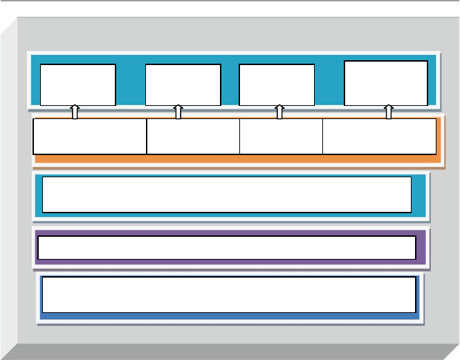
463
guarantees that the virtual machine will run on the host with relative efficiency. It
also compels the virtual machine to be similar or identical to the host and forbids
tampering with the control store to add an entirely new order code.
In the environment of virtual machines, a hypervisor is needed to control all the
sandboxes (virtual machines). Generally, in practice, the underlying architecture of
the hypervisor determines if there is a desired true separation between the sand-
boxes or not. Robert P. Goldberg classifies two types of hypervisor [10]:
Type 1 (or Native, Bare Metal). Hypervisors run directly on the host’s hardware
to control the hardware and to manage guest operating systems. See Fig. 21.2. All
guest operating systems then run on a level above the hypervisor. This model repre-
sents the classic implementation of virtual machine architectures. Modern hypervi-
sors based on this model include Citrix XenServer, VMware ESX/ESXi, and
Microsoft Hyper-V. The most common commercial hypervisors are based on a
monolithic architecture below.
The underlying hypervisor services all virtual sandboxes, each running a guest
operating system. The hypervisor runs as part of the native monolithic operating
system, side-by-side with the device drivers, file system, and network stack, com-
pletely in kernel space.
Type 2 (or Hosted). Hypervisors run just above a host operating system kernel
such as Linux, Windows, and others as shown in Fig. 21.3. With the hypervisor
layer as a distinct second software level, guest operating systems run at the third
Hypervisor
Hardware – Host CPU
OS Functionalitie
sD
evice DriversNetworking File System
Virtual
Machine N
Host OS Kernel
Virtual
Machine 2
Virtual
Machine J
Virtual
Machine 1
Fig. 21.2 Type 1 hypervisor
21.8 Cloud Computing Security, Reliability, Availability, and Compliance Issues
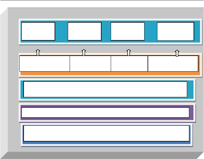
464
level above the hardware. The host operating system has direct access to the server’s
hardware like host CPU, memory, and I/O devices and is responsible for managing
basic OS services. The hypervisor creates virtual machine environments and coor-
dinates calls to CPU, memory, disk, network, and other resources through the host
OS. Modern hypervisors based on this model include KVM and VirtualBox.
The discussion so far highlights the central role of the hypervisor in the opera-
tions of virtual machine systems, and it points to its central role in securing all vir-
tual machine systems. Before we look at what can be done to secure it, let us ask
ourselves what security breaches can happen to the hypervisor. There are several of
these security breaches most severe involving self-installation of both malware and
rootkits masquerading as they are the hypervisor.
Hacking the Hypervisor
In his blog “Yes, Hypervisors Are Vulnerable,” Neil MacDonald, Vice President and
a Gartner Fellow [11], observes the following about hypervisor and the vulnerabilities
associated with it:
•The virtualization platform (hypervisor/VMM) is a software written by human
beings and will contain vulnerabilities. Microsoft, VMware, Citrix, and others all
of them will and have had vulnerabilities.
Host OS Kernel
Hardware – Host CPU
OS Functionalities Device DriversNetworking File System
Virtual
Machine N
Hypervisor
Virtual
Machine 2
Virtual
Machine J
Virtual
Machine 1
Fig. 21.3 Type 2 hypervisor
21 Cloud Computing and Related Security Issues

465
•Some of these vulnerabilities will result in a breakdown in isolation that the vir-
tualization platform was supposed to enforce.
•Bad guys will target this layer with attacks. The benefits of a compromise of this
layer are simply too great.
•While there have been a few disclosed attacks, it is just a matter of time before a
widespread publicly disclosed enterprise breach is tied back to a hypervisor
vulnerability.
As we have seen so far in this chapter, there has been a growing increase in the
virtualization vulnerabilities. Published papers have so far shown that the security
of hypervisors can be undermined. As far back as 2006, Samuel T. King, Peter
M. Chen, Yi-Min Wang, Chad Verbowski, Helen J. Wang, and Jacob R. Lorch dem-
onstrate in their paper “SubVirt: Implementing malware with virtual machines” the
use of type of malware, which is called a virtual-machine-based rootkit (VMBR),
installing a virtual machine monitor underneath an existing operating system and
hoists the original operating system into a virtual machine [13].
In fact in this study, the authors demonstrated a malware program that started to
act as its own hypervisor under Windows. According to the IBM X-Force 2010 Mid-
Year Trend and Risk Report, which disclosed a 10-year virtualization vulnerability
trend from 1999 to 2009, there were 373 reported vulnerabilities affecting virtual-
ization solutions during the period with a steady growth trend starting around 2002
and peaking in 2008 to 100 and falling off by 12 % in 2009. What do we learn from
all these? We learn that the hypervisor layer of virtualization, playing the core role
in the virtualization process, is very vulnerable to hacking because this is the weak-
est link in the data center. Therefore, attacks on hypervisor are on the rise. Data
from the IBM X-Force 2010 Mid-Year Trend and Risk Report show that every year
since 2005, vulnerabilities in virtualization server products, the hypervisors, have
overshadowed those in workstation products, an indication of the hackers interest in
the hypervisors. The report further shows that 35 % of the server virtualization vul-
nerabilities are vulnerabilities that allow an attacker to “escape” from a guest virtual
machine to affect other virtual machines or the hypervisor itself. Because, as Fig.
21.2 shows, the hypervisor in type 1 environment is granted CPU privilege to access
all system I/O resources and memory, this makes it a security threat to the whole
cloud infrastructure. Just one vulnerability in the hypervisor itself could result in a
hacker gaining access to the entire system, including all the guest operating sys-
tems. Because malware runs below the entire operating system, there is a growing
threat of hackers using malware and rootkits to install themselves as a hypervisor
below the operating system, thus making them more difficult to detect. Once
installed and operating below the main operating system, there is evidence that mal-
ware can intercept any operations without the antivirus software detecting them,
although there is a debate with some scholars disputing this. Since 2009, there have
been efforts in producing kernel-mode anti-rootkit products, such as Hoosafe from
Microsoft and North Carolina State University and Rackspace’s NoVirus Thanks
Anti-Rootkit [13].
21.8 Cloud Computing Security, Reliability, Availability, and Compliance Issues

466
In type 2 hypervisor configuration, Fig. 21.3, the microkernel architecture is
designed specifically to guarantee a robust separation of application partitions. This
architecture puts the complex virtualization program in user space; thus, every guest
operating system uses its own instantiation of the virtualization program. In this
case, therefore, there is complete separation between the sandboxes (virtual boxes),
thus reducing the risks exhibited in type 1 hypervisors.
An attack, therefore, on type 2 hypervisors can bring down one virtual box, not
more, and cannot bring down the cloud infrastructure as is the case in type 1
hypervisors.
According to Samuel T. King et al., overall, virtual machine–based rootkits are
hard to detect and remove because their state cannot be accessed by software run-
ning in the target system. Further, VMBRs support general-purpose malicious ser-
vices by allowing such services to run in a separate operating system that is protected
from the target system [12].
21.8.2.2 Securing Load Balancers
For every hypervisor, there is a load balancer, used to route traffic to different virtual
machines to help spread traffic evenly across available machines. A load balancer in
a hypervisor plays a vital role of ensuring a fair distribution of available load to all
virtual machines especially during high traffic and ensuring the full utilization of
the cloud infrastructure. Elastic load balancers play a central in the cloud infrastruc-
ture along the following lines [13]:
•It listens to all traffic destined for the internal network and distributes incoming
traffic across the cloud infrastructure.
•Automatically scales its request handling capacity in response to incoming appli-
cation traffic.
•It creates and manages security groups associated with each instance and pro-
vides additional networking and security options if and when needed.
•It can detect the health of the virtual machines, and if it detects unhealthy load-
balanced virtual machine, it stops routing traffic to it and spreads the load across
the remaining healthy virtual machines.
•It supports the ability to stick user sessions to specific virtual machines.
•It supports SSL termination at the load balancer, including offloading SSL
decryption from application virtual machines, centralized management of SSL
certificates, and encryption to backend virtual machines with optional public-key
authentication.
•It supports use of both the Internet Protocol version 4 and 6 (IPv4 and IPv6).
Due to the load balancer’s ability to listen and process all traffic that is destined
to the internal network of the cloud, it is a prime target for attackers. If a load bal-
ancer was compromised, an attacker could listen to traffic and may compromise
secure traffic destined to outside the network. Additionally, if the load balancer is
compromised along with a virtual machine, traffic could be directed to an unsecure
internal server where further attacks are launched [14]. Because the load balancer is
21 Cloud Computing and Related Security Issues

467
a single point in the cloud infrastructure, it is very vulnerable to denial-of-service
attacks, if it is compromised. This can lead to cloud activity disruption.
What is the best way to secure the load balancer from attacks then? A load bal-
ancer is normally secured through proper configuration and monitoring of the bal-
ancer’s logs. This is achieved through restriction of access to administration of the
balancer itself by configuring the load balancer to only accept administrative access
over a specific administrative network. This administrative network should be con-
nected to the administrative-only network. Limiting access over the administrator
network greatly limits the number of users with access to the load balancer [15].
21.8.2.3 Virtual Operating Systems Security
Besides the hypervisor, the virtualization system also hosts virtual servers, each running
either a guest operating system or another hypervisor. And on the peripheral of the vir-
tual machine system are the consoles and hosts. Through each one of these resources,
the virtual machine system can be susceptible to security vulnerabilities. Let us briefly
look at these since they were covered in more detail in the previous chapter.
Host Security
Through hosts like workstations, user gains access to the virtual machine system,
hence to the cloud. Two problems are encountered here:
•Escape-to-hypervisor vulnerabilities – that allow intruders to penetrate the vir-
tual machine from the host
•Escape-to-host vulnerabilities – that allow vulnerabilities in the virtual machine
to move to the hosts
Guest Machines
Guest machines running guest operating system can also pose a security problem to
the cloud. However, as we saw in the previous chapter, vulnerabilities in the guest
virtual machines are confined to that machine, and they rarely affect other machines
in the system.
21.8.3 Security of Data in Transition: Cloud Security Best
Practices
With the vulnerabilities in the cloud we have discussed above, what is the best way
to protect the user of the cloud? For a cloud customer, the key areas of concerns are
virtualization technology security vulnerabilities that may be encountered during
the use of the cloud that may affect the customer, unauthorized access to customer
data, and other resources stored or implemented in the cloud, whether the cloud
provider uses strong enough encryption to safeguard customer data, secure access
and use of cloud applications, and secure cloud management. Let us next discuss the
best practices that try to address some of these concerns.
21.8 Cloud Computing Security, Reliability, Availability, and Compliance Issues

468
21.8.4 Service-Level Agreements (SLAs)
A service-level agreement (SLA) is a service contract between the provider of a
service and the client, defining the level of expected service in terms of security,
availability, and performance. The cloud service-level agreements (SLAs) are a
series of service contracts between cloud providers and clients to define the level(s)
of service based on the types of services sought by the client because the effective-
ness of these contracts depends on how well maximized and tailored these services
are to the particular needs of each client. For example, the security of services
sought by a client may depend on the tier of cloud offering the client is using. To see
how involved and intricate these documents can be, take an example of security
concerns. For IaaS, the security responsibilities are shared with the provider respon-
sible for physical, environmental, and virtualization security, while the client takes
care of the security in applications, operating system, and others. Now if we change
the service model to SaaS, the provider is responsible for almost every aspect of
security.
21.8.5 Data Encryption
The moment data leaves your endpoint Web cloud access point in your location, it
travels via a public network and is stored in a shared environment – the cloud. In a
public or in a shared environment, data can be intercepted and infiltrated by intrud-
ers from within and outside the cloud and during transmission from man in the
middle cryptanalysis. To prevent these kinds of breaches, strong encryptions and
authentications regimes are needed. Encryption to safeguard any kinds of data
breaches required a strong access control and authentication to all Web-based cloud
resource interface, encryption of all administrative access to the cloud hypervisor,
and all access to applications and data.
21.8.6 Web Access Points Security
Most cloud access instances are Web based. Most security breaches to stored data
originated from Web applications. There is therefore a need for strong security con-
trols in the cloud APIs.
21.8.7 Compliance
Because most clouds are either public, community, or hybrids and clients using
these clouds usually are in businesses that deal with personal data, cloud providers
must observe a number of compliance regulations including FISMA, HIPAA, SOX,
and SAS 70 II for clouds based in the United States and the Data Protection Directive
21 Cloud Computing and Related Security Issues

469
for clouds based in the EU. In addition, providers accepting payments using credit
card must comply with PCI DSS. Let us briefly look at these [15]:
The Federal Information Security Management Act of 2002 (FISMA) is a United
States federal law enacted in 2002 as Title III of the E-Government Act of 2002
(Pub.L. 107–347, 116 Stat. 2899). The act recognized the importance of informa-
tion security to the economic and national security interests of the United States.
It requires federal agencies to develop, document, and implement an agency-
wide program to provide information security for the information and informa-
tion systems that support the operations and assets of the agency, including those
provided or managed by another agency, contractor, or other source. So cloud
providers intending to contract with or affiliate with any organization that pro-
vides services to the US Federal government must adhere to FISMA.
The Health Insurance Portability and Accountability Act of 1996 (HIPAA; Pub.L.
104–191, 110 Stat. 1936, enacted August 21, 1996) was enacted by the United
States Congress 1996. It has two parts: Title I which protects health insurance
coverage for workers and their families when they change or lose their jobs and
Title II, also known as the Administrative Simplification (AS) provisions, which
requires the establishment of national standards for electronic health-care trans-
actions and national identifiers for providers, health insurance plans, and employ-
ers. The AS also address the security and privacy of health data. Cloud providers
must abide by this provision.
Exercises
1. What is cloud computing?
2. Discuss the software models predating cloud computing.
3. Discuss the major models in cloud computing.
4. What are the benefits of cloud computing over software as a service (SaaS).
5. Define and discuss software as a service (SaaS), infrastructure as a service
(IaaS), and storage as a service.
6. Describe the seven business models of software.
7. Discuss the services that make up/describe cloud computing.
8. Discuss the differences between clouding computing and virtualization.
9. Discuss four business applications best suited for cloud computing.
10. To determine what business applications should go on the cloud, you need to
estimate the return on investment for that application. What can you consider
when computing ROI?
11. List and discuss three characteristics an application must have in order to be
considered suited for the cloud.
12. What is MapReduce? Describe the structure and working of MapReduce.
13. What is Hadoop? Describe the three subprojects of Hadoop.
14. The structure and working of MapReduce are as follows:
21.8 Cloud Computing Security, Reliability, Availability, and Compliance Issues

470
Structure
– Map – for each input (Ki,Vi) produce zero or more output pairs (Km,Vm)
– Combine – optional intermediate aggregation (less M->R data transfer)
– Reduce – for input pair (Km, list(V1,V2…Vn)) produce zero or more output
pairs (Kr,Vr)
Describe the functions in the dataflow of MapReduce that you need to write to
make it useable:
Advanced Exercises
Cloud Computing Semester Projects
Research Guidelines:
For these projects, you are going to work either in groups or individually. Study the
problems and use MapReduce/Hadoop to try to find meaningful answers to the
chosen problem through research and development.
Write a 20-double-spaced page paper summarizing your research. The paper should
be at a publishable level, meaning that it must have an abstract and must follow
either IEEE or ACM scientific presentation guidelines. The paper must also be
well referenced:
1. Text mining and sentiment analysis for online forums, hotspot detection, and
forecast
Text sentiment analysis, or emotional polarity computation as it is commonly
referred to also, has become a flourishing frontier in the text mining community.
The research involves a careful study of online forums for hotspots, to detect and
forecast options forming in these hotspots using sentiment analysis and text min-
ing techniques and relevant tools.
Using MapReduce or Hadoop, split the chosen text into subtexts and analyze
the emotional polarity of each subtext to obtain a value for each subtext. Then try
to group together the subtext to obtain value for the original text. Do this to as
many texts as you can in the corpus or forum.
Using these analyzed pieces and a good unsupervised text mining approach
group the forums into various clusters, with the center of each representing a
hotspot forum within the current time span. The data sets used in your research
should come from all social networks and the open Web.
Comment on whether your results demonstrate a good way of forecasting and
whether it achieves highly consistent results. List ten top hotspot forums you
found.
2. Unlock the power of the mobile cloud through the development of new powerful
Cloud Mobile Hybrid Application Development
Rapid advances and marriage between computing and telecommunication
technologies have created a ubiquitous landscape of powerful smart mobile com-
puting devices capable of and are progressively being used in a pay-as-you-go
computing model, now called mobile cloud computing. This model of cloud
computing is increasingly using a growing amount of big data, particularly in
data-intensive domains. Define and develop a new class of cloud mobile hybrid
21 Cloud Computing and Related Security Issues

471
(CMH) applications, a collective applications that have a cloud-based backend
and a mobile device front end that are capable of advancing and unlocking the
huge potential of the mobile cloud landscape and its capabilities.
3. Protect the mobile cloud through development of applications
Rapid advances and marriage between computing and telecommunication
technologies have created a ubiquitous landscape of powerful smart mobile com-
puting devices capable of and are progressively being used in a pay-as-you-go
computing model, now called mobile cloud computing. This new model of cloud
computing and the resulting mobile cloud landscape is currently highly unsecure
from rogue application to unscrupulous users; it is a wild west in there. Define
and develop a new class of secure cloud mobile hybrid (CMH) applications.
4. Opinion and public sentiment setters and leaders
Rapid advances and marriage between computing and telecommunication
technologies have created a ubiquitous landscape of powerful smart mobile com-
puting devices capable of and are progressively being used as Internet-ready
devices capable of and powerful enough in performing many of the Internet
functionalities that are currently confined within the spheres of their big broth-
ers, the PC and laptops. This hybrid new landscape is increasingly being used as
trend and public opinion setters, thanks to Twitter, Facebook, and the likes. Most
opinion and trend setting takes plan in social network groups or clusters. Use
modern tools dealing with big data and text mining techniques to develop an
analysis that identifies social groups for leaders, followers, and special hot topics
and trends within the social networks. You can use your findings to comment on
public options based on demographics of society.
5. Real-time cloud notifier
Cloud Notify is a Web application that takes advantage of the cloud to provide
management and notification services to users. Using Cloud Notify, users can
create one or more topics and assign subscribers to those topics. Users can then
send notifications either via text message or email to the subscribers. The system
should be able to bounce and inform the management console who is off and
who has seen the message and the locations of those who have not seen the mes-
sage. The system should be able to re-notify – two more times in a given period
of time and send a warning message to the management console.
References
1. Mell P, Grance T, The NIST definition of cloud computing, NIST Special Publication 800–
145. http://csrc.nist.gov/publications/nistpubs/800-145/SP800-145.pdf
2. Metzler J, Taylor S, The data center network transition: wide area networks. ACM conference.
3. Networking on Information Systems. Chicago (2011) Alert. Network World, 8 August 2011,
http://www.networkworld.com/newsletters/frame/2011/080811wan1.html?source=nww_rss
4. Peter M, Grance T, Effectively-and-securely-using-the-cloud-computing-paradigm. http://
www.scribd.com/doc/13427395/
5. Greenpeace Make IT green: cloud computing and its contribution to climate change. Greenpeace,
USA. http://www.greenpeace.org/usa/en/media-center/reports/make-it-green-cloud-computing/
References

472
6. Climate Group and the Global e-Sustainability Initiative (GeSI), SMART 2020: enabling the
low carbon economy in the information age. http://www.smart2020.org/_assets/files/02_
Smart2020Report.pdf
7. Windows Azure AppFabric. http://acs.codeplex.com/.
8. Perspectives on cloud computing: strategies to build and deploy applications to the cloud.
http://cloud-computing.learningtree.com/tag/access-control-service/
9. http://www.csoonline.com/article/647128/five-cloud-security-trends-experts-seefor-2011
10. Goldberg RP (1973) Architectural principles for virtual computer systems. Harvard University,
pp 22–26. Retrieved 12 April 2010. http://www.dtic.mil/cgi-bin/GetTRDoc?AD=AD772809&
Location=U2&doc=GetTRDoc.pdf
11. Wikipedia. http://en.wikipedia.org/wiki/Hypervisor
12. MacDonald Neil, Yes, hypervisors are vulnerable, 26 January 2011. http://blogs.gartner.com/
neil_macdonald/2011/01/26/yes-hypervisors-are-vulnerable/
13. King ST, Chen PM, Wang Y-M, Verbowski C, Wang HJ, Lorch JR. SubVirt: implementing
malware with virtual machines http://web.eecs.umich.edu/~pmchen/papers/king06.pdf
14. Elastic Load Balancing, AWS. http://aws.amazon.com/elasticloadbalancing/
15. http://it-audit.sans.org/community/papers/ids-load-balancer-security-audit-
administratorsperspective_119
16. Rackspace Authentication. http://docs.rackspace.com/servers/api/v1.0/cs-devguide/content/
Authentication-d1e506.html
21 Cloud Computing and Related Security Issues

473
© Springer-Verlag London 2015
J.M. Kizza, Guide to Computer Network Security, Computer Communications
and Networks, DOI 10.1007/978-1-4471-6654-2_22
22
Virtualization Security
22.1 Introduction
Virtualization is a process through which one can create something that is there in
effect and performance but in reality not there – that is virtual. It is a physical
abstraction of the company computing resources like storage, network servers,
memory, and others. VMware.com, a software developer and a global leader in the
virtualization market, defi nes virtualization as a process in which software creates
virtual machines (VMs) including a virtual machine monitor called “hypervisor”
that allocates hardware resources dynamically and transparently so that multiple
operating systems, called “guest operating systems,” can run concurrently on a sin-
gle physical computer without even knowing it [ 1 ]. For example, using software
virtualization, one can, using the existing underlying hardware and software
resources like operating systems, create and run several independent virtual operat-
ing systems on top of one physical operating system using the existing hardware
resources to execute independent system tasks. Hardware virtualization also takes
the same concept where several servers or client machines can be created based on
one underlying hardware. The virtualization concept has been with us for some
time.
The potential power of virtualization in substantially increasing the performance
of computing systems such as hardware and software through division of the under-
lying physical computing resources into many equally powerful virtual machines
has increased the popularity of the technology in the last 20 years and this love
continues today. According to the IDC, an IT research fi rm, 2012 ranking of chief
information offi cers (CIO) priorities, virtualization, and the server consolidation
that it delivers were the top priority for chief information offi cers. Forty percent of
CIOs picked virtualization and server consolidation more than any other area of IT
[ 2 ]. The rush to virtualization is driven by its resulting server consolidation creating
savings to be invested in new IT initiatives such as cloud computing, mobility, data
analytics, and the use of social media for business purposes. This rapid growth is a
refl ection of the changing benefi ts of virtualization from being used only as a

474
tactical tool to drive consolidation and higher system utilization to leveraging the
mobility of virtual machines to improve management and operations of IT environ-
ments. The virtualization concept now includes a host of new use cases that range
from high availability and disaster recovery to hosted clients and true utility
computing.
22.2 History of Virtualization
The history of virtualization is as amazing as the concept itself. Since computers of
the 1960s could do only one task at a time and depended on human operators,
increasing system performance was bottlenecked at two points: at the submission
stage and at the computation stage. One way to improve the submission stage was
to use a batch, where jobs were submitted into a queue and the system picked them
from there, thus reducing human intervention and errors. Batching improved system
performance but did not go far enough. This problem, together with creating back-
ward compatibility for customers of older computing systems the ability to bring
old functionalities of the old to the new, and thus keep customer royalty, led IBM
began work on the S/360 mainframe system. The S/360 mainframe was capable of
running legacy functionalities of nearly all IBM’s older systems, although it was
still a batch machine. In the following years, there was a growing need, especially
in the research community like at Bell Labs and Massachusetts Institute of
Technology (MIT) for a machine that was capable of running tasks of more than one
simultaneous user. In response to this growing need for speed up, IBM responded
with the CP-40 mainframe which later evolved into the CP-67 system, thought to be
the fi rst commercial mainframe to support virtualization. The CP-67 had a unique
operating system combination consisting of CMS (console monitor system) piggy-
backed on a control program called rightly CP. The CP/CMS was a small single-
user interactive operating system and CP, upon which CMS run, actually run on the
mainframe to create the virtual machines which individually run their own copies of
CMS. To each virtual machine running CMS, CP allocated parts of the underlying
physical machine which formed the virtual machine [ 4 ].
When microprocessors made their debut into computing in the 1980s and beyond,
creating an era of personal computers which led into desktops and small servers
leading to computer networks of varying sizes which seemed to lower the costs of
computing and improved system performance, virtualization technology took a
back seat and was almost forgotten. The situation did not change until the mid-
1990s when the cost of computing skyrocketed again in spite of large-scale distribu-
tion of computing by client–server models of computation. There was a growing
need to revisit virtualization and rain in the rising costs of information technology.
In 1999, VMware introduced a new kind of virtualization technology which
instead of running on the mainframe, run on the x86 system. VMware virtualization
technology was able to isolate the shared hardware infrastructure of the x86 archi-
tecture. Today, VMware is the global leader in x86 virtualization which offers desk-
top, server, and data center [ 3 ].
22 Virtualization Security

475
22.3 Virtualization Terminologies
For one to understand the virtualization process, one has to fi rst understand the
terminologies used and make up the process. There are several terminologies used
specifi cally in the virtualization process, and they include host CPU and guest CPU ,
host operating system and guest operating system , hypervisor , and emulation .
22.3.1 Host CPU/Guest CPU
When a virtualization software is creating a new VM upon which the virtual OS
runs, it creates a virtual CPU, known as a guest CPU , best on the time slices allowed
on the underlying physical, now called a host CPU on the host machine. There is
corresponding coordination and linkages between the host and guest CPUs. The
guest CPU in the VM created is not aware of the host CPU or the host machine
supporting it. It is also not aware of its sibling guest CPUs in the sibling VMs.
22.3.2 Host OS/Guest OS
During the virtualization process, the virtualization software creates complete VMs
based on the underlying physical machine. These VMs have all the functionalities
of the underlying physical/host machine. However, during the process, the virtual-
ization software, for each VM created, may or may not create a new/guest operating
system or make as a copy of the physical/host operating system. This new operating
system, on each newly created VM, is a guest operating ( guest OS ) system, and the
physical operating system running on the physical machine is the host operating
system ( host OS ). The guest operating system has no knowledge of the existence of
either the host operating system or the sibling guest operating systems. All VMs are
consistent with each other and the host VM, in that each has the same resources,
except the guest operating system, like the host machine. The only difference in
consistency occurs in disk I/O operations. To solve this problem, there is a required
mapping of the guest disk I/O operations with the physical disk I/O operations. For
example, users of a Windows VMs must interact with it over the network via
Windows Terminal Services (RDP), and those using Unix/Linux VMs must interact
with them via the network using SSH.
22.3.3 Hypervisor
A hypervisor, as a virtual machine manager, is a software program that allows mul-
tiple operating systems to share a single physical hardware host. In creating the
virtual machine for each operating system, the hypervisor uses “slices” of the
physical host machine’s physical components like memory, processor, and other
resources to anchor each guest operating system running the virtual machine
22.3 Virtualization Terminologies

476
created. The host physical machine’s “slices” allocated to each virtual machine are
managed by the hypervisor in amounts and time durations as needed by each operat-
ing system.
22.3.4 Emulation
An emulation is a process of making an exact copy of all the functionalities of an
entity like a hardware resource of a computing system like a CPU and operating
system, I/O devices and drivers, and others. Emulation software is an application
software running on a host to emulate the host. Emulators can create guest OS. These
emulated OS have no knowledge of the existence of either the host machine and its
OS or its siblings. The problem with emulators as opposed to hypervisors is that
emulators are slow.
22.4 Types of Computing System Virtualization
There are many types of virtualization including platform, network, storage, and
application.
22.4.1 Platform Virtualization
Platform virtualization is the use of server hardware by the virtualization software
to host multiple VMs as guest VMs. Each VM is a virtual environment with its oper-
ating system (the guest operating system), which may or may not be the same as the
physical server’s operating system (the host operating system), and emulates the
whole physical infrastructure of a computing system including memory, and each
VM is independent of other VMs sharing the physical server. Platform virtualization
itself is subdivided into two types: workstation and server.
22.4.1.1 Workstation Virtualization
This is also referred to as desktop virtualization . It is the abstraction of the tradi-
tional workstation with its operating system, by moving it to a remote server sys-
tem, accessed via a smart or dump terminal. Desktop virtualization become popular
to the business world because of its savings resulting from a reduction in desktop
sprawl. Desktop virtualization has been around for decades starting in the days of
the timeshare systems. During those days, the technology was known by different
names including terminal service computing that included dump terminals, terminal
emulators, and thin-client computing. It was also known as technology which
allowed full exploitation of the true power and fl exibility of a desktop or laptop
computer by making it capable of running multiple operating systems simultane-
ously on a single processor. With the ability to emulate multiple fully operational
22 Virtualization Security

477
“machines” on one computer, one can get the following benefi ts from that one
computer [ 5 ]:
• Ability to run a variety of applications specifi c to individual operating systems
not currently running on the physical machine.
• Ability to host legacy applications and overcome platform migration issues
• Demonstrate multi-tier confi gurations on a single processor like running SQL
Server Database Server running in one virtual machine, a Web server running on
another virtual machine, and several other server-based applications all running
on a single host desktop.
• Confi gure and test new software or patches in an isolated environment, thus
reducing deployment risks and costs.
• Automate tasks for software development and testing.
22.4.1.2 Server Virtualization
Server virtualization is the process of having a physical server run a server-based
virtualization software called a hypervisor to divide the physical server into multi-
ple isolated virtual environments. Each virtual environment is a virtual machine,
homed on a virtual server has all the functionalities of the physical server it is homed
on and runs a virtual operating system called a guest operating system. The virtual
machines created are known by different names including virtual private servers,
guest machines, instances, containers, or emulations.
According to [ 3 ], there are three popular approaches to server virtualization: the
virtual machine model, the paravirtual machine model, and virtualization at the
operating system (OS) layer.
The virtual machine model is based on a host / guest paradigm. Each guest runs
on a virtual imitation of the physical hardware layer. This approach allows each
guest operating system on each virtual machine to run without modifi cations to the
resources of the underlying physical machine. It also allows the different virtual
machines to run different guest operating systems. The guest operating systems has
no knowledge of the host’s operating system because they assume that they are run-
ning on the physical hardware. Each guest operating system access to the physical
recourses of the host machine is managed by the hypervisor.
The paravirtual machine ( PVM ) model is also based on the host / guest paradigm.
The two models are very much alike. The only difference though between the vir-
tual machine and the paravirtual machine models lies in the fact that this time, the
hypervisor can modify the guest operating system’s code through a process called
porting . With porting, the hypervisor can prioritize and utilize privileged systems
calls between the guest operating system and the physical processor.
Unlike the virtual machine and paravirtual machine models, the OS - level virtual-
ization model is not based on the host / guest paradigm. In the OS-level model, the
host runs a single OS kernel as its core and exports operating system functionality
to each of the guests. Guests must use the same operating system as the host,
although different distributions of the same system are allowed. This distributed
22.4 Types of Computing System Virtualization

478
architecture eliminates system calls between layers, which reduces CPU usage
overhead. It also requires that each partition remain strictly isolated from its neigh-
bors so that a failure or security breach in one partition isn’t able to affect any of the
other partitions. In this model, common binaries and libraries on the same physical
machine can be shared, allowing an OS-level virtual server to host thousands of
guests at the same time. Virtuozzo and Solaris Zones both use OS-level virtualiza-
tion. Although we stated earlier that there are no modifi cations by the hypervisor of
the characteristics of the underlying physical resources given to each virtual
machine, there is in fact a limited modifi cation by the hypervisor. The hypervisor
actually modifi es the guest operating system’s code. This modifi cation is called
porting. Porting supports the hypervisor so it can utilize privileged systems calls
sparingly [ 12 ].
Whether workstation or server virtualization, platform virtualization is the more
popular form of virtualization, and it is growing fast. The table below lists a good
number of platform virtual machine (VM) software packages, their host CPU, guest
CPU, host operating systems, guest operating system, and type of license it carries
[ 6 ]. Note licensing is classifi ed as follows [ 11 ]:
• LGPL – GNU Lesser General Public License (formerly the GNU Library General
Public License) is a free software license published by the Free Software
Foundation (FSF). It was published in 1991 and adopted the version number 2
for parity with GPL version 2, renamed in 1997 as the GNU Lesser General
Public License. It places copyleft (a general method for making a program (or
other work) free and requiring all modifi ed and extended versions of the program
to be free as well) restrictions on the program governed under it but does not
apply these restrictions to other software that merely link with the program. It is
primarily used for software libraries.
• GPL – the GNU General Public License (or simply GPL) is the most widely used
free software license. Currently in version 3, the GPL is the fi rst copyleft license
for general use, which means that derived works can only be distributed under
the same license terms.
• CDDL – Common Development and Distribution License (CDDL) is a free soft-
ware license, produced by Sun Microsystems, based on the Mozilla Public
License (MPL), version 1.1. Files licensed under the CDDL can be combined
with fi les licensed under other licenses, whether open source or proprietary.
• BSD – BSD licenses are a family of permissive free software licenses. The origi-
nal license was used for the Berkeley Software Distribution (BSD), a Unix-like
operating system after which it is named.
• OPL – Open Publication License is a license open publications created by the
Open Content Project, which now recommends [ 1 ] using one of the Creative
Commons licenses.
• Proprietary – proprietary software is computer software licensed under exclusive
legal right of the copyright holder. The licensee is given the right to use the soft-
ware under certain conditions, while restricted from other uses, such as modifi ca-
tion, further distribution, or reverse engineering.
22 Virtualization Security

479
• Open Source – is a philosophy which allows free redistribution, reuse, re-
engineering, and access to an end product’s design and implementation details.
What follows are some of the most popular platform virtualization software
packages. A more extensive list can be found at: http://en.wikipedia.org/wiki/
Comparison_of_platform_virtual_machines (Table 22.1 ).
22.4.2 Network Virtualization
Like storage virtualization, network virtualization pools the resources, like fi les,
folders, storage, and I/O devices, of separate and different networks into one net-
work. This in fact is a network abstraction which isolates network traffi c from net-
work physical elements like switches, network ports, routers, and others within
those networks, replacing each physical element with virtual representations and
being able to duplicate them. This is done by splitting up the available bandwidth
into independent channels, within the system. This makes it easy for the network
administrator to share and assign network resources out among local network users
thus allowing each network user to access all of the pooled network resources from
their computer. This perhaps is the greatest benefi t for network virtualization. In
addition, network virtualization improves the ability of a user to move data into and
out of storage resources to meet their current demands.
There are two types of network virtualization , the external and internal. External
network involves the creation of multiple networks or parts of networks into a single
virtual entity using all physical network elements like cabling, network adapters,
switches, routers, and so on. Internal virtualization on the other hand is the process
of creating one or more logical networks by defi ning logical switches and network
adapters within a virtualized server itself. Note that an internal virtual network can
connect two or more virtual machines on a single server and allow data exchanges
between the virtual machines via the virtual server without involving the underlying
physical network infrastructure thus creating virtual a system-wide sharing and
other network functionality. This is creates a fast and more effi cient communication
between virtual machines in the network on the virtual server thus minimizing traf-
fi c on the physical network. Also it gives a network administrator fl exibility to com-
bine virtual network elements in any way to create a network of any size and scope
for the organization or create multiple networks that will share the same physical
network infrastructure. Although internal virtualization is fast and eases the job of a
network administrator, it creates other problems including workload balancing and
migration within the network.
Both external and internal network virtualization to work requires network virtu-
alization software on each virtualized server as well as within switches and other
network elements that support network virtualization. This integration between
hardware and software elements must work well to support network virtualization.
At the writing of this chapter, some of the best network virtualization software
include Citrix, Vyatta, ConteXtream, Inc., and others.
22.4 Types of Computing System Virtualization

480
Table 22.1 Platform virtualization software packages
Name Responsible party Host CPU Guest CPU Host OS(s) Guest OS(s) License
FreeBSD jail FreeBSD
Any running
FreeBSD
Any running
FreeBSD FreeBSD FreeBSD, Linux ABI BSD
Hyper-V
Server 2008
R2
Microsoft x86-64 + hardware-
assisted
virtualization (Intel
VT-x or AMD-V)
x86-64, x86 (up to
8 physical CPUs)
Windows 2008
w/Hyper-V Role,
Windows Hyper-V
Server
Supported drivers for
Windows 2000, Windows
2003, Windows 2008,
Windows XP, Windows
Vista, Linux (SUSE 10
released, more
announced)
Proprietary
iCore Virtual
Accounts
iCore Software x86 x86 Windows XP Windows XP Proprietary
Integrity
Virtual
Machines
Hewlett-Packard IA-64 IA-64 HP-UX HP-UX, Windows, Linux
(OpenVMS announced)
Proprietary
LynxSecure LynuxWorks x86, Intel VT-x, Intel
VT-d
x86 No host OS LynxOS, Linux, Windows Proprietary
PikeOS SYSGO AG PowerPC, x86,
ARM, MIPS,
SPARC, SuperH
Same as host PikeOS PikeOS native, Linux,
POSIX, AUTOSAR,
ANDROID, RTEMS,
OSEK, ARINC 653
APEX, ITRON
Proprietary
QuickTransit Transitive Corp. x86, x86-64, IA-64,
POWER
MIPS, PowerPC,
SPARC, x86
Linux, Mac OS X,
Solaris
Linux, Mac OS X, Irix,
Solaris
Proprietary
RTS
Hypervisor
Real-time systems x86 x86 No host OS Windows 7, Windows XP,
Windows Embedded,
Windows CE, Linux,
Android, VxWorks, OS-9,
RTOS-32, QNX, RTEMS,
T-Kernel, proprietary
Proprietary
22 Virtualization Security

481
Safe virtual
machine, SVM
Altreonic, www.
altreonic.com
Any Any OpenComRTOS or
any other (RT)OS
N.A. Binary, open
technology
license
Simics Virtutech x86, x86-64, SPARC
v9
Alpha, ARM,
IA-64, MIPS 32/64,
MSP430, POWER,
PowerPC 32/64,
SPARC v8/v9, x86,
x86-64, TI
TMS320C64xx
Windows, Linux,
Solaris
Depends on target
machine, VxWorks, OSE,
QNX, Linux, Solaris,
Windows, FreeBSD,
RTEMS, TinyOS, many
others
Proprietary
Containers or
zones
Sun Microsystems x86, x86-64, SPARC
(portable: not tied to
hardware)
Same as host Solaris 10, Solaris 11
Express, OpenSolaris
2009.06
Solaris (8, 9, 10, 11),
Linux (BrandZ)
CDDL
Sun xVM
Server
Sun Microsystems x86-64, SPARC Same as host No host OS Windows XP, 2003
Server (x86-64 only),
Linux, Solaris
GPL version 3
Virtual PC
2007
Connectix x86, x86-64 x86 Windows Vista
(Business, Enterprise,
Ultimate), XP Pro,
XP Tablet PC Edition
DOS, Windows, OS/2,
Linux (SUSE, Xubuntu),
OpenSolaris (Belenix)
Proprietary
Virtual PC 7
for Mac
Connectix PowerPC x86 Mac OS X Windows, OS/2, Linux Proprietary
Virtual Server
2005 R2
Connectix x86, x86-64 x86 Windows 2003, XP Windows NT, 2000,
2003, Linux (Red Hat,
SUSE)
Proprietary
VirtualBox Innotek, acquired
by Oracle
Corporation
x86, x86-64 x86, (x86-64 only
on VirtualBox 2 and
later with hardware
virtualization)
Windows, Linux,
Mac OS X x86,
Solaris, FreeBSD,
eComStation
DOS, Linux, Mac OS X
Server [
6 ], FreeBSD,
Haiku, OS/2, Solaris,
Syllable, Windows
GPL version 2;
full version
with extra
enterprise
features is
proprietary
(continued)
22.4 Types of Computing System Virtualization

482
Table 22.1 (continued)
VMware ESX
Server
VMware x86, x86-64 x86, x86-64 No host OS Windows, Linux, Solaris,
FreeBSD, OSx86 (as
FreeBSD), virtual
appliances, Netware,
OS/2, SCO, BeOS,
Darwin, others: runs
arbitrary OS
[8]
Proprietary
VMware ESXi VMware x86, x86-64 x86, x86-64 No host OS Same as VMware ESX
Server
Proprietary
VMware
Fusion
VMware x86, x86-64 x86, x86-64 Mac OS X x86 Same as VMware ESX
Server
Proprietary
VMware
Player 3.1
VMware x86, x86-64 x86, x86-64 Windows, Linux Same as VMware ESX
Server
Proprietary,
free of charge
for personal
noncommercial
use [
9 , 10 ]
VMware
Server
VMware x86, x86-64 x86, x86-64 Windows, Linux Same as VMware ESX
Server
Proprietary
VMware
Workstation
7.1
VMware x86, x86-64 x86, x86-64 Windows, Linux Same as VMware ESX
Server
Proprietary
Wind River
hypervisor
Wind River x86, PowerPC Same as host No host OS Linux, VxWorks,
unmodifi ed guests
(including MS Windows
and RTOSes such ach
OSE, QNX and others),
bare metal virtual board
Proprietary
Name Responsible party Host CPU Guest CPU Host OS(s) Guest OS(s) License
FreeBSD jail FreeBSD
Any running
FreeBSD
Any running
FreeBSD FreeBSD FreeBSD, Linux ABI BSD
22 Virtualization Security

483
Windows
Virtual PC
Connectix x86, x86-64 with
Intel VT-x or
AMD-V
x86 Windows 7 Windows XP, Windows
Vista, Windows 7,
Windows Server 2003,
Windows Server 2008
Proprietary
Xen XenSource x86, x86-64, IA-64 Same as host NetBSD, Linux,
Solaris
FreeBSD, NetBSD,
Linux, Solaris, Windows
XP & 2003 Server (needs
vers. 3.0 and an Intel
VT-x (Vanderpool) or
AMD-V (Pacifi ca)-
capable CPU), Plan 9
GPL
z LPARs IBM z/Architecture z/Architecture Integrated in
fi rmware of System z
mainframes
Linux on zSeries, z/OS,
z/VSE, z/TPF, z/VM,
MUSIC/SP, and
predecessors
Integrated in
fi rmware of
System z
mainframes
PowerVM IBM POWER4,
POWER5,
POWER6, PowerPC
970
POWER4/5/6,
PowerPC 970, X86
(PowerVM-Lx86)
No host OS Linux PowerPC, x86;
AIX, i5/OS, IBM i
Proprietary
z/VM IBM z/Architecture z/Architecture, z/
VM does not run on
predecessor
mainframes
No host OS, itself
(single or multiple
levels/versions deep,
e.g. VM/ESA
running in z/VM
4.4 in z/VM 5.2 in z/
VM 5.1.)
Linux on zSeries, z/OS,
z/VSE, z/TPF, z/VM,
VM/CMS, MUSIC/SP,
OpenSolaris for System
z, predecessors
Proprietary
Source and for a full list: Wikipedia.
http://en.wikipedia.org/wiki/Comparison_of_platform_virtual_machines
22.4 Types of Computing System Virtualization

484
Finally, the concept network virtualization is not a new one. For years, we have been
working with virtual private networks (VPNs), fi rst by telephone companies before digi-
tal networks. With advent of digital network, security professionals have been using the
concept VPN for years now. In addition to VPNs, there has also been the concept of
virtual local area networks (VLANs); or virtual LAN (VLAN), a group of logically
networked devices on one or more LANs confi gured so that they can communicate as if
they were attached to the same wire, when in fact they are located on a number of differ-
ent LAN segments, also represents a common variation of network virtualization.
22.4.3 Storage Virtualization
The process of pooling together of resources of many different network storage
devices such as hard drives to create what looks like one big storage managed from
a single console is referred to as storage virtualization. There are several advantages
why storage virtualization is good for business. First, it hides the complexity of hav-
ing multiple storage devices in many and different networks into one and simplifying
the interface and console operations. Second, it reduces the costs of storage reducing
the overall storage infrastructure problems. And fi nally it works well for backups.
There are some drawbacks that tend to prevent some from utilizing the technology
like being complex to implement therefore requiring external help sometimes.
22.4.4 Application Virtualization
In application virtualization, the software package allows the bytecode of an applica-
tion package to be portably run on many different computer architectures and operating
systems. The virtualization software package achieves this through the use of running
an interpreter or just-in-time compilation of the application before it runs on the com-
puter architecture of choice. An example of this is the Java Machine Virtualization.
22.5 The Benefits of Virtualization
As we discussed in Sect. 22.2 , virtualization technology has had a long history. This
history has been driven by developers longing for a technology that will come with
handsome benefi ts that will yield a high return on investment. Virtualization tech-
nology fi ts that technology. It is a technology that has brought to the computing
community the following benefi ts [ 7 ].
22.5.1 Reduction of Server Sprawl
For a growing business with intensive computing requirement, the demand for serv-
ers cannot be underestimated. With business growth, there is a corresponding
growth in the number of servers in the business. This can be costly not only in terms
22 Virtualization Security

485
of physical storage but also in management, monitoring, and maintenance. One of
the best solutions to this problem is server virtualization. Server virtualizations
allows the company to scale up the business server infrastructure without purchas-
ing additional pieces of hardware and requiring more space to store them and less
technical staff to maintaining and manage them.
22.5.2 Conservation of Energy
With less physical servers at the business data center, there is likely to be far less
power consumption, thus reducing the overall company IT costs.
22.5.3 Reduced IT Management Costs
Again with a reduced physical server count on the premises and the ability to man-
age all the virtual infrastructure via one or two consoles, there are corresponding
reduction in the IT management requirements and therefore reduced IT manage-
ment costs.
22.5.4 Better Disaster Recovery Management
The process of preparing for any disaster through routine server backups and recov-
ery is made simpler and faster by the server virtualization because the virtual infra-
structure essentially consists of software and fi les. So backing up of these is a lot
easier and far less time consuming than doing it on several individual machines.
Moreover, hardware failures like hard disk failures do not affect virtual machines in
the same way they would a physical machine.
22.5.5 Software Development Testing and Verification
If there is any software that is being either developed in-house or outsourced that
will run on the business infrastructure, it is easier and cheaper to test it on the virtual
infrastructure and verify its compatibility with the infrastructure and all other busi-
ness processes before deploying it on a live system.
22.5.6 Isolation of Legacy Applications
With virtualization, there is no longer the drive to get rid of any useful software
package just because it requires a legacy infrastructure or it is not compatible with
newer software versions. Virtualization enables the creation of an isolated server
environment where all these legacies can still gainfully function without retarding
and constraining the company business.
22.5 The Benefi ts of Virtualization

486
22.5.7 Cross-Platform Support
Lastly but of great value is the platform fl exibility that virtualization brings
about that makes it easy to run software packages that would normally other-
wise be run on only one specifi c platform, for example, to run a Windows-based
software on a virtual machine running on a Mac physical machine and the other
way round.
22.5.8 Minimizing Hardware Costs
One thing that causes more pain in African system management is fi rst acquisition
and upgrading of both hardware and software and maintaining these resources in
good working conditions. When it comes to maintaining network equipment, this
further creates a constant problem. For large institutions and businesses, the costs of
keeping all servers and other hardware in top working conditions are always higher
than in other parts of the world. Virtualization eases this burden of purchasing more
hardware each time a new system is put in place. Why because one server can be
used in place of several servers.
22.5.9 Faster Server Provisioning
It is always diffi cult to have a good estimate of how many servers may be needed
especially during those times when there is unseasonal demand. Virtualization gives
an answer to being always ready to meet the challenges of unseasonal demands by
using its elastic capacity to provide system provisioning and deployment at a
moment’s notice.
22.5.10 Better Load Balancing
Each virtualization server runs a load balancer – a software that effectively spreads
out network traffi c among multiple systems, thus avoiding horrible network jams.
Network traffi c is easily dispersed to multiple systems, virtual or physical by the
load balancer.
22.5.11 Reduce the Data Center Footprint
In addition to saving more on energy with a smaller energy bills, server consolida-
tion with virtualization will also reduce the overall footprint of the entire data center
because data is now on fewer servers, requiring less networking gear, hence a
smaller number of racks needed [ 9 ].
22 Virtualization Security

487
22.5.12 Increase Uptime
Most server virtualization platforms now offer a number of advanced features such
as live migration, storage migration, fault tolerance, high availability, and distrib-
uted resource scheduling. These technologies give the virtual machines the ability
to quickly recover from unplanned outages. In addition, modern virtualization soft-
ware has the ability to quickly and easily move a virtual machine from one server to
another. There will be more and better capabilities with newer virtualization soft-
ware [ 10 ].
22.5.13 Isolate Applications
Virtualization technology has removed the old requirement of a “one app/one
server.” This requirement is used to cause physical server sprawl, increased costs,
and underutilized servers. This also cuts down on server waste by more fully
utilizing the physical server resources and by provisioning virtual machines
with the exact amount of CPU, memory, and storage resources that it
needs [ 10 ].
22.5.14 Extend the Life of Older Applications
Let’s be honest – you probably have old legacy applications still running in your
environment. These applications probably fi t into one or more of these categories: It
doesn’t run on a modern operating system, it may not run on newer hardware, your
IT team is afraid to touch it, and chances are good that the person or company who
created it is no longer around to update it.
By virtualizing and encapsulating a legacy application and its environment, we
can extend its life, maintain uptime, and fi nally get rid of that old and costly
machines such an application used to run on, thus extending its life [ 10 ].
There are of course many other benefi ts, but we cannot discuss them all here.
22.6 Virtualization Infrastructure Security
To understand virtualization security problems and appreciate the efforts being
made to protect any virtualized infrastructure, one has to remember that virtualiza-
tion technology is based on software. So all security problems and vulnerabilities
ever been encountered in any software product have the potential to be in a virtual-
ized infrastructure. This opens up a very broad area of attach for those interested in
securing virtualized infrastructures. To narrow the focus, it is important and prob-
ably more feasible to concentrate on specifi c on those major components of a vir-
tualization infrastructure like the hypervisor, hosts, communication pathways, and
probably users. These major focus points can be secured to the best of known
security protocols and best practices. More specifi cally, the focus should be put on
22.6 Virtualization Infrastructure Security

488
the understanding that all virtual infrastructures are based on physical port gate-
ways so if we tighten security on those entry points, we can go a long way in secur-
ing the virtual infrastructure. So our fi rst points of interest are those points where
certain types of network traffi c go within the physical network. We focus on these
fi rst because network traffi c into and out of the virtual infrastructure goes through
these points. The restriction of traffi c into and out of the virtual infrastructure
through a few of these designated points also offers additional security of the vir-
tual resources from unauthorized users from outside of the virtual infrastructure
access gateway ring. Security within the virtual infrastructure is also enhanced by
the growing inclusion and migration into the virtual infrastructure of security com-
ponents that were traditionally hardware-based fi rewall, VPN, and others, thus
ensuring that virtual infrastructure customers can themselves extend the enforce-
ment of security and compliance requirements of their physical network into the
virtual environments.
Perhaps the greatest threat presented by virtualization to computer networks is
the fact that using one physical computer, one can access many virtual infrastruc-
ture, a feat that not so feasible in the physical networks. According to Gruman quot-
ing Simard [ 8 ], “graphics cards and network cards today are really miniature
computers that see everything in all the VMs.” They could be used as spies across
all the VMs, letting a single PC spy on multiple networks.
22.6.1 Hypervisor Security
In Sect. 22.3.3 , we defi ned a virtualization hypervisor as a virtual machine manager
software program that allows multiple operating systems to share a single physical
hardware host. Besides its traditional role of creating and managing VMs, the
hypervisor is also responsible for the security between the virtual machines.
However, the security provided to the virtual infrastructure is not enough. One has
to remember again that the hypervisor is still a software package that is prone to all
software threats and vulnerabilities as usual.
22.6.2 Securing Communications Between Desktop
and Virtual Infrastructure
This is an old problem with probably similar security threats and vulnerabilities and
same protocols and best practices with communications between two or more phys-
ical network infrastructure. In this particular case we are focusing on the pathways
between the desktop and the virtual infrastructure. Securing these pathways is
essential in order to prevent eavesdropping, data leakage, and man-in-the-middle
attacks. Best practices today for securing these pathways include SSH, SSL, and
IPSec [ 9 ].
22 Virtualization Security

489
22.6.3 Security of Communication Between Virtual Machines
In a virtual infrastructure, every host has a virtual switch. This virtual switching
component manages and directs all inter-VM traffi c that go via the host. This
virtual switch creates a potential threat to all virtual machines connected to this
host. Although this is the case, standard protocols and best practices enjoyed in
physical network router infrastructure for network monitoring and intrusion
detection can still be deployed and successfully used in the virtual switching
environment.
22.6.4 Threats and Vulnerabilities Originating from a VM
We have been talking only about threats and vulnerabilities that are pumped
upstream from the workstations, from the hypervisor, and from the host machines
into the virtual machines. There is also a high potential for threats and vulnerabili-
ties originating from the individual virtual machines and spreading downstream to
the hypervisor, the hosts, and the desktops. The good news is that most of these
problems can be handled by current best practices including protocols and vendor
patches.
Exercises
1. What is a virtual switching element?
2. Why should a small business opt to virtualize its computing resources?
3. In recent years, there have been a phenomenal growth in the business use of
computing virtualization technology. What are the biggest challenges you see to
the technology in its future growth?
4. Although there has been tremendous growth in the virtualization of computing
resources, there are still many skeptics of the technology. List their concerns.
Suggest ways to overcome those concerns.
5. Discuss the differences between desktop and server virtualization. Which one of
the two is most likely to benefi t a small business?
6. Discuss the differences between virtualization and emulation by giving
examples.
Advanced Exercises
1. Discuss the connection between virtualization and cloud computing.
2. In the chapter we discussed the pros of virtualization, discuss the cons of
virtualization.
3. Compare and contrast the two most popular virtualization software packages.
4. From the knowledge you have acquired in this chapter about virtualization,
discuss the future of virtualization as a business model.
5. Compare and contrast the security concerns in a virtual network infrastructure
and a physical network infrastructure.
22.6 Virtualization Infrastructure Security

490
6. Virtual PC from Microsoft Corp. is a free virtualization software that can stat
you going for a free VM s on Windows XP or Windows 2003 server. Download
Virtual PC and create a few VMs on your Windows.
7. Sun xVM Virtual Box is also a free virtualization software. And it is open source
best for small networks. Download Sun x VM and set up a couple of VMs.
8. Try out the following:
(a) Citrix Xen
(b) Linux KVM
9. QEMU is a free emulation software that runs on a limited number of architec-
tures including x86, x86-64. Try QUEM.
References
1. VMware.com
2. Mullins R, Virtualization tops CIO priorities in 2012: IDC savings from server consolidation
will go to new IT innovations, IDC says. InformationWeek January 11, 2012.
http://www.
informationweek.com/news/storage/virtualization/232400150
3 . http://www.infobarrel.com/History_of_Virtualization#ixzz1l9armMAL
4. History of virtualization. http://www.everythingvm.com/content/history-virtualization
5. Workstation virtualization featuring VMware workstation 7.0/7.1. http://mv4t.com/
Virtualization_VMware-Workstation.php
6. Wikipedia. http://en.wikipedia.org/wiki/Comparison_of_platform_virtual_machines
7. Wikipedia. http://en.wikipedia.org/wiki/Comparison_of_platform_virtual_machines
8. Gruman G, Virtualization’s secret security threats: virtualization can be both a blessing and a
curse, serving up improved security while at the same time hiding dangers. InfoWorld, 13
March 2008. http://www.infoworld.com/d/security-central/virtualizations-secret-security- threats-
159?page =0,0
9. Shackleford D, An introduction to virtualization security. SANS – Tuesday, 9 March 2010.
http://www.net-security.org/article.php?id=1397&p=2
10. Mullins R, Virtualization tops CIO priorities in 2012: IDC savings from server consolidation
will go to new IT innovations, IDC says. InformationWeek , January 11, 2012.
http://www.
informationweek.com/news/storage/virtualization/232400150
11. Wikipedia. http://en.wikipedia.org/wiki
12. Kartheek. Virtualization technology. http://katireddykartheek.blogspot.com/
22 Virtualization Security

491
© Springer-Verlag London 2015
J.M. Kizza, Guide to Computer Network Security, Computer Communications
and Networks, DOI 10.1007/978-1-4471-6654-2_23
23
Mobile Systems and Corresponding
Intractable Security Issues
23.1 Introduction
In Chap. 18 and 19 , we dealt with wireless communication but restricted our
discussion to sensor networks, wireless communication networks, and cellular
networks. We discussed a good number of communication devices and their
communication protocols. We also discussed the security problems and we
proposed solutions in some cases. What we did not do is actually put all these
devices and technologies together to create the current phenomenal mobile
communication devices and the technology currently driving computing and com-
munication. We are going to do this in this chapter and more. The last two decades
have witnessed a revolution of sorts in communication spearheaded by the rapidly
evolving technologies in both software and hardware. A mobile communication
systems consists of two or more of the following devices, running specifi cally
developed software to sustain, for a period of time, a wireless communication link
between them: mobile telephone, broadly construed here to include devices based
on code division multiple access (CDMA), time division multiple access (TDMA),
Global System for Mobile Communications (GSM), and wireless personal digital
assistants (WPDA) digital technologies and follow-ons, as well as satellite tele-
phones and e-mail appliances. Mobile communication systems are revolutionizing
the world today, shrinking the world to two or more small handheld mobile devices.
The rapid changes in communication technologies, revolutionary changes in soft-
ware, and the growth of large powerful communication network technologies have
eased communication and brought it to large swaths of the globe. The high-end
competition between the mobile telecommunication operators resulting in plum-
meting device prices, the quickly developing smartphone technology, and growing
number of undersea cables and cheaper satellites technologies are bringing Internet
access to almost every one, the global rural poor as well as the rich, almost in the
same way.

492
23.2 Current Major Mobile Operating Systems
Perhaps none has contributed more handsomely to the global digital communica-
tion revolution than the mobile operating system technology. The mobile operating
system, commonly called the mobile OS, or just mOS, is an operating system that
is specifi cally designed to run on mobile devices such as mobile phones, smart-
phones, PDAs, tablet computers, and other handheld devices. The mobile operat-
ing system is the software platform on top of which other programs, called
application programs, can run on mobile devices. The mOS performs the same
functionalities like its bigger brother that runs laptops and PCs. The differences,
however, are in the size of memory an ordinary and modern operating system will
need to perform those functions. In the case of mOS, we are talking small sizes for
everything. In addition to running in limited everything, modern mOS’s must com-
bine the required features of a personal computer with touchscreen, cellular,
Bluetooth, Wi-Fi, GPS navigation, camera, video camera, speech recognition,
voice recorder, music player, near fi eld communication, personal digital assistant
(PDA), and others [ 17 ].
Mobile operating systems are as crucial and central to the running and security
of the mobile device as they are in the bigger less mobile devices like PCs and lap-
tops. When it comes to security-related issues, the mobile device is as secure as its
operating system. So every mobile device integrates as in its operating systems as
much security as it can possibly carry without sacrifi cing speed, ease of use, and
functionalities expected by the consumers. Since most mobile operating systems are
similar in a number of ways to their older brothers, the operating systems in PCs and
laptops, which have seem and continue to see a growing problem with security like
backdoors, spyware, worms, Trojans, and a growing list of others, mOS developers
and other application third parties should not wait and solve these security problems
using a knee-jack reaction like was the case with PCs and laptop security. Probably
quick preemptive measure could help safeguard the mobile device a lot faster.
At the writing of this chapter, the most popular mOSs are Android, Symbian,
iOS, BlackBerry OS, Bada, and Windows Phone. Of course there are many others.
Let us look at a few of these in limited details [ 1 , 2 ].
23.2.1 Android
Android was developed by a small startup company that was purchased by Google
Inc., and Google continues to update the software. Android is a Linux-derived OS
backed by Google, along with major hardware and software developers (such as
Intel, HTC, ARM, Samsung, Motorola, and eBay, to name a few), that form the
Open Handset alliance. Released on November 5, 2007, the OS received praise
from a number of developers upon its introduction. Android releases prior to 2.0
(1.0, 1.5, 1.6) were used exclusively on mobile phones. Most Android phones, and
some Android tablets, now use a 2.x release. Android 3.0 was a tablet-oriented
23 Mobile Systems and Corresponding Intractable Security Issues

493
release and does not offi cially run on mobile phones. The current Android version
is 4.0. Android releases are nicknamed after sweets or dessert items like Cupcake
(1.5), Frozen Yogurt (2.2), Honeycomb (3.0), and Ice Cream Sandwich (4.0). Most
major mobile service providers carry an Android device. Since the HTC Dream
was introduced, there has been an explosion in the number of devices that carry
Android OS. From Q2 of 2009 to the second quarter of 2010, Android’s worldwide
market share rose 850 % from 1.8 to 17.2 %. On November 15, 2011, Android
reached 52.5 % of the global smartphone market share [ 1 , 3 , 4 ]. Google acquired
Android Inc. in August 2005, making Android Inc. a wholly owned subsidiary of
Google Inc. Android has seen a number of updates since its original release, each
fi xing bugs and adding new features. Each version is named, in alphabetical order,
after a dessert. The latest version (released and available till date) is Android 3.2
Honeycomb, which is a tablet-oriented Android version. For mobile devices
Android 2.3 (Gingerbread) is available. Android v4.0 (Ice Cream Sandwich), not
yet released, is said to be a combination of Gingerbread and Honeycomb into a
“cohesive whole” and expected to be released in October or November, 2011. And
the next version (after v4.0) is said to be named as “Jellybean” ( Last updated Sept.
16 , 2011 ).
Features
– Multitasking
– “Zoom-to-fi ll” screen compatibility mode
– Supports connectivity technologies: GSM/EDGE, IDEN, CDMA, EV-DO,
UMTS, Bluetooth, Wi-Fi, LTE, NFC, and WiMAX
– Threaded SMS view
– Multi-touch input support
– Notifi cation bar
– Customizable homescreen and keyboard
23.2.2 iOS
iOS is Apple’s mobile operating system, originally developed for the iPhone; it has
since been extended to support other Apple devices such as the iPod touch, iPad,
and Apple TV. iOS is not licensed for installation on third-party hardware. Interaction
with the OS includes gestures such as swipe, tap, pinch, and reverse pinch, all of
which have specifi c defi nitions within the context of the iOS operating system and
its multi-touch interface. The current version of the operating system (iOS 4.3.5)
uses roughly 650 MBs of the device’s storage, varying for each model.
iOS 5.0 and its features were announced on June 6 at the WWDC 2011 keynote
address. The expected release date is believed to be in the third quarter of 2011. iOS
5 will introduce the iCloud service and the Notifi cation Center, also improvements
to apps such as camera.
23.2 Current Major Mobile Operating Systems

494
Features (Including iOS 5)
– Multitasking
– A dock at the bottom of the screen where users can pin their most frequently used
apps
– Notifi cation Center (similar to notifi cation bar)
– iMessage (allow iPod touch, iPhone, and iPad users to communicate, much like
a chat service only used between these devices)
– Newsstand
– Location-based reminders (get an alert as soon as you enter a particular location/
area)
– WI-Fi Sync
– Improved multi-touch input gestures
23.2.3 Windows Phone 7.5
Windows Phone 7.5 is a major software update for Windows Phone, the mobile
operating system, by Microsoft. Although the OS internally identifi ed itself as ver-
sion 7.1 during pre-beta 2 releases, it is marketed as version 7.5 in all published
materials intended for end users. It was announced on May 24, 2011 – when
Microsoft gave an in-depth preview of the update which is scheduled to be released
in mid-October.
Release Date: July 2011
Features
– Multitasking
– Dynamic live tile information
– Facebook Places check-in support
– Windows Live Messenger and Facebook Chat integration
– All in one thread view: SMS, MMS, IMs, Facebook Chat together in one
conversation
– Threaded e-mail conversations support
– Built-in voice-to-text/text-to-voice functionality
– Twitter and Facebook integration
– Geolocation support
– Multi-touch input support
– Internet Explorer 9
23.2.4 Bada (Samsung)
“Bada” is a Korean word that means “ocean” and “seashore.” The Wave S8500 was
fi rst shown at Mobile World Congress 2010 in Barcelona in February 2010. At that
23 Mobile Systems and Corresponding Intractable Security Issues

495
time, applications running on the fi rst Bada phone were demonstrated, including
Gameloft’s Asphalt 5 . The Samsung S8500 Wave was launched with version 1.0 of
the Bada operating system. Soon after the launch, Samsung released version 1.0.2,
which included minor fi xes for European users. Version 1.2 was released with the
Samsung S8530 Wave II phone. The alpha version of Bada 2.0 was introduced on
February 15, 2011, with Samsung S8600 Wave III.
Release Date: August 2010 (v1.0); August 2011 (v2.0)
Features
– Multitasking
– Multi-touch input support
– Notifi cation bar
– Multiple homescreens with widgets support
– Improved user Interface
23.2.5 BlackBerry OS/RIM
BlackBerry OS is a proprietary mobile operating system, developed by Research In
Motion for its BlackBerry line of smartphone handheld devices. The operating sys-
tem provides multitasking and supports specialized input devices that have been
adopted by RIM for use in its handhelds, particularly the trackwheel, trackball,
trackpad, and touchscreen. The BlackBerry platform is perhaps best known for its
native support for corporate e-mail, through MIDP 1.0 and, more recently, a subset
of MIDP 2.0, which allows complete wireless activation and synchronization with
Microsoft Exchange, Lotus Domino, or Novell GroupWise e-mail, calendar, tasks,
notes, and contacts, when used with BlackBerry Enterprise Server. BlackBerry OS
8, with no known release date, will likely be built by QNX, be faster and prettier,
and will even run Android apps.
Release Date: August 2011 (v7.0)
Features
– Multitasking
– NFC (near fi eld communication)
– Ajax and HTML5 support
– Notifi cations preview on homescreen
– Multi-touch support (for touch screen)
– Geotagging
– The new Liquid Graphics technology in OS 7 delivers high-resolution displays,
slicker graphics, and a more responsive touchscreen, as compared to OS 6
– Integrated BlackBerry Messenger 6 and Facebook application
– 40 % faster Web browsing experience in OS 7 as compared to OS 6 and 100 %
when compared to OS 5
23.2 Current Major Mobile Operating Systems

496
23.2.6 Symbian
Led by device manufacturers Nokia and Sony Ericsson, Symbian is used on more
phones and smartphones globally than any other mobile OS. Symbian’s strengths
include its longevity, widespread use, and maturity as an operating system. With its
most recent release, Symbian 9, increased emphasis has been placed on improved
e-mail functionality, enhanced capabilities to assist third-party developers, and
additional security functions.
In recently years, the Android mOS market share has drastically improved and
overtaken the smartphone OS market share since its launch. There are several rea-
sons propping up the Android OS including the following [ 3 ]:
• Android is affordable. You can buy an android-powered smartphone and tablet in
moderate budget. This is not possible with RIM’s BlackBerry and Apple’s
iPhone.
• It has all capacities to perform all the tasks that iPhone or BlackBerry devices do.
This feature increases its interactivity and usability.
• It has scalable program. Many useful apps have been released only for Android
devices.
• It rapidly executes operations.
• It supports 3D graphics that means you can run 3D games as well.
• It also enables high-defi nition screen fi le sizes.
• Google Play offers millions of free and paid apps which you can download on
Android device.
23.3 The Security in the Mobile Ecosystems
As mobile devices, more importantly smart devices that can do almost everything a
computer can do and more, become ubiquitous, the risk for using them is increas-
ing. They are increasingly holding and storing more private data like personal and
business, and they are roaming in public spaces on public networks with limited
security and cryptographic protocols to protect the data. In fact the kind of security
threats toward these devices is similar and probably more than that experienced by
PCs and laptops in their heydays. The security threats to these mobile devices are
comparable if not more than those facing servers in that these devices can remain on
without user attention and are always connected to a network. Also because of the
fact that these devices have the ability to roam on several networks, there is a wider
sphere of attack beset by geographical, legal, and moral differences. Because of the
high demand for global connectivity, especially in developing countries, service
providers are responding with a zeal to consolidate networks and standardize com-
munication protocols, thus making it easier for these devices to roam in large spaces
and networks, creating fertile ground for attackers. The penetration trend of these
smart mobile devices is not limited to far away rural places but more scaring is their
23 Mobile Systems and Corresponding Intractable Security Issues

497
rapid penetration on enterprise IT spaces where security is paramount for any
device. This extension of smart devices into the enterprise IT spaces is a result of
their popularity as they slowly eat away the enterprise laptop as the enterprise
mobile device. This in turn is increasingly causing enterprise management to start
focusing on their security issues. Although antivirus client applications have been
available and security best practices have been in place for most high-level operat-
ing systems, this is not the case with small mobile devices. In his article, New
Security Flaws Detected in Mobile Devices , Byron Acohido [ 4 ] reports of the two
recent examinations by Cryptography Research, the company that did the research,
of mobile devices that revealed gaping security fl aws. In one study, Cryptography
Research showed how it’s possible to eavesdrop on any smartphone or tablet as it is
being used to make a purchase, conduct online banking, or access a company’s vir-
tual private network. Also, McAfee, an antivirus software company and a division
of Intel, showed ways to remotely hack into Apple iOS and steal secret keys and
passwords and pilfer sensitive data, including call histories, e-mail, and text mes-
sages. What is more worrying is the reported fact that the device under attack would
not in any way show that an attack is underway. Almost every mobile system user,
security experts, and law enforcement offi cials are all anticipating that cybergangs
will accelerate attacks as consumers and companies begin to rely more heavily on
mobile devices for shopping, banking, and working. So there is an urgent need for
a broader array of security awareness of the community and actions by community
to assist in providing all users the highest level of protection.
In their security report titled “2011 Mobile Threat Report,” the Lookout Mobile
Security, a smartphone security company [ 5 ], discuss security threats to mobile
devices under four major areas: application, Web-based access, network, and physi-
cal environments. Major threats are encountered by mobile devices on a daily basis.
23.3.1 Application-Based Threats
For every mobile device, the biggest appealing feature is the ability to run thousands
of applications (apps) to accomplish a variety of tasks. These applications are writ-
ten by really unknown people with limited to no allegiance to anybody and taking
no command from anyone. The applications archiving companies like the Apple
Store really have any security standards for these applications and rely, if at all,
check for security requirements. Do downloadable applications present the greatest
security issues for any mobile device that is capable of downloading software?
Application-based threats, therefore, generally fi t into one or more of the following
categories [ 5 ]:
• Malware – software designed with the intent to engage in malicious behavior on
a device. As we will see later, malware can be used in a variety of ways including
identity theft and stealing of personal information from a mobile device.
• Spyware is designed with the intent to collect or use data without a user’s knowl-
edge or approval. We will discuss this more later in Sect. 23.5 .
23.3 The Security in the Mobile Ecosystems

498
• Functionality features – these are the device’s normal functionality features that
reveal or threaten an individual’s privacy. These features include the GPS’s loca-
tion identifi cation.
• Vulnerable applications is software that may have vulnerabilities that can be
exploited for malicious purposes. Such software include the device’s operating
system.
23.3.2 Web-Based Threats
Mobile devices, once on, are continuously roaming in public spaces on public net-
works with limited security and cryptographic protocols to protect them. In many
cases, they are often constantly connected to the Internet for normal Web-based
services. Under such circumstances, they are exposed to Web-based threats such as
[ 5 ]:
• Phishing scams – in this case intruders use Web-based services to launch attacks
on those devices connected to the Web to acquire information such as usernames,
passwords, and credit card details and other private data of the device owner by
the intruder masquerading as a trustworthy friend in an electronic communica-
tion like e-mail and text.
• Drive-by downloads – these are like pop-ups written by scammers to automati-
cally begin uploading treacherous application as soon as the device visits a Web
page.
• Other Web exploits – anyone of the many Web exploits discussed in Sect. 23.5
below is possible. This is possible because scammers take advantage of vulner-
abilities in a Web browser or software that can be launched via a Web browser to
attack the mobile device.
• Direct exploitation is a threat to mobile browsers, some of them as code bases on
mobile devices that malicious Web pages can target, including the browser itself
and image viewers, Flash, PDF readers, and more [ 5 ] .
23.3.3 Network Threats
As we stated above, once mobile devices are on, the immediately start looking
for networks to connect on either cellular networks or the Internet. As we will see
in Sect. 23.5 below, there are a number of threats that originate from these
networks [ 5 ]:
• Network exploits – recall that mobile devices always network once on. Each one
of these networks, including the Internet and Bluetooth, has their own exploits.
See more of this discussion in Sect. 23.5 below.
23 Mobile Systems and Corresponding Intractable Security Issues

499
23.3.4 Physical Threats
While all the different classes of threats we have discussed so far are based on the
nature and the functionality of the mobile device itself, the physical threats are
based on the size and the owner of the mobile device.
• Lost or stolen devices – the miniaturization of mobile devices while afford more
convenience for the use, the small sizes make them more susceptible to theft and
getting lost from the user. While there ways to remote wipe the device, still very
few users can think of it immediately giving enough time to the robbers to acquire
the data on it. In fact there are more mobile devices prone to these kinds of
threats than any other we have seen so far.
23.3.5 Operating System–Based Threats
The last major category of mobile devices is that category based on the device’s
operating system. As has been observed by many security experts, while the
threats originating from the device’s operating systems are many, there are so far
two windows opportunities: one is that we have learned a lot from operating
system security and vulnerabilities from their bigger brothers, the PC and the
laptops, and two is that so far the domain is still relatively safer than the domain
of the PCs and laptops either because many would-be attackers have not yet
acquired the script programming skills needed to develop and launch attacks or
that since most attacks in the PC and laptop domains are repeat attacks supported
by large archives of malware and viruses, the mobile device domain, has yet to
develop extensive archives of these malware and viruses. So far, it is lack of
expertise that is still helping. Also most operating system threats are specifi c to
the brand. So in our discussion, we will make specifi c mention of the brand
whenever possible.
• KDataAtruct – this is a Windows Mobile (WM) operating system problem based
on the vulnerability that in WM Microsoft placed all main system functions in
one coredll.dll fi le so that developers do not have to include the code for func-
tions in their own programs. They just call the coredll addresses of all the APIs it
uses into memory space it is allocated. In so doing an address to the list of mod-
ules is provided so that the address of the coredll can be determined. From here,
one can search through memory looking for the virtual address of the API
wanted. This can open up the device for exploitation. This vulnerability is
exploited by the virus WinCE.Duts.A.
• Pocket IE – another Windows vulnerability found in the small Internet Explorer –
commonly known as Pocket IE (PIE), default Web Browser for the WM Oss. The
PIE has all the vulnerabilities found in the standard IE for the big brothers PC
and laptops. See all these vulnerabilities in Sect. 23.5 below.
23.3 The Security in the Mobile Ecosystems

500
• Jailbreaking – is a process a user can alter the phone’s operating system to gain
full access (or root access) to the operating system and allow applications not
offi cially vetted by the Apple’s review policies. For example, JailbreakMe 3.0 for
iOS devices is a nonmalicious Web page that exploits two vulnerabilities to jail-
break a device [ 6 ].
• DroidDream – is an Android malware that utilizes two exploits, Exploid and
RageAgainstTheCage, to break out of the Android security sandbox, gain root
control of the operating system, and install applications without user intervention
[ 7 – 9 ].
• Update attacks – there is a growing problem of using application updates as an
attack method in the Android Market. A malware writer fi rst releases a legitimate
application containing no malware. Once they have a large enough user base, the
malware writer updates the application with a malicious version [ 5 ].
• Malvertising – is malicious advertising where an attacker lures victims into
downloading malware, especially on the Android Market. They rely on the fact
that developers commonly use in-app advertisements to gain more users, so peo-
ple are used to downloading apps via advertisements [ 5 ].
• Other threats include fl owed shell model (iOS), root account (iOS), static
addressing (iOS), static systems (iOS), and reuse of code (iOS).
23.4 General Mobile Devices Attack Types
Most mobile system attacks are launched against specifi c mobile devices or oper-
ating systems or applications. Most of these attack techniques are carry-overs
from the computer and computer networks. So they are not generally new into the
arsenal of attacks. Over the years, we have learned specifi c methodologies the
attackers use to success in the quest. The most common attack channels and tech-
niques are [ 17 ]:
23.4.1 Denial of Service (DDoS)
This technique is meant to cause network system disruption so that network services
are disrupted and network devices cannot complete the operation under way.
23.4.2 Phone Hacking
This is a technique used to intercept phone calls or voicemail messages, either by
accessing the voicemail or text messages of a mobile phone without the knowledge
or consent of the phone’s owner. You may recall the News of The World phone
hacking stories in the United Kingdom.
23 Mobile Systems and Corresponding Intractable Security Issues

501
23.4.3 Mobile Malware/Virus
A mobile malware or virus is software that deliberately targets mobile phones or
wireless-enabled PDAs.
23.4.4 Spyware
Spyware is a type of malware automatically installs itself or in some cases installed
manually on computers so that it continuously or periodically collects information
about a range or one event, user, or application without the owner’s knowledge.
23.4.5 Exploit
An exploit is software code that takes advantage of a bug, glitch, or vulnerability in
order to cause unintended or unanticipated consequences to occur on computer soft-
ware, hardware, or something electronic.
23.4.6 Everything Blue
This is a collection of malwares and spywares that take advantage of Bluetooth
technology. Just like in any other wireless network, Bluetooth, with its ability to
automatically connect with other Bluetooth enable wireless devices, has a number
of security problems that are exploited. Bluetooth is now basic feature of mobile
devices. All mobile devices now all have this feature embedded in them. Before
Bluetooth, infrared technology was used to transfer data and communication
between any two wireless devices as long as they were within the line of sight. But
infrared hindered meaningful mobility of the devices. So Bluetooth technology
came in to solve that problem. Many Bluetooth offered the needed communication
and mobility within the unlicensed band of radio waves without having to be in line
of sight. Because of this, Bluetooth applications have emerged that allow peering
of users with false security. Because this unlicensed radio band is under no regula-
tion, it is more vulnerable to an array of security issues. Mobile devices operating
within the Bluetooth range can be compromised easily as hackers can have easy
access to data into these devices even commanding them to do anything the hacker
wants. Without exhausting them all, let us look into the different categories of how
hackers can infi ltrate user’s mobile devices using Bluetooth; then we will discuss
their mechanism briefl y to make the end user aware of how vulnerable the user can
be [ 10 ].
• Bluejacking – this is similar to spamming but in Bluetooth by sending unsolic-
ited messages to victim device which opens up communication between the
paired devices. This can lead to the attacker gaining access to the victim device.
23.4 General Mobile Devices Attack Types

502
• Bluesnarfi ng – a form of Bluetooth hacking which can allow a hacker to gain
access to the victim’s device’s contact list, text messages, e-mails, and other vital
information. The hacker can even use brute force attack even if the device is
invisible to guess the victims MAC address.
• Bluebugging – is the type of attack, like a Trojan horse, where the hacker uses
sophisticated attack techniques to gain control of victim’s mobile device. Once
in control, the attacker can do anything with the mobile device.
• Bluetoothing – this is social engineering in Bluetooth where a hacker can use
traditional social engineering tricks to masquerade as the legitimate user of the
mobile device.
• BlueBumping – is an attack involving two mobile devices pairing up setting
communication, the attacking device gets the victim to accept a connection for a
trivial data exchange such as a picture, then using that pairing to attack other
services. While the connection is still open, the attacker requests for a link key
regeneration which it uses later for to gain access to the victim device, thus gets
full access to any of the services on the victim device.
• BlueChopping – is an attack that targets Bluetooth piconet (an ad hoc Bluetooth
network linking other Bluetooth devices. It allows one master device to intercon-
nect with many other active slave devices), for disruption by spoofi ng one of the
participating piconet slaves leading to confusion of the master’s internal state
and thus disrupting the piconet.
• BlueDumping – is the act of sniffi ng a Bluetooth device’s key exchange by forc-
ing the Bluetooth victim mobile device to dump its stored link key. Before the
sniff, the attacker needs to know the BDADDR of a set of paired devices. To get
this, the attacker spoofs the address of one of the devices and connects to the
other. Since the attacker has no link key, when the target device requests authen-
tication, the attacker’s device will respond with an “HCI_Link_Key_Request_
Negative_Reply,” which will, in some cases, cause the target device to delete its
own link key and go into pairing mode [ 11 ].
• BlueSmucking – is a Bluetooth denial-of-service attack that knocks out some
Bluetooth-enabled devices immediately. It is carried out using the old “ping of
death” but transform to work in Bluetooth. On the L2CAP (echo request) layer,
there is the possibility to request an echo from another Bluetooth peer, to check
connectivity, and to measure roundtrip time on the established link. This is pos-
sible in Bluetooth because the l2ping in BlueZ utils allows the user to specify a
packet length that is sent to the respective peer. This is done by means of the - s
< num > option [ 11 ].
• BlueSniffi ng – is a Bluetooth version of war driving.
23.4.7 Phishing
Phishing in Bluetooth devices takes the same attempting techniques just like in their
big brothers the PC and laptops in that it is intended to acquire information such as
23 Mobile Systems and Corresponding Intractable Security Issues

503
usernames, passwords, and credit card details and other private data of the device
owner by the intruder masquerading as a trustworthy friend in an electronic com-
munication like e-mail and text.
23.4.8 Smishing
Smishing is social engineering crime like phishing in that it uses the mobile devices
and texts as baits to pull in the mobile device owner to divulge private and some-
times personal information.
23.4.9 Vishing
Vishing is another criminal practice in the social engineering class just like the last
two. It mostly uses the mobile device phone features facilitated by voice over IP
(VoIP), to gain access to private personal and fi nancial information from the public
for the purpose of fi nancial reward. The term is a combination of “voice” and
phishing.
23.5 Mitigation of Mobile Devices Attacks
More and more people are now using some form of a data-carrying mobile device.
The data on these devices is either personal or work related. Either way, this trend
is growing. What is growing even faster and more worrying is the trend where a
growing number of employers are increasingly using unmanaged, personal devices
to access sensitive enterprise resources and then connecting these devices to third-
party services outside of the enterprise security controls. This potentially exposes
the enterprise sensitive data to possible attackers. This is creating a growing security
headache for sometimes underfunded and overworked security staff. The enterprise
security team has to deal with a plethora of different devices running different oper-
ating systems or different versions of an operating system. According to the report
“Mobile Devices Expose Company Data To Severe Vulnerabilities” by Mobilisafe,
a Seattle-based mobile risk management company, small and midsized business
(SMB) are more affected by this growing move. The report found that [ 12 ]:
• SMBs are exposed to high severity vulnerabilities from the increasing levels of
mobile devices used to access and download company data.
• SMB IT managers cannot keep up with the rate of discovery of severe vulnera-
bilities these devices bring to their corporate network.
• SMB IT departments lack a standardized approach to mitigate the risks from dif-
ferent types of mobile devices, as they do with laptops, desktops, and servers.
• Even though they feel exposed to mobile device security risk, SMBs do not feel
they have adequate tools to assess and mitigate these risks at a granular level.
23.5 Mitigation of Mobile Devices Attacks

504
So what needs to be done? There are several security protocols and best practices
that can come in handy to situations like this. According to Clint Adams [ 13 ], the
“holy trinity of mobile device management,” there are three security components
that must form the minimum security requirements for any mobile security manage-
ment. These components are hardware encryption, remote wiping, and the ability to
set a passcode policy. Therefore, those responsible for security in any enterprise that
is intending to use mobile devices as one form of communication and corporate data
access must pay attention to these three components of security. One good thing is
that mobile device manufacturers and operating system developers have been pay-
ing increasing attention to these tenants at least the fi rst two. Because the rather
large pool of mobile device makers and mobile operating system developers, the
task of ensuring that these three security tenants are adhered to by all in the com-
pany can be daunting. To sort of lessen this task for a variety of companies and
individuals, a new industry has sprung up. The mobile device management (MDM)
system is a platform either from third-party or original mobile device manufacturers
to support and help enterprises set up and enforce mobile security policies centrally.
The mobile device management (MDM) software secures, monitors, manages, and
supports mobile devices deployed across mobile operators, service providers, and
enterprises. MDM functionality typically includes over-the-air distribution of appli-
cations, data, and confi guration settings for all types of mobile devices, including
mobile phones, smartphones, tablet computers, ruggedized mobile computers,
mobile printers, mobile POS devices, and others [ 14 ].
23.5.1 Mobile Device Encryption
So it is important and probably a must that on either personal or business mobile
devices where sensitive data is carried, such devices must be encrypted. Encrypting
a mobile device is meant to protect such data as the power-on and screensaver pass-
word, the SIM card, passwords to open apps, or certain functions within apps such
as logging into an e-commerce retailer account, confi dential e-mail, instant mes-
sages, SMS messages, and confi dential data and medical fi les [ 15 ].
There are different ways mobile device encryption can be done, including appli-
cation and hardware.
23.5.1.1 Application Encryption
In securing mobile devices using applications encryption protects the mobile device
from attacks made on the host device, as well as across network connections end to
end. There are many vendor solutions for this kind of encryption.
23.5.1.2 Hardware Encryption
Hardware encryptions are encryption protocols embedded into the hardware by
either the original mobile hardware manufacturer. For example, Research in
23 Mobile Systems and Corresponding Intractable Security Issues

505
Motion (RIM), the manufacturer of BlackBerry, is well known and indeed
currently takes fi rst place in hardware encryption of the BlackBerry phones. On
BlackBerry, RIM combines strong Advanced Encryption Standard (AES) and
Triple Data Encryption Standard (Triple DES) encryption with a strong mobile
device management platform to provide a strong security stance for enterprise
BlackBerry. Its BlackBerry Enterprise Server (BES) and the BlackBerry devices
provide a strong solution that can deliver encryption, remote wipe, and passcode
policy enforcement [ 16 ]. Similarly other mobile device manufacturers like Apple,
Goggle, Microsoft, and others have corresponding embedded encryptions either
in their device operating systems, embedded SIM cards or movable encryption
SIM cards.
23.5.2 Mobile Remote Wiping
To remotely wipe data from a mobile device is one of the security techniques in the
mobile device security bag of tricks. It offers the security IT managers the basic
mobile device management capabilities to remotely wipe data from lost mobile
device. The remote wipe and other management features both mobile device manu-
facturer and third-party developed. Many are cross-platform like the Google’s Apps
Premier and Education Edition which works for iPhones, Nokia E series devices,
and Windows Mobile smartphones.
23.5.3 Mobile Passcode Policy
Because there is a plethora of different devices running different operating systems
or different versions of an operating system, it is hard for the IT team to keep abreast
of the many mobile device manufacturers and third-party vendor mobile security
solutions. To cope with these problems, a security policy targeting the mobile
devices in use is required.
A complete mobile security solution should include [ 2 ]:
• A fi rewall to secure the device from attacks and malicious code
• A VPN to allow fl exible means to ensure secure communications for any wire-
less data traffi c
• An authentication mechanism to ensure that unauthorized persons are not access-
ing the device if it is lost or stolen
• Data encryption on the device to ensure that information is not stolen, either
physically or electronically
• Antivirus software to protect the device from viruses and malware
23.5 Mitigation of Mobile Devices Attacks

506
23.6 Users Role in Securing Mobile Devices
Although we are living in a time when mobile devices are inevitable to do without
in day-to-day personal communication and personal access to data, users must be
aware that there are risks to the convenience afforded by mobile devices. It is impor-
tant to know that mobile computing devices can store large amounts of personal and
sometimes sensitive data whose loss may cause problems to the owner or user. It is
also important to know that it is easy to steal or lose that data. Furthermore, it is
important to know that unless precautions are taken, an unauthorized person can
gain access to the information stored on these mobile devices or gain accessed
through these devices to other devices or data because these devices may provide
access to other services that store or display nonpublic data. This access may be
enabled because the mobile device contains passwords or security certifi cates and
other information that may help to identify the device, its user, or its content. So our
role as users is to be vigilant and security aware.
Exercises
1. Discuss the steps you would take to protect your mobile device.
2. Search the Internet to fi nd a company’s security policy for its mobile devices.
Suggest what you would change in that security policy to enhance security.
3. Study three remote wiping solutions and compare them.
4. Comment on the reasons for the rapid growth of the Android operating system.
5. Recently Apple’s iOS4 encryption was hacked by a Russian compare, discuss
the weaknesses in the iOS4 disclosed by the Russian company.
Advanced Exercises
1. Study the mobile device management platforms and discuss the solutions t
offered.
2. What does a typical MDM solution include?
3. List and discuss vendors of MDM.
4. Discuss the Windows Mobile security model, Authentication Services, Credential
Manager, Cryptography, and LASS application development and programming
elements.
5. Discuss the iPhone Mobile Authentication system.
References
1. Everything you need to know about each Mobile OS (Operating System) – parts 1–4. http://
www.fusedblog.com/everything-you-need-to-know-about-each-mobile-os-operating-system-part-1-
of-4-series-40- symbian/
2. Komisky M, Mobile device security II: handheld operating systems, Bluefi re.
http://www.
datamation.com/mowi/article.php/3575316/Mobile-Device-Security-II-Handheld-Operating-
Systems.htm
3. Richard D, Why android is so popular? http://ezinearticles.com/?Why-Android-Is-So-
Popular?&id=7011641
23 Mobile Systems and Corresponding Intractable Security Issues

507
4. Acohido B. http://www.enterprise-security-today.com/news/Mobile-Devices-Vulnerable-to-
Attack/story.xhtml?story_id=0010003FAI65 . 10 April 2012 9:50 AM
5. 2011 mobile threat report. https://www.mylookout.com/mobile-threat-report
6 . http://esec-lab.sogeti.com/post/Analysis-of-the-jailbreakme-v3-font-exploit
7. C-skills (23 July 2010). http://c-skills.blogspot.com/search?q=exploid
8. C-skills (15 July 2010). http://c-skills.blogspot.com/
9. Android malware droidDream how it works, lookout mobile security blog (March 2011).
http://blog.mylookout.com/2011/03/android-malware-droiddream-how-it-works
10. Types of bluetooth hacks and its security issues.
http://hassam.hubpages.com/hub/
11. http://trifi nite.org/trifi nite_stuff_bluedump.html
12. Mobile devices expose company data to severe vulnerabilities.
http://www.prnewswire.com/
news-releases/mobilisafe-study-details-vulnerability-risk-to-company-data-for-
smbs-146647805.html
13. Adams C. http://searchconsumerization.techtarget.com/tutorial/Mobile-device-security-overview
14. Wekipedia. http://en.wikipedia.org/wiki/Mobile_device_management
15. Adhikari R, Encryption on the go, part 1, TechNewsWorld.
http://www.technewsworld.com/
story/75245.html
16. Brandenburg M, Mobile device security overview.
http://searchconsumerization.techtarget.
com/tutorial/Mobile-device-security-overview
17. http://en.wikipedia.org/wiki/Smartphone_operating_systems
References

P a r t V
Securing the Last Frontiers – The Home Front

511
© Springer-Verlag London 2015
J.M. Kizza, Guide to Computer Network Security, Computer Communications
and Networks, DOI 10.1007/978-1-4471-6654-2_24
24
Conquering the Last Frontier
in the Digital Invasion: The Home Front
24.1 Introduction
As digital technology conquers new territory and there is ubiquitous use of
technology, the last frontier has fallen in the digital invasion, and the digital
activity hub has come home. It is almost a paradox that as more technological
activities have come home to make the lives of millions of people easier and more
enjoyable, the threat to their core personal security is becoming real. Since the
early 1950s as digital technology become pervious, the main activity and locus of
technological activities invaded the workplace fi rst to increase production.
Millions of people took on the task of learning the new technologies as a way to
prevent job losses as these new technologies entered the workplace. There were
cries of “computers invading the workplace and eating jobs.” After a while, we all
got used to these new invaders, and we became comfortable to work with the job
skills they provided. Production skyrocketed, and new jobs were created as old
ones disappeared and the fear of job losses was overcome and confi dence increased
among young workers as they entered the workplace with ever-increasing new
skills promising enormous fortunes. We saw new technology giants springing up
every the other day and making millions. With little fanfare and unknowingly, we
become members of social networks as we linked up with colleagues and relatives
and a million other people we never and we will never know.
We become the netizens, and we become connected and linked to the world. We
unknowingly became part of the foci of technology we carried in little ever power-
ful digital devices. Technology now had moved out of the workplace. We carried it
whenever and wherever we went. We become unknowing carriers as we couldn’t
live without those devices. Noticing that as workers carried the little powerful giz-
mos, they remained productive; employers allowed us to bring the gizmos back to
the workplace. Now technology was everywhere.

512
While all these activities and the silent digital crusade were going on, there was
a clear demarcation between the home and the workplace. The workplace was a
place of production, of making a living, of discovery, and of personal development.
The home on the other hand was a place of sanity, serenity, rest, and personal enter-
tainment. The kind of technology that entered the home front was designed to do
just that. For example, television, video, and audio technologies directed to the
home front were meant to entertain – and they were stand alone. Instead of becom-
ing small like their production technologies, these home-bound technologies
became big to enhance realism in entertainment.
These divisions in the two technologies helped up for a while. But in the early
2000s, things started to change, an invasion of sorts started to encroach on both
technologies – the smartness and intelligence of digital devices whether big or
small. Smartness in digital devices started to create a kind of relationship and court-
ship between the two divergent technologies. As the courtship grew, it started lead-
ing to a convergence of telecommunication, computing, and broadcasting
technologies – a marriage that was unstoppable. The marriage took place without
fanfare, and the home front will never be the same. It becomes, in addition to enter-
tainment, a production front.
More and more people are now working from home for convenience or other-
wise. Employers are fi nding benefi ts for some kind of employees to work from
home. More and more professions are discovering that working from home is more
benefi cial and profi table than the workplace outside the home. There is now a grow-
ing list of production activities that are better done home. In the following sections,
we will discuss the enablers of home production.
24.2 The Changing Home Network and Hot Spots
The growing and evolving entertainment technology in the home, the advent of the
Internet, and the new monitoring home technologies have all turned the home place
into the new “Wild West” as far as the security and integrity of the home, including
house data and individuals in the home are concerned. Before we look at the data in
the home, let us take a look at the way the home network has evolved over the years
and the specifi c entry points into the home. There are several avenues that intruders
and hackers can penetrate and access house data at will. Some of the most known of
these avenues are:
24.2.1 Cable LAN
For a long time, homes used to have devices offering different functions like enter-
tainment and communication, but these devices were never connected. As more
digital devices started to enter the homes, there was a need to interconnect them
with cables for easy use, better services, and experience. A central component to
connect such devices was needed, and it came to be the router . Using cables and
24 Conquering the Last Frontier in the Digital Invasion: The Home Front

513
wires, each house digital device plugs into a designated entry point into the router
called a port . With this kind of cascading of home devices, a local area network
( LAN ) is formed in the home, with the router as the central connecting device.
A router can have several ports, called RJ45s, that can connect several devices in the
house.
A router has two sets of ports, internal ports that connect all devices in the home
onto a LAN and one special port, usually designated by a different color or with a
word uplink , known as the wide area network ( WAN ) port [ 1 ]. This port, also
known as the Internet port , connects the router and hence the hone LAN to an
Internet source, such as a broadband modem . The WAN allows the router to con-
nect to the Internet and share that connection with all the Ethernet-ready devices
connected to it [ 1 ].
24.2.2 Wireless Home Networks
The development and the perverseness of wireless technology in the last few years
have created great freedoms for and more mobility of users with mobile devices.
This has also increased the use of mobile devices at home leading to the birth of
wireless networks in homes. There are several types of wireless networks that can
be found in homes:
24.2.2.1 Wireless Personal Area Networks (WPANs)
These networks, based on IEEE standard 802.15.4 of 2004, interconnect home
devices within a range of between 10 and 100 m with a transfer rate of 250 kbit/s.
WPANs networks focus on low-cost, low-speed ubiquitous communication between
devices within the range. Devices using this standard, like mobile phones, comput-
ers, GPS receivers, digital cameras, and video game consoles, can exchange data
and information using the network layers based on the OSI model; although only
the lower layers, the physical and MAC layers are defi ned in the standard.
According Lou Frenzel [ 6 ], the 802.15.4 category is probably the largest stan-
dard for low-data-rate WPANs. It has many subcategories including the 802.15.4a/,
802.15.4c for China, 802.15.4d for Japan, 802.15.4e for industrial applications,
802.15.4f for active (battery powered) radio-frequency identifi cation (RFID) uses,
and 802.15.4 g for smart utility networks for monitoring the smart grid. All of these
special versions use the same base radio technology and protocol as defi ned in
802.15.4a/b.
The 802.15.4 standard defi nes the physical layer (PHY) and media access con-
trol (MAC) layer of the Open Systems Interconnection (OSI) model of network
operation (Fig. 24.1 ). The PHY layer defi nes frequency, power, modulation, and
other wireless conditions of the link. The MAC layer defi nes the format of the data
handling. The remaining layers defi ne other measures for handing the data and
related protocol enhancements including the fi nal application [ 6 ]. See more details
of these networks in Chap. 18 .
24.2 The Changing Home Network and Hot Spots
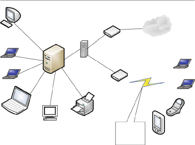
514
24.2.2.2 Wireless Local Area Networks (WLANs) (Wi-Fi)
This is another short range, up to 500 m, local area wireless technology that allows
an electronic device to exchange data or connect to the Internet using 2.4 GHz UHF
and 5 GHz SHF radio waves. Wi-Fi is probably the premier local area network
(LAN) technology for high-speed Internet access for mobile devices like laptops,
smartphones, tablets, and smart TV sets for video transfer. Wi-Fi-enabled devices,
like those we have given, can connect to the Internet when within range of a wireless
router which connects to the broadband modem ( access point ). A broadband modem
is a device that bridges the Internet connection from a service provider to the LAN
router or a computer, making the Internet available to the home devices [ 1 ]. With
wireless technology, wireless-enabled devices can connect to one another in the
same LAN or outside the LAN without being connected by cables as it used to be.
See Fig. 24.1 .
Although Wi-Fi ranges are limited, they can be extended with the use of several
overlapping coverage of access points to cover a large area as large as many square
miles. Wi-Fi technology is increasingly being used in private homes, businesses, as
well as in public spaces called hot spots usually set up by businesses or public
authorities for free-of-charge use. Wi-Fi technology has been standardized as IEEE
802.11. See more details of this in Chap. 18 .
Laptop
Laptop Firewall
Internet
Communication
wireless signals
from home
wireless enabled
devices
Response Subsystem
Laptop
Laptop
Broadband Modem
Server
Wi-FI Router
Mobile
phone
Mobile
device
Laptop
Apple desktop
Printer
Fig. 24.1 The home LAN
24 Conquering the Last Frontier in the Digital Invasion: The Home Front
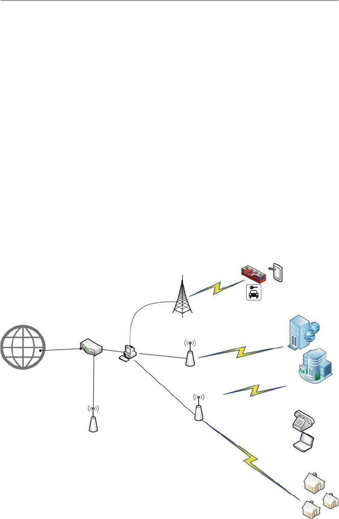
515
24.2.2.3 WiMAX LAN
WiMAX (Worldwide Interoperability for Microwave Access) is another limited
area wireless communication technology based on IEEE 802-16 standard, designed
to extend the range and functionalities of Wi-Fi technology. It provides data rates
reaching up to 75 megabits per second (Mb/s) and a number of wireless signaling
options ranging anywhere from the 2 GHz range up to 66 GHz, with up to 1 Gbit/s
for fi xed stations. It can also provide a service range of up to 10 miles. Because of
that range, WiMAX can be installed either by a survive provider as base stations or
as small receivers installed by clients to connect to the base station. The WiMAX
base station then sends and receives data to and from a WiMAX-enabled router,
which would then send the data to the different devices in the home LAN. It is pos-
sible to combine Wi-Fi with WiMAX by having the router send the data to the
devices via Wi-Fi server. See Fig. 24.2 .
As a step above DSL and cable modem, WiMAX protocol accommodates a
whole range of data transmission protocols that both cable modems and DSL can-
not, so far, like voice over Internet Protocol (VoIP). VoIP allows making of local,
long-distance and even international calls through a broadband Internet connection
Mobile Devices and Smart
automobiles
Smart Homes
Internet
Sever/Router
Car
Smart train
Mobile
device
Access point
WiMax Access Point
Router
Cell Tower
Access Point
Fiber optic
Fiber optic
Fiber optic
Fiber optic
Enterprise Office
Fig. 24.2 WiMAX coverage
24.2 The Changing Home Network and Hot Spots

516
possible. As we look forward, will scale up city size metropolitan area network
(MAN). See more in Chap. 18 .
24.2.2.4 LTE LAN
The last of the extension of the home LAN is the LTE (Long-Term Evolution)
LAN. It is a wireless broadband technology designed to support roaming Internet
access via cell phones and handheld devices. It is also commonly known as 4G
(fourth-generation) technology. Since these devices can also be part of the home
inventory, we will consider this technology as home-based technology to join the
other three we have so far discussed. Because LTE is a newer technology, its com-
munication protocols are based on Internet Protocol (IP). Because of this, it offers a
variety of communication protocols that the older technologies could not offer
including VoIP and other IP-based services. LTE can theoretically support down-
loads at 300 Mbps or more based on experimental trials. It is growing after getting
early support from telecommunication providers.
24.2.3 Types of Broadband Internet Connections
Doug Ngo [ 1 ] gives three types of broadband Internet connections:
• Wired Internet ( residential broadband ): In this category, the home LAN is
connected to the Internet via a physical cable such as a telephone line (DSL) or
a cable line (cable) or a fi ber-optic line (FIOS). This is one of the good options
for a home LAN because with it, there are no data caps or at least very high caps,
so users don’t need to worry about how much they download or upload.
• Satellite Internet ( satellite broadband ): With satellite broadband, the home LAN
connection to the Internet is via a satellite disk, probably on the roof, which
communicates with satellites to provide the LAN with Internet access. Although
satellite Internet is slower and more expensive, it is a great, probably the only,
option for remote areas with no cable, DSL, or FIOS services.
• Cellular Internet ( wireless broadband ): With this option, the LAN Internet
connection is made possible via a cell phone signal to carry data and connect the
supported device directly to the Internet. There are several cellular data standards
and starting with 3G, it’s fast enough to be called “broadband.” The latest stan-
dard, 4G LTE, offers the speed equivalent to that of a midrange residential broad-
band connection (somewhere between 5 and 20 Mbps download speed).
24.2.4 Smart Home Devices
For generation, the home has been a source of entertainment for the family and
guest to the family. Throughout history, the family as an entertainment center has
seen a growing number of gadgets to enhance entertainment. As technology started
24 Conquering the Last Frontier in the Digital Invasion: The Home Front

517
invading the home, it came via the entertainment devices. With changing technolo-
gies, the evolving entertainment menu and the need to enhancing the integrity and
security of the family, a new role of technology in the home, beyond entertainment,
of monitoring the home was born. This new role brought to the home a new bred
of digital devices that will later turn into a security problem as we will soon
discuss.
24.3 Data and Activities in the Home LAN
With the miniaturization of digital devices, there is a new breed of medical moni-
toring and wearable devices that are in peoples’ home. More and more people are
wearing health-supporting and health-monitoring devices that are actually con-
nected or are able to connect to the Internet. There are now devices that are
remotely regulating or delivering medicines to patients in their homes via the
Internet. These kinds of devices are increasing. Also there is an increasing number
and caliber of digital devices that are meant to monitor the integrity and security
of the home letting the owner from afar know in real time or near real time, or
through alerts, the status of the home. It used to be that the types of data that were
most common in the home network were pictures, usually from family vacations
and occasions of family value like weddings and family get together, videos of
family events, and various personal data fi les usually stored on the family com-
puter hard drive. Given the changing nature and utility of the family network,
although these data are still being stored in the family LAN, a lot more data types
have come home too.
24.3.1 Work Data
The growth of work at home movement that started in the late 1980s has changed
the home LAN, not only by bringing in new technologies but also bringing in the
home enterprise data. Home workers routinely download and upload and conse-
quently store enterprise data on the home LAN in their routine work. Also the new
movement of bring your own device (BYOD) to the enterprise premises is creating
avenues where employees are bringing enterprise data on their devices knowingly
or otherwise. Mobile devices have a way of collecting and sometimes storing data
either from the enterprise spaces or public commons.
24.3.2 Social Media Data
The increasing use of smart and more powerful mobile devices is increasing the
amount of both personal and public data brought into the home LAN by these
mobile devices from social media and from public commons.
24.3 Data and Activities in the Home LAN

518
24.3.3 Banking and Investment Data
Long lines in banks are numbered as more and more bank customers are running
home to do their banking in the comfort of their homes. The banks themselves are
encouraging this through advertising of online banking. Most people that do online
banking do it either after work or on weekends, most at home. Doing any online
banking activity on the home LAN transfers sensitive data back and forth between
the family LAN and the banker servers. It is not only banking that invades the
home LAN, but investment activities are not far behind banking. Again most peo-
ple who have investments check, invest, and trade mostly after work or on week-
ends, again using the home LAN. Doing these activities, like in banking, a
considerable amount of data is exchanged between the home LAN and the invest-
ment house servers. Some of this data and the trail of activities are stored in histo-
ries on the home LAN.
24.3.4 Health Devices
It has taken a while but at last medical technology has become of age. In fact among
all the sectors, the medical sector has seen the fastest growing and more promising
technologies in the last several years. As providers, hospitals, and health insurance
companies are fi ghting for consumer dollars, technology is coming in to the rescue.
Health insurance providers in order to cut on long and expensive hospital stays are
encouraging health providers to embrace and use technologies that enable patients
to have operations and leave hospitals in a day or two. These patients and many
other health care types are increasing getting follow-up care at home. Medications,
monitoring signals, and patient data information are usually and commonly
uploaded on the family LAN, and many times this data stay stored either on the
family LAN or LAN histories.
24.3.5 Home Monitoring and Security Devices
The growth in monitoring technology in the last few years has opened a fl ood gate
in home monitoring. The usual movement sensor monitoring that home security
providers like ADT used to offer is now archaic. All types of sensors are now pack-
aged in minute, well-hidden devices that can be remotely controlled via the family
LAN. We have already discussed the use of the family LAN to penetrate and take
control of the family electronic devices through the electric meter. The marriage
between the electric and cyber signals in the family LAN has made the remote con-
trol of most family devices and family electronic data a reality and has created a
security quagmire in the home. No home and no home LAN is secure anymore.
24 Conquering the Last Frontier in the Digital Invasion: The Home Front

519
24.4 Threats to the Home and Home LAN
As we pointed out before, the home front, as the last frontier of invasion to personal
security and privacy, has become the “new Wild West.” What is more worrying is that
the individuals in the home front, unlike their counterparts in the workplace, are less
knowledgeable and far less prepared to deal with the intruders. In a way, they are
helpless in a sense that they may not know what is or may happen to their home, data,
and home devices and more frightening, their personal lives because hackers can
now use physical harm to individuals in the home. Even if they come to know, they
may not be able to do anything to stop it. In “Hacking Home Automation Systems
Through Your Power Lines,” Kim Zetter [ 2 ] details how hackers can attack a home
or even a business automation and security systems through power lines. Using this
conduit, the hackers can, through remote commands, take control of a multitude of
devices, such as lights, electronic locks, heating and air conditioning systems, and
security alarms and cameras. The systems operate on Ethernet networks that com-
municate over the existing power lines in a home, sending signals back and forth to
control devices. Beyond taking control of your devices, hackers can also introduce
sniffers to the broadband power network through an electrical outlet and sniff the
signals in the home to know what is going on in the home using already installed
security and monitoring devices such motion sensors and image cameras.
What is worrying is that these cheap systems are running on open-source tools to
conduct the hacks. Although most of the current tools are more successful on home
systems running non-encrypted protocols, very soon, even systems supporting encryp-
tions may be attacked as encryptions are increasingly being broken by hackers.
The tools and attacks to the home are varied and are on the increase. Attack types
are also changing. With attackers now able to remotely enter the home, they are now
able to reprogram the house devices to do things unimaginable including opening
doors, jamming home security, and monitoring signals thus able to prevent security
signals from ever reaching home security and monitoring companies, the police,
and even the home owner.
As we have seen above, growth in medical and monitoring technologies is
increasingly allowing an increasing number of patients to receive care from their
homes. With this kind of increasing potential attacks on home systems, the future of
health home care is also in jeopardy.
Let us discuss a few of the major steps individuals can do to mitigate, if not stop,
a home invasion by hackers for whatever reason. First, we will look at the most
common threats to the home and home LAN.
24.4.1 Most Common Threats to Homes and Home LANs
The most common methods used by intruders to gain control of home computers are
briefl y described by CERT in “Home Network Security” [ 3 ]:
24.4 Threats to the Home and Home LAN

520
• Trojan horse programs – Trojan horse programs are social engineering programs
sent by introducers and designed to make you trust them as they introduce access
traps for easy access into the home LAN.
• Back door and remote administration programs – common on Windows comput-
ers, these are three tools used by intruders to gain remote access to the house
LAN. The tools are Back Orifi ce, Netbus, and SubSeven. These tools allow
access and control house LAN.
• Denial of service – this attack, common in the 1990s, causes digital devices on the
home LAN to crash or to become so busy processing data that you are unable to use it.
• Mobile code (Java/JavaScript/ActiveX) – code from these Web programming lan-
guages is executed by most computer Web browser. This code can be used by
intruders to gather or to run malicious code on any computer on the family
LAN. Read more about this at http://www.cert.org/archive/pdf/activeX_report.pdf
• Cross-site scripting – these are malicious scripts moved around the Internet by
computers visiting servers sitting these scripts. There are several ways a LAN
computer can expose the family LAN to these types of code [ 3 ]:
– Following links in Web pages, e-mail messages, or newsgroup postings with-
out knowing what they link to
– Using interactive forms on an untrustworthy site
– Viewing online discussion groups, forums, or other dynamically generated
pages where users can post text containing HTML tags
• E-mail spoofi ng – E-mail “spoofi ng” is a way to trick a user to believe an e-mail
is coming from a specifi c source when it is actually coming from another.
Spoofed e-mail can range from harmless pranks to social engineering ploys.
• E-mail-borne viruses – transporting and spreading viruses via e-mails. Most
viruses are actually transported and spread using e-mail attachments.
• Hidden fi le extensions – Windows operating systems “fi le extension hiding,” if
not disabled, can be exploited by e-mail-borne viruses. So these fi le extension-
hiding options, whether in Windows systems or other products, which are usu-
ally defaults must be disabled.
• Packet sniffi ng – these are programs deposited at strategic points of the Internet
to capture data from information packets as they travel over the network. They
can attach any designated network including the family LAN.
24.4.2 Actions to Safeguard the Family LAN
The most recommended steps a home owner and home LAN user can take are again
CERT [ 3 ]:
• Consult your system support personnel if you work from home.
• Use virus protection software.
• Use a fi rewall.
• Don’t open unknown e-mail attachments.
24 Conquering the Last Frontier in the Digital Invasion: The Home Front

521
• Don’t run programs of unknown origin.
• Disable hidden fi lename extensions.
• Keep all applications (including your operating system) patched.
• Turn off your computer or disconnect from the network when not in use.
• Disable Java, JavaScript, and ActiveX if possible.
• Disable scripting features in e-mail programs.
• Make regular backups of critical data.
• Make a boot disk in case your computer is damaged or compromised.
For more details of each one of these, the reader is referred to [ 3 ].
24.4.3 Using Encryption to Protect the Family LAN
The wireless family LAN has not only brought convenience in the use of home
devices but has also brought ease of use and a far greater exposure and outreach of
the family computer and other devices via the Internet. However, wireless technol-
ogy has also brought more problems to the family with a wireless LAN. While
wired home networks are confi ned by their connected wires, to send and receive
data from specifi ed points of the network, wireless networks, on the other hand,
broadcast data in every direction to every device that happens to be listening, within
a limited range [ 4 ]. Because of this, the security and integrity of the devices and the
wireless LAN in the family are at risk. More directed steps, therefore, are called for
to mitigate these risks.
As more advanced wireless communication technologies are developed, there is
a need for stronger and more focused encryption protocols. Along the way, there-
fore, various wireless security protocols have been developed to protect home wire-
less networks. These wireless security protocols include WEP, WPA, and WPA2,
each with their own strengths and weaknesses. These new wireless encryption pro-
tocols have improved the prevention of uninvited guests from connecting to the
family LAN and have further helped to harden private data by encrypting it as it
leaves and enters the family LAN. Lawrence C. Miller in “The Essentials of Setting
Up a Wireless Network: Wireless Security Protocols: WEP, WPA, and WPA2” [ 4 ]
discusses the three most popular protocols as follows [ 4 ]:
• Wired Equivalent Privacy ( WEP ): The original encryption protocol developed
for wireless networks. It was designed to provide the same level of security as
wired networks, but WEP suffers from many well-known security fl aws; it is dif-
fi cult to confi gure, and it is easily broken.
• Wi-Fi Protected Access ( WPA ): To further harden the wireless network, a newer
protocol, WPA, was developed as an interim security enhancement over WEP
while the 802.11i wireless security standard was being developed. Most current
WPA implementations use a preshared key (PSK), commonly referred to as WPA
Personal , and the Temporal Key Integrity Protocol (TKIP, pronounced tee - kip )
for encryption. WPA Enterprise uses an authentication server to generate keys or
certifi cates.
24.4 Threats to the Home and Home LAN

522
• Wi-Fi Protected Access version 2 ( WPA2 ): Based on the 802.11i wireless security
standard, which was fi nalized in 2004. It enhanced WPA by introducing the use
of the Advanced Encryption Standard (AES) for encryption. The security pro-
vided by AES is far superior to that of WPA. The US government uses it to
encrypt information classifi ed as top secret.
24.4.4 Protecting the Family LAN with Known Protocols
Although WLANs provide many benefi ts to a family using it, but as we pointed out
earlier, WLANs broadcast data in every direction to every device that happens to be
listening, within a limited range. Unprotected WLANs can result in unauthorized
use and potential harm to the family LAN and those in the family. Family WLANs,
therefore, need to be protected with the most effi cient encryption protocols avail-
able to the user. In “Protecting Your Wireless Network,” the US Federal
Communications Commission – Consumer Task Force [ 5 ] suggests the following
security steps should be taken:
• Turn encryption on – Turn on the WLANs router’s encryption setting right after
installing the router. As the router comes out of the box, the encryption feature is
usually disabled. Use “WPA2” the most current and most effective. When turn-
ing on WPA2, choose a longer password that utilizes a combination of letters,
numbers, and symbols for better security.
• Turn the fi rewall on – In addition to turning on WPA2 at install, also turn on
the fi rewall to protect the LAN from harmful intrusions. Firewalls can be
hardware based or software based. Wireless routers generally contain built-in
fi rewalls but are sometimes shipped with the fi rewall turned off. So it is impor-
tant and recommended to check and see if the wireless router’s fi rewall is
turned on.
• Change default passwords – Most wireless routers come with preset passwords
for administering the devices settings (this is different from the password used to
access the wireless network itself). Unauthorized users may be familiar with the
default passwords, so it is important to change the router device’s password as
soon as it is installed. Again, longer passwords made up of a combination of let-
ters, numbers, and symbols are more secure.
• Change the default name of the network – A network’s name is known as its
“SSID” (service set identifi er). When a computer with a wireless connection
searches for and displays the wireless networks nearby, it lists each network that
publicly broadcasts its SSID. Manufacturers usually give all of their wireless
routers a default SSID, which is often the company’s name. It is a good practice
to change the LAN’s SSID. Never use personal information such as the names of
family members.
• Turn network name broadcasting off – Wireless routers may broadcast the name
of the network (the “SSID”) to the general public. This feature is often useful for
24 Conquering the Last Frontier in the Digital Invasion: The Home Front

523
businesses and institutions offering free Wi-Fi to the public. For personal or fam-
ily Wi-Fi networks, turn this feature off.
• Use the MAC address fi lter – Every device that can connect to a Wi-Fi network
has a unique ID called the “physical address” or “MAC” (media access control)
address. Wireless routers can screen the MAC addresses of all devices that con-
nect to them, and users can set their wireless network to accept connections only
from devices with MAC addresses that the router is set to recognize. In order to
create another obstacle to unauthorized access, change the family LAN’s router’s
settings to activate its MAC address fi lter to include only the LANs authorized
devices.
Exercises
1. Discuss why the home front is the last digital frontier of the digital invasion.
2. Discuss with evidence why the home front is the “new Wild West” in personal
privacy and security.
3. Why is the home LAN user in a more precarious state than an enterprise LAN
user.
4. Discuss the growing hacker invasion and the pending potential threat to the
home devices and home LAN security.
5. What are the security imperative of a home LAN user not knowing or ignoring
putting security measures in the family LAN.
6. Based on your current knowledge, what must be done to stop or mitigate this
pending Armageddon.
7. Do you think this is a mere small threat or a pending catastrophe?
8. How should the home LAN user be alerted to or trained to meet the pending
threat.
9. Given what you know, should working from home be discouraged?
10. Should corporations and businesses be responsible for the security of the family
LAN for those working from home?
Advanced Exercises
1. Develop an application that can be used to run a security assessment of a family
LAN.
2. Develop an application that can intercept and prevent a home-based medical
device to be hacked into – save a life.
3. Develop an application that alerts a home LAN user of a penetration attempt and
suggest quick remedies to mitigate prevent the intrusion.
4. Develop a series of remedies for a home LAN intrusion and develop applications
for each.
5. Develop a menu of security applications for a family LAN capable of intercept-
ing an intrusion into a family LAN and generating a corresponding alert.
24.4 Threats to the Home and Home LAN

524
References
1. Ngo D, CNET, Home networking explained, part 4: Wi-Fi vs. Internet. http://www.cnet.com/
how-to/home-networking-explained-part-4-wi-fi -vs-internet/
2. Zetter K, Hacking home automation systems through your power lines. Wired.
http://www.
wired.com/2011/08/hacking-home-automation/
3. CERT. Home network security. http://www.cert.org/historical/tech_tips/home_networks.
cfm?#IV-A-1
4. Miller LC, The essentials of setting up a wireless network: wireless security protocols: WEP,
WPA, and WPA2, Home networking do-it-yourself for dummies.
http://www.dummies.com/
how-to/content/wireless-security-protocols-wep-wpa-and-wpa2.html
5. Protecting your wireless network, Federal communications commissions – consumer task force.
http://www.fcc.gov/guides/protecting-your-wireless-network
6. Frenzel L, What’s the difference between IEEE 802.15.4 and ZigBee wireless? 22 March 2013,
electronic design.
http://electronicdesign.com/what-s-difference-between/what-s-difference-
between-ieee-802154-and-zigbee-wireless
24 Conquering the Last Frontier in the Digital Invasion: The Home Front

P a r t V I
Hands-on Projects

527
© Springer-Verlag London 2015
J.M. Kizza, Guide to Computer Network Security, Computer Communications
and Networks, DOI 10.1007/978-1-4471-6654-2_25
25
Projects
25.1 Introduction
This is a special chapter dealing with security projects. We have arranged the
projects in three parts. Part one consists of projects that can be done on a weekly or
biweekly basis. Part two consists of projects that can be done in a group or individu-
ally on a semi-semester or on a semester basis. Part three consists of projects that
demand a great deal of work and may require extensive research to be done. Some
of the projects in this part may fulfill a master’s or even Ph.D. degree project require-
ments. We have tried as much as possible throughout these projects to encourage
instructors and students to use open source as much as possible. This will decouple
the content of the guide from the rapidly changing proprietary software market.
25.2 Part I: Weekly/Biweekly Laboratory Assignments
Projects in this part were drawn up with several objectives in mind. One is that stu-
dents in a network security course must be exposed to hands-on experience as much
as possible. However, we also believe that students, while getting hands-on experi-
ence, must also learn as much as they can about the field of security. Since no one
can effectively cover in one course all areas of computer and network security, we
must find a way to accomplish as much of this as possible without compromising
the level needed in the few core areas covered by the course. Our second objective,
therefore, is to cover as broad an area of both computer and network security issues
as possible. We do this by sending the students out on a scavenger hunt and requir-
ing them to study and learn as much as possible on their own.
For each of the selected areas the students must cover, they must write a paper. They
doubly benefit, for not only do they learn about security in the broadest sense possible,
but they also learn to communicate, a crucial element in the security profession.
Security professionals must investigate, analyze, and produce reports. By including
report writing in the course on security, we accomplish, on the side, an important task.

528
25.2.1 Laboratory # 1
Exploratory (2 weeks) – to make students understand the environment and appreci-
ate the field of network security.
Study computer and network vulnerabilities and exploits (see Chaps. 4 and 7). In
an essay of not less than three and not more than five double-spaced typed pages,
discuss ten such exploits and/or vulnerabilities, paying attention to the following:
•Routing algorithm vulnerabilities: route and sequence number spoofing, instabil-
ity, and resonance effects
•TCP/UDP vulnerabilities
•Denial of service
•ARP hazard: phantom sources, ARP explosions, and slow links
•Registry vulnerabilities
•Fragmentation vulnerabilities and remedies (ICMP Echo overrun)
25.2.2 Laboratory # 2
Exploratory (2 weeks) – to make students aware of the availability of an array of
solutions to secure the networks.
Research and study the available software and hardware techniques to deter, if
not eliminate, computer systems attacks (see Part III of the text). Write a compara-
tive discussion paper (minimum three and maximum five double-spaced pages) on
five such techniques, paying attention to the following:
•Encryption techniques (DNSSEC, IPSec, PGP, S/MIME, S-HTTP, and HTTPS)
•Intrusion detection and prevention
•Computer and network forensics techniques
•Firewalls (DMZ)
•Secure network infrastructure services: DNS, NTP, and SNMP
•Secure binding of multimedia streams: Secure RTP/Secure RPC
•Access control and authentication: Secure RSVP
•Mobile systems: WEP and WPA
•Internet security models: IPv4/v6 encapsulation headers in IPSec
25.2.3 Laboratory # 3
Exploratory (2 weeks) – to make students aware of the role and weaknesses of oper-
ating systems in network and data security.
Research four major operating systems’ vulnerabilities and write a five-page
double-spaced paper on these vulnerabilities for each operating system.
25 Projects

529
Consider the following operating systems:
•Unix (and other varieties of Unix such as FreeBSD and OpenBSD)
•Linux
•Windows (NT, 2000, XP, etc.)
•OS/2
•Mac OS X
•Any Mobile OS
25.2.4 Laboratory # 4
(1 Week): A look at the security of Windows, Linux, and any mobile OS – to give
students hands-on experience of handling security of the major operating systems
today. A student picks one of these platforms and studies it for weaknesses and
vulnerabilities and what is being done to harden it. A student then can make an oral
presentation to the class on the findings.
25.2.5 Laboratory # 5
(1 Week): Installation and maintenance of firewalls – to give students the experience
of installing and maintaining a peripheral (fencing) security component of both
small and large enterprise networks. There are plenty of open source and free fire-
walls. Also a number of companies on the Web offer a variety of firewalls both in
software and ready configured hardware. Some of these companies offer free per-
sonal firewalls; others offer high-end but limited corporate firewalls you can down-
load on a trial basis. Check out companies on the Web, and if you are not already
using a firewall, download one for free or on a trial basis.
Install it and run it. Here is a list of some of the companies with good software
firewalls:
•McAfee – www.mcafee.com (personal)
•Symantec – www.symantec.com (professional/personal)
•Sygate Personal Firewall – www.sygate.com
•Tiny Personal Firewall – www.tinysoftware.com
•ZoneAlarm Pro – www.zonelabs.com
Firewall policies – as you install your firewall, decide on the following:
•Whether you will let Internet users in your organization upload files to the net-
work server.
•What about letting them download?
•Will the network have a Web server? Will inside/outside people access the server?
•Will the site have telnet?
25.2 Part I: Weekly/Biweekly Laboratory Assignments

530
25.2.6 Laboratory # 6
(2 weeks): Research on key and certificate management to acquaint the students to
the new and developing trends in key management, techniques that are leading to
new security and customer confidence tools in e-commerce. In a three- to five-page
double-spaced paper, discuss key management issues (Chaps. 10, 11, and 17). In
particular, pay attention to
•DNS certificates
•Key agreement protocols: STS protocol and IETF work orders
•Key distribution protocols: Kerberos, PGP, X.509, S/MIME, and IPSec
•SSL, SET, and digital payment systems
•One-time passwords: schemes based on S/KEY
•Session key management: blind-key cryptosystems (NTP)
•Secure access control and management: secure SNMP
•Certificate authorities (CAs)
25.2.7 Laboratory # 7
(1 week): Network-based and host-based intrusion detection systems (IDS) and pre-
vention. The laboratory is to give students practical experience in safeguarding a
network, scanning for vulnerabilities and exploits, downloading and installation of
scanning software, and scanning a small network. Options for scanning are SATAN,
LANguard Network Scanner (Windows), and Nmap. For an IDS system, use Snort.
See Part II for installation information.
25.2.8 Laboratory # 8
(1 week): Develop a security policy for an enterprise network to enable students to
acquire the experience of starting from scratch and designing a functioning security
system for an enterprise, an experience that is vital in the network security community.
Write a three- to five-page double-spaced paper on the security policy you have just
developed.
25.2.9 Laboratory # 9
Set up a functioning VPN. There are a variety of sources for materials on how to set
up a VPN.
25.2.10 Laboratory # 10
Any project the instructor may find as having a culminating security experience.
25 Projects

531
25.3 Part II: Semester Projects
This part focuses on security tools that can make your network secure. We divide
the tools into three parts: intrusion detection tools, network reconnaissance and
scanning tools, and Web-based security protocols.
25.3.1 Intrusion Detection Systems
There are a number of free IDS that can be used for both network-based and host-
based intrusion detection. Some of the most common are Snort and TCPdump.
25.3.1.1 Installing Snort (www.snort.org)
Snort is a free network analysis tool that can be used as a packet sniffer like
TCPdump, a packet logger, or as a network intrusion detection system. Year after
year, Snort has been excelling at traffic analysis and packet logging on IP networks
(see more on network traffic analytics at: http://www.smarter.com/s--q-
traffic%2Banalysis.html. Through protocol analysis, content searching, and various
preprocessors, Snort detects thousands of worms, vulnerability exploit attempts,
port scans, and other suspicious behavior.
Developed in 1998 by Martin Roesch, it has been undergoing improvements.
These improvements have made Snort highly portable, and now it can run on a vari-
ety of platforms including Linux, Solaris, BSD, IRIX, HP-UX, MacOS X, Win 32,
and many more.
Also Snort is highly configurable allowing users, after installation, to create their
own rules, from a flexible rule-based language to describe traffic for collecting or
passing on, using a modular detection engine, and reconfigure its base functionality
using its plug-in interface. For Web interface analysis of Snort alerts, see Basic
Analysis and Security Engine (BASE) at http://base.secureideas.net/.
For this project, you need to
•Take note of the operating system you are using.
•Choose the type of Snort to use based on your operating system.
•Download a free Snort Users’ Manual
•Download free Snort and install it.
•Analyze a Snort ASCII output.
•Read Snort rules and learn the different rules of handling Snort outputs.
NOTE: A Snort performance ASCII output has the following fields:
•Name of alert
•Time and date (such as 06/05 – 12:04:54.7856231) – to mark the time the packet
was sent. The last trailing floating number (.7856231) is a fraction of a second
included to make the logging more accurate given that within a second, many
events can occur.
25.3 Part II: Semester Projects

532
•Source address (192.163.0.115.15236) – IP source address. (.15236) is the port
number. Using this string, it may be easy to deduce whether the traffic is originat-
ing from a client or server.
•(>) – direction of traffic
•Destination address (192.168.1.05.www).
•TCP options that can be set (Port type, Time to live, Type of service, Session
ID, IP length, Datagram Length) – they are set at the time a connection is
made.
•Don’t fragment (DF)
•S-Flags(P = PSH, R = RST, S = SYN, or F = FIN).
•Sequence number(5678344:5678346(2)) – the first is the initial sequence num-
ber followed by the ending sequence number and (2) indicates the number of
bytes transmitted.
•Acknowledgment # (3456789).
•Win (MSS) – window size. MSS = maximum segment size. If the client sends
packets bigger than the maximum window size, the server may drop them.
•Hex Payload. [56 78 34 90 6D 4F, . . . . . .]
•Human Readable Format
25.3.1.2 Installation of TCPdump (http://www.tcpdump.org/)
TCPdump is a powerful command-line network monitoring tool and packet analyzer
and libpcap, a portable C/C++ library for network traffic capture. TCPdump was
developed by the Department of Energy at Lawrence Livermore Laboratory and, as
a freeware, is used extensively in intrusion detection.
To use TCPdump do the following:
•Take note of the operating system you are using.
•Choose the type of Snort to use based on your operating system.
•Download and install TCPdump.
•Run a TCPdump trace.
•Analyze a TCPdump trace.
NOTE: In analyzing, consider each field of a TCPdump output. A normal
TCPdump output has nine fields as follows:
•Time (such as 12:04:54.7856231) to mark the time the packet was sent. The last
trailing floating number (.7856231) is a fraction of a second included to make the
logging more accurate given that within a second, many events can occur.
•Interface (ethX for Linux, hmeX for Solaris, and BSD-based systems, varied
with platform) – interface being monitored.
•(>) – direction of traffic
•Source address (192.163.0.115.15236) – IP source address. (.15236) is the port
number. Using this string, it may be easy to deduce whether the traffic is originat-
ing from a client or server.
25 Projects

533
•Destination address (192.168.1.05.www).
•S-Flags(P = PSH, R = RST, S = SYN, or F = FIN).
•Sequence number(5678344:5678346(2)) – the first is the initial sequence num-
ber followed by the ending sequence number and (2) indicates the number of
bytes transmitted.
•Win (MSS) – window size. MSS = maximum segment size. If the client sends
packets bigger than the maximum window size, the server may drop them.
•TCP options that can be set – they are set at the time a connection is made.
•Don’t fragment (DF) – contains fragment information. If the size of the data-
gram exceeds the MTU (maximum transmission unit of an IP datagram), then
fragmentation occurs.
Read more about TCPdump and the latest releases at http://www.tcpdump.org/.
25.3.1.3 Nping (http://nmap.org/nping/)
Nping is an open-source tool for network packet generation, response analysis, and
response time measurement. Still in its infancy stages (developed in 2009, as
“Google Summer of Code”), Nping can generate network packets for a wide range
of protocols, allowing users full control over protocol headers. While Nping can be
used as a simple ping utility to detect active hosts, it can also be used as a raw
packet generator for network stack stress testing, ARP poisoning, denial-of-service
attacks, route tracing, etc. Nping’s novel echo mode lets users see how packets
change in transit between the source and destination hosts. Nping’s features
include:
•Custom TCP, UDP, ICMP, and ARP packet generation
•Support for multiple target host specification
•Support for multiple target port specification
•Unprivileged modes for non-root users
•Support for Ethernet frame generation
•Support for IPv6 (currently experimental)
•Runs on Linux, Mac OS, and MS Windows
•Route tracing capabilities
•Highly customizable
•Free and open source
25.3.2 Scanning Tools for System Vulnerabilities
25.3.2.1 Scans with Nmap (www.insecure.org)
Nmap for Network Mapper was created by Fyodor and is free under the GNU Public
License (GPL). Nmap is a network-wide portscan and OS detection tool that audits
the security of the network. Nmap traces are easily detected because it leaves a
25.3 Part II: Semester Projects

534
signature trail. Scans can be made more difficult by adding a few features such as
stealth scanning and Xmas. For this exercise, do the following:
•Download Nmap and install it.
•Scan a selected network.
•Download additional features like Xman, SYN-FIN, and stealth scanning.
•Show how these help in creating a less detectable scanning tool.
25.4 The Following Tools Are Used to Enhance Security
in Web Applications
25.4.1 Public Key Infrastructure
The aim of the project is to make students learn the basic concepts of a public key
infrastructure (PKI) and its components. Get a free PKI tool from http://pki.winsite.
com/, a WinSite specialty archive site. Among the activities to carry out in the proj-
ect are the following:
•Identify Trusted Root Certificate Authorities.
•Design a certificate authority.
•Create a Certification Authority Hierarchy.
•Manage a public-key infrastructure.
•Configure Certificate Enrollment.
•Configure Key Archival and Recovery.
•Configure Trust Between Organizations.
25.4.1.1 Configuring E-mail Security
In Chap. 17, we discussed at length the different ways of securing e-mail on the
Internet. This project focuses on that. So read Chap. 17. The project will teach you
how to implement secure e-mail messages in PGP. You will need to do the
following:
•Go to http://www.pgpi.org/products/pgp/versions/freeware/ to pick up a PGP
free version for your operating system.
•Install PGP on your computer.
– Create your own keys.
– Publicize your public key.
– Import new PGP keys.
– Encrypt a text message to send to a friend.
– Decrypt a message from a friend encrypted with PGP.
– Encrypt/decrypt a file with PGP.
– Wipe a file with PGP.
25 Projects

535
25.5 Part III: Research Projects
25.5.1 Consensus Defense
One of the weaknesses of the current global network is the lack of consensus
within the network. When one node or system is attacked, that node or system
has no way of making an emergency distress call to all other systems starting
with the nearest neighbor so that others should get their defenses up for the emi-
nent attack. This project is to design a system that can trigger an SOS message to
the nearest neighbors to get their defenses up. The system should also include,
where possible, all information the node being attacked can get about the attack-
ing agent.
25.5.2 Specialized Security
Specialized security is vital to the defense of networks. A viable specialized security shell
should be able to utilize any organization’s specific attributes and peculiarities to achieve
a desired level of security for that organization. This project is to design a security shell
that can be used by any organization to put in its desired attributes and whatever peculiari-
ties that organization may have in order to achieve its desired level of security.
25.5.3 Protecting an Extended Network
Enterprise network resources are routinely extended to users outside the organiza-
tion, usually partner organizations and sometimes customers. This, of course, opens
up huge security loopholes that must be plugged to secure network resources. We
want to design an automated security system that can be used to screen external user
access, mitigate risks, and automatically deal with, report, and recover from an
incident, if one occurs.
25.5.4 Automated Vulnerability Reporting
Currently, reporting of system vulnerabilities and security incidents is still a manual
job. It is the responsibility of the system administrator to scan and sort threats and
incidents before reporting them to the national reporting centers. However, as we all
know, this approach is both slow and itself prone to errors (human and system). We
are looking for an automated system that can capture, analyze, sort, and immedi-
ately and simultaneously report such incidents to both the system administrator and
the national reporting center of choice.
25.5 Part III: Research Projects

536
25.5.5 Turn-Key Product for Network Security Testing
Most network attacks are perpetuated through network protocol loopholes.
Additional weak points are also found in application software in the top most layers
of the protocol stack. If security is to be tackled head on, attention should be focused
on these two areas. This project is aimed at designing a turn-key product that a net-
work administrator can use to comprehensively comb both the network protocol and
the system application software for those sensitive loopholes. Once these weak
points are identified, the administrator can then easily plug them.
25.5.6 The Role of Local Networks in the Defense
of the National Critical Infrastructure
In the prevailing security realities of the time, local networks, as the building blocks
of the national critical infrastructure, have become a focal point of efforts to defend
the national infrastructure. While the federal government is responsible for manag-
ing threat intelligence and efforts to deter security threats on the national infrastruc-
ture, the defense of local networks is the responsibility of local authorities, civic
leaders, and enterprise managers. One of the techniques to defend the thousands of
local spheres of influence is the ability of these local units to be able to automati-
cally separate themselves off the national grid in the event of a huge “bang” on the
grid. This project is meant to design the technology that can be used by local net-
works to achieve this.
25.5.7 Enterprise VPN Security
The growth of Internet use in enterprise communication and the need for security
assurance of enterprise information have led to the rapid growth and use of VPN
technology. VPN technology has been a technology of choice for securing enter-
prise networks over public network infrastructure. Although emphasis has been put
on the software side of VPN implementation which looks like a more logical thing,
information in Enterprise VPNs has not been secured to a desired level. This means
that other aspects of VPN security need to be explored. Several aspects including
implementation, policy, and enterprise organization, among many others, need to be
researched. This project requires the researcher to look for ways of improving VPN
security by critically examining these complementary security issues.
25.5.8 Perimeter Security
Although the perimeter of the traditional network has changed, perimeter security is
still one of the cornerstones of system defense. We assume that all the things we
want to protect should be enclosed within the perimeter. The perimeter, therefore,
25 Projects

537
separates the “bad Internet” outside from the protected network. Firewalls have
been built for this very purpose. Yet we still dream of a perfect security within the
protected networks. Is it possible to design a penetration-proof perimeter defense?
25.5.9 Enterprise Security
Security threats to an enterprise originate from both within and outside the enter-
prise. While threats originating from outside can be dealt with to some extent, with
a strong regime of perimeter defense, internal threats are more difficult to deal with.
One way to deal with this elusive internal problem is to develop a strong and effec-
tive security policy. But many from the security community are saying that an effec-
tive security policy and strong enforcement of it are not enough. Security is still
lacking. In this project, study, research, and devise additional ways to protect the
enterprises against internal threats.
25.5.10 Password Security: Investigating the Weaknesses
One of the most widely used system access control security techniques is the use of
passwords. However, it has been known that system access and authorization based
on passwords alone is not safe. Passwords are at times cracked. But password access
as a security technique remains the most economically affordable and widely used
technique in many organizations because of its bottom line. For this project, research
and devise ways to enhance the security of the password system access.
25.6 Case Studies
These links below are for Cryptographic and Mobile security hands-on projected
and case studies from two successful National Science Foundation (NSF) funded
workshops at the author’s university. They contain extensive lab hands-on and case
studies for a variety of problems.
•Teaching Cryptography Using Hands-on Labs and Case Studies – http://web2.
utc.edu/~djy471/cryptography/crypto.htm
•Capacity Building Through Curriculum and Faculty Development on Mobile
Security – http://www.utc.edu/faculty/li-yang/mobilesecurity.php
25.6 Case Studies

539
© Springer-Verlag London 2015
J.M. Kizza, Guide to Computer Network Security, Computer Communications
and Networks, DOI 10.1007/978-1-4471-6654-2
A
Access
control list , 186–189, 202, 292, 297, 412
control matrix , 187–188
mandatory , 191, 192, 199, 354
role-based , 187–191, 460
rule-based , 187, 190–191
Activism , 114, 437, 443
Advocacy , 341, 443
Alert notifi er , 282
Amplitude , 8, 405
Annualized loss , 160
Anomaly , 274, 277–279, 281, 294
ARPANET , 66
Asynchronous token , 213
Asynchronous transfer mode (ATM) , 22, 23,
36–38, 382, 397
Auditing , 55, 145, 146, 166–168, 185, 206,
264, 292, 293, 354, 387
Authentication
anonymous , 211, 219–220, 222
DES , 218
dial-in , 218–219
header , 377, 378
Kerberos , 216–217, 369–371
null , 218, 412
policy , 221–222
protocols , 216, 218, 220, 320, 369,
385–388, 433
remote , 211, 218–219, 386–387
Unix , 218
Authenticator , 205, 207–209, 211, 213, 217, 219
Authority registration , 243
Authorization
coarse grain , 202
fi ne grain , 202
granularity , 200, 201
Availability , 6, 10, 83, 91, 93, 96, 107, 120,
165, 202, 294, 300, 355, 407, 408, 430,
432, 451, 457–469, 474, 487, 528
B
Bandwidth , 8–12, 25, 38, 83, 131, 281, 283,
329, 397, 402, 407, 409, 411, 423, 451,
457, 479
Base-T , 35
Base-X , 35
Bastion , 250, 253, 265, 266, 271
Biometrics , 41, 51, 194–195, 206, 210, 211, 308
Blue box , 111
Bluetooth , 39, 393, 394, 416, 418, 427, 492,
493, 498, 501, 502
Bridge , 3, 12, 22, 24, 26–29, 31, 34, 134, 250,
263, 296, 514
Buffer overfl ow , 61, 65, 76, 108
C
Carrier sense multiple access (CSMA) , 34
CASPR. See Commonly Accepted Security
Practices and Regulations (CASPR)
C E R T . See Computer Emergency Response
Team (CERT)
Certifi cate authority , 215, 236, 238–243, 366,
368, 534
Certifi cation
process , 152, 165
security , 145, 146, 164–165
Chain of custody , 304, 308, 315
Challenge-response , 206, 212–214, 219, 365
Cipher
feedback , 227
specs , 372, 374
Index

540
Cladding , 12
Coaxial cable , 10, 11, 150
Code Red , 66, 75–76, 96, 97, 113, 331, 333, 334
Common criteria (CC) , 351–352
Commonly Accepted Security Practices
and Regulations (CASPR) , 54
Communicating element , 238, 239
Communication
radio , 12
satellite , 12
Complacency , 88
Complexity
programming , 139
software , 88, 89, 162, 459
system , 88, 97
Compression
data , 83, 309, 313
lossless , 306
lossy , 306
Computer Emergency Response Team
(CERT) , 55, 61, 87, 90, 97, 105, 112,
140, 327, 442, 519, 520
Confi dentiality
data , 47, 127, 225, 232–234, 244, 270, 400,
430, 434
information , 46
message , 361, 434
PPP , 386
Congestion control , 21, 23, 25, 31
Consolidation , 83, 473, 474, 486
Control Objectives for Information and
(Related) Technology (COBIT) , 55
Cracker , 79, 111–113
CRC. See Cyclic redundancy check (CRC)
Cryptanalysis , 46, 227, 228
Cryptographic algorithm , 47, 226, 228, 234,
235, 365–366
CSMA. See Carrier sense multiple access
(CSMA)
Cyber
crime , 105–129, 175, 439, 442
cyberspace , 62, 63, 66–67, 70, 74, 78, 85,
98, 106, 107, 109, 114, 118, 131, 139,
185, 187, 191, 249, 300, 359, 437–440,
443, 444
sleuth , 119
Cyclic redundancy check (CRC) , 35, 247, 306
D
DARPA. See Defense Advanced Research
Project Agency (DARPA)
Data circuit-terminating equipment (DCE) , 39
Datagram , 19–23, 26, 30–33, 38, 253, 254,
376–380, 532, 533
DCE. See Data circuit-terminating equipment
(DCE)
Defense Advanced Research Project Agency
(DARPA) , 19
Demilitarized zone (DMZ) , 41, 152, 265–266
Denial of service , 62, 65, 71–73, 76, 105,
107–108, 115, 116, 127, 140, 148,
271, 274, 275, 277, 313, 316, 416,
430, 431, 435, 438, 467, 500, 502,
520, 528, 533
Destroyers , 124, 125, 335, 336
Detection , 35, 41, 76, 81, 85, 113, 127, 128,
150, 164, 166, 175, 256, 267, 273–298,
308, 313, 315, 316, 320, 324, 334, 406,
417, 424, 425, 427, 430, 439, 442, 470,
489, 528, 531–533
intrusion , 81, 85, 113, 128, 150, 166, 267,
273–298, 308, 315–317, 319, 320, 323,
430, 439, 489, 528, 530–532
Deterrence , 41
Disaster
committee , 178, 180
human , 174–175
management , 173–183
natural , 78, 151, 156, 157, 173, 174
planning , 174
prevention , 175–176
recovery , 174, 177–178
resources , 182
response , 177
Distribution center , 216, 236–238
Domain name service (DNS) , 20, 32, 114,
149, 167, 257, 265–267, 269, 296, 316,
319, 338, 528, 530
Dual-homed , 258
Dumpster diving , 99
E
e-attack , 108
ECBS. See European Committee for Banking
Standards (ECBS)
ECMA. See European Computer
Manufacturers Association (ECMA)
Education
focused , 441
formal , 441
mass , 440–442, 444
occasional , 441
Effectiveness , 8, 91, 98, 164, 165, 177,
206–208, 286, 294, 297, 327, 328, 338,
339, 345, 349, 444, 468
Electronic
codebook , 227
surveillance , 119, 193–194
Index

541
Encoding
analog , 7–9
digital , 8–9
scheme , 8
Encryption
asymmetric , 47
symmetric , 47, 226, 228–232, 234
End-points , 252, 468
Espionage
economic , 79, 109
military , 79, 118–119
Ethernet , 17, 22, 29, 30, 34–36, 39, 250, 288,
298, 513, 519, 533
ETSI. See European Telecommunications
Standards Institute (ETSI)
European Committee for Banking Standards
(ECBS) , 48
European Computer Manufacturers
Association (ECMA) , 49
European Telecommunications Standards
Institute (ETSI) , 48, 406
Evidence
analysis of , 309–311
preserving , 307–308
recovery , 305–307
Exploits , 63, 64, 66, 77, 81, 87, 95, 108, 114,
126, 159, 162, 163, 289, 298, 429, 430,
498, 500, 501, 528, 530, 531
Exterior gateway protocol (EGP) , 31
F
FDDI. See Fiber distributed data interface
(FDDI)
Federal criteria , 351, 356
Federal Information Processing Standards
(FIPS) , 50, 51, 353
Fiber distributed data interface (FDDI) , 34, 36
File transfer protocol (FTP) , 20, 52, 149, 152,
203, 220, 244, 254, 255, 257, 259, 265,
266, 269, 271, 296, 316, 337, 338
Filtering
address , 254–255
content , 325–343
exclusion , 325, 327
keyword , 328
packet , 328
port , 25–257
profi le , 328
stateful , 253
stateless , 253, 254
virus , 330–337
Fingerprint , 45–47, 100, 194–196, 206, 207,
210, 244
FIPS. See Federal Information Processing
Standards (FIPS)
Firewall
forensics , 269
limitations , 269–270
NAT , 252, 253, 263
services , 252, 269–270
SOHO , 253, 263
VPN , 251, 261–262
Forensics
analysis , 82, 85, 311, 314
computer , 301, 305, 314
network , 310
FTP. See File transfer protocol (FTP)
G
Gateways , 3, 22, 24, 27, 30–34, 44, 74, 115,
126, 133, 136, 139, 249, 250, 252, 325,
326, 329, 330, 334, 338, 380, 382–384,
409, 457, 488
Globalization , 105, 109, 118, 119, 173, 185,
299, 437
Global System for Mobile Communications
(GSM) , 393, 401, 406, 491
Goodtimes , 71
GSM. See Global System for Mobile
Communications (GSM)
H
Hacktivist , 113–116, 127
Half open , 64, 108, 137
Hash function , 47, 213, 244–247, 309, 363,
366, 374, 434
Hashing algorithm , 47
Hidden fi les , 307, 311–312
Honeypot , 288–290, 415
Hotlines , 443–444
HTTPS. See Hypertext transfer protocol over
secure socket layer (HTTPS)
Humanware , 93, 157, 159, 161, 163
Hybrid , 17, 235, 277, 287, 288, 298, 381, 383,
416, 453, 454, 458, 468, 470, 471
Hypertext transfer protocol over secure socket
layer (HTTPS) , 363, 366
I
ICMP. See Internet control message protocol
(ICMP)
Ignorance , 81, 119
Impersonation , 100, 126
Incident response , 56, 154, 290–291, 316–319
Index

542
Information quality , 83
Information Sharing and Analysis Centers
(ISACs) , 105
Infrared , 12, 39, 196, 417, 418, 427, 501
Initial sequence numbers , 65, 256–257,
532, 533
Integrated services digital network (ISDN) ,
36–37
Integrity , 34, 44, 47, 50, 51, 61, 79, 91, 106,
107, 109, 151, 152, 165, 191, 208, 215,
225, 226, 231–235, 237–240, 243–246,
270, 288, 303, 304, 307–309, 321, 322,
335, 353–355, 363, 367, 369, 372,
374–378, 382, 413, 430, 431, 434, 480,
512, 517, 521
Interface , 18, 20, 22, 28, 30–33, 44, 48, 63,
91–93, 101, 136–139, 145, 156, 159,
162, 181, 187, 191, 209, 253, 287,
298, 346, 354, 396, 422, 451, 453,
454, 456, 457, 461, 468, 484, 493,
495, 531, 532
Internet control message protocol (ICMP) , 20,
21, 30, 31, 65, 66, 108, 151, 252–254,
270, 376, 528, 533
Internet protocol security (IPSec) , 49, 50, 261,
270, 359, 376–380, 383, 384, 387, 488,
528, 530
Internetworking , 4, 30–34, 110
Intruder , 41, 42, 64, 65, 76, 78, 81, 87, 88,
95, 96, 107–109, 125, 126, 150, 151,
159, 162, 163, 192, 194, 202, 207,
211, 212, 214, 228, 235, 252, 256,
257, 260, 265, 267, 274–276, 278,
279, 284, 286–290, 304, 316, 339,
361, 367, 412–416, 433, 462, 467,
468, 498, 503, 512, 519, 520
Intrusion detection , 81, 85, 113, 128, 150, 166,
267, 273–298, 308, 315, 316, 320, 323,
430, 439, 489, 528, 530–534
IP version (IPv) , 22, 339, 376, 378, 380,
466, 531
Iris , 45, 196–197, 206, 207, 210
ISACs. See Information Sharing and Analysis
Centers (ISACs)
ISDN. See Integrated services digital network
(ISDN)
J
Jamming , 35, 114, 414, 416, 431
JavaScript , 132, 134, 334
JPEG , 73, 74, 363
K
Kerberos , 49, 50, 210, 215–217, 222, 308,
359, 364, 365, 369–371, 383, 388,
417, 418, 512
K e y
distribution , 231, 236–238, 242, 361, 530
encryption , 47, 236
escrow , 242
exchange , 213, 234, 236, 364, 417,
433, 484
infrastructure , 363
management , 49–51, 235–242, 413–414,
417, 432, 433, 512
private , 47, 214, 215, 220, 226, 232–234,
243, 245, 361, 368, 369, 374
public , 47, 49–50, 211, 214–218, 220,
222, 226, 228, 229, 232–240,
242–244, 361, 363–366, 368, 369,
371, 372, 374, 383, 399, 432, 433,
466, 534
L
LAN. See Local area network (LAN)
Land.c attack , 108
Least privileges , 190, 191, 201, 203
Legislation , 128, 129, 300, 342, 437–439
Load balancer , 281, 282, 466–467, 486
Local area network (LAN) , 5–7, 12, 14,
15, 17, 20, 26–32, 34–36, 38–40,
49, 66, 107, 108, 120, 153, 209, 221,
250, 385, 393–401, 411, 413, 414,
418, 484
M
MAC. See Medium access control (MAC)
MAN. See Metropolitan area network (MAN)
Manchester , 8
MD-5 , 50
Medium access control (MAC) , 34, 36, 49,
191, 192, 245, 246, 252, 254, 315, 316,
366, 374, 375, 394, 396, 397, 399, 412,
416, 434, 484
Metropolitan area network (MAN) , 6, 7, 13,
40, 50
Modes
transport , 379–381, 383, 387
tunnel , 379–381, 387
Monitoring remote , 45
Multiplexing , 9–10, 33, 405, 424
Multi-ported , 27–29
Index

543
N
Narrowband , 12, 39
National Infrastructure Protection Center
(NIPC) , 106, 442
National Institute of Standards and
Technology (NIST) , 49, 51, 93, 189,
230, 242, 245, 246, 347, 352, 354, 442,
449, 452
Network
centralized , 5, 356
civic , 6, 207
distributed , 4, 5, 43
extended , 12, 250, 535
mobile , 12, 220, 407, 408
packet , 25, 30, 63, 106
public , 37, 253, 317, 468, 480, 496, 536
wireless , 12, 39, 40, 56, 220, 391–419,
425, 501
Next-hop , 31, 126, 319
NIPC. See National Infrastructure Protection
Center (NIPC)
NIST. See National Institute of Standards and
Technology (NIST)
Nmap , 530, 533–534
Nonrepudiation , 44, 47–48, 56, 226, 233–235,
244, 245, 430
Nonreturn to zero (NRZ) , 8–9
Nonreturn to zero, invert on ones
(NRZ-I) , 8–9
Nonreturn to zero level (NRZ-L) , 8–9
Normalizer , 293, 294
Notoriety , 81, 109, 119
NRZ. See Nonreturn to zero (NRZ)
NRZ-I. See Nonreturn to zero, invert on ones
(NRZ-I)
NRZ-L. See Nonreturn to zero level (NRZ-L)
O
Open architecture , 17, 63, 163, 408
Open System Interconnection (OSI) , 17–21,
28–30, 32, 37, 394, 396, 397, 424,
453, 513
model , 17–20, 28
Orange Book , 53, 348, 349, 352–355
OSI. See Open System Interconnection (OSI)
P
Packet
fi ltering , 249, 252, 253, 256–257, 328, 337
inspection , 253–254, 259
Password
cracking , 192, 301, 313
one-time , 212–213, 260, 512
token , 213
Pathogen , 69–70
PGP. See Pretty Good Privacy (PGP)
Phase shift , 8
Phreaking , 111, 117
Ping-of-death , 275
PKCS. See Public-Key Cryptography
Standards (PKCS)
PKI. See Public-key infrastructure (PKI)
PKZip , 306
Point-to-point protocol (PPP)
authentication , 218, 219, 385
confi dentiality , 386
Prank , 117–118
Precedence , 187
Pretty Good Privacy (PGP) , 50, 52, 234, 236,
307, 359–362, 364, 366, 387, 528,
530, 534
Prevention , 41, 44, 107, 127–128, 150, 174–176,
273–298, 439, 442, 521, 528, 530
Protocol
alert , 372, 374
SSL record , 372, 374–375
Proxy server , 252, 253, 258–259, 261, 263,
329, 330, 338, 339, 409
Public-Key Cryptography Standards (PKCS) ,
49–50, 364, 366
Public-key infrastructure (PKI) , 50, 56, 215,
216, 220, 222, 238, 242–244, 247, 361,
398, 534
R
RADIUS. See Remote Authentication Dial-In
User Service (RADIUS)
Regulation , 300, 437, 438, 468, 501
Remote Authentication Dial-In User Service
(RADIUS) , 218, 219, 296, 319, 359,
385–388, 417, 418
Repeater , 9, 26–28, 37
Replication , 124, 167, 222, 335, 432
Risk assessment , 82, 85, 91, 151, 165, 178,
181–183
Rivest, Shamir, and Adleman (RSA) , 49–51,
57, 211, 234, 244, 246, 361,
363–365, 367
S
SATAN , 512
Scanning
content , 326
heuristic , 326
Index

544
Scripts
CGI , 132–139, 334
hostile , 131
Perl , 133
server-side , 132–133
Secure/Multipurpose Internet Mail Extension
(S/MIME) , 49–52, 320, 359, 360,
362–363, 388, 528, 530
Security
analysis , 145–169, 355
assessment , 145–169, 348
associations , 378–379, 384
assurance , 145–169, 346, 348, 446, 536
awareness , 53, 54, 83, 84, 92, 102, 153,
441, 444, 445, 497
certifi cation , 145, 146, 164–165
model , 260–261, 459, 506
policy , 52, 56, 57, 87, 91, 92, 127,
145–155, 161, 163–165, 189, 221, 222,
249–254, 260, 264, 282, 285, 291, 294,
326, 354, 504–506, 530, 537
requirements , 146, 147, 152–156, 165,
185, 348–350, 353–355, 382, 383, 430,
439, 497, 504
threat , 53, 62–85, 108, 134, 140, 141, 143,
145, 150, 156–162, 164, 169, 261, 273,
414, 465, 488, 496, 497, 536, 537
vulnerability , 76, 77, 87, 88, 107, 161, 350,
411–419, 429, 467
Self-regulation , 129, 438–440, 444
Sensor networks
design features , 423–427
growth , 422–423
routing in , 424–426
securing , 430–431
vulnerability of , 428–430
Service Set Identifi er (SSID) , 412, 415–417
Shadow , 297
Signature
chameleon , 209, 211
digital , 47, 48, 50, 51, 211, 214, 215, 220,
226, 234, 240, 245–247, 361–363,
365–367, 369
Simple network management protocol
(SNMP) , 20, 61, 149, 282, 415,
528, 530
S/Key , 212, 213, 530
Slack space , 312
S/MIME. See Secure/Multipurpose Internet
Mail Extension (S/MIME)
Sniffer , 46, 123, 126, 193, 194, 254, 258, 308,
412, 519, 531
Sniffi ng , 65, 108, 119, 127, 502
SNMP. See Simple network management
protocol (SNMP)
Snort , 297, 323, 530–532
Social engineering , 62, 78, 85, 88, 99–100,
102, 119, 126, 153, 163, 169, 413, 502,
503, 520
Software
application , 162, 453, 456
controls , 440
security , 56, 102
Spam laws , 342
Spread spectrum , 12, 39
SSID. See Service Set Identifi er (SSID)
Steganography , 309, 312, 313
Surrogate , 4, 46, 70, 73, 115, 124, 125, 135,
330, 332, 333, 335
Switching
circuit , 24
data , 24
packet , 20, 24–26
SYN fl ooding , 65, 108, 109, 257, 275, 280
T
TACACS , 387
TACACS+. See Terminal access controller
access control system (TACACS+)
TCPDump , 90, 126, 297, 323, 531–533
TCP/IP , 18–22, 32, 38, 39, 50, 51, 64, 135,
252, 254, 257, 263, 296, 366, 381,
416, 424
TDM. See Time-division multiplexing
(TDM)
TDMA. See Time division multiple access
(TDMA)
Teardrop , 108, 109
Terminal access controller access control
system (TACACS+) , 387
Terrorism , 79, 106, 118, 122, 123, 174,
179, 341
Third generation (3G) , 406–407
Three-way handshake , 23, 64, 65, 84, 108,
126, 136–138, 219, 256, 373
Time
bomb , 124, 125, 336
response , 82, 97, 457, 515
turnaround , 82, 85, 97, 98
Time division multiple access (TDMA) ,
393, 406, 409, 491
Time-division multiplexing (TDM) , 9, 10
Toolkit , 168, 290, 301, 305, 314, 322
Index

545
Topology
bus , 14, 15
ring , 15–17
star , 15, 16
Trapdoor , 124, 125, 278
Trust model , 208
U
UDP. See User datagram protocol (UDP)
Unauthorized access , 41, 44, 61, 62, 107, 110,
142, 148, 201, 202, 213, 252, 273, 277,
376, 431, 467
User datagram protocol (UDP) , 20, 21, 24,
63–65, 109, 151, 252–258, 269, 270,
376, 510, 515
V
VBScript , 134, 136, 334
Vendetta , 79–81, 88, 117, 120, 122
Verifi er , 209
Victim computer , 72, 76, 107, 109
Virtual private network (VPN)
hybrid , 381, 383
secure , 381–383
trusted , 381–383
Virtual sit-in , 114, 115
Virus
boot , 333, 342
Code Red , 97, 113, 331, 334
multipartite , 335
palm , 73–74
polymorphic , 334, 337
retro , 335
stealth , 334, 335
Trojan horse , 334
VPN. See Virtual private network (VPN)
Vulnerability assessment , 100–102, 145, 168,
274, 275
W
WAN. See Wide area network (WAN)
W a r
chalking , 414
driving , 414, 419, 502
fare , 116, 118
fl ying , 414
Games , 111, 414, 419
walking , 414, 419
Wide area network (WAN) , 5–7,
20, 36–40, 107,
296, 495
Wi-Fi. See Wireless Fidelity (Wi-Fi)
WildList , 337
WinNuke , 275
WinZip , 306
Wireless
LAN , 38–40, 49, 393, 398,
411–416, 521
Wireless Fidelity (Wi-Fi) , 221, 393–398,
407, 411, 414, 416–417,
492–494
Wiretap , 80, 127, 291
Workload , 157, 179
X
X.25 , 36–38
xDirect Service Line (xDSL) , 38
XML , 4–51, 409
Y
YK
bug , 70–71
crisis , 71
Z
ZDNet , 72
Index
