Guide To Assembly Language AConcise Introduction
GuideToAssemblyLanguageAConciseIntroduction
User Manual:
Open the PDF directly: View PDF ![]() .
.
Page Count: 272 [warning: Documents this large are best viewed by clicking the View PDF Link!]
- Cover
- Guide to Assembly Language
- ISBN 9780857292704
- Preface
- Contents
- 1 Variables, Registers, and Data Movement
- 2 Input/Output
- 3 Arithmetic Instructions
- 3.1 Addition and Subtraction
- 3.2 Multiplication and Division
- 3.3 Implementing Unary Operators: Increment, Decrement, and Negation
- 3.4 Order of Operations with Binary and Unary Operators
- 3.5 Complete Program: Impementing I/O and Arithmetic
- 3.6 Summary
- 3.7 Exercises (Items Marked with an * Have Solutions in Appendix E)
- 4 Selection Structures
- 4.1 Introduction
- 4.2 If-Then Structure
- 4.3 If-Then-Else Structure
- 4.4 Nested If Structures
- 4.5 Case Structure
- 4.6 Characters and Logical Operations
- 4.7 Arithmetic Expressions in High-Level Directives
- 4.8 Complete Program: Using Selection Structures and I/O
- 4.9 Summary
- 4.10 Exercises (Items Marked with an * Have Solutions in Appendix E)
- 5 Iteration Structures
- 6 Logic, Shifting, Rotating, and Stacks
- 6.1 Introduction
- 6.2 Logic Instructions
- 6.3 Logical Shift Instructions
- 6.4 Arithmetic Shift Instructions
- 6.5 Rotate Instructions
- 6.6 Stack Operations
- 6.7 Swapping Using Registers, the Stack, and the xchg Instruction
- 6.8 Complete Program: Simulating an OCR Machine
- 6.9 Summary
- 6.10 Exercises (Items Marked with an * Have Solutions in Appendix E)
- 7 Procedures and Macros
- 7.1 Procedures
- 7.2 Complete Program: Implementing the Power Function in a Procedure
- 7.3 Saving and Restoring Registers
- 7.4 Macros
- 7.5 Conditional Assembly
- 7.6 Swap Macro Revisited Using Conditional Assembly
- 7.7 Power Function Macro Using Conditional Assembly
- 7.8 Complete Program: Implementing a Macro Calculator
- 7.9 Summary
- 7.10 Exercises (Items Marked with an * Have Solutions in Appendix E)
- 8 Arrays
- 8.1 Array Declaration and Addressing
- 8.2 Indexing Using the Base Register
- 8.3 Searching
- 8.4 Indexing Using the es1 and ed1 Registers
- 8.5 Lengthof and sizeof Operators
- 8.6 Complete Program: Implementing a Queue
- 8.7 Complete Program: Implementing the Selection Sort
- 8.8 Summary
- 8.9 Exercises (Items Marked with an * Have Solutions in Appendix E)
- 9 Strings
- 9.1 Introduction
- 9.2 String Instructions: Moving Strings (movsb)
- 9.3 String Instructions: Scanning (scasb ), Storing (stosb), and Loading (lodsb)
- 9.4 Array of Strings
- 9.5 String Instructions: Comparing Strings (cmpsb )
- 9.6 Complete Program: Searching an Array of Strings
- 9.7 Summary
- 9.8 Exercises (Items Marked with an * Have Solutions in Appendix E)
- 10 Selected Machine Language Instructions
- 10.1 Introduction
- 10.2 Inc and dec Instructions
- 10.3 Mov Instruction
- 10.4 Add and sub Instructions
- 10.5 Movoffset and lea Instructions
- 10.6 Jmp Instructions
- 10.7 Instruction Timings
- 10.8 Complete Program: Machine Language Listing
- 10.9 Summary
- 10.10 Exercises (Items Marked with an * Have Solutions in Appendix E)
- Appendix A Installation of Visual C++ and MASM
- Appendix B Binary, Hexadecimal, Logic, and Arithmetic
- Appendix C Glossary
- Appendix D Selected Assembly Language Instructions
- Appendix E Answers to Selected Exercises
- Index
Guide to Assembly Language
James T. Streib
Guide to Assembly
Language
A Concise Introduction
123
Professor James T. Streib
Illinois College
Department of Computer Science
1101 W. College Ave.
Jacksonville, Illinois 62650
USA
jtstreib@ic.edu
ISBN 978-0-85729-270-4 e-ISBN 978-0-85729-271-1
DOI 10.1007/978-0-85729-271-1
Springer London Dordrecht Heidelberg New York
British Library Cataloguing in Publication Data
A catalogue record for this book is available from the British Library
Library of Congress Control Number: 2011922159
© Springer-Verlag London Limited 2011
Apart from any fair dealing for the purposes of research or private study, or criticism or review, as
permitted under the Copyright, Designs and Patents Act 1988, this publication may only be reproduced,
stored or transmitted, in any form or by any means, with the prior permission in writing of the publishers,
or in the case of reprographic reproduction in accordance with the terms of licenses issued by the
Copyright Licensing Agency. Enquiries concerning reproduction outside those terms should be sent to
the publishers.
The use of registered names, trademarks, etc., in this publication does not imply, even in the absence of
a specific statement, that such names are exempt from the relevant laws and regulations and therefore
free for general use.
The publisher makes no representation, express or implied, with regard to the accuracy of the information
contained in this book and cannot accept any legal responsibility or liability for any errors or omissions
that may be made.
Printed on acid-free paper
Springer is part of Springer Science+Business Media (www.springer.com)

Preface
Purpose
The purpose of this text is to assist one in learning how to program in Intel assembly
language in a minimal amount of time. In addition, through programming the reader learns
more about the computer architecture of the Intel 32-bit processor and also the relationship
between high-level languages and low-level languages.
Need
In the past, many departments have had two separate courses: one in assembly language
programming (sometimes called computer systems) and a second course in computer
organization and architecture. With today’s crowded curriculums, there is sometimes just
one course in the computer science curriculum in computer organization and architec-
ture, where various aspects of both courses are included in the one course. The result
might be that unfortunately there is not enough coverage concerning assembly language
programming.
Importance of Assembly Language
Although the need for assembly language programmers has decreased, the need to under-
stand assembly language has not, and the reasons why one ought to learn to program in
assembly language include the following:
•Sometimes just reading about assembly language is not enough, and one must actually
write assembly language code to understand it thoroughly (although the code does not
have to be extremely complicated or tricky to gain this benefit).
•Although some high-level languages include low-level features, there are times when
programming in assembly language can be more efficient in terms of both speed and
memory.
v

vi Preface
•Programming in assembly language has the same benefits as programming in machine
language, except it is easier. Further one can gain some first-hand knowledge into
the nature of computer systems, organization, and architecture from a software
perspective.
•Having knowledge of low-level programming concepts helps one understand how
high-level languages are implemented and various related compiler construction
concepts.
Comparison to Other Computer Organization and Assembly Language Textbooks
Many textbooks on computer organization have only a few sections or chapters dealing
with assembly language and as a result they might not cover the aspects of assembly lan-
guage thoroughly enough. Also, instead of discussing a real assembly language, they might
just use a hypothetical assembly and machine language. Although this can be helpful in
understanding some of the basic concepts, the student might neither see the relevance nor
appreciate many of the important concepts of a real assembly language.
On the other hand, there are a number of assembly language texts that go into significant
detail which can easily fill an entire semester and almost warrant a two-semester sequence.
Unfortunately, some of the more comprehensive assembly language texts might not be the
best choice for learning to program in assembly language due to the same reasons that
make them excellent comprehensive texts.
This current text does not attempt to fill the needs of either of these two previous vari-
eties of texts, because it falls between the scopes of these two types of texts. The purpose
of this text is to provide a concise introduction to the fundamentals of assembly language
programming and as a result, it can serve well as either a stand-alone text or a companion
text to the current popular computer organization texts.
Features of This Text
The primary goal of this text is to get the student programming in assembly language
as quickly as possible. Some of these features that make this possible include simplified
register usage, simplified input/output using C-like statements, and the use of high-level
control structures. All of these features help the reader begin programming quickly and
reinforce many of the concepts learned in previous computer science courses. Also, many
of the control structures are implemented without the use of high-level structures to allow
readers to understand how they are actually implemented. Further, many of the assembly
language code segments are preceded by C program code segments to help students see
the relationships between high-level and low-level languages. Other notable features at the
end of each chapter include the following:
•One or more complete programs illustrating many of the concepts introduced in that
chapter.

Preface vii
•Chapter summaries, which by themselves do not substitute for reading a chapter, but
after reading a chapter they serve as nice review for students preparing for a quiz or
exam.
•Exercises composed of a variety of questions, from short answer to programming
assignments. Items marked with an ∗have solutions in Appendix E.
Brief Overview of the Chapters and Appendices
If this text is used in conjunction with another text in a computer organization course,
then there is a potential for some duplication between the texts. For example, many texts
in assembly language begin with an introduction to binary arithmetic, which of course is
incredibly important in a low-level language. However, should this text be used in con-
junction with a computer organization text, then many of those concepts will have already
been introduced. As a result, this text begins at the outset to get students into programming
quickly and introduces or reviews binary on an as-needed basis. However, should this text
be used as a stand-alone text, then Appendix B introduces binary numbers, hexadecimal
numbers, conversions, logic, and arithmetic in more detail, should the instructor or student
wish to examine this material first. What follows is a brief overview of the chapters and the
appendices:
•Chapter 1 provides an overview of assembly language and an introduction to the general
purpose registers.
•Chapter 2 introduces the reader to input/output in assembly language, specifically using
the C programming language scanf and printf instructions.
•Chapter 3 explains basic arithmetic in assembly language, including addition, subtrac-
tion, multiplication, division, and operator precedence.
•Chapter 4 shows how to implement selection structures in assembly language, such as
if-then, if-then-else, nested if structures, and the case (switch) structure.
•Chapter 5 continues with iteration structures, specifically the pre-test, post-test, and
definite iterations loop structures, along with nested loops.
•Chapter 6 introduces the logic, shift, arithmetic shift, rotate, and stack instructions.
•Chapter 7 discusses procedures, introduces macros, and explains conditional assembly.
•Chapter 8 presents arrays, sequential searching, and the selection sort.
•Chapter 9 discusses strings, string instructions, arrays of strings, and comparisons of
strings.
•Chapter 10 introduces machine language from a discovery perspective and can serve as
an introduction to some of the principles of computer organization or it might be used
as a supplement to a companion computer organization text (optional).
•Appendix A illustrates how to install and assemble programs using Visual C++ and
MASM.
•Appendix B provides an overview of binary and hexadecimal conversions, logic, and
arithmetic. The first three chapters of the text require limited use of binary and hex-
adecimal numbers, so one might not need to read this appendix until later in the course.

viii Preface
However, Chapter 6 requires extensive use of binary numbers and logic. Depending on
the reader’s background, this appendix should be read prior to that chapter. If not cov-
ered elsewhere or it has been a while since one has studied numbering systems, this
appendix can serve as a good introduction or a good review, respectively. If one has
had previous exposure to these topics in a previous course, concurrent course, or from
another textbook in the same course, then this appendix can be skipped.
•Appendix C is a glossary of terms first introduced in italics in the text. The descriptions
of terms in glossary should not be used in lieu of the complete descriptions in the text
but rather they serve as a quick review and reminder of the basic meaning of various
terms. Should a more complete description be needed, the index can guide the reader to
the appropriate pages where the terms are discussed in more detail.
•Appendix D summarizes the assembly language instructions introduced in this text.
•Appendix E provides answers to selected exercises marked with an ∗that appear at the
end of each chapter and at the end of Appendix B.
Scope
This text includes the necessary fundamentals of assembly language to allow it to be used
as either a stand-alone text in a one-semester assembly language course or a companion
text in a computer organization and architecture course. As with any text, decisions then
must be made on what should be included, excluded, emphasized, and deemphasized. This
text is no exception in that it does not include every idiosyncrasy of assembly language and
thus it might not contain some of the favorite sub-topics of various instructors. Some of
these might include 16-bit processing, floating point processing, and Windows program-
ming among others, but these of course can be supplemented at the instructor’s discretion.
However, what is gained is that readers should be able to write logically correct programs
in a minimal amount of time, which is the original intent of this text.
The Intel architecture is used because of its wide availability and MASM (Microsoft
Assembler) is used due to a number of high-level control structures that are available in
that assembler. Note that Java is a registered trademark of Oracle and/or its affiliates, Intel
386 and Pentium are trademarks of Intel Corporation, and Visual Studio, Visual C++, and
MASM (Microsoft Assembler) are registered trademarks of Microsoft Corporation.
Audience
It is assumed that the reader of this book has completed a two-semester introductory course
sequence in a high-level language such as C, C++, or Java. Although a student might be
able to use this text only after a one-semester course, an additional semester of program-
ming in a high-level language is usually preferred to allow for better understanding of the
material due to increased programming skills.

Preface ix
Acknowledgments
The author wishes to acknowledge his editor Wayne Wheeler for his assistance; thank his
reviewers Mark E. Bollman of Albion College, James W. Chaffee of the University of
Iowa, Brenda Tuomi Litka of Loras College, Takako Soma of Illinois College, and Curt M.
White of DePaul University for their suggestions; recognize the computer science students
of Illinois College for examining various sections of the text in the classroom; offer a
special thanks to his wife Kimberly A. Streib and son Daniel M. Streib for their patience;
and lastly on a personal note dedicate this work to the memory of both his mother Doris G.
Streib and sister Lynn A. Streib.
Feedback
As with any work the possibility of errors exists. Any comments, corrections, or sugges-
tions are welcome and should be sent to the e-mail address listed below. In addition to
copies of the complete programs at the end of each chapter, any significant corrections can
also be found at the Web site listed below.
Illinois College James T. Streib
Jacksonville, Illinois E-mail: jtstreib@ic.edu
October 2010 Web site: http://www2/jtstreib/guide

Contents
1 Variables, Registers, and Data Movement .................. 1
1.1 Introduction ................................ 1
1.2 TheFirstProgram ............................ 2
1.3 Variable Declaration . .......................... 4
1.4 Immediate Data .............................. 6
1.5 Registers ................................. 7
1.6 DataMovement.............................. 10
1.7 CharacterData .............................. 11
1.8 Errors ................................... 12
1.9 CompleteProgram:ImplementingInlineAssemblyinC ........ 13
1.10 Summary ................................. 14
1.11 Exercises (Items Marked with an ∗Have Solutions in Appendix E) . . . 14
2 Input/Output .................................. 17
2.1 Introduction ................................ 17
2.2 Hello World ................................ 17
2.3 IntegerOutput .............................. 19
2.4 Integer Input ............................... 21
2.5 Complete Program: Using Input, Data Transfer, and Output ...... 23
2.6 Summary ................................. 24
2.7 Exercises (Items Marked with an ∗Have Solutions in Appendix E) . . . 25
3 Arithmetic Instructions ............................ 29
3.1 Addition and Subtraction ......................... 29
3.2 Multiplication and Division ....................... 31
3.3 Implementing Unary Operators: Increment, Decrement, and Negation . 36
3.4 OrderofOperationswithBinaryandUnaryOperators ......... 39
3.5 CompleteProgram:ImpementingI/OandArithmetic.......... 41
3.6 Summary ................................. 43
3.7 Exercises (Items Marked with an ∗Have Solutions in Appendix E) . . . 43
xi

xii Contents
4 Selection Structures .............................. 47
4.1 Introduction ................................ 47
4.2 If-Then Structure . . ........................... 48
4.3 If-Then-Else Structure .......................... 53
4.4 NestedIfStructures ........................... 54
4.5 CaseStructure .............................. 57
4.6 CharactersandLogicalOperations.................... 59
4.7 Arithmetic Expressions in High-Level Directives ............ 64
4.8 Complete Program: Using Selection Structures and I/O . . ....... 66
4.9 Summary................................. 69
4.10 Exercises (Items Marked with an ∗Have Solutions in Appendix E) . . . 69
5 Iteration Structures ............................... 71
5.1 Pre-testLoopStructure.......................... 71
5.2 Post-testLoopStructures......................... 74
5.3 Fixed-Iteration Loop Structures ..................... 76
5.4 Loops and Input/Output ......................... 78
5.5 Nested Loops ............................... 82
5.6 Complete Program: Implementing the Power Function . . ....... 84
5.7 Summary................................. 87
5.8 Exercises (Items Marked with an ∗Have Solutions in Appendix E) . . . 87
6 Logic, Shifting, Rotating, and Stacks ..................... 91
6.1 Introduction ................................ 91
6.2 LogicInstructions ............................ 91
6.3 LogicalShiftInstructions......................... 95
6.4 ArithmeticShiftInstructions....................... 99
6.5 RotateInstructions ............................ 102
6.6 StackOperations ............................. 104
6.7 Swapping Using Registers, the Stack, and the xchg Instruction .... 107
6.8 Complete Program: Simulating an OCR Machine ............ 109
6.9 Summary................................. 112
6.10 Exercises (Items Marked with an ∗Have Solutions in Appendix E) . . . 113
7 Procedures and Macros ............................ 115
7.1 Procedures ................................ 115
7.2 Complete Program: Implementing the Power Function in a Procedure . 119
7.3 SavingandRestoringRegisters ..................... 122
7.4 Macros .................................. 123
7.5 Conditional Assembly .......................... 129
7.6 Swap Macro Revisited Using Conditional Assembly . . . ....... 132
7.7 Power Function Macro Using Conditional Assembly . . . ....... 136
7.8 Complete Program: Implementing a Macro Calculator . . ....... 139
7.9 Summary................................. 145
7.10 Exercises (Items Marked with an ∗Have Solutions in Appendix E) . . . 146

Contents xiii
8Arrays...................................... 147
8.1 Array Declaration and Addressing .................... 147
8.2 Indexing Using the Base Register .................... 150
8.3 Searching................................. 153
8.4 Indexing Using the esi and edi Registers............... 155
8.5 Lengthof and sizeof Operators................... 161
8.6 CompleteProgram:ImplementingaQueue ............... 162
8.7 CompleteProgram:ImplementingtheSelectionSort .......... 167
8.8 Summary ................................. 171
8.9 Exercises (Items Marked with an ∗Have Solutions in Appendix E) . . . 171
9 Strings ...................................... 173
9.1 Introduction ................................ 173
9.2 String Instructions: Moving Strings (movsb) .............. 175
9.3 String Instructions: Scanning (scasb), Storing (stosb),
and Loading (lodsb) .......................... 177
9.4 ArrayofStrings.............................. 179
9.5 String Instructions: Comparing Strings (cmpsb) ............ 181
9.6 CompleteProgram:SearchinganArrayofStrings ........... 186
9.7 Summary ................................. 188
9.8 Exercises (Items Marked with an ∗Have Solutions in Appendix E) . . . 189
10 Selected Machine Language Instructions ................... 191
10.1 Introduction ................................ 191
10.2 Inc and dec Instructions ........................ 191
10.3 Mov Instruction .............................. 194
10.4 Add and sub Instructions ........................ 199
10.5 Mov offset and lea Instructions................... 200
10.6 Jmp Instructions ............................. 202
10.7 Instruction Timings . . .......................... 203
10.8 Complete Program: Machine Language Listing ............. 204
10.9 Summary ................................. 206
10.10 Exercises (Items Marked with an ∗Have Solutions in Appendix E) . . . 207
Appendix A Installation of Visual C++ and MASM ............... 209
A.1 Directions for Installing Visual C++ and MASM ............ 209
A.2 Writing C Programs and Inline Assembly ................ 210
A.3 Writing Stand-alone MASM Programs ................. 211
A.4 Summary................................. 213
Appendix B Binary, Hexadecimal, Logic, and Arithmetic ............ 215
B.1 DecimalandBinaryNumbers ...................... 215
B.2 HexadecimalNumbers.......................... 218
B.3 OverviewofLogic ............................ 220
B.4 Unsigned Numbers and Addition ..................... 222

xiv Contents
B.5 SignedNumbers ............................. 223
B.6 Addition and Subtraction of Signed Numbers .............. 225
B.7 Characters ................................ 228
B.8 Hex/ASCIITable............................. 229
B.9 Summary................................. 230
B.10 Exercises (Items Marked with an ∗Have Solutions in Appendix E) . . . 231
Appendix C Glossary ................................ 235
Appendix D Selected Assembly Language Instructions ............. 239
Appendix E Answers to Selected Exercises .................... 247
Index ......................................... 253

Variables, Registers, and Data
Movement 1
1.1
Introduction
High-level languages, such as C, C++, and Java, are more like natural languages and thus
make programs easier to read and write. Low-level languages are closer to the machine and
there is a one-to-many relationship between high-level languages and low-level languages,
where language translators such as compilers and interpreters convert each high-level
instruction into many low-level instructions. The native language of a particular machine is
a low-level language known as machine language and is coded in ones and zeros. Further,
the machine language of an Intel microprocessor is different than that of other micropro-
cessors or mainframes, thus machine language is not transferable from one type of machine
to another.
Programming in machine language can be very tedious and error prone. Instead of using
ones and zeros, an assembly language has an advantage, because it uses mnemonics (abbre-
viations) for the instructions and variable names for memory locations, instead of ones and
zeros. There is also a one-to-one correspondence between the instructions in assembly
language and in machine language. Programs can be written more easily in assembly lan-
guage and do not have many of the disadvantages of programming in machine language.
The advantage of programming in assembly language over a high-level language is that
one can gain a very detailed look at the architecture of a computer system and write very
efficient programs, in terms of both increasing speed and saving memory.
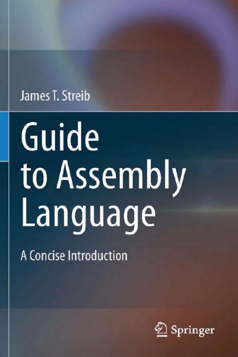
Just as compilers convert a high-level language to a low-level language, an assembler
converts assembly language to machine language. Although some newer compilers convert
high-level languages (such as Java) to an intermediate language (such as bytecode) which
is then interpreted to machine language, the result is that the final code is in machine
language of the machine the program is to be executed on. Figure 1.1 illustrates how a
language might be implemented.
There are a number of assemblers available to convert to Intel machine language,
but the one used in this text is MASM (Microsoft Assembler). The method used for
installing, keying in an assembly program, assembling a program, and executing a program
will probably be explained by one’s instructor or might be demonstrated by colleagues
at one’s place of employment. However, if one is reading this text independently and
1
J.T. Streib, Guide to Assembly Language, DOI 10.1007/978-0-85729-271-1_1,
C
Springer-Verlag London Limited 2011

21 Variables, Registers, and Data Movement
Compiler Assembler
Machine Languages
Low-Level Language
1’s and 0’s
Assembly Languages
Low-Level Language
Mnemonics
C-Like Languages
High-Level Languages
English-Like
Fig. 1.1 High-level language and assembly language translation to machine language
wants to install the software on a home computer, the instructions can be found in
Appendix A.
When learning any new programming language, whether high level or low level, it is
helpful to start with a very simple program. Often when learning a high-level language,
the first program is the infamous “Hello World” program, which when keyed in allows the
programmer to have a correctly compiled and executable program. Unfortunately, when
starting to learn a low-level language, the input/output (I/O) facilities are much more com-
plicated and it is usually not the best place to start. As a result, this text will first look
at some of the fundamentals of assembly language and then subsequently examine I/O to
verify that the fundamentals have been learned and implemented properly.
1.2
The First Program
The first program to be implemented will be the equivalent of the following C program,
which merely declares two variables, assigns a value to the first variable, and then assigns
the contents of the first variable to the second variable:
int main(){
int num1,num2;
num1=5;
num2=num1;
return 0;
}
What follows is an assembly language program that implements the same logic as the C
program above. Although at first it might look a little intimidating, it can serve as a useful
starting point in learning the basic layout and format of an assembly language program:
.386
.model flat, c
.stack 100 h
.data

1.2 The First Program 3
num1 sdword ? ; first number
num2 sdword ? ; second number
.code
main proc
mov num1,5 ; initialize num1 with 5
mov eax,num1 ; load eax with contents of num1
mov num2,eax ; store eax in num2
ret
main endp
end
The first thing to be understood is that some of the statements above are directives,
while others are instructions. Although it will be discussed in more detail later, simply put,
instructions tell the central processing unit (CPU) what to do, whereas directives tell the
assembler what to do. Similar to directives, operators also tell the assembler what to do
with a particular instruction.
The .386 at the beginning of the program is a directive and indicates that the program
should be assembled as though the program will be run on an Intel 386 or newer processor,
such as Pentiums and 64-bit machines. It is possible to specify that older processors could
be used, but the .286 and older processors were 16-bit machines and did not have as many
features as the .386, which is a 32-bit machine. Although a newer processor could be
specified, there are not a significant number of newer instructions that will be covered in
this text and using .386 would still allow the program to be run on some older processors.
The .model flat directive specifies that the program uses protected mode which
indicates that 32-bit addresses will be used and thus it is possible to address 4 GB of
memory. Although there exist some previous forms of addressing, this protected mode is
fairly common now, is simpler to understand, and can address more memory. The cin the
model directive indicates that it can link with C and C++ programs and is needed to run in
the Visual C++ environment.
The .stack directive indicates the size of the stack in hexadecimal (see Appendix B)
and indicates the stack should be 100 hexadecimal bytes large, or 256 bytes. The use of
the stack will be discussed later in Chapter 6.The.data and .code directives will be
discussed shortly, but the proc directive stands for procedure and indicates that the name
of the procedure is main. Although other names can be used, the name main is similar
to naming a C, C++, or Java program main and allows the assembly program to be run
independently of other programs. The ret instruction serves as a return 0 statement
doesinCorC++.Themain endp label and directive indicate the end of the procedure
and the end directive indicates the end of the program for the assembler.
In the past, different assembly languages have used specific columns to place the various
fields of the assembly language instructions. Although the rules as to which exact columns
the fields need to be placed in have become more relaxed, it is still customary to line up the
fields in columns to help with the readability of the code.
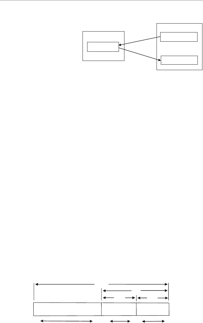
In order from left to right, the four columns or fields of an instruction are the label,
operation code (opcode), operand, and comment fields. The first field is typically reserved
for the names of variables and possibly labels used for branching to various instructions.

41 Variables, Registers, and Data Movement
Label Opcode Operand Comment
.data
num1 sdword ? ; first number
num2 sdword ? ; second number
.code
m
ain proc
mov num1,5 ; initialize num1 with 5
mov eax,num1 ; load eax with contents of num1
mov num2,eax ; store eax in num2
ret
Fig. 1.2 Label, opcode, operand, and comment fields
The second field is typically used for operation codes (opcodes) that represent executable
instructions and also assembler directives. The third field, typically only separated by a
space from the second field, is used for operands of which there can be anywhere from
zero to three operands. The optional last field is typically used for comments, but note that
comments are not restricted to the fourth field, can start anywhere on a line, and must begin
with a semicolon.
As an example, consider Fig. 1.2 illustrating a couple of lines from the previous code
segment. Note that although the label, opcode, and comment fields typically line up, the
operand field is usually separated only by a single space from the opcode field.
As seen in Fig. 1.2, there are two major sections to an assembly language program, the
data segment and the code segment indicated by the .data and .code directives. The
next section will discuss the data segment, while the following section will discuss the code
segment.
1.3
Variable Declaration
The data segment in the program above declares two variables called num1 and num2 as
indicated by the names listed in the label field of each of these two lines. The rules for
variable names are not unlike high-level languages, with some minor differences. Similar
to high-level languages, a variable name can begin with a letter and then be followed by
letters or digits. They can also include the special symbols _,@,or$anywhere in the name,
but typically these three symbols should be avoided. Unlike languages such as C, C++, and
Java, the names are not case sensitive, so the variables cat and CAT refer to the same
memory location. The maximum length of a variable name is 247 characters, but normally
a variable is only 1–10 characters long. Table 1.1 contains some examples of valid and
invalid variable names.
When declaring a variable, the opcode field has the assembler directive sdword,which
stands for signed double word, is 32 bits long, and is the same as an int variable in Visual
C++. The word bit stands for binary digit, where 1 bit can hold a single binary digit, a 0
or a 1, and a group of 8 bits is called a byte. On the Intel processor, a word of memory

1.3 Variable Declaration 5
Table 1.1 Valid and invalid
variable names Valid Invalid
auto 1num
num1 7eleven
z28 57chevy
Table 1.2 Types, number of bits, and range of values
Type Number of bits Range (inclusive)
sdword 32 –2,147,483,648 to +2,147,483,647
dword 32 0 to +4,294,967,295
sword 16 –32,768 to +32,767
word 16 0 to +65,535
sbyte 8 –128 to +127
byte 8 0 to +255
contains 2 bytes or 16 bits, and a double word contains 4 bytes or 32 bits. If the reader has
not had previous experience with bits, bytes, and binary numbers, or they just need a good
review, then refer to Appendix B.
There are other declarations possible, as shown in Table 1.2, indicating the number of
bits allocated to each data type. Also included is the range of values that can be stored
in each type of memory location. For now this text will use only signed double words for
positive and negative integers and bytes for characters, both for the sake of simplicity.
The third field, or operand field, for the two variables in the declaration section of the
previous program each contains a question mark, which indicates that the variable would
not be initialized by the assembler. It is also possible to put a number in place of the
question mark, which would cause the assembler to initialize the variable at assembly time,
similar to initializing a variable in C when one writes the following:
int num3 =5;
The equivalent of the above C code in assembly language is as follows:
num3 sdword 5 ; num3 initialized to 5
Lastly, comments can be in the fourth field or prior to the line of code they are describ-
ing, and in each case they must be preceded by a semicolon. Both types of comments are
used in assembly language, where comments located prior to a line of code tend to be more
general in nature, while the ones to the right tend to be specific to the line they are on.
Comments are usually not placed off to the side as much in high-level languages, due to
the indenting of code in selection and iteration structures. However, since assembly lan-
guage is typically not indented, there is plenty of room to the right and comments are often
placed there.

61 Variables, Registers, and Data Movement
Character data can also similarly be declared. To declare two variables, the first called
grade1 which is not initialized and the second called grade2 initialized to the letter ‘A’,
it would be done as follows in C/C++/Java:
char grade1;
char grade2='A';
The same can be done in assembly language similar to using sdword previously, except
byte is used instead. Although shown here using single quotes, note that character data
can also be enclosed in double quotes:
grade1 byte ?
grade2 byte 'A'
Further, a string as an array of byte can also be declared. Although the instructions to
process a string will be postponed until Chapter 9, it is sometimes necessary to output a
string as a message or to serve as a prompt for input. Sometimes a string can be declared
as separate letters as follows:
grades byte 'A','B','C'
But unless each letter is going to be processed separately, they are usually declared as a
complete string for the sake of readability as in the following example:
name byte 'Abe'
As will be seen in the next section, strings are often terminated with a binary zero taking
up 1 byte to indicate the end of the string. This is often used in output statements and is
declared as follows:
name byte 'Abe',0
There are many other possibilities for string declaration and as mentioned above there
are also various string processing instructions, but they are fairly complicated and the above
will suffice for Chapter 2. It is also possible to declare an array of integers or in other words
an array of sdword, but this and the instructions necessary to process an array are not
currently needed and they will be discussed in Chapter 8.
1.4
Immediate Data
Moving from the data segment to the code segment, if one does not initialize a variable in
the data segment, how does one assign a constant to a memory location? The instruction
necessary to do this is the mov instruction, pronounced “move,” but be careful not to spell
it with the letter eat the end or it will cause a syntax error. A mov instruction always
moves information from the operand on the right, called the source, to the operand on the
left, called the destination. The mov instruction is similar to the assignment symbol, the
equals sign in C, C++, and Java, where the instruction does not necessarily move data,

1.5 Registers 7
Table 1.3 Mov instructions
Instruction Meaning
mov mem,imm move the immediate data to memory
mov reg,mem move the contents of memory to a register
mov mem,reg move the contents of a register to memory
mov reg,imm move immediate data to a register
mov reg,reg move the contents of the source (second)register
to the destination (first) register
but rather makes a copy of it. Some of the formats of the mov instruction are shown in
Table 1.3.
The abbreviations above stand for each of the following:
imm =immediate mem =memory reg =register
For example, if one wants to move the integer 5into the memory location num1, such as
num1=5; in the previous listed C code, then one would write the corresponding assembly
language instruction as shown below and also shown in the previous assembly language
code segment:
mov num1,5
The variable num1 is the previously declared memory location (abbreviated as mem
in the previous table) and 5is what is known as an immediate value (abbreviated as imm
in the previous table). The reason the integer is known as immediate data is because it is
immediately available in the assembly language instruction as a part of the instruction and
it does not need to be retrieved from a variable in memory. For more information on how
data is stored immediately in an instruction, see Chapter 10.
1.5
Registers
As can be seen, the initializing of a variable with an immediate value is relatively easy,
so how does one transfer the contents from one memory location to another? If there is
one thing that the reader should learn about computers it is that data is typically not moved
directly from one memory location to another. Although the high-level C/C++/Java instruc-
tion y=x; looks as though the contents of memory location xare being copied directly
to y, in reality it has to in a sense make a detour. With the exception of a few specialized
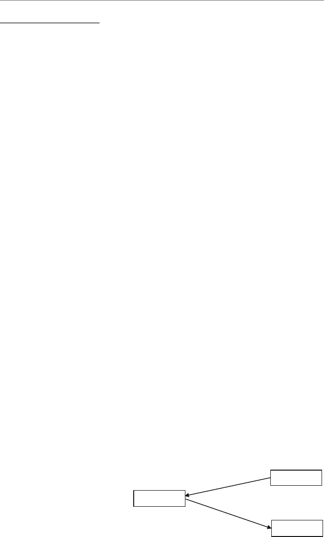
string processing instructions, the way most computers work is that the contents of one
memory location in random access memory (RAM) need to be moved or loaded into the
central processing unit (CPU) and from there moved or stored back into a memory location
in RAM. This is accomplished via a fast short-term memory location in the CPU called
aregister, where in some computers, registers might be called accumulators. Initially the
81 Variables, Registers, and Data Movement
Memory Location x
Memory Location y
5
5
Register
5
RAM
Load
CPU
Store
Fig. 1.3 Load and store
operations
contents of the register and memory location yare indeterminate. The contents of memory
location xare first copied into the register by an operation that is often generically called
aload operation and then the contents of the register are copied into the memory location
yby an operation that is often generically called a store operation as illustrated in Fig. 1.3.
Although some computers have instructions called load and store, as will be seen shortly
in the Intel processor, these load and store operations can both be accomplished with the
mov instruction.
In examining any new processor architecture, one of the first things one should do is
examine the register set of the processor. There are a number of registers in all processors,
but the ones that are accessible to the programmer are called general purpose registers. The
original Intel processors were only 16-bit machines, hence their general purpose registers
were only 16 bits long. These registers were called ax,bx,cx,anddx. When the 386
microprocessor came along in the late 1980s, it used 32-bit registers, so the original four
register names were preceded by the letter eto indicate the extended length from 16 to
32 bits. So the four general purpose registers in a modern Intel processor are called eax,
ebx,ecx,andedx. However, it should be noted that the four original registers are still
accessible as the lower order, first 16 bits of the modern extended registers as indicated in
Fig. 1.4. Not only is the ax register the first 16 bits of the eax register, but the ax register
is further subdivided into the higher order 8 bits and lower order 8 bits, as the ah register
and the al register, respectively. Although the lower 16 bits of each 32-bit register have
their own name, such as ax, the upper 16 bits of the 32-bit register do not have their own
name. If they do not have their own name, can they still be accessed? The answer is yes,
and this will be discussed later in Chapter 6. Only a drawing of the eax,ax,ah,andal
registers is given in Fig. 1.4, but the same drawing can be applied to the other registers as
well, by substituting the letters b,c,anddfor the letter ain the figure.
eax
ax
al
0
87
16 15
31
ah
Fig. 1.4 Format of the eax,ax,ah,andal registers

1.5 Registers 9
Each of the above four general purpose registers can be used for data movement, and
as will be seen later they can also be used for arithmetic and logic. Further, they also have
some special purposes as indicated by the letters a,b,c,anddin the names of the four
registers. Although all registers might be called accumulators on some machines, only the
eax register is sometimes referred to as the accumulator in the Intel processor because it
is useful in various arithmetic operations. The ebx register is sometimes called the base
register and is useful in array processing. The ecx register can be used as a counter and
is useful in special loop instructions. Lastly, the edx register is used as a data register in
various arithmetic instructions. For now, the register that will probably be used the most is
the eax register which will be demonstrated shortly.
Beyond the above four general purpose registers, there are other registers that will be
used later in this text. In particular, these are the ebp,esp,esi,andedi. The first
two have to do with the stack and are accessed indirectly. The esp is a stack pointer and
indicates the top of the stack and ebp is the base pointer and indicates the bottom of the
stack, both of which will be discussed further in Chapter 6.Theesi and edi registers
indicate the source index and the destination index, respectively, and are useful with arrays
and extremely useful with strings as will be seen in Chapters 8 and 9.Thecs,ds,andss
registers are 16-bit segment registers that point to the code, data, and stack segments and
are set by the .code,.data,and.stack directives, respectively. Three other segment
registers, es,fs,andgs, are extended segment registers that can be used for data. Beyond
this basic information, the segment registers are not needed for the rest of this text.
Two more registers are the eip and eflags registers. The former is the instruction
pointer and indicates which instruction is going to be executed next. Although not directly
accessible, it is indirectly accessible when changing the flow of control of the program
using the equivalents of selection and iteration structures discussed in Chapters 4 and 5.
Among other functions, the eflags register indicates the status of the CPU after exe-
cuting various instructions that help indicate the flow of control of the program and will
be discussed further in Chapter 4. For the sake of convenience, Table 1.4 summarizes the
registers used most in this text.
Table 1.4 Summary of registers
32-Bit
registers Name
16- and 8-bit
sub-registers
Brief description and/or
primary use
eax Accumulator ax,ah,al Arithmetic and logic
ebx Base bx,bh,bl Arrays
ecx Counter cx,ch,cl Loops
edx Data dx,dh,dl Arithmetic
esi Source index si Strings and arrays
edi Destination index di Strings and arrays
esp Stack pointer sp Top of stack
ebp Base pointer bp Stack base
eip Instruction pointer ip Points to next instruction
eflags Flag flags Status and control flags
10 1 Variables, Registers, and Data Movement
1.6
Data Movement
Returning back to the problem of transferring information from one memory location to
another, the data needs to pass through an intermediate stop in a register. What should be
noted in the previous table concerning the various formats of the mov instruction is that
there is no format to move from one memory location to another memory location. In other
words, there is no format for mov mem,mem. Again, if there is one thing that should be
learned from studying assembly language, it is that instructions typically do not exist for
memory to memory operations and such transfers must first go through a register. So, if one
wants to implement the instruction num2=num1;, one cannot say mov num2,num1.
Instead one must first copy the contents of num1 to a register and then copy the contents
of the register to the memory location num2, as shown below:
; num2 =num1
mov eax,num1 ; load eax with the contents of num1
mov num2,eax ; store the contents of eax in num2
Although at first this might seem a little awkward, it is a fundamental concept of com-
puter architecture and low-level languages. It is not unique to the Intel processor, but exists
in other processors as well. Once one gets used to the idea, it just becomes a matter of
habit for the experienced assembly language programmer. Also notice in the above that
although the semicolon is at the beginning instead of at the end, in order to form a com-
ment, the original C instruction makes a nice comment prior to the assembly language code
segment.
Similar to the previous generic drawing in Fig. 1.3, the initial contents of eax and num2
are indeterminate. When the two instructions are done executing in Fig. 1.5, the number
5in num1 is copied into the eax register and then the number 5is copied from the eax
register into the variable num2.
In the previous code segment, notice that the comments on the side indicate load and
store instead of move. The reason for this is that on other types of CPUs, the act of moving
the contents of memory into a register or an accumulator is often called a load operation,
where one is loading a value from memory into the CPU, whereas the reverse operation is
called a store operation, where one stores the value in the CPU back into memory.
5
5
5
num1
mov num2,eax
mov eax,num1
num2
eax
Fig. 1.5 Mov instruction

1.7 Character Data 11
Since registers are located in the CPU itself, they can be accessed much faster than
memory and it is possible to leave data in the register to gain the advantage of speed. In
fact, this is one of the reasons why programmers sometimes program in assembly language.
Although it might be tempting to use only registers, it should be noted that there are only
four general purpose registers, where as mentioned above many of those registers in spite
of being general purpose registers also have specialized uses. For example, if the ecx
register was being used for loop control, the ebx register for indexing an array, and the
edx register for multiplication (as will all be explained and demonstrated later), then eax
would be the only register left. It might then be the case that data would have to be moved
from the eax register back into memory so that the eax register could be freed up to load
more data in from memory.
Furthermore, since register names are not very descriptive of their content and memory
locations can be given descriptive variable names as discussed in the previous section, it
is usually easier to program using variable names rather than trying to remember what is
stored in which register at any particular time in a program. Although there is a perfor-
mance penalty when moving data back into memory, the penalty for lost time trying to
debug an assembly program as a beginning student of assembly language programming is
much greater during the course of a semester. Also, since most programs written in the
academic environment are used only a few times (for testing and grading), as opposed to
being executed many times in the industrial environment, time is better spent writing a
program that is easier to read, understand, and debug. Besides, it is usually easier to go
back and modify an easy-to-read program to make it run faster and use less memory than
it is to try to debug a supposedly optimized and difficult-to-read program. Once a program
is written and works properly, it can always be easily modified to perform faster and use
less memory in the places where it counts the most. These techniques will be introduced
later, on an as-needed basis. So for now, resist the temptation to save that extra byte or
nanosecond and make sure that your programs are implemented logically, correctly, and
are easy to read and modify.
1.7
Character Data
The above code works well with numbers, but what if one wanted to move a character
from one location to another? The same principles apply, except instead of moving 32-bit
double words around, only a single byte needs to be moved because a character is only
8 bits long. For example, how would the following C code segment be implemented in
assembly language?
char letter1,letter2;
letter1 ='A';
letter2 =letter1;

12 1 Variables, Registers, and Data Movement
As before, the variables letter1 and letter2 would need to be declared in the data
section, but instead of being declared as type sdword, they would need to be declared sim-
ply as type byte. The first line of executable code would be implemented as an immediate
instruction and the transfer of data between the memory locations would be done via a
register, but instead of a 32-bit register, only an 8-bit register would be used. The following
assembly language code segment implements the above C code:
.data
letter1 byte ?
letter2 byte ?
.code
; letter1 ='A'
mov letter1,'A'; store 'A'in letter1
; letter2 =letter1
mov al,letter1 ; load al with letter1
mov letter2,al ; store al in letter2
What if one wanted to move more than a single character? This can be done using
special string instructions which will be introduced in Chapter 9.
1.8
Errors
As with high-level programs, there can of course be various types of errors in assem-
bly language. The first type of error usually encountered is a syntax error which is an
error in the grammar of the language. For example, if move was typed in the above
code segment instead of mov, then a syntax error would occur. The second type of error
is an execution or a run-time error, in which although the syntax might be correct, the
instruction being executed cannot be performed by the processor. A typical error like
this might be a division by zero error, where division will be discussed in Chapter 3.
The last type of error is the most difficult to resolve because it does not give the pro-
grammer an error message and is known as a logic error. In the above code segment,
what would happen if the last two lines were reversed? The contents of letter1 would
never be copied from the al register into letter2 because the contents of letter2
would contain the indeterminate contents of the al register. At first, one will probably
make a number of syntax errors due to the newness of the language, but with the help
of the assembler’s error messages and with practice, the number of syntax errors will
decrease. However, as with any language, it is the logic errors that can take the most time
to debug, but with careful attention to the logic of the code being written and following
many of the suggestions presented throughout the text, the number of logic errors can be
minimized.

1.9 Complete Program: Implementing Inline Assembly in C 13
1.9
Complete Program: Implementing Inline Assembly in C
If one looks at the first complete C and assembly programs at the beginning of this chap-
ter, what is noticeably absent is any form of input/output (I/O). The reason for this is that
I/O in stand-alone assembly language programs can be quite complex. As is explained in
Appendix A, all the programs used in the subsequent chapters of this text are run as stand-
alone assembly language programs. To help simplify the I/O in stand-alone programs, it is
possible to use the I/O from the C programming language as introduced in the next chapter.
Until then, in order to get a glimpse to see that the above programs do indeed work, it is pos-
sible to run assembly instructions in a C program using Visual C++. This process is known
as inline or embedded assembly and is a quick way to test program segments. However,
there are some disadvantages to this method where the high-level assembly directives, such
as if and while statements introduced in Chapters 4 and 5, respectively, cannot be used
in embedded assembly and this is the reason why stand-alone assembly language programs
are used in all subsequent chapters.
In order to include assembly language instructions in a C program, one must include
the __asm{ statement at the beginning of the assembly language code segment, which
is a double underscore, followed by the word asm and an opening brace. After including
the needed assembly language statements, one must include a closing brace, }, at the end
of the segment. The advantage of using inline assembly is that C input and output can be
used to see if the processing has been done correctly. Input and output from the C language
will be used here since it is the easiest to use when dealing with stand-alone programs and
described in more detail in the next chapter.
To see how assembly language can be included in a C program, consider the following
program:
#include <stdio.h>
int main(){
int num1,num2;
num1 =5;
num2 =num1;
printf("%s%d\n","The answer is: ",num2);
return 0;
}
Although some of the code above may seem a bit cryptic to those readers who are not
familiar with C, where many of the details of the above will be discussed in Chapter 2,
it should be obvious the printf is the output of the variable num2. The key part of the
above program is the assignment statement num2=num1; and given the mov instruc-
tion and the eax register presented in this chapter, it can easily be converted to assembly
language. The above C program can be implemented using assembly language for the
assignment statement shown below:

14 1 Variables, Registers, and Data Movement
#include <stdio.h>
int main(){
int num1,num2;
num1 =5;
__asm {
mov eax,num1
mov num2,eax
}
printf("%s%d\n","The answer is: ",num2);
return 0;
}
Go ahead and key in the above program using Visual C++ (see Appendix A) to prove
to yourself that the code works. Also, feel free to try some of the other instructions intro-
duced in this chapter to become more familiar with the mov instruction and registers. For
example, try converting the num1=5; statement to assembly language and move it to the
inline assembly section of the program.
1.10
Summary
•Directives tell the assembler what to do and instructions tell the processor what to do.
•A double word is 32 bits, a word is 16 bits, and a byte is 8 bits.
•The four general purpose registers are eax,ebx,ecx,andedx.
•Immediate data is data that appears in an operand.
•The mov instruction cannot move data directly from one memory location to another
memory location.
•Typically, a variable name will begin with a letter and is followed by any combination
of letters and numbers. Although _,@,or$canbeusedanywhereinthename,inthis
text the use of these characters is discouraged.
•To declare integers, use sdword and for characters, use byte.
•Inline or embedded assembly is good for testing small assembly language code seg-
ments, but it has limitations where high-level directives, such as if statements and while
structures, cannot be used in the segment.
•As with high-level languages, error messages are given for syntax and execution (or
run-time) errors, but not for logic errors.
1.11
Exercises (Items Marked with an ∗Have Solutions in Appendix E)
1. Which of the following are syntactically correct variable names in assembly language?
∗A. RX8 B. 325i ∗C. Total$ D. @1234

1.11 Exercises 15
2. Implement each of the following declarations in assembly language:
∗A. char initial;
B. char grade ='B';
∗C. char x ='P',y='Q';
D. int amount;
∗E. int count =0;
F. int number =-396;
3. Assuming that the variables have been declared properly, indicate whether the following
statements are syntactically correct or incorrect. If incorrect, indicate what is wrong
with the statement:
∗A. move cat,5 B. mov dog,cat *C. mov eax,ebx
D. mov mouse,-7 *E. mov 1,frog F. mov horse,ecx
4. Assuming all the variables are declared as sdword, write assembly language instruc-
tions to implement each of the following C statements or segments:
∗A. i =1;
B. x =y;
∗C. c =2;
b=c;
a=b;
D. x =y=1;
5. Assuming all the variables are declared as byte, write assembly language instructions
to implement each of the following C statements or segments:
∗A. a ='B';
B. b =c;
∗C. d ='E'
e=d;
D. d ='z';
a=d;
b=a;

Input/Output 2
2.1
Introduction
As mentioned in Chapter 1, input and output (I/O) in assembly language can be quite
difficult and complicated. Although the exploration of I/O at the assembly language level
is a subject worthy of study, it often times gets in the way of many of the other important
topics and reasons for studying assembly language. The result is that it is helpful to have
a simplified form of input/output. To that end, it is possible to access the input/output
capabilities that are available in the C programming language, and of the various high-level
languages that MASM can interface with, C is probably the easiest. If one has studied
C before, then the following will seem fairly straightforward. If one has not studied C
previously, but rather has experience with other languages like C++ or Java, the transition
to the C language I/O should not be too difficult. Although all the fundamentals of I/O in
C that are necessary for this text will be presented in this chapter, the reader can always
refer to any number of C programming language texts to explore some of the other options
available.
2.2
Hello World
When learning a new programming language, one of the first programs learned is the
infamous “Hello World” program. The advantage of such a program is to insure that the
program has compiled or assembled correctly and subsequently executed properly. This
program in C often appears as follows:
#include <stdio.h>
int main(){
printf("Hello World!\n");
return 0;
}
17
J.T. Streib, Guide to Assembly Language, DOI 10.1007/978-0-85729-271-1_2,
C
Springer-Verlag London Limited 2011

18 2 Input/Output
where printf is the method used for output, the string to be output is in double quotes,
and the \nmeans advance to the next line, similar to using endl in a cout statement in
C++ and similar to the ln portion of a system.out.println() statement in Java.
The corresponding program to output “Hello World” in MASM would appear as follows:
.386
.model flat, c
.stack 100h
printf PROTO arg1:Ptr Byte
.data
msg1 byte "Hello World!",0Ah,0
.code
main proc
INVOKE printf, ADDR msg1
ret
main endp
end
The PROTO directive, preceded by the label printf, indicates a prototype for the func-
tion printf. When the assembler encounters the printf, it does not cause an error but
rather leaves space for the address of the instruction to be filled in later by the linker prior
to being loaded into memory for execution. The parameter arg1:Ptr Byte indicates
that the argument of the printf will be a pointer to a string of bytes.
In order to call the printf function, the INVOKE directive is used, which is like
calling a subprogram (see Chapter 7), but is simpler to use because it takes care of the
parameter passing. However, be very careful to note that the INVOKE directive destroys
the contents of the eax,ecx,andedx registers. Again as mentioned in Chapter 1,itis
wise to save data in memory locations instead of leaving them in registers to avoid the
possibility of long debugging sessions.
Continuing, the argument ADDR msg1 in the INVOKE above indicates the address
of the string to be output. The actual message to be output is in the .data section as
msg1 byte "Hello World",0Ah,0, where string data was discussed in Chapter 1.
The difference here is that the string is followed by a 0Ah, which is the hexadecimal code
for a new line, such as \nin C (see Appendix B for a discussion of hexadecimal). The 0Ah
is followed by a 0, which is the code to terminate a string used with output.
The above code is good for outputting a single character string, but what if there is
a need to format and output a number of parameters? As a transition step to the ability
to output more than one argument, the original C program above could be rewritten as
follows:
#include <stdio.h>
int main(){
printf("%s\n","Hello World!");
return 0;
}

2.3 Integer Output 19
The advantage of the above code segment is that the formatting is separated from the
data to be output. The %s indicates that there is a string in the first argument following
the current formatting argument. Although in C the formatting and data are often together,
their separation makes for a little cleaner code in assembly language when there is more
than one item to be output. Although the cleaner code might not be readily apparent in the
segment below, it paves the way for multiple arguments in subsequent examples:
.386
.model flat, c
.stack 100h
printf PROTO arg1:Ptr Byte, printlist:VARARG
.data
msg1fmt byte "%s",0Ah,0
msg1 byte "Hello World!",0
.code
main proc
INVOKE printf, ADDR msg1fmt, ADDR msg1
ret
main endp
end
First note that the PROTO statement has an additional argument printlist:
VARARG, which indicates that a variable number of arguments can now follow the first
argument, where the first argument will now serve as the format string. In the data declara-
tion section, note that the %s is in a separate data declaration called msg1fmt, where %s
indicates that string data will be output. Also, the string to be output is only terminated by
the 0string terminator and the 0Ah has been moved to msg1fmt. Lastly, the first ADDR in
the INVOKE directive references the format string and the second one references the string
to be output.
2.3
Integer Output
In addition to outputting a single string, the previous example can be expanded to output
multiple strings. Further, it can be expanded to output multiple integers or a combination
of strings and integers. The advantage of this is that the integer output can be identified to
the users with matching strings. For example, in the following C program, the integer 5is
output along with an identifying string:
#include <stdio.h>
int main(){
int number;
number =5;

20 2 Input/Output
printf("%s%d\n","The number is: ",number);
return 0;
}
The first argument of the printf says that a string will be output (%s), followed by
an integer (%d), followed by a line feed. The second argument of the printf is the string
and the third is the variable number. The corresponding MASM code is as follows:
.386
.model flat, c
.stack 100h
printf PROTO arg1:Ptr Byte, printlist:VARARG
.data
msg1fmt byte "%s%d",0Ah,0
msg1 byte "The number is: ",0
number sdword ?
.code
main proc
mov number,5
INVOKE printf, ADDR msg1fmt, ADDR msg1, number
ret
main endp
end
As in the last example of the previous section, the PROTO statement remains unchanged.
Note that the msg1fmt string has the %d added to it. The variable number has been
declared as a signed double word in the data section and the number 5assigned to it in the
code segment. Lastly, the variable number has been added as an argument to the INVOKE
directive. Both msg1fmt and msg1 need ADDR because they are pointers to the strings,
but ADDR is not needed for number because it is a simple integer variable.
The following example further illustrates how multiple arguments work and includes
two integers in addition to a string. It also includes cleaner output by including better
vertical spacing by using \nand better horizontal spacing by using spaces in the string as
shown below:
#include <stdio.h>
int main(){
int num1 =5, num2 =7;
printf("\n%d%s%d\n\n",num1," is not equal to ",num2);
return 0;
}
The above C program would be implemented in assembly as follows:
.386
.model flat, c
.stack 100h

2.4 Integer Input 21
printf PROTO arg1:Ptr Byte, printlist:VARARG
.data
msg1fmt byte 0Ah,"%d%s%d",0Ah,0Ah,0
msg1 byte " is not equal to ",0
num1 sdword 5
num2 sdword 7
.code
main proc
INVOKE printf, ADDR msg1fmt, num1, ADDR msg1, num2
ret
main endp
end
Without any change to the PROTO directive in the above program, there are now three
arguments after the msg1fmt string in the INVOKE directive. As mentioned previously,
the reason extra arguments are allowed is due to the VARARG in the PROTO directive which
allows for a variable number of arguments. Again, notice that 0Ah is used instead of \n
and the careful use of spaces in the string, both to assist in the vertical and horizontal
spacing. As an aside, also note that the variables num1 and num2 are initialized in the data
section during assembly time rather than during execution time, corresponding to the prior
C program.
2.4
Integer Input
Although having the ability to output is extremely important, it does lead to some dull
programs unless one can also input data. Just as printf can be invoked to allow for
output, so too can scanf be invoked for input. Instead of merely assigning an integer to the
variable number, the following C program inputs a number from the user and then outputs
the same number (note that when using scanf, a warning message might be issued, where
one can use scanf_s instead or just ignore the warnings):
#include <stdio.h>
int main(){
int number;
scanf("%d",&number);
printf("\n%s%d\n\n","The number is: ",number);
return 0;
}
Notice in the above code that number is preceded with an ampersand (&) in the
scanf but not in the printf. Although experienced C programmers are probably famil-
iar with this, programmers coming from other languages might not be familiar with it. The
ampersand indicates the address of number is being passed to scanf to allow the value

22 2 Input/Output
read in from the keyboard to be passed back to the variable number. Whereas with output,
the value in number beingpassedtoprintf will be output and since no number will be
passed back, an ampersand is not needed. The passing back of values through arguments
is known as a reference parameter in languages like C++, but the equivalent is not avail-
able in Java since values can be returned from methods only via a return statement. The
following assembly program implements the above C program:
.386
.model flat, c
.stack 100h
printf PROTO arg1:Ptr Byte, printlist:VARARG
scanf PROTO arg2:Ptr Byte, inputlist:VARARG
.data
in1fmt byte "%d",0
msg1fmt byte 0Ah,"%s%d",0Ah,0Ah,0
msg1 byte "The number is: ",0
number sdword ?
.code
main proc
INVOKE scanf, ADDR in1fmt, ADDR number
INVOKE printf, ADDR msg1fmt, ADDR msg1, number
ret
main endp
end
Although there are a number of similarities between the scanf and printf above,
such as the similarity between the two prototypes, there are some important details that
need to be pointed out. First, note that a %s does appear in the input format, because only
an integer is being input in this example. Further, the input format is terminated only by
a0and does not contain a 0Ah. The reason is that during input a new line is not needed
because it is supplied by the user after the data has been entered and they press the “enter”
or “return” key, which supplies the new line on the screen. Lastly, notice that the variable
number is preceded by ADDR in the invoking of scanf, but it is not preceded by ADDR in
the printf. The reason for this is that ADDR serves the same function as the ampersand
(&) in C as discussed above.
Although the above code works, it is not very helpful to the user. The reason is that
when either the above C or the MASM program executes, there is just a cursor blinking
on the screen and no indication to the user that any input is needed or what type of input
is needed. Instead, as with any language, it is a good idea to prompt the user for the type
of input needed as shown in the C program below, where the prompt and output message
have been changed to specify an integer instead of just a generic number:
#include <stdio.h>
int main(){
int number;

2.5 Complete Program: Using Input, Data Transfer, and Output 23
printf("\n%s","Enter an integer: ");
scanf("%d",&number);
printf("\n%s%d\n\n","The integer is: ",number);
return 0;
}
The corresponding assembly code is given as follows:
.386
.model flat, c
.stack 100h
printf PROTO arg1:Ptr Byte, printlist:VARARG
scanf PROTO arg2:Ptr Byte, inputlist:VARARG
.data
in1fmt byte "%d",0
msg0fmt byte 0Ah,"%s",0
msg1fmt byte 0Ah,"%s%d",0Ah,0Ah,0
msg0 byte "Enter an integer: ",0
msg1 byte "The integer is: ",0
number sdword ?
.code
main proc
INVOKE printf, ADDR msg0fmt, ADDR msg0
INVOKE scanf, ADDR in1fmt, ADDR number
INVOKE printf, ADDR msg1fmt, ADDR msg1, number
ret
main endp
end
Notice that the prompt in the C code does not contain a \nnor does the prompt in the
MASM code contain a 0Ah, because in both cases the cursor will remain on the same line
as the prompt awaiting the user to enter the integer, and then only when the user presses
the “enter” key will the cursor move to the next line.
2.5
Complete Program: Using Input, Data Transfer, and Output
As one more modification to the above program to implement both the concepts learned in
Chapters 1 and 2, consider the following program. It prompts for and inputs an integer into
num1, copies it to num2, and then outputs the contents of num2:
#include <stdio.h>
int main(){

24 2 Input/Output
int num1, num2;
printf("\n%s","Enter an integer for num1: ");
scanf("%d",&num1);
num2=num1;
printf("\n%s%d\n\n","The integer in num2 is: ",num2);
return 0;
}
This program is then implemented in assembly language as follows:
.386
.model flat, c
.stack 100h
printf PROTO arg1:Ptr Byte, printlist:VARARG
scanf PROTO arg2:Ptr Byte, inputlist:VARARG
.data
in1fmt byte "%d",0
msg0fmt byte 0Ah,"%s",0
msg1fmt byte 0Ah,"%s%d",0Ah,0Ah,0
msg0 byte "Enter an integer for num1: ",0
msg1 byte "The integer in num2 is: ",0
num1 sdword ? ; first number
num2 sdword ? ; second number
.code
main proc
INVOKE printf, ADDR msg0fmt, ADDR msg0
INVOKE scanf, ADDR in1fmt, ADDR num1
mov eax,num1 ; load eax with the content of num1
mov num2,eax ; store the contents of eax in num2
INVOKE printf, ADDR msg1fmt, ADDR msg1, num2
ret
main endp
end
2.6
Summary
•Use the PROTO and INVOKE directives to implement the C functions scanf and
printf.
•Be careful, the INVOKE directive destroys the contents of the eax, ecx, and
edx registers.
•Use separate formatting to make the assembly language equivalents more readable.
•The 0Ah in assembly language is like a \nin C, an endl in C++, and a println in
Java.

2.7 Exercises 25
•Be sure to terminate a string for output in assembly language with a 0.
•On output, do not forget to include an ADDR for strings.
•On input, do not forget to include an ADDR for all variables, which is like an & in C.
2.7
Exercises (Items Marked with an ∗Have Solutions in Appendix E)
1. Indicate whether the following statements are syntactically correct or incorrect. If
incorrect, indicate what is wrong with the statement:
∗A. printf PROTO arg1:Ptr Byte, printlist:VARARG
B. msg1fmt byte "\n%s%d\n",0
∗C. INVOKE printf, ADDR msg1fmt, ADDR number
D. msg2fmt byte 0Ah,0Ah„"%s",0Ah,0Ah,0
2. Assuming that the .data section is set up properly, what is wrong with the logic of
the following code segment? How could it be rewritten to avoid the difficulty?
mov num1,5
mov eax,num1
INVOKE printf, ADDR msg1fmt, ADDR msg1, num2
mov num2,eax
∗3. Given the following MASM program, what will be output to the screen? Be sure to
line everything up properly. Use a lowercase letter bto represent a blank and the words
blank line to represent a blank line:
.386
.model flat, c
.stack 100h
printf PROTO arg1:Ptr Byte, printlist:VARARG
.data
msg1fmt byte "%s%d",0
msg2fmt byte "%s%d",0Ah,0Ah,0Ah,0
msg3fmt byte "%s%d",0Ah,0
msg1 byte "x =",0
msg2 byte " y =",0
msg3 byte "z=",0
num1 sdword 1
num2 sdword 2
num3 sdword 3
.code

26 2 Input/Output
main proc
INVOKE printf, ADDR msg1fmt, ADDR msg1, num1
INVOKE printf, ADDR msg2fmt, ADDR msg2, num2
INVOKE printf, ADDR msg3fmt, ADDR msg3, num3
ret
main endp
end
4. Given the following MASM program, what will be output to the screen. Be sure to
line everything up properly. Use a lowercase letter bto represent a blank and the
words blank line to represent a blank line:
.386
.model flat, c
.stack 100h
printf PROTO arg1:Ptr Byte, printlist:VARARG
.data
msg1fmt byte 0Ah,"%s%d%s%d%s",0Ah,0
msg2fmt byte 0Ah,"%s%d",0Ah,0Ah,0
msg11 byte "The first number is ",0
msg12 byte ", but the second number is ",0
msg13 byte ",",0
msg2 byte "while the third number is ",0
num1 sdword 5
num2 sdword 7
num3 sdword 11
.code
main proc
INVOKE printf, ADDR msg1fmt, ADDR msg11, num1,
ADDR msg12, num2, ADDR msg13
INVOKE printf, ADDR msg2fmt, ADDR msg2, num3
ret
main endp
end
5. Implement the following C program in MASM. Be sure to use proper spacing on
all output. If necessary, first key in the C program and then implement the MASM
program to insure the MASM program works identically to the C program:
#include <stdio.h>
int main(){
int x, y, z;
x=1;
y=2;
z=3;

2.7 Exercises 27
printf(%\n%d%s%d%s%d\n\n", x, " + ", y, " =", z);
return 0;
}
6. Implement the following C program in MASM. Be sure to use proper spacing on
all output. If necessary, first key in the C program and then implement the MASM
program to insure the MASM program works identically to the C program:
#include <stdio.h>
int main(){
int num1, num2;
printf("\n%s","Enter a value for num1: ");
scanf("%d",&num1);
printf("\n%s","Enter a value for num2: ");
scanf("%d",&num2);
printf("\n%s\n\n","num1 num2");
printf("%s%d%s%d\n\n"," ",num1," ",num2);
return 0;
}
7. Given the following input and output, write both the C and assembly code necessary
to make it look exactly as below. Pay careful attention to spacing and the blank lines:
Input and Output
Enter a number: 1
Enter a larger number: 3
Enter an even larger number: 5
1<3<5
5>3>1

Arithmetic Instructions 3
3.1
Addition and Subtraction
After learning how to load a register, transfer data between memory locations, and perform
I/O, the next step is to learn how to perform various arithmetic operations. One of the sim-
plest ways to learn how to perform arithmetic in assembly language is to first write the
equation as a high-level statement. Assuming the integer variables num1 and num2 already
contain values, then how could one implement the following C statement in assembly
language?
sum =num1 + num2;
Just like the discussion concerning data movement, where the contents of one memory
location cannot be copied directly into another memory location without first being copied
to a register, the same concept applies to arithmetic operations, where arithmetic cannot be
performed between two memory locations as indicated in Table 3.1 concerning the add
instruction.
Table 3.1 Add instructions
Instruction Meaning
add mem,imm add the immediate value to memory
add reg,mem add the contents of memory to the register
add mem,reg add the contents of the register to memory
add reg,imm add immediate value to the register
add reg,reg add the contents of the source (second)register
to the destination (first)register
Again note that an add mem,mem instruction does not appear in the list of instruc-
tions, just as there was not a mov mem,mem listed previously. Instead, one must usually
move the contents of one memory location into a register, add the contents of the other
memory location to the register, and then copy the contents of the register into the specified
29
J.T. Streib, Guide to Assembly Language, DOI 10.1007/978-0-85729-271-1_3,
C
Springer-Verlag London Limited 2011
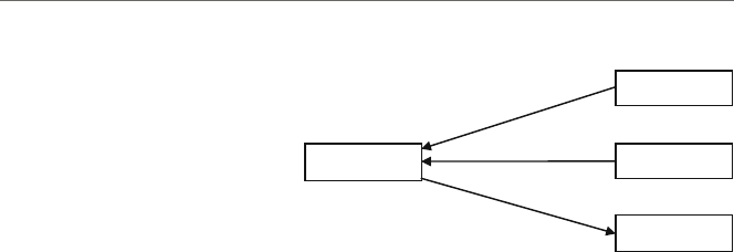
30 3 Arithmetic Instructions
12
num1
num2
sum
mov sum,eax
mov eax,num1
add eax,num2
eax
5
7
12
Fig. 3.1 Results of an addition
operation
memory location. The following assembly language code segment implements the C
statement from above:
; sum =num1 + num2
mov eax,num1 ; load eax with the contents of num1
add eax,num2 ; add the contents of num2 to eax
mov sum,eax ; store eax in sum
As before, the C statement makes a nice general comment prior to the assembly lan-
guage code segment. In the above segment, the contents of num1 are copied into the eax
register, then the contents of num2 are added to eax, and lastly the contents of eax are
copied into the variable sum. Assuming num1 initially contains a 5and num2 contains a
7, then Fig. 3.1 shows the results after execution of the previous code segment, where eax
and sum contain a 12.
Although it is possible to use any of the other three registers and accomplish the same
task, it is usually better to use the accumulator, the eax register, because the arithmetic
instructions that use the eax register tend to use less memory and are also a little faster,
as will be seen in Chapter 10. Also, just like there are often many ways to solve a problem
in high-level languages, the same is true in low-level languages. Further, just like some
solutions are better solutions in high-level languages, the same is also true in low-level
languages. For example, the previous assembly code segment could have been written as
follows:
mov sum,0 ; initialize sum to zero
mov eax, num1 ; load eax with the contents of num1
add sum, eax ; add the contents of eax to sum
mov eax, num2 ; load eax with the contents of num2
add sum, eax ; add eax to sum
Although the above code segment works, in that sum contains the sum of
both num1 and num2, it is not necessarily implementing the original C statement:
sum =num1 +num2; but rather it is implementing the following C code segment:
sum =0;
sum =sum + num1;
sum =sum + num2;

3.2 Multiplication and Division 31
Table 3.2 Sub instructions
Instruction Meaning
sub mem,imm subtract the immediate value from memory
sub reg,mem subtract contents of memory from the register
sub mem,reg subtract contents of the register from memory
sub reg,imm subtract the immediate value from the register
sub reg,reg subtract the contents of the source (second)
register from the destination (first) register
Although both of the above assembly language and C code segments work, in that the
variable sum contains the sum of both num1 and num2, the second one is less efficient in
terms of both memory and speed. With respect to memory, the second code segment takes
up more memory because there are more instructions. Also, if there are more instructions,
then the code segment will tend to take more time to execute.
As demonstrated above, one way to help write somewhat cleaner code is to not necessar-
ily think in assembly language but rather think in a high-level language and then convert
the high-level instructions into the low-level assembly language. Although at times this
might introduce some inefficiencies into the low-level code with regard to register usage,
the results would not usually be nearly as bad as in the last example, thus demonstrating
that one can still be concerned with efficiency at any level of programming.
Similar to the addition instruction is the subtraction instruction outlined in Table 3.2,
where the same formats of instructions that apply to the addition instruction also apply to
the subtraction instruction.
Note again that a memory to memory instruction does not exist. As before, a simple
high-level subtraction statement such as
difference =num2 - num1;
would be implemented in assembly language as follows:
; difference =num2 - num1
mov eax,num2 ; load num2 into eax
sub eax,num1 ; subtract num1 from eax
mov difference,eax ; store answer in variable difference
3.2
Multiplication and Division
While addition and subtraction seem to be fairly straightforward, multiplication and divi-
sion can be just a little more complicated. When adding two numbers together, it is possible
that the answer will be larger than the size of the register or memory location that can hold

32 3 Arithmetic Instructions
that value which would cause an overflow error. For example, adding the numbers 999
and 999 in base 10 will result in the number 1,998, which is one digit larger than the
two original numbers. The same applies to base 2, where adding the numbers 111 and 111
would result in the number 1110 (as discussed in Appendix B). However, when using 32-bit
signed double words, unless the sum is greater than 2,147,483,647 as indicated Table 1.2,
this should not be a problem at this time.
However, with multiplication, the situation is worse. For example, when multiplying the
numbers 999 and 999 in base 10, the answer is 998,001, where there is not just one extra
digit but potentially twice as many digits as is the case in this example. The same holds
true for binary, where multiplying the numbers 111 and 111 results in the answer 110001,
where again there are twice as many digits.
The result is that when multiplication occurs in the computer, there needs to be room for
the extra digits when two 32-bit registers are multiplied together, because the result could
take up 64 bits. Although there are many variations of the multiplication instruction that can
use two operands or three operands, this text will examine only the one-operand versions of
the instruction which has been available since the first Intel processor (although then only
in 16-bit form). Also, the one-operand instructions most closely resemble the one-operand
division instructions which are the only form of division instructions available. As a result,
this will help provide consistency when studying that instruction later. Although there is
an unsigned version of the multiply instruction called mul which can work with slightly
larger numbers (see Chapter 1 and Appendix B), it cannot work with negative numbers. As
a result, this text will consider only the signed versions of the multiplication instruction,
signified by iat the beginning of the instruction as imul. The two formats of these two
versions of the imul instruction are shown in Table 3.3.
The way these two one-operand versions of the signed multiplication instruction work
is that the eax register must first be loaded with the number that needs to be multiplied
(the multiplicand). Then, the number to be multiplied by (the multiplier) either is placed
into a register or can be located in a memory location. Note that with the one-operand
imul instruction, there is no provision for an immediate operand and that the use of the
eax register for the multiplicand is implied.
During execution of the imul instruction, the number in eax is multiplied by the
number either in the specified register or in the memory location and the answer (prod-
uct) is placed into what is called the edx:eax register pair. Recall from Chapter 1 that
edx is the data register that is used in various arithmetic instructions, where imul is one
of those arithmetic instructions. As mentioned above, it is possible that the answer from
multiplication could be twice the size of the original numbers being multiplied, so what
happens is that the low-order bits of the product are placed into the eax register and the
Table 3.3 Imul instructions
Instruction Meaning
imul reg multiply eax by an integer in a register
imul mem multiply eax by an integer in a memory location

3.2 Multiplication and Division 33
high-order bits of the product are placed into the edx register. For now, there is no plan to
multiply any numbers where the product is greater than 32 bits, or in other words a posi-
tive 2,147,483,647 or negative 2,147,483,648 (as discussed in Chapter 1 and Appendix B).
Regardless, it is still important to realize that the edx register will be filled with any high-
order bits, which in our case will usually be zeros or ones depending on whether the product
is positive or negative, respectively. As a result, this would destroy any values that might
have been placed in the edx register previously. Given the above, one can implement the
following C instruction
product =num1 *num2;
as follows in assembly language:
; product =num1 *num2
mov eax,num1 ; load eax with the contents of num1
imul num2 ; multiply eax by mum2
mov product,eax ; store eax in product
Again, at the end of the above segment the contents of the edx register will have been
destroyed. Assuming num1 contained a positive 2and num2 contained a positive 5,the
results in the edx:eax register pair would be that the 0located in the 31st bit (leftmost
bit) of the eax register would be copied or propagated throughout all 32 bits of the edx
register. If num1 instead contained a negative 2and num2 still contained a positive 5, then
the results in the edx:eax register pair would have been that the 1located in the 31st bit
of the eax register would have been copied or propagated throughout all 32 bits of the edx
register as shown in Fig. 3.2.(SeeAppendix B for a discussion of positive and negative
numbers.) This is yet another good reason not to keep values in registers, but rather to store
values in memory.
Given the above description of the imul instruction, how would one implement the
following C statement?
product =num1 *2;
Although it is possible to use immediate values with the two- and three-operand ver-
sions of the imul instruction, it is also possible to easily solve this problem using only
the one-operand version. The immediate value can first be moved into an empty register
and then that register can be used in the imul instruction. Again, this mimics the idiv
instruction to be discussed immediately after the following code segment:
31 ------------ 0 31 ----------- 0
1 --------------1 1---------110110
edx eax
Fig. 3.2 The edx:eax
registers after execution of
the imul instruction

34 3 Arithmetic Instructions
; product =num1 *2
mov eax, num1 ; load eax with the contents of num1
mov ebx,2 ; load ebx with the value 2
imul ebx ; multiply eax by ebx
mov product, eax ; store eax in product
Just as there is an instruction for the multiplication for unsigned numbers (mul), there
is also a division instruction for unsigned numbers (div). Although it can divide somewhat
larger numbers, it cannot divide negative numbers, so this text will consider only the signed
division instruction called idiv. As mentioned previously, the idiv instruction follows
the same format as for the previously introduced one-operand imul instruction. The only
two formats of the idiv instruction are shown in Table 3.4.
The division statement works much like the multiplication statement, except in reverse,
so just like the product of multiplication can be larger than the multiplier and multiplicand,
so it is that the answer (quotient) and remainder can be smaller than the original number to
be divided (the dividend). The result is that where the product for multiplication is in the
edx:eax pair, with division the dividend must be initially placed in the edx:eax pair
prior to using the idiv instruction. After execution of the idiv instruction, the quotient
is in the eax register and the remainder is in the edx register.
But how does one take a number, whether immediate data or in memory, and put it in
the edx:eax pair? Without any special instructions, one already has the ability to do this.
For example, what if one wanted to implement the following C statement?
answer =number / amount;
First, the contents of number would be moved into the eax register. Then assuming
that the contents of number are positive, a 0could be moved into the edx register. But
what if the contents of number were negative? Then instead of moving a 0into edx,a-1
could be moved into the edx register. This would cause each of the bits in the edx register
to be set to a binary 1, thus setting the sign bit to 1. However, this solution would require
the use of a selection structure which has not been discussed yet and would be a clumsy
solution at best. Luckily the designers of the Intel processor thought of this problem and
have special instructions to propagate or extend the sign bit from a smaller register to a
larger register. These instructions are shown in Table 3.5.
It is the latter instruction in Table 3.5 that is of interest here. The cdq instruction
allows the sign bit, whether a 0 or a 1, to be propagated throughout the edx register and
thus avoids the initial messy solution proposed above. For example, if the eax register
Table 3.4 Idiv instructions
Instruction Meaning
idiv mem divide the edx:eax register pair by memory
idiv reg divide the edx:eax register pair by a register

3.2 Multiplication and Division 35
Table 3.5 Convert instructions
Opcode Meaning Description
cbw Convert byte to word Extends the sign from al to ax
cwd Convert word to double Extends sign from ax to eax
cdq Convert double to quad word Extends sign from eax to edx:eax pair
originally contains a -2, then the sign bit (a 1in bit position 31)ofeax is copied into
each bit position of the edx register as illustrated in Fig. 3.3.
The solution to the previous C code is as follows:
; answer =number / amount
mov eax,number ; load eax with number
cdq ; propagate sign bit into the edx register
idiv amount ; divide edx:eax by amount
mov answer,eax ; store eax in answer
Assuming that the contents of number is a 5, and the contents of amount is a 2, then
the contents of the edx:eax pair would be as follows after the execution of the above
code segment, where the remainder of a 1is in the edx register and the quotient of a 2is
in the eax register shown in binary in Fig. 3.4:
Although the two- and three-operand formats for the imul instruction allow for an
immediate operand, the idiv does not have this luxury and the single operand can only
be a memory location or a register. So how would one implement an immediate value as
in answer =number/2? As a hint, look at the proposed solution using an immediate
value in the discussion concerning multiplication. Further, how would one implement the
%operator in the C programming language, as in answer =number % amount?If
one remembers what the %operator does (the mod or remainder function) and reviews how
the idiv instruction works, the answers to the above two questions should be obvious and
both of these problems are left as exercises for the reader at the end of the chapter.
1 -------------11 1------------110
31 ------------ 0 31 ----------- 0
eax
edx
Fig. 3.3 Propagating the sign
bit from eax through edx
0 -------------01 0------------010
31 ------------ 0 31 ----------- 0
edx eax
Fig. 3.4 Contents of
edx:eax after execution
of the idiv instruction

36 3 Arithmetic Instructions
3.3
Implementing Unary Operators: Increment, Decrement, and Negation
In high-level languages, the arithmetic operations presented in the previous two sections
are known as binary operators, not because they perform arithmetic on binary numbers
but rather because they have two operands as in x+y. However other high-level language
operators have only one operand, such as the negative sign –y, and these are known as
unary operators.
Although it is possible to implement all of the arithmetic necessary to implement
unary operators with the instructions presented previously, there are some extra arithmetic
instructions that tend to take up a little less memory, might be a little faster, and also make
life a little easier for the assembly language programmer. In addition to introducing these
instructions, some of the concepts concerning the order of operations are introduced in this
section.
For example, if one needed to increment a variable xby 1and decrement a variable y
by 1,suchas
x=x+1;
y=y-1;
or one could alternatively use the increment and decrement operators
x++; or ++x;
y--; or --y;
where in a stand-alone statement it does not matter whether the ++ or –-goes before
or after the variable. The above can be implemented by merely using the add and sub
instructions:
add x,1
sub y,1
Although the above works, the designers of the Intel processor built in two instruc-
tions that specifically increment and decrement by only 1. The format of each of these
instructions is shown in Table 3.6.
As mentioned at the beginning of this section, these instructions take up less memory
than do add or sub instructions. In fact, on older 16-bit processors if one needed to add or
Table 3.6 Inc and dec instructions
Instruction Instruction
inc reg dec reg
inc mem dec mem

3.3 Implementing Unary Operators: Increment, Decrement, and Negation 37
subtract the number 2to or from a register, it was faster to use two inc or dec instructions
than it was to use a single add or sub instruction to add or subtract the number 2. Although
this is not true with newer 32-bit processors, a single inc or dec instruction is still more
memory efficient than using an add or a sub instruction to increment or decrement by 1
(see Chapter 10). The result is the following:
inc x
dec y
As shown previously, it does not matter in C/C++/Java whether the increment or decre-
ment operators in a stand-alone statement are used in prefix or postfix notation. However,
as may have been learned in a previous computer science course, it is quite different when
they are used in conjunction with other operators in an arithmetic expression. Although
these combinations should probably be avoided by the novice programmer, they do arise
on occasion and one should understand how they work in a high-level language and how
to implement them in a low-level language. As either a review or an introduction, how do
the following two instructions differ?
x=y++; x =++y;
In the first case on the left, the value of yis first assigned to xand then the value of yis
incremented. In the second case, the value of yis first incremented and then it is assigned
to x. Assuming in both cases that yinitially contains the number 2, the results of both are
illustrated respectively on the left and right in Fig. 3.5.
Clearly there is a difference between the two, and the above two statements can
alternatively be implemented as
x=y; y =y+1;
y=y+1; x=y;
and thus can be implemented correspondingly in assembly language as
mov eax,y inc y
mov x,eax mov eax,y
inc y mov x,eax
What if one needed to negate a number, or in other words find the two’s complement of
a number (see Appendix B), and store it in another memory location? For example,
x=-y;
2 3
3
3
xx
y
y
Fig. 3.5 Results of x=y++
and x=++y

38 3 Arithmetic Instructions
As shown before with increment and decrement, one could accomplish negation using
the instructions that have already been introduced:
mov eax,0
sub eax,y
mov x,eax
Again as before, there is another instruction that is shorter and faster for negation called
neg and has the format shown in Table 3.7.
Using the neg instruction, the code segment above can then be rewritten as
mov eax,y
neg eax
mov x,eax
Notice that the variable yis not negated, since the negation symbol does not alter the
contents of the variable it precedes. Rather, the value of yis first moved to a register and
then negated prior to being moved to the variable x. Although it takes the same number of
instructions as the previous assembly language code segment, the neg instruction takes up
less memory than does the corresponding sub instruction.
Although there was some possible confusion of using the increment and decrement
instructions in an expression, the negation instruction is less complicated. One must
remember that the unary minus symbol for negation has precedence over the other binary
operators of +, -,∗,and/. Given the following statement on the left, the negation of y
occurs prior to the addition, and if one wants to negate after the addition, parentheses must
be used as shown on the right:
x=-y + z; x =-(y + z);
The above two statements are implemented correspondingly below in assembly
language:
mov eax,y mov eax,y
neg eax add eax,z
add eax,z neg eax
mov x,eax mov x,eax
Table 3.7 Neg instructions
Instruction Meaning
neg reg two’s complement of the contents of the register
neg mem two’s complement of the contents of a memory location

3.4 Order of Operations with Binary and Unary Operators 39
3.4
Order of Operations with Binary and Unary Operators
Although the previous section delved into some issues concerning order of operation, it
did so only with respect to the unary operators. This section discusses order of operation in
more depth with all arithmetic operators, including the binary operators, and in conjunction
with the unary operators. To help understand the order of operation and sharpen one’s skills
using assembly language arithmetic instructions, this section examines how slightly more
complicated arithmetic statements might be implemented. Again, it helps to first write it
out as a high-level instruction:
answer =num1 + 3 - num2;
Remembering the order of operations from C, C++, and Java, since addition and sub-
traction have the same level of precedence, the order of operation is from left to right.
In this case, the addition should be done first and the subtraction done second. Although
some compilers and skilled assembly language programmers might change the order of
various arithmetic operations to help optimize the efficiency of the machine code, this text
will adhere to the pre-defined rules for the sake of consistency and help reinforce the rules
regarding the order of operation.
First, the contents of the variable num1 should be loaded into the eax register, then the
number 3needs to be added to the eax register, where the number 3is not in a memory
location but rather is implemented as an immediate value. Next the value in num2 needs
to be subtracted from the eax register and lastly, the contents of the eax register need to
be copied into the variable answer, as shown below:
; answer =num1 + 3 - num2
mov eax,num1 ; load eax with the contents of num1
add eax,3 ; add 3 to eax
sub eax,num2 ; subtract num2 from eax
mov answer,eax ; store the result in answer
As before, there is usually more than one way to solve a problem in assembly language,
such as the following code segment suggests:
add num1,3 ; add 3 to num1
mov eax,num1 ; load num1 into eax
sub eax,num2 ; subtract num2 from eax
mov answer,eax ; store the result in answer
At first the code immediately above seems to be just as good as the code given pre-
viously. It has the same number of instructions and it places the correct number into the
memory location answer. However, it should be noticed that it references memory one addi-
tional time, which might cause it to be just a little bit slower than the first code segment.

40 3 Arithmetic Instructions
However, there is something else wrong with the code segment that does not concern speed
or memory, but rather with the implementation of the original C/C++/Java code segment.
Note that in the original high-level instruction answer =num1 +3 - num2; the only
variable altered is the variable answer that appears on the left of the assignment sym-
bol (=). The variables num1 and num2 would not be altered by this statement. However,
in the second assembly language implementation, the immediate value 3is added to the
variable num1, thus altering its contents. The above assembly language code segment does
not implement the C statement answer =num1 +3–num2; but rather implements the
following C code segment:
num1 =num1 + 3;
answer =num1 - num2;
If in the program being written the value in the variable num1 was not going to be used
again, this might not be a problem. However, if one is not sure at the time the code segment
is written whether that value is going to be used again or not, then as a general rule it is
probably better not to alter the contents of the variable in the first place. Again, it is best to
write out the original arithmetic operation in a high-level language (or pseudo-code), use it
as a general comment, and then carefully implement the assembly language to insure that
it does indeed implement the high-level statement correctly.
To illustrate further the rules concerning order of operation, consider the following C
statement:
answer =num1 + 3 *num2;
First, it must be remembered that multiplication has a higher precedence over addition
so that the value 3must be loaded into the eax register first and then multiplied by the
value in num2. Then the value in num1 must be added to eax and lastly the value in eax
should be stored in answer as follows:
; answer =num1 + 3 *num2
mov eax,3 ; load eax with the number 3
imul num2 ; multiply eax by num2
add eax,num1 ; add the contents of num1 to eax
mov answer,eax ; store the contents of eax in answer
Again, be sure to remember that any value in the edx register is altered by the imul
instruction. As another example, consider the following C statement:
result =num3 / (num4 - 2);
Although division has a higher precedence over subtraction, remember that the expres-
sion in parentheses should be evaluated first so that the subtraction must be performed prior
to the division. Then the value in num3 must be divided by the results of the subtraction
and lastly the value in eax should be stored in result:

3.5 Complete Program: Impementing I/O and Arithmetic 41
; result =num3 / (num4 - 2);
mov ebx,num4 ; load ebx with num4
sub ebx,2 ; subtract 2 from ebx
mov eax,num3 ; load eax with the contents of num3
cdq ; propagate the sign bit into the edx register
idiv ebx ; divide edx:eax by amount
mov result,eax ; store the contents of eax in result
Note that the ebx register was used to store the temporary results of the subtraction
so that the difference could be used later in the division instruction. Combining the unary
instructions from the previous section and the binary instructions from the current section,
consider the following C statement:
v=-w + x *y - z++;
The order of operation should be that the value in w should be negated first, followed by
the multiplication of xand y, then the addition of the negated value of w, then the subtrac-
tion of z, then the results assigned to v, and finally the value of zshould be incremented
since it is a postfix ++, as shown in the assembly code below:
;v=-w+x*y - z++
mov ebx,w
neg ebx
mov eax,x
imul y
add ebx
sub z
mov v,eax
inc z
Again note that the value in wis not actually negated, and the value in zis only incre-
mented after the assignment to v. The best way to become more familiar with operator
precedence is to attempt some problems on one’s own. For further practice, there are a
number of problems in Section 3.7.
3.5
Complete Program: Impementing I/O and Arithmetic
Combining all the material from Chapters 1,2,and3, one can now write a complete pro-
gram to prompt for and input various numbers, perform a wide variety of calculations,
and output answers as needed. Derived from the last program in Chapter 2, the following
program is still relatively simple, but it can serve as a model for even more complicated

42 3 Arithmetic Instructions
programs to test various arithmetic equations as needed and help implement some of the
programs in the exercises at the end of this chapter.
For example, how would one write a program to calculate the number of amperes given
the number of volts and ohms? The solution uses Ohm’s law and is often written as E
=IR, where Eis the electromotive force (volts), Iis the impedance (amperes), and R
is the resistance (ohms). Obviously the equation will not work as written, but it is noth-
ing that a little algebra cannot fix, hence I=E/R. Granted the answer will be off a little
since the program is written using only integers, however it will serve the purpose of illus-
trating a complete program. As in the past, it is helpful to see the solution in C first as
follows:
#include <stdio.h>
int main(){
int volts, ohms, amperes;
printf("\n%s", "Enter the number of volts: ");
scanf("%d", &volts);
printf("%s", "Enter the number of ohms: ");
scanf("%d", &ohms);
amperes =volts / ohms;
printf("\n%s%d\n\n", "The number of amperes is: ", amperes);
return 0;
}
The corresponding assembly code is given below:
.386
.model flat, c
.stack 100h
printf PROTO arg1:Ptr Byte, printlist:VARARG
scanf PROTO arg2:Ptr Sdword, inputlist:VARARG
.data
in1fmt byte "%d",0
msg1fmt byte 0Ah,"%s",0
msg2fmt byte "%s",0
msg3fmt byte 0Ah,"%s%d",0Ah,0Ah,0
msg1 byte "Enter the number of volts: ",0
msg2 byte "Enter the number of ohms: ",0
msg3 byte "The number of amperes is: ",0
volts sdword ? ; number of volts
ohms sdword ? ; number of ohms
amperes sdword ? ; number of amperes
.code
main proc
INVOKE printf, ADDR msg1fmt, ADDR msg1
INVOKE scanf, ADDR in1fmt, ADDR volts

3.7 Exercises 43
INVOKE printf, ADDR msg2fmt, ADDR msg2
INVOKE scanf, ADDR in1fmt, ADDR ohms
; amperes =volts/ohms
mov eax,volts ; load volts into eax
cdq ; extend the sign bit
idiv ohms ; divide eax by ohms
mov amperes,eax ; store eax in amperes
INVOKE printf, ADDR msg3fmt, ADDR msg3, amperes
ret
main endp
end
3.6
Summary
•Be careful not to alter any variables that appear only to the right of an assignment
symbol.
•Remember that the contents of the edx register contain the high-order bits after
multiplication.
•Do not forget to use the cdq instruction prior to division.
•Follow the order of operations when implementing arithmetic statements:
oParentheses first with the most nested first.
oUnary minus sign has precedence over multiplication and division.
oMultiplication and division prior to addition and subtraction.
oIn a tie, go left to right.
•Be careful with increment and decrement ( ++ and -- ) operators:
oWhen stand-alone, no difference between prefix and postfix.
oIn an assignment statement, prefix is performed first prior to an assignment and
postfix is performed after an assignment.
3.7
Exercises (Items Marked with an ∗Have Solutions in Appendix E)
1. Indicate whether the following statements are syntactically correct or incorrect. If incor-
rect, indicate what is wrong with the statement:
∗A. inc eax,1 B. add ebx,ecx ∗C. add dog,cat
B. idiv 3 ∗E. sub 2,number F. imul eax

44 3 Arithmetic Instructions
2. Convert the following C arithmetic statements to the equivalent Intel assembly language
statements (hint: as discussed in the text, do not forget to move any immediate values
into a register first for the imul and idiv instructions, if necessary):
∗A. product =3∗number;
∗B. result =number % amount;
∗C. answer =number / 2;
∗D. difference =4 - number;
3. Using order of operations from C, convert the following arithmetic statements into the
equivalent assembly language statements. Be sure not to destroy the contents of any of
the variables that appear only to the right of the assignment symbol:
∗A. x=x∗y+z
∗2;
∗B. a=b-c/3;
∗C. total =num1 / num2 - (num3 ∗num4);
∗D. r=-s + t++;
∗E. m=n∗((i - j) ∗k);
4. Using the order of operations from C, convert the following arithmetic statements into
the equivalent assembly language code segment. Be careful to implement the unary
minus sign, increment, and decrement operators carefully:
∗A. --i;
∗B. j=++k - m;
∗C. z=-(x + y);
∗D. a=++b - c++;
∗E. x=-y + z--;
5. Write a complete assembly language program to implement the following C program:
#include <stdio.h>
int main(){
int number;
printf("\n%s","Enter an integer: ");
scanf("%d",&number);
number=7-number*3;
printf("\n%s%d\n\n","The integer is: ",number);
return 0;
}
6. Given Ohm’s law from the complete program at the end of this chapter and Watt’s law
as W=IE, where Wstands for the number of watts, write a complete assembly language
program to prompt for and input the number amperes and ohms, and then calculate both

3.7 Exercises 45
the number of volts and number of watts. The form of the input and output can be found
below, and as always be careful with the vertical and horizontal spacings:
Input and Output
Enter the number of amperes: 5
Enter the number of ohms: 4
The number of volts is: 20
The number of watts is: 100
7. Write a complete assembly language program to prompt for and input the temperature
in degrees Fahrenheit, calculate the degrees in Celsius, and then output the degrees in
Celsius. The equation to be used is C=(F–32)/9∗5, where Cstands for Celsius and F
stands for Fahrenheit. Note that the answer will be off slightly due to using integers and
be very careful to use the proper order of operations. The form of the input and output
can be found below. Be sure to use proper vertical and horizontal spacings:
Input and Output
Enter the degrees in Fahrenheit: 100
The degrees in Celsius is: 35

Selection Structures 4
4.1
Introduction
As one should have learned in Computer Science I, there are two basic types of control
structures available regardless of the language used. These two types of control structures
are selection structures and iteration structures, also commonly known as ifs and loops.
At a lower level, all control structures can be created using if and branch statements.
There are two types of branch statements known as conditional and unconditional branches,
where the former branches only under certain conditions (such as if equal to 0) and the lat-
ter branches unconditionally, regardless of the conditions. The unconditional branch or
goto is often avoided in high-level languages, but in low-level languages the uncondi-
tional branch or goto statement can hardly be avoided, since it is the use of the goto
statement that allows all the other high-level control structures to be created via a compiler
or an interpreter. As a result, most assembly languages often use the equivalent of a goto
statement in their programs.
MASM, however, is relatively unique in that it allows the programmer to use the equiv-
alent of high-level control structures. Although this somewhat negates the reason why one
might use an assembly language, it does provide a nice segue from high-level languages
to low-level languages and provides an opportunity to see how high-level language con-
trol structures can be implemented in a low-level language. After examining the high-level
control structures in a low-level language, the corresponding low-level implementation of
the structure will also be examined.
Of the selection structures, the most common are the if-then and if-then-else structures.
Further, these structures can be nested to form the if-then-else-if and if-then-if structures,
where the former is probably the more commonly used of the two. Lastly, there is what is
known as the case structure, also known as the switch statement in C, C++, and Java.
Although a high-level version of this is not available in MASM, it can be constructed fairly
simply out of conditional and unconditional branches. The longest of the following sections
is the first one on the if-then structure, because once all of the details are covered there, the
others are essentially variations on theme.
47
J.T. Streib, Guide to Assembly Language, DOI 10.1007/978-0-85729-271-1_4,
C
Springer-Verlag London Limited 2011

48 4 Selection Structures
4.2
If-Then Structure
The common if-then structure has the following form in C, where if there is only one
statement in the then section, the use of the opening and closing braces { } is optional.
However, should more than one statement be used in the then section of the if structure,
the use of the braces is required as shown on the right:
if (number == 0) if (amount !=1) {
number--; count++;
amount =amount + 2;
}
Assuming number is declared as an sdword, the corresponding MASM code for each
of the above is shown below:
.if number == 0 .if amount !=1
dec number inc count
.endif add amount,2
.endif
First, notice that there is a decimal point prior to the words if and endif which
indicates that these words are not actual executable instructions but rather directives that
tell the assembler to insert the necessary code to implement the directives, not unlike the
.data and .code directives encountered previously in Chapter 1. Also note that there
are no parentheses around the relationals as in C, but rather they are optional in MASM,
where any of the relationals available in C are available in MASM as well. Also, the use of
the directive .endif is required, whether there are many instructions in the then section
or just one instruction. By now the implementation of the arithmetic statements intro-
duced in Chapter 3 should be starting to become familiar, and given an understanding
of if statements in languages such as C, the above should look fairly straightforward.
However, there are some additional capabilities in MASM, as well as some limitations.
With respect to additional capabilities, instead of just comparing a variable to a literal as
shown above, a register can be compared to a literal and two registers can be compared.
However a limitation in these two later instances is that the assembler assumes by default
for the purpose of comparison that the values are unsigned, which can lead to some logic
errors. In these two cases, be sure to compare only non-negative numbers or should neg-
ative numbers need to be compared, be sure one of the two values being compared is
declared in a variable as an sdword. With respect to another limitation, what if one wants
to compare two memory locations as follows in C?
if (count > number)
flag =-1;

4.2 If-Then Structure 49
As might be suspected, given the mov instruction in Chapter 1, two memory locations
cannot be compared in the .if directive. The reason why the memory to memory com-
parison cannot be performed is due to the compare instruction (cmp) generated by the
.if directive. Like the mov instruction, the cmp instruction cannot have both operands
reference memory locations. As will be seen in the discussion of the cmp instruction, the
contents of one of the two variables need to be copied into a register and then a comparison
between the register and the other variable can be performed as illustrated below:
mov eax,count
.if eax > number
mov flag,-1
.endif
Although the above is a mild inconvenience, the use of MASM directives makes the
implementation of the if-then structure fairly easy. But if MASM did not have high-level
directives, how could the if-then structure be implemented? One might say that since
MASM has high-level directives, why should this be a concern? However, not all low-
level languages have high-level directives, so knowledge of how high-level structures are
implemented can be very useful should there be a need to learn another assembly language.
It is also helpful in understanding how high-level control structures, whether in a high-level
or a low-level language, are ultimately implemented in a low-level language.
As discussed in Chapter 1, a programmer has direct access to the four general pur-
pose registers. Although there are other registers that a programmer cannot directly access,
they can often be accessed indirectly. One of the most important of these registers is the
eflags register that controls various aspects of the CPU and contains the status of the
CPU at any particular time. As various instructions execute, they set various 1-bit and 2-bit
flags within the eflags register. Instead of having to use logic instructions to access the
individual bits as is done in many other processors, each flag is given an individual two-
letter abbreviation and some of these flags can be accessed in high-level control structures
using a high-level operator as will be discussed later in this chapter. As seen below, the
direction flag does not contain a high-level operator because it is a control flag and there
are specific instructions to manipulate it as will be seen in Chapter 9. Table 4.1 indicates
some of the more common flags used by assembly language programmers.
Table 4.1 Commonly used flags
Flag Abbreviation High-level operator Bit position Indication when set to 1
Carry CF CARRY? 0 A carry out of an unsigned integer
Parity PF PARITY? 2 An even number of set bits
Zero ZF ZERO? 6 The result of an operation is zero
Sign SF SIGN? 7 The result is negative
Direction DF 10 Process strings from high to low
Overflow OF OVERFLOW? 11 Overflow of a signed integer

50 4 Selection Structures
Table 4.2 ZF and SF flags Result ZF SF
Zero 1 0
Negative 0 1
Positive 0 0
Two of the most important flags for the discussion here indicate whether the result of
the last instruction executed was zero, negative, or positive. If the result was zero, the zero
flag (ZF) would be set to 1 and the sign flag (SF) would be set to 0. At first the setting of
the zero flag to 1 might seem counter-intuitive, but if 1 is thought of as representing true,
it makes more sense. Continuing, if the result was negative, then SF would be set to 1 and
ZF would be set to 0. Lastly, if the result was positive, then both ZF and SF would be set
to 0, as can be seen in Table 4.2.
One convenient way to alter these flags is by using the cmp instruction which compares
the two operands and sets the flags accordingly. The comparison is accomplished by the
CPU performing an implied subtraction between the two operands and then setting the
corresponding flags accordingly, where an implied subtraction means that neither of the
operands is altered in the operation. For example, if the first and second operands are
equal, then a subtraction would result in a value of 0, or should the first operand be greater
than the second, then the result of the subtraction would be positive. The format of the cmp
instruction is given in Table 4.3.
As can be seen in Table 4.3 and as mentioned previously, one can compare a register to
an immediate value, a register to memory, an immediate value to memory, or compare two
registers, but one cannot compare two memory locations. Once two operands have been
compared, the corresponding flags will be set and then one can branch or jump based on
the flags, where two of the conditional jump instructions are as shown in Table 4.4.
The je and jne instructions can be used with either signed or unsigned data. The
conditional jump instructions for signed numeric data are listed in Table 4.5.
Notice in Table 4.5 that the instructions on the same line in the columns on the right
are equivalent to the instructions on the left. Although the instructions on the right are
Table 4.3 Cmp instruction
Instruction Meaning
cmp reg,imm compare a register to an immediate value
cmp imm,reg compare an immediate value to a register
cmp reg,mem compare a register to memory
cmp mem,reg compare memory to a register
cmp mem,imm compare memory to an immediate value
cmp imm,mem compare an immediate value to memory
cmp reg,reg compare a register to a register

4.2 If-Then Structure 51
Table 4.4 Je and jne
instructions Instruction Meaning
je Jump equal
jne Jump not equal
Table 4.5 Signed conditional jump instructions
Instruction Meaning Instruction Meaning
jg Jump greater than jnle Jump not less than or equal to
jge Jump greater than or equal to jnl Jump not less than
jl Jump less than jnge Jump not greater than or equal to
jle Jump less than or equal to jng Jump not greater than
equivalent, the use of the word “not” can sometimes be confusing and as a result, these
instructions are not used as much as their counterparts on the left. To help illustrate how
the above instructions can be used to implement if-then structures, consider a previously
introduced example:
.if number == 0
dec number
.endif
The decrementing of number occurs when it is equal to 0; otherwise number remains
unchanged. As mentioned previously, in order to implement the .if directive, one needs
to use the cmp instruction along with one of the conditional jump instructions listed above.
However, there is one small complication: When the condition in an if statement is true
in a high-level implementation, the code immediately below the if in the then section is
executed; otherwise the flow of control branches to the code following the then section.
Unfortunately, the jump statements mentioned above branch when the result is true and do
not fall through to the code immediately below, but rather jump or branch around the code.
There are a couple of ways to resolve this problem, but the easiest is to just reverse the
relationship. The result is that the code above could be implemented as shown below, where
first the comparison is done between number and 0. If the two are not equal, a jump not
equal (jne) occurs to the endif01 label, but should the two be equal, the flow of control
falls through to the decrement statement immediately below, which was the original intent:
; if number == 0
if01: cmp number,0 ; compare number and zero
jne endif01 ; jump not equal to endif01
then01: dec number ; decrement number by one
endif01: nop ; end if, no operation

52 4 Selection Structures
A few other remarks are necessary concerning the above code segment. First, since the
jump is opposite of the equivalent high-level statement, a good high-level comment prior
to the assembly code is always helpful. Second, the label endif01 is used instead of just
endif to help distinguish it from other subsequently numbered endifs that can appear in
the program. Also, the label if01 is used instead of just if1, because if1 is used for a
process known as conditional assembly as discussed in Chapter 7.Thenop statement takes
up 1 byte of memory, means “no operation,” and is a statement that does nothing. At first
this might sound unusual, but it is sometimes useful to place a label on a nop instruction.
In the case above, the nop could be omitted and the opcode area left blank. However, for
beginning assembly language programmers, it is often a good idea to include it to make
it easier to add statements before or after the nop.Theif01: and the then01: labels
are optional, since there are no jumps to them, but they help to indicate the beginning and
middle of the if-then structure and including them is highly recommended. Lastly, notice
that the labels end in a colon, as with the if01: label, where if the colon is omitted, a
syntax error will occur.
If one expanded the .if directive of the previous code segment to see what the
underlying code would look like, one would see very similar results using cmp and
jne instructions. This can be accomplished by including the directive .listall at the
beginning of the program, reassembling the program, and then opening the .lst file as
described in Appendix A.
The first thing one would notice is the use of @C0001 as a label generated by the
assembler. For each label generated by the assembler the number is incremented so that
the next label would be @C0002. The use of the @symbol at the beginning of the label is
to make it less likely that there would be a duplicate label error with a label created by a
programmer. This is one of the reasons why it was suggested in Chapter 1 that programmers
should avoid the use of the @symbol when creating label names. The other thing one
should notice is that a nop statement is not included at the bottom of the code segment. As
mentioned previously, although nop statements are optional, they will be included in the
programmer-generated code in this text to help readability and they can always be removed
later if memory and speed were a concern:
. cmp number,000h
jne @C0001
dec number
@C0001:
For further practice, how would the following previously introduced segment be
implemented without using the .if directive?
mov eax,count
.if eax > number
mov flag,-1
.endif

4.3 If-Then-Else Structure 53
At first, it might be tempting to implement it with a jump less than (jl) instruction, but
be careful. What is the opposite of greater than? It is not less than, but rather it is less than or
equal to, which is one of the more common mistakes that are made by beginning assembly
language programmers when trying to write low-level implementations. This would also be
a difficult logic error to debug, because until there was an instance where the two operands
are equal, the code would work correctly. The following is the correct implementation:
; if count > number
if02: mov eax,count
cmp eax,number
jle endif02
then02: mov flag,-1
endif02: nop
4.3
If-Then-Else Structure
Given the above, it is relatively easy to extend the implementation of if-then structure to the
if-then-else structure. For example, the following C code on the left would be implemented
using the .else directive as shown on the right:
ifx>=y ;ifx>=y
x--; mov eax,x
else .if eax >=y
y--; dec x
.else
dec y
.endif
Further, it can be implemented without the use of directives by using compares, jumps,
and labels. The first part of the implementation is just like a simple if-then, but instead of
branching to the endif03 label, control is transferred to an else03 label as follows:
;if x >=y
if03: mov eax,x
cmp eax,y
jl else03
then03: dec x
jmp endif03
else03: dec y
endif03: nop

54 4 Selection Structures
The most important thing about the above implementation is that one must not forget
to include the unconditional jump (jmp) at the end of the then section, otherwise the flow
of control will fall through into the else section, which would not correctly implement
the if-then-else structure. An unconditional jump means that it will jump regardless of the
conditions, or in other words, it will jump no matter how the flags in the eflags register
are set. Also, since the unconditional jump instruction can branch to anywhere in the pro-
gram, extra care must be taken to insure that it branches only to the end of the if-then-else
structure, otherwise the program will be unstructured and difficult to subsequently modify.
4.4
Nested If Structures
Just as one can nest if structures in a high-level language, the same can be done in a low-
level language. This is especially easy with the use of high-level directives in MASM. For
example, the following C code segment on the left can be implemented in MASM as shown
on the right:
if (x < 50) .if x < 50
y++; inc y
else .else
if (x <=100) .if x <=100
y=0; mov y,0
else .else
y--; dec y
.endif
.endif
It should be noted that since there are two .if directives, then there also need to be
two corresponding .endif directives. Should an .endif be omitted, a syntax error will
occur, although there is an exception to this as will be shown later with the .elseif
directive. The C code above can also be implemented without the use of the directives as
shown in Fig. 4.1, where the entire nested if is contained within the else of the outer if.
Note that each if-then-else has a complete set of labels so that there are two if,then,
else,andendif labels. Sometimes it is helpful to draw what are known as scoping lines
asshowninFig.4.1 to help insure that there is the correct number of labels in the appro-
priate locations. It is possible to have the first jge jump directly to the if02 instead of
the else01 and also terminate both ifs with a single endif label which would make
the code a little shorter. As mentioned before, it is usually better to include both the jump
to else01 label and the two endif labels. This allows statements to be added both
before and after the nested if structure in the outer else section and makes it easy to mod-
ify the code at a later date. An example of this is included in the complete program in
Section 4.8.

4.4 Nested If Structures 55
; if x < 50
if01: cmp x,50
jge else01
then01: inc y
jmp endif01
else01: nop
; if x <= 100
if02: cmp x,100
jg else02
then02: mov y,0
jmp endif02
else02: nop
dec y
endif02: nop
endif01: nop
Fig. 4.1 Nested if-then-else-if
structure
It might be argued further that the additional labels and nop instructions take up extra
memory, but as mentioned previously, the nop instructions could be removed from the
labels and memory would be saved. One could further ask, what about the labels? In
response, it should be pointed out that although labels need to be accounted for by the
assembler in what is known as a symbol table during the assembly process, the labels do
not take up any extra memory in the corresponding machine language and it does not hurt
to leave them in the program.
Although C, C++, and Java do not have what is known as an elseif statement,
MASM does have an .elseif directive. This can simplify the previous assembly code
that contains the MASM directives and the code could be rewritten as follows:
.if (x < 50)
inc y
.elseif (x <=100)
mov y,0
.else
dec y
.endif
The advantage of the above code segment is that it is a little less cluttered in that it does
not have two .endif directives. The disadvantage is that it does not facilitate adding code
prior to the nested if structure in the outer else section, nor does it easily allow code that
does not belong in the inner else section to be added at the bottom of the outer else section.
If code is not going to be modified in the future, then the above code works fine, but if
there is a good chance that code will be modified in the future, then the first example is
probably the better choice. Again, an example of this is included in the complete program in
Section 4.8.
Given the previous discussion of the nested if-then-else-if structure, it should be fairly
straightforward to implement the nested if-then-if structure both with and without the use
of MASM directives, where the nested if structure could be in the then section of the outer
if structure instead of the else section. Instead of having the first if simply check whether

56 4 Selection Structures
xis less than 50, it should check for the equivalent of two possibilities. The first if structure
would now check whether xis less than or equal to 100 and then subsequently check with
another if structure whether xis less than 50:
if (x <=100) .if x <=100
if (x < 50) .if x < 50
y++; inc y
else .else
y=0; mov y,0
else .endif
y--; .else
dec y
.endif
Note that in the assembly code to the right it is necessary to include the .endif to
terminate the nested if within the then portion of the outer if structure. The above assembly
code can also be implemented without the use of high-level directives using only compare
and jump statements as shown in Fig. 4.2.
As always, one needs to be careful with the conditional jump statements to be sure that
they are actually implementing the opposite relation to help avoid logic errors. Likewise,
one needs to be sure not to forget to include the unconditional jump statements in the
necessary locations and jump to the appropriate places. Again, the use of scoping lines
makes it easier to insure that appropriate labels have not been forgotten.
As before, the code segment could be modified to avoid the possibility of a double jump
from the end of the then04 sectiontotheendif04 label and again from just after the
endif04 label to the endif03 label as illustrated by the arrows on the right in Fig. 4.2.
However, again that would make the code less modifiable should code need to be added at
the end of the outer if structure’s then section. For example, what if one wanted to add an
instruction such as mov x,0 after the endif04 label in the original code in Fig. 4.2?The
answer is that xwould be set to 0whenever xis 100 or less. However, what would happen
if the jump to endif04 were modified to jump directly to endif03 label as illustrated
in Fig. 4.3?
; if x <= 100
if03: cmp x,100
jg else03
; if x < 50
then03: nop
if04: cmp x,50
jge else04
then04: inc y
jmp endif04
else04: nop
mov y,0
endif04: nop
jmp endif03
else03: dec y
endif03: nop
Fig. 4.2 If-then-if structure
with double jump

4.5 Case Structure 57
; if x <= 100
if03: cmp x,100
jg else03
; if x < 50
then03: nop
if04: cmp x,50
jge else04
then04: inc y
jmp endif03 ; modified jmp instruction
else04: nop
mov y,0
endif04: nop
mov x,0 ; new instruction
jmp endif03
else03: dec y
endif03: nop
Fig. 4.3 If-then-if structure with inadvisable jump
The result would be that xwould not be set to 0 when xis less than 50 as was originally
intended. As the code in Fig. 4.3 illustrates, it is usually best not to modify the code to avoid
what appear to be unnecessary jumps. For the beginning assembly language programmer,
doing so can result in rather messy logic errors that are difficult to debug and probably
should not be done unless execution efficiency is of critical importance.
With respect to nested if statements, given the choice between if-then-else-if and if-
then-if structures, the if-then-else-if is probably the more common of the two since it more
closely mimics the way one normally states a problem in natural languages. However, on
occasion, some logic can be implemented more simply as a nested if-then-if structure or it
is possible that previously written code might have been implemented using this structure,
so it does not hurt to have knowledge of the if-then-if structure as part of one’s repertoire.
4.5
Case Structure
As mentioned previously, a case structure directive (known as the switch statement in
C) does not exist in MASM. When a case structure is unavailable, a nested if structure
can always be used instead. However, should there be too many nested if statements in a
program, the resulting code can be difficult to read and maintain, thus the reason why many
languages include a case structure. Even though MASM does not have a case structure
directive, one can be created using a combination of conditional and unconditional jumps.
Consider the following C switch statement:
switch (w) {
case 1: x++;
break;
case 2:

58 4 Selection Structures
case 3: y++;
break;
default: z++;
}
The above switch structure can be implemented as a series of cmp and je instructions.
When the variable in question is equal to the various constants, control is transferred to the
corresponding particular case. The default case can be implemented simply as an uncondi-
tional jump. Just as a break statement is usually entered at the end of each particular case
in C, an unconditional jump needs to be included in assembly language as well to cause
the flow of control to be transferred to the end of the case structure. Also, just as the last
case or default does not need a break statement in C, neither does assembly lan-
guage need an unconditional jump, because the flow of control will merely fall through to
the next statement. Unlike the break statement in C, where control is only transferred to
the end of the switch statement, the jmp instruction can transfer control to anywhere in
the program, so care should be taken by the programmer to only transfer control to the end
of the switch statement. Otherwise unstructured code can be created that can become
very difficult to modify or debug, especially in assembly language.
The assembly language code segment below implements the C code segment above, and
continues to use unique numbers in the labels, so as not to cause a syntax error should more
than one switch structure be used in a program. For example, the label case12 indicates
that it is the second case in the first switch structure. Other labeling schemes can be used
at the discretion of the instructor or the programmer:
switch01: cmp w,1
je case11;
cmp w,2
je case12
cmp w,3
je case12
jmp default01
case11: inc x
jmp endswitch01
case12: inc y
jmp endswitch01
default01: inc z
endswitch01: nop
Granted, a switch statement in a C program can sometimes provide cleaner code
compared to a series of nested if statements. However, given all the jump statements in
the low-level implementation in an assembly program, it is a matter of taste as to whether
the above implementation is better than a series of nested .if directives. Should the if
statements be implemented without the directives, the above case structure would probably
be easier to read and modify, but with the availability of the .if directive, the above case

4.6 Characters and Logical Operations 59
structure might be more complicated. Regardless, knowledge of how a case structure is
implemented is useful, especially if one uses a low-level language that does not have any
high-level control structures.
4.6
Characters and Logical Operations
Just as it is possible to compare individual characters in high-level languages like C, it is
also possible to do the same in assembly language using high-level directives. Assuming
that the variable initial is declared as type char in the C code on the left below, it can
be implemented in assembly language as shown on the right, assuming that initial is
declared as a byte:
if (initial < 'e') .if initial < 'e'
count++; inc count
.endif
It is also possible to implement the above without using high-level directives by using a
compare and appropriate jump instruction. It might be possible to use the previously intro-
duced signed conditional jumps for character data (see Table 4.5), since many characters
(such as the letters of the alphabet) contain a 0 in the sign bit and do not risk the possibility
of being considered as smaller values. For example, the character 'a', which is a binary
01000001, is less than the character 'b', which is a binary 01000010. However, what if
one is comparing one of the extended ASCII characters that use the sign bit such as 'ä'
which is a binary 10000100 (see Appendix B)toan'a'which is a binary 01000001?
The result is that the 'ä'would be considered smaller than the 'a', which is not true.
This would result in a logic error and might be difficult to debug. Given the old adage “use
the right tool for the job,” it is good programming practice to use instructions that were
designed for the particular circumstances under consideration. In addition, it again provides
some self-documenting code to use unsigned jump instruction to indicate that it is unsigned
data that is being compared. The corresponding unsigned jump instructions are given in
Table 4.6.
Note that je and jne are not included in Table 4.6. As mentioned previously, they can
be used with either signed or unsigned data, because when two things are equal, it does not
Table 4.6 Unsigned conditional jump instructions
Instruction Meaning Instruction Meaning
ja Jump above jnbe Jump not below or equal to
jae Jump above or equal to jnb Jump not below
jb Jump below jnae Jump not above or equal to
jbe Jump below or equal to jna Jump not above

60 4 Selection Structures
matter whether they are signed or unsigned. As before, the instructions in the right column
of Table 4.6 are equivalent to the instructions in the left column. Again, the use of a “not”
in an instruction can be confusing, so the instructions on the left are generally preferred
over the instructions on the right.
Given the above and similar to past examples, the assembly code at the beginning of
this section can be implemented without high-level directives as
if initial < 'e'
if01: cmp initial,'e'
jae endif01
inc count
endif01: nop
Turning to high-level logical operators, how might they be implemented in assembly
language? The simplest of these is the “not” operator ( ! ). Returning to the use of inte-
gers for the sake of convenience, the following C code segment on the left can be easily
implemented in assembly language using high-level directives as shown on the right:
if (!(x == 1)) .if !(x == 1)
y++; inc y
.endif
Given the code above, how can this be implemented without using high-level directives?
Although the “not” operator is the simplest of the logical operators, it sometimes can cause
the largest number of errors in logic. The simplest way to avoid any problems is try to avoid
the use of the “not” in the first place. However, there are times that the use of the “not”
cannot be avoided, so the easiest way is to try to simplify the code as much as possible
to minimize many of the potential pitfalls. In this case the solution is simple, because the
previous code !(x==1) could be implemented as x!=1. It can then easily be rewritten at
the assembly level without using high-level directives:
;if!(x== 1)
if02: cmp x,1
je endif02
then02: inc y
endif02: nop
What about an expression that contains the logical “or” operator ( ||)? Given the C
code on the left below, it could be implemented as one might suspect in assembly language
to the right:
if(x==1||y==2) .if x==1||y==2
z++; inc z
.endif

4.6 Characters and Logical Operations 61
Again, how would this be implemented without the use of MASM directives? In order
to implement the logical “or” operator, two compare instructions would need to be used.
At first, one might be tempted to reverse the jump statement immediately after the first
compare as was discussed previously. However, if one thinks about it for a few minutes, is
there any need to check the second conditional if the first cmp is true? It should be obvious
that there is no need to fall through and check the second conditional, since in a logical
“or” statement, only one of the relationals needs to be true. The result is that the first jump
needs to branch around the second compare and go straight to the then section. As should
be recalled from Computer Science I, this is known as “short circuit,” where if the first part
of the logical “or” is true, the second part need not be tested. In the second compare, the
jump is the same as in a simple if-then structure discussed previously in Section 4.2, where
the conditional jump is reversed.
;ifx==1ory==2
if03: cmp x,1
je then03
cmp y,2
jne endif03
then03: inc z
endif03: nop
How then would the logical “and” operator (&&) in C be implemented? Remember that
with a logical “and”, both conditionals must be true. Given the C code on the left and the
assembly language using high-level directives on the right, how would they be implemented
in assembly language without using high-level directives?
if (x==1&&y==2) .if x==1&&y==2
z++; inc z
.endif
Using analysis similar to that demonstrated in the previous example, the correct use
of jump statements can be determined. In this case, one cannot jump around the second
condition because with an “and” operation, both conditions must be true before the whole
expression can be considered to be true. However, if the first one is false, then there is no
need to compare the second relational and the jump can be to the end of the if structure:
;ifx==1 and y==2
if04: cmp x,1
jne endif04
cmp y,2
jne endif04
then04: inc z
endif04: nop

62 4 Selection Structures
In more complicated examples, the rules of precedence for logical operators should be
remembered. First, similar to the unary arithmetic minus sign, the logical unary “not” oper-
ation (!) has the highest precedence. Next, the “and” operator (&&) has higher precedence
over the “or” operator ( ||). A helpful way to remember this is to know that an “and” oper-
ation is sometimes called logical multiplication and an “or” operation is sometimes called
logical addition, where similar to arithmetic, logical multiplication has a higher precedence
over logical addition. As with arithmetic, parentheses can always be used to override these
rules of precedence where the most nested parentheses are evaluated first. Lastly in the
case of a tie between operations, the order is from left to right. Given this information, how
would the following logical expressions in the C and assembly language code segments be
implemented in assembly language without using high-level directives?
if w==1||x==2&&y==3) .if w==1||x==2&&y== 3
z++; inc z
.endif
Remember that the && has precedence over the ||,sothe&& should be handled first.
One might think at this point in time that it really does not matter whether the w==1is
handled first or the (x ==2&&y==3) is handled first. Although this might be true
under some circumstances, it might not be what the writer of the original C code intended.
For example, what if wis undefined when x==2&&y==3is true? Then obviously the
w==1should not be checked first and there might be a logic error. The result is that it is
usually best to do a direct translation of the code as written to avoid any possible unforeseen
circumstances which might cause subsequent errors:
;ifw== 1||x==2&&y== 3
if05: cmp x,2
jne or05
cmp y,3
je then05
or05: cmp w,1
jne endif05
then05: inc z
endif05: nop
Notice that if xdoes not equal 2, then the && will be false, but that does not mean that
the entire logical expression is false. So if the && operation is false, then the w==1must
be checked indicated by the code at the or05 label. If x==2is true, it is necessary to
check to see if the y==3is true and if so, then the rest of the ||can be short circuited.
However, if it is false, then the && expression is false, and as before, the w==1needs to
be checked.
What would happen if parentheses were added around the w== 1|| x== 2in
the segments above? How could it be implemented in assembly language without using
high-level directives? Again using the techniques presented in this section, the problem
can carefully be solved and this is left as an exercise at the end of the chapter.

4.6 Characters and Logical Operations 63
Table 4.7 De Morgan’s rules not (x and y) =not x or not y
not (x or y) =not x and not y
In previous classes, the reader may or may not have heard of De Morgan’s rules. These
rules allow the distribution of a “not” over an “and” or an “or”, provided the “and” is
changed to an “or” and conversely an “or” is changed to an “and” as shown in Table 4.7.
For example given the following C program on the left and assembly language program
on the right, it might be difficult to implement the equivalent code in assembly language
without using high-level directives:
if (!(x==1||y==1)) .if !(x==1||y==1)
z++; inc z
.endif
This is where De Morgan’s rules come in handy, where each of the above can be
rewritten as follows:
if (!(x==1) && !(y==1)) .if !(x==1) && !(y==1)
z++; inc z
.endif
Note that each of the “not” operators (!) has been distributed over the two checks for
equality and that the “or” operator ( ||) has been changed to an “and” operator (&&). To
help further convert the above code to assembly language without directives, the !(x==1)
and the !(y==1) above have been changed to x!=1and y! =1below, respectively:
if (x!=1&&y!=1) .if x!=1&&y!=1
z++; inc z
.endif
Now the code can be converted easily to assembly language without using high-level
directives, where the relations are reversed and only when both variables are not equal to
1does the flow of control fall through to the then06 label of the if structure as shown
below:
if06: cmp x,1
je endif06
cmp y,1
je endif06
then06: inc z
endif06: nop

64 4 Selection Structures
4.7
Arithmetic Expressions in High-Level Directives
When programming in C and C++ it is possible to not use a relational in an if statement,
whereas in Java this is not possible. As might already be known, the reason for this is that
in C and C++, the result of an expression is not true or false, as it is in Java, but rather
the result is non-zero or zero. This means that if the result is zero, it is treated as though
it is false and the then portion of the if is not executed, but if the result is anything but
zero (positive or negative), then the result is considered to be true and the subsequent then
portion of the if is executed. Given this, a statement such as the following is possible:
if (x-1)
y++;
Notice that there is no equality symbol (==) in the expression. When xis equal to 1,
then x-1 would be equal to 0 which is considered to be false and the then portion of the
if statement is not executed. In any other case the result is non-zero which is considered
as true and the then portion of the if would be executed. For example, if xis equal to 0,
the result would be that x-1 is equal to -1 which is considered true and the then portion
would be executed. Of course the above code could have been written as if(x !=1)
and this code is much more straightforward. Although this is the preferred method of this
text, one might run into code written using only arithmetic statements, so it does not hurt
to understand how it might be implemented.
At first, one might be tempted to write the above code segment in assembly language
using directives as follows:
;*** Caution: Incorrectly implemented code ***
.if x-1
inc y
.endif
However, the above code does not implement the same thing as the C code shown
previously. Instead, if one looks at the code generated by the assembler in the .lst file,
one would see something similar to the following:
cmp x-001h,000h
je @C0001
inc y
@C0001:
Although it appears that a 1is being subtracted from the variable xin the compare
statement, in fact it is not being subtracted from the contents of the variable x at all, but
rather a 1is being subtracted from the address of the variable xfor the purpose of the
comparison. As will be discussed in Chapter 8, it is possible to access other variables

4.7 Arithmetic Expressions in High-Level Directives 65
by way of a positive or a negative offset using an addition or a subtraction symbol. For
example, assume the following variables are declared:
w byte 0
x sdword 0
y sdword 0
In the original C code segment, when xis 0, the intent was that x-1 would result
in -1, which is non-zero, and ywould be incremented. However, in the generated assembly
language code segment, x-1 refers to the byte above x, which is the variable wthat contains
a0.Sincewis equal to 0, the flow of control branches around the then section and does
not increment y. This was not the original intent and it might be a difficult logic error to
uncover. The result is that unless accessing an element of an array or a string, arithmetic
statements should generally not be used in high-level directives. Further, when writing
questionable code, it does not hurt to examine the .lst file to insure that the instructions
generated are correct.
Although all of the past examples that have been written without high-level directives
in assembly language have been implemented utilizing a cmp instruction, it is not always
necessary to do so and a statement like if(x-1) above is a good example. As discussed in
Section 4.1,thecmp instruction sets various flags in the eflags register and the same is
true for arithmetic expressions. After a subtraction, an addition, an increment, or a decre-
ment, the zero flag (ZF) and the sign flag (SF) are set accordingly. Should xbe equal
to 1, then x−1is 0 and the zero flag would be set to 1. Further, if the result is posi-
tive or negative, the zero flag would be set to 0and the sign flag would be set to 0or 1,
respectively.
There are two methods that can be used to solve this problem. The first uses high-level
directives and the second uses conditional jump instructions. Recall from earlier in this
chapter (Table 4.1) that there were high-level operators that returned the value of vari-
ous flags. One of these was ZERO? that returns a 1should the zero flag be set, and a 0
otherwise. Using this operator, the following code can be written:
mov eax, x
dec eax
.if(!ZERO?)
inc y
.endif
Note that the value in xis first moved into a register and then decremented. Since an
assignment symbol (=) does not appear in the expression of the previous C code segment,
the value of xwas not and should not be altered. Should xbe equal to a 0, then x-1 would
be equal to -1. The result is that the zero flag would not be set, !ZERO? would be true, and
ywould be incremented.
In the second way to solve this problem, a new conditional jump instruction is needed.
Listed in Table 4.8 are branch instructions that jump based on the contents of various
flags in the eflags register. Note that the instructions on the left branch when the

66 4 Selection Structures
Table 4.8 Jump instructions based on eflags register
Instruction Description Flag Instruction Description Flag
jc Jump if carry CF =1jnc Jump if not carry CF =0
jp Jump if parity (even) PF =1jnp Jump if not parity PF =0
jz Jump if zero ZF =1jnz Jump if not zero ZF =0
js Jump if sign (neg) SF =1jns Jump if not sign SF =0
jo Jump if overflow OF =1jno Jump if not overflow OF =0
corresponding flag is set (true) and the instructions on the right branch when the corre-
sponding flag is not set (false). The instructions that are of most interest here are the ones
that are concerned with the zero flag and the sign flag.
Given the information in Table 4.8, the previous C code segment can be written in
assembly language as follows:
if07: mov eax,x
dec eax
jz endif07
then07: inc y
endif07: nop
Unlike using relationals, there is no reversing of the logic since when the result is not
zero, the code falls through to the then section, otherwise when the result is zero, the jump
is to the endif07 label. As before, note that the value in xis first moved into a register
and then decremented so that the value in xis not altered. Again, the preferred method of
this text is the use of relationals, but when necessary, if statements can be implemented
without them.
4.8
Complete Program: Using Selection Structures and I/O
It is now possible to start creating some more interesting programs using both selection
structures and I/O. For example, suppose that one wanted to input a value representing an
alternating current (AC) voltage, indicate whether the voltage was either too high, too low,
or at an acceptable level, and then output an appropriate message according to Table 4.9.
Table 4.9 Voltages and
messages Voltage Message
109 and below Warning! Voltage too low
110–120, inclusive Voltage is acceptable
121 and above Warning! Voltage too high

4.8 Complete Program: Using Selection Structures and I/O 67
Table 4.10 Sample input/output
Sample I/O Sample I/O Sample I/O
Enter an AC voltage: 109 Enter an AC voltage: 110 Enter an AC voltage: 121
Warning! Voltage is acceptable Warning!
Voltage too low Voltage too high
Table 4.10 contains three samples of the prompt and messages needed in order from left
to right.
First, notice that there is a blank line after the prompt and input, but prior to the output.
Also notice that the “Warning!” message appears on a separate line. In order to write the
program it should be obvious that a nested if-then-else-if structure would be the best choice.
The question should then be which test should be done first. A good choice might be to go
in the order as they are presented in the table, starting with the low voltages. In terms of
logic, this is the simplest order to implement. However, given that there is a separate output
line for the “Warning!” message, it might be best to group these two together to make the
I/O simpler. Although this would mean the use of logical operators, the I/O is sufficiently
more complicated at this level and starting with the acceptable voltages first appears to be
the better solution.
To help understand the logic and I/O better, it is probably best to show the solution in a
C program first and then convert it to assembly language as has been done in the past:
#include <stdio.h>
int main () {
int voltage;
printf("%s", "Enter an AC Voltage: ");
scanf("%d", &voltage);
if (voltage >=110 && voltage <=120)
printf("\n%s\n", "Voltage is Acceptable");
else {
printf("\n%s\n","Warning!");
if voltage < 110)
printf("%s\n","Voltage too Low");
else
printf("%s\n","Voltage too High");
}
printf("\n");
return 0;
}
Notice that there are two occurrences of \nin both the acceptable message and the
warning message, where the one before the %s causes the blank line after the prompt and
input. Also note that only two ifs are needed because if the voltage is not in the first two
ranges, it must be in the third. Lastly, notice that the “Warning!” message appears prior

68 4 Selection Structures
to the nested if, thus avoiding having to output it in two different locations within the
nested if statement. This is a very good example to illustrate why an elseif statement in
any language is not always as effective. In this particular situation in assembly language,
the .elseif directive would not allow the “Warning!” message to be placed between
an .else and an .if directive and would result in code that would be more difficult to
maintain. The code below illustrates the benefit of using separate directives. Of course the
code below could be implemented without using directives and this is left as an exercise:
.listall
.386
.model flat,c
.stack 100h
scanf PROTO arg2:Ptr Byte, inputlist:VARARG
printf PROTO arg1:Ptr Byte, printlist:VARARG
.data
in1fmt byte "%d",0
msg1fmt byte "%s",0
msg2fmt byte 0Ah,"%s",0Ah,0
msg4fmt byte "%s",0Ah,0
msg6fmt byte 0Ah,0
msg1 byte "Enter an AC voltage: ",0
msg2 byte "Voltage is Acceptable",0
msg3 byte "Warning!",0
msg4 byte "Voltage too Low",0
msg5 byte "Voltage too High",0
voltage sdword ?
.code
main proc
INVOKE printf, ADDR msg1fmt, ADDR msg1
INVOKE scanf, ADDR in1fmt, ADDR voltage
.if voltage >=110 && voltage <=120
INVOKE printf, ADDR msg2fmt, ADDR msg2
.else
INVOKE printf, ADDR msg2fmt, ADDR msg3
.if voltage < 110
INVOKE printf, ADDR msg4fmt, ADDR msg4
.else
INVOKE printf, ADDR msg4fmt, ADDR msg5
.endif
.endif
INVOKE printf, ADDR msg6fmt
ret
main endp
end

4.10 Exercises 69
4.9
Summary
•If possible, avoid instructions that contain “nots” (for example, jg is preferred to
jnle).
•When implementing if statements without high-level directives, the conditional jump
often needs to be reversed to implement the if statement correctly.
•Nested if-then-else-if structures are usually preferred over if-then-if structures.
•MASM does not have a high-level case structure (switch statement), but one can be
constructed using compare and jump statements.
•The complexity of creating a case structure without high-level directives needs to be
compared to the simplicity of using nested high-level .if directives.
•When used properly, the .elseif directive can be helpful but can make it slightly
more difficult to modify code segments in various situations.
•When not using high-level directives, use good label names to help readability.
•When comparing characters, use unsigned jumps instead of signed jumps (for example,
use ja instead of jg).
•Remember that a logical “and” operation (&&) has precedence over a logical “or”
operation (||).
•Unless accessing an element of an array or a string, avoid using arithmetic expressions
in high-level directives. Instead write the corresponding code using relationals.
4.10
Exercises (Items Marked with an ∗Have Solutions in Appendix E)
1. Indicate whether the following statements are syntactically correct or incorrect in
MASM. If incorrect, indicate what is wrong with the statement:
∗A. .if (number =0)
add number,2
.endif
∗B. .if count >=0 then
sub count,2
.else
add count,3
.endif
∗C. .if x-1
dec x
.endif
∗D. if01: cmp x,y
jle endif01
then01: inc x
endif01: nop

70 4 Selection Structures
2. Using MASM directives, write an assembly language code segment to implement the
following:
if(a>b)
a=a-1;
else
if ( b >=c)
b=b−2;
else
if(c>d)
c=c+d;
else
d=d/2;
3. Convert the following C selection structures to the corresponding assembly language
code segments. Do not use MASM directives, but rather only compares, jumps, and
appropriate labels (hint: Problem B, use De Morgan’s rules):
∗A. if (w == 1&&x== 2)
y-;
∗B. if (!(num > 0 && num <=3))
count=count-2;
∗B. if((w== 1||x== 2)&&y== 3)
z++;
∗B. if (a == 1||b== 2&&c>3||d<=4)
e--;
4. Given the example of the if-then-else-if structure in Problem 2 above, re-implement it
using a nested if-then-if structure:
A. Use MASM directives.
B. Do not use MASM directives, but rather compares, jumps, and appropriate labels.
5. Implement the following C switch statement, which does not have a default statement,
using compares, jumps, and appropriate labels. If number does not contain a 0 through
3, then the value of count should not change:
switch number {
case 0:
case 1: count =count +2;
break;
case 2:
case 3: count =count - 2;
}
6. Implement the program in Section 4.8 in assembly language without using high-level
directives with only compares, jumps, and appropriate labels.

Iteration Structures 5
As should be recalled from previous courses, there are many different types of iteration
structures available to a programmer in a high-level programming language. Just as there
are many structures in a high-level language, there are corresponding structures in assem-
bly language, such as the pre-test, post-test, and fixed-iteration loop structures. Depending
on the circumstances, one should use the best structure for the task at hand.
5.1
Pre-test Loop Structure
Probably the most versatile loop is the count-controlled pre-test while loop, where any
number of tasks can be performed in the body of the loop. The basic structure of this loop
can be found below in the C code segment:
i=1;
while(i<=3) {
// body of loop
i++;
}
The three parts of any loop are “initialization,” “test,” and “change.” In the segment
above, iis known as the loop control variable (LCV), where it is initialized to 1, it is then
tested, and loops when iis less than or equal to 3, and it changes when it is incremented by
1. As with the if-then structure, MASM has directives that simplify the implementation of
the while loop structure. The directives are the .while and .endw directives as shown
below:
mov i,1
.while i<=3
; body of loop
inc i
.endw
71
J.T. Streib, Guide to Assembly Language, DOI 10.1007/978-0-85729-271-1_5,
C
Springer-Verlag London Limited 2011

72 5 Iteration Structures
The .while directive has the same limitations as the .if directive, where a compar-
ison cannot be made between two memory locations. Also, unless addressing elements of
an array or a string, the use of arithmetic expressions should be avoided. Further, regardless
of the number of statements in the body of the loop, the structure must end with the .endw
directive. Lastly, a register could be used in place of the variable ito help increase speed,
but as will be seen shortly, there is another loop that could be used if speed is a concern.
As with the if structure, the while structure can be implemented using a compare state-
ment and the appropriate jump statements. As before, one must be sure to use the opposite
jump from the relational. Also as with the if-then-else structure, one must be careful to
include an extra unconditional jump, but in this case the jump is back to the beginning of
the loop:
mov i,1
; while i<=3
while01: cmp i,3
jg endw01
; body of loop
inc i
jmp while01
endw01: nop
Keeping the label scheme used with the if structure, numbers are used to avoid mul-
tiple label names with the same name when more than one loop is used in a program.
As mentioned above, notice the inclusion of the unconditional jmp while01 at the bot-
tom of the loop, because without it, the loop would execute the body of the loop only
once.
As an example of how the while loop could be used, some very small microprocessors
do not have a multiplication or a division instruction as part of their instruction set. These
processors are not designed to solve mathematical problems, but rather to control devices.
Further, these types of processors have very little memory and are known as embedded
systems. Although a processor might not have a multiplication instruction, it would have
a way to perform iteration. If multiplication does need to be performed, one way is to
implement it is as repetitive addition. For the sake of convenience, assume that multiplica-
tion can only be between non-negative numbers, similar to the mul instruction in the Intel
processor:
ans=0;
i=1;
while(i <=y) {
ans=ans+x;
i++;
}
In the C code above, should ybe 0, then the loop will never be executed and the ans
willbeequalto0.However,ifxis 0, then it is possible that the loop will iterate ytimes

5.1 Pre-test Loop Structure 73
and redundantly add xto ans. How could this problem be solved? An if statement could
be added as shown below:
ans=0;
if(x!=0) {
i=1;
while(i<=y) {
ans=ans+x;
i++;
}
}
The above C code can be implemented in assembly language below illustrating the use
of the .while directive and further illustrating the use of the .if directive:
mov ans,0 ; initialize ans to 0
.if x !=0
mov i,1 ; initialize i to 1
mov eax,y ; load eax with y for while
.while i<=eax
mov eax,ans ; load eax with ans
add eax,x ; add eax to ans
mov ans,eax ; store eax in ans
mov eax,y ; reload eax with y for while
inc i ; increment i by 1
.endw
.endif
Note in the .while directive, as with the .if directives in the previous chapter, one
of the variables is moved into the eax register to be compared in the .while directive.
Using eax might seem incorrect at first, since it is being used for addition in the body of
the loop, but since ans is loaded into and subsequently stored back into ans,usingeax
is acceptable. Note that toward the bottom of the body of the loop, the value of yis copied
back into eax for the subsequent times through the loop. Although another register could
have been used, this method minimizes the number of registers used and on completion of
the segment, all the values of the respective memory locations contain the same values as
in the previous C code.
Alternatively, instead of using ias a loop control variable, a register could be used as
shown below. Since ecx is known as the counter register, this would be a good choice
and would cause the loop to execute quicker at the expense of using one more register to
implement the code. If the variable ineeds to contain the corresponding final value as it
would in the previous C code, then the value in ecx can simply be moved into the variable
iat the end of the segment as illustrated below. Provided one does not branch out of the
middle of the loop, which would result in unstructured code and should be avoided, the
code below would work and should be acceptable:

74 5 Iteration Structures
mov ans,0 ; initialize ans to 0
.if x!=0
mov ecx,1 ; initialize ecx to 1
.while ecx<=y
mov eax,ans ; load eax with ans
add eax,x ; add x to ans
mov ans,eax ; store eax in ans
inc ecx ; increment ecx by one
.endw
mov i,ecx ; store ecx in i
.endif
Although embedded processors might not have high-level directives, the solution to
the problem is still the same and the above can be implemented with compares and
jumps in their respective assembly languages. The result would be similar to implement-
ing the code without directives in MASM, which is left as an exercise at the end of the
chapter.
5.2
Post-test Loop Structures
The C programming language has a post-test loop structure called the do-while. The
unique feature of post-test loops is that the body of the loop is executed at least one
time, unlike the pre-test loop where the body of the loop might not be executed at
all. It is because of this difference that the pre-test loop is sometimes used more often
than the post-test loop, but the latter is helpful in various circumstances in some lan-
guages, such as filtering interactive input or reading files. In MASM, the post-test loop
structure is implemented using the .repeat and .until directives. Given the follow-
ing C do-while loop on the left, the corresponding assembly language appears on the
right:
i=1; mov i,1
do { .repeat
// body of loop ; body of loop
i++; inc i
} while (i<=3); .until i>3
Note that instead of i<=3,the.until has i>3. This is not a mistake. Whereas the
do-while continues to loop while iis less than or equal to 3and falls through when iis
equal to 4, the repeat-until loops until iis greater than 3, where it also falls through to the
next instruction when iis equal to 4. This is similar to other languages such as Pascal and

5.2 Post-test Loop Structures 75
VBA (Visual Basic for Applications), where the latter has both do-while and repeat-until
instructions. One just has to be careful to use the exact opposite relational and must not
forget to consider the case where the values are equal, which could result in a subsequent
logic error. The implementation of this loop without MASM high-level directives using
compares, jumps, and labels is shown below. As before, the relation of the jump is reversed
from the one in the .until directive above:
mov i,1
repeat01: nop
; body of loop
inc i
cmp i,0
jle repeat01
endrpt01: nop
Implementing the multiplication of the previous section using .repeat -.until
directives requires a little rethinking, since the body of a post-test loop structure is executed
at least once. If the value of yis equal to 0, then the loop will execute once and the answer
will be incorrect. As a result, there needs to be an if statement prior to either do-while in
the C code on the left or the .repeat -.until directives in the assembly code on the
right. The requirement that there often needs to be an if statement prior to a post-test loop
is one of the reasons why these types of loops are not usually the first choice when solving
many problems:
ans=0; mov ans,0
if (y!=0) { .if y!=0
i=1; mov ecx,1
do { .repeat
ans=ans+x; mov eax,ans
i++; add eax,x
} while (i<=y); mov ans,eax
} inc ecx
.until ecx>y
mov i,ecx
.endif
However, if the value of xis checked to see if it is equal to 0as done previously in the
while loop, then this is not much of an imposition, where the values of both xand ycould
be checked in the if statement using an “and” operation. As with the previous section,
notice that the above code is implemented using the ecx register. The advantages and
disadvantages of using ecx as a loop control variable will be made more apparent in the
next section where it is not an option, but rather a requirement. Given that an if statement
is often needed prior to the .repeat,the.while loop will tend to be used more often
in this text.

76 5 Iteration Structures
5.3
Fixed-Iteration Loop Structures
As found in many high-level languages, there usually exists a fixed-iteration loop structure
often called a for loop structure. Its primary advantage is that it is used when a loop needs
to loop only a fixed number of times. An example of such a loop is the for loop in C,
where the braces are optional when there is only one statement:
for(i=1;i<=3;i++) {
// body of loop
}
Typically most machine architectures have a specialized instruction to accomplish this
task and it can often execute a little faster than the loops discussed in the previous two
sections. In MASM, the directives that can be used for this task are the .repeat and
.untilcxz directives. If one recalls when the general purpose registers were first intro-
duced in Chapter 1, it was mentioned that the ecx register was sometimes used as a counter
register. Along with some other instructions, the .repeat and .untilcxz directives
use the ecx register as a counter. Unlike using the separate compare and jump instruc-
tions in the previous two loop structures, the .untilcxz directive performs two tasks: it
decrements the ecx register by 1 and then jumps to the .repeat directive when ecx is
not equal to 0. In other words, it loops until the ecx register equals 0 (cxz). Unfortunately,
unlike the for statement which is typically implemented as a pre-test loop, the .repeat
and .untilcxz directives are implemented as a postfix loop structure, which means the
body of the loop is executed at least once. However, if one is careful with the .repeat
and .untilcxz directives, they can prove to be very useful. An understanding of how
it works can be helpful later in Chapter 9 when learning how to manipulate strings. The
above for loop can be implemented as follows:
mov ecx,3
.repeat
; body of the loop
.untilcxz
First, the ecx register is loaded with the number of times the body of the loop should
be executed. Then, each time the .untilcxz directive is executed, the value of the ecx
register is decremented by 1 and then compared to 0. If the value is not equal to 0, the loop
repeats. When the value is 0, the flow of control is passed onto the instruction immediately
following the .untilcxz directive.
One temptation that the beginning assembly language programmer has is to decrement
the ecx register within the body of the loop. Just like with a for loop in many high-level
languages, where the loop control variable should not be altered in the body of the loop,
neither should the ecx variable be altered in the body of the .repeat -.untilcxz
loop.

5.3 Fixed-Iteration Loop Structures 77
As with the other structures before, the .repeat and .untilcxz directives can
be implemented using only assembly language instructions. In this case, it is the loop
instruction which implements the .repeat and .untilcxz directives:
mov ecx,3
for01: nop
; body of the loop
loop for01
endfor01: nop
The loop instruction works the same as the .repeat and .untilcxz directives,
where the ecx register is loaded with the number of times to iterate and the loop instruc-
tion then decrements the ecx register by 1, branches to the label indicated in the operand
field when ecx is not equal to 0, and falls through otherwise.
With both the .repeat and .untilcxz directives and the loop instruction, one
has to be careful that the ecx register does not contain a 0 or a negative number. If one
takes a moment and thinks of how the loop instruction works, the potential problem should
be apparent. If ecx is initially 0, then what is the first thing the loop instruction does?
It decrements the ecx register by 1, thus causing ecx to be a negative one. Since it is not
0, it branches back to the beginning of the loop and the process continues. Would this be
an infinite loop? No, because the loop instruction would continue to decrement ecx until
it hits –2,147,483,648 and on the subsequent decrement, the negative number would turn
to a positive 2,147,483,647 (see Appendix B). Eventually it would decrement that number
back to 0. Although it would not be an infinite loop, it would loop over four billion times.
If the value is merely being assigned to ecx prior to the loop, this might not be as much
of a problem. However, if, for example, the value of ecx is being input from a user, then the
value ecx should be checked. An instruction that can help with this problem is the jecxz
instruction that will jump to a label after the loop should the value of ecx be equal to 0.
This is especially useful when using the loop instruction where labels are already being
used. Although this works to prevent a situation where ecx might contain a 0, it does not
check for negative values which can cause just as much havoc as a value of 0. If necessary,
an if structure can be used to check for a non-positive value and the .if directive would
work well when using the .repeat-.untilcxz directives. An example of each can be
seen below, where the value of ecx is not assigned and it can be assumed to already have
a value that needs to be checked:
; check for zero ; check for non-positive
jecxz endfor01 .if ecx >0
for01: nop .repeat
; body of the loop ; body of the loop
loop for01 .untilcxz
endfor01: nop .endif
Another problem with this loop is that the .repeat directive can only be 128 bytes
prior to the .untilcxz directive, or the label referenced in a loop instruction can also

78 5 Iteration Structures
only be 128 bytes prior to the loop instruction. As will be discussed in Chapter 10,
the instructions used in this text vary from 1 byte (such as the inc eax instruction) to
6 bytes (such as a mov ebx,amount instruction). Given that the loop instruction is
2 bytes long, there could be 126 one-byte instructions and in the worst case only 11 six-
byte instructions could be in the body of a .repeat-.untilcxz loop. If the number
of bytes is exceeded, the assembler will generate an error message indicating how many
bytes the loop has exceeded this limit. Although this seems rather restrictive, in practice
this does not occur too often, and if it does, a .while loop can always be used instead.
In spite of some of the above restrictions, the .repeat-untilcxz directives and
loop instructions are very useful and can be used in a variety of situations. For example,
the previous multiplication problem can be solved with this loop as well:
ans =0; mov ans,0
if (y !=0) .if y !=0
for(i=1; i<=y;i++) mov ecx,y
ans =ans + x; .repeat
mov eax,ans
add eax, x
mov ans,eax
.untilcxz
.endif
Note that in the assembly code on the right, the final value of the ecx register is not
moved into i. The reason is that unlike the previous two loops, where ior ecx started at 1
and ended up being one more than the variable y,heretheecx register starts at the variable
yand counts down to zero. It is possible that the final value of icould be mathematically
calculated to be equal to the correct value whether through normal termination or branching
outside from somewhere within the loop. However, in many languages the final value of
the loop control variable in a fixed-iteration loop structure is said to be indeterminate, and
the result here is consistent with those languages.
5.4
Loops and Input/Output
If a code segment needs to be written to input, process, and output a fixed number of items,
then a fixed-iteration loop is probably the best choice. Although a simple example, assume
that the segment needs to input and sum exactly 10 integers and then output the sum:
sum=0;
for(i=1; i<=10; i++) {
printf("%s","Enter an integer: ");
scanf("%d",&num);

5.4 Loops and Input/Output 79
sum=sum+num;
}
printf("\n%s%d\n\n","The sum is ",sum);
return 0;
Assuming all the formats and variables are declared correctly, the partial equivalent in
assembly is shown below. Note that the value of ecx is stored in a memory location called
temp at the top of the loop and then the value of ecx is restored at the bottom of the
loop. Recall from Chapter 2 that the INVOKE directive can destroy the eax,ecx,and
edx registers. Since the .repeat-untilcxz directive uses the ecx register, care must
be taken to save and restore its value. In the next chapter, the stack will be discussed and
will be a convenient way to accomplish the same task:
.data
msg1 byte "Enter an integer: ",0
msg2 byte "The sum is ",0
.code
mov sum,0
mov ecx,10
.repeat
mov temp,ecx
INVOKE printf, ADDR msg1fmt, ADDR msg1
INVOKE scanf, ADDR in1fmt, ADDR num
mov eax,sum
add eax,num
mov sum,eax
mov ecx,temp
.untilcxz
INVOKE printf, ADDR msg2fmt, ADDR msg2, sum
Should more or fewer than 10 numbers need to be input and summed, the above code
segments would be rather restrictive. In order to allow more versatility, a prompt and
input for the number of integers could be added prior to the loop. Also, to help avoid
the problems of entering a 0 or a negative number, the loop could be changed from a
.repeat-.untilcxz to a .while-.endw. Again, assuming the formats and data
declarations are correct, the partial program is as follows:
.data
msg0 byte "Enter the number of integers to input: ",0
msg1 byte "Enter an integer: ",0
msg2 byte "The sum is ",0
.code
mov sum,0

80 5 Iteration Structures
INVOKE printf, ADDR msg1fmt, ADDR msg0
INVOKE scanf, ADDR in1fmt, ADDR count
mov ecx,1
.while ecx<=count
mov temp,ecx
INVOKE printf, ADDR msg1fmt, ADDR msg1
INVOKE scanf, ADDR in1fmt, ADDR num
mov eax,sum
add eax,num
mov sum,eax
mov ecx,temp
inc ecx
.endw
INVOKE printf, ADDR msg2fmt, ADDR msg2, sum
However, what if one did not want to enter the number or integers to be input and
summed? A convenient way to solve this problem is to use what is known as a sentinel-
controlled loop, or what is sometimes called an end-of-data loop (EOD). As commonly
presented in a first semester computer science text, it contains two input statements,
where the first one appears prior to the loop and is sometimes referred to as a prim-
ing read and the second one appears as the last statement in the body of the loop. The
appearance of two input statements sometimes confuses the beginning programmer, but
remembering the three parts of any loop, “initialization,” “test,” and “change,” this prim-
ing read can be thought of as the initialization portion of the loop. Next, the test does
not check a loop control variable (LCV), but rather the test is of the value input. Of
course this is not to say that a counter cannot be added to the loop, where the counter
may or may not be part of the control of the loop. Lastly, the second input statement
appears as the last statement in the body of the loop, which serves as the change in
the loop:
sum =0;
printf("%s","Enter an integer or a negative integer to stop: ");
scanf("%d",&num);
while (num >0) {
sum=sum+num;
printf("%s","Enter an integer or a negative integer to stop: ");
scanf("%d",&num);
}
printf("\n%s%d\n\n","The sum is ",sum);
Again assuming that all the formats and variables are declared properly, the partial
assembly language equivalent is as follows:
data
msg1 byte "Enter an integer or a negative integer to stop: ",0
msg2 byte "The sum is ",0

5.4 Loops and Input/Output 81
.code
mov sum,0
INVOKE printf, ADDR msg1fmt, ADDR msg1
INVOKE scanf, ADDR in1fmt, ADDR num
.while num >=0
mov eax,sum
add eax,num
mov sum,eax
INVOKE printf, ADDR msg1fmt, ADDR msg1
INVOKE scanf, ADDR in1fmt, ADDR num
.endw
INVOKE printf, ADDR msg2fmt, ADDR msg2, sum
It is possible to implement a sentinel-controlled loop using only one input statement,
but this is not considered good programming practice. This is usually not a problem in
many high-level languages because of the lack or discouraged use of a goto statement. If
it is not a good method, then why present it here? The reason is that some older programs
may have been written with this style of loop and should the code need to be debugged
or modified, then knowledge of this type of loop might be helpful. At the same time, by
understanding the loop, the disadvantages of such a structure can be understood and its use
in the future limited.
This style of loop is written by having only one input statement in the body of the loop
and then comparing the value to see if it is equal to the sentinel value, and if so branching
out of the middle of the loop. The actual loop is often written to possibly loop an infinite
number of times so that the only way out of the loop is the comparison from somewhere
in the middle of the loop. Another and possibly more common way that these loops are
written is that the loop itself is controlled by a loop control variable, which is then the
default number of times to loop. Should the sentinel value be encountered prior to the
default number of times, the branch is then taken to some point outside the loop. Using the
equivalent of a goto statement, this can be anywhere else in the program, creating a very
hard to follow program known as spaghetti code. In C, this effect can be minimized by
using the break statement, which restricts the branch to the end of the current structure,
not unlike with the switch statement discussed previously. The following C code segment
loops infinitely until the sentinel value is detected by the if statement and the break is
executed:
sum =0;
while (1) {
printf("%s","Enter an integer or a negative integer to stop: ");
scanf("%d",&num);
if (num <0)
break;
sum=sum+num;
}
printf("\n%s%d\n\n", "The sum is ",sum);
Since the above code does not exit from either the beginning or the end of the loop
but rather from the middle, some purists would say that the code is unstructured, while
others would say that since the break statement limits the branch to the end of the while
statement, it is an acceptable branch. In the purist’s defense, it is possible that the if might

82 5 Iteration Structures
not appear as the first statement immediately after the scanf and it might be tempting for a
programmer to add code prior to the if statement. This can possibly introduce a potential
logic error that when the loop terminates, some processing has occurred that should not
have prior to the input of a sentinel value. Although it might be counter-argued that was
the intended reason for placing code prior to the if statement anyway, it does introduce
the possibility of misplaced code and subsequent unintended logic errors, especially by
beginning programmers.
Unlike the break statement in C which only branches to the end of the loop structure,
in assembly the jump instructions can branch anywhere in the program. So the endl:
label in the code segment below does not necessarily need to be located at the end of
the loop but placed anywhere in the program, even pages away from the loop itself. The
above C code can be implemented as shown in the partial assembly language code segment
below:
.data
msg1 byte "Enter an integer or a negative integer to stop: ",0
msg2 byte "The sum is ",0
.code
mov sum,0
.while 1
INVOKE printf, ADDR msg1fmt, ADDR msg1
INVOKE scanf, ADDR in1fmt, ADDR num
cmp num,0
jl endl
mov eax,sum
add eax,num
mov sum,eax
.endw
endl: nop
INVOKE printf, ADDR msg2fmt, ADDR msg2, sum
As mentioned above, the result of this approach of using the single input is some-
what controversial and will not be used in this text. However, if the instructor of the class
says it is okay to use this method or if it is used extensively at work, then hopefully the
reader has learned the potential dangers of this method and will thus use it sparingly and
carefully.
5.5
Nested Loops
As one might recall from a first or a second computer science course, nested loops are
helpful when accessing a two-dimensional array or with various sorting algorithms, such
as the selection, bubble, or insertion Sorts. In this section, the equivalent of nested while
and for loop structures will be introduced and the actual application of nested loops will
be deferred until Chapter 8.

5.5 Nested Loops 83
As might be suspected, the implementation of a nested while loop is not much more
difficult than the implementation of a nested if statement. The most important thing that
should be remembered is to be sure to use different loop control variables for each of
the loops as shown in the C code segment below to the left and the assembly code using
high-level directives to the right:
i=1; mov i,1
while(i<=2) { .while i <=2
j=1; mov j,1
while(j<=3) { .while j <=3
// body of nested loop ; body of nested loop
j++; inc j
} .endw
i++; inc i
} .endw
Of course, the code gets a little more complicated without the benefit of high-level
directives. One must pay particularly close attention to the conditional jumps to make sure
that the relational is reversed properly and also that the unconditional jumps branch to the
appropriate location as shown below:
mov i,1
while02: cmp i,2
jg endwhile02
mov j,1
while03: cmp j,3
jg endwhile03
; body of nested loop
inc j
jmp while03
endwhile03: nop
inc i
jmp while02
endwhile02: nop
Often when dealing with two-dimensional arrays and sorting algorithms, when there
are a fixed number of times to loop in both the outer and inner loops, a fixed-iteration loop
structure is understandingly used for convenience and speed as shown below:
for (i =1; i <=2; i++)
for (j =1; j <=3; j++) {
// body of nested loop
}

84 5 Iteration Structures
As learned previously, the above can be implemented using the .repeat and
.untilcxz directives in assembly language. However, care must be taken when writing
the code or it can be implemented incorrectly as shown below:
;*** Caution: Incorrectly implemented code ***
mov ecx,2
.repeat
mov ecx,3
.repeat
; body of nested loop
.untilcxz
.untilcxz
What is wrong with the above code? Although it is syntactically correct, there is a logic
error. Unlike the while loops above that can use two different variables, or alternatively
could use two different registers, the .repeatand.untilcxz directives can work with
only one register. The result is that the value of ecx is 0 upon completion of the nested
loop, which causes the outer loop to never terminate. Could another register be used with
the .repeat -.untilcxz directives? Unfortunately no, because as should be recalled,
the underlying loop instruction that implements the .untilcxz directive works only
with the ecx register. The question then is how can the above problem be solved? One way
is to store the value of ecx in a memory location prior to the inner loop and then restore
the value of ecx when the inner loop is complete as follows, where it can be assumed that
tempecx is declared as a temporary memory location:
;*** Note: Correctly implemented code ***
mov ecx,2
.repeat
mov tempecx,ecx
mov ecx,3
.repeat
; body of nested loop
.untilcxz
mov ecx,tempecx
.untilcxz
There is of course another way to save and restore the value of ecx. Again, a stack
is a convenient way to save and restore registers, and this will be discussed in the next
chapter. Could the above be implemented without using the .repeat and .untilcxz
directives? Of course, by using the loop instruction and that is left as an exercise at the
end of this chapter.
5.6
Complete Program: Implementing the Power Function
The selection structures of the previous chapter and the iteration structures of this chapter
can obviously be combined. As an example of a complete program, consider the imple-

5.6 Complete Program: Implementing the Power Function 85
mentation of the power function (xn), where an iterative definition of the power function is
as follows:
x
n= If x< 0 or n< 0, then negative message
Else if x= 0 and n= 0, then undefined message
Else if n= 0, then 1
Otherwise 1 * x* x* … * x(ntimes)
For the purposes of this program, it will not calculate the case where either xor nis
negative and should both xand nbe 0, the result is undefined. In each case, an appropriate
error message is output. The following C program implements the above definition:
#include <stdio.h>
int main() {
int x,n,i,ans;
printf("%s","Enter x: ");
scanf("%d",&x);
printf("%s","Enter n: ");
scanf("%d",&n);
if(x<0 || n<0)
printf("\n%s\n\n","Error: Negative x and/or y");
else
if(x==0&&n==0)
printf("\n%s\n\n","Error: Undefined answer");
else {
i=1;
ans=1;
while(i<=n) {
ans=ans*x;
i++;
}
printf("\n%s%d\n\n","The answer is: ",ans);
}
return 0;
}
The above can be implemented in assembly language using directives and as follows:
.listall
.386
.model flat,c
.stack 100h
scanf PROTO arg2:Ptr Byte, inputlist:VARARG
printf PROTO arg1:Ptr Byte, printlist:VARARG
.data
in1fmt byte "%d",0

86 5 Iteration Structures
msg1fmt byte "%s",0
msg3fmt byte "%s%d",0Ah,0Ah,0
errfmt byte "%s",0Ah,0Ah,0
errmsg1 byte 0Ah,"Error: Negative x and/or y",0
errmsg2 byte 0Ah,"Error: Undefined answer",0
msg1 byte "Enter x: ",0
msg2 byte "Enter n: ",0
msg3 byte 0Ah,"The answer is: ",0
x sdword ?
n sdword ?
ans sdword ?
i sdword ?
.code
main proc
INVOKE printf, ADDR msg1fmt, ADDR msg1
INVOKE scanf, ADDR in1fmt, ADDR x
INVOKE printf, ADDR msg1fmt, ADDR msg2
INVOKE scanf, ADDR in1fmt, ADDR n
.if x<0 || n<0
INVOKE printf, ADDR errfmt, ADDR errmsg1
.else
.if x==0&&n==0
INVOKE printf, ADDR errfmt, ADDR errmsg2
.else
mov ecx,1
mov ans,1
.while ecx <=n
mov eax,ans
imul x
mov ans,eax
inc ecx
.endw
mov i,ecx
INVOKE printf, ADDR msg3fmt, ADDR msg3, ans
.endif
.endif
ret
main endp
end
The implementation of the above MASM code is fairly straightforward and follows the
corresponding C program. Note that ecx is used for loop control, but the value of iis
updated upon completion of the loop to reflect the logic of the corresponding C code.

5.8 Exercises 87
5.7
Summary
•The .while -.end directives implement a pre-test loop structure.
•The .repeat -.until and .repeat -.untilcxz directives are both post-test
loop structures.
•The .repeat -.untilcxz directives are a fixed-iteration loop structure.
•The loop instruction underlies the .repeat -.untilcxz directives.
•As with the .if directive, the .while -.end and .repeat -.until directives
cannot compare memory to memory due to the underlying cmp instruction.
•Be extra careful to initialize ecx to a positive number (not zero or negative) when
using the loop instruction or the .repeat -.untilcxz directives. The jecxz
instruction or an .if directive, respectively, can be helpful in avoiding this problem.
•When using either the loop instruction or the .repeat -.untilcxz directives, it
is a good idea to not alter the contents of the ecx register in the body of the loop.
•When nesting .repeat –.untilcxz directives or loop instructions, be careful to
save and restore the ecx register just before and after the inner loop.
•The beginning of the .repeat-.until directives or loop instruction cannot be
more than 128 bytes away.
5.8
Exercises (Items Marked with an ∗Have Solutions in Appendix E)
1. Given the following assembly language statements, indicate whether they are syntac-
tically correct or incorrect. If incorrect, indicate what is wrong with the statement:
∗A. .for i=1;i<=3;i++
;body of loop
.endfor
B. mov i,1
while i <=x
;body of loop
inc i
.endw
∗C. mov i,0
.repeat
; body of loop
add i,2
.until i>10

88 5 Iteration Structures
D. mov edx,3
.repeat
;body of loop
.untiledx
2. Implement the last code segment in Section 5.1 without using directives and using
only conditional and unconditional jumps.
3. Given the following while loops implemented using conditional and unconditional
jumps, indicate how many times the body of each loop will be executed:
∗A. mov i,2
while04: cmp i,8
jge endwhile04
; body of loop
add i,2
jmp while04
endwhile04: nop
B. mov k,0
repeat05: nop
; body of loop
add k,3
cmp k,3
jl repeat05
endrepeat05: nop
C. mov j,1
while06: cmp j,0
jg endwhile06
; body of loop
inc j
jmp while06
endwhile06: nop
4. Implement the .repeat and .until directive at the end of Section 5.2 using only
compare and jump instructions, along with the appropriate label names.
5. Implement unsigned divide (similar to the div instruction) using repetitive subtrac-
tion, with your choice (or your instructor’s choice) of any of the following (start with
the dividend in eax and the divisor in ebx, then place the quotient in eax and the
remainder in edx. Note: Do not worry about division by zero or negative numbers):
∗A. .while
B. .repeat - .until
C. .repeat - .untilcxz

5.8 Exercises 89
6. Implement the following C segment using the .repeat -.untilcxz directives.
What if the value of nis 0 or negative? Does your code segment still work properly?
How can this problem be rectified?
sum =0;
for (i=1; i<=n; i++)
sum =sum + i;
7. Implement the following do-while loop first using the .repeat -.until
directives and then using only compares, and conditional and unconditional jumps:
i=10;
sum=0;
do {
sum=sum+i;
i=i-2;
} while i>0;
8. Implement the last code segment in Section 5.5 using the loop instruction instead of
.repeat and .untilcxz directives.
9. Given the factorial function (n!) defined iteratively as follows:
If n=0orn=1, then 1
If n=2, then 1 ∗2=2
If n=3, then 1 ∗2∗3=6
If n=4, then 1 ∗2∗3∗4=24
etc.
Implement the above function iteratively with your choice (or your instructor’s choice)
of any of the following:
A. .while
B. .repeat - .until
C. .repeat - .untilcxz
10. Given the Fibonacci sequence defined iteratively as follows:
if n=0, then 0
if n=1, then 1
if n=2,then0+1=1
if n=3,then1+1=2
if n=4,then1+2=3
etc.

90 5 Iteration Structures
Implement the above function iteratively with your choice (or your instructor’s choice)
of any of the following:
A. .while
B. .repeat - .until
C. .repeat - .untilcxz

Logic, Shifting, Rotating, and Stacks 6
6.1
Introduction
As introduced in most first semester computer science courses and previously discussed
in Chapter 4, various relationals in an if statement can be connected via the use of logical
operators such as “and” (&&), “or” (||), and “not” (!), where these operators in assembly
language work with comparisons between variables, registers, and literals. However, some-
times it is necessary to not just compare the contents of variables or registers but check the
individual bits within a memory location or a register. These types of operations are known
as bit-wise operations. An example of this is when interfacing with an external device,
when often only a single bit is needed to be checked or set on the external device.
As may or may not have been learned in a previous course, one of the reasons why
the C-like languages are very popular is that they do have some capabilities to manipulate
individual bits. Instead of having to learn a particular low-level language for a particular
processor, basic bit-wise operations can be done in a high-level language that is transferable
from processor to processor, provided there is a C or C++ compiler for that particular pro-
cessor. Of course, assembly language has these same capabilities by using logic, shifting,
and rotating instructions for manipulating the contents of registers and memory locations,
as well as built-in instructions for manipulating a stack.
Although previous exposure to both bit-wise manipulations (such as in a course in C or
C++) and binary arithmetic (such as in a course in computer organization) is helpful, it is
not a requirement for this text since this material is contained in Appendix B. Should one
not have the above previous experience, then Appendix B is recommended reading prior to
starting this chapter.
6.2
Logic Instructions
There are many times in low-level programming that individual bits need to be set, tested,
or toggled in a register or a memory location. In order to do so, the use of the logic oper-
ations “or,” “and,” and “exclusive-or,” respectively, can be very useful. As also shown in
91
J.T. Streib, Guide to Assembly Language, DOI 10.1007/978-0-85729-271-1_6,
C
Springer-Verlag London Limited 2011

92 6 Logic, Shifting, Rotating, and Stacks
Table 6.1 Logic operations
Operation Logic
Set Or
Test And
Toggle Xor
Appendix B,Table6.1 can be helpful in summarizing which logic operation is used under
which circumstances.
So how does one implement the above logic operations to set, test, and toggle bits in
assembly language? As before, it is helpful to start with similar code in a language like C.
As mentioned previously, one of the advantages of the C-like languages is their ability to
perform some logic operations. To help introduce this topic, what happens if the second
ampersand (&) is accidentally left off when performing an “and” (&&) operation in an if
statement? Depending on the compiler or the level of the warning messages set in the
compiler, either a warning would be issued or there might be some unintended results. The
reason for this is that using only one of the symbols causes a bit-wise logic operation to
be performed which might not be what was originally intended. However, this is precisely
how one is able to perform logic operations in a programming language like C.
For example, to check if a particular bit is set, a single ampersand logical operator (&)
would be used instead of the double ampersand logical operator (&&). In the code segment
below, the variable flag contains various bits that are set as a result of some previous
operation. The variable maskit is what is known as a mask that has the bit or bit set that
will filter out all the other bits that do not need to be tested in this instance:
if(flag & maskit)
count++;
The above is not trying to determine whether both flag and maskit are true, but
rather assuming that flag equals 01101110 in binary and maskit equals 00000100
in binary, the above is a bit-wise & operation between flag and maskit, where the result
is equal to 00000100 as shown below:
01101110
00000100
&
00000100
Since anything that is not zero is assumed to be true, the then section of the if statement
is performed. On the other hand, should flag equal 01101010 in binary, then the result
of the bit-wise &operator would be 00000000, where zero is interpreted to be false,
and the then portion would not be executed. As one might suspect, given the high-level
directives in MASM, the above is very easy to implement as shown below:

6.2 Logic Instructions 93
mov eax, flag
.if eax & maskit
inc count
.endif
In the above code segment, why do the contents of maskit need to be moved to a
register prior to the .if directive? As indicated in the past two chapters, many assembly
languages do not have the benefit of having high-level directives, so it is necessary to use
the logic instructions that are part of the instruction set. In the case of the Intel processor,
these are and,or,xor,andnot as shown in Table 6.2.
Table 6.2 Logic instructions
And instructions Or instructions Xor instructions Not instructions
and reg,reg or reg,reg xor reg,reg not reg
and reg,imm or reg,imm xor reg,imm not mem
and reg,mem or reg,mem xor reg,mem
and mem,reg or mem,reg xor mem,reg
and mem,imm or mem,imm xor mem,imm
Further, just like the compare and arithmetic instructions, these logic instructions cannot
have two operands that are memory locations. Given the above, the previous code can be
implemented without directives as follows:
if01: mov eax, flag
and eax, maskit
jz endif01
then01: inc count
endif01: nop
Note the use of the jz instruction instead of jne, where the jz instruction was intro-
duced in Chapter 4. The reason for this is that variables such as flag and maskit are
typically unsigned numbers and are not compared to determine if one is greater or less than
the other. As before, care must be taken to reverse the jump to allow the if-then logic to
work correctly.
Is there a way to use both the logic instructions and the high-level directives? Yes, the
logic instruction can be used followed by the .if directive as shown below. The advantage
of this format is that one can gain familiarity with the use of the actual logic instructions
and still have relatively clean code using high-level directives:
mov eax,flag
and eax, maskit
.if !ZERO?
inc count
.endif

94 6 Logic, Shifting, Rotating, and Stacks
As with the cmp and other arithmetic instructions, the result of the and operation sets
various bits in the eflags register. These individual bits can be accessed via the logical
operators introduced in Chapter 4.Inparticular,theZERO? operator is of interest here
which returns true should the zero flag be set. Thus in the above code segment, if the result
of the and operation is 1, indicating a bit is set, then ZERO? would be false and !ZERO?
would be true allowing the increment of the variable count.
It should be noted that instead of using a variable such as maskit, an immediate value
in any of the above examples could be used, thus avoiding the need to move the mask
into a register prior to the and instruction. The disadvantage of this method is that if the
mask has to be used many times, the chance of making an error in one of the instances
is greater. However, if the mask is going to be used only once, then the literal method is
acceptable. Of course, do not forget to use the letter bafter the literal to indicate a binary
number, otherwise a decimal number will be assumed and a logic error would probably
occur. Although it is possible to use decimal numbers with logic operations, they are rarely
used in these situations because the exact bit pattern cannot be seen by other programmers.
If the number is larger than 8 bits, then a hexadecimal number followed by an hcan be
used. Further, it is always a good idea to show all the bit positions used to help any reader
of the code understand how many bits are being compared. Below are three different ways
of using an immediate value as a mask:
.if flag & 00000010b and flag,00000010b and flag,00000010b
inc count if02: jz endif02 .if !ZERO?
.endif then02: inc count inc count
endif02: nop .endif
Although probably not seen much in a first-year computer science sequence, a particular
bit can be set in a memory location in the C programming language using the bit-wise or
(|) operator:
flag =flag | maskit;
The same can be accomplished in assembly language using the or instruction. As in
previous chapters, notice the high-level comment prior to the code segment below:
; flag =flag | maskit
mov eax,flag
or eax,maskit
mov flag,eax
As application of the bit-wise or, consider the changing of an uppercase character to a
lowercase character. In looking at the ASCII table in Section B.8, notice that the bit pattern
for an uppercase character always has bit 5 (sixth from the right) equal to 0, whereas the
bit pattern for lowercase characters always has bit 5 equal to 1. For example, the letter "S"
is equal to 53 in hexadecimal or 01010011 in binary and the letter "s" is equal to 73
in hexadecimal or 01110011 in binary. In order to convert an uppercase character to a
lowercase character, an or instruction using a mask of 00100000 in binary could be used

6.3 Logical Shift Instructions 95
to set bit 5. Assuming the variable letter is declared as a byte and already contains a
letter, the following instruction would work:
or letter,00100000b
Although C does not have a logical exclusive-or operation that could be used between
two relationals in an if or a while statement, it does have a bit-wise exclusive-or oper-
ation (ˆ). As mentioned above, the “xor” operation can be used for toggling a bit. For
example, if one wanted to toggle bit 1 from a 0 to a 1 or from a 1 to a 0, the following
instruction would accomplish that task:
flag =flag ˆ maskit;
which can be written in assembly language using the xor instruction as
; flag =flag ˆ maskit
mov eax,flag
xor eax,maskit
mov flag,eax
On occasion, when examining code previously written by someone else, one might see
something similar to the following instruction:
xor eax,eax
At first, it may seem a bit strange to see a logic operation with the same register for both
operands. If this was done with any of the other logic instructions, it would not accomplish
anything. For example, with the or operation, 0or0is 0and 1or1is 1.However,itis
in this second case that there is a difference with the xor instruction where 1 xor 1 is 0.
In other words, all the bit positions with a 0remain a 0and all the bits with a 1become a
0, thus clearing all the bit positions in the register to 0. Logic instructions are some of the
fastest instructions in most processor architectures and using xor eax,eax is usually
faster than using mov eax,0. This is one of those tricks used by experienced assembly
language programmers to speed up the execution of a program, but unless it is used in
a critical location such as within a loop or nested loops, the speed gained is negligible
compared to the loss of readability for inexperienced assembly language programmers.
6.3
Logical Shift Instructions
Sometimes if there are more than one bit to test, set, or toggle in a register or a mem-
ory location, it is easier to move the bit patterns instead of having multiple if statements.
This can be accomplished by using a shift or a rotate instruction. The C programming

96 6 Logic, Shifting, Rotating, and Stacks
language has the ability to shift bits to the left or the right in a memory location by using the
<< or >> operators, respectively. For example, if the memory location num contained a 2
and the following instruction was executed, the contents of num would then be a 16:
num =num << 3;
Assuming only 8 bits for the sake of convenience, the 2in num would be represented
as a 00000010 in binary. Then shifting the bits three places to the left would cause num
to contain a 00010000, which is a 16 in base 10. Once the bit in question is in the correct
location, the previous logical operators could be applied to the memory location.
However, a question arises as to whether to move the bits in the mask or move the
bits in either the register or the memory location to be tested. Which should be moved
is largely up to the application, the preference of the instructor, or the preference of the
programmer. There are, however, some guidelines that can help you make a choice. If only
part of the register or the memory location needs to be checked and it is moved, then the
original contents of the register or the memory location will be altered. Of course, if it is
no longer needed, then this is not a concern, but if the original contents are needed again
in the future or if there is a chance that they might be needed, it might be better to move
the mask instead.
However, if the mask is relatively complicated, where more than a single bit is set,
then it might be better to move the register or the memory location. Also, by shifting the
data, the mask can be kept as immediate data and the actual code might be a little cleaner.
One technique is to save the original contents in a temporary location, shift the original,
and then the original data in the temporary location can always be restored back into the
original location later. (An alternative to using a temporary memory location is to use a
stack, which will be discussed later in this chapter.) A second option is to move the original
to a temporary memory location or register and then shift the temporary location, which
would preserve the original contents from alteration. A third technique to be discussed
later is to rotate the bits back to the original location so that subsequent logic can access
the data in its original format. All three of these methods have their advantages under
various circumstances, but for the time being the first alternative will be used to illustrate
how data must be saved and restored.
Two very helpful instructions are the logical shift instructions, which shift the contents
of a register or a memory location to either the left or the right of a specified number of
bits. The instructions are known as logical instructions, because they do not assume the
presence of a sign bit. These two instructions are listed in Table 6.3.
Note that on older 8086/8088 processors, the only immediate number in an operand
thatcouldbeusedwas1so that any other number would first need to be loaded into
the cl register. Although any number can now be used on newer processors, on occa-
sion, some programmers who originally programmed these older processors might carry
on that tradition. These instructions move each bit the number of positions indicated to the
left or the right, accordingly. Assuming an 8-bit register is being used, the shl instruc-
tion moves the contents of the leftmost bit (bit 7) into the carry flag (CF), moves the
contents of the other 7 bits to the left one bit, and then moves a 0 into the rightmost bit
(bit 0). For example, assume that the al register contained the bit pattern in Fig. 6.1 and
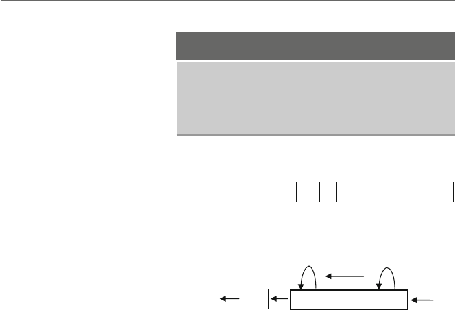
6.3 Logical Shift Instructions 97
Table 6.3 Shift instructions
Shift left instructions Shift right instructions
shl reg,cl shr reg,cl
shl reg,imm shr reg,imm
shl mem,cl shr mem,cl
shl mem,imm shr mem,imm
0 1 0 1 0 1 0 1?
CF 7 ----------- 0
Fig. 6.1 Initial contents of al
register
1 0 1 0 1 0 1 00
?0
bit CF 7 ----------- 0 (bits)
bucket
Fig. 6.2 Results in al register
after shl instruction
that the content of the carry flag on the left was unknown, as indicated by the question
mark.
After the execution of the instruction shl al,1,the0in bit position 7 on the left
would be moved into the carry flag, the contents of bit position 6 would be moved into bit
position 7, the contents of bit position 5 would be moved into bit position 6, and so on,
where finally the contents of bit position 0 would be filled with a 0as shown in Fig. 6.2.
What happens to the previous contents of the carry flag? Some might say it disap-
pears into thin air or some “old timers” might say that its contents are moved to the bit
bucket. With respect to the latter, the old timers might sometimes further inform begin-
ning assembly language programmers that when the bit bucket gets full, it needs to be
emptied. However, be aware there is no such thing as a bit bucket nor does it need to be
emptied. It is just an expression to mean that that bit is no longer accessible and more
importantly it is merely a way to have a little fun at the expense of beginning assembly
language programmers!
The shifting of bits in the reverse direction is also possible, where if a shr al,1 were
executed on the original contents of al in Fig. 6.1, the contents of al would appear as
shown in Fig. 6.3. The contents of the carry flag would go into the bit bucket (see how
convenient the terminology is?), the contents of bit position 0 would move into the carry
flag, the contents of bit position 1 would move into bit position 0, and so on, where a 0
would be placed into bit position 7.
The carry flag is now drawn on the right side of the al register just for the sake of
convenience. For the most part, one usually does not worry about the carry flag when
doing logical shifting. In a number of other processors, the end bit usually goes directly to
the bit bucket.
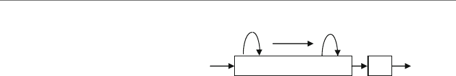
98 6 Logic, Shifting, Rotating, and Stacks
0 0 1 0 1 0 1 0 1 ?0
(bits) 7 ----------- 0 CF bit
bucket
Fig. 6.3 Results in al register
after shr instruction
Given the original contents of the al register above, what would happen if instead of
ashl al,1 the instruction shl al,8 was executed? If each bit was shifted to the left
eight times, bit 7 would be moved to the carry flag, the other 7 bits would end up in the bit
bucket, and all 8 bits of the register would be filled with zeros. This same concept could
be expanded to 32 bits and on rare occasions, one might see code such as this to clear a
32-bit register such as eax to zero. However, shift instructions are traditionally some of
the slower instructions on most processors and this method can be slower than using either
the mov instruction or the xor instruction mentioned in the last section. If however each
of the bits in a register needed to be processed one at a time and the register also needed to
be cleared to zeros, then clearing a register to zero is a nice by-product of using the shl
instruction in a loop as discussed below.
As an example of processing each bit individually and using only a byte instead of a
double word to save space, assume that each bit in the al register represents a device that
is connected to the processor. Further, if a bit is a 1or a 0, it would indicate whether
the device is turned on or off, respectively. For this task, also assume that the original data
needs to be retained. Given these assumptions, how could one determine how many devices
are turned on?
In order to solve this problem, there are a number of questions that need to be answered.
First, a loop is obviously needed, but which loop should be used? Since there are a fixed
number of bits in a byte, the equivalent of a for loop structure appears to be the best choice,
which in MASM is the .repeat-.untilcxz loop. Another question is should the mask
be shifted or should the register be shifted? As mentioned previously, it often depends on
whether the original data needs to be retained and since it was mentioned above that it needs
to be retained, it might be simpler to shift the mask. However, as also mentioned previously,
shifting the data means that the mask can be kept as immediate data. This makes the actual
code a little simpler even though the original data will need to be saved and restored in a
temporary memory location. Lastly, should the shl or the shr instruction be used? Often
it really does not make a difference, unless one is only processing the bits on one side of the
register or the other. By default it is probably best to process the bits in the order in which
the bit positions are numbered, which is from right to left. In the following code segment,
assume that the memory location temp is declared as an unsigned byte:
mov count,0 ; initialize count to zero
mov ecx,8 ; initialize loop counter to zero
mov temp,al ; save al in temp
.repeat
mov ah,al ; mov data in al to ah for testing
and ah,00000001b ; test bit position zero
.if !ZERO? ; is the bit set?

6.4 Arithmetic Shift Instructions 99
inc count ; yes, count it
.endif
shr al,1 ; shift al right one bit position
.untilcxz
mov al,temp ; restore al from temp
Note that the first thing prior to the loop is that the data in al issavedinmemory
location temp declared as a byte and the last thing after the loop is that the data in temp is
restored to the al register. Further, notice that there appears to be an extra move instruction
at the top of the body of the loop. The reason for this is that since there are bits set to 0in
the mask and as a result the and instruction will destroy other bits in the al register, the
data needs to be moved to another register. Since the upper 8 bits of the ax register are not
being used, the ah register is a good choice. At the bottom of the body of the loop, the al
register is shifted one bit to the right and then back at the top of the loop the al register is
again moved into the ah register so that the next bit can be tested.
However, would it not be nice to have a method of checking a particular bit without
having to destroy the other bits around it? Luckily, the designers of the Intel processor have
designed just such an instruction. It is called the test instruction, and instead of perform-
ing an actual and operation, it performs what is known as an implied and operation. This
means it performs the and operation and sets the eflags register, but it does not actually
alter the corresponding register or memory location. Although in the example above the
contents of the al register will still be altered due to the shift instruction, the contents will
not be destroyed each time through the loop by the test instruction and the above code
can be rewritten without the extra mov instruction as shown below:
mov count,0 ; initialize count to zero
mov ecx,8 ; initialize loop counter to zero
mov temp,al ; save al in temp
.repeat
test al,00000001b ; test bit position zero
.if !ZERO? ; is the bit set?
inc count ; yes, count it
.endif
shr al,1 ; shift al right one bit position
.untilcxz
mov al,temp ; restore al from temp
6.4
Arithmetic Shift Instructions
Besides the logical shift instructions, there are also the arithmetic shift instructions called
sal and sar, which stand for shift arithmetic left and shift arithmetic right, respectively.
The arithmetic shifts have the same operand formats as their logical counterparts as shown
in Table 6.4.
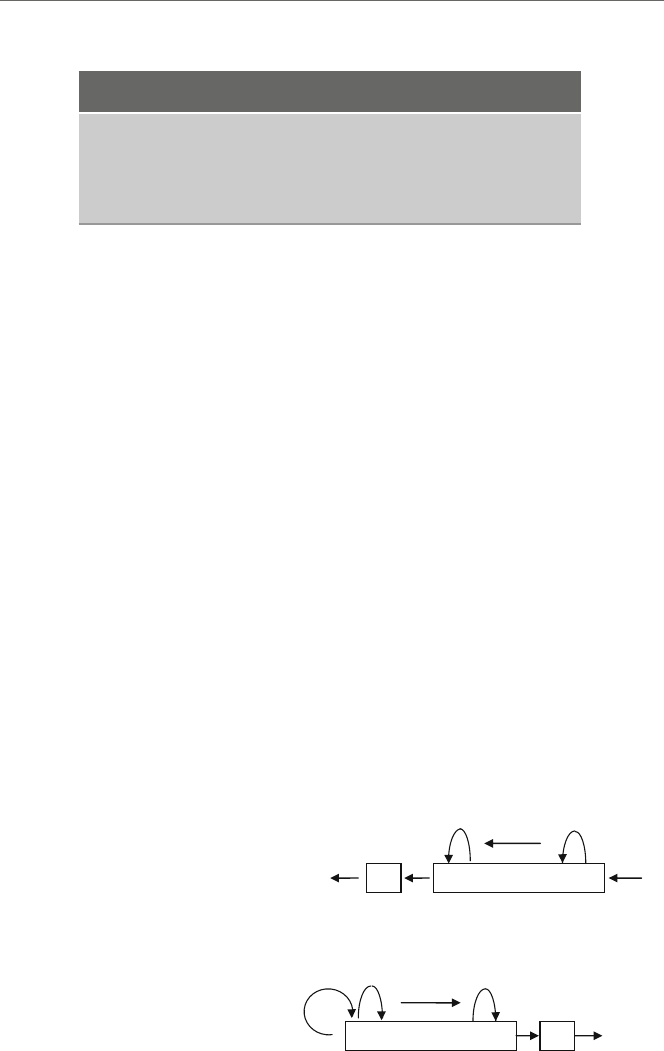
100 6 Logic, Shifting, Rotating, and Stacks
Table 6.4 Arithmetic shift instructions
Shift arithmetic left Shift arithmetic right
sal reg,cl sar reg, cl
sal reg,imm sar reg, imm
sal mem,cl sar mem, cl
sal mem,imm sar mem, imm
Unlike the logical instructions, the arithmetic shifts assume that the leftmost bit in a
register or memory location is a sign bit. With the sal instruction, this does not make any
difference and it performs the same as the shl instruction because when shifting to the
left, the leftmost bit is moved into the carry flag whether the leftmost bit is or is not a sign
bit. Using the original data from Fig. 6.1, the result of the shl in Fig. 6.2 is the same as
the sal in Fig. 6.4.
Although the sal instruction works the same as the shl instruction, this is not the case
with the sar instruction. With the sar, the leftmost bit is copied to the bit to the right as
with the slr, but instead of bringing in a 0into the leftmost position, the leftmost position
is copied into itself, thus preserving the sign bit as shown in Fig. 6.5.
The result is that the arithmetic shifts can be used for performing arithmetic. Again for
the sake of simplicity in the following examples, 8-bit registers and memory locations will
be used instead of 32-bit ones. Assume that the memory location number contains a 5
as 00000101 in binary. If this number was shifted to the left one bit, the result would be
00001010, which is the number 10 and is twice the number 5. Likewise, shifting number
to another bit position results in 00010100, which is the number 20. In other words, for
every bit position shifted to the left, the number in the register is effectively multiplied by
a power of two. Likewise, shifting the number 00010100 two bits to the right results in
the number 00000101 and is the equivalent of dividing by 4.
However, what about negative numbers? For example, when shifting a –4, 11111100
one bit to the right using a shr instruction, the result would be a 01111110, which is a
1 0 1 0 1 0 1 00?0
bit CF 7 ----------- 0 (bits)
bucket
Fig. 6.4 Results in al register
after sal instruction
0 0 1 0 1 0 1 0 1 ?
(bits) 7 ----------- 0 CF bit
bucket
Fig. 6.5 Results in al register
after sar instruction

6.4 Arithmetic Shift Instructions 101
positive 125 and is clearly incorrect. This is the reason for the arithmetic sar instruction,
which would cause the sign bit to be copied not only to the right but also back into the
leftmost bit position. This would result in a 11111110, a –2 which is correct. If the
original number was a –5, 11111011,thenasar al,1 would result in a 11111101,
which is a –2 demonstrating that it is the equivalent of integer division, where the remainder
would be in the carry flag.
When multiplying, choosing either the sal or the shl instruction is not really a prob-
lem, because to multiply 11111100 by 2 the result would be 11111000 in binary, which
is a –8. The reason why one would use a sal instead of a shl in this instance is to indicate
to others that the purpose of the shift is the arithmetic operation of multiplication. Although
a good comment is always in order, this is in a sense an example of self-documenting code.
However, should a number be shifted too many times to the left, a negative number
would eventually become a positive number. Although the numbers used in the examples
in this text will be smaller, as with the arithmetic instruction counterparts from Chapter 3,
one should always be careful with the possibility of overflow and underflow.
So given the above and for further practice, how would the following C statement be
implemented using a shift instruction?
product =num1 *8;
Assuming 32-bit words and using the sal instruction, it could be implemented as
follows:
; product =num1 *8;
mov eax,num1 ; load eax with num1
sal eax,3 ; multiply by 8
mov product,eax ; store eax in product
Notice that num1 above is not shifted, but rather it is first moved to the eax register and
then it is shifted. As in Chapter 2,num1 appears to the right of the assignment symbol in
the original high-level code implementation and it should not be altered. Another common
mistake made by beginners is putting the multiplier in the second operand of the shift
instruction instead of the number of positions to be shifted. For example, if the number 8
was accidentally used as the second operand in the shift instruction in the above example,
it would cause num1 to be multiplied by the number 256 which is clearly incorrect. As
another example to help reinforce these concepts, how would one implement the following
using shift instructions?
answer =amount / 4;
With positive numbers the choice of slr or sar does not really make a difference. For
example, if amount in the above example contained a 32 (00100000 in binary), then
after shifting to the right 2times to divide by 4, the result would be 8(00001000 in
binary). Since the sign bit is 0, it would not make a difference whether a 0was shifted into
bit position 7 by a slr instruction or it was copied onto itself by a sar instruction

102 6 Logic, Shifting, Rotating, and Stacks
However, it cannot always be known whether the number in a memory location such
as amount is positive or negative. Unlike above with multiplication the choice of which
shift to use, logical or arithmetic, is of critical importance with division when dealing
with negative numbers or the possibility of negative numbers. Consider the following
implementation:
;*** Caution: Possible incorrect code ***
; answer =amount / 4
mov eax,amount
shr eax,2 ; divide by 4
mov answer,eax
Again assuming 8-bit words for convenience, if in the above code segment, amount
contains a –8, or 11111000 in binary, then shifting the eax register to the right two
positions would result in a 00111110 in binary, or 62 in decimal, which is clearly not
correct. However, if the above code segment is rewritten with the appropriate instruction
as follows:
;*** Note: Correctly implemented code ***
; answer =amount / 4
mov eax,amount
sar eax,2 ; divide by 4
mov answer,eax
Then when 11111000 in binary is shifted to the right arithmetically, the result is that
eax contains 11111110 in binary, because in addition to being moved the right, the sign
bit is copied back into bit 7 and the result is a –2 as it should be.
The result is that when using shift instructions to perform multiplication and division,
it is best to use the arithmetic versions to not only help alert other programmers that the
shift is being done for the purposes of arithmetic but also avoid a potential logic error in
the event that the quotient in the division operation is a negative number. If the code using
shifts is not as clear as using imul and idiv, why would one want to use this method? The
answer is that it can be faster and more convenient than are its multiplication and division
counterparts, especially when multiplying and dividing by multiples of two, respectively.
6.5
Rotate Instructions
There are many cases with shifting where the unused bits are not needed and their disap-
pearance into the bit bucket is not a problem, especially with multiplication and division.
However, there are other cases where it might be convenient to keep the unused bits. The
instructions that help in these cases are known as rotate instructions. The rotate instructions
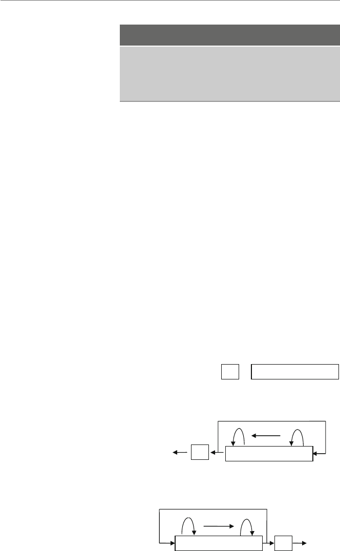
6.5 Rotate Instructions 103
Table 6.5 Rotate instructions
Rotate left instructions Rotate right instructions
rol reg,cl ror reg,cl
rol reg,imm ror reg,imm
rol mem,cl ror mem,cl
rol mem,imm ror mem,imm
are similar to the logical shift instructions in that the end bit goes into the carry flag, and
the previous contents of the carry flag go into the proverbial bit bucket. However, instead
of zeros being inserted at the other end as with the logical shift instructions, with the rotate
instructions the bits from the one end are carried around and inserted into the other end as
will be shown shortly.
The format of the two rotate instructions can be found in Table 6.5, where rol means
rotate left and ror means rotate right. Although there are two other rotate instructions,
rcl and rcr that rotate out of the carry flag, they will not be considered here.
Using the same initial drawing from Fig. 6.1 used previously with the shift instructions
and as repeated in Fig. 6.6,arol al,1 instruction would have the results shown in
Fig. 6.7.
Similarly, rotating the drawing in Fig. 6.6 to the right using ror al,1 would work as
shown in Fig. 6.8.
The advantage of the rotate instructions is that if the bits are rotated the exact number
of times as there are bits in a register or a memory location, the register or the memory
location is returned back to its original state. The advantage of this is that there is no need
to save or restore the register or the memory location prior to testing it and the same would
apply if one were to rotate the mask instead of the data.
0 1 0 1 0 1 0 1?
CF 7 ----------- 0
Fig. 6.6 Initial contents of al
register
1 0 1 0 1 0 1 0
0
?
bit CF 7 ----------- 0 (bits)
bucket
Fig. 6.7 Results in al register
after rol instruction
0 0 1 0 1 0 1 0 1 ?
(bits) 7 ----------- 0 CF bit
bucket
Fig. 6.8 Results in al register
after ror instruction

104 6 Logic, Shifting, Rotating, and Stacks
The example of testing the 8 bits shown previously is now redone below using a rotate
instruction instead of a shift instruction:
mov count,0 ; initialize count to zero
mov ecx,8 ; initialize loop counter to zero
.repeat
test al,00000001b ; test bit position zero
.if !ZERO? ; is the bit set?
inc count ; yes, count it
.endif
rol al,1 ; shift al left one bit position
.untilcxz
Again, the advantage here of using a rotate instruction instead of a shift instruction is
that the contents of the al register need not be saved and restored. The only danger is that
sometimes when only part of the register or the memory location needs to be processed, one
might forget to rotate the rest of the register or the memory location back to its original
location, or inadvertently rotate the wrong number of times, which could lead to a logic
error later in the program. When in doubt, one can always save and restore the register or
the memory location, whether either a shift or a rotate instruction is used.
6.6
Stack Operations
If one took the second semester computer science course that is usually required in a com-
puter science major or minor, there is a good chance that one has been exposed to the data
structure called the stack and the related methods or functions, push and pop. A stack is a
LIFO (last in first out) structure, where the last item pushed onto the stack is the first one
popped off the stack. As should be recalled, there are number of useful applications for
stacks. Some of those applications include reversing data, matching, number conversions,
evaluation of expressions, and implementing recursion. Given the usefulness of a stack,
most processors include built-in stack instructions and this is true with the Intel processor
as well.
In order to use the stack instructions, one must be sure to reserve memory space for
the stack itself. As introduced in Chapter 1, this is accomplished by using the .stack
directive which indicates how much memory should be reserved, where typically 100
hexadecimal bytes, or in other words 256 decimal bytes, is usually sufficient as shown
below:
.stack 100h

6.6 Stack Operations 105
Although there are other variations of the push and pop instruction, only the two
simplest versions are introduced at the present time. As would be expected, the instructions
push and pop are used to put data on top of the stack and remove data from the top of
the stack, respectively. Note that only 16- or 32-bit registers and memory locations work
with the push and pop instructions. For example, if the al register needs to be pushed
on the stack, then either the entire ax register or the eax register would need to be used.
The format of these instructions can be found in Table 6.6, where obviously it is possible
to push an immediate value onto a stack, but it is not possible to pop a value off the stack
and put it into an immediate value.
Table 6.6 Push and pop
instructions Push instructions Pop instructions
push reg pop reg
push mem pop mem
push imm
The use of push and pop instructions is typically a good way to save and restore values.
On some processors the use of a stack can be faster than using a temporary memory loca-
tion. However, on the Intel processor it tends to be a little slower when saving and restoring
a memory location but is about the same speed when saving and restoring a register. If
there is not much of a difference and in some cases using the stack might be a little slower,
what is the advantage of using the stack to save and restore values over a temporary mem-
ory location? The benefit of using the stack is primarily convenience. Since memory for
the stack has already been allocated using the .stack directive, extra temporary memory
locations do not need to be declared. Further, the stack is always available and the names
of various temporary memory locations do not need to be remembered.
As indicated in the last section, it is often useful to use a stack to hold the original con-
tents of a register or a memory location prior to manipulation of the bit pattern. Instead of
moving the original bit pattern into a memory location, it can be pushed onto the stack prior
to the loop and then restored to its original pattern after the loop as shown below. Although
this might not be necessary when using a rotate instruction as mentioned in the last section,
sometimes one might accidentally not rotate the register or the memory location the cor-
rect number of times. So saving or restoring the original pattern is inexpensive insurance
and the push and pop instructions make this easy. For example, the following uses the
shift instruction to demonstrate the use of the push and pop instructions. As mentioned
previously, note that although only the al register needs to be pushed on and popped off
the stack, the eax register is used here, where the ax register would have worked as well:
push eax
mov count,0 ; initialize count to zero
mov ecx,8 ; initialize loop counter to zero
.repeat
test al,00000001b ; test bit position zero

106 6 Logic, Shifting, Rotating, and Stacks
.if !ZERO? ; is the bit set?
inc count ; yes, count it
.endif
shr al,1 ; shift al right one bit position
.untilcxz
pop eax
If for some reason more than one register needs to be saved and restored, the order
of the pushes and pops must be taken into consideration. For example, what if following
arithmetic statement needs to be evaluated?
w=x/y-z;
Assuming that the previous contents of the registers used to evaluate the expression
should not be altered, they would need to be saved and restored. Using the stack, Fig. 6.9
illustrates how this could be accomplished.
It should be noted that both the eax and edx registers are pushed onto the stack.
Although it is obvious that the eax register is used by the sub and mov instructions, do
not forget that the cdq instruction extends the sign bit through the edx register and that
the idiv instruction leaves the remainder in the edx register. As a result, both registers
need to be pushed onto the stack. As can be seen, the first register popped off the stack is
the edx register. Recall that a stack is a LIFO structure, where the last item pushed onto
the stack is the edx register, so it is the first item that needs to be popped off the stack.
A possible problem when using the stack extensively is that one might forget which
items were pushed onto the stack and in what order. This can result in some difficulty in
debugging logic errors. To help avoid these errors, one possibility is to avoid overusing the
stack. Further, when using the stack it is a good idea to keep the associated pushes and
pops relatively close to one another so that the connections between the two can easily be
seen. It can be quite confusing to see a push in a middle of a code segment only to find the
corresponding pop many pages further away in the code. Yet another technique that can
help is to use scoping lines to help match push instructions with the corresponding pop
instructions to insure that the item being popped off the stack is the correct one. Scoping
lines can be drawn on a program listing by hand to help with creating or debugging code
and are illustrated in the code segment in Fig. 6.9.
push eax
push edx
mov eax,x
cdq
idiv y
sub eax,z
mov w,eax
pop edx
pop eax
Fig. 6.9 Saving and restoring
multiple registers

6.7 Swapping Using Registers, the Stack, and the xchg Instruction 107
6.7
Swapping Using Registers, the Stack, and the xchg Instruction
As another example of using the stack, assume that two values need to be swapped, such
as is done in a number of sorting algorithms. The typical high-level code is as follows:
temp =num1;
num1 =num2;
num2 =temp;
This could be implemented on a line-by-line basis in assembly language using registers,
but that would require two instructions for each line of code as follows:
mov eax,num1
mov temp,eax
mov eax,num2
mov num1,eax
mov eax,temp
mov num2,eax
Clearly, the above seems inefficient. Instead, a register such as edx could be used
instead of the temporary memory location temp.Theedx register is chosen as the tempo-
rary register to make sure that the ecx register is free to be used for loop control and ebx
is free to be used as an index register, both of which will be discussed further in Chapter 8.
However, the middle high-level instruction would still need to use another register such as
eax to enable the transfer between the two memory locations:
mov edx,num1
mov eax,num2
mov num1,eax
mov num2,edx
The above use of the registers can be rearranged as follows to help in readability:
mov eax,num1
mov edx,num2
mov num1,edx
mov num2,eax
Instead of using registers and mov instructions, another possibility is to use the stack.
Not only is a stack a nice way to save and restore values, it can also be useful in swapping
two values. An advantage over the mov instructions is that the stack does not need to use
any of the general purpose registers which free them up for other uses. The following code
segment swaps the values in num1 and num2:

108 6 Logic, Shifting, Rotating, and Stacks
push num1
push num2
pop num1
pop num2
Is the order of the pop instructions above correct? Yes, since the purpose of the above
code is not to save and restore the contents of num1 and num2 but rather to swap their
contents. In other words, since the last value pushed onto the stack is the contents of num2,
it is the first value popped off the stack. Instead of being popped back into num2,itis
popped into num1. The same happens with the value originally in num1, thus swapping
the two values.
Yet another method of swapping two values is to use the exchange (xchg) instruction.
When swapping two registers, it is faster than the two methods previously presented. The
format of this instruction is given in Table 6.7.
Table 6.7 Exchange
instructions Xchg instructions
xchg reg,reg
xchg reg,mem
xchg mem,reg
Of course the one instruction that would directly allow the swapping of two mem-
ory locations is noticeably absent. Like many previous instructions, memory to memory
exchanges are not possible. However, the above does allow an exchange between two mem-
ory locations to occur in only three instructions, instead of the four needed in the previous
three examples:
mov eax,num1
xchg eax,num2
mov num1,eax
This is accomplished by moving one of the two values into a register, swapping the
register with the other memory location, and then moving the contents of the register back
into the original memory location. Assuming that num1 originally contains a 5and num2
originally contains a 7, the three diagrams in Fig. 6.10 illustrate the three instructions in
the above code segment.
With respect to register usage when swapping to memory locations, the stack does not
use any general purpose registers, the xchg instruction uses one register and mov instruc-
tions require two registers. With respect to speed, using mov instructions is the fastest, the
xchg instruction is just a little slower, and using the stack is the slowest. The result is
that the xchg instruction is a nice compromise between the other two methods in terms of
both register usage and speed. Also, given the convenience of the xchg instruction, it will
usually be the method of choice in subsequent examples.
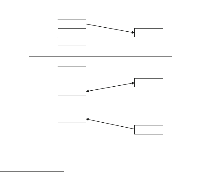
6.8 Complete Program: Simulating an OCR Machine 109
5
5
5
5
5
num1
num2
eax
mov eax,num1
xchg eax,num2
num1
eax
num2
7
7
7
7
eax
num1
num2
mov num1,eax
Fig. 6.10 Swapping using the xchg instruction
6.8
Complete Program: Simulating an OCR Machine
As alluded to in many of the preceding sections, computers use individual bits in a register
or a memory location to indicate the status or to control various parts of the CPU or periph-
eral devices. One such machine might be an optical character recognition (OCR) device
that reads typed or handwritten characters from a piece of paper. On larger machines, they
use a transport device that can handle more than a single piece of paper at one time, similar
to a copying machine, where a memory location might be used to indicate the status of
the paper in the transport. For the following simulation, the memory location used will be
called the document status byte (DSB). There are a variety of problems that can happen
with any sheet of paper in a transport as indicated in Table 6.8.
As can be seen, the bit number indicates the corresponding location of the error bit in
the DSB, remembering that the low-order bit in a byte is located on the right. It is also
possible that more than one of the above conditions could occur at the same time. For
example, if two documents are overlapped, it might cause both a multiple feed and a long
document error condition.
To help create appropriate input to test the program, it would be inconvenient to input
the bit patterns in decimal (base 10). Instead it would be easier to input in binary or
hexadecimal, where fortunately C has the ability to input hexadecimal numbers. This is
accomplished by using the letter xinstead of the letter din the format string as shown
below. Further, in writing this program, one might be tempted to use nested if statements
in order to make the code more readable and efficient. However, recall from above that

110 6 Logic, Shifting, Rotating, and Stacks
Table 6.8 Error messages
Bit Message Meaning
0 Short document The document just read is shorter than anticipated
1 Long document The document just read is shorter than anticipated
2 Close feed Current document is too close to the preceding document
3 Multiple feed Two documents were detected at the same time
4 Excessive skew The document is skewed (crooked) in the transport
5 Document misfeed The document fails to feed into the transport
6 Document jam The document jammed in the transport
7 Unspecified error An unknown/unspecified error occurred
it is possible to have more than one error condition and the use of nested if statements
would rule out this possibility. It might be possible to use the equivalent of the switch
statement but leave the break statements out of the code to allow more than one case to
be tested. However, not using break statements in a switch statement might be con-
sidered by some to be unstructured. Further, given that there is no high-level directive
equivalent of the case structure, it would have to be implemented using only low-level
code. As has been seen previously, sometimes the code can get rather ugly using a lot of
jump statements. Instead the approach taken here is the use of non-nested high-level if
directives:
.listall
.386
.model flat,c
.stack 100h
scanf PROTO arg2:Ptr Byte, inputlist:VARARG
printf PROTO arg1:Ptr Byte, printlist:VARARG
.data
msg1fmt byte "%s",0
in1fmt byte "%x",0
msg2fmt byte "%s%x",0Ah,0Ah,0
msg1 byte 0Ah,"Enter a hexadecimal number: ",0
msg2 byte "The hexadecimal number is: ",0
msgshort byte "SHORT DOCUMENT",0Ah,0
msglong byte "LONG DOCUMENT",0Ah,0
msgclose byte "CLOSE FEED",0Ah,0
msgmult byte "MULTIPLE FEED",0Ah,0
msgskew byte "EXCESSIVE SKEW",0Ah,0
msgfeed byte "DOCUMENT MISFEED",0Ah,0
msgjam byte "DOCUMENT JAM",0Ah,0
msgerror byte "UNSPECIFIED ERROR",0Ah,0
dsb dword ?

6.8 Complete Program: Simulating an OCR Machine 111
.code
main proc
INVOKE printf, ADDR msg1fmt,ADDR msg1
INVOKE scanf, ADDR in1fmt,ADDR dsb
INVOKE printf, ADDR msg2fmt, ADDR msg2, dsb
.while dsb<=0ffh
test dsb,00000001b
.if !zero? ; if bit 0 =1 then
INVOKE printf, ADDR msg1fmt,ADDR msgshort
.endif
test dsb,00000010b
.if !ZERO? ; if bit 1 =1 then
INVOKE printf, ADDR msg1fmt,ADDR msglong
.endif
test dsb,00000100b
.if !ZERO? ; if bit 2 =1 then
INVOKE printf, ADDR msg1fmt,ADDR msgclose
.endif
test dsb,00001000b
.if !ZERO? ; if bit 3 =1 then
INVOKE printf, ADDR msg1fmt,ADDR msgmult
.endif
test dsb,00010000b
.if !ZERO? ; if bit 4 =1 then
INVOKE printf, ADDR msg1fmt,ADDR msgskew
.endif
test dsb,00100000b
.if !ZERO? ; if bit 5 =1 then
INVOKE printf, ADDR msg1fmt,ADDR msgfeed
.endif
test dsb,01000000b
.if !ZERO? ; if bit 6 =1 then
INVOKE printf, ADDR msg1fmt,ADDR msgjam
.endif
test dsb,10000000b
.if !ZERO? ; if bit 7 =1 then
INVOKE printf, ADDR msg1fmt,ADDR msgerror
.endif
INVOKE printf, ADDR msg1fmt,ADDR msg1
INVOKE scanf, ADDR in1fmt,ADDR dsb
INVOKE printf, ADDR msg2fmt,ADDR msg2, dsb
.endw

112 6 Logic, Shifting, Rotating, and Stacks
ret
main endp
end
As can be seen in the while loop, any bit combination that is less than or equal to
0FFh, or 11111111b is allowed, where the hand bstand for hexadecimal and binary,
respectively. Note that when a hex number begins with a letter, it has to be preceded with a
0so that the assembler does not confuse it with a variable name. Once a number of 100 h
or greater is entered, the loop stops, as can be seen in the sample input/output below.
Sample Input/Output
Enter a hexadecimal number: 1
The hexadecimal number is: 1
SHORT DOCUMENT
Enter a hexadecimal number: 2
The hexadecimal number is: 2
LONG DOCUMENT
Enter a hexadecimal number: 3
The hexadecimal number is: 3
SHORT DOCUMENT
LONG DOCUMENT
Enter a hexadecimal number: ff
The hexadecimal number is: ff
SHORT DOCUMENT
LONG DOCUMENT
CLOSE FEED
MULTIPLE FEED
EXCESSIVE SKEW
DOCUMENT MISFEED
DOCUMENT JAM
UNSPECIFIED ERROR
Enter a hexadecimal number: 100
The hexadecimal number is: 100
Press any key to continue . . .
6.9
Summary
•The inclusive-or includes the case when both operands are true and the result is true,
whereas the exclusive-or excludes this case and the result is false when both operands
are true.

6.10 Exercises 113
•To set, test, and toggle bits, use the or,and,andxor instructions, respectively.
•If data is needed later, be sure to save the data when using the shl and shr instructions.
•As a by-product of other tasks, a register or a memory location can be cleared to zero
using the shl and shr instructions. However, the shift instructions can be slower than
the mov or xor instructions and the latter two are usually a better choice.
•To multiply or divide by powers of two, use sal and sar, respectively, to communicate
to others that arithmetic is being performed and to insure that negative numbers are
handled properly with division.
•If a bit pattern is rotated exactly the same number of bits that are in a register or a
memory location, then the bit pattern does not need to be saved and restored.
•When saving and restoring data using push and pop instructions, be sure to remember
that the last one pushed on the stack should be the first one popped off the stack (LIFO).
•The use of scoping lines when using push and pop instructions can be helpful when
creating or debugging code.
•Data in memory can be swapped using only mov instructions which use more registers
and are faster compared to using the push and pop instructions which do not use
any general purpose registers but are slower. Using the xchg instruction along with
the appropriate mov instructions is a good compromise in terms of register usage and
speed.
6.10
Exercises (Items Marked with an ∗Have Solutions in Appendix E)
1. Given the following assembly language statements, indicate whether they are syntacti-
cally correct or incorrect. If incorrect, indicate what is wrong with the statement:
∗A. or eax,ebx B. xor al,ah ∗C. rotate al,1
D. shr ax,2 ∗E. sar eax,3 F. xchg dog,cat
2. Given the following C arithmetic instructions, implement them using arithmetic shift
instructions, where possible:
A. answer =num - total / 32;
∗B. result =(amount + number) *4;
C. x=y*8+z/2;
3. Write a code segment that takes the contents of eax,ebx,ecx,andedx, and puts
them in the reverse order of edx,ecx,ebx,andeax using only the push and
pop instructions. In other words, eax should contain the contents of edx and vice
versa, etc.
4. Assume that a status register in a processor indicates the current state of a photocopying
machine according to the following table. For each bit, output an appropriate message
indicating the status of the machine. Note that although there can be more than one bit

114 6 Logic, Shifting, Rotating, and Stacks
set at one time, only one error message can be generated, where bit 0 has the highest
priority, followed by bit 1, etc. At the discretion of the instructor, implement using
high-level directives, without high-level directives, or a combination as shown in the
text.
Bit Message
0 Paper jam
1 Paper misfeed
2 Paper tray empty
3 Toner low
4 Toner empty
5. Similar to the program in Section 6.8, write a program to simulate a security alarm
system according to the following table, where it is possible that any of the first three
high-priority items could happen at the same time. Although the last three items can
also occur at the same time, the program should check and output messages for them
only when none of the higher priority first three items have occurred.
Bit Message
0 Fire alarm
1 Carbon monoxide
2 Power outage
3 Gate unlocked
4 Door open
5 Window open

Procedures and Macros 7
This chapter will first show the reader how procedures are implemented in assembly
language. The implementation of macros is introduced next which is probably a new topic
to most readers. Both procedures and macros are tools that allow programmers to save
time by not having to rekey the same code over and over again, but there are important
differences between the two mechanisms. The chapter then continues with the introduction
of conditional assembly which can be a difficult concept for new assembly language pro-
grammers. Lastly, this chapter shows the beginning of the implementation of what might
be called a macro calculator which simulates a one register (accumulator) computer.
7.1
Procedures
Most readers are probably familiar with procedures from a previous programming class.
Depending on what language was used in that class, procedures may have also been called
subprocedures, subprograms, subroutines, functions, or methods. The most generic of these
terms is subprograms, which encompass all the others. Functions and many methods can or
should return only a single value, whereas procedures, subprocedures, and subroutines are
designed to return anywhere from zero to many values. In assembly language, subprograms
are called procedures and belong to this last group. Although there are ways to make it
possible to utilize parameters, the simplest way to communicate between a program and a
procedure is to use either global variables or registers.
The instruction used to invoke a procedure is the call instruction. The call instruc-
tion has one operand that specifies the name of the procedure to be invoked. Upon return
from the procedure, execution will continue with the instruction after the call instruction.
An example is given below, where pname is a placeholder for the procedure name:
call pname
Although the actual procedure can be placed in a number of locations in the program,
probably the most convenient place is after the endp statement in the main program and
115
J.T. Streib, Guide to Assembly Language, DOI 10.1007/978-0-85729-271-1_7,
C
Springer-Verlag London Limited 2011

116 7 Procedures and Macros
prior to the end statement. The first line of the procedure contains the name of the proce-
dure in the label field, represented by the word pname, followed by the proc directive in
the opcode field. Next comes the body of the procedure, followed by the return instruction
ret,followedbytheendp directive, which has the name of the procedure in the label
field as shown below:
pname proc
; body of the procedure
ret
pname endp
The proc and endp directives indicate to the assembler the beginning and the end of
the procedure, respectively. The ret instruction, during the execution of the procedure,
indicates when to return to the calling program. Unlike many high-level language, the
ret instruction does not return a value to the calling program but rather indicates that the
execution of the program should return to the calling program. One of the most common
errors made by beginning assembly language programmers is forgetting to include the ret
instruction, allowing the execution of the program to continue past the end of the procedure
and possibly into another procedure following the current procedure. Although there can
be more than one ret instruction in a procedure, like in many high-level languages, it
is recommended to include only one return statement in a procedure. This helps to keep
the program structured with only one entry point and one exit point. Further, almost any
procedure can be rewritten to contain only one ret instruction. For example, given the
following procedure with two ret instructions:
sample1 proc
.if eax == 0
mov edx,1
ret
.else
mov edx,0
ret
.endif
sample1 endp
it can be rewritten to utilize only one ret instruction:
sample1 proc
.if eax == 0
mov edx,1
.else
mov edx, 0
.endif
ret
sample1 endp

7.1 Procedures 117
The result is cleaner code that is less prone to logic errors during modification. Also, it
is usually best to be sure that the ret instruction is the last statement in a procedure prior
to the endp directive. Can you determine what is wrong with the following procedure that
is supposed to add all the registers together and return the value in eax?
;*** Caution: Contains a logic error ***
sample2 proc
add eax, ebx
add eax, ecx
ret
add eax, edx
sample2 endp
Yes, the value in the edx register is never added to the eax register, and eax only
contains the sum of eax,ebx,andecx upon return to the calling program. The add
eax,edx instruction in the above procedure is sometimes referred to as “dead code,”
because although it takes up space in memory, it is never executed. In larger programs,
whole sections of code might never be executed if the code is located incorrectly and it
might create a difficult situation to debug. The correct procedure is given below:
;*** Note: Correctly implemented code ***
sample2 proc
add eax, ebx
add eax, ecx
add eax, edx
ret
sample2 endp
What if one wanted to implement the multiplication algorithm from Chapter 5 in two
different locations? The code could be written twice in two different sections of the pro-
gram, but instead of writing the code twice, it would be much easier to put the logic in a
procedure and then call the procedure from two different locations in the main program:
.
call mult
.
.
call mult
.
Then after the main program, the code for the mult procedure could be written. Recall
this algorithm from the end of Section 5.1 which used the .while directive. The variables
xand ycould still contain the two values to be multiplied, but instead of using the variables
iand ans, the following procedure uses the ecx and eax registers, respectively, along
with other minor changes:

118 7 Procedures and Macros
mult proc
mov eax,0 ; initialize eax to 0
.ifx!=0
mov ecx,1 ; initialize i to 1
.while ecx<=y
add eax,x ; add x to eax
inc ecx ; increment i by 1
.endw
.endif
ret
mult endp
Is there a potential problem with the above procedure? Since ecx is being used as a
temporary variable to implement the loop, the contents of ecx will be destroyed. If the
main program is not using the ecx register, this would not be a problem. However, if
ecx is being used to hold various values, such as a counter for another loop in the calling
program, this routine could cause problems. It could be difficult to debug if a programmer
did not know that ecx is being used by the procedure. Although it is fairly obvious in this
case, it can be difficult to notice in larger procedures.
One solution is to document the procedure carefully and include a comment right at
the beginning of the procedure indicating which registers are destroyed by the procedure
to warn potential users of the procedure. The responsibility for saving the contents of the
affected register then lies with the programmer of the calling program. Although for some
small, seldom-used procedures, this effectively solves the problem, it is still possible that
the programmer using the procedure might miss the warning. Further, if the procedure
is going to be called many times, then the calling program needs to save and restore the
affected registers many times, thus wasting memory. Also, the possibility of forgetting to
save and restore the registers at some point in time is increased.
When writing procedures, it is usually a good idea to have the procedure take the respon-
sibility of saving and restoring any registers being destroyed. This saves memory, since
there is only one copy of the code and also lessens the chance for error by the calling
program. What is the best way to accomplish this task? Although a temporary variable
could be used, this is an excellent situation to use the stack as discussed in Chapter 6.The
following multiplication procedure includes the pushing and popping of the ecx register:
mult proc
push ecx ; save ecx
mov eax,0 ; initialize eax to 0
.ifx!=0
mov ecx,1 ; initialize i to 1
.while ecx<=y
add eax,x ; add x to eax
inc ecx ; increment i by 1
.endw

7.2 Complete Program: Implementing the Power Function in a Procedure 119
.endif
pop ecx ; restore ecx
ret
mult endp
Although the act of calling and returning a procedure is a little slower than straight line
code, it does save memory because the code needs to be written only once. Of course,
the memory saving is compounded as the size of the procedure and the number of calls
increase.
7.2
Complete Program: Implementing the Power Function in a Procedure
To illustrate a complete example, consider the problem of calculating xnfrom Chapter 5.
Instead of having the code to calculate xnin the main program, it could be placed in a
procedure. The procedure can then be invoked more than one time from the main program
without having to duplicate the code each time. For the sake of simplicity both here in the
C program and more importantly in the subsequent assembly language program, power is
implemented as a procedure (void function) and x,n,andans are implemented as global
variables. In addition to outputting a message in the case of an error, the procedure also
returns a -1 in the variable ans:
#include <stdio.h>
int x,n,ans;
int main() {
void power();
printf("%s","Enter x: ");
scanf("%d",&x);
printf("%s","Enter n: ");
scanf("%d",&n);
power();
printf("\n%s%d\n\n","The answer is: ",ans);
return 0;
}
void power() {
int i;
ans=-1;
if(x<0 || n<0)
printf("\n%s\n","Error: Negative x and/or y");
else
if(x==0&&n==0)
printf("\n%s\n","Error: Undefined answer");
else {

120 7 Procedures and Macros
i=1;
ans=1;
while(i<=n) {
ans=ans∗x;
i++;
}
}
}
As mentioned previously, global variables are used for x,n,andans both in the C
program above and in the assembly language below. Since iis declared as a local variable
in the C code above and is not needed in the main program, ecx is used as the loop control
variable in the assembly language procedure below:
.listall
.386
.model flat,c
.stack 100h
scanf PROTO arg2:Ptr Byte, inputlist:VARARG
printf PROTO arg1:Ptr Byte, printlist:VARARG
.data
in1fmt byte "%d",0
msg1fmt byte "%s",0
msg3fmt byte "%s%d",0Ah,0Ah,0
errfmt byte "%s",0Ah,0
errmsg1 byte 0Ah,"Error: Negative x and/or y",0
errmsg2 byte 0Ah,"Error: Undefined answer",0
msg1 byte "Enter x: ",0
msg2 byte "Enter n: ",0
msg3 byte 0Ah,"The answer is: ",0
x sdword ?
n sdword ?
ans sdword ?
.code
main proc
INVOKE printf, ADDR msg1fmt, ADDR msg1
INVOKE scanf, ADDR in1fmt, ADDR x
INVOKE printf, ADDR msg1fmt, ADDR msg2
INVOKE scanf, ADDR in1fmt, ADDR n
call power
INVOKE printf, ADDR msg3fmt, ADDR msg3, ans
ret
main endp
power proc

7.2 Complete Program: Implementing the Power Function in a Procedure 121
push eax ; save registers
push ecx
push edx
mov ans,-1 ; default value for ans
.if x<0 || n<0
INVOKE printf, ADDR errfmt, ADDR errmsg1
.else
.if x==0&&n==0
INVOKE printf, ADDR errfmt, ADDR errmsg2
.else
mov ecx,1 ; initialize ecx loop counter
mov ans,1 ; initialize ans
.while ecx <=n
mov eax,ans ; load eax with ans
imul x ; multiply eax by x
mov ans,eax ; sotre eax in ans
inc ecx ; increment eax loop countere
.endw
.endif
.endif
pop edx ; restore registers
pop ecx
pop eax
ret
power endp
end
Could the assembly language procedure above use registers instead of global variables
to communicate back and forth between the procedure and the main program? Yes, but in
the procedure above, xand yare checked to see if they are negative in the .if directive.
Recall from Chapter 4 that the default in high-level directives is unsigned data unless a
memory location declared as sdword is used. Also, INVOKE directives are being used
in the procedure to output error messages and remember from Chapter 2 that they destroy
the contents of the eax,ecx,andedx registers. The result is that for smaller and simpler
procedures the use of registers is probably the preferred method, but in instances like this,
the use of global variables might be the better choice.
Note that the eax,ecx,andedx registers are saved at the beginning and restored at
the end of the procedure. This is done not only because of the INVOKE directives but also
because even if the procedure did not perform any output, the three registers should be
saved and restored. It is obvious that eax is used in the mov instructions and the contents
of ecx are destroyed when it is used for loop control. However, the edx register does not
appear in the procedure, so why should it be saved and restored? Again, look carefully at
the code and recall what happens with the imul instruction. The imul instruction extends
the sign of the eax register into the edx register and destroys the contents of edx,soit
should be saved and restored also. Even if the main program that called the procedure does

122 7 Procedures and Macros
not use the eax,ecx and edx registers, the procedure should save and restore them so
that the procedure could easily be used by other programs that might use these registers.
Lastly, as discussed in Chapter 6, be careful to insure that the pop instructions are in the
correct order to properly restore the three registers.
7.3
Saving and Restoring Registers
Note that if registers are not being used to communicate back to the main program, it is
possible to save and restore all the registers, whether they were altered or not. Although
this might be an easy way to avoid having to think about whether a register is altered, it
is a sloppy method and does not help other programmers understand what is happening in
the procedure. In other words, even though it might be simpler for the person writing the
code, it is not necessarily easier for subsequent people reading and modifying the code.
By saving and restoring only the registers that are altered, it helps others understand which
registers are being altered and also helps makes the code more self-documenting. Of course
whether code appears to be self-documenting or not, documentation is always a good idea
to supplement any code written.
However, what if a routine was altering all the registers and does not use a register to
communicate back from a procedure to the main program? It could get a little messy trying
to push and pop all the registers and further, there could be a chance for a logic error if
the pop instructions were accidently written in the wrong order. Luckily it is possible to
save the four general purpose registers (eax,ebx,ecx,andedx) along with the esi,
edi,ebp,andesp registers with only one instruction. The pushad instruction pushes
contents of all the above registers onto the stack and the popad instruction subsequently
pops the values from the stack and puts them back into their respective register locations.
As an example, consider a procedure that outputs blank lines a variable number of
times. It would be nice that it does not destroy the contents of any registers and also not
use any global variables, both of which would make it a very portable procedure that could
be used in many different programs. As is known, using the INVOKE directive to output
the blank lines can cause the contents of the eax,ecx,andedx registers to be altered.
Since global variables will not be used, the ebx register could be used to communicate to
the procedure how many blank lines need to be output. At the same time, since ebx would
not be destroyed by the INVOKE directive, it would also make a good candidate for a
loop control variable. Given these circumstances in this example, all four registers should
probably be saved and restored. In the first example, each of the four general purpose
registers are saved and restored individually:
blankln proc
push eax
push ebx
push ecx
push edx
.repeat

7.4 Macros 123
INVOKE printf, ADDR blnkfmt
dec ebx
.until ebx<=0
pop edx
pop ecx
pop ebx
pop eax
ret
blankln endp
Note the order of the push and pop instructions above to properly save and restore the
contents of the four registers. In the example below, the four general purpose registers are
saved all at once using the pushad and popad instructions:
blankln proc
pushad
.repeat
INVOKE printf, ADDR blnkfmt
dec ebx
.until ebx<=0
popad
ret
blankln endp
As can be seen, clearly the second procedure is much cleaner than the first procedure.
Since the above procedures do not return a value via a register and all four general purpose
registers need to be saved and restored, this is a good example of when the pushad and
popad instructions should be used. However, since most of the time the majority of the
procedures in this text will be returning a value, the previously described method of saving
and restoring registers individually will be used more frequently.
7.4
Macros
Another method to avoid having to write the same code again and again is the macro.
However, be forewarned that even though it executes faster than a procedure, it tends to
waste memory. Although most readers have probably not encountered macros in previous
programming classes, they might have encountered the term in working with application
software packages. Probably the most common occurrence of macros is in spreadsheet
packages, where one can record a macro that consists of a series of steps performed by
the user. Although a macro in assembler can contain a series of instructions, it is different
from a macro in a spreadsheet, where the instructions are not recorded but rather need to
be written by the programmer.

124 7 Procedures and Macros
Like procedures, macros can be declared in many different places. Whereas procedures
are usually declared after the main program, macros are usually written and located prior
to the main program, just after the .code directive. This first writing of the macro is
sometimes called the macro definition and does not take up any memory in the executable
program. Further, a macro has a similar structure to a procedure, where on the first line the
name of the macro is in the label field, indicated by mname below, and the macro directive
is in the opcode field. The body of the macro follows, which is then followed by the endm
directive which unlike an endp does not repeat the name of the macro in the label field as
shown below:
mname macro
; body of the macro
endm
However, a question here might be, should there be a ret instruction just prior to
the endm directive above? The answer is no, because there is not a set of instructions
in a common place that are branched to and executed as with a procedure. Rather, a set
of instructions exist only in the source code file (.asm), a copy of the instructions is
inserted into the listing file (.lst), and the machine language equivalent is inserted into
the execution file (.exe), wherever the macro is invoked.
Instead of a call instruction as with a procedure, a macro invocation is done by just
using the name of the macro, mname in this instance, in the opcode field of the invoking
program as demonstrated below:
.
mname
.
.
mname
.
Thus unlike a procedure, where the flow of executions jumps to the procedure and then
returns back to the calling program, a copy of the macro is inserted into the program at
each point where the macro is invoked. The result is that macros are faster because there is
no calling or returning. Further, it is possible that if the macro is never invoked, it will never
take up any memory because the code exists only in the source code file (.asm). However,
usually macros tend to take up more memory due to the copying of the instructions at every
location it is invoked and this is especially true when macros are large and/or invoked many
times.
Consider an example of swapping two memory locations num1 and num2, where a
macro could be written as follows:
swap macro
mov ebx,num1 ; copy num1 into ebx
xchg ebx,num2 ; exchange ebx and num2

7.4 Macros 125
mov num1,ebx ; copy ebx into num1
endm
As mentioned above, notice the lack of a ret instruction in the macro declaration. The
invoking of a macro is done by just specifying the macro name in the opcode field in the
calling program, as shown below, where it can be assumed that the programmer wanted to
swap num1 and num2, and then turn around and swap them back to their original locations:
.
swap
.
.
swap
.
A common mistake made by beginning assembly language programmers is that they
include the call instruction when trying to invoke the macro, where this should be
avoided and would cause a syntax error. A question that many readers might have at
this point is: Why haven’t push and pop been included in the macro definition above?
Couldn’t there be the same problems with the calling program as with procedures, since
the contents of the ebx register are being destroyed by the macro? The answer to the sec-
ond question is yes, the same problem still exists. But in answer to the first question, the
reason why the push and pop instructions have not been included is because they take
up memory. One must remember that every time a macro is invoked, another copy of the
macro is inserted into the code in the invoking program. As a result, many times the con-
tents of registers are not saved in macros in order to save memory and a programmer needs
to be extra careful whenever invoking a macro.
This can be especially confusing, because unlike the procedure which is invoked via the
call instruction, a macro is invoked only by using the name of the macro. Many times
the name of a macro almost appears to be like the name of an instruction, so the user of
the macro might be lulled into believing it is an instruction and forget about the hidden
instructions in the macro that might destroy the contents of the registers. Many a program-
mer has accidentally made this mistake and spent much time trying to subsequently debug
a program.
To help illustrate how macro takes up memory and helps remind programmers that they
are not instructions, it is sometimes useful to examine the assembly listing file (.lst)to
see what is known as the macro expansion and all the instructions from the macro that
are inserted into the code. For example the above calling program that invokes the macro
swap twice would look as follows in the .lst file:
swap
00000000 8B 1D 00000046 R 1 mov ebx,num1 ; copy num1 into ebx
00000006 87 1D 0000004A R 1 xchg ebx,num2 ; exchange ebx and num2
0000000C 89 1D 00000046 R 1 mov num1,ebx ; copy ebx into num1
swap
00000012 8B 1D 00000046 R 1 mov ebx,num1 ; copy num1 into ebx

126 7 Procedures and Macros
00000018 87 1D 0000004A R 1 xchg ebx,num2 ; exchange ebx and num2
0000001E 89 1D 00000046 R 1 mov num1,ebx ; copy ebx into num1
In the above listing, both the relative memory address and machine language equivalent
in hexadecimal can be seen to the left. However, since the .lst file can sometimes get
rather messy and have a cluttered appearance when macros are expanded, the addresses
and machine code have been removed to make this example easier to read in both the
listing below and many subsequent listings (for more information on machine language,
see Chapter 10):
swap
mov ebx,num1 ; copy num1 into ebx
xchg ebx,num2 ; exchange ebx and num2
mov num1,ebx ; copy ebx into num1
swap
mov ebx,num1 ; copy num1 into ebx
xchg ebx,num2 ; exchange ebx and num2
mov num1,ebx ; copy ebx into num1
A nice feature that should be noticed above is that any comments placed in the macro
definition also appear in the macro expansion. Although the macro expansion might cause
the program to appear more cluttered and also waste more paper when printing out the
listing of the program, the possibility of avoiding errors during program development might
well be worth it. It can also be especially helpful during the debugging process when trying
to track down pesky logic errors.
A very useful feature when using macros is the ability to use arguments and parameters.
Recall from high-level languages that the calling program sends arguments to procedures
which correspond to parameters in the procedure. However, parameters in macros are dif-
ferent from many of the parameters that one may have encountered in various high-level
languages. Depending on which language the reader has used previously, it should be
recalled that reference and value parameters are used in C++ and that only value parame-
ters are used in Java. Reference parameters refer to their corresponding arguments via an
address and value parameters copy the values from the corresponding arguments. If the
reader has had an upper level course in programming languages, then name parameters
might be familiar. Although name parameters are not used by very many modern program-
ming languages, they were used in the past in languages such as Algol in the 1960s. For
those who have not encountered them before, name parameters are essentially substitu-
tion parameters, where the names of the arguments are merely substituted in place of the
parameter names.
For example, in the previous swap macro, what if one wanted to swap the contents of
any two memory locations instead of just num1 and num2?Theswap macro could be
rewritten as follows, where p1 and p2 are the two name parameters:
swap macro p1,p2
mov ebx,p1 ; copy p1 into ebx
xchg ebx,p2 ; exchange ebx and p2

7.4 Macros 127
mov p1,ebx ; copy ebx into p1
endm
Now, the above macro would work with any two memory locations as arguments. For
example,
.
swap num1,num2
.
.
swap x,y
.
Although at first glance the macro invocations look somewhat like memory to memory
instructions, they are not. In order to understand how the above macros work it is best to
look at the macro expansions. In the first swap, the code would look similar to the previous
example without parameters because the argument names are the same as the previously
used variable names. However, the second swap looks different because different memory
locations are used in the arguments:
.
swap num1,num2
mov ebx,num1 ; copy p1 into ebx
xchg ebx,num2 ; exchange ebx and p2
mov num1,ebx ; copy ebx into p1
.
.
swap x,y
mov ebx,x ; copy p1 into ebx
xchg ebx,y ; exchange ebx and p2
mov x,ebx ; copy ebx into p1
.
The above example shows the versatility of parameters, where different arguments
can be used with each invocation. Although the comments from the macro definition are
included in the expansion, unfortunately the comments refer to the parameter names rather
than the argument names. Should one want to document the macro definition using com-
ments, but not see the comments in the macro expansion, double semicolons (;;) should
be used prior to the comment in the macro definition instead of the single semicolons (;)
as used above.
What if a programmer left one or both arguments blank when trying to invoke the
swap macro? With this particular macro it is not much of a problem, because in this
instance a syntax error would occur from the instructions themselves in the macro that
are missing a required operand. However, there are a few instructions, such as the imul
instruction, that have optional operands and not requiring an argument might cause a syntax
error to be missed. As a result, it is good programming practice to indicate whether or not

128 7 Procedures and Macros
the arguments are required. This can be accomplished by using the :REQ statement in
the parameter list. Should a required argument not be included, a syntax error would be
generated regardless of the instructions used in the macro. To require both arguments in
the swap macro, the resulting macro definition would look as follows:
swap macro p1:REQ,p2:REQ
mov ebx,p1 ;; copy p1 into ebx
xchg ebx,p2 ;; exchange ebx and p2
mov p1,ebx ;; copy ebx into p1
endm
Note also the comments above have been changed to use double semicolons (;;)sothat
they do not appear in subsequent macro expansions. Although the problem of a missing
argument is solved, what would happen if an incorrect argument was used? For example,
what would happen if an immediate value was inadvertently used as one of the arguments
instead, as in swap num,1? The result is that this would cause a syntax error in the
second instruction of the macro expansion in the .lst file, because immediate values
cannot be exchanged as illustrated below:
.
swap num1,1
mov ebx,num1
xchg ebx,1
error A2070: invalid instruction operands
mov num1,ebx
.
In another potential problem, what if registers were used instead of memory locations?
Would this cause a problem, especially if one of the registers was ebx as in the second
example below?
.
swap eax,ecx
.
.
swap ebx,ecx
.
The above invocations would generate the following macro expansions. As an aside,
note that comments are not generated in the macro expansion due to the use of the double
semicolons (;;) in the previous macro definition:
.
swap eax,ecx
mov ebx,eax

7.5 Conditional Assembly 129
xchg ebx,ecx
mov eax,ebx
.
.
swap ebx,ecx
mov ebx,ebx
xchg ebx,ecx
mov ebx,ebx
.
Although both of the above work, they are very redundant. In the first example, the value
of eax is placed into ebx, then swapped with ecx, and then the value originally in ecx is
placed into eax, where just a simple xchg eax,ecx would have sufficed instead. The
second example is even more redundant where the value of ebx is moved into itself, then
ebx is exchanged with ecx,andthenebx is moved again back into ebx. Although both
of these expansions are redundant, they are syntactically correct and logically harmless.
But what would happen if the two registers in the last example were reversed, as in swap
ecx,ebx? The answer can be found in the following macro expansion:
.
swap ecx,ebx
mov ebx,ecx
xchg ebx,ebx
mov ecx,ebx
.
As can be seen, the contents of ebx are wiped out by the contents of ecx in the first line
of the macro expansion, then ebx is swapped with itself, and then ecx is reloaded with
the results that were originally in ecx. The result is that both ebx and ecx would now
contain the contents of ecx. Would this produce an error message? No, this is not a syntax
or an execution error but rather a logic error and points to a problem with using parameters
with macros. As a result, where some problems produced syntax errors and some produced
redundant code, this last one is the most serious. Programmers must be very careful when
using macros and be sure to understand how they work before invoking them. It might
be argued that a mistake like this is solely the responsibility of the programmer using the
macro and let the user beware. However, can the problem be fixed? Yes, where a possible
solution to this problem will be addressed in Section 7.5.
7.5
Conditional Assembly
Conditional assembly can be a confusing topic to beginning assembly language program-
mers. It uses what looks like if statements so that it seems like it is altering the flow
of control during the execution of the program, but it is not the same as the selection

130 7 Procedures and Macros
Table 7.1 Conditional assembly directives
Directive Meaning
if If (can use EQ,NE,LT,LE,GT,GE,OR,AND)
ifb If blank
ifnb If not blank
ifidn If identical
ifidni If identical case insensitive
ifdif If different
ifdifi If different case insensitive
structures learned in Chapter 4. Instead, the key to understanding conditional assem-
bly is from its name, where it is “conditional assembly,” not “conditional execution.”
Specifically, conditional assembly controls the assembler, not the flow of execution.
Instead of having one or two possible routes for the execution to follow as with an .if
statement, conditional assembly tells the assembler whether to put in a possible instruction
or a possible set of instructions into the program as opposed to other possible instructions
or no instructions at all.
There are a number of ways that conditional assembly can work, and this section will
look at a few of the more commonly used methods. Table 7.1 lists the conditional assem-
bly directives used in this and subsequent sections. Probably the best way to illustrate the
concept and the directives is through an example.
Although somewhat simplistic, the first method to be examined is whether or not there
is an argument in a macro invocation. In other words, instead of causing an error from a
:REQ or subsequent instruction in the macro expansion, whether caused by an intentional
or an unintentional missing argument, alternative code can be generated.
For example, suppose one wanted to create a macro called addacc, that when invoked
without an argument, the default is to add the number 1to the eax register. Since the
mostefficientwaytodothatistousetheinc instruction, that is what the macro will use.
However, when a number, a register, or a memory location is used as an argument, the
macro will then add that number, register, or memory location to the eax register. Clearly
the inc instruction would not work in this second instance, so an add instruction must be
used. How would the conditional assembly work in this example? If the argument is blank,
then the inc instruction would be inserted into the code, otherwise the add instruction
with the appropriate argument would be inserted into the code. The macro would be written
as follows:
addacc macro parm
ifb <parm>
inc eax
else
add eax,parm
endif
endm

7.5 Conditional Assembly 131
Note that :REQ is not used in the parameter list, because a blank argument is one of
the options. The first directive in the macro is ifb, which stands for “if blank.” Again, it
is not an instruction, nor is it like one of the directives from Chapter 4 which generate the
instructions like cmp and je. Rather as the assembler is inputting statement after statement
from the assembly language source file (.asm), it checks to see if the argument from the
macro invocation statement is blank. If it is blank, it inserts the inc eax instruction
into the .lst file and the equivalent machine language instruction into the .exe file.
Otherwise the mov eax,parm instruction after the else directive is inserted with the
corresponding argument in place of the parameter parm. Lastly, the endif indicates the
endoftheifb. It should be carefully noted that unlike the selection statements introduced
in Chapter 4, none of these three directives have a decimal prior to the directive.
The following contains four different invocations of the preceding macro definition:
.
addacc
.
.
addacc 5
.
.
addacc edx
.
.
addacc num
.
The complete resulting code with the macro expansions is given below to show how
it would actually look in the .lst file. Although it appears that there are a number of
instructions, the only real lines of executable code that are generated are the ones that have
addresses and machine code off to the left in hexadecimal (again see Chapter 10):
addacc
1 ifb <>
0000000A 40 1 inc eax
1 else
1 add eax,
1 endif
addacc 5
1 ifb <5>
1 inc eax
1 else
0000000B 83 C0 05 1 add eax,5
1 endif
addacc edx
1 ifb <edx>
1 inc eax
1 else

132 7 Procedures and Macros
0000000E 03 C2 1 add eax,edx
1 endif
addacc num
1 ifb <num>
1 inc eax
1 else
00000010 03 05 0000003A R 1 add eax,num
1 endif
The above code segment does save a little memory under some circumstances because
as mentioned back in Chapter 3 and will be demonstrated in Chapter 10,theinc instruc-
tion takes up less memory. Although it is getting a little ahead here in the text, it is
interesting to point out that depending on the argument, a different machine language
instruction is generated based on the operand. To illustrate, the inc eax instructions
generates at relative memory location 0000000A a hexadecimal 40 machine language
instruction that is only 1 byte long and the add eax,num instruction generates at rela-
tive memory location 00000010 a hexadecimal 03 05 0000003A machine language
instruction that is 6 bytes long (see Chapter 10). As before, since the above is rather clut-
tered, by eliminating the other lines of source code, the following shows a copy of each
macro invocation followed by only the assembly instruction that would be generated and
executed:
addacc
inc eax
addacc 5
add eax,5
addacc edx
add eax,edx
addacc num
add eax,num
Although the above cleaned up code segment seems relatively simple, it illustrates how
different code can be used in place of other code when using conditional assembly, even
though the source code containing the macro definition looks as though there might be
more instructions. Again, there is only one actual assembly language instruction generated
for each invocation in the above example.
7.6
Swap Macro Revisited Using Conditional Assembly
Returning to the swap example from a previous section, what would happen if invocations
such as the ones on the left in Table 7.2 were used to invoke the previous definition repeated
on the right?

7.6 Swap Macro Revisited Using Conditional Assembly 133
Table 7.2 Macro invocations and definition
Invocations Definition
.swap macro p1:REQ,p2:REQ
swap num1,num1 mov ebx,p1 ;; copy p1 into ebx
.xchg ebx,p2 ;; exchange ebx and p2
.mov p1,ebx ;; copy ebx into p1
swap eax,eax endm
.
The result would be that the following code would be generated:
.
swap num1,num1
mov ebx,num1
xchg ebx,num1
mov num1,ebx
.
.
swap eax,eax
mov ebx,eax
xchg ebx,eax
mov eax,ebx
.
As has happened before, redundant code is generated in both cases, but is there a
possible solution to this problem? The answer is yes and it can be solved by using
conditional assembly. As per the previous table, an ifidn (if identical) checks to see
if the two arguments are equal using case sensitivity and an ifidni does the same
thing but is case insensitive. The directive ifdif (if different) uses case sensitivity to
check to see if the arguments are different and ifdifi does the same thing with case
insensitivity.
The statement that can help in this instance is ifidni directive. For example, if the
arguments are the same, then there is no need to swap the contents and thus no code needs
to be generated as shown in the following macro definition:
swap macro p1:REQ, p2:REQ
ifdifi <p1>,<p2>
mov ebx,p1
xchg ebx,p2
mov p1,ebx
endif
endm

134 7 Procedures and Macros
The invocation of swap using various different scenarios is shown below:
swap num1,num2
swap num1,num1
swap eax,ecx
swap eax,eax
The resulting macro expansions are as follows:
swap num1,num2
mov ebx,num1
xchg ebx,num2
mov num1,ebx
swap num1,num1
swap eax,ecx
mov ebx,eax
xchg ebx,ecx
mov eax,ebx
swap eax,eax
Note that code is not generated in the second and fourth examples because of the
ifdifi directive and thus the redundant code need not be generated. The swapping of
two memory locations is carried out easily in the first example and although the third
example is still redundant, there is no harm done. As can be seen, this helps clean up much
of the redundant code but still allows for some redundant code as in the third case above.
However, what about the more serious problem when the ebx register was used as the
second argument resulting in a logic error?
In addition to seeing if the two arguments are the same or different, the above directives
can be used to see if the parameters are equal to a particular register. In other words, by
putting a particular register in brackets in one of the two positions of the ifidni, and the
name of the parameter in brackets in the other position, it can then compare the parameter
to the particular register and generate the appropriate code:
swap macro p1:REQ,p2:REQ
ifidni <ebx>,<p2>
xchg p1,ebx
else
mov ebx,p1
xchg ebx,p2
mov p1,ebx
endif
endm

7.6 Swap Macro Revisited Using Conditional Assembly 135
In the code above, <p2> is compared to see if it is identical to <ebx>, and if so,
different codes can be generated, otherwise the original code is executed in the else section.
The following invocations
.
swap ebx,eax
.
.
swap eax,ebx
.
show how the code is different when the ebx is in either of the argument positions:
swap ebx,eax
mov ebx,ebx
xchg ebx,eax
mov ebx,ebx
swap eax,ebx
xchg eax,ebx
Again, some of the code is still redundant, but the danger of the logic error has now
been eliminated. Can this last bit of redundancy be eliminated? Yes, by nesting another
set of if,else,andendif directives after the outer else directive. Even an elseif
directive could be used as follows:
swap macro p1:REQ,p2:REQ
ifidni <ebx>,<p2>
xchg p1,ebx
elseifidni <p1>,<ebx>
xchg ebx,p2
else
mov ebx,p1
xchg ebx,p2
mov p1,ebx
endif
endm
Using the same two swap invocations from above, the following code is generated:
swap ebx,eax
xchg ebx,eax
swap eax,ebx
xchg eax,ebx

136 7 Procedures and Macros
If a macro is going to be used only a few times by knowledgeable programmers, does
one need to create such an elaborate macro using conditional assembly? The answer is
probably no, because the time and effort needed to create the macro is most likely not
worth the savings in terms of memory and execution speed. However, if the macro will be
used a lot and by programmers with a variety of different skill levels, then the savings not
only in terms of memory and execution speed might be worth it, but also the savings in
terms of not having to correct syntax, redundancy, and logic errors may prove to be well
worth the additional effort too.
7.7
Power Function Macro Using Conditional Assembly
In another example, what if one wanted to implement the power function in a macro? Recall
from Chapter 6 the definition of the power function, which is reiterated below. For the sake
of convenience, instead of outputting error messages, only a flag such as a -1 could be
returned to indicate error had occurred:
x
n
= If x< 0 or n< 0, then -1
Else if x= 0 and n= 0, then -1
Else if n= 0, then 1
Otherwise 1 * x* x* … * x(ntimes)
Although the above definition would ideally be better implemented as a procedure
because only one copy of it would be needed, it is a good example that can help illustrate
some more important concepts concerning macros and conditional assembly. Of course,
a macro could be written without conditional assembly, but then every time the code was
generated, both the selection statements and loop would need to be inserted whether they
were needed or not, which would be a waste of memory.
However, by using conditional assembly, not all of the if statements need to be included
every time the macro is invoked. Further, in some of the cases a loop is not needed and
the code for the loop would not need to be generated. For example, when nis 0, then the
answer is 1, when nis 1the answer is x,andwhenxis either 0or 1, the answer is x.
Thus, the above definition can be further revised as follows to better reflect how the macro
could be written. Only when both xand nare greater than 1would the code for the loop
need to be generated. Below is the modified definition used in this example:
x
n= If x< 0 or n< 0, then -1
Else if x= 0 and n= 0, then -1
Else if x= 0 or x= 1, then x
Else if n= 0, then 1
Else if n= 1, then x,
Otherwise 1 * x* x* … * x(ntimes)
In addition to the directives used previously (ifb,inb,idif, etc.), it is possible to
use just a simple if directive that can use the equivalent of relationals (eq,ne,lt,gt,

7.7 Power Function Macro Using Conditional Assembly 137
le,ge) and logic (and,or) as shown in Table 7.1. The implementation of the above
definition can then be accomplished as below. However, note that the simple if directive
cannot contain memory locations or registers, but only constants. Also, it should be noted
to use parentheses when using the logical operators as shown below. For this example, a
constant for xwill be passed as the first argument and a constant for the exponent nas the
second argument, and the answer returned in the eax register:
power macro x:REQ,n:REQ
if (x lt 0) or (n lt 0)
mov eax,-1
elseif (x eq 0) and (n eq 0)
mov eax,-1
elseif (x eq 0) or (x eq 1)
mov eax,x
elseif n eq 0
mov eax,1
elseif n eq 1
mov eax,x
else
mov eax,x
mov ebx,eax
mov ecx,n
dec ecx
.repeat
imul ebx
.untilcxz
endif
endm
When either xor nis less than 0, or if both xand nare equal to 0, the eax register is
set to -1. Should xbe equal to either 0or 1, the result is x, if only nis 0, the answer is 1,
or if nis 1, then the answer is x, where in all of these cases the loop does not need to be
executed nor does it even need to be generated. Lastly, notice that the loop is implemented
using a .repeat-.untilcxz directive instead of a while loop. Since the case when n
is equal to one is already handled, the loop only needs to iterate n-1 times. Although the
above code segment looks rather large, remember that not all of the code is used in each
invocation. Only the last case is the largest and since it is generated only when xand nare
greater than 1, it does not need to be generated for all of the other cases. Note that all the
registers are used, so care must be used when invoking this macro. The following sample
invocations test seven different cases:
.
power 2,-1
.
power 0,0

138 7 Procedures and Macros
.
power 0,2
.
power 1,2
.
power 2,0
.
power 3,1
.
power 2,3
.
Given the invocations above, the following macro expansions would be generated
in each of the seven cases. Note that it is in only the last case that the loop is actu-
ally generated, where the .repeat-.untilcxz directive is implemented as a loop
instruction:
.
power 2,-1
mov eax,-1
.
power 0,0
mov eax,-1
.
power 0,2
mov eax,0
.
power 1,2
mov eax,1
.
power 2,0
mov eax,1
.
power 3,1
mov eax,3
.
power 2,3
mov eax,2
mov ebx,eax
mov ecx,3
dec ecx
@C0001:
imul ebx
loop @C0001
.

7.8 Complete Program: Implementing a Macro Calculator 139
7.8
Complete Program: Implementing a Macro Calculator
A nice way to illustrate the use of macros is to create what could be thought of as a macro
calculator that simulates a one register (accumulator) computer. In a sense, the macros
created and subsequently invoked almost appear to be a new set of instructions that can
be used by the programmer. Although it somewhat looks like a new assembly language
has been created and it is even sometimes mistakenly called an assembler, it is not really
a new assembly language because that would require a separate program to assemble the
instructions into the corresponding machine language. Instead, macros are used to create
what looks like new instructions for the programmer and those macros in turn use exist-
ing assembly language instructions. Even though it is not really an assembler, it is still
interesting to invoke the macros that appear to be like instructions that come from another
hypothetical assembly language.
To implement this macro calculator, it is assumed that there is only one register in the
machine called the accumulator. The eax register naturally can assume the role of this
accumulator. As far as the macro calculator instruction set is concerned, there are no other
registers. However, that does not mean that the other registers cannot be used on occasion
as necessary to implement some of the other instructions. In a sense, the other registers
are hidden from the macro calculator programmer. For those who are taking or have had a
computer organization course, this is not unlike many processors that have registers that are
not directly accessible by the programmers, such as the MAR (memory address register)
and MDR (memory data register) in the CPU. The instructions for this macro calculator
are given in Table 7.3.
As mentioned above, the only register that should be modified is the eax register,
which serves as the accumulator for the macro calculator. When implementing the var-
ious macros, care should be taken not to alter any of the other registers needlessly. For
example, with the MULTACC macro, it will be necessary to alter at least one other regis-
ter. As stated previously, macros typically do not save and restore the registers because that
can take up time and memory. However, the purpose of this program is not necessarily to
Table 7.3 Macro calculator instructions
Instruction Implemented as Description
INACC proc Prompt for and input an integer into the accumulator
OUTACC proc Output message and integer in the accumulator
LOADACC macro Load the accumulator with the operand
STOREACC macro Store accumulator in the operand
ADDACC macro Add operand to the accumulator
SUBACC macro Subtract operand from the accumulator
MULTACC macro Multiply accumulator by the operand (iterative)
DIVACC macro Divide accumulator by the operand (iterative)

140 7 Procedures and Macros
be efficient but rather to simulate a one accumulator machine where the only register that
should be altered is eax and this will provide further practice in using the stack.
As mentioned previously in Chapter 6, a possible solution to saving and restoring regis-
ters is to use the pushad and popad instructions, but many of the above macros return a
value via the eax register. Also, many of the macros will only alter a single register, so this
method would almost be overkill. Another solution is that instead of trying to determine
which registers are indeed altered, just save and restore all the other registers not being
used to return values to insure that none of them will accidently be altered. Although this
solution would work and is sometimes employed by some programmers, it is again overkill
and also a sloppy solution. Instead, it is best to save and restore only those registers that
are indeed altered, which helps other programmers examining the macros to understand the
code and also helps cut down on the number of instructions necessary to implement the
macro when saving and restoring registers.
In looking at a few of the above macros, the LOADACC macro simply loads the contents
of the specified memory location into the accumulator. Obviously, this is like the mov
instruction and it forms the body of the macro. The ADDACC macro is similarly just the
implementation of the add instruction. In both cases, no other registers are altered, so
there is no reason to save and restore any other registers. The implementation of each can
be found below:
LOADACC macro operand
mov eax,operand
endm
ADDACC macro operand
add eax,operand
endm
The MULTACC macro could obviously be implemented using an imul instruction, but
for the sake of practice the iteration method will be used. Again since there is more than
one instruction, it might be better to have it implemented as a procedure, but to allow
for additional practice, a macro will be used. The algorithm presented here is somewhat
similar to the algorithm presented in Chapter 5; however, the one presented here stresses
some different concepts. Although there are some inefficiencies in the following algorithm,
a more interesting concern here is the multiplying by a negative number which will allow
another demonstration of conditional assembly.
If the multiplier in the operand is positive, there is no problem, because the loop
will repetitively add the value of the multiplicand in the accumulator (eax) and whether
the value in the accumulator is positive or negative does not matter. But if the mul-
tiplier in the operand is negative, it needs to be made positive in order to loop the
correct number of times. Then if the value of the multiplicand in the accumulator is
positive, the answer will need to be made negative and if the value of the multipli-
cand in the accumulator is negative, the answer will need to be made positive, because
a negative number multiplied by a negative is positive. Table 7.4 illustrates these four
possibilities.

7.8 Complete Program: Implementing a Macro Calculator 141
Table 7.4 Four possibilities
Accumulator Operand Iteration Answer Answer corrected
2 3 2+2+2 =6
-2 3 -2 + -2 + -2 =-6
2 -3 2+2+2 =6 -(6) =-6
-2 -3 -2 + -2 + -2 =-6 -(-6) =6
Using the simple conditional if directive, the following can use only immediate integer
values for the operand:
MULTACC macro operand
push ebx ;; save ebx and ecx
push ecx
mov ebx,eax ;; mov eax to ebx
mov eax,0 ;; clear accumulator to zero
mov ecx,operand ;; load ecx with operand
if operand LT 0 ;; if operand is negative
neg ecx ; make ecx positive for loop
endif
.while ecx >0
add eax,ebx ;; repetitively add
dec ecx ;; decrement ecx
.endw
if operand LT 0 ;; if operand is negative
neg eax ; negate accumulator, eax
endif
pop ecx ;; restore ecx and ebx
pop ebx
endm
Since the eax register is serving as the accumulator and it contains the value that needs
to be returned as a result of the multiplication operation, note that the ebx and ecx reg-
isters are obviously saved and restored and that the eax register is not. Also notice the
negation of ecx prior to the loop and the negation of eax after the loop are done using con-
ditional assembly, where only if the operand is negative will these instructions be generated
in the macro expansion. If the value of the operand is 0, then the loop will not iterate, but if
the value in eax is 0, then the loop will iterate redundantly. Can this be solved using con-
ditional assembly? Yes, and this is left as an exercise for the reader at the end of the chapter.
Obviously there is no single instruction to output the contents of the accumulator. Since
the implementation of the output is really a call to a procedure via the INVOKE directive
and to incorporate some procedures in this example, the OUTACC is implemented below
as a procedure. Of course the format statements and the temporary memory location temp
will need to be defined as is shown in the program skeleton shortly:

142 7 Procedures and Macros
OUTACC proc
push eax ; save eax, ecx, and edx
push ecx
push edx
mov temp,eax
INVOKE printf, ADDR msg1fmt, ADDR msg1, temp
pop edx ; restore eax, ecx, and edx
pop ecx
pop eax
ret
OUTACC endp
Why does the above code save and restore the contents of the eax,ecx,andedx
registers? Again remember from Chapter 2 that the INVOKE directive destroys the contents
of these three registers. Although the pushad and popad might have been able to be used
here, only three registers are used, the code is more self-documenting, and since the above
is implemented as a procedure, space is not as much of a concern.
The following is the skeleton of the program which loads the accumulator with the value
1, adds the number 2to the accumulator, adds the contents of memory location three
which contains a 3, multiplies the accumulator by 4, and then multiplies the accumulator
by a -3. Lastly, it outputs the contents of the accumulator:
.listall
.386
.model flat,c
.stack 100h
scanf PROTO arg2:Ptr Byte, inputlist:VARARG
printf PROTO arg1:Ptr Byte, printlist:VARARG
.data
msg1fmt byte 0Ah,"%s%d",0Ah,0Ah,0
msg1 byte "The contents of the accumulator are: ",0
temp sdword ?
three sdword 3
.code
LOADACC macro operand
mov eax,operand ;; load eax with the operand
endm
ADDACC macro operand
add eax,operand ;; add to eax the operand
endm
MULTACC macro operand
push ebx ;; save ebx and ecx

7.8 Complete Program: Implementing a Macro Calculator 143
push ecx
mov ebx,eax ;; mov eax to ebx
mov eax,0 ;; clear accumulator to zero
mov ecx,operand ;; load ecx with operand
if operand LT 0 ;; if operand is negative
neg ecx ; make ecx positive for loop
endif
.while ecx >0
add eax,ebx ;; repetitively add
dec ecx ;; decrement ecx
.endw
if operand LT 0 ;; if operand is negative
neg eax ; negate accumulator, eax
endif
pop ecx ;; restore ecx and ebx
pop ebx
endm
main proc
LOADACC 1
ADDACC 2
ADDACC three
MULTACC 4
MULTACC -3
CALL OUTACC
ret
main endp
OUTACC proc
push eax ; save eax, ecx, and edx
push ecx
push edx
mov temp,eax
INVOKE printf, ADDR msg1fmt, ADDR msg1, temp
pop edx ; restore eax, ecx, and edx
pop ecx
pop eax
ret
OUTACC endp
end
What is interesting is that the main program above only contains the following macro
invocations and procedure call. As alluded to at the beginning of this section, they almost
look like a new assembly language has been created:

144 7 Procedures and Macros
LOADACC 1
ADDACC 2
ADDACC three
MULTACC 4
MULTACC -3
CALL OUTACC
When the above macros are expanded, the following code is generated:
LOADACC 1
mov eax,1
ADDACC 2
add eax,2
ADDACC three
add eax,three
MULTACC 4
push ebx
push ecx
mov ebx,eax
mov eax,0
mov ecx,4
jmp @C0001
@C0002:
add eax,ebx
dec ecx
@C0001:
cmp ecx, 0
ja @C0002
pop ecx
pop ebx
MULTACC -3
push ebx
push ecx
mov ebx,eax
mov eax,0
mov ecx,-3
neg ecx ; make ecx positive for loop
jmp @C0004
@C0005:
add eax,ebx
dec ecx
@C0004:
cmp ecx, 0
ja @C0005

7.9 Summary 145
neg eax ; negate accumulator, eax
pop ecx
pop ebx
CALL OUTACC
When this program is assembled, it is advisable to get a copy of the assembly listing in
the .lst file. As hinted at previously and to pique the reader’s interest to read Chapter 10,
although the instructions for the ADDACC macro are both add instructions, it is interesting
to note that the machine code in hexadecimal is different. An add eax,3 in machine
language is 83 C0 02 and this is different than an add eax,three which in machine
language is 03 05 00000032. When using different arguments for the parameter, the
instructions are different as a result of using name parameters which use strict substitution.
Another thing to note is the conditional assembly of the MULACC macro when the operand
is negative, where the additional neg instructions are inserted along with their associated
comments due to their single semicolons (;). Lastly, note the somewhat unusual way in
which the .while directive is implemented with the comparison at the bottom. Although
it appears to be implemented as a post-test loop where it seems possible that the loop will
execute at least once, be sure to note the jmp instruction at the beginning of the loop that
prevents that from happening.
The reader is encouraged to use this program to experiment with, by using the macros
given. It also forms the skeleton to add the other macros listed previously which are a
part of the exercises at the end of this chapter. The reader can also add other macros and
procedures as requested by the instructor or can experiment on their own initiative.
7.9
Summary
•Procedures create only one copy of the code, whereas macros create a new copy of the
code every time they are invoked.
•Procedures often save and restore registers, whereas macros often do not in an attempt
to save and restore registers.
•Procedures tend to save memory, whereas macros tend to save execution time.
•To invoke a procedure, use the call instruction followed by the name of the procedure,
whereas to invoke a macro, merely put the name of the macro in the opcode field.
•Always include a ret instruction in a procedure but do not include one in a macro.
•Although more than one ret instruction can be included in a procedure, it is best to
have only one and include it as the last instruction in a procedure.
•Remember to include the name of a procedure in the label field of the endp statement
but do not include the name of the macro in the label field of the endm statement.
•When arguments are required when invoking a macro, use :REQ after the parameter
name in the macro definition.
•When using any of the conditional assembly directives, such as if,ifb,else,and
endif, do not include a period prior to the directive.

146 7 Procedures and Macros
•When using the conditional assembly directive if, do not use registers or memory
locations for arguments in the macro, rather use only constants. Also, when using logical
operators or and and, use parentheses as in if(x lt 0)or(y gt 0).
•Use the ifb conditional assembly directive to check for a blank matching argument and
ifnb to check for a non-blank matching argument.
•Use the conditional assembly directive ifid to check if two items are identical and
ifdif to check if they are different. Both of these are case sensitive, so to make them
case insensitive, add the letter ito the end of the directive as in ifidi and ifdifi.
7.10
Exercises (Items Marked with an ∗Have Solutions in Appendix E)
1. Given the following assembly language statements, indicate whether they are syntacti-
cally correct or incorrect. If incorrect, indicate what is wrong with the statement:
∗A. return B. endm ∗C. .ifb <parm>
C. ifdif <p>,<q> ∗E. if eax lt 0 F. elseif
2. Write a procedure to implement the factorial function as defined in the exercise section
of Chapter 5.
3. Write a procedure to implement the Fibonacci numbers as defined in the exercise
section of Chapter 5.
4. Write a macro to implement the factorial function as defined in the exercise section of
Chapter 5.
5. Write a macro to implement the Fibonacci numbers as defined in the exercise section
of Chapter 5.
6. Using conditional assembly, modify the MULACC macro defined in this chapter to not
only eliminate the redundant looping but also not generate the loop instruction itself
in the case that the multiplier in the operand is 0and the answer is 0,orwhenitis1
and the answer is just the value in the accumulator. (Hint: Use the power macro as an
example.)
7. Implement the following instructions as macros as part of the macro calculator problem
in the last section of this chapter. For the division macro, use conditional assembly to
solve any problems with negative numbers. Also, when dealing with the possibility of
division by 0,a-1 should be returned from the macro to indicate an error:
INACC
STOREACC
SUBACC
DIVACC

Arrays 8
Up until this point, arrays have not been needed in the examples shown. However, this
chapter will introduce the declaration of arrays, array access, indexing arrays, and how to
input, process, and output arrays. Although there are many ways one can index an array,
this text will present only two of them. This chapter will be concerned with the declaration
of arrays of signed double words (sdword), while the declaration of an array of bytes will
be introduced in the next chapter on strings. Lastly, this chapter will illustrate the use of
arrays in a number of examples.
8.1
Array Declaration and Addressing
There are a couple of different ways to declare an array based on the data and the needs
of the programmer. The simplest way to declare an array is to list memory location after
memory location. In fact, it is entirely possible to address the next memory location after
any other memory location by adding a constant to the address. For example, given the
following two memory locations, it is possible to address the memory location result
when referring to memory location number:
.data
number sdword 2
result sdword 7
In other words, instead of an instruction such as mov eax,result, which would
move the integer 7into the eax register, mov eax,number+4could also be written
which would accomplish that exact same thing. Note that the +4does not add 4to the
contents of number, rather an add instruction would be needed to accomplish that task.
Instead, it adds a 4to the address of number. However, one might ask isn’t result only
one memory location away from number? That would be true if number was declared as
abyte, but note that number is declared as an sdword which takes up 4 bytes as shown
in Fig. 8.1.
147
J.T. Streib, Guide to Assembly Language, DOI 10.1007/978-0-85729-271-1_8,
C
Springer-Verlag London Limited 2011

148 8Arrays
00000002
00000007
number = 100
result = 104
Fig. 8.1 Signed double words
Although the above form of addressing memory is allowable and useful in specific
situations, trying to address memory locations by another variable name other than the
variable name assigned to it is known as aliasing. It is not considered to be very good
programming practice because it can make programs very difficult to debug and maintain,
where a program that uses two different variable names for the same memory location
can cause difficultly when trying to make updates to a program. To help illustrate the sort
of problems that might be encountered, what if one added another variable between the
variables number and result above, such as demonstrated below?
.data
number sdword 2
answer sdword 5
result sdword 7
The problem would be that when the previous instruction mov eax,number+4is
used, the number 5would be moved into the eax register instead of the number 7.
Although in small programs, it might be relatively easy to find all such references, it would
be very difficult in large programs. This is the reason why this method should be avoided
when addressing individually declared variables.
However, it is also possible to create an array as follows, where it should be noticed that
the subsequent memory locations do not have variable names attached to them:
numary sdword 2
sdword 5
sdword 7
Although using offsets should be avoided when addressing individual labeled memory
locations, it is necessary when dealing with arrays. In the case above, the programmer
has no choice but to use the variable name numary to access the subsequent memory
locations in the array and since there are no other variable names, each of the subsequent
memory locations would not be referred to via an alias. However, what if there were many
entries in the above array? It could take up quite a few lines of code to create the array.
Luckily, MASM has an easier way to declare the above on just one line, where the directive
sdword need to appear only once, and each of the entries would appear on the same line,
each separated by a comma as follows:
numary sdword 2,5,7
In both cases, the array would appear in memory as shown in Fig. 8.2.
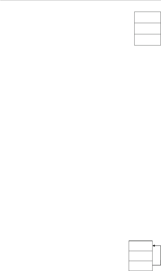
8.1 Array Declaration and Addressing 149
00000002
00000005
00000007
numary = 100
= 104
= 108
Fig. 8.2 Array of signed
double word
Continuing, what if each element of an array were to be initialized to the same number,
such as 0, or what if each memory location in the array did not need to be initialized? Each
of the following could be used, respectively:
zeroary sdword 0,0,0
empary sdword ?,?,?
Although the above works okay for small arrays, what if there were hundreds of ele-
ments needed to be initialized? Then clearly the above method would be cumbersome.
Instead, the dup operator is very convenient, where the above would be rewritten as
follows:
zeroary sdword 3 dup(0)
empary sdword 3 dup(?)
With only three elements the previous method of individually listing each element is
sufficient, but as the number of elements increases, using the dup operator is obviously
more convenient.
Given the above, how does one access individual elements of an array? For example,
assume that the last element of the previously declared numary needed to be moved to the
first element of numary. Remembering that arrays in C start with the zeroth element, the
C equivalent of this operation would be numary[0]=numary[2]; and the equivalent
assembly code would be as follows:
mov eax,numary+8 ; load eax with third element
mov numary+0,eax ; store eax in first element
and would appear in memory as shown in Fig. 8.3.
Of course regardless of whether one is dealing with a single memory location or with
the elements of an array, memory to memory transfer needs to go through a register. As
00000007
00000005
numary
=
100
=
104
=
108 00000007
Fig. 8.3 Copying individual
elements of an array

150 8Arrays
with C, the first element in an array is the zeroth element. Also, since numary is two
memory locations away, the offset needs to be multiplied by 4 to determine the correct
address because as mentioned previously, each memory location is 4 bytes long. Lastly,
numary in the second mov statement technically does not need to have the +0,sinceby
default the offset of a stand-alone memory location is +0. However, including the +0is
a nice way of indicating to others who might read the program that the memory location
specified is part of an array instead of a stand-alone memory location.
8.2
Indexing Using the Base Register
Although occasionally only access to a single element of an array is needed, more often
than not access to many elements of the array is necessary and simply accessing them one
at a time would prove to be inefficient. As mentioned at the outset of this chapter, there
are two major ways of indexing an array. The first one is similar to indexing an array using
subscripts in a high-level language, whereas the second one is similar to using pointers and
is helpful when trying to process strings as discussed in the next chapter.
Although high-level languages typically use a variable as an index when index-
ing arrays, in assembly language indexing is accomplished using registers. Recall from
Chapter 1 that the ebx register is known as the base register and is very useful when
indexing arrays. Although it is a register, it is used much like an index variable in the C
programming language.
How would one use the ebx register to index an array? As an example, what if one
wanted to sum all the elements of an array? To make things simpler at first, assume that the
array already contains values as introduced in the last section and as shown below:
numary sdword 2,5,7
sum sdword ?
In C, the variable sum would first need to be initialized to 0. Further, since there are
a fixed number of items to be summed, a for loop would be the best choice. Lastly, for
each iteration of the for loop, the ith element of the numary would need to be added to
sum using sum=sum+numary[i];. Optionally, the summation could be done using the
shorthand notation sum+=numary[i]; as shown below:
sum =0;
for(i=0; i<3; i++)
sum +=numary[i];
Of course since the for loop is the best choice as used above, the equivalent code in
assembly language would be the use of the .repeat-.untilcxz directive. Unlike C
code, where the variable iis being used both as a loop counter and as an index, in assembly
language, two separate registers need to be used. So in addition to using the ebx register

8.2 Indexing Using the Base Register 151
for indexing, the ecx register would be used for loop control. Lastly, since sum was not
initialized in the data section, it must be initialized to 0 during execution time. The resulting
code is as follows:
mov sum,0 ; initialize sum to 0
mov ecx,3 ; initialize ecx to 3
mov ebx,0 ; initialize ebx to 0
.repeat
mov eax,numary[ebx] ; load eax with element of numary
add sum,eax ; add eax to sum
add ebx,4 ; increment ebx by 4
.untilcxz
As discussed in the previous section, note that a 4needs to be added to the ebx register
to access the next signed double word. Also, do not forget that the ecx register should not
be altered, since the .untilcxz directive decrements the ecx register by 1 automatically.
After walking through the above code segment, the contents of the registers and memory
locations would be as shown in Fig. 8.4, where all values are in hexadecimal.
Why does the ebx register have the hexadecimal number 0000000C (decimal 12) in
it? Could it not end up addressing the memory location sum? Prior to the loop, the ebx
register is initialized to 0to access the first element in the array. After accessing and sum-
ming the current element in the array, the value in ebx is incremented by 4in anticipation
of accessing the next element in the array the next time through the loop. To answer the
first question, during the last iteration of the loop and after the third memory location has
been accessed, ebx is incremented by 4to 0000000C in anticipation of accessing the
next element in the array. The answer to the second question would then be yes, where the
memory location sum could be accessed upon completion of the loop. Would this have
caused an execution or run-time error if the contents of sum were accessed? As discussed
in the previous section, accessing another memory location like this is possible, and no, it
would not cause an error. The result is that extra care must be taken when addressing arrays
in assembly language.
In all of the previous examples, the array already contains data. How can one input
data into an array? To add a small twist, how could the array also be output in reverse
order? Obviously this problem will require the I/O capabilities learned in Chapter 2 and
will require two non-nested loops. Furthermore, assume that the user will need to first be
prompted and will then enter the number of integers to be input. Can all of this be done in
the C programming language? The answer is, of course, yes:
00000002 0000000E
00000005
00000007
0000000E
0000000C
00000000
numary
=
100
=
104
=
108
sum
=
10C
eax
ebx
ecx
Fig. 8.4 Using ebx for array
processing

152 8Arrays
int arry[20],n,i;
printf("\n%s","Enter the number of integers to be input: ");
scanf("%d",&n);
if (n>0){
for (i=0; i<n; i++){
printf("\n%s","Enter an integer: ");
scanf("%d",&arry[i]);
}
printf("\n%s\n\n","Reversed");
for (i=n-1;i>=0;i--)
printf(" %d\n\n",arry[i]);
}
else
printf("\n%s\n\n","No data entered.");
The user is first prompted to enter the integers to be input followed by prompts to enter
the integers themselves. After the integers have been placed into the array, a loop then
outputs the array in reverse order. In the event that a 0or a negative number is entered
for the first prompt, a message stating that no data was entered is displayed. The above
C code can then be implemented as follows in the partial .data and .code segments
below:
.data
msg1fmt byte 0Ah,"%s",0
msg2fmt byte 0Ah,"%s",0Ah,0Ah,0
msg3fmt byte " %d",0Ah,0Ah, 0
in1fmt byte "%d",0
msg1 byte "Enter the number of integers to be input: ",0
msg2 byte "Enter an integer: ",0
msg3 byte "Reversed",0
msg4 byte "No data entered."
n sdword ?
arry sdword 20 dup(?)
.code
INVOKE printf, ADDR msg1fmt,ADDR msg1
INVOKE scanf, ADDR in1fmt, ADDR n
mov ecx,n ; initialize ecx to n
mov ebx,0 ; initialize ebx to 0
.if ecx>0
.repeat
push ecx ; save ecx
INVOKE printf, ADDR msg1fmt, ADDR msg2

8.3 Searching 153
INVOKE scanf, ADDR in1fmt, ADDR arry[ebx]
pop ecx ; restore ecx
add ebx,4 ; increment ebx by 4
.untilcxz
INVOKE printf, ADDR msg2fmt, ADDR msg3
mov ecx,n ; initialize ecx to n
sub ebx,4 ; subtract 4 from ebx
.repeat
push ecx ; save ecx
INVOKE printf, ADDR msg3fmt,arry[ebx]
pop ecx ; restore ecx
sub ebx,4 ; decrement ebx by 4
.untilcxz
.else
INVOKE printf, ADDR msg2fmt, ADDR msg4
.endif
Notice in the assembly code segment that the use of the .if directive to check whether
nis greater than 0 is not only helpful in outputting a message that no data was entered but
also necessary to help insure that the value of the ecx register does not start off at 0or a
negative number for the .repeat-untilcxz directives that follow. Also, note that the
ecx register is saved and restored before and after the INVOKE directives in the body of
the loop so that the count is not destroyed. Should the contents of the ebx register also
be saved and restored in the loop? No, because it is the only register that is not altered by
the INVOKE directive.
8.3
Searching
As another example of using the ebx register for indexing, there are two main searches
that the reader has probably heard about in a previous high-level programming course: the
sequential search and the binary search. The former works with either unordered or ordered
data, whereas the latter works with only ordered data. Since the binary search is the more
complicated of the two, it is probably best to leave that to be implemented in a high-level
language and this text will examine only the sequential search.
Assuming that the data has already been entered into an array, that the number of ele-
ments in the array is known, and that there are no duplicates in the array, the first thing
needed to be done is to request from the user what data needs to be found. Then a flag
needs to be initially cleared indicating the data has not yet been found. Next the program
needs to loop through the array to determine whether the data being searched for is in the
array. If the data is found, the flag needs to be set to indicate that it was found, the index
should be set to the location of the data, and the rest of the array need not be searched. The
following C program is one way of solving this problem:

154 8Arrays
int arry[20],n=20,i,number,found;
printf("\n%s","Enter the integer to be found: ");
scanf("%d",&number);
i=0;
found=0;
while(i<n && !found)
if(number==arry[i])
found=-1;
else
i++;
if (found)
printf("\n%s\n\n", "The integer was found");
else
printf("\n%s\n\n","The integer was not found");
Note that the code was written using a while loop instead of a for loop. The use of
afor loop would require the code to branch out of the middle of the loop and in C this
would require the use of a break statement. This would be the equivalent of a “goto”
or a jump statement in assembly language and could cause unstructured code to be written
which this text has been trying to avoid. Assuming that the PROTO statements have already
been written correctly, the following partial .data and .code segments implement the
preceding C program:
.data
msg1fmt byte "%s",0
msg2fmt byte 0Ah,"%s",0Ah,0Ah,0
in1fmt byte "%d",0
msg1 byte "Enter the integer to be found: ",0
msg2 byte "The integer was found",0
msg3 byte "The integer was not found",0
arry sdword 20 dup(?)
n sdword 20
number sdword ?
found sbyte ?
.code
INVOKE printf, ADDR msg1fmt,ADDR msg1
INVOKE scanf, ADDR in1fmt, ADDR number
mov ebx,0 ; initialize ebx to 0
mov ecx,0 ; initialize ecx to 0
mov edx,number ; load edx with number
mov found,0 ; initialize found to 0
.while(ecx<n && !found)
.if(edx==arry[ebx])
mov found,-1 ; set found to -1

8.4 Indexing Using the esi and edi Registers 155
.else
add ebx, 4 ; increment ebx by 4
.endif
inc ecx ; increment ecx by 1
.endw
.if(found)
INVOKE printf, ADDR msg2fmt, ADDR msg2
.else
INVOKE printf, ADDR msg2fmt, ADDR msg3
.endif
In the above code segment, note that since only single byte is needed instead of 4 bytes
to create a flag, the found flag is only a signed byte (sbyte) instead of a signed double
word (sdword). Also, notice that the ecx register is used instead of the memory location
i. Although icould be used, it could not be easily used in the .while because memory
to memory comparisons are not allowed. Since it would need to be transferred to a reg-
ister anyway and ecx is also known as the counter register, it did not hurt to somewhat
mimic the .repeat-.untilcxz directives and use the ecx register. The primary dif-
ference is that the count is going forward instead of backward and the increment of the
ecx register should not be forgotten at the bottom of the loop. The other difference is the
.repeat-.untilcxz directive is a post-test loop structure and the .while directive
is a pre-test loop structure, and if nwas equal to 0, the while loop would not loop at all.
8.4
Indexing Using the esi and edi Registers
Although the use of the base register ebx is fairly straightforward, being limited to a single
register can prove to be somewhat restrictive. To help with this matter, there are two index
registers esi and edi, where the esi register is known as the source index register and
edi is known as the destination index register. The subtle difference between the use of the
ebx register and the esi and edi registers is that the former is used with the name of the
array as an index and the latter are used more like pointers. In this latter case, the address of
the array is first loaded into the register and the name of the array is not subsequently used.
Also, these two registers are very useful when manipulating strings, as will be discussed in
the next chapter.
To demonstrate the different way of addressing using these registers, it is easier to
examine the addressing of only a single element of an array first. For example, if only
the second element of an array needed to be moved into the eax register, the instruc-
tion mov eax,numary+4could be written as done in the first section of this chapter.
However, could the contents of numary+4be moved into eax without using +4attached
to the name of the array? Yes, the same thing could be accomplished by using a register as
an index. The following code segment would work the same assuming the existence of the
previous array, numary:
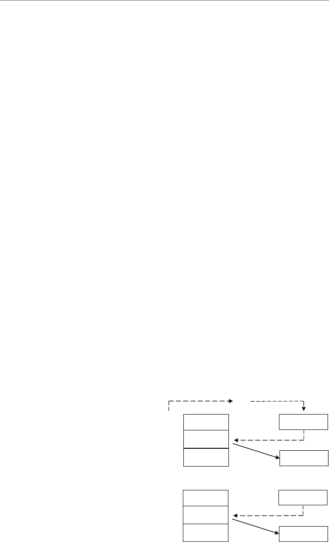
156 8Arrays
mov ebx,4
mov eax,numary[ebx]
Although a bit cumbersome compared to using numary+4, this code segment should
make sense given the previous section, where ebx contains a 4, and numary indexed by
ebx would be the address of the second element of numary. The dashed arrows in Fig. 8.5
show how the address of numary,whichis100, is added to or indexed by the 4in the
ebx register to create the address 104, which is the address of the second element of the
array numary. The solid arrow in Fig. 8.5 shows the contents of memory location 104
being copied into the eax register.
Using the esi register could accomplish the same task in the following code segment
which introduces the new offset operator:
mov esi,offset numary+4
mov eax,[esi]
Instead of causing the “contents” of numary+4to be loaded into the esi register, the
word offset causes the “address” of numary+4to be loaded into the esi register. In
the second statement, notice that there is no reference to numary because the address of
numary+4was loaded into the esi in the first line. Now the address in esi can be used
like a pointer, indicated by the square brackets, to point to the data in the second element
in the array, where its contents are transferred to the eax register. The dashed arrow in
Fig. 8.6 shows the esi register pointing to the second element of numary at memory
location 104 and the solid arrow in Fig. 8.6 shows the contents of memory location 104
being copied into the eax register.
Care must be taken when using this form of indexing. If the word offset was not
included on the first line, then the “contents” of memory location numary+4,whichis
a5, would be loaded into the esi register instead of the “address” of numary+4. This
would have caused havoc on the second line of code because the unknown contents of
00000002
+
00000004
00000005
00000007
numary
=
100
=
104
=
108
ebx
00000005
eax
Fig. 8.5 Using ebx register
to access a single element
00000002 00000104
00000005
00000007
numary
=
100
=
104
=
108
esi
00000005
eax
Fig. 8.6 Using esi to access
a single element

8.4 Indexing Using the esi and edi Registers 157
memory location 5would be loaded into the eax register. Further, if the square brackets
were accidently omitted on the second line of code, then the 104 in the esi register would
be transferred to the eax register, and this is clearly not what is intended in this example.
In addition to using the offset operator, there is an alternative method. Instead of
using the mov instruction with the word offset,thelea instruction, which stands for
“load effective address,” can be used as follows:
lea esi,memory + 4
mov eax,[esi]
Although in these two instances, the end results are the same, there is a subtle difference
between these two ways of getting an address. In a sense, using offset is static and
lea is dynamic. When using offset, the address is calculated at assembly time, and
with lea, the address is calculated at run-time. The only time the latter would need to
be used is when there is a register in the second operand, where the register value could
change during the course of the execution of the program and the address would need to be
recalculated. Since in the above example there is no register as part of the second operand
and a recalculation of the address is not necessary, either the mov and offset or the lea
can be used. Further, since the use of registers in a second operand will not be used in this
text, either method is acceptable. This text will use both methods interchangeably to allow
readers to get use to both methods. Although the offset operator can be used with the
lea instruction, it is not needed nor is it recommended, in order to keep these two methods
separate and distinct.
The above shows the use of the esi register, but what of the edi register? Actually,
the edi register could have been used equally well in the above example. However, as will
be seen in the next chapter, some string instructions have specific uses for each register
and substituting one for the other would not work. In the above case, however, if both
could have been used equally well, why should one be used over the other? The answer can
be found in the names of the registers mentioned above, where esi is the source index
register and edi is the destination index register. As a general rule, when retrieving data
from memory, it is best to use the esi register because memory is the source from which
the data is coming. When storing data back into memory, the edi register indicates the
destination where the data will be placed. This use of these registers corresponds to how
the string instructions work and it provides a common way of using the registers to help
programmers who might look at the code in the future.
As should be recalled from Chapter 1, data can be moved from one memory location to
another by simply moving the contents of one memory location to a register and then from
that register to the other memory location as follows:
mov eax,num1
mov num2,eax
Although the following example is clearly less efficient than the above, it helps demon-
strate how the esiand edi registers can be used to transfer data between memory
locations and will be helpful in subsequent examples of array processing:
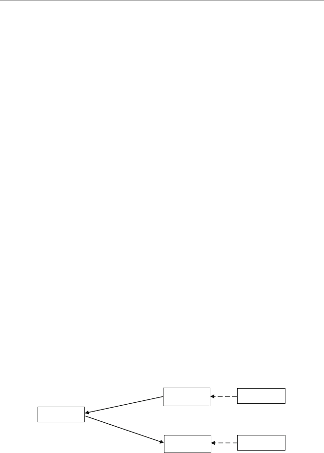
158 8Arrays
lea esi,num1 ; load the address of num1 into esi
lea edi,num2 ; load the address of num2 into edi
mov eax,[esi] ; move contents of where esi is pointing into eax
mov [edi],eax ; move contents of eax to where edi is pointing
Instead of having the memory locations as part of the two latter mov statements, they
appear in the first two lea instructions, where the addresses of num1 and num2 are trans-
ferred into the esi and edi registers, respectively. Then instead of moving the contents
of num1 into eax, the contents of where esi is pointing to, which is num1, are moved to
eax, and then the contents of eax are moved to where edi is pointing, which is num2 as
shown in Fig. 8.7.
As discussed previously, note that esi points to the source of the transfer, num1,
and edi points to the destination of the transfer, num2. Could one have saved an extra
instruction and just coded mov [edi],[esi]? At first, the answer may appear to be yes
because it looks like a simple register-to-register mov instruction. However, if one thinks
about it for a moment, this is not a simple register transfer, rather those registers are point-
ers to memory locations, and as learned in Chapter 1, memory to memory mov instructions
are not allowed. As always with this form of addressing, care must be taken. For example,
if the brackets around esi and edi were left off, then a 100 would be moved into eax
and the 100 would then be moved into the edi register, which is not the intended goal.
Clearly the first example is simpler, but the code above accomplishes the same task and
can be expanded to transferring elements of an array. Given how the esi and edi registers
work, can they be used to implement some of the array functions introduced previously?
The answer is yes. As an example consider the previous C segment which summed the
elements of an array:
sum =0;
for(i=0; i<3; i++)
sum +=numary[i];
num1
=
100
00000100
esi
5
5
5
num2
=
104
00000104
edi
mov [edi], eax
mov eax, [esi]
eax
Fig. 8.7 Using esi and edi to move data from memory to memory
The above C program segment can be implemented using the esi registers as follows:
mov sum,0 ; initialize sum to zero
mov ecx,3 ; initialize ecx to 3
lea esi,numary+0 ; load the address of numary into esi
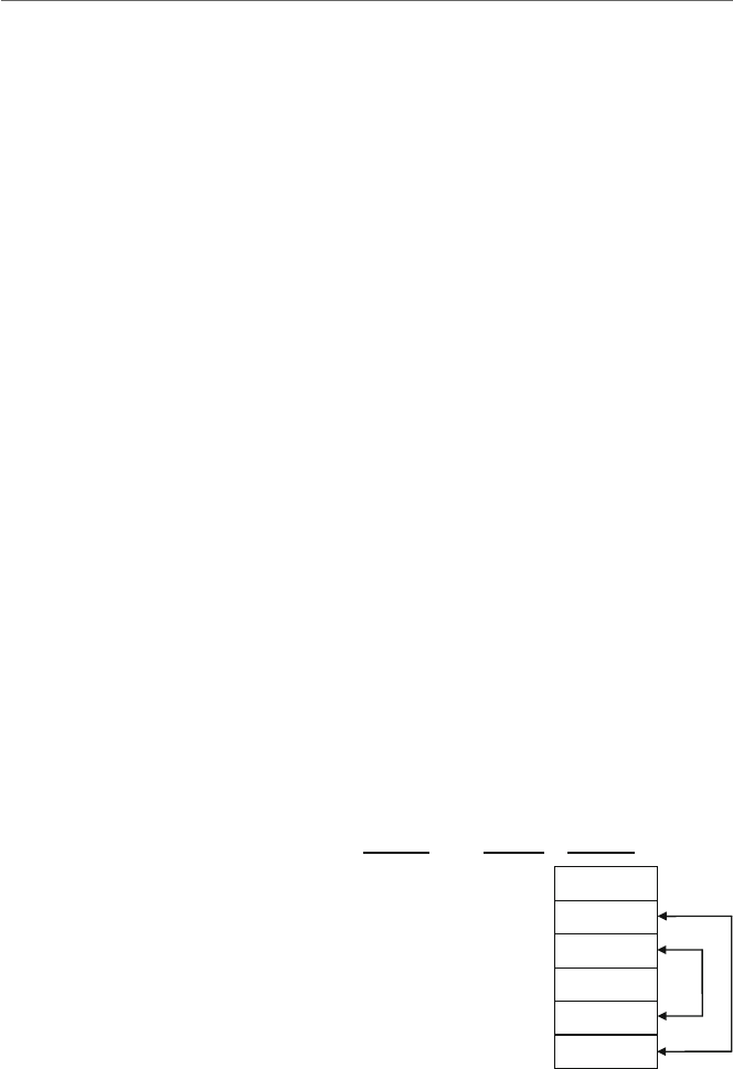
8.4 Indexing Using the esi and edi Registers 159
.repeat
mov eax,[esi] ; move contents of where esi pointing to eax
add sum,eax ; add eax to sum
add esi,4 ; increment esi by 4 to next element
.untilcxz
In comparison to the previous version, notice that instead of initializing the ebx register
to 0,theesi register is initialized to the address of numary+0. As mentioned previously,
the +0alerts other programmers that numary is not just a simple variable, but rather is
an array. The other change is that instead of accessing numary indexed by [ebx], only
[esi] is used. Lastly, esi instead of ebx is incremented, but regardless of which index
is used, it is incremented by 4to access the next sdword in the array.
What if one wanted to reverse the contents of an array? Instead of trying to just write
in assembly language, first think through the problem in a high-level language. Also, it is
a good idea to expand the array from 3 to 5 elements so that more of a pattern can be seen:
n sdword 5
numary sdword 2,4,7,9,12
One of the common mistakes to be made here is an assumption that a fixed-iteration
loop structure that loops five times is needed. What often happens in such circumstances is
that the array is returned back to its original order. Instead, by drawing arrows to indicate
which elements need to be swapped as shown in Fig. 8.8, it should be noticed below that
only approximately half the elements in the array need to be swapped. Since in this example
there are an odd number of items, the middle element does not need to be swapped. Integer
division can then be used to determine the number of items that need to be swapped, where
in this case 5 divided by 2 is 2. The result is that the loop should iterate a fixed number of
times as n/2.
00000005
00000002
00000004
00000009
0000000C
100
104
108
10C
110
114
Variable Address Contents
n
=
numary
=
00000007
Fig. 8.8 Swap routine
Although this algorithm can be implemented with just one index, the iand jindexes
are helpful in this example and will lend themselves to the use of the esi and edi registers
in the subsequent assembly language program:

160 8Arrays
j=n-1;
for(i=0; i<n/2; i++){
temp=numary[i];
numary[i]=numary[j];
numary[j]=temp;
j--;
}
However, the only major change that will probably be needed is to remember that esi
and edi are initially loaded with the appropriate addresses of the array, as can be seen prior
to the .repeat-.untilcxz loop below. The esi register is loaded with the address of
the first element of the array, numary+0. To calculate the address of the last element of
the array, the number of elements in the array is first decremented by 1 and then multiplied
by 4. As seen in Fig. 8.8, 5 minus 1 is 4, times 4 is 16, which when added to 104 is 120 in
decimal or 114 in hexadecimal:
mov ecx,n ; load ecx with contents of n
sar ecx,1 ; divide ecx by 2, number of times to loop
lea esi,numary+0 ; load address of numary into esi
mov edi,esi ; move contents of esi to edi
mov eax,n ; load eax with contents of n
dec eax ; decrement eax by one
sal eax,2 ; multiply eax by 4
add edi,eax ; add eax to edi for ending address of array
.repeat
mov eax,[esi] ; move contents where esi is pointing to eax
xchg eax,[edi] ; exchange eax and where edi is pointing
mov [esi],eax ; move eax to where edi is pointing
add esi,4 ; add four to esi for next element
sub edi,4 ; subtract four from edi for next element
.untilcxz
Note that the idiv instruction is not used in the code segment above. Since the nneeds
to be divided by 2, arithmetically shifting ecx one bit position to the right accomplishes the
same task. Likewise, when calculating the ending address of the array, after subtracting 1,
multiplication by 4is needed, so a 2-bit arithmetic shift to the left is a simple solution
(see Chapter 6). Of course, both esi and edi need to be adjusted by 4 each time
through the loop. Lastly, would xchg [esi],[edi] have worked in the above seg-
ment? Although it would be nice if it did, remember that the xchg instruction cannot work
between two memory locations as mentioned in Chapter 7. Also as discussed earlier in this
chapter, just because it seems that two registers are being exchanged, [esi] and [edi]
are actually pointing to two memory locations and thus at most only one of the operands
in the exchange instruction can reference a memory location.

8.5 Lengthof and sizeof Operators 161
8.5
Lengthof and sizeof Operators
In the previous example, the following declarations were used to declare the array and
indicate its length:
n sdword 5
numary sdword 2,4,7,9,12
Putting the number of elements in a variable is clearly a better choice than to leave
the number of elements as an immediate value in an instruction. The advantage of using a
variable is that any time the number of elements in the array is changed, the programmer
can easily change the variable n, which is hopefully declared in close proximity to the
declaration of the array.
Although this method works and is better, it is still rather clumsy. Consider if the number
15 was added to the end of numary and the number of elements in the array changed from
5 to 6. In addition to adding the extra element to the array, the value for nwouldalsoneed
to be changed as follows:
n sdword 6
numary sdword 2,4,7,9,12,15
What would happen if one forgot to update the value of nfrom 5 to 6? In this case,
the previous swapping program would process only the first five elements of the array.
Now consider instead of adding an additional element to the original array, an element was
removed from the array as in the following:
n sdword 4
numary sdword 2,4,7,9
What would happen if one forgot to decrease the value of nin this case? The previous
swapping program code segment would still attempt to process five elements, and whatever
memory location was declared after numary would also be involved in the swap routine,
which is clearly incorrect.
The solution to this problem is to neither leave the length of the array as an imme-
diate value in an instruction nor leave it in a variable, but rather declare it using the
lengthof operator. This operator instructs the assembler to calculate the length of the
array at assembly time. For example, in the previous code segment from the end of the
last section that reverses an array, the instruction mov ecx,n could be replaced with
mov ecx,lengthof numary. Then every time the length of the array is changed, the
assembler would recalculate the length of the array.
Whereas the lengthof operator indicates how many elements there are in an array, the
sizeof operator indicates how many bytes there are in an array. So if with a five-element
array of sdword the lengthof operator would return a 5, what would the sizeof

162 8Arrays
operator return? Since there are 4 bytes in a sdword and there are 5 elements in the array,
the answer would be 20.
Although the mov eax,n instruction in the program in the previous section could
also be replaced with a mov eax,lengthof numary instruction, there is an even
better way. Since the purpose of that section of the code segment was to calculate the
number of bytes to determine the address of the last element in the array to be stored in the
edi register, the sizeof operator could be utilized. The result is that the following code
segment
mov eax,n ; load eax with contents of n
dec eax ; decrement eax by one
sal eax,2 ; multiply eax by 4
could be replaced with
mov eax,sizeof numary ; load eax with the size of numary
sub eax,4 ; decrement eax by four
In the first case, eax is decremented by 1, where the 4 times 4 bytes per sdword would
be 16. Then the 16 needs to be added to the beginning address of the array to calculate the
address of the last element of the array. In the second example, the size of numary is
20, where 4 is subtracted to get 16, which again is used to calculate the address of the last
element of the array. Using both the lengthof and sizeof operators, the previous code
segment could be rewritten as follows:
mov ecx,lengthof numary ; load ecx with length of numary
sar ecx,1 ; divide ecx by 2, of times to loop
lea esi,numary+0 ; load address of numary into esi
mov edi,esi ; move contents of esi to edi
mov eax,sizeof numary ; load eax with size of numary
sub eax,4 ; decrement eax by four
add edi,eax ; add eax to edi for ending address of array
.repeat
mov eax,[esi] ; move contents where esi is pointing to eax
xchg eax,[edi] ; exchange eax and where edi is pointing
mov [esi],eax ; move eax to where edi is pointing
add esi,4 ; add four to esi for next element
sub edi,4 ; subtract four from edi for next element
.untilcxz
8.6
Complete Program: Implementing a Queue
A common structure that sometimes needs to be implemented in assembly language is the
queue. As learned in a second semester computer science course, a queue is known as a

8.6 Complete Program: Implementing a Queue 163
FIFO data structure, where the first item put into the queue is the first item taken out. The
operation used to put an item in a queue is often called enqueue and the operation to remove
an item from a queue is known as dequeue. Although the Intel processor has instructions
to push and pop items from a stack, it does not have instructions to enqueue and dequeue
items from a queue.
A queue is especially helpful when there is a faster process trying to communicate with
a slower process, where data can be placed into a queue by a faster process and the slower
process can then remove that data from the queue at a later time. A common example is
when a fast processor needs to send something to a slow printer and data is placed in a print
queue. In another example, when an interrupt occurs in a processor, it must be attended to
immediately in what is known as the foreground environment. However, the foreground
environment may not have time to completely process the interrupt, so the information
is placed in a queue, sometimes called a foreground/background queue. Then when there
are no pending interrupts, the background environment will complete the processing of
the information that was previously placed in the foreground/background queue. Although
the implementation of interrupts is beyond the scope of this text, the implementation of a
queue provides an excellent opportunity to demonstrate the use of an array and indexing.
Before looking at assembly code, it might be helpful to be reminded how queues can be
implemented in a high-level language. Although ideally it would be best to use parameters,
the following code again uses global variables to mimic the subsequent assembly language
program. The main program uses a sentinel-controlled loop to continue to iterate until
the letter sis input, which stands for stop. Then for each iteration of the loop, it checks
for the letter efor enqueue or dfor dequeue, otherwise an appropriate error message is
output.
The enqueue routine should look somewhat familiar to those who have taken a computer
science II course. Although there can be some complex ways to determine whether a queue
is full, the simplest method is to use a counter such as count, which is checked to see if
it is less than the length of the queue, nin this case. If so, number is placed in the rear
of the queue. The variable rear is incremented by 1. The mod function (%)isusedto
cause rear to be reset to 0should it exceed the length of the queue (n). For example, if
rear is equal to 3,the3%3 is equal to 0.Thedequeue routine is similar and it is left
for the reader to walk through the procedure:
#include <stdio.h>
const int n=3;
int queue[3],number,front=0,rear=0,count=0;
char command;
int main() {
void enqueue();
void dequeue();
printf("\n%s","Enter a command, e, d, or s: ");
scanf("%s",&command);
while (command !='s'){
if (command=='e'){
printf("\n%s","Enter a positve integer: ");

164 8Arrays
scanf("%d",&number);
enqueue();
}
else
if (command=='d'){
dequeue();
if (number>0)
printf("\n%s%d\n","The integer is: ",number);
}
else
printf("\n%s","Invalid entry, try again");
printf("\n%s","Enter a command, e, d, or s: ");
scanf("%s",&command);
}
printf("\n");
return 0;
}
void enqueue(){
if (count<n){
count++;
queue[rear]=number;
rear=(rear+1)%n;
}
else
printf("\n%s\n","Error: Queue is full");
}
void dequeue(){
if (count>0){
count--;
number=queue[front];
front=(front+1)%n;
}
else{
printf("\n%s\n","Error: Queue is empty");
number =-1;
}
}
Since there needs to be a pointer for both the front and the rear of a queue, the use of
the esi and edi registers, respectively, makes an excellent choice. Although procedures
are often used for the enqueue and dequeue operations, the use of macros will mimic the
push and pop instructions and also provide another opportunity to reinforce the concept
of macros. Although not very versatile, global variables are used to communicate between
the main program and the macros as with the previous C program:

8.6 Complete Program: Implementing a Queue 165
.listall
.386
.model flat,c
.stack 100 h
scanf PROTO arg2:Ptr Byte, inputlist:VARARG
printf PROTO arg1:Ptr Byte, printlist:VARARG
.data
in1fmt byte "%s",0
in2fmt byte "%d",0
msg1fmt byte 0Ah,"%s",0
msg3fmt byte 0Ah,"%s%d",0Ah,0
msg4fmt byte 0Ah,0
errfmt byte 0Ah,"%s",0Ah,0
msg1 byte "Enter a command, e, d, or s: ",0
msg2 byte "Enter a positive integer: ",0
msg3 byte "The integer is: ",0
errmsg1 byte "Error: Invalid entry, try again",0
errmsg2 byte "Error: Queue is full",0
errmsg3 byte "Error: Queue is empty",0
queue sdword 3 dup(?)
command sdword ?
number sdword ?
count sdword 0
.code
enqueue macro
.if count < lengthof queue
inc count ; increment count
mov eax,number ; load eax with number
mov [edi],eax ; store eax in rear
mov eax,edi ; copy edi (rear) to eax
sub eax,offset queue ; subtract address of queue
add eax,4 ; increment eax by 4
cdq ; convert double to quad
mov ecx,sizeof queue ; get size of queue (bytes)
idiv ecx ; divide
mov edi,offset queue ; load address in rear
add edi,edx ; add remainder to rear
.else
INVOKE printf, ADDR errfmt, ADDR errmsg2
.endif
endm
dequeue macro
.if count > 0
dec count ; decrement count
mov eax,[esi] ; load eax from front
mov number,eax ; store eax in number
mov eax,esi ; copy esi (front) to eax
sub eax,offset queue ; subtract address of queue
add eax,4 ; increment eax by 4

166 8Arrays
cdq ; convert double to quad
mov ecx, sizeof queue ; get size of queue (bytes)
idiv ecx ; divide
mov esi,offset queue ; load address in front
add esi,edx ; add remainder to front
.else
INVOKE printf, ADDR errfmt, ADDR errmsg3
mov number,-1 ; store -1 (flag) in number
.endif
endm
main proc
mov edi,offset queue+0 ; use edi as front of queue
mov esi,offset queue+0 ; use esi as rear of queue
INVOKE printf, ADDR msg1fmt, ADDR msg1 ; priming
INVOKE scanf, ADDR in1fmt, ADDR command ; read
.while command !="s" ; while not stop
.if command=="e" ; enqueue?
INVOKE printf, ADDR msg1fmt, ADDR msg2
INVOKE scanf, ADDR in2fmt, ADDR number
enqueue ; enqueue number
.elseif command=="d" ; dequeue?
Dequeue ; deque number
.if number >0 ; not -1 (flag)?
INVOKE printf, ADDR msg3fmt, ADDR msg3, number
.endif
.else
INVOKE printf, ADDR errfmt, ADDR errmsg1
.endif
INVOKE printf, ADDR msg1fmt, ADDR msg1
INVOKE scanf, ADDR in1fmt, ADDR command
.endw
INVOKE printf, ADDR msg4fmt
ret
main endp
end
Although much of the assembly code is similar to its C counterpart, there are a few
sections that might need some explanation, such as the enqueue routine. As previously
indicated, the edi register is used to point to the rear of the queue. However, instead of
merely adding a 1to rear as with the previous C code, a 4needs to be added for the
sdword elements of queue. Also note that offset queue is subtracted from edi
prior to the division and then offset queue isaddedbacktoedi after the division.
This is because edi does not contain a simple index within queue as in the previous C
program but rather edi is acting as a pointer to queue and the address of queue needs
to be removed before the division can take place and then added back afterward.

8.7 Complete Program: Implementing the Selection Sort 167
8.7
Complete Program: Implementing the Selection Sort
Although sorting could be done more easily in a high-level language, it provides an excel-
lent opportunity to examine nested loops, ifs, and again the use of the esi and edi
registers. As should be recalled from a first-year sequence in computer science, there are a
number of sorts called in-place sorts, which can sort the contents of an array. These sorts
typically use two loops and on average if the array contains nelements, they have a time
complexity of O(n2). Compared to other sorts, these are relatively slow but are acceptable
with smaller sets of data and are relatively easy to learn. Three common O(n2) sorts are
the selection sort, the bubble sort, and the insertion sort, of which the bubble sort is one of
the more popular. Although all three sorts have a number of similarities, the selection sort
tends to be a little easier to understand and a little simpler to implement, especially when
trying to implement a sort in assembly language. Since many students may have already
implemented a bubble sort previously in a high-level language, the implementation of the
bubble sort in assembly language is left as an exercise at the end of this chapter.
The implementation of the selection sort (and the bubble sort for that matter) can be
implemented in two different ways. The first method is what could be called the simplified
method, where only the two loops, an if structure, and a swap routine need to be written. In
this form, the sort is very inefficient but the technique of accessing various elements in the
array is made quite clear. The second method of implementing the sort could be called the
modified method, where the sort is modified to be more efficient and avoid any unnecessary
swapping of elements or passes through the data in the array. The simplified method of the
selection sort will be presented first and then it will be subsequently modified. Should the
reader already be familiar with the selection sort, the following paragraph could be skipped,
but it could also serve as a quick refresher as to how the sort works.
The simplified way of implementing the selection sort is to perform n-1 passes through
the array. During the first pass, the first element of the array will be compared with each of
the subsequent elements in the array. If the array is to be sorted in ascending order (smallest
to the largest) and if a subsequent element is smaller than the first element, a swap occurs.
Comparison continues on through all of the subsequent elements. After comparing the first
element with all the subsequent elements on the first pass, the smallest element will be in
the first position. The process then continues on with the second element being compared to
all the subsequent elements, the third element being compared to all subsequent elements,
and so on until the second to the last element is compared to the last element, where the
entire array will be sorted. Notice that the number of elements that need to be compared in
each pass decreases by one with each subsequent pass.
The simplified selection sort can be implemented as follows in C:
// number of passes
for(i=0; i<n-1; i++)
//number of comparisions
for (j=i+1; j<n; j++)
// compare the ith and jth element
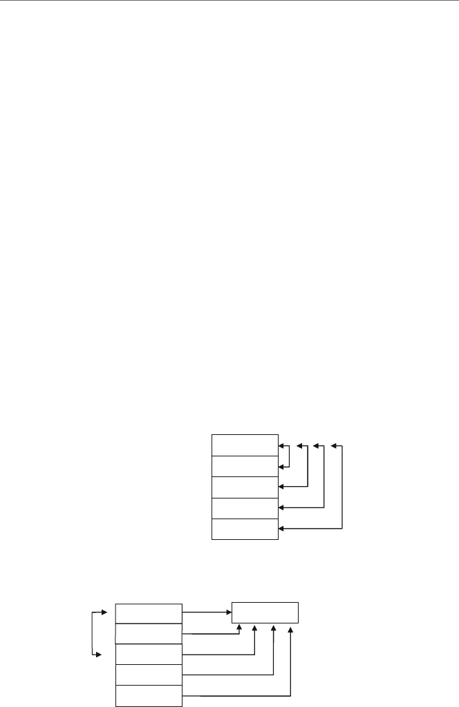
168 8Arrays
if (arry[j]<arry[i]) {
// swap the elements
temp=arry[j];
arry[j]=arry[i];
arry[i]=temp;
}
Note that the outer for loop iterates n-1 times for the number of passes needed through
the array and that the inner for loop starts at the i+1position to compare to the subsequent
number of elements. The if statement compares the subsequent element to the current
element, and if it is smaller, it swaps the subsequent element with the current element as
shown in Fig. 8.9.
However, the above algorithm is somewhat inefficient because it keeps swapping each
time it finds a smaller number. Wouldn’t it be easier to only swap once? The answer is yes.
First, the index of the starting element would be copied into a variable called smallest.
Second, should a smaller element be found, its index is copied into smallest. Third, at
the end of the pass the element that contains the smallest number indicated by the index in
smallest is swapped with the element in the starting element. Now instead of a potential
swap with every comparison, there is only one swap at the end of each pass as illustrated
in Fig. 8.10.
arry
Compare and if smaller,
swap
Fig. 8.9 Simplified selection
sort
?
arry 1. Copy index smallest
3. Swap
starting
element
with
smallest
index
element
2. Compare and if smaller,
save index
Fig. 8.10 Modified selection sort

8.7 Complete Program: Implementing the Selection Sort 169
The C code implementing the above algorithm can be found below:
// number of passes
for(i=0; i<n-1; i++) {
// save index of first element of pass in smallest
smallest=i;
//number of comparisions
for(j=i+1; j<n; j++)
// compare jth elelemnt with smallest
if(arry[j]<arry[smallest])
// save new smallest element
smallest=j;
// swap first element of pass with smallest
temp=arry[i];
arry[i]=arry[smallest];
arry[smallest]=temp;
}
The use of the two indexes iand jmakes it easy to implement these two loops in
assembly language using the esi and edi registers. Conversely, the use of iand jas
loop counters makes it a little more difficult because only the ecx register can be used as
a counter in nested .repeat-.untilcxz loops. One solution is to use the equivalent of
two while structures and thus the memory locations iand jcould easily be used as loop
counters. However, the alternative is to use two .repeat-.untilcxz loops and to be
careful to save and restore the contents of the ecx register at the beginning and end of the
outer loop structure. In the code below, the esi register in a sense does double duty. At the
beginning and the end of the sort, it points to the starting element, but in the middle part
of the sort, it points to the smallest element. To be consistent, the input and the output also
use the esi and edi registers:
.listall
.386
.model flat,c
.stack 100 h
scanf PROTO arg2:Ptr Byte, inputlist:VARARG
printf PROTO arg1:Ptr Byte, printlist:VARARG
.data
msg1fmt byte 0Ah,"%s",0
msg2fmt byte "%s",0
msg3fmt byte 0Ah,"%s",0Ah,0Ah,0
msg4fmt byte " %d",0Ah,0
msg5fmt byte 0Ah,0
in1fmt byte "%d",0
msg 1 byte "Enter the number of integers to be input: ",0
msg2 byte "Enter an integer: ",0

170 8Arrays
msg3 byte "Sorted",0
n sdword ?
arry sdword 20 dup(?)
temp sdword ?
.code
main proc
INVOKE printf,ADDR msg1fmt,ADDR msg1
INVOKE scanf,ADDR in1fmt,ADDR n
INVOKE printf,ADDR msg5fmt
.if n>0 ; if n <=0, dont continue
mov ecx,n ; load ecx with n
mov edi,offset arry+0 ; load address of arry into edi
.repeat
push ecx ; save ecx
INVOKE printf,ADDR msg2fmt,ADDR msg2
INVOKE scanf,ADDR in1fmt,ADDR [edi]
add edi,4 ; incrment edi by 4
pop ecx ; restore ecx
.untilcxz
.if n>1 ; check >1 elements in array
mov ecx,n ; load ecx with n
dec ecx ; loop n-1 times
mov esi,offset arry+0 ; load esi with address of arry
.repeat
push ecx ; save ecx
push esi ; save address, esi now smallest
mov edi,esi ; load address of esi in edi
add edi,4 ; move edi to the next element
.repeat
mov eax,[esi] ; move smallest to eax to compare
.if [edi]<eax ; compare smallest to next
mov esi,edi ; save the new smallest in esi
.endif
add edi,4 ; move to next element to compare
.untilcxz
mov edi,esi ; edi points to smallest element
pop esi ; esi points to the start element
mov eax,[esi] ; move start element to temp
xchg eax,[edi] ; exchange start and smallest
mov [esi],eax ; move smallest back to start
add esi,4 ; move start index to next
pop ecx ; restore ecx to be decremented
.untilcxz
.endif
INVOKE printf, ADDR msg3fmt, ADDR msg3
mov ecx, n ; load ecx with n
mov esi,offset arry+0 ; load esi with address of arry
.repeat
push ecx ; save ecx
mov eax,[esi] ; load eax with element from arry
mov temp,eax ; store eax in temp for output
INVOKE printf, ADDR msg4fmt, temp
add esi,4 ; increment esi to next element

8.9 Exercises 171
pop ecx ; restore ecx
.untilcxz
INVOKE printf, ADDR msg5fmt
.endif
ret
main endp
end
Notice that edi is used on input because the array is the destination of the data and esi
is used on output because the source of the data is the array. Again, esi does double duty,
where at the beginning and the end of the sort, it points to the starting element, but in the
middle part of the sort, it points to the smallest element. The push and pop instructions
are carefully used when making the transition between these two tasks. Lastly, note that a
temporary memory location is used to help output the array, since [esi] unfortunately
cannot be used in the printf routine.
8.8
Summary
•The dup operator allows for the declaration of large initialized or uninitialized arrays.
•The ebx register can be used as an index for an array, much like a variable such as iin
a high-level language.
•The esi and edi registers are known as the source index register and destination index
register, respectively. They work like pointers and are especially useful with strings.
•When dealing with arrays of sdword, remember to increment by 4 instead of 1, because
a signed double word takes up 4 bytes.
•The mov instruction and offset operator, or the lea instruction, allows for getting
the address of a variable, where the former is static and the latter dynamic.
•Use square brackets [] around the ebx,esi,andedi registers, not to get the contents
of the register but rather to get the contents of the memory location to which they are
indexing or pointing.
•The lengthof operator returns how many elements are in an array, whereas the
sizeof operator returns how many bytes there are in an array.
8.9
Exercises (Items Marked with an ∗Have Solutions in Appendix E)
1. Given the following assembly language statements, indicate whether they are syntacti-
cally correct or incorrect. If incorrect, indicate what is wrong with the statement:
∗A. x sdword ?,?,? B. y sdword 3 dup(0) ∗C. mov eax,x+8
D. mov eax,y[ebx] ∗E. mov esi,edi F. mov [esi],[edi]

172 8Arrays
2. Given the contents of the following memory location, what is stored in the eax register
at the end of each segment?
temp = 200
= 204
00000005
00000007
∗A. mov eax,temp B. mov eax,offset temp
∗C. lea eax,temp D. mov eax,offset temp+4
∗E. mov esi,offset temp F. mov edi,offset temp
mov eax,esi mov eax,[edi]
3. Implement the following C instructions using assembly language. Assume all variables
are declared as sdword:
∗A. num[0] =1;
B. x[1] =x[2];
∗C. y[i+1] =y[i];
D. z[i] =z[j];
4. Given the declarations below, indicate what would be stored in the eax register for each
of the following instructions. Note that oarray is of type sword, not sdword (hint:
see Chapter 1):
narray sdword 1,2,3,4,5
marray sdword 10 dup(?)
oarray sword 15,20,25
∗A. mov eax,lengthof narray ∗B. mov eax,sizeof narray
C. mov eax,lengthof marray D. mov eax,sizeof marray
∗E. mov eax,lengthof oarray F. mov eax,sizeof oarray
5. Write both the C code and the assembly code to transfer the contents of a 20-element
array of integers to a second 20-element array of integers.
6. Just as there is a simple and modified version of the selection sort, so is there both a
simple version and a modified version of the bubble sort. The simple version in C is the
same length as the simplified version of the selection sort presented in Section 8.6.
a. Write both the C code and the assembly code to implement the simplified version
of the bubble sort which compares every element of every pass through the array
whether there was a swap on the previous pass or not.
b. First write the C code for the modified version of the bubble sort and then write the
modified version in assembly language. With the modified version, if there is not
a swap on the previous pass through the array, the array is in order and there is no
need to make any subsequent passes through the array.

Strings 9
9.1
Introduction
This chapter concerns string processing. Specifically it examines various string process-
ing instructions that are available in MASM. Continuing on with the last chapter, it also
examines the manipulation of arrays of strings.
In its simplest case, a string is nothing more than an array of bytes as opposed to an array
of signed double words. So, it is possible to use all of the techniques for arrays introduced
in the last chapter with strings. For example, what if one wanted to copy the contents of
one string to another string? As with arrays, the ebx register could be used an index for
both strings. However, there are a couple of subtle but important changes in the following
code:
.data
string1 byte "Hello World!",0
string2 byte 12 dup(?),0
.code
mov ecx,12 ;load ecx with 12
mov ebx,0 ;load ebx with 0
.repeat
mov al,string1[ebx] ;load al with string1[ebx]
mov string2[ebx],al ;store al in string2[ebx]
inc ebx ;increment ebx by 1
.untilcxz
First, note that the strings are declared as byte instead of sdword. As a result, notice
that the mov instructions are using only a 1-byte register, al, instead of a 32-bit register
eax, where it should be recalled from Chapter 1 that al is the rightmost byte of the eax
register. Lastly, instead of incrementing ebx by four, it is incremented only by one to
account for the size of byte as opposed to the size of a sdword.
173
J.T. Streib, Guide to Assembly Language, DOI 10.1007/978-0-85729-271-1_9,
C
Springer-Verlag London Limited 2011
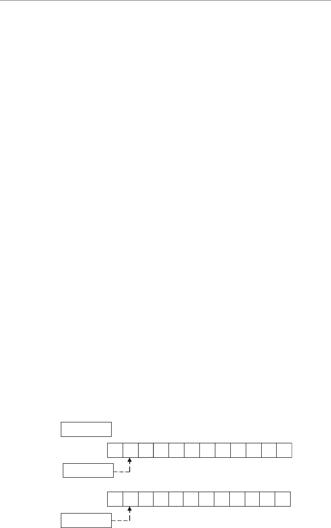
174 9 Strings
Just as arrays can be indexed using the esi and edi registers, so too can strings be
indexed using these registers. The esi register can be used for string1 as the source of
the transfer, and the edi can be used for the destination of the transfer to string2:
.data
string1 byte "Hello World!"
string2 byte 12 dup(?)
.code
mov ecx,12 ; load ecx with 12
lea esi,string1 ; load esi with address of string1
lea edi,string2 ; load edi with address of string2
.repeat
mov al,[esi] ; load al with [esi]
mov [edi],al ; store al in [edi]
inc esi ; increment esi by 1
inc edi ; increment edi by 1
.untilcxz
As with the ebx register previously, esi and edi are incremented by one instead of
four. As seen in the previous chapter, arrays are typically drawn vertically, and in repre-
senting how strings are processed, they are typically drawn horizontally. This is especially
helpful when trying to represent arrays of strings later in this chapter. The above code
could be illustrated just prior to the mov al,[esi] instruction the second time through
the loop as shown in Fig. 9.1, where brepresents a blank or a space.
First, the letter Hhas been transferred from the first byte in name1 to the first byte in
name2. Also, the ecx register has been decremented by one from 12 to 11, 0000000B
in hexadecimal. Lastly, the esi and edi registers have been incremented by one and are
pointing to the next byte in each of the strings.
In looking at the above code, it seems to be more complicated than its previous ebx
counterpart. Although, if the array were to be transferred in reverse order, then clearly using
esi and edi would be easier because there are two registers available to accomplish the
task. But in a purely simple transfer, ebx has the advantage because the same register can
be used as both the source and the destination. However, as alluded to in Chapter 8, the use
of esi and edi in the above example is a good preview of some of the string processing
instructions that use these two registers.
0000000B
H E LLObWORLD!
00000101
ecx
edi
esi
H
name1
=
100
0000010D
Name2
=
10C
Fig. 9.1 Using esi and edi to move a string

9.2 String Instructions: Moving Strings (movsb)175
9.2
String Instructions: Moving Strings (movsb)
Since there are a number of functions that need to be performed on strings, many high-level
languages include specialized libraries with instructions that perform many of the unique
functions that help in string processing. Although assemblers usually do not come with a
library of string functions, that does not prevent users from creating their own libraries.
Whether or not a library of string functions is created, or code for string processing is
written on an as-needed basis, creating the code needed using the same instructions that
can be used for arrays can be tedious and cumbersome. Luckily, there are some instructions
provided in the Intel architecture that help to make the task a little easier.
Before looking at these instructions, it should be pointed out that some of the instruc-
tions are designed to help with array processing as well. But since the needs when
processing an array tend to be different, programmers often times use the mechanisms
described in the previous chapter and use the following instructions primarily for string
processing. As will be shown later, having the ability to use both techniques can be helpful
in some instances. As with previous instructions, there are many different options available,
but only the basic and most useful ones will be discussed here.
Instruction Meaning
movsb Move string byte
cmpsb Compare string byte
scasb Scan string byte
storsb Store string byte
lodsb Load string byte
Although the above instructions have their word and double word counterparts, which
can be created by substituting the letter bin the instructions with the letters wand d,
respectively, only the byte instructions are listed above. One of the most useful instructions
listed above to be discussed in this section is the movsb instruction which is used to move
a string of bytes. This instruction is not a simple instruction because it does more than one
thing. In particular, the movsb instruction does two things. First, it moves the contents
of the byte pointed at by the esi register to the byte in memory pointed at by the edi
register. Then it decrements the ecx register and either increments or decrements the esi
and edi registers by 1. So, for example, if one wanted to move only a single byte, then
whether the esi and edi registers are incremented or decremented would not matter and
one could write the following code segment:
.data
letter1 byte 'a'
letter2 byte ?
.code
lea esi,letter1 ; load esi with address of letter1
lea edi,letter2 ; load edi with address of letter2
movsb ; move string byte from [esi] to [edi]

176 9 Strings
However, obviously the above code segment could be written much easier by simply
writing the following:
mov al,letter1 ; load al with letter1
mov letter2,al ; store al in letter2
As can be seen, by itself the movsb instruction is not terribly useful, but when used
in conjunction with some other instructions, it becomes a fairly powerful instruction. The
fact that the movsb instruction can alter esi and edi can be very useful when moving
a number of bytes. The way to determine which way esi and edi will be altered is
based on the direction flag (mentioned previously in Chapter 4). The direction flag can
be cleared or set by using the cld or std instructions, which stand for clear direction flag
or set direction flag, respectively. If the esi and edi registers need to be incremented,
the direction flag then needs to be cleared (cld), otherwise the direction flag needs to
set (std) to cause the registers to be decremented. Using this information, the movsb
instruction could be used to simplify the loop used in the previous section and relisted
below on the left, where the modified code using the movsb instruction is listed on the
right:
mov ecx,12 mov ecx,12
mov esi,offset string1 mov esi,offset string1
mov edi,offset string2 mov edi,offset string2
.repeat cld
mov al,[esi] .repeat
mov [edi],al movsb
inc esi .untilcxz
inc edi
.untilcxz
Note that ecx,esi,andedi all need to be initialized as before, but notice that the
body of the loop is much smaller because of the power of the movsb instruction. An
intermediate general purpose register is not needed to move from one memory location to
another. Also note that it is not necessary for the programmer to increment the esi and
edi registers, because it is automatically done by the movsb instruction. The only thing
that needs to be done is to clear the direction flag using the cld instruction to cause the
two registers to be incremented as opposed to being decremented, which only needs to be
done once prior to the loop.
To help with making string processing even simpler, the above code can be further
simplified by using a prefix. There are three prefixes that are useful here as listed below:
Prefix Meaning
rep Repeat
repe Repeat while equal
repne Repeat while not equal

9.3 String Instructions: Scanning (scasb), Storing (stosb), and Loading (lodsb)177
The rep prefix works just like the .repeat-.untilcxz directives, where it decre-
ments the ecx register until it reaches 0. Unlike the .repeat-.untilcxz directives
which can have any number of instructions in the body of the loop, the rep prefix works
only in conjunction with instructions like movsb. Thus the above code on the right and
shown again below on the left can be further simplified as follows on the right:
mov ecx,12 mov ecx,12
lea esi,string1 lea esi,string1
lea edi,string2 lea edi,string2
cld cld
.repeat rep movsb
movsb
.untilcxz
As mentioned previously, the movsb instruction is not very useful when used as a
stand-alone instruction, but when used in conjunction with other instructions, its power
is evident. However, as with any instruction that has a lot of power, it loses some of its
versatility. If each character needed to be processed as it was moved from one string to
another, then the movsb instruction is not very useful. Since all it does is move bytes,
which it does very well, it cannot do much of anything else. This is not to disparage the
powerofthemovsb, but rather to show its limitations. For example, if each letter moved
from one string to the other needed to be changed from lowercase to uppercase, the movsb
would not be as useful and the following code segment would instead accomplish this task.
For the sake of convenience in the example below, it is assumed that each character in the
variable name1 is a letter of the alphabet:
.data
name1 byte "MaryJo"
name2 byte 6 dup(?)
.code
mov ecx,lengthof name1 ; load ecx with length
lea esi,name1 ; load esi with address of name1
lea edi,name2 ; load edi with address of name2
.repeat
mov al,[esi] ; load al with [esi]
and al,11011111b ; convert lower to upper case
mov [edi],al ; store al in [edi]
inc esi ; increment esi by 1
inc edi ; increment edi by 1
.untilcxz
9.3
String Instructions: Scanning (scasb), Storing (stosb), and Loading (lodsb)
The scasb instruction is a fairly useful instruction when used with either the repe or
repne prefixes. For example, what if one wanted to scan a string of bytes to find whether
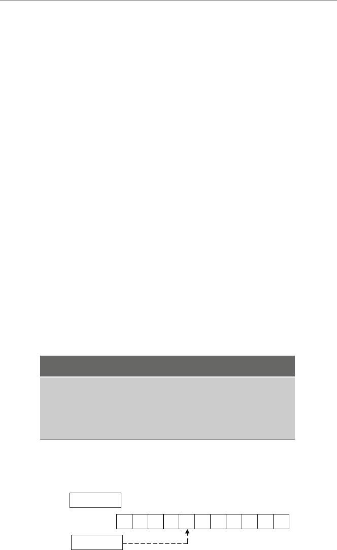
178 9 Strings
there was a particular character in a string, such as a blank? First, the al register is loaded
with the character that needs to be found. Then the edi register needs to be loaded with
address of the string to be scanned. And lastly, the ecx register needs to be loaded with
the number of characters to be scanned in the string. Then each time a character is scanned
in the string, the ecx register is decremented by 1 and the edi register is incremented by
1. Using the repne prefix, the string will be scanned until the character is found or until
the ecx is equal to 0:
.data
name1 byte "Abe Lincoln"
.code
mov al,'' ; load al with a space
mov ecx,lengthof name1 ; load ecx with length
lea edi,name1 ; load address of name1
repne scasb
In the above code segment, ecx is initially loaded with the length of name1, which
is 11 (Bin hex). After scanning for a space, or in other words, a blank as indicated by a
lowercase bin Fig. 9.2,theecx register will have been decremented to 7, which is how
many characters are left to be scanned in name1, and the edi register would be pointing
to the next character in the string as shown.
The stosb instruction is useful to store the contents of the al register at the location
in a string pointed at by the edi register. The lodsb instruction loads the al register with
the contents of the string pointed at by the esi register. In both cases the edi or the esi
register is incremented after their respective operations. The semantics of each instruction
is shown below using equivalent mov and inc instructions.
String instruction Equivalent
stosb mov al,[edi]
inc edi
lodsb mov [esi],al
inc esi
As can be seen, the string instructions are a little cleaner and have the option of using
the rep prefix. Although both instructions could be used with a rep prefix, only the
00000007
ABEbLINCOLN
00000104
ecx
edi
name1
=
100
Fig. 9.2 Using repne scasb

9.4 Array of Strings 179
stosb instruction would benefit the most by its use when initializing a string to blanks or
some other character. As an example of how many of the above instructions might be used,
consider the task of taking someone’s name in the normal first name followed by last name
order and then reversing it so that the last name is first, followed by a comma, followed by
a space, and then followed by the last name:
.data
name1 byte "Abe Lincoln"
name2 byte 12 dup (?)
.code
mov al,'' ; load al with space
mov ecx,lengthof name1 ; load length of name1
lea edi,name1 ; load address of name1
repne scasb ; find space in name1
push ecx ; save ecx
mov esi,edi ; move edi to esi
lea edi,name2 ; load adress of name2
rep movsb ; copy last name to name2
mov al,','; load al with comma
stosb ; store comma in name2
mov al,'' ; load al with comma
stosb ; store space in name2
mov ecx,lengthof name2 ; store length of name2
pop eax ; restore ecx into eax
sub ecx,eax ; sub length of last name
dec ecx ; decrement ecx for space
lea esi,name1 ; load address of name1
rep movsb ; copy first name to name2
In the above program, first the space needs to be found between the first and the last
name in name1 using the scasb instruction. After ecx is saved for subsequent process-
ing, the last name from name1 needs to be copied to name2 using the movsb instruction.
Then a comma and a space needs to be inserted into name2 using the stosb instruction.
Then using the previously saved value of ecx to determine the length of the first name, the
first name can be copied from name1 to name2 using the movsb instruction.
9.4
Array of Strings
What if one wanted to move an array of strings to another array of strings? It is possible
that one could just treat the entire array of strings as one giant string and use a single rep
movsb instruction. Given the following array of strings,
names1 byte "Abby","Fred","John","Kent","Mary"
it could be viewed as shown in Fig. 9.3.
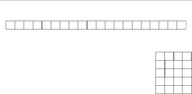
180 9 Strings
r e d J h noy F aMtneKb b rA y
names1
Fig. 9.3 Strings viewed as a single string
r e d
J h no
y
F
aM
tneK
b b
r
A
y
names1
Fig. 9.4 Strings viewed as an
array of strings
Although using only a rep movsb would work, the disadvantage of this approach is,
what if one wanted to process each string individually? Instead it is helpful to not view
names1 as just a single string but rather to view it as an array of strings as shown in
Fig. 9.4.
Although the following solution to the problem does not address the issue of processing
each string separately, it lays the groundwork for that in a future problem and illustrates a
more versatile way to process an array of strings. What are needed are two loops: one to
control the array of strings and the other for each character in the string:
.data
names1 byte "Abby","Fred","John","Kent","Mary"
names2 byte 20 dup(?)
.code
main proc
mov ecx,5 ; load ecx with 5
lea esi,names1 ; load esi with address of names1
lea edi,names2 ; load edi with address of names2
cld ; clear direction flag
.repeat
push ecx ; save ecx
mov ecx,4 ; load ecx with 4
rep movsb ; move string from names1 to names2
pop ecx ; restore ecx
.untilcxz
Note that the value of ecx needs to be pushed and popped prior to and after the rep
movsb instruction since the rep prefix uses the ecx register too. Further, the cld could
have been placed in the loop prior to the rep movsb instructions, but since the value of
the direction flag does not change, there is no need to clear it each time and it can be placed
just prior to the outer loop. Again, although the above code could have been done with only
arep movsb instruction, it lays the foundation for a problem in a subsequent section.
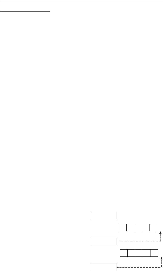
9.5 String Instructions: Comparing Strings (cmpsb)181
9.5
String Instructions: Comparing Strings (cmpsb)
What if one wanted to compare two strings to see if they are equal? As might be suspected,
this can be done with a loop and an if structure, but the code for this is rather ungainly.
Instead of showing this option, it is much easier to go straight to the instruction designed
for this task, which is the cmpsb instructionusedtocompareastringofbytes.Itisvery
similar to the movsb instruction, where it performs two major tasks. First, it compares the
two bytes pointed to by the esi and edi registers and sets the appropriate flags such as
the zero and sign flags, respectively. It then decrements the ecx register, and increments
or decrements the esi and edi registers as indicated by the direction flag, just like with
the movsb instruction. Also, similar to the rep operator with the movsb,arepe prefix
can be added to allow loop control. The repe repeats, while the two characters being
compared are equal. For example, given the following declaration with equal length strings,
what would happen in the following code segment?
.data
name1 byte "James"
name2 byte "James"
.code
mov ecx,lengthof name1 ; load ecx with length
lea esi,name1 ; load address of name1
lea edi,name2 ; load address of name2
cld ; clear direction flag
repe cmpsb ; repeat while equal
First, upon completion of the segment, ecx would be 0. Assuming that name1 was
at memory location 100 and name2 was at memory location 105 as in the drawing in
Fig. 9.5, the final values of esi and edi would be 105 and 10A (in hex), respectively.
J sema
name1
=
100
00000000ecx
00000105esi
name2
=
105 J a m e s
edi 0000010A
Fig. 9.5 Using repe cmpsb
with identical strings
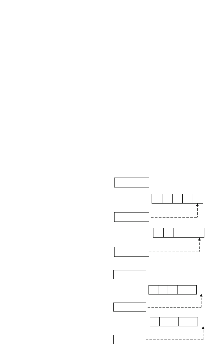
182 9 Strings
But what if name1 and name2 contained James and Jamie, respectively?
.data
name1 byte "James"
name2 byte "Jamie"
Since the repe cmpsb instructions stop after a difference is found, the value of ecx
would be 1, after being decremented four times for the four characters that were compared.
The value of esi and edi would be 104 and 109, respectively, as shown in Fig. 9.6.
At first, it would seem that the final two values of the ecx register would be useful in
determining whether two strings are equal or not. However, what if the difference between
the two strings was only in the last position as in the following?
.data
name1 byte "Marci"
name2 byte "Marcy"
Again, since repe cmpsb stops when a difference is found, the value of ecx would
be 0after being decremented five times, the value of esi would be 105, and edi would
be 10A, as shown in Fig. 9.7.
J sema
name1
=
100
00000001ecx
00000104esi
name2
=
105 Jamie
edi 00000109
Fig. 9.6 Using repe cmpsb
with non-identical strings
M icra
name1
=
100
00000000ecx
00000105esi
name2
=
105 M a r c y
edi 0000010A
Fig. 9.7 Using repe cmpsb
with difference in last
character

9.5 String Instructions: Comparing Strings (cmpsb)183
If the difference between the two strings is in the last position of the strings, then the
results in the registers are no different than if the two strings were identical as in Fig. 9.5.
The simple solution to this problem is to make sure that the strings are at least 1 byte longer
than the data they contain and there is a blank in the last position as in the following:
.data
name1 byte "Marci "
name2 byte "Marcy "
Then the previous code can be used to check whether two strings are equal or not. For
example, if ecx is 0, then it is known that the repe cmpsb made it throughout the entire
string, including the blanks at the end, and that they are equal. However, if ecx is not 0,
then it is known that the two strings were not equal as shown in Fig. 9.8.
So after the repe cmpsb instructions in the code segment above, an .if directive
could be added to test the contents of the ecx register and act accordingly. However, what
if adding extra bytes to the string is not a possibility? What would happen if the difference
occurred in the last element of the string and ecx was a 0? Returning to the previous
example which did not contain the extra spaces,
.data
name1 byte "Marci"
name2 byte "Marcy"
the code would still need to check to see if ecx was 0, but there would need to be an addi-
tional check to determine whether there was a difference between the last two characters.
Since the values of esi and edi would be one beyond the last character as they are in
Fig. 9.7, they would need to be “backed up” or decremented by 1 to determine whether
there was a difference in the last character as illustrated in Fig. 9.9.
Modifying the previous code segment above to include input and output, the following
complete program illustrates how this would work. Should ecx be greater than 0, then
the two strings are different. However, if ecx is equal to zero, then esi and edi would
need to be decremented to determine whether the strings are same. Note that this program
assumes that equal length strings will be input:
M icra
name1
= 100
00000001ecx
00000105esi
name2
= 105 Marcy
edi 0000010A
b
b
Fig. 9.8 Using repe cmpsb
with extra blanks
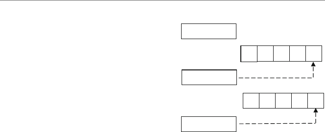
184 9 Strings
M icra
name1
=
100
00000000
ecx
00000104
esi
name2
=
105 M a r c y
edi 00000109
Fig. 9.9 Using repe cmpsb
and backing up one character
.listall
.386
.model flat,c
.stack 100 h
scanf PROTO arg2:Ptr Byte, inputlist:VARARG
printf PROTO arg1:Ptr Byte, printlist:VARARG
.data
msg1fmt byte "%s",0
msg2fmt byte 0Ah,"%s",0Ah,0Ah,0
in1fmt byte "%s",0
msg1 byte "Enter a first name: ",0
msg2 byte "Enter another first name: ",0
msg3 byte "The names are not the same.",0
msg4 byte "The names are the same.",0
name1 byte 6 dup(" ")
name2 byte 6 dup(" ")
.code
main proc
INVOKE printf, ADDR msg1fmt, ADDR msg1
INVOKE scanf, ADDR in1fmt, ADDR name1
INVOKE printf, ADDR msg1fmt, ADDR msg2
INVOKE scanf, ADDR in1fmt, ADDR name2
mov ecx,lengthof name1 ; load ecx with length
lea esi,name1 ; load address of name1
lea edi,name2 ; load address of name2
cld ; clear direction flag
repe cmpsb ; compare while equal
.if ecx > 0 ; check if ecx > 0
INVOKE printf, ADDR msg2fmt, ADDR msg3
.else
dec esi ; back up esi one position
dec edi ; back up edi one position
mov al,[esi] ; load al with [esi}
.if al !=[edi] ; if not equal

9.5 String Instructions: Comparing Strings (cmpsb)185
INVOKE printf, ADDR msg2fmt, ADDR msg3
.else
INVOKE printf, ADDR msg2fmt, ADDR msg4
.endif
.endif
ret
main endp
end
Looking carefully at the declaration of name1 and name2, it should be noted that they
have been declared to be 6 bytes long instead of 5 bytes. Is the reason for adding the extra
byte to make the comparisons easier as discussed previously? The answer is no, because
the data is not a pre-defined string, but rather it is being input via an INVOKE scanf
instruction. When the user keys in a string, the last thing they do is press the Enter or
Return key at the end of the string. The Enter key appears at the end of the string as a
binary zero, not unlike the 0that appears at the end of a string such as msg3 and msg4
in the .data section in the above program. The result is that space needs to be made for
the binary zero, otherwise it could spill over into other memory locations and could cause
various logic errors.
What if one wanted to determine if the content of one string is less than or greater
than another string? For example, what if one wanted to put the names in alphabetical
order? Unfortunately, an instruction does not exist for this, but looking back at the previ-
ous program, there is a hint of a possible solution to the problem. Previously, when ecx
was 0, esi and edi needed to be backed up to determine whether or not the strings
were equal. What would need to happen if ecx was not 0 in the previous case as shown
below?
.data
name1 byte "James"
name2 byte "Jamie"
The repe cmpsb instruction stopped after a difference was found and in this case the
value of ecx was 1after being decremented four times for the four comparisons. However,
to determine whether the character is less than or greater than the other, the values of the
esi and edi registers would again need to be backed up in this case to 103 and 108,
respectively, as shown in Fig. 9.10.
In other words, regardless of whether ecx is 0 or not, esi and edi need to be backed
up. In both cases, the last two characters can be compared to determine whether they are the
same, or whether one is larger or smaller. Using some of the same code from the previous
example, where it is assumed that equal length strings for name1 and name2 have already
been prompted for and input, it can be modified as follows:
;*** assume previous INVOKEs, prompts, and formats
msg3 byte "The names are the same.",0
msg4 byte "The first name is less than the second.",0
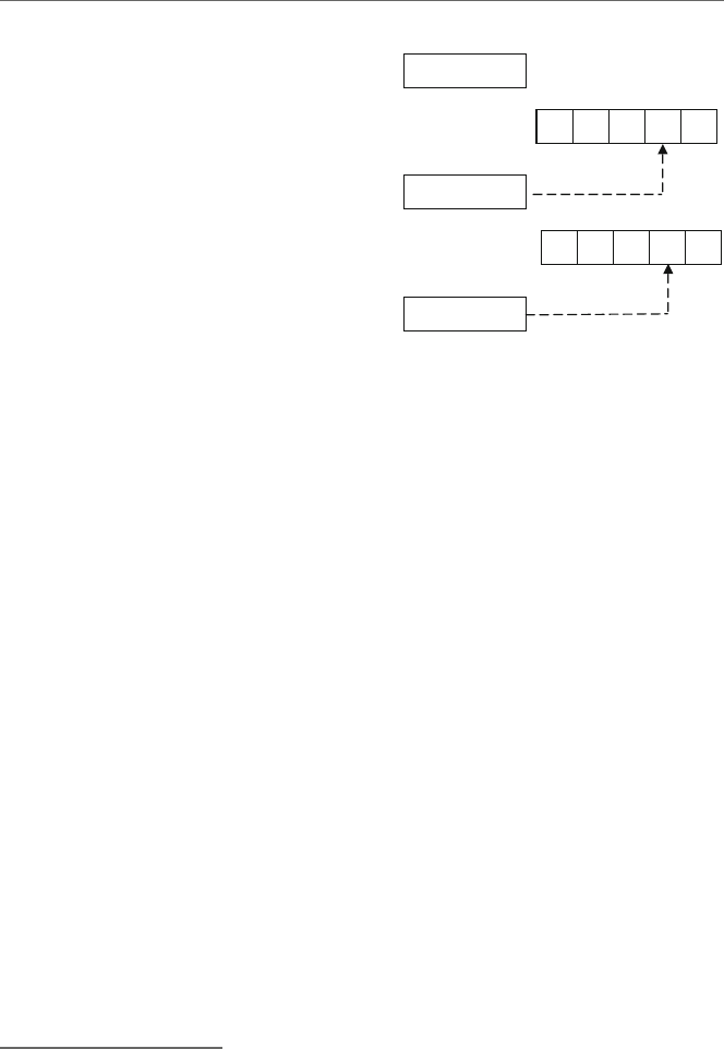
186 9 Strings
J semaname1
=
100
00000001ecx
00000103esi
name2
=
105 J a m i e
edi 00000108
Fig. 9.10 Backing up to
determine name1 is greater
than or less than name2
msg5 byte "The first name is greater than the second.",0
name1 byte 6 dup(" ")
name2 byte 6 dup(" ")
.code
main proc
;*** assume previous prompts and input
mov ecx,lengthof name1 ; load ecx with length
lea esi,name1 ; load address of name1
lea edi,name2 ; load address of name2
cld ; clear direction flag
repe cmpsb ; compare while equal
dec esi ; back up esi one position
dec edi ; back up edi one position
mov al,[esi] ; load al with [esi}
.if al == [edi] ; if equal
INVOKE printf, ADDR msg2fmt, ADDR msg3
.else
.if al < [edi] ; if less than
INVOKE printf, ADDR msg2fmt, ADDR msg4
.else
INVOKE printf, ADDR msg2fmt, ADDR msg5
.endif
.endif
9.6
Complete Program: Searching an Array of Strings
As mentioned previously, although an array of strings can be moved by simply using a
single loop or by using merely a rep movsb instruction, the disadvantage is that the
individual strings cannot be processed. In order to accomplish individual processing of

9.6 Complete Program: Searching an Array of Strings 187
each string in the array, two loops should be employed. To illustrate this, consider the
problem of searching an array of fixed length strings sequentially. As before, an outer loop
is needed to iterate through each string in the array and an inner loop is needed to compare
each character in the string. For this latter task, the repe cmpsb instructions learned in
the previous section is the obvious choice. Note that since ecx is used for the loop control
variable of the outer loop, its value must be pushed prior to the repe cmpsb instruction
and then popped prior to the end of the outer loop:
.listall
.386
.model flat,c
.stack 100 h
scanf PROTO arg2:Ptr Byte, inputlist:VARARG
printf PROTO arg1:Ptr Byte, printlist:VARARG
.data
msg1fmt byte 0Ah,"%s",0
msg2fmt byte 0Ah,"%s",0Ah,0Ah,0
in1fmt byte "%s",0
msg1 byte "Enter the state to be found: ",0
msg2 byte "The state was found.",0
msg3 byte "The state was not found.",0
arrystr byte "Illinois ","Michigan ","Iowa ",
"Missouri ","Arkansas ","Tennessee ",
"Louisiana ","Arizona ","Montana ",
"Ohio "
n sdword 10
string byte 10 dup(?)
found sdword ?
.code
main proc
INVOKE printf, ADDR msg1fmt,ADDR msg1
INVOKE scanf, ADDR in1fmt, ADDR string
mov ecx,0 ; initialize ecx to 0
mov found,0 ; initialize found to 0
lea edi,arrystr+0 ; load edi with address
.while(ecx<n && found !=-1)
push ecx ; save ecx
lea esi,string+0 ; load address of string
cld ; clear direction flag
mov ecx,lengthof string ; load length of string
repe cmpsb ; compare while equal
dec esi ; decrement es1
dec edi ; decrement edi
mov al,[esi] ; load al with [esi]
mov ah,[edi] ; load ah with [edi]

188 9 Strings
.if (al==0)&&(ah==" ") ; compare for 0 and space
mov found,-1 ; if yes, found
.endif
inc edi ; increment edi back
add edi,ecx ; adjust edi to next string
pop ecx ; restore ecx
inc ecx ; increment ecx
.endw
.if (found ==-1)
INVOKE printf, ADDR msg2fmt, ADDR msg2
.else
INVOKE printf, ADDR msg2fmt, ADDR msg3
.endif
ret
main endp
end
Although each string in the array of strings in the above program is of equal length,
each string entered is of variable length. Again these strings are terminated by the pressing
of the Enter key which appears at the end of the string as a binary 0. In the case where the
input string is equal to the fixed length string in the array, repe cmpsb will stop because
the binary 0will not equal the space in the array. For example, "Tennessee",0 will not
be equal to "Tennessee ". So, the esi and edi registers are backed up to check for the
0and the space, and if they are there, the string has been found.
However, in the case that the strings are different, such as "Tennessea",0, the dif-
ference will occur before the binary 0, and thus when backing up the esi register, the
binary 0will not be found. In the case where the string that is input is longer, such as
"Ioway",0 as compared to "Iowa", again the difference would occur before the binary
0is encountered. However, if all these cases are caught by checking for the binary 0,why
check for the space? If the presence of the space was not checked for, then "Iow",0
would end up being equal to "Iowa", which is clearly incorrect.
Also notice that when the string is not found in the array, the value edi will be incor-
rect, so it is necessary to adjust the values to point to the beginning of the next string in
the array. This is accomplished by first incrementing edi back to its original location to
account for the decrement discussed in the previous paragraph. Then, the number of char-
acters left in the string needs to be added, which is the value in the ecx register and it is
added to the edi register.
9.7
Summary
•The movsb instruction moves a string of bytes from where the esi register is pointing
to where the edi register is pointing. The registers are then incremented or decremented
based on the direction flag.

9.8 Exercises 189
•The cmpsb instruction compares a byte in a string pointed to by the esi and edi
registers. The registers are then incremented or decremented based on the direction flag.
•Do not forget to clear the direction flag using cld to increment esi and edi or set
the direction flag using std to decrement esi and edi prior to either the cmpsb or
movsb instructions.
•The rep prefix prior to movsb loops the number of times indicated by the ecx register,
decrements the ecx register by 1, and continues until ecx is 0.
•The repe prefix prior to cmpsb works like the rep prefix in that it will quit looping
when ecx equals 0, but it will also quit looping when the 2 bytes pointed to by esi and
edi are not equal. The repne prefix is like repe but will instead quit looping when
the 2 bytes are equal.
•The scasb instruction will scan a string for the character located in the al register and
the edi register will point 1 byte after the location it is found. The stosb instruction
will store the character in the al register in a string at the location pointed at by the
edi register. And the lodsb instruction will load the character in a string pointed to
by the esi register into the al register.
9.8
Exercises (Items Marked with an ∗Have Solutions in Appendix E)
1. Given the following assembly language statements, indicate whether they are syntacti-
cally correct or incorrect. If incorrect, indicate what is wrong with the statement:
∗A. movesb B. cmpsb ∗C. scasb
D. stosb ∗E. rept strsb F. loadsb
2. Given the following declarations, walk through the following code segments and indi-
cate the contents of the ecx,esi,edi,andal registers upon completion of each
segment. You may assume that string1 starts at memory location 100 and string2
at memory location 105. With problem D, in addition to the registers, what would be
the contents of string2?
string1 byte "abcde"
string2 byte "abcyz"
∗A. mov ecx,5
mov al,"c"
mov edi,offset string1
rep scasb
B. mov esi,offset string1+3
lodsb
∗C. mov ecx,5
mov esi,offset string1

190 9 Strings
mov edi,offset string2
repe cmpsb
D. lea edi,string2
mov al,"d"
stosb
3. Using the esi and edi registers and a .repeat-untilcxz loop, determine
whether the word in a string is a palindrome. For the sake of convenience, assume
that the string is 10 elements long and all the words in the string are also 10 characters
long. Do not use a stack.

Selected Machine Language
Instructions 10
10.1
Introduction
As may have been learned from a computer organization text, there are many considera-
tions that need to be taken into account and many different formats that can be used for
machine language instructions. One of the first considerations is the size of the instruction.
With a larger the instruction, more opcodes can be included, more registers can be refer-
enced, and more memory locations can be addressed. Also, how a particular instruction is
divided up indicates how many of each of the above can be included. For example, assume
a 16-bit word is divided up as follows: bits 15–13 for the opcode, 12–11 for referencing
registers, and 10–0 for addressing memory locations, as shown in Fig. 10.1.
Since there are 3 bits allocated for the opcode, there are 23or 8 possible opcodes. Given
2 bits for the register, there are 22or 4 possible registers, and given 11 bits allocated for
addresses, there are 211 or 2,048 possible addresses for memory locations.
Although there is a very formal procedure and elaborate mechanism for determining the
machine code for Intel machine language, one can discover the format of many instructions
by merely examining the machine code of particular instructions. What is interesting about
this method is that one can examine the machine language of almost any given processor
and see some of the instruction layouts merely by inspection.
10.2
Inc and dec Instructions
By turning on the assembly language listing option using the .listall directive (see
Chapter 7), the .lst file can be generated and the corresponding assembly language can
be seen in the left columns of the listing. The complete program listing used in this chapter
is shown in Section 10.8. Although the program does not do anything relevant in terms
of an algorithm, its sole purpose is to list out selected machine language instructions for
the purpose of comparison. Of course the machine language is given in hexadecimal, but
it can always be converted to binary (see Appendix B) in order to see the corresponding
191
J.T. Streib, Guide to Assembly Language, DOI 10.1007/978-0-85729-271-1_10,
C
Springer-Verlag London Limited 2011

192 10 Selected Machine Language Instructions
Opcode Register Address
0
15 13 1112 10
Fig. 10.1 Hypothetical instruction
bit patterns. Then the bit patterns can be carefully examined to help one understand the
machine language.
For example, in the following section of code taken from the complete listing in Section
10.8, there are listed a number of similar instructions. Again, the code listed does not actu-
ally do anything useful, because the purpose is to understand the corresponding machine
language. In this first example, only the single register inc instructions are shown for the
sake of simplicity, where multiple register instructions, immediate data instructions, and
instructions that address memory locations will be examined later:
Address Machine Assembly Address Machine Assembly
00000000 40 inc eax 00000004 44 inc esp
00000001 41 inc ecx 00000005 45 inc ebp
00000002 42 inc edx 00000006 46 inc esi
00000003 43 inc ebx 00000007 47 inc edi
First note that the above inc instructions are only two hex digits long, or in other words
these are 1-byte instructions, where each byte has its own sequential memory address to
the left. In looking at the above code, it should be noticed that the last hexadecimal digit
changes as the register changes, where the hexadecimal digits 0,1,2,3,4,5,6,and7
correspond to the registers eax,ecx,edx,ebx,esp,ebp,esi,andedi, respectively.
The equivalent numbers in binary would be 0000,0001,0010,0011,0100,0101,
0110,and0111, respectively. Note as discussed above, it took three binary digits (the
three low-order bits of the second hex digit) to represent the eight registers, leaving five
binary digits (four from the first hex digit and the one high-order bit from the second
hex digit) to represent the opcode for inc as 01000. The format for inc 32-register
instruction is as in Fig. 10.2.
Expanding on the above, the following is a listing of the dec reg instruction:
Address Machine Assembly Address Machine Assembly
00000008 48 dec eax 0000000C 4C dec esp
00000009 49 dec ecx 0000000D 4D dec ebp
0000000A 4A dec edx 0000000E 4E dec esi
0000000B 4B dec ebx 0000000F 4F dec edi

10.2 Inc and dec Instructions 193
01000XXX
inc reg ,where XXX is the register.
Fig. 10.2 Format for the inc instruction
Again, it should be noticed that each instruction is only 1 byte long as before. Yes, there
is a hex 4in the first four bits, but the second hex digit is not as obvious as the previous
example. However, looking at the binary for these instructions, it becomes much more
obvious:
Hex Binary Assembly Hex Binary Assembly
48 01001000 dec eax 4C 01001100 dec esp
49 01001001 dec ecx 4D 01001101 dec ebp
4A 01001010 dec edx 4E 01001110 dec esi
4B 01001011 dec ebx 4F 01001111 dec edi
In examining the binary carefully, it should be noticed that the same bit pattern appears
again in the right three bit positions representing the registers eax through edi. The only
difference is that bit position 3 (fourth from the left) is a 1instead of a 0. The result is
that the only difference between the inc and dec instructions is this one bit, where a 0
tells the processor to increment the specified register by 1, whereas a 1tells the processor
to decrement the specified register by 1. The machine code for the dec 32-bit register
instruction is as in Fig. 10.3.
Machine code Register
000 eax
001 ecx
010 edx
011 ebx
100 esp
101 ebp
110 esi
111 edi
For convenience, a summary of the machine code representation of the registers can be
found below, where the first column shows the machine code and the second column shows
the corresponding register:
01001XXXdec reg ,where XXX is the register.
Fig. 10.3 Format for the dec instruction

194 10 Selected Machine Language Instructions
10.3
Mov Instruction
Before looking at how memory is addressed, it is helpful to first examine the mov instruc-
tions that are used with registers to notice some similarities and differences between them
and the inc reg and dec reg instructions. First, the mov reg,reg instructions will
be examined, but instead of listing out all possible register combinations, only some of the
possibilities are shown in the interest of saving space. Besides, the patterns should become
obvious by examining only a select few of these instructions:
Address Machine Assembly
00000010 8B C0 mov eax,eax
00000012 8B C1 mov eax,ecx
00000014 8B C2 mov eax,edx
00000016 8B C3 mov eax,ebx
00000018 8B C4 mov eax,esp
0000001A 8B C5 mov eax,ebp
0000001C 8B C6 mov eax,esi
0000002E 8B C7 mov ebx,edi
00000020 8B C8 mov ebx,eax
00000022 8B C9 mov ebx,ecx
00000024 8B CA mov ebx,edx
00000026 8B CB mov ebx,ebx
The first thing to notice is that the address of each instruction is incremented by 2 each
time and that the machine language is now 4 hex digits long, which is 16 bits or 2 bytes
long. The first byte in all the instructions is an 8B which one can probably assume is part
of the opcode of the instruction indicating a register-to-register mov instruction. Although
there appears to be somewhat of a pattern in the second byte of the first three instructions, it
probably would not hurt to convert these to binary to see the pattern in all of the instructions
more clearly as in Table 10.1.
The suspicions of the first set of instructions appear to be correct, where eax through
edi are 000 through 111, respectively, just like the inc and dec instructions previously.
Then looking at the last four instructions, the same pattern appears to begin again with eax
through ebx with 000 through 011, respectively.
In examining bits 3 through 5 (the 4th through 6th bits from the right), it can be noticed
that for the first set of instructions, the bits are set at 000 and for the second set they are
set at 001, which happens to correspond to the first registers in the operand, eax and ecx,
respectively. So part of the reason why this mov reg,reg instruction is larger than the
inc reg instruction is that it needs to have room to reference two registers instead of
one. The result is that one should be able to surmise that the mov between two registers
has the format shown in Fig. 10.4.

10.3 Mov Instruction 195
Table 10.1 Binary of second byte of the mov reg, reg instruction
Hex Binary (2nd byte) Assembly
8B C0 11000000 mov eax,eax
8B C1 11000001 mov eax,ecx
8B C2 11000010 mov eax,edx
8B C3 11000011 mov eax,ebx
8B C4 11000100 mov eax,esp
8B C5 11000101 mov eax,ebp
8B C6 11000110 mov eax,esi
8B C7 11000111 mov eax,edi
8B C8 11001000 mov ebx,eax
8B C9 11001001 mov ebx,ecx
8B CA 11001010 mov ebx,edx
8B CB 11001011 mov ebx,ebx
mov reg,reg
w
here XXX is the destination register
and YYY is the source register
10001011 11XXXYYY
Fig. 10.4 Format for the mov
reg,reg instruction
Having looked at a few of the single and double register instructions, what does an
instruction with immediate data look like? Staying with the mov instruction is a convenient
next step:
Address Machine Assembly
00000028 B8 00000001 mov eax,1
0000002D B9 0000000A mov ecx,10
00000032 BA FFFFFFFF mov edx,-1
00000037 BB FFFFFFF6 mov ebx,-10
Note that the addresses of each instruction is incremented by 5 and that each instruction
is 10 hexadecimal digits long, equating to 40 bits, indicating that each instruction is 5 bytes
long. It should be noticed that the last four bytes of each instruction is the hexadecimal
equivalent of the immediate data in the instruction, where it should be remembered that
negative numbers are represented in two’s complement notation (see Appendix B). Again
it helps to convert the first byte to binary to determine the machine code as follows:
Hex Binary Register
B8 10111000 eax
B9 10111001 ecx
BA 10111010 edx
BB 10111011 ebx

196 10 Selected Machine Language Instructions
m
ov reg,imm
where XXX is the register and YYY is the immediate data
10111XXX YYYYYYYY YYYYYYYY YYYYYYYY YYYYYYYY
Fig. 10.5 Format for the mov reg,imm instruction
As before, the last three binary digits 000,001,010,011 are the same digits as in
previous instructions representing the eax,ecx,edx,andebx registers, respectively. The
format then is as illustrated in Fig. 10.5.
As can be seen, the immediate data instructions are fairly straightforward, so how would
memory addresses be represented in an instruction? Just as the first instruction in the
.code segment starts at relative address or relative memory location 00000000,the
first memory location declared in the .data segment will also start at relative memory
location 00000000 as shown below:
Address Machine Assembly language
.data
00000000 00000003 num1 sdword 3
00000004 00000005 num2 sdword 5
00000008 00000000 num3 sdword ?
A relative memory location is relative to the beginning of either the .data or the
.code segment, because at the time of assembly it is not known where in memory the
segments will be loaded. When the machine language is subsequently loaded into mem-
ory, the relative addresses are eventually changed into the absolute addresses or absolute
memory locations within RAM, where the first memory location in RAM is absolute
memory location 00000000. Using the memory locations declared above, consider the
following mov instructions that use the eax register and address memory locations num1
and num2:
Address Machine Assembly
0000003C A1 00000004 mov eax,num2
00000041 A3 00000008 mov num3,eax
As with immediate data, note that these two instructions are both 5 bytes long. Unlike
the immediate instructions, where the data in the rightmost four bytes was the actual
number contained in the instruction, here it should be noticed that address of the mem-
ory locations num2 and num3 appears in the right four bytes. In other words, instead
of the numbers 00000005 or 00000000 appearing in the instruction, the addresses
of the memory location num2 and num3,00000004 and 00000008, appear in the
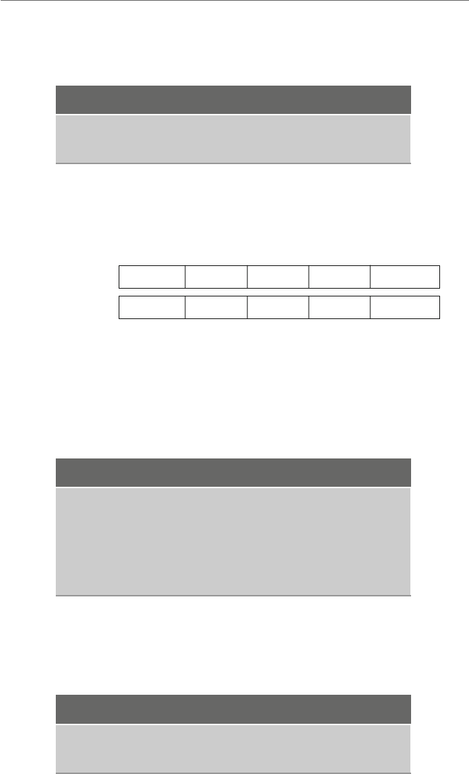
10.3 Mov Instruction 197
instructions, respectively. In converting the first byte to binary, notice that there is only
one bit difference between the instructions:
Hex Binary Assembly
A1 10100001 mov eax,mem
A3 10100011 mov mem,eax
When moving from memory to the eax register, bit 1 (second from the right) is set
to 0, and when moving from the eax register to memory, note that bit 1 is set to 1.The
format of these instructions is as shown in Fig. 10.6.
m
ov eax,mem
where the eax register is implied and YYY is the address
m
ov mem,eax
10100001
10100011
YYYYYYYYYYYYYYYY YYYYYYYY YYYYYYYY
YYYYYYYYYYYYYYYY YYYYYYYY YYYYYYYY
Fig. 10.6 Format for the mov eax,mem and mov mem,eax instructions
But what about moving to and from memory into the other registers? Consider the
following instructions using the other three general purposes registers:
Address Machine Assembly
00000046 8B 0D 00000004 mov ecx,number
0000004C 8B 15 00000004 mov edx,number
00000052 8B 1D 00000004 mov ebx,number
00000058 89 0D 00000008 mov number,ecx
0000005E 89 15 00000008 mov number,edx
00000064 89 1D 00000008 mov number,ebx
The address part of the instruction in the rightmost four bytes looks okay. Also the
mov reg,mem instructions all have an 8B in the first byte and all the mov mem,reg
instructions have an 89 in the first byte. Again looking at the binary:
Hex Binary Assembly
8B 10001011 mov reg,mem
89 10001001 mov mem,reg

198 10 Selected Machine Language Instructions
Note that some of the leftmost five bits are different from the eax instructions in
Fig. 10.6, where instead bit 3 (fourth from the right) is a 1instead of a 0and bit 5
(sixth from the right) is a 0instead of a 1. However, there is a similarity to the mov
eax,mem and mov mem,eax instructions, where bit 1 (second from the right) is a 0
when transferring from memory to a register and a 1when transferring from a register to
memory.
The most noticeable difference is that these instructions are 1 byte longer than their
eax counterparts, 6 bytes instead of 5. Recall from Chapter 1 when discussing reg-
isters, it was said that the eax instruction is usually the preferred register, because it
tends to be shorter. Further, in many of the code examples in this text, the eax register
tends to be used more often than any other register. As can be seen in the code segment
above, the use of the other registers is indeed a little less efficient in terms of memory
utilization.
The first byte above is indeed the opcode, but look carefully at the binary of the second
byte below. Clearly the first two bits on the left are the same. Also, the last three bits are the
same and do not contain the register bits as they have in the past. However, in examining
the middle bits, specifically bits 3 through 5 (fourth through sixth from the right), they
are different with each instruction. As with previous instructions, 001,010,and011
correspond to the registers ecx,edx,andebx, respectively:
Hex Binary Register
0D 00 001 101 ecx
15 00 010 101 edx
1D 00 011 101 ebx
Since this instruction format is a little more complicated than all the other ones exam-
ined thus far, in order to analyze the bits of this second byte, it is helpful to break it down
and look at the machine language format of this byte. Although there are many possible bit
combinations, this text only looks at a few of them. The basic format of this byte is shown
in Fig. 10.7.
As seen previously, the bits in the middle (bit positions 3 through 5) indicate the regis-
ter and is abbreviated as reg. The two bits on the left (bit positions 6 and 7) indicate the
mode of the instruction and is abbreviated as mod. The three bits on the right (bit positions
0 through 2) indicate the register and mode, abbreviated as r/m. With a 00 in the mod
field and a 101 in the r/m field, this means that it is displacement only addressing mode
or in other words direct addressing mode. Again, the meaning of the contents of this byte
can be very complicated and will vary with other instructions that use different address-
ing schemes, but only a few of the simpler instructions are discussed here to serve as an
introduction.
76543210
mod reg r/m
Fig. 10.7 Format of mod reg
r/m

10.4 Add and sub Instructions 199
10.4
Add and sub Instructions
Having looked at some of the inc,dec,andmov instructions, what about some of the
arithmetic instructions? Instead of looking at all the registers as done in previous exam-
ples, only a few select registers will be examined, since the bit patterns of the registers
have already been established. Consider the following register-to-register add and sub
instructions:
Address Machine Assembly Binary equivalent
0000006A 03C0 add eax,eax 00000011 11 000 000
0000006C 03C1 add eax,ecx 00000011 11 000 001
0000006E 03C2 add eax,edx 00000011 11 000 010
00000070 03C3 add eax,ebx 00000011 11 000 011
00000072 2BC8 sub eax,eax 00101011 11 001 000
00000074 2BC9 sub eax,ecx 00101011 11 001 001
00000076 2BCA sub eax,edx 00101011 11 001 010
00000078 3BCB sub eax,ebx 00101011 11 001 011
Note that instead of separating the binary equivalent of the opcodes on separate lines, it
is now included off to the right for convenience. The first thing to notice is that the opcode
for the add instruction and sub instruction differs by only 2 bits, where bit position 3 and
5 of the first byte (fourth and sixth from the right) are each a 1instead of a 0for the subtract
instruction. Also notice that the rightmost six bits of the second byte appear to represent
the registers, just like the register-to-register mov instruction earlier. However, given the
previous information on mod,reg,andr/m sections in the mov instruction above, it sheds
some further light on the format of this and the previous mov reg,reg instruction. The
reg section is indeed the first register that appears in the operand. However, the 11 in the
leftmost two bits of the second byte is actually part of the mod section and indicates that
the r/m section holds the code for the second register in the operand. This is true for all
three of the reg,reg instructions examined in this chapter: the mov reg,reg,add
reg,reg,andsub reg,reg instructions.
Given the reg mod r/m byte, there can be up to 256 bit combinations which allow
for a large number of addressing modes. This is one of the reasons the Intel processor is
known as a complex instruction set computer (CISC) as opposed to a computer with fewer
instructions and addressing modes known as a reduced instruction set computer (RISC).
Looking at add and sub instructions referencing memory locations below,
what similarities and differences can found between them and various previous
instructions?
First, one should notice that the first byte is the same as the previous add and
sub register-to-register instructions. Next, the last four bytes (32 bits) are the relative
addresses of the memory location num2, just like the previous mov reg,mem instruc-
tions. Lastly, the mod reg r/m byte is different than the add reg,reg and sub

200 10 Selected Machine Language Instructions
Address Machine Assembly Binary equivalent
0000007A 03 05 00000004 add eax,num2 00000011 00 000 101
00000080 03 0D 00000004 add ecx,num2 00000011 00 001 101
00000086 03 15 00000004 add edx,num2 00000011 00 010 101
0000008C 03 1D 00000004 add ebx,num2 00000011 00 011 101
00000092 2B 05 00000004 sub eax,num2 00101011 00 000 101
00000098 2B 0D 00000004 sub ecx,num2 00101011 00 001 101
0000009E 2B 15 00000004 sub edx,num2 00101011 00 010 101
000000A4 2B 1D 00000004 sub ebx,num2 00101011 00 011 101
reg,reg instructions, but they are the same as the previous mov reg,mem instructions
because they are addressing memory in the same fashion.
10.5
Mov offset and lea Instructions
Having looked at the moving of the contents of a memory location to a register, what is
the difference between that type of instruction and a lea instruction or mov offset
instruction. First consider the following mov and lea instructions:
Address Machine Assembly Binary equivalent
000000AA 8B 35 00000004 mov esi,num2 10001011 00 110 101
000000B0 8B 3D 00000004 mov edi,num2 10001011 00 111 101
000000B6 8D 35 00000004 lea esi,num2 10001101 00 110 101
000000BC 8D 3D 00000004 lea edi,num2 10001101 00 111 101
The first two instructions are the same as previous mov instructions, where in this case
they use the esi and edi registers and the middle bits of the mod reg r/m byte are 110
and 111, respectively. The two lea instructions have the same format in the second byte
as the mov instructions. The only difference is in the first byte, where bit positions 1 and
2 (second and third from the right) are opposite of each other. As before, the result is that
when the processor encounters the mov instructions, the “contents” of memory location
num2 are loaded into the specified register and with the lea instructions the “address” of
memory location num2 is loaded into the specified register. In this instance in the former
case, a 5is loaded and in the latter case a 4is loaded.
Remember from Chapter 8 that the mov offset and lea instructions effectively
perform the same task, where they both load the address of the memory location into the
specified register. The only difference is that the mov offset instruction is static and the
lea instruction is dynamic, where in the former the address is determined at assembly

10.5 Mov offset and lea Instructions 201
time, and in the latter the address can be indexed by a register and is determined at run-
time. In looking at the machine language for the mov offset instruction below, the
address is in the last four bytes of the instruction as with many other instructions before.
Further, its machine language equivalent is 1 byte shorter than its lea counterpart, where
instead of the esi and edi registers being included in a mod reg r/m byte, they are
in the rightmost three bits (bit positions 0 though 2) of the opcode byte as 110 and 111,
respectively:
Address Machine Assembly Binary equivalent
000000C2 BE 00000004 mov esi,offset num2 10111 110
000000C7 BF 00000004 mov edi,offset num2 10111 111
The significant difference, as discussed in Chapter 8, is that instead of the “contents”
of the memory location being moved to the register, the “address” of the memory location
is moved to the register. Although probably not readily apparent, the machine language
for the opcode of the mov offset instruction should be familiar. In fact it is the
same, 10111,asthemov reg,imm instruction discussed in Section 10.3. Compare the
following instructions with the instructions above:
Address Machine Assembly Binary equivalent
000000CC BE 00000004 mov esi,4 10111 110
000000D1 BF 00000004 mov edi,4 10111 111
Note that the machine language of the mov reg,imm instructions looks the same as
that of the mov reg,offset mem instructions. Does this mean that one should use the
immediate instructions to try to load the address of a memory location? The answer is
no, because if the contents of the register in both cases were to be output, there would be a
difference between the two. Recall from Section 10.3 the discussion of relative and absolute
addresses. Although the value in the immediate case is 4, the value in the offset case is not
the relative address of num2 which is 4, but rather the absolute address of the memory
location num2 which can vary depending on where the program is loaded in memory.
For example, when running a test program on one computer, the value in the register was
00404008 (in hex) and when running the same program on another computer, the value
in the register was 010F4008 (in hex).
Even if one could use the correct address of a particular variable, is this method of
addressing memory a good idea? As might be suspected, the answer is no, because the
location of the variable could change and cause potential logic or execution errors. Using
immediate values to access memory instead of variable names or pointers essentially
reduces an assembly language instruction back to that of a machine language instruction,
thus eliminating the purpose of using an assembler in the first place.

202 10 Selected Machine Language Instructions
10.6
Jmp Instructions
As discussed in Chapter 4,thejmp instruction is known as an unconditional jump because
it jumps regardless of the setting of the eflags register. Although the code is somewhat
nonsensical, the machine language of the jmp instruction can be found in the following
sample code segment:
Address Machine
Assembly language
instruction
000000D6 EB 04 jmp around
000000D8 90 above: nop
000000D9 90 nop
000000DA EB FC jmp above
000000DC 90 around: nop
The opcode for the jmp instruction is EB, but what is interesting to note is that
the machine code for the jmp around instruction does not contain the address of the
around: nop instruction. Why is this and is it referring to memory location 04?The
answer to the latter part of this question is no, because the jmp instruction is referring to
a location that is relative to itself. However, if a 04 is added to the address of the memory
location where the jmp around instruction is located, 000000D6, the new address is
000000DA. But looking at the above code segment, 000000DA is the address of the jmp
above instruction and not the around: nop instruction. If the 04 is the address relative
to jmp around instruction, why does the number seem incorrect? The answer is that the
number is not incorrect because the number is relative to where the instruction pointer is
pointing.
To those who have had or are currently taking a computer organization course, the
following explanation should be somewhat familiar. As a program executes, the instruction
pointer or instruction counter in the CPU points to the instruction that it is about to fetch
and subsequently execute. After an instruction is fetched, the instruction pointer is then
incremented to point to the next instruction that follows the current instruction. Then when
the current instruction is decoded and executed, the instruction pointer is no longer pointing
at the current instruction but rather to the next instruction in anticipation of fetching it. In
the above case, the instruction pointer is not pointing to memory location 000000D6,but
rather 000000D8, so that when 04 is added to 000000D8, the answer is 000000DC
which is the address of the correct instruction. The value 000000DC is then placed into
the instruction pointer so that when the next instruction is fetched, it is not to the above:
nop instruction but rather the around: nop instruction.
However, what about the jmp above instruction? Shouldn’t it be a jump backward
and not a jump forward? The answer is yes, where the FC is not a positive number but
rather a negative number (11111100 in binary) and it is in two’s complement form. Using
the techniques learned in Appendix B,11111100 in binary is equal to –4in decimal.

10.7 Instruction Timings 203
Remembering that the instruction pointer is not pointing to the current instruction, jmp
above, but rather the instruction after it at memory location 000000DC, subtracting a
04 results in the address 000000D8, which is the correct location and instruction.
Notice that only 1 byte is used to store the relative offset address and this allows for
jumps of only +127 bytes or –128 bytes away. On older 16-bit machines, this sometimes
posed a problem and on occasion a code segment needed to be rewritten to accommodate
jumps in excess of the above limitations. Fortunately, with the newer 32-bit processors, this
does not pose a problem because should the unconditional jump be more than the above
limits, a 32-bit relative offset is generated.
10.7
Instruction Timings
As has been mentioned at various points throughout this text, some instructions are faster
than others. It has been implied that the faster instructions should be used over their slower
counterparts when necessary, and also when it does not interfere with the readability and
maintainability of the program. Why is it that some instructions are faster than others?
The reasons for this can have to do with many different factors including the size of the
instruction, whether the instruction references registers as opposed to memory locations,
the complexity of the operation, and how the processor is designed. When a processor is
said to be rated at a speed 2.0 GHz, that means that the processor can execute at two billion
cycles per second, where different instructions take different number of cycles to execute.
For the discussion that follows, the instruction timings are based on a Pentium processor.
Generally, instructions that do not reference memory tend to be faster than instructions
that do reference memory. For example, an inc eax instruction takes only one clock
cycle of the CPUs time, whereas an inc instruction that references memory such as inc
number takes three clock cycles (see Appendix D). The reason why registers are faster is
that registers are internal to the CPU, whereas memory is external to the CPU and it takes
time for data to be transferred from RAM to the CPU or from the CPU to RAM.
Does this mean that memory should be avoided? No, because there are only four general
purpose registers in the Intel processor and it would be impractical to restrict a program
to only four registers. What it does mean is that when in a critical section of the program
where speed is important, a value might be left in a register in lieu of returning the value
back to memory so that readability is sacrificed for efficiency.
In looking at a few other instructions, take the imul instruction for example. To multi-
ply the contents of eax by the contents of another register such as the ecx register would
take 10 clock cycles. Similarly, the idiv ecx instruction takes 46 clock cycles. However,
if in each case the contents of the ecx register are a power of 2, an arithmetic shift instruc-
tion could be used instead. For example, if the contents of the ecx register in an imul
ecx instruction were a 4,thenasal eax,2 instruction could be used instead, which
would take only three clock cycles which is over three times faster. Likewise, if the con-
tents of ecx in an idiv ecx instruction were a 32, a sar eax,5 instruction could be
used which also takes only three cycles and would be 15 times faster. This is the reason

204 10 Selected Machine Language Instructions
why some programmers will use arithmetic shift instructions instead of multiplication and
division instructions. Does this mean that arithmetic shifts should always be used over their
arithmetic counterparts? No, not necessarily. If the code appears in a non-critical section
of a program that is executed only once, then the increase in speed may not be worth the
decrease in readability. However, if the arithmetic operation occurs in a time-sensitive sec-
tion of a program, then the increase in execution far outweighs any loss of readability or
maintainability.
10.8
Complete Program: Machine Language Listing
.listall
.386
.model flat,c
.stack 100 h
00000000 .data
00000000 00000003 num1 sdword 3
00000004 00000005 num2 sdword 5
00000008 00000000 num3 sdword ?
00000000 .code
00000000 main proc
00000000 40 inc eax
00000001 41 inc ecx
00000002 42 inc edx
00000003 43 inc ebx
00000004 44 inc esp
00000005 45 inc ebp
00000006 46 inc esi
00000007 47 inc edi
00000008 48 dec eax
00000009 49 dec ecx
0000000A 4A dec edx
0000000B 4B dec ebx
0000000C 4C dec esp
0000000D 4D dec ebp
0000000E 4E dec esi
0000000F 4F dec edi

10.8 Complete Program: Machine Language Listing 205
00000010 8B C0 mov eax,eax
00000012 8B C1 mov eax,ecx
00000014 8B C2 mov eax,edx
00000016 8B C3 mov eax,ebx
00000018 8B C4 mov eax,esp
0000001A 8B C5 mov eax,ebp
0000001C 8B C6 mov eax,esi
0000001E 8B C7 mov eax,edi
00000020 8B C8 mov ecx,eax
00000022 8B C9 mov ecx,ecx
00000024 8B CA mov ecx,edx
00000026 8B CB mov ecx,ebx
00000028 B8 00000001 mov eax,1
0000002D B9 0000000A mov ecx,10
00000032 BA FFFFFFFF mov edx,-1
00000037 BB FFFFFFF6 mov ebx,-10
0000003C A1 00000004 R mov eax,num2
00000041 A3 00000008 R mov num3,eax
00000046 8B 0D 00000004 R mov ecx,num2
0000004C 8B 15 00000004 R mov edx,num2
00000052 8B 1D 00000004 R mov ebx,num2
00000058 89 0D 00000008 R mov num3,ecx
0000005E 89 15 00000008 R mov num3,edx
00000064 89 1D 00000008 R mov num3,ebx
0000006A 03 C0 add eax,eax
0000006C 03 C1 add eax,ecx
0000006E 03 C2 add eax,edx
00000070 03 C3 add eax,ebx
00000072 2B C8 sub ecx,eax
00000074 2B C9 sub ecx,ecx
00000076 2B CA sub ecx,edx
00000078 2B CB sub ecx,ebx
0000007A 03 05 00000004 R add eax,num2
00000080 03 0D 00000004 R add ecx,num2
00000086 03 15 00000004 R add edx,num2
0000008C 03 1D 00000004 R add ebx,num2
00000092 2B 05 00000004 R sub eax,num2
00000098 2B 0D 00000004 R sub ecx,num2
0000009E 2B 15 00000004 R sub edx,num2
000000A4 2B 1D 00000004 R sub ebx,num2

206 10 Selected Machine Language Instructions
000000AA 8B 35 00000004 R mov esi,num2
000000B0 8B 3D 00000004 R mov edi,num2
000000B6 8D 35 00000004 R lea esi, num2
000000BC 8D 3D 00000004 R lea edi, num2
000000C2 BE 00000004 R mov esi, offset num2
000000C7 BF 00000004 R mov edi, offset num2
000000CC BE 00000004 mov esi,4
000000D1 BF 00000004 mov edi,4
000000D6 EB 04 jmp around
000000D8 90 above: nop
000000D9 90 nop
000000DA EB FC jmp above
000000DC 90 around: nop
000000DD C3 ret
000000DE main endp
end
10.9
Summary
•The number of bits allocated for an instruction and how that instruction is divided up
indicates the number of opcodes, the number of register references, and the number of
memory locations that can be addressed.
•Much can be learned about the machine language of many assembly languages by mere
inspection.
•Sometimes the difference between two operations can be the difference of the setting of
only one bit.
•Some instructions such as mov eax,mem take up less memory than do mov
reg,mem instructions.
•The Intel processor is known as a complex instruction set computer (CISC) as opposed
to a reduced instruction set computer (RISC), due to the number of instructions and
addressing modes.
•When dealing with powers of 2, using arithmetic shift instructions can be significantly
faster than using imul and idiv instructions.
•Just because an instruction is faster does not mean that it needs to be used all the time.
The decision must be based on the necessity for execution speed versus readability and
maintainability.

10.10 Exercises 207
10.10
Exercises (Items Marked with an ∗Have Solutions in Appendix E)
∗1. If there is an 8-bit instruction, where 2 bits are reserved for the opcodes and 0 bits for
the registers, how many opcodes and registers are there, and how much memory can
be addressed?
2. If there is a 16-bit instruction, where 4 bits are reserved for the opcodes and 1 bit for
the registers, how many opcodes and registers are there, and how much memory can
be addressed?
∗3. If there is a 16-bit instruction, where 5 bits are reserved for the opcodes and 2 bits for
the registers, how many opcodes and registers are there, and how much memory can
be addressed?
4. If there is a 32-bit instruction, where 8 bits are reserved for the opcode and 4 bits for
the registers, how many opcodes and registers are there, and how much memory can
be addressed?
5. Convert the following assembly language instructions to their machine language
equivalents. List the answers in both hex and binary:
∗A. add ecx,ebx B. sub ecx,edx C. add esi,edi
6. Write an assembly language program and generate the .lst file to determine the
machine language format of the following 1-byte instructions. Write out the answers
in both hex and binary:
∗A. nop B. cld C. ret D. std
7. Write an assembly language program and generate the .lst file to determine the
machine language format of the following 2-byte instructions. Write out the answers
in both hex and binary:
∗A. and eax,ebx
B. or ebx,ecx
C. xor eax,eax
D. test ecx,edx

Appendix A
Installation of Visual C++ and MASM
If your college, university, or company already has Visual C++ and MASM installed, then
their procedures should be consulted and the information contained in this appendix can
be ignored. However, if one needs to download Visual C++ and MASM on their own
personal computer, the following will be useful. Although 2008 or the 2010 Visual C++
Express Edition can be used to run inline assembly language programs as demonstrated
in Chapter 1, at the time of this writing only the 2008 version seems to run stand-alone
assembly language programs and it is needed in all subsequent chapters of this text. As a
result, what follows are the directions on how to install Microsoft Visual C++ 2008 Express
Edition with SP1, where SP1 is the Visual Studio 2008 Service Pack 1 that contains
MASM 9.0.
A.1
Directions for Installing Visual C++ and MASM
1. The software used in this text is Microsoft Visual C++ 2008 Express Edition with SP1,
which can be downloaded from www.microsoft.com/express/Downloads
2. At the Downloads page, click the Visual Studio 2008 Express tab which is the last of
the three tabs, then click the Visual C++ 2008 Express Edition link, and then click the
Free Download button.
3. Note that during setup it may be necessary to click on the Visual Studio 2008 Service
Pack 1 link, and then click on the Download button. If not, proceed to step 4. As always,
be sure to examine the license terms. After the service pack has been downloaded,
return back to the Visual C++ 2008 Express Edition setup. If it does not continue with
the setup, it might be necessary to repeat steps 1 and 2 above prior to proceeding onto
step4below.
4. As always, be sure to examine the license terms and note that the optional products are
not required prior to continuing with the installation.
5. After the software is downloaded, there will be a message reminding one to register the
evaluation copy within 30 days, where once one has entered the registration key, the
product is free. To register, select Register Product under the Help menu of the Express
Edition software itself.
209
J.T. Streib, Guide to Assembly Language, DOI 10.1007/978-0-85729-271-1,
C
Springer-Verlag London Limited 2011

210 Appendix A
A.2
Writing C Programs and Inline Assembly
As indicated in Chapter 1, if you are already familiar with Visual C++ and C/C++ pro-
gramming, a simple way to explore MASM is to first write C/C++ code and then use inline
assembly. Again, the inline assembly works fine in both the 2008 and 2010 versions of
Visual C++ Express Edition, but at the time of this writing, only the 2008 version seems to
work with stand-alone assembly. Since stand-alone assembly will be used in Chapter 2 and
all subsequent chapters, the directions that follow will only describe entering and running
programs in Visual C++ 2008 Express Edition.
After installing Visual C++, invoke Visual C++ by clicking on the appropriate icon
or choosing it from the list of programs. Once started, then select from the pull-down
menus: file, new,andthenproject. Then from the Project types section on the left, expand
the Visual C++ entry and click on Win32.IntheTemplates section under Visual Studio
Installed Templates, select Win32 Console Application.Nextinthename: section at the
bottom of the window, type in a name for the project and click the OK button. From the
window that says Welcome to the Win32 Application Wizard, click the Next button. Then
on the next page concerning Application Settings, make sure that in the Application Type:
section, Console Application is selected and under the Additional Options: section, check
Empty project and then click the Finish button.
Back at the start page in the Solution Explorer window, which is on either the right or
the left side, right click Source Files, click Add,andthenNew Item. Then in the Visual
Studio installed templates, click on C++ file.ThenintheName: section, type the name of
the file to hold the program and click the Add button. Prior to trying to run inline assembly,
it is best to first insure that a simple C program works properly. Key in the following the
program which merely assigns the number 5to the variable num1, copies the contents of
num1 to num2, and then outputs the contents of num2:
#include <stdio.h>
int main(){
int num1,num2;
num1 =5;
num2 =num1;
printf("%s%d\n","The answer is: ",num2);
return 0;
}
One might notice that the above program uses the C printf for output instead of the
C++ cout for output. The reason for this is that it is fairly easy to use C input/output in
stand-alone assembly language as will be seen in Chapter 2. It is of course wise to be sure
to save the project to insure that the code is saved. To compile and run the program, click
Build from the pull-down menu and select Build Solution. In order to run the program,
click Debug from the pull-down menu and select Start Without Debugging or optionally
one can press Ctrl-F5. Unfortunately the pull-down selection does not seem to have made
it to Visual C++ 2010 Edition, but the Ctrl-F5 option did.

Appendix A 211
In order to demonstrate the transfer of num1 to num2 in assembly language, the follow-
ing code segment implements the same thing as the above code segment but instead uses
inline assembly. This is accomplished by including the word __asm (which it should be
noticed is preceded by a double underscore, not a single underscore). Then all the assem-
bly codes are bracketed by opening and closing braces as shown below. To demonstrate
how inline assembly works, alter the above code segment to replace the num2=num1;
line of code with the inline assembly code below. Then run the program as explained
previously:
#include <stdio.h>
int main(){
int num1,num2;
num1 =5;
__asm {
mov eax,num1
mov num2,eax
}
printf("%s%d\n","The answer is: ",num2);
return 0;
}
The advantage of using inline assembly code is that it is very easy to use and one
can take advantage of high-level input and output. The major disadvantage is that one
cannot use high-level structures utilizing .if and .while directives in assembly lan-
guage. Instead, one must use compare and jump statements as discussed in Chapters 4
and 5.
A.3
Writing Stand-alone MASM Programs
As stated previously, at the time of this writing, the following seems to work only with
Visual C++ 2008. If one wants to write a stand-alone MASM program, then one needs
to make some careful changes to the properties section of the project and later the .asm
file. Everything is done as outlined in the previous section, except after one creates a new
project and is ready to create a source file, one must be certain to add a .asm extension to
the source file name. This will cause the MASM assembler to be invoked instead of the
C++ compiler. In other words, when back at the start page and in the Solution Explorer
window, which is on either the right or the left side, right click Source Files, click Add,and
then New Item.ThenintheVisual Studio installed templates,clickonC++ file.Thenin
the Name: section, type the name of the file to hold the program with a .asm extension and
click the Add button.
Although the following is a little cumbersome, once it is typed in the first time, it can
easily be copied and pasted in other projects. In the Solutions Explorer section on the right
or the left part of the screen, right click the name of the project, which is usually bolded,

212 Appendix A
and select Properties. Then in the window on the left, expand Configuration Properties,
then expand Linker, and then click on Input.IntheAdditional Dependencies area on the
right, key in the following:
msvcrt.lib
Then again in the Solutions Explorer section on the right or the left part of the screen,
right-click on the name of the source program to be assembled and select Properties.
Then in the window on the right, expand Configuration Properties, then expand Custom
Build Step, then expand General.ThenintheCommand Line area on the right, key in the
following:
ml -c -Zi "-Fl$(IntDir)\$(InputName).lst" "-Fo$(IntDir)\$(InputName).obj" "$(InputPath)"
Note that the ml, Fl,and.lst all contain the letter land not the number 1.Thenin
the Outputs section two lines down, key in the following, click Apply,andthenOK when
finished:
$(IntDir)\$(InputName).obj
Then key in the sample program below and be sure that it is saved with a .asm extension,
where this program is similar to both the previous C program and the C program with inline
assembly. Although much of the assembly code below might not make a lot of sense when
you are first installing MASM, it is a good program to check to make sure that MASM
has been installed properly. After reading Chapters 1 and 2, most of the code below should
make sense:
.386
.model flat, c
.stack 100 h
printf PROTO arg1:Ptr Byte, printlist:VARARG
.data
msg1fmt byte "%s%d",0Ah,0
msg1 byte "The answer is: ",0
num1 sdword ?
num2 sdword ?
.code
main proc
mov num1,5
mov eax,num1
mov num2,eax
INVOKE printf, ADDR msg1fmt, ADDR msg1, num2
ret
main endp
end

Appendix A 213
To assemble and run the program, as before click Build from the pull-down menu and
select Build Solution. In order to run the program, click Debug from the pull-down menu
and select Start Without Debugging or optionally one can press Ctrl-F5.
One of the files generated by the build process that will be useful in various chap-
ters throughout the text is the .lst file. This can be opened by first clicking file on the
pull-down menu, then clicking Open, then file...,thenintheObject name area, type ∗.lst,
then click on the Debug subdirectory, and then click on the file that has the same name as
the .asm file. This file contains not only the macro expansions but also the machine lan-
guage as discussed in Chapters 7 and 10, respectively. If one includes the .listall
directive at the beginning of the program, the code generated by high-level directives
can also be revealed as discussed in Chapter 4. (Note: Be very careful to return back
to the .asm file before making any changes to the program, because only changes to
the .asm program will be reassembled and subsequently executed.)
A.4
Summary
•If one wants to try only a few of the features of MASM, the simplest way is to just install
Visual C++ and use inline assembly as used in Chapter 1. However, the disadvantage of
inline assembly is that features such as high-level directives cannot be used. Again note
that inline assembly is used only in Chapter 1.
•If one wants to use all the features of MASM in a stand-alone program, be sure to
include the changes listed in Section A.3 and save the source program with a .asm
extension. Again note that stand-alone assembly is the only method used in all chapters
from Chapter 2 onward.

Appendix B
Binary, Hexadecimal, Logic, and Arithmetic
The purpose of this appendix is to introduce the reader to binary and hexadecimal numbers
(the latter often abbreviated as simply “hex”), how to convert back and forth between the
two, and how to convert the two back and forth between them and the decimal number sys-
tem. This chapter also introduces logic, signed numbers, and binary arithmetic. Although
there are calculators which can perform some of these conversions, it is sometimes faster
to just do the conversions by hand, which also helps one better understand number repre-
sentation. If the reader already has knowledge of these concepts, this appendix can either
be skipped or serve as a good review.
B.1
Decimal and Binary Numbers
The reader is obviously familiar with the decimal numbering system, otherwise known as
the base 10 numbering system, which contains the ten decimal digits 0 through 9. In base
10, the number 2,137 can be represented as shown below, where the lines are not fractions,
but rather indicate a place holder with the corresponding power of 10 below each line:
2
103
1
102
3
101
7
100
As should be known, 103is equal to 1,000, 102is equal to 100, 101is equal to 10, and
100is equal to 1, where in the number 2,137 there is a 2 in the one thousand’s position, a
1 in the one hundred’s position, a 3 in the ten’s position, and a 7 in the one’s position. If
each number in each position was multiplied by the value of the position they are in, then
the result would be 2 times 1,000 equals 2,000, 1 times 100 equals 100, 3 times 10 equals
30, and 7 times 1 equals 7. If the products of each of these are added together, the answer
is 2,137:
2∗1, 000 =2, 000
1∗100 =100
3∗10 =30
7∗1=7
—————————
sum =2, 137
215

216 Appendix B
Although this explanation of the base 10 numbering system should be fairly obvious,
it is fundamental to any numbering system, regardless of what base is used. Computers
use the binary numbering system, or in other words the base 2 numbering system. It is
much easier to distinguish between just two digits, 0 and 1, in electronic circuits than it
is to represent 10 different digits. A binary digit is known as a bit, where typically 8 bits
make up a byte. For example, the number 101112in the binary number system would be
represented as follows:
1
24
0
23
1
22
1
21
1
20
Again, 24equals 16, 23equals 8, 22equals 4, 21equals 2, and 20equals 1. Of
course, one can go through the next step of multiplication as done previously with decimal
numbers:
1∗16 =16
0∗8=0
1∗4=4
1∗2=2
1∗1=1
——————–
sum =23
However, since a placeholder is only a 1 or a 0, where 0 times anything is 0, one only
needs to look at the places where there is a 1 and add up the value of the corresponding
placeholder. The result is that there is a 1 in the sixteen’s, four’s, two’s, and one’s positions,
which adds up to 23. In fact, it is the above method that makes it easy to convert binary
numbers to decimal numbers. All one has to do is add up the placeholder positions of
those containing a 1 and the result is the decimal equivalent. As another example, given
the number 100102, what is the decimal equivalent? There are 1s in the sixteen’s and two’s
positions, so the decimal equivalent is 18. There are a number of exercises at the end of
this appendix to allow the reader the opportunity of additional practice.
What about conversion of decimal numbers to binary numbers? There are two methods
that can be used to accomplish this task. The first is in a sense a reverse of the method of
converting binary to decimal. Instead, one just asks how large a particular power of two
could go into a decimal number and then subtracts that power of two. The difference is
then moved to the next position and a 1 placed in the current position, but if the difference
is negative, a 0 is placed in the current position, and the original number is placed in the
next column. Using the previous example of 23, where the largest power of two that can
be subtracted from 23 is 16, a 1 is placed in the 16’s position and after the subtraction a 7
remains. The process is repeated and since an 8 cannot be subtracted from 7 without the
results being negative, a 0 is placed in the 8’s position. However, a 4 can be subtracted
from 7, so a 1 is placed in the 4’s position and a 3 remains. Further, a 2 can be subtracted
from a 3, so a 1 is placed in the 2’s position and a 1 remains, which is placed in the 1’s
position so that the number is 101112. A visual representation of this method showing the
subtraction and the corresponding binary digits in the appropriate positions is illustrated in
Fig. B.1.
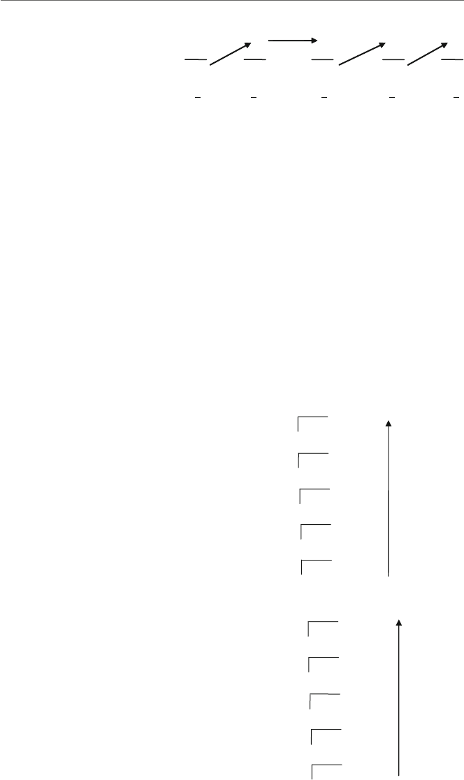
Appendix B 217
23 7 731
–16 –8 –4 –2 –1
7310
10 1 1 1
2
4
2
3
2
2
2
1
2
0
Fig. B.1 Conversion of
decimal to binary using
subtraction method
Although the above method works fairly well with smaller numbers, it can get rather
cumbersome with larger numbers. Another method is the repetitive division by two meth-
ods, where one just continually divides by 2 and keeps track of the remainders. For
example, 23 divided by 2 is 11 with a remainder of 1. This process continues with 11
divided by 2 is 5 with a remainder of 1, 5 divided by 2 is 2 with a remainder of 1, 2 divided
by 2 is 1 with a remainder of 0, and 1 divided by 2 is 0 with a remainder of 1. Once the
result is a 0, the division should stop and the remainders are written in reverse order as
101112, which is correct. An easy way to perform this is shown in Fig. B.2, where the
division is repeated until there is a 0, and then the remainders are written from the bottom
up, as 101112.
As another example, what is the binary equivalent of the decimal number 18, which was
converted from binary to decimal previously? Again, either method can be used, where the
repetitive division method is illustrated in Fig. B.3.
11 r 1 =
101112
5r 1
2r 1
1r 0
0r 1
2
211
25
22
21
23
Fig. B.2 Conversion of
decimal 23 to binary using
division method
9r 0 =10010
2
218
4r1
29
2r 0
24
1r0
22
0r1
21
Fig. B.3 Conversion of
decimal 18 to binary using
division method

218 Appendix B
Once a conversion has been made from one base to another, it can be checked for accu-
racy by converting the number back to its original base. Although this is not a guarantee
that the original conversion was done properly, because a mistake might have been made
in both conversions, it does provide a way to check one’s work and avoid some possible
mistakes.
B.2
Hexadecimal Numbers
Often times, binary numbers need to be stored in an 8-bit byte, a 16-bit word, or a 32-bit
double word, where a bit is a binary digit. So a decimal number 2 would be stored in binary
in an 8-bit byte as 00000010, in a 16-bit word as 00000000000000102, and so on, where
the leading zeros will almost always be shown. As can be seen, this can become very prone
to error, where one might accidently leave off a bit, especially when dealing with 32-bit
double words. In order to help alleviate this problem, assembly language programmers will
often group 4 bits together to form what is known as a hexadecimal digit. Hexadecimal
is often just shortened to the word “hex” and stands for the base 16 numbering system.
In hex there are 16 digits, where the first 10 digits are the digits 0 through 9 from the
decimal numbering system, and the last 6 digits are the letters A through F from the English
alphabet. Table B.1 illustrates the numbers 0 through 15 in the decimal, binary, and hex
numbering systems.
Conversions between binary and hex are very common, so it is important that the reader
can readily convert back and forth between these first 16 numbers where the above table
should probably be memorized. The first 10 digits are fairly easy, because they are the
same as decimal, but the second 6 letters of the alphabet can be a little clumsy at first, but
this becomes easier with practice. Once one is comfortable with the above equivalencies,
the conversion back and forth between hex numbers and binary numbers is fairly easy,
where each group of four binary digits is represented by one hex digit and vice versa. The
usefulness of hex can be seen in the following, where instead of representing a number in
a combination of 16 different ones and zeros, the same number can easily be converted to
hex, where it can be represented in just four hex digits:
Table B.1 Decimal, binary, and hex numbering systems
Decimal Binary Hex Decimal Binary Hex
0 0000 0 8 1000 8
1 0001 1 9 1001 9
2 0010 2 10 1010 A
3 0011 3 11 1011 B
4 0100 4 12 1100 C
5 0101 5 13 1101 D
6 0110 6 14 1110 E
7 0111 7 15 1111 F

Appendix B 219
16-bit Binary 16-bit Hex Equivalent
0000 0010 1100 0101 02C5
One can convert numbers directly from hex to decimal, by using the same techniques
learned with binary, where each digit position is a power of 16. Looking at the above
number 02C5, it can be represented as done previously and as shown below:
0
163
2
162
C
161
5
160
Again, 163is 4,096, 162is 256, 161is 16, and 160is 1. Then looking only at the
positions that do not contain a 0, then 2 times 256 is 512, C (which is 12) times 16 is 192,
and 5 times 1 is 1, and adding 512, 192, and 5 equals 709. The same conversion process
learned previously can be performed on the binary number, which should result in the
same number, thus helping to confirm that the conversion between the binary and hex was
performed properly. Again, this does not guarantee that the conversion was done properly
but allows one to check one’s work for simple errors. In another example, what is 10EA16
in decimal? Again, 1 times 4,096 is 4,096, E (which is 15) times 16 is 240, and A (which
is 10) times 1 is 10, resulting in a total of 4,346.
The conversion from decimal to hex is a little more difficult. For example, trying to
decide how many times the number 4,096 goes into a number can be a little challenging,
but converting the above 709 should provide a sufficient example. It is obvious that the
number 4,096 will not work and that the number 256 does twice, so subtracting 512 from
709 leaves 197, so the first two hexadecimal digits are 02. The number 16 goes into 197, 12
times, which is the hexadecimal digit C, leaving the number 5, so the last two digits are C5,
resulting in the number 02C5. The repetitive division method can be equally challenging,
where 709 divided by 16 is 44 with a remainder of 5, 44 divided by 16 is 2 with a remainder
of 12 (which is C in hex), and 2 divided by 16 is 0 with a remainder of 2, for an answer of
02C516 as shown in Fig. B.4.
Note that the 12 is converted to C in hex and that a leading 0 is shown in order to
show all 16 bits. Given the complexity of dividing by 16, it is sometimes easier to convert
a number to binary and then convert the number to hexadecimal. It is also sometimes
advisable for especially large numbers to use a calculator, but for the exercises at the end
of this appendix, the conversions from decimal to hexadecimal and vice versa will be kept
small, so the use of a calculator should not be necessary and is not recommended.
44 =
02C516
16 709
2
16 44
0
r 5
r 12
r 2
16 2
Fig. B.4 Conversion of
decimal 709 to hexadecimal
using division method
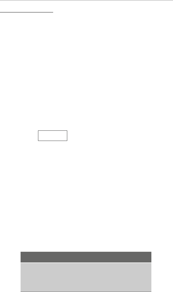
220 Appendix B
B.3
Overview of Logic
Prior to examining arithmetic, it might be helpful to first look at logic. Recall that a “not”
operation causes a false to become a true and a true to become a false. With an “and”
operation, both operands need to be true in order for the result to be true, and with an “or”
operation, only one operand needs to be true for the result to be true. Whereas an “or”
is often called an inclusive-or, another type of “or” operation is the exclusive-or, (often
abbreviated as “xor”), where either of the operands can be true for the result to be true,
but not both. A convenient way to remember the difference between the two is that the
inclusive-or includes the case where both operands are true, and the exclusive-or excludes
that case. Of course, instead of trues and falses, ones and zeros can be used instead, as
shown in the truth table in Table B.2.
In the following examples, only 8 bits will be used instead of 16–32 bits to make it
simpler to understand. Given the following unsigned 8-bit memory location called flag,
where the high-order bit on the left is bit position 7 and the low-order bit on the right is bit
position 0,
flag 01101010
what if bit position 2 (third from the right) needed to be set to 1? A mask would need to be
created to change bit position 2 to a 1 and yet keep all the other bit positions unchanged.
Given the previously introduced knowledge of logic, which logic operation and bit pattern
should be used to set bit 2? If one thinks about the basic logic operations for a few minutes,
one ought to be able to reason it out. Recall that with an “or” operation, either or both of
the conditions must be true and with an “xor” operation either one or the other, but not
both, condition must be true. Assuming that 1 stands for true and 0 stands for false, if bit
position 2 is a 0, and one wants to make it a 1, then in looking at the truth table in Table B.2,
either an “or” or an “xor” operation could be used.
However, what if bit position 2 were already a 1? Whether bit position 2 is a 1 or a 0, the
task is to set it to a 1. Using an “xor” would cause the 1 to switch to a 0, which is not what
is needed. However, using an “or” would cause the result to be a 1 regardless of whether the
initial value was a 1 or a 0, which is the intended result. In fact, as a general rule, anytime
one wants to set a bit, regardless of the previous value, an “or” operation should be used.
Table B.2 Truth table
x y not x x and y x or y x xor y
00 1 0 0 0
01 1 0 1 1
10 0 0 1 1
11 0 1 1 0

Appendix B 221
What about the other bits? Although bit 2 can be set to a 1, how can it be that the other
bits remain unchanged? In further examining the truth table, one should notice that a 0 “or”
a 0 is a 0, and a 0 “or” a 1 is a 1. In other words, if all the other bit positions in the mask are
set to 0, the result would be that those bit positions would remain unchanged. The resulting
mask is 00000100 as shown below, where only bit 2 is set to 1 regardless of whether the
original bit position is a 1 or a 0, and all the other bit positions remain unchanged:
01101010 =Flag 01101110 =Flag
00000100 =Mask 00000100 =Mask
or ———————— or ————————
01101110 =Result 01101110 =Result
What if instead of setting bit 2 to 1, it needed to be determined whether bit 2 is set to 1?
A simple comparison will not do because of the other bits in the byte which may or may
not be set to 1. In other words, 00000100 does not equal 01101110, even though bit 2 is
set to 1 in both cases. As one might have guessed, a mask is needed to filter out the other
bits so that only bit 2 is compared. Again, examining the truth table, it should be noticed
that the “and” operation might be a good choice, where a 0 “and” either a 1 or a 0 results
in 0, and a 1 “and” either a 0 or a 1 results in either a 0 or a 1, respectively. After filtering
out all of the other bits, all that remains is the value of bit position 2, and all the other bit
positions are set to 0:
01101110 =Flag 01101010 =Flag
00000100 =Mask 00000100 =Mask
and ———————— and ————————
00000100 =Result 00000000 =Result
What if one wanted to just reverse or toggle a single bit? At first thought, the “not” oper-
ation sounds good, but it must be remembered that the not operation would complement all
the bits in the byte and not just a single bit. As hinted at previously with the discussion of
the inclusive-or, the exclusive-or (“xor”) might be a good possibility. Again examining the
truth table, a 0 “xor” 1 is a 1, and a 1 “xor” 1 is a 0, thus performing the toggling operation.
However, what about the other bits? Well, a 0 “xor” 0 is a 0 and a 1 “xor” 0 is a 1, thus not
altering the other bits. Looking at the two examples below, notice that in each case, bit 2 is
toggled and the other bits remain the same:
01101010 =Flag 01101110 =Flag
00000100 =Mask 00000100 =Mask
xor ———————— xor ————————
01101110 =Result 01101010 =Result
Given the above, the result is that Table B.3 is a useful summary of which logical oper-
ator should be used for which type of operation needed. Although once in a while it seems
that some other operation will do, as was indicated in the discussion of the inclusive-or, it
is best to stick with the following table to help subsequent programmers who might need

222 Appendix B
Table B.3 Logic operations Operation Logic
Set Or
Test And
Toggle Xor
to update code and also avoid some difficult logic errors that can take quite a bit (no pun
intended...) of time to debug.
B.4
Unsigned Numbers and Addition
Prior to examining signed numbers, it is helpful to first understand unsigned numbers and
binary addition. Unsigned numbers are just the non-negative numbers, or in other words
the number 0 and the positive numbers. For the sake of simplicity and space, again the
following discussion concerning unsigned numbers and addition will be limited to using
only 8 bits instead of 16 or 32 bits, but all the concepts can be readily expanded to 16 and 32
bits. Given only 8 bits, what then is the largest unsigned number that could be represented?
That number would be 111111112,FF
16,or255
10. If necessary, use the techniques learned
previously to verify that these three numbers are equal to each other.
Binary addition is similar to decimal addition except for the change in base. For exam-
ple, when two decimal digits are added together such as 1 + 1, the answer is obviously 2.
However, when two binary digits are added together and the sum is greater than the largest
digit available in binary, which is the digit 1, the solution is to carry a 1 to the next posi-
tion. The result is similar to base 10 when adding 9 + 1, where the result is 10. The same
principle holds true in binary, where when a digit is not available, a carry of 1 occurs to
the next position. Although this is not a problem when adding numbers such as in 0 + 1,
where the result is 1, but when adding 1 + 1, the digit 2 is not available, so a 1 is carried
into the next position, where 1 + 1 is 102. The following shows the results of adding the
four possible bit combinations that are possible in binary:
001 1
+0 +1 +0 +1
__ __ __ __
01110
When more than one digit numbers are being added together in the decimal numbering
system, it is possible that a carry of 1 is generated, where the carry is then added to the
next column. Although this is second nature to us, an example is shown below:
11 ←Carries
157
+978
____
1035

Appendix B 223
When carrying into the next position, it is possible to have three digits to add together.
This is true in binary as well, where the following shows the results of adding the eight
possible bit combinations together in binary, where the top digit is the possible carry-in
from the previous addition:
00001111←Possible carries
00110011
+0 +1 +0 +1 +0 +1 +0 +1
__ __ __ __ __ __ __ __
01110 1101011
As with decimal addition, the same occurs in binary, where two or more ones will also
generate a carry of 1 into the next column as shown below:
11 111 ←Carries
00110111
+00110011
_________
01101010
Although at first binary addition may seem a little awkward, this is just because of one’s
familiarity with the decimal numbering system. However, with a little practice it becomes
much easier and there are exercises at the end of the chapter to help one get used to binary
addition.
What happens if one tries to add two numbers that end up with a sum that is too large
for an 8-bit byte? For example, if one tried to add the decimal numbers 202 and 168, which
result in the number 370? Remember from the beginning of this section that the largest
unsigned positive number that can be stored in a byte is the number 25510. In looking at
the binary arithmetic for this example, where 20210 equals 110010102and 16810 equals
101010002, the result is
11001010
+10101000
_________
101110010
With unsigned numbers, it is fairly obvious when a number does not fit in 8 bits,
because there is a carry-out of the leftmost or most significant bit position. In this case
what is known as the carry flag (CF) would be set to 1 in the central processing unit
(CPU). However, as will be seen later, this method does not work when dealing with signed
numbers and negative numbers.
B.5
Signed Numbers
Again for the sake of simplicity and space, the following discussion concerning signed
numbers will be limited to using only 8 bits instead of 32 bits, but all the concepts can

224 Appendix B
be readily expanded to 16 and 32 bits. In decimal, negative numbers are commonly rep-
resented by the appearance of the minus sign to the left of the number. Unfortunately in a
computer, everything is represented as either a 0 or a 1, which rules out the use of a minus
sign. A simple solution would be to use one of the bits in a number to represent the sign of
the number, where, for example, a 0 in the leftmost byte could represent a positive number,
and a 1 could represent a negative number. Of course, this would limit the largest possible
number to only 7 bits, but in exchange, the representation of negative numbers is gained.
For example, 011111112would represent a positive 127 and 111111112would represent a
negative 127, where the leftmost bit would represent the sign and would be called the sign
bit. This method of representing negative numbers is called the signed magnitude method.
However, it does have a disadvantage, which is that although the number 0 could be rep-
resented as 000000002, there also exists the possibility of 100000002, which is a negative
zero. Another disadvantage is that it is more difficult for a computer to do arithmetic using
the signed magnitude method, because beyond requiring circuitry to perform addition in
the arithmetic logic unit (ALU) in the CPU, there also needs to be circuitry to perform sub-
traction. Thus although this method appears to be intuitively easy, it is not used in computer
architectures.
Another method to represent negative numbers is the one’s complement method, which
makes it easier for the CPU to perform arithmetic. The reason for this is that only cir-
cuitry for addition is needed because subtraction can be done using the addition of negative
numbers, which will be demonstrated shortly.
The way a negative number is represented using one’s complement is that for each bit
in a number, the complement is taken, similar to using the not instruction. For example,
a positive 7 in base 10 is represented as 00000111 in binary. A negative 7 in base 10
is represented in base 2 by merely complementing each bit as 111110002. In order to
determine whether a number is negative, one first looks at the sign bit. If it is a 0, indicating
a positive number, one just converts the number to decimal. If the sign bit is 1, indicating
a negative number, then one knows that one needs to take the one’s complement first, then
convert it to decimal, and also be careful not to forget to include a minus sign.
Although arithmetic is easier with one’s complement, there still remains a problem with
both a positive and a negative zero, where the complement of 000000002is 111111112.
Although this method has been used in computers in the past, it tends not to be used in
more modern computer designs.
Two’s complement is just a little more complicated than one’s complement, but is easier
to perform arithmetic and avoids the problem on both a positive and a negative zero. As
with the previous two mechanisms, positive numbers are represented in the same fashion,
and the leftmost bit is used as a sign bit. If it is a 0, then the number is positive, otherwise
if it is a 1, then the number is negative.
In order to convert a positive number to a negative number, first take the one’s com-
plement and then merely add a 1 to the resulting number. For example, a positive 7 is
represented as 000001112. To convert it to a negative 7, first perform the one’s complement
of 111110002and then add 1 to the one’s complement, thus creating the two’s complement:
111110012. Although slightly more complicated, it makes arithmetic easier as will be seen
shortly and also avoids the problem of both a negative and a positive zero. For example, a 0

Appendix B 225
is represented as a 000000002. The one’s complement is 111111112, and when a 1 is added
to this number to obtain the two’s complement, the result is 000000002. Although when
adding 1, there is a 1 carried out of the leftmost bit position which would cause the carry
flag to be set, it should be noted that this does not indicate overflow since this is a signed
number as will be explained in the next section. The result is the carry-out discarded and
000000002is a self-complementing number.
What this does is free up one bit combination, 100000002, which represents –128 and
means that there is one more negative number than there are positive numbers. If one con-
verts 100000002to a positive number, first by taking the one’s complement 011111112and
then adding 1 to it, it becomes 100000002, which makes –128 also a self-complementing
number.
Because of the ease of performing arithmetic and the lack of both a positive and a
negative zero, this method is the most common method used in today’s modern computers,
including the Intel processor. Table B.4 shows the range of numbers that are possible in
each of the three ways of representing positive and negative numbers.
To calculate the largest positive number that can be stored in nbits, where nequals 8 in
this example, note that in all three cases the largest positive number is 2n–1–1, which equals
27–1, or 128–1, or 127. The largest negative number in sign magnitude or one’s comple-
ment is –2n–1–1, or –127. But in the case of two’s complement as mentioned above, note
that the largest negative number is –2n–1, or –128.
Table B.4 Three ways of representing positive and negative numbers
Sign-Magnitude One’s-Complement Two’s-Complement
Base 2 Base 10 Base 2 Base 10 Base 2 Base 10
01111111 +127 01111111 +127 01111111 +127
00000000 +0 00000000 +0 00000000 0
10000000 -0 11111111 -0 11111111 -1
10000001 -1 11111110 -1 11111110 -2
11111110 -126 10000001 -126 10000001 -127
11111111 -127 10000000 -127 10000000 -128
B.6
Addition and Subtraction of Signed Numbers
In Section B.4, it was seen that if two numbers were added together that were too large
for a byte, a carry-out of the leftmost bit was generated and the carry flag was set to 1.
However, what about the following case when adding the signed numbers 127 plus 127?
When adding these two numbers together, the answer is 254, which is less than 255, so
it should not be a problem, should it? It would not be if unsigned numbers were used,
because as mentioned previously the largest number that can be stored in an unsigned

226 Appendix B
number is 255, or 11111111 in binary. But the question asked here is what would happen
if the signed numbers 127 plus 127 were added together. In this case, the largest number
that can be stored as a signed number is 127, and clearly 254 is larger than 127.
To help clarify this further, it helps to carefully examine the binary equivalent of these
numbers when they are added together:
01111111
+01111111
_________
011111110
If the two numbers 127 are considered to be unsigned, then the result of 11111110 is equal
to 254 and there is no carry-out of the leftmost bit, so there is no overflow. However, if
the numbers are considered to be signed numbers, then it is now the case that the answer
of 11111110 is no longer a positive number, but rather a negative number due to the 1
in the sign bit. Using two’s complement and converting the above number 11111110 to
determine its decimal equivalent, the result is that the answer for adding a 127 plus a 127
is a –2, which is clearly incorrect. How can the sum of two positive numbers end up being
a negative number? The answer is that they cannot and this is a case where overflow has
occurred. Although as humans we can see that something has gone wrong here, there is
a simpler way for the computer to determine an overflow condition. Whether or not there
is a carry-out from the leftmost bit position, if the carry into the leftmost bit position is
equal to the carry-out of the leftmost bit position, then no overflow has occurred. But if
one looks at the above situation, the carry-in to the last position is a 1, and the carry-out is
a 0, thus indicating that overflow has occurred in this situation, and the overflow flag (OF)
in the CPU would be set to 1.
Although this might seem a little difficult, it really is not, because instead of the system
trying to keep track of what sign the numbers are and then trying to determine under what
circumstances overflow might have occurred, it is much simpler to check these two carry
bits. In fact it is much easier than even performing any sort of comparison, and only a
simple logic operation can be used. So the question should be which logic operation can
be used in this situation? If one takes a few minutes to think about it, the answer is fairly
simple. If the carry-in and the carry-out are the same, such as both 0 or both 1, there is
no overflow, so the carry flag should be set to 0. If the carry-in and carry-out are different,
such as 0 and 1, or 1 and 0, respectively, then there is overflow, so the carry flag should be
1. The results are in the form of the truth table in Table B.5.
Table B.5 Overflow carry-in carry-out overflow flag
00 0
01 1
10 1
11 0

Appendix B 227
Given the previous overview of logic in Section B.3, it should be apparent that the above
operation is the exclusive-or operation, where the result is a 1 if either of the operands
are 1 but not when both operands are either a 1 or a 0. For those who have had or are
currently taking a computer organization and architecture course, it should be noted that
the computer circuitry in the arithmetic logic unit (ALU) could use a simple exclusive-or
gate that uses as input both the carry-in and the carry-out and the output of the gate fed to
the overflow flag that can then be subsequently tested by programmers.
With respect to subtraction, the advantage of using one’s complement and two’s com-
plement representation of negative numbers over sign magnitude representation of negative
numbers is that instead of subtracting the subtrahend from the minuend, subtraction
can easily be performed by just negating the subtrahend and then adding it to the
minuend.
Besides the absence of a positive and a negative zero, to illustrate the other advantage of
using two’s complement over one’s complement when performing subtraction, one needs
to first see how subtraction is performed in one’s complement. In order to perform sub-
traction using one’s complement, one only needs to find the complement of the subtrahend
and add, but the problem with this is that the answer is sometimes off by 1 less than it
should. In these cases, there is a carry-out of the leftmost bit position and this is added to
the answer to obtain the correct answer. For example, 7–5 would be the same as saying 7
+ (–5) as shown below. But notice that the answer is 1 instead of 2. So in the next line, the
carry-out of the leftmost bit position 1 is added to correct the problem:
00000111
11111010
100000001
00000010
+
1+
The advantage of two’s complement is that 1 never needs to be added and thus the
logic circuitry in the ALU is simpler. In order to perform the above subtraction of 7–5, one
only needs to perform the equivalent of 7 + (–5) by taking the two’s complement of the
subtrahend and then adding:
00000111
+ 11111011
__________
00000010
Unlike using unsigned numbers, it is not readily apparent whether or not overflow has
occurred. Although it is not shown, looking at and walking through the addition above,
there appears to have been carry-out of the leftmost bit position and the carry flag is set
to 1. However, given the previous discussion concerning signed numbers, would this be
considered an overflow condition? It should not be, because the carry-in to the leftmost
bit is the same as the carry-out of the leftmost bit. Looking at a simpler and more obvious
example, consider adding (–1) + (–1), where the answer is obviously –2 in base 10. Looking

228 Appendix B
at the addition below, it looks as though when one adds the two numbers together, there is
a carry-out into the next bit position:
11111111
+ 11111111
__________
111111110
Again, the difference here is that overflow is not determined whether or not there has
been a carry-out of the rightmost bit position, but rather overflow is determined again by
examining the carry-in into the leftmost bit position and the carry-out of the leftmost bit
position. The two numbers are the same and again there has been no overflow.
B.7
Characters
Although a computer uses binary to perform various logic and arithmetic operations, all
the input and output are performed using character data. For simple letters and strings, the
data that is input stays in character format, is processed as such, and then in turn is output
as character data. However, when it comes to numbers that need to be processed using
arithmetic, the character representation of the numbers needs to first be converted to base 2
so that the arithmetic logic unit (ALU) portion of the CPU can perform the arithmetic, and
if the numbers need to be output, they will then need to be converted back to characters so
that they can be displayed. This is one of the reasons why assembly language input/output
can be difficult, because in addition to special routines necessary to communicate with
the device in question, specialized operating system functions must be called or unique
routines need to be written to perform the conversions. This is also one of the reasons
why it is helpful to have the ability to use the input/output facilities of the C programming
language as discussed in Chapter 2. However, even character data needs to be stored in
ones and zeros and various codes have been developed to represent the character data.
On mainframe computers, many times an 8-bit format called EBCDIC (Extended Binary
Coded Decimal Interchange Code) is used. The Java programming language uses Unicode,
which is a 16-bit code that can incorporate many of the symbols from languages other than
English. However, many microcomputers and some interface devices use an 8-bit code
called ASCII (American Standard Code for Information Interchange).
The hexadecimal representations of these characters can be found in the following table.
It is interesting to note that not only are the character representations of the digits in ascend-
ing order but also all of the upper and lowercase letters are in ascending order, which makes
it possible to sort character data, because the letter A has a lower value than the letter B,
and so on. It is also interesting to note that the upper and lowercase representations of the
alphabetic letters differ by only 1 bit, thus making is easy to convert between the two using
simple logic operations, as described in Chapter 6. To see which bit, convert the hex codes
to binary using the techniques described in Section B.2. Some of these operations are also
left as exercises at the end of this appendix.
Appendix B 229
B.8
Hex/ASCII Table
Hex Character Hex Character Hex Character Hex Character
00 null 20 space 40 @ 60 `
01 21 ! 41 A 61 a
02 22 " 42 B 62 b
03 23 # 43 C 63 c
04 24 $ 44 D 64 d
05 25 % 45 E 65 e
06 26 & 46 F 66 f
07 27 ' 47 G 67 g
08 28 ( 48 H 68 h
09 29 ) 49 I 69 i
0A line feed 2A * 4A J 6A j
0B 2B + 4B K 6B k
0C 2C , 4C L 6C l
0D return 2D - 4D M 6D m
0E 2E . 4E N 6E n
0F 2F / 4F O 6F o
10 30 0 50 P 70 p
11 31 1 51 Q 71 q
12 32 2 52 R 72 r
13 33 3 53 S 73 s
14 34 4 54 T 74 t
15 35 5 55 U 75 u
16 36 6 56 V 76 v
17 37 7 57 W 77 w
18 38 8 58 X 78 x
19 39 9 59 Y 79 y
1A 3A : 5A Z 7A z
1B 3B ; 5B [ 7B {
1C 3C < 5C \ 7C |
1D 4D = 5D ] 7D }
1E 4E > 5E ^ 7E ~
1F 5F ? 5F _ 7F
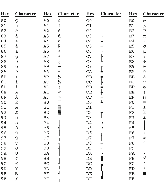
230 Appendix B
B.9
Summary
•All numbering systems use the powers of their respective bases.
•It is helpful to memorize the first 15 numbers of binary and hexadecimal to help with
conversions between the two.
•When using unsigned numbers, the carry flag indicates overflow.
•Use “or,” “and,” and “xor,” to set, test, and toggle a bit, respectively.
•There are three methods to represent negative numbers: signed magnitude, one’s com-
plement, and two’s complement. The first two have the problem of both a positive and
a negative zero, whereas the latter has an extra negative number.
•The two’s complement method is the most common method to represent signed numbers
and it is the method used in the Intel processor.
•Overflow occurs during addition with two’s complement numbers when the carry-in to
the leftmost bit position is different than the carry-out of the leftmost bit position.

Appendix B 231
B.10
Exercises (Items Marked with an ∗Have Solutions in Appendix E)
1. Convert the following “unsigned” binary numbers to their decimal equivalent:
∗A. 00011111
B. 01011110
∗C. 01111110
D. 10101011
2. Convert the following “unsigned” decimal numbers to their binary equivalent:
∗A. 27
B. 82
∗C. 110
D. 245
3. Convert the following “signed” binary numbers to the decimal equivalent:
∗A. 01010111
B. 11111110
∗C. 10101111
D. 01110111
4. Convert the following “signed” decimal numbers to binary (use only 8 bits):
∗A. 54
B. 127
∗C. -23
D. -125
5. Convert the following “unsigned” decimal numbers to hexadecimal (use only 8 bits):
∗A. 73
B. 162
∗C. 200
D. 255
6. Convert the following “unsigned” hexadecimal numbers to decimal:
∗A. 2A
B. 7E
∗C. AB
D. EF

232 Appendix B
7. Convert the following “signed” decimal numbers to hexadecimal (use only 8 bits):
∗A. 18
B. 100
∗C. -79
D. -112
8. Convert the following “signed” hexadecimal numbers to decimal:
∗A. 34
B. 7A
∗C. 85
D. E0
9. Convert the following binary numbers to hexadecimal, where signed or unsigned is
irrelevant:
∗A. 01011100
B. 10111111
∗C. 01111101
D. 10001001
10. Convert the following hexadecimal numbers to binary, where signed or unsigned is
irrelevant:
∗A. 12
B. 6D
∗C. A1
D. FE
11. Using the ASCII table, convert the following ASCII characters to their binary
equivalent:
∗A. "9"
B. "B"
∗C. "q"
D. "∗"
12. Using the ASCII table, convert the following binary numbers to their ASCII equiva-
lent:
∗A. 01000000
B. 01111001
∗C. 01010001
D. 01101000

Appendix B 233
13. Add the following “signed” binary numbers. Indicate whether or not overflow has
occurred:
∗A. 00001001 + 00010111
B. 11101010 + 11110111
∗C. 00101111 + 11111000
D. 01101111 + 01110001
14. Given the following “signed” binary numbers, perform the subtraction by taking the
two’s complement of the subtrahend and then adding. Indicate whether or not overflow
has occurred:
∗A. 10001000 - 00000001
B. 01111011 - 01110010
∗C. 01011111 - 10111100
D. 10000001 - 01011101

Appendix C
Glossary
The descriptions of terms in this glossary should not be used in lieu of the complete
descriptions in the text. Rather they serve as a quick review and reminder of the basic
meaning of various terms that are first introduced in italics in the text. Should a more com-
plete description be needed, the index can guide the reader to the appropriate pages where
the terms are discussed in more detail.
Absolute When a memory location’s address is referenced from location 0 in RAM, then
it is known as an absolute address.
Aliasing Referencing the same memory location using two different names. In general,
this should be avoided.
Assembler A program that converts an assembly language program into a machine
language program.
Assembly language A low-level language that uses mnemonics and is converted to
machine language by an assembler.
Bit bucket A term used to describe where bits go when the shifted off the end of a register
or a memory location.
Bit-wise Whenever there are operations on individual bits within a register or memory
locations, these are known as bit-wise operations, such as when using logic, shift, or rotate
instructions.
Conditional assembly A technique in a macro during assembly where one set of instruc-
tions can be generated under one set of circumstances and yet an entirely different set of
instructions can be generated under other circumstances.
CPU Central Processing Unit
Directive A command that tells the assembler what to do, as opposed to the CPU.
Dynamic When a value is calculated during execution time as opposed to assembly time,
it is known as dynamic.
FIFO First In Last Out as with a stack.
Instruction A command that tells the CPU what to do as opposed to the assembler.
235

236 Appendix C
Immediate An immediate value is a piece of data that is part of an instruction instead of
being in a memory location or a register.
LIFO Last In First Out as with a queue.
Load A load operation is the copying of the contents of a memory location or immediate
value into a register.
Machine language The native language of a processor coded in ones and zeros.
Macro A macro is a previously defined set of instructions that when invoked will cause
the previously defined instructions to be inserted into the assembly language program.
Macro definition The original copy of the macro as it was written. It does not take up any
memory until it is invoked and expanded in the program.
Macro expansion The code from the macro definition is inserted and expanded in the
program at the point where the macro is invoked.
Macro invocation Similar to calling a procedure except that instead of branching to and
returning from a procedure, the macro definition is inserted into the assembly program at
the point that the macro is invoked.
Mask A bit pattern in a register, a memory location, or an immediate data that when used
in logical operations will filter out all other bits that do not need to be tested or altered.
Mnemonics Abbreviations used in an assembly language to represent various instructions.
Operator Similar to a directive, it tells the assembler what to do with respect to an
individual instruction.
Queue A data structure often implemented as an array that allows data to be put in only
on one end and removed only from the other end. The putting of information into a queue
is known as an enqueue operation and the removing is known as a dequeue operation. The
data first enqueued into a queue is the first data that is dequeued from the queue. This
first-in first-out principle makes the queue a FIFO data structure.
RAM Random Access Memory
Register A short-term memory location located in the CPU that is used for a variety of
operations including arithmetic, logic, counting, indexing an array, and transferring data
between memory locations.
Relative When a memory location’s address is referenced from some point in RAM other
than memory location 0, then it is known as a relative memory address.
Stack A data structure often implemented as an array that allows data to be only put in
and taken out on one end. The placing of data on the stack is known as a push operation
and the removing of data from the stack is known as a pop operation. The data last pushed
onto the stack is the data first popped off the stack, where this last-in first-out principle
makes the stack a LIFO data structure.

Appendix C 237
Static When a value is calculated at assembly time prior to execution, then it is known as
static.
Store A store operation is the copying of the contents of a register or an immediate value
into a memory location.

Appendix D
Selected Assembly Language Instructions
This appendix is useful for quick reference. It does not contain a complete listing of all
instructions but rather only those used in this text. For further descriptions of the fol-
lowing instructions, use the index to find the page number in the text for more complete
descriptions and examples of each of the following instructions. For a more complete list
of instructions, see Appendix E of Introduction to Assembly Language Programming by
Sivarama P. Dandamudi, Springer, 2005.
Abbreviations used Selected flag abbreviations
reg =register C=Carry flag
mem =memory O=Overflow flag
imm =immediate Z=Zero flag
xx =placeholder S=Sign flag
Instruction Operands Flags affected Clock cycle times
add reg,reg C, O, Z, S are modified 1 to 3
reg,imm
reg,mem
mem,reg
mem,imm
Description: Adds the contents of the source (second) operand to the
destination (first) operand.
and reg,reg C and O set to 0 1 to 3
reg,imm Z and S are modified
reg,mem
mem,reg
mem,imm
Description: Logical bit-wise and of the source (second) operand on the
destination (first) operand.
239

240 Appendix D
call label none are affected 1 to 2
Description: The address of the next instruction after the call instruction
is saved on the stack and control is transferred to the location
label.
cdq none none are affected 2
Description: Converts double to quad. Converts the eax register to the
edx:eax register pair, where the sign bit of eax is propa-
gatedintotheedx register.
cld none none 2
Description: Clears the direction flag to 0.
cmp reg,reg C,O,Z,S are modified 1 to 2
reg,imm
reg,mem
mem,reg
mem,imm
Description: An implied subtraction of the second from the first operand,
where neither operand is altered and the flags set accordingly.
cmpsb none C,O,Z,S are modified 5
Description: Compares a string of bytes pointed at by the esi and edi
registers and sets the flags accordingly. If the direction flag
is cleared using cld,theesi and edi registers are incre-
mented, otherwise if the direction flag is set using std,the
esi and edi registers are decremented. The instruction is
often used with the rep prefix.
dec reg O,Z,S are modified 1 to 3
mem C is not affected
Description: The operand is decremented by 1.
div reg C,O,Z,S are undefined 41
mem
Description: See the idiv instruction.

Appendix D 241
idiv reg C,O,Z,S are undefined 41
mem
Description: The quotient in the eax register is divided by the divisor in
the operand. The quotient is placed in the eax register and
the remainder is placed in the edx register. The div instruc-
tion is for unsigned division, whereas the idiv instruction is
used for signed division. Prior to using the idiv instruction,
be sure to use the cdq instruction.
imul reg C,O are modified 10
mem Z,S are undefined
Description: The multiplicand in the eax register is multiplied by the
multiplier in the operand. The product is placed in the
edx:eax register pair, where the high-order bits are in edx
and the low-order bits are in eax.Themul instruction is
for unsigned multiplication, whereas the imul instruction is
used for signed multiplication.
inc reg O,Z,S are modified 1 to 3
mem C is not affected
Description: The operand is incremented by 1.
jecxz label none are affected 5 to 6
Description: Control is transferred to the location label when the ecx
register is equal to 0.
jmp label none are affected 1 to 2
Description: Control is unconditionally transferred to the location label.
jxx label none are affected 1
Description: Control is conditionally transferred to the location label,
depending on the particular instruction and the correspond-
ing flag. See the list below:
Instruction: Description:
je/jne jump equal/jump not equal
jg/jng jump greater than/jump not greater than
jge/jnge jump greater than or equal/jump not greater than or equal

242 Appendix D
jl/jnl jump less than/jump not less than
jle/jnle jump less than or equal/ jump not less than or equal
ja/jna jump above/jump not above
jae/jnae jump above or equal/jump not above or equal
jb/jnb jump below/jump not below
jbe/jnbe jump below or equal/jump not below or equal
jz/jnz jump zero/jump not zero
jc/jnc jump carry/jump not carry
jp/jnp jump parity (even)/jump not parity
js/jns jump sign (negative)/jump not sign
jo/jno jump overflow/jump not overflow
lea reg,mem none are affected 1
Description: The address of the source (second) operand is copied into the
destination (first) operand.
lodsb none none are affected 4
Description: Load the al register from a string of bytes from where
the esi register is pointing. If the direction flag is cleared
using cld,theesi register is incremented, otherwise if
the direction flag is set using std,theesi register is
decremented.
loop label none are affected 5 to 6
Description: The contents of the ecx register are decremented, and if it
is not zero, control is transferred to the location label,oth-
erwise control falls through to the next instruction after the
loop instruction.
mov reg,reg C,O,Z,S are modified 1
reg,imm
reg,mem
mem,reg
mem,imm
Description: The contents of the source (second) operand are copied to the
destination (first) operand.
movsb none none are affected 4
Description: Copies a string of bytes from where the esi register is point-
ing to where the edi register is pointing. If the direction flag

Appendix D 243
is cleared using cld,theesi and edi registers are incre-
mented, otherwise if the direction flag is set using std,the
esi and edi registers are decremented. The instruction is
often used with the rep prefix.
mul reg C,O are modified 10
mem Z,S are undefined
Description: See the imul instruction.
neg reg C,O,Z,S are modified 1 to 3
mem
Description: Negates the operand, or in other words take the two’s comple-
ment of the operand.
nop none none are affected 1
mem
Description: No operation.
not reg none are affected 1 to 3
mem
Description: Performs a logical not (one’s complement) operation on the
operand.
or reg,reg C and O set to 0 1 to 3
reg,imm Z and S are modified
reg,mem
mem,reg
mem,imm
Description: Logical bit-wise inclusive or of the source (second) operand
on the destination (first) operand.
pop reg none are affected 1 to 3
mem
Description: Pops a value from the stack into the operand.
popad none none are affected 5
Description: Pops the registers on the stack into the edi,esi,ebp,esp,
ebx,edx,ecx,andeax registers.

244 Appendix D
push reg none are affected 1 to 3
mem
imm
Description: Pushes the operand onto the stack.
pushad none none are affected 5
Description: Pushes the eax,ecx,edx,ebx,esp,ebp,esi,andedi
registers onto the stack.
rep none Z is modified varies
repe C, O, and S are not affected
repne
Description: Can be used as a prefix with instructions like cmpsb,
lodsb,movsb,scasb,andstosb.Therep prefix decre-
ments the ecx register and repeats until it is 0.Therepe and
repne both decrement ecx and repeat until it is 0, but repe
will repeat while equal and stop if the result of a comparison
is not equal and the repne will repeat while not equal and
stop when the result of a comparison is equal.
ret none none are affected 1 to 2
Description: Control is transferred to the location immediately following
the corresponding call instruction.
rol reg,cl C and O are modified 1 to 4
ror reg,imm Z and S are not affected
mem,cl
mem,imm
Description: The contents of the destination (first) operand are rotated to
the left using the rol instruction or to the right using the
ror instruction by the number of bits indicated in the second
operand. When rotated to the left, the leftmost bit is moved
into the rightmost bit position and when rotated to the right,
the rightmost bit is moved into the leftmost position. On an
8086/8088 processor, imm can only be a 1.
sal reg,cl C, O, Z, and S are modified 1 to 4
sar reg,imm
mem,cl
mem,imm

Appendix D 245
Description: The contents of the destination (first) operand are shifted to
the left using the sal instruction or to the right using the
sar instruction by the number of bits indicated in the second
operand. When shifted to the left, the leftmost bit is moved
into the carry flag and the rightmost bit position is filled with
a 0. When shifted to the right, the rightmost bit is moved into
the carry flag and the leftmost bit position is copied into both
the next position to the right and onto itself to maintain the
sign bit. On an 8086/8088 processor, imm can only be a 1.
scasb none C,O,Z,S are modified 4
Description: Scans a string of bytes pointed at by the edi register for
the character in the al register and when found sets the
flags accordingly. If the direction flag is cleared using cld,
the edi register is incremented, otherwise if the direction
flag is set using std,theedi register is decremented. The
instruction is often used with the rep prefix.
shl reg,cl C, O, Z, and S are modified 1 to 4
shr reg,imm
mem,cl
mem,imm
Description: The contents of the destination (first) operand are shifted to
the left using the shl instruction or to the right using the
shr instruction by the number of bits indicated in the second
operand. When shifted to the left, the leftmost bit is moved
into the carry flag and the rightmost bit position is filled with
a 0. When shifted to the right, the rightmost bit is moved into
the carry flag and the leftmost bit position is filled with a 0.
On an 8086/8088 processor, imm can only be a 1.
std none none 2
Description: Sets the direction flag to 1.
stosb none none are modified 3
Description: Stores the contents of the al register in a string of bytes
pointed at by the edi register. If the direction flag is cleared
using cld,theedi register is incremented, otherwise if
the direction flag is set using std,theedi register is
decremented. The instruction can be used with the rep
prefix.

246 Appendix D
sub reg,reg C,O,Z,S are modified 1 to 3
reg,imm
reg,mem
mem,reg
mem,imm
Description: Subtracts the contents of the source (second) operand from
the destination (first) operand.
test reg,reg C and O set to 0 1 to 2
reg,imm Z and S are modified
reg,mem
mem,reg
mem,imm
Description: Logical bit-wise and between the source (second) operand to
the destination (first) operand, where the destination (first)
operand is not altered and only the flags are altered.
xchg reg,reg none are modified 2 to 3
reg,mem
mem,reg
Description: The contents of the source (second) operand are exchanged
with the destination (first) operand.
xor reg,reg C and O set to 0 1 to 3
reg,imm Z and S are modified
reg,mem
mem,reg
mem,imm
Description: Logical bit-wise exclusive or of the source (second) operand
on the destination (first) operand.

Appendix E
Answers to Selected Exercises
Chapter 1
1.A. Correct
1.C. Correct
2.A. initial byte ?
2.C. x byte 'P'
x byte 'Q'
2.E. count sdword 0
3.A. Incorrect, move should be mov
3.C. Correct
3.E. Incorrect, cannot move a memory location into an immediate value
4.A. mov i,1
4.C. Direct translation :
mov c,2
mov eax,c
mov b,eax
mov eax,b
mov a,eax
5.A. mov a,'B'
5.C. Direct translation :
mov d,'E'
mov al,d
mov e,al
Chapter 2
1.A. Correct
1.C. Incorrect, delete the ADDR prior to number
247

248 Appendix E
3. xb=b1byb=b2
blank line
blank line
z=3
Chapter 3
1.A. Incorrect, delete the , 1
1.C. Incorrect, cannot add memory to memory
1.E. Incorrect, cannot subtract from an immediate value
2.A. mov eax,3
imul number
mov product,eax
2.C. mov eax,number
mov ebx,2
cdq
idiv ebx
mov answer,eax
3.A. mov eax,x
imul y
mov ecx,eax
mov eax,z
mov ebx,2
imul ebx
add ecx,eax
mov x,ecx
3.C. mov eax,num3
imul num4
mov ebx,eax
mov eax,num1
cdq
idiv num2
sub eax,ebx
mov total,eax
4.A. dec i
4.C. mov eax,x
add eax,y
neg eax
mov z,eax
Chapter 4
1.A. Incorrect, change =to ==

Appendix E 249
1.C. Although syntactically correct, it might not be what was intended logically
3.A. if01: cmp w,1
jne endif01
cmp x,2
jne endif01
then01: dec y
endif01: nop
3.C. if02: cmp w,1
je and02 :
cmp x,2
jne endif02
and02: cmp y,3
jne endif02
then02: inc z
endif02: nop
Chapter 5
1.A. Incorrect, .for and .endfor do not exist in MASM
1.C. Correct
3.A Three times
5.A mov edx,eax
mov eax,0
.while(edx >=ebx)
sub edx, ebx
inc eax
.endw
Chapter 6
1.A. Correct
1.C. Incorrect: rotate is not an instruction, use rol or ror.
1.E. Correct
2.B. mov eax,amount
add eax,number
sal eax,2 ; multiply by 2
mov result,eax

250 Appendix E
Chapter 7
1.A. Incorrect: it should be ret, not return.
1.C. Incorrect : there shouldn’t be a decimal point prior to the if directive.
1.E. Correct
Chapter 8
1.A. Correct
1.C. Correct
1.E. Correct
2.A. 5
2.C. 200
2.E. 200
3.A. mov num+0,1
3.C. mov eax,num[ebx]
mov num+4[ebx],eax ; or better yet: mov num[ebx+4]
4.A. 5
4.B. 20
4.E. 3
Chapter 9
1.A. Incorrect, it should be movsb
1.C. Correct
1.E. Incorrect, it should be rep stosb
2.A. ecx =2, esi=undefined, edi =103, al =“c”
2.C. ecx =1, esi=104, edi =109, al =undefined
Chapter 10
1. 22=4 opcodes, 20=1 register, 26=64 memory locations
3. 25=32 opcodes, 22=4 registers, 29=512 memory locations
5. 03CB and 0000001111001011
6. 90 and 10010000
7. 23C3 and 0010001111000011

Appendix E 251
Appendix B
1.A. 3110
1.C. 12610
2.A. 000110112
2.C. 011011102
3.A. 8710
3.C. −8110
4.A. 001101102
4.C. 111010012
5.A. 4916
5.C. C816
6.A. 4210
6.C. 17110
7.A. 1216
7.C. B116
8.A. 5210
8.C. −12310
9.A. 5C16
9.C. 7D16
10.A. 000100102
10.C. 101000012
11.A. 001110012
11.C. 011100012
12.A. ''@''
12.C. ''Q''
13.A. 001000002No Overflow
13.C. 001001112No Overflow
14.A. 100001112No Overflow
14.C. 101000112Ye s O v e r fl ow

Index
A
Absolute address, 201
add,29,205,248
Addition, 230
Addition instructions, 31
ADDR operator, 18–20
Aliasing, 148
and,239
And operator (&&), 61
Array of strings, 186–188
Arrays, 147–150
Arithmetic instructions, 29–45
Arithmetic shift, 99–102
ASCII, 228–230
.asm file, 211,213
Assembler, 1
Assembly language, 1–2
B
Binary numbers, 215–218
Bit, 216
Bit-bucket, 97
Bit manipulation
set, 92,222
test, 92,222
toggle, 92,222
Bit-wise, 95
Branch instructions, 47,51,61,65,73
break (C instruction), 58
byte directive, 5–6
C
C programming language
break,58
for,76
if,48–49
printf,18–24
scanf,24–25
switch,57–59
while,71
call,115,240
Carry flag, 96
Case structure, 57–59
cbw,35
cdq,35,240
Characters, 228
cld,181,240
cmp,51–52,240
cmpsb,181,186–190,240
.code directive, 3
Comments, 4–5
Comparisons, 48
Conditional assembly, 129–132
Conditional assembly directives, 130
else,130
endif,130
if,130,133–135
ifb,130–132
ifdif,130
ifdifi,130,133–134
ifidn,130
ifidni,130,133–135
ifnb,130
EQ,GE,GT,LT,LE,NE,130
Conditional jump, 50,56,65
CPU, 3,7
cwd,35
D
.data directive, 3
dec,36,191–193,240
Decimal numbers, 218–219
De Morgan’s rules, 70
Direction flag, 49,181
.386 directive, 3
Directives, see individual listings
div,34,240
253

254 Index
Division instructions, 32,34
Do-while loops, 74
dup operator, 149
Dynamic, 157
dword directive, 5
E
eflags register, 9,49,65–66
.else directive, 53
.elseif directive, 54
end directive, 8
.endif directive, 54
endm directive, 124
endp directive, 3,117
.endw directive, 72
EOD loop, 80
Errors, 12
Exclusive or, 91,95,220–221
Execution errors, 129
F
FIFO, 163
Flags, 50
Fixed iteration loop, 76–78
For loop, 76
H
Hello world program, 17
Hexadecimal numbers, 218–219
High-level languages, 5
I
idiv,33,241
.if directive, 51–52
If statements, 58,64
Immediate data, 6–7
imul,33,241
inc,36–37,193–194,241
Inclusive or, 112,220–221,243
Inline assembly, 13–14
Input, 22–24
Instructions, see individual listings
Instruction timings, 203–204
Integers, 19–20
INVOKE directive, 18–21
Iteration instructions, 76–85
J
ja,59,242
jae,59,242
jb,59,242
jbe,59,242
jc,66,242
je,50,242
jecxz,77,241
jg,51,241
jge,51,241
jl,51,241
jle,51,242
jmp,54,202–203,241
jna,59,242
jnae,59,242
jnb,59,242
jnbe,59,242
jnc,66,242
jne,50,241
jng,51,241
jnge,51,241
jnl,51,242
jnle,51,242
jno,66,242
jnp,66,242
jns,66,242
jnz,66,242
jo,66,242
jp,66,242
js,66,242
Jump instructions, 50–51,59,65,241–242
jz,66,242
L
Label field, 3–4
lea,200–201,242
Lengthof operator, 161–162
LIFO, 104
.listall directive, 52
.lst file, 52
Load operation, 10
Lodsb,175,177–178,242
Logic, 220–222
Logic errors, 117
Logic instructions, 91–95
Logical shifts, 95–99
loop,77–78,242
Loop instructions, 76–85
Low-level languages, 2
M
Machine language, 2,194
Macros, 123–129
definition, 124
expansion, 125
invocation, 124
parameters, 127–128
macro directive, 124

Index 255
Masks, 92,220
Mnemonics, 2
.model directive, 3
mov,6–7,13–15,194–198,242
movsb,176–177,242
mul,32,241
Multiplication instructions, 31–35
N
neg,38,243
Nested if statements, 54–57
Nested loops, 82–84
nop,51,243
not,93,243
Not operator (!), 60
Number systems, 215–219
O
offset operator, 156–157,200–201
One’s complement, 224–225
Opcode field, 3–4
Operand field, 3–4
Operator precedence, 39–40
Operators, see individual listings
or,93–95,243
Or operator (||), 60–61
Output, 19–21
Overflow flag, 49,226–227
P
Parity flag, 49
pop,104–106,243
popad,122–123,243
Post-test loops, 74–75
Precedence, 40–43
Pre-test loops, 71–74
Procedures, 115–119
printf (C instruction), 20–24
proc directive, 3,116
PROTO directive, 20–22
push,105–106,244
pushad,122–123,244
Q
Queues, 162–165
R
RAM, 7
Registers, 7–8
eax,8–11
ebp,9
ebx,8–9,152–156
ecx,8–9,75–79
edx,8–9,33–35
edi,9,155–160,174–176,178
eip,9
esi,9,11,155–160,174–175,178
esp,9
eflags,9,49,65–66
rep,176,244
repe,177,244
Repeat– until instructions, 74–75
.repeat directive, 76–77
.repeat–.untilcxz directives, 77–79
repne,178,244
ret,3,116–121,244
rol,103–104,244
ror,103,244
Rotate instructions, 102–104,244
S
sal,99–101,245
sar,99–102,245
sbyte directive, 15
scanf (C instruction), 21–23
scasb,175,177–179,244–245
sdword directive, 6
Selection instructions, 47–70
Search (sequential), 153–155
Selection sort, 167–171
Sentinel controlled loop, 81
Sequential search, 153
Shift instructions, 95–99,245
shl,96–98,245
shr,97,99,245
Sign bit, 226
Sign flag, 49–50
Sign magnitude, 225–226
Signed numbers, 225–228
SIGN? operator, 49
sizeof operator, 161–162
Sort (selection), 167–171
Stacks, 91–114
.stack directive, 3,104
Static, 157
std,176,243
Store operation, 8
stosb,177–179,244
Strings, 175–177
sub,31,199–200,246
Subprograms, 115
Subtraction instructions, 31,240
Swap, 108
switch (C instruction), 57–58
sword directive, 5
Syntax errors, 12

256 Index
T
test,98–96,246
Two’s compliment, 224–225
U
Unary operations, 36–38
Unconditional jump, 54
Unsigned numbers, 222–223
.until directive, 74–75
.untilcxz directive, 76–79
V
Variables, 1–6
W
.while directive, 72–73
While loops, 71–72
word directive, 4
X
xchg,107–109,246
xor,92,95,246
Z
Zero flag, 50
ZERO? operator, 49
